
A Novel Approach to Transverse Flux Machine Construction
13
energies Article A Novel Approach to Transverse Flux Machine Construction Tomasz Drabek 1 , Piotr Kapustka 2 , Tomasz Lerch 1, * and Jerzy Skwarczy ´ nski 1 Citation: Drabek, T.; Kapustka, P.; Lerch, T.; Skwarczy´ nski, J. A Novel Approach to Transverse Flux Machine Construction. Energies 2021, 14, 7690. https://doi.org/10.3390/en14227690 Academic Editors: Ants Kallaste and Lorand Szabo Received: 24 September 2021 Accepted: 13 November 2021 Published: 17 November 2021 Publisher’s Note: MDPI stays neutral with regard to jurisdictional claims in published maps and institutional affil- iations. Copyright: © 2021 by the authors. Licensee MDPI, Basel, Switzerland. This article is an open access article distributed under the terms and conditions of the Creative Commons Attribution (CC BY) license (https:// creativecommons.org/licenses/by/ 4.0/). 1 Faculty of Electrical Engineering, Automatics, Computer Science and Biomedical Engineering, AGH University of Science and Technology, 30-059 Krakow, Poland; [email protected] (T.D.); [email protected] (J.S.) 2 Department of Electrical Engineering, Polytechnic Faculty, PWSZ University of Applied Sciences in Tarnow, 33-100 Tarnow, Poland; [email protected] * Correspondence: [email protected]; Tel.: +48-12-617-4016 Abstract: The article presents a concept for a new design of the well-known Transverse Flux Machine (TFM) made with the use of a flat core used in classical electrical machines. The proposed design was first analytically verified and was subsequently verified using the finite element method, which fully corroborated the results. The simulations show that a set of three single-phase TFM machines with slotted flat rotor yokes generates a torque over three times greater than that of an induction motor and twice as large as Fractional Slot Concentrated Winding—Permanent Magnet Synchronous Machines (FSCW-PMSM). The performed comparative calculations confirmed that the torque generated by machines operating on principles similar to TFM can generate a torque much greater than those currently in common use. Keywords: transverse flux machine; permanent magnet synchronous motor; induction motor 1. Introduction There is always strong interest in new designs of electrical machines due to the desire to increase the power and torque unit indicators. One way in which this goal can be achieved is through the elimination or at least shortening of the winding front connections. These connections do not participate directly in the energy conversion process, but they are necessary for generating a rotating field during the operation of machines based on the use of this field. TFMs, however, use a completely different operating principle, resulting in the complete absence of front connections. The design of an electrical machine with a transverse flux was patented in 1888 [1], and almost a hundred years later it was adapted to modern technical capabilities and technologies [2]. Over the past 30 years, much research work has been devoted to TFMs, e.g., [3–5]. Numerous advantages of this construction have been demonstrated, the most impor- tant of which is the much greater ratio of mass and volume to power than exists in other machines. Despite this, TFMs are not widely used and produced at present, probably due to several disadvantages in their construction, the most serious of which are: - the complicated design and, as a result, higher production costs and reduced reliability; - the relatively low use of permanent magnet surfaces, which results in large leakage fluxes; - the large cogging torque. Since the transverse flux machine is an extremely interesting object from the per- spective of the theory of electrical machines, it was considered useful to compare some of its properties with the corresponding features of induction machines and Fractional Slot Concentrated Winding—Permanent Magnet Synchronous Machines (FSCW-PMSM), which are in common use. Over the past 20 years, a series of studies have been published describing their features and performance [6,7]. Energies 2021, 14, 7690. https://doi.org/10.3390/en14227690 https://www.mdpi.com/journal/energies
-
Upload
khangminh22 -
Category
Documents
-
view
1 -
download
0
Transcript of A Novel Approach to Transverse Flux Machine Construction

energies
Article
A Novel Approach to Transverse Flux Machine Construction
Tomasz Drabek 1 , Piotr Kapustka 2 , Tomasz Lerch 1,* and Jerzy Skwarczynski 1
Citation: Drabek, T.; Kapustka, P.;
Lerch, T.; Skwarczynski, J. A Novel
Approach to Transverse Flux Machine
Construction. Energies 2021, 14, 7690.
https://doi.org/10.3390/en14227690
Academic Editors: Ants Kallaste and
Lorand Szabo
Received: 24 September 2021
Accepted: 13 November 2021
Published: 17 November 2021
Publisher’s Note: MDPI stays neutral
with regard to jurisdictional claims in
published maps and institutional affil-
iations.
Copyright: © 2021 by the authors.
Licensee MDPI, Basel, Switzerland.
This article is an open access article
distributed under the terms and
conditions of the Creative Commons
Attribution (CC BY) license (https://
creativecommons.org/licenses/by/
4.0/).
1 Faculty of Electrical Engineering, Automatics, Computer Science and Biomedical Engineering,AGH University of Science and Technology, 30-059 Krakow, Poland; [email protected] (T.D.);[email protected] (J.S.)
2 Department of Electrical Engineering, Polytechnic Faculty, PWSZ University of Applied Sciences in Tarnow,33-100 Tarnow, Poland; [email protected]
* Correspondence: [email protected]; Tel.: +48-12-617-4016
Abstract: The article presents a concept for a new design of the well-known Transverse Flux Machine(TFM) made with the use of a flat core used in classical electrical machines. The proposed design wasfirst analytically verified and was subsequently verified using the finite element method, which fullycorroborated the results. The simulations show that a set of three single-phase TFM machines withslotted flat rotor yokes generates a torque over three times greater than that of an induction motor andtwice as large as Fractional Slot Concentrated Winding—Permanent Magnet Synchronous Machines(FSCW-PMSM). The performed comparative calculations confirmed that the torque generated bymachines operating on principles similar to TFM can generate a torque much greater than thosecurrently in common use.
Keywords: transverse flux machine; permanent magnet synchronous motor; induction motor
1. Introduction
There is always strong interest in new designs of electrical machines due to the desireto increase the power and torque unit indicators. One way in which this goal can beachieved is through the elimination or at least shortening of the winding front connections.These connections do not participate directly in the energy conversion process, but theyare necessary for generating a rotating field during the operation of machines based on theuse of this field. TFMs, however, use a completely different operating principle, resultingin the complete absence of front connections.
The design of an electrical machine with a transverse flux was patented in 1888 [1],and almost a hundred years later it was adapted to modern technical capabilities andtechnologies [2]. Over the past 30 years, much research work has been devoted to TFMs,e.g., [3–5].
Numerous advantages of this construction have been demonstrated, the most impor-tant of which is the much greater ratio of mass and volume to power than exists in othermachines. Despite this, TFMs are not widely used and produced at present, probably dueto several disadvantages in their construction, the most serious of which are:
- the complicated design and, as a result, higher production costs and reduced reliability;- the relatively low use of permanent magnet surfaces, which results in large leakage
fluxes;- the large cogging torque.
Since the transverse flux machine is an extremely interesting object from the per-spective of the theory of electrical machines, it was considered useful to compare someof its properties with the corresponding features of induction machines and FractionalSlot Concentrated Winding—Permanent Magnet Synchronous Machines (FSCW-PMSM),which are in common use. Over the past 20 years, a series of studies have been publisheddescribing their features and performance [6,7].
Energies 2021, 14, 7690. https://doi.org/10.3390/en14227690 https://www.mdpi.com/journal/energies

Energies 2021, 14, 7690 2 of 13
Transverse flux machines have a construction containing electromagnetic circuits inwhich the lines of force mediating the energy conversion remain in a plane perpendicularto the direction of the motion [2,8]. Figure 1 schematically shows the construction of theprototype motor in its most basic form, designed in order to conduct laboratory tests [9].
Energies 2021, 14, x FOR PEER REVIEW 1 of 13
which are in common use. Over the past 20 years, a series of studies have been published
describing their features and performance [6,7].
Transverse flux machines have a construction containing electromagnetic circuits in
which the lines of force mediating the energy conversion remain in a plane perpendicular
to the direction of the motion [2,8]. Figure 1 schematically shows the construction of the
prototype motor in its most basic form, designed in order to conduct laboratory tests [9].
Figure 1. Cross‐section and longitudinal section of the transverse flux machine (TFM) basic version:
1—outer steel cylinder, 2—permanent magnets, 3—armature components—U cores, 4—winding
ring, 5—hub/shaft.
The movable element is the steel cylinder 1, external to the armature, with permanent
magnets 2 placed on its inner surface. The armature consists of a winding ring 4 with cores
3 covering the winding. The poles dimensions in Figure 1 are: h—width in the axial direc‐
tion, b—thickness in the circumferential direction, hM—height. The distance of armature
elements (inverted U‐shaped cores) in the circumferential direction is 2τp, where τp—pole
pitch in the circumferential direction. The angular span of the armature cores should be
equal or slightly smaller than the angular span of the magnets (in the presented structure
it is smaller, b < τp). The armature winding has the form of a ring wound in a plane per‐
pendicular to the axis of rotation. The air gap δ allows the winding to move along with
the cores relative to the magnets. Armature cores comprise packages of sheets.
The following engine dimensions were adopted for the simulation: the outer diam‐eter of the rotor yoke Dz = 0.152 m; the outer diameter of the cylindrical surface of the
armature Dw = 0.133 m; the air gap δ = 8.4 × 10⁻⁴ m; the height of the magnets hM = 0.0038
m; the dimensions of the armature cores: b = 0.008 m; h = 0.0127 m; the core window
0.02 × 0.02 m; the axial dimension of the core lr = 0.0454 m; the permanent magnet used:
μpmr = 1.045; HC = 883,310 A/m.
The arrangement of elements and the relationships between individual dimensions
were taken from [9], including the assumption that the dimensions of the system of three
single‐phase units must not exceed the external dimensions of the winded stator of the 2.2
kW squirrel‐cage induction motor, which is treated as comparative. Therefore, the diam‐
eter of the outer ring with magnets Dz = 152 mm was taken as equal to the outer diameter
of the 2.2 kW motor stator yoke. However, the axial dimension of U cores with spaces
could not be greater than the value of 170 mm, which is close to the axial dimension of the
winding of induction motor package of this size.
The value determining the motor’s properties is the linkage flux of the winding ring,
which is produced by permanent magnets. The flux is the sum of magnetic field lines
running along the axial fragments of individual U cores. The Finite Element Method
Figure 1. Cross-section and longitudinal section of the transverse flux machine (TFM) basic version:1—outer steel cylinder, 2—permanent magnets, 3—armature components—U cores, 4—winding ring,5—hub/shaft.
The movable element is the steel cylinder 1, external to the armature, with permanentmagnets 2 placed on its inner surface. The armature consists of a winding ring 4 withcores 3 covering the winding. The poles dimensions in Figure 1 are: h—width in theaxial direction, b—thickness in the circumferential direction, hM—height. The distance ofarmature elements (inverted U-shaped cores) in the circumferential direction is 2τp, whereτp—pole pitch in the circumferential direction. The angular span of the armature coresshould be equal or slightly smaller than the angular span of the magnets (in the presentedstructure it is smaller, b < τp). The armature winding has the form of a ring wound in aplane perpendicular to the axis of rotation. The air gap δ allows the winding to move alongwith the cores relative to the magnets. Armature cores comprise packages of sheets.
The following engine dimensions were adopted for the simulation: the outer diameterof the rotor yoke Dz = 0.152 m; the outer diameter of the cylindrical surface of the armatureDw = 0.133 m; the air gap δ = 8.4 × 10⁻⁴ m; the height of the magnets hM = 0.0038 m; thedimensions of the armature cores: b = 0.008 m; h = 0.0127 m; the core window 0.02 × 0.02 m;the axial dimension of the core lr = 0.0454 m; the permanent magnet used: µpmr = 1.045;HC = 883,310 A/m.
The arrangement of elements and the relationships between individual dimensionswere taken from [9], including the assumption that the dimensions of the system of threesingle-phase units must not exceed the external dimensions of the winded stator of the 2.2kW squirrel-cage induction motor, which is treated as comparative. Therefore, the diameterof the outer ring with magnets Dz = 152 mm was taken as equal to the outer diameter of the2.2 kW motor stator yoke. However, the axial dimension of U cores with spaces could notbe greater than the value of 170 mm, which is close to the axial dimension of the windingof induction motor package of this size.
The value determining the motor’s properties is the linkage flux of the winding ring,which is produced by permanent magnets. The flux is the sum of magnetic field linesrunning along the axial fragments of individual U cores. The Finite Element Method (FEM)2D software was used to determine this flux and its changes caused by the rotor movement,wherein treating the magnetic field in TFM as “flat” is only allowed in limited parts of themachine. A fragment of a two-dimensional model of the field excited using permanent

Energies 2021, 14, 7690 3 of 13
magnets is shown in Figure 2. It consists of a cross-section of cores and magnets (Figure 1)with the plane perpendicular to the axis of rotation. The cross-sectional plane runs alongthe radial axis of the U core sections located on one side of the armature winding.
Energies 2021, 14, x FOR PEER REVIEW 2 of 13
(FEM) 2D software was used to determine this flux and its changes caused by the rotor
movement, wherein treating the magnetic field in TFM as “flat” is only allowed in limited
parts of the machine. A fragment of a two‐dimensional model of the field excited using
permanent magnets is shown in Figure 2. It consists of a cross‐section of cores and mag‐
nets (Figure 1) with the plane perpendicular to the axis of rotation. The cross‐sectional
plane runs along the radial axis of the U core sections located on one side of the armature
winding.
Figure 2. Finite Element Method (FEM) model of a TFM machine used to calculate flux changes
during rotor rotation.
It was assumed that the sought flux value in the axial section of the core is equal to
the flux in the radial section of the core, close to the transition to the axial section. In the
“flat” field for the radial section, this can be expressed as:
pmpm Ah (1)
wherein h—the pole width in the axial direction (Figure 1), pmA —the difference of vec‐
tor potentials at two selected points outside the core poles [Vs/m].
In the case under consideration, pmA , it may be called the core flux per unit of its
axial dimension, or the unit core flux. Figure 3 shows the course of changes in the unit
flux with a solid blue line pmA in the core as the rotor rotates by two pole graduations.
The amplitude of the first harmonic of the waveform )(pmA is 33.5 10 Vs/m , while
the amplitude of the third harmonic is 3.7% of the first, and the others are below 1%.
Figure 3. Unit flux changes as the rotor turns 18 degrees.
Uni
t flu
x [V
s/m
]
Figure 2. Finite Element Method (FEM) model of a TFM machine used to calculate flux changesduring rotor rotation.
It was assumed that the sought flux value in the axial section of the core is equal tothe flux in the radial section of the core, close to the transition to the axial section. In the“flat” field for the radial section, this can be expressed as:
φpm = h ∆Apm (1)
wherein h—the pole width in the axial direction (Figure 1), ∆Apm—the difference of vectorpotentials at two selected points outside the core poles [Vs/m].
In the case under consideration, ∆Apm, it may be called the core flux per unit of itsaxial dimension, or the unit core flux. Figure 3 shows the course of changes in the unit fluxwith a solid blue line ∆Apm in the core as the rotor rotates by two pole graduations. Theamplitude of the first harmonic of the waveform ∆Apm(ϕ) is 3.5 · 10−3 Vs/m, while theamplitude of the third harmonic is 3.7% of the first, and the others are below 1%.
Energies 2021, 14, x FOR PEER REVIEW 2 of 13
The value determining the motor’s properties is the linkage flux of the winding ring,
which is produced by permanent magnets. The flux is the sum of magnetic field lines
running along the axial fragments of individual U cores. The Finite Element Method
(FEM) 2D software was used to determine this flux and its changes caused by the rotor
movement, wherein treating the magnetic field in TFM as “flat” is only allowed in limited
parts of the machine. A fragment of a two-dimensional model of the field excited using
permanent magnets is shown in Figure 2. It consists of a cross-section of cores and
magnets (Figure 1) with the plane perpendicular to the axis of rotation. The cross-sectional
plane runs along the radial axis of the U core sections located on one side of the armature
winding.
Figure 2. Finite Element Method (FEM) model of a TFM machine used to calculate flux changes
during rotor rotation.
It was assumed that the sought flux value in the axial section of the core is equal to
the flux in the radial section of the core, close to the transition to the axial section. In the
“flat” field for the radial section, this can be expressed as:
pmpm Ah= (1)
wherein h—the pole width in the axial direction (Figure 1), pmA —the difference of
vector potentials at two selected points outside the core poles [Vs/m].
In the case under consideration, pmA , it may be called the core flux per unit of its
axial dimension, or the unit core flux. Figure 3 shows the course of changes in the unit
flux with a solid blue line pmA in the core as the rotor rotates by two pole graduations.
The amplitude of the first harmonic of the waveform )(pmA is 33.5 10 Vs/m− , while
the amplitude of the third harmonic is 3.7% of the first, and the others are below 1%.
Figure 3. Unit flux changes as the rotor turns 18 degrees.
In Figure 4, the blue line represents the drawn distribution of the radial inductioncomponent in the center of the width of the air gap between the magnets and the corepole U, and the average value of this induction. The induction in the core cross-section forwhich the flux was calculated can be considered a constant. It is 0.42 T; hence it is almosthalf of the average induction in the air gap (0.78 T). The reason for this difference is the
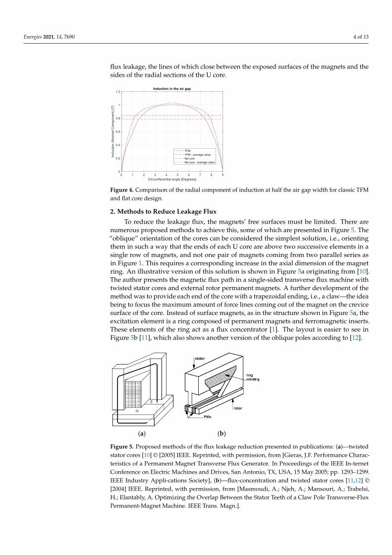
Energies 2021, 14, 7690 4 of 13
flux leakage, the lines of which close between the exposed surfaces of the magnets and thesides of the radial sections of the U core.
Energies 2021, 14, x FOR PEER REVIEW 3 of 13
Figure 3. Unit flux changes as the rotor turns 18 degrees.
In Figure 4, the blue line represents the drawn distribution of the radial induction
component in the center of the width of the air gap between the magnets and the core pole
U, and the average value of this induction. The induction in the core cross-section for
which the flux was calculated can be considered a constant. It is 0.42 T; hence it is almost
half of the average induction in the air gap (0.78 T). The reason for this difference is the
flux leakage, the lines of which close between the exposed surfaces of the magnets and the
sides of the radial sections of the U core.
Figure 4. Comparison of the radial component of induction at half the air gap width for classic TFM
and flat core design.
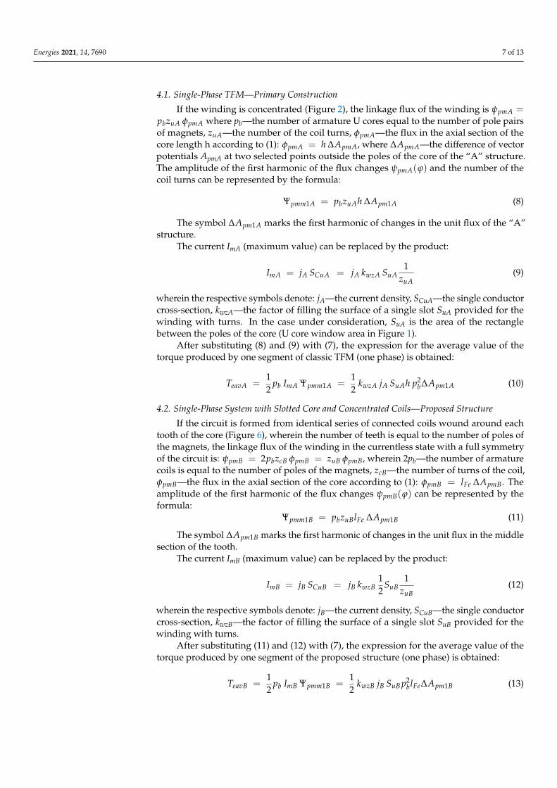
2. Methods to Reduce Leakage Flux
To reduce the leakage flux, the magnets’ free surfaces must be limited. There are
numerous proposed methods to achieve this, some of which are presented in Figure 5.
The “oblique” orientation of the cores can be considered the simplest solution, i.e.,
orienting them in such a way that the ends of each U core are above two successive
elements in a single row of magnets, and not one pair of magnets coming from two parallel
series as in Figure 1. This requires a corresponding increase in the axial dimension of the
magnet ring. An illustrative version of this solution is shown in Figure 5a originating from
[10]. The author presents the magnetic flux path in a single-sided transverse flux machine
with twisted stator cores and external rotor permanent magnets. A further development
of the method was to provide each end of the core with a trapezoidal ending, i.e., a claw—
the idea being to focus the maximum amount of force lines coming out of the magnet on
the crevice surface of the core. Instead of surface magnets, as in the structure shown in
Figure 5a, the excitation element is a ring composed of permanent magnets and
ferromagnetic inserts. These elements of the ring act as a flux concentrator [1]. The layout
is easier to see in Figure 5b [11], which also shows another version of the oblique poles
according to [12].
(a) (b)
Figure 4. Comparison of the radial component of induction at half the air gap width for classic TFMand flat core design.
2. Methods to Reduce Leakage Flux
To reduce the leakage flux, the magnets’ free surfaces must be limited. There arenumerous proposed methods to achieve this, some of which are presented in Figure 5. The“oblique” orientation of the cores can be considered the simplest solution, i.e., orientingthem in such a way that the ends of each U core are above two successive elements in asingle row of magnets, and not one pair of magnets coming from two parallel series asin Figure 1. This requires a corresponding increase in the axial dimension of the magnetring. An illustrative version of this solution is shown in Figure 5a originating from [10].The author presents the magnetic flux path in a single-sided transverse flux machine withtwisted stator cores and external rotor permanent magnets. A further development of themethod was to provide each end of the core with a trapezoidal ending, i.e., a claw—the ideabeing to focus the maximum amount of force lines coming out of the magnet on the crevicesurface of the core. Instead of surface magnets, as in the structure shown in Figure 5a, theexcitation element is a ring composed of permanent magnets and ferromagnetic inserts.These elements of the ring act as a flux concentrator [1]. The layout is easier to see inFigure 5b [11], which also shows another version of the oblique poles according to [12].
Energies 2021, 14, x FOR PEER REVIEW 3 of 13
In Figure 4, the blue line represents the drawn distribution of the radial induction
component in the center of the width of the air gap between the magnets and the core pole
U, and the average value of this induction. The induction in the core cross‐section for
which the flux was calculated can be considered a constant. It is 0.42 T; hence it is almost
half of the average induction in the air gap (0.78 T). The reason for this difference is the
flux leakage, the lines of which close between the exposed surfaces of the magnets and the
sides of the radial sections of the U core.
Figure 4. Comparison of the radial component of induction at half the air gap width for classic TFM
and flat core design.
2. Methods to Reduce Leakage Flux
To reduce the leakage flux, the magnets’ free surfaces must be limited. There are nu‐
merous proposed methods to achieve this, some of which are presented in Figure 5. The
“oblique” orientation of the cores can be considered the simplest solution, i.e., orienting
them in such a way that the ends of each U core are above two successive elements in a
single row of magnets, and not one pair of magnets coming from two parallel series as in
Figure 1. This requires a corresponding increase in the axial dimension of the magnet ring.
An illustrative version of this solution is shown in Figure 5a originating from [10]. The
author presents the magnetic flux path in a single‐sided transverse flux machine with
twisted stator cores and external rotor permanent magnets. A further development of the
method was to provide each end of the core with a trapezoidal ending, i.e., a claw—the
idea being to focus the maximum amount of force lines coming out of the magnet on the
crevice surface of the core. Instead of surface magnets, as in the structure shown in Figure
5a, the excitation element is a ring composed of permanent magnets and ferromagnetic
inserts. These elements of the ring act as a flux concentrator [1]. The layout is easier to see
in Figure 5b [11], which also shows another version of the oblique poles according to [12].
(a) (b)
Figure 5. Proposed methods of the flux leakage reduction presented in publications: (a)—twisted
stator cores [10] © [2005] IEEE. Reprinted, with permission, from [Gieras, J.F. Performance Charac‐
teristics of a Permanent Magnet Transverse Flux Generator. In Proceedings of the IEEE In‐ternet
Conference on Electric Machines and Drives, San Antonio, TX, USA, 15 May 2005; pp. 1293–1299.
Figure 5. Proposed methods of the flux leakage reduction presented in publications: (a)—twistedstator cores [10] © [2005] IEEE. Reprinted, with permission, from [Gieras, J.F. Performance Charac-teristics of a Permanent Magnet Transverse Flux Generator. In Proceedings of the IEEE In-ternetConference on Electric Machines and Drives, San Antonio, TX, USA, 15 May 2005; pp. 1293–1299.IEEE Industry Appli-cations Society], (b)—flux-concentration and twisted stator cores [11,12] ©[2004] IEEE. Reprinted, with permission, from [Masmoudi, A.; Njeh, A.; Mansouri, A.; Trabelsi,H.; Elantably, A. Optimizing the Overlap Between the Stator Teeth of a Claw Pole Transverse-FluxPermanent-Magnet Machine. IEEE Trans. Magn.].
Energies 2021, 14, 7690 5 of 13
Cores designed for “oblique” as well as “transverse” alignment are situated in thechanging magnetic field while the machine is moving and cannot be solid. Due to thedifficulty of using magnetic core sheets, they have to be made of metal powders. However,the use of oblique poles does not eliminate the leakage flux, even after using the hub,and only reduces its impact at the expense of the emergence of a significant constructioncomplication. It can also be seen that when the positions of the cores are changed, thestructure formally ceases to be a machine with a transverse flux.
3. The Use of a Flat Core
A traditional slotted flat core can be considered a series of oblique U cores rotated90 degrees from a transverse position, as in Figure 5a. The winding inserted into such a corecan no longer be a flat ring but must consist of fragments in slots and frontal connections.It can also be formed of coils wound around individual teeth, then connected in a series.This solution doubles the flux linkage with the winding.
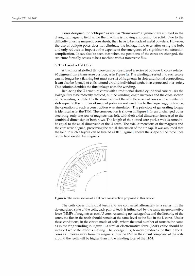
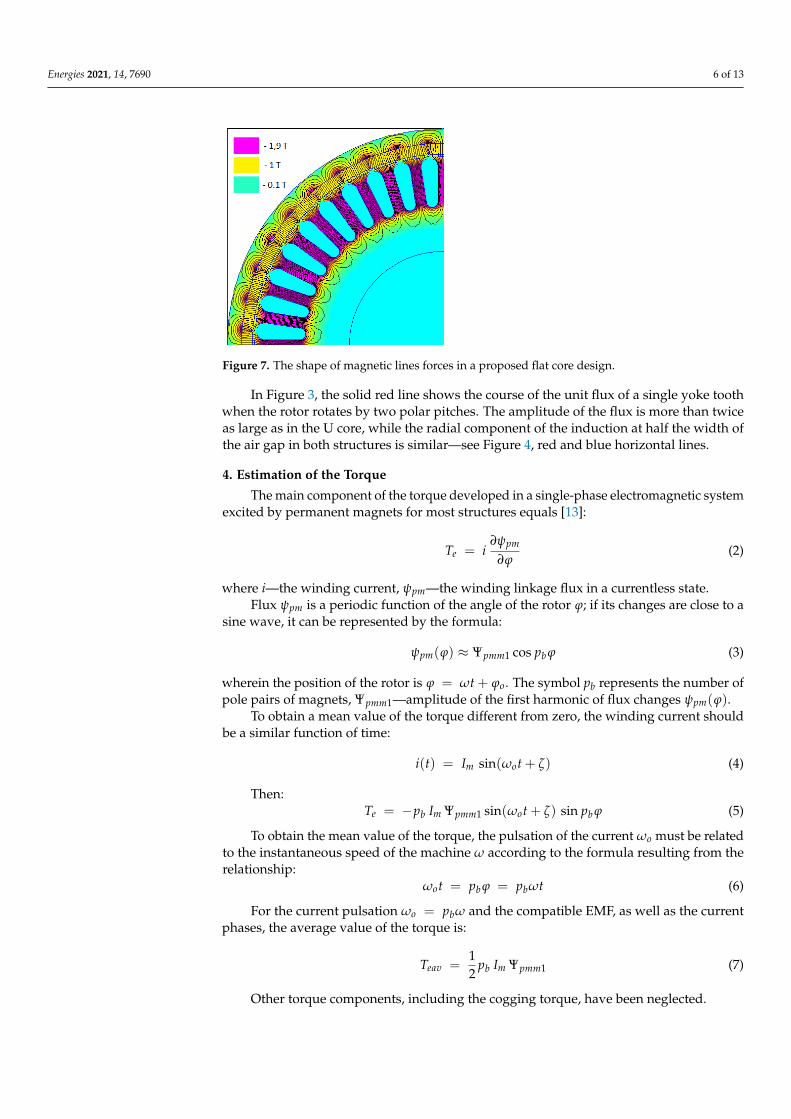
Replacing the U armature cores with a traditional slotted cylindrical core causes theleakage flux to be radically reduced, but the winding length increases and the cross-sectionof the winding is limited by the dimensions of the slot. Because flat cores with a number ofslots equal to the number of magnet poles are not used due to the large cogging torque,the operation of such a construction was simulated. The principle of generating torqueis identical as in the TFM. The cross-section is shown in Figure 6. In an unchanged outersteel ring, only one row of magnets was left, with their axial dimension increased to thecombined dimension of both rows. The length of the slotted core packet was assumed tobe equal to the axial dimension of the U cores. The axial dimensions of the magnets andthe core were aligned, preserving the radial dimension of the air gap. It was assumed thatthe field in such a layout can be treated as flat. Figure 7 shows the shape of the force linesof the field excited by magnets.
Energies 2021, 14, x FOR PEER REVIEW 4 of 13
IEEE Industry Appli‐cations Society], (b)—flux‐concentration and twisted stator cores [11,12] ©
[2004] IEEE. Reprinted, with permission, from [Masmoudi, A.; Njeh, A.; Mansouri, A.; Trabelsi, H.;
Elantably, A. Optimizing the Overlap Between the Stator Teeth of a Claw Pole Transverse‐Flux Per‐
manent‐Magnet Machine. IEEE Trans. Magn.].
Cores designed for “oblique” as well as “transverse” alignment are situated in the
changing magnetic field while the machine is moving and cannot be solid. Due to the
difficulty of using magnetic core sheets, they have to be made of metal powders. However,
the use of oblique poles does not eliminate the leakage flux, even after using the hub, and
only reduces its impact at the expense of the emergence of a significant construction com‐
plication. It can also be seen that when the positions of the cores are changed, the structure
formally ceases to be a machine with a transverse flux.
3. The Use of a Flat Core
A traditional slotted flat core can be considered a series of oblique U cores rotated 90
degrees from a transverse position, as in Figure 5a. The winding inserted into such a core
can no longer be a flat ring but must consist of fragments in slots and frontal connections.
It can also be formed of coils wound around individual teeth, then connected in a series.
This solution doubles the flux linkage with the winding.
Replacing the U armature cores with a traditional slotted cylindrical core causes the
leakage flux to be radically reduced, but the winding length increases and the cross‐sec‐
tion of the winding is limited by the dimensions of the slot. Because flat cores with a num‐
ber of slots equal to the number of magnet poles are not used due to the large cogging
torque, the operation of such a construction was simulated. The principle of generating
torque is identical as in the TFM. The cross‐section is shown in Figure 6. In an unchanged
outer steel ring, only one row of magnets was left, with their axial dimension increased to
the combined dimension of both rows. The length of the slotted core packet was assumed
to be equal to the axial dimension of the U cores. The axial dimensions of the magnets and
the core were aligned, preserving the radial dimension of the air gap. It was assumed that
the field in such a layout can be treated as flat. Figure 7 shows the shape of the force lines
of the field excited by magnets.
Figure 6. The cross‐section of a flat core construction proposed in this article. Figure 6. The cross-section of a flat core construction proposed in this article.
The coils cover individual teeth and are connected alternately in a series. In thede-energized state of the coils, each pair of teeth is influenced by the same magnetomotiveforce (MMF) of magnets as each U core. Assuming no leakage flux and the linearity of thecores, the flux in the teeth should remain at the same level as the flux in the U cores. Underthese conditions, in the circuit made of coils, where the total number of turns is the sameas in the ring winding in Figure 1, a similar electromotive force (EMF) value should beinduced while the rotor is moving. The leakage flux, however, reduces the flux in the Ucores as it moves away from the magnets; thus the EMF in the circuit composed of the coilsaround the teeth will be higher than in the winding loop of the TFM.
Energies 2021, 14, 7690 6 of 13Energies 2021, 14, x FOR PEER REVIEW 5 of 13
Figure 7. The shape of magnetic lines forces in a proposed flat core design.
The coils cover individual teeth and are connected alternately in a series. In the de‐
energized state of the coils, each pair of teeth is influenced by the same magnetomotive
force (MMF) of magnets as each U core. Assuming no leakage flux and the linearity of the
cores, the flux in the teeth should remain at the same level as the flux in the U cores. Under
these conditions, in the circuit made of coils, where the total number of turns is the same
as in the ring winding in Figure 1, a similar electromotive force (EMF) value should be
induced while the rotor is moving. The leakage flux, however, reduces the flux in the U
cores as it moves away from the magnets; thus the EMF in the circuit composed of the
coils around the teeth will be higher than in the winding loop of the TFM.
In Figure 3, the solid red line shows the course of the unit flux of a single yoke tooth
when the rotor rotates by two polar pitches. The amplitude of the flux is more than twice
as large as in the U core, while the radial component of the induction at half the width of
the air gap in both structures is similar—see Figure 4, red and blue horizontal lines.
4. Estimation of the Torque
The main component of the torque developed in a single‐phase electromagnetic sys‐
tem excited by permanent magnets for most structures equals [13]:
pm
e iT (2)
where i —the winding current, pm —the winding linkage flux in a currentless state.
Flux pm is a periodic function of the angle of the rotor ; if its changes are close to
a sine wave, it can be represented by the formula:
bpmmpm pcos1 (3)
wherein the position of the rotor is ot . The symbol pb represents the number of
pole pairs of magnets, 1pmm —amplitude of the first harmonic of flux changes pm .
To obtain a mean value of the torque different from zero, the winding current should
be a similar function of time:
)(sin)( tIti om (4)
Then:
bopmmmbe ptIpT sin)(sin1 (5)
Figure 7. The shape of magnetic lines forces in a proposed flat core design.
In Figure 3, the solid red line shows the course of the unit flux of a single yoke toothwhen the rotor rotates by two polar pitches. The amplitude of the flux is more than twiceas large as in the U core, while the radial component of the induction at half the width ofthe air gap in both structures is similar—see Figure 4, red and blue horizontal lines.
4. Estimation of the Torque
The main component of the torque developed in a single-phase electromagnetic systemexcited by permanent magnets for most structures equals [13]:
Te = i∂ψpm
∂ϕ(2)
where i—the winding current, ψpm—the winding linkage flux in a currentless state.Flux ψpm is a periodic function of the angle of the rotor ϕ; if its changes are close to a
sine wave, it can be represented by the formula:
ψpm(ϕ) ≈ Ψpmm1 cos pb ϕ (3)
wherein the position of the rotor is ϕ = ωt + ϕo. The symbol pb represents the number ofpole pairs of magnets, Ψpmm1—amplitude of the first harmonic of flux changes ψpm(ϕ).
To obtain a mean value of the torque different from zero, the winding current shouldbe a similar function of time:
i(t) = Im sin(ωot + ζ) (4)
Then:Te = −pb Im Ψpmm1 sin(ωot + ζ) sin pb ϕ (5)
To obtain the mean value of the torque, the pulsation of the current ωo must be relatedto the instantaneous speed of the machine ω according to the formula resulting from therelationship:
ωot = pb ϕ = pbωt (6)
For the current pulsation ωo = pbω and the compatible EMF, as well as the currentphases, the average value of the torque is:
Teav =12
pb Im Ψpmm1 (7)
Other torque components, including the cogging torque, have been neglected.
Energies 2021, 14, 7690 7 of 13
4.1. Single-Phase TFM—Primary Construction
If the winding is concentrated (Figure 2), the linkage flux of the winding is ψpmA =pbzuA φpmA where pb—the number of armature U cores equal to the number of pole pairsof magnets, zuA—the number of the coil turns, φpmA—the flux in the axial section of thecore length h according to (1): φpmA = h ∆ApmA, where ∆ApmA—the difference of vectorpotentials ApmA at two selected points outside the poles of the core of the “A” structure.The amplitude of the first harmonic of the flux changes ψpmA(ϕ) and the number of thecoil turns can be represented by the formula:
Ψpmm1A = pbzuAh ∆Apm1A (8)
The symbol ∆Apm1A marks the first harmonic of changes in the unit flux of the “A”structure.
The current ImA (maximum value) can be replaced by the product:
ImA = jA SCuA = jA kwzA SuA1
zuA(9)
wherein the respective symbols denote: jA—the current density, SCuA—the single conductorcross-section, kwzA—the factor of filling the surface of a single slot SuA provided for thewinding with turns. In the case under consideration, SuA is the area of the rectanglebetween the poles of the core (U core window area in Figure 1).
After substituting (8) and (9) with (7), the expression for the average value of thetorque produced by one segment of classic TFM (one phase) is obtained:
TeavA =12
pb ImA Ψpmm1A =12
kwzA jA SuAh p2b∆Apm1A (10)
4.2. Single-Phase System with Slotted Core and Concentrated Coils—Proposed Structure
If the circuit is formed from identical series of connected coils wound around eachtooth of the core (Figure 6), wherein the number of teeth is equal to the number of poles ofthe magnets, the linkage flux of the winding in the currentless state with a full symmetryof the circuit is: ψpmB = 2pbzcB φpmB = zuB φpmB, wherein 2pb—the number of armaturecoils is equal to the number of poles of the magnets, zcB—the number of turns of the coil,φpmB—the flux in the axial section of the core according to (1): φpmB = lFe ∆ApmB. Theamplitude of the first harmonic of the flux changes ψpmB(ϕ) can be represented by theformula:
Ψpmm1B = pbzuBlFe ∆Apm1B (11)
The symbol ∆Apm1B marks the first harmonic of changes in the unit flux in the middlesection of the tooth.
The current ImB (maximum value) can be replaced by the product:
ImB = jB SCuB = jB kwzB12
SuB1
zuB(12)
wherein the respective symbols denote: jB—the current density, SCuB—the single conductorcross-section, kwzB—the factor of filling the surface of a single slot SuB provided for thewinding with turns.
After substituting (11) and (12) with (7), the expression for the average value of thetorque produced by one segment of the proposed structure (one phase) is obtained:
TeavB =12
pb ImB Ψpmm1B =12
kwzB jB SuB p2blFe∆Apm1B (13)

Energies 2021, 14, 7690 8 of 13
The relationship between the mean values of torques TeavA and TeavB is defined by thequotient:
TeavATeavB
=kwzA jA SuAh ∆Apm1A
kwzB jB SuBlFe ∆Apm1B(14)
Assuming the same current density and the same slot filling with copper, we will get:
TeavATeavB
=SuASuB
hlFe
∆Apm1A
∆Apm1B(15)
For the TFM dimensions presented above and the assumed dimensions of the cylin-drical core, the slot cross-section is SuB = 80.5 mm2 and for the core length lFe = 40 mm,we get:
TeavATeavB
=20× 20
80.512.740
3.5 · 10−3
7.8 · 10−3 = 5 · 13.15
12.2
= 0.7 (16)
The difference between the torques can be reduced by design measures, in particularby reducing the leakage fluxes in the machine with a transverse flux. The difference willalso vary for the various TFM variants already proposed. Both presented single-phaseconstructions can thus be “roughly” regarded as equivalent.
If we assume, as in the case of an induction motor, a power of 2.2 kW, the slot fillingfactor kwz = 0.35 and the current density j = 6.5 Ask/mm2, the value of the torque generatedby the classic design TFM according to (10) is:
TeavA = 12 jAkwzA SuAh p2
b∆Apm1A = 12 6.5 ·
√2 · 0.35 · 411 · 0.01267 · 202 · 3.5 · 10−3 =
= 11.7 Nm
The torque produced in the system with a traditional (slotted) core, according to(13), is:
TeavB = 12 jBkwzBSuB p2
blFe∆Apm1B = 12 6.5 ·
√2 · 0.35 · 80.5 · 202 · 0.04 · 7.8 · 10−3 =
= 16.2 Nm
In Figure 8, the blue line shows the changes in TeB torque, produced by one segmentof the proposed construction, when rotating the rotor under the conditions of supplyingthe winding with alternating current, in phase with the EMF. FEM calculations were madeusing the FEMM 4.2 software. The horizontal blue line shows the average TeB torque value.It amounts to 16 Nm; hence it is close to TeavB determined according to (13). Taking intoconsideration the nonlinearity of the core, the magnetization characteristic reduces theaverage torque value to 14.5 Nm, i.e., approx. 10%—the horizontal red line in Figure 9. Thesame figure also shows the dependence of the torque on the position of the rotor, takinginto consideration the saturation of the core—the red curve. Except for the mean value,torque has a large variable component. Theoretically, its amplitude should be equal tothe average value; however, the influence of the cogging torque is visible, which causes aperiodic change of the sign of the torque.
Figure 9 shows the first harmonics of the EMF induced in the armature windingresulting from the permanent magnets (solid blue line), the linkage flux with the arma-ture winding under load (solid black line) and the armature flux impact (solid red line).The dotted blue curve corresponds to the voltage waveform on the armature resistance,magnified 10 times. For the assumed number of turns in one coil—8—the rated armaturecurrent is 11.5 A (root mean square (RMS) value), and the resistance of the entire windingis 0.44 Ω. For a rotational speed of 1500 rpm, the RMS value of EMF induced by thewinding flux linkage is 226 V, with the phase angle between this EMF and the current of10.8 degrees. This corresponds to the produced torque of 16.2 Nm, hence a value very closeto the one previously determined (for the linear magnetization characteristic of the cores).The machine is characterized by its very low armature impact and very good power factor.

Energies 2021, 14, 7690 9 of 13
Energies 2021, 14, x FOR PEER REVIEW 8 of 13
It amounts to 16 Nm; hence it is close to TeavB determined according to (13). Taking into
consideration the nonlinearity of the core, the magnetization characteristic reduces the
average torque value to 14.5 Nm, i.e., approx. 10%—the horizontal red line in Figure 9.
The same figure also shows the dependence of the torque on the position of the rotor,
taking into consideration the saturation of the core—the red curve. Except for the mean
value, torque has a large variable component. Theoretically, its amplitude should be equal
to the average value; however, the influence of the cogging torque is visible, which causes
a periodic change of the sign of the torque.
Figure 8. Comparison of torque waveform as a function of rotor position angle for the linear core
and nonlinear core.
Figure 9 shows the first harmonics of the EMF induced in the armature winding
resulting from the permanent magnets (solid blue line), the linkage flux with the armature
winding under load (solid black line) and the armature flux impact (solid red line). The
dotted blue curve corresponds to the voltage waveform on the armature resistance,
magnified 10 times. For the assumed number of turns in one coil—8—the rated armature
current is 11.5 A (root mean square (RMS) value), and the resistance of the entire winding
is 0.44 Ω. For a rotational speed of 1500 rpm, the RMS value of EMF induced by the
winding flux linkage is 226 V, with the phase angle between this EMF and the current of
10.8 degrees. This corresponds to the produced torque of 16.2 Nm, hence a value very
close to the one previously determined (for the linear magnetization characteristic of the
cores). The machine is characterized by its very low armature impact and very good
power factor.
Figure 9. First harmonics of EMF induced by linkage fluxes in the proposed flat core design.
5. Three-Phase System
A set of three single-phase systems of slotted flat cores placed on a common shaft
with magnets shifted circumferentially by the “electric” angle 2π/3, powered by three-
Figure 8. Comparison of torque waveform as a function of rotor position angle for the linear coreand nonlinear core.
Energies 2021, 14, x FOR PEER REVIEW 8 of 13
It amounts to 16 Nm; hence it is close to TeavB determined according to (13). Taking into
consideration the nonlinearity of the core, the magnetization characteristic reduces the
average torque value to 14.5 Nm, i.e., approx. 10%—the horizontal red line in Figure 9.
The same figure also shows the dependence of the torque on the position of the rotor,
taking into consideration the saturation of the core—the red curve. Except for the mean
value, torque has a large variable component. Theoretically, its amplitude should be equal
to the average value; however, the influence of the cogging torque is visible, which causes
a periodic change of the sign of the torque.
Figure 8. Comparison of torque waveform as a function of rotor position angle for the linear core
and nonlinear core.
Figure 9 shows the first harmonics of the EMF induced in the armature winding
resulting from the permanent magnets (solid blue line), the linkage flux with the armature
winding under load (solid black line) and the armature flux impact (solid red line). The
dotted blue curve corresponds to the voltage waveform on the armature resistance,
magnified 10 times. For the assumed number of turns in one coil—8—the rated armature
current is 11.5 A (root mean square (RMS) value), and the resistance of the entire winding
is 0.44 Ω. For a rotational speed of 1500 rpm, the RMS value of EMF induced by the
winding flux linkage is 226 V, with the phase angle between this EMF and the current of
10.8 degrees. This corresponds to the produced torque of 16.2 Nm, hence a value very
close to the one previously determined (for the linear magnetization characteristic of the
cores). The machine is characterized by its very low armature impact and very good
power factor.
Figure 9. First harmonics of EMF induced by linkage fluxes in the proposed flat core design.
5. Three-Phase System
A set of three single-phase systems of slotted flat cores placed on a common shaft
with magnets shifted circumferentially by the “electric” angle 2π/3, powered by three-
Figure 9. First harmonics of EMF induced by linkage fluxes in the proposed flat core design.
5. Three-Phase System
A set of three single-phase systems of slotted flat cores placed on a common shaft withmagnets shifted circumferentially by the “electric” angle 2π/3, powered by three-phasecurrents, will increase the mean torque by a factor of three and thereby radically reduceits variable component—see Figure 10. As it can be seen from the previous calculations,one segment of the set produces an average torque of 14.5 Nm (considering saturation),so a set of 3 segments with a total axial dimension Lo ≈ 0.17 m, will generate a torque of3–14.5 Nm = 43.5 Nm. With a pulsation of 3-phase currents ωo = 1000π s−1 (500 Hz) itwill issue power 1000π s−1·43.5 Nm/20 ≈ 6.8 kW for 1500 rpm, thus more than 3 timeslarger than a squirrel-cage induction motor with an electromagnetic circuit of the samedimensions.
Energies 2021, 14, x FOR PEER REVIEW 9 of 13
phase currents, will increase the mean torque by a factor of three and thereby radically
reduce its variable component—see Figure 10. As it can be seen from the previous
calculations, one segment of the set produces an average torque of 14.5 Nm (considering
saturation), so a set of 3 segments with a total axial dimension Lo ≈ 0.17 m, will generate a
torque of 3–14.5 Nm = 43.5 Nm. With a pulsation of 3-phase currents ωo = 1000π s−1 (500
Hz) it will issue power 1000π s−1·43.5 Nm/20 ≈ 6.8 kW for 1500 rpm, thus more than 3 times
larger than a squirrel-cage induction motor with an electromagnetic circuit of the same
dimensions.
Figure 10. Torque waveforms for three segments and their resultant values.
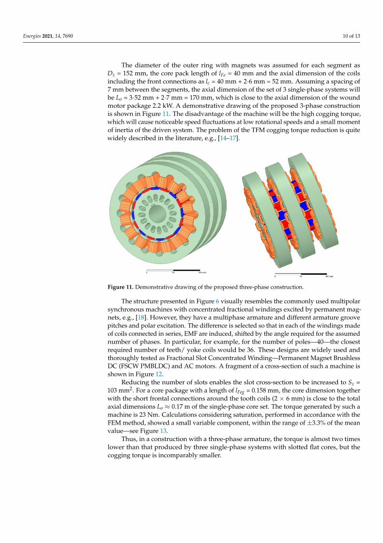
The diameter of the outer ring with magnets was assumed for each segment as Dz =
152 mm, the core pack length of lFe = 40 mm and the axial dimension of the coils including
the front connections as lc = 40 mm + 2·6 mm = 52 mm. Assuming a spacing of 7 mm
between the segments, the axial dimension of the set of 3 single-phase systems will be Lo
= 3·52 mm + 2·7 mm = 170 mm, which is close to the axial dimension of the wound motor
package 2.2 kW. A demonstrative drawing of the proposed 3-phase construction is shown
in Figure 11. The disadvantage of the machine will be the high cogging torque, which will
cause noticeable speed fluctuations at low rotational speeds and a small moment of inertia
of the driven system. The problem of the TFM cogging torque reduction is quite widely
described in the literature, e.g., [14,15,16,17].
Figure 11. Demonstrative drawing of the proposed three-phase construction.
The structure presented in Figure 6 visually resembles the commonly used
multipolar synchronous machines with concentrated fractional windings excited by
permanent magnets, e.g., [18]. However, they have a multiphase armature and different
Figure 10. Torque waveforms for three segments and their resultant values.
Energies 2021, 14, 7690 10 of 13
The diameter of the outer ring with magnets was assumed for each segment asDz = 152 mm, the core pack length of lFe = 40 mm and the axial dimension of the coilsincluding the front connections as lc = 40 mm + 2·6 mm = 52 mm. Assuming a spacing of7 mm between the segments, the axial dimension of the set of 3 single-phase systems willbe Lo = 3·52 mm + 2·7 mm = 170 mm, which is close to the axial dimension of the woundmotor package 2.2 kW. A demonstrative drawing of the proposed 3-phase constructionis shown in Figure 11. The disadvantage of the machine will be the high cogging torque,which will cause noticeable speed fluctuations at low rotational speeds and a small momentof inertia of the driven system. The problem of the TFM cogging torque reduction is quitewidely described in the literature, e.g., [14–17].
Energies 2021, 14, x FOR PEER REVIEW 9 of 13
reduce its variable component—see Figure 10. As it can be seen from the previous calcu‐
lations, one segment of the set produces an average torque of 14.5 Nm (considering satu‐
ration), so a set of 3 segments with a total axial dimension Lo ≈ 0.17 m, will generate a
torque of 3–14.5 Nm = 43.5 Nm. With a pulsation of 3‐phase currents ωo = 1000π s−1 (500
Hz) it will issue power 1000π s−1∙43.5 Nm/20 ≈ 6.8 kW for 1500 rpm, thus more than 3 times
larger than a squirrel‐cage induction motor with an electromagnetic circuit of the same
dimensions.
Figure 10. Torque waveforms for three segments and their resultant values.
The diameter of the outer ring with magnets was assumed for each segment as
Dz = 152 mm, the core pack length of lFe = 40 mm and the axial dimension of the coils
including the front connections as lc = 40 mm + 2∙6 mm = 52 mm. Assuming a spacing of 7
mm between the segments, the axial dimension of the set of 3 single‐phase systems will
be Lo = 3∙52 mm + 2∙7 mm = 170 mm, which is close to the axial dimension of the wound
motor package 2.2 kW. A demonstrative drawing of the proposed 3‐phase construction is
shown in Figure 11. The disadvantage of the machine will be the high cogging torque,
which will cause noticeable speed fluctuations at low rotational speeds and a small mo‐
ment of inertia of the driven system. The problem of the TFM cogging torque reduction is
quite widely described in the literature, e.g., [14–17].
Figure 11. Demonstrative drawing of the proposed three‐phase construction.
The structure presented in Figure 6 visually resembles the commonly used multipo‐
lar synchronous machines with concentrated fractional windings excited by permanent
magnets, e.g., [18]. However, they have a multiphase armature and different armature
groove pitches and polar excitation. The difference is selected so that in each of the
0 2 4 6 8 10 12 14 16 18
Rotor position [deg]
-10
0
10
20
30
40
50
Torq
ue
[Nm
]
Torque waveforms - three segments
phase Aphase Bphase Cresultant valueresultant average value
Figure 11. Demonstrative drawing of the proposed three-phase construction.
The structure presented in Figure 6 visually resembles the commonly used multipolarsynchronous machines with concentrated fractional windings excited by permanent mag-nets, e.g., [18]. However, they have a multiphase armature and different armature groovepitches and polar excitation. The difference is selected so that in each of the windings madeof coils connected in series, EMF are induced, shifted by the angle required for the assumednumber of phases. In particular, for example, for the number of poles—40—the closestrequired number of teeth/ yoke coils would be 36. These designs are widely used andthoroughly tested as Fractional Slot Concentrated Winding—Permanent Magnet BrushlessDC (FSCW PMBLDC) and AC motors. A fragment of a cross-section of such a machine isshown in Figure 12.
Reducing the number of slots enables the slot cross-section to be increased to Sz =103 mm2. For a core package with a length of lFeg = 0.158 mm, the core dimension togetherwith the short frontal connections around the tooth coils (2 × 6 mm) is close to the totalaxial dimensions Lo ≈ 0.17 m of the single-phase core set. The torque generated by such amachine is 23 Nm. Calculations considering saturation, performed in accordance with theFEM method, showed a small variable component, within the range of ±3.3% of the meanvalue—see Figure 13.
Thus, in a construction with a three-phase armature, the torque is almost two timeslower than that produced by three single-phase systems with slotted flat cores, but thecogging torque is incomparably smaller.

Energies 2021, 14, 7690 11 of 13
Energies 2021, 14, x FOR PEER REVIEW 10 of 13
windings made of coils connected in series, EMF are induced, shifted by the angle re‐
quired for the assumed number of phases. In particular, for example, for the number of
poles—40—the closest required number of teeth/ yoke coils would be 36. These designs
are widely used and thoroughly tested as Fractional Slot Concentrated Winding—Perma‐
nent Magnet Brushless DC (FSCW PMBLDC) and AC motors. A fragment of a cross‐sec‐
tion of such a machine is shown in Figure 12.
Figure 12. Fragment of a cross‐section of a 3‐phase FSCW‐PMSM machine with 40 poles and 36
teeth‐coils.
Reducing the number of slots enables the slot cross‐section to be increased to
Sz = 103 mm2. For a core package with a length of lFeg = 0.158 mm, the core dimension
together with the short frontal connections around the tooth coils (2 × 6 mm) is close to
the total axial dimensions Lo ≈ 0.17 m of the single‐phase core set. The torque generated
by such a machine is 23 Nm. Calculations considering saturation, performed in accord‐
ance with the FEM method, showed a small variable component, within the range of
±3.3% of the mean value—see Figure 13.
Figure 13. Torque calculations of a Fractional Slot Concentrated Winding—Permanent Magnet
Brushless DC (FSCW PMBLDC) machine with 40 poles and 36 teeth‐coils considering saturation.
Thus, in a construction with a three‐phase armature, the torque is almost two times
lower than that produced by three single‐phase systems with slotted flat cores, but the
cogging torque is incomparably smaller.
Figure 12. Fragment of a cross-section of a 3-phase FSCW-PMSM machine with 40 poles and 36teeth-coils.
Energies 2021, 14, x FOR PEER REVIEW 10 of 13
armature groove pitches and polar excitation. The difference is selected so that in each of
the windings made of coils connected in series, EMF are induced, shifted by the angle
required for the assumed number of phases. In particular, for example, for the number of
poles—40—the closest required number of teeth/ yoke coils would be 36. These designs
are widely used and thoroughly tested as Fractional Slot Concentrated Winding—
Permanent Magnet Brushless DC (FSCW PMBLDC) and AC motors. A fragment of a
cross-section of such a machine is shown in Figure 12.
Figure 12. Fragment of a cross-section of a 3-phase FSCW-PMSM machine with 40 poles and 36
teeth-coils.
Reducing the number of slots enables the slot cross-section to be increased to Sz = 103
mm2. For a core package with a length of lFeg = 0.158 mm, the core dimension together with
the short frontal connections around the tooth coils (2 × 6 mm) is close to the total axial
dimensions Lo ≈ 0.17 m of the single-phase core set. The torque generated by such a
machine is 23 Nm. Calculations considering saturation, performed in accordance with the
FEM method, showed a small variable component, within the range of ±3.3% of the mean
value—see Figure 13.
Figure 13. Torque calculations of a Fractional Slot Concentrated Winding—Permanent Magnet
Brushless DC (FSCW PMBLDC) machine with 40 poles and 36 teeth-coils considering saturation.
Thus, in a construction with a three-phase armature, the torque is almost two times
lower than that produced by three single-phase systems with slotted flat cores, but the
cogging torque is incomparably smaller.
Figure 13. Torque calculations of a Fractional Slot Concentrated Winding—Permanent MagnetBrushless DC (FSCW PMBLDC) machine with 40 poles and 36 teeth-coils considering saturation.
6. Comparison with an Induction Motor
The torque produced by a 2.2 kW squirrel-cage induction motor at a rated speed of1435 rpm is 14.6 Nm with a power factor of 0.74. The outer diameter is 152 mm, whilethe axial dimension of the stator package is 95 mm. The dimensions are determined bythe diameter and axial dimensions of the wound stator and are thus considered togetherwith the winding front connections. The relation of this dimension to the length of the corevaries, depending on many factors, from 1.2 to as high as 2. In the considered motor, itis 48 mm on each side of the core. In low-power motors, the frontal connections usuallyextend the machine by 60–80%; hence the reference dimension was taken as Lo = 170 mm.
The simulation shows that the commonly used FSCW-PMSM, without any optimiza-tion procedures carried out at the design stage, can produce 23 Nm, which is 50% morethan the squirrel-cage motor. A set of 3 single-phase machines with slotted flat rotor yokesproduces a torque of 48 Nm, which is more than 3 times greater than that of an inductionmotor and twice as large as that of the FSCW-PMSM. This is also how the torque producedby the TFM should be assessed. However, the average torque value is superimposed byhigh cogging torques with a pulsation of 2pbω. The values of the torques generated byindividual constructions obtained from the simulation are compared with the rated torqueof the induction motor in Table 1.

Energies 2021, 14, 7690 12 of 13
Table 1. Summary of the torque generated by individual constructions.
InductionMotor FSCW-PMSM
3 TFMwith Toroidal
Windings
3 Segmentswith Flat Cores
Tav [Nm]for lFe = 0.095 m
14.6(1435 rpm/min) 13.8 3 × 11.7 = 35.1 3 × 14.5 = 43.5
Tav [Nm]for lFeg
—- 23 —- —-
Tzm [% Tsr] —- ±3.5 —- ±9
7. Conclusions
It is widely assumed that one of the great advantages of transverse flux machines isthat there is no direct correlation between the dimensions of the winding cross-section andthe dimensions of the main magnetic circuit. In traditional machines, the enlargement ofthe winding cross-section takes place at the expense of reducing the area through whichthe magnetic field lines of force close and vice versa; in the TFM, these dimensions areindependent of each other. The presented analyses show that, within the given dimensions,the range of changes in the dimensions of electric and magnetic circuits is limited, and thedimensions are largely interdependent. The comparative calculations performed confirmedthat the torque generated by machines operating on principles similar to the TFM can bemuch greater than the torque generated by machines currently in common use. However,the cogging torques accompanying the operation of the machine need to be reduced byspecial design treatments.
Because segmented machines are only used to a limited extent due to their higherproduction costs, it can be predicted that the TFM will remain a machine dedicated for usein drives where generating great torque in the smallest possible volume is required, e.g.,on ships or in wind farms. A patent application for the described design of the TFM motorhas been filed and is pending [19].
Author Contributions: Conceptualization, J.S. and T.D.; methodology, T.D.; software, J.S.; validation,T.D. and T.L.; formal analysis, T.D.; investigation, P.K.; resources, P.K.; data curation, T.D.; writing—original draft preparation, J.S. and T.L.; writing—review and editing, P.K. and T.L. All authors haveread and agreed to the published version of the manuscript.
Funding: This research was funded by the AGH University of Science and Technology, researchsubsidy no. 16.16.120.7998.
Institutional Review Board Statement: Not applicable.
Informed Consent Statement: Not applicable.
Data Availability Statement: The data presented in this study are available on request from thecorresponding author.
Conflicts of Interest: The authors declare no conflict of interest.
References1. Mordey, W.M. Electric Generator, No. 5162. U.S. Patent 437501, 30 September 1890.2. Weh, H.; May, H. Achievable Force Densities for Permanent Magnet Excited Machines in New Configurations. In Proceedings of
the Internet Conference Electrical Machines (ICEM86), München, Germany, 8–10 September 1986; pp. 1107–1111.3. Husain, T.; Hasan, I.; Sozer, Y.; Husain, I.; Muljadi, E. A Comprehensive Review of Permanent Magnet Transverse Flux Machines:
Use in Direct-Drive Applications. IEEE Ind. Appl. Mag. 2020, 26, 87–98. [CrossRef]4. Zhang, B.; Wang, A.; Doppelbauer, M. Multi-Objective Optimization of a Transverse Flux Machine with Claw-Pole and Flux-
Concentrating Structure. IEEE Trans. Magn. 2016, 52, 8107410. [CrossRef]5. Guo, Y.; Zhu, J.G.; Watterson, P.A.; Wu, W. Development of a PM Transverse Flux Motor with Soft Magnetic Composite Core.
IEEE Trans. Energy Convers. 2006, 21, 426–434. [CrossRef]

Energies 2021, 14, 7690 13 of 13
6. EL-Refaie, A.M. Fractional-Slot Concentrated-Windings Synchronous Permanent Magnet Machines: Opportunities and Chal-lenges. IEEE Trans. Ind. Electron. 2010, 57, 107–121. [CrossRef]
7. Cros, J.; Viarouge, P. Synthesis of High-Performance PM Motors with Concentrated Windings. IEEE Trans. Energy Convers. 2002,17, 248–253. [CrossRef]
8. Weh, H. Permanentmagneterregte Synchronmaschinen hoher Kraftdichte nach dem Transversalflußkonzept. ETZ Arch. 1988, 10,143–149.
9. Harris, M.R.; Mecrow, B.C. Variable Reluctance Permanent Magnet Motors for High Specific Output. In Proceedings of the SixthInternet Conference on Electrical Machines and Drives, Oxford, UK, 8–10 September 1993; pp. 437–442.
10. Gieras, J.F. Performance Characteristics of a Permanent Magnet Transverse Flux Generator. In Proceedings of the IEEE InternetConference on Electric Machines and Drives, San Antonio, TX, USA, 15 May 2005; pp. 1293–1299.
11. Maddison, C.P.; Mecrow, B.C.; Jack, A.G. Claw Pole Geometries for High Performance Transverse Flux Machines. In Proceedingsof the Internet Conference on Electrical Machines (ICEM’98), Istanbul, Turkey, 2–4 September 1998; pp. 340–345.
12. Masmoudi, A.; Njeh, A.; Mansouri, A.; Trabelsi, H.; Elantably, A. Optimizing the Overlap Between the Stator Teeth of a Claw PoleTransverse-Flux Permanent-Magnet Machine. IEEE Trans. Magn. 2004, 40, 1573–1578. [CrossRef]
13. Sobczyk, T. Problemy modelowania matematycznego pradnic synchronicznych wzbudzanych magnesami Trwałymi. Pr. Inst.Elektrotechniki 2007, 231, 99–123.
14. Dreher, F.; Parspour, N. Reducing the Cogging Torque of PM Transverse Flux Machines by Discrete Skewing of a Segment-edStator. In Proceedings of the 21th International Conference on Electrical Machines, Marseille, France, 2–5 September 2012;pp. 454–457.
15. Gao, J.; Wang, G.; Liu, X.; Zhang, W.; Huang, S.; Li, H. Cogging Torque Reduction by Elementary-Cogging-Unit Shift forPermanent Magnet Machines. IEEE Trans. Magn. 2017, 53, 8208705. [CrossRef]
16. Zhu, L.; Jiang, S.Z.; Zhu, Z.Q.; Chan, C.C. Analytical Methods for Minimizing Cogging Torque in Permanent-Magnet Machines.IEEE Trans. Magn. 2009, 45, 2023–2031. [CrossRef]
17. Husain, T.; Hasan, I.; Sozer, Y.; Husain, I.; Muljadi, E. Cogging torque minimization in transverse flux machines. IEEE Trans. Ind.Appl. 2018, 55, 385–397. [CrossRef]
18. Junlong, L.; Yongxiang, X.; Jibin, Z.; Baochao, W.; Qian, W.; Weiyan, L. Analysis and Design of SPM Machines With FractionalSlot Concentrated Windings for a Given Constant Power Region. IEEE Trans. Magn. 2015, 51, 3401804. [CrossRef]
19. Skwarczynski, J.; Drabek, T.; Lerch, T. Maszyna Elektryczna Zaczepowa i Sposób Działania Maszyny Elektrycznej Zaczepowej.Polish Patent P.437412, 25 March 2021.