
A new method for perspective correction of document images
12
A new method for perspective correction of document images Jos´ e Rodr´ ıguez-Pi˜ neiro a , Pedro Comesa˜ na-Alfaro a,b , Fernando P´ erez-Gonz´alez a,b,c and Alberto Malvido-Garc´ ıa d a University of Vigo, Signal Theory and Communications Dept., Vigo, Spain b University of New Mexico, Electrical and Computer Engineering Dept., Albuquerque, NM c Gradiant (Galician Research and Development Center in Advanced Telecommunications), Vigo, Spain d Bit Oceans Research, L´opez de Neira, 3, Office 408, 36202 Vigo, Spain ABSTRACT In this paper we propose a method for perspective distortion correction of rectangular documents. This scheme exploits the orthogonality of the document edges, allowing to recover the aspect ratio of the original document. The results obtained after correcting the perspective of several document images captured with a mobile phone are compared with those achieved by digitizing the same documents with several scanner models. Keywords: Document image, perspective distortion correction 1. INTRODUCTION Nowadays, the increasing performance and low price of portable imaging devices (e.g. mobile phones, PDAs) are boosting the usage of these devices for supplementing or even replacing traditional flat-bed scanners for document image adquisition. Unfortunately, a number of problems that traditional scanners do not have to face have arisen with this increasing use, with perspective distortion one of the most evident and probably most harmful for the subsequent application of document processing tools. Although this problem has already deserved some attention in previous works in the literature, most of the proposed solutions are based on rather restrictive assumptions on the nature of the captured document, so the target of this work is to follow a systematic approach with a minimum number of constraints. Indeed, the only constraint imposed on our method is that the four corners of the document are captured in the considered image. Next, we review some of the most representative methods related to perspective distortion correction. These methods can be classified into two main categories. The methods in the first category use the text in the document for characterizing perspective distortion. The second category encompasses those algorithms that do not require that the original document includes text. A deeper discussion about both is provided below. 1.1 Methods requiring text in the document Clark and Mirmehdi 1 proposed a perspective distortion correction method based on the use of vanishing points recovery, where these points provide the information required to correct the perspective distortion of the captured document. In this work, the recovery of the vanishing points is based on the assumption that a text paragraph must display some sort of left, right, centered or full formatting. Probably, its main drawbacks are the com- putational cost required by some steps of the correction method —including several image transformations and exhaustive searches on some parameters, such as the horizontal vanishing point— and the need of knowing some correspondences between imaged points and their real-world counterparts. A different approach is followed by Lu et al., 2 where a method based on applying morphological operators is proposed. This method needs neither high-contrast document boundaries nor paragraph formatting information. Nevertheless, it is constrained to deal with text documents, and, even more importantly, it is based on the use of some parameters that require much knowledge about the document contents, like the number of characters Further author information: (Send correspondence to P. C.-A.) P. C.-A.: E-mail: [email protected], Telephone: +34 986818655
-
Upload
independent -
Category
Documents
-
view
0 -
download
0
Transcript of A new method for perspective correction of document images
A new method for perspective correction of document images
Jose Rodrıguez-Pineiroa, Pedro Comesana-Alfaroa,b, Fernando Perez-Gonzaleza,b,c and AlbertoMalvido-Garcıad
a University of Vigo, Signal Theory and Communications Dept., Vigo, Spainb University of New Mexico, Electrical and Computer Engineering Dept., Albuquerque, NMc Gradiant (Galician Research and Development Center in Advanced Telecommunications),
Vigo, Spaind Bit Oceans Research, Lopez de Neira, 3, Office 408, 36202 Vigo, Spain
ABSTRACT
In this paper we propose a method for perspective distortion correction of rectangular documents. This schemeexploits the orthogonality of the document edges, allowing to recover the aspect ratio of the original document.The results obtained after correcting the perspective of several document images captured with a mobile phoneare compared with those achieved by digitizing the same documents with several scanner models.
Keywords: Document image, perspective distortion correction
1. INTRODUCTION
Nowadays, the increasing performance and low price of portable imaging devices (e.g. mobile phones, PDAs) areboosting the usage of these devices for supplementing or even replacing traditional flat-bed scanners for documentimage adquisition. Unfortunately, a number of problems that traditional scanners do not have to face have arisenwith this increasing use, with perspective distortion one of the most evident and probably most harmful for thesubsequent application of document processing tools. Although this problem has already deserved some attentionin previous works in the literature, most of the proposed solutions are based on rather restrictive assumptionson the nature of the captured document, so the target of this work is to follow a systematic approach with aminimum number of constraints. Indeed, the only constraint imposed on our method is that the four corners ofthe document are captured in the considered image.
Next, we review some of the most representative methods related to perspective distortion correction. Thesemethods can be classified into two main categories. The methods in the first category use the text in thedocument for characterizing perspective distortion. The second category encompasses those algorithms that donot require that the original document includes text. A deeper discussion about both is provided below.
1.1 Methods requiring text in the document
Clark and Mirmehdi1 proposed a perspective distortion correction method based on the use of vanishing pointsrecovery, where these points provide the information required to correct the perspective distortion of the captureddocument. In this work, the recovery of the vanishing points is based on the assumption that a text paragraphmust display some sort of left, right, centered or full formatting. Probably, its main drawbacks are the com-putational cost required by some steps of the correction method —including several image transformations andexhaustive searches on some parameters, such as the horizontal vanishing point— and the need of knowing somecorrespondences between imaged points and their real-world counterparts.
A different approach is followed by Lu et al.,2 where a method based on applying morphological operators isproposed. This method needs neither high-contrast document boundaries nor paragraph formatting information.Nevertheless, it is constrained to deal with text documents, and, even more importantly, it is based on the useof some parameters that require much knowledge about the document contents, like the number of characters
Further author information: (Send correspondence to P. C.-A.)P. C.-A.: E-mail: [email protected], Telephone: +34 986818655
in the document image, and some parameters that are not automatically tuned, like some parameters used todiscard false detections of top and bottom lines of the text; thus, small changes on the value of those parameterscan make the method fail. More recently, Lu and Tan have presented an extended version of the mentionedwork,3 although it inherits the discussed drawbacks.
Morphological operations are also used in the method proposed by Miao and Peng,4 although a smallerknowledge about the contents of the document is required in comparison with Lu et al.’s aproaches. Additionally,an adaptive thresholding technique is adopted to binarize the capture, which makes the method capable of dealingwith lighting variations. Nevertheless, no clue is provided on how to obtain the value of some parameters —likethe size of structure elements used to cluster the detected connected components into text lines—. Furthermore,the image correction process requires the use of three transformations, which are computationally expensive.
Methods that do not depend so much on the contents of the document, as they are not exclusively aimed attext-based documents, are due to Yun.5,6 The first of them is centered on the perspective estimation problem,while the second one is focused on the rectification system design. Indeed, Yin et al.5 describe a method thatuses textual information —if it is available— and also other sources of information, such as document boundaries.Nevertheless, most of the method is based on the clues provided by textual information. In this case there arealso some parameters that are not automatically tuned —like the thresholds used to classify a detected line ashorizontal—. On the other hand, both methods are carefully designed to minimize the computational cost. Infact, a multi-stage approach to perspective correction is proposed6 which is able to avoid some unnecesary stages.Nevertheless, the most important drawback of these methods is the fact that they are not able to recover theoriginal aspect ratio of the document.
Iwamura et al.7 proposed a method that estimates the depth of each area of the document by using mea-surements of its textual contents, like the variation of the area of characters with respect to their position.Nevertheless, the proposed aproach does not obtain the focal length, being only able to recover an affine dis-torted version of the original document.
Finally, there exist some considerations that can make the methods based on text documents undesirablefor general applications. First of all, it is obvious that the requirement of dealing with text documents reducesthe generality of the designed methods, and hence, the potential number of applications. In addition, most ofthe described methods constrain features like the size of the text, as well as its variation over the document, orparameters about the paragraphs formatting. Furthermore, according to the described algorithms, most of themcould fail when restoring handwritten documents, or those written with some particular typographies, such asitalics, where the tips of the characters are not vertical. Also, the presence of several columns of text can makesome methods fail, as well as the consideration of different alphabets —like some kinds of writing that are notordered from left to right and from top to bottom—. According to these facts, it is reasonable to pay attentionto those methods that do not require the presence of text in the document.
1.2 Methods not requiring text in the document
A more theoretic approach than those followed in the methods presented in the previous section is introducedby Liebowitz and Zisserman.8 This approach is not only suitable for recovering the fronto-parallel view of textdocuments, but also for describing the geometry, constraints and algorithmic implementations that allow metricproperties of figures on a plane, like angles and length ratios, to be measured from a captured image of that plane.Perhaps the most novel contribution of this work is the presentation of different ways of providing geometricalconstraints, including the availability of a known angle in the original scene, two equal but unknown angles, or aknown length ratio. Unfortunately, formal proofs supporting those procedures are not provided. It must be alsonoted that, depending on the level of knowdelegde about the contents of the document —measured by means ofthe number of known pairs of orthogonal lines in the original scene—, more than a single image transformationmay be required.
On the other hand, there also exist a great number of publications that deal with camera calibration. Althoughthey are not designed for performing perspective distortion correction of captures, they can be used to estimatethe camera position and its orientation in relation to the imaged document. Unfortunately, since those methodshave been designed for other purposes, most of them cannot be applied to the perspective distortion correctionproblem.
This is not the case of Guillou et al.’s approach,9 where a method is proposed for camera calibration as wellas recovering fronto-parallel views of general three-dimensional scenes. Although the followed approach is similarto that described in the current work, especially in what concerns the characterization of the camera parameters,the estimation of the camera position and orientation in Guillou et al.’s approach is based on the use of twovanishing points, being the transformation performed by using projective coordinates. In contrast, our approachis exclusively based on Euclidean geometry, not requiring the use of vanishing points nor projective coordinates.In any case, it is interesting to remark that the limitations and requirements of both methods are very similar.
T. M. Breuel and colleagues have also published several works dealing with the rectification of documentimages. Of those works, the most similar one10 to the current proposal is based on the work by Zhang and He.11
Special attention should be devoted to the latter paper, where the authors propose a method that enhanceswhiteboards captures. Indeed, the approach followed by those authors to estimate the focal distance and theaspect ratio of the original object (a rectangular whiteboard) is similar to that presented here, although thespecific way of performing picture points transformation is not specified (which is instead done in the currentpaper). Furthermore, the current work studies in detail the problematic cases, i.e. those situations where theperspective distortion parameters can not be estimated. As it happened for Guillou et al.’s approach,9 both therequirements and the limitations of Zhang and He’s proposal11 are similar to those of the method introducedbelow.
The remainder of this paper is organized as follows: Sect. 2 introduces the considered capture process model,and the proposed perspective distortion correction method is introduced in Sect. 3. Experimental results areprovided in Sect. 4, and Sect. 5 presents the main conclusions.
2. CAPTURE PROCESS MODEL
When a three-dimensional scene is photographed, a two-dimensional image is captured. Although this dimen-sionality reduction inherently entails ambiguity about the photographed scene, in this work it will be shown thatwhenever some constraints about the photographed object are met, a good estimate of the original object canbe obtained (although modified by an isotropic-scaling). Specifically, a method is proposed aimed at estimatingthe original document-plane relative coordinates of a rectangular document.
In order to achieve this goal, in this section the capture model of a flat document will be given, and in thenext section the possibility of obtaining the inverse transform of that capture process will be studied.
Three different coordinate systems will be introduced to illustrate the capture process of a flat document:
• Original document plane. Let us denote by x the coordinates of a point of the original document inthe plane defined by that document, so x ∈ R
2. The origin of this two-dimensional space will be assumedto be located at a corner of the document, and its axes will be aligned with document edges.
• Three-dimensional space. Given that the document to be photographed is located in a three-dimensionalspace, x will be transformed onto a different point y ∈ R
3. The origin of this three-dimensional space willbe located at the camera center.
• Image plane. When the document located in a three-dimensional space is captured, a two-dimensionalimage is obtained. This process needs to define an aiming direction in R
3, and a plane orthogonal to thatdirection, i.e. the so-called image plane. Consequently, y will produce a point in the two-dimensional imageby intersecting the straight line defined by y and the camera center with the image plane; this intersectingpoint will be denoted by z ∈ R
3. For the sake of simplicity, the aiming direction will coincide with thethird component of the three-dimensional space introduced above, so the points on the image plane will becharacterized by sharing their third component, i.e. z = (z1, z2, f)T , where f is usually named camera’sfocal length. Finally, the origin of this image plane, i.e. (0, 0, f)T , will be located at the center of theobtained rectangular image.
This notation, used for denoting the point coordinates according to the different coordinate systems, shouldnot be confused with that followed for referring to the coordinate system components; namely, X, Y and Z
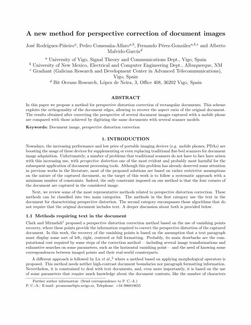
Figure 1. Pinhole model.
will be used for denoting the first, second, and (where applicable) third component of the considered coordinatesystem.
The used capture model is depicted in Fig. 1, and it is usually named pinhole model of the camera,12 beingextensively used in the literature.
Taking into account the definition of z and y, it is straightforward to see that there exists a scalar λ > 0 suchthat y = λz, and at the same time all the values of y equal to λz for any λ > 0 will produce the same capturedpoint, showing the capture ambiguity mentioned at the beginning of this section. An example of this ambiguityis illustrated in Fig. 1, where both y and y would produce the same captured point z. Finally, it will be usefulto take into account that λ can be constrained to be strictly positive, as y cannot be the null vector (i.e., we willassume that the document will not be located at the camera center).
The approach followed in this work for correcting the perspective distortion is based on performing the inverseoperations to those involved in the capture process.
3. INVERTING THE CAPTURE PROCESS
3.1 Recovering the three-dimensional coordinates of the corners
Let zi be the image plane coordinates of the ith corner of the document, where i = 0, · · · , 3, and the indices areassigned in such a way that the ith corner’s neighbors are the (i ± 1)mod4-th corners. Following the notationintroduced in the previous section, the first two components of zi determine the position of the ith corner ofthe document in the captured image. Nevertheless, the value of the third component, i.e. f , will be usually notknown at the image processing side. Therefore, in order to invert the capture process, we will assume that thevalue of that parameter is f , and afterwards, as it will be shown below, the value of f will be estimated takinginto account the geometrical properties of the original document. Consequently, we will denote by zi , (zi
1, zi2, f)
the estimated coordinates of the document on the image plane.
According to the discussion presented above, one can compute the coordinates of every point in the three-dimensional space yielding zi, obtaining the points in the straight semi-line y = λzi, with λ > 0. However, oneneeds to estimate the particular λi’s yielding yi = λiz
i, using again the geometrical properties among the yi’s.
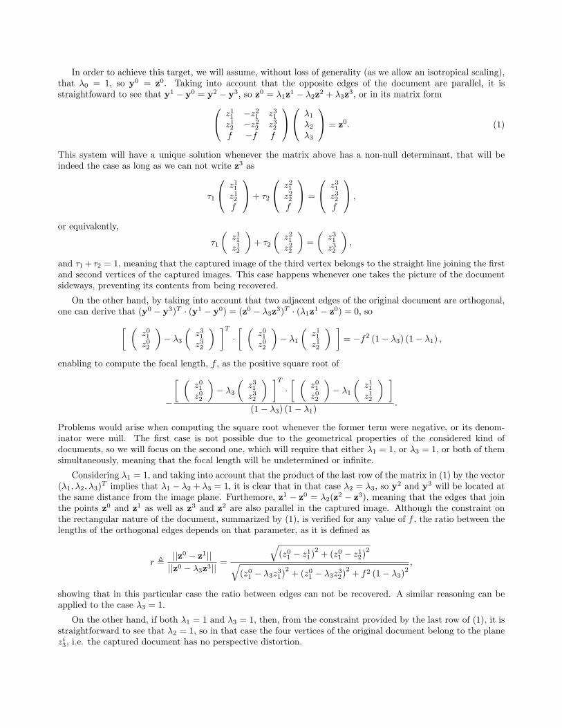
In order to achieve this target, we will assume, without loss of generality (as we allow an isotropical scaling),that λ0 = 1, so y0 = z0. Taking into account that the opposite edges of the document are parallel, it isstraightfoward to see that y1 − y0 = y2 − y3, so z0 = λ1z
1 − λ2z2 + λ3z
3, or in its matrix form
z11 −z2
1 z31
z12 −z2
2 z32
f −f f
λ1
λ2
λ3
= z0. (1)
This system will have a unique solution whenever the matrix above has a non-null determinant, that will beindeed the case as long as we can not write z3 as
τ1
z11
z12
f
+ τ2
z21
z22
f
=
z31
z32
f
,
or equivalently,
τ1
(
z11
z12
)
+ τ2
(
z21
z22
)
=
(
z31
z32
)
,
and τ1 + τ2 = 1, meaning that the captured image of the third vertex belongs to the straight line joining the firstand second vertices of the captured images. This case happens whenever one takes the picture of the documentsideways, preventing its contents from being recovered.
On the other hand, by taking into account that two adjacent edges of the original document are orthogonal,one can derive that (y0 − y3)T · (y1 − y0) = (z0 − λ3z
3)T · (λ1z1 − z0) = 0, so
[ (
z01
z02
)
− λ3
(
z31
z32
) ]T
·[ (
z01
z02
)
− λ1
(
z11
z12
) ]
= −f2 (1 − λ3) (1 − λ1) ,
enabling to compute the focal length, f , as the positive square root of
−
[ (
z01
z02
)
− λ3
(
z31
z32
) ]T
·[ (
z01
z02
)
− λ1
(
z11
z12
) ]
(1 − λ3) (1 − λ1).
Problems would arise when computing the square root whenever the former term were negative, or its denom-inator were null. The first case is not possible due to the geometrical properties of the considered kind ofdocuments, so we will focus on the second one, which will require that either λ1 = 1, or λ3 = 1, or both of themsimultaneously, meaning that the focal length will be undetermined or infinite.
Considering λ1 = 1, and taking into account that the product of the last row of the matrix in (1) by the vector(λ1, λ2, λ3)
T implies that λ1 − λ2 + λ3 = 1, it is clear that in that case λ2 = λ3, so y2 and y3 will be located atthe same distance from the image plane. Furthemore, z1 − z0 = λ2(z
2 − z3), meaning that the edges that jointhe points z0 and z1 as well as z3 and z2 are also parallel in the captured image. Although the constraint onthe rectangular nature of the document, summarized by (1), is verified for any value of f , the ratio between thelengths of the orthogonal edges depends on that parameter, as it is defined as
r ,||z0 − z1||
||z0 − λ3z3|| =
√
(z01 − z1
1)2
+ (z01 − z1
2)2
√
(z01 − λ3z3
1)2
+ (z01 − λ3z3
2)2
+ f2 (1 − λ3)2,
showing that in this particular case the ratio between edges can not be recovered. A similar reasoning can beapplied to the case λ3 = 1.
On the other hand, if both λ1 = 1 and λ3 = 1, then, from the constraint provided by the last row of (1), it isstraightforward to see that λ2 = 1, so in that case the four vertices of the original document belong to the planezi3, i.e. the captured document has no perspective distortion.
Summarizing, although when both λ1 and λ2 are equal to 1 the irrecoverability of the focal length is notrelevant, as there is no perspective distortion to be corrected, this is indeed a problem when only one of them isequal to 1. Note that, although Zhang and He11 only consider explicitly the case where both λ1 and λ2 are equalto 1, it can be easily proved that their approach also fails to recover the aspect ratio when only one of them isequal to 1.
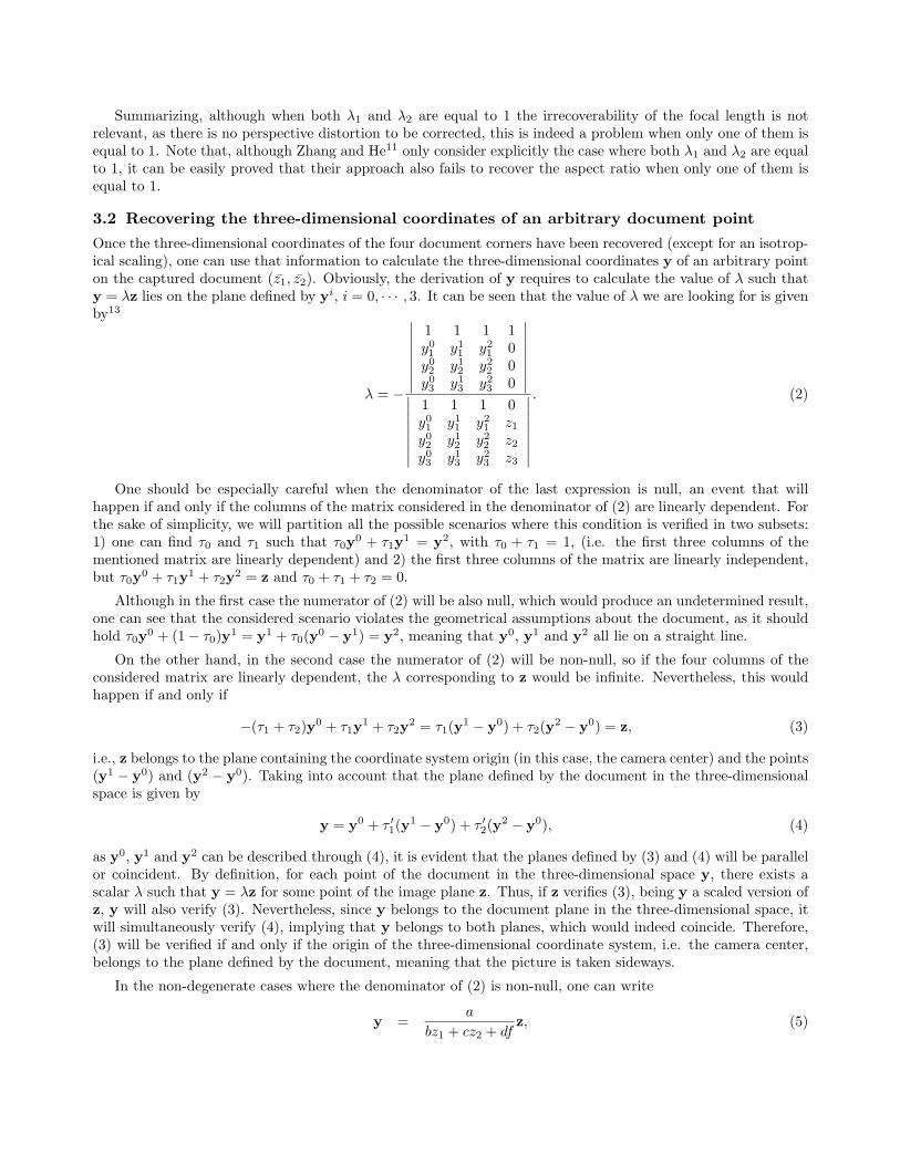
3.2 Recovering the three-dimensional coordinates of an arbitrary document point
Once the three-dimensional coordinates of the four document corners have been recovered (except for an isotrop-ical scaling), one can use that information to calculate the three-dimensional coordinates y of an arbitrary pointon the captured document (z1, z2). Obviously, the derivation of y requires to calculate the value of λ such thaty = λz lies on the plane defined by yi, i = 0, · · · , 3. It can be seen that the value of λ we are looking for is givenby13
λ = −
∣
∣
∣
∣
∣
∣
∣
∣
1 1 1 1y01 y1
1 y21 0
y02 y1
2 y22 0
y03 y1
3 y23 0
∣
∣
∣
∣
∣
∣
∣
∣
∣
∣
∣
∣
∣
∣
∣
∣
1 1 1 0y01 y1
1 y21 z1
y02 y1
2 y22 z2
y03 y1
3 y23 z3
∣
∣
∣
∣
∣
∣
∣
∣
. (2)
One should be especially careful when the denominator of the last expression is null, an event that willhappen if and only if the columns of the matrix considered in the denominator of (2) are linearly dependent. Forthe sake of simplicity, we will partition all the possible scenarios where this condition is verified in two subsets:1) one can find τ0 and τ1 such that τ0y
0 + τ1y1 = y2, with τ0 + τ1 = 1, (i.e. the first three columns of the
mentioned matrix are linearly dependent) and 2) the first three columns of the matrix are linearly independent,but τ0y
0 + τ1y1 + τ2y
2 = z and τ0 + τ1 + τ2 = 0.
Although in the first case the numerator of (2) will be also null, which would produce an undetermined result,one can see that the considered scenario violates the geometrical assumptions about the document, as it shouldhold τ0y
0 + (1 − τ0)y1 = y1 + τ0(y
0 − y1) = y2, meaning that y0, y1 and y2 all lie on a straight line.
On the other hand, in the second case the numerator of (2) will be non-null, so if the four columns of theconsidered matrix are linearly dependent, the λ corresponding to z would be infinite. Nevertheless, this wouldhappen if and only if
−(τ1 + τ2)y0 + τ1y
1 + τ2y2 = τ1(y
1 − y0) + τ2(y2 − y0) = z, (3)
i.e., z belongs to the plane containing the coordinate system origin (in this case, the camera center) and the points(y1 − y0) and (y2 − y0). Taking into account that the plane defined by the document in the three-dimensionalspace is given by
y = y0 + τ ′1(y
1 − y0) + τ ′2(y
2 − y0), (4)
as y0, y1 and y2 can be described through (4), it is evident that the planes defined by (3) and (4) will be parallelor coincident. By definition, for each point of the document in the three-dimensional space y, there exists ascalar λ such that y = λz for some point of the image plane z. Thus, if z verifies (3), being y a scaled version ofz, y will also verify (3). Nevertheless, since y belongs to the document plane in the three-dimensional space, itwill simultaneously verify (4), implying that y belongs to both planes, which would indeed coincide. Therefore,(3) will be verified if and only if the origin of the three-dimensional coordinate system, i.e. the camera center,belongs to the plane defined by the document, meaning that the picture is taken sideways.
In the non-degenerate cases where the denominator of (2) is non-null, one can write
y =a
bz1 + cz2 + dfz, (5)
where a ,
∣
∣
∣
∣
∣
∣
y01 y1
1 y21
y02 y1
2 y22
y03 y1
3 y23
∣
∣
∣
∣
∣
∣
, b ,
∣
∣
∣
∣
∣
∣
1 1 1y02 y1
2 y22
y03 y1
3 y23
∣
∣
∣
∣
∣
∣
, c , −
∣
∣
∣
∣
∣
∣
1 1 1y01 y1
1 y21
y03 y1
3 y23
∣
∣
∣
∣
∣
∣
, and d ,
∣
∣
∣
∣
∣
∣
1 1 1y01 y1
1 y21
y02 y1
2 y22
∣
∣
∣
∣
∣
∣
.
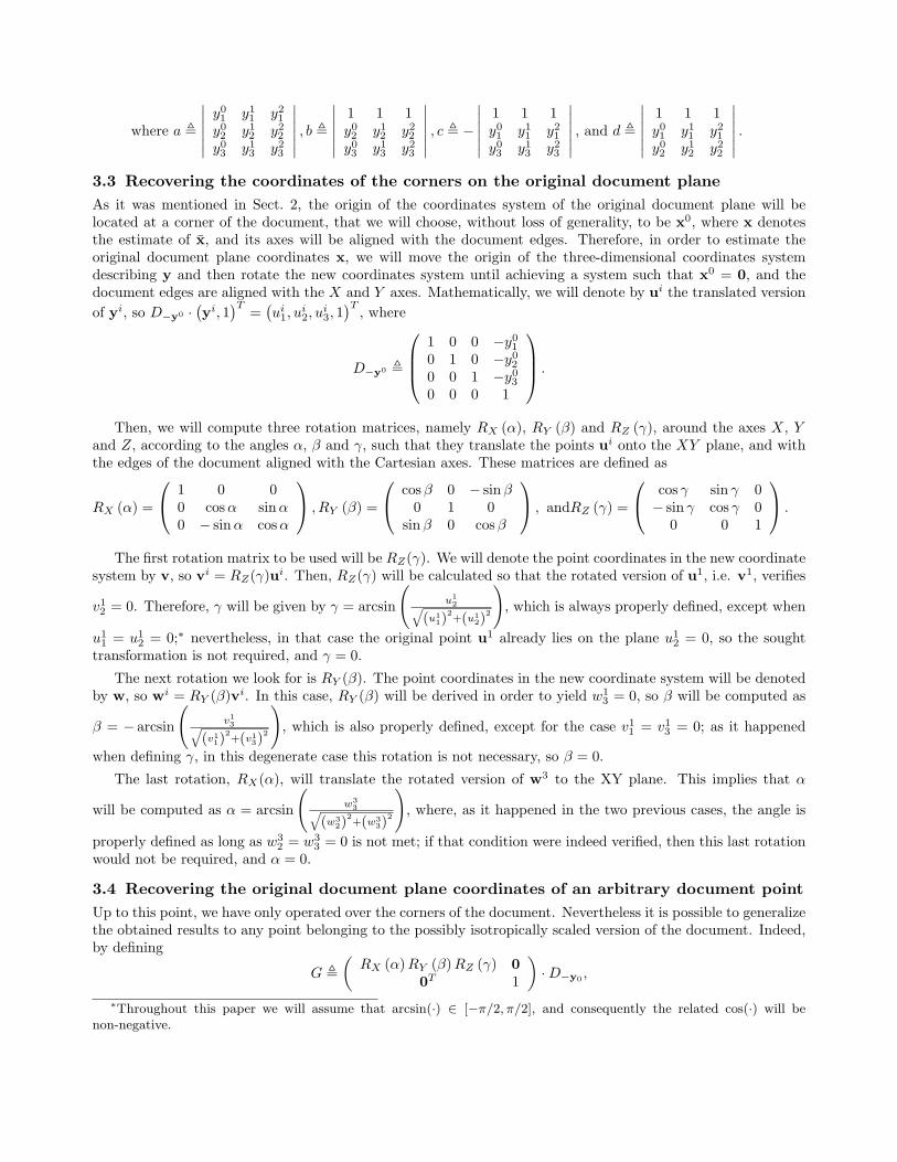
3.3 Recovering the coordinates of the corners on the original document plane
As it was mentioned in Sect. 2, the origin of the coordinates system of the original document plane will belocated at a corner of the document, that we will choose, without loss of generality, to be x0, where x denotesthe estimate of x, and its axes will be aligned with the document edges. Therefore, in order to estimate theoriginal document plane coordinates x, we will move the origin of the three-dimensional coordinates systemdescribing y and then rotate the new coordinates system until achieving a system such that x0 = 0, and thedocument edges are aligned with the X and Y axes. Mathematically, we will denote by ui the translated version
of yi, so D−y0 ·(
yi, 1)T
=(
ui1, u
i2, u
i3, 1)T
, where
D−y0 ,
1 0 0 −y01
0 1 0 −y02
0 0 1 −y03
0 0 0 1
.
Then, we will compute three rotation matrices, namely RX (α), RY (β) and RZ (γ), around the axes X, Yand Z, according to the angles α, β and γ, such that they translate the points ui onto the XY plane, and withthe edges of the document aligned with the Cartesian axes. These matrices are defined as
RX (α) =
1 0 00 cos α sinα0 − sin α cos α
, RY (β) =
cos β 0 − sin β0 1 0
sin β 0 cos β
, andRZ (γ) =
cos γ sin γ 0− sin γ cos γ 0
0 0 1
.
The first rotation matrix to be used will be RZ(γ). We will denote the point coordinates in the new coordinatesystem by v, so vi = RZ(γ)ui. Then, RZ(γ) will be calculated so that the rotated version of u1, i.e. v1, verifies
v12 = 0. Therefore, γ will be given by γ = arcsin
(
u1
2q
(u1
1)2+(u1
2)2
)
, which is always properly defined, except when
u11 = u1
2 = 0;∗ nevertheless, in that case the original point u1 already lies on the plane u12 = 0, so the sought
transformation is not required, and γ = 0.
The next rotation we look for is RY (β). The point coordinates in the new coordinate system will be denotedby w, so wi = RY (β)vi. In this case, RY (β) will be derived in order to yield w1
3 = 0, so β will be computed as
β = − arcsin
(
v1
3q
(v1
1)2+(v1
3)2
)
, which is also properly defined, except for the case v11 = v1
3 = 0; as it happened
when defining γ, in this degenerate case this rotation is not necessary, so β = 0.
The last rotation, RX(α), will translate the rotated version of w3 to the XY plane. This implies that α
will be computed as α = arcsin
(
w3
3q
(w3
2)2+(w3
3)2
)
, where, as it happened in the two previous cases, the angle is
properly defined as long as w32 = w3
3 = 0 is not met; if that condition were indeed verified, then this last rotationwould not be required, and α = 0.
3.4 Recovering the original document plane coordinates of an arbitrary document point
Up to this point, we have only operated over the corners of the document. Nevertheless it is possible to generalizethe obtained results to any point belonging to the possibly isotropically scaled version of the document. Indeed,by defining
G ,
(
RX (α) RY (β) RZ (γ) 0
0T 1
)
· D−y0,
∗Throughout this paper we will assume that arcsin(·) ∈ [−π/2, π/2], and consequently the related cos(·) will benon-negative.
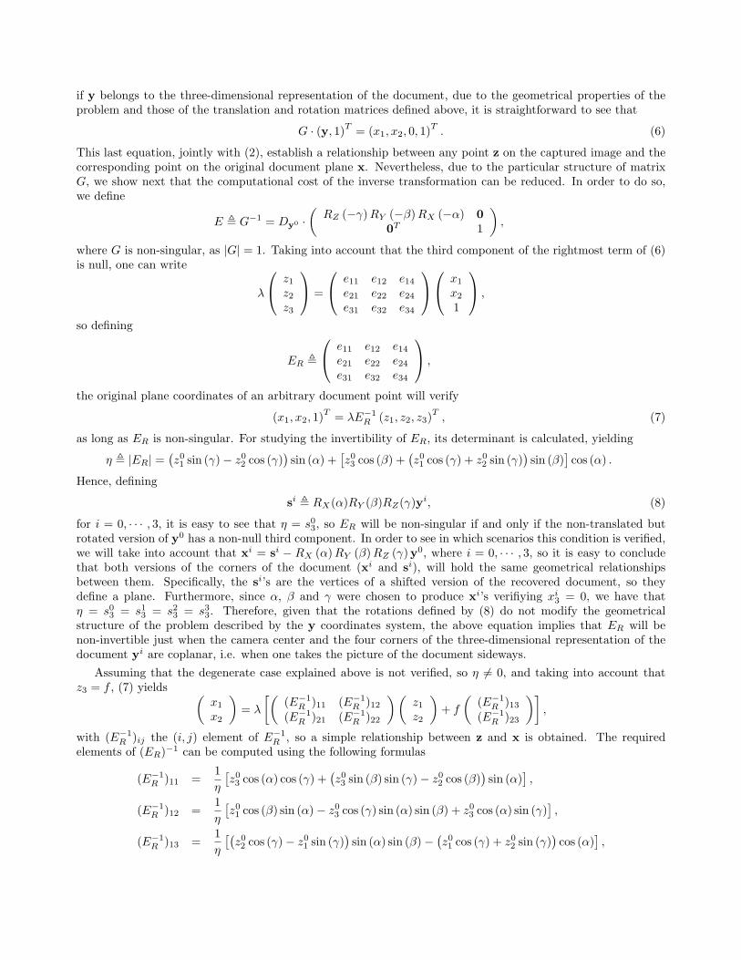
if y belongs to the three-dimensional representation of the document, due to the geometrical properties of theproblem and those of the translation and rotation matrices defined above, it is straightforward to see that
G · (y, 1)T
= (x1, x2, 0, 1)T
. (6)
This last equation, jointly with (2), establish a relationship between any point z on the captured image and thecorresponding point on the original document plane x. Nevertheless, due to the particular structure of matrixG, we show next that the computational cost of the inverse transformation can be reduced. In order to do so,we define
E , G−1 = Dy0 ·(
RZ (−γ) RY (−β) RX (−α) 0
0T 1
)
,
where G is non-singular, as |G| = 1. Taking into account that the third component of the rightmost term of (6)is null, one can write
λ
z1
z2
z3
=
e11 e12 e14
e21 e22 e24
e31 e32 e34
x1
x2
1
,
so defining
ER ,
e11 e12 e14
e21 e22 e24
e31 e32 e34
,
the original plane coordinates of an arbitrary document point will verify
(x1, x2, 1)T
= λE−1R (z1, z2, z3)
T, (7)
as long as ER is non-singular. For studying the invertibility of ER, its determinant is calculated, yielding
η , |ER| =(
z01 sin (γ) − z0
2 cos (γ))
sin (α) +[
z03 cos (β) +
(
z01 cos (γ) + z0
2 sin (γ))
sin (β)]
cos (α) .
Hence, defining
si , RX(α)RY (β)RZ(γ)yi, (8)
for i = 0, · · · , 3, it is easy to see that η = s03, so ER will be non-singular if and only if the non-translated but
rotated version of y0 has a non-null third component. In order to see in which scenarios this condition is verified,we will take into account that xi = si − RX (α) RY (β) RZ (γ)y0, where i = 0, · · · , 3, so it is easy to concludethat both versions of the corners of the document (xi and si), will hold the same geometrical relationshipsbetween them. Specifically, the si’s are the vertices of a shifted version of the recovered document, so theydefine a plane. Furthermore, since α, β and γ were chosen to produce xi’s verifiying xi
3 = 0, we have thatη = s0
3 = s13 = s2
3 = s33. Therefore, given that the rotations defined by (8) do not modify the geometrical
structure of the problem described by the y coordinates system, the above equation implies that ER will benon-invertible just when the camera center and the four corners of the three-dimensional representation of thedocument yi are coplanar, i.e. when one takes the picture of the document sideways.
Assuming that the degenerate case explained above is not verified, so η 6= 0, and taking into account thatz3 = f , (7) yields
(
x1
x2
)
= λ
[(
(E−1R )11 (E−1
R )12(E−1
R )21 (E−1R )22
)(
z1
z2
)
+ f
(
(E−1R )13
(E−1R )23
)]
,
with (E−1R )ij the (i, j) element of E−1
R , so a simple relationship between z and x is obtained. The requiredelements of (ER)−1 can be computed using the following formulas
(E−1R )11 =
1
η
[
z03 cos (α) cos (γ) +
(
z03 sin (β) sin (γ) − z0
2 cos (β))
sin (α)]
,
(E−1R )12 =
1
η
[
z01 cos (β) sin (α) − z0
3 cos (γ) sin (α) sin (β) + z03 cos (α) sin (γ)
]
,
(E−1R )13 =
1
η
[(
z02 cos (γ) − z0
1 sin (γ))
sin (α) sin (β) −(
z01 cos (γ) + z0
2 sin (γ))
cos (α)]
,
(E−1R )21 =
1
η
[
z02 sin (β) + z0
3 cos (β) sin (γ)]
,
(E−1R )22 =
1
η
[
z03 cos (β) cos (γ) + z0
1 sin (β)]
, and
(E−1R )23 =
1
η
[(
z01 sin (γ) − z0
2 cos (γ))
cos (β)]
.
3.5 Computational cost
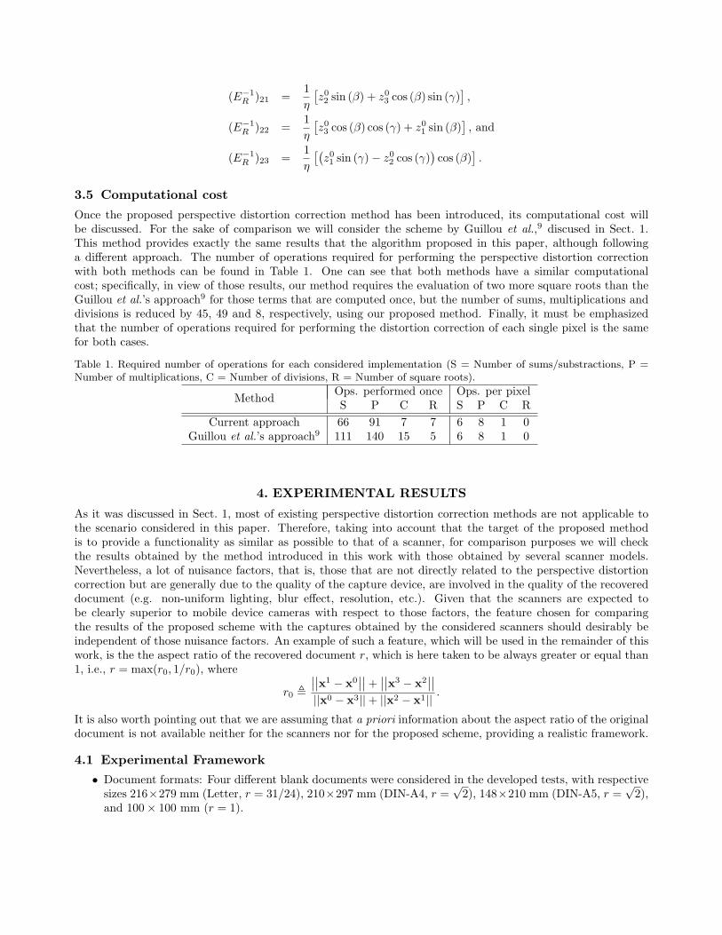
Once the proposed perspective distortion correction method has been introduced, its computational cost willbe discussed. For the sake of comparison we will consider the scheme by Guillou et al.,9 discused in Sect. 1.This method provides exactly the same results that the algorithm proposed in this paper, although followinga different approach. The number of operations required for performing the perspective distortion correctionwith both methods can be found in Table 1. One can see that both methods have a similar computationalcost; specifically, in view of those results, our method requires the evaluation of two more square roots than theGuillou et al.’s approach9 for those terms that are computed once, but the number of sums, multiplications anddivisions is reduced by 45, 49 and 8, respectively, using our proposed method. Finally, it must be emphasizedthat the number of operations required for performing the distortion correction of each single pixel is the samefor both cases.
Table 1. Required number of operations for each considered implementation (S = Number of sums/substractions, P =Number of multiplications, C = Number of divisions, R = Number of square roots).
MethodOps. performed once Ops. per pixelS P C R S P C R
Current approach 66 91 7 7 6 8 1 0Guillou et al.’s approach9 111 140 15 5 6 8 1 0
4. EXPERIMENTAL RESULTS
As it was discussed in Sect. 1, most of existing perspective distortion correction methods are not applicable tothe scenario considered in this paper. Therefore, taking into account that the target of the proposed methodis to provide a functionality as similar as possible to that of a scanner, for comparison purposes we will checkthe results obtained by the method introduced in this work with those obtained by several scanner models.Nevertheless, a lot of nuisance factors, that is, those that are not directly related to the perspective distortioncorrection but are generally due to the quality of the capture device, are involved in the quality of the recovereddocument (e.g. non-uniform lighting, blur effect, resolution, etc.). Given that the scanners are expected tobe clearly superior to mobile device cameras with respect to those factors, the feature chosen for comparingthe results of the proposed scheme with the captures obtained by the considered scanners should desirably beindependent of those nuisance factors. An example of such a feature, which will be used in the remainder of thiswork, is the the aspect ratio of the recovered document r, which is here taken to be always greater or equal than1, i.e., r = max(r0, 1/r0), where
r0 ,
∣
∣
∣
∣x1 − x0∣
∣
∣
∣+∣
∣
∣
∣x3 − x2∣
∣
∣
∣
||x0 − x3|| + ||x2 − x1|| .
It is also worth pointing out that we are assuming that a priori information about the aspect ratio of the originaldocument is not available neither for the scanners nor for the proposed scheme, providing a realistic framework.
4.1 Experimental Framework
• Document formats: Four different blank documents were considered in the developed tests, with respectivesizes 216×279 mm (Letter, r = 31/24), 210×297 mm (DIN-A4, r =
√2), 148×210 mm (DIN-A5, r =
√2),
and 100 × 100 mm (r = 1).
• Mobile capture device: The document photos were taken with a 5 megapixels camera, corresponding to aNokia N82 mobile phone, being the corners of the captured document located by using a method proposedby us elsewhere.14 The results reported in this section for the method proposed in this work were obtainedusing 6 letter-sized, 19 DIN-A4, 14 DIN-A5, and 14 100×100 mm document photos, captured with differentcamera locations and orientations.
• Scanners: The considered documents were also captured using seven different scanners: the automaticdocument feeding scanner Fujistu Fi-5210c, and the flat-bed scanners with manual document feeding CanonMP-550, EPSON Perfection 1200 Photo, EPSON Stylus SX-105, HP ScanJet 4470C and HP ScanJet 5100C.All of them were fed with all the considered blank documents. In order to evaluate both the mean valueand the variability of the obtained results, each document was scanned 5 times, changing the position ofthe document for each scan.
Given that the distortion perspective correction method proposed in this work estimates the coordinates ofthe document corners, the derivation of the aspect ratio obtained when applying that method is straightforward.This is no longer the case when we consider scanned documents, so we will introduce here the method followedto estimate the document corners in that scenario. First of all, in order to avoid undesiderable shadows in thecapture, all the documents digitized with the flat-bed scanners were scanned over a black background. Secondly,given that the scanned documents are blank, Otsu’s method15 can be used to estimate a proper threshold valuefor binarizing the scanners’ output. Following the binarization, several equidistant points belonging to each edgeof the document are obtained; this is done by manually providing the horizontal and vertical coordinates of thefirst and last point considered along each edge, as the corners of the scanned document are still not known.Specifically, 10 points per edge are considered for the 100 × 100 mm documents, and a number proportional tothe edges lengths for the other formats. In order to accurately estimate the document edges, a robust regressionalgorithm was used.† The estimated document corners are just the intersection of those edges, yielding theresulting aspect ratio. Unfortunately, this method can not be applied to those documents scanned using theconsidered automatic feeding scanner, as in that case one can not establish a background. In order to circumventthis problem, each edge of the digitized version of the documents was estimated by manually locating two pointsof that edge.
4.2 Obtained results
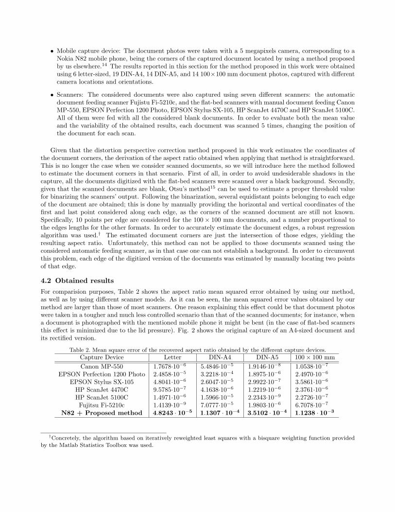
For comparision purposes, Table 2 shows the aspect ratio mean squared error obtained by using our method,as well as by using different scanner models. As it can be seen, the mean squared error values obtained by ourmethod are larger than those of most scanners. One reason explaining this effect could be that document photoswere taken in a tougher and much less controlled scenario than that of the scanned documents; for instance, whena document is photographed with the mentioned mobile phone it might be bent (in the case of flat-bed scannersthis effect is minimized due to the lid pressure). Fig. 2 shows the original capture of an A4-sized document andits rectified version.
Table 2. Mean square error of the recovered aspect ratio obtained by the different capture devices.
Capture Device Letter DIN-A4 DIN-A5 100 × 100 mm
Canon MP-550 1.7678·10−6 5.4846·10−5 1.9146·10−8 1.0538·10−7
EPSON Perfection 1200 Photo 2.4858·10−5 3.2218·10−4 1.8975·10−6 2.4970·10−6
EPSON Stylus SX-105 4.8041·10−6 2.6047·10−5 2.9922·10−7 3.5861·10−6
HP ScanJet 4470C 9.5785·10−7 4.1638·10−6 1.2219·10−6 2.3761·10−6
HP ScanJet 5100C 1.4971·10−6 1.5966·10−5 2.2343·10−9 2.2726·10−7
Fujitsu Fi-5210c 1.4139·10−9 7.0777·10−5 1.9803·10−6 6.7078·10−7
N82 + Proposed method 4.8243 · 10−5 1.1307 · 10−4 3.5102 · 10−4 1.1238 · 10−3
†Concretely, the algorithm based on iteratively reweighted least squares with a bisquare weighting function providedby the Matlab Statistics Toolbox was used.
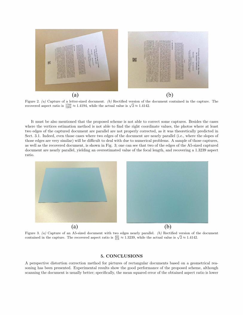
Figure 2. (a) Capture of a letter-sized document. (b) Rectified version of the document contained in the capture. Therecovered aspect ratio is 1709
1204≈ 1.4194, while the actual value is
√2 ≈ 1.4142.
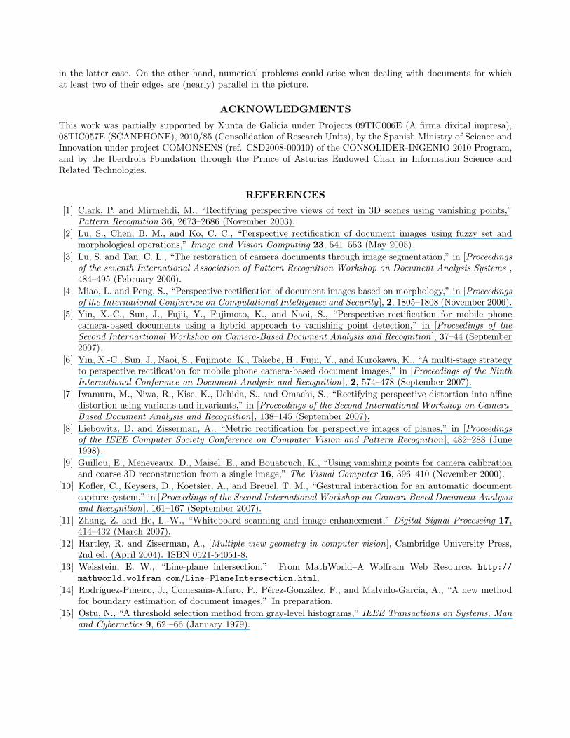
It must be also mentioned that the proposed scheme is not able to correct some captures. Besides the caseswhere the vertices estimation method is not able to find the right coordinate values, the photos where at leasttwo edges of the captured document are parallel are not properly corrected, as it was theoretically predicted inSect. 3.1. Indeed, even those cases where two edges of the document are nearly parallel (i.e., where the slopes ofthose edges are very similar) will be difficult to deal with due to numerical problems. A sample of those captures,as well as the recovered document, is shown in Fig. 3; one can see that two of the edges of the A5-sized captureddocument are nearly parallel, yielding an overestimated value of the focal length, and recovering a 1.3239 aspectratio.
Figure 3. (a) Capture of an A5-sized document with two edges nearly parallel. (b) Rectified version of the documentcontained in the capture. The recovered aspect ratio is 421
318≈ 1.3239, while the actual value is
√2 ≈ 1.4142.
5. CONCLUSIONS
A perspective distortion correction method for pictures of rectangular documents based on a geometrical rea-soning has been presented. Experimental results show the good performance of the proposed scheme, althoughscanning the document is usually better; specifically, the mean squared error of the obtained aspect ratio is lower
in the latter case. On the other hand, numerical problems could arise when dealing with documents for whichat least two of their edges are (nearly) parallel in the picture.
ACKNOWLEDGMENTS
This work was partially supported by Xunta de Galicia under Projects 09TIC006E (A firma dixital impresa),08TIC057E (SCANPHONE), 2010/85 (Consolidation of Research Units), by the Spanish Ministry of Science andInnovation under project COMONSENS (ref. CSD2008-00010) of the CONSOLIDER-INGENIO 2010 Program,and by the Iberdrola Foundation through the Prince of Asturias Endowed Chair in Information Science andRelated Technologies.
REFERENCES
[1] Clark, P. and Mirmehdi, M., “Rectifying perspective views of text in 3D scenes using vanishing points,”Pattern Recognition 36, 2673–2686 (November 2003).
[2] Lu, S., Chen, B. M., and Ko, C. C., “Perspective rectification of document images using fuzzy set andmorphological operations,” Image and Vision Computing 23, 541–553 (May 2005).
[3] Lu, S. and Tan, C. L., “The restoration of camera documents through image segmentation,” in [Proceedings
of the seventh International Association of Pattern Recognition Workshop on Document Analysis Systems ],484–495 (February 2006).
[4] Miao, L. and Peng, S., “Perspective rectification of document images based on morphology,” in [Proceedings
of the International Conference on Computational Intelligence and Security ], 2, 1805–1808 (November 2006).
[5] Yin, X.-C., Sun, J., Fujii, Y., Fujimoto, K., and Naoi, S., “Perspective rectification for mobile phonecamera-based documents using a hybrid approach to vanishing point detection,” in [Proceedings of the
Second Internartional Workshop on Camera-Based Document Analysis and Recognition ], 37–44 (September2007).
[6] Yin, X.-C., Sun, J., Naoi, S., Fujimoto, K., Takebe, H., Fujii, Y., and Kurokawa, K., “A multi-stage strategyto perspective rectification for mobile phone camera-based document images,” in [Proceedings of the Ninth
International Conference on Document Analysis and Recognition ], 2, 574–478 (September 2007).
[7] Iwamura, M., Niwa, R., Kise, K., Uchida, S., and Omachi, S., “Rectifying perspective distortion into affinedistortion using variants and invariants,” in [Proceedings of the Second International Workshop on Camera-
Based Document Analysis and Recognition ], 138–145 (September 2007).
[8] Liebowitz, D. and Zisserman, A., “Metric rectification for perspective images of planes,” in [Proceedings
of the IEEE Computer Society Conference on Computer Vision and Pattern Recognition ], 482–288 (June1998).
[9] Guillou, E., Meneveaux, D., Maisel, E., and Bouatouch, K., “Using vanishing points for camera calibrationand coarse 3D reconstruction from a single image,” The Visual Computer 16, 396–410 (November 2000).
[10] Kofler, C., Keysers, D., Koetsier, A., and Breuel, T. M., “Gestural interaction for an automatic documentcapture system,” in [Proceedings of the Second International Workshop on Camera-Based Document Analysis
and Recognition ], 161–167 (September 2007).
[11] Zhang, Z. and He, L.-W., “Whiteboard scanning and image enhancement,” Digital Signal Processing 17,414–432 (March 2007).
[12] Hartley, R. and Zisserman, A., [Multiple view geometry in computer vision ], Cambridge University Press,2nd ed. (April 2004). ISBN 0521-54051-8.
[13] Weisstein, E. W., “Line-plane intersection.” From MathWorld–A Wolfram Web Resource. http://
mathworld.wolfram.com/Line-PlaneIntersection.html.
[14] Rodrıguez-Pineiro, J., Comesana-Alfaro, P., Perez-Gonzalez, F., and Malvido-Garcıa, A., “A new methodfor boundary estimation of document images,” In preparation.
[15] Ostu, N., “A threshold selection method from gray-level histograms,” IEEE Transactions on Systems, Man
and Cybernetics 9, 62 –66 (January 1979).