A Multi-Service Adaptive Semi-Persistent LTE Uplink ... - MDPI
28
Citation: Afrin, N.; Brown, J.; Khan, J.Y. A Multi-Service Adaptive Semi-Persistent LTE Uplink Scheduler for Low Power M2M Devices. Future Internet 2022, 14, 107. https://doi.org/10.3390/fi14040107 Academic Editors: Xavier Fernando and Kandasamy Illanko Received: 2 January 2022 Accepted: 25 March 2022 Published: 27 March 2022 Publisher’s Note: MDPI stays neutral with regard to jurisdictional claims in published maps and institutional affil- iations. Copyright: © 2022 by the authors. Licensee MDPI, Basel, Switzerland. This article is an open access article distributed under the terms and conditions of the Creative Commons Attribution (CC BY) license (https:// creativecommons.org/licenses/by/ 4.0/). future internet Article A Multi-Service Adaptive Semi-Persistent LTE Uplink Scheduler for Low Power M2M Devices Nusrat Afrin 1, * , Jason Brown 2 and Jamil Y. Khan 1 1 School of Engineering, University of Newcastle, Callaghan, NSW 2308, Australia; [email protected] 2 School of Mechanical and Electrical Engineering, University of Southern Queensland, Springfield, QLD 4300, Australia; [email protected] * Correspondence: [email protected] Abstract: The prominence of Machine-to-Machine (M2M) communications in the future wide area communication networks place various challenges to the cellular technologies such as the Long Term Evolution (LTE) standard, owing to the large number of M2M devices generating small bursts of infrequent data packets with a wide range of delay requirements. The channel structure and Quality of Service (QoS) framework of LTE networks fail to support M2M traffic with multiple burst sizes and QoS requirements while a bottleneck often arises from the limited control resources to communicate future uplink resource allocations to the M2M devices. Moreover, many of the M2M devices are battery-powered and require a low-power consuming wide area technology for wide-spread deployments. To alleviate these issues, in this article we propose an adaptive semi- persistent scheduling (SPS) scheme for the LTE uplink which caters for multi-service M2M traffic classes with variable burst sizes and delay tolerances. Instead of adhering to the rigid LTE QoS framework, the proposed algorithm supports variation of uplink allocation sizes based on queued data length yet does not require control signaling to inform those allocations to the respective devices. Both the eNodeB and the M2M devices can determine the precise uplink resource allocation related parameters based on their mutual knowledge, thus omitting the burden of regular control signaling exchanges. Based on a control parameter, the algorithm can offer different capacities and levels of QoS satisfaction to different traffic classes. We also introduce a pre-emptive feature by which the algorithm can prioritize new traffic with low delay tolerance over ongoing delay-tolerant traffic. We also build a model for incorporating the Discontinuous Reception (DRX) mechanism in synchronization with the adaptive SPS transmissions so that the UE power consumption can be significantly lowered, thereby extending their battery lives. The simulation and performance analysis of the proposed scheme shows significant improvement over the traditional LTE scheduler in terms of QoS satisfaction, channel utilization and low power requirements of multi-service M2M traffic. Keywords: LTE; Machine-to-Machine; Internet of Things; packet scheduling; channel utilization; DRX; low-power M2M; QoS 1. Introduction Machine-to-Machine (M2M)/Machine Type Communications (MTC) is the key enabler of the imminent connected world of Internet of Things (IoT), which would encompass a massive number of objects with variable capabilities and connectivity requirements. The ubiquitous presence and robust infrastructure of commercially deployed LTE networks offer an attractive solution to the M2M challenge, both from the technical and commercial perspective. Yet there are unforeseen complications which require novel solutions since there is a huge increase in the number of end users and their usage profile exhibits a whole different paradigm [1,2]. Future Internet 2022, 14, 107. https://doi.org/10.3390/fi14040107 https://www.mdpi.com/journal/futureinternet
-
Upload
khangminh22 -
Category
Documents
-
view
4 -
download
0
Transcript of A Multi-Service Adaptive Semi-Persistent LTE Uplink ... - MDPI

�����������������
Citation: Afrin, N.; Brown, J.; Khan,
J.Y. A Multi-Service Adaptive
Semi-Persistent LTE Uplink
Scheduler for Low Power M2M
Devices. Future Internet 2022, 14, 107.
https://doi.org/10.3390/fi14040107
Academic Editors: Xavier Fernando
and Kandasamy Illanko
Received: 2 January 2022
Accepted: 25 March 2022
Published: 27 March 2022
Publisher’s Note: MDPI stays neutral
with regard to jurisdictional claims in
published maps and institutional affil-
iations.
Copyright: © 2022 by the authors.
Licensee MDPI, Basel, Switzerland.
This article is an open access article
distributed under the terms and
conditions of the Creative Commons
Attribution (CC BY) license (https://
creativecommons.org/licenses/by/
4.0/).
future internet
Article
A Multi-Service Adaptive Semi-Persistent LTE UplinkScheduler for Low Power M2M DevicesNusrat Afrin 1,* , Jason Brown 2 and Jamil Y. Khan 1
1 School of Engineering, University of Newcastle, Callaghan, NSW 2308, Australia;[email protected]
2 School of Mechanical and Electrical Engineering, University of Southern Queensland,Springfield, QLD 4300, Australia; [email protected]
* Correspondence: [email protected]
Abstract: The prominence of Machine-to-Machine (M2M) communications in the future wide areacommunication networks place various challenges to the cellular technologies such as the LongTerm Evolution (LTE) standard, owing to the large number of M2M devices generating small burstsof infrequent data packets with a wide range of delay requirements. The channel structure andQuality of Service (QoS) framework of LTE networks fail to support M2M traffic with multipleburst sizes and QoS requirements while a bottleneck often arises from the limited control resourcesto communicate future uplink resource allocations to the M2M devices. Moreover, many of theM2M devices are battery-powered and require a low-power consuming wide area technology forwide-spread deployments. To alleviate these issues, in this article we propose an adaptive semi-persistent scheduling (SPS) scheme for the LTE uplink which caters for multi-service M2M trafficclasses with variable burst sizes and delay tolerances. Instead of adhering to the rigid LTE QoSframework, the proposed algorithm supports variation of uplink allocation sizes based on queueddata length yet does not require control signaling to inform those allocations to the respective devices.Both the eNodeB and the M2M devices can determine the precise uplink resource allocation relatedparameters based on their mutual knowledge, thus omitting the burden of regular control signalingexchanges. Based on a control parameter, the algorithm can offer different capacities and levels of QoSsatisfaction to different traffic classes. We also introduce a pre-emptive feature by which the algorithmcan prioritize new traffic with low delay tolerance over ongoing delay-tolerant traffic. We also build amodel for incorporating the Discontinuous Reception (DRX) mechanism in synchronization with theadaptive SPS transmissions so that the UE power consumption can be significantly lowered, therebyextending their battery lives. The simulation and performance analysis of the proposed scheme showssignificant improvement over the traditional LTE scheduler in terms of QoS satisfaction, channelutilization and low power requirements of multi-service M2M traffic.
Keywords: LTE; Machine-to-Machine; Internet of Things; packet scheduling; channel utilization;DRX; low-power M2M; QoS
1. Introduction
Machine-to-Machine (M2M)/Machine Type Communications (MTC) is the key enablerof the imminent connected world of Internet of Things (IoT), which would encompass amassive number of objects with variable capabilities and connectivity requirements. Theubiquitous presence and robust infrastructure of commercially deployed LTE networksoffer an attractive solution to the M2M challenge, both from the technical and commercialperspective. Yet there are unforeseen complications which require novel solutions sincethere is a huge increase in the number of end users and their usage profile exhibits a wholedifferent paradigm [1,2].
Future Internet 2022, 14, 107. https://doi.org/10.3390/fi14040107 https://www.mdpi.com/journal/futureinternet
Future Internet 2022, 14, 107 2 of 28
The 3GPP has launched specifications defining the service requirements and corre-sponding system improvements for MTC to design significant device and network modifi-cations in the latest releases of LTE [3,4]. The key challenges for massive M2M deploymentinclude small and intermittent data bursts with variable application-specific delay andreliability requirements generated by massive number of autonomous devices. Unlike thecurrent human-centric traffic, they incur a higher traffic volume on the uplink and thelimited Quality of Service (QoS) framework supported by LTE evidently fails to addresstheir requirements. The initial near simultaneous access attempts taken by a huge numberof devices have led most of the research initiatives to focus on the random access procedure,and propose several prioritization/multiple access methods [5–7].
Nevertheless, a major system bottleneck for realizing M2M-enabled LTE networks hasbeen paid insufficient attention which is the uplink grant conveying process in LTE and itsdependency on downlink control channel resources. Once the devices are connected aftersuccessful random access procedure, each device initiated/terminated transmission has tobe scheduled in the time-frequency resource grid by the LTE packet scheduler and thesescheduling grants must be signaled beforehand via the Physical Downlink Control Channel(PDCCH). However, the PDCCH resources are limited as compared to the data channelresources. Therefore, in case of M2M communications involving massive number of uplinkrequests, the scarcity of PDCCH resources are very likely to cause under-utilization ofthe system capacity [8,9]. Moreover, during this whole process, the M2M devices needto actively monitor the PDCCH for possible grants which drains their battery. Given theactual amount of M2M user data transmitted in the uplink is often very small (in order offew Kbytes), the time and resources consumed in the dynamic scheduling process of theLTE standard is extravagant and imprudent. For an efficient and long-term solution of theM2M communications, the signaling overhead of the scheduling process as well as powerconsumption of the devices need to be reduced [10].
In the 3GPP standards, Semi-Persistent Scheduling (SPS) [11] was proposed to resolvecontrol channel congestion for voice traffic with a deterministic flow and predictable burstsize, but it fails to meet the requirements of diverse M2M applications with stochastic flowand different burst sizes. The standards [12] also propose the Discontinuous Reception(DRX) mechanism as an effective power saving mechanism that allows the LTE UserEquipment (UE) to turn their transceivers off when there is no incoming traffic. TheDRX mechanism seems very attractive for low power M2M communications because ofa small data per terminal in irregular intervals. The sleep cycles of many delay tolerantM2M applications can be scheduled so that they are allowed to transmit only in network-permitted time intervals, thus alleviating the network load in peak times and also savingdevice power. However, again, many M2M applications have a random traffic arrivalpattern and variable burst sizes depending on specific events and triggers, and variabledelay tolerances depending on the event type. The random arrival of uplink packetsnon-synchronized with the DRX sleep cycle may result in either unacceptably long packetdelays or the UE seldom entering sleep state. These problems need to be addressed toachieve the utmost benefits of the SPS and DRX mechanisms for low control-overhead andlow power requirements of M2M communications.
In view of these unique challenges, in this paper, we propose a multi-service adaptivesemi-persistent scheduler which allocates the radio resources to the M2M devices/gatewaysin a semi-persistent way to reduce downlink control signaling yet adaptive to the actualM2M data burst sizes and also sensitive to the different QoS (delay budget) requirementsof various M2M services. Our proposed scheduler can also alter the SPS allocationsin real-time to make room for high priority M2M transmissions with small and strictdelay requirements by pre-empting the already allocated but less delay-sensitive trafficclasses. Afterwards, to support low-power devices, we design a mechanism to deploy the DRXmechanism in harmony with the adaptive SPS transmission intervals to maximize device sleepcycles without compromising the class-specific delay requirements. The proposed algorithm is
Future Internet 2022, 14, 107 3 of 28
simulated using the Riverbed modeler and the performance is analyzed and compared with thedynamic scheduler in terms of QoS, power consumption and channel utilization.
The idea of our adaptive SPS algorithm was proposed in [13–15] and we also derived astatistical model for the device queue size and packet delay for static and adaptive persistentallocations for any arrival process in [16]. In this paper, we present an extended workby introducing a system model for multi-service adaptive SPS algorithm with priority-based pre-emptive feature to distinguish between traffic classes and maximize overallQoS satisfaction and also enhance the algorithm by combining with DRX for supportingpower-constrained M2M devices. The novel contributions of this paper are listed below:
• Design of a system model which offers different capacities to multi-service M2M trafficclasses with variable burst sizes and packet delay budgets.
• Introduction of a control mechanism to vary the semi-persistent period according tothe required QoS for different adaptive allocation policies.
• Pre-emption of low priority traffic (can be served dynamically in a best-effort way)upon arrival of higher priority traffic with more stringent delay budgets.
• Reduction in power consumption of M2M UEs with DRX-enabled adaptive SPSmechanism without compromising their QoS requirements.
The rest of the paper is organized as follows: Section 2 provides the background ofthis work, Section 3 describes the proposed multi-service adaptive SPS algorithm, Section 4explains the implementation of DRX within the proposed framework to achieve powersaving, Section 5 presents the simulation parameters. In Section 6, we discuss the resultsand finally, Section 7 draws the conclusion.
2. Background2.1. Related Enhancements for M2M Communications
The 3GPP has undertaken steps for supporting low-cost, low power-consuming M2MUEs by introducing new physical and MAC layer features in the latest LTE releases yet usingthe existing network infrastructure as much as possible. To reduce signaling complexity,Uplink Configured Grant (CG) transmission was proposed in 3GPP Release 15 instead ofDynamic Grant (DG) [17,18].
To reduce signaling load on the radio network, group-based scheduling approacheshave been investigated. In [19], the authors proposed a cluster-based massive accessmanagement scheme by dividing the M2M devices in a number of clusters and assigningthem periodic Access Grant Time Intervals (AGTI) according to their packet arrival rate,in a fixed or opportunistic manner depending on their QoS requirements. However, onlyconstant inter-arrival gap and fixed packet size are considered. In [20], an extension ismade to the AGTI algorithm [19] for maintaining jitter at the desired level for the alreadyallocated clusters by barring any new M2M device to join the cluster if certain conditionsare not met. Nevertheless, the limitations of the AGTI algorithm i.e., fixed size deterministictraffic flows remain which makes it unsuitable for event-based M2M traffic.
In [21], the authors developed QoS and queue-length aware uplink scheduling algo-rithms targeting M2M service clusters. To improve the limitations of the AGTI framework,in [22], they provided an analytical model to combine the statistical delay violation proba-bility with an allocated grant interval. They used Poisson arrival pattern and the periodicgrants also reduced control overhead significantly, but they do not examine the effect ofvariable sized data burst and the individual grants are still fixed in size (number of PRBs)which can be inefficient.
In the review article [23], the authors have classified and compared various schedulingtechniques for M2M communications in LTE and discussed the potential of semi-persistentscheduling for massive access, which is still not studied in depth.
Several works have explored the potential of DRX for UE power saving [24–28]. In [27],a DRX and QoS-aware scheduling algorithm was proposed which aimed to minimize theON-duration of the UEs, but it considered only conventional QoS classes defined in theLTE standard. The algorithm in [28], proposed to dynamically adjust the DRX parameters

Future Internet 2022, 14, 107 4 of 28
by considering channel conditions and QoS. However, the application of DRX for M2Mtraffic has not been evaluated anywhere else and the strategy of coupling it with adaptiveSPS is a unique concept which we examine in this paper.
2.2. Dynamic Scheduling in LTE
The LTE radio resources are distributed in a time-frequency grid. For every Trans-mission Time Interval (TTI), the available PRBs for data channels are allocated to the UEsselected by the eNoedB packet scheduler and the downlink/uplink scheduling decisionsare communicated to the respective UEs via the PDCCH [29]. For downlink transmissions,the eNodeB sends the grant information while the corresponding UE is monitoring thePDCCH followed by the actual data received by the UE in the designated downlink re-sources. In case of UE generated traffic, the device needs to send a Scheduling Request(SR) [29] first to the eNodeB in the uplink control channel, and then continuously monitorthe PDCCH for possible uplink allocations. Upon reception of the desired grant, the UEmakes the transmission in the designated uplink resources attached with a Buffer StatusReport (BSR) [30]. If the BSR indicates the requirement of further resource allocation, theUE is again entered in the scheduling queue of the eNodeB and needs to keep monitoringthe PDCCH for subsequent grants. The scheduling process is called dynamic because theallocated bandwidth can vary from one allocation to another as well as the timing andModulation and Coding (MCS) [29] schemes can be adapted based on UE channel condi-tions and QoS requirements. However, this flexibility comes at a cost of PDCCH signalingoverhead and increased power consumption of the UEs for monitoring and processing ofcontrol information.
2.3. Adaptive Semi-Persistent Scheduling (SPS)
The adaptive SPS is a series of PUSCH resources semi-persistently allocated to an LTEUE, where the allocations have a fixed period TSPS in the time domain but the allocation sizeis variable in the frequency domain. The adaptation of the allocations is done in terms of thenumber of PRBs utilizing the BSR reported by the UE within its transmitted uplink data unitto vary the PRBs allocated for the next semi-persistent transmission. The BSR is piggybackedwith the uplink data unit, hence does not require any explicit control channel resources. Theuplink scheduler considers this BSR information for determining the future uplink resourcesaccording to a customized function and the UE can also determine the exact amount andtime-frequency co-ordinates for the allocation using this mutual knowledge.
Instead of signaling ahead of each uplink transmission separately, the followingparameters are signaled via the PDCCH before the UE can initiate their adaptive SPS uplinktransmissions: the adaptive SPS period, TSPS, uplink subframe number, i, initial frameoffset, j, MCS index, IMCS, starting index of the contiguously allocated uplink PRBs, k,the maximum number of allocated uplink PRBs NP,max in a subframe and the adaptationfunction f unc(B) which is used to calculate the adaptively allocated number of PRBs foreach new transmission based on the latest BSR information B.
The supported adaptive SPS periods are always integer multiples of the LTE frameduration. This constraint is required to avoid changes in the allocated uplink subframenumber for the subsequent adaptive SPS transmissions from the same device. Initialframe offset indicates the number of frames the device has to wait until they can begin theadaptive SPS transmissions. More than one device can use the same uplink resources foradaptive SPS transmission if they have the same value of TSPS yet different initial frameoffsets (j) assigned to them which means they are multiplexed in time.
3. Multi-Service Adaptive Semi-Persistent Scheduling Algorithm3.1. Adaptive Frequency Domain Scheduling
In our system model, we consider an LTE system which has a frame duration of10 milliseconds (ms) and consists of 10 subframes. For a Frequency Division Duplex (FDD)system, there are 10 uplink subframes in a frame whereas in a Time Division Duplex

Future Internet 2022, 14, 107 5 of 28
(TDD) system, there is a certain downlink/uplink subframe ratio depending on the TDDconfiguration. Any uplink traffic class S supported by the adaptive SPS algorithm willhave its subscribers assigned to one or more uplink subframes in the LTE frame.
Each traffic class is designated with an SPS allocation period TSPS,S which meansthe allocations are periodic in the time domain with a constant inter-allocation gap. Eachsubscriber of that class is further allowed to consume variable number of PRBs withina pre-negotiated range in the frequency domain. The variation of the allocated PRBsto a subscriber device is dependent on the latest buffer report of the device which isknown to both the device and the eNodeB, and hence does not require to be signalledexplicitly. Therefore, for a particular traffic class S, the instantaneous number of uplinkPRBs assigned to the adaptive allocation in the frequency domain, NP,AS can vary accordingto Equation (1).
NP,AS =
{min
{NP, f unc(B), NP,max(S)
}, f or NP, f unc(B) > 0
1, otherwise(1)
where NP, f unc(B) = NP,Blatest , for buffer-based adaptive allocations, which means theadaptation function utilized here is the number of uplink PRBs required to transmit thedata volume indicated by the latest BSR report of the subscriber device. Note that suchan adaptation function uses a reactive approach, so as to grant a conservative amount ofresource to only accommodate the data which was already present in the UE buffer at thetime of the previous adaptive SPS transmission, which is prudent from resource efficiencyperspective, but comes at an expense of increased packet delay. The PRB ceiling NP,max(S)is set with the initial grant depending on a number of factors such as the expected data volumeof the traffic class S at each SPS interval, and availability of contiguous uplink PRBs which maydepend on the instantaneous occupancy of the system by already saved SPS allocations.
We assume each uplink subframe in the LTE frame supports only one adaptive SPStraffic class, S. The class S supports maximum nS subscribers, each having the sameadaptive SPS period TSPS,S and the same adaptation function for the instantaneous numberof adaptively calculated PRBs NP,AS. If the maximum possible number of adaptivelyallocated uplink PRBs to each of the nS subscribers is given by NP,max(S), then the totalmaximum number of adaptively allocated PRBs for all subscribers of the class S in anygiven uplink subframe, RS,max is expressed by Equation (2).
RS,max = nSNP,max(S) (2)
If R is the number of total uplink PRBs for that particular subframe, then the relationbetween RS,max and R must be governed by Equation (3).
RS,max ≤ R (3)
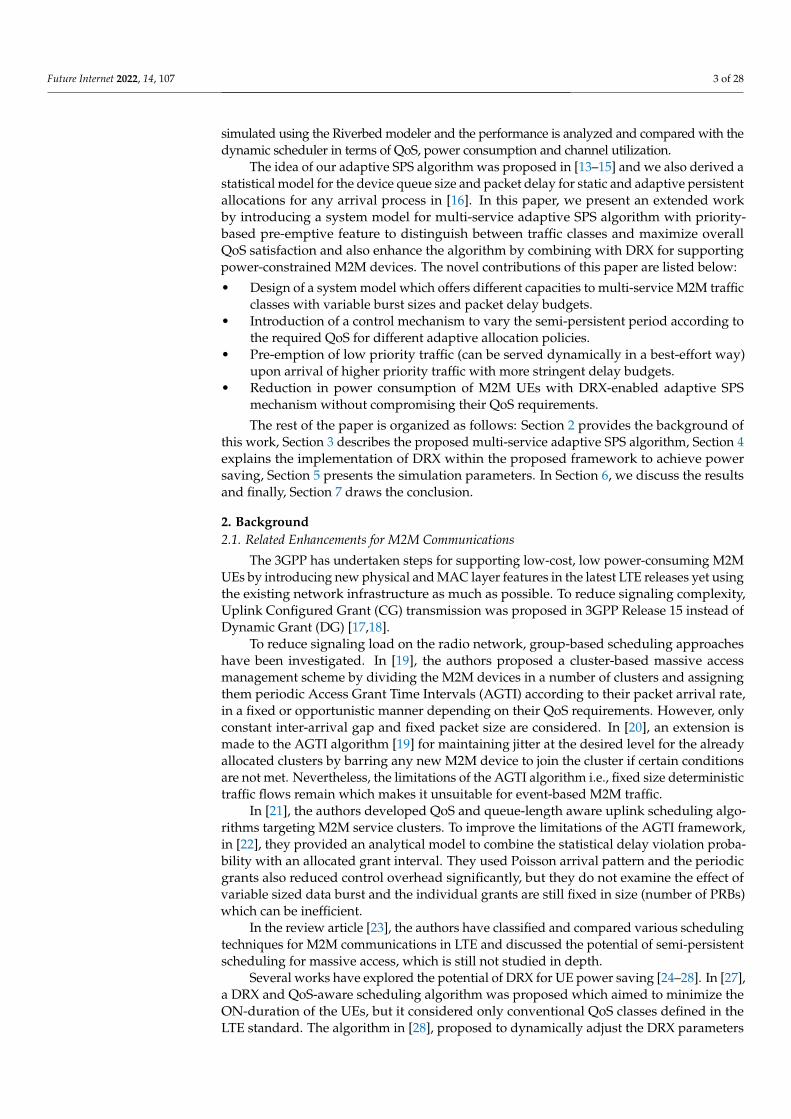
For demonstration purpose, we consider an LTE TDD system with configuration 6that has 5 uplink subframes per frame. Figure 1 demonstrates how 5 adaptive SPS trafficclasses A, B, C, D and E are implemented for this configuration where each class is assignedto one uplink subframe. For 3 MHz bandwidth and 2 PRBs reserved for uplink controlinformation, R = 13 PRBs are available for scheduling uplink data. In this example, trafficclass A supports nS = 3 subscribers in one subframe and they occupy the range of PRBs rA1 ,rA2 , rA3 respectively in the example scheduling instance. The possible maximum numberof adaptively allocated PRBs for class A in the example is, NP,max(A) = 3. The Other trafficclasses are shown similarly.
Future Internet 2022, 14, 107 6 of 28
Figure 1. Multi-service traffic classes allocated in different uplink subframes.
3.2. Control Mechanism for the Adaptive SPS Period
The SPS period assigned to each traffic class has a significant impact on the overallservice capacity of the class and also on their QoS performance. From the principle of theadaptive SPS, for any traffic class S, the assigned SPS period TSPS,S is selected to be aninteger multiple of the LTE frame duration TF so that the subframe number designated tothe traffic class is not changed and different subscribers to the traffic class can be multiplexedin different frames. The condition can be expressed as Equation (4).
TSPS,S = mSTF (4)
where
• mS is an integer number.• TF is the LTE frame duration, fixed at 10 ms [29].
On the other hand, Equation (5) introduces a control mechanism for variation of theadaptive SPS period for QoS guarantee of the traffic class S.
TSPS,S = fSTPDB,S (5)
where TPDB,S is the PDB of traffic class S and fS is a fractional value i.e., 0 < fS < 1, sothat TSPS,S does not exceed the value of their class-specific TPDB,S. Here, fS is a controlparameter that can be varied to control the statistical delay budget violation probability ofthe respective traffic class S.
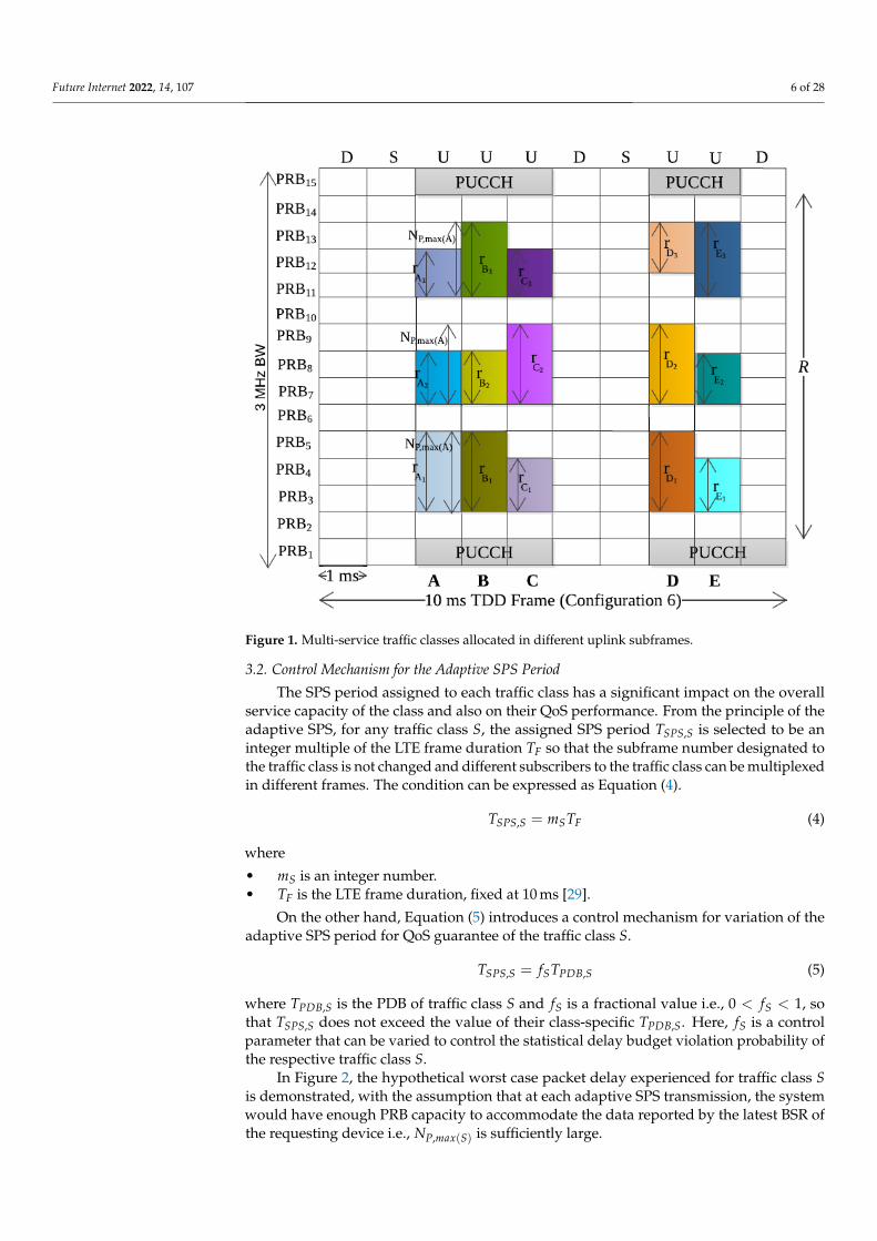
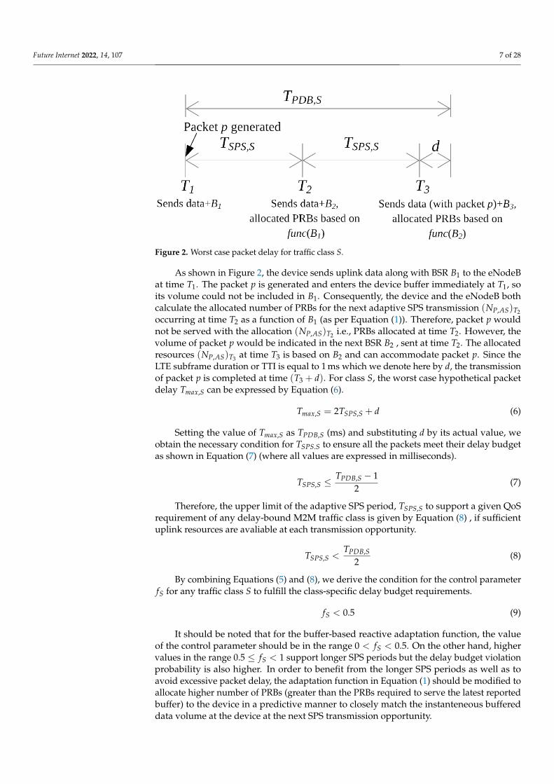
In Figure 2, the hypothetical worst case packet delay experienced for traffic class Sis demonstrated, with the assumption that at each adaptive SPS transmission, the systemwould have enough PRB capacity to accommodate the data reported by the latest BSR ofthe requesting device i.e., NP,max(S) is sufficiently large.
Future Internet 2022, 14, 107 7 of 28
Figure 2. Worst case packet delay for traffic class S.
As shown in Figure 2, the device sends uplink data along with BSR B1 to the eNodeBat time T1. The packet p is generated and enters the device buffer immediately at T1, soits volume could not be included in B1. Consequently, the device and the eNodeB bothcalculate the allocated number of PRBs for the next adaptive SPS transmission (NP,AS)T2
occurring at time T2 as a function of B1 (as per Equation (1)). Therefore, packet p wouldnot be served with the allocation (NP,AS)T2 i.e., PRBs allocated at time T2. However, thevolume of packet p would be indicated in the next BSR B2 , sent at time T2. The allocatedresources (NP,AS)T3 at time T3 is based on B2 and can accommodate packet p. Since theLTE subframe duration or TTI is equal to 1 ms which we denote here by d, the transmissionof packet p is completed at time (T3 + d). For class S, the worst case hypothetical packetdelay Tmax,S can be expressed by Equation (6).
Tmax,S = 2TSPS,S + d (6)
Setting the value of Tmax,S as TPDB,S (ms) and substituting d by its actual value, weobtain the necessary condition for TSPS.S to ensure all the packets meet their delay budgetas shown in Equation (7) (where all values are expressed in milliseconds).
TSPS,S ≤TPDB,S − 1
2(7)
Therefore, the upper limit of the adaptive SPS period, TSPS,S to support a given QoSrequirement of any delay-bound M2M traffic class is given by Equation (8) , if sufficientuplink resources are avaliable at each transmission opportunity.
TSPS,S <TPDB,S
2(8)
By combining Equations (5) and (8), we derive the condition for the control parameterfS for any traffic class S to fulfill the class-specific delay budget requirements.
fS < 0.5 (9)
It should be noted that for the buffer-based reactive adaptation function, the valueof the control parameter should be in the range 0 < fS < 0.5. On the other hand, highervalues in the range 0.5 ≤ fS < 1 support longer SPS periods but the delay budget violationprobability is also higher. In order to benefit from the longer SPS periods as well as toavoid excessive packet delay, the adaptation function in Equation (1) should be modified toallocate higher number of PRBs (greater than the PRBs required to serve the latest reportedbuffer) to the device in a predictive manner to closely match the instanteneous buffereddata volume at the device at the next SPS transmission opportunity.
Future Internet 2022, 14, 107 8 of 28
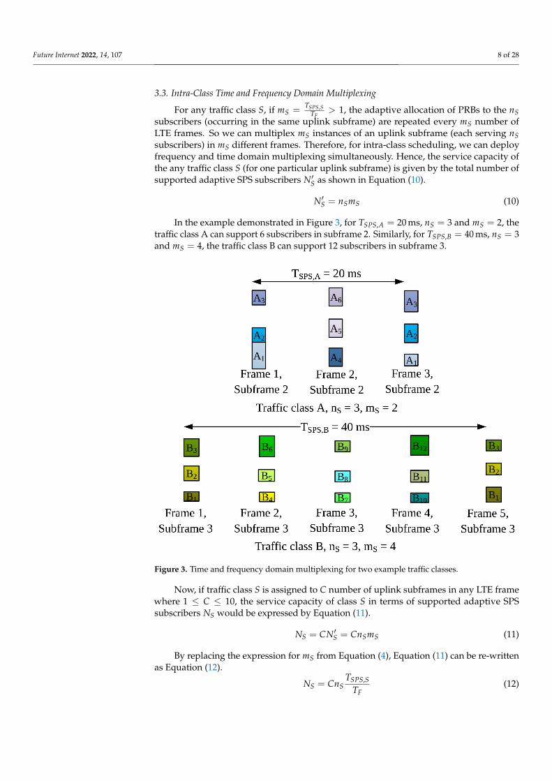
3.3. Intra-Class Time and Frequency Domain Multiplexing
For any traffic class S, if mS =TSPS,S
TF> 1, the adaptive allocation of PRBs to the nS
subscribers (occurring in the same uplink subframe) are repeated every mS number ofLTE frames. So we can multiplex mS instances of an uplink subframe (each serving nSsubscribers) in mS different frames. Therefore, for intra-class scheduling, we can deployfrequency and time domain multiplexing simultaneously. Hence, the service capacity ofthe any traffic class S (for one particular uplink subframe) is given by the total number ofsupported adaptive SPS subscribers N′S as shown in Equation (10).
N′S = nSmS (10)
In the example demonstrated in Figure 3, for TSPS,A = 20 ms, nS = 3 and mS = 2, thetraffic class A can support 6 subscribers in subframe 2. Similarly, for TSPS,B = 40 ms, nS = 3and mS = 4, the traffic class B can support 12 subscribers in subframe 3.
Figure 3. Time and frequency domain multiplexing for two example traffic classes.
Now, if traffic class S is assigned to C number of uplink subframes in any LTE framewhere 1 ≤ C ≤ 10, the service capacity of class S in terms of supported adaptive SPSsubscribers NS would be expressed by Equation (11).
NS = CN′S = CnSmS (11)
By replacing the expression for mS from Equation (4), Equation (11) can be re-writtenas Equation (12).
NS = CnSTSPS,S
TF(12)

Future Internet 2022, 14, 107 9 of 28
3.4. Scheduling of H2H Traffic
So far, we described the allocation of PRBs to adaptive SPS users which is intended forM2M subscribers. However, this does not come at an expense of jeopardizing human users.As expressed in Equation (3), the maximum number of PRBs available for the adaptiveSPS users in an uplink subframe, RS,max must not exceed the total uplink PRBs, R in asubframe. For fairness between M2M and H2H users, we reserve RH,res PRBs for H2Husers per uplink subframe. Hence it follows:
R = RS,max + RH,res (13)
The actual consumption of PRBs by the adaptive SPS users is often less than the allowedmaximum (as the buffered data and is often very small or zero in case of M2M traffic).
Suppose, in an arbitrary uplink subframe, nS users of traffic class S instantaneouslyconsume r̂S1 , r̂S2 , . . . , r̂SnS
PRBs respectively based on their buffered data. Then for theparticular subframe, the actual number of total PRBs consumed by the adaptive SPS users,R̂S is given by Equation (14) as follows:
R̂S =nS
∑i=1
r̂Si (14)
Then, it follows that the rest of the PRBs unused from the maximum PRB limits ofthe adaptive SPS ranges i.e., (RS,max − R̂S) are also available for the H2H users and can bescheduled dynamically on an on-demand basis. So the total number of PRBs available forhuman users in one subframe would be given by RH as expressed by Equation (15).
RH = RH,res + RS,max − R̂S (15)
By replacing RS,max from Equation (13), we get the expression for RH as given byEquation (16).
RH = R− R̂S (16)
For any scheduling instance, the actual requirement of PRBs by the adaptive SPS users, R̂Sis determined first by the scheduler (based on the mutual knowledge of the eNodeB and thedevices regarding the buffered data and using Equation (1)) and then the remaining RH PRBsavailable for the H2H users are scheduled dynamically according to the queued requests.
3.5. Multi-Service Adaptive SPS Algorithm
Figure 4 demonstrates the functionality of the multi-service adaptive SPS algorithm.Firstly, when an M2M UE (here we refer to both standalone M2M devices and M2Mgateways as M2M UEs) sends an initial request, the algorithm checks whether the devicerequires an SPS or a dynamic allocation, which can be indicated by the request parametersand traffic patterns. If the M2M application sends one-off data without any specific pattern,then it is indicated in the device class which means the scheduling scheme would bedynamic. However, if the device has a regular pattern of intermittent traffic burst (which isnon-deterministic such as Poisson arrival process), then the preferred scheduling scheme isadaptive SPS, subject to fulfillment of certain conditions.
If the UE requires an SPS allocation, the traffic class S is determined from the requestparameters and the optimum value of SPS period TSPS,S is determined. The proposedalgorithm aims to achieve maximum service capacity for each traffic class i.e., increasingthe number of subscribers supported by adaptive SPS scheme thus saving control channelresources of the system. The higher the SPS period for a traffic class, the greater numberof subscribers can be served by the SPS scheme for the same class (as per Equation (12)).However, the SPS period TSPS,S is proportional to the control parameter fS and the PDBTPDB,S of the class S. The PDB is constant for a class whereas the maximum value of fS isdependent on the adaptation function used in Equation (1). For the buffer-based adaptive

Future Internet 2022, 14, 107 10 of 28
SPS allocations, to meet the delay requirements, fS must be in the range 0 < fS < 0.5. Butthe value of the SPS period TSPS,S must also satisfy the condition in Equation (4). Therefore,the optimum value of TSPS,S is determined by selecting the maximum value of fS in thesupported range, while the SPS period is an integer multiple of the LTE frame duration i.e.,10 ms. For the buffer-based adaptive SPS allocations, the optimum value of TSPS,S is foundfor fS = 0.4, for all traffic classes. Since the theoretical supported range of fS for ensuring100% packets are transmitted within their PDB values, is dependent on the adaptationfunction, not on the traffic patterns or the actual PDB values of the classes. Increasing thevalue of fS beyond that range would require changes to the adaptation function.
Figure 4. Multi-service adaptive Semi-Persistent Scheduling (SPS) algorithm with pre-emptivefunctionality.
Afterwards,the scheduler checks with the uplink subframe(s) primarily designatedfor traffic class S whether there are enough resources available to admit the new user. This
Future Internet 2022, 14, 107 11 of 28
is done by comparing the number of ongoing adaptive SPS connections for class S to itsservice capacity NS. If enough resources are available then the new user is admitted forSPS allocation and the database is updated accordingly. Then the initial SPS grant is sent tothe user device via PDCCH including the necessary parameters i.e., the designated uplinksubframe number, starting frame number, the starting index, the range of PRBs allowed forthe device and the required MCS index.
The device starts transmitting in its allocated resources and the buffered data volumeis piggybacked with every uplink transmission (in form of BSR MAC control element).The BSR information sent with the tth uplink transmission is used to adapt the next i.e.,(t + 1)th allocation size by both the scheduler and the device with the calculation fromEquation (1).
Whenever an SPS request is denied by the scheduler due to capacity constraint, thedefault scheduling scheme is dynamic. In case of the dynamic scheduler, the experiencedpacket delay is dependent upon many factors such as the instantaneous system load, dataand control channel capacities etc. and in general, there is a higher probability of meetingthe delay constraints for the traffic classes with higher delay budget. On the other hand,with the adaptive SPS algorithm, by issuing a semi-persistent adaptive allocation with anappropriate value of TSPS,S in accordance with the corresponding TPDB,S, the schedulerensures a high statistical probability of meeting the delay constraints even for packets withsmall delay budget. The pre-emptive function is based on these phenomenon. Some trafficclasses with small and strict delay budget may have priority over other classes with higherand less strict delay budget values. Due to this prioritization, if there is not enough capacityleft to admit a new adaptive SPS request with higher priority, the packet scheduler searchesif there are any SPS resources designated for traffic class(es) with lower priority. If sufficientresources to support the new request are found and they are already in use by any lowerpriority UE(s), these allocations are pre-empted and higher priority traffic is admitted andtheir new SPS grant is sent accordingly. If the pre-emption attempt is unsuccessful dueto resource insufficiency, the current allocations are unchanged and the new request isscheduled dynamically. Another approach might be modification of the control parameterfS of the ongoing adaptive SPS allocations of lower priority traffic class(es), by assigninghigher values of fS such as 0.5 ≤ fS < 1, so that they are allocated a range of longer SPSperiods with a tolerable range of QoS degradation level.
4. Implementation of DRX Power Savings with Adaptive SPS4.1. Standard DRX Mechanism
The 3GPP has standardized the DRX power-saving mechanism [12] to allow the UEsto enter a sleep mode when there is no data to be received. The UEs are configured withtwo parameters, i.e., the sleep period and the inactivity timer which determines how oftenand for how long the UE can remain in sleep by turning off its transceiver. A DRX cycleconsists of a sleep period and an ON-period. In the sleep period, the UE is in power-savingstate and does not monitor the PDCCH and any downlink packets arriving at the eNodeBdestined for this UE needs to wait. At the end of the sleep period, the UE enters ON-periodand monitors the PDCCH for possible scheduled transmissions. Two types of DRX cycles,short and long DRX are supported. The short DRX cycle has a short sleep period and it willbe repeated until the expiry of a short DRX cycle timer, expressed in number of short DRXcycles, with no traffic. Upon expiry of the short DRX cycle timer, the long DRX cycle isstarted and is continued until traffic is indicated in the ON-period of the UE. If there is anyPDCCH grant for this UE during the ON-period, the UE becomes active to process dataand starts an inactivity timer. Whenever there is a new transmission or reception duringthe active state of the UE, the inactivity timer is reset and only upon expiry of it withoutany activity, the UE can start DRX cycle.
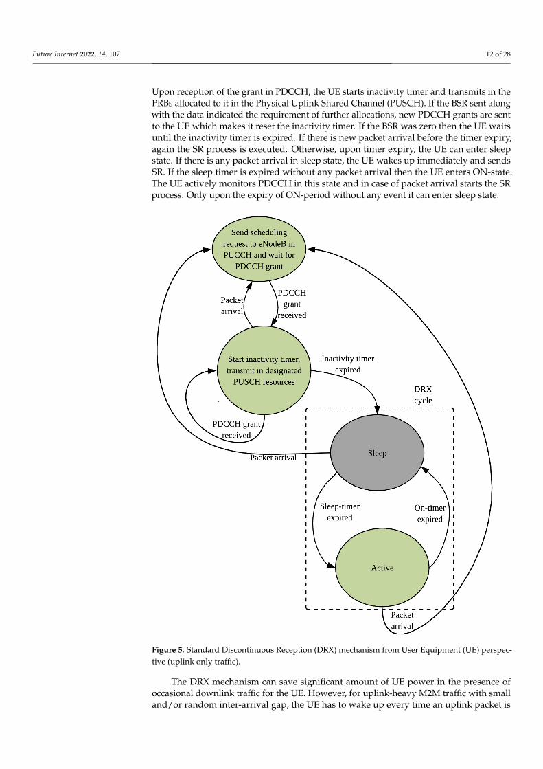
Figure 5 shows the DRX mechanism for uplink traffic in LTE. For initial packet arrivalat the UE in its active state, a request in sent to the eNodeB using the Physical UplinkControl Channel (PUCCH) and the UE actively listens to the PDCCH for scheduling grant.
Future Internet 2022, 14, 107 12 of 28
Upon reception of the grant in PDCCH, the UE starts inactivity timer and transmits in thePRBs allocated to it in the Physical Uplink Shared Channel (PUSCH). If the BSR sent alongwith the data indicated the requirement of further allocations, new PDCCH grants are sentto the UE which makes it reset the inactivity timer. If the BSR was zero then the UE waitsuntil the inactivity timer is expired. If there is new packet arrival before the timer expiry,again the SR process is executed. Otherwise, upon timer expiry, the UE can enter sleepstate. If there is any packet arrival in sleep state, the UE wakes up immediately and sendsSR. If the sleep timer is expired without any packet arrival then the UE enters ON-state.The UE actively monitors PDCCH in this state and in case of packet arrival starts the SRprocess. Only upon the expiry of ON-period without any event it can enter sleep state.
Figure 5. Standard Discontinuous Reception (DRX) mechanism from User Equipment (UE) perspec-tive (uplink only traffic).
The DRX mechanism can save significant amount of UE power in the presence ofoccasional downlink traffic for the UE. However, for uplink-heavy M2M traffic with smalland/or random inter-arrival gap, the UE has to wake up every time an uplink packet is
Future Internet 2022, 14, 107 13 of 28
generated. Moreover, for such arrival pattern, in most cases, there is data remaining in theUE buffer after each uplink transmission; thus keeping the UE awake and monitoring. Allthese factors prevent the UE to benefit from the DRX mechanism because the probability ofthe UE entering the sleep state and completing the sleep period becomes very low.
4.2. UE State Transitions with Adaptive SPS
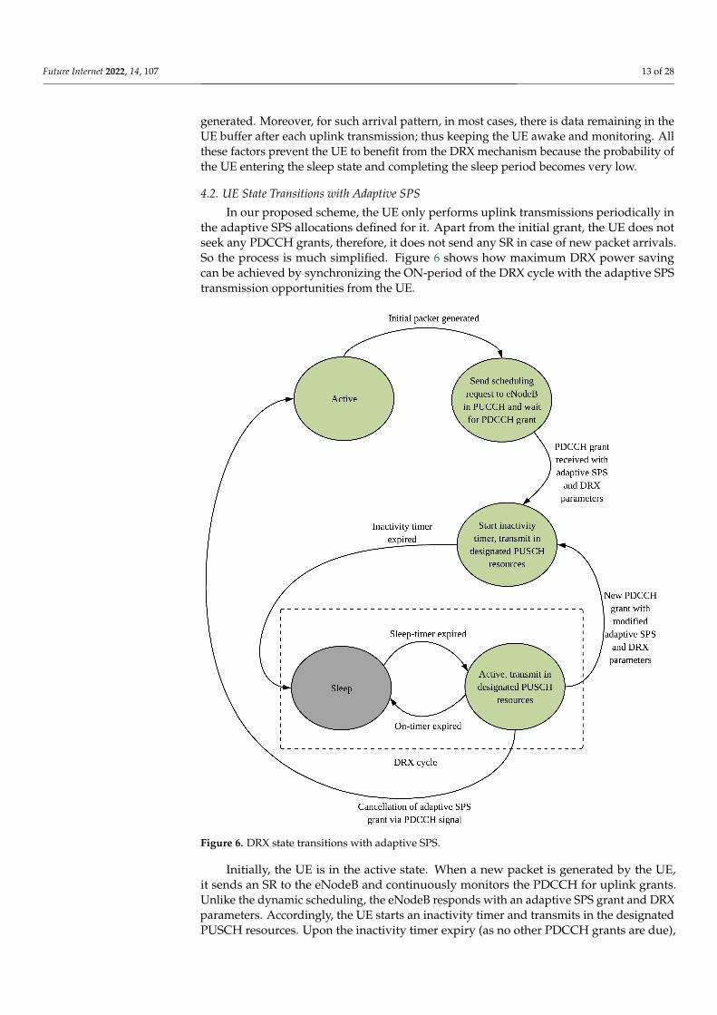
In our proposed scheme, the UE only performs uplink transmissions periodically inthe adaptive SPS allocations defined for it. Apart from the initial grant, the UE does notseek any PDCCH grants, therefore, it does not send any SR in case of new packet arrivals.So the process is much simplified. Figure 6 shows how maximum DRX power savingcan be achieved by synchronizing the ON-period of the DRX cycle with the adaptive SPStransmission opportunities from the UE.
Figure 6. DRX state transitions with adaptive SPS.
Initially, the UE is in the active state. When a new packet is generated by the UE,it sends an SR to the eNodeB and continuously monitors the PDCCH for uplink grants.Unlike the dynamic scheduling, the eNodeB responds with an adaptive SPS grant and DRXparameters. Accordingly, the UE starts an inactivity timer and transmits in the designatedPUSCH resources. Upon the inactivity timer expiry (as no other PDCCH grants are due),
Future Internet 2022, 14, 107 14 of 28
the UE enters sleep state. During the sleep period, the UE does not wake up in caseof new packet arrivals. When the sleep-timer is expired, the UE enters active state andmakes the adaptive SPS transmission in its allocated PRBs and reports the amount ofdata left in the buffer (if any) to the eNodeB in the BSR. Upon the ON-timer expiry, thesleep period is started again. If the eNodeB requires to modify or cancel the adaptive SPSallocations, it sends a PDCCH signal during the ON-period of the UE and the UE actsaccordingly. In this scheme, the randomness of packet arrivals and unpredictable PDCCHgrants do not affect the entering/remaining in the sleep state of the UE. Thus the UE cansave power by lengthening its sleep period, subject to matching with the delay tolerancesof the buffered packets.
4.3. Sleep Period and Power Saving
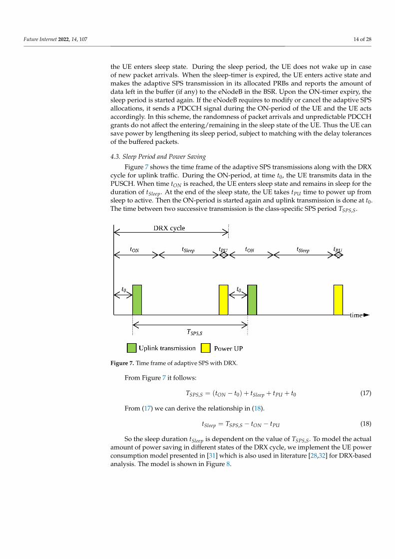
Figure 7 shows the time frame of the adaptive SPS transmissions along with the DRXcycle for uplink traffic. During the ON-period, at time t0, the UE transmits data in thePUSCH. When time tON is reached, the UE enters sleep state and remains in sleep for theduration of tSleep. At the end of the sleep state, the UE takes tPU time to power up fromsleep to active. Then the ON-period is started again and uplink transmission is done at t0.The time between two successive transmission is the class-specific SPS period TSPS,S.
Figure 7. Time frame of adaptive SPS with DRX.
From Figure 7 it follows:
TSPS,S = (tON − t0) + tSleep + tPU + t0 (17)
From (17) we can derive the relationship in (18).
tSleep = TSPS,S − tON − tPU (18)
So the sleep duration tSleep is dependent on the value of TSPS,S. To model the actualamount of power saving in different states of the DRX cycle, we implement the UE powerconsumption model presented in [31] which is also used in literature [28,32] for DRX-basedanalysis. The model is shown in Figure 8.

Future Internet 2022, 14, 107 15 of 28
Figure 8. UE power consumption model.
4.4. Power Saving through Predictive Allocation
For the reactive buffer-based allocations, the values of 0 < fS < 0.5 ensures satisfactorydelay budget performance but shortens the supported SPS preiods which leads to shortersleep cycles for the M2M devices. The values of 0.5 ≤ fS < 1 support longer SPS periodshence longer sleep cycles, but increases the waiting time for the packets in the buffer andthe statistical probability of exceeding the delay budget values are much higher if the samebuffer-based adaptation functions are used. To leverage the benefit of longer sleep cyclesand compensate for the longer SPS periods, the scheduler must use predictive adaptationfunctions where the traffic arrival rates and BSR data would be utilized to predict theinstantaneous amount of data in the device buffer.
We raise the maximum possible allocated number of PRBs, NP,max for the traffic classesfor low-power devices such that more packets would be served from the device buffersat each uplink transmission opportunity thus decreasing packet delay. The predictiveadaptation function is used for the range 0.5 ≤ fS < 1 to modify the BSR mapping functionNP, f unc(B) in Equation (1). The new mapping function is given by Equation (19) as follows:
NP, f unc(B) =
{NP,Blatest , f or 0 < fS < 0.5NP,(E(B)+σ(B)), f or 0.5 ≤ fS < 1
(19)
where NP,Blatest is the exact number of PRBs required to accommodate the latest reportedbuffer size, as implemented for 0 < fS < 0.5. But for 0.5 ≤ fS < 1, the predictive allocationsize is used to accommodate the expected number of packets in the device buffer at eachSPS interval i.e., E(B) plus the standard deviation σ(B) of the historical BSR data over thespecified measurement window.
For any traffic class S with packet arrival rate of λS, the value of E(B) is calculatedfrom Equation (20) as follows:
E(B) = λSTSPS,S (20)
5. Simulation Parameters
We implemented the proposed adaptive SPS algorithm for multi-service traffic classeswith DRX power saving scheme using the Riverbed Modeler software (previously knownas OPNET). We deployed an M2M scenario where the LTE eNodeB serves M2M UEsincluding both sensor nodes generating packet bursts intermittently and M2M GWs which

Future Internet 2022, 14, 107 16 of 28
aggregate the traffic generated by their respective M2M area networks to be sent to theserver. The generated M2M traffic are assigned to different traffic classes based on theirpacket delay budget values. The scope of the packet delay budget is from the M2M UEto the eNodeB (the core network delay is not considered here). The important simulationparameters are described in Table 1.
Table 1. Simulation Parameters.
Parameter Value
LTE Configuration 3 MHz TDD
Uplink:Downlink ratio 5:5
Maximum UE transmission power 0.5 W
Maximum eNodeB transmission power 5 W
UE reception sensitivity −95 dBm
eNodeB reception sensitivity −123 dBm
UE antenna gain −1 dBi
eNodeB antenna gain 15 dBi
SR periodicity 10 ms
Uplink control channels 2
Channel model Suburban Erceg, Terrain C [33]
Radio network model Single cell, 3 km radius
Adaptive SPS parameters nS = 3, NP,max = 3
M2M traffic modelPoisson arrival process with mean λS
requests/millisecond for traffic class S whereλS is varied for different simulation runs
M2M request size Mean packet size 10 Bytes (exponentiallydistributed)
DRX parameters ON-timer = 5 ms, Inactivity timer = 50 ms
The simulated multi-service traffic classes and their respective PDB values are listedin Table 2.
Table 2. Traffic Model for Multi-service Traffic Classes.
Traffic Class PDB (ms)
A 50B 100C 150D 200E 250
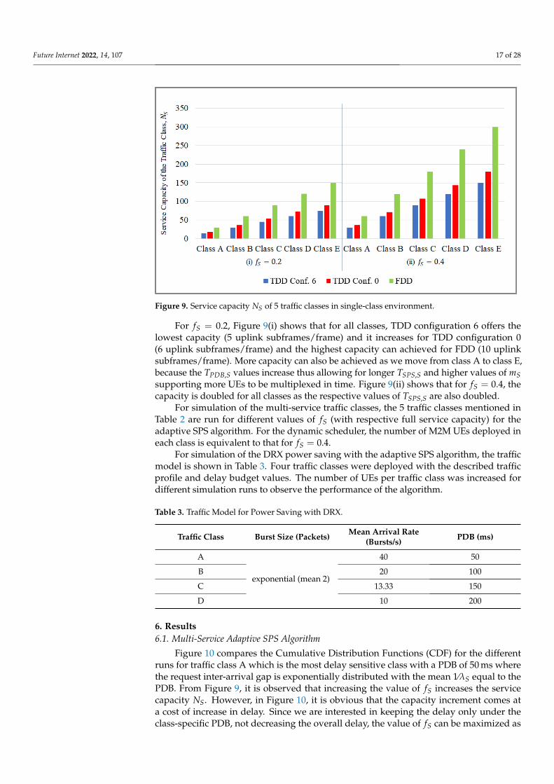
The selected value of fS controls the value of TSPS,S and also affects the service capacityNS, which is the maximum supported number of adaptive SPS users of each traffic class.which is demonstrated in Figure 9 for single-class simulation environment.
Future Internet 2022, 14, 107 17 of 28
Figure 9. Service capacity NS of 5 traffic classes in single-class environment.
For fS = 0.2, Figure 9(i) shows that for all classes, TDD configuration 6 offers thelowest capacity (5 uplink subframes/frame) and it increases for TDD configuration 0(6 uplink subframes/frame) and the highest capacity can achieved for FDD (10 uplinksubframes/frame). More capacity can also be achieved as we move from class A to class E,because the TPDB,S values increase thus allowing for longer TSPS,S and higher values of mSsupporting more UEs to be multiplexed in time. Figure 9(ii) shows that for fS = 0.4, thecapacity is doubled for all classes as the respective values of TSPS,S are also doubled.
For simulation of the multi-service traffic classes, the 5 traffic classes mentioned inTable 2 are run for different values of fS (with respective full service capacity) for theadaptive SPS algorithm. For the dynamic scheduler, the number of M2M UEs deployed ineach class is equivalent to that for fS = 0.4.
For simulation of the DRX power saving with the adaptive SPS algorithm, the trafficmodel is shown in Table 3. Four traffic classes were deployed with the described trafficprofile and delay budget values. The number of UEs per traffic class was increased fordifferent simulation runs to observe the performance of the algorithm.
Table 3. Traffic Model for Power Saving with DRX.
Traffic Class Burst Size (Packets) Mean Arrival Rate(Bursts/s) PDB (ms)
A
exponential (mean 2)
40 50
B 20 100
C 13.33 150
D 10 200
6. Results6.1. Multi-Service Adaptive SPS Algorithm
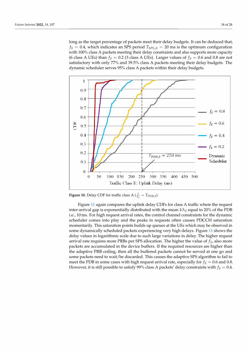
Figure 10 compares the Cumulative Distribution Functions (CDF) for the differentruns for traffic class A which is the most delay sensitive class with a PDB of 50 ms wherethe request inter-arrival gap is exponentially distributed with the mean 1⁄λS equal to thePDB. From Figure 9, it is observed that increasing the value of fS increases the servicecapacity NS. However, in Figure 10, it is obvious that the capacity increment comes ata cost of increase in delay. Since we are interested in keeping the delay only under theclass-specific PDB, not decreasing the overall delay, the value of fS can be maximized as
Future Internet 2022, 14, 107 18 of 28
long as the target percentage of packets meet their delay budgets. It can be deduced that,fS = 0.4, which indicates an SPS period TSPS,A = 20 ms is the optimum configurationwith 100% class A packets meeting their delay constraints and also supports more capacity(6 class A UEs) than fS = 0.2 (3 class A UEs). Larger values of fS = 0.6 and 0.8 are notsatisfactory with only 77% and 39.5% class A packets meeting their delay budgets. Thedynamic scheduler serves 95% class A packets within their delay budgets.
Figure 10. Delay CDF for traffic class A ( 1λS
= TPDB,S).
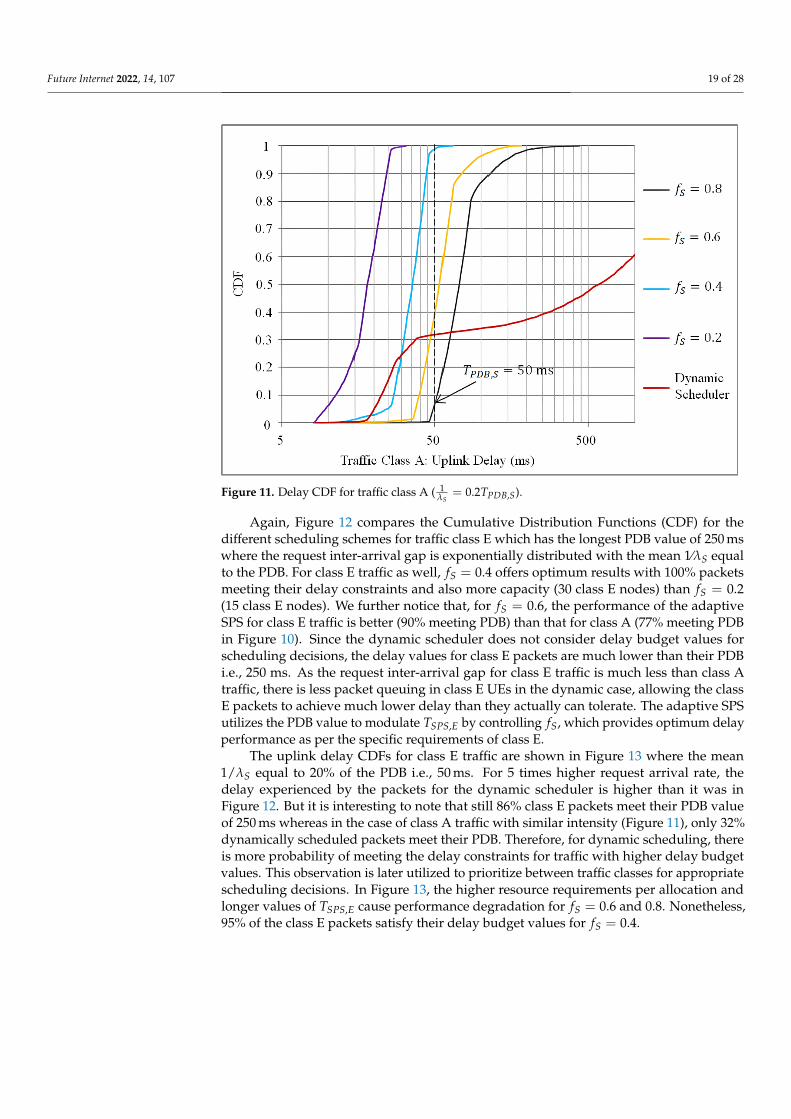
Figure 11 again compares the uplink delay CDFs for class A traffic where the requestinter-arrival gap is exponentially distributed with the mean 1⁄λS equal to 20% of the PDBi.e., 10 ms. For high request arrival rates, the control channel constraints for the dynamicscheduler comes into play and the peaks in requests often causes PDCCH saturationmomentarily. This saturation points builds up queues at the UEs which may be observed insome dynamically scheduled packets experiencing very high delays. Figure 11 shows thedelay values in logarithmic scale due to such large variations in delay. The higher requestarrival rate requires more PRBs per SPS allocation. The higher the value of fS, also morepackets are accumulated in the device buffers. If the required resources are higher thanthe adaptive PRB ceiling, then all the buffered packets cannot be served at one go andsome packets need to wait/be discarded. This causes the adaptive SPS algorithm to fail tomeet the PDB in some cases with high request arrival rate, especially for fS = 0.6 and 0.8.However, it is still possible to satisfy 99% class A packets’ delay constraints with fS = 0.4.
Future Internet 2022, 14, 107 19 of 28
Figure 11. Delay CDF for traffic class A ( 1λS
= 0.2TPDB,S).
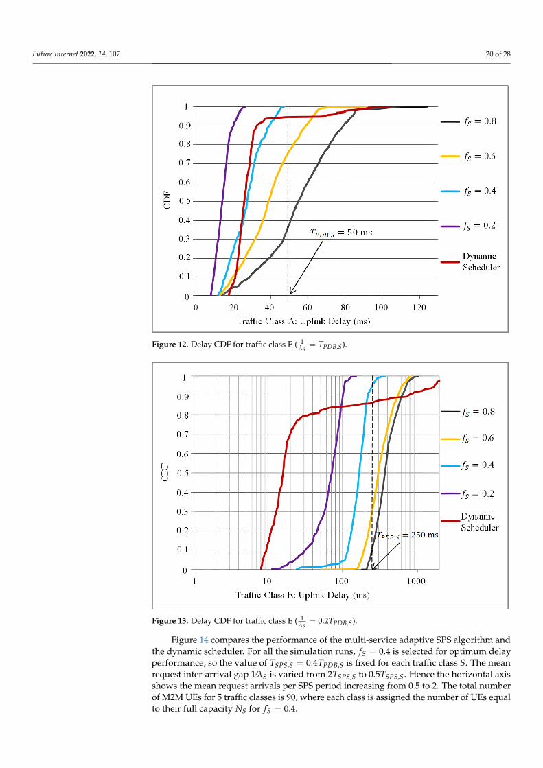
Again, Figure 12 compares the Cumulative Distribution Functions (CDF) for thedifferent scheduling schemes for traffic class E which has the longest PDB value of 250 mswhere the request inter-arrival gap is exponentially distributed with the mean 1⁄λS equalto the PDB. For class E traffic as well, fS = 0.4 offers optimum results with 100% packetsmeeting their delay constraints and also more capacity (30 class E nodes) than fS = 0.2(15 class E nodes). We further notice that, for fS = 0.6, the performance of the adaptiveSPS for class E traffic is better (90% meeting PDB) than that for class A (77% meeting PDBin Figure 10). Since the dynamic scheduler does not consider delay budget values forscheduling decisions, the delay values for class E packets are much lower than their PDBi.e., 250 ms. As the request inter-arrival gap for class E traffic is much less than class Atraffic, there is less packet queuing in class E UEs in the dynamic case, allowing the classE packets to achieve much lower delay than they actually can tolerate. The adaptive SPSutilizes the PDB value to modulate TSPS,E by controlling fS, which provides optimum delayperformance as per the specific requirements of class E.
The uplink delay CDFs for class E traffic are shown in Figure 13 where the mean1/λS equal to 20% of the PDB i.e., 50 ms. For 5 times higher request arrival rate, thedelay experienced by the packets for the dynamic scheduler is higher than it was inFigure 12. But it is interesting to note that still 86% class E packets meet their PDB valueof 250 ms whereas in the case of class A traffic with similar intensity (Figure 11), only 32%dynamically scheduled packets meet their PDB. Therefore, for dynamic scheduling, thereis more probability of meeting the delay constraints for traffic with higher delay budgetvalues. This observation is later utilized to prioritize between traffic classes for appropriatescheduling decisions. In Figure 13, the higher resource requirements per allocation andlonger values of TSPS,E cause performance degradation for fS = 0.6 and 0.8. Nonetheless,95% of the class E packets satisfy their delay budget values for fS = 0.4.
Future Internet 2022, 14, 107 20 of 28
Figure 12. Delay CDF for traffic class E ( 1λS
= TPDB,S).
Figure 13. Delay CDF for traffic class E ( 1λS
= 0.2TPDB,S).
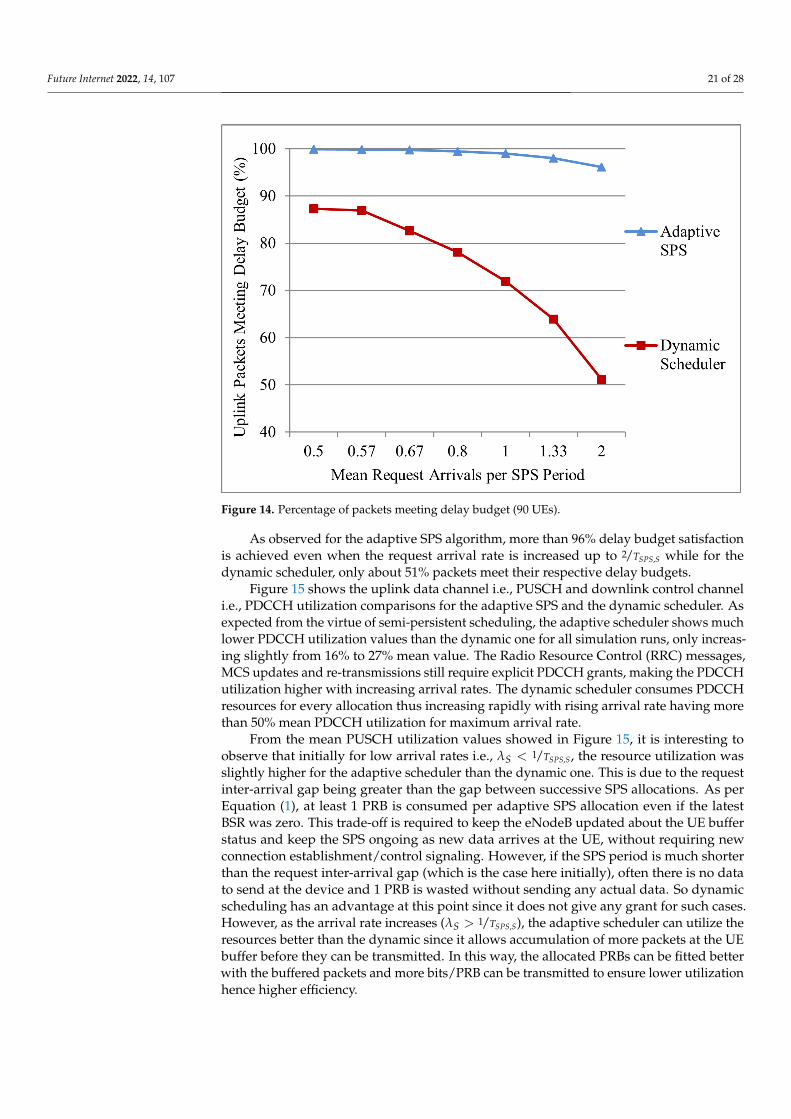
Figure 14 compares the performance of the multi-service adaptive SPS algorithm andthe dynamic scheduler. For all the simulation runs, fS = 0.4 is selected for optimum delayperformance, so the value of TSPS,S = 0.4TPDB,S is fixed for each traffic class S. The meanrequest inter-arrival gap 1⁄λS is varied from 2TSPS,S to 0.5TSPS,S. Hence the horizontal axisshows the mean request arrivals per SPS period increasing from 0.5 to 2. The total numberof M2M UEs for 5 traffic classes is 90, where each class is assigned the number of UEs equalto their full capacity NS for fS = 0.4.
Future Internet 2022, 14, 107 21 of 28
Figure 14. Percentage of packets meeting delay budget (90 UEs).
As observed for the adaptive SPS algorithm, more than 96% delay budget satisfactionis achieved even when the request arrival rate is increased up to 2/TSPS,S while for thedynamic scheduler, only about 51% packets meet their respective delay budgets.
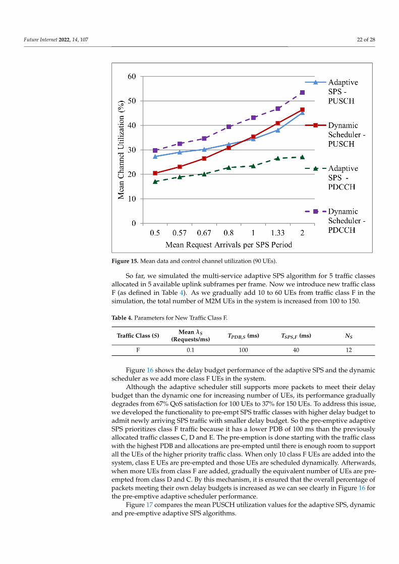
Figure 15 shows the uplink data channel i.e., PUSCH and downlink control channeli.e., PDCCH utilization comparisons for the adaptive SPS and the dynamic scheduler. Asexpected from the virtue of semi-persistent scheduling, the adaptive scheduler shows muchlower PDCCH utilization values than the dynamic one for all simulation runs, only increas-ing slightly from 16% to 27% mean value. The Radio Resource Control (RRC) messages,MCS updates and re-transmissions still require explicit PDCCH grants, making the PDCCHutilization higher with increasing arrival rates. The dynamic scheduler consumes PDCCHresources for every allocation thus increasing rapidly with rising arrival rate having morethan 50% mean PDCCH utilization for maximum arrival rate.
From the mean PUSCH utilization values showed in Figure 15, it is interesting toobserve that initially for low arrival rates i.e., λS < 1/TSPS,S, the resource utilization wasslightly higher for the adaptive scheduler than the dynamic one. This is due to the requestinter-arrival gap being greater than the gap between successive SPS allocations. As perEquation (1), at least 1 PRB is consumed per adaptive SPS allocation even if the latestBSR was zero. This trade-off is required to keep the eNodeB updated about the UE bufferstatus and keep the SPS ongoing as new data arrives at the UE, without requiring newconnection establishment/control signaling. However, if the SPS period is much shorterthan the request inter-arrival gap (which is the case here initially), often there is no datato send at the device and 1 PRB is wasted without sending any actual data. So dynamicscheduling has an advantage at this point since it does not give any grant for such cases.However, as the arrival rate increases (λS > 1/TSPS,S), the adaptive scheduler can utilize theresources better than the dynamic since it allows accumulation of more packets at the UEbuffer before they can be transmitted. In this way, the allocated PRBs can be fitted betterwith the buffered packets and more bits/PRB can be transmitted to ensure lower utilizationhence higher efficiency.
Future Internet 2022, 14, 107 22 of 28
Figure 15. Mean data and control channel utilization (90 UEs).
So far, we simulated the multi-service adaptive SPS algorithm for 5 traffic classesallocated in 5 available uplink subframes per frame. Now we introduce new traffic classF (as defined in Table 4). As we gradually add 10 to 60 UEs from traffic class F in thesimulation, the total number of M2M UEs in the system is increased from 100 to 150.
Table 4. Parameters for New Traffic Class F.
Traffic Class (S) Mean λS(Requests/ms) TPDB,S (ms) TSPS,F (ms) NS
F 0.1 100 40 12
Figure 16 shows the delay budget performance of the adaptive SPS and the dynamicscheduler as we add more class F UEs in the system.
Although the adaptive scheduler still supports more packets to meet their delaybudget than the dynamic one for increasing number of UEs, its performance graduallydegrades from 67% QoS satisfaction for 100 UEs to 37% for 150 UEs. To address this issue,we developed the functionality to pre-empt SPS traffic classes with higher delay budget toadmit newly arriving SPS traffic with smaller delay budget. So the pre-emptive adaptiveSPS prioritizes class F traffic because it has a lower PDB of 100 ms than the previouslyallocated traffic classes C, D and E. The pre-emption is done starting with the traffic classwith the highest PDB and allocations are pre-empted until there is enough room to supportall the UEs of the higher priority traffic class. When only 10 class F UEs are added into thesystem, class E UEs are pre-empted and those UEs are scheduled dynamically. Afterwards,when more UEs from class F are added, gradually the equivalent number of UEs are pre-empted from class D and C. By this mechanism, it is ensured that the overall percentage ofpackets meeting their own delay budgets is increased as we can see clearly in Figure 16 forthe pre-emptive adaptive scheduler performance.
Figure 17 compares the mean PUSCH utilization values for the adaptive SPS, dynamicand pre-emptive adaptive SPS algorithms.

Future Internet 2022, 14, 107 23 of 28
Figure 16. Percentage of packets meeting delay budget (150 UEs).
Figure 17. Mean data channel utilization with increasing number of UEs.
Future Internet 2022, 14, 107 24 of 28
Both of the adaptive schedulers shows similar PUSCH utilization for increasing num-ber of UEs and reaches channel capacity saturation for 150 M2M UEs. On the other hand,the PUSCH utilization of the dynamic scheduler reaches a plateau for 140 UEs and doesnot increase further. So the adaptive schedulers clearly exhibit more capacity in the datachannel with the pre-emptive adaptive SPS offering even better delay performance byprioritizing among SPS traffic classes.
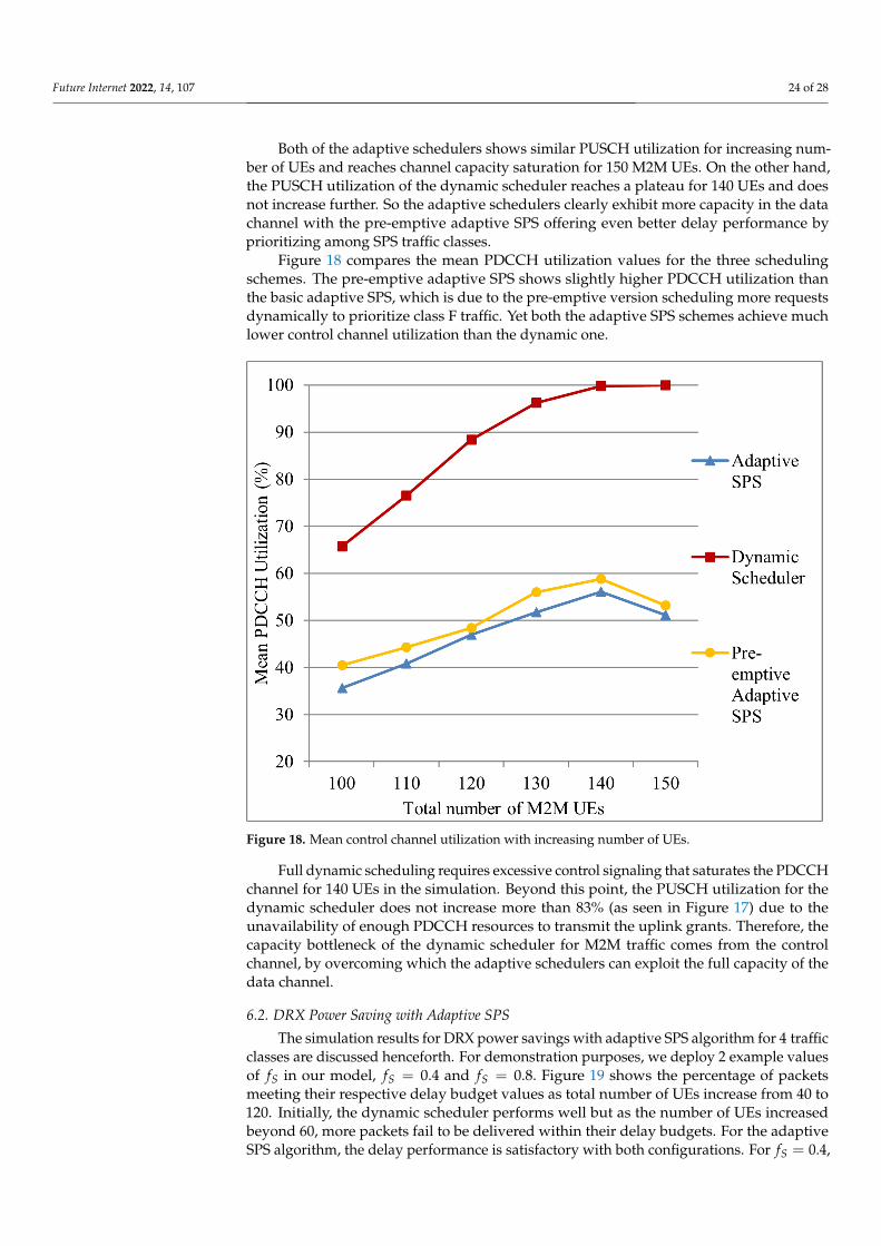
Figure 18 compares the mean PDCCH utilization values for the three schedulingschemes. The pre-emptive adaptive SPS shows slightly higher PDCCH utilization thanthe basic adaptive SPS, which is due to the pre-emptive version scheduling more requestsdynamically to prioritize class F traffic. Yet both the adaptive SPS schemes achieve muchlower control channel utilization than the dynamic one.
Figure 18. Mean control channel utilization with increasing number of UEs.
Full dynamic scheduling requires excessive control signaling that saturates the PDCCHchannel for 140 UEs in the simulation. Beyond this point, the PUSCH utilization for thedynamic scheduler does not increase more than 83% (as seen in Figure 17) due to theunavailability of enough PDCCH resources to transmit the uplink grants. Therefore, thecapacity bottleneck of the dynamic scheduler for M2M traffic comes from the controlchannel, by overcoming which the adaptive schedulers can exploit the full capacity of thedata channel.
6.2. DRX Power Saving with Adaptive SPS
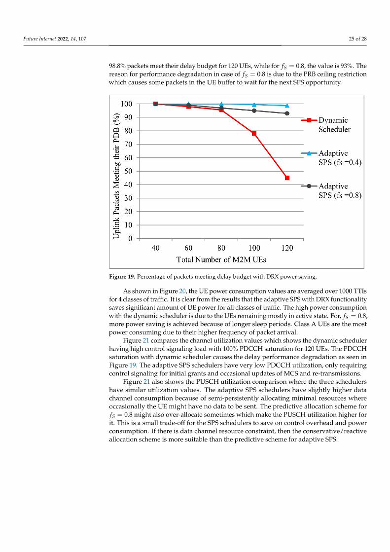
The simulation results for DRX power savings with adaptive SPS algorithm for 4 trafficclasses are discussed henceforth. For demonstration purposes, we deploy 2 example valuesof fS in our model, fS = 0.4 and fS = 0.8. Figure 19 shows the percentage of packetsmeeting their respective delay budget values as total number of UEs increase from 40 to120. Initially, the dynamic scheduler performs well but as the number of UEs increasedbeyond 60, more packets fail to be delivered within their delay budgets. For the adaptiveSPS algorithm, the delay performance is satisfactory with both configurations. For fS = 0.4,
Future Internet 2022, 14, 107 25 of 28
98.8% packets meet their delay budget for 120 UEs, while for fS = 0.8, the value is 93%. Thereason for performance degradation in case of fS = 0.8 is due to the PRB ceiling restrictionwhich causes some packets in the UE buffer to wait for the next SPS opportunity.
Figure 19. Percentage of packets meeting delay budget with DRX power saving.
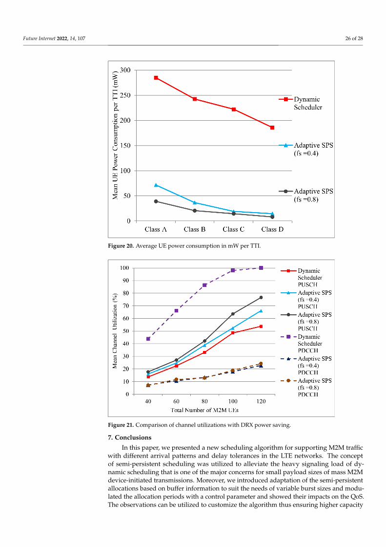
As shown in Figure 20, the UE power consumption values are averaged over 1000 TTIsfor 4 classes of traffic. It is clear from the results that the adaptive SPS with DRX functionalitysaves significant amount of UE power for all classes of traffic. The high power consumptionwith the dynamic scheduler is due to the UEs remaining mostly in active state. For, fS = 0.8,more power saving is achieved because of longer sleep periods. Class A UEs are the mostpower consuming due to their higher frequency of packet arrival.
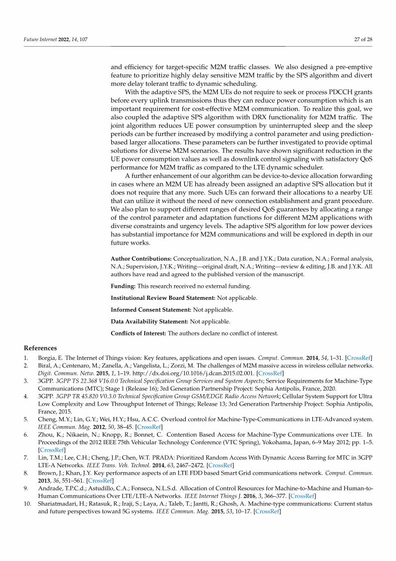
Figure 21 compares the channel utilization values which shows the dynamic schedulerhaving high control signaling load with 100% PDCCH saturation for 120 UEs. The PDCCHsaturation with dynamic scheduler causes the delay performance degradation as seen inFigure 19. The adaptive SPS schedulers have very low PDCCH utilization, only requiringcontrol signaling for initial grants and occasional updates of MCS and re-transmissions.
Figure 21 also shows the PUSCH utilization comparison where the three schedulershave similar utilization values. The adaptive SPS schedulers have slightly higher datachannel consumption because of semi-persistently allocating minimal resources whereoccasionally the UE might have no data to be sent. The predictive allocation scheme forfS = 0.8 might also over-allocate sometimes which make the PUSCH utilization higher forit. This is a small trade-off for the SPS schedulers to save on control overhead and powerconsumption. If there is data channel resource constraint, then the conservative/reactiveallocation scheme is more suitable than the predictive scheme for adaptive SPS.
Future Internet 2022, 14, 107 26 of 28
Figure 20. Average UE power consumption in mW per TTI.
Figure 21. Comparison of channel utilizations with DRX power saving.
7. Conclusions
In this paper, we presented a new scheduling algorithm for supporting M2M trafficwith different arrival patterns and delay tolerances in the LTE networks. The conceptof semi-persistent scheduling was utilized to alleviate the heavy signaling load of dy-namic scheduling that is one of the major concerns for small payload sizes of mass M2Mdevice-initiated transmissions. Moreover, we introduced adaptation of the semi-persistentallocations based on buffer information to suit the needs of variable burst sizes and modu-lated the allocation periods with a control parameter and showed their impacts on the QoS.The observations can be utilized to customize the algorithm thus ensuring higher capacity
Future Internet 2022, 14, 107 27 of 28
and efficiency for target-specific M2M traffic classes. We also designed a pre-emptivefeature to prioritize highly delay sensitive M2M traffic by the SPS algorithm and divertmore delay tolerant traffic to dynamic scheduling.
With the adaptive SPS, the M2M UEs do not require to seek or process PDCCH grantsbefore every uplink transmissions thus they can reduce power consumption which is animportant requirement for cost-effective M2M communication. To realize this goal, wealso coupled the adaptive SPS algorithm with DRX functionality for M2M traffic. Thejoint algorithm reduces UE power consumption by uninterrupted sleep and the sleepperiods can be further increased by modifying a control parameter and using prediction-based larger allocations. These parameters can be further investigated to provide optimalsolutions for diverse M2M scenarios. The results have shown significant reduction in theUE power consumption values as well as downlink control signaling with satisfactory QoSperformance for M2M traffic as compared to the LTE dynamic scheduler.
A further enhancement of our algorithm can be device-to-device allocation forwardingin cases where an M2M UE has already been assigned an adaptive SPS allocation but itdoes not require that any more. Such UEs can forward their allocations to a nearby UEthat can utilize it without the need of new connection establishment and grant procedure.We also plan to support different ranges of desired QoS guarantees by allocating a rangeof the control parameter and adaptation functions for different M2M applications withdiverse constraints and urgency levels. The adaptive SPS algorithm for low power deviceshas substantial importance for M2M communications and will be explored in depth in ourfuture works.
Author Contributions: Conceptualization, N.A., J.B. and J.Y.K.; Data curation, N.A.; Formal analysis,N.A.; Supervision, J.Y.K.; Writing—original draft, N.A.; Writing—review & editing, J.B. and J.Y.K. Allauthors have read and agreed to the published version of the manuscript.
Funding: This research received no external funding.
Institutional Review Board Statement: Not applicable.
Informed Consent Statement: Not applicable.
Data Availability Statement: Not applicable.
Conflicts of Interest: The authors declare no conflict of interest.
References1. Borgia, E. The Internet of Things vision: Key features, applications and open issues. Comput. Commun. 2014, 54, 1–31. [CrossRef]2. Biral, A.; Centenaro, M.; Zanella, A.; Vangelista, L.; Zorzi, M. The challenges of M2M massive access in wireless cellular networks.
Digit. Commun. Netw. 2015, 1, 1–19. http://dx.doi.org/10.1016/j.dcan.2015.02.001. [CrossRef]3. 3GPP. 3GPP TS 22.368 V16.0.0 Technical Specification Group Services and System Aspects; Service Requirements for Machine-Type
Communications (MTC); Stage 1 (Release 16); 3rd Generation Partnership Project: Sophia Antipolis, France, 2020.4. 3GPP. 3GPP TR 45.820 V0.3.0 Technical Specification Group GSM/EDGE Radio Access Network; Cellular System Support for Ultra
Low Complexity and Low Throughput Internet of Things; Release 13; 3rd Generation Partnership Project: Sophia Antipolis,France, 2015.
5. Cheng, M.Y.; Lin, G.Y.; Wei, H.Y.; Hsu, A.C.C. Overload control for Machine-Type-Communications in LTE-Advanced system.IEEE Commun. Mag. 2012, 50, 38–45. [CrossRef]
6. Zhou, K.; Nikaein, N.; Knopp, R.; Bonnet, C. Contention Based Access for Machine-Type Communications over LTE. InProceedings of the 2012 IEEE 75th Vehicular Technology Conference (VTC Spring), Yokohama, Japan, 6–9 May 2012; pp. 1–5.[CrossRef]
7. Lin, T.M.; Lee, C.H.; Cheng, J.P.; Chen, W.T. PRADA: Prioritized Random Access With Dynamic Access Barring for MTC in 3GPPLTE-A Networks. IEEE Trans. Veh. Technol. 2014, 63, 2467–2472. [CrossRef]
8. Brown, J.; Khan, J.Y. Key performance aspects of an LTE FDD based Smart Grid communications network. Comput. Commun.2013, 36, 551–561. [CrossRef]
9. Andrade, T.P.C.d.; Astudillo, C.A.; Fonseca, N.L.S.d. Allocation of Control Resources for Machine-to-Machine and Human-to-Human Communications Over LTE/LTE-A Networks. IEEE Internet Things J. 2016, 3, 366–377. [CrossRef]
10. Shariatmadari, H.; Ratasuk, R.; Iraji, S.; Laya, A.; Taleb, T.; Jantti, R.; Ghosh, A. Machine-type communications: Current statusand future perspectives toward 5G systems. IEEE Commun. Mag. 2015, 53, 10–17. [CrossRef]
Future Internet 2022, 14, 107 28 of 28
11. Wang, H.; Jiang, D. Performance Comparison of Control-Less Scheduling Policies for VoIP in LTE UL. In Proceedings of the2008 IEEE Wireless Communications and Networking Conference, Las Vegas, NV, USA, 31 March–3 April 2008; pp. 2497–2501.[CrossRef]
12. 3GPP. 3GPP TS 36.300 V11.5.0 Evolved Universal Terrestrial Radio Access (E-UTRA) and Evolved Universal Terrestrial Radio AccessNetwork (E-UTRAN); Overall Description; Stage 2, Release 11; 3rd Generation Partnership Project: Sophia Antipolis, France, 2013.
13. Afrin, N.; Brown, J.; Khan, J.Y. An Adaptive Buffer Based Semi-persistent Scheduling Scheme for Machine-to-Machine Communi-cations over LTE. In Proceedings of the 2014 Eighth International Conference on Next Generation Mobile Apps, Services andTechnologies, Oxford, UK, 10–12 September 2014; pp. 260–265. [CrossRef]
14. Afrin, N.; Brown, J.; Khan, J.Y. Performance evaluation of an adaptive semi-persistent LTE packet scheduler for M2M communi-cations. In Proceedings of the 2014 8th International Conference on Signal Processing and Communication Systems (ICSPCS),Gold Coast, QLD, Australia, 15–17 December 2014; pp. 1–7. [CrossRef]
15. Afrin, N.; Brown, J.; Khan, J.Y. Design of a buffer and channel adaptive LTE semi-persistent scheduler for M2M communications.In Proceedings of the 2015 IEEE International Conference on Communications (ICC), London, UK, 8–12 June 2015; pp. 5821–5826.[CrossRef]
16. Brown, J.; Afrin, N.; Khan, J.Y. Delay Models for Static and Adaptive Persistent Resource Allocations in Wireless Systems. IEEETrans. Mob. Comput. 2016, 15, 2193–2205. [CrossRef]
17. Ratasuk, R.; Zhou, D.; Sinha, R. LTE-M Coexistence Within 5G New Radio Carrier. In Proceedings of the 2020 IEEE 3rd 5G WorldForum (5GWF), Bangalore, India, 10–12 September 2020; pp. 224–228. [CrossRef]
18. Le, T.K.; Salim, U.; Kaltenberger, F. An Overview of Physical Layer Design for Ultra-Reliable Low-Latency Communications in3GPP Releases 15, 16, and 17. IEEE Access 2021, 9, 433–444. [CrossRef]
19. Lien, S.Y.; Chen, K.C. Massive Access Management for QoS Guarantees in 3GPP Machine-to-Machine Communications. IEEECommun. Lett. 2011, 15, 311–313. [CrossRef]
20. Lien, S.Y.; Chen, K.C.; Lin, Y. Toward ubiquitous massive accesses in 3GPP machine-to-machine communications. IEEE Commun.Mag. 2011, 49, 66–74. [CrossRef]
21. Gotsis, A.G.; Lioumpas, A.S.; Alexiou, A. Evolution of packet scheduling for Machine-Type communications over LTE: Algorith-mic design and performance analysis. In Proceedings of the 2012 IEEE Globecom Workshops, Anaheim, CA, USA, 3–7 December2012; pp. 1620–1625. [CrossRef]
22. Gotsis, A.G.; Lioumpas, A.S.; Alexiou, A. Analytical modelling and performance evaluation of realistic time-controlled M2Mscheduling over LTE cellular networks. Trans. Emerg. Telecommun. Technol. 2013, 24, 378–388. [CrossRef]
23. Hussain, F.; Anpalagan, A.; Vannithamby, R. Medium access control techniques in M2M communication: Survey and criticalreview. Trans. Emerg. Telecommun. Technol. 2017, 28, e2869. [CrossRef]
24. Wu, J.; Zhang, T.; Zeng, Z. Performance analysis of discontinuous reception mechanism with web traffic in LTE networks. InProceedings of the 2013 IEEE 24th Annual International Symposium on Personal, Indoor, and Mobile Radio Communications(PIMRC), London, UK, 8–11 September 2013; pp. 1676–1681. [CrossRef]
25. Tung, L.P.; Wang, L.C.; Hsueh, C.W.; Chang, C.J. Analysis of DRX power saving with RRC states transition in LTE networks. InProceedings of the 2015 European Conference on Networks and Communications (EuCNC), Paris, France, 29 June–2 July 2015;pp. 301–305. [CrossRef]
26. Zhang, Z.; Zhao, Z.; Guan, H.; Du, L.; Tan, Z. Performance analysis of an adaptive DRX mechanism with flexible short/long cycleswitching in LTE network. In Proceedings of the 2013 5th IEEE International Symposium on Microwave, Antenna, Propagationand EMC Technologies for Wireless Communications, Chengdu, China, 29–31 October 2013; pp. 27–32. [CrossRef]
27. Ergul, O.; Yilmaz, O.; Koc, A.T.; Akan, O.B. DRX and QoS-aware energy-efficient uplink scheduling for long term evolution.In Proceedings of the 2013 IEEE Global Communications Conference (GLOBECOM), Atlanta, GA, USA, 9–13 December 2013;pp. 4644–4649. [CrossRef]
28. Tung, L.P.; Lin, Y.D.; Kuo, Y.H.; Lai, Y.C.; Sivalingam, K.M. Reducing power consumption in LTE data scheduling with theconstraints of channel condition and QoS. Comput. Netw. 2014, 75, 149–159. [CrossRef]
29. 3GPP. 3GPP TS 36.211 V10.7.0 Evolved Universal Terrestrial Radio Access (E-UTRA); Physical Channels and Modulation; Release 10;3rd Generation Partnership Project: Sophia Antipolis, France, 2013.
30. 3GPP. 3GPP TS 36.321 V10.8.0 Evolved Universal Terrestrial Radio Access (E-UTRA); Medium Access Control (MAC) ProtocolSpecification; Release 10; 3rd Generation Partnership Project: Sophia Antipolis, France, 2013.
31. 3GPP. 3GPP TSG-RAN WG2 Meeting, R2-071285, DRX Parameters in LTE; 3rd Generation Partnership Project: Sophia Antipolis,France, 2007.
32. Tseng, C.C.; Wang, H.C.; Kuo, F.C.; Ting, K.C.; Chen, H.H.; Chen, G.Y. Delay and Power Consumption in LTE/LTE-A DRXMechanism with Mixed Short and Long Cycles. IEEE Trans. Veh. Technol. 2016, 65, 1721–1734. [CrossRef]
33. Erceg, V.; Greenstein, L.J.; Tjandra, S.Y.; Parkoff, S.R.; Gupta, A.; Kulic, B.; Julius, A.A.; Bianchi, R. An empirically based path lossmodel for wireless channels in suburban environments. IEEE J. Sel. Areas Commun. 1999, 17, 1205–1211. [CrossRef]