
A model to increase the value of ISO9001 documented procedures
106
A model to increase the value of ISO9001 documented procedures A case study Växjö May 2007 Examensarbete nr: TD 043/2007 Ricardo Ortigoza Monroy Jorge Einnar Ramirez Knape Avdelningen för Systemekonomi Institutionen för teknik och design, TD
-
Upload
khangminh22 -
Category
Documents
-
view
1 -
download
0
Transcript of A model to increase the value of ISO9001 documented procedures
A model to increase the value of ISO9001 documented procedures
A case study
Växjö May 2007 Examensarbete nr: TD 043/2007
Ricardo Ortigoza Monroy Jorge Einnar Ramirez Knape
Avdelningen för Systemekonomi
Institutionen för teknik och design, TD
Organisation/ Organization Författare/Author(s) VÄXJÖ UNIVERSITET Ricardo Ortigoza Monroy Institutionen för teknik och design Jorge Einnar Ramirez Knape Växjö University School of Technology and Design
Dokumenttyp/Type of document Handledare/tutor Examinator/Examiner Examensarbete/ Diplomawork Jaime Campos Basim Al-Najjar
Titel och undertitel/Title and subtitle
A model to increase the value of ISO 9001 documented procedures: A case study
Abstract (in English) The International Organization for Standardization (ISO) has been facilitating the coordination of industrial standards since 1947 (ISO, 2007), and for many years ISO 9001 has been the most popular standard in the area of quality improvement and management. However many companies face difficulties when implementing it and/or passing the time, a difference between the procedures and the actual processes, which could bring major consequences. The main purpose of this study is to extend the theory of the process of documentation by analyzing the nature of this gap and its causes, create a model to reduce this problem and justify it by studying our problem consequences. The research itself follows the model designed. It starts with document research and on-site observations that revealed several improve opportunities for our case company (Alstom Power Sweden). The results show how important the employee involvement and the management encouragement are for the beneficial use of ISO 9001. It also demonstrates that the real value of the documented procedures is the findings during the “making of” and its revisions. Nevertheless, besides analyzing the particular opportunities and giving suggestions for solution, we modeled the vicious cycle that in the general case, organizations might deal with and gave recommendations to break it. Key Words Quality, Quality Management System (QMS), Standard ISO 9001, Process, Documented Procedures, Employee Involvement
Utgivningsår/Year of issue Språk/Language Antal sidor/Number of pages 2007 English 78 Internet/WWW http://www.vxu.se/td
Acknowledgements We would like to thank our case company, ALSTOM Power, especially to the Manager of Mechanical Design department, Pekka Sihvola and the Lead Mechanical Engineers of the ongoing projects; Göran Svensson; Jonas Persson; among others, for their entire support in the development of this study. In addition we thank our tutor, Mr. Jaime Campos, and the responsible of the course SED 932 Degree Project, Miss Mirka Kans. Their availability and guidance was the keystone of this project. Moreover, they always made sure that we were on track and on time. Thanks to Ruth Hubenthal and Ramona Kraft for their love and invariable support in every way. Finally, we would like to thank our colleagues and friends for their oppositions, constructive comments and all the time spent together. The mix of cultures and background brought us all one step further in our academic as well as our personal life. We specially dedicate this thesis to our beloved families whom with love and understanding have supported us every day. Para nuestros padres, porque les debemos todo lo que somos. May 2007. Växjö, Sweden.
Ricardo Ortigoza Monroy Jorge Einnar Ramirez Knape
Chapter 1. Introduction ............................................................................................. 1 1.1 Background .................................................................................................. 1 1.2 Problem discussion ..................................................................................... 1 1.3 Problem formulation ................................................................................... 2 1.4 Purpose........................................................................................................... 2 1.5 Theoretical Relevance ............................................................................... 3 1.6 Practical Relevance ................................................................................... 3 1.7 Delimitations ................................................................................................. 4 1.8 Time–frame .................................................................................................... 4
Chapter 2. Methodology........................................................................................... 5
2.1 Preunderstanding ........................................................................................ 5 2.2 Inductive versus Deductive Approach ................................................. 6 2.3 Positivistic Paradigm versus Hermeneutic Paradigm........................ 6 2.4 Research strategy ....................................................................................... 8 2.5 Value of the Study ....................................................................................... 8 2.6 Data Collection ............................................................................................ 9
2.6.1 Theoretical Data Collection ............................................................. 9 2.6.2 Empirical Data Collection ............................................................... 10
Chapter 3. Theory ...................................................................................................... 11
3.1 Terms and Definitions................................................................................ 11 3.2 Quality .......................................................................................................... 11
3.2.1 Quality in the big companies ........................................................ 12 3.3 Total Quality Management..................................................................... 13
3.3.1 TQM way of working ......................................................................... 14 3.4 Quality Management systems............................................................... 14
3.4.1 Quality management support ....................................................... 14 3.4.2 Easy quality ......................................................................................... 15 3.4.3 Quality management system approach.................................... 15
3.5 ISO9000......................................................................................................... 16 3.5.1 How ISO standards benefit society .............................................. 16 3.5.2 ISO9000 sections................................................................................ 17 3.5.3 ISO9001:2000; document that describes a company ............ 18 3.5.4 Simplifying procedures .................................................................... 18
3.6 EN ISO19011 ................................................................................................ 18 3.6.1 Scope.................................................................................................... 18 3.6.2 Managing an audit program ......................................................... 19
3.7 Documentation .......................................................................................... 20 3.7.1 Documentation and data control ................................................ 20 3.7.2 Documents and data changes ..................................................... 21 3.7.3 Types of documents used in QMS ................................................ 21 3.7.4 Documents involved ........................................................................ 21 3.7.5 Value of documentation ................................................................. 22 3.7.6 12 rules for ISO9000 documentation ............................................ 22
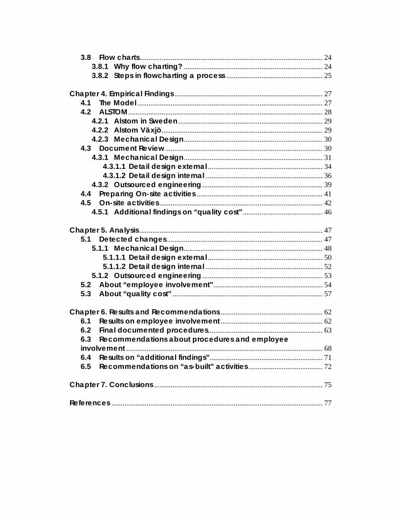
3.8 Flow charts................................................................................................... 24 3.8.1 Why flow charting? ........................................................................... 24 3.8.2 Steps in flowcharting a process .................................................... 25
Chapter 4. Empirical Findings ................................................................................ 27
4.1 The Model .................................................................................................... 27 4.2 ALSTOM......................................................................................................... 28
4.2.1 Alstom in Sweden .............................................................................. 29 4.2.2 Alstom Växjö....................................................................................... 29 4.2.3 Mechanical Design........................................................................... 30
4.3 Document Review ..................................................................................... 30 4.3.1 Mechanical Design........................................................................... 31
4.3.1.1 Detail design external .............................................................. 34 4.3.1.2 Detail design internal ............................................................... 36
4.3.2 Outsourced engineering ................................................................. 39 4.4 Preparing On-site activities .................................................................... 41 4.5 On-site activities ........................................................................................ 42
4.5.1 Additional findings on “quality cost” ........................................... 46 Chapter 5. Analysis ................................................................................................... 47
5.1 Detected changes .................................................................................... 47 5.1.1 Mechanical Design........................................................................... 48
5.1.1.1 Detail design external .............................................................. 50 5.1.1.2 Detail design internal ............................................................... 52
5.1.2 Outsourced engineering ................................................................. 53 5.2 About “employee involvement”........................................................... 54 5.3 About “quality cost” ................................................................................. 57
Chapter 6. Results and Recommendations ....................................................... 62
6.1 Results on employee involvement ....................................................... 62 6.2 Final documented procedures.............................................................. 63 6.3 Recommendations about procedures and employee involvement .......................................................................................................... 68 6.4 Results on “additional findings”............................................................. 71 6.5 Recommendations on “as-built” activities ........................................ 72
Chapter 7. Conclusions ........................................................................................... 75 References .................................................................................................................. 77
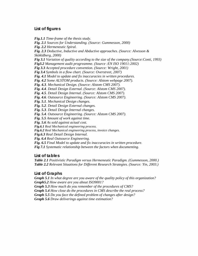
List of figures Fig.1.1 Time-frame of the thesis study. Fig. 2.1 Sources for Understanding. (Source: Gummesson, 2000) Fig. 2.2 Hermeneutic Spiral. Fig. 2.3 Deductive, Inductive and Abductive approaches. (Source: Alvesson & Skökldberg, 2000) Fig 3.1 Variation of quality according to the size of the company.(Source:Conti, 1993) Fig3.2 Management audit progreamme. (Source :EN ISO 19011:2002) Fig 3.3 Accepted procedure convention. (Source: Wright, 2001) Fig 3.4 Symbols in a flow chart. (Source: Overstreet, 2007) Fig. 4.1 Model to update and fix inaccuracies in written procedures. Fig. 4.2 Some ALSTOM products. (Source: Alstom webpage 2007). Fig. 4.3. Mechanical Design. (Source: Alstom CMS 2007). Fig. 4.4. Detail Design External. (Source: Alstom CMS 2007). Fig. 4.5. Detail Design Internal. (Source: Alstom CMS 2007). Fig. 4.6. Outsource Engineering. (Source: Alstom CMS 2007). Fig. 5.1. Mechanical Design changes. Fig. 5.2. Detail Design External changes. Fig. 5.3. Detail Design Internal changes. Fig. 5.4. Outsource Engineering. (Source: Alstom CMS 2007). Fig. 5.5 Amount of work against time. Fig. 5.6 As sold against actual cost. Fig.6.1 Real Mechanical engineering process. Fig.6.2 Real Mechanical engineering process, invoice changes. Fig.6.3 Real Detail Design Internal. Fig. 6.4 Real Outsource Engineering. Fig. 6.5 Final Model to update and fix inaccuracies in written procedure. Fig 7.1 Systematic relationship between the factors when documenting. List of tables Table 2.1 Positivistic Paradigm versus Hermeneutic Paradigm. (Gummesson, 2000.) Table 2.2 Relevant Situations for Different Research Strategies. (Source: Yin, 2003.) List of Graphs Graph 5.1 In what degree are you aware of the quality policy of this organization? Graph5.2 How aware are you about ISO9001? Graph 5.3 How much do you remember of the procedures of CMS? Graph 5.4 How close do the procedures in CMS describe the real process? Graph 5.5 Do you face the defined problem of changes after design? Graph 5.6 Draw deliverings against time estimation?
1
Chapter 1. Introduction In the first chapter we will present the background of our topic, and give a brief presentation. Also, we will define and discuss the problem to be analyzed. We will continue with the purpose and limitations of this study. To conclude this chapter, we are going to discuss the theoretical and practical relevance of this study and show the time frame used. 1.1 Background In today’s highly competitive and global market place, the pressure on organizations to survive and stay in business is increasing constantly. In this environment, the company that stops becoming better will soon end up not being good enough. That is why a great number of companies continuously look for quality improvements by using different methods or tools. The International Organization for Standardization (ISO) has been facilitating the international coordination and unification of industrial standards since 1947 (ISO, 2007), and for many years ISO 9001 has been the most popular standard in the area of quality improvement and management. Just until the end of 2005, at least 776,608 ISO 9001:2000 certificates were issued in 161 countries/economies, and the interest of this certification grew approximately 18% compared with 2004(ISO, 2007). However many companies face difficulties when implementing it and/or passing the time, a difference between the procedures and processes, which could bring major consequences. 1.2 Problem discussion Those organizations that work with ISO 9000, ISO 14000 or any other standard or program that needs documentation of their processes could present difficulties for developing accurate procedures or keeping them updated. Sometimes this documentation could bring more problems than solutions. The objective of those documentations could be misunderstood, and those could be designed for equivocated reasons, therefore these documents lose effectiveness and the whole purpose of the standard i.e. ISO 9000 could be jeopardized. Moreover if this documentation is inadequate, their follow up would bring consequences in the production, the quality of the final product, or the continuous part of the improving process. A clear example of the problem could be any given company recently certified by ISO 9001. Most probably the documentation of the processes, usually called procedures, were developed by a consultant and did not necessarily reflect the real way of working of the organization. Or maybe months after, the process has evolved and the procedures are not up-to-date.
2
This gap between the documentation and the actual processes is a problem affecting many companies at the time; some of them ignore the causes and others might not even realize the effects. 1.3 Problem formulation This study intends to solve several questions:
• What is ISO 9000? And what is its purpose? • Why is documentation important to improve quality? • What are the causes of having a gap between the documentation and the actual
process? And what are the consequences? • How to find the gap between the written procedures and the processes? • How to stop these gaps from appearing?
Taking all the above into consideration, we decided to come up with the following research question:
How can one reduce the gap between the ISO written procedures and the actual processes of an organization?
1.4 Purpose The main purpose of this thesis is to extend the theory of the process of documentation. First we intend to create a model to find the gaps; change the inadequate documentation and keep it updated. Second, we will find the differences between the written procedures and the processes of a case company. We plan to evaluate whether the people should follow the procedures, or the procedures should be changed and given recommendations to improve quality in the particular case. During this case study we will test the effectiveness of our model. We will study the causes and consequences of the gap as well, in order to gain a deeper understanding about them in general. Our objective for the end of the project will be to solve the particular problem of a case company and at the same time gather general knowledge about the problem to publish relevant new findings for the field of study.
3
1.5 Theoretical Relevance To lead and operate an organization successfully, it is necessary to direct and control it in a systematic and transparent manner (BS EN ISO 9000:2005). But we think this “gap” or difference in the documentation is a very common problem. We believe this problem should have a simple and systematic solution, therefore the relevance of a model that finds the gaps, fixes and keeps these documents up-to-date. Even though the interest from the companies in ISO 9001, among others, increases dramatically every year, we realized that there is a poor understanding of the causes and consequences of the inadequate documentation. In fact this study tries to draw a solution for a case company and remark on its relevance by carefully studying the problem’s possible causes and consequences, which we realize is a very common problem that has very little or no literature. 1.6 Practical Relevance This study has plenty of practical relevance, starting from our case company who is very interested in finding out if their people are really working according to the written procedures they publish in their Content Management System (CMS). The company expects suggestions for changes in their written procedures and the management expects us to involve more the floor workers with the continuous improvement. In a way, this study intends to integrate the whole department as a subsystem compromised with quality and standards, which should impact the performance of the whole organization. Other departments should be impacted as well by the workers of our department (engineering department). They will get a deeper understanding of the benefits of their good work and their accurate documentation. In fact, the practical relevance of this thesis can be found in the recommendations for our case company towards increasing the value of their quality management system. Finally, we believe that the findings of this study as well as our model should be suitable for many other organizations facing similar problems. We as authors of this study will get the experience of working with people with different backgrounds towards the same objective of improving the department’s quality and communication. Without a doubt, the opportunity of developing and implementing our solution in a case company will bring plenty of empirical knowledge for us as authors, which we will try to transmit in a clear and concise way to the reader.
4
1.7 Delimitations In order to clarify and eliminate the fussiness of this research field, we have established several important limitations:
• The research of this project is limited from January until June of the year 2007
(10 Swedish points). • The case study will be limited to one department of our case company. • We will be talking specifically about the written procedures, necessary to ISO
9001 certification, although the model should be useful for many other standards etc.
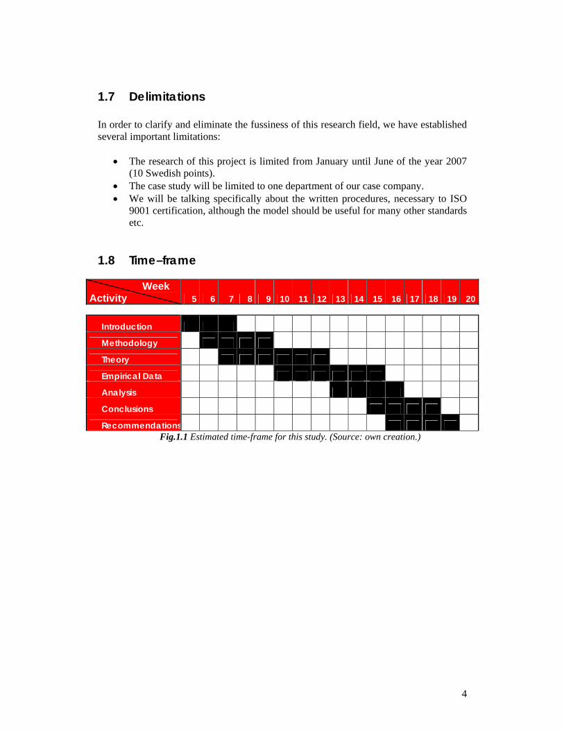
1.8 Time–frame
Week Activity 5 6 7 8 9 10 11 12 13 14 15 16 17 18 19 20
Introduction
Methodology
Theory
Empirical Data
Analysis
Conclusions
Recommendations Fig.1.1 Estimated time-frame for this study. (Source: own creation.)
5
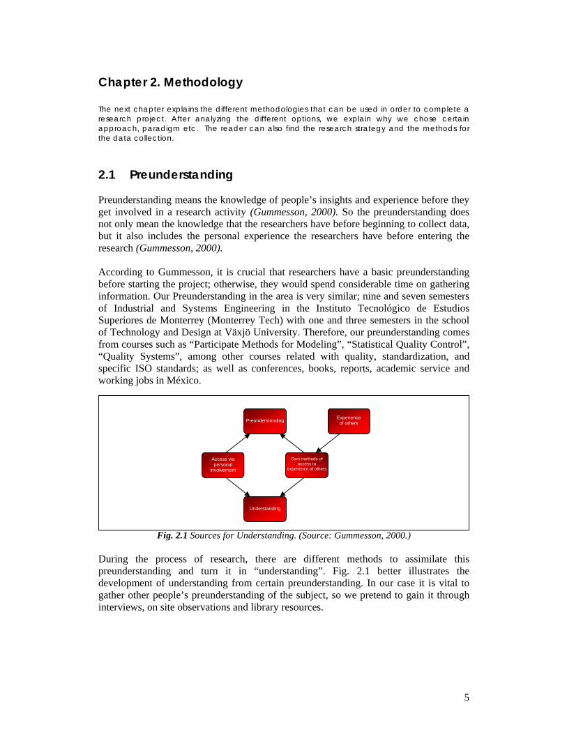
Chapter 2. Methodology The next chapter explains the different methodologies that can be used in order to complete a research project. After analyzing the different options, we explain why we chose certain approach, paradigm etc. The reader can also find the research strategy and the methods for the data collection. 2.1 Preunderstanding Preunderstanding means the knowledge of people’s insights and experience before they get involved in a research activity (Gummesson, 2000). So the preunderstanding does not only mean the knowledge that the researchers have before beginning to collect data, but it also includes the personal experience the researchers have before entering the research (Gummesson, 2000). According to Gummesson, it is crucial that researchers have a basic preunderstanding before starting the project; otherwise, they would spend considerable time on gathering information. Our Preunderstanding in the area is very similar; nine and seven semesters of Industrial and Systems Engineering in the Instituto Tecnológico de Estudios Superiores de Monterrey (Monterrey Tech) with one and three semesters in the school of Technology and Design at Växjö University. Therefore, our preunderstanding comes from courses such as “Participate Methods for Modeling”, “Statistical Quality Control”, “Quality Systems”, among other courses related with quality, standardization, and specific ISO standards; as well as conferences, books, reports, academic service and working jobs in México.
Fig. 2.1 Sources for Understanding. (Source: Gummesson, 2000.) During the process of research, there are different methods to assimilate this preunderstanding and turn it in “understanding”. Fig. 2.1 better illustrates the development of understanding from certain preunderstanding. In our case it is vital to gather other people’s preunderstanding of the subject, so we pretend to gain it through interviews, on site observations and library resources.
Understanding
Preunderstanding
Access via personal
involvement
Own methods of access to
experience of others
Experience of others
6
Fig. 2.2 Hermeneutic Spiral. (Source: Gummesson, 2000.)
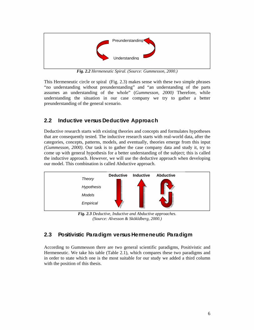
This Hermeneutic circle or spiral (Fig. 2.3) makes sense with these two simple phrases “no understanding without preunderstanding” and “an understanding of the parts assumes an understanding of the whole” (Gummesson, 2000) Therefore, while understanding the situation in our case company we try to gather a better preunderstanding of the general scenario. 2.2 Inductive versus Deductive Approach Deductive research starts with existing theories and concepts and formulates hypotheses that are consequently tested. The inductive research starts with real-world data, after the categories, concepts, patterns, models, and eventually, theories emerge from this input (Gummesson, 2000). Our task is to gather the case company data and study it, try to come up with general hypothesis for a better understanding of the subject; this is called the inductive approach. However, we will use the deductive approach when developing our model. This combination is called Abductive approach.
Fig. 2.3 Deductive, Inductive and Abductive approaches. (Source: Alvesson & Skökldberg, 2000.)
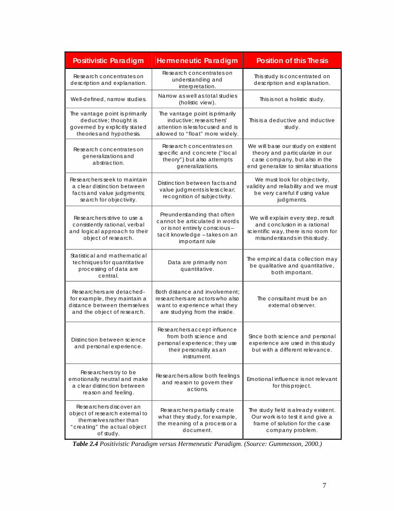
2.3 Positivistic Paradigm versus Hermeneutic Paradigm According to Gummesson there are two general scientific paradigms, Positivistic and Hermeneutic. We take his table (Table 2.1), which compares these two paradigms and in order to state which one is the most suitable for our study we added a third column with the position of this thesis.
Theory Hypothesis Models Empirical
Deductive Inductive Abductive
Preunderstanding
Understanding
7
Positivistic Paradigm Hermeneutic Paradigm Position of this Thesis
Research concentrates on description and explanation.
Research concentrates on understanding and
interpretation.
This study is concentrated on description and explanation.
Well-defined, narrow studies. Narrow as well as total studies (holistic view). This is not a holistic study.
The vantage point is primarily deductive; thought is
governed by explicitly stated theories and hypothesis.
The vantage point is primarily inductive; researchers’
attention is less focused and is allowed to “float” more widely.
This is a deductive and inductive study.
Research concentrates on generalizations and
abstraction.
Research concentrates on specific and concrete (“local
theory”) but also attempts generalizations.
We will base our study on existent theory and particularize in our case company, but also in the
end generalize to similar situations
Researchers seek to maintain a clear distinction between facts and value judgments;
search for objectivity.
Distinction between facts and value judgments is less clear;
recognition of subjectivity.
We must look for objectivity, validity and reliability and we must
be very careful if using value judgments.
Researchers strive to use a consistently rational, verbal
and logical approach to their object of research.
Preunderstanding that often cannot be articulated in words
or is not entirely conscious – tacit knowledge – takes on an
important rule
We will explain every step, result and conclusion in a rational
scientific way, there is no room for misunderstands in this study.
Statistical and mathematical techniques for quantitative
processing of data are central.
Data are primarily non quantitative.
The empirical data collection may be qualitative and quantitative,
both important.
Researchers are detached- for example, they maintain a distance between themselves
and the object of research.
Both distance and involvement; researchers are actors who also want to experience what they are studying from the inside.
The consultant must be an external observer.
Distinction between science and personal experience.
Researchers accept influence from both science and
personal experience; they use their personality as an
instrument.
Since both science and personal experience are used in this study but with a different relevance.
Researchers try to be emotionally neutral and make
a clear distinction between reason and feeling.
Researchers allow both feelings and reason to govern their
actions.
Emotional influence is not relevant for this project.
Researchers discover an object of research external to
themselves rather than “creating” the actual object
of study.
Researchers partially create what they study, for example, the meaning of a process or a
document.
The study field is already existent. Our work is to test it and give a frame of solution for the case
company problem.
Table 2.4 Positivistic Paradigm versus Hermeneutic Paradigm. (Source: Gummesson, 2000.)
8
After filling in this table with the project position, we can conclude that this study will follow the positivist paradigm. 2.4 Research strategy
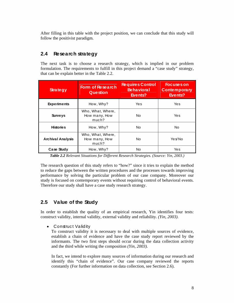
The next task is to choose a research strategy, which is implied in our problem formulation. The requirements to fulfill in this project demand a “case study” strategy, that can be explain better in the Table 2.2.
Strategy Form of Research Question
Requires Control Behavioral
Events?
Focuses on Contemporary
Events?
Experiments How, Why? Yes Yes
Surveys Who, What, Where,
How many, How much?
No Yes
Histories How, Why? No No
Archival Analysis Who, What, Where,
How many, How much?
No Yes/No
Case Study How, Why? No Yes
Table 2.2 Relevant Situations for Different Research Strategies. (Source: Yin, 2003.) The research question of this study refers to “how?” since it tries to explain the method to reduce the gaps between the written procedures and the processes towards improving performance by solving the particular problem of our case company. Moreover our study is focused on contemporary events without requiring control of behavioral events. Therefore our study shall have a case study research strategy. 2.5 Value of the Study
In order to establish the quality of an empirical research, Yin identifies four tests: construct validity, internal validity, external validity and reliability. (Yin, 2003).
• Construct Validity To construct validity it is necessary to deal with multiple sources of evidence, establish a chain of evidence and have the case study report reviewed by the informants. The two first steps should occur during the data collection activity and the third while writing the composition (Yin, 2003). In fact, we intend to explore many sources of information during our research and identify this “chain of evidence”. Our case company reviewed the reports constantly (For further information on data collection, see Section 2.6).
9
• Internal Validity According to Yin, internal validity is the establishment of a causal relationship, whereby certain conditions are shown to lead to other conditions. (Yin, 2003). Then the investigator tries to understand whether event X leads to event Y (Yin, 2003).
• External Validity In this test it is necessary to establish the domain to which a study’s findings can be generalized (Yin, 2003). To construct both internal and external validity, we will study the causes of our problem; we will be very careful and try to be clear so the reader can understand the needed causes and consequences. We are also expecting to show the consequences that the evolution or correction of our scenario could bring. After having a minimum level knowledge about the causes of our scenario, we can have a clear idea of which similar scenarios could be solved with our study, and why.
• Reliability Reliability is the final test to be done, and the major objective is to make sure that if two or more independent investigators follow the same procedures and the same research method is conducted, they will reach the same conclusions (Yin, 2003). Because of our interest in conducing a reliable study, we try to get feedback from many sources, such as school supervision. We minimize assumptions, judgments and non well-founded information in order to maximize reliability.
2.6 Data Collection 2.6.1 Theoretical Data Collection The first source of theoretical information was the library at Växjö University. We are collecting data in relation to ISO 9000 implementation, purpose and benefits. We rely on web sources as well; for example, electronic book resources that Växjö University offered us. In addition, we consider the following programs great tools for documental engineering research: the Biblioteca Digital from Monterrey Tech (Digital Library), Scientific Direct, Emerald, ProQuest, Lexis and Google. They gave us some reliable and important information. Moreover since ISO is central in our study, their website and standards are the cornerstone for a better understanding of the scenario and the development of a better solution.
10
2.6.2 Empirical Data Collection The empirical data was collected by different sources of evidence. There are six important sources from which to gather empirical data: documentation, archival records, interviews, direct observation, participant-observation and physical artifacts. (Yin, 2003). The development of this study was on-site. We have access to the case company Quality Management System (QMS) to review all the necessary documentation. We will compare these documents with the actual way of working by on-site observation. We also intend to spend time in the fore mentioned department to watch their dynamics. Finally a vital source for our study is interviewing; we intend to talk with as many workers as possible to involve them in the process of change and take part in the development of the solutions.
11
Chapter 3. Theory This chapter introduces the theoretical background of this study. Initially, we are going to present the vocabulary used in this thesis in order to facilitate the understanding for the reader. As well we introduce some basic knowledge about quality definitions, ISO standards, and other topics that we discus during this study.
3.1 Terms and Definitions To limit the discussion of this paper it is exceptionally important that the reader and the author use the same language. Therefore in order to avoid misinterpretations we present the definitions of some crucial terms used in this paper. Management system System to establish policy and objectives and to achieve those objectives (BS EN 9000:2005). Organization (An organization is a) group of people and facilities with an arrangement of responsibilities, authorities and relationships. For example company, corporation, firm, enterprise, institution, charity, sole trader, association etc (BS EN 9000:2005). Process Set of interrelated or interacting activities which transforms inputs into outputs (BS EN 9000:2005). Product Result of a process (BS EN 9000:2005). Procedure Specified way to carry out an activity or a process. Procedures can be documented or not. When a procedure is documented, the term “written procedure” or “documented procedure” is frequently used (BS EN 9000:2005). 3.2 Quality The development of quality as a management system began at the turn of last century. Several individuals such as Taylor, Deming Juran, and Crosby among others, played key roles in the development, implementation, and dissemination of the new approach to manage an organization. While they may have previously labored with little recognition for their contributions, since 1980 their involvement in Quality has become appreciated thought the world. (Tenner, 1992). The term quality means different things to different people. For example, a quality automobile may be one which has no defects and works exactly as we expect. Such a definition would fit with an often repeated definition by J.M Juran (1988): "Quality is fitness for use." However, there are other definitions widely discussed. Quality as
12
"conformance to specifications" is a position that people in the manufacturing industry often promote. Presumably that is because manufacturing can do nothing to change the design. Others promote definitions that include the expectations that the product or service being delivers for instance:
1) Meeting customer standards 2) Meeting and fulfills customer needs,
3) Meeting customer expectations, and 4) Meeting unanticipated future needs and aspirations.
The case for use of quality tools and methodologies is that these tools help people work to improve quality at all levels (Dilts, 2007). The official definition of quality according to ISO 8402 is: “the totality of features and characteristics of a product or service that bear upon its ability to satisfy stated or implied needs” Well-planned design is one of the major contributing factors to achieve quality within a product or service. It is therefore necessary to control critical elements of a company’s documentation system with particular reference to each phase. (Haider, 2001). To be successful, an organization must offer services and products that meet a purpose or need. A company must satisfy its users, including delivery time scales. It should be ensured that applicable standards, statuary requirements, and specifications are in compliance. Companies should ensure that their total operations are carefully reviewed before implementation to reduce the occurrence of error and quickly correct any error inadvertently made. Control should be demonstrated on changes through proactive communication and feedback loops between the company and external interfaces. Training needs must be identified to promote efficiency and cost-effectiveness. (Haider, 2001). Over the past decade, we have seen drastic changes in the world around us. There has been more competition in terms of quality, and companies have to do more work, accomplish targets, and be proactive rather than reactive. All this must be accomplished with fewer people. In addition, the quality must be better than ever, due to competitive forces and consumer demands. Since the beginning of the new millennium, it is evident that we are working in a global village where it is impossible for a company to survive without offering quality products and services (Haider, 2001). 3.2.1 Quality in the big companies The question whether quality varies according to the size of the company. Figure 3.1, shows it can be seen that the weight of quality problems are linked to technical causes and technical causes due to flaws in organization, communication, management varying as the companies grow.
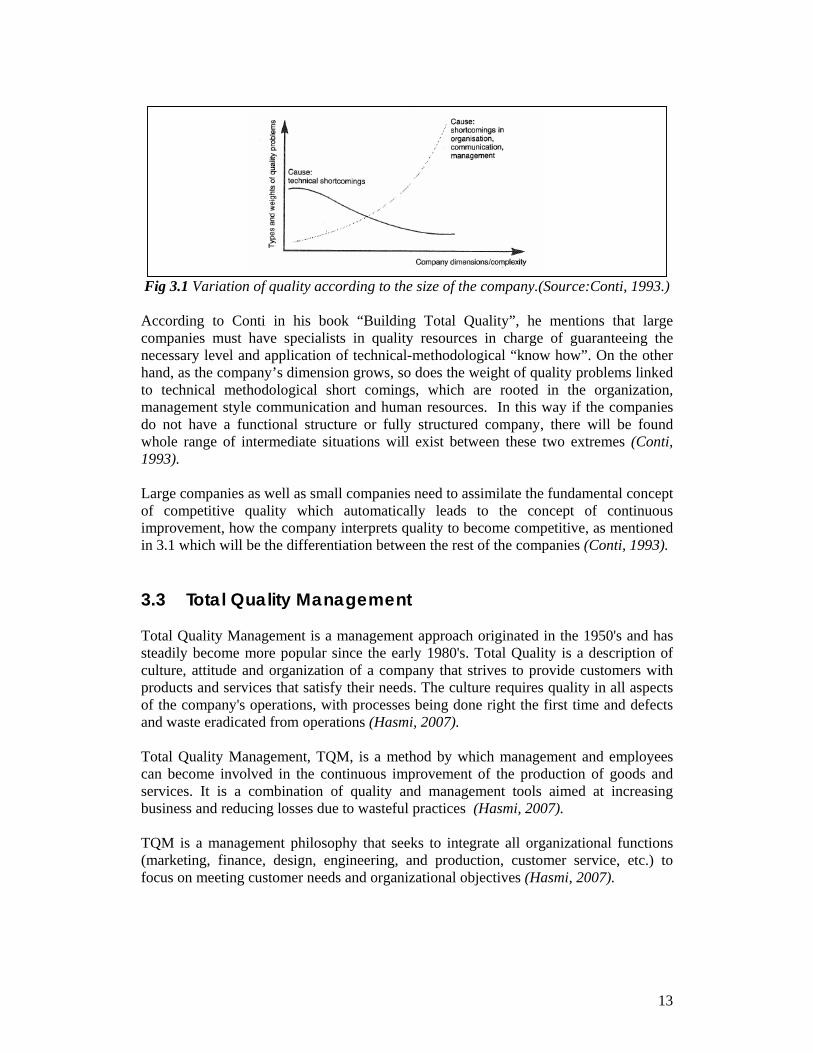
13
Fig 3.1 Variation of quality according to the size of the company.(Source:Conti, 1993.)
According to Conti in his book “Building Total Quality”, he mentions that large companies must have specialists in quality resources in charge of guaranteeing the necessary level and application of technical-methodological “know how”. On the other hand, as the company’s dimension grows, so does the weight of quality problems linked to technical methodological short comings, which are rooted in the organization, management style communication and human resources. In this way if the companies do not have a functional structure or fully structured company, there will be found whole range of intermediate situations will exist between these two extremes (Conti, 1993). Large companies as well as small companies need to assimilate the fundamental concept of competitive quality which automatically leads to the concept of continuous improvement, how the company interprets quality to become competitive, as mentioned in 3.1 which will be the differentiation between the rest of the companies (Conti, 1993). 3.3 Total Quality Management Total Quality Management is a management approach originated in the 1950's and has steadily become more popular since the early 1980's. Total Quality is a description of culture, attitude and organization of a company that strives to provide customers with products and services that satisfy their needs. The culture requires quality in all aspects of the company's operations, with processes being done right the first time and defects and waste eradicated from operations (Hasmi, 2007). Total Quality Management, TQM, is a method by which management and employees can become involved in the continuous improvement of the production of goods and services. It is a combination of quality and management tools aimed at increasing business and reducing losses due to wasteful practices (Hasmi, 2007). TQM is a management philosophy that seeks to integrate all organizational functions (marketing, finance, design, engineering, and production, customer service, etc.) to focus on meeting customer needs and organizational objectives (Hasmi, 2007).
14
3.3.1 TQM way of working TQM views an organization as a collection of processes. It maintains that organizations must strive to continuously improve these processes by incorporating the knowledge and experiences of workers. The simple objective of TQM is "Do the right things, right the first time, every time" (Hasmi,2007). TQM is infinitely variable and adaptable. Although originally applied to manufacturing operations, and for a number of years only used in that area, TQM is now becoming recognized as a generic management tool, just as applicable in service and public sector organizations. There are a number of evolutionary strands, with different sectors creating their own versions from the common ancestor (Hasmi, 2007). TQM encourages participation amount shop floor workers and managers. There is no single theoretical formalization of total quality, but Deming, Juran and Ishikawa provide the core assumptions, as a "...discipline and philosophy of management which institutionalizes planned and continuous... improvement ... and assumes that quality is the outcome of all activities that take place within an organization; that all functions and all employees have to participate in the improvement process; that organizations need both quality systems and a quality culture."(Hasmi, 2007) 3.4 Quality Management systems A quality management system is a series of integrated and interlinked tasks and processes working towards mutually agreed and understood end objectives. Those objectives will satisfy the customer and supply with a product or service that meets all the specific requirements on time and every time. The standards provide some guidance on who specifies the requirements or to what extent the requirements need to be specified. It is generally accepted that this would mean those requirements specified by the customer in its contact purchase order (Sayle, 1994). Every quality system will provide a set of deliverables, task elements which will help to perform auditing and quality assurance duties to analyze each and every work station; Where work task comprises a set of up to five elements which are necessary for this performance (Sayle, 1994). The chain of tasks that compromises a complete quality management system, whose function is to create the finished product or service, is only as strong as its weakest link. Each task element has to be performed correctly, enabling the recipient to do his or her job properly in order to achieve the quality of items or services supplied meeting the customers, user or community requirements (Sayle, 1994). 3.4.1 Quality management support Quality management systems can assist organizations in enhancing customer satisfaction. Customer requirements maybe specified by the customer or maybe
15
determined by the organization itself. In both cases the customers determine the acceptability of the product. Because customer needs and expectations are changing; and because of competitive pressures and technical advances, organizations are driven to improve continually their products and processes (BS EN 9000:2005). The quality management system approach encourages organizations to analyze customer requirements, define processes that contribute to the achievement of a product which is acceptable to the customer, and keep the processes under control. As it will be seen in next chapter, quality management system can provide the framework for continual improvement, providing confidence to the organization and its customers to fulfill the requirements (BS EN 9000:2005). 3.4.2 Easy quality Managers almost never realise how easy it is to implement and use the structure of ISO 9001:200 but there are some ways to make it easier to use and easy to adapt when following it. The first step of a quality manager is to take the standard and write it into his own words, using guidance notes to help, personalizing what the clause says to the organization and call the revised version “Policies. Senior management shall ensure that targets for quality are established at all relevant levels for all appropriate functions within the organization (Wright, 2001). Once the quality manager has policies, which states what the organization is doing and what it will achieve. Then the system has to show how these things are being done and how they are going to be achieved. These procedures should be inserted or referenced beneath each appropriate policy statement (Wright, 2001). Defining the process is the area of ISO 9001:200 that probably caused more confusion. But it can be very simple. A process is any set of associated activities having inputs and generating outputs. ISO actually says that processes should cover management activities, provision of resources, product realization and measurement (Wright, 2001). According to Wright there are several ways to satisfy this element of the standard, and quality manager has to choose which method best suits the organization: A) Mapping B) Referencing C) Corporate or global processes (stating the policies, processes and procedures) Try not to think of ISO as a set of rules that have to be obeyed, picture it as a statement being made to a potential customer, imagine the customer is being shown your quality manual (Wright, 2001). 3.4.3 Quality management system approach According to BS EN ISO9000: 2005 there is an approach to develop and implement a quality management system consists of several steps including:
• Determining the needs and expectations from customers and interested parties • Establishing a quality policy and quality objectives of the organization
16
• Determining the processes and responsibilities necessary to attain the quality objectives
• Determining and providing the resources necessary to attain the quality objectives
• Establishing methods to measure the effectiveness and efficiency of the process • Applying these measures to determine the effectiveness and efficiency of the
process • Determining means of preventing nonconformities and eliminating their causes • Establishing and applying a process for continual improvement of the quality
management system. The organization that adopts this approach can be sure that its processes and the quality products are reliable and ready for a continuous improvement For that companies establish, document, implement and maintain a quality system that conforms the ISO 9000 series standards, with a quality manual that covers the requirements, including references, quality system procedures and outlines of the quality system structure documentation (Schmauch, 1995). 3.5 ISO9000 ISO 9000 is a series of international standards developed by the International organization of standardization, that applies to the quality management system and the process used to produce a product. ISO 9000 establishes a basic set of quality system requirements necessary to ensure that your process is capable to meet the expectation for your customers. It provides a base upon which to extend and improve the processes. ISO 9000 studies do not provide for leading-edge quality but does provide a strong quality foundation (Schmauch, 1995). ISO 9000 standards provide a framework for quality systems, but they do not specify the particulars for implementation. The standards are not specifications, they state what has to be done; they do not state how things have to be done. These standards leave it to the development organization to design and implement its own development process within the framework of standards. They will compel the organization to build quality. (Schmauch, 1995) As mentioned before, ISO9000 is a series of international standards for quality management systems developed by the International Organization of Standardization. ISO 9000 series of standards applies to quality management systems for development and manufacturing, defining minimum processes requirements that must be met to assure customers a good product. (Schmauch, 1995) 3.5.1 How ISO standards benefit society For businesses, the widespread adoption of International Standards means that suppliers can base the development of their products and services on specifications that have wide acceptance in their sectors. This, in turn means that businesses using International
17
Standards are increasingly free to compete on many more markets around the world, giving benefit:
a) For customers, the worldwide compatibility of technology which is achieved when products and services are based on International Standards brings them an increasingly wide choice of offers, and they also benefit from the effects of competition among suppliers (ISO, 2007). b) For developing countries, International Standards that represent an international consensus on the state of the art constitute an important source of technological know-how. By defining the characteristics that products and services will be expected to meet on export markets, International Standards give developing countries a basis for making the right decisions when investing their scarce resources and thus avoid squandering them (ISO, 2007). c) For consumers, conformity of products and services to International Standards provides assurance about their quality, safety and reliability (ISO, 2007). d) For everyone, International Standards can contribute to the quality of life in general by ensuring that the transport, machinery and tools we use are safe (ISO, 2007). e) For the planet we inhabit, International Standards on air, water and soil quality, and on emissions of gases and radiation, can contribute to efforts to preserve the environment (ISO, 2007).
3.5.2 ISO9000 sections Quality management systems have become a necessity for the survival of any company and the ISO 9000 standards provide a framework upon which to build that system. The ISO 9000 family of standards mentioned in the BS EN 9000:2005 have been developed to assist organizations, of all types and sizes, to implement and operate effective quality management systems:
• ISO 9000 describes fundamentals of quality management system and specifies the terminology for quality management systems
• ISO 9001 specifies the requirements for a quality management system where an organization needs to demonstrate the ability to provide products that fulfill customer and applicable regulatory requirements and aims to enhance customer satisfaction
• ISO 9004 provides guidelines that consider both effectiveness and efficiency of quality management system. The aim of this standard is improvement of the performance of the organization and satisfaction of customers and other interested parties
• ISO 19011 provides guidance on auditing quality and environmental management systems in national and international trade.
18
3.5.3 ISO9001:2000; document that describes a company People often write wishes and hopes, nor reality, into procedures. They write what they would like to have happen or what they intend to introduce as soon as they get the time or what they think the auditor wants to see, and that is not the way ISO 9001 has to be if it is to be effective and hassle free. A procedure has to be an accurate reflection of reality, a description of what really happens. If what really happens is not good then it should be changed. Then when the new practice is established and running smoothly, it should be simply described. It is actually difficult to incur a nonconformity or non-compliance when describing what people really do every day (Wright, 2001). 3.5.4 Simplifying procedures ISO 9001:2000 says that the extent of documentation used in the system is partly dependent on the competence of the personnel performing the task. So the amount of detail put into the procedures should take account of the skills, training, experience or qualifications of the operation (Wright, 2001). A procedure needs to inform three things to make it valid according to Wright:
• Who does the work? • What do they do? • What evidence is generated that thy have done it and done it right?
3.6 EN ISO19011 The ISO 9000 emphasizes the importance of audits as a management tool for monitoring and verifying the effective implementation of an organization's quality. Audits are also essential part of conformity assessments activities such as external certification/registration and supply chain evaluation surveillance (EN ISO 19011:2002). Between the ISO 9000 standards we can find the EN ISO19011:2002 which provides guidance to the management of audit programs, the conduct of internal or external audits of quality and/or environmental management systems, as well as on the competence and evaluation of auditors. It is intended to apply a broad range of potential users, including auditors, organizations implementing quality and/or environmental management systems, organizations needing to conduct audits of quality and /or environmental management systems for contractual reasons, and organizations involved in auditor certification or training (EN ISO 19011:2002). 3.6.1 Scope ISO19011provides guidance on the principles of auditing, managing audit programs conducting quality management system audits and environmental management system audits, as well as guidance on the competence of quality and environmental management system auditors (EN ISO 19011:2002).
19
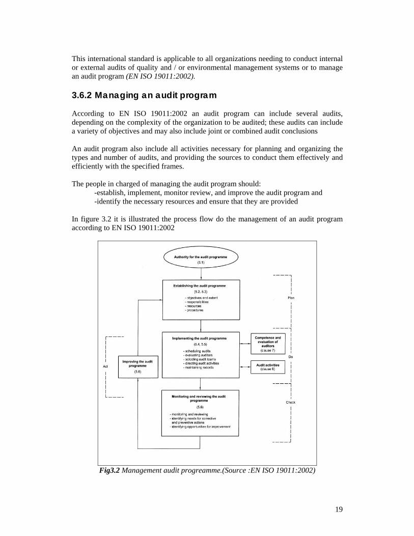
This international standard is applicable to all organizations needing to conduct internal or external audits of quality and / or environmental management systems or to manage an audit program (EN ISO 19011:2002). 3.6.2 Managing an audit program According to EN ISO 19011:2002 an audit program can include several audits, depending on the complexity of the organization to be audited; these audits can include a variety of objectives and may also include joint or combined audit conclusions An audit program also include all activities necessary for planning and organizing the types and number of audits, and providing the sources to conduct them effectively and efficiently with the specified frames. The people in charged of managing the audit program should: -establish, implement, monitor review, and improve the audit program and -identify the necessary resources and ensure that they are provided In figure 3.2 it is illustrated the process flow do the management of an audit program according to EN ISO 19011:2002
Fig3.2 Management audit progreamme.(Source :EN ISO 19011:2002)
20
According to ISO 19011:2002 an audit procedure should contain: -planning and scheduling audits -assuring the competence of auditors and audit team leaders -selecting appropriate audit teams and assigning their roles and responsibilities -conducting audits -conducting audit follow up -maintaining audit program records -monitoring the performance and effectiveness of the audit program -reporting tot top management on the overall achievements of the audit program. 3.7 Documentation The Oxford Dictionary explains that a document is something “written, inscribed which furnishes evidence or information on a subject”. But the word needs to be considered in the light of business activities, then a useful explanation of the word “documentation was included in the quality assurance standard ANSI N45.2.10-1973 stating that: “documentation - any written or pictorial information describing, defining, specifying, reporting or certifying activities, requirements, procedures or results” (Sayle, 1994). 3.7.1 Documentation and data control ISO 9000 states that, procedures to control all documents data, including review, approval and change, must be defined and ensure that the right level of information is available to the right people at the right time (Schmauch.1995). For documented items, there must be procedures for review, approval change issue, and ensuring they get to the right people at the right time and that obsolete documents are not in active use. It is important to have procedures that ensure obsolete information (Schmauch.1995). The identification of all documentation and data needs to be controlled. This should include all internal documentation that will affect the product and the quality of the product as well as any product any product documentation that will be produced. The names of controlled documents should be kept on a aster list along with the name of each document owner, date of last update, review status, etc. as a way of maintaining control (Schmauch.1995). The documents and data shall be reviewed and approved for adequacy by authorized personnel prior to use. A master list or equivalent document-control procedure identifying the current revision status of documents shall be established and be readily available to preclude the use of invalid or obsolete documents (Parisher, 1998). A cording to Paricher this control ensures that: a) A pertinent issues of appropriate documents are available at all locations where operations essential to the effective function of the quality system are performed b) Invalid or obsolete documents are promptly removed from all points of issue c) Any obsolete documents retained for legal or knowledge-preservation purposes are suitable identified.
21
3.7.2 Documents and data changes Changes to documents and data shall be reviewed and approved by the same functions/organizations that performed the original review and approval, unless specifically designated otherwise. The designated functions/organizations shall have access to pertinent background information upon which to base their review and approval (Parisher, 1998). Where practicable, the nature of the change shall be identified in the document or the appropriate attachment statements. Although only one paragraph of the standard is designated “Document and Data control,” the remaining paragraphs have a direct relationship to documentation, since the whole quality system is about documenting and following processes (Parisher, 1998). 3.7.3 Types of documents used in QMS The following types of documents are mentioned and used in quality management systems According to ISO 9000:2005 • Documents that provide consistent information about the organization’s quality
management system; such documents are referred as the Quality Manuals • Documents that describe how the quality management system is applied to a
specific, product, project or contract; such documents are referred to as quality plans • Documents stating requirements; such documents are referred to as specifications • Documents stating recommendations or suggestions; such documents are referred to
as guidelines • Documents that provide information about how to perform activities and processes
consistently; such documents can include documented procedures, work instructions and drawings
• Documents that provide objective evidence of activities performed or results achieved; such documents are referred as records
Each organization determines the extent of documentation required and the media to be used. This depends on factors such as the type and size of the organization, the complexity and interaction of the processes, the complexity of the products, customer requirements, the applicable regulatory requirements, the demonstrated ability of personnel, and the extent to which it is necessary to demonstrate fulfillment of quality management system requirements (BS EN ISO 9000:2005). 3.7.4 Documents involved There are three levels of documentation needed in ISO 9000, and these are often referred to as levels 1, 2 and 3. The top level is the Quality Manual; the second level is made up of all the specific documents needed to control the issues which are fundamental to quality and the third and lowest level, is made up of the standard operating procedures (Rothery, 1995).
22
The key document is, of course, the Quality Manual, then the documents can be classified as: plan, procedures, controls and records; including the Quality manual incorporating procedures and controls (Rothery, 1993). According to Brian Rothery a useful check on the comprehensiveness of the quality management system in meeting the requirements of ISO 900 is to ensure that: • The quality Manual is complete • It reflects the real situation it’s not just a paper exercise. • All of the other necessary support documentation is in place, using a broad list. Apart form these quality management system documents it is needed: • Task procedures related to shop floor and connected activities, which are the exact
instructions for your product and activities • Health and safety procedures 3.7.5 Value of documentation ISO 9000:2005 mentions that documentation enables communication of intent and consistency of action, and its use contributes to: A) Achievement of conformity to customer requirements and quality improvement b) Provision of appropriate training c) Repeatability and traceability d) Provision of objective evidence and e) Evaluation of the effectiveness and continuing suitability of the quality management system Generation of documentation should not be an end in itself but should be a value adding activity for competitive advantage (BS EN 9000:2005). 3.7.6 12 rules for ISO9000 documentation When verifying that ISO is working correctly, through an analysis, the auditors more likely are to register errors found in the documentation. This process is supposed to be simple and easy to use, but companies do what the quality manual says instead of registering what they are already doing (Russo, 1997). To improve this process of documentation in the article"12 Rules to make your ISO 9000 Documentation simple and easy to use” there are mentioned 12 simple recommendation rules to develop the documentation for ISO 9000 (Russo, 1997). 1-write your quality manual last
usually the management try to start with the registration of the manual by writing it first. Doing these since the beginning will delay the process around 6 months by creating discussions and differences between the people who are already doing the job. This delay happens because there has to be a premature approval process conducted while members try to protect their political sides (Russo, 1997).
23
2-Write a simple quality policy This one should be written in less that one page, where the company's approach
on doing business should be stated and agreed upon. Then it should be developed goals that can be achieved within one and one and a half years, including a metric that can be tied to the goals of ISO 9000 process in order to achieve strategic
initiatives (Russo, 1997). 3-Write only what is needed and concise
In section 42.2 of ISO 900 it is said: "the range and detail of procedures depend on the complexity of the work, the methods used, and the skills and training needed personnel involved in carrying out the activity" This sentence allows companies to avoid the unneeded documentation. So if a procedure is not used and the work can still be done, probably the procedure is not necessary (Russo, 1997).
4-Push documents to the lowest level possible Write procedures rather than including information in the quality manual, otherwise write instructions or create forms rather than procedures. This because The ISO 9000 requires procedures, but there are instances where additional documentation is necessary for the company's needs (Russo, 1997). If the employees don’t like to use these procedures a format that has a better chance to used by the employees should be applied or include directions in forms t
5-Write the process in the procedure list When writing procedures, the body of them should be written first, then a flowchart of the process and activities will be more descriptive in order to register the purpose scope statements; the responsibilities and authorities section. Finally write the title of the procedure which should start with the words "How to" to understand the purpose of the procedure '(Russo, 1997).
6-Write what is, not what must it must be It is so easy to create policies of how procedures must be done, but in order to have the people working for the procedure; the current process must be flowcharted using an internal audit program and a continuous improvement program to drive improvements in processes(Russo, 1997).
7-Write to the lowest level possible Write ISO documents easy to understand. People are more inclined to use documents that are easy to read. There are no ISO 900 requirements to include complex wordy or overblown language in procedures (Russo, 1997).
8-Avoid words altogether There is no requirement in the ISO 9000 standard that procedures must be in words. Many procedures will be in sentence format. More important people use nonverbal formats. A picture is worth a thousand words (Russo, 1997).
9-Avoid references To avoid these problems, try not to refer to any other documents, work instructions, or procedures within a procedure. ISO requires maintaining a master list of all documents with their current revisions (Russo,1997).
10-Do not define terms Avoid defining terms in procedures. Having a glossary is not necessary. If a glossary is absolutely necessity, make it stand-alone document (Russo, 1997).
24
11-Make revisions easy Make the procedure revision process as painless as possible. Seek ways to encourage employees to initiate changes and improvements in procedures. In fact an often-heard complain about ISO 9000 is that it stifles creativity and hinders the company from responding quickly to changing needs. Procedures should be changed frequently as people find better ways to accomplish tasks or select other practices (Russo, 1997).
12-Make documents user friendly Make your documents easy to read by avoiding type that is difficult to read. Use a legible font with serifs. Avoid using words or sentences of all capital letters, avoid long strings of bold type, limit the use of italics to a few words, and use plenty of space (Russo, 1997).
In summary, the best documentation system is a simple one that works well. These 12 rules proposed can help shape a documentation process that will meet the requirements of the ISO 9000 (Russo, 1997) 3.8 Flow charts A flowchart is a graphical representation of a process, depicting inputs, outputs and units of activity. It represents the entire process at a high or detailed (depending on your use) level of observation, allowing analysis and optimization of workflow (Khurram, 2007). It represents the entire process from start to finish, showing inputs, pathways and circuits, action or decision points, and ultimately, completion. It can serve as an instruction manual or a tool for facilitating detailed analysis and optimization of workflow and service delivery (Khurram, 2007). 3.8.1 Why flow charting? Flow charting is a good method to use with procedures. It is easy, anybody can do it without special training and most people can understand it easily. Management system flowcharts are not engineering schematics: they are steps of a procedure put into boxes. (Wright, 2001). Flowcharting removes the ambiguity from procedures, clarifies what things are essential in the procedures and presents them in a simple to follow and logical flow from start to finish. In the next figure it is shown the accepted convention for constructing any procedure (Wright, 2001).
25
Fig 3.3 Accepted procedure convention.(Source: Wright, 2001)
Everything begins with some kind of stimulus. Every task is initiated by something that kick-starts the process. Work, in one form or another, comes to us. A purchasing procedure, for instance, begins with some form or request of purchase. The flow chart tell us who does the work at every stage of the operation, it also tell us what they do showing the evidence that has to be generated. A flowchart is simple to be audited, contains no padding or unnecessary information, and is short and to the point (Wright, 2001). 3.8.2 Steps in flowcharting a process According to Overstreet the steps to make flow charts should be as follow:
1. Choose which process should be used to flowchart. 2. Set the boundaries of the process: the beginning and the end. 3. Set the beginning step of the process in an oval. 4. Question "what happens next?" And add the step to the flowchart as a
rectangle. Continue mapping out the steps as rectangles connected by one-way arrows.
5. When a decision point is faced, write the decision in the form of a question in a diamond and develop the” yes" and “no" paths. Each yes/no path must reenter the process or exit somewhere.
6. Repeat steps 4 and 5 until the last step in the process is reached. 7. Describe the ending boundary/step in an oval.
When drawing a flowchart, constantly ask "what happens next?", "is there a decision made at this point?", "does this reflect reality?", "who else knows this process?", etc. When possible, do a walk-through of the process to see if any steps have been left out or extras added that should not be there. The key is not to draw a flowchart representing how the process is supposed to operate, but to determine how it actually does operate. A good flowchart of a bad process will show how illogical or wasteful some of the steps or branches are (Overstreet, 2007).
Input
Output
Activities
26
Defines the documents need during the process
Designates a step in a process. In short words describe the step inside the box.
A diamond means a decision point in the process. Write the type of decision made inside the diamond in the form of a question. The question is answered by two arrows-- "yes" and "no" --which lead to two different paths
Exemplifies a magnetic disk considered as software or electronic documentation
Fig 3.4 Symbols in a flow chart. (Source:Overstreet, 2007)
27
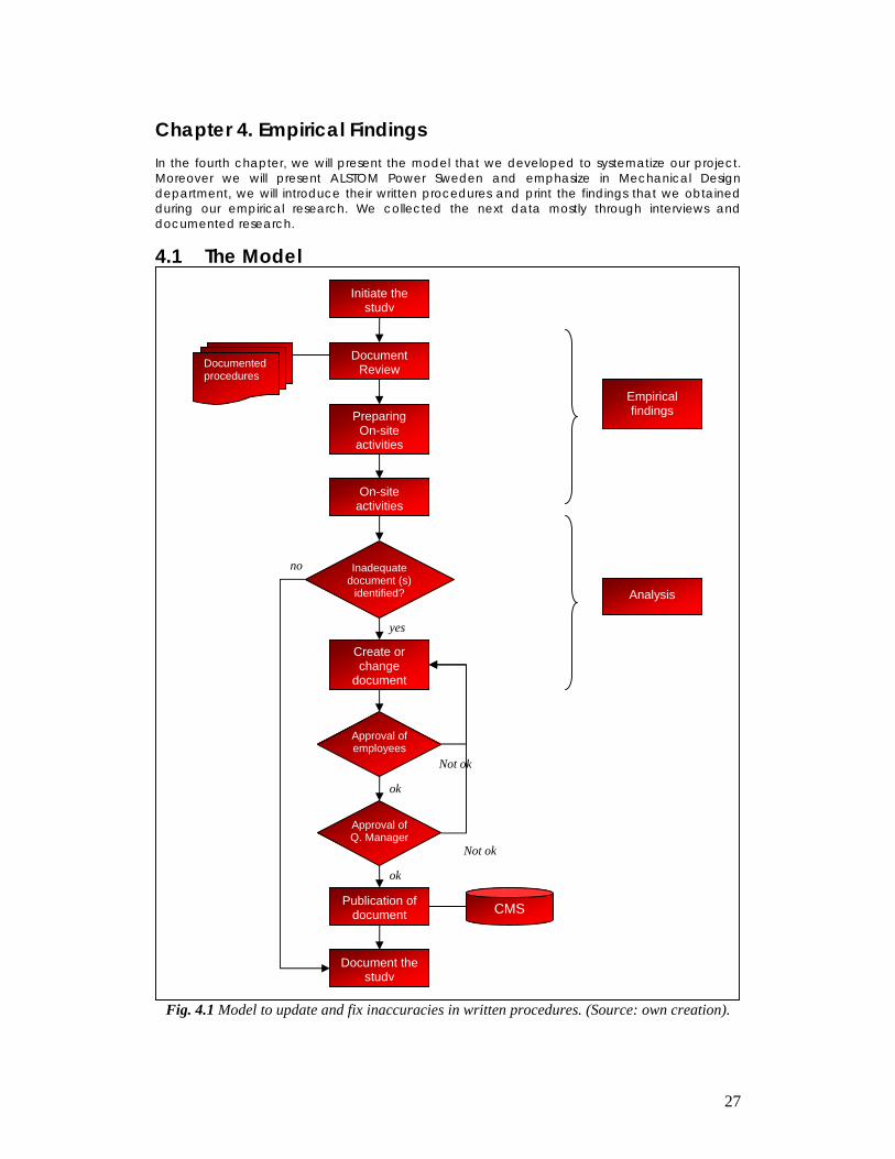
Chapter 4. Empirical Findings In the fourth chapter, we will present the model that we developed to systematize our project. Moreover we will present ALSTOM Power Sweden and emphasize in Mechanical Design department, we will introduce their written procedures and print the findings that we obtained during our empirical research. We collected the next data mostly through interviews and documented research.
4.1 The Model
Fig. 4.1 Model to update and fix inaccuracies in written procedures. (Source: own creation).
ok
Not ok
Not ok
ok
no
yes
Initiate the study
Preparing On-site
activities
Document Review
On-site activities
Create or change
document
Inadequate document (s)
identified?
Publication of document
Document the study
Approval of employees
Approval of Q. Manager
CMS
Documented procedures
Analysis
Empirical findings
28
As mentioned before, one of the top characteristics of ISO is the systemization of the processes. To profit from this characteristic we developed a model that describes the process that we follow to conduct this case study (See Fig 4.1). The main purpose of this model is to document our journey of finding and fixing the differences between the documented procedures and the real processes of our case company. In this way, if our procedure is imitated by anyone, similar results should be obtained. Moreover this model intends to standardize the documented procedure’s audits of our case company for the future if needed. As we mentioned in the purpose of the study, our intention is not only to find the gaps between the documents and the reality, but also to fix them and learn about it in order to try to reduce this problem. Therefore our model (See Fig 4.1) is inspired by an audit procedure (according to ISO 19011), but it also incorporates the change and creation of documents, among other subtle differences. The model could be divided in the same way this study is, because it includes the three main parts that any project should contain; an introduction, dissertation and conclusions. Nevertheless, we decided to divide the dissertation of our model in the same way as our project to improve and clarify its order. In this way, the steps of our model will be the guide through the Empirical findings and Analysis chapters. 4.2 ALSTOM ALSTOM was previously called ALSTHOM after its original owners, Société Alsacienne de Constructions Mécaniques and Thomson-Houston. In 1989, the energy and transport branches of ALSTHOM and GEC merged under the name GEC ALSTHOM. (Alstom webpage, 2007) In 1998, the company was quoted at the stock exchange under the name ALSTOM for the first time, when 52% of the share capital was sold while 48% was retained by the previous owners, Alcatel and GEC (which today is known as Marconi). In the spring of 2001, Alcatel and GEC sold the majority of their holdings in another stock market placing. (Alstom webpage, 2007) In 1999, ABB ALSTOM POWER was formed by ALSTOM in conjunction with ABB. Their power generation activities were combined in this new company. In May 2000, ALSTOM acquired ABB's share of the joint company. (Alstom webpage, 2007) Today, ALSTOM is a worldwide known company with around 65,000 employees and presence in 70 countries whom core business is both power and transportation. ALSTOM's power generation activities comprise the three sectors; Power Environment, Power Service and Power Turbo-Systems. In Sweden ALSTOM have large units in Norrköping, Västerås and Växjö. ALSTOM Transport has its office in Stockholm. The ALSTOM Sweden headquarters are located in Norrköping. (Alstom webpage, 2007)
29
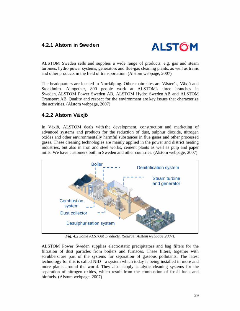
4.2.1 Alstom in Sweden ALSTOM Sweden sells and supplies a wide range of products, e.g. gas and steam turbines, hydro power systems, generators and flue-gas cleaning plants, as well as trains and other products in the field of transportation. (Alstom webpage, 2007) The headquarters are located in Norrköping. Other main sites are Västerås, Växjö and Stockholm. Altogether, 800 people work at ALSTOM's three branches in Sweden, ALSTOM Power Sweden AB, ALSTOM Hydro Sweden AB and ALSTOM Transport AB. Quality and respect for the environment are key issues that characterize the activities. (Alstom webpage, 2007) 4.2.2 Alstom Växjö In Växjö, ALSTOM deals with the development, construction and marketing of advanced systems and products for the reduction of dust, sulphur dioxide, nitrogen oxides and other environmentally harmful substances in flue gases and other processed gases. These cleaning technologies are mainly applied in the power and district heating industries, but also in iron and steel works, cement plants as well as pulp and paper mills. We have customers both in Sweden and other countries. (Alstom webpage, 2007)
Fig. 4.2 Some ALSTOM products. (Source: Alstom webpage 2007).
ALSTOM Power Sweden supplies electrostatic precipitators and bag filters for the filtration of dust particles from boilers and furnaces. These filters, together with scrubbers, are part of the systems for separation of gaseous pollutants. The latest technology for this is called NID - a system which today is being installed in more and more plants around the world. They also supply catalytic cleaning systems for the separation of nitrogen oxides, which result from the combustion of fossil fuels and biofuels. (Alstom webpage, 2007)
Boiler
Steam turbine and generator
Dust collector
Combustion system
Desulphurisation system
Denitrification system
30
4.2.3 Mechanical Design Mechanical Design department is where the detail design of the products and plants takes place, it is composed by 59 employees of which ones 39 are contractors. In Alstom Växjö there are several processes that take place, among them we focused on the engineering part of the execution of the projects. specifically in two processes. The first one is Mechanical Design, where the basis and design of the projects are stated, in this process there is also close contact with the customer, where the project is agreed and the information is distributed through the company. We also covered Outsourced Engineering that basically consists of the project realization with a subcontractor. This process manages the relationships and process steps that happen between Alstom and the outsource 4.3 Document Review As our model indicates, the second step is to carry out the document review. The output of this operation will be the first input for our analysis. Its objective is to get to know the procedures and who is involved in them. (See fig 4.1) Alstom kindly granted us access to their Content Management System (CMS) where they store their ISO documentation among others. Like we explained before, we are just studying the Mechanical Design department of the organization, therefore we concentrated on two written procedures: Outsourced Engineering and Mechanical Design with its two sub procedures.
31
4.3.1 Mechanical Design
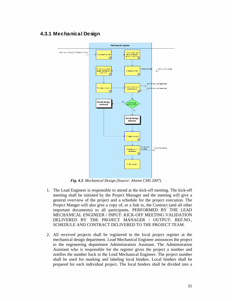
Fig. 4.3. Mechanical Design (Source: Alstom CMS 2007).
1. The Lead Engineer is responsible to attend at the kick-off meeting. The kick-off
meeting shall be initiated by the Project Manager and the meeting will give a general overview of the project and a schedule for the project execution. The Project Manger will also give a copy of, or a link to, the Contract (and all other important documents) to all participants. PERFORMED BY THE LEAD MECHANICAL ENGINEER / INPUT: KICK-OFF MEETING VALIDATION DELIVERED BY THE PROJECT MANAGER / OUTPUT: REF.NO., SCHEDULE AND CONTRACT DELIVERED TO THE PROJECT TEAM.
2. All received projects shall be registered in the local project register at the
mechanical design department. Lead Mechanical Engineer announces the project to the engineering department Administration Assistant. The Administration Assistant who is responsible for the register gives the project a number and notifies the number back to the Lead Mechanical Engineer. The project number shall be used for marking and labeling local binders. Local binders shall be prepared for each individual project. The local binders shall be divided into a
32
predetermined register. Local binders shall be marked and labeled according predetermined labels. Type of document, which is not filed as a hard copy in the local binder, shall be marked in the local binder with a note that determined where to find this type of document. It is the Lead Mechanical Engineer who decides which type of document that shall be file as a hard copy. PERFORMED BY THE LEAD MECHANICAL ENGINEER / INPUT: MOM FORM KICK-OFF MEETING DELIVERED BY THE PROJECT MANAGER / OUTPUT: PROJECT NO. FOR LOCAL BINDER DELIVERED TO THE MEMBER IN DISCIPLINE TEAM.
3. To read the contract in order to understand the scope and complexity of the
project. Notes are taken during the reading to point out valid chapters for our discipline, to point out risks or unusual contractual text or anything that needs to be looked at in the Design Review No1 and later during the engineering. Compare also with the deviations, risks and notes from the tender phase. PERFORMED BY THE LEAD MECHANICAL ENGINEER / INPUT: CONTRACT DELIVERED BY PROJECT MANAGER, P&ID,PROCESS FLOW DIAGRAM, LAYOUT, FOUNDATION PLAN, AND COST ESTIMATION DELIVERED BY THE LEAD MECHANICAL ENGINEER / OUTPUT: NOTES BY THE PROJECT TEAM.
4. The design work planning is to be done in consultation and collaboration with
other disciplines within the project team. The planning shall be documented and shall be performed in a level of detailing that is suitable for the specific project plan. The Lead Mechanical Engineer has the responsibility that correct input is given to the project time schedule. The Lead Mechanical Engineer has also the responsibility for the design work progress and reporting of the same. The Lead Mechanical Engineer shall to the mechanical Group Manager in the line organisation make a request for needed resources at specific times. It is the Group Manager responsibility to allocate resources to the project. PERFORMED BY THE LEAD MECHANICAL ENGINEER / INPUT: TENDER SCHEDULE BY THE PROJECT MANAGER,DRAFT OF PROJECT SCHEDULE BY THE PROJECT PLANNER AND TIME ESTIMATION BY THE LEAD ENGINEER MECHANICAL FOR TENDER / OUTPUT: PROJECT SCHEDULE FOR MECHANICAL BY THE PROJECT PLANNER AND RESOURCE ESTIMATION BY THE GROUP MANAGER
5. The Lead Engineer is responsible to attend in the Design Review meeting. The
Design Review meeting shall be initiated by the Project Engineer and the meeting will clarify the project scope of supply. It will also assure that all necessary information is available to make it possible to start the design and to make proper project documentation. PERFORMED BY THE LEAD MECHANICAL ENGINEER / INPUT DESIGN REVIEW MEETING INVITATION DELIVERED BY THE PROJECT ENGINEER / OUTPUT: KG1 PROTOCOL DELIVERED TO THE PROJECT TEAM.
6. Normally a layout is produced in the sales phase. If a layout not has been
produced in the sales phase it is highly recommended producing a layout before
33
start of detail design. The layout must be verified and adjusted according to contract requirements and requirements stated in Design Review 1. Right sizes for ALSTOM products and auxiliary equipment shall be delivered from Process Engineering. Engineering must verify placing of cable trays and external instruments. A service analyse must be established. It is important to identify and put in all necessary platforms, walkways and stairs. Delivery limits must be clearly shown. A thoroughly layout is to be worked out to obtain and secure that the plant have a design based on the company best knowledge and experiences concerning function and security. The layout must be reviewed by the project team and if possible approved by the customer before start of detail design. Beside a traditional layout several other layout-based drawing may be required in a project. It can be special Service Analyse Layouts, special General Arrangement Drawings, Building Permit Drawings, and Special Cable Tray Layouts etc. All special layout based drawings shall be identified in Design Review 1. PERFORMED BY THE MECHANICAL ENGINEER / INPUT: AS SOLD LAYOUT AND CONTRACTUAL DELIVERY LIMITS DELIVERED BY THE LEAD ENGINEER MECHANICAL FOR TENDER, DRAWINGS-INFORMATION OF EXISTING PLANT DELIVERED BYTHE LEAD ENGINEER MECHANICAL FOR TENDER AND THE PROJECT MANAGER, TENDERS AND DIMENSION PRINTS DROM SUB SUPPLIER BY THE LEAD ENGINEER MECHANICAL FOR TENDER AND PURCHASING, FIRST ISSUE OF PROCESS DESIGN SPEC. WITH PRODUCT AND EQUIPMENT SIZES DELIVERED BY THE LEAD PROCESS ENGINEER, AND MATERIAL SPECIFICATON FROM SALES PHASE DELIVERED BY LEAD ENGINEER MECHANICAL FOR TENDER / OUTPUT: REVISED LAYOUT CHECKED BY THE MECHANICAL EXAMINER, APPROVED BY THE LEAD MECHANICAL ENGINEER AND DELIVERED TO THE PROJECT TEAM.
• Decide between detail design in-house or external
7. The Lead Engineer is responsible to initiate Design Review No 2. The objective is to secure and verify that all produced documents fulfil stated requirements Distribution of design documents shall be done according to requirements stated in Design Review 1. PERFORMED Y THE LEAD MECHANICAL ENGINEER / INPUT: DOCUMENTS FOR MECHANICAL SUB TO BE REVIEWED AND KG1 PROTOCOL DELIVERED BY THE LEAD MECHANICAL ENGINEER / OUTPUT: KG2 PROTOCOL DELIVERED TO THE PROJECT ENGINEER.
8. Distribution of the documents PERFORMED BY THE LEAD MECHANICAL
ENGINEER / INPUT: DESIGN REVIEW 1 DELIVERED BY THE PROJECT ENGINEER AND THE PROJECT MANAGER / OUTPUT: PRODUCED DESIGN DOCUMENTS CHECKED AND APPROVED BY ACC INSTRUCTION, DELIVERED TO PROJECT ENGINEER AND PROJECT MANAGER.
9. Close the project
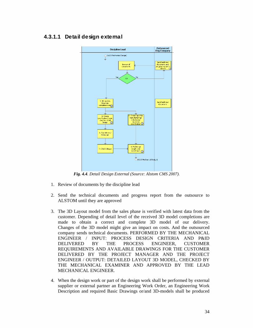
34
4.3.1.1 Detail design external
Fig. 4.4. Detail Design External (Source: Alstom CMS 2007).
1. Review of documents by the discipline lead 2. Send the technical documents and progress report from the outsource to
ALSTOM until they are approved 3. The 3D Layout model from the sales phase is verified with latest data from the
customer. Depending of detail level of the received 3D model completions are made to obtain a correct and complete 3D model of our delivery. Changes of the 3D model might give an impact on costs. And the outsourced company sends technical documents. PERFORMED BY THE MECHANICAL ENGINEER / INPUT: PROCESS DESIGN CRITERIA AND P&ID DELIVERED BY THE PROCESS ENGINEER, CUSTOMER REQUIREMENTS AND AVAILABLE DRAWINGS FOR THE CUSTOMER DELIVERED BY THE PROJECT MANAGER AND THE PROJECT ENGINEER / OUTPUT: DETAILED LAYOUT 3D MODEL, CHECKED BY THE MECHANICAL EXAMINER AND APPROVED BY THE LEAD MECHANICAL ENGINEER.
4. When the design work or part of the design work shall be performed by external
supplier or external partner an Engineering Work Order, an Engineering Work Description and required Basic Drawings or/and 3D-models shall be produced
35
by the mechanical discipline The basic drawings or/and 3D-models shall contents all information required for performing the detail design described in Engineering Work Description. As guidelines to cover all information to be put into a basic drawing several templates exist. These templates can also be a part when describing responsibility and raise the level for the basic drawings. PERFORMED BY THE MECHANICAL ENGINEER / INPUT: MOM FROM DESIGN REVIEW 1, RESULT FROM STEP 1,DEFINE DETAIL / INPUT AND SCHEDULE DELIVERED BY THE LEAD ENGINEER / OUTPUT: ENGINEER WORK ORDER, ENGINEEERING WORK DESCRIPTION AND BASIC DRAWINGS CHECKED AND APPROVED BY THE LEAD ENGINEER AND DELIVERED TO THE SUB SUPPLIER
5. To read the contract in order to understand the scope and complexity of the
project. Notes are taken during the reading to point out valid chapters for our discipline, to point out risks or unusual contractual text or anything that needs to be looked at in the Design Review No1 and later during the engineering. Compare also with the deviations, risks and notes from the tender phase
6. Coordinate and follow up 7. Check design
8. Actual weights shall as soon as possible be compared versus estimated weights.
Comparison must latest be done before distribution off manufacturing documents. The comparison shall be on sub number level. All deviations must be reported to the Project Engineer / Project Manager. If weight deviations occur, measures for action shall be taken in conjunction with Project Engineer / Project Manager. Progress of man-hours shall continuously be followed up and reported to the Project Engineer / Project Manager. The progress shall monthly be presented in a pre determined Design Report. PERFORMED BY THE MECHANICAL ENGINEER / INPUT: DELIVERY LIST DELIVERED BY THE MECHANICAL ENGINEER, TIME REPORTS FROM MECHANICAL ENGINEERS DELIVERED BY SAP MAX / OUTPUT: WEIGHT COMPARISON AND DESIGN REPORT DELIVERED TO PROJECT ENGINEER AND PROJECT MANAGER
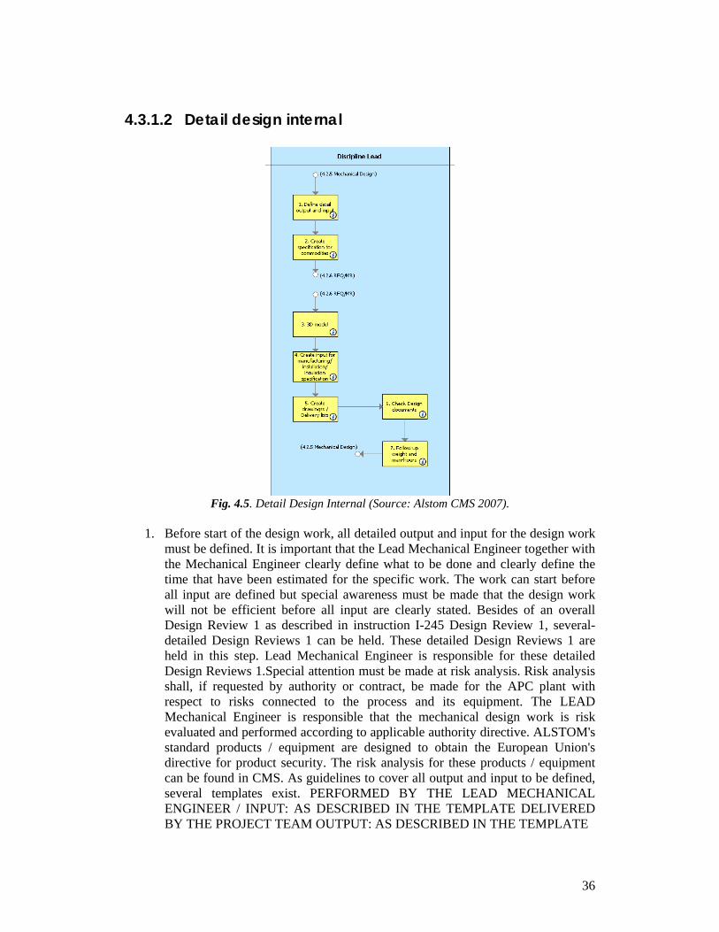
36
4.3.1.2 Detail design internal
Fig. 4.5. Detail Design Internal (Source: Alstom CMS 2007).
1. Before start of the design work, all detailed output and input for the design work
must be defined. It is important that the Lead Mechanical Engineer together with the Mechanical Engineer clearly define what to be done and clearly define the time that have been estimated for the specific work. The work can start before all input are defined but special awareness must be made that the design work will not be efficient before all input are clearly stated. Besides of an overall Design Review 1 as described in instruction I-245 Design Review 1, several-detailed Design Reviews 1 can be held. These detailed Design Reviews 1 are held in this step. Lead Mechanical Engineer is responsible for these detailed Design Reviews 1.Special attention must be made at risk analysis. Risk analysis shall, if requested by authority or contract, be made for the APC plant with respect to risks connected to the process and its equipment. The LEAD Mechanical Engineer is responsible that the mechanical design work is risk evaluated and performed according to applicable authority directive. ALSTOM's standard products / equipment are designed to obtain the European Union's directive for product security. The risk analysis for these products / equipment can be found in CMS. As guidelines to cover all output and input to be defined, several templates exist. PERFORMED BY THE LEAD MECHANICAL ENGINEER / INPUT: AS DESCRIBED IN THE TEMPLATE DELIVERED BY THE PROJECT TEAM OUTPUT: AS DESCRIBED IN THE TEMPLATE
37
2. Create a technical specification for the procurement of commodities as Flue gas
dampers, Expansion bellows, Dosing feeders etc. The technical specification shall cover all requirements in respect of the contract and the design review 1. PERFORMED BY THE MECHANICAL ENGINEER / INPUT: CONTRACT REQUIREMENTES AND SCHEDULE DELIVERED BY THE PROJECT MANAGER AND MOM FROM DEDIGN REVIEW 1 FROM MECHANICAL LEAD ENGINEER / OUTPUT: TECHNICAL SPECIFICATION CHECKED AND APPROVED BY THE MECHANICAL EXAMINER AND DELIVERED TO SUB RFQ/MR
3. The 3D Layout model from the sales phase is verified with latest data from the
customer. Depending of detail level of the received 3D model completions are made to obtain a correct and complete 3D model of our delivery. Changes of the 3D model might give an impact on costs. . PERFORMED BY THE MECHANICAL ENGINEER / INPUT: PROCESS DESIGN CRITERIA AND P&ID DELIVERED BY THE PROCESS ENGINEER, CUSTOMER REQUIREMENTS AND AVAILABLE DRAWINGS DELIVERED BY THE PROJECT MANAGER AND PROJECT ENGINEER / OUTPUT: DETAILED LAYOUT 3D MODEL CHECKED BY THE MECHANICAL EXAMINER, APPORVED BY THE LEAD MECHANICAL ENGINEER
4. The technical part of the manufacturing / installation / insulation inquiry
specification shall be performed by the mechanical discipline. The technical specification shall coverall requirements in respect of the contract and the Design Review 1. Before signing a manufacturing / installation /insulation contract the technical specification shall be updated to latest edition. PERFORMED BY THE MECHANICAL ENGINEER / INPUT: CONTRACT REQUIREMENTS DELIVERED BY THE PROJECT MANAGER AND MOM FROM DESIGN REVIEW 1 DELIVERED BY THE MECHANICAL LEAD ENGINEER / OUTPUT: TECHNICAL SPECIFICATION CHECKED AND APPROVED BY THE MECHANICAL EXAMINER AND DELIVERED TO SUB RFQ/MR.
5. The contract technical- and material specifications shall act as bases for define
what drawings, together with required Delivery List (LF) that shall be produced. The identification of required drawings and Delivery Lists is made in the Design Review 1. Creating of Drawings shall normally follow instruction . Exceptions can be made depending on contractual requirements. Delivery List (LF) is an uniting document for defining what shall be manufactured delivered and erected. Creating of Delivery List shall follow instruction . Exception for using Delivery List can be made depending on individual project requirements. PERFORMED BY THE MECHANICAL ENGINEER / INPUT: OUT FROM STEP "DEFINE DETAIL OUTPUT AND INPUT" DELIVERED BY LEAD MECHANICAL ENGINEER / OUTPUT: DRAWINGS AND DELIVERY LISTS CHECKED AND APPROVED BY ACC. INSTRUCTION AND DELIVERED TO ACC. PROJECT REQUIREMENTS.
38
6. Before issuing of final design documents these must be checked and approved.
For documents that demands checking and approval from customer or/and authority, it is on the Lead Mechanical Engineer's responsibility to arrange these checking and approvals. . PERFORMED BYT THE LEAD MECHANICAL ENGINEER / INPUT: PRODUCED DESIGN DOCUMENTS DELIVERED BY MECHANICAL DESIGN TEAM / OUTPUT: APPROVED DOCUMENTS CHECKED AND APPROVED BYT ACC.INSTRUCTION
7. Actual weights shall as soon as possible be compared versus estimated weights.
Comparison must latest be done before distribution off manufacturing documents. The comparison shall be on sub. no. level. All deviations must be reported to the Project Engineer / Project Manager. If weight deviations occur, measures for action shall be taken in conjunction with Project Engineer / Project Manager. Progress of man-hours shall continuously be followed up and reported to the Project Engineer / Project Manager. The progress shall monthly be presented in a pre determined Design Report. PERFORMED BY THE LEAD MECHANICAL ENGINEER / INPUT DELIVERY LIST DELIVERED BY THE MECHANICAL ENGINEER AND TIME REPORTS FROM MECHANICAL ENGINEERS DELIVERED BY SAP MAX / OUTPUT: WEIGHT COMPARISON AND DESIGN REPORT DELIVERED TO THE PROJECT ENGINEER AND PROJECT MANAGER
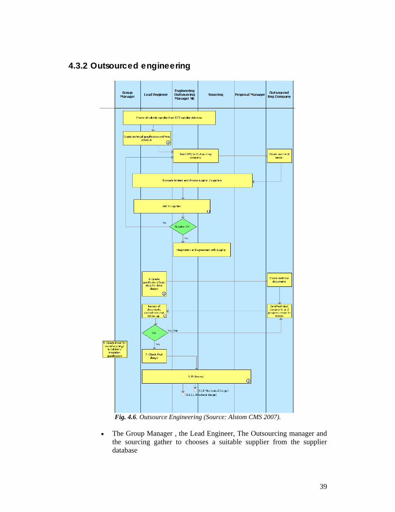
39
4.3.2 Outsourced engineering
Fig. 4.6. Outsource Engineering (Source: Alstom CMS 2007).
• The Group Manager , the Lead Engineer, The Outsourcing manager and
the sourcing gather to chooses a suitable supplier from the supplier database

40
• Before start of the design work, all detailed output and input for the design work must be defined. It is important that the Lead Mechanical Engineer together with the Mechanical Engineer clearly define what is to be done and clearly define the time that has been estimated for the specific work. The work can start before all input is defined but special awareness must be made that the design work will not be efficient before all input is clearly stated. Beside is an overall Design Review 1. These detailed Design Reviews 1 are held in this step. Lead Mechanical Engineer is responsible for these detailed Design Reviews 1. Special attention must be made for risk analysis. Risk analysis shall, if requested by authority or contract, be made for the APC plant with respect to risks connected to the process and it's equipment. The LEAD Mechanical Engineer is responsible that the mechanical design work is risk evaluated and performed according to applicable authority directive. ALSTOM's standard products / equipment are designed to obtain the European Union's directive for product security. The risk analysis for these products / equipment can be find in CMS.
• The Engineering outsourcing Manager and the sourcing send RFQ to
outsourcing company, while the outsource engineering company creates and send the tender
• The Group Manager, Lead Engineer, Engineering Outsourcing Manager,
Sourcing and Proposal Manager evaluate the tender suppliers. • The Group Manager, Lead Engineer, Engineering Outsourcing Manager
and Sourcing visit the supplier • The decision if the supplier meets the requirements or no, is taken.
• If the requirements are met the negotiation and agreement takes place, if
not The Engineering outsourcing Manager and the sourcing send RFQ to outsourcing company again.
4. When the design work or part of the design work shall be performed by external supplier or external partner an Engineering Work Order, an Engineering Work Description and required Basic Drawings or/and 3D-models shall be produced by the mechanical discipline. PERFORMED BY THE MECHANICAL ENGINEER / INPUT: MOM FROM DESIGN REVIEW 1, RESULT DORM STEP 1 DEFINE DETAIL INPUT AND SCHEDULE DELIVERED BY THE LEAD MECHANICAL ENGINEER / OUTPUT: ENGINEER WORK ORDER, ENGINEER WORK DESCRIPTION AND BASIC DRAWINGS CHECKED AND APPROVED BY THE LEAD ENGINEER AND DELIVERED TO THE SUB SUPPLIER • The outsource engineering company creates the documents • It sends technical documents and progress report to ALSTOM
41
• The Lead engineer reviews the documents, coordinates and follow up
• If the documents do not meet the requirements the outsource sends the technical documents and progress report to ALSTOM with the corrections until they are approved by the Lead Engineer.
5. The group manager creates the input for manufacturing, installation and insulation specification.
7. If the documents are approved by the Lead Engineer, he will do the final check. 8. The follow up will be conducted by the Lead Engineer, Engineering Outsourcing Manager, Sourcing and Proposal Manager.
4.4 Preparing On-site activities In this stage of the model we planned the way that we would carry out the on-site activities. After evaluating other options, we opted for the interview. By interviews (instead of questionnaires or surveys) the employee would hopefully feel the task as less of a “weight in their backs”; it would make him/her feel involved with the change process and it would give us the chance to explore deeper the causes and consequences of the inaccuracies. Nevertheless, for important data, if the personnel couldn’t be reached, email surveys or phone surveys were used. During one of the first encounters with the Manager of our department, we learned that there are many contractors in the department, moreover during the creation of the procedures, the employees were not fully involved and due to the rotation of contactors there was probably some lack of information about this topic. Therefore is important to mention that we plan to interview at least 50% of the employees and contractors to fulfill both objectives: our research increases the involvement of the employees with the ISO certification. In this case, the preparation of the on-site activities was also the design of the interview template which purpose is to spend the time with the interviewed in an effective way. During the interview we ask the next main questions followed by a review of the written procedures: Do you have knowledge of the quality policy, and the CMS content? How do you carry out your job? Does your job is reflected in the given written procedures? What related problems do you face during your job? It is important to mention that in the beginning of all interviews and surveys we clarified that we would not judge the employees’ manner of working, but rather the quality of the ISO 9000 procedures.
42
Moreover we let them talk freely about their opinions about the problems their department faced and the imagined causes. But afterwards, we asked about the problems we were interested in from previous interviews and documentation. Our objective by leaving our questions to the end was not to interfere with their answers, but to know their individual opinion on previous gathered knowledge. 4.5 On-site activities This step intends to give a better understanding of the dynamics in the work place in order to compare the written procedures and find the similarities or differences. We carried out the interviews previously scheduled, first with all the project leaders of the ongoing projects. The duration of the interviews varied from 40 to 70 minutes. Mechanical Design department duty is the design of the Alstom products, which could be from a smaller component needed in an electricity generation plant to an entire plant project. Therefore we realize that the cycle time for any of our written procedures could vary from one week to couple years and trend to have small differences from time to time depending on the complexity of the project. This might be the reason why this department work divided in projects. For example at the time they work with ten projects, the division of man power goes from 15 for the bigger projects to a couple in the smaller ones. The following highlights are quoted from interviews carried out: 21st March 2007 ELEKTRENAI, Lead Engineer (G. Svensson)
• There are always problems when finalizing the projects. It is not clear when the design is ok.
• There is always changes after the design was “ok” that exceeds the budget, sometimes due to our mistakes, sometimes not. There should be a difference between them.
• The Mechanical Design procedure is not accurate in the end. • As well in Outsource Engineering procedure there should say something about
the “as built drawings” coming from the supplier. (Means the drawings of the actual construction, which come after the follow up, since as I mentioned before there is always changes during the construction phase of the project).
26th March 2007 NID, Lead engineer (F. Jaksic)
• In mechanical design procedure, step3 “read the contract” would take too long time, so it is not clear the real meaning of the step.
• In detail design external there is misunderstanding in the procedure and the actions that are taken are not totally clear. There is a need of being clarified or better explained.
43
• It is not clear for me what the difference is between the “Detail Design External” and the “Outsource engineering”.
26th March 2007 ESP, Lead engineer (J. Persson)
• Mechanical Design procedure match, no need for change. • In Outsource Engineering after create the specifications, communication steps
are missing. It would be good to create a proposal document to go in and out. • Should be reflected in the procedure the feedback between Alstom and the
Outsource Company. This is one of the steps that take more time. 27th March 2007 DARLEY DALE, Lead Engineer (P. Johansson)
• The design review, it is hard to do it at once. It is done through the process because of prioritizing other activities.
• In Mechanical Design procedure, “Verifying and Adjusting as-sold layout” is not usually like in the procedure, because by then there are still changes in the layout and things are added on the road. Some of these things are difficult to see since the beginning.
• I estimate that 5% of the man hours of the project belong to the cost of changes. • There is a need of standardize processes for Alstom in other countries. • We could reduce the number of partials reviews, if the outsourcing part of
Alstom did it right at the first time. • Information availability between companies is vital • Maybe we could use e-conference (i.e. Skipe, Net Meeting, etc) to ease
explanations and avoid mistakes, from the external company, this way reduce number of revisions.
• In the first half of Outsource Engineering “choice of suitable supplier”, there should be in someway mentioned that this is done only when there is available time.
• Standardization of drawings is not mentioned in the procedure of choosing the supplier.
• The outsourcing should be done paying attention on the usage of the same software, because then there is always time taken to convert, send and receive the documents.
• Because of the distance there is bad communication especially when converting or testing the 3D models, this process needs some communication improves.
29th March 2007 SASSOL, Lead Engineer (K. Thornström)
• You never get complete information from the client or the supplier that is a big problem, and still you have to continue and go back and forward
• Keep working without knowing the final output until it is done, and still then sometimes when it is done you have to redesign.
44
• The redesign is extra cost and we are blamed for that, for every change that has to be done it does not matter if it comes from the customer or by Alstom.
• It is difficult to define where that cost should be allocated, because the contract is signed first and then the changes come
• These changes affect the efficiency of the company and the image of the company and trying to be effective there is lot of time and money spend
• By being more careful and specific on the requirements in the contract these can be reduced
• The cause is the lack of information or late and the consequence is the increase of the cost
• Main problem when outsourcing is the usage of different software and the communication which makes more difficult the development and time for the projects
• So the design department should take care when choosing the outsource company
29th March 2007 VKG, Lead Engineer (J. Ericsson)
• The kick of meeting is not always driven. It depends on time availability. • The plan review is not done in a meeting is checked when there is available time • Internal design is done pretty much how it is shown in CMS • Design review is divided in several products and small design reviews • The after the design has been finish, the redesign due to the client should be in
another account but sometimes this is not done, it is supposed to be for the new organization to have it in another account.
• For mistakes it goes to the original account • Some projects work the old way and they don’t use other account and then
everything goes to the same account and these makes the design area look bad, these because of the continuous changes
• The 3d models are not always received from other companies sometimes they received the second and then sometimes they do the 3d models, these depending on the tool that the other company has.
• The company at least should do the 2D models and Alstom the specifications in general before they are sent to the companies and 3d models are done by them.
• Create input for manufacturing installation and installation specification should be after the documents by the lead engineer but sometimes they are done before engineering.
• For the outsourcing, when choosing the company, there should be at least three candidates possible to develop the project, then the contract should be checked, and if it is not ok then they should go back and make the changes
• Then there is a need in the process of mentioning the sending in and out the contract in order to be checked
45
23rd April 2007 DARLEY DALE, Engineer (R. Provencher)
• In the mechanical design they start when the project comes to the design in-house so if there is a project the mechanical already know the detail at the PA so when the kick of the project leader participates but not the people of the design so most of them is because they are contractors this in the mechanical engineering.
• He works with the internal mechanical design • They don’t read the entire contract, they just give them the copies and work with
their section because it is so big, just the lead engineer has the whole contract and there is one person in charge of divide it in sections
• The planning is done by the lead mechanical and the mechanical engineer • When there is some unexpected changes this can be happening because they are
not considered in the first design review and then there is no one to tell of what they are capable, how much time it is needed or how many people for the project.
• Getting experienced people involved earlier in the project will help avoid problems in design and example of these is the Darley Dale, where they have problems involving and training people because they were new so there was more time involved for the training that wasn’t considered in the project, so it takes more time and money.
• This factor of always having new people is because of the workload they use contractors that don’t work for a long time.
• There is two kinds of external one is with contractors and the other one done by Alstom but in INDIA.
• By the end of summer they will start working with INDIA using same Catia and having same time databases, because these days it takes a long time to send and receive documents. Finally after having the checking takes a lot of time because sometimes they check a lot more than needed and then send them back with question.
• When the change is easy the change is done in Sweden. • In this kind of projects, time is money and saving the sending and receiving time
will save money, which most of the times this is not considered. • Also the design correction hours is not considered in the budgets. • In the budget, there should be in the planning of the activities, they should be
thinking on the mechanical design hours, and a certain percent for plus percent for the outsourcing.
• Last minute changes increase the budget really big, because a lot of effort is required.
26th April 2007 LKAB, Lead Engineer (M. Jonasson)
• We do not have changes cost problems since there is a special person from the project department that handles only the change orders.
• We rarely meet to discuss the CMS documents. Maybe that should change.
46
• Follow up is done trough all project not only in where it is placed in the procedure.
• The design reviews are several meetings.
25th April 2007 Engineering Manager M. Björck:
• If the customer or supplier causes a change then it is the lead engineer task to say “yes we can do it and we come back tomorrow with the calculation of the cost” and the “change order”.
• The general problem here is that must of the people just do the changes. • But actually in the work description says they are not allowed to do changes and
they should have an agreement. Then if they are supposed to do the work, then of course the budged should increase.
• There is already a way to work with this and in theory they should not make any changes like that, but these changes are still done. About these other employees mention that these won’t work 100% because the small cost may not be seen.
4.5.1 Additional findings on “quality cost” Even though there is a chain of evidence in the interviews, there are inconclusive issues about the quality cost. How much is this problem affecting? In order to understand this problem better and give better recommendations, we researched figures and concrete examples. (Appendix 1/2) Even though there are more examples with similar tendencies, due to time constraints, we concentrate in one, since it was easier to gather official data. In a closed Alstom project from 2002/3, we found that the organization had difficulties with the earthquake norms in Greece. They changed, and the Mechanical Design department had to invest man hours in already “standard” tasks i.e. ESP design. This change of norm almost duplicated the amount of steel needed for erection, which added design hours, not to mention material costs. This was a remote problem, however, when we realized the difference between the planned and the actual projection. Originally there were 6864 man hours, compared to the 14953 (according to the follow up). That is not even close to budget, 46% of the time invested was not planned. However, we realized that 1300 design man hours were accounted as “extra cost”, which means “design not included in the plan, besides the earth quake regulations”. Moreover, it is important to say that the total of these numbers is due to changes during detail design. This fact makes those changes easier to document than the ones after the “books” are closed. For analysis purposes the reader may find fractions of the official follow up, the date relation and the original economical reports of this Alstom project as Appendix 1, 2 and 3 correspondingly.
47
Chapter 5. Analysis In the fifth chapter, we will present the analysis of our thesis. The Analysis chapter mainly includes the documentation of fifth stage of our model. Moreover we will analyze the additional problems we found during on-site activities, and analyze in what way they affect our main concern. The Analysis Chapter will give the reader the information about how the procedures lacked of quality and how they were changed in accordance with the Theory Chapter. 5.1 Detected changes The following sections reveal the inaccuracies and errors found in the procedures before mentioned (Section 4.3). The evaluation criterion is a mixture between the general preunderstanding about ISO; the theory chapter; the documentation review and the on site activities. According to ISO 9000 the documentation should contribute to repeatability and traceability. Furthermore it should make the evaluation easier of the effectiveness and continuing suitability of the quality management system (Section 3.7.5). Also, it is important to remember the sixth rule from Section 3.7.6 “Write what it is, not what it must be” (Russo, 1997). Saying this, we can start to analyze possible changes in the Mechanical Design procedures. The four different procedures compared with some of the Russo’s rules for quality documentation (Section 3.7.6): All the processes avoided traditional writing altogether, mentioned by rule 8, which leads to a better understanding. This is why most of the time there are boxed descriptions. Moreover according to rule 9 they should avoid the usage of references in the procedures. These four different procedures fulfilled this rule and yet gave a list of documents needed in the boxed description. Rule 10 was satisfactorily graded, since the authors avoided defining terms in the procedures. In this aspect, users do not need special glossaries etc, which at the same time makes this documents user friendly and helped them to fulfill rule 12. What we did not find, is that according to rule 11, they should be flexible for revisions; or that even the process should encourage personnel to make revisions frequently. Reading the procedure, we could not find even a single step that leads to the revision of the process. Therefore, this aspect is needed to create a manner to revise the processes frequently.

48
5.1.1 Mechanical Design
Fig. 5.1. Mechanical Design changes (Source: Own creation)
1 Lack of time may interfere with the realization of this meeting but most of the time takes place normally. 2 There were couple comments about the delay “Reading the contract” causes. We realize that most of the time the contract is a very large document, therefore not many people have a complete knowledge about it. If there are changes in this step, they should simply be reflected in the description of the box. Furthermore, not every “mechanical engineer” has to read the contract. According to the manuals, there should be a Lead Mechanical Engineer who is supposed to divide the contract and give it to the Engineering team in order to make reading more efficient.
2
1
3 4
5
6
7!

49
3 “Design Review1 meeting is hard to do at once” “the design review is several meetings”. There should probably be a change in the description of the box, from singular meeting to plural. 4 It is carried out but it is not infallible, afterwards the customer always want more follow-up platforms, etc. The description of the process says “if possible should be approved by the customer (…)”. To improve performance, the customer must approve the layout before starting detail design. 5 This should not be a decision taken by a mechanical engineer. Rather, this should be a decision from top management with the Mechanical Design support, invoiced from purchasing department. 6 Distribution of documents to the construction division is not the mechanical team duty. 7 In most of the cases, there exsists a redesign work which is ignored by the top management. This redesign is not contemplated in the procedures, in the financial books, nor in the planning. The final part of this procedure does not match the reality.
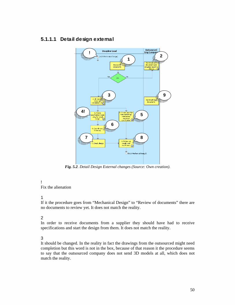
50
5.1.1.1 Detail design external
Fig. 5.2. Detail Design External changes (Source: Own creation).
! Fix the alienation 1 If it the procedure goes from “Mechanical Design” to “Review of documents” there are no documents to review yet. It does not match the reality. 2 In order to receive documents from a supplier they should have had to receive specifications and start the design from them. It does not match the reality. 3 It should be changed. In the reality in fact the drawings from the outsourced might need completion but this word is not in the box, because of that reason it the procedure seems to say that the outsourced company does not send 3D models at all, which does not match the reality.
! 1
2
3
4! 5
6
7 8
9
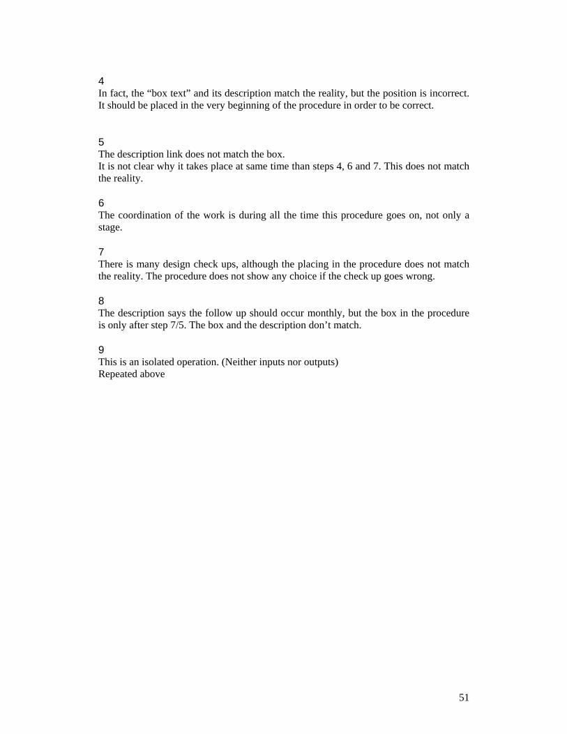
51
4 In fact, the “box text” and its description match the reality, but the position is incorrect. It should be placed in the very beginning of the procedure in order to be correct. 5 The description link does not match the box. It is not clear why it takes place at same time than steps 4, 6 and 7. This does not match the reality. 6 The coordination of the work is during all the time this procedure goes on, not only a stage. 7 There is many design check ups, although the placing in the procedure does not match the reality. The procedure does not show any choice if the check up goes wrong. 8 The description says the follow up should occur monthly, but the box in the procedure is only after step 7/5. The box and the description don’t match. 9 This is an isolated operation. (Neither inputs nor outputs) Repeated above
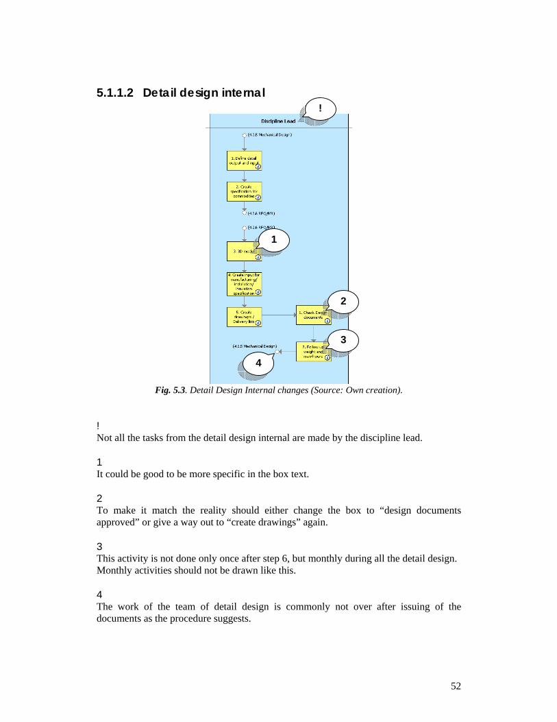
52
5.1.1.2 Detail design internal
Fig. 5.3. Detail Design Internal changes (Source: Own creation).
! Not all the tasks from the detail design internal are made by the discipline lead. 1 It could be good to be more specific in the box text. 2 To make it match the reality should either change the box to “design documents approved” or give a way out to “create drawings” again. 3 This activity is not done only once after step 6, but monthly during all the detail design. Monthly activities should not be drawn like this. 4 The work of the team of detail design is commonly not over after issuing of the documents as the procedure suggests.
!
2
1
3
4
53
5.1.2 Outsourced engineering
Fig. 5.4. Outsource Engineering (Source: Alstom CMS 2007).
Due to our limitations, we will only concentrate in the stages where our department is involved. In addition since we haven’t gathered data about the sub supplier selection or other employees in the “purchase” department we just analyze the second half of the procedure. The descriptions of the procedure lack of content The aim of the second half of this procedure and “detail design external” is the same, there should not be two procedures for it. Moreover they should not be different. Therefore we will fix the previous mentioned and if Quality Management decides to repeat them they should match.
54
5.2 About “employee involvement” As it was mentioned before in chapter 3.5, it is very important for the company to have their employees involved in ISO documentation and the processes used by them, they should represent the way of working more than just mentioning how things should be done. In this way, when there is involvement by the employee, the documentation will be more consistent and it will be easy to find mistakes or descriptions missing. To understand how much involvement there is in the company, we decided to create a small survey that was spread through the mechanical engineers of the company as well as the lead engineers. This survey included questions concerning aspects like ISO 9000 and their processes description in their CMS. The questions were: In what degree are you aware of the quality policy of this organization? How aware are you about ISO9001? How much do you remember of the procedures of CMS? How close do the procedures in CMS describe the real process? After applying this survey the answers showed the following:
minimal13% low
7%
moderate54%
fair13%
significant13%
none0%excelent
0%
Graph 5.1 In what degree are you aware of the quality policy of this
organization?(Source: own creation) As mentioned before in section 3.2.1, companies need to assimilate the fundamental concept of competitive quality, which automatically leads to the concept of continuous improvement, then it is important how the company interprets quality to become competitive. (Conti, 1993). In this first question we were expecting to discover how much of the quality policy they have assimilated and how do they interpret it in order to apply it to their everyday work. We decided to start by the lowest level of quality in which the company should be running. In the graph it can be seen that the majority (54%) of the employees are moderately aware. And it tends to be significantly more than the minimum or low. However, everyone in the company should be aware, however sometimes the contractors change frequently and they barely last more than 3 years so they can not be completely aware of the policies.
55
At a certain point this shows that the employee in different degrees is aware of the quality strategy, of what it is expected and the guidelines the company has in order to become competitive. As mentioned in the theory chapter 3.3 this quality policy which is included in the total quality management will seeks to integrate all organizational functions to focus on meeting customer needs and organizational objectives.
minimal20%
low26%moderate
27%
fair20%
significant7%
none0%
excelent0%
Graph5.2 How aware are you about ISO9001? (Source: own creation)
The second question gets deeper in quality aspects but not only about the company, here we wanted to understand if they have heard or know how ISO 9001 works and what does it encompasses. We wanted to find out if they are aware of the meaning of using ISO9001 which was mentioned in the chapter 3.5 by Schmauch mentions that the standards are not specifications, they state what has to be done; they do not state how things have to be done. According to the results in the Graph 5.2 it can be seen that most of the employees (about 54%) have at least moderate idea of ISO9001 in which 27% they know what they should know, but then 26% has low and 20%minimal which should not be like that, because it is a matter for everyone in the company even if they just started. In one way or another International Standards can contribute to the quality of life in general by ensuring that what we do is safe, as it is mentioned in chapter 3.5.1. From the ISO 2007
minimal27%
low40%
moderate20%
fair13%
excelent0% none
0%
significant0%
Graph 5.3 How much do you remember of the procedures of CMS? (Source: own
creation)
56
As mentioned in chapter 3.7.2, changes to documents and data shall be reviewed and approved by the same functions/organizations that performed the original review and approval, unless specifically designated otherwise. (Parisher, 1998) In order to accomplish this, the company employees should be aware of their processes in the documents (in this case CMS), that is why the question of “How much do you remember of the procedures of CMS?” to know which percent of the employees actually know what is written about the processes in the procedures, even though it should be reflecting what they do, in this way after the question they should be understanding that CMS reflects what they do , that they are not rules , as it was mention before for the Figure 5.2. In the case of Alstom, 40% remember low amount of what it can be found in the CMS but the worst is that 27% has minimal awareness of their own process description which will lead to not even reading them nor changing them when the processes are not anymore done. Just 13% are fairly aware; even though everyone knowing the description of their process should be excellent. As mentioned in chapter 3.5, it is the description of their own work, they should own that description.
minimal13%
low20%
moderate40%
fair7%
significant20%
excelent0%
none0%
Graph 5.4 How close do the procedures in CMS describe the real process? (Source:
own creation Since it is important to have accurate documented procedures we decided to ask the employees about how closely the procedures describe their real process. These questions had two different purposes, one to find out how close to reality the procedures in general are, and two, to find the possible changes that the procedures may have. As mentioned in section 3.7.1 for documented items, there must be procedures for review, approval change issue, and ensuring they get to the right people at the right time and that obsolete documents are not in active use. It is important to have procedures that avoid obsolete information. That is why, when comparing this idea with graph 5.4, we can see that the company documents are not avoiding obsolete information since 40% of the employees think that the documentation is moderately close, 7% fairly and 20% significant, but 33% think it is poor. This should not be happening and the employees should be realizing that, since they are their procedures, the descriptions should be at least fairly closer to reality
57
These documents should be closely describing the reality because as said in chapter 7.2 Changes to documents and data shall be reviewed and approved by the same functions/organizations that performed the original review and approval. So it is their task to keep them close to the reality. 5.3 About “quality cost” As the reader may find in the interviews (Section 4.5) there are many employees talking in common about what happens after the design is “ready”. Some employees define it as “quality cost” problem, others don’t care so much about the mess when accounting, but about the lack of available time or personal that this problems bring. Either way we find this issue related to our main problem, because the procedures don’t reflect the reality and these procedures lose their advantages. Therefore together with our control case (See 4.5.1) we analyze this issue as part of our main problem. The first observation of this issue is that there is no record of it in the CMS; therefore it has been very difficult to explore. Since there is no record of it, we assume the top management does not have knowledge of the actual circumstances, therefore there are no actions taken to reduce it or at even document it for a better allocation of resources. In addition it risks the repetition of the process. Problem definition: There is never a clear point which you can call the “end of the design project”, nevertheless the financial departments need to close the books so they can note account savings and loses. We call this point a “theoretical” close down of the project. At this point, the design team is relocated in a new project or if they were contracted for a single project they leave. At this time all the drawings have been sent and according to the ISO procedure the job is finished. The only person that would possibly stay in the project is the project leader. The problem is that after this point, during the construction, there are always changes that have to be reflected in the As-built drawings (caused by construction or the customer), or changes that simply need to be redesigned for construction. The main observation from the workers is that this work is “extra”. It is never planned therefore it impacts in the budget (metrics) of the “normal” design and affects them as if they had poor quality. There is a way to order changes from the customer, but the main complaint from the workers is that due to delicate relations or other reasons, construction or purchasing (etc) might just grant the change without the papers needed (change order). Even if this happened the change has to be reflected in the as-built drawings, therefore it affects the “design resources”. These changes may be small, but all together, they can sum up a large amount. I.e. To add/change stairs or platforms, it might take 8 hours to design, but to do the paper work would inflate the cost, therefore they just allocate the cost in the same account as the normal budget for “stairs”.
58
Furthermore, there are not planned workers to do the changes. And as we mentioned there are times where the entire team is dissolved into other jobs as soon as the project is theoretically closed. It is important to mention that the self-caused changes should be fixed and cost reflected in the budget of the normal design, which the personal know and understand. But it is important to mention that their mistakes are commonly found before erection. In other cases attempting to solve this problem, the project leader would try to delay writing “100%” completed in the economical reports, so Alstom would not absorb the profit until the risk of changes is lower so as to not affect the way the management would see the project. This stems from the leader belief that in the end “hours are hours”. We found as well that even though this is a common problem, every lead mechanical engineer works differently to solve it. There are projects that claim the expenses for every change while there are others that rather to grant the changes. Some projects would have “sub numbers” (accounts) for external and internal extra costs while others don’t. The next graph was our first evidence of the problem and takes its data form all the lead mechanical engineers working in ongoing projects with past experience. For the personal that couldn’t be reached for interview, email or phone was used.
yes43%
partially57%
no0%
Graph 5.5 Do you face the defined problem “after design”?
Furthermore we needed figures to prove the situation at the top management level. Therefore, we got the official follow up of our control case which shows as a final cost of 14953 hours. (appendix 1) According to the former leader of this project, “most of the work was finished and sent for the end of 2002”, however due to the strength norms that we mentioned in “appendix 1” there were many small drawing changes until beginning of 2003 (which explain the “noise” in the following estimation graph 5.6). In order to deduct the termination of the design stage, we got the date relation of the packages of drawings. (appendix 2)
59
As our contact mentioned, the work done sent the 9th of May 2003 was self-caused (by Alstom when writing the contract) changes, but not original planned design, therefore this data should not appear in other projects and we should not analyze this point.
27/0
6/20
02
27/0
7/20
02
27/0
8/20
02
27/0
9/20
02
27/1
0/20
02
27/1
1/20
02
27/1
2/20
02
27/0
1/20
03
27/0
2/20
03
27/0
3/20
03
27/0
4/20
03
27/0
5/20
03
27/0
6/20
03
27/0
7/20
03
27/0
8/20
03
Pack
ages
Sen
t
Graph 5.6 Draw delivering against time
From the data of appendix 2 we draw the graph 5.2. It is important to mention that not all the deliveries are equally important or similar in size. Therefore one delivery in January could be more important than two in May etc. Either way this estimation proves the testimony of our contact about “the work was supposed to be finished before December 2002” and the large amount of communication in May 2003. According to this new evidence we can suggest that the ends of the projects are not shaped as the CMS show and the management perhaps believe.
Fig. 5.5 Estimation amount of work against time
The figure 5.5 shows the amount of work compared with the time elapsed, validated by our contact, this graph shows in the point number 1 the end of the project. It is this point where generally the personnel is gone and the books are closed. Between point 1 and 2 present could pass couple weeks maybe months. Respectively point 2 represents the
Time (T)
Wor
k
1 2
60
extra work that some employees estimate in 5% (See 4.5) but that the management (and/or CMS) does not seems to recognize. A secondary problem surge between point 1 and 2. We already explained how the employees move to other projects or leave the company, but we want the reader to realize that the extra work represented by point 2 will affect the performance of the following project in a lack of personnel or availability of time. Therefore man-hours charged or planned for the following project are lost or delayed due to the previous project. At this point in the analysis our concern is to try to measure the size of the problem. In order to get a realistic size of the problem (in man hour terms) we will not analyze it from the theoretical closing down of the project (around December 2002), but from the date when the last registered drawing was sent.
0
2000
4000
6000
8000
10000
12000
14000
16000
31/06/2003 01/09/2003 01/10/2003 01/11/2003 01/12/2003 01/02/2004
As soldActual
Figure 5.6 As sold against actual cost (Source: Own creation).
The figure 5.6 was built from data in appendix 3. It shows the comparison between the As-sold and the Actual costs. Just like we mentioned earlier in section 4.5.1, the very large difference between those costs is mostly due to Alstom miscalculations in earthquake norm matters. Therefore, we will not analyze their differences, but the growth after the project finale. Point 1 shows the most probable project finale, this is (according to appendix 2) the date of the last drawing sent to construction (11/09/2003). The project cost at that time was 14502.5 man hours. Let us remember that according to the procedure from CMS after sending the documentation to construction, there are no operations left but “closing project” therefore after this date not any additional cost is expected. Point 2 shows the cost according to the official follow up (appendix 1) with cost of 14953 man hours.
23
1
61
Either way we can state that the actual cost increased until February 2004 (Point 3) and it was 15075.5 If we take CMS definition of the project finale, then the increase of the cost is 573 man hours. On the other hand, according to the latest follow-up, the increase was 122.5 man hours. The purpose of this comparison is to demonstrate that after either of the project finales that the readers could agree about, there is still growth of the actual cost and in this case, there is not complete documentation of the changes that caused the expense. In addition the budget for this project never changed in the documentation. This makes us consider that design department took all the blame for every change. According to the former lead mechanical engineer of this project, after May 2003 everyone received new projects, even himself, who started as lead in other project. This data demonstrates that the efficiency of the new projects (where the former engineering team started to work) was impacted by percentage of the previously mentioned 122 to 573 man hours.
62
Chapter 6. Results and Recommendations In Chapter six, we will present the results and recommendations of this study. The Results and Recommendations section is based in the Analysis chapter and it finalizes with the case company. It contains the conclusions obtained by the employee interviews and the final version of the procedures obtained by them. It also includes the final results for the additional findings and recommendations for further activities towards continuous improvement in the department of our study and others involved.
6.1 Results on employee involvement After applying surveys and having some interviews with the employees of the company, several factors were found that, according to chapter 3, are very important. Sometimes the company does not pay too much attention to these factors and that is when several problems appeared. The first one of these factors is the enrollment with the quality policy, which should be well known, understood, and applied to the every day work of the employee. Speaking of which, we found that in Alstom Power 13% of the people are minimally aware of it. This idea should be considered, since this quality policy should be well known by every employee in order to reach the company’s goal. This basic aspect can improve several areas. The second aspect is the awareness about ISO9001, where the employees should understand and be aware of the concepts in order to work with them and use them as a tool to improve the way of working, and make it easier to find and solve problems that may occur. In the mechanical engineering of the company 46% percent of the workers have low or minimal awareness of what ISO is and when to use it. It is extremely important that the company ensures that everybody gets to know what it is, so that the employees work with it and are conscious that the processes are owned by them, also that it describes what they do, not what they should do. And then if there is something not working properly, they can make changes whenever it is needed. Then, if they are conscious about this, problems will be easier to find and solve. We realize from our experience in the department that a fraction of the personnel resists to change. In addition, it is a common understanding that the ISO 9001 is impeding their job rather than benefiting it, which we tried to change through explaining ISO benefits and basics on our interviews. The third and last aspect is about their CMS which is the way the company documents all the procedures and is available for every employee of the company to access, and if there is a need of change, then it can be made through a notification to the quality department. After the surveys and interviews, we found out that the employees are not aware or are not intimate with their procedures in CMS. Sometimes they do not even remember
63
them. Besides, 67% of the employees had either low or minimal knowledge of the procedures in CMS. Then if they do not even remember them, of course these procedures contain several mistakes and sometimes they are not aware of this. All these is reflected in how close the procedures are to the reality where according to the employees at least 33% say that they are close in a low degree, and sometimes there are mistakes easy to notice even for people that is not familiar to the process. As it is for our department of study, we realize there was concern from the management since the beginning, which was keystone for the realization of this study. Furthermore, we can conclude that after the activities for updating the procedures, the personnel had shown more interest in writing the procedures more correctly. All that decided to form part of this project should have a better understanding now of what ISO 9001 stands for and the importance of reflecting the reality in their procedures. We made participants of the lead mechanical engineers of the concern in management, and then to the mechanical engineers. We realize that according to the theory chapter, it is the right track to take, from the concern and compromise of the management to the compromise of the lower levels. 6.2 Final documented procedures After auditing the department documentation, we found that even at the level that Alstom decided to describe their processes, there were inaccuracies. These inaccuracies show us first that ISO 9001 is not being used as it should, therefore it is not giving enough benefits at the moment. Secondly, that where these inaccuracies occur; they are problems difficult to trace, and because of this, there is not any action taken to reduce these circumstances. From our journey in the Alstom Power Mechanical Design department, we conclude that the real situation appears as follows:
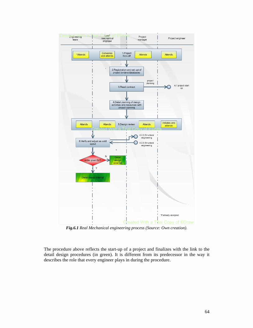
64
Fig.6.1 Real Mechanical engineering process (Source: Own creation).
The procedure above reflects the start-up of a project and finalizes with the link to the detail design procedures (in green). It is different from its predecessor in the way it describes the role that every engineer plays in during the procedure.
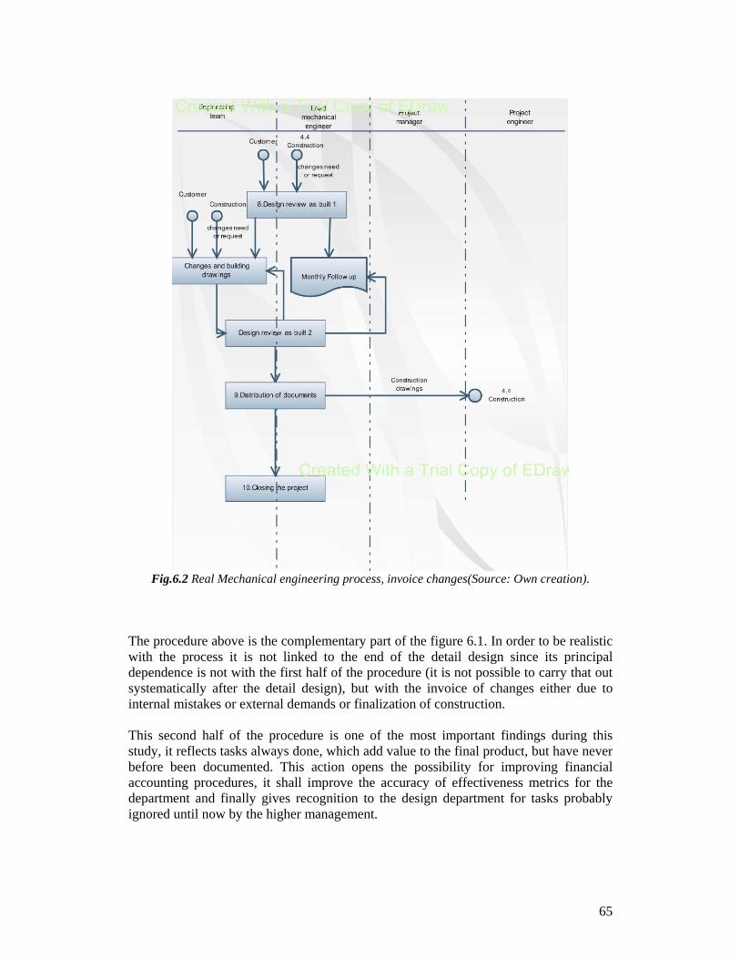
65
Fig.6.2 Real Mechanical engineering process, invoice changes(Source: Own creation).
The procedure above is the complementary part of the figure 6.1. In order to be realistic with the process it is not linked to the end of the detail design since its principal dependence is not with the first half of the procedure (it is not possible to carry that out systematically after the detail design), but with the invoice of changes either due to internal mistakes or external demands or finalization of construction. This second half of the procedure is one of the most important findings during this study, it reflects tasks always done, which add value to the final product, but have never before been documented. This action opens the possibility for improving financial accounting procedures, it shall improve the accuracy of effectiveness metrics for the department and finally gives recognition to the design department for tasks probably ignored until now by the higher management.
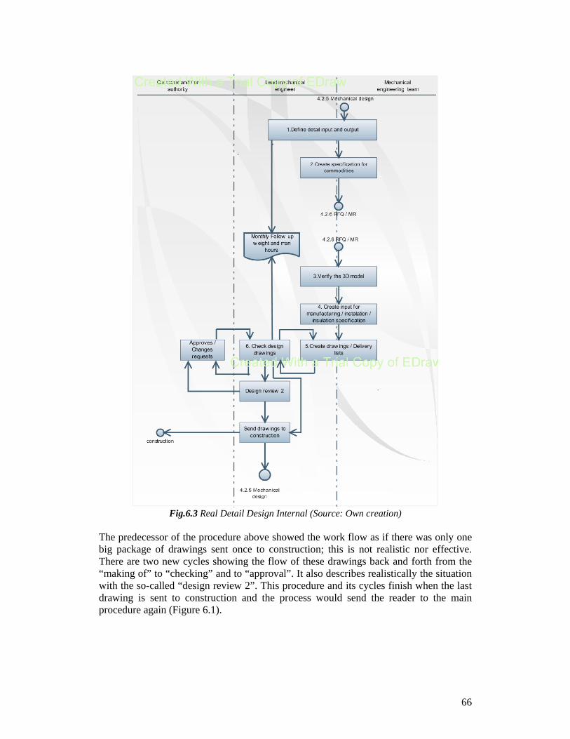
66
Fig.6.3 Real Detail Design Internal (Source: Own creation)
The predecessor of the procedure above showed the work flow as if there was only one big package of drawings sent once to construction; this is not realistic nor effective. There are two new cycles showing the flow of these drawings back and forth from the “making of” to “checking” and to “approval”. It also describes realistically the situation with the so-called “design review 2”. This procedure and its cycles finish when the last drawing is sent to construction and the process would send the reader to the main procedure again (Figure 6.1).
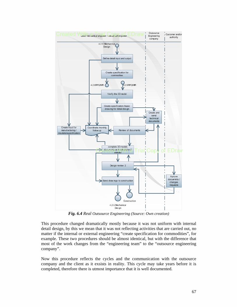
67
Fig. 6.4 Real Outsource Engineering (Source: Own creation)
This procedure changed dramatically mostly because it was not uniform with internal detail design, by this we mean that it was not reflecting activities that are carried out, no matter if the internal or external engineering “create specification for commodities”, for example. These two procedures should be almost identical, but with the difference that most of the work changes from the “engineering team” to the “outsource engineering company”. Now this procedure reflects the cycles and the communication with the outsource company and the client as it exsists in reality. This cycle may take years before it is completed, therefore there is utmost importance that it is well documented.
68
In general, the main difference between these procedures and the original published in Alstom CMS, is that in the originals, there is not recognition about the amount of changes that the design department is forced to do; the department is the place where these changes are invoiced and their nature is defined. There is no recognition about the “As-built” operations, which take place even if there were not any “after design” changes at all. Another highlight on our work is the confusion (in reality and reflected, as well as in the documented procedures) about the “outsourcing”. The variability between the outsourcing of a project and another is notorious. This is reflected in waste of time and delay of projects and manufacturing. As we mentioned before each one of these problems impact the departments effectiveness at the very moment when they occur, as well as in in future projects by taking personnel already designated to cover for the past changes. These new procedures reflect the reality, but their real value is that they map opportunity areas. These procedures have been revised by the personnel and they accept them as a true picture of the actual situation. This is also true for the quality manager, she accepted the procedures. She shall change the procedure format and upload them to CMS. 6.3 Recommendations about procedures and employee
involvement In general, the company should consider focusing on more quality aspects, keeping their employees better informed, and ensuring that every worker becomes aware of the quality policies. Also, create awareness about ISO so that they understand that the documentation is the description of their work. This way they will be able to own the processes and they are responsible for keeping them updated, which will lead to a better way of working, discovering, and solving problems. This is pertinent, because during the interviews, we even found that there were some people saying that they “do not work in any way with ISO and CMS”. The quality systems indicate the existence of quality, and should lend reliability to the process and pilot improvements. And the best way to implement a quality system is involving the people of the company. The manager should insist on the statement that the procedures described towards ISO 9001 certification and the “way of working” are not different things. They must emphasize that the procedures should just be a picture of the process that bring benefits further than the actual certification. In ISO, the best way to have the process documented is by letting the process owners to document it; but before this happens, they should be able to understand what the ISO standard is about. This implies the usage of the structure to improve processes. In
69
general, the standard operation procedure tells how processes are performed, not how they should be done. In addition it is important to consider that the owners of the procedures would better be employees with commitment towards quality, whom voluntarily should have scheduled paid time to spend in these matters. Even if it is not necessary much time once the procedures are correct this periodical check ups should not be a punishment for the owners of the procedures, but just a part of their jobs. At this point it is important to mention that in this study the procedures were practically written from scratch and much time was required to gather information from employees to have a truly reliable procedure, which should be “satisfactorily valid” for up to two or three years. Eventually, another deep audit will be merited and many man hours will be used to gather reliable information from sufficient personnel. Otherwise, a couple hours a month should be invested in keeping the records reliable and updated. There will be substantial time saved for the next “re-certification audit”. In the company, there should be continuous self managed work teams responsible for documenting the process, but the management should be responsible that these procedures reach the main goal of the process. Then the process owners are the ones who will be writing the procedures considering a section for continuous improvement. We recommend the top management to set meetings with the closest medium management to discuss regularly quality topics and document these meetings to make them official and binding. As well medium management with the lower lever and so on. This way the documented procedures should change in the proper way, “evolve”, first the way of working changes, then the documented procedures. During the process of this study we found severe order mistakes in the procedure called “Detail Design External” which makes us wonder when the last review over the process for this procedure was. As we mentioned before, we should change the way of working before the procedure (once it matches the reality, of course). Therefore we recommend the organization, rather than the department, to start up with a new process to update their procedures. The organization must remember that Quality is not an expense, but an investment. With this in mind we recommend Alstom to use our model to make all their procedures coincide, and once they match the reality, to start using periodically the following modification of our model procedure.
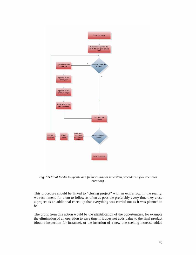
70
Fig. 6.5 Final Model to update and fix inaccuracies in written procedures. (Source: own
creation). This procedure should be linked to “closing project” with an exit arrow. In the reality, we recommend for them to follow as often as possible preferably every time they close a project as an additional check up that everything was carried out as it was planned to be. The profit from this action would be the identification of the opportunities, for example the elimination of an operation to save time if it does not adds value to the final product (double inspection for instance), or the insertion of a new one seeking increase added
71
value. As in this study we identified the “after design” problem or pointed out the confusion and discontent with some operations in the outsourcing procedures. If some time is invested when the information and records are fresh in the personnel minds towards keeping procedures updated and performance effective, much time would be saved during internal audits. This would also ensure the certification by being “ready” for audits all the time. It is important to mention that there is not such a procedure at the time. Even though we find procedures for tasks like “reporting sick employee” for example, there is no link or procedure that encourages revisions or updates for published procedures, neither in the real life nor documented. In other matters, we recommend the assignment of couple engineers in advance to the project. This is in order to facilitate communication of the unwritten information shared with the department during the kick-off meeting. This should ensure that the engineer’s vision of the two phases of the project is similar. This vision or preunderstanding gained by the sales department and the tender phase engineers have is important since they had close contact with the customer. The results should match their expectations. 6.4 Results on “additional findings” As we suggested in the previous section, the value of documentation versus the documentation itself and the certification on ISO 9001, is the findings you get from writing them. In section 5.3 “About quality cost” we verified the existence of the then defined problem and calculated its impact in the future project. From this control case, we can refer to many of the projects the following statements. It is always stipulated in the contracts that Alstom should hand in assembly drawings As-built to the customer, which, even if there was any change at all in the construction, are supposed to be printed again, stamped as “As-built” and signed by the lead mechanical engineer with the date. Very often, after the last drawing was sent, the team is dissolved into other new projects, because it is not cost effective to have a team of engineers on stand-by. Some random time after this point is when the “As-built” operations take place and most of the time there are changes that meanwhile have to be reflected in the detail drawings, and often in the assembly as well. It is common that during the construction problems emerge that should be fixed first in the design department, normally as soon as possible, since they may stop construction and increase Alstom costs. This is the reason many “small” changes are not properly documented in the rush. As the reader may understand what is on paper is official. Yet there is no documentation about the “after design” activities. This work is simply not recognized and it is charged to the same budget of the original design.
72
In the first instance, its cost is impacting the effectiveness metrics of the Mechanical Design department. For explanation purposes, let us assume that the budget is calculated for the department to perform task 1 only, but in real life they are performing task 1 and 2, then they are working constantly over budget with a very small chance to make the two tasks with the budget of one. The situation explained above does not means that the work would stop, but in fact the reader should remember that in a big company the responsibilities and operations are outsized and therefore divided. For this reason, the management is not expected to know the process intimately that takes place at the bottom of the organization, or in this case, the design department. For the top levels of management of this company, the effectiveness of the department of Mechanical Design to reach their goal in budget might be just a number with couple notes that means everything to our department of study. If this metric is inaccurate and keeps showing an inflated cost of design due to “after design” activities we predict discontent from the management and low motivation of employees to reach their goals, among other situations. Additionally, since the team is dissolved at the theoretical end of the project, the lead mechanical engineer has to try to cover the changes him/herself; this means responsibility to distract former engineers from the project who are probably busy, or to hire new engineers. These are new people who will need time to adapt to the project, understand the drawings, and gather all of the proper information and/or experience (in the given project) that the former engineers had already. Either way, this results in ineffective use of the time. Finally, this problem impacts upcoming projects by borrowing resources and delaying already planned operations in order to perform the as-built activities of the former project. This is most probable if both projects share personnel, and due to the cut of contractors in the theoretical end of the project. 6.5 Recommendations on “as-built” activities First of all, we believe that documenting these activities as it was done during this study is the first step to get recognition for the job our department does. From now on we believe there should be at least a minimal level of planning about these activities. We identify the need of creating another account to take on these changes since they do not belong to the first level of design. This account is intimately related with quality and added value. The as-built design activities could be, instead of a problem, a competitive advantage against other companies that offer similar products. We suggest the creation of a sub-department or an operation dedicated to do these changes. We realize it is difficult to plan this stage of design because the time when it will begin is not predictable.
73
Our first notion would be that a defined number of employees (from 3 to 5) take roles in this sub department. These engineers should be individually chosen from finished projects, who therefore are immersed in the knowledge of a given project and “Alstom’s way of working”.They could easily go back and make changes to the drawings and communicate this unwritten knowledge to the others in the sub department. Meanwhile, these specially assigned activities which arise in the sub department could help other projects as extra personnel and not with vital activities, so they could leave them when they get external work. This transition team could have rotational rolls. After the project that a given team member belonged to is closed and the as-built drawings were accepted by the customer, this member could abandon the sub department and be restored to another project. In the meanwhile some other engineer from a project almost finalized with the normal design should start to link with the team. If not opting for the rotational scheme, then the team should be involved in a way with the projects in any way to have preunderstanding on the on-going projects, probably though revision of assembly drawings or the changes in the normal design. Either way, the departments should issue a document when the given stage of design is ove,r where they renounce their responsibility and hand it in to the following stage during the holistic process. This is comparable with the handing of the project in “Project kick-off” from the group that worked in the tender phase to the detail design, but this document or meeting could be accepted and/or signed by the customer as a way to finalize the as-built activities. Furthermore the changes during normal design are charged as an “external and internal extra” which does not say much about the nature of the change itself. We believe that instead of grouping the costs only by “project” they ought to be numbered by design, a number for “As-built”, a number for Quality cost, and so on. The quality cost should be an account for project where all quality costs should be charged, by the means of every mistake or rework of every discipline involved in the project (i.e. design, manufacture etc.) Creating this account would make it very easy to trace and analyze repetitive failures to their causes and their nature. The additional value of handling the accounting this way would be to point out correctional actions that could open possibilities for improved opportunities and various quality projects. About the great quantity of small and medium sized changes requested from the customer, we understand that sometimes the changes are not worth the paper work (change orders) for opening a sub-number, for example, but we recommend Alstom to define what a “small change” is. At the moment, 8 or 10 design-hours of change comes frequently and in many steps during the design procedure. That give the impression of hardly affecting the budget of the department or the profit of the company, but in reality summing them all up, the result might be mistaken.
74
Granted, an amount of changes (i.e. 50 design-hours in total in small changes) in the contract issuing could satisfy the customer, and help the company refuse future changes after the limit agreed on without damaging the customer/vendor relationship. Granting opportunities for changes would be healthy, as well as knowing when to expect them, and to push changes back at other times with the same purpose of keeping a good relationship with the clients while being strict with organization policies at the same time. After the mutually agreed-on limits have passed, Alstom should enforce a “no change” policy where every change granted is only due to clear Alstom faults. Or, if this is not possible, to treat every small change request as if it was a large one, and push the client to compensate for it. These two measures would support and ensure the present policy of the “change orders” and make it simpler to follow. Likewise, depending on the negotiation or the imposed limit of changes, this strategy could trace the small changes that now are granted with no further documentation, reduce the amount of changes, save resources, and finally, contribute to reduce the variability of the projects.
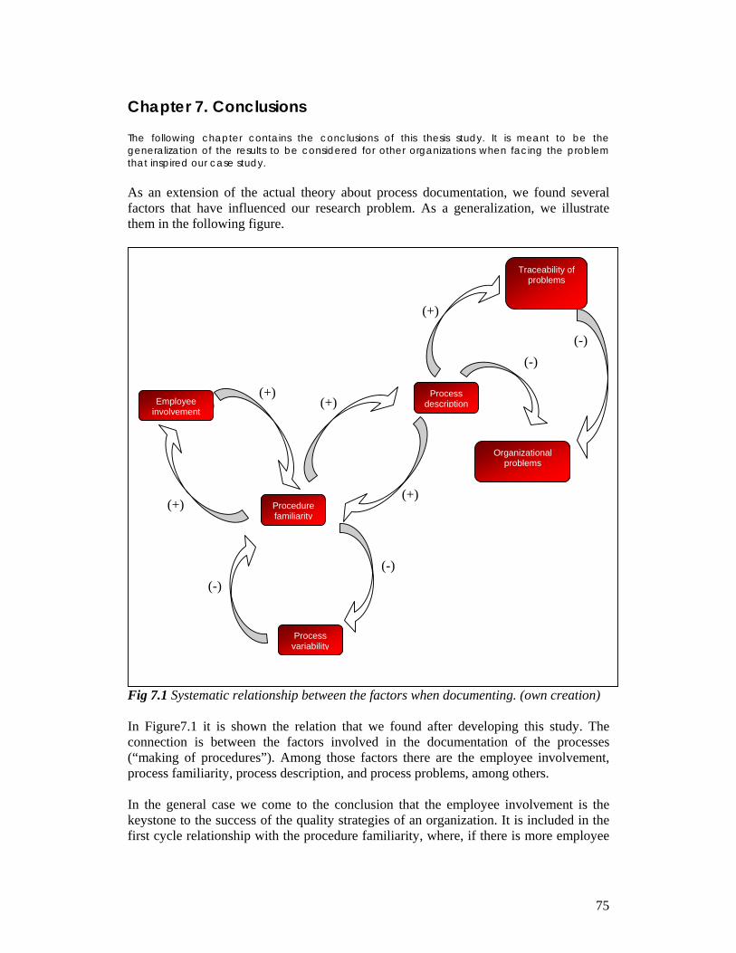
75
Chapter 7. Conclusions The following chapter contains the conclusions of this thesis study. It is meant to be the generalization of the results to be considered for other organizations when facing the problem that inspired our case study. As an extension of the actual theory about process documentation, we found several factors that have influenced our research problem. As a generalization, we illustrate them in the following figure.
Fig 7.1 Systematic relationship between the factors when documenting. (own creation) In Figure7.1 it is shown the relation that we found after developing this study. The connection is between the factors involved in the documentation of the processes (“making of procedures”). Among those factors there are the employee involvement, process familiarity, process description, and process problems, among others. In the general case we come to the conclusion that the employee involvement is the keystone to the success of the quality strategies of an organization. It is included in the first cycle relationship with the procedure familiarity, where, if there is more employee
(+)
(+)
(+)
(+)
Organizational problems
(+) (+)
(-)
Procedure familiarity
Traceability of problems
Process descriptionEmployee
involvement
Process variability
(-)
(-) (-)
76
involvement, there will be more process knowledge and procedure familiarity (or the opposite). In the same way, if there is more procedure familiarity there will be more employee involvement (or the opposite). In addition the procedure familiarity cyclically impacts the process description and the process variability respectively. If the employee does not recognize and assimilate a procedure, each project will be carried out in a different way, which may impact in the product quality or at least in the process quality. Meanwhile this is reflected in a poor quality documentation or “process description”. In overview a poor process description will complicate quality improvements; recognition of the situation from the management may cause problems in the production process and therefore impact in the traceability of the problems. In a company with different core business, for instance, automobile’s mass production, every operation is vital for the final product, there is no customer check-up during assembly or design and there are no changes of assembly after is sold due to customer request. Therefore the identification of recurrent problems and tracing their causes is even more important. In this kind of organization the lack of recognition of an operation would have a bigger impact than in our case company, since the same non-recognized operation has to be carried out x10 or x100 every day. Likewise, the documentation in every kind of company is valuable for consultants or managers that desire to change the way of working. In the case that the decision is taken to upgrade the process, the first (or only) aspect considered is the documentation, because it is supposed to map the process and from there, upgrades are prescribed. At this point it is harder for the personnel to change from “way of working A” to “A+” if they actually are in “A-” and this may lead to the failure of the project. We should realize that the success of programs like ISO 9001 is because of the value of documentation (which would be null if the documents lacked content). In general we can say that if the company’s purpose is only to achieve an ISO certification, they probably will, but instead of being a competitive advantage or an improve project, they will be simply an annoyance. The documents, instead of being beneficial, will slow the organization activities, additionally theywill give a fake sensation of good quality to the top levels of management who will be poorly informed about shop floor situations. Under these circumstances “to have correct documentation and keep it updated” gains importance. Because of this, we prove the relevance of our model. Every company should encourage a deep revision of their procedures and follow a procedure like ours. Subsequent to this action, they could develop their own plan of periodical check-ups linked to their ordinary activities.
77
References Internet -Overstreet Michael, Innovations as a competitive advantage, GCI 2007 http://databas.bib.vxu.se:2081/ehost/pdf?vid=2&hid=111&sid=68d92779-f8c7-4d95-83ad-7c602942aeef%40sessionmgr108 -Dilts David, What is Quality? Definitions and contrasts, Quality Library 2007 http://mot.vuse.vanderbilt.edu/mt322/Whatis.htm -Khurram Hashmi, Introduction and Implementation of Total Quality Management (TQM). iSix Sigma 2007 http://www.isixsigma.com/library/content/c031008a.asp -ISO 2007 webpage http://www.iso.org/iso/en/ISOOnline.frontpage http://www.iso.org/iso/en/aboutiso/introduction/index.html http://www.iso.ch/iso/en/iso9000-14000/pdf/survey2005.pdf Books -Sayle, Allan, Meeting ISO9000 in a TQM World, 1994, British Library catalogin publication data, pages 61,345 -Conti Tito, Building total quality, Chapman and Hall 1993, pages36-39 -BS EN ISO 9000:2005 Quality management systems-fundamentals and vocabulary, CEN -International Standard ISO 19011, guidelines for quality and/or environmental Management system auditing -Schamauch Charles, ISO for software developers, ASQC quality press, 1995 -Haider syed, ISO 9001:2000 Document Development Compliance Manual -Lamprecht James, ISO 9000 Implementation for small businesses, ASQC Quality Press -Rothery Brian, ISO 14000 and ISO 9000, Gower publishing limited, 1995 -Rothery Brian, ISO 9000, Gower publishing limited, 1993 Articles and Journals -Wright Tony, ISO without tears, ABI/Inform Global, pg57
78
- Russo Rus, 12 rules to make your ISO 9000 documentation simple and easy to use, Quality Progress, ABI/Informs global pg 51 -Teener Arthur, Total Quality Management, Three steps to continuous improvement, Addison Wesley Pulishing company, 1995, pg 14-15 -Gummesson Evert, Qualitative Methods in Management research, Thousand Oaks, 2000 -Yin Robert, Applications of Case Study Research, Newsbury Park, 1993 -Alvesson & Sköldberg, Reflexive Methodology
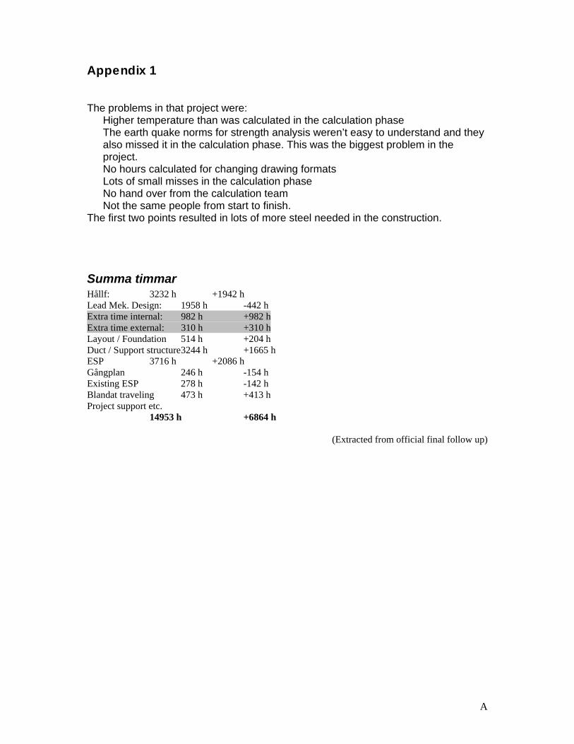
A
Appendix 1 The problems in that project were:
Higher temperature than was calculated in the calculation phase The earth quake norms for strength analysis weren’t easy to understand and they also missed it in the calculation phase. This was the biggest problem in the project. No hours calculated for changing drawing formats Lots of small misses in the calculation phase No hand over from the calculation team Not the same people from start to finish.
The first two points resulted in lots of more steel needed in the construction.
Summa timmar Hållf: 3232 h +1942 h Lead Mek. Design: 1958 h -442 h Extra time internal: 982 h +982 h Extra time external: 310 h +310 h Layout / Foundation 514 h +204 h Duct / Support structure 3244 h +1665 h ESP 3716 h +2086 h Gångplan 246 h -154 h Existing ESP 278 h -142 h Blandat traveling 473 h +413 h Project support etc. 14953 h +6864 h
(Extracted from official final follow up)

B
Appendix 2
Sub No Sub No Description Delivery date of
dwg´s Unit 3 Unit 4
Existing ESP / Parts for repairing 2 502 Guide Vanes 2003-05-09 5 505 Insulators 2003-05-09 6 506 Heating Tubes 2003-05-09 8 508 Inlet Gas Screen 2003-05-09 12 512 Emitting Frame Work 2003-05-09 15 515 Discharge Electrodes 2003-05-09 16 516 Discharge rapping Hammers 2003-05-09 17 517 Discharge Rapping Motor 20 520 Collecting Electrodes 2003-05-09 24 524 Collecting Shock Bars 2003-05-09
25 525 Collecting Rapping Hammers 2003-05-09
26 526 Collecting Rapping Motor 2003-05-09 30 530 Assembly Details 2003-05-09 31 531 Outlet Gas Screen 2003-05-09
60 560 Insulation, t=100 mm, 80 kg/m3
60 560 Lagging, alum 1 mm or galv.
Flue Gas Ducts / Exist ESP to New ESP 101-01 601-01 Foundation Details 2002-09-02 101-02 601-02 Slide Bearings 2002-11-06
115 615 Ducts 2002-12-13 116 616 Expansion Joints 117 617 Damper incl Actuator 119 619 Test Ports 123 623 Inspection Doors 128 628 Duct Support
128-01 628-01 Duct support "high/low" 2002-09-19 128-02 628-03 Duct supports "Long" 2002-11-19 130 630 Assembly Parts 2003-03-31 159 659 Accessways
160 660 Insulation, t=100 mm, 80 kg/m3 2002-09-20
160 660 Lagging, alum 1 mm 2002-09-20
Flue Gas Ducts / New ESP to Fan 201-01 701-01 Foundation Parts (New) 2003-07-07
201 701 Slide Bearings 2002-11-06 215 715 Ducts
215-01 715-01 Duct outlet ESP --> ESP roof line B
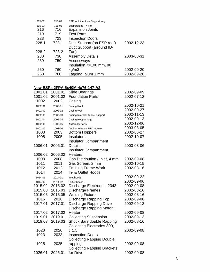
C
215-02 715-02 ESP roof line A --> Support long 215-03 715-03 Support long --> Fan 216 716 Expansion Joints 219 719 Test Ports 223 723 Inspection Doors
228-1 728-1 Duct Support (on ESP roof) 2002-12-23
228-2 728-2 Duct Support (arround ID-Fan)
230 730 Assembly Details 2003-03-31 259 759 Accessways
260 760 Insulation, t=100 mm, 80 kg/m3 2002-09-20
260 760 Lagging, alum 1 mm 2002-09-20
New ESPs 2FPA 5x40M-4x76-147-A2 1001.01 2001.01 Slide Bearings 2002-09-09 1001.02 2001.02 Foundation Parts 2002-07-12
1002 2002 Casing 1002-01 2002-01 Casing Roof 2002-10-21 1002-02 2002-02 Casing Wall 2002-09-27 1002-03 2002-03 Casing Internal+Tunnel support 2002-11-13 1002-04 2002-04 Casing Hopper ridge 2002-09-13 1002-05 1002-05 Assembly Parts 2002-12-06 1002-05 1002-06 Anchorge beam PPC require 2003-03-05 1003 2003 Bottom Hoppers 2002-06-27 1005 2005 Insulators 2002-10-07
1006.01 2006.01 Insulator Compartment Details 2003-03-06
1006.02 2006.02 Insulator Compartment Heaters
1008 2008 Gas Distribution / Inlet, 4 mm 2002-09-08 1011 2011 Gas Screen, 2 mm 2002-10-15 1012 2012 Emitting Frame Work 2002-08-16 1014 2014 In- & Outlet Hoods 1014-01 2014-01 Inlet hoods 2002-09-22 1014-02 2014-02 Outlet hoods 2002-09-06
1015.02 2015.02 Discharge Electrodes, 2343 2002-09-08 1015.03 2015.03 Discharge Frames 2002-08-16 1015.05 2015.05 Welding Fixture 2002-08-16
1016 2016 Discharge Rapping Top 2002-09-08 1017.01 2017.01 Discharge Rapping Drive 2002-09-13
1017.02 2017.02 Discharge Rapping Motor + Heater 2002-09-08
1019.01 2019.01 Collecting Suspension 2002-09-13 1019.03 2019.03 Shock Bars double Rapping 2002-08-16
1020 2020 Collecting Electrodes-800, t=1,5 2002-09-08
1023 2023 Inspection Doors
1025 2025 Collecting Rapping Double rapping 2002-09-08
1026.01 2026.01 Collecting Rapping Brackets for Drive 2002-09-08
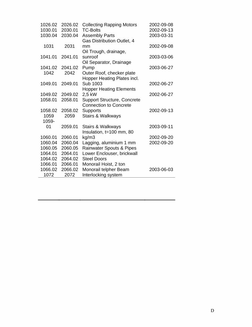
D
1026.02 2026.02 Collecting Rapping Motors 2002-09-08 1030.01 2030.01 TC-Bolts 2002-09-13 1030.04 2030.04 Assembly Parts 2003-03-31
1031 2031 Gas Distribution Outlet, 4 mm 2002-09-08
1041.01 2041.01 Oil Trough, drainage, sunroof 2003-03-06
1041.02 2041.02 Oil Separator, Drainage Pump 2003-06-27
1042 2042 Outer Roof, checker plate
1049.01 2049.01 Hopper Heating Plates incl. Sub 1003 2002-06-27
1049.02 2049.02 Hopper Heating Elements 2,5 kW 2002-06-27
1058.01 2058.01 Support Structure, Concrete
1058.02 2058.02 Connection to Concrete Supports 2002-09-13
1059 2059 Stairs & Walkways 1059-
01 2059.01 Stairs & Walkways 2003-09-11
1060.01 2060.01 Insulation, t=100 mm, 80 kg/m3 2002-09-20
1060.04 2060.04 Lagging, aluminium 1 mm 2002-09-20 1060.05 2060.05 Rainwater Spouts & Pipes 1064.01 2064.01 Lower Enclouser, brickwall 1064.02 2064.02 Steel Doors 1066.01 2066.01 Monorail Hoist, 2 ton 1066.02 2066.02 Monorail telpher Beam 2003-06-03
1072 2072 Interlocking system
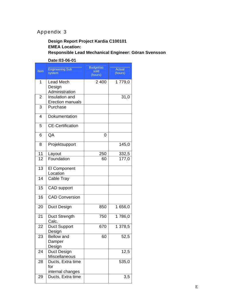
E
Appendix 3
Design Report Project Kardia C100101 EMEA Location: Responsible Lead Mechanical Engineer: Göran Svensson
Date:03-06-01
Item Engineering Sub system
Budget/as sold
(hours)
Actual (hours)
1 Lead Mech
Design Administration
2 400 1 779,0
2 Insulation and Erection manuals
31,0
3 Purchase
4 Dokumentation
5 CE-Certification
6 QA 0
8 Projektsupport 145,0
11 Layout 250 332,5 12 Foundation 60 177,0
13 El Component Location
14 Cable Tray
15 CAD support
16 CAD Conversion
20 Duct Design 850 1 656,0
21 Duct Strength Calc.
750 1 786,0
22 Duct Support Design
670 1 378,5
23 Bellow and Damper Design
60 52,5
24 Duct Design Miscellaneous
12,5
28 Ducts, Extra time for internal changes
535,0
29 Ducts, Extra time 3,5
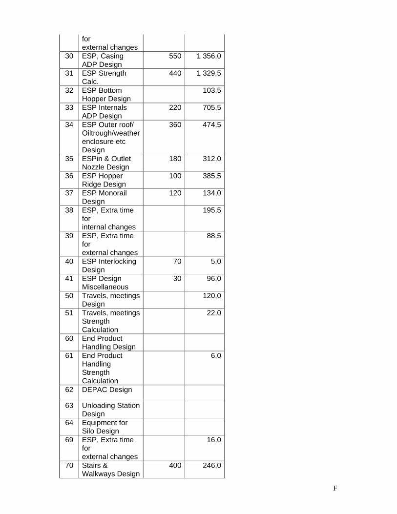
F
for external changes
30 ESP, Casing ADP Design
550 1 356,0
31 ESP Strength Calc.
440 1 329,5
32 ESP Bottom Hopper Design
103,5
33 ESP Internals ADP Design
220 705,5
34 ESP Outer roof/ Oiltrough/weather enclosure etc Design
360 474,5
35 ESPin & Outlet Nozzle Design
180 312,0
36 ESP Hopper Ridge Design
100 385,5
37 ESP Monorail Design
120 134,0
38 ESP, Extra time for internal changes
195,5
39 ESP, Extra time for external changes
88,5
40 ESP Interlocking Design
70 5,0
41 ESP Design Miscellaneous
30 96,0
50 Travels, meetings Design
120,0
51 Travels, meetings Strength Calculation
22,0
60 End Product Handling Design
61 End Product Handling Strength Calculation
6,0
62 DEPAC Design
63 Unloading Station Design
64 Equipment for Silo Design
69 ESP, Extra time for external changes
16,0
70 Stairs & Walkways Design
400 246,0
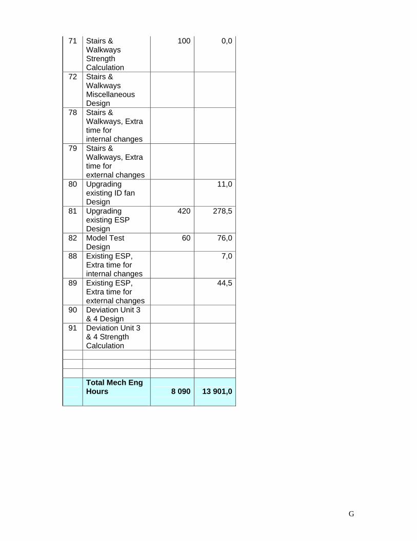
G
71 Stairs & Walkways Strength Calculation
100 0,0
72 Stairs & Walkways Miscellaneous Design
78 Stairs & Walkways, Extra time for internal changes
79 Stairs & Walkways, Extra time for external changes
80 Upgrading existing ID fan Design
11,0
81 Upgrading existing ESP Design
420 278,5
82 Model Test Design
60 76,0
88 Existing ESP, Extra time for internal changes
7,0
89 Existing ESP, Extra time for external changes
44,5
90 Deviation Unit 3 & 4 Design
91 Deviation Unit 3 & 4 Strength Calculation
Total Mech Eng Hours 8 090 13 901,0
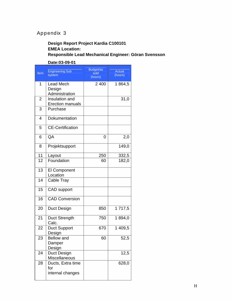
H
Appendix 3
Design Report Project Kardia C100101 EMEA Location: Responsible Lead Mechanical Engineer: Göran Svensson
Date:03-09-01
Item Engineering Sub system
Budget/as sold
(hours)
Actual (hours)
1 Lead Mech
Design Administration
2 400 1 864,5
2 Insulation and Erection manuals
31,0
3 Purchase
4 Dokumentation
5 CE-Certification
6 QA 0 2,0
8 Projektsupport 149,0
11 Layout 250 332,5 12 Foundation 60 182,0
13 El Component Location
14 Cable Tray
15 CAD support
16 CAD Conversion
20 Duct Design 850 1 717,5
21 Duct Strength Calc.
750 1 894,0
22 Duct Support Design
670 1 409,5
23 Bellow and Damper Design
60 52,5
24 Duct Design Miscellaneous
12,5
28 Ducts, Extra time for internal changes
628,0
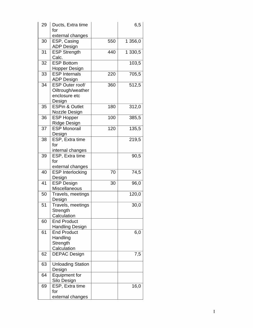
I
29 Ducts, Extra time for external changes
6,5
30 ESP, Casing ADP Design
550 1 356,0
31 ESP Strength Calc.
440 1 330,5
32 ESP Bottom Hopper Design
103,5
33 ESP Internals ADP Design
220 705,5
34 ESP Outer roof/ Oiltrough/weather enclosure etc Design
360 512,5
35 ESPin & Outlet Nozzle Design
180 312,0
36 ESP Hopper Ridge Design
100 385,5
37 ESP Monorail Design
120 135,5
38 ESP, Extra time for internal changes
219,5
39 ESP, Extra time for external changes
90,5
40 ESP Interlocking Design
70 74,5
41 ESP Design Miscellaneous
30 96,0
50 Travels, meetings Design
120,0
51 Travels, meetings Strength Calculation
30,0
60 End Product Handling Design
61 End Product Handling Strength Calculation
6,0
62 DEPAC Design 7,5
63 Unloading Station Design
64 Equipment for Silo Design
69 ESP, Extra time for external changes
16,0
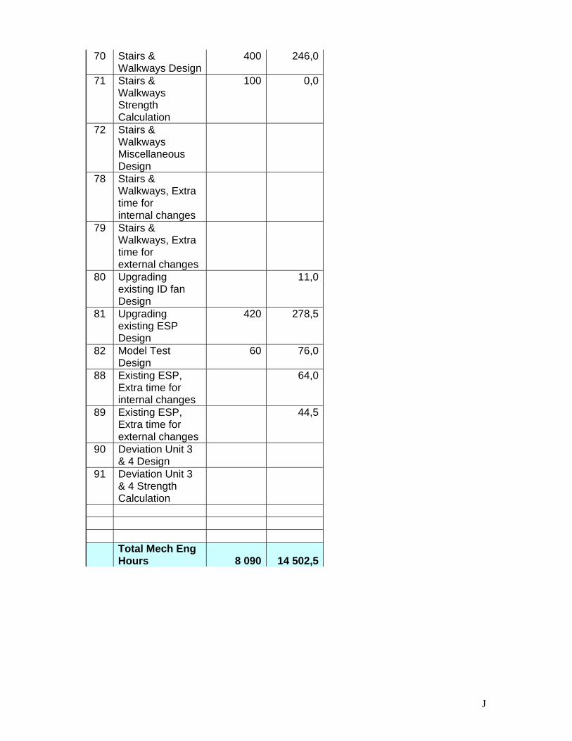
J
70 Stairs & Walkways Design
400 246,0
71 Stairs & Walkways Strength Calculation
100 0,0
72 Stairs & Walkways Miscellaneous Design
78 Stairs & Walkways, Extra time for internal changes
79 Stairs & Walkways, Extra time for external changes
80 Upgrading existing ID fan Design
11,0
81 Upgrading existing ESP Design
420 278,5
82 Model Test Design
60 76,0
88 Existing ESP, Extra time for internal changes
64,0
89 Existing ESP, Extra time for external changes
44,5
90 Deviation Unit 3 & 4 Design
91 Deviation Unit 3 & 4 Strength Calculation
Total Mech Eng Hours 8 090 14 502,5
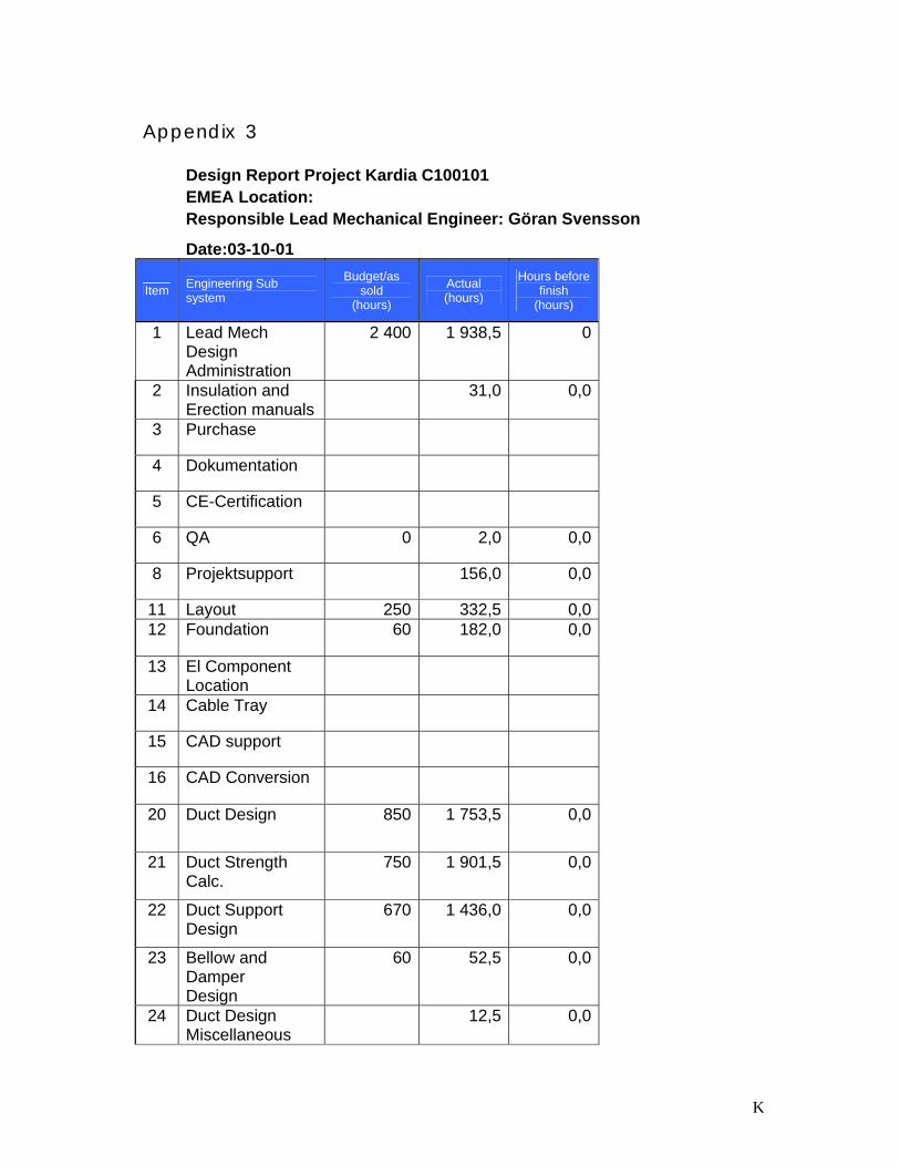
K
Appendix 3
Design Report Project Kardia C100101 EMEA Location: Responsible Lead Mechanical Engineer: Göran Svensson
Date:03-10-01
Item Engineering Sub system
Budget/as sold
(hours)
Actual (hours)
Hours before finish
(hours) 1 Lead Mech
Design Administration
2 400 1 938,5 0
2 Insulation and Erection manuals
31,0 0,0
3 Purchase
4 Dokumentation
5 CE-Certification
6 QA 0 2,0 0,0
8 Projektsupport 156,0 0,0
11 Layout 250 332,5 0,0 12 Foundation 60 182,0 0,0
13 El Component Location
14 Cable Tray
15 CAD support
16 CAD Conversion
20 Duct Design 850 1 753,5 0,0
21 Duct Strength Calc.
750 1 901,5 0,0
22 Duct Support Design
670 1 436,0 0,0
23 Bellow and Damper Design
60 52,5 0,0
24 Duct Design Miscellaneous
12,5 0,0
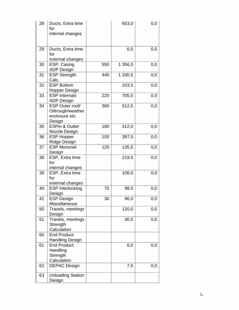
L
28 Ducts, Extra time for internal changes
653,0 0,0
29 Ducts, Extra time for external changes
6,5 0,0
30 ESP, Casing ADP Design
550 1 356,0 0,0
31 ESP Strength Calc.
440 1 330,5 0,0
32 ESP Bottom Hopper Design
103,5 0,0
33 ESP Internals ADP Design
220 705,5 0,0
34 ESP Outer roof/ Oiltrough/weather enclosure etc Design
360 512,5 0,0
35 ESPin & Outlet Nozzle Design
180 312,0 0,0
36 ESP Hopper Ridge Design
100 397,5 0,0
37 ESP Monorail Design
120 135,5 0,0
38 ESP, Extra time for internal changes
219,5 0,0
39 ESP, Extra time for external changes
106,0 0,0
40 ESP Interlocking Design
70 98,0 0,0
41 ESP Design Miscellaneous
30 96,0 0,0
50 Travels, meetings Design
120,0 0,0
51 Travels, meetings Strength Calculation
30,0 0,0
60 End Product Handling Design
61 End Product Handling Strength Calculation
6,0 0,0
62 DEPAC Design 7,5 0,0
63 Unloading Station Design

M
64 Equipment for Silo Design
69 ESP, Extra time for external changes
16,0 0,0
70 Stairs & Walkways Design
400 246,0 0,0
71 Stairs & Walkways Strength Calculation
100 0,0 0,0
72 Stairs & Walkways Miscellaneous Design
78 Stairs & Walkways, Extra time for internal changes
79 Stairs & Walkways, Extra time for external changes
80 Upgrading existing ID fan Design
38,0 0,0
81 Upgrading existing ESP Design
420 278,5 0,0
82 Model Test Design
60 76,0 0,0
88 Existing ESP, Extra time for internal changes
64,0 0,0
89 Existing ESP, Extra time for external changes
44,5 0,0
90 Deviation Unit 3 & 4 Design
91 Deviation Unit 3 & 4 Strength Calculation
Total Mech Eng Hours 8 090 14 756,5 0,0
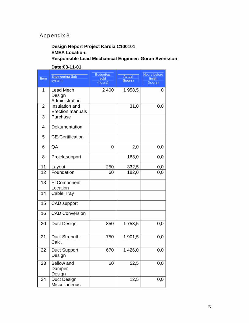
N
Appendix 3
Design Report Project Kardia C100101 EMEA Location: Responsible Lead Mechanical Engineer: Göran Svensson
Date:03-11-01
Item Engineering Sub system
Budget/as sold
(hours)
Actual (hours)
Hours before finish
(hours) 1 Lead Mech
Design Administration
2 400 1 958,5 0
2 Insulation and Erection manuals
31,0 0,0
3 Purchase
4 Dokumentation
5 CE-Certification
6 QA 0 2,0 0,0
8 Projektsupport 163,0 0,0
11 Layout 250 332,5 0,0 12 Foundation 60 182,0 0,0
13 El Component Location
14 Cable Tray
15 CAD support
16 CAD Conversion
20 Duct Design 850 1 753,5 0,0
21 Duct Strength Calc.
750 1 901,5 0,0
22 Duct Support Design
670 1 426,0 0,0
23 Bellow and Damper Design
60 52,5 0,0
24 Duct Design Miscellaneous
12,5 0,0
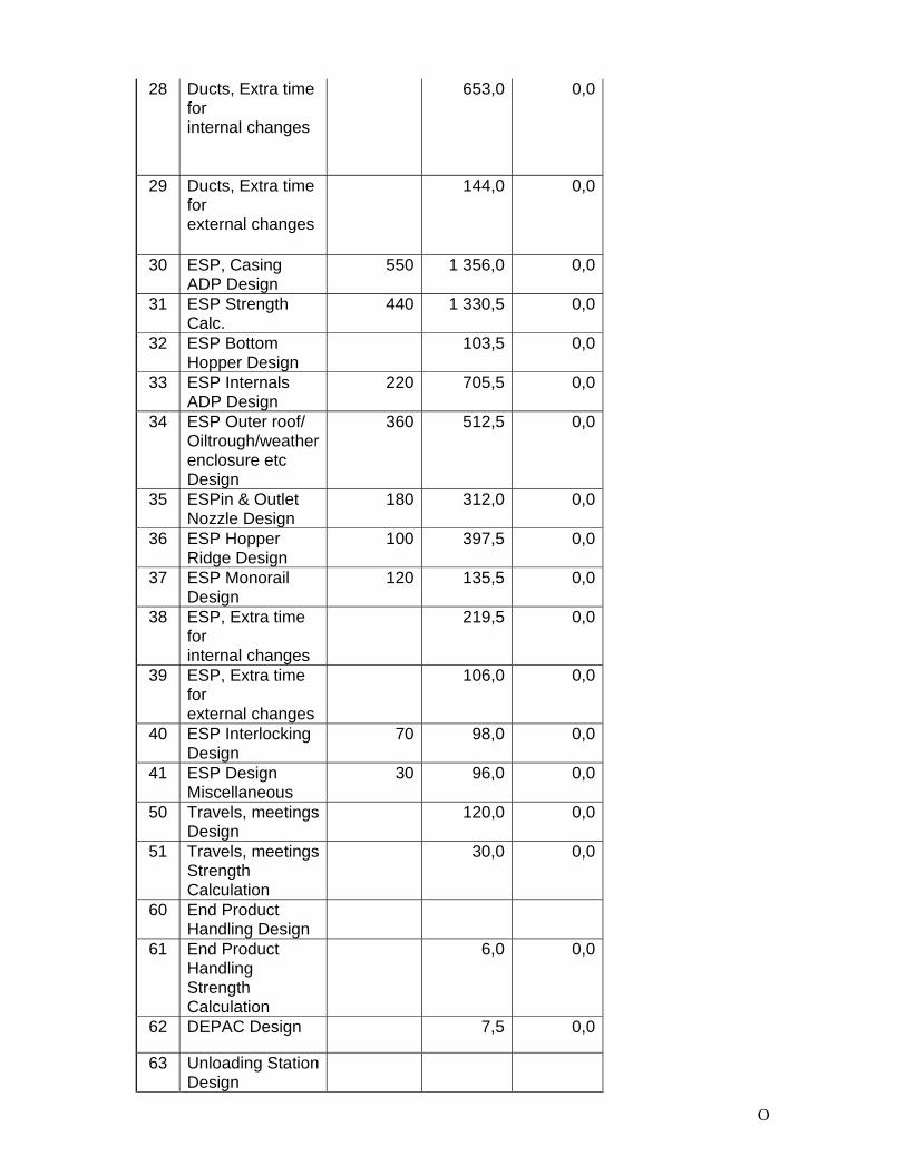
O
28 Ducts, Extra time for internal changes
653,0 0,0
29 Ducts, Extra time for external changes
144,0 0,0
30 ESP, Casing ADP Design
550 1 356,0 0,0
31 ESP Strength Calc.
440 1 330,5 0,0
32 ESP Bottom Hopper Design
103,5 0,0
33 ESP Internals ADP Design
220 705,5 0,0
34 ESP Outer roof/ Oiltrough/weather enclosure etc Design
360 512,5 0,0
35 ESPin & Outlet Nozzle Design
180 312,0 0,0
36 ESP Hopper Ridge Design
100 397,5 0,0
37 ESP Monorail Design
120 135,5 0,0
38 ESP, Extra time for internal changes
219,5 0,0
39 ESP, Extra time for external changes
106,0 0,0
40 ESP Interlocking Design
70 98,0 0,0
41 ESP Design Miscellaneous
30 96,0 0,0
50 Travels, meetings Design
120,0 0,0
51 Travels, meetings Strength Calculation
30,0 0,0
60 End Product Handling Design
61 End Product Handling Strength Calculation
6,0 0,0
62 DEPAC Design 7,5 0,0
63 Unloading Station Design
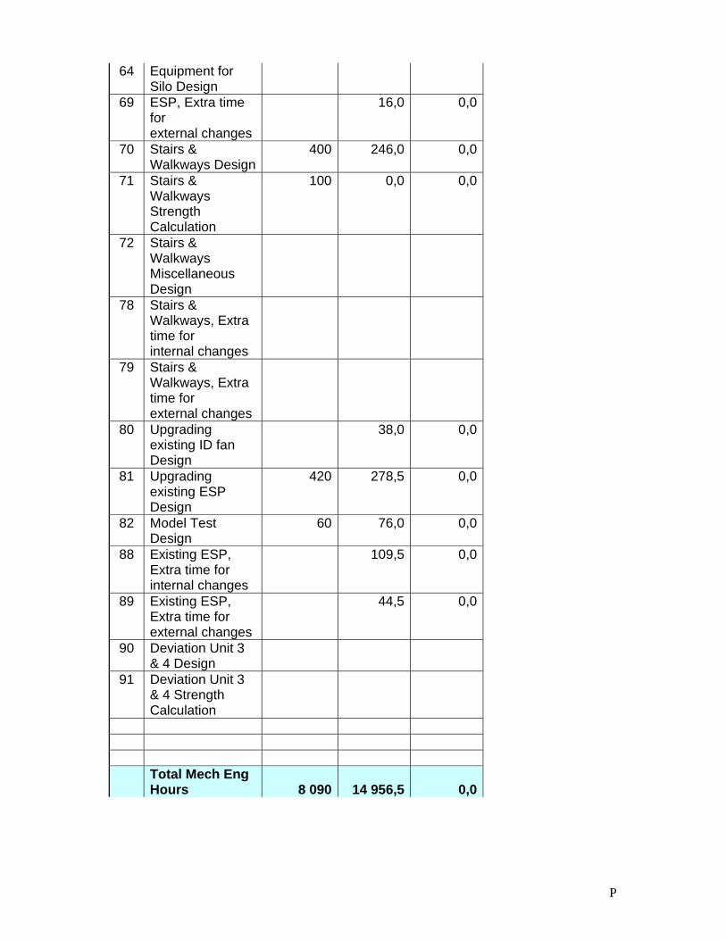
P
64 Equipment for Silo Design
69 ESP, Extra time for external changes
16,0 0,0
70 Stairs & Walkways Design
400 246,0 0,0
71 Stairs & Walkways Strength Calculation
100 0,0 0,0
72 Stairs & Walkways Miscellaneous Design
78 Stairs & Walkways, Extra time for internal changes
79 Stairs & Walkways, Extra time for external changes
80 Upgrading existing ID fan Design
38,0 0,0
81 Upgrading existing ESP Design
420 278,5 0,0
82 Model Test Design
60 76,0 0,0
88 Existing ESP, Extra time for internal changes
109,5 0,0
89 Existing ESP, Extra time for external changes
44,5 0,0
90 Deviation Unit 3 & 4 Design
91 Deviation Unit 3 & 4 Strength Calculation
Total Mech Eng Hours 8 090 14 956,5 0,0
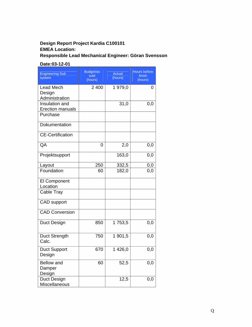
Q
Design Report Project Kardia C100101 EMEA Location: Responsible Lead Mechanical Engineer: Göran Svensson
Date:03-12-01
Engineering Sub system
Budget/as sold
(hours)
Actual (hours)
Hours before finish
(hours) Lead Mech Design Administration
2 400 1 979,0 0
Insulation and Erection manuals
31,0 0,0
Purchase
Dokumentation
CE-Certification
QA 0 2,0 0,0
Projektsupport 163,0 0,0
Layout 250 332,5 0,0 Foundation 60 182,0 0,0
El Component Location
Cable Tray
CAD support
CAD Conversion
Duct Design 850 1 753,5 0,0
Duct Strength Calc.
750 1 901,5 0,0
Duct Support Design
670 1 426,0 0,0
Bellow and Damper Design
60 52,5 0,0
Duct Design Miscellaneous
12,5 0,0
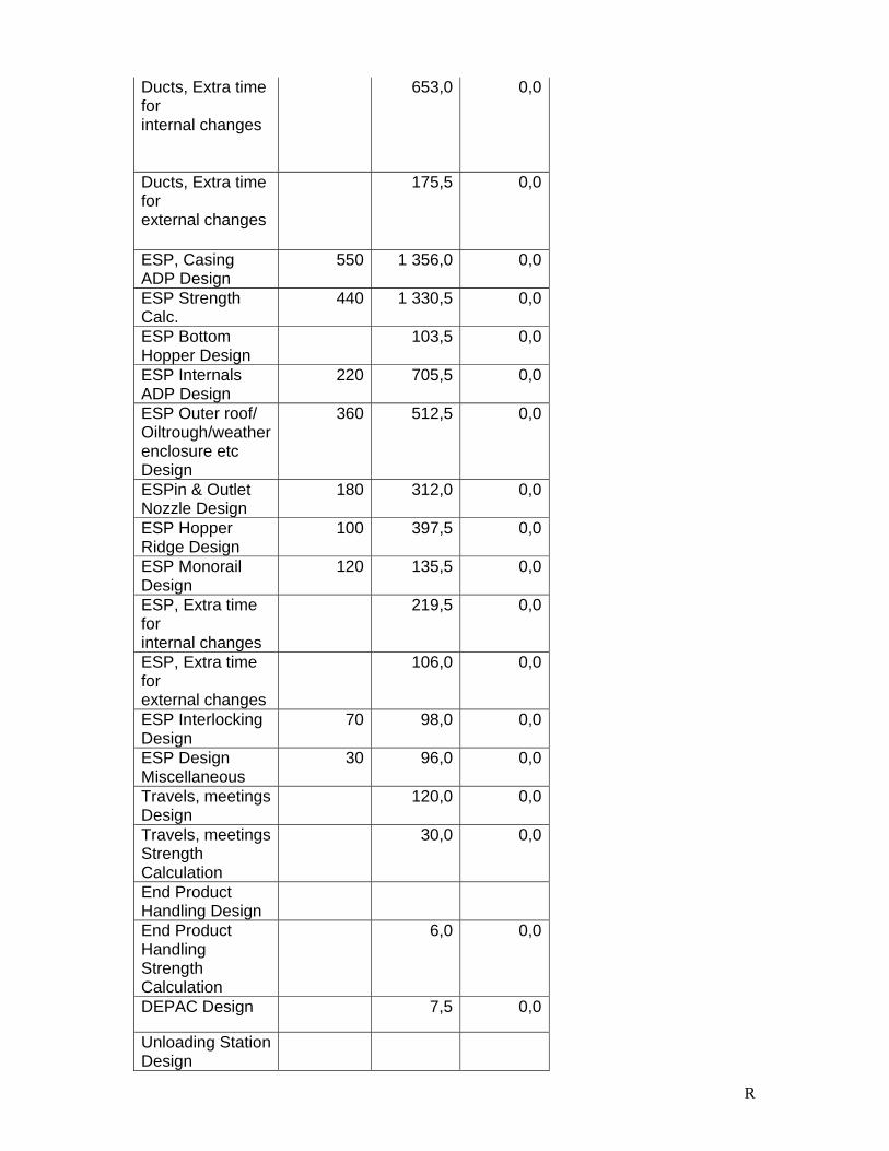
R
Ducts, Extra time for internal changes
653,0 0,0
Ducts, Extra time for external changes
175,5 0,0
ESP, Casing ADP Design
550 1 356,0 0,0
ESP Strength Calc.
440 1 330,5 0,0
ESP Bottom Hopper Design
103,5 0,0
ESP Internals ADP Design
220 705,5 0,0
ESP Outer roof/ Oiltrough/weather enclosure etc Design
360 512,5 0,0
ESPin & Outlet Nozzle Design
180 312,0 0,0
ESP Hopper Ridge Design
100 397,5 0,0
ESP Monorail Design
120 135,5 0,0
ESP, Extra time for internal changes
219,5 0,0
ESP, Extra time for external changes
106,0 0,0
ESP Interlocking Design
70 98,0 0,0
ESP Design Miscellaneous
30 96,0 0,0
Travels, meetings Design
120,0 0,0
Travels, meetings Strength Calculation
30,0 0,0
End Product Handling Design
End Product Handling Strength Calculation
6,0 0,0
DEPAC Design 7,5 0,0
Unloading Station Design
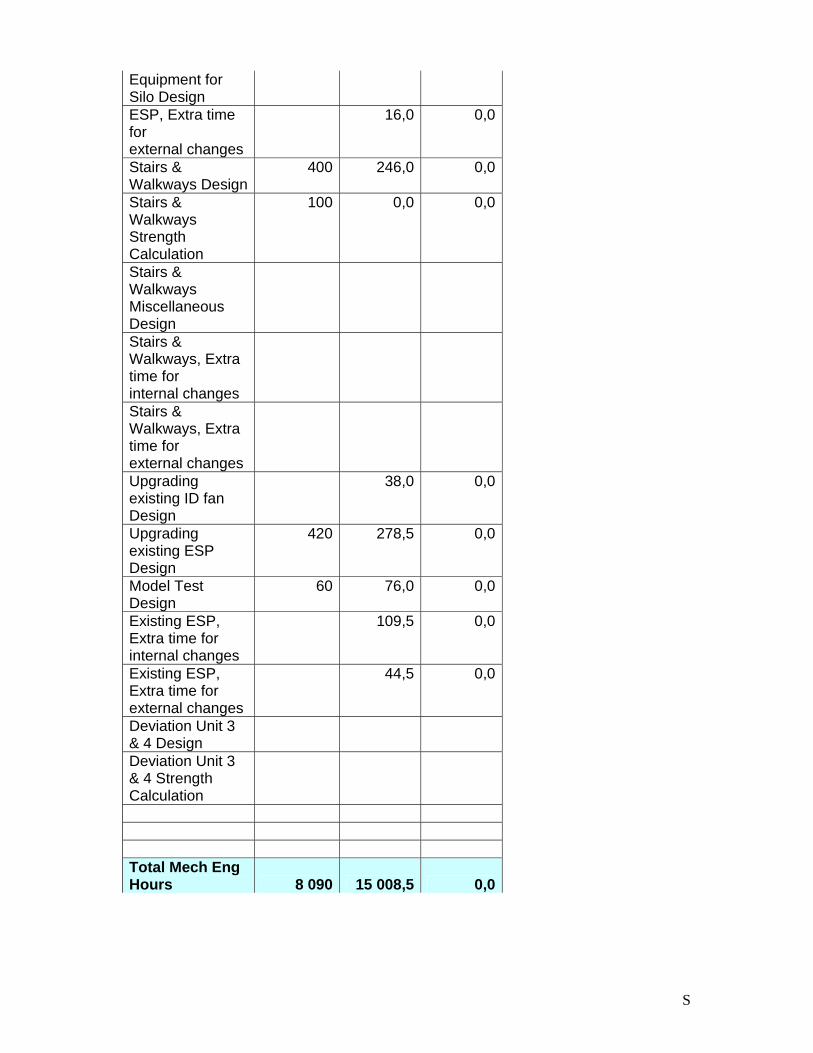
S
Equipment for Silo Design
ESP, Extra time for external changes
16,0 0,0
Stairs & Walkways Design
400 246,0 0,0
Stairs & Walkways Strength Calculation
100 0,0 0,0
Stairs & Walkways Miscellaneous Design
Stairs & Walkways, Extra time for internal changes
Stairs & Walkways, Extra time for external changes
Upgrading existing ID fan Design
38,0 0,0
Upgrading existing ESP Design
420 278,5 0,0
Model Test Design
60 76,0 0,0
Existing ESP, Extra time for internal changes
109,5 0,0
Existing ESP, Extra time for external changes
44,5 0,0
Deviation Unit 3 & 4 Design
Deviation Unit 3 & 4 Strength Calculation
Total Mech Eng Hours 8 090 15 008,5 0,0
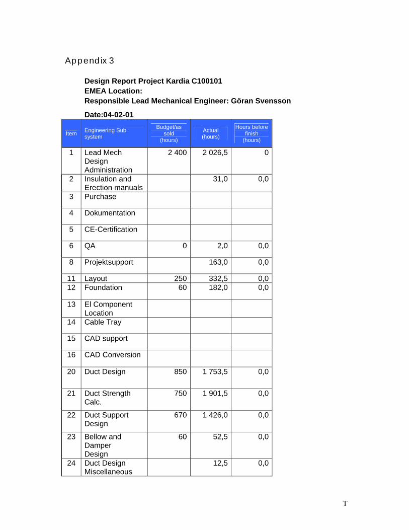
T
Appendix 3
Design Report Project Kardia C100101 EMEA Location: Responsible Lead Mechanical Engineer: Göran Svensson
Date:04-02-01
Item Engineering Sub system
Budget/as sold
(hours)
Actual (hours)
Hours before finish
(hours) 1 Lead Mech
Design Administration
2 400 2 026,5 0
2 Insulation and Erection manuals
31,0 0,0
3 Purchase
4 Dokumentation
5 CE-Certification
6 QA 0 2,0 0,0
8 Projektsupport 163,0 0,0
11 Layout 250 332,5 0,0 12 Foundation 60 182,0 0,0
13 El Component Location
14 Cable Tray
15 CAD support
16 CAD Conversion
20 Duct Design 850 1 753,5 0,0
21 Duct Strength Calc.
750 1 901,5 0,0
22 Duct Support Design
670 1 426,0 0,0
23 Bellow and Damper Design
60 52,5 0,0
24 Duct Design Miscellaneous
12,5 0,0
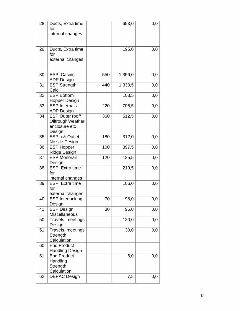
U
28 Ducts, Extra time for internal changes
653,0 0,0
29 Ducts, Extra time for external changes
195,0 0,0
30 ESP, Casing ADP Design
550 1 356,0 0,0
31 ESP Strength Calc.
440 1 330,5 0,0
32 ESP Bottom Hopper Design
103,5 0,0
33 ESP Internals ADP Design
220 705,5 0,0
34 ESP Outer roof/ Oiltrough/weather enclosure etc Design
360 512,5 0,0
35 ESPin & Outlet Nozzle Design
180 312,0 0,0
36 ESP Hopper Ridge Design
100 397,5 0,0
37 ESP Monorail Design
120 135,5 0,0
38 ESP, Extra time for internal changes
219,5 0,0
39 ESP, Extra time for external changes
106,0 0,0
40 ESP Interlocking Design
70 98,0 0,0
41 ESP Design Miscellaneous
30 96,0 0,0
50 Travels, meetings Design
120,0 0,0
51 Travels, meetings Strength Calculation
30,0 0,0
60 End Product Handling Design
61 End Product Handling Strength Calculation
6,0 0,0
62 DEPAC Design 7,5 0,0
V
63 Unloading Station Design
64 Equipment for Silo Design
69 ESP, Extra time for external changes
16,0 0,0
70 Stairs & Walkways Design
400 246,0 0,0
71 Stairs & Walkways Strength Calculation
100 0,0 0,0
72 Stairs & Walkways Miscellaneous Design
78 Stairs & Walkways, Extra time for internal changes
79 Stairs & Walkways, Extra time for external changes
80 Upgrading existing ID fan Design
38,0 0,0
81 Upgrading existing ESP Design
420 278,5 0,0
82 Model Test Design
60 76,0 0,0
88 Existing ESP, Extra time for internal changes
109,5 0,0
89 Existing ESP, Extra time for external changes
44,5 0,0
90 Deviation Unit 3 & 4 Design
91 Deviation Unit 3 & 4 Strength Calculation
Total Mech Eng Hours 8 090 15 075,5 0,0