Using theory to design effective health behavior interventions

14
A LOGICAL THEORY OF DESIGN
FRANCES BRAZIER, PIETER V AN LANGEN AND JAN TREUR Vrije Universiteit Amsterdam, The Netherlands
Abstract. Design tasks typically deal with incomplete information and involve flexible reasoning patterns for which sophisticated control strategies are needed. As a result, the reasoning patterns are highly dynamic and non-monotonic. The logical framework introduced provides formal semantics of state descriptions of design processes based on (compositional) partial models and formal semantics of the reasoning behaviour based on (compositional) partial temporal models.
1. Introduction
In the area of diagnosis, a number of well-established logical theories have been developed and are acknowledged as valuable contributions to the field, such as Reiter (1987), and Console and Torasso (1990). For design (e.g., Brown and Chandrasekaran, 1989; French and Mostow, 1985; Logan, Come, and Smithers, 1992; Takeda, Veerkamp, Tomiyama, and Yoshikawa, 1990) the situation differs. Although models for design have been proposed using logic as a vehicle (e.g., Coyne, 1988), and general design theories have been proposed (e.g., Tomiyama and Yoshikawa, 1987), formal semantics of both static aspects (Le., characteristics of an individual state) of the design process and dynamic aspects (i.e., the reasoning behaviour) have yet to be defined. Design tasks typically reason with incomplete and inconsistent knowledge of requirements and design object descriptions: they reason non-monotonically with and about, for example, (default) assumptions, contradictory information, and new design knowledge. To handle such dynamic reasoning patterns, knowledge of tactics and strategies is needed. The formulation of the logical foundations (including formal semantics) of these patterns goes beyond classical logic.
In the current paper, a logical foundation is introduced in which formal semantics for both static and dynamic aspects of design are based on partial models (e.g., Langholm, 1988; Blarney, 1986). Partial models are a means to formalise information states, representing incomplete world descriptions (e.g., Langen and Treur, 1989); types of world descriptions relevant for design are design object descriptions and requirement sets. To obtain formal
J. S. Gero et al. (eds.), Advances in Formal Design Methods for CAD© Springer Science+Business Media Dordrecht 1996

244 FRANCES BRAZIER, PIETER V AN LANGEN AND JAN TREUR
semantics of reasoning behaviour in design tasks, a recently developed approach based on partial temporal models is adopted, which has shown to be applicable to different types of (non-monotonic) reasoning (see Engelfriet and Treur, 1994; Gavrila and Treur, 1994; Treur, 1994). Semantics of a reasoning process is formalised by a set of (alternative) reasoning traces, represented by a partial temporal model, i.e., a sequence of partial models. As the partial models representing information states are used to provide semantics of the static aspects, a structural connection between the semantics of static aspects and of dynamic aspects is obtained. In Brazier, Langen, Ruttkay, and Treur (1994), the static aspects of design have been formalised; this paper elaborates upon that work with a formalisation of the dynamic aspects. Since a design task is complex (involving integration of different views and perspectives, and often different agents) and consists of a number of subtasks, the information states also have a compositional structure.
In Brazier, Langen, Ruttkay, and Treur (1994), an approach is presented to the development of intelligent design support systems based on a highlevel formal specification language, as well as a generic task model of design specified in this formal specification language. This generic task model has been developed on the basis of the analysis of task models for the development of design support systems (e.g., Brumsen, Pannekeet and Treur, 1992; Geelen and Kowalczyk, 1992) and has been employed for the development of new design support systems (e.g., Brazier, Langen, Treur, Willems and Wijngaards, 1994). The logical foundations presented in this paper provide formal semantics for both the static and dynamic aspects of design tasks modelled by the generic task model. Moreover, the logical foundations can be used to establish (and prove) properties of design support systems, such as consistency, correctness, and completeness (see Treur and Willems, 1994a; 1994b), and to develop automated tools to support verification and validation of these properties. In most current frameworks such properties are basically static: they do not refer to the behaviour of the system. However, in interactive systems dynamic properties are also important (e.g., if under certain circumstances a particular type of behaviour of the system has been rejected by the user in the past, it should not be repeated in the present). Expressing dynamic properties requires a logical foundation for reasoning behaviour of a system (in interaction with the user)-this paper proposes a framework for this purpose.
In Section 2 of this paper, the notions of design process and design space are explained. In Sections 3 and 4, static and dynamic aspects of design processes are presented, respectively. In Section 5, an example of a design process is given. In Section 6, the logical theory of design is discussed and conclusions are drawn.

A LOGICAL THEORY OF DESIGN 245
2. Design Processes and the Design Space
In design, requirement qualification sets and design object descriptions are manipulated. Requirement qualifications are qualitative expressions of the extent to which (individual or groups of) requirements must be met, either in isolation or in relation to each other.· A design object description is a specification of the object to be created. A design process is described by a sequence of design decisions (and their rationale) concerning modifications to sets of requirements and their qualifications and to (partial) design object descriptions.
Figure 1 shows an example of a design process in the two-dimensional design space spanned by requirement qualification sets and design object descriptions. Note that the notions of space and dimension are used informally here: the choice of metric on the design space is left open. (A possibility would be to measure the distance between two points in a dimension by the number of differences between the descriptions denoted by these points.)
t requirement qualification
sets
2
8
5
design object descriptions
6
7
Figure 1. Example of a design process in the design space.
Figure 1 shows a nine-step sequence of modifications to requirement qualification set and design object description. The first step in the sequence, depicted by the arrow labelled '1', represents a modification to the initial requirement qualification set only. The initial design object description is modified in steps 2 and 3. After step 3 (i.e., at the point in which the arrow labelled '3' ends), modification of the design object description halts for some reason: maybe the design object description satisfies all requirements

246 FRANCES BRAZIER, PIETER VAN LANGEN AND JAN TREUR
of the current requirement qualification set, or maybe there is reason to believe that no design object description can be made that satisfies all requirements. In each case, the requirement qualification set is modified in step 4, taking into account the reason why modification of the design object description stopped. After the modifications in steps 5 to 8, the design process reaches an interesting state: the sequence of modifications has led to a requirement qualification set and a design object description that in combination are equivalent to the result of step 2. Therefore another direction is sought, which differs from the one chosen in step 3, leading in step 9 to a modification to the requirement qualification set. In summary, there are five requirement qualification set modifications (steps 1, 4, 6, 8 and 9) and four design object description modifications (steps 2, 3, 5 and 7).
In general, a large (and possibly infinite) number of new points in the design space could be generated by modification to either the requirement qualification set or the design object description that correspond to a given point. In practice, only a few of these new points are of interest, because they are the ones that 'make sense' -these are the possible alternative choices for the next step in the design process. To describe the dynamics of the design process, knowledge of tactics and strategies, needed to guide the design process, must be made explicit.
3. Static Aspects of Design Processes
In design, manipulation of requirement sets, of their qualifications, and of design object descriptions plays a crucial role. A design process can be regarded as a sequence of design decisions concerning requirements, their qualifications and (partial) design object descriptions. The current state of the design process changes continually: requirements can be added or withdrawn, requirement qualifications can be changed, and partial design object descriptions can be added or retracted. During design, often different (alternative) requirement sets (and their qualifications) and design object descriptions are considered.
Steps in the design process can be represented by transitions of two types: transitions modifying design object descriptions and those modifying requirement qualification sets. Note that no commitment is made to model design as a search process. Steps in the design process can be controlled completely, depending on the strategic knowledge used.
The logical analysis of the static aspects of design processes is discussed below in Sections 3.2, 3.3, and 3.4. In Section 3.1, the basic terminology employed is introduced. Throughout Section 3 and Section 4, the example of designing a house will be used to illustrate the logical analysis.

A LOGICAL THEORY OF DESIGN 247
3.1. BASIC APPROACH AND TERMINOLOGY ON STATIC ASPECTS
It is assumed that the reader is familiar with many-sorted first-order predicate logic, an essential element in our approach. In Langen and Treur, (1989), formal definitions of semantics fo~ many-sorted partial models are presented. For an overview of partial logic, see Blamey (1986) and Langholm (1988).
Definition. A signature for many-sorted first-order predicate logic is a tuple !: = (S, C, F, P) with sorts S, constants C, functions F and predicates P.
In the sequel, !: denotes a signature, At(!:) the set of all ground atoms of !: and Wff(!:) the set of all closed well-formed formulae over !:.
Definition. A partial model for !: is a mapping M: At(!:) ~ { 0, 1, u }. An atom a E At(!:) is true in M if M(a) = 1,false in M if M(a) = 0, and undefined or unknown in M if M(a) = u. A partial model M is complete if for all a E At(!:), either M(a) = 0 or M(a) = 1.
Definition. The model space Mod(!:)is the set of all partial models for !:.
Definition. The satisfaction relation t= on Mod(!:) x Wff(!:) is defined for all atomic well-formed formulae a E At(!:) as:
M t=+ a iff M(a) = 1 M t=- a iff M(a) = 0 M~+a iff M(a) * 1 M ~- a iff M(a) *0.
For the logical connectives "A, V, ~ and ¢::>, the strong Kleene semantics is adopted (Blamey, 1986; LaIigholm, 1988), of which the truth tables are shown in Figure 2.
Definition. The refinement relation :s; on Mod(!:) x Mod(!:) is such that for all M, M' E Mod(!:), M :s; M' holds if for all a E At(!:), M(a):S; M'(a) (with o :s; 0, u :s; 0, 1 :s; 1, U :s; 1, U :s; u).
Definition. A theory for!: is a set T c Wff(!:).
Definition. Let M be a partial model for Land T a theory for L. The class of models defined by M with T is the set { N E Mod(L) I N is complete, M:S; N, and N t= T }.

248 FRANCES BRAZIER, PIETER VAN LANGEN AND JAN TREUR
-,A
o o 1
u u
o u
o u
o 0 0 0
u u 0 u
A:::::}B 1 0 u
o u
o 1
u u u
AvB 1 d u
1
o 1 0 u
u u u
A <=>B o u
1 0 u
o 0 u
u u u u
Figure 2. Kleene's strong three-valued connectives.
3.2. STATIC ASPECTS OF DESIGN OBJECT DESCRIPTIONS
To describe a design object, a language is needed in which properties and their values can be named and relations between properties can be expressed.
Definition. A design object description lexicon is a signature LOOO = (5, C, F, P), where {Parameters, Values} ~ 5 and {eq c Parameters x Values} ~ P.
In other words, the signature should at least contain the sorts Parameters and Values for denoting design parameters and values, respectively, and should contain a relation eq on Parameters x Values for denoting the fact that a certain design parameter has a certain value. Common relations used in design object ontologies, such as the 'part-of' relation by means of which the components and parts of a design object can be described, can also be included.
During design, not all properties of a design object are considered simultaneously: the description of a design object is often partial. In the sequel, LOOO denotes a design object description lexicon.
Definition. A design object description based on LOoo is a partial model for LOOO.
Example. Suppose the designer has placed the living-room and the kitchen on the ground-floor (floor 0) and one bedroom (bedroom 1) on the first floor (floor 1). Whether the first bathroom (bathroom 1) and the second

A LOGICAL THEORY OF DESIGN 249
bedroom (bedroom 2) should be placed on the ground-floor or on the first floor is, as yet, undecided. This can be expressed by means of the following design object description DOD1:
DOD1 (eq(floor-of(living-room(1 », 0» = 1 DOD1(eq(floor-of(kitchen(1», 0» = 1 DOD1 (eq(floor-of(bedroom(1 », 1» = 1 DOD1(eq(floor-of(bedroom(2», 1» = U
DOD1 (eq(floor-of(bathroom(1 », 0» = U
DOD1(eq(floor-of(bathroom(1», 1» = u.
An abbreviated notation for DOD1 is:
{ eq(floor-of(living-room(1», 0), eq(floor-of(kitchen(1 », 0), eq(floor-of(bedroom(1», 1) }.
A design object description can be seen as one element of the set of all partial or complete design object descriptions.
Definition. The design object description space DOD based on LOoo is the set of tuples of models from MOd(LoOO).
During design the number of properties of the design object that have been determined may increase or decrease. Both types of modification can be described by means of the following refinement relation.
Definition. The design object refinement relation based on LOOO is the refinement relation ::;; on Mod(LOOO) x Mod(LOOO). Furthermore, for any two tuples Sand T that are elements of DOD, the combined design object refinement relation S::;; T holds if for all M E S there is an NET with M ::;; N and for all NET there is an ME S with M::;; N.
Example. Suppose the designer, after allocating rooms as in the previous example, designs a kitchen with an area of 9 m2. This can be expressed by means of the design object description DOD2:
{ eq(floor-of(living-room(1 », 0), eq(floor-of(kitchen(1 », 0), eq(floor-of(bedroom(1 », 1), eq(area(kitchen(1), m2), 9) }.

250 FRANCES BRAZIER, PIETER VAN LANGEN AND JAN TREUR
To design an object, knowledge of the properties and the relations between the properties is essential. In practice, not all knowledge is available and has to be acquired during the design process.
Definition. A design object theory based on l:DOD is a theory TDOD for l:DOD·
Example. Assume that general house design knowledge is that the area of a floor equals the sum of the areas of the rooms on that floor, and that a room can be allocated to one floor only. This can be expressed by means of the design object theory TDOD:
'v'f E Floors 'v'u E AreaUnits: eq(area(f, u»,
La E Areas: :3r E Rooms (eq(floor-of(r), f) 1\ eq(area(r, u), a»
'v'r E Rooms 'v'f1, f2 E Floors: (eq(floor-of(r), f1) 1\ eq(floor-of(r), f2» ~ f1 = f2.
(L k: <p(k) is the sum over each k satisfying <p, such that if k satisfies exactly
N quantifier-free instances of <p, then k appears exactly N times in the sum. The symbol '=' is the symmetric, reflexive and transitive equality relation on values.)
3.3. STATIC ASPECTS OF REQUIREMENT QUALIFICATION SETS
Before and during the process of design, knowledge of necessary and desired properties of the object to be designed (within a given context) is of importance. These necessary and desired properties are the requirements placed upon a design.
Definition. Let l:DOD be a design object description lexicon. A requirement is a well-formed formula over l:DOD.
To describe requirements, a language is needed in which requirements, qualifications and relations between qualifications can be expressed.
Definition. A requirement qualification lexicon is an extension of the signature l:RQS = (5, C, F, P), where
5: Sorts, Vars,
/* sorts in l:DOD */ /* variables over l:DOD */

A LOGICAL THEORY OF DESIGN 251
VarSets, 1* variable sets over l:DOD *1 Wffs, 1* well-formed formulae over l:DOD *1 WffTuples, QualificationNames, Parameters, Values;
1* well-formed formula tuples over l:DOD *1 1* names for qualifications *1 1* design parameters *1 1* values of design parameters *1
C : A: WffTuples; 0: VarSets;
1* the empty tuple *1 1* the empty set *1
F : ( , ): Wffs x WffTuples ~ WffTuples; { , }: Vars x VarSets ~ VarSets; eq: Parameters x Values ~ Wffs; and, or, implies: Wffs x Wffs ~ Wffs; not: Wffs ~ Wffs; for-all, exists: VarSets x Sorts x Wffs ~ Wffs;
1* written as ( , ... , ) *1 1* written as { , ... , } *1
P: rq c WffTuples x QualificationNames; 1* requirement qualification *1.
The meaning of the above functions representing logical connectives is intuitive; see (Langen and Treur, 1989) for a definition. In the sequel, l:RQS denotes a requirement qualification lexicon.
Definition. A requirement qualification set based on l:RQS is a partial model for l:RQS.
Example. The customer's requirements for the design of the house are that: (1) there must always be a bathroom on the same floor as a bedroom, (2) the house has one kitchen, one living-room, three bedrooms of which one is on the ground-floor, and one bathroom and (3) the ground-floor area is at most 36 m2. These are all hard requirements, i.e., a design must satisfy them all. This can be expressed by means of the requirement qualification set RQS1:
{ rq( (for-all( {f}, Floors, for-all( {n}, RoomNrs, implies( eq(floor-of(bedroom(n», f), exists({m}, RoomNrs, eq(floor-of(bathroom(m», f))), hard),
rq( (exists( {f}, Floors, eq(floor-of(kitchen(1», fn), hard), rq( (for-all( {n }, RoomNrs,
implies(exists( {f}, Floors, eq(floor-of(kitchen(n», f), n=1»), hard), rq«exists({f}, Floors, eq(floor-of(living-room(1», f)), hard),

252 FRANCES BRAZIER, PIETER VAN LANGEN AND JAN TREUR
rq( (for-all( {n}, RoomNrs, implies( exists( {f}, Floors, eq(floor-of(living-room(n», f)), n=1) »,
hard), rq«eq(floor-of(bedroom(1», 0», hard), rq«exists( {f}, Floors, eq(floor-of(bedroom(2», f)), hard), rq«exists( {f}, Floors, eq(floor-of(bedroom(3», f)), hard), rq( (for-all( {n}, RoomNrs,
implies(exists({f}, Floors, eq(floor-of(bedroom(n», f», and(1:::;n, n:::;3»»,
hard), rq( (exists( {f}, Floors, eq(floor-of(bathroom(1», f)), hard), rq( (for-all( {n}, RoomNrs,
implies(exists( {f}, Floors, eq(floor-of(bathroom(n», f», n=1 »), hard), rq( (for-all( {a}, Areas,
implies(eq(area(floor(O), m2), a), ge(36, a»»), hard) }
(where ge denotes the relation 'greater than or equal to').
Definition. The requirement qualifications space RQS based on LRQS is the set of tuples from Mod(LRQS).
Comparison of requirement qualification sets is necessary to guide the design process: knowledge is required of how qualifications are related and what the implications of the relations are.
Definition. A requirement qualification theory based on LRQS is a theory TRQS for LRQS.
Example. Suppose that general building requirements require that there must be a hall on the ground-floor and that the minimum area of (1) a hall is 2 m2, (2) a kitchen is 4 m2, (3) a living-room is 16 m2, (4) a bathroom is 3 m2, and (5) a bedroom is 6 m2. Furthermore, in general if the customer wants the kitchen on the ground-floor, then an additional requirement is that the living-room also be on the ground-floor. These hard requirements can be expressed by means of the requirement qualification theory T' RQS:
rq«exists( {n}, RoomNrs, eq(floor-of(hall(n», 0»), hard) rq( (for-all( {n}, RoomNrs, for-all( {a}, Areas,
implies(eq(area(hall(n), m2), a), ge(a, 2»)))), hard) rq( (for-all( {n}, RoomNrs, for-all( {a}, Areas,
implies(eq(area(kitchen(n), m2), a), ge(a, 4»»), hard)

A LOGICAL THEORY OF DESIGN
rq( (for-all( {n}, RoomNrs, for-all( {a}, Areas, implies(eq(area(living-room(n), m2), a), ge(a, 16)))), hard)
rq( (for-all( {n}, RoomNrs, for-all( { a}, Areas, implies(eq(area(bathroom(n), m2), a), ge(a, 3))))), hard)
rq( (for-all( {n}, RoomNrs, for-all( {a}, Areas, implies(eq(area(bedroom(n), m2), a), ge(a, 6»)))), hard)
'lim,n E RoomNrs: rq(eq(floor-of(kitchen(m», 0», hard) :::::} rq( (eq(floor-of(living-room(n», 0», hard).
3.4. STATIC ASPECTS OF THE DESIGN PROCESS AS A WHOLE
253
Given a number of requirement qualifications, specific tactics and strategies can be chosen to guide the overall design process (when to reason about requirements and their qualifications and when to reason about design object descriptions). These tactics and strategies determine on which requirements the design process is to (possibly temporarily) focus: a commitment is made to satisfy these requirements. In the sequel, LOOO denotes a design object description lexicon and LROS a requirement qualification lexicon.
Definition. A commitment mapping from LROS to LOoo is a mapping of partial models in Mod(LROS) onto sets of well-formed formulae in Wff(LOOO)·
The qualifications placed on requirements may be comparable. If one set of requirement qualifications specifies precisely the same as another, but in addition specifies extra requirement qualifications, the first is seen as a specialisation of the second.
Definition. Let TOOO be a design object theory based on LOOO and commit a commitment mapping from LROS to LOOO. The requirement qualification specialisation relation based on LROS with TOOO and commit is a relation ~ on Mod(LROS) X Mod(LROS) such that for all rqs 1, rqs2 E Mod(LROS):
rqs1 ~ rqs2 if for all dod E Mod(Looo) such that dod F T 000, dod F commit(rqs2) implies dod F commit(rqs1).
As in the design object description space, this refinement relation can be extended to the requirements qualification space RQS, consisting of tuples.
Example. Suppose the requirement qualification set RQS1 is refined to RQS2 by applying the requirement qualification theory T'ROS to RQS1.

254 FRANCES BRAZIER, PIETER VAN LANGEN AND JAN TREUR
Suppose further that for the design only hard requirements are taken into account. This commitment can be expressed by means of the following mapping Commit':
Vrqs E Mod(1:RQS) Vwff E Wffs: rq«wff), hard) E rqs ~ Commit'(rqs) 1= wff.
Then ROS1 ~ ROS2 with Tooo and Commit'. A design problem can be seen as a problem of generating a description
or modifying an existing description of a design object, given a number of requirement qualifications.
Definition. A design problem description is a pair (dod, rqs) with dod E
Mod(1:ooo) and rqs E Mod(1:RQS).
The solution to a design problem is a design object description which fulfils the requirements chosen and which complies with the knowledge of the domain.
Definition. Let dodO and dod be design object descriptions based on 1:000, Tooo a design object theory based on 1:000, rqs a requirement qualification set based on 1:RQS and commit a commitment mapping from 1:RQS to 1:000. dod is a design solution of the design problem description (dodO, rqs) with TOOO and commit if (1) dodO ~ dod, (2) the class of models defined by dod with Tooo is non-empty, and (3) for each element dod' of that class, dod' 1= commit(rqs).
Example. The design object description 0002 is not a design solution of the design problem description (0001, ROS2) with Tooo and Commit'.
4. Dynamic Aspects of Design Processes
To describe the dynamic aspects of a design process, the circumstances under which specific choices are to be made must be specified in relation to the alternatives. Strategic and tactical knowledge is required to steer the design process: that is, to determine along which of the two dimensions of the design space the design process should continue, and to determine how to proceed.
Section 4.1 defines the general basic concepts underlying the formalisation of the dynamic aspects of design: information states, transitions between information states and traces generated by these transitions. In Section 4.2 the notion of information state is more specifically defined for

A LOGICAL THEORY OF DESIGN 255
the information states relevant for design: design object (description) states, requirement qualification (set) states and overall control states. In Section 4.3 the related transitions are defined and in Section 4.4 the reasoning traces (temporal models of design process behaviour) based on the transitions are presented.
4.1. BASIC APPROACH AND TERMINOLOGY ON DYNAMIC ASPECTS
To define the dynamic aspects of a design process, a notion of state is required. In our logical approach, a state is the current state of the information acquired or derived so far, including information about incompleteness or partiality of the design process information.
Definition. An information state for signature l: is a (partial) model M for l:. The set of all information states for signature l: is denoted by IS(l:).
An information state formalised as a partial model reflects all ground literal conclusions that have been derived at a certain moment in time. This approach can also be used to model inference relations such as SLD resolution or chaining.
Definition. A transition between information states for signature l: is a pair of partial models for l:; i.e., an element (5, 5') of IS(l:) x IS(l:). A transition relation is defined as a set of transitions, i.e. a relation on IS(l:) x IS(l:). If this relation is defined as a mapping from IS(l:) into IS(l:), it is called a transition function.
Definition. A trace or partial temporal model for signature l: is a sequence of information states (Mt)t E I'T in IS(l:). The set of all partial temporal models is denoted by IS(l:)i'T, or Traces(l:).
Traces generated by repeatedly applying a tranSItion function on the current information state can be interpreted as partial temporal models. These partial temporal models provide a declarative description of the semantics of the behaviour of the design process; the set of these models can be viewed as the required behaviour of the design process.
If a design process is modelled as a compositional structure, then the information state is a combination of information (sub-)states of each of the components of the structure. Transitions from one information state to another are specified in a similar way by their effect on the different information sub states. The overall partial temporal model, that models the behaviour of the design process, can be constructed as a composition of partial temporal models of each of the components.

256 FRANCES BRAZIER, PIETER VAN LANGEN AND JAN TREUR
4.2. STATES IN A DESIGN PROCESS
An information state of the design process comprises information on a design object description and a requirement qualification set. The abbreviations used below are DOD for design object description space and RQS for requirement qualification set space.
Definition. (design object states and requirement qualification states) a) A design object state is an element of ISOOO = ISoooobject x ISOOometa, where ISoooobject = IS(~oOoobject) and ISOOometa = IS(~OOometa), with ~oooobject and ~OOometa signatures for the object-information and metainformation about design object descriptions, respectively. b) A requirement qualification state is an element of ISRQS = ISRQSobject x ISRQSmeta, where ISRQSobject = IS(~RQSobject) and ISRQSmeta = IS(~RQSmeta), with ~RQSobject and ~RQSmeta signatures for the object information and meta-information about requirement qualification sets, respectively.
Example. The designer often needs to reason at a meta-level about a partial design object description, for instance with respect to completeness. For example (cf. 0001), the designer knows that the living-room and the kitchen are on the ground-floor and not on the first floor and that the first bedroom is on the first floor and not on the ground-floor. In addition, he/she knows that the floor for a second bedroom has not yet been decided. This can be expressed by means of the following design object state IS'OOO:
( { eq(floor-of(living-room), 0), eq(floor-of(kitchen), 0), eq(floor-of(bedroom(1 », 1) },
{ true(eq(floor-of(living-room), 0», false( eq(floor-of(living-room), 1», true(eq(floor-of(kitchen), 0», false( eq(floor-of(kitchen), 1», true( eq(floor-of(bedroom(1 », 1 », false( eq(floor-of(bedroom(1», 0», -, known( eq(floor-of(bedroom(2», 0», -, known(eq(floor-of(bedroom(2», 1»} ).
In a similar way, a requirement qualification state IS'RQS can be defined as a pair (Sobject. Smeta), where Sobject equals, for example, the requirement qualification set RQS1 (cf. Section 2.3) and Smeta comprises the metainformation about RQS1 that all requirement qualifications in RQS1 are known to be true.

A LOGICAL THEORY OF DESIGN 257
As can been seen in the above example, one part of the meta-information about a design object description or a requirement qualification set concerns epistemic information (i.e., information about what is known). The full epistemic information ISe associated with an object information state ISo is:
ISo(a) = 1 ~ ( ISe(true(a» = 1 A ISe(false(a)) = 0 A ISe(known(a)) = 1 ) ISo(a) = 0 ~ ( ISe(true(a» = 0 A ISe(false(a» = 1 A ISe(known(a» = 1 ) ISo(a) = u ~ ( ISe(true(a)) = 0 A ISe(false(a» = 0 A ISe(known(a» = 0 ).
Besides epistemic information, the meta-information also includes local control information, which directs the design process within either the design object description space or the requirement qualifications space.
Overall design process coordination is needed to determine in which of these two spaces the design process is to continue. Therefore, a third state of design process coordination information is defined, expressed in terms taken from an overall control lexicon ~oScontrol. For the design system, the abbreviation OS is used.
Definition. (states of a design process) a) A basic state of a design process is a pair consisting of a design object state and a requirement qualification state, i.e., an element of ISoSbasic = ISooo x ISRQS. b) An overall state of a design process is a pair consisting of a basic state of the design process and an overall control state, i.e., an element of ISoSoverall = ISosbasic x ISoScontrol, where ISoScontrol = IS(~OScontrol).
4.3. DESIGN STEPS
Having defined states, design steps can be defined by transitions from one state to another. This can be described in the following compositional manner.
Definition. (transitions in the two spaces) a) A transition in the design object space is a pair of design object states, i.e., an element of ISOOO x ISOOO. b) A transition in the requirement qualification space is a pair of requirement qualification states, i.e., an element of ISRQS x ISRQS.
Definition. (basic and overall design transitions) a) A basic design transition is a pair of basic design states, i.e., an element of ISOSbasic x ISOSbasic that is induced by a transition in either the design object space or the requirement qualification space.

258 FRANCES BRAZIER, PIETER VAN LANGEN AND JAN TREUR
b) An overall control transition is a pair of control states, i.e., an element of ISoscontrol x ISoscontrol. c) An upward control interaction transition is a pair consisting of a basic design state and a control state, i.e., an element of ISOSbasic x ISOSoverall that is induced by a transition in either the design object space or the requirement qualification space. d) A downward control interaction transition is a pair consisting of a control state and a basic design state, i.e., an element of ISOSoverall x ISOSbasic that is induced by a transition in either the design object space or the requirement qualification space. e) An overall transition is a pair consisting of two overall design states, i.e., an element of ISOSoverall x ISOSoverall that is induced by one of the above transition types.
For each of these types of transitions, it holds that if an individual transition is element of S x S', a transition relation of that type is defined as a subset of S x S'. Furthermore, if this relation is defined as a mapping from S into S', it is called a transition function. It will be assumed that in upward and downward control interactions, only the meta-level information of the basic design states is involved. Examples of basic design transitions are shown in Section 5.
4.4. TRACES AND TEMPORAL MODELS OF A DESIGN PROCESS
Having defined states and transitions in a compositional manner, traces can be defined.
Definition. (overall temporal model) Let Tracesos = (lSosoverall)Ii. An overall trace is an element (Mt>. E IT E TracesoS. Such a trace (Mt>. E II
is a temporal model of a design system if for all time points t the step from Mt to Mt+1 is defined in accordance with an overall transition. The set BehMod of temporal models forms a subset of Tracesos.
A trace defines a complete design history. In most systems only part of the design history is actually represented (see for instance (Brazier, Langen, Treur, Willems, and Wijngaards, 1994), where it was sufficient for devising an elevator configuration to remember the previous state of the configuration). An overall temporal model describes a trace representing possible (intended) behaviour of the design process. From every initial information setting, traces can be generated by the transitions. All generated traces together form the set BehMod. The transition functions in fact define a set of (temporal) axioms BehTheory on temporal models in TracesoS. The possible behavioural alternatives are given by the set of the temporal models

A LOGICAL THEORY OF DESIGN 259
satisfying these temporal axioms. A design process is correct with respect to the specified transitions if each generated trace (from BehMod) satisfies the theory BehTheory. This can be used for purposes of verification or proving properties of a specification. For example, proof techniques in temporal logic can be used to derive whether a design system is able to generate a given design object description on the basis of a given set of requirement qualifications. For more details on verification, see (Treur and Willems, 1994a; 1994b).
5. Example of a Design Process
In this section, the example of designing a house is pursued to show an overall trace of a design process. In this example, a customer and a designer cooperate in the design: the customer by stating his/her wishes with regards to rooms, floors and room areas, and the designer by allocating rooms to floors and determining the areas of rooms.
The sample process proceeds as follows. First, the customer states his/her wishes, which are then translated into requirements and qualifications (cf. the set ROS1 in Section 3.3). After this, the designer tries to design a bungalow that fulfils the requirements. This, however, results in a design with too large a ground-floor area. The designer cannot remedy this problem: adding one storey to the house and putting a bedroom on the first floor also entails putting a bathroom on that floor, but that would mean there would be more bathrooms than the customer wanted. To resolve this problem, the customer decides to allow for more than one bathroom. The designer then designs a two-storey house that pleases the customer.
A (partial) overall trace of this process is shown below. Of each element (Mt)t E H from this trace, the contents of its five components, ISoooobject, ISOOometa, ISRQSobject, ISRQSmeta, and ISOScontrol, are shown. Together, these states (in chronological order) form the design history.
The requirement qualification sets that are generated during the design process are written as ROSj E I'J, and similarly, the design object descriptions as DODj E I+ Note that initially, ROSo = 0 and 0000 = 0. For the sake of convenience, the meta-information in states of ISooometa and ISRQSmeta is restricted to the (partial) results of analysis of the corresponding objectinformation and the chosen method of modification. Similarly, the overall control information in states of ISoScontrol is restricted to information about which description to be manipulated next and how.
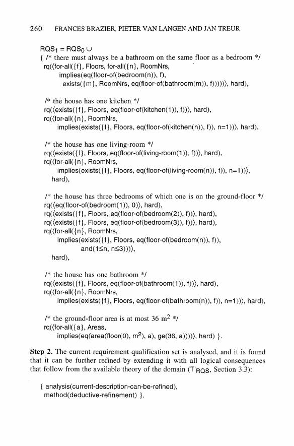
Step 1. The customer states his/her wishes, which are translated into a set of requirements for the design of the house ('u' is the set union operation):
260 FRANCES BRAZIER, PIETER VAN LANGEN AND JAN TREUR
ROS1 = ROSa u { /* there must always be a bathroom on the same floor as a bedroom */ rq( (for-all( {f}, Floors, for-all( {n}, RoomNrs, .
implies( eq(floor-of(bedroom(n», f), exists( {m}, RoomNrs, eq(floor-of(bathroom(m», f»»», hard),
1* the house has one kitchen */ rq«exists({f}, Floors, eq(floor-of(kitchen(1», f»), hard), rq( (for-all( {n}, RoomNrs,
implies( exists( {f}, Floors, eq(floor-of(kitchen(n», f», n=1 »), hard),
/* the house has one living-room *1 rq«exists( {f}, Floors, eq(floor-of(living-room(1 », f»), hard), rq( (for-all( {n}, RoomNrs,
implies( exists( {f}, Floors, eq(floor-of(living-room(n», f», n=1»), hard),
/* the house has three bedrooms of which one is on the ground-floor */ rq«eq(floor-of(bedroom(1 », 0», hard), rq( (exists( {f}, Floors, eq(floor-of(bedroom(2», f»), hard), rq«exists({f}, Floors, eq(floor-of(bedroom(3», f»), hard), rq«for-all({n}, RoomNrs,
implies(exists( {f}, Floors, eq(floor-of(bedroom(n», f», and(1::;;n, n::;;3»»,
hard),
/* the house has one bathroom */ rq«exists({f}, Floors, eq(floor-of(bathroom(1», f»), hard), rq( (for-all( {n }, RoomNrs,
implies( exists( {f}, Floors, eq(floor-of(bathroom(n», f», n=1 »), hard),
1* the ground-floor area is at most 36 m2 */ rq( (for-all( {a}, Areas,
implies(eq(area(floor(O), m2), a), ge(36, a»»), hard) }.
Step 2. The current requirement qualification set is analysed, and it is found that it can be further refined by extending it with all logical consequences that follow from the available theory of the domain (T'RQS, Section 3.3):
{ analysis( current-description-can-be-refined), methode deductive-refinement) }.

A LOGICAL THEORY OF DESIGN 261
Step 3. The current requirement qualification set is deductively refined by means of TROS:
ROS2 = ROS1 U
{ 1* there must be a hall on the ground-floor *1 rq«exists({n}, RoomNrs, eq(floor-of(hall(n)), 0), hard),
1* the minimum area of a hall is 2 m2 *1 rq«for-all({n}, RoomNrs, for-all({a}, Areas,
implies(eq(area(hall(n), m2), a), ge(a, 2))))), hard),
1* the minimum area of a kitchen is 4 m2 *1 rq( (for-all( {n}, RoomNrs, for-all( {a}, Areas,
implies(eq(area(kitchen(n), m2), a), ge(a, 4))))), hard),
1* the minimum area of a living-room is 16 m2 *1 rq( (for-all( {n}, RoomNrs, for-all ( {a}, Areas,
implies(eq(area(living-room(n), m2), a), ge(a, 16))))), hard),
1* the minimum area of a bathroom is 3 m2 *1 rq( (for-all( {n}, RoomNrs, for-all( {a}, Areas,
implies(eq(area(bathroom(n), m2), a), ge(a, 3))))), hard),
1* the minimum area of a bedroom is 6 m2 *1 rq( (for-all( {n}, RoomNrs, for-all( {a}, Areas,
implies(eq(area(bedroom(n), m2), a), ge(a, 6))))), hard).
Step 4. The current requirement qualification set is analysed and no further problems can be found:
{ -, analysis(current-description-can-be-refined), -, analysis( current-description-is-too-restrictive) }.
Step 5. The current design process is analysed, and it is determined that it is now time to refine the current design object description:
{ to-manipulate-next(current-design-object-description), manipulation-type(refinement) }.
Step 6. The current design object description is analysed, and it is found that it is incomplete and should be refined by making assumptions about useful extensions to the current description:

262 FRANCES BRAZIER, PIETER VAN LANGEN AND JAN TREUR
{ analysis( cu rrent-description-is-incomplete), method(refinement-by-assumptions) }.
Step 7. The designer's first idea is to design a bungalow, with a kitchen of 4 m2, a living-room of 16 m2, a hall of 2 m2, a bathroom of 3 m2, and three bedrooms, each of 6 m2:
0001 = 0000 u { eq(floor-of(kitchen(1 », 0), eq(area(kitchen(1), m2), 4), eq(floor-of(living-room(1 », 0), eq(area(living-room(1), m2), 16), eq(floor-of(hall(1 », 0), eq(area(hall(1), m2), 2), eq(floor-of(bathroom(1 », 0), eq(area(bathroom(1), m2), 3), eq(floor-of(bedroom(1 », 0), eq(area(bedroom(1), m2), 6), eq(floor-of(bedroom(2», 0), eq(area(bedroom(2), m2), 6), eq(floor-of(bedroom(3», 0), eq(area(bedroom(3), m2), 6) }.
Step 8. The current design object description is analysed, and it is found that it can be further refined by extending it with all logical consequences that follow from the available theory of the domain (Tooo, Section 3.2):
{ analysis( current-description-can-be-refined), methode deductive-refinement) }.
Step 9. The current design object description is deductively refined by means ofT'ooo:
0002 = 0001 U { eq(area(floor(O), m2), 43) }.
Step 10. The current design object description is analysed, and it is found that it is incorrect, because of a violation of requirements, in particular the requirement on the maximum floor area, and should therefore be revised:
{ analysis( cu rrent-description-is-incorrect), method(revision) }.
A LOGICAL THEORY OF DESIGN 263
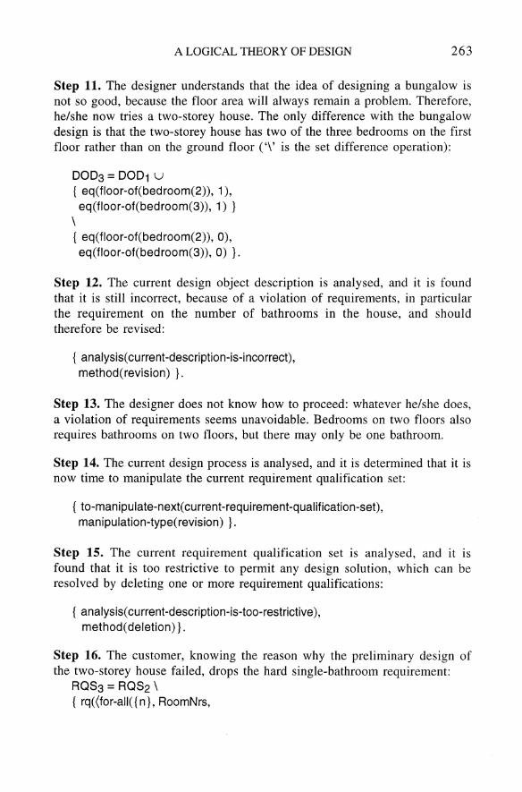
Step 11. The designer understands that the idea of designing a bungalow is not so good, because the floor area will always remain a problem. Therefore, he/she now tries a two-storey house. The only difference with the bungalow design is that the two-storey house has two of the three bedrooms on the first floor rather than on the ground floor ('\' is the set difference operation):
0003 = 0001 U
{ eq(floor-of(bedroom(2)), 1), eq(floor-of(bedroom(3)), 1) }
\ { eq(floor-of(bedroom(2)), 0), eq(floor-of(bedroom(3)), 0) }.
Step 12. The current design object description is analysed, and it is found that it is still incorrect, because of a violation of requirements, in particular the requirement on the number of bathrooms in the house, and should therefore be revised:
{ analysis( current -description-is-incorrect), method(revision) }.
Step 13. The designer does not know how to proceed: whatever he/she does, a violation of requirements seems unavoidable. Bedrooms on two floors also requires bathrooms on two floors, but there may only be one bathroom.
Step 14. The current design process is analysed, and it is determined that it is now time to manipulate the current requirement qualification set:
{ to-man i pu late-next( cu rrent -requi rement -q ualification-set), manipulation-type(revision) }.
Step 15. The current requirement qualification set is analysed, and it is found that it is too restrictive to permit any design solution, which can be resolved by deleting one or more requirement qualifications:
{ analysis( current-description-is-too-restrictive), method( deletion)}.
Step 16. The customer, knowing the reason why the preliminary design of the two-storey house failed, drops the hard single-bathroom requirement:
ROS3 = ROS2 \ { rq( (for-all( {n}, RoomNrs,
264 FRANCES BRAZIER, PIETER VAN LANGEN AND JAN TREUR
implies(exists({f}, Floors, eq(floor-of(bathroom(n», f», n=1»), hard) }.
Step 17. The current requirement qualification set is analysed and no further problems can be found:
{ -, analysis(current-description-can-be-refined), -, analysis( current-description-is-too-restrictive) }.
Step 18. The current design process is analysed, and it is determined that it is now time to revise the current design object description:
{ to-manipulate-next( cu rrent-design-object-description), manipulation-type(revision) }.
Step 19. The current design object description is analysed, and it is found that it is (still) incorrect and should be revised:
{ analysis( current -description-is-incomplete), method(revision) }.
Step 20. The designer proceeds with the design of the two-storey house and need not throw any parts away. The only thing he/she does is to place a bathroom on the first floor, with an area of 3 m2:
DOD4= DOD3U { eq(floor-of(bathroom(2), 1), eq(area(bathroom(2), m2), 3) }.
Step 21. The current design object description is analysed, and it is found that it can be further refined by extending it with all logical consequences that follow from the available theory of the domain (ToOO, Section 3.2):
{ analysis( current-description-can-be-refined), methode deductive-refinement) }.
Step 22. The current design object description is deductively refined by means of Tooo:
DODS: DOD4U { eq(area(floor(O), m2), 31), eq(area(floor(1), m2), 15) }.
Step 23. The current design object description is analysed and, since it is complete and satisfies all requirements, no more problems are found:

A LOGICAL THEORY OF DESIGN 265
{ -, analysis(current-description-is-incorrect), -, analysis(current-description-is-incomplete) }.
6. Discussion and Conclusions
A logical framework, capturing both static and dynamic aspects of design has been presented in this paper. It constitutes a logical theory of design which can be (and has been) instantiated for different types of design tasks (cf. Geelen and Kowalczyk, 1992; Brumsen, Pannekeet, and Treur, 1992).
The formal analysis of the dynamic aspects of design processes provides an explicit means to model design strategies. Declarative specifications of strategies provide a basis for interaction between autonomous systems on, for example, the strategy employed during design. As expert designers often wish to determine the design strategy employed, flexibility is mandatory. By formally defining the strategies involved, design support systems can be designed within which the user is given the freedom to determine how a task is to be approached. Formal specifications, together with well-defined semantics, provide a basis for such flexibility and a basis for the verification and validation of design support systems' behaviour.
Current research focusses on fundamental issues with respect to the formalisation of design strategies, (non-monotonic) reasoning patterns, verification, validation and knowledge acquisition.
Acknowledgements
This research has been partially supported by the Dutch Foundation for Knowledge-Based Systems (SKBS) within the A3 project "An environment for modular knowledge-based systems (based on meta-knowledge) for design tasks." The constructive comments and suggestions for improvements provided by Tim Smithers have been much appreciated.
References
Blarney, S.: 1986, Partial logic, in D. Gabbay and F. Giinthner (eds). Handbook of Philosophical Logic, Reidel, Dordrecht, III, pp. 1-70.
Brazier, F. M. T., Langen, P. H. G. van, Ruttkay, Zs., and Treur, J.: 1994, On formal specification of design tasks, in J. S. Gero and F. Sudweeks (eds), Proceedings Artificial Intelligence in Design '94, K1uwer, Dordrecht, pp. 535-552.
Brazier, F. M. T., Langen, P. H. G. van, Treur, J., Wijngaards, N. 1. E., and Willems, M.: 1994, Modelling a design task in DESIRE: The VT example, Technical Report IR-377. Artificial Intelligence Group, Department of Mathematics and Computer Science, Vrije Universiteit, Amsterdam. Also in A. Th. Schreiber and W. Birmingham (eds) (1995), International Journal on Human-Computer Studies, Special Issue on Sisyphus.
Brown, D. C. and Chandrasekaran, B.: 1989, Design Problem Solving: Knowledge Structures and Control Strategies, Pitman, London.

266 FRANCES BRAZIER, PIETER V AN LANGEN AND JAN TREUR
Brumsen, H. A., Pannekeet, 1. H. M., and Treur, 1.: 1992, A compositional knowledge-based architecture modelling process aspects of design tasks, Proceedings of the Twelfth International Conference on Artificial Intelligence, Expert Systems and Natural Language (Avignon-92), EC2, Nanterre, Vol. 1, pp. 283-294.
Console, L., and Torasso, P.: 1990, Hypothetical reasoning in causal models, International lournal of Intelligent Systems, 5(1), 83-124.
Coyne, R. D.: 1988, Logic Models of Design, Pitman, London. Engelfriet, 1. and Treur, J.: 1994, Temporal theories of reasoning, Proceedings of the Fourth
European Workshop on Logics in Artificial Intelligence (lELIA '94), Springer-Verlag, Berlin.
French, R. and Mostow, J.: 1985, Toward better models of the design process, Al Magazine, 6(1), 44-57.
Gavrila, 1. S. and Treur, J.: 1994, A formal model for the dynamics of compositional reasoning systems, in A. G. Cohn (ed.), Proceedings of the Eleventh European Conference on Artificial Intelligence (ECA! '94), John Wiley, Chichester, pp. 307-311.
Geelen, P. A. and Kowalczyk, W.: 1992, A knowledge-based system for the routing of international blank payment orders, Proceedings Twelfth International Conference on Artificial Intelligence, Expert Systems and Natural Language (Avignon-92), EC2, Nanterre, Vol. 2, pp. 669-677.
Langen, P. H. G. van, and Treur, J.: 1989, Representing World Situations and Information States by Many-Sorted Partial Models, Technical Report PE8904, Programming Research Group, Department of Mathematics and Computer Science, University of Amsterdam, Amsterdam.
Langholm, T.: 1988, Partiality, Truth and Persistence, CSLI Lecture Notes No. 15, Stanford University, Stanford, CA.
Logan, B. S., Corne, D. W., and Smithers, T.: 1992, Enduring support: on defeasible reasoning in design support systems, in J. S. Gero (ed.), Artificial Intelligence in Design '92, Kluwer, Dordrecht, pp. 433-454.
Reiter, R.: 1987, A theory of diagnosis from first principles, Artificial Intelligence, 32, 57-95.
Takeda, H., Veerkamp, P. J., Tomiyama, T. and Yoshikawa, H.: 1990, Modelling design processes, A! Magazine, 11(4), 37-48.
Tomiyama, T. and Yoshikawa, H.: 1987, Extended general design theory, in H. Yoshikawa and E. A. Warman (eds), Proceedings IFfP WG 5.2 Working Conference on Design Theory for CAD, North-Holland, Amsterdam, pp. 95-125.
Treur, J.: 1991, A logical framework for design processes, in P. J. W. ten Hagen and P. J. Veerkamp (eds), Intelligent CAD Systems Ill, Proceedings of the Third Eurographics Workshop on Intelligent CAD Systems, Springer-Verlag, Berlin, pp. 3-20.
Treur, J.: 1994, Temporal semantics of meta-level architectures for dynamic control of reasoning, Proceedings of the Fourth International Workshop on Meta-Programming in Logic (META '94), Springer-Verlag, Berlin, Lecture Notes in Computer Science 883.
Treur, J., and Willems, M.: 1994a, A logical foundation for verification, in A. G. Cohn (ed.), Proceedings of the Eleventh European Conference on Artificial Intelligence (ECA! '94), John Wiley, Chichester, pp. 745-749.
Treur, J., and Willems, M.: 1994b, On verification in compositional knowledge-based systems, in A. Preece (ed.), Proceedings of the ECA! '94 Workshop on Validation of Knowledge-Based Systems, Amsterdam, pp. 4-20. Also: Formal notions for verification of dynamics of knowledge-based systems, in M.-C. Rousset and M. Ayel (eds.) (1995), Proceedings of the European Symposium on Validation and Verification of KBSs (EUROVAV '95), Chambery.
Copyright © 2022 FDOKUMEN