A Histogram Specification Technique for Dark Image ...
11
IPSJ Transactions on Computer Vision and Applications Hussain et al. IPSJ Transactions on Computer Vision and Applications (2018) 10:3 https://doi.org/10.1186/s41074-018-0040-0 RESEARCH PAPER Open Access A histogram specification technique for dark image enhancement using a local transformation method Khalid Hussain 1* , Shanto Rahman 1 , Md. Mostafijur Rahman 1 , Shah Mostafa Khaled 1 , M. Abdullah-Al Wadud 2 , Muhammad Asif Hossain Khan 3 and Mohammad Shoyaib 1 Abstract Traditional image enhancement techniques produce different types of noise such as unnatural effects, over-enhancement, and artifacts, and these drawbacks become more prominent in enhancing dark images. To overcome these drawbacks, we propose a dark image enhancement technique where local transformation of the pixels have been performed. Here, we apply a transformation method of different parts of the histogram of an input image to get a desired histogram. Afterwards, histogram specification technique has been done on the input image using this transformed histogram. The performance of the proposed technique has been evaluated in both qualitative and quantitative manner, which shows that the proposed method improves the quality of the image with minimal unexpected artifacts as compared to the other techniques. Keywords: Dark image enhancement, Histogram equalization, Histogram specification 1 Introduction Image enhancement is commonly used to improve the visual quality of an image. The quality of the images may be degraded for several reasons like the lack of operator expertise and quality of image capturing device. Generally, images are captured in bright, dark, or any uncontrolled environments. And if an image is captured in too bright or too dark environment (Fig. 1), then enhancement is necessary for creating better looking image. Furthermore, events such as scanning or transmitting an image from one place to another may cause distortion to that image. Differences in brightness of different parts of an image due to shadow or non-uniform illumination also demand enhancement. For example, we may take an image where the face looks dark as compared to the background. How- ever, in spite of the availability of many enhancement algorithms, there have been very little work focusing specifically on dark image (image mean, μ < 0.5 [1], where the darkness is due to low illumination, not for *Correspondence: [email protected] 1 Institute of Information Technology, University of Dhaka, Dhaka 1000, Bangladesh Full list of author information is available at the end of the article dark-colored objects) enhancement, and these methods might also result in over-enhancement and/or unnatural effects. Histogram equalization (HE) is a simple and effec- tive contrast enhancement technique for enhancing an image. HE spreads the intensities of an image pixels based on the whole image information. As a result, there might be a case where some low occurring intensities are transformed to become merged with neighboring high occurring intensities, which creates over-enhancement [2, 3]. Moreover, mean shift problems may also occur in such cases. So, brightness preservation cannot be guaranteed in HE. An improved version of HE is the brightness preserving bi-histogram equalization (BBHE) [4] which produces better results as compared to HE, and most often, it preserves the brightness of the original image. However, it may not give desired out- come when the image pixel distribution does not fol- low the symmetric distribution [5]. A method called equal area dualistic sub-image histogram equalization (DSIHE) [6] performs better than BBHE because it separates the histogram based on the image median. Recently, Rahman et al. proposed an enhancement tech- nique where the histogram is divided using harmonic © The Author(s). 2018 Open Access This article is distributed under the terms of the Creative Commons Attribution 4.0 International License (http://creativecommons.org/licenses/by/4.0/), which permits unrestricted use, distribution, and reproduction in any medium, provided you give appropriate credit to the original author(s) and the source, provide a link to the Creative Commons license, and indicate if changes were made.
-
Upload
khangminh22 -
Category
Documents
-
view
1 -
download
0
Transcript of A Histogram Specification Technique for Dark Image ...
IPSJ Transactions on ComputerVision and Applications
Hussain et al. IPSJ Transactions on Computer Vision andApplications (2018) 10:3 https://doi.org/10.1186/s41074-018-0040-0
RESEARCH PAPER Open Access
A histogram specification technique fordark image enhancement using a localtransformation methodKhalid Hussain1*, Shanto Rahman1, Md. Mostafijur Rahman1, Shah Mostafa Khaled1,M. Abdullah-Al Wadud2, Muhammad Asif Hossain Khan3 and Mohammad Shoyaib1
Abstract
Traditional image enhancement techniques produce different types of noise such as unnatural effects,over-enhancement, and artifacts, and these drawbacks become more prominent in enhancing dark images. Toovercome these drawbacks, we propose a dark image enhancement technique where local transformation of thepixels have been performed. Here, we apply a transformation method of different parts of the histogram of an inputimage to get a desired histogram. Afterwards, histogram specification technique has been done on the input imageusing this transformed histogram. The performance of the proposed technique has been evaluated in both qualitativeand quantitative manner, which shows that the proposed method improves the quality of the image with minimalunexpected artifacts as compared to the other techniques.
Keywords: Dark image enhancement, Histogram equalization, Histogram specification
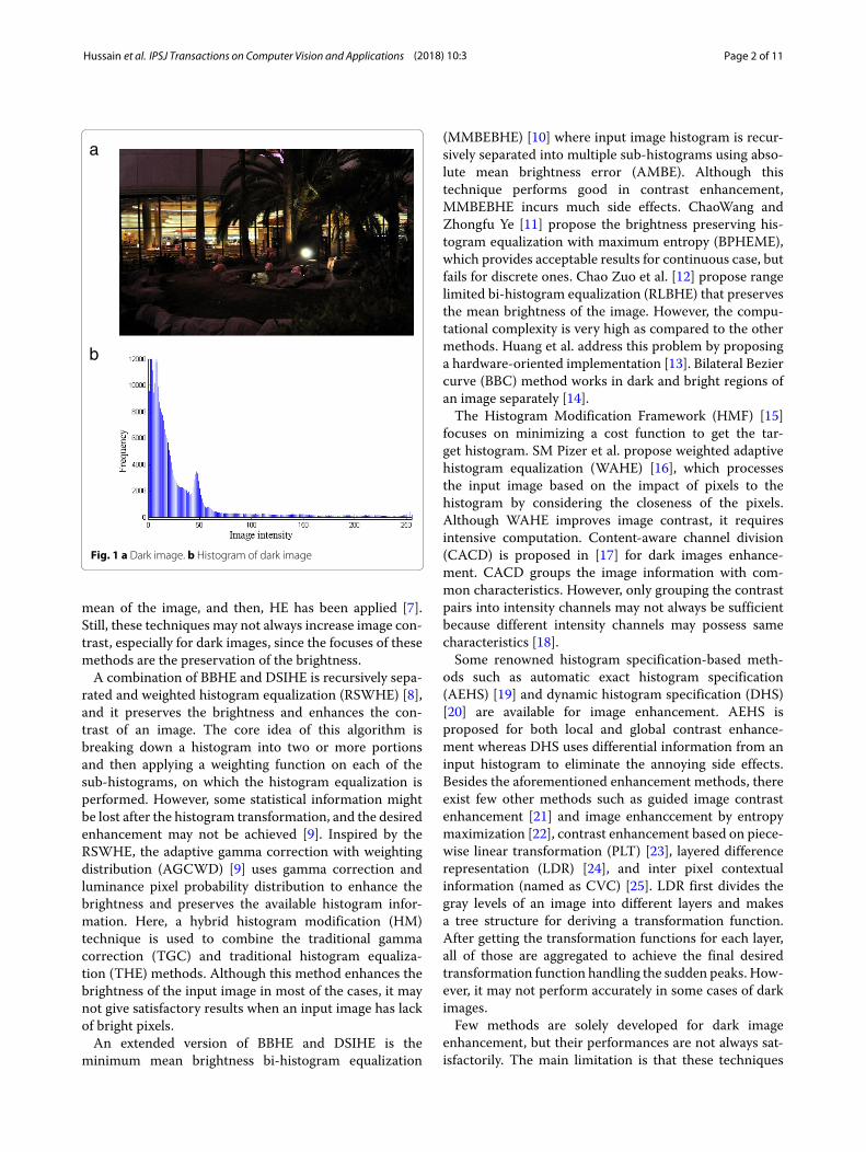
1 IntroductionImage enhancement is commonly used to improve thevisual quality of an image. The quality of the images maybe degraded for several reasons like the lack of operatorexpertise and quality of image capturing device. Generally,images are captured in bright, dark, or any uncontrolledenvironments. And if an image is captured in too brightor too dark environment (Fig. 1), then enhancement isnecessary for creating better looking image. Furthermore,events such as scanning or transmitting an image fromone place to another may cause distortion to that image.Differences in brightness of different parts of an imagedue to shadow or non-uniform illumination also demandenhancement. For example, we may take an image wherethe face looks dark as compared to the background. How-ever, in spite of the availability of many enhancementalgorithms, there have been very little work focusingspecifically on dark image (image mean, μ < 0.5 [1],where the darkness is due to low illumination, not for
*Correspondence: [email protected] of Information Technology, University of Dhaka, Dhaka 1000,BangladeshFull list of author information is available at the end of the article
dark-colored objects) enhancement, and these methodsmight also result in over-enhancement and/or unnaturaleffects.Histogram equalization (HE) is a simple and effec-
tive contrast enhancement technique for enhancing animage. HE spreads the intensities of an image pixelsbased on the whole image information. As a result, theremight be a case where some low occurring intensities aretransformed to become merged with neighboring highoccurring intensities, which creates over-enhancement[2, 3]. Moreover, mean shift problems may also occurin such cases. So, brightness preservation cannot beguaranteed in HE. An improved version of HE is thebrightness preserving bi-histogram equalization (BBHE)[4] which produces better results as compared to HE,and most often, it preserves the brightness of theoriginal image. However, it may not give desired out-come when the image pixel distribution does not fol-low the symmetric distribution [5]. A method calledequal area dualistic sub-image histogram equalization(DSIHE) [6] performs better than BBHE because itseparates the histogram based on the image median.Recently, Rahman et al. proposed an enhancement tech-nique where the histogram is divided using harmonic
© The Author(s). 2018 Open Access This article is distributed under the terms of the Creative Commons Attribution 4.0International License (http://creativecommons.org/licenses/by/4.0/), which permits unrestricted use, distribution, andreproduction in any medium, provided you give appropriate credit to the original author(s) and the source, provide a link to theCreative Commons license, and indicate if changes were made.
Hussain et al. IPSJ Transactions on Computer Vision and Applications (2018) 10:3 Page 2 of 11
a
b
Fig. 1 a Dark image. b Histogram of dark image
mean of the image, and then, HE has been applied [7].Still, these techniques may not always increase image con-trast, especially for dark images, since the focuses of thesemethods are the preservation of the brightness.A combination of BBHE and DSIHE is recursively sepa-
rated and weighted histogram equalization (RSWHE) [8],and it preserves the brightness and enhances the con-trast of an image. The core idea of this algorithm isbreaking down a histogram into two or more portionsand then applying a weighting function on each of thesub-histograms, on which the histogram equalization isperformed. However, some statistical information mightbe lost after the histogram transformation, and the desiredenhancement may not be achieved [9]. Inspired by theRSWHE, the adaptive gamma correction with weightingdistribution (AGCWD) [9] uses gamma correction andluminance pixel probability distribution to enhance thebrightness and preserves the available histogram infor-mation. Here, a hybrid histogram modification (HM)technique is used to combine the traditional gammacorrection (TGC) and traditional histogram equaliza-tion (THE) methods. Although this method enhances thebrightness of the input image in most of the cases, it maynot give satisfactory results when an input image has lackof bright pixels.An extended version of BBHE and DSIHE is the
minimum mean brightness bi-histogram equalization
(MMBEBHE) [10] where input image histogram is recur-sively separated into multiple sub-histograms using abso-lute mean brightness error (AMBE). Although thistechnique performs good in contrast enhancement,MMBEBHE incurs much side effects. ChaoWang andZhongfu Ye [11] propose the brightness preserving his-togram equalization with maximum entropy (BPHEME),which provides acceptable results for continuous case, butfails for discrete ones. Chao Zuo et al. [12] propose rangelimited bi-histogram equalization (RLBHE) that preservesthe mean brightness of the image. However, the compu-tational complexity is very high as compared to the othermethods. Huang et al. address this problem by proposinga hardware-oriented implementation [13]. Bilateral Beziercurve (BBC) method works in dark and bright regions ofan image separately [14].The Histogram Modification Framework (HMF) [15]
focuses on minimizing a cost function to get the tar-get histogram. SM Pizer et al. propose weighted adaptivehistogram equalization (WAHE) [16], which processesthe input image based on the impact of pixels to thehistogram by considering the closeness of the pixels.Although WAHE improves image contrast, it requiresintensive computation. Content-aware channel division(CACD) is proposed in [17] for dark images enhance-ment. CACD groups the image information with com-mon characteristics. However, only grouping the contrastpairs into intensity channels may not always be sufficientbecause different intensity channels may possess samecharacteristics [18].Some renowned histogram specification-based meth-
ods such as automatic exact histogram specification(AEHS) [19] and dynamic histogram specification (DHS)[20] are available for image enhancement. AEHS isproposed for both local and global contrast enhance-ment whereas DHS uses differential information from aninput histogram to eliminate the annoying side effects.Besides the aforementioned enhancement methods, thereexist few other methods such as guided image contrastenhancement [21] and image enhanccement by entropymaximization [22], contrast enhancement based on piece-wise linear transformation (PLT) [23], layered differencerepresentation (LDR) [24], and inter pixel contextualinformation (named as CVC) [25]. LDR first divides thegray levels of an image into different layers and makesa tree structure for deriving a transformation function.After getting the transformation functions for each layer,all of those are aggregated to achieve the final desiredtransformation function handling the sudden peaks. How-ever, it may not perform accurately in some cases of darkimages.Few methods are solely developed for dark image
enhancement, but their performances are not always sat-isfactorily. The main limitation is that these techniques
Hussain et al. IPSJ Transactions on Computer Vision and Applications (2018) 10:3 Page 3 of 11
may transfer most of the pixels from dark region to thebright region which might cause over-enhancement andunwanted shift in brightness. To mitigate this, we pro-pose a method specifically to enhance images having darkportions in them (a preliminary version of this work canbe found in [26]). We divide the whole image histograminto several segments and then modify those to have ahistogram with desired characteristics. Finally, histogramspecification is performed on the input image using thisdesired histogram. According to our method, the desiredhistogram is carefully created to enhance the image, espe-cially the dark parts. Moreover, the gray levels of onesegment are not transferred to another segment. Thishelps to avoid over-enhancement and additional noise.Experimental results also advocate for the effectiveness ofthe proposed method.Rest of the paper is organized as follows. Section 2 dis-
cusses the proposedmethod, and the results are presentedin Section 3 using both qualitative and quantitative anal-ysis. Finally, Section 4 concludes the contribution of thispaper.
2 ProposedmethodThe proposed method enhances an image with a specialattention to the dark region of that image. This methodcan be applied on both gray and color images. For colorimages, color space conversion is needed because directRGB color processing cannot preserve the original color;rather, it produces undesirable effect on the output image.Different kinds of color spaces are available such as HSV,HSI, Lab, and Luma. In the proposed method, we haveused HSV color space to process the image due to its addi-tive advantages. The advantages which HSV provides aredelineated below [23].
• In HSV color model, V (luminance) and colorinformation (hue and saturation) are decoupled.
• Color relationships of HSV color model are describedmore meticulously than RGB color model.
• We can easily transform RGB color model to HSVcolor model and vice versa.
After applying the enhancement on V channel, theimage is converted back to RGB. The whole enhancementprocess consists of two major steps: (1) preprocessing and(2) enhancement. These two are discussed in the followingsub-sections.
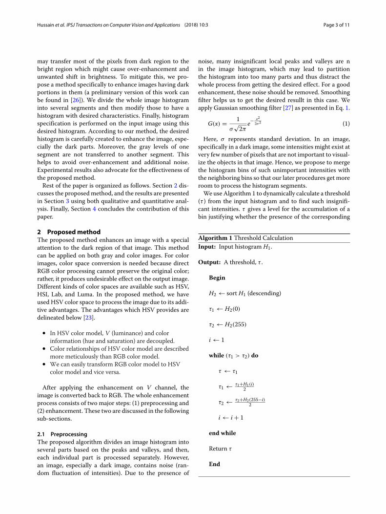
2.1 PreprocessingThe proposed algorithm divides an image histogram intoseveral parts based on the peaks and valleys, and then,each individual part is processed separately. However,an image, especially a dark image, contains noise (ran-dom fluctuation of intensities). Due to the presence of
noise, many insignificant local peaks and valleys are nin the image histogram, which may lead to partitionthe histogram into too many parts and thus distract thewhole process from getting the desired effect. For a goodenhancement, these noise should be removed. Smoothingfilter helps us to get the desired resullt in this case. Weapply Gaussian smoothing filter [27] as presented in Eq. 1.
G(x) = 1σ√2π
e−x22σ2 (1)
Here, σ represents standard deviation. In an image,specifically in a dark image, some intensities might exist atvery few number of pixels that are not important to visual-ize the objects in that image. Hence, we propose to mergethe histogram bins of such unimportant intensities withthe neighboring bins so that our later procedures get moreroom to process the histogram segments.We use Algorithm 1 to dynamically calculate a threshold
(τ ) from the input histogram and to find such insignifi-cant intensities. τ gives a level for the accumulation of abin justifying whether the presence of the corresponding
Algorithm 1 Threshold CalculationInput: Input histogram H1.
Output: A threshold, τ .
Begin
H2 ← sort H1 (descending)
τ1 ← H2(0)
τ2 ← H2(255)
i ← 1
while (τ1 > τ2) do
τ ← τ1
τ1 ← τ1+H1(i)2
τ2 ← τ2+H2(255−i)2
i ← i + 1
end while
Return τ
End
Hussain et al. IPSJ Transactions on Computer Vision and Applications (2018) 10:3 Page 4 of 11
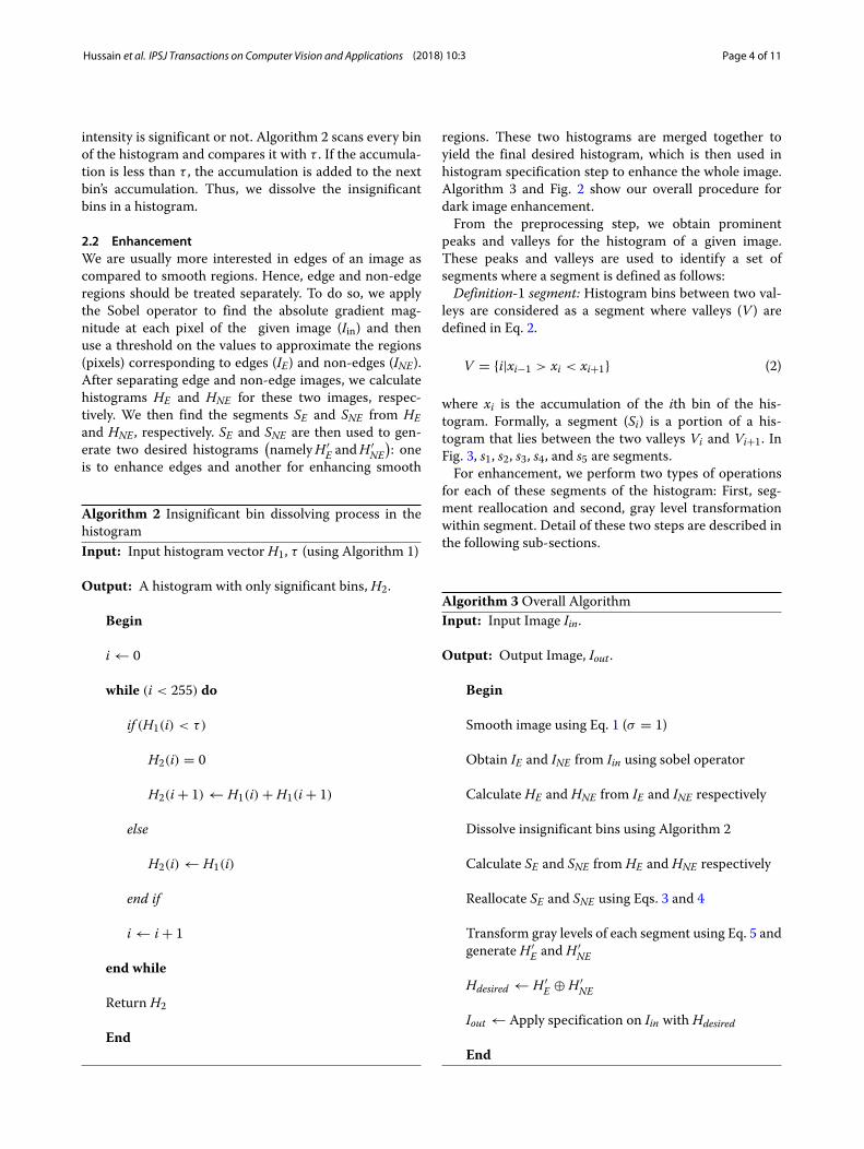
intensity is significant or not. Algorithm 2 scans every binof the histogram and compares it with τ . If the accumula-tion is less than τ , the accumulation is added to the nextbin’s accumulation. Thus, we dissolve the insignificantbins in a histogram.
2.2 EnhancementWe are usually more interested in edges of an image ascompared to smooth regions. Hence, edge and non-edgeregions should be treated separately. To do so, we applythe Sobel operator to find the absolute gradient mag-nitude at each pixel of the given image (Iin) and thenuse a threshold on the values to approximate the regions(pixels) corresponding to edges (IE) and non-edges (INE).After separating edge and non-edge images, we calculatehistograms HE and HNE for these two images, respec-tively. We then find the segments SE and SNE from HEand HNE , respectively. SE and SNE are then used to gen-erate two desired histograms
(namelyH ′
E andH′NE
): one
is to enhance edges and another for enhancing smooth
Algorithm 2 Insignificant bin dissolving process in thehistogramInput: Input histogram vector H1, τ (using Algorithm 1)
Output: A histogram with only significant bins, H2.
Begin
i ← 0
while (i < 255) do
if (H1(i) < τ)
H2(i) = 0
H2(i + 1) ← H1(i) + H1(i + 1)
else
H2(i) ← H1(i)
end if
i ← i + 1
end while
Return H2
End
regions. These two histograms are merged together toyield the final desired histogram, which is then used inhistogram specification step to enhance the whole image.Algorithm 3 and Fig. 2 show our overall procedure fordark image enhancement.From the preprocessing step, we obtain prominent
peaks and valleys for the histogram of a given image.These peaks and valleys are used to identify a set ofsegments where a segment is defined as follows:Definition-1 segment: Histogram bins between two val-
leys are considered as a segment where valleys (V ) aredefined in Eq. 2.
V = {i|xi−1 > xi < xi+1} (2)
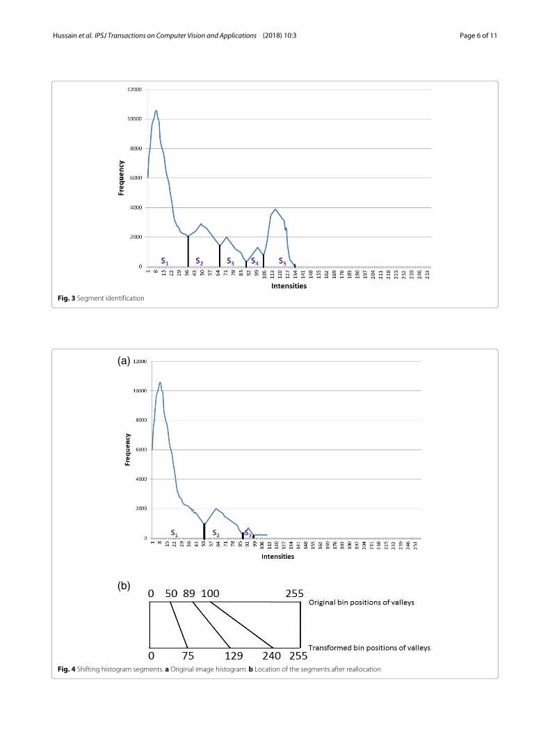
where xi is the accumulation of the ith bin of the his-togram. Formally, a segment (Si) is a portion of a his-togram that lies between the two valleys Vi and Vi+1. InFig. 3, s1, s2, s3, s4, and s5 are segments.For enhancement, we perform two types of operations
for each of these segments of the histogram: First, seg-ment reallocation and second, gray level transformationwithin segment. Detail of these two steps are described inthe following sub-sections.
Algorithm 3Overall AlgorithmInput: Input Image Iin.
Output: Output Image, Iout .
Begin
Smooth image using Eq. 1 (σ = 1)
Obtain IE and INE from Iin using sobel operator
Calculate HE and HNE from IE and INE respectively
Dissolve insignificant bins using Algorithm 2
Calculate SE and SNE from HE and HNE respectively
Reallocate SE and SNE using Eqs. 3 and 4
Transform gray levels of each segment using Eq. 5 andgenerate H ′
E and H ′NE
Hdesired ← H ′E ⊕ H ′
NE
Iout ← Apply specification on Iin with Hdesired
End
Hussain et al. IPSJ Transactions on Computer Vision and Applications (2018) 10:3 Page 5 of 11
0
2000
4000
6000
8000
10000
12000
0 50 100 150 200 250
0
500
1000
1500
2000
2500
3000
3500
4000
4500
5000
0 0.1 0.2 0.3 0.4 0.5 0.6 0.7 0.8 0.9 1
a b c
d e f
g h i
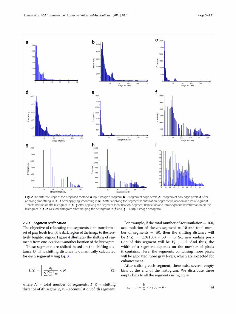
Fig. 2 The different steps of the proposed method. a Input image histogram. b Histogram of edge pixels. c Histogram of non-edge pixels. d Afterapplying smoothing in (b). e After applying smoothing in (c). f After applying the Segment Identification, Segment Relocation and Intra SegmentTransformation on the histogram in (d). g After applying the Segment Identification, Segment Relocation and Intra Segment Transformation on thehistogram in (e). h Desired histogram after merging the histograms in (f) and (g). i Output image histogram
2.2.1 Segment reallocationThe objective of relocating the segments is to transform aset of gray levels from the dark region of the image to the rela-tively brighter region. Figure 4 illustrates the shifting of seg-ments fromone location to another location of the histogram.These segments are shifted based on the shifting dis-
tance D. This shifting distance is dynamically calculatedfor each segment using Eq. 3.
D(i) =⌈
xi∑N−1
i=0 xi× N
⌉
(3)
where N = total number of segments, D(i) = shiftingdistance of ith segment, xi = accumulation of ith segment.
For example, if the total number of accumulation= 100,accumulation of the ith segment = 10 and total num-ber of segments = 50, then the shifting distance willbe D(i) = (10/100) × 50 = 5. So, new ending posi-tion of this segment will be Vi+1 + 5. And thus, thewidth of a segment depends on the number of pixelsit contains. Here, the segments containing more pixelswill be allocated more gray levels, which are expected forenhancement.After shifting each segment, there exist several empty
bins at the end of the histogram. We distribute theseempty bins to all the segments using Eq. 4
Li = li + liθ
× (255 − θ) (4)
Hussain et al. IPSJ Transactions on Computer Vision and Applications (2018) 10:3 Page 6 of 11
Fig. 3 Segment identification
(a)
(b)
Fig. 4 Shifting histogram segments. a Original image histogram. b Location of the segments after reallocation
Hussain et al. IPSJ Transactions on Computer Vision and Applications (2018) 10:3 Page 7 of 11
where li = width of the ith segment, Li = resultant widthof the ith segment, θ = ending bin position of the lastsegment. Thus, it also gives more space to perform intra-segment transformation.
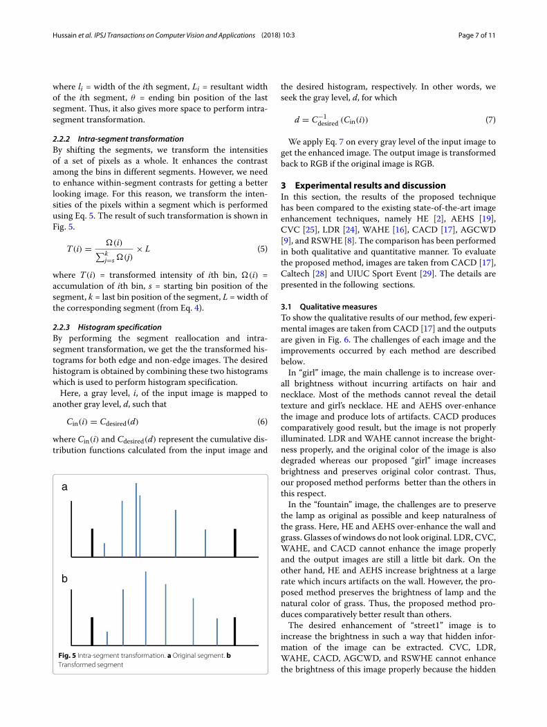
2.2.2 Intra-segment transformationBy shifting the segments, we transform the intensitiesof a set of pixels as a whole. It enhances the contrastamong the bins in different segments. However, we needto enhance within-segment contrasts for getting a betterlooking image. For this reason, we transform the inten-sities of the pixels within a segment which is performedusing Eq. 5. The result of such transformation is shown inFig. 5.
T(i) = �(i)∑k
j=s �(j)× L (5)
where T(i) = transformed intensity of ith bin, �(i) =accumulation of ith bin, s = starting bin position of thesegment, k = last bin position of the segment, L = width ofthe corresponding segment (from Eq. 4).
2.2.3 Histogram specificationBy performing the segment reallocation and intra-segment transformation, we get the the transformed his-tograms for both edge and non-edge images. The desiredhistogram is obtained by combining these two histogramswhich is used to perform histogram specification.Here, a gray level, i, of the input image is mapped to
another gray level, d, such that
Cin(i) = Cdesired(d) (6)
where Cin(i) and Cdesired(d) represent the cumulative dis-tribution functions calculated from the input image and
b
a
Fig. 5 Intra-segment transformation. a Original segment. bTransformed segment
the desired histogram, respectively. In other words, weseek the gray level, d, for which
d = C−1desired (Cin(i)) (7)
We apply Eq. 7 on every gray level of the input image toget the enhanced image. The output image is transformedback to RGB if the original image is RGB.
3 Experimental results and discussionIn this section, the results of the proposed techniquehas been compared to the existing state-of-the-art imageenhancement techniques, namely HE [2], AEHS [19],CVC [25], LDR [24], WAHE [16], CACD [17], AGCWD[9], and RSWHE [8]. The comparison has been performedin both qualitative and quantitative manner. To evaluatethe proposed method, images are taken from CACD [17],Caltech [28] and UIUC Sport Event [29]. The details arepresented in the following sections.
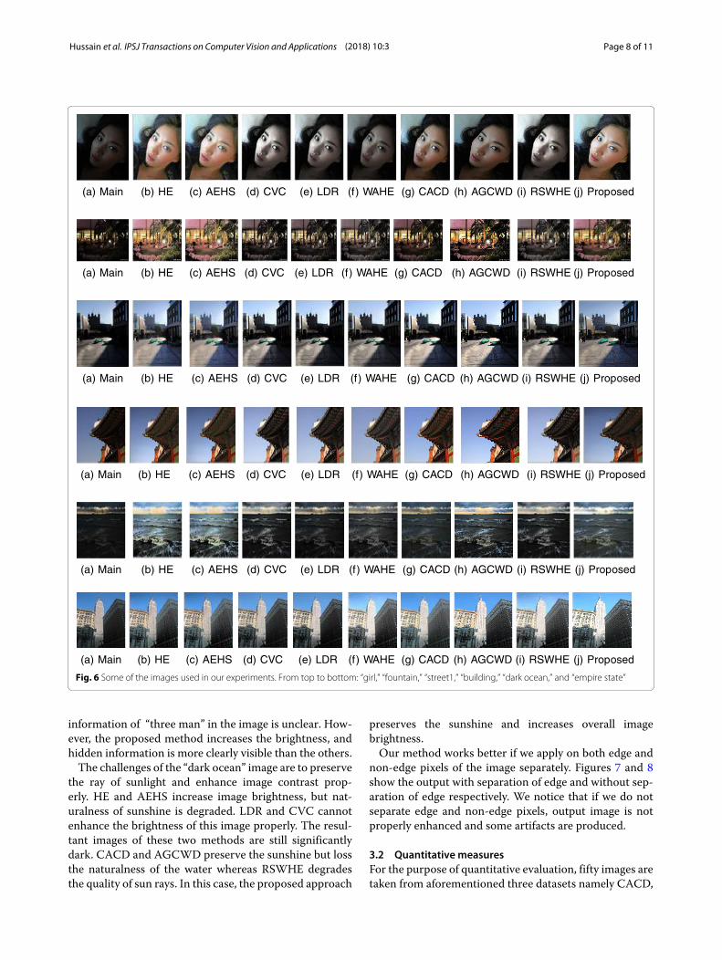
3.1 Qualitative measuresTo show the qualitative results of our method, few experi-mental images are taken from CACD [17] and the outputsare given in Fig. 6. The challenges of each image and theimprovements occurred by each method are describedbelow.In “girl” image, the main challenge is to increase over-
all brightness without incurring artifacts on hair andnecklace. Most of the methods cannot reveal the detailtexture and girl’s necklace. HE and AEHS over-enhancethe image and produce lots of artifacts. CACD producescomparatively good result, but the image is not properlyilluminated. LDR and WAHE cannot increase the bright-ness properly, and the original color of the image is alsodegraded whereas our proposed “girl” image increasesbrightness and preserves original color contrast. Thus,our proposed method performs better than the others inthis respect.In the “fountain” image, the challenges are to preserve
the lamp as original as possible and keep naturalness ofthe grass. Here, HE and AEHS over-enhance the wall andgrass. Glasses of windows do not look original. LDR, CVC,WAHE, and CACD cannot enhance the image properlyand the output images are still a little bit dark. On theother hand, HE and AEHS increase brightness at a largerate which incurs artifacts on the wall. However, the pro-posed method preserves the brightness of lamp and thenatural color of grass. Thus, the proposed method pro-duces comparatively better result than others.The desired enhancement of “street1” image is to
increase the brightness in such a way that hidden infor-mation of the image can be extracted. CVC, LDR,WAHE, CACD, AGCWD, and RSWHE cannot enhancethe brightness of this image properly because the hidden
Hussain et al. IPSJ Transactions on Computer Vision and Applications (2018) 10:3 Page 8 of 11
(a) Main (b) HE (c) AEHS (d) CVC (e) LDR (f) WAHE (g) CACD (h) AGCWD (i) RSWHE (j) Proposed
(a) Main (b) HE (c) AEHS (d) CVC (e) LDR (f) WAHE (g) CACD (h) AGCWD (i) RSWHE (j) Proposed
(a) Main (b) HE (c) AEHS (d) CVC (e) LDR (f) WAHE (g) CACD (h) AGCWD (i) RSWHE (j) Proposed
(a) Main (b) HE (c) AEHS (d) CVC (e) LDR (f) WAHE (g) CACD (h) AGCWD (i) RSWHE (j) Proposed
(a) Main (b) HE (c) AEHS (d) CVC (e) LDR (f) WAHE (g) CACD (h) AGCWD (i) RSWHE (j) Proposed
(a) Main (b) HE (c) AEHS (d) CVC (e) LDR (f) WAHE (g) CACD (h) AGCWD (i) RSWHE (j) Proposed
Fig. 6 Some of the images used in our experiments. From top to bottom: “girl,” “fountain,” “street1,” “building,” “dark ocean,” and “empire state”
information of “three man” in the image is unclear. How-ever, the proposed method increases the brightness, andhidden information is more clearly visible than the others.The challenges of the “dark ocean” image are to preserve
the ray of sunlight and enhance image contrast prop-erly. HE and AEHS increase image brightness, but nat-uralness of sunshine is degraded. LDR and CVC cannotenhance the brightness of this image properly. The resul-tant images of these two methods are still significantlydark. CACD and AGCWD preserve the sunshine but lossthe naturalness of the water whereas RSWHE degradesthe quality of sun rays. In this case, the proposed approach
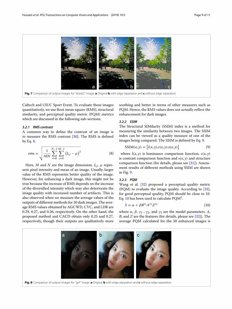
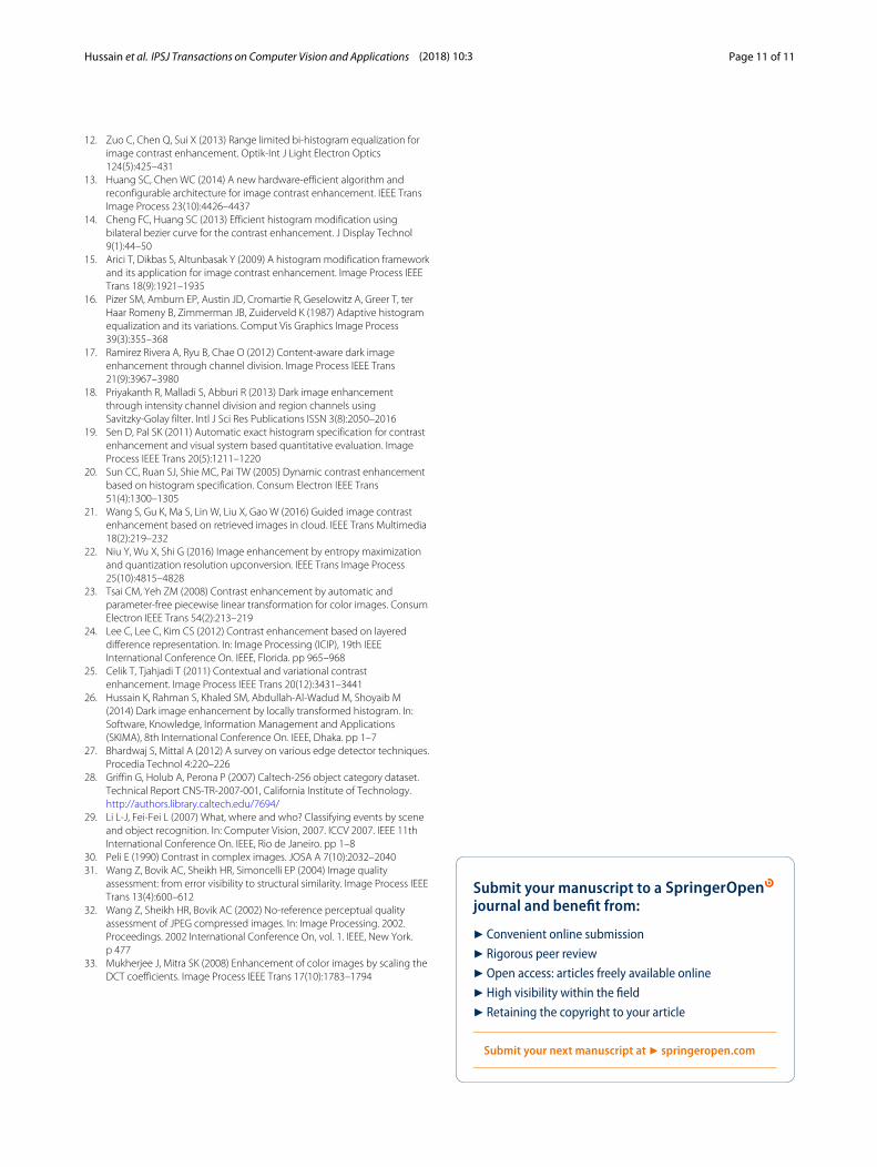
preserves the sunshine and increases overall imagebrightness.Our method works better if we apply on both edge and
non-edge pixels of the image separately. Figures 7 and 8show the output with separation of edge and without sep-aration of edge respectively. We notice that if we do notseparate edge and non-edge pixels, output image is notproperly enhanced and some artifacts are produced.
3.2 Quantitative measuresFor the purpose of quantitative evaluation, fifty images aretaken from aforementioned three datasets namely CACD,
Hussain et al. IPSJ Transactions on Computer Vision and Applications (2018) 10:3 Page 9 of 11
Fig. 7 Comparison of output images for “street2” image. a Original b with edge separation and c without edge separation
Caltech and UIUC Sport Event. To evaluate these imagesquantitatively, we use Root mean square (RMS), structuralsimilarity, and perceptual quality metric (PQM) metricswhich are discussed in the following sub-sections.
3.2.1 RMS contrastA common way to define the contrast of an image isto measure the RMS contrast [30]. The RMS is definedby Eq. 8.
rms =√√√√ 1
MN
N−1∑
i=0
M−1∑
j=0
(Ii,j − μ
)2 (8)
Here, M and N are the image dimension. Ii,j, μ repre-sent pixel intensity and mean of an image. Usually, largervalue of the RMS represents better quality of the image.However, for enhancing a dark image, this might not betrue because the increase of RMS depends on the increaseof the diversified intensity which may also deteriorate theimage quality with increased number of artifacts. This isalso observed when we measure the average values of theoutputs of different methods for 50 dark images. The aver-age RMS values obtained by AGCWD, CVC, and LDR are0.29, 0.27, and 0.26, respectively. On the other hand, theproposed method and CACD obtain only 0.25 and 0.27,respectively, though their outputs are qualitatively more
soothing and better in terms of other measures such asPQM. Hence, the RMS values does not actually reflect theenhancement for dark images.
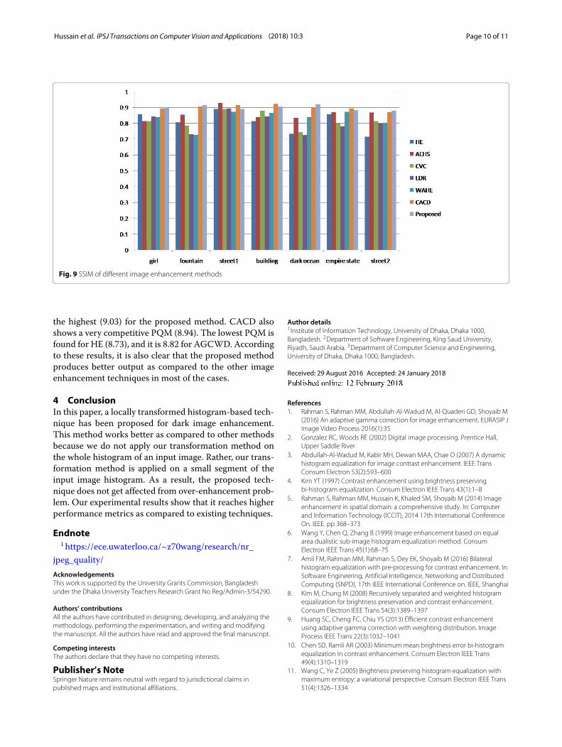
3.2.2 SSIMThe Structural SIMilarity (SSIM) index is a method formeasuring the similarity between two images. The SSIMindex can be viewed as a quality measure of one of theimages being compared. The SSIM is defined by Eq. 9.
SSIM(x, y) = [l(x, y).c(x, y).s(x, y)
](9)
where l(x, y) is luminance comparison function, c(x, y)is contrast comparison function and s(x, y) and structurecomparison function (for details, please see [31]). Assess-ment results of different methods using SSIM are shownin Fig. 9.
3.2.3 PQMWang et al. [32] proposed a perceptual quality metric(PQM) to evaluate the image quality. According to [33],for good perceptual quality, PQM should be close to 10.Eq. 10 has been used to calculate PQM1.
S = α + βBγ1Aγ2Zγ3 (10)
where α, β , γ1 , γ2, and γ3 are the model parameters. A,B, and Z are the features (for details, please see [32]). Theaverage PQM calculated for the 50 enhanced images is
b ca
Fig. 8 Comparison of output images for “girl” image. a Original b with edge separation and c without edge separation
Hussain et al. IPSJ Transactions on Computer Vision and Applications (2018) 10:3 Page 10 of 11
Fig. 9 SSIM of different image enhancement methods
the highest (9.03) for the proposed method. CACD alsoshows a very competitive PQM (8.94). The lowest PQM isfound for HE (8.73), and it is 8.82 for AGCWD. Accordingto these results, it is also clear that the proposed methodproduces better output as compared to the other imageenhancement techniques in most of the cases.
4 ConclusionIn this paper, a locally transformed histogram-based tech-nique has been proposed for dark image enhancement.This method works better as compared to other methodsbecause we do not apply our transformation method onthe whole histogram of an input image. Rather, our trans-formation method is applied on a small segment of theinput image histogram. As a result, the proposed tech-nique does not get affected from over-enhancement prob-lem. Our experimental results show that it reaches higherperformance metrics as compared to existing techniques.
Endnote1 https://ece.uwaterloo.ca/~z70wang/research/nr_
jpeg_quality/AcknowledgementsThis work is supported by the University Grants Commission, Bangladeshunder the Dhaka University Teachers Research Grant No Reg/Admin-3/54290.
Authors’ contributionsAll the authors have contributed in designing, developing, and analyzing themethodology, performing the experimentation, and writing and modifyingthe manuscript. All the authors have read and approved the final manuscript.
Competing interestsThe authors declare that they have no competing interests.
Publisher’s NoteSpringer Nature remains neutral with regard to jurisdictional claims inpublished maps and institutional affiliations.
Author details1Institute of Information Technology, University of Dhaka, Dhaka 1000,Bangladesh. 2Department of Software Engineering, King Saud University,Riyadh, Saudi Arabia. 3Department of Computer Science and Engineering,University of Dhaka, Dhaka 1000, Bangladesh.
Received: 29 August 2016 Accepted: 24 January 2018
References1. Rahman S, Rahman MM, Abdullah-Al-Wadud M, Al-Quaderi GD, Shoyaib M
(2016) An adaptive gamma correction for image enhancement. EURASIP JImage Video Process 2016(1):35
2. Gonzalez RC, Woods RE (2002) Digital image processing. Prentice Hall,Upper Saddle River
3. Abdullah-Al-Wadud M, Kabir MH, Dewan MAA, Chae O (2007) A dynamichistogram equalization for image contrast enhancement. IEEE TransConsum Electron 53(2):593–600
4. Kim YT (1997) Contrast enhancement using brightness preservingbi-histogram equalization. Consum Electron IEEE Trans 43(1):1–8
5. Rahman S, Rahman MM, Hussain K, Khaled SM, Shoyaib M (2014) Imageenhancement in spatial domain: a comprehensive study. In: Computerand Information Technology (ICCIT), 2014 17th International ConferenceOn. IEEE. pp 368–373
6. Wang Y, Chen Q, Zhang B (1999) Image enhancement based on equalarea dualistic sub-image histogram equalization method. ConsumElectron IEEE Trans 45(1):68–75
7. Amil FM, Rahman MM, Rahman S, Dey EK, Shoyaib M (2016) Bilateralhistogram equalization with pre-processing for contrast enhancement. In:Software Engineering, Artificial Intelligence, Networking and DistributedComputing (SNPD), 17th IEEE International Conference on. IEEE, Shanghai
8. Kim M, Chung M (2008) Recursively separated and weighted histogramequalization for brightness preservation and contrast enhancement.Consum Electron IEEE Trans 54(3):1389–1397
9. Huang SC, Cheng FC, Chiu YS (2013) Efficient contrast enhancementusing adaptive gamma correction with weighting distribution. ImageProcess IEEE Trans 22(3):1032–1041
10. Chen SD, Ramli AR (2003) Minimummean brightness error bi-histogramequalization in contrast enhancement. Consum Electron IEEE Trans49(4):1310–1319
11. Wang C, Ye Z (2005) Brightness preserving histogram equalization withmaximum entropy: a variational perspective. Consum Electron IEEE Trans51(4):1326–1334
Hussain et al. IPSJ Transactions on Computer Vision and Applications (2018) 10:3 Page 11 of 11
12. Zuo C, Chen Q, Sui X (2013) Range limited bi-histogram equalization forimage contrast enhancement. Optik-Int J Light Electron Optics124(5):425–431
13. Huang SC, Chen WC (2014) A new hardware-efficient algorithm andreconfigurable architecture for image contrast enhancement. IEEE TransImage Process 23(10):4426–4437
14. Cheng FC, Huang SC (2013) Efficient histogram modification usingbilateral bezier curve for the contrast enhancement. J Display Technol9(1):44–50
15. Arici T, Dikbas S, Altunbasak Y (2009) A histogrammodification frameworkand its application for image contrast enhancement. Image Process IEEETrans 18(9):1921–1935
16. Pizer SM, Amburn EP, Austin JD, Cromartie R, Geselowitz A, Greer T, terHaar Romeny B, Zimmerman JB, Zuiderveld K (1987) Adaptive histogramequalization and its variations. Comput Vis Graphics Image Process39(3):355–368
17. Ramirez Rivera A, Ryu B, Chae O (2012) Content-aware dark imageenhancement through channel division. Image Process IEEE Trans21(9):3967–3980
18. Priyakanth R, Malladi S, Abburi R (2013) Dark image enhancementthrough intensity channel division and region channels usingSavitzky-Golay filter. Intl J Sci Res Publications ISSN 3(8):2050–2016
19. Sen D, Pal SK (2011) Automatic exact histogram specification for contrastenhancement and visual system based quantitative evaluation. ImageProcess IEEE Trans 20(5):1211–1220
20. Sun CC, Ruan SJ, Shie MC, Pai TW (2005) Dynamic contrast enhancementbased on histogram specification. Consum Electron IEEE Trans51(4):1300–1305
21. Wang S, Gu K, Ma S, Lin W, Liu X, Gao W (2016) Guided image contrastenhancement based on retrieved images in cloud. IEEE Trans Multimedia18(2):219–232
22. Niu Y, Wu X, Shi G (2016) Image enhancement by entropy maximizationand quantization resolution upconversion. IEEE Trans Image Process25(10):4815–4828
23. Tsai CM, Yeh ZM (2008) Contrast enhancement by automatic andparameter-free piecewise linear transformation for color images. ConsumElectron IEEE Trans 54(2):213–219
24. Lee C, Lee C, Kim CS (2012) Contrast enhancement based on layereddifference representation. In: Image Processing (ICIP), 19th IEEEInternational Conference On. IEEE, Florida. pp 965–968
25. Celik T, Tjahjadi T (2011) Contextual and variational contrastenhancement. Image Process IEEE Trans 20(12):3431–3441
26. Hussain K, Rahman S, Khaled SM, Abdullah-Al-Wadud M, Shoyaib M(2014) Dark image enhancement by locally transformed histogram. In:Software, Knowledge, Information Management and Applications(SKIMA), 8th International Conference On. IEEE, Dhaka. pp 1–7
27. Bhardwaj S, Mittal A (2012) A survey on various edge detector techniques.Procedia Technol 4:220–226
28. Griffin G, Holub A, Perona P (2007) Caltech-256 object category dataset.Technical Report CNS-TR-2007-001, California Institute of Technology.http://authors.library.caltech.edu/7694/
29. Li L-J, Fei-Fei L (2007) What, where and who? Classifying events by sceneand object recognition. In: Computer Vision, 2007. ICCV 2007. IEEE 11thInternational Conference On. IEEE, Rio de Janeiro. pp 1–8
30. Peli E (1990) Contrast in complex images. JOSA A 7(10):2032–204031. Wang Z, Bovik AC, Sheikh HR, Simoncelli EP (2004) Image quality
assessment: from error visibility to structural similarity. Image Process IEEETrans 13(4):600–612
32. Wang Z, Sheikh HR, Bovik AC (2002) No-reference perceptual qualityassessment of JPEG compressed images. In: Image Processing. 2002.Proceedings. 2002 International Conference On, vol. 1. IEEE, New York.p 477
33. Mukherjee J, Mitra SK (2008) Enhancement of color images by scaling theDCT coefficients. Image Process IEEE Trans 17(10):1783–1794