A GENERALIZED UPPER BOUND SOLUTION FOR ...
12
JOURNAL OF THEORETICAL AND APPLIED MECHANICS 51, 1, pp. 105-116, Warsaw 2013 A GENERALIZED UPPER BOUND SOLUTION FOR EXTRUSION OF BI-METALLIC RECTANGULAR CROSS-SECTION BARS THROUGH DIES OF ANY SHAPE Heshmatollah Haghighat, Parvaneh Amjadian Razi University, Mechanical Engineering Department, Kermanshah, Iran e-mail: [email protected] In this paper, a generalized upper bound solution is developed for extrusion of bi-metallic rectangular cross-section bars through dies of any shape. The internal, shearing and fric- tional power terms are derived and they are used in the upper bound model. By using the developed upper bound model, the extrusion pressures for two types of die shapes, an optimum wedge shaped die as a linear die profile and an optimum streamlined die shape as a curved die profile, are determined. The corresponding results for those two die shapes are also determined by using the finite element code and compared with the upper bound results. These comparisons show a good agreement. Key words: extrusion, bimetal, plane strain, upper bound method, FEM Nomenclature b c ,b s – widths of core and sleeve materials, respectively dQ – differential volume flow P – extrusion pressure J * – externally supplied power of deformation L,L o – length of die and initial bi-metallic billet length m 1 ,m 2 – friction factor between sleeve and die, and between core and sleeve r,θ,z – cylindrical coordinate system r f ,r o – radial position of surfaces S 2 and S 4 , and of surfaces S 1 and S 3 x – punch displacement S – surface of integration S 1 -S 4 – cylindrical surfaces of velocity discontinuity t 1f ,t 2f – half thickness of sleeve and core in final product t 1o ,t 2o – half thickness of sleeve and core in initial bar ˙ U r , ˙ U θ , ˙ U z – radial, angular and third components of velocity V – volume of integration V f ,V o – velocity of final product and initial billet, respectively ˙ W f , ˙ W i , ˙ W s – friction power losses along the wall, internal power of deformation and shear power losses along surface of velocity discontinuity, respectively α – angle of line connecting initial to final point of die γ – arbitrary angle on cylindrical surfaces S 1 and S 3 β – angle of interface in deformation zone ΔV – velocity difference ˙ ε rr , ˙ ε θθ , ˙ ε zz – normal strain rate components in radial, angular and third directions ˙ ε rθ , ˙ ε rz , ˙ ε zθ – shear strain rate components η – local angle of die surface with respect to local radial velocity component
-
Upload
khangminh22 -
Category
Documents
-
view
5 -
download
0
Transcript of A GENERALIZED UPPER BOUND SOLUTION FOR ...

JOURNAL OF THEORETICAL
AND APPLIED MECHANICS
51, 1, pp. 105-116, Warsaw 2013
A GENERALIZED UPPER BOUND SOLUTION FOR EXTRUSION OF
BI-METALLIC RECTANGULAR CROSS-SECTION BARS THROUGH DIES
OF ANY SHAPE
Heshmatollah Haghighat, Parvaneh Amjadian
Razi University, Mechanical Engineering Department, Kermanshah, Iran
e-mail: [email protected]
In this paper, a generalized upper bound solution is developed for extrusion of bi-metallicrectangular cross-section bars through dies of any shape. The internal, shearing and fric-tional power terms are derived and they are used in the upper bound model. By usingthe developed upper bound model, the extrusion pressures for two types of die shapes, anoptimum wedge shaped die as a linear die profile and an optimum streamlined die shapeas a curved die profile, are determined. The corresponding results for those two die shapesare also determined by using the finite element code and compared with the upper boundresults. These comparisons show a good agreement.
Key words: extrusion, bimetal, plane strain, upper bound method, FEM
Nomenclature
bc, bs – widths of core and sleeve materials, respectivelydQ – differential volume flowP – extrusion pressureJ∗ – externally supplied power of deformationL,Lo – length of die and initial bi-metallic billet lengthm1,m2 – friction factor between sleeve and die, and between core and sleever, θ, z – cylindrical coordinate systemrf , ro – radial position of surfaces S2 and S4, and of surfaces S1 and S3x – punch displacementS – surface of integrationS1-S4 – cylindrical surfaces of velocity discontinuityt1f , t2f – half thickness of sleeve and core in final productt1o, t2o – half thickness of sleeve and core in initial bar
Ur, Uθ, Uz – radial, angular and third components of velocityV – volume of integrationVf , Vo – velocity of final product and initial billet, respectively
Wf , Wi, Ws – friction power losses along the wall, internal power of deformation and shearpower losses along surface of velocity discontinuity, respectively
α – angle of line connecting initial to final point of dieγ – arbitrary angle on cylindrical surfaces S1 and S3β – angle of interface in deformation zone∆V – velocity differenceεrr, εθθ, εzz – normal strain rate components in radial, angular and third directionsεrθ, εrz, εzθ – shear strain rate componentsη – local angle of die surface with respect to local radial velocity component

106 H. Haghighat, P. Amjadian
σc, σs – mean flow stress of core and sleeve materialψ(r), ψi(r) – angular position of die and interface as function of radial position
1. Introduction
Bimetals are components made up of two separate metallic units, each occupying a distinctposition in the component. Bimetal components make possibility of combining properties ofdissimilar metals. The compressive state of stress in extrusion and the possibility of producingmetallurgical bonds between the two metals make this process a suitable choice for producingbimetal bars (Berski et al., 2004). In this process, alike other metal forming processes, estimationand minimization of the extrusion pressure is important. The upper bound technique as ananalytical method and the finite element method have been widely used for the analysis of theextrusion of bars made of mono-metal and bi-metallic materials. One of the limitations of mostof the current FE solution schemes for metal forming is that they do not provide parametricanalysis. Hence, any parametric investigation is usually done manually by changing one FEmodel to another until a feasible solution is obtained. Analytical solutions facilitate parametricstudy and can aid an FE modeler in seeking out optimal extrusion process conditions. Afterthe upper bound model has determined the optimal die shapes, a finite element model has thenbeen used to study the extrusion through dies with these optimal shapes.
A number of people have used the upper bound method and FEM to analyze the mono-metal and bimetal extrusion process through a variety of die shapes. Zimmerman and Avitzur(1970) modeled the mono-metal extrusion using the upper bound method with generalized shearboundaries. Osakada et al. (1973) described the hydrostatic extrusion of bi-metallic bars withhard cores through conical dies by the upper bound method. Nagpal (1974) developed velocityfields for axisymmetric mono-metal extrusions through arbitrarily shaped dies. Chen et al. (1979)used finite element analysis to examine the axisymmetric extrusion through conical dies. Avitzur(1983) summarized the factors that affect simultaneous flow of layers in the extrusion of abimetal bar through conical dies. Tokuno and Ikeda (1991) verified the deformation in extrusionof composite bars by experimental and upper bound methods. Yang et al. (1999) studied theaxisymmetric extrusion of composite bars through curved dies by experimental and upper boundmethods. Sliwa (1997) described the plastic zones in the forward extrusion of metal compositesby experimental and upper bound methods. Chitkara and Aleem (2001a,b) theoretically studiedthe mechanics of extrusion of axisymmetric bi-metallic tubes from solid circular bars usingfixed mandrel with application of generalized upper bound and slab method analyses. Theyinvestigated the effect of different parameters such as the extrusion ratio, frictional conditions,and shape of the dies and the mandrels on the extrusion pressures. Kang et al. (2002) designed adie for the hot forward and backward extrusion process of Al-Cu clad composite by experimentalinvestigations and FEM simulations. Hwang and Hwang (2002) studied the plastic deformationbehavior within a conical die during composite bar extrusion by experimental and upper boundmethods. Haghighat and Asgari (2011) proposed a generalized spherical velocity field for thebi-metallic tube extrusion process through dies of any shape. Haghighat and Amjadian (2011)developed velocity fields for the mono-metal plane strain extrusion through arbitrarily curveddies.
The purpose of this paper is to develop a generalized upper bound solution for flow of bi-metallic rectangular cross-section bars during extrusion through dies of any shape. Based onthis model, for a given die shape and process parameters, the optimum die length and extrusionpressure are derived. The FEM simulation on the extrusion of a bi-metallic rectangular cross-section bar composed of a copper sleeve layer and an aluminum core layer is also conducted.

A generalized upper bound solution for extrusion... 107
2. Upper bound analysis
Based on the upper bound theory, for a rigid-plastic Von-Misses material and amongst all thekinematically admissible velocity fields, the actual one that minimizes the power required formaterial deformation is expressed as
J∗ =2√3σ0
∫
v
√
1
2εij εij dV +
σ0√3
∫
SV
|∆V | dS +m σ0√3
∫
Sf
|∆V | dS −∫
St
TiVi dS (2.1)
where σ0 is the mean flow stress of the material, εij the strain rate tensor, m the constantfriction factor, V the volume of the plastic deformation zone, SV and Sf the area of velocitydiscontinuity and frictional surfaces, respectively, St the area where tractions may occur, ∆V theamount of velocity discontinuity on the frictional and discontinuity surfaces and Vi and Ti arethe velocity and tractions applied on St, respectively.
The extrusion of the bi-metallic rectangular cross-section bar through a die of arbitrarycurved shape is modelled as shown in Figs. 1 and 2. An initially billet, made up two differentductile materials with the mean flow stresses σc and σs, is considered. The subscripts c and sdenote the inner material, core, and outer material, sleeve, respectively. The material starts asa bar with the sleeve thickness 2t1o and core thickness 2t2o and it extrudes into a product ofthicknesses 2t2f and 2t1f for the sleeve and core through a curved die, respectively. Because ofthe width of the core bc and width of the sleeve bs are long, bc ∼= bs ≫ 2t1o, the process can beassumed as a plane strain extrusion.
Fig. 1. The extrusion process of a bi-metallic rectangular cross-section billet through an arbitrarilycurved die
To analyze the process, the material under deformation is divided into six zones, as shown inFig. 2. The die surface, which is labeled as ψ(r) in Fig. 2, is given in the cylindrical coordinatesystem (r, θ, z). The origin of the cylindrical coordinate system is located at the point O whichis defined by the intersection of the midline with a line at the angle α that goes through thepoint where the die begins and the exit point of the die.
In zones I and II, the incoming materials are assumed to flow horizontally as a rigid bodywith velocity Vo. In zones V and VI, the extruded materials are assumed to flow horizontallyas a rigid body with velocity Vf . Zones III and IV are the deformation regions, where thevelocity is complex. These zones are surrounded by four velocity discontinuity surfaces S1, S2,S3 and S4. In addition to these surfaces, there are two frictional surfaces between the sleeve andcontainer and the die surface and sleeve S5. The surfaces S1 and S3 are located at a distance rofrom the origin, and the surfaces S2 and S4 are located at a distance rf from the origin. The

108 H. Haghighat, P. Amjadian
Fig. 2. Schematic diagram of a plane strain extrusion of a bi-metallic strip through a curved die and thecylindrical coordinate system
mathematical equations for radial positions of four velocity discontinuity surfaces S1, S3 andS2, S4 are given by
ro =t1o − t2osinα
rf =t1f − t2fsinα
(2.2)
where α is the angle of the line connecting the initial point of the curved die to the final pointof the die and
tanα =t1o − t1f
L(2.3)
where L denotes the die length. The interface surface between the inner and the outer materialsis defined by ψi(r), which is the angular position of the interface surface as a function of theradial distance from the origin. The angle β, shown in Fig. 2, is given by
sin β =t2ot1osinα (2.4)
2.1. Velocity field in the deformation zone
The first step in the upper bound analysis is to choose an admissible velocity field for thematerial undergoing plastic deformation. The velocity field that derives from incompressibilitycondition and satisfies the velocity boundary conditions is a kinematically admissible velocityfield.The velocity component in the radial direction within the deformation zone Ur can be
obtained by assuming volume flow balance. In Fig. 2, the volume flow of the material across theS1 and S3 surface at the point (ro, γ, z) in the radial direction is
dQ = −Vo cos(γ)bro dγ (2.5)
The volume flow of the material in the radial direction at the point (r, θ, z) in the deformationzone is
dQ = Urbr dθ (2.6)
Equating Eqs. (2.5) and (2.6), the radial velocity in the deformation zone is
Ur = −Vororcos γ
dγ
dθ(2.7)

A generalized upper bound solution for extrusion... 109
Regarding the relationship between the angular positions γ, on the surfaces S1 and S3, andthe angular position θ in the deformation zone and assuming proportional distances from themidline in the deformation zone (Gordon et al., 2007), one obtains
sin γ
sinα=sin θ
sinψ(2.8)
where the angle ψ is the angular position of a point on the die profile.Differentiating Eq. (2.8) yields
cos γdγ
dθ= sinα
cos θ
sinψ(2.9)
Replacing Eqs. (2.9) into Eq. (2.7) gives the radial velocity component in the deformation zoneas
Ur = −Voror
sinα
sinψcos θ (2.10)
When the die shape reduces to a linear die profile, it has a single value (i.e. ψ(r) = α) and Eq.(2.10) reduces to the velocity field proposed by Avitzur (1968) for the mono-metal plane strainextrusion through a wedge shaped die.The full velocity field for the flow of the material in the deformation zones is obtained by
invoking volume constancy. The volume constancy in cylindrical coordinate system is defined as
εrr + εθθ + εzz = 0 (2.11)
where εii is the normal strain rate component in the i-th direction. The strain rates componentsin cylindrical coordinates are defined as
εrr =∂Ur∂r
εθθ =1
r
∂Uθ∂θ+Urr
εzz =∂Uz∂z
εrθ =1
2
(∂Uθ∂r+1
r
∂Ur∂θ− Uθ
r
)
εθz =12
(
∂Uθ∂z+1
r
∂Uz∂θ
)
εzr =1
2
(∂Ur∂z+∂Uz∂r
)
(2.12)
For the plane strain extrusion (i.e. Uz = 0), the full velocity field is obtained by placing Ur,from Eq. (2.10) into Eqs. (2.11) and (2.12), solving for Uθ and applying appropriate boundaryconditions. The boundary conditions are as Uθ|θ=0 = 0 for the midline and for the die surface(Uθ/Ur)|θ=ψ = r∂ψ/∂r. Then, the velocity components can be given by
Ur = −Voror
sinα
sinψcos θ Uθ = −Voro
sinα
sinψ
∂ψ
∂rcotψ sin θ Uz = 0 (2.13)
Based on the established velocity field, the strain rate field for the deformation zone can beobtained by Eqs. (2.12) as
εrr = −εθθ = Voror2sinα
sinψ(1 + r
∂ψ
∂rcotψ) cos θ
εrθ =1
2Voror2sinα
sinψ
[
1− r2 cotψ∂2ψ
∂r2+ r2(1 + cot2 ψ)
(∂ψ
∂r
)2+ cot2 ψ
(∂ψ
∂r
)2
+ r cotψ∂ψ
∂r
]
sin θ
εzz = εθz = εzr = 0
(2.14)

110 H. Haghighat, P. Amjadian
With the strain rate field and the velocity field, the standard upper bound method can beimplemented. This upper bound model involves calculating the internal power of deformationover the deformation zone volume, calculating the shear power losses over the four surfaces ofvelocity discontinuity, and the frictional power losses between the sleeve and the die and betweenthe sleeve and the container.
2.2. Internal power of deformation
The internal power of deformation in the upper bound model is
Wi =2√3σ0
∫
v
√
1
2εij εij dV (2.15)
The internal power of zones I, II, V and VI are zero, and the equation to calculate the internalpower of deformation in zone III is
WiIII =2σs√3b
ro∫
rf
ψ(r)∫
ψi(r)
√
1
2ε2rr +
1
2ε2θθ + ε
2rθ r dθ dr (2.16)
where σs is the mean flow stress of the sleeve material, and is determined by
σs =1
ε
ε∫
0
σ dε ε = lnt1o − t2ot1f − t2f
(2.17)
and ψi(r) is the angular position of the interface surface as a function of the radial distancefrom the origin O, and is given by
ψi(r) = sin−1[ sin β
sinαsinψ(r)
]
(2.18)
The general equation to calculate the internal power of deformation in zone IV is determined as
WiIV =2σc√3b
ro∫
rf
ψi(r)∫
0
√
1
2ε2rr +
1
2ε2θθ + ε
2rθ r dθ dr (2.19)
where σc is the mean flow stress of core material and is given by
σc =1
ε
ε∫
0
σ dε ε = lnt2ot2f
(2.20)
2.3. Shear power losses
The equation for the power losses along the shear surface of velocity discontinuity is
WS =σ0√3
∫
Sv
|∆V | dS (2.21)

A generalized upper bound solution for extrusion... 111
The shear power losses along the velocity discontinuity surfaces S1, S2, S3 and S4 can be givenby
WS1 =σs√3Vorob
α∫
β
(
1 + ro∂ψ
∂r
∣
∣
∣
r=rocotα
)
sin θ dθ
WS2 =σs√3Vorob
α∫
β
(
1 + rototf
∂ψ
∂r
∣
∣
∣
r=rfcotα
)
sin θ dθ
WS3 =σc√3Vorob
β∫
0
(
1 + ro∂ψ
∂r
∣
∣
∣
r=rocotα
)
sin θ dθ
WS4 =σc√3Vorob
β∫
0
(
1 + rototf
∂ψ
∂r
∣
∣
∣
r=rfcotα
)
sin θ dθ
(2.22)
2.4. Friction power losses
The general equation for the friction power losses for the surface with a constant frictionfactor m1 is
Wf = m1σ0√3
∫
Sf
|∆V | dS (2.23)
For the die surface S5
dS5 =
√
1 +(
r∂ψ
∂r
)2dr |∆V | = |Ur cos η + Uθ sin η|θ=ψ (2.24)
where η is the local angle of the die surface with respect to the local radial velocity componentand
cos η =1
√
1 +(
r ∂ψ∂r
)2sin η =
r ∂ψ∂r
√
1 +(
r ∂ψ∂r
)2(2.25)
The frictional power losses along the die surface are calculated as
Wf5 =σs√3m1V0br1o
ro∫
rf
sinα
r tanψ
[
1 +(
r∂ψ
∂r
)2]
dr (2.26)
where m1 is the constant friction factor between the sleeve and die.The frictional power losses along the container surface S7 can be given by
Wf7 =σs√3m1Vob(Lo − x) (2.27)
where x is the displacement of the punch and Lo is the initial bi-metallic billet length.Based on the upper bound model, the total power needed for a bi-metallic plane strain
extrusion process can obtained by summing the internal power and the power dissipated onall frictional and velocity discontinuity surfaces. Then, the total upper bound solution for theextrusion pressure is given by
Pe =WiIII + WiIV + Ws1 + Ws2 + Ws3 + Ws4 + Wf5 + Wf7
bt1oVo(2.28)

112 H. Haghighat, P. Amjadian
A MATLAB program has been implemented for the previously derived equations and has beenused to study the plastic deformation for different die shapes and friction conditions. It includesthe parameter L, the die length that should be optimized.
3. Results and discussion
To make a comparison with the developed model, a bimetal bar composed of aluminium as thecore layer and copper as the sleeve layer is used. The flow stresses for copper and aluminium inroom temperature are obtained as (Hwang and Hwang, 2002)
σAl = 189.2ε0.239MPa σCu = 335.2ε
0.113MPa (3.1)
Friction factors m1 = 0.2 and m2 = 0.9, t1o = 10mm, t2o = 6mm, t1f = 7mm are adoptedduring the analytical solution and FEM simulation.
The developed upper bound model can be used for the bi-metallic plane strain extrusionthrough dies of any shape if the die profile is expressed as an equation of ψ(r). Two types ofdie shapes are examined in the present investigation. The first die shape is wedge shaped dieas a linear die profile. This profile has a single constant value, i.e. ψ(r) = α. The second dieshape is taken from the work by Yang and Han (1987). They created a streamlined die shape asa fourth-order polynomial whose slope is parallel to the axis at both entrance and exit. The dieshape of Yang and Han (1987) was expressed in the cylindrical coordinate system.
In Fig. 3, the extrusion pressure of the wedge shaped die and the Yang and Han die shapeobtained from the upper bound method are compared with each other. The extrusion pressure ofYang and Han die shape is lower than that of conical die. Because this curved die has a smoothtransition at the die entrance and exit, the shearing in the velocity discontinuity surfaces is zero.At a die length called the optimum die length, the extrusion pressure is minimized. As shownin Fig. 3, the optimum die length in the case of the wedge shaped die is 7.9mm, and in the caseof Yang and Han die shape is of 10.7mm.
Fig. 3. Comparison between the analytical extrusion pressure values versus die length for the wedgeshaped die and Yang and Han die shape
The extrusion process is simulated by using the finite element code ABAQUS. Two dieshapes are used in simulations: (a) optimum wedge shaped die with 7.9mm die length and(b) optimum Yang and Han die with 10.7mm die length. Considering the symmetry in geometry,plane strain models are used for FEM analyses. In each case, the whole model is meshed withCAX4R elements. The punch and the die are modeled as rigid materials. The die model isfixed by applying displacement constraint on its nodes, while the punch model is loaded byspecifying displacement in the axial direction. Figure 4a illustrates the mesh used to analyze the
A generalized upper bound solution for extrusion... 113
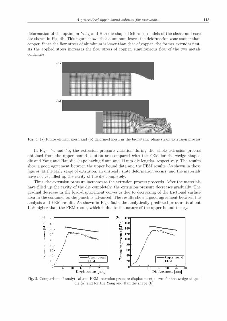
deformation of the optimum Yang and Han die shape. Deformed models of the sleeve and coreare shown in Fig. 4b. This figure shows that aluminum leaves the deformation zone sooner thancopper. Since the flow stress of aluminum is lower than that of copper, the former extrudes first.As the applied stress increases the flow stress of copper, simultaneous flow of the two metalscontinues.
Fig. 4. (a) Finite element mesh and (b) deformed mesh in the bi-metallic plane strain extrusion process
In Figs. 5a and 5b, the extrusion pressure variation during the whole extrusion processobtained from the upper bound solution are compared with the FEM for the wedge shapeddie and Yang and Han die shape having 8mm and 11mm die lengths, respectively. The resultsshow a good agreement between the upper bound data and the FEM results. As shown in thesefigures, at the early stage of extrusion, an unsteady state deformation occurs, and the materialshave not yet filled up the cavity of the die completely.
Thus, the extrusion pressure increases as the extrusion process proceeds. After the materialshave filled up the cavity of the die completely, the extrusion pressure decreases gradually. Thegradual decrease in the load-displacement curves is due to decreasing of the frictional surfacearea in the container as the punch is advanced. The results show a good agreement between theanalysis and FEM results. As shown in Figs. 5a,b, the analytically predicted pressure is about14% higher than the FEM result, which is due to the nature of the upper bound theory.
Fig. 5. Comparison of analytical and FEM extrusion pressure-displacement curves for the wedge shapeddie (a) and for the Yang and Han die shape (b)

114 H. Haghighat, P. Amjadian
The effect of die length on the extrusion pressure for different values of the friction factoris shown in Fig. 6. As expected, for a given value of the friction factor, the extrusion pressureis minimized in the optimum die length. It is observed that the optimum die length decreaseswhen the shearing friction factor increases. This figure, also, shows that an increase in the frictionfactor tends to increase the extrusion pressure.
Fig. 6. The effect of die length on the extrusion pressure for different values of the friction factor for theYang and Han die shape
Since the developed upper bound solution is faster than FEM analysis, it can be very bene-ficial in studying the influence of multiple variables on the bi-metallic rectangular cross-sectionbar extrusion process and for a given die shape, it can be used for finding the optimum dielength which minimizes the extrusion pressure.
4. Conclusions
In this research, a generalized velocity field for use in the upper bound model of the extrusionprocess of the bi-metallic rectangular cross-section bar through dies of any shape was developed.By using the developed upper bound model, optimum die lengths for the wedge shaped die andalso for the Yang and Han die shape have been determined. The extrusion pressure for these twodies has been found by using the finite element code, ABAQUS, and compared with analyticalresults. These comparisons show a good agreement, and the extrusion pressure of the Yang andHan die shape was lower than in the wedge shaped die.
The developed upper bound model can be used for fast estimation of the extrusion pressureof bi-metallic rectangular cross-section bars through dies of any shape and for a given die shapeand process parameters. It can be used for finding the optimum die length which minimizes theextrusion pressure.
References
1. Avitzur B., 1968, Metal Forming: Processes and Analysis, McGraw-Hill, New York
2. Avitzur B., 1983, Handbook of Metal-Forming Processes, Wiley, New York
3. Berski S., Dyja H., Banaszek G., Janik M., 2004, Theoretical analysis of bimetal bar extrusionprocess in double reduction dies, Journal of Materials Processing Technology, 154, 153-183

A generalized upper bound solution for extrusion... 115
4. Chen C.C., Oh S.I., Kobayashi S., 1979, Ductile fracture in axisymmetric extrusion and drawing- Part 1: deformation mechanics of extrusion and drawing metal, Transactions of the ASME,Journal of Engineering for Industry, 101, 23-35
5. Chitkara N.R., Aleem A., 2001a, Extrusion of axi-symmetric bi-metallic tubes from solid cir-cular bars: application of a generalized upper bound analysis and some experiments, InternationalJournal of Mechanical Sciences, 43, 2833-2856
6. Chitkara N.R., Aleem A., 2001b, Extrusion of axi-symmetric bi-metallic tubes: some experi-ments using hollow bars and the application of a generalized slab method of analysis, InternationalJournal of Mechanical Sciences, 43, 2857-2882
7. Gordon W.A, Van Tyne C.J., Moon Y.H., 2007a, Axisymmetric extrusion through adaptabledies – Part 1: Flexible velocity fields and power terms, International Journal of Mechanical Sciences,49, 86-95
8. Gordon W.A., Van Tyne C.J., Moon Y.H., 2007b, Axisymmetric extrusion through adapta-ble dies - Part 3: Minimum pressure streamlined die shapes, International Journal of MechanicalSciences, 49, 104-115
9. Haghighat H., Amjadian P., 2011, A generalized velocity field for plane strain extrusion thro-ugh arbitrarily curved dies, Transactions of the ASME, Journal of Manufacturing Science andEngineering, 133, 041006
10. Haghighat H., Asgari G.R., 2011, A generalized spherical velocity field for bi-metallic tubeextrusion through dies of any shape, International Journal of Mechanical Sciences, 53, 248-253
11. Hwang Y.M., Hwang T.F., 2002, An investigation into the plastic deformation behavior withina conical die during composite bar extrusion, Journal of Materials Processing Technology, 12,226-233
12. Kang C.G., Jung Y.J., Kwon H.C., 2002, Finite element simulation of die design for hotextrusion process of Al/Cu clad composite and its experimental investigation, Journal of MaterialsProcessing Technology, 124, 49-56
13. Nagpal V., 1974, General kinematically admissible velocity fields for some axisymmetric metalforming problems, Transactions of the ASME, Journal of Engineering for Industry, 96, 1197-1201
14. Osakada K., Limb M., Mellor P.B., 1973, Hydrostatic extrusion of composite bars with hardcores, International Journal of Mechanical Sciences, 15, 291-307
15. Sliwa R., 1997, Plastic zones in the extrusion of metal composites, Journal of Materials ProcessingTechnology, 67, 29-35
16. Tokuno H., Ikeda K., 1991, Analysis of deformation in extrusion of composite bars, Journal ofMaterials Processing Technology, 26, 323-335
17. Yang D.Y., Han C.H., 1987, A new formulation of generalized velocity field for axisymmetric for-ward extrusion through arbitrarily curved dies, Transactions of the ASME, Journal of Engineeringfor Industry, 109, 161-168
18. Yang D.Y., Kim Y.G., Lee C.M., 1999, An upper-bound solution for axisymmetric extrusionof composite bars through curved dies, International Journal of Mechanical Sciences, 31, 565-575
19. Zimmerman Z., Avitzur B., 1970, Metal flow through conical converging diesa lower upper boundapproach using generalized boundaries of the plastic zone, Transactions of the ASME, Journal ofEngineering for Industry, 92, 119-129

116 H. Haghighat, P. Amjadian
Uogólnione rozwiązanie ograniczenia górnego problemu wytłaczania bimetalowych belek
o przekroju prostokątnym za pomocą tłoczników o dowolnym kształcie
Streszczenie
W pracy wyprowadzono uogólnione rozwiązanie ograniczenia górnego problemu wytłaczania bime-talowych belek o przekroju prostokątnym za pomocą tłoczników o dowolnym kształcie. Wyznaczonowyrażenia potęgowe opisujące wewnętrzne, ścinające oraz tarciowe obciążenia i zastosowano je w mo-delu matematycznym omawianego zagadnienia. Zaproponowana metoda badań pozwoliła na określenienacisku podczas wytłaczania elementów przy użyciu dwóch typów tłocznika – optymalnego klinowegoo profilu liniowym oraz tłocznika o zarysie krzywoliniowym, opływowym. W obydwu przypadkach ob-liczenia porównano z wynikami uzyskanymi z metody elementów skończonych. Porównanie to wykazałodobrą zgodność rozwiązania ograniczenia górnego z rezultatami MES.
Manuscript received January 5, 2012; accepted for print March 26, 2012