A Fuzzy Path Selection Strategy for Aircraft Landing on a Carrier
17
applied sciences Article A Fuzzy Path Selection Strategy for Aircraft Landing on a Carrier Xichao Su 1 ID , Yu Wu 2, * ID , Jingyu Song 3 and Peilong Yuan 1 1 Department of Airborne Vehicle Engineering, Naval Aviation University, Yantai 264001, China; [email protected] (X.S.); [email protected] (P.Y.) 2 College of Aerospace Engineering, Chongqing University, Chongqing 400044, China 3 System Engineering Research Institute, China State Shipbuilding Corporation, Beijing 10094, China; [email protected] * Correspondence: [email protected]; Tel.: +86-023-6510-2510 Received: 15 April 2018; Accepted: 11 May 2018; Published: 14 May 2018 Abstract: Landing is one of the most dangerous tasks in all the operations on an aircraft carrier, and the landing safety is very important to the pilot and the flight deck operation. Nowadays, the landing safety of carrier aircraft is improved by designing an automatic landing controller and by training the pilot to increase his/her control ability. However, the importance of choosing the landing path has not been investigated thus far. In this paper, the problem of landing path selection for an aircraft carrier is studied as there are several candidates corresponding to different situations. A fuzzy path selection strategy is proposed to solve the problem considering the fuzziness of environmental information and human judgment, and the goal is to provide the pilot with a more reasonable decision. The strategy is in view of the idea of Fuzzy Multi-attribute Group Decision Making (FMAGDM), which has been widely used in industry. Firstly, the background of the landing path selection is given. Then, the factors influencing the decision making are abstracted to build the conceptual model. A TOPSIS-based group decision-making method is developed to denote the preference of each decision maker for each alternative route, and the optimal landing path under the current environment is determined taking into account the knowledge and the weight of both the pilot and the landing console operator (LCO). Experimental studies under different setups, i.e., different environments, are carried out. The results demonstrate that the proposed path selection strategy is validated in different environments, and the optimal landing paths corresponding to different environments can be determined. Keywords: landing; aircraft carrier; landing path; fuzziness; fuzzy multi-attribute group decision making 1. Introduction Aircraft landing on a carrier is a task with high risk [1]. An aircraft can land on a carrier successfully with a probability of 70%, and the rate is lower at night. In comparison with land-based aircraft, landing on an aircraft carrier is more dangerous and complicated since a series of particular conditions needs to be taken into account. In addition, the flight condition and the maritime environment are changing all the time, and these uncertainties make the landing task difficult [2,3]. In order to guide the aircraft landing safely, an aircraft carrier must be equipped with certain special guidance devices such as a Fresnel lens optical landing system [4], an all-weather radar landing system [5] and so on. Further, a variety of commanders and staff are needed to guarantee the landing safety of aircraft and cope with all emergencies [6]. Among them, the landing console operator (LCO) onboard is responsible for supervising the aircraft, which is about 20 nautical miles away from the aircraft carrier. The landing signal officer (LSO) concentrates on the last step of landing and he/she Appl. Sci. 2018, 8, 779; doi:10.3390/app8050779 www.mdpi.com/journal/applsci
-
Upload
khangminh22 -
Category
Documents
-
view
0 -
download
0
Transcript of A Fuzzy Path Selection Strategy for Aircraft Landing on a Carrier
applied sciences
Article
A Fuzzy Path Selection Strategy for Aircraft Landingon a Carrier
Xichao Su 1 ID , Yu Wu 2,* ID , Jingyu Song 3 and Peilong Yuan 1
1 Department of Airborne Vehicle Engineering, Naval Aviation University, Yantai 264001, China;[email protected] (X.S.); [email protected] (P.Y.)
2 College of Aerospace Engineering, Chongqing University, Chongqing 400044, China3 System Engineering Research Institute, China State Shipbuilding Corporation, Beijing 10094, China;
[email protected]* Correspondence: [email protected]; Tel.: +86-023-6510-2510
Received: 15 April 2018; Accepted: 11 May 2018; Published: 14 May 2018�����������������
Abstract: Landing is one of the most dangerous tasks in all the operations on an aircraft carrier,and the landing safety is very important to the pilot and the flight deck operation. Nowadays, thelanding safety of carrier aircraft is improved by designing an automatic landing controller and bytraining the pilot to increase his/her control ability. However, the importance of choosing the landingpath has not been investigated thus far. In this paper, the problem of landing path selection for anaircraft carrier is studied as there are several candidates corresponding to different situations. A fuzzypath selection strategy is proposed to solve the problem considering the fuzziness of environmentalinformation and human judgment, and the goal is to provide the pilot with a more reasonable decision.The strategy is in view of the idea of Fuzzy Multi-attribute Group Decision Making (FMAGDM),which has been widely used in industry. Firstly, the background of the landing path selection isgiven. Then, the factors influencing the decision making are abstracted to build the conceptualmodel. A TOPSIS-based group decision-making method is developed to denote the preference ofeach decision maker for each alternative route, and the optimal landing path under the currentenvironment is determined taking into account the knowledge and the weight of both the pilotand the landing console operator (LCO). Experimental studies under different setups, i.e., differentenvironments, are carried out. The results demonstrate that the proposed path selection strategyis validated in different environments, and the optimal landing paths corresponding to differentenvironments can be determined.
Keywords: landing; aircraft carrier; landing path; fuzziness; fuzzy multi-attribute group decision making
1. Introduction
Aircraft landing on a carrier is a task with high risk [1]. An aircraft can land on a carriersuccessfully with a probability of 70%, and the rate is lower at night. In comparison with land-basedaircraft, landing on an aircraft carrier is more dangerous and complicated since a series of particularconditions needs to be taken into account. In addition, the flight condition and the maritimeenvironment are changing all the time, and these uncertainties make the landing task difficult [2,3].In order to guide the aircraft landing safely, an aircraft carrier must be equipped with certain specialguidance devices such as a Fresnel lens optical landing system [4], an all-weather radar landingsystem [5] and so on. Further, a variety of commanders and staff are needed to guarantee the landingsafety of aircraft and cope with all emergencies [6]. Among them, the landing console operator (LCO)onboard is responsible for supervising the aircraft, which is about 20 nautical miles away from theaircraft carrier. The landing signal officer (LSO) concentrates on the last step of landing and he/she
Appl. Sci. 2018, 8, 779; doi:10.3390/app8050779 www.mdpi.com/journal/applsci
Appl. Sci. 2018, 8, 779 2 of 17
assists the pilot to land safely using body language or by talking to the pilot directly [7]. The airofficer in the control tower does the work related to the flight deck, e.g., preparing the flight deck forlaunching, managing the aircraft on the flight deck and emptying the flight deck for landing. Each staffmember mentioned above assumes their own duty at different stages of landing, and the safe landingof aircraft is accomplished by their team work.
In each landing stage, the above commanders and staff make a decision to guide the aircraftin a very short time based on their knowledge and the information shown on various instruments,which makes high-level demands on their judgment and reaction [8]. However, there is fuzziness inthe environment and flight information, and accurate judgment cannot always be reached quickly,which is attributed to the complicacy and variability of weather at sea, the lack of comprehensiveinformation and other subjective factors. In recent years, artificial intelligence (AI) has been widelyapplied to various fields, and many great achievements have been made in this field. For instance,the complex changes and uncertainties in manufacturing can be managed by AI and machine learningtechniques [9]. Another case in point is the routing problems for ground vehicles, and minimal totalcost can be achieved using AI without violating the capacity and time window constraints [10]. As theAI-based methods have shown better performance than humans in ranking the candidates [11] andoptimizing the index [12], these methods are expected to be introduced into the decision-makingsystem of the aircraft carrier to reduce the workload of the staff onboard and to improve the safetylevel of the landing.
Currently, the studies on the landing of aircraft concentrate primarily on the last step, i.e.,the design of an automatic landing controller and the interaction between the pilot and the LSO.For example, the landing safety is analyzed based on rough set theory, and the values of kinematicparameters and their combinations are determined to define the boundary conditions for safelanding [13]. The action of the LSO is described by a fuzzy language, and multiple AI techniques areapplied to the landing decision-support tool. The obtained landing decision-support tool allows theLSO to make better time-critical decisions in a dangerous environment [14]. The gesture of the LSO isalso studied extensively, and a multi-signal gesture database, which requires both body knowledgeand hand knowledge of the LSO to distinguish gestures, was introduced. Subsequently, the truemeaning of gestures obtained based on the gesture database is communicated to the pilot to enablea better understanding and to assist landing [15]. Our team also conducted intensive research onthe automatic landing guidance technology. A model of LSO was found for the digital simulationof a pilot-carrier system on the basis of analyzing the behaviors of LSO in the final stage of landing.Fuzzy logic laws were used to model three kinds of behaviors of the LSO. Afterwards, the carriermotion prediction of the LSO was described by a neural network model, and the model was verifiedby simulating landing under several kinds of conditions [16]. In the aspect of studying pilot behavior,a variable-strategy pilot model was established for landing. This model is comprised of two switchablecomponents: a discrete component of the acquisition strategy for a large deviation of the glide pathand a continuous component of the pursuit tracking strategy for a small deviation [17]. The citedliterature can explain the work of LSO, and mathematical models are established to describe the LSO’saction. The above studies regarding the landing process of the carrier aircraft presented solid researchwork on the automatic landing guidance technology and have potential significance in the landingsafety of aircraft. The issue of the landing path for aircraft carrier is also an important part of theautomatic landing guidance technology. Unlike the unmanned aerial vehicle (UAV) path planningproblem [18], the landing path of manned aircraft is fixed and can only be selected from severalcandidates. Therefore, instead of planning the landing path, it is determined before the aircraft isready to reach the carrier, and the landing path determination is also a part of the LCO’s work [19,20].However, no relevant literature has been reported on this issue so far. Besides, the previous methods,such as the proposed method in Ref. [14,17], are related to the behavior of the LSO and the pilot,and the goal is to reduce the error between the ideal and actual landing path as much as possible.The premise of those methods is that the landing path has been determined, and a new method has to
Appl. Sci. 2018, 8, 779 3 of 17
be developed to solve the landing path selection problem. As the landing path selection is the firststep to guide the aircraft landing, it is important to the whole process of the landing task and thus isworthwhile to be studied intensively.
At present, the landing path of carrier aircraft is determined by the LCO’s experience, and thenthe decision is sent to the pilot. The pilot is passive in the process of determining the landing path,which is not so reasonable because the pilot also has some important information and should havethe right to make a suggestion on the selection of the landing path. Besides, the experience of theLCO is not always reliable, especially in complicated situations, and some unreasonable decisions maybe made if only the knowledge and experience of a human are depended on. Therefore, a landingpath selection strategy is imperative to deal with the above defects, thus reducing the workload andensuring the landing safety. The decision should be made according to the performance of the aircraft,the traffic conditions, a variety of weather conditions and the visibility of the pilot, and fuzziness isinvolved in the landing path selection problem [21].
The main contribution is to establish a mathematical model and provide a method to solve thelanding path selection problem. This problem is a sort of decision-making problem which belongsto the air traffic management of the carrier. To make a subjective judgment optimal and practical,a decision needs to be made based on reliable information considering all constraints. Obtainingthe environmental information quickly is essential to the decision-making process in this problem.Moreover, how to process information according to knowledge and experience is the key. The probleminvolves various elements and fuzzy information. Therefore, it is an unstructured decision-makingproblem. This kind of problem can only be solved based on the experience and flexibility of adecision maker or using an AI method. It is also worth noting that different decision makers mayresult in different judgments due to many reasons. For example, they obtain different information,they are assigned different flight tasks and objectives, or they have a different understanding ofperformance criteria. Considering all the above-mentioned factors, this paper introduces a groupdecision-making scheme based on the TOPSIS (Technique for Order Preference by Similarity to anIdeal Solution) approach, which is an effective method to coordinate the above differences to result ina reasonable decision.
2. Problem Statement and Conceptual Model Establishment
In this section, the landing path selection problem will be described firstly, and then the essentialelements involved in the problem are discussed. A brief conceptual model is given at the end of thissection to provide an overview for solving this problem.
2.1. Problem Statement
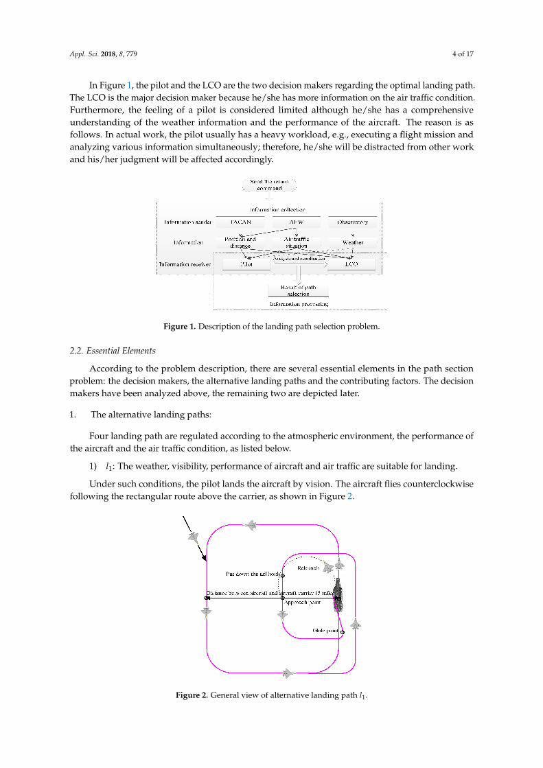
According to the tactical imperatives, an aircraft receives returning information from the aircontrol system on the carrier. To ensure the safety of returning flight, the real-time position informationis provided by the Tactical Air Navigation (TACAN), which contains the relative position of the carrier.The returning aircraft is also instructed by an airborne early warning (AEW) system, which providesthe returning aircraft with the overall air traffic situation. The information from an AEW is essentialwhen managing the landing paths for a large amount of airplanes in order to guarantee a safe andorderly landing. The sea weather is obtained from the carrier and is transmitted to the pilot. To sumup, the landing path selection problem is a process in which the pilot and the LCO combine/analyzevarious information and then make quick decision accordingly. The details of the problem are shownin Figure 1.
The dotted line in Figure 1 shows that when the pilot selects the optimal landing path, he/shetreats the weather information as a reference instead of relying on it to make a judgment. This isbecause the weather information is relative to the carrier, and there may be differences between theplaces around the aircraft and around the carrier. This explains why the pilot merely regards theweather information from an observatory as a reference.
Appl. Sci. 2018, 8, 779 4 of 17
In Figure 1, the pilot and the LCO are the two decision makers regarding the optimal landing path.The LCO is the major decision maker because he/she has more information on the air traffic condition.Furthermore, the feeling of a pilot is considered limited although he/she has a comprehensiveunderstanding of the weather information and the performance of the aircraft. The reason is asfollows. In actual work, the pilot usually has a heavy workload, e.g., executing a flight mission andanalyzing various information simultaneously; therefore, he/she will be distracted from other workand his/her judgment will be affected accordingly.
Figure 1. Description of the landing path selection problem.
2.2. Essential Elements
According to the problem description, there are several essential elements in the path sectionproblem: the decision makers, the alternative landing paths and the contributing factors. The decisionmakers have been analyzed above, the remaining two are depicted later.
1. The alternative landing paths:
Four landing path are regulated according to the atmospheric environment, the performance ofthe aircraft and the air traffic condition, as listed below.
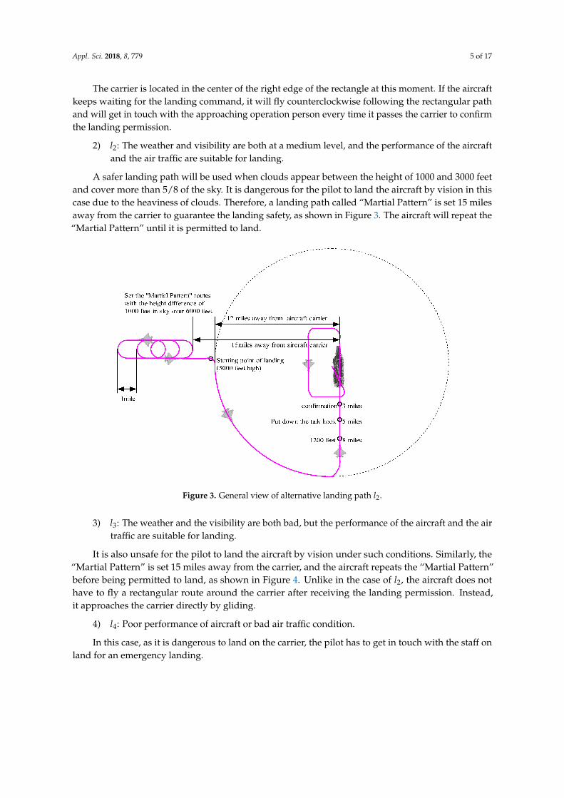
1) l1: The weather, visibility, performance of aircraft and air traffic are suitable for landing.
Under such conditions, the pilot lands the aircraft by vision. The aircraft flies counterclockwisefollowing the rectangular route above the carrier, as shown in Figure 2.
Figure 2. General view of alternative landing path l1.
Appl. Sci. 2018, 8, 779 5 of 17
The carrier is located in the center of the right edge of the rectangle at this moment. If the aircraftkeeps waiting for the landing command, it will fly counterclockwise following the rectangular pathand will get in touch with the approaching operation person every time it passes the carrier to confirmthe landing permission.
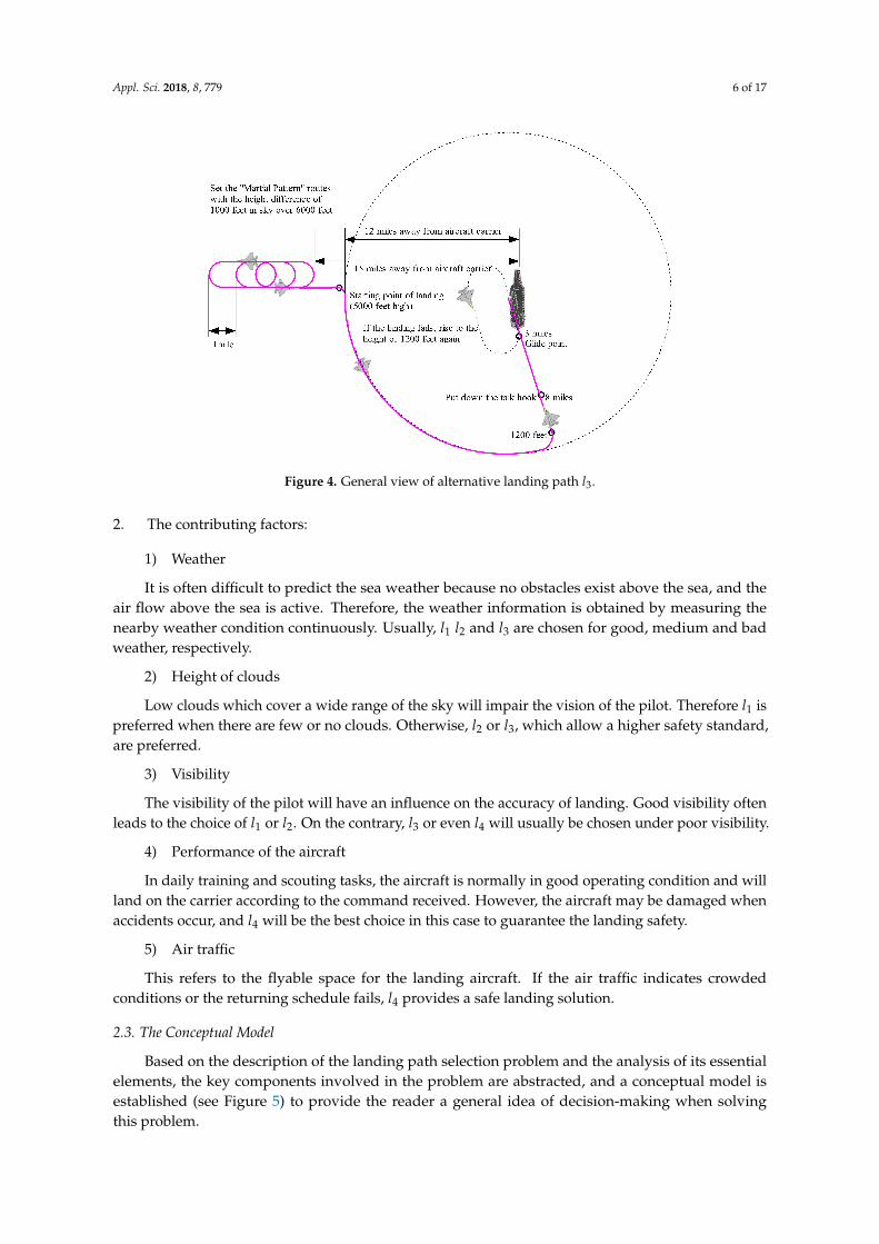
2) l2: The weather and visibility are both at a medium level, and the performance of the aircraftand the air traffic are suitable for landing.
A safer landing path will be used when clouds appear between the height of 1000 and 3000 feetand cover more than 5/8 of the sky. It is dangerous for the pilot to land the aircraft by vision in thiscase due to the heaviness of clouds. Therefore, a landing path called “Martial Pattern” is set 15 milesaway from the carrier to guarantee the landing safety, as shown in Figure 3. The aircraft will repeat the“Martial Pattern” until it is permitted to land.
Figure 3. General view of alternative landing path l2.
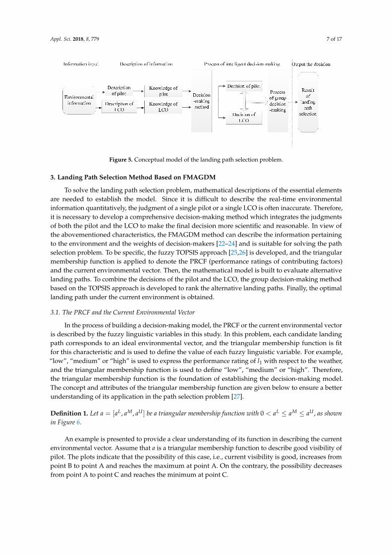
3) l3: The weather and the visibility are both bad, but the performance of the aircraft and the airtraffic are suitable for landing.
It is also unsafe for the pilot to land the aircraft by vision under such conditions. Similarly, the“Martial Pattern” is set 15 miles away from the carrier, and the aircraft repeats the “Martial Pattern”before being permitted to land, as shown in Figure 4. Unlike in the case of l2, the aircraft does nothave to fly a rectangular route around the carrier after receiving the landing permission. Instead,it approaches the carrier directly by gliding.
4) l4: Poor performance of aircraft or bad air traffic condition.
In this case, as it is dangerous to land on the carrier, the pilot has to get in touch with the staff onland for an emergency landing.
Appl. Sci. 2018, 8, 779 6 of 17
Figure 4. General view of alternative landing path l3.
2. The contributing factors:
1) Weather
It is often difficult to predict the sea weather because no obstacles exist above the sea, and theair flow above the sea is active. Therefore, the weather information is obtained by measuring thenearby weather condition continuously. Usually, l1 l2 and l3 are chosen for good, medium and badweather, respectively.
2) Height of clouds
Low clouds which cover a wide range of the sky will impair the vision of the pilot. Therefore l1 ispreferred when there are few or no clouds. Otherwise, l2 or l3, which allow a higher safety standard,are preferred.
3) Visibility
The visibility of the pilot will have an influence on the accuracy of landing. Good visibility oftenleads to the choice of l1 or l2. On the contrary, l3 or even l4 will usually be chosen under poor visibility.
4) Performance of the aircraft
In daily training and scouting tasks, the aircraft is normally in good operating condition and willland on the carrier according to the command received. However, the aircraft may be damaged whenaccidents occur, and l4 will be the best choice in this case to guarantee the landing safety.
5) Air traffic
This refers to the flyable space for the landing aircraft. If the air traffic indicates crowdedconditions or the returning schedule fails, l4 provides a safe landing solution.
2.3. The Conceptual Model
Based on the description of the landing path selection problem and the analysis of its essentialelements, the key components involved in the problem are abstracted, and a conceptual model isestablished (see Figure 5) to provide the reader a general idea of decision-making when solvingthis problem.
Appl. Sci. 2018, 8, 779 7 of 17
Figure 5. Conceptual model of the landing path selection problem.
3. Landing Path Selection Method Based on FMAGDM
To solve the landing path selection problem, mathematical descriptions of the essential elementsare needed to establish the model. Since it is difficult to describe the real-time environmentalinformation quantitatively, the judgment of a single pilot or a single LCO is often inaccurate. Therefore,it is necessary to develop a comprehensive decision-making method which integrates the judgmentsof both the pilot and the LCO to make the final decision more scientific and reasonable. In view ofthe abovementioned characteristics, the FMAGDM method can describe the information pertainingto the environment and the weights of decision-makers [22–24] and is suitable for solving the pathselection problem. To be specific, the fuzzy TOPSIS approach [25,26] is developed, and the triangularmembership function is applied to denote the PRCF (performance ratings of contributing factors)and the current environmental vector. Then, the mathematical model is built to evaluate alternativelanding paths. To combine the decisions of the pilot and the LCO, the group decision-making methodbased on the TOPSIS approach is developed to rank the alternative landing paths. Finally, the optimallanding path under the current environment is obtained.
3.1. The PRCF and the Current Environmental Vector
In the process of building a decision-making model, the PRCF or the current environmental vectoris described by the fuzzy linguistic variables in this study. In this problem, each candidate landingpath corresponds to an ideal environmental vector, and the triangular membership function is fitfor this characteristic and is used to define the value of each fuzzy linguistic variable. For example,“low”, “medium” or “high” is used to express the performance rating of l1 with respect to the weather,and the triangular membership function is used to define “low”, “medium” or “high”. Therefore,the triangular membership function is the foundation of establishing the decision-making model.The concept and attributes of the triangular membership function are given below to ensure a betterunderstanding of its application in the path selection problem [27].
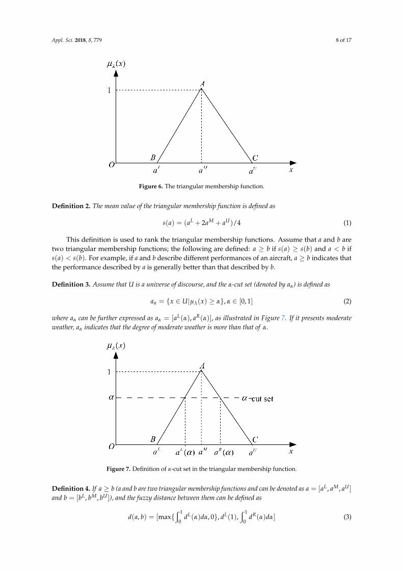
Definition 1. Let a = [aL, aM, aU ] be a triangular membership function with 0 < aL ≤ aM ≤ aU , as shownin Figure 6.
An example is presented to provide a clear understanding of its function in describing the currentenvironmental vector. Assume that a is a triangular membership function to describe good visibility ofpilot. The plots indicate that the possibility of this case, i.e., current visibility is good, increases frompoint B to point A and reaches the maximum at point A. On the contrary, the possibility decreasesfrom point A to point C and reaches the minimum at point C.
Appl. Sci. 2018, 8, 779 8 of 17
Figure 6. The triangular membership function.
Definition 2. The mean value of the triangular membership function is defined as
s(a) = (aL + 2aM + aU)/4 (1)
This definition is used to rank the triangular membership functions. Assume that a and b aretwo triangular membership functions; the following are defined: a ≥ b if s(a) ≥ s(b) and a < b ifs(a) < s(b). For example, if a and b describe different performances of an aircraft, a ≥ b indicates thatthe performance described by a is generally better than that described by b.
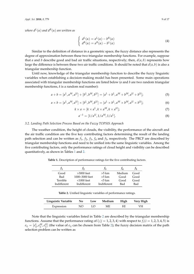
Definition 3. Assume that U is a universe of discourse, and the α-cut set (denoted by aα) is defined as
aα = {x ∈ U|µλ(x) ≥ α}, α ∈ [0, 1] (2)
where aα can be further expressed as aα = [aL(α), aR(α)], as illustrated in Figure 7. If it presents moderateweather, aα indicates that the degree of moderate weather is more than that of α.
Figure 7. Definition of α-cut set in the triangular membership function.
Definition 4. If a ≥ b (a and b are two triangular membership functions and can be denoted as a = [aL, aM, aU ]
and b = [bL, bM, bU ]), and the fuzzy distance between them can be defined as
d(a, b) = [max{w 1
0dL(α)dα, 0}, dL(1),
w 1
0dR(α)dα] (3)
Appl. Sci. 2018, 8, 779 9 of 17
where dL(α) and dR(α) are written as {dL(α) = aL(α)− bR(α)
dR(α) = aR(α)− bL(α)(4)
Similar to the definition of distance in a geometric space, the fuzzy distance also represents thedegree of approximation between these two triangular membership functions. For example, supposethat a and b describe good and bad air traffic situations, respectively; then, d(a, b) represents howlarge the difference is between these two air traffic conditions. It should be noted that d(a, b) is also atriangular membership function.
Until now, knowledge of the triangular membership function to describe the fuzzy linguisticvariables when establishing a decision-making model has been presented. Some main operationsassociated with triangular membership functions are listed below (a and b are two random triangularmembership functions, k is a random real number):
a + b = [aL, aM, aU ] + [bL, bM, bU ] = [aL + bL, aM + bM, aU + bU ]; (5)
a× b = [aL, aM, aU ]× [bL, bM, bU ] = [aL × bL, aM × bM, aU × bU ]; (6)
k× a = [k× aL, k× aM, k× aU ]; (7)
a−1 = [1/aU , 1/aM, 1/aL]. (8)
3.2. Landing Path Selection Process Based on the Fuzzy TOPSIS Approach
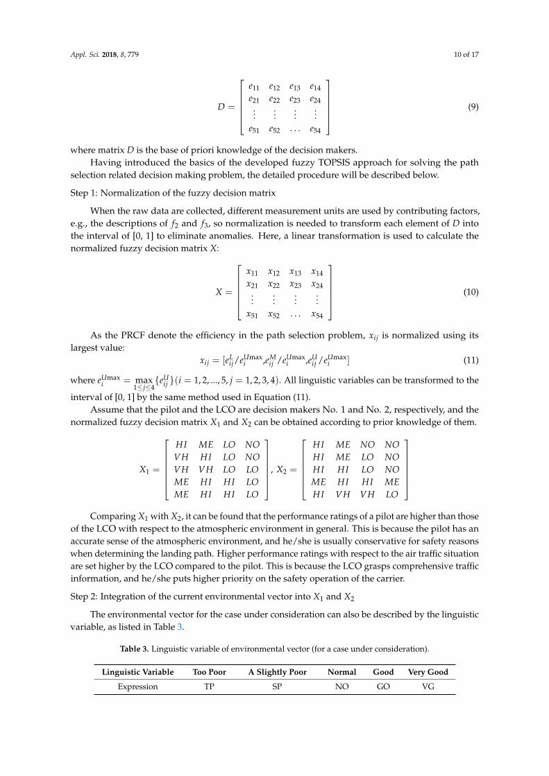
The weather condition, the height of clouds, the visibility, the performance of the aircraft andthe air traffic condition are the five key contributing factors determining the result of the landingpath selection and can be written as f1, f2, f3, f4 and f5, respectively. The PRCF are described bytriangular membership functions and need to be unified into the same linguistic variables. Among thefive contributing factors, only the performance ratings of cloud height and visibility can be describedquantitatively, as shown in Tables 1 and 2.
Table 1. Description of performance ratings for the five contributing factors.
f1 f2 f3 f4 f5
Good >3000 feet >5 km Medium GoodBad 1000–3000 feet >5 km Good Good
Terrible <1000 feet <5 km Good GoodIndifferent Indifferent Indifferent Bad Bad
Table 2. Unified linguistic variables of performance ratings.
Linguistic Variable No Low Medium High Very High
Expression NO LO ME HI VH
Note that the linguistic variables listed in Table 2 are described by the triangular membershipfunctions. Assume that the performance rating of lj(j = 1, 2, 3, 4) with respect to fi(i = 1, 2, 3, 4, 5) iseij = [eL
ij, eMij , eU
ij ] (the value of eij can be chosen from Table 2); the fuzzy decision matrix of the pathselection problem can be written as
Appl. Sci. 2018, 8, 779 10 of 17
D =
e11 e12 e13 e14
e21 e22 e23 e24...
......
...e51 e52 . . . e54
(9)
where matrix D is the base of priori knowledge of the decision makers.Having introduced the basics of the developed fuzzy TOPSIS approach for solving the path
selection related decision making problem, the detailed procedure will be described below.
Step 1: Normalization of the fuzzy decision matrix
When the raw data are collected, different measurement units are used by contributing factors,e.g., the descriptions of f2 and f3, so normalization is needed to transform each element of D intothe interval of [0, 1] to eliminate anomalies. Here, a linear transformation is used to calculate thenormalized fuzzy decision matrix X:
X =
x11 x12 x13 x14
x21 x22 x23 x24...
......
...x51 x52 . . . x54
(10)
As the PRCF denote the efficiency in the path selection problem, xij is normalized using itslargest value:
xij = [eLij/eUmax
i ,eMij /eUmax
i ,eUij /eUmax
i ] (11)
where eUmaxi = max
1≤j≤4{eU
ij }(i = 1, 2, ..., 5, j = 1, 2, 3, 4). All linguistic variables can be transformed to the
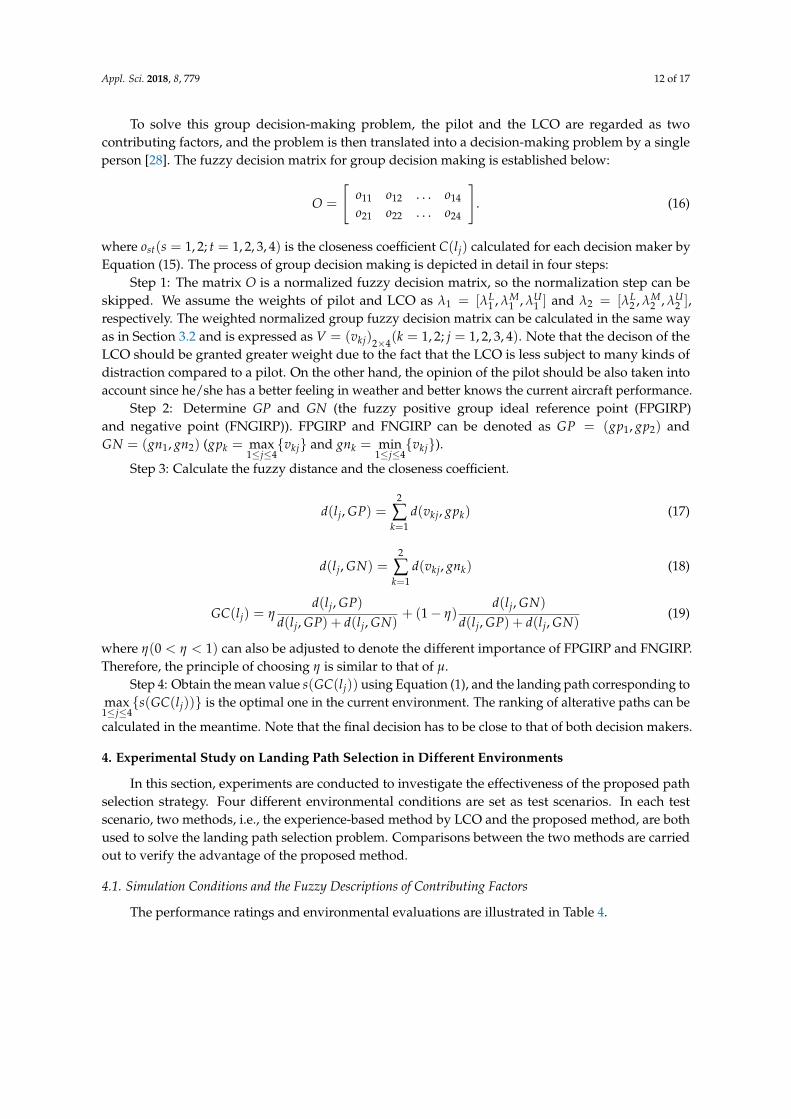
interval of [0, 1] by the same method used in Equation (11).Assume that the pilot and the LCO are decision makers No. 1 and No. 2, respectively, and the
normalized fuzzy decision matrix X1 and X2 can be obtained according to prior knowledge of them.
X1 =
HI ME LO NOVH HI LO NOVH VH LO LOME HI HI LOME HI HI LO
, X2 =
HI ME NO NOHI ME LO NOHI HI LO NOME HI HI MEHI VH VH LO
Comparing X1 with X2, it can be found that the performance ratings of a pilot are higher than those
of the LCO with respect to the atmospheric environment in general. This is because the pilot has anaccurate sense of the atmospheric environment, and he/she is usually conservative for safety reasonswhen determining the landing path. Higher performance ratings with respect to the air traffic situationare set higher by the LCO compared to the pilot. This is because the LCO grasps comprehensive trafficinformation, and he/she puts higher priority on the safety operation of the carrier.
Step 2: Integration of the current environmental vector into X1 and X2
The environmental vector for the case under consideration can also be described by the linguisticvariable, as listed in Table 3.
Table 3. Linguistic variable of environmental vector (for a case under consideration).
Linguistic Variable Too Poor A Slightly Poor Normal Good Very Good
Expression TP SP NO GO VG

Appl. Sci. 2018, 8, 779 11 of 17
Assume that the environmental evaluation of each contributing factor is ωi = [ωL, ωM, ωU ]
(i = 1, 2, ..., 5); the value of ωi is chosen from Table 3. After integrating the environmental vector, thenormalized fuzzy decision matrix can be written as follows:
Z = (zij)5×4 = (ωixij)5×4 =
z11 z12 z13 z14
z21 z22 z23 z24...
......
...z51 z52 . . . z54
(12)
Step 3: Determination of the ideal solutions
The ideal solutions refer to the fuzzy positive ideal reference point (FPIRP) and negative point(FNIRP) and are written as P and N for convenience. P is obtained when each PRCF chooses itshighest value from the fuzzy decision matrix D, and similarly N is obtained by choosing the lowestvalue for each performance rating. Therefore, P and N can be denoted as P = (p1, p2, ..., p5) andN = (n1, n2, ..., n5) with pi = max
1≤j≤4{zij} and ni = min
1≤j≤4{zij}. These solutions are called the ideal
solutions because the corresponding cases are almost impossible to happen in reality.
Step 4: Calculation of the fuzzy distance between lj(j = 1, 2, ..., 4) and the ideal solution
The fuzzy distance is defined as follows using Equation (3):
d(lj, P) =5
∑i=1
d(zij, pi) (13)
d(lj, N) =5
∑i=1
d(zij, ni) (14)
The optimal landing path is the one which is close to the FPIRP and far away from the FNIRP.According to different distances from the FPIRP, the ranking of all the alternative landing paths canbe determined.
Step 5: Calculation of the closeness coefficient
The closeness coefficient denotes the degree of closeness between the alternative landing pathand the fuzzy ideal solution, and a high value means a closer degree. The following formula is used tocalculate the closeness coefficient.
C(lj) = µd(lj, P)
d(lj, P) + d(lj, N)+ (1− µ)
d(lj, N)
d(lj, P) + d(lj, N)(15)
where µ(0 < µ < 1) is a variable parameter which denotes the weight of different distances from FPIRPand FNIRP, and it can be adjusted by the bias of the decision maker. For example, if the atmosphericenvironment is good in general, the decision maker usually puts more attention on FPIRP and setsµ as a smaller value. A larger value will be set for µ to put more attention on FNIRP if the air trafficsituation is bad.
3.3. Process of the Group Decision-Making
The decision of a pilot or an LCO can be calculated separately according to the above mentionedprocedure. In reality, a decision made by one of them may not be the optimal solution because differentdecision makers obtain different information and have difference in knowledge and preference.Therefore, to deal with the divergence and to make an optimal decision, the decision of both thepilot and the LCO should be integrated. The group decision-making problem will be discussed andaddressed in this section.
Appl. Sci. 2018, 8, 779 12 of 17
To solve this group decision-making problem, the pilot and the LCO are regarded as twocontributing factors, and the problem is then translated into a decision-making problem by a singleperson [28]. The fuzzy decision matrix for group decision making is established below:
O =
[o11 o12 . . . o14
o21 o22 . . . o24
]. (16)
where ost(s = 1, 2; t = 1, 2, 3, 4) is the closeness coefficient C(lj) calculated for each decision maker byEquation (15). The process of group decision making is depicted in detail in four steps:
Step 1: The matrix O is a normalized fuzzy decision matrix, so the normalization step can beskipped. We assume the weights of pilot and LCO as λ1 = [λL
1 , λM1 , λU
1 ] and λ2 = [λL2 , λM
2 , λU2 ],
respectively. The weighted normalized group fuzzy decision matrix can be calculated in the same wayas in Section 3.2 and is expressed as V = (vkj)2×4(k = 1, 2; j = 1, 2, 3, 4). Note that the decison of theLCO should be granted greater weight due to the fact that the LCO is less subject to many kinds ofdistraction compared to a pilot. On the other hand, the opinion of the pilot should be also taken intoaccount since he/she has a better feeling in weather and better knows the current aircraft performance.
Step 2: Determine GP and GN (the fuzzy positive group ideal reference point (FPGIRP)and negative point (FNGIRP)). FPGIRP and FNGIRP can be denoted as GP = (gp1, gp2) andGN = (gn1, gn2) (gpk = max
1≤j≤4{vkj} and gnk = min
1≤j≤4{vkj}).
Step 3: Calculate the fuzzy distance and the closeness coefficient.
d(lj, GP) =2
∑k=1
d(vkj, gpk) (17)
d(lj, GN) =2
∑k=1
d(vkj, gnk) (18)
GC(lj) = ηd(lj, GP)
d(lj, GP) + d(lj, GN)+ (1− η)
d(lj, GN)
d(lj, GP) + d(lj, GN)(19)
where η(0 < η < 1) can also be adjusted to denote the different importance of FPGIRP and FNGIRP.Therefore, the principle of choosing η is similar to that of µ.
Step 4: Obtain the mean value s(GC(lj)) using Equation (1), and the landing path corresponding tomax
1≤j≤4{s(GC(lj))} is the optimal one in the current environment. The ranking of alterative paths can be
calculated in the meantime. Note that the final decision has to be close to that of both decision makers.
4. Experimental Study on Landing Path Selection in Different Environments
In this section, experiments are conducted to investigate the effectiveness of the proposed pathselection strategy. Four different environmental conditions are set as test scenarios. In each testscenario, two methods, i.e., the experience-based method by LCO and the proposed method, are bothused to solve the landing path selection problem. Comparisons between the two methods are carriedout to verify the advantage of the proposed method.
4.1. Simulation Conditions and the Fuzzy Descriptions of Contributing Factors
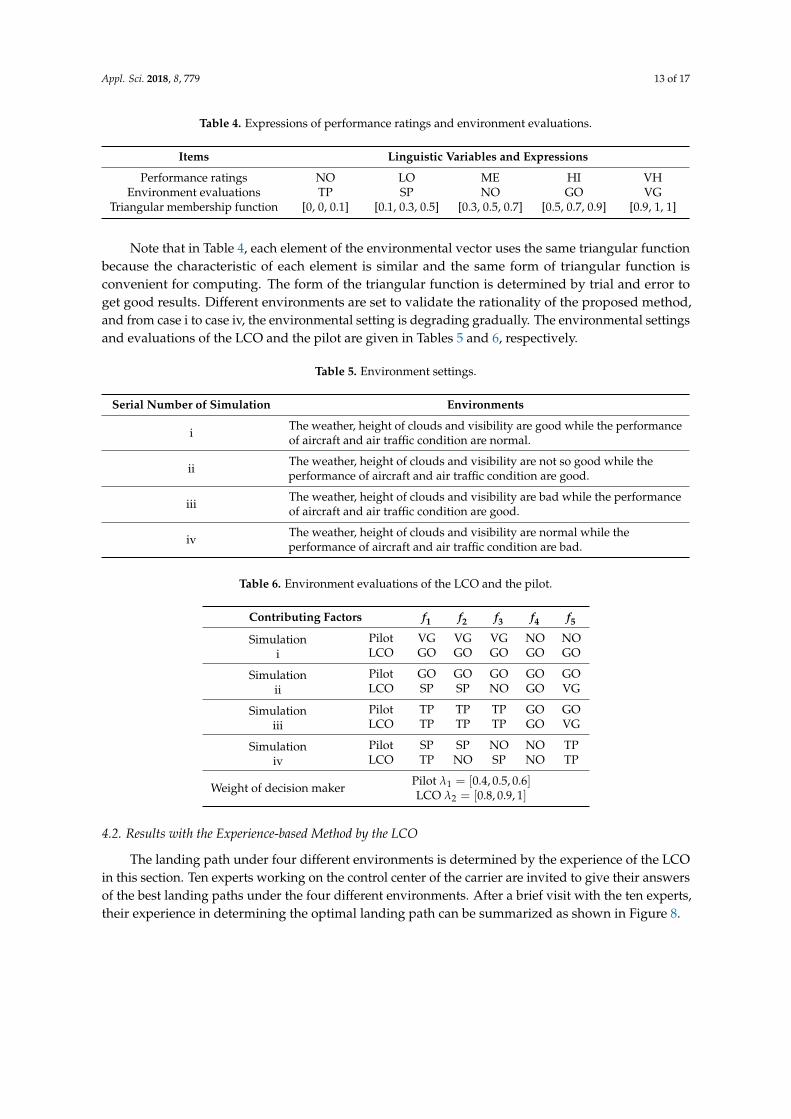
The performance ratings and environmental evaluations are illustrated in Table 4.
Appl. Sci. 2018, 8, 779 13 of 17
Table 4. Expressions of performance ratings and environment evaluations.
Items Linguistic Variables and Expressions
Performance ratings NO LO ME HI VHEnvironment evaluations TP SP NO GO VG
Triangular membership function [0, 0, 0.1] [0.1, 0.3, 0.5] [0.3, 0.5, 0.7] [0.5, 0.7, 0.9] [0.9, 1, 1]
Note that in Table 4, each element of the environmental vector uses the same triangular functionbecause the characteristic of each element is similar and the same form of triangular function isconvenient for computing. The form of the triangular function is determined by trial and error toget good results. Different environments are set to validate the rationality of the proposed method,and from case i to case iv, the environmental setting is degrading gradually. The environmental settingsand evaluations of the LCO and the pilot are given in Tables 5 and 6, respectively.
Table 5. Environment settings.
Serial Number of Simulation Environments
i The weather, height of clouds and visibility are good while the performanceof aircraft and air traffic condition are normal.
ii The weather, height of clouds and visibility are not so good while theperformance of aircraft and air traffic condition are good.
iii The weather, height of clouds and visibility are bad while the performanceof aircraft and air traffic condition are good.
iv The weather, height of clouds and visibility are normal while theperformance of aircraft and air traffic condition are bad.
Table 6. Environment evaluations of the LCO and the pilot.
Contributing Factors f1 f2 f3 f4 f5
Simulationi
Pilot VG VG VG NO NOLCO GO GO GO GO GO
Simulationii
Pilot GO GO GO GO GOLCO SP SP NO GO VG
Simulationiii
Pilot TP TP TP GO GOLCO TP TP TP GO VG
Simulationiv
Pilot SP SP NO NO TPLCO TP NO SP NO TP
Weight of decision maker Pilot λ1 = [0.4, 0.5, 0.6]LCO λ2 = [0.8, 0.9, 1]
4.2. Results with the Experience-based Method by the LCO
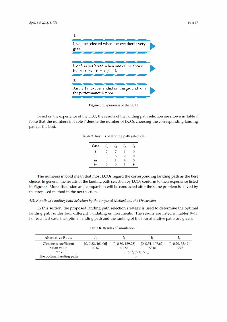
The landing path under four different environments is determined by the experience of the LCOin this section. Ten experts working on the control center of the carrier are invited to give their answersof the best landing paths under the four different environments. After a brief visit with the ten experts,their experience in determining the optimal landing path can be summarized as shown in Figure 8.
Appl. Sci. 2018, 8, 779 14 of 17
Figure 8. Experience of the LCO.
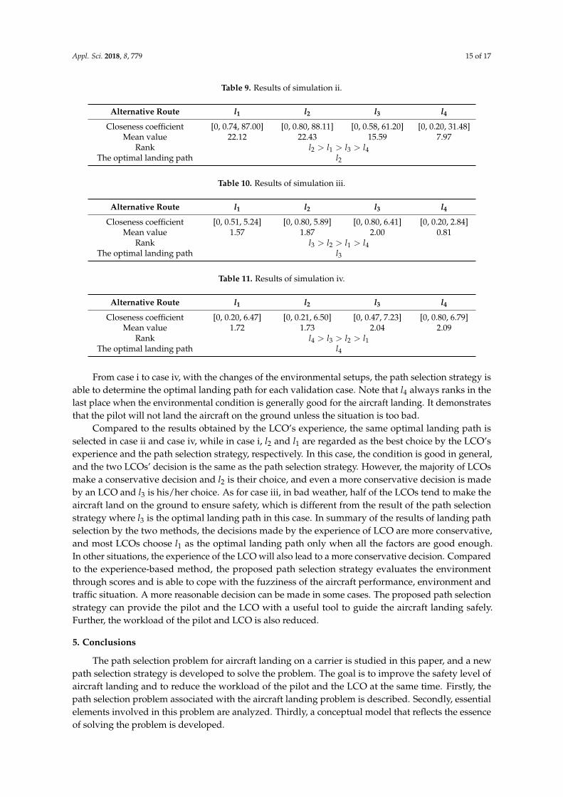
Based on the experience of the LCO, the results of the landing path selection are shown in Table 7.Note that the numbers in Table 7 denote the number of LCOs choosing the corresponding landingpath as the best.
Table 7. Results of landing path selection.
Case l1 l2 l3 l4
i 2 7 1 0ii 0 8 2 0iii 0 1 4 5iv 0 0 1 9
The numbers in bold mean that most LCOs regard the corresponding landing path as the bestchoice. In general, the results of the landing path selection by LCOs conform to their experience listedin Figure 8. More discussion and comparison will be conducted after the same problem is solved bythe proposed method in the next section.
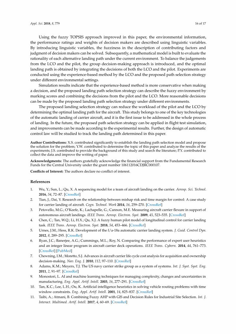
4.3. Results of Landing Path Selection by the Proposed Method and the Discussion
In this section, the proposed landing path selection strategy is used to determine the optimallanding path under four different validating environments. The results are listed in Tables 8–11.For each test case, the optimal landing path and the ranking of the four alterative paths are given.
Table 8. Results of simulation i.
Alternative Route l1 l2 l3 l4
Closeness coefficient [0, 0.82, 161.06] [0, 0.80, 159.28] [0, 0.51, 107.62] [0, 0.20, 55.49]Mean value 40.67 40.22 27.16 13.97
Rank l1 > l2 > l3 > l4The optimal landing path l1
Appl. Sci. 2018, 8, 779 15 of 17
Table 9. Results of simulation ii.
Alternative Route l1 l2 l3 l4
Closeness coefficient [0, 0.74, 87.00] [0, 0.80, 88.11] [0, 0.58, 61.20] [0, 0.20, 31.48]Mean value 22.12 22.43 15.59 7.97
Rank l2 > l1 > l3 > l4The optimal landing path l2
Table 10. Results of simulation iii.
Alternative Route l1 l2 l3 l4
Closeness coefficient [0, 0.51, 5.24] [0, 0.80, 5.89] [0, 0.80, 6.41] [0, 0.20, 2.84]Mean value 1.57 1.87 2.00 0.81
Rank l3 > l2 > l1 > l4The optimal landing path l3
Table 11. Results of simulation iv.
Alternative Route l1 l2 l3 l4
Closeness coefficient [0, 0.20, 6.47] [0, 0.21, 6.50] [0, 0.47, 7.23] [0, 0.80, 6.79]Mean value 1.72 1.73 2.04 2.09
Rank l4 > l3 > l2 > l1The optimal landing path l4
From case i to case iv, with the changes of the environmental setups, the path selection strategy isable to determine the optimal landing path for each validation case. Note that l4 always ranks in thelast place when the environmental condition is generally good for the aircraft landing. It demonstratesthat the pilot will not land the aircraft on the ground unless the situation is too bad.
Compared to the results obtained by the LCO’s experience, the same optimal landing path isselected in case ii and case iv, while in case i, l2 and l1 are regarded as the best choice by the LCO’sexperience and the path selection strategy, respectively. In this case, the condition is good in general,and the two LCOs’ decision is the same as the path selection strategy. However, the majority of LCOsmake a conservative decision and l2 is their choice, and even a more conservative decision is madeby an LCO and l3 is his/her choice. As for case iii, in bad weather, half of the LCOs tend to make theaircraft land on the ground to ensure safety, which is different from the result of the path selectionstrategy where l3 is the optimal landing path in this case. In summary of the results of landing pathselection by the two methods, the decisions made by the experience of LCO are more conservative,and most LCOs choose l1 as the optimal landing path only when all the factors are good enough.In other situations, the experience of the LCO will also lead to a more conservative decision. Comparedto the experience-based method, the proposed path selection strategy evaluates the environmentthrough scores and is able to cope with the fuzziness of the aircraft performance, environment andtraffic situation. A more reasonable decision can be made in some cases. The proposed path selectionstrategy can provide the pilot and the LCO with a useful tool to guide the aircraft landing safely.Further, the workload of the pilot and LCO is also reduced.
5. Conclusions
The path selection problem for aircraft landing on a carrier is studied in this paper, and a newpath selection strategy is developed to solve the problem. The goal is to improve the safety level ofaircraft landing and to reduce the workload of the pilot and the LCO at the same time. Firstly, thepath selection problem associated with the aircraft landing problem is described. Secondly, essentialelements involved in this problem are analyzed. Thirdly, a conceptual model that reflects the essenceof solving the problem is developed.
Appl. Sci. 2018, 8, 779 16 of 17
Using the fuzzy TOPSIS approach improved in this paper, the environmental information,the performance ratings and weights of decision makers are described using linguistic variables.By introducing linguistic variables, the fuzziness in the description of contributing factors andjudgment of decision makers can be solved. Subsequently, a mathematical model is built to evaluate therationality of each alternative landing path under the current environment. To balance the judgementsfrom the LCO and the pilot, the group decision-making approach is introduced, and the optimallanding path is obtained by integrating the decisions of both the LCO and the pilot. Experiments areconducted using the experience-based method by the LCO and the proposed path selection strategyunder different environmental settings.
Simulation results indicate that the experience-based method is more conservative when makinga decision, and the proposed landing path selection strategy can describe the fuzzy environment bymarking scores and combining the decisions from the pilot and the LCO. More reasonable decisionscan be made by the proposed landing path selection strategy under different environments.
The proposed landing selection strategy can reduce the workload of the pilot and the LCO bydetermining the optimal landing path for the aircraft. This study belongs to one of the key technologiesof the automatic landing of carrier aircraft, and it is the first issue to be addressed in the whole processof landing. In the future, the proposed path selection strategy can be applied in flight test simulation,and improvements can be made according to the experimental results. Further, the design of automaticcontrol law will be studied to track the landing path determined in this paper.
Author Contributions: X.S. contributed significantly to establish the landing path selection model and proposethe solution for the problem; Y.W. contributed to determine the topic of this paper and analyze the results of theexperiments; J.S. contributed to provide the background of this study and search the literature; P.Y. contributed tocollect the data and improve the writing of paper.
Acknowledgments: The authors gratefully acknowledge the financial support from the Fundamental ResearchFunds for the Central University under the grant number 106112016CDJRC000107.
Conflicts of Interest: The authors declare no conflict of interest.
References
1. Wu, Y.; Sun, L.; Qu, X. A sequencing model for a team of aircraft landing on the carrier. Aerosp. Sci. Technol.2016, 54, 72–87. [CrossRef]
2. Tian, J.; Dai, Y. Research on the relationship between mishap risk and time margin for control: A case studyfor carrier landing of aircraft. Cogn. Technol. Work 2014, 16, 259–270. [CrossRef]
3. Petovello, M.G.; O’Keefe, K.; Lachapelle, G.; Cannon, M.E. Measuring aircraft carrier flexure in support ofautonomous aircraft landings. IEEE Trans. Aerosp. Electron. Syst. 2009, 45, 523–535. [CrossRef]
4. Chen, C.; Tan, W.Q.; Li, H.X.; Qu, X.J. A fuzzy human pilot model of longitudinal control for carrier landingtask. IEEE Trans. Aerosp. Electron. Syst. 2018, 54, 453–466. [CrossRef]
5. Urnes, J.M.; Hess, R.K. Development of the f/a-18a automatic carrier landing system. J. Guid. Control Dyn.2012, 8, 289–295. [CrossRef]
6. Ryan, J.C.; Banerjee, A.G.; Cummings, M.L.; Roy, N. Comparing the performance of expert user heuristicsand an integer linear program in aircraft carrier deck operations. IEEE Trans. Cybern. 2014, 44, 761–773.[CrossRef] [PubMed]
7. Chewning, I.M.; Moretto, S.J. Advances in aircraft carrier life cycle cost analysis for acquisition and ownershipdecision-making. Nav. Eng. J. 2010, 112, 97–110. [CrossRef]
8. Adams, K.M.; Meyers, T.J. The US navy carrier strike group as a system of systems. Int. J. Syst. Syst. Eng.2011, 2, 91–97. [CrossRef]
9. Monostori, L. AI and machine learning techniques for managing complexity, changes and uncertainties inmanufacturing. Eng. Appl. Artif. Intell. 2003, 16, 277–291. [CrossRef]
10. Tan, K.C.; Lee, L.H.; Ou, K. Artificial intelligence heuristics in solving vehicle routing problems with timewindow constraints. Eng. Appl. Artif. Intell. 2001, 14, 825–837. [CrossRef]
11. Taibi, A.; Atmani, B. Combining Fuzzy AHP with GIS and Decision Rules for Industrial Site Selection. Int. J.Interact. Multimed. Artif. Intell. 2017, 4, 60–69. [CrossRef]
Appl. Sci. 2018, 8, 779 17 of 17
12. Farhane, N.; Boumhidi, I.; Boumhidi, J. Smart algorithms to control a variable speed wind turbine. Int. J.Interact. Multimed. Artif. Intell. 2017, 4, 88–95. [CrossRef]
13. Dai, Y.; Tian, J. An analysis method of landing safety based on Rough Set Theory. In Proceedings of the IEEEReliability Maintainability Symposium, Reno, NV, USA, 23–26 January 2012; pp. 1–6.
14. Richards, R.A. Application of multiple artificial intelligence techniques for an aircraft carrier landing decisionsupport tool. In Proceedings of the IEEE International Conference on Fuzzy Systems, Honolulu, HI, USA,12–17 May 2002; Volume 1, pp. 7–11.
15. Song, Y.; Demirdjian, D.; Davis, R. Tracking body and hands for gesture recognition: NATOPS aircrafthandling signals database. In Proceedings of the IEEE International Conference on Automatic Face &Gesture Recognition and Workshops, Santa Barbara, CA, USA, 21–25 March 2011; pp. 500–506.
16. Ming, S. Modeling landing signal officer for carrier approach. J. Beijing Univ Aeronaut. Astronaut. 2006,32, 135–138.
17. Qu, X.; Cui, H. Variable strategy pilot model of carrier landing approach. J. Beijing Univ Aeronaut. Astronaut.2003, 29, 993–997.
18. Aristeidis, A.; Theoklis, N.; Pericles, P. Multi-Objective Climb Path Optimization for Aircraft/EngineIntegration Using Particle Swarm Optimization. Appl. Sci. 2017, 7, 469.
19. Douglas, M. NATOPS Flight Manual Navy Model F/A-18E/F 165533 and Up Aircraft. Nav. Air Syst. Command.2001, 8, 1–20.
20. Rudowsky, T.; Cook, S.; Hynes, M.; Heffley, R.; Luter, M.; Lawrence, T. Review of the Carrier Approach Criteriafor Carrier-Based Aircraft–Phase I: Final Report; Naval Air Warfare Center Aircraft Division: Patuxent River,MD, USA, 2002.
21. Shem, A.G.; Mazzuchi, T.A.; Sarkani, S. Addressing uncertainty in uav navigation decision-making.IEEE Trans. Aerosp. Electron. Syst. 2018, 44, 295–313. [CrossRef]
22. Cho, H.C.; Lee, D.; Ju, H.; Park, H.C.; Kim, H.Y.; Kang, K. Fire damage assessment of reinforced concretestructures using fuzzy theory. Appl. Sci. 2017, 7, 518. [CrossRef]
23. Xu, Z. Approaches to multiple attribute group decision making based on intuitionistic fuzzy poweraggregation operators. Knowl.-Based Syst. 2011, 24, 749–760. [CrossRef]
24. Chen, M.; Wan, Z.; Chen, X. New min-max approach to optimal choice of the weights in multi-criteria groupdecision-making problems. Appl. Sci. 2015, 5, 998–1015. [CrossRef]
25. Cheng, J.; Zhang, Y.; Feng, Y.; Liu, Z.; Tan, J. Structural optimization of a high-speed press consideringmulti-source uncertainties based on a new heterogeneous topsis. Appl. Sci. 2018, 8, 126. [CrossRef]
26. Wang, T.C.; Chang, T.H. Application of TOPSIS in evaluating initial training aircraft under a fuzzyenvironment. Expert Syst. Appl. 2007, 33, 870–880. [CrossRef]
27. Zavadskas, E.K.; Mardani, A.; Turskis, Z.; Jusoh, A.; Md. Nor, K. Development of topsis method to solvecomplicated decision-making problems: An overview on developments from 2000 to 2015. Int. J. Inf. Technol.Decis Mak. 2016, 15, 645–682.
28. Bashir, Z.; Rashid, T.; Watróbski, J.; Sałabun, W.; Malik, A. Hesitant probabilistic multiplicative preferencerelations in group decision making. Appl. Sci. 2018, 8, 398. [CrossRef]
© 2018 by the authors. Licensee MDPI, Basel, Switzerland. This article is an open accessarticle distributed under the terms and conditions of the Creative Commons Attribution(CC BY) license (http://creativecommons.org/licenses/by/4.0/).