
A dvanced Junos Security - 1 File Download
256
-
Upload
khangminh22 -
Category
Documents
-
view
4 -
download
0
Transcript of A dvanced Junos Security - 1 File Download

A�dvanced Junos Security
12.b
Worldwide Education Services
1194 North Mathilda Avenue
Sunnyvale, CA 94089
USA
408 745-2000
www.juniper.net
Course Number: EDU-JUN-AJSEC
Detailed Lab Guide
This document is produced by Juniper Networks, Inc.
This document or any part thereof may not be reproduced or transmitted in any form under penalty of law, without the prior written permission of Juniper Networks
Education Services.
Juniper Networks, Junos, Steel-Belted Radius, NetScreen, and ScreenOS are registered trademarks of Juniper Networks, lnc. in the United States and other countries. The Juniper Networks Logo, the Junos logo, and JunosE are trademarks of Juniper Networks, Inc. All other trademarks, service marks, registered trademarks, or registered service marks are the property of their respective owners.
Advanced Ju nos Security Detailed Lab Guide, Revision 12.b
Copyright© 2013 Juniper Networks, Inc. All rights reserved.
Printed in USA.
Revision History:
Revision 10.a-March 2011
Revision 12.a-June 2012
Revision 12.b--June 2013
The information in this document is current as of the date listed above.
The information in this document has been carefully verified and is believed to be accurate for software Release 12.1.X44-010.4. Juniper Networks assumes no
responsibilities for any inaccuracies that may appear in this document. In no event will Juniper Networks be liable for direct, indirect, special, exemplary, incidental, or consequential damages resulting from any defect or omission in this document, even if advised of the possibility of such damages.
Juniper Networks reserves the right to change, modify, transfer, or otherwise revise this publication without notice.
YEAR 2000 NOTICE
Juniper Networks hardware and software products do not suffer from Year 2000 problems and hence are Year 2000 compliant. The Junos operating syslem has no known time-related limitations through the year 2038. However, the NTP application is known to have some difficulty in the year 2036.
SOFTWARE LICENSE
The terms and conditions for using Juniper Networks software are described in the software license provided with the software, or to the extent applicable, in an agreement executed between you and Juniper Networks, or Juniper Networks agent By using Juniper Networks software, you indicate that you understand and
agree to be bound by its license terms and conditions. Generally speaking, the software license restricts the manner in which you are permitted to use the: Juniper
Networks software. may contain prohibitions against certain uses, and may state conditions under which the license is automatically terminated. You should consult the software license for further details.
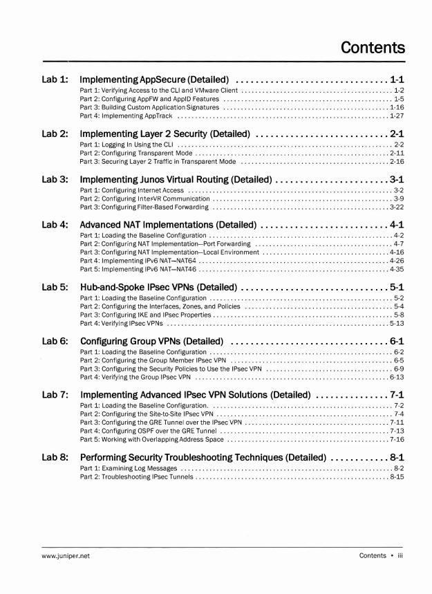
Contents
Lab 1: Implementing AppSecure {Detailed) ............................... 1-1 Part 1: Verifying Access to the CLI and VMware Client ........................................... 1-2
Part 2: Configuring AppFW and ApplD Features ................................................ 1-5
Part 3: Building Custom Application Signatures ........••••................................... 1-16
Part 4: Implementing App Track ............................................................ 1-27
Lab 2: Implementing Layer 2 Security {Detailed) ........................... 2-1 Part 1: Logging In Using the CLI ............................................................. 2-2
Part 2: Configuring Transparent Mode ....................................................... 2-11
Part 3: Securing Layer 2 Traffic in Transparent Mode .......................................... 2-16
Lab 3: Implementing Junos Virtual Routing {Detailed) ....................... 3-1 Part 1: Configuring Internet Access .......................................................... 3-2
Part 2: Configuring lnter-VR Communication ................................................... 3-9
Part 3: Configuring Filter-Based Forwarding .................................................. 3-22
Lab 4: Advanced NAT Implementations {Detailed) .......................... 4-1 Part 1: Loading the Baseline Configuration .................................................... 4-2
Part 2: Configuring NAT Implementation-Port Forwarding ....................................... 4-7
Part 3: Configuring NAT Implementation-Local Environment .................................... 4-16
Part 4: Implementing 1Pv6 NAT-NAT64 ...................................................... 4-26
Part 5: Implementing 1Pv6 NAT-NAT46 ...................................................... 4-35
Lab 5: Hub-and-Spoke IPsec VPNs {Detailed) .............................. 5-1 Part 1: Loading the Baseline Configuration .................................................... 5-2
Part 2: Configuring the Interfaces, Zones, and Policies .......................................... 5-4
Part 3: Configuring IKE and IPsec Properties ................................................... 5-8
Part 4: Verifying IPsec VPNs ............................................................... 5-13
Lab 6: Configuring Group VPNs {Detailed) ................................ 6-1 Part 1: Loading the Baseline Configuration .................................................... 6-2
Part 2: Configuring the Group Member IPsec VPN .............................................. 6-5
Part 3: Configuring the Security Policies to Use the IPsec VPN .................................... 6-9
Part 4: Verifying the Group IPsec VPN ....................................................... 6-13
Lab 7: Implementing Advanced IPsec VPN Solutions {Detailed) ............... 7-1 Part 1: Loading the Baseline Configuration . ................................................... 7-2
Part 2: Configuring the Site-to-Site IPsec VPN .................................................. 7-4
Part 3: Configuring the GRE Tunnel over the IPsec VPN ......................................... 7-11
Part 4: Configuring OSPF over the GRE Tunnel ................................................ 7-13
Part 5: Working with Overlapping Address Space .............................................. 7-16
Lab 8: Performing Security Troubleshooting Techniques {Detailed) ............ 8-1 Part 1: Examining Log Messages ............................................................ 8-2
Part 2: Troubleshooting IPsec Tunnels ....................................................... 8-15
www.juniper.net Contents • iii

iv • Contents www.juniper.net
Cours1� Overview
Objectives
www.juniper.net
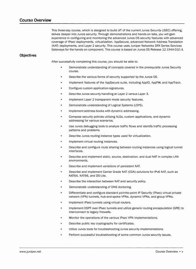
This three-day course, which is designed to build off of the currentJunos Security (JSEC) offering,
delves deeper into Junos security. Through demonstrations and hands-on labs, you will gain
experience in configuring and monitoring the advanced Junos OS security features with advanced
coverage of IPsec deployments. virtualization. AppSecure, advanced Network Address Translation
(NAT) deployments, and Layer 2 security. This course uses Juniper Networks SRX Series Services
Gateways for the hands-on component. This course is based on Junos OS Release 12.1X44-010.4.
After successfully completing this course, you should be able to:
Demonstrate understanding of concepts covered in the prerequisite Ju nos Security
course.
Describe the various forms of security supported by the Ju nos OS.
Implement features of the AppSecure suite, including Appl 0, AppFW, and App Track.
Configure custom application signatures.
Describe Ju nos security handling at Layer 2 versus Layer 3.
Implement Layer 2 transparent mode security features.
Demonstrate understanding of Logical Systems (LSYS).
Implement address books with dynamic addressing.
Compose security policies utilizing ALGs, custom applications. and dynamic
addressing for various scenarios.
Use Ju nos debugging tools to analyze traffic flows and identify traffic processing
patterns and problems.
Describe Ju nos routing instance types used for virtualization.
Implement virtual routing instances.
Describe and configure route sharing between routing instances using logical tunnel
interfaces.
Describe and implement static, source, destination, and dual NAT in complex LAN
environments.
Describe and implement variations of persistent NAT.
Describe and implement Carrier Grade NAT (CGN) solutions for 1Pv6 NAT, such as
NAT64, NAT46, and OS-Lite.
Describe the interaction between NAT and security policy.
Demonstrate understanding of DNS doctoring.
Differentiate and configure standard point-to-point IP Security (IPsec) virtual private
network (VPN) tunnels, hub-and-spoke VPNs, dynamic VPNs, and group VPNs.
Implement IPsec tunnels using virtual routers.
Implement OSPF over IPsec tunnels and utilize generic routing encapsulation (GRE) to
interconnect to legacy firewalls.
Monitor the operations of the various IPsec VPN implementations.
Describe public key cryptography for certificates.
Utilize Ju nos tools for troubleshooting Ju nos security implementations.
Perform successful troubleshooting of some common Ju nos security issues.
Course Overview • v
Intended Audience
Course Level
Prerequisites
vi • Course Overview
This course benefits individuals responsible for implementing, monitoring, and troubleslhooting
Junos security components.
Advanced Junos Security is an advanced-level course.
Students should have a strong level of TCP/IP networking and security knowledge. Stude-nts should
also attend the Introduction to the Junos Operating System (IJOS), Junos Routing Essentials (JRE),
and Junos Security (JSEC) courses prior to attending this class.
www,juniper.net
Course Agenda
Day1
Day2
Day3
www.juniper.net
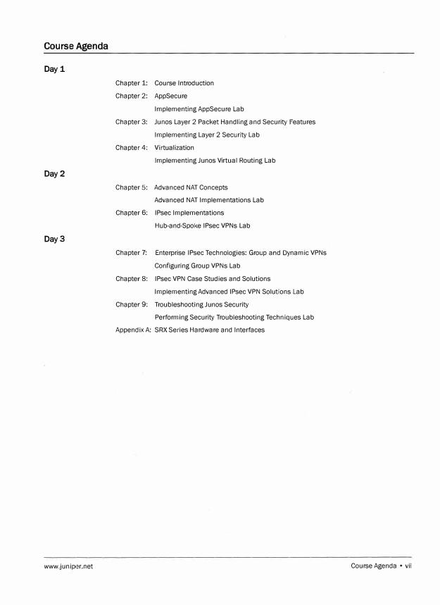
Chapter 1: Course Introduction
Chapter 2: AppSecure
Implementing AppSecure Lab
Chapter 3: Ju nos Layer 2 Packet Handling and Security Features
Implementing Layer 2 Security Lab
Chapter 4: Virtualization
Implementing Ju nos Virtual Routing Lab
Chapter 5: Advanced NAT Concepts
Advanced NAT Implementations Lab
Chapter 6: IPsec Implementations
Hub-and-Spoke IPsec VPNs Lab
Chapter 7: Enterprise IPsec Technologies: Group and Dynamic VPNs
Configuring Group VPNs Lab
Chapter 8: IPsec VPN Case Studies and Solutions
Implementing Advanced IPsec VPN Solutions Lab
Chapter 9: Troubleshooting Ju nos Security
Performing Security Troubleshooting Techniques Lab
Appendix A: SRX Series Hardware and Interfaces
Course Agenda • vii
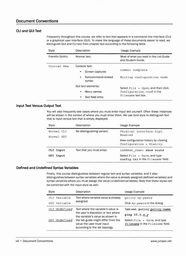
Document Conventions
CU and GUI Text
Frequently throughout this course, we refer to text that appears in a command-line interface (CLI)
or a graphical user interface (GUI). To make the language of these documents easier to read , we distinguish GUI and CLI text from chapter text according to the following table.
Style
Franklin Gothic
Courier New
Description
Normal text.
Console text:
Screen captures
Noncommand-related
syntax
GUI text elements:
Menu names
Text field entry
Usage Example
Most of what you read in the Lab Guide and Student Guide.
commit complete
Exiting configuration mode
Select File > Open, and then click Configuration. conf in tile
Fi 1 ename text box.
Input Text Versus Output Text
You will also frequently see cases where you must enter input text yourself. Often these instances will be shown in the context of where you must enter them. We use bold style to distinguish text that is input versus text that is simply displayed.
Style
Normal CLI
Normal GUI
CLI Input
GUI Input
Description
No distinguishing variant.
Text that you must enter.
Defined and Undefined Syntax Variables
Usage Example
Phy sical interface:fx:pO, Enabled
View configuration history by clicking
Configuration > History.
lab@San_Jose> show rc,ute
Select File > Save, and type config. ini in the Filename field.
Finally, this course distinguishes between regular text and syntax variables, and it also distinguishes between syntax variables where the value is already assigned (defined variables) and syntax variables where you must assign the value (undefined variables). Note that these styles can
be combined with the input style as well.
Style
CLI Variable
GUI Variable
CLI Undefined
Description
Text where variable value is already assigned.
Text where the variable's value is the user's discretion or text where
the variable's value as shown in GUI Undefined the lab guide might differ from the
value the user must input according to the lab topology.
viii • Document Conventions
Usage Example
policy my-peers
Click my-peers in the dialog.
Type set policy policy-name.
ping 10.0.�
Select File > Save, and type filename in the Filename field.
www.juniper.net
Additional Information
Education Services Offerings
You can obtain information on the latest Education Services offerings, course dates, and class
locations from the World Wide Web by pointing your Web browser to:
http://www.juniper.net;training/education/.
About This Publication
The Advanced Junos Security Detailed Lab Guide was developed and tested using software
Release 12.1X44-D10.4. Previous and later versions of software might behave differently so you
should always consult the documentation and release notes for the version of code you are running
before reporting errors.
This document is written and maintained by the Juniper Networks Education Services development
team. Please send questions and suggestions for improvement to [email protected].
Technical Publications
You can print technical manuals and release notes directly from the Internet in a variety of formats:
Go to http://www.juniper.net;techpubs/.
Locate the specific software or hardware release and title you need, and choose the
format in which you want to view or print the document.
Documentation sets and CDs are available through your local Juniper Networks sales office or
account representative.
Juniper Networks Support
www.juniper.net
For technical support, contact Juniper Networks at http://www.juniper.net;customers/support;, or
at 1-888-314-JTAC (within the United States) or 408-745-2121 (from outside the United States).
Additional Information • ix

x • Additional Information www._juniper.net
Overvi,ew
Lab
Implementing AppSecure (Detailed)
In this lab, you will implement features of the AppSecure suite. You will begin by
configuring ApplD and AppFW features to protect the VM server against Application Layer
attacks. Then, you will configure a custom application signature to restrict access to
certain sections of the VM server. Finally, you will configure App Track to monitor FTP
exchanges between the VM client and the VM server.
The lab is available in two formats: a high-level format designed to make you think through
each step and a detailed format that offers step-by-step instructions complete with
sample output from most commands.
By completing this lab, you will perform the following tasks:
Configure and monitor ApplD and AppFW features.
Configure and use custom application signatures.
Configure and monitor App Track.
www.juniper.net Implementing AppSecure (Detailed) • Lab 1-1
Advanced Junos Security
Part 1: Verifying Access to the CLI and VMware Client
Step i1
Step 1.2
In this lab part, you become familiar with the access details used to access the lab
equipment. Once you are familiar with the access details, you will use the
command-line interface (CLI) to log in to your designated station. Then, you verify
that you can log in to the VMware client and confirm that FTP and Web browsing are
available on the desktop.
Note
You will only be able to FTP and Web
browse within the constraints that are
created on the VMware server.
Note
Depending on the class, the lab equipment
used might be remote from your physical
location. The instructor will inform you as to
the nature of your access and will provide
you with the details needed to access your assigned device.
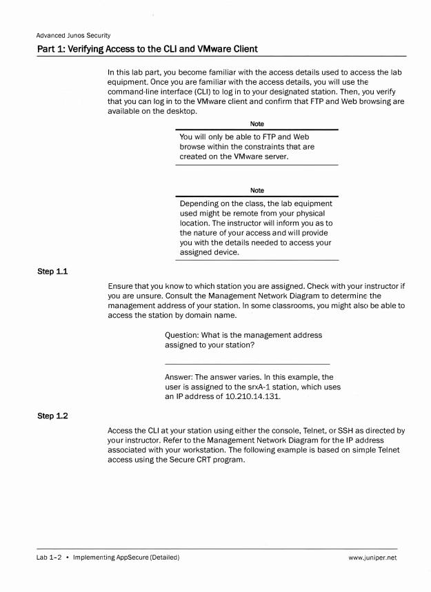
Ensure that you know to which station you are assigned. Check with your instructor if
you are unsure. Consult the Management Network Diagram to determine the
management address of your station. In some classrooms, you might also be able to
access the station by domain name.
Question: What is the management address
assigned to your station?
Answer: The answer varies. In this example, the
user is assigned to the srxA-1 station, which uses an IP address of 10.210.14.131.
Access the CLI at your station using either the console, Telnet, or SSH as directed by
your instructor. Refer to the Management Network Diagram for the IP address
associated with your workstation. The following example is based on simple Telnet
access using the Secure CRT program.
Lab 1-2 • lmplementingAppSecure (Detailed) www.juniper.net

Step i3
srxA-1 (ttyuO)
login: lab
Password:
O Show quick connect on sla1tup � Save session
el Open in a tab
11 . Connect � I Cancel j
Advanced Junos Security
Log in as user lab with the password supplied by your instructor.
--- JUNOS 12.1X44-Dl0.4 built 2013-01-08 05:15:31 UTC
lab@srxA-1>
Step 1.4
www.junipe·r.net
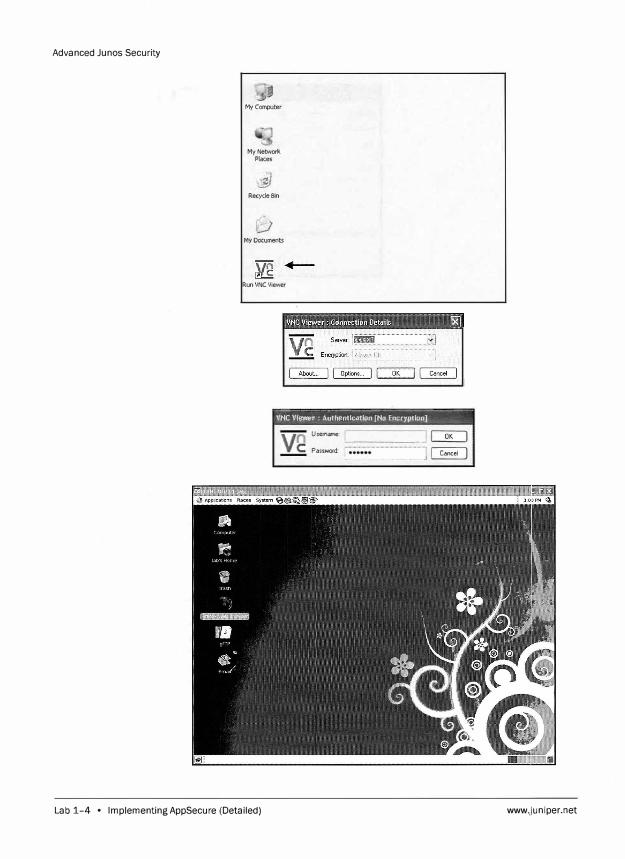
Refer to the Management Network Diagram to determine the IP address of the
VMware client device attached to your assigned SRX device. The device to which this
lab step refers depends on which SRX device you have been assigned. Connect to
the IP address associated with the appropriate VMware client using the Virtual
Network Computing (VNC) client application provided to you by your instructor. Use
lab123 as the password to connect to the VMware client. Insert a": 1" after the
appropriate IP address to make the connection.
Note
The applications are installed on virtual
network computers. Your access to the
VMware client might vary according to lab
environments. Your instructor will provide
the access method. Please notify your
instructor if you are not sure how to access
the VMware client device.
Implementing AppSecure (Detailed) • Lab 1-3
Advanced Junos Security
My Computer
My Network Places
Recycle Bin
My Documents
Run VNC Viewer
-������������---���-
VNC Viewer : ,l\uthentlcation (No Encryption]
Username: �------� CK:)
Pass'rK)fd: <... ........................•.•.••..........•.............•••••• �
Lab 1-4 • Implementing AppSecure (Detailed) www.juniper.net
Advanced Junos Security
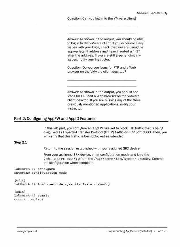
Question: Can you log in to the VMware client?
Answer: As shown in the output, you should be able to log in to the VMware client. If you experience any issues with your login, check that you are using the appropriate IP address and have inserted a ": 1" after the address. If you are still experiencing any issues, notify your instructor.
Question: Do you see icons for FTP and a Web browser on the VMware client desktop?
Answer: As shown in the output, you should see icons for FTP and a Web browser on the VMware client desktop. If you are missing any of the three previously mentioned applications, notify your instructor.
Part 2: C1onfiguring AppFW and ApplD Features
Step 2.1
In this lab part, you configure an AppFW rule set to block FTP traffic that is being disguised as Hypertext Transfer Protocol (HTIP) traffic on TCP port 8080. Then, you will verify that this traffic is being blocked as intended.
Return to the session established with your assigned SRX device.
From your assigned SRX device, enter configuration mode and load the labl-start. configfrom the /var /home/lab/ aj sec/ directory. Commit the configuration when complete.
lab@srxA-1> configure
Entering configuration mode
[edit]
lab@srxA-1# load override ajsec/labl-start.config
[edit]
lab@srxA-1# commit
commit complete
www.juniper.net Implementing AppSecure (Detailed) • Lab 1-5
Advanced Junos Security
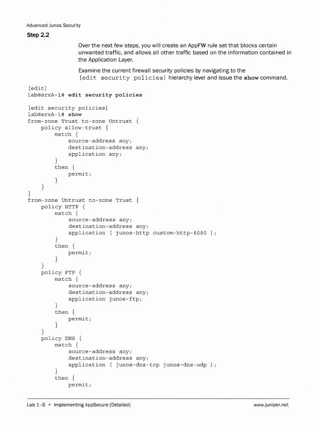
Step 2.2
Over the next few steps, you will create an AppFW rule set that blocks certain
unwanted traffic, and allows all other traffic based on the information contained in
the Application Layer.
Examine the current firewall security policies by navigating to the
[edit security policies] hierarchy level and issue the show command.
[edit] lab@srxA-1# edit security policies
[edit security policies] lab@srxA-1# show from-zone Trust to-zone Untrust
policy allow-trust { match {
}
source-address any; destination-address any; application any;
then { permit;
from-zone Untrust to-zone Trust { policy HTTP {
match {
}
source-address any; destination-address any; application [ junos-http custom-http-8080 J;
then { permit;
policy FTP { match {
}
source-address any; destination-address any; application junos-ftp;
then { permit;
policy DNS { match {
}
source-address any; destination-address any; application [ junos-dns-tcp junos-dns-udp J;
then { permit;
Lab 1-6 • Implementing AppSecure (Detailed) www.juniper.net
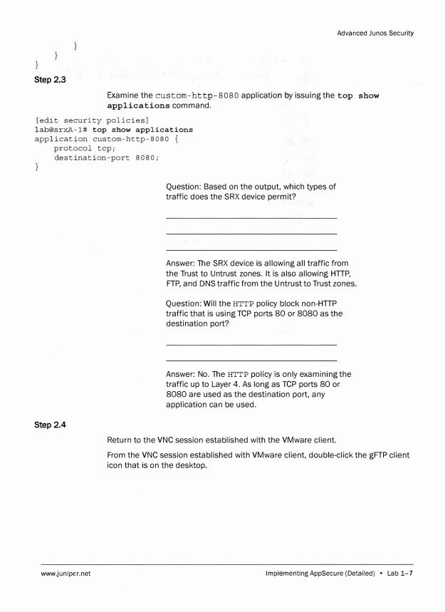
Step 2.3
Advanced Junos Security
Examine the custom-http-8080 application by issuing the top show applications command.
[edit security policies] lab@srxA-1# top show applications application custom-http-8080 {
protocol tcp; destination-port 8080;
Step 2.4
www.junipe,r.net
Question: Based on the output, which types of traffic does the SRX device permit?
Answer: The SRX device is allowing all traffic from
the Trust to Untrust zones. It is also allowing HTTP, FTP, and DNS traffic from the Untrust to Trust zones.
Question: Will the HTTP policy block non-HTTP traffic that is using TCP ports 80 or 8080 as the destination port?
Answer: No. The HTTP policy is only examining the traffic up to Layer 4. As long as TCP ports 80 or 8080 are used as the destination port, any
application can be used.
Return to the VNC session established with the VMware client.
From the VNC session established with VMware client, double-click the gFTP client
icon that is on the desktop.
Implementing AppSecure (Detailed) • Lab 1-7
Advanced Junes Security
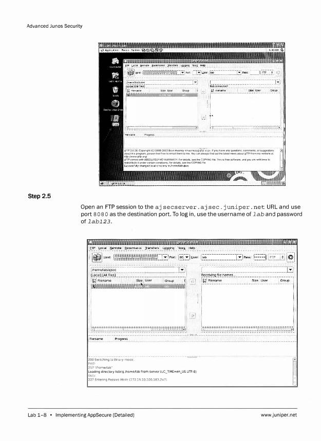
Step 2.5
............................... L�J Group
Progress
gFTP 2.0.18. Copyr1ght (CJ 1998-2003 Brl,.n Masney <n1o1sl'leyb@yf".p org>. If you h.ive ;my questions. co mments. or SU99Utlot'li about tnls progr,1m. ple.ise reel free to email !hem to me. 'ltlu can always l'Ind out the latest l'lews about gFTP from my weDsite al. http://Wwwgrtp.org/ gFTP comes wn:n A.BSOL.U1cLY NO WARRANTY: for details. see !he COPYING flle Th!s Is free sortware, and you are welt:ome to redistribute itundercertalnconditions:rordetails.s eetheCOPYINGl'ile
Open an FTP session to the aj sec server. aj sec.juniper. net UHL and use port 8 o 8 o as the destination port. To log in, use the username of lab and password of labl23.
200 Switching l-o Binary mode.
p..•.:o
257 "/homel1ab"
User Group
Loading directory listing /home/lab rrom server (LC_TIME=en_US.UTF-8) PA:iV
227 Entering Pa,;slve Mede (.172 . .16.10,100,183.2471
·······-
�
I
' '
Lab 1-8 • Implementing AppSecure (Detailed) www,juniper.net
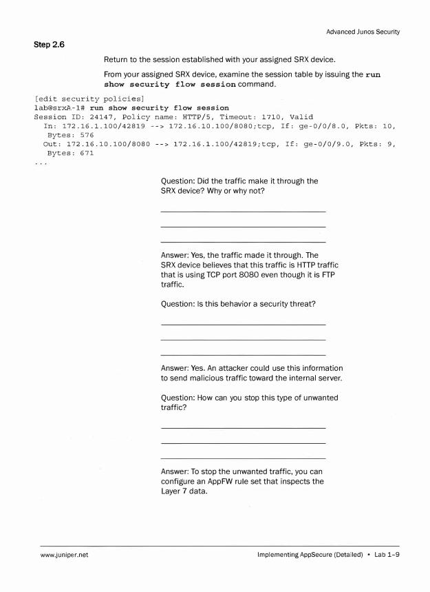
Step 2.6
Advanced Ju nos Security
Return to the session established with your assigned SRX device.
From your assigned SRX device, examine the session table by issuing the run
show security flow session command.
[edit security policies] lab@srxl\.-1# run show security flow session Session ID: 24147, Policy name: HTTP/5, Timeout: 1710, Valid
In: 172.16.1.100/42819 --> 172.16.10.100/8080;tcp, If: ge-0/0/8.0, Pkts: 10, Bytes: 576
Out: 172.16.10.100/8080 --> 172.16.l.100/42819;tcp, If: ge-0/0/9.0, Pkts: 9, Bytes: 671
www.juniper.net
Question: Did the traffic make it through the
SRX device? Why or why not?
Answer: Yes, the traffic made it through. The
SRX device believes that this traffic is HTTP traffic
that is using TCP port 8080 even though it is FTP
traffic.
Question: Is this behavior a security threat?
Answer: Yes. An attacker could use this information
to send malicious traffic toward the internal server.
Question: How can you stop this type of unwanted
traffic?
Answer: To stop the unwanted traffic, you can
configure an AppFW rule set that inspects the
Layer 7 data.
Implementing AppSecure (Detailed) • Lab 1-9
Advanced Junos Security
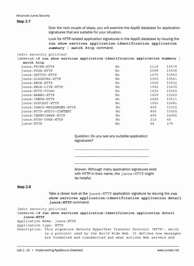
Step 2.7
Over the next couple of steps, you will examine the ApplD database for application signatures that are suitable for your situation.
Look for HTIP-related application signatures in the ApplD database by issuing the run show services application-identification application sUllllllary I match http command.
[edit security policies] lab@srxA-1# run show services application-identification application
match http
junos:FRING-HTTP junos:VUZE-HTTP junos:ZATTOO-HTTP junos:DIASPORA-HTTP junos:XBOX-HTTP junos:XBOX-LIVE-HTTP junos:HTTP-VIDEO junos:HABBO-HTTP junos:IMESH-HTTP junos:SOPCAST-HTTP junos:YAHOO-MESSENGER-HTTP junos:HTTP-AUDIO-CONTENT junos:TEAMVIEWER-HTTP junos:RTSP-OVER-HTTP junos:HTTP
No No No No No No No No No No No No No No No
Question: Do you see any suitable application signatures?
1119 1098 1070 1065 1056 1042 1032 1029 1026 1021 809 806 495 215 64
Answer: Although many application signatures exist with HTIP in their name, the j unos : HTTP might be helpful.
Step 2.8
si:lllllilary
33479 33538 33543 33541 33532 33435 33564 33520 33511 33481 33315 33565 32992 46 179
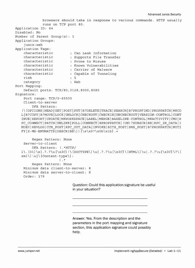
Take a closer look at the junos: HTTP application signature by issuing the run show services application-identification application detail junos:HTTP command.
[edit security policies] lab@srxA-1# run show services application-identification application d,;itail
junos:HTTP
Application Name: junos:HTTP Application type: HTTP Description: This signature detects HyperText Transfer Protocol (HTTP), which
is a protocol used by the World Wide Web. It defines how messages are formatted and transmitted and what actions Web servers and
Lab 1-10 • Implementing AppSecure (Detailed) www.juniper.net
Advanced Junes Security
browsers should take in response to various commands. HTTP usually runs on TCP port 80.
Application ID: 64 Disabled: No Number c-f Parent Group(s): 1 Application Groups:
junos:web Application Tags:
characteristic characteristic characteristic characteristic characteristic characteristic risk category
Port Mapping:
Can Leak Information Supports File Transfer Prone to Misuse Known Vulnerabilities Carrier of Malware Capable of Tunneling 5 Web
Default ports: TCP/80,3128,8000,8080 Signature:
Port range: TCP/0-65535 Client-to-server
DFA Pattern: (\[OPTIONSIHEADIGETIPOSTIPUTIB?DELETEITRACEISEARCHIB?PROPFINDIPROPPATCHIMKCO LIB?COPYIB?MOVEILOCKIUNLOCKICHECKOUTICHECKINIUNCHECKOUTIVERSION-CONTROLICONT INUEIREPORTIUPDATEIMKWORKSPACEILABELIMERGEIBASELINE-CONTROLIMKACTIVITYICMDIR PC_CONNECTIPATCHIUNLINKIPOLLICONNECTIBPROPPATCHI (UN)?SUBSCRIBEIRPC_IN_DATAII NDEXIREVLOGICCM_POSTIRPC_OUT_DATAIINVOKEIBITS_POSTISMS_POSTIB?PROPPATCHINOTI FY I X-MS-ENUMATTS I DESCRIBE\]) [\s\x07\x0b\xlb] . +
Regex Pattern: None Server-to-client
DFA Pattern: (. *HTTP/ 1 \. [01] \s I.?. ?\u [\x3C] ! \ [DOCTYPE\] \u I . ? . ?\u [\x3C] \ [HTML\] \u I.?. ?\u [\x3C] \ ?\ [ xml\]\ul\[Content-type\J:
) . *
Regex Pattern: None Minimum data client-to-server: 8 Minimum data server-to-client: 8 Order: 179
www.juniper.net
Question: Could this application signature be useful
in your situation?
Answer: Yes. From the description and the
parameters in the port mapping and signature
section, this application signature could possibly
help.
Implementing AppSecure (Detailed) • Lab 1-11
Advanced Junos Security
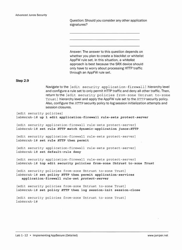
Step 2.9
Question: Should you consider any other application
signatures?
Answer: The answer to this question depends on
whether you plan to create a blacklist or whitelist
AppFW rule set. In this situation, a whitelist
approach is best because the SRX device should
only have to worry about processing HTTP traffic
through an AppFW rule set.
Navigate to the [edit security application-f irewalll hierarchy level
and configure a rule set to only permit HTTP traffic and deny all other traffic. Then,
return to the [edit security policies from-zone Untrust to-zone
Trust] hierarchy level and apply the AppFW rule set to the HTTP security policy.
Also, configure the HTTP security policy to log session initialization attempts and
session closures.
[edit security policies]
lab@srxA-1# up 1 edit application-firewall rule-sets protect-server
[edit security application-firewall rule-sets protect-server]
lab@srxA-1# set rule HTTP match dynamic-application junos:HTTP
[edit security application-firewall rule-sets protect-server]
lab@srxA-1# set rule HTTP then permit
[edit security application-firewall rule-sets protect-server]
lab@srxA-1# set default-rule deny
[edit security application-firewall rule-sets protect-server]
lab@srxA-1# top edit security policies from-zone Untrust to-zone Trust
[edit security policies from-zone Untrust to-zone Trust]
lab@srxA-1# set policy HTTP then permit application-services
application-firewall rule-set protect-server
[edit security policies from-zone Untrust to-zone Trust]
lab@srxA-1# set policy HTTP then log session-init session-close
[edit security policies from-zone Untrust to-zone Trust]
lab@srxA-1#
Lab 1-12 • Implementing AppSecure (Detailed) www.juniper.net
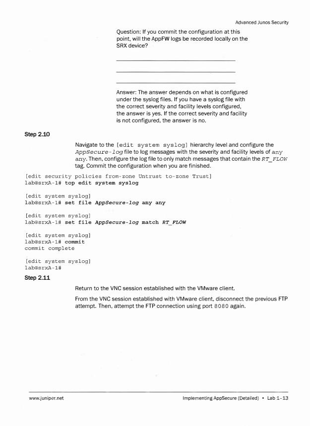
Step2.10
Advanced Ju nos Security
Question: If you commit the configuration at this
point, will the AppFW logs be recorded locally on the
SRX device?
Answer: The answer depends on what is configured
under the syslog files. If you have a syslog file with
the correct severity and facility levels configured,
the answer is yes. If the correct severity and facility
is not configured, the answer is no.
Navigate to the [edit system sys log] hierarchy level and configure the
AppSecure-logfile to log messages with the severity and facility levels of any
any. Then, configure the log file to only match messages that contain the RT_ FLOW tag. Commit the configuration when you are finished.
[edit security policies from-zone Untrust to-zone Trust]
lab@srxl\.-1# top edit system syslog
[edit system syslog]
lab@srxl\-1# set file AppSecure-log any any
[edit system syslog]
[email protected]# set file AppSecure-log match RT FLOW
[edit system syslog]
lab@srxA-1# commit
commit complete
[edit system syslog]
lab@srxA-1#
Step 2.11
Return to the VNC session established with the VMware client.
www.junip,�r.net
From the VNC session established with VMware client, disconnect the previous FTP
attempt. Then, attempt the FTP connection using port 8080 again.
Implementing AppSecure (Detailed) • Lab 1-13

Advanced Junos Security
Step 2.12
!,� Fiiename '
Size; User i Group
Filename Progress
Successfully changed local directory to /llome/lab/ajsec
Looking up ajsecserver.ajsec.juniper.net
Trying ajsecserver.ajsec .juniper .net: BOBO
Connected to ajsecserver.a]sec.juniper.net:8080
220 fvsFT?d 2 0.5)
USER !ab
Return to the session established with your assigned SRX device.
From your assigned SRX device, issue the run show security
application-firewall rule-set all command.
[edit system syslog]
lab@srxA-1# run show security application-firewall rule-set all Rule-set: protect-server
Rule: HTTP Dynamic Applications: junos:HTTP Action:permit Number of sessions matched: O
Default rule:deny Number of sessions matched: 1
Number of sessions with appid pending: O
Question: Is the AppFW rule set denying the FTP
session?
Answer: The output suggests that the FTP session is
being denied. However, although the output shows
that the default rule is being hit, it does not
specifically note exactly what is being blocked.
Lab 1-14 • lmplementingAppSecure (Detailed)
� . .
www,juniper.net
Advanced Junos Security
Step2.13
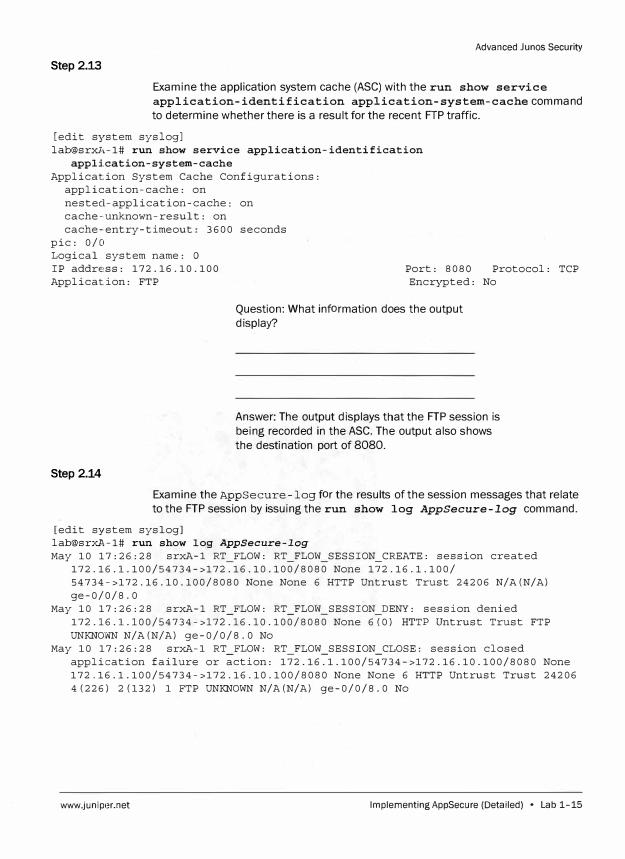
Examine the application system cache (ASC) with the run show service application-identification application-system-cachecommand to determine whether there is a result for the recent FTP traffic.
[edit system syslog] lab@srxl,-1# run show service application-identification
application-system-cache Application System Cache Configurations:
application-cache: on nested-application-cache: on cache-unknown-result: on cache-entry-timeout: 3600 seconds
pie: 0/0 Logical system name: O IP address: 172.16.10.100 Port: 8080 Protocol: TCP Application: FTP Encrypted: No
Step 2.14
Question: What information does the output display?
Answer: The output displays that the FTP session is being recorded in the ASC. The output also shows the destination port of 8080.
Examine the AppSecure-log for the results of the session messages that relate to the FTP session by issuing the run show log AppSecure-log command.
[edit system syslog] lab@srxA-1# run show log AppSecure-log
May 10 17:26:28 srxA-1 RT FLOW: RT_FLOW SESSION_CREATE: session created 172.16.l.100/54734->172.16.10.100/8080 None 172.16.1.100/ 54734->172.16.10.100/8080 None None 6 HTTP Untrust Trust 24206 N/A(N/A) ge-0/0/8.0
May 10 17:26:28 srxA-1 RT_FLOW: RT_FLOW SESSION_DENY: session denied 172.16.l.100/54734->172.16.10.100/8080 None 6(0) HTTP Untrust Trust FTP UNKNOWN N/A(N/A) ge-0/0/8.0 No
May 10 17:26:28 srxA-1 RT FLOW: RT_FLOW_SESSION_CLOSE: session closed application failure or action: 172.16.1.100/54734->172.16.10.100/8080 None 172.16.1.100/54734->172.16.10.100/8080 None None 6 HTTP Untrust Trust 24206 4(226) 2(132) 1 FTP UNKNOWN N/A(N/A) ge-0/0/8.0 No
www.juniper.net Implementing AppSecure (Detailed) • Lab 1-15

Advanced Junos Security
Question: What is the reason given for closing the
session?
Answer: The message of application failure
or action is given as the reason for closing the
session.
Part 3: Building Custom Application Signatures
Step 3.1
Step 3.2
In this lab part, you will configure a custom application signature that you will use in
an AppFW rule set to block specific traffic. Then, you will verify that this traffic is
being blocked by the AppFW rule set.
Return to the VNC session established with the VMware client.
From the VNC session established with VMware client, open the Web browser by
double-clicking the Firefox icon. If necessary, you can close the gFTP client now.
When the Web browser opens, the home page should open to the
http: I I aj secserver. aj sec.juniper. net/test. html URL. Once the
Web browser has opened, click the AJSEC FILES bookmark.
Note
If clicking the AJSEC FILES or the TESTURL
bookmark produces an error, please inform
your instructor immediately.
Lab 1-16 • Implementing AppSecure (Detailed) www.juniper.net
Advanced Junos Security
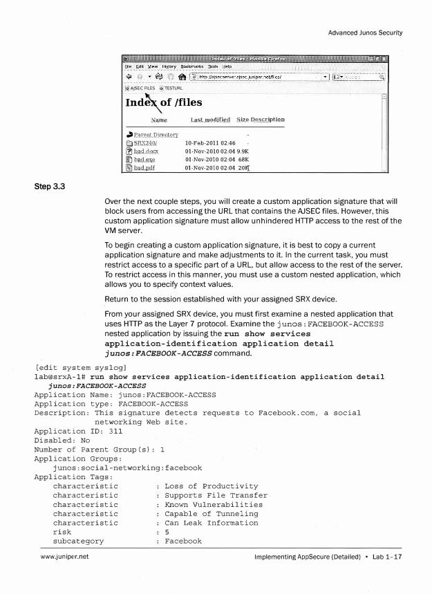
Step 3.3
[!>)AJSEC FlLES [i:!;TESTURL
lnd��f /filesNan1e J.ast.mo<l.ified S.iz.11 D.!).�_uJption
.> P.�rnnt..Q.ice.�.tQJ:y El S.BX.i'}_Qi � h.�.ci,.d.QSli [[) l:!r11L�1i.Q �l2il..!L!lill
10-Feb-2011 02,46
Ol-Nov-2010 02,04 9.9K
Ol-Nov-2010 02,04 68K
Ol-Nov-2010 02,04 20ij
i I 11
L.l
Over the next couple steps, you will create a custom application signature that will
block users from accessing the URL that contains the AJSEC files. However, this
custom application signature must allow unhindered HTIP access to the rest of the
VM server.
To begin creating a custom application signature, it is best to copy a current
application signature and make adjustments to it. In the current task, you must
restrict access to a specific part of a URL, but allow access to the rest of the server.
To restrict access in this manner, you must use a custom nested application, which
allows you to specify context values.
Return to the session established with your assigned SRX device.
From your assigned SRX device, you must first examine a nested application that
uses HTIP as the Layer 7 protocol. Examine the junos: FACEBOOK-ACCESS
nested application by issuing the run show services
application-identification application detail
junos: FACEBOOK-ACCESS command.
[edit system syslog] lab@srxA-1# run show services application-identification application detail
junos:FACEBOOK-ACCESS
Application Name: junos:FACEBOOK-ACCESS Application type: FACEBOOK-ACCESS Description: This signature detects requests to Facebook.com, a social
networking Web site. Application ID: 311 Disabled: No Number of Parent Group(s): 1 Application Groups:
junos:social-networking:facebook Application Tags:
characteristic characteristic characteristic characteristic characteristic risk subcategory
www.juniper.net
Loss of Productivity Supports File Transfer Known Vulnerabilities Capable of Tunneling Can Leak Information 5 Facebook
Implementing AppSecure (Detailed) • Lab 1-17
Advanced Junos Security
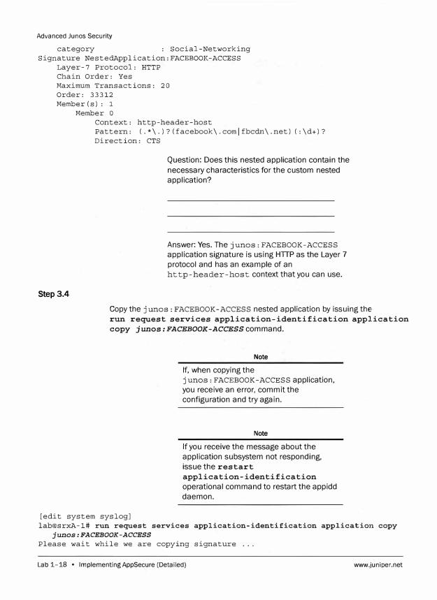
category : Social-Networking Signature NestedApplication:FACEBOOK-ACCESS
Layer-7 Protocol: HTTP Chain Order: Yes Maximum Transactions: 20 Order: 33312 Member(s): 1
Step3.4
Member o Context: http-header-host Pattern: (.*\.)?(facebook\.comlfbcdn\.net) (:\d+)? Direction: CTS
Question: Does this nested application contain the
necessary characteristics for the custom nested application?
Answer: Yes. The junos: FACEBOOK-ACCESS application signature is using HTTP as the Layer 7 protocol and has an example of an http-header-host context that you can use.
Copy the j unos : FACEBOOK-ACCESS nested application by issuing the, run request services application-identification application
copy junos: FACEBOOK-ACCESS command.
[edit system syslog]
Note
If, when copying the junos: FACEBOOK-ACCESS application, you receive an error, commit the configuration and try again.
Note
If you receive the message about the application subsystem not responding, issue the restart
application-identification
operational command to restart the appidd daemon.
lab@srxA-1# run request services application-identification application copy junos:FACEBOOK-ACCESS
Please wait while we are copying signature ...
Lab 1-18 • Implementing AppSecure (Detailed) www.juniper.net
Advanced Junos Security
Please wait while we are copying signature .. . Please wait while we are copying signature .. . Copy application junos:FACEBOOK-ACCESS succeed.
Step 3.5
When copying a built-in application signature, the system copies the application signature and replaces the junos keyword with the my keyword. For example,
copying the application signature j unos: FACEBOOK-ACCESS creates the custom application signature my: FACEBOOK-ACCESS.
Navigate to the [edit services application-identification] hierarchy level and issue a show command to view the recently copied application
signature.
[edit system syslog) lab@srxl,-1# top edit services application-identification
[edit services application-identification) lab@srxA-1# show nested-application my:FACEBOOK-ACCESS
protocol HTTP; signature my:FACEBOOK-ACCESS {
Step 3.6
member mOl { context http-header-host; pattern 11 (.*\.)?(facebook\.comlfbcdn\.net) (:\d+)?"; direction client-to-server;
maximum-transactions 20;
Question: What must you change in the new
application signature to block access to the AJSEC FILES URL?
Answer: You must change the signature pattern in member mo 1 to correctly match the new HTTP
header context. Then, yo_u must add a new
signature member that matches on the context in
the URL. Renaming the nested application name
and signature name to something more appropriate is also recommended.
Rename the nested application and signature to my:AJSEC-FILES. Then,
navigate to the [edit services application-identification
nested-application my:AJSEC-FILES signature my:AJSEC-FILES]
hierarchy level.
www.juniper.net Implementing AppSecure (Detailed) • Lab 1-19
Advanced Junos Security
[edit services application-identification] lab@srxA-1# rename nested-application my:FACEBOOK-ACCESS to nested-application
my:AJSEC-FILES
[edit services application-identification] lab@srxA-1# edit nested-application my:AJSEC-FILES
[edit services application-identification nested-application my:AJSEC-FILES] lab@srxA-1# rename signaturemy:FACEBOOK-ACCESS to signaturemy:AJSEC-FILES
[edit services application-identification nested-application my:AJSEC-FILES] lab@srxA-1# edit signature my:AJSEC-FILES
[edit services application-identification nested-application my:AJSEC-FILES signature my:AJSEC-FILES] �
lab@srxA-1#
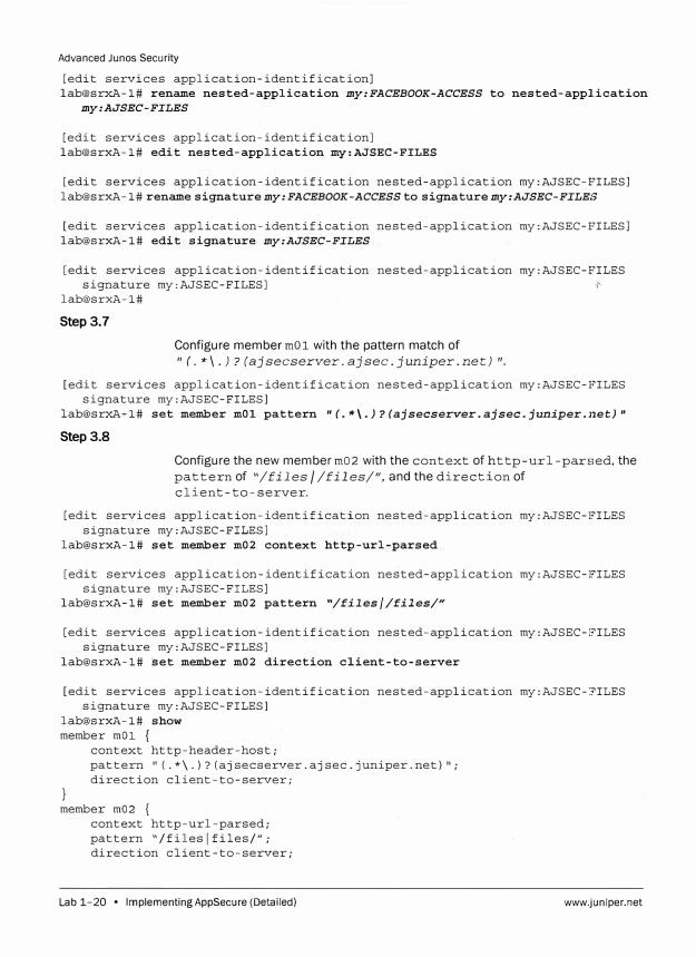
Step 3.7
Configure member mOl with the pattern match of "(.*\.)?(ajsecserver.ajsec.juniper.net)•.
[edit services application-identification nested-application my:AJSEC-FILES signature my:AJSEC-FILES]
lab@srxA-1# set member mOl pattern 11 (.*\.)?(ajsecserver.ajsec.juniper.11et)"
Step 3.8
Configure the new member m02 with the context of http-url-parsed, the pattern of "/files / /files/", and the direction of client-to-server.
[edit services application-identification nested-application my:AJSEC-FILES signature my:AJSEC-FILES]
lab@srxA-1# set member m02 context http-url-parsed
[edit services application-identification nested-application my:AJSEC-FILES signature my:AJSEC-FILES]
lab@srxA-1# set member m02 pattern "/files//files/"
[edit services application-identification nested-application my:AJSEC-FILES signature my:AJSEC-FILES]
lab@srxA-1# set member m02 direction client-to-server
[edit services application-identification nested-application my:AJSEC-FILES signature my:AJSEC-FILES]
lab@srxA-1# show member mOl {
}
context http-header-host; pattern "(.*\.)?(ajsecserver.ajsec.juniper.net)"; direction client-to-server;
member m02 { context http-url-parsed; pattern "/fileslfiles/"; direction client-to-server;
Lab 1-20 • Implementing AppSecure (Detailed) www.juniper.net
Advanced Junos Security
maximum-transactions 20;
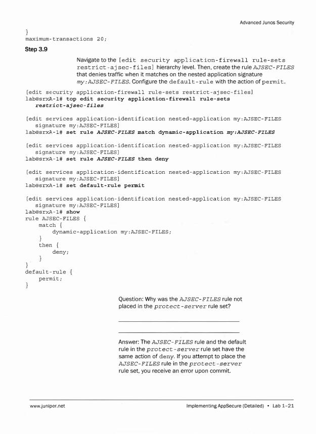
Step 3.9
Navigate to the [edit security application-firewall rule-sets
restrict-aj sec-files] hierarchy level. Then, create the rule AJSEC-FILES
that denies traffic when it matches on the nested application signature
my:AJSEC-FILES. Configure the default-rule with the action of permit.
[edit security application-firewall rule-sets restrict-ajsec-filesl lab@srxP.,-1# top edit security application-firewall rule-sets
restrict-ajsec-files
[edit services application-identification nested-application my:AJSEC-FILES signature my:AJSEC-FILES]
[email protected]# set rule AJSEC-FILES match dynamic-application my:AJSEC-FILES
[edit services application-identification nested-application my:AJSEC-FILES signature my:AJSEC-FILES]
[email protected]# set rule AJSEC-FILES then deny
[edit services application-identification nested-application my:AJSEC-FILES signature my:AJSEC-FILES]
[email protected]# set default-rule permit
[edit services application-identification nested-application my:AJSEC-FILES signature my:AJSEC-FILES]
lab@srxA-1# show rule AJSEC-FILES {
match { dynamic-application my:AJSEC-FILES;
}
} then {
deny;
default-rule permit;
www.juniper.net
Question: Why was the AJSEC-FILES rule not
placed in the protect-server rule set?
Answer: The AJSEC-FILES rule and the default
rule in the protect-server rule set have the
same action of deny. If you attempt to place the
AJSEC-FILES rule in the protect-server
rule set, you receive an error upon commit.
lmplementingAppSecure (Detailed) • Lab 1-21
Advanced Junos Security
Step 3.10
Navigate to the [edit security policies from-zone Untrust
to- zone Trust] hierarchy level. Then, configure the HTTP security policy to
reference the restrict-aj sec-files AppFW rule set. Commit the
configuration when you are finished.
[edit services application-identification nested-application my:AJSEC-E'ILES
signature my:AJSEC-FILES]
lab@srxA-1# top edit security policies from-zone Untrust to-zone Trust
[edit security policies from-zone Untrust to-zone Trust]
lab@srxA-1# set policy HTTP then permit application-services
application-firewall rule-set restrict-ajsec-files
[edit security policies from-zone Untrust to-zone Trust]
lab@srxA-1# commit
commit complete
[edit security policies from-zone Untrust to-zone Trust]
lab@srxA-1#
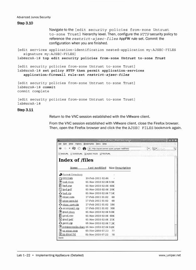
Step 3.11
Return to the VNC session established with the VMware client.
From the VNC session established with VMware client, close the Firefox browser.
Then, open the Firefox browser and click the the AJSEC FILES bookmark again .
.... Ble Edit YJew Hl1tory aookmarkS Iools !:::!elp
� Y • �� C3 ft [.@1 !_http://ajsecserver.ajsec.J�n;per.neur;,est .....
@) BADURL @.] GOODURL @IAJSEC FILES �TESTURL
Index of /files
Name Last modified .s.iz!l Description
.,�lllQ.i.r�
E:) SJlX.2!.lQI 10-Feb-2011 02:46 � )?JL<Lr!.ai;x Ol-Nov-2010 02:04 9.9K � l!r"lllllK..<il Ol-Nov-2010 02:04 68K
� ):,..lliLp..l).f Ol-Nov-2010 02:04 20K {lo� Ol-Nov-2010 02:04 7.SK �.!li0.Llmll 17-Feb-2011 01:02 68 � elcar com txt 17-Feb-2011 01:02 68 {lo eic<lC com.zip 17-Feb-2011 01:02 184 {lo .e.i��.r.r&n:iJ.,Z.ill. 17-Feb-2011 01:02 308 � g:QQ.Q.0QQJ;� Ol-Nov-2010 02:04 9.8K � !JQ.9 .d.,fill!l Ol-Nov-2010 02:04 68K � g:QQ.d.,l)..c;IJ Ol-Nov-2010 02:04 21K {), !).Q.Q.\L.;Qll Ol-Nov-2010 02:04 7.3K � juniper-rocks docx Ol-Nov-2010 02:04 9.BK � ss-eicar.com OS-Nov-2010 07:23 77 �ss-eicar.txt 05-Nov-2010 07:22 78 Done
Lab 1-22 • lmplementingAppSecure (Detailed) www.juniper.net
Question: Did the restrict-aj sec-files
AppFW rule set restrict the HTIP transaction?
Advanced Junos Security
Answer: No. The HTIP transaction completed as if
the restrict-aj sec-files AppFW rule set
had no effect on it.
Step 3.12
Return to the session established with your assigned SRX device.
From your assigned SRX device, examine the AppFW rule sets and ASC by issuing
therun show security application-firewall rule-set
restrict-ajsec-£i1es and therun show services
application-identification application-system-cache
commands.
[edit security policies from-zone Untrust to-zone Trust]
lab@srxA-1# run show security application-firewall rule-set
restrict-ajsec-files
Rule-set: restrict-ajsec-files
Rule: AJSEC-FILES
Dynamic Applications: my:AJSEC-FILES
Action:deny
Number of sessions matched: O
Default rule:permit
Number of sessions matched: 2
Number of sessions with appid pending: 0
[edit security policies from-zone Untrust to-zone Trust]
lab@srxA-1# run show services application-identification
application-system-cache
Application System Cache Configurations:
application-cache: on
nested-application-cache: on
cache-unknown-result: on
cache-entry-timeout: 3600 seconds
pie: 0/0
Logical system name: 0
IP address: 172.16.10.100 Port: 80 Protocol: TCP Application: HTTP Encrypted: No
Logical system name: O
IP address: 172.16.10.100
Application: FTP
Step 3.13
Port: 8080 Protocol: TCP
Encrypted: No
Examine the AppSecure -1 og sys log file.
www.juniper.net Implementing AppSecure (Detailed) • Lab 1-23
Advanced Junos Security
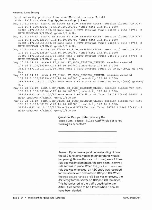
[edit security policies from-zone Untrust to-zone Trust] lab@srxA-1# run show log AppSecure-log I last May 10 21:58:13 srxA-1 RT_FLOW: RT_FLOW_SESSION_CLOSE: session closed TCP FIN:
172.16.1.100/32803->172.16.10.100/80 junos-http 172.16.1.100/ 32803->172.16.10.100/80 None None 6 HTTP Untrust Trust 24662 5(715) S(761) 2 HTTP UNKNOWN N/A(N/A) ge-0/0/8.0 No
May 10 21:58:13 srxA-1 RT_FLOW: RT_FLOW_SESSION_CLOSE: session closed TCP FIN: 172.16.l.100/32804->172.16.10.100/80 junos-http 172.16.1.100/ 32804->172.16.10.100/80 None None 6 HTTP Untrust Trust 24663 5(714) S(762) 2 HTTP UNKNOWN N/A(N/A) ge-0/0/8.0 No
May 10 21:58:13 srxA-1 RT_FLOW: RT_FLOW_SESSION_CLOSE: session closed TCP FIN: 172.16.l.100/32805->172.16.10.100/80 junos-http 172.16.1.100/ 32805->172.16.10.100/80 None None 6 HTTP Untrust Trust 24664 5(714) 5(793) 2 HTTP UNKNOWN N/A(N/A) ge-0/0/8.0 No
May 10 22:04:17 srxA-1 RT_FLOW: RT_FLOW_SESSION_CREATE: session created 172.16.l.100/38338->172.16.10.100/80 junos-http 172.16.1.100/ 38338->172.16.10.100/80 None None 6 HTTP Untrust Trust 24709 N/A(N/A) ge-0/0/ 8.0
May 10 22:04:17 srxA-1 RT_FLOW: RT_FLOW_SESSION_CREATE: session created 172.16.l.100/38339->172.16.10.100/80 junos-http 172.16.1.100/ 38339->172.16.10.100/80 None None 6 HTTP Untrust Trust 24710 N/A(N/A) ge-0/0/ 8.0
May 10 22:04:19 srxA-1 RT FLOW: RT_FLOW_SESSION_CLOSE: session closed TCP FIN: 172.16.1.100/38338->172.16.10.100/80 junos-http 172.16.1.100/ 38338->172.16.10.100/80 None None 6 HTTP Untrust Trust 24709 5(679) 5(855) 2 HTTP UNKNOWN N/A(N/A) ge-0/0/8.0 No
May 10 22:04:19 srxA-1 RT_FLOW: RT_FLOW_SESSION_CLOSE: session closed TCP FIN: 172.16.l.100/38339->172.16.10.100/80 junos-http 172.16.1.100/ 38339->172.16.10.100/80 None None 6 HTTP Untrust Trust 24710 7(784) 7(4437) 2 HTTP UNKNOWN N/A(N/A) ge-0/0/8.0 No
Question: Can you determine why the restrict-aj sec-files AppFW rule set is not working as expected?
Answer: If you have a good understanding of how the ASC functions, you might understand what is happening. Before the restrict-aj sec-files rule set was implemented, the protect-server rule set was in place. When the protect-server rule set was employed, an ASC entry was recorded for the server with destination TCP port 80. When the restrict-aj sec-files was employed, the ASC entry for the server on TCP port 80 remained. This behavior led to the traffic destined to the AJSEC files section to be allowed when it should have been denied.
Lab 1-24 • Implementing AppSecure (Detailed) www.juniper.net
Step3.14
Advanced Junos Security
Question: What can you do to resolve the issue?
Answer: You might think that clearing the ASC might
resolve the issue, and this action might appear to
work. However, the same cycle will repeat itself if a
section, other than the AJSEC files section, is
accessed before the AJSEC files section. The only
real solution is to disable the ASC for nested
applications.
Navigate to the [edit services application-identification)
hierarchy level. Once you are there, disable the recording of nested applications in
the ASC and commit the configuration.
[edit security policies from-zone Untrust to-zone Trust]
lab@srxA-1# top edit services application-identification
[edit services application-identification]
lab@srxA-1# set nested-application-settings no-application-system-cache
[edit services application-identification]
lab@srxA-1# commit
commit c:::>mplete
[edit services application-identification]
lab@srxA-1#
Step 3.15
Return to the VNC session established with the VMware client.
www.juniper.net
From the VNC session established with VMware client, close the Firefox browser.
Then, open the Firefox browser and click the the AJSEC FILES bookmark again.
Implementing AppSecure (Detailed) • Lab 1-25
Advanced Junos Security
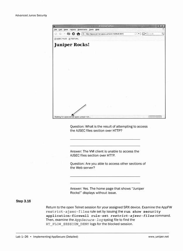
Step 3.16
@:jAJSEC FILES (<!)1ES1URL
Juniper Rocks!
/ Waiting ror ajsecserver.ajsec.juniper.net. ..
Question: What is the result of attempting to access the AJSEC files section over HTTP?
Answer: The VM client is unable to access the AJSEC files section over HTTP.
Question: Are you able to access other sections of the Web server?
Answer: Yes. The home page that shows "Juniper Rocks!" displays without issue.
Return to the open Telnet session for your assigned SRX device. Examine the AppFW restrict-ajsec-files rule set by issuing the run show security
application-firewall rule-set restrict-ajsec-files command. Then, examine the AppSecure-log syslog file to find the RT _FLOW_ SESSION _DENY logs for the blocked session.
Lab 1-26 • Implementing AppSecure (Detailed) www.juniper.net
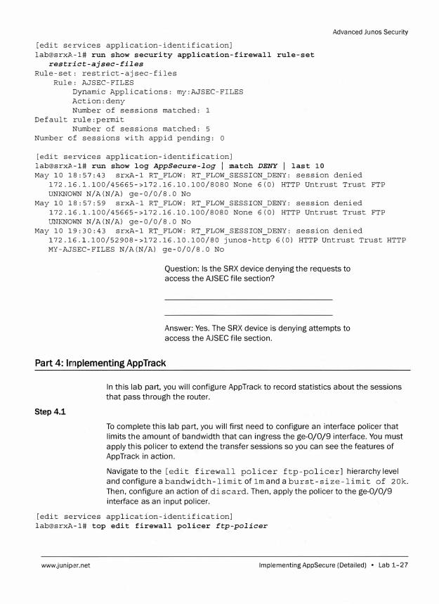
[edit services application-identification] [email protected]# run show security application-firewall rule-set
restrict-ajsec-files
Rule-set: restrict-ajsec-files Rule,: AJSEC-FILES
Dynamic Applications: my:AJSEC-FILES Action:deny Number of sessions matched: 1
Default rule:permit Number of sessions matched: 5
Number of sessions with appid pending: O
[edit services application-identification] [email protected]# run show log AppSecure-log I match DENY I last 10
Advanced Junos Security
May 10 18:57:43 srxA-1 RT_FLOW: RT_FLOW_SESSION_DENY: session denied 172.16.l.100/45665->172.16.10.100/8080 None 6(0) HTTP Untrust Trust FTP UNKNOWN N/A(N/A) ge-0/0/8.0 No
May 10 18:57:59 srxA-1 RT_FLOW: RT_FLOW_SESSION_DENY: session denied 172.16.l.100/45665->172.16.10.100/8080 None 6(0) HTTP Untrust Trust FTP UNKNOWN N/A(N/A) ge-0/0/8.0 No
May 10 19:30:43 srxA-1 RT_FLOW: RT_FLOW_SESSION_DENY: session denied 172.16.l.100/52908->172.16.10.100/80 junos-http 6(0) HTTP Untrust Trust HTTP MY-AJSEC-FILES N/A(N/A) ge-0/0/8.0 No
Question: Is the SRX device denying the requests to access the AJSEC file section?
Answer: Yes. The SRX device is denying attempts to access the AJSEC file section.
Part 4: Implementing App Track
Step 4.1
In this lab part, you will configure App Track to record statistics about the sessions that pass through the router.
To complete this lab part, you will first need to configure an interface policer that
limits the amount of bandwidth that can ingress the ge-0/0/9 interface. You must
apply this policer to extend the transfer sessions so you can see the features of AppTrack in action.
Navigate to the [edit firewall policer ftp-policer] hierarchy level and configure a band wid th-limit of lm and a burst -size-limit of 20k.
Then, configure an action of discard. Then, apply the policer to the ge-0/0/9
interface as an input policer.
[edit services application-identification] lab@srxA-1# top edit firewall policer ftp-policer
www.junip,�r.net Implementing AppSecure (Detailed) • Lab 1-27
Advanced Junos Security
[edit firewall policer ftp-policer] lab@srxA-1# set if-exceeding bandwidth-limit lm
[edit firewall policer ftp-policer] lab@srxA-1# set if-exceeding burst-size-limit 20k
[edit firewall policer ftp-policer] lab@srxA-1# set then discard
[edit firewall policer ftp-policer] lab@srxA-1# show if-exceeding {
bandwidth-limit lm; burst-size-limit 20k;
then discard;
[edit firewall policer ftp-policer] lab@srxA-1# top edit interfaces ge-0/0/9
[edit interfaces ge-0/0/9] lab@srxA-1# set unit O family inet policer input ftp-policer
[edit interfaces ge-0/0/9] lab@srxA-1#
Step4.2
Navigate to the [edit security] hierarchy level and configure AppTrack to
generate a message upon session creation.
[edit interfaces ge-0/0/9] lab@srxA-1# top edit security
[edit security] lab@srxA-1# set application-tracking first-update
[edit security] lab@srxA-1#
Step 4.3
Apply application tracking to the Trust zone. Commit the configuration when you
are finished.
[edit security] lab@srxA-1# set zones security-zone Trust application-tracking
[edit security] lab@srxA-1# commit commit complete
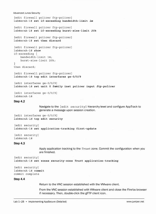
Step4.4
Return to the VNC session established with the VMware client.
From the VNC session established with VMware client and close the Firefox browser
if necessary. Then, double-click the gFTP client icon.
Lab 1-28 • lmplementingAppSecure (Detailed) www.juniper.net
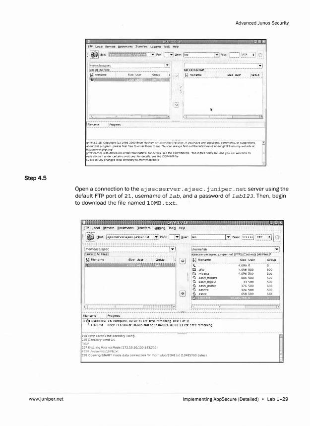
Step 4.5
www.juniper.net
Advanced Junos Security
fTP Local fiemote a.ookmark.S Jransf'ers LQ.gging Toolj_ Help
l/home11ab/aJsec ·························-····---···· .. - - ···················-� (Local] (All Ries]
11 ·!,! Rl@name I !t(""'
i
Size User Group _ .. ( ......... -1 I'
L - ___ ______ J �''�- -----·_ ... -- ! ---====:i:.,
..... . ..... . ......... , , ;. -..;..-;j"···-
····---�Pass:
I .---- �---T�I
gFTP 2.0.18. Copyright (C} 1998·2003 Brian Masney <n1<1<,:rmyll@g:-tµ.ur9>. If you have any questions, comments. or suggestions about this program, please reel free to email them to me. '\'bu can always t'ind out the latest news about gFTPrrom my website at http://Www.grtp.org/ gFTP comes with ABSOWTELY NO WARRANTY: for details. see the COPYING file. This Is free sortware, and you are welcome to redistribute It under certain conditions: ror details, see the COPYING rile Successru11y changed local directory to Jllome/lab/aJsec
Open a connection to the aj secserver. aj sec.juniper. net server using the default FTP port of 21, username of lab, and a password of labl23. Then, begin to download the file named 1 OMB. txt.
\mome/lab/ajsec __
l1::.1?.t::�D !� Ales]
&., Filename Size
150 Here comes the directory listing 226 Directory send CK. F�'l..SV 227 Entering ?"nssM? Mode (172 • .16.10,100,133,2311 RFffi Jhom�,li.'lb/lOMB.txt
[�]
lfhome/lab
ajse_cserver.ajsec.Juniper.net [FTP} (Cached) {All Ales]-+-
r i� Fllen�me .
Slze � User Group
't.. : . . . . ....... .. . .. ·········· ·· ·
4:095-
0
CJ .grtp 4.096 500 CJ .mozilla 4,096 500 Q .bash_hlstory 884 500 0 .bash_logout 33 soo C .bash_profile 176 500 Q .bashrc 124 500 e .zshrc 658 500 '
500 500 500 500 500 500 500
150 Opemng BINARY ,node data connection for /home/labllOMB.txt (10485i60 bytes).
Implementing AppSecure (Detailed) • Lab 1-29
Advanced Junos Security
Step 4.6
Return to the session established with your assigned SRX device.
From your assigned SRX device, examine the session table to obtain the session IDs
of the FTP control and data sessions by issuing the run show security flow
session command.
[edit security] lab@srxA-1# run show security flow session Session ID: 25593, Policy name: FTP/8, Timeout: 1752, Valid Resource information : FTP ALG, 2, 0
In: 172.16.1.100/39113 --> 172.16.10.100/2l;tcp, If: ge-0/0/8.0, Pkts: 14, Bytes: 669
Out: 172.16.10.100/21 --> 172.16.l.100/39113;tcp, If: ge-0/0/9.0, Pkts: 13, Bytes: 914
Session ID: 25595, Policy name: FTP/8, Timeout: 300, Valid Resource information : FTP ALG, 2, 1
In: 172.16.1.100/58637 --> 172.16.10.100/22424;tcp, If: ge-0/0/8.0, Pkts: 1982, Bytes: 103648
Out: 172.16.10.100/22424 --> 172.16.l.100/58637;tcp, If: ge-0/0/9.0, Pkts: 2451, Bytes: 3675060
Total sessions: 2
Step 4.7
Question: How can you determine which session is
the FTP control session, and which session is the
FTP data session?
Answer: The FTP control session has significantly
fewer packets transferred than the FTP data
session. In the previous output, the second session
is the FTP data session. The control session can
also be identified by the session that is using port
21.
Question: What are the session IDs for the FTP
control and data sessions?
Answer: In the previous output, the FTP control
session has a session ID of 25593, and the FTP
data session has a session ID of 25595. The
session IDs on your SRX device might be different.
Once the file transfer is complete, examine the AppTrack counters by issuing the
run show security application-tracking counters command.
Lab 1-30 • lmplementingAppSecure (Detailed) www,juniper.net
Advanced Ju nos Secur ity
[edit security] lab@srxl,-1# run show security application-tracking counters Application tracking counters:
AppTrack counter type Session create messages Session close messages Session volume updates Failed messages
Step4.8
Value 6 5
0
0
Question: Are any session volume update messages present? Why?
Answer: No. By default, a session must last longer than five minutes for the Junos OS to generate a session volume update message. The FTP transfer only lasted a little over two minutes.
Examine the AppTrack log messages for the logs pertaining to the FTP data session by issuing the run show log AppSecure-log I match
ftp-data-session-id command, where the match condition is the session ID of the FTP data session that you obtained in step 4.6.
[edit security] lab@srxl\.-1# run show log AppSecure-log I match ftp-data-session-id
May 11 16:45:04 srxA-1 RT_FLOW: APPTRACK_SESSION_CREATE: AppTrack session created 172.16.l.100/58637->172.16.10.100/22424 None ftp-data UNKNOWN 172.16.l.100/58637->172.16.10.100/22424 None None 6 FTP Untrust Trust 25595 N/A N/A N/A
May 11 16: 47: 27 srxA-1 RT_FLOW: APPTRACK_SESSION_CLOSE: AppTrack session closed TCP FIN: 172.16.l.100/58637->172.16.10.100/22424 None ftp-data UNKNOWN 172.16.l.100/58637->172.16.10.100/22424 None None 6 FTP Untrust Trust 25595 6453(336464) 7245(10863956) 144 N/A N/A N/A
www.junip,�r.net
Question: What is the elapsed time of the FTP transfer?
Answer: The elapsed time of the FTP transfer can be seen in the session close log. In the output displayed, the session lasted a total of 144 seconds. The elapsed time of your FTP transfer might be different.
Implementing AppSecur e (Detailed) • Lab 1-31
Advanced Junos Security
Step 4.9
[edit security]
Configure App Track to generate session volume update messages when a session is
active for 2 minutes. Commit the configuration when you are finished.
lab@srxA-1# set application-tracking session-update-interval 2
[edit security] lab@srxA-1# coilllllit commit complete
Step4.10
Step4.11
[edit security]
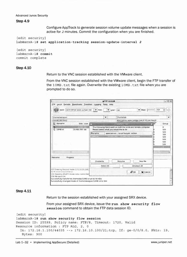
Return to the VNC session established with the VMware client.
From the VNC session established with the VMware client, begin the FTP transfer of
the 1 OMB. txt file again. Overwrite the existing 1 OMB. txt file when you are
prompted to do so.
gFTP 2.0.18
£TP J,.ocal fiemote a.ookmarkS ]ransrers LQgging Tool.5. Help
:; � tlost [•i:•::.:'.:'.'.�rajse:ju�;P.�'..��t EJ Port L.li:J !,iser i1ab
... .... . ..... ........ ........ ... ---· ······.·.·,;·==== ·=···=······=······:::::..··,··::···=·· ··=·· ==······=··· =···=······ ! i,i,ome,lab/ajsec j..., j l/home,1ab � {Local} (All Files} _________ ·-··-------, �secserver.aisec.juniper.net [FTP] [All Files]• ···------!,; Rlename Size User
The ronowing rile(s) exist on both the local and remote computer O lOMB.txt 10,485,760 lab Please select what you would like to do �
I
I
Rlename Proqress
227 Entenng Passive Mode (172.16,10,100, P.1! ri-t ;horn�.,1.:�b/lOMB.V\t 150 Opening BINARY mode data connectior
iAlename [ ajsecserver.<. local files�st_1 Action ___
__ ___ ___
______ J �
overwrite Resume I I
��"�
S�p Rle ] ....
···········---�· Se1ect_AJ1 _____ .... --� [_·-·-·· Deselect.Al l _=1
226 File send OK. �---------------- - -�
Successfully transferred /home/lab/lOMB.txt at 66.90 KB/s Successruny changed mode of JhomeJlab/ajsec/lOMB.txtto 644
Return to the session established with your assigned SRX device.
From your assigned SRX device, issue the run show security flow
session command to obtain the FTP data session ID.
Group
500
500
500
500
500
500
500
......•....
··········1
�
lab@srxA-1# run show security flow session Session ID: 25599, Policy name: FTP/8, Timeout: 1720, Valid Resource information : FTP ALG, 2, 0
In: 172.16.1.100/44035 --> 172.16.10.100/2l;tcp, If: ge-0/0/8.0, Pkts: 19, Bytes: 900
Lab 1-32 • Implementing AppSecure (Detailed) www.juniper.net
Advanced Junos Security
Out: 172.16.10.100/21 --> 172.16.1.100/44035;tcp, If: ge-0/0/9.0, Pkts: 16,
Bytes: 1184
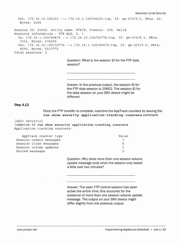
Session ID: 25602, Policy name: FTP/8, Timeout: 300, Valid
Resource information : FTP ALG, 2, 1
In: 172.16.1.100/49470 --> 172.16.10.100/32774;tcp, If: ge-0/0/8.0, Pkts:
3331, Bytes: 174252
Out: 172.16.10.100/32774 --> 172.16.l.100/49470;tcp, If: ge-0/0/9.0, Pkts:
4093, Bytes: 6137772
Total sessions: 2
Step4.12
Question: What is the session ID for the FTP data
session?
Answer: In the previous output, the session ID for
the FTP data session is 25602. The session ID for
the data session on your SRX device might be
different.
Once the FTP transfer is complete, examine the AppTrack counters by issuing the
run show security application-tracking counters command.
[edit security]
lab@srxA-1# run show security application-tracking counters
Application tracking counters:
AppTrack counter type
Session create messages
Session close messages
Session volume updates
Failed messages
www.juniper.net
Value
7
6
3
0
Question: Why does more than one session volume
update message exist when the session only lasted
a little over two minutes?
Answer: The open FTP control session has been
active the entire time; this accounts for the
existence of more than one session volume update
message. The output on your SRX device might
differ slightly from the previous output.
lmplementingAppSecure (Detailed) • Lab 1-33
Advanced Junos Security
Step4.13
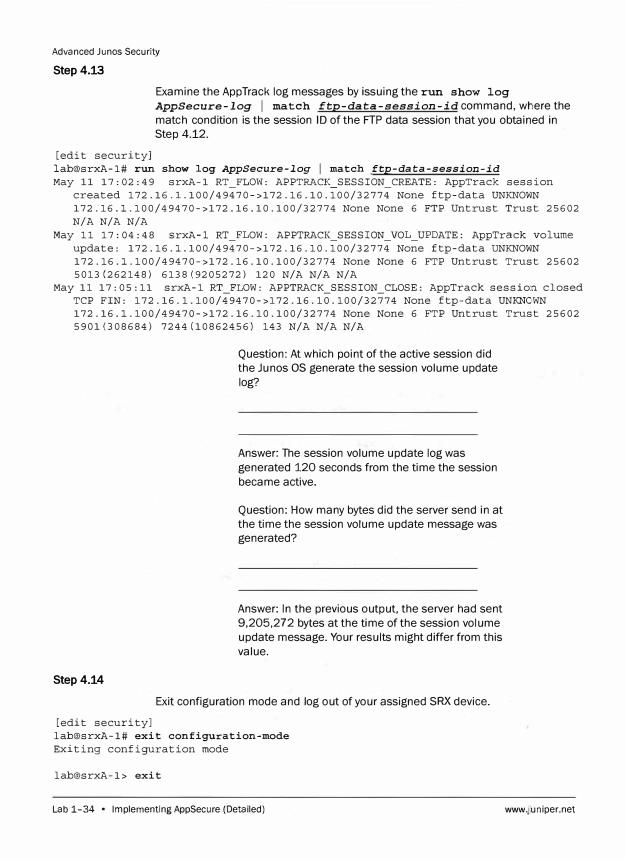
Examine the App Track log messages by issuing the run show log
AppSecure-log I match ftp-data-session-id command, where the match condition is the session ID of the FTP data session that you obtained in Step 4.12.
[edit security] lab@srxA-1# run show log AppSecure-log [ match ftp-data-session-id
May 11 17:02:49 srxA-1 RT_FLOW: APPTRACK_SESSION_CREATE: AppTrack session created 172.16.l.100/49470->172.16.10.100/32774 None ftp-data UNKNOWN 172.16.l.100/49470->172.16.10.100/32774 None None 6 FTP Untrust Trust 25602 N/A N/A N/A
May 11 17:04:48 srxA-1 RT_FLOW: APPTRACK_SESSION_VOL_UPDATE: AppTrack volume update: 172.16.l.100/49470->172.16.10.100/32774 None itp-data UNKNOWN 172.16.l.100/49470->172.16.10.100/32774 None None 6 FTP Untrust Trust 25602 5013(262148) 6138(9205272) 120 N/A N/A N/A
May 11 17: 05: 11 srxA-1 RT_FLOW: APPTRACK_SESSION_CLOSE: AppTrack session closed TCP FIN: 172 .16 .1.100/49470->l 72 .16 .10 .100/32774 None ftp-data UNKNOWN 172.16.l.100/49470->172.16.10.100/32774 None None 6 FTP Untrust Trust 25602 5901(308684) 7244(10862456) 143 N/A N/A N/A
Step4.14
Question: At which point of the active session did the Ju nos OS generate the session volume update log?
Answer: The session volume update log was generated 120 seconds from the time the session became active.
Question: How many bytes did the server send in at the time the session volume update message was generated?
Answer: In the previous output, the server had sent 9,205,272 bytes at the time of the session volume update message. Your results might differ from this value.
Exit configuration mode and log out of your assigned SRX device.
[edit security] lab@srxA-1# exit configuration-mode Exiting configuration mode
lab@srxA-1> exit
Lab 1-34 • Implementing AppSecure (Detailed) www.juniper.net
Advanced Junos Security
srxA-1 (ttyuO)
login:
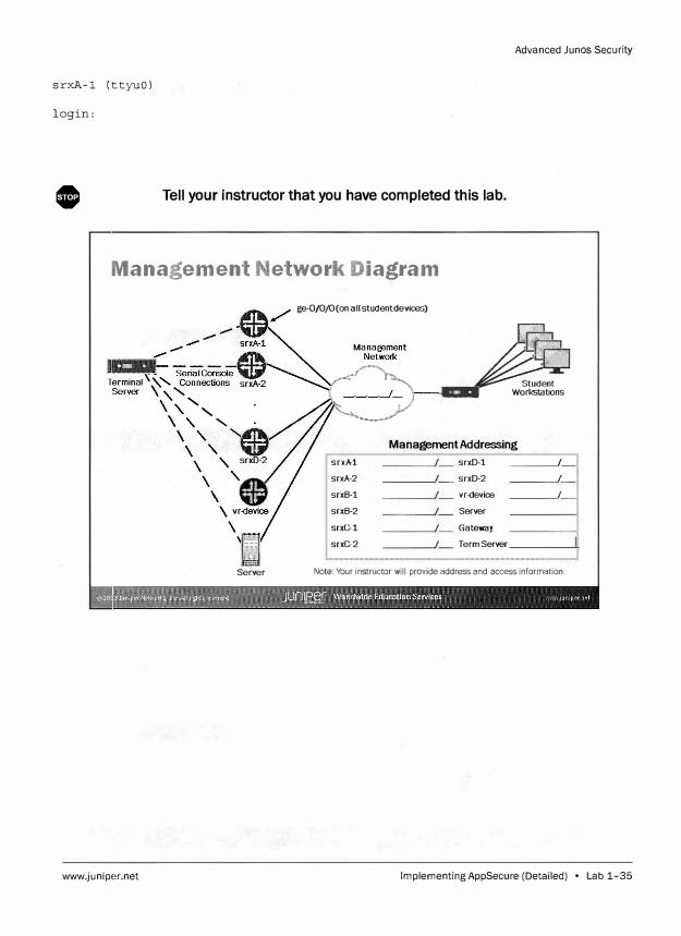
0 Tell your instructor that you have completed this lab.
Management Network Diagram
ge-0/0/0(on allstudentdevices)
� 1:1:111( Workstations
Management Addressing
srxA-1 srxD-1 I
srxA-2 I srxD-2 I
srxB-1 vr-device I
srxB-2 Server
srxC-1 Gateway
srxC-2 Term Server
Server Note: Your instructor will provide address and access information.
www.juniper.net Implementing AppSecure (Detailed) • Lab 1-35
Advanced Junos Security
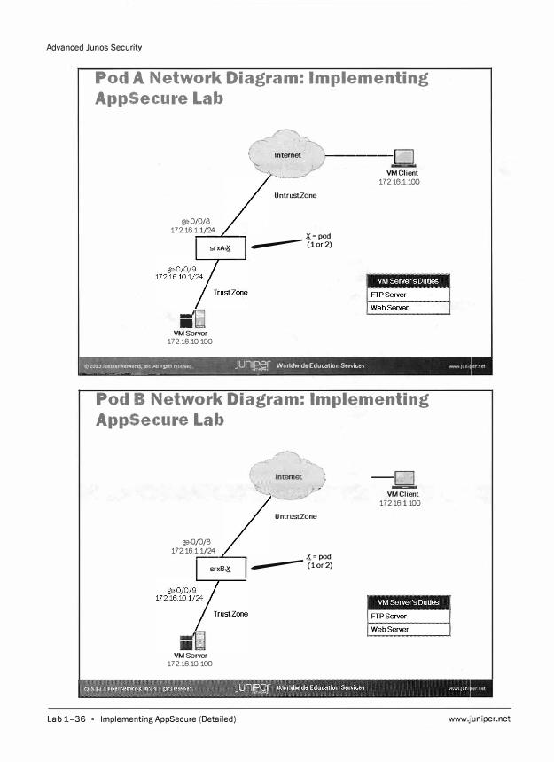
Pod A Network Diagram: Implementing
AppSecure Lab
ge-0/0/8 172.16.1.1/24
__ ........__
srxA-K
iilil VMServer
172.16.10.100
� �
. Internet
1 ·;--------! I '--' VMClient
UntrustZone
K = pod ---(1or2)
172.16.1.100
y��20�3J11n.1p:rN;i::�. lnc Allrlfbt'$ re$erve(! JUn�.r Worldwide Education Services ._ 1un1 ---- A.... --���-- A
Pod B Network Diagram: Implementing
AppSecure Lab
ge-0/0/8 172.16.1.1/24
�-.L--�
srxB-K
VMServer 172.16.10.100
Lab 1-36 • lmplementingAppSecure (Detailed)
�:--J;;J, --../. VM Client
U ntrustZone
<(=pod ---(1or2)
17 2.16.1.100
www.juniper.net
Advanced Junos Security
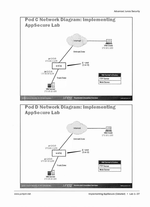
Pod C Network Diagram: Implementing
AppSecure Lab
ge-0/0/8 172161.1/24
,--""""'----,
srxC-K
VMServer 172.16.10.100
�•-• �����-v��lie�t
UntrustZone
X=pod ---(1or2)
172.16.1.100
Pod D Network Diagram: Implementing
AppSecure Lab
www.junip,3r.net
Pft-0/0/8 17 2 16 1.1/24
..... -....... ----,
ge-0/0/9 17216.10.1/24
,_/ ..... •
VMServer
srxD-K
Trust Zone
172.16.10.100
A,----Q � VMClient
UntrustZone
X=pod ---(1or2)
172.16.1.100
lmplementingAppSecure (Detailed) • Lab 1-37

Advanced Junos Security
Lab 1-38 • Implementing AppSecure (Detailed) www.juniper.net
Overvh�w
Lab
Implementing Layer 2 Security (Detailed)
In this lab, you will implement Layer 2 security. You will work with the remote student team
within your pod to verify Ethernet switching and transparent mode operations. You will
also configure Layer 2 security, and verify the results.
The lab is available in two formats: a high-level format designed to make you think through
each step and a detailed format that offers step-by-step instructions complete with
sample output from most commands.
By completing this lab, you will perform the following tasks:
Verify Ethernet switching behavior.
Implement transparent mode.
Secure Layer 2 traffic.
www.juniper.net Implementing Layer 2 Security (Detailed} • Lab 2-1
Advanced Junos Security
Part 1: Logging In Using the CLI
Step 1.1
Step 1.2
In this lab part, you load the starting configuration for Lab 2. Next, you will examine
Ethernet switching behavior. You will configure two interfaces with Ethernet
switching and will verify the results by passing Layer 2 traffic through your
SRX device.
Note
Depending on the class, the lab equipment
used might be remote from your physical
location. The instructor will inform you as to
the nature of your access and will provide
you the details needed to access your
assigned device.
Ensure that you know to which student device you have been assigned. Check with
your instructor if you are not certain. Consult the Management Network Diagram to
determine the management address of your student device.
Question: What is the management address
assigned to your student router?
Answer: The answer varies. The sample hostname
and IP address used in the output examples in this
lab are for srxA-1, which uses 10.210.35.131 as its management IP address. The actual management
address varies between delivery environments.
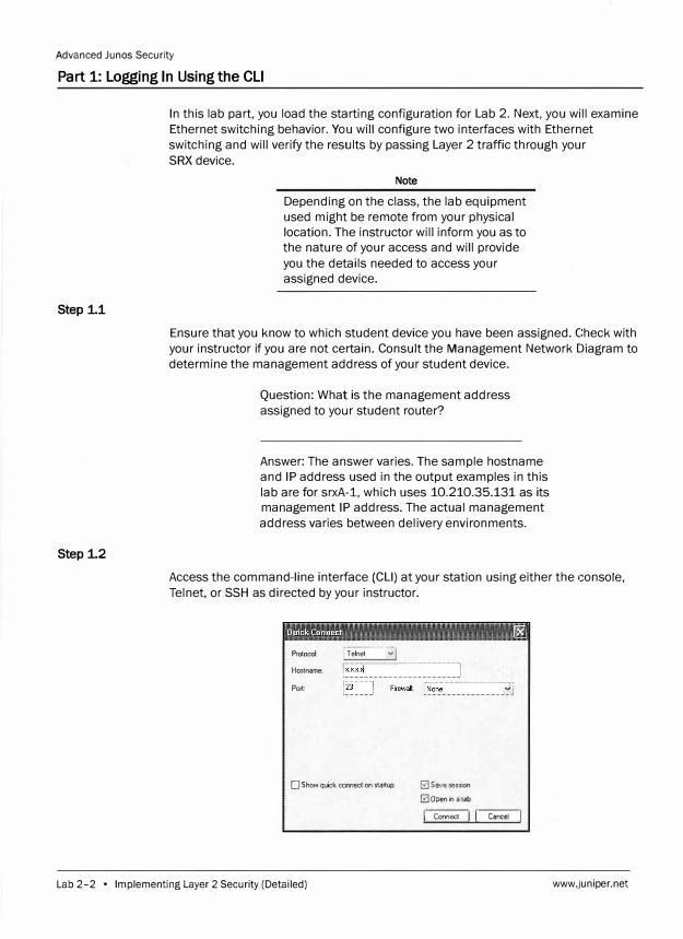
Access the command-line interface (CLI) at your station using either the console,
Telnet, or SSH as directed by your instructor.
Protocol: [ T ehet :::::··::::: v.j
Hostname:
Port:
O Show quick connect on startup 0 Save session
0 Open in a tab
I: Connecl ,J I Concel J
Lab 2-2 • Implementing Layer 2 Security (Detailed) www._juniper.net
Step 1.3
srxA-1 (ttyuO)
login: :tab
Password:
Advanced Junos Security
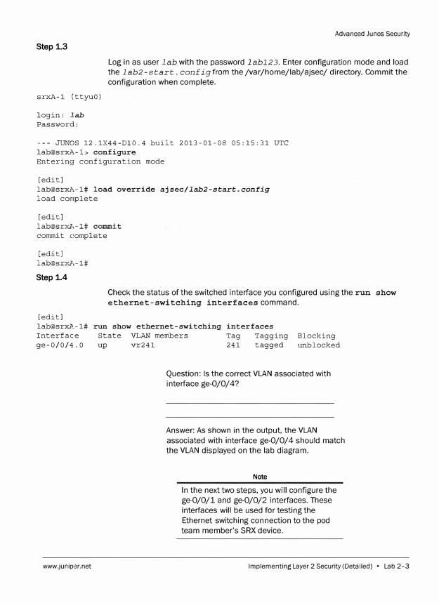
Log in as user lab with the password labl23. Enter configuration mode and load
the lab2-start. configfrom the /var/home/lab/ajsec/ directory. Commit the
configuration when complete.
--- JUNOS 12.1X44-Dl0.4 built 2013-01-08 05:15:31 UTC lab@srxA-1> configure Enterinsr configuration mode
[edit] lab@srxl,-1# load override ajsec/lab2-start.aonfig
load complete
[edit] lab@srxl\-1# coIIII!lit commit complete
[edit] lab@srxl\-1#
Step 1.4
Check the status of the switched interface you configured using the run show
ethernet-switching interfaces command.
[edit] lab@srxl'.-1# run show ethernet-switching interfaces Interface State VLAN members Tag Tagging Blocking
unblocked ge-0/0/4.0 up vr241 241 tagged
www.juniper.net
Question: Is the correct VLAN associated with
interface ge-0/0/4?
Answer: As shown in the output, the VLAN
associated with interface ge-0/0/4 should match
the VLAN displayed on the lab diagram.
Note
In the next two steps, you will configure the
ge-0/0/1 and ge-0/0/2 interfaces. These
interfaces will be used for testing the
Ethernet switching connection to the pod
team member's SRX device.
Implementing Layer 2 Security (Detailed) • Lab 2-3
Advanced Junos Security
Step i5
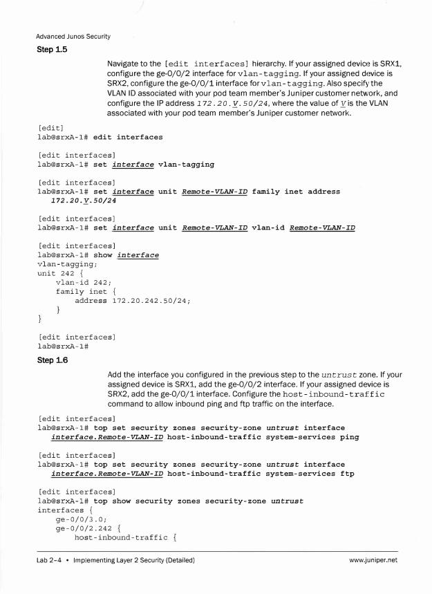
Navigate to the [edit interfaces] hierarchy. If your assigned device is SRX1,
configure the ge-0/0/2 interface for vlan-tagging. If your assigned device is
SRX2, configure the ge-0/0/1 interface for vlan-tagging. Also specify the
VLAN ID associated with your pod team member's Juniper customer network, and
configure the IP address 1 72. 20. _y. 50/24, where the value of _y is the VLAN
associated with your pod team member's Juniper customer network.
[edit] lab@srxA-1# edit interfaces
[edit interfaces] lab@srxA-1# set interface vlan-tagging
[edit interfaces] lab@srxA-1# set interface unit Remote-VLAN-ID family inet address
172. 20 .y. 50/24
[edit interfaces] lab@srxA-1# set interface unit Remote-VLAN-ID vlan-id Remote-VLAN-ID
[edit interfaces] lab@srxA-1# show interface
vlan-tagging; unit 242 {
vlan-id 242; family inet {
address 172.20.242.50/24;
[edit interfaces] lab@srxA-1#
Step 1.6
Add the interface you configured in the previous step to the untrus t zone. If your
assigned device is SRX1, add the ge-0/0/2 interface. If your assigned device is
SRX2, add the ge-0/0/1 interface. Configure the host-inbound-traffic
command to allow inbound ping and ftp traffic on the interface.
[edit interfaces] lab@srxA-1# top set security zones security-zone untrust interface
interface.Remote-VLAN-ID host-inbound-traffic system-services ping
[edit interfaces] lab@srxA-1# top set security zones security-zone untrust interface
interface.Remote-VLAN-ID host-inbound-traffic system-services ftp
[edit interfaces] lab@srxA-1# top show security zones security-zone untrust
interfaces { ge-0/0/3.0; ge-0/0/2.242
host-inbound-traffic
Lab 2-4 • Implementing Layer 2 Security (Detailed) www.juniper.net
Step 1.7
system-services ping; ftp;
Advanced Junos Security
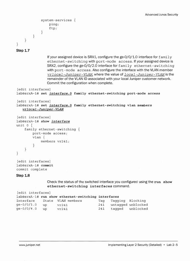
If your assigned device is SRX1, configure the ge-0/0/1.0 interface for family
ethernet-swi tching with port-mode access. If your assigned device is
SRX2, configure the ge-0/0/2.0 interface for family ethernet-switching
with port-mode access. Also configure the interface with the VLAN member vrlocal-Juniper-VLAN, where the value of local -Juniper-VLAN is the
remainder of the VLAN ID associated with your local Juniper customer network. Commit the configuration when complete.
[edit interfaces] lab@sr��-1# set interface.a family ethernet-switching port-mode access
[edit interfaces] lab@sr�-1# set interface.a family ethernet-switching vlan members
vrlocal -Juniper-VLAN
[edit interfaces] lab@srxi�-1# show interface
unit a { family ethernet-switching
port-mode access; vlan {
members vr241;
[edit interfaces] lab@srxl,-1# commit commit complete
Step 1.8
Check the status of the switched interface you configured using the run show ethernet-switching interfaces command.
[edit interfaces] lab@srxJ,-1# run show ethernet-switching Interface State VLAN members ge-0/0/1..0 up vr241 ge-0/0/4.0 up vr241
www.juniper.net
interfaces Tag Tagging Blocking 241 untagged unblocked 241 tagged unblocked
Implementing Layer 2 Security (Detailed) • Lab 2-5
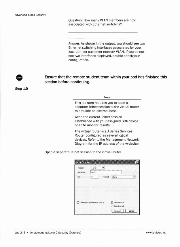
Advanced Junes Security
Step 1.9
Question: How many VLAN members are now
associated with Ethernet switching?
Answer: As shown in the output, you should see two
Ethernet switching interfaces associated for your
local Juniper customer network VLAN. If you do not
see two interfaces displayed, double-check your
configuration.
Ensure that the remote student team within your pod has finished this
section before continuing.
Note
This lab step requires you to open a
separate Telnet session to the virtual router
to emulate an external host.
Keep the current Telnet session
established with your assigned SRX device
open to monitor results.
The virtual router is a J Series Services
Router configured as several logical
devices. Refer to the Management Network
Diagram for the IP address of the vr-device.
Open a separate Telnet session to the virtual router.
Protocol:
Hostname:
Port e=:J Firewall [None ··----··--··- ·················,.,]
O Show quick connect on startup � Save session
� Open in a tab
Connect J I Cancel I
Lab 2-6 • Implementing Layer 2 Security (Detailed) www._juniper.net
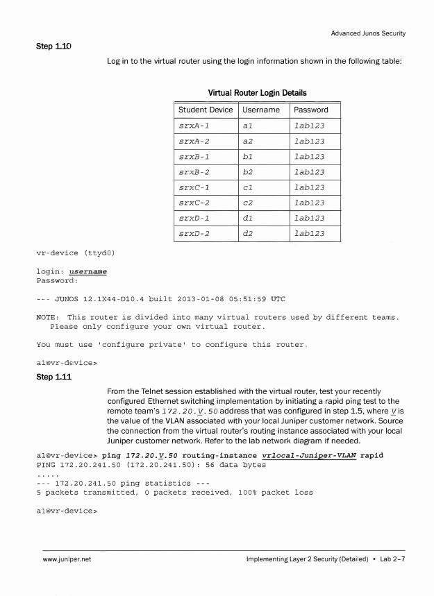
Advanced Junes Security
Step 1.10
Log in to the virtual router using the login information shown in the following table:
Virtual Router Login Details
Student Device Username Password
srxA-l al labl23
srxA-2 a2 labl23
srxB-l bl labl23
srxB-2 b2 labl23
srxC-1 cl labl23
srxC-2 c2 labl23
srxD-1 dl labl23
srxD-2 d2 labl23
vr-device (ttydO)
login: 11sername
Password:
--- JUNOS 12.1X44-Dl0.4 built 2013-01-08 05:51:59 UTC
NOTE: This router is divided into many virtual routers used by different teams.
Please only configure your own virtual router.
You must: use 'configure private' to configure this router.
al@vr-de,vice>
Step 1.11
From the Telnet session established with the virtual router, test your recently
configured Ethernet switching implementation by initiating a rapid ping test to the
remote team's I 72. 20. y. so address that was configured in step 1.5, where yis
the value of the VLAN associated with your local Juniper customer network. Source
the connection from the virtual router's routing instance associated with your local
Juniper customer network. Refer to the lab network diagram if needed.
al@vr-device> ping 172.20.�.50 routing-instance vrlocal-Juniper-VLAN rapid
PING 172.20.241.50 (172.20.241.50): 56 data bytes
--- 172.20.241.50 ping statistics ---
5 packets transmitted, O packets received, 100% packet loss
al@vr-device>
www.juniper.net Implementing Layer 2 Security (Detailed) • Lab 2-7
Advanced Junos Security
Step 1.12
Question: Was the ping test successful? Why or why
not?
Answer: As shown in the output, the ping test was
not successful, because an interface in access
port-mode does not allow an inbound VLAN-tagged
frame.
Return to the session established with your assigned SRX device.
From your assigned SRX device, change the port-mode on your untrust family
ethernet-switching interface from access to trunk. If your assigned device is
SRX1, modify the ge-0/0/1 interface. If your assigned device is SRX2, modify the
ge-0/0/2 interface. When finished, navigate to the top of the configuration hierarchy
and commit the configuration.
[edit interfaces]
lab@srxA-1# set interface.O family ethernet-switching port-mode trunk
[edit interfaces] lab@srxA-1# top
[edit]
lab@srxA-1# commit
commit complete
0 Ensure that the remote student team within your pod has finished this
section before continuing.
Step 1.13
Return to the Telnet session established with the virtual router.
From the Telnet session established with the virtual router, initiate the piing test
again.
al@vr-device> ping 172.20.y.so routing-instance vrlocal-Juniper-VLAN rapid
PING 172.20.241.50 (172.20.241.50): 56 data bytes
. ! ! ! !
--- 172.20.241.50 ping statistics ---
5 packets transmitted, 4 packets received, 20% packet loss
round-trip min/avg/max/stddev = 2.109/3.216/4.305/0.946 ms
Lab 2-8 • Implementing Layer 2 Security (Detailed) www.Jiuniper.net
Step 1.14
[edit]
Question: Was the ping test successful?
Answer: As shown in the output, the ping test
should be successful.
Note
You might see the first ping response time out due to the ARP entry being resolved.
Advanced Junos Security
Return to the session established with your assigned SRX device.
From your assigned SRX device, review the current VLAN member configuration for
Ethernet switching by issuing the command show vlans and answer the following
question.
lab@srxl,-1# show vlans vr241 {
vlan-id 241;
Step 1.15
[edit]
Question: Does the current VLAN member
configuration allow the Ethernet switching hosts to
route Layer 3 traffic through the SRX device?
Answer: The answer is no. The current vlan
configuration does not include a Layer 3 interface.
In this step, you will configure the vlan interface that will be used to route Layer 3
traffic for the Ethernet switching hosts. Issue the command set interfaces
vlan unitlocal-Juniper-VLAN family inet address
172. 20 .y.1/24, where yis the value of the VLAN associated with your local
Juniper customer network.
[email protected]# set interfaces vlan unit local-Juniper-VLAN family inet address 172. 2'0 .y.1/24
[edit] [email protected]# show interfaces vlan unit 241 {
family inet address 172.20.241.1/24;
www.juniper.net Implementing Layer 2 Security (Detailed) • Lab 2-9
Advanced Junos Security
Step 1.16
[edit]
Apply the v lan interface you created in the previous step as a Layer 3 interface with the command set vlans vr local-Juniper-VLAN 13-interface
vlan. local-Juniper-VLAN, where local-Juniper-VLANis the value of
the VLAN associated with your local Juniper customer network.
lab@srxA-1# set vlans vr local -Juniper-VLAN 13-interface vlan. local-Juniper-VLAN
Step 1.17
Add the interface you configured in the previous step to your local Juniper customer
network security zone. Configure the host-inbound-traffic command to
allow inbound ping on the interface. When finished commit the configuration.
[edit] lab@srxA-1# set security zones security-zone Juniper-local interface
vlan.local-Juniper-VLAN host-inbound-traffic system-services ping
lab@srxA-1# show security zones security-zone Juniper-local interfaces {
vlan.241 { host-inbound-traffic {
system-services { ping;
[edit] lab@srxA-1# commit commit complete
Step 1.18
Return to the Telnet session established with the virtual router.
From the Telnet session established with the virtual router, initiate a rapid ping test
to the Internet host address 172.31.15.1. Source the connection from the virtual
router's routing instance associated with your local Juniper customer network. Refer
to the lab network diagram if needed.
al@vr-device> ping 172.31.15.1 routing-instance vrlocal-Juniper-VLAN rapid PING 172.31.15.1 (172.31.15.1): 56 data bytes ! ! ! ! !
--- 172.31.15.1 ping statistics 5 packets transmitted, 5 packets received, 0% packet loss round-trip min/avg/max/stddev = 2.650/3.769/4.795/0.901 ms
al@vr-device>
Lab 2-10 • Implementing Layer 2 Security (Detailed) www.juniper.net
0
Question: Were your pings to the Internet host
successful?
Advanced Ju nos Security
Answer: As shown in the output, your pings should
be successful to the Internet host. If the pings
failed, double-check your configuration and notify
your instructor.
Do not proceed to the next lab part until directed by the instructor to do
so.
Part 2: Configuring Transparent Mode
Step 2.1
[edit]
In this lab part, you become familiar with transparent mode operations. The rest of
the lab steps for this part will be performed on SRX1. You will remove any
unnecessary configuration from your assigned SRX device, and configure the ge-0/
0/1 and ge-0/0/4 interfaces to pass Layer 2 traffic in transparent mode. You will
also configure transparent mode device management.
Note
Perform the rest of this lab part only on the
SRX1 device. Both teams should be
working only from SRX1!
Note
In the following steps you will lose access to
the SRX1 device through the management
interface. You must access the SRX1
device through the console port.
Delete the [edit security] and [edit routing-options] configuration
hierarchies.
lab@srxA-1# delete security
[edit]
lab@srxA-1# delete routing-options
Step 2.2
www.juniper.net
Delete the [edit firewall] and [edit vlans] configuration hierarchies.
Then, delete all of the interfaces.
Implementing Layer 2 Security (Detailed) • Lab 2-11
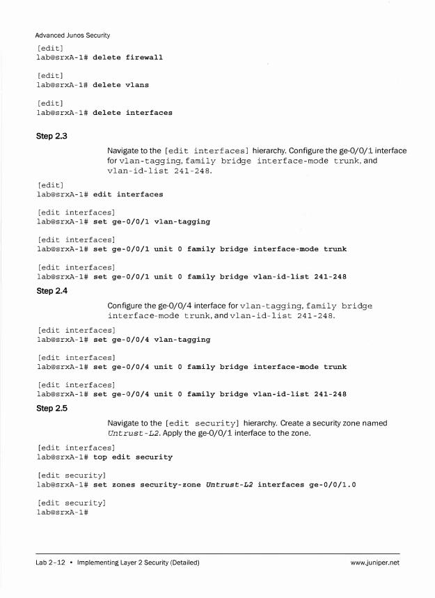
Advanced Junos Security
[edit] lab@srxA-1# delete firewall
[edit] lab@srxA-1# delete vlans
[edit] lab@srxA-1# delete interfaces
Step 2.3
Navigate to the [edit interfaces) hierarchy. Configure the ge-0/0/:L interface
forvlan-tagging,family bridge interface-mode trunk,and
vlan-id-list 241-248.
[edit] lab@srxA-1# edit interfaces
[edit interfaces] lab@srxA-1# set ge-0/0/1 vlan-tagging
[edit interfaces] lab@srxA-1# set ge-0/0/1 unit O family bridge interface-mode trunk
[edit interfaces] lab@srxA-1# set ge-0/0/1 unit O family bridge vlan-id-list 241-248
Step2.4
Configure the ge-0/0/4 interface for vlan-tagging, family bridge
interface-mode trunk, and vlan-id-list 241-248.
[edit interfaces] lab@srxA-1# set ge-0/0/4 vlan-tagging
[edit interfaces] lab@srxA-1# set ge-0/0/4 unit O family bridge interface-mode trunk
[edit interfaces] lab@srxA-1# set ge-0/0/4 unit O family bridge vlan-id-list 241-248
Step 2.5
Navigate to the [edit security) hierarchy. Create a security zone named
Untrust-L2. Apply the ge-0/0/1 interface to the zone.
[edit interfaces] lab@srxA-1# top edit security
[edit security] lab@srxA-1# set zones security-zone Untrust-L2 interfaces ge-0/0/1.0
[edit security] lab@srxA-1#
Lab 2-12 • Implementing Layer 2 Security (Detailed) www.juniper.net
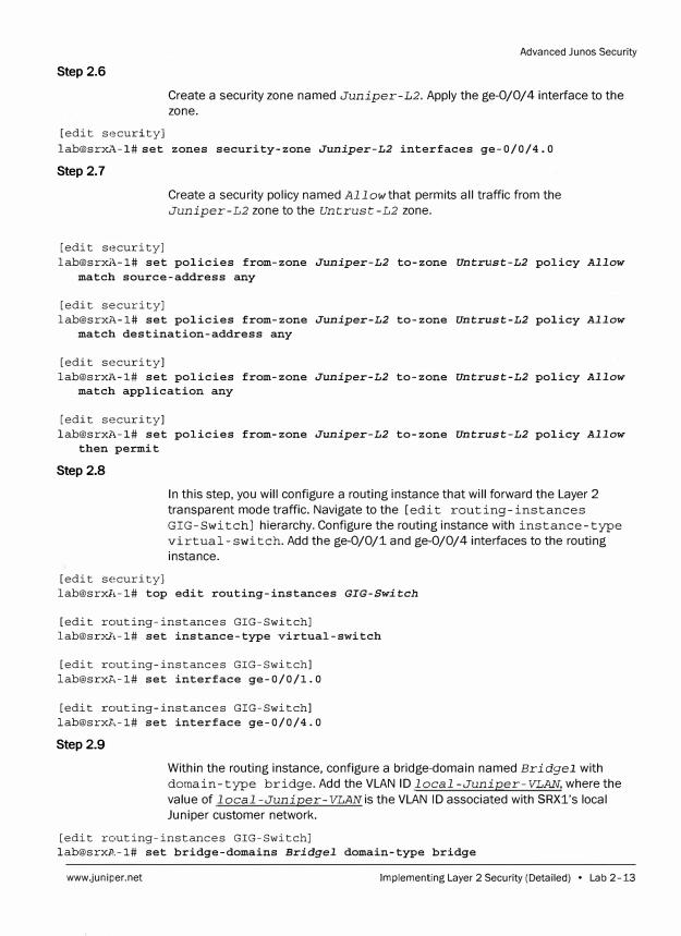
Step 2.6
[edit security]
Advanced Junos Security
Create a security zone named Juniper-L2. Apply the ge-0/0/4 interface to the
zone.
lab@srxA-l#set zones security-zone Juniper-L2 interfaces ge-0/0/4.0
Step 2.7
[edit security]
Create a security policy named Allow that permits all traffic from the
Juniper-L2 zone to the Untrust-L2 zone.
lab@srxA-1# set policies from-zone Juniper-L2 to-zone Untrust-L2 policy Allow
match source-address any
[edit security]
lab@srxl,-1# set policies from-zone Juniper-L2 to-zone Untrust-L2 policy Allow match destination-address any
[edit security]
lab@srxl,-1# set policies from-zone Juniper-L2 to-zone Untrust-L2 policy Allow match application any
[edit security]
lab@srxl,-1# set policies from-zone Juniper-L2 to-zone Untrust-L2 policy Allow then permit
Step 2.8
[edit security]
In this step, you will configure a routing instance that will forward the Layer 2
transparent mode traffic. Navigate to the [edit routing-instances
GIG-Switch] hierarchy. Configure the routing instance with instance-type
virtual-switch. Add the ge-0/0/1 and ge-0/0/4 interfaces to the routing
instance.
lab@srxll-1# top edit routing-instances GIG-Switch
[edit routing-instances GIG-Switch]
lab@srxl\-1# set instance-type virtual-switch
[edit routing-instances GIG-Switch]
lab@srxP,-1# set interface ge-0/0/1. 0
[edit routing-instances GIG-Switch]
lab@srxP,-1# set interface ge-0/0/4.0
Step2.9
Within the routing instance, configure a bridge-domain named Bridgel with
domain-type bridge. Add the VLAN ID local-Juniper-VLAN, where the
value of local -Juniper-VLAN is the VLAN ID associated with SRXl's local
Juniper customer network.
[edit routing-instances GIG-Switch]
lab@srxl'.-1# set bridge-domains Bridgel domain-type bridge
www.juniper.net Implementing Layer 2 Security (Detailed) • Lab 2-13
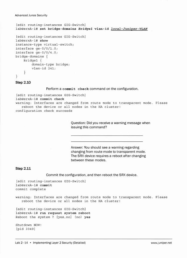
Advanced Junos Security
[edit routing-instances GIG-Switch] lab@srxA-1# set bridge-domains Bridgel vlan-id local-Juniper-VLAN
[edit routing-instances GIG-Switch] lab@srxA-1# show instance-type virtual-switch; interface ge-0/0/1.0; interface ge-0/0/4.0; bridge-domains {
Bridge! {
Step2.10
domain-type bridge; vlan-id 241;
Perform a commit check command on the configuration.
[edit routing-instances GIG-Switch] lab@srxA-1# commit check warning: Interfaces are changed from route mode to transparent mode. Please
reboot the device or all nodes in the HA cluster! configuration check succeeds
Step2.11
Question: Did you receive a warning message when
issuing this command?
Answer: You should see a warning regarding
changing from route mode to transparent mode.
The SRX device requires a reboot after changing
between these modes.
Commit the configuration, and then reboot the SRX device.
[edit routing-instances GIG-Switch] lab@srxA-1# commit commit complete
warning: Interfaces are changed from route mode to transparent mode. Pl.ease reboot the device or all nodes in the HA cluster!
[edit routing-instances GIG-Switch] lab@srxA-1# run request system reboot Reboot the system? [yes,no] (no) yes
Shutdown NOW! [pid 3049]
Lab 2-14 • Implementing Layer 2 Security (Detailed) www.juniper.net
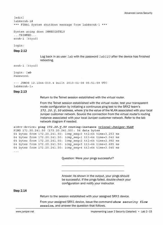
[edit] [email protected]#
Advanced Junos Security
*** FINAL System shutdown message from [email protected] ***
System �;oing down IMMEDIATELY ... TRIMMED ... srxl\.-1 [ttyuO)
login:
Step 2.12
srxll.-1 (ttyuO)
login: 2ab
Password:
Log back in as user lab with the password labl23 after the device has finished · rebooting.
--- JUNOS 12.1X44-Dl0.4 built 2013-01-08 05:51:59 UTC [email protected]>
Step2.13
Return to the Telnet session established with the virtual router.
From the Telnet session established with the virtual router, test your transparent mode configuration by initiating a continuous ping test to the SRX2 team's 172. 20 .y. 50 address, where yis the value of the VLAN associated with your local
Juniper customer network. Source the connection from the virtual router's routinginstance associated with your local Juniper customer network. Refer to the labnetwork diagram if needed.
al@vr-device> ping 172.20.y.so routing-instance vrlocal-Juniper-VLAN
PING 17:;:.20.241.50 (172.20.241.50): 56 data bytes 64 byteE: from 172. 20. 241. 50: icmp_seq=O ttl=64 time=3. 253 ms 64 byteE: from 172.20.241.50: icmp_seq=l ttl=64 time=3.042 ms 64 byteE: from 172.20.241.50: icmp_seq=2 ttl=64 time=2.992 ms 64 bytes from 172.20.241.50: icmp_seq=3 ttl=64 time=2.685 ms 64 bytes from 172.20.241.50: icmp_seq=4 ttl=64 time=3.045 ms
Step 2.14
www.juniper.net
Question: Were your pings successful?
Answer: As shown in the output, your pings should be successful. If the pings failed, double-check your
configuration and notify your instructor.
Return to the session established with your assigned SRX1 device.
From your assigned SRX1 device, issue the command show security flow
session, and answer the question that follows.
Implementing Layer 2 Security (Detailed) • Lab 2-15
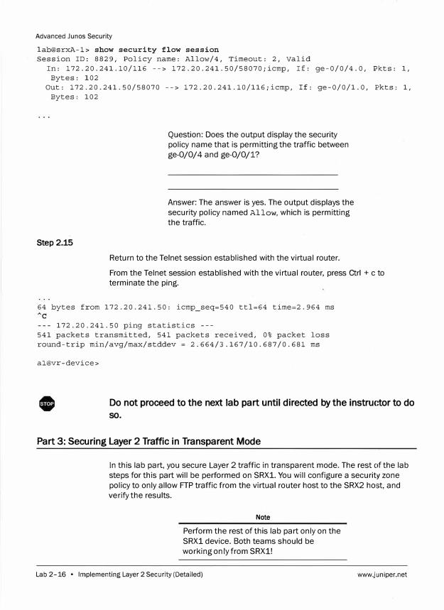
Advanced Junes Security
lab@srxA-1> show security flow session
Session ID: 8829, Policy name: Allow/4, Timeout: 2, Valid
In: 172.20.241.10/116 --> 172.20.241.50/58070;icmp, If: ge-0/0/4.0, Pkts: 1,
Bytes: 102
Out: 172.20.241.50/58070 --> 172.20.241.10/116;icmp, If: ge-0/0/1.0, Pkts: 1,
Bytes: 102
Step 2.15
Question: Does the output display the security
policy name that is permitting the traffic between
ge-0/0/4 and ge-0/0/1?
Answer: The answer is yes. The output displays the
security policy named Allow, which is permitting
the traffic.
Return to the Telnet session established with the virtual router.
From the Telnet session established with the virtual router, press Ctrl + c to
terminate the ping.
64 bytes from 172.20.241.50: icmp_seq=540 ttl=64 time=2.964 ms
--- 172.20.241.50 ping statistics ---
541 packets transmitted, 541 packets received, 0% packet loss
round-trip min/avg/max/stddev = 2.664/3.167/10.687/0.681 ms
al@vr-device>
Do not proceed to the next lab part until directed by the instructor to do
so.
Part 3: Securing Layer 2 Traffic in Transparent Mode
In this lab part, you secure Layer 2 traffic in transparent mode. The rest of the lab
steps for this part will be performed on SRX1. You will configure a security zone
policy to only allow FTP traffic from the virtual router host to the SRX2 host, and
verify the results.
Note
Perform the rest of this lab part only on the
SRX1 device. Both teams should be
working only from SRX1!
Lab 2-16 • Implementing Layer 2 Security (Detailed) www.juniper.net
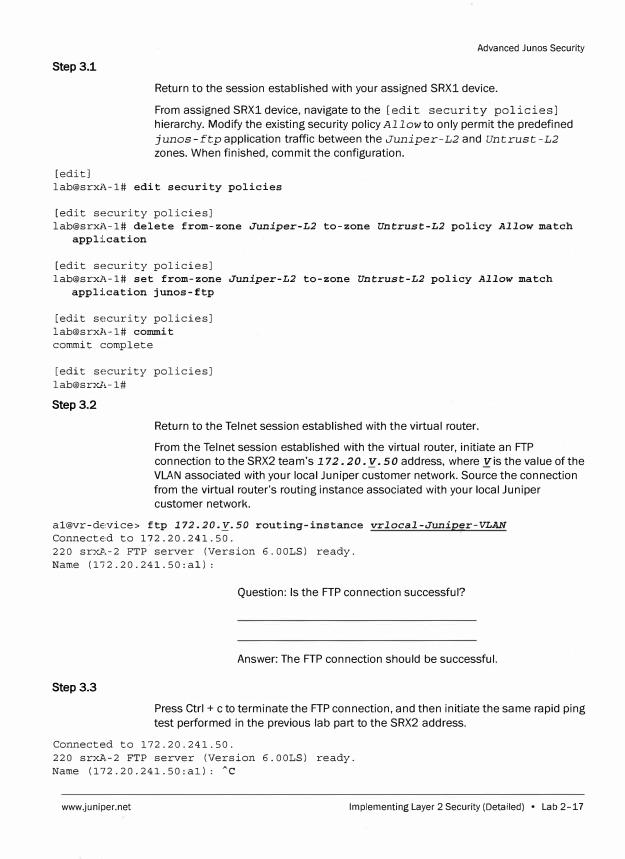
Step 3.1
[edit]
Advanced Junos Security
Return to the session established with your assigned SRX1 device.
From assigned SRX1 device, navigate to the [edit security policies]
hierarchy. Modify the existing security policy Allow to only permit the predefined
junos-ftp application traffic between the Juniper-L2 and Untrust-L2
zones. When finished, commit the configuration.
lab@srxA-1# edit security policies
[edit security policies] lab@srxA-1# delete from-zone Juniper-L2 to-zone Untrust-L2 policy Allow match
application
[edit security policies] lab@srxA-1# set from-zone Juniper-L2 to-zone Untrust-L2 policy Allow match
application junos-ftp
[edit security policies]
lab@srxA-1# commit
commit complete
[edit security policies]
lab@srxl,-1#
Step 3.2
Return to the Telnet session established with the virtual router.
From the Telnet session established with the virtual router, initiate an FTP
connection to the SRX2 team's l 72. 20 .y. 50 address, where yis the value of the
VLAN associated with your local Juniper customer network. Source the connection
from the virtual router's routing instance associated with your local Juniper
customer network.
al@vr-device> ftp 172.20.y.so routing-instance vrlocal-Junip�r-VLAN
Connected to 172.20.241.50.
220 srxl'.,-2 FTP server (Version 6. OOLS) ready.
Name (172.20.241.50:al):
Step3.3
Question: Is the FTP connection successful?
Answer: The FTP connection should be successful.
Press Ctrl + c to terminate the FTP connection, and then initiate the same rapid ping
test performed in the previous lab part to the SRX2 address.
Connected to 172.20.241.50.
220 srxA-2 FTP server (Version 6.00LS) ready.
Name (172.20.241.50:al): Ac
www.juniper.net Implementing Layer 2 Security (Detailed) • Lab 2-17
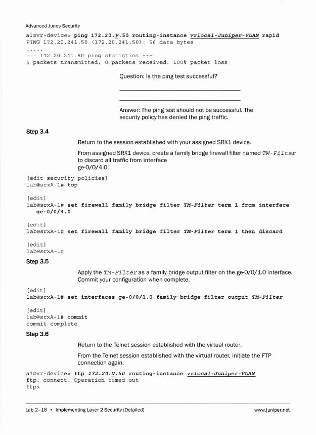
Advanced Junos Security
al@vr-device> ping 172.20.y.so routing-instance vrlocal-Juniper-VLAN rapid
PING 172.20.241.50 (172.20.241.50): 56 data bytes
--- 172.20.241.50 ping statistics ---
5 packets transmitted, 0 packets received, 100% packet loss
Step 3.4
Question: Is the ping test successful?
Answer: The ping test should not be successful. The
security policy has denied the ping traffic.
Return to the session established with your assigned SRX1 device.
From assigned SRX1 device, create a family bridge firewall filter named TM-Filter
to discard all traffic from interface
ge-0/0/4.0.
[edit security policies]
lab@srxA-1# top
[edit]
lab@srxA-1# set firewall family bridge filter TM-Filter term 1 from interface
ge-0/0/4.0
[edit] lab@srxA-1# set firewall family bridge filter TM-Filter term 1 then discard
[edit]
lab@srxA-1#
Step 3.5
[edit]
Apply the TM-Filter as a family bridge output filter on the ge-0/0/1.0 interface.
Commit your configuration when complete.
lab@srxA-1# set interfaces ge-0/0/1.0 family bridge filter output TM-Filter
[edit] lab@srxA-1# commit
commit complete
Step 3.6
Return to the Telnet session established with the virtual router.
From the Telnet session established with the virtual router, initiate the FTP
connection again.
al@vr-device> ftp 172.20.y.so routing-instance vrlocal-Juniper-VLAN
ftp: connect: Operation timed out
ftp>
Lab 2-18 • Implementing Layer 2 Security (Detailed) www.juniper.net
Step 3.7
Advanced Ju nos Security
Question: Is the FTP connection successful?
Answer: The answer should be no. The FTP
connection should not be successful. The traffic
has been blocked by the firewall filter.
Type bye to exit the FTP connection. Then, exit the open Telnet session on the
virtual router.
ftp> byE!
al@vr-device> exit
vr-devic:e (ttydO)
login:
Step 3.8
Return to the session established with your assigned SRX1 device.
From your assigned SRX1 device, log out using the exit command.
[edit]
[email protected]# exit
Exiting configuration mode
lab@srxA,-1> exit
srxA-1 (ttyuO)
login:
0 Tell your instructor that you have completed this lab.
www.juniper.net Implementing Layer 2 Security (Detailed) • Lab 2-19
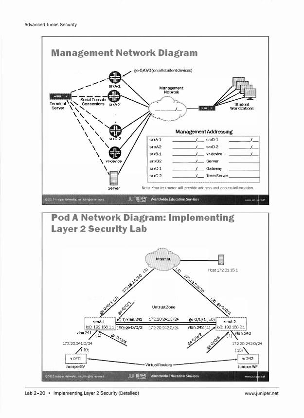
Advanced Junes Security
Management Network Diagram
ge-0/0/0(on all studentdevices)
Management Addressing
srxA-1 srxD-1 I
srxA-2 I srxD-2
srxB-1 vr-device
I srxB-2 Server
srxG-1 Gateway
I srxC-2 Term Server
'[i] Server Note: Your instructor will provide address and access information.
e,.2013Jun1pe:rNetworo, Int Altrtbh teH:rved JUn�J Worldwide EducatmnServices WWN ,un1p -- I
Pod A Network Diagram: Implementing
Layer 2 Security Lab
UntrustZone
Host 172.31.15.1
rl)
vlan.242
172.20.242.0/24 (.10)
�-------vr242
] -Ju-n-iper--':y/- Virtual Routers _
__________ ... !Juniper-WF
... _�o:�J��P�t N�two�°= !n�Allnr1� , ... u)r�lj _}Unff?�.[ Worldwide Education Services WHn JUrll
Lab 2-20 • Implementing Layer 2 Security (Detailed) www.juniper.net
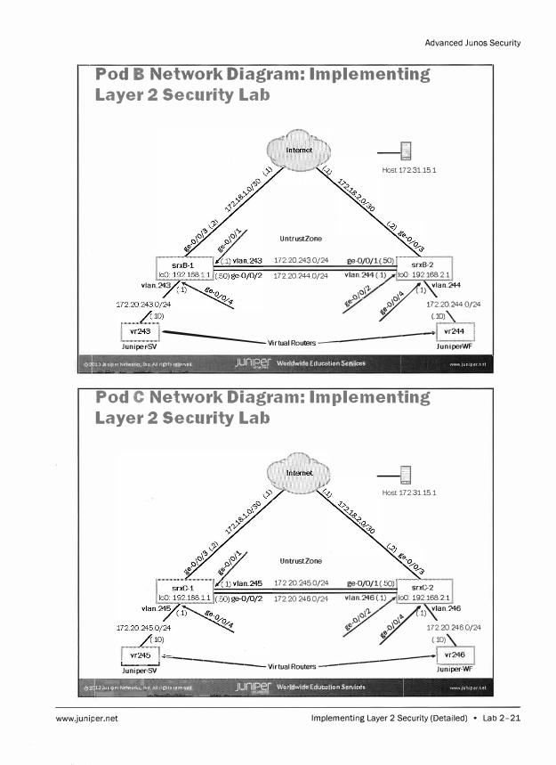
Advanced Junos Security
Pod B Network Diagram: Implementing
Layer 2 Security Lab
UntrustZone
172.20 243.Q/24
17220244 0/24 vlan.243
:---� Host 172.3115.1
ge-0/0/1(.50) srxB-2 vlan.244(.1) loO: 192.168.2.1
of'\'), rl) vlan.244
�e; 172.20.244.0/24 (10)\.
---- �-----1 vr244 IJunipe r -SY Virtual Routers Juniper-WF
13J\ltllperNetw;lin� Inc All rlghhr�,eNl!'(I Junm Worldwide Education Services I V>JWW JIJfllper n�, �---�--�- -�
Pod C Network Diagram: Implementing
Layer 2 Security Lab
,--fil Host 172.31.15.1
UntrustZone
172.20 245.0/24 ge-0/0/1(.50) srxC-2 172 20 246.0/24 vlan.246 (.1) loO 192.168.2.1
olcl'J.
rl) vlan.246
�0- 172.20246.Q/24
(10)
'"Ju
-n
-ipe-r -
SV__, -----------Virtual Routers ------------1Juniper-WF �.,Tugf¥1"' '?A!'\ �""·""'� �r� =" -1lJu1upt1 Nttworla, !flt" All ilghh te",t!Wd JUn1Per Worldwide EducaUonSen:ices \'ll'l'IW ,unipern�t �-�-"---- ----- -- - �
www.juniper.net Implementing Layer 2 Security (Detailed) • Lab 2-21
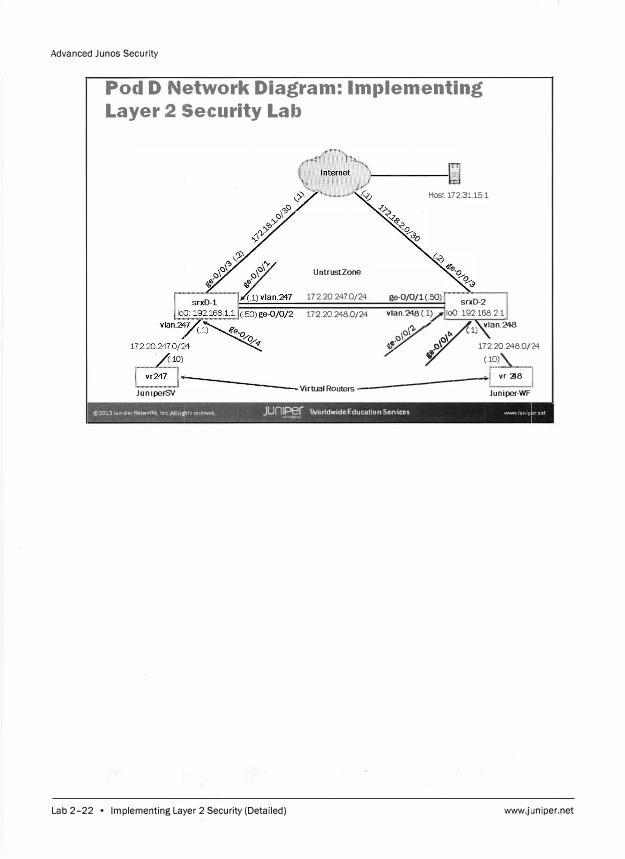
Advanced Junes Security
Pod D Network Diagram: Implementing
Layer 2 Security Lab
UntrustZone
172 20.2470/24
172.20 248 0/24
Host 172.31.15.1
ge-0/0/1(.50) srxD-2 vlan.248 (.1) lo() 192.168.2.1
cl'). r
(.1) vlan.248
e.cl
\c\
� J:) 172.20.248.0/24 � (.10)
Juniper-SV �����������l,--v"",2"-48�,
Virtual Routers Juniper-WF
<02013JUnlperNetwO,fks Inc All rt�H reserved Juniper Worldwide Education Services WWI'! JUn1p , ' """""°"�f,
Lab 2-22 • Implementing Layer 2 Security (Detailed) www.juniper.net
Overvi1ew
Lab
Implementing Ju nos Virtual Routing (Detailed)
In this lab, you will configure two virtual routing instances. You will then configure the
virtual routers (VRs) to communicate with the Internet host, and then to communicate
with each other. You will then configure filter-based forwarding to direct traffic over the
ge-0/0/1 interface.
The lab is available in two formats: a high-level format designed to make you think through
each step and a detailed format that offers step-by-step instructions complete with
sample output from most commands.
By completing this lab, you will perform the following tasks:
Configure Internet access for the VRs.
Configure inter-VR communication.
Configure filter-based forwarding.
www.juniper.net Implementing Junos Virtual Routing (Detailed) • Lab 3-1
Advanced Junos Security
Part 1: Configuring Internet Access
Step 1.1
Step 1.2
In this lab part, you will become familiar with the access details used to access the
lab equipment. Once you are familiar with the access details, you will use the CLI to
log in to your designated station. Then, you will load the starting configuration for
lab 3. Then, you will configure two VRs-Juniper and ACME. You will then configure
Internet access for these VRs.
Note
Depending on the class, the lab equipment
used might be remote from your physical
location. The instructor will inform you as to
the nature of your access and will provide
you the details needed to access your
assigned device.
Ensure that you know to which student device you have been assigned. Check with
your instructor if you are not certain. Consult the Management Network Diagram to
determine the management address of your student device.
Question: What is the management address
assigned to your station?
Answer: The answer varies. In this example, the
user is assigned to the srxA-1 station, which uses
an IP address of 10.210.14.131.
Access the CLI at your station using either the console, Telnet, or SSH as directed by
your instructor. Refer to the Management Network Diagram for the IP address
associated with your workstation. The following example is based on simple Telnet
access using the Secure CRT program.
Lab 3-2 • Implementing Ju nos Virtual Routing (Detailed) www.juniper.net
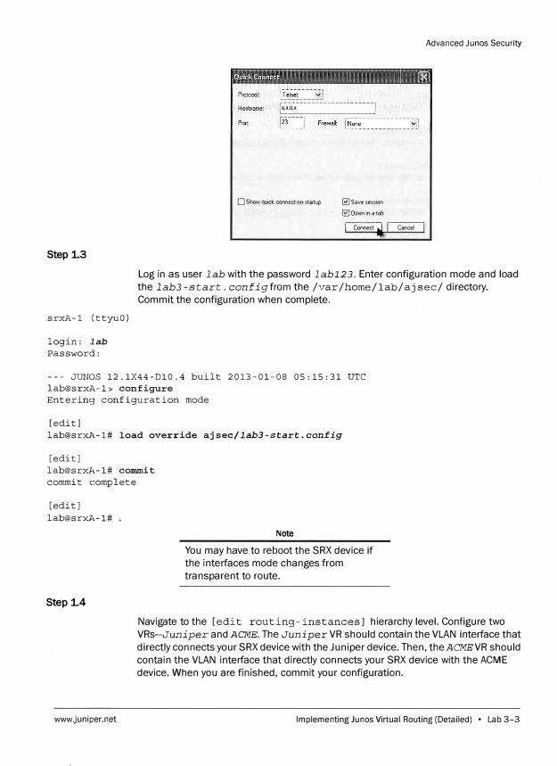
Step 1.3
srxA-1 (ttyuO)
login: Iab
Password:
D Show quick connect on startup � Save session
0 Open in a tab
J, Connect ' I Cancel I
Advanced Junes Security
Log in as user lab with the password labl2 3. Enter configuration mode and load
the lab3-start. configfrom the /var /home/lab/aj sec/ directory.
Commit the configuration when complete.
--- JUNOS 12.1X44-Dl0.4 built 2013-01-08 05:15:31 UTC
lab@srxA-1> configure
Enterin9 configuration mode
[edit]
lab@srxl,-1# load override ajsec/lab3-start.con£ig
[edit]
lab@srxl,-1# commit
commit complete
[edit]
lab@srxA-1#
Step 1.4
www.juniper.net
Note
You may have to reboot the SRX device if
the interfaces mode changes from
transparent to route.
Navigate to the [edit routing- instances J hierarchy level. Configure two
VRs-Juniper and ACME. The Juniper VR should contain the VLAN interface that
directly connects your SRX device with the Juniper device. Then, the ACMEVR should
contain the VLAN interface that directly connects your SRX device with the ACME
device. When you are finished, commit your configuration.
Implementing Ju nos Virtual Routing (Detailed) • Lab 3-3
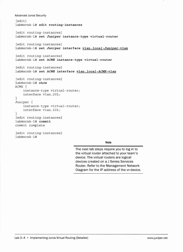
Advanced Junos Security
[edit] lab@srxA-1# edit routing-instances
[edit routing-instances] lab@srxA-1# set Juniper instance-type virtual-router
[edit routing-instances] lab@srxA-1# set Juniper interface vlan.local-Juniper-vlan
[edit routing-instances] lab@srxA-1# set ACME instance-type virtual-router
[edit routing-instances] lab@srxA-1# set ACME interface vlan.local-ACME-vlan
[edit routing-instances] lab@srxA-1# show ACME {
instance-type virtual-router; interface vlan.201;
} Juniper {
instance-type virtual-router; interface vlan.101;
[edit routing-instances] lab@srxA-1# commit commit complete
[edit routing-instances] lab@srxA-1#
Note
The next lab steps require you to log in to
the virtual router attached to your team's
device. The virtual routers are logical
devices created on a J Series Services
Router. Refer to the Management Network
Diagram for the IP address of the vr-device.
Lab 3-4 • Implementing Ju nos Virtual Routing (Detailed) www.juniper.net
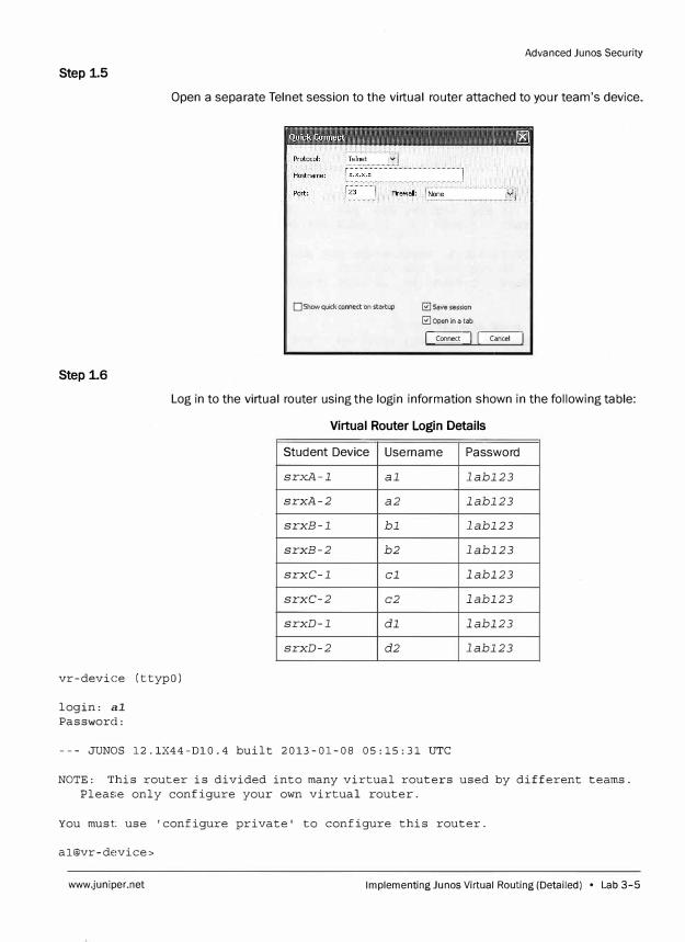
Advanced Junos Security
Step 1.5
Open a separate Telnet session to the virtual router attached to your team's device.
D Show quick connect on startup
Step 1.6
0 Save session
0 Open in a tab
L Connect J [ Cancel I
Log in to the virtual router using the login information shown in the following table:
vr-device (ttypO)
login: al
Password:
Virtual Router Login Details
Student Device Username Password
srxA-1 al labl23
srxA-2 a2 labl23
srxB-1 bl labl23
srxB-2 b2 labl23
srxC-1 cl labl23
srxC-2 c2 labl23
srxD-1 dl labl23
srxD-2 d2 labl23
--- JUNOS 12.1X44-Dl0.4 built 2013-01-08 05:15:31 UTC
NOTE: This router is divided into many virtual routers used by different teams.
Please only configure your own virtual router.
You must use 'configure private' to configure this router.
al@vr-de�vice>
www.juniper.net Implementing Ju nos Virtual Routing (Detailed) • Lab 3-5
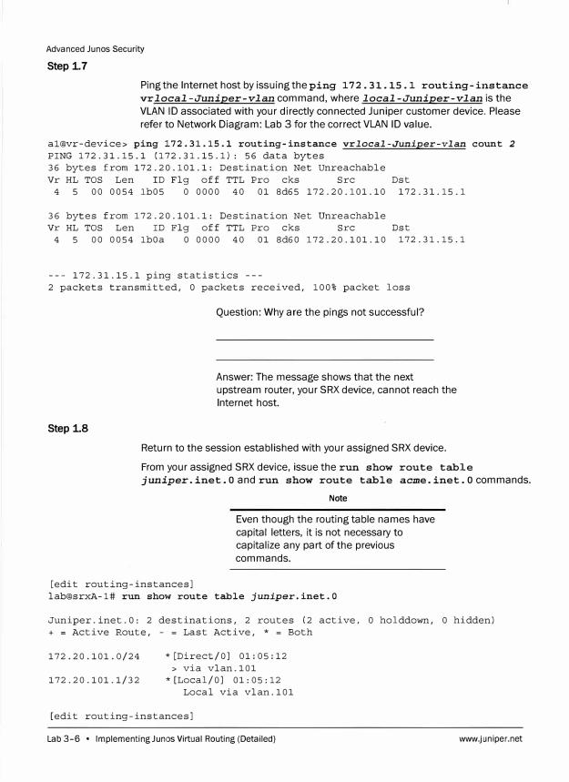
Advanced Junos Security
Step 1.7
Ping the Internet host by issuing the ping 172. 31.15 .1 routing-instance
vr local-Juniper-vlan command, where local-Juniper-vlan is the
VLAN ID associated with your directly connected Juniper customer device .. Please
refer to Network Diagram: Lab 3 for the correct VLAN ID value.
al@vr-device> ping 172.31.15.1 routing-instance vrlocal-Juniper-vlan count 2
PING 172.31.15.1 (172.31.15.1): 56 data bytes
36 bytes from 172.20.101.1: Destination Net Unreachable
Vr HL TOS Len ID Flg off TTL Pro cks Src Dst
4 5 00 0054 lb05 0 0000 40 01 8d65 172.20.101.10 172.31.15.1
36 bytes from 172.20.101.1: Destination Net Unreachable
Vr HL TOS Len ID Flg off TTL Pro cks Src
4 5 00 0054 lbOa O 0000 40 01 8d60 172.20.101.10
Dst
172.31.15.1
--- 172.31.15.1 ping statistics ---
2 packets transmitted, O packets received, 100% packet loss
Step 1.8
Question: Why are the pings not successful?
Answer: The message shows that the next
upstream router, your SRX device, cannot reach the
Internet host.
Return to the session established with your assigned SRX device.
From your assigned SRX device, issue the run show route table
juniper. inet. 0 and run show route table acme. inet. 0 commands.
[edit routing-instances]
Note
Even though the routing table names have
capital letters, it is not necessary to
capitalize any part of the previous
commands.
lab@srxA-1# run show route table juniper.inet.O
Juniper.inet.O: 2 destinations, 2 routes (2 active, 0 holddown, 0 hidden)
+ = Active Route, - = Last Active, * = Both
172.20.101.0/24 *[Direct/OJ 01:05:12
> via vlan.101
172.20.101.1/32 *[Local/OJ 01:05:12
Local via vlan.101
[edit routing-instances]
Lab 3-6 • Implementing Ju nos Virtual Routing (Detailed) www.juniper.net
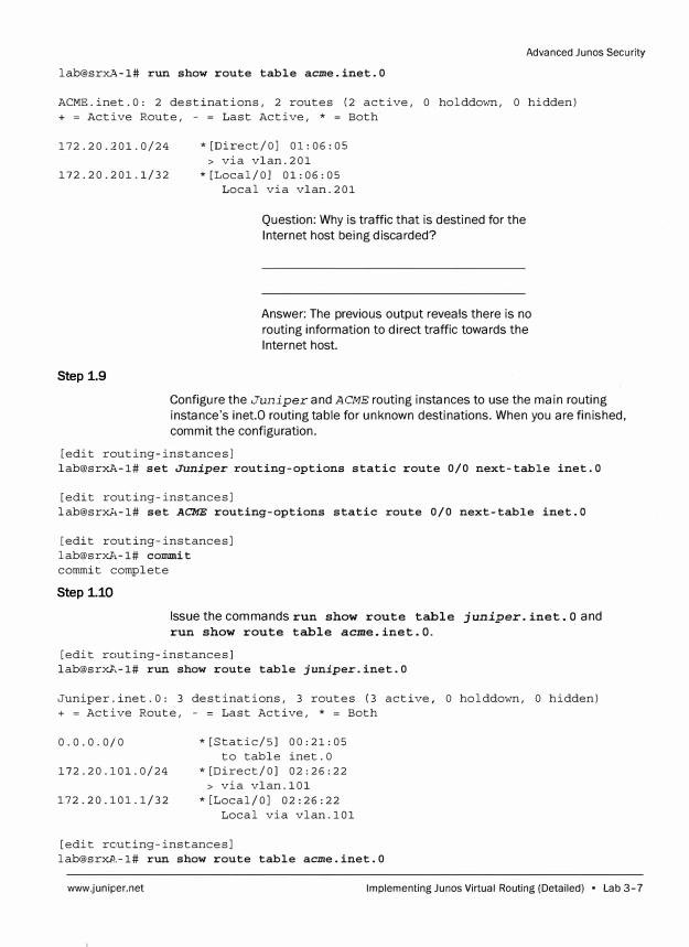
Advanced Junes Security
lab@srxA-1# run show route table acme.inet.0
ACME.inet.O: 2 destinations, 2 routes (2 active, O holddown, 0 hidden) + = Active Route, - = Last Active, * = Both
172.20.201.0/24 *[Direct/OJ 01:06:05 > via vlan.201
172.20.201.1/32 *[Local/OJ 01:06:05 Local via vlan.201
Question: Why is traffic that is destined for the
Internet host being discarded?
Answer: The previous output reveals there is no
routing information to direct traffic towards the
Internet host.
Step 1.9
Configure the Juniper and ACME routing instances to use the main routing
instance's inet.0 routing table for unknown destinations. When you are finished,
commit the configuration.
[edit routing-instances] lab@srxA-1# set Juniper routing-options static route 0/0 next-table inet.O
[edit routing-instances] [email protected],-1# set ACME routing-options static route 0/0 next-table inet.O
[edit routing-instances] lab@srxA-1# commit commit complete
Step 1.10
Issue the commands run show route table juniper. inet. O and
run show route table acme.inet.O.
[edit routing-instances] lab@srxA-1# run show route table juniper.inet.0
Juniper.inet.O: 3 destinations, 3 routes (3 active, O holddown, O hidden) + = Active Route, - = Last Active, * = Both
0.0.0.0/0 *[Static/SJ 00:21:05 to table inet.O
172.20.101.0/24 *[Direct/OJ 02:26:22 > via vlan.101
172.20.101.1/32 *[Local/OJ 02:26:22 Local via vlan.101
[edit routing-instances] [email protected]# run show route table acme.inet.0
www.juniper.net Implementing Junes Virtual Routing (Detailed) • Lab 3-7
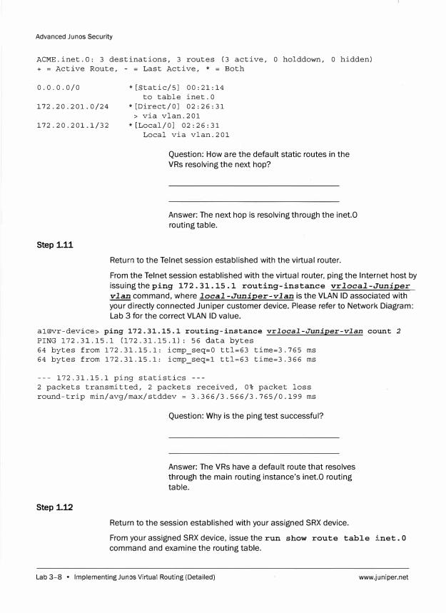
Advanced Junos Security
ACME.inet.O: 3 destinations, 3 routes (3 active, O holddown, O hidden) + = Active Route, - = Last Active, * = Both
0.0.0.0/0 *[Static/SJ 00:21:14 to table inet.O
172.20.201.0/24 *[Direct/OJ 02:26:31 > via vlan.201
172.20.201.1/32 *[Local/OJ 02:26:31
Step 1.11
Local via vlan.201
Question: How are the default static routes in the
VRs resolving the next hop?
Answer: The next hop is resolving through the inet.O
routing table.
Return to the Telnet session established with the virtual router.
From the Telnet session established with the virtual router, ping the Internet host by
issuing theping 172.31.15.1 routing-instance vrlocal-Juniper
vlan command, where local -Juniper-vlan is the VLAN ID associated with
your directly connected Juniper customer device. Please refer to Network Diagram:
Lab 3 for the correct VLAN ID value.
al@vr-device> ping 172.31.15.1 routing-instance vrlocal-Juniper-vlan count 2
PING 172.31.15.1 (172.31.15.1): 56 data bytes 64 bytes from 172.31.15.1: icmp_seq=O ttl=63 time=3.765 ms 64 bytes from 172.31.15.1: icmp_seq=l ttl=63 time=3.366 ms
--- 172.31.15.1 ping statistics ---2 packets transmitted, 2 packets received, 0% packet loss round-trip min/avg/max/stddev = 3.366/3.566/3.765/0.199 ms
Step 1.12
Question: Why is the ping test successful?
Answer: The VRs have a default route that resolves
through the main routing instance's inet.O routing
table.
Return to the session established with your assigned SRX device.
From your assigned SRX device, issue the run show route table inet. O
command and examine the routing table.
Lab 3-8 • Implementing Ju nos Virtual Routing (Detailed) www.juniper.net
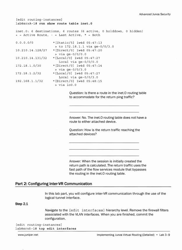
Advanced Junos Security
[edit routing-instances]
lab@srx�-1# run show route table inet.O
inet.O: 6 destinations, 6 routes (6 active, 0 holddown, O hidden)
+ = Active Route, - = Last Active, * = Both
0.0.0.0/0 *[Static/SJ lw4d 05:47:13
> to 172.18.1.1 via ge-0/0/3.0
10.210.14.128/27 *[Direct/OJ lw4d 05:47:20
> via ge-0/0/0.0
10.210.14.131/32 *[Local/OJ lw4d 05:47:27
Local via ge-0/0/0.0
172.18.1.0/30 *[Direct/OJ lw4d 05:47:14
> via ge-0/0/3.0
172.18.1.2/32 *[Local/OJ lw4d 05:47:27
Local via ge-0/0/3.0
192.168.1.1/32 *[Direct/OJ lw4d 05:48:15
> via loO.O
Question: Is there a route in the inet.O routing table
to accommodate for the return ping traffic?
Answer: No. The inet.O routing table does not have a
route to either attached device.
Question: How is the return traffic reaching the
attached devices?
Answer: When the session is initially created the
return path is calculated. Jhe return traffic uses the
fast path of the flow services module that bypasses
the routing in the inet.0 routing table.
Part 2: Configuring lnter-VR Communication
Step 2.1
In this lab part, you will configure inter-VR communication through the use of the
logical tunnel interface.
Navigate to the [edit interfaces] hierarchy level. Remove the firewall filters
associated with the VLAN interfaces. When you are finished, commit the
configuration.
[edit routing-instances]
lab@srxA-1# top edit interfaces
www.juniper.net Implementing Ju nos Virtual Routing (Detailed) • Lab 3-9
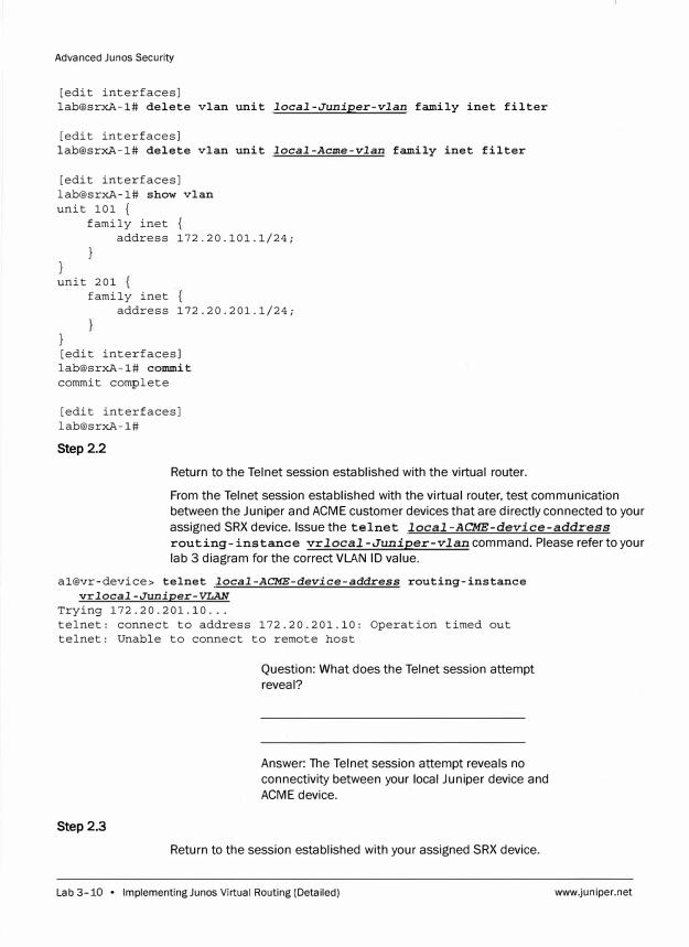
Advanced Junos Security
[edit interfaces] lab@srxA-1# delete vlan unit local-Juniper-vlan family inet filter
[edit interfaces] lab@srxA-1# delete vlan unit local-Acme-vlan family inet filter
[edit interfaces] lab@srxA-1# show vlan unit 101 {
family inet { address 172.20.101.1/24;
unit 201 family inet
address 172.20.201.1/24;
[edit interfaces] lab@srxA-1# commit commit complete
[edit interfaces] lab@srxA-1#
Step 2.2
Return to the Telnet session established with the virtual router.
From the Telnet session established with the virtual router, test communication
between the Juniper and ACME customer devices that are directly connected to your
assigned SRX device. Issue the telnet local-ACME-device-address
routing-instance vrlocal-Juniper-vlan command. Please refer to your
lab 3 diagram for the correct VLAN ID value.
al@vr-device> telnet local-ACME-device-address routing-instance vrlocal-Juniper-VLAN
Trying 172.20.201.10 ... telnet: connect to address 172.20.201.10: Operation timed out telnet: Unable to connect to remote host
Step2.3
Question: What does the Telnet session attempt
reveal?
Answer: The Telnet session attempt reveals no
connectivity between your local Juniper device and
ACME device.
Return to the session established with your assigned SRX device.
Lab 3-10 • lmplementingJunos Virtual Routing (Detailed) www.juniper.net
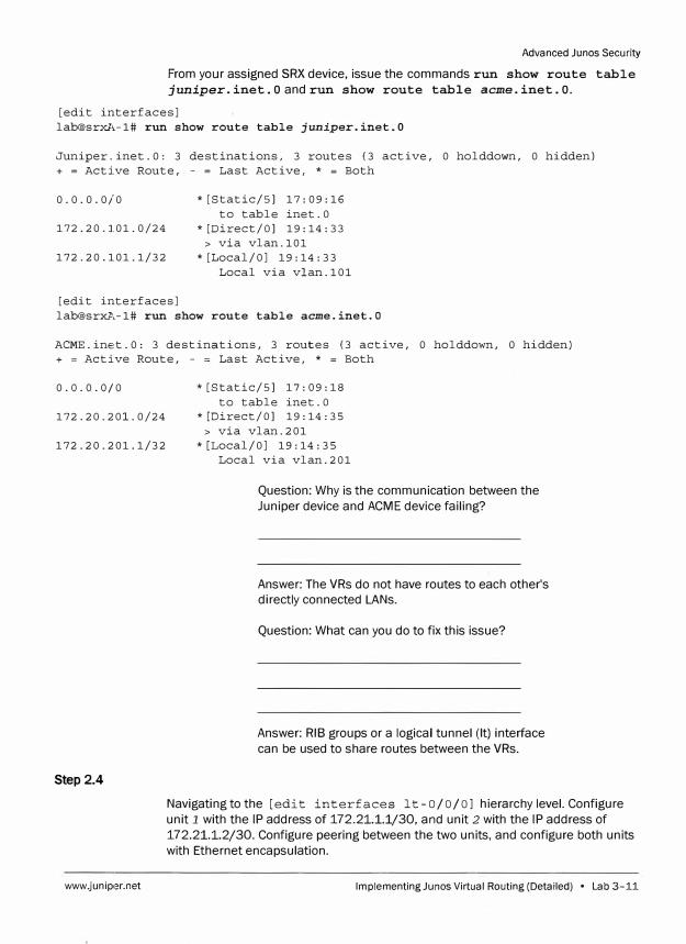
Advanced Junes Security
From your assigned SRX device, issue the commands run show route table
juniper. inet. 0 and run show route table acme. inet. 0.
[edit interfaces] lab@srxl,-1# run show route table juniper.inet.0
Juniper.inet.O: 3 destinations, 3 routes (3 active, O holddown, O hidden) + = Active Route, - = Last Active, * = Both
0.0.0.0/0 *[Static/SJ 17:09:16
to table inet.O 172.20.101.0/24 *[Direct/OJ 19:14:33
> via vlan.101172.20.101.1/32 *[Local/OJ 19:14:33
Local via vlan.101
[edit interfaces] lab@srxA-1# run show route table acme.inet.O
ACME.inet.O: 3 destinations, 3 routes (3 active, O holddown, O hidden) + = Active Route, - = Last Active, * = Both
0.0.0.0/0 * [Static/SJ 17:09:18
to table inet.O 172.20.201.0/24 *[Direct/OJ 19:14:35
> via vlan.201172.20.201.1/32 *[Local/OJ 19:14:35
Step 2.4
www.juniper.net
Local via vlan.201
Question: Why is the communication between the
Juniper device and ACME device failing?
Answer: The VRs do not have routes to each other's
directly connected LANs.
Question: What can you do to fix this issue?
Answer: RIB groups or a logical tunnel (It) interface
can be used to share routes between the VRs.
Navigating to the [edit interfaces lt- 0/0/0] hierarchy level. Configure
unit 1 with the IP address of 172.2 1.1.1/30, and unit 2 with the IP address of
172.2 1.1.2/30. Configure peering between the two units, and configure both units
with Ethernet encapsulation.
Implementing Junes Virtual Routing (Detailed) • Lab 3-11
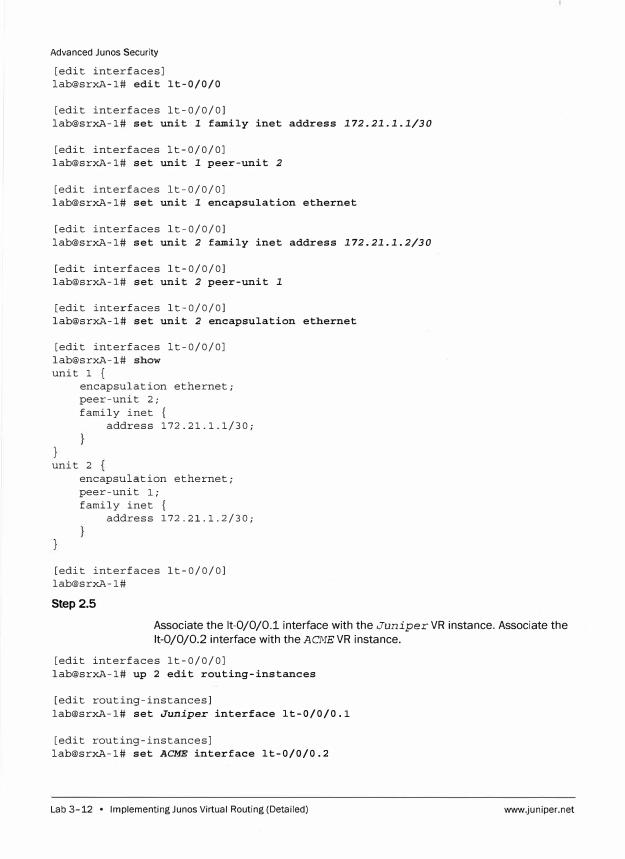
Advanced Junos Security
[edit interfaces] lab@srxA-1# edit lt-0/0/0
[edit interfaces lt-0/0/0] lab@srxA-1# set unit 1 family inet address 172.21.1.1/30
[edit interfaces lt-0/0/0] lab@srxA-1# set unit 1 peer-unit 2
[edit interfaces lt-0/0/0] lab@srxA-1# set unit 1 encapsulation ethernet
[edit interfaces lt-0/0/0] lab@srxA-1# set unit 2 family inet address 172.21.1.2/30
[edit interfaces lt-0/0/0] lab@srxA-1# set unit 2 peer-unit 1
[edit interfaces lt-0/0/0] lab@srxA-1# set unit 2 encapsulation ethernet
[edit interfaces lt-0/0/0] lab@srxA-1# show unit 1 {
encapsulation ethernet; peer-unit 2; family inet {
address 172.21.1.1/30;
unit 2 encapsulation ethernet; peer-unit l; family inet {
address 172.21.1.2/30;
[edit interfaces lt-0/0/0] lab@srxA-1#
Step 2.5
Associate the lt-0/0/0.1 interface with the Juniper VR instance. Associate the
lt-0/0/0.2 interface with the ACME VR instance.
[edit interfaces lt-0/0/0] lab@srxA-1# up 2 edit routing-instances
[edit routing-instances] lab@srxA-1# set Juniper interface lt-0/0/0.1
[edit routing-instances] lab@srxA-1# set ACME interface lt-0/0/0.2
Lab 3-12 • lmplementingJunos Virtual Routing (Detailed) www.juniper.net
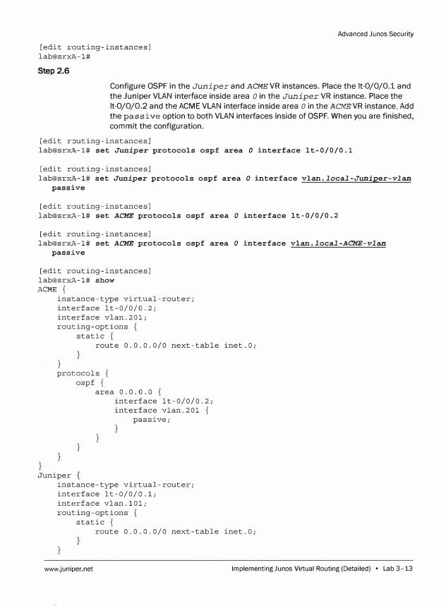
[edit routing-instances] [email protected]#
Step 2.6
Advanced Ju nos Security
Configure OSPF in the Juniper and ACME VR instances. Place the lt-0/0/0.1 and
the Juniper VLAN interface inside area o in the Juniper VR instance. Place the
lt-0/0/0.2 and the ACME VLAN interface inside area o in the ACMEVR instance. Add
the passive option to both VLAN interfaces inside of OSPF. When you are finished,
commit the configuration.
[edit routing-instances] lab@srx�-1# set Juniper protocols ospf area O interface lt-0/0/0.1
[edit routing-instances] lab@srx�-1# set Juniper protocols ospf area O interface vlan.local-Juniper-vlan
passive
[edit routing-instances] lab@srxA-1# set ACME protocols ospf area O interface lt-0/0/0.2
[edit routing-instances] lab@srxA-1# set ACME protocols ospf area O interface vlan.local-ACME-vlan
passive
[edit routing-instances] lab@srxA-1# show ACME {
instance-type virtual-router; interface lt-0/0/0.2; interface vlan.201; routing-options {
static { route 0.0.0.0/0 next-table inet.O;
protocols { ospf {
Juniper
area 0.0.0.0 { interface lt-0/0/0.2; interface vlan.201 {
passive;
instance-type virtual-router; interface lt-0/0/0.1; interface vlan.101; routing-options {
static { route 0.0.0.0/0 next-table inet.O;
www.juniper.net lmplementingJunos Virtual Routing (Detailed) • Lab 3-13
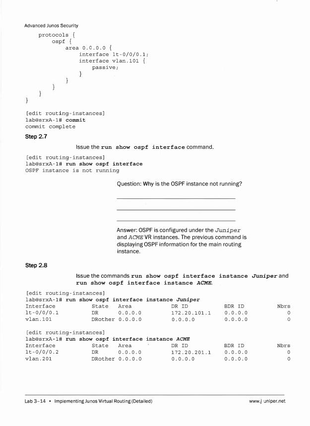
Advanced Junos Security
protocols { ospf {
area 0.0.0.0 { interface lt-0/0/0.1; interface vlan.101 {
passive;
[edit routing-instances] lab@srxA-1# commit commit complete
Step 2.7
Issue the run show ospf interface command.
[edit routing-instances] lab@srxA-1# run show ospf interface OSPF instance is not running
Step 2.8
Question: Why is the OSPF instance not running?
Answer: OSPF is configured under the Juniper
and ACMEVR instances. The previous command is
displaying OSPF information for the main routing instance.
Issue the commands run show ospf interface instance Juniper and run show ospf interface instance ACME.
[edit routing-instances] lab@srxA-1# run show ospf interface instance Juniper
Interface State Area DR ID lt-0/0/0.1 DR 0.0.0.0 172.20.101.1 vlan.101 DRother 0.0.0.0 0.0.0.0
[edit routing-instances] lab@srxA-1# run show ospf interface instance ACME
Interface State Area DR ID lt-0/0/0.2 DR 0.0.0.0 172.20.201.1 vlan.201 DRother 0.0.0.0 0.0.0.0
Lab 3-14 • Implementing Ju nos Virtual Routing (Detailed)
BDR ID 0.0.0.0 0.0.0.0
BDR ID 0.0.0.0 0.0.0.0
Nbrs 0 0
Nbrs 0 0
www.juniper.net
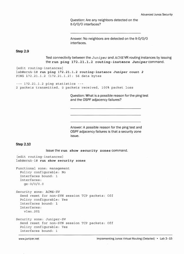
Question: Are any neighbors detected on the
lt-0/0/0 interfaces?
Advanced Junos Security
Answer: No neighbors are detected on the lt-0/0/0
interfaces.
Step 2.9
Test connectivity between the Juniper and ACME VR routing instances by issuing
the run ping 172.21.1.2 routing-instance Junipercommand.
[edit routing-instances] lab@sr�A-1# run ping 172.21.1.2 routing-instance Juniper count 2
PING 172.21.1.2 (172.21.1.2): 56 data bytes
--- 172.21.1.2 ping statistics ---2 packets transmitted, O packets received, 100% packet loss
Step 2.10
Question: What is a possible reason for the ping test
and the OSPF adjacency failures?
Answer: A possible reason for the ping test and
OSPF adjacency failures is that a security zone
issue.
Issue the run show security zones command.
[edit routing-instances] lab@srxl\-1# run show security zones
Functional zone: management Policy configurable: No Interfaces bound: 1 Interfaces:
ge-0/0/0.0
Security zone: ACME-SV Send reset for non-SYN session TCP packets: Off Policy configurable: Yes Interfaces bound: 1 Interfaces:
vlan.201
Security zone: Juniper-SV Send reset for non-SYN session TCP packets: Off Policy configurable: Yes Interfaces bound: 1
www.juniper.net lmplementingJunos Virtual Routing (Detailed) • Lab 3-15
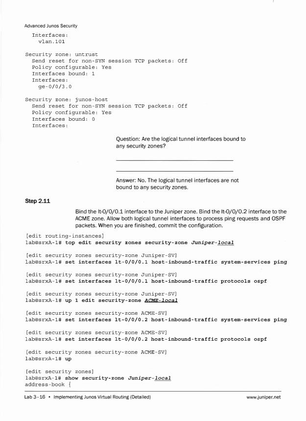
Advanced Junos Security
Interfaces: vlan.101
Security zone: untrust Send reset for non-SYN session TCP packets: Off Policy configurable: Yes Interfaces bound: 1 Interfaces:
ge-0/0/3.0
Security zone: junos-host Send reset for non-SYN session TCP packets: Off Policy configurable: Yes
Interfaces bound: 0 Interfaces:
Step 2.11
Question: Are the logical tunnel interfaces bound to
any security zones?
Answer: No. The logical tunnel interfaces are not
bound to any security zones.
Bind the lt-0/0/0.1 interface to the Juniper zone. Bind the lt-0/0/0.2 interface to the
ACME zone. Allow both logical tunnel interfaces to process ping requests and OSPF
packets. When you are finished, commit the configuration.
[edit routing-instances] lab@srxA-1# top edit security zones security-zone Juniper-local
[edit security zones security-zone Juniper-SV] lab@srxA-1# set interfaces lt-0/0/0.1 host-inbound-traffic system-services ping
[edit security zones security-zone Juniper-SV] lab@srxA-1# set interfaces lt-0/0/0.1 host-inbound-traffic protocols oe:pf
[edit security zones security-zone Juniper-SV] lab@srxA-1# up 1 edit security-zone ACME-local
[edit security zones security-zone ACME-SV] lab@srxA-1# set interfaces lt-0/0/0.2 host-inbound-traffic system-services ping
[edit security zones security-zone ACME-SV] lab@srxA-1# set interfaces lt-0/0/0. 2 host-inbound-traffic protocols os:pf
[edit security zones security-zone ACME-SV] lab@srxA-1# up
[edit security zones] lab@srxA-1# show security-zone Juniper-local
address-book {
Lab 3-16 • Implementing Ju nos Virtual Routing (Detailed) www.juniper.net
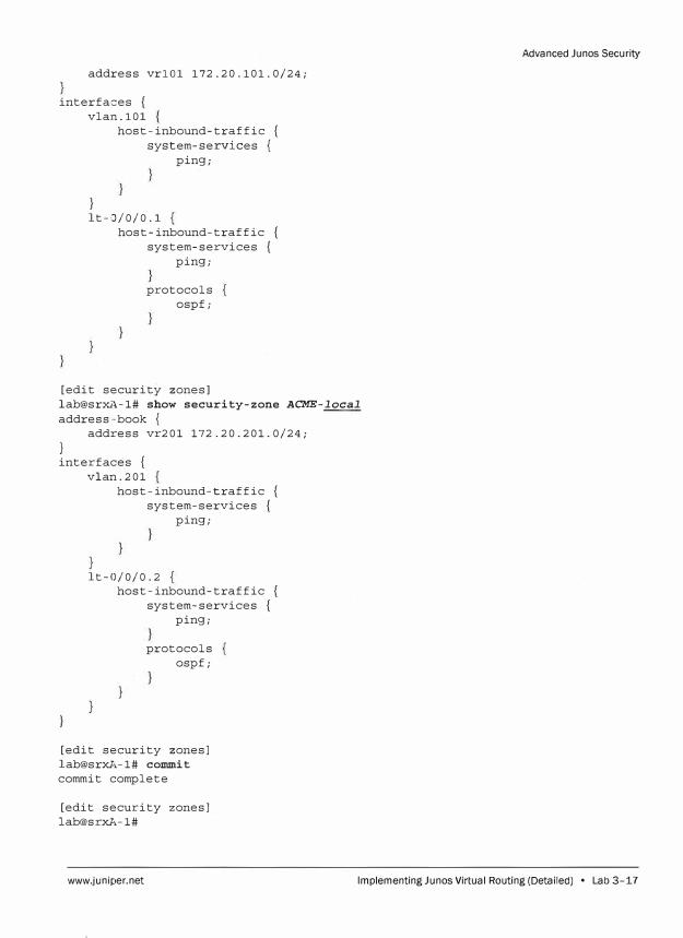
address vrlOl 172.20.101.0/24;
interfaces { vla:n.101
host-inbound-traffic { system-services {
ping;
} lt-0/0/0 .1
host-inbound-traffic { system-services {
ping;
protocols ospf;
[edit security zones] lab@srxA-1# show security-zone ACME-local
address--book { address vr201 172.20.201.0/24;
} interfaces {
vlan.201 host-inbound-traffic {
system-services { ping;
lt-0/0/0.2 host-inbound-traffic {
system-services { ping;
protocols ospf;
[edit security zones] lab@srxA-1# commit
commit complete
[edit security zones] lab@srxA-1#
Advanced Junos Security
www.juniper.net Implementing Ju nos Virtual Routing (Detailed) • Lab 3-17
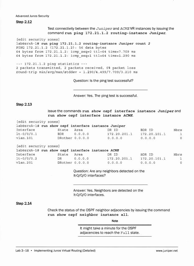
Advanced Junos Security
Step 2.12
Test connectivity between the Juniper and ACME VR instances by issuing the
command run ping 172. 21.1. 2 routing-instance Juniper.
[edit security zones] lab@srxA-1# run ping 172.21.1.2 routing-instance Juniper count 2
PING 172.21.1.2 (172.21.1.2): 56 data bytes 64 bytes from 172.21.1.2: icmp_seq=O ttl=64 time=7.709 ms 64 bytes from 172.21.1.2: icmp seq=l ttl=64 time=l.290 ms
--- 172.21.1.2 ping statistics ---2 packets transmitted, 2 packets received, 0% packet loss round-trip min/avg/max/stddev = l.290/4.499/7.709/3.210 ms
Question: Is the ping test successful?
Answer: Yes. The ping test is successful.
Step 2.13
Issue the commands run show ospf interface instance Juniper and
run show ospf interface instance ACME.
[edit security lab@srxA-1# run Interface lt-0/0/0.1 vlan.101
[edit security lab@srxA-1# run Interface lt-0/0/0.2 vlan.201
Step 2.14
zones] show ospf interface instance Juniper
State Area DR ID BDR ID BDR 0.0.0.0 172.20.201.1 172.20.101.J. DRother 0.0.0.0 0.0.0.0 0.0.0.0
zones] show ospf interface instance ACME
State DR DRother
Area DR ID BDR ID 0.0.0.0 172.20.201.1 172.20.101.J. 0.0.0.0 0.0.0.0 0.0.0.0
Question: Are any neighbors detected on the
lt-0/0/0 interfaces?
Answer: Yes. Neighbors are detected on the
lt-0/0/0 interfaces.
Check the status of the OSPF neighbor adjacencies by issuing the command
run show ospf neighbor instance all.
Note
It might take a minute for the OSPF
adjacencies to reach the Full state.
Nbrs 1 0
Nbrs 1 0
Lab 3-18 • Implementing Ju nos Virtual Routing (Detailed) www.juniper.net
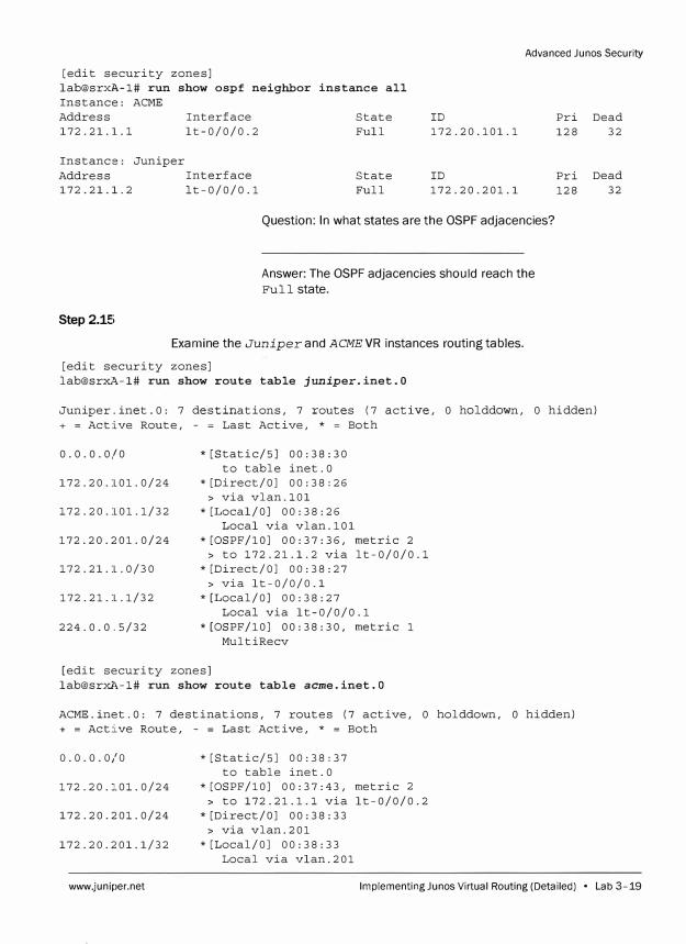
Advanced Junos Security
[edit security zones] lab@srx�-1# run show ospf neighbor instance all Instance: ACME Address 172.21.l.l
Instance: Juniper
Interface lt-0/0/0.2
Address Interface 172.21.1.2 lt-0/0/0.1
Step 2.1!:i
State Full
State Full
ID
172.20.101.1
ID
172.20.201.1
Question: In what states are the OSPF adjacencies?
Answer: The OSPF adjacencies should reach the
Full state.
Examine the Juniper and ACME VR instances routing tables.
[edit security zones] lab@srxA-1# run show route table juniper.inet.0
Pri Dead 128 32
Pri Dead 128 32
Juniper.inet.O: 7 destinations, 7 routes (7 active, O holddown, O hidden) + = Active Route, - = Last Active, * = Both
0.0.0.0/0 *[Static/SJ 00:38:30 to table inet.O
172.20.101.0/24 *[Direct/OJ 00:38:26 > via vlan.101
172.20.101.1/32 *[Local/OJ 00:38:26 Local via vlan.101
172.20.201.0/24 *[OSPF/10] 00:37:36, metric 2 > to 172.21.1.2 via lt-0/0/0.l
172.21.1.0/30 *[Direct/OJ 00:38:27 > via lt-0/0/0.1
172.21.1.1/32 *[Local/OJ 00:38:27 Local via lt-0/0/0.1
224.0.0.5/32 *[OSPF/10] 00:38:30, metric 1 MultiRecv
[edit security zones] lab@srxl,-1# run show route table acme.inet.O
ACME.inet.O: 7 destinations, 7 routes (7 active, 0 holddown, 0 hidden) + = Active Route, - = Last Active, * = Both
0.0.0.0/0 *[Static/SJ 00:38:37 to table inet.0
172.20.101.0/24 *[OSPF/10] 00:37:43, metric 2
> to 172.21.1.l via lt-0/0/0.2172.20.201.0/24 *[Direct/OJ 00:38:33
> via vlan.201172.20.201.1/32 *[Local/OJ 00:38:33
Local via vlan.201
www.juniper.net lmplementingJunos Virtual Routing (Detailed) • Lab 3-19
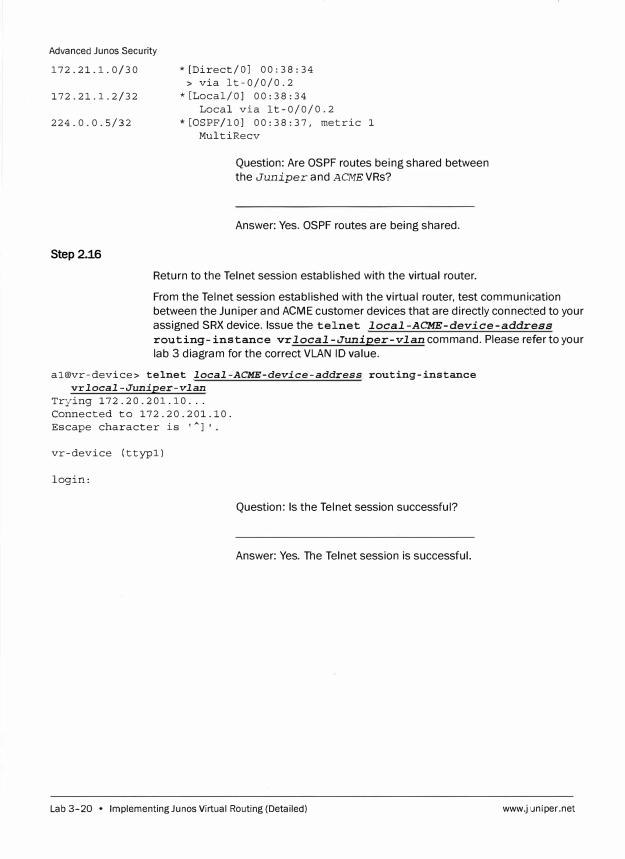
Advanced Junos Secur ity
172.21.1.0/30
172.21.1.2/32
224.0.0.5/32
Step2.16
* [Direct/OJ 00: 38: 34> via lt-0/0/0.2
* [Local/OJ 00:38:34Local via lt-0/0/0.2
*[OSPF/lOJ 00:38:37, metric 1 MultiRecv
Question: Are OSPF routes being shared between
the Juniper and ACMEVRs?
Answer: Yes. OSPF routes are being shared.
Return to the Telnet session established with the virtual router.
From the Telnet session established with the virtual router, test communication
between the Juniper and ACME customer devices that are directly connected to your
assigned SRX device. Issue the telnet local-ACME-device-address
routing-instance vr local-Juniper-vlan command. Please refer to your
lab 3 diagram for the correct VLAN ID value.
al@vr-device> telnet local-ACME-device-address routing-instance vrlocal-Juniper-vlan
Trying 172.20.201.10 ... Connected to 172.20.201.10. Escape character is '
A
l '
vr-device (ttypl)
login:
Question: Is the Telnet session successful?
Answer: Yes. The Telnet session is successful.
Lab 3-20 • Implementing Ju nos Virtual Routing (Detailed) www.juniper.net

Advanced Ju nos Security
Step 2.17
Log in to the virtual router to ensure that the Telnet session does not time out. Use
the login information shown in the following table:
vr-device (ttypO)
login: al
Password:
Virtual Router Login Details
Student Device Username Password
srxA-1 al labl23
srxA-2 a2 labl23
srxB-1 bl labl23
srxB-2 b2 labl23
srxC-1 cl labl23
srxC-2 c2 labl23
srxD-1 dl labl23
srxD-2 d2 labl23
--- JUNOS 12.1X44-Dl0.4 built 2013-01-08 05:15:31 UTC
NOTE: This router is divided into many virtual routers used by different teams.
Please only configure your own virtual router.
You must. use 'configure private' to configure this router.
al@vr-device>
Step2.18
Return to the session established with your assigned SRX device.
From your assigned SRX device, find the recently created Telnet session in the
session table.
[edit security zones]
lab@srxA-1# run show security flow session application telnet
Session ID: 57866, Policy name: intrazone-Juniper-SV/4, Timeout: 3394, Valid
In: 172.20.101.10/56290 --> 172.20.201.10/23;tcp, If: vlan.101, Pkts: 27,
Bytes: 1568
Out: 172.20.201.10/23 --> 172.20.101.10/56290;tcp, If: lt-0/0/0.1, Pkts: 21,
Bytes: 1543
Session ID: 57867, Policy name: intrazone-ACME-SV/5, Timeout: 3394, Valid
In: 172.20.101.10/56290 --> 172.20.201.10/23;tcp, If: lt-0/0/0.2, Pkts: 27,
Bytes: 1568
Out: 172.20.201.10/23 --> 172.20.101.10/56290;tcp, If: vlan.201, Pkts: 21,
Bytes: 1543
Total sessions: 2
www.juniper.net Implementing Ju nos Virtual Routing (Detailed) • Lab 3-21
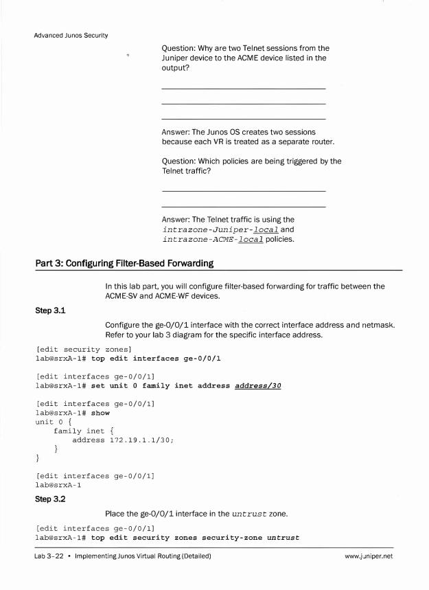
Advanced Junos Security
Question: Why are two Telnet sessions from the
Juniper device to the ACME device listed in the
output?
Answer: The Junos OS creates two sessions because each VR is treated as a separate router.
Question: Which policies are being triggered by the
Telnet traffic?
Answer: The Telnet traffic is using the
intrazone-Juniper-local and
intrazone-ACME-local policies.
Part 3: Configuring Filter-Based Forwarding
In this lab part, you will configure filter-based forwarding for traffic between the
ACME-SV and ACME-WF devices.
Step 3.1
Configure the ge-0/0/1 interface with the correct interface address and netmask.
Refer to your lab 3 diagram for the specific interface address.
[edit security zones] lab@srxA-1# top edit interfaces ge-0/0/1
[edit interfaces ge-0/0/1] lab@srxA-1# set unit O family inet address address/30
[edit interfaces ge-0/0/1] lab@srxA-1# show unit O {
family inet address 172.19.1.1/30;
[edit interfaces ge-0/0/1] lab@srxA-1
Step 3.2
Place the ge-0/0/1 interface in the untrust zone.
[edit interfaces ge-0/0/1] lab@srxA-1# top edit security zones security-zone untrust
Lab 3-22 • Implementing Ju nos Virtual Routing (Detailed) www.juniper.net
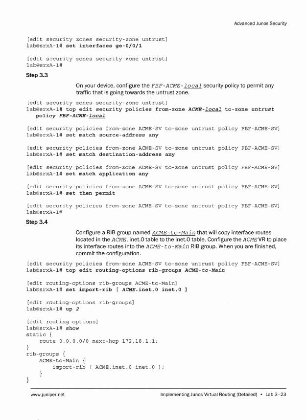
[edit security zones security-zone untrust] lab@srx�-1# set interfaces ge-0/0/1
[edit security zones security-zone untrust] lab@srx�-1#
Step 3.3
Advanced Junos Security
On your device, configure the FBF-ACME-local security policy to permit any
traffic that is going towards the untrust zone.
[edit s,,,curity zones security-zone untrust] lab@srxA-1# top edit security policies from-zone ACME-local to-zone untrust
poli,:y FBF-ACME-local
[edit security policies from-zone ACME-SV to-zone untrust policy FBF-ACME-SV] lab@srxA-1# set match source-address any
[edit security policies from-zone ACME-SV to-zone untrust policy FBF-ACME-SV] lab@srxA-1# set match destination-address any
[edit security policies from-zone ACME-SV to-zone untrust policy FBF-ACME-SV] lab@srxA-1# set match application any
[edit security policies from-zone ACME-SV to-zone untrust policy FBF-ACME-SV] lab@srxA-1# set then permit
[edit security policies from-zone ACME-SV to-zone untrust policy FBF-ACME-SV] lab@srxl,-1#
Step3.4
Configure a RIB group named ACME-to-Main that will copy interface routes
located in the ACME. inet.0 table to the inet.O table. Configure the ACMEVR to place
its interface routes into the ACME-to-Main RIB group. When you are finished,
commit the configuration.
[edit security policies from-zone ACME-SV to-zone untrust policy FBF-ACME-SV] lab@srxA-1# top edit routing-options rib-groups ACME-to-Main
[edit routing-options rib-groups ACME-to-Main] lab@srxl,-1# set import-rib [ ACME.inet.0 inet.0
[edit routing-options rib-groups] lab@srxl,-1# up 2
[edit routing-options] lab@srxl,-1# show static {
route 0.0.0.0/0 next-hop 172.18.1.1;
} rib-groups {
ACME-to-Main import-rib [ ACME.inet.O inet.O];
www.juniper.net lmplementingJunos Virtual Routing (Detailed) • Lab 3-23
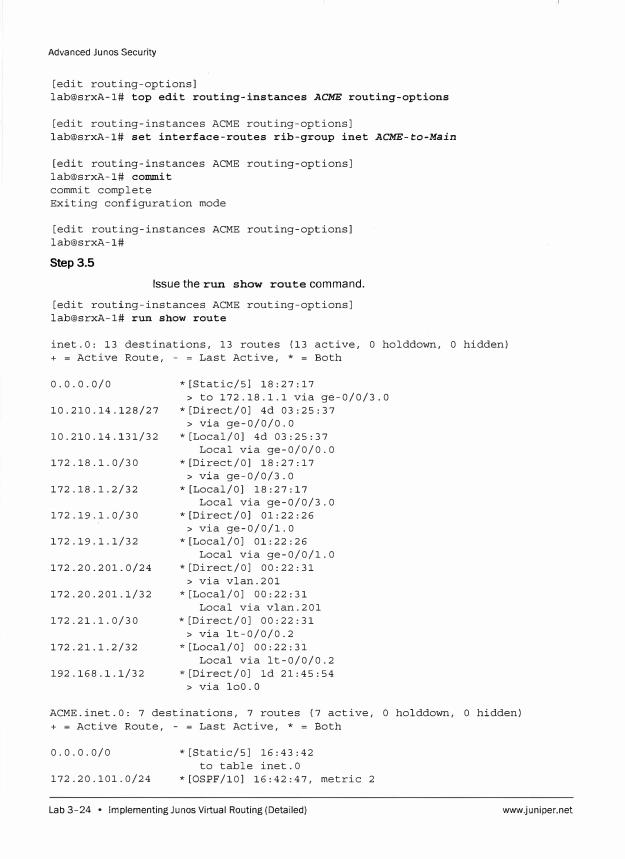
Advanced Ju nos Security
[edit routing-options]
lab@srxA-1# top edit routing-instances ACME routing-options
[edit routing-instances ACME routing-options]
lab@srxA-1# set interface-routes rib-group inet ACME-to-Main
[edit routing-instances ACME routing-options]
lab@srxA-1# commit
commit complete
Exiting configuration mode
[edit routing-instances ACME routing-options]
lab@srxA-1#
Step 3.5
Issue the run show route command.
[edit routing-instances ACME routing-options]
lab@srxA-1# run show route
inet.O: 13 destinations, 13 routes (13 active, O holddown, 0 hidden)
+ = Active Route, - = Last Active, * = Both
0.0.0.0/0
10.210.14.128/27
10.210.14.131/32
172.18.1.0/30
172.18.1.2/32
172.19.1.0/30
172.19.1.1/32
172.20.201.0/24
172.20.201.1/32
172.21.1.0/30
1 72. 21. 1. 2/32
192.168.1.1/32
*[Static/5] 18:27:17
> to 172.18.1.1 via ge-0/0/3.0
*[Direct/OJ 4d 03:25:37
> via ge-0/0/0.0
*[Local/OJ 4d 03:25:37
Local via ge-0/0/0.0
*[Direct/OJ 18:27:17
> via ge-0/0/3.0
* [Local/OJ 18: 27: 17
Local via ge-0/0/3.0
*[Direct/OJ 01:22:26
> via ge-0/0/1.0
*[Local/OJ 01:22:26
Local via ge-0/0/1.0
* [Direct/OJ 00: 22: 31
> via vlan.201
* [Local/OJ oo: 22: 31
Local via vlan.201
*[Direct/OJ 00:22:31
> via lt-0/0/0.2
*[Local/OJ 00:22:31
Local via lt-0/0/0.2
*[Direct/OJ ld 21:45:54
> via loo.a
ACME.inet.O: 7 destinations, 7 routes (7 active, O holddown, O hidden)
+ = Active Route, - = Last Active, * = Both
0.0.0.0/0 *[Static/5] 16:43:42
to table inet.O
172.20.101.0/24 *[OSPF/10] 16:42:47, metric 2
Lab 3-24 • Implementing Ju nos Virtual Routing (Detailed) www.juniper.net
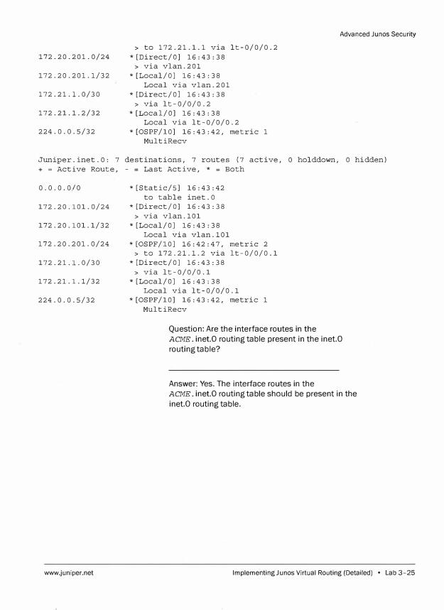
172.20.201.0/24
172.20.201.1/32
172.21.1.0/30
172.21.1.2/32
224.0.0.5/32
> to 172.21.1.1 via lt-0/0/0.2
*[Direct/OJ 16:43:38
> via vlan.201
*[Local/OJ 16:43:38
Local via vlan.201
*[Direct/OJ 16:43:38
> via lt-0/0/0.2
*[Local/OJ 16:43:38
Local via lt-0/0/0.2
*[OSPF/lOJ 16:43:42, metric 1
MultiRecv
Advanced Junos Security
Juniper.inet.O: 7 destinations, 7 routes (7 active, 0 holddown, O hidden)
+ = Active Route, - = Last Active, * = Both
0.0.0.0/0 *[Static/SJ 16:43:42
to table inet.O
172.20.101.0/24 *[Direct/OJ 16:43:38
> via vlan.101
172.20.101.1/32 *[Local/OJ 16:43:38
Local via vlan.101
172.20.201.0/24 *[OSPF/lOJ 16:42:47, metric 2
> to 172.21.1.2 via lt-0/0/0.1
172.21.1.0/30 *[Direct/OJ 16:43:38
> via lt-0/0/0.1
172.21.1.1/32 *[Local/OJ 16:43:38
Local via lt-0/0/0.1
224.0.0.5/32 *[OSPF/lOJ 16:43:42, metric 1
www.juniper.net
MultiRecv
Question: Are the interface routes in the
ACME. inet.O routing table present in the inet.0
routing table?
Answer: Yes. The interface routes in the
ACME. inet.O routing table should be present in the
inet.0 routing table.
lmplementingJunos Virtual Routing (Detailed) • Lab 3-25
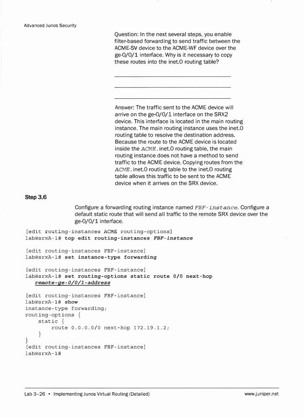
Advanced Junos Security
Step 3.6
Question: In the next several steps, you enable
filter-based forwarding to send traffic between the
ACME-SV device to the ACME-WF device over the
ge-0/0/1 interface. Why is it necessary to copy
these routes into the inet.0 routing table?
Answer: The traffic sent to the ACME device will
arrive on the ge-0/0/1 interface on the SRX2
device. This interface is located in the main routing
instance. The main routing instance uses the inet.O
routing table to resolve the destination address.
Because the route to the ACME device is located
inside the ACME. inet.0 routing table, the main
routing instance does not have a method to send
traffic to the ACME device. Copying routes from the
ACME. inet.O routing table to the inet.0 routing
table allows this traffic to be sent to the ACME
device when it arrives on the SRX device.
Configure a forwarding routing instance named FBF-instance. Configure a
default static route that will send all traffic to the remote SRX device over the
ge-0/0/1 interface.
[edit routing-instances ACME routing-options] lab@srxA-1# top edit routing-instances FBF-instance
[edit routing-instances FBF-instance] lab@srxA-1# set instance-type forwarding
[edit routing-instances FBF-instance] lab@srxA-1# set routing-options static route 0/0 next-hop
remote-ge-0/0/1-address
[edit routing-instances FBF-instance] lab@srxA-1# show instance-type forwarding; routing-options {
static {
route 0.0.0.0/0 next-hop 172.19.1.2;
[edit routing-instances FBF-instance] lab@srxA-1#
Lab 3-26 • Implementing Ju nos Virtual Routing (Detailed) www.juniper.net
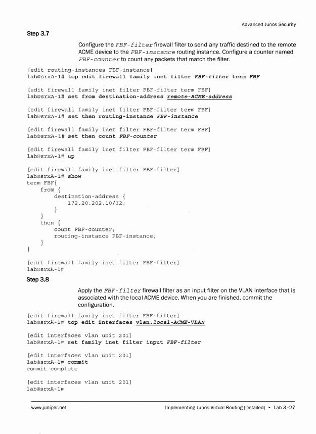
Advanced Junos Security
Step 3.7
Configure the FBF-f il ter firewall filter to send any traffic destined to the remote
ACME device to the FBF-instance routing instance. Configure a counter named
FBF-counterto count any packets that match the filter.
[edit routing-instances FBF-instance] lab@srxA-1# top edit firewall family inet filter FBF-filter term FBF
[edit firewall family inet filter FBF-filter term FBF] lab@srxA-1# set from destination-address remote-ACME-address
[edit firewall family inet filter FBF-filter term FBF] lab@srxA-1# set then routing-instance FBF-instance
[edit firewall family inet filter FBF-filter term FBF] lab@srxA-1# set then count FBF-counter
[edit firewall family inet filter FBF-filter term FBF] lab@srxA-1# up
[edit firewall family inet filter FBF-filter] lab@srxi�-1# show term FBF{
from { destination-address
172.20.202.10/32;
} then {
count FBF-counter; routing-instance FBF-instance;
[edit firewall family inet filter FBF-filter] lab@srxl�-1#
Step3.8
Apply the FBF-fil ter firewall filter as an input filter on the VLAN interface that is
associated with the local ACME device. When you are finished, commit the
configuration.
[edit firewall family inet filter FBF-filter] lab@sr�,-1# top edit interfaces vlan.local-ACME-VLAN
[edit interfaces vlan unit 201] lab@sr�-1# set family inet filter input FBF-filter
[edit interfaces vlan unit 201] lab@sr�,-1# commit commit complete
[edit interfaces vlan unit 201] [email protected]#
www.juniper.net Implementing Ju nos Virtual Routing (Detailed) • Lab 3-27
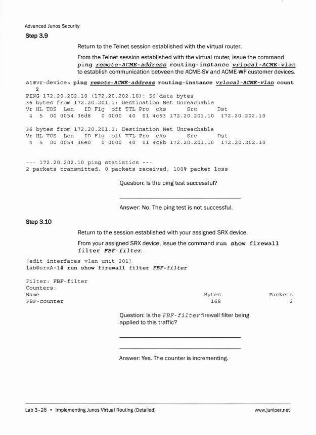
Advanced Junes Security
Step 3.9
Return to the Telnet session established with the virtual router.
From the Telnet session established with the virtual router, issue the command
ping remote-ACME-address routing-instance vrlocal-AC'ME-vlan
to establish communication between the ACME-SV and ACME-WF customer devices.
al@vr-device> ping remote-ACME-address routing-instance vrlocal-ACME-vlan count
2
PING 172.20.202.10 (172.20.202.10): 56 data bytes
36 bytes from 172.20.201.1: Destination Net Unreachable
Vr HL TOS Len ID Flg off TTL Pro cks Src
4 5 00 0054 36d8 O 0000 40 01 4c93 172.20.201.10
36 bytes from 172.20.201.1: Destination Net Unreachable
Vr HL TOS Len ID Flg off TTL Pro cks Src
4 5 00 0054 36e0 0 0000 40 01 4c8b 172.20.201.10
--- 172.20.202.10 ping statistics ---
Dst
172.20.202.10
Dst
172.20.202.10
2 packets transmitted, 0 packets received, 100% packet loss
Question: Is the ping test successful?
Answer: No. The ping test is not successful.
Step3.10
Return to the session established with your assigned SRX device.
From your assigned SRX device, issue the command run show firewall
filter FBF-filter.
[edit interfaces vlan unit.201]
lab@srxA-1# run show firewall filter FBF-filter
Filter: FBF-filter
Counters:
Name
FBF-counter
Bytes
168
Question: Is the FBF-fil terfirewall filter being
applied to this traffic?
Answer: Yes. The counter is incrementing.
Lab 3-28 • Implementing Ju nos Virtual Routing (Detailed)
Packets
2
www.juniper.net
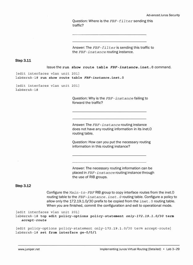
Step3.11
Advanced Junos Secur ity
Question: Where is the FBF-fil ter sending this
traffic?
Answer: The FBF-fil ter is sending this traffic to
the FBF-instance routing instance.
Issue the run show route table FBF-instance. inet. O command.
[edit interfaces vlan unit 201] lab@srxA-1# run show route table FBF-instance.inet.0
[edit interfaces vlan unit 201] lab@srxA-1#
Step 3.12
Question: Why is the FBF-instance failing to
forward the traffic?
Answer: The FBF-instance routing instance
does not have any routing information in its inet.O
routing table.
Question: How can you put the necessary routing
information in this routing instance?
Answer: The necessary routing information can be
placed in FBF-instance routing instance through
the use of RIB groups.
Configure the Main-to-FBF RIB group to copy interface routes from the inet.0
routing table to the FBF-instance. inet. o routing table. Configure a policy to
allow only the 172.19.1.0/30 prefix to be copied from the inet. o routing table.
When you are finished, commit the configuration and exit to operational mode.
[edit interfaces vlan unit 201] lab@srxA-1# top edit policy-options policy-statement only-172.19.1.0/30 term
accept-route
[edit policy-options policy-statement only-172.19.1.0/30 term accept-route] lab@srxA-1# set from interface ge-0/0/1
www.juniper.net Implementing Ju nos Virtual Routing (Detailed) • Lab 3-29
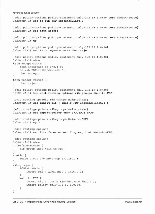
Advanced Junos Security
[edit policy-options policy-statement only-172.19.1.0/30 term accept-route] lab@srxA-1# set to rib FBF-instance.inet.O
[edit policy-options policy-statement only-172.19.1.0/30 term accept-route] lab@srxA-1# set then accept
[edit policy-options policy-statement only-172.19.1.0/30 term accept-route] lab@srxA-1# up
[edit policy-options policy-statement only-172.19.1.0/30] lab@srxA-1# set term reject-routes then reject
[edit policy-options policy-statement only-172.19.1.0/30] lab@srxA-1# show term accept-route {
from interface ge-0/0/1.0; to rib FBF-instance.inet.O; then accept;
term reject-routes then reject;
[edit policy-options policy-statement only-172.19.1.0/30] lab@srxA-1# top edit routing-options rib-groups Main-to-FBF
[edit routing-options rib-groups Main-to-FBF] lab@srxA-1# set import-rib [ inet.O FBF-instance.inet.0
[edit routing-options rib-groups Main-to-FBF] lab@srxA-1# set import-policy only-172.19.1.0/30
[edit routing-options rib-groups Main-to-FBF] lab@srxA-1# up 2
[edit routing-options] lab@srxA-1# set interface-routes rib-group inet Main-to-FBF
[edit routing-options] lab@srxA-1# show interface-routes {
rib-group inet Main-to-FBF;
} static {
route 0.0.0.0/0 next-hop 172.18.1.1;
} rib-groups {
ACME-to-Main import-rib [ ACME.inet.O inet.O J;
} Main-to-FBF {
import-rib [ inet.O FBF-instance.inet.O J; import-policy only-172.19.1.0/30;
Lab 3-30 • Implementing Ju nos Virtual Routing (Detailed) www.juniper.net
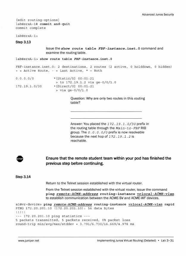
Advanced Junos Security
[edit routing-options] lab@srxA-1# commit and-quit commit complete
lab@srxA-1>
Step3.13
Issue the show route table FBF-instance. inet. O command and
examine the routing table.
lab@srxl\-1> show route table FBF-instance.inet.O
FBF-inst:ance.inet.O: 2 destinations, 2 routes (2 active, O holddown, O hidden) + = Active Route, - = Last Active, * Both
0.0.0.0/0
172.19.1.0/30
Step3.14
* [Static/SJ oo: 01: 21> to 172.19.1.2 via ge-0/0/1.0
*[Direct/OJ 00:01:21 > via ge-0/0/1.0
Question: Why are only two routes in this routing
table?
Answer: You placed the 172 .19 .1. 0/30 prefix in
the routing table through the Main-to-FBF RIB
group. The o. o. o. 0/0 prefix is now resolvable
because the next hop of 1 72. 19 .1. 2 is
reachable.
Ensure that the remote student team within your pod has finished the
previous step before continuing.
Return to the Telnet session established with the virtual router.
From the Telnet session established with the virtual router, issue the command
ping remote-ACME-address routing-instance vrlocal-ACME-vlan
to establish communication between the ACME-SV and ACME-WF devices.
al@vr-device> ping remote-ACME-address routing-instance vrlocal-ACME-vlan rapid PING 172.20.201.10 (172.20.201.10): 56 data bytes ! ! ! ! !
--- 172.20.201.10 ping statistics ---5 packets transmitted, s packets received, 0% packet loss round-trip min/avg/max/stddev = 3.791/6.730/16.669/4.978 ms
www.juniper.net Implementing Junes Virtual Routing (Detailed) • Lab 3-31
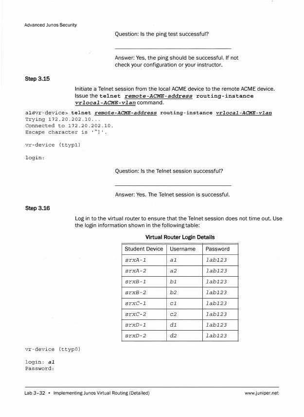
Advanced Ju nos Security
Step3.15
Question: Is the ping test successful?
Answer: Yes, the ping should be successful. If not
check your configuration or your instructor.
Initiate a Telnet session from the local ACME device to the remote ACME clevice.
Issue the telnet remote-ACME-address routing-instance
vrlocal-ACME-vlan command.
al@vr-device> telnet remote-ACME-address routing-instance vrlocal-ACME-vlan
Trying 172.20.202.10 ...
Connected to 172.20.202.10.
Escape character is 'A
l'.
vr-device (ttypl)
login:
Question: Is the Telnet session successful?
Answer: Yes. The Telnet session is successful.
Step 3.16
Log in to the virtual router to ensure that the Telnet session does not time out. Use
the login information shown in the following table:
Virtual Router Login Details
vr-device (ttypO)
login: al
Password:
Student Device
srxA-1
srxA-2
srxB-1
srxB-2
srxC-1
srxC-2
srxD-1
srxD-2
Lab 3-32 • Implementing Ju nos Virtual Routing (Detailed)
Username Password
al labl23
a2 labl23
bl labl23
b2 labl23
cl labl23
c2 labl23
dl labl23
d2 labl23
www.juniper.net
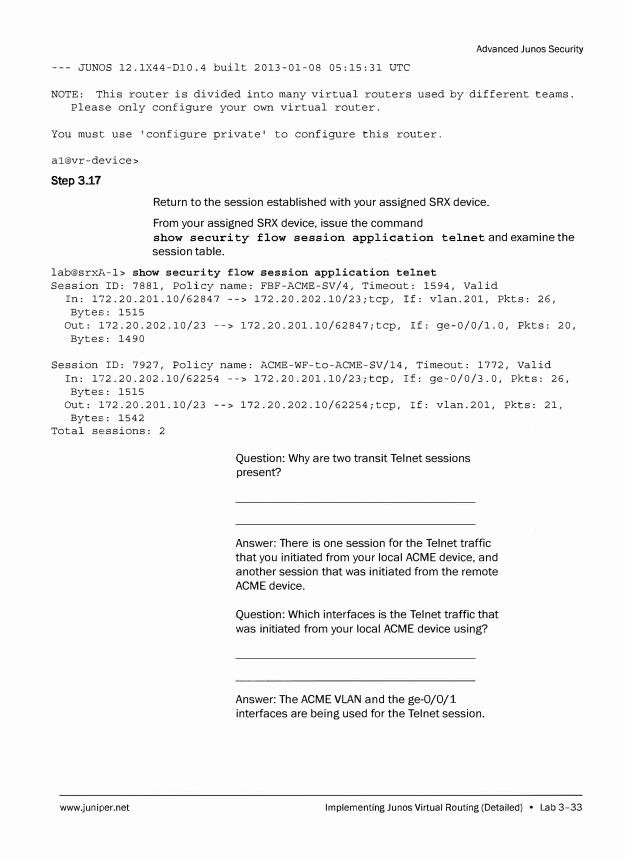
Advanced Junos Security
--- JUNOS 12.1X44-Dl0.4 built 2013-01-08 05:15:31 UTC
NOTE: This router is divided into many virtual routers used by different teams. PleaE:e only configure your own virtual router.
You must use 'configure private' to configure this router.
al@vr-device>
Step 3.17
Return to the session established with your assigned SRX device.
From your assigned SRX device, issue the command
show security flow session application telnet and examine the
session table.
lab@srxl\-1> show security flow session application telnet Session ID: 7881, Policy name: FBF-ACME-SV/4, Timeout: 1594, Valid
In: 172.20.201.10/62847 --> 172.20.202.10/23;tcp, If: vlan.201, Pkts: 26, ByteE:: 1515
Out: 172.20.202.10/23 --> 172.20.201.10/62847;tcp, If: ge-0/0/1.0, Pkts: 20, ByteE:: 1490
Session ID: 7927, Policy name: ACME-WF-to-ACME-SV/14, Timeout: 1772, Valid In: 172.20.202.10/62254 --> 172.20.201.10/23;tcp, If: ge-0/0/3.0, Pkts: 26,
Bytes: 1515 Out: 172.20.201.10/23 --> 172.20.202.10/62254;tcp, If: vlan.201, Pkts: 21,
Bytes: 1542 Total sessions: 2
www.juniper.net
Question: Why are two transit Telnet sessions
present?
Answer: There is one session for the Telnet traffic
that you initiated from your local ACME device, and
another session that was initiated from the remote
ACME device.
Question: Which interfaces is the Telnet traffic that
was initiated from your local ACME device using?
Answer: The ACME VLAN and the ge-0/0/1
interfaces are being used for the Telnet session.
Implementing Ju nos Virtual Routing (Detailed) • Lab 3-33
Advanced Ju nos Security
Step3.18
Question: Why is the remotely initiated Telnet
session using the ge-0/0/3 interface and not the
ge-0/0/1 interface?
Answer: Even though the return traffic for the
remotely initiated Telnet session is matching the
firewall filter that is applied to the ACME VLAN
interface, the flow module has already determined
which interface the return traffic should use when
the initial packets of the Telnet session entered the
SRX device. This means that the return traffic for
the remote Telnet session must use the ge-0/0/3
interface.
Return to the Telnet session established with the virtual router.
From the Telnet session established with the virtual router, exit the sessic,n.
al@vr-device> exit
Step3.19
Return to the session established with your assigned SRX device.
From your assigned SRX device, log out using the exit command.
lab@srxA-1> exit
srxA-1 (ttyuO)
login:
0 Tell your instructor that you have completed this lab.
Lab 3-34 • Implementing Ju nos Virtual Routing (Detailed) www.juniper.net
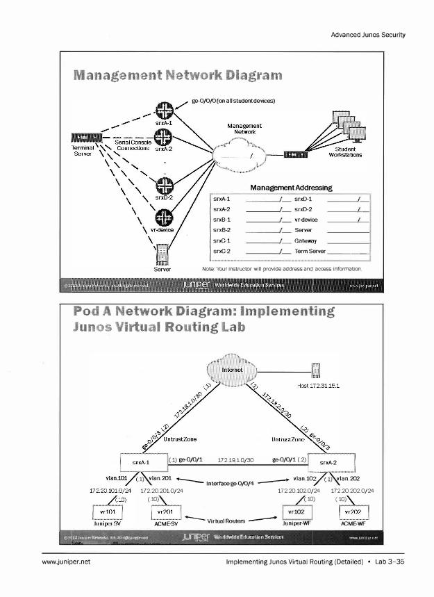
Advanced Junos Security
Management Network Diagram
Server
ge-0/0/0(on all studentdevices)
Management Addressing
srxA-1
srxA-2
srxB-1
srxB-2
srxG-1
srxG-2
srxD-1
srxD-2
vr-device
Server
Gateway
Term Server ______ ,,
Note: Your instructor will provide address and access information.
Pod A Network Diagram: Implementing
Junos Virtual Routing Lab
(1) ge-0/0/1 172 1910/30 ge-0/0/1 (.2) srxA-2
(1) vlan.201 -- -- vlan.!00�) vlan.202 Interface ge-0/0/4
172 20.201 0/24 172 20 102 0/24 172.20.202.0/24
(.� (.� (.�
ACME-SV -- Virtual Ro uters -- Juniper-WF ACME-WF
1;;JuptrN��. !M:.Altr!gtiUuutiwd JU(1JW Worldwide Education Services mvwJun1pern"'t ��---,�-=-VA --�= -
www.juniper.net lmplementingJunos Virtual Routing (Detailed) • Lab 3-35
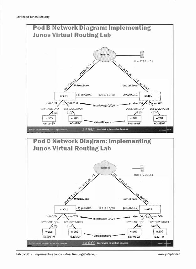
Advanced Junos Security
Pod B Network Diagram: Implementing
Junos Virtual Routing Lab
vlan.103
Juniper -SY
Host 172.31.15.1
(.1) ge-0/0/1 172.19.1.D/30
(.1) vlan.203 -- lnterfacege-0/0/4 -- vlan.104 172.20.203.D/24 172.20.104.0/24
(.� (.�
ACME-SY -- Virtual Routers -- Juniper-WF ACME-WF
tt,2013JunlperNetw'>OO, Inc All rl�\$reserved Jun� Worldwide Education Services WNW Jun1p - � - - A - - <""'-"•- -1
Pod C Network Diagram: Implementing
Junos Virtual Routing Lab
c\',,c
'b'),• '},'>'
�
(.1) ge-0/0/1
Ai-----� '<'Y' t:{J Host 172.31.15.1
172.19.1.0/30
vlan.105 (.1) vlan.205 -- Interface ge-0/0/4 172.20.205.0/24
(10)
Juniper-SY
0:�0.!.3Jullli;,t:rNt.t'#ork$, lne-.AUt!�ts tt�IJ:r.tl!d JUn!£?€r Worldwide Education Services WWY'J 1un1p - �- -�--�-1-- - -
Lab 3-36 • Implementing Ju nos Virtual Routing (Detailed) www.juniper.net

Advanced Junos Security
Pod D Network Diagram: Implementing
Junos Virtual Routing Lab
vlan.107
Juniper -SY
www.juniper.net
(.1) ge-0/0/1 172.191.Q/30
(.1) vlan.207 --- lnterfacege-0/0/4 -- vlan.108
172 20 2070/24 172.20.1080/24 (.� (.�
ACME-SY ...__ Virtual Routers -- Juniper-WF ACME-WF
lmplementingJunos Virtual Routing (Detailed) • Lab 3-37

Advanced Junos Security
Lab 3-38 • Implementing Ju nos Virtual Routing (Detailed) www.juniper.net
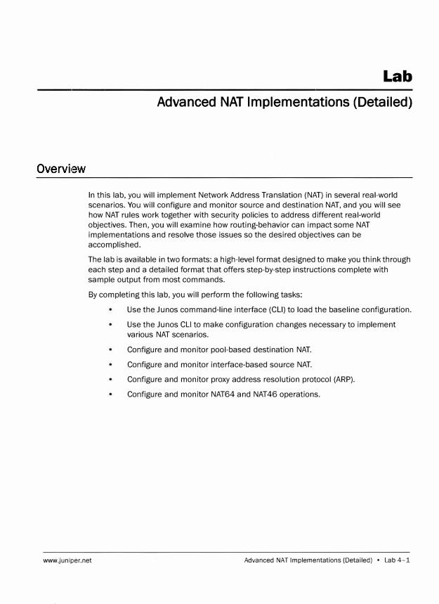
Lab
Advanced NAT Implementations (Detailed)
In this lab, you will implement Network Address Translation (NAT) in several real-world
scenarios. You will configure and monitor source and destination NAT, and you will see
how NAT rules work together with security policies to address different real-world
objectives. Then, you will examine how routing-behavior can impact some NAT
implementations and resolve those issues so the desired objectives can be
accomplished.
The lab is available in two formats: a high-level format designed to make you think through
each step and a detailed format that offers step-by-step instructions complete with
sample output from most commands.
By completing this lab, you will perform the following tasks:
www.juniper.net
Use the Ju nos command-line interface (CLI) to load the baseline configuration.
Use the Ju nos CLI to make configuration changes necessary to implement
various NAT scenarios.
Configure and monitor pool-based destination NAT.
Configure and monitor interface-based source NAT.
Configure and monitor proxy address resolution protocol (ARP).
Configure and monitor NAT64 and NAT46 operations.
Advanced NAT Implementations (Detailed) • Lab 4-1
Advanced Junes Security
Part 1: Loading the Baseline Configuration
Step 1.1
Step 1.2
Step 1.3
srxA-1 (ttyuO)
login: lab
In this lab part, you load the baseline configuration. You will also work witi1 the
remote student team within your pod, and execute a quick verification that you can
reach the remote team's device through the use of the ping utility and review the
route being used. You will also make configuration changes that will allow you to
implement advanced NAT scenarios presented in subsequent parts.
Ensure that you know to which student device you have been assigned. Check with
your instructor if you are not certain. Consult the Management Network Diagram to
determine the management address of your student device.
Question: What is the management address
assigned to your student router?
Answer: The answer varies. The sample hostname
and IP address used in the output examples in this
lab are for srxA-1, which uses 10.210.35.131 as its
management IP address. The actual management
address varies between delivery environments.
Access the command-line interface (CLI) at your station using either the console,
Telnet, or SSH as directed by your instructor.
O Show quick connect on sta1tup � Save session
00penina tab
I, Connect ,! J Cancel l
Log in as user lab with the password labl2 3. Enter configuration mode and load
the lab4-start. configfrom the /var/home/lab/ajsec/ directory. Commit the
configuration and exit to operational mode when complete.
Lab 4-2 • Advanced NAT Implementations (Detailed) www.juniper.net
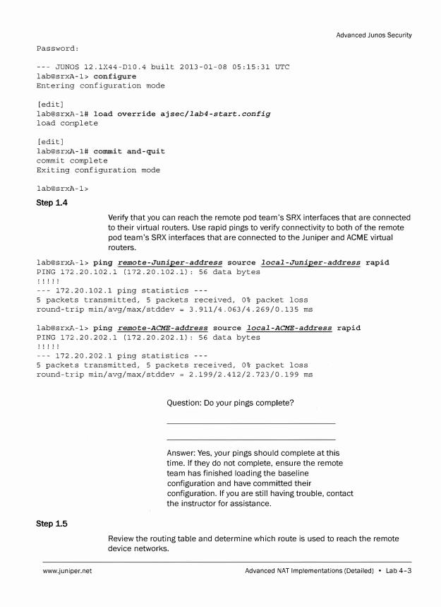
Password:
--- JUNOS 12.1X44-Dl0.4 built 2013-01-08 05:15:31 UTC
lab@srxl\.-1> configure
Entering configuration mode
[edit]
lab@srxl\.-1# load override ajsec/lab4-start.config
load complete
[edit]
lab@srxA-1# commit and-quit
commit complete
Exiting configuration mode
lab@srxl,-1>
Step 1.4
Advanced Junes Security
Verify that you can reach the remote pod team's SRX interfaces that are connected
to their virtual routers. Use rapid pings to verify connectivity to both of the remote
pod team's SRX interfaces that are connected to the Juniper and ACME virtual
routers.
lab@srxA-1> ping remote-Juniper-address source local-Juniper-address rapid
PING 172.20.102.1 (172.20.102.1): 56 data bytes
! ! ! ! !
--- 172.20.102.1 ping statistics ---
5 packets transmitted, 5 packets received, 0% packet loss
round-trip min/avg/max/stddev = 3.911/4.063/4.269/0.135 ms
lab@srxA-1> ping remote-ACME-address source local-ACME-address rapid
PING 172.20.202.1 (172.20.202.1): 56 data bytes
! ! ! ! !
--- 172.20.202.1 ping statistics ---
5 packets transmitted, 5 packets received, 0% packet loss
round-trip min/avg/max/stddev = 2.199/2.412/2.723/0.199 ms
Step 1.5
www.juniper.net
Question: Do your pings complete?
Answer: Yes, your pings should complete at this
time. If they do not complete, ensure the remote
team has finished loading the baseline
configuration and have committed their
configuration. If you are still having trouble, contact
the instructor for assistance.
Review the routing table and determine which route is used to reach the remote
device networks.
Advanced NAT Implementations (Detailed) • Lab 4-3
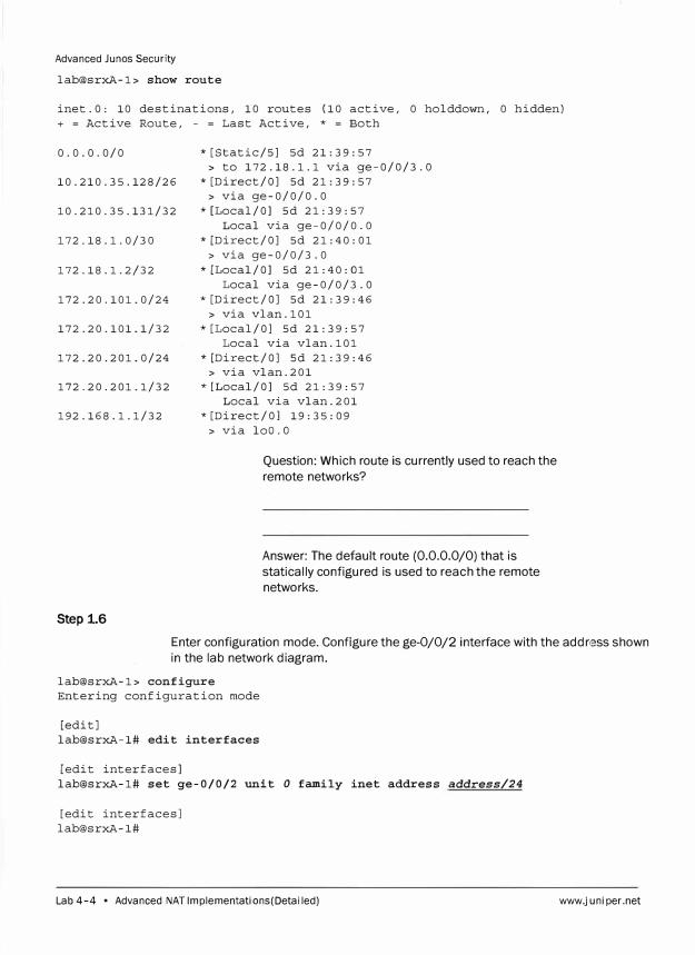
Advanced Junos Security
lab@srxA-1> show route
inet.O: 10 destinations, 10 routes (10 active, 0 holddown, 0 hidden)
+ = Active Route, - = Last Active, * = Both
0.0.0.0/0
10.210.35.128/26
10.210.35.131/32
172.18.1.0/30
172.18.1.2/32
172.20.101.0/24
172.20.101.1/32
172.20.201.0/24
172.20.201.1/32
192.168.1.1/32
Step 1.6
*[Static/SJ Sd 21:39:57
> to 172.18.1.1 via ge-0/0/3.0
*[Direct/OJ Sd 21:39:57
> via ge-0/0/0.0
*[Local/OJ Sd 21:39:57
Local via ge-0/0/0.0
*[Direct/OJ Sd 21:40:01
> via ge-0/0/3.0
* [Local/OJ Sd 21: 40: 01
Local via ge-0/0/3.0
*[Direct/OJ Sd 21:39:46
> via vlan.101
*[Local/OJ Sd 21:39:57
Local via vlan.101
*[Direct/OJ 5d 21:39:46
> via vlan.201
*[Local/OJ Sd 21:39:57
Local via vlan.201
* [Direct/OJ 19: 35: 09
> via loo.a
Question: Which route is currently used to reach the
remote networks?
Answer: The default route (0.0.0.0/0) that is
statically configured is used to reach the remote
networks.
Enter configuration mode. Configure the ge-0/0/2 interface with the address shown
in the lab network diagram.
lab@srxA-1> configure
Entering configuration mode
[edit]
lab@srxA-1# edit interfaces
[edit interfaces]
lab@srxA-1# set ge-0/0/2 unit O family inet address address/24
[edit interfaces]
lab@srxA-1#
Lab 4-4 • Advanced NAT Implementations (Detailed) www.juniper.net
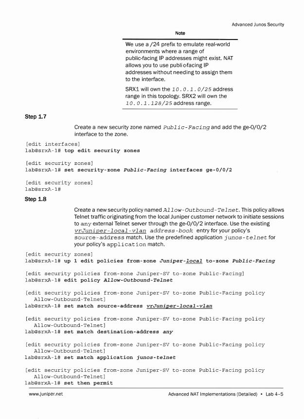
Step 1.7
Advanced Ju nos Security
Note
We use a /24 prefix to emulate real-world
environments where a range of
public-facing IP addresses might exist. NAT
allows you to use publi c -facing IP
addresses without needing to assign them
to the interface.
SRX1 will own the 10. o .1. 0/25 address
range in this topology. SRX2 will own the
1 o. o .1.128/25 address range.
Create a new security zone named Public-Facing and add the ge-0/0/2
interface to the zone.
[edit interfaces] lab@srxll,-1# top edit security zones
[edit se,curity zones] lab@srxll,-1# set security-zone Public-Facing interfaces ge-0/0/2
[edit security zones] [email protected]#
Step 1.8
Create a new security policy named Allow-Outbound-Telnet. This policy allows
Telnet traffic originating from the local Juniper customer network to initiate sessions
to any external Telnet server through the ge-0/0/2 interface. Use the existing
vrJuniper-local-vlan address-book entry for your policy's
source-address match. Use the predefined application j unos-telnet for
your policy's application match.
[edit security zones] [email protected]# up 1 edit policies from-zone Juniper-local to-zone Public-Facing
[edit security policies from-zone Juniper-SV to-zone Public-Facing] lab@srxA-1# edit policy Allow-Outbound-Telnet
[edit security policies from-zone Juniper-SV to-zone Public-Facing policy Allow-Outbound-Telnet]
lab@srxA-1# set match source-address vrJuniper-local-vlan
[edit security policies from-zone Juniper-SV to-zone Public-Facing policy Allow-Outbound-Telnet]
lab@srxA-1# set match destination-address any
[edit security policies from-zone Juniper-SV to-zone Public-Facing policy Allow-Outbound-Telnet]
lab@srxA-1# set match application junos-telnet
[edit security policies from-zone Juniper-SV to-zone Public-Facing policy Allow-Outbound-Telnet]
lab@srxA-1# set then permit
www.junip,er.net Advanced NAT Implementations (Detailed) • Lab 4-5

Advanced Junos Security
[edit security policies from-zone Juniper-SV to-zone Public-Facing policy Allow-Outbound-Telnet]
lab@srxA-1# show match {
source-address vrlOl; destination-address any; application junos-telnet;
then {
permit;
[edit security policies from-zone Juniper-SV to-zone Public-Facing policy Allow-Outbound-Telnet]
lab@srxA-1#
Step 1.9
Note
You will configure inbound security policies
later as part of your NAT implementations.
Delete the existing static default route and create a new static default route for your
assigned SRX device. The new route should use the IP address associated with the
remote team's ge-0/0/2 interface as the next hop.
[edit security policies from-zone Juniper-SV to-zone Public-Facing policy Allow-Outbound-Telnet]
lab@srxA-1# top edit routing-options
[edit routing-options] lab@srxA-1# delete static route 0/0
[edit routing-options] lab@srxA-1# set static route 0/0 next-hop address
[edit routing-options] lab@srxA-1# show static route 0.0.0.0/0 next-hop 10.0.1.129;
[edit routing-options] lab@srxA-1#
Step 1.10
Navigate to the top of the configuration hierarchy. Remove all stateless firewall filter
configuration on your assigned SRX device. When you are finished, commit the
configuration.
Lab 4-6 • Advanced NAT Implementations (Detailed) www.juniper.net
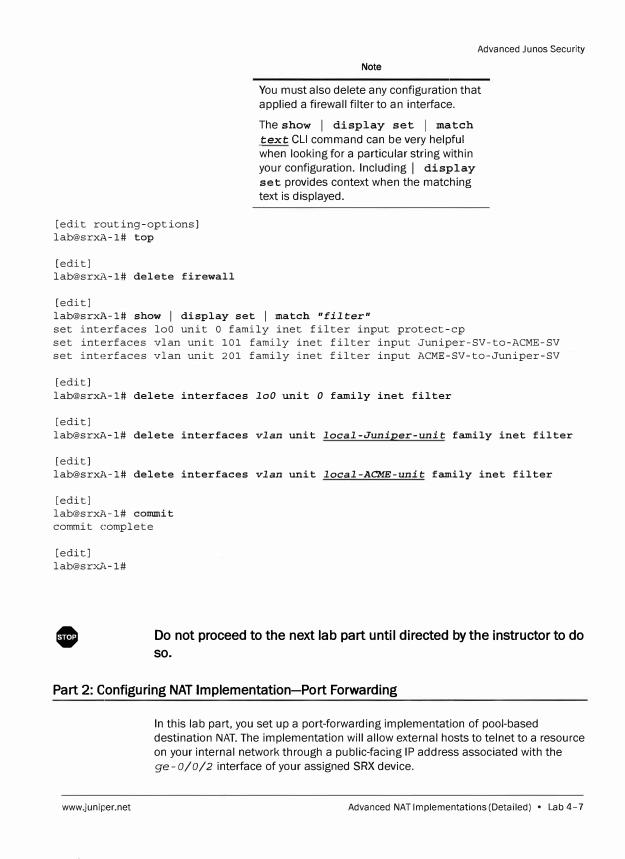
Advanced Junes Security
Note
You must also delete any configuration that applied a firewall filter to an interface.
Theshow I display set I match text CLI command can be very helpful when looking for a particular string within your configuration. Including I display
set provides context when the matching text is displayed.
[edit routing-options]
lab@srxA-1# top
[edit]
lab@srxJ\-1# delete firewall
[edit]
lab@srxJ\-1# show I display set I match "filter"
set interfaces loO unit O family inet filter input protect-cp
set interfaces vlan unit 101 family inet filter input Juniper-SV-to-ACME-SV
set interfaces vlan unit 201 family inet filter input ACME-SV-to-Juniper-SV
[edit]
lab@srxA-1# delete interfaces loO unit O family inet filter
[edit]
lab@srxA-1# delete interfaces vlan unit local-Juniper-unit family inet filter
[edit]
lab@srxl,-1# delete interfaces vlan unit local-ACME-unit family inet filter
[edit]
lab@srxl,-1# commit
commit complete
[edit]
lab@srxA-1#
0 Do not proceed to the next lab part until directed by the instructor to do
so.
Part 2: Configuring NAT Implementation-Port Forwarding
www.juniper.net
In this lab part, you set up a port-forwarding implementation of pool-based destination NAT. The implementation will allow external hosts to telnet to a resource on your internal network through a public-facing IP address associated with the ge-0/0/2 interface of your assigned SRX device.
Advanced NAT Implementations (Detailed) • Lab 4-7
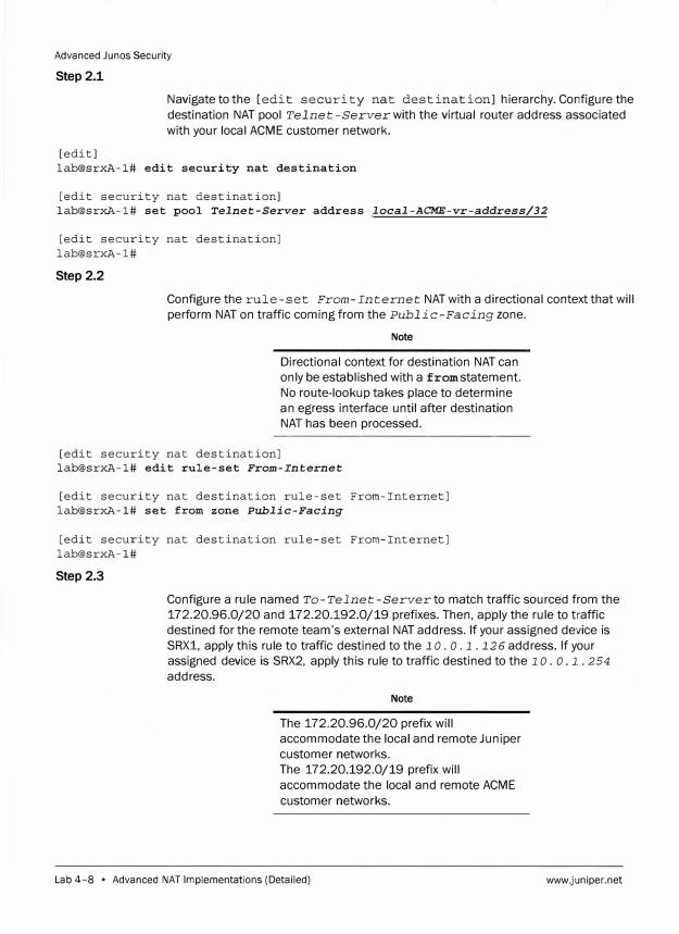
Advanced Ju nos Security
Step 2.1
Navigate to the [edit security nat destination] hierarchy. Configure the
destination NAT pool Telnet-Server with the virtual router address associated
with your local ACME customer network.
[edit] lab@srxA-1# edit security nat destination
[edit security nat destination] lab@srxA-1# set pool Telnet-Server address local-ACME-vr-address/32
[edit security nat destination] lab@srxA-1#
Step 2.2
Configure the rule-set From-Internet NAT with a directional context that will
perform NAT on traffic coming from the Public-Facing zone.
Note
Directional context for destination NAT can
only be established with a from statement.
No route-lookup takes place to determine
an egress interface until after destination
NAT has been processed.
[edit security nat destination] lab@srxA-1# edit rule-set From-Internet
[edit security nat destination rule-set From-Internet] lab@srxA-1# set from zone Public-Facing
[edit security nat destination rule-set From-Internet] lab@srxA-1#
Step 2.3
Configure a rule named To-Telnet-Server to match traffic sourced from the
172.20.96.0/20 and 172.20.192.0/19 prefixes. Then, apply the rule to traffic
destined for the remote team's external NAT address. If your assigned device is
SRXl, apply this rule to traffic destined to the 1 o. o .1. 126 address. If your
assigned device is SRX2, apply this rule to traffic destined to the 1 o. o .1.. 254
address.
Note
The 172.20.96.0/20 prefix will
accommodate the local and remote Juniper
customer networks.
The 172.20.192.0/19 prefix will
accommodate the local and remote ACME
customer networks.
Lab 4-8 • Advanced NAT Implementations (Detailed) www.juniper.net
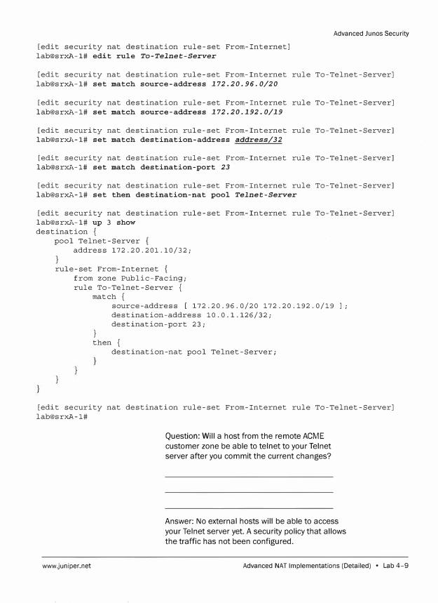
[edit security nat destination rule-set From-Internet] lab@srxl,-1# edit rule To-Telnet-Server
Advanced Ju nos Security
[edit security nat destination rule-set From-Internet rule To-Telnet-Server] lab@srxl,-1# set match source-address 172.20.96.0/20
[edit security nat destination rule-set From-Internet rule To-Telnet-Server] lab@srxl,-1# set match source-address 172.20.192.0/19
[edit security nat destination rule-set From-Internet rule To-Telnet-Server] lab@srxl,-1# set match destination-address address/32
[edit security nat destination rule-set From-Internet rule To-Telnet-Server] lab@srxl,-1# set match destination-port 23
[edit security nat destination rule-set From-Internet rule To-Telnet-Server] lab@srxA-1# set then destination-nat pool Telnet-Server
[edit security nat destination rule-set From-Internet rule To-Telnet-Server] lab@srxA-1# up 3 show destination {
pool Telnet-Server address 172.20.201.10/32;
rule-set From-Internet { from zone Public-Facing; rule To-Telnet-Server {
match {
}
source-address [ 172.20.96.0/20 172.20.192.0/19 ]; destination-address 10.0.1.126/32; destination-port 23;
then { destination-nat pool Telnet-Server;
[edit security nat destination rule-set From-Internet rule To-Telnet-Server] [email protected]#
www.juniper.net
Question: Will a host from the remote ACME
customer zone be able to telnet to your Telnet
server after you commit the current changes?
Answer: No external hosts will be able to access
your Telnet server yet. A security policy that allows
the traffic has not been configured.
Advanced NAT Implementations (Detailed) • Lab 4-9
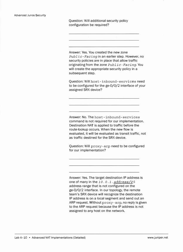
Advanced Ju nos Security
Question: Will additional security policy
configuration be required?
Answer: Yes. You created the new zone
Public-Facing in an earlier step. However, no
security policies are in place that allow traffic
originating from the zone Public-Facing. You
will create the appropriate security policy in a
subsequent step.
Question: Will host-inbound-services need
to be configured for the ge-0/0/2 interface of your
assigned SRX device?
Answer: No. The host-inbound-services
command is not required for our implementation.
Destination NAT is applied to traffic before the
route-lookup occurs. When the new flow is
evaluated, it will be evaluated as transit traffic, not
as traffic destined for the SRX device.
Question: Will proxy-arp need to be configured
for our implementation?
Answer: Yes. The target destination IP address is
one of many in the 1 o. o. 1. address/2 5
address range that is not configured on the
ge-0/0/2 interface. In our topology, the remote
team's SRX device will recognize the destination
IP address is on a local segment and send out an
ARP request. Withoutproxy-arp, no reply is given
to the ARP request because the IP address is not
assigned to any host on the network.
Lab 4-10 • Advanced NAT Implementations (Detailed) www.juniper.net
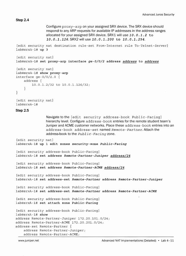
Advanced Junos Security
Step 2.4
Configure proxy-arp on your assigned SRX device. The SRX device should
respond to any ARP requests for availa ble IP addresses in the address ranges
allocated for your assigned SRX device. SRX1 will use 1 o. o. 1. 2 to
10. 0.1.126. SRX2 will use 10. 0.1.200 to 10. 0.1.254.
[edit security nat destination rule-set From-Internet rule To-Telnet-Server] lab@srxA-1# up 3
[edit security natl lab@srxA-1# set proxy-arp interface ge-0/0/2 address address to address
[edit security natl lab@srxA-1# show proxy-arp interface ge-0/0/2.0 {
address { 10.0.1.2/32 to 10.0.1.126/32;
[edit security natl lab@srxA-1#
Step 2.5
Navigate to the [edit security address-book Public-Facing] hierarchy level. Configure address -book entries for the remote student team's Juniper and ACME customer networks. Place these address-book entries into an address-book address-set named Remote-Partner. Attach the address-book to the Public-Facing zone.
[edit security natl lab@srxl,-1# up 1 edit zones security-zone Public-Facing
[edit security address-book Public-Facing) lab@srxl,-1# set address Remote-Partner-Juniper address/24
[edit security address-book Public-Facing) lab@srxl',-1# set address Remote-Partner-ACME address/24
[edit security address-book Public-Facing) lab@srxl'.-1# set address-set Remote-Partner address Remote-Partner-Juniper
[edit security address-book Public-Facing] lab@srxl',-1# set address-set Remote-Partner address Remote-Partner-ACME
[edit security address-book Public-Facing] lab@srxl'.-1# set attach zone Public-Facing
[edit security address-book Public-Facing] lab@srxll,-1# show address Remote-Partner-Juniper 172.20.101.0/24; address Remote-Partner-ACME 172.20.201.0/24; address-set Remote-Partner {
address Remote-Partner-Juniper; address Remote-Partner-ACME;
www.juniper.net Advanced NAT Implementations (Detailed) • Lab 4-11
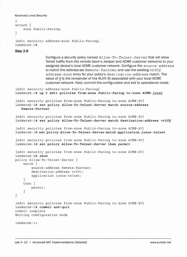
Advanced Junos Security
} attach {
zone Public-Facing;
[edit security address-book Public-Facing] lab@srxA-1#
Step 2.6
Configure a security policy named Allow-To-Telnet-Server that will allow Telnet traffic from the remote team's Juniper and ACME customer networl<s to your assigned device's local ACME customer network. Configure the source-address to match the address-set Remote-Partner, and use the existing vr2oy
address-book entry for your policy's destination-address match. The value of y is the remainder of the VLAN ID associated with your local ACME
customer network. Next, commit the configuration and exit to operational mode.
[edit security address-book Public-Facing] lab@srxA-1# up 2 edit policies from-zone Public-Facing to-zone ACME-local
[edit security policies from-zone Public-Facing to-zone ACME-SV] lab@srxA-1# set policy Allow-To-Telnet-Server match source-address
Remote-Partner
[edit security policies from-zone Public-Facing to-zone ACME-SV] lab@srxA-1# set policy Allow-To-Telnet-Server match destination-address vr20�
[edit security policies from-zone Public-Facing to-zone ACME-SV] lab@srxA-1# set policy Allow-To-Telnet-Server match application junos-telnet
[edit security policies from-zone Public-Facing to-zone ACME-SV] lab@srxA-1# set policy Allow-To-Telnet-Server then permit
[edit security policies from-zone Public-Facing to-zone ACME-SV] lab@srxA-1# show policy Allow-To-Telnet-Server {
match {
}
source-address Remote-Partner; destination-address vr201; application junos-telnet;
then { permit;
[edit security policies from-zone Public-Facing to-zone ACME-SV] lab@srxA-1# commit and-quit commit complete Exiting configuration mode
lab@srxA-1>
Lab 4-12 • Advanced NAT Implementations (Detailed) www.juniper.net
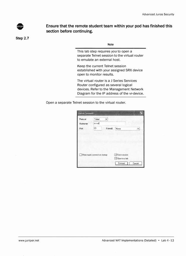
Step 2.7
www.juniper.net
Advanced Junos Security
Ensure that the remote student team within your pod has finished this
section before continuing.
Note
This lab step requires you to open a
separate Telnet session to the virtual router
to emulate an external host.
Keep the current Telnet session
established with your assigned SRX device
open to monitor results.
The virtual router is a J Series Services
Router configured as several logical
devices. Refer to the Management Network
Diagram for the IP address of the vr-device.
Open a separate Telnet session to the virtual router.
O Show quick connect on startup 0 Save session
0 Open in a tab
I, Connect 1! I Cancel I
Advanced NAT Implementations (Detailed) • Lab 4-13
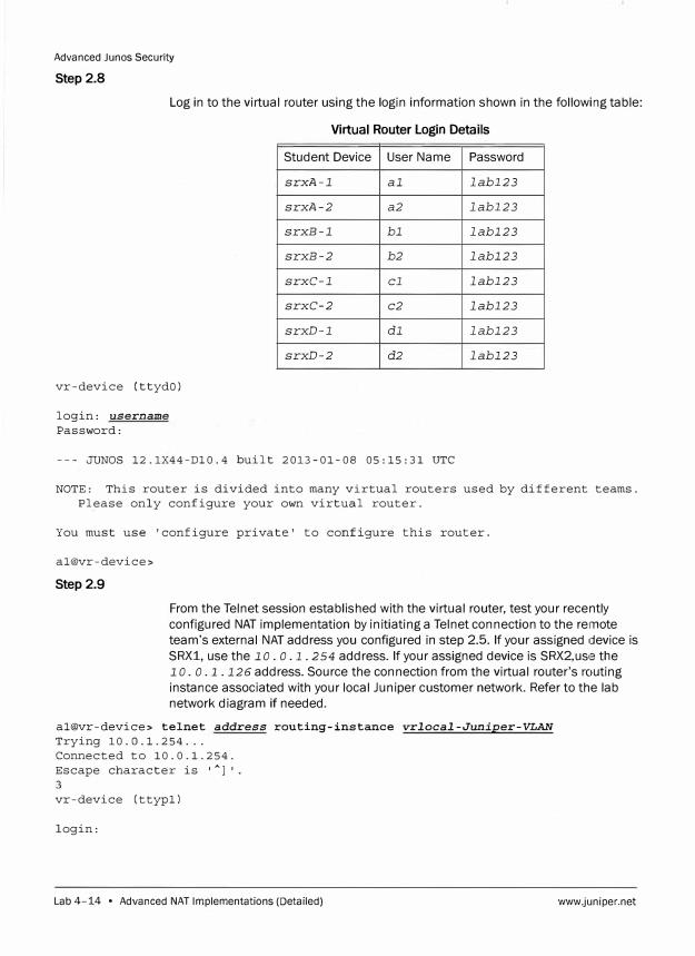
Advanced Junos Security
Step 2.8
Log in to the virtual router using the login information shown in the following table:
Virtual Router Login Details
vr-device (ttydO)
login: username
Password:
Student Device
srxA-1
srxA-2
srxB-1
srxB-2
srxC-1
srxC-2
srxD-1
srxD-2
User Name
al
a2
bl
b2
cl
c2
dl
d2
--- JUNOS 12.1X44-Dl0.4 built 2013-01-08 05:15:31 UTC
Password
labl23
labl23
labl23
labl23
labl23
labl23
labl23
labl23
NOTE: This router is divided into many virtual routers used by different teams.
Please only configure your own virtual router.
You must use 'configure private' to configure this router.
al@vr-device>
Step 2.9
From the Telnet session established with the virtual router, test your recently
configured NAT implementation by initiating a Telnet connection to the remote
team's external NAT address you configured in step 2.5. If your assigned device is
SRX1, use the 1 o. o. 1. 2 54 address. If your assigned device is SRX2,use the
1 o. o .1. 126 address. Source the connection from the virtual router's routing
instance associated with your local Juniper customer network. Refer to the lab
network diagram if needed.
al@vr-device> telnet address routing-instance vrlocal-Juniper-VLAN
Trying 10.0.1.254 ...
Connected to 10.0.1.254.
Escape character is 'A
l'
vr-device (ttypl)
login:
Lab 4-14 • Advanced NAT Implementations (Detailed) www.juniper.net
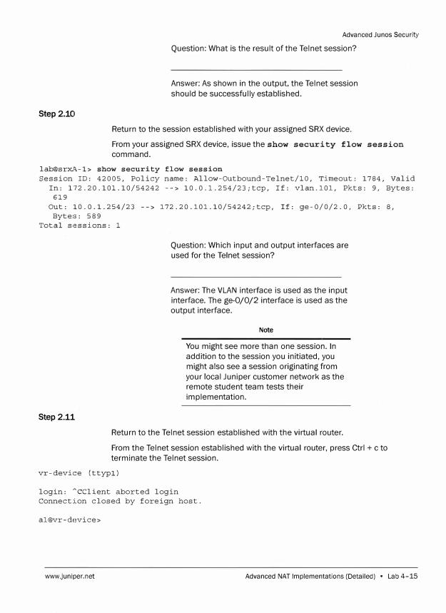
Step 2.10
Advanced Junos Security
Question: What is the result of the Telnet session?
Answer: As shown in the output, the Telnet session
should be successfully established.
Return to the session established with your assigned SRX device.
From your assigned SRX device, issue the show security flow session
command.
lab@srxA-1> show security flow session Session ID: 42005, Policy name: Allow-Outbound-Telnet/10, Timeout: 1784, Valid
In: 172.20.101.10/54242 --> 10.0.l.254/23;tcp, If: vlan.101, Pkts: 9, Bytes: 619
Out: 10.0.1.254/23 --> 172.20.101.10/54242;tcp, If: ge-0/0/2.0, Pkts: 8, Bytes: 589
Total sessions: 1
Step 2.11
Question: Which input and output interfaces are
used for the Telnet session?
Answer: The VLAN interface is used as the input
interface. The ge-0/0/2 interface is used as the
output interface.
Note
You might see more than one session. In
addition to the session you initiated, you
might also see a session originating from
your local Juniper customer network as the
remote student team tests their
implementation.
Return to the Telnet session established with the virtual router.
From the Telnet session established with the virtual router, press Ctrl + c to
terminate the Telnet session.
vr-device (ttypl)
login: "cclient aborted login Connection closed by foreign host.
al@vr-device>
www.juniper.net Advanced NAT Implementations (Detailed) • Lab 4-15
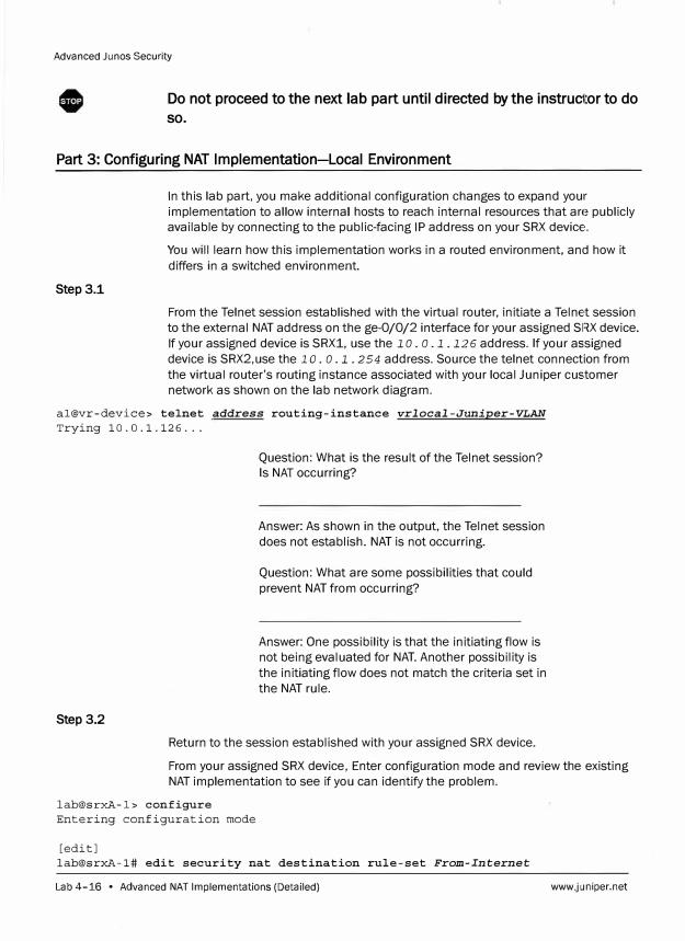
Advanced Junes Security
Do not proceed to the next lab part until directed by the instruc1tor to do
so.
Part 3: Configuring NAT Implementation-Local Environment
Step 3.1
In this lab part, you make additional configuration changes to expand your
implementation to allow internal hosts to reach internal resources that are publicly
available by connecting to the public-facing IP address on your SRX device.
You will learn how this implementation works in a routed environment, and how it
differs in a switched environment.
From the Telnet session established with the virtual router, initiate a Telnet session
to the external NAT address on the ge-0/0/2 interface for your assigned SF�X device.
If your assigned device is SRX1, use the 1 o. o. l .126 address. If your assigned
device is SRX2,use the lo. o. l. 2 54 address. Source the telnet connection from
the virtual router's routing instance associated with your local Juniper customer
network as shown on the lab network diagram.
al@vr-device> telnet address routing-instance vrlocal-Juniper-VLAN
Trying 10.0.1.126 ...
Step 3.2
Question: What is the result of the Telnet session?
Is NAT occurring?
Answer: As shown in the output, the Telnet session
does not establish. NAT is not occurring.
Question: What are some possibilities that could
prevent NAT from occurring?
Answer: One possibility is that the initiating flow is
not being evaluated for NAT. Another possibility is
the initiating flow does not match the criteria set in
the NAT rule.
Return to the session established with your assigned SRX device.
From your assigned SRX device , Enter configuration mode and review the existing
NAT implementation to see if you can identify the problem.
lab@srxA-1> configure
Entering configuration mode
[edit]
lab@srxA-1# edit security nat destination rule-set From-Internet
Lab 4-16 • Advanced NAT Implementations (Detailed) www.juniper.net
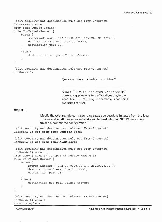
[edit security nat destination rule-set From-Internet] lab@srxA-1# show from zone Public-Facing; rule To-Telnet-Server {
match {
}
source-address [ 172.20.96.0/20 172.20.192.0/19 ]; destination-address 10.0.1.126/32; destination-port 23;
then { destination-nat pool Telnet-Server;
[edit security nat destination rule-set From-Internet] lab@srxA-1#
Question: Can you identify the problem?
Advanced Ju nos Security
Answer: The rule-set From-Internet NAT currently applies only to traffic originating in the
zone Public-Facing. Other traffic is not being evaluated for NAT.
Step 3.3
Modify the existing rule set From-Internet so sessions initiated from the local Juniper and ACME customer networks will be evaluated for NAT. When you are finished, commit the configuration.
[edit security nat destination rule-set From-Internet] lab@srxA-1# set from zone Juniper-local
[edit security nat destination rule-set From-Internet] lab@srxi\-1# set from zone ACME-local
[edit security nat destination rule-set From-Internet] lab@srxi\-1# show from zone [ ACME-SV Juniper-SV Public-Facing J; rule To··Telnet-Server {
match { source-address [ 172.20.96.0/20 172.20.192.0/19 J; destination-address 10.0.1.126/32; destination-port 23;
} then {
destination-nat pool Telnet-Server;
[edit security nat destination rule-set From-Internet] lab@srxA-1# commit commit complete
www.juniper.net Advanced NAT Implementations (Detailed) • Lab 4-17
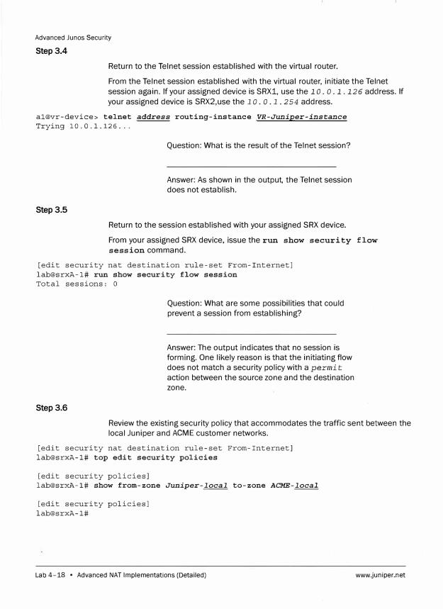
Advanced Junos Security
Step 3.4
Return to the Telnet session established with the virtual router.
From the Telnet session established with the virtual router, initiate the Telnet
session again. If your assigned device is SRX1, use the 1 o. o. 1. 126 adclress. If
your assigned device is SRX2,use the 1 o. o .1. 254 address.
al@vr-device> telnet address routing-instance VR-Juniper-instance
Trying 10.0.1.126 ...
Step 3.5
Question: What is the result of the Telnet session?
Answer: As shown in the output, the Telnet session does not establish.
Return to the session established with your assigned SRX device.
From your assigned SRX device, issue the run show security flow
session command.
[edit security nat destination rule-set From-Internet] lab@srxA-1# run show security flow session Total sessions: O
Step 3.6
Question: What are some possibilities that could
prevent a session from establishing?
Answer: The output indicates that no session is forming. One likely reason is that the initiating flow
does not match a security policy with a permit
action between the source zone and the destination
zone.
Review the existing security policy that accommodates the traffic sent between the
local Juniper and ACME customer networks.
[edit security nat destination rule-set From-Internet] lab@srxA-1# top edit security policies
[edit security policies] lab@srxA-1# show from-zone Juniper-local to-zone ACME-local
[edit security policies] lab@srxA-1#
Lab 4-18 • Advanced NAT Implementations (Detailed) www.juniper.net
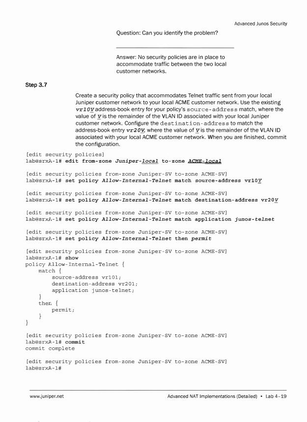
Step 3.7
Question: Can you identify the problem?
Answer: No security policies are in place to accommodate traffic between the two local customer networks.
Advanced Junos Security
Create a security policy that accommodates Telnet traffic sent from your local Juniper customer network to your local ACME customer network. Use the existing vrl oyaddress-book entry for your policy's source-address match, where the value of yis the remainder of the VLAN ID associated with your local Juniper customer network. Configure the destination-address to match the address-book entry vr20Y, where the value of yis the remainder of the VLAN ID associated with your local ACME customer network. When you are finished, commit the configuration.
[edit security policies] [email protected],-1# edit from-zone Juniper-local to-zone ACME-local
[edit security policies from-zone Juniper-SV to-zone ACME-SV] [email protected],-1# set policy Allow-Internal-Telnet match source-address vrlOy
[edit security policies from-zone Juniper-SV to-zone ACME-SV] lab@sr:X.Z,-1# set policy Allow-Internal-Telnet match destination-address vr20V
[edit security policies from-zone Juniper-SV to-zone ACME-SV] lab@srxA-1# set policy Allow-Internal-Telnet match application junos-telnet
[edit security policies from-zone Juniper-SV to-zone ACME-SV] [email protected],-1# set policy Allow-Internal-Telnet then permit
[edit se,curity policies from-zone Juniper-SV to-zone ACME-SV] lab@srxA-1# show policy Allow-Internal-Telnet {
match {
}
source-address vrlOl; destination-address vr201; application junos-telnet;
then. { permit;
[edit security policies from-zone Juniper-SV to-zone ACME-SV] [email protected]# commit commit complete
[edit security policies from-zone Juniper-SV to-zone ACME-SV] lab@srxA-1#
www.juniper.net Advanced NAT Implementations (Detailed) • Lab 4-19
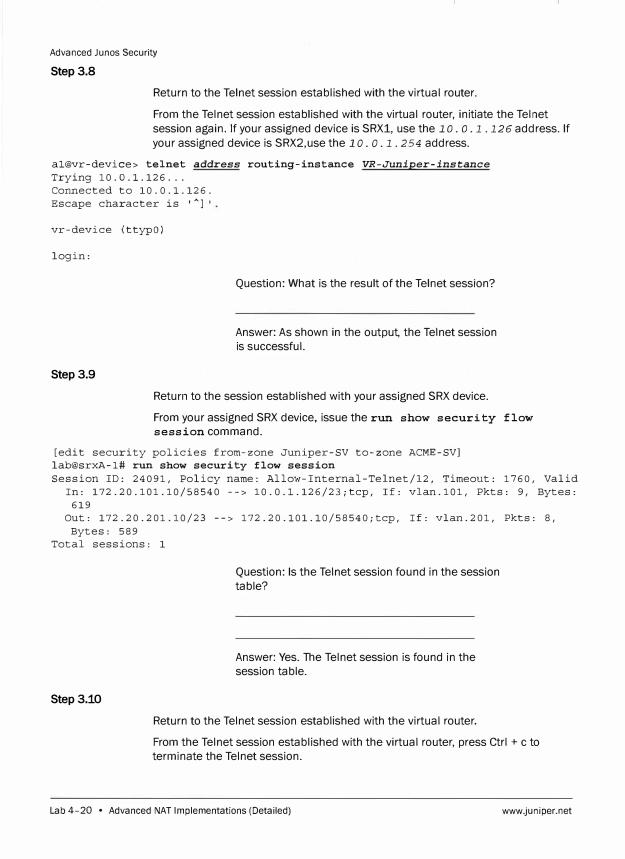
Advanced Junos Security
Step 3.8
Return to the Telnet session established with the virtual router.
From the Telnet session established with the virtual router, initiate the Telnet
session again. If your assigned device is SRX1, use the 1 o. o. 1. 126 address. If
your assigned device is SRX2,use the lo. o. 1. 254 address.
al@vr-device> telnet address routing-instance VR-Juniper-instance
Trying 10.0.1.126 ... Connected to 10.0.1.126. Escape character is '
Al•
vr-device (ttypO)
login:
Step 3.9
Question: What is the result of the Telnet session?
Answer: As shown in the output, the Telnet session
is successful.
Return to the session established with your assigned SRX device.
From your assigned SRX device, issue the run show security flow
session command.
[edit security policies from-zone Juniper-SV to-zone ACME-SV] lab@srxA-1# run show security flow session Session ID: 24091, Policy name: Allow-Internal-Telnet/12, Timeout: 1760, Valid
In: 172.20.101.10/58540 --> 10.0.l.126/23;tcp, If: vlan.101, Pkts: 9, Bytes: 619
Out: 172.20.201.10/23 --> 172.20.101.10/58540;tcp, If: vlan.201, Pkts: 8, Bytes: 589
Total sessions: 1
Step3.10
Question: Is the Telnet session found in the session
table?
Answer: Yes. The Telnet session is found in the
session table.
Return to the Telnet session established with the virtual router.
From the Telnet session established with the virtual router, press Ctrl + c to
terminate the Telnet session.
Lab 4-20 • Advanced NAT Implementations (Detailed) www.juniper.net
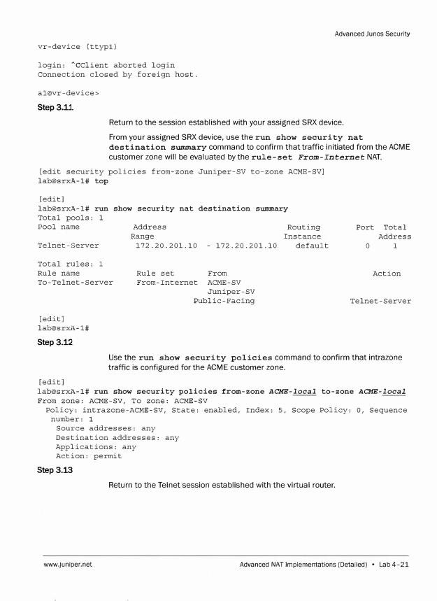
Advanced Junos Security
vr-device (ttypl)
login: ACClient aborted login Connection closed by foreign host.
al@vr-device>
Step3.U
Return to the session established with your assigned SRX device.
From your assigned SRX device, use the run show security nat
destination SUlllIIlary command to confirm that traffic initiated from the ACME
customer zone will be evaluated by the rule-set From-Internet NAT.
[edit security policies from-zone Juniper-SV to-zone ACME-SV] lab@srX:11.-1# top
[edit] lab@srX:11.-1# run show security nat destination summary Total pools: 1 Pool name
Telnet-Server
Total rules: 1 Rule name To-Telnet-Server
[edit] lab@srxA-1#
Step 3.12
Address Routing Instance Range
172.20.201.10 - 172.20.201.10 default
Rule set From From-Internet ACME-SV
Juniper-SV Public-Facing
Port Total Address
0 1
Action
Telnet-Server
Use the run show security policies command to confirm that intrazone
traffic is configured for the ACME customer zone.
[edit] lab@srxl,-1# run show security policies from-zone ACME-local to-zone ACME-local
From zone: ACME-SV, To zone: ACME-SV Policy: intrazone-ACME-SV, State: enabled, Index: 5, Scope Policy: 0, Sequence
number: 1 Source addresses: any Destination addresses: any Applications: any Action: permit
Step 3.13
Return to the Telnet session established with the virtual router.
www.juniper.net Advanced NAT Implementations (Detailed) • Lab 4-21
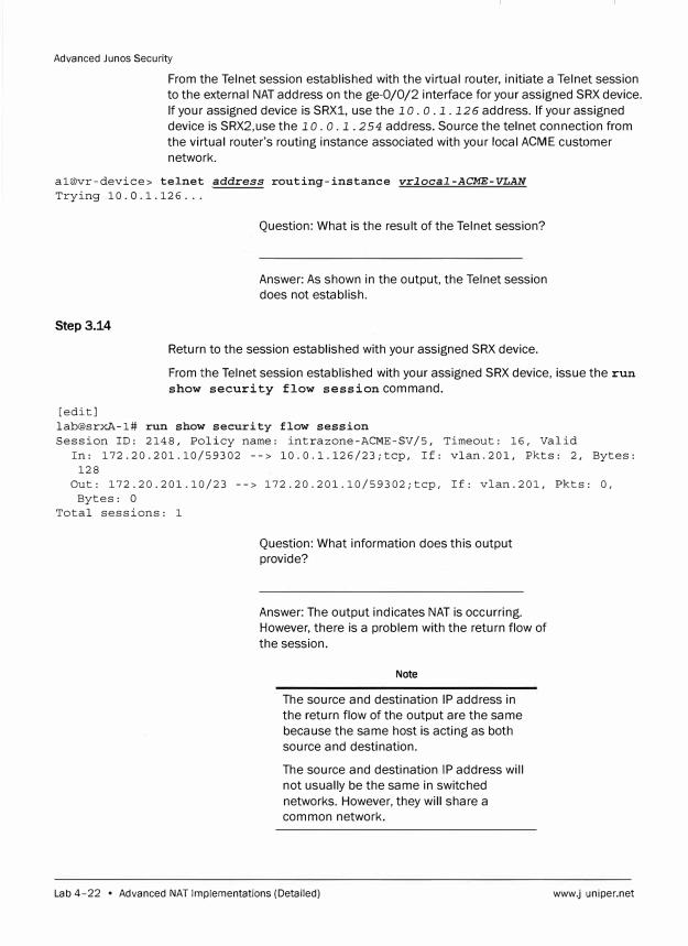
Advanced Junes Security
From the Telnet session established with the virtual router, initiate a Telnet session
to the external NAT address on the ge-0/0/2 interface for your assigned SRX device.
If your assigned device is SRX1, use the 1 o. o. 1. 126 address. If your assigned
device is SRX2,use the 1 o. o. 1. 2 54 address. Source the telnet connection from
the virtual router's routing instance associated with your local ACME customer
network.
al@vr-device> telnet address routing-instance vrlocal-ACME-VLAN
Trying 10.0.1.126 ...
Step3.14
Question: What is the result of the Telnet session?
Answer: As shown in the output, the Telnet session
does not establish.
Return to the session established with your assigned SRX device.
From the Telnet session established with your assigned SRX device, issue the run
show security flow session command.
[edit] lab@srxA-1# run show security flow session Session ID: 2148, Policy name: intrazone-ACME-SV/5, Timeout: 16, Valid
In: 172.20.201.10/59302 --> 10.0.l.126/23;tcp, If: vlan.201, Pkts: 2, Bytes: 128
Out: 172.20.201.10/23 --> 172.20.201.10/59302;tcp, If: vlan.201, Pkts: 0, Bytes: 0
Total sessions: 1
Question: What information does this output
provide?
Answer: The output indicates NAT is occurring.
However, there is a problem with the return flow of
the session.
Note
The source and destination IP address in
the return flow of the output are the same
because the same host is acting as both
source and destination.
The source and destination IP address will
not usually be the same in switched
networks. However, they will share a
common network.
Lab 4-22 • Advanced NAT Implementations (Detailed) www.juniper.net
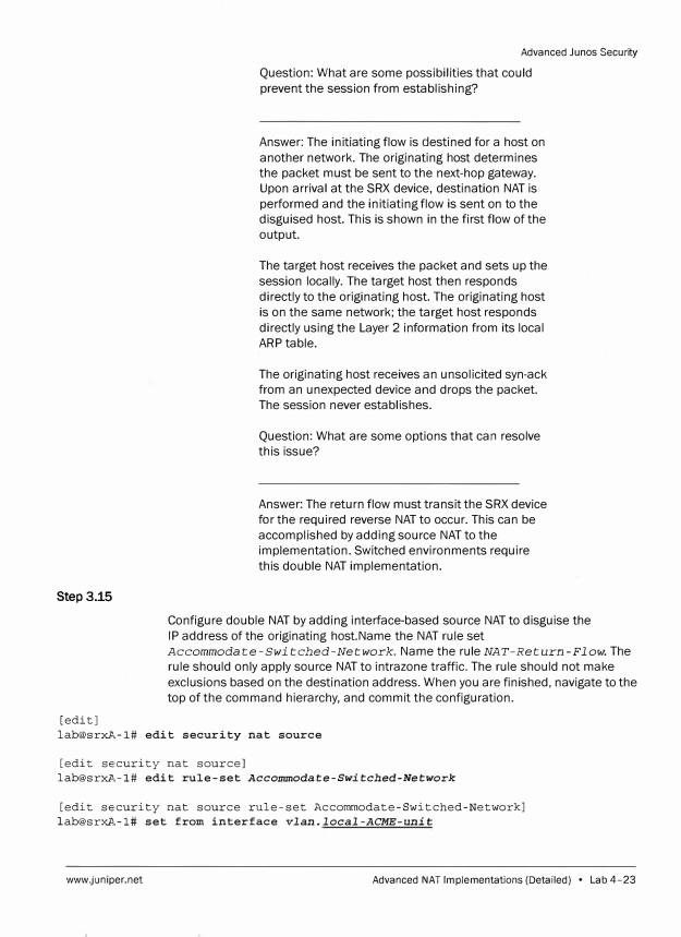
Step 3.15
[edit]
Advanced Junes Security
Question: What are some possibilities that could
prevent the session from establishing?
Answer: The initiating flow is destined for a host on
another network. The originating host determines
the packet must be sent to the next-hop gateway.
Upon arrival at the SRX device, destination NAT is
performed and the initiating flow is sent on to the
disguised host. This is shown in the first flow of the
output.
The target host receives the packet and sets up the
session locally. The target host then responds
directly to the originating host. The originating host
is on the same network; the target host responds
directly using the Layer 2 information from its local
ARP table.
The originating host receives an unsolicited syn-ack
from an unexpected device and drops the packet.
The session never establishes.
Question: What are some options that can resolve
this issue?
Answer: The return flow must transit the SRX device
for the required reverse NAT to occur. This can be
accomplished by adding source NAT to the
implementation. Switched environments require
this double NAT implementation.
Configure double NAT by adding interface-based source NAT to disguise the
IP address of the originating host.Name the NAT rule set
Accommodate-Switched-Network. Name the rule NAT-Return-Flow. The
rule should only apply source NAT to intrazone traffic. The rule should not make
exclusions based on the destination address. When you are finished, navigate to the
top of the command hierarchy, and commit the configuration.
lab@srxA,-1# edit security nat source
[edit se,curity nat source]
lab@srxA,-1# edit rule-set Accommodate-Switched-Network
[edit se,curity nat source rule-set Accommodate-Switched-Network]
[email protected]# set from interface vlan. local-ACME-unit
www.juniper.net Advanced NAT Implementations (Detailed) • Lab 4-23
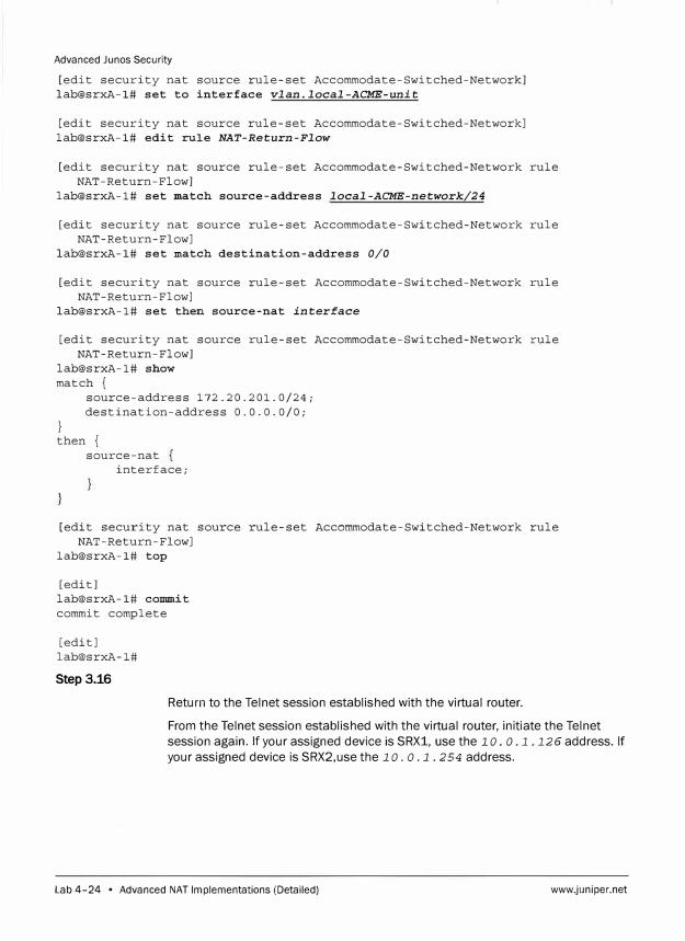
Advanced Junos Security
[edit security nat source rule-set Accommodate-Switched-Network] lab@srxA-1# set to interface vlan.local-ACME-unit
[edit security nat source rule-set Accommodate-Switched-Network] lab@srxA-1# edit rule NAT-Return-Flow
[edit security nat source rule-set Accommodate-Switched-Network rule NAT-Return-Flow]
lab@srxA-1# set match source-address local-ACME-network/24
[edit security nat source rule-set Accommodate-Switched-Network rule NAT-Return-Flow]
lab@srxA-1# set match destination-address 0/0
[edit security nat source rule-set Accommodate-Switched-Network rule NAT-Return-Flow]
lab@srxA-1# set then source-nat interface
[edit security nat source rule-set Accommodate-Switched-Network rule NAT-Return-Flow]
lab@srxA-1# show match {
}
source-address 172.20.201.0/24; destination-address 0.0.0.0/0;
then { source-nat
interface;
[edit security nat source rule-set Accommodate-Switched-Network rule NAT-Return-Flow]
lab@srxA-1# top
[edit] lab@srxA-1# commit commit complete
[edit] lab@srxA-1#
Step 3.16
Return to the Telnet session established with the virtual router.
From the Telnet session established with the virtual router, initiate the Telnet
session again. If your assigned device is SRX1, use the 1 o. o .1.126 address. If
your assigned device is SRX2,use the 1 o. o .1. 254 address.
Lab 4-24 • Advanced NAT Implementations (Detailed) www.juniper.net
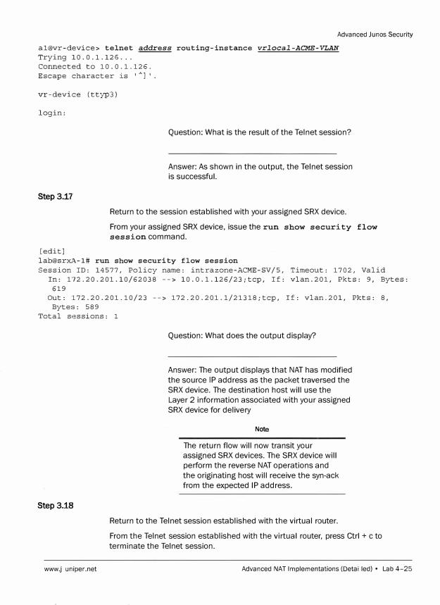
Advanced Junos Secur ity
al@vr-device> telnet address routing-instance vrlocal-ACME-VLAN
Trying 10.0.1.126 ... Connected to 10.0.1.126. Escape character is '
Al'.
vr-device (ttyp3)
login:
Step 3.17
[edit]
Question: What is the result of the Telnet session?
Answer: As shown in the output, the Telnet session
is successful.
Return to the session established with your assigned SRX device.
From your assigned SRX device, issue the run show security flow
session command.
lab@srxA-1# run show security flow session
Session ID: 14577, Policy name: intrazone-ACME-SV/5, Timeout: 1702, Valid In: 172.20.201.10/62038 --> 10.0.l.126/23;tcp, If: vlan.201, Pkts: 9, Bytes:
619 Out: 172.20.201.10/23 --> 172.20.201.l/21318;tcp, If: vlan.201, Pkts: 8,
Bytes: 589 Total sessions: 1
Step 3.18
www.juniper.net
Question: What does the output display?
Answer: The output displays that NAT has modified
the source IP address as the packet traversed the
SRX device. The destination host will use the
Layer 2 information associated with your assigned
SRX device for delivery
Note
The return flow will now transit your
assigned SRX devices. The SRX device will
perform the reverse NAT operations and
the originating host will receive the syn-ack
from the expected IP address.
Return to the Telnet session established with the virtual router.
From the Telnet session established with the virtual router, press Ctrl + c to
terminate the Telnet session.
Advanced NAT Implementations (Detailed) • Lab 4-25
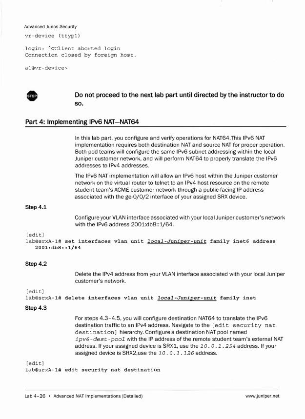
Advanced Junos Security
vr-device (ttypl)
login: ACClient aborted login Connection closed by foreign host.
al@vr-device>
Do not proceed to the next lab part until directed by the instructor to do
so.
Part 4: Implementing 1Pv6 NAT-NAT64
Step 4.1
[edit]
In this lab part, you configure and verify operations for NAT64.This 1Pv6 NAT
implementation requires both destination NAT and source NAT for proper operation.
Both pod teams will configure the same 1Pv6 subnet addressing within the local
Juniper customer network, and will perform NAT64 to properly translate ttle 1Pv6
addresses to 1Pv4 addresses.
The 1Pv6 NAT implementation will allow an 1Pv6 host within the Juniper customer
network on the virtual router to telnet to an 1Pv4 host resource on the remote
student team's ACME customer network through a public-facing IP address
associated with the ge-0/0/2 interface of your assigned SRX device.
Configure your VLAN interface associated with your local Juniper customer's network
with the 1Pv6 address 2001:db8::1/64.
lab@srxA-1# set interfaces vlan unit local-Juniper-unit family inet6 address 2001:dbS::1/64
Step 4.2
[edit]
Delete the 1Pv4 address from your VLAN interface associated with your local Juniper
customer's network.
lab@srxA-1# delete interfaces vlan unit local-Juniper-unit family inet
Step4.3
[edit]
For steps 4.3-4.5, you will configure destination NAT64 to translate the 1Pv6
destination traffic to an 1Pv4 address. Navigate to the [edit security nat
destination] hierarchy. Configure a destination NAT pool named
ipv6-dest-pool with the IP address of the remote student team's external NAT
address. If your assigned device is SRX1, use the lo. o. l. 254 address. If your
assigned device is SRX2,use the 10. o .1.126 address.
lab@srxA-1# edit security nat destination
Lab 4-26 • Advanced NAT Implementations (Detailed) www.juniper.net
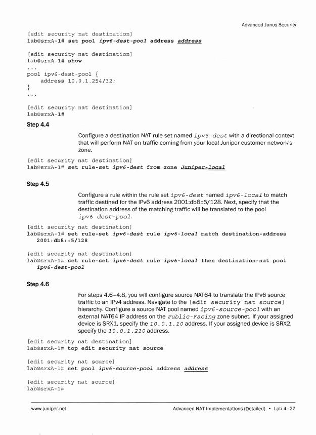
[edit security nat destination] lab@srx�-1# set pool ipv6-dest-pool address address
[edit security nat destination] lab@srx..�-1# show
pool ipv6-dest-pool address 10.0.1.254/32;
[edit security nat destination] lab@srxA-1#
Step4.4
Advanced Junos Security
Configure a destination NAT rule set named ipv6 -dest with a directional context
that will perform NAT on traffic coming from your local Juniper customer network's
zone.
[edit security nat destination] [email protected]�-1# set rule-set ipv6-dest from zone Juniper-local
Step 4.5
Configure a rule within the rule set ipv6 -dest named ipv6 -local to match
traffic destined for the 1Pv6 address 2001:dbB::5/128. Next, specify that the
destination address of the matching traffic will be translated to the pool
ipv6-dest-pool.
[edit security nat destination] lab@srxA-1# set rule-set ipv6-dest rule ipv6-local match destination-address
2001:dbS::5/128
[edit security nat destination] lab@srxl\-1# set rule-set ipv6-dest rule ipv6-local then destination-nat pool
ipv6 ··dest-pool
Step 4.6
For steps 4.6-4.8, you will configure source NAT64 to translate the 1Pv6 source
traffic to an 1Pv4 address. Navigate to the [edit security nat source)
hierarchy. Configure a source NAT pool named ipv6-source-pool with an
external NAT64 IP address on the Public-Facing zone subnet. If your assigned
device is SRX1, specify the 1 o. o. 1. 1 o address. If your assigned device is SRX2,
specify the 1 o. o. 1. 21 o address.
[edit security nat destination] lab@srxA-1# top edit security nat source
[edit security nat source] lab@srxJ!,-1# set pool ipv6-source-pool address address
[edit security nat source] lab@srxJ!,-1#
www.juniper.net Advanced NAT Implementations (Detailed) • Lab 4-27
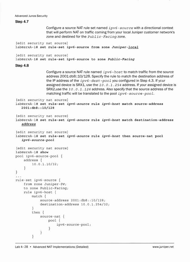
Advanced Junes Security
Step 4.7
Configure a source NAT rule set named ipv6 -source with a directional context
that will perform NAT on traffic coming from your local Juniper customer network's
zone and destined for the Public-Facing zone.
[edit security nat source] lab@srxA-1# set rule-set ipv6-source from zone Juniper-local
[edit security nat source] lab@srxA-1# set rule-set ipv6-source to zone Public-Facing
Step4.8
Configure a source NAT rule named ipv6-host to match traffic from the source
address 2001:dbS::10/128. Specify the rule to match the destination address of
the IP address of the ipv6-dest -pool you configured in Step 4.3. If your
assigned device is SRX1, use the 1 o. o. 1. 2 54 address. If your assigned device is
SRX2,use the 1 o. o. 1. 126 address. Also specify that the source address of the
matching traffic will be translated to the pool ipv6 -source -pool.
[edit security nat source] lab@srxA-1# set rule-set ipv6-source rule ipv6-host match source-address
2001:dbS::10/128
[edit security nat source] lab@srxA-1# set rule-set ipv6-source rule ipv6-host match destination-address
address
[edit security nat source] lab@srxA-1# set rule-set ipv6-source rule ipv6-host then source-nat pool
ipv6 -source-pool
[edit security nat source] lab@srxA-1# show pool ipv6-source-pool
address { 10.0.1.10/32;
rule-set ipv6-source { from zone Juniper-SV; to zone Public-Facing; rule ipv6-host {
match {
}
source-address 2001:dbS: :10/128; destination-address 10.0.1.254/32;
then { source-nat
pool { ipv6-source-pool;
Lab 4-28 • Advanced NAT Implementations (Detailed) www.j1Jniper.net
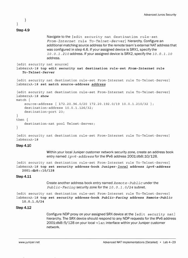
Step 4.9
Advanced Junos Security
Navigate to the [edit security nat destination rule-set
From-Internet rule To-Telnet-Server] hierarchy. Configure an
additional matching source address for the remote team's external NAT address that
was configured in step 4.6. If your assigned device is SRX1, specify the
1 o. o. 1 . 21 o address. If your assigned device is SRX2, specify the 1 o. o. 1 . 1 o
address.
[edit security nat source] lab@sr��-1# top edit security nat destination rule-set From-Internet rule
To-T,:!lne t -Server
[edit security nat destination rule-set From-Internet rule To-Telnet-Server] lab@srxA-1# set match source-address address
[edit s,�curity nat destination rule-set From-Internet rule To-Telnet-Server] lab@srxA-1# show match {
source-address [ 172.20.96.0/20 172.20.192.0/19 10.0.1.210/32 J; destination-address 10.0.1.126/32; destination-port 23;
} then {
destination-nat pool Telnet-Server;
[edit security nat destination rule-set From-Internet rule To-Telnet-Server] lab@srxA-1#
Step4.10
Within your local Juniper customer network security zone, create an address book
entry named ipv6-address for the 1Pv6 address 2001:dbS::10/128.
[edit security nat destination rule-set From-Internet rule To-Telnet-Server] lab@srxl,-1# top set security address-book Juniper-local address ipv6-address
2001::dbS: :10/128
Step 4.11
Create another address book entry named Remote-Public under the
Public-Facing security zone for the 1 o. o .1. 0/24 subnet.
[edit security nat destination rule-set From-Internet rule To-Telnet-Server] lab@srxl,-1# top set security address-book Public-Facing address Remote-Public
10.0.1.0/24
Step4.12
www.juniper.net
Configure NDP proxy on your assigned SRX device at the [edit security natl hierarchy. The SRX device should respond to any NDP requests for the 1Pv6 address
2001:db8::5/128 on your local vlan interface within your Juniper customer
network.
Advanced NAT Implementations (Detailed) • Lab 4-29
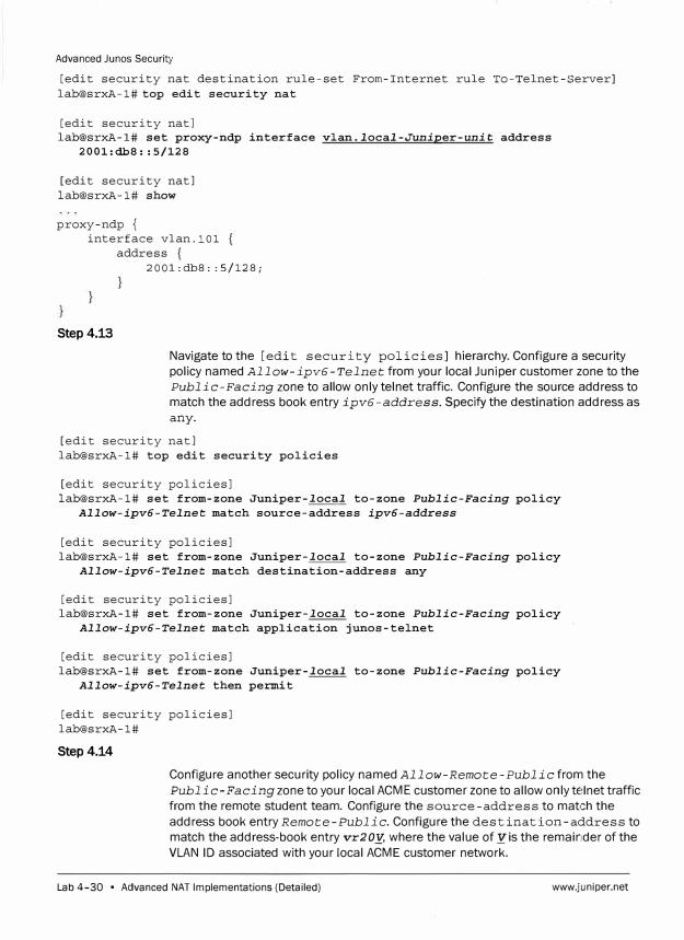
Advanced Junos Security
[edit security nat destination rule-set From-Internet rule To-Telnet-Server] lab@srxA-1# top edit security nat
[edit security natl lab@srxA-1# set proxy-ndp interface vlan.local-Juniper-unit address
2001:db8: :5/128
[edit security natl lab@srxA-1# show
proxy-ndp { interface vlan.101 {
address { 2001:db8: :5/128;
Step4.13
Navigate to the [edit security policies] hierarchy. Configure a security policy named Allow-ipv6-Telnet from your local Juniper customer zone to the Public-Facing zone to allow only telnet traffic. Configure the source address to match the address book entry ipv6-address. Specify the destination address as any.
[edit security natl lab@srxA-1# top edit security policies
[edit security policies] lab@srxA-1# set from-zone Juniper-local to-zone Public-Facing policy
Allow-ipv6-Telnet match source-address ipv6-address
[edit security policies] lab@srxA-1# set from-zone Juniper-local to-zone Public-Facing policy
Allow-ipv6-Telnet match destination-address any
[edit security policies] lab@srxA-1# set from-zone Juniper-local to-zone Public-Facing policy
Allow-ipv6-Telnet match application junos-telnet
[edit security policies] lab@srxA-1# set from-zone Juniper-local to-zone Public-Facing policy
Allow-ipv6-Telnet then permit
[edit security policies] lab@srxA-1#
Step4.14
Configure another security policy named Allow-Remote-Public from the
Public-Facing zone to your local ACME customer zone to allow only telnet traffic from the remote student team. Configure the source-address to match the address book entry Remote-Public. Configure the destination-address to match the address-book entry vr2 oy, where the value of y is the remainder of the VLAN ID associated with your local ACME customer network.
Lab 4-30 • Advanced NAT Implementations (Detailed) www.juniper.net
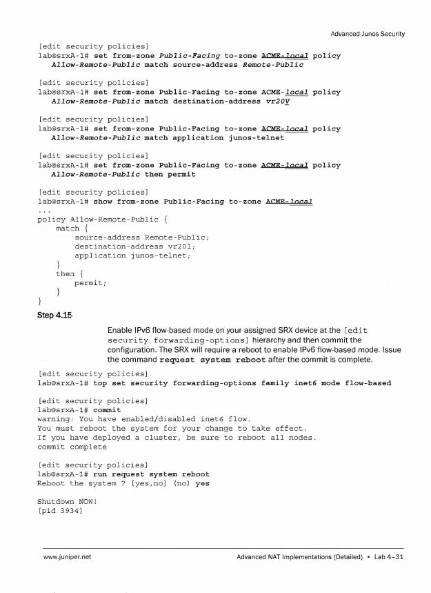
Advanced Junos Security
[edit security policies] lab@srxA-1# set from-zone Public-Facing to-zone ACME-local policy
Allow-Remote-Public match source-address Remote-Public
[edit security policies] lab@srxA-1# set from-zone Public-Facing to-zone ACME-local policy
Allow-Remote-Public match destination-address vr20y
[edit security policies] lab@srxA-1# set from-zone Public-Facing to-zone ACME-local policy
Allow·-Remote-Public match application junos-telnet
[edit security policies] lab@srxA-1# set from-zone Public-Facing to-zone ACME-local policy
Allow-Remote-Public then permit
[edit security policies] lab@srxA-1# show from-zone Public-Facing to-zone ACME-local
policy Allow-Remote-Public match {
}
source-address Remote-Public; destination-address vr201; application junos-telnet;
then { permit;
Step 4.15,
Enable 1Pv6 flow-based mode on your assigned SRX device at the [edit
security forwarding-options] hierarchy and then commit the configuration. The SRX will require a reboot to enable 1Pv6 flow-based mode. Issue the command request system reboot after the commit is complete.
[edit security policies] lab@srxA-1# top set security forwarding-options family inet6 mode flow-based
[edit security policies] lab@srxi\-1# commit warning: You have enabled/disabled inet6 flow. You must reboot the system for your change to take effect. If you have deployed a cluster, be sure to reboot all nodes. commit complete
[edit security policies] lab@srxl\-1# run request system reboot Reboot the system ? [yes,no] (no) yes
Shutdown NOW! [pid 3934]
www.juniper.net Advanced NAT Implementations (Detailed) • Lab 4-31
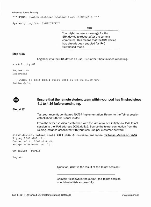
Advanced Junos Security
*** FINAL System shutdown message from lab@srxA-1 ***
System going down IMMEDIATELY
Step4.16
Note
You might not see a message for the
SRX device to reboot after the commit
completes. This means that the SRX device
has already been enabled for 1Pv6
flow-based mode.
Log back into the SRX device as user lab after it has finished rebooting.
srxA-1 (ttyuO)
login: lab
Password:
--- JUNOS 12.1X44-D10.4 built 2013-01-08 05:51:59 UTC
lab@srxA-1>
Step 4.17
Ensure that the remote student team within your pod has finished steps
4.1 to 4.16 before continuing.
Test your recently configured NAT64 implementation. Return to the Telnet session
established with the virtual router.
From the Telnet session established with the virtual router, initiate an 1Pv6 Telnet
session to the 1Pv6 address 2001:dbS::5. Source the telnet connection from the
routing instance associated with your local Juniper customer network.
al@vr-device> telnet inet6 2001:dbS::5 routing-instance vrlocal-Juniper-VLAN
Trying 2001:dbB: :5 ...
Connected to 2001:dbB: :5.
Escape character is 'A
l'.
vr-device (ttypl)
login:
Question: What is the result of the Telnet session?
Answer: As shown in the output, the Telnet session
should establish successfully.
Lab 4-32 • Advanced NAT Implementations (Detailed) www.juniper.net
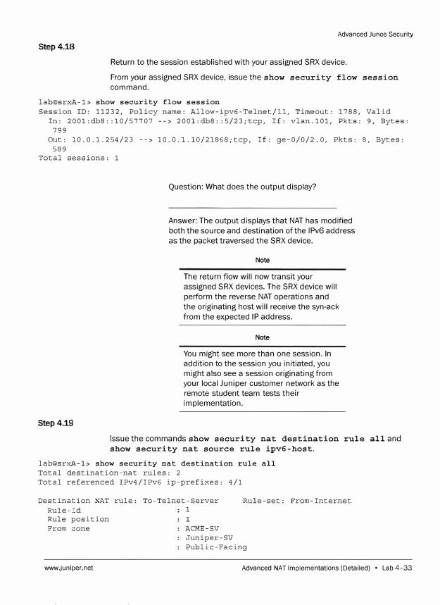
Step 4.18
Advanced Junes Security
Return to the session established with your assigned SRX device.
From your assigned SRX device, issue the show security flow session
command.
lab@srxA-1> show security flow session
Session ID: 11232, Policy name: Allow-ipv6-Telnet/ll, Timeout: 1788, Valid
In: 2001:db8: :10/57707 --> 2001:db8: :5/23;tcp, If: vlan.101, Pkts: 9, Bytes:
799
Out: 10.0.1.254/23 --> 10.0.l.10/21868;tcp, If: ge-0/0/2.0, Pkts: 8, Bytes:
589
Total sessions: 1
Step4.rn
Question: What does the output display?
Answer: The output displays that NAT has modified
both the source and destination of the 1Pv6 address
as the packet traversed the SRX device.
Note
The return flow will now transit your
assigned SRX devices. The SRX device will
perform the reverse NAT operations and
the originating host will receive the syn-ack
from the expected IP address.
Note
You might see more than one session. In
addition to the session you initiated, you
might also see a session originating from
your local Juniper customer network as the
remote student team tests their
implementation.
Issue the commands show security nat destination rule all and
show security nat source rule ipv6-host.
lab@srxl�-1> show security nat destination rule all
Total destination-nat rules: 2
Total referenced IPv4/IPv6 ip-prefixes: 4/1
Destination NAT rule: To-Telnet-Server
Rule-Id 1
1
Rule-set: From-Internet
Rule position
From zone ACME-SV
Juniper-SV
Public-Facing
www.juniper.net Advanced NAT Implementations (Detailed) • Lab 4-33
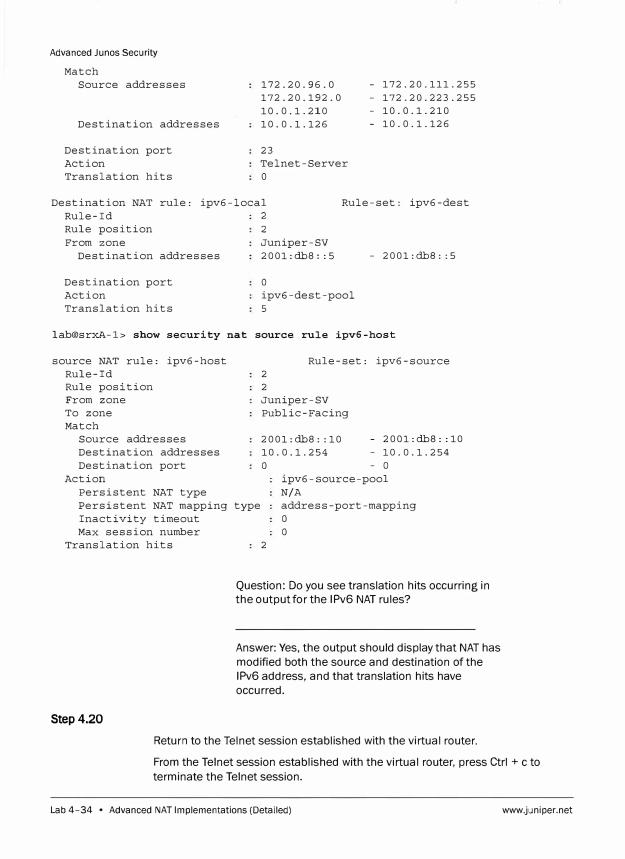
Advanced Junos Security
Match
Source addresses
Destination addresses
Destination port
Action
Translation hits
172.20.96.0
172.20.192.0
10.0.1.210
10.0.1.126
23
Telnet-Server
0
- 172.20.111.255
- 172.20.223.255
- 10.0.1.210
- 10.0.1.126
Destination NAT rule: ipv6-local Rule-set: ipv6-dest
Rule-Id 2
Rule position
From zone
Destination addresses
Destination port
Action
Translation hits
2
Juniper-SV
2001:db8: :5
0
ipv6-dest-pool
5
- 2001:db8: :5
lab@srxA-1> show security nat source rule ipv6-host
source NAT rule: ipv6-host
Rule-Id
Rule position
From zone
To zone
Match
Source addresses
Destination addresses
Destination port
Action
Rule-set: ipv6-source
2
2
Juniper-SV
Public-Facing
2001:db8: :10
10.0.1.254
0
- 2001:db8: :10
- 10.0.1.254
- 0
ipv6-source-pool
Persistent NAT type
Persistent NAT mapping type
Inactivity timeout
N/A
address-port-mapping
0
Max session number
Translation hits
Step4.20
0
2
Question: Do you see translation hits occurring in
the output for the 1Pv6 NAT rules?
Answer: Yes, the output should display that NAT has
modified both the source and destination of the
1Pv6 address, and that translation hits have
occurred.
Return to the Telnet session established with the virtual router.
From the Telnet session established with the virtual router, press Ctrl + c to
terminate the Telnet session.
Lab 4-34 • Advanced NAT Implementations (Detailed) www.j,uniper.net
Advanced Junos Security
vr-device (ttypl)
login: ACClient aborted login Connection closed by foreign host.
al@vr-device>
Do not proceed to the next lab part until directed by the instructor to do
so.
Part 5: Implementing 1Pv6 NAT-NAT46
Step 5.1
[edit]
In this lab part, you configure and verify NAT46 operations. This NAT implementation
requires both destination NAT and source NAT for proper operation. Both pod teams
will configure source and destination NAT to perform NAT46, to translate the 1Pv4
addresses to 1Pv6 addresses.
The 1Pv6 NAT implementation will allow an 1Pv4 host within the ACME customer
network on the virtual router to telnet to an 1Pv6 host resource on the remote
student team's Juniper customer network through a public-facing IP address
associated with the ge-0/0/2 interface.
For steps 5.1-5.3, you will configure destination NAT to translate a local 1Pv4
address within the ACME customer network to a public facing address that will be
used for NAT46. Enter configuration mode and navigate to the [edit security
nat destination] hierarchy. Configure a destination NAT pool named
nat46public-dest-pool with a public-facing address that will be used for
NAT46. If your assigned device is SRX1, specify the address 1 o. o .1. 211. If your
assigned device is SRX2, configure the address 1 o. o. 1. 11.
lab@srx�-1# edit security nat destination
[edit security nat destination] lab@srxA-1# set pool nat46public-dest-pool address address
Step 5.2
Configure a destination NAT rule set named nat46public-dest with a
directional context that will perform NAT on traffic coming from your local ACME
customer network's zone.
[edit security nat destination] lab@srxA-1# set rule-set nat46public-dest from zone ACME-local
www.juniper.net Advanced NAT Implementations (Detailed) • Lab 4-35
Advanced Junos Security
Step 5.3
Configure a rule within the rule set nat46public-dest named ipv4-.local to
match traffic destined for 172. 20. address. 5/32, where address is your local
ACME customer network. Then specify that the destination address of the matching
traffic will be translated to the pool nat46public-dest-pool.
[edit security nat destination]
lab@srxA-1# set rule-set nat46public-dest rule ipv4-local match
destination-address 172.20.address.5/32
[edit security nat destination]
lab@srxA-1# set rule-set nat46public-dest rule ipv4-local then destination-nat
pool nat46public-dest-pool
Step 5.4
Configure another destination NAT pool named nat46remote-dest-pool with
the 1Pv6 address 2008:dbS::10/128. This pool will be used to perform NAT46 on
the traffic from the remote student team's ACME customer network.
[edit security nat destination]
lab@srxA-1# set pool nat46remote-dest-pool address 2001:dbS::10/128
Step 5.5
Under the destination NAT rule-set From-Internet, configure another source NAT
rule named nat46-remote to match Telnet traffic sourced from the
172.20.192.0/19 prefix. Apply this rule to traffic destined to the remote team's
nat46public-dest-pool IP address. If your assigned device is SRX1, specify
the address Io. o .1 .11. If your assigned device is SRX2, configure the address
1 o. o. 1 . 211. Specify that the destination address of the matching traffic will be
translated to the pool nat46remote-dest-pool.
Note
The 172. 20 .192. 0/19 prefix will
accommodate the local and remote ACME
customer networks.
[edit security nat destination]
lab@srxA-1# set rule-set From-Internet rule nat46-remote match source-address
172.20.192.0/19
[edit security nat destination]
lab@srxA-1# set rule-set From-Internet rule nat46-remote match
destination-address address
[edit security nat destination]
lab@srxA-1# set rule-set From-Internet rule nat46-remote match destination-port
23
[edit security nat destination]
lab@srxA-1# set rule-set From-Internet rule nat46-remote then destination-nat
pool nat46remote-dest-pool
Lab 4-36 • Advanced NAT Implementations (Detailed) www.juniper.net
Step 5.6
Advanced Junos Security
For steps 5.6-5.8, you will configure source NAT46 to translate the source 1Pv4
address to an 1Pv6 address. Navigate to the [edit security nat source)
hierarchy. Configure a source NAT pool named nat46-source-pool with the
1Pv6 address 2001:db8::6/128.
[edit security nat destination]
[email protected]# top edit security nat source
[edit security nat source]
[email protected]# set pool nat46-source-pool address 2001:dbB::6/128
[edit security nat source]
Step 5.7
Configure a NAT rule-set named nat46-source with a directional context that will
perform source NAT on traffic coming from the Public-Facing zone and destined for your local Juniper customer network's zone.
[edit security nat source]
lab@srxA-1# set rule-set nat46-source from zone Public-Facing
[edit security nat source]
lab@srxA-1# set rule-set nat46-source to zone Juniper-local
Step 5.8
Configure a source NAT rule for the nat46-source rule-set named nat46-host
to match traffic sourced from the 172.20.192.0/19 prefix. Apply this rule to traffic destined to the 2001:db8::10/128 address. Then specify that the source address of
the matching traffic will be translated to the pool nat46-source-pool.
[edit security nat source]
lab@srxJl,-1# set rule-set nat46-source rule nat46-host match source-address
172.20.192.0/19
[edit security nat source]
lab@srxA-1# set rule-set nat46-source rule nat46-host match destination-address
2001:dbB::10/128
[edit security nat source]
lab@srxA,-1# set rule-set nat46-source rule nat46-host then source-nat pool
na t4 6' -source-pool
Step 5.9
Configure NDP proxy on your assigned SRX device at the [edit security natl hierarchy. The SRX device should respond to any NDP requests for the 1Pv6 address
2001:db8::6/128 on your local vlan interface within your Juniper customer
network.
[edit security nat source]
[email protected]# top set security nat proxy-ndp interface vlan.1oca1-Juniper-unit
address 2001:dl>S::6/128
www.juniper.net Advanced NAT Implementations (Detailed) • Lab 4-37
Advanced Junos Security
Step 5.10
Configure proxy-arp on your local vlan interface within your ACME customer
network for 172. 20. address. 5/32, where address is your local ACME
customer network.
[edit security nat source] lab@srxA-1# top set security nat proxy-arp interface vlan.local-ACME-un.it
address 172.20.address.5/32
Step 5.11
Create another address book entry named Remote-NAT46 under the
Public-Facing zone for the remote student team's source NAT address for
NAT46. If your assigned device is SRX1, use the address 1 o. o. l. 211. If your
assigned device is SRX2, use the address 1 o. o. 1. 11.
[edit security nat source] lab@srxA-1# top set security address-book Public-Facing address Remote-NAT46
address
Step 5.12
Navigate to the [edit security policies] hierarchy. Configure a security
policy named Allow-NAT46-Local to allow Telnet traffic from your local ACME
customer zone to the remote student team's source NAT address for NAT46 on the
Public-Facing zone. Configure the source-address to match the
address-book entry vr20Y, where the value of yis the remainder of the \/LAN ID
associated with your local ACME customer network. Configure the
destination-address to match the address book entry Remote-NJlT46.
[edit security nat source] lab@srxA-1# top edit security policies
[edit security policies] lab@srxA-1# set from-zone ACME-local to-zone Public-Facing policy
Allow-NAT46-Local match source-address vr20V
[edit security policies] lab@srxA-1# set from-zone ACME-local to-zone Public-Facing policy
Allow-NAT46-Local match destination-address Remote-NAT46
[edit security policies] lab@srxA-1# set from-zone ACME-local to-zone Public-Facing policy
Allow-NAT46-Local match application junos-telnet
[edit security policies] lab@srxA-1# set from-zone ACME-local to-zone Public-Facing policy
Allow-NAT46-Local then permit
Step5.13
Configure another security policy named Allow-NAT4 6-Remote to allow Telnet
traffic from the remote student team on the Public-Facing zone to your local
Juniper customer zone. Configure the source address to match the address book
entry Remote-Partner-ACME. Configure the destination address to match the
address book entry ipv6-address. When finished, commit the configuration and
return to operational mode.
Lab 4-38 • Advanced NAT Implementations (Detailed) www.juniper.net
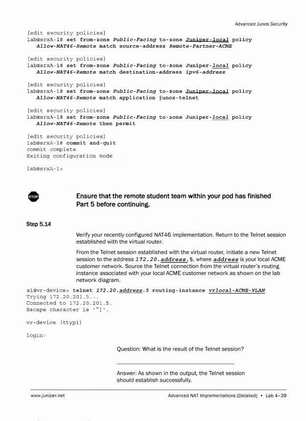
Advanced Ju nos Security
[edit security policies]
lab@srx�-1# set from-zone Public-Facing to-zone Juniper-local policy
Allow-NAT46-Remote match source-address Remote-Partner-ACME
[edit security policies]
lab@srx�-1# set from-zone Public-Facing to-zone Juniper-local policy
Allo,v-NAT46-Remote match destination-address ipv6-address
[edit security policies]
lab@srx.�-1# set from-zone Public-Facing to-zone Juniper-local policy
Allow-NAT46-Remote match application junos-telnet
[edit security policies]
lab@srxA-1# set from-zone Public-Facing to-zone Juniper-local policy
Allo,v-NAT46-Remote then permit
[edit security policies]
lab@srxA-1# commit and-quit
commit complete
Exiting configuration mode
lab@srxA-1>
Step 5.14
Ensure that the remote student team within your pod has finished
Part 5 before continuing.
Verify your recently configured NAT46 implementation. Return to the Telnet session
established with the virtual router.
From the Telnet session established with the virtual router, initiate a new Telnet
session to the address 172. 20. address. 5, where address is your local ACME
customer network. Source the Telnet connection from the virtual router's routing
instance associated with your local ACME customer network as shown on the lab
network diagram.
al@vr-device> telnet 172.20.address.5 routing-instance vrlocal-ACME-VLAN
Trying 172.20.201.5 ...
Connected to 172.20.201.5.
Escape character is 'A
l'.
vr-device (ttypl)
login:
www.juniper.net
Question: What is the result of the Telnet session?
Answer: As shown in the output, the Telnet session
should establish successfully.
Advanced NAT Implementations (Detailed) • Lab 4-39
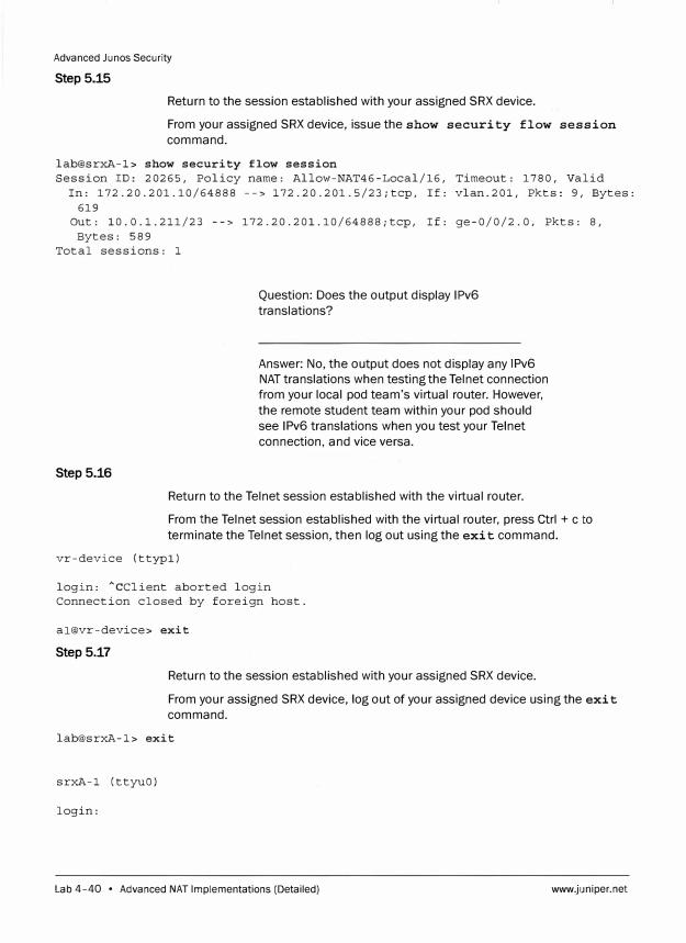
Advanced Ju nos Security
Step 5.15
Return to the session established with your assigned SRX device.
From your assigned SRX device, issue the show security flow session
command.
lab@srxA-1> show security flow session Session ID: 20265, Policy name: Allow-NAT46-Local/16, Timeout: 1780, Valid
In: 172.20.201.10/64888 --> 172.20.201.5/23;tcp, If: vlan.201, Pkts: 9, Bytes:
619 Out: 10.0.1.211/23 --> 172.20.201.10/64888;tcp, If: ge-0/0/2.0, Pkts: 8,
Bytes: 589 Total sessions: 1
Step 5.16
Question: Does the output display 1Pv6
translations?
Answer: No, the output does not display any 1Pv6
NAT translations when testing the Telnet connection
from your local pod team's virtual router. However,
the remote student team within your pod should
see 1Pv6 translations when you test your Telnet
connection, and vice versa.
Return to the Telnet session established with the virtual router.
From the Telnet session established with the virtual router, press Ctrl + c to
terminate the Telnet session, then log out using the exit command.
vr-device (ttypl)
login: ACClient aborted login Connection closed by foreign host.
al@vr-device> exit
Step 5.17
Return to the session established with your assigned SRX device.
From your assigned SRX device, log out of your assigned device using the exit
command.
lab@srxA-1> exit
srxA-1 (ttyuO)
login:
Lab 4-40 • Advanced NAT Implementations (Detailed) www.juniper.net
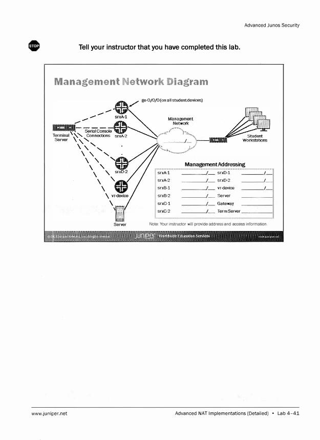
Advanced Junos Security
Tell your instructor that you have completed this lab.
Management Network Diagram
ge-0/0/0(on all studentdevices)
Mana@mentAddressing
srxA-1 srxD-1 I
srxA-2 srxD-2 I
srxB-1 vr-<levice I
srxB-2 Server
srxC-1 Gateway
srxC-2 I Term Server
Server Note: Your instructor will provide address and access information.
www.juniper.net Advanced NAT Implementations (Detailed) • Lab 4-41

Advanced Junos Security
Pod A Network Diagram: Advanced NAT
Implementations Lab (Parts 1-3)
172.20 1010/24
�)
L::'.::J vr201
,_AC_M_E--':N--' -- Virtual Routers -- Juniper-WF Jun i pe r -':N
: , r (12013JunlperNetwork,, lnc.AAnfits remve(! Juniper Worldwide Education SeMces WWW 1un1p
-- -�-�� --·- ----· -----l-- ---- "�
Pod A Network Diagram: Advanced NAT
Implementations Lab (Parts 4-5)
10.0.1.D/24
1Pv6Subnet
Added
vlan.202
ACME-':N Juniper-WF AC ME-WF
;s,... .,,, , "' ," r
; 1)::!�J.3J1Jnii.trNttw\?fk$, l�t Allrl#l1S m"l'M'd JUnL�f Worldwide Education Services W'l•}W JUlllP �--��--��� - �� - --
Lab 4-42 • Advanced NAT Implementations (Detailed) www.juniper.net
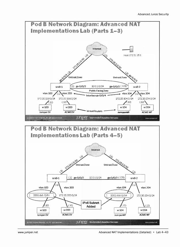
Advanced Ju nos Security
Pod B Network Diagram: Advanced NAT
Implementations Lab (Parts 1-3)
:--El
vlan.103
Juniper-SY ACME-SY -- Virtual Routers _.... Juniper-WF ACME-WF
13JunlperNetwol'IOf
Inc AU tlghti resenti,d JUnlPer Worldwide Education Services WWW Juniper net ---'-� -� ��-�-"""-- - -� -
,,cc�
Pod B Network Diagram: Advanced NAT
Implementations Lab (Parts 4-5)
vr103 I
Juniper-SY
10010/24
1Pv6Subnet
Added
Juniper-WF
vlan.204
www.juniper.net Advanced NAT Implementations (Detailed) • Lab 4-43
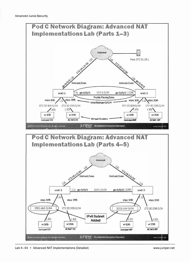
Advanced Junos Security
Pod C Network Diagram: Advanced NAT
Implementations Lab (Parts 1-3)
vlan.105
Juniper-SY ACME-SY --VirwalRouters .-- Juniper-WF ACME-WF
()-2013Jt1nlperNetwork,, lttt: AIJnJts re1erv� JUn� Worldwide Education Services WNW JUn1p --- - -A- � � j
Pod C Network Diagram: Advanced NAT
Implementations Lab {Parts 4-5)
(.1) ge-0/0/2 10010/24
1Pv6Subnet
Added
vlan.206
Juniper-SY ACME-WF
IS)::?01JJunlp .. ,tJetwork;., lM AUrl�1S ,, .. i:r�lj JUn1Per Worldwide Education Services IWNI Jlln1p -----'" � " - - ----1
""'�
Lab 4-44 • Advanced NAT Implementations (Detailed) www.juniper.net

Advanced Junos Security
Pod D Network Diagram: Advanced NAT
Implementations Lab (Parts 1-3}
vlan.107
Juniper-SY
Host 172.31.15.1
ACME-SV -- Virtual Routers -- Juniper-WF
(�lan208
172 20 208.Q/24 (10)
ACME-WF i.(F' ¥"J, ""� , ' 13{�;":.��ln¢,Allrlght$((1'Serve:d ...._� �� Junm WorldwideEducationServices Wll>IWJUrllpernet
Pod D Network Diagram: Advanced NAT
Implementations Lab (Parts 4-5}
(1) ge-0/0/2 10010/24
1Pv6Subnet
Added
vlan.208
(10)
ACME-SV Juniper-WF ACME-WF
www.juniper.net Advanced NAT Implementations (Detailed) • Lab 4-45

Advanced Junos Security
Lab 4-46 • Advanced NAT Implementations (Detailed) www.juniper.net
Lab
Hub-and-Spoke IPsec VPNs (Detailed)
In this lab, you will load the baseline configuration for your device. The configuration will
include interfaces, interfaces assigned to their zones, security policies to allow traffic
between zones, and a stateless firewall filter for selective packet-based services. You will
then configure your device to act as a hub in a hub-and-spoke IP Security (IPsec) virtual
private network (VPN). You will use the loopback interface as your gateway interface. The
spokes have been preconfigured with all the necessary requirements. The IPsec tunnel
will be configured to encrypt and pass traffic for the Local-VR network attached to each
student device. After completing your configuration, you will verify the IPsec functionality
on your local device.
The lab is available in two formats: a high-level format designed to make you think through
each step and a detailed format that offers step-by-step instructions complete with
sample output from most commands.
By completing this lab, you will perform the following tasks:
www.juniper.net
Use the Ju nos command line interface (CLI) to load the baseline configuration.
Use the Ju nos CLI to configure the IPsec VPN parameters.
Assign interfaces to security zones.
Implement security policies between zones.
Verify that the expected traffic traverses the VPN.
Monitor the effects of the configuration from both the local device.
Hub-and-Spoke IPsec VPNs (Detailed) • Lab 5-1
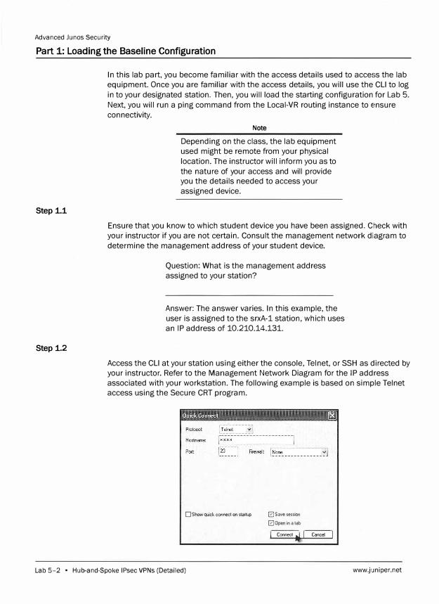
Advanced Junos Security
Part 1: Loading the Baseline Configuration
Step 1.1
Step 1.2
In this lab part, you become familiar with the access details used to access the lab
equipment. Once you are familiar with the access details, you will use the CU to log
in to your designated station. Then, you will load the starting configuration for Lab 5.
Next, you will run a ping command from the Local-VR routing instance to ensure
connectivity.
Note
Depending on the class, the lab equipment
used might be remote from your physical
location. The instructor will inform you as to
the nature of your access and will provide
you the details needed to access your
assigned device.
Ensure that you know to which student device you have been assigned. Check with
your instructor if you are not certain. Consult the management network diagram to
determine the management address of your student device.
Question: What is the management address
assigned to your station?
Answer: The answer varies. In this example, the
user is assigned to the srxA-1 station, which uses
an IP address of 10.210.14.131.
Access the CU at your station using either the console, Telnet, or SSH as directed by
your instructor. Refer to the Management Network Diagram for the IP address
associated with your workstation. The following example is based on simple Telnet
access using the Secure CRT program.
D Show quick connect on startup � Save session
� Open in a tab
I, Connect � J C,ncel j
Lab 5-2 • Hub-and-Spoke IPsec VPNs (Detailed) www.juniper.net
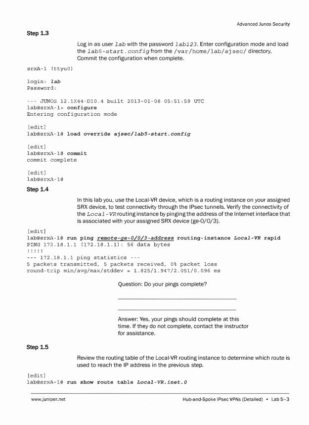
Step 1.3
srxA-1 (ttyuO)
login: lab
Password:
Advanced Ju nos Security
Log in as user lab with the password labl2 3. Enter configuration mode and load
the lab5-start. configfrom the /var /home/lab/aj sec/ directory.
Commit the configuration when complete.
--- JUNOS 12.1X44-Dl0.4 built 2013-01-08 05:51:59 UTC
lab@srxA-1> configure
Entering configuration mode
[edit]
lab@srxA-1# load override ajsec/lab5-start.config
[edit]
lab@srx/\.-1# commit
commit complete
[edit]
lab@srxA-1#
Step i4
[edit]
In this lab you, use the Local-VR device, which is a routing instance on your assigned
SRX device, to test connectivity through the IPsec tunnels. Verify the connectivity of
the Local - VR routing instance by pinging the address of the Internet interface that
is associated with your assigned SRX device (ge-0/0/3).
lab@srxA-1# run ping remote-ge-0/0/3-address routing-instance Local-VR rapid
PING 172.18.1.1 (172.18.1.1): 56 data bytes
! ! ! ! !
--- 172.18.1.1 ping statistics ---
5 packets transmitted, 5 packets received, 0% packet loss
round-trip min/avg/max/stddev = l.825/l.947/2.051/0.096 ms
Step i5
[edit]
Question: Do your pings complete?
Answer: Yes, your pings should complete at this
time. If they do not complete, contact the instructor
for assistance.
Review the routing table of the Local-VR routing instance to determine which route is
used to reach the IP address in the previous step.
lab@srxl\.-1# run show route table Local-VR.inet.O
www.juniper.net Hub-and-Spoke JPsec VPNs (Detailed) • Lab 5-3
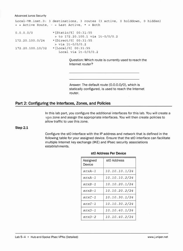
Advanced Junos Security
Local-VR.inet.O: 3 destinations, 3 routes (3 active, 0 holddown, O hidden)
+ = Active Route, - = Last Active, * = Both
0.0.0.0/0
172.20.100.0/24
* [Static/SJ 00: 31: 55
> to 172.20.100.1 via lt-0/0/0.2
* [Direct/OJ 00: 31: 55
> via lt-0/0/0.2
172.20.100.10/32 *[Local/OJ 00:31:55
Local via lt-0/0/0.2
Question: Which route is currently used to reach the
Internet router?
Answer: The default route (0.0.0.0/0), which is
statically configured, is used to reach the Internet
router.
Part 2: Configuring the Interfaces, Zones, and Policies
Step 2.1
In this lab part, you configure the additional interfaces for this lab. You will create a
vpn zone and assign the appropriate interfaces. You will then create policies to
allow traffic to use this zone.
Configure the stO interface with the IP address and network that is defined in the
following table for your assigned device. Ensure that the stO interface can facilitate
multiple Internet key exchange (IKE) and IPsec security associations
establishments.
stO Address Per Device
Assigned stO Address
Device
srxA-1 10.10.10.1/24
srxA-1 10.10.10.2/24
srxB-1 10.10.20.1/24
srxB-1 10.10.20.2/24
srxC-1 10.10.30.1/24
srxC-1 10.10.30.2/24
srxD-1 10.10.40.1/24
srxD-2 10.10.40.2/24
Lab 5-4 • Hub-and-Spoke !Psec VPNs (Detailed) www.juniper.net
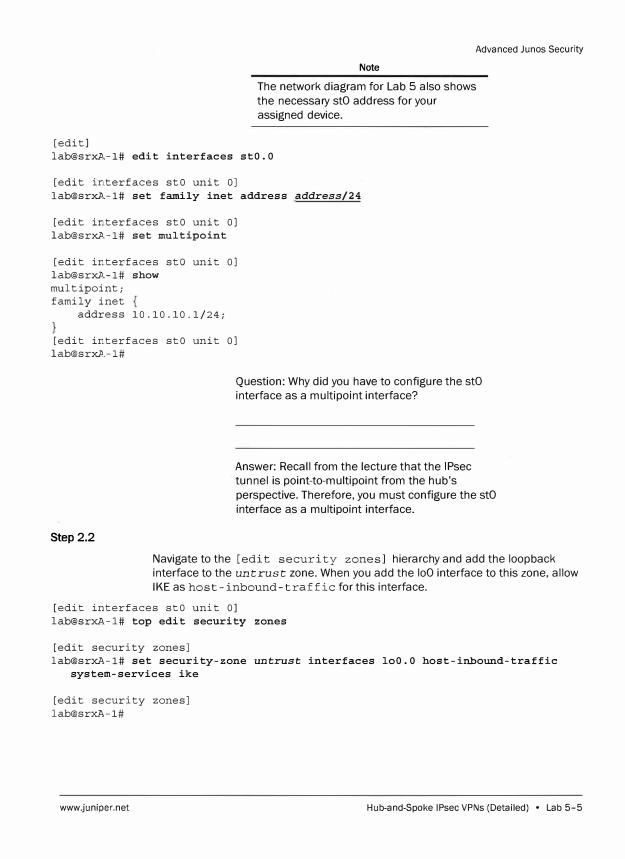
[edit]
Advanced Junos Security
Note
The network diagram for Lab 5 also shows
the necessary stO address for your
assigned device.
lab@srxA,-1# edit interfaces stO.O
[edit interfaces stO unit OJ
lab@srxA,-1# set family inet address address/24
[edit interfaces stO unit OJ
lab@srxA,-1# set multipoint
[edit interfaces sto unit OJ
[email protected]# show
multipoint;
family inet
address 10.10.10.1/24;
[edit interfaces stO unit OJ
Question: Why did you have to configure the stO
interface as a multipoint interface?
Step 2.2
Answer: Recall from the lecture that the IPsec
tunnel is point-to-multipoint from the hub's
perspective. Therefore, you must configure the stO
interface as a multipoint interface.
Navigate to the [edit security zones] hierarchy and add the loopback
interface to the untrust zone. When you add the loO interface to this zone, allow
IKE as host-inbound-traffic for this interface.
[edit interfaces stO unit OJ
lab@srxA-1# top edit security zones
[edit security zones]
lab@srxA-1# set security-zone untrust interfaces loO.O host-inbound-traffic
system-services ike
[edit security zones]
lab@srxA-1#
www.juniper.net Hub-and-Spoke IPsec VPNs (Detailed) • Lab 5-5
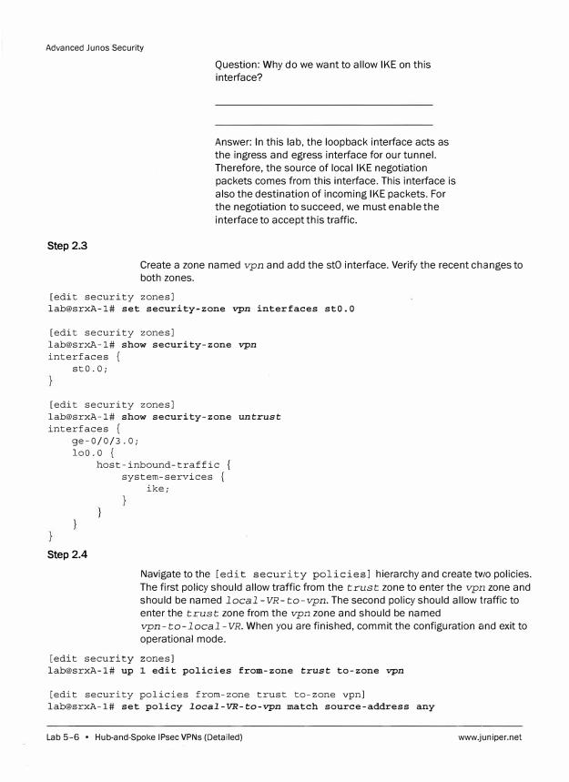
Advanced Junos Security
Step 2.3
Question: Why do we want to allow IKE on this interface?
Answer: In this lab, the loopback interface acts as the ingress and egress interface for our tunnel. Therefore, the source of local IKE negotiation packets comes from this interface. This interface is also the destination of incoming IKE packets. For the negotiation to succeed, we must enable the interface to accept this traffic.
Create a zone named vpn and add the stO interface. Verify the recent changes to both zones.
[edit security zones] lab@srxA-1# set security-zone vpn interfaces stO.O
[edit security zones] lab@srxA-1# show security-zone vpn
interfaces { stO.O;
[edit security zones] lab@srxA-1# show security-zone untrust
interfaces { ge-0/0/3.0;
loo.a { host-inbound-traffic {
system-services { ike;
Step 2.4
Navigate to the [edit security policies] hierarchy and create two policies. The first policy should allow traffic from the trust zone to enter the vpn zone and should be named local -VR-to-vpn. The second policy should allow traffic to enter the trust zone from the vpn zone and should be named vpn-to-local-VR. When you are finished, commit the configuration c1nd exit to operational mode.
[edit security zones] lab@srxA-1# up 1 edit policies from-zone trust to-zone vpn
[edit security policies from-zone trust to-zone vpn] lab@srxA-1# set policy local-VR-to-vpn match source-address any
Lab 5-6 • Hub-and-Spoke IPsec VPNs (Detailed) www.juniper.net
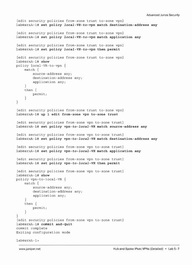
Advanced Ju nos Security
[edit security policies from-zone trust to-zone vpn] lab@srxA-1# set policy local-VR-to-vpn match destination-address any
[edit security policies from-zone trust to-zone vpn] lab@srxA-1# set policy local-VR-to-vpn match application any
[edit security policies from-zone trust to-zone vpn] lab@srxA-1# set policy local-VR-to-vpn then permit
[edit security policies from-zone trust to-zone vpn] lab@srxA-1# show
policy local-VR-to-vpn match {
}
source-address any; destination-address any; application any;
then { permit;
[edit security policies from-zone trust to-zone vpn] lab@srxA-1# up 1 edit from-zone vpn to-zone trust
[edit security policies from-zone vpn to-zone trust] lab@srxl,-1# set policy vpn-to-local-VR match source-address any
[edit security policies from-zone vpn to-zone trust] lab@srxA-1# set policy vpn-to-local-VR match destination-address any
[edit security policies from-zone vpn to-zone trust] lab@srxl,-1# set policy vpn-to-local-VR match application any
[edit security policies from-zone vpn to-zone trust] lab@srxA-1# set policy vpn-to-local-VR then permit
[edit security policies from-zone vpn to-zone trust] lab@srxl,-1# show
policy vpn-to-local-VR match {
}
source-address any; destination-address any; application any;
then { permit;
[edit security policies from-zone vpn to-zone trust] lab@srxA-1# commit and-quit
commit complete Exiting configuration mode
lab@srxA-1>
www.juniper.net Hub-and-Spoke IPsec VPNs (Detailed) • Lab 5-7

Advanced Junos Security
Note
For the purposes of this lab, we want to
allow all traffic, from the Local-YR network
to the spoke sites, to pass through the
IPsec VPN and vice versa. In a production
network this might not be the ideal
situation, and you can limit the traffic
allowed to pass through the IPsec tunnel by
restricting the source, destination, and
applications allowed.
Do not proceed to the next lab part until directed by the instructor to do
so.
Part 3: Configuring IKE and IPsec Properties
In this lab part, you configure the properties to establish the IKE security
associations (SAs). You will also configure the necessary IPsec properties to
establish your IPsec SAs.
Step 3.1
Enter configuration mode and navigate to the [edit security ike] hierarchy.
Begin by defining an IKE policy named policy-1. The spokes are configured to
use main mode, and they also takes advantage of the predefined standard
proposal-set. The spokes are also configured to use a pre-shared-key; the
key is juniper. Configure your IKE policy to match the spokes' settings. Heview the
policy before continuing.
lab@srxA-1> configure Entering configuration mode
[edit] lab@srxA-1# edit security ike
[edit security ike] lab@srxA-1# set policy policy-l mode main
[edit security ike] lab@srxA-1# set policy policy-l proposal-set standard
[edit security ike] lab@srxA-1# set policy policy-l pre-shared-key ascii-text juniper
[edit security ike] lab@srxA-1# show policy policy-1 {
mode main;
Lab 5-8 • Hub-and-Spoke !Psec VPNs (Detailed) www.juniper.net
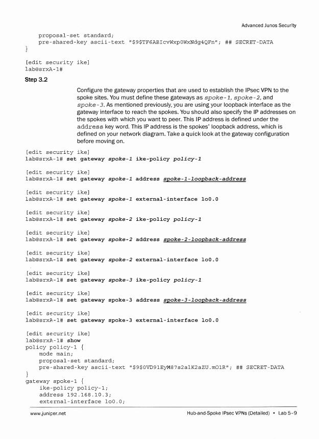
Advanced Junos Security
proposal-set standard; pre-shared-key ascii-text "$9$TF6ABicvWxpOWxNdg4QFn"; ## SECRET-DATA
[edit security ike] lab@srxA-1#
Step 3.2
Configure the gateway properties that are used to establish the IPsec VPN to the
spoke sites. You must define these gateways as spoke-1, spoke-2, and
spoke-3. As mentioned previously, you are using your loopback interface as the
gateway interface to reach the spokes. You should also specify the IP addresses on
the spokes with which you want to peer. This IP address is defined under the
address key word. This IP address is the spokes' loopback address, which is
defined on your network diagram. Take a quick look at the gateway configuration
before moving on.
[edit security ike] lab@srxA-1# set gateway spoke-1 ike-policy policy-1
[edit security ike] lab@srxA-1# set gateway spoke-1 address spoke-1-loopback-address
[edit security ike] lab@srxA-1# set gateway spoke-1 external-interface loO.O
[edit security ike] lab@srxA-1# set gateway spoke-2 ike-policy policy-1
[edit security ike] lab@srxA-1# set gateway spoke-2 address spoke-2-loopback-address
[edit security ike] [email protected]# set gateway spoke-2 external-interface loO. 0
[edit security ike] [email protected]# set gateway spoke-3 ike-policy policy-1
[edit security ike] [email protected]# set gateway spoke-3 address spoke-3-loopback-address
[edit security ike] [email protected]# set gateway spoke-3 external-interface loO. 0
[edit security ike] [email protected]# show policy policy-1 {
mode main; proposal-set standard; pre-shared-key ascii-text "$9$0VD91EyM87s2alK2aZU.m01R"; ## SECRET-DATA
} gateway spoke-1 {
ike-policy policy-1; address 192.168.10.3; external-interface loO.O;
www.juniper.net Hub-and-Spoke IPsec VPNs (Detailed) • Lab 5-9
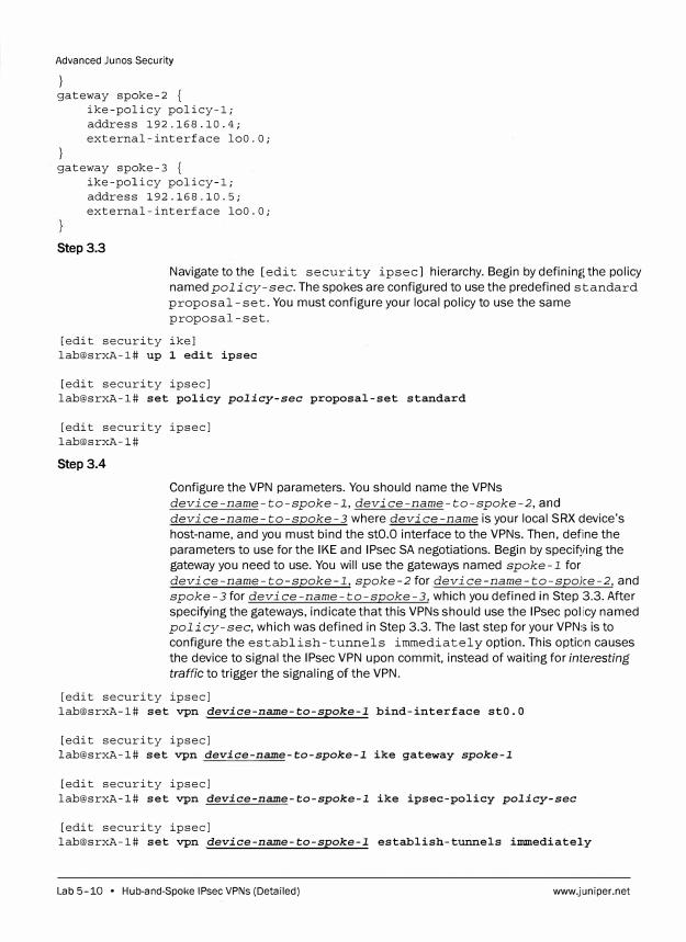
Advanced Junes Security
} gateway spoke-2 {
}
ike-policy policy-1; address 192.168.10.4; external-interface loO.O;
· gateway spoke-3 {ike-policy policy-1; address 192.168.10.5; external-interface loO.O;
Step 3.3
Navigate to the [edit security ipsec] hierarchy. Begin by defining the policy
named policy-sec. The spokes are configured to use the predefined standard
proposal-set. You must configure your local policy to use the same
proposal -set.
[edit security ike] lab@srxA-1# up 1 edit ipsec
[edit security ipsec] lab@srxA-1# set policy policy-sec proposal-set standard
[edit security ipsec] lab@srxA-1#
Step 3.4
Configure the VPN parameters. You should name the VPNs
device-name-to-spoke-l,device-name-to-spoke-2,and
device-name-to-spoke-3 where device-name is your local SRX device's
host-name, and you must bind the stO.O interface to the VPNs. Then, define the
parameters to use for the IKE and IPsec SA negotiations. Begin by specifying the gateway you need to use. You will use the gateways named spoke-1 for
device-name-to-spoke-1, spoke-2 for device-name-to-spoke-2, and
spoke-3 for device-name-to-spoke-3, which you defined in Step 3.3. After
specifying the gateways, indicate that this VPNs should use the IPsec policy named policy-sec, which was defined in Step 3.3. The last step for your VPNs is to
configure the establish-tunnels immediately option. This option causes
the device to signal the IPsec VPN upon commit, instead of waiting for interesting
traffic to trigger the signaling of the VPN.
[edit security ipsec] lab@srxA-1# set vpn device-name-to-spoke-1 bind-interface stO.O
[edit security ipsec] lab@srxA-1# set vpn device-name-to-spoke-1 ike gateway spoke-1
[edit security ipsec] lab@srxA-1# set vpn device-name-to-spoke-1 ike ipsec-policy policy-sec
[edit security ipsec] lab@srxA-1# set vpn device-name-to-spoke-1 establish-tunnels iim11ediately
Lab 5-10 • Hub-and-Spoke IPsec VPNs (Detailed) www.juniper.net
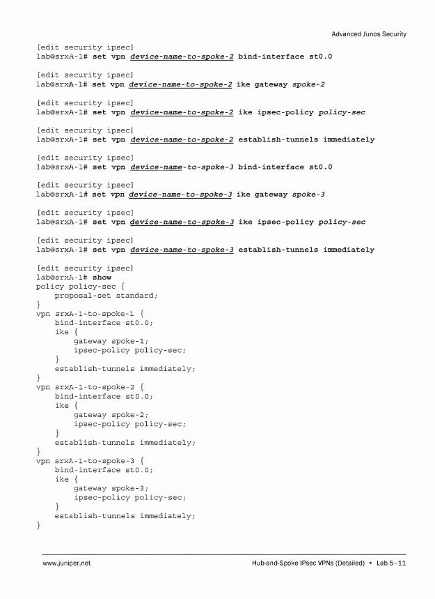
Advanced Ju nos Security
[edit security ipsec] lab@srxA-1# set vpn device-name-to-spoke-2 bind-interface stO.O
[edit security ipsec] lab@srXJ\-1# set vpn device-name-to-spoke-2 ike gateway spoke-2
[edit security ipsec] lab@srxA-1# set vpn device-name-to-spoke-2 ike ipsec-policy policy-sec
[edit security ipsec] lab@srxA-1# set vpn device-name-to-spoke-2 establish-tunnels immediately
[edit security ipsec] lab@srxA-1# set vpn device-name-to-spoke-3 bind-interface stO.O
[edit security ipsec] lab@srxA-1# set vpn device-name-to-spoke-3 ike gateway spoke-3
[edit security ipsec] lab@srxA-1# set vpn device-name-to-spoke-3 ike ipsec-policy policy-sec
[edit security ipsec] lab@srxA-1# set vpn device-name-to-spoke-3 establish-tunnels immediately
[edit security ipsec] [email protected],-1# show
policy policy-sec {
proposal-set standard;
vpn srxA-1-to-spoke-l {
bind-interface stO.O; ike {
gateway spoke-1; ipsec-policy policy-sec;
establish-tunnels immediately;
vpn srxA-1-to-spoke-2 bind-interface stO.O; ike {
gateway spoke-2; ipsec-policy policy-sec;
establish-tunnels immediately;
vpn srxA,-1-to-spoke-3 bind-interface st0.0; ike {
gateway spoke-3; ipsec-policy policy-sec;
esta.blish-tunnels immediately;
www.juniper.net Hub-and-Spoke IPsec VPNs (Detailed) • Lab 5-11
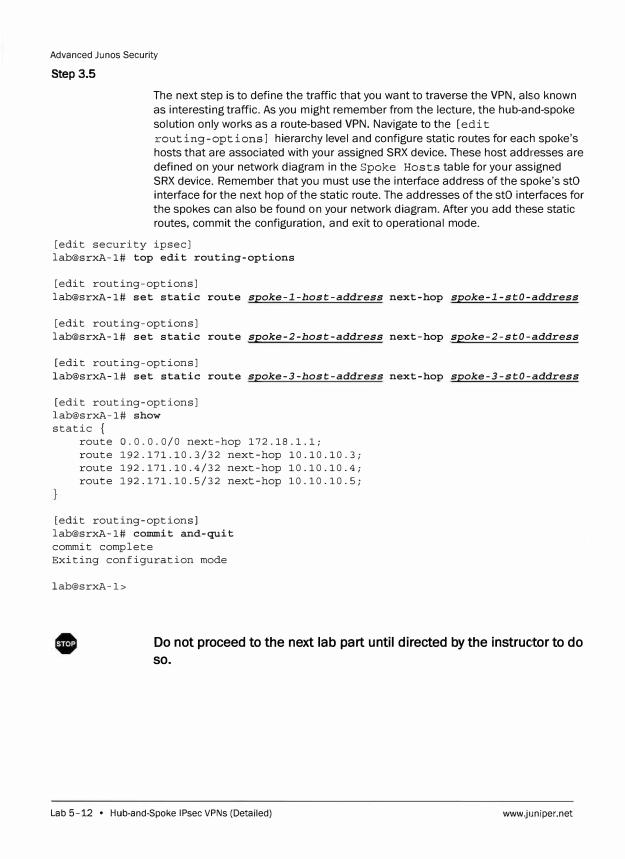
Advanced Junos Security
Step 3.5
The next step is to define the traffic that you want to traverse the VPN, also known
as interesting traffic. As you might remember from the lecture, the hub-and-spoke
solution only works as a route-based VPN. Navigate to the [edit
routing-options] hierarchy level and configure static routes for each spoke's
hosts that are associated with your assigned SRX device. These host addresses are
defined on your network diagram in the Spoke Hosts table for your assigned
SRX device. Remember that you must use the interface address of the spoke's stO
interface for the next hop of the static route. The addresses of the stO interfaces for
the spokes can also be found on your network diagram. After you add these static
routes, commit the configuration, and exit to operational mode.
[edit security ipsec] lab@srxA-1# top edit routing-options
[edit routing-options] lab@srxA-1# set static route spoke-I-host-address next-hop spoke-1-stO-address
[edit routing-options] lab@srxA-1# set static route spoke-2-host-address next-hop spoke-2-stO-address
[edit routing-options] lab@srxA-1# set static route spoke-3-host-address next-hop spoke-3-stO-address
[edit routing-options] lab@srxA-1# show static {
route 0.0.0.0/0 next-hop 172.18.1.l; route 192.171.10.3/32 next-hop 10.10.10.3; route 192.171.10.4/32 next-hop 10.10.10.4; route 192.171.10.5/32 next-hop 10.10.10.5;
[edit routing-options] lab@srxA-1# commit and-quit commit complete Exiting configuration mode
lab@srxA-1>
Do not proceed to the next lab part until directed by the instruc:tor to do
so.
Lab 5-12 • Hub-and-Spoke IPsec VPNs (Detailed) www.juniper.net
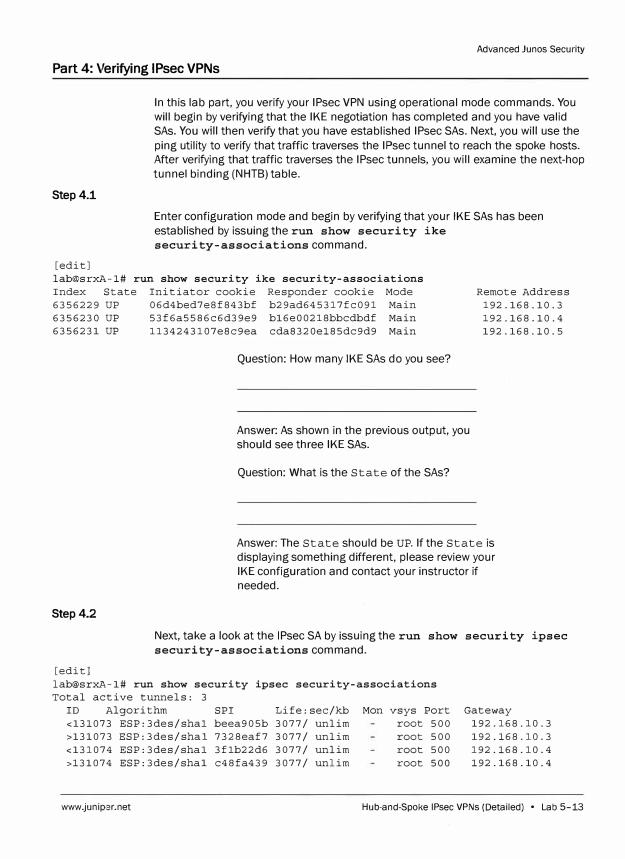
Advanced Junos Security
Part 4: Verifying IPsec VPNs
Step4.1
[edit]
In this lab part, you verify your IPsec VPN using operational mode commands. You
will begin by verifying that the IKE negotiation has completed and you have valid
SAs. You will then verify that you have established IPsec SAs. Next, you will use the
ping utility to verify that traffic traverses the IPsec tunnel to reach the spoke hosts.
After verifying that traffic traverses the IPsec tunnels, you will examine the next-hop
tunnel binding (NHTB) table.
Enter configuration mode and begin by verifying that your IKE SAs has been
established by issuing the run show security ike
security-associations command.
lab@srxA-1# run show security ike security-associations
Index State Initiator cookie Responder cookie Mode Remote Address
192.168.10.3
192.168.10.4
192.168.10.5
6356229 UP 06d4bed7e8f843bf b29ad645317fc091 Main
6356230 UP 53f6a5586c6d39e9 b16e00218bbcdbdf Main
6356231 UP 1134243107e8c9ea cda8320e185dc9d9 Main
Question: How many IKE SAs do you see?
Answer: As shown in the previous output, you
should see three IKE SAs.
Question: What is the State of the SAs?
Answer: The State should be UP. If the State is
displaying something different, please review your
IKE configuration and contact your instructor if
needed.
Step 4.2
Next, take a look at the IPsec SA by issuing the run show security ipsec
security-associations command.
[edit]
lab@srxA-1# run show security ipsec security-associations
Total active tunnels: 3
ID Algorithm SPI
<131073 ESP:3des/shal beea905b
>131073 ESP:3des/shal 7328eaf7
<131074 ESP:3des/shal 3flb22d6
>131074 ESP:3des/shal c48fa439
Life:sec/kb
3077/ unlim
3077/ unlim
3077/ unlim
3077/ unlim
Mon vsys Port
root 500
root 500
root 500
root 500
Gateway
192.168.10.3
192.168.10.3
192.168.10.4
192.168.10.4
www.juniper.net Hub-and-Spoke IPsec VPNs (Detailed) • Lab 5-13
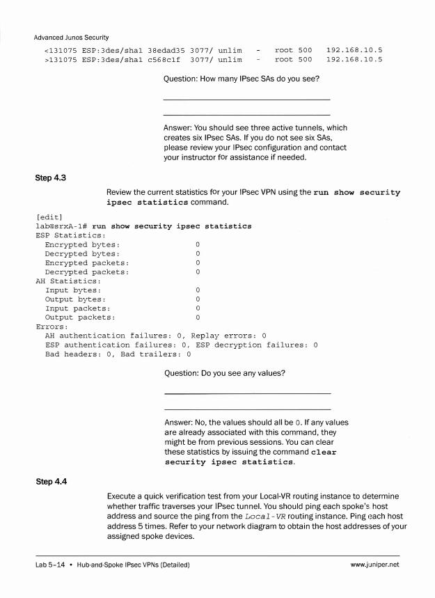
Advanced Junes Security
<131075 ESP:3des/shal 38edad35 3077/ unlim >131075 ESP:3des/shal c568clf 3077/ unlim
root 500 root 500
192.168.10.5 192.168.10.5
Step 4.3
Question: How many IPsec SAs do you see?
Answer: You should see three active tunnels, which
creates six IPsec SAs. If you do not see six SAs,
please review your IPsec configuration and contact
your instructor for assistance if needed.
Review the current statistics for your IPsec VPN using the run show security
ipsec statistics command.
[edit] lab@srxA-1# run show security ipsec statistics ESP Statistics:
Encrypted bytes: 0 Decrypted bytes: 0 Encrypted packets: 0 Decrypted packets: O
AH Statistics: Input bytes: O Output bytes: O Input packets: o Output packets: O
Errors: AH authentication failures: 0, Replay errors: O ESP authentication failures: 0, ESP decryption failures: 0 Bad headers: 0, Bad trailers: O
Step4.4
Question: Do you see any values?
Answer: No, the values should all be o. If any values
are already associated with this command, they
might be from previous sessions. You can clear
these statistics by issuing the command clear
security ipsec statistics.
Execute a quick verification test from your Local-VR routing instance to determine
whether traffic traverses your IPsec tunnel. You should ping each spoke's. host
address and source the ping from the Local - VR routing instance. Ping each host
address 5 times. Refer to your network diagram to obtain the host addresses of your
assigned spoke devices.
Lab 5-14 • Hub-and-Spoke IPsec VPNs (Detailed) www.juniper.net
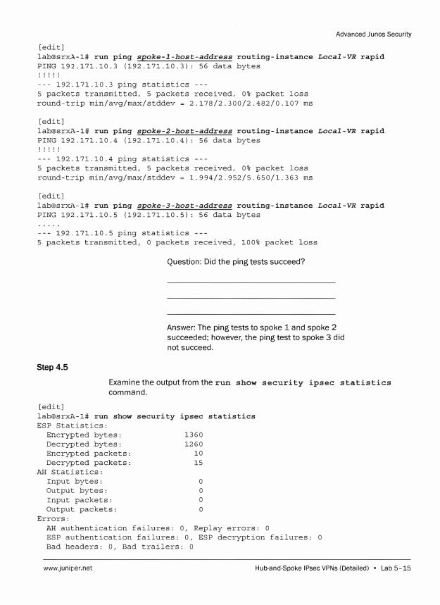
Advanced Junes Security
[edit] lab@srxA-1# run ping spoke-1-host-address routing-instance Local-VR rapid PING 192.171.10.3 (192.171.10.3): 56 data bytes ! ! ! ! !
--- 192.171.10.3 ping statistics ---5 packets transmitted, 5 packets received, 0% packet loss round-trip min/avg/max/stddev = 2.178/2.300/2.482/0.107 ms
[edit] lab@srxA-1# run ping spoke-2-host-address routing-instance Local-VR rapid PING 192.171.10.4 (192.171.10.4): 56 data bytes ! ! ! ! !
--- 192.171.10.4 ping statistics ---5 packets transmitted, 5 packets received, 0% packet loss round-trip min/avg/max/stddev = l.994/2.952/5.650/l.363 ms
[edit] lab@srxi\-1# run ping spoke-3-host-address routing-instance Local-VR rapid PING 192.171.10.5 (192.171.10.5): 56 data bytes
--- 192.171.10.5 ping statistics 5 packets transmitted, 0 packets received, 100% packet loss
Question: Did the ping tests succeed?
Answer: The ping tests to spoke 1 and spoke 2
succeeded; however, the ping test to spoke 3 did
not succeed.
Step 4.5
Examine the output from the run show security ipsec statistics
command.
[edit] lab@srxA-1# run show security ipsec statistics ESP Statistics:
Encrypted bytes: 1360 Decrypted bytes: 1260 Encrypted packets: 10 Decrypted packets: 15
AH Statistics: Input bytes: 0 Output bytes: 0 Input packets: O Output packets: 0
Errors: AH authentication failures: 0, Replay errors: 0 ESP authentication failures: 0, ESP decryption failures: 0 Bad headers: 0, Bad trailers: 0
www.juniper.net Hub-and-Spoke IPsec VPNs (Detailed) • Lab 5-15
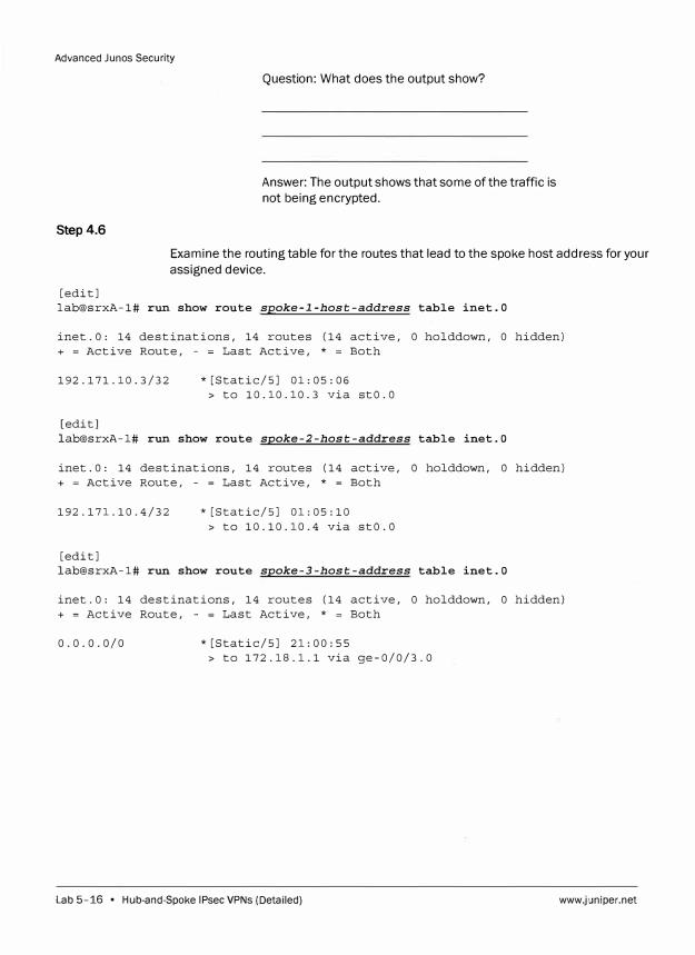
Advanced Junos Security
Step 4.6
Question: What does the output show?
Answer: The output shows that some of the traffic is
not being encrypted.
Examine the routing table for the routes that lead to the spoke host address for your
assigned device.
[edit]
lab@srxA-1# run show route spoke-1-host-address table inet.0
inet.O: 14 destinations, 14 routes (14 active, O holddown, O hidden)
+ = Active Route, - = Last Active, * = Both
192.171.10.3/32 * [Static/SJ 01: 05: 06
> to 10.10.10.3 via stO.O
[edit]
lab@srxA-1# run show route spoke-2-host-address table inet.O
inet.O: 14 destinations, 14 routes (14 active, O holddown, O hidden)
+ = Active Route, - = Last Active, * = Both
192.171.10.4/32 * [Static/SJ 01: 05: 10
> to 10.10.10.4 via stO.O
[edit]
lab@srxA-1# run show route spoke-3-host-address table inet.O
inet.O: 14 destinations, 14 routes (14 active, O holddown, O hidden)
+ = Active Route, - = Last Active, * = Both
0.0.0.0/0 * [Static/SJ 21: 00: 55
> to 172.18.1.1 via ge-0/0/3.0
Lab 5-16 • Hub-and-Spoke IPsec VPNs (Detailed) www.juniper.net
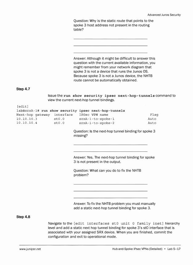
Step 4.7
[edit]
Advanced Junos Security
Question: Why is the static route that points to the
spoke 3 host address not present in the routing
table?
Answer: Although it might be difficult to answer this
question with the current available information, you
might remember from your network diagram that
spoke 3 is not a device that runs the Junos OS.
Because spoke 3 is not a Ju nos device, the NHTB
route cannot be automatically obtained.
Issue the run show security ipsec next-hop-tunnels command to
view the current next-hop tunnel bindings.
lab@srxA-1# run show security ipsec next-hop-tunnels
Next-hop gateway interface IPSec VPN name Flag
Auto
Auto
10.10.10.3 stO.O srxA-1-to-spoke-l
10.10.10.4 stO.O srxA-1-to-spoke-2
Step 4.8
www.juniper.net
Question: Is the next-hop tunnel binding for spoke 3
missing?
Answer: Yes. The next-hop tunnel binding for spoke
3 is not present in the output.
Question: What can you do to fix the NHTB
problem?
Answer: To fix the NHTB problem you must manually
add a static next-hop tunnel binding for spoke 3.
Navigate to the [edit interfaces stO unit o family inet] hierarchy
level and add a static next hop tunnel binding for spoke 3's stO interface that is
associated with your assigned SRX device. When you are finished, commit the
configuration and exit to operational mode.
Hub-and-Spoke IPsec VPNs (Detailed) • Lab 5-17
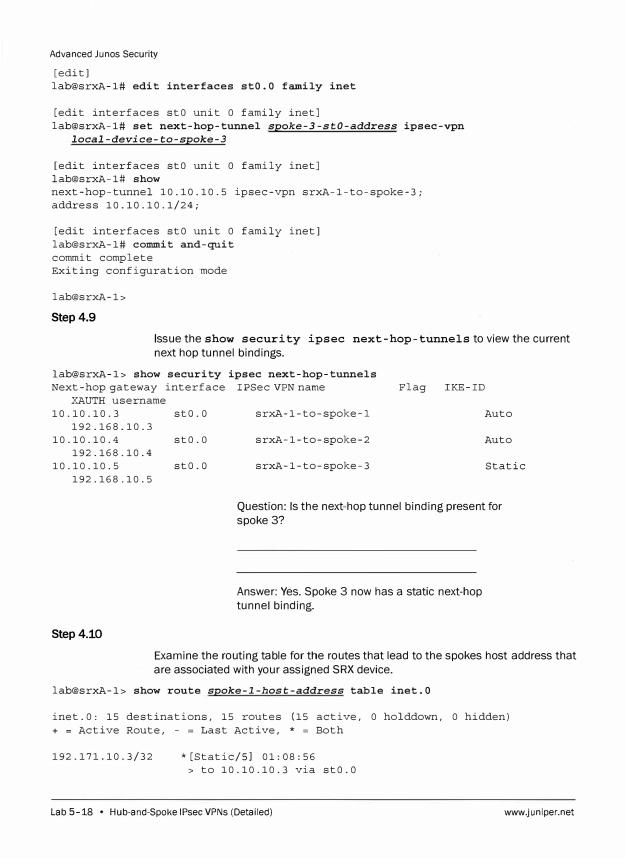
Advanced Junes Security
[edit) lab@srxA-1# edit interfaces stO.O family inet
[edit interfaces stO unit O family inet] lab@srxA-1# set next-hop-tunnel spoke-3-stO-address ipsec-vpn
local-device-to-spoke-3
[edit interfaces stO unit O family inet] lab@srxA-1# show next-hop-tunnel 10.10.10.5 ipsec-vpn srxA-1-to-spoke-3; address 10.10.10.1/24;
[edit interfaces stO unit O family inet] lab@srxA-1# commit and-quit commit complete Exiting configuration ·mode
lab@srxA-1>
Step 4.9
Issue the show security ipsec next-hop-tunnels to view the current
next hop tunnel bindings.
lab@srxA-1> show security ipsec next-hop-tunnels Next-hop gateway interface IPSec VPN name
XAUTH username 10.10.10.3
192.168.10.3 10.10.10.4
192.168.10.4 10.10.10.5
192.168.10.5
sto.o srxA-1-to-spoke-l
stO.O srxA-1-to-spoke-2
sto.o srxA-1-to-spoke-3
Flag IKE-ID
Auto
Auto
Static
Question: Is the next-hop tunnel binding present for
spoke 3?
Step4.10
Answer: Yes. Spoke 3 now has a static next-hop
tunnel binding.
Examine the routing table for the routes that lead to the spokes host address that
are associated with your assigned SRX device.
lab@srxA-1> show route spoke-l-host-address table inet.O
inet.O: 15 destinations, 15 routes (15 active, O holddown, O hidden) + = Active Route, - = Last Active, * = Both
192.171.10.3/32 * [Static/SJ 01: 08: 56 > to 10.10.10.3 via stO.O
Lab 5-18 • Hub-and-Spoke IPsec VPNs (Detailed) www.juniper.net
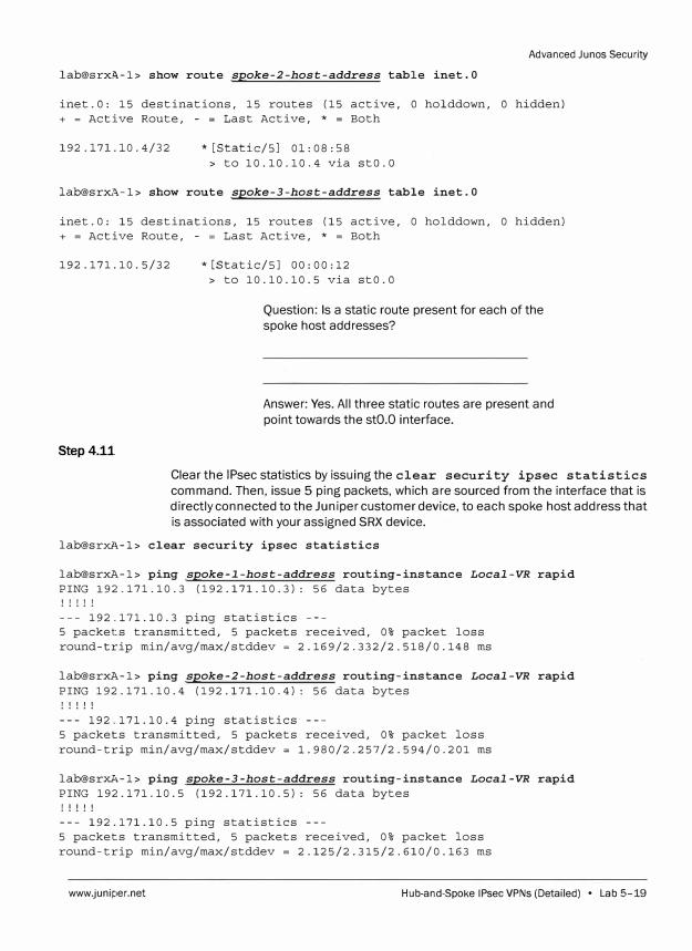
Advanced Junos Security
lab@srxA-1> show route spoke-2-host-address table inet.O
inet.O: 15 destinations, 15 routes (15 active, O holddown, O hidden) + = Active Route, - = Last Active, * = Both
192 .171.10. 4/32 * [Static/SJ 01: 08: 58> to 10.10.10.4 via sto.o
lab@srxA-1> show route spoke-3-host-address table inet.O
inet.O: 15 destinations, 15 routes (15 active, 0 holddown, 0 hidden) + = Active Route, - = Last Active, * = Both
192 .171.10. 5/32
Step4.11
* [Static/SJ oo: 00: 12> to 10.10.10.5 via stO.O
Question: Is a static route present for each of the
spoke host addresses?
Answer: Yes. All three static routes are present and
point towards the stO.O interface.
Clear the IPsec statistics by issuing the clear security ipsec statistics
command. Then, issue 5 ping packets, which are sourced from the interface that is
directly connected to the Juniper customer device, to each spoke host address that
is associated with your assigned SRX device.
lab@srxA-1> clear security ipsec statistics
lab@srxA-1> ping spoke-1-host-address routing-instance Local-VR rapid PING 192.171.10.3 (192.171.10.3): 56 data bytes ! ! ! ! !
--- 192.171.10.3 ping statistics ---5 packets transmitted, 5 packets received, 0% packet loss round-trip min/avg/max/stddev = 2.169/2.332/2.518/0.148 ms
lab@srxA-1> ping spoke-2-host-address routing-instance Local-VR rapid PING 192.171.10.4 (192.171.10.4): 56 data bytes ! ! ! ! !
--- 192.171.10.4 ping statistics ---5 packets transmitted, 5 packets received, 0% packet loss round-trip min/avg/max/stddev = l.980/2.257/2.594/0.201 ms
lab@srxA-1> ping spoke-3-host-address routing-instance Local-VR rapid PING 192.171.10.5 (192.171.10.5): 56 data bytes! ! ! ! !
--- 192.171.10.5 ping statistics ---5 packets transmitted, 5 packets received, 0% packet lossround-trip min/avg/max/stddev = 2.125/2.315/2.610/0.163 ms
www.juniper.net Hub-and-Spoke IPsec VPNs (Detailed) • Lab 5-19
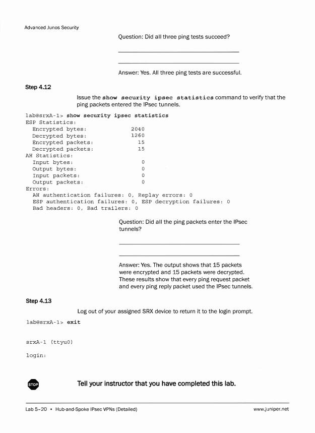
Advanced Junos Security
Question: Did all three ping tests succeed?
Answer: Yes. All three ping tests are successful.
Step4.12
Issue the show security ipsec statistics command to verify that the
ping packets entered the IPsec tunnels.
lab@srxA-1> show security ipsec statistics
ESP Statistics: Encrypted bytes: 2040
Decrypted bytes: 1260
Encrypted packets: 15
Decrypted packets: 15 AH Statistics:
Input bytes: O
Output bytes: O Input packets: O Output packets: O
Errors: AH authentication failures: 0, Replay errors: O ESP authentication failures: 0, ESP decryption failures: O Bad headers: 0, Bad trailers: O
Step4.13
Question: Did all the ping packets enter the IPsec
tunnels?
Answer: Yes. The output shows that 15 packets
were encrypted and 15 packets were decrypted.
These results show that every ping request packet
and every ping reply packet used the IPsec tunnels.
Log out of your assigned SRX device to return it to the login prompt.
lab@srxA-1> exit
srxA-1 (ttyuO)
login:
0 Tell your instructor that you have completed this lab.
Lab 5-20 • Hub-and-Spoke IPsec VPNs (Detailed) www.juniper.net
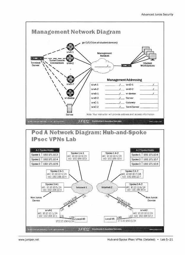
Advanced Junos Security
Management Network Diagram
\
ge- 0/0/0(on all studentdevic:es)
srxA-1
srxA-2
srxB-1
srxB-2
srxC-1
srxC-2
ManagementAddressing
srxD-1
srxD-2
vr-device
Server
---�- Gateway Term Server -- ----ii
Server Note: Your instructor will provide address and access information.
Pod A Network Diagram: Hub-and-Spoke
IPsec VPNs Lab
A -1 Spoke Hosts
Spoke 1 192.171.10.3
Spoke2 192.171.10.4
Spoke3 192.171.10.5
Spoke stO 10.10.10. 4/24 loO 192.168.10.4
Spoke3A-1 stO: 10 10.10.5/ 24 loO 192.168.10.5
NonJunos / Device
srxA-1 stO 10.10.10.1/24 loO 192.168.10.1
www.juniper.net
Spoke1A-1 stO: 1010.103/24 loO 192.168.10.3
Spoke1A-2 stO 10.10.10.6/24 loO 192.168.10. 6
A -2 Spoke Hosts
Spoke 1 192.171-10.6
Spoke2 192.171.10.7
Spoke3 192.171.10.8
�NonJunos Device
srxA-2 stO 10.1010.2/24
( 'O) (.1) loO 192.168.10.2 Local-VR L\:·::;;":!!.------"-----�
---� 172.20.200.G/24
Hub-and-Spoke IPsec VPNs (Detailed) • Lab 5-21
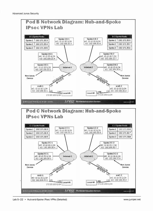
Advanced Junos Security
Pod B Network Diagram: Hub-and-Spoke
IPsec VPNs Lab
-· B-1 Spoke Hosts
Spoke 1 192.171.20.3
Spoke 2 192.171.20.4
Spoke3 192.171.20.5
Spoke3B-1 stO: 10.10.20.5/24 loO 192.168.20.5
NonJunos / Device
srxB-1 stO 10.10.20.1/24 loO: 192.168.20.1
Spoke lB-1 stO 10.10.20.3/24 loO: 192.168.20.3
172.20.100.0/24
SpokelB-2 stO: 10 10.20.6/24 loO 192.168.20.6
, B· 2 Spoke Hosts
Spoke 1 192.171.20.6
Spoke 2 192.171.20. 7
Spoke3 192.171.20.8
"""Non Ju nos Device
srxB-2 stO 10.10.20.2/24
(.l) loO: 192.168.20.2 Local-VR ll(,1:.:l.O�ll--="-=====;;..J
L----' 172.20.200.0/24
©2013JuniperNetwork,, Int AJlo:(ht� reserved JUn�f Worldwide Education Services 'l'll"IW )lHllP - .
Pod C Network Diagram: Hub-and-Spoke
IPsec VPNs Lab
C-1 Spoke Hosts
Spoke1
Spoke2
Spoke3
NonJunos Device
192.171.30.3
192.171.30.4
192.171.30.5
Spoke1C-1 stO: 10.10.30.3/24 loO: 192.168.30.3
172.20 1000/24 '----.J
C-2 Spoke Hosts
192.171.30.0�
Spokel
Spoke2
Spoke3
192.171.30.7
192.171.30.8
NonJunos Device
srxC-2 stO 10.10.30.2/24
( 10) (i) loO: 192.168.30.2 Local-VR �· �-
_.:=--------'
'----.J 172.20.200.0/24
0:?0.l3J1Jnlp1;rNetworlu:, lne .e.nrl:1tiUrt�erm1 JUn� WorldwideEducatlonServices WJW'IJUfll --- -- - - -----� �"'---- -
Lab 5-22 • Hub-and-Spoke IPsec VPNs (Detailed) www.juniper.net
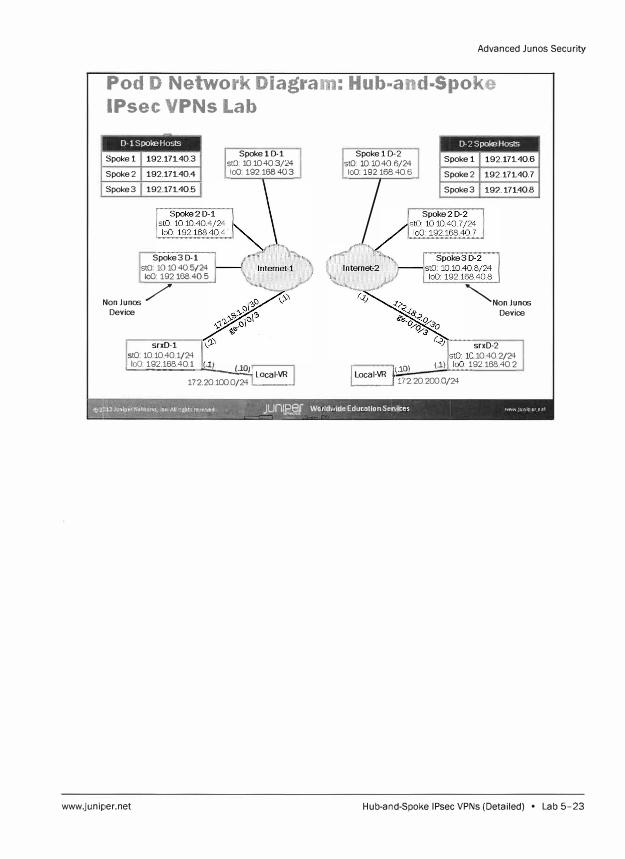
Advanced Junos Security
Pod D Network Diagram: Hub-and-Spoke
IPsec VPNs Lab
-
D-1 Spoke Hosts
Spokel
Spoke2
Spoke3
192.171. 40.3
192.171. 40.4
192.171. 40.5
Spoke30-1 stO 10.10 .40.5/24 loO 192.168.40.5
NonJunos / Device
srxD-1 stO 10.10 40 1/24
Spoke10-1 stO: 10. 10.40.3/24 loO 192.168.40.3
._1o0 _: 1_9 _2_.1_68_.40_.1_.._.._-!.;r-1�0:!JJ Local-VR 172.20.100.0/24 .__ __ .....
Spokel 0-2 stO: 10.10.40.6/24 loO 192.168.40.6
/
D-2SpokeHosts
Spoke 1 192.171.40.6
Spoke2 192.171.40.7
Spoke3 192.171. 40.8
"'NonJunos Device
I 1(.10) (.1) Local-VR .
... --� 172202000/24
srxD-2 10 40 2/24
9 2.168.40.2
,&2 [;''ir
'l'. JUf7l1Der WorldwideEducatlonServices ¥'1WWJUA1pernet ,i "� _,/?;
----=-�--�- =
www.juniper.net Hub-and-Spoke IPsec VPNs (Detailed) • Lab 5-23

Advanced Ju nos Security
Lab 5-24 • Hub-and-Spoke IPsec VPNs (Detailed) www.juniper.net
Overview
Lab
Configuring Group VPNs (Detailed)
In this lab, you will load the baseline configuration for your device. The configuration will
include interfaces, interfaces zone assignments, security policies to allow traffic between
zones, and a stateless firewall filter for selective packet-based services. You will then
configure your device to act as a member of a group IP Security (IPsec) virtual private
network (VPN). You will use the loopback interface as your gateway interface. The key
server has been preconfigured with all the necessary requirements. The IPsec tunnel will
be configured to encrypt and pass traffic for the Juniper customer networks attached to
each student device within a single pod. After completing your configuration, you will
verify the IPsec VPN status on your local device. You will also verify functionality and
reachability from the virtual router device. For all IP addresses and network information,
please refer to the Network Diagram: Lab 6 slide in your Lab Diagrams handout.
The lab is available in two formats: a high-level format designed to make you think through
each step and a detailed format that offers step-by-step instructions complete with
sample output from most commands.
By completing this lab, you will perform the following tasks:
Use the Junos command-line interface (CLI) to load the baseline configuration.
Use the Junos CLI to configure the group IPsec VPN parameters.
Assign interfaces to security zones.
Implement security policies between zones.
Verify that the expected traffic traverses the VPN.
Monitor the effects of the configuration from the local device.
Verify reachability by using the virtual router (VR) device.
www.juniper.net Configuring Group VPNs (Detailed) • Lab 6-1

Advanced Junos Security
Part 1: Loading the Baseline Configuration
Step 1.1
Step 1.2
Step 1.3
srxA-1 (ttyuO)
login: lab
Password:
In this lab part, you change the current configuration for the loopback IP address.
You will then add the loopback to the appropriate zone and allow appropriate
host-bound traffic. You will configure the appropriate policies to allow
communication to the loopback interface.
Ensure that you know to which student device you have been assigned. Check with
your instructor if you are not certain. Consult the Management Network Diagram to
determine the management address of your student device.
Question: What is the management address
assigned to your student router?
Answer: The answer varies. The sample hostname
and IP address used in the output examples in this
lab are for srxA-1, which uses 10.210.35.131 as its
management IP address. The actual management
address varies between delivery environments.
Access the command-line interface (CLI) at your station using either the console,
Telnet, or SSH as directed by your instructor.
Quick Connect (8}
Protocol:
Hostname:
Po1t
D Show quick connect on startup 0 Save session
� Open in a tab
Connect J I Cancel
Log in as user lab with the password lab123. Enter configuration mode and load
the lab6-start. configfrom the /var/home/lab/ajsec/ directory. Commit the
configuration and exit to operational mode when complete.
Lab 6-2 • Configuring Group VPNs (Detailed) www.juniper.net
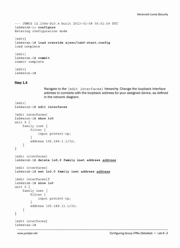
--- JUNOS 12.1X44-Dl0.4 built 2013-01-08 05:51:59 UTC lab@srxA-1> configure Entering configuration mode
[edit] lab@srxA-1# load override ajsec/lab6-start.config load complete
[edit] lab@srxA-1# commit commit complete
[edit] lab@srxA-1#
Step 1.4
Advanced Junes Security
Navigate to the [edit interfaces] hierarchy. Change the loopback interface
address to correlate with the loopback address for your assigned device, as defined
in the network diagram.
[edit] lab@srxA-1# edit interfaces
[edit interfaces] lab@srxA-1# show loO unit O {
family inet { filter {
input protect-cp;
address 192.168.1.1/32;
[edit interfaces] [email protected],-1# delete loO. 0 family inet address address
[edit interfaces] lab@srx A-1# set loO.O family inet address address
[edit interfaces]f lab@srx A-1# show loO unit O {
family inet { filter {
input protect-cp;
address 192.168.11.1/32;
[edit interfaces] lab@srxA-1#
www.juniper.net Configuring Group VPNs (Detailed) • Lab 6-3
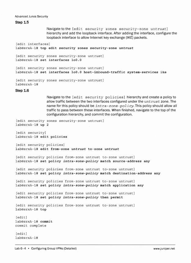
Advanced Junos Security
Step 1.5
Navigate to the [edit security zones security-zone untrust]
hierarchy and add the loopback interface. After adding the interface , configure the
loopback interface to allow Internet key exchange (IKE) packets.
[edit interfaces]
lab@srxA-1# top edit security zones security-zone untrust
[edit security zones security-zone untrust]
lab@srxA-1# set interfaces loO.O
[edit security zones security-zone untrust]
lab@srxA-1# set interfaces loO.O host-inbound-traffic system-services ike
[edit security zones security-zone untrust]
lab@srxA-1#
Step 1.6
Navigate to the [edit security policies] hierarchyand create a policyto
allow traffic between the two interfaces configured under the untrust zone. The
name for this policy should be intra-zone-policy. This policy should allow all
traffic to pass between these interfaces. When finished, navigate to the top of the
configuration hierarchy, and commit the configuration.
[edit security zones security-zone untrust]
lab@srxA-1# up 2
[edit security]
lab@srxA-1# edit policies
[edit security policies]
lab@srxA-1# edit from-zone untrust to-zone untrust
[edit security policies from-zone untrust to-zone untrust]
lab@srxA-1# set policy intra-zone-policy match source-address any
[edit security policies from-zone untrust to-zone untrust]
lab@srxA-1# set policy intra-zone-policy match destination-address any
[edit security policies from-zone untrust to-zone untrust]
lab@srxA-1# set policy intra-zone-policy match application any
[edit security policies from-zone untrust to-zone untrust]
lab@srxA-1# set policy intra-zone-policy then permit
[edit security policies from-zone untrust to-zone untrust]
lab@srxA-1# top
[edit]
lab@srxA-1# commit
commit complete
[edit]
lab@srxA-1#
Lab 6-4 • Configuring Group VPNs (Detailed) www.juniper.net
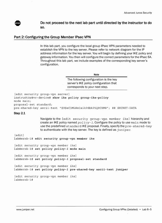
0
Advanced Junos Security
Do not proceed to the next lab part until directed by the instructor to do
so.
Part 2: Configuring the Group Member IPsec VPN
In this lab part, you configure the local group IPsec VPN parameters needed to
establish the VPN to the key server. Please refer to network diagram for the IP
address information for the key server. You will begin by defining your IKE policy and
gateway information. You then will configure the correct parameters for the IPsec SA.
Throughout this lab part, we include examples of the corresponding key server's
configuration.
Note
The following configuration is the key
server's IKE policy configuration that
corresponds to your next step.
[edit security group-vpn server]
instructor@vr-device# show ike policy group-ike-policy
mode main;
proposal-set standard;
pre-shared-key ascii-text "$9$eC3MLNs2aikPdbkP5Q9CKM8"; ## SECRET-DATA
Step 2.1
Navigate to the [edit security group-vpn member ike] hierarchy and
create an IKE policy named policy-1. Configure the policy to use main mode to
use the predefined standard IKE proposal. Finally, specify the pre-shared-key
to authenticate with the key server. The key is defined as juniper.
[edit]
lab@srxA-1# edit security group-vpn member ike
[edit security group-vpn member ike]
lab@srxA-1# set policy policy-I mode main
[edit security group-vpn member ike]
lab@srxA-1# set policy policy-I proposal-set standard
[edit security group-vpn member ike]
lab@srxA-1# set policy policy-I pre-shared-key ascii-text juniper
[edit security group-vpn member ike]
lab@srxA-1#
www.juniper.net Configuring Group VPNs (Detailed) • Lab 6-5
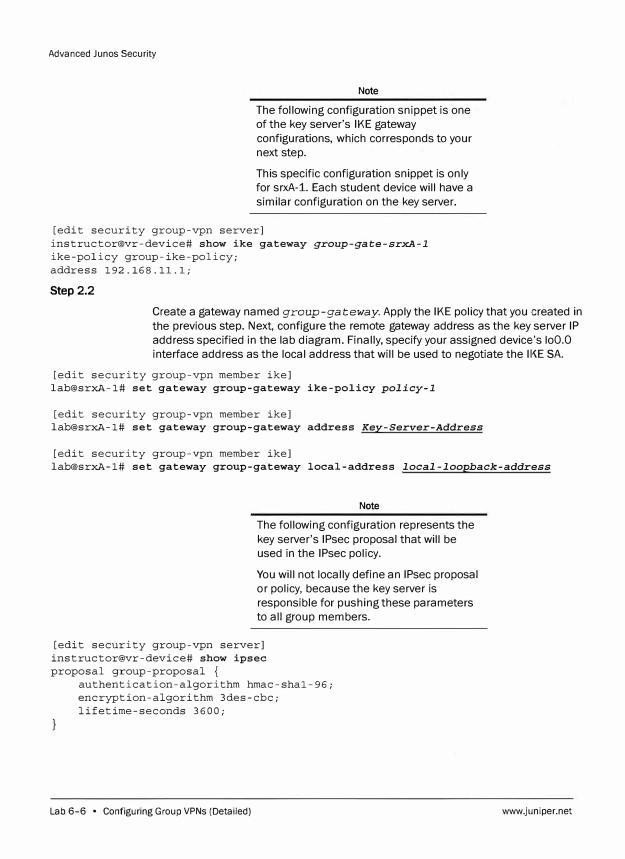
Advanced Junos Security
Note
The following configuration snippet is one
of the key server's IKE gateway
configurations, which corresponds to your
next step.
This specific configuration snippet is only
for srxA-1. Each student device will have a
similar configuration on the key server.
[edit security group-vpn server] instructor@vr-device# show ike gateway group-gate-srxA-1
ike-policy group-ike-policy; address 192.168.11.1;
Step 2.2
Create a gateway named group-gateway. Apply the IKE policy that you created in
the previous step. Next, configure the remote gateway address as the key server IP
address specified in the lab diagram. Finally, specify your assigned device's loO.O
interface address as the local address that will be used to negotiate the 11-<E SA.
[edit security group-vpn member ike] lab@srxA-1# set gateway group-gateway ike-policy policy-1
[edit security group-vpn member ike] lab@srxA-1# set gateway group-gateway address Key-Server-Address
[edit security group-vpn member ike] lab@srxA-1# set gateway group-gateway local-address local-loopback-address
Note
The following configuration represents the
key server's IPsec proposal that will be
used in the IPsec policy.
You will not locally define an IPsec proposal
or policy, because the key server is
responsible for pushing these parameters
to all group members.
[edit security group-vpn server] instructor@vr-device# show ipsec proposal group-proposal {
authentication-algorithm hmac-shal-96; encryption-algorithm 3des-cbc; lifetime-seconds 3600;
Lab 6-6 • Configuring Group VPNs (Detailed) www.juniper.net
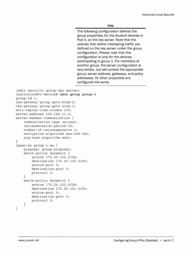
Advanced Junos Security
Note
The following configuration defines the
group properties, for the student devices in
Pod A, on the key server. Note that the
policies that define interesting traffic are
defined on the key server under the group
configuration. Please note that this
configuration is only for the devices
participating in group 1. For members of
another group, the server configuration is
very similar, but will contain the appropriate
group, server address, gateways, and policy
addresses. All other properties are
configured the same.
[edit security group-vpn server] instructor@vr-device# show group group-1
group-id l; ike-gateway group-gate-srxA-1; ike-gateway group-gate-srxA-2; anti-replay-time-window 100; server-address 192.168.11.3; server-member-communication {
communication-type unicast; retransmission-period 30; number-of-retransmission 3; encryption-algorithm aes-256-cbc; sig-hash-algorithm shal;
ipsec-sa group-1-sa { proposal group-proposal; match-policy dynamicl {
source 172.20.101.0/24; destination 172.20.102.0/24; source-port O; destination-port O; protocol O;
match-policy dynamic2 source 172.20.102.0/24; destination 172.20.101.0/24; source-port O; destination-port O; protocol O;
www.juniper.net Configuring Group VPNs (Detailed) • Lab 6-7
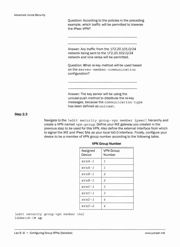
Advanced Junes Security
Step 2.3
Question: According to the policies in the preceding
example, which traffic will be permitted to traverse
the IPsec VPN?
Answer: Any traffic from the 172.20.101.0/24
network being sent to the 172.20.102.0/24
network and vice versa will be permitted.
Question: What re-key method will be used based
on the server-member-communication
configuration?
Answer: The key server will be using the
unicast-push method to distribute the re-key
messages, because the communication-type
has been defined as unicast.
Navigate to the [edit security group-vpn member ipsec] hierarchy and
create a VPN named vpn-group. Define your IKE gateway you created in the
previous step to be used for this VPN. Also define the external interface from which
to signal the IKE and IPsec SAs as your local loO.O interface. Finally, configure your
device to be a member of VPN group number according to the following table.
VPN Group Number
Assigned VPN Group
Device Number
srx.A-1 1
srx.A-1 1
srxB-1 2
srxB-1 2
srxC-1 3
srxC-1 3
srxD-1 4
srxD-2 4
[edit security group-vpn member ike]
lab@srxA-1# up
Lab 6-8 • Configuring Group VPNs (Detailed) www.juniper.net
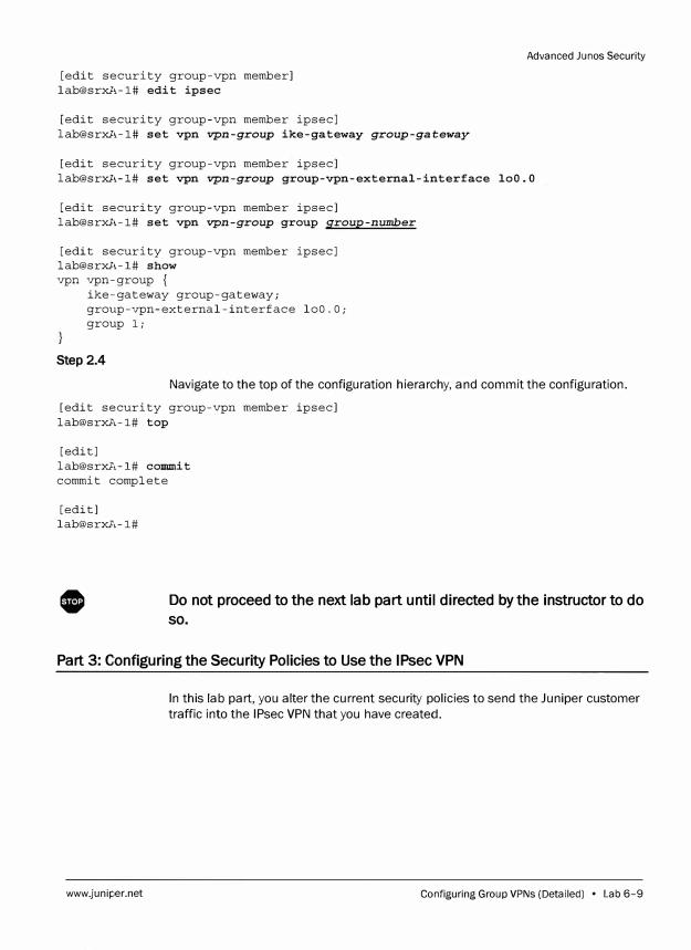
[edit security group-vpn member] lab@srxA-1# edit ipsec
[edit security group-vpn member ipsec] lab@srxA-1# set vpn vpn-group ike-gateway group-gateway
[edit security group-vpn member ipsec]
Advanced Junos Security
lab@srxA-1# set vpn vpn-group group-vpn-external-interface loO.O
[edit security group-vpn member ipsec] lab@srxA-1# set vpn vpn-group group group-number
[edit security group-vpn member ipsec] lab@srxA-1# show vpn vpn-group {
ike-gateway group-gateway; group-vpn-external-interface loO.O; group l;
Step 2.4
Navigate to the top of the configuration hierarchy, and commit the configuration.
[edit security group-vpn member ipsec] lab@srxA-1# top
[edit] lab@srxA-1# commit commit complete
[edit] lab@srxA-1#
0 Do not proceed to the next lab part until directed by the instructor to do
so.
Part 3: Configuring the Security Policies to Use the IPsec VPN
www.juniper.net
In this lab part, you alter the current security policies to send the Juniper customer
traffic into the IPsec VPN that you have created.
Configuring Group VPNs (Detailed) • Lab 6-9
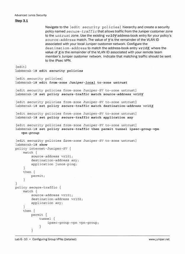
Advanced Ju nos Security
Step 3.1
Navigate to the [edit security policies] hierarchy and create a security
policy named secure-traffic that allows traffic from the Juniper customer zone
to the untrust zone. Use the existing vrlOyaddress-book entry for your policy's
source-address match. The value of yis the remainder of the VLAN ID associated with your local Juniper customer network. Configure the
destination-address to match the address-book entry vrlOlf, where the value of lf is the remainder of the VLAN ID associated with your remote team
member's Juniper customer network. Indicate that matching traffic should be sent to the IPsec VPN.
[edit] lab@srxA-1# edit security policies
[edit security policies] lab@srxA-1# edit from-zone Juniper-local to-zone untrust
[edit security policies from-zone Juniper-SV to-zone untrust] lab@srxA-1# set policy secure-traffic match source-address vrlO.Y
[edit security policies from-zone Juniper-SV to-zone untrust] lab@srxA-1# set policy secure-traffic match destination-address vrlOX
[edit security policies from-zone Juniper-SV to-zone untrust] lab@srxA-1# set policy secure-traffic match application any
[edit security policies from-zone Juniper-SV to-zone untrust] lab@srxA-1# set policy secure-traffic then permit tunnel ipsec-group-vpn
vpn-group
[edit security policies from-zone Juniper-SV to-zone untrust] lab@srxA-1# show policy internet-Juniper-SV {
match {
}
source-address vrlOl; destination-address any; application junos-ping;
then { permit;
policy secure-traffic { match {
}
source-address vrlOl; destination-address vrl02; application any;
then { permit
tunnel ipsec-group-vpn vpn-group;
Lab 6-10 • Configuring Group VPNs (Detailed) www.juniper.net
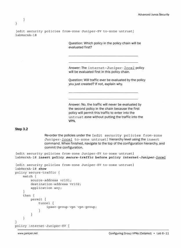
Advanced Junes Security
[edit security policies from-zone Juniper-SV to-zone untrust] lab@srxA-1#
Step 3.2
Question: Which policy in the policy chain will be
evaluated first?
Answer: The internet-Juniper-local policy
will be evaluated first in this policy chain.
Question: Will traffic ever be evaluated by the policy
you just created? If not, explain why.
Answer: No, the traffic will never be evaluated by
the second policy in the chain because the first
policy will permit this traffic to enter into the
untrust zone without putting the traffic into the
VPN.
Re-order the policies under the [edit security policies from-zone
Juniper-local to-zone untrust] hierarchy level using the insert
command. When finished, navigate to the top of the configuration hierarchy, and
commit the configuration.
[edit security policies from-zone Juniper-SV to-zone untrust] lab@srxA-1# insert policy secure-traffic before policy internet-Juniper-local
[edit security policies from-zone Juniper-SV to-zone untrust] lab@srxA-1# show policy secure-traffic {
match {
}
source-address vrlOl; destination-address vrl02; application any;
then { permit
tunnel ipsec-group-vpn vpn-group;
policy internet-Juniper-SV
www.juniper.net Configuring Group VPNs (Detailed) • Lab 6-11
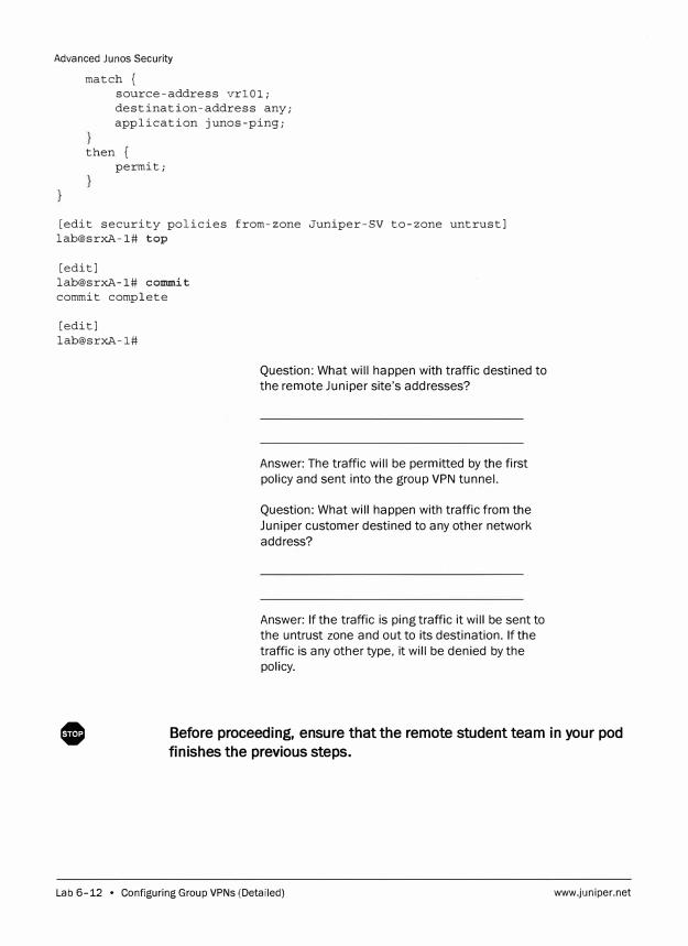
Advanced Junos Security
match { source-address vrlOl; destination-address any; application junos-ping;
then { permit;
[edit security policies from-zone Juniper-SV to-zone untrust] lab@srxA-1# top
[edit] lab@srxA-1# commit commit complete
[edit] lab@srxA-1#
Question: What will happen with traffic destined to
the remote Juniper site's addresses?
Answer: The traffic will be permitted by the first
policy and sent into the group VPN tunnel.
Question: What will happen with traffic from the
Juniper customer destined to any other network
address?
Answer: If the traffic is ping traffic it will be sent to
the untrust zone and out to its destination. If the
traffic is any other type, it will be denied by the
policy.
0 Before proceeding, ensure that the remote student team in your pod
finishes the previous steps.
Lab 6-12 • Configuring Group VPNs (Detailed) www.juniper.net
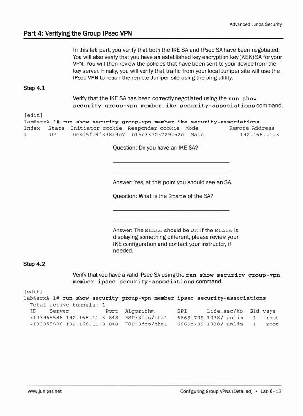
Advanced Junos Security
Part 4: Verifying the Group IPsec VPN
Step4.1
[edit]
In this lab part, you verify that both the IKE SA and IPsec SA have been negotiated.
You will also verify that you have an established key encryption key (KEK) SA for your
VPN. You will then review the policies that have been sent to your device from the
key server. Finally, you will verify that traffic from your local Juniper site will use the
IPsec VPN to reach the remote Juniper site using the ping utility.
Verify that the IKE SA has been correctly negotiated using the run show
security group-vpn member ike security-associations command.
lab@srxA-1# run show security group-vpn member ike security-associations Index State Initiator cookie Responder cookie Mode Remote Address 1 UP Oe3d5fc9f338a9b7 bl5c33725729b52c Main 192.168.11.3
Step4.2
Question: Do you have an IKE SA?
Answer: Yes, at this point you should see an SA.
Question: What is the State of the SA?
Answer: The State should be UP. If the State is
displaying something different, please review your
IKE configuration and contact your instructor, if
needed.
Verify that you have a valid IPsec SA using the run show security group-vpn
member ipsec security-associations command.
[edit] lab@srxA-1# run show security group-vpn member ipsec security-associations
Total active tunnels: 1 ID Server Port Algorithm SPI Life:sec/kb Gid vsys >133955586 192.168.11.3 848 ESP: 3des/shal 6669c709 1038/ unlim 1 root <133955586 192.168.11.3 848 ESP: 3des/shal 6669c709 1038/ unlim 1 root
www.juniper.net Configuring Group VPNs (Detailed) • Lab 6-13
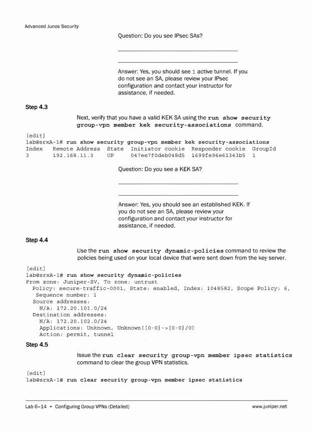
Advanced Junos Security
Step4.3
Question: Do you see IPsec SAs?
Answer: Yes, you should see 1 active tunnel. If you do not see an SA, please review your IPsec configuration and contact your instructor for assistance, if needed.
Next, verify that you have a valid KEK SA using the run show security group-vpn member kek security-associations command.
[edit] lab@srxA-1# run show security group-vpn member kek security-associations Index Remote Address State Initiator cookie Responder cookie Groupid 3 192.168.11.3 UP 047ee7f0deb048d5 1699fe96e61343b5 1
Step4.4
Question: Do you see a KEK SA?
Answer: Yes, you should see an established KEK. If you do not see an SA, please review your configuration and contact your instructor for assistance, if needed.
Use the run show security dynamic-policies command to review the policies being used on your local device that were sent down from the key server.
[edit] lab@srxA-1# run show security dynamic-policies From zone: Juniper-SV, To zone: untrust
Policy: secure-traffic-0001, State: enabled, Index: 1048582, Scope Policy: 6, Sequence number: 1
Source addresses: N/A: 172.20.101.0/24
Destination addresses: N/A: 172.20.102.0/24 Applications: Unknown, Unknown( [0-0]->[0-0]/0) Action: permit, tunnel
Step 4.5
Issue the run clear security group-vpn member ipsec statistics
command to clear the group VPN statistics.
[edit] lab@srxA-1# run clear security group-vpn member ipsec statistics
Lab 6-14 • Configuring Group VPNs (Detailed) www.juniper.net
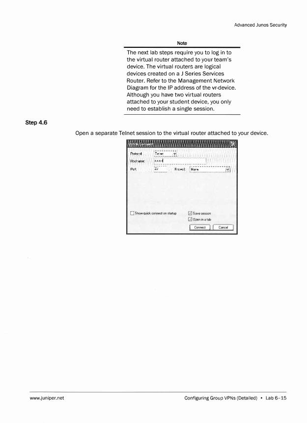
Step4.6
www.juniper.net
Advanced Junos Security
Note
The next lab steps require you to log in to
the virtual router attached to your team's
device. The virtual routers are logical
devices created on a J Series Services
Router. Refer to the Management Network
Diagram for the IP address of the vr-device.
Although you have two virtual routers
attached to your student device, you only
need to establish a single session.
Open a separate Telnet session to the virtual router attached to your device.
D Show quick connect on startup 0 Save session
0 Open in a lab
11 Connect J I Cancel J
Configuring Group VPNs (Detailed) • Lab 6-15
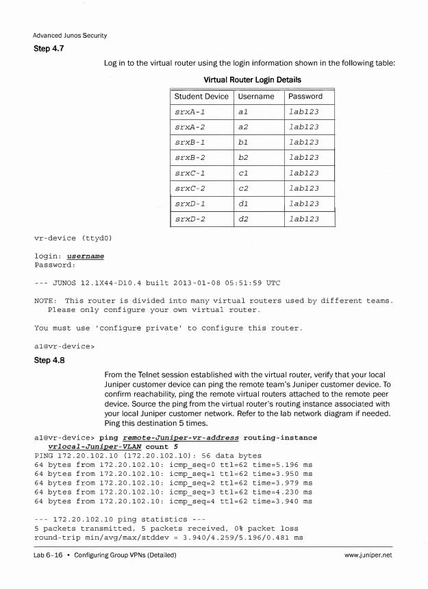
Advanced Junos Security
Step 4.7
Log in to the virtual router using the login information shown in the following table:
Virtual Router Login Details
vr-device (ttydO)
login: username Password:
Student Device
srxA-1
srxA-2
srxB-1
srxB-2
srxC-1
srxC-2
srxD-1
srxD-2
Username
al
a2
bl
b2
cl
c2
dl
d2
--- JUNOS 12.1X44-Dl0.4 built 2013-01-08 05:51:59 UTC
Password
labl23
labl23
labl23
labl23
labl23
labl23
labl23
labl23
NOTE: This router is divided into many virtual routers used by different teams. Please only configure your own virtual router.
You must use 'configure private' to configure this router.
al@vr-device>
Step4.8
From the Telnet session established with the virtual router, verify that your local
Juniper customer device can ping the remote team's Juniper customer device. To
confirm reachability, ping the remote virtual routers attached to the remote peer
device. Source the ping from the virtual router's routing instance associated with
your local Juniper customer network. Refer to the lab network diagram if needed.
Ping this destination 5 times.
al@vr-device> ping remote-Juniper-vr-address routing-instance vrlocal-Juniper-VLAN count 5
PING 172.20.102.10 (172.20.102.10): 56 data bytes 64 bytes from 172.20.102.10: icmp_seq=O ttl=62 time=5.196 ms 64 bytes from 172.20.102.10: icmp_seq=l ttl=62 time=3.950 ms 64 bytes from 172.20.102.10: icmp_seq=2 ttl=62 time=3.979 ms 64 bytes from 172.20.102.10: icmp_seq=3 ttl=62 time=4.230 ms 64 bytes from 172.20.102.10: icmp_seq=4 ttl=62 time=3.940 ms
--- 172.20.102.10 ping statistics ---5 packets transmitted, 5 packets received, 0% packet loss round-trip min/avg/max/stddev = 3.940/4.259/5.196/0.481 ms
Lab 6-16 • Configuring Group VPNs (Detailed) www.juniper.net
Advanced Ju nos Security
Question: Do your pings complete?
Answer: Yes, your pings should complete at this
time. If they do not, review your SAs and contact
your instructor as needed to assist with
troubleshooting.
Step4.9
Once you have verified that the pings complete, log out of the virtual router and
close out the session.
al@vr-device> exit
vr-device (ttydO)
login:
Step4.10
Return to the session established with your assigned SRX device.
From your assigned SRX device, review the IPsec statistics to verify that the ping
packets you sent from the virtual router device used the IPsec VPN. This can be
accomplished using the run show security group-vpn member ipsec
statistics command.
[edit] lab@srxA-1# run show security group-vpn member ipsec statistics ESP Statistics:
Encrypted bytes: 680 Decrypted bytes: 420 Encrypted packets: 5 Decrypted packets: 5
AH Statistics:
Input bytes: O
Output bytes: O Input packets: O Output packets: O
Errors: AH authentication failures: 0, Replay errors: O ESP authentication failures: 0, ESP decryption failures: 0 Bad headers: 0, Bad trailers: O
www.juniper.net Configuring Group VPNs (Detailed) • Lab 6-17
Advanced Junos Security
Step4.11
Question: Do you see encrypted and decrypted
packets?
Answer: Yes, you should see at least 5 encrypted
and s decrypted packets. Note that you might see
more than that depending on the number of pings
that were sent. You will also see additional statistics
if the remote team has finished their verification
also.
Exit configuration mode and log out of your assigned device using the exit
command.
[edit] lab@srxA-1# exit Exiting configuration mode
lab@srxA-1> exit
srxA-1 (ttyuO)
login:
0 Tell your instructor that you have completed this lab.
Lab 6-18 • Configuring Group VPNs (Detailed) www.juniper.net
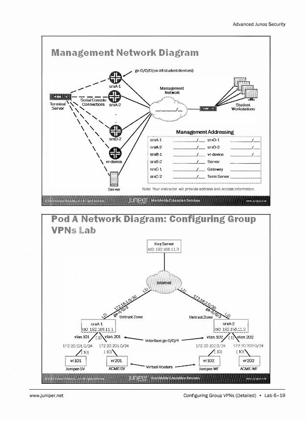
Advanced Ju nos Security
Management Network Diagram
ge-0/0/0(on all studentdevices)
ManagementAddressing
�-1 I srxD-1 I
xA-2 srxD-2 I
j srxB-1 I vr-device I
srxB-2 Server
srxC-1 Gateway
srxC-2 Term Server
Server Note: Your instructor will provide address and access information.
Pod A Network Diagram: Configuring Group
VPNslab
www.juniper.net
Key Server loO 192.168.11.3
-- lnterfacege-0/0/4 --172.20.201.0/24 172.20.102.0/24
(� (�
Configuring Group VPNs (Detailed) • Lab 6-19
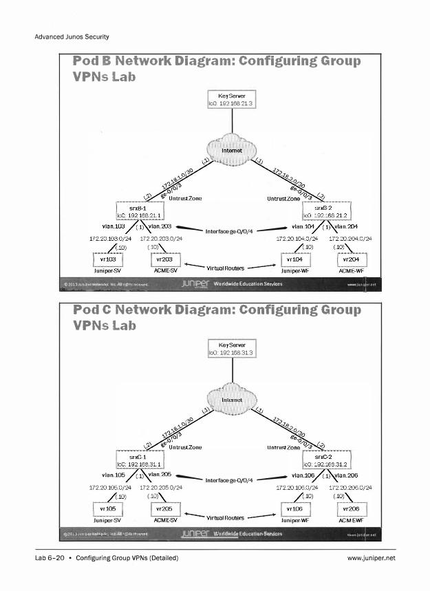
Advanced Junos Security
Pod B Network Diagram: Configuring Group
VPNsLab
Key Server loO: 192.168.21.3
-- lnterfacege-0/0/4 --172 20 203 0/24
(.10)
� 1f)2013Jun10,erNeh!fQfi<j, lnC Affrl!ht� reserve4 JUn1Per Worldwide Education Services www1un11ernet �-·
""'"" �>-' ___ ,....,,.._ -- -- - -� - -- -
Pod C Network Diagram: Configuring Group
VPNsLab
vlan.105
Juniper-SY
Key Server loO: 192.168.31.3
-- lnterfacege-0/0/4 --172.20.205.Q/24
(.10)
ACME-WF
t,::?OJ.JJ•Jn!11trNttwt\rk:, Int Allrl:;hh rtO:MJi -- -
JUnJN Worldwide Education Services 0/WM 1un1 tr net
Lab 6-20 • Configuring Group VPNs (Detailed) www.juniper.net
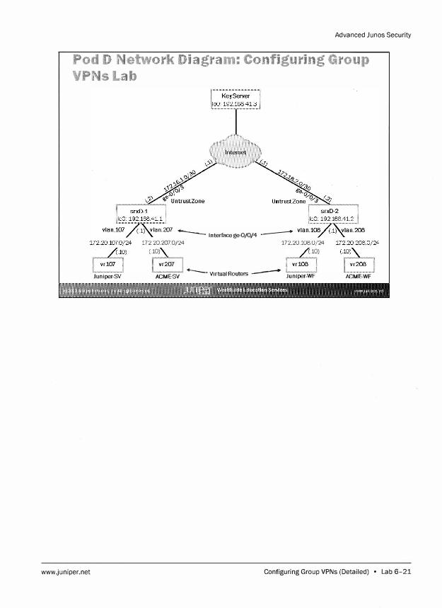
Advanced Junos Security
Pod D Network Diagram: Configuring Group
VPNsLab
Juniper-SY
www.juniper.net
(.l) vlan.20? -- lnterfacege-0/0/4 ---
172 20 2070/24 172 20 108 0/24
(.� (.�
ACME-SV --- Virtual Routers -- Juniper-WF ACME-WF
Configuring Group VPNs (Detailed) • Lab 6-21

Advanced Junos Security
Lab 6-22 • Configuring Group VPNs (Detailed) www.juniper.net
Lab
Implementing Advanced IPsec VPN Solutions (Detailed)
Overviiew
In this lab, you will load the baseline configuration for your device. The configuration will
include interfaces, interfaces assigned to their zones, security policies to allow traffic
between zones, and a stateless firewall filter for selective packet-based services. You will
then configure your device to peer with the remote device in your pod through a route
based site-to-site IP Security (IPsec) VPN. You will use the external ge-0/0/3 interface as
your gateway. You will then configure a generic routing encapsulation (GRE) tunnel to
operate over the site-to-site IPsec VPN. After establishing GRE through the IPsec tunnel
you will configure your device to establish an OSPF adjacency with the remote peer over
this GRE tunnel as well as with the local Juniper customer site. Next, you will configure
static NAT to route traffic between the overlapping address space of your assigned
Local-VR device and the remote Local-VR device. After completing your configuration, you
will verify the functionality on your local device using show commands as well as using
the ping utility. For all IP addresses and network information please refer to the Lab 7
network diagram for your assigned pod.
The lab is available in two formats: a high-level format designed to make you think through
each step and a detailed format that offers step-by-step instructions complete with
sample output from most commands.
By completing this lab, you will perform the following tasks:
Use the Ju nos command line interface (CU) to load the baseline configuration.
Use the Ju nos CU to configure the IPsec VPN parameters.
Use the Ju nos CU to configure the GRE tunnel.
Use the Ju nos CU to configure the OSPF protocol.
Assign interfaces to security zones.
Implement security policies between zones.
Verify that the expected traffic traverses the VPN using the OSPF route.
Use the Ju nos CU to configure static NAT.
Monitor the effects of the configuration from the local device.
www.juniper.net Implementing Advanced IPsec VPN Solutions (Detailed) • Lab 7-1
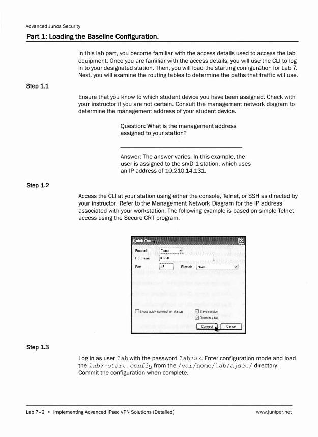
Advanced Junos Security
Part 1: Loading the Baseline Configuration.
Step 1.1
Step 1.2
Step 1.3
In this lab part, you become familiar with the access details used to access the lab
equipment. Once you are familiar with the access details, you will use the CLI to log
in to your designated station. Then, you will load the starting configuration for Lab 7.
Next, you will examine the routing tables to determine the paths that traffic will use.
Ensure that you know to which student device you have been assigned. Check with
your instructor if you are not certain. Consult the management network diagram to
determine the management address of your student device.
Question: What is the management address
assigned to your station?
Answer: The answer varies. In this example, the
user is assigned to the srxD-1 station, which uses
an IP address of 10.210.14.131.
Access the CLI at your station using either the console, Telnet, or SSH as directed by
your instructor. Refer to the Management Network Diagram for the IP adclress
associated with your workstation. The following example is based on simple Telnet
access using the Secure CRT program.
O Show quick comeci on startup 0 Save session
� Open in a lab
� .. Connect �' I Cancel I
Log in as user lab with the password labl23. Enter configuration mode and load
the lab7-start. configfrom the /var /home/lab/ aj sec/ directory.
Commit the configuration when complete.
Lab 7-2 • Implementing Advanced IPsec VPN Solutions (Detailed) www.juniper.net
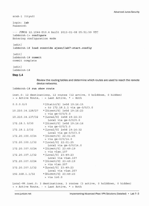
srxA-1 (ttyuO)
login: Iab
Password:
--- JUNOS 12.1X44-Dl0.4 built 2013-01-08 05:51:59 UTC
lab@srxl,-1> configure
Entering configuration mode
[edit]
lab@srxl,-1# load override ajsec/lab7-start.config
[edit]
lab@srxl,-1# commit
commit complete
[edit]
lab@srxl,-1#
Step 1.4
Advanced Junes Security
Review the routing tables and determine which routes are used to reach the remote
device networks.
lab@srxll-1# run show route
inet.O: 12 destinations, 12 routes (12 active, O holddown, O hidden)
+ = Active Route, - = Last Active, * = Both
0.0.0.0/0
10.210.14.128/27
10.210.14.137/32
172.18.1. 0/30
172.18.1.2/32
172.20.100.0/24
172.20.100.1/32
172.20.107.0/24
172.20.107.1/32
172.20.2:07.0/24
172.20.207.1/32
192.168.1.1/32
*[Static/SJ lwOd 19:16:15
> to 172.18.1.1 via ge-0/0/3.0
*[Direct/OJ lwOd 19:16:23
> via ge-0/0/0.0
*[Local/OJ lwOd 19:16:33
Local via ge-0/0/0.0
*[Direct/OJ lwOd 19:16:16
> via ge-0/0/3.0
*[Local/OJ lwOd 19:16:32
Local via ge-0/0/3.0
*[Direct/OJ 22:01:25
> via ge-0/0/14.0
* [Local/OJ 22: 01: 25
Local via ge-0/0/14.0
*[Direct/OJ 23:49:19
> via vlan.107
* [Local/OJ 23:49:23
Local via vlan.107
*[Direct/OJ 23:49:19
> via vlan.207
*[Local/OJ 23:49:23
Local via vlan.207
*[Direct/OJ 23:49:23
> via loO.O
Local-VR.inet.0: 3 destinations, 3 routes (3 active, 0 holddown, 0 hidden)
+ = Active Route, - = Last Active, * = Both
www.juniper.net Implementing Advanced IPsec VPN Solutions (Detailed) • Lab 7-3
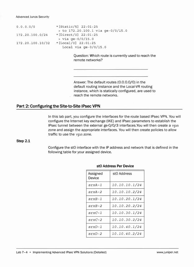
Advanced Junos Security
0.0.0.0/0
172.20.100.0/24
* [Static/SJ 22: 01: 25
> to 172.20.100.1 via ge-0/0/15.0
*[Direct/OJ 22:01:25
> via ge-0/0/15.0
172.20.100.10/32 *[Local/OJ 22:01:25
Local via ge-0/0/15.0
Question: Which route is currently used to reach the
remote networks?
Answer: The default routes (0.0.0.0/0) in the
default routing instance and the Local-VR routing
instance, which is statically configured, are used to
reach the remote networks.
Part 2: Configuring the Site-to-Site IPsec VPN
Step 2.1
In this lab part, you configure the interfaces for the route based IPsec VPI\J. You will
configure the Internet key exchange (IKE) and IPsec parameters to establish the
IPsec tunnel between the external ge-0/0/3 interfaces.You will then create a vpn
zone and assign the appropriate interfaces. You will then create policies to allow
traffic to use the vpn zone.
Configure the stO interface with the IP address and network that is defined in the
following table for your assigned device.
stO Address Per Device
Assigned stO Address
Device
srxA-1 10.10.10.1/24
srxA-2 10.10.10.2/24
srxB-1 10.10.20.1/24
srxB-2 10.10.20.2/24
srxC-1 10.10.30.1/24
srxC-2 10.10.30.2/24
srxD-1 10.10.40.1/24
srxD-2 10.10.40.2/24
Lab 7-4 • Implementing Advanced IPsec VPN Solutions (Detailed) www.juniper.net
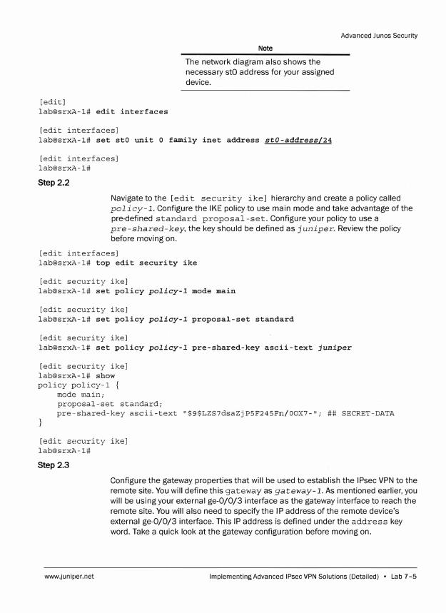
[edit] lab@srxA-1# edit interfaces
[edit interfaces]
Note
The network diagram also shows the
necessary stO address for your assigned
device.
lab@srxA-1# set stO unit O family inet address stO-address/24
[edit interfaces] lab@srxl,-1#
Step 2.2
Advanced Junos Security
Navigate to the [edit security ike] hierarchy and create a policy called
policy-1. Configure the IKE policy to use main mode and take advantage of the
pre-defined standard proposal-set. Configure your policy to use a
pre-shared-key, the key should be defined as juniper. Review the policy
before moving on.
[edit interfaces] lab@srxl,-1# top edit security ike
[edit security ike] lab@srxl,-1# set policy policy-1 mode main
[edit security ike] lab@sr:iu,-1# set policy policy-1 proposal-set standard
[edit security ike] lab@srxl,-1# set policy policy-1 pre-shared-key ascii-text juniper
[edit security ike] lab@srxl,-1# show policy policy-1 {
mode main; proposal-set standard; pre··shared-key ascii-text "$9$LZS7dsaZjP5F245Fn/OOX7-"; ## SECRET-DATA
[edit security ike] lab@srxl,-1#
Step 2.3
www.juniper.net
Configure the gateway properties that will be used to establish the IPsec VPN to the
remote site. You will define this gateway as gateway-1. As mentioned earlier, you
will be using your external ge-0/0/3 interface as the gateway interface to reach the
remote site. You will also need to specify the IP address of the remote device's
external ge-0/0/3 interface. This IP address is defined under the address key
word. Take a quick look at the gateway configuration before moving on.
Implementing Advanced IPsec VPN Solutions (Detailed) • Lab 7 -5
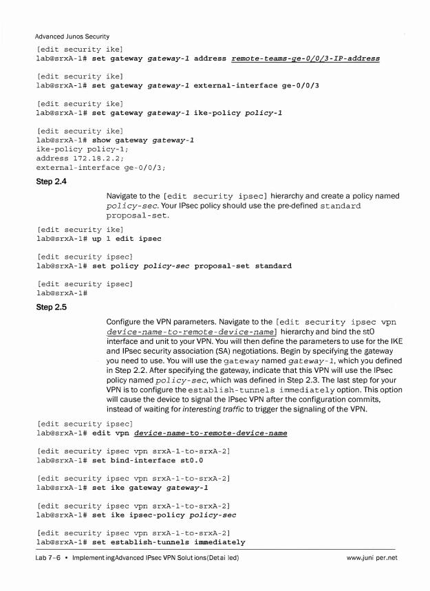
Advanced Junos Security
[edit security ike] lab@srxA-1# set gateway gateway-1 address remote-teams-ge-0/0/3-IP-address
[edit security ike] lab@srxA-1# set gateway gateway-1 external-interface ge-0/0/3
[edit security ike] lab@srxA-1# set gateway gateway-1 ike-policy policy-1
[edit security ike] lab@srxA-1# show gateway gateway-1
ike-policy policy-1; address 172.18.2.2; external-interface ge-0/0/3;
Step 2.4
Navigate to the [edit security ipsec] hierarchy and create a policy named
policy-sec. Your IPsec policy should use the pre-defined standard
proposal -set.
[edit security ike] lab@srxA-1# up 1 edit ipsec
[edit security ipsec] lab@srxA-1# set policy policy-sec proposal-set standard
[edit security ipsec] lab@srxA-1#
Step 2.5
Configure the VPN parameters. Navigate to the [edit securit y ipsec vpn
device-name-to-remote-device-name] hierarchy and bind the stO
interface and unit to your VPN. You will then define the parameters to use for the IKE
and IPsec security association (SA) negotiations. Begin by specifying the gateway
you need to use. You will use the gateway named gateway-1, which you defined
in Step 2.2. After specifying the gateway, indicate that this VPN will use the IPsec
policy named policy-sec, which was defined in Step 2.3. The last step for your
VPN is to configure the establish-tunnels immediately option. This option
will cause the device to signal the IPsec VPN after the configuration commits,
instead of waiting for interesting traffic to trigger the signaling of the VPN.
[edit security ipsec] lab@srxA-1# edit vpn device-name-to-remote-device-name
[edit security ipsec vpn srxA-1-to-srxA-2] lab@srxA-1# set bind-interface stO.O
[edit security ipsec vpn srxA-1-to-srxA-2] lab@srxA-1# set ike gateway gateway-1
[edit security ipsec vpn srxA-1-to-srxA-2] lab@srxA-1# set ike ipsec-policy policy-sec
[edit security ipsec vpn srxA-1-to-srxA-2] lab@srxA-1# set establish-tunnels immediately
Lab 7 -6 • Implementing Advanced IPsec VPN Solutions (Detailed) www.juniper.net
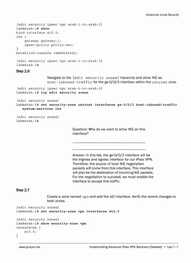
[edit security ipsec vpn srxA-1-to-srxA-2] lab@srxA-1# show bind-interface stO.O; ike {
gateway gateway-1; ipsec-policy policy-sec;
establi:ah-tunnels immediately;
[edit security ipsec vpn srxA-1-to-srxA-2] lab@srxA-1#
Step 2.6
Advanced Junos Security
Navigate to the [edit security zones] hierarchy and allow IKE as
host-inbound-traffic for the ge-0/0/3 interface within the untrust zone.
[edit security ipsec vpn srxA-1-to-srxA-2] lab@srxA-1# top edit security zones
[edit security zones] lab@srxi,-1# set security-zone untrust interfaces ge-0/0/3 host-inbound-traffic
systE!ln-services ike
[edit security zones] lab@srxl,-1#
Step 2.7
Question: Why do we want to allow IKE on this
interface?
Answer: In this lab, the ge-0/0/3 interface will be
the ingress and egress interface for our IPsec VPN.
Therefore, the source of local IKE negotiation
packets will come from this interface. This interface
will also be the destination of incoming IKE packets.
For the negotiation to succeed, we must enable the
interface to accept this traffic.
Create a zone named vpn and add the stO interface. Verify the recent changes to
both zones.
[edit security zones] lab@srxA-1# set security-zone vpn interfaces stO.O
[edit security zones] lab@srxA-1# show security-zone vpn interfaces {
stO.O;
www.juniper.net Implementing Advanced IPsec VPN Solutions (Detailed) • Lab 7- 7
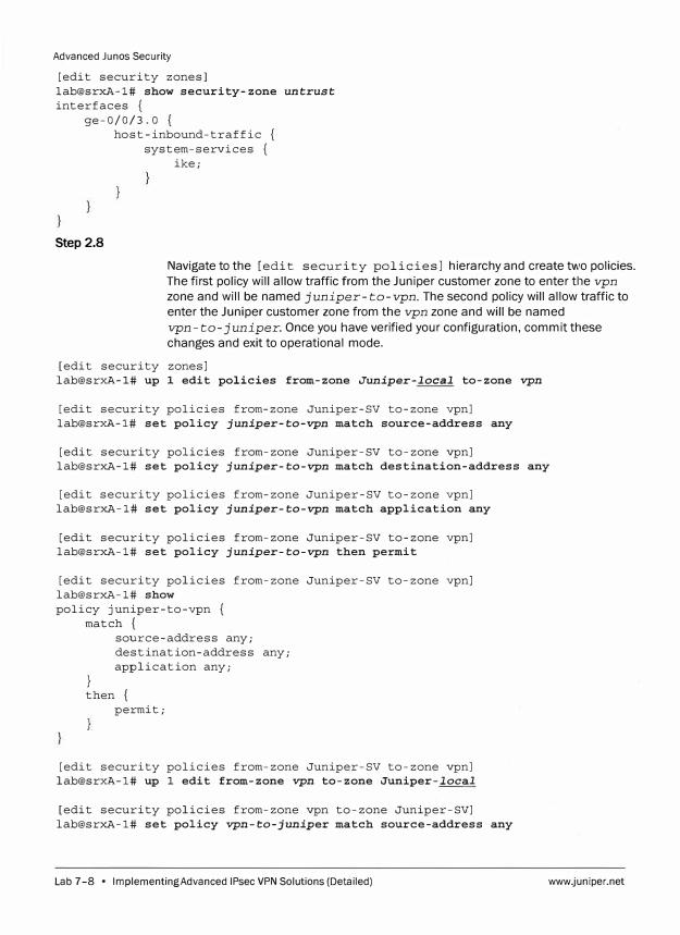
Advanced Junos Security
[edit security zones] lab@srxA-1# show security-zone untrust
interfaces { ge-0/0/3.0 {
host-inbound-traffic { system-services {
ike;
Step 2.8
Navigate to the [edit security policies] hierarchy and create two policies. The first policy will allow traffic from the Juniper customer zone to enter tile vpn
zone and will be named juniper-to-vpn. The second policy will allow traffic to enter the Juniper customer zone from the vpn zone and will be named
vpn-to-juniper. Once you have verified your configuration, commit these
changes and exit to operational mode.
[edit security zones] lab@srxA-1# up 1 edit policies from-zone Juniper-local to-zone vpn
[edit security policies from-zone Juniper-SV to-zone vpn] lab@srxA-1# set policy juniper-to-vpn match source-address any
[edit security policies from-zone Juniper-SV to-zone vpn] lab@srxA-1# set policy juniper-to-vpn match destination-address any
[edit security policies from-zone Juniper-SV to-zone vpn] lab@srxA-1# set policy juniper-to-vpn match application any
[edit security policies from-zone Juniper-SV to-zone vpn] lab@srxA-1# set policy juniper-to-vpn then permit
[edit security policies from-zone Juniper-SV to-zone vpn] lab@srxA-1# show policy juniper-to-vpn {
match {
}
source-address any; destination-address any; application any;
then { permit;
[edit security policies from-zone Juniper-SV to-zone vpn] lab@srxA-1# up 1 edit from-zone vpn to-zone Juniper-local
[edit security policies from-zone vpn to-zone Juniper-SV] lab@srxA-1# set policy vpn-to-juniper match source-address any
Lab 7-8 • Implementing Advanced IPsec VPN Solutions (Detailed) www.juniper.net
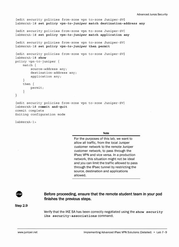
Advanced Junos Security
[edit security policies from-zone vpn to-zone Juniper-SV] lab@srxA-1# set policy vpn-to-juniper match destination-address any
[edit security policies from-zone vpn to-zone Juniper-SV] lab@srxA-1# set policy vpn-to-juniper match application any
[edit security policies from-zone vpn to-zone Juniper-SV] lab@srxA-1# set policy vpn-to-juniper then permit
[edit security policies from-zone vpn to-zone Juniper-SV] lab@srxA-1# show policy vpn-to-juniper {
match { source-address any; destination-address any; application any;
} then {
permit;
[edit security policies from-zone vpn to-zone Juniper-SV] lab@srxl,-1# commit and-quit commit complete Exiting configuration mode
lab@srxl,-1>
Step 2.9
www.juniper.net
Note
For the purposes of this lab, we want to
allow all traffic, from the local Juniper
customer network to the remote Juniper
customer network, to pass through the
IPsec VPN and vice versa. In a production
network, this situation might not be ideal
and you can limit the traffic allowed to pass
through the IPsec tunnel by restricting the
source, destination and applications
allowed.
Before proceeding, ensure that the remote student team in your pod
finishes the previous steps.
Verify that the IKE SA has been correctly negotiated using the show security
ike security-associations command.
Implementing Advanced IPsec VPN Solutions (Detailed) • Lab 7-9

Advanced Junos Security
lab@srxA-1> show security ike security-associations Index State Initiator cookie Responder cookie Mode 2742735 UP 5d6e9e5ffdcl2d0c 9d8066e7ea59307b Main
Remote Address 172.1!3.2.2
Step 2.10
Question: Do you have an IKE SA?
Answer: Yes, at this point you should see an IKE SA.
Question: What is the State of the SA?
Answer: The State should be UP. If the State is
displaying something different, please review your
IKE configuration and contact your instructor if
needed.
Next, verify that you have a valid IPsec SA using the show security ipsec
security-associations command.
lab@srxA-1> show security ipsec security-associations Total active tunnels: 1
ID Algorithm SPI Life:sec/kb Mon lsys Port Gateway <131073 ESP:3des/shal e9829557 3506/ unlim root 500 172.18.2.2 >131073 ESP:3des/shal ec47b6d2 3506/ unlim root 500 172.18.2.2
Question: Do you see IPsec SAs?
Answer: Yes, you should see 1 active tunnel. If you
do not see an SA, please review your IPsec
configuration and contact your instructor for
assistance if needed.
Do not proceed to the next lab part until directed by the instruc:tor to do
so.
Lab 7-10 • Implementing Advanced IPsec VPN Solutions (Detailed) www.juniper.net
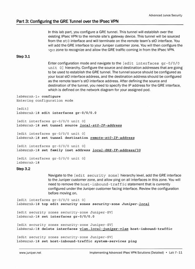
Advanced Junes Security
Part 3: Configuring the GRE Tunnel over the IPsec VPN
Step 3.1
In this lab part, you configure a GRE tunnel. This tunnel will establish over the
existing IPsec VPN to the remote site's gateway device. This tunnel will be sourced
from the sto interface and will terminate on the remote team's stO interface. You
will add the GRE interface to your Juniper customer zone. You will then configure the
vpn zone to recognize and allow the GRE traffic coming in from the IPsec VPN.
Enter configuration mode and navigate to the [edit interfaces gr-0/0/0
unit o] hierarchy. Configure the source and destination addresses that are going
to be used to establish the GRE tunnel. The tunnel source should be configured as
your local stO interface address, and the destination address should be configured
as the remote team's stO interface address. After defining the source and
destination of the tunnel, you need to specify the IP address for the GRE interface,
which is defined on the network diagram for your assigned pod.
lab@srxi\-1> configure
Entering configuration mode
[edit]
lab@srxl\-1# edit interfaces gr-0/0/0.0
[edit interfaces gr-0/0/0 unit OJ
lab@srxl\-1# set tunnel source local-stO-IP-address
[edit interfaces gr-0/0/0 unit O]
lab@srxl,-1# set tunnel destination remote-stO-IP-address
[edit interfaces gr-0/0/0 unit OJ
lab@srxl\-1# set family inet address local-GRE-IP-address/30
[edit interfaces gr-0/0/0 unit O]
lab@srxl\-1#
Step 3.2
Navigate to the [edit security zone] hierarchy level, add the GRE interface
to the Juniper customer zone, and allow ping on all interfaces in this zone. You will
need to remove the host-inbound-traffic statement that is currently
configured under the Juniper customer facing interface. Review the configuration
before moving on.
[edit interfaces gr-0/0/0 unit OJ
lab@srxA-1# top edit security zones security-zone Juniper-local
[edit security zones security-zone Juniper-SV]
lab@srxA-1# set interfaces gr-0/0/0.0
[edit security zones security-zone Juniper-SV]
lab@srxA-1# delete interfaces vlan.local-juniper-vlan host-inbound-traffic
[edit security zones security-zone Juniper-SV]
lab@srxA-1# set host-inbound-traffic system-services ping
www.juniper.net Implementing Advanced IPsec VPN Solutions (Detailed) • Lab 7-11
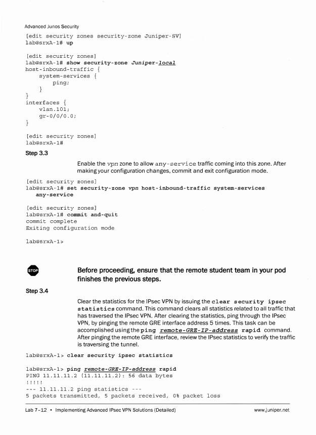
Advanced Ju nos Security
[edit security zones security-zone Juniper-SV] lab@srxA-1# up
[edit security zones] lab@srxA-1# show security-zone Juniper-local host-inbound-traffic {
system-services { ping;
interfaces vlan.101; gr-0/0/0.0;
[edit security zones] lab@srxA-1#
Step 3.3
Enable the vpn zone to allow any-service traffic coming into this zone. After
making your configuration changes, commit and exit configuration mode.
[edit security zones] lab@srxA-1# set security-zone vpn host-inbound-traffic system-services
any-service
[edit security zones] lab@srxA-1# coI11I11it and-quit commit complete Exiting configuration mode
lab@srxA-1>
0
Step3.4
Before proceeding, ensure that the remote student team in your pod
finishes the previous steps.
Clear the statistics for the IPsec VPN by issuing the clear security ipsec
statistics command. This command clears all statistics related to all traffic that
has traversed the IPsec VPN. After clearing the statistics, ping through the IPsec
VPN, by pinging the remote GRE interface address 5 times. This task can be
accomplished using the ping remote-GRE-IP-address rapid command.
After pinging the remote GRE interface, review the IPsec statistics to verify the traffic
is traversing the tunnel.
lab@srxA-1> clear security ipsec statistics
lab@srxA-1> ping remote-GRE-IP-address rapid PING 11.11.11.2 (11.11.11.2): 56 data bytes ! ! ! ! !
--- 11.11.11.2 ping statistics ---5 packets transmitted, 5 packets received, 0% packet loss
Lab 7-12 • Implementing Advanced IPsec VPN Solutions (Detailed) www.juniper.net
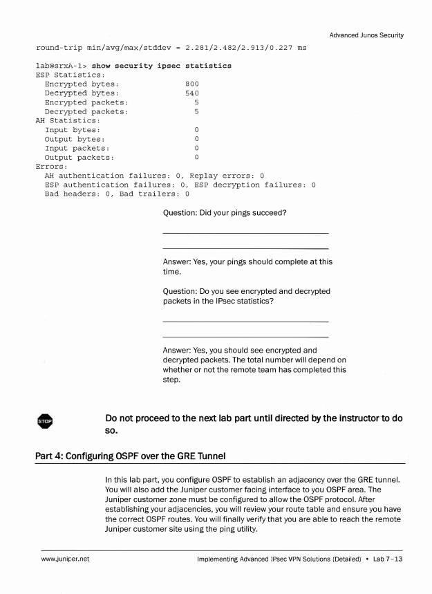
round-trip min/avg/max/stddev = 2.281/2.482/2.913/0.227 ms
lab@srxA-1> show security ipsec statistics
ESP Statistics:
Encrypted bytes: 800
Decrypted bytes: 540
Encrypted packets: 5
Decrypted packets: 5
AH Statistics:
Input bytes: O
Output bytes: 0
Input packets: O
Output packets: O
Errors:
AH authentication failures: 0, Replay errors: O
ESP authentication failures: 0, ESP decryption failures: O
Bad headers: 0, Bad trailers: O
Question: Did your pings succeed?
Advanced Junos Security
Answer: Yes, your pings should complete at this
time.
Question: Do you see encrypted and decrypted
packets in the IPsec statistics?
Answer: Yes, you should see encrypted and
decrypted packets. The total number will depend on
whether or not the remote team has completed this
step.
Do not proceed to the next lab part until directed by the instructor to do
so.
Part 4: Configuring OSPF over the GRE Tunnel
www.juniper.net
In this lab part, you configure OSPF to establish an adjacency over the GRE tunnel.
You will also add the Juniper customer facing interface to you OSPF area. The
Juniper customer zone must be configured to allow the OSPF protocol. After
establishing your adjacencies, you will review your route table and ensure you have
the correct OSPF routes. You will finally verify that you are able to reach the remote
Juniper customer site using the ping utility.
Implementing Advanced IPsec VPN Solutions (Detailed) • Lab 7 -13
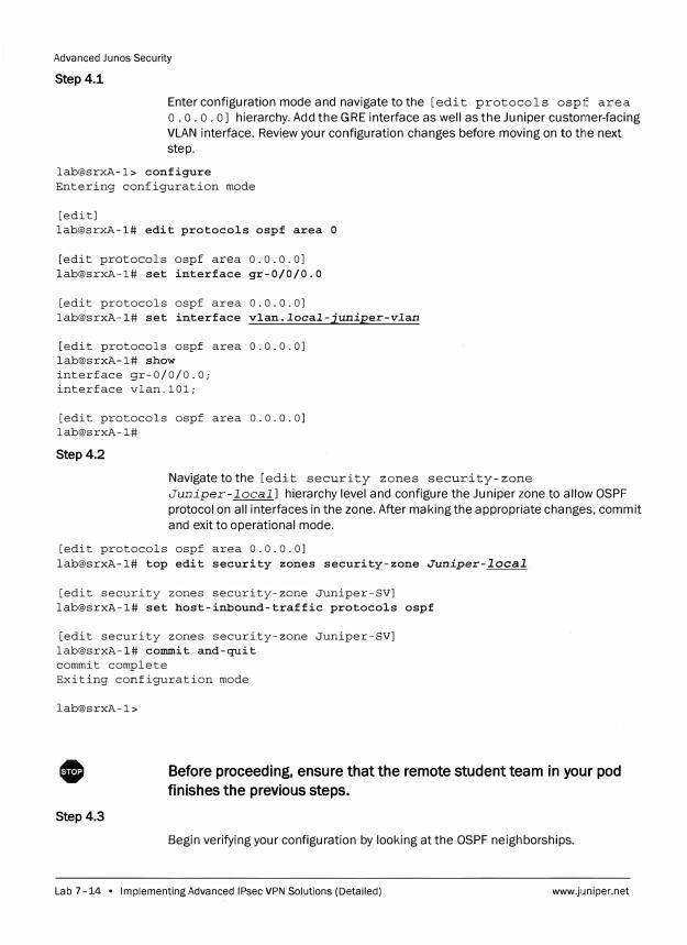
Advanced Junos Security
Step 4.1
Enter configuration mode and navigate to the [edit protocols ospf area
o. o. o. o] hierarchy. Add the GRE interface as well as the Juniper customer-facing
VLAN interface. Review your configuration changes before moving on to the next
step.
lab@srxA-1> configure Entering configuration mode
[edit] lab@srxA-1# edit protocols ospf area O
[edit protocols ospf area 0.0.0.0] lab@srxA-1# set interface gr-0/0/0.0
[edit protocols ospf area 0.0.0.0] lab@srxA-1# set interface vlan.local-juniper-vlan
[edit protocols ospf area 0.0.0.0] lab@srxA-1# show interface gr-0/0/0.0; interface vlan.101;
[edit protocols ospf area 0.0.0.0] lab@srxA-1#
Step4.2
Navigate to the [edit security zones security-zone
Juniper-local] hierarchy level and configure the Juniper zone to allow OSPF
protocol on all interfaces in the zone. After making the appropriate changes, commit
and exit to operational mode.
[edit protocols ospf area 0.0.0.0] lab@srxA-1# top edit security zones security-zone Juniper-local
[edit security zones security-zone Juniper-SV] lab@srxA-1# set host-inbound-traffic protocols ospf
[edit security zones security-zone Juniper-SV] lab@srxA-1# commit and-quit commit complete Exiting configuration mode
lab@srxA-1>
Before proceeding, ensure that the remote student team in your pod
finishes the previous steps.
Step4.3
Begin verifying your configuration by looking at the OSPF neighborships.
Lab 7-14 • Implementing Advanced IPsec VPN Solutions (Detailed) www.juniper.net
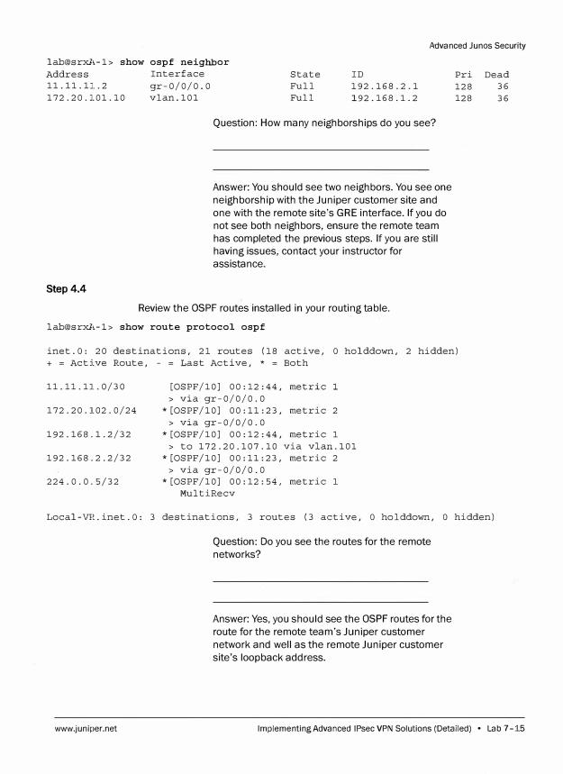
Advanced Junes Security
lab@srxA-1> show ospf neighbor
Address Interface
11.11.11.2 gr-0/0/0.0
172.20.101.10 vlan.101
Step4.4
State
Full
Full
ID
192.168.2.1
192.168.l.2
Question: How many neighborships do you see?
Answer: You should see two neighbors. You see one
neighborship with the Juniper customer site and
one with the remote site's GRE interface. If you do
not see both neighbors, ensure the remote team
has completed the previous steps. If you are still
having issues, contact your instructor for
assistance.
Review the OSPF routes installed in your routing table.
lab@srxA-1> show route protocol ospf
Pri Dead
128 36
128 36
inet.O: 20 destinations, 21 routes (18 active, O holddown, 2 hidden)
+ = Active Route, - = Last Active, * = Both
11.11.11.0/30
172.20.102.0/24
192.168.1.2/32
192.168.2.2/32
224.0.0.5/32
[OSPF/10] 00:12:44, metric l
> via gr-0/0/0.0
*[OSPF/10] 00:11:23, metric 2
> via gr-0/0/0.0
*[OSPF/10] 00:12:44, metric l
> to 172.20.107.10 via vlan.101
*[OSPF/10] 00:11:23, metric 2
> via gr-0/0/0.0
*[OSPF/10] 00:12:54, metric l
MultiRecv
Local-VR.inet.O: 3 destinations, 3 routes (3 active, O holddown, O hidden)
www.juniper.net
Question: Do you see the routes for the remote
networks?
Answer: Yes, you should see the OSPF routes for the
route for the remote team's Juniper customer
network and well as the remote Juniper customer
site's loopback address.
Implementing Advanced IPsec VPN Solutions (Detailed) • Lab 7-15
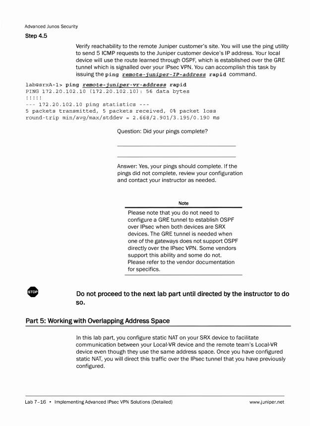
Advanced Junos Security
Step 4.5
Verify reachability to the remote Juniper customer's site. You will use the ping utility
to send 5 ICMP requests to the Juniper customer device's IP address. Your local
device will use the route learned through OSPF, which is established over the GRE
tunnel which is signalled over your IPsec VPN. You can accomplish this task by
issuing the ping remote-juniper-IP-address rapid command.
lab@srxA-1> ping remote-juniper-vr-address rapid PING 172.20.102.10 (172.20.102.10): 56 data bytes ! ! ! ! !
--- 172.20.102.10 ping statistics ---5 packets transmitted, 5 packets received, 0% packet loss round-trip min/avg/max/stddev = 2.668/2.901/3.195/0.190 ms
0
Question: Did your pings complete?
Answer: Yes, your pings should complete. If the
pings did not complete, review your configuration
and contact your instructor as needed.
Note
Please note that you do not need to
configure a GRE tunnel to establish OSPF
over IPsec when both devices are SRX
devices. The GRE tunnel is needed when
one of the gateways does not support OSPF
directly over the IPsec VPN. Some vendors
support this ability and some do not.
Please refer to the vendor documentation
for specifics.
Do not proceed to the next lab part until directed by the instructor to do
so.
Part 5: Working with Overlapping Address Space
In this lab part, you configure static NAT on your SRX device to facilitate
communication between your Local-VR device and the remote team's Local-VR
device even though they use the same address space. Once you have configured
static NAT, you will direct this traffic over the IPsec tunnel that you have previously
configured.
Lab 7-16 • Implementing Advanced IPsec VPN Solutions (Detailed) www.juniper.net
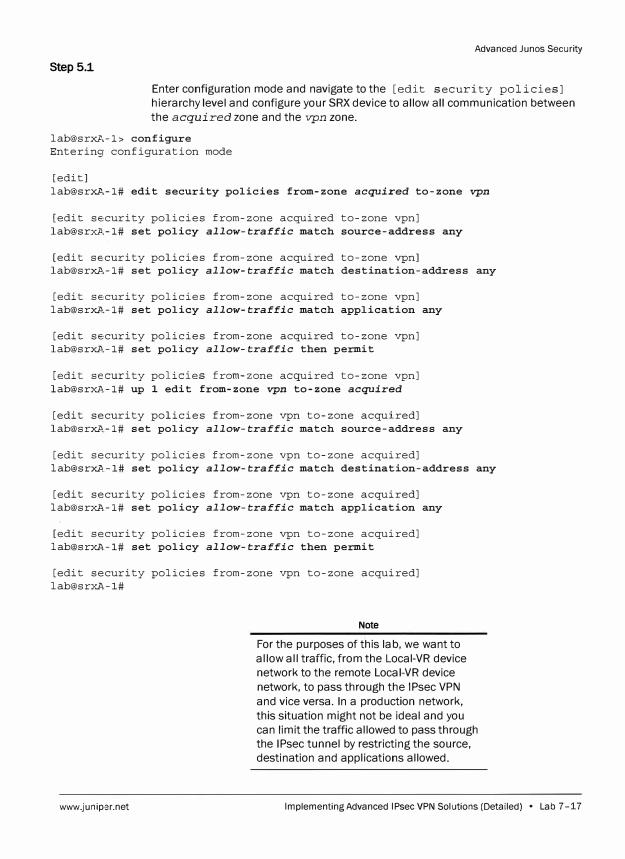
Advanced Junes Security
Step 5.1
Enter configuration mode and navigate to the [edit security policies]
hierarchy level and configure your SRX device to allow all communication between
the acquired zone and the vpn zone.
lab@srxA-1> configure Entering configuration mode
[edit] lab@srxA-1# edit security policies from-zone acquired to-zone vpn
[edit security policies from-zone acquired to-zone vpn] [email protected]# set policy allow-traffic match source-address any
[edit security policies from-zone acquired to-zone vpn] [email protected]# set policy allow-traffic match destination-address any
[edit security policies from-zone acquired to-zone vpn] [email protected]# set policy allow-traffic match application any
[edit security policies from-zone acquired to-zone vpn] [email protected]# set policy allow-traffic then permit
[edit security policies from-zone acquired to-zone vpn] lab@srxl\_-1# up 1 edit from-zone vpn to-zone acquired
[edit security policies from-zone vpn to-zone acquired] lab@srxA-1# set policy allow-traffic match source-address any
[edit security policies from-zone vpn to-zone acquired] [email protected]# set policy allow-traffic match destination-address any
[edit security policies from-zone vpn to-zone acquired] lab@srxA-1# set policy allow-traffic match application any
[edit security policies from-zone vpn to-zone acquired] lab@srxA-1# set policy allow-traffic then permit
[edit security policies from-zone vpn to-zone acquired] lab@srxA-1#
www.juniper.net
Note
For the purposes of this lab, we want to
allow all traffic, from the Local-VR device
network to the remote Local-VR device
network, to pass through the IPsec VPN
and vice versa. In a production network,
this situation might not be ideal and you
can limit the traffic allowed to pass through
the IPsec tunnel by restricting the source,
destination and applications allowed.
Implementing Advanced IPsec VPN Solutions (Detailed) • Lab 7-17
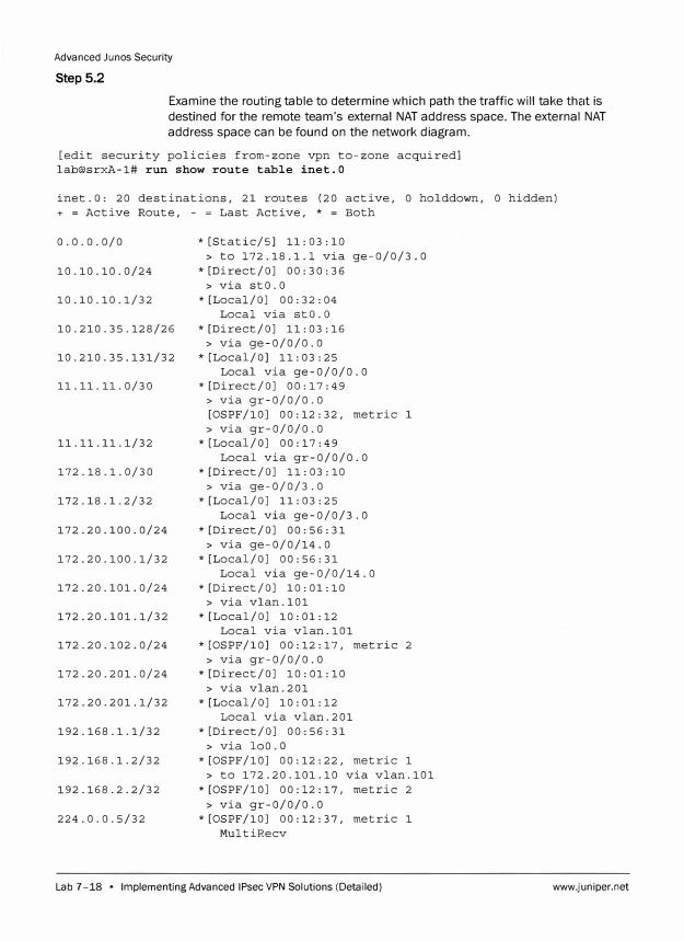
Advanced Junos Security
Step 5.2
Examine the routing table to determine which path the traffic will take that is
destined for the remote team's external NAT address space. The external NAT
address space can be found on the network diagram.
[edit security policies from-zone vpn to-zone acquired]
lab@srxA-1# run show route table inet.0
inet.O: 20 destinations, 21 routes (20 active, 0 holddown, 0 hidden)
+ = Active Route, - = Last Active, * = Both
0.0.0.0/0
10.10.10.0/24
10.10.10.1/32
10.210.35.128/26
10. 210. 35 .131/32
11 .11. 11. 0/30
11.11.11.1/32
172.18.1.0/30
172.18.1.2/32
172.20.100.0/24
172.20.100.1/32
172.20.101.0/24
172.20.101.1/32
172.20.102.0/24
172.20.201.0/24
172.20.201.1/32
192.168.1.1/32
192.168.1.2/32
192.168.2.2/32
224.0.0.5/32
* [Static/SJ 11: 03: 10
> to 172.18.1.1 via ge-0/0/3.0
* [Direct/OJ oo: 30: 36
> via stO.O
*[Local/OJ 00:32:04
Local via stO.O
* [Direct/OJ 11: 03: 16
> via ge-0/0/0.0
* [Local/OJ 11: 03: 25
Local via ge-0/0/0.0
*[Direct/OJ 00:17:49
> via gr-0/0/0.0
[OSPF/10] 00:12:32, metric 1
> via gr-0/0/0.0
*[Local/OJ 00:17:49
Local via gr-0/0/0.0
* [Direct/OJ 11: 03: 10
> via ge-0/0/3.0
*[Local/OJ 11:03:25
Local via ge-0/0/3.0
* [Direct/OJ 00: 56: 31
> via ge-0/0/14.0
*[Local/OJ 00:56:31
Local via ge-0/0/14.0
*[Direct/OJ 10:01:10
> via vlan.101
*[Local/OJ 10:01:12
Local via vlan.101
*[OSPF/10] 00:12:17, metric 2
> via gr-0/0/0.0
* [Direct/OJ 10: 01: 10
> via vlan.201
*[Local/OJ 10:01:12
Local via vlan.201
* [Direct/OJ 00: 56: 31
> via loo.a
*[OSPF/10] 00:12:22, metric 1
> to 172.20.101.10 via vlan.101
*[OSPF/10] 00:12:17, metric 2
> via gr-0/0/0.0
*[OSPF/10] 00:12:37, metric 1
MultiRecv
Lab 7-18 • Implementing Advanced IPsec VPN Solutions (Detailed) www.juniper.net
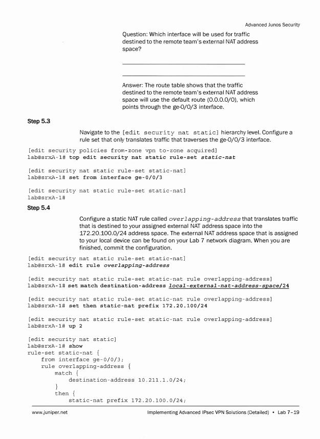
Step 5.3
Advanced Junos Security
Question: Which interface will be used for traffic
destined to the remote team's external NAT address
space?
Answer: The route table shows that the traffic
destined to the remote team's external NAT address
space will use the default route (0.0.0.0/0), which
points through the ge-0/0/3 interface.
Navigate to the [edit security nat static] hierarchy level. Configure a
rule set that only translates traffic that traverses the ge-0/0/3 interface.
[edit security policies from-zone vpn to-zone acquired] lab@srxA-1# top edit security nat static rule-set static-nat
[edit security nat static rule-set static-natl lab@srxA-1# set from interface ge-0/0/3
[edit security nat static rule-set static-natl lab@srxJ,-1#
Step 5.4
Configure a static NAT rule called overlapping-address that translates traffic
that is destined to your assigned external NAT address space into the
172.20.100.0/24 address space. The external NAT address space that is assigned
to your local device can be found on your Lab 7 network diagram. When you are
finished, commit the configuration.
[edit security nat static rule-set static-natl lab@srxl,-1# edit rule overlapping-address
[edit security nat static rule-set static-nat rule overlapping-address] lab@srxl<-1# set match destination-address local-external-nat-address-space/24
[edit security nat static rule-set static-nat rule overlapping-address] lab@srxl<-1# set then static-nat prefix 172.20.100/24
[edit security nat static rule-set static-nat rule overlapping-address] lab@srxl<-1# up 2
[edit security nat static] lab@srxl<-1# show rule-set static-nat {
from interface ge-0/0/3; rule overlapping-address
match { destination-address 10.211.1.0/24;
} then {
static-nat prefix 172.20.100.0/24;
www.juniper.net Implementing Advanced IPsec VPN Solutions (Detailed) • Lab 7-19
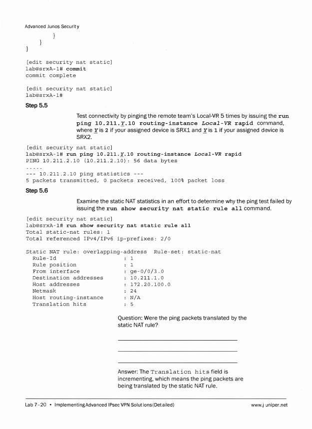
Advanced Junos Secur ity
[edit security nat static] lab@srxA-1# commit commit complete
[edit security nat static] lab@srxA-1#
Step 5.5
Test connectivity by pinging the remote team's Local-VR 5 times by issuing the run
ping 10. 211._K.10 routing-instance Local-VR rapid command,
where Xis 2 if your assigned device is SRX1 and Xis 1 if your assigned device is SRX2.
[edit security nat static] lab@srxA-1# run ping 10.211._K.10 routing-instance Local-VR rapid PING 10.211.2.10 (10.211.2.10): 56 data bytes
--- 10.211.2.10 ping statistics 5 packets transmitted, O packets received, 100% packet loss
Step 5.6
Examine the static NAT statistics in an effort to determine why the ping test failed by
issuing the run show security nat static rule all command.
[edit security nat static] lab@srxA-1# run show security nat static rule all Total static-nat rules: 1 Total referenced IPv4/IPv6 ip-prefixes: 2/0
Static NAT rule: overlapping-address Rule-set: static-nat Rule-Id 1 Rule position From interface Destination addresses Host addresses Net mask Host routing-instance Translation hits
1
ge-0/0/3.0 10.211.1.0 172.20.100.0 24 N/A 5
Question: Were the ping packets translated by the
static NAT rule?
Answer: The Translation hits field is
incrementing, which means the ping packets are
being translated by the static NAT rule.
Lab 7-20 • Implementing Advanced IPsec VPN Solutions (Detailed) www.juniper.net
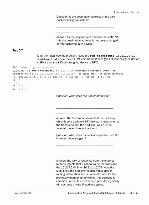
Step 5.7
Advanced Junes Security
Question: Is the destination address of the ping
packets being translated?
Answer: As the ping packets traverse the static NAT
rule the destination address is not being changed
on your assigned SRX device.
To further diagnose the problem, issue the run traceroute 10. 211._¥.10
routing-instance Local-VR command. Where _ris 2 if your assigned device
is SRX1 and Xis 1 if your assigned device is SRX 2.
[edit security nat static] lab@srxA-1# run traceroute 10.211._¥.10 routing-instance Local-VR
traceroute to 10.211.2.10 (10.211.2.10), 30 hops max, 40 byte packets 1 172.20.100.1 (172.20.100,1) 1.950 ms 2.386 ms 1.654 ms 2 * * *
29 * * *
30 * * *
www.juniper.net
Question: What does the traceroute reveal?
Answer: The traceroute shows that the first hop,
which is your assigned SRX device, is responding to
the traceroute, but the next hop, which is the
Internet router, does not respond.
Question: What does the lack of response from the
Internet router suggest?
Answer: The lack of response from the Internet
router suggests that it cannot route the traffic for
the 10.211.2.0/24 or 10.2 1 1.1.0/24 networks.
Most likely the problem resides with a lack of
routing information for the Internet router for the
previously mentioned networks. This scenario is
common, in that Internet service providers typically
will not route private IP address space.
Implementing Advanced IPsec VPN Solutions (Detailed) • Lab 7 -21
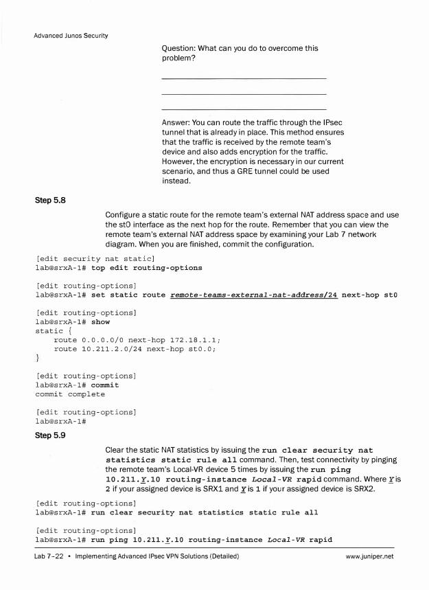
Advanced Junos Security
Step 5.8
Question: What can you do to overcome this
problem?
Answer: You can route the traffic through the IPsec
tunnel that is already in place. This method ensures
that the traffic is received by the remote team's
device and also adds encryption for the traffic.
However, the encryption is necessary in our current
scenario, and thus a GRE tunnel could be used instead.
Configure a static route for the remote team's external NAT address space and use
the stO interface as the next hop for the route. Remember that you can view the
remote team's external NAT address space by examining your Lab 7 network
diagram. When you are finished, commit the configuration.
[edit security nat static] lab@srxA-1# top edit routing-options
[edit routing-options] lab@srxA-1# set static route remote-teams-external-nat-address/24. next-hop stO
[edit routing-options] lab@srxA-1# show static {
route 0.0.0.0/0 next-hop 172.18.1.1; route 10.211.2.0/24 next-hop stO.O;
[edit routing-options] lab@srxA-1# commit commit complete
[edit routing-options] lab@srxA-1#
Step 5.9
Clear the static NAT statistics by issuing the run clear security nat
statistics static rule all command. Then, test connectivity by pinging
the remote team's Local-VR device 5 times by issuing the run ping
10.211._r.10 routing-instance Local-VR rapid command. Where_ris
2 if your assigned device is SRX1 and .r is 1 if your assigned device is SRX2.
[edit routing-options] lab@srxA-1# run clear security nat statistics static rule all
[edit routing-options] lab@srxA-1# run ping 10.211._!'.10 routing-instance Local-VR rapid
Lab 7-22 • Implementing Advanced IPsec VPN Solutions (Detailed) www.juniper.net

Advanced Junes Security
PING 10.211.2.10 (10.211.2.10): 56 data bytes
--- 10.211.2 ping statistics ---
5 packe1:s transmitted, 0 packets received, 100% packet loss
Step 5.10
Examine the static NAT statistics in an effort to determine why the ping test failed by
issuing the run show security nat static rule all command.
[edit routing-options]
lab@srxA-1# run show security nat static rule all
Total static-nat rules: 1
Total referenced IPv4/IPv6 ip-prefixes: 2/0
Static NAT rule: overlapping-address Rule-set: static-nat
Rule-Id 1
Rule position 1
From interface ge-0/0/3.0
Destination addresses 10.211.1.0
Host addresses
Netmask
Host routing-instance
Transj_ation hits
www.juniper.net
172.20.100.0
24
N/A
0
Question: What is preventing the translation hits
from occurring?
Answer: Recall that in a previous step, you set the
ge-0/0/3 interface as the from criteria. This action
made sense in the previous step because the traffic
was using the default route that uses the ge-0/0/3
interface. However, you added the static route that
uses the stO interface as the next hop to direct the
traffic through the IPsec tunnel.
Question: What must you do to fix the problem?
Answer: To fix the problem, you can set the from
criteria to the vpn zone or the stO interface in the
static NAT rule set.
Implementing Advanced IPsec VPN Solutions (Detailed) • Lab 7 -23
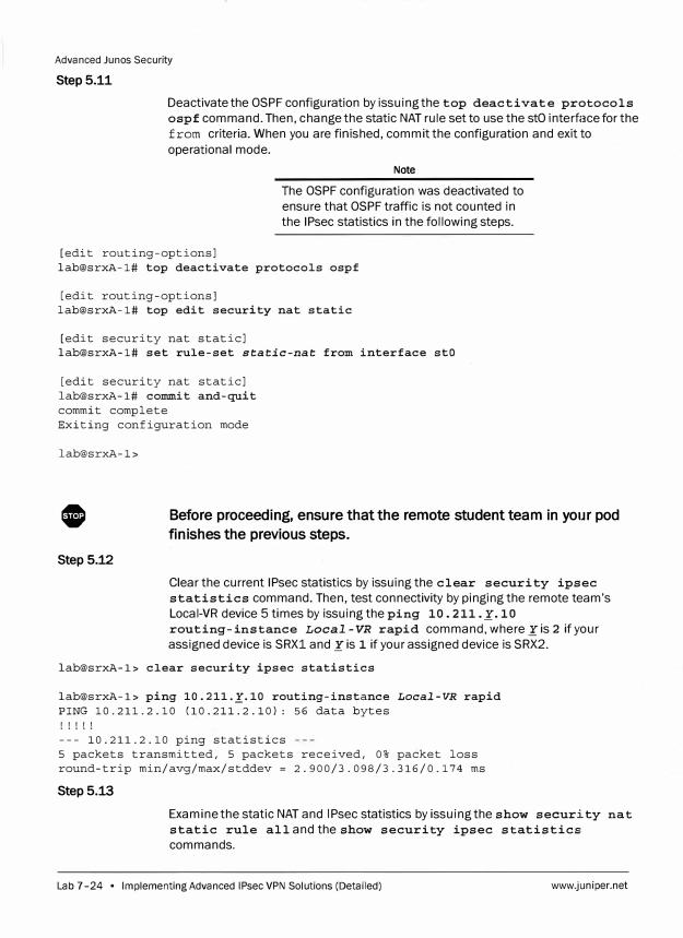
Advanced Junos Security
Step 5.11
Deactivate the OSPF configuration by issuing the top deactivate protocols
ospf command. Then, change the static NAT rule set to use the stO interface for the
from criteria. When you are finished, commit the configuration and exit to
operational mode.
[edit routing-options]
Note
The OSPF configuration was deactivated to
ensure that OSPF traffic is not counted in
the IPsec statistics in the following steps.
lab@srxA-1# top deactivate protocols ospf
[edit routing-options] lab@srxA-1# top edit security nat static
[edit security nat static] lab@srxA-1# set rule-set static-nat from interface stO
[edit security nat static] lab@srxA-1# commit and-quit commit complete Exiting configuration mode
lab@srxA-1>
0 Before proceeding, ensure that the remote student team in your pod
finishes the previous steps.
Step 5.12
Clear the current IPsec statistics by issuing the clear security ipsec
statistics command. Then, test connectivity by pinging the remote team's
Local-VR device 5 times by issuing the ping 10. 211._r. 10
routing-instance Local-VR rapid command, where_ris 2 if your
assigned device is SRX1 and Xis 1 if your assigned device is SRX2.
lab@srxA-1> clear security ipsec statistics
lab@srxA-1> ping 10.211._r.10 routing-instance Local-VR rapid PING 10.211.2.10 (10.211.2.10): 56 data bytes ! ! ! ! !
--- 10.211.2.10 ping statistics 5 packets transmitted, 5 packets received, 0% packet loss round-trip min/avg/max/stddev = 2.900/3.098/3.316/0.174 ms
Step 5.13
Examine the static NAT and IPsec statistics by issuing the show security nat
static rule alland the show security ipsec statistics
commands.
Lab 7-24 • Implementing Advanced IPsec VPN Solutions (Detailed) www.juniper.net
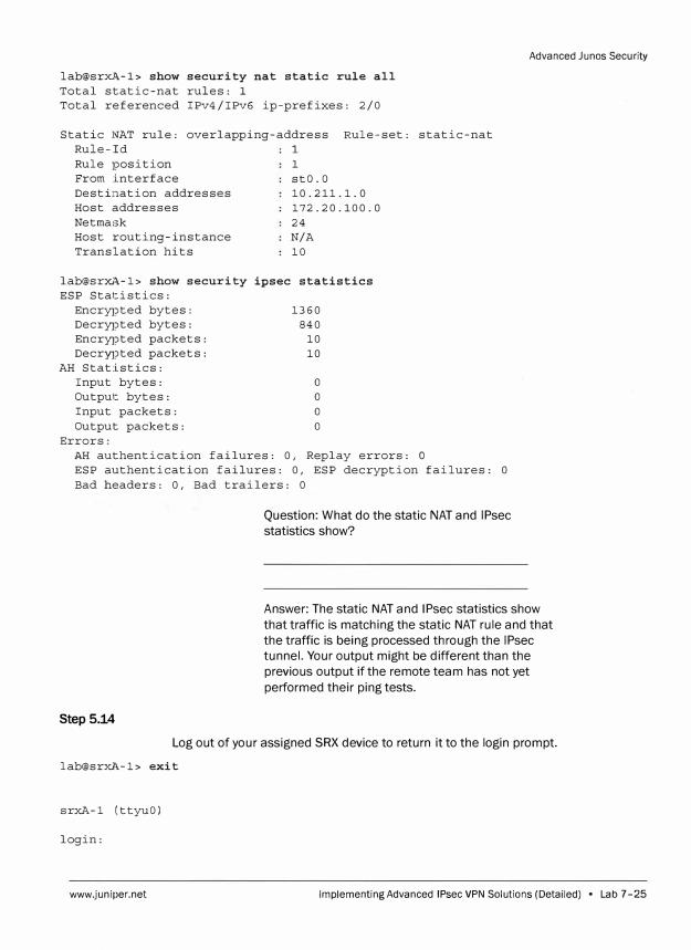
lab@srxA-1> show security nat static rule all
Total static-nat rules: l
Total referenced IPv4/IPv6 ip-prefixes: 2/0
Static NAT rule: overlapping-address Rule-set: static-nat
Rule-Id 1
Rule position
From interface
Destination addresses
Host addresses
Netmask
Host routing-instance
Translation hits
lab@srxA-1> show security
ESP Statistics:
Encrypted bytes:
Decrypted bytes:
Encrypted packets:
Decrypted packets:
AH Statistics:
Input bytes:
Output bytes:
Input packets:
Output packets:
Errors:
l
stO.O
10.211.1.0
172.20.100.0
24
N/A
10
ipsec statistics
1360
840
10
10
0
0
0
0
AH authentication failures: 0, Replay errors: O
ESP authentication failures: 0, ESP decryption failures: 0
Bad headers: 0, Bad trailers: 0
Question: What do the static NAT and IPsec
statistics show?
Advanced Junos Security
Answer: The static NAT and IPsec statistics show
that traffic is matching the static NAT rule and that
the traffic is being processed through the IPsec
tunnel. Your output might be different than the
previous output if the remote team has not yet
performed their ping tests.
Step 5.14
Log out of your assigned SRX device to return it to the login prompt.
lab@srxA-1> exit
srxA-1 (ttyuO)
login:
www.juniper.net Implementing Advanced IPsec VPN Solutions (Detailed) • Lab 7-25
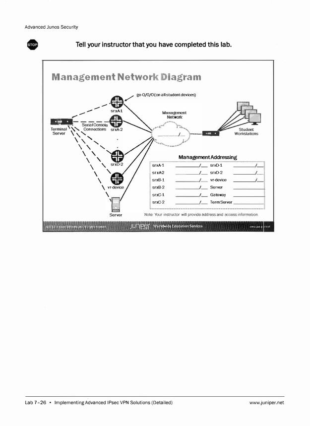
Advanced Junos Security
Tell your instructor that you have completed this lab.
Management Network Diagram
--·@/ _......--
srxA-1
., ., ----� R ··· ·········· ·• Serial Console� Terminal\�'- Connections srxA-2 Server \
'\ '-
, , '-, \' .......
\' ....... � \' �
\ '\ srxD-2
\e \ vr-device
Server
ge-0/0/0(on allstudentdevices)
�sea. Workstations
Management Addressing
11
srxA -1 I srxD-1
srxA-2 I srxD-2
srxB-1 I vr-device
srxB-2 I Server
srxC-1 I Gateway
srxC-2 I Term Server
Note: Your instructor will provide address and access informabon.
Lab 7-26 • Implementing Advanced IPsec VPN Solutions (Detailed) www.juniper.net
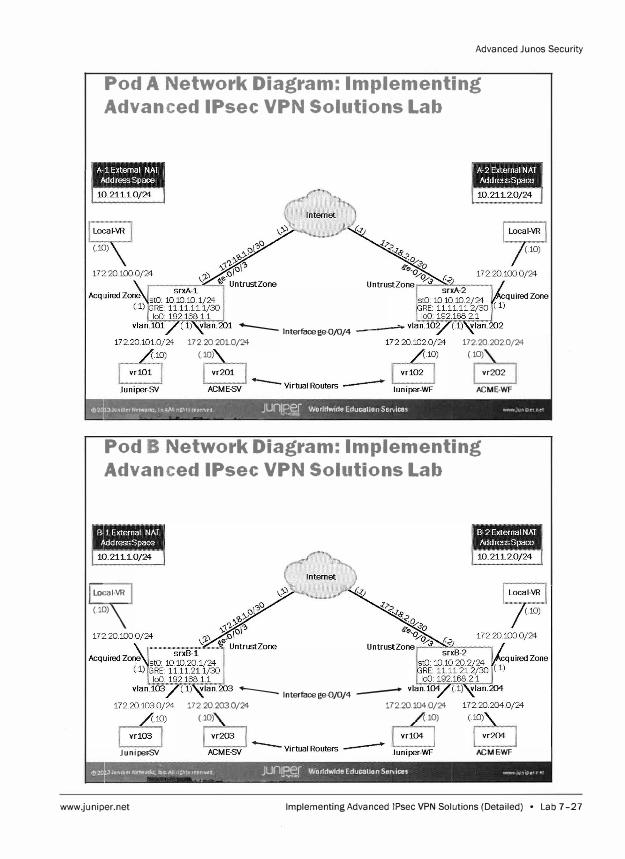
Advanced Ju nos Security
Pod A Network Diagram: Implementing
Advanced IPsec VPN Solutions Lab
..._____ lnterfacege-0/0/4 -·�--172.20.201.0/24
(.10) 172 20 202 0/24
(.10)
vr202
ACME-WF
�J:n1p:r Networit,:, ! n � ->JI nghts re:seNed JUnlPer Worldwide Education Services Wl'IIW Juniper n el �==-" ----� _......._�---� -� -
-
Pod B Network Diagram: Implementing
Advanced IPsec VPN Solutions Lab
Ecal-VR I
(.10)\
Juniper-SY
..._____ lnterfacege-0/0/4 ---172.20.203.Q/24 172.20.104.0/24
(.� (.�
ACME-WF
�::i:t� t:;.o,;;�;��llig?it;�tstlWQ JUnJPff Worldwide Education Services \'mll."1 jUn1p�r t �, ... �-- � ---� ' - - -
www.juniper.net Implementing Advanced IPsec VPN Solutions (Detailed) • Lab 7-27
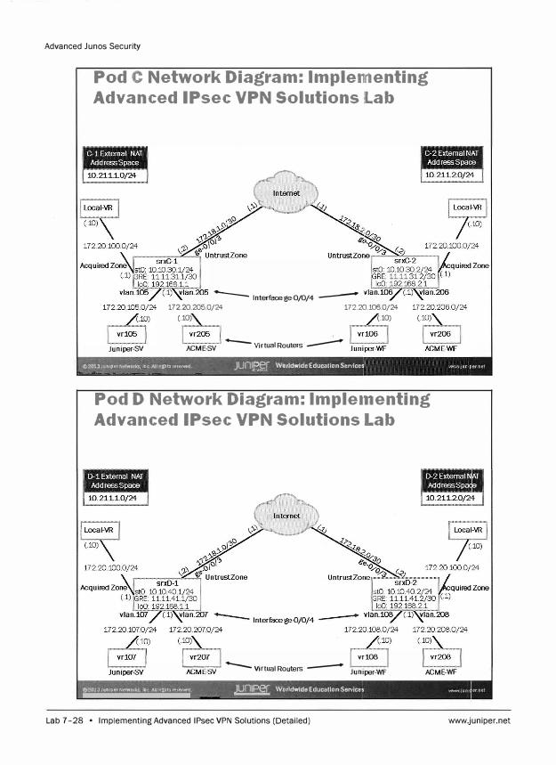
Advanced Junos Security
Pod C Network Diagram: lmple1111enting
Advanced IPsec VPN Solutions lab
Juniper-SV
-- lnterfacege-0/0/4 --172.20 2050/24 172.20106.0/24
(� (�
ACME-SV -- Virtual Routers --
©:?013 Jt1nlper Network,, �,nc All 111',ht� re�er.ted JUnff?�f Worldwide Education Service -L--..... �------ ��
Pod D Network Diagram: lmple1nenting
Advanced IPsec VPN Solutions Lab
vr108 ....,.,,......,,..,,..- -- Virtual Routers -- Juniper-WF ACME-WF
©'.?o:JJ11:l{l�tNttwor�, lne .�n;tt,1s�•'lrwtJ ---�--�- JUnlE:5:J Worldwide Education Services 'l'IWi'I JUhl
Lab 7-28 • Implementing Advanced IPsec VPN Solutions (Detailed) www.juniper.net
Lab
Peirforming Security Troubleshooting Techniques (Detailed)
Overvi,ew
In this lab, you will examine log outputs to determine useful troubleshooting information.
You will then configure security flow traceoptions to troubleshoot a failing Telnet session.
When you discover the reason behind the Telnet session failure you will fix the problem.
You will then work as a team to troubleshoot a down IP Security (IPsec) tunnel. Once the
problem with the IPsec tunnel has been discovered, you will fix it and bring the tunnel
back to its operational state.
The lab is available in two formats: a high-level format designed to make you think through
each step and a detailed format that offers step-by-step instructions complete with
sample output from most commands.
By completing this lab you will perform the following tasks:
View and examine logs.
Configure security traceoptions.
Troubleshoot a failing Telnet session.
Troubleshoot an IPsec tunnel that is down.
www.juniper.net Performing Security Troubleshooting Techniques (Detailed) • Lab 8-1

Advanced Junos Security
Part 1: Examining Log Messages
Step 1.1
Step 1.2
Step 1.3
srxA-1 (ttyuO)
login: lab
Password:
In this lab part, you examine various logs that will aid in the troubleshooting process.
You will also configure and examine security flow traceoptions to troubleshoot a
failing Telnet session.
Ensure that you know to which student device you have been assigned. Check with
your instructor if you are not certain. Consult the management network diagram to
determine the management address of your student device.
Question: What is the management address
assigned to your student router?
Answer: The answer varies. The sample hostname
and IP address used in the output examples in this
lab are for srxA-1, which uses 10.210.35.131 as its
management IP address. The actual management
address varies between delivery environments.
Access the command-line interface (CLI) at your station using either the console, Telnet, or SSH as directed by your instructor.
D Show quick connect on startup 0 Save session
� Open in a tab
Connect J J Cancel I
Log in as user lab with the password labl2 3. Enter configuration mode and load
the 1 abB -start . conf ig from the /var/home/lab/ajsec/ directory. Commit the
configuration and exit to operational mode when complete.
Lab 8-2 • Performing Security Troubleshooting Techniques (Detailed) www.juniper.net
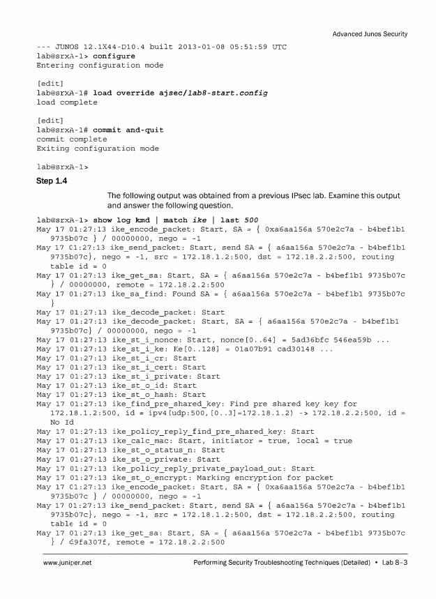
--- JUNOS 12.1X44-Dl0.4 built 2013-01-08 05:51:59 UTC lab@srxl-\.-1> configure Entering configuration mode
[edit] lab@srxA-1# load override ajsec/labB-start.config
load complete
[edit] lab@srxA-1# commit and-quit commit complete Exiting configuration mode
lab@srxi\-1 >
Step 1.4
Advanced Junos Security
The following output was obtained from a previous IPsec lab. Examine this output
and answer the following question.
lab@srxi\-1> show log kmd I match ike I last 500
May 17 01:27:13 ike_encode_packet: Start, SA= { Oxa6aa156a 570e2c7a - b4beflbl 9735b07c } I 00000000, nego = -1
May 17 01:27:13 ike_send_packet: Start, send SA= { a6aa156a 570e2c7a - b4beflbl 9735b07c}, nego = -1, src = 172.18.1.2:500, dst = 172.18.2.2:500, routing table id= O
May 17 01:27:13 ike_get_sa: Start, SA= { a6aa156a 570e2c7a - b4beflbl 9735b07c } I 00000000, remote= 172.18.2.2:500
May 17 01:27:13 ike sa find: Found SA= { a6aa156a 570e2c7a - b4beflbl 9735b07c }
May 17 01:27:13 ike_decode_packet: Start May 17 01:27:13 ike_decode_packet: Start, SA= { a6aa156a 570e2c7a - b4beflbl
9735b07c} I 00000000, nego = -1 May 17 01:27:13 ike_st_i_nonce: Start, nonce[O .. 64] = 5ad36bfc 546ea59b May 17 01:27:13 ike_st_i_ke: Ke[O .. 128] = Ola07b91 cad30148 ... May 17 01:27:13 ike
-
st -
i -
er: Start May 17 01:27:13 ike st i cert: Start May 17 01:27:13 ike -st _i_private: Start May 17 01:27:13 ike st 0 id: Start May 17 01:27:13 ike_st_o_hash: Start May 17 01:27:13 ike_find_pre_shared_key: Find pre shared key key for
172.1.8.1.2:500, id= ipv4(udp:500, [0 .. 3]=172.18.1.2) -> 172.18.2.2:500, id No Id
May 17 01:27:13 ike_policy_reply_find_pre_shared_key: Start May 17 01:27:13 ike_calc_mac: Start, initiator= true, local true May 17 01:27:13 ike_st_o_status_n: Start May 17 01:27:13 ike_st_o_private: Start May 17 01:27:13 ike_policy_reply_private_payload_out: Start May 17 01:27:13 ike st o encrypt: Marking encryption for packet May 17 01:27:13 ike_=-en�ode_packet: Start, SA= { Oxa6aa156a 570e2c7a - b4beflbl
9735b07c } I 00000000, nego = -1 May 17 01:27:13 ike_send_packet: Start, send SA= { a6aa156a 570e2c7a - b4beflbl
9735b07c}, nego = -1, src = 172.18.1.2:500, dst = 172.18.2.2:500, routing table id= O
May 17 01:27:13 ike_get_sa: Start, SA= { a6aa156a 570e2c7a - b4beflbl 9735b07c } I d9fa307f, remote= 172.18.2.2:500
www.juniper.net Performing Security Troubleshooting Techniques (Detailed) • Lab 8-3
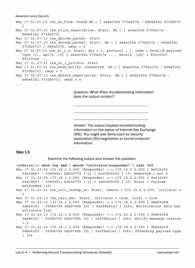
Advanced Junos Security
May 17 01:27:13 ike_sa_find: Found SA = { a6aal56a 570e2c7a - b4beflbl 9735b07c
May 17 01:27:13 ike alloc_negotiation: Start, SA = { a6aal56a 570e2c7a -b4beflbl 9735b07c}
May 17 01:27:13 ike_decode_packet: Start May 17 01:27:13 ike_decode_packet: Start, SA = { a6aal56a 570e2c7a - b4beflbl
9735b07c} I d9fa307f, nego = O May 17 01:27:13 ike_st_i_n: Start, doi = 1, protocol = 1, code = Invalid payload
type (1), spi [O .. 16J = a6aal56a 570e2c7a ... , data [O .. 125J = 800c0001 800300e8 ...
May 17 01:27:13 ike_st_i_private: Start May 17 01:27:13 ike_send_notify: Connected, SA = { a6aal56a 570e2c7a - b4beflbl
9735b07c}, nego = O May 17 01:27:13 ike_delete_negotiation: Start, SA = { a6aal56a 570e2c7a -
b4beflbl 9735b07c}, nego = O
Step 1.5
Question: What IPsec troubleshooting information
does the output contain?
Answer: The output displays troubleshooting
information on the status of Internet Key Exchange
(IKE). You might see items such as security
association (SA) negotiation or tunnel endpoint
information.
Examine the following output and answer the question.
lab@srxA-1> show log kmd I match "initiator/responder" I last 500May 17 01:23:03 172.18.1.2:500 (Responder) <-> 172.18.2.2:500 { 8e0364fc
54639b87 - 53869911 bd032772 [-lJ / OxOOOOOOOO } IP; Reserved 1 not O May 17 01:23:03 172.18.1.2:500 (Responder) <-> 172.18.2.2:500 { 8e0364fc
54639b87 - 53869911 bd032772 [-lJ / OxOOOOOOOO } IP; Error = Payload malformed ( 16)
May 17 01:23:13 ike_init_isakmp_sa: Start, remote = 172.18.2.2:500, initiator 1
May 17 01:23:13 ike calc mac: Start, initiator = true, local = true May 17 01:23:13 172�18.1�2:500 (Responder) <-> 172.18.2.2:500 { 8be54c6d
6eb863f3 - f05b6749 Obb9795b [OJ I Ox2f8a2la3 } Info; Notification data has attribute list
May 17 01:23:13 172.18.1.2:500 (Responder) <-> 172.18.2.2:500 { 8be54c6d 6eb863f3 - f05b6749 Obb9795b [OJ I Ox2f8a2la3 } Info; Notify message version = 1
May 17 01:23:13 172.18.1.2:500 (Responder) <-> 172.18.2.2:500 { 8be54c6d 6eb863f3 - f05b6749 Obb9795b [OJ I Ox2f8a2la3 } Info; Offending payload type = 156
Lab 8-4 • Performing Security Troubleshooting Techniques (Detailed) www.juniper.net
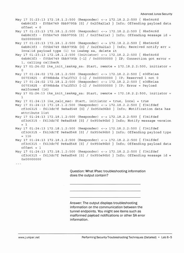
Advanced Ju nos Security
May 17 01:23:13 172.18.1.2:500 (Responder) <-> 172.18.2.2:500 { 8be54c6d 6eb863f3 - f05b6749 Obb9795b [OJ I Ox2f8a2la3 } Info; Offending payload data offset = O
May 17 01:23:13 172.18.1.2:500 (Responder) <-> 172.18.2.2:500 { 8be54c6d 6eb863f3 - f05b6749 Obb9795b [OJ I Ox2f8a2la3 } Info; Offending message id OxOOOOOOOO
May 17 01:23:13 172.18.1.2:500 (Responder) <-> 172.18.2.2:500 { 8be54c6d 6eb863f3 - f05b6749 Obb9795b [OJ I Ox2f8a2la3 } Info; Received notify err Invalid payload type (1) to isakmp sa, delete it
May 17 01:23:13 172.18.1.2:500 (Initiator) <-> 172.18.2.2:500 { 8be54c6d 6eb863f3 - f05b6749 Obb9795b [-lJ I OxOOOOOOOO } IP; Connection got error l, calling callback
May 17 01:24:02 ike_init_isakmp_sa: Start, remote = 172.18.2.2:500, initiator 0
May 17 01:24:02 172.18.1.2:500 (Responder) <-> 172.18.2.2:500 { e3d5elaa 00703825 - d798bbda 07alff53 [-lJ / OxOOOOOOOO } IP; Reserved 1 not O
May 17 01:24:02 172.18.1.2:500 (Responder) <-> 172.18.2.2:500 { e3d5elaa 00703825 - d798bbda 07alff53 [-lJ / OxOOOOOOOO } IP; Error = Payload malformed ( 16)
May 17 01:24:13 ike_init_isakmp_sa: Start, remote = 172.18.2.2:500, initiator 1
May 17 01:24:13 ike_calc_mac: Start, initiator = true, local = true May 17 01:24:13 172.18.1.2:500 (Responder) <-> 172.18.2.2:500 { f34lfdef
cf3c6315 - f613dc7f 9e8ad548 [OJ I Ox950e96b0 } Info; Notification data has attribute list
May 17 01:24:13 172.18.1.2:500 (Responder) <-> 172.18.2.2:500 { f34lfdef cf3c6315 - f613dc7f 9e8ad548 [OJ I Ox950e96b0} Info; Notify message version = 1
May 17 01:24:13 172.18.1.2:500 (Responder) <-> 172.18.2.2:500 { f34lfdef cf3c6315 - f613dc7f 9e8ad548 [OJ I Ox950e96b0} Info; Offending payload type = 116
May 17 01:24:13 172.18.1.2:500 (Responder) <-> 172.18.2.2:500 { f34lfdef cf3c6315 - f613dc7f 9e8ad548 [OJ I Ox950e96b0} Info; Offending payload data offset = 1
May 17 01:24:13 172.18.1.2:500 (Responder) <-> 172.18.2.2:500 { f34lfdef cf3c6315 - f613dc7f 9e8ad548 [OJ I Ox950e96b0 } Info; Offending message id OxOOOOOOOO
www.juniper.net
Question: What IPsec troubleshooting information
does the output contain?
Answer: The output displays troubleshooting
information on the communication between the
tunnel endpoints. You might see items such as
malformed payload notifications or other SA error
information.
Performing Security Troubleshooting Techniques (Detailed) • Lab 8-5
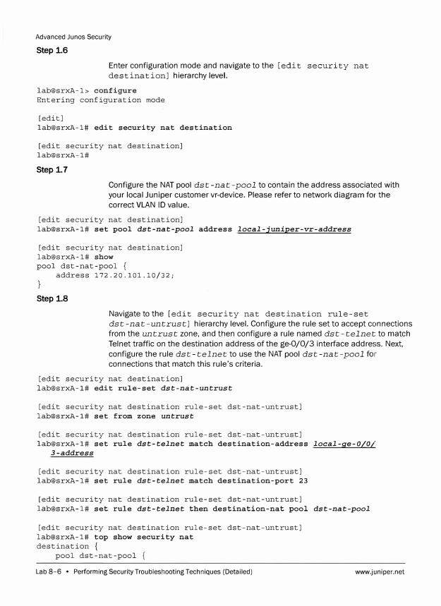
Advanced Junes Security
Step i6
Enter configuration mode and navigate to the [edit security nat
destination] hierarchy level.
lab@srxA-1> configure Entering configuration mode
[edit] lab@srxA-1# edit security nat destination
[edit security nat destination] lab@srxA-1#
Step i7
Configure the NAT pool dst-nat-pool to contain the address associated with
your local Juniper customer vr-device. Please refer to network diagram for the
correct VLAN ID value.
[edit security nat destination] lab@srxA-1# set pool dst-nat-pool address local-juniper-vr-address
[edit security nat destination] lab@srxA-1# show pool dst-nat-pool {
address 172.20.101.10/32;
Step i8
Navigate to the [edit security nat destination rule-set
dst-nat-untrust] hierarchy level. Configure the rule set to accept connections
from the untrust zone, and then configure a rule named dst-telnet to match
Telnet traffic on the destination address of the ge-0/0/3 interface address. Next,
configure the rule dst-telnet to use the NAT pool dst-nat-pool fo1·
connections that match this rule's criteria.
[edit security nat destination] lab@srxA-1# edit rule-set dst-nat-untrust
[edit security nat destination rule-set dst-nat-untrust] lab@srxA-1# set from zone untrust
[edit security nat destination rule-set dst-nat-untrust] lab@srxA-1# set rule dst-telnet match destination-address local-ge-0/0/
3-address
[edit security nat destination rule-set dst-nat-untrust] lab@srxA-1# set rule dst-telnet match destination-port 23
[edit security nat destination rule-set dst-nat-untrust] lab@srxA-1# set rule dst-telnet then destination-nat pool dst-nat-pool
[edit security nat destination rule-set dst-nat-untrust] lab@srxA-1# top show security nat destination {
pool dst-nat-pool {
Lab 8-6 • Performing Security Troubleshooting Techniques (Detailed) www.juniper.net
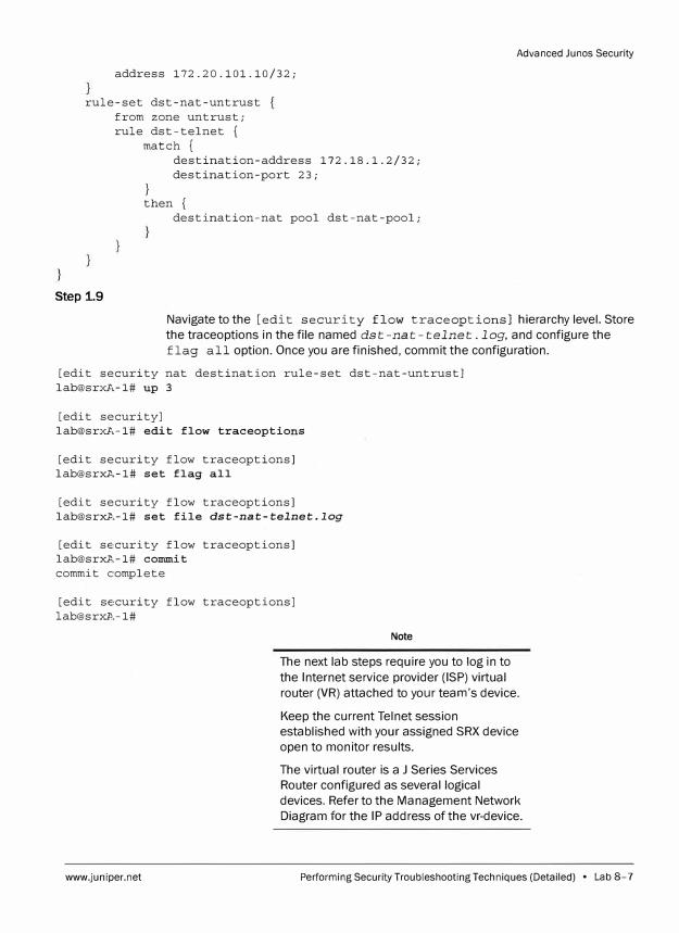
address 172.20.101.10/32;
rule-set dst-nat-untrust from zone untrust; rule dst-telnet {
match {
Step 1.9
}
destination-address 172.18.1.2/32; destination-port 23;
then { destination-nat pool dst-nat-pool;
Advanced Junos Security
Navigate to the [edit security flow traceoptions] hierarchy level.Store the traceoptions in the file named dst-nat-telnet. log, and configure the flag all option. Once you are finished, commit the configuration.
[edit security nat destination rule-set dst-nat-untrust] lab@srxA-1# up 3
[edit security] lab@srxA-1# edit flow traceoptions
[edit security flow traceoptions] lab@srxA-1# set flag all
[edit security flow traceoptions] lab@srxA-1# set file dst-nat-telnet.log
[edit security flow traceoptions] lab@srxA-1# commit commit complete
[edit security flow traceoptions] lab@srxl'.-1#
www.juniper.net
Note
The next lab steps require you to log in to the Internet service provider (ISP) virtual router (VR) attached to your team's device.
Keep the current Telnet session established with your assigned SRX device open to monitor results.
The virtual router is a J Series Services Router configured as several logical devices. Refer to the Management Network Diagram for the IP address of the vr-device.
Performing Security Troubleshooting Techniques (Detailed) • Lab 8-7
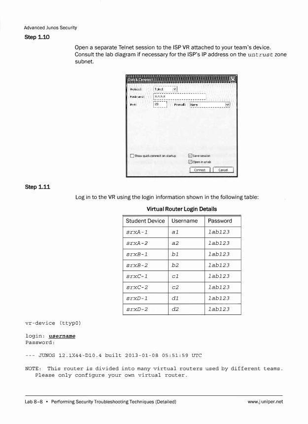
Advanced Junes Security
Step 1.10
Open a separate Telnet session to the ISP VR attached to your team's device.
Consult the lab diagram if necessary for the ISP's IP address on the untrust zone
subnet.
D Show quick connect on startup
Step 1.11
� Save session
0 Open in a tab
j Connect 1l j Cancel l
Log in to the VR using the login information shown in the following table:
Virtual Router Login Details
vr-device (ttypO)
login: username
Password:
Student Device
srxA-1
srxA-2
srxB-1
srxB-2
srxC-1
srxC-2
srxD-1
srxD-2
Username
al
a2
bl
b2
cl
c2
dl
d2
--- JUNOS 12.1X44-Dl0.4 built 2013-01-08 05:51:59 UTC
Password
labl23
labl23
labl23
labl23
labl23
labl23
labl23
labl23
NOTE: This router is divided into many virtual routers used by different teams.
Please only configure your own virtual router.
Lab 8-8 • Performing Security Troubleshooting Techniques (Detailed) www.juniper.net
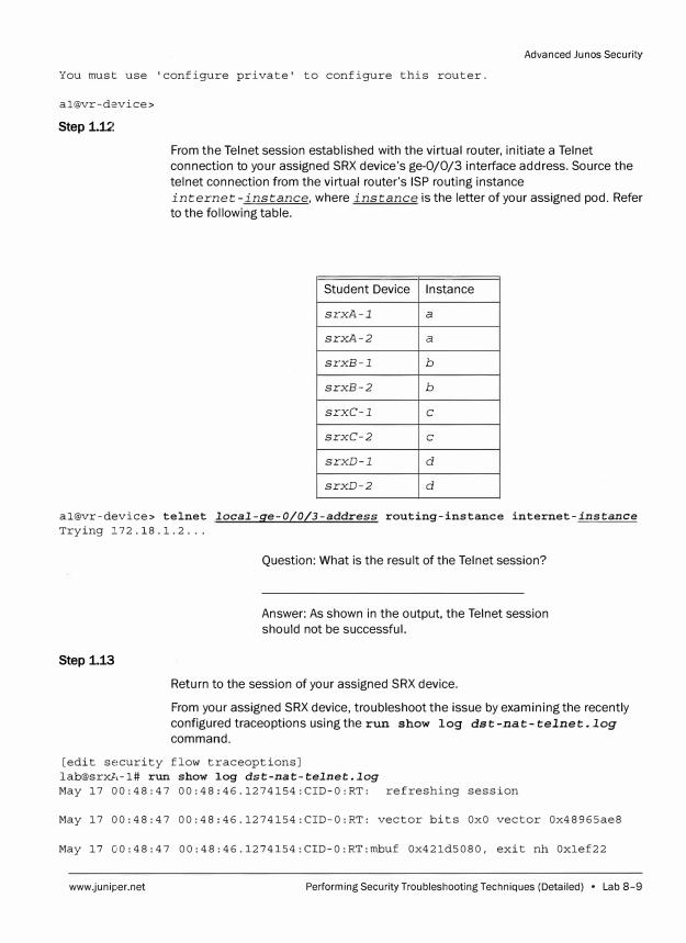
Advanced Ju nos Security
You must use 'configure private' to configure this router.
al@vr-device>
Step 1.1.2
From the Telnet session established with the virtual router, initiate a Telnet
connection to your assigned SRX device's ge-0/0/3 interface address. Source the
telnet connection from the virtual router's ISP routing instance
internet-instance, where instance is the letter of your assigned pod. Refer
to the following table.
Student Device Instance
srxA-1 a
srxA-2 a
srxB-1 b
srxB-2 b
srxC-1 c
srxC-2 c
srxD-1 d
srxD-2 d
al@vr-device> telnet local-ge-0/0/3-address routing-instance internet-instance
Trying 172.18.1.2 ...
Step 1.13
Question: What is the result of the Telnet session?
Answer: As shown in the output, the Telnet session
should not be successful.
Return to the session of your assigned SRX device.
From your assigned SRX device, troubleshoot the issue by examining the recently
configured traceoptions using therun show log dst-nat-telnet.log
command.
[edit security flow traceoptions]
lab@srxA-1# run show log dst-nat-telnet.log
May 17 00:48:47 00:48:46.1274154:CID-0:RT: refreshing session
May 17 00:48:47 00:48:46.1274154:CID-O:RT: vector bits OxO vector Ox48965ae8
May 17 00:48:47 00:48:46.1274154:CID-0:RT:mbuf Ox42ld5080, exit nh Oxlef22
www.juniper.net Performing Security Troubleshooting Techniques (Detailed) • Lab 8-9
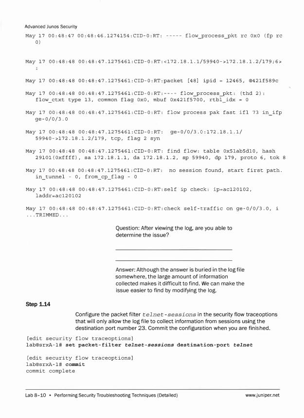
Advanced Junos Security
May 17 00:48:47 00:48:46.1274154:CID-0:RT: ----- flow_process_pkt re OxO (fp re 0)
May 17 00:48:48 00:48:47.1275461:CID-0:RT:<172.18.l.l/59940->172.18.l.2/179;6>
May 17 00:48:48 00:48:47.1275461:CID-O:RT:packet [48] ipid = 12465, @42lf589c
May 1 7 00: 48: 48 00: 48: 4 7 .1275461: CID-0: RT: ---- flow_process_pkt: (thd 2) : flow_ctxt type 13, common flag OxO, mbuf Ox42lf5700, rtbl idx = O
May 17 00:48:48 00:48:47.1275461:CID-0:RT: flow process pak fast ifl 73 in_ifp ge-0/0/3.0
May 17 00:48:48 00:48:47.1275461:CID-0:RT: ge-0/0/3.0:172.18.1.1/ 59940->172.18.1.2/179, tcp, flag 2 syn
May 17 00:48:48 00:48:47.1275461:CID-0:RT: find flow: table Ox5lab5dl0, hash 2910l(Oxffff), sa 172.18.1.1, da 172.18.1.2, sp 59940, dp 179, proto 6, tok 8
May 17 00:48:48 00:48:47.1275461:CID-0:RT: no session found, start first path. in_tunnel - 0, from_cp_flag - 0
May 17 00:48:48 00:48:47.1275461:CID-O:RT:self ip check: ip=ac120102, laddr=acl20102
May 17 00:48:48 00:48:47.1275461:CID-O:RT:check self-traffic on ge-0/0/3.0, i ... TRIMMED ...
Step 1.14
Question: After viewing the log, are you able to
determine the issue?
Answer: Although the answer is buried in the log file
somewhere, the large amount of information
collected makes it difficult to find. We can make the
issue easier to find by modifying the log.
Configure the packet filter telnet-sessions in the security flow traceoptions
that will only allow the log file to collect information from sessions using the
destination port number 23. Commit the configuration when you are finished.
[edit security flow traceoptions] lab@srxA-1# set packet-filter telnet-sessions destination-port telnet
[edit security flow traceoptions] lab@srxA-1# commit commit complete
Lab 8-10 • Performing Security Troubleshooting Techniques (Detailed) www.juniper.net
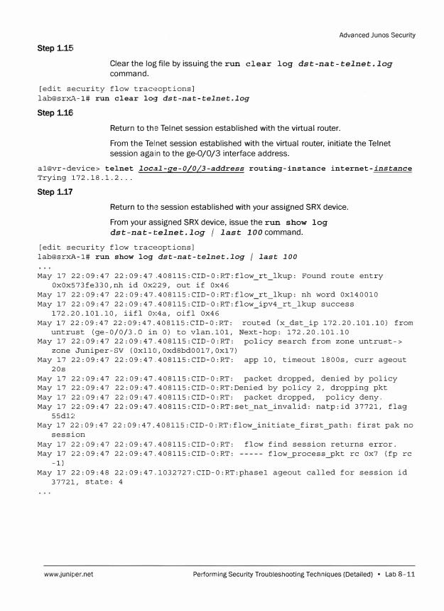
Step 1.15
Advanced Junos Security
Clear the log file by issuing therun clear log dst-nat-telnet.log
command.
[edit security flow traceoptions] lab@srxA-1# run clear loq- dst-nat-telnet.log
Step 1.16i
Return to the Telnet session established with the virtual router.
From the Telnet session established with the virtual router, initiate the Telnet session again to the ge-0/0/3 interface address.
al@vr-device> telnet local-ge-0/0/3-address routing-instance internet-instance Trying 172.18.1.2 ...
Step 1.17
Return to the session established with your assigned SRX device.
From your assigned SRX device, issue the run show log dst-nat-telnet.log / last lOOcommand.
[edit security flow traceoptions] lab@srxA-1# run show log dst-nat-telnet.log / last 100
May 17 22:09:47 22:09:47 .. 408115:CID-0:RT:flow rt lkup: Found route entry Ox0x573fe330,nh id Ox229, out if Ox46
May 17 22:09:47 22:09:47.408115:CID-0:RT:flow_rt_lkup: nh word Oxl40010 May 17 22:09:47 22:09:47.408115:CID-O:RT:flow_ipv4_rt_lkup success
172.20.101.10, iifl Ox4a, oifl Ox46 May 17 22:09:47 22:09:47.408115:CID-0:RT: routed (x_dst ip 172.20.101.10) from
untrust (ge-0/0/3.0 in 0) to vlan.101, Next-hop: 172.20.101.10 May 17 22:09:47 22:09:47.408115:CID-0:RT: policy search from zone untrust->
zone Juniper-SV (Oxll0,0xd8bd0017,0xl7) May 17 22:09:47 22:09:47.408115:CID-0:RT: app 10, timeout 1800s, curr ageout
20s May 17 22:09:47 22:09:47.408115:CID-0:RT: packet dropped, denied by policy May 17 22:09:47 22:09:47.408115:CID-0:RT:Denied by policy 2, dropping pkt May 17 22:09:47 22:09:47.408115:CID-0:RT: packet dropped, policy deny. May 17 22:09:47 22:09:47.408115:CID-0:RT:set_nat invalid: natp:id 37721, flag
55dl2 May 17 22:09:47 22:09:47.408115:CID-0:RT:flow_initiate_first_path: first pak no
session May 17 22:09:47 22:09:47.408115:CID-0:RT: May 17 22:09:47 22:09:47.408115:CID-0:RT:
-1)
flow find session returns error. flow_process_pkt re Ox7 (fp re
May 17 22:09:48 22:09:47.1032727:CID-0:RT:phasel ageout called for session id 37721, state: 4
www.juniper.net Performing Security Troubleshooting Techniques (Detailed) • Lab 8-11
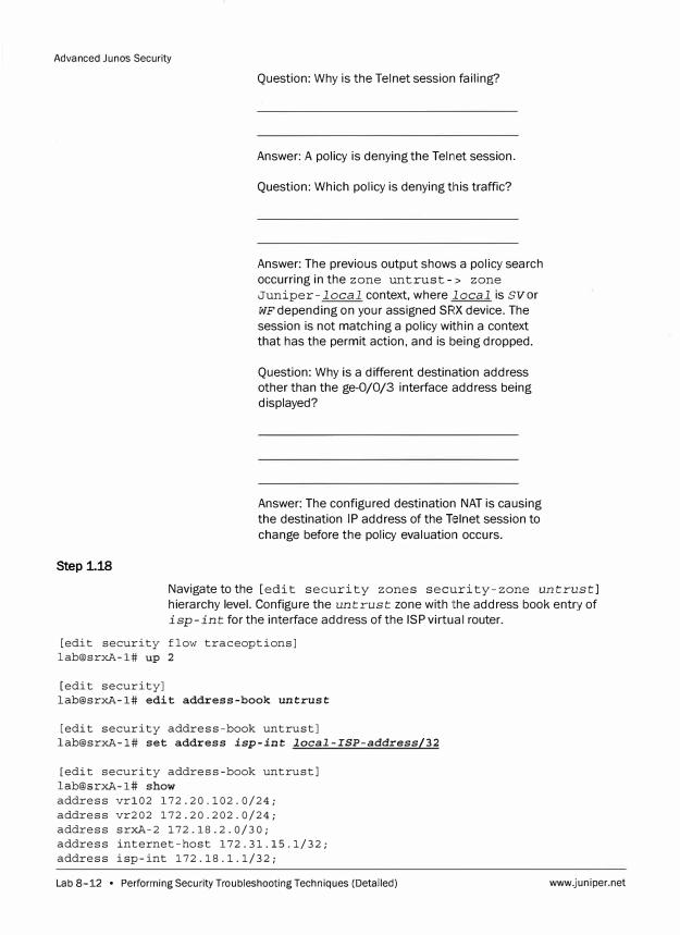
Advanced Junes Security
Step 1.18
Question: Why is the Telnet session failing?
Answer: A policy is denying the Telnet session.
Question: Which policy is denying this traffic?
Answer: The previous output shows a policy search
occurring in the zone untrust- > zone
Juniper-local context, where local is svor
WF depending on your assigned SRX device. The
session is not matching a policy within a context
that has the permit action, and is being dropped.
Question: Why is a different destination address
other than the ge-0/0/3 interface address being
displayed?
Answer: The configured destination NAT is causing
the destination IP address of the Telnet session to
change before the policy evaluation occurs.
Navigate to the [edit security zones security-zone untrust]
hierarchy level. Configure the untrust zone with the address book entry of
isp-int for the interface address of the ISP virtual router.
[edit security flow traceoptions]
lab@srxA-1# up 2
[edit security]
lab@srxA-1# edit address-book untrust
[edit security address-book untrust]
lab@srxA-1# set address isp-int local-ISP-address/32
[edit security address-book untrust]
lab@srxA-1# show
address vrl02 172.20.102.0/24;
address vr202 172.20.202.0/24;
address srxA-2 172.18.2.0/30;
address internet-host 172.31.15.1/32;
address isp-int 172.18.1.1/32;
Lab 8-12 • Performing Security Troubleshooting Techniques (Detailed) www.juniper.net
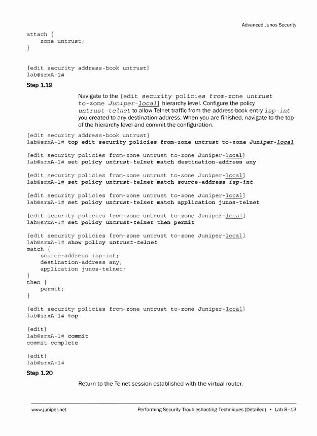
attach { zone untrust;
[edit security address-book untrust] lab@srxA-1#
Step 1.191
Advanced Ju nos Security
Navigate to the [edit security policies from-zone untrust
to-zone Juniper-local] hierarchy level. Configure the policy
untrust-telnet to allow Telnet traffic from the address-book entry isp-int
you created to any destination address. When you are finished, navigate to the top
of the hierarchy level and commit the configuration.
[edit security address-book untrust] lab@srxA-1# top edit security policies from-zone untrust to-zone Juniper-local
[edit security policies from-zone untrust to-zone Juniper-local] lab@srxi�-1# set policy untrust-telnet match destination-address any
[edit security policies from-zone untrust to-zone Juniper-local] lab@srxA-1# set policy untrust-telnet match source-address isp-int
[edit security policies from-zone untrust to-zone Juniper-local] lab@srxA-1# set policy untrust-telnet match application junos-telnet
[edit security policies from-zone untrust to-zone Juniper-local] lab@srxA-1# set policy untrust-telnet then permit
[edit security policies from-zone untrust to-zone Juniper-local] lab@srxA-1# show policy untrust-telnet match {
}
source-address isp-int; destination-address any; application junos-telnet;
then { permit;
[edit security policies from-zone untrust to-zone Juniper-local] lab@srxA-1# top
[edit] lab@srxA-1# commit commit complete
[edit] lab@srxA-1#
Step 1.20
Return to the Telnet session established with the virtual router.
www.juniper.net Performing Security Troubleshooting Techniques (Detailed) • Lab 8-13
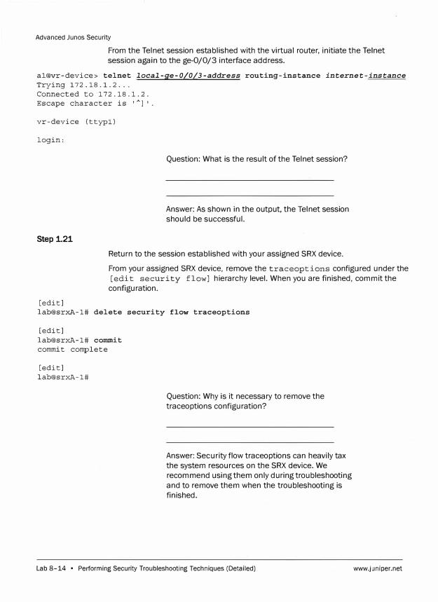
Advanced Junos Security
From the Telnet session established with the virtual router, initiate the Telnet
session again to the ge-0/0/3 interface address.
al@vr-device> telnet local-ge-0/0/3-address routing-instance internet-instance
Trying 172.18.1.2 ... Connected to 172.18.1.2. Escape character is '
Al'.
vr-device (ttypl)
login:
Step 1.21
Question: What is the result of the Telnet session?
Answer: As shown in the output, the Telnet session
should be successful.
Return to the session established with your assigned SRX device.
From your assigned SRX device, remove the traceoptions configured under the
[edit security flow] hierarchy level. When you are finished, commit the
configuration.
[edit] lab@srxA-1# delete security flow traceoptions
[edit] lab@srxA-1# coilllllit commit complete
[edit] lab@srxA-1#
Question: Why is it necessary to remove the
traceoptions configuration?
Answer: Security flow traceoptions can heavily tax
the system resources on the SRX device. We
recommend using them only during troubleshooting
and to remove them when the troubleshooting is
finished.
Lab 8-14 • Performing Security Troubleshooting Techniques (Detailed) www.juniper.net
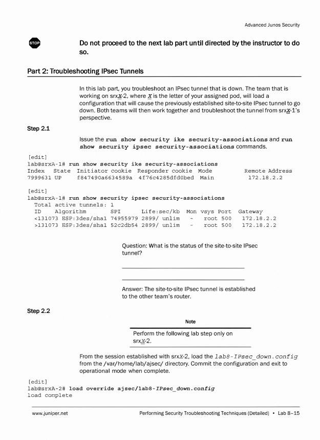
0
Advanced Junos Security
Do not proceed to the next lab part until directed by the instructor to do
so.
Part 2: Troubleshooting IPsec Tunnels
Step 2.1
[edit]
In this lab part, you troubleshoot an IPsec tunnel that is down. The team that is working on srx�-2. where� is the letter of your assigned pod, will load a configuration that will cause the previously established site-to-site IPsec tunnel to go down. Both teams will then work together and troubleshoot the tunnel from sr�-1's perspective.
Issue the run show security ike security-associations and run show security ipsec security-associations commands.
lab@srxA-1# run show security ike security-associations Index State Initiator cookie Responder cookie Mode Remote Address
172.18.2.2 7999631 UP f847490a6634589a 4f76c4285dfdObed Main
[edit] lab@srxA-1# run show security ipsec security-associations
Total active tunnels: 1 ID Algorithm SPI Life:sec/kb Mon vsys Port Gateway <131073 ESP:3des/shal 74955979 2899/ unlim root 500 172.18.2.2 >131073 ESP:3des/shal 52c2db54 2899/ unlim root 500 172.18.2.2
Step 2.2
[edit]
Question: What is the status of the site-to-site IPsec tunnel?
Answer: The site-to-site IPsec tunnel is established to the other team's router.
Note
Perform the following lab step only on srxx-2.
From the session established with srxx-2, load the labB-IPsec _down. config
from the /var/home/lab/ajsec/ directory. Commit the configuration and exit to operational mode when complete.
lab@srxA-2# load override ajsec/lab8-IPsec_down.config load complete
www.juniper.net Performing Security Troubleshooting Techniques (Detailed) • Lab 8-15
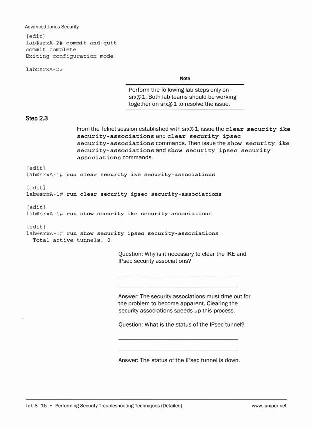
Advanced Junos Security
[edit)
lab@srxA-2# commit and-quit
commit complete
Exiting configuration mode
lab@srxA-2>
Step 2.3
Note
Perform the following lab steps only on
srxK-1. Both lab teams should be working
together on srq-1 to resolve the issue.
From the Telnet session established with srxx-1, issue the clear security ike
security-associationsand clear security ipsec
security-associations commands. Then issue the show security ike
security-associationsand show security ipsec security
associations commands.
[edit)
lab@srxA-1# run clear security ike security-associations
[edit)
lab@srxA-1# run clear security ipsec security-associations
[edit)
lab@srxA-1# run show security ike security-associations
[edit)
lab@srxA-1# run show security ipsec security-associations
Total active tunnels: O
Question: Why is it necessary to clear the IKE and
IPsec security associations?
Answer: The security associations must time out for
the problem to become apparent. Clearing the
security associations speeds up this process.
Question: What is the status of the IPsec tunnel?
Answer: The status of the IPsec tunnel is down.
Lab 8-16 • Performing Security Troubleshooting Techniques (Detailed) www.juniper.net
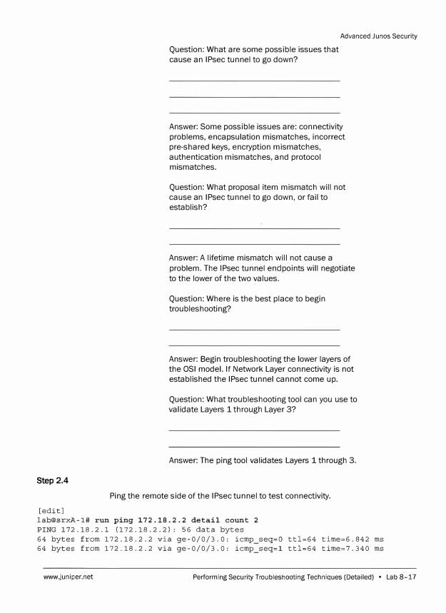
Step 2.4
[edit]
Question: What are some possible issues that
cause an IPsec tunnel to go down?
Advanced Junos Security
Answer: Some possible issues are: connectivity
problems, encapsulation mismatches, incorrect
pre-shared keys, encryption mismatches,
authentication mismatches, and protocol
mismatches.
Question: What proposal item mismatch will not
cause an IPsec tunnel to go down, or fail to
establish?
Answer: A lifetime mismatch will not cause a
problem. The IPsec tunnel endpoints will negotiate
to the lower of the two values.
Question: Where is the best place to begin
troubleshooting?
Answer: Begin troubleshooting the lower layers of
the OSI model. If Network Layer connectivity is not
established the IPsec tunnel cannot come up.
Question: What troubleshooting tool can you use to
validate Layers 1 through Layer 3?
Answer: The ping tool validates Layers 1 through 3.
Ping the remote side of the IPsec tunnel to test connectivity.
[email protected]# run ping 172.18.2.2 detail count 2 PING 172.18.2.1 (172.18.2.2): 56 data bytes 64 bytes from 172.18.2.2 via ge-0/0/3.0: icmp_seq=O ttl=64 time=6.842 ms 64 bytes from 172.18.2.2 via ge-0/0/3.0: icmp_seq=l ttl=64 time=7.340 ms
www.juniper.net Performing Security Troubleshooting Techniques (Detailed) • Lab 8-17
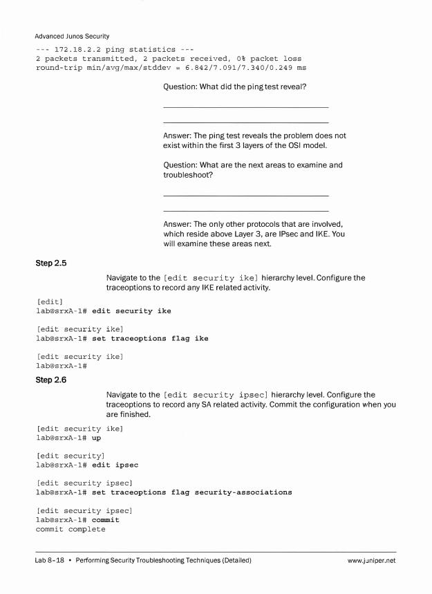
Advanced Junos Security
--- 172.18.2.2 ping statistics ---2 packets transmitted, 2 packets received, 0% packet loss round-trip min/avg/max/stddev ; 6.842/7.091/7.340/0.249 ms
Step 2.5
Question: What did the ping test reveal?
Answer: The ping test reveals the problem does not
exist within the first 3 layers of the OSI model.
Question: What are the next areas to examine and
troubleshoot?
Answer: The only other protocols that are involved,
which reside above Layer 3, are IPsec and IKE. You
will examine these areas next.
Navigate to the [edit security ike] hierarchy level. Configure the
traceoptions to record any IKE related activity.
[edit] lab@srxA-1# edit security ike
[edit security ike] lab@srxA-1# set traceoptions flag ike
[edit security ike] lab@srxA-1#
Step 2.6
Navigate to the [edit security ipsec] hierarchy level. Configure the
traceoptions to record any SA related activity. Commit the configuration when you
are finished.
[edit security ike] lab@srxA-1# up
[edit security] lab@srxA-1# edit ipsec
[edit security ipsec] lab@srxA-1# set traceoptions flag security-associations
[edit security ipsec] lab@srxA-1# commit
commit complete
Lab 8-18 • Performing Security Troubleshooting Techniques (Detailed) www.juniper.net
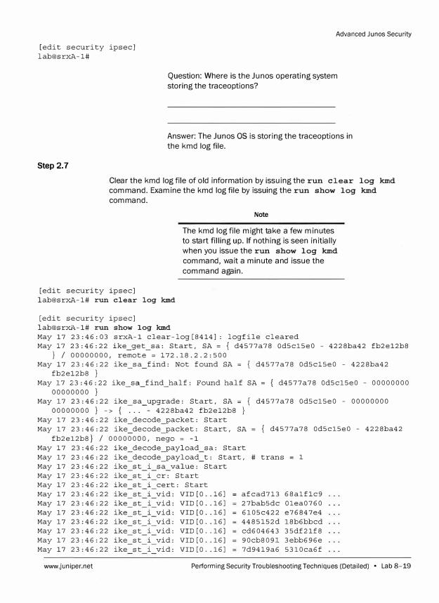
Advanced Junos Security
[edit security ipsec] lab@srxA-1#
Step 2.7
Question: Where is the Ju nos operating system
storing the traceoptions?
Answer: The Ju nos OS is storing the traceoptions in
the kmd log file.
Clear the kmd log file of old information by issuing the run clear log kmd
command. Examine the kmd log file by issuing the run show log kmd
command.
[edit security ipsec] lab@srxA-1# run clear log kmd
[edit security ipsec] lab@srxA-1# run show log kmd
Note
The kmd log file might take a few minutes
to start filling up. If nothing is seen initially
when you issue the run show log kmd
command, wait a minute and issue the
command again.
May 17 23:46:03 srxA-1 clear-log[8414]: logfile cleared May 17 23:46:22 ike_get_sa: Start, SA = { d4577a78 Od5c15e0 - 4228ba42 fb2e12b8
} I 00000000, remote = 172.18.2.2:500 May 17 23:46:22 ike sa find: Not found SA = { d4577a78 Od5c15e0 - 4228ba42
fb2el2b8 } - -May 17 23:46:22 ike sa find half: Found half SA = { d4577a78 Od5c15e0 - 00000000
00000000 } - - -May 17 23:46:22 ike sa upgrade: Start, SA = { d4577a78 Od5c15e0 - 00000000
00000000 } -> { �- .-- 4228ba42 fb2e12b8 } May 17 23:46:22 ike_decode_packet: Start May 17 23:46:22 ike_decode_packet: Start, SA { d4577a78 Od5c15e0 - 4228ba42
fb2e12b8} I 00000000, nego = -1 May 17 23:46:22 ike_decode_payload_sa: Start May 17 23:46:22 ike_decode_payload_t: Start, # trans 1 May 17 23:46:22 ike st i sa value: Start May 17 23:46:22 ike
-
st May 17 23:46:22 ike st
-
May 17 23:46:22 ike -
st May 17 23:46:22 ike
-
st May 17 23:46:22 ike
-
st May 17 23:46:22 ike st
-
May 17 23:46:22 ike st May 17 23:46:22 ike st
-
May 17 23:46:22 ike st
www.juniper.net
i er: Start i cert: Start
- -
i vid: i vid: i vid: i vid: i vid: i vid: i vid:
VID [O .. 16] VID [O .. 16] VID [O .. 16] VID [O .. 16] VID [O .. 16] VID [O .. 16] VID [O .. 16]
afcad713 68alflc9 27bab5dc Olea0760 6105c422 e76847e4 4485152d 18b6bbcd cd604643 35df21f8 90cb809l 3ebb696e 7d9419a6 5310ca6f
Performing Security Troubleshooting Techniques (Detailed) . Lab 8-19

Advanced Junes Security
May 17 23:46:22 ike st May 17 23:46:22 ike st May 17 23:46:22 ike
-
st May 17 23:46:22 ike st
i vid: VID (0 .. 16] i vid: VID (0 .. 28]
_i_private: Start 0 ke: Start
4al3lc81 07035845 69936922 874lc6d4
May 17 23:46:22 ike st o nonce: Start May 17 23:46:22 ike_policy_reply_isakmp_nonce_data_len: Start May 17 23:46:22 ike_st_o_private: Start May 17 23:46:22 ike_policy_reply_private_payload_out: Start May 17 23:46:22 ike_policy_reply_private_payload_out: Start May 17 23:46:22 ike_policy_reply_private_payload_out: Start May 17 23:46:22 ike_encode_packet: Start, SA = { Oxd4577a78 Od5cl5e0 - 4228ba42
fb2el2b8 } I 00000000, nego = -1 May 17 23:46:22 ike_send_packet: Start, send SA = { d4577a78 Od5cl5e0 - 4228ba42
fb2el2b8}, nego = -1, dst = 172.18.2.2:500, routing table id = O May 17 23:46:22 ikev2_packet_allocate: Allocated packet bdOcOO from freelist May 17 23:46:22 ike_sa_find: Found SA = { d4577a78 Od5cl5e0 - 4228ba42 fb2el2b8
} May 17 23:46:22 ikev2_packet_vl_start: Passing IKE vl.O packet to IKEvl library May 17 23:46:22 ike_get_sa: Start, SA = { d4577a78 Od5cl5e0 - 4228ba42 fb2el2b8
} I 00000000, remote = 172.18.2.2:500 May 17 23:46:22 ike sa find: Found SA = { d4577a78 Od5cl5e0 - 4228ba42 fb2el2b8
}
Step 2.8
Question: From the previous output can you determine the problem?
Answer: Although the answer lies somewhere in the output, the overwhelming amount of data makes it difficult to find.
Question: What are some match conditions that you can use to filter the output, but still obtain the necessary information?
Answer: Some match conditions that might help are: ike, initiator, and responder.
Filter the kmd logs by issuing the run show log kmd I match ike command.
[edit security ipsec] lab@srxA-1# run show log kmd I match ike
May 17 23:46:22 ike decode packet: Start, SA { d4577a78 Od5cl5e0 - 4228ba42 fb2el2b8} / 00000000, n;go = -1
May 17 23:46:22 ike_decode_payload_sa: Start
Lab 8-20 • Performing Security Troubleshooting Techniques (Detailed) www.juniper.net
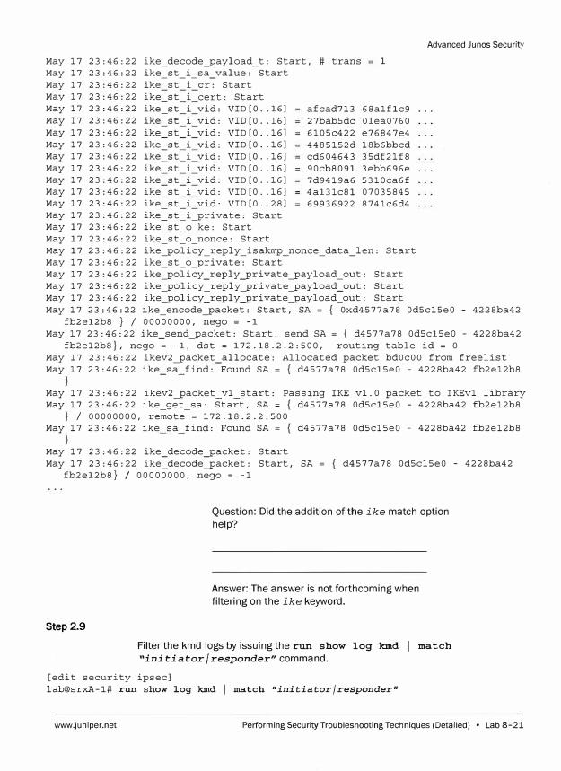
May 17 23:46:22 ike_decode_payload_t: Start, # trans 1 May 17 23:46:22 ike_st_i_sa_value: Start May 17 23:46:22 ike st i er: Start May 17 23:46:22 May 17 23:46:22 May 17 23:46:22 May 17 23:46:22 May 17 23:46:22 May 17 23:46:22 May 17 23:46:22 May 17 23:46:22 May 17 23:46:22 May 17 23:46:22 May 17 23:46:22 May 17 23:46:22
ike ike ike ike ike ike ike ike ike ike ike ike
st -
st -
st st st
-
st -
st st st st
-
st -
st
i cert: Start i vid: VID [O .. 16] i vid: VID [O .. 16] i vid: VID [O .. 16] i vid: VID [O .. 16] i vid: VID [O .. 16] i vid: VID [O .. 16] i vid: VID [O .. 16] i vid: VID [O .. 16] i vid: VID [O .. 28]
_i_private: Start o ke: Start
May 17 23:46:22 ike_st_o_nonce: Start
afcad713 68alflc9 27bab5dc Olea0760 6105c422 e76847e4 4485152d 18b6bbcd cd604643 35df21f8 90cb8091 3ebb696e 7d9419a6 5310ca6f 4a13lc81 07035845 69936922 874lc6d4
May 17 23:46:22 ike_policy_reply_isakmp_nonce_data_len: Start May 17 23:46:22 ike_st_o_private: Start May 17 23:46:22 ike_policy_reply_private_payload_out: Start May 17 23:46:22 ike_policy_reply_private_payload_out: Start May 17 23:46:22 ike_policy_reply_private_payload_out: Start
Advanced Junes Security
May 17 23:46:22 ike_encode_packet: Start, SA = { Oxd4577a78 Od5c15e0 - 4228ba42 fb2e12b8 } I 00000000, nego = -1
May 17 23:46:22 ike_send_packet: Start, send SA = { d4577a78 Od5c15e0 - 4228ba42 fb2e12b8}, nego = -1, dst = 172.18.2.2:500, routing table id = O
May 17 23:46:22 ikev2_packet_allocate: Allocated packet bdOcOO from freelist May 17 23:46:22 ike_sa_find: Found SA = { d4577a78 Od5c15e0 - 4228ba42 fb2e12b8
May 17 23:46:22 ikev2_packet_vl_start: Passing IKE vl.O packet to IKEvl library May 17 23:46:22 ike_get_sa: Start, SA = { d4577a78 Od5c15e0 - 4228ba42 fb2e12b8
} I 00000000, remote = 172.18.2.2:500 May 17 23:46:22 ike sa find: Found SA = { d4577a78 Od5c15e0 - 4228ba42 fb2e12b8
} May 17 23:46:22 ike_decode_packet: Start May 17 23:46:22 ike_decode_packet: Start, SA
fb2e12b8} / 00000000, nego = -1 { d4577a78 Od5c15e0 - 4228ba42
Step 2.9
Question: Did the addition of the ike match option help?
Answer: The answer is not forthcoming when filtering on the ike keyword.
Filter the kmd logs by issuing the run show log kmd I match
"initiator/ responder" command.
[edit security ipsec] lab@srxA-1# run show log kmd I match "initiator/responder"
www.juniper.net Performing Security Troubleshooting Techniques (Detailed) • Lab 8-21
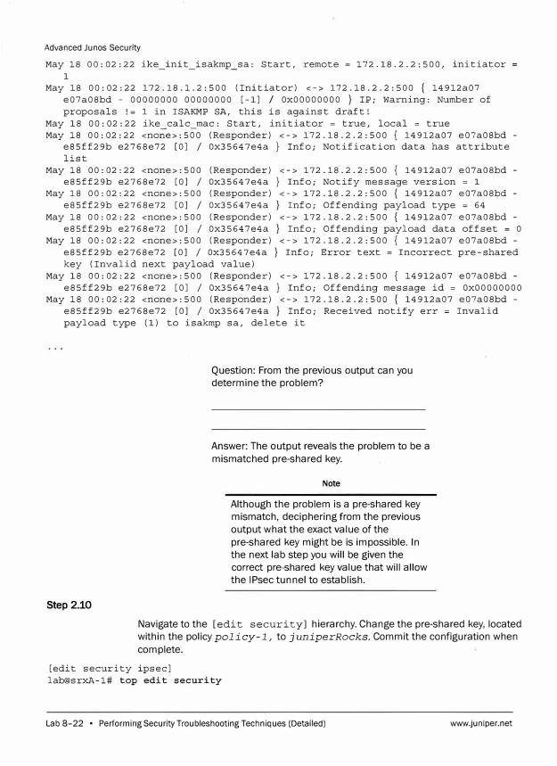
Advanced Junos Security
May 18 00:02:22 ike_init_isakmp_sa: Start, remote = 172.18.2.2:500, initiator 1
May 18 00:02:22 172.18.1.2:500 (Initiator) <-> 172.18.2.2:500 { 14912a07 e07a08bd - 00000000 00000000 [-lJ / OxOOOOOOOO } IP; Warning: Number of proposals != 1 in ISAKMP SA, this is against draft!
May 18 00:02:22 ike calc mac: Start, initiator = true, local = true May 18 00:02:22 <no�e>:500 (Responder) <-> 172.18.2.2:500 { 14912a07 e07a08bd -
e85ff29b e2768e72 [OJ I Ox35647e4a} Info; Notification data has attribute list
May 18 00:02:22 <none>:500 (Responder) <-> 172.18.2.2:500 { 14912a07 e07a08bd -e85ff29b e2768e72 [OJ I Ox35647e4a} Info; Notify message version = 1
May 18 00:02:22 <none>:500 (Responder) <-> 172.18.2.2:500 { 14912a07 e07a08bd -e85ff29b e2768e72 [OJ I Ox35647e4a} Info; Offending payload type = 64
May 18 00:02:22 <none>:500 (Responder) <-> 172.18.2.2:500 { 14912a07 e07a08bd -e85ff29b e2768e72 [OJ I Ox35647e4a} Info; Offending payload data offset = O
May 18 00:02:22 <none>:500 (Responder) <-> 172.18.2.2:500 { 14912a07 e07a08bd -e85ff29b e2768e72 [OJ I Ox35647e4a} Info; Error text = Incorrect pre-shared key (Invalid next payload value)
May 18 00:02:22 <none>:500 (Responder) <-> 172.18.2.2:500 { 14912a07 e07a08bd -e85ff29b e2768e72 [OJ I Ox35647e4a} Info; Offending message id = OxOOOOOOOO
May 18 00:02:22 <none>:500 (Responder) <-> 172.18.2.2:50D { 14912a07 e07a08bd -e85ff29b e2768e72 [OJ I Ox35647e4a} Info; Received notify err = Invalid payload type (1) to isakmp sa, delete it
Step 2.10
Question: From the previous output can you determine the problem?
Answer: The output reveals the problem to be a mismatched pre-shared key.
Note
Although the problem is a pre-shared key mismatch, deciphering from the previous output what the exact value of the pre-shared key might be is impossible. In the next lab step you will be given the correct pre-shared key value that will allow the IPsec tunnel to establish.
Navigate to the [edit securi tyJ hierarchy. Change the pre-shared key, located within the policy policy-1, to juniperRocks. Commit the configuration when complete.
[edit security ipsecJ lab@srxA-1# top edit security
Lab 8-22 • Performing Security Troubleshooting Techniques (Detailed) www.juniper.net
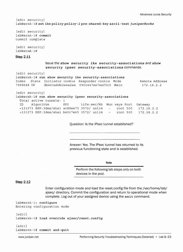
Advanced Ju nos Security
[edit security]
lab@srxA-1# set ike policy policy-I pre-shared-key ascii-text juniperRocks
[edit security] lab@srxA-1# commit commit complete
[edit security] lab@srxi'>.-1#
Step 2.11
Issue the show security ike security-associations and show
security ipsec security-associations commands.
[edit security] lab@srxA-1# run show security ike security-associations Index State Initiator cookie Responder cookie Mode 7999688 UP db463a8d62e4a2ee 0901447ee7eef5c0 Main
[edit security] lab@srxA-1# run show security ipsec security-associations
Total active tunnels: 1
ID Algorithm SPI Life:sec/kb <131073 ESP:3des/shal ac88ee70 3572/ unlim
>131073 ESP:3des/shal b40c7e65 3572/ unlim
Mon vsys Port root 500
root 500
Question: Is the IPsec tunnel established?
Remote Address 172.18. 2.2
Gateway 172.18.2.2
172.18.2.2
Answer: Yes. The IPsec tunnel has returned to its
previous functioning state and is established.
Step2.12
Note
Perform the following lab steps only on both
devices in the pod.
Enter configuration mode and load the reset.config file from the /var/home/lab/
ajsec/ directory. Commit the configuration and return to operational mode when
complete. Log out of your assigned device using the exit command.
lab@srxA-1> configure Entering configuration mode
[edit] lab@srxA-1# load override ajsec/reset.config
[edit] lab@srxA-1# commit and-quit
www.juniper.net Performing Security Troubleshooting Techniques (Detailed) • Lab 8-23
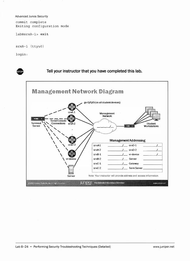
Advanced Junos Security
commit complete
Exiting configuration mode
lab@srxA-1> exit
srxA-1 (ttyuO)
login:
Tell your instructor that you have completed this lab.
Management Network Diagram
ge-0/0/0(on all studentdevices)
Management Addressing
srxA-1 srxD-1
srxA-2 srxD-2
srxB-1 vr.<fevice
srxB-2 Server
\ -
'E1 srxC-1 _ Gateway
srxC-2 Term Server
-i_i
-Iii ii
Server Note: Your instructor will provide address and access information.
Lab 8-24 • Performing Security Troubleshooting Techniques (Detailed) www.juniper.net
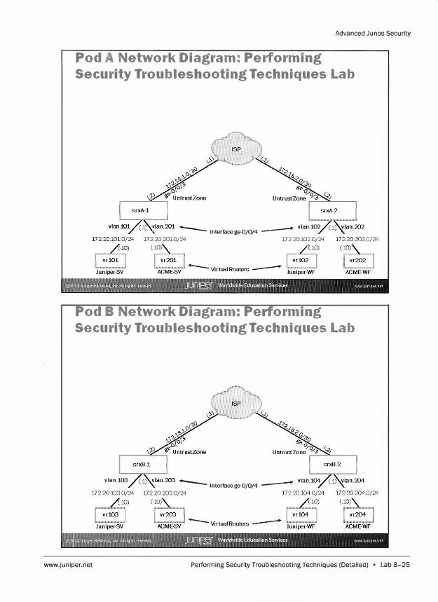
Advanced Ju nos Security
Pod A Network Diagram: Performing
Security Troubleshooting Techniques Lab
--- lnterfacege-0/0/4 --172.20.2010/24 17220 1020/24
(.� (.�
Pod B Network Diagram: Performing
Security Troubleshooting Techniques Lab
vlan.103
www.juniper.net
--- lnterfacege-0/0/4 -----� 172.20.2030/24
(.10)
Performing Security Troubleshooting Techniques (Detailed) • Lab 8-25
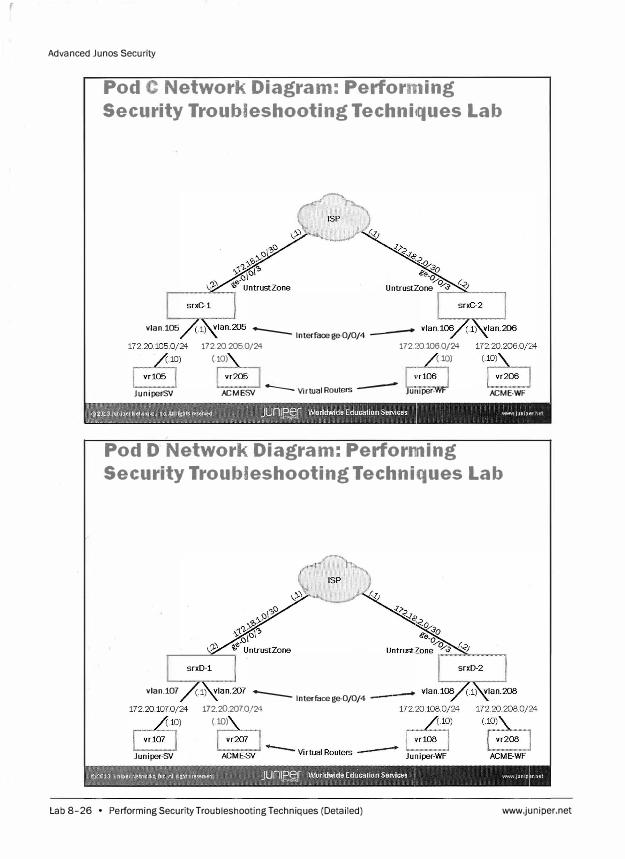
Advanced Junos Security
Pod C Network Diagram: Perforn1ing
Security Troubleshooting Techniicwues Lab
vlan.105 -- lnterfacege-0/0/4 --
172.20.205.0/24 172.20.106.0/24 (.10) (.10)
Juniper-SY ACME-SV ......_ Virtual Routers -- Juniper-WF ACME-WF
Pod D Network Diagram: Perfor11ning
Security Troubleshooting Techniques Lab
vlan.107 -- lnterfacege-0/0/4 -�----
172 20 2070/24 (.10)
Lab 8-26 • Performing Security Troubleshooting Techniques (Detailed) www.juniper.net