A cyclic hydraulic jacking test to determine the in situ stress normal to a fracture
17
Pergamon hf. J. Rock Mech. Min. Sci. & Geomech. Abstr. Vol. 33, No. 7, pp. 695-111, 1996 PIk SO148-9062(96)00013-7 Copyright 0 1996 Elsevier Science Ltd Printed in Great Britain. All rights reserved 0148-9062196 $15.00 i- 0.00 A clic Hydraulic Jackin the zh situ Stress Normal t J. RUTQVISTt$ 0. STEPHANSONt Hydraulic fracturing and cyclic hydraulic jacking (step -pressure) tests were used to determine the virgin stress normal to six natural joints in granitic rocks. A numerical model was used to analyse the coupled problem of ~~id~ow and rock/fracture deformation during the field tests. Fracture closure and virgin normal stress was determined from the zero-Jaw pressure in a well press- ure-well JEow diagram. The cyclic hydraulic jacking tests gave a zero-$0~ pressure in close agreement with both the shut-in pressure and the weight of the overburden rock for four out of six tested joints. For the two remaining joints the virgin normal stress could be estimated by a &ear extrapolation to zero-flow rate. The zero-pow pressure is clearly defined and is insensitive to the transmissivity and non-linear normal stiffness of the $racture near the wellbore. Cyclic hydraulic jacking is therefore an alternative to traditional shut-in analysis when shut -in pressure is d@cult to determine. Copyright 0 1996 Elsevier Science Ltd INTRODUCTION Hydro-fracturing is a common method for in situ stress measurements [l]. The stress rate is assessed from the fluid pressure and flow rate records during water injec- tion from a wellbore into induced fractures or natural joints. In classical hydro-fracturing stress measurements, a fracture is induced radially and in a direction parallel to the borehole axis. In such a case, the in situ stresses are related to the fluid pressure against the borehole wall required to initiate and reopen the fracture. Natural joints, on the other hand, frequently intersect a borehole transversely. In this case the in situ stress normal to the joint plane is related to the fluid pressure inside the joint plane required to open or close the joint. The opening and closure of the joints markedly change the well pressure and well flow response during hydraulic testing. The change in response may be distinct and the in- terpretation of the fluid pressure and flow rate records are straightforward. However, in jointed rock masses where the hydraulically tested fracture is connected to other conducting joints, the pressure-flow response may not be distinct and the test results are difficult to interpret. The interpretation of the hydro-fracturing tDivision of Engineering Geology, Department of Civil and Environ- mental Engineering, Royal Institute of Technology, S-100 44 Stockholm, Sweden. $Author to whom correspondence should be addressed at: Earth Sciences Division, Lawrence Berkeley Lab, 1 Cyclotron Road, Berkeley, CA 94720, U.S.A. data in such a case may be su~jcct~ve, and different hydraulic testing methods and interpretative techniques have frequently resulted in different estimates of the in situ stresses 12-51. One reason for this discrepancy may be that the results are affected by the contacts between asperities of rough fracture surfaces near the wellbore. During fluid injection into a rock fracture, the pressure- flow response may be dominated by the normal stiffness and the fracture aperture of the fracture plane near the wellbore [6]. This may mask the well pressure response to remote in situ stress and introduce errors in the interpretation of the test results. In the following sections the role of joint normal stiffness and effective stress on the hydromechanical response of a single joint will be discussed with special attention to hydraulic fracturing stress measurements. Thereafter, a cyclic hydraulic jacking (constant step- pressure) test is applied to determine the virgin stress normal to natural joints intersecting a borehole. The field tests are simulated by couple hydromechanical numerical modelling to demonstrate the a~p~~cabil~tyof in situ stress determination. Finally, recommendations are given on how a cyclic hydraulic jackin be conducted for a successful determination of virgin stress normal to a fracture plane. The study deals primarily with h~d~a~~ic testing of natural joints which intersect a borehole to the borehole axis [Fig. l(a)]. The te defined as a mechanical discontinuity with zero tensile strength. If a natural joint is ~~~ssurised, hydraulic 695
-
Upload
independent -
Category
Documents
-
view
3 -
download
0
Transcript of A cyclic hydraulic jacking test to determine the in situ stress normal to a fracture

Pergamon hf. J. Rock Mech. Min. Sci. & Geomech. Abstr. Vol. 33, No. 7, pp. 695-111, 1996
PIk SO148-9062(96)00013-7 Copyright 0 1996 Elsevier Science Ltd
Printed in Great Britain. All rights reserved 0148-9062196 $15.00 i- 0.00
A clic Hydraulic Jackin the zh situ Stress Normal t J. RUTQVISTt$ 0. STEPHANSONt
Hydraulic fracturing and cyclic hydraulic jacking (step -pressure) tests were used to determine the virgin stress normal to six natural joints in granitic rocks. A numerical model was used to analyse the coupled problem of ~~id~ow and rock/fracture deformation during the field tests. Fracture closure and virgin normal stress was determined from the zero-Jaw pressure in a well press- ure-well JEow diagram. The cyclic hydraulic jacking tests gave a zero-$0~ pressure in close agreement with both the shut-in pressure and the weight of the overburden rock for four out of six tested joints. For the two remaining joints the virgin normal stress could be estimated by a &ear extrapolation to zero-flow rate. The zero-pow pressure is clearly defined and is insensitive to the transmissivity and non-linear normal stiffness of the $racture near the wellbore. Cyclic hydraulic jacking is therefore an alternative to traditional shut-in analysis when shut -in pressure is d@cult to determine. Copyright 0 1996 Elsevier Science Ltd
INTRODUCTION
Hydro-fracturing is a common method for in situ stress measurements [l]. The stress rate is assessed from the fluid pressure and flow rate records during water injec- tion from a wellbore into induced fractures or natural joints. In classical hydro-fracturing stress measurements, a fracture is induced radially and in a direction parallel to the borehole axis. In such a case, the in situ stresses are related to the fluid pressure against the borehole wall required to initiate and reopen the fracture. Natural joints, on the other hand, frequently intersect a borehole transversely. In this case the in situ stress normal to the joint plane is related to the fluid pressure inside the joint plane required to open or close the joint. The opening and closure of the joints markedly change the well pressure and well flow response during hydraulic testing. The change in response may be distinct and the in- terpretation of the fluid pressure and flow rate records are straightforward. However, in jointed rock masses where the hydraulically tested fracture is connected to other conducting joints, the pressure-flow response may not be distinct and the test results are difficult to interpret. The interpretation of the hydro-fracturing
tDivision of Engineering Geology, Department of Civil and Environ- mental Engineering, Royal Institute of Technology, S-100 44 Stockholm, Sweden.
$Author to whom correspondence should be addressed at: Earth Sciences Division, Lawrence Berkeley Lab, 1 Cyclotron Road, Berkeley, CA 94720, U.S.A.
data in such a case may be su~jcct~ve, and different hydraulic testing methods and interpretative techniques have frequently resulted in different estimates of the in situ stresses 12-51. One reason for this discrepancy may be that the results are affected by the contacts between asperities of rough fracture surfaces near the wellbore. During fluid injection into a rock fracture, the pressure- flow response may be dominated by the normal stiffness and the fracture aperture of the fracture plane near the wellbore [6]. This may mask the well pressure response to remote in situ stress and introduce errors in the interpretation of the test results.
In the following sections the role of joint normal stiffness and effective stress on the hydromechanical response of a single joint will be discussed with special attention to hydraulic fracturing stress measurements. Thereafter, a cyclic hydraulic jacking (constant step- pressure) test is applied to determine the virgin stress normal to natural joints intersecting a borehole. The field tests are simulated by couple hydromechanical numerical modelling to demonstrate the a~p~~cabil~ty of in situ stress determination. Finally, recommendations are given on how a cyclic hydraulic jackin be conducted for a successful determination of virgin stress normal to a fracture plane.
The study deals primarily with h~d~a~~ic testing of natural joints which intersect a borehole to the borehole axis [Fig. l(a)]. The te defined as a mechanical discontinuity with zero tensile strength. If a natural joint is ~~~ssurised, hydraulic
695

696 RUTQVIST and STEPHANSSON: CYCLIC HYDRAULIC JACKING TEST
fracturing may take place when healed parts of the joint plane are broken and two fracture surfaces are created. A hydraulic fracture is initiated and propagated along the weakness plane of the natural joint. In this study, the hydraulic fracture is assumed to be shaped like a circular disc with the borehole-fracture intersection, fracture plane, fracture surfaces and fracture periphery defined according to Fig. 1. Normal deformation of the fracture is caused by the relative displacements of the fracture surfaces in a direction normal to the fracture plane. Opening and tensile stress are defined as positive quan- tities. The hydraulic fracture may be intersected by hydraulic conducting natural joints where injected fluid can leak-off.
INCOMPLETE CLOSURE AND EFFECTIVE STRESSES IN SINGLE FRACTURES
Traditionally, in hydro-fracturing stress measure- ments, a fracture plane is considered as either open or closed. A fracture is considered open when the two opposing fracture surfaces are apart so that water can flow through it. A closed fracture is frequently defined as when there is no separation of the two fracture
(4
surfaces and no water can be conducted. However; for rock fractures, it is known that they do not close completely even at very high compressive normal stress due to the roughness of the two fracture surfaces [7]. This behaviour is frequently termed incomplete closure and may affect the interpretation of hydraulic fracturing stress measurements data.
In this study the fracture planes are considered to be open or completely open [Fig. l(b)]. For an open fracture, compressive stresses may be transferred across the fracture plane via contacts of surface asperities and fluid flow can take place through interconnected voids between the contact points. A fracture plane is com- pletely open when there is no surface contact and no stress can be transferred across the fracture plane [Fig. l(b)]. A completely closed fracture is defined as when the fracture plane is compressed so that it is mechanically or hydraulically indistinguishable from the surrounding rock material.
It is well known from laboratory experiments that rock fractures close gradually as a function of the applied load normal to the fracture plane due to the deformation of asperity contacts between the two frac- ture surfaces. The normal stress-normal displacement
/
Original joint plane
intersection
(b) Completely open Open or incompletely closed Completely closed
~ Mechanically and hydraulically I indistinguishable from rock matrix
Fig. 1. Geometry and nomenclature at hydraulic fracturing of a natural joint in a vertical borehole. (a) Fracture in the joint plane and (b) detail of sealed fracture plane near the borehole.

RUTQVIST and STEPHANSSON: CYCLIC HYDRAULIC JACKING TEST 697
MAXIMUM CLOSURE, V, (pm)
0 - 50 -100 -150 -200 -250 -300 -3%O -400 a
z r -5.
d
%
2 -10
Li
z
a) Artificial fracture .,.I -‘,‘-..
8 z -15
-20
Fig. 2. Normal stress versus maximum closure of an ideal synthetic joint, and mated and unmated rock fracture of crystalline rock. Curves
of rock fractures are reproduced from Goodman [8].
behaviour of a fracture usually follows a hyperbolic relationship [S, 91. Figure 2 (curves b and c) presents the characteristic normal stress-normal displacement be- haviour of a fracture in crystalline rock. This is com- pared to the behaviour for an artificial fracture of two opposite, perfectly planar and smooth surfaces (curve a). For the artificial fracture, the two fracture surfaces are physically separated until the moment at which they make contact. This implies that the fracture opens distinctly when the compressive normal stress across the fracture plane becomes zero. This behaviour could be expected for a fracture induced by tensile splitting or hydraulic fracturing in a wellbore. However, curves b and c show that the mechanical closure is gradual even for an induced rock fracture and that very high normal stress is required to close the fracture completely. The curves b and c can be fitted to a hyperbolic relationship according to Goodman [g].
gn - 5ni -------=A ‘(Av < V,i) (1) Oai
where Av is the fracture normal ~~o~a.t~on under a given normal stress, fin, V, is the initial maximum closure, cni is the initial stress level, and A and t are constants. Maximum closure (V,) is the compressive normal deformation required to compress the fracture completely.
The hydromechanical behaviour of a single fracture in rock can be explained by a simple elastic one-dimen- sional model (Fig. 3). The purpose of the model is to visualise the effect of incomplete closure and effective stress on the pressure-flow response. In the model, an equivalent thickness (L) of the rock mass is compressed one-dimensionally as the fract plane opens. The one-dimensional model can e compared to a Boussineqs problem with a constant normal surface load on a semi-infinite region [lo]. y comparison with Boussineqs solution the thickness (L) of the one-dimen- sional model may be taken to be of the same order as the diameter of the fracture plane. This implies that the total stress across the fracture is:
E, AE By = Oni- 2L (2)
where ~T,i is the initial total normal stress and I&, is the deformation modulus of the rock mass. Equation (2) shows that the compressive total stress across the frac- ture will increase when the fracture opens.
In a deformable medium containing fluid, the mechan- ical deformation depends on the effective stresses. This implies that the normal stress (a,) in Fig. 2 and equation (1) must be replaced with the effective normal stress (0:) leading to the following relationship:
The constants A and t in equation (1) are here taken as unity. The fluid pressure (P) required to obtain a certain normal deformation (AU) can be der by includin equations (2) and (3) in the effective s s law, leadin to:
P = a:, - B, = O~i + v~“~~v - ai,i C -. ml
E;Av (4)
Fig. 3. One-dimensional elastic model of a single fracture plane in a rock mass.
RMMS 33/7--D
698 RUTQVIST and STEPHANSSON: CYCLIC HYDRAULIC JACKING TEST
25
a) Artificial fracture
d) Goodman’s joint model
b) Mated rock fracture
c) Unmated rock fracture
0 100 200 300 400
NORMAL DISPLACEMENT (w)
Fig. 4. Fluid pressure versus normal displacement for a single fracture plane in a rock mass. Curves a-c are calculated assuming the joint properties in Fig. 1. Curve d is calculated according to equation (4) with V, = 5.47 pm. Initial fluid pressure is 6 MPa and initial total
normal stress is 16 MPa.
Figure 4 presents the pressure versus normal displace- ment calculated according to equation (4) with the initial total normal stress, trni = - 16 MPa and initial fluid pressure, Pi = 6 MPa. This corresponds to the conditions at a depth of about 600 m in crystalline rocks. Curves a-c were obtained by determining the effective stress directly from Fig. 2 instead of using equation (3). Curve d was calculated according to equation (4) assuming an initial maximum closure (V,J of - 5.47 pm at an initial effective stress (aAi) of - 10 MPa. The thickness (L) of the surrounding rock slab is assumed to be 2 m.
One important conclusion from equation (4) and Fig. 4 is that the fracture will begin to open for an excess of fluid pressure even if the current fluid pressure is less than the total virgin stress normal to the fracture plane. Water flow can take place in the fracture through interconnected voids between the asperity contacts. The transmissivity (T) of the fracture depends on the size of the interconnected voids and is related to a hydraulic fracture aperture (e) which can be defined according to [ll]:
(5)
where pw and pw are the density and dynamic viscosity of the fluid. For rock fractures, the hydraulic aperture (e) is less than or equal to the physical separation between the two fracture surfaces due to the roughness and asperity contacts.
For hydraulic injection into a transverse fracture from a wellbore according to Fig. l(a), the flow rate can be derived from Darcy’s law and is [ll]:
Q=-T ) @w - he)
where h, and h, are hydraulic head at the wellbore and fracture periphery, respectively. In this situation, the area around the wellbore-fracture intersection can be regarded as a “bottle neck” dictating the flow rate. Therefore, a pressure-flow response during a hydraulic injection test will be characterised by the press- ure-transmissivity relationship of the fracture plane near the wellbore. We may assume that the hydraulic aperture is given by [12]:
e =e,+Ae =ei+fAv (7)
where ei is the initial hydraulic aperture at the initial stress level (a”i) and Av is the normal displacement according to Fig. 2. The factor fin equation (7) reflects the deviation from the ideal case of two parallel and smooth fracture surfaces.
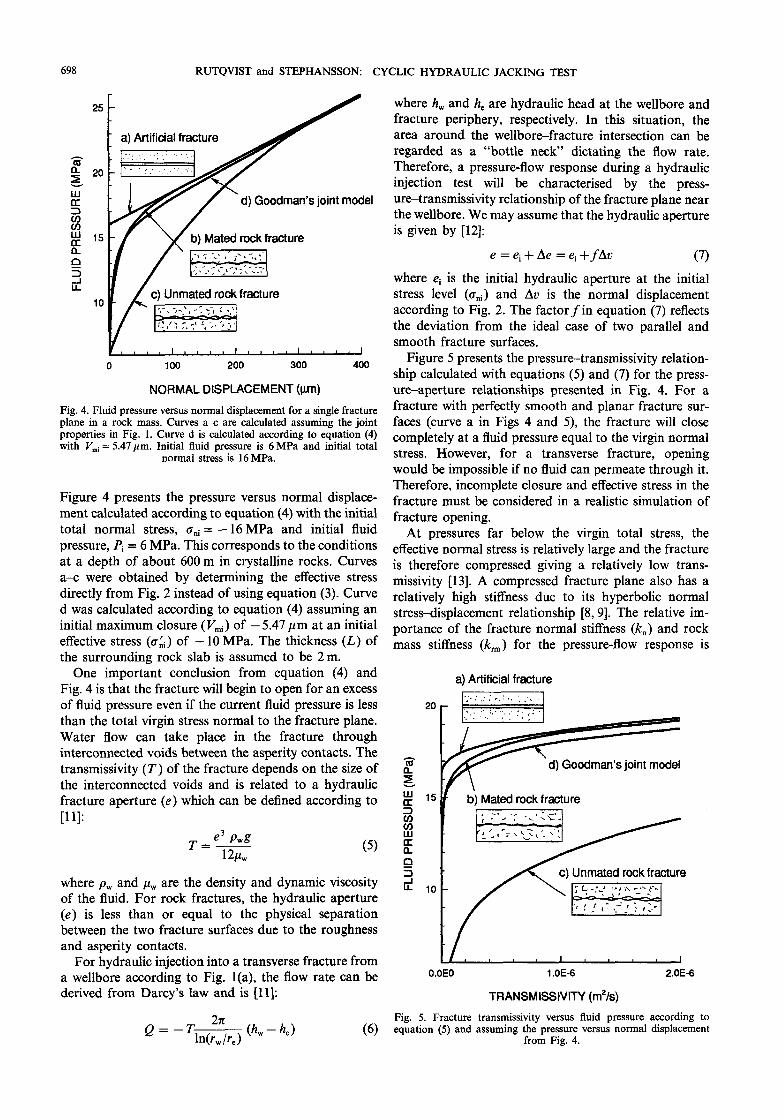
Figure 5 presents the pressure-transmissivity relation- ship calculated with equations (5) and (7) for the press- ure-aperture relationships presented in Fig. 4. For a fracture with perfectly smooth and planar fracture sur- faces (curve a in Figs 4 and 5), the fracture will close completely at a fluid pressure equal to the virgin normal stress. However, for a transverse fracture, opening would be impossible if no fluid can permeate through it. Therefore, incomplete closure and effective stress in the fracture must be considered in a realistic simulation of fracture opening.
At pressures far below the virgin total stress, the effective normal stress is relatively large and the fracture is therefore compressed giving a relatively low trans- missivity [13]. A compressed fracture plane also has a relatively high stiffness due to its hyperbolic normal stress-displacement relationship [8,9]. The relative im- portance of the fracture normal stiffness (k,) and rock mass stiffness (k,) for the pressure-flow response is
a) Artificial fracture
d) Goodman’s joint model
b) Mated rock fracture
c) Unmated rock fracture
O.OEO 1 .OE-6 2.OE-6
TRANSMISSIVITY (m’/s)
Fig. 5. Fracture transmissivity versus fluid pressure according to equation (5) and assuming the pressure versus normal displacement
from Fig. 4.

RUTQVIST and STEPHANSSON: CYCLIC HYDRAULIC JACKING TEST 699
investigated by taking the derivatives of equation (4) with respect to AU, leading to:
dp _ da:, I da” d(Av) d(Atr) d(Av)
5 Li vmi
= (Vmi - Au)~ +E” =k,+k,.
2L (8)
The force of the fluid pressure is applied at the interface between the rock and the fracture which implies that the springs of the rock mass and fracture in Fig. 3 work in parallel. For curve d in Figs 4 and 5 at P = Pi the fracture normal stiffness, k, = 2000 GPa/m and the rock mass stiffness, k, = 25 GPa/m according to equation (8). Hence, the rock mass stiffness is about 1% of the fracture normal stiffness which implies that the press- m-e-transmissivity behaviour is dominated by the nor- mal stiffness of the fracture. As the fluid pressure increases and the fracture opens, and Au is about 50 pm, k, decreases and reaches a value of the same order as k, . At this stage the deformability of the system is equally affected from the fracture stiffness and the rock mass stiffness. Ultimately, when the fracture is completely open, the fracture normal stiffness tends to zero and the deformability of the ambient rock mass dominates the pressure-transmissivity response. This implies that, for low injection flow rates the joint stiffness dominates the pressure-flow response, while at high flow rates the asperities may lose contact and the behaviour becomes independent of the fracture stiffness. This may be the case for high flow rate hydraulic injection such as well stimulations in petroleum engineering. However, for the relatively low flow rates applied in this study (maximum 5 litres per min) several of the asperities on the fracture surfaces never lose contact.
According to the model, the total normal stress across the fracture increases continuously as a result of com- pression of the surrounding rock mass. The current total normal stress across a fracture during the fluid injection is therefore equal to the virgin stress, plus the stress induced by the injection. The fluid pressure can therefore be increased beyond the virgin normal stress (a,,) with- out loss of contact between the two fracture surfaces (Fig. 4). The how rate increases gradually without a distinct response at a pressure equal to the virgin normal stress (Fig. 5). This may affect the interpretation of hydraulic fracturing stress measurement data which of- ten assumes a distinct opening or closure of the fracture at a pressure equal to the virgin normal stress. The consequences of incomplete fracture closure and effec- tive stress on different hydro-fracturing stress measure- ments techniques will be discussed in the next section.
IMPLICATIONS OF FRACTURE STIFFNESS FOR HYDRO-FRACTURING STRESS MEASUREMENT
METHODS
A number of test procedures has been suggested to evaluate the iri situ stresses from the fluid pressure and how records of hydraulic wellbore testing of single
fractures [l, 7, 14, 451. efore the testing, a wellbore is sealed-off with an inflated str The hydraulic testing then starts with a constant rate injection test to induce and propagate a fracture from the borehole wall. A fracture can be induced by increas- ing the well pressure to a stage where it is capable of breaking the rock in the wall of the wellbore. However, if a natural joint intersects the test section, the fracturing may take place along the weak plane of the natural joint. In this case the fracturing occurs when the fluid pressure in the fracture is large enough to break the healed parts of the joint and then propagate it. After fracture propa- gation, the in situ stresses are determined from a number of different hydraulic testing procedures [I, 7, 14, 151. The most common are shut-in analysis, hydraulic jack- ing (constant pressure step test or step-rate test) and constant flow rate test. Frequently, a combination of these procedures is used to gain better confidence in the test results.
Shut-in analysis
In a shut-in analysis, water is injected into the fracture at a constant flow rate for a few minutes until the fracture is completely opened and fractured. The pump- ing is then stopped and the hydraulic hose to the test interval is kept shut-in. Immediately after the shut-in, the well pressure will decay first very fast and thereafter much slower following the fracture closure. At the transition between fast and slow response, an instan- taneous shut-in pressure is defined and used to determine the virgin stress normal to the fracture plane [l-5, 7, 14-171. Numerical modelling of shut-in tests [18-201 shows that the fracture plane closes gradually after shut-in, starting at the fracture periphery when the Auid pressure in the fracture becomes less than the in situ normal stress.
In some cases the slope of the pressure-time curve changes gradually and no distinct shut-in pressure can be identified. Such behaviour occurs due to significant leakage from the fracture plane into the ambient rock [18]. This can be the case in sandstone of high per- meability [15] or in crystalline rock if the hydraulic fracture is connested to conducting natural joints 121. A number of methods has been suggested to identify the shut-in pressure from the pressure-time curve. These methods aim to identify when the fracture closes from the hydraulic response. Comparison of different methods to interpret a shut-in test indicates that discrepancies of a few MPa may exist depending on the interpretation method [3-51. It has also been questioned if the shut-in pressure is equal to the virgin normal stress, especially in tight rock formation where the shut-in pressure may represent the fracture propa ation pressure which may be considerably higher than he virgin stress normal to the fracture plane [21].
In the shut-in analysis the flow rate between the wellbore and the fracture may be 1 suggests that it is not affected by the normal sti transmissiv- ity near the wellbore. However, in massive hydraulic fracturing experiments, a “kink” in the pressure-time

700 RUTQVIST and STEPHANSSON: CYCLIC HYDRAULIC JACKING TEST
behaviour after shut-in has been observed, which has been explained as being caused by the asperities of the fracture surfaces making contact [22]. Boone et al. [20] modelled the influence of a propants in the fracture on the shut-in test results. They observed that a distinct “kink” in the pressure-time record appears when the fracture surfaces make contact via the propants. The results also indicated that the shut-in pressure in such a case would be higher than the virgin normal stress across the fracture. In their analysis, the propants was assumed to be infinitely stiff. In a rock fracture on the other hand, the stiffness is non-linear and will gradually increase as the fracture closes. This implies that a smooth response is expected. However, the pressure-time response may still be disturbed by the non-linear stiffness behaviour of the fracture plane near the wellbore.
Hydraulic jacking test A hydraulic jacking test is conducted as a number
of constant pressure injection tests. The well pressure is increased step-wise and the flow rate into the test section is monitored. At each step, the pressure should be kept constant until a steady flow is attained before proceeding to the next step. The results are plotted on a diagram as well pressure (P,) versus well flow (Q,). The P,-Q, curve is characterised by two dominant slopes. Traditionally, this is interpreted as that the fracture plane remains closed for pressures below the virgin normal stress. For pressure above the virgin normal stress, the fracture opens and the flow rate increases considerably [l]. A reopening pressure defined as the transition between the two slopes is frequently interpreted as the virgin stress normal to the fracture plane [l, 2,23,24]. In some cases, the transition between the two slopes is not well defined and the interpretation may be subjective [ 11.
Considering the effective stress and non-linear stiffness of a fracture plane, it is likely that the P,-Q, relationship of a hydraulic jacking test is non-linear. For a hydraulic jacking test conducted on a hydraulic fracture connected to conducting joints, the P,Q, relationship should be similar to the pressure-transmissjvity relationship pre- sented in Fig. 5. This indicates that small fracture opening takes place even at very low fluid pressures. Coupled hydromechanical modelling [6,25,26], where the effective stress and normal stiffness of the fracture was considered, has also proved that the fracture open- ing takes place continuously during hydraulic injection tests. Simulations of hydraulic jacking tests [6] demon- strate that a linear laminar region of the P,Q, diagram does not exist even for fluid pressures less than the in situ stress normal to the fracture plane. This indicates that a determination of the reopening pressure from a hy- draulic jacking test is an apparent reopening pressure reflecting a reduced fracture normal stiffness. This ap- parent reopening pressure may be approximately equal to the virgin normal stress. However, as demonstrated in Fig. 5, a larger discrepancy may be obtained for rough fractures where the normal stiffness is low.
Constant flow rate
A constant flow rate test is conducted to detect the pressure at which the fracture reopens (reopening press- ure) or closes (closing pressure). The reopening pressure is used in classical hydro-fracturing stress measurements of induced fractures to determine the maximum princi- pal stress [27]. The method assumes that the fracture opens as a result of the fluid pressure applied on the borehole wall. The reopening pressure may be deter- mined from the moment where the pressure-time curve deviates from a linear relationship [28]. The motivation for this assumption is that the pressure increases linearly with injected volume due to wellbore storage until the fracture opens and the pressure-time response becomes non-linear. However, the reopening pressure determined by this method is known to be dependent on the injection rate [7,29-311. The reason is that fluid permeates into the fracture through interconnected voids between con- tact points along the fracture surface. The opening can therefore take place as a result of increased internal pressure between the two fracture surfaces. It has there- fore been recommended to use a high flow rate of 10 litres per min [31] so that no flow has time to permeate into the fracture before the fracture is opened by the pressure against the wellbore wall. However, considering the effective stress and normal stiffness of the fracture, the reopening should take place gradually as a function of increased fluid pressure in the fracture. This has also been modelled numerically by Hardy and Asgain [26] using realistic material properties of a crystalline rock fracture. Their analysis indicates that the reopening starts at the wellbore as soon as the fluid pressure increases in the wellbore. The reopening was gradual even for fractures with very small initial aperture (1 pm). This confirms the previous observation that the re- opening pressure is apparent since the opening is gradual.
For a transverse fracture, the reopening must take place as a result of internal pressure between the two fracture surfaces. Here too, numerical modelling indi- cates that the reopening takes place gradually [6,25]. Therefore, the apparent reopening pressure at a constant flow rate injection on a transverse fracture in a borehole may not represent the virgin normal stress.
A slow pumping test is a constant flow rate injection test conducted at a low flow rate. After long-term pumping, the well pressure should stabilise at a uniform pressure needed to keep the fracture open [2,7]. This test is probably not sensitive to the incomplete closure and non-linear normal stiffness of the fracture plane near the wellbore. Instead, it reflects the conditions at the fracture periphery. This test is applied in low permeable rock where the leakage from the well and fracture into the ambient rock mass is small.
A constant rate back-flow test is commonly used in petroleum engineering to determine virgin stress normal to hydro-fractures instead of using shut-in analysis [21,32]. The pressure-time response is non-linear until the fracture has closed near the wellbore. Thereafter, the

RUTQVBT and STEPHANSSON: CYCLIC HYD ULIC JACKING TEST
TIME I 4 10 minutes
701
Fig. 6. A typical strip chart of well pressure and well flow versus time in a cyclic hydraulic jacking test.
pressure decay is a linear function of time. However, the fracture closure process may be smooth due to non-lin- ear stiffness of the fracture plane and a distinct closure pressure may thus be difficult to determine.
From the experience and test results of different hydraulic stress measurement techniques it seems that it is desired to evaluate the fracture closure pressure at the periphery of the fracture by a method which is not masked by the near wellbore effects. Hence, methods such as hydraulic jacking and constant flow rate which are based on flow between the wellbore and the fracture should be avoided. For these methods the non-linear fracture stiffness behaviour near the wellbore may dom- inate the pressure versus flow or pressure versus time response, and mask the true virgin normal stresses across the fracture. A shut-in test works well if the shut-in pressure can be defined and if it can be assured that it represents the closure pressure and not the fracture propagation pressure. To overcome these problems, cyclic hydraulic jacking is proposed as a method to determine the virgin stress normal to a fracture plane. A similar method has been used in Australia 1151 as an alternative when the conventional shut-in analysis may be difficult to interpret. The cyclic hydraulic jacking is applied in a series of field tests of horizontal natural joints in a borehole. Numerical modelling of cyclic hydraulic jacking is conducted by means of the ROCMAS code 1331 and results are validated against the field tests.
FIELD MEASUREMENTS AND INTERPRETATIONS DURING CYCLIC HYDRAULIC JACKING TEST
OF SINGLE FRACTURES Cyclic hydraulic jacking testing was conducted on six
sub-horizontal joints intersecting a 500-m deep vertical borehole at the Rock Mechanics Laboratory of LuleL University of Technology, Sweden. The sub-horizontal fractures are located at a depth of between 80 and 417 m in granitic rocks and the vertical stress is the least principal compressive stress [34]. The field equipment for testing is ermanently installed on a truck and is equipped with a multi-hose system which permits measurements down to a depth of 1000 m. The borehole diameter is 56 mm. The downhole equipment consists of a straddle packer with 0.65 m of packer separation and
a downhole pressure transducer. Flow from the draulic hose into the packer section can be shut off by a valve located immediately above the packer. The valve can be used to conduct fast pressure pulse tests for determination of hydraulic conducting aperture of a fracture intersecting the borehole.
Two hydraulic jacking tests were conducted on each fracture with one day of venting inbetween. Hydraulic pulse injection testing was performed prior to and after fracturing to determine the hydraulic aperture of the incomplete closed fracture plane at. virgin normal stress 1351. The pressure pulse test is conducted by adding a small amount of water to the section of the wellbore isolated by the straddle packer. well pressure first increases instantaneously until t valve above the packer is closed. Thereafter, the pressure decreases as the fluid is discharged from the wellbore into the fracture. The rate of the pressure decay is proportional to the hydraulic aperture of the fracture. From the pulse decay it is also possible to judge whether the fracture is hydraulically closed or connected to other conducting joints [35].
The cyclic hydraulic jacking tests were conducted in cycles with a step-wise increase of well ure (forward step-pressure) followed by step-wise ease of well pressure (backward step-pressure) [Fig. 61. The pressure is kept constant for a few minutes in each step until a steady flow has been attained. The forward step-pressure cycle is conducted up to a maximum flow rate of 5 litres per min. The subsequent backward step-pressure cycle is conducted until a back-flow is obtained from the frac- ture into the wellbore. The well pressure and well flow at each step are plotted on a P, versus Q,, diagram. Figure 7 presents the results of a complete hydraulic fracturing, cyclic hydraulic jacking test and pulse test on the joint located at a depth of 417 m.
Cyclic hydraulic jacking at 4 17 rn The first pulse test at 417 m was conducted on the
natural joint before the hydro-fracturi decay of the pulse test indicated that hydraulic aperture of 5 microns and was hydraulically isolated, i.e. it was not connected to conducting joints. The first cycle of the first hydr jacking was conducted to a maximum well pressure of 16.5 MPa (Fig. 7). At this stage, less than .5 litres had been

702 RUTQVIST and STEPHANSSON: CYCLIC HYDRAULIC JACKING TEST
injected into the joint. Following the first peak, the flow rate now increased and well pressure slowly decreased. This was interpreted as that the fluid pressure had exceeded the tensile strength of the healed joint plane and/or that the stress intensity at the joint periphery has exceeded the fracture toughness and the fracture was propagating outward from the borehole. The maximum pressure is termed break-up pressure, since it is the pressure required to break the healed parts of the joint plane and create a fracture. A second peak of pressure was attained at a flow rate of 2 litres per min, and again the pressure decreased and the flow increased again due to fracture propagation. The temporary halt in fracture propagation might be due to an intersecting conducting joint. At a flow rate of 4 litres per min a constant pressure was obtained again. This is interpreted as that the fracture is stable and the injected fluid is leaking from the hydro-fracture to interconnected joints. The well pressure was then reduced stepwise, keeping the pressure constant for about l-2 min in each step. The well flow also decreased, but a steady flow was obtained at each step. At a well pressure of below 11.5 MPa a back-flow from the fracture to the well was recorded. Hydraulic jacking was then continued with two additional cycles of forward and backward step-pressure, and was ended by a injection of 5 litres per min for 10 min and a conven- tional shut-in test. The fracture was then vented one day before a second pulse test and cyclic hydraulic jacking was conducted.
The second pulse test showed that the hydro-fracture increased the aperture of the joint plane from 5 to 12
Propagation . Intersecting joint
I, I I I I * I I I I I I t 8 II I I I I
0 1 2 3 4 5
Well flow, Q, (Vmin)
Fig. 7. Field measurement and interpretation during cyclic hydraulic jacking test on a single joint at a depth of 417 m in granitic rocks at
Lulel University of Technology.
microns near the wellbore. The pressure decay of the pulse test also confirmed that the fracture had propa- gated, but the aperture seemed to be smaller than 12 microns at a distance away from the borehole. For the second hydraulic jacking test, the P,-Q, curves were considerably lower than for the first hydraulic jacking test which is due to further fracture propagation. However, the zero-flow pressure, i.e. pressure at zero flow, was the same for the two tests.
Comparison of zero -Jaw pressure and shut -in pressure for six horizontal joints
Figure 8 presents the pressure-flow response of three step-pressure cycles on six sub-horizontal joints in the same vertical borehole. The results are from the second hydraulic jacking test which was conducted after the hydro-fracturing of the joints. The figures also include the break-up pressure (P,,) obtained at the first hydraulic fracturing. Table 1 compares the zero-flow pressure from the cyclic hydraulic jacking test and shut-in pressure from a shut-in test to the weight of the overburden rock. The shut-in pressure was obtained by the tangent inter- section method [36]. The third cycle shut-in pressure was determined after the first break-up of the joint by a conventional shut-in analysis with three pressurisation cycles. The final shut-in pressure was determined in a shut-in test performed after the hydraulic jacking test, i.e. after maximum fracture propagation. For four out of the six fractures, the zero-flow pressure agrees well with the final shut-in pressure and the general trend of a vertical stress equal to the weight of the overburden rock mass. The zero-flow pressures at 131 and 283 m are considerably lower than the weight of the overburden rock. From Fig. 8 it can be observed that the backward and forward step-pressure curves intersect at zero-flow rate for all tests except at 131 and 283 m. This indicates that the zero-flow pressure represents the virgin stress normal to the fracture plane if the forward and back- ward step-pressure curves intersect at zero-flow. This observation is verified by numerical modelling of the cyclic hydraulic jacking test with variation of virgin normal stress and boundary conditions at the fracture periphery.
NUMERICAL MODELLING OF THE CYCLIC HYDRAULIC JACKING TEST
The cyclic hydraulic jacking test and the possibility of obtaining the virgin stress normal to the fracture plane were examined by means of the coupled hydro- mechanical finite element program ROCMAS [33]. The program is based on Biot’s theory of consolidation and simulates coupled hydromechanical effects of disconti- nuities in an ambient homogeneous isotropic rock matrix.
Conceptual model In the development of the conceptual model of the test
environment of a joint intersecting a borehole in crys- talline rock, it has to be recognised that most of the

groundwater flow takes place in the discrete joints which do not close completely even at high stresses. Based on fracture mechanics, a hydraulic fracture should be ap- proximately radial after propagation. However, crys- talline rocks include natural joints and faults which will affect the mechanics of the fracture propagation [37,38]. The water flow will also be strongly affected by existing joints. This implies that if the hydraulic fracture inter- sects a joint, further propagation may be prevented. Especially if a set of joints or a fracture zone intersects, the leakage may be so large that fluid pressure becomes too low to propagate the fracture further. The fracture
RUTQVIST and STEPHANSSON: CYCLIC HYDRAULIC SACKING TEST 703
will propagate until the leakage knto the intersecting joints is equal to the injected flow rate, and the fracture becomes stable. The maximum radius of fracture propa- gation at a given flow rate depends on hydromechanical properties of both the hydraulic fracture and intersecting joints. Field studies of hydraulic fracturing [39,40] in crystalline rock with the same flow rate (- 5 litres/min) indicate that hydraulic fractures propagate only a few metres.
After break-up of the existing joint and further frac- ture propagation, a geometry as in Fig. 9(a) is reason- able. The fracture has propagated and intersected a
(4 14
13
12
g 11
- 10
WELL FLOW, Cl, (Vmin)
14
13
(b) 14
13
12 k
0 1 2 3 4 5
(4 I4 r 13
12
0 1 2 3 4 5
WELL FLOW, Q, (Vmin) 0 1 2 3 4 5
Fig. 8 (aA) See caprion overieaf

704 RUTQVIST and STEPHANSSON: CYCLIC HYDRAULIC JACKING TEST
(4
0 1 2 3 4 5
WELL FLOW, Q, (Vmin) WELL FLOW, Cl, (Vmin) Fig. 8. Field tests of cyclic hydraulic jacking on six sub-horizontal joints in granitic rocks located at a depth of: (a) 81 m,
(b) 131 m, (c) 257 m, (d) 283 m, (e) 357 m and (f) 417 m. Pb is the break-up pressure at the first pressurisation.
number of joints in which the main part of the injected the axis of the wellbore (Fig. 10). The top of the model fluid is leaked off. Figure 9(b) presents an equivalent is subjected to a vertical stress equal to the weight of the axisymmetric model of the assumed field test environ- overburden rock mass. The other three boundaries are ment with an equivalent boundary condition at an restricted to moving only parallel to the boundary equivalent radius. It is a reasonable model because the surfaces. The hydraulic boundary conditions are zero- flow is predominantly radial in the vicinity of the flow on the bottom and hydrostatic fluid pressure along wellbore [41]. A somewhat irregular shape of the outer the vertical and top boundary. The rock mass surround- boundary may not be very important for the flow out of ing the fracture is discretised into quadrilateral elements the well into the fracture. However, the equivalent radius with linear hydroelastic properties. The fracture itself is of the fracture influences the steady flow by means of the discretised into discontinuity elements with a non-linear hydraulic gradient [see equation (6)]. The diffusion relationship between effective normal stress and normal through the rock matrix is small, but cannot be disre- displacement according to equation (3). This implies that garded due to the large fracture surface area. The closure and effective stress inside the joint are properly analysis has therefore to consider both the leakage to the simulated. The fluid flow is assumed to be governed by rock matrix and to the intersecting joints. In the model, the cubic relationship between the hydraulic aperture leakage to the rock matrix is considered as flow in and the fracture transmissivity according to equation (5). porous media and leakage to intersecting joints is as- The current hydraulic aperture is calculated according to sumed to take place at the equivalent outer radius. equation (7) with the factor f equal to 1.
Finite element model The conceptual model is discretised into an axisym-
metric finite element model with an axis coinciding with
The leakage to intersecting joints is simulated by the hydraulic boundary condition at the equivalent radius according to Fig. 9(b). A constant pressure boundary condition (open periphery) can be applied if the
Table 1. Virgin stress normal horizontal joints from cyclic hydraulic jacking test, shut-in pressure analysis and theoretical value from weight of
overburden
Depth (m) 81
131 257 283 356 417
Zero-flow pressure (MPa)
2.2 2.8 6.0
5.2-5.6 9.5
11.5
Third cycle Final shut-in shut-in
pressure pressure (MPa) (MPa)
2.3 3.5 3.5 6.2 6.5 6.5 5.9 - 9.5 10.2
12.1 -
Overburden pressure 0=pgr @Pa)
2.2 3.5 6.8 7.5 9.5
11.0

RUTQVIST and STEPHANSSON: CYCLIC HYDRAULIC JACKING TEST 705
Fig. 9. Models of hydraulic injection into a hydraulic fracture: (4 conceptual model and (b) equivalent axisymmet~c model.
intersecting joints are highly conductive and can main- tain a constant pressure 1411. A zero-flow boundary condition (closed periphery) can be applied if no joint intersects the hydraulic fracture. In the field tests, the hydraulic condition at the fracture periphery may be something inbetween the two extreme cases of open and closed. Leakage of water to intersecting joints will occur at the fracture periphery, but the pressure at the intersecting joints may not be constant.
The influence of open or closed fracture periphery on the test results is studied by a simulation of a constant pressure injection test using the material parameters in Table 2. The material parameters were obtained from laboratory experiments and by a calibration of the numerical model to the field test results at a depth of 417 m, according to Rutqvist [42]. Three different hy- draulic conditions at a radius of 4.5 m are modelled: (a) the fracture is assumed to be finite and hydraulically isolated except for the leakage into the rock matrix, (b) the fracture intersects highly conductive joints that can maintain a constant pressure and (c) the fracture inter- sects joints in which leakage of water occurs, but the
e Borehole axis
!a) i 15 m +
Equivalent pressure boundary Pr at t-e
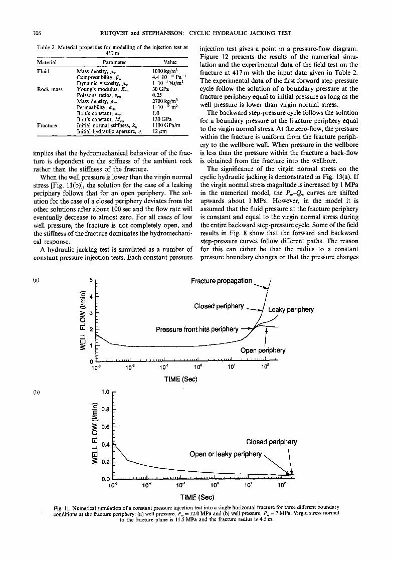
pressure may not be constant. Case c is modelled by assigning a high permeability to the ambient rock mass at the fracture periphery. Figure 11 presents the results of the simulations for a well pressure higher [Fig. 1 l(a)] and lower [Fig. 11(b)] than the virgin normal stress.
In all cases, the flow rate decreased initially as ex- pected for a non-deformable fracture according to the classic Jacob and Lohman solution for porous media [43]. However, when the fluid pressure has penetrated far enough into the fracture, the flow rate increases as a result of fracture opening. The solution for a given well pressure is identical in the three cases until the pressure front has reached the fracture periphery. Thereafter, the solutions deviate depending on the hydraulic conditions at the fracture periphery.
In the case of a high well pressure [Fig. 1 l(a)] and a closed or leaking fracture periphery, the fracture periphery increases and reaches a pressure re- quired to propagate the fracture further. At fracture propagation, the entire fracture plane from the borehole to the periphery is almost completely open This results in a low effective stress, and low normal stiffness, and
Fig. 10. Axisymmetric finite element model of the fracture rock mass system for simulation of fluid injection: (a) finite element model, (b) mechanical and hydraulic boundary conditions.
706 RUTQVIST and STEPHANSSON: CYCLIC HYDRAULIC JACKING TEST
Table 2. Material properties for modelling of the injection test at 417m
Material
Fluid
Rock mass
Fracture
Parameter Value
Mass density, pW 1000 kg/m3 Compressibility, 8, 4.4. IO-i0 Pa-’ Dynamic viscosity, pc, 1. 10e3 Ns/m* Young’s modulus, Em 30 GPa Poissons ratios, v, 0.25 Mass density, pnn 2700 kg/m3 Permeability, k, 1. lo-i9 m2 Boit’s constant, a,.,,, 1.0 Boit’s constant, M,,,, 130 GPa Initial normal stiffness, k, 1100 GPa/m Initial hydraulic aperture, e, 12 pm
implies that the hydromechanical behaviour of the frac- ture is dependent on the stiffness of the ambient rock rather than the stiffness of the fracture.
When the well pressure is lower than the virgin normal stress [Fig. 1 l(b)], the solution for the case of a leaking periphery follows that for an open periphery. The sol- ution for the case of a closed periphery deviates from the other solutions after about 100 set and the flow rate will eventually decrease to almost zero. For all cases of low well pressure, the fracture is not completely open, and the stiffness of the fracture dominates the hydromechani- cal response.
A hydraulic jacking test is simulated as a number of constant pressure injection tests. Each constant pressure
(4
(b)
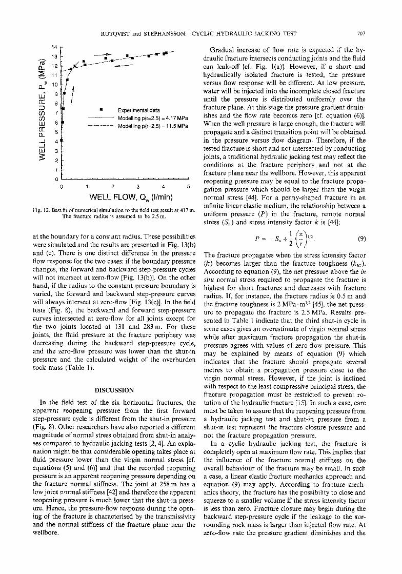
injection test gives a point in a pressure-flow diagram. Figure 12 presents the results of the numerical simu- lation and the experimental data of the field test on the fracture at 417 m with the input data given in Table 2. The experimental data of the first forward step-pressure cycle follow the solution of a boundary pressure at the fracture periphery equal to initial pressure as long as the well pressure is lower than virgin normal stress.
The backward step-pressure cycle follows the solution for a boundary pressure at the fracture periphery equal to the virgin normal stress. At the zero-flow, the pressure within the fracture is uniform from the fracture periph- ery to the wellbore wall. When pressure in the wellbore is less than the pressure within the fracture a back-flow is obtained from the fracture into the wellbore.
The significance of the virgin normal stress on the cyclic hydraulic jacking is demonstrated in Fig. 13(a). If the virgin normal stress magnitude is increased by 1 MPa in the numerical model, the P,-Q, curves are shifted upwards about 1 MPa. However, in the model it is assumed that the fluid pressure at the fracture periphery is constant and equal to the virgin normal stress during the entire backward step-pressure cycle. Some of the field results in Fig. 8 show that the forward and backward step-pressure curves follow different paths. The reason for this can either be that the radius to a constant pressure boundary changes or that the pressure changes
Fracture propagation -4
Open piriphery
TIME (Set)
1.0 -
g 0.8 - 1
g 0.6 ;
Closed periphery
Open or leaky periphery
TIME (Set)
Fig. 11. Numerical simulation of a constant pressure injection test into a single horizontal fracture for three different boundary conditions at the fracture periphery: (a) well pressure, P, = 12.0 MPa and (b) well pressure, P, = 7 MPa. Virgin stress normal
to the fracture plane is 11.5 MPa and the fracture radius is 4.5 m.
RUTQVIST and STEPHANSSON: CYCLIC HYD ULIC JACKING TEST 707
14
‘13
12
11
10
9
8
7
6
5
4
3
2
1
?? Experimental data
Modelling p(r=2.5) = 4.17 MPa
-..-..-..-’ Modelling p(k2.5) = 11.5 MPa
o~.“‘l”.““““““‘..” 0 1 2 3 4 5
ELL FLOW, Q, (Vmin)
Fig. 12. Best fit of numerical simulation to the field test result at 417 m. The fracture radius is assumed to be 2.5 m.
at the boundary for a constant radius. These possibilities were simulated and the results are presented in Fig. 13(b) and (c). There is one distinct difference in the pressure flow response for the two cases: if the boundary pressure changes, the forward and backward step-pressure cycles will not intersect at zero-flow [Fig. 13(b)]. On the other hand, if the radius to the constant pressure boundary is varied, the forward and backward step-pressure curves will always intersect at zero-flow [Fig. 13(c)]. In the field tests (Fig. g), the backward and forward step-pressure curves intersected at zero-flow for all joints except for the two joints located at 131 and 283 m. For these joints, the fluid pressure at the fracture periphery was decreasing during the backward step-pressure cycle, and the zero-flow pressure was lower than the shut-in pressure and the calculated weight of the overburden rock mass (Table 1).
DISCUSSION
In the field test of the six horizontal fractures, the apparent reopening pressure from the first forward step-pressure cycle is different from the shut-in pressure (Fig. 8). Other researchers have also reported a different magnitude of normal stress obtained from shut-in analy- ses compared to hydraulic jacking tests [2,4]. An expla- nation might be that considerable opening takes place at fluid pressure lower than the virgin normal stress [cf. equations (5) and (6)] and that the recorded reopening pressure is an apparent reopening pressure depending on the fracture normal stiffness. The joint at 258 m has a low joint normal stiffness [42] and therefore the apparent reopening pressure is much lower that the shut-in press- ure. Hence, the pressure-flow response during the open- ing of the fracture is characterised by the transmissivity and the normal stiffness of the fracture plane near the wellbore.
Gradual increase of flow rate is expected if the hy- draulic fracture intersects conducting joints and the fluid can leak-off [cf. Fig. l(a)]. However, if a short and hydraulically isolated fracture is tested, the pressure versus flow response will be different. At low pressure, water will be injected into the incomplete closed fracture until the pressure is distributed uniformly over the fracture plane. At this stage the pressure gra ishes and the flow rate becomes zero [cf. equation (6)]. When the well pressure is large enough, the fracture will propagate and a distinct transition point will be obtained in the pressure versus flow diagram. Therefore, if the tested fracture is short and not intersected by conducting joints, a traditional hydraulic jacking test may reflect the conditions at the fracture periphery and not at the fracture plane near the wellbore. However, this apparent reopening pressure may be equal to the fracture propa- gation pressure which should be larger than the virgin normal stress [44]. For a penny-shaped fracture in an infinite linear elastic medium, the relationship between a uniform pressure (P) in the fracture, remote normal stress (S,) and stress intensity factor k is [44]:
The fracture propagates when the stress intensity factor (k) becomes larger than the fracture toughness (k,,). According to equation (9) the net pressure above the in situ normal stress required to propagate the fracture is highest for short fractures and decreases with fracture radius. If, for instance, the fracture radius is 0.5 m and the fracture toughness is 2 MPa+m”’ ]45], the net press- ure to propagate the fracture is 2.5 MPa. esults pre- sented in Table 1 indicate that the third shut-in cycle in some cases gives an overestimate of virgin normal stress while after maximum fracture propagation the shut-in pressure agrees with values of zero-flow pressure. This may be explained by means of equation (9) which indicates that the fracture should propa metres to obtain a propagation pressure close to the virgin normal stress. However, if the joint is inclined with respect to the least compressive principal stress, the fracture propagation must be restricted to prevent ro- tation of the hydraulic fracture [15]. Xn such a case, care must be taken to assure that the reopening pressure from a hydraulic jacking test and shut-in pressure from a shut-in test represent the fracture closure pressure and not the fracture propagation pressure.
In a cyclic hydraulic jacking test, the fracture is completely open at maximum flow rate. This implies that the influence of the fracture normal stiffness on the overall behaviour of the fracture may be small. In such a case, a linear elastic frac nits approach and equation (9) may apply. to fracture mech- anics theory, the fracture has the possibility to close and squeeze to a smaller volume if the stress intensity factor is less than zero. Fracture closure may begin during the backward step-pressure cycle if the leakage to the sur- rounding rock mass is larger than injecte zero-flow rate the pressure gradient diminishes and the

708 RUTQVIST and STEPHANSSON: CYCLIC HYDRAULIC JACKING TEST
pressure becomes uniformly distributed in the fracture. A large part of the fracture plane may still be completely open and the fracture normal stiffness has little effect on the pressure-flow response. The zero-flow point should therefore be equal to the virgin normal stress according to equation (9).
During back-flow, the fracture will continue to squeeze to a smaller volume and shorter radius. For the subsequent forward step-pressure cycle, the fracture radius is shorter and the pressure-flow curve will follow
(4
~ Sv = 12.5 MPa
---- Sv=11.5MPa
a different path than for the backward step-pressure cycle [see Fig. 13(c)]. However, according to equation (9), the zero-flow point should still be the same since it is independent of the fracture radius.
Figure 14(a) illustrates the details of the pressure-flow response of a successful cyclic hydraulic jacking test where the forward and backward step-pressure curves intersect at zero-flow rate. The pressure-flow response depicted in Fig. 14(a) is similar to the behaviour from the field test at 417 m presented in Fig. 7. The dashed lines
04 14
13 L
_- , __--
/’ _ e_;z.-- ,_.._..:..I.---.~
_ :..--‘. _*_.e_.c--
- P,=4.17MPa ---- P, 10.5 MPa = _____ P,=ll.OMPa
WELL FLOW, Q, (Vmin) WELL FLOW, Q, (Vmin)
(cl
- r/2 = 1.25 m ---- r =2.5m - ..-..-..- 2r _5,0rn
WELL FLOW, Cl, (Vmin) Fig. 13. Sensitivity analysis of hydraulic jacking test on the horizontal fracture at 417 m. (a) Different virgin stress normal to the fracture, (b) different fluid pressure at the fracture periphery located at a radius of 2.5 m and (c) different radius to the
constant pressure of 11.5 MPa.

RLJTQVIST and STEPHANSSON: CYCLIC HYD WLIC JACKING TEST 709
WELL FLOW, Q,
P, = s, Intersection point
@I ,
WELL FLOW, Q,
Fig. 14. Details of the determination of the virgin normal stress from a cyclic hydraulic injection test into a transverse hydraulic fracture. (a) Test where the backward and forward step-pressure curves intersect at zero Bow rate and (b) test where the backward and forward step-press- ure curves do not intersect at zero-flow. Dashed lines are the solutions for different fracture radius and boundary pressures presented in Fig.
13(b) and (c).
in Fig. 14(a) are the solutions for different radii follow- ing the data presented in Fig. 13(c). In this case, the fluid pressure is kept equal to the virgin normal stress at the periphery of the fracture. The pulse test at 417 m, showed that the fracture aperture was smaller at a distance away from the wellbore. This may be inter- preted such as that the initial fracture aperture is smaller for the fracture propagated in the rock extending radi- ally outside the original joint plane. In this case, the pressure at the leading edge of fracture was not lost and the zero-flow pressure is equal to the virgin normal stress.
For the fractures at 131 and 283 m, the forward step-pressure and backward step-pressure curves do not intersect at zero-flow. The pressure-flow response in such a case is illustrated in Fig. 14(b). The dashed lines are the
numerical solutions for different press~rcs at the fracture periphery. The backward step-pressure curve follows the soluti& of a periphery pressure equal to the virgin normal stress when the flow rate is high I-Iowever, at low flow rates the pressure is lost and the experimental data drop to a solution of less b dary pressure. The subsequent forward step-pressure le follows a path of lower boundary pressure, but the boundary pressure increases again to the virgin normal stress at maximum flow. In this case, the pressure has changed at the fracture periphery and the zero-flow point is lower than the virgin normal stress. The boundary pressure at the leading edge may be lost if the fracture surfaces are in contact via asperities and the fluid is leaking to a highly conducting joint which intersects within the original joint plane near the wellbore. However, a fair approxi- mation of the virgin normal stress can be obtained from a zero-flow point obtained from a straight line connect- ing the intersection point and the point of maximum flow rate point [Fig. 14(b)]. For the fractures at 283 and 131 m, such interpretation of the test results gives a zero-flow point close to the shut-in press
The complete stress tensor can be deriv ing the stress normal to at least six fract directions according to Cornet and Valette [24]. Many of these fractures will be inclined to the principal stresses and will therefore take shear stress. When an inclined fracture is jacked open, the shear stress along the fracture becomes zero and the fracture becomes a prin- cipal sties’s plane. At the same time, during the fluid injection the stress normal to the fracture plane will increase due to the compression of the surrounding rot mass. This implies that the hydraulic jacking itse rotates and changes the local stress field which may affect the stress measurement. However, the closure pressure measured by zero-flow pressure in the cyclic hydraulic jacking test reflects the closure at the fracture periphery. This closure pressure is a measure of the normal component of the virgin stress field and should therefore not be a function of the locally induced stress.
Reopening of a pressurised fracture plane is gradual, and depends on the fracture normal stiffness and effec- tive stress inside the fracture near the wellbore. An apparent reopening pressure determined from a constant flow rate test or a hydraulic jacking test on a transverse fracture may therefore deviate from the virgin stress normal to the fracture plane. A cyclic test, on the other hand, can be used pressure of closure at the fracture peri an accurate estimate of the virgin stress normal to the fracture plane. The method is insensitive to effects QF fracture transmissivity and non-linear ~~~~1 stiffness of the fracture plane near the wellbore.
The jacking test should be conduct break-up and propagation of the fracture. It is rec- ommended to start the cyclic hydraulic jacking at a short fracture radius and then propagate the fracture further

710 RUTQVIST and STEPHANSSON: CYCLIC HYDRAULIC JACKING TEST
and thereafter conduct repeated cycles. If the cycles of Comprehensive Rock Engineering (Edited by Hudson J.),
the forward step-pressure and backward step-pressure pp. 81 l-837. Pergamon Press, Oxford (1993).
follow different paths but intersect at zero well-flow, then 15. Enever J. R. Case studies of hydraulic fracture stress measurement
in Australia. Comprehensive Rock Engineering (Edited by Hudson the zero-flow pressure is equal to the virgin stress normal J.), pp. 498-531. Pergamon Press, Oxford (1993).
to the fracture. 16. McLenna J. D. and Roegiers J.-C. Do instantaneous shut-in
The backward and forward step-pressure curves from pressures accurately represent the minimum principal stress. Proc. Int. Workshop on Hydraulic Fracturing Stress Measurements (Ed-
cyclic hydraulic jacking may not intersect the zero-flow ited by Zoback and Haimson), Monterey, pp. 68-78. National
rate if the fracture is very permeable and intersects a Academy Press, Washington D.C. (1983).
highly conductive zone near the wellbore. In such a case, 17. Thunbridge L. W. Interpretation of the shut-in pressure from the
rate of pressure decay. Znt. J. Rock Mech. Min. Sci. & Geomech. the virgin normal stress can be estimated by taking a Abstr. 26, 4.57-459 (1989).
straight line through the maximum flow point and the 18. Palen W. A. and Narasimhan T. N. The roles of pore pressure and
intersection point, and extending the line to zero-flow fluid flow in the hydraulic fracturing process. Technical Report LBL-13049, Lawrence Berkeley Laboratory (1981).
rate. The cyclic hydraulic jacking test is an alternative to 19. Hayashi K. and Sakurai I. Interpretation of hydraulic fracturing
a shut-in pressure analysis for fractures of any orien- shut-in curves for tectonic stress measurements. Int. J. Rock Mech.
tation when the pressures at fracture closure and virgin Min. Sci. & Geomech. Abstr. 26, l-14 (1989).
20. Boone T. J., Ingraffea A. R. and Roegiers J.-C. Simulation of normal stress are difficult to determine. hydraulic propagation in poroelastic rock with application to
stress measurement techniques. Znt. J. Rock Mech. Min. Sci. &
Acknowledgements-The financial support from the Swedish Nuclear Geomech. Abstr. 28, l-14 (1991).
Power Inspectorate is acknowledged. Dr Jahan Noorishad at 21. Shlyapobersky J. On-site interactive hydraulic fracturing pro-
Lawrence Berkeley Laboratory is gratefully acknowledged for develop- cedures for determining the minimum in situ stress from fracture
ment of the ROCMAS code. Thanks are also eiven to Dr Christer closure and reouening oressures. Int. J. Rock Mech. Min. Sci. &
Ljungren and Hans Klasson at the Vattenfall Hidropower Company for conducting the field tests.
22. Geomech. Abstry 26, 541-548 (1989). Evans K. F. Some examples and implications of observed elastic deformation associated with growth of hydraulic fracture in the earth. Proc. Int. Workshop on Hydraulic Fracturing Stress
Accepted for publication 29 February 1996.
REFERENCES
1. Haimson B. C. The hydraulic fracturing method of stress measure- ment: Theory and practice. Comprehensive Rock Engineering (Ed- ited by Hudson J.), pp. 395412. Pergamon Press, Oxford (1993).
2. Doe T. W. and Korbin G. E. A comparison of hydraulic fracturing and hydraulic jacking stress measurements. Proc. 28th U.S. Rock Mechanics Symp., Tucson, pp. 283-290 (1987).
3. Aggson J. R. and Kim K. Analysis of hydraulic fracturing pressure histories: A comparison of five methods used to identify shut-in pressure. Znt. J. Rock Mech. Min. Sci. & Geomech. Abstr. 24,75-80 (1987).
4. Hayashi K. and Ito T. In situ stress measurement by hydraulic fracturing at the Kamishi Mine. ht. J. Rock Mech. Min. Sci. & Geomech. Abstr. 30, 951-957 (1993).
5. Gou F., Morgenstern N. R. and Scott J. D. Interpretation of hydraulic fracturing pressure: a comparison of eight methods used to identify shut-in pressure. Int. J. Rock Mech. Min. Sci. t Geomech. Abstr. 30, 627637 (1993).
6. Rutqvist J., Noorishad J., Stephansson 0. and Tsang C.-F. Theoretical and field studies of coupled hydromechanical be- haviour of fractured rocks-2. Field experiment and modelling. ht. J. Rock Mech. Min. Sci. & Geomech. Abstr. 29,411419 (1992).
7. Cornet F. H. Interpretation of hydraulic injection test for in-situ stress determination. Proc. Int. Workshop on Hydraulic Fracturing Stress Measurements (Edited by Zoback and Haimson), Monterey, DD. 149-158. National Academv Press, Washington D.C. (1983).
8. AGoodman R. E. Methods of Geological Enginee&g in Discdntinu- ous Rock, p. 472. West Publishing, New York (1976).
9. Bandis S. C. Mechanical properties of rock joints. Rock Joints Proc. Int. Symp. on Rock Joints (Edited by Barton and Stephansson),. Lien, pp. 125-140. Balkema, Rotterdam (1990).
10. Jaeger J. C. and Cook N. G. W. Fundamentals of Rock Mechanics, ThGd Edition. p. 593. Chapman and Hall (1979).
11. Witherspoon P. A., Wang J. S. Y., Iwai K. and Gale J. E. Validity of the cubic law for fluid flow in a deformable fracture. Water Resources Res. 16, 10161024 (1980).
12. Zhao J. and Brown E. T. Hydro-thermo-mechanical properties of joints in the Carnrnenellis granite. Q. J. Eng. Geol. 25, 279-290 (1992).
13. Gale J. E. The effect of fracture type (induced versus natural) on the stress-fracture closure-fracture permeability relationship. Proc. 23rd U.S. Rock Mechanics Symp., Berkeley, California, pp. 290-296 (1982).
14. Warpinski N. R. Case study of hydraulic fracture experiments at the multiwell experiment site, Pieance Basin, Colorado, USA.
23.
24.
25.
26.
27.
28.
29.
30.
31.
32.
33.
34.
35.
36.
Measurements (Edited by Zoback and Haimson), Monterey, DD. 246259. National Academv Press. Washineton D.C. (1983). xamodt R. L. and Kuriyagawa M.’ Measurement of shut-m pressure in crystalline rock. Proc. Int. Workshop on Hydraulic Fracturing Stress Measurements (Edited by Zoback and Haimson), Monterey, pp. 139-142. National Academy Press, Washington D.C. (1983). Cornet F. H. and Valette B. In situ stress determination from hydraulic injection test data. J. Geophys. Res. 89, 11,527-11,537 (1984). Noorishad J. and Doe T. Numerical simulation of fluid injection into deformable fractures. Proc. 23rd U.S. Rock Mechanics Symp., Berkeley, California, pp. 664654 (1982). Hardy M. P. and Asgain M. I. Fracture reopening during hy- draulic fracturing stress determinations. Znt. J. Rock Mech. Min. Sci. & Geomech. Abstr. 26, 489497 (1989). Bredehoeft J. D., Wolff R. G., Keys W. S. and Shutter E. Hydraulic fracturing to determine the regional in-situ stress in the Pieance Basin, Colorado. Geol. Sot. Am. Bull. 87,25&258 (1976). Hickman S. H. and Zoback M. D. The interpretation of hydraulic fracturing pressure-time data for in-situ stress determination. Proc. Int. Workshop on Hydraulic Fracturing Stress Measurements (Edited by Zoback and Haimson), Monterey, pp. 119-129. Na- tional Academy Press, Washington D.C. (1983). Cheung L. S. and Haimson B. C. Laboratory study of hydraulic fracturing pressure data-How valid is their conventional in- terpretation? Int. J. Rock Mech. Min. Sci. & Geomech. Abstr. 26, 595-604 (1993). Ito T. and Hayashi K. Analysis of crack reopening behaviour for hydrofrac stress measurement. Znt. J. Rock Mech. Min. Sci. & Geomech. Abstr. 30, 1235-1240 (1993). Cornet F. H. The HTPF and the integrated stress determination methods. Comprehensive Rock Engineering (Edited by Hudson J.), pp. 413432. Pergamon Press, Oxford (1993). De Bree P. and Walters J. V. Micro/minifrac test procedures and interpretation for in situ press determination. Znt. J. Rock Mech. Min. Sci. & Geomech. Abstr. 26, 515-521 (1989). Noorishad J., Tsang C.-F. and Witherspoon P. A. Theoretical and field studies of coupled hydromechanical behaviour of fractured rocks-l. Development and verification of a numerical simulator. Int. J. Rock Mech. Min. Sci. & Geomech. Abstr. 29, 401409 (1992). Ljunggren C. Hydraulic fracturing and hydraulic tests on preexist- ing fractures in a foliated rock-a comparison of results and techniques. Proc. 3lst U.S. Rock Mechanics Symp., Golden, Colorado, pp. 1027-1034 (1990). Rutovist J. Hvdraulic pulse testing of single joints in porous and deformable hard rocks. Q. J. En; Geol.3, 181-192 (1996). Enever J. R. and Chopra P. N. Experience with hydraulic fractur- ing stress measurements in granites. Proc. Int. Workshop on Rock

RUTQVIST and STEPHANSSON: CYCLIC HYDRAULIC JACKING TEST 711
Stress and Rock Stress Measurements (Edited by Stephansson), Stockholm, pp. 41 l-420. Centek Publisher, Lulel (1986).
37. Danehy A. Propagation of hydraulic fracture and its conductivity in layered media. Hydraulic Fracturing and Geothermal Energy (Edited by Nemat-Nasser, Abe’ and Hirakwa), pp. 159-173. Martinus Nijotf, The Hauge (1983).
38. Roegiers J.-C., McLennan J. D. and Murphy D. L. Influence of pre-existing discontinuities the hydraulic fracturing propagation process. Hydraulic Fracturing and Geothermal Energy (Edited by Nemat-Nasser, Abe’ and Hirakwa), pp. 413430. Martinus Nijoff, The Hauge (1983).
39. Doe T. W., Hustrulid W. A., Leijon B., Ingvald K. and Strindell L. Determination of the state of stress at the Stripa mine, Sweden. Proc. Int. Workshop on Hydraulic Fracturing Stress Measurements (Edited by Zoback and Haimson), Monterey, pp. 119-129. National Academy Press, Washington D.C. (1983).
40. Ljunggren C. and Raillard G. In-situ stress determination by
hydraulic tests on pre-existing fractures at Gidei test site, Sweden. Research Report TULEA 1986:22. LuleL University of Technol- ogy, Sweden-(1986).
41. Doe T. W. and Geier J. E. Internretation of fracture svstem geometry using well test data. St&a project, TR 91-03, SKB, Stockhoim (1991).
_ _ _
42. Rutavist J. Determination of hvdraulic normal stiffness of frac- tures’ in hard rock from hydraulic well testing. ht. 1. Rock Mech. Min. Sci. & Geomech. Abstr. 32, 513-523 (1995).
43. Jacob C. E. and Lohman S. W. Nonsteady flow to a well of constant drawdown in an extensive aquifer. Trans. AGU 31, 559-569 (1952).
44. Abe H., Mura T. and Keer L. M. Growth rate of a penny-shaped crack in hydraulic fracturing of rocks. J. Geophys. Res. 81, 5335-5340 (1976).
45. Zhao X. L. and Roegiers J.-C. Determination of in situ fracture toughness. Znt. J. Rock Mech. Min. Sci. & Geomech. Abstr. 30, 837-840 (1993).