A crane hook's design and stress values calculation
26
European Journal of Molecular& Clinical Medicine ISSN2515-8260 Volume04, Issue01, 2017 212 A crane hook's design and stress values calculation G.MD.JAVEED BASHA,S.KAMALESH RAO,. Assistant professor., Assistant professor., Department of MECHANICAL St.Johns College of Engineering and Technology, Yemmiganur, Kurnool (Dist). ABSTRACT Crane Hooks are highly liable components and are always subjected to failure due to accumulation of large amount of stresses which can eventually lead to its failure. To study the stress pattern of crane hook in its loaded condition, a solid model of crane hook is prepared with the help of CAD software. Real time pattern of stress concentration in 3D model of crane hook is obtained. The present work is directed towards the modeling of a CAD tool called solid works and also analyzed in it by applying force on crane and determining the von misses stresses, after design and calculation of stress values, material selection is happened, and discussed each material properties, INTRODUCTION A crane is a type of machine, generally equipped with a hoist, wire ropes or chains, and sheaves, that can be used both to lift and lower materials and to move them horizontally. It is mainly used for lifting heavy things and transporting them to other places. It uses one or more simple machines to create mechanical advantage and thus move loads beyond the normal capability of a man. Cranes are commonly employed in the transport industry for the loading and unloading of freight, in the construction industry for the movement of materials and in the manufacturing industry for the assembling of heavy equipment. The first construction cranes were invented by the Ancient Greeks and were powered by men or beasts of burden, such as donkeys. These cranes were used for the construction of tall buildings. Larger cranes were later developed, employing the use of human tread wheels, permitting the lifting of heavier weights. In the High Middle Ages, harbor cranes were introduced to load and unload ships and assist with their construction – some were built into stone towers for extra strength and stability. The earliest cranes were constructed from wood, but cast iron and steel took over with the coming of the Industrial Revolution.
-
Upload
khangminh22 -
Category
Documents
-
view
1 -
download
0
Transcript of A crane hook's design and stress values calculation

European Journal of Molecular& Clinical Medicine
ISSN2515-8260 Volume04, Issue01, 2017
212
A crane hook's design and stress values calculation G.MD.JAVEED BASHA,S.KAMALESH RAO,.
Assistant professor., Assistant professor.,
Department of MECHANICAL
St.Johns College of Engineering and Technology, Yemmiganur, Kurnool (Dist).
ABSTRACT
Crane Hooks are highly liable components and are always subjected to failure due to
accumulation of large amount of stresses which can eventually lead to its failure. To study the
stress pattern of crane hook in its loaded condition, a solid model of crane hook is prepared
with the help of CAD software. Real time pattern of stress concentration in 3D model of crane
hook is obtained.
The present work is directed towards the modeling of a CAD tool called solid works and also
analyzed in it by applying force on crane and determining the von misses stresses, after design
and calculation of stress values, material selection is happened, and discussed each material
properties,
INTRODUCTION
A crane is a type of machine, generally equipped with a hoist, wire ropes or chains, and sheaves,
that can be used both to lift and lower materials and to move them horizontally. It is mainly used
for lifting heavy things and transporting them to other places. It uses one or more simple
machines to create mechanical advantage and thus move loads beyond the normal capability of a
man. Cranes are commonly employed in the transport industry for the loading and unloading of
freight, in the construction industry for the movement of materials and in the manufacturing
industry for the assembling of heavy equipment.
The first construction cranes were invented by the Ancient Greeks and were powered by men or
beasts of burden, such as donkeys. These cranes were used for the construction of tall buildings.
Larger cranes were later developed, employing the use of human tread wheels, permitting the
lifting of heavier weights. In the High Middle Ages, harbor cranes were introduced to load and
unload ships and assist with their construction – some were built into stone towers for extra
strength and stability. The earliest cranes were constructed from wood, but cast iron and steel
took over with the coming of the Industrial Revolution.

European Journal of Molecular& Clinical Medicine
ISSN2515-8260 Volume04, Issue01, 2017
213
For many centuries, power was supplied by the physical exertion of men or animals, although
hoists in watermills and windmills could be driven by the harnessed natural power. The first
'mechanical' power was provided by steam engines, the earliest steam crane being introduced in
the 18th or 19th century, with many remaining in use well into the late 20th century. Modern
cranes usually use internal combustion engines or electric motor and hydraulic systems to
provide a much greater lifting capability than was previously possible, although manual cranes
are still utilized where the provision of power would be uneconomic.
Cranes exist in an enormous variety of forms – each tailored to a specific use. Sometimes sizes
range from the smallest jib cranes, used inside workshops, to the tallest tower cranes, used for
constructing high buildings. For a while, mini - cranes are also used for constructing high
buildings, in order to facilitate constructions by reaching tight spaces. Finally, we can find larger
floating cranes, generally used to build oil rigs and salvage sunken ships.
This article also covers lifting machines that do not strictly fit the above definition of a crane, but
are generally known as cranes, such as stacker cranes and loader cranes.
Types of cranes:
Overhead crane
Mobile
o 3.2.1 Truck-mounted crane
o 3.2.2 Side lift crane
o 3.2.3 Rough terrain crane
o 3.2.4 All terrain crane
o 3.2.5 Pick and carry crane
o 3.2.6 Carry deck crane
o 3.2.7 Telescopic handler crane
o 3.2.8 Crawler crane
o 3.2.9 Railroad crane
o 3.2.10 Floating crane
o 3.2.11 Aerial crane
3.3 Fixed:
o 3.3.1 Tower crane
o 3.3.2 Self-erecting crane

European Journal of Molecular& Clinical Medicine
ISSN2515-8260 Volume04, Issue01, 2017
214
o 3.3.3 Telescopic crane
o 3.3.4 Hammerhead crane
o 3.3.5 Level luffing crane
o 3.3.6 Gantry crane
o 3.3.7 Deck crane
o 3.3.8 Jib crane
o 3.3.9 Bulk-handling crane
o 3.3.10 Loader crane
Overhead crane:
An overhead crane, also known as a bridge crane, is a type of crane where the hook-and-line
mechanism runs along a horizontal beam that it self runs along two widely separated rails. Often
it is in a long factory building and runs along rails along the building's two long walls. It is
similar to a gantry crane. Overhead cranes typically consist of either a single beam or a double
beam construction. These can be built using typical steel beams or a more complex box girder
type. Pictured on the right is a single bridge box girder crane with the hoist and system operated
with a control pendant. Double Girder Bridge are more typical when needing heavier capacity
systems from 10 tons and above. The advantage of the box girder type configuration results in a
system that has a lower deadweight yet a stronger overall system integrity. Also included would
be a hoist to lift the items, the bridge, which spans the area covered by the crane, and a trolley to
move along the bridge.
Mobile:
Truck-mounted crane:
A crane mounted on a truck carrier provides the mobility for this type of crane. This crane has
two parts: the carrier often referred to as the Lower, and the lifting component which includes

European Journal of Molecular& Clinical Medicine
ISSN2515-8260 Volume04, Issue01, 2017
215
the boom, referred to as the Upper. These are mated together through a turntable allowing the
upper to swing from side to side. These modern hydraulic truck cranes are usually single-engine
machines, with the same engine powering the undercarriage and the crane. The upper is usually
powered via hydraulics run through the turntable from the pump mounted on the lower. In older
model designs of hydraulic truck cranes there were 2 engines. One in the lower pulled the crane
down the road and ran a hydraulic pump for the outriggers and jacks. The one in the upper ran
the upper through a hydraulic pump of its own. Many older operators favor the 2 engine system
due to leaking seals in the turntable of aging newer design cranes.
Side lift crane:
A side lifter crane is a road-going truck or semi-trailer, able to hoist and transport ISO standard
containers. Container lift is done with parallel crane-like hoists, which can lift a container from
the ground or from a railway vehicle.
Pick and carry crane:
A Pick and Carry Crane is similar to a mobile crane in that is designed to travel on public roads,
however pick and Carry cranes have no stabilizer legs or outriggers and are designed to lift the
load and carry it to its destination, within a small radius, then be able to drive to the next job.
Pick and Carry cranes are popular in Australia where large distances are encountered between
job sites. One popular manufacturer in Australia was Farina, who have since been bought by
Terex, and now all pick and carry cranes are commonly referred to as "Fran’s" even though they
may be made by other manufacturers. Nearly every medium and large sized crane company in
Australia has at least one and many companies have fleets of these cranes.
Carry deck crane:
A carry deck crane is a small 4 wheel crane with a 360 degree rotating boom placed right in the
centre and an operators cab located at one end under this boom. The rear section houses the
engine and the area above the wheels is a flat deck. Very Much an American invention the Carry
deck can hoist a load in a confined space and then load it on the deck space around the cab or
engine and subsequently move to another site. The Carry Deck principle is the American version
of the pick and carry crane and both allow the load to be moved by the crane over short
distances.
Telescopic handler crane:
Telescopic Handlers are like forklift trucks that have a telescoping extendable boom like a crane.
Early telescopic handlers only lifted in one direction and did not rotate, however, several of the
manufacturers have designed telescopic handlers that rotate 360 degrees through a turntable and
these machines look almost identical to the Rough Terrain Crane. These new 360 degree
telescopic handler/crane models have outriggers or stabilizer legs that must be lowered before
lifting,

European Journal of Molecular& Clinical Medicine
ISSN2515-8260 Volume04, Issue01, 2017
216
Crawler crane:
A crawler is a crane mounted on an undercarriage with a set of tracks (also called crawlers) that
provide stability and mobility. Crawler cranes range in lifting capacity from about 40 to 3,500
short tons (35.7 to 3,125.0 long tons; 36.3 to 3,175.1 t).
Crawler cranes have both advantages and disadvantages depending on their use. Their main
advantage is that they can move around on site and perform each lift with little set-up, since the
crane is stable on its tracks with no outriggers. In addition, a crawler crane is capable of traveling
with a load. The main disadvantage is that they are very heavy, and cannot easily be moved from
one job site to another without significant expense. Typically a large crawler must be
disassembled and moved by trucks, rail cars or ships to its next location.
Floating crane:
Floating cranes are used mainly in bridge building and port construction, but they are also used
for occasional loading and unloading of especially heavy or awkward loads on and off ships.
Some floating cranes are mounted on a pontoon, others are specialized crane barges with a lifting
capacity exceeding 10,000 short tons (8,929 long tons; 9,072 t) and have been used to transport
entire bridge sections. Floating cranes have also been used to salvage sunken ships.
Aerial crane:
Aerial crane or 'Sky cranes' usually are helicopters designed to lift large loads. Helicopters are
able to travel to and lift in areas that are difficult to reach by conventional cranes. Helicopter
cranes are most commonly used to lift units/loads onto shopping centers and high rises. They can
lift anything within their lifting capacity, (cars, boats, swimming pools, etc.).

European Journal of Molecular& Clinical Medicine
ISSN2515-8260 Volume04, Issue01, 2017
217
3.3 Fixed:
Exchanging mobility for the ability to carry greater loads and reach greater heights due to
increased stability, these types of cranes are characterized by the fact that their main structure
does not move during the period of use. However, many can still be assembled and
disassembled.
Self-erecting crane:
Generally a type of tower crane, these cranes, also called self-assembling, jack-up, or "kangaroo"
cranes, lift themselves from the ground or lift an upper, telescoping section using jacks, allowing
the next section of the tower to be inserted at ground level or lifted into place by the partially
erected crane itself. They can thus be assembled without outside help, and can grow together
with the building or structure they are erecting.
Telescopic crane:
A telescopic crane has a boom that consists of a number of tubes fitted one inside the other. A
hydraulic or other powered mechanism extends or retracts the tubes to increase or decrease the
total length of the boom. These types of booms are often used for short term construction
projects, rescue jobs, lifting boats in and out of the water, etc. The relative compactness of
telescopic booms makes them adaptable for many mobile applications.

European Journal of Molecular& Clinical Medicine
ISSN2515-8260 Volume04, Issue01, 2017
218
Function of Crane:
Overhead bridge cranes have long been used in factories and warehouses to hoist and move
heavy objects, often in small or cramped areas that may not allow for proper and safe
maneuvering of forklift trucks. An overhead bridge crane can remedy this situation by providing
an effective manner to hoist and move heavy loads that require significant power capability. It
can readily meet numerous requirements that are sometimes performed by other types of
equipment.
Types:
Overhead bridge cranes can be divided into two groups: top-running bridge cranes and under-
running bridge cranes. The primary distinction is the manner in which the end trucks are attached
to the crane. Top-running overhead bridge cranes have the end trucks supported on rails attached
to the top of the crane runway, while under-running bridge cranes have the end trucks supported
on tracks attached to the bottom flanges of the beams.
USES OF CRANE:
1. IT IS USED FOR LIFTING
2. IT IS ALSO USED FOR MOVING MATERIAL
3. TRANSPOTR HEAVY LOADS
4. DECREASES HUMAN WORK LOAD
5. CONSTRUCTION FIELD
6. RESCUE OPERATIONS
Benefits:
The benefits of an overheard bridge crane, whether top-running or under-running, are fairly
numerous and can be significant solutions to alternative methods such as forklifts and elevators.
A major benefit is that overhead bridge cranes are considerably less expensive than other
options. They are also of a relatively simple design, lending to ease of operation and can be
ordered as kits and installed on-site by the purchaser. They are designed so that in case of failure,
they lock their load in place and prevent it from falling.
Shortcomings of Overhead Bridge Cranes:
The primary–and possibly only–drawback to having an overheard bridge crane is that they are
not very mobile. However, even this situation can be remedied by installing a track network to
extend the range of the crane. This added expense still allows an overhead bridge crane to be a
more economical choice than a forklift. The fact that an overhead bridge crane can actually
reduce or even eliminate the need for forklifts or freight elevators is also a considerable benefit.

European Journal of Molecular& Clinical Medicine
ISSN2515-8260 Volume04, Issue01, 2017
219
PREVENTATIVE MAINTENENCE:
Many crane owners have inspections performed on an annual basis. This is an OSHA
requirement. What many companies don’t know is OSHA also requires that the crane must be
maintained on a scheduled basis, complete with dated records based upon the manufactures
criteria. The maintenance can be performed in house or by a third party and the schedule is based
on the duty cycle of the equipment along with following the manufacturer’s requirements.
Aside from the mandatory requirements listed and their costs, there may be additional costs
involved by doing only an annual inspection. Historically, cranes with only an annual
inspection/preventive maintenance service incur more break downs than cranes serviced
quarterly. Small problems or adjustments normally taken care of during a quarterly
inspection/preventive maintenance service have become bigger problems by the time the annual
inspection/preventive maintenance service is due. Deficiencies found on an annual
inspection/preventive maintenance service may be multiplied vs. cranes being inspected and
maintained quarterly.
When breakdowns do occur, production time is lost and repair costs rise. If one was to look at
two identical cranes of the same age, running at the same duty cycle and one unit maintained
quarterly, the other maintained annually; you would find that the equipment maintained annually
would cost more in higher operating costs, with lost time and expensive repair bills.
Benefits of Performing a Quarterly Inspection / Preventive Maintenance Service:
1) Lower your costs on repairs, including expediting costs and airfreight bills when purchasing
replacement parts.
2) Decrease your equipment down time due to breakdowns.
3) Allows you, the Crane Owner and Crane Service Company to schedule repairs around your
production.
4) Provides you and your staff advanced notice of equipment condition for future and existing
budget requirements.
5) The above cost savings alone can be enough to allow for future upgrades or equipment
replacement.
Are you proactive or reactive when it comes to maintaining your overhead cranes and hoists?
Why take a chance, let a qualified Crane –Tec specialist recommend the correct program for
your operation
LD Electric single-girder overhead crane

European Journal of Molecular& Clinical Medicine
ISSN2515-8260 Volume04, Issue01, 2017
220

European Journal of Molecular& Clinical Medicine
ISSN2515-8260 Volume04, Issue01, 2017
221
CRANE HOOK
Crane Hooks are highly liable components that are typically used for industrial purposes. It is
basically a hoisting fixture designed to engage a ring or link of a lifting chain or the pin of a
shackle or cable socket and must follow the health and safety guidelines [1-4]. Thus, such an
important component in an industry must be manufactured and designed in a way so as to deliver
maximum performance without failure. Thus, the aim of the project is to study the stress
distribution pattern of a crane hook using finite element method and verify the results using
Photo elasticity.
Types of hook:
Mmd crane hook:

European Journal of Molecular& Clinical Medicine
ISSN2515-8260 Volume04, Issue01, 2017
222
Smithing straight shank hook:
Forged crane hook:
Shank hook:

European Journal of Molecular& Clinical Medicine
ISSN2515-8260 Volume04, Issue01, 2017
223
FORGED CRANE HOOK:
• PROPER DESIGN, CAREFUL FORGING, AND PRECISION CONTROLLED QUENCH AND TEMPERING
GIVE MAXIMUM STRENGTH WITHOUT EXCESSIVE WEIGHT AND BULK.
• AVAILABLE IN CARBON STEEL, ALLOY STEEL
HOOK FAILURE
To minimize the failure of crane hook, the stress induced in it must be studied. Crane is
subjected to continuous loading and unloading. This causes fatigue of the crane hook but the
fatigue cycle is very low. If a crack is developed in the crane hook, it can cause fracture of the
hook and lead to serious accident. In ductile fracture, the crack propagates continuously and is
more easily detectible and hence preferred over brittle fracture. In brittle fracture, there is sudden
propagation of the crack and hook fails suddenly. This type of fracture is very dangerous as it is
difficult to detect.
Strain aging embrittlement due to continuous loading and unloading changes the microstructure.
Bending stress and tensile stress, weakening of hook due to wear, plastic deformation due to
overloading, and excessive thermal stresses are some of the other reasons for failure. Hence
continuous use of crane hooks may increase the magnitude of these stresses and ultimately result
in failure of the hook.
LITERATURE SURVEY
The comparative study by Mr. A Gopichand. Et al. [1] has shown that taguchi method
can be used for optimization of crane hook. In his work optimization of design parameters is
carried out using Taguchi method. He considered total three parameters and made mixed levels a
L16 orthogonal array. The optimum combination of input parameters for minimum Vonmises
stresses Are determined. From that array he found optimum combination of area radius for
minimum Vonmises stress.
Ram Krishna rathour. et al. [2] has worked on a general approach for the multiple
responses. He started optimization with the regression models to calculate the correlation
between response function and control function. An objective function is generated with the
helpof system for collecting various response functions together. By using artificial neural
network (ANN) to find out the response function. He used multiple objective genetic algorithms
(MOGA) to optimize shape function of the crane hook for same capacity by considering
combination of objective function to find out the optimize shape of crane hook. The result shows
that the reduction in mass as well as safety of factor is not disturbed.
Nishantsoni et al. [3] has worked on the optimization of low carbon steel for its self-
weight. The self-weight and component load coming on the crane–hook hence he worked with
objective of the optimization of the mass for cane hook-under the effect of static load comprising
the peak pressure load. He used finite element analysis for the shape optimization of crane hook
as well as for validation of final geometry.
Chetan N. Benkar.et al. [4] worked on crane hook for the optimization. He estimated the
stress pattern of crane hook in its loaded condition by preparing a solid model with the help of
ANSYS 14 workbench. He calculated stress pattern for various cross section topology such as
rectangular, triangular, trapezoidal, and circular by keeping the area constant and found that
rectangular cross sectional area gives minimum stress and deformation level.

European Journal of Molecular& Clinical Medicine
ISSN2515-8260 Volume04, Issue01, 2017
224
Rashmi Uddanwadiker.et.al. [5] Has calculated the stress pattern produced due to the
load on hook. He compared the analytical result of stress and the stress estimated from the FEM
analysis and found that there was 8.26% percent error between them. Photo elasticity test is
based on the property of birefringence. From the analysis he found the area at which high stress
concentration occurs. For the design improvement if the inner side of hook at the portion of
maximum stress is widened then the stress will get reduced. He estimated that the stress is
reduced up to 17% if the thickness of the inner curvature is reduced by 3mm
C. Oktay Azeloglu.et al. [6] has studied the method for the calculation of stress based on
the different assumption. He adopted Timoshenko‟s curved theory and Bach approximation on
the simple hooks calculation. He used finite element method to estimate the stress and compared
it with different method.
M. Shaban. et al [7] prepared a solid model of crane hook to estimate the pattern of stress
in the crane hook. They used ABAQUS software and obtained real time pattern of stress
concentration. The value and location is very much important factor in reducing the failure. If the
inner curvature of hook is widened the stress will be reduced. For complicated mechanical
element it is suitable to use caustic method. In caustic method several small several holes are
drilled to predict accurate stress value.
Takuma Nishimura.et al. [8] studied damage factor estimation of crane hooks to
recognize the tendency of the load condition. They used FEM to estimate the relation between
the load condition and its deformation. First, load –deformation database that has the relation
between the load condition of crane hook and its deformation using numerical calculation is
constructed. After the completion of study they found that load acts in downward position and tip
–end position and load direction is not downward normal in damaged hook.
Santosh Sahu.et al. [9] made a model of crane hook of trapezoidal using CATIA
V5R20.Then estimated the location of stress after Appling the 2 ton load using FEM. They also
analyzed the effect of variation in length of two parallel sides of trapezoidal hook on stress.
Apeksha K Patel.et al. [10] has worked on reduction of weight of girder which has
reduced the cost of girder and also life of girder is increased. They made a mathematical design
for crane component by using ANSYS workbench V12.They also optimized hook by using
Trapezoidal cross sectional area.
Pradyumnakeshrimaharana. [11] Has estimated hook dimensions for various cross section
topology by keeping the depth and cross section area. He concludes from his work that the
trapezoidal section was lest stressed
.SpasojeTrifkovic’ et al[12] worked on the stress state in the crane hook using exact and
approximate methods. Stresses are calculated in various regions of the crane hook material by
assuming crane hook as a straight beam and curved beam.
Torres et al [13] worked on the causes which led to failure of the crane hook in service.
This study shows the simulation of the thermal history of the hook and explains the standards
governing the manufacturing
INTRODUCTION TO CAD
Computer-aided design (CAD), also known as computer-aided design and drafting (CADD),
is the use of computer technology for the process of design and design-documentation. Computer
Aided Drafting describes the process of drafting with a computer. CADD software, or
environments, provides the user with input-tools for the purpose of streamlining design

European Journal of Molecular& Clinical Medicine
ISSN2515-8260 Volume04, Issue01, 2017
225
processes; drafting, documentation, and manufacturing processes. CADD output is often in the
form of electronic files for print or machining operations. The development of CADD-based
software is in direct correlation with the processes it seeks to economize; industry-based
software (construction, manufacturing, etc.) typically uses vector-based (linear) environments
whereas graphic-based software utilizes raster-based (pixilated) environments.
CADD environments often involve more than just shapes. As in the manual drafting of technical
and engineering drawings, the output of CAD must convey information, such as materials,
processes, dimensions, and tolerances, according to application-specific conventions.
CAD may be used to design curves and figures in two-dimensional (2D) space; or curves,
surfaces, and solids in three-dimensional (3D) objects.
CAD is an important industrial art extensively used in many applications, including automotive,
shipbuilding, and aerospace industries, industrial and architectural design, prosthetics, and many
more. CAD is also widely used to produce computer animation for special effects in movies,
advertising and technical manuals. The modern ubiquity and power of computers means that
even perfume bottles and shampoo dispensers are designed using techniques unheard of by
engineers of the 1960s. Because of its enormous economic importance, CAD has been a major
driving force for research in computational geometry, computer graphics (both hardware and
software), and discrete differential geometry.
The design of geometric models for object shapes, in particular, is often called computer-aided
geometric design (CAGD).
Current computer-aided design software packages range from 2D vector-based drafting systems
to 3D solid and surface modelers. Modern CAD packages can also frequently allow rotations in
three dimensions, allowing viewing of a designed object from any desired angle, even from the
inside looking out. Some CAD software is capable of dynamic mathematic modeling, in which
case it may be marketed as CADD — computer-aided design and drafting.
CAD is used in the design of tools and machinery and in the drafting and design of all types of
buildings, from small residential types (houses) to the largest commercial and industrial
structures (hospitals and factories).
CAD is mainly used for detailed engineering of 3D models and/or 2D drawings of physical
components, but it is also used throughout the engineering process from conceptual design and
layout of products, through strength and dynamic analysis of assemblies to definition of
manufacturing methods of components. It can also be used to design objects.
CAD has become an especially important technology within the scope of computer-aided
technologies, with benefits such as lower product development costs and a greatly shortened
design cycle. CAD enables designers to lay out and develop work on screen, print it out and save
it for future editing, saving time on their drawings.

European Journal of Molecular& Clinical Medicine
ISSN2515-8260 Volume04, Issue01, 2017
226
Types of CAD Software
2D CAD
Two-dimensional, or 2D, CAD is used to create flat drawings of products and structures. Objects
created in 2D CAD are made up of lines, circles, ovals, slots and curves. 2D CAD programs
usually include a library of geometric images; the ability to create Bezier curves, splines and
polylines; the ability to define hatching patterns; and the ability to provide a bill of materials
generation. Among the most popular 2D CAD programs are AutoCAD, CAD key, CADDS 5,
and Medusa.
3D CAD
Three-dimensional (3D) CAD programs come in a wide variety of types, intended for different
applications and levels of detail. Overall, 3D CAD programs create a realistic model of what the
design object will look like, allowing designers to solve potential problems earlier and with
lower production costs. Some 3D CAD programs include Autodesk Inventor, Co Create Solid
Designer, Pro/Engineer Solid Edge, Solid Works, Unigraphics NX and VX CAD, CATIA V5.
3D Wireframe and Surface Modeling
CAD programs that feature 3D wireframe and surface modeling create a skeleton-like inner
structure of the object being modeled. A surface is added on later. These types of CAD models
are difficult to translate into other software and are therefore rarely used anymore.
Solid Modeling
Solid modeling in general is useful because the program is often able to calculate the dimensions
of the object it is creating. Many sub-types of this exist. Constructive Solid Geometry (CSG)
CAD uses the same basic logic as 2D CAD, that is, it uses prepared solid geometric objects to
create an object. However, these types of CAD software often cannot be adjusted once they are
created. Boundary Representation (Brep) solid modeling takes CSG images and links them
together. Hybrid systems mix CSG and Brep to achieve desired designs.
Solid Works is a solid modeling computer-aided design (CAD) and computer-aided
engineering (CAE) computer program that runs on Microsoft Windows. SolidWorks is published
by Dassault Systems.According to the publisher, over two million engineers and designers at
more than 165,000 companies were using SolidWorks as of 2013. Also according to the
company, fiscal year 2011–12 revenue for SolidWorks totaled $483 million

European Journal of Molecular& Clinical Medicine
ISSN2515-8260 Volume04, Issue01, 2017
227
History
SolidWorks Corporation was founded in December 1993 by Massachusetts Institute of
Technology graduate Jon Hirschtick. Hirschtick used $1 million he had made while a member of
the MIT Blackjack Team to set up the company. Initially based in Waltham, Massachusetts,
United States, Hirschtick recruited a team of engineers with the goal of building 3D CAD
software that was easy-to-use, affordable, and available on the Windows desktop. Operating later
from Concord, Massachusetts, SolidWorks released its first product SolidWorks 95, in
November 1995. In 1997 Dassault, best known for its SOLIDWORKS CAD software, acquired
SolidWorks for $310 million in stock. Jon Hirschtick stayed on board for the next 14 years in
various roles. Under his leadership, SolidWorks grew to a $100 million revenue company.
SolidWorks currently markets several versions of the SolidWorks CAD software in addition to
eDrawings, a collaboration tool, and DraftSight, a 2D CAD product.SolidWorks was headed by
John McEleney from 2001 to July 2007 and Jeff Ray from 2007 to January 2011. The current
CEO is Gian Paolo Bassi from Jan 2015. Gian Paolo Bassi replaces Bertrand Sicot, who is
promoted Vice President Sales of Dassault Systèmes’ Value Solutions sales channel.DS
Solidworks Corp. has sold over 3.5 million licenses of SolidWorks worldwide. This includes a
large proportion of educational licenses. The Sheffield Telegraph comments that Solidworks is
the world's most popular CAD software.
Its user base ranges from individuals to large corporations, and covers a very wide cross-section
of manufacturing market segments. Commercial sales are made through an indirect channel,
which includes dealers and partners throughout the world. In the United States, the first reseller
of SolidWorks, in 1995, was Computer Aided Technology, Inc, headquartered in Chicago.
Directly competitive products to SolidWorks include PTC Solidworks Elements/Pro, Solid Edge,
and Autodesk Inventor. SolidWorks also partners with third party developers to add functionality
in niche market applications like finite element analysis, circuit layout, tolerance checking, etc.
SolidWorks has also licensed its 3D modeling capabilities to other CAD software vendors,
notably ANVIL
SolidWorks is a solid modeler, and utilizes a parametric feature-based approach which was
initially developed by PTC (Solidworks/Pro-Engineer) to create models and assemblies. The
software is written on Parasolid-kernel.
Parameters refer to constraints whose values determine the shape or geometry of the model or
assembly. Parameters can be either numeric parameters, such as line lengths or circle diameters,
or geometric parameters, such as tangent, parallel, concentric, horizontal or vertical, etc.
Numeric parameters can be associated with each other through the use of relations, which allows
them to capture design intent.
Design intent is how the creator of the part wants it to respond to changes and updates. For
example, you would want the hole at the top of a beverage can to stay at the top surface,
regardless of the height or size of the can. SolidWorks allows the user to specify that the hole is a
feature on the top surface, and will then honor their design intent no matter what height they later
assign to the can.
Features refer to the building blocks of the part. They are the shapes and operations that
construct the part. Shape-based features typically begin with a 2D or 3D sketch of shapes such as
bosses, holes, slots, etc. This shape is then extruded or cut to add or remove material from the
part. Operation-based features are not sketch-based, and include features such as fillets,
chamfers, shells, applying draft to the faces of a part, etc.
European Journal of Molecular& Clinical Medicine
ISSN2515-8260 Volume04, Issue01, 2017
228
Building a model in SolidWorks usually starts with a 2D sketch (although 3D sketches are
available for power users). The sketch consists of geometry such as points, lines, arcs, conics
(except the hyperbola), and splines. Dimensions are added to the sketch to define the size and
location of the geometry. Relations are used to define attributes such as tangency, parallelism,
perpendicularity, and concentricity. The parametric nature of SolidWorks means that the
dimensions and relations drive the geometry, not the other way around. The dimensions in the
sketch can be controlled independently, or by relationships to other parameters inside or outside
of the sketch.
In an assembly, the analog to sketch relations are mates. Just as sketch relations define
conditions such as tangency, parallelism, and concentricity with respect to sketch
geometry, assembly mates define equivalent relations with respect to the individual parts or
components, allowing the easy construction of assemblies. SolidWorks also includes additional
advanced mating features such as gear and cam follower mates, which allow modeled gear
assemblies to accurately reproduce the rotational movement of an actual gear train.
Finally, drawings can be created either from parts or assemblies. Views are automatically
generated from the solid model, and notes, dimensions and tolerances can then be easily added to
the drawing as needed. The drawing module includes most paper sizes and standards
(ANSI, ISO, DIN, GOST, JIS, BSI and SAC).
File format
SolidWorks files (previous to version 2015) use the Microsoft Structured Storage file format.
This means that there are various files embedded within each SLDDRW (drawing files),
SLDPRT (part files), SLDASM (assembly files) file, including preview bitmaps and metadata
sub-files. Various third-party tools (see COM Structured Storage) can be used to extract these
sub-files, although the subfiles in many cases use proprietary binary file formats.
Capabilities and Benefits:
1. Complete 3D modeling capabilities enable you to exceed quality arid time to arid time to
market goals.
2. Maximum production efficiency through automated generation of associative C tooling
design, assembly instructions, and machine code.
3. Ability to simulate and analysis virtual prototype to improve production performance and
optimized product design.
4. Ability to share digital product data seamlessly among all appropriate team members
5. Compatibility with myriad CAD tools-including associative data exchange and industry
standard data formats.
2.4 Features of SOLIDWORKS
SOLIDWORKS is a one-stop for any manufacturing industry. It offers effective feature,
incorporated for a wide variety of purpose. Some of the important features are as follows:
Simple and powerful tool
Parametric design
Feature-based approach
Parent child relationship

European Journal of Molecular& Clinical Medicine
ISSN2515-8260 Volume04, Issue01, 2017
229
Associative and model centric
2.4.1. Simple and Powerful Tool
SOLIDWORKS tools are used friendly. Although the execution of any operation using the tool
can create a highly complex model
2.4.2. Parametric Design
SOLIDWORKS designs are parametric. The term ―parametric‖ means that the design operations
that are captured can be stored as they take place. They can be used effectively in the future for
modifying and editing the design. These types of modeling help in faster and easier
modifications of design
2.4.3. Feature-Based Approach
Features are the basic building blocks required to create an object. SOLIDWORKS wildfire
models are based on the series of feature. Each feature builds upon the previous feature, to create
the model (only one single feature can be modified at a time). Each feature may appear simple,
individually, but collectively forms a complex part and assemblies.
The idea behind feature based modeling is that the designer construct on object, composed of
individual feature that describe the manner in which the geometry supports the object, if its
dimensions change. The first feature is called the base feature.
2.4.4. Parent Child Relationship
The parent child relationship is a powerful way to capture your design intent in a model. This
relationship naturally occurs among features, during the modeling process. When you create a
new feature, the existing feature that are referenced, become parent to the feature.
2.4.5. Associative and Model Centric
SOLIDWORKS drawings are model centric. This means that SOLIDWORKS models that are
represented in assembly or drawings are associative. If changes are made in one module, these
will automatically get updated in the referenced module.
2.5. SOLIDWORKS Basic Design Modes
When a design from conception to completion in SOLIDWORKS, the design information goes
through three basic design steps.
1. Creating the component parts of the design
2. Joining the parts in an assembly that records the relative position of the parts.
3. Creating mechanical drawing based on the information in the parts and the
assembly.

European Journal of Molecular& Clinical Medicine
ISSN2515-8260 Volume04, Issue01, 2017
230
2.6 Assembly in SOLIDWORKS:
Bottom-Up Design (Modeling):
The components (parts) are created first and then added to the assembly file. This technique is
particularly useful when parts already exist from previous designs and are being re-used.
Top-Down Design (Modeling):
The assembly file is created first and then the components are created in the
assembly file. The parts are build relative to other components. Useful in new designs
In practice, the combination of Top-Down and Bottom-Up approaches is used. As you often use
existing parts and create new parts in order to meet your design needs.
Degrees of Freedom:
An object in space has six degrees of freedom.
• Translation – movement along X, Y, and Z axis (three degrees of freedom)
• Rotation – rotate about X, Y, and Z axis (three degrees of freedom)
Assembly Constraints:
In order to completely define the position of one part relative to another, we must constrain all of
the degrees of freedom COINCIDENT, OFFSET
OFFSET
Two surfaces are made parallel with a specified offset distance.
COINCIDENT
Two selected surfaces become co-planar and face in the same direction. Can also be applied to
revolved surfaces. This constrains 3 degrees of freedom (two rotations and one translation).
When Align is used on revolved surfaces, they become coaxial (axes through the centers align).
SOLIDWORKS Modules:-
Sketcher (2D)
Part (3D)
Assembly
Drawing and Drafting
Sheet Metal
Surface modeling
Crane hook Calculation
Components having curved portions are frequently subjected to axial or bending loads or to a
combination of bending and axial loads. The stress due to curvature become greater and the
results of the equations of straight beams when used becomes less satisfactory, with the
reduction in the radius of curved portion. The dimensions for crane hook are taken as follows: 1)
Bed diameter C = x√P, mm C = 3.12 × 10³ Where, P=load, 49.82 KN X=constant ranging
between 12 to 24.For economic design, x should be as minimum as possible. 2) Throat of Hook
(J):2.34 × 103 mm 3) Depth of cross-section area: h = 70.89 × 103mm 4) Width of cross-section
(b): bi = 46.08 × 103mm 5) Parameter of cross-section: The inner surface of the cross-section is
called ad intrados while the outer surface is called as extrados The parameters of cross-section
area are: Ri = 53.16 × 103mm R2 = 8.86 × 103mm O1O2 = 8.86 × 103mm 6) Radius of intrados
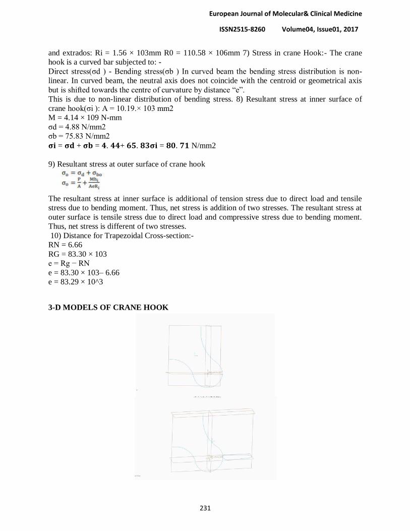
European Journal of Molecular& Clinical Medicine
ISSN2515-8260 Volume04, Issue01, 2017
231
and extrados: Ri = 1.56 × 103mm R0 = 110.58 × 106mm 7) Stress in crane Hook:- The crane
hook is a curved bar subjected to: -
Direct stress(σd ) - Bending stress(σb ) In curved beam the bending stress distribution is non-
linear. In curved beam, the neutral axis does not coincide with the centroid or geometrical axis
but is shifted towards the centre of curvature by distance ―e‖.
This is due to non-linear distribution of bending stress. 8) Resultant stress at inner surface of
crane hook(σi ): A = 10.19.× 103 mm2
M = 4.14 × 10⁹ N-mm
σd = 4.88 N/mm2
σb = 75.83 N/mm2
𝛔𝐢 = 𝛔𝐝 + 𝛔𝐛 = 𝟒. 𝟒𝟒+ 𝟔𝟓. 𝟖𝟑𝛔𝐢 = 𝟖𝟎. 𝟕𝟏 N/mm2
9) Resultant stress at outer surface of crane hook
The resultant stress at inner surface is additional of tension stress due to direct load and tensile
stress due to bending moment. Thus, net stress is addition of two stresses. The resultant stress at
outer surface is tensile stress due to direct load and compressive stress due to bending moment.
Thus, net stress is different of two stresses.
10) Distance for Trapezoidal Cross-section:-
RN = 6.66
RG = 83.30 × 10³
e = Rg − RN
e = 83.30 × 10³– 6.66
e = 83.29 × 10^3
3-D MODELS OF CRANE HOOK

European Journal of Molecular& Clinical Medicine
ISSN2515-8260 Volume04, Issue01, 2017
232

European Journal of Molecular& Clinical Medicine
ISSN2515-8260 Volume04, Issue01, 2017
233
Material selection
Steel
Steel is an alloy of iron and carbon and other elements. Because of its high tensile
strength and low cost, it is a major component used
in buildings, infrastructure, tools, ships, automobiles, machines, appliances, and weapons.
Iron is the base metal of steel. Iron is able to take on two crystalline forms (allotropic
forms), body centered cubic (BCC) and face centered cubic (FCC), depending on its temperature.
In the body-centred cubic arrangement, there is an iron atom in the centre of each cube, and in
the face-centred cubic, there is one at the center of each of the six faces of the cube. It is the
interaction of the allotropesof iron with the alloying elements, primarily carbon, that gives steel
and cast iron their range of unique properties.
In pure iron, the crystal structure has relatively little resistance to the iron atoms slipping
past one another, and so pure iron is quite ductile, or soft and easily formed. In steel, small
amounts of carbon, other elements, and inclusions within the iron act as hardening agents that
prevent the movement of dislocations that are common in the crystal lattices of iron atoms.
The carbon in typical steel alloys may contribute up to 2.14% of its weight. Varying the
amount of carbon and many other alloying elements, as well as controlling their chemical and
physical makeup in the final steel (either as solute elements, or as precipitated phases), slows the
movement of those dislocations that make pure iron ductile, and thus controls and enhances its
qualities. These qualities include such things as the hardness, quenching behavior, need
for annealing, tempering behavior, yield strength, and tensile strength of the resulting steel. The
increase in steel's strength compared to pure iron is possible only by reducing iron's ductility.
Steel was produced in bloomery furnaces for thousands of years, but its large-scale,
industrial use began only after more efficient production methods were devised in the 17th
century, with the production of blister steel and then crucible steel. With the invention of
the Bessemer process in the mid-19th century, a new era of mass-produced steel began. This was
followed by the Siemens-Martin process and then the Gilchrist-Thomas process that refined the
quality of steel. With their introductions, mild steel replaced wrought iron.
Further refinements in the process, such as basic oxygen steelmaking (BOS), largely
replaced earlier methods by further lowering the cost of production and increasing the quality of
the final product. Today, steel is one of the most common man-made materials in the world, with
more than 1.6 billion tons produced annually. Modern steel is generally identified by various
grades defined by assorted standards organizations.
European Journal of Molecular& Clinical Medicine
ISSN2515-8260 Volume04, Issue01, 2017
234
Heat treatment
There are many types of heat treating processes available to steel. The most common
are annealing, quenching, and tempering. Heat treatment is effective on compositions above the
eutectoid composition (hypereutectoid) of 0.8% carbon. Hypoeutectoid steel does not benefit
from heat treatment.
Annealing is the process of heating the steel to a sufficiently high temperature to relieve
local internal stresses. It does not create a general softening of the product but only locally
relieves strains and stresses locked up within the material. Annealing goes through three
phases: recovery, recrystallization, and grain growth. The temperature required to anneal a
particular steel depends on the type of annealing to be achieved and the alloying constituents.
Quenching involves heating the steel to create the austenite phase then quenching it in
water or oil. This rapid cooling results in a hard but brittle martensitic structure. The steel is then
tempered, which is just a specialized type of annealing, to reduce brittleness. In this application
the annealing (tempering) process transforms some of the martensite into cementite,
or spheroidite and hence it reduces the internal stresses and defects. The result is a more ductile
and fracture-resistant steel
Carbon steel
Carbon steel is a steel with carbon content up to 2.1% by weight. The definition of carbon steel
from the American Iron and Steel Institute (AISI) states:
no minimum content is specified or required
for chromium, cobalt, molybdenum, nickel, niobium, titanium, tungsten, vanadium, zirco
nium, or any other element to be added to obtain a desired alloying effect;
the specified minimum for copper does not exceed 0.40 percent;
or the maximum content specified for any of the following elements does not exceed the
percentages noted: manganese 1.65, silicon 0.60, copper 0.60
The term "carbon steel" may also be used in reference to steel which is not stainless steel; in this
use carbon steel may include alloy steels. High carbon steel has many different uses such as
milling machines, cutting tools (such as chisels) and high strength wires. These applications
require a much finer microstructure, which improves the toughness.
As the carbon percentage content rises, steel has the ability to
become harder and stronger through heat treating; however, it becomes less ductile. Regardless
of the heat treatment, a higher carbon content reduces weldability. In carbon steels, the higher
carbon content lowers the melting point
Mild or low-carbon steel
Mild steel (iron containing a small percentage of carbon, strong and tough but not readily
tempered), also known as plain-carbon steel and low-carbon steel, is now the most common form
of steel because its price is relatively low while it provides material properties that are acceptable
for many applications. Mild steel contains approximately 0.05–0.30% carbonmaking it malleable
and ductile. Mild steel has a relatively low tensile strength, but it is cheap and easy to form;
surface hardness can be increased through carburizing.
In applications where large cross-sections are used to minimize deflection, failure by yield is not
a risk so low-carbon steels are the best choice, for example as structural steel. The density of

European Journal of Molecular& Clinical Medicine
ISSN2515-8260 Volume04, Issue01, 2017
235
mild steel is approximately 7.85 g/cm3 (7850 kg/m
3 or 0.284 lb/in
3) and the Young's modulus is
200 GPa (29,000 ksi).
Low-carbon steels display yield-point runout where the material has two yield points. The first
yield point (or upper yield point) is higher than the second and the yield drops dramatically after
the upper yield point. If a low-carbon steel is only stressed to some point between the upper and
lower yield point then the surface develops Lüderbands.Low-carbon steels contain less carbon
than other steels and are easier to cold-form, making them easier to handle
Heat treatment
The purpose of heat treating carbon steel is to change the mechanical properties of steel, usually
ductility, hardness, yield strength, or impact resistance. Note that the electrical and thermal
conductivity are only slightly altered. As with most strengthening techniques for steel, Young's
modulus (elasticity) is unaffected. All treatments of steel trade ductility for increased strength
and vice versa. Iron has a higher solubility for carbon in the austenite phase; therefore all heat
treatments, except spheroidizing and process annealing, start by heating the steel to a
temperature at which the austenitic phase can exist. The steel is then quenched (heat drawn out)
at a moderate to low rate allowing carbon to diffuse out of the austenite forming iron-carbide
(cementite) and leaving ferrite, or at a high rate, trapping the carbon within the iron thus forming
martensite. The rate at which the steel is cooled through the eutectoid temperature (about 727 °C)
affects the rate at which carbon diffuses out of austenite and forms cementite. Generally
speaking, cooling swiftly will leave iron carbide finely dispersed and produce a fine
grained pearlite and cooling slowly will give a coarser pearlite. Cooling a hypo eutectoid steel
(less than 0.77 wt% C) results in a lamellar-pearlitic structure of iron carbide layers with α-
ferrite (nearly pure iron) between. If it is hypereutectoid steel (more than 0.77 wt% C) then the
structure is full pearlite with small grains (larger than the pearlite lamella) of cementite formed
on the grain boundaries. A eutectoid steel (0.77% carbon) will have a pearlite structure
throughout the grains with no cementite at the boundaries. The relative amounts of constituents
are found using the lever rule. The following is a list of the types of heat treatments possible
Spheroidizing: Spheroidite forms when carbon steel is heated to approximately 700 °C
for over 30 hours. Spheroidite can form at lower temperatures but the time needed
drastically increases, as this is a diffusion-controlled process. The result is a structure of
rods or spheres of cementite within primary structure (ferrite or pearlite, depending on
which side of the eutectoid you are on). The purpose is to soften higher carbon steels and
allow more formability. This is the softest and most ductile form of steel.
Full annealing: Carbon steel is heated to approximately 40 °C above Ac3 or Acm? for 1
hour; this ensures all the ferrite transforms into austenite (although cementite might still
exist if the carbon content is greater than the eutectoid). The steel must then be cooled
slowly, in the realm of 20 °C (36 °F) per hour. Usually it is just furnace cooled, where the
furnace is turned off with the steel still inside. This results in a coarse pearlitic structure,
which means the "bands" of pearlite are thick. Fully annealed steel is soft and ductile,
with no internal stresses, which is often necessary for cost-effective forming. Only
spheroidized steel is softer and more ductile.
Process annealing: A process used to relieve stress in a cold-worked carbon steel with
less than 0.3% C. The steel is usually heated to 550–650 °C for 1 hour, but sometimes
temperatures as high as 700 °C. The image rightwardshows the area where process
annealing occurs.
European Journal of Molecular& Clinical Medicine
ISSN2515-8260 Volume04, Issue01, 2017
236
Isothermal annealing: It is a process in which hypoeutectoid steel is heated above the
upper critical temperature. This temperature is maintained for a time and then reduced to
below the lower critical temperature and is again maintained. It is then cooled to room
temperature. This method eliminates any temperature gradient.
Normalizing: Carbon steel is heated to approximately 55 °C above Ac3 or Acm for 1
hour; this ensures the steel completely transforms to austenite. The steel is then air-
cooled, which is a cooling rate of approximately 38 °C (100 °F) per minute. This results
in a fine pearlitic structure, and a more-uniform structure. Normalized steel has a higher
strength than annealed steel; it has a relatively high strength and hardness.
Quenching: Carbon steel with at least 0.4 wt% C is heated to normalizing temperatures
and then rapidly cooled (quenched) in water, brine, or oil to the critical temperature. The
critical temperature is dependent on the carbon content, but as a general rule is lower as
the carbon content increases. This results in a martensitic structure; a form of steel that
possesses a super-saturated carbon content in a deformed body-centered cubic (BCC)
crystalline structure, properly termed body-centered tetragonal (BCT), with much internal
stress. Thus quenched steel is extremely hard but brittle, usually too brittle for practical
purposes. These internal stresses may cause stress cracks on the surface. Quenched steel
is approximately three times harder (four with more carbon) than normalized steel.
Martempering (Marquenching): Martempering is not actually a tempering procedure,
hence the term "marquenching". It is a form of isothermal heat treatment applied after an
initial quench, typically in a molten salt bath, at a temperature just above the "martensite
start temperature". At this temperature, residual stresses within the material are relieved
and some bainite may be formed from the retained austenite which did not have time to
transform into anything else. In industry, this is a process used to control the ductility and
hardness of a material. With longer marquenching, the ductility increases with a minimal
loss in strength; the steel is held in this solution until the inner and outer temperatures of
the part equalize. Then the steel is cooled at a moderate speed to keep the temperature
gradient minimal. Not only does this process reduce internal stresses and stress cracks,
but it also increases the impact resistance.
Tempering: This is the most common heat treatment encountered, because the final
properties can be precisely determined by the temperature and time of the tempering.
Tempering involves reheating quenched steel to a temperature below
the eutectoid temperature then cooling. The elevated temperature allows very small
amounts of spheroidite to form, which restores ductility, but reduces hardness. Actual
temperatures and times are carefully chosen for each composition.
Austempering: The austempering process is the same as martempering, except the quench
is interrupted and the steel is held in the molten salt bath at temperatures between 205 °C
and 540 °C, and then cooled at a moderate rate. The resulting steel, called bainite,
produces an acicular microstructure in the steel that has great strength (but less than
martensite), greater ductility, higher impact resistance, and less distortion than martensite
steel. The disadvantage of austempering is it can be used only on a few steels, and it
requires a special salt bath.

European Journal of Molecular& Clinical Medicine
ISSN2515-8260 Volume04, Issue01, 2017
237
CONCLUSIONS
The model that is created in a CAD Tool called solid works, and also calculate
theoretical analysis results stress values, after calculating and designing object material selection
were made, both steel and low carbon steel material properties were discussed with their
properties
REFERENCE
[1] ASME Standard B30.2, “Overhead Gantry Cranes (Top Running Bridge, Single or
Multiple Girder, Top Running Trolley Hoist),” 2005.
[2]ASME Standard B30.9, “Slings Safety Standard for Cableways, Cranes, Derricks, Hoists,
Hooks, Jacks and Slings,” 2006.
[3] ASME Standard B30.10, “Hooks Safety Standard for bleways, Cranes, Derricks, Hoists,
Hooks, Jacks and Slings,” 2009.
[4] Department of Labour of New Zealand, “Approved Code of Practice for Cranes,” 3rd
Edition, 2009.
[5] B. Ross, B. McDonald and S. E. V. Saraf, “Big Blue Goes Down. The Miller Park Crane
Accident,” Engineering Failure Analysis, Vol. 14, No. 6, 2007