A computational approach to biologically inspired design
17
Artificial Intelligence for Engineering Design, Analysis and Manufacturing http://journals.cambridge.org/AIE Additional services for Artificial Intelligence for Engineering Design, Analysis and Manufacturing: Email alerts: Click here Subscriptions: Click here Commercial reprints: Click here Terms of use : Click here A computational approach to biologically inspired design Jacquelyn K.S. Nagel and Robert B. Stone Artificial Intelligence for Engineering Design, Analysis and Manufacturing / Volume 26 / Special Issue 02 / May 2012, pp 161 176 DOI: 10.1017/S0890060412000054, Published online: 20 April 2012 Link to this article: http://journals.cambridge.org/abstract_S0890060412000054 How to cite this article: Jacquelyn K.S. Nagel and Robert B. Stone (2012). A computational approach to biologically inspired design. Artificial Intelligence for Engineering Design, Analysis and Manufacturing, 26, pp 161176 doi:10.1017/S0890060412000054 Request Permissions : Click here Downloaded from http://journals.cambridge.org/AIE, IP address: 65.242.47.202 on 14 Oct 2012
Transcript of A computational approach to biologically inspired design

Artificial Intelligence for Engineering Design, Analysis and Manufacturinghttp://journals.cambridge.org/AIE
Additional services for Artificial Intelligence for Engineering Design, Analysis and Manufacturing:
Email alerts: Click hereSubscriptions: Click hereCommercial reprints: Click hereTerms of use : Click here
A computational approach to biologically inspired design
Jacquelyn K.S. Nagel and Robert B. Stone
Artificial Intelligence for Engineering Design, Analysis and Manufacturing / Volume 26 / Special Issue 02 / May 2012, pp 161 176DOI: 10.1017/S0890060412000054, Published online: 20 April 2012
Link to this article: http://journals.cambridge.org/abstract_S0890060412000054
How to cite this article:Jacquelyn K.S. Nagel and Robert B. Stone (2012). A computational approach to biologically inspired design. Artificial Intelligence for Engineering Design, Analysis and Manufacturing, 26, pp 161176 doi:10.1017/S0890060412000054
Request Permissions : Click here
Downloaded from http://journals.cambridge.org/AIE, IP address: 65.242.47.202 on 14 Oct 2012

A computational approach to biologically inspired design
JACQUELYN K.S. NAGEL1AND ROBERT B. STONE2
1School of Engineering, James Madison University, Harrisonburg, Virginia, USA2Design Engineering Lab, Department of Mechanical, Industrial and Manufacturing Engineering, Oregon State University, Corvallis,Oregon, USA
(RECEIVED March 3, 2011; ACCEPTED October 15, 2011)
Abstract
The natural world provides numerous cases for analogy and inspiration in engineering design. During the early stages ofdesign, particularly during concept generation when several variants are created, biological systems can be used to inspireinnovative solutions to a design problem. However, identifying and presenting the valuable knowledge from the biologicaldomain to an engineering designer during concept generation is currently a somewhat disorganized process or requires ex-tensive knowledge of the biological system. To circumvent the knowledge requirement problem, we developed a computa-tional approach for discovering biological inspiration during the early stages of design that integrates with established func-tion-based design methods. This research defines and formalizes the information identification and knowledge transferprocesses that enable systematic development of biologically inspired designs. The framework that supports our computa-tional design approach is provided along with an example of a smart flooring device to demonstrate the approach. Bio-logically inspired conceptual designs are presented and validated through a literature search and comparison to existing pro-ducts.
Keywords: Biomimicry; Concept Generation; Design; Function
1. INTRODUCTION
Engineering design is considered both an art and a science,which encourages the use of engineering principles, imagina-tion, and a designer’s intuition to create novel engineering so-lutions. Nature is a powerful resource for engineering design-ers. The natural world provides numerous cases for analogyand inspiration in engineering design (Brebbia et al., 2002;Brebbia & Collins, 2004; Bar-Cohen, 2006b; Brebbia,2006, 2008; Brebbia & Carpi, 2010). Biological organisms,phenomena, and strategies, herein referred to as biologicalsystems, provide insight into sustainable and adaptable de-sign and offer engineers billions of years of valuable experi-ence, which can be used to inspire engineering innovation.Many engineering breakthroughs have occurred based on bi-ological phenomena, and it is evident that mimicking biolog-ical systems or using them for inspiration has led to successfulinnovations (e.g., velcro, flapping wing micro air vehicles,synthetic muscles, self-cleaning glass).
Nature has influenced engineering and the engineering de-sign process. Although inspiration from nature can be taken atmultiple stages in the engineering design process, it most no-
tably occurs during concept generation, when inspiration inthe form of analogies, metaphors, and connections from mul-tiple engineering domains and other sources (e.g., biologicaldomain) are utilized for developing novel or creative solu-tions to a design problem. Concept generation methods andtools help stimulate designer creativity and encourage ex-ploration of the solution space beyond an individual design-er’s knowledge and experience (Gordon, 1961; Hyman,1998; Otto & Wood, 2001; Dym & Little, 2004; Ulrich & Ep-pinger, 2004; Voland, 2004; Pahl et al., 2007; Cross, 2008;Ullman, 2009). There are multiple approaches to conceptgeneration for engineering design; however, most are notcomputational. Although in recent years, computation-basedor automatic concept generation has gained importance in theengineering design research community and has taken manyforms (Hong-Zhong et al., 2006; Bryant et al., 2007; Jin & Li,2007; Bohm et al., 2008; Bryant Arnold et al., 2008; Kurtogluet al., 2008; Yao Zu, 2009). Identifying and presenting the val-uable knowledge from the biological domain to an engineer-ing designer during concept generation is currently a manual,in most cases, and somewhat disorganized process. This re-search aims to define and formalize the information identifi-cation and knowledge transfer processes, which will result ina systematic technique for developing biologically inspired,or biomimetic, designs.
Reprint requests to: Jacquelyn K.S. Nagel, School of Engineering, JamesMadison University, 801 Carrier Drive, MSC 4113, Harrisonburg, VA 22807, USA.E-mail: [email protected]
Artificial Intelligence for Engineering Design, Analysis and Manufacturing (2012), 26, 161–176.# Cambridge University Press 2012 0890-0604/12 $25.00doi:10.1017/S0890060412000054
161

This paper presents a computational approach that com-bines established function-based design tools to enable sys-tematic development of biologically inspired designs. In or-der to facilitate concept generation for biologically inspiredengineering design, two bodies of knowledge are required:successful engineered systems and biological systems, bothindexed by engineering function. A Design Repository(Bohm et al., 2008), containing descriptive product informa-tion, serves as the engineered systems body of knowledge. In-stead of creating a database containing functionally decom-posed biological systems, similar to the Design Repository,a biology textbook serves as the biological systems body ofknowledge. To circumvent the terminology difference issue,which is indexed by natural language rather than engineeringfunction, an engineering to biology thesaurus is utilized (Na-gel et al., 2010). Structurally, the thesaurus acts as a set of cor-respondent terms to the functions and flows of the functionalbasis (Hirtz et al., 2002), which provides term mapping be-tween the biological and engineering domains for the supportof concept generation. Integrating biological system informa-tion with an established, computational method for conceptgeneration enables designers to consider taking inspirationfrom biology without having to expend extra effort to learna new method.
This paper begins by introducing the reader to related bio-logically inspired design research and information retrieval inengineering design, followed by a section describing back-ground research. Next, the computational framework and al-gorithm for discovering biological inspiration during conceptgeneration is presented and discussed. The paper ends with anillustrative example, conclusions, and future work.
2. RELATED WORK
With biology-inspired design emerging as its own field, engi-neering design research as turned to investigating methodsand techniques for transferring biological knowledge to theengineering domain. Prominent research focuses on investi-gating individual aspects of the overall engineering designprocess involving biological systems for inspiration (Vincentet al., 2006; Linsey et al., 2008; Mak & Shu, 2008; Nagelet al., 2008; Wen et al., 2008; Helms et al., 2009), and com-putational design techniques. The main goal of these researchefforts is to create generalized methods, knowledge, and toolssuch that biomimetic design can be broadly practiced in engi-neering. Biology-inspired design “offers enormous potentialfor inspiring new capabilities for exciting future technolo-gies” and encourages engineering innovation (Lindemann& Gramann, 2004; Bar-Cohen, 2006a).
Work in the area of computational biologically inspired de-sign techniques involves the creation of databases, software,and search methods. Chakrabarti et al. (2005) developed a soft-ware package entitled Idea-Inspire that searches a database ofnatural and complex artificial mechanical systems by chosenfunction, behavior, and structure terms. Their database com-prises natural and complex artificial mechanical systems and
aims to inspire the designer during the design process (Sriniva-san & Chakrabarti, 2009). Another database-driven method isontology driven bioinspired Design Repository developed byWilson et al. (2009). This ontology is encoded using descrip-tion logics and uses subsumption, an inference mechanism,to precisely retrieve relevant biological strategies from the re-pository. Chiu and Shu (2007a, 2007b) developed a methodfor identifying biological analogies by searching a biologicalcorpus using functional keywords. A set of natural-languagekeywords is defined for each engineering keyword to yield bet-ter results during the analogy search. This method has success-fully generated engineering solutions analogous to biologicalphenomena (Shu et al., 2006).
Work in the area of information retrieval in design related tothis research involves the design of a hierarchal thesaurus, soft-ware, and search methods. A general approach to design infor-mation retrieval was undertaken by Wood et al. (1998), whichcreated a hierarchical thesaurus of component and system func-tional decompositions to capture design context. Strategies forretrieval, similar to search heuristics, of issue based and compo-nent/function information were presented. Bouchard et al.(2008) developed a content-based information retrieval systemnamed TRENDS. This software aims at improving designers’access to Web-based resources by helping them to find appro-priate materials, to structure these materials in way that supportstheir design activities and identify design trends. The TRENDSsystem integrates flexible content-based image retrieval basedon ontological referencing and clustering components throughconjoint trends analysis. Cheong et al. (2008) developed a set ofsearch cases for determining sets of biologically meaningfulkeywords to engineering keywords. Although the results aresubjective, the process for retrieving the words is systematicand was successful in determining biologically meaningfulwords to several functions of the reconciled functional basis.
3. SUPPORTING DESIGN TOOLS
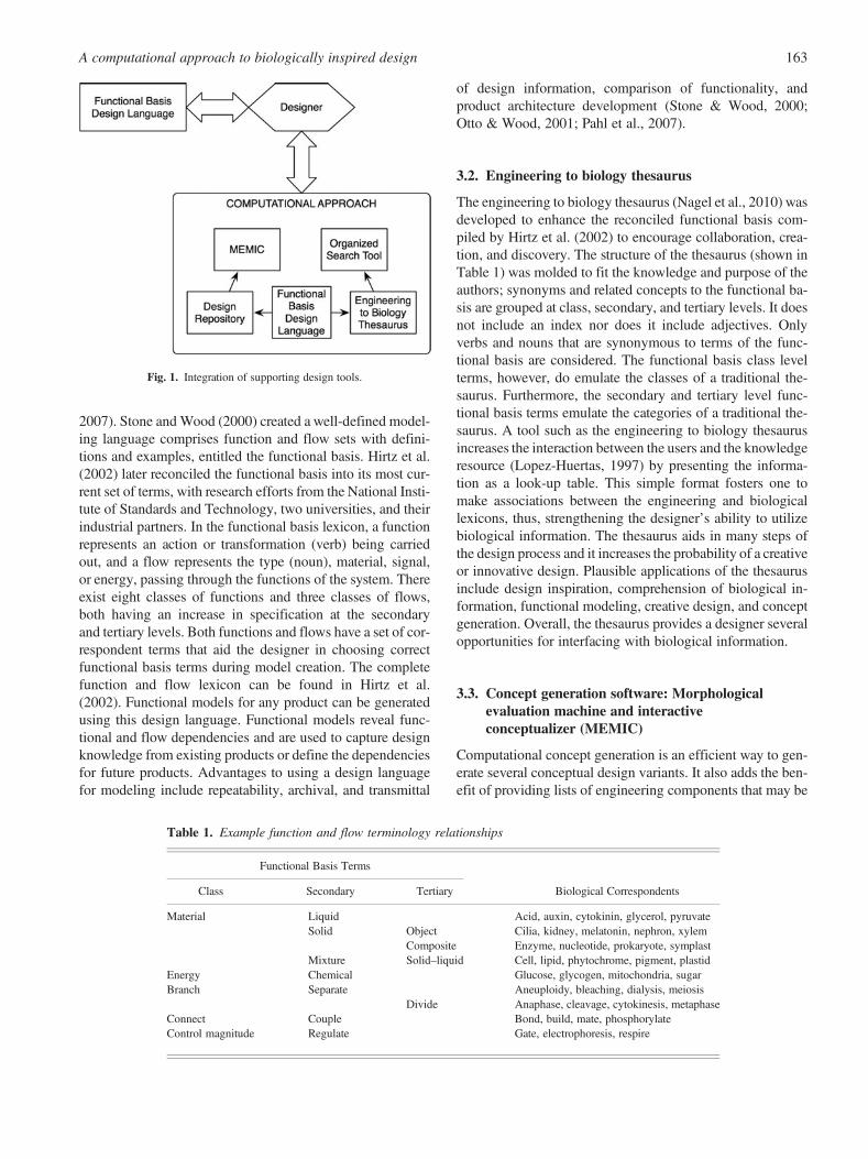
This section provides background information on the twocomputational tools and the respective supporting designtools that are required to achieve the computational frame-work for discovering biological inspiration. Figure 1 illus-trates how the design tools integrate to achieve the computa-tional framework. The designer interfaces directly with thefunctional basis design language to develop the inputs forthe computational approach. Consistency of design languageacross the design tools facilitates integration. The remainingdesign tools serve each other to automate the search processwithin the concept generation phase of design. Researchersof the Design Engineering Lab developed each design tooldescribed within this section. The tools are accessible athttp://www.designengineeringlab.org.
3.1. Functional basis design language
Functional representation through functional modeling has along history of use in systematic design methods (Pahl et al.,
J.K.S. Nagel and R.B. Stone162
2007). Stone and Wood (2000) created a well-defined model-ing language comprises function and flow sets with defini-tions and examples, entitled the functional basis. Hirtz et al.(2002) later reconciled the functional basis into its most cur-rent set of terms, with research efforts from the National Insti-tute of Standards and Technology, two universities, and theirindustrial partners. In the functional basis lexicon, a functionrepresents an action or transformation (verb) being carriedout, and a flow represents the type (noun), material, signal,or energy, passing through the functions of the system. Thereexist eight classes of functions and three classes of flows,both having an increase in specification at the secondaryand tertiary levels. Both functions and flows have a set of cor-respondent terms that aid the designer in choosing correctfunctional basis terms during model creation. The completefunction and flow lexicon can be found in Hirtz et al.(2002). Functional models for any product can be generatedusing this design language. Functional models reveal func-tional and flow dependencies and are used to capture designknowledge from existing products or define the dependenciesfor future products. Advantages to using a design languagefor modeling include repeatability, archival, and transmittal
of design information, comparison of functionality, andproduct architecture development (Stone & Wood, 2000;Otto & Wood, 2001; Pahl et al., 2007).
3.2. Engineering to biology thesaurus
The engineering to biology thesaurus (Nagel et al., 2010) wasdeveloped to enhance the reconciled functional basis com-piled by Hirtz et al. (2002) to encourage collaboration, crea-tion, and discovery. The structure of the thesaurus (shown inTable 1) was molded to fit the knowledge and purpose of theauthors; synonyms and related concepts to the functional ba-sis are grouped at class, secondary, and tertiary levels. It doesnot include an index nor does it include adjectives. Onlyverbs and nouns that are synonymous to terms of the func-tional basis are considered. The functional basis class levelterms, however, do emulate the classes of a traditional the-saurus. Furthermore, the secondary and tertiary level func-tional basis terms emulate the categories of a traditional the-saurus. A tool such as the engineering to biology thesaurusincreases the interaction between the users and the knowledgeresource (Lopez-Huertas, 1997) by presenting the informa-tion as a look-up table. This simple format fosters one tomake associations between the engineering and biologicallexicons, thus, strengthening the designer’s ability to utilizebiological information. The thesaurus aids in many steps ofthe design process and it increases the probability of a creativeor innovative design. Plausible applications of the thesaurusinclude design inspiration, comprehension of biological in-formation, functional modeling, creative design, and conceptgeneration. Overall, the thesaurus provides a designer severalopportunities for interfacing with biological information.
3.3. Concept generation software: Morphologicalevaluation machine and interactiveconceptualizer (MEMIC)
Computational concept generation is an efficient way to gen-erate several conceptual design variants. It also adds the ben-efit of providing lists of engineering components that may be
Fig. 1. Integration of supporting design tools.
Table 1. Example function and flow terminology relationships
Functional Basis Terms
Class Secondary Tertiary Biological Correspondents
Material Liquid Acid, auxin, cytokinin, glycerol, pyruvateSolid Object Cilia, kidney, melatonin, nephron, xylem
Composite Enzyme, nucleotide, prokaryote, symplastMixture Solid–liquid Cell, lipid, phytochrome, pigment, plastid
Energy Chemical Glucose, glycogen, mitochondria, sugarBranch Separate Aneuploidy, bleaching, dialysis, meiosis
Divide Anaphase, cleavage, cytokinesis, metaphaseConnect Couple Bond, build, mate, phosphorylateControl magnitude Regulate Gate, electrophoresis, respire
A computational approach to biologically inspired design 163

used to solve a particular function. MEMIC was created foruse during the early stages of design to produce design solu-tions for an engineering design from a given functional modelusing knowledge of existing engineered products (Bryantet al., 2007; Bryant Arnold et al., 2008). The concept genera-tor software MEMIC accepts an input functional model anduses functionality and compatibility information stored inthe Design Repository to generate, filter, and rank full con-cept variants. The MEMIC algorithm utilizes the relation-ships contained in a function–component matrix and the com-patibility information contained in a design structure matrix,both of which are generated from the Design Repository con-tents (Bryant, Stone, et al., 2005). MEMIC returns a listing ofengineering component solutions for each function–flow pairof the input functional model. This allows a designer to easilychoose between multiple solutions for a given function andinteractively build a complete conceptual design.
3.4. Design Repository
The Design Repository housed at Oregon State Universitycontains descriptive product information such as functional-ity, component physical parameters, manufacturing pro-cesses, failure, and component compatibility of over 130 con-sumer products. Each consumer product was decomposedand functionally modeled using the functional basis. Each re-pository entry is designated as an artifact or assembly of arti-facts, whether it performs a supporting function (secondary tothe product’s operation) and the class of the artifact when en-tered into the repository database. In addition, several artifactattributes are captured and stored in a relational databasewhere each record contains an artifact name, part number,and part family that can be used to catalog similar artifacts.Information about the actual function of an artifact is capturedas a subfunction value.
3.5. Organized search tool
The organized search tool was originally developed for re-trieving relevant biological systems that performed functionsof interest. In this research we extend the search tool to betterfacilitate biologically inspired design through combinationwith other established function-based design tools. Specifi-cally, the organized search tool is designed to work withnonengineering subject domain specific information. Themajority of nonengineering domain texts are written in nat-ural-language format, which prompted the investigation ofusing both a functional basis function and flow term whensearching for solutions. Realizing how the topic of the textis treated increases the extensibility of the organized verb–noun search algorithm. This organized verb–noun combina-tion search strategy provides two levels of results: associatedwith verb only, of which the user can choose to utilize or ig-nore, and the narrowed results associated with verb–noun.This search strategy requires the designer to first form an ab-straction (e.g., functional model) of the unsolved problem
using the functional basis lexicon. The verbs (functions) ofthe abstraction are input as keywords in the organized searchtool to generate a list of matches, and subsequently a list ofwords that occur in proximity to the searched verb in thosematches. The generated list contains mostly nouns, whichcan be thought of as flows (materials, energies, and signals),synonymous with the correspondent words already providedin the functional basis flow set. The noun listing is then usedin combination with the search verb results for a second, moredetailed search to locate specific text excerpts that describehow the nonengineering domain systems perform the ab-stracted functionality with certain flows. The verb searchesare constrained to the chosen corpus and the verb–nounsearches are constrained to the extracted sentences that in-clude the search verb.
This search strategy is embodied in an automated retrievaltool that allows an engineering designer to selectively choosewhich corpus or documents to search and to upload additionalsearchable information as it is made available. The user inter-face initially presents the designer with a function (verb) entryfield and search options. Search options prompt the designerto choose from exact word, derivatives of the word, and par-tial word. Once the information is searched for the functionterm the designer is presented with a flow (noun) listing foreach searched corpus or document followed by a group ofsentences that include the function and listed flows. If the de-signer does not want to search by verb–noun then the de-signer simply scrolls down to the group of sentences, whichinclude the desired function. For this application, the non-engineering domain chosen for examples is biology.
The designer utilizing this organized search technique doesnot need an extensive background in the nonengineering do-main but instead needs sufficient engineering backgroundto abstract the unsolved problem to its most basic level utiliz-ing the functional basis lexicon. The search tool typicallyyields more than one biological system for potential designinspiration.
4. COMPUTATIONAL APPROACH
Automated concept generation methods promise engineers afaster realization of potential design solutions based uponpreviously known products and implementations. The ap-proach described here requires the designer to input desiredfunctionality, and based on an algorithm, several concept var-iants are presented to the designer. Functionality is a usefulmetric for defining a conceptual idea, as functional represen-tation has been shown to reduce fixation of how a product ordevice would look and operate (Otto & Wood, 2001; Pahlet al., 2007).
Required input to the computational approach is a func-tional model that abstractly represents a conceptual engi-neered solution. The functional model is then digitized andrepresented as a matrix of forward flows. Each function/flow pair of the model is then searched in the engineeringand biological knowledge bases, the Design Repository and
J.K.S. Nagel and R.B. Stone164
a chosen biological corpus, respectively, to identify solutions.The search algorithm parses the repository entries for the ex-act engineering function/flow pair, where as, the biologicalcorpus is parsed repeatedly with the biological terms corre-sponding to the engineering terms per the engineering tobiology thesaurus. Multiple solutions from both domains,to each function/flow pair, are returned and presented tothe designer. The biological solutions are not indented forphysical use, but are intended for spurring creative ideas orconnections to the engineering domain that could be imple-mented in an engineered system that partially (i.e., one or twocomponents) to completely (i.e., entire design) mimic a bio-logical system.
To make a biologically inspired concept work, a leap is re-quired from the designer to understand that component map-ping is an activity that relates biological system attributes toengineered components. This computational approach assistswith identifying biological solutions to engineering func-tions; however, to arrive at the final concept, the designer isrequired to identify principles, components, materials, and/or systems within the engineering domain that support whatthe biological solution suggests. Therefore, this approachlends itself more toward innovative design problems wherenovel solutions tend to dominate.
Computational concept generation provides the added ad-vantage of limitless resources for inspiration. The techniquedescribed in this section can be extended by adding entriesinto the Design Repository and texts or documents into the bi-ological corpus database. With this technique the well-knowncustomer needs driven engineering design approach is uti-lized, which is an additional advantage.
4.1. Algorithm
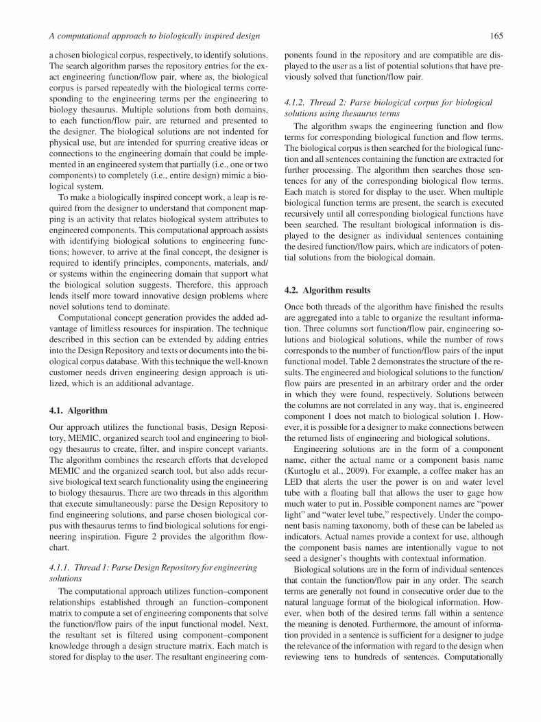
Our approach utilizes the functional basis, Design Reposi-tory, MEMIC, organized search tool and engineering to biol-ogy thesaurus to create, filter, and inspire concept variants.The algorithm combines the research efforts that developedMEMIC and the organized search tool, but also adds recur-sive biological text search functionality using the engineeringto biology thesaurus. There are two threads in this algorithmthat execute simultaneously: parse the Design Repository tofind engineering solutions, and parse chosen biological cor-pus with thesaurus terms to find biological solutions for engi-neering inspiration. Figure 2 provides the algorithm flow-chart.
4.1.1. Thread 1: Parse Design Repository for engineeringsolutions
The computational approach utilizes function–componentrelationships established through an function–componentmatrix to compute a set of engineering components that solvethe function/flow pairs of the input functional model. Next,the resultant set is filtered using component–componentknowledge through a design structure matrix. Each match isstored for display to the user. The resultant engineering com-
ponents found in the repository and are compatible are dis-played to the user as a list of potential solutions that have pre-viously solved that function/flow pair.
4.1.2. Thread 2: Parse biological corpus for biologicalsolutions using thesaurus terms
The algorithm swaps the engineering function and flowterms for corresponding biological function and flow terms.The biological corpus is then searched for the biological func-tion and all sentences containing the function are extracted forfurther processing. The algorithm then searches those sen-tences for any of the corresponding biological flow terms.Each match is stored for display to the user. When multiplebiological function terms are present, the search is executedrecursively until all corresponding biological functions havebeen searched. The resultant biological information is dis-played to the designer as individual sentences containingthe desired function/flow pairs, which are indicators of poten-tial solutions from the biological domain.
4.2. Algorithm results
Once both threads of the algorithm have finished the resultsare aggregated into a table to organize the resultant informa-tion. Three columns sort function/flow pair, engineering so-lutions and biological solutions, while the number of rowscorresponds to the number of function/flow pairs of the inputfunctional model. Table 2 demonstrates the structure of the re-sults. The engineered and biological solutions to the function/flow pairs are presented in an arbitrary order and the orderin which they were found, respectively. Solutions betweenthe columns are not correlated in any way, that is, engineeredcomponent 1 does not match to biological solution 1. How-ever, it is possible for a designer to make connections betweenthe returned lists of engineering and biological solutions.
Engineering solutions are in the form of a componentname, either the actual name or a component basis name(Kurtoglu et al., 2009). For example, a coffee maker has anLED that alerts the user the power is on and water leveltube with a floating ball that allows the user to gage howmuch water to put in. Possible component names are “powerlight” and “water level tube,” respectively. Under the compo-nent basis naming taxonomy, both of these can be labeled asindicators. Actual names provide a context for use, althoughthe component basis names are intentionally vague to notseed a designer’s thoughts with contextual information.
Biological solutions are in the form of individual sentencesthat contain the function/flow pair in any order. The searchterms are generally not found in consecutive order due to thenatural language format of the biological information. How-ever, when both of the desired terms fall within a sentencethe meaning is denoted. Furthermore, the amount of informa-tion provided in a sentence is sufficient for a designer to judgethe relevance of the information with regard to the design whenreviewing tens to hundreds of sentences. Computationally
A computational approach to biologically inspired design 165

Fig. 2. The flowchart of the computational approach. [A color version of this figure can be viewed online at http://journals.cambridge.org/aie]
J.K.S. Nagel and R.B. Stone166

speaking, parsing data as sentences and collecting the relevantsentences is quick and inexpensive.
4.3. Limitations to the computational approach
As with all computational design approaches the designer islimited by the information made available to the software.For this case, the limitations are the engineering and biolog-ical knowledge bases. Entries into the Design Repositoryhave varied levels of detail and mostly focus on consumerproducts. With regard to the biological corpus, the limitationis the natural language used in the text. Although these limita-tions are present, both knowledge bases return useful solu-tions that can be implemented in design. A designer who isfamiliar with considering components and systems abstractlyand by function will succeed even with the limitations ex-pressed here. However, both knowledge bases can be im-proved. A broader range of products can be entered into theDesign Repository and different biological texts can be addedfor searching.
5. ILLUSTRATIVE EXAMPLE
To illustrate the proposed computational concept generationtechnique, a smart flooring example is presented. The compu-tational approach is utilized to search engineered and biolog-ical systems for solutions that can be implemented in the ex-ample product. When using the functional basis for productdesign there are a few basic steps needed before function-based concept generation can begin. First, one must definethe customer needs and convert them into engineering terms(Otto & Wood, 2001; Kurfman et al., 2003; Pahl et al., 2007).Second, one must develop either a conceptual functionalmodel of the desired new product or a functional model ofan existing product to be redesigned using the functional ba-sis lexicon. Examples can be found in Bryant, McAdams,et al. (2005), Stone and Wood (2000), and Nagel et al.(2007). With the functional model, the designer now has sev-eral function–flow pairs that represent the desired newproduct. These pairs are utilized by the computational con-
cept generation technique to gather engineering and biologi-cal inspiration.
5.1. Problem definition
Consider the following scenario. A customer wants to create asecurity/surveillance product that looks like ordinary carpet,mats, rugs, and so forth, to detect intruders, a presence, ormovement. Requirements for the smart flooring include de-tection mechanism unseen by human eye, durability, andcomposed of common materials and a quick detection re-sponse. In addition, the system needs to be autonomous.Meaning a signal generated can alert personnel and doesnot require a person to monitor the surveillance system. It isknown that tagged systems require the user to carry a badgeor other device to be tracked or monitored, and simply remov-ing the traceable item can defeat the system. Radar or similarsystems require calibration and an area map to be created.Each time the area layout is changed, the map needs to be up-dated. Video surveillance and heat signature systems can bevery expensive and often require a person to watch the real-time video feed who can be unreliable. The design should of-fer advantages over the others listed.
With this knowledge the customer needs are mapped toflows (Table 3) for the creation of a functional model(Fig. 3). The model of Figure 2 was created with a boundaryof the flooring in place, energy is being supplied to the detec-tion mechanism and when an object or human interacts withthe flooring a signal is generated. Importation of human/ob-ject symbolizes interaction and exportation symbolizes the
Table 2. Structure of the results
Function/Flow Engineering Solution Biological Solution
Function 1/flow A 1. Component 1 1. Sentence that contains the equivalent biological function and flow pair2. Component 2 2. Sentence that contains the equivalent biological function and flow pair3. Component 3 3. Sentence that contains the equivalent biological function and flow pair. . . 4. . . .
Function 2/flow A1. Component 1 1. Sentence that contains the equivalent biological function and flow pair2. Component 2 2. Sentence that contains the equivalent biological function and flow pair3. Component 3 3. Sentence that contains the equivalent biological function and flow pair. . . 4. . . .
Table 3. Needs of smart flooring device mappedto flows
Needs/Constraints Functional Basis Flow
Object/human to detect Solid materialQuick detection response Status signalSystem power Electrical energy
A computational approach to biologically inspired design 167

human/object exiting the boundary. In order to use the com-putational approach, an adjacency matrix representing theforward flows of the model in Figure 3 must be created. Ta-ble 4 demonstrates the adjacency matrix for the smart flooringconceptual functional model.
5.2. Application of computational approach
The corpus chosen as the biological knowledge base is Life,The Science of Biology by Purves et al. (2001). This corpuscomprises 58 chapters; however, our algorithm searchesonly 37 chapters. Chapters that have little relevance or pro-vide results that are generally abstract, ambiguous, or are inthe context of scientists discovering something have beenleft out; these chapters include the introduction chapter, chap-ters on evolutionary processes, evolution of diversity, ecol-ogy, and biogeography. Thus, the remaining 37 chapters onthe cell, information and heredity, the biology of floweringplants, and the biology of animals serve as the biologicalknowledge base and offer sources of biological inspiration.
With the knowledge bases chosen the algorithm can beexecuted. Executing the computational approach with the ad-jacency matrix of Table 4 resulted in a total of 31 unique, en-gineering solutions and 60 unique, biological text excerpts (inthe form of individual sentences) for the seven function/flowpairs. Table 5 lists the resulting engineering and biological
solutions. The table format has been modified to enhanceclarity of presentation. Engineered solutions that have multi-ple functions (e.g., circuit board, electric switch) are repeated.Although less likely, biological solutions that are associatedwith multiple functions will also be repeated.
5.3. Discussion of results
The computational approach method fosters and guides theabilities of the designer and encourages objective evaluationof results. After the search algorithm has been applied the de-signer must synthesize concept variants from the resulting en-gineering and biological solutions. A designer must use gooddesign judgment and knowledge of constraints external to thedesign itself (e.g., manufacturing process, materials) to deter-mine if the solutions within the design space are feasible.Again, this computational approach assists with identifyingsolutions, engineered and biological, to engineering func-tions; however, to arrive at the final biologically inspired con-cept, the designer is required to make correlations to the engi-neering domain that support what the biological solutionsuggests. Several such correlations can be made with the so-lutions identified by the computational approach (Table 5) forthe smart flooring example.
Correlations between the resulting engineering and biolog-ical solutions in Table 5 are present. For example, sensory
Fig. 3. The smart flooring conceptual functional model.
Table 4. Smart flooring adjacency matrix
ImportSolid
Material
ImportElectricalEnergy
RegulateElectricalEnergy
TransferElectricalEnergy
DetectSolid
Material
TransmitElectricalEnergy
IndicateStatusSignal
ExportElectricalEnergy
ExportSolid
Material
Import solid material 0 0 0 0 1 0 0 0 0Import electrical energy 0 0 1 0 0 0 0 0 0Regulate electrical energy 0 0 0 1 0 0 0 0 0Transfer electrical energy 0 0 0 0 1 0 0 0 0Detect solid material 0 0 0 0 0 1 0 0 1Transmit electrical energy 0 0 0 0 0 0 1 1 0Indicate status signal 0 0 0 0 0 0 0 0 0Export electrical energy 0 0 0 0 0 0 0 0 0Export solid material 0 0 0 0 0 0 0 0 0
J.K.S. Nagel and R.B. Stone168

Table 5. Smart flooring search results
Solutions Function/Flow
Engineering
Function/Flow
1. Battery2. Circuit board3. Electric motor4. Electric wire5. Electric switch
Biological
Import/electrical energy1. The light energy absorbed by the antenna system is transferred from one pigment molecule to another as an electron.2. keep noncyclic electron flow going, photosystems I and II must constantly be absorbing light, thereby boosting electrons to higher orbitals from
which they may be captured by specific oxidizing agents.3. Photosystem II absorbs photons, sending electrons from P680 to pheophytin-I, the first carrier in the redox chain, and causing P680 to become
oxidized to P680+.4. Electrons from the oxidation of water are passed to P680+, reducing it once again to P680, which can absorb more photons.5. In sum, noncyclic electron flow uses a molecule of water, four photons (two each absorbed by photosystems I and II), one molecule each of NADP+ and
ADP, and one Pi.6. The attractive force that an atom exerts on electrons is its electronegativity.7. Na+ ions would diffuse into the cell because of their higher concentration on the outside, and they would also be attracted into the cell by the
negative membrane potential.8. These positive charges electrostatically attract the negative phosphate groups on DNA.9. Because opposite charges attract, the DNA moves toward the positive end of the field.
10. Leptin appears to be one important feedback signal in the regulation of food intake.
Engineering
Export/electrical energy1. Circuit board2. Electric wire3. Electric switch
Biological
1. Depending on the channel, this stimulus can range from the binding of a chemical signal to an electrical charge caused by an imbalance of ions.2. This binding causes changes in the membrane potential of the sensory cells, which release neurotransmitters onto the dendrites of the sensory neurons.3. When an action potential arrives at the neuromuscular junction, The neurotransmitter from the motor neuron binds to receptors in the postsynaptic
membrane, causing ion channels in the motor end plate to open.
Engineering
Transmit/electrical energy1. Electrical wire2. Battery contacts3. Motor controller
Biological
1. These electrical changes generate action potentials, the language by which the nervous system processes and communicates information.2. Ganglion cells communicate information about the light and dark contrasts that fall on different regions of their receptive fields.3. Whether the sensory cell itself fires action potentials, ultimately the stimulus is transduced into action potentials and the intensity of the stimulus is encoded
by the frequency of action potentials.4. In the rest of this chapter we will learn how sensory systems gather and filter stimuli, transduce specific stimuli into action potentials, and transmit
action potentials to the central nervous system.5. Auditory systems use mechanoreceptors to transduce pressure waves into action potentials.6. Earlier in this chapter, we saw how crayfish stretch receptors transduce physical force into action potentials.7. Sitting on the basilar membrane is the organ of Corti, the apparatus that transduces pressure waves into action potentials in the auditory nerve, which
in turn conveys information from the ear to the brain.
Engineering
Transfer/electrical energy1. Battery 4. Electric motor 7. Electric switch 10. Light fixture2. Circuit board 5. Electric socket 8. Heating element 11. Speaker3. Electric wire 6. Electric plate 9. USB cable
A computational approach to biologically inspired design 169

Table 5 (cont.)
Solutions Function/Flow
Biological
1. We have just noted proteins that function in blood clotting; others of interest include albumin, which is partly responsible for the osmotic potential incapillaries that prevents a massive loss of water from plasma to intercellular spaces; antibodies (immunoglobulins); hormones; and various carriermolecules, such as transferrin, which carries iron from the gut to where it is stored or used.
2. Because the electronegativities of these elements are so different, any electrons involved in bonding will tend to be much nearer to the chlorine nucleus, sonear that there is a complete transfer of the electron from one element to the other.
3. Redox reactions transfer electrons and energy.4. Another way of transferring energy is to transfer electrons.5. A reaction in which one substance transfers one or more electrons to another substance is called an oxidation–reduction reaction or redox reaction.6. Thus, when a molecule loses hydrogen atoms, it becomes oxidized. Oxidation and reduction always occur together: as one material is oxidized, the
electrons it loses are transferred to another material, reducing that material.7. As we will see, another carrier, flavin adenine dinucleotide, is also involved in transferring electrons during the metabolism of glucose.8. The citric acid cycle is a cyclic series of reactions in which the acetate becomes completely oxidized, forming CO2 and transferring electrons (along with
their hydrogen nuclei) to carrier molecules.9. The transfer of electrons along the respiratory chain drives the active transport of hydrogen ions (protons) from the mitochondrial matrix into the space
between the inner and outer mitochondrial membrane.10. The light energy absorbed by the antenna system is transferred from one pigment molecule to another as an electron.11. The high energy stored in the electrons of excited chlorophyll can be transferred to suitably oxidized nonpigment acceptor molecules.
Engineering
Detect/solid material1. Read head2. Line guide
Biological
1. Because both AT and GC pairs obey the base-pairing rules, how does the repair mechanism “know” whether the AC pair should be repaired by removingthe C and replace it with T, for instance, or by removing the A and replacing it with G? The repair mechanism can detect the “wrong” base becausea newly synthesized DNA strand is chemically modified some time after replication.
2. The Cnidarian’s nerve net merely detects food or danger and causes its tentacles and body to extend or retract.3. Most sensory cells possess a membrane receptor protein that detects the stimulus and responds by altering the flow of ions across the plasma membrane.4. The mammalian inner ear has two equilibrium organs that use hair cells to detect the position of the body with respect to gravity: semicircular canals
and the vestibular apparatus.5. These sensory cells enable the fish to detect weak electric fields, which can help them locate prey.6. This change is detected by the carotid and aortic stretch receptors, which stimulate corrective responses within two heartbeats.7. Any objects in the environment, such as rocks, plants, or other fish, disrupt the electric fish’s electric field, and the electroreceptors of the lateral line detect
those disruptions.8. Bats use echolocation, pit vipers sense infrared radiation from the warm bodies of their prey, and certain fishes detect electric fields created in the
water by their prey.9. In addition to genes for antibiotic resistance, several other marker genes are used to detect recombinant DNA in host cells.
10. The length of the night is one of several environmental cues detected by plants or by individual parts such as leaves.11. Animals whose eyes are on the sides of their heads have nonoverlapping fields of vision and, as a result, poor depth vision, but they can see predators
creeping up from behind.12. How does the sensory cell signal the intensity of a smell? It responds in a graded fashion to the concentration of odorant molecules: the more
odorant molecules that bind to receptors, the more action potentials are generated and the greater the intensity of the perceived smell.
Engineering
Indicate/status signal1. Light2. Tube3. Displacement gauge4. LCD screen
Biological
1. The durability of pheromonal signals enables them to be used to mark trails, as ants do, or to indicate directionality, as in the case of the moth sex attractant.2. To cause behavioral or physiological responses, a nervous system communicates these signals to effectors, such as muscles and glands.3. The information from the signal that was originally at the plasma membrane is communicated to the nucleus.4. A change in body color is a response that some animals use to camouflage themselves in a particular environment or to communicate with other animals.5. The binding of a hormone to its cellular receptor protein causes the protein to change shape and provides the signal to initiate reactions
within the cell.6. Separation of the chromatids marks the beginning of anaphase, the phase of mitosis during which the two sister chromatids of each chromosome,
now called daughter chromosomes, each containing one double-stranded DNA molecule, move to opposite ends of the spindle.
J.K.S. Nagel and R.B. Stone170

cells (Bio Solution 3 for Transmit Electrical Energy in Ta-ble 5) are described as a biological system that encodes,sends, and receives electrical signals related to stimulus inten-sity, which is analogous to a motor controller (Engr Solution3 for Transmit Electrical Energy in Table 5) that encodes,sends, and receives electrical signals related to feedback.This type of correlation is easy when there is a long list of en-gineering solutions. When the number of engineering solu-tions is low, as in the case of the function/flow pair detectsolid material, the biological solutions should be correlatedto analogous engineering principles, components, materials,and/or systems external to the engineering solutions iden-tified by our computational approach. Analogies can bediscovered through application of prior knowledge and expe-rience (intuitive), or found through reference materials (di-rected). It is the correlations that facilitate the leap from biol-ogy to engineering for the development of a biologicallyinspired design.
Starting with the boundaries of the smart flooring concep-tual functional model, importation and exportation of solidmaterial did return biological solutions; however, in regardto the voluntary human/object interaction with the flooringthe results are out of context. Therefore, the solutions to im-port and export solid material can be ignored and are not in-
cluded in the results. The remaining function/flow pairs of thefunctional model offer insight for solutions that can be usedfor developing concept variants.
Considering the flow of electrical energy through the smartflooring conceptual functional model, and the respective func-tions that transform it, the Design Repository returned severalrelevant engineering solutions. Solutions of electrical wire,electrical switch, circuit board, and battery are commonplace,but offer a wide range of functionality. These engineering so-lutions are appropriate and have the advantage of being cost-effective components. Reviewing the biological solutions tothe functions of import, regulate, transfer, transmit, and ex-port electrical energy did not inspire engineered solutionsbeyond those already represented in the results. Althoughthe biological solutions to importing, regulating, transferring,transmitting, and exporting electrical energy did not offerpractical implementations, the results are interesting and infor-mative. Essentially, what an engineer can gain from these bi-ological solutions is that natural systems do utilize electricalenergy for communication, sensing, regulating metabolism,photosynthesis, and many other processes.
Results that are more intriguing are those relevant to thefunction of detect. The two engineering results for detectsolid material are mechanical objects that move, which goes
Table 5 (cont.)
Solutions Function/Flow
7. The lung tissues reacted to this onslaught by swelling, which is the hallmark of pneumonia.8. When the substrate binds, the enzyme changes shape, exposing the parts of itself that react with the substrate.9. This pathway consists of a series of redox reactions in which electrons derived from hydrogen atoms are passed from one type of carrier to another
and finally are allowed to react with O2 to produce water.10. This new oxaloacetate can react with a second acetyl coenzyme A, producing a second molecule of citrate and thus enabling the cycle to continue.11. In other combinations, the red blood cells of one individual form clumps because of the presence in the other individual’s serum of specific proteins, called
antibodies, that react with foreign, or “nonself,” cells.Engineering
Regulate/electrical energy1. Actuation lever 7. Transistor2. Capacitor 8. Transformer3. Circuit board 9. Thermostat4. Automobile distributor 10. Regulator5. Electric switch 11. Volume knob6. Heating element
Biological
1. Changes in the gated channels may perturb the resting potential.2. An opposite change in the resting potential would occur if gated Cl2 channels opened.3. The inactivation gate remains closed for 1–2 ms before it spontaneously opens again, thus explaining why the membrane has a refractory period (a period
during which it cannot act) before it can fire another action potential.4. When the inactivation gate finally opens, the activation gate is closed, and the membrane is poised to respond once again to a depolarizing
stimulus by firing another action potential.5. The binding of the neurotransmitter to receptors at the motor end plate and the resultant opening of chemically gated ion channels perturb the resting
potential of the postsynaptic membrane.6. The structure of many plants is maintained by the pressure potential of their cells; if the pressure potential is lost, a plant wilts.7. Negatively charged chloride ions and organic ions also move out with the potassium ions, maintaining electrical balance and contributing to the change in
the solute potential of the guard cells.8. This unloading serves two purposes: it helps maintain the gradient of solute potential and hence of pressure potential in the sieve tubes, and it
promotes the buildup of sugars and starch to high concentrations in storage regions, such as developing fruits and seeds.
A computational approach to biologically inspired design 171

against the design criteria for the smart flooring. Therefore, tosynthesize concepts following this approach the designermust turn to the biological solutions for inspiration. Biologi-cal phenomena relevant to the function of detect are naturalways of detecting, which designers can use to formulate con-nections and inspire an engineered sensing solution. Of the 12biological solutions for the engineering function detect, mostof them offer inspiration and the single-sentence descriptiondemonstrates relevance to the smart flooring design problem.Relevant biological solutions are explored further to enablecorrelations to be discovered and adapted for use in engi-neered systems.
Sensory cells (Bio Solution 3 for Detect Solid Material inTable 5) that alter the flow of ions are effectively changing theelectrical current flowing across the membrane. With regardto sensory cells in the nose (Bio Solution 12 for Detect SolidMaterial in Table 5), the flow of ions correlates to the concen-tration of odorant molecules. This biological system corre-lates well with a material’s change in resistivity or conductiv-ity when deformed. Choosing a material that when stepped onchanges the flow of electrical current and can be woven intocarpet is a very good candidate for this design. Considering aplant’s ability to detect and measure the length of night (BioSolution 10 for Detect Solid Material in Table 5) evokes a de-tection solution that relies on blocking light. Blocked lightsensors distributed within the flooring would signal detectionof an object; however, this could be troublesome if shadowsalso trigger the signal. Durability is of major concern for thisdesign; therefore, it should be determined what detriment thelight sensors can withstand. The two biological solutions ref-erencing DNA (Bio Solutions 1, 9 for Detect Solid Materialin Table 5) inspires a mechanism that detects a color change,mark, or chemical modification on the flooring, which doesnot fulfill the customer need of unseen to the human eye. Adye, mark, or chemical modification that can only be seen un-der UV light most likely will not allow automated detection.The idea of nonoverlapping fields of vision (Bio Solution 11for Detect Solid Material in Table 5) is not helpful here ascamera-based solutions have already been ruled out.
The hair cell (Bio Solution 4 for Detect Solid Material inTable 5) readily inspires a connection to engineering. Haircells are analogous to cantilevers and would detect a presencewhen disturbed by deflection. The deflection from appliedweight or force changes the electrical potential of the cell at-tached to the protruding hair or cilia, identically to the sensorycell description. Pit organs that sense heat and infrared radia-tion (Bio Solution 8 for Detect Solid Material in Table 5) con-nect with current solutions that can read heat signatures; how-ever, objects that do not emit a wavelength in the infraredrange would not be detected. Thus, this approach would notbe reliable. Electroreception of fish and echolocation ofbats (Bio Solutions 5, 8 for Detect Solid Material in Table 5)uses electric waves and sound waves, respectively, for detec-tion. These natural sensing systems inspire a near-field sens-ing device that can detect the presence of an object whenit is just above the flooring. Echolocation is analogous to ra-
dar. Radar is already used to detect objects; however, it is nota distributed system, as would be needed for a smart flooringconcept. Electroreceptors of fish generate an electric field fornavigation of the environment, to locate objects, which is alsoanalogous to radar. Carotid and aortic stretch receptors (BioSolution 6 for Detect Solid Material in Table 5) assist withthe regulation of blood pressure and circulation in animals.Working against gravity, these stretch receptors keep bloodregulated within the body by expanding and contracting asneeded. This biological system inspires a detection mecha-nism that is pliable and sends a signal when deformed. Afterreviewing the 12 biological systems and their potential appli-cation to the smart flooring design, three inspire advanta-geous solutions to the function of detect. Hair cells and ca-rotid and aortic stretch receptors offer natural tactile responsesthat could be exploited to achieve the customer requirementsas well as the flow of ions across a sensory cell that correspondto a stimulus.
Solutions for the function/flow pair indicate status signalare a mixed set of analog and digital methods. The engineeredsolutions are simple and could be easily implemented for re-mote indication. Expelling of pheromones (Bio Solution 1 forIndicate Status Signal in Table 5) inspires an indicator thatchanges smell. The biological solutions involving communi-cation of signals (Bio Solution 2, 3 for Indicate Status Signalin Table 5) correlate to the engineered solutions of LCDscreen, light, and displacement gauge. Biological systemsthat change in color or shape (Bio Solution 4, 5, 6, 7, 8 forIndicate Status Signal in Table 5) to indicate their status areinteresting, but are applicable to this design problem as anal-ogous systems identified would go against the needs of thedesign problem. Some of the biological results are more infor-mative than useful; however, in the event that the resultant en-gineered solutions are not useful the designer has the oppor-tunity to become inspired by the biological solutions.
Now that the search results have been analyzed and reflectedupon to get to a biologically inspired product concept, the for-malized connections between the biology and engineering andthe returned engineering solutions are synthesized. Functionalrepresentation enables a thorough understanding of the require-ments while decreasing the tendency of designers to fixate onsome particular physical solution for a problem. Therefore, thisapproach is form independent and relies on the designer’s abil-ity to develop a reasonable form for the concept. The compu-tational approach results and biological inspiration are synthe-sized into two concept variants.
Both concept variants use wires and circuits boards to per-form the functions involving electrical energy and will likelybe powered by an external, low-voltage power supply. Re-gardless of the concept, a flexible circuitry layer and bufferlayer would need to be underneath the visible flooring layerto connect the array to a processing unit and to protect the un-derlying circuitry, respectively. These are represented in theconcept sketch closeup views as the orange layer betweentwo black layers. Wanting to remotely monitor a space meansthat the solution for indicate status signal must also be re-
J.K.S. Nagel and R.B. Stone172
motely located to the smart flooring. For both concept var-iants, the LCD screen is a viable option, as the detectionmechanism will produce a measurable result, which can bedisplayed on the LCD screen. The concept variants are cen-tered around a biologically inspired detection mechanism;therefore, the auxiliary components (i.e., power supply andLCD screen) are not shown in the concept sketches.
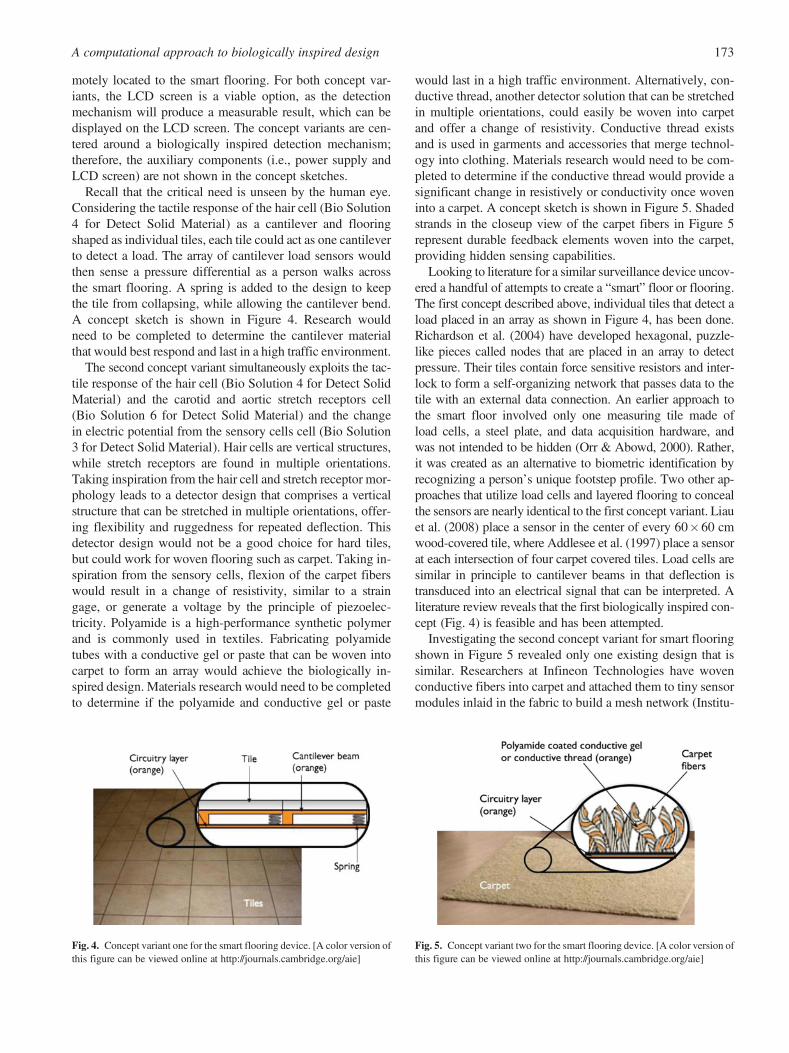
Recall that the critical need is unseen by the human eye.Considering the tactile response of the hair cell (Bio Solution4 for Detect Solid Material) as a cantilever and flooringshaped as individual tiles, each tile could act as one cantileverto detect a load. The array of cantilever load sensors wouldthen sense a pressure differential as a person walks acrossthe smart flooring. A spring is added to the design to keepthe tile from collapsing, while allowing the cantilever bend.A concept sketch is shown in Figure 4. Research wouldneed to be completed to determine the cantilever materialthat would best respond and last in a high traffic environment.
The second concept variant simultaneously exploits the tac-tile response of the hair cell (Bio Solution 4 for Detect SolidMaterial) and the carotid and aortic stretch receptors cell(Bio Solution 6 for Detect Solid Material) and the changein electric potential from the sensory cells cell (Bio Solution3 for Detect Solid Material). Hair cells are vertical structures,while stretch receptors are found in multiple orientations.Taking inspiration from the hair cell and stretch receptor mor-phology leads to a detector design that comprises a verticalstructure that can be stretched in multiple orientations, offer-ing flexibility and ruggedness for repeated deflection. Thisdetector design would not be a good choice for hard tiles,but could work for woven flooring such as carpet. Taking in-spiration from the sensory cells, flexion of the carpet fiberswould result in a change of resistivity, similar to a straingage, or generate a voltage by the principle of piezoelec-tricity. Polyamide is a high-performance synthetic polymerand is commonly used in textiles. Fabricating polyamidetubes with a conductive gel or paste that can be woven intocarpet to form an array would achieve the biologically in-spired design. Materials research would need to be completedto determine if the polyamide and conductive gel or paste
would last in a high traffic environment. Alternatively, con-ductive thread, another detector solution that can be stretchedin multiple orientations, could easily be woven into carpetand offer a change of resistivity. Conductive thread existsand is used in garments and accessories that merge technol-ogy into clothing. Materials research would need to be com-pleted to determine if the conductive thread would provide asignificant change in resistively or conductivity once woveninto a carpet. A concept sketch is shown in Figure 5. Shadedstrands in the closeup view of the carpet fibers in Figure 5represent durable feedback elements woven into the carpet,providing hidden sensing capabilities.
Looking to literature for a similar surveillance device uncov-ered a handful of attempts to create a “smart” floor or flooring.The first concept described above, individual tiles that detect aload placed in an array as shown in Figure 4, has been done.Richardson et al. (2004) have developed hexagonal, puzzle-like pieces called nodes that are placed in an array to detectpressure. Their tiles contain force sensitive resistors and inter-lock to form a self-organizing network that passes data to thetile with an external data connection. An earlier approach tothe smart floor involved only one measuring tile made ofload cells, a steel plate, and data acquisition hardware, andwas not intended to be hidden (Orr & Abowd, 2000). Rather,it was created as an alternative to biometric identification byrecognizing a person’s unique footstep profile. Two other ap-proaches that utilize load cells and layered flooring to concealthe sensors are nearly identical to the first concept variant. Liauet al. (2008) place a sensor in the center of every 60�60 cmwood-covered tile, where Addlesee et al. (1997) place a sensorat each intersection of four carpet covered tiles. Load cells aresimilar in principle to cantilever beams in that deflection istransduced into an electrical signal that can be interpreted. Aliterature review reveals that the first biologically inspired con-cept (Fig. 4) is feasible and has been attempted.
Investigating the second concept variant for smart flooringshown in Figure 5 revealed only one existing design that issimilar. Researchers at Infineon Technologies have wovenconductive fibers into carpet and attached them to tiny sensormodules inlaid in the fabric to build a mesh network (Institu-
Fig. 5. Concept variant two for the smart flooring device. [A color version ofthis figure can be viewed online at http://journals.cambridge.org/aie]
Fig. 4. Concept variant one for the smart flooring device. [A color version ofthis figure can be viewed online at http://journals.cambridge.org/aie]
A computational approach to biologically inspired design 173

tion of Electrical Engineers, 2003). The flooring can reportwhere a person is located, which way they are moving, andif a sensor module has failed. Each conductor in the designis a copper wire coated with silver to prevent corrosion andthen covered with polyester (Institution of Electrical En-gineers, 2003). A German textile company, Vorwerk, hasteamed up with Infineon to develop and market the smart car-pet (Vorwerk & Co., 2004; Crane, 2005). The Vorwerk/Infi-neon product is similar in structure to the second concept var-iant in that a conductor is concealed and woven into a textileproduct. In this design the conductor is copper where as in thesecond concept variant the conductor was proposed to be agel or thread that mimics the flexibility of carotid and aorticstretch receptors. Both suggest a protective coating for theconductor. A literature review revealed that the second bio-logically inspired concept (Fig. 5) is feasible.
6. CONCLUSIONS AND FUTURE WORK
Concept generation and synthesis is perhaps the most excit-ing, important, and challenging step of engineering design.This research makes fundamental contributions to engineer-ing design through the creation of a computational approachthat identifies biological solutions based on engineering func-tion. The key contributions of this research extend beyondcomputational design practices and biological information re-trieval. Our design tool represents a first step toward enablingwidespread biologically inspired concept generation, andsubsequently, biologically inspired design. In addition, thisresearch will enable engineers knowledgeable of customerneeds driven design activities, but a limited biological back-ground, to begin biomimetic design activities. Mimicking na-ture offers more than just the observable aspects that conjureup engineering solutions performing similar functions, butalso less obvious strategic and sustainable aspects. It is theseless obvious aspects that this research aims to facilitate as theyhold the greatest potential for impact.
The computational approach to biologically inspired designassists with developing biomimetic designs by presenting thedesigner with short descriptions of biological systems that per-form an engineering function of interest. From these descrip-tions the designer can make connections, similar to the processof Synectics (Prince, 1967, 1970) that correlate the biologicalsolutions to engineering solutions, principles, components,systems, and materials. A key part of the connection makingprocess is considering the biological systems from severalviewpoints. Multiple viewpoints can spur novel and innovativeideas (Prince, 1970). Integrating a strategic search method forindexing nonengineering information with an established com-putational concept generation method affords a computationalfoundation for accessing stored engineering information and,in this case, biological solutions for use with design activities.By placing the focus on function during concept generation, ra-ther than form or component, the computational approach pre-sented here has shown to successfully extract relevant biolog-
ical solutions. Example results from the proposed techniquewere demonstrated with a smart flooring example.
The illustrative smart flooring example demonstrates that itis possible to use a computational approach to identify bio-logical inspiration for engineering design. Biological solu-tions corresponding to the function/flow pairs of the concep-tual functional model for designing smart flooring as apotential security/surveillance device were discussed. Theconnections between the biological solutions and engineeringdomain for detect were analyzed. For the smart flooring ex-ample, the biological systems of the hair cell, action potentialsof sensory cells, and carotid and aortic stretch receptors of-fered strong connections to the engineering domain, whichwere used as inspiration to synthesize two concept variants.The other functions yielded informative results of how naturaland engineered systems utilize electrical energy. Validationof the concepts occurred through a literature review. Existingsystems that were very similar to both concept variants werefound. Therefore, both concept variants are considered feasi-ble. Our computational approach provides targeted resultsand prompts designers to make correlations across domains,which result in creative solutions.
Through the incorporation of the engineering to biology the-saurus in this algorithm, a 33% increase of relevant biologicalsolutions for the function of detect resulted when compared toprior organized search tool results in Stroble et al. (2009). Itshould also be noted that the 21 nonrelevant, biological resultsin Stroble et al. (2009) were ignored with this computationalapproach. Therefore, this approach is further validated at suc-cessfully extracting specific biological solutions that performthe functions/flow pairs of a conceptual functional model.
The biological domain provides many opportunities foridentifying connections between what is found in the naturalworld and engineered systems. It is important to understandthat the computational approach does not generate completeconcepts; that is, the task of the designer. However, it doesprovide a systematic method for discovering biological in-spiration based on function, so that it may be easier for the de-signer to make the necessary correlations leading to bio-logically inspired designs.
Future work includes the addition of hyperlinks to detailedbiological information, integration of images into the results,and implementation of search heuristics. Visuals can stimulatedesigners in a different manner than text alone. Search heuristicscould be applied to input functional models to reduce the num-ber of function/flow pairs that are searched by this approach,which would further reduce the necessary time and effort tofind relevant biological inspiration. Another avenue for this re-search is engineering education. The computational approachcould be used to assist engineering students with discoveringthe connections between the biology and engineering domains.
ACKNOWLEDGMENTS
This material is partly based on work supported by the National Sci-ence Foundation under Grant CMMI-0968410. Any opinions, find-
J.K.S. Nagel and R.B. Stone174

ings, and conclusions or recommendations expressed in this materialare those of the authors and do not necessarily reflect the views of theNational Science Foundation.
REFERENCES
Addlesee, M.D., Jones, A., Livesey, F., & Samaria, F. (1997). The ORL ac-tive floor. IEEE Personal Communication 4(5), 35–41.
Bar-Cohen, Y. (2006a). Biomimetics—Using nature to inspire human inno-vation. Journal of Bioinspiration and Biomimetics 1, P1–P12.
Bar-Cohen, Y. (2006b). Biomimetics Biologically Inspired Technologies.Boca Raton, FL: CRC Press/Taylor & Francis.
Bohm, M., Vucovich, J., & Stone, R. (2008). Using a design repository todrive concept generation. Journal of Computer and Information Sciencein Engineering 8(1), 14502–14508.
Bouchard, C., Omhover, J.-F., Mougenot, C., Aoussat, A., & Westerman, S.J.(2008). TRENDS: a content-based information retrieval system for de-signers. Proc. Design Computing and Cognition ’08, Vol. 4, pp. 593–611. Atlanta, GA: Springer Science þ Business Media B.V.
Brebbia, C.A. (2006). Design and Nature III: Comparing Design in NatureWith Science and Engineering. Southampton: WIT.
Brebbia, C.A. (2008). Design & Nature IV: Comparing Design in NatureWith Science and Engineering. Southampton: WIT.
Brebbia, C.A., & Carpi, A. (2010). Design & Nature V: Comparing Design inNature With Science and Engineering. Southampton: WIT.
Brebbia, C.A., & Collins, M.W. (2004). Design and Nature II: ComparingDesign in Nature With Science and Engineering. Southampton: WIT.
Brebbia, C.A., Sucharov, L.J., & Pascolo, P. (2002). Design and Nature:Comparing Design in Nature With Science and Engineering. Southampton:WIT.
Bryant, C., Bohm, M., McAdams, D., & Stone, R. (2007). An interactivemorphological matrix computational design tool: a hybrid of twomethods. Proc. ASME 2007 IDETC/CIE, Las Vegas, NV.
Bryant, C., McAdams, D., Stone, R., Kurtoglu, T., & Campbell, M. (2005). Acomputational technique for concept generation. Proc. 2005 ASMEIDETC/CIE, Long Beach, CA.
Bryant, C., Stone, R., McAdams, D., Kurtoglu, T., & Campbell, M. (2005).Concept generation from the functional basis of design. Proc. Int. Conf.Engineering Design, Melbourne, Australia.
Bryant Arnold, C.R., Stone, R.B., & McAdams, D.A. (2008). MEMIC: aninteractive morphological matrix tool for automated concept generation.Proc. Industrial Engineering Research Conf.
Chakrabarti, A., Sarkar, P., Leelavathamma, B., & Nataraju, B.S. (2005). Afunctional representation for aiding biomimetic and artificial inspirationof new ideas. Artificial Intelligence for Engineering Design, Analysisand Manufacturing 19(2), 113–132.
Cheong, H., Shu, L.H., Stone, R.B., & McAdams, D.A. (2008). Translatingterms of the functional basis into biologically meaningful words. 2008Proc. ASME IDETC/CIE, New York.
Chiu, I., & Shu, L.H. (2007a). Biomimetic design through natural languageanalysis to facilitate cross-domain information retrieval. Artificial Intelli-gence for Engineering Design, Analysis and Manufacturing 21(1), 45–59.
Chiu, I., & Shu, L.H. (2007b). Using language as related stimuli for conceptgeneration. Artificial Intelligence for Engineering Design, Analysis andManufacturing 21(2), 103–121.
Crane, D. (2005). New high-tech sensor-laden smart carpet may revolutio-nize building security. Defense Review. Accessed at http://www.defensereview.com/new-high-tech-sensor-laiden-smart-carpet-may-revolutionize-building-security/
Cross, N. (2008). Engineering Design Methods: Strategies for Product De-sign. Chichester: Wiley.
Dym, C.L., & Little, P. (2004). Engineering Design: A Project-Based Intro-duction. New York: Wiley.
Gordon, W.J.J. (1961). Synectics, the Development of Creative Capacity.New York: Harper.
Helms, M., Vattam, S.S., & Goel, A.K. (2009). Biologically inspired design:products and processes. Design Studies 30(5), 606–622.
Hirtz, J., Stone, R., McAdams, D., Szykman, S., & Wood, K. (2002). A func-tional basis for engineering design: reconciling and evolving previous ef-forts. Research in Engineering Design 13(2), 65–82.
Hong-Zhong, H., Bo, R., & Chen, W. (2006). An integrated computationalintelligence approach to product concept generation and evaluation.Mechanism and Machine Theory 41(5), 567–583.
Hyman, B. (1998). Engineering Design. Englewood Cliffs, NJ: Prentice–Hall.Institution of Electrical Engineers. (2003). Research news—walk this way for
the smart floor. Electronics Systems and Software 1(3), 5–7.Jin, Y., & Li, W. (2007). Design concept generation: a hierarchical coevolu-
tionary approach. Journal of Mechanical Design 129(10), 1012–1022.Kurfman, M., Stone, R., Rajan, J., & Wood, K. (2003). Experimental studies
assessing the repeatability of a functional modeling derivation method.Journal of Mechanical Design 125(4), 682–693.
Kurtoglu, T., Campbell, M.I., Bryant, C.R., Stone, R.B., & McAdams, D.A.(2009). A component taxonomy as a framework for computational designsynthesis. Journal of Computing and Information Science in Engineering9(1), 011007.
Kurtoglu, T., Swantner, A., & Campbell, M.I. (2008). Automating the con-ceptual design process: from black-box to component selection. Proc.Design Computing and Cognition ’08, Vol. 7, pp. 553–572. Atlanta,GA: Springer Science þ Business Media B.V.
Liau, W.-H., Wu, C.-L., & Fu, L.-C. (2008). Inhabitants tracking system in acluttered home environment via floor load sensors. IEEE Transactions onAutomation Science and Engineering 5(1), 10–20.
Lindemann, U., & Gramann, J. (2004). Engineering design using biologicalprinciples. Proc. Int. Design Conf., Design ’04, Dubrovnik.
Linsey, J., Wood, K., & Markman, A. (2008). Modality and representation inanalogy. Artificial Intelligence for Engineering Design, Analysis andManufacturing 22(2), 85–100.
Lopez-Huertas, M.J. (1997). Thesarus structure design: a conceptual approachfor improved interaction. Journal of Documentation 53(2), 139–177.
Mak, T.W., & Shu, L.H. (2008). Using descriptions of biological phenomenafor idea generation. Research in Engineering Design 19(1), 21–28.
Nagel, J.K.S., Stone, R.B., & McAdams, D.A. (2010). An engineering-to-biology thesaurus for engineering design. Proc. 2010 ASME IDETC/CIE, Montreal.
Nagel, R., Tinsley, A., Midha, P., McAdams, D., Stone, R., & Shu, L. (2008).Exploring the use of functional models in biomimetic design. Journal ofMechanical Design 130(12), 11–23.
Nagel, R.L., Stone, R., & McAdams, D. (2007). A theory for the develop-ment of conceptual functional models for automation of manual pro-cesses. Proc. 2007 ASME IDETC/CIE, Las Vegas, NV.
Orr, R.J., & Abowd, G.D. (2000). The smart floor: a mechanism for naturaluser identification and tracking. Proc. Conf. Human Factors in Comput-ing Systems (CHI), The Hague.
Otto, K.N., & Wood, K.L. (2001). Product Design: Techniques in ReverseEngineering and New Product Development. Upper Saddle River, NJ:Prentice–Hall.
Pahl, G., Beitz, W., Feldhusen, J., & Grote, K.H. (2007). Engineering De-sign: A Systematic Approach. Berlin: Springer–Verlag.
Prince, G.M. (1967). The operational mechanism of synectics. Journal ofCreative Behavior 2(1), 1–13.
Prince, G.M. (1970). The Practice of Creativity. New York: Collier Books.Purves, W.K., Sadava, D., Orians, G.H., & Heller, H.C. (2001). Life, The Sci-
ence of Biology. Sunderland, MA: Sinauer Associates.Richardson, B., Leydon, K., Fernstrom, M., & Paradiso, J.A. (2004). Z-Tiles:
building blocks for modular, pressure-sensing floorspaces. Proc. Conf.Human Factors in Computing Systems (CHI), Vienna.
Shu, L.H., Hansen, H.N., Gegeckaite, A., Moon, J., & Chan, C. (2006). Casestudy in biomimetic design: handling and assembly of microparts. Proc.ASME 2006 IDETC/CIE, Philadelphia, PA.
Srinivasan, V., & Chakrabarti, A. (2009). SAPPhIRE—an approach to anal-ysis and synthesis. Proc. Int. Conf. Engineering Design, Stanford, CA.
Stone, R., & Wood, K. (2000). Development of a functional basis for design.Journal of Mechanical Design 122(4), 359–370.
Stroble, J.K., Stone, R.B., McAdams, D.A., & Watkins, S.E. (2009). Anengineering-to-biology thesaurus to promote better collaboration, crea-tivity and discovery. Proc. CIRP Design Conf. 2009, pp. 353–368, Cran-field.
Ullman, D.G. (2009). The Mechanical Design Process, 4th ed. New York:McGraw–Hill.
Ulrich, K.T., & Eppinger, S.D. (2004). Product Design and Development.Boston: McGraw–Hill/Irwin.
Vincent, J.F.V., Bogatyreva, O.A., Bogatyrev, N.R., Bowyer, A., & Pahl,A.-K. (2006). Biomimetics: its practice and theory. Journal of the RoyalSociety Interface 3, 471–482.
A computational approach to biologically inspired design 175

Voland, G. (2004). Engineering by Design. Upper Saddle River, NJ: PearsonPrentice Hall.
Vorwerk & Co. (2004). Infineon Thinking Carpet. Wuppertal, Germany:Vorwerk.
Wen, H.-I., Zhang, S.-j., Hapeshi, K., & Wang, X.-f. (2008). An innovativemethodology of product design from nature. Journal of Bionic Engineer-ing 5(1), 75–84.
Wilson, J., Chang, P., Yim, S., & Rosen, D. (2009). Developing a bio-inspireddesign repository using ontologies. Proc. 2009 ASME IDETC/CIE.
Wood, W.H., Yang, M.C., Cutkosky, M.R., & Agogino, A.M. (1998). De-sign information retrieval: improving access to the informal side of de-sign. Proc. ASME 1998 IDETC/CIE, Atlanta, GA.
Yao, Zu, Xiao, R., & Zhang, X. (2009). Automated conceptual design ofmechanisms using enumeration and functional reasoning. InternationalJournal of Materials and Product Technology 34(3), 273–294.
Jacquelyn K. S. Nagel is currently an Assistant Professor inthe School of Engineering at James Madison University.She worked as an engineering contractor at Mission CriticalTechnologies prior to James Madison University. Jacquelynobtained her PhD in mechanical engineering from OregonState University researching biologically inspired design.
Jacquelyn earned her MS and BS in manufacturing engi-neering and electrical engineering, respectively, from theUniversity of Missouri–Rolla (now known as MissouriUniversity of Science and Technology). Her research inter-ests include sensor technology, biomimicry, engineering de-sign, optics/photonics, applied control theory, robotics, andautomation.
Robert B. Stone is a Professor and the Interim Head of theSchool of Mechanical, Industrial, and Manufacturing Engi-neering at Oregon State University. He was a DistinguishedVisiting Professor in the Department of Engineering Me-chanics at the US Air Force Academy from 2006 to 2007.He attained his PhD from the University of Texas at Austin.Prior to initiating his graduate work, Dr. Stone worked inthe Missions Operation Directorate of NASA Johnson SpaceCenter as a Space Shuttle Flight Controller for the Guidance,Navigation, and Control Section. Rob has received numerousawards for his research in product design.
J.K.S. Nagel and R.B. Stone176