A comprehensive approach to on-board autonomy verification and validation
10
A Comprehensive Approach to On-Board Autonomy Verification and Validation M. Bozzano, A. Cimatti, M. Roveri, A. Tchaltsev Fondazione Bruno Kessler {bozzano,cimatti,roveri,tchaltsev}@fbk.eu Abstract Deep space missions are characterized by severely con- strained communication links and often require intervention from Ground to overcome the difficulties encountered dur- ing the mission. An adequate Ground control could be com- promised due to communication delays and required Ground decision-making time, endangering the system, although saf- ing procedures are strictly adhered to. To meet the needs of future missions and increase their scientific return, space sys- tems will require an increased level of autonomy on-board. We propose a comprehensive approach to on-board auton- omy relying on model-based reasoning. This approach en- compasses in a uniform formal framework many important reasoning capabilities needed to achieve autonomy (such as plan generation, plan validation, plan execution and monitor- ing, fault detection identification and recovery, run-time di- agnosis, and model validation). The controlled platform is represented symbolically, and the reasoning capabilities are seen as symbolic manipulation of such formal model. In this approach we separate out the discrete control parts and the continuous parts of the domain model (e.g., resources such as the power consumed or produced and the data acquired during an execution of a certain action) to facilitate the de- liberative actions. The continuous part is associated to the discrete part by means of the resource estimation functions, that are taken into account while validating the generated plan and while monitoring the execution of the current plan. We have developed a prototype of this framework and we have plugged it within an Autonomous Reasoning Engine. This engine has been evaluated on two case studies inspired by real-world ongoing projects: a planetary rover and an or- biting spacecraft. We have performed a characterization of the approach in terms of reliability, availability and perfor- mances both on a desktop platform and on a spacecraft simu- lator. Introduction Deep space and remote planetary exploration missions are characterized by severely constrained communication links. Limited spacecraft visibility, reduced data rates and high communication latency do not allow for the real-time con- trol by Ground operators. For the surface missions, high Copyright c 2009, Association for the Advancement of Artificial Intelligence (www.aaai.org). All rights reserved. level of interaction with the environment may require sig- nificant efforts from Ground control, implying high cost of operations. Furthermore, adequate Ground control could be compromised due to communication delays and required Ground decision-making time, endangering the system, al- though safing procedures are strictly adhered to. To meet the needs of future missions and increase their scientific return, space systems will require an increased level of intelligence on-board. Taking autonomous decisions through creating their own plans based on up-to-date infor- mation, and re-planning in response to unexpected events or anomalous conditions, would greatly improve the efficiency of a mission, system safety, and potentially reduce the cost of Ground operations. In this paper we propose a solution to on-board auton- omy relying on symbolic model-based reasoning. Our ap- proach integrates plan generation, plan execution and moni- toring, fault detection isolation and recovery, and run-time diagnosis functionalities in a common formal framework. This framework relies on a symbolic representation of the system to control, and allows to capture the intrinsic partial observability of the controlled system (available system sen- sors may not allow for conclusive determination of the con- trolled components’ status). We propose to use safe assump- tion based contingent plans. These plans at execution time sense the world and, depending on the state of the world, can execute different actions. Moreover, they are annotated with conditions to help monitoring whether the assumptions under which the plan was generated for are satisfied dur- ing the execution. All the autonomy functionalities (plan generation, validation, execution, monitoring and FDIR) are seen as symbolic transformations applied to the symbolic representation of the controlled system. We remark that, this framework allows for the application of model check- ing techniques to validate the model of the controlled sys- tem and to perform checks for diagnosability. The formal framework separates the discrete part of the system to con- trol from the continuous parts (e.g. power consumption, pro- duced data) to facilitate deliberative reasoning. This solu- tion has been developed in response to an invitation to ten- der of the European Space Agency aiming at developing an integrated uniform approach for model based on board au- tonomy (OMC-ARE 2008) relying on model checking tech- niques.
-
Upload
independent -
Category
Documents
-
view
2 -
download
0
Transcript of A comprehensive approach to on-board autonomy verification and validation

A Comprehensive Approach to On-Board Autonomy Verification and Validation
M. Bozzano, A. Cimatti, M. Roveri, A. TchaltsevFondazione Bruno Kessler
{bozzano,cimatti,roveri,tchaltsev}@fbk.eu
Abstract
Deep space missions are characterized by severely con-strained communication links and often require interventionfrom Ground to overcome the difficulties encountered dur-ing the mission. An adequate Ground control could be com-promised due to communication delays and required Grounddecision-making time, endangering the system, although saf-ing procedures are strictly adhered to. To meet the needs offuture missions and increase their scientific return, space sys-tems will require an increased level of autonomy on-board.We propose a comprehensive approach to on-board auton-omy relying on model-based reasoning. This approach en-compasses in a uniform formal framework many importantreasoning capabilities needed to achieve autonomy (such asplan generation, plan validation, plan execution and monitor-ing, fault detection identification and recovery, run-time di-agnosis, and model validation). The controlled platform isrepresented symbolically, and the reasoning capabilities areseen as symbolic manipulation of such formal model. In thisapproach we separate out the discrete control parts and thecontinuous parts of the domain model (e.g., resources suchas the power consumed or produced and the data acquiredduring an execution of a certain action) to facilitate the de-liberative actions. The continuous part is associated to thediscrete part by means of the resource estimation functions,that are taken into account while validating the generated planand while monitoring the execution of the current plan.We have developed a prototype of this framework and wehave plugged it within an Autonomous Reasoning Engine.This engine has been evaluated on two case studies inspiredby real-world ongoing projects: a planetary rover and an or-biting spacecraft. We have performed a characterization ofthe approach in terms of reliability, availability and perfor-mances both on a desktop platform and on a spacecraft simu-lator.
IntroductionDeep space and remote planetary exploration missions arecharacterized by severely constrained communication links.Limited spacecraft visibility, reduced data rates and highcommunication latency do not allow for the real-time con-trol by Ground operators. For the surface missions, high
Copyright c© 2009, Association for the Advancement of ArtificialIntelligence (www.aaai.org). All rights reserved.
level of interaction with the environment may require sig-nificant efforts from Ground control, implying high cost ofoperations. Furthermore, adequate Ground control couldbe compromised due to communication delays and requiredGround decision-making time, endangering the system, al-though safing procedures are strictly adhered to.
To meet the needs of future missions and increase theirscientific return, space systems will require an increasedlevel of intelligence on-board. Taking autonomous decisionsthrough creating their own plans based on up-to-date infor-mation, and re-planning in response to unexpected events oranomalous conditions, would greatly improve the efficiencyof a mission, system safety, and potentially reduce the costof Ground operations.
In this paper we propose a solution to on-board auton-omy relying on symbolic model-based reasoning. Our ap-proach integrates plan generation, plan execution and moni-toring, fault detection isolation and recovery, and run-timediagnosis functionalities in a common formal framework.This framework relies on a symbolic representation of thesystem to control, and allows to capture the intrinsic partialobservability of the controlled system (available system sen-sors may not allow for conclusive determination of the con-trolled components’ status). We propose to use safe assump-tion based contingent plans. These plans at execution timesense the world and, depending on the state of the world,can execute different actions. Moreover, they are annotatedwith conditions to help monitoring whether the assumptionsunder which the plan was generated for are satisfied dur-ing the execution. All the autonomy functionalities (plangeneration, validation, execution, monitoring and FDIR) areseen as symbolic transformations applied to the symbolicrepresentation of the controlled system. We remark that,this framework allows for the application of model check-ing techniques to validate the model of the controlled sys-tem and to perform checks for diagnosability. The formalframework separates the discrete part of the system to con-trol from the continuous parts (e.g. power consumption, pro-duced data) to facilitate deliberative reasoning. This solu-tion has been developed in response to an invitation to ten-der of the European Space Agency aiming at developing anintegrated uniform approach for model based on board au-tonomy (OMC-ARE 2008) relying on model checking tech-niques.

The spacecraft is equipped with an Autonomous Reason-ing Engine (ARE). The ARE is structured according to ageneric three-layer hybrid autonomy architecture. The De-liberative layer provides goal-driven planning and schedul-ing, plan validation and system-level fault detection, isola-tion and recovery (FDIR) facilities. The Executive layer pro-vides facilities to execute and monitor the correct executionof the current mission plan. The Control layer provides low-level interactions with the controlled system (sensor acqui-sition and commands to actuators sending). The Deliber-ative and Executive layers use the symbolic representationof the system for all the reasoning. While, the feedbackcontrol loop algorithms of the Control layer are not basedon symbolic reasoning, but rely on complex numerical com-putations. Such computations are directly connected to thesymbolic representation of the system through resource es-timation functions and logical predicates that provide an ab-straction of the computation results and of the sensing. Inthis way, the computation steps are interleaved with logicalreasoning at the higher levels. The formal model the AREoperates on captures The model is used in the Deliberativelayer for mission plan validation, for re-planning, and forsystem-level FDIR (e.g. by re-planning to solve the identi-fied problem). The Executive layer uses the formal modelfor plan execution and monitoring to detect if an anomaly(i.e. fault, anomalous resource consumption) preventing theachievement of the mission goal occurred. The Control layeruses the model to encode low-level sensor information, andto decode commands to be sent to actuators.
We have developed a prototype of the ARE. It relies onNUSMV, a symbolic model checker for the efficient manip-ulation of a symbolic representation of a system. On top ofits primitives, we have built all the algorithms of the ARE(including plan generation, validation, execution and mon-itoring, and FDIR). The ARE is largely independent of thecontrolled system: the upper layers are application indepen-dent, bound to the application domain through the systemmodel description; the dependencies related to the low-levelplatform interactions are localized in the Control layer thatcan be customized through dedicated APIs. The ARE re-lies on the POSIX C libraries of the RTEMS operating sys-tem, and can thus be easily adapted to any system providingPOSIX compliant interfaces.
The approach has been evaluated on three case studies (aplanetary rover, a simplified planetary rover, and an orbitingspacecraft), all inspired by real-world, ongoing projects. Foreach case study, a symbolic representation of the spacecraftwas built. It was then validated using symbolic model check-ing techniques before deploying it within the ARE. We thenperformed a characterization in terms of reliability, avail-ability and performances using a spacecraft simulator. Thespacecraft simulator is parametrized on the functional modelof the spacecraft to simulate (i.e. in this case the two variantof the planetary rover and the orbiting spacecraft). It alsoinclude the on-board software framework which in turn isrun on a real hardware target emulator. This architecture al-lows to evaluate ARE in a platform that is very similar tothe one used in real missions. The evaluation relies on sce-narios where re-planning is necessary to take into account
possible failures or anomalies caused by changes in the en-vironment, including cases of partial observability resultingfrom the interaction of failures and anomalies. The prelim-inary experimental evaluation showed the feasibility of theapproach, although a lot of work has still to be done to bereally deployed on-board as to use them in real missions.
This paper is structured as follows. First we present themodeling and reasoning framework. Then we present theARE and we describe the experimental evaluation we car-ried out on deploying the proposed solution on a real spaceplatform. Finally we discuss related work and we draw someconclusions and future work.
Modeling and Reasoning FrameworkFormal Model of the SystemWe model the system to control following the Planning asModel Checking approach presented in (Cimatti et al. 2003;Cimatti and Roveri 2000; Bertoli et al. 2006), and extendingit to allow to reason about resources (continuous variableslike e.g. the power consumed by the system).
Definition 1 (System) A system is a tuple M =〈S, I,A, T ,Q,L,O,F ,R,RS〉 where:
• S is a finite set of states;• I ⊆ S is a set of initial states;• A is a finite set of actions;• T : S ×A → 2S is the transition relation;• O is a finite set of observations;• X : S → 2O is the observation function;• R is a finite set of resources;• RS : 2S → (R→ R2) is resource estimation function.
We require that some observation is associated to each states ∈ S, that is, X (s) 6= ∅.
The model of the system include both the nominal behaviorand the behavior when faults occurred.
Resources R are represented by rational numbers. Re-source estimation function RS provides an estimate of re-sources in set of states. RS(S) is a resource estimationfunction which maps resources to their lower and highervalues. For RS(S, r) = 〈m,M〉, with m ≤ M , we useRS(S, r)l = m and RS(S, r)h = M respectively to referto lower and upper bound values of the resources r in the setof states S. We say that RS(S1) ≤R RS(S2) (RS(S1) isless then, or equal to, RS(S2)) iff ∀r ∈ R.RS(S1, r)h 6≤RS(S2, r)l, and RS(S1) ≤R RS(S2) (RS(S1) is not lessthen, or equal to, RS(S2)) iff ∃r ∈ R.RS(S1, r)hnot ≤RS(S2, r)l.
This representation separates out the discrete control partand the continuous parts (e.g., resources such as the powerconsumed or produced and the data acquired during an ex-ecution of a certain action) to facilitate model based vali-dation and the deliberative actions. The continuous part isassociated to the discrete part by means of the resource esti-mation function.
Given an action a ∈ A, the precondition of an action a isthe set of states pre(a) = {s ∈ S | ∃s′ ∈ S, 〈s, a, s′〉 ∈ T }.An action a can be applied to a state s ∈ S (set of states
S) only if s ∈ pre(a) (S ⊆ pre(a)). Otherwise, s has (Scontains states with) no successors if action a is applied.
The system is fully observable if O = S and X (s) = s.We write S[o,>] to denote the set {s ∈ S|o ∈ X (s)}, ofstates compatible with observation o, and dually S[o,⊥] todenote the set {s ∈ S|∃o′ ∈ X (s), o′ 6= o} of states thatare compatible with any observation other than o. The set ofstates indistinguishable from a set S ⊆ S, written IND(S), isthe set IND(S) = {s ∈ S | ∃s′ ∈ S.∀o ∈ O(o ∈ X (s) ⇐⇒o ∈ X (s′))}. In other words, states indistinguishable froma set S are such that there exists an observation which makeit impossible to detect if the states are in S or not. The setof states indistinguishable from S always includes S, i.e.S ⊆ IND(S).
We remark that this formalization of the system model isindependent from the language used to specify it.
Model validationHaving a formal model in terms of Kripke structure allowsto validate the model to guarantee it really captures the be-haviors of the system. Validation of the model of the systemcan be performed with model checking techniques (Clarke,Grumberg, and Peled 1999). Temporal logic formulae ex-pressed e.g. in Linear Temporal Logic (LTL) (Pnueli 1977),or in Computational Tree Logic (CTL) (Emerson 1990),or even in more expressive logic like e.g. the PropertySpecification Language (PSL) (PSL 2005) which combinesLTL with Regular Expressions (Hopcroft and Ullman 1979)to express omega regular languages can be used to ex-press expected behaviors of the system. These formulaeare then validated with the classical Binary Decision Dia-grams (BDD) (Bryant 1992) symbolic model checking tech-niques (McMillan 1993) or with Bounded Model Check-ing (BMC) techniques based on propositional satisfiabil-ity (Biere et al. 2003).
To manage the complexity of the model and of the val-idation abstraction techniques like predicate abstraction (S.Graf and H. Saidi 1997) and Counterexample-Guided Ab-straction Refined (CEGAR) loop (Clarke et al. 2000) canbe applied. The CEGAR loop consists of four phases: ab-straction, where the abstract system is built according toa given set of predicates; verification, where the abstractsystem is model checked and a if the verification succeedsthen also the concrete system is correct; otherwise, an coun-terexample trace is produced; simulation, to check whetherthe abstract trace has a realistic counterpart in the con-crete system (in this case the verification fails and a coun-terexample is generated); refinement: if the simulation ofthe abstract trace in the concrete system fails, new pred-icates to rule out the unrealistic path are added and theloop is iterated. The abstract model of the system canbe computed with regards to the set of predicates P overstate variables Q at each iteration. The abstraction can becomputed efficiently by means of decision procedures andby enumerating the models (satisfying assignments) to theabstract variables corresponding to the predicates used inthe abstraction (Lahiri, Nieuwenhuis, and Oliveras 2006;Cavada et al. 2007).
We also remark, that using BMC techniques extended to
use a Satisfiability Modulo Theory (SMT) solver instead ofa pure propositional SAT solver it would be also possible toconsider in the validation the continuous component of thesystem.
Plan generation, validation, execution andmonitoringThe planning problem consists in finding a plan that whenexecuted will allow to achieve the goal. In the planning com-munity, different notions of goal and different kind of solu-tions to a planning problem have been studied. (See (Cimattiet al. 2003; Cimatti and Roveri 2000; Bertoli et al. 2006;Ghallab, Nau, and Traverso 2005; Bozzano, Cimatti, andRoveri 2007) for a thorough discussion.) In this work we re-strict to consider reachability goals only (Cimatti et al. 2003;Cimatti and Roveri 2000; Bertoli et al. 2006). Reachabilitygoals are characterized by a non-empty set of states G ⊆ Sthat the system to control is aimed to achieve.
In the setting of planning in non-deterministic do-mains, different notions of plan strength have been consid-ered (Ghallab, Nau, and Traverso 2005). In this work werestrict to weak and strong plans (Cimatti et al. 2003). Weakplans are plans that have a chance to reach the goal, whilestrong plans are plans that are guaranteed to achieve the goaldespite the non-determinism and the partial observability ofthe controlled system. Intuitively, a plan P is a weak so-lution to the planning problem of reaching a goal G from anon-empty set of states S, iff the plan is such that all theactions in it are applicable in the set of states that can beachieved by progressing the set of initial states S till the cur-rent point of action execution; and the set of states that canbe reached by progressing the set of initial states followingall the possible branches of the plan has a non-empty inter-section with the set of goal states. This means, that thereexists an execution of the plan that can reach the goal. How-ever, because of non-determinism it might be the case thatafter the execution of the plan, the controlled system is not inthe goal state. On the contrary, strong plans are such that theexecution of the plan is guaranteed to achieve the goal, de-spite the non-determinism of the controlled system and theincomplete run-time information. That’s all executions areguaranteed to achieve the goal.
Planning under partial observability requires to be able toreason about the uncertainty in which state exactly the sys-tem is (because of the non-determinism in transition relationT and of the partial observability). Belief states (Bonet andGeffner 2000; Cimatti, Roveri, and Bertoli 2004; Bertoli etal. 2006) (i.e. non empty set of states in S) have been in-troduced to allow for this kind of reasoning. Planning un-der partial observability consists in finding a contingent planthat at execution time sense the world via observations and,depending on the state of the world, can execute differentactions. Thus, contingent plans allow for conditional execu-tion depending on the status of the system. Planning underpartial observability in non-deterministic domain is an ex-tremely hard task, and it is often the case that strong plansdo not exist. However, in many cases it is possible to expressreasonable assumptions over the expected dynamics of thecontrolled system, e.g. by identifying “nominal” behaviors.
Using these assumptions to constrain the search may greatlyease the planning task, allowing for an efficient construc-tion of assumption-based solutions. The assumptions takenwhen generating a plan may turn out to be incorrect whenexecuting the plan.
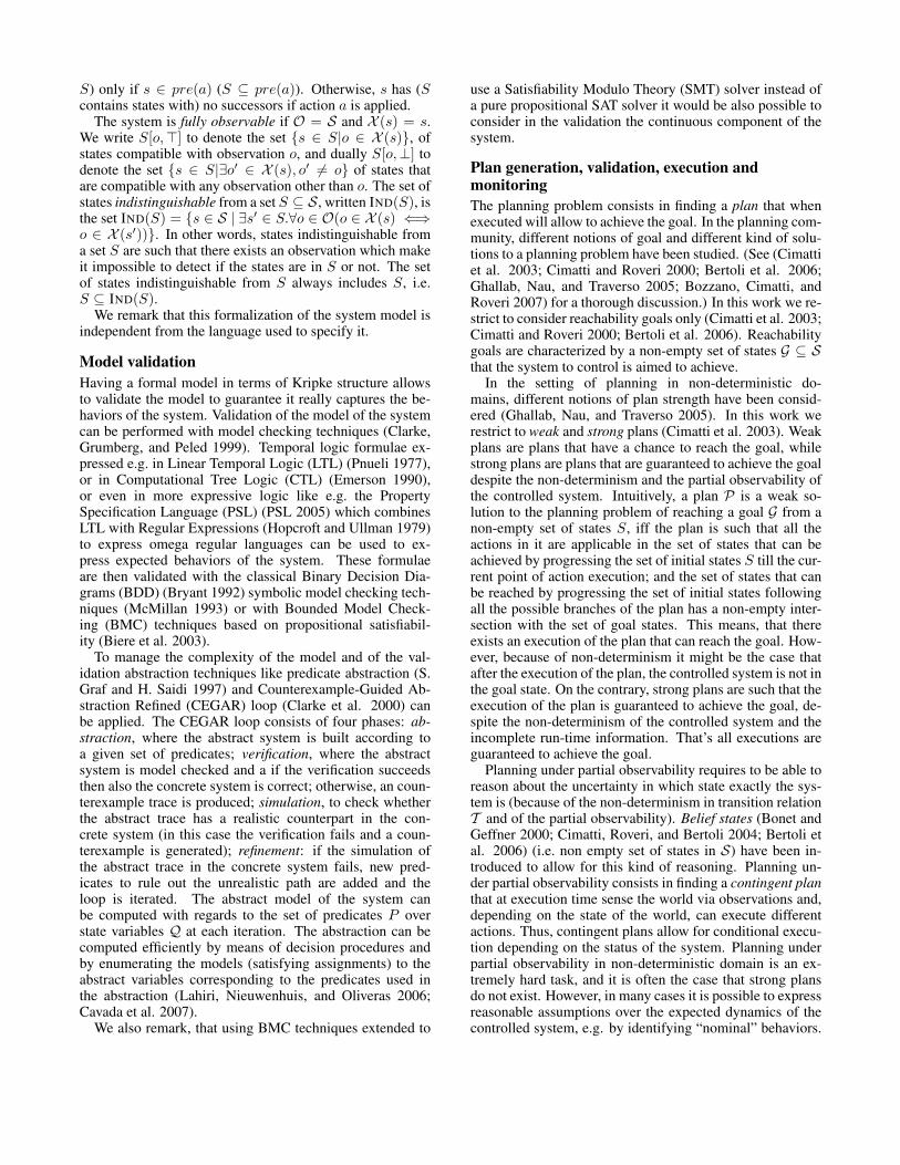
Thus, assumption-based plans must be executed withinreactive architectures (likee.g. the one of Figure 1)where a monitoring compo-nent traces the status of thedomain, in order to abort planexecution and take correctiveactions activating FDIRwhenever an unexpectedbehavior (e.g. violation ofthe assumptions) has com-promised the success of theplan.
Plan
Execute &Monitor
Plant
FDIR
ObsAct
HWPlan
Figure 1: The approach.
In (Albore and Bertoli 2004; 2006) has been consideredthe possibility to specify assumptions over the domain dy-namic using the LTL temporal logic (Pnueli 1977), and hasbeen proposed a planning algorithm to generate safe (con-tingent) LTL assumption-based plans for non-deterministic,partially observable domains. A safe plan not only guar-antee that the goal is reached when the given assumptionholds, but also guarantee that, during its execution, the mon-itor will be able to unambiguously distinguish whether thecurrent status of the controlled system has been planned foror not. In this way, it is possible to guarantee that, duringplan execution, the monitor will not trigger any plan abortionunless really needed. In this work we restrict to assumptionsof type invariants: i.e. conditions the systems is suppose toobey at each point during the execution of the plan. Theseassumptions are introduced to simplify plan generation bydecreasing the search state space.
We remark that, since we are in the setting of partial ob-servability there may be uncertainty whether the assump-tions are satisfied. To this extent, we annotate contingentplans with additional information, built at planning time, inorder to monitor the satisfaction of the assumptions at run-time.
Definition 2 (Plan with Assumptions) A plan PAs withassumptions As is a tuple 〈Sg, Spb, P 〉 where Sg ⊆ S isa set of “good” states, Spb ⊆ S is a set of “possibly bad”states and sub-plan P is either:• an empty plan ε;• a sequence a :: PAs , where a ∈ A is an action;• a conditional plan ite(o,PAs
1,PAs2), where o ∈ O is
an observation.
Sets Sg and Spb are introduced to allow monitoring of theplan execution and checking if assumptions hold. The in-tuition is the following. Set Sg consists of such states thatthe assumptions hold in these states and their predecessors.Set Spb includes Sg and may additionally have states indis-tinguishable from Sg such that the assumptions are violatedin these states or their predecessors. I.e. if during executionthe assumptions always holds than at every step the beliefset of states has to be a subset of Sg . But if the assumptions
have been violated and it has not been detected then the be-lief states may only partly intersect with Sg but still have tobe a subset of Spb.
Contingent plans with assumptions can be constructedby the algorithm presented in (Albore and Bertoli 2006)simplified to only deal with assumptions of type invariantAs . The pseudo-code of the modified algorithm is presentedin (OMC-ARE 2008).
In the following we assume PAs to be a plan with as-sumptions built to monitor the satisfaction of the invariantAs using the adaption of the planning algorithm of (Alboreand Bertoli 2006) as presented in (OMC-ARE 2008). Wealso assume given a resource assignmentRMIN specifyingthe minimal values the resources are allowed to assume dur-ing plan execution. If this limit is violated the plan executionfails.
We can formally present the execution of a plan with as-sumptions starting from a belief state S, assuming a resourceassignment RMIN as follows. Let PAs = 〈Sg, Spb, P 〉be a plan with assumptions, and let S ⊆ S be a set ofstates, SG = S and SPB = IND(S).. The sets of statesresulting by the execution of PAs from 〈SG, SPB〉, writtenEXEC[PAs ](SG, SPB) can be computed recursively on thestructure of the plan as follows (below we allow EXEC[]() tobe applied to plan PAs as well as to sub-plan P ):
• EXEC[〈GS ,BS , P 〉](SG, SPB) = 〈∅, ∅〉 if SG 6⊆ GS ∨SPB 6⊆ BS ;
• EXEC[〈GS ,BS , P 〉](SG, SPB) = EXEC[P ](SG, SPB) ifSG ⊆ GS ∧ SPB ⊆ BS ;
• EXEC[ε](SG, SPB) = 〈∅, ∅〉 if RMIN 6≤R RS(SPB);• EXEC[ε](SG, SPB) = 〈SG, SPB〉 if RMIN ≤RRS(SPB);
• EXEC[a :: PAs ](SG, SPB) = 〈∅, ∅〉 if SPB 6⊆ pre(a) ∨RMIN 6≤R RS(SPB);
• EXEC[a :: PAs ](SG, SPB) = EXEC[PAs ](S′G, S′PB ∩IND(S′G)) if SPB ⊆ pre(a) ∧ RMIN ≤R RS(SPB)where S′G = {s′ : s ∈ SG ∧ s′ ∈ As ∧ 〈s, a, s′〉 ∈ T }and S′PB = {s′ : s ∈ SPB ∧ 〈s, a, s′〉 ∈ T };
• EXEC[ite(o,PAs1,PAs
2)](SG, SPB) = 〈∅, ∅〉if EXEC[PAs
1](SG[o,>], SPB [o,>]) = 〈∅, ∅〉 ∨EXEC[PAs
2](SG[o,⊥], SPB [o,⊥]) = 〈∅, ∅〉• EXEC[ite(o,PAs
1,PAs2)](SG, SPB) = 〈S>G ∪
S⊥G , SPB> ∪ SPB
⊥〉 if 〈S>G , SPB>〉 6= 〈∅, ∅〉 ∧
〈S⊥G , SPB⊥〉 6= 〈∅, ∅〉 where 〈S>G , SPB
>〉 =EXEC[PAs
1](SG[o,>], SPB [o,>]) and 〈S⊥G , SPB⊥〉 =
EXEC[PAs2](SG[o,⊥], SPB [o,⊥])
This definition is such that after plan execution the obtainedsets 〈S′G, S′PB〉 = EXEC[PAs ](SG, SPB) S′G remains to bea subset of S′PB . Intuitively, set S′G consists of the stateswhose predecessors satisfy the assumption. Set S′PB con-sists of the states whose predecessors may violate the as-sumptions but are indistinguishable from corresponding pre-decessors in S′G. Thus after applying an action the set S′G isconstrained to be a subset of the assumptions As , whereasstates of S′PB may violate the assumptions but have to be in-distinguishable from S′G. In the fifth and sixth items above,
we check whether SPB is contained in the precondition ofthe action a to execute, since at run-time while executingthe plans, we cannot distinguish the states in SG from thestates in SPB because of partial observability. Moreover, ifthe action is applicable in SPB it is also applicable in SG
(since SG ⊆ SPB). The distinguishable states removedfrom S′PB after applying an action (i.e. S′PB \ IND(S′G))are those which may be reached only by violating the as-sumptions. If such a state is indeed reached during a realexecution of the plan on an real system then this is alwaysdetectable and has to cause the plan termination. Neverthe-less, such plan can be considered valid since the cause of theproblem is in the incorrect assumptions, not in the plan. Inthe execution of a plan PAs , the resources estimation func-tion is computed w.r.t. the possibly bad states SPB since thisis the set of states that can be observed at run-time becauseof partial observability. This choice results in consideringa more pessimistic approach to the resource consumption.Indeed, if the resources are good for such belief state, thanthey are good also for the set of good states. Different no-tions of validity w.r.t. resources can be defined as to relax orto strength this definition thus allowing for different notionsof planning success criteria.
A plan with assumptions PAs , given a resource assign-ment RMIN specifying the minimal values the resourcesare allowed to assume during plan execution, is applicablein S ⊆ S iff plan’s initials SG = S ∩ As and SPB =S ∩ IND(SG) are non empty and the plan does not fail dur-ing execution (i.e. it does not reach empty sets):
EXEC[PAs ](SG, SPB) 6= 〈∅, ∅〉.
A plan with assumptions PAs , given a resource assign-ment RMIN specifying the minimal values the resourcesare allowed to assume during plan execution, and a goalG ⊆ S, is valid in S for G iff it is applicable in S and for〈S′G, S′PB〉 = EXEC[P](S ∩As, S ∩ IND(S ∩As)):• S′PB ⊆ G if we want strong plan solutions;• S′G ∩ G 6= ∅ if we want weak plan solutions.For strong plans we check that the progressed set of possi-bly bad states S′PB resulting from the execution is includedin the set of goal states G. This is because at run-time wecannot distinguish S′G to S′PB because of partial observabil-ity. Thus if S′PB is include in the goal then we are guar-anteed that we indeed reached the goal. On the other hand,for weak solutions we cannot simply check for non-emptyintersection with the goal of the set S′PB , but we check fornon-empty intersection with S′G. Indeed, if this is not thecase the assumption was violated (the actual state is bad)and the goal G has not been reached.
These definitions provide a formal characterization ofplan execution and of success criteria for a plan execution.In fact, a plan is successful when the plan is applicable fromthe initial belief state, the resources are enough to completethe plan (that’s they do not go below the limit specified byRMIN , and the set of possibly bad states resulting from theexecution of the plan are included in the set of goal states G.
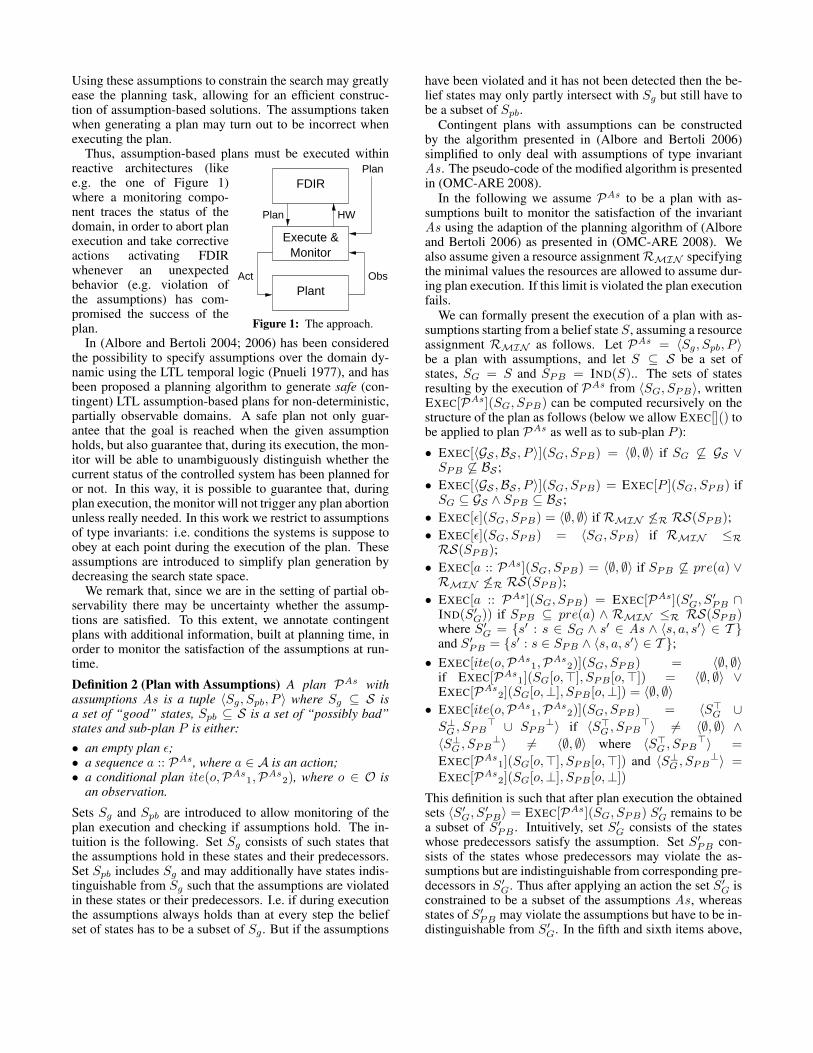
Algorithm 1 describes the pseudo-code of a function thattakes a plan with assumptions, the set of assumptions and
the goal the plan was created for, and it starts executing itfrom the current belief state obtained from the sensors. De-pending on the execution condition it returns success if theplan was executed correctly without violating neither the as-sumption nor the limit on the resources; and different failureconditions in all the other cases.
Algorithm 1 Plan execution and monitoring.1: function PLANEXECUTEANDMONITOR(P, Ass, G)2: CBS = SENSORSGETBS( );3: ER = SENSORSGETRESOURCES( );4: 〈Good, PBad, NextPlan〉 := Pi;5: if ¬ENTAILED(CBS, PBad) then6: return FailureNotSupportedInitialStates;7: while ε 6= NextPlan do8: CBS := SENSORSGETBS( );9: CR := SENSORSGETRESOURCES( );
10: 〈Good, PBad, NextPlan〉 := Pi;11: if ¬INTERSECT(CBS, Good) then12: return FailureAssertNotSatisfied;13: if RESOURCESLOWERTHAN(CR,ER) then14: return FailureAnomalousResourceConsumption;15: switch NextPlan16: case a :: Pi1:17: cresult := EXECUTELLCOMMAND(a);18: if Success 6= cresult then19: return FailureCommandExecution;20: ER := ESTIMATERESOURCES(a, CBS, Ass, CR);21: Pi := Pi1;22: break;23: case ite(o, Pi1, Pi2):24: switch COMPATIBILITYCHECK(CBS, o)25: case CBS SUB O >:26: case CBS SUB O > NONEMPTYINT O ⊥:27: Pi := Pi1;28: break;29: case CBS SUB O ⊥:30: case CBS SUB O ⊥ NONEMPTYINT O >:31: Pi := Pi2;32: break;33: case CBS SUB O TRUEFALSE:34: Pi := (RANDOM( ) % 2) ? Pi1: Pi2;35: break;36: default:37: return FailureCondPlanWrongCondition;38: end switch39: case ε:40: break;41: default:42: return FailureInvalidPlanStructure;43: end switch44: end while45: return Success;46: end function
Diagnosis, Diagnosability and FDIRDiagnosis is the process of inferring the set of (most plau-sible) causes for an unexpected behavior of a given system,given a set of observations. Diagnosability is the possibilityfor an ideal diagnosis system to infer accurate and sufficient
run-time information on the behavior of the observed sys-tem.
The formal framework here described allows for theapplicability of the techniques for tackling diagnosabil-ity as described in (Cimatti, Pecheur, and Cavada 2003).In (Cimatti, Pecheur, and Cavada 2003) it was shown howit is possible to reduce the problem of diagnosability to theproblem of checking whether a diagnosability condition isviolated, that in turns corresponds to checking whether acritical pair can be found. A critical pair is a pair of exe-cutions that are indistinguishable (i.e., they share the sameinputs and outputs), but hide conditions that should be dis-tinguished (e.g., to prevent simple failures to stay undetectedand degenerate into catastrophic events). The problem offinding a critical pair can be reduced to a problem of modelchecking a temporal formula, representing the diagnosabil-ity conditions, over the coupled twin model M × M =〈S ×S, I×I,A, T ×T ,O,X ×X ,R,RS×〉 where for alls1, s2 ∈ S, 〈s1, s2〉 ∈ S ×S iff there exists o ∈ O such thato ∈ X (s1) and o ∈ X (s2); 〈〈s1, s2〉〉, a, 〈s′1, s′2〉〉 ∈ T × Tiff 〈s1, a, s′1〉, 〈s2, a, s3〉 ∈ T ; and o ∈ (X × X )(〈s1, s2〉)iff o ∈ X (s1) and o ∈ X (s2).
Fault detection is concerned with detecting whether agiven system is malfunctioning. Fault detection analysischecks whether an observation can be considered a fault de-tection means for a given fault, i.e., every occurrence of thefault will eventually cause the observable to be true. All suchobservables are reported as possible detection means.
Fault isolation analysis is concerned with detecting thespecific cause of malfunctioning. It can be performed bygenerating a fault tree that contains the minimal explana-tions that are compatible with the observable being true. Incase of perfect isolation, the fault tree contains a single cutset consisting of one fault, indicating that the fault has beenidentified as the cause of the malfunctioning. A fault treewith more than one cut set indicates that there may be sev-eral explanations for the malfunctioning. In this case prob-abilistic information can be taken into account, in order toconsider the most likely explanation.
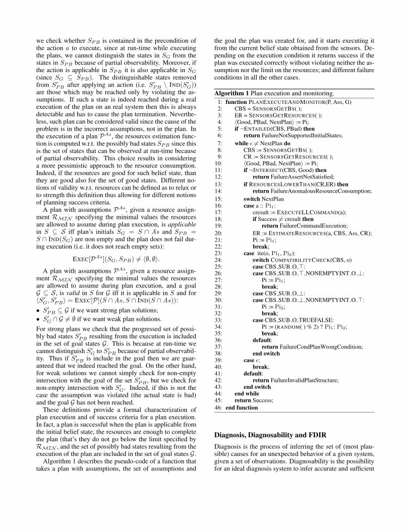
During the execution of a plan the executed actions andthe performed observations can be stored, and can then beused to isolate the faults by restricting the search performedto construct the fault trees. However, storing the full set ofperformed actions and observations is not practical, and onlya given number of the last performed actions and observa-tions is memorized (the so called history window) (Williamsand Nayak 1996; Mikaelian, Williams, and Sachenbacher2005) to this purpose. The algorithm 2 can be used to isolatefaults. It takes the assumptions Ass under which the planhas been executed and the history window HW of size N .It starts by building a transition system that aims to monitorthe value of fault variables. This monitor is then composedwith the system model. Then, a bounded backward reacha-bility of N steps from states such that the monitor variablesequate the respective monitor fault variables is performed.Each step of the backward reachability is restricted to per-formed actions (line 12) and to the observations (line 13)stored in the history window. Finally it is restricted to theassumptions (line 14). The resulting set is projected over
Algorithm 2 Fault isolation.1: function ISOLATEFAULTS(Ass, HW, N)2: Monitor := BUILDFAULTMONITOR( );3: EM := BUILDPRODUCT(M, Monitor);4: Reached := BUILDHVEQFV(M, Monitor);5: Reached := Reached ∩ Ass;6: i := N - 1;7: if 0 ≤ i then8: Reached := Reached ∩ GETOBS(HW[i]);9: i := i - 1;
10: while i ≥ 0 do11: a := GETACTION(HW[i]);12: Reached := BWDIMAGE(M, Reached, a);13: Reached := Reached ∩ GETOBS(HW[i]);14: Reached := Reached ∩ Ass;15: i := i - 1;16: end while17: FS := PROJECT(Monitor, Reached);18: return EXTRACTFAULTS(FS);19: end function
the monitor variables (line 17) and analyzed to extract thefaults (line 18).
The Autonomous Reasoning EngineWe have integrated the framework described in previous sec-tions within a generic three layers hybrid autonomy archi-tecture, the Autonomous Reasoning Engine (ARE), devel-oped in response to an invitation to tender of the EuropeanSpace Agency aiming at developing an integrated uniformapproach for model based on board autonomy (OMC-ARE2008). The spacecraft will be equipped with an ARE. TheARE interacts with the spacecraft and with the Ground Con-trol Station to provide autonomous reasoning capabilities.From the spacecraft, it will receive information from the sen-sors, and delivers control commands to the actuators. Withthe Ground Control it will exchange information on the mis-sion goals and initial mission plan, and it will also receivedirect commands to activate ARE functionalities and to in-spect the status of the ARE.
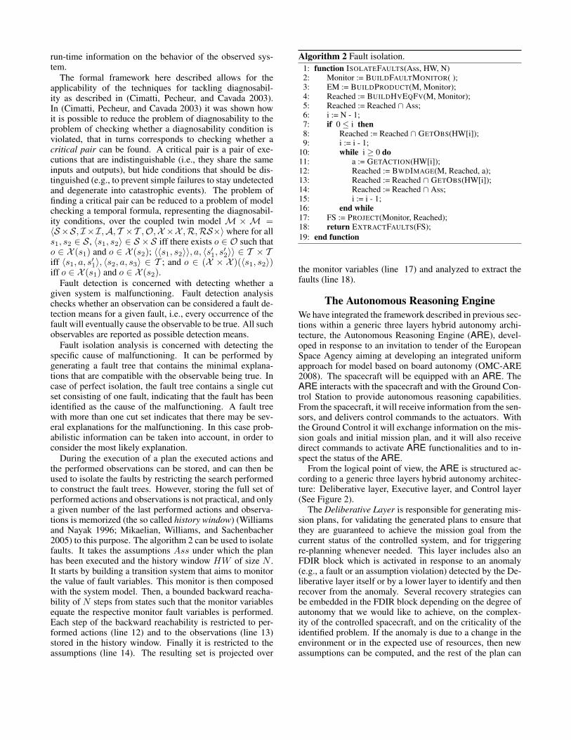
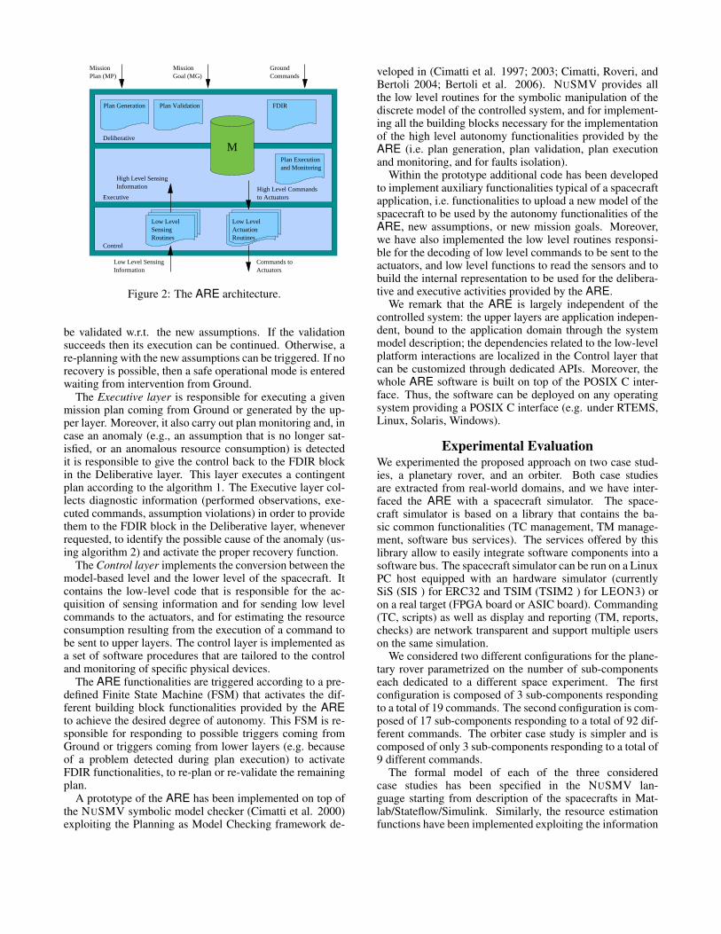
From the logical point of view, the ARE is structured ac-cording to a generic three layers hybrid autonomy architec-ture: Deliberative layer, Executive layer, and Control layer(See Figure 2).
The Deliberative Layer is responsible for generating mis-sion plans, for validating the generated plans to ensure thatthey are guaranteed to achieve the mission goal from thecurrent status of the controlled system, and for triggeringre-planning whenever needed. This layer includes also anFDIR block which is activated in response to an anomaly(e.g., a fault or an assumption violation) detected by the De-liberative layer itself or by a lower layer to identify and thenrecover from the anomaly. Several recovery strategies canbe embedded in the FDIR block depending on the degree ofautonomy that we would like to achieve, on the complex-ity of the controlled spacecraft, and on the criticality of theidentified problem. If the anomaly is due to a change in theenvironment or in the expected use of resources, then newassumptions can be computed, and the rest of the plan can
M
MissionPlan (MP)Mission
CommandsGround
Deliberative
Executive
Control
FDIR
InformationHigh Level Sensing
Low LevelLow LevelSensingRoutines
High Level Commandsto Actuators
Plan Executionand Monitoring
InformationLow Level Sensing
ActuatorsCommands to
Routines
Plan Generation
Plan Validation
Actuation
Goal (MG)
Figure 2: The ARE architecture.
be validated w.r.t. the new assumptions. If the validationsucceeds then its execution can be continued. Otherwise, are-planning with the new assumptions can be triggered. If norecovery is possible, then a safe operational mode is enteredwaiting from intervention from Ground.
The Executive layer is responsible for executing a givenmission plan coming from Ground or generated by the up-per layer. Moreover, it also carry out plan monitoring and, incase an anomaly (e.g., an assumption that is no longer sat-isfied, or an anomalous resource consumption) is detectedit is responsible to give the control back to the FDIR blockin the Deliberative layer. This layer executes a contingentplan according to the algorithm 1. The Executive layer col-lects diagnostic information (performed observations, exe-cuted commands, assumption violations) in order to providethem to the FDIR block in the Deliberative layer, wheneverrequested, to identify the possible cause of the anomaly (us-ing algorithm 2) and activate the proper recovery function.
The Control layer implements the conversion between themodel-based level and the lower level of the spacecraft. Itcontains the low-level code that is responsible for the ac-quisition of sensing information and for sending low levelcommands to the actuators, and for estimating the resourceconsumption resulting from the execution of a command tobe sent to upper layers. The control layer is implemented asa set of software procedures that are tailored to the controland monitoring of specific physical devices.
The ARE functionalities are triggered according to a pre-defined Finite State Machine (FSM) that activates the dif-ferent building block functionalities provided by the AREto achieve the desired degree of autonomy. This FSM is re-sponsible for responding to possible triggers coming fromGround or triggers coming from lower layers (e.g. becauseof a problem detected during plan execution) to activateFDIR functionalities, to re-plan or re-validate the remainingplan.
A prototype of the ARE has been implemented on top ofthe NUSMV symbolic model checker (Cimatti et al. 2000)exploiting the Planning as Model Checking framework de-
veloped in (Cimatti et al. 1997; 2003; Cimatti, Roveri, andBertoli 2004; Bertoli et al. 2006). NUSMV provides allthe low level routines for the symbolic manipulation of thediscrete model of the controlled system, and for implement-ing all the building blocks necessary for the implementationof the high level autonomy functionalities provided by theARE (i.e. plan generation, plan validation, plan executionand monitoring, and for faults isolation).
Within the prototype additional code has been developedto implement auxiliary functionalities typical of a spacecraftapplication, i.e. functionalities to upload a new model of thespacecraft to be used by the autonomy functionalities of theARE, new assumptions, or new mission goals. Moreover,we have also implemented the low level routines responsi-ble for the decoding of low level commands to be sent to theactuators, and low level functions to read the sensors and tobuild the internal representation to be used for the delibera-tive and executive activities provided by the ARE.
We remark that the ARE is largely independent of thecontrolled system: the upper layers are application indepen-dent, bound to the application domain through the systemmodel description; the dependencies related to the low-levelplatform interactions are localized in the Control layer thatcan be customized through dedicated APIs. Moreover, thewhole ARE software is built on top of the POSIX C inter-face. Thus, the software can be deployed on any operatingsystem providing a POSIX C interface (e.g. under RTEMS,Linux, Solaris, Windows).
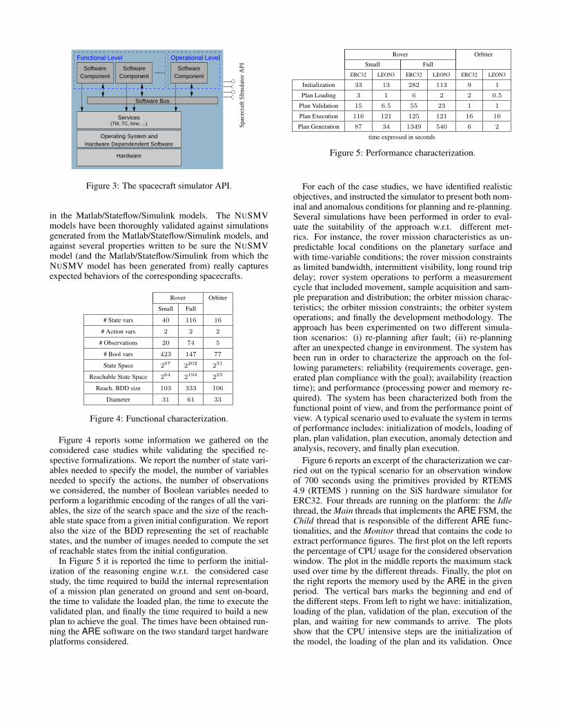
Experimental EvaluationWe experimented the proposed approach on two case stud-ies, a planetary rover, and an orbiter. Both case studiesare extracted from real-world domains, and we have inter-faced the ARE with a spacecraft simulator. The space-craft simulator is based on a library that contains the ba-sic common functionalities (TC management, TM manage-ment, software bus services). The services offered by thislibrary allow to easily integrate software components into asoftware bus. The spacecraft simulator can be run on a LinuxPC host equipped with an hardware simulator (currentlySiS (SIS ) for ERC32 and TSIM (TSIM2 ) for LEON3) oron a real target (FPGA board or ASIC board). Commanding(TC, scripts) as well as display and reporting (TM, reports,checks) are network transparent and support multiple userson the same simulation.
We considered two different configurations for the plane-tary rover parametrized on the number of sub-componentseach dedicated to a different space experiment. The firstconfiguration is composed of 3 sub-components respondingto a total of 19 commands. The second configuration is com-posed of 17 sub-components responding to a total of 92 dif-ferent commands. The orbiter case study is simpler and iscomposed of only 3 sub-components responding to a total of9 different commands.
The formal model of each of the three consideredcase studies has been specified in the NUSMV lan-guage starting from description of the spacecrafts in Mat-lab/Stateflow/Simulink. Similarly, the resource estimationfunctions have been implemented exploiting the information
Spac
ecra
ft S
Imul
ator
API
Hardware Dependendent Software
Services(TM, TC, time, ...)
Component
Software Bus
Functional Level
SoftwareComponent
Operational Level
SoftwareComponent
Software
Operating System and
Hardware
Figure 3: The spacecraft simulator API.
in the Matlab/Stateflow/Simulink models. The NUSMVmodels have been thoroughly validated against simulationsgenerated from the Matlab/Stateflow/Simulink models, andagainst several properties written to be sure the NUSMVmodel (and the Matlab/Stateflow/Simulink from which theNUSMV model has been generated from) really capturesexpected behaviors of the corresponding spacecrafts.
Rover Orbiter
Small Full
# State vars 40 116 16
# Action vars 2 2 2
# Observations 20 74 5
# Bool vars 423 147 77
State Space 267 2202 231
Reachable State Space 264 2194 223
Reach. BDD size 103 333 106
Diameter 31 61 33
Figure 4: Functional characterization.
Figure 4 reports some information we gathered on theconsidered case studies while validating the specified re-spective formalizations. We report the number of state vari-ables needed to specify the model, the number of variablesneeded to specify the actions, the number of observationswe considered, the number of Boolean variables needed toperform a logarithmic encoding of the ranges of all the vari-ables, the size of the search space and the size of the reach-able state space from a given initial configuration. We reportalso the size of the BDD representing the set of reachablestates, and the number of images needed to compute the setof reachable states from the initial configuration.
In Figure 5 it is reported the time to perform the initial-ization of the reasoning engine w.r.t. the considered casestudy, the time required to build the internal representationof a mission plan generated on ground and sent on-board,the time to validate the loaded plan, the time to execute thevalidated plan, and finally the time required to build a newplan to achieve the goal. The times have been obtained run-ning the ARE software on the two standard target hardwareplatforms considered.
Rover Orbiter
Small Full
ERC32 LEON3 ERC32 LEON3 ERC32 LEON3
Initialization 33 13 282 113 9 1
Plan Loading 3 1 6 2 2 0.5
Plan Validation 15 6.5 55 23 1 1
Plan Execution 116 121 125 121 16 16
Plan Generation 87 34 1349 540 6 2
time expressed in seconds
Figure 5: Performance characterization.
For each of the case studies, we have identified realisticobjectives, and instructed the simulator to present both nom-inal and anomalous conditions for planning and re-planning.Several simulations have been performed in order to eval-uate the suitability of the approach w.r.t. different met-rics. For instance, the rover mission characteristics as un-predictable local conditions on the planetary surface andwith time-variable conditions; the rover mission constraintsas limited bandwidth, intermittent visibility, long round tripdelay; rover system operations to perform a measurementcycle that included movement, sample acquisition and sam-ple preparation and distribution; the orbiter mission charac-teristics; the orbiter mission constraints; the orbiter systemoperations; and finally the development methodology. Theapproach has been experimented on two different simula-tion scenarios: (i) re-planning after fault; (ii) re-planningafter an unexpected change in environment. The system hasbeen run in order to characterize the approach on the fol-lowing parameters: reliability (requirements coverage, gen-erated plan compliance with the goal); availability (reactiontime); and performance (processing power and memory re-quired). The system has been characterized both from thefunctional point of view, and from the performance point ofview. A typical scenario used to evaluate the system in termsof performance includes: initialization of models, loading ofplan, plan validation, plan execution, anomaly detection andanalysis, recovery, and finally plan execution.
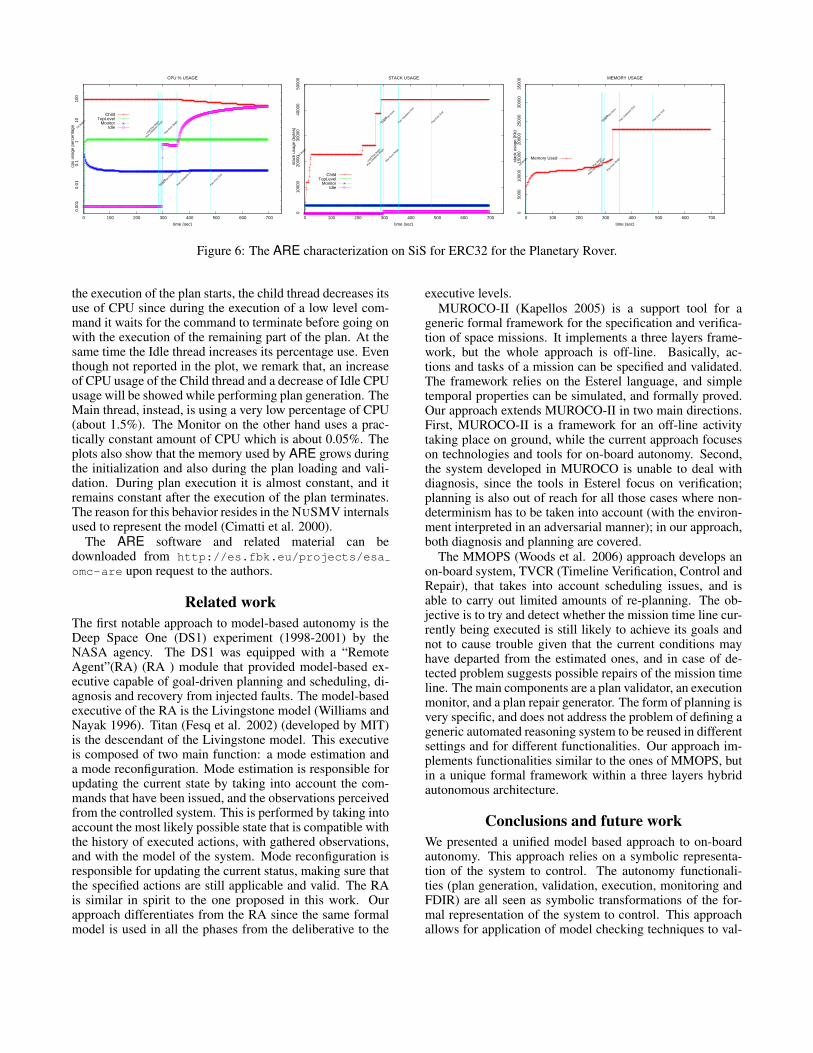
Figure 6 reports an excerpt of the characterization we car-ried out on the typical scenario for an observation windowof 700 seconds using the primitives provided by RTEMS4.9 (RTEMS ) running on the SiS hardware simulator forERC32. Four threads are running on the platform: the Idlethread, the Main threads that implements the ARE FSM, theChild thread that is responsible of the different ARE func-tionalities, and the Monitor thread that contains the code toextract performance figures. The first plot on the left reportsthe percentage of CPU usage for the considered observationwindow. The plot in the middle reports the maximum stackused over time by the different threads. Finally, the plot onthe right reports the memory used by the ARE in the givenperiod. The vertical bars marks the beginning and end ofthe different steps. From left to right we have: initialization,loading of the plan, validation of the plan, execution of theplan, and waiting for new commands to arrive. The plotsshow that the CPU intensive steps are the initialization ofthe model, the loading of the plan and its validation. Once
0.0
01 0
.01
0.1
1 1
0 1
00
0 100 200 300 400 500 600 700
cpu
usag
e pe
rcen
tage
time (sec)
CPU % USAGE
Init B
egin
Init E
nd
Load
Plan
Beg
in
Load
Plan
Don
e
Plan E
xec B
egin
Plan E
xec E
nd
Plan V
alida
tion
Begin
Plan V
alida
tion
End
ChildTopLevel
MonitorIdle
0 1
0000
200
00 3
0000
400
00 5
0000
0 100 200 300 400 500 600 700
stac
k us
age
(byt
es)
time (sec)
STACK USAGE
Init B
egin
Init E
nd
Load
Plan
Beg
in
Load
Plan
Don
e
Plan E
xec B
egin
Plan E
xec E
nd
Plan V
alida
tion
Begin
Plan V
alida
tion
End
ChildTopLevel
MonitorIdle
0 5
000
100
00 1
5000
200
00 2
5000
300
00 3
5000
0 100 200 300 400 500 600 700
stac
k us
age
(Kb)
time (sec)
MEMORY USAGE
Init B
egin
Init E
nd
Load
Plan
Beg
in
Load
Plan
Don
e
Plan E
xec B
egin
Plan E
xec E
nd
Plan V
alida
tion
Begin
Plan V
alida
tion
End
Memory Used
Figure 6: The ARE characterization on SiS for ERC32 for the Planetary Rover.
the execution of the plan starts, the child thread decreases itsuse of CPU since during the execution of a low level com-mand it waits for the command to terminate before going onwith the execution of the remaining part of the plan. At thesame time the Idle thread increases its percentage use. Eventhough not reported in the plot, we remark that, an increaseof CPU usage of the Child thread and a decrease of Idle CPUusage will be showed while performing plan generation. TheMain thread, instead, is using a very low percentage of CPU(about 1.5%). The Monitor on the other hand uses a prac-tically constant amount of CPU which is about 0.05%. Theplots also show that the memory used by ARE grows duringthe initialization and also during the plan loading and vali-dation. During plan execution it is almost constant, and itremains constant after the execution of the plan terminates.The reason for this behavior resides in the NUSMV internalsused to represent the model (Cimatti et al. 2000).
The ARE software and related material can bedownloaded from http://es.fbk.eu/projects/esaomc-are upon request to the authors.
Related workThe first notable approach to model-based autonomy is theDeep Space One (DS1) experiment (1998-2001) by theNASA agency. The DS1 was equipped with a “RemoteAgent”(RA) (RA ) module that provided model-based ex-ecutive capable of goal-driven planning and scheduling, di-agnosis and recovery from injected faults. The model-basedexecutive of the RA is the Livingstone model (Williams andNayak 1996). Titan (Fesq et al. 2002) (developed by MIT)is the descendant of the Livingstone model. This executiveis composed of two main function: a mode estimation anda mode reconfiguration. Mode estimation is responsible forupdating the current state by taking into account the com-mands that have been issued, and the observations perceivedfrom the controlled system. This is performed by taking intoaccount the most likely possible state that is compatible withthe history of executed actions, with gathered observations,and with the model of the system. Mode reconfiguration isresponsible for updating the current status, making sure thatthe specified actions are still applicable and valid. The RAis similar in spirit to the one proposed in this work. Ourapproach differentiates from the RA since the same formalmodel is used in all the phases from the deliberative to the
executive levels.MUROCO-II (Kapellos 2005) is a support tool for a
generic formal framework for the specification and verifica-tion of space missions. It implements a three layers frame-work, but the whole approach is off-line. Basically, ac-tions and tasks of a mission can be specified and validated.The framework relies on the Esterel language, and simpletemporal properties can be simulated, and formally proved.Our approach extends MUROCO-II in two main directions.First, MUROCO-II is a framework for an off-line activitytaking place on ground, while the current approach focuseson technologies and tools for on-board autonomy. Second,the system developed in MUROCO is unable to deal withdiagnosis, since the tools in Esterel focus on verification;planning is also out of reach for all those cases where non-determinism has to be taken into account (with the environ-ment interpreted in an adversarial manner); in our approach,both diagnosis and planning are covered.
The MMOPS (Woods et al. 2006) approach develops anon-board system, TVCR (Timeline Verification, Control andRepair), that takes into account scheduling issues, and isable to carry out limited amounts of re-planning. The ob-jective is to try and detect whether the mission time line cur-rently being executed is still likely to achieve its goals andnot to cause trouble given that the current conditions mayhave departed from the estimated ones, and in case of de-tected problem suggests possible repairs of the mission timeline. The main components are a plan validator, an executionmonitor, and a plan repair generator. The form of planning isvery specific, and does not address the problem of defining ageneric automated reasoning system to be reused in differentsettings and for different functionalities. Our approach im-plements functionalities similar to the ones of MMOPS, butin a unique formal framework within a three layers hybridautonomous architecture.
Conclusions and future workWe presented a unified model based approach to on-boardautonomy. This approach relies on a symbolic representa-tion of the system to control. The autonomy functionali-ties (plan generation, validation, execution, monitoring andFDIR) are all seen as symbolic transformations of the for-mal representation of the system to control. This approachallows for application of model checking techniques to val-
idate the symbolic representation of the system to controland to check for diagnosability conditions. Moreover, theunderlying techniques can be used to realize the autonomyfunctionalities. We have implemented the approach in a pro-totype of an Autonomous Reasoning Engine relying on theNUSMV symbolic model checker. We have carried out acharacterization of the approach using two case studies in-spired by real on-going projects to understand it usability inthe context of current space applications and available on-board computers. The obtained results were promising.
There are several directions for improvements at differ-ent levels. The reasoning engine currently uses BDDs, itwould be worth experimenting with SAT and also with SMTtechniques to consider then in a unique framework both thecontinuous and the discrete components. As far as goals areconsidered, it would be worth extending the approach to dealwith sequential goals. In parallel the approach could benefitfrom using more complex assumptions.
AcknowledgmentsThis work was sponsored by the European Space Agencyunder ESA/ESTEC ITT AO/1-5184/06/NL/JD - ONBOARD MODEL CHECKING.
ReferencesAlbore, A., and Bertoli, P. 2004. Generating Safe Assumption-Based Plans for Partially Observable Nondeterministic Domains.In AAAI, 495–500. AAAI Press / The MIT Press.Albore, A., and Bertoli, P. 2006. Safe LTL Assumption-BasedPlanning. In ICAPS, 193–202. AAAI.Bertoli, P.; Cimatti, A.; Roveri, M.; and Traverso, P. 2006. Strongplanning under partial observability. Artif. Intell. 170(4-5):337–384.Biere, A.; Cimatti, A.; Clarke, E. M.; Strichman, O.; and Zhu,Y. 2003. Bounded model checking. Advances in Computers58:118–149.Bonet, B., and Geffner, H. 2000. Planning with Incomplete Infor-mation as Heuristic Search in Belief Space. In 5th ICAPS, 52–61.AAAI-Press.Bozzano, M.; Cimatti, A.; and Roveri, M. 2007. OMC-ARE —Technical Note (TN1). Technical Report OBMC-TN-FBK-01,Fondazione Bruno Kessler.Bryant, R. E. 1992. Symbolic Boolean manipulation with orderedbinary-decision diagrams. ACM Comp. Surveys 24(3):293–318.Cavada, R.; Cimatti, A.; Franzen, A.; Kalyanasundaram, K.;Roveri, M.; and Shyamasundar, R. K. 2007. Computing predicateabstractions by integrating BDDs and SMT solvers. In FMCAD,69–76. IEEE.Cimatti, A., and Roveri, M. 2000. Conformant planning via sym-bolic model checking. J. Artif. Intell. Res. (JAIR) 13:305–338.Cimatti, A.; Giunchiglia, E.; Giunchiglia, F.; and Traverso, P.1997. Planning via Model Checking: A Decision Procedure forAR. In Proceeding of ECP-97, volume 1348 of LNAI, 130–142.Toulouse, Fr: Springer.Cimatti, A.; Clarke, E. M.; Giunchiglia, F.; and Roveri, M. 2000.NuSMV: A New Symbolic Model Checker. STTT 2(4):410–425.Cimatti, A.; Pistore, M.; Roveri, M.; and Traverso, P. 2003. Weak,strong, and strong cyclic planning via symbolic model checking.Artif. Intell. 147(1-2):35–84.
Cimatti, A.; Pecheur, C.; and Cavada, R. 2003. Formal verifica-tion of diagnosability via symbolic model checking. In Gottlob,G., and Walsh, T., eds., IJCAI, 363–369. Morgan Kaufmann.Cimatti, A.; Roveri, M.; and Bertoli, P. 2004. Conformant plan-ning via symbolic model checking and heuristic search. Artif.Intell. 159(1-2):127–206.Clarke, E. M.; Grumberg, O.; Jha, S.; Lu, Y.; and Veith, H. 2000.Counterexample-Guided Abstraction Refinement. In CAV, 154–169.Clarke, E. M.; Grumberg, O.; and Peled, D. A. 1999. ModelChecking. The MIT Press. ISBN 0-262-03270-7.Emerson, E. A. 1990. Temporal and modal logic. In Handbookof Theoretical Computer Science, Volume B: Formal Models andSematics (B). 995–1072.Fesq, L.; Ingham, M.; Pekala, M.; Eepoel, J. V.; Watson, D.;and Williams, B. C. 2002. Model-based autonomy for the nextgeneration of robotic spacecraft. http://groups.csail.mit.edu/mers/papers/IAC02 MIT paper.pdf.Ghallab, M.; Nau, D.; and Traverso, P. 2005. Automated Plan-ning: Theory and Practice. Morgan Kaufman.Hopcroft, J., and Ullman, J. 1979. Introduction to AutomataTheory, Languages and Computation. Addison-Wesley.Kapellos, K. 2005. Formal Robotic Mission Inspection and De-bugging (MUROCO II) Executive Summary, Issue 1, ESA Con-tract 17987/03/NL/SFe. ftp://ftp.estec.esa.nl/pub/wm/wme/obmc/MUROCO-TRA-EXSUM.pdf.Lahiri, S. K.; Nieuwenhuis, R.; and Oliveras, A. 2006. SMTtechniques for fast predicate abstraction. In CAV 2006, LNCS,424–437. Springer.McMillan, K. 1993. Symbolic Model Checking. Kluwer Aca-demic Publ.Mikaelian, T.; Williams, B. C.; and Sachenbacher, M. 2005.Model-based monitoring and diagnosis of systems with software-extended behavior. In AAAI, 327–333. AAAI Press.2008. OMC-ARE: On Board Model Checking - AutonomousReasoning Engine. http://es.fbk.eu/projects/esaomc-are/.Pnueli, A. 1977. The temporal logic of programs. In Proceedingsof 18th IEEE Symp. on Foundation of Computer Science, 46–57.2005. IEEE Standard for Property Specification Language (PSL).IEEE Std 1850-2005.Remote Agent. http://ic.arc.nasa.gov/projects/remote-agent/.RTEMS — Real-Time Operating System for Multiprocessor Sys-tems. http://www.rtems.com.S. Graf, and H. Saidi. 1997. Construction of Abstract StateGraphs with PVS. In CAV’97, volume 1254 of LNCS, 72–83.Springer.SPARC instruction simulator (SIS). http://www.esa.int/TEC/Software engineering andstandardisation/TECS2BUXBQE 0.html.TSIM2 LEON3. http://www.gaisler.com.Williams, B. C., and Nayak, P. P. 1996. A model-based approachto reactive self-configuring systems. In AAAI/IAAI, Vol. 2, 971–978.Woods, M.; Long, D.; Aylett, R.; Baldwin, L.; and Wil-son, G. 2006. Mars Mission On-Board Planner andScheduler (MMOPS) Summary Report, Issue 1, ESA Con-tract 17987/03/NL/SFe CCN1. ftp://ftp.estec.esa.nl/pub/wm/wme/obmc/MMOPS-SUMRPT.pdf.