A comparison of dry and air-cooled turning of grey cast iron with mixed oxide ceramic tool
13
Journal of Materials Processing Technology 190 (2007) 160–172 A comparison of dry and air-cooled turning of grey cast iron with mixed oxide ceramic tool D.K. Sarma, U.S. Dixit ∗ Department of Mechanical Engineering, Indian Institute of Technology Guwahati 781039, India Received 4 September 2006; received in revised form 29 December 2006; accepted 26 February 2007 Abstract The present work compares the performance of a mixed oxide ceramic tool in dry and air-cooled turning of grey cast iron. First, the study was done in the range of process parameters where dry turning provided satisfactory performance. The contours of surface roughness and tool life were generated with the help of trained neural networks. A novel procedure of neural network training is used in this work. The study was extended to the range in which dry turning performed poorly in terms of tool life. Tool wear, surface roughness of the machined job and forces and vibration during the cutting were studied. It was observed that air-cooling significantly reduces the tool wear at high cutting speed. At higher cutting speeds, where the dry turning performs very poorly, the air-cooled turning provides an improved surface finish also apart from the reduction in tool wear. In all the cases, the cutting and feed forces get reduced in air-cooling. Thus, air-cooled turning of grey cast iron with mixed oxide ceramic tools offers a promising environment-friendly option. © 2007 Elsevier B.V. All rights reserved. Keywords: Dry turning; Air-cooled turning; Mixed oxide ceramic tool; Surface roughness; Tool wear; Cutting forces and vibrations; Neural network 1. Introduction Alumina-based ceramic cutting tools are attractive alterna- tives to carbide tools for the machining of steels and cast irons, because of their higher hot hardness [1]. Two main types of these ceramics are pure/white oxide ceramic and mixed/black oxide ceramic. White oxide ceramic containing Al 2 O 3 with sintered additives and without metallic binder phase is relatively brittle. Its toughness can be improved by embedding of fine zirconia (ZrO 2 ) particles by an amount of 3–5% into the aluminium oxide matrix. Such a ceramic is called dispersion ceramic. White oxide ceramic is used in rough machining of grey cast iron, nodular cast iron and chilled cast iron. The black oxide ceramic con- tains besides aluminium oxide, titanium oxide and/or titanium carbonitride in the order of about 30% by weight. It is generally used for machining of hard materials and finish machining of cast iron. Compared to carbide tools, ceramic tools are expensive. Therefore, in order to manufacture the goods at competitive ∗ Corresponding author. Tel.: +91 361 2582657 (O)/2584657 (R)/2691036 (R); fax: +91 361 2582699. E-mail addresses: [email protected], [email protected] (U.S. Dixit). price, the proper selection of the cutting tool as well as cutting parameters is of utmost importance. A good tool may produce poor performance, if the operating conditions are not proper. The performance of a cutting tool is judged mainly by machining speed, tool life and quality of the machined surface. A number of researchers have carried out the studies on the performance of the ceramic cutting tools. Bhattacharyya et al. [2] studied the performance of ceramic cutting tools for machin- ing of cast iron and found that mixed oxide ceramics give better performance compared to pure oxide and nitride ceramics. They found that the dominant wear mechanisms are attrition and dif- fusion, attrition dominating at slower speeds and diffusion at higher speeds. Ezugwu et al. [3] used a black oxide ceramic cutting tool for turning of grey cast iron. They studied the tool life and failure modes and trained an artificial neural network, which could be used for predicting tool lives and failure modes for different cutting conditions. The accuracy of prediction by the trained network was not very good and authors felt the need of carrying more experiments for training the network. Ezugwu and Tang [4] compared the quality of machined surface in the turning of G-17 cast iron and nickel-based Inconel 718 alloy with round and rhomboid-shaped pure oxide (Al 2 O 3 + ZrO 2 ) and mixed oxide (Al 2 O 3 +T i C) ceramic tools. The test results showed the round inserts to give better surface finish compared to 0924-0136/$ – see front matter © 2007 Elsevier B.V. All rights reserved. doi:10.1016/j.jmatprotec.2007.02.049
Transcript of A comparison of dry and air-cooled turning of grey cast iron with mixed oxide ceramic tool

A
dgtdwIo©
K
1
tbccaI(mcctcuc
T
(
0d
Journal of Materials Processing Technology 190 (2007) 160–172
A comparison of dry and air-cooled turning of greycast iron with mixed oxide ceramic tool
D.K. Sarma, U.S. Dixit ∗Department of Mechanical Engineering, Indian Institute of Technology Guwahati 781039, India
Received 4 September 2006; received in revised form 29 December 2006; accepted 26 February 2007
bstract
The present work compares the performance of a mixed oxide ceramic tool in dry and air-cooled turning of grey cast iron. First, the study wasone in the range of process parameters where dry turning provided satisfactory performance. The contours of surface roughness and tool life wereenerated with the help of trained neural networks. A novel procedure of neural network training is used in this work. The study was extended tohe range in which dry turning performed poorly in terms of tool life. Tool wear, surface roughness of the machined job and forces and vibrationuring the cutting were studied. It was observed that air-cooling significantly reduces the tool wear at high cutting speed. At higher cutting speeds,
here the dry turning performs very poorly, the air-cooled turning provides an improved surface finish also apart from the reduction in tool wear.n all the cases, the cutting and feed forces get reduced in air-cooling. Thus, air-cooled turning of grey cast iron with mixed oxide ceramic toolsffers a promising environment-friendly option. 2007 Elsevier B.V. All rights reserved.
roug
pppps
p[ipffhclw
eywords: Dry turning; Air-cooled turning; Mixed oxide ceramic tool; Surface
. Introduction
Alumina-based ceramic cutting tools are attractive alterna-ives to carbide tools for the machining of steels and cast irons,ecause of their higher hot hardness [1]. Two main types of theseeramics are pure/white oxide ceramic and mixed/black oxideeramic. White oxide ceramic containing Al2O3 with sintereddditives and without metallic binder phase is relatively brittle.ts toughness can be improved by embedding of fine zirconiaZrO2) particles by an amount of 3–5% into the aluminium oxideatrix. Such a ceramic is called dispersion ceramic. White oxide
eramic is used in rough machining of grey cast iron, nodularast iron and chilled cast iron. The black oxide ceramic con-ains besides aluminium oxide, titanium oxide and/or titaniumarbonitride in the order of about 30% by weight. It is generallysed for machining of hard materials and finish machining of
ast iron.Compared to carbide tools, ceramic tools are expensive.herefore, in order to manufacture the goods at competitive
∗ Corresponding author. Tel.: +91 361 2582657 (O)/2584657 (R)/2691036R); fax: +91 361 2582699.
E-mail addresses: [email protected], [email protected] (U.S. Dixit).
ftoatwas
924-0136/$ – see front matter © 2007 Elsevier B.V. All rights reserved.oi:10.1016/j.jmatprotec.2007.02.049
hness; Tool wear; Cutting forces and vibrations; Neural network
rice, the proper selection of the cutting tool as well as cuttingarameters is of utmost importance. A good tool may produceoor performance, if the operating conditions are not proper. Theerformance of a cutting tool is judged mainly by machiningpeed, tool life and quality of the machined surface.
A number of researchers have carried out the studies on theerformance of the ceramic cutting tools. Bhattacharyya et al.2] studied the performance of ceramic cutting tools for machin-ng of cast iron and found that mixed oxide ceramics give bettererformance compared to pure oxide and nitride ceramics. Theyound that the dominant wear mechanisms are attrition and dif-usion, attrition dominating at slower speeds and diffusion atigher speeds. Ezugwu et al. [3] used a black oxide ceramicutting tool for turning of grey cast iron. They studied the toolife and failure modes and trained an artificial neural network,hich could be used for predicting tool lives and failure modes
or different cutting conditions. The accuracy of prediction byhe trained network was not very good and authors felt the needf carrying more experiments for training the network. Ezugwund Tang [4] compared the quality of machined surface in the
urning of G-17 cast iron and nickel-based Inconel 718 alloyith round and rhomboid-shaped pure oxide (Al2O3 + ZrO2)nd mixed oxide (Al2O3 + TiC) ceramic tools. The test resultshowed the round inserts to give better surface finish compared to

ls Pr
rifi
vtir1t[IictsHchicostwocot
cme7esspt
chodtcrHrwifuth
t
Ttsfndhdobtaoli
2
lmr
dha±rrw(mfoa3fwI1iricoa(pflakes against the lighter background of the metal.
The cutting tool used for the experiment was mixed triangular ceramic insertdesignated as TNGA 16 04 08T01020 650 of make: Sandvik. The ASA toolsignature is designated by (-9)-(-5)-7-7-30-1-0.8. The compatible tool holderwas PTGNR 2020 K16 of make: WIDAX.
Table 1Chemical composition and mechanical properties of grey cast iron
Work material Chemical composition (%)
C Si Mn S P
D.K. Sarma, U.S. Dixit / Journal of Materia
homboid-shaped tools for both the types of ceramics. Machin-ng with the mixed oxide ceramic tools produced better surfacenish than with the pure oxide ceramic.
Ghani et al. [5] investigated the tool life, surface finish andibration in turning nodular cast iron with mixed oxide ceramicool. The experimental results show that tool life of ceramicnsert is not satisfactory in high-speed turning. In the speedange 364–685 m/min, maximum tool life achieved was only.5 min. Surface finish was found to be almost constant withhe progress of flank wear under all cutting conditions. Li et al.6] carried out some experiments on high-speed dry turning ofnconel 718 and found that the cutting speed plays a major rolen causing the tool wear. The authors have found the optimalutting speeds giving minimum production times for differentools. Senthil Kumar et al. [7] carried out the experiments fortudying the growth of wear in the turning of 40 HRC and 45RC hardened EN24 steels with pure oxide and mixed oxide
eramic tool. Benga and Abrao [8] conducted experiments onard turning of 100Cr6 hardened bearing steel with a hardnessn the range of 60–65 HRC with mixed oxide ceramic and poly-rystalline cubic boron nitride (PCBN) insert. The performancef PCBN tool was found to be better. Recently, Camuscu [9]tudied the effect of cutting speed in turning with three ceramicools, viz. TiN coated Al2O3 + TiCN mixed oxide ceramic, SiChisker reinforced Al2O3 and uncoated Al2O3 + TiCN mixedxide ceramic tool. Considering tool wear, surface finish andutting force aspects together, TiN coated Al2O3 + TiCN mixedxide ceramic tool was found to be the most suitable one forurning nodular cast iron.
Machining with ceramic tools is usually carried out in dryondition. However, some researchers have studied the perfor-ance of wet turning with ceramic tools. For example, Ezugwu
t al. [10] carried out some experiments on turning of Inconel18 alloy with SiC whisker reinforced ceramic tool in the pres-nce of high lubricity emulsion coolant containing alkanolaminealts of the fatty acid and dicyclohexylamine. The coolant wasupplied with pressure and found to give lesser tool wear up to aressure of 150 bar. Further, increase in the pressure deterioratedhe performance of the coolant.
In general, environmental concerns call for the reduction ofutting fluids in industry [11]. The concept of dry machiningas many advantages, such as non-pollution of the atmospherer water, no residue or the swarf resulting in the reduction ofisposal and cleaning cost, no danger to health, such as skin rup-ure and allergy. This prompts researchers to develop ceramicutting tool materials with self-lubricating property [12]. Someesearchers have adopted a method of mist lubrication [13].owever, the mist in the industrial environment can have serious
espiratory effects on the operator. In view of this, the presentork investigates the possibility of using dry compressed air for
ncreasing the cutting performance of mixed oxide ceramic toolor the turning of grey cast iron. The air is a free available nat-ral resource and many a times compressed air is available at
he shop floor for other purposes. It has no adverse effect on theealth of the operator.This paper compares the performance of dry and air-cooledurning of a grey cast iron with mixed oxide ceramic tool.
GHTC
ocessing Technology 190 (2007) 160–172 161
he surface roughness of the machined surface, tool wear, cut-ing forces and vibrations are the parameters, which have beentudied. Preliminary study was carried out according to a fullactorial design with a number of replicates. Later on a neuraletwork model was trained with more number of experimentalata. Considering that the data is noisy and it is not possible toave a large number of training and testing data, a novel proce-ure is employed for the training of the network. With the helpf the trained network, contours of dependent variables haveeen plotted to compare the performance of dry and air-cooledurning. Observing that at the high speed, the air-cooling is quitedvantageous, the experimental study was extended to the rangef cutting speed, where the dry turning provides a very low toolife. The air-cooled turning provided satisfactory performancen that range also.
. Experimental procedure
A series of experiment on turning were conducted in HMT make NH-26athe. A three phase 11 kW induction motor drives the spindle of the lathe. The
achine provides 23 speeds between 40 and 2040 rpm and 27 different feedsanging from 0.04 to 2.24 mm/rev.
The cutting forces were measured using a piezoelectric type 4-componentynamometer (Kistler make, type 9272), which was fitted on the tool holder. Itas a threshold of 0.01 N in the measurement of forces in feed and radial directionnd 0.02 N in the measurement of force in vertical direction. It has a linearity of1% of full-scale output. For measuring the centerline average (CLA) surface
oughness values (Ra), Pocket Surf (Mahr, GMBH) was used. Its measuringange is 0.03–6.35 �m. The surface roughness evaluation length in each caseas kept as 2.4 mm. The flank wear was measured under an Optical Microscope
Axiotechvario 100 HD, make: Carl Zeiss) of magnification range 5–200×. Foreasuring vibration, two accelerometers (type 4396, sensitivity 10 mV/m/s2,
requency 1 Hz–14 kHz, make: Bruel & Kjaer) were connected on the tool holderf the lathe to measure the vibration in the radial and the feed directions. Theseccelerometers were connected to a dynamic signal analyzer (Model: Single560D, make: Bruel & Kjaer), which in turn was connected to the computeror taking the readings with the help of B&K software, Pulse. Compressed airas generated in a single stage air-cooled compressor of make: Ingersoll Rand
ndia Ltd. The air was dried and delivered through a nozzle of diameter 5 mm at.5 bars. The velocity of airflow was approximately 150 m/s. The material usedn the experiment was grey cast iron in the form of round bar of various diametersanging from 90 to 100 mm. The length of each stock was 220 mm, the lengthnside the 3-jaw hydraulic chuck being 50 mm. The chemical compositions forarbon, silicon, manganese, sulphur and phosphorus were analyzed by Bureauf Indian Standard (BIS) method (IS: 228). The different chemical compositionsnd mechanical properties are listed in Table 1. Scanning electron microscopeSEM) picture of the grey cast iron is given in Fig. 1. The picture shows ahotomicrograph of a “grey” cast iron that has been polished to show the darker
rey cast iron 3.2 approximately 1.8 0.36 1.8 0.05ardness 143 HBensile strength 86 MPaompressive strength 512 MPa

162 D.K. Sarma, U.S. Dixit / Journal of Materials
3p
ram4wMvToli0
rfawhcaCo
cmstttthpcse
tat
a(nliehtoddcm
wiiiatw
eanfcstltgitcga
rsittid
tsiminimized. Other advantage is the lowering of cutting and feed
Fig. 1. SEM micrograph of grey cast iron.
. Full factorial experimental study of the cuttingerformance
A number of experiments were conducted in the desiredange of process parameters, viz. cutting speed (v), feed (f)nd depth of cut (d). Therefore, initially, a series of experi-ents were conducted for ceramic tool in the speed range of
80–600 m/min. However, in this range excessive tool wearas observed, the tool life ranging between 2 and 15 min [14].oreover, due to tool wear, the machined surface roughness
alue reached more than 3 �m after first few turning passes.herefore, a number of experiments were carried out to findut the range of process parameters giving a reasonable toolife and surface finish. Based on experimental study, the follow-ng ranges were chosen—cutting speed, 100–400 m/min, feed,.04–0.16 mm/rev, depth of cut, 1.0–1.5 mm.
It was decided to carry out 2-level full factorial design. Cor-esponding to three process parameters, total number of fullactorial experiments are 23, i.e. 8. For each cutting condition,number of replicate experiments were carried out based onhich the average performance of dry and air-cooled turningas been studied (Figs. 2–7). For each cutting condition, a newutting edge was used and 100 mm length was turned in one passfter which the tool wear and surface roughness were measured.utting time at different experiments was different dependingn the feed and cutting speed.
Fig. 2 compares the surface roughness for dry and air-ooled turning for eight different cutting conditions. Over aachined length of 100 mm, the surface roughness was mea-
ured at 9–12 places and the mean value was taken. Finally,he mean value of all replicates at a cutting condition wasaken and the same have been plotted in Fig. 2. It is observedhat in general the surface roughness is lower at higher cut-ing speeds compared to lower cutting speeds. However, atigh speed, a combination of low feed and high depth of cutrovided a relatively poorer surface finish (Fig. 2(f)) with air-
ooling. It is observed that air-cooling does not improve theurface finish. For one condition (Fig. 2(f)), air-cooling gen-rated more surface roughness compared to dry turning. Atfsu
Processing Technology 190 (2007) 160–172
his condition, which is low feed and high depth combination,ir-cooled turning produces more vibration compared to dryurning.
Fig. 3 compares the progression of flank wear for drynd air-cooled turning. It is noted that at high cutting speedsFig. 3(e–h)), the air-cooling reduces the flank wear. This isot the case, at low cutting speeds (Fig. 3(a–d)). In fact, atow cutting speed, for some cases, the air-cooling slightlyncreased the flank wear. At low cutting speed, the heat gen-ration is low and tool-job temperature is not as high as inigh-speed machining. Therefore, the forced convective heatransfer is not as effective as in high-speed machining andne should not expect any significant reduction in tool wearue to reduction of tool-tip temperature. Instead, sometimes inry turning at low speed, a slight increase of job temperatureauses a slight reduction in tool wear due to softening of theaterial.Fig. 4 shows the variation of main (vertical) cutting force
ith the cutting time for eight cutting conditions. Interest-ngly, in some cases of low speed turning, the cutting forcen dry turning was found more compared to air-cooled turn-ng, although the tool wear in dry turning was less than that inir-cooled turning. In all the cases of high-speed turning, the ver-ical cutting force is less in air-cooled turning due to less flankear.Fig. 5 shows the variation of feed force with cutting time for
ight cutting conditions. Here, also it is observed that forces inir-cooled turning are lower, although the difference is less pro-ounced than in the case of cutting force (Fig. 4). Unlike cuttingorce, feed force increases significantly with the progression ofutting particularly at high cutting speed, thus making it moreuitable for indirect measurement of tool wear. It is also notedhat percentage increase of force due to tool wear is more atow feed than at high feed. This observation is in line with theheoretical analysis of Smithy et al. [15], who showed that for aiven tool and work-piece combination, the incremental increasen the cutting forces due to tool flank wear is solely a function ofhe amount and nature of the wear and is independent of cuttingondition in which tool wear was produced. Thus, it may be aood strategy to carry out the indirect measurement of tool weart low feeds.
Figs. 6 and 7 shows the plot of acceleration of vibrations inadial and feed direction with the change of cutting length. Nopecific pattern has been observed. In some cases, the vibrationsncreases with the progression of flank wear, whilst in some caseshey decrease. Also there seems to be no correlation betweenhe accelerations of vibration in both the directions. Thus, anynference on the basis of the acceleration of vibration might beeceptive.
The major advantage of air-cooled turning seems to be reduc-ion of tool wear at high speed. Fig. 8 shows the photographshowing the progression of flank wear in dry and air-cooled turn-ng. It is seen that with air-cooling the growth of wear land is
orces. Against these advantages, there is very slight reduction inurface roughness in air-cooled cutting. Thus, air-cooled turningsing ceramic offers attractive alternative to dry turning.

D.K. Sarma, U.S. Dixit / Journal of Materials Processing Technology 190 (2007) 160–172 163
s of t
4r
aTaAoali
ie0cgwtl
Fig. 2. Variation of surface roughnes
. Neural network modeling of tool life and surfaceoughness in dry and air-cooled turning
Two important performance parameters in turning processre tool life and surface roughness of the machined surface.ool life estimation involves a number of tests to be carried outt various cutting conditions till the failure of the cutting tool.s this procedure consumes a number of tools and requires a lot
f time and work-piece material, a procedure suggested by Ojhand Dixit [16] is adopted to obtain the rough estimate of toolife. Accordingly, at different cutting conditions, the machinings carried out for 5–6 passes. The wear after each cutting passurdr
urned component with cutting time.
s noted and the time for a limiting flank wear is estimated byxtrapolating the wear–time curve till a maximum flank wear of.4 mm. The maximum flank wear of 0.4 mm is chosen as theriterion for tool failure based on the literature and experienceained in this work. In the present study, the notch and nose wearas always less than the flank wear. By conducting a few tests
ill tool failure, it was verified that wear–time curve is almostinear up to maximum flank wear of 0.4 mm, thus justifying the
se of linear interpolation based on the best fit line. The surfaceoughness does change with time depending on the cutting con-itions. However, for ease of comparison the average surfaceoughness of 5–6 passes is considered here.
164 D.K. Sarma, U.S. Dixit / Journal of Materials Processing Technology 190 (2007) 160–172
l flank
f[(tniban
oie
S
Fig. 3. Progression of too
Neural network modeling has become a popular methodor modeling of tool life and surface roughness in machining16–21]. The most popular network is multi-layer perceptronMLP) neural network trainable by the so-called back propaga-ion algorithm. Recently, the radial basis function (RBF) neuraletworks have also been applied for predicting the parameters
n machining. RBF neural network can be trained at a faster rate,ut requires more training data. MLP neural network needs rel-tively less training data, but takes more time in training. Theoise in the experimental data creates problem in both the typeswear with cutting time.
f network. Considering the limitation on the number of exper-mental data and inherent noise, a novel modeling procedure ismployed here. The procedure follows the following steps:
tep 1 In this step, a number of training and testing data aregenerated experimentally following the methodology
suggested in Ref. [17]. The details of this procedure willnot be described here. In essence, in this method, theinitial training data set is selected based on the influenceof the process parameters on the performance. Some
D.K. Sarma, U.S. Dixit / Journal of Materials Processing Technology 190 (2007) 160–172 165
ting f
S
Fig. 4. Variation of cut
testing data is also generated experimentally. The MLPnetwork is trained and errors are calculated. The testingdata providing more than a specified error of predictionare transferred from testing set to training set. In lieu ofthe transferred data, fresh experimental data are gener-ated for the testing data set. This procedure is repeatedtill the neural network is able to predict reasonably in the
entire domain. This way, 19 training data and 8 testingdata were generated experimentally for air-cooled turn-ing and 16 training data and 9 testing data were generatedexperimentally for dry turning.orce with cutting time.
tep 2 In this step, all the training and testing data is mergedto make the combined data sets of sizes 27 and 25for air-cooled and dry turning, respectively. For testingdata sets 10 data are generated from the neural net-work trained in Step 1. In this step, the more attentionis paid to the reduction of training error, rms trainingerror being limited to 5%. The testing error is allowed
to go up to 20%, as the testing data is not the real exper-imental data. The testing data only serves the purposeof avoiding excessive over-fitting. Using the fitted net-work, in this step, a total of 64 data are generated by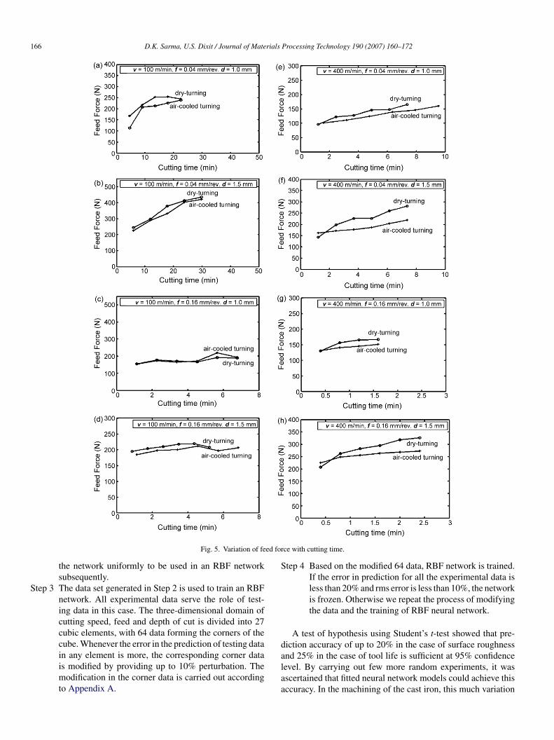
166 D.K. Sarma, U.S. Dixit / Journal of Materials Processing Technology 190 (2007) 160–172
ed for
S
S
d
Fig. 5. Variation of fe
the network uniformly to be used in an RBF networksubsequently.
tep 3 The data set generated in Step 2 is used to train an RBFnetwork. All experimental data serve the role of test-ing data in this case. The three-dimensional domain ofcutting speed, feed and depth of cut is divided into 27cubic elements, with 64 data forming the corners of thecube. Whenever the error in the prediction of testing data
in any element is more, the corresponding corner datais modified by providing up to 10% perturbation. Themodification in the corner data is carried out accordingto Appendix A.alaa
ce with cutting time.
tep 4 Based on the modified 64 data, RBF network is trained.If the error in prediction for all the experimental data isless than 20% and rms error is less than 10%, the networkis frozen. Otherwise we repeat the process of modifyingthe data and the training of RBF neural network.
A test of hypothesis using Student’s t-test showed that pre-iction accuracy of up to 20% in the case of surface roughness
nd 25% in the case of tool life is sufficient at 95% confidenceevel. By carrying out few more random experiments, it wasscertained that fitted neural network models could achieve thisccuracy. In the machining of the cast iron, this much variation
D.K. Sarma, U.S. Dixit / Journal of Materials Processing Technology 190 (2007) 160–172 167
of rad
im
dsIiafc
T
ttttmtoI
Fig. 6. Variation of acceleration
n the machining performance is common due to variation inaterial quality.Based on these steps, neural networks were fitted for the pre-
iction of the average surface roughness and tool life. Fig. 9hows the contours of surface roughness for 1 mm depth of cut.t is seen that in general the surface roughness in dry turnings less compared to the air-cooled turning. Both the dry turningnd air-cooled turning are capable of providing N7 (1.6 �m) sur-
ace roughness. Similar observation is made at other depths ofut.Fig. 10 shows the contours of tool life for 1 mm depth of cut.he trend at other depths of cut is similar. It is clearly seen that
afs[
ial vibration with cutting time.
he tool life gets improved due to air-cooling. In certain cases,he improvement in tool life is more than 50%. Generally, in allhe cases, the tool life decreases with cutting speed. For most ofhe cases, it does decrease with feed, however, for some cases of
achining at high depth of cut and low speed, tool life is foundo increase with feed (figure not shown). The effect of the depthf cut on the tool life is not uniform particularly at low speed.ncreasing the depth of cut increases the tool life some times
nd decreases at some other times depending on the value ofeed. Physics governing this phenomenon is complex; however,ome explanation can be given on the basis of Markarow’s law22]. Way back in 1976, Markarow introduced the concept of
168 D.K. Sarma, U.S. Dixit / Journal of Materials Processing Technology 190 (2007) 160–172
of fe
omlwTt
5
Fig. 7. Variation of acceleration
ptimal cutting temperature based on experimental studies onetal cutting, which has been presented as the first metal cutting
aw in the book by Astakhov [23]. According to it, the toolear will be the minimum at an optimal cutting temperature.hus, the combination of process parameters providing optimum
emperature gives maximum tool life.
wtfi
ed vibration with cutting time.
. Effect of air-cooling at higher cutting speeds
At the beginning of the present study, a series of experimentsere carried out on dry turning of cast iron by ceramic tool in
he cutting speed range 480–600 m/min. However, the surfacenish and tool life was not found satisfactory. Therefore, fur-

D.K. Sarma, U.S. Dixit / Journal of Materials Processing Technology 190 (2007) 160–172 169
Fig. 8. Progression of tool flank wear in turning passes: (a) dry turning and (b) air-cooled turning.
Fig. 9. CLA surface roughness (in micrometer) of machined surface for turning with 1 mm depth of cut: (a) dry turning and (b) air-cooled turning.

170 D.K. Sarma, U.S. Dixit / Journal of Materials Processing Technology 190 (2007) 160–172
Fig. 10. Tool life (in minute) for turning with 1 mm dept
Table 2Operating conditions for high-speed turning
Experimentnumber
Cutting speed(m/min)
Feed(mm/rev)
Depth ofcut (mm)
1 480 0.04 0.52 600 0.04 1.53 600 0.32 1.54 480 0.04 1.55 480 0.32 1.56 600 0.32 0.57 600 0.04 0.58
twcws4acT
iolaahwc6rBiscfttp
Fig. 12 shows the variation of surface roughness of the
480 0.32 0.5
her study concentrated in the speed range 100–400 m/min, inhich dry turning provided satisfactory performance and air-
ooled turning produced even lower flank wear. Encouragedith the results of air-cooled turning, it was planned to conduct a
eries of experiment with compressed air for a high-speed range80–600 m/min. The results for dry turning were already avail-
ble [14]. Here also, the cutting speed (v), feed (f) and depth ofut (d) were taken as 2-level factors in a full factorial design.able 2 shows the different operating conditions.tia
Fig. 11. Progression of tool flank wear with cutting t
h of cut: (a) dry turning and (b) air-cooled turning.
Fig. 11 shows the flank wear versus cutting time for dry turn-ng and air-cooled turning of the first five operating conditionsf Table 2. During dry turning, crater wear was observed in theast three operating conditions, i.e. in experiment number 6, 7nd 8 leading to early tool breakage. The surface finish waslso found very poor at these conditions and a large amount ofeat was generated. However, in air-cooled turning, no craterear was seen in experiment number 7 and combinations of
rater wear and flank wear were seen in experiment numbersand 8. It indicates that compressed air plays a vital role in
educing the temperature at high-speed turning on ceramic tool.oth surface finish and tool life were found to be satisfactory
n experiment numbers 6, 7 and 8 during air-cooled turning (nothown in figure). For the first five operating conditions, the air-ooled turning would provide the better tool life as is evidentrom Fig. 11. Also, during dry turning, for conditions 2, 3 and 5,ool breakage occurred after 3–4 passes. However, in air-cooledurning, the tool breakage was not observed up to even the 6asses, after which the experiment was stopped.
urned component with time for dry and air-cooled turning. Its observed that the surface roughness at operating conditions 3nd 5 is quite high in both dry and air-cooled turning. These cases
ime: (a) dry turning and (b) air-cooled turning.

D.K. Sarma, U.S. Dixit / Journal of Materials Processing Technology 190 (2007) 160–172 171
utting
pacarata
mitebt
6
ciIcsflm4ofvlia
oadtrt
wccswfmwa
A
ncr
ξ
ζ )
AEiup
E
w
N
a
Fig. 12. Progression of surface roughness with c
ertain to a high feed of 0.32 mm/rev. For the cases, 1, 2 and 4,ir-cooling reduce the surface roughness significantly. For theonditions 1 and 4, which pertain to cutting speed of 480 m/minnd feed of 0.04 mm/rev, a very low and almost constant surfaceoughness was observed in air-cooled turning. Tool wear waslso very low in these conditions. This shows that in high-speedurning, the air-cooling improves the surface roughness as wells tool life apart from the reduction in cutting forces.
Thus, it is seen that high-speed turning of grey cast iron withixed alumina ceramic provides a low tool life. This observation
s in line with the observations of Ghani et al. [5] for high-speedurning of nodular cast iron by mixed alumina ceramic. How-ver, air-cooled turning provides an enhanced tool life and maye adopted by industries for high-speed machining by ceramicools.
. Conclusions
The performance of the dry and air-cooled turning of greyast iron with a mixed oxide ceramic cutting tool was stud-ed. The air-cooling was achieved by a jet of compressed air.t was observed that at a low cutting speed of 100 m/min air-ooling did not offer any advantage. However, at higher cuttingpeeds (400 m/min and above), it significantly reduced the toolank wear and increased the tool life. Although, no improve-ent in the surface finish was observed at a cutting speed of
00 m/min compared to dry turning, however at a cutting speedf 480 m/min, where the dry turning provides a very poor sur-ace finish due to rapid tool wear, the air-cooling provided aery good surface finish. In all the cases, air-cooled turningowered the cutting and feed forces compared to correspond-ng forces in dry turning. Thus, air-cooled turning seems to begood environment friendly option for high-speed turning.
This study also brought out some interesting and usefulbservations for future researches in this area. For example,cceleration of vibrations during cutting does not provide any
irect correlation with flank wear or surface roughness. Thus,he inclusion of raw vibration data, for prediction of surfaceoughness as was successfully done by Kohli and Dixit [17] forhe prediction of surface roughness during turning of mild steelti
e
time: (a) dry turning and (b) air-cooled turning.
ith HSS and carbide tool may not be advisable in the presentase. It is, however, yet to be explored whether vibration dataan be processed to provide the useful information regardingurface roughness and tool wear. The main focus of the presentork was to explore the possibility of improving the cutting per-
ormance of mixed oxide ceramic in turning of grey cast iron byeans of air-cooling. The results are encouraging. The futureork will concentrate in optimizing the process parameters of
ir-cooled turning process.
ppendix A
The entire domain of process parameters is divided into aumber of cubic cells. This cell can be transferred into naturaloordinates having the eight corner nodes as (±1, ±1, ±1). Theelation between physical parameters and natural coordinates is
= 2(v − (vmax + vmin)/2)
vmax− vmin, η= 2(f − (fmax+ fmin)/2)
fmax − fmin,
= 2(d − (dmax + dmin)/2)
dmax − dmin(A.1
ssume that error in the prediction of an experimental data is. This error is distributed at the nodes such that error at the
th node is ei. Assuming that error function is tri-linear in nat-ral coordinates, the corner errors are related to the error at aarticular point in the cell in the following way:
=8∑
i=1
Niei (A.2)
here
i = (1 + ξiξ)(1 + ηiη)(1 + ζiζ) (A.3)
re called shape functions. Further, we assume that error at a par-
icular corner is proportional to corresponding shape function,.e.i = kNi (A.4)

1 rials
S
k
T
e
Iec
R
[
[
[
[
[
[
[
[
[
[
[
[
72 D.K. Sarma, U.S. Dixit / Journal of Mate
ubstituting it in Eq. (A.2), the constant k is found equal to
= E∑8
i=1N2i
(A.5)
hus, error in a corner node is
i = Ni∑8i=1N
2i
E (A.6)
n order to reduce the error in prediction, the value of the param-ter to be predicted is modified at the corner by subtracting theorresponding error value calculated from Eq. (A.6).
eferences
[1] T.A. Sadasivan, D. Sarathy, Cutting Tools for Productive Machining, firsted., Widia (India) Limited, Bangalore, 1999.
[2] S.K. Bhattacharyya, E.O. Ezugwu, A. Jawahid, The performance ofceramic tool materials for the machining of cast iron, Wear 135 (1989)147–159.
[3] E.O. Ezugwu, S.J. Arthur, E.L. Hines, Tool-wear prediction using artificialneural networks, J. Mater. Process. Technol. 49 (1995) 255–264.
[4] E.O. Ezugwu, S.H. Tang, Surface abuse when machining cast iron (G-17) and nickel-base superalloy (Inconel 718) with ceramic tools, J. Mater.Process. Technol. 55 (1995) 63–69.
[5] A.K. Ghani, A. Choudhary, Husni, Study of tool life, surface roughnessand vibration in machining nodular cast iron with ceramic tool, J. Mater.Process. Technol. 127 (2002) 17–22.
[6] L. Li, N. He, M. Wang, Z.G. Wang, High speed cutting of Inconel 718 withcoated carbide and ceramic inserts, J. Mater. Process. Technol. 129 (2002)127–130.
[7] A. Senthil Kumar, A. Raja Durai, T. Sornakumar, Machinability of hard-ened steel using alumina based ceramic cutting tools, Int. J. Refract. Met.Hard Mater. 21 (2003) 109–117.
[8] G.C. Benga, A.M. Abrao, Turning of hardened 100Cr6 bearing steel withceramic and PCBN cutting tools, J. Mater. Process. Technol. 143–144(2003) 237–241.
[9] N. Camuscu, Effect of cutting speed on the performance of Al2O3 basedceramic tools in turning nodular cast iron, Mater. Des. 27 (2006) 997–1006.
[
[
Processing Technology 190 (2007) 160–172
10] E.O. Ezugwu, J. Bonney, D.A. Fadare, W.F. Sales, Machining of nickel-base, Inconel 718, alloy with ceramic tools under finishing conditionswith various coolant supply pressures, J. Mater. Process. Technol. 162–163(2005) 609–614.
11] P.S. Sreejith, B.K.A. Ngoi, Dry machining: machining of the future, J.Mater. Process. Technol. 101 (2000) 287–291.
12] D. Jianxin, C. Tongkun, L. Lili, Self-lubricating behaviors of Al2O3/TiB2
ceramic tools in dry high-speed machining of hardened steel, J. Eur. Ceram.Soc. 25 (2005) 1073–1079.
13] A.S. Varadarajan, P.K. Philip, B. Ramamoorthy, Investigations on hardturning with minimal cutting fluid application (HTMF) and its compari-son with dry and wet turning, Int. J. Mach. Tools Manuf. 42 (2002) 193–200.
14] D.K. Sarma, N. Abburi, U.S. Dixit, A study of performance of ceramiccarbide and high speed steel tools in turning of gray cast iron, in: Interna-tional Conference on Recent Advances in Material Processing Technology,National Engineering College, Kovilpatti, Tamilnadu, India, 2005, pp.85–93.
15] D.W. Smithy, S.G. Kapoor, R.E. DeVor, A worn tool force model forthree dimensional cutting operation, Int. J. Mach. Tools Manuf. 40 (2000)1929–1950.
16] D.K. Ojha, U.S. Dixit, An economic and reliable tool life estimation pro-cedure for turning, Int. J. Adv. Manuf. Technol. 26 (2005) 726–732.
17] A. Kohli, U.S. Dixit, A neural-network-based methodology for the predic-tion of surface roughness in a turning process, Int. J. Adv. Manuf. Technol.25 (2004) 118–129.
18] T. Ozel, Y. Karpat, Predictive modeling of surface roughness and tool wearin hard turning using regression and neural networks, Int. J. Mach. ToolsManuf. 45 (2005) 467–479.
19] J.F. Briceno, H. El-Mounayri, S. Mukhopadhyay, Selecting an artificialneural network for efficient modeling and accurate simulation of the millingprocess, Int. J. Mach. Tools Manuf. 42 (2002) 663–674.
20] J.T. Lin, D. Bhattacharyya, V. Kecman, Multiple regression and neural net-work analyses in composite machining, Compos. Sci. Technol. 63 (2003)539–548.
21] D.K. Sonar, U.S. Dixit, D.K. Ojha, The application of radial basis function
neural network for predicting the surface roughness in a turning process,Int. J. Adv. Manuf. Technol. 27 (2006) 661–666.22] A.D. Markarow, Optimization of Cutting Processes, Moscow, Mashinos-troenie, 1976 (in Russian).
23] V.P. Astakhov, Metal Cutting Mechanics, CRC Press, Boca Raton, 1998.