
A bipartite model of distributed systems - W&M ScholarWorks
220
W&M ScholarWorks W&M ScholarWorks Dissertations, Theses, and Masters Projects Theses, Dissertations, & Master Projects 1996 A bipartite model of distributed systems: Possibilities and A bipartite model of distributed systems: Possibilities and implications implications Anna Karin Brunstrom College of William & Mary - Arts & Sciences Follow this and additional works at: https://scholarworks.wm.edu/etd Part of the Computer Sciences Commons Recommended Citation Recommended Citation Brunstrom, Anna Karin, "A bipartite model of distributed systems: Possibilities and implications" (1996). Dissertations, Theses, and Masters Projects. Paper 1539623877. https://dx.doi.org/doi:10.21220/s2-6g9g-8h25 This Dissertation is brought to you for free and open access by the Theses, Dissertations, & Master Projects at W&M ScholarWorks. It has been accepted for inclusion in Dissertations, Theses, and Masters Projects by an authorized administrator of W&M ScholarWorks. For more information, please contact [email protected].
-
Upload
khangminh22 -
Category
Documents
-
view
0 -
download
0
Transcript of A bipartite model of distributed systems - W&M ScholarWorks

W&M ScholarWorks W&M ScholarWorks
Dissertations, Theses, and Masters Projects Theses, Dissertations, & Master Projects
1996
A bipartite model of distributed systems: Possibilities and A bipartite model of distributed systems: Possibilities and
implications implications
Anna Karin Brunstrom College of William & Mary - Arts & Sciences
Follow this and additional works at: https://scholarworks.wm.edu/etd
Part of the Computer Sciences Commons
Recommended Citation Recommended Citation Brunstrom, Anna Karin, "A bipartite model of distributed systems: Possibilities and implications" (1996). Dissertations, Theses, and Masters Projects. Paper 1539623877. https://dx.doi.org/doi:10.21220/s2-6g9g-8h25
This Dissertation is brought to you for free and open access by the Theses, Dissertations, & Master Projects at W&M ScholarWorks. It has been accepted for inclusion in Dissertations, Theses, and Masters Projects by an authorized administrator of W&M ScholarWorks. For more information, please contact [email protected].

INFORMATION TO USERS
This manuscript has been reproduced from the microfilm master. UMI
films the text directly from the original or copy submitted. Thus, some
thesis and dissertation copies are in typewriter face, while others may be
from any type o f computer printer.
The quality of this reproduction is dependent upon the quality of the
copy submitted. Broken or indistinct print, colored or poor quality
illustrations and photographs, print bleedthrough, substandard margins,
and improper alignment can adversely affect reproduction.
In the unlikely event that the author did not send UMI a complete
manuscript and there are missing pages, these will be noted. Also, if
unauthorized copyright material had to be removed, a note will indicate
the deletion.
Oversize materials (e.g., maps, drawings, charts) are reproduced by
sectioning the original, beginning at the upper left-hand corner and
continuing from left to right in equal sections with small overlaps. Each
original is also photographed in one exposure and is included in reduced
form at the back of the book.
Photographs included in the original manuscript have been reproduced
xerographically in this copy. Higher quality 6” x 9” black and white
photographic prints are available for any photographs or illustrations
appearing in this copy for an additional charge. Contact UMI directly to
order.
UMIA Bell & Howell Information Company
300 North Zed) Road, Ann Arbor MI 48106-1346 USA 313/761-4700 800/521-0600
Reproduced with permission of the copyright owner. Further reproduction prohibited without permission.

Reproduced with permission of the copyright owner. Further reproduction prohibited without permission.Reproduced with permission of the copyright owner. Further reproduction prohibited without permission.

A BIPARTITE MODEL OF DISTRIBUTED SYSTEMS:
POSSIBILITIES AND IMPLICATIONS
A D issertation
Presented to
The Faculty of the D epartm ent of Com puter Science
The College of W illiam and Mary in Virginia
In P artia l Fulfillment
Of the Requirements for the Degree of
Doctor of Philosophy
by
Anna Brunstrom
1996
Reproduced with permission of the copyright owner. Further reproduction prohibited without permission.

UMI Number: 9701085
Copyright 1997 by Brunstrom, Anna KarinAll rights reserved.
UMI Microform 9701085 Copyright 1996, by UMI Company. All rights reserved.
This microform edition is protected against unauthorized copying under Title 17, United States Code.
UMI300 North Zeeb Road Ann Arbor, MI 48103
Reproduced with permission of the copyright owner. Further reproduction prohibited without permission.

APPROVAL SHEET
This d issertation is subm itted in p a rtia l fulfillment of
the requirements for the degree of
Doctor of Philosophy
runstrom
Approved, June 1996
Phil KearnsThesis Advisor
Rahul Simha
Weizhen Mao
Gianfranco Ciardo
Stephen ClementDepartment of Geology
ii
Reproduced with permission of the copyright owner. Further reproduction prohibited without permission.

C ontents
A ck n ow led gm ents v iii
L ist o f T ables ix
L ist o f F igures x
A b stract x iii
1 Introduction and M otivation 2
1.1 T h e s i s .................................................................................................................................. ‘2
1.2 The Thesis in a Bigger C o n te x t ................................................................................... 5
1.3 Overview of the D issertation ..................................................................................... 8
2 Formal A spects 11
2.1 System M o d e l .................................................................................................................... 11
2.1.1 In troduction to C S P ........................................................................................ 12
2.1.2 T raditional System M o d e l .............................................................................. 14
2.1.3 B ipartite System M o d e l ................................................................................. 16
Reproduced with permission of the copyright owner. Further reproduction prohibited without permission.

2.1.4 P roof O b lig a tio n s ............................................................................................... 19
2.2 The Delivered and Delivered_all P rim itives............................................................. 21
2.3 Applying the P roof R u l e s ........................................................................................... 27
2.4 C hapter S u m m a r y ......................................................................................................... 31
3 Causally Ordered Com m unication 33
3.1 In tro d u c tio n ....................................................................................................................... 34
3.2 Im p lem en ta tio n ................................................................................................................ 39
3.3 Perfo rm ance....................................................................................................................... 42
3.4 Message by Message Causal Ordering C o n stra in ts ................................................ 50
3.5 C hapter S u m m a r y ......................................................................................................... 57
4 Flush Channels 58
4.1 Introduction and M o tiv a tio n ........................................................................................ 58
4.2 Flush Channel Sem antics ............................................................................................ 60
4.3 Flush Channel Im p le m e n ta t io n ................................................................................. 62
4.4 Previous Im p le m e n ta tio n s ............................................................................................ 64
4.5 Perfo rm ance....................................................................................................................... 67
4.6 C hapter S u m m a r y ......................................................................................................... 79
5 Transport Layer Vector Tim e 81
5.1 Introduction and M o tiv a tio n ........................................................................................ 82
5.2 Causality and Vector Tim e ........................................................................................ 83
5.3 R e la tio n sh ip s ................................................................................................................... 85
5.4 Impact on previous w o rk ............................................................................................... 94
5.4.1 Global Predicate E v a lu a tio n ........................................................................... 95
iv
Reproduced with permission of the copyright owner. Further reproduction prohibited without permission.

5.4.2 Causally Consistent M ulticast in ISIS ........................................................ 101
5.4.3 General G u id e lin es .............................................................................................. 104
5.5 U pdates on ACKs ........................................................................................................... 105
5.6 Term ination Detection Based on Vector T i m e ........................................................ 108
5.6.1 The Term ination D etection P r o b le m ........................................................... 109
5.6.2 The A lg o r ith m .................................................................................................... 110
5.6.3 D iscussion ............................................................................................................... I l l
5.7 C hap ter S u m m a r y ........................................................................................................... 114
6 P rototype Implementation 116
6.1 R U PP Protocol S p e c if ic a tio n ....................................................................................... 116
6.1.1 General D e s c r ip t io n .......................................................................................... 116
6.1.2 Relation to o ther p r o to c o l s ............................................................................ 118
6.1.3 Header F o r m a t .................................................................................................... 120
6.1.4 Connection M anagement ................................................................................ 122
6.1.5 D ata Transfer - O v e rv ie w ................................................................................ 129
6.1.6 Reliable D ata T ra n sfe r ....................................................................................... 130
6.1.7 Flow C o n t r o l ........................................................................................................ 137
6.1.8 Information About Delivery of M essages ..................................................... 139
6.1.9 User In te rface ........................................................................................................ 140
6.2 R U PP Prototype Im p lem en ta tio n ................................................................................ 141
6.2.1 The Networking Code in L in u x ...................................................................... 142
6.2.2 Adding RU PP .................................................................................................... 144
6.2.3 User In te rface ........................................................................................................ 147
v
Reproduced with permission of the copyright owner. Further reproduction prohibited without permission.

6.2.4 Delivered and D e liv e red _ a ll........................................................................... 148
6.3 Flush Channel Im p le m e n ta tio n .................................................................................. 150
6.4 C hap ter S u m m a r y ......................................................................................................... 151
7 Experim ental R esults 154
7.1 Experim ental Setup ...................................................................................................... 155
7.2 R U PP Experim ents ....................................................................................................... 157
7.2.1 Bulk D a ta Transfer (Experim ent 1) 157
7.2.2 Request-Response Message Passing (Experim ent 2 ) ................................ 161
7.2.3 Influence of Message Length (Experim ent 3 ) ............................................ 165
7.2.4 Perform ance Over a Lossy Network (Experim ents 4 and 5) ............... 165
7.3 Delivered Experim ents (Experiments 6 and 7 ) ......................................................... 170
7.4 Flush Channel Experim ent (Experim ent 8) ............................................................ 175
7.5 S u m m a r y .......................................................................................................................... 178
8 Concluding Remarks 181
8.1 D issertation S u m m a r y .................................................................................................. 181
8.1.1 Form al D e v e lo p m e n ts ..................................................................................... 182
8.1.2 Message Ordering P ro to c o ls ........................................................................... 182
8.1.3 T ransport Layer Vector T i m e ........................................................................ 184
8.1.4 P ro to type Im plem en ta tion ............................................................................... 185
8.2 Future Research D i r e c t io n s ......................................................................................... 187
8.2.1 T rad itional P ro b lem s........................................................................................ 187
8.2.2 Im plem entation E x te n s io n s ........................................................................... 189
8.2.3 A lternative Semantics for Delivered and Delivered_all ....................... 191
vi
Reproduced with permission of the copyright owner. Further reproduction prohibited without permission.

8.2.4 Delivered and Delivered_all for Broadcast C o m m u n ic a tio n .................. 192
8.2.5 Formal V erifica tion ............................................................................................ 193
8.3 Chapter S u m m a r y ......................................................................................................... 194
Reproduced with permission of the copyright owner. Further reproduction prohibited without permission.

ACKNOWLEDGMENTS
The au thor wishes to thank her advisor, Dr. Phil Kearns, for his excellent guidance
throughout the developm ent of this dissertation, and for his inspiring enthusiasm for the
field of C om puter Science. The au tho r also wishes to thank Dr. Rahul Simha for his
careful reading of an earlier draft of this work and for many useful discussions on the
m aterial contained in this dissertation. Finally, the au thor wishes to thank her fellow
graduate students, w ith a special thanks to Felipe Perrone and Jean M ayo, for many helpful
discussions and for good company over the years when this work was carried out.
viii
Reproduced with permission of the copyright owner. Further reproduction prohibited without permission.

List o f Tables
6.1 R U PP F la g s ...................................................................................................................... 122
7.1 Param eters Used in Experim ent 5 ............................................................................. 169
7.2 Best-case Behavior of D e liv e red ................................................................................. 175
ix
Reproduced with permission of the copyright owner. Further reproduction prohibited without permission.

List o f Figures
1.1 T C P /IP Com m unication M o d e l................................................................................... 3
1.2 System View Taken by D istributed A lg o r i th m s .................................................... 4
2.1 Traditional System M o d e l ............................................................................................. 15
2.2 Extended System M o d e l ................................................................................................ 17
2.3 Sample P r o g r a m .............................................................................................................. 28
2.4 A nnotated P r o g r a m ....................................................................................................... 29
3.1 Causally O rdered Message P a s s in g ............................................................................ 35
3.2 Non-Causally Ordered Message P a s s i n g .................................................................. 35
3.3 Sqrt(£ (.D )) versus E( S ) , L and 5 Exponentially D istribu ted ............................ 46
3.4 Sqrt( E ( D ) ) versus E ( S ), L and S Exponentially D istributed, E( L) = 100. . 47
3.5 Sqrt(£ '(£))) versus E( S ) , L C onstant, S Exponentially D istributed ................ 48
3.6 Sqrt(E(£>)) versus E ( S ) , L C onstant, S Uniform ly D istribu ted ....................... 49
3.7 Problem atic C o m p u ta tio n ............................................................................................. 52
4.1 Perform ance Model for the W aitfor T ech n iq u e ....................................................... 68
4.2 Performance Model for Our Im p le m e n ta tio n ........................................................... 69
4.3 Expected Message Delay versus A ............................................................................... 71
x
Reproduced with permission of the copyright owner. Further reproduction prohibited without permission.

4.4 Effective Send Rate versus A .................................................................................... 72
4.5 Expected Message Delay versus Effective A ........................................................... 74
4.6 Expected Message Delay versus B atch -size ............................................................ 75
4.7 Effective A versus B atch -size ....................................................................................... 77
4.8 Expected Message Delay versus Message Length ................................................ 78
5.1 Com m unication P r o c e s s .............................................................................................. 86
5.2 Sample C o m p u ta tio n ..................................................................................................... 88
5.3 A pplication Layer V i e w .............................................................................................. 89
5.4 T ransport Layer V i e w ................................................................................................. 89
5.5 Transitive Buffering E f fe c t ........................................................................................... 92
5.6 A pplication Layer V i e w .............................................................................................. 96
5.7 Corresponding L a t t i c e ................................................................................................. 97
5.8 T ransport Layer v iew ..................................................................................................... 99
5.9 Corresponding L a t t i c e ................................................................................................. 100
5.10 A pplication Layer V i e w .............................................................................................. 103
5.11 T ransport Layer V i e w ................................................................................................. 103
5.12 Sample C o m p u ta tio n ..................................................................................................... 106
5.13 Corresponding Lattice w ith No Vector T im e U pdate by ACKs ..................... 107
5.14 Corresponding Lattice when ACKs U pdate Vector T i m e ................................. 107
5.15 ACKs Do Not U pdate Vector T im e .......................................................................... 113
5.16 ACKs U pdate Vector T i m e ....................................................................................... 113
6.1 Relation to O ther P ro to c o ls ....................................................................................... 119
6.2 RU PP Header F o r m a t ................................................................................................. 121
xi
Reproduced with permission of the copyright owner. Further reproduction prohibited without permission.
6.3 RU PP S ta te T ransition D ia g r a m ............................................................................... 1*27
6.4 RU PP D uplicate D e t e c t io n ......................................................................................... 135
6.5 The proto S t r u c t u r e ....................................................................................................... 143
6.6 The RU PP pro to S t r u c t u r e ......................................................................................... 145
6.7 The flush_sendto R outine................................................................................................ 152
7.1 Markov Model for Packet Loss .................................................................................. 155
7.2 Outline of M aster P r o c e s s ........................................................................................... 158
7.3 Time versus B a tc h -s ize ................................................................................................. 159
7.4 Tim e versus B a tch -s ize ................................................................................................. 160
7.5 Outline of M aster P r o c e s s ............................................................................................ 162
7.6 Time versus N um ber of Request-response M essag es............................................ 163
7.7 Tim e versus N um ber of Request-response M essag es ............................................ 164
7.8 Round-trip T im e versus Message Size ..................................................................... 166
7.9 Tim e versus Loss P r o b a b i l i ty .................................................................................... 168
7.10 Time versus Holding Tim e in Loss S t a t e ................................................................. 171
7.11 Time versus Message S i z e .......................................................................................... 173
7.12 Tim e versus B a tc h -s ize ................................................................................................. 177
Reproduced with permission of the copyright owner. Further reproduction prohibited without permission.

ABSTRACT
Networking software is generally designed in layers. User processes exist a t the application layer. They rely on the transport layer to provide them w ith end-to-end comm unication. In the d istribu ted system s literature com munication is traditionally viewed from the application layer. At the application layer we have no knowledge o f the whereabouts of a message once a send operation is completed. At the tran sp o rt layer, on the other hand, inform ation abou t the delivery of a message to the transport layer in the receiving host is often available. We believe transport layer inform ation can be b e tte r utilized in d istribu ted system s design. This d issertation presents support for this thesis.
We first develop a b ipartite system model th a t allows us to reason formally about tran sport layer inform ation. We can then propagate transport layer inform ation to the application layer in a form ally sound fashion. We define two constructs, delivered and delivered_all, for th is purpose. The constructs allow easy im plem entation of message ordering protocols a t the user level. We develop user-level im plem entations of bo th causally ordered communication and flush channels.
We also consider the im pact of transport layer inform ation on vector tim e. T ransport layer vector tim e can improve both the com putational efficiency and the accuracy of results for certain algorithm s. T ransport layer vector tim e also provides the possibility of updating vector tim e for acknowledgment messages. A d istributed term ination detection algorithm th a t takes advantage of this possibility is designed.
Finally, we provide a prototype im plem entation and associated experimental results. We design and im plem ent a transport layer protocol w ith support for the delivered and delivered_all constructs. Our flush channel im plem entation is also included in the prototype system . Our experim ental results verify the feasibility of our im plem entation and show practical evidence in support of the usefulness of transport layer information.
xiii
Reproduced with permission of the copyright owner. Further reproduction prohibited without permission.

A BIPARTITE MODEL OF
DISTRIBUTED SYSTEMS:
POSSIBILITIES AND IMPLICATIONS
Reproduced with permission of the copyright owner. Further reproduction prohibited without permission.

Chapter 1
Introduction and M otivation
This chapter introduces ou r thesis. A discussion on how this thesis relates to o ther current
trends in the research com m unity is provided. Finally, a more detailed overview of the
remainder of this d isserta tion is presented.
1.1 Thesis
Networking software is trad itionally developed in layers, where each layer is responsible
for a particu lar aspect of comm unication. The T C P /IP protocol suite, for example, is
usually regarded as a four-layer system[98] whereas the ISO reference model provides a
seven-layer view of the com m unication software[100]. In the T C P /IP protocol suite, as
well as in most models, the layer responsible for providing end-to-end comm unication is
the transport layer. A tra n sp o rt layer protocol a t a source node accepts messages from
an application and forw ards them to the corresponding tran sp o rt layer protocol on the
destination host for delivery to the destination application. W hile com m unicating with the
transport layer in ano ther host the transport layer protocols rely on services provided by
2
Reproduced with permission of the copyright owner. Further reproduction prohibited without permission.

CHAPTER 1. INTRODUCTION AND MOTIVATION 3
<
Applicationlayer
Transportlayer
Transportlayer
Data-linklayer
Applicationlayer
Networklayer
Networklayer
User space
a
Kernel
Communication medium
Figure 1.1: T C P /IP Com m unicatiou Model
the layers underneath it, the network layer and the datalink layer in the T C P /IP protocol
suite. The services provided by transport layer protocols vary from reliable fully-ordered
connection-oriented service, as provided by TCP[80], to unordered and unreliable message
delivery, as provided by UDP[77]. In most systems the transport layer protocols and the
protocols of lower layers are implemented in the kernel. The applications utilizing the
services of the tran sp o rt layer belong to the application layer. Application layer processes
include general user processes, comm unicating through (for example) BSD-style sockets, as
well as well-known application services provided by most system s, such as F T P and Telnet.
All application layer processes exist in user space. The layered view of com m unication used
by the T C P /IP protocol suite is depicted in Figure 1.1.
Most algorithm s developed to solve problems in d istribu ted systems are designed a t the
application level. T heir design is based on comm unication as perceived a t the application
Reproduced with permission of the copyright owner. Further reproduction prohibited without permission.

CH APTER 1. INTRODUCTION AND MOTIVATION 4
Applicationprocess
Applicationprocess
Communication subsystem
Figure 1.2: System View Taken by D istributed Algorithms
layer. The operations of the lower layers are only im plicitly defined by the system assum p
tions m ade by the algorithm s. A d istributed system , P , is generally modeled as a set of
N processes, P = {Pq, P i , . . . , i f y - 1}, which com m unicate only through message passing;
there is no shared memory or global clock in a d istribu ted system . The message passing
system is traditionally assumed to provide reliable asynchronous communication. T here is
no known upper bound on the delay of messages but messages are assumed to eventually
reach their destinations. In addition, some algorithm s may require the underlying channels
to be FIFO . The system as viewed by m ost algorithm s in d istributed systems is illustrated
in Figure 1.2.
Asynchronous message passing as viewed from the application layer operates in a “fire-
and-forget” fashion. Once a message is sent, the user has no knowledge of when it will
reach its destination. A process executing a send operation returns immediately. The
message is copied by the networking support code which is responsible for delivering the
message to the receiver. Assuming reliable message passing, the transport layer in the
sender m ust m aintain inform ation on the sta tus of messages. To ensure reliable end-to-end
com m unication the transport layer m ust keep the copy of the message in its buffers until it
Reproduced with permission of the copyright owner. Further reproduction prohibited without permission.

CHAPTER 1. INTRODUCTION AND MOTIVATION 5
knows th a t it has been correctly delivered to the transport layer of the receiver. Thus, even
though no inform ation on the whereabouts of messages is available a t the user level, this
inform ation is available a t the kernel level. In fact, inform ation about delivery of messages
is available virtually for free a t the transport layer.
Our thesis is that low-level information, available at the transport layer, may be used
to our advantage when solving problems in distributed system s. /Is will be explored in this
dissertation, knowledge o f the delivery o f messages can be a useful tool fo r distributed system s
design.
Both formal and practical aspects of the use of low-level inform ation will be considered.
We will develop a b ipartite system model th a t models bo th the application layer and the
tran spo rt layer in the receiving host. Our b ipartite system model will allow us to reason
formally about transport layer inform ation. Based on our m odel, we can develop m ethods to
propagate transport layer inform ation to the user level. We will show how this information
can be applied to design alternative solutions to several well-known problems in d istributed
system s. Finally, we will describe a prototype im plem entation and experim ental results in
order to show th a t our ideas are not only theoretically sound and academically appealing,
but also implem entable in practice.
1.2 The Thesis in a Bigger Context
In this section we examine how our thesis relates to some o th er m ain ideas which inspire
today ’s researchers. We will merely a ttem p t to illustrate how our thesis fits in the context
of some current research trends. Additional related work will be presented throughout our
development as we tackle each aspect of the utilization of tran sp o rt layer information.
B etter utilization of tran spo rt layer inform ation and propagation of transport layer
Reproduced with permission of the copyright owner. Further reproduction prohibited without permission.

CH APTER 1. INTRODUCTION AND M OTIVATION 6
inform ation to the application layer are consistent w ith the end-to-end argum ent [88]. Ac
cording to the end-to-end argum ent very few functions should be placed a t a low level in
the im plem entation of a distributed system . The power should be available a t a high level
since th is is where the functionality m ust u ltim ately be implemented. Low-level functions
are not sufficient a t a higher level and only serve as performance enhancers. If we want
functionality in ou r system to be im plem ented a t the application layer, then we cannot hide
power from this level. To reveal as much power as possible is one of the cardinal rules in
operating system design[54].
Inspired in part by the end-to-end argum ent, m any recent research efforts have con
sidered how to implem ent network protocols a t the user level[65, 102, 56, 67]. Ease of
extensibility, support for m ultiple protocols providing different services, and the ability to
utilize application-specific knowledge to improve performance are identified as the main
advantages of a user-level implementation[102]. As we will see, some of the applications
considered in this dissertation will be user-level im plem entations of network protocols. In
form ation propagated from the transport layer to the application layer can be utilized to
design flexible and straightforw ard user-level im plem entations of message ordering proto
cols.
T he effort to implement networking protocols a t the user level is illustrative of the
general trend in operating system design today. M any current operating system s are large,
inflexible and poorly m atched to the quickly changing needs of the app lica tions[ll, 24, 33].
A num ber of current research projects focus on providing a small operating system kernel
which provides a core of basic services and the tools for flexible extensions to the kernel
or for im plem enting additional services a t the user level. Well-known micro kernels include
Mach[2] and Amoeba[66]. Recent work on extensible operating system kernels include
Reproduced with permission of the copyright owner. Further reproduction prohibited without permission.

CHAPTER 1. INTRODUCTION AND MOTIVATION 7
SPIN[11], the cache kemel[24], and the exokernel[33].
As described earlier, network software is commonly developed in layers. A lthough this
makes for a clear division o f labour and a logical design, it can also lead to poor implemen
tations of network code. Redundancy between the layers can account for a m ajor portion of
the execution cost. Early im plem entations of network code often copied the d a ta to be trans
m itted between buffers a t each layer, adding an substan tia l overhead to the im plem entation.
W ith the emergence of high-speed networks, the execution cost of com m unication software
has become predom inantly more im portan t. Today, m ultiple layers are being squeezed for
efficiency and unnecessary buffer copying is being removed[72, 1, 28]. P resenting transport
layer inform ation to the user level can also reduce redundancy. It is often the case th a t an
algorithm sends explicit acknowledgment messages a t the user level. Allowing inform ation
about transport layer acknowledgments to be propagated to the user level m ay alleviate
the need for user-level acknowledgments. One o f the algorithm s which will be developed
in our d issertation is a d istributed term ination detection algorithm . O ur a lgorithm utilizes
information provided by acknowledgments a t the tran spo rt layer. The use of low-level infor
mation makes our algorithm a simple and efficient solution to the d istribu ted term ination
detection problem . Our algorithm would not be feasible if user-level acknowledgments had
been used due to the high message passing overhead such acknowledgments would introduce.
As this section has illustrated , the thesis prom oted in this dissertation fits in well with
many of today’s research trends. The appropriate use of transport layer inform ation can
aid in the design of flexible user-level protocols as well as reduce redundancy.
Reproduced with permission of the copyright owner. Further reproduction prohibited without permission.

CHAPTER 1. INTRO DU CTION AND MOTIVATION 8
1.3 Overview of the Dissertation
This section gives an overview of the m aterial presented in the rem inder of this dissertation.
To reason formally abou t low-level information, we first develop a b ipartite system model
which allows us to make a d istinction between inform ation available a t the application layer
and a t the transport layer. In particular, our system model m ust allow us to distinguish
between when a message is delivered at the tran spo rt layer and when it is received a t the
application layer.1 The model currently used for reasoning about asynchronous message
passing system s was developed by Schlichting and Schneider[90]. It does not allow such a
distinction. Schlichting and Schneider’s model considers com m unication between processes
a t the application layer. All lower layers are combined into a single entity which represents
the network. Our system model will be a straightforw ard extension of Schlichting and
Schneider’s model. O ur b ip artite system model explicitly models the transport layer in the
receiver as well as the application layer processes. Based on our system model we can then
formally define two constructs, delivered and delivered-all, which will allow us to propagate
low-level inform ation to the user level in a sound fashion. O ur b ipartite system model as
well as our delivered and delivered-all constructs will be developed in C hapter 2.
In the next few chapters we illustrate how our constructs, and the transport layer in
form ation they provide, can be used to solve some sample problems in d istributed systems.
As mentioned earlier, one m ajor application of our constructs is in the design of message
ordering protocols a t the user level. As long as messages are passed in FIFO order from
the transport layer to the application layer, knowledge of delivery of messages is as pow
erful as knowledge of receipt of messages in term s of order. As a result, our constructs
*Our use of delivered and received is based on the work by Schlichting and Schneider[90]. We warn the reader that some authors use the words with the opposite meaning.
Reproduced with permission of the copyright owner. Further reproduction prohibited without permission.

CH APTER 1. INTRODUCTION AND MOTIVATION 9
are extrem ely useful for providing application-specific ordering constraints. We will present
user-level im plem entations o f both causally consistent message passing[89] in C hapter 4 and
flush channels[5] in C hapter 3. As an extension of causally consistent message passing we
will also define causal consistency and causally early delivery for an individual message in
C hapter 3. For some applications causally consistent message passing enforces more order
ing constrain ts th an necessary. Allowing ordering constraints to apply to specific messages
can greatly increase the efficiency of such algorithm s.
As m entioned above no common clock exists in a d istribu ted system. Events in the
system are only partially ordered based on causality[53]. Vector tim e was introduced, by
Mattern[57] and Fidge[34] independently, as a m eans for capturing the causal relationship
in the system . It has become a standard tool used in the design of algorithm s for d istributed
systems. Vector tim e is updated through com m unication2. As we consider the im pact of
transport layer inform ation, it is therefore im portan t to consider vector time as perceived
a t the tran sp o rt layer. This is the topic of C hap ter 5. We establish formal relationships
between application layer and transport layer vector tim e and show how transport layer
vector tim e can improve performance, both in term s of quality of results and in term s of
com putational efficiency, for certain types of algorithm s. T ransport layer vector tim e can
also allow us to update vector time for acknowledgment messages, a possibility which we
also explore in C hap ter 5.
C hapter 6 discusses our prototype im plem entation. We have implemented a transport
layer protocol for reliable unordered message passing, with support for the delivered and
delivered-all system calls, w ithin the realm of the Linux operating system. Our user-level
2Communication events always update vector time. It is also possible to allow local events to update vector time. The formal definition of vector time is given in Chapter 5.
Reproduced with permission of the copyright owner. Further reproduction prohibited without permission.

CH APTER I. INTRODUCTION AND MOTIVATION 10
routines for flush channel communication have also been im plem ented. Experim ental results
from our p ro to type im plem entation are discussed in C hap ter 7. Finally, C hapter 8 contains
concluding rem arks and directions for further research.
Reproduced with permission of the copyright owner. Further reproduction prohibited without permission.

Chapter 2
Formal A spects
In this chapter we develop the formal tools needed in order to reason about transport layer
information. We begin by developing a b ipartite system model which lets us distinguish
between when a message is delivered and when a message is received. We then proceed to
define two user-callable constructs, delivered and delivered-all, which convey transport layer
inform ation to the user layer. The proof rules for our system are established and their use
is illustrated through an example.
2.1 System Model
As mentioned in the in troduction, the trad itional model used for reasoning about asyn
chronous message passing was developed by Schlichting and Schneider[90]. The model
developed by Schlichting and Schneider makes no distinction between when a message is
delivered and when a message is received. Ignoring the delivery of a message to the transport
layer of the receiver is justified if we reason strictly about receipt of messages. However,
we are interested in using tran sp o rt layer inform ation on when a message is delivered. The
11
Reproduced with permission of the copyright owner. Further reproduction prohibited without permission.

CH APTER 2. FORMAL A SP EC TS 12
transport layer support code a t the sender gives up responsibility for the message when it
has been delivered to the transport layer in the receiver. This could happen long before the
message is received by the application program in the receiving process. W hen needed, the
transport layer will buffer an incom ing message until a receive system call is performed by
the application. In a system employing reliable message passing, inform ation about delivery
of messages is available to the kernel as a result of the natu ra l operation of the transport
layer. In con trast, knowledge of when a message is received cannot be obtained w ithout ex
tra message passing overhead. Thus, a distinction between the two operations is necessary.
As our review of Schlichting and Schneider’s model will show, it is not powerful enough
to allow reasoning about delivery of messages. In this section we will therefore develop a
b ipartite system model which allows us to reason formally about inform ation available a t
the tran sp o rt layer. O ur model is easily derived from Schlichting and Schneider’s traditional
model. T he proof obligations for the comm unication statem ents in ou r system can be di
rectly adopted from the rules derived by Schlichting and Schneider. Since both models use
CSP processes to model comm unication we will begin the section w ith a brief introduction
to CSP[40].
2.1.1 In trod u ction to C SP
CSP was introduced by Hoare[40] as a mechanism for program m ing parallel processes.
There are four simple commands in CSP: assignment (:= ), skip (the null com m and), and
two com m unication commands corresponding to send and receive. Com m unication in CSP
is synchronous. Com m unication takes place between two processes Pq and Pi when Pq
specifies P\ as the destination of its o u tp u t and P\ specifies Po as the source of its input or
vice versa. W hen the com m unicating processes have both reached their respective commu
Reproduced with permission of the copyright owner. Further reproduction prohibited without permission.

C H APTER 2. FORMAL ASPECTS 13
nication com m ands the commands are ready and the information exchange can take place.
E ither of th e two processes might be blocked waiting for the other process to reach its input
or ou tpu t com m and. A communication com m and fails when the process w ith which it tries
to com m unicate is term inated. An ou tpu t com m and has the form:
Pr ! expr
where Pr indicates the process which is the destination of the ou tpu t, and expr is the
expression whose value is the da ta to be o u tp u t. In term s of message passing, PT is the
receiver o f the message expr. An input com m and has the form:
Ps ? var
where Ps indicates the process which is the source of the input com m and, and var is the
target variable for the input data . In term s of message passing, Ps is the sender of the
message received in var.
A dditional commands are formed by com position of the simple com m ands. The com
posite com m ands we need are sequence and repetition. Just as one would expect, a sequence
comm and, 5 i ; . . . ; S n, executes S i through S n in sequence. A repetitive com m and has the
form:
d o < guarded com m and > {Q < guarded com m and >} o d
where a guarded command has the form:
< guard > — ► < com m and lis t >
Reproduced with permission of the copyright owner. Further reproduction prohibited without permission.
CHAPTER 2. FO RM AL ASPECTS 14
A guarded com m and is executed only when its guard is ready. A guard consists of a possibly
em pty sequence of boolean expressions possibly followed by a comm unication sta tem ent.
The guard is evaluated and executed from left to right. A guard is ready for execution if all
the boolean expressions evaluate to true and the com m unication statem ent is ready. The
guard is blocked if the boolean expressions are true and the comm unication sta tem ent is
blocked. If a boolean expression evaluates to false or the comm unication statem ent fails,
then the guard fails. A repetitive command repeatedly selects, a t random , a command
for execution am ong the guarded commands whose guards are ready. W hen all guarded
commands fail the repetitive command exits.
2.1 .2 T rad ition al S y stem M odel
The system model for asynchronous comm unication, developed by Schlichting and Schnei
der, consists of th ree processes. The sending and receiving processes communicate through
a third process which represents the network. Processes in the model comm unicate using
CSP-style com m unication. Modeling comm unication using CSP processes allows proof rules
derived from the m odel to use a proof m ethodology for CSP which is known to be both
sound and relatively complete[55]. The system model established by Schlichting and Schnei
der is depicted in Figure 2.1. As we can see, the model conforms to the view of the system
used by most algorithm s in d istributed systems, illustrated in Figure 1.2. All layers below
the application layer as well as the comm unication m edium are combined into one process
representing the netw ork. The sta te of the network is represented by implicit variables. For
unordered message passing, a send operation inserts the message in a send m ultiset, <r, and
a receive operation inserts the message in a receive m ultiset, p. The received message m ust
be a member of a © p prior to the execution of the receive sta tem en t, where 0 represents
Reproduced with permission of the copyright owner. Further reproduction prohibited without permission.

CHAPTER 2. FORMAL ASPECTS 15
Figure 2.1: T raditional System Model
the multiset difference operator. The messages in a 0 p are messages which have been sent
but not yet received. If FIFO comm unication is used, then a and p are sequences rather
than m ultisets and the received message is the head of a — p, where a — p is the sequence
difference1. The receiver m ust receive the earliest message sent am ong all ou tstanding mes
sages. The model is most easily understood by examining an example. Let us consider
FIFO comm unication. Sim ulating a virtual circuit using the model is straightforw ard. The
sending process, 5 , and the receiving process, R , com m unicate through the network
process N:
N :: a ,p := 0 ,0 ;
do
5?<r — ► skip
D (ff ~ P) 7̂ 0; &! (h d (a - p), p + hd{(T - p)) — ► skip
o d
'The sequence difference, si — S2 , is obtained by deleting prefix s2 from the beginning of s j. It is undefined if * 2 is not a prefix of s i.
Reproduced with permission of the copyright owner. Further reproduction prohibited without permission.

CH APTER 2. FORMAL ASPECTS 16
The symbol 0 is used to denote an empty sequence, the + operator appends an elem ent
to a sequence, and hd(-) returns a copy of the elem ent a t the head of a sequence. An
application-level asynchronous send statem ent send(expr) is modeled by:
N ! <7 + expr
and a receive statem ent receive(m) is modeled by:
N 1 { m ,p )
We can see th a t the network process executes a loop, a repetitive command in CSP, receiving
messages from the sender or sending messages to the receiver. All the work performed by
the network process is carried out in the guards o f the repetitive comm and. The netw ork
process term inates when the sending process has term inated and there are no ou tstand ing
messages or when both the sending and the receiving processes have term inated. As seen
above the sending of a message is modeled by inserting the message into a. W hen the
sending process and the network process com m unicate it is as if the d istributed assignm ent
a := <7 + expr had been carried out. When a message is received it is inserted into p as well
as passed to the receiver. Comm unication between the network process and the receiving
process corresponds to the d istributed assignments m := hd(cr — p) and p := p + hd(cr — p).
As ensured by the boolean expression in the second guard, communication between the
network process and the receiving process can only occur when a — p is nonempty.
2.1 .3 B ip a rtite S y stem M odel
In the model developed by Schlichting and Schneider there is no distinction between when
a message is delivered and when a message is received. No such distinction is possible since
all lower layers are represented by a single process. In order to construct a model which
Reproduced with permission of the copyright owner. Further reproduction prohibited without permission.
C H APTER 2. FORM AL ASPECTS 17
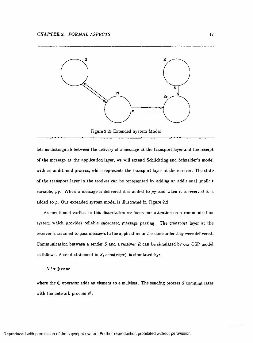
Figure 2.2: Extended System Model
lets us distinguish between the delivery of a message a t the tran spo rt layer and the receipt
of the message a t the application layer, we will extend Schlichting and Schneider’s model
with an additional process, which represents the tran sp o rt layer a t the receiver. The s ta te
of the tran spo rt layer in the receiver can be represented by adding an additional implicit
variable, pr- W hen a message is delivered it is added to p j and when it is received it is
added to p. O ur extended system model is illustrated in Figure 2.2.
As m entioned earlier, in this dissertation we focus our a tten tion on a comm unication
system which provides reliable unordered message passing. The transport layer a t the
receiver is assum ed to pass messages to the application in the sam e order they were delivered.
Com m unication between a sender S and a receiver R can be sim ulated by our CSP model
as follows. A send sta tem ent in 5 , send(expr), is sim ulated by:
N ! a ® expr
where the © opera to r adds an element to a m ultiset. T he sending process S comm unicates
w ith the netw ork process N :
Reproduced with permission of the copyright owner. Further reproduction prohibited without permission.
CH APTER 2. FORMAL ASPECTS 18
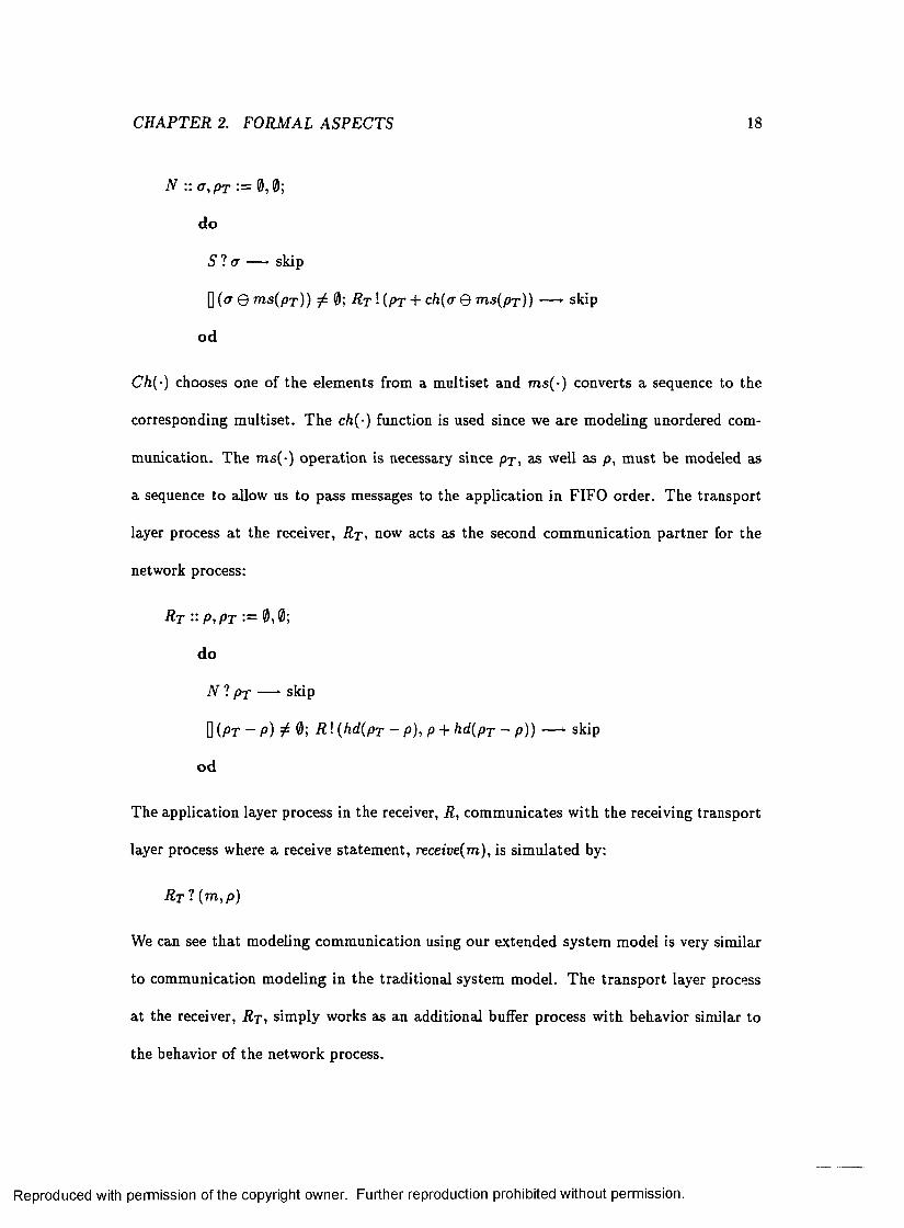
N :: a ,p T := 0 ,0 ;
do
S '! a — ► skip
Q (a © m s(p T )) # 0; R t ! {pr + ch(<r Q m s{p r)) — ► skip
od
Ch(-) chooses one of the elements from a m ultiset and m s(-) converts a sequence to the
corresponding m ultiset. T he ch{-) function is used since we are m odeling unordered com
m unication. The m s(-) operation is necessary since px, as well as p, m ust be modeled as
a sequence to allow us to pass messages to the application in FIFO order. The transport
layer process a t the receiver, R t , now acts as the second com m unication partner for the
network process:
R t :: p ,p T ■= 0?0;
do
N 't p t — ► skip
Q (PT - p) # 0; R ! (hd(pT - p ) , p + hd(pT - p)) — ► skip
od
The application layer process in the receiver, R , com m unicates w ith the receiving transport
layer process where a receive statem ent, receive(m), is sim ulated by:
R t ? (m ,p )
We can see th a t m odeling com m unication using our extended system model is very similar
to comm unication m odeling in the traditional system model. The tran spo rt layer process
a t the receiver, R t , sim ply works as an additional buffer process w ith behavior similar to
the behavior of the netw ork process.
Reproduced with permission of the copyright owner. Further reproduction prohibited without permission.
CHAPTER 2. FORMAL ASPECTS 19
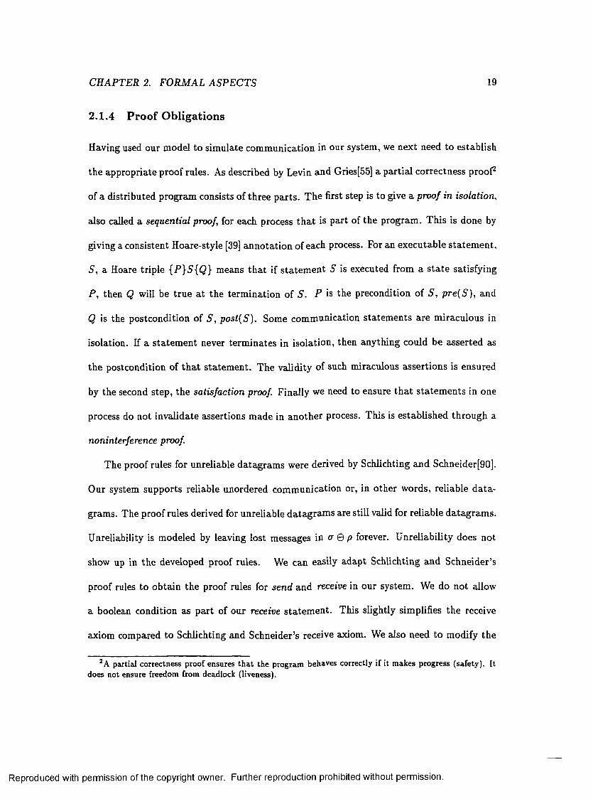
2.1 .4 P ro o f O bligations
Having used our model to sim ulate com m unication in our system, we next need to establish
the appropriate proof rules. As described by Levin and Gries[55] a partial correctness proof2
of a distributed program consists of three parts . The first step is to give a proof in isolation,
also called a sequential proof, for each process th a t is part of the program . This is done by
giving a consistent Hoare-style [39] anno tation of each process. For an executable s ta tem en t.
S , a Hoare triple {P}S{Q } means th a t if sta tem ent S is executed from a s ta te satisfying
P , then Q will be true a t the term ination of S . P is the precondition of S , p re (S ) , and
Q is the postcondition of S , post(S ). Some comm unication statem ents are m iraculous in
isolation. If a sta tem ent never term inates in isolation, then anything could be asserted as
the postcondition of th a t sta tem ent. The validity of such miraculous assertions is ensured
by the second step, the satisfaction proof Finally we need to ensure th a t sta tem ents in one
process do not invalidate assertions made in another process. This is established through a
noninterference proof
The proof rules for unreliable datagram s were derived by Schlichting and Schneider[90].
Our system supports reliable unordered comm unication or, in other words, reliable d a ta
gram s. The proof rules derived for unreliable datagram s are still valid for reliable datagram s.
Unreliability is modeled by leaving lost messages in a Q p forever. U nreliability does not
show up in the developed proof rules. We can easily adapt Schlichting and Schneider’s
proof rules to obtain the proof rules for send and receive in our system. We do not allow
a boolean condition as part of our receive s ta tem en t. This slightly simplifies the receive
axiom compared to Schlichting and Schneider’s receive axiom. We also need to modify the
2 A partial correctness proof ensures that the program behaves correctly if it makes progress (safety). It does not ensure freedom from deadlock (liveness).
Reproduced with permission of the copyright owner. Further reproduction prohibited without permission.

CH APTER 2. FORMAL ASPECTS 20
proof rules to account for our addition of p We derive the following axioms, used during
the proof in isolation:
Network Axioms: m s(px) Q cr; m s(p) C <7; p < p r
Send Axiom: {WJffie;rpr} send(expr) {W}
R eceive Axiom: {iZ} receive(m ) {Q }
where the notation P% means th a t every free occurrence o f y in P is textually replaced by
x . T he receive s ta tem ent is miraculous in isolation. To establish satisfaction, we have the
following proof obligation:
Satisfaction Proof: For every receive statem ent r , prove the validity of
So.tasynch( r ): ( p r e ( r ) A (p t — p) ^ 0 A M T E X T = h d (p T — p )) => Q m t e x t , p + m t e x t
Note th a t ((px - p) ^ 0 A M T E X T = h d ( p T — p ) ) ^ ( M T E X T € (crQ m s(p))). To show
noninterference for senck and receives we must establish:
Noninterference Proof: For every send sta tem ent, s, and every assertion, / , parallel to
s , show
NIasynch{Si -0 • {pre(s) A /} s{ /}
For every receive sta tem ent, r, and every assertion, / , parallel to r , show
N l J S a t asynch { r , I ) : (pre(r) A / A (px — p) ^ 0 A M T E X T = h d ( p r - p ) ) =$>
rm,p1M T E X T , p + M T E X T
As expected, we can see th a t our extension of the system model to allow reasoning
about delivery of messages does not really affect the proof obligations for send and receive
Reproduced with permission of the copyright owner. Further reproduction prohibited without permission.

CHAPTER 2. FORM AL ASPECTS 21
statem ents in the system . The proof rules are only strengthened to allow reasoning about
transport layer inform ation. Programs which do not employ transport layer inform ation
are not affected. T he netw ork axiom is strengthened to express the relationships between
pT and cr and p? and p. T he send and receive axioms rem ain as derived by Schlichting and
Schneider. The antecedents for the satisfaction form ula and for the second noninterference
formula are slightly a ltered . However, as noted above, ((p t — p) ^ 0 A M T E X T = h d (p j —
p)) =3- (M T E X T G [a © m s(p))). Thus, any proof based on the weaker assum ption,
M T E X T G (<7 0 p ), used by Schlichting and Schneider is still valid under the proof rules
derived above. The stronger assertions about the s ta te of the transport layer are needed
for programs which utilize transport layer inform ation. This will become evident as we
examine an example in Section 2.3.
2.2 The Delivered and Delivered_all Primitives
The previous section in troduced our model of the system and established the proof obli
gations for sends and receives in our system. In this section we can now define two new
primitives, delivered and delivered-all, which will allow us to utilize the low-level knowledge
of when a message is delivered at the transport layer of the receiver in a formally sound
way.
Our delivered prim itive takes a message identifier as a param eter. A call to delivered
will return when the message indicated by the message identifier has been delivered at the
transport layer of the receiver. Thus, by definition of delivered we have:
delivered(id(m)) =>■ m G P t
Reproduced with permission of the copyright owner. Further reproduction prohibited without permission.

CHAPTER 2. FO RM AL ASPECTS 22
where id (m ) is the m essage identifier corresponding to message m . Delivered is a monotonic
property which rem ains true forever once it is established. Delivered-all takes no param eters.
When a call to delivered-all returns, all messages sent prior to invoking delivered-all have
been delivered to the tran sp o rt layer of the receiving process. By definition of delivered-all
we have:
deliveredjill() =» ( m s { p j ) = a)
Delivered-all is a nonm onotonic property. It remains true un til another send operation is
performed, and thus can only be invalidated by the sending process itself.
The proof rules for delivered and delivered-all are easily established. The primitives are
miraculous in isolation3 which gives us the following axioms:
D e liv e re d A x io m : { S } delivered(id(m )) {Q}
D e liv e re d -a ll A x io m : {R } deliveredjill{) {U}
Validity for the prim itives is established by a satisfaction proof. Im m ediately before deliv-
ered(id(m)) returns, the s ta te can be described by (S A (m 6 P t) ) , and immediately before
delivered-all returns, the s ta te can be characterized by (R A (m s (p r) = ° '))4- Thus in order
to establish satisfaction we have the following proof obligation:
S a tis fa c tio n P ro o f : For every delivered(id(m)) sta tem ent d, prove
Satdei • (pre(d ) A (m € p r )) => Q
3The axioms are not sound in isolation since it is possible for a process to send messages to itself in an asynchronous message passing system. This is not a problem since the satisfaction proof will ensure validity. The receive axiom is unsound in isolation for the same reason[90].
4The characterization of the states assumes a correct noninterference proof.
Reproduced with permission of the copyright owner. Further reproduction prohibited without permission.

CHAPTER 2. FO RM AL ASPECTS
and for every delivered-all statem ent a prove
23
Satdaii ■ (pre(a) A (m s(p r) = cr)) => U
Noninterference follows triv ially from the Delivered Axiom and the Delivered_all Axiom for
delivered and delivered-all in isolation. We must also establish noninterference in accordance
w ith satisfaction as given by:
N I S a td e i{ d ,I ) : (I A pre(d) A (m £ p t ) ) => I
N IS a td a ii{a , I ) : ( / A pre(a) A (m s(px) = &)) =>• I
N l-Sa tdei and N I-S a td an are also trivially true. Thus, we see th a t noninterference can
be ignored for delivered and delivered-all. This could have been established by noting th a t
delivered and delivered-all do not modify the s ta te of any variables, as well as through
explicitly expressing the proof obligations.
In a system th a t supports reliable message passing, the deh sred and delivered-all p rim
itives can be im plem ented by the kernel a t very low cost. To ensure reliable delivery the
networking support code has to buffer sent messages until they are known to be delivered.
Thus, all the kernel has to do to implement the prim itives is to check the transport layer
send buffers. For exam ple, when delivered is invoked, the buffers are checked for the indi
cated message. If the message is present in the buffers, then the caller will be suspended
until the message is cleared from the buffers. The message identifier used by delivered
would, in practice, refer to the sequence number or sequence num ber offset of the message.
Reuse of sequence num bers by the transport layer is not a problem w ith respect to correct
Reproduced with permission of the copyright owner. Further reproduction prohibited without permission.

CH APTER 2. FORMAL ASPECTS 24
ness. An application th a t performs a delivered call w ith an old sequence num ber th a t has
already been reused will not return until the new message has been delivered. This could
cause an unnecessary wait, but the semantics of delivered are still preserved. The fact th a t
the transport layer is again using the sequence num ber implies tha t the earlier message
has been correctly delivered. Normally, an application is concerned about the delivery of
recently sent messages and the reuse of sequence num bers is not an issue. O ur prototype
im plem entation of delivered and delivered-all will be discussed in Chapter 6.
A lthough the distinction between delivery and receipt of messages is sometimes m ade in
the literature, for instance when considering im plem entations of transport layer protocols,
we have not encountered any discussion form alizing the differences. To our knowledge, our
delivered and delivered-all primitives do not have any clear counterparts in the litera tu re .
An a ttem p t to provide low-level inform ation to the user is m ade in Psync [73]. Psync is
a system supporting causally ordered broadcasts, where causal order is im plem ented by
m aintaining a view of the message context graph a t each processor. The user is provided
w ith prim itives for retrieving inform ation from the context graph. The user can test w hether
a message m is stable , where m is considered stab le once every other process has sent a
message in the context of m . Thus, unless all processes send messages, m will never become
stable. A prim itive for determining if there are any ou tstand ing messages is also provided.
A message is defined to be outstanding if it is a m em ber of the context graph but it is not
yet in the process’ view of the context graph. T his is not a sound construct. It is impossible
to determ ine w hether a message is en route to a process. The property is also nonm onotonic
and can be invalidated by statem ents outside the control of the process using the construct.
One of the m ost a ttrac tive features about the delivered and delivered-all prim itives is
th a t they are as powerful as received and received-all in term s of ordering, where received
Reproduced with permission of the copyright owner. Further reproduction prohibited without permission.

CH APTER 2. FORMAL ASPECTS 25
and received-all have the obvious interpretation. T his is true as long as the transport layer
in the receiver passes messages to the application layer in an order consistent w ith the
order messages were delivered at the transport layer. It is expressed by the following order
conservation property:
O r d e r C o n s e r v a t io n P r o p e r ty : If the transport layer in the receiver passes messages in
FIFO order w ith respect to delivery order, then
(T (delivered(id (m ))) < T (d e liv e red(id(m /)))) =>
(T (received (id (m ))) < T(received{id{m '))))
where T(delivered(id(m ))) indicates the tim e a t which message m was delivered. W hen
unordered message passing is used, the normal procedure would be for the transport layer
to pass messages to the application in FIFO order and the Ordering Conservation P roperty
can be applied. In the next chapters we will see how our delivered and delivered-all prim itives
in com bination w ith the Order Conservation P roperty can be used to implement ordering
constraints on top of an unordered comm unication channel.
In this d isserta tion we focus on a system th a t uses unordered message passing. However,
the semantics o f delivered and delivered-all are independent of this fact. Only what can be
deduced from the inform ation given by the prim itives and the usefulness of the prim itives
depend on the com m unication paradigm used. For a system comm unicating over FIFO
channels, the O rder Conservation Property described above does not usually hold. M ost
im plem entations of FIFO communication rely on the tran spo rt layer in the receiver to ensure
the correct receipt order. The sender includes a sequence num ber in each message, from
Reproduced with permission of the copyright owner. Further reproduction prohibited without permission.

CH APTER 2. FORMAL ASPECTS 26
which the correct receipt order can be deduced. T he transport layer in the receiver passes
messages to the application in the order they were sent, as indicated by their sequence
numbers, ra th e r than in the order they were delivered. Over a FIFO channel, the messages
are fully ordered and we can establish a stronger order conservation property between sends
and receives:
S tro n g O r d e r C o n s e rv a t io n P r o p e r ty : If FIFO comm unication is used, then
(T (sen d (m )) < T (sen d (m '))) =>
(T (received(id (m ))) < T (rece ived (id (m '))))
The Strong O rder Conservation Property expresses the semantics of a FIFO channel. It
assumes th a t messages m and m! are sent on the same channel.
Our delivered.all construct is redundant for FIFO channels th a t are implem ented using
cum ulative acknowledgm ents. When cumulative acknowledgments are used, an acknowl
edgment for a message w ith a given sequence num ber implicitly acknowledges the delivery
of all messages w ith lower sequence numbers. T he transport layer in the receiver will not
acknowledge a message until all messages sent before it have been delivered. For a system
th a t uses cum ulative acknowledgments we can establish the following two facts:
delivered(id (m )) =>■ del ivered( id(prea( m )))
delivered (id (m )) A (la s t(a ) = m ) => d e livered jill()
where p re (7(m ) is the message preceding message m in the send sequence ct, and last(cr)
Reproduced with permission of the copyright owner. Further reproduction prohibited without permission.

CHAPTER 2. FORMAL ASPECTS 27
is the last message in cr. We can see th a t delivered-all is not as useful when cumulative
acknowledgments are used since the sam e inform ation can be obtained by performing a
delivered on the last message sent. A lthough the information provided by delivered-all can
be obtained through the use of delivered, it is still im portant to provide the delivered-all
construct for systems th a t use cum ulative acknowledgments. The use of delivered-all results
in much more portable code which will work correctly irrespective of the acknowledgment
scheme used by the underlying system .
2.3 Applying the Proof Rules
In this section we illustra te how our constructs and proof rules derived in previous sec
tions can be used. We will examine a small two-process distributed program and show its
correctness.
Consider a two-process system where one process represents a custom er and the other
process represents a bank. The custom er process sends two successive messages to the bank.
The first message represents a deposit and the second message represents a w ithdraw al. The
custom er m ust ensure th a t a positive balance is m aintained in the bank; to ensure th a t the
deposit is performed before the w ithdraw al, the customer executes a delivered call before
sending the second message. The bank process simply receives the messages and updates
the balance. The program is depicted in Figure 2.3. We will assume th a t the balance is
initially set to 0. We would like to show th a t the program in Figure 2.3 does indeed ensure
th a t the balance in the bank rem ains positive. Thus we need to prove th a t
I : bal > 0
Reproduced with permission of the copyright owner. Further reproduction prohibited without permission.

CHAPTER 2. FORMAL ASPECTS 28
C:: d e p o s it = 20; B:: r e c e iv e ( x ) ;se n d (d e p o s it) to B; b a l = b a l + x;w ithdraw al = -15 ; r e c e iv e ( x ) ;d e l iv e r e d (m id (2 0 ) ) ; b a l = b a l + x;send(w ithdraw al) to B;
Figure 2.3: Sample Program
is an invariant for the program . To prove invariant / , we give an annotated version of the
program as depicted in Figure 2.4. Invariant I follows trivially if we can show our anno ta ted
program to be correct. As explained earlier, this involves three steps: a proof in isolation,
a satisfaction proof, and a noninterference proof.
Showing th a t the annotations are consistent in isolation is triv ial for both process C
and process B . T he delivered and receive s ta tem ents are all m iraculous in isolation. The
correctness for the assignm ent and send s ta tem ents are easily established. The process is
illustrated by considering the first send s ta tem ent in process C. From the send axiom , we
m ust show
(cr = 0 A deposit = 20) =► (<r = {20})'eifcpMft
= (cr = 0 A deposit = 20) => cr © deposit = {20}
which is trivially true. Correctness for the other send statem ent and the assignm ent s ta te
ments can be shown in a sim ilar fashion.
Next we need to establish satisfaction. Let us first consider satisfaction for the delivered
Reproduced with permission of the copyright owner. Further reproduction prohibited without permission.

CHAPTER 2. FORMAL ASPECTS 29
C:: { a = 0}d e p o s it = 20;{cr = 0A deposit = 20} se n d (d e p o s it ) to B;W = {20}}w ithdraw al = -15 ;{cr = {20}A withdrawal = -15} d e liv e r e d (m id (2 0 ) ) ;{<r = {20} A hd(px) = 20 A withdrawal = -15} send (w ithd raw s!) t o B;{cr = {20, - 1 5 } A hd{pT ) = 20}
B:: {p = 0A bal = 0} r e c e i v e ( x ) ;{p = < 20 > A X = 20 A bal = 0} bal = b a l + x ;{p = < 20 > A bal = 20} r e c e i v e ( x ) ;{p = < 20, —15 > A x = -15 A bal = *20} b a l = b a l + x;{bal = 5}
Figure 2.4: Annotated Program
sta tem ent. We m ust show
(cr = {20} A withdraw l = —15 A 20 E p r ) =>
(cr = {20} A hd(pT ) = 20 A w ithdraw l = —15)
The first and th ird conjunct of the consequent follows trivially. The second conjunct follows
from the first and th ird conjunct of the antecedent and the netw ork axiom, (cr = {20} A20 E
PT A m s(pT) G <r) => hd(pT) = 20. We m ust also show satisfaction for the two receive
statem ents as
(p = 0 A bal = 0 A (p t — p) £ 0 A M T E X T — hd{pT — p) =>
(p = < 20 > Ax = 20 A bal = Q)Xm t e x t ,p+m t e x t
= (p = 0 A bal = 0 A (pT — p) 0 A M T E X T — hd(pT — p) =>
(,p + M T E X T = < 20 > A M T E X T = 20 A bal = 0)
Reproduced with permission of the copyright owner. Further reproduction prohibited without permission.

CH APTER 2. FO RM AL ASPEC TS 30
and
(p = < 20 > A bal = 20 A ( p j — p) ^ 0 A M T E X T = hd(px — p) =►
( p — < 20, —15 > Ax = —15 A bal = W Y m t E X T , p + M T E X T
= (p = < 20 > Abal = 20 A (p t — p) ^ 0 A A fT E X T = hd{pT — p) ^
(p + M T E X T = < 20, - 1 5 > A M T E X T = - 1 5 A 6a/ = 20)
The satisfaction form ulae for the receive statem ents are not valid. The antecedents are not
strong enough to show th a t the values received are 20 and —15 respectively.
As suggested by Schlichting and Schneider[90], we will strengthen our antecedents by
the use of invariants. The following two invariants are easily established:
I\ : (hd(pT) = 2OV<r = 0Vcr = {20})
h : (a- = 0Vo- = {20} V a = { 2 0 ,-1 5 } )
It is easy to see th a t I \ and I 2 hold in process C. They are not affected by the actions
in process B , and thus hold for process B as well; hence, I \ and I 2 are invariants of the
distributed program and can be used in the antecedents of the satisfaction formulae.
Adding / j to the antecedent of the satisfaction form ula o f the first receive we get:
(I \ A p = 0 A bal = 0 A ( p t — p ) 5̂ 0 A M T E X T = h d ( p T — p) ^
(p = < 20 > A x = 20 A bal = 0Y m t e x t , p + m t e x t
= (I i A p = 0 A bal = 0 A ( p t — p) 0 A M T E X T — hd(pT — p) =>
(p + M T E X T = < 20 > A M T E X T = 20 A bal = 0)
The satisfaction form ula for the first receive is now valid. T he first disjunct of I \ in combi
nation w ith conjunct two and five of the antecedent implies th a t the value received is 20.
The second disjunct o f I \ makes the antecedent false since it contradicts the fourth con
Reproduced with permission of the copyright owner. Further reproduction prohibited without permission.

CHAPTER 2. FORM AL ASPECTS 31
junct of the antecedent. T he third disjunct of I i in com bination w ith the network axiom
and conjunct two, four, and five of the antecedent again implies th a t the value received is
20 .
Similarly, we can add I 2 to the satisfaction form ula for the second receive:
( I 2 A p = < 20 > A bal = 20 A (px — p) ^ 0 A M T E X T = hd(px — p) =>■
( p = < 20, —15 > Ax = —15 A bal = 20 ) m x e x t , p + m t e x t
= ( I 2 A p = < 20 > A bal = 20 A ( p x — p ) 0 A M T E X T = h d ( p x — p ) =>•
(p + M T E X T = < 20, -1 5 > A M T E X T = - 1 5 A bal = 20)
The first two disjuncts of I 2 falsify the antecedent, since they contradict conjunct four. The
third disjunct o f I 2 in com bination with the network axiom and conjunct two, four, and five
implies th a t the value received is —15. The form ula is valid and satisfaction is established.
The final step in our proof is noninterference, which follows trivially. To establish
noninterference it suffices to observe that no assertions m ade in the sequential proof of one
process involves a variable altered by the other process.
2.4 Chapter Summary
In this chapter we developed the formal framework needed to reason about transport layer
inform ation. A b ipartite system model th a t lets us distinguish between delivery and re
ceipt of messages was developed. As opposed to the trad itional model used for reason
ing about asynchronous communication, our model explicitly models the operation of the
transport layer in the receiver. Based on the model we defined two constructs, delivered
and delivered-all, which propagate transport layer inform ation to the user level. The proof
Reproduced with permission of the copyright owner. Further reproduction prohibited without permission.

C H APTER 2. FORMAL A SP E C TS 32
rules for comm unication in the system as well as for our newly defined constructs were
established. We illustrated w ith an example how the proof rules can be applied to program
verification.
Reproduced with permission of the copyright owner. Further reproduction prohibited without permission.

Chapter 3
Causally Ordered Com m unication
In the previous chapter we defined two sound and easily understood constructs, delivered
and delivered-all, which reveal low-level inform ation to the user. In th is chapter we illustrate
how our delivered and delivered-all constructs can be applied in practice. We present an
im plem entation of causally consistent message passing based on our constructs. Causally
ordered comm unication can simplify algorithm developm ent, but has been ham pered by its
high im plem entation cost. O ur im plem entation dem onstrates how the additional system
inform ation provided by our constructs allows us to im plem ent ordering constraints in a
very different and more flexible way. We provide causally consistent message passing as a
lib rary routine a t the user level. The efficiency of our proposed im plem entation as opposed
to previously presented im plem entations will also be considered. Due to the flexibility
of our constructs, they lend themselves to considering ordering constraints on a message-
by-message basis. As an extension to causally consistent message passing, we will define
causally ordered and causally early messages.
33
Reproduced with permission of the copyright owner. Further reproduction prohibited without permission.

CH APTER 3. C AU SALLY ORDERED COMMUNICATION 34
3.1 Introduction
In an asynchronous d istribu ted system there is no notion of a global clock. No common
physical tim e line exists, and thus, there exists no to ta l tem poral order on the events of
the system. Instead, the events of a distributed system are only partia lly ordered based on
their causality relation. T he “happens-before” relation or causality relation, denoted — is
an irreflexive p a rtia l order. As defined by Lamport[53], it is the sm allest relation satisfying
the following th ree conditions:
1. If e and e' are events in the same process and e occurs before e ', then e — e'.
2. If e is the sending event of a message by one process and e' is the corresponding receive
event of th a t message in another process, then e —*• e'.
3. If e —► e' and e' —► e", then e —*• e" .
Clearly, e —► e' indicates th a t event e may potentially affect event e'. Two events, e and e',
which are not ordered by causality are said to be concurrent, e |j e '. Thus, e || e' if and only
if (e -f* e') A (e ' ■/* e). The send event of a message m is denoted by s (m ) and the receive
event of the message is denoted by r(m ).
Causally ordered message passing, or causally consistent m essage passing, ensures th a t
all messages received a t a process are received in the causal order they were sent. Concur
rently sent messages may be received in any order. Causally ordered message passing was
introduced by B irm an and Joseph[13] in the context o f broadcast com m unication. It was
extended to point-to-point comm unication by Schiper e t al.[89]. Causally ordered message
passing can be form ally defined as follows[23]. Let (s, r) denote corresponding send and
receive events, m eaning th a t s sent the message which was received by r . A com putation is
Reproduced with permission of the copyright owner. Further reproduction prohibited without permission.

CH APTER 3. CAUSALLY ORDERED COMMUNICATION 35
P, P. P,
Figure 3.1: Causally Ordered Message Figure 3.2: Non-Causally O rdered Mes-Passing sage Passing
causally ordered if for all pairs of corresponding communication events in the com putation,
( s , r ) and (s ', r'):
r ~ r ' A s —► s' r —► r1
where r ~ r1 indicates th a t r and r' are events in the same process.
The difference between a causally ordered message passing and a message passing that
violates th e causal order property is illustrated in figures 3.1 and 3.2. T he message passing
in figure 3.1 is causally ordered. The message passing in figure 3.2 is not causally ordered
since the send of the second message received by P i causally precedes the send of the first
message received. As illustrated by the figures, FIFO channels do not guarantee causal
message passing. A good, less technical, discussion on causality and w hat causally ordered
com m unication means can be found in [104]. It is easy to see why causally ordered message
passing m ay be useful. Consider the com putation in Figure 3.2. Let us assum e th a t P\
Reproduced with permission of the copyright owner. Further reproduction prohibited without permission.

CH APTER 3. C AU SALLY ORDERED COMMUNICATION 36
is a file server. Process Pq sends a message to P i creating a file and then a message to
P 2 notifying P2 abou t the new file. In response P2 sends a message to access the file a t
P i. If the message passing is not causally ordered the message from P2 may get to Pi
first, as depicted in Figure 3.2. As a result, P2 will try to access the file before it exists a t
P i. This is clearly an undesirable ordering of events, and a system in which such causally
unordered com m unication is possible must explicitly implem ent a protocol to deal w ith this
situation. In a system which provides causally ordered com m unication, such an ordering of
events is not possible. The system will ensure th a t P i receives the message from Po before
it receives the message from Pi- Another well-known, and less harm ful, example of causal
inconsistency comes from USENET news. It is often the case th a t replies to an article
arrive a t a site before the original article. The causal ordering between the articles are not
preserved. Users o f USENET news have simply learned to live w ith this artifact.
Causally consistent message passing in the broadcast or m ulticast context has been im
plemented in several systems: two of the m ost well-known system s being ISIS[14, 15] and
Psync [73, 64]. T h e im plem entation in ISIS uses vector tim e to track the causal dependen
cies in the system . Based on the vector tim e of a message the receiver can determ ine if
the delivery of th e message to the application m ust be delayed. As described earlier, the
im plem entation in Psync m aintains a view of the context graph a t each node. As in ISIS,
the receipt of a message is delayed when there are causally preceding messages outstanding.
O ther proposed im plem entations are similar in nature[51, 96].
In a non-broadcast system the im plem entation of causally ordered communication is
complicated by th e fact th a t not every message is seen by every process in the system . The
am ount of inform ation th a t needs to be included in each message to track causality in an N
process system increases to 0 ( N 2) as opposed to O ( N ) for a broadcast system. Two sim ilar
Reproduced with permission of the copyright owner. Further reproduction prohibited without permission.

CH APTER 3. CAUSALLY ORDERED COMMUNICATION 37
im plem entations have been presented in the literature. The first im plem entation is based
on vector time[89] whereas the second im plem entation uses message sequence numbers [83],
a slight variant on vector tim e. As for the broadcast im plem entations, the e x tra information
included in a message is used by the receiver to determine if the message needs to be delayed.
Due to the high cost involved in ensuring causal order a vast num ber o f algorithm s have
been proposed for more efficient im plem entations based on specific system characteristics.
Singhal and Kshemkalyani[92] take advantage of locality of com m unication. Assuming FIFO
channels, only vector tim e entries which have been changed since the last message sent to a
process need to be included in the next message to the process. Rodrigues and Verissimo[86]
compress the inform ation included in messages based on the com m unication topology, as
represented by a graph. They identify a set of nodes, called causal separators, which can
be used to filter causal inform ation. Their work extends the idea of using gateways to
filter causal information[62]. Causal order in a distributed system with a single server was
studied by Kearns and K oodalattupuram [49]. Adelstein and Singhal [3] consider real-time
m ultim edia systems. They focus on preventing causal ordering violations th a t are due to
w hat they call “the triangle inequality” 1. They argue th a t in a real-tim e system this is the
only causal anomaly of im portance; any message that is delayed for an extensive am ount of
tim e is discarded anyway. A sim ilar idea is used by Ruget[87]. He cuts down on the cost of
implem enting vector clocks a t the expense of providing less stringent ordering guarantees.
In general however, the am ount of piggybacked information needed to track causality grows
linearly with the size of the system[22].
There is clearly a trade-off between the advantages of causally ordered com m unication
and its im plem entation cost. W hether causal consistency should be provided by the com
1 Figure 3.2 illustrates the triangle inequality.
Reproduced with permission of the copyright owner. Further reproduction prohibited without permission.

CH APTER 3. CAUSALLY ORDERED COMMUNICATION 38
m unication system or not has caused a heated debate in the distributed systems community
over the past several years. The controversy was s ta rted by Cheriton and Skeene when they
attacked the use of causally ordered com m unication[25]. Cheriton and Skeene argue th a t
causal consistency should not be built into a system since it is expensive and there are
many situations where it is not powerful enough. Based on the end-to-end argument[88]
they argue in favor of a state-level approach to message ordering. The a ttack triggered
replies from B irm an [12], Reneese [105] and Cooper [26]. They claim th a t causally ordered
com m unication can be implem ented efficiently and th a t system development on top of it
is greatly simplified. Development of the ISIS system has shown th a t causally ordered
com m unication can be worthwhile.
All the im plem entations discussed above rely on the receiver to enforce the required
causal ordering constraints based on ex tra inform ation included in the messages. Our
im plem entation, presented in the next section, takes a completely different approach. It
relies on the sender to enforce the required causal order based on occasional synchronization.
A sim ilar idea was recently pursued by M attern and Fiinfrocken[61]. They suggest using
two buffers, an input buffer and an output buffer, for each process. All message passing for
a process goes through its associated buffers. T he ou tpu t buffers enforce the causal order by
only allowing one outstanding message at a tim e. An ou tpu t buffer does not transm it a new
message until the previous message has been acknowledged by the receiving input buffer.
The input buffers simply deliver messages to the application process in the same order they
arrive. O ur im plem entation does not use buffers, instead the sender uses our delivered-all
construct to guarantee causal order. As we will see in the next section, our im plem entation
of causally ordered comm unication provides causal consistency at the user level; hence, it
allows causally ordered communication to be used on an application-by-application basis.
Reproduced with permission of the copyright owner. Further reproduction prohibited without permission.

CHAPTER 3. C AU SALLY ORDERED COMMUNICATION 39
R ather than adding complexity and cost to the underlying com m unication system , our
im plem entation provides causally ordered message passing through a library routine. The
buffer processes suggested by M attern and Fiinfrocken could be implem ented a t the user
level, but would then require user-level acknowledgments to be sent between the o u tp u t and
input buffers.
3.2 Implementation
Several proposed im plem entations of causally ordered com m unication were discussed in the
previous section. T he trad itional approach to implementing causally ordered com m unica
tion is to include additional inform ation in each message and then require the receiver to
enforce the appropriate ordering constraints. We take a different approach to the problem.
Our im plem entation relies on the sender of a message to impose the required ordering con
straints. No ex tra inform ation is included in the messages. Instead, the sender uses the
delivered-a.ll construct2, resulting in possible delay, to enforce the order. O ur im plem enta
tion provides causally ordered comm unication through the following library routine:
causa l_send(data) : d e l iv e r e d _ a l l ( ) ;
send(data) ;
The correctness of ou r im plem entation is established by Theorem 1.
2The choice to use delivered-all is somewhat arbitrary. A delivered on the last message sent would work equally well. However, using delivered-all should be slightly more efficient.
Reproduced with permission of the copyright owner. Further reproduction prohibited without permission.

CHAPTER 3. CAU SALLY ORDERED COMMUNICATION 40
Theorem 1 The causa lsend routine provides causally ordered communication.
P ro o f: Consider two messages m and m ' such th a t s(m ) — s(m ') and both m and
m ' are received by the sam e process. We must show th a t our im plem entation ensures
r(m ) —► r(m '). If s (m ) —► s (m ') , then there are two non-exclusive cases. The first possi
bility is th a t s(m ) —► s (m ') because r(m ) —*• s(m '). For this case it follows trivially that
r (m) -* r(m '). The second possibility is th a t both m and ml were sent by the same process
or there exists a message m " such th a t s (m) —<• s (m ") — s(m ') and m and m " were sent by
the same process. W ithout loss o f generality let us assume th a t message m " exists. Before
sending message m " our im plem entation calls delivered-all. On return from delivered-all we
know th a t a = p i- Thus we know th a t message m was delivered before message m " was
sent. Since s(m ") —* s(m '), message m was also delivered before message m ' was sent. But
then by necessity, message m was delivered before message m l. Finally, from the Order
Conservation P roperty we know th a t message m was received before message m ' and hence
r(m ) —► r(m '). ■
In this paper we are focusing on a system in which the com m unication subsystem pro
vides reliable unordered message passing. If causally ordered com m unication is implemented
on top of FIFO channels, then the im plem entation can be optim ized to employ potential
synchronization only when successive messages are sent on different channels:
causa l_send(data) to P,-: i f ( i != LAST){
d e l iv e r e d -a l l0 ;
LAST = i ;
}
se n d (d a ta );
Reproduced with permission of the copyright owner. Further reproduction prohibited without permission.

CH APTER 3. CAUSALLY ORDERED COMMUNICATION 41
T he variable LAST records the channel on which the last message was sent and should
be initialized to an illegal channel identifier. T he im plem entation above assumes th a t a
single FIFO channel connects any two processes. The transport layer in the receiver is still
assum ed to pass messages to the application in the same order they were delivered.
The m ajor advantage of our im plem entation over previously presented im plem entations
is th a t we can provide causally ordered com m unication at the user level. We do not need
to build causally ordered message passing into the system , ra ther we can provide it as a
library routine for the applications th a t need it. In light of the ongoing debate on whether
causal consistency should be built in to the system or not, a user-level im plem entation is a
very appealing alternative. It is especially appealing considering th a t the debate on causally
ordered comm unication was focused on a broadcast context where the overhead induced on
each message is O ( N ) for a N process system . W hen point-to-point com m unication is used
the overhead on each message increases to 0 ( N 2). Requiring every message in the system
to carry 0 ( N 2) ex tra inform ation is a high price. Providing causally ordered comm unica
tion at the user level for the applications th a t need it is a much more flexible approach.
As described above, M attern and Fiinfrocken have suggested an im plem entation sim ilar to
ours. However, their im plem entation is not designed as a user-level im plem entation. Al
though their proposed buffer processes could be implemented a t the user level, they are
most naturally im plem ented a t the tran sp o rt layer. The potential advantage of having a
buffer process, as opposed to the application process, enforce the required causal ordering
constraints is th a t it may impose less delay on the application process.
Reproduced with permission of the copyright owner. Further reproduction prohibited without permission.

CHAPTER 3. CAU SALLY ORDERED COMMUNICATION 42
3.3 Performance
The approach used in our protocol for casually consistent message passing stands in sharp
contrast to the approach used in most previous im plem entations[89, 83]. Our approach uses
occasional synchronization as opposed to including additional inform ation in messages. In
our protocol, the sender of the message must ensure th a t the ordering constraints are satis
fied. The trad itional approach is to require the receiver to enforce the ordering constra in ts,
aided by the e x tra inform ation included in the message. As mentioned earlier, a m ajor
advantage of our approach is th a t it is easily im plem ented a t the user level. We do not need
to build causal consistency into the system, ra ther we can supply it on an application-by-
application basis. However, we must also consider the efficiency of our approach com pared
to previous im plem entations. This section will present a straightforw ard analysis to th a t
measure. Executing a delivered-all call for every message m ay appear very costly a t first.
However, as we will see in this section, it is not as bad as it may appear for two reasons.
F irst, even if we execute a delivered-all call every tim e we send a message, we do not nec
essarily have to synchronize every tim e we send a message. Second, no cheap alternative
exists. In an N process system the traditional approach requires 0 ( N 2) ex tra inform ation
to be included in every message. The optim izations discussed earlier will not be considered
in this section since they only apply for certain com m unication patterns or com m unication
topologies. The im plem entation proposed by M attem and Fiinfrocken is also not consid
ered.
For our analysis we will assume th a t network propagation tim e for one integer is unity.
The length of a message is measured as a num ber of integers. As a convenience for our
analysis we will consider the length of a message to be a continuous random variable. The
Reproduced with permission of the copyright owner. Further reproduction prohibited without permission.

CH APTER 3. CAU SALLY ORDERED COMMUNICATION 43
system will be characterized by the following param eters:
N Number of processes in the system.
q Network latency. This is the s tartup cost for a message. It is the tim e elapsed from when
a process is ready to transm it a message until the message is actually s ta rting to
propagate over the communication channel. We will assum e this delay to be constant,
hence independent of the message size.
L Length of a message. L is a random variable w ith probability density function f ( L ) and
expected value E( L) .
S Intersend tim e. The intersend time is the tim e elapsed between two successive send
operations. 5 is a random variable with probability density function g(S) and expected
value E ( S ) .
We will evaluate the expected delay for a message. The expected delay for a message is the
expected tim e elapsed from when a process is ready to send a message until the message
is available for receipt to the application in the receiving process. The im plem entation
proposed by Schiper and Sandos and the one proposed by Raynal and Toueg are v irtually
equivalent w ith respect to efficiency. Both im plem entations require N 2 ex tra integers for a
message. We will consider both implem entations together as the “inform ation approach” .
The expected delay for a message in our im plem entation will be denoted by Ts and the ex
pected delay for a message in the information approach will be denoted by T/. Establishing
a lower bound for the expected message delay for the inform ation approach is trivial:
T , = a + E{L) + N 2
Reproduced with permission of the copyright owner. Further reproduction prohibited without permission.

CH APTER 3. CAU SALLY ORDERED COMMUNICATION 44
T he above equation is a lower bound on the delay since it ignores the potential resequencing
delay encountered by the message a t the receiver. If a message arrives out of causal order,
then the receiver cannot make the message available for receipt until all causally preceding
messages have arrived; hence, the message experiences a resequencing delay. In addition, the
equation ignores the potential synchronization delay encountered by a message as discussed
later.
The synchronization delay for a message is the delay encountered from when a sender
is ready to request transmission of the message until the transport layer is ready to s ta r t
servicing th a t request. A synchronization delay is experienced in our im plem entation due to
the call to delivered-all. Let D be the synchronization delay for a message. D is a random
variable w ith expected value E( D) . The expected message delay for our im plem entation
can then be defined as:
Ts = a + E( L ) + E ( D)
Com paring the equations for Tj and Ts we can see th a t when the quantity
A = T i - T s = N 2 - E ( D )
is positive our im plem entation has a sm aller expected message delay th an the inform ation
approach. To evaluate A we must further examine D.
The synchronization delay depends on both the message length and the intersend tim e.
The random variable D can be formally defined as:
D =0, if X — S < 0
X — 5, otherw ise
Reproduced with permission of the copyright owner. Further reproduction prohibited without permission.

CHAPTER 3. C AU SALLY ORDERED COMMUNICATION 45
where X = L + 2 a + 1 . T he random variable X represents the to ta l tim e elapsed from when
we s ta rt transm ission of a message until we know it has been delivered. The transm ission
tim e for a message of length L is L + a . Assuming the receiver acknowledges each message
individually the tim e to send an acknowledgment is 1 + a. Hence, the to ta l tim e from when
we s ta rt transm ission of the message until we know it has been delivered is L + 2 a + 1. If
another message is sent during this tim e-interval, it will encounter a synchronization delay.
It is reasonable to assum e th a t the length of a message is independent of the intersend
tim e. Hence, we will assum e L and S to be independent of one another. Based on our
assum ption of independence, we can represent the jo int density of L and 5 by the product
of their individual densities. The expected value of D, E ( D) , can then be expressed as:
Jroo r l+ 2 a + l' / f ( l )g(s) ( l + 2 a + l - s ) d s d l0 Jo
To see how E ( D ) com pares to N 2 let us look at some specific examples. Let us assume
th a t a has a value of 127. M easurements reported in Experim ent 3, discussed in C hapter
7, indicate th a t th is is a reasonable estim ate for a ; the constant com m unication overhead
for datagram com m unication in our system is approxim ately 127 tim es larger than the cost
associated with tran sm ittin g a single integer3. Let us first consider a system where both
the message length and the intersend tim e are exponentially d istributed. Initially, let L
be exponentially d istribu ted w ith mean 10. Figure 3.3 shows the square root of E ( D) as
a function of the mean intersend tim e when the mean of the intersend distribution varies
from 50 to 1000.
3The results for Experiment 3 suggest that the constant overhead for a message using our RUPP protocol is approximately 433 microseconds. The additional cost associated with each integer transmitted is approximately 3.42 microseconds.
Reproduced with permission of the copyright owner. Further reproduction prohibited without permission.

CHAPTER 3. CAU SALLY ORDERED COMMUNICATION 46
12- •
Q
O10- •4Joau
©ua&a
1000E ( S )
Figure 3.3: S q r t(£ (D )) versus E ( S ), L and S Exponentially D istributed.
A point (E ( S ), \ / E{D) ) on the curve in Figure 3.3 gives the system size for which
the expected delay for a message is the same in both our approach and the information
approach, given the specific param eters used. For example, we can see th a t when the mean
intersend tim e is 200 (roughly 700 microseconds) and the system size is 11 the delay for a
message is approxim ately the same for our im plem entation and the inform ation approach.
The message delay in our im plem entation is independent of th e size of the system. For
the inform ation approach on the o ther hand, the delay for a message is proportional to the
square of the system size. As the system size grows the inform ation approach becomes more
Reproduced with permission of the copyright owner. Further reproduction prohibited without permission.

CHAPTER 3. C AU SALLY ORDERED COMMUNICATION 47
lfr-
14 -
QM*0
ou
1000E ( S )
Figure 3.4: S qrt(£ (Z ?)) versus E( S) , L and 5 Exponentially D istributed, E ( L ) = 100.
expensive and our im plem entation compares m ore favorably.
To evaluate the influence of the mean message length, next let L be exponentially
d istributed w ith m ean 100. The resulting g raph is shown in Figure 3.4. As before, the
intersend distribution is exponentially d istribu ted with a mean varying from 50 to 1000.
The graph in Figure 3.4 is very similar to the graph displayed in Figure 3.3. However, for
larger size messages a slightly larger system size is needed for com parative delay between
the two im plem entation m ethods. Larger messages take longer to transm it, and thus the
synchronization delay for the delivered-all call increases. We can see in Figure 3.4 th a t when
Reproduced with permission of the copyright owner. Further reproduction prohibited without permission.

CHAPTER 3. CAU SALLY ORDERED COMMUNICATION 48
Figure 3.5: S q r t(£ (D )) versus E ( S ) , L C onstant, S Exponentially D istributed.
the mean intersend tim e is 200 a system size of approxim ately 14 processes results in equal
delay for our im plem entation and the inform ation approach.
The influence of the d istributions of the message length and the intersend tim e should
also be considered. Figure 3.5 displays the resulting graph when L has a constant size of
10, and the intersend tim e is exponentially d istributed. Figure 3.6 displays the results for
a system where L has a constant size of 10, and the intersend tim e is uniformly distribu ted
between 0 and twice the m ean, w ith the m ean varying from 50 to 1000. As we can see
from Figures 3.5 and 3.6, the results are not very sensitive to the particu lar distributions
Reproduced with permission of the copyright owner. Further reproduction prohibited without permission.

CHAPTER 3. CAU SALLY ORDERED COMMUNICATION 49
18-
16 "
14 -
12"
ouo xo-•uOOu©
& '•03O’w
800 1000E ( S )
Figure 3.6: S q rt( E( D) ) versus E( S ) , L C onstan t, S Uniformly D istributed.
used. A lthough not displayed, we verified tha t the influence of mean message length on
the d istributions used for Figures 3.5 and 3.6 was consistent with the behavior displayed
in Figures 3.3 and 3.4. For larger message sizes a slightly larger system size was needed to
reach an equal delay between the synchronization and the inform ation approach.
The results displayed in Figures 3.3, 3.4, 3.5, and 3.6 are very consistent. We can see
from the figures th a t , due to the high cost of the inform ation approach, our im plem entation
performs well in relation to the information approach for m edium and large sized system s.
There are some im portan t factors which are not reflected in the graphs. Consider the
Reproduced with permission of the copyright owner. Further reproduction prohibited without permission.
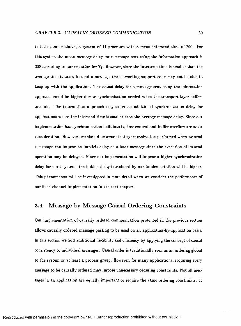
CHAPTER 3. C A U SA LLY ORDERED COMMUNICATION 50
initial exam ple above, a system of 11 processes with a m ean intersend tim e of *200. For
this system the m ean message delay for a message sent using the inform ation approach is
258 according to our equation for T /. However, since the in tersend tim e is smaller than the
average tim e it takes to send a message, the networking support code may not be able to
keep up w ith the application. The actual delay for a message sent using the information
approach could be higher due to synchronization needed when the transport layer buffers
are full. The inform ation approach may suffer an add itional synchronization delay for
applications where the intersend tim e is smaller than the average message delay. Since our
im plem entation has synchronization built into it, flow control and buffer overflow are not a
consideration. However, we should be aware th a t synchronization performed when we send
a message can im pose an im plicit delay on a later message since the execution of its send
operation may be delayed. Since our implementation will im pose a higher synchronization
delay for most system s the hidden delay introduced by our im plem entation will be higher.
This phenomenon will be investigated in more detail when we consider the performance of
our flush channel im plem entation in the next chapter.
3.4 Message by Message Causal Ordering Constraints
Our im plem entation of causally ordered communication presented in the previous section
allows causally ordered message passing to be used on an application-by-application basis.
In this section we add additional flexibility and efficiency by applying the concept of causal
consistency to individual messages. Causal order is trad itionally seen as an ordering global
to the system or a t least a process group. However, for m any applications, requiring every
message to be causally ordered may impose unnecessary ordering constraints. Not all mes
sages in an application are equally im portant or require the same ordering constraints. It
Reproduced with permission of the copyright owner. Further reproduction prohibited without permission.
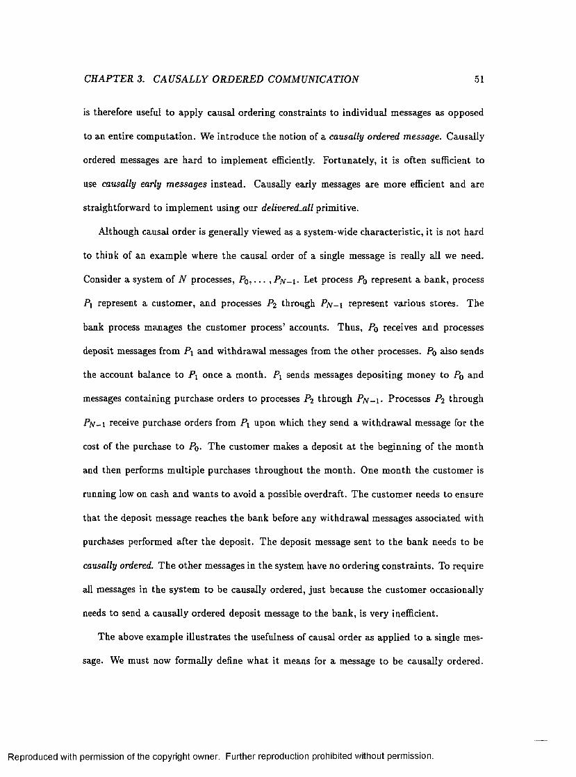
CHAPTER 3. C AU SALLY ORDERED COMMUNICATION 51
is therefore useful to apply causal ordering constraints to individual messages as opposed
to an entire com putation. We introduce the notion of a causally ordered message. Causally
ordered messages are hard to im plem ent efficiently. Fortunately, it is often sufficient to
use causally early messages instead. Causally early messages are m ore efficient and are
straightforw ard to im plem ent using our delivered-all prim itive.
A lthough causal order is generally viewed as a system-wide characteristic , it is not hard
to think of an exam ple where the causal order of a single message is really all we need.
Consider a system of N processes, Po, . . . , P /v-i- Let process Po represent a bank, process
Pi represent a custom er, and processes P2 through PjV-i represent various stores. The
bank process m anages the custom er process’ accounts. Thus, Po receives and processes
deposit messages from P i and w ithdraw al messages from the o ther processes. P0 also sends
the account balance to P i once a m onth. Pi sends messages depositing money to Po and
messages containing purchase orders to processes P 2 through P jv -i- Processes P 2 through
P n - i receive purchase orders from P i upon which they send a w ithdraw al message for the
cost of the purchase to Po- T he custom er makes a deposit a t the beginning of the m onth
and then performs m ultiple purchases throughout the m onth. One m onth the custom er is
running low on cash and wants to avoid a possible overdraft. The custom er needs to ensure
that the deposit message reaches the bank before any withdrawal messages associated with
purchases performed after the deposit. The deposit message sent to the bank needs to be
causally ordered. T he o ther messages in the system have no ordering constra in ts. To require
all messages in the system to be causally ordered, ju st because the custom er occasionally
needs to send a causally ordered deposit message to the bank, is very inefficient.
The above exam ple illustrates the usefulness of causal order as applied to a single mes
sage. We must now form ally define w hat it means for a message to be causally ordered.
Reproduced with permission of the copyright owner. Further reproduction prohibited without permission.

CH APTER 3. CAUSALLY ORDERED COMMUNICATION 52
P,
Figure 3.7: Problem atic Com putation
Let (s, r ) denote the send and receive events of message m. Message m is causally ordered
if for all pairs of corresponding com m unication events (s ', r ') in the com putation:
( r ~ t ' A s —► s' => r —► r ') A
( r ~ r ' A s ' - * s ^ / - + r )
Unfortunately, it is not possible to im plem ent causal order for individual messages based
on our prim itives without requiring possible synchronization for every message; th a t is,
im plem enting causally ordered message passing for the system. Consider the com putation
shown in Figure 3.7. Let us assume th a t process Pi needs to send message m as a causally
ordered message. Process Pi has no way of locally ensuring th a t message m is not received
before message m ' based on our prim itives. W hen causally ordered message passing is
used, process Pq would ensure th a t message m ' is received before message m by executing
Reproduced with permission of the copyright owner. Further reproduction prohibited without permission.
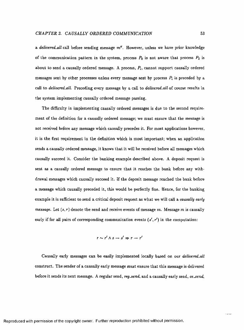
CH APTER 3. CAU SALLY ORDERED COMMUNICATION 53
a delivered-all call before sending message m " . However, unless we have prior knowledge
of the comm unication p a tte rn in the system , process Po is not aware th a t process P2 is
about to send a causally ordered message. A process, P{, cannot support causally ordered
messages sent by o ther processes unless every message sent by process P t- is preceded by a
call to delivered-all. Preceding every message by a call to delivered-all o f course results in
the system im plem enting causally ordered message passing.
The difficulty in im plem enting causally ordered messages is due to the second require
m ent of the definition for a causally ordered message; we m ust ensure th a t the message is
not received before any message which causally precedes it. For m ost applications however,
it is the first requirem ent in the definition which is m ost im portan t; when an application
sends a causally ordered message, it knows th a t it will be received before all messages which
causally succeed it. Consider the banking example described above. A deposit request is
sent as a causally ordered message to ensure th a t it reaches the bank before any w ith
drawal messages which causally succeed it. If the deposit message reached the bank before
a message which causally preceded it, this would be perfectly fine. Hence, for the banking
example it is sufficient to send a critical deposit request as w hat we will call a causally early
message. Let (s, r ) denote the send and receive events of message m . Message m is causally
early if for all pairs of corresponding comm unication events (s ', r ') in the com putation:
r ~ r ' A s - t s ' ^ r - t r '
Causally early messages can be easily implem ented locally based on our delivered-all
construct. The sender of a causally early message m ust ensure th a t this message is delivered
before it sends its next message. A regular send, reg-send, and a causally early send, cesend ,
Reproduced with permission of the copyright owner. Further reproduction prohibited without permission.

CH APTER 3. C AU SALLY ORDERED COMMUNICATION 54
can then be im plem ented by the following two library routines:
reg-s end (d a ta ) : if(D_FLAG){
d e l iv e r e d -a l l ( ) ;
D-FLAG = f a l s e ;
}
se n d (d a ta );
ce_ sen d (d a ta ): if(D_FLAG)
d e l iv e r e d -a l l0 ;
D-FLAG = tru e;
se n d (d a ta );
The sender m aintains a flag to keep track of w hether the last message sent was a causally
early message or no t. If the flag is set, then a call to delivered-all is performed before
sending the next message. A call to delivered-all is performed prior to sending a message
which succeeds a causally early message rather than a t the end of the c e se n d routine
in order to m inimize the delay imposed on the sender. The correctness argum ent for our
im plem entation of causally early messages is sim ilar to the correctness argum ent for causally
ordered com m unication and is given by Theorem 2:
Theorem 2 The regsend and cesend routines provide causally early messages.
P ro o f: Consider two messages m and m! such th a t m is sent as a causally early message,
s(m ) —> s(m' ) , and both m and m' are received by the sam e process. We m ust show
th a t our im plem entation ensures r(m) —* r(m' ) . If s ( m ) —► s(m' ) , then there are two non
exclusive cases. T he first possibility is th a t s(m ) —*■ s(m' ) because r (m) —► s(m '). For
Reproduced with permission of the copyright owner. Further reproduction prohibited without permission.

C H APTER 3. CAUSALLY ORDERED COMMUNICATION 55
this case it follows trivially th a t r(m ) — r(m' ) . T he second possibility is th a t m and
m' were sent as successive messages by the same process or there exist a message m"
such th a t s (m) —► s (m") —► s(m' ) and m and m " were sent as successive messages by the
same process. W ithout loss of generality let us assum e th a t message m " exists. Since
message m is a causally early message, D-FLAG will be set by the cesen d routine before
message m is sent. Since m " is the next message to be sent, D-FLAG will initially be set
to true and our im plem entation will call delivered-all. On return from delivered-all, we
know th a t a = p j- Thus we know th a t message m was delivered before message m " was
sent. Since s(m w) — s(m' ) , message m was also delivered before message m! was sent. But
then by necessity, message m was delivered before message m' . Finally, applying the O rder
Conservation P roperty we know th a t message m was received before message m' and hence
r(m ) —► r(m ') . ■
Sending individual messages as causally early messages when needed, as opposed to
using causally ordered communication for the system, m ay greatly increase efficiency. Con
sider the banking example described above once more. Let us assume that k out of one
hundred messages sent is a crucial deposit message. T he expected synchronization delay
for a message when causally ordered communication is used was derived in the previous
section. Let us now consider what happens if we instead send the crucial deposit messages
as causally early messages. The expected synchronization delay for messages im m ediately
succeeding a causally early message will be as derived in the previous section. T he ex
pected synchronization delay for all o ther messages is zero. Fortunately most messages do
not follow a causally early message. For our example, the expected synchronization delay
for a message when causally early messages are used is k% of the expected synchronization
delay for a message when causally ordered message passing is used in the system. Hence,
Reproduced with permission of the copyright owner. Further reproduction prohibited without permission.

CH APTER 3. CAUSALLY ORDERED COMMUNICATION 56
enforcing only the relevant causal ordering constraints can greatly increase efficiency for
applications where k is small.
We believe the focus on causal order as a global concept is partia lly due to the approach
used in previous im plem entations. W hen ex tra information is included in messages to track
causality in the system , there is not much incentive to provide causal ordering constraints
on a message-by-message basis. All the ex tra information m ust be included on every mes
sage even if we only occasionally need causal constraints. In our proposed im plem entation
of causally early messages, on the o ther hand, the amount of synchronization needed can be
proportional to the num ber of causal constraints imposed. Not only can our approach pro
vide causal order on an application-by-application basis, it can also provide causal ordering
constraints on a message-by-message basis.
An idea sim ilar to our causally early messages has been pursued by Rodrigues and
Verissimo[85] for a m ulticast context. They distinguish between two types of causal mes
sages: opaque and transparent causal messages. The only restriction on a transparent
message is th a t it cannot be received before an opaque message th a t causally precedes it.
No messages are ever delayed waiting for a transparent message. T heir suggested implemen
tation still requires 0 ( N ) ex tra inform ation for all messages, including transparent causal
messages. T heir work is m otivated by a need to cut down on the resequencing delay and
to allow transparen t messages to be sent w ithout reliability constra in ts, issues which are
more relevant for m ulticast com m unication than for point-to-point comm unication. For
point-to-point com m unication, the resequencing delay is generally negligible compared to
the delay induced by including ex tra inform ation in the messages.
Reproduced with permission of the copyright owner. Further reproduction prohibited without permission.

CH APTER 3. CAU SALLY ORDERED COMMUNICATION 57
3.5 Chapter Summary
In th is chapter we illustrated how our delivered and delivered-all constructs can be used in
practice. We provided an im plem entation of causally consistent message passing. Causally
consistent message passing can greatly simplify algorithm developm ent, but also imposes
a fairly high im plem entation cost. W hether causally ordered comm unication should be
provided by the system or not is causing heated debate in the d istribu ted systems commu
nity. Our im plem entation o f causally consistent message passing provides the primitive in
a user-level library. This alleviates the need for building expensive support into the under
lying system and imposes the cost of causal order only on applications which use it. Our
im plem entation is based on occasional synchronization as opposed to including ex tra infor
m ation in messages. As an extension to causally consistent message passing this chapter
also introduced causally ordered and causally early messages. Causally early messages can
be im plem ented efficiently based on our delivered-all construct. Allowing causal ordering
constraints to be applied on a message-by-message basis can radically improve performance.
As illustrated by the banking example considered in th is chapter, it is often sufficient to
impose causal constraints only on selected messages.
Reproduced with permission of the copyright owner. Further reproduction prohibited without permission.

Chapter 4
Flush Channels
The previous chapter described an im plem entation of causally ordered com m unication based
on our delivered-all construct. As a second example of the applicability of ou r constructs this
chapter will consider an im plem entation o f flush channels. Flush channels offer a suitable
a lternative to FIFO comm unication for applications which require only a partially ordered
message service. Our flush channel im plem entation utilizes both our delivered and our
delivered-all constructs. As for causally ordered communication, the m ain advantage of our
im plem entation is that we can provide it a t the user level on an application-by-application
basis. A sim ulation study of the perform ance of our im plem entation com pared to previous
im plem entations is also included in this chapter.
4.1 Introduction and Motivation
The In ternet protocol stack, and trad itional message passing prim itives, provide either fully
ordered connection-oriented service (T C P ) or completely unordered (usually unreliable)
service (U D P). However, for certain classes of applications, such as m ultim edia, a partially
58
Reproduced with permission of the copyright owner. Further reproduction prohibited without permission.

CHAPTER 4. FLUSH CHANNELS 59
ordered service is sufficient to ensure correctness and can greatly improve efficiency. Con
sider the transm ission o f a sequence of images across the network for display at a rem ote
site. Each im age may be split into several messages where each message contains p a rt of
the image d a ta and a tag field identifying which p a rt of the image it contains. The re
ceiver assembles the image pieces into a frame and displays it. The situation described
above creates a message pattern where we have batches of messages without any internal
ordering constrain ts but where the batches need to be sequentially ordered. The pieces of
one image may arrive in any order but we require all pieces of an image to arrive before
parts of the next image. Requiring applications such as the one described above to use
fully ordered service is overly restrictive. Flush channels [5] offer an appealing alternative
for such applications. A flush channel allows the sender to enforce an arb itrary partia l
receipt order on messages. (A formal specification of flush channels is given in the next
section.) Hence, a flush channel relaxes the to ta l order, as appropriate for the application,
to gain efficiency. Im plem enting the application described above on top of a flush channel
would allow messages w ithin a batch to arrive in any order while still enforcing the ordering
constraint present between batches; this could am ply improve performance compared to a
FIFO channel. T he performance benefits of flush channels over multi-link virtual circuits
were considered in [18]. The performance benefits of a partially ordered as opposed to fully
ordered tran sp o rt layer protocol was also discussed in [8]. Here a partially ordered protocol
where the partia l order is negotiated between th e sender and receiver prior to s ta rtu p is
considered.
As described above, flush channels offer great flexibility in the ordering constraints im
posed on messages. However, the flush channel im plem entations suggested in the litera tu re
[6, 7, 48] are not as flexible. All im plem entations presented so far are most naturally imple
Reproduced with permission of the copyright owner. Further reproduction prohibited without permission.

CHAPTER 4. FLUSH CHANNELS 60
mented at a low level by building flush channels into the underlying com m unication system.
Although flush channels are very useful for some applications, it is not realistic to expect the
m ajority of applications to use flush channels. Flush channels are not a standard construct
which we can expect the comm unication subsystem to provide. Building flush channels
into the underlying com m unication system is also inflexible and results in added network
ing complexity. In this chap ter we provide a user-level im plem entation of flush channels.
Providing flush channels a t the user level is the missing link in allowing flush channels to
be a viable alternative for applications which can benefit in perform ance by relaxing the
to ta l ordering on messages. Based on our delivered and delivered^all prim itives we provide
flush channels as a set o f lib rary routines. These library routines can be incorporated by
applications which use flush channels but impose no cost to o ther applications. As our per
formance study will show, our im plem entation performs m ost favorably when the ordering
requirements are weak and messages are short.
4.2 Flush Channel Semantics
Flush channels were introduced by Ahuja[5]. As mentioned earlier, a flush channel allows
the sender to construct an a rb itra ry partial order, specifying constra in ts on the receipt order
of the sent messages. A message sent on a flush channel has a type in addition to the data.
The partial order is built by sending messages of different types. T here are four different
types of messages, each one imposing a different ordering constraint:
• Type O rd , an ordinary message. An ordinary message imposes no ordering constraint.
However, an ordering constraint can be be imposed on the m essage by a message of
another type.
Reproduced with permission of the copyright owner. Further reproduction prohibited without permission.

CHAPTER 4. FLUSH CHANNELS 61
• Type 2 F , a two-way flush message. A two-way flush message m ust be received after
all messages sent prior to it, and before all messages sent after it.
• Type F F , a forward flush message. A forward flush message m ust be received after
all messages sent prior to it.
• Type B F , a backward flush message. A backward flush message m ust be received
before all messages sent after it.
The proof rules for flush channels were developed by Cam p, Kearns and Ahuja[19]. T heir
development is based on Schlichting and Schneider’s work on proof rules for asynchronous
communication[90] discussed in C hapter 2. T he sta te of a flush channel, F , is modeled
through im plicit variables. W hen a message is sen t, it is inserted into the send m ultiset o p ,
and when a message is received, it is inserted in to the receive multiset pp . The ordering
restriction im posed on F is modeled by an irreflexive partia l order, -<+p C o p x crp. For
m, m ' 6 <t f , T tK + p m ' if and only if m m ust be received before m l. The partial order
is implicitly constructed by the sender as new messages are sent along the channel. The
semantics ensured by a flush channel can then be expressed by the following Flush Channel
Network Axiom:
F lu sh C h a n n e l N e tw o rk A x io m : For flush channel F , the following two properties must
hold:
E n R o u te P r o p e r ty : pp C op
O r d e r P r o p e r ty : Vm, m ' : m ,m ' E o p A m -i+ p m 1 A m ' e pp =>• m € Pf
The En Route P roperty simply says th a t we cannot receive a message before it is sent. The
Order P roperty says th a t messages must be received in an order th a t is consistent w ith
Reproduced with permission of the copyright owner. Further reproduction prohibited without permission.

CH APTER 4. FLUSH CHANNELS 6 2
the partial order specified by the sender. The sem antics of a flush channel given by the
Flush Channel Network Axiom must be ensured by any im plem entation of flush channels.
The En Route Property , of course, follows directly from the semantics of any underlying
comm unication channel and is of no concern.
4.3 Flush Channel Implementation
Having formally defined flush channels in the previous section we now turn to the m a tte r of
im plem entation. O ur im plem entation provides flush channels through a f lu sh se n d library
routine. The f lu s h s e n d library routine expands a send for each one of the four message
types into sequences of delivered, delivered-all, and sends on the unordered com m unication
system . Based on the type of the message a f lu s h s e n d call is expanded as follows:
flu sh _sen d (2F , d a ta ): d e l iv e r e d _ a l l ( ) ;
s e n d (d a ta );
D_FLAG = tru e;
mid = id (d a ta ) ;
flush_send(F F , d a ta ): d e l iv e r e d _ a l l ( ) ;
se n d (d a ta );
D_FLAG = f a l s e ;
flush_send(B F, data) i f (D.FLAG)
d e liv e r e d (m id );
se n d (d a ta );
D_FLAG = tru e;
mid = id (d a ta ) ;
Reproduced with permission of the copyright owner. Further reproduction prohibited without permission.

CHAPTER 4. FLUSH CHANNELS 63
flush_send(O rd, d a ta ): if(DJFLAG) {
d e liv e r e d (m id );
D-FLAG = f a l s e ;
}
se n d (d a ta );
As can be seen from above, our im plem entation uses occasional user-level synchronization,
through the use o f delivered and deliveredsll, to ensure the necessary message ordering. The
boolean D_FLAG is used to indicate whether the next message needs to be potentially delayed
or not. The message identifier of the message must also be saved so th a t the next flush-send
can identify the message for whose delivery it must w ait. Recall th a t the td(-) function is
defined to return the message identifier for the message. Note tha t D-FLAG is false a t the
completion of a send event for an ordinary message. Thus only the first message in a batch
of ordinary messages can ever require synchronization. To show that our im plem entation
is correct we m ust show th a t the Order Property of the Flush Channel Network Axiom is
m aintained.
T h e o re m 3 The flu sh se n d routines ensure the Order Property o f the Flush Channel Net
work Axiom.
To prove Theorem 3 we will first establish th a t our im plem entation ensures the weak order
property:
L e m m a 1 The f lu sh se n d routines ensure the Weak Order Property:
Vm, m ' : m , m ' € o' A m ^+ pT n ' A m ' 6 p t => m 6 p r
P ro o f: To ensure the Weak Order P roperty we m ust guarantee th a t all messages sent
before a two-way flush or forward flush message are delivered before this message. This is
ensured in our im plem entation by executing a delivered-all call prior to sending a two-way
Reproduced with permission of the copyright owner. Further reproduction prohibited without permission.

CHAPTER 4. FLUSH CHANNELS 64
flush or forward flush. O n retu rn from delivered-all we know th a t a = p j . All messages
sent so far have already been delivered and thus are delivered before the two-way flush or
forward flush we are abou t to send.
We must also guarantee th a t all messages sent after a two-way flush message or backward
flush message are delivered after this message. This is ensured in the im plem entation by
delaying a message which im m ediately follows a two-way flush or a backward flush until the
two-way flush or backward flush has been delivered. If the message immediately following
is a two-way flush or a forw ard flush this is ensured by the stronger guarantee th a t all
messages sent prior to it have been delivered as discussed above. For an ordinary message
or a backward flush this is ensured by executing a delivered call on the message identifier of
the two-way flush or backw ard flush. On return from delivered we know th a t the indicated
message is in p j . T he two-way flush or backward flush message has been delivered and thus
the message we are about to send and all successive messages will be delivered after the
two-way flush or backward flush. This establishes Lem ma 1. ■
The proof of Theorem 3 follows directly from Lem ma 1 and the Order Conservation
Property. Lemma 1 ensures th a t all messages are delivered in a correct order a t the transport
layer of the receiver, and the Ordering Conservation P roperty ensures tha t the messages
are received in the sam e o rder a t the application layer.
4.4 Previous Implementations
Our im plem entation of flush channels should be com pared to o ther implem entations pre
viously presented in the lite ra tu re [6, 48, 7]. The earliest im plem entation described in the
literature is based on “selective” flooding[6]. A flush message is implemented by sending
a message on every possible pa th between the sender and the receiver. The technique re
Reproduced with permission of the copyright owner. Further reproduction prohibited without permission.

CH APTER 4. FLUSH CHANNELS 65
quires the underlying network to be reliable and assumes each interm ediate switch node to
have FIFO queues for all incoming and outgoing channels. W hen a flush message arrives
a t a switch node, the node is responsible for placing the flush message in the queues of all
outgoing channels which lead to the destination. This way a copy of the flush message can
be tran sm itted over every channel between the sender and the receiver. The decision on
when a flush message can be passed on to the application depends on the type o f message
transm itted . A two-way flush or forward flush message can be received by the application
when the m essage is a t the head of the queues o f all incom ing channels. This ensures th a t
all messages sent before the two-way flush or forward flush has been received. A two-way
flush a t the head of the queue blocks all messages behind it, whereas messages behind a
forward flush are still eligible for receipt. A backward flush can be received as soon as the
first copy arrives on an incoming channel. A backward flush blocks messages behind it in
the queue. T his way the backward flush is received before all messages sent after it. Ordi
nary messages are transm itted over a single pa th in the network. The flooding technique is
not very practical. For a large network with m any paths between a sender and a receiver
a large num ber of messages is necessary. For two-way flush and forward flush messages it
is necessary to wait for the slowest copy of the message before passing the message to the
application. In addition, the im plem entation is inflexible in th a t it requires all nodes along
any path between two comm unicating nodes to support flush channel com m unication.
An im proved im plem entation, term ed the “w aitfor” technique was suggested by Cam p,
Kearns and Ahuja[48]. In the waitfor technique each message contains two integers: a
sequence num ber and a waitfor value. The tran sp o rt layer a t the receiver can determ ine
the order in which messages must be presented to the application based on the waitfor
value and the type of the message. For a two-way flush or forward flush message the
Reproduced with permission of the copyright owner. Further reproduction prohibited without permission.

CHAPTER 4. FLUSH CHANNELS 66
sender sets the waitfor value to the sequence number of the message preceding the flush
message. The receiver knows th a t the message cannot be handed to the application until
all messages w ith sequence num bers smaller than or equal to the w aitfor value have been
received. For a backward flush or ordinary message the sender sets the waitfor value to the
sequence num ber of the curren t backward flush point, where the backward flush point is the
backward flush or two-way flush message last sent. The receiver knows th a t the message
cannot be received until a fter the message w ith a sequence num ber equal to the waitfor value
has been received. W hen buffer space is lim ited, as in any real im plem entation, dum my
messages may be required to synchronize the sender and the receiver and avoid deadlock[18].
One additional im plem entation, very sim ilar in nature to the waitfor technique, has been
suggested in the literature[7]. This technique also works by including two ex tra integers in
each message from which th e receipt order can be derived. The two techniques have been
shown functionally equivalent[18].
The im plem entations described above take a very different approach from our imple
m entation. In our im plem entation, synchronization may be needed when a flush message is
sent. O rdinary messages are sent w ithout ex tra overhead unless they im m ediately follow a
two-way flush or backward flush. In contrast, the waitfor technique and its cohort imposes
overhead (in the form of piggybacked ordering information) on every message even when no
resequencing delay is encountered. For most applications using flush channels, we expect
the m ajority of the messages transm itted to be ordinary messages. The flush messages
would be used to separate, te rm ina te , or indicate a batch of ordinary messages[I9]. In this
scenario we believe our im plem entation to be competitive in term s of performance. The
locations in the application where flush messages are sent can be seen as synchronization
points which are naturally represented in our implem entation. As m entioned previously,
Reproduced with permission of the copyright owner. Further reproduction prohibited without permission.
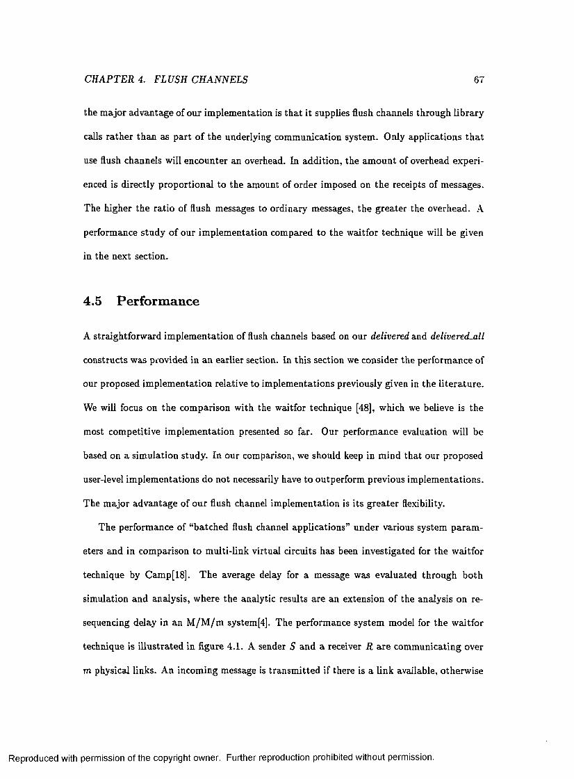
CHAPTER 4. FLUSH CHANNELS 67
the m ajor advantage of our im plem entation is th a t it supplies flush channels through library
calls ra the r than as part o f the underlying communication system . Only applications th a t
use flush channels will encounter an overhead. In addition, the am ount of overhead experi
enced is directly proportional to the amount of order imposed on the receipts of messages.
The higher the ratio of flush messages to ordinary messages, the greater the overhead. A
performance study o f our im plem entation compared to the w aitfor technique will be given
in the next section.
4.5 Performance
A straightforw ard im plem entation of flush channels based on our delivered and delivered.all
constructs was provided in an earlier section. In th is section we consider the perform ance of
our proposed im plem entation relative to im plem entations previously given in the lite ra tu re .
We will focus on the com parison with the waitfor technique [48], which we believe is the
most com petitive im plem entation presented so far. Our perform ance evaluation will be
based on a sim ulation study. In our comparison, we should keep in m ind that our proposed
user-level im plem entations do not necessarily have to outperform previous im plem entations.
The m ajor advantage of our flush channel im plem entation is its g rea ter flexibility.
The perform ance of “batched flush channel applications” under various system param
eters and in comparison to m ulti-link virtual circuits has been investigated for the w aitfor
technique by Camp[18]. T he average delay for a message was evaluated through both
sim ulation and analysis, where the analytic results are an extension of the analysis on re
sequencing delay in an M /M /m system[4]. The performance system model for the w aitfor
technique is illustrated in figure 4.1. A sender S and a receiver R are com m unicating over
m physical links. An incoming message is transm itted if there is a link available, otherw ise
Reproduced with permission of the copyright owner. Further reproduction prohibited without permission.

CHAPTER 4. FLUSH CHANNELS 68
M/M/m systemLink I |t
Link 2
Link 3
ResequencingBuffer
TransmissionQueue
Figure 4.1: Performance Model for the W aitfor Technique
it is buffered in the transm ission queue. Once a message reaches its destination , it might
experience a resequencing delay. The message m ust be buffered until all messages which
m ust be received before it have arrived. A message m ust also be buffered until the appli
cation executes a receive sta tem ent but this delay is not considered when evaluating the
performance. We are only interested in the delay from when the message was sent until
it is eligible for receipt by the application. The expected delay for a m essage is found by
adding up the expected delay in the transmission queue, the expected transm ission time
and the expected resequencing delay. As indicated in figure 4.1, the system excluding the
resequencing buffer is an M /M /m queue. The average delay of an M /M /m queue is well
known [50] and is independent of the imposed ordering constraints. The resequencing delay,
on the o ther hand , depends on the ordering constraints and was derived individually for
each considered application[18].
As illustrated in figure 4.2, our performance system model will look slightly different
from the one presented by Cam p. In our im plem entation a message need never be delayed
at the receiver, and thus there is no resequencing buffer in our model. U nfortunately, our
system is not an M / M / m queue due to constraints on when a message can be transm itted .
Reproduced with permission of the copyright owner. Further reproduction prohibited without permission.

CHAPTER 4. FLUSH CHANNELS 69
TransmissionQueue
Figure 4.2: Performance Model for Our Im plem entation
Analysis of the system is com plicated by the fact th a t a message might have to be delayed
even when there are em pty links in the system. In this dissertation we focus on a sim ulation
study comparing the two im plem entations.
Simulating flush channel com m unication for our im plem entation as well as for the waitfor
technique is a straightforw ard extension to an M /M /m queue simulation[69]. We will focus
on a batched flush channel application where the batches are separated by two-way flush
messages. Our sim ulations used the method of batch means to calculate 95% confidence
intervals of the expected delay for a message. T he widths of the confidence intervals were all
w ithin 2% of the values calculated for their corresponding point estim ates. For notational
convenience, only the point estim ates are displayed in our graphs. As explained above, the
delay for a message is the tim e elapsed from when the message is tran sm itted until it is
available for receipt by the application. For all our sim ulations the num ber of links between
the sender and the receiver was set to 25. T he intersend tim e between messages as well
as the transmission tim e was assumed to be exponentially distributed w ith m eans 1/A and
1/fi respectively. Since the waitfor technique includes an ex tra integer in each message the
average transmission tim e was set to be slightly higher for the waitfor technique than for
Reproduced with permission of the copyright owner. Further reproduction prohibited without permission.

CH APTER 4. FLUSH CHANNELS 70
our approach. We use m to indicate the transm ission ra te for the waitfor im plem entation
and to ind icate the transmission ra te for our im plem entation.
Figure 4.3 shows the average message delay as a function of A when there are 999
ordinary messages in a batch. The curve for our im plem entation is labeled “synch” for
synchronization approach and the curve for the w aitfor technique is labeled “info” for infor
m ation approach. The transmission rates were set a t //,• = 0.1 and fi3 = 0.1111. Assuming
th a t the tim e to transm it one integer is unity a transm ission rate of 0 .1 corresponds to
a average message size of 1 0 integers and a transm ission rate of 0 .1 1 1 1 corresponds to a
average message size of approxim ately 9 integers.
We can see from Figure 4.3 th a t as expected the expected message delay increases with
A. However, we can see th a t, for our approach, the delay does not increase a t all as fast
as for the inform ation approach. We can see th a t, when A goes above 2.25, the expected
delay for a message sent using the waitfor technique increases dram atically. This is due
to a very high queuing delay in the transm ission queue. A send rate of 2.25 corresponds
to a link utilization of 0.9. Our im plem entation does not experience the same build-up
in the transm ission queue. In our im plem entation, the two-way flush messages work as
a natural form of flow control. Before sending a two-way flush message, delivered-all is
called. The application pauses until all messages sent prior to the two-way flush have been
delivered and the transmission queue is empty. After the two-way flush has been delivered
the messages in the next batch can be tran sm itted w ithout hardly any delay besides their
actual transm ission tim e.
As illustrated by Figure 4.3, the expected delay for a message is lower for our implemen
ta tion than for th e waitfor technique. However, our occasional synchronization introduces a
hidden delay for a message. When the application pauses, no messages are generated, which
Reproduced with permission of the copyright owner. Further reproduction prohibited without permission.

CH APTER 4. FLUSH CHANNELS 71
35info -x—
synch I-*—
30
25
20
15
10
50.4 0.6 0.8 1.2 1.6 1.8 2 2.2 2.61 1.4 2.4
X
Figure 4.3: Expected Message Delay versus A
Reproduced with permission of the copyright owner. Further reproduction prohibited without permission.

CH APTER 4. FLUSH CHANNELS 72
2.6info -)
synch •*
2.4
2.2
1.8
1.6
1.4
1.2
0.8
0.6
0.40.4 0.6 0.8 1 1.4 1.61.2 1.8 2 2.2 2.4 2.6
X.
Figure 4.4: Effective Send R ate versus A
Reproduced with permission of the copyright owner. Further reproduction prohibited without permission.
CH APTER 4. FLUSH CHANNELS 73
causes the actual send of a later message to be delayed. Hence, to be fair in our analysis
we m ust also exam ine the “effective send ra te” for the two applications. T he effective send
ra te versus A is shown in Figure 4.4 for the experiment from Figure 4.3.
We can see from Figure 4.4 th a t the effective send rate for our im plem entation is slightly
lower th an A. As A increases, more delays are imposed by our im plem entation, and the
effective send ra te s ta rts to deviate more from A. As expected, the effective send rate
m atches A for the waitfor technique. Since our simulation assumes an infinite transm ission
buffer the waitfor technique imposes no send delay. In practice the transm ission buffer
would be finite, and a send operation would block when the transm ission buffer was full.
This would cause the effective send ra te for the waitfor technique to deviate from A for high
utilizations.
Realizing th a t the effective send ra te differs between the two im plem entations, it is
im portan t to consider delay as a function of the effective send rate . T his inform ation
is displayed in Figure 4.5. We can see from the figure th a t, the delay im posed by our
im plem entation is lower than the delay imposed by the waitfor technique even when the
effective send rate is considered. The g raph for the waitfor technique is of course identical to
the graph in Figure 4.3. (Again, this is due to our use of an infinite send buffer.) The graph
for our im plem entation now show th a t the delay for our im plem entation increases rapidly
when the effective send rate gets very high. Even though the two-way flush messages work
as flow control, the queuing delay in the transmission queue increases when the effective
send ra te becomes high.
Next, let us exam ine the influence on performance by the batch-size. Figure 4.6 displays
the expected delay for a message as a function of the batch-size. The send ra te was held
constant a t 2 .0 and all other param eters were the same as in the previously described
Reproduced with permission of the copyright owner. Further reproduction prohibited without permission.

C H APTER 4. FLUSH CHANNELS 74
35info -x—
synch
30
25
20
10
0.6 0.8 1 1.6 20.4 1.2 1.4 1.8 2.2 2.4 2.6effective k
Figure 4.5: Expected Message Delay versus Effective A
Reproduced with permission of the copyright owner. Further reproduction prohibited without permission.

CH APTER 4. FLUSH CHANNELS 75
info -x- synch -a
35
30
25
20
1000010 100 1000 100000batchsize
Figure 4.6: Expected Message Delay versus Batch-size
Reproduced with permission of the copyright owner. Further reproduction prohibited without permission.

CHAPTER 4. FLUSH CHANNELS 76
sim ulation. As expected, we can see th a t the average delay for a message decreases as
the batch-size increases for both im plem entations. As the batch-size increases less two-
way flush messages are transm itted . Fewer flush messages leads to less synchronization
for our im plem entation and a sm aller resequencing delay for the w aitfor im plem entation.
Again, we can see th a t the expected delay for a message is sm aller in our im plem entation
than in the w aitfor im plem entation. However, we must also consider the “hidden delay”
discussed above by exam ining the effective send rate. Figure 4.7 shows the effective send
ra te as a function of batch-size. We can see from Figure 4.7 th a t our im plem entation is not
a good solution for a batch-size of one, even though the expected delay for a message is
significantly sm aller th an for the waitfor im plem entation. W hen a batch-size of one is used
every message requires potential synchronization. As a result the effective send ra te for our
im plem entation is very low. As before, an infinite transmission buffer is assum ed and the
send ra te for the w aitfor technique stays constant a t A. In practice the transm ission buffer
is finite, and a send may block to avoid buffer overflow.
Finally, let us exam ine the influence of message length on the relative perform ance of
the two im plem entations. The average length of a message is reflected in the difference
in m and Ha- The value used for Ha above, 0.1111, was based on a Hi value of 0.1 and a
message length of 10. If the message length was instead 5, then the corresponding value for
fi3 would be 0.125. Hence, to exam ine the influence of message length we will fix Hi and
then calculate Ha based on varying message lengths. Figure 4.8 shows the average message
delay versus the message length used to calculate Ha- The batch-size was set to 999 and A
was set a t 2.0. As illustrated by Figure 4.8 our im plem entation is more beneficial for short
messages relative to the waitfor im plem entation. For short message the ex tra inform ation
included in a message by the w aitfor technique is more costly. If the messages are long,
Reproduced with permission of the copyright owner. Further reproduction prohibited without permission.

CH APTER 4. FLUSH CHANNELS 77
2.2info -x—
synch
1.8
1.6
1.4
0.8
0.6
0.4
0.2
100 1000 10000 100000101batchsize
Figure 4.7: Effective A versus Batch-size
Reproduced with permission of the copyright owner. Further reproduction prohibited without permission.
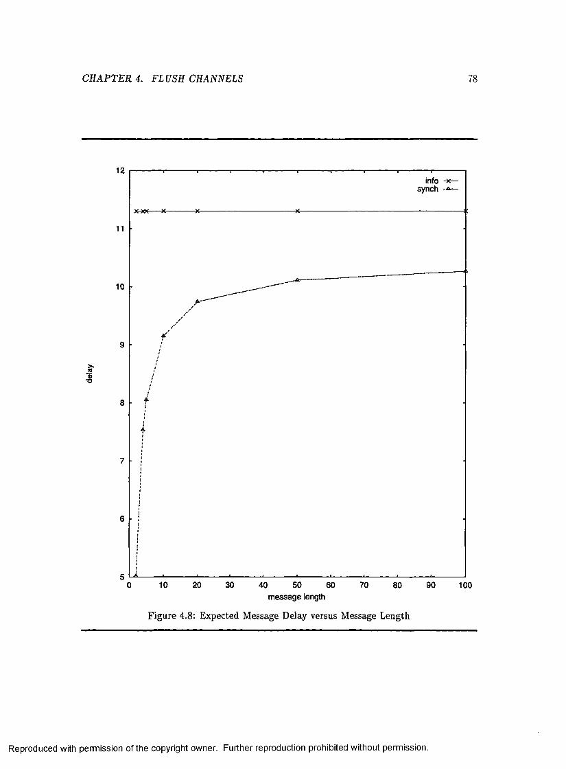
CHAPTER 4. FLUSH CHANNELS 78
12info -x—
synch
11
10
9
8
7
6
510 20 30 50 70 900 40 60 80 100
message length
Figure 4.8: Expected Message Delay versus Message Length
Reproduced with permission of the copyright owner. Further reproduction prohibited without permission.

CHAPTER 4. FLUSH CHANNELS 79
then the overhead due to the additional inform ation becomes less relevant.
To sum m arize, the average message delay for our im plem entation is superior to the aver
age message delay for the w aitfor im plem entation. O ur occasional synchronization performs
a natu ral form of flow control which prevents large transm ission queue build-ups. However,
our occasional synchronization also decreases the effective send rate. Our im plem entation
is not preferable, from a performance standpoint, when the batch-size becomes very small.
Our im plem entation is m ost beneficial when the batch-size is large and the average message
size is small.
4.6 Chapter Summary
In this chapter we presented a second example o f how our delivered and delivered.all con
structs can be used in practice. We presented an im plem entation of flush channels based on
our constructs. Flush channels can be an extrem ely useful construct for applications which
require only a p a rtia l receipt order on messages. Previously suggested im plem entations
of flush channels incorporate flush channels as a part of the underlying com m unication
subsystem. Today, it is not realistic to expect the underlying comm unication system to
support flush channels. Building flush channels in to the system is inflexible and imposes
an overhead on the system as a whole. The im plem entation of flush channels presented in
this chapter provides flush channels a t the user level; it allows applications to benefit from
the relaxed ordering constrain ts and greater efficiency offered by flush channels w ithout
requiring kernel-level support for the construct. Providing flush channels a t the user level
is much more flexible and allows applications to use the construct selectively. An exten
sive performance study com paring our im plem entation to the waitfor technique was also
presented in th is chapter. We saw th a t our im plem entation was most advantageous, from
Reproduced with permission of the copyright owner. Further reproduction prohibited without permission.

CHAPTER 4. FLUSH CHANNELS 80
a performance s tandpo in t, when the number of flush messages is small com pared to the
num ber of ordinary messages. O ur im plem entation also com pares more favorably for short
messages.
Reproduced with permission of the copyright owner. Further reproduction prohibited without permission.

Chapter 5
Transport Layer Vector T im e
In earlier chapters we developed the formal tools needed to reason about transport layer
information and illustrated how transport layer inform ation could be used to provide al
ternative im plem entations o f message ordering protocols. W hen exam ining the difference
between application and tran spo rt layer inform ation, it is also im portan t to consider the
im pact on vector tim e. Vector tim e has emerged as a useful technique for solving problems
in d istributed system s. A lthough vector tim e is likely to be m aintained by supporting code
positioned in kernel space, vector tim e is traditionally viewed w ith respect to the applica
tion layer. In this chapter we consider vector time as perceived a t the transport layer. We
establish existing relationships between transport layer and application layer vector time.
We show th a t transport layer vector tim e provides a more up-to-date view of the current
system sta te , and therefore can improve performance for algorithm s on which concurrency
has an adverse effect. The possibility of updating vector tim e for acknowledgment messages
is also considered. A new distribu ted term ination detection algorithm based on this feature
is presented.
81
Reproduced with permission of the copyright owner. Further reproduction prohibited without permission.

C H A P T E R 5. T R A N SP O R T L A Y E R V E C T O R TIM E
5.1 Introduction and Motivation
8*2
In a sequential program , the events of th a t program are to tally ordered by their occurrence
in physical tim e. In an asynchronous d istribu ted system , however, no common physical
tim e line exists. As mentioned earlier, the events of a d istributed system are only partially
ordered based on causality[53]. Since no tem poral order exists on the events in the system ,
physical clocks cannot be used to order the events. Vector tim e was introduced as a m eans of
capturing the causal relationships present in the system[57, 34]. The relationships between
the vector tim es of events in the system are isomorphic to the causal relationships between
the events. Vector tim e has become a standard construct used for solving many problem s in
d istribu ted system s. For example, vector tim e is used to provide causally consistent message
passing in ISIS[14, 15], in algorithm s for global predicate detection[27, 35, 36, 38], rollback
recovery[75, 84], and deadlock detection[74], and in tools for distributed debugging[9, 31].
In the lite ra tu re , vector tim e is traditionally considered to be present a t the application
layer. The vector tim e of a communication event corresponds to the vector tim e of the event
occurrence a t the application layer. However, vector tim e will most likely be m aintained by
supporting code positioned in the kernel space o f a process. This dissertation is concerned
with the d istinction between information available a t the application level of a process and
a t the kernel level of a process. As we have seen, the transport layer of a process which
provides end-to-end communication, has often access to information not available a t the
application layer. It is im portant to examine the im pact of this inform ation on vector
tim e. In th is chapter we consider differences and relationships between application layer
and tran sp o rt layer vector time. Examining causality as present a t the two layers is an
im portan t step towards understanding the differences between the two layers and towards
Reproduced with permission of the copyright owner. Further reproduction prohibited without permission.

CHAPTER 5. T R A N SP O R T LAYER VECTOR TIME 83
understanding how the inform ation available a t the tran sp o rt layer can be used.
The causal relationships between communication events a t the transport layer is not
always consistent w ith the causal relationships between the events a t the application layer.
It is therefore crucial to make a distinction between vector tim e a t the two layers. In
this chapter we take a detailed look at comm unication to establish existing relationships
between events a t the two layers. We find th a t transport layer vector time gives a more
up-to-date view of the “current causal tim e” in the system than application layer vector
tim e. In addition , any causal relationships between two events in different processes present
a t the application layer are preserved at the transport layer. T he im pact of using transport
layer vector tim e as opposed to application layer vector tim e for some sample applications
from the lite ra tu re is also considered. Some general guidelines for when transport layer
vector tim e m ay be appropria te are given. We show th a t tran sp o rt layer vector tim e can
be beneficial for applications th a t gain from a decrease in concurrency. Another advantage
of using tran sp o rt layer vector tim e is th a t we can allow vector tim e to be updated for
acknowledgment messages, not seen at the application layer, as well as for regular messages.
Assuming a system th a t uses reliable message passing based on a positive acknowledgment
scheme, we use th is feature to derive a new distributed term ination detection algorithm .
The algorithm is in tu itive and simple when using transport layer vector tim e but would not
be feasible based on application layer vector time.
5.2 Causality and Vector Time
As mentioned above, one im portan t characteristic of a d istribu ted system is the lack of a
global clock. Due to the lack of a common physical tim e line, no tem poral order exists
on the events o f a d istribu ted system . Instead, the events o f the system are only partially
Reproduced with permission of the copyright owner. Further reproduction prohibited without permission.

C H APTER 5. TRANSPORT LA Y E R VECTO R TIME 84
ordered based on causality[53]. Recall from C hapter 3 th a t the causality relation is the
sm allest relation satisfying the following three conditions:
1. If e and e ' are events in the sam e process and e occurs before e ' , then e — e ' .
2. If e is the sending event of a message by one process and e‘ is the corresponding receive
event in another process, then e —* e'.
3. If e —*• e ' and e ' —► e", then e —► e".
Recall th a t two events, e and e', are said to be concurrent, e || e', if they are not ordered
by causality. The send event for message m is denoted by s (m ) and the receive event for
message m is denoted by r(m ).
Vector tim e was introduced by M attem [57], and independently by Fidge[34], as a means
for cap tu ring the causal relationships present in the system. Vector tim e is an extension
of L am port’s logical clocks[53]. In an iV-process system, {Po, P i , . . . , P jv -i} , each process,
Pi, m aintains a vector, V{, of N logical clocks or counters, indexed 0 through N — 1. The
value of component j of P j’s vector tim e, V?, represents the best approxim ation process
Pi can make about the current “tim e” in process P j. In general, only com ponent i of P,-’s
vector tim e is completely accurate. Each tim e a process sends a message, it appends its
vector tim e to the message, conveying its current view of tim e in the system to the receiving
process. Initially, V? — 0 for all i , j . T he vector tim es are then m aintained according to the
following rules:
1. If event e occurs in P t , then Vf = V- + 1 .
2. If event e is a send event in Pi and e' is the corresponding receive event in Pj, then
Vj = sup(Vi, Vj), where sup(V i, Vj) = ( m a x (V ° , V f ) , . . . , m ax(V {N ~ l , .
Reproduced with permission of the copyright owner. Further reproduction prohibited without permission.

C H APTER 5. TRAN SP O R T LAYER VECTO R TIME 85
For event e, the vector time of e, denoted V(e) , is the vector tim e in the process where
e occurred. Thus, if e is an event on Pi, then V(e) is the value of Vi a t the occurrence
of e. T he vector tim e of event e is assigned after the vector tim e, Vi, has been properly
updated. T he events in the system include, but axe not lim ited to , all send and receive
events. M atte rn defines the following relationships between any two vector tim es W and U :
1. W < U iff VJfc : W k < Uk
2. W < U iff ( W < U) A ( W ^ U)
3. W \ \ U i t t ( W j L U ) A ( U { W )
The relationship between the vector tim estam ps of two events is isomorphic to the causal
relationship between the events. For events e and e' , e —*■ e' if and only if V{e) < V{e') and
e || e' if and only if V(e) || V(e').
5.3 Relationships
C om m unication events result in activity a t m ultiple layers of a system . The definition of
vector tim e in the previous section does not concern itself w ith where in the system send
and receive events occur. The trad itional view in the literatu re is to consider vector time
with respect to comm unication events occurring in the application. However, it is also
im portan t to consider vector time as associated w ith the com m unication events as they
occur a t the tran spo rt layer. It is necessary to make a distinction between vector tim e at
the two levels since the causal relationships between send and receive events m ay not be
consistent between the two levels. In this section, we examine relationships existing between
application and tran sp o rt layer vector tim e. We assum e th a t vector tim e is only updated
Reproduced with permission of the copyright owner. Further reproduction prohibited without permission.

CHAPTER 5. T R A N SP O R T LAYER VECTOR TIME 86
m
Figure 5.1: Com m unication Process
due to com m unication, since the com putational events of an application m ay not be seen
at the transport layer. Similarly, we assume for the m om ent th a t possible acknowledgment
messages, present only a t the transport layer, do not affect vector tim e. Recall from earlier
chapters th a t we assume a receiving transport layer passes messages to the application in
the same order they arrive a t the receiving tran sp o rt layer.
To establish the relationships existing between application and transport layer vector
time, we will first examine the comm unication process. Com m unication between two appli
cation processes involves several steps. The sending application process sends the message
to its transport layer by executing a send system call. The transport layer is then re
sponsible for delivering the message to the tran spo rt layer of the receiver. T he receiving
application process obtains the message from its tran spo rt layer through a receive system
call. This com m unication is illustrated in Figure 5.1. In the figure, PiA denotes the ap
plication process in process P, and P \T denotes the transport layer. The causal chain for
sending a message m in th is detailed com m unication view is expressed by the following
Reproduced with permission of the copyright owner. Further reproduction prohibited without permission.

CHAPTER 5. TR A N SP O R T LAYER VECTOR TIME 87
Com m unication P roperty :
C o m m u n ic a tio n P r o p e r ty : s a ( t t i ) —*■ s x (m ) —► r x{m ) —*• r^ (m )
where the subscripts A and T denote comm unication events as perceived by the application
process and tran spo rt layer respectively. Note th a t the Com m unication P roperty is consis
ten t with our form al system model presented in C hap ter 2. It is a straightforw ard extension
of the Network Axioms expressed in causal term s.
Vector tim e could be easily modified to capture the causal relationships expressed by
the Com m unication Property. We would simply include two com ponents for each process
in the vector tim e. For example, we could let V 2t denote the tim e a t the application layer
in process Pi and V 2 t + 1 denote the tim e a t the tran sp o rt layer in process P,. A lthough this
extension to vector tim e would capture the application layer’s as well as the transport layer’s
view of the causal relationships in the com putation, it is not very practical. It requires two
components for each process, which doubles the size of the vector tim estam p included in
each message. Instead, we examine the relationships between causality as perceived by the
application layer and the transport layer. We can then determ ine which form of vector tim e
is more appropriate for a specific application.
To see why the causal relationships between events m ay differ between the two layers,
consider the com putation shown in Figure 5.2. We can see th a t message mi is delivered
to the transport layer of P i before message m 2 is sent. However, message m i is buffered
by the transport layer in the receiver and it is not received by the application process until
after message m 2 has been sent. Assuming the system uses blocking sends, a send system
call will not re tu rn until the transport layer has space in its send buffer. Thus, we can
view send events as being atom ic across the layers with respect to incoming messages and
o ther send events. However, this is not true for receive events. A message delivered a t
Reproduced with permission of the copyright owner. Further reproduction prohibited without permission.

CH APTER 5. TRAN SP O R T LAYER VECTOR TIME 88
m
mm
m
P,\ P,
Figure 5.2: Sample Com putation
the transport layer of a process may be buffered indefinitely until the application process,
for which the message is destined, executes a receive system call. Due to th is buffering,
the causal relationship between events can differ between the application and the tran sp o rt
layer. A bstracting the application layer’s view of the com putation in Figure 5.2 we obtain
the space-tim e diagram shown in Figure 5.3. A bstracting the tran spo rt layer’s view produces
a different diagram as shown in Figure 5.4. We can see from Figures 5.3 and 5.4 th a t the
causal relationships present between send and receive events in the com putation depend on
whether the com putation is viewed from the application layer or the transport layer. As
reflected by the displayed vector times, from the application’s view a || b and b —* c. From
the transport layer’s view, on the o ther hand, a —► 6 and c —► 6 .
As illustrated above, there axe differences between the causal relationships o f events a t
Reproduced with permission of the copyright owner. Further reproduction prohibited without permission.

CH APTER 5. TRAN SP O R T LAYER VECTO R TIME 89
[1.01
m
m
po
c [1, 2 ]
ft [0, I]
[1, 0]
m
ft [1.2]
c [1, 1]
Figure 5.3: A pplication Layer View
*0 r i
Figure 5.4: T ransport Layer View
the application layer and transport layer. However, as we will see there are relationships
between vector tim e a t the two levels which can be shown to hold. For a send or receive
event, e, we will use e \ to represent the occurrence of e at the application layer and e? to
represent the occurrence of e a t the tran spo rt layer; we will use V^Ce) to denote the vector
time of the send or receive w ith respect to the application layer and Vx(e) to denote the
vector tim e of the send or receive with respect to the tran sp o rt layer. We will talk about
send and receive events for a message as single events viewed from either the transport
layer or the application layer. However, we m ust keep in mind th a t a receive event from the
viewpoint of the transport layer occurs when the message is delivered to the transport layer.
This may happen long before the event is observed a t the application layer. As mentioned
above, we view sends as atom ic across the layers. As long as the system uses blocking sends
Reproduced with permission of the copyright owner. Further reproduction prohibited without permission.

CH APTER 5. TR A N SP O R T LAYER VECTOR TIME 90
this is reasonable and easy to implem ent. Assuming atom ic sends allows us to utilize the
Atomic Send P roperty described below:
A to m ic S e n d P r o p e r ty : For any event e, e SA(m) A e ST(m) ,
1 . —► e if and only if s t (tti) —► e
2 . e —► SA(m) if and only if e —> s t ( t t i )
For process P,-, vector tim e as m aintained a t the application layer is denoted by V)A and
vector tim e as m aintained a t the transport layer is denoted by K'r • W hen convenient and
no confusion exists we will drop the first subscript and simply use Va to denote vector
tim e with respect to the application layer and Vt to denote vector tim e w ith respect to the
transport layer. Vector tim e is m aintained according to the sam e rules, described in Section
5.2, both a t the application layer and at the transport layer.
Incoming messages provide information about the progress of the com putation. When
an incoming message is buffered, this information is tem porarily stalled a t the transport
layer. In a sense, the tran spo rt layer is more well-informed th an the application layer. This
fact is expressed by P roperty 1 :
P r o p e r ty 1 Va < Vt
P ro o f: Recall th a t we assum e th a t only communication events u p d a te vector tim e. Send
events are considered to be atom ic across the layers, which m eans th a t vector tim e is
updated sim ultaneously a t the two layers for a send event. For receive events, we know
from the Com m unication P roperty th a t r j { m ) -+ ^ ( m ) . For a receive event, vector time is
updated a t the tra n sp o rt layer prior to the event occurrence a t the application layer. Thus,
the transport layer always has a more accurate or equal view of the “current tim e” in the
system. I
Reproduced with permission of the copyright owner. Further reproduction prohibited without permission.

CHAPTER 5. TR A N SP O R T LAYER VECTOR TIME 91
W hen the application layer receives a buffered message it “catches up” with the knowl
edge available a t the tran sp o rt layer. As expressed by P roperty 2, there is a straightforw ard
relationship between the local tim e perceived at the two layers and the num ber o f messages
in the receive buffer.
P r o p e r ty 2 Vf = V'T — the number o f messages in the receive buffers at P,-.
P ro o f: Send events are viewed as atomic across the layers so the same num ber of sends have
been executed a t bo th layers. The number of receive events performed by the application
equals the num ber of messages received by the transport layer minus the messages which
are still buffered. Hence, the relationship described above. ■
Note th a t when there are no messages in the receive buffers a t the transport layer the
perception of local tim e in a process is “synchronized” between the two layers. Even though
the local component of vector tim e is synchronized between the layers when there are no
outstanding messages in the receive buffers, this m ay not be true for the other com ponents.
Due to the transitive effect of buffering, the transport layer may still be more well-informed
about the current tim e in the system than the application layer even when there are no
messages in the receive buffers. This situation is illustrated in Figure 5.5, which displays
vector tim e as perceived both a t the application layer and a t the transport layer. Note th a t
the vector tim estam ps appended to the messages in the com putation depend on w hat form
of vector time is used. W hen application layer vector tim e is used, the tim estam p appended
to message m 2 is [0 , 1 , 0 ] and when transport layer vector tim e is used the tim estam p is
[0,2,1]. In the figure, a fter message m 2 has been received by the application there are
no messages in the receive buffers a t process Pq. Yet a t this point the vector tim e a t the
application layer is [1,1,0] and the vector tim e at the transport layer is [1,2,1]. The difference
in vector time between the two layers is due to the fact th a t message m i has been delivered
Reproduced with permission of the copyright owner. Further reproduction prohibited without permission.

CH APTER 5. TR A N SP O R T LAYER VECTOR TIME 9 2
[1, 1,0] 1,2,1]
[0,2,1]m
m[0,1,0][0,2,1]
[0,1,1].
from P~
Pr0.
Figure 5.5: Transitive Buffering Effect
but not yet received a t process Pi when message m 2 is sent. The difference in vector times
a t process Pq is caused by the buffering of message m i in process P i.
Several relationships can be established between the causal relationship of two events
as perceived by the two layers. For two events e and e' in the same process, the following
properties hold:
P r o p e r ty 3 Lei e and e' be send events in the same process, then V ^ e ) < V ^ e ') i f and
only i f V j ( e ) < Vx(e').
P r o p e r ty 4 Let e and e' be receive events in the same process, then V ^ e ) < V ^ e ') i f and
only i f Vr(e) < V r(e').
Reproduced with permission of the copyright owner. Further reproduction prohibited without permission.

CH APTER 5. T R A N SP O R T LAYER VECTOR TIME 93
P r o p e r t y 5 Let e be a send event and e' be a receive event in the same process, then
Vr(e) < Vr(e' ) =>■ VA(e) < VA{e‘).
P r o p e r t y 6 Let e be a receive event and e' be a send event in the same process, then
VA(e) < VA(e') =* Vr {e) < VT(e%
P ro o f : Since we assum e send events to be atom ic across the layers successive send events
in a process will occur in the same order a t both layers. P roperty 3 follows triv ially from
this fact. Similarly, messages are assumed to be passed to the application in the sam e order
they were delivered a t the transport layer. Hence, messages are received in the sam e order
a t bo th layers and P roperty 4 follows trivially. To show Property 5, let e be the send event
for message m and e' be the receive event of message m \ Assume th a t V j(e) < Vr(e')
which means th a t s r (m ) —► P r(m '). From the Com m unication Property we know th a t
r 7’(m ') —*• rA(m') . Combining the facts we have s r ( m ) —* rA(m') . From the Atom ic Send
Property we then have sA(m) —► rA{m') which implies th a t VA(e) < VA(e'). This establishes
P roperty 5. Sim ilarly for Property 6 , let e be the receive event of message m and e' be
the send event of message m '. Assume th a t rA(m) —► sA(m*). From the Com m unication
Property we have r j ( m ) —► rA{m) — sA(m'). The Atomic Send Property then gives
r r (m ) -♦ s r im ') . This implies th a t Vr(e) < Vr(e' ) and establishes Property 6 . I
For events in different processes, the relationships between the application layer and
transport layer view is straightforw ard. Any causal relationships present a t the application
layer are preserved a t the transport layer. This is expressed by P roperty 7:
P r o p e r ty 7 Let e and e' be events in different processes, then VA(e) < VA(e') =>
VT(e) < VT(e').
P ro o f : Assume VA{e) < VA{e') and e and e' are events on different processes. Then there
Reproduced with permission of the copyright owner. Further reproduction prohibited without permission.

CHAPTER 5. T R A N SP O R T LAYER VECTO R TIME 94
must exist a message o r a chain of messages creating a causal link between e and e '. W ithout
loss of generality, assum e there exists a single message m . Then we have — s A( m ) —
r .4 (771) e'A. By Properties 3 and 6 we have ex —► s t (tti), from the Com m unication
Property we have sx (tti) —*• rx (m ), and from Properties 4 and 6 we have r f ( m ) — e'T .
Combining the three facts we conclude ex —*• e'T , and thus Vx(e) < Vr{e'). If there are
several messages on th e causal chain the same argum ent can be repeated for each message.
The case where e = s ( m ) or e ' = r ( 7n ) only simplifies the argum ent. Hence, P roperty 7 is
established. ■
Property 7 applies to two events in distinct processes. However, it can of course also
be applied to two events in the same process if they are causally linked through a th ird
event e", e —► e" —► e', where e" is an event in a different process. It follows from the
contrapositive of P roperty 7 th a t Vx(e) < Vr(e' ) => (VA(e) < VA(e')) V (V ^ e ) || V ^ e ') ) ,
for e and e' events in different processes. This is consistent with P roperty 1 which tells
us tha t the tran sp o rt layer has a more up-to-date view of the current tim e in the system .
Since the transport layer is be tter informed than the application layer, it cap tures some
causal relationships which are not visible a t the application layer. As we will see in the next
section this can be very useful for some applications.
5.4 Impact on previous work
The differences and relationships present between application and transport layer vectdr
time were described in the previous section. In this section we will examine the im pact of
using transport layer vector tim e instead of application layer vector tim e for two sample
applications. To illu stra te under what conditions a particu lar type of vector tim e is appro
priate, we will consider two well-known applications of vector time: Cooper and M arzullo’s
Reproduced with permission of the copyright owner. Further reproduction prohibited without permission.

CHAPTER 5. T R A N SP O R T LAYER VECTOR TIM E 95
algorithm s for global predicate detection[27] and the im plem entation of causally consistent
m ulticast in ISIS[14].
5.4.1 G lobal P red ica te E valuation
Let us first consider the work on global predicate detection done by Cooper and Marzullo[27].
Their algorithm s for detecting possibly $ and definitely 4>, for global predicate $ , are based
on vector tim e. Each process in the system reports com m unication events and o ther relevant
changes in their local s ta te to a m onitoring process. Based on the vector tim e of the
reported events, the m onitoring process can then construct a lattice of global sta tes which
is consistent w ith the observed execution of the system . A node in the lattice corresponds
to a consistent cut[57] of the com putation; the global s ta te could have occurred, in real tim e,
during the execution w ithout violating the observed causal dependencies. A point in the
lattice, x = (xo, £ i , . . . , xn_ i) , represents a global s ta te where process p,- has executed x,-
relevant events. T he level of a point, x, is defined to be the sum of the components of the
vector, x o + x H b ^ n -i • A path through the lattice where the level of each successive point
in the path increases by one then forms a sequence of consistent global states representing
a possible execution pa th for the observed com putation. An execution of a two-process
system and the corresponding lattice are shown in Figures 5.6 and 5.7, respectively. A
point 5,-j in the la ttice denotes the point x = ( i , j ) . One possible execution path for the
observed execution is given by the global s ta te sequence
■S’o.O) •S'i,o; £ 2 ,0 ; •S'2 ,1; 5 3 ,1; S 3 X, S 3 X S 3 X, S 4 4
All states in the lattice represent global states reachable in a possible execution of the
Reproduced with permission of the copyright owner. Further reproduction prohibited without permission.

CH APTER 5. TRANSPORT LA YE R VECTOR TIME 96
[4,2]
m [3,4]
Xj= 10 [0,3]
[0,2]m
[3.0]
[2.0]
xn= 10 [1,0]
Figure 5.6: Application Layer View
observed com putation. Hence, the possibly $ predicate is satisfied if there is a point in the
lattice a t which $ is satisfied. W hen possibly $ is true, all we know is th a t $ is satisfied in
some consistent cut of the com putation. No definite knowledge is ob tained . The predicate,
<f>, may or may not have been satisfied in a real-time global s ta te of th e com putation. On the
contrary, when possibly $ is false we know with certainty th a t $ was never satisfied during
the execution; the observed com putation could not exhibit a consistent cut in which $ was
true. The algorithm to evaluate possibly $ constructs the lattice level-by-level searching for
a point a t which the predicate is satisfied. Only the global sta tes o f the current level and
local sta tes th a t may be part of higher-level global states are m aintained. For definitely $ to
be satisfied every possible execution o f the observed com putation m ust pass through a sta te
Reproduced with permission of the copyright owner. Further reproduction prohibited without permission.

CHAPTER 5. TRAN SP O R T LAYER VECTOR TIME 97
%.o
^.l ^2
Figure 5.7: Corresponding Lattice
at which $ is satisfied. Hence, definitely $ is satisfied if ail possible paths through the lattice
pass through a point a t which $ is satisfied. W hen definitely $ is true we know w ith certainty
tha t the predicate was satisfied a t some real-tim e instan t of the observed com putation; a
consistent cu t in which $ is true must have been realized during the execution. Little
inform ation is obtained when definitely $ is false since the predicate may or m ay not have
been satisfied; a consistent cut in which $ is true may still exist and could have been
realized during the execution. The algorithm to determ ine definitely $ builds the lattice
level-by-level, bu t for each level it only m aintains global sta tes a t which $ is not satisfied.
If the algorithm reaches a point a t which no s ta te can be constructed for the next level,
Reproduced with permission of the copyright owner. Further reproduction prohibited without permission.

CHAPTER 5. T R A N SP O R T LAYER VECTOR TIM E 98
then it concludes definitely $ to be true.
Let us now examine the im pact of the type of vector tim e used on the algorithm s. The
execution shown in Figure 5.6 is the execution from Figure 5.3 augm ented with some ad
ditional events which modify the local variables Xo and x i . Again, let the execution shown
in Figure 5.6 represent the application’s view of the com putation . T he la ttice correspond
ing to the view of the application is shown in Figure 5.7. Consider the evaluation of the
global predicates possibly ( x q = 10 A x i = 10) and definitely ( xq = 5 A xi = 5). Since possi
bly (xo = 10 A xj = 10) is satisfied as long as the predicate evaluates to true a t any point
in the lattice, we can see th a t the algorithm will retu rn a positive answer. The predicate
(xo = 10 A xi = 10) is satisfied a t lattice point Si,3. Next, let us consider the evaluation
of definitely (xo = 5 A Xi = 5). For definitely (xq = 5 A Xi = 5 ) to evaluate to true, every
possible execution path m ust pass through a lattice point a t which the predicate evaluates
to true. Consider the path
■ S o . o ; ‘S ’l . o ! *5*1,1 i S i , 2 ; S i , 3 ; S 2 , 3 ; S 3 , 3 ; £ 3 , 4 ; £ 4 , 4
We can see th a t ( x q = 5 A x x = 5) is not satisfied a t any of the points along the path. Thus,
definitely (xo = 5 A x i = 5) will be false. Little or no inform ation about the observed execu
tion was gained by evaluating possibly (xo = 10 A Xi = 10) and definitely ( io = 5 A xx = 5 )
based on application layer vector time.
The com putation as viewed by the transport layer is shown in Figure 5.8. This is the
com putation from Figure 5.4, augmented with the ex tra local events. The corresponding
lattice is shown in Figure 5.9. Since relevant changes m ust be reported to the m onitor
ing process such changes will be visible at the tran spo rt layer as well as the application
Reproduced with permission of the copyright owner. Further reproduction prohibited without permission.

CHAPTER 5. TR A N SP O R T LAYER VECTOR TIME 99
[4,31
13,0]
[2,0]■vx0= 10 [1,0]
x 1= 10 [3,4]
[3,3]
[3,2]
x 1= 5 [0,1]
Figure 5.8: Transport Layer view
layer. A lthough the control messages are not shown in Figures 5.6 and 5.8, we can view
the updates of vector tim e as occurring when the control messages are sent rather than
when the m odifications to the local variables occur. We can see th a t, if we use trans
port layer vector tim e, then possibly (xo = l OAx i = 10) will be evaluated to false. The
point 5i,3 is no longer in the lattice since it no longer represents a consistent global sta te .
The predicate (xo = 10 A Xi = 10) is not satisfied a t any point in the lattice. Thus, the
result of evaluating possibly (xq = 10 A xi = 10) is different when transport layer vector
tim e is used. Similarly, definitely (xo = 5 A x \ = 5) will be evaluated to true. The predi
cate (xo = 5 A xx = 5) is satisfied a t lattice point 5 3 ,1 . Since 5 3 ,1 is the only point in the
lattice a t level four, all possible paths through the la ttice m ust pass through this point.
Reproduced with permission of the copyright owner. Further reproduction prohibited without permission.

CH APTER 5. TRAN SP O R T LAYER VECTO R TIME 100
Figure 5.9: Corresponding Lattice
Hence, definitely (xo = 5 A Xi = 5) is satisfied. Evaluation of the predicates based on trans
port layer vector tim e provides useful inform ation about the observed execution. We know
with certa in ty th a t predicate (xo = 5 A X\ = 5) was true a t some point during the observed
com putation and th a t predicate (xo = 10 A x i = 10) was never satisfied.
The tra n sp o rt layer has a more up-to-date view of the global sta te of the system . At the
tran spo rt layer we have sufficient information to deduce th a t predicate (xo = 10 A x i = 10)
was not satisfied and th a t predicate (xo = 5 A x \ = 5 ) was satisfied a t an instan t of the
observed com putation . The information available a t the application layer is not sufficient
to draw such conclusions. The more informed view a t the transport layer decreases the
Reproduced with permission of the copyright owner. Further reproduction prohibited without permission.

CH APTER 5. TRANSPO RT L A Y E R VECTOR TIME 101
num ber of concurrent events in the system . The number of global s ta tes in the lattice are
reduced and more informed conclusions can be drawn. The global s ta tes th a t are pruned
from the application layer la ttice are global states which could not have been realized during
the execution; based on the causal inform ation available a t the tran sp o rt layer they do no
longer correspond to consistent cu ts of the com putation. It follows from Theorem 7 th a t the
set of global states th a t constitu te the transport layer lattice for an observed com putation
is a subset of the global sta tes th a t constitu te the corresponding application layer lattice.
This means th a t, whenever possibly <& evaluates to false based on application layer vector
tim e, it will also evaluate to false based on transport layer vector tim e. Similarly, whenever
definitely $ evaluates to true a t the application layer, it will also evaluate to true a t the
transport layer. Hence, the results obtained when transport layer vector tim e is used are
always a t least as inform ative as the results obtained when application layer vector time
is used. As our example above showed, the reverse is not true. Evaluating the predicates
based on transport layer vector tim e produced more informative results than evaluating the
predicates based on application layer vector tim e. Since the num ber o f sta tes in the lattice
is reduced the use of transport layer vector tim e is also more com putationally efficient. The
complexity of both algorithm s is linear in the number of possible global states. Thus, we
see th a t, for the algorithm s presented by Cooper and M arzullo, tran sp o rt layer vector time
allows more informative conclusions and is more efficient.
5 .4 .2 C a u s a l ly C o n s i s t e n t M u l t i c a s t in IS IS
As a second example let us consider the use of vector tim e to im plem ent causally consistent
m ulticast comm unication in ISIS[14, 15]. All communication in ISIS is in the form of
m ulticasts within process groups. The ISIS system provides causally consistent m ulticast
Reproduced with permission of the copyright owner. Further reproduction prohibited without permission.

CH APTER 5. TRANSPORT LAYER VECTO R TIME 102
through its CBCAST protocol[14]. M ulticast com m unication is causally consistent if for all
processes Pi in the process group:
s(m ) —*• s (m ') =>■ r i(m ) —► r,(m ')
Causal consistency is ensured in ISIS by buffering an incoming message until all messages
which causally precede it have been received by the application. W hether an incoming
message m ust be buffered or not can be deduced from a vector tim estam p generated a t the
tim e of its transm ission and piggybacked on the message. W hen message m , sent by process
Pi and tim estam ped w ith F (m ), arrives a t process P j ,i ^ j , it is buffered until:
V k(m ) = Vjc + l i f k = i
V k(m ) < V k otherwise> •*
Messages sent by process Pj itself are never buffered.
To illu stra te the difference in using application layer and transport layer vector time
in the CBCAST im plem entation provided by ISIS, let us consider the message passing
shown in Figures 5.10 and 5.11. This is again the com putation from Figures 5.3 and 5.4,
however th is tim e messages m i and m 2 are also m ulticast to additional processes. From the
viewpoint o f the application, V {m \) = [1,0] and V (m 2) = [0,1], hence messages m x and
m 2 are concurrent. Using application layer vector tim e the CBCAST protocol will allow
a process to receive messages m i and m 2 in any order. Using transport layer vector time
instead, V (m i) = [1,0] and U (m 2) = [1,2], hence s (m i) —► s(m 2). The CBCA ST protocol
would require th a t message m i be received before message m 2. To enforce th is requirem ent,
'N ote tha t our use of receive and deliver is reversed from the notation used by Birman et al. in their presentation of the CBCAST protocol.
Reproduced with permission of the copyright owner. Further reproduction prohibited without permission.

CHAPTER 5. TR A N SP O R T LAYER VEC TO R TIME 103
To rest of process group
To rest of process group
m
m [1. 2]
m [0, 1]m
[1,0]
Pn P,
To rest of process group
To rest of process group
m
[ 1, 2]m
[1, 1]
[1, 0]
Pn
Figure 5.10: A pplication Layer View Figure 5.11: T ransport Layer View
the CBCAST protocol would have to be modified to allow a process to buffer messages sent
by itself. In our exam ple, process Pi would have to buffer message m 2 until message
has been received to avoid violating the causal consistency requirem ent.
The purpose of causally consistent m ulticast is to ensure that, if message m m ay have
influenced the contents of message m ' or even caused the sending of m ', then m will be
received before m ' by all processes. Since message sends are triggered by the application,
the sent message cannot be influenced by messages which have only been delivered and not
yet received. Here we are interested in the causal relationship between messages a t the
application layer and thus the proper vector tim e to use is application layer vector time.
Using tran spo rt layer vector tim e induces redundant ordering constraints on messages. It
is also awkward for a process sometimes to be required to buffer messages sent by itself.
Transport layer vector tim e is both less efficient and less intuitive to use for this application.
Reproduced with permission of the copyright owner. Further reproduction prohibited without permission.

CHAPTER 5. T R A N SP O R T LAYER VECTOR TIM E 104
5.4.3 G eneral G u id elin es
For the applications considered above, transport layer vector tim e showed to be more ap
propriate in one case and application layer vector tim e was more appropriate in the other
case. A question then natu ra lly arises: what is the difference between the two applications?
Are there s truc tu ra l differences between the two applications which cause transport layer
vector tim e to work well for our first example but not for our second example? Examining
these questions will help us identify the type of applications for which transport layer vector
time may be useful.
We saw th a t tran sp o rt layer vector tim e was more appropria te for Cooper and M arzullo’s
algorithm s. In th is application, vector tim e was used to provide a partia l order on the events
in the system , which were then used to construct possible global s ta tes. The more well-
informed system view present a t the transport layer reduced the num ber of concurrent events
and as a result reduced the num ber of possible global sta tes. A lgorithm s which benefit from
a reduction in the num ber of concurrent events in the system are likely to benefit, both in
terms of efficiency and in term s of accuracy, from the use o f tran spo rt layer vector time.
Algorithms, such as Cooper and M arzullo’s, which a ttem p t to construct a “global view” of
the system fall into this category. For the im plem entation of causally consistent m ulticast in
ISIS, application layer vector time was shown to be more appropriate . In this application,
vector tim e was used to ensure th a t application-level causal constra in ts on message passing
events where not violated. For this application the tran sp o rt layer was, in a sense, too
well-informed. Using tran sp o rt layer vector tim e enforced causal constraints which were
not relevant. This resulted in a loss of efficiency. A pplication layer vector time is more
appropriate for algorithm s which benefit from an increase in concurrency. Algorithms, such
as the ISIS im plem entation, which enforce some m inim al causal constraints, fall into this
Reproduced with permission of the copyright owner. Further reproduction prohibited without permission.

C H APTER 5. TRANSPO RT LAYER VECTOR TIME 105
category. It should also be noted th a t applications th a t depend on causal dependencies th a t
are different a t the application layer and a t the tran spo rt layer may be forced to use the
form of vector tim e which represents the relevant causal relationships.
5.5 Updates on ACKs
The previous section illustrated how transport layer vector tim e could improve perform ance
for certain classes of algorithm s by reducing the num ber of causally concurrent events in
the system . T ransport layer vector tim e is also more powerful than application layer vector
tim e in th a t it can allow vector tim e to be updated for acknowledgment messages (ACK s) as
well as for regular messages. In a system employing reliable message passing, the tran sp o rt
layer m ust ensure th a t all messages are correctly delivered to the tran spo rt layer a t the
receiving process. This is normally done through some positive acknowledgment algorithm ,
such as a sliding window protocol. W hen considering vector tim e as m aintained a t the
transport layer, it is im portant to also consider the possibility of letting ACKs update
vector tim e. Since the acknowledgment messages are only seen at the tran sp o rt layer,
this is not possible for application layer vector tim e. Acknowledgments provide additional
s tructu re to the com putation and it is only natural to take the opportunity to convey this
inform ation through vector time. Allowing inform ation to flow through the ACKs will give
a more up-to-date view of the system sta te which will cut down on the num ber of concurrent
events in the system . Decreasing the num ber of concurrent events in the system , through
vector tim e updates on ACKs, can even further enhance the efficiency and accuracy of
some algorithm s. Consider the algorithm s by Cooper and Marzullo discussed earlier on the
com putation shown in Figure 5.12. In the figure, acknowledgment messages are indicated
by dashed lines. The lattice corresponding to a system using regular tran spo rt layer vector
Reproduced with permission of the copyright owner. Further reproduction prohibited without permission.

CHAPTER 5. T R A N SP O R T LAYER VECTOR TIME 106
x,= 5
x,= 10
Figure 5.12: Sample C om putation
tim e is shown in Figure 5.13 and the lattice corresponding to a system where vector time
is updated on ACKs is shown in Figure 5.14. We can see th a t the la ttice in Figure 5.14
allows more inform ative conclusions. From the lattice in Figure 5.14 we can conclude th a t
definitely (xq = 10 A x j = 5) is true and th a t possibly (xo = 5 A x i = 10) is false, something
which is not possible from the lattice in Figure 5.13. Allowing ACKs to update vector time
also increases the efficiency o f the algorithm as a result of decreasing the num ber of possible
global states.
The acknowledgment messages carry inform ation about the safe delivery of one or several
messages. We m ust be aware th a t, when we use the inform ation provided by the ACKs,
we may rely on causal dependencies th a t are not represented by regular vector tim e. If
Reproduced with permission of the copyright owner. Further reproduction prohibited without permission.

CHAPTER 5. TRANSPORT LAYER VECTO R TIME 107
3),0 3).0
/ \ / \S1.0 \ l ^ .O ^0,1
/ \ / \ / \ / \^ 0 ^ . I ^).2 ^ 0 Sl.l
/ \ / \ / \ / \ /^ .0 Sl,2 % .! Sl.2
\ / \ / \ /^ 2
\ / \ \^3,2 ^2,3
\ / /Figure 5.13: Corresponding Lattice w ith Figure 5.14: Corresponding Lattice when No Vector T im e Update by ACKs ACKs U pdate Vector Tim e
we use causal links introduced by ACKs we must also provide an accurate representation
of causality. Any algorithm based on vector time which utilizes causal links introduced by
ACKs will also require vector tim e to be updated by ACKs. In the next section we will
derive a d istribu ted term ination detection algorithm th a t relies on this fact.
Considering the possibility to update vector tim e on ACKs also poses a conceptual
question. If vector tim e is m apping causality exactly [57], then how can there be an option
on when to update vector time? There should only be one causality relation present in the
system. One approach to try and resolve th e contradiction would be to view vector time as
a means of exactly capturing the pertinent causality in the system . Changing our notion of
which causal links in the system are relevant would then allow us to change the occasions a t
Reproduced with permission of the copyright owner. Further reproduction prohibited without permission.

CH APTER 5. TRAN SP O R T LAYER VECTO R TIM E 108
which vector tim e m ust be updated. Note th a t the same conceptual problem does not arise
when considering the d istinction between application and transport layer vector tim e. The
delivery of a message to the transport layer and the receipt of the message a t the application
layer are two tim e-distinct events. They m ay have different causal relationships to o ther
events in the system as reflected by the possible difference in the vector tim estam p of the
events.
5.6 Termination Detection Based on Vector Time
Just as vector tim e is assumed to exist a t the application level, the control algorithm
handling term ination detection is traditionally viewed to exist a t the application layer,
“above” the basic com putation. However, in practice the control algorithm is more likely to
be positioned in kernel space ra ther than as another user process. In this d issertation we are
interested in the improved use of low-level inform ation. As mentioned earlier, a user process
sending a message in a system using reliable asynchronous message passing only knows th a t
this message will eventually reach its destination. The transport layer is responsible for
ensuring the reliability of the message. The transport layer support code must keep a copy
of the message in its buffers until it is notified th a t the message has been properly delivered.
Hence, a t the kernel level we can determ ine w hether all messages sent by a process have been
safely delivered or not. In C hapter 2, we derived constructs for passing this inform ation
to the user level. Subsequent chapters dem onstrated how the constructs could be used.
The d istribu ted term ination detection algorithm derived in this chapter will illustra te how
information about delivery of messages can be used directly by control algorithm s th a t
reside in kernel space. If it is desired to run the term ination detection algorithm as a user
process, then the prim itives presented in C hap ter 2 can be used to propagate inform ation
Reproduced with permission of the copyright owner. Further reproduction prohibited without permission.

CHAPTER 5. TR A N SP O R T LA Y E R VECTOR TIME 109
on delivery of messages to the algorithm . Our protocol will use transport layer vector
time. We will assum e th a t the protocol employed by the networking software uses positive
acknowledgments. This will allow us to update vector tim e for acknowledgment messages as
well as for regular messages. Since we use our knowledge about properly delivered messages,
it is necessary to update vector tim e for acknowledgment messages to represent the pertinent
causality present in the system.
5.6.1 T h e T erm ination D e tec tio n P rob lem
Before proceeding, we define the term ination detection problem. As before, we are consid
ering a com putation consisting of a set of N processes. The processes are communicating
only through reliable asynchronous message passing. The term ination detection problem
can be described as follows [101]:
• A process m ust be in one of two states, active or passive.
• Only active processes are allowed to send messages.
• An active process may spontaneously become passive a t any time.
• A passive process only becomes active upon the receipt of a message.
• The com putation is term inated when all processes are concurrently passive and there
are no messages in transit.
A correct solution to the problem m ust ensure the following safety and liveness conditions:
S a fe ty : If term ination is detected, then the com putation is term inated.
L iv en ess : If the com putation is term inated , then term ination will eventually be detected.
Reproduced with permission of the copyright owner. Further reproduction prohibited without permission.

CHAPTER 5. TRAN SP O R T LAYER VEC TO R TIME 110
5.6.2 T he A lgorith m
Having defined the term ination detection problem we are now ready to present our solution.
Our algorithm uses a centralized server which will m aintain inform ation allowing it to
conclude term ination of the system . The algorithm is extremely simple:
The centralized server m ain ta ins an array o f N vector timestamps, one tim estam p
for each process in the system . Each process is required to send a message to the
server whenever it changes its state from active to passive and it has no outstanding
messages. This message updates vector tim e in the usual way, and thus it conveys
the time at which the process turned passive. When the server receives a message it
stores the vector time o f the message in the position o f the sender. Termination is
concluded by the server when it has acquired N concurrent vector timestamps.
In our algorithm a process only reports passivity to the server when it is passive and has
no outstanding messages. We can enforce this requirem ent since we know th a t inform ation
about outstanding messages will be available a t the kernel level. W hen an active user
process is ready to tu rn passive, it will not be considered passive by the control algorithm
until all its messages have been delivered. It is na tu ra l for the control algorithm to consider
a process with outstanding messages as active; a message residing in the buffers m ight have
to be resent, and only active processes should send messages. A user process m ust receive
all pending messages before it is considered passive by the control algorithm .
Establishing the correctness of the algorithm is trivial. Let us first examine the safety
requirement. Assume th a t term ination is detected. Then the server must have a vector
tim estam p from each process, all of which are concurrent. A process only sends its vector
tim e to the server when it is passive and has no outstand ing messages. These two facts in
combination imply th a t all processes are concurrently passive and there are no messages in
Reproduced with permission of the copyright owner. Further reproduction prohibited without permission.

CH APTER 5. TR A N SP O R T LAYER VECTOR TIM E 111
transit. Hence, the com putation is term inated, and the safety theorem is valid. Next we
exam ine the liveness requirem ent. Assume th a t the com putation is term inated. Then all
processes m ust be concurrently passive. Each of the processes m ust have sent a tim estam ped
message to the server when it became passive. Hence, the server will eventually acquire N
concurrent vector tim es and conclude term ination. Thus, the liveness theorem is valid and
the correctness argum ent is complete.
The solution presented above stands in sharp contrast to most o ther solutions presented
in the litera tu re . T hey take the “user’s approach” to the system , where there is no knowledge
of when a message is delivered. As a result, they go to g rea t lengths to track the messages
in the system . In [101], weights are passed around as a m eans of m onitoring the messages
in the system , and, in [60], send and receive counts are m aintained for all processes for
the same purpose. The protocol presented in [17] has some sim ilarities to ours in th a t
acknowledgments are used to m onitor the messages in the system . However, vector time
is not m aintained in the system , which forces their algorithm to send a series of polling
waves to determ ine term ination . Due to possible activ ity “in the back of the wave” , a t least
two waves must be sent even if the system is term inated when the first wave is initiated.
Much of the lite ra tu re also eliminates the problem of messages in tran sit by considering the
simpler problem of d istribu ted term ination in a system using synchronous communication
[30, 29, 82, 103, 58].
5 .6 .3 D iscu ssion
As presented above, the server in our algorithm m aintains N vector tim estam ps. Termina
tion is inferred when N concurrent tim estam ps are acquired. This describes the conceptual
operation of the algorithm . In practice, it is sufficient to m aintain two vectors to deduce
Reproduced with permission of the copyright owner. Further reproduction prohibited without permission.

CHAPTER 5. TR A N SP O R T LAYER VECTOR TIME 112
when N concurrent tim estam ps have been reported[38]. The server stores the highest tim es
tam p reported for each process in the first vector, and a flag for each process in the second
vector. A flag value of true indicates th a t the highest tim estam p reported for the process
was reported by the process itself. W hen all the flags are set to true N concurrent tim es
tam ps have been received an d term ination can be concluded. Thus the practical storage
requirement for the algorithm is 0 ( N ) .
A centralized server is used to determ ine term ination in our algorithm . However, the
algorithm can be easily modified to run as a token-based algorithm if so desired. In a
d istributed solution, the token would contain the collection of vector tim es. T he token
would be passed along in lazy fashion. The process holding the token would update its
token vector tim e when passive and w ithout outstanding messages. If the token contains
N concurrent vector tim es, th en the process would signal term ination, otherwise it would
pass the token to the next process. Again, in practice the token only needs to contain two
vectors.
Our distributed term ination detection algorithm is extremely simple and intuitive. The
algorithm utilizes low-level inform ation on delivery of messages, available a t the kernel level,
which allows it to determ ine term ination solely based on vector tim e. Term ination cannot be
detected based on a collection o f vector times w ithout this, or o ther, additional inform ation.
The correctness of the algorithm relies on the fact that vector tim e is updated by ACKs.
Since our algorithm uses causal relationships introduced by ACKs, vector tim e m ust be
updated on ACKs to represent the pertinent causality. Figures 5.15 and 5.16 illu stra te how
vector tim e updates on ACKs is indeed necessary. In the figures, acknowledgment messages
are indicated by dashed lines and messages to the server are indicated by dotted lines. A
gray shadow on the tim e line for a process indicates tha t the process is passive. Figure 5.15
Reproduced with permission of the copyright owner. Further reproduction prohibited without permission.
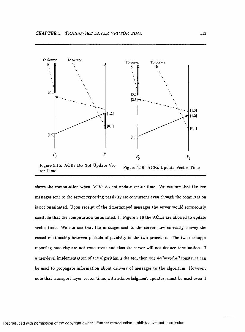
CHAPTER 5. TR A N SP O R T LA YE R VECTOR TIME 113
To Server To Server
[2 ,0 ;
[1.21
[0.1]
[1.0]
To Server To Server
[0.1]
[1.0]
Pn P,
Figure 5.15: ACKs Do Not U pdate Vec- Figurfi AQ K s U pdate VectQr Tim e tor Time
shows the com putation when ACKs do not update vector tim e. We can see th a t the two
messages sent to the server reporting passivity are concurrent even though the com putation
is not term inated. Upon receipt of the tim estam ped messages the server would erroneously
conclude th a t the com putation term inated. In Figure 5.16 the ACKs are allowed to update
vector tim e. We can see th a t the messages sent to the server now correctly convey the
causal relationship between periods of passivity in the two processes. The two messages
reporting passivity are not concurrent and thus the server will not deduce term ination. If
a user-level im plem entation of the algorithm is desired, then our delivered-all construct can
be used to propagate inform ation about delivery of messages to the algorithm . However,
note th a t transport layer vector tim e, with acknowledgment updates, m ust be used even if
Reproduced with permission of the copyright owner. Further reproduction prohibited without permission.

CHAPTER 5. TR A N SP O R T LAYER VECTOR TIM E 114
the algorithm is im plem ented a t the user level.
Although simple and in tu itive , our distributed term ination detection algorithm is in ter
esting not only because it provides a good solution to the problem of d istributed term ination
detection, but also because it illustrates how low-level inform ation on delivery of messages
and transport layer vector tim e w ith updates on ACKs can be used to design an algorithm
th a t would otherwise not be feasible. Of course, it would be possible to require the control
algorithm to send an explicit ACK message for every user message and then use regular
vector tim e. However, an algorithm that requires a t least one control message for every
user message is not a feasible solution. It is the fact th a t our solution uses the ACKs al
ready present in the system th a t makes it a practical solution. O ur algorithm illustrates
the additional power gained by updating vector tim e on ACKs and is a good example of
how low-level inform ation cam be used.
5.7 Chapter Summary
In this chapter we considered the structure of vector tim e as present a t the transport
layer as opposed to the application layer. The causal relationship between send and receive
events a t the transport layer is not necessarily isomorphic to the causal relationship between
the events a t the application layer. It is therefore crucial to make a distinction between
vector tim e at the two layers. Realizing th a t the tran sp o rt layer possesses a more up-to-
date view of the system and th a t many control algorithm s will in practice be positioned
in kernel space, transport layer vector time is a viable a lternative for many algorithm s.
We began by establishing any formal relationships between application layer and transport
layer vector tim e. We then examined the influence of using transport layer vector tim e
on some algorithm s based on vector time from the lite ra tu re . Algorithms which benefit
Reproduced with permission of the copyright owner. Further reproduction prohibited without permission.

CH APTER 5. TRAN SP O R T LAYER VECTOR TIME 115
from a reduction of the am ount of concurrency in the system appears to be well-suited for
the use o f tra n sp o rt layer vector tim e. Such algorithm s can gain in both efficiency and
accuracy th rough the use of transport layer vector tim e. However, application layer vector
tim e is m ore appropria te for algorithms which benefit from concurrency in the system . One
advantage of tran sp o rt layer vector tim e over application layer vector tim e is that it provides
the possibility to allow acknowledgment messages to u p d a te vector time. Utilizing the
inform ation flow in the system represented by ACKs can provide us w ith a more accurate
view of the global s ta te of the system. U pdating vector tim e on ACKs is necessary for
algorithm s th a t utilize the causal relationships introduced by acknowledgment messages. We
derived a d istribu ted term ination detection algorithm based on vector tim e which used the
inform ation abou t message delivery provided by acknowledgm ent messages. Our algorithm
employed causal inform ation propagated through ACKs an d thus required vector tim e to
be updated by ACKs. Our distributed term ination detection algorithm is a compelling
example o f how low-level information, available virtually for free bu t traditionally ignored,
can be used to our advantage. As pursued in this d isserta tion , we believe that the use of
inform ation on delivery of messages available a t the tran sp o rt layer offers great possibilities.
Exam ining the causal relationships, as represented by vector tim e, present a t the transport
layer as opposed to the application layer is an im portan t step in learning how to better
utilize tran sp o rt layer information.
Reproduced with permission of the copyright owner. Further reproduction prohibited without permission.

Chapter 6
P rototype Im plem entation
In previous chapters we laid the theoretical foundation for the use of transport layer infor
m ation and discussed some possible applications. O ur prototype im plem entation discussed
in this chapter show th a t our ideas can be put to practical use. This chapter describes the
design and im plem entation of R U PP1 - a reliable unordered message passing protocol with
support for the delivered and delivered-all prim itives. Our im plem entation of flush channels
on top of the R U PP protocol is also considered.
6.1 RUPP Protocol Specification
6.1.1 G eneral D escription
The Reliable U nordered Packet Protocol, RUPP, is a connection-oriented protocol designed
to provide a reliable unordered message service for d istribu ted applications. The prim ary
target applications are d istributed applications running on a local area network. R U PP is
designed to provide a simple and efficient service which is easy to implement. In addition
l RUPP stands for Reliable Unordered Packet Protocol.
116
Reproduced with permission of the copyright owner. Further reproduction prohibited without permission.

CHAPTER 6. P R O TO TYP E IM PLEM ENTATION 117
to the basic message service, RU PP supports propagation of inform ation about delivery
of messages to the application. This facilitates the im plem entation of message ordering
constraints by the application or by higher-layer protocols. The design of R U PP has been
heavily influenced by the Reliable D a ta Protocol (RDP)[106, 71]. The design was also
influenced by SRMP[68], another reliable message passing protocol, as well as by the T rans
mission C ontrol Protocol[80]. The m ain features of RU PP are outlined below.
• RU PP provides lightweight connection m anagement. A new connection is im plicitly
established by the first message sent. This provides efficient connection m anagem ent
for short-lived connections. RU PP connections support bidirectional d a ta transm is
sion w ith an independent flow of messages going in each direction.
• RU PP presents the application w ith a reliable message service. Unlike stream -oriented
protocols, like TCP, the message boundaries are preserved by RUPP. Reliable message
transport is achieved by using sequence numbers and a positive acknowledgment and
retransm it policy. RUPP uses a selective retransm it policy where only lost messages
are re transm itted . This saves bandw idth compared to a protocol (such as Go-Back-
N[100]) th a t retransm its all messages or segments sent after a lost transm ission.
• The message service provided by R U PP is unordered. Messages are not guaranteed
to be delivered to the receiving application in the order they were sent. R U PP passes
messages to the application in the same order they arrive to the R U PP protocol a t the
receiving host. Messages arriving on a RU PP connection are im m ediately available
for receipt by the application. As long as there is a t least one message available in the
receive buffers, the receiving application is never delayed by message loss or message
reorder. For a sequenced protocol, on the o ther hand, the receiving application m ust
Reproduced with permission of the copyright owner. Further reproduction prohibited without permission.

CHAPTER 6. P R O T O T Y P E IMPLEMENTATION 118
wait for a lost message to be retransm itted even when there is out-of-sequence da ta
present in th e receive buffers.
• RU PP provides some simple mechanisms for flow control. It lim its the number of
packets th a t can be outstand ing on a connection a t any given tim e as well as the
m aximum skew in sequence numbers allowed between outstand ing packets. RUPP
also im plem ents a means for notifying the o ther end of a RU PP connection when there
is no receive buffer space left. The other end then refrains from sending additional
messages until it is notified th a t receive buffer space is again available.
• R U PP supports the delivered and delivered-all prim itives. It allows an application to
gain inform ation about the safe delivery of messages to the R U PP protocol layer a t
the receiving host. To the best of our knowledge this feature is unique to the RUPP
protocol.
Each of the features outlined above will be described in more detail in subsequent sections.
6 .1 .2 R e l a t i o n t o o t h e r p r o to c o l s
The RU PP protocol is a transport layer protocol. It was developed with the T C P /IP
protocol suite in m ind. The position of the RUPP protocol in the T C P /IP protocol suite
is illustrated in Figure 6.1. W hen implemented as a member of the T C P /IP protocol suite,
RUPP relies on the IP protocol[78] to provide it with an unreliable datagram service. As
part of this service the IP protocol performs protocol dem ultiplexing and supplies part
of the address inform ation needed by RUPP. Although we present RU PP in the context
of the T C P /IP protocol suite, it is possible to implement RU PP in a different context
as long as the encapsulating protocol presents a sufficient service, sim ilar to the service
Reproduced with permission of the copyright owner. Further reproduction prohibited without permission.

CH APTER 6. PR O T O TYP E IMPLEMENTATION 119
UDP RUPP
Userprocess
TCP
Userprocess
Userprocess
Userprocess
Ethernet driver
Internet Protocol and ICMP
Ethernet
Figure 6.1: Relation to O ther Protocols
Applicationlayer
Transportlayer
Networklayer
Data-linklayer
Communicationmedium
provided by the IP protocol.
W hen implem ented as part of the T C P /IP protocol suite , R U PP can provide a viable
a lternative to the trad itional protocols (U D P and T C P ). In addition to supporting the
unique feature of allowing the sender to obtain inform ation abou t delivery of messages, the
RU PP protocol adds reliable delivery to the service provided by UDP without the com
plexity of TC P. For applications th a t need reliable service b u t do not require an ordered
byte stream , T C P is unnecessarily complex. The T C P protocol spends considerable effort
on providing the da ta stream abstraction to the application. In addition, T C P does not
acknowledge a da ta byte until all earlier bytes have been received which can lead to unnec
Reproduced with permission of the copyright owner. Further reproduction prohibited without permission.
CH APTER 6. P R O T O T Y P E IMPLEMENTATION 120
essary retransm issions2. T C P also enforces sequenced delivery, which can slow down the
application and consume buffer space when packets are lost or delayed.
The RU PP protocol is most closely related to R D P (Reliable D ata Protocol). RDP
provides reliable, optionally unordered, message passing. It was proposed by Velten, Hinden,
and Sax as an a lternative to T C P for packet-based applications such as remote debugging
and loading. As described above, T C P has several draw backs for packet-based applications.
These drawbacks served as m otivation for the developm ent o f RDP. At the m om ent, RDP
is not considered a s tan d ard Internet protocol. The la tes t version of the Internet Official
Protocol Standard[76] still lists its s ta te as experim ental. T he RU PP protocol and RDP
differ in their connection m anagem ent and in how messages are acknowledged. RU PP uses
implicit connection setup whereas RDP uses a three-way handshake to set up a connection.
Messages th a t arrive ou t of sequence are acknowledged using a bitvector in RUPP. RDP
acknowledges out-of-sequence messages by including the ir sequence numbers in its variable-
length header.
6.1 .3 H eader Form at
The RU PP protocol adds a header containing control inform ation to each d a ta message.
The RU PP header combined with the data message forms a RU PP segment. Additional
headers are added to the packet by the lower layers before it is transm itted over the network.
The header used by the R U PP protocol has a fixed size o f 24 bytes. The format of the RUPP
header is shown in Figure 6.2. The header fields are described below.
2The fast retransmit and fast recovery algorithms proposed by Jacobson[42] attempt to remedy this problem.
Reproduced with permission of the copyright owner. Further reproduction prohibited without permission.

CHAPTER 6. P R O T O T Y P E IMPLEMENTATION 121
IS 16
16>bit source port number 16-bit destination port number
16-bit RUPP length 16-bit RUPP checksum
32-bit sequence number
24 bytes
32-bit bicvector acknowledgement
32-bit cumulative acknowledgement
Rags
Data (if any)
Figure 6.2: R U PP Header Form at
S o u rc e P o r t : The 16-bit source port number, in combination w ith a 32-bit source IP
address provided by th e IP layer, identifies the comm unication endpoint on the sending
host.
D e s t in a t io n P o r t : The 16-bit destination port number, in com bination with a 32-bit
destination IP address provided by the IP layer, identifies the com m unication endpoint
on the destination host. The source and destination port num bers, in combination
with the source and destination IP addresses, uniquely identify a connection.
L e n g th : A 16-bit field giving the length of the message in bytes. The length of the header
is not included in the length.
C h e c k su m : A 16-bit checksum to allow the receiver to detect corrupted packets. Both
the RUPP header and the message d a ta are covered by the checksum.
F la g s : This 8-bit field encodes inform ation about the message or the s ta te of the connec
tion. Only 6 of the b its are currently in use. The currently defined flags and their
Reproduced with permission of the copyright owner. Further reproduction prohibited without permission.

CHAPTER 6. P R O T O T Y P E IMPLEMENTATION 122
Mask Flag Description1 ACK The acknowledgment fields are valid.2 DATA The segment contains data.4 FIN The o ther end has closed the connection.8 RST Reset, sent in response to a segment arriv ing on
an unavailable comm unication endpoint.16 STO P Receive buffers are are full. Stop sending.32 GO Receive space has opened up.
Table 6.1: RUPP Flags
in terpretation are displayed in Table 6.1. In our description of the RU PP protocol
we will frequently refer to a message with a particu lar flag set by the name of the
flag. For exam ple, a message w ith the FIN flag set is commonly referred to as a FIN
message or sim ply a FIN.
S eq u e n c e N u m b e r : If the DATA or FIN flag is set, th is field contains the 32-bit sequence
number of the message. The sequence number field has no m eaning when the message
carries no da ta . (Acknowledgment messages can be sent w ithout d a ta .)
C u m u la tiv e A c k n o w le d g m e n t: W hen the ACK flag is set, this field contains the 32-bit
sequence num ber o f the last message received in sequence.
B itv e c to r A c k n o w le d g m e n t: W hen the ACK flag is set, th is field contains a 32-bit
bitvector identifying any messages tha t have been received ou t of sequence.
6.1.4 C onnection M anagem ent
RUPP is a connection-oriented protocol. Connections in R U PP are full duplex. A connec
tion between two processes provides for an independent sequence of messages to be passed
Reproduced with permission of the copyright owner. Further reproduction prohibited without permission.
CHAPTER 6. P R O T O T Y P E IMPLEMENTATION 123
in each direction. Each endpoint of a connection is identified by a host IP address and a
port number. A pair of host IP addresses/port numbers forms a connection identifier tha t
uniquely identifies a connection. Several connections can be established between two hosts
a t any given tim e.
Connection Setup
Connection setup in R U PP is lightweight. No special messages are passed to establish a
connection. The RU PP protocol considers a connection to be established once the two
endpoints of the connection are fully specified. As soon as b o th endpoints are specified, the
R U PP protocol changes the s ta te of the connection to ESTABLISHED. Since the commu
nication endpoints can be specified locally, it is possible to establish a RU PP connection
with a destination th a t is unavailable. As soon as the application a ttem p ts to transm it da ta
over the connection this will be detected and the error reported to the application.
To establish a R U PP connection the user issues an open request. Open requests can
be active or passive. Normally, one side of the connection would perform an active open,
and the other side would perform a passive open. An active open request must specify the
destination IP address and port number. An active open request changes the sta te of the
connection to ESTABLISHED. An active open can be perform ed explicitly or implicitly.
An explicit open request specifies the destination endpoint w ithout requesting any data to
be sent. An implicit open is performed by requesting a message to be sent on a previously
unconnected local com m unication endpoint. A passive open request only specifies the local
endpoint of a connection. A passive open request changes th e s ta te of the connection to
LISTEN. A connection in the LISTEN sta te changes its s ta te to ESTABLISHED when a
packet destined for the local endpoint arrives.
Reproduced with permission of the copyright owner. Further reproduction prohibited without permission.

CHAPTER 6. P R O T O T Y P E IMPLEMENTATION 124
C o n n e c tio n re c o rd
The RU PP protocol m aintains a connection record for each connection. A few of the more
prominent variables m aintained in a RU PP connection record are listed below. We do not
a ttem pt to give a full list of variables or specify a particu lar im plem entation. The list
is merely an a ttem p t to illu stra te the kind of inform ation th a t needs to be m aintained.
Defining some variables will also simplify the further description of the protocol.
C o n n e c tio n Id e n t i f ie r : The source and destination port and IP addresses used to
uniquely identify a connection.
s ta te : The current s ta te o f the connection. The valid sta tes for a R U PP connection are
described in the next subsection.
p a c k e ts -o u t: The current num ber of outstanding packets.
co n g e s tio n _ w in d o w : T he m aximum num ber of outstanding packets allowed.
m ax_w indow : T he m axim um sequence number difference allowed between two ou tstand
ing packets.
se n t-se q n o : The highest sequence num ber transm itted.
w rite_ seq n o : The highest sequence num ber sent by the application. If flow control pro
hibits transm ission o f a packet, the RUPP protocol will a ttem p t to buffer the message.
The write-seqno is always larger than or equal to the sent-seqno.
rcv_seqno : The highest consecutive sequence number received.
rc v _ b itv e c to r: A bitvector indicating any messages th a t have been received out of or
der. If no messages were ever received out of order, then the b itvector would always
Reproduced with permission of the copyright owner. Further reproduction prohibited without permission.

CHAPTER 6. PR O TO TYP E IMPLEMENTATION 125
contain all 0 ’s.
rcv _ ack ed _ seq n o : The highest consecutive sequence number acknowledged by the re
ceiver.
C o n n e c t io n S ta te s
During its lifetim e, a RUPP connection passes through a sequence o f states. The valid
states for a R U PP connection are described below.
C L O S E D : T he CLOSED sta te is the in itial s ta te from which all R U PP connections are
created. T he CLOSED sta te exists before the connection identifier is specified. In the
CLOSED sta te , neither of the two com m unication endpoints th a t form the connection
identifier has been initialized. O ther parts of the connection record may be defined.
L IS T E N : T h e LISTEN sta te is entered when the user performs a passive open. The
local endpoint of the communication identifier is defined in the LISTEN sta te . The
connection is waiting for a message to arrive, which im plicitly specifies the rem ote
endpoint for the connection.
E S T A B L IS H E D : In the ESTABLISHED sta te both endpoints of the connection have
been defined and user da ta may flow in both directions. A connection is in the
ESTABLISHED state during normal operation.
L O C A L -C L O S IN G : The LOCAL-CLOSING sta te is entered when the application issues
a close request on an ESTABLISHED connection. No operations can be performed
by the application on a connection in the LOCAL-CLOSING s ta te . W hen the LO
CAL-CLOSING state is entered a FIN message is sent to inform the o ther end about
the change in state.
Reproduced with permission of the copyright owner. Further reproduction prohibited without permission.

CHAPTER 6. P R O T O TY P E IMPLEMENTATION 126
R E M O T E -C L O S IN G : When a message w ith the FIN flag set is received the RU PP
protocol sends an acknowledgment and enters the REM OTE-CLOSING state. Any
a ttem p t by the application to send on a connection in the REM OTE-CLOSING sta te
returns an erro r. Buffered data may still be received by the application. If there is no
buffered d a ta an error must be returned. T he application is also allowed to receive
inform ation abou t delivery of a message. If the message has not been delivered an
error m ust be returned.
T IM E -W A IT : A connection in the LOCAL-CLOSING sta te enters the TIM E-W AIT
s ta te when it receives an acknowledgment for its FIN message or it receives a FIN mes
sage from th e o ther end. The TIM E-W AIT s ta te is entered from the REM OTE-CLOSING
s ta te when the application issues a close. A connection in the TIM E-W AIT sta te
discards all incom ing messages except for incoming FINs. FIN messages are still ac
knowledged in the TIM E-W AIT sta te to allow the o ther end to proceed w ith the
closing o f the connection.
The sta te tran sition diagram for the RUPP protocol is shown in Figure 6.3.
C lo s in g a C o n n e c t io n
Both directions of a RU PP connection are closed sim ultaneously. The RUPP protocol begins
closing down a connection when the application issues a close or when a FIN message is
received from the o ther end. When a close is performed by the application, all d a ta in
the send and receive buffers are deallocated. The RU PP protocol does not ensure th a t all
ou tstanding d a ta is delivered before the connection is closed. If needed, it is up to the
application to ensure th a t all d a ta is delivered before issuing a close request; leaving this
responsibility to th e application is consistent w ith the end-to-end argum ent. The RU PP
Reproduced with permission of the copyright owner. Further reproduction prohibited without permission.

CHAPTER 6. P R O T O T Y P E IMPLEMENTATION 127
CLOSED
AppI: passive open
Appl: active open
LISTEN
Segment received or Appl: active open
ESTABLISHED
Appl: close FIN received
REMOTE_CLOSINGLOCAL_CLOSING
FIN acked ^ or FIN received
Appl: close
timeoutTIMEJVAIT
Figure 6.3: RU PP State Transition D iagram
Reproduced with permission of the copyright owner. Further reproduction prohibited without permission.

CH APTER 6. P R O T O T Y P E IMPLEMENTATION 128
protocol supports propagation of information about delivery of messages to the application
which allows the application to carry out this responsibility without appreciable overhead.
Many applications can also deduce th a t all d a ta has been delivered based on a request-
response com m unication pa tte rn .
W hen a close is issued for a connection in the ESTABLISHED sta te , the s ta te of the
connection is changed to LOCAL-CLOSING and a FIN message is sent to inform the
o ther end. The FIN is delivered reliably to avoid leaving the o ther end of the connection
dangling, possibly w aiting for data . R U PP will a ttem p t to retransm it the FIN until it
has been acknowledged or until a FIN is received from the o ther end. The s ta te of the
connection is then changed to the TIM E-W AIT sta te . A connection in the TIM E-W A IT
sta te discards all incom ing segments except for FIN segments. A FIN from th e o ther end
is still acknowledged to let the other side continue its close down of the connection. The
purpose of the TIM E-W A IT s ta te is to prohibit replay errors from occurring. A replay error
occurs when a segment from an old connection arrives and causes a new connection to be
established or is falsely believed to be part of a current connection. A connection in the
TIM E-W AIT s ta te filters ou t any delayed old segments which could otherwise cause replay
errors to occur. A connection stays in the TIM E-W A IT state for a set am ount o f tim e,
after which all resources for the connection are deallocated.3
A FIN segment is required to carry valid acknowledgment fields. W hen a connection in
the ESTABLISHED s ta te receives a FIN segment, it processes the acknowledgm ent inform a
tion contained in the segment. It cancels any scheduled tim er events, bu t leaves its receive
and send buffers in tac t. The s ta te of the connection is changed to REM O TE-CLO SIN G
3To avoid reply errors, the time spent in the TIME-WAIT state should be at least twice the maximum segment lifetime.
Reproduced with permission of the copyright owner. Further reproduction prohibited without permission.

C H APTER 6. PR O TO TYP E IMPLEMENTATION 129
and an acknowledgment for the FIN transm itted . The application can still receive buffered
d a ta on a connection in the REM OTE-CLOSING state. If no buffered d a ta is available, a
receive request results in an error being reported to the application. The application can
also query about delivery of messages on a connection in the REM O TE-CLO SIN G state .
This is the reason the FIN segment is required to contain an acknowledgm ent. If the mes
sage segment is still in the send buffers, an error is reported to the user. All a ttem p ts to
send on a connection in the REM OTE-CLOSING sta te results in an error being reported
to the user. A connection remains in the REM OTE-CLOSING s ta te until the application
issues a close request. The connection then enters the TIM E-W AIT sta te .
6.1 .5 D a ta Transfer - O verview
A R U PP connection provides bidirectional d a ta transfer. D ata is passed between the RUPP
protocol layer on two hosts in the form o f RU PP segments. A R U PP segm ent is formed
by prepending a R U PP header to the user d a ta . As RUPP segments are created , they are
queued as inpu t for the IP layer. Each segment is kept by the RU PP protocol software
until it has been acknowledged. W hen an incoming packet arrives, it is acknowledged and
queued for receipt by the application. If an incoming packet is destined for a comm unication
endpoint which is unavailable, an RST segment is returned to the sender, and the segment
is discarded. A detailed description of the measures taken by the R U PP protocol to ensure
reliable delivery is given in the next section.
Each message sent by the application is transm itted in a single R U PP segm ent. The
RU PP protocol does not provide fragm entation of user da ta . Instead, the R U PP protocol
imposes a fixed upper lim it, MAX.SIZE, on the size of a user message. T he M AX.SIZE
value is currently set to 1456 bytes. This value was chosen to perm it efficient transm ission
Reproduced with permission of the copyright owner. Further reproduction prohibited without permission.

CH APTER 6. P R O T O TY P E IMPLEMENTATION 130
of the message over an E thernet. Adding the R U PP header and the IP header to a 1456
byte application message results in a 1500 byte IP datagram . The m axim um transmission
unit (M TU ) on an E thernet is 1500 bytes4, thus allowing the IP layer to send the datagram
without fragm entation . Any im plem entation o f the R U PP protocol m ust be able to receive
a RU PP segm ent of MAX_SIZE size. An im plem entation may choose to enforce a smaller
value on the m axim um message size it accepts for transm ission.
RU PP does not support “keep-alive” segments. Keep-alive segments are used to peri
odically probe the o ther end of an idle connection to verify th a t it is still active. W hether
keep-alive segm ents should be used or not is a controversial issue. Keep-alive segments are
not included in the T C P specification since they can cause an otherwise good connection to
be term inated due to transient network failure, they waste bandw idth, and they could cost
money on connections th a t are charged by the packet[l6]. However, most im plem entations
of T C P support keep-alive segments. Consistent w ith the end-to-end argum ent, the RUPP
protocol leaves it to the application to poll the o ther end of a connection if needed.
6.1 .6 R e lia b le D a ta Transfer
The RU PP protocol provides reliable message transfer to the application. D atagram s trans
m itted on th e com m unication system underlying the RU PP protocol may be damaged, de
layed, lost o r duplicated. RU PP uses a com bination of mechanisms to ensure reliability
on an unreliable com m unication system. R U PP uses a checksum algorithm to detect dam
aged segm ents, sequence numbers are used to detect duplicate segments, and lost segments
are resent based on an acknowledgment retransm it mechanism. Each one of the reliability
4The Ethernet encapsulation of IP datagrams, defined in RFC 894[8l], states that the maximum size of an IP datagram that can be contained in an Ethernet frame is 1500 bytes. Every Internet host connected to a 10 Mbits/sec Ethernet cable is required by the Host Requirement RFC[16] to use RFC 894 encapsulation as its default.
Reproduced with permission of the copyright owner. Further reproduction prohibited without permission.

C H A P T E R 6. P R O T O T Y P E IM P L E M E N TA T IO N
measures used by the R U PP protocol is described in detail below.
131
Checksum Algorithm
A RU PP segment may be corrupted by the underlying com m unication system . To ensure
the integrity of the transferred d a ta , the RU PP protocol employs a checksum algorithm
to detect damaged segments. The R U PP protocol uses the sam e checksum algorithm as
UDP. The RU PP checksum covers both the RU PP header and the d a ta contained in the
segment. As for UDP and TC P, R U PP includes a 12-byte pseudo-header in the checksum
com putation. The pseudo-header contains part of the address inform ation from the IP
header. The checksum is calculated as the one’s complement sum of 16-bit words. If the
number of bytes in the R U PP segment is odd, a pad byte of 0’s is added to the end of the
segment for the checksum com putation. The pad byte is not tran sm itted . The value of the
checksum field of the RU PP header is set to zero during the checksum com putation for an
outgoing segment. W hen an incoming segment arrives, the R U PP checksum is calculated.
Since the checksum stored by the sender is contained in the checksum calculated by the
receiver, the receiver’s checksum should contain all ones if the segment is undam aged. Any
detected damaged segments are silently discarded.
Sequence Numbers
As is custom ary for reliable tran spo rt protocols, RU PP includes a sequence num ber in each
segment. The sequence num ber allows detection of duplicate segm ents and is needed for
the acknowledgment retransm it mechanism. Sequence numbers in R U PP are 32 bits long.
Thus all arithm etic has to be perform ed modulo 232. This will be an implicit assum ption
in the rest of the presentation.
Reproduced with permission of the copyright owner. Further reproduction prohibited without permission.

C H APTER 6. P R O TO TYP E IMPLEMENTATION 132
A separa te sequence number stream is used for each direction of the connection. The
first segm ent transm itted in each direction carries th e sequence number 1. Using 1 as the
initial sequence num ber for all connections allows us to correctly initialize the connection
record before the first segment has arrived. The advantage of this approach is th a t we do not
require th e in itial segment sent to be the first segment to arrive to the o ther end. M ultiple
segments can be transm itted before the initial segment has been acknowledged, im proving
performance for short-lived connections. A protocol th a t initializes the connection record
based on the initial segment, on the o ther hand, m ust wait for the initial segment to be
acknowledged before transm itting the next segment.
The draw back of using the same in itial sequence num ber for all connections is th a t the
possibility for replay errors increases. As described above, the requirement to deliver FIN
segments reliably in combination w ith the TIM E-W AIT sta te was designed to avoid replay
errors. However, when a host crashes, it is possible th a t one end of a R U PP connection is
left dangling. If the host later recovers and a ttem p ts to restart the connection using the
same connection identifier, it is possible th a t the new segments are accepted by the o ther
end as p a rt of the previous connection. If a different initial sequence num ber is used on
each connection, usually assigned based on the processor clock, the probability th a t the
new segment will fall w ithin the sequence number window of the old connection decreases.
However, replay errors of this type are very rare and should not be a problem for most
applications. In addition, on a local area network, hum an intervention is often possible to
prevent replay errors after a system crash.
A different initial sequence num ber for each connection, in combination w ith the use
of a three-way handshake protocol for connection setup , is also used to provide a more
secure connection. The implicit connection setup and the use of the same in itial sequence
Reproduced with permission of the copyright owner. Further reproduction prohibited without permission.

CH APTER 6. P R O T O T Y P E IMPLEMENTATION 133
num ber for every connection makes the RU PP protocol vulnerable to IP address spoofing
attacks. However, a skillful in truder may be able to predict the in itial sequence number
and spoof a connection even when a three-way handshake is used for connection setup. A
description of the steps involved to spoof a T C P connection, as well as a discussion of other
security problems w ith the T C P /IP protocols, is given by Bellovin[10]. To provide a truly
secure connection some form of encryption scheme m ay have to be used. For our initial
development of the R U PP protocol, security is not a m ajor concern. If the RUPP protocol
were to be pu t in w idespread use for high security applications, the security issues of the
protocol would have to be reexamined. For RU PP applications running on a local area
network it may suffice to protect the local network by an IP firewall[37].
D etecting D uplicate Segments
Duplicate segments are detected based on their sequence num bers. To detect duplicates,
the RU PP protocol m aintains the rcv-seqno and rcv .b itvecto r, described above, as part of
its connection record. Any incoming segment with a sequence num ber less than or equal to
the current value of rcv_seqno is discarded as a duplicate. Since messages may arrive out of
order, it is possible th a t an incoming segment is a duplicate even if its sequence number is
greater than the curren t value of rcv_seqno; in a sequenced protocol the receive buffers can
be examined to detect such duplicate segments. Since the R U PP protocol passes messages
to the application in the order they arrive, the RUPP protocol cannot rely on the contents of
its receive buffers to detect out-of-order duplicates. Instead the R U PP protocol m aintains a
receive bitvector, rcv_bitvector, which records any messages th a t are received out of order.
Each sequence num ber is m apped to a specific bit in the receive vector by performing a
mod 32 operation on the sequence number. The 32-bit length of the receive vector results
Reproduced with permission of the copyright owner. Further reproduction prohibited without permission.

CH APTER 6. P R O T O T Y P E IMPLEMENTATION 134
in a maximum allowed value of 32 for the max_window param eter. If a higher sequence
number difference between outstanding packets were allowed th e receive vector could not
be in terpreted unambiguously. W hen a segment arrives w ith a sequence num ber larger than
rcv_seqno, its corresponding bit in the rcv_bitvector is checked to determ ine if th e segment
is an out-of-order duplicate. As the rcv_seqno value is updated , the rcv_bitvector must be
updated accordingly.
Figure 6.4 illustrates how RU PP duplicate detection is performed. It shows how the
rcv_seqno and rev .b itvec to r are updated in response to a series of incoming R U PP seg
ments and the tests perform ed to detect duplicates. R ather th an displaying each bit in the
bitvector we display the value of the bitvector in hexadecimal notation. For exam ple, a
bitvector w ith bits 0 and 2 set are displayed as a value of 5. We can see in F igure 6.4 th a t
the second copy of segment 4 is detected as a duplicate since its sequence num ber is less
than or equal to the rcv-seqno. The second copies of segment 3 and segment 6 are detected
as duplicates since their corresponding bits in the rcv_bitvector are already set. Also note
th a t the rev .b itvector is updated in accordance with the rev .seqno. After segm ent 5 arrives
there are no out-of-order segments received and the rev .b itvecto r is 0.
Acknowledgment and Retransm ission
RUPP segments may be lost or damaged by the underlying com m unication system . To
ensure reliable delivery o f messages to the application, lost segm ents must be re transm itted .
RU PP provides a sim ple acknowledgment retransm it mechanism . RUPP keeps a tim er for
its oldest ou tstanding segm ent. If the tim er expires before an acknowledgment is received
the segment is re tran sm itted . RU PP uses a fixed initial tim eout value, R E T R .T IM E O U T ,
for its retransm it tim er. R U PP does not a ttem p t to m easure the round-trip tim e (R TT)
Reproduced with permission of the copyright owner. Further reproduction prohibited without permission.

CHAPTER 6. P R O T O TY P E IMPLEMENTATION 135
‘ k rcv_seqno = 6, rcv_vector = 0
rcv_seqno = 4, rcv_vector = 40
rcv_seqno = 4, rcv_vector = 40
rcv_seqno = 4, rcv_vector = 40
2 > 1, bit 2 not set => segment OK
rcv_seqno = 1, rcv_vector = 58
rcv_seqno = 1, rcv_vector = 18
3 > 1, bit 3 set => DUPLICATE
rcv_seqno = 1, rcv_vector = 18
4 > 1, bit 4 not set => segment OK
rcv_seqno = 1, rcv_vector = 8
rcv_seqno = 1, rcv_vector = 0
rcv_seqno = 0, rcv_vector = 0
seqno 5 5 > 4, bit 5 not set => segment OK
seqno 6 6 > 4, bit 6 set => DUPLICATE
seqno 4 4 <= 4 => DUPLICATE
seqno
seqno 6 6 > 1, bit 6 not set => segment OK
seqno
seqno
seqno 3 3 > 1, bit 3 not set => segment OK
seqno 1 1 > 0, bit 1 not set => segment OK
Figure 6.4: RUPP D uplicate Detection
Reproduced with permission of the copyright owner. Further reproduction prohibited without permission.

C H APTER 6. P R O T O TY P E IMPLEMENTATION 136
experienced on a connection, as is done in TC P. Over a local area network we expect the
variability in round-trip tim e to be low. To provide resilience in the face of transient network
errors or tem porary congestion R U PP uses an exponential tim er back-off[41]. The tim eout
interval is doubled between successive retransm it a ttem pts. The RU PP protocol will make
a fixed num ber of a ttem p ts , M AX_ATTEM PTS, a t transm itting a message before giving
up and reporting an error to the application.
W hen an incoming segment arrives, it m ust be acknowledged. By default RU PP will
delay an acknowledgment in anticipation of being able to piggyback the ACK on user d a ta
going in the o ther direction. An acknowledgment is delayed for a m aximum tim e interval,
ACK-TIM E. By default, no more th an one unacknowledged segment is allowed. If a second
segment arrives w ithin the A C K -TIM E interval, an acknowledgment is im m ediately sent.
RU PP supports an option for acknowledging incoming segments w ithout delay. RU PP
also supports an option for changing the number of allowed unacknowledged segments. A
RU PP acknowledgment consists of two parts, a cumulative acknowledgment and a bitvector
acknowledging segments received out o f sequence. A RUPP acknowledgment is constructed
by including the rev .seqno as the cum ulative acknowledgment and the rev .b itvector as the
b itvector acknowledgment in the R U PP header.
In addition to the basic acknowledgment mechanism described above R U PP supports
a fast retransm it algorithm . The fast retransm it algorithm is an adap ta tion of the fast
retransm it algorithm proposed for T C P by Jacobson[42]. T C P is required to send an
im m ediate ACK when an out-of-order segment arrives. Since T C P uses only cum ulative
acknowledgments, out-of-order segments will cause duplicate ACKs to be transm itted . The
purpose of these ACKs is to let the o ther side know th a t an out-of-order segment has
been received and w hat sequence num ber is expected next. An out-of-order segment can
Reproduced with permission of the copyright owner. Further reproduction prohibited without permission.

CH APTER 6. P R O TO TYP E IMPLEMENTATION 137
arrive due to a reordering of segments or as the result o f a lost segment. If a reordering
of segments occurred, we expect no more than one o r two duplicate ACKs to arrive before
the reordered segment is processed. If additional duplicate ACKs are received in a row,
this provides strong evidence th a t a segment has been lost. W hen three or more duplicate
ACKs are received in a row, the fast retransm it rule of T C P responds by im m ediately
retransm itting the missing segment w ithout waiting for the retransm it tim er to expire. The
fast retransm it rule used by TC P is easily adopted for use by the RU PP protocol. Since
RUPP acknowledges out-of-order segments, no duplicate ACKs can be expected. Instead,
the R U PP protocol im m ediately retransm its a missing segm ent when three or more out-of-
order segments have been acknowledged. Note that this inform ation could be carried in a
single R U PP acknowledgment. The num ber of acknowledged out-of-order segments can be
derived as sent .seqno — rcv_acked_seqno — packets jou t.
6.1 .7 F low C ontrol
To avoid overwhelming the receiver, a reliable transport protocol must provide mechanisms
for flow control. RU PP relies on a simple window-based scheme for flow control. The num ber
of ou tstanding packets on a connection is controlled by two variables, the max.window and
the congestion.window. The max_window specifies the m axim um skew allowed between the
sequence num bers of any two outstanding packets. As discussed above, the m aximum pos
sible value for m ax.window is 32. This is the recommended value. W ith the fast re transm it
rule used by RU PP is it unlikely th a t the transm ission of a segm ent over an E thernet LAN
is ever suspended due to the max.window. The congestion.window, discussed next, would
normally prevent transm ission of additional segments before the max.window is exhausted.
The congestion.window specifies the m aximum num ber of ou tstand ing packets allowed on
Reproduced with permission of the copyright owner. Further reproduction prohibited without permission.

CH APTER 6. P R O TO TYP E IMPLEMENTATION 138
a given connection. The congestion.window value should be chosen to allow maximum
throughput w ithou t causing receive buffer overflow; since the size of the tran sm itted RUPP
segments depend on the size of the d a ta messages sent by the application, there is no clear
choice. We recom m end a value of 15 as a reasonable trade-off between throughput require
m ents and buffer space requirements. Based on a bandwidth-delay product5 of 3,750 bytes
for an E therne t LAN[98], a congestion.window of 15 will allow segments w ith an average
size of 250 bytes or more to be sent w ithout delay. W hen bulk data transfer is performed
we would expect the transm itted segments to be a t least th is size. Fifteen R U PP segments
w ith a m axim um size o f 1456 bytes occupy 21840 bytes of buffer space. Before transm itting
a packet, th e R U PP protocol checks th a t the resulting num ber of outstanding packets does
not exceed the congestion.window value and th a t the m aximum skew in sequence numbers
does not exceed the max.window value. If transm ission of a segment violates either of
the flow control requirem ents, then transm ission of the segment is suspended. Suspended
segments are transm itted later when an incoming ACK opens up the windows.
The flow control mechanism described above does not guarantee th a t the receive buffers
do not overflow. Recall that a RU PP segment is acknowledged when it has been correctly
received by th e R U PP protocol layer a t the o ther end of the connection. Incoming segments
are queued to be delivered to the application. T hus, even w ith a congestion.window value
of 1 it is possible to exhaust receive buffer space if the application is not issuing receives.
For a reliable tran spo rt protocol it is not sufficient to simply discard incom ing segments
if there is no buffer space available. This would cause the sending side to repeatedly re
transm it a segm ent if no buffer space became available. This not only wastes bandw idth,
sThe capacity of a pipe is given by its bandwidth-delay product. It is calculated as bandwidth(bits/sec)*round-trip time(sec).
Reproduced with permission of the copyright owner. Further reproduction prohibited without permission.

CHAPTER 6. P R O T O T Y P E IMPLEMENTATION 139
but could cause the sender to falsely detect a network failure and report an error to the
application. Handling receive buffer overflow properly is, thus, more a m atte r of reliability
than performance. It is not acceptable for a reliable transport protocol to lose segments as
a result of the receiving application lagging behind.
The RU PP protocol uses a simple stop-and-w ait algorithm to handle receive buffer
overflow. If an incoming segm ent m ust be discarded due to buffer overflow, the RU PP
protocol informs the sender by transm itting a RU PP segment w ith the STO P flag set. W hen
sufficient buffer space is reclaim ed to allow receipt of a t least one m axim um sized segment,
the RUPP protocol sends a segment with the GO flag set. W hen a segment with the STO P
flag set is received, segment transm ission is suspended until a message w ith the GO flag set
arrives. To avoid deadlock in case the GO segment gets lost, R U PP enters a probing phase
when a segment with the ST O P flag set is received. During probing the oldest outstanding
segment is transm itted a t regular intervals. These retransm it a ttem p ts do not count towards
the number of retransm it a ttem p ts performed before giving up on a segment. If a new
acknowledgment is received during probing, it is considered an im plicit GO indication.
Segments w ith the STO P flag set are required to carry valid acknowledgment fields.
6.1 .8 Inform ation A b o u t D e liv ery o f M essages
RUPP supports the propagation of inform ation about delivery of messages to the applica
tion. The application may inquire about a specific message or inquire w hether all messages
have been delivered. W hen the application requests inform ation about a specific message
it must provide the sequence number offset of the message. T he sequence num ber offset for
the n th message sent on a R U PP connection is n — 1. The R U PP protocol then maps this
offset to a segment sequence num ber. If the sequence num ber is less than or equal to the
Reproduced with permission of the copyright owner. Further reproduction prohibited without permission.

CH APTER 6. P R O T O TY P E IMPLEMENTATION 140
current value o f rcv_ack_seqno, the message has been delivered. If the sequence number is
larger than rcv_ack_seqno, the RUPP protocol examines its send buffers for the message. If
the message is still in the buffers, the application is suspended until the message has been
delivered or an error occurs. An application th a t requests inform ation about delivery of all
messages sent is suspended until the RUPP send buffers are em pty or an error occurs.
The requirem ent to provide information about delivery of messages to the application
is unique to the RU PP protocol. The primary m otivation for developing RUPP was to
show practical evidence of how inform ation about delivery of messages can be utilized at
the application level. The requirem ent to provide this inform ation to the application is
therefore p a rt o f the specification of RUPP. Adding this feature to o ther reliable message
passing protocols is straightforw ard. Providing inform ation abou t the delivery of user d a ta is
most in tu itive for message-based protocols, but this feature could also be added to stream -
oriented protocols such as TC P. For a stream -oriented protocol, the user would request
inform ation abou t the delivery of all d a ta up to a specified byte or about the delivery of all
sent bytes.
6 .1 .9 U ser Interface
The specification of RU PP given above is independent of the user interface. The user
interface provided for RU PP is im plem entation dependent. This section merely indicates
the kind of functionality th a t should be provided.
O p e n R e q u e s t : The open request is used to establish a connection. Open requests may
be active or passive. An active open request m ust contain the destination port num ber
and IP address.
Reproduced with permission of the copyright owner. Further reproduction prohibited without permission.

CHAPTER 6. P R O TO TYP E IMPLEMENTATION 141
S e n d R e q u e s t : The send request is used to send an application message. The d a ta buffer
and the length of the message m ust be specified. A send request which specifies the
destination endpoint provides implicit connection establishm ent.
R e c e iv e R e q u e s t : The receive request is used to receive an application message. The
d a ta buffer and the length of the message must be specified.
D e liv e ry R e q u e s t : The delivery request is used to query the RUPP protocol about
delivery of messages. A query should be allowed on a specific message or on all
messages. W hen the query refers to a specific message, the sequence num ber offset of
the message m ust be provided.
C lo se R e q u e s t : The close request is used to close a connection.
6.2 RUPP Prototype Implementation
Our prototype im plem entation of RU PP was carried out w ithin the realm of the Linux
operating system[108]. Linux is a complete UNIX clone for personal com puters. Linux
currently runs on Intel 386, 486, and Pentium machines. The full source code for the Linux
operating system is freely available, m aking it an excellent source for experim ental system
development.
As in m ost UNIX system s, the T C P /IP networking code in Linux is part of the kernel.
The application program m ing interface to T C P /IP is provided through Berkeley sockets.
Our im plem entation of RU PP was incorporated into version 1.2.0 of the Linux kernel. Any
further references to the Linux kernel implicitly refers to version 1.2.0 of the kernel. The
Linux kernel is rapidly changing, thus the description of the networking code given below
may not be completely accurate for o ther versions of the kernel.
Reproduced with permission of the copyright owner. Further reproduction prohibited without permission.

CHAPTER 6. P R O T O T Y P E IMPLEMENTATION 142
6.2 .1 T h e N etw ork in g C ode in Linux
Before a Linux application can send or receive a message it m ust create a socket using the
socket system call. T he dom ain , the type, and, optionally, th e protocol of the socket must
be supplied as param eters to the call. The domain specifies the comm unication domain
for the socket; this defines the address family used for operations on the socket. The
domain for T C P /IP sockets is A F JN E T . The type of the socket specifies the semantics
of communication. For exam ple, a socket of type SOCK_STREAM provides a reliable,
sequenced, connection-oriented byte stream . The protocol specifies the particular protocol
to be used. Generally, only a single protocol is im plem ented for each type of socket and
the protocol does not need to be specified. TC P is the default protocol for sockets of type
SOCK.STREAM , and UDP is the default protocol for sockets of type SOCK JDGRAM.
Each supported address fam ily and protocol is specified in the Linux networking code as
a collection of functions. T he p ro to structure which specifies an protocol in the A F JN E T
domain is shown in Figure 6.5. The functions specified in th e p r o to structure defines the
interface to a protocol. In addition, a protocol may im plem ent numerous functions for
internal use. The p ro to _ o p s structu re which is used to specify an address family have a
similar form at.
The easiest way to understand how the networking code in Linux is structured is to look
a t what happens when an application sends a message. We will assum e th a t the application
has created a socket o f type S 0C K J3G R A M in the A F JN E T dom ain. We will examine
what happens when the application sends a message using the sendto system call. The
system call is vectored through a stub in libc which sets up the calling stack fram e and
traps into the kernel. All system calls enter the kernel th rough the same entry point, the
_system _call function. Control is transferred to the actual code for the system call based
Reproduced with permission of the copyright owner. Further reproduction prohibited without permission.
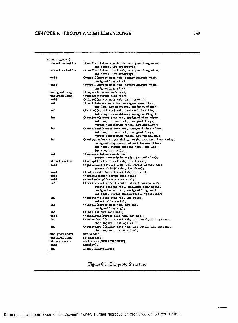
CH APTER 6. P R O T O TY P E IMPLEMENTATION 143
struct proto { struct sk-buff *
struct sk-buff *
void
void
unsigned long unsigned long void int
int
int
int
int
int
struct sock • to id
void void t o id int
int
int
int t o id int
int
unsigned short unsigned long struct sock • char int
(•emalloc)(struct sock *sk, unsigned long size, int force, int priority);
C*rmalloc)(struct sock *sk, unsigned long size, int force, int priority);
(•vfree)(struct sock *sk, struct sk-buff *skb, unsigned long size);
(•rfree) (struct sock *sk, struct sk-buff *skb, unsigned long size);
(*rspace)(struct sock *sk) ;(•vspace)(struct sock *sk) ;(*close)(struct sock *sk, int timeout);(•read)(struct sock *sk, unsigned char *to,
int len, int nonblock, unsigned flags);(•write) (struct sock *sk, unsigned char *to,
int len, int nonblock, unsigned flags);(•sendto)(struct sock *sk, unsigned char *from,
int len, int noblock, unsigned flags, struct sockaddr-in *usin, int addr_len);
(•reCTfrom) (struct sock *sk, unsigned char «from, int len, int noblock, unsigned flags, struct sockaddr-in *usin, int *addr-len);
(•build-header) (struct sk-buff *skb, unsigned long saddr, unsigned long daddr, struct deTice **deT, int type, struct options *opt, int len, int tos, int ttl);
(•connect)(struct sock *sk,struct sockaddr-in *usin, int addr-len);
(•accept) (struct sock *sk, int flags);(•queuejnait) (struct sock *sk, struct deTice *deT,
struct sk-buff «skb, int free);(•retransmit) (struct sock *sk, int all);(•vrite-sakeup) (struct sock *sk) ;(•read-sakeup) (struct sock *sk) ;(*rcT)(struct sk-buff *buff, struct deTice *deT,
struct options *opt, unsigned long daddr, unsigned short len, unsigned long saddr, int redo, struct inet-protocol ̂ protocol);
(•select)(struct sock *sk, int which, select-table *uait);
(•ioctl) (struct sock *sk, int and, unsigned long arg);
(*init)(struct sock *sk);(•shutdown) (struct sock *sk, int hou) ;(•setsockopt)(struct sock *sk, int leTel, int optname,
char *optTal, int optlen);(•getsockopt)(struct sock *sk, int leTel, int optnaoe,
char *optTal, int •option) ; max-header; retransmits;sock-array [SOCK JRRAY-SIZE] ; name[80];inuse, highestinuse;
Figure 6.5: The proto S tructure
Reproduced with permission of the copyright owner. Further reproduction prohibited without permission.

C H APTER 6. PRO TO TYPE IMPLEMENTATION 144
on an offset in the _ sy s_ c a ll_ ta b le . T he offset is put in the calling stack fram e by the libc
library routine. Almost all socket system calls use the same offset and thus are vectored
to the same function, s y s _ s o c k e tc a l l . Based on additional inform ation put in by the
libc s tub , sock_sendto is invoked. In sock_send to , the so c k e t struc tu re associated with
the file descriptor provided by the application is retrieved. The s o c k e t s truc tu re contains
inform ation on the address family and protocol associated w ith the socket. A fter some error
checking, control is passed to the address family by invoking its specified sendto function;
in our example this is in e t_ se n d to . In e t_ se n d to performs additional error checking and
then invokes the sendto function specified for the protocol, in our case udp_sendto . The
UDP protocol performs the bulk of the work involved in sending the message. In short, it
allocates a suitable datagram , fills in th e header information, copies the user d a ta , performs
checksum com putation, and invokes the IP protocol to send the datagram . The IP protocol
will in tu rn invoke the device driver to actually transm it the datagram .
6 .2 .2 A dd ing R U P P
As m entioned above, the protocols in the T C P /IP suite are specified as a collection of
functions. The first step in im plem enting RU PP was then to define an appropriate p ro to
s tructu re for the protocol. The p r o to structu re specifying the RU PP interface is shown
in Figure 6.66. Although many m inor adjustm ents to existing header files and code were
needed to integrate the RU PP protocol, the bulk of the RUPP im plem entation is contained
w ithin functions internal to the protocol or the functions specified in the RU PP proto
structure .
R U PP is implemented according to the protocol specification given in the previous
6Since our protocol was initially w ithout a nam e and its specification sim ilar to RDP, we used the name RDP during development of the code
Reproduced with permission of the copyright owner. Further reproduction prohibited without permission.

CHAPTER 6. P R O T O TY P E IMPLEMENTATION 145
s t r u c t proto rdp_prot = { sock .w m alloc, sock_rm alloc, sock-vf r e e , sock _rfree , sock_rspace, sock-w space, rdp .c lo s e , rdp_read, rdp_w rite, rdp -sen d to , rdp-xecvf rom, ip_build_header, rdp_connect,NULL,ip_queue_m it,NULL,NULL,NULL,rdp_rcv,d atagram -select, r d p _ io c t l , r d p _ in it ,NULL,rdp_setsockopt, rd p -getsockopt,128,0 ,NULL,,"RDP",0 , 0
}Figure 6.6: The RUPP proto S tructure
Reproduced with permission of the copyright owner. Further reproduction prohibited without permission.

CHAPTER 6. P R O T O T Y P E IMPLEMENTATION 146
section. The s ta te transition diagram of Figure 6.3 is implem ented in software w ith the ex
ception tha t the LISTEN s ta te is not used. The operation o f the protocol in the CLOSED
and LISTEN states is sim ilar enough th a t a distinction, in software, between the two states
would only add complexity to the code. The Linux networking code m aintains a sock
structu re for each socket in the inet dom ain. The EU PP connection record constitutes part
of the information stored in the so ck structure. Our im plem entation differs from the speci
fication in its treatm ent of segm ents th a t arrive for an unknown p o rt. O ur im plem entation
does not use RST segments. Instead , we send an ICM P port unreachable message[79] to
inform the o ther end when a segment for an unknown com m unication endpoint is received.
W hen an ICMP error message is received by the RU PP software th e error is reported to
the application.
In addition to the options described in the RUPP specification, we also implem ented an
option for changing the in itia l re transm it tim eout used on a connection. This additional
option was implem ented to allow easy experim entation w ith the protocol. Inform ation
about RUPP was incorporated in to the n e t directory of the /p r o c filesystem[46]. The
/p ro c filesystem in Linux is a v irtual filesystem, providing an interface to kernel da ta
structures. It provides easy access to kernel statistics and process inform ation. Applications
can obtain inform ation from the /p r o c filesystem instead of having to read /dev/kmem. The
RU PP protocol m aintains s ta tis tics on the number of segments sent, num ber of retransm its,
num ber of segments received, and so on. This information is available through the /p ro c
filesystem interface.
Control is transfered to the R U PP protocol software by three different mechanisms:
as the result of a system call executed by the application, when a R U PP tim er expires,
and from the IP layer as a result of a hardw are in terrupt caused by an incoming packet.
Reproduced with permission of the copyright owner. Further reproduction prohibited without permission.

CHAPTER 6. P R O T O T Y P E IMPLEMENTATION 147
Much of the complexity involved in implementing th e RU PP protocol stem s from the need
to provide adequate concurrency control. System call invocations have the lowest priority.
The RU PP software can never be in terrupted during processing as a result of an application
performing a system call. RU PP m aintains three tim ers for each socket, a retransm it tim er,
an ack tim er, and a w aitfor tim er. A RUPP tim er m ay expire and in terrup t the RU PP
protocol software during processing. Functions invoked as a result of a system call can
protect themselves from a tim er operating on the sam e socket by setting the in u se flag,
which is part of the sock structure . Processing o f an incoming packet is protected from
tim er operations through the in_bh flag which is se t by lower layers. Each tim er function
begins by tu rn ing off in terrup ts and checking if th e socket is in use or if processing of an
incoming packet is in progress by checking the in u s e flag for the socket and the in_bh. flag.
If either flag is set, then the tim er reschedules itself, tu rn s in terrupts on, and exits. If neither
flag is set, the tim er code sets the in u se flag to pro tect itself from another tim er operating
on the same socket, tu rns in terrup ts back on, and proceeds with processing. Processing of
an incoming packet has the highest priority. Unless in terrup ts are turned off, an incoming
packet will in terrup t processing performed as a result of a system call or a tim er event.
Hence, access to volatile variables and other critical operations must be protected in the
code by turn ing in terrup ts off. For example, suspension of a process m ust be protected from
interrupts to make sure th a t the “wakeup call” for the process is not missed.
6.2.3 U ser Interface
As mentioned above, the networking user interface in Linux is provided through sockets. A
socket for the R U PP protocol should be created as type SOCK-RDM , a socket for reliably
delivered messages. No protocol was previously supported for a socket of type SOCK-RDM
Reproduced with permission of the copyright owner. Further reproduction prohibited without permission.

CHAPTER 6. P R O T O TY P E IMPLEMENTATION 148
so RU PP is the default protocol for a socket of this type. No protocol number needs to be
specified when th e socket is created.
All the s tan d a rd socket system calls supported on a UD P socket are supported by RUPP.
An application using UDP which only communicates w ith one process on each UDP port
should be able to move to reliable communication by sim ply altering the type of its sockets
to SOCK-RDM . Since R U PP uses implicit connection setup the listen and accept system
calls, used by T C P , are not supported.
An active open for a RU PP connection is performed explicitly using the connect system
call or im plicitly by sending a message using the sendto system call. A passive open is
performed by binding the socket to a local port num ber through the bind system call.
Messages are tran sm itted using the send or sendto system calls and received using the recv
or recevfrom system calls. W hen sendto is used to transm it a message on a connected socket,
the destination address m ust m atch the address given when th e connection was opened. The
read and write system calls are also supported. A R U PP connection is closed using the close
system call. R U PP options are m anipulated through the setsockopt and getsockopt system
calls.
6 .2 .4 D e liv ered and D elivered_all
Two new system calls, delivered and delivered.all, were added to the Berkely socket interface
in Linux to retrieve inform ation about delivery of messages from the RUPP protocol. The
delivered and delivered-all system calls are only valid for R U PP sockets. The calls are
declared in a header file, d e l . h, as:
in t delivered(int s, m essageJd mid)
int delivered.all(int s )
Reproduced with permission of the copyright owner. Further reproduction prohibited without permission.

CH APTER 6. P R O TO TYP E IMPLEMENTATION 149
where s should be a RU PP socket and m id is the message sequence number offset. The
type m essage_id is defined in the header file as unsigned long. As described earlier, the
sequence num ber offset for the n th message sent on a connection is n — 1.
To im plem ent the system calls two library stubs were created for the calls. As for most
socket system calls, we have the kernel entry routine vector the delivered and delivered-all
system calls to the s y s _ s o c k e tc a l l function. Besides the _ s y s_ c a ll_ ta b le offset and the
user param eters, the library stub provides an identifier to indicate what socket call was
invoked. Two new identifiers, SYS-DEL and SYS.DELALL, were defined. Based on these
identifiers s y s _ s o c k e tc a l l invokes an appropriate function. T he type of the socket is
checked and some general error checking performed before the RU PP protocol is invoked
to handle the calls.
T he R U PP software acts in accordance with the R U PP specification. For a delivered
call the sequence number offset is m apped to a segment sequence number by adding the
offset to the initial send sequence num ber. The resulting segment sequence num ber is
com pared against rcv_ack_seqno. If the sequence num ber is larger than rcv_ack_seqno the
R U PP software examines its send buffers for the segment. If the segment is found the
calling application is suspended until the segment has been delivered or an error occurs.
For a delivered-all call the send buffers are examined. If there are outstanding segments the
calling application is suspended until all segments have been delivered or an error occurs.
W hen an error condition occurs on a R U PP socket, it is up to the application to correctly
in terp re t the result of subsequent calls to delivered and delivered-all. The RU PP software
makes a fixed num ber of a ttem p ts a t delivering a segment. A fter MAX_ATTEMPTS re
tran sm it a ttem p ts , the R U PP software gives up. The segment is cleared from the buffers
and an ETIM ED O U T error is recorded for the socket. T he error is reported to the ap
Reproduced with permission of the copyright owner. Further reproduction prohibited without permission.

CH APTER 6. P R O T O TY P E IMPLEMENTATION 150
plication the next tim e a system call is invoked on the socket. The error is then cleared.
At this point the segment th a t caused the ETIM ED O U T error is indistinguishable from a
segment th a t was successfully delivered. The R U PP protocol does not close a socket when
an error occurs. Instead it is up to the application to decide how to proceed after an error
was reported on a socket. If the application decides to carry on it m ust account for the
fact th a t the semantics of la ter operations on the socket may not be preserved. Allow
ing the application to decide how to proceed after an error occurs is consistent w ith the
end-to-end argum ent.
6.3 Flush Channel Implementation
Flush channel com m unication was introduced in C hap ter 4. A straightforw ard user-level
im plem entation of flush channels was presented. Having implemented the R U PP protocol
and the delivered and delivered-all system calls, it was an easy task to transform our proposed
im plem entation into a flush channel library running on top of RUPP. In the library we
defined a new socket type, SOCK-FLUSH, for flush channel semantics. SOCK_FLUSH is
simply an alias for SOCK-RDM since the flush channel is built on top of a R U PP socket.
The SOCK-FLUSH type was defined in support of good coding style. Two library functions
were declared for tran sm itting a message over a flush channel socket, f lu s h _ s e n d and
f lu sh _ se n d to . As described in C hapter 4, flush channel messages have a type in addition
to the d a ta . Thus the f lu sh _ sen d and f lu sh _ sen d to routines require a type param eter in
addition to the regular param eters required by the send and sendto system calls. The two
routines are declared as:
in t flush-send(in t s, const void *msg, int len, unsigned int flags, char type)
Reproduced with permission of the copyright owner. Further reproduction prohibited without permission.

CHAPTER 6. P R O T O TY P E IMPLEMENTATION 151
in t flu shsend to{ int s, const void *msg, in t len , unsigned int flags,
const struct sockaddr *to, in t tolen, char type)
The code for the f lu s h _ s e n d to routine is shown in Figure 6.7. The m apping from the
proposed im plem entation in Chapter 4 to the code in Figure 6.7 is obvious. The D_FLAG,
mid, and c o u n t variables are declared as sta tic ex ternal variables. They are used by both
the f lu sh _ se n d and f lu sh _ se n d to routine and they m ust m aintain their values between
successive invocations of the routines. The coun t variable records the number of messages
sent on the flush channel. It gives the sequence num ber offset needed for the delivered call.
The f lu sh _ se n d routine looks very sim ilar with the sendto system calls replaced by send
system calls.
Since our flush channel im plem entation puts the sole responsibility of providing the
correct sem antics on the sender, no flush_receive routine is needed. Applications commu
nicating over a flush channel use all the standard system calls on the socket except for
when tran sm ittin g a message. All messages tran sm itted on a SOCK-FLUSH socket must
be tran sm itted using the flu sh _ se n d or f lu s h _ s e n d to routine. It is the responsibility of
the application to conform to this rule.
6.4 Chapter Summary
This chapter presented our prototype im plem entation. To illustrate how transport layer
inform ation can be used in practice, we designed and im plem ented the RUPP transport layer
protocol. The R U PP specification requires protocol support for propagation of information
about delivery of messages to the application. RU PP does not only provide message delivery
inform ation, b u t is a complete transport layer protocol. R U PP provides the application with
Reproduced with permission of the copyright owner. Further reproduction prohibited without permission.

CH APTER 6. P R O T O TY P E IMPLEMENTATION 152
i n t f l u s h - s e n d t o ( i n t s , c o n s t v o id *msg, i n t l e n , u n s ig n e d i n t f l a g s , c o n s t s t r u c t s o c k a d d r * t o , i n t t o l e n , c h a r ty p e )
{i n t r e s ;
sw itch C ty p e ) {
c a s e ORD:i f (D-FLAG) {
i f ( ( r e s = d e l i v e r e d ( s , m id )) < 0) r e t u r n - 1 ;
D-FLAG = 0 ;}r e s = s e n d t o ( s , msg, l e n , f l a g s , t o , t o l e n ) ;c o u n t++;b r e a k ;
c a s e TVF:i f ( ( r e s = d e l i v e r e d - a l l ( s ) ) < 0)
r e t u r n - 1 ;r e s = s e n d t o ( s , msg, l e n , f l a g s , t o , t o l e n ) ;D.FLAG = 1; m id = c o u n t; c o u n t++; b r e a k ;
c a s e FF:i f ( ( r e s = d e l i v e r e d - a l l ( s ) ) < 0)
r e t u r n - 1 ;r e s - s e n d t o ( s , msg, l e n , f l a g s , t o , t o l e n ) ;D.FLAG = 0 ; c o u n t++; b r e a k ;
c a s e BF:i f (D.FLAG)
i f ( ( r e s = d e l i v e r e d ( s , m id )) < 0) r e t u r n - 1 ;
r e s = s e n d t o ( s , msg, l e n , f l a g s , t o , t o l e n ) ;D.FLAG = 1; m id - c o u n t; c o u n t++; b r e a k ;
d e f a u l t :e r r n o = -EINVAL; r e t u r n - 1 ;
}r e t u r n r e s ;
}
Figure 6.7: The flush_sendto Routine.
Reproduced with permission of the copyright owner. Further reproduction prohibited without permission.

CH APTER 6. PR O TO TYP E IMPLEMENTATION 153
a reliable unordered message passing service. Some of the main features of R U PP include:
lightweight connection m anagem ent; reliable delivery of messages based on a checksum
algorithm , sequence numbers, a receive bitvector to record segments received out of order,
and an acknowledgment retransm it a lgorithm which includes a fast re tran sm it rule; window-
based flow control; and mechanisms for buffer management.
The R U PP protocol was im plem ented within the networking code of the Linux kernel
(version 1.2.0). The user interface to the RU PP protocol is provided through the standard
socket system calls available in Linux. To retrieve inform ation abou t delivery of messages
from a R U PP socket, two new system calls, delivered and delivered-all, were implemented.
The delivered and delivered-all system calls axe only available on R U PP sockets.
Once the RU PP protocol was im plem ented it was an easy task to im plem ent a flush
channel lib rary on top of it. Based on the im plem entation proposed in C hap ter 4 two library
routines, f lu sh _ se n d and f lu s h _ s e n d to , were constructed. All messages transm itted on a
flush channel socket must be tran sm itted through one of these two routines. The regular
socket lib rary routines are used for all o ther operations on the socket.
The im plem entation described in th is chapter show th a t the im proved use of transport
layer inform ation is not only a theoretically appealing idea but achievable in practice. Al
though the requirem ent to support propagation of inform ation abou t delivery of messages
to the application is unique to the R U PP protocol, it is straightforw ard to add similar
support to o ther reliable transport protocols.
Reproduced with permission of the copyright owner. Further reproduction prohibited without permission.

Chapter 7
Experim ental R esults
Our pro to type im plem entation of the RU PP protocol and the delivered and delivered-all
system calls were presented in the previous chapter. O ur im plem entation of a flush channel
library routine was also discussed. In this chapter we present experimental results obtained
from our prototype im plem entation. The first set of experim ents evaluates the performance
of R U PP com pared to TC P and UDP. The second set of experiments evaluates the perfor
mance o f our delivered and delivered-all prim itives, and the final set of experiments evaluates
the perform ance of our flush channel im plem entation. We begin the chapter w ith a brief
description of our experimental setup. Any results presented are naturally bound to the
specific Linux im plem entations of T C P and RU PP th a t were used. However, it is safe to
assume th a t any performance gains displayed for our im plem entation are due to inherent
advantages of a reliable unordered transport protocol. A lthough some effort was spent on
code optim ization, the main focus for our pro to type im plem entation was on functionality
and correctness. The design and im plem entation of T C P is naturally much m ore m ature
and m ore highly optimized.
154
Reproduced with permission of the copyright owner. Further reproduction prohibited without permission.

CH APTER 7. EX PERIM ENTAL RESULTS 155
pOO pOl p l l
state 0 (no loss)
state 1 (loss)
plO
Figure 7.1: Markov Model for Packet Loss
7.1 Experimental Setup
O ur experim ents were conducted over a lOM bits/sec local area E thernet. All the machines
used in our experim ents were 90MHz Pentium s running the Linux 2.0 kernel. At the tim e
our experim ents were conducted, there was minimal com peting traffic on the network. The
only com peting traffic was due to regular system activities such as clock synchronization.
During norm al operation , no packets were lost or corrupted during transm ission from
one host to another. To evaluate performance over an unreliable network, we implemented
a socket option to probabilistically discard incoming packets. We refer to a socket with
this option enabled as a “lossy” socket. The option was im plem ented for both T C P and
RU PP sockets. A Lehmer random num ber generator[70] was compiled in to the kernel and
the value passed in when se tting the socket to lossy was used to seed the generator. Packets
arriving to a lossy socket were dropped based on a tw o-state M arkov chain, illustrated in
Figure 7.1. By default, a transition was performed in the M arkov chain each tim e a packet
arrived on the socket. If the M arkov chain was in the loss s ta te (sta te 1) after the transition ,
Reproduced with permission of the copyright owner. Further reproduction prohibited without permission.

CHAPTER 7. EXPERIM ENTAL RESULTS 156
then the packet was dropped. (This is G ilbert’s Markov model for channels with memory
with an error probability o f 1 in the “bad” sta te and an error probability of 0 in the “good”
state[47].) For our experim ents w ith an unreliable network, we dropped packets both at
random and in a bursty fashion. Random packet loss was achieved by selecting the s ta te
transition probabilities in the Markov chain such th a t pOO = plO and pOl = p l l . Thus, the
s ta te transition probability of entering the loss s ta te was the sam e from both states of the
Markov chain. As a result, an independent Bernoulli trial was performed for each incoming
packet to decide if it should be dropped or not. Bursty packet loss was initially created by
modifying the s ta te transition probabilities to increase the expected num ber of packets lost
when the loss s ta te was entered. However, this did not work well. The problem was th a t
both T C P and RU PP respond to packet loss by increasing the re transm it tim eout, thus
sending fewer packets, bu t the only way to leave the loss s ta te was to transm it packets.
The assum ption made by T C P and RU PP that bursty errors axe tied to tim e is reasonable.
It was ill m atched by the m odel which created bursty error behavior through the number
of packets lost independent of tim e. To remedy this problem we allowed a holding tim e
to be associated with the loss s ta te . Only when the first packet arrived after the holding
tim e had expired was a s ta te transition performed. This allowed several packets to be lost
each tim e the loss s ta te was entered during normal transm ission. The process of selecting
the holding tim e will be discussed further below when we describe our experim ents for an
unreliable network.
For all experim ents, average tim ings were obtained and the 95% confidence intervals for
the average tim ings were calculated. W here possible, the calculated confidence intervals are
displayed in our graphs. A lthough the 95% confidence intervals produced for the experi
ments were generally very sm all, we saw evidence of a higher variability in the system. This
Reproduced with permission of the copyright owner. Further reproduction prohibited without permission.

C H APTER 7. EXPERIMENTAL RESULTS 157
was especially true for the T C P protocol. For our bulk d a ta transfer experim ent, described
below, repeated executions of the experim ent produced clearly non-overlapping confidence
intervals for TCP. This suggests th a t the tim e required for bulk d a ta transfer over successive
T C P connections may not be completely independent. We see no obvious explanation for
a dependence between successive T C P connections, and merely account it to the fact tha t
we are dealing with a real system. Although some of th e confidence intervals produced for
T C P appeared to be misleadingly small, the general trend illustrated by our experiments
always remained consistent. The performance m easured for the RU PP and UDP protocols
was much more consistent than the T C P performance.
7.2 RUPP Experiments
Our first set of experiments was designed to evaluate the performance of our RU PP protocol
in com parison with T C P and UDP. All tests for T C P were run with the TCP-NODELAY
option enabled. Normally, T C P will delay the transm ission of small packets in an a ttem pt
to combine several small packets into a single packet before transm ission. Setting the
TCP-NODELAY option caused T C P to im m ediately transm it each packet, providing the
most useful comparison for our protocol.
7.2 .1 B u lk D ata Transfer (E xp erim en t 1)
In our first experiment, we examined the performance of the protocols for bulk d a ta transfer.
We m easured the tim e it took to transfer a batch of 512-byte messages back and forth
between two hosts for varying batch sizes. The batch of messages was passed in both
directions since all tim ings had to be performed on the same host to avoid tim ing errors
due to clock drift between the two machines. The pseudo code for the host controlling the
Reproduced with permission of the copyright owner. Further reproduction prohibited without permission.
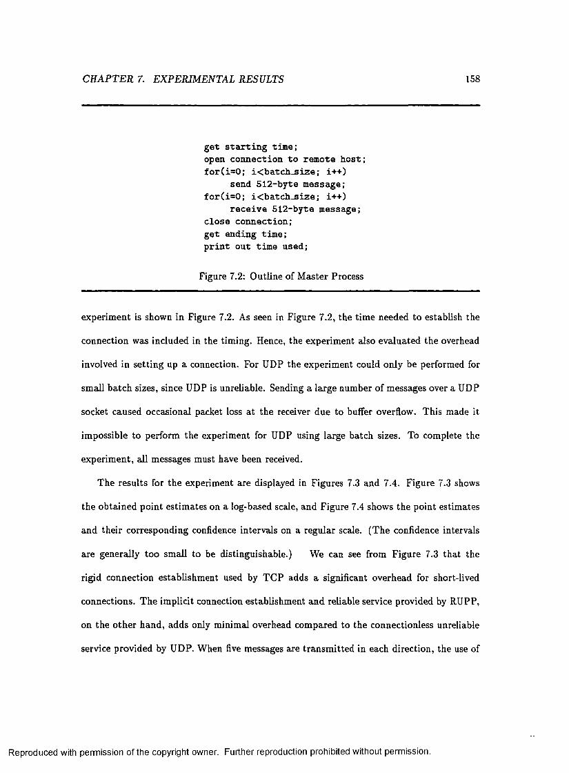
C H APTER 7. EXPERIMENTAL RESULTS 158
g e t s t a r t in g tim e; open c o n n e c t io n t o rem ote h o s t ; f o r ( i = 0 ; i< b a tc h _ s iz e ; i+ + )
send 5 1 2 -b y te m essage; f o r ( i = 0 ; i< b a tc h _ s iz e ; i+ + )
r e c e iv e 5 1 2 -b y te m essage; c lo s e co n n e c t io n ; g e t en d in g tim e; p r in t o u t tim e u sed ;
Figure 7.2: O utline of M aster Process
experim ent is shown in Figure 7.2. As seen in Figure 7.2, the tim e needed to establish the
connection was included in the tim ing. Hence, the experim ent also evaluated the overhead
involved in setting up a connection. For UDP the experim ent could only be performed for
small ba tch sizes, since UDP is unreliable. Sending a large number o f messages over a UDP
socket caused occasional packet loss a t the receiver due to buffer overflow. This made it
impossible to perform the experiment for UDP using large batch sizes. To complete the
experim ent, all messages must have been received.
The results for the experiment are displayed in Figures 7.3 and 7.4. Figure 7.3 shows
the obtained point estim ates on a log-based scale, and Figure 7.4 shows the point estim ates
and their corresponding confidence intervals on a regular scale. (T he confidence intervals
axe generally too small to be distinguishable.) We can see from Figure 7.3 th a t the
rigid connection establishm ent used by T C P adds a significant overhead for short-lived
connections. T he implicit connection establishm ent and reliable service provided by RUPP,
on the o ther hand, adds only m inimal overhead com pared to the connectionless unreliable
service provided by UDP. W hen five messages are transm itted in each direction, the use of
Reproduced with permission of the copyright owner. Further reproduction prohibited without permission.

CH APTER 7. EXPERIM ENTAL RESULTS 159
1e+08rupp
tcp -S™ udp -h—
1e+07
1e+06CO■acooa>(0o>_oEc<DE
100000
10000
1000100 10001 10 10000
# of messages in batch
Figure 7.3: Time versus Batch-size
Reproduced with permission of the copyright owner. Further reproduction prohibited without permission.

CH APTER 7. EXPERIM ENTAL RESULTS 160
1.2e+07rupp -e—
tcp - s - udp -x—
1e+07
to"Ocooa>to5 6e+06E_c<0E
2e+06
1000 2000 3000 4000 5000 6000 7000 8000 9000 100000# of messages in batch
Figure 7.4: Tim e versus Batch-size
Reproduced with permission of the copyright owner. Further reproduction prohibited without permission.

C H APTER 7. EXPERIMENTAL RESULTS 161
T C P adds approxim ately 95% overhead com pared to UDP. In contrast, the use of RUPP
adds only approxim ately 5% overhead. O ur experim ent was conducted over a local area
network. Over a wide area network, we would expect connection setup for T C P to be even
more expensive in comparison to UDP and RU PP.
As the num ber of messages transm itted increases, the cost for connection establishm ent
becomes less im portan t. For large batch sizes, we see th a t R U PP and T C P perform simi
larly. T he overhead involved in sending a R U PP segment is less than for TC P, but RU PP
is slowed down by occasional buffer overflows in the receiver. The higher overhead of TC P
is offset by T C P ’s more sophisticated flow control mechanism. The net result is com parable
perform ance for the two protocols for bulk d a ta transfer over a non-lossy network. The
situation where packets are lost during transm ission from one host to ano ther will be con
sidered in a la te r experim ent. As expected, we can see from Figure 7.4 th a t the tim e needed
to com plete the message passing is proportional to the num ber of messages transm itted .
7 .2 .2 R eq u est-R esp o n se M essage P assin g (E xp erim en t 2)
In our second experiment we considered the performance of RUPP, T C P, and UDP for
request-response type message passing. Instead of transm itting a batch o f messages, we
transm itted one message, then waited for a reply before transm itting the next message.
The pseudo code for the host controlling the experim ent is shown in Figure 7.5. As can
be seen in Figure 7.5, we still included the cost o f connection establishm ent in ou r tim ings
and still used messages of size 512 bytes. T he num ber of messages tran sm itted in this
experim ent was the same as in the previous experim ent but the pattern of com m unication
was completely different. Since there was no risk of buffer overflow for request-response
type com m unication UDP could be included for all num bers of messages.
Reproduced with permission of the copyright owner. Further reproduction prohibited without permission.

CHAPTER 7. EXPERIM ENTAL RESULTS 162
g e t s t a r t in g tim e; open c o n n e c t io n t o rem ote h o s t ; f o r ( i = 0 ; i< n u m _ ite r a t io n ; i + + ) {
send 5 1 2 -b y te m essage; r e c e iv e 5 1 2 -b y te m essa g e;
}c l o s e co n n ec tio n ; g e t en d in g tim e; p r in t o u t tim e u sed;
Figure 7.5: Outline of M aster Process
The produced point estim ates are shown on a log scale in Figure 7.6 and the point es
tim ates and their corresponding confidence intervals are shown on a regular scale in Figure
7.7. Again we can see from Figure 7.6 th a t the cost of connection establishm ent is con
siderable for short-lived connections when using TC P. RU PP, on the other hand, imposes
only a small overhead com pared to UDP. As before, we can see th a t the cost of connection
establishment is less im portan t when a large number of messages is transm itted . From Fig
ure 7.7 we can see th a t R U PP outperform s TCP for request-response type communication.
As expected, we see th a t UDP produces the smallest response tim e. Since UDP supports
no reliability, there is less overhead involved in sending a UDP datagram than a RU PP or
T C P segment. However, T he performance of RU PP stays fairly close to the performance
of UDP. The performance difference between UDP and R U PP is less than the performance
difference between RU PP and TC P. Consistent with the results from the previous exper
iment, RU PP adds reliability to UDP a t an approxim ate cost of 5% - a very reasonable
overhead for the added functionality of RUPP. For request-response type comm unication
the use of T C P adds an approxim ate 18% overhead com pared to UDP.
Reproduced with permission of the copyright owner. Further reproduction prohibited without permission.

CHAPTER 7. EXPERIM ENTAL RESULTS 163
1e+08rupp -e—
tap -B~ udp -x—
1e+07
1e+06
100000
10000
1000100 10001 10 10000
# of request-response messages
Figure 7.6: T im e versus Number of Request-response Messages
Reproduced with permission of the copyright owner. Further reproduction prohibited without permission.

C H APTER 7. EXPERIM ENTAL RESULTS 164
3e+07rupp -e—
tcp S • udp - x —
Se+07
2e+07
01*oco0 ©01
§ 1.5e+07Eca>E
1e+07
5e+06
1000 2000 3000 4000 5000 6000 7000 8000 9000 100000# of request-response messages
Figure 7.7: T im e versus Number of Request-response Messages
Reproduced with permission of the copyright owner. Further reproduction prohibited without permission.

CHAPTER 7. EXPERIMENTAL RESULTS 165
7.2 .3 Influence o f M essage L en gth (E xperim ent 3)
In our th ird experim ent, we exam ined the influence of messages size on the performance
of our RU PP protocol as well as on performance of the T C P protocol. Experim ent 2
was modified to no longer consider connection m anagement and to send a fixed number
of request-response messages. Instead of varying the num ber of messages transm itted we
varied the size of the messages. The average round-trip tim e for a message was calculated
and used as one d a ta point in the calculation of our 95% confidence interval (m ethod of batch
m eans). The mean round-trip times and their corresponding confidence intervals are shown
in Figure 7.8. Except for the perform ance of TC P for small messages, the results in Figure
7.8 look as we would expect. The round-trip tim e needed for a message is proportional to
the size of the message. Consistent w ith Experim ent 2, the round-trip tim e for a message
over RU PP is considerably sm aller th an the round-trip tim e of a message of equivalent
size over TCP. We do not have an explanation for the poor perform ance of T C P for small
messages, but we repeatedly verified the behavior. We are merely happy to observe tha t
our RU PP protocol does not exhibit th is strange behavior. The results shown for RU PP in
Figure 7.8 serves as validation for ou r RU PP im plem entation.
7 .2 .4 Perform ance O ver a L ossy N etw ork (E xp er im en ts 4 and 5)
As m entioned earlier, our experim ents were run over an E thernet w ithout com peting tra f
fic. No packets were ever lost or corrupted during transm ission from one host to another.
However, over wide area networks o r wire-less networks, packets can get lost or reordered.
The performance of the RU PP protocol is more interesting when packets get lost. Only
when packet loss or packet reorder occurs can we expect to see a gain from unordered com
m unication compared to ordered com m unication. Not until packet loss occurs are we able
Reproduced with permission of the copyright owner. Further reproduction prohibited without permission.

CHAPTER 7. EXPERIM ENTAL RESULTS 166
7000
rupp -e— tcp B -
6000
5000
4000
3000
2000
1000
00 200 800 1600400 600 1000 1200 1400
size of message in bytes
F igure 7.8: Round-trip Time versus Message Size
Reproduced with permission of the copyright owner. Further reproduction prohibited without permission.

C H APTER 7. EXPERIMENTAL RESULTS 167
to evaluate the performance of our reliability mechanisms. As described above, we imple
m ented an option to probabilistically discard arriving packets to evaluate perform ance in
the presence of packet loss.
Perform ance over a lossy netw ork is most interesting for bulk d a ta transfer. W hen
request-response communication is used, there is no difference between ordered and un
ordered comm unication, and the only im plem entation param eter of real im portance is the
retransm it tim eout value. For bulk d a ta transfer, on the o ther hand, we can expect un
ordered comm unication to offer perform ance benefits and the full capacity o f our reliability
mechanisms to be tested. Thus, to tes t performance over a lossy network, we slightly m od
ified Experim ent 1. Connection m anagem ent was no longer considered in our tim ings and
a fixed num ber of 1000 messages were transm itted in each batch. The characteristics o f the
lossy network were varied between the various runs.
We first considered performance when packets were random ly lost; th a t is, an indepen
dent Bernoulli trial was performed for each incoming packet to decide if it should be dropped
or not. The results for RU PP and T C P for varying loss probabilities are shown in Figure
7.9. This figure illustrates the great performance benefits of unordered com m unication. For
instance, when the probability of packet loss is 0.02, the message transm ission tim e required
by T C P is more than three times g rea ter than the tim e required by RU PP. This is prim arily
due to the sequenced delivery enforced by TCP. Thus, we can see th a t, for applications th a t
require reliability but not order, the use of T C P imposes unnecessarily high overheads. We
can see from Figure 7.9, th a t the slow-down for T C P is roughly proportional to the loss
probability. In contrast, RU PP perform s very well as long as the probability of packet loss
is not too great. For large packet loss probabilities performance of RU PP s ta r ts to degrade
a t a ra te sim ilar to the rate of TC P. A lthough this trend should be noted, we see th a t RU PP
Reproduced with permission of the copyright owner. Further reproduction prohibited without permission.

CHAPTER 7. EX PERIM ENTAL RESULTS 168
4e+08rupp -0—
tcp S -
3.5e+08
3e+08
coT3Coo®CO
§ 2e+08Ec®E
,5e+08
5e+07
0.050 0.01 0.02 0.03 0.04 0.06probability of packet loss
Figure 7.9: Tim e versus Loss P robability
Reproduced with permission of the copyright owner. Further reproduction prohibited without permission.

CH APTER 7. EXPERIM ENTAL RESULTS 169
Probability of entering loss s ta te
Holding tim e in microseconds
A pproxim ate num ber of packets lost in loss sta te
0.016 300 10.008 850 20.004 1950 40.002 4150 8
Table 7.1: Param eters Used in Experim ent 5
performs very well for loss probabilities within the range o f practical interest. W hen the
probability o f packet loss is 0.005, the slowdown for R U PP compared to its performance
over an error-free channel is around 12%, whereas the corresponding slowdown for T C P is
approxim ately 235%.
Our next experim ent was designed to evaluate the behavior of the protocols for various
types of loss behavior. We considered the protocols for varying degrees of bursty error
behavior. As described above, we associated a holding tim e with the “loss” sta te in our
M arkov chain to sim ulate bursty packet loss. T he holding tim es between experiment runs
were chosen to allow an increasing number of packets to be lost when the loss s ta te was
entered. From Experim ent 6, described below, we know th a t the tim e to send a 512-byte
message is approxim ately 550 microseconds. Thus, during bulk da ta transfer, a segment
arrives a t th e receiver approxim ately every 550 microseconds unless recovery or flow control
measures are invoked. Based on this knowledge, appropriate holding tim es could be selected.
The to ta l num ber of packets lost during an experim ent was held approxim ately constant
by adjusting the probability of entering the loss s ta te to compensate for the increased
burstiness. The holding tim es used, the corresponding probabilities, and the approxim ate
num ber of packets lost each tim e the loss s ta te was entered are shown in Table 7.1. The
Reproduced with permission of the copyright owner. Further reproduction prohibited without permission.

C H A P TE R 7. EXPERIMENTAL RESULTS 170
results for R U PP and TCP for the various holding tim es are shown in Figure 7.10. We can
see from Figure 7.10 th a t the perform ance o f the R U PP protocol is not greatly affected by
the burstiness o f the packet loss. The perform ance when packets are lost a t random is sim ilar
to perform ance when packets are lost in bursts as long as the overall probability of losing a
packet is roughly the same. Since the R U PP protocol allows unordered delivery of messages
and re transm its packets selectively, the cost of recovery for a lost packet is roughly the same
w hether the packets are lost a t random or in bursts. The T C P protocol, on the o ther hand,
perform s much b e tte r when packets are lost in bursts. For T C P the number of times
recovery m ust be performed is more im portan t than the num ber of packets lost each tim e
recovery is needed. Since TC P provides ordered delivery, each tim e a segment is lost, T C P
must delay the receiver until the segment has been re transm itted . This delay is roughly
the sam e w hether a single segment or a sequence o f segments are lost. In addition, the
Linux im plem entation of T C P retransm its all segments in the send-queue when a retransm it
tim eout occurs, incurring a sim ilar cost regardless of the num ber of segments lost. The cost
of congestion avoidance and slow s ta rt [41] is also fairly unaffected by the number of segments
lost.
7.3 Delivered Experiments (Experiments 6 and 7)
Our second set of experiments considered the performance o f the delivered and delivered.all
system calls. The use of the delivered and delivered-all constructs can reduce network traffic
by alleviating the need for user-level acknowledgments. We would also expect the use
of delivered and deliveredjall to be more efficient in term s of tim e compared to user-level
acknowledgments. To evaluate the differences we m easured the tim e needed to send and
acknowledge a message at the user level com pared to the tim e needed to execute a send
Reproduced with permission of the copyright owner. Further reproduction prohibited without permission.

CH APTER 7. EXPERIMENTAL RESULTS 171
1e+08rupp
top S •••
9e+07
8e+07
7e+07COTJcoo©CO
§ 6e+07E_c<DE
5e+07
4e+07
3e+07
2e+07500 1000 1500 2000 2500 3000 3500 4000 45000
holding time in microseconds for bad state
Figure 7.10: T im e versus Holding Tim e in Loss S tate
Reproduced with permission of the copyright owner. Further reproduction prohibited without permission.

CHAPTER 7. EXPERIM ENTAL RESULTS 172
directly followed by a delivered. For our tim ings with delivered, we enabled the R U PP option
th a t acknowledges messages w ithout delay. We varied the size o f the message tran sm itted ,
bu t used a constant size of four bytes (one integer) for the user-level acknowledgment. To
evaluate the worst-case overhead of our delivered system call, we also m easured the tim e
needed to execute a send system call. As in Experim ent 3, we used the m ethod of batch
means to calculate 95% confidence intervals. The results of our experiment are shown in
Figure 7.11. We can see th a t the use of user-level acknowledgments adds a fairly constant
overhead compared to using the delivered system call. W hen the size of the transm itted
message is small the use o f user-level acknowledgments adds an approxim ate 20% overhead
compared to the use o f delivered. As the size of the message increases, the overhead becomes
less significant since th e transm ission cost of the message is the dom inant cost.
Comparing the delay for a send operation to the delay for a send operation im m ediately
followed by a delivered call, we see th a t, in the worst case, the delay of a delivered call
is approxim ately 2.5 tim es the delay of the send operation. In practice we would expect
communication events to be interspersed with processing, and the delay for a delivered call
would be much sm aller. The discussion above focused on our delivered system call. However,
replacing the call to delivered by a call to delivered-all produced virtually identical results
since the operation was performed after every send operation.
The results displayed in Figure 7.11 also support our analytical results derived in C hap
ter 3, where we analyzed the message delay for causally ordered communication; we con
sidered the delay from when a process is ready to send a message until this message is
available for receipt to the application in the receiving host. We can see from Figure 7.11
th a t just the send delay for a 1000-byte message is approxim ately the same as the delay
to send and execute a delivered for a 100-byte message. For a system with 15 processes
Reproduced with permission of the copyright owner. Further reproduction prohibited without permission.

CH APTER 7. EXPERIM ENTAL RESULTS 173
3500explicit acks -e—
delivered -x— send only Q -
3000
2500
2000
1500
1000
500
. . aIE
01000 12000 200 400 600 800 1400 1600
size of message in bytes
Figure 7.11: Time versus Message Size
Reproduced with permission of the copyright owner. Further reproduction prohibited without permission.

CHAPTER 7. EXPERIM ENTAL RESULTS 174
and point-to-point com m unication, the vector tim e inform ation needed to support causally
ordered com m unication adds 900 bytes to each message. For such a system , the delay to
send a 1000-byte message is a lower bound on the message delay for a 100-byte message
in a vector tim e based im plem entation of causally ordered com m unication. (Since the cost
to acknowledge a message is constant, Figure 7.11 also shows th a t the actual delay is sig
nificantly larger.) T he delay to send and execute a delivered call for a 100-byte message
is an upper bound on the message delay for a 100-byte message when our proposed im
plem entation is used. Thus our experiment suggests th a t, over a local area network, our
im plem entation o f causally ordered communication is more efficient than the vector time
im plem entation for medium or large size systems.
The tim ings for a send operation directly followed by a delivered call illustrated the
worst-case behavior of our delivered construct. Since delivered is invoked directly after the
send operation, we have to wait a maximal am ount of tim e before the acknowledgment is
received. Normally, o ther processing would be interspersed between the send call and the
delivered call for a message and the delay would be smaller. In the best case, the message
has already been acknowledged when delivered is invoked. T he delay for the delivered call
is then merely th e cost of the kernel call th a t retrieves this inform ation. To evaluate the
delay for our delivered system call in the best case, we m easured the tim e needed to execute
a delivered call for a message th a t was known to be delivered. T he best-case delay for the
delivered call in com parison to the delay for a send call is shown in Table 7.2. We can see
th a t in the best case the overhead for the delivered call is negligible com pared to the delay
of sending a message. Even for a very small message (4 bytes), the delay for the delivered
call is merely a rough 1% of the delay for the send operation. As the size of the transm itted
message increases the cost of the delivered call becomes even less significant. Again, the
Reproduced with permission of the copyright owner. Further reproduction prohibited without permission.

C H APTER 7. EXPERIMENTAL RESULTS 175
Operation T im e in microsecondsdelivered
send (4-byte message) send (512-byte message)
3.30 + / - 0.08 293.12 + / - 0.34 551.34 + / - 0.99
Table 7.2: Best-case Behavior of Delivered
delay for a delivered.aU call when all messages are already delivered is virtually identical to
the delay for delivered.
7.4 Flush Channel Experiment (Experiment 8)
O ur final experim ent was designed to evaluate the perform ance of our flush channel imple
m entation . We compared the tim e needed for bulk d a ta transfer using TC P to the tim e
needed to transm it the d a ta as batches of messages over a flush channel. As mentioned in
C hap ter 4, m any m ultim edia applications require only a partia l receipt order on messages,
where th e messages are naturally partitioned into batches. We considered partitioning the
batches of ordinary messages by each of the three flush message types. The experim ent
where the batches are separated by two-way flush messages is representative of the image
transm ission example mentioned in C hapter 4. In our experiment we focus on the mes
sage passing and do not consider any of the o ther processing involved. Similar sample
applications can be given for the other flush message types[19].
T he perform ance of our flush channel im plem entation compared to T C P is most in ter
esting for an unreliable network. Only when packets get occasionally lost or reordered can
we expect any m ajor performance gains by relaxing the ordering constraints on messages.
Reproduced with permission of the copyright owner. Further reproduction prohibited without permission.
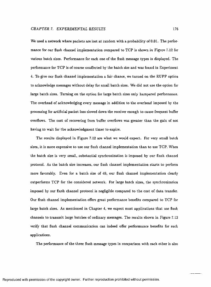
CH APTER 7. EXPERIM ENTAL RESULTS 176
We used a network where packets are lost a t random with a probability of 0.01. The perfor
mance for our flush channel im plem entation compared to TC P is shown in Figure 7.12 for
various batch sizes. Perform ance for each one of the flush message types is displayed. The
performance for T C P is of course unalfected by the batch size and was found in Experiment
4. To give our flush channel im plem entation a fair chance, we tu rned on the R U PP option
to acknowledge messages w ithout delay for small batch sizes. We did not use the option for
large batch sizes. Turning on the option for large batch sizes only ham pered performance.
The overhead of acknowledging every message in addition to the overhead imposed by the
processing for artificial packet loss slowed down the receiver enough to cause frequent buffer
overflows. The cost of recovering from buffer overflows was g rea ter than the gain of not
having to wait for the acknowledgment tim er to expire.
The results displayed in Figure 7.12 are what we would expect. For very small batch
sizes, it is more expensive to use our flush channel im plem entation th an to use TC P. When
the batch size is very small, substan tial synchronization is im posed by our flush channel
protocol. As the batch size increases, our flush channel im plem entation s ta r ts to perform
more favorably. Even for a batch size of 49, our flush channel im plem entation clearly
outperform s T C P for the considered network. For large batch sizes, the synchronization
imposed by our flush channel protocol is negligible compared to th e cost of d a ta transfer.
Our flush channel im plem entation offers great performance benefits com pared to TC P for
large batch sizes. As m entioned in C hapter 4, we expect most applications th a t use flush
channels to transm it large batches of ordinary messages. The results shown in Figure 7.12
verify th a t flush channel com m unication can indeed offer perform ance benefits for such
applications.
The performance of the three flush message types in comparison w ith each o ther is also
Reproduced with permission of the copyright owner. Further reproduction prohibited without permission.

CH APTER 7. EXPERIM ENTAL RESULTS 177
1.6e+08
twftcp -B~
1.2e+08
CO*oco0 ©CO
§ 8e+071 c 0 E
6e+07
4e+07
2e+07
200 300 400 500 600 700 800 10000 100 900batch size
Figure 7.12: T im e versus Batch-size
Reproduced with permission of the copyright owner. Further reproduction prohibited without permission.

C H APTER 7. EXPERIM ENTAL RESULTS 178
consistent with our expectations. For sm all batch sizes, we can see th a t separating the
batches by two-way flush messages is the most expensive. The two-way flush messages
im pose the most synchronization since a delivered.all system call is executed before sending
a two-way flush message and a delivered system call is executed before sending the ordinary
message im m ediately succeeding the two-way flush. T he forward flush messages require
only a deliveredjall call and the backward flush messages are the most efficient requiring
only a delivered call. A gain, for large batch sizes, the synchronization imposed by the flush
messages are negligible and there is no significant difference between the three flush message
types.
T he flush channel experim ent was carried out over a netw ork w ith random packet loss.
From Experim ent 5 we know th a t TC P performs b e tte r when packets are lost in bursts.
Hence, for bursty packet loss we would expect the difference in performance between T C P
and ou r flush channel im plem entation to decrease. The im plem entation overhead for bursty
packet loss is g reater th an the im plem entation overhead for random packet loss. Bursty
packet loss in com bination w ith the RU PP option to acknowledge messages w ithout delay
slows down the receiver enough to prohibit meaningful experim ents. Our flush channel
experim ent therefore focused on a system with random packet loss.
7.5 Summary
This chap ter presented some experimental results obtained from our prototype im plem enta
tion. O ur experim ents show th a t RUPP outperform s T C P for short-lived connections and
for request-response type comm unication. Com pared to U D P, our RUPP protocol adds reli
ability a t only a small overhead of approxim ately 5%. For bulk d a ta transfer over long-lived
connections and an error-free network, the performance o f R U PP and T C P is comparable.
Reproduced with permission of the copyright owner. Further reproduction prohibited without permission.

CHAPTER 7. EXPERIM ENTAL RESULTS 179
To consider performance over an unreliable network, we im plem ented a socket option to
drop random ly selected incom ing packets. For random packet loss, our R U PP protocol of
fered great performance benefits over TCP. We saw th a t the num ber of packets lost is most
critical to the perform ance o f RUPP. Performance is not greatly affected by w hether the
packets are lost a t random or in bursts. For TC P, on the o ther hand, the num ber of times
recovery must be invoked is m ost critical. T C P performs much be tte r when the packets are
lost in bursts since this leads to less recovery invocations. The num ber of packets lost each
time an error condition occurs is less critical.
The performance of th e delivered and delivered-all system calls was also considered in
our experim ents. We considered both worst-case and best-case performance. In the worst
case, when a delivered or delivered-all im m ediately succeeds a send, a fairly substantial
overhead is encountered. However, in practice we expect to have interspersed processing,
hence the delay will be m uch lower. In the best case, when the message (messages) has
(have) already been acknowledged before delivered ( delivered-all) is invoked, the overhead
is negligible. In practice, th e cost of delivered and delivered-all would also commonly be
amortized over m ultiple send operations. Only for select message would our prim itives be
invoked. Thus the overhead imposed by our prim itives would generally be low.
Our final experim ent evaluated the performance of our flush channel im plem entation
over a network w ith random packet loss. We considered batched d a ta transfer, separating
batches of ordinary messages by each one of the three flush message types. As expected,
performance improved for larger batch sizes. For medium and large size batches our flush
channel im plem entation clearly outperform ed TC P. Our experim ents illu stra ted th a t re
laxed constraints on the m essage receipt order can indeed offer great perform ance benefits.
The experim ental resu lts, presented in this chapter, validate the design and implemen
Reproduced with permission of the copyright owner. Further reproduction prohibited without permission.

CHAPTER 7. EXPERIM ENTAL RESULTS 180
ta tion of the RU PP protocol. They show the feasibility of our delivered and delivered-all
as well as our flush channel im plem entation. O ur experim ents also identify the areas where
the RU PP protocol can be improved. The bulk d a ta transfer experiments show th a t per
formance of R U PP is hampered by occasional buffer overflows a t the receiver. The number
of buffer overflows th a t occur has a direct im pact on performance. Efforts to improve the
design of the R U PP protocol should be focused on the areas of flow control and buffer
m anagement. Since the design and im plem entation of RU PP is in its infant stages com
pared to TCP, it is safe to assume th a t the perform ance benefits of RU PP displayed by
our experiments are due to inherent performance benefits of a reliable unordered transport
protocol.
Reproduced with permission of the copyright owner. Further reproduction prohibited without permission.

Chapter 8
Concluding Remarks
This chapter contains a sum m ary of the results presented in this dissertation and suggests
some directions for fu rther research.
8.1 Dissertation Summary
This d issertation has exam ined several aspects of the use of transport layer inform ation for
d istributed system s. It provides support for our thesis th a t low-level inform ation available
a t the tran spo rt layer m ay be used to our advantage when solving problems in d istributed
systems. As was shown in this dissertation, knowledge of the delivery of messages can be a
useful tool for d istribu ted systems design.
Both form al and practical aspects of the use of low-level inform ation were considered. A
b ipartite system model th a t allows us to reason formally about transport layer inform ation
was developed. Based on our model, we developed m ethods to propagate transport layer
inform ation to the user level. We applied this inform ation to design alternative solutions
to several well-known problems in d istributed systems. We showed th a t our ideas are not
181
Reproduced with permission of the copyright owner. Further reproduction prohibited without permission.

CH APTER 8. CONCLUDING REM ARKS 182
only theoretically sound and intellectually appealing, bu t also implem entable in practice
through a p ro to type im plem entation and experim ental results.
8 .1 .1 Form al D evelop m en ts
We began our development by defining a b ipartite system model. Our b ipartite system
model is needed to allow formal reasoning about tran sp o rt layer inform ation. The previous
system m odel used for reasoning about d istribu ted system did not allow any distinction
between when a message is delivered to the tran sp o rt layer a t the receiving host and when
it is received by the application. Our system model is a straightforw ard extension of the
previous model and it explicitly models the tran sp o rt layer in the receiver as well as the
application layer processes. In this d issertation, we focused on a system employing reliable
unordered message passing. The proof rules for com m unication in the system under our
b ipartite system model were defined. Based on ou r system model we formally defined two
constructs, delivered and deliveredjall which propagate tran spo rt layer inform ation to the
user layer. The delivered and delivered-all constructs allow us to utilize transport layer
inform ation a t the user level in a sound fashion. The proof rules for our constructs were
established. We illustrated with a small example how the proof rules may be employed to
show program correctness.
8.1 .2 M essage O rdering P rotoco ls
We next applied our delivered and delivered-all constructs, and the transport layer infor
m ation they provide, to solve some well-known problem s in distributed systems. As was
illustrated in this d issertation, one m ajor application o f our constructs is in the design of
message ordering protocols a t the user level. As long as messages are passed in FIFO or
Reproduced with permission of the copyright owner. Further reproduction prohibited without permission.

CHAPTER 8. CONCLUDING REM ARKS 183
der from the transport layer to the application layer, knowledge of delivery of messages
is as powerful as knowledge of receipt of messages in term s of order. As a result, our
constructs are extrem ely useful for providing application-specific ordering constraints. We
designed user-level im plem entations of both causally ordered communication[89] and flush
channels [5].
Causally ordered com m unication can greatly simplify system developm ent but its use
is impeded by a high im plem entation cost. W hether the system should provide causally
ordered comm unication or no t has caused heated debate in the d istribu ted system s commu
nity. We presented a user-level im plem entation based on ou r delivered-all construct. Our
user-level im plem entation provides causally ordered com m unication in a flexible manner. It
alleviates the need for building expensive support into the underlying system and inflicts
the cost of causal order only on applications which use it. O ur performance analysis showed
th a t our suggested im plem entation performs very well com pared to previously suggested
im plem entations for m edium and large size systems. As an extension to causally ordered
communication, we also considered causal order on a message-by-message basis. Enforcing
causal ordering constraints on only a subset of the messages in a com putation is often suf
ficient for correctness and can am ply improve performance. We introduced the notion of a
causally early message and provided an im plem entation based on our delivered-all construct.
Flush channels are a useful comm unication primitive for applications such as multimedia
which require only a p a rtia l receipt order on messages. Previously proposed implem enta
tions were designed to build flush channels into the underlying com m unication subsystem.
This is inflexible and im poses an overhead on the system as a whole. A lthough flush chan
nels can be very useful, th ey are not a standard construct we can expect the underlying
communication subsystem to support. We proposed a user-level im plem entation of flush
Reproduced with permission of the copyright owner. Further reproduction prohibited without permission.

CH APTER 8. CONCLUDING RE M A R K S 184
channels based on our delivered and delivered-all constructs. O ur user-level im plem entation
allows applications to benefit from the relaxed ordering constraints and greater efficiency
offered by flush channels w ithout requiring kernel-level support for the construct. As shown
by our performance analysis, our suggested im plem entation performs best when the num ber
of flush messages is sm all compared to the number of ordinary messages.
8.1 .3 T ransport Layer V ector T im e
No common clock exists in a d istribu ted system. Events in the system are only partially
ordered based on causality [53]. Vector tim e was introduced[57, 34] as a means for capturing
the causal relationship in the system . It has become a standard tool used in the design of
algorithm s for d istribu ted system s. Vector time is traditionally perceived with respect to
the application layer; it is updated by communication events as they occur a t the applica
tion layer. Our d issertation considers the impact and use of transport layer inform ation.
Considering vector tim e as perceived at the transport layer is therefore im portan t. Exam
ining the causal relationships present a t the transport layer as opposed to the application
layer can provide considerable insight on how to better utilize transport layer inform ation.
We established the form al relationships present between transport layer and application
layer vector tim e. Any causal relationships present a t the application layer between events
in different processes are preserved a t the transport layer. The transport layer is also more
well informed about the “current tim e” in the system than the application layer. We showed
how this can be very useful for certain types of algorithm s. Algorithms th a t benefit from a
reduction of the am ount of concurrency in the system can gain in both com putational effi
ciency and accuracy through the use of transport layer vector tim e. One im portan t class of
algorithm s th a t falls in to this category is the class of algorithm s for d istribu ted debugging.
Reproduced with permission of the copyright owner. Further reproduction prohibited without permission.

CHAPTER 8. CONCLUDING REMARKS 185
Debugging a d istribu ted program is an inherently hard problem. Reducing the am ount of
concurrency in the system is the key to simplifying the debugging process. The use o f tran s
port layer vector tim e also provides the possibility to let acknowledgment messages update
vector time. T he additional inform ation conveyed by acknowledgm ent messages can provide
us w ith a m ore accurate view of the global s ta te of th e system . This can further improve
efficiency for algorithm s th a t construct a global view of the system . Updating vector tim e
for acknowledgment messages also allows algorithm s to utilize the causal relationships in
troduced by the acknowledgments. We derived a vector tim e based distributed term ination
detection algorithm which take advantage of this possibility. O ur distributed term ination
detection algorithm uses causal information propagated through acknowledgments and thus
requires vector tim e to be updated by acknowledgments. O ur distributed term ination de
tection algorithm is an excellent example of how low-level inform ation, available virtually
for free but trad itionally neglected, can be employed to our advantage.
8 .1 .4 P r o to ty p e Im p lem en tation
To show practical evidence in support of how transport layer inform ation can be used, we
designed and im plem ented the RUPP transport layer protocol. Support for propagation of
inform ation about delivery o f messages to the application is an explicit part of the RU PP
specification. R U PP does not only offer message delivery inform ation, but is a full-fledged
transport layer protocol providing a reliable unordered message passing service to the ap
plication. Some of the m ain components of RU PP include: lightweight connection m an
agement; reliable delivery of messages based on sequence num bers, a checksum algorithm ,
a receive bitvector to rem em ber segments received ou t of order, and an acknowledgment
retransm it algorithm th a t includes a fast retransm it rule; window-based flow control; and
Reproduced with permission of the copyright owner. Further reproduction prohibited without permission.
CHAPTER 8. CONCLUDING REMARKS 186
measures for buffer m anagem ent. Our prototype im plem entation was carried out within the
Linux operating system . T he R U PP protocol was incorporated into the networking code
of the Linux kernel (version 1.2.0). The RUPP protocol is accessed through the standard
socket interface in Linux. R U PP sockets support all operations th a t can be performed on a
UDP socket. Two new system calls, delivered and delivered-all, were implemented to obtain
information about delivery of messages from a RU PP socket; delivered and delivered-all are
only supported for R U PP sockets. We also im plem ented a flush channel library on top
of RUPP. Two library routines, flu sh _ sen d and f lu s h _ s e n d to , were defined. The flush
channel library routines take the message type as a param eter in addition to the standard
param eters needed by send and sendto.
We performed several experim ents with our RU PP protocol. Our experimental results
verified the feasibility of our R U PP design and im plem entation. The RUPP protocol ou t
performs TC P for short connections and for “request-response” type communication. The
performance of RU PP and T C P is roughly equal for bulk d a ta transfer over an error free
network. When packets are lost during transmission from one host to another RUPP can
offer performance benefits over TC P, especially when packet loss is fairly random . Our ex
perim ental results also showed th a t the overhead for delivered and delivered-all are generally
low. In practice, com m unication is interspersed with processing and the cost of delivered
or delivered-all is comm only am ortized over m ultiple send operations. The performance
benefit of using tran spo rt layer acknowledgments as opposed to explicit user-level acknowl
edgments was also validated. Additionally, our experim ental results illustrated the potential
performance benefits of flush channel communication.
Reproduced with permission of the copyright owner. Further reproduction prohibited without permission.

CHAPTER 8. CONCLUDING R E M A R K S 187
8.2 Future Research Directions
The work presented in th is d isserta tion illustrates the great potential for the use of transport
layer information. A sum m ary of our research accomplishments was provided in the previous
section. In th is section we identify several open problems th a t w arrant fu rth e r investigation.
8 .2 .1 Traditional P rob lem s
In previous chapters, we used our delivered and deliveredjall constructs to design user-level
im plem entations of causally ordered communication and flush channels. Our distributed
term ination detection algorithm can also be phrased in term s of our constructs. Many
o ther application areas for ou r constructs still remain to be investigated. We will explore
how our constructs can be used in algorithm s for solving several o ther trad itio n a l problems
in distributed systems. A few candidate problems are described below.
Distributed Snapshot
D istributed snapshot[20] is a suitable application area for our constructs. A distributed
snapshot is a collection of local process states and messages in transit which form a consistent
global state. A consistent global s ta te is a global sta te th a t could possibly have occurred
during the com putation. If an event e is recorded in the snapshot, then all events which
causally precede e m ust also be recorded. Taking a meaningful snapshot of a d istributed
system is a nontrivial task due to the lack of a common tim e frame and the lack of shared
memory. A d istributed snapshot can be used for determ ining stable properties such as
d istributed term ination or for checkpointing. Another application area is the com putation
of monotonic functions of th e global s ta te such as lower bounds on the global virtual time
reached by d istributed sim ulations [44, 43]. Several distributed snapshot algorithm s have
Reproduced with permission of the copyright owner. Further reproduction prohibited without permission.

CHAPTER 8. CONCLUDING REM ARKS 188
been proposed[94, 20, 52, 59]. We believe our constructs can be applied to algorithm s from
the litera tu re in order to make them more efficient. O ur constructs can aid a snapshot
algorithm in tracking messages in transit.
Optim istic Recovery
Another area where we believe our constructs may be useful is optim istic recovery [99, 93,
45, 32, 107]. System s employing optim istic recovery take checkpoints and log messages
asynchronously. W hen a process fails, an earlier s ta te of the process is restored by rolling
back to the last checkpoint and replaying any messages stored in stable storage. The other
processes in the system are rolled back to form a consistent system sta te . Knowledge
of which messages have been successfully delivered should be useful when recovering failed
processors and in determ ining if rollback is necessary for non-failed processors. The problem
of optim istic recovery is also interesting from ano ther standpoin t. Some recent rollback
recovery algorithm s are based on vector time[75, 84]. The im pact of transport layer vector
time on these algorithm s should be considered.
Global Predicate D etection
Global predicate detection [27, 95, 35, 38] is a problem closely related to the global snapshot
problem. M onitoring the events in a d istributed system is difficult due to the concurrency
present in the system . Knowledge of when a message is delivered can reduce the am ount of
concurrency which needs to be considered. We have already seen this indirectly in our work
on transport layer vector tim e. We should also consider if our constructs could be applied
directly in the design of global predicate detection algorithm s.
Reproduced with permission of the copyright owner. Further reproduction prohibited without permission.

CH APTER 8. CONCLUDING REM ARK S 189
8 .2 .2 Im p lem en ta tio n E xtensions
The R U PP protocol was designed and im plem ented as practical evidence in support of how
tran sp o rt layer inform ation could be used. We are considering several extensions to our
pro to type im plem entation.
M em ory M apped Send Buffers
As m entioned earlier, much current research effort is spent on providing more efficient im
plem entations of network code. The cost of copying the user d a ta into kernel space accounts
for a big portion of the transmission cost for a message. Memory m apped send buffers can
be used to alleviate the need for copying the user d a ta into kernel space[72]. Instead of
copying th e d a ta , the kernel adjusts the m em ory m ap to access it. Since both the user code
and the kernel are accessing the same mem ory segments, access to the segments m ust be
synchronized. The user cannot modify the contents of a memory segment until the kernel no
longer needs it. Previous im plem entations control access to the shared segments through
sem aphores or some sim ilar construct. We believe memory m apped send buffers can be
im plem ented very elegantly for the RU PP protocol. The key observation behind th is claim
is th a t our delivered construct provides exactly the inform ation needed to control access to
the shared m em ory segments. No explicit synchronization would be needed in the imple
m entation. Instead, to ensure correct transm ission of its messages the application would be
required to call delivered before accessing a segm ent th a t may still be used by the kernel.
Showing th a t our delivered and delivered-all constructs can provide support for memory
m apped send buffers would present a strong argum ent for our constructs. Reducing net
working software overhead is the key to allowing high-performance com puting applications
to be run on a network of workstation.
Reproduced with permission of the copyright owner. Further reproduction prohibited without permission.

CHAPTER 8. CONCLUDING RE M A RK S 190
C a u sa lly O rd e re d C o m m u n ic a t io n
We would like to incorporate our proposed im plem entation o f causally ordered communica
tion into our pro to type im plem entation. Implementing a causally ordered communication
library on top of R U PP is not as straightforw ard as implem enting the flush channel library.
Flush channels is a connection-oriented construct and could thus be easily implemented
on top of a RU PP connection. Causally ordered communication, on the o ther hand, is a
system-wide construct. Im plem enting it on top of RUPP requires a m echanism for m ulti
plexing between m ultiple R U PP connections. Another alternative would be to implement a
connectionless version o f RUPP. Implementing a connectionless reliable protocol is substan
tially harder, but opens up num erous issues worthy of investigation. We will not elaborate
further upon all the issues involved in the design of a connectionless reliable transport
protocol. We simply note th a t this is a topic involving m any interesting research problems.
W A N E x p e r im e n ts
To date, all our experim ents w ith RU PP were conducted over a local a rea network. During
normal operation no packets were lost or corrupted during transm ission from one host to
another. To evaluate perform ance over an unreliable network, we im plem ented an option
to drop select incom ing packets artificially. The packets were dropped a t random or in a
bursty fashion. We plan to conduct experim ents with our protocol between hosts in Sweden
and in the US to evaluate its performance over a “true” unreliable netw ork. Com paring
these results to the results obtained in our experiments w ith artificial packet loss will be
very interesting. Over a wide area network packets get lost or corrupted for a variety of
reasons such as electrical interference, buffer overflow a t interm ediary gatew ays, or faulty
software along the pa th . Thus, realistic modeling of packet loss for a wide area network is
Reproduced with permission of the copyright owner. Further reproduction prohibited without permission.

CHAPTER 8. CONCLUDING R E M A RK S 191
hard. Although much theoretical work on the probability of packet loss can be found in the
literature, prim arily based on queuing theoretic models, experim ental results in this area
are scarce. The uncontrollable natu re o f experiments over a wide area network also poses
practical problems. A large num ber of runs will be required to ob tain useful statistics.
8 .2 .3 A ltern ative S em an tics for D elivered and D elivered_all
By definition, a call to delivered for a message m will return when message m has been
safely delivered to the tran sp o rt layer a t the receiving host. A call to delivered-all returns
when all messages sent prior to invoking delivered-all have been delivered to the transport
layer in the receiving host. O ur definitions of delivered and delivered-all are intu itive and
easy to understand. However it is also possible to imagine o ther definitions:
• Our constructs could be im plem ented as booleans. A call to delivered would return
true if the message was known to be delivered, false otherw ise. Similarly, a call
to delivered-all would re tu rn true if all messages were known to be delivered, false
otherwise.
• An in terrupt approach is another possibility. A call to delivered or delivered-all could
indicate th a t an in te rru p t should be generated once the message o r all messages were
known to be delivered. T he in te rrup t would put the process perform ing the call in a
specified in terrupt handler. The user should be allowed to specify sections of the code
where the in terrup t ac tiv ity is tem porarily disabled.
• We could associate a tim e-out value with the constructs. T he tim e-out value would
allow the user to specify the m axim um amount of tim e a delivered or delivered-all call
would wait for the delivery o f a message. This is sim ilar to the SO -LING ER socket
Reproduced with permission of the copyright owner. Further reproduction prohibited without permission.

CH APTER 8. CONCLUDING REM ARKS 192
option[98]. The retu rn value from delivered and delivered-all would have to indicate
w hether the call returned due to the tim e-out expiring or due to successful delivery
of the message(s).
• As an extension to the tim e-out approach, delivered and delivered-a.ll could be designed
in a fashion th a t allowed them to be part of a modified version of the select system
call [97]. Besides examining I/O descriptors for read and write activity, the select call
would check if an indicated message had been delivered.
Considering the form al im plications of various possible definitions of delivered and deliv-
ered-all is interesting. For instance, a boolean im plem entation would not allow anything
to be concluded when the return value is false, since the message may indeed have been
delivered even though the invocation of delivered retu rned false. Most interesting from a
formal standpoin t m ay be the in terrup t approach. Including the in terrupt capability with
its associated disabled code segments into our form al fram ework is a challenging problem .
8.2 .4 D e liv ered and D elivered_all for B road cast C om m unication
Our definitions of delivered and delivered-all refers to point-to-point com m unication. Con
sidering delivered and delivered-all for a broadcast context [21, 91, 63] presents ano ther
interesting extension. It seems straightforw ard to generalize our constructs to a broadcast
system. We also believe many of the applications suggested for our constructs could be
directly extended to a broadcast environm ent. However, less inform ation is often required
to enforce message orderings in a broadcast context. This could make im plem entations of
message ordering protocols th a t are based on synchronization less competitive.
Reproduced with permission of the copyright owner. Further reproduction prohibited without permission.

CH APTER 8. CONCLUDING REMARKS 193
8.2 .5 Form al V erification
We have established the proof rules for our delivered and delivered-all constructs. As for
the proof rules o f o th er comm unication primitives, the proof rules do not account for the
possibility th a t th e constructs could return an error code. In the form al framework, commu
nication com m ands succeed or hang indefinitely. However, in practice the use of a reliable
transport protocol does not guarantee tha t a message is successfully delivered. The trans
port protocol will m ake a fixed num ber of a ttem pts a t delivering the message, after which it
gives up and reports an error to the application. We would like to extend the proof rules for
communication events to handle error returns. This would be an im portan t step towards
narrowing the gap between form al verification and program software.
Similarly, in th e form al framework, a delivered call on an unsent message is assumed to
hang indefinitely. In practice, however, there is no distinction between a message th a t was
never sent and a message th a t has already been successfully delivered. A delivered call for
an unsent message would re tu rn immediately. Our proof rules could be modified to allow
delivered calls only for messages th a t have been sent.
Our developed proof rules can be used to show the p a rtia l correctness (safety) of a
d istributed program . A partial correctness proof ensures th a t the program behaves correctly
if it makes progress[55]. It does not ensure freedom from deadlock. Freedom from deadlock
is ensured through a liveness proof. Any impact of tran sp o rt layer inform ation on the
liveness of a d istribu ted program should also be considered.
Reproduced with permission of the copyright owner. Further reproduction prohibited without permission.

CHAPTER 8. CONCLUDING REM ARKS 194
8.3 Chapter Summary
T ransport layer inform ation is traditionally ignored in m ost work on distributed system s.
We believe th a t tran spo rt layer inform ation can be a valuable tool for solving problems in
d istribu ted system s. Knowledge of when a message is delivered provides useful inform ation
th a t can be applied to d istributed systems design. As dem onstrated in this dissertation
we have already obtained many promising results in th is area. A sum m ary of our research
contributions was given in this chapter. Finally we outlined several open problems which
we plan to investigate further.
Reproduced with permission of the copyright owner. Further reproduction prohibited without permission.

Bibliography
[1] M ark A bbott and Larry Peterson. Increasing network throughput by in tegrating protocol layers. IE E E /A C M Transactions on Networking, 1(5):600-610, October 1993.
[2] M. J . A ccetta, R. V. Baron, W . Bolosky, D. B. Golub, R. F. Rashid, A. Tevanian, and M. W . Young. Mach: A new kernel foundation for unix development. In Proceedings o f the 1986 Sum m er U SE N IX Conference, pages 93-113, July 1986.
[3] Frank Adelstein and Mukesh Singhal. Real-time causal message ordering in m ulti- media system s. In Proceedings o f the 15th International Conference on Distributed Computing System s , pages 36-43, 1995.
[4] Subhash Agrawal and Ravi Ramaswamy. Analysis o f the resequencing delay for M /M /m system s. Proc. 1987 A C M S IG M E T R IC S Conference on M easurement and Modeling o f Computer System s , pages 27-35, 1987.
[5] M ohan Ahuja. Flush prim itives for asynchronous d istribu ted system s. Inform ation Processing Letters, 34:5-12, 1990.
[6] Mohan Ahuja. An im plem entation of f-channels, a preferable alternative to fifo channels. Proc. 11th Int. Conf. Distributed Computing System s , pages 180-187, 1991.
[7] M ohan Ahuja, K annan V aradhan, and A m itabh Sinha. Flush message passing in com m unicating sequential processes. In S. Navathe N. Rishe and D. Tal, editors, Parallel Architecture , pages 31-47. IEEE Com puter Society Press, 1991.
[8] Paul D. Amer, Christophe C hassot, Thom as J. Connoly, Michel Diaz, and Philp Conrad. Partial-order transport service for m ultim edia and other applications. IE E E /A C M Transactions on Networking, 2(5):440-455, October 1994.
[9] Twan Basten. Breakpoints and tim e in distributed com putations. In G erard Tel and Paul V itanyi, editors, Proceedings o f 8th International Workshop on Distributed Algorithms (L C N S 857), pages 340-354. Springer-Verlang, 1994.
[10] S. M. Bellovin. Security problems in the T C P /IP protocol suite. Com puter C om m unication Review , 19(2):32-48, April 1989.
[11] Brian N. Bershad, C raig Cham bers, Susan Eggers, Chris M aeda, Dylan McNamee, Przemyslaw Pardyak, Stefan Savage, and Emin Gun Sirer. Spin - an extensible microkernel for application-specific operating system services m achine. Operating System s Review , 29(l):74-77 , January 1995.
195
Reproduced with permission of the copyright owner. Further reproduction prohibited without permission.

BIBLIO G RAPH Y 196
[12] K enneth Birman. A response to Cheriton and Skeen’s criticism o f causal and to tally ordered comm unication. Operating System s Review, 28( 1 ):11—21, January 1994.
[13] K enneth Birman and T . A. Joseph. Reliable comm unication in the presence of failures. A C M Transactions on Com puter System s, 5:47-76, 1987.
[14] K enneth Birman, A ndre’ Schiper, and P a t Stephenson. Lightweight causal and atom ic group m ulticast. A C M Transactions on Computer System s, 9(3):272-314, aug 1991.
[15] K enneth Birman. The process group approach to reliable d istribu ted computing. Com munications o f the ACM , 36(12):37-53, December 1993.
[16] R. Braden, Editor. Requirem ents for internet hosts - com m unication layers. RFC 1122, October 1989.
[17] Jerszy Brzezinski, Jean-M ichel Helary, and Michel Raynal. D istribu ted term ination detection: General model and algorithm s. Technical R eport 1964, Unite de recherche INRIA Rennes, IRISA, Cam pus universitaire de Beaulieu, 35042 RENNES Cedex, France, M arch 1993.
[18] Tracy Cam p. Flush Communication Channels: Effective Im plem entation and Verification. PhD thesis, The College of W illiam & Mary in V irginia, 1993.
[19] Tracy Camp, Phil K earns, and M ohan Ahuja. Proof rules for flush channels. IE E E Transactions on Software Engineering, 19(4):366-378, 1993.
[20] K.M . Chandy and L. Lam port. D istributed snapshots: D eterm ining global states of d istribu ted systems. A C M Transactions on Computer System s, 3 (l):63 -75 , 1985.
[21] Jo-M ei Chang and N. F . M axemchuk. Reliable broadcast protocols. A C M Transactions on Computer System s, 2(3):251-273, August 1984.
[22] B. Charron-Bost. Concerning th e size of logical clocks in d istribu ted systems. Inform ation Processing Letters, 39( 1 ):11—16, 1991.
[23] B. Charron-Bost, F . M attern , and G. Tel. Synchronous, asynchronous, and causally ordered comm unication. Technical Report LITP 92.77, In stitu t Blaise Pascal, Uni- versite Paris 7, 1992. U pdated version (Feb. 94) of the tech report received from M attern .
[24] David R. Cheriton and Kenneth J . Duda. A caching model of operating system kernel functionality. Opearting System s Review, 29(l):83-86, January 1995.
[25] David R. Cheriton and Dale Skeen. Understanding the lim ita tions of causally and to ta lly ordered com m unication. Operating System s Review, 27(5):44-57, December1993.
[26] R obert Cooper. Experience w ith causally and totally ordered com m unication support: A cautionary tale. Operating System s Review, 28(1):28-31, January 1994.
Reproduced with permission of the copyright owner. Further reproduction prohibited without permission.

BIBLIOGRAPHY 197
[27] Robert Cooper and K eith Marzullo. Consistent detection of global predicates. Proc. A C M /O N R Workshop on Parallel and Distributed Debugging, pages 167-174, 1991.
[28] Chris D alton, Greg W atson, David Banks, Costas Calamvokis, Aled Edwards, and John Lumley. A fterburner: Architectural support for high performance protocols. IE E E Network, 7(4):35-43, July 1993.
[29] Edsger W . D ijkstra, W .H .J. Feijen, and A.J.M . van G asteren. Derivation of a te rm ination detection algorithm for distributed com putations. Inform ation Processing Letters, 16:217-219, 1983.
[30] Edsger W . D ijkstra and C.S. Scholten. Term ination detection for diffusing com putations. Inform ation Processing Letters, 11(1):1—4, August 1980.
[31] Dennis Edwards and Ph il Kearns. DTVS: A d istribu ted trace visualization system . In Proceedings o f the 6th IE E E Symposium on Parallel and Distributed Processing, pages 281-288. IEEE C om puter Society Press, 1994.
[32] E. Elnozahy and W . Zwaenepoel. Manetho: Transparent rollback-recovery with low overhead, lim ited rollback and fast ou tput com m it. IE E E Transactions on Computers, 41(5):526-531, May 1992.
[33] Dawson R. Engler, M. Frans Kaashoek, and Jam es W . O ’Toole J r . The opera ting system kernel as a secure programmable machine. Operating System s Review, 29(l):78-82, January 1995.
[34] C. J . Fidge. P artia l orders for parallel debugging. Proceedings o f the A C M SIG - P L A N /S IG O P S W orkshop on Parallel and Distributed Debugging, published in A C M S IG P L A N Notices, 24(1):183-194, January 1989.
[35] Eddy From entin and Michel Raynal. Inevitable global states: a concept to detect unstable properties of d istribu ted com putations in an observer independent way. In Proceedings o f the 6th IE E E Symposium on Parallel and Distributed Processing, pages 242-248. IEEE C om puter Society Press, 1994.
[36] Eddy From entin and Michel Raynal. Characterizing and detecting the set of global states seen by all observers of a distributed com putation. In Proceedings o f the 15th International Conference on Distributed Computing System s, pages 431-438, 1995.
[37] Simson Garfinkel and Gene Spafford. Practical U N IX Security, chapter 14: Firewall Machines. O ’Reilly & Associates, 1994.
[38] Vijay G arg and Craig Chase. D istributed algorithm s for detecting conjunctive predicates. In Proceedings o f the 15th International Conference on Distributed Computing System s , pages 423-430, 1995.
[39] C.A.R. Hoare. An axiom atic basis for computer program m ing. Com munications o f the AC M , 12(10):576-583,1969.
Reproduced with permission of the copyright owner. Further reproduction prohibited without permission.

BIBLIO G RAPH Y 198
[40] C.A.R. Hoare. Com m unicating sequential processes. Communications o f the A C M , 21 (8):666-677 ,1978.
[41] Van Jacobson. Congestion avoidance and control. In Proceedings A C M SIG C O M M 1988, pages 314-329. ACM, August 1988.
[42] Van Jacobson. Modified TC P congestion avoidance algorithm . end2end-interst mailing list, A pril 1990.
[43] D. Jefferson. V irtual tim e II: Storage m anagem ent in conservative and optim istic systems. In Proceedings o f the 9th A C M Sym posium on Principles o f Distributed Computing (PO D C), pages 75-90. ACM Press , New York, NY, USA, 1990.
[44] D. R. Jefferson. V irtual time. A C M Transactions on Programming Languages and System s, 7(3):404-425, 1985.
[45] D. Johnson and W . Zwaenepoel. Recovery in d istribu ted system s using optim istic message logging and checkpointing. Journal o f Algorithms, 11(3):462-491, 1990.
[46] Michael K. Johnson. Linux Kernel Hackers’ Guide, chapter 2: The /p roc filesystem. h ttp ://su n site .u n c .ed u /m d w /L D P /k h g /k h g .h tm l.
[47] Laveen N. K anal and A. R. K. Sastry. Models for channels with memory and their application to error control. Proceedings o f the IE E E , 66(7):724-744, July 1978.
[48] Phil Kearns, Tracy Cam p, and Mohan Ahuja. An im plem entation of flush channels based on a verification methodology. Proc. 12th In t. Conf. Distributed Computing System s, pages 336-343, 1992.
[49] Phil Kearns and B rahm a K oodalattupuram . Im m ediate ordered service in distributed systems. In Proceedings o f the 9th International Conference on Distributed Computing System s, pages 611-618, 1989.
[50] L. Kleinrock. Queueing Systems, volume 1. John W iley & Sons, Inc., 1975.
[51] Rivka Ladin, B arbara Liskov, Liuba Shrira, and Sanjay Ghem aw at. Lazy replication: Exploiting the semantics of d istributed services. Technical Report M IT /L C S/T R -84, MIT L aboratory for Com puter Science, 1990.
[52] T . Lai and T . Yang. On distributed snapshots. Inform ation Processing Letters, 25:153-158, 1987.
[53] L. L am port. Tim e, clocks, and the ordering of events in a d istribu ted system . Comm unications o f the AC M , 21(7):558-565,1978.
[54] Lampson. H ints for com puter system design. In Proc. 9th A C M Symposium on Operating System Principles, pages 33-48. O ctober 1983.
[55] G.M. Levin and D. Gries. A proof technique for com m unicating sequential processes. Acta Informatica, 15:281-302, 1981.
Reproduced with permission of the copyright owner. Further reproduction prohibited without permission.

BIBLIO G RAPH Y 199
[56] Chris M aeda and Brian N. Bershad. Protocol service decomposition for high- performance networking. In Proceedings o f the 1 4 th A C M Symposium on Operating System s Principles , pages 244-255. ACM Press, December 1993.
[57] Friedem ann M attern . V irtual tim e and global s ta tes of d istributed systems. In Parallel and Distributed Algorithms: Proceedings o f the International Workshop on Parallel and Distributed Algorithm s, pages 215-226. Elsevier Science Publishers B. V., 1989.
[58] Friedem ann M attern . D istributed term ination detection with sticky sta te indicators. Technical Report 200/90, D epartm ent of C om puter Science, University of Kaiserslautern , Germany, 1990.
[59] Friedem ann M attern . Efficient algorithms for d istributed snapshots and global virtua l tim e approxim ation. Journal o f Parallel and Distributed Computing, 18:423-434, A ugust 1993.
[60] Friedm ann M attern . New algorithm s for d istribu ted term ination detection in asynchronous message passing systems. Technical Report 42/85, University of Kaiserslau tern , Septem ber 1985.
[61] Friedm ann M attern and Stefan Fiinfrocken. A non-blocking lightweight im plem entation of causal order message delivery. Technical Report TR-VS-95-01, D epartm ent of C om puter Science, Technical University of D arm stad t, M arch 1995.
[62] Sigurd Meldal, S riram Sankar, and James Vera. Exploiting locality in m aintain ing potential causality. In Proceedings o f the 10th A C M SIG A C T -SIG O P S Sym posium on Principles o f Distributed Computing, pages 231-239, 1991.
[63] P. M. M elliar-Sm ith, Louise M. Moser, and Vivek Agrawala. Broadcast protocols for d istribu ted system s. IE E E Transactions on Parallel and Distributed System s, l( l) :1 7 -2 5 , January 1990.
[64] Shivakant M ishra, Larry L. Peterson, and Richard D. Schlichting. Implementing fault- to lerant replicated objects using psync. In Proc 8th Symp. on Reliable Distributed System s , pages 42-52. IEEE Com puter Society, 1989.
[65] J . C. Mogul, R. F. Rashid, and M. J. Accetta. The packet filter: An efficient mechanism for user-level netw ork code. In Proceedings o f the 11th Symposium on Operating System Principles, pages 39-51. ACM, November 1987.
[66] Sape J . M ullender. The Amoeba distributed operating system : selected papers, 1984- 1987. C entrum voor W iskunde en Informatica, A m sterdam , the Netherlands, 1987.
[67] M arco Oey, Koen Langendoen, and Henri Bal. Com paring kernel-space and user- space com m unication protocols on amoeba. In Proceedings o f the 15th International Conference on D istributed Computing System s , pages 238-245, 1995.
[68] Shawn O sterm ann. Reliable Message Transport fo r Network Communication. PhD thesis, Purdue University, May 1994.
Reproduced with permission of the copyright owner. Further reproduction prohibited without permission.

BIBLIOGRAPHY •200
[69] Steve Park. Lecture notes on sim ulation, 1992.
[70] Steve Park and Keith Miller. Random num ber generators: Good ones are hard to find. Com m unications o f the A C M , 31( 10):1192—1201, O ctober 1988.
[71] C. Partridge and R. Hinden. Version 2 of the reliable d a ta protocol (R D P ). RFC 1151, April 1990.
[72] Craig P artridge and Stephen Pink. A faster udp. IE E E /A C M Transactions on Networking, 1(4), August 1993.
[73] Larry L. Peterson, Nick C. Buchholz, and Richard D. Schlichting. Preserving and using context inform ation in interprocess com m unication. A C M Transactions on Computer System s , 7(3):217-246, August 1989.
[74] Sandy Peterson. Causal Synchrony in the Design o f Distributed Protocols. PhD thesis, College o f W illiam & Mary, 1994.
[75] Sandy L. Peterson and Phil Kearns. Rollback based on vector tim e. In Proceedings o f the 12th Sym posium on Reliable Distributed System s , pages 68-77. IEEE Com puter Society Press, 1993.
[76] Jon Postel, E ditor. Internet official protocol s tandards. RFC 1600, March 1994.
[77] Jon Postel. User datagram protocol. RFC 768, A ugust 1980.
[78] Jon Postel, Editor. Internet protocol. RFC 791, Septem ber 1981.
[79] Jon Postel, Editor. Internet control message protocol. RFC 792, September 1981.
[80] Jon Postel. Transm ission control protocol. RFC 793, Septem ber 1981.
[81] Jon Postel. A standard for the transm ission of IP datagram s over E thernet networks. RFC 894, April 1984.
[82] S. Rana. A d istribu ted solution of the d istribu ted term ination problem. Information Processing Letters , 17:43-46, 1983.
[83] Michel Raynal, A ndre’ Schiper, and Sam Toueg. The causal ordering abstraction and a simple way to implement it. Inform ation Processing Letters , 39:343-350, Septem ber 1991.
[84] Golden G. R ichard III and Mukesh Singhal. Com plete process recovery in d istributed systems using vector time. Technical Report OSU-CISRC-7/94-TR39, Ohio S tate University, Ju ly 1994.
[85] Luis Rodrigues and Paulo Verissimo. How to avoid the cost of causal communication in large-scale system s. In Proceedings o f the 6th S IG O P S European Workshop, Septem ber1994.
Reproduced with permission of the copyright owner. Further reproduction prohibited without permission.

BIBLIOGRAPHY •201
[86] Luis Rodrigues and Paulo Verissimo. Causal separators for large-scale m ulticast comm unication. In Proceedings o f the 15th International Conference on Distributed Computing System s , pages 83-91, 1995.
[87] Frederic Ruget. C heaper m atrix clocks. In G erard Tel and Paul V itanyi, editors, Proceedings o f 8th International Workshop on Distributed Algorithm s (LC N S 857), pages 355-369. Springer-Verlang, 1994.
[88] J . H. Saltzer, D. P. Reed, and D. D. Clark. End-to-end argum ents in system design. A C M Transaction on Com puter System s, 2(4):277-288, November 1984.
[89] A. Schiper, J. Eggli, and A. Sandoz. A new algorithm to im plem ent causal ordering. In Proc 3rd In tem a t. Workshop on Distributed Algorithms, Nice, Lecture Notes in Computer Science 392, pages 219-232. Springer, Berlin, 1989.
[90] R.D. Schlichting and F .B . Schneider. Using message passing for d istribu ted programming: Proof rules an d disciplines. AC M Transactions on Programming Languages and System s , 6(3):402-431, 1984.
[91] Fred B. Schneider, D avid Gries, and Richard D. Schlichting. Fault-to lerant broadcasts. Science o f Com puter Programming, 4:1-15, 1984. (N orth Holland).
[92] Mukesh Singhal and A jay Kshemkalyani. An efficient im plem entation of vector clocks. Information Processing Letters, 43:47-52, August 1992.
[93] A. Sistla and J. Welch. Efficient distributed recovery using message logging. In Procedings o f the A C M Symposium on Principles o f Distributed Computing , pages 223-238. 1989.
[94] M. Spezialetti and J .P . Kearns. Efficient d istributed snapshots. In Proceedings o f the 6th International Conference on Distributed Com puting System s , pages 382-388, 1986.
[95] M. Spezialetti and J .P . Kearns. Simultaneous regions: A fram ework for the consistent m onitoring of d istribu ted systems. In Proceedings o f the 9th International Conference on Distributed Com puting System s (ICDCS), pages 61-69. IEEE Com puter Society , W ashington, DC, 1989.
[96] P a t Stephenson. Fast Causal Multicast. PhD thesis, Cornell University, February 1991.
[97] W. Richard Stevens. U N IX Network Programming. P rentice-H all, Inc., Englewood Cliffs, NJ 07632, 1990.
[98] W. R ichard Stevens. T C P /IP Illustrated, Volume 1: The Protocols. Addison-Wesley Publishing Company, 1994.
[99] R. Strom and S. Yemini. O ptim istic recovery in d istribu ted system s. A C M Transactions on Computer System s , 3(3):204-226, 1985.
Reproduced with permission of the copyright owner. Further reproduction prohibited without permission.

BIBLIO G RAPH Y 202
100] Andrew S. Tanenbaum . Computer Networks. Prentice-Hall, Inc., Englewood Cliffs, New Jersey 07632, 1981.
101] G. Tel and F. M attern . The derivation of d istribu ted term ination detection from garbage collection schemes. A C M Transactions on Programming Languages and System s , 15( 1 ):1—35, 1993.
102] C handram ohan A. T hekkath, Thu D. Nguyen, Evelyn Moy, and Edward D. Lazowska. Im plem enting network protocols a t user level. IE E E /A C M Transactions on Networking, l(5):554-565, O ctober 1993.
103] Rodney W . Topor. Term ination detection for d istribu ted com putations. Information Processing Letters , 18:33-36, 1984.
104] Robert van Renesse. Causal controversy a t le M ount St. Michel. Operating System s Review , 27(2), April 1993.
105] Robert van Renesse. W hy bother with CATOCS? Operating System s Review , 28 (l):22 -27 , January 1994.
106] David Velten, Robert Hinden, and Jack Sax. Reliable d a ta protocol. RFC 908, July 1984.
107] S. Venkatesan. O ptim istic crash recovery without rolling back non-faulty processors. Technical R eport IS-92-813-A, University of Texas a t Dallas, 1992.
108] M att Welsh and Lar Kaufman. Running Linux. O ’Reilly & Associates, first edition, February 1995.
Reproduced with permission of the copyright owner. Further reproduction prohibited without permission.

VITA
A nna K arin Brunstrom was born in K arlstad , Sweden, M ay 14, 1967. She graduated
from Sundsta Gym nasiet, K arlstad , w ith a concentration in N atu ra l Science, June 1986.
She a ttended Pepperdine University, 1987-91, where she received a B.S. degree in Com puter
Science and M athem atics. In August 1991, the au tho r entered the College of W illiam and
M ary as a graduate assistant in the Depaxtment of C om puter Science. She received a
M.S degree in C om puter Science in May 1993. The au tho r rem ained w ith the Departm ent
entering the Ph.D program in August 1993.
Reproduced with permission of the copyright owner. Further reproduction prohibited without permission.