2021JFE-Final-Vol-8.1.pdf - Journal of Folklore and Education
Upload
independentCategory
view
4download
0
8.1 All-Air Systems
The all-air systems are for applications in which the only coolingmedium used directly within the conditioned space is air. They may bearranged in various ways for transmitting and distributing the air toand within the space, as well as controlling the space temperature andhumidity condition.
1. CONVENTIONAL SYSTEMSThe conventional all-air systems are ordinary single duct air
transmission arrangements with standard air distributing outlets,and include direct control of room conditions. Such systems areapplied within defined areas of usually constant but occasionallyvariable occupancies such as stores, interior office spaces andfactories, where precise control of temperature and humidity is notrequired. However, these systems can be arranged to satisfy veryexacting requirements.
The conventional systems are classified in two major categories:constant volume, variable temperature and variable volume, constanttemperature systems. The first category has the greater flexibilityto control space conditions, extending from on-off refrigerationcapacity control to exacting reheat control.
The conventional systems and their methods of room temperature control are listed as follows:A. Constant volume, variable temperature systems with
a. On-off or variable capacity control of refrigeration.b. Apparatus face and bypass damper control.c. Air reheat control.
B. Variable volume, constant temperature systems with supply air volume control.
The conditioned area may include either a single zone or severalzones, the latter consisting of two or more individually controlledzones, Single zones are usually served by using refrigerationcapacity or face and bypass control, and at times reheat control.The multi-zone applications require reheat control or varying volumecontrol systems.
1

Maintenance of uniform conditions depends on a balanced design ofair distribution and matching of design space load withrefrigeration capacity.
1.1 SYSTEM DESCRIPTIONCONSTANT VOLUME, VARIABLE TEMPERATURE SYSTEMS
Figure 1 shows the basic parts of a conventional systemrequired for summer air conditioning: outdoor and return airconnections, filter, dehumidifier, fan and motor, and supply airducts and outlets. The optional elements provide preheating ofoutdoor air and space heating when required.
A variation of the preceding arrangement to improve thecontrol of space conditions and to allow a more economicalselection and utilization of the refrigeration plant is the useof an air connection between the return air and fan intake toallow a bypass of air around the dehumidifier (Fig. 2). Thisarrangement for mixing the bypassed return air with thedehumidified air improves the control of space conditions. Space
2
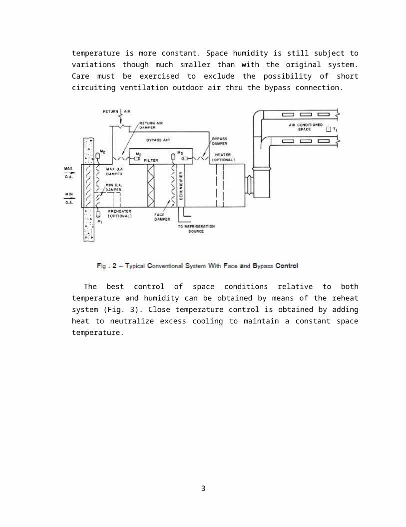
temperature is more constant. Space humidity is still subject tovariations though much smaller than with the original system.Care must be exercised to exclude the possibility of shortcircuiting ventilation outdoor air thru the bypass connection.
The best control of space conditions relative to bothtemperature and humidity can be obtained by means of the reheatsystem (Fig. 3). Close temperature control is obtained by addingheat to neutralize excess cooling to maintain a constant spacetemperature.
3
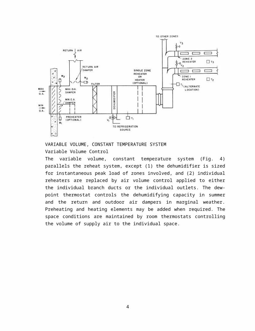
VARIABLE VOLUME, CONSTANT TEMPERATURE SYSTEMVariable Volume ControlThe variable volume, constant temperature system (Fig. 4)parallels the reheat system, except (1) the dehumidifier is sizedfor instantaneous peak load of zones involved, and (2) individualreheaters are replaced by air volume control applied to eitherthe individual branch ducts or the individual outlets. The dew-point thermostat controls the dehumidifying capacity in summerand the return and outdoor air dampers in marginal weather.Preheating and heating elements may be added when required. Thespace conditions are maintained by room thermostats controllingthe volume of supply air to the individual space.
4

2. CONSTANT VOLUME INDUCTION SYSTEMThe all-air Constant Volume Induction System is well suited for manyapplications, particularly medium and small multi-room buildingswhere individual rooms as well as large spaces may be airconditioned from one central air conditioning plant. It is oftenapplied to buildings having a large ratio of floor area to height,indicating a need for horizontal ductwork and piping.
This system is particularly suited to high latent loadapplications such as schools and laboratories, as well as existinghotels in which the design sensible cooling load is low and where aserviceable steam or hot water system is available. Hospitals,motels, apartment houses, professional buildings, and officebuildings are other applications.
An exceptional application of this system is a school in whichheating and ventilation are required at present and conversion tofull air conditioning may be required at a future date. In thisinstance, equipment, air quantities and layout are based on the airconditioning calculations. Future conversion is easily accomplishedby adding a refrigeration machine, cooling coils and piping.
5

2.1 SYSTEM DESCRIPTIONFigure 10 is a schematic diagram of the system.
2.2 CENTRAL STATION APPARATUSThe central station apparatus conditions the air and supplies
either a mixture of outdoor and return air or 100% outdoor air tothe room unit. The apparatus contains filters to clean the air,and a dehumidifier to cool and remove excess moisture from warmhumid air or to add winter dehumidification.
A relatively constant supply air temperature is maintained atthe fan discharge, normally from 50-55 F.
A high or low velocity air distribution system is used to movethe air from the central station to the room units.
A sound absorber (when required) located downstream from thefan discharge is used to reduce the noise generated by the fan.
Chilled water is circulated or refrigerant is evaporated inthe coils of the dehumidifier to remove excess moisture and cool
6

the air. Hot water or steam is supplied to the unit heatingcoils.
2.3 INDUCTION UNITThe induction unit is designed for use either with a complete
air conditioning system or with a system providing heating andventilating only. Figure 11 shows the unit elements which includethe air inlet, sound attenuating plenum, nozzle and heating coil.
A constant volume of cool conditioned air is supplied to theunit. This air, designated as primary air, handles the entireroom requirements for cooling, dehumidification orhumidification, and ventilation. The primary air induces room airwhich is heated by the coil to provide summer tempering (whenneeded) and winter heating.
Room temperature control is achieved by adjusting the flow ofhot water or steam thru the coil by a manual or an automaticcontrol valve.
3. MULTI-ZONE UNIT SYSTEMThe all-air Multi-Zone Blow-Thru Unit System that has heating and
cooling coils in parallel is a constant volume, variable temperature
7

system. It is applied to areas of multiple spaces or zones whichrequire individual temperature control.
This system is considered when one or more of the following conditions exist:a. The area consists of several large or small spaces to be
individually controlled – a school, a suite of offices, an interior zone combining several individual open floors of a multi-story building.
b. The area includes zones with different exposure and differentcharacteristics of internal load – a bank floor of a building, alarge open multi-exposure office space.
c. The area combines a large interior zone with a relatively smallgroup of exterior spaces.
d. The area consists of interior spaces with individual loadcharacteristics – radio and television studios.
Examples of these conditions are shown in Fig. 14.
8

The blow-thru system is essentially applicable to locations andareas heaving high sensible heat loads and limited ventilationrequirements. Applications of high ventilation requirements need adehumidifying coil in the minimum outdoor air with heating availableat the heating coil at all times. This is necessary to prevent thebypass of humid outdoor air around the cooling coil.
3.1 CENTRAL APPARATUSA multi-zone unit system is shown in Fig. 15. This apparatus
may be a factory-assembled unit, or it may be field-assembled.However, a majority of the applications use one or more factory-assembled units, each of which consists of a mixing chamber,filter, fan, a chamber containing heating and cooling coils, warmand cold air plenums, and a set of mixing dampers. The mixing
9
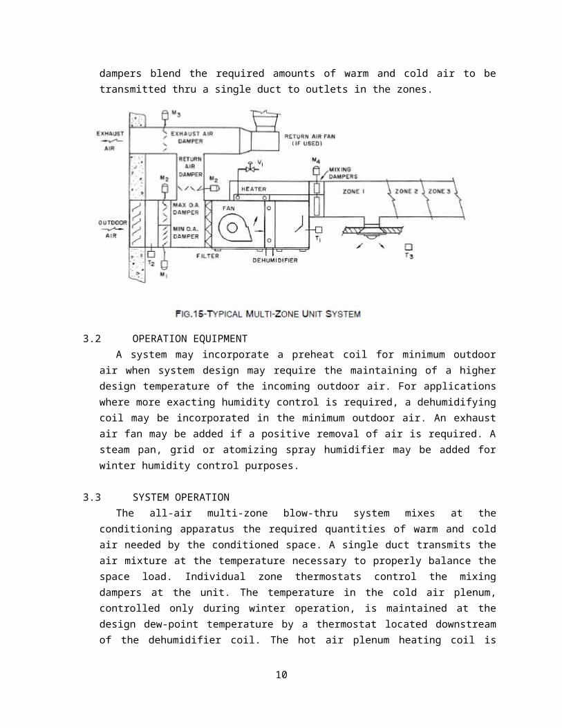
dampers blend the required amounts of warm and cold air to betransmitted thru a single duct to outlets in the zones.
3.2 OPERATION EQUIPMENTA system may incorporate a preheat coil for minimum outdoor
air when system design may require the maintaining of a higherdesign temperature of the incoming outdoor air. For applicationswhere more exacting humidity control is required, a dehumidifyingcoil may be incorporated in the minimum outdoor air. An exhaustair fan may be added if a positive removal of air is required. Asteam pan, grid or atomizing spray humidifier may be added forwinter humidity control purposes.
3.3 SYSTEM OPERATIONThe all-air multi-zone blow-thru system mixes at the
conditioning apparatus the required quantities of warm and coldair needed by the conditioned space. A single duct transmits theair mixture at the temperature necessary to properly balance thespace load. Individual zone thermostats control the mixingdampers at the unit. The temperature in the cold air plenum,controlled only during winter operation, is maintained at thedesign dew-point temperature by a thermostat located downstreamof the dehumidifier coil. The hot air plenum heating coil is
10
activated by a thermostat located outdoors. This thermostat inthe hot air plenum, due to changing outdoor temperature.
4. DUAL-DUCT SYSTEMThe all-air Dual-Duct System is well suited to provide
temperature control for individual spaces or zones. This temperaturecontrol is achieved by supplying a mixing terminal unit with airfrom two ducts with air streams at two different temperature levels;one air stream is cold and the other is warm. The mixing terminalunit proportions the cold and warm air in response to a thermostatlocated in its respective space or zone.
The multi-room building is a natural application for this system.Many systems are installed in office buildings, hotels, apartmenthouses, hospitals, schools and large laboratories. The commoncharacteristic of these multi-room buildings is their highlyvariable sensible heat load; a properly designed dual-duct systemcan adequately offset this type of load.4.1 THREE BASIC ARRANGEMENTS
Figure 20 shows three basic arrangements of a dual-ductsystem, in each of which the two ducts conveying the warm andcold air stream and the air terminal units are of common design.
However, the arrangements of the central station apparatusdiffer, depending on the degree of precision desired in humiditycontrol. In Arrangement 1, during summer partial load conditionsminimum outdoor air may bypass the cooling coil and traveldirectly into the warm duct. Thus, the space or zone relativehumidity may rise above design if heat is not applied to the warmduct. The addition of heat in summer does add to operating costs.
11

12

In Arrangement 2 a pre-cooling coil cools and dehumidifies theminimum outdoor air. Therefore, the problem of bypassingunconditioned outdoor air thru the warm duct is eliminated.Operation of both Arrangement 1 and 2 is similar to the operationof either a single-duct face and bypass system or a multi-zoneunit system, except that in a dual-duct system the bypass warmair and the cold air are mixed at the terminal unit. It should benoted also that in both Arrangements 1 and 2 the dehumidifier andfan are applied in a blow-thru arrangement.
In Arrangement 3 the dehumidifier and the fan are shown for adraw-thru arrangement; the total air quantity is dehumidifiedbefore heat is applied to the warm air stream. Thus, Arrangement3 is similar in operation to a straight reheat system. It is usedprimarily to satisfy exacting humidity requirements.
4.2 CENTRAL STATION APPARATUSAs seen in Fig. 20, there are several variations of the
central station apparatus. Generally, the diagrams show that:
13

a. Whatever the arrangement, the dual-duct system is capable ofutilizing 100% outdoor air for cooling purposes duringintermediate seasons.
b. A combination return-exhaust air fan is used to exhaust excessair to the outdoors and to return air to the central apparatusin balance with maximum outdoor air required.
c. The total supply air is always filtered.d. Minimum ventilation air may be preheated if required.e. The degree of dehumidification is determined by the apparatus
arrangement.f. Sprays are optional, and may be included where shown in
Fig.20.
Standard methods of refrigeration and sources of heating areemployed to provide the cooling and heating required to conditionthe spaces. For ordinary comfort applications, precise control ofhumidity is not essential. However, for economic and comfortreasons during summer operation, the humidity variations shouldbe limited to a range of approximately 45-55% rh. During winteroperation lower relative humidities (10-30% rh) are usuallymaintained to prevent moisture condensation on cold surfaces.
The dual-duct system may be designed by using either a high ormedium velocity air transmission system connecting the centralapparatus and the terminal units. On both the blow-thru and draw-thru arrangements, care should be exercised to design theapparatus-to-main duct transitions for a minimum pressure lossand noise generation. Although the terminal units are soundtreated, it may be necessary to additional sound treatment afterthe fan to reduce the noise generated by the fan.
4.3 DUAL-DUCT TERMINALThe dual-duct terminal unit is designed to:
a. Supply the correct proportions of the cold and warm airstreams thru thermostatically controlled air valves.
b. Mix the two air streams and discharge them at an acceptablesound level.
14

c. Provide a constant volume of discharge air with varying ductstatic pressures.
The individual terminal units are available in arrangementssuitable for either a vertical or horizontal installation, andmay be used with an under-the-window grille, a side wall grille,or a ceiling diffuser. The horizontal units are also availablewith octopus-type adapters to supply several ceiling mounteddiffusers. Some of the large units may be connected to a lowpressure duct system to distribute air thru standard side wallgrilles or ceiling diffusers.
Varying amounts of cold dehumidified air from the cold ductand either neutral (slightly above room temperature) ormoderately heated air from the warm duct are supplied to theterminal units to satisfy the demands of the space or zonethermostat. The cold air supply at 100% volume is designed tooffset the sensible and latent heat loads and the ventilationrequirements of the space. The warm air is supplied to keep thespace or zone thermostat reduces the cold air flow.
There are two commonly used methods of operating the warm airportion of the system. The warm air temperature may be maintainedslightly above that of the space or zone; it may also becontrolled by a return air hygrostat which raises the temperatureas the relative humidity increases. As the warm air temperatureis raised, the space or zone thermostat calls for less warm airand more dehumidified air, thus reducing the rising relativehumidity. Another method is to maintain the warm air temperatureat a higher level constantly.
In winter the warm air duct may supply all the heatingrequirements of the space or zone served. If the building has, oris designed to have, peripheral heating, the warm air temperatureis maintained close to the room temperature.
The dual-duct terminal units are equipped with dampers(valves), damper actuators, and volume compensators to provideconstant volume, regardless of varying pressure within the coldand warm air supply ducts. The terminal unit warm air damper isnormally open. Space temperature is controlled by a thermostat
15

operating the cold warm air damper actuators to effect a propermixture of the two streams to satisfy the load.
5. VARIABLE VOLUME, CONSTANT TEMPERATURE SYSTEMThe all-air Variable Volume, Constant Temperature System is well
suited for many applications. Among these are applications for whicha relatively constant cooling load exists year round, i.e. interiorzones of an office building and department stores.
Other applications for which this system should be considered arethose with variable loads having a serviceable steam or hot waterheating system and for which only summer cooling is desired.Examples are existing buildings such as office buildings, hotels,hospitals, apartments and schools.
5.1 SYSTEM DESCRIPTIONThere are many variations that can be applied to this system.
The following is a description for a system that may be appliedto interior zones where the load is fairly constant.
The room outlet delivers completely filtered, humiditycontrolled air during all seasons. Individual space temperaturecontrol is accomplished by modulating the air quantity to matchthe required space load.
The air handling apparatus conditions the air and supplieseither a mixture of outdoor and return air or 100% outdoor air tothe terminal unit. The apparatus contains filters to clean theair, pre-heaters (if required) to temper cold winter air, and adehumidifier to remove excess moisture and cool the supply air.For a typical variable volume, constant temperature system, seeFig. 24.
A constant leaving temperature is maintained in the fandischarge during intermediate and winter seasons when therefrigeration machine is not operating.
A high or low velocity air distribution system is used to movethe air from the apparatus to the room terminal units. Whenrequired, a sound absorber is used to reduce the noise generatedby the fan.
16

The dehumidifier may be supplied by either a direct expansionor chilled water refrigeration system.
6. DUAL CONDUIT SYSTEMThe all-air Dual Conduit System is a modern central station
system that can be applied to multi-zone buildings such as schools,offices, apartments and hospitals, for areas that have a reversingtransmission load and require individual room temperature control.It can be adapted easily to areas that have variable cooling andheating requirements caused by sun, outdoor temperature and internalloads. Generally, its application is similar to the dual-ductsystem, but with a more economical first cost.
6.1 SYSTEM DESCRIPTIONThe system is designed to supply two air streams to exposures
that have a reversing transmission load. One air stream calledthe secondary air is cool the year round, and is constant intemperature and variable in volume to match the capacity requiredfor the changing cooling load caused by sun, lights and people.
17

Therefore, the secondary air is a constant temperature, variablevolume air stream.
The other air stream called the primary air is constant involume, and the air temperature is varied to offset transmissioneffects; it is warm in winter and cool in summer. The primary airis, therefore, a constant volume, variable temperature airstream.
Various central station arrangements can be used to providethe air temperatures and volumes required for practicaltemperature control.
A dual fan, dual apparatus system is described here andillustrated in Fig. 26.
18

19

The primary air apparatus conditions the air and supplies amixture of outdoor and return air to the room terminals. Theapparatus contains filters to clean the air, preheat coils (asrequired) to temper cold winter air, a humidifier (if desired) toadd winter humidification, and a dehumidifier to remove excessmoisture and cool the supply air. The primary air stream containsa reheat coil controlled by a master-submaster thermostatarrangement, the function of which is to adjust the airtemperature to match the building transmission affects. Outdoorair is admitted to the apparatus thru a rain louver and screen.
The secondary air apparatus conditions the air and suppliesall return air, a mixture of outdoor and return air, or alloutdoor air, depending on the season. The apparatus containsfilters to clean the air and a dehumidifier to remove excessmoisture and cool the supply air. A thermostat located in the fandischarge modulates the outdoor and return air dampers tomaintain a constant leaving temperature during seasons of non-operation.
Air from both the primary and secondary apparatus is deliveredto the room terminal units thru ductwork. Normal practicerequires the use of a high velocity air distribution system forthe primary air and either high or medium velocities for thesecondary air.
A refrigeration and heating plant is necessary to complete thesystem.
- End -
20

21
Copyright © 2022 FDOKUMEN