761-590 - SENECA II SERVICE MANUAL - PA-34-200T - IIS ...
675
SENECA II SERVICE MANUAL CARD 1 OF 3 PA-34-200T SENECA II PIPER AIRCRAFT CORPORATION (PART NUMBER 761 590) 1A1 Island Enterprises
-
Upload
khangminh22 -
Category
Documents
-
view
0 -
download
0
Transcript of 761-590 - SENECA II SERVICE MANUAL - PA-34-200T - IIS ...

SENECA II
SERVICE MANUALCARD 1 OF 3
PA-34-200T SENECA II
PIPER AIRCRAFT CORPORATION
(PART NUMBER 761 590)1A1
Island Enterprises

PIPER SENECA II SERVICE MANUAL
AEROFICHE EXPLANATION AND REVISION STATUS
Service manual information incorporated in this set of Aerofiche cards is arranged in accordance with thegeneral specifications of Aerofiche adopted by the General Aviation Manufacturer's Association. Informationcompiled in this Aerofiche service manual is kept current by revisions distributed periodically. These revisionssupersede all previous revisions, are complete Aerofiche card replacements, and supersede Aerofiche cards ofthe same number in the set.
Identification of revised material:Revised text and illustrations are indicated by a black vertical line along the left-hand margin of the frame,
opposite revised or added material. Revision lines indicate only current revisions with changes and additions toexisting text and illustrations. Changes in capitalization, spelling, punctuation, indexing, physical location ofthe material, or complete page additions are not identified by revision lines.
Interim Revisions*If there is more than one interim revision on a page, the most recent will have the letters IR next to the
revision line. Any other revision lines may reflect a previous permanent revision or previous interim revision.Check the Revision Status page for revision history.
Revisions to Service Manual 761 590 issued October 11, 1979 are as follows:
Effectivity Publication Date Aerofiche Card Effectivity
ORG791011 October 11, 1979 1, 2 and 3PR800810 August 10, 1980 1, 2 and 3PR810316 March 16, 1981 1, 2 and 3PR821112 November 12, 1982 1, 2 and 3PR831208 December 8, 1983 1, 2 and 3IR860730 July 30, 1986 1IR860920 September20, 1986 1IR870506 June 12, 1987 1IR960624 June 24, 1996 1IR970205* February 5, 1997 1
This publication contains material revised as of December 8,1983 (with five interim revisions effective July 30, 1986,September 20, 1986, May 6, 1987, June 24, 1996, andFebruary 5, 1997).
* INTERIM CHANGERevisions appear in Sections III, V, and VII of card 1.There are no other changes in this service manual.Please discard your current card 1 and replace itwith this revised one. DO NOT DISCARD CARDS 2or 3.
1A2
Island Enterprises

TABLE OF CONTENTS
AEROFICHE CARD NO. 1 GRID NO.
I
IIIVVVIVII
INTRODUCTION ................................... 1A13HANDLING AND SERVICING ...................... 1A16INSPECTION ....................................... 1 C23STRUCTURES ...................................... 1 D12SURFACE CONTROLS ............................. 1 F21HYDRAULIC SYSTEM .............................. 113LANDING GEAR AND BRAKE SYSTEM ............ 1J5
AEROFICHE CARD NO. 2
VIIIIXXXIXIIXIII
POWERPLANT ...............................FUEL SYSTEM ...............................INSTRUMENTS ..............................ELECTRICAL SYSTEM .......................ELECTRONICS ...............................HEATING AND VENTILATING SYSTEM ......
AEROFICHE CARD NO. 3
..... . 2A9.2D4.2E8
2F162120
. 2J6
.3A6XIV ACCESSORIES AND UTILITIES ...................
1A3
Island Enterprises

1A4INTENTIONALLY LEFT BLANK
Island Enterprises

PIPER SENECA II SERVICE MANUAL
LIST OF ILLUSTRATIONS
Figure AeroficheGrid No.
2-1. Three View ............................................................... IA192-2. Station References .......................................................... IA202-2A. Torque Wrench Formula ................................................... IB 12-3. Access Plates and Panels .................................................... 1B52-4. Jacking ................................................................... B72-5. Weighing ................................................................. 1 B82-6. Leveling Airplane .......................................................... 1 B92-7. Turning Distance .......................................................... IB142-8. Service Points ............................................................. B 162-9. Lubrication Chart (Landing Gear, Main) ..................................... IC22-10. Lubrication Chart (Landing Gear, Nose) ....................................... IC32-11. Lubrication Chart (Control System) .......................................... IC42-12. Lubrication Chart (Control System) (cont.) ................................... 1C52-13. Lubrication Chart (Power Plant and Propeller) ................................ IC62-14. Lubrication Chart (Cabin Door, Baggage Doors and Seats) ..................... 1C74-1. Cherrylock Rivet Removal ..... .......................................... ID154-1a. Hose/Line Markings ....................................................... ID164-1b. Flareless Tube Fittings ..................................................... I D 184-1c. Aileron and Flap Installation ................................................ ID224-2. Wing Installation .......................................................... 1E4-3. Empennage Group .................................... ... .................. IE74-4. Method of Securing Control Cables .......................................... I E114-5. Windshield Installation ..................................................... E 134-6. Side Window Installation (Typical) .......................................... I E 144-7. Rear Door Window Replacement ............................................ IE164-7a. Snubber Installation ....................................................... IE 184-8. Seat Back Lock ........................................................... IE234-9. Skin Materials and Thickness ............................................... IF34-10. Surfaces Scratches, Abrasions or Ground-in-Dirt .............................. IF84-11. Deep Scratches, Shallow Nicks and Small Holes ............................... IF84-12. Mixing of Epoxy Patching Compound ....................................... 1F94-13. Welding Repair Method .................................................... 1F94-14. Repairing of Cracks ..................................................... . IF104-15. Various Repairs ........................................................... IF114-16. Repair of Stress Lines ...................................................... 1F124-17. Repair of Impacted Damage ................................................ IF124-18. Control Surface Balance Tool ................... ............................ 1F164-19. Aileron and Rudder Balance Configuration ................................... IF184-20. Stabilator Balance Configurations ........................................... IF195-1. Control Column Assembly .................................................. IG15-1a. Correct Method of Installing Rod End Bearing ................................ IG45-2. Aileron Controls .......................................................... IG5
Revised: 3/16/811A5
Island Enterprises

PIPER SENECA II SERVICE MANUAL
LIST OF ILLUSTRATIONS (cont.)
Figure AeroficheGrid No.
5-3. Bellcrank Rigging Tool ..................................................... 1G95-4. Aileron Rigging Tool ...................................................... IG105-5. Stabilator and Stabilator Trim Controls ...................................... 1G 135-6. Stabilator Rigging Tool .................................................... IG165-7. Methods of Securing Trim Cables ........................................... IG165-8. Rudder and Brake Pedal Assembly ......................... ................. 1G225-9. Rudder and Rudder Trim Controls .......................................... H I5-10. Rudder Rigging Tool ...................................................... 1H35-11. Clamping Rudder Pedals ................................................... 1H35-12. Rudder and Stabilator Travel Adjustment .................................... I H45-13. Flap Controls ............................................................. 1H95-14. Flap Step Adjustment .............. ........................................ 1 H II5-15. Flap Rigging Tool ......................................................... 1HI15-16. Fabricated Aileron Bellcrank Rigging Tool ........................... ....... 1 H 135-17. Fabricated Aileron and Flap Rigging Tool .................................... 1H 145-18. Fabricated Stabilator Rigging Tool .......................................... H 155-19. Fabricated Rudder Rigging Tool ............................................ H 166-1. Schematic Diagram of Hydraulic System ..................... ................ 1176-2. Hydraulic System Installation ............................................... 1186-3. Hydraulic Pump/Reservoir, Exploded View ................................... 11116-4. Test and Adjustments of Hydraulic Pump .................................... 11146-5. Pump Mounting ....................................................... .... 11156-6. Free-Fall Valve Assembly ................................................... 11156-7. Gear Actuating Cylinder .................................................... 11166-7a. Installation of T-Rings .................................................... . . 11176-8. End Gland Locking Device ................................................. 11186-9. Nose Gear Actuating Cylinder Installation .................................... 11207-1. Nose Gear Oleo Strut Assembly .................... ......................... 1J97-1a. Nose Gear Service Tolerances ............................................... 1J 17-2. Nose Gear Installation ..................................................... IJ167-3. Clamping Rudder Pedals in Neutral Position .................................. 1 K27-4. Rudder Pedals at Neutral Angle ............................................. 1K27-5. Main Gear Oleo Strut Assembly ............................................. 1K47-5a. Main Gear Service Tolerances ............................................... 1K67-6. Main Gear Installation ..................................................... 1K107-7. Aligning Main Gear ........................................................ 1 K167-8. Toe-In/Toe-Out Adjustment ................................................ IK177-9. Adjust Nose Gear Down Limit Switch ........................................ 1K197-10. Adjust Main Gear Down Limit Switch ....................................... 1K197-11. Throttle Warning Switch ................................................... I K207-12. Nose Wheel Assembly ...................................................... 1L17-13. Main Wheel Assembly ..................................................... 1L37-14. Wheel Brake Assembly ..................................................... 1L4
Revised: 12/08/83
1A6Island Enterprises

PIPER SENECA II SERVICE MANUAL
LIST OF ILLUSTRATIONS (cont.)
Figure AeroficheGrid No.
7-15. Removal and Installation of Anchor Bolts .................................... IL57-16. Brake Master Cylinder (Hand, Parking Brake) ................................ 1L77-17. Brake System Installation ..................... .............................. L87-18. Brake Cylinder (17000) (Toe Brake) .......................................... 1L97-19. Brake Cylinder (10-27) (Toe Brake) .......................................... 1L97-20. Brake Cylinder (10-30) (Toe Brake) .......................................... IL107-21. Brake Reservoir ........................................................... IL147-22. Bleeding Brake ........................................................... 1L148-1. Engine Cowling Installation ..................... ............................ 2A148-2. Cowl Flap Installation ........................................ 2A148-3. Propeller Installation ....................................................... 2A 168-4. Typical Nicks and Removal Method ......................................... 2A178-5. Propeller Governor ........................................................ 2A208-6. Engine Installation ......................................................... 2A238-7. Schematic Diagram of Turbocharger System .................................. 2B58-8. Induction System Installation ............................................... 2B68-8a. Magneto Assembly ........................................ 2B98-9. Contact Spring Inspection ..................... ............................. 2B118-10. Contact Points ......................................................... ... 2B128-11. Impulse Coupling .......................................................... 2B128-12. Flyweight Clearance of Impulse Coupling ..................................... 2B138-13. Rotor Holding Tool Installed ............................................... 2B148-14. Timing Kit Installed ........................................ 2B148-15. Cast-In Timing Marks ...................................................... 2B158-16. Fabricated Pointer ......................................................... 2B 158-17. Engine Timing Marks ...................................................... 2B178-18. Removing Spring From Lead Assembly ...................................... 2B 198-19. Assembly Tool ........................................ 2B208-20. Assembly Tool Application ..................... ............................ 2B208-21. Measuring Lead Assembly Length ........................................... 2B208-22. Ferrule Seating Tool ....................................................... 2B228-23. Measuring Wire From Top of Ferrule ........... ............................. 2B228-24. Needle ...... ....................................... 2B228-25. Installing Grommet Over Lead Assemblies .................................... 2B228-26. Lead Assembly Installed in Grommet ........................................ 2B238-27. Wire Doubled Over For Installation of Eyelet ................................. 2B238-28. Ignition Schematic ......................................................... 2B248-29. Removing Frozen Spark Plug ........................................ 2C38-30. Lubrication System Maintenance Points ...................................... 2C68-31. Schematic Diagram of Fuel Injection System .................................. 2C88-32. Fuel Injector Nozzle Assembly .............................................. 2C98-33. Engine Controls ........................................................... 2C108-34. Idle Speed and Mixture Adjustment Points ................................... 2C 128-35. Sectional View of Altitude Compensating Fuel Pump Assembly ................. 2C168-36. Exhaust Bypass Valve Screw ................................................ 2C18
Revised: 3/16/81 11A7
Island Enterprises

PIPER SENECA II SERVICE MANUAL
LIST OF ILLUSTRATIONS (cont.)
Figure AeroficheGrid No.
9-1. Fuel System Schematic ..................................................... 2D79-2. Fuel Cell Installation ....................................................... 2D129-3. Fuel Gauges ............................................................... 2D209-4. Fuel Filter ........................................................... ..... 2D209-5. Fuel Selector Valve ........................................................ 2D239-6. Slider Resistor Terminal .................................................... 2EI9-6a. Resistor Set-Up/Test for Fuel Quantity Gauge ................................ 2E39-6b. Maximum Deviation of Fuel Quantity Gauge Needle ........................... 2E410-1. Gyro Pressure System ...................................................... 2E1410-2. Pitot-Static System, Serial Nos. 34-7570001 to 34-7670136 incl .................. 2E1610-2a. Pitot-Static System, Serial Nos. 34-7670137 and up ............................ 2E1710-3. Instrument Panel ................................................... ....... 2E1811-1. Switch Panel - For Models Without Primer System ............................ 2F2111-la. Switch Panel - For Models With Primer System ............................... 2F2211-2. Removal of Slip Ring End Bearing .......................................... 2G 111-3. Removal of Rectifer . .................... .................................. 2G I11-4. Testing Rotor for Ground .................................................. 2G411-5. Testing Rotor for Shorts ................................................... 2G411-6. Installation of Rectifier ..................................................... 2G511-7. Terminal Assembly ........................................................ 2G611-8. Slip Ring End Bearing Assembly ........................................... 2G711-9. Testing Alternator ........................................................ . 2G711-10. Regulator Diagram .................................................. ...... 2G 1011-11. Testing Regulator .......................................................... 2G1211-12. Adjusting Regulator ....................................................... 2G 1311-13. Application of Overvoltage Control .......................................... 2G1511-14. Testing Overvoltage Control ................................................ 2G1511-15. Exploded View of Starting Motor ........................................... 2G1711-16. Turning Motor Commutator ...................................... ...... .. 2G1811-17. Testing Motor Armature for Shorts .......................................... 2G1811-18. Testing Motor Fields for Grounds ........................................... 2G1911-19. No-Load Test Hookup ............................................ ........ 2G1911-20. Stall Torque Hookup ...................................................... 2G2011-21. Landing Light Adjustment .................................................. 2H111-22. Adjusting Lift Detector Micro Switch ........................................ 2H2
NOTE
Electrical Schematics for Section XI. see 2F18
12-1. Two Year, Magnesium Battery Connections ................................... 212212-2. Garrett ELT Schematic ................................. .................. 212312-3. Communications Components ELT Schematic ................................. 2J 112-4. Emergency Locator Transmitter Schematic (Narco) ............................ 2J I
Revised: 11/12/82lA8
Island Enterprises
PIPER SENECA II SERVICE MANUAL
LIST OF ILLUSTRATIONS (cont.)
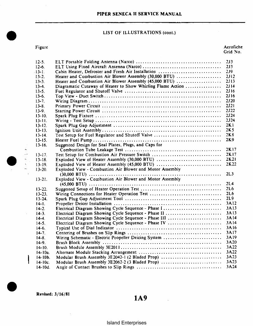
Figure
12-5. ELT Portable Folding Antenna (Narco) ......................................12-6. ELT Using Fixed Aircraft Antenna (Narco) ...................................13-1. Cabin Heater, Defroster and Fresh Air Installation ............................13-2. Heater and Combustion Air Blower Assembly (30,000 BTU) ....................13-3. Heater and Combustion Air Blower Assembly (45,000 BTU) ....................13-4. Diagramatic Cutaway of Heater to Show Whirling Flame Action ................13-5. Fuel Regulator and Shutoff Valve ...........................................13-6. Top View - Duct Switch ....................................................13-7. Wiring Diagram...........................................................13-8. Primary Power Circuit .....................................................13-9. Starting Power Circuit .....................................................13-10. Spark Plug Fixture ........................................................13-11. Wiring - Test Setup ........................................................13-12. Spark Plug Gap Adjustment ................................................13-13. Ignition Unit Assembly .....................................................13-14. Test Setup for Fuel Regulator and Shutoff Valve ..............................13-15. Heater Fuel Pump .........................................................13-16. Suggested Design for Seal Plates, Plugs, and Caps for
Combustion Tube Leakage Test ...........................................13-17. Test Setup for Combustion Air Pressure Switch ...............................13-18. Exploded View of Heater Assembly (30,000 BTU) .............................13-19. Exploded View of Heater Assembly (45,000 BTU) .............................13-20. Exploded View - Combustion Air Blower and Motor Assembly
(30,000 BTU) ...........................................................13-21. Exploded View - Combustion Air Blower and Motor Assembly
(45,000 BTU) ...........................................................13-22. Suggested Setup of Heater Operation Test ....................................13-23. Wiring Connections for Heater Operation Test ................................13-24. Spark Plug Gap Adjustment Tool ..........................................14-1. Propeller Deicer Installation ................................................14-2. Electrical Diagram Showing Cycle Sequence - Phase 1..........................14-3. Electrical Diagram Showing Cycle Sequence - Phase II .........................14-4. Electrical Diagram Showing Cycle Sequence - Phase III ........................14-5. Electrical Diagram Showing Cycle Sequence - Phase IV ........................14-6. Typical Use of Dial Indicator ...............................................14-7. Centering of Brushes on Slip Rings ..........................................14-8. Wiring Schematic - Electric Propeller Deicing System ..........................14-9. Brush Block Assembly .....................................................14-10. Brush Module Assembly 3E2011 .............................................14-1Oa. Alternate Module Stacking Arrangement .....................................14-1Ob. Modular Brush Assembly 3E2042-1 (2 Bladed Prop) ...........................14-10c. Modular Brush Assembly 3E2062-2 (3 Bladed Prop) ...........................14-10d. Angle of Contact Brushes to Slip Rings ......................................
AeroficheGrid No.
2J32J32J92J122J132J142J162J162J202J212J222J242J242KI2K52K82K9
2K172K172K212K22
2L3
2L42L62L62L93A123A133A133A143A143A163A173A193A203A223A223A233A233A24
Revised: 3/16/811A9
Island Enterprises

Figure
PIPER SENECA II SERVICE MANUAL
LIST OF ILLUSTRATIONS (cont.)
AeroficheGrid No.
14-11.14-12.14-13.14-14.14-15.14-15a.14-16.14-17.14-18.14-19.14-20.14-20a.14-21.14-22.14-23.14-24.14-25.14-26.14-27.14-28.14-29.14-30.14-31.14-32.14-33.14-34.14-35.14-36.14-37.14-37a.14-38.14-39.
Propeller Deicer Installation ................................................Installation of Deicer Boot..................................................Wrinkled Deicers ..........................................................Sealer Application (Boot) ..................................................Pneumatic Diecer System Installation (S/N's to 34-8070144) ....................Pneumatic Deicer System Installation (S/N 34-8070144 and up) .................Pneumatic Deicer Boots Operation ...........................................Pneumatic Deicer System Schematic .........................................Ice Detection Light Schematic ...............................................Portable Oxygen Installation ................................................Fixed Oxygen System Installation (Optional) ..................................Oxygen Tubing Installations ................................................Oxygen System Filler Valve Installation ......................................Oxygen Cylinder and Regulator Assembly ....................................Oxygen Pressure Gauge Installation ..........................................Air Conditioning System Installation .........................................Test Gauge and Manifold Set ...............................................Manifold Set Operation ....................................................Leak Test Hookup.........................................................Evacuation Hookup........................................................Charging Stand ...........................................................Charging Hookup .........................................................Top Dead Center Casting Mark (Sankyo Compressor) .........................Rotation of Clutch Front Plate (Sankyo Compressor) ..........................Condenser Air Scoop Installation ............................................Expansion Valve ..........................................................Components Installation ....................................................Air Conditioning Wiring Schematic (Early Models) ............................Synchrophaser Wiring Schematic Auto Synch/Manual Switch ...................Synchrophaser Wiring Schematic (Phase Adjustment Switch)....................Engine Synchrophaser Installation ...........................................Pulse Generator Installation .................................................
3B13B33B63B73B153B163B183B183C93C153C163C173C.183C183C203C243D53D63D73D93D 113D123D153D153D193D203D223E13E113E123E133E15
Revised:3/16/811A10
Island Enterprises

PIPER SENECA II SERVICE MANUAL
LIST OF TABLES
Table AeroficheGrid No.
11-1.11-11.II-11A.II-IIB.II-III.
II-IV.III-1.IV-I.IV-II.IV-III.IV-IV.V-II.V-II.V-Ill.V-III.
VI-l.
VII-I.
VI I-111.VII-l.VIII-ll.
VII-IV.VIII-III.
VIII-IV.
VIII-VII.IX-I.IX-II.IX-ll.IX-IV.X-I .X-II.X-lll.X-IV.X-V.
Leading Particulars and Principal Dimensions ..............................Recommended Torque Values ............................................Flare Fitting Torque Chart ...............................................Thread Lubricants .......................................................Conversion Tables ......................................................Chart A. Inches to Millimeter ............................................Chart B. Fraction; Decimal Conversions ...................................Chart C. Centigrade Fahrenheit Conversion Table ..........................Chart D. English Vs. Metric ..............................................Chart E. Decimal Millimeter Equivalents of Drill Sizes
from 1 2" to No. 80 ...................................................List of Consumable Materials .............................................Inspection Report .......................................................Maximum Distances Between Fluid Tubing Supports ........................Maximum Resistance Values Allowed for Electrical Bonding..................List of Materials (Thermoplastic Repair) ......... ..........................Balance Specifications ................................................Control Surface Travels and Cable Tensions ................................Cable Tension Vs. Ambient Temperature ...................................Troubleshooting Chart (Surface Controls) ..................................Leading Particulars. Hydraulic Pump ......................................Characteristics. Hydraulic Pump MotorTroubleshooting Chart (Hydraulic System) .................................Nose Gear Service Tolerances .............................................Main Gear Service Tolerances .............................................Toe-In - Toe-Out Correction Chart .......................................Troubleshooting Chart (Landing Gear) .....................................Propeller Specifications ..................................................Propeller Chamber Pressure Requirements ..................................Engine Data ............................................................Fuel Flow Vs. Engine Speed ..............................................Metered Fuel Assembly Calibration ........................................Limits - Fuel Flow Vs. Brake H.P........................................Troubleshooting Chart (Engine)...........................................Fuel Quantity Sender Gauge Tolerances ....................................Fuel Gauge Reading Tolerances ...........................................Gauge Readings' Resistance With Fuel in Tanks .............................Troubleshooting Chart (Fuel System) ......................................Gvro Pressure System ....................................................Directional Gyro Indicator ...............................................Gvro Horizon Indicator .................................................Rate of Climb Indicator ......... .......................................Altimeter ..............................................................
IA21IB21B41B41C81C91CII1C121C13
1C141C151D21D191D191F71F171F231F241H17111211121122IJ121K7IK151L152A182A182A212C172C182C192C202D202E42E52E62E122E202E212E222E23
Revised: 3/16/811All
Island Enterprises

PIPER SENECA II SERVICE MANUAL
LIST OF TABLES (cont.)
Table AeroficheGrid No.
X-VI.X-VII.X-VIII.X-IX.X-X.X-XI.X-XII.X-XIII.X-XIV.X-XV.X-XVI.X-XVII.
XI-I.XI-1.
XI-III.XI-IV.XI-V.XI-VI.XI-VII.XI-VIII.XI-IX.
XIII-I.XIII-IIXIV-I.XIV-II.XIV-III.XIV-IV.XIV-V.XIV-VI.XIV-VII.XIV-VIII.XIV-IX.XIV-X.XIV-XI.XIV-XII.XIV-XIII.
Airspeed Tubes and Indicator .............................................Magnetic Compass ......................................................Manifold Pressure Indicator ..............................................Tachometer .............................................................Engine Oil Pressure Gauge ...............................................Turn and Bank Indicator .................................................Fuel Quantity Indicators .................................................Oil Temperature Indicators ...............................................Exhaust Gas Temperature Gauge ..........................................Cylinder Head Temperature Gauge ........................................Fuel Flow Gauge .......................................................Instrument Markings ....................................................Index to Electrical Schematics ............................................Alternator Specifications .................................................Starting Motor Specifications .............................................Hydrometer Reading and Battery Charge Percent ............................Troubleshooting Chart (Electrical System) ..................................Lamp Replacement Guide................................................Electrical Wire Coding ...................................................Electrical Symbols .......................................................Electrical System Component Loads .......................................Inspection ........ 'Inspection ......... ................................................................Troubleshooting Chart (Janitrol Heater) ......... ..........................Required Materials for Repair of Propeller Deicer ...........................Mixing of Materials .....................................................Electrical Resistance .....................................................Troubleshooting Chart (Propeller Deicer System) ............................Operating Pressures......................................................Materials and Supplies for Cold Repair ......... ...........................Troubleshooting Chart (Pneumatic Deicer System) ...........................Oxygen System Components Limits........................................Troubleshooting Chart (Oxygen System) ...................................Temperature Pressure Chart ..............................................Aluminum Tubing Torque ................................................Blower System Wire Color Codes .........................................Troubleshooting Chart (Air Conditioner) ...................................
2FI2F22F52F62F72F82F92F102F132F142F142F152F182G82G212G232H82H202H212H222H232K52L103B33B53B73B93B213B243C73C133C213D13D43D243E2
I Revised: 8/10/801A12
Island Enterprises

SECTION I
INTRODUCTION
ParagraphAeroficheGrid No.
1-1. General1-2. Scope of1-3. Descripti¢1-4. Wing ..1-5. Empenna1-6. Fuselage1-7. Landing Gear1-8. Brake System1-9. Engines a1-10. Fuel Syst1-11. Flight Co1-12. Radio1-13. Cabin Heater, Defroster and fresh air sustem1-14. Instrument and Autopilot System
............................................... . ....I1A14Manual ................... ....................... 1A14
................. .................. .......... 1A14. .. . . . . . . . . . . . . . . . . . . . . . . . . . . . . . . . . . . . . . . . . . . . . IA 141A14ge ............................................. IA14
1A14Gear ............................................ 1A14system ............................................ 1A14item ............................................ 1A14nd Propeller ....................................... 1A15em ............................................ IA15ntrols ...................................... ..... 1A15. . . . . . . . . . . . . . . . . . . . . . . . . . . . . . . . . . . . . . . . . . . . . . . 1A 15ater, Defroster and Fresh Air System ......................... 1A15
and Autopilot System ................................ 1A15
Reissued: 10/11/79
1A13
Island Enterprises
PIPER SENECA I SERVICE MANUAL
SECTION I
INTRODUCTION
1-1. GENERAL. This manual contains service and maintenance instructions for the Piper PA-34-200TSeneca II, designed and manufactured as a versatile airplane in the personal and business aviation field, bythe Piper Aircraft Corporation, Vero Beach, Florida.
1-2. SCOPE OF MANUAL. Sections II and III comprise the service part of this manual; whereas, SectionsIV through XIV comprise the maintenance instructions. The service instructions include ground handling,servicing and inspection. The maintenance instructions for each system include troubleshooting, removaland installation of components, and corrective maintenance and testing; each major system of the airplaneis covered in a separate section. Only qualified personnel should perform the operations described in thismanual.
The description of the airplane included in this section is limited to general information. Section IIgives leading particulars and principal dimensions, along with ground handling, while each major system isdescribed in its appropriate section of the manual For a more detailed description of the airplane, refer tothe Owner's Handbook.
1-3. DESCRIPTION. The Seneca II is a six place (seventh seat optional), twin engine, low-wing monoplaneof all metal construction. The following paragraphs provide descriptions of the major components andsystems.
1-4. WING. The laminar flow wing is of all metal stressed-skin, full cantilever, low-wing design, consistingof two wing panels bolted to a spar box assembly in the fuselage. The wing tips are removable. The aileronsare cable and push rod controlled and are aero dynamically balanced. The trailing edge wing flaps aremanually operated.
1-5. EMPENNAGE. The empennage consists of the fin, rudder, rudder trim tab, stabilator and stabilatortrim tabs. The rudder and stabilator are statically balanced.
1-6. FUSELAGE. The fuselage consists of three basic units: the nose section, the cabin section and thesheet-metal tail cone.
1-7. LANDING GEAR. The tricycle landing gear is of the retractable air-oil strut type, consisting of a nosewheel and two main wheels.
1-8. BRAKE SYSTEM. The standard brake system is operated hydraulically by dual toe brakes located onthe rudder pedals or by a hand lever connected to a single brake cylinder below and behind the left centerof the instrument panel.
Reissued: 10/11/79 A14 INTRODUCTION
A14
Island Enterprises

PIPER SENECA I SERVICE MANUAL
1-9. ENGINES AND PROPELLER. The airplane is powered by two Teledyne Continental six cylinder,direct drive, wet sump, horizontally opposed turbocharged engines. The left engine rotation is in theright-hand direction while the right engine rotates in the left-hand direction. The propellers are Hartzell fullfeathering, constant speed units controlled by a governor mounted on each engine.
1-10. FUEL SYSTEM. The fuel system consists of two interconnected aluminum fuel tanks in each wing,having a combined capacity of 49 U.S. gallons, for a total capacity of 98 U.S. gallons. With optional fueltanks, each wing will have a combined capacity of 64 U.S. gallons, for a total capacity of 128 U.S. gallons.Incorporated in the system are selector valves, gascolators, and electric priming fuel pumps and enginedriven pumps.
1-1 1. FLIGHT CONTROLS. The flight controls are conventional equipment, consisting of a control wheelwhich operates the ailerons and stabilator, and pedals which operate the rudder. Duplicate controls areprovided for the copilot. Trim controls are provided for the rudder and stabilator.
1-12. RADIO. Provisions are provided for the installations of microphone and headset jacks, loudspeaker,and panel space for radios and various avionic equipment.
1-13. CABIN HEATER, DEFROSTER AND FRESH AIR SYSTEM. Heated air for the cabin and defrosteris obtained from the combustion heater located in the tail cone. Fresh air is supplied to the heater from anintake located in the dorsal fin. The combustion heater has a blower which is used to circulate heated orunheated air through six adjustable outlets. There is a defroster blower, in the same distribution system toprovide additional defrost capability when required. There are six overhead fresh air vents supplied by aseparate inlet in the dorsal fin. This system can be supplemented by an optional blower.
1-14. INSTRUMENT AND AUTOPILOT SYSTEM. Provisions for instrument installation include panelsfor engine instruments and advanced instruments, as well as for an Autopilot system.
Reissued: 10/11/79 INTRODUCTION
1A15Island Enterprises

SECTION II
HANDLING AND SERVICING
AeroficheParagraph Grid No.
2-1. Introduction ........................................... . 1A182-2. Dimensions ...................................... ....... 1A182-3. Station Reference Lines ...................................... A182-4. Weight and Balance Data ..................................... A182-5. Serial Number Plate ...................................... .. 1A182-6. Access and Inspection Provisions ................................ 1A182-7. Tools and Test Equipment .................................... IA182-8. Torque Requirements ...................................... . IA242-8a. Torque Wrenches ................. .................................... . IB2-9. Step, Handhold and Walkways .................................. -1B72-10. Ground Handling ...................................... ... 1B7
2-11. Introduction to Ground Handling ............... ......... . 1B72-12. Jacking ...................................... ... B72-13. Weighing .......................................... . B82-14. Leveling ................... ................... .. . 1B82-15. Mooring ...................................... .. . 1B92-16. Locking Airplane .................................. . 1B92-17. Parking .. .... .................................. IBIO2-18. Towing ................................... ... ... IBIO2-19. Taxiing ...................................... .. . IBIO
2-20. External Power Receptacle .................................... IB I2-21. Operation of External Power Receptacle ...................... IBII
2-22. Servicing ................. .................... ........ IBII2-23. Introduction to Servicing ................... ............ B IB I
2-24. Fuel System .................... ........................ IBII2-25. Servicing Fuel System ................................. IBII2-26. Filling Fuel Tanks ................................... 1B112-27. Handling of Moisture in Fuel System ................................... B122-28. Draining Fuel System ................................. 1B12
2-29. Brake System ........................................... . 1B132-30. Servicing Brake System ................................ 1B132-31. Filling Brake Cylinder Reservoir ........................... B132-32. Draining Brake System ................................ B13
2-33. Oleo Struts ............................................. 11B132-34. Servicing Oleo Struts ................................. IB132-35. Filling Nose Gear Oleo Strut ............................. IB152-36. Filling Main Gear Oleo Struts ............................ B 172-37. Inflating Oleo Struts .............. .................... 1B192-38. Servicing Steering Bungees ................... B........... 119
Revised: 8/10/80
1A16
Island Enterprises

AeroficheParagraph Grids
2-39. Tires ... ................. ....... ........ .. ..... .... 1 B192-40. Servicing Tires ..................................... 1 B 19
2-41. Hydraulic System ........................................ . 1 B 192-42. Servicing Hydraulic System ................... I.......... 1B192-43. Servicing Hydraulic Pump/Reservoir ........................ 1B20
244. Battery ............................................... 1 B202-45. Servicing Battery.................................... IB20
246. Cleaning ......... ...... ........ ... ... ...... ...... ... 1B202-47. Cleaning Engine Compartments ...... ............ .... . 1B202-48. Cleaning Landing Gear ................................ 1B21249. Cleaning Exterior Surfaces .............................. IB212-50. Cleaning Windshield and Windows ......................... 1 B212-51. Cleaning Headliner, Side Panels and Seats ..................... 1B212-52. Cleaning Carpets ................... .................. 1 B22
2-53. Lubrication ....... .......... ............. . B222-54. Oil System (Engine) ................... ................... . . 1B22
2-55. Servicing Oil System ............................. 1B222-56. Filling Oil Sump ................... ...... .......... B.222-57. Draining Oil Sump .................................. . 1B222-58. Oil Screen (Suction) .................................. 1B222-59. Oil Filter (Full Flow) ................................ 1B222-60. Recommendations for Changing Oil ......................... 1B232-61. Lubrication Instructions ................... .......2-62. Application of Oil ........................ ........2-63. Application of Grease ..................... ........... . I B242-64. Lubrication Chart ................................... 1 B24
NOTE
This chapter contains the Conversion Tables. For ease of use theyare also indexed herein.
CHART A. Inches to Millimeters ...................... IC9CHART B. Fraction / Decimal Conversions .............. 1C I ICHART C. Centigrade/Fahrenheit Conversions .......... IC 12CHART D. English Vs. Metric ........................ IC13CHART E. Decimal/Millimeter Equivalents of Drill
Sizes from 1/2"to No.80 .......................... IC14
Revised: 8/10/80
1 A17
Island Enterprises

PIPER SENECA II SERVICE MANUAL
SECTION II
HANDLING AND SERVICING
2-1. INTRODUCTION. This section contains routine handling and servicing procedures that are mostfrequently encountered. Frequent reference to this section will aid the individual by providing informationsuch as the location of various components, ground handling procedures, routine service procedures andlubrication. When any system or component requires service other than the routine procedures as outlinedin this section, refer to the appropriate section for that component.
2-2. DIMENSIONS. The principal airplane dimensions are shown in Figure 2-1 and are listed in.Table II-L
2-3. STATION REFERENCE LINES. In order to facilitate the location of various components of theairplane which require maintenance and servicing, a method utilizing fuselage station, wing station orbuttock line (BL), and waterline (WL) designations is frequently employed in this manual. (Refer to Figure2-2.) Fuselage stations, buttock lines, and waterlines are reference points measured by inches in the verticalor horizontal direction from a given reference line which indicates station locations of structural membersof the airplane.
2-4. WEIGHT AND BALANCE DATA. When figuring various weight and balance computations, theempty, static and gross weight, and center of gravity of the airplane may be found in the Weight andBalance Form of the Airplane Flight Manual.
2-5. SERIAL NUMBER PLATE. The serial number plate is located on the left side of the fuselage near theleading edge of the stabilator. The serial number should always be used when referring to the airplane onservice or warranty matters.
2-6. ACCESS AND INSPECTION PROVISIONS. The access and inspection provisions for the airplane areshown in Figure 2-3. The component to be serviced or inspected through each opening is identified in theillustration. All access plates and panels are secured by either metal fasteners or screws. To enter the aftsection of the fuselage, remove the rear baggage compartment upholstery panel by removing the attachmentscrews.
CAUTION
Before entering the aft section of the fuselage, be sure the airplaneis supported at the tail skid.
2-7. TOOLS AND TEST EQUIPMENT. Because of the simplicity and easy accessibility of components,few special tools outside normal shop tools will be required. Tools that are required may be fabricated fromdimensions given in the back of the section that pertains to a particular component or are listed in the backof the PA-34-200T Parts Catalog.
Reissued: 10/11/79 HANDLING AND SERVICING
1 A18
Island Enterprises

* PIPER SENECA II SERVICE MANUAL
13' 6.7"
6'4" DIAMETER
7 DIHEDRAL
t
STATIC CLOUD LINE
Figure 2-1. Three View
Reissued: 10/11/79 HANDLING AND SERVICING
1A19Island Enterprises

1 94
__
W. L-19 75
*PIPER SENECA II SERVICE MANUAL
76.98
W 141444
78.0
W .S221.49
Figure 2-2. Station References
Reissued: 10/11/79 A201A20
HANDLING AND SERVICING
Island Enterprises

PIPER SENECA II SERVICE MANUAL
TABLE II-I. LEADING PARTICULARS AND PRINCIPAL DIMENSIONS
PA-34-200T SENECA IIMODEL
ENGINE
ManufacturerModel - LeftModel - Right
FAA Type CertificateRated Horsepower (Max. Continuous, Sea Level)Rated SpeedOil, SAE NumberOil Sump CapacityFuel, Aviation Grade, Minimum OctaneFuel InjectorMagnetos, Scintilla: "'
Left (Left Engine)Right (Left Engine)Left (Right Engine)Right (Right Engine)
Magneto TimingMagneto Point ClearanceSpark Plugs (Shielded):
Spark Plug Gap Setting
Firing Order:Left EngineRight Engine
Starter - Prestolite (12-volt):Left EngineRight Engine
Alternator - Prestolite (65 amp)Alternator Voltage Regulator, LAMARAlternator Overvoltage Relay, WICO
ContinentalTSIO-360E-1A (CW) or TSIO-360-EBLTSIO-360E-1A (CCW) or LTSIO-360-EBE9CE2002575 RPMSee Lubrication Chart8 U.S. quarts100/130Continental
10-79020-18L10-79020-19R10-79020-18L10-79020-19R20° BTC.018Refer to latest revision ofTeledyne Continental AircraftEngine Service Bulletin M77-10
Refer to latest revision ofTeledyne Continental AircraftEngine Service Bulletin M77-10
1-6-3-2-5-41-4-5-2-3-6
MCL-6501MCL-6501ALX 9425B-00288-1X-16799B
( REPLACEMENT ENGINE ON AIRCRAFT MODELS WITH SERIAL NUMBERS PA-34-7570001 AND UP.10 MAY BE PRESSURIZED IF KIT NO 764 921V IS INSTALLED
Revised: 12/08/83 1A21 HANDLING AND SERVICING
Island Enterprises

PIPER SENECA II SERVICE MANUAL *
TABLE II-I. LEADING PARTICULARS AND PRINCIPAL DIMENSIONS (cont)
PROPELLER
ManufacturerHub, Model:
Left EngineRight Engine
Alternate Hub, Models:
Blade, Model:Left EngineRight Engine
DiameterDiameter, MinimumBlade Angle, Low Pitch (High RPM)
Blade Angle, High Pitch (Low RPM)
Governor ControlGovernor Model:
Left EngineRight Engine
Alternate Governor Model:Left EngineRight EngineRight Engine When Synchrophaser
is installed
Hartzell McCauley
BHC-C2YF-2CKF(2)BHC-C2YF-2CLKF(2)BHC-C2YF-2CKUF (Left Eng.)(2BHC-C2YF-2CLKUF (Right
Eng.)(2)
FC8459-8R & FC8459B-8RFJC8459-8R & FJC8459B-8R76 in.75 in.14.4° + 0.2°
79.3°,+ 2.0° (4)or80° to 81.5 ° (4) (5)
Woodward
3AF34C5023AF34C503
80HA-4L80HA-476 in.75 in.12.2° + 0.2° or
11.5° + 0.2°
Up to S/N34-7870492 (inclusive)
12.0° + 0.2°
S / N 34-7970001(inclusive) andup (9)
81° to 83.5°
C210659210C58HartzellE-3E-3L49E-8L
FUEL SYSTEM
Fuel TankTotal Capacity (Both Wings)Total Usable Fuel
49 gal. / wing98 gal.93 gal.
64 gal./wing(3)128 gal. (3)123 gal. (3)
(2) PROPELLERS TO BE MOUNTED IN PAIRS ONLY. DO NOT MIX WITH OTHER PROPELLERS(3) WITH OPTIONAL FUEL TANKS INSTALLED
(4) ON PROPELLER HUBS WITH SERIAL NUMBERS PRIOR TO AN3943. EITHER SETTING IS APPROPRIATE AT OWNER'S DISCRETION.
(5) ON PROPELLER HUBS WITH SERIAL NUMBERS AN3943 AND SUBSEQUENT ONLY THIS SETTING CAN BE USED.(7) LEFT ENGINE ONLY.(8) RIGHT ENGINE ONLY(9) BOTH ENGINES
Revised: 12/08/83 HANDLING AND SERVICING1A22
Island Enterprises

PIPER SENECA II SERVICE MANUAL *
TABLE II-I. LEADING PARTICULARS AND PRINCIPAL DIMENSIONS (cont.)
LANDING GEAR
TypeShock Strut TypeFluid Required (Struts, Brakes & Hydraulic System)Strut Exposure (Exposure under Static load):
NoseMain
Wheel TreadWheel BaseNose Wheel TravelWheel, NoseWheel, Main
Brake TypeTires, NoseTires, MainTire Pressure, NoseTire Pressure, Main
Fully RetractableAir-Oil OleoMIL-H-5606
2.60 + .25 in.3.60 + .25 in.11.1 ft.7 ft.27° left, 27 rightCleveland 38501, 6:00 x 6Cleveland 40-56B 6:00 x 6Cleveland 40-90 6:00 x 6Cleveland 40-120 6:00 x 6 Heavy DutyCleveland 30-65 or 30-83 (6)6:00 x 6 (6 ply) or Nylon-T.T. Type III (6)6:00 x 6 (8 ply) or Nylon-T.T. Type III (6)
31 psi @ Gross Weight, 34 psi 6)55 psi @ Gross Weight, 46 psi 6)
CONTROL SURFACES
Refer to Section V
CABLE TENSIONS
Refer to Section V
(6) PA-34-200T MODEL WITH HEAVY DUTY BRAKES. WHEELS AND EITHER B.F. GOODRICH NYLON.T.T. TYPE III TIRES ORMcCREARY AIR HAWK TYPE III. (REFER TO PIPER KIT NO. 761 048 V.)
Revised: 12/08/83 HANDLING AND SERVICING1A23
Island Enterprises

* PIPER SENECA II SERVICE MANUAL
2-8. TORQUE REQUIREMENTS. Proper torque application cannot be overemphasized. Undertorquedassemblies can result in premature failure due to fatigue from uneven loads, as well as causing unnecessarywear of nuts. bolts, and other parts. Overtorqued assemblies can be equally harmful by causing failure of a boltor nut by overstressing the threaded areas.
The torque values given in Table 11-11 are derived from oil-free cadmium-plated threads and arerecommended for all airframe installation procedures where torquing is required, unless otherwise noted insections where other values are stipulated. Engine torque values are found in the latest revision of TeledyneContinental Overhaul Manual, and propeller torque values are found in Section VIII of this manual. TableIl-IIA lists the torque values for flared fittings of various sizes and material. Important procedures fortorquing assemblies on Piper Aircraft are as follows:
a. Frequently check and or calibrate the torque wrench.b. MAKE SURE bolt/screw and nut threads are clean and dry, unless otherwise required. If the
threads are to be lubricated and no torque is specified, reduce recommended nut torque (plus the friction dragtorque) by 50.
c. Unless otherwise specified the charted torque values should be used. Should a bolt or nut be listedand not its mating fastener, use the lower torque.
d. When using "self-locking fasteners" and hardware with thread sizes 8 through 7/ 16 add the specifiedfriction drag torque to the designated torque. Assume a friction drag torque of zero for non self-lockingfasteners. For other bolt sizes the friction drag torque is determined as follows:
1. Turn nut to "near contact" with the bearing surface (NOT IN CONTACT).2. Attach a scale type torque wrench and determine the torque required to turn the nut on the bolt
before it contacts the bearing surface. Add this value to the specified torque for the total torque value to be.applied.
e. When torquing castellated nuts remember the following:1. Determine total torque value (friction torque - if any - plus max. torque) and do not exceed
when aligning slot and hole, change washers if necessary.2. Tighten nuts only to remove looseness in the joint before installing cotter pin.
f. Use the latest information from CONTINENTAL for torquing powerplant parts.g. On critical installations the nut should be permanently marked red after torquing and not be
further tightened or disturbed.
NOTE
When flared fittings are being installed, ascertain that the malethreads are properly lubricated. Torque the fittings in accordancewith Table Il-IIA. For more details on torquing, refer to FAAManual AC 43-13-1A.
CAUTION
Do not overtorque fittings.
Revised: 3/16/81 HANDLING AND SERVICING1A24
Island Enterprises

PIPER SENECA II SERVICE MANUAL
2-8A. TORQUE WRENCHES.
Torque wrenches should be checked daily and calibrated by means of weights and a measured lever arm tomake sure that inaccuracies are not present. Checking one torque wrench against another is not sufficient andis not recommended. Some wrenches are quite sensitive as to the way they are supported during a tighteningoperation. Any instructions furnished by the manufacturer must be followed explicitly.
When it is necessary to use a special extension or adapter wrench together with a torque wrench, a simplemathematical equation must be worked out to arrive at the correct torque reading. Following is the formula tobe used: (Refer to Figure 20-5.)
T =Torque desired at the part.A= Basic lever length from center of wrench shank to center of handle. This may be stamped on the
wrench itself or it may be listed elsewhere.B = Length of adapter extension, center of bolt to center of shank.C = Scale reading needed to obtain desired torque (T).
The formula: C = AA+B
EXAMPLE
A bolt requires 30 foot-pounds and a 3 inch adapter(one-quarter ofa foot or .25) is needed to get at it. You want to know what scalereading it will take on a one-foot lever arm wrench to obtain the 30foot-pounds at the bolt.
C = x 30 or C = 30 = 24 ft.-lbs.+.25 1.25
Remember. the 3 inch adapter must be projecting 3 inches straightalong the wrench axis. In general. avoid all complex assemblages oradapters and extensions of flex joints.
A933
A
T
Figure 2-2a. Torque Wrench Formula
Added: 8/10/80 HANDLING AND SERVICING
1B1
Island Enterprises

PIPER SENECA II SERVICE MANUAL
TABLE 11-11. RECOMMENDED TORQUE VALUES
NOTE
COARSE THREAD SERIES
BOLTSSteel Tension
AN 3 thru AN 20AN 42 thru AN 49AN 73 thru AN 81AN 173 thru AN 186MS 20033 thru MS 20046MS 20073MS 20074AN 509 NK9MS 24694AN 525 NK525MS 27039
NUTS
WHERE NORMAL OPERATION REQUIRES MOVEMENT BETWEENCOMPONENTS BEING BOLTED OR CLAMPED TOGETHER, THEHARDWARE SHOULD BE TIGHTENED AS REQUIRED OR SPECIFIED.DISREGARDING THE TORQUE CHART(S)
USE THE LOWER SIDE OF THE TORQUE RANGE WHERE THE BOLT ISFIXED AND THE NUT MOVEABLE
USE THE HIGHER SIDE OF THE TORQUE RANGE WHERE THE NUT ISFIXED AND THE BOLT MOVEABLE
Steel Tension Steel Shear
AN 310AN 315AN 363AN 365NAS 1021MS 17825MS 21045MS 20365MS 20500NAS 679
AN 320AN 364NAS 1022MS 17826MS 20364
FRICTION DRAG TORQUESCOARSE AND FINE
FRICTION DRAGBOLT SIZE TORQUE (IN -LBS )
8 (coarse)
10
1/4
15
18
30
Nut-bolt Torque Limits Torque Limitssize in-lbs in-lbs
Min Mx. Min Max.
5/16 60
800
a
8 -3210 -24
1/4-205/16-183/8-16
7/16-141/2-13
9/16-125/8-113/4-107/8- 9
1 -81-1/8-81-1/4-8
12204080
160235400500700
1.1502.2003.7005,5006.500
15255090
185255480700900
1.6003,0005.0006.5008.000
712254895
140240300420700
1.3002.2003.3004.000
9153055
110155290420540950
1,8003.0004.0005.000
Revised: 3/16/811B2
HANDLING AND SERVICING
Island Enterprises

PIPER SENECA II SERVICE MANUAL
TABLE II-11. RECOMMENDED TORQUE VALUES (cont.)
FINE THREAD SERIES
BOLTSSteel Tension
BOLTSSteel Tension
BOLTSAluminum
AN 3 thru AN 20AN 42 thru AN 49AN 73 thru AN 81AN 173 thru AN 186MS 20033 thru MS 20046MS 20073MS 20074AN 509 NK9MS 24694AN 525 NK525MS 27039
NUTS
Steel Tension Steel Shear
AN 310 AN 320AN 315 AN 364AN 363 NAS 1022AN 365 MS 17826NAS 1021 MS 20364MS 17825MS 21045MS 20365MS 20500NAS 679
MS 20004 thru MS 20024NAS 144 thru NAS 158NAS 333 thru NAS 340NAS 583 thru NAS 590NAS 624 thru NAS 644NAS 1303 thru NAS 1320NAS 172NAS 174NAS 517 Steel sheer bolt
NAS 464
NUTS
AN 3DD thru AN 20DDAN 173DD thru AN 18600AN 509DDAN525DMS 27039DMS 24694DD
NUTS
Steel Tension Steel Sheer Alum. Tension Alum. Shear
AN 310AN 315AN 363AN 365MS 17825MS 20365MS 21045NAS 1021NAS 679NAS 1291
AN 320AN 364NAS 1022MS 17826MS 20364
AN 3650AN 3100NAS 1021D
AN 3200AN 3640NAS 10220
Nut-boltsize
Torque Limits Torque Limitsin-lbs in-lbs
Min. Max. Min. Max.
Torque Limits Torque Limitsin-lbs in-lbs
Min. Max. Min. Ma x.
Torque Limits Torque Limitsin-lbs in-lbs
Min. Max. Min. Max.
8 -3610 -32
1/4-285/16-243/8-24
7/16-201/2-20
9/16-185/8-183/4-167/8-14
1 -141-1/8-121-1/4-12
12 15 7 920 25 12 1550 70 30 40
100 140 60 85160 190 95 110450 500 270 300480 690 290 410800 1,000 480 600
1,100 1,300 660 7802,300 2,500 1,300 1,5002.500 3,000 1,500 1,8003,700 4,500 2,200 3,3005,000 7,000 3,000 4,2009,000 11,000 5,400 6,600
25 30 15 2080 100 50 60
120 145 70 90200 250 120 150520 630 300 400770 950 450 550
1.100 1.300 650 8001.250 1,550 750 9502.650 3,200 1,600 1,9003,550 4,350 2,100 2,6904,500 5,500 2,700 3,3006,000 7,300 3,600 4,400
11,000 13,400 6,600 8,000
5 10 3 610 15 5 1030 45 15 3040 65 25 4075 110 45 70
180 280 110 170280 410 160 260380 580 230 360550 670 270 420950 1,250 560 880
1,250 1,900 750 1,2001,600 2,400 950 1,5002,100 3,200 1,250 2,0003,900 5,,00 2,300 3,650
Revised: 8/10/80 HANDLING AND SERVICING1B3
Island Enterprises

* PIPER SENECA II SERVICE MANUAL
TABLE II-IIA. FLARE FITTING TORQUE CHART
TORQUE - INCH POUND
TUBINGOD
INCHES
ALUMINUM - ALLOYTUBING FLARE-AND10061 OR AND 10078
STEEL TUBINGFLARE
AND 10061
HOSE END FITTINGAND
HOSE ASSEMBLIES
MINIMUM MAXIMUM MINIMUM MAXIMUM MINIMUM MAXIMUM
1/83/161/45/163/81/25/83/4
1-1/41-1/21-3/4
2
406075
150200300500600600
9065 13580 180
125 270250 450350 650500 900700 1200900900
100150200300500700
10001400
707085
100210300500700
100120180250420480850
1150
TABLE II-IIB. THREAD LUBRICANTS
TYPE OF LINE TYPE OF LUBRICANT
Brakes MIL-H-5606
Freon TT-A-580 or MIL-T-5544. Anti-Seize Compound
MIL-T-5544. Anti-Seize. Graphite PetrolatumFuel
Landing Gear (Air Valve) 6PB Parker
Oil MIL-G-6032. Lubricating Grease(Gasoline and Oil Resistant)
Pitot and Static
Lubricate engine fittings only
Added: 8/10/80
TT-A-580 (JAN-A-669). Anti-Seize Compound(White Lead Base)
NOTEwith the fluid contained in the particular lines.
HANDLING AND SERVICING1B4
Island Enterprises
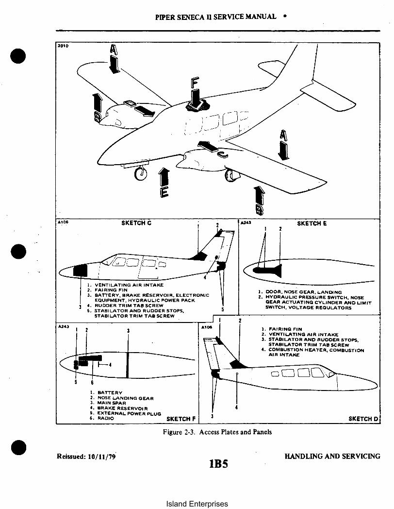
2010
A106 SKETCH C
1. VENTILATING AIR INTAKE2. FAIRING FIN3. BATTERY, BRAKE RESERVOIR, ELECTRONIC
EQUIPMENT, HYDRAULIC POWER PACKj 4. RUDDER TRIM TAB SCREW
5. STABILATOR AND RUDDER STOPS.STABILATOR TRIM TAB SCREW
A243
PIPER SENECA 11 SERVICE MANUAL *
SKETCH E
1. DOOR, NOSE GEAR, LANDING2. HYDRAULIC PRESSURE SWITCH. NOSE
GEAR ACTUATING CYLINDER AND LIMITSWITCH, VOLTAGE REGULATORS
6
1. BATTERY2. NOSE LANDING GEAR3. MAIN SPAR4. BRAKE RESERVOIR5. EXTERNAL POWER PLUG6. RADIO
A106 1. FAIRING FIN2. VENTILATING AIR INTAKE3. STABILATOR AND RUDDER STOPS,
STABILATOR TRIM TAB SCREW4. COMBUSTION HEATER, COMBUSTION
AIR INTAKE
SKETCH F SKETCH D
Figure 2-3. Access Plates and Panels
Reissued: 10/11/791BS
HANDLING AND SERVICING
Island Enterprises

2 3 11
PIPER SENECA II SERVICE MANUAL
11 3 2
9 9
1. WING TIP2. CAP, FUEL TANK ASSEMBLY3. FAIRING4. OIL FILLER DOOR5. FAIRING
6. LINES, WIRES, CABLES7. COWL, INBOARD8. SPINNER, PROPELLER9. PROPELLER RECHARGE VALVE
10. COWL, OUTBOARD11. HATCH, NACELLE SKETCH A
1978
13 13
1. FUEL GAUGE SENDER2. COWL FLAP3. PROPELLER RECHARGE VALVE4. SPINNER, PROPELLER5. ENGINE OIL DRAIN6. LINES, WIRES, CABLES7. FAIRING8. DOOR, MAIN GEAR, LANDING
9. COVER, GEAR ATTACHMENT FITTING10. ELECTRIC WIRING11. FUEL VALVE12. COVER, BELLCRANK AND CONTROL CABLE13. WING TIP14. STALL WARNING & DEICER BOOTS
15. PITOT HEAT WIRING -AILERON CABLESDEICER LINES
SKETCH B
Figure 2-3. Access Plates and Panels (cont.)
REISSUED: 10/11/79 HANDLING AND SERVICING1B6
Island Enterprises

1976
Figure 2-4. Jacking
2-9. STEP, HANDHOLD AND WALKWAYS. A fixed handhold is located on the right side of the fuselage,above and aft of the second window. The walkway is made up of a non-skid material which is in turnbonded to the wing surface. (Refer to Section IV for repair or replacement of wing walkway material.)
CAUTION
Walk on the walkways only to avoid damage to the wings.
2-10. GROUND HANDLING.
2-11. INTRODUCTION TO GROUND HANDLING. Ground handling covers all essential informationgoverning the handling of the airplane while on the ground. This includes jacking, weighing, leveling,mooring, parking, towing and taxiing. When the airplane is handled in the manner described in thefollowing paragraphs, damage to the airplane and its equipment will be prevented.
2-12. JACKING. Jack the airplane as specified to perform various service operations. Proceed as follows:a. Place the jacks under the jack pads on the wing front spar.b. Attach a tail support to the tail skid. Place approximately 600 pounds of ballast on the support
to hold the tail down. (Refer to Figure 2-4.)
CAUTION
Be sure to apply sufficient support ballast; otherwise, the airplanewill tip forward and fall on the fuselage nose section:
c. Carefully raise jacks until all three wheels are clear of the surface.
Revised: 8/10/80 HANDLNG AND SERVICING
PIPER SENECA I SERVICE MANUAL .
1B7
Island Enterprises

1977
PIPER SENECA II SERVICE MANUAL
Figure 2-5. Weighing
CAUTION
If the purpose for placing the airplane on jacks is to service thehydraulic system, the free-fall valve knob should be pulled full outfrom the instrument panel. (Refer to Section VI, Paragraph 6-1.)
2-13. WEIGHING. (Refer to Figure 2-5.) The airplane may be weighed by the following procedure:a. Position a scale and ramp in front of each of the three wheels.b. Secure the scales from rolling forward and tow the airplane up onto the scales. (Refer to Towing,
Paragraph 2-18.)c. Remove the ramp so as not to interfere with the scales.d. If the airplane is to be weighed for weight and balance computations, level the airplane per
instructions given in Paragraph 2-14.
2-14. LEVELING. All configurations of the airplane are provided with a means for longitudinal and lateralleveling. The airplane may be leveled while on jacks, during the weighing procedure while the wheels are onscales, or while the wheels are on the ground. To level the airplane for purposes of weighing or rigging, thefollowing procedures may be used:
a. To longitudinally level the airplane, partially withdraw the two leveling screws locatedimmediately below the left front side window. (Refer to Figure 2-6.) Place a spirit level on these screwheads and deflate the nose wheel tire or adjust the jacks until the bubble of the level is centered.
b. To laterally level the airplane, place a spirit level across the baggage compartment floor along therear bulkhead (refer to Figure 2-6) and deflate the tire on the high side of the airplane or adjust either jackuntil the bubble of the level is centered.
Reissued: 10/11/79 HANDLING AND SERVICING
1B8Island Enterprises

* PIPER SENECA II SERVICE MANUAL
A368
Longitudinally Laterally
Figure 2-6. Leveling Airplane
2-15. MOORING. The airplane is moored to insure its immovability, protection, and security undervarious weather conditions. The following procedure, gives the instructions for proper mooring of theairplane:
a. Head the airplane into the wind, if possible.b. Block the wheels.c. Lock the aileron and stabilator controls by looping the pilot's seat belt around wheel.d. Secure tie-down ropes to the wing tie-down rings and the tail skid at approximately 45 degree
angles to the ground. When using rope constructed of non-synthetic material, leave sufficient slack to avoiddamage to the airplane when the ropes contract due to moisture.
CAUTION
Use square or bowline knots. Do not use slip knots.
NOTE
Additional preparations for high winds include using tie-downropes from the landing gear forks, securing the rudder, andsecuring the props to prevent windmilling.
2-16. LOCKING AIRPLANE. The right cabin door is provided with a key lock on the outside. The cabindoor lock and nose baggage compartment door lock use the same key.
Reissued: 10/11/79 HANDLING AND SERVICING
1 B9
Island Enterprises

PIPER SENECA II SERVICE MANUAL
2-17. PARKING. When parking the airplane, insure that it is sufficiently protected against adverse weatherconditions and presents no danger to other aircraft. When parking the airplane for any length of time orovernight, it is recommended that it be moored as in Paragraph 2-15.
a. To park the airplane, head it into the wind, if possible.b. Set the parking brake by pulling back the brake lever and depressing the knob attached to the left
side of the handle. Then release the handle. To release the parking brakes, pull back on the brake lever todisengage the catch mechanism. Then allow the handle to swing forward.
NOTE
Care should be taken when setting brakes that are overheated orduring cold weather when accumulated moisture may freeze thebrakes.
c. The aileron and stabilator controls may be secured with the pilot's seat belt.
2-18. TOWING. The airplane may be moved by using the nose wheel steering bar that is stowed below theforward ledge of the rear baggage compartment or power equipment that will not damage or cause excessstrain to the nose gear steering assembly. Tow bar engages front axle inside fork.
CAUTION
When towing with power equipment, do not turn the nose gear ineither direction beyond its steering radius limits as this will resultin damage to the nose gear and steering mechanism.
CAUTION
When moving the aircraft forward by hand, avoid pushing on thetrailing edge of the ailerons as this will cause the aileron contourto change resulting in an out-of-trim condition.
In the event towing lines are necessary, lines (rope) should be attached to both main gear struts as highup on the tubes as possible. Lines should be long enough to clear the nose and/or tail by not less than 15feet, and a qualified person to ride in the pilot's seat to maintain control by use of the brakes.
2-19. TAXIING. Before attempting to taxi the airplane, ground personnel should be checked out by aqualified pilot or other responsible person. Engine starting and shutdown procedures should be covered aswell. When it is ascertained that the propeller back blast and taxi areas are clear, apply power to start thetaxi roll and perform the following checks:
a. Taxi forward a few feet and apply brakes to determine their effectiveness.b. Taxi with propellers set in low pitch, high RPM setting.c. While taxiing, make slight turns to ascertain the effectiveness of steering.d. Observe wing clearances when taxiing near buildings or other stationary objects. If possible,
station a guide outside the airplane to observe.e. When taxiing on uneven ground, look for and avoid holes and ruts.f. Do not operate the engines at high RPM when running up or taxiing over ground containing loose
stones, gravel, or any loose material that may cause damage to the propeller blades.
Reissued: 10/11/79 HANDLING AND SERVICING
lB10Island Enterprises

PIPER SENECA II SERVICE MANUAL
2-20. EXTERNAL POWER RECEPTACLE.
2-21. OPERATION OF EXTERNAL POWER RECEPTACLE. The external power receptacle is locatedon the left side of the nose section. When using external power for starting or operation of any of the airplane'sequipment. the master switch must be ON.
CAUTION
Turn master switch off before inserting or removing plug.
NOTE
When using a 12-volt battery for external power starting and theairplane's battery is nearly depleted, the instructions given inSection XI must be followed.
2-22. SERVICING.
2-23. INTRODUCTION TO SERVICING. Servicing the airplane includes the replenishment of fuel. oil.hydraulic fluid. tire pressures. lubrication requirements, and other items required to completely service theairplane.
2-24. FUEL SYSTEM.
2-25. SERVICING FUEL SYSTEM. At intervals of 50 hours or 90 days, whichever comes first, clean thefuel filter pack. Remove and clean the filters in accordance with the instructions outlined in Section IX.Additional service information may also be found in Section IX. Inspection intervals of the various fuel systemcomponents may be found in Section III.
2-26. FILLING FUEL TANKS. The fuel tanks of each wing are filled through a single filler located on theforward slope of the wing at the outboard tank. An anti-icing additive complying with MIL-I-27686 may beadded if desired when filling the system (see paragraph 2-27).
With each of the interconnected wing tanks having a capacity of 24.5 gallons, a total capacity of 49 gallonsis available per wing. 64 gallons with optional tanks.
CAUTION
Observe all required safety precautions and use the fuel specifiedon the placard adjacent to the filler neck.
Revised: 8/10/80 HANDLING AND SERVICING
IBlI
Island Enterprises

PIPER SENECA II SERVICE MANUAL
2-27. HANDLING OF MOISTURE IN FUEL SYSTEM. Moisture and foreign matter can be drained fromdrains incorporated in the bottom of the system's lowest point and the inboard end of each fuel tank. Toprevent ice contamination an anti-icing additive per MIL-I-27686B may be used provided it is uniformlyblended with the fuel while refueling. The additive must not exceed .15% by volume of the refueled quantity.To be effective the blend should not be less than .10% by volume. A good example would be 1-1/2 liquidounces per 10 gallons of fuel. For best results, follow the manufacturer's mixing or blending instructions. Referto list of consumable materials for purchasing information. If possible a blender supplied by the manufacturershould be used.
CAUTION
Make sure that when adding an anti-icing additive it is directed intothe flowing fuel stream, starting after and stopping before the fuelflow. DO NOT permit the additive to come in contact with paintedsurfaces or interior surfaces of the tank.Do not add further blending to pre-blended fuels.Fuel additive(s) do not substitute for preflight draining of fuelsystem drains.
2-28. DRAINING FUEL SYSTEM. The bulk of the fuel may be drained from the system by opening thevalve at the inboard end of each fuel tank. Push up on the arms of the drain valve and turn counterclockwiseto hold the drain in the open position. The remaining fuel in the system may be drained through the fuel filtersand the two drains located on the lower right side of the fuselage inboard to the flaps.
INTENTIONALLY LEFT BLANK
Revised: 8/10/80 HANDLING AND SERVICING1B12
Island Enterprises

* PIPER SENECA II SERVICE MANUAL
2-29. BRAKE SYSTEM.
2-30. SERVICING BRAKE SYSTEM. The brake system incorporates a hydraulic fluid reservoir throughwhich the brake system is periodically serviced. Fluid is drawn from the reservoir by the brake cylinders tomaintain the volume of fluid required for maximum braking efficiency. Spongy brake pedal action is oftenan indication that the brake fluid reservoir is running low on fluid. Instructions for filling the reservoir aregiven in Paragraph 2-31. When found necessary to accomplish repairs to any of the brake systemcomponents, or to bleed the system, these instructions may be found in Section VII.
2-31. FILLING BRAKE CYLINDER RESERVOIR. The brake cylinder reservoir should be filled to thelevel marked on reservoir with the fluid specified in Table II-I. The reservoir, located on the center of thebulkhead in the nose baggage compartment, should be checked at every 50 hour inspection and replenishedas necessary. No adjustment of the brakes is necessary, though they should be checked periodically perinstructions given in Section VII.
2-32. DRAINING BRAKE SYSTEM. To drain the brake system, connect a hose to the bleeder fitting onthe bottom of the cylinder and place the other end of the line in a suitable container. Open the bleeder andslowly pump the hand brake lever and the desired brake pedal until fluid ceases to flow. To drain the wheelbrake unit, disconnect the line at the bottom of the unit and allow fluid to flow into a suitable container.To clean the brake system, flush with denatured alcohol.
2-33. OLEO STRUTS.
2-34. SERVICING OLEO STRUTS. The air-oil type oleo strut should be maintained at proper strut pistontube exposures for best oleo action. The nose gear strut must have approximately 2.60 ± .25 inches ofpiston tube exposed, while the main gear strut requires approximately 3.60 ± .25 inches of tube exposure.These measurements are taken with the airplane sitting on a level surface under normal static load.
NOTE
Normal static load is the empty weight of the airplane plus fullfuel and oil.
CAUTION
Do not exceed these tube exposures.
If the strut has less tube exposure than prescribed, determine whether it needs air or oil by rocking the airplane.If the oleo strut oscillated with short strokes (approximately one inch) and the airplane settles to its normalposition within one or two cycles after the rocking force is removed, the oleo strut requires inflating. Check thevalve core and filler plug for air leaks, correct if required, and add air or nitrogen as described in Paragraph2-37. If the oleo strut oscillates with long strokes (approximately three inches) and the airplane continues tooscillate after the rocking force is removed, the oleo struts require fluid. Check the oleo for indications of oilleaks, correct if required, and add fluid as described in Paragraph 2-35 or 2-36. For repair procedures of thelanding gear and/or oleo struts, refer to Section VII of this manual.
WARNING
Do not release air by removing the strut valve core or filler plug.Depress the valve core pin until the strut chamber pressure hasdiminished.
Revised: 3/16/81 HANDLING AND SERVICTNG
1B13
Island Enterprises

PIPER SENECA II SERVICE MANUAL
840
M.T.D.
MINIMUM TURNING DISTANCE (M.T.D.) 60.4 Ft.
Figure 2-7. Turning Distance
Reissued: 10/11/79 HANDLING AND SERVICING
1B14Island Enterprises

PIPER SENECA II SERVICE MANUAL
CAUTION
Dirt and foreign particles form around the filler plugs of thelanding gear struts, therefore, before attempting to remove theseplugs, the area around the filler plugs should be cleaned withcompressed air and/or with a quick drying solvent.
2-35. FILLING NOSE GEAR OLEO STRUT. To fill the nose gear oleo strut with hydraulic fluid(MIL-H-5606), whether it be only the addition of a small amount or if the unit has been completelyemptied and will require a large amount, it should be filled as follows:
a. Raise the airplane on jacks. (Refer to Paragraph 2-12.)b. Place a pan under the gear to catch spillage.c. Relieve air pressure from the strut housing chamber by removing the cap from the air valve and
depressing the valve core.d. There are two methods by which the strut chamber may be filled and these are as follows:Method 1: Addition of small amounts of fluid.
1. Remove the valve core from the filler plug at the top of the nose gear strut housing. Allowthe filler plug to remain installed.
2. With the piston tube extended, fill the strut with approved type fluid.3. Attach one end of a clean plastic hose to the valve stem of the filler plug and submerge the
other end of the hose in a container of clean hydraulic fluid; make sure the end of the hose is below thesurface of the fluid.
NOTE
An air tight connection is necessary between the plastic tube andthe valve stem. Without such a connection, a small amount of airwill be sucked into the oleo strut during each sequence, resultingin an inordinate amount of air bubbles and prolonged fillingoperations.
4. Fully compress and extend the piston tube, thus expelling any air trapped within the strutchamber. By watching the fluid pass through the plastic hose, it can be determined when the strut is fulland no air is present in the chamber.
5. When air bubbles cease to flow through the hose, compress the piston fully and remove thehose from the valve stem. Remove the filler plug to determine that fluid level is visible up to the bottom ofthe filler plug hole.
6. Reinstall the core in the filler plug and the plug in the strut housing and torque from 350 to 400inch-pounds.
Method II - Filling completely empty struts.1. Proceed with steps A through C.2. Remove the filler plug at the top inboard side of the.gear housing.3. Disconnect the torque links by removing any one of the three torque link bolts.
CAUTION
With the torque link disconnected, the strut tube is free to slide outof the trunnion.
4. Extend the piston to a visible strut extension of 10 inches minimum - 12 inches maximum.5. Add one-half pint minimum of hydraulic fluid through the air valve hole and allow it to drain
and fill the chamber below the top bearing hole.
Revised: 12/08/83 HANDLING AND SERVICING1B15
Island Enterprises

2
PIPER SENECA II SERVICE MANUAL
1970
12
54
12 4
16
1. FUEL FILLERS
2. FUEL INJECTORS
3. ENGINE OIL FILL
4. ENGINE OIL FILTERS
5. FUEL FILTERS
6. INSTRUMENT AIR FILTERS
7. FUEL SYSTEM DRAINS
8. FUEL METERING CONTROL UNIT
9. OIL DIPSTICK
10. MAIN GEAR STRUT
11. MAIN GEAR TIRES
12. INDUCTION AIR FILTERS
13. ENGINE OIL SUCTION SCREEN
14. PROPELLER AIR CHARGE
15. BRAKE RESERVOIR
16. NOSE GEAR STRUT
17. NOSE GEAR TIRE
18. EXTERNAL POWER RECEPTACLE
19. BATTERY
20. HYDRAULIC RESERVOIR
Figure 2-8. Service Points
HANDLING AND SERVICINGHANDLING AND SERVICINGReissued: 10/11/79
lB16
Island Enterprises

PIPER SENECA II SERVICE MANUAL *
6. Reconnect the torque links.7. Add hydraulic fluid through the air valve hole until the fluid level reaches the bottom (or lower
side) of the air valve hole with the piston fully compressed and no air trapped in the assembly below the valvehole.
NOTE
Gear assemblies with the air valve hole on the side of the cylindermay be serviced in the horizontal position with the air valve holevertical.
8. Install the air valve and torque it from 350 to 400 inch pounds.
2-36. FILLING MAIN GEAR OLEO STRUTS. To fill the main gear oleo struts with hydraulic fluid(MIL-H-5606) one of the following methods should be used, depending on the type of service performed onthe strut assembly:
a. Method I: Addition of small amount of fluid.1. Raise the airplane on jacks. (Refer to Paragraph 2-12.)2. Place a pan under the gear to catch any spillage.3. Relieve the air pressure from the strut housing chamber by removing the cap from the air valve
and depressing the valve core.4. Remove the valve core from the filler plug and allow the filler plug to remain installed.5. With the piston tube extended, fill the strut with the approved type hydraulic fluid.6. Attach one end of a clear plastic hose to the valve stem of the filler plug and submerge the other
end of the hose in a container of clean hydraulic fluid; make sure the end of the hose is below the surface of thefluid.
NOTE
An air tight connection is necessary between the plastic tube andthe valve stem. Without such a connection, a small amount of airwill be sucked into the oleo strut during each sequence, resultingin an inordinate amount of air bubbles and prolonged fillingoperations.
7. Fully compress and extend the piston tube, thus expelling any air trapped within the strutchamber. By watching the fluid pass through the plastic hose, it can be determined when the strut is full and noair is present in the chamber.
8. When air bubbles cease to flow through the hose, fully compress the piston and remove thehose from the valve stem. Remove the filler plug to determine that fluid is visible up to the bottom of the fillerplug hole.
9. Reinstall the air valve core in the filler plug and the plug in the strut housing and torque to45 foot-pounds.
10. With the airplane still on jacks, compress and extend the gear piston tube several times toascertain that the strut will operate freely. The weight of the gear, wheel, and fork should allow the piston tubeto extend.
11. Clean off any overflow of fluid and inflate the strut with air to 250 psi.12. Remove the aircraft from jacks and check strut exposure per Paragraph 2-34.
Revised: 3/16/81 HANDLING AND SERVICING1B17
Island Enterprises

*PIPER SENECA II SERVICE MANUAL
Method II - Filling completely empty struts.1. Proceed with steps I through 3 of Method I.2. Remove the filler plug at the top inboard side of the main gear housing.3. Disconnect the torque links by removing any one of the three torque link bolts.
CAUTION
With the torque link disconnected, the strut tube is free to slide outof the trunnion.
4. Extend the piston to a visible strut extension of 10 inches minimum - 12 inches maximum.
5. Add one-half pint minimum of hydraulic fluid through the air valve hole and allow it to drain
and fill the chamber below the top bearing hole.6. Reconnect the torque links.7. Add hydraulic fluid through the air valve hole until the fluid level reaches the bottom (or lower
side) of the air valve hole with the piston fully compressed and no air trapped in the assembly below the valve
hole.
NOTE
Gear assemblies with the air valve hole on the side of the cylindermay be serviced in the horizontal position with the air valve holevertical.
8. Reinstall the air valve core in the filler plug and the plug in the strut housing and torque the
plug from 350 to 400 inch-pounds.
Revised: 12/08/83 HANDLING AND SERVICING1B18
Island Enterprises

PIPER SENECA II SERVICE MANUAL *
2-37. INFLATING OLEO STRUTS. After making certain that an oleo strut has sufficient fluid, attach astrut pump to the air valve. With the airplane at empty weight (full fuel and oil only) fill the main strut to 250psi and the nose gear to 150 psi. Rock the airplane several times to ascertain that the gear settles back to thecorrect strut position. If a strut pump is not available, the airplane may be raised with line pressure from a highpressure air system. Before capping the valve, check for valve core leakage.
2-38. SERVICING STEERING BUNGEES. At the specified frequencyaccording to the Lubrication Chart.the steering bungees must be serviced as follows:
a. Remove the access panels located in the forward baggage compartment.b. Clamp the rudder pedals in the neutral position as shown in Figure 5-11.c. Remove the nut. washers, and bolt that secures the steering bungee and the steering arm.d. Remove the clamp that secures the boot, on the frame at station 49.50. to the bungee.e. Within the fuselage. disconnect the bungee from the rudder pedal arm by removing the nut. washer
and bolt.f. Remove the steering bungee from the aircraft.g. Cut the safety wire from the bungee retainer.h. Carefully remove the retainer and release the spring.i. Apply Aero Lubriplate to the spring and mounting hardware as specified in the Lubrication Chart.j. Compress the spring into the bungee tube and install the retainer securing with M IL-W-6713 Type
316 safety wire.k. Ascertain that the measurement taken between the facing sides of the washers at the rod end is
13.71 inches.1. With the nose gear in the neutral position, install the steering bungee into position. The web must
be in the vertical position. (Refer to Figure 7-2.)m. Install the bolt. washers, and nut that secures the bungee to the steering arm.n. Install the bolt. washer. and nut that secures the bungee to the rudder pedal arm.o. Install the boot clamp.p. Repeat this procedure for the other steering bungee.q. Align the nose gear per Alignment of Nose Landing Gear. Section VII.r. Remove the rudder pedal clamps and check the operation of the steering bungees.s. Install the access panels in the forward baggage compartment with the attachment hardware.
2-39. TIRES.
2-40. SERVICING TIRES. The tires should be maintained at the pressure specified in Table I1-1. Whenchecking tire pressure. examine the tires for wear. cuts. bruises and slippage. The tire. tube. and wheelshould be balanced when installed. Align the index mark on the tire with the index mark on the tube.
2-41. HYDRAULIC SYSTEM.
2-42. SERVICING HYDRAULIC SYSTEM. The hydraulic pump and landing gear actuating cylindersshould be checked for leaks, tightness of line fittings and general condition. The cylinder rods are to be freeof all dirt and grit. To clean the rods. use an oil soaked rag and carefully wipe them. All the hydraulic linesshould also be checked for leaks. kinks, corrosion and attachment fittings for tightness and security. Repairand check procedures for the hydraulic pump. cylinders, and various components may be found in SectionVI of this manual.
Revised: 8/10/80 HANDLING AND SERVICING1B19
Island Enterprises

PIPER SENECA SERVICE MANUAL
2-43. SERVICING HYDRAULIC PUMP/RESERVOIR. The fluid level of the reservoir of the combinationpump and reservoir should be checked every 50 hours by viewing the fluid through the filler plug hole inthe hydraulic pump. Access to the pump is through the panel at the right forward side of the nose baggagecompartment.
To check fluid level, remove the filter plug located on the forward side of the pump and ascertain thatfluid is visible up to the bottom of the filler plug hole. Should fluid be below the hole, add fluid,MIL-H-5606, through the filler hole until full. Reinstall the filler plug and tighten.
NOTE
A small vent hole is located under the vent screw head. Retain1/64 inch clearance between the screw head and small vent hole.
2-44. BATTERY.
2-45. SERVICING BATTERY. Servicing of the battery which is located under the floor panel of theforward baggage compartment, involves adding distilled water to maintain electrolyte even with thehorizontal baffles, checking cable connections, and checking for any spilled electrolyte that would lead tocorrosion. A check for proper fluid level and presence of corrosion should be conducted at intervals of 50hours or 30 days, whichever comes first. When corrosion is found, at each 100 hour inspection or every 90days, the battery should be removed from the box and the battery and box should be cleaned. Removal,cleaning, and charging instructions may be found in Section XI of this manual.
2-46. CLEANING.
247. CLEANING ENGINE COMPARTMENTS. Before cleaning the engine compartments, place a strip oftape on the magneto vents to prevent any solvent from entering these units.
a. Place a pan under the engines to catch waste.b. With the engine cowlings removed, spray or brush the engines with solvent or a mixture of
solvent and degreaser as desired. It may be necessary to brush areas that were sprayed, where heavy greaseand dirt deposits have collected in order to clean them.
CAUTION
Do not spray solvent into the alternator, starter, air intake,alternate air inlets and pressure pump drive area.
c. Allow the solvent to remain on the engine from five to 10 minutes; then rinse the engine cleanwith additional solvent and allow to dry.
CAUTION
Do not operate engines until excess solvent has evaporated orotherwise been removed.
d. Remove the protective covers from magnetos.e. Lubricate controls, bearing surfaces, etc., per Lubrication Chart.
Reissued: 10/11/79 HANDLING AND SERVICINGlB20.
Island Enterprises

PIPER SENECA II SERVICE MANUAL
2-48. CLEANING LANDING GEAR. Before cleaning the landing gear. place a plastic cover or similarmaterial over the wheel and brake assembly.
a. Place a pan under the gear to catch waste.b. Spray or brush the gear area with solvent or a mixture of solvent and degreaser as desired. It may
be necessary to brush areas that were sprayed where heavy grease and dirt deposits have collected in orderto clean them. Do not brush micro switches.
c. Allow the solvent to remain on the gear from 5 to 10 minutes: then rinse the gear with additionalsolvent and allow to dry.
d. Remove the cover from the wheel and remove the catch pan.e. Lubricate the gear per Lubrication Chart.
2-49. CLEANING EXTERIOR SURFACES. The airplane should be washed with a mild soap and water.Harsh abrasive or alkaline soaps or detergents used on painted or plastic surfaces could make scratches orcause corrosion of metal surfaces. Cover areas where cleaning solution could cause damage. To wash theairplane. the following procedure may be used:
a. Flush away loose dirt with water.b. Apply cleaning solution with a rag. sponge or soft bristle brush.c. To remove stubborn oil and grease, use a cloth dampened with naphtha.d. Where exhaust stains exist, allow solution to remain on the surface longer.e. Any good automotive wax may be used to preserve the painted surfaces. Soft cleaning cloths or a
chamois should be used to prevent scratches when cleaning or polishing. A heavier coating of wax on theleading surfaces will reduce the abrasion problems in these areas.
2-50. CLEANING WINDSHIELD AND WINDOWS.a. Remove dirt. mud. etc.. from exterior surfaces with clean water.b. Wash with mild soap and warm water or an aircraft plastic cleaner. Use a soft cloth or sponge
using a straight rubbing motion. Do not harshly rub surfaces.c. Remove oil and grease with a cloth moistened with kerosene.
NOTE
Do not use gasoline, alcohol. benzene. carbon tetrachloride.thinner. acetone. or window cleaning sprays.
d. After cleaning plastic surfaces, apply a thin coat of hard polishing wax. Rub lightly with a softcloth. Do not use a circular motion.
e. A severe scratch or mar in plastic can be removed by using jeweler's rouge to rub out the scratchSmooth both sides and apply wax.
f. Visibility through the windshield may be improved when flying through rain by using a waterrepellent on the windows such as Repcon. Refer to the List of Consumable Materials for purchasinginformation.
2-51. CLEANING HEADLINER. SIDE PANELS AND SEATS.a. Clean headliner. side panels. and seats with a stiff bristle brush and vacuum where necessary.b. Soiled upholstery. except leather. may be cleaned by using an approved air type cleaner or foam
upholstery cleaner. Carefully follow the manufacturer's instructions. Avoid soaking or harsh rubbing.
CAUTION
Solvent cleaners require adequate ventilation.
c. Leather material should be cleaned with saddle soap or mild soap and water.
Revised: 8/10/80 HANDLING AND SERVICING1B21
Island Enterprises

PIPER SENECA II SERVICE MANUAL
2-52. CLEANING CARPETS. Use a small whisk broom or vacuum to remove dirt. For soiled spots, use anon-inflammable dry-cleaning fluid. Floor carpets may be removed and cleaned like any household carpet.
2-53. LUBRICATION.
2-54. OIL SYSTEM (ENGINE).
2-55. SERVICING OIL SYSTEM. The engine oil level should be checked before each flight and changedafter each 100 hours of engine operation. During oil change the oil screen(s) should be removed andcleaned, and the oil filter cartridge replaced. Replace oil filter at 50 hour intervals. The engine manufacturerdoes not recommend oils by brand names. Use a quality brand Aviation Grade oil of the proper seasonviscosity. For information on the use of detergent oil, refer to Paragraph 2-60.
CAUTION
Do not introduce any trade additive to the basic lubricant unlessrecommended by the manufacturer.
2-56. FILLING OIL SUMP. The oil sump should normally be filled with oil to the mark on the enginedipstick. The quantity of oil required for the engines may be found in Table II-I. The specified grade of oilmay be found in Table II-III, the Lubrication Chart, or on the cowl panel access door of each engine. Toservice the engine with oil, open the access door of the cowl and remove the oil filler cap.
2-57. DRAINING OIL SUMP. To drain the oil sump, provide a suitable container with a minimumcapacity of that required to fill the sump. Remove the access panel in the lower cowl and remove oil drainplug located on the underside of the engine. It is recommended the engine be warmed to operatingtemperature to insure complete draining of the old oil.
2-58. OIL SCREEN (SUCTION). The oil suction screen is located on the bottom aft end of the enginesump, installed horizontally. To remove, cut the safety wire and remove the hex head plug. The screenshould be cleaned at each oil change to remove any accumulation of sludge and to examine for metal filingsor chips. If metal particles are found in the screen, the engine should be examined for internal damage.After cleaning and inspection, place the screen inside the recess in the hex head plug to eliminate possibledamage to the screen. Insert the screen into the housing and when certain that the screen is properly seated,tighten and safety the plug with MS-20995-C41 safety wire.
2-59. OIL FILTER (FULL FLOW).a. The oil filter should be replaced after each 50 hours of engine operation; this is accomplished by
removing the lockwire from the bolt head at the end of the filter, loosening and removing the filterassembly from the adapter.
b. Before discarding the filter, remove the outer cover, and using a sharp knife, cut through thefolds of the element at both ends. Then carefully unfold the pleated element and examine the materialtrapped in the filter for evidence of internal engine damage such as chips or particles from bearings. In newor newly overhauled engines, some small particle or metallic shavings might be found; these are generally ofno consequence and should not be confused with particles produced by impacting, abrasion or pressure.Evidence of internal engine damage found in the oil filter justifies further examination to determine thecause.
Reissued: 10/11/79 HANDLING AND SERVICING
1B22Island Enterprises

PIPER SENECA II SERVICE MANUAL
NOTE
Ascertain that oil filter completes with specifications of ContinentalAircraft Engine Service Bulletin M75-7.
c. Before installing the new filter, lubricate the gasket on the filter with engine oil, then install. Tightenslightly more than hand tight or 3 4 to I full turn after gasket makes contact. Do not over torque.
d. Run the engine and check for oil leaks: then install lockwire between nut on filter and oil filteradapter assembly.
2-60. RECOMMENDATIONS FOR CHANGING OIL. The engine manufacturer recommends that the oilsupply be drained and the entire sump filled with fresh oil after each 100 hours of engine operation. Alwaysstart and warm the engine to operating temperature before performing an oil change. While draining the oil,the screens should be removed from the crankcase cover and cleaned thoroughly. If sludge deposits are heavy.subsequent oil changes should be made at shorter intervals. Detergent oil that meets the latest revision ofContinental Motors Corporation Specification MHS-24, is the only recommended lubricating oil. UseSAE-30 15W-50 or 20W-50 below 40° F and SAE-50 15W-50. 20W-50 or 25W-60 above 40° F. When theaverage ambient air temperature is approximately at the dividing line, use the lighter oil.
2-61. LUBRICATION INSTRUCTIONS. Proper lubrication procedures are of immeasurable value both asa means of prolonging the service life of the airplane and as a means of reducing the frequency of extensiveand expensive repairs. The periodic application of recommended lubricants to their relevant bearing surfaces.as detailed in the following paragraphs, together with the observance of cleanliness will insure the maximumefficiency and utmost service of all moving parts. Lubrication instruction regarding the locations, timeintervals, and type of lubricants used may be found in the Lubrication Chart. To insure the best possible results
- from the application of lubricants, the following precautions should be observed:a. Use recommended lubricants. Where general purpose lubricating oil is specified, but unavailable.
clean engine oil may be used as a satisfactory substitute.b. Check the components to be lubricated for evidence of excessive wear and replace them as
necessary.c. Remove all excess lubricants from components in order to prevent the collection of dirt and sand
in abrasive quantities capable of causing excessive wear or damage to bearing surfaces.
NOTE
If the airplane is inactive for long periods of time, it should belubricated in accordance with Lubrication Chart every 90 days.
2-62. APPLICATION OF OIL. Whenever specific instructions for lubrication of mechanisms requiringlubrication are not available, observe the following precautions:
a. Apply oil sparingly, never more than enough to coat the bearing surfaces.b. Since the control cables are sufficiently coated by the manufacturer, additional protection for
the prevention of corrosion is unnecessary.c. Squeeze the magneto cam follower felts at regular inspection periods. If oil appears on fingers, do
not add oil. If the felt is dry, moisten with light oil.
Revised: 12/08/83 1B23 HANDLING AND SERVICING
Island Enterprises

PIPER SENECA SERVICE MANUAL
CAUTION
Be careful not to add too much oil, because the excess will bethrown off during operation and will cause pitting and burning ofthe magneto points.
2-63. APPLICATION OF GREASE. Care must be taken when lubricating bearings and bearing surfaceswith a grease gun, to insure that gun is filled with new clean grease of the grade specified for the particularapplication before applying lubricant to the grease fittings.
a. Where a reservoir is not provided around a bearing, apply the lubricant sparingly and wipe off anyexcess.
b. Remove wheel bearings from the wheel hub and clean thoroughly with a suitable solvent. Whenrepacking with grease, be sure the lubricant enters the space between the rollers in the retainer ring. Do notpack the grease into the wheel hub.
c. Use extra care when greasing the constant speed propeller hub to avoid blowing the clampgaskets. Remove one grease fitting and apply grease to the other fitting until fresh grease appears at the holeof the removed fitting.
2-64. LUBRICATION CHARTS. The lubrication charts consists of individual illustrations for the variousaircraft systems, and each component to be lubricated is indicated by a number, the type of lubricant andthe frequency of application. Special instructions are listed at the beginning of the lubrication charts andwith the applicable component illustration.
Reissued: 10/11/79 HANDLING AND SERVICING1B24
Island Enterprises

PIPER SENECA SERVICE MANUAL
TYPE OF LUBRICANTS
SPECIFICATION LUBRICANT
MIL-L-7870 LUBRICATING OIL, GENERAL PURPOSE LOWTEMPERATURE
LATEST REVISION OFMHS-24B = TCMSPECIFICATION
MI L-H-5606
MI L-G-23827
MIL-G-7711
AERO
LUBRICATING OIL. AIRCRAFT RECIPROCATINGENGINE (PISTON) GRADE AS SPECIFIEDSAE 50 15W-50, 20W-50 OR 25W-60 ABOVE40*F AMBIENT AIR (S.L.)SAE 30 15W-50 OR 20W-50 BELOW 40 °
AMBIENT AIR (S.L.)
HYDRAULIC FLUID. PETROLEUM BASE
GREASE. AIRCRAFT AND INSTRUMENT, GEARAND ACTUATOR SCREWTEXACO MARFAK ALL PURPOSE GREASE,MOBIL MOBIL GREASE 77 (OR MOBIL EP2GREASE)
GREASE - LUBRICATION GENERALPURPOSE AIRCRAFTFLUOROCARBON RELEASE AGENTDRY LUBRICANT* MS-122 (PURCH)
LUBRIPLATE (PURCH) FISKE BROS.REFINING CO.
SPECIAL INSTRUCTIONS
1. BEARINGS AND BUSHINGS - CLEAN EXTERIOR WITH A DRY TYPESOLVENT BEFORE LUBRICATING.
2. LUBRICATION POINTS , WIPE ALL LUBRICATION POINTS CLEAN OF OLDGREASE, OIL, DIRT, ETC., BEFORE LUBRICATING.
NOTES
1. FUEL SYSTEM - SERVICE REGULARLY - FUEL PUMP STRAINERINJECTOR SCREEN - FILTER BOWL -QUICK DRAIN UNIT.
2 BATTERY - FLUID LEVEL AND CONDITION CHECK EVERY 25 HOURS.
CAUTIONS
1. DO NOT USE HYDRAULIC FLUID WITH A CASTOR OIL OR ESTER BASE.2. DO NOT OVERLUBRICATE COCKPIT CONTROLS.3. DO NOT APPLY LUBRICANT TO RUBBER PARTS.4. DO NOT LUBRICATE CABLES - THIS CAUSES SLIPPAGE.
Revised: 12/08/83 HANDLING AND SERVICING1C1
Island Enterprises

* PIPER SENECA II SERVICE MANUAL
COMPONENT LUBRICANT FREQUENCY
1. MAIN GEAR PIVOT POINTS2, MAIN GEARDOOR HINGE3. MAIN GEAR TORQUE LINKS4. EXPOSED OLEO STRUT MAIN
5. MAIN GEAR WHEEL BEARINGS
6. MAIN GEAR DOOR CONTROL ROD ENDS7. MAIN GEAR SIDE BRACE LINK ASSEMBLY8. UPPER SIDE BRACE SWIVEL FITTING9. MAIN GEAR DOWNLOCK ASSEMBLY
RETRACTION FITTING AND CYLINDERATTAC HMENT POI NTS
10. OLEO STRUT FILLER POINT (MAIN GEAR)11. HYDRAULIC PUMP RESERVOIR12. BRAKE RESERVOIR
MIL-G-23827MIL-L-7370MIL-L-7870FLUOROCARBON RELEASEAGENT DRY LUBRICANT
#MS-122TEXACO MARFAX ALLPURPOSE GREASE ORMOBIL MOBIL GREASE77 (OR MOBIL EP2GREASE)MIL-L-7870MIL-G-23127MIL-G-23827
MIL-L-7170MIL-H-5606MIL-H-606MIL-H-5606
100 HRS100 HRS100 HRS
100 HRS
100 HRS100 HRS100 HRS100 HRS
100 HRSAS REQUIRED
100 HRS100 HRS
1880
4
SPECIAL INSTRUCTIONS
1. Main and nose wheel barings - Disassemble nd cleanwith a dry type solvent Ascertain that grea Is packedbetween the roller and cone. Do not pack grease Inwheel housing Wheel bearings require cleaning andrepackng after exposure to an abnormal quantity ofwater.
2. Oleo struts, hydraulic pump reservoir and brakereservoir - Fill per nstructions on unit or container orrefer to service manual.
Figure 2-9. Lubrication Chart (Landing Gear, Main)
o
Reissued: 10/11/791C2
HANDLING AND SERVICING
Island Enterprises

PIPER SENECA II SERVICE MANUAL
COMPONENT
1. NOSE GEAR STRUT HOUSING2. NOSE GEAR PIVOT POINT AND HYDRAULIC
CYLINDER ROD END3. NOSE GEAR DOOR RETRACTION MECHANISM4. NOSE GEAR DOOR HINGES5. EXPOSED OLEO STRUT
6. NOSE WHEEL BEARINGS
LUBRICANT
MIL-G-2327
MIL-L-770MIL-L-7770MIL-L-7-70FLUOROCARBON RELEASEAGENT DRY LUBRICANT# MS-122TEXACO MARFAX ALLPURPOSE GREASE ORMOBIL GREASE77 (OR MOBIL EP2GREASE)MIL-L-770
MIL-G238 27
MIL-L-7870MIL-L-7870AERO LUBRIPLATEMAG-1 OR AEROSHELL #7
MIL-L-7870MIL.G-7711MIL-H-5606
FREQUENCY
100 HRS
100 HRS100 HRS100 HRS
100 HRS
100 HRS100 HRS
100 HRS
100 HRS100 HRS
100 HRS
100 HRS100 HRS
AS REQUIRED
7. NOSE GEAR TORQUE LINK ASSEMBLY8. NOSE GEAR TORQUE LINK ASSEMBLY AND
STRUT HOUSING9. NOSE GEAR PIVOT POINT, DRAG LINK
ASSEMBLY, DOWNLOCK AND CYLINDERASSEMBLY, STEERING ROLLER ANDCENTERING SPRING PIVOT POINTS
10. LINK BUSHING11. BUNGEES
12. STEERING BELLCRANK PIVOT POINTS ANDROD ENDS
13. NOSE GEAR ROLLER TRACK14. NOSE GEAR OLEO STRUT FILLER POINT
1 464 12 11
10
9
934
SPECIAL INSTRUCTIONS
I. Bungee - Lubricate springs If bungee Is disssembled.
5
Figure 2-10. Lubrication Chart (Landing Gear, Nose)
1C3 HANDLING AND SERVICING1 C3Revised: 3/16/81
Island Enterprises

2 RUDDER TRIM SCREW
166169
PIPER SENECA II SERVICE MANUAL
-CA UTION -
Do not lubricate control wheel shaft or bushing. Clean only usingalcohol or other suitable solvent.COMPONENT LUBRICANT
FLAP HINGE BEARINGS MIL-L-7870
3 CONTROL CABLE PULLEYS
4 TRIM CONTROL WHEELS . STABILATOR AND RUDDER
5 CONTROL COLUMN FLEX JOINT AND SPROCKET
6 O-RING CONTROL SHAFT BUSHING
AERO LUBRIPLATE, AERO #907.MAG #1 OR AEROSHELL #7
MIL-L-7870
MIL-L-7870
MIL-L 7870
FLUOROCARBON RELEASE AGENTDRY LUBRICANT #MS-122
FREQUENCY
100 HRS
100 HRS
100 HRS
100 HRS
1 00 HRRS
100 HRS
7 TEE BAR PIVOT POINTS. AILERONAND STABILATOR CONTROL PULLEYS MIL-L-7870
8 STABILATOR CONTROL ROD. ROD ENDBEARINGS LINKS AND IDLER PULLEY MIL-L-7870
9 FLAP CONTROL ROD END BEARINGS MIL-L-7870
10 FLAP RETURN AND TENSION CHAIN MIL L-7870
11 FLAP HANDLE PIVOT POINT LOCK MECHANISMAND CABLE PULLEY MIL-L-7870
12 FLAP TORQUE TUBE BEARING BLOCK MIL-L-7870
13 AILERON AND STABILATOR CONTROL CHAIN MIL-L-7870
100 HRS
100 HRS
100 HRS
500 HRS
100 HRS
100 HRS
500 HRS
3008l
8
2
SKETCH B
Figure 2-11. Lubrication Chart (Control System)
Interim Revision: July 30, 19861C4 HANDLING AND SERVICING
Island Enterprises

C1
PIPER SENECA II SERVICE MANUAL .
COMPONENT
1. AILERON HINGE PINS2. AILERON HINGE PINS3. CONTROL CABLE PULLEYS4. STABILATOR TRIM SCREW
5. RUDDER HINGE AND TAB HINGE BEARINGS6. ARM BUSHING7. STABILATOR TRIM TAB HINGE PINS8. RUDDER TUBE CONNECTIONS, TUBE CABLE
ENDS AND STEERING ROD ENDS9. TOE BRAKE ATTACHMENTS
10. BRAKE ROD ENDS11. RUDDER SECTOR ANDSTABILATOR TRIM
PIVOT POINTS12. AILERON CONTROL ROD END BEARINGS13. AILERON BELLCRAK CABLE ENDS
938
LUBRICANT
MIL-L-77 0MIL-L-7870MIL-L-7870AERO LUBRIPLATE. MAG #1OR AEROSHELL #7MIL-L-7870MIL-L-78 0MIL-L-7870
MIL-L-770MIL-L-7870MIL-L-7L70
MIL-L-770MIL-L-7870MIL-L-7870
FREQUENCY
100 HRS100 HRS100 HRS
100 HRS100 HRS100 HRS100 HRS
100 HRS100 HRS
100 HRS
100 HRS100 HRS100 HRS100 HRS
A268
SKETCH A2016
SKETCH B SKETCH C
Figure 2-12. Lubrication Chart (Control System) (cont.)
Revised: 3/16/81 HANDLING AND SERVICING1C5
Island Enterprises

A271
A272
A2B
COMPONENT
PIPER SENECA II SERVICE MANUAL *
1. ENGINE OIL SUMPS
2. OIL FILTERS
3. INDUCTION AIR FILTERS
4. ALTERNATE AIR DOORS5. GOVERNOR CONTROLS6. CONTROL QUADRANT CONTROLS7. PROPELLER ASSEMBLY
8. COWL FLAP ACTUATING MECHANISM
LUBRICANT
THE LATEST REVISIONS OFCONTINENTAL SPECIFICATIONMHS-24A AND SERVICEBULLETIN M75-2SEE SPECIAL INSTRUC-TIONS NO. 2 AND 3.CLEAN AS OFTEN ASNECESSARY, EVERYDAYUNDER SEVERECONDITIONSMIL-L-7 70MIL-L-7870MIL-L-7870MIL-G-23127AERO LUBRIPLATE, MAG-1OR AEROSHELL #7
.100 HRS
50 HRS
100 HRS100 HRS100 HRS100 HRS
500 HRS
FREQUENCY
SKETCH C
SPECIAL INSTRUCTIONS
SKETCH B1. Air filter - To clean filter, tap gently to remove dirt particles.
Do not blow out with compressed air or use oil; replace filter
if punctured or damaged.2. See the latest revision of TCM Service Bulletin M-81-11
Rev. 1 for recommended oil and filter change period. The
engine lubricating oil system is serviced with MIL-C-6529.
Type II for the initial fill and for the first 25 hours engine
time per the latest revisions of TCM Operator's Manual and
MHS-184. Service engine thereafter with oil per the latest
revisions of MHS-24B and TCM Service Bulletin M-81-11
Rev. 1.3. Ascertain that oil filter complies with specifications of the
latest revision of TCM Service Bulletin M75-74. Propeller - Remove one of two grease fittings for each blade
Apply grease through fitting until fresh grease appears at
hole of removed fitting.5. Lubricate outer surface of inner spacer on cowl flap linkageA
Figure 2-13. Lubrication Chart (Power Plant & Propeller)
HANDLING AND SERVICINGRevised: 12/08/83 1C6
Island Enterprises

3
PIPER SENECA II SERVICE MANUAL
COMPONENT
1. FORWARD BAGGAGE DOOR2. LATCH MECHANISM3. PILOT AND COPILOT SEAT ADJUSTMENT4. MAIN DOOR HINGES AND LATCH MECHANISM5. BAGGAGE AND REAR DOOR HINGES AND
LATCH MECHANISM
LUBRICANT
MIL-L-7770MIL-L-7870MIL-G-7711MIL-L-7870
MIL-L-7870
FREQUENCY
100 HRS500 HRS100 HRS500 HRS
500 HRS
2017
4 5
2
SPECIAL INSTRUCTIONS
1. Pilot and passenger seats - Lubricate track rollers andstop pins as required.
Figure 2-14. Lubrication Chart (Cabin Door, Baggage Door & Seats)
HANDLING AND SERVICINGRevised: 11/12/82
1C7
Island Enterprises

PIPER SENECA II SERVICE MANUAL
TABLE 11-111. CONVERSION TABLES
1. These charts contain the various conversion data that may be useful when figuring capacities, length,temperatures, and various weights and measures from the English system values to the metric system valuesor back again.
2. The English system is in use by England and the United States. All other countries use the metric system.
3. Procedure for Converting Inches to Millimeters.
A. Example: Convert 1.5 inches to millimeters.
(1) Read down inches column to 1. inches.(2) Read across top inch column to 0.5.(3) Read down and across to find millimeters (1.5 inches is 38.10 millimeters).
4. Procedure for converting Fahrenheit (°F) and Celsius (°C) (Centigrade) temperature.
A.Read number in middle column, if in degrees Celsius (C), read Fahrenheit equivalent in right- handcolumn. If in degrees Fahrenheit (°F), read Celsius equivalent in left-hand column.
(1) 70F = 21.1°C.(2) 30°C = 86.0°F.
Added: 8/10/80 HANDLING AND SERVICING1C8
Island Enterprises

PIPER SENECA II SERVICE MANUAL
TABLE I1-111. CONVERSION TABLES (cont.)
INCHES TO MILUMETER
INCHES- 0.0000I
0.0000.001 0.02540.002 0.05080.003 0.07620.004 0.10160.005 0.12700.006 0.15240.007 0.17780.008 0.20320.009 0.2286
INCHES -0.000
0.000.01 0.2540.02 0.5080.03 0.7620.04 1.0160.05 1.2700.06 1.5240.07 1.7780.08 2.0320.09 2.286
INCHES 0.00
0.00.1 2.5400.2 5.0800.3 7.6200.4 10.1600.5 12.7000.6 15.2400.7 17.7800.8 20.3200.9 22.860
0.0001
0.00250.02790.05330.08120.10410.12950.15490.18030.20570.2311
0.001
0.0250.2790.5330.7871.0411.2951.5491.8032.0572.311
0.01
0.2542.7945.3347.874
10.41412.95415.49418.03420.57423.114
0.0002
0.00500.03040.05580.08380.10660.13200.15740.18280.20820.2336
0.0003 0.0004 0.0005MILLIMETER
0.0076 0.0101 0.01270.0330 0.0355 0.03810.0584 0.0609 0.06350.0863 0.0889 0.09140.1092 0.1117 0.11430.1346 0.1371 0.13970.1600 0.1625 0.16510.1854 0.1879 0.19050.2108 0.2133 0.21590.2362 0.2387 0.2413
0.0006
0.01520.04060.06600.09390.11680.14220.16760.19300.21840.2438
0.0007
0.01770.04310.06850.09650.11930.14470.17010.19550.22090.2463
0.0008 0.0009
0.0203 0.02280.0457 0.04820.0711 0.07360.0965 0.09900.1219 0.12440.1447 0.14980.1727 0.17520.1981 0.20060.2235 0.22600.2489 0.2514
0.002 0.003 0.004 0.005MILUMETER
0.050 0.076 0.101 0.1270.304 0.330 0.355 0.3810.558 0.584 0.609 0.6350.812 0.838 0.863 0.8891.066 1.092 1.117 1.1431.320 1.346 1.371 1.3971.574 1.600 1.625 1.6511.828 1.854 1.879 1.9052.082 2.108 2.133 2.1592.336 2.362 2.387 2.413
0.02 0.03 0.04 0.05MILUMETER
0.508 0.762 0.016 1.2703.048 3.302 3.556 3.8105.558 5.842 6.096 6.3508.128 8.382 8.636 8.890
10.668 10.922 11.176 11.43013.208 13.462 13.716 13.97015.748 16.002 16.256 16.51018.288 18.542 18.796 19.05020.828 21.082 21.336 21.59023.368 23.622 23.876 24.130
0.006 0.007 0.008 0.009
0.1520.4060.6600.9141.1681.4221.6761.9302.1842.438
0.06
1.5244.0646.6049.144
11.68414.22416.76419.30421.84424.384
0.1770.4310.6850.9391.1931.4471.7011.9552.2092.463
0.07
1.7784.3186.8589.398
11.93814.47817.01819.55822.09824.638
0.203 0.2280.457 0.4820.711 0.7360.965 0.9901.219 1.2441.473 1.4981.727 1.7521.981 2.0062.235 2.2602.489 2.514
0.08 009
2.0324.5727.1129.652
12.19214.73217.27219.81222.35224.892
2.2864.8267.3669.906
12.44614.98617.52620.06622.60625.146
Added: 8/10/801C9 HANDLING AND SERVICINGl 9
Island Enterprises

PIPER SENECA II SERVICE MANUAL
TABLE I1-111. CONVERSION TABLES (cont.)
CHART A INCHES TO MILLIMETER (cont.)
INCHES- 0.00
0.1. 25.402. 50.803. 76.204. 101.605. 127.006. 152.407. 177.808. 203.209. 228.60
27578
1012151802023
0.1 0.2 0.3 0.4 0.5 0.6 0.7MILUMETER
2.54 5.08 7.62 10.16 12.70 15.24 17.787.94 30.48 33.02 35.56 38.10 40.64 43.183.34 55.88 58.42 60.96 63.50 66.04 68.588.74 81.28 83.82 86.36 88.90 91.44 93.984.14 106.68 109.22 111.76 114.30 116.84 119.389.54 132.08 134.62 137.16 139.70 142.24 144.784.94 157.48 160.02 162.56 165.10 167.64 170.180.34 182.88 185.42 187.96 190.50 193.04 195.585.74 208.28 210.82 213.36 215.90 218.44 220.981.14 233.68 236.22 238.76 241.30 243.84 246.38
0.8 0.9
20.32 22.8645.72 48.2671.12 73.6696.52 99.06
121.92 124.46147.32 149.86172.72 175.26198.12 200.66223.52 226.06248.92 251.46
THIS SPACE INTENTIONAI.I. LEFT BLANK
Added: 8/10/80 HANDLING AND SERVICING
1C10Island Enterprises
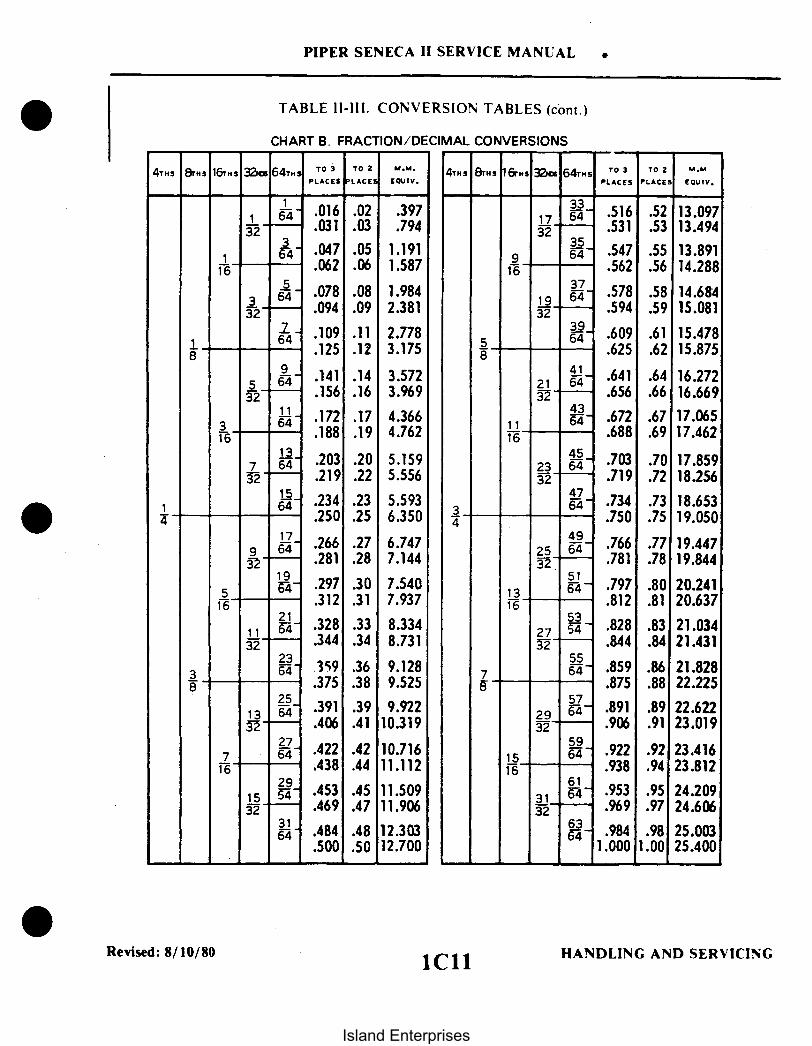
PIPER SENECA II SERVICE MANUAL
TABLE 11-111. CONVERSION TABLES (cont.)
CHART B. FRACTION/DECIMAL CONVERSIONS
4THS 8THs 16THS 32 64THS TO TO 2 M..PLACES PLACES EQUIV.
4Ts 8THS 16rTS 32ND 64THS TO TO 2 M.MPLACES PLACES EOUIV.
18
14
11 64 .016 .023—2 .031 .03
1 4- .047 .0516 .062 .06
64 .078 .08-- .094 .09
4- .109 .1164.125 .12
95 64- .141 .1432 .156 .16
- .172 .173 64
.188 .19
7 64 .203 .2032 .219 .22
64 .234 .23.250 .25
179 6- .266 .2732 .281 .28
195 -4- .297 .30
16 .312 .3121
1 64- .328 .3332 .344 .34
2364 359 .36
.375 .3825
13 64 391 .3932-- .406 .41
277 6- 422 .4216 .438 .44
2915 .453 .4532 .469 .47
316- .484 .48
.500 .50
.397
.794
1.1911.587
1.9842.381
2.7783.175
3.5723.969
4.3664.762
5.1595.556
5.5936.350
6.7477.144
7.5407.937
8.3348.731
9.1289.525
9.92210.319
10.71611.112
11.50911.906
12.30312.700
58
34
3317 6 .516 .52 13.09732 .531 .53 13.494
359 6- .547 .55 13.89116 .562 .56 14.288
371- .578 .58 14.684
32 .594 .59 15.081396- .609 .61 15.478
.625 .62 15.875
41- .641 .64 16.27221 6432- .656 .66 16.669
436- .672 .67 17.065
—6 .688 .69 17.462
33 6- .703 .70 17.85932 .719 .72 18.256
4764- .734 .73 18.653
.750 .75 19.05049
25 6- .766 .77 19.44732 .781 .78 19.844
5164- .797 .80 20.241
16 .812 .81 20.63753
27 5 .828 .83 21.03422 .844 .84 21.431
556- .859 .86 21.828
.875 .88 22.22557
29 6 .891 .89 22.62232 .906 .91 23.019
5915 6- .922 .92 23.41616 .938 .94 23.812
6131 64 .953 .95 24.20932 .969 .97 24.606
636- .984 .98 25.0031.000 1.00 25.400
38
78
Revised: 8/10/80 1C11 HANDLING AND SERVICING
Island Enterprises

PIPER SENECA II SERVICE MANUAL
TABLE I1-111. CONVERSION TABLES (cont.)
CHART C. CENTIGRADE-FAHRENHEIT CONVERSION TABLE
Example: To convert 20°C. to Fahrenheit. find 20 in the centercolumn headed (F-C): then read 68.0° F. in the column (F) to theright. To convert 20° F. to Centigrade: find 20 in the center columnand read -6.67°C. in the (C) column to the left.
C F-C
-56.7-51.1-45.6-40.0-34.0-38.9-23.3-17.8
-12.22-6.67-1.114.44
10.0015.5621.1126.6732.2227.7843.3338.8954.4460.0065.5671.0076.6782.2287.7893.3398.89
-70-60-50-40-30-20-100102030405060708090
100110120130140150160170180190200210
F
-94.0-76.0-58.0-40.0-22.0
-4.014.032.050.068.086.0
104.0122.0140.0158.0176.0194.0212.0230.0248.0266.0284.0302.0320.0338.0356.0374.0392.0410.0
C
104.44110.00115.56121.11126.67132.22137.78143.33148.89154.44160.00165.56171.11176.67182.22187.78193.33198.89204.44210.00215.56221.11226.67232.22257.78243.33248.89254.44260.00
F-C
220230240250260270280290300310320330340350360370380390400410420430440450460470480490500
F
428.0446.0464.0482.0500.0518.0536.0554.0572.0590.0608.0626.0644.0662.0680.0698.0716.0734.0752.0770.0788.0806.0824.0842.0860.0878.0896.0914.0932.0
Added: 8/10/80 HANDLING AND SERVICING1C12
Island Enterprises

PIPER SENECA II SERVICE MANUAL
MULTIPLY
CENTIMETERS
CU. CENTIMETERS
CU. FT.
CU. IN.
CU. METERS
FEET
FT.-LB.
FLUID OZ.
GAL., IMPERIAL
GAL., U.S. DRY
GAL., U.S. UQ.
IN.
JOULES
TA
BY
0.39370.03281
0.0010.061020.0002642
28.3201.7287.48128.3216.390.016390.0043290.01732
100000035.31461.023264.17999.97
0.304812.000304.80.3333
0.13830.0012850.000000376
829.6
277.41.2014.546
268.80.15561.1644.405
231.00.13373.7850.8327128
2.540.08333
0.0009480.7376
TABLE 11-111. CONVERSION TABLES (cont.)
CHART D. ENGLISH VS METRIC
TO OBTAIN MULTIPLY
IN.FT.
LITERSCU. INU.S. GAL.
CU. CMCU. IN.U.S. GAL.LITERSCU. CMLITERSU.S. GAL.QUARTS
CU. CMCU. FT.CU. INGAL.LITERS
METERSMILSMM.YARDS
M-KGBTUKW-HR
DRAMCU. CM
CU. IN.U.S. GAL.LITERS
CU. IN.CU. FT.U.S. GAL., UQ.LITERS
CU. IN.CU. FT.LITERSIMPERIAL GAL.FLUID OZ.
CM.FT.
FT.FT.-LB.
KILOGRAMS
LITERS
METERS
METER-KILOGRAM
OUNCES, AVDP
OUNCES, FLUID
LB., AVDP
SQUARE INCH
POUND PERSQUARE INCH(PSI)
STATUTE MILE
NAUTICAL MILE
QUART
MILIMETER
MICRON
INCHPOUNDS
INCHOUNCES
POUNDS
BY
2.20535.271000
100061.030.035320.26420.221.057
39.373.2811000
7.2339.807
0.062528.35437.5
29.571.805
453.6700016.0
6.4516
0.0703
1.6090.8684
1.151
.9463
1000
0.0010.000039
11.521
0.72
0.453
TO OBTAIN
LB.OZ.GRAMS
CU. CM.CU. IN.CU. FT.U.S. GAL.IMPERIAL GAL.QUARTS
IN.FT.MM.
FT.-LB.JOULES
LB., AVDPGRAMSGRAINS
CU. CM.CU. IN.
GRAMSGRAINSOUNCES
SQ. CM.
KG.-CMSQUARED
KILOMETERNAUTICAL MILE
STATUTEMILE
LITER
MICRON
MILLIMETERINCH
METERGRAMS
METERGRAMS
KILOGRAMS
Added: 8/10/80 HANDLING AND SERVICING1C13
Island Enterprises

PIPER SENECA II SERVICE MANUAL
TABLE I1-111. CONVERSION TABLES (cont.)
CHART E. DECIMAL/MILLIMETER EQUIVALENTS OF DRILL SIZES FROM 1/2" TO NO. 80
Decimal/Millimeter Equivalents of Drill Sizes From 1/2 to No. 80
Size Decimal MillimeterEquiv. Equiv.
Size Decimal MillimeterEquiv. Equiv.
Size Decimal Millimeter Size Decimal MillimeterEquiv. Equiv. Equiv. Equiv.
1/231/6415/3229/64
7/16
27/64Z
13/32yYX
25/64WV
3/8U
23/64TS
11/32R
Q21/64
P0
5/16
N19/64
ML
9/32
KJ
H17/64
0.5000.48430.46870.45310.4375
0.42180.4130.40620.4040.397
0.39060.3860.3770.3750.368
0.35930.3580.3460.34370.339
0.3320.32810.3230.3160.3125
0.3020.29680.2950.2900.2812
0.2810.2770.2720.2660.2656
12.700012.303111.906211.509411.1125
10.715610.490210.318710.261610.0838
GF
E-1/4DC
B15/64
A12
9.92129.80449.57589.52509.3472
7/323456
0.2610.2570.2500.2460.242
0.2380.23430.2340.2280.221
0.21870.2130.2090.20550.204
0.20310.2010.1990.1960.1935
0.1910.1890.18750.1850.182
0.1800.1770.1730.17180.1695
6.62946.52786.35006.24846.1468
5/3223242526
0.15620.1540.1520.14950.147
0.1440.14060.14050.1360.01285
3.96873.91163.86083.79733.7338
6.04525.95315.94365.79125.6134
279/64
282930
3.65763.57193.56873.45443.2639
3.17503.0482.94642.87022.8194
553/64
565758
5152
1/165354
5.55625.41025.30865.21975.1816
0.0670.06350.06250.05950.055
0.0520.04680.04650.0430.042
1.70181.61291.58751.51131.397
1.32081.19061.18111.09221.0668
1.04141.0160.99060.96520.9398
0.91440.8990.83820.79370.8128
1/8 0.12531 0.12032 0.11633 0.11334 0.111
59 0.04160 0.04061 0.03962 0.03863 0.037
9.12629.12818.78848.73008.6106
13/6478910
5.15945.10545.05464.97844.9149
357/64
363738
0.1100.10930.10650.1040.1015
0.09950.0980.0960.09370.0935
2.7942.77812.70512.64162.5781
646566
1/3267
0.0360.0350.0330.03120.032
8.43288.33378.20428.02647.9375
1112
3/161314
4.85144.80064.76254.6994.6228
4.5724.49584.39424.36564.3053
394041
3/3242
2.52732.48922.43842.38122.3749
2.26062.18442.08282.05741.9939
68 0.03169 0.02970 0.02871 0.02672 0.025
73 0.02474 0.022975 0.02176 0.02077 0.018
7.67087.53877.49307.36607.1425
151617
11/6418
43 0.08944 0.08645 0.08246 0.08147 0.0785
0.78740.73660.71120.66040.635
0.06960.581660.53340.5080.4572
0.39690.40640.36830.3429
7.13747.03586.90886.75646.7462
19 0.16620 0.16121 0.15922 0.157
4.21644.08944.03863.9878
5/64484950
0.07810.0760.0730.070
1.98441.93041.85421.778
1/64787980
0.01560.0160.01450.0135
DRILL SIZES AVAILABLEDrill may be obtained in regular sizes to a 4 inch diameter, and increase in 64ths of an inch.
The regular metric drills vary from 2 to 76mm and increase in 0.5mm variations.
1C C14 HANDLING AND SERVICING1C14Added: 8/10/80
Island Enterprises

PIPER SENECA II SERVICE MANUAL
TABLE II-IV. LIST OF CONSUMABLE MATERIALS
MATERIAL
Grease, Highemperature
SPECIFICATION BRAND NAME
High Temp Grease.Marfax all Purpose
M IL-G-3545QPL-3545-15
MANUFACTURER
Texaco, Inc., 135 East42nd, New York,New York 10017
Shellaire Grease HT,Alvania EP Grease 2,Aeroshell Grease 5
Grease 77, MobiluxEP2
Royco 45A
L-1231
Shell Oil Co.. 50West 50th StreetNew York, New York10020
Mobil Oil CorporationShoreham BuildingWashington, D.C. 20005
Royal Lubricants, Co.,River Road, Hanover,New 'Jersey 07936
Sinclair Refining Co.,600 Fifth Avenue, NewYork, New York 10020
Hydraulic Fluid MIL-H-5606QPL-5606-12
Aircraft HydraulicOil AA
Texaco, Inc., 135 East42nd, New York,New York 10017
RPM Aviation OilNo. 2 CodePED 2585.PED 3337
3126 Hydraulic Oil,Univis 40
Aeroshell Fluid 4,Aeroshell Fluid 4SL-7694
Aero HF
Royco 756, 756A.756B
Standard Oil ofCalifornia, 225 BushSt., San Francisco,California, 94120
Exxon Company, U.S.A.,Box 2180, Houston,Texas 77001
Shell Oil Co., 50West 50th Street,New York, New York10020
Mobil Oil CorporationShoreham Building,Washington. D.C. 20005
Royal Lubricants, Co.,River Road, Hanover.New Jersey 07936
Reissued: 10/11/79 HANDLING AND SERVICING1C15
Island Enterprises

PIPER SENECA II SERVICE MANUAL
TABLE II-IV. LIST OF CONSUMABLE MATERIALS (cont.)
MATERIAL
Lubricating Grease
SPECIFICATION
MIL-G-7711QPL-7711-15
BRAND NAME
Regal AFB2. RegalStarfak Premium 2
MANUFACTURER
Texaco, Inc., 135 East42nd., New York.New York 10017
PED 3040 Standard Oil ofCalifornia. 225 BushSt.. San Francisco,California 94120
Aeroshell Grease 6 Shell Oil Co.. 50West 50th. Street,New York. New York10020
Royco II Royal Lubricants, Co..River Road, Hanover,New Jersey 07936
Lubricating OilGeneral Purpose,Low Temperature
MIL-L-7870QPL-7870-9
1692 Low Temp Oil Texaco, Inc., 135 East42nd., New York,New York 10017
Aviation InstrumentOil
Royco 363
Sinclair AircraftOrbit lube
Standard Oil ofCalifornia, 225 BushSt., San FranciscoCalifornia 94120
Royal Lubricants. Co..River Road. Hanover,New Jersey 07936
Sinclair Refining Co.,600 Fifth Avenue,New York, New York10020
Caltex Low Temp OilOil Caltex Oil ProductsCo., New York,New York
HANDLING AND SERVICINGReissued: 10/11/791C16
Island Enterprises

Grease. Aircraft.General PurposeWide TemperatureRange
PIPER SENECA II SERVICE MANUAL
TABLE II-IV. LIST OF CONSUMABLE MATERIALS (cont.)
MATERIAL
Grease Aircraft andInstrument. Gear andActuator Screw
SPECIFICATION
MIL-G-23827QPL-23827-10(See Note 2)
BRAND NAME
Low Temp Grease EP
MANUFACTURER
Texaco. Inc.. 135 East42nd.. New York.New York 10017
5114 EP Grease.AV 55
Aeroshell Grease 7.Braycote 627S
Mobil Grease 27
Royco 27A
Castrolease AL
Supermil Grease No.A72832
BP Aero Grease 31B
Standard Oil ofCalifornia. 225 BushSt.. San Francisco.California 94120
Shell Oil Co.. 50West 50th. Street.New York. New York10020
Mobil Oil CorporationShoreham Building.Washington. D.C. 20005
Royal Lubricants Co..River Road. Hanover.New Jersey 07936
Castrol Oils Inc..Newark. New Jersey
American Oil Company165 N. Canal. Chicago.Illinois 60606
BP Trading LimitedMoore Lane.Britannic House.London E.C. 2England
ML-81322QPL-81322-3(See Note 2)
Aeroshell Grease 22
Mobil Grease 28
Rovco 22
Shell Oil Co.. 50West 50th Street.New York. New York10020
Mobil Oil CorporationShoreham Building.Washington. D.C. 20005
Royal Lubricants Co..River Road. Hanover.New Jersey 07936
Reissued: 10/11/79 HANDLING AND SERVICING1C17
Island Enterprises

PIPER SENECA II SERVICE MANUAL
TABLE II-IV. LIST OF CONSUMABLE MATERIAL (cont.)
MATERIAL
Grease, Aircraft andInstruments, Highand Low Temperature
SPECIFICATION
MIL-G-3278QPL-3278-24
BRAND NAME
Unitemp EP
MANUFACTURER
Texaco, Inc., 135 East42nd,, New York,New York 10017
RPM Avn. Grease 5,Supermil Grease No.8723
Aeroshell Grease 7A
Mobil Grease 22
Royco 78
L-1212
1916 Uni-Temp Grease
Standard Oil ofCalifornia, 225 BushSt., San Francisco,California 94120
Shell Oil Co., 50West 50th Street,New York, New York10020
Mobil Oil CorporationShoreham Building,Washington, D.C. 20005
Royal Lubricants Co.,River Road, Hanover,New Jersey 07936
Sinclair Refining Co.,600 Fifth AvenueNew York, New York10020
California Texas OilCorp., 380 MadisonAve., New York, NewYork 10017
Lubricating GreaseMolybdenum Disulfide
MIL-G-21164QPL-21164-15
Aeroshell Grease 17 Shell Oil Co., 50West 50th Street,New York, New York10020
Royco 64C
Castrolease MSA (C)
Royal Lubricants Co.,River Road, Hanover,New Jersey 07936
Castrol Oil Inc., 254-266 Doremus Avenue,Newark, New Jersey07105
HANDLING AND SERVICINGReissued: 10/11/791C18
Island Enterprises

Anti-Seize CompoundGraphite Petroleum
PIPER SENECA II SERVICE MANUAL
TABLE II-IV. LIST OF CONSUMABLE MATERIALS (cont.)
MATERIAL
Grease, Ball andRoller Bearing
SPECIFICATION
MIL-G-18709QPL-18709-55
BRAND NAME
Regal ASB-2 FormulaTG- 10293
MANUFACTURER
Texaco, Inc., 135 East42nd., New York,New York 10017
Andok B Exxon Company, U.S.A.,Box 2180, Houston,Texas 77001
Code 1-20481, DarinaGrease I XSG-6213Code 71-501, DarinaGrease 2 XSG-6152Code 71-502, AlvaniaGrease 2 XSG-6151Code 71-012, CyprinaGrease 3 XSG-6280Code 71-003
Shell Oil Co., 50West 50th Street,New York, New York10020
Lubricating Grease,Plug, Valve, Gasolineand Oil Resistant
MIL-G-6032QPL-6032-10
Royco 32 Royal EngineeringCo., Whippany,New Jersey
Castrolease PV
Parker Fuel Lube 44
BP Aero Grease 32
Castrol Oils Inc.,Newark, New Jersey
Parker Seal Co.
BP Trading LimitedMoore Lane,Britannic HouseLondon E.C. 2England
MIL-T-5544TT-S-1732(TT-A-580)
Royco 44 Royal Lubricants Co.,River Road, Hanover,New Jersey 07936
Silicone Compound MIL-S-8660(MIL-C-21567)QPL-8660-7
DC-4, DC-6Compound
Dow Corning, S.Saginaw Road,Midland, Michigan48641
G-624 General Electric Co.,Silicone ProductsDept., Waterford,New York 12188
Reissued: 10/11/79 HANDLING AND SERVICING1C19
Island Enterprises

PIPER SENECA II SERVICE MANUAL
TABLE II-IV. LIST OF CONSUMABLE MATERIAL (cont.)
MATERIAL SPECIFICATION BRAND NAME MANUFACTURER
Y-2900 Union Carbide
Dry Lubricant,FluorocarbonRelease Agent
MIL-L-60326 MS-122, 607S
Waterproof Grease,High and LowTemperature
Aero Lubriplate Fiske BrothersRefining Company,129 Lockwood,Newark, New Jersey07105
Products Research Co.2919 Empire AvenueBurbank, Cal. 91504
Sealer PR 1321 B
SolventPD680
Tuluol TT-T-548
Buffing and RubbingCompounds
Automotive Type-DuPont #7
Dupont CompanyWilmington, Del. 19898
Ram Chemical #69 x I
Mirror Glaze #1
Fantastic SprayPerchlorethyleneVM&P Naphtha(Lighter Fluid)
Ram ChemicalsGardena, Cal. 90248
Mirror Bright PolishCo., Inc.Irvin, Cal. 92713
Local SuppliersCleaners
ABS-SolventCements
Solarite #11 Series Solar Compounds Corp.Linden, N.J. 07036
Solvents Methylethyl KetoneMethylene ChlorideAcetone
Local Suppliers
Rain Repellent RepconFSCM 50159
Unelko Corporation727 E. 110th StreetChicago, Illinois60628
Reissued: 10/11/79 HANDLING AND SERVICING1C20
Island Enterprises

PIPER SENECA II SERVICE MANUAL
TABLE II-IV. LIST OF CONSUMABLE MATERIALS (cont)
MATERIAL
poxy Patchingompound
Hot Melt AdhesivesPolyamids and HotMelt Gun
SPECIFICATION BRAND NAME
Solarite #400
MANUFACTURER
Solar Compounds Corp.Lindon, N. J. 07036
Sears Roebuck & Co. orMost Hardware Stores
Stick Form 1/2 in. dia.3 in. long
Sealant PRC5000 Behr-Manning DivisionNorton
Norton Tape DivisionTroy, New York
Tapes, Vinyl Foam 1/8 in. x I in. 510 Series, Type II
Black Vinyl Plastic 2 in. x 9 mil. and/or1 1/2in. x 9mil.
Norton Tape DivisionTroy, New York
Vinyl Foam
Fuel Anti-IcingAdditive
I in. x 1/8 in.
MIL-1-27686E
530 Series, Type I
PFA-55MB
Norton Tape DivisionTroy, New York
Phillips PetroleumCompany, Bartlesville,Oklahoma 74004
PRIST Houston ChemicalCompany Div. of PPGIndustriesOne Gateway CenterPittsburgh, Pa. 15222
Carboline Company328 Hanley Ind. Ct.St. Louis, Missouri 63144
Adhesives (Snubberand Rubber TypeParts)
Carboline F-1
Scotch Grip 2210
Proco Adhesives6205-1
3M Company, AdhesivesCoatings and Sealers Div.3M Center, St. PaulMinnesota, 55101
Protective Coatings Inc.807 N. Fremont Ave.Tampa, Florida
NOTES:1. Precautions should be taken when using MIL-G-23827 and MIL-G-81322, since these greases contain
chemicals harmful to painted surfaces.
Revised: 3/16/811C21
HANDLING AND SERVICING
Island Enterprises

1C22INTENTIONALLY LEFT BLANK
Island Enterprises

SECTION III
INSPECTION
Paragraph
3-1. Introduction ......................3-2. Recommended Lubricants ..................3-3. Inspection Periods .................. .................... ...
3-4. Inspection Requirements ...............................3-5. Preflight Check ..................................3-6. Overlimits Inspection ................
3-7. Special Inspections ...................................3-8. Programmed Inspection ........ ..................
Aerofich.Grid No.
IC24IC24IC24IC24IC24IDIIDIID1
Revised: 8/10/80
1C23
Island Enterprises

PIPER SENECA II SERVICE MANUAL v
SECTION III
INSPECTION
3-1. INTRODUCTION. This section provides instructions for conducting inspections. These inspectionsare described in Paragraphs 3-4 and 3-5. Repair or replacement instructions for those components found tobe unserviceable at inspection may be found in the section covering the applicable aircraft system.
CAUTION
When working on engines, ground the magneto primary circuitbefore performing any operation.
3-2. RECOMMENDED LUBRICANTS. Refer to Recommended Lubricants, Section II for LubricationServicing Instructions.
3-3. INSPECTION PERIODS.
3-4. INSPECTION REQUIREMENTS. The required inspection procedures are listed in Table III-I. Theinspection procedure is broken down into major groups which include Propeller, Engine, Cabin, Fuselageand Empennage, Wing, Landing Gear, Engine Run-up Inspection and General. The first column in eachgroup lists the inspection or procedure to be performed. The second column is divided into four columnsindicating the required inspection intervals of 50 hours, 100 hours, 500 hours and 1000 hours. Eachinspection or operation is required at each of the inspection intervals as indicated by a circle (O). If an itemis not entirely accessible or must be removed, refer to the applicable section of this manual for instructionson how to gain access to remove the item. When performing inspections, use inspection forms furnished bythe Piper Factory Service Department available through Piper Dealers or Distributors, No. 230 856.
NOTE
In addition to inspection intervals required in Table III-I apreflight check must be performed as described in Paragraph 3-5.
3-5. PREFLIGHT CHECK. The airplane must be given a thorough preflight and walk-around check. Thepilot and/or mechanic must include the preflight check as a normal procedure necessary for the safeoperation of the aircraft. Refer to the Pilot's Operating Handbook for a listing of items that must be checked.
Reissued: 10/11/79 INSPECTION1C24
Island Enterprises

PIPER SENECA II SERVICE MANUAL .
3-6. OVERLIMITS INSPECTION. If the airplane has been operated so that any of its components haveexceeded their maximum operational limits, check with the appropriate manufacturer.
3-7. SPECIAL INSPECTIONS. The special inspections given in the following paragraphs supplement thescheduled inspections as outlined in the Inspection Report, Table III-I, to include inspection of items whichare required to be examined at intervals not compatible with airframe operating time or airframe inspectionintervals. Typical of this type are:
a. Inspections required because of special conditions or incidents that arise and because of theseconditions or incidents an immediate inspection would be required to insure further safe flight.
b. Inspection of airframe or components on a calendar basis. This type of inspection could often beaccomplished during the nearest scheduled inspection.
c. Specific definitive inspection on engines based strictly upon engine operating time.d. Those inspections not completely covered in other sections of this manual but outlined in the
Inspection Report and must be explained in more detail to give a clearer and complete inspection.
3-8. PROGRAMMED INSPECTION. The Programmed Inspection was designed to permit the utilization ofthe aircraft by scheduling inspections through the use of a planned inspection schedule. ProgrammedInspection manuals are available from Piper Service Sales under Part No. 761 592.
Reissued: 10/11/79 INSPECTION1D1
Island Enterprises

* PIPER SENECA II SERVICE MANUAL
TABLE III-. INSPECTION REPORT
-NOTE-
Perform all inspections or operations at each inspection intervals indicated by acircle (0). (See Notes 1, 2 and 3.)
Nature of InspectionInspection Time (HRS)
L R 50 100 500 1000
A. PROPELLER
1. Inspect spinner and back plate for cracks .............................................2. Inspect blades for nicks and cracks .....................................................3. Check for grease and oil leaks ..............................................................4. Lubricate propeller per lubrication chart (see note 10).........................5. Inspect spinner mounting brackets for cracks.......................................6. Inspect propeller mounting bolts and safety (check
to see if safety is broken) .....................................................................7. Inspect hub parts for cracks and corrosion............................................8. Rotate blades of constant speed propeller and check for
tightness in hub pilot tube .....................................................................9. Remove constant speed propeller; remove sludge from
propeller and crankshaft........................................................................10. Inspect complete propeller and spinner assembly for
security, chafing, cracks, deterioration, wear, andcorrect installation.................................................................................
11. Check propeller air pressure (at least once a month) ............................12. Overhaul Hartzell propeller per latest revision of
Hartzell Service Letter 61 .....................................................................13. Overhaul McCauley propeller per latest revision of
McCauley Service Bulletin 137 ............................................................
B. ENGINE GROUP
WARNING: Read Note 24 before completing inspection.WARNING: Ground magneto primary circuit before working on engine.
0 0000 0000 0
0 00 0
0 0
0 0
0 00 0
0 00 00 00 0
0
O 000O 00 00 0
0O O0O O
0 o 0
O O 0
0 O O O
00
00
.IR | NOTE: Read Notes 6, 11, 25, and 26 before completing inspection.
1. Remove engine cowl .............................................................................2. Clean and inspect cowling for cracks, distortion, and
loose or missing fasteners .....................................................................3. Drain oil sump.......................................................................................4. Clean suction oil strainer at oil change (check
strainer for foreign particles).................................................................5. Change full flow (spin on type) oil filter element
(check element for foreign particles) (check oillevel after installing new filter).............................................................
6. Check oil temperature sender unit for leaks and security .....................
7. Inspect oil lines and fittings for leaks, security,chafing, dents and cracks (see Notes 6 and 26) ....................................
0 0 0 0 0 0
0 00 0
00
0 00 0
O 00 0 0
O O 0
0 00
0 000
O O 0 0
Interim Revision: 02/05/97 INSPECTION
1D2Island Enterprises
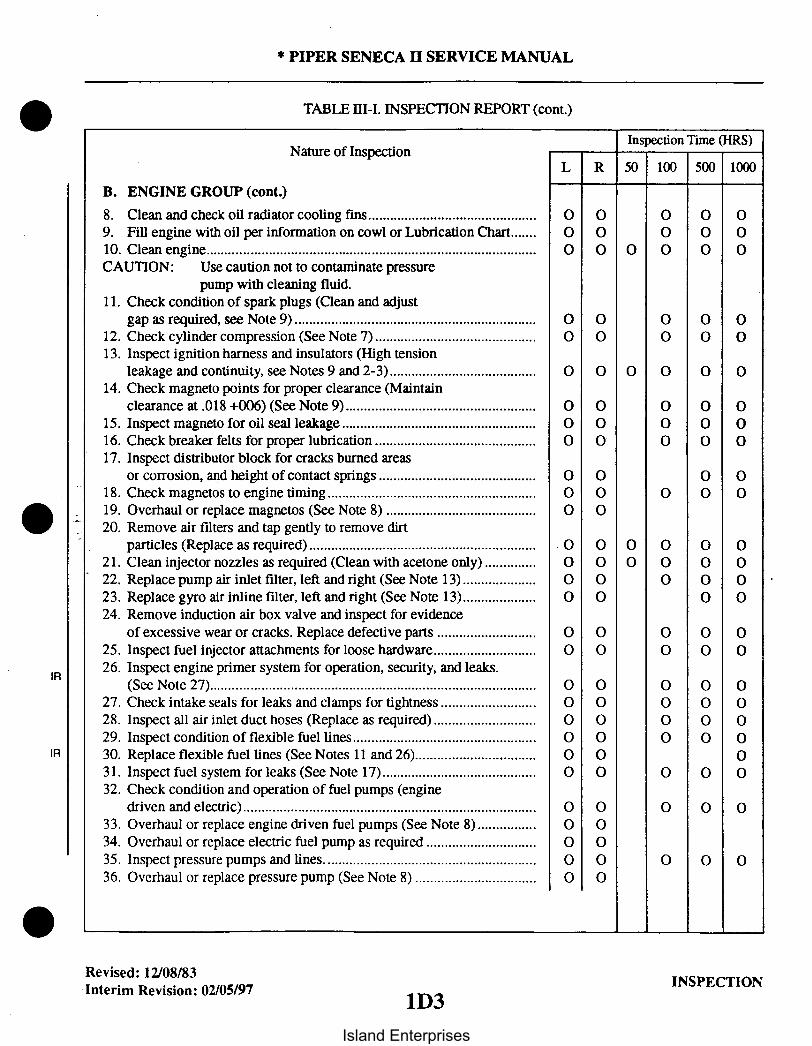
* PIPER SENECA SERVICE MANUAL
TABLE III-I. INSPECTION REPORT (cont.)
Nature of InspectionInspection Time (HRS)
L R 50 100 500 1000
B. ENGINE GROUP (cont.)
8. Clean and check oil radiator cooling fins..............................................9. Fill engine with oil per information on cowl or Lubrication Chart.......10. Clean engine..........................................................................................CAUTION: Use caution not to contaminate pressure
pump with cleaning fluid.11. Check condition of spark plugs (Clean and adjust
gap as required, see Note 9)..................................................................12. Check cylinder compression (See Note 7)............................................13. Inspect ignition harness and insulators (High tension
leakage and continuity, see Notes 9 and 2-3)........................................14. Check magneto points for proper clearance (Maintain
clearance at .018 +006) (See Note 9)....................................................15. Inspect magneto for oil seal leakage .......................................16. Check breaker felts for proper lubrication ............................................17. Inspect distributor block for cracks burned areas
or corrosion, and height of contact springs ...........................................18. Check magnetos to engine timing.........................................................19. Overhaul or replace magnetos (See Note 8) ........................................20. Remove air filters and tap gently to remove dirt
particles (Replace as required) ..............................................................21. Clean injector nozzles as required (Clean with acetone only) ..............22. Replace pump air inlet filter, left and right (See Note 13) ....................23. Replace gyro air inline filter, left and right (See Note 13)....................24. Remove induction air box valve and inspect for evidence
of excessive wear or cracks. Replace defective parts ...........................25. Inspect fuel injector attachments for loose hardware............................26. Inspect engine primer system for operation, security, and leaks.
(See Note 27).........................................................................................27. Check intake seals for leaks and clamps for tightness ..........................28. Inspect all air inlet duct hoses (Replace as required) ............................29. Inspect condition of flexible fuel lines .......................................
IR 30. Replace flexible fuel lines (See Notes 11 and 26).................................31. Inspect fuel system for leaks (See Note 17)..........................................32. Check condition and operation of fuel pumps (engine
driven and electric)................................................................................33. Overhaul or replace engine driven fuel pumps (See Note 8)................34. Overhaul or replace electric fuel pump as required ..............................35. Inspect pressure pumps and lines..........................................................36. Overhaul or replace pressure pump (See Note 8) .................................
0 0 0 00 0 0 0
0000 00
0 0 0 00 0 0 0
0000 00
0 0 0 00 0 0 0
00 000
0 00 00 0
0 00 00 00 0
0 00 0 0
0 00 0
0
0 00 00 00 0
00 0 00O0 0 0 00
0 00 00 00 00 00 0
0 00 00 00 00 0
0 0 00 0 00 0 00 0 0
00 0 0
0 0 0
0 0 0
Revised: 12/08/83Interim Revision: 02/05/97 INSPECTION
1D3Island Enterprises

TABLE III-I. INSPECTION REPORT (cont.)
37. Check throttle, alternate air, mixture and propellergovernor controls for security, travel and operating condition..................
38. Inspect exhaust stacks, connections and gaskets(Replace gaskets as required) ....................................................................
39. Inspect breather tubes for obstructions andsecurity ......................................................................................................
40. Inspect crankcase for cracks, leaks and security ofseam bolts ..................................................................................................
41. Inspect engine mounts for cracks and loosemountings ..................................................................................................
42. Check rubber ending mount bushings for deterioration(Replace as required).................................................................................
43. Inspect all engine baffles ...........................................................................44. Inspect fire wall seals ................................................................................45. Inspect condition of alternator and starter .......................................46. Inspect all lines, air ducts, electrical leads and
engine attachments for security, proper routing,chafing cracks, deterioration and correct installation................................
47. Check air conditioning compressor oil level(See Note 19).............................................................................................
48. Check condition and tension of compressor drive belt(Refer to Service Manual, Section XIV) ...................................................
49. Check security of compressor mounting ...................................................50. Inspect compressor clutch security and condition
of wiring ...................................................................................................51. Lubricate all controls (See Note 10)..........................................................52. Overhaul or replace propeller governor (Refer to latest
revision of Hartzell Service Letter No. 61) ...............................................53. Complete overhaul of engine or replace with factory
rebuilt (See Note 8) ...................................................................................54. Check magneto to RPM drop ...................................................................55. Check full power RPM ..............................................................................56. Check full power manifold pressure..........................................................57. Check full power fuel flow ........................................................................58. Check idle RPM and mixture ....................................................................59. Inspect and clean oil pressure relief valve.....................................60. Check unmetered fuel pressure at idle.......................................................61. Reinstall engine cowl ................................................................................
Revised: 12/08/83Interim Revision: 02/05/97 1D4
* PIPER SENECA II SERVICE MANUAL
Inspection Time (HRS)Nature of Inspection
L R 50 100 500 1000
B. ENGINE GROUP (cont.)
0 0
00
0 0 0
0 0 0 0 0 0
0 0
0 0
0 0
0 00 00 00 0
O O O
0 0 0
0 00
0 0 00 00O O O0 0 O
O 0 O 0 O O
0 0 0 0
00
0 0 00 0 0
0 0 00 0 00
0 0
0 00 00 00 00 00 00 00 00 0
000 00 00 00 0
00
0 0
0 00 00 00 00 00 00 00 0
INSPECTION
Island Enterprises

*PIPER SENECA II SERVICE MANUAL
TABLE II-I. INSPECTION REPORT (cont.)
Nature of Inspection
C. TURBOCHARGER GROUP
1. Inspect all air inlet ducting and compressor dischargeducting for worn spots. loose clamps or leaks ...............
2. Inspect engine air inlet assembly for cracks. looseclamps and screws ......................................
3. Inspect exhaust ducting and exhaust stacks for signsof leaks or cracks. Check all clamps for tightness ...........
4. Carefully check all turbo support brackets. struts. etc..for breakage. sagging or wear ............................
5. Inspect all oil lines and fittings for wear. leakage.heat damage or fatigue ..................................
6. Inspect bypass valve for security and safety.................7. Run up engines. check all instruments for smooth.
steady response .........................................8. Remove all turbocharger components from the engine.
Inspect and repair or replace as necessary. Checkturbocharger rotor for excessive play. carbon anddirt deposits. See Troubleshooting Section for RotorPlay Limits. Remove turbine and compressor housings.Inspect turbine wheel and impeller for physicaldamage and excessive build up of deposits. Ifexcessive, replace Turbocharger Assembly..................
Revised: 12/08/831D5
Inspection Time (hrs)
L R 50 100 500 1000
0
0
0
0
00
0
0
O 0 0 0 0
O 0 0 0 0
O 0 0 0 0
O 0 0 0 0
O 0 0 0 0O 0 0 0 0
0 0 0 0 0
0 0
INSPECTION
Island Enterprises

* PIPER SENECA I SERVICE MANUAL
TABLE III-I. INSPECTION REPORT (cont.)
Nature of InspectionInspection Time (HRS)
50 100 500 1000
D. CABIN GROUP
1. Inspect cabin entrance doors, cargo and baggage doors for damage and operation.Check condition and security of locks, latches and hinges. (See latest revisionof Piper Service Bulletins 633 and 872.)................................................................
2. Inspect windows for condition and security. ..........................................................3. Inspect upholstery for tears.....................................................................................4. Inspect seats, seat belts, security brackets and bolts...............................................5. Check trim system operation..................................................................................6. Check operation and condition of rudder pedals ..................................................7. Check parking brake handle and toe brakes for operation and cylinder leaks .......8. Check operation and condition of control wheels, column pulleys,
bobweight and cables..............................................................................................9. Inspect flap control cable attachment bolt (See latest revision of Piper Service
B ulletin 965) ...........................................................................................................10. Inspect landing, navigation, cabin and instrument lights .......................................11. Inspect instruments, lines and attachments (See latest revision of Piper Service
Bulletin 584)...........................................................................................................12. Inspect gyro operated instruments and electric turn and bank
(Overhaul or replace as required) ...........................................................................13. Replace filters on gyro horizon and directional gyro or replace central air
filters (where applicable) (See Note 13).................................................................14. Inspect altimeter (Calibrate system in accordance with FAR 91.170 if
appropriate)...........................................................................................................15. Perform pitot-static tests if appropriate (Refer to FAR 91.170) .............................16. Check operation of fuel selector valves..................................................................17. Check operation of fuel drains................................................................................18. Check condition and operation of heater controls and ducts ..................................19. Check condition and operation of air vents ...........................................................20. Inspect condition of air conditioning ducts ............................................................21. Remove and clean air conditioning evaporator filter .............................................22. Inspect stabilator control stops to insure stop has not loosened
and jam nuts are tight..............................................................................................23. Inspect rudder control stop to insure stop has not loosened and locknuts
are tight...................................................................................................................
E. FUSELAGE AND EMPENNAGE GROUP
O 0 00 0 00 0 00 0 00 0 00 0 00 0 0
0 0 0
O 0 000 00
0 0 0
0 0 0
O 0 0
O 0 00 0 00 0 00 0 00 0 00 0 0O 0 00 0 0
0 0 0
0 0 00 0 0o
1. Remove inspection plates and panels .....................................................................2. Inspect battery box and cables (Check at least every 30 days. Flush box
as required and fill battery per instructions on box) .......................................3. Check fluid level in brake reservoir (Fill as required)............................................4. Inspect electronics installations for security (See latest revision of Piper
Service Bulletin 553)..............................................................................................5. Inspect antenna mounts and wiring for security and condition..............................
Revised: 12/08/83Interim Revision: 02/05/97
1D6
o o o
00 00
0 0 00 00
INSPECTION
0
Island Enterprises

PIPER SENECA II SERVICE MANUAL
TABLE II-I. INSPECTION REPORT (cont.)
Nature of Inspection
E. FUSELAGE AND EMPENNAGE GROUP (cont.)
6. Inspect bulkheads and stringers for damage ...........................7. Inspect hydraulic pump motor brushes (See Note 16) ...................8. Check hydraulic pump fluid level (Fill as required) .....................9. Inspect hydraulic lines for damage and leaks ..........................
10. Check air conditioning system for freon leaks..........................11. Check freon level in sight gauge of receiver-dehydrator (Refer to
Service Manual, Section XIV) .......................................12. Inspect air conditioner condenser air scoop rigging .....................13. Inspect heater (See Note 18 for overhaul information) ..................14. Check fuel lines, valves and gauges for damage and operation ...........15. Check security of all lines ..........................................16. Inspect vertical fin and rudder surface for damage......................17. Inspect rudder hinges, horn and attachments for damage and
operation (Refer to the latest revision of Piper Service BulletinNo. 699)..........................................................
18. Inspect vertical fin attachments for condition and security(See latest revision of Piper Service Bulletin No. 579) ...................
19. Inspect ELT installation and condition of battery and antenna(See latest revision of Piper Service Letter No. 820) ....................
20. Inspect rudder tab hinge bolts for excess wear (Replace as required)(See Note 13)......................................................
21. Inspect rudder trim mechanism (See Note 14)..........................22. Inspect stabilator surfaces for damage ................................23. Inspect stabilator, tab hinges, horn and attachments for damage
and operation .....................................................24. Check condition of stabilator attachment (See latest Piper Service
Bulletins 579 and 856) ..............................................25. Inspect stabilator and tab hinge bolts and bearings for excess wear
(Replace as required) ...............................................26. Check condition and operation of stabilator trim mechanism ............27. Check all cable tensions (use tensiometer) (See Note 15) ................28. Inspect aileron, rudder, stabilator, stabilator trim cables, turnbuckles,
guides and pulleys for condition, damage, safety, tension andoperation .........................................................
29. Inspect all control cables, electrical leads, air ducts, and attachingparts for security, routing, chafing, deterioration, wear and correctinstallation (Refer to the latest revision of Piper Service BulletinNo. 555)......... ......... ........................................
30. Clean and lubricate stabilator trim screw (See Note 10) .................31. Clean and lubricate all exterior needle bearings ........................
Revised: 12/08/83Interim Revision: 5/6/87 1
1D7
Inspection Time (hrs)
50 100 500 1000
0
000
0
0 0 00 0 00 0 00 0 00 0 0
0 0 00 0 00 0 00 0 00 0 00 0 0
0 0 0
0 0 0
0 0 0
0 0 00 0 00 0 0
0 0 0
0 0 0
0 0 00 0 00 0 0
0 0 0
0 0 00 0
0
INSPECTION
Island Enterprises

*PIPER SENECA II SERVICE MANUAL
TABLE III-1. INSPECTION REPORT (cont.)
Inspection Time (hrs)Nature of Inspection
50 100 500 1000E. FUSELAGE AND EMPENNAGE GROUP (cont.)
32.33.34.35.36.
Lubricate per Lubrication Chart (See Note 10).........................Inspect strobe lights for security and operation ........................Check condition and security of autopilot bridle cable clamps ...........Reinstall inspection plates and panels ................................Inspect aileron control stops to insure stop has not loosened andlock nut is tight....................................................
0 0 0 0O 0 0O 0 0O 0 0
0 0 0
F. WING GROUP
I. Remove inspection plates and fairings ................................2. Inspect surfaces and tips for damage, loose rivets and condition
of walkway .......................................................3. Inspect aileron hinges and attachments ...............................4. Inspect aileron cables, pulleys, and bellcrank for damage and
operation .........................................................5. Inspect flaps and attachments for damage and operation ................6. Inspect condition of bolts used with hinges (Replace as required).........7. Lubricate per Lubrication Chart (See Note 10).........................8. Inspect wing attachment bolts, nuts and brackets for security and
condition .........................................................9. Inspect all control cables, electrical leads, air ducts, lines and
attaching parts for security, routing, chafing, deterioration, wearand correct installation .............................................
10. Inspect fuel tanks and lines for leaks and water (See Note 11) ...........II. Remove, drain and clean fuel filter bowls (Drain and clean at
least every 90 days) ................................................12. Ascertain that fuel tanks are marked for minimum octane rating
and capacity ......................................................13. Inspect condition of fuel tank vents (See Note 12)......................14. Reinstall inspection plates and fairings................................
O 0 O
O O OO 0 0
0 0 00 0 0O 0 0O 0 00
0 O O
0 O OO O O
0 O O O
O O OO 0 OO O O
G. LANDING GEAR GROUP
1. Check oleo struts for proper extension (Check for proper fluidlevel and air pressure as required) ....................................
2. Check nose gear steering control and travel ...........................3. Check wheel alignment .............................................4. Put airplane on jacks (Refer to Section 11 of Service Manual) ...........5. Inspect tires for cuts, uneven or excessive wear and slippage .............6. Remove wheels, clean, inspect and repack bearings .....................
I Revised: 12/08/83
0 O 0 0O 0 0O 0 00 0 0O 0 00 0 0
INSPECTION
Island Enterprises

* PIPER SENECA I SERVICE MANUAL
TABLE III-I. INSPECTION REPORT (cont.)
Nature of InspectionInspection Time (HRS)
50 100 500 1000G. LANDING GEAR GROUP (cont.)
7. Inspect wheels for cracks, corrosion and broken belts ..........................................8. Check tire pressure (Refer to Section II, Table II-I)...............................................9. Inspect condition of brake linings and disc (Refer to Section VII,
Paragraph 7-52)10. Inspect condition of brake backing plates ..............................................................11. Inspect condition and security of brake lines and retaining clamps .......................12. Inspect condition of center spring and bungees......................................................13. Inspect gear forks for damage ................................................................................14. Inspect oleo struts for fluid leaks and scoring .......................................................15. Inspect gear struts, attachment, torque links, retraction links and
bolts for condition and security (See Note 20) .......................................................16. Check downlocks for operation and adjustment............................... ........17. Inspect torque link bolts and bushings (Rebush as required) .................................18. Inspect drag end side brace link bolts (Replace as required) .................................
IR 19. Inspect nose gear upper drag link AN7-35 attach bolt .........................................20. Replace nose gear upper drag link AN7-35 attach bolt..........................................21. Inspect gear doors and attachments for condition and security..............................22. Check operation of gear warning horn and light ....................................................23. Retract gear - check operation and gear doors for clearance..................................24. With gear retracted, check "Free Fall" valve operation..........................................25. Check operation of squat switch.............................................................................26. Check downlock switches, up switches and electrical leads for
operation, condition and security of mounting.......................................................27. Inspect all hydraulic lines, electrical leads, and attaching parts for
security, routing, chafing, deterioration, wear and correct installation(See the latest revision of Piper Service Letter No. 808) .......................................
28. Lubricate per Lubrication Chart (See Note 9) ........................................................29. Ascertain landing gear is down and locked; then remove airplane
from jacks ...............................................................................................................
0 000000
0 000 000 000 0 00 0 0
00000
0 00 00 000
0 00 000 000 000 000 00
0 00
0000
0 0 0O lO O
Revised: 12/08/83Interim Revision: 02/05/97 INSPECTION
1D9Island Enterprises

*PIPER SENECA II SERVICE MANUAL
TABLE 111-1. INSPECTION REPORT (cont.)
Nature of Inspection
H. OPERATIONAL INSPECTION
1. Check fuel pumps. fuel tank selector and crossfeed operation ............2. Check fuel quantity and pressure or flow gauges .......................3. Check oil pressure and temperature gauges ............................4. Check alternator output - left and right engines ........................5. Check manifold pressure gauge ......................................6. Check alternate air.................................................7. Check parking and toe brake ........................................8. Check pressure gauge...............................................9. Check gyro for noise and roughness ..................................
10. Check cabin heater and defroster ....................................I11. Check magneto RPM variation .....................................12. Check magneto switch operation .....................................13. Check throttle and mixture controls ...................................14. Check propeller controls and propeller action..........................15. Check engine idle ..................................................16. Check electronic equipment operation (Refer to Section XII of
Service Manual for ELT check) ......................................17. Check air condition compressor clutch operation .......................18. Check air conditioner condenser scoop operation ......................19. Check operation of flight controls and flaps ...........................20. Check operation of Autopilot, including automatic pitch trim and
manual electric trim (See Note 22) ...................................
Inspection Time (hrs)
50 100 500 1000
000000000000000
0000
0
0 0 0O 0 0O 0 00 0 00 O 0O 0 0O 0 0O 0 0O 0 00 0 0O 0 0O 0 0O 0 0O 0 0O 0 0
O 0 0O 0 0O 0 0O 0 0
O 0 0
1. GENERAL
1. Aircraft conforms to latest FAA Specifications ........................2. All latest FAA Airworthiness Directives complied with .................3. All latest revisions of Manufacturers Service Letters and Bulletins
complied with .....................................................4. Check for proper Flight Manual .....................................5. Aircraft papers in proper order ......................................
Revised: 12/08/831D10
00
000
0 0 00 0 0
0 0 00 0 00 0 0
0INSPECTION
Island Enterprises

* PIPER SENECA II SERVICE MANUAL
NOTES:
IR
IR
1. Refer to the last card of the Piper Parts Price List - Aerofiche, for a checklist of current revision datesto Piper inspection reports and manuals.
2. All inspections or operations are required at each of the inspection intervals as indicated by an (O).Both the annual and 100 hour inspections are complete inspections of the airplane, identical in scope,while both the 500 and 100 hour inspections are extensions of the annual or 100 hour inspections,which require a more detailed examination of the airplane, and overhaul or replacement of some majorcomponents. Inspections must be accomplished by persons authorized by the FAA.
3. Piper service bulletins are of special importance and Piper considers compliance mandatory.4. Piper service letters are product improvements and service hints pertaining to servicing the airplane
and should be given careful attention.5. Inspections given for the power plant are based on the engines manufacturer's operator's manual for
the particular airplane. Any changes issued to the engine manufacturer's operator's manual shallsupersede or supplement the inspections outlined in this report.
6. Replace flexible oil lines as required, but not to exceed 1000 hours or 8 years, the first to occur. Inaddition, replace lines at engine overhaul.
7. Refer to the latest revision of Continental Motors Service Bulletin M73-19.8. Replace or overhaul as required or at engine overhaul. Refer to the latest revision of Continental
Motors Service Bulletin M74-20.9. For operation at higher altitudes (12,000 feet and up), more frequent ignition system maintenance is
required. (Refer to the latest revision of Continental Service Bulletin M78-8.)10. Refer to lubrication chart.11. Replace flexible fuel supply hose and interconnect hose couplings as required, but not to exceed 1000
hours or 8 years, the first to occur. In addition, replace lines at engine overhaul.12. Replace fuel tank vent line flexible connections as required, but not later than three years time in service.13. Early Seneca's had inline filter in cabin; later models have filter located in nacelle.14. Refer to section V, paragraph 5-34 for allowable rudder tab and trim free play.15. Maintain cable tensions specified in section V of service manual.16. Inspect brushes every 100 hours if aircraft is used for training or 500 hours if aircraft is used for
normal service (refer to service manual, section VI).17. Refer to the latest revision of Piper Service Bulletin 596.18. Conduct 100 hour inspections in accordance with Janitrol Maintenance and Overhaul Manual 24E25-
1, dated October 1981. Overhaul any heater that does not pass the combustion pressure decay testoutlined in the Janitrol Manual. Copies obtainable from: Janitrol Aero Division, Midland-Ross Corp.,4200 Surface Rd., Columbus, Ohio 43228.
19. The compressor oil level should not be checked unless a Freon leak has occurred which requires anaddition of Freon to the system.
20. For all aircraft in excess of 1000 hours carefully inspect the trunnion forging barrel for cracks with a10 power glass at the lower end of the fillet every 500 hours thereafter unless replaced by p/n 67926-12, 67926-13, 67926-14 or 67926-15.
21. Refer to section XII of service manual for appropriate subject manual part number.22. Refer to flight manual supplement for preflight and flight check, for intended function in all modes.23. Refer to the latest revision of Bendix Service Bulletin 612 for inspection of magnetos and ignition harness.24. Refer to Teledyne Continental Service Bulletin M86-11, latest revision.25. Refer to VSP 69.26. Flexible hose replacement times are in-service times. In-service must be determined by (1) the date the
aircraft was licensed, if new or (2) the date entered in the logbook for the replacement hose placed inservice. Do not use the date stamped on the hose, as time may be included for shelf life, and notin-service use.
27. See latest revision of Piper Service Bulletin 905.
IR
Interim Revision: 02/05/97 INSPECTION1D11
Island Enterprises

SECTION IV
STRUCTURESAeroficheGrid No.Paragraph
4-1.4-2.4-2a.
Introduction ..............................................................Description ...............................................................Standard Practices.........................................................4-2b. Removal of Cherrylock Rivets ......................................4-2c. Identification of Fluid Lines........................................4-2d. Flareless Tube Assemblies..........................................4-2e. Support Clamps Information .......................................4-2f. Electrical Bonding ................................................Wing Group ..............................................................Wing Tip .................................................................
4-3.4-4.
4-5. Removal of Wing Tip .............................................4-6. Repair of Wing Tip ...............................................4-7. Installatin of Wing Tip ...................................... .....
4-8. Aileron...................................................................4-9. Removal of Aileron ...............................................4-10. Installation of Aileron .............................................
4-11. Wing Flap ................................................................4-12. Removal of Wing Flap ............................................4-13. Installation of Wing Flap .........................................
4-14. Wing.....................................................................4-15. Removal of Wing .................................................4-16. Installation of Wing...............................................
4-17. Empennage Group.........................................................4-18. Stabilator .................................................................
4-19. Removal of Stabilator .............................................4-20. Installation of Stabilator...........................................
4-21. Stabilator Trim Tab .......................................................4-22. Removal of Stabilator Trim Tab ....................................4-23. Installation of Stabilator Trim Tab .................................
4-24. Rudder...................................................................4-25. Removal of Rudder ...............................................4-26. Installation of Rudder .............................................
4-27. Rudder Trim Tab..........................................................4-28. Removal of Rudder Trim Tab ............... :......................4-29. Installation of Rudder Trim Tab ....................................
4-30. Vertical Fin...............................................................4-31. Removal of Vertical Fin ...........................................4-32. Installation of Vertical Fin .........................................
4-33. Fuselage Assembly.........................................................4-34. Windshield ...............................................................
4-35. Removal of Windshield ............................................4-36. Installation of Windshield .........................................
ID14ID14ID141D14ID171D171D20ID201D20ID20I D20ID20ID21ID21ID21ID21ID21ID21ID21ID241D24IE3IE4IE4IE4IE5IE5IE5IE5IEIO1E10IEI0IE10IEIOIE111E11IE111E12IE121E12IE12IE12
Revised: 8/10/80 1D12
Island Enterprises
Paragraph AeroficheGrid No.
4-37. Side Windows............................................................. I E144-38. Removal of Windows (Side) ........................................ IE 144-39. Installation of Windows (Side)...................................... I E 144-40. Removal of Rear Door Window .................................... I E154-41. Installation of Rear Door Window .................................. I E 15
4-42. Door (Entrance) ........................... 7.......... ....... IE174-42a. Removal and Installation of Door Snubbers .......................... 1E174-43. Removal of Door ................................................. 1E204-44. Installation of Door............................................... IE204-45. Adjustment of Door .............................................. 1E214-46. Removal of Door Latch Mechanism ................................ IE214-47. Installation of Door Latch Mechanism .............................. IE214-48. Adjustment of Door Latch Mechanism .............................. 1E214-49. Removal of Door Lock Assembly................................... IE214-50. Installation of Door Lock Assembly ................................. E214-51. Removal of Door Safety (Auxiliary) Latch ........................... IE214-52. Installation of Door Safety (Auxiliary) Latch ......................... 11E214-53. Adjustment of Door (Auxiliary) Latch............................... IE21
4-54. Baggage Door ......... ...................... .......................... E214-55. Removal of Baggage Door ......................................... IE214-56. Installation of Baggage Door ....................................... IE224-57. Removal of Baggage Door Lock Assembly ........................... 1E224-58. Installation of Baggage Door Lock Assembly ......................... 1E224-59. Removal of Baggage Door Hinge ................. .............. . 1E224-60. Installation of Baggage Door Hinge ................................. IE22
4-61. Rigging Instructions - Seat Back Lock and Release ............................ IE224-61a. Shoulder Harness Inertia Reel Adjustment .................................... IE224-62. Structural Repairs ......................................................... 1E244-63. Fiberglass Repairs ......................................................... 1E24
4-64. Fiberglass Touch-Up and Surface Repairs............................ IE244-65. Fiberglass Fracture and Patch Repairs ............................... IF2
4-66. Thermoplastic Repairs ..................................................... IF54-67. Safety Walk Repair ........................................................ 1F13
4-68. Surface Preparation for Liquid Safety Walk .......................... 2F134-69. Product Listing for Liquid Safety Walk Compound ................... IF134-70. Application of Liquid Safety Walk Compound ....................... IF134-71. Surface Preparation for Pressure Sensitive Safety Walk ................ IF144-72. Application of Pressure Sensitive Safety Walk ........................ IF14
4-73. Control Surface Balancing .................................................. F 154-74. Checking Control Surface Balance .................................. IF154-75. Balancing Equipment .............................................. 1F154-76. Balancing Ailerons ................................................ I F 174-77. Balancing Rudder ................................................ IF174-78. Balancing Stabilator............................................... IF194-79. Checking Free Play of Control Surfaces ............................. IF19
Revised: 8/10/80ID 13
Island Enterprises

PIPER SENECA II SERVICE MANUAL
SECTION IV
STRUCTURES
4-1. INTRODUCTION. This section explains the removal and installation procedures for the structuralsurfaces of the airplane. For the removal, installation, and rigging and adjustment procedures of thecontrolling components of the various structural surfaces, refer to Section V.
NOTE
When torquing structural assemblies, standard torque values are tobe used as found in Section II or FAA Advisory Circular 43. 13-1 A.unless otherwise stated in this section.
4-2. DESCRIPTION. The PA-34-200T is an all metal semi-monocoque structure with an overall length of28 feet 7.5 inches. The fuselage is constructed of bulkheads, stringers and stiffeners. to which all of the outerskin is riveted. Windows include a single pane windshield and eight side windows; all windows are single pane.A storm window is located in the forward lower section of the left window and can be opened inward when thelatch is released. The cabin entrance door is located on the right side of the fuselage, above the wing, and isequipped with a safety latch on the top of the door which can be operated from the inside or outside. A doorprovided for entrance to the aft passenger compartment is located just aft of the left wing.
Each wing panel is an all metal, full cantilever semi-monocoque type construction with a removablefiberglass or thermoplastic tip. Installed in each wing ahead of the main spar are two metal fuel tanks with acapacity of 24.5 U.S. gallons each or 49.0 U.S. gallons total perwing. Attached to each wing is an aileron, flap,main landing gear and power plant. The wings are attached to each side of the fuselage by inserting the buttends of the main spars into a spar box carry-through. The spar box is an integral part of the fuselage structurewhich provides, in effect, a continuous main spar with splices at each side of the fuselage. There are also foreand aft attachments at the front and rear spars.
The all metal empennage group is a full cantilever design consisting of a vertical stabilizer (fin), rudderand stabilator. all with removable fiberglass or thermoplastic tips. The rudder and stabilator have trim tabsattached that are controllable from the cockpit. The stabilator also incorporates one channel main spar thatruns the full length of the stabilator and hinges to the aft bulkhead assembly of the fuselage. All exteriorsurfaces are coated with enamel or acrylic lacquer. As an option, the airplane may be completely primedwith zinc chromate.
4-2a. STANDARD PRACTICES.
4-2b. REMOVAL OF CHERRYLOCK RIVETS. (Refer to Figure 4-1.) If necessity requires the removal ofa cherrylock rivet, proceed as follows:
a. In thick material remove the lock by driving out the rivet stem, using a tapered steel drift pin. (SeeView 1.)
NOTE
Do not drill completely through the rivet sleeve to remove a rivet asthis will tend to enlarge the hole.
Revised: 8/10/80 STRUCTURES
1D14Island Enterprises

SMALLCENTER DRILL
PIPER SENECA II SERVICE MANUAL
B361
DRIFT PIN
VIEW 1
VIEW 2 VIEW 3
Figure 4-1. Cherrylock Rivet Removal
Added: 8/10/80 STRUCTURES1D15
Island Enterprises

WHITE
PIPER SENECA II SERVICE MANUAL
362 TWO COTTON BRAIDS- IMPREGNATEDWITH SYNTHETIC COMPOUND
YELLOW SINGLE WIRE BRAIDSYNTHETIC INNER TUBE
A. FLAME AND AROMATIC RESISTANT HOSE
YELLOW, NUMERALS,LETTERS AND STRIPE
D. NONSELF-SEALING AROMATICRESISTANT HOSE
WHITE NUMERALS, LETTERS AND STRIPE RED
(VIEWS SHOWING OPPOSITE SIDES OF HOSE)
B. NONSELF-SEALING AROMATIC AND HEAT-RESISTANT HOSE
RED NUMERALS AND LETTERS
C. FLAME, AROMATIC, AND OIL RESISTANT HOSE
RED NUMERALS, LETTERS AND STRIPE
E. SELF-SEALING AROMATICRESISTANT HOSE
BROWN OR NGE
ELECTRICALCONDUIT
GREEN
HOSE
ORANGE
COMPRESSEDGAS
RED
FUEL
IDENTIFICATION
ORANGE GRAY
INSTRUMENTAIR
ORANGE BLUE
PNEUMATIC
MARKINGS
BLUE YELLOW
HYDRAULIC
GRAY
DE-ICING
YELLOW BROWN GREY
LUBRICATION AIRCONDITION
TAPE AND DECALS
OXYGEN
FLUID LINE IDENTIFICATION USING
Figure 4-1a. Hose/Line Markings
Added: 8/10/80 STRUCTURES
1D16Island Enterprises

PIPER SENECA II SERVICE MANUAL
b. If the rivets have been installed in thin sheets, driving out the locked stem may damage the sheets. Itis recommended that a small center drill be used to provide a guide for a larger drill on top of the rivet stem, andthe tapered portion of the stem be drilled away to destroy the lock. (See View 2.)
c. Pry the remainder of the locking collar out of the rivet head with the drift pin. (See View 2.)d. Drill nearly through the head of the rivet, using a drill the same size as the rivet shank. (See View 3.)e. Break off rivet head, using a drift pin as a pry. (See View 3.)f. Drive out the remaining rivet shank with a pin having a diameter equal to the rivet shank. (See View
3.)
4-2c. IDENTIFICATION OF FLUID LINES. (Refer to Figure 4-1a.) Fluid lines in aircraft are oftenidentified by markers made up of color codes, words, and geometric symbols. These markers identify eachline's function, content, and primary hazard, as well as the direction of fluid flow.
In most instances, fluid lines are marked with 1-inch tape or decals. Paint is used on lines in enginecompartments, where there is the possibility of tapes, decals or tags being drawn into the engine inductionsystem.
In addition to the above mentioned markings, certain lines may be further identified as to specificfunction within a system; for example. DRAIN. VENT, PRESSURE or RETURN.
Lines conveying fuel may be marked FLAM: lines containing toxic materials are marked TOXIC in placeof FLAM. Lines containing physically dangerous materials, such as oxygen, nitrogen. or freon. are markedPHDAN.
The aircraft and engine manufacturers are responsible for the original installation of identificationmarkers, but the aviation mechanic is responsible for their replacement when it becomes necessary.
Generally, tapes and decals are placed on both ends of a line and at least once in each compartmentthrough which the line runs. In addition, identification markers are placed immediately adjacent to each valve.regulator, filter or other accessory within a line. Where paint or tags are used. location requirements are thesame as for tapes and decals.
4-2d. FLARELESS-TUBE ASSEMBLIES. (Refer to Figure 4-lb.) Although the use of flareless-tubefittings eliminates all tube flaring, another operation, referred to as presetting, is necessary prior to installationof a new flareless-tube assembly which is preformed as follows:
a. Cut the tube to the correct length, with the ends perfectly square. Deburr the inside and outside ofthe tube. Slip the nut, then the sleeve, over the tube (Step 1).
b. Lubricate the threads of the fitting and nut. See Figure 4-lb for proper lubricant to use. dependingon the type system the tubing assemblies are to be used on. Place the fitting in the vise (Step 2). and hold thetubing firmly and squarely on the seat in the fitting. (Tube must bottom firmly in the fitting.) Tighten the nutuntil the cutting edge of the sleeve grips the tube. This point is determined by slowly turning the tube back andforth while tightening the nut. When the tube no longer turns, the nut is ready for final tightening.
c. Final tightening depends upon the tubing. For aluminum alloy tubing up to and including 1/2 inchoutside diameter, tighten the nut from one to one and one-sixth turns. For steel tubing and aluminum alloytubing over 1/2 outside diameter, tighten from one and one-sixth to one and one-half turns.
After presetting the sleeve, disconnect the tubing from the fitting and check the following points(illustrated in Step 3):
a. The tube should extend 3/32 to 1/8 inch beyond the sleeve pilot: otherwise blowoff may occur.b. The sleeve pilot should contact the tube or have a maximum clearance of 0.005 inch for aluminum
alloy tubing or 0.015 inch for steel tubing.c. A slight collapse of the tube at the sleeve cut is permissible. No movement of the sleeve pilot. except
rotation is permissible.
Added: 8/10/80 17 STRUCTURES1D 17
Island Enterprises

CAUTION-DO NOT USE OIL OR GREASE
TUBING AND HOSE LUBRICANTS
SLEEVEPILOT TUBE NUT
SLEEVE CUTTING EDGE
STEP 1
3/32 TO1/8 INCH
PIPER SENECA II SERVICE MANUAL
B363
TUBING SYSTEM
HYDRAULICFUELOILPNEUMATICOXYGEN*
LUBRICANT
MIL-H-5606MIL-H-5606System OilMIL-L-4343MIL-T-5542
BEVEL
NUT
FLARELESS-TUBE FITTING
STEP 3SLIGHT DEFORMATIONPERMISSIBLE
.005 INCH MAXIMUM - ALUMINUMALLOY TUBING
015 INCH MAXIMUM - CORROSIONRESISTANT STEEL TUBING
PRESETTING FLARELESS-TUBE ASSEMBLY
Figure 4-lb. Flareless-Tube Fittings
Added: 8/10/80 STRUCTURES
1D18
Island Enterprises

PIPER SENECA II SERVICE MANUAL
TABLE IV-I. MAXIMUM DISTANCES BETWEEN FLUID TUBING SUPPORTS
TUBE OD
(IN.)
DISTANCE BETWEEN SUPPORTS (IN.)
ALUMINUM ALLOY
9-1, 2
STEEL
11-1/21 8
3 16 12 14
14 13-1 /2 16
5 16 15 18
38 16-1 2 20
1 2 19 23
58 22 25-1, 2
34 24 27-1 2
1 26-1 2 30
TABI.E IV-II. MAXIMUM M RESISTANCE VALUES ALLOWED FOR ELECTRICAL BONDING
ITEM TO BE ELECTRICALLY BONDED
Engine MountGeneratorsAileronsElevatorsRudderMotor(s)FlapsTrim Tabs
Conventional HingePiano Wire Hinge
Instrument Panel InsertsInterior LightsExterior Lights Mounted onNon-Conductive Material
HeatersElectrical EquipmentAvionics "Black Boxes"Battery Ground Point to GeneratorGround Point
Refueling Ground Attachment to .032Aluminum Plate under Tire (A/C onGround)
MAXIMUM ALLOWABLERESISTANCE VALUE
IN OHMS
.003
.003
.003
.003
.003
.003
.003
.003.01.01.01
.003
.003
.003
.003
.01
10 Megohms0
Revised: 3/1(/81 STRUCTURES1D19
Island Enterprises

PIPER SENECA II SERVICE MANUAL
4-2e. SUPPORT CLAMPS INFORMATION. Support clamps are used to secure the various lines to theairframe or power plant assemblies. Several types of support clamps are used for this purpose. The rubber-cushioned and plain are the most commonly used clamps. The rubber-cushioned clamp is used to secure linessubject to vibration: the cushioning prevents chafing of the tubing. The plain clamp is used to secure lines inareas not subject to vibration.
A teflon-cushioned clamp is used in areas where the deteriorating effect of Skydrol 500, hydraulic fluid(MIL-H-5606)or fuel is expected, however, because it is less resilient, it does not provide as good a vibration-damping effect as other cushion materials.
Use bonded clamps to secure metal hydraulic, fuel and oil lines in place. Unbonded clamps should be usedonly for securing wiring. Remove any paint or anodizing from the portion of the tube at the bonding clamplocation. Make certain that clamps are of the correct size. Clamps or supporting clips smaller than the outsidediameter of the hose may restrict the flow of fluid through the hose.
All plumbing lines must be secured at specified intervals. The maximum distance between supports forrigid fluid tubing is shown in Table IV-I.
4-2f. ELECTRICAL BONDING. Aircraft electrical bonding should be accomplished or verified to establisha maximum allowable resistance value. See Table IV-II for values.
All electrical, electronic equipment and components shall be installed in such a manner as to provide acontinuous low-resistance path from the equipment enclosure to the airplane structure.
Parts shall be bonded directly to the primary structure rather than to other bonded parts.All parts shall be bonded with as short a lead as possible.All bonding surfaces shall be cleaned prior to the installation of the bonded joint.All nuts used in bonding shall be of the self-locking type. (Do Not use fiber-locking type.)All electrical bonding shall be accomplished without affecting the structural integrity of the airframe.Bond connections shall be secure and free from corrosion.Self-Tapping Screws will not be used for bonding purposes.
4-3. WING GROUP.
NOTE
The major subassemblies of the wing may be removed individuallyor the wing may be removed as a unit. To remove a wing, afuselage supporting cradle is required.
4-4. WING TIP.
4-5. REMOVAL OF WING TIP.a. Remove the screws holding the wing tip to the wing being careful not to damage the wing or wing
tip.b. Pull off the wing tip far enough to disconnect the navigation light wire assembly. The ground lead
may be disconnected at the point of connection on the wing rib and the positive lead may be disconnectedat the wire terminal or unscrewed from the light assembly.
c. Inspect the fiberglass wing tip to ascertain that it is free of cracks, severe nicks and minordamage.
4-6. REPAIR OF WING TIP. Fiberglass wing tips may be repaired in accordance with fiberglass repairprocedures in the structural repairs portion of this section. Badly damaged thermoplastic tips should bereplaced.
Added: 8/10/80 1D20 STRUCTURES1D 20
Island Enterprises

PIPER SENECA II SERVICE MANUAL
4-7. INSTALLATION OF WING TIP.a. Place the wing tip in a position that the navigation light leads may be connected. Connect the
ground lead to the wing rib by use of a screw and nut and the positive lead to the navigation light byconnecting the wire terminals or screwing the connectors together. Insulate the wire terminals and becertain that the ground lead is free of dirt and film to insure a good connection.
b. Insert the wing tip into position and install the screws around the tip. Use caution to refrain fromdamaging the wing tip or wing. Check operation of the navigation light.
4-8. AILERON.
4-9. REMOVAL OF AILERON. (Refer to Figure 4-1c.)a. Disconnect the aileron control rod at the center hinge by removing the nut, washers, and bolt
from the rod end bearing. To simplify installation, note the location of the washers.b. Support the aileron and disconnect the inboard, outboard and center aileron hinges by removing
the nuts, washers and hinge bolts. Remove the aileron by lifting and pulling aft.
4-10. INSTALLATION OF AILERON. (Refer to Figure 4-1c.)a. Position the aileron in the wing and install the bolts, washers, and nuts at the hinges.b. Connect the aileron control rod to the aileron at the center hinge brackets with bolt, washers and
nut.
4-11. WING FLAP.
4-12. REMOVAL OF WING FLAP. (Refer to Figure 4-1c.)a. Extend the flaps to their fullest degree and remove the bolt and bushing from the rod end bearing
by use of an angle or offset screwdriver.b. Remove the nuts. washers, bushing, and hinge bolts that hold the flap to the wing assembly.c. Pull the flap straight back off the wing.
4-13. INSTALLATION OF WING FLAP. (Refer to Figure 4-1c.)a. Replace the wing flap by placing the flap into its proper position and inserting the hinge bolts,
bushings, washers and nuts.b. With the flap control in the full flap position, place the bushing on the outboard side of the rod
end bearing and insert and tighten the bolt.c. Operate the flap several times to be certain it operates freely.
Reissued: 10/11/79 1D21 STRUCTURES
Island Enterprises

883
PIPER SENECA II SERVICE MANUAL
A162 A322
BOLT AN3-11 AWASHER AN960-10NUT MS20365-1032CBUSHING 63900-19 (2 REQ.)2 REQ.
SKETCH B SKETCH D
Figure 4-1c. Aileron and Flap Installation
Reissued: 10/11/79 STRUCTURES
1D22
Island Enterprises

WING
PIPER SENECA II SERVICE MANUAL
A321
0
0BOLT AN2 3 -1WASHER AN960-10NUT MS24665-132COTTER PIN AN310-3BUSHING 63900-39
A322
BOLT AN3-13AWASHER AN960-10NUT MS20365-1032CBUSHING 63900-20 (2 REQ.)
SKETCH A SKETCH E
Figure 4-1c. Aileron and Flap Installation (cont.)
Reissued: 10/11/79 STRUCTURES1D23
Island Enterprises

PIPER SENECA II SERVICE MANUAL
4-14. WING.
4-15. REMOVAL OF WING. (Refer to Figure 4-2.)a. Close the fuel valve and drain the fuel from the wing to be removed. (Refer to Draining Fuel
System, Section II.)b. Drain the brake lines and reservoir. (Refer to Draining Brake System, Section II.)c. Remove the engine from the wing to be removed. (Refer to Removal of Engine, Section VIII.)d. Drain the hydraulic lines of the landing gear of the wing to be removed by separating the lines
and elbows at the actuating cylinder.e. Remove the access plate at the wing butt rib and wing inspection panels. (Refer to Access Plates
and Panels, Section II.)f. Remove the front and back seats from the airplane.g. Expose the spar box and remove the side trim cockpit panel assembly that corresponds with the
wing being removed.h. Place the airplane on jacks. (Refer to Jacking, Section II.)
NOTE
To help facilitate reinstallation of control cables, power plantcontrols, and fuel and hydraulic lines, mark cable and line ends insome identifying manner and attach a line where applicable tocables before drawing them through the fuselage or wing.
i. Disconnect the aileron balance and control cables at the turnbuckles that are located within thefuselage aft of the spar.
j. If the left wing is being removed, remove the cotter pin from the pulley bracket assembly toallow the left aileron balance cable end to pass between the pulley and bracket.
k. Disconnect the flap from the torque tube by extending the flap to its fullest degree and removingthe bolt and bushing from the bearing at the aft end of the control rod.
1. Disconnect the fuel line at the fitting located inside of the wing by removing the access panel onthe forward inboard portion of the wheel well and reaching through to the fuel line coupling.
CAUTION
To prevent damage or contamination of fuel, hydraulic andmiscellaneous lines, place a protective cover over the line fittingsand ends.
m. Remove the clamps that are necessary to release the electrical harness assembly. Disconnect theleads from the terminal strip by removing the cover and appropriate nuts and washers.
n. With the appropriate trim panel removed, disconnect the hydraulic brake line at the fittinglocated within the cockpit at the leading edge of the wing.
o. Disconnect the landing gear hydraulic lines at the fittings aft of the spar and within the fuselage.p. If the left wing is being removed, it will be necessary to disconnect pitot and static tubes at the
elbows located within the cockpit at the wing butt line.
Reissued: 10/11/79 STRUCTURES
1D24Island Enterprises

A296
A364
BOLT NAS464 -PS LA15NUT MS21042-5WASHER AN960416L (UNDER HEAD)WASHER AN960-516MAX. TORQUE 7040 IN.-LBS.
SKETCH A
A368
PIPER SENECA II SERVICE MANUAL
WASHER AN9604-16 L S
BOLT NAS464P6 LASNUT 210424MAX. TORQUE360 -390 IN.-LBS.
SECTION A-A SECTION B-BSKETCH B
Figure 4-2. Wing Installation
Reissued: 10/11/79 STRUCTURES1El
Island Enterprises

A357
PIPER SENECA II SERVICE MANUAL
BOLT LEGEND 2
POSITION BOLT NUT WASHER UNDER HEAD WASHER UNDER NUT
A-1A-2A-3A-4A-5B-1 4*B-2 4*B-3 4*B4 4*B4 4-C-lC-2C-3C4C-5C4D-1D-2D-3D-4D-5D4-6
NAS464P6LAI7NAS464P6LA16NAS464P6LA16NAS464P6LA16NAS464 P6 LA16NAS464P6LA15NAS464P6LA14NAS464P6 LA14NAS464 P LA14NAS464P6LA14NAS464PSLA20NAS464 P LA20NAS464 PLA20NAS464P6LA20NAS464 P6LA21NAS464PSLA21NAS464 PSLA20NAS464P6LA20NAS464P6LA20NAS464P6LA20NAS464P6LA21NAS464PSLA21
MS210426MS210426MS210424MS21'0426MS210426H193006H193006H193006H193004H193006MS210424MS210426MS210426MS210424MS210426MS210426MS210426MS210426MS210426MS210426MS210424MS210426
(1)AN960416(1)AN960416(1)AN960416(1) AN960416(1)AN960416(1)AN960-616 L(1)AN960416(1) AN960-616(1)AN960-616(1)AN960-616(1)AN960-616L(1)AN9606-16L(1)AN960-616 L(1)AN960-616L(1) AN960-616 L(1) AN960416L(1)AN960-616L(1)AN960-616L(1) AN960-616L(1)AN960-616 L(1)AN960416L(1)AN960-616L
(1) AN960-616 (2 MAX.)(1) AN960-616 (2 MAX.)(1) AN960-616 (2 MAX.)(1) AN960416 (2 MAX.)(1) AN960-616 (2 MAX.)(1) K19301-6 3'(1) K19301-6 3'(1) K19301-6 3'(1) K19301-6 3-(1) K19301-6 3'(1) AN960516 (2 MAX.)(1) AN960-616 (2 MAX.)(1) AN960-6 16 (2 MAX.)(1) AN960--616 (2 MAX.)(1)96352-3 3'(1)96352-2 3*(1) AN960-516 (2 MAX.)(1) AN960-616 (2 MAX.)(1) AN960416 (2 MAX.)(1)AN960-616 (2 MAX.)(1)95352-3 3(1)95352-2 3-
NOTES
2.* TORQUE BOLT HEAD ON UPPER SPAR CAP & NUT ON LOWER SPARCAP AS FOLLOWS:
FOR A S/16 BOLT - 205 -225 IN.-LBS.FOR A 3/S BOLT - 360 -390 IN.-LBS.
3.' A MAXIMUM OF ONE (1) AN960416 WASHERS OR AN960416WASHER MAY ALSO BE LISTED UNDER THE SPECIAL WASHER.
4.* NUTS H193004 (B-1, B-2, B-3, B-4 & B5) TO BE COLOR CODED WITHBLUE PAINT.
5.* IT IS ACCEPTABLE TO HAVE THE FACES OF THE FITTING AGAINSTEACH OTHER IN WHICH CASE AN960416L WASHER SHOULD BEUSED UNDER THE BOLT HEAD.
SKETCH C SKETCH D
Figure 4-2. Wing Installation (cont.)
Reissued: 10/11/79 STRUCTURES1E2
Island Enterprises

PIPER SENECA II SERVICE MANUAL
q. Arrange a suitable fuselage cradle and supports for both wings.r. Remove the wing jacks.s. Remove the front and rear spar nuts, washers and bolts.t. Remove the eighteen main spar bolts.u. Slowly remove the wing being certain that all electrical leads, control cables, power plant
controls, and fuel lines are disconnected.
4-16. INSTALLATION OF WING. (Refer to Figure 4-2.)a. Ascertain that the fuselage is positioned solidly on a support cradle.b. Place the wing in position for installation, with the spar end a few inches from the side of the
fuselage and set on trestles.c. Prepare the various electrical leads, fuel lines, control cables, and power plant controls for
insertion into the wing or fuselage when the wing is eased into place.d. Slide the wing into position on the fuselage.e. Install the main spar bolts in accordance with the information given in Figure 4-2, Sketches C and
D.f. Install the bolt, washers, and nut that attaches the front spar and fuselage fitting. A minimum of
one washer is required under the bolt head; then add washers as needed to leave a maximum of one andone-half threads visible or a minimum of bolt chamfer exposed. (Refer to Sketch A, Section A-A of Figure4-2.)
g. Install the bolt, washers, and nut that attaches the rear spar and fuselage fitting. It is acceptableto have the faces of the fittings against each other in which case the AN960-616L washer should be usedunder the bolt head. The AN960-616 washer may be added under the nut when not used as a shim. (Referto Sketch B, Section B-B of Figure 4-2.) Check to insure that no threads are bearing on the forward plateprior to installing the nut.
h. Torque the main spar bolts in accordance with specifications given in the bolt legend of Figure 4-2.The forward spar attachment bolt should be torqued to a maximum of 70 to 90 inch-pounds. The rear sparattachment bolt should be torqued to a maximum of 360 to 390 inch-pounds.
i. Install the wing jacks and tail support to the tail skid with approximately 600 pounds of ballaston the base of the tail support. Remove the fuselage cradle and wing supports.
j. If the left wing was removed, it is necessary that the pitot and static tubes be connected at theelbows located within the cockpit at the wing butt line. Replace or install clamps where found necessary.
k. Connect the hydraulic brake line onto the fitting located within the cockpit at the leading edgeof the wing and the landing gear hydraulic lines at the fittings within the fuselage aft of the spar.
1. Connect the leads to the appropriate posts on the terminal strip and install the washers and nuts.(For assistance in connecting the electrical leads, refer to the electrical schematics in Section XI.) Place theclamps along the electrical harness to secure it in position and install the terminal strip dust cover.
m. Connect the fuel line at the fitting located inside the wing, by reaching through the access panelon the forward inboard portion of the wheel well.
n. Connect the aileron balance and control cables at the turnbuckles that are located within thefuselage aft of the spar. After the left balance cable has been inserted through the bracket assembly andconnected, install a cotter pin cable guard into the hole that is provided in the bracket assembly.
o. Connect the flap by placing the flap handle in the full flap position; place the bushing on theoutside of the rod end bearing and insert and tighten bolt.
p. Install the engine. (Refer to Installation of Engine, Section VIII.)q. Check the rigging and control cable tension of the ailerons and flaps. (Refer to Rigging and
Adjustment of Ailerons, and Rigging and Adjustment of Flaps, Section V.)r. Service and refill the brake system with hydraulic fluid in accordance with Servicing Brake
System, Section II. Bleed the system as outlined in Section VII and check for fluid leaks.
Revised: 8/10/80 E3 STRUCTURES1E3
Island Enterprises
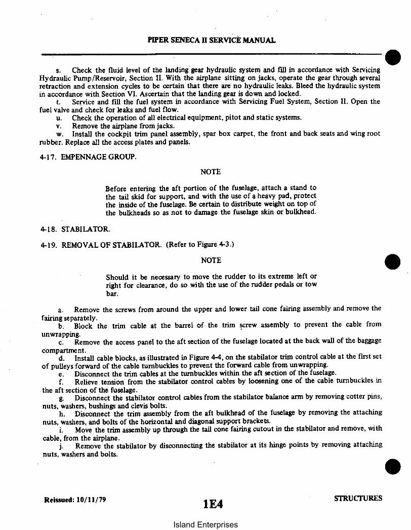
PIPER SENECA I SERVICE MANUAL
s. Check the fluid level of the landing gear hydraulic system and fill in accordance with ServicingHydraulic Pump/Reservoir, Section II. With the airplane sitting on jacks, operate the gear through severalretraction and extension cycles to be certain that there are no hydraulic leaks. Bleed the hydraulic systemin accordance with Section VI. Ascertain that the landing gear is down and locked.
t. Service and fill the fuel system in accordance with Servicing Fuel System, Section II. Open thefuel valve and check for leaks and fuel flow.
u. Check the operation of all electrical equipment, pitot and static systems.v. Remove the airplane from jacks.w. Install the cockpit trim panel assembly, spar box carpet, the front and back seats and wing root
rubber. Replace all the access plates and panels.
4-17. EMPENNAGE GROUP.
NOTE
Before entering the aft portion of the fuselage, attach a stand tothe tail skid for support, and with the use of a heavy pad, protectthe inside of the fuselage. Be certain to distribute weight on top ofthe bulkheads so as not to damage the fuselage skin or bulkhead.
4-18. STABILATOR.
4-19. REMOVAL OF STABILATOR. (Refer to Figure 4-3.)
NOTE
Should it be necessary to move the rudder to its extreme left orright for clearance, do so with the use of the rudder pedals or towbar.
a. Remove the screws from around the upper and lower tail cone fairing assembly and remove thefairing separately.
b. Block the trim cable at the barrel of the trim screw assembly to prevent the cable fromunwrapping.
c. Remove the access panel to the aft section of the fuselage located at the back wall of the baggagecompartment.
d. Install cable blocks, as illustrated in Figure 4-4, on the stabilator trim control cable at the first setof pulleys forward of the cable turnbuckles to prevent the forward cable from unwrapping.
e. Disconnect the trim cables at the turnbuckles within the aft section of the fuselage.f. Relieve tension from the stabilator control cables by loosening one of the cable turnbuckles in
the aft section of the fuselage.g. Disconnect the stabilator control cables from the stabilator balance arm by removing cotter pins,
nuts, washers, bushings and clevis bolts.h. Disconnect the trim assembly from the aft bulkhead of the fuselage by removing the attaching
nuts, washers, and bolts of the horizontal and diagonal support brackets.i. Move the trim assembly up through the tail cone fairing cutout in the stabilator and remove, with
cable, from the airplane.j. Remove the stabilator by disconnecting the stabilator at its hinge points by removing attaching
nuts, washers and bolts.
Reissued: 10/11/79 1E4 STRUCURES1 E4Island Enterprises

PIPER SENECA II SERVICE MANUAL
4-20. INSTALLATION OF STABILATOR. (Refer to Figure 4-3.)
NOTE
A clearance of.25 ± .06 of an inch between the stabilator and theside of the fuselage and .18 of an inch minimum between all partsof the stabilator and the tail cone assembly must be maintainedthroughout the stabilator travel. Use a proper washer combinationon the stabilator hinges to attain the necessary tolerances.
a. Insert the stabilator in position and install attaching hinge bolts, washers and nuts.b. Move the trim assembly through the cutout in the stabilator and attach the brackets of the
assembly to the aft bulkhead with bolts, washers and nuts. Insert the trim cable ends into the fuselage.c. Attach the stabilator control cables to the stabilator balance arm with clevis bolts, bushings,
washers, nuts and cotter pins.d. Connect the ends of the fore and aft trim cables' at the turnbuckles within the aft section of the
fuselage.e. Remove the cable block from the trim control cable within the fuselage.f. Set stabilator control cable tension and check rigging and adjustment according to Rigging and
Adjustment of Stabilator, Section V.g. Remove the cable blocks from the trim cable at the barrel of the trim screw assembly.h. Set stabilator trim control cable tension and check rigging and adjustment according to Rigging
and Adjustment of Stabilator Trim, Section V.i. Remove the pad from the aft section of the fuselage and replace the access panel.j. Install the tail cone fairing and remove tail stand.
NOTE
When stabilator and/or stabilator trim tab is replaced, the balancemay be disturbed. Rebalancing is required.
4-21. STABILATOR TRIM TAB.
4-22. REMOVAL OF STABILATOR TRIM TAB. (Refer to Figure 4-3.)a. Disconnect the stabilator trim control rod by removing the bolts that attach the control rod to
the stabilator trim tab.b. Remove the stabilator trim hinge pins by cutting one end of the wire pins and removing.c. The stabilator trim tab can now be removed.
4-23. INSTALLATION OF STABILATOR TRIM TAB. (Refer to Figure 4-3.)a. Place the trim tab in position on the aft end of the stabilator.b. Replace the old hinge pins with new pins. (Refer to Parts Catalog for proper Part No.)c. Insert the pins and secure by bending the end to a 45 degree angle.d. Install the control rod and attach with the four bolts and washers.e. The trim tab free end play must not exceed .125 inches maximum.
Reissued: 10/11/79 STRUCTURES
1E5
Island Enterprises

1E6INTENTIONALLY LEFT BLANK
Island Enterprises

A297
A330
PIPER SENECA II SERVICE MANUAL
IA329 SKETCH A
PIN MS20253PZ
A300 SKETCH F
BOLT AN4-5 AWASHER AN960-416 LTORQUE TO 100 IN. LBS.
BOLT AN173-7AWASHER AN960-10LNUT MS20365-1032C
A299BOLT AN173-1AWASHER AN960-10 (2 REQ. - 1 UNDER HEAD, 1 UNDER NUT)NUT MS20365-1032CTORQUE 35-40 IN. LBS.
SKETCH E
SKETCH D
A329
PIN MS20253PZ
SKETCH C
BOLT AN3-I0AWASHER AN9600-10 (UNDER NUT)
NUT MS20365-1032C
Figure 4-3. Empennage Group
Revised: 11/12/82 STRUCTURES1E7
Island Enterprises

BOLT AN35AWASHER AN960-10NUT MS20365-1032C4 REQ.TORQUE NUT 35 TO 40 IN.-LBS.
BOLT NAS464P3A5WASHER AN960-10NUT MS21045-134 REQ.TORQUE NUT TO 65 + + IN.-LBS.SEE CAUTION
BOLT AN3-5AWASHER AN960-10 (2 REQ.
UNDER NUT)WASHER AN960-10
(UNDER HEAD)NUT MS20365-1032C4 REQ.TORQUE NUT 35 TO 40 IN.-LBS.— — — — — —------ --- -- - -BOLT NAS464P3A4WASHER AN960-10 (2 REQ.)NUT MS21045-L34 REQ.TORQUE NUT TO 65 + 5 IN.-LBS.SEE CAUTION
BOLT NAS 1104-17WASHERS AN960-4 6
CAUTION: IDENTIFY HARDWARE (1) UNDER HEADBEFORE TORQUING. () UNDER NUT
NUT - MS21045-4TORQUE 80-90 IN. LB
PIPER SENECA II SERVICE MANUAL
A301
BALANCE PLATESP/N 96564 (AS REQ.)
BOLT AN4-24WASHER AN960-416 (2 REQ.)NUT MS20365-428C
TORQUE 50 TO 70 IN. LBS.
BOLT AN23-12WASHER AN960-10NUT AN320-3COTTER PIN MS24665-134BUSHING 63900-31(2 REQ.) SKETCH G
A346
SKETCH I
BOLT AN4-6 ANUT MS20365-428WASHER AN960-416
8 REQ.
BOLT AN3-5AWASHER AN960-10NUT MS20365-1032C4 REQ.TORQUE NUT 35 TO 40 IN.-LBS.
-----------------------BOLT NAS464P3A4WASHER AN960-10NUT MS21045-L34 REQ.TORQUE NUT 65 + 5 IN.-LBS.SEE CAUTION
WASHER 960-416LAS REQ. TO CENTERSTABILATOR ANDLOCK BEARING INNERRACE.
BS.
SECTION A-A
Figure 4-3. Empennage Group (cont.)
Revised: 11/12/82 STRUCTURES1E8
Island Enterprises

PIPER SENECA II SERVICE MANUAL
SKETCH H
BOLT AN173-16A TORQUE 38-43 IN-LBSNUT MS20365-1032C
OR'BOLT AN174-16A TORQUE 70-80 IN.-LBS.'NUT MS20365-428CWASHER AN960-PD10WASHER AN960-PD416L (UNDER HEAD)WASHER AN960-PD 416 (UNDER NUT)
BOLT AN173-10AWASHER AN960-10 (2 REQ.)NUT MS20365-1032C
WASHER AN960WASHER AN960-1OL(AS REQ.) TO CENTER
BOLT ANS-6AWASHER AN960-516 (2 REQ.)NUT MS20365-524C(4 REQ.)TORQUE 180-200 IN. LBS.
BOLT AN4-7AWASHER AN960-PD10NUT MS20365-1032CTORQUE BOLT TO 70-80 IN -LBS.
OR'WASHER AN960-PD416 (2)'NUT MS20365-428C
I 'IF KIT 764 100V HAS BEEN INCORPORATED
Figure 4-3. Empennage Group (cont.)
Revised: 12/08/83 STRUCTURES
1E9
Island Enterprises

PIPER SENECA ii SERVICE MANUAL
4-24. RUDDER.
4-25. REMOVAL OF RUDDER. (Refer to Figure 4-3.)a. Remove the screws from around the upper tail cone fairing assembly and remove the fairing.b. Remove the rudder tip by removing the attaching screws and disconnect the tail position light
wire at- the quick disconnect located at the tip of the rudder. Open the access panel in the rear of thebaggage compartment to gain access to the aft section of the fuselage.
c. Relieve the cable tension from the rudder control system by loosening one of the cableturnbuckles in the aft section of the fuselage.
d. Disconnect the two control cables from the rudder horn by removing the cotter pins, nuts,washers, bushings and bolts.
e. Disconnect the rudder trim tab push rod from the actuating link by removing cotter pin, nut,washer and bolt.
f. Disconnect the jumper lead between the rudder and vertical fin.g. Remove the cotter pins, nuts, washers, and bolts from the upper and lower rudder hinge pivot
points.h. Pull the rudder up and aft from the vertical fin.
4-26. INSTALLATION OF RUDDER. (Refer to Figure 4-3.)a. Place the rudder in position and install the hinge bolts, washers, nuts and cotter pins.
NOTE
Use any washer combination of the hinge assembly to suit best,the centering and operation of the rudder.
b. Connect the rudder trim tab push rod to the actuating link with bolt, washer, nut and cotter pin.c. Connect the tail position light electrical lead at the quick disconnect and cover the connector
with an insulating sleeve. Tie both ends of the sleeve with number six electrical lacing twine.d. Connect the jumper lead between the rudder and vertical fin.e. Connect the control cables to the rudder horn with bolts, washers, nuts and cotter pins.f. Check the rudder in accordance with Rigging and Adjustment of Rudder, Section V.g. Install the upper tail cone fairing and rudder tip and secure with the attachment screws. Secure
the access panel to the aft section of fuselage.
NOTE
When rudder and/or rudder trim tab is replaced, the balance maybe disturbed. Rebalancing is required.
4-27. RUDDER TRIM TAB.
4-28. REMOVAL OF RUDDER TRIM TAB. (Refer to Figure 4-3.)a. Remove the bolt assembly which connects the trim tab actuating arm to the tab assembly.b. Remove the trim tab hinge pin and remove the tab assembly from the rudder.
Reissued: 10/11/79 STRUCTURES
lE10
Island Enterprises

A977
Figure 4-4. Methods of Securing Control Cables
4-29. INSTALLATION OF RUDDER TRIM TAB. (Refer to Figure 4-3.)a. Position the trim tab assembly into the rudder aligning the two hinge bolts.b. Install a new hinge pin. Ascertain that at least .50 of an inch of hinge pin extends out from each
end of the hinge.c. Bend both ends of the hinge pin to a 30 * angle to secure it in place.d. Connect the trim tab actuating arm to the bracket and the tab and secure with bolt assembly.
4-30. VERTICAL FIN.
4-31. REMOVAL OF VERTICAL FIN. (Refer to Figure 4-3.)a. Remove the screws from the upper and lower tail cone fairing; the fin tip cover and the fairing at
the forward base of the fin.b. Remove the rudder per instructions given in Paragraph 4-25.c. Disconnect the leads from the antenna terminals (optional) and attach a line to the leads to assist
in reinstallation.d. Disconnect the wire antenna (optional) that attaches to the leading edge of the fin.e. Disconnect the positive lead to the rotating beacon (optional) and attach a line prior to removal.
Disconnect the ground lead by removing the attachment screw.f. Remove the rudder trim assembly and trim cable in accordance with Removal of Rudder Trim
Assembly, Section V.g. Remove the bolt and washer that attaches the leading edge of the fin to the fuselage.h. Remove the nuts, washers, and bolts that secure the fin spar to the aft bulkhead and remove the
vertical fin.
Reissued: 10/11/79 STRUCTURES
PIPER SENECA II SERVICE MANUAL
1E11
Island Enterprises

PIPER SENECA II SERVICE MANUAL
4-32. INSTALLATION OF VERTICAL FIN. (Refer to Figure 4-3.)a. Insert the vertical fin into position and install the bolts, washers, and nuts that secure the fin spar
to the aft bulkhead.b. Install the bolt and washer that attaches the leading edge of the fin to the fuselage.c. Install the rudder trim assembly and trim cable per instructions given in Installation of Rudder
Trim Assembly, Section V.d. Install the rudder per Paragraph 4-26.e. Pull the electrical and antenna leads through the vertical fin with the line that was attached.f. Connect the antenna leads to the proper terminals and secure with the washers and nuts.g. Connect the electrical leads at the disconnects and insulate.h. Rig and adjust the rudder and trim control cables as given in Section V.i. Check the operation of the radios and electrical lights.j. Replace all fairings and access plates and secure with attaching screws.
4-33. FUSELAGE ASSEMBLY.
4-34. WINDSHIELD.
4-35. REMOVAL OF WINDSHIELD. (Refer to Figure 4-5.)a. Remove the collar molding from around the bottom of the windshield by removing attaching
screws.b. Remove the trim strip from between the windshield halves by removing attaching screws.c. Remove the windshield by raising the lower portion of the windshield and pulling forward.d. Clean old tape and sealer from the windshield retainer channels and strips.
4-36. INSTALLATION OF WINDSHIELD. (Refer to Figure 4-5.)a. Ascertain that the new windshield outside contours are that of the old windshield. It may be
necessary to cut or grind the new windshield.b. Apply black vinyl plastic tape around the outer edge of the entire windshield.c. Apply a strip of vinyl foam tape (1/8 x 1 wide - type 1 P.V.C.) over the plastic tape completely
around the top and outboard edges of the windshield.d. Apply white PRC * 5000 sealing compound (Product Research Corporation) in the upper and
outboard windshield channel.e. Slide the windshield aft and up into place. Use caution not to dislocate the tape around the edges
of the windshield. Allow clearance between the two sections of the windshield, at the divider post, forexpansion.
f. Lay sealant at the bottom and center (inboard) of the windshield, in the hollow between theoutside edge and channel.
g. Lay a small amount of sealant under the center trim strip; install and secure.h. Lay black vinyl tape on the underside of the collar molding; install and secure.i. Apply sealant to any areas around windshield that may allow water to penetrate past windshield.j. Remove excess exposed sealer or tape.
Revised: 3/16/81 STRUCTURES
1E12
Island Enterprises

WHITE SEALANT
WHITESEALANT
2019
WHITESEALANT
BLACKVINYL TAPEVINYL
FOAM TAPE
D-D
PIPER SENECA 11 SERVICE MANUAL
957 955956
VINYL -FOAM TAPEVINYL FOAM
TAPE
WHITE
BLACKVINYL TAPE BLACK
TAPE
A-A C-C
WHITE899 A376
WHITESEALANT
FOAM TAPE
F-FE-E
Figure 4-5. Windshield Installation
Reissued: 10/11/79 STRUCTURES1E13
Island Enterprises

WHITE
PIPER SENECA II SERVICE MANUAL
A376
VINYL FOAM TAPE
Figure 4-6. Side Window Installation (Typical)
4-37. SIDE WINDOWS.
4-38. REMOVAL OF WINDOWS (SIDE). (Refer:to Figure 4-6.)a. Remove the retainer molding from around the window by removing attachment screws. At the
forward end of both the right and left window that is adjacent to the second row of seats, the windowretainer is riveted in place and need not be removed.
b. Remove the window from the frame.c. Remove excess tape and sealer from the window frame.
NOTE
A damaged window should be saved to provide a pattern forshaping the new window.
4-39. INSTALLATION OF WINDOWS (SIDE). (Refer to Figure 4-6.)a. Cut or grind the new window to the same dimension as the window removed.b. Apply a strip of vinyl foam tape (1/8 x 1" wide - Type I P.V.C.) completely around the edge of the
window.c. Apply white PRC 5000 sealing compound (Product Research Corporation) completely around
the outer surface of the window at all attachment flanges.d. Install the window in the frame and install retainer moldings. Secure with screws.e. Remove excess exposed sealer and tape.
Revised: 3/16/81 STRUCTURES
1E14Island Enterprises

PIPER SENECA II SERVICE MANUAL
4-40. REMOVAL OF REAR DOOR WINDOW. (Refer to Figure 4-7.)a. Although it is not necessary, the door may be taken off the airplane. If the door is removed, make
sure it is placed on a surface that will not scratch the painted finish of the door.b. Remove the trim panels on the door.c. Unscrew the window retainers and carefully remove the window. Remove any excess tape and sealer
from the window frame as well.
NOTE
A damaged window should be saved to provide a pattern for fittingthe new window.
4-41. INSTALLATION OF REAR DOOR WINDOW. (Refer to Figure 4-7.)a. With the windows compared to each other, grind the new window to the same outlying dimensions
as the old.b. With the frame thoroughly cleaned align the new window in the frame to insure a proper fit.c. Remove the new window and proceed as follows:
1. Apply 3/4 inch wide sealant tape to the contacting exterior surfaces of the window (around theperimeter of the window that touches the door's skin).
2. With the tape aligned on the window, apply pressure to force the seal against the window.3. Remove the protective paper from the tape and set window in place on the door.4. With a narrow, hand held, rubber roller, apply pressure around the perimeter of the window
to cause a tight seal between the window and skin.d. Reinstall window retainer clips and trim panels.
THIS SPACE INTENTIONALLY LEFT BLANK
Revised: 8/10/80 STRUCTURES
1E15
Island Enterprises

DOOR VIEWE
LOOKING
C -
COVERPANEL
PIPER SENECA II SERVICE MANIAL
B974M975
B976 COVERPANEL
B
D INSIDEOUT
SIDEPANEL
COVERPANEL
WINDOW _RETAINEREXTERNAL
SKIN OFDOOR WINDOW
SEALANT
COVERPANEL
WINDOW AND
WINDOW
SECTION C-C
SECTION A-A
SEALANT
EXTERNAL SKIN
SIDEPANEL
SECTION B-B
Figure 4-7. Rear Door Window Replacement
Revised: 8/10/80 STRUCTURES1E16
Island Enterprises

PIPER SENECA II SERVICE MANUAL
g. Place new retainer into position and secure with 16 screws and washers (AN960-6).h. Carefully invert the door. Apply a bead of PRC-5000 sealant to the outer perimeter of the
window. Allow sealant to dry before reinstalling door.
NOTE
Inspect to determine that all original bond lines between outerpanel and window and window and inner panel are tight. Freshbreaks in bond lines can be sealed using one of the following:1. Eastman 9102. Aron Alpha Vigor Tool Co., NYC., N.Y.
Older breaks in bond lines should be sealed using one of thefollowing adhesives:1. Scotchweld 2216 B/A Liquid Epoxy, MMM Co., St. Paul,
Minnesota2. Chemlock 304 Hughson Chemical Co., Erie, Penna.3. Reisweld 7006 H.B. Fuller Co., St. Paul, Minnesota4. Locktite 2508t Locktite Corp., Newington, Conn.
tPackaged in 1 oz. cups for ready mix under P/N 53-83
4-42. DOOR (ENTRANCE).
4-42a. REMOVAL AND INSTALLATION OF DOOR SNUBBERS. Door snubber seals have beenincorporated in the three door jambs to improve on door sealing. For those aircraft equipped as such. thefollowing procedure should be used. If snubbers are not installed. the "Field Kit For Improved Sealing"(763-993V). should be consulted for installation if so desired.
NOTE
If the existing seal is torn or badly deteriorated, it should bereplaced. If the seal is found to be loose, or the bond is "marginal." itshould be rebonded. The adhesives listed herein are recommendedfor the following procedure.
1. Carboline Adhesive F-l.2. Scotch Grip 2210.3. Proco #6205-1.
Refer to the List of Consumable Materials for vendor information.
a. To remove the snubber proceed as follows:I. Back off the windlacing trim screws, tape the windlacing back out of the way, and remove all
scuff plates.2. With mineral spirits, soak the edges of the snubber all around the door jamb.3. With a plastic scraper or other appropriate instrument, scrape off the snubber while applying
mineral spirits as necessary to loosen the strip.4. With mineral spirits and a clean cloth clean off all excess adhesive.
b. Before proceeding with installation instructions make sure the windlacing is rolled back far enoughto prevent adhesive from coming in contact with it.
Revised: 8/10/80 STRUCTURES1E17
Island Enterprises

PIPER SENECA II SERVICE MANUAL
A
SEENOTE
2
STRIKER/SCUFF
FORWARD CABINDOOR INSTALLATION
SEENOTE 1
DO NOT STRETCH SNUBBERAROUND CORNERS (4 PLACES)
NOTES:1. SNUBBER BUTT JOINT SHOULD
OCCUR AT DOOR DRAIN AREA ASAPPLICABLE.
2. ORIENT SNUBBER FLAT WITHSURFACE INDICATED BY NOTEDESIGNATION.
SNUBBER
SECTION A-A
TYPICALCORNER
VIEW AFRAME
SECTION B-B(ROTATED 180° )
SECTION C-C
FRAME
APPLICATION OF ADHESIVE
Figure 4-7a. Snubber Installation
Added: 8/10/80 STRUCTURES41E18
Island Enterprises

FRAME
' VIEW A
SNUBBER
SEENOTE
FRAME
WIND LACING
OUTB
SEE NOTE 2 SNUBBER
SEENOTE
SECTION E-E(ROTATED 90' COUNTERCLOCKWISE)
WIND
PIPER SENECA II SERVICE MANUAL
8970
AFT CABIN DOORINSTALLATION
NOTES2. ORIENT SNUBBER FLAT WITH
SURFACE INDICATED WITHNOTE DESIGNATION
3. TRY TO KEEP WIND LACING ATLEAST .03 TO .06 IN FROMSNUBBER.
STRIKERPLATE SECTION D-D
(ROTATED)
SNUBBER
SEE NOTE 2CUT SNUBBER -AFTER ADHESIVECURES
HINGECENTERLINE
VIEW B
OUTBD
AFT
SECTION F-FBAGGAGEDOOR
FUSELAGESKIN
Figure 4-7a. Snubber Installation (cont.)
Added: 8/10/80 STRUCTURES1E19
Island Enterprises

PIPER SENECA II SERVICE MANUAL
c. If the door jamb is flaking or excessively scuffed proceed as follows:1. Rub down and feather the finish with "wet or dry" emery cloth. Make sure to go over the
surface with fine (400 grit) paper.2. Go over the surface with "Prep-Sol" or other type of cleaner that will not leave anoily residue.3. Prime, sand (400 grit), and paint affected area. Wait for paint to dry before proceeding.
d. Go over the entire door jamb with "Prep-Sol" or other cleaner that will not leave an oily residue.e. On aircraft up to 34-7670063 cut a length of snubber to fit the installation plus two or three inches to
spare. On aircraft 34-7670064 and up use the appropriate snubber installation or as just described if a supply isavailable.
NOTE
Normal tack time for Carboline F-1 (which is used as a reference)is 30 to 45 minutes, less in a warm area.
NOTE
On forward cabin door make sure leg of snubber goes under strikerplate on side latch and over the striker plate for the upper latch.
On the aft cabin and cargo doors make sure the baggage door isclosed and start at the forward edge of the cabin door workingupward. Make sure leg of snubber is under striker plate.
f. Although not critical it is recommended that masking tape be applied to the door jamb at theborders of the area to be glued. (Refer to Figure 4-7a.)
g. Apply adhesive to the affected area on the door jamb and the inside surface of the snubber. It isrecommended that the snubber be installed before the adhesive becomes tacky enabling manipulation of thesnubber.
h. Position the snubber with the teat facing outboard and start at the bottom center of the jamb.applying pressure to insure a proper bond. DO NOT prestretch the snubber. Stretching the snubber will causecracks.
i. Wait for at least two hours for the bond to cure and DO NOT allow door to close. The bond will curemore efficiently with the door left open and a maximum cure age will be effected.
j. To check for proper cure try peeling back a small local area of the snubber leg.k. With adhesive properly cured, remove the masking tape. Replace scuff plates and windlacing. If the
snubber for the aft cabin door has just been installed, cut snubber as shown in Figure 4-7a.1. Check that the door closes properly and readjust as necessary to achieve a flush fit. Latching effort
must not have increased.m. With all hardware and plates reinstalled coat snubbers with silicone.
4-43. REMOVAL OF DOOR.a. Remove clevis bolt, washer, and bushing from door holder assembly.b. Remove cotter pins, clevis pins, and washers from serrated door hinges.c. Remove door from airplane.
4-44. INSTALLATION OF DOOR.a. Insert the door into position and install the washers, clevis bolts, and cotter pins on the door
hinges.b. For adjustment of door, refer to Paragraph 4-45.c. Hook up and install the clevis bolt, bushing, and washer into the door holder assembly.
Revised: 8/10/80 STRUCTURES1E20
Island Enterprises

PIPER SENECA II SERVICE MANUAL
4-45. ADJUSTMENT OF DOOR.a. To acquire the proper vertical adjustment of the door, insert the necessary washer combination
between the cabin door hinge and fuselage bracket assembly.b. Additional adjustments must be made by tapping out the serrated door hinge, bushings and
rotating them to obtain the hinge centerline location that will provide proper door fit.
446. REMOVAL OF DOOR LATCH MECHANISM.a. Remove the door latch mechanism by removing the door trim upholstery and the screws that
attach the latch plate and latch mechanism to the door.b. Disconnect the latch pull rod from the inside door handle.c. Remove the complete latch mechanism.
4-47. INSTALLATION OF DOOR LATCH MECHANISM.a. Place the latch assembly into position on the door.b. Connect the latch pull rod to the inside door handle.c. Replace the screws that attach the latch plate and mechanism to the door. Install the door trim
upholstery and secure with screws.
4-48. ADJUSTMENT OF DOOR LATCH MECHANISM. To adjust the door latch, loosen the screws onthe striker plate; make necessary adjustment and retighten the screws.
449. REMOVAL OF DOOR LOCK ASSEMBLY.a. Remove the door trim upholstery by removing the attachment screws.b. Loosen the nut on the lock assembly and remove the lock by turning it sideways.
4-50. INSTALLATION OF DOOR LOCK ASSEMBLY.a. Install the lock in the door by turning it sideways and placing it through the opening provided.b. Replace the nut on the back of the lock assembly and tighten.c. Replace the door trim upholstery and secure with the attachment screws.
4-51. REMOVAL OF DOOR SAFETY (AUXILIARY) LATCH.a. Remove screw and handle from top outer surface of door.b. Remove screws holding latch assembly to the inner panel of the door and remove the latch.
4-52. INSTALLATION OF DOOR SAFETY (AUXILIARY) LATCH.a. Insert hook through rectangular slot in top of door. Align holes in latch assembly with those in
the door inner panel and secure with screws.b. Install outer handle and screw.
4-53. ADJUSTMENT OF DOOR (AUXILIARY) LATCH.a. To adjust the door safety latch, remove the two screws from latch plate found at the top of the
door opening.b. Remove the plate and turn the loop assembly in or out to make necessary adjustments.c. Replace the latch plate and secure with the two attachment screws.
4-54. BAGGAGE DOOR.
4-55. REMOVAL OF BAGGAGE DOOR. With the door open, remove the hinge pin from the hinge andremove the door.
Revised: 8/10/80 STRUCTURES1E21
Island Enterprises
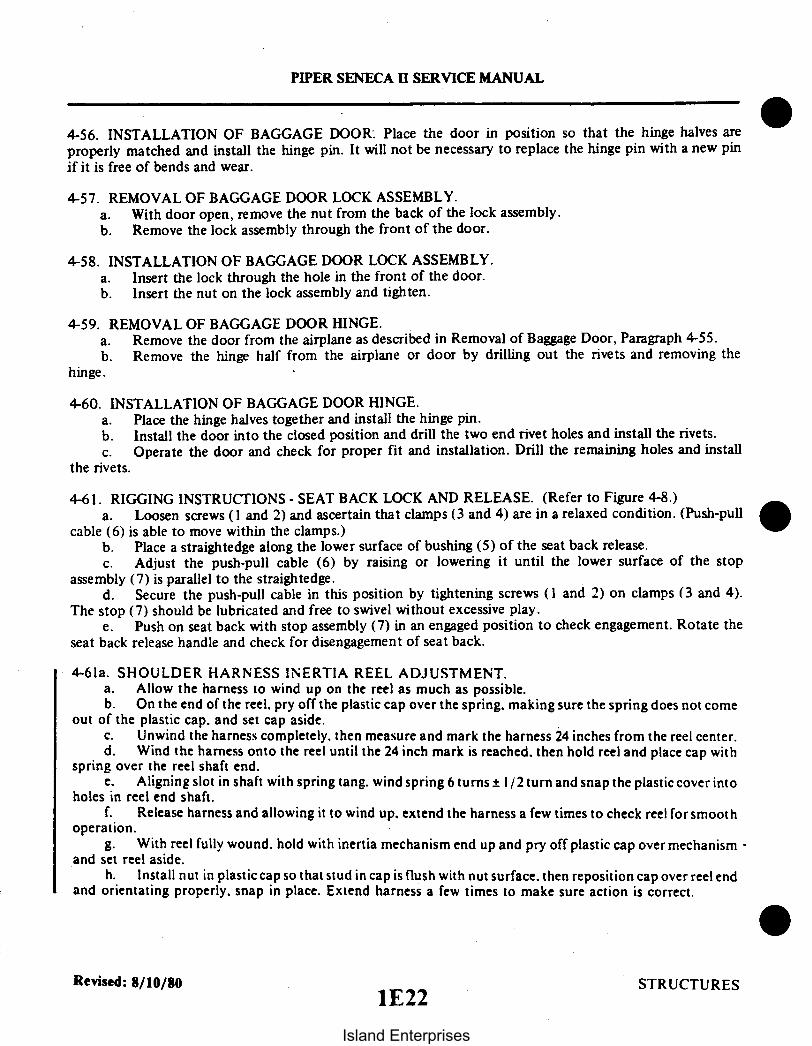
PIPER SENECA II SERVICE MANUAL
4-56. INSTALLATION OF BAGGAGE DOOR: Place the door in position so that the hinge halves areproperly matched and install the hinge pin. It will not be necessary to replace the hinge pin with a new pinif it is free of bends and wear.
4-57. REMOVAL OF BAGGAGE DOOR LOCK ASSEMBLY.a. With door open, remove the nut from the back of the lock assembly.b. Remove the lock assembly through the front of the door.
4-58. INSTALLATION OF BAGGAGE DOOR LOCK ASSEMBLY.a. Insert the lock through the hole in the front of the door.b. Insert the nut on the lock assembly and tighten.
4-59. REMOVAL OF BAGGAGE DOOR HINGE.a. Remove the door from the airplane as described in Removal of Baggage Door, Paragraph 4-55.b. Remove the hinge half from the airplane or door by drilling out the rivets and removing the
hinge.
4-60. INSTALLATION OF BAGGAGE DOOR HINGE.a. Place the hinge halves together and install the hinge pin.b. Install the door into the closed position and drill the two end rivet holes and install the rivets.c. Operate the door and check for proper fit and installation. Drill the remaining holes and install
the rivets.
4-61. RIGGING INSTRUCTIONS - SEAT BACK LOCK AND RELEASE. (Refer to Figure 4-8.)a. Loosen screws (1 and 2) and ascertain that clamps (3 and 4) are in a relaxed condition. (Push-pull
cable (6) is able to move within the clamps.)b. Place a straightedge along the lower surface of bushing (5) of the seat back release.c. Adjust the push-pull cable (6) by raising or lowering it until the lower surface of the stop
assembly (7) is parallel to the straightedge.d. Secure the push-pull cable in this position by tightening screws (1 and 2) on clamps (3 and 4).
The stop (7) should be lubricated and free to swivel without excessive play.e. Push on seat back with stop assembly (7) in an engaged position to check engagement. Rotate the
seat back release handle and check for disengagement of seat back.
4-61a. SHOULDER HARNESS INERTIA REEL ADJUSTMENT.a. Allow the harness to wind up on the reel as much as possible.b. On the end of the reel. pry off the plastic cap over the spring, making sure the spring does not come
out of the plastic cap. and set cap aside.c. Unwind the harness completely, then measure and mark the harness 24 inches from the reel center.d. Wind the harness onto the reel until the 24 inch mark is reached, then hold reel and place cap with
spring over the reel shaft end.e. Aligning slot in shaft with spring tang. wind spring 6 turns ± 1/2 turn and snap the plastic cover into
holes in reel end shaft.f. Release harness and allowing it to wind up. extend the harness a few times to check reel for smooth
operation.g. With reel fully wound, hold with inertia mechanism end up and pry off plastic cap over mechanism -
and set reel aside.h. Install nut in plastic cap so that stud in cap is flush with nut surface. then reposition cap over reel end
and orientating properly, snap in place. Extend harness a few times to make sure action is correct.
Revised: 8/10/80 STRUCTURES1E22
Island Enterprises

PIPER SENECA II SERVICE MANUAL
1. SCREW2. SCREW3. CLAMP4. CLAMP5. BUSHING6. CABLE7. STOP ASSY.
LUBRICATED AND FREEEXCESSIVE PLAY
STRAIGHTEDGE
Figure 4-8. Seat Back Lock
THIS SPACE INTENTIONALLY LEFT BLANK
I Revised: 8/10/80 STRUCTURES
1E23
Island Enterprises

PIPER SENECA II SERVICE MANUAL
4-62. STRUCTURAL REPAIRS. Structural repair methods used may be made in accordance with theregulations set forth in FAA Advisory Circular 43.13-1A. To assist in making repairs, Figure 4-3 identifiesthe type and thickness of skin structure used. Never make a skin replacement or patch from a materialother than the type of the original skin. Original material and thickness is recommended and must result ina surface which is as strong as, or stronger than, the original skin. However, flexibility must be retained sothat the surrounding areas will not receive extra stress.
When making major structural repairs, using other than factory manufactured parts, it is recommendedthe manufacturer be contacted. No major alterations are recommended without contacting themanufacturer.
4-63. FIBERGLASS REPAIRS. The repair procedure in this manual will describe the methods for therepair of fiberglass reinforced structures. Paragraph 4-64 describes Touch-up and Surface Repairs such asblisters, open seams, delaminations, cavities, small holes, and minor damages that have not harmed thefiberglass cloth material. Paragraph 4-65 describes Fracture and Patch Repairs such as puncture, breaks, andholes that have penetrated through the structure and damaged the fiberglass cloth. A repair kit, PartNumber 756 729, that will furnish the necessary material for such repairs is available through Piper AircraftDistributors.
NOTE
Very carefully follow resin and catalyst mixing instructionsfurnished with repair kit.
4-64. FIBERGLASS TOUCH-UP AND SURFACE REPAIRS.a. Remove wax, oil, and dirt from around the damaged area with acetone, methylethylketone or
equivalent and remove paint to gel coat.b. The damaged area may be scraped with a fine blade knife or a power drill with a burr attachment
to roughen the bottom and sides of the damaged area. Feather the edge surrounding the scratch or cavity.Do not undercut the edge. (If the scratch or cavity is shallow and penetrates only the surface coat, continueto Step f.)
c. Pour a small amount of resin into a jar lid or on a piece of cardboard just enough to fill the areabeing worked on. Mix an equal amount of milled fiberglass with the resin using a putty knife or stick. Addcatalyst, according to kit instructions, to the resin and mix thoroughly. A hypodermic syringe may be usedto inject gel into small cavities not requiring fiberglass millings mixed with the gel.
d. Work the mixture of resin, fibers, and catalyst into the damaged area, using the sharp point of aputty knife or stick to press it into the bottom of the hole and to puncture any air bubbles which may bepresent. Fill the scratch or hole above the surrounding undamaged area about 1/16 inch.
e. Lay a piece of cellophane or waxed paper over the repair to cut off air and start the cure of gelmixture.
f. Allow the gel to cure 10 to 15 minutes until it feels rubbery to the touch. Remove the cellophaneand trim flush with the surface, using a sharp razor blade or knife. Replace the cellophane and allow to curecompletely for 30 minutes to an hour. The patch will shrink slightly below the structure surface as it cures.(If wax paper is used, ascertain wax is removed from surface.)
Reissued: 10/11/79 STRUCTURES1E24
Island Enterprises

PIPER SENECA II SERVICE MANUAL
g. Rough up the bottom and edges of the hole with an electric burr attachment or rough sandpaper.Feather hole into surrounding gel coat, do not undercut.
h. Pour out a small amount of resin, add catalyst and mix thoroughly, using a cutting motion ratherthan stirring. Use no fibers.
i. Using the tip of a putty knife or finger tips, fill the hole to about 1/16 inch above thesurrounding surface with the gel coat mixture.
j. Lay a piece of cellophane over the patch to start the curing process. Repeat Step f, trimmingpatch when partially cured.
k. After trimming the patch, immediately place another small amount of gel coat on one edge of thepatch and cover with cellophane. Then, using a squeegee or the back of a razor blade, squeegee level witharea surrounding the patch, leave the cellophane on patch for one or two hours or overnight, for completecure.
1. After repair has cured for 24 hours, sand patched area, using a sanding block with fine wetsandpaper. Finish by priming, again sanding and applying color coat.
Reissued: 10/11/79 STRUCTURESIF1
Island Enterprises

PIPER SENECA II SERVICE MANUAL
4-65. FIBERGLASS FRACTURE AND PATCH REPAIRS.a. Remove wax, oil, and dirt from around the damaged area with acetone, methylethylketone or
equivalent.b. Using a keyhole saw, electric saber saw or sharp knife, cut away ragged edges. Cut back to sound
material.c. Remove paint three inches back from around damaged area.d. Working inside the structure, bevel the edges to approximately a 30 degree angle and rough sand
the hole and the area around it, using 80 grit dry paper. Feather back for about two inches all around thehole. This roughens the surface for strong bond with patch.
e. Cover a piece of cardboard or metal with cellophane. Tape it to the outside of the structure,covering the hole completely. The cellophane should face toward the inside of the structure. If the repair ison a sharp contour or shaped area, a sheet of aluminum formed to a similar contour may be placed over thearea. The aluminum should also be covered with cellophane.
f. Prepare a patch of fiberglass mat and cloth to cover an area two inches larger than the hole.g. Mix a small amount of resin and catalyst, enough to be used for one step at a time, according to
kit instructions.h. Thoroughly wet mat and cloth with catalyzed resin. Daub resin on mat first and then on cloth.
Mat should be applied against structures surface with cloth on top. Both pieces may be wet out oncellophane and applied as a sandwich. Enough fiberglass cloth and mat reinforcements should be used to atleast replace the amount of reinforcements removed in order to maintain the original strength. If damageoccurred as a stress crack, an extra layer or two of cloth may be used to strengthen area.
i. Lay patch over hole on inside of structure; cover with cellophane and squeegee from center toedges to remove all air bubbles and assure adhesion around edge of hole. Air bubbles will show white in thepatch and they should all be worked out to the edge. Remove excess resin before it gels on the part. Allowpatch to cure completely.
j. Remove cardboard or aluminum sheet from outside of hole and rough sand the patch and edge ofhole. Feather edge of hole about two inches into undamaged area.
k. Mask area around hole with tape and paper to protect surface. Cut a piece of fiberglass mat aboutone inch larger than the hole and one or more pieces of fiberglass cloth two inches larger than the hole.Brush catalyzed resin over hole; lay mat over hole and wet out with catalyzed resin. Use a daubing actionwith brush. Then apply additional layer or layers of fiberglass cloth to build up patch to the surface ofstructure. Wet out each layer thoroughly with resin.
1. With a squeegee or broad knife, work out all air bubbles in the patch. Work from center to edge,pressing patch firmly against the structure. Allow patch to cure for 15 to 20 minutes.
m. As soon as the patch begins to set up, but while still rubbery, take a sharp knife and cut awayextra cloth and mat. Cut on outside edge of feathering. Strip cut edges of structure. Do this before cure iscomplete, to save extra sanding. Allow patch to cure overnight.
n. Using dry 80 grit sandpaper on a power sander or sanding block, smooth patch and blend withsurrounding surface. Should air pockets appear while sanding, puncture and fill with catalyzed resin. Ahypodermic needle may be used to fill cavities. Let cure and resand.
o. Mix catalyzed resin and work into patch with fingers. Smooth carefully and work into anycrevices.
p. Cover with cellophane and squeegee smooth. Allow to cure completely before removingcellophane. Let cure and resand.
q. Brush or spray a coat of catalyzed resin to seal patch. Sand patch; finish by priming; againsanding and applying color coat.
NOTE
Brush and hands may be cleaned in solvents such as acetone ormethylethylketone. If solvents are not available, a strong solutionof detergent and water may be used.
Reissued: 10/11/79 STRUCTURE1F2
Island Enterprises

PIPER SENECA II SERVICE MANUAL
A318
Figure 4-9. Skin Material and Thicess
Figure 4-9. Skin Material and Thickness
Reissued: 10/11/79 STRUCTURES1F3
Island Enterprises

PIPER SENECA II SERVICE MANUAL
9
1 2024-T3 .016
2 2024-00 .0203 2024-T3 .0204 2024-T3 .0255 2024-T3 .032
6 2024-T3 .0407 2024-T3 .0518 2024-T3 .025
9 FIBERGLASS
10 2024-T3 .020
11 THERMOPLASTIC OR FIBERGLASS
12 2024-0 .02513 5062-H34 .04014 321A ST.STL. .016
12
A3749
5 6
4
NUMBER MATERIAL THICKNESS
12
12
12 13
A186
NOTE: LEFT WING SHOWN. RIGHT WINGOPPOSITE. LEFT NACELLE SHOWN.RIGHT NACELLE OPPOSITE.*HEAT TREAT TO 2024-T42 AFTERFORMING.
Figure 4-9. Skin Material and Thickness (cont.)
Reissued: 10/11/79 STRUCTURES1F4
Island Enterprises

PIPER SENECA II SERVICE MANUAL
4-66. THERMOPLASTIC REPAIRS. The following procedure will assist in making field repairs to itemsmade of thermoplastic which are used throughout the airplane. A list of material needed to perform theserepairs is given along with suggested suppliers of the material. Common safety precautions should beobserved when handling some of the materials and tools used while making these repairs.
a. Surface Preparation:1. Surface dirt and paint if applied must be removed from the item being repaired. Household
cleaners have proven most effective in removing surface dirt.2. Preliminary cleaning of the damaged area with perchlorethylene or VM&P Naptha will
generally insure a good bond between epoxy compounds and thermoplastic.b. Surface Scratches, Abrasion or Ground-in-Dirt: (Refer to Figure 4-10.)
1. Shallow scratches and abraded surfaces are usually repaired by following directions oncontainers of conventional automotive buffing and rubbing compounds.
2. If large dirt particles are embedded in thermoplastic parts, they can be removed with a hotair gun capable of supplying heat in the temperature range of 300 ° to 400 ° F. Use care not to overheat thematerial. Hold the nozzle of the gun about 1/4 of an inch away from the surface and apply heat with acircular motion until the area is sufficiently soft to remove the dirt particles.
3. The thermoplastic will return to its original shape upon cooling.c. Deep Scratches, Shallow Nicks and Small Holes: (Less than 1 inch in diameter.) (Refer to Figure
4-11.)1. Solvent cements will fit virtually any of these applications. If the area to be repaired is very
small, it may be quicker to make a satisfactory cement by dissolving thermoplastic material of the sametype being repaired in solvent until the desired paste-like consistency is achieved.
2. This mixture is then applied to the damaged area. Upon solvent evaporation, the harddurable solids remaining can easily be shaped to the desired contour by filing or sanding.
3. Solvent adhesives are not recommended for highly stressed areas, on thin walled parts or forpatching holes greater than 1/4 inch in diameter.
4. For larger damages an epoxy patching compound is recommended. This type material is atwo part, fast curing, easy sanding commercially available compound.
5. Adhesion can be increased by roughing the bonding surface with sandpaper and by utilizingas much area for the bond as possible.
6. The patching compound is mixed in equal portions on a hard flat surface using a figure eightmotion. The damaged area is cleaned with perchlorethylene or VM&P Naphtha prior to applying thecompound. (Refer to Figure 4-12.)
7. A mechanical sander can be used after the compound is cured, providing the sander is keptin constant motion to prevent heat buildup.
8. For repairs in areas involving little or no shear stress, the hot melt adhesives, polyamidswhich are supplied in stick form may be used. This type of repair has a low cohesive strength factor.
9. For repairs in areas involving small holes, indentations or cracks in the material where highstress is apparent or thin 'walled sections are used, the welding method is suggested.
IC. This welding method requires a hot air gun and ABS rods, to weld, the gun should be held todirect the flow of hot air into the fusion (repair) zone, heating the damaged area and rod simultaneously.The gun should be moved continuously in a fanning motion to prevent discoloration of the material.Pressure must be maintained on the rod to insure good adhesion. (Refer to Figure 4-13.)
11. After the repair is completed, sanding is allowed to obtain a surface finish of acceptableappearance.
Reissued: 10/11/79 STRUCTURE1F5
Island Enterprises

PIPER SENECA II SERVICE MANUAL
d. Cracks: (Refer to Figure 4-14.)1 Before repairing a crack in the thermoplastic part, first determine what caused the crack and
alleviate that condition to prevent it recurring after the repair is made.2. Drill small stop holes at each end of the crack.3. If possible, a double plate should be bonded to the reverse side of the crack to provide extra
strength to the part.4. The crack should be "V" grooved and filled with repair material, such as solvent cement,
hot melt adhesive, epoxy patching compound or hot air welded, whichever is preferred.5. After the repair has cured, it may be sanded to match the surrounding surface finish.
e. Repairing Major Damage: (Larger than I inch in diameter.) (Refer to Figure 4-15.)1. If possible a patch should be made of the same material and cut slightly larger than the
section being repaired.2. When appearances are important, large holes, cracks, tears, etc. should be repaired by
cutting out the damaged area and replacing it with a piece of similar material.3. When cutting away the damaged area, under cut the perimeter and maintain a smooth edge.
The patch and/or plug should also have a smooth edge to insure a good fit.4. Coat the patch with solvent adhesive and firmly attach it over the damaged area.5. Let the patch dry for approximately one hour before any additional work is performed.6. The hole, etc. is then filled with the repair material. A slight overfilling of the repair material
is suggested to allow for sanding and finishing after the repair has cured. If patching compound is used therepair should be made in layers, not exceeding a 1/2 inch in thickness at a time, thus allowing thecompound to cure and insuring a good solid buildup of successive layers as required.
f. Stress Lines: (Refer to Figure 4-16.)1. Stress lines produce a whitened appearance in a localized area and generally emanate from
the severe bending or impacting of the material. (Refer to Figure 4-17.)2. To restore the material to its original condition and color, use a hot air gun or similar
heating device and carefully apply heat to the affected area. Do not overheat the material.g. Painting the Repair:
1. An important factor in obtaining a quality paint finish is the proper preparation of therepair and surrounding area before applying any paint.
2. It is recommended that parts be cleaned prior to painting with a commercial cleaner or asolution made from one-fourth cup of detergent mixed with one gallon of water.
3. The paint used for coating thermoplastic can be either lacquers or enamels depending onwhich is preferred by the repair facility or customer. (See NOTE.)
NOTE
It is extremely important that solvent formulations be consideredwhen selecting a paint, because not all lacquers or enamels can beused satisfactorily on thermoplastics. Some solvents used in thepaints can significantly affect and degrade the plastic properties.
4. Another important matter to consider is that hard, brittle coatings that are usually best forabrasion resistance should not be used in areas which incur high stress, flexing or impact. Such coatings maycrack, thus creating a weak area.
Reissued: 10/11/79 STRUCTURE1F6
Island Enterprises

PIPER SENECA II SERVICE MANUAL
I TABLE IV-III. LIST OF MATERIALS (THERMOPLASTIC REPAIR)
ITEMS DESCRIPTIONS SUPPLIERS
Buffing and RubbingCompounds
Automotive Type - DuPont#7
DuPont CompanyWilmington, Del. 19898
Ram Chemical #69 x 1
Mirror Glaze #1
Fantastic SprayPerchlorethyleneVM&P Naphtha (LighterFluid)
Ram ChemicalsGardena, Cal. 90248
Mirror Bright Polish Co., Inc.Irvin, Cal. 92713
Obtain From Local SuppliersCleaners
ABS-Solvent Cements Solarite #11 Series Solar Compounds Corp.Linden, N.J. 07036
Solvents Methylethyl KetoneMethylene ChlorideAcetone
Obtain From Local Suppliers
Epoxy PatchingCompound
Hot Melt AdhesivesPolyamids and Hot MeltGun
Hot Air Gun
Solarite #400
Stick Form 1/2 in. dia.3 in. long
Temp. Range 300° to400 F
Solar Compounds Corp.linden, N.J. 07036
Sears Roebuck & Co. or MostHardware Stores
Local Suppliers
Revised: 8/10/80 STRUCTURES1F7
Island Enterprises

PIPER SENECA II SERVICE MANUAL
871
Hot Air Gun
Figure 4-10. Surface Scratches, Abrasions or Ground-in-Dirt.
871
Figure 4-11. Deep Scratches, Shallow Nicks and Small Holes.
Reissued: 10/11/79 STRUCTURE1F8
Island Enterprises

870
PIPER SENECA II SERVICE MANUAL
825
Figure 4-12. Mixing of Epoxy Patching Compound.
Figure 4-13. Welding Repair Method.
Reissued: 10/11/79 STRUCTURE1F9
Island Enterprises

PIPER SENECA II SERVICE MANUAL
827
Figure 4-14. Repairing of Cracks.
Reissued: 10/11/79 STRUCTURE1F10
Island Enterprises

831
PIPER SENECA II SERVICE MANUAL
PATCHING
828
DAMAGED AREA
Figure 4-15. Various Repairs.
Reissued: 10/11/79 STRUCTURElFll
Island Enterprises

827
828
PIPER SENECA II SERVICE MANUAL
Figure 4-16. Repair of Stress Lines.
832
PROFILE VIEW INDICATINGDAMAGED AREA
Figure 4-17. Repair of Impacted Damage.
Reissued: 10/11/79 STRUCTURE1F12
Island Enterprises

PIPER SENECA II SERVICE MANUAL
4-67. SAFETY WALK REPAIR.
4-68. SURFACE PREPARATION FOR LIQUID SAFETY WALK.a. Clean all surfaces with a suitable cleaning solvent to remove dirt, grease and oils. Solvents may be
applied by dipping, spraying or mopping.b' Insure that no moisture remains on the surface by wiping with a clean dry cloth.c. Outline the area to which the liquid safety. walk compound is to be applied, and mask adjacent
surfaces.
NOTE
Newly painted surfaces shall be allowed to dry for 2.5 hoursminimum prior to the application of the safety walk.
4-69. PRODUCT LISTING FOR LIQUID SAFETY WALK COMPOUND.a. Suggested Solvents:
Safety solvent per MIL-S 18718Sherwin Williams Lacquer Thinner R7KC120Glidden Thinner No. 207
b. Safety Walk Material:Walkway Compound, Nonslip and Walkway Matting, Nonslip (included in Piper Part No.179 872)
4-70. APPLICATION OF LIQUID SAFETY WALK COMPOUND. Liquid safety walk compound shall beapplied in an area free of moisture for a period of 24 hours minimum after application. Do not applywhen surface to be coated is below 50 F. Apply liquid as follows:
a. Mix and thin the liquid safety walk compound in accordance with the manufacturer'sinstructions on the container.
b. Coat the specified surfaces with a smooth, unoroken film of the liquid safety walk compound. Anap type roller or a stiff bristle brush is recommended using fore and aft strokes.
c. Allow the coating to dry for 15 minutes to one hour before recoating or touch-up, if requiredafter application of the initial coating.
d. After recoating or touch-up, allow the coating to dry for 15 minutes to one hour before removing-masking.
NOTE
The coated surface shall not be walked on for six hours minimumafter application of final coating.
Revised: 11/12/82 STRUCTURE
1F13
Island Enterprises

PIPER SENECA II SERVICE MANUAL
4-71. SURFACE PREPARATION FOR PRESSURE SENSITIVE SAFETY WALK. The areas to which thepressure sensitive safety walk is to be installed must be free from all contaminates and no moisture present.If liquid safety walk is installed the area must be prepared as follows:
a. Area must be masked off to protect painted surfaces.b. Apply suitable stripper MEK Federal Spec. TT-M-261, U.S. Rubber No. 3339 to wingwalk
compound. As compound softens, remove by using putty knife or other suitable tool.c. Area must be clean and dry prior to painting.d. Prime and paint area.
NOTE
Newly painted surfaces, shall be allowed to dry for 2.5 hoursminimum prior to the application of the safety walk.
4-72. APPLICATION OF PRESSURE SENSITIVE SAFETY WALK. (Kit 763 849V) Wipe area with aclean dry cloth to insure that no moisture remains on surface. Do not apply when surface temperature isbelow 500F. Apply pressure sensitive safety walk as follows:
a. Peel back the full width of the protective liner approximately 2 inches from the leading edge ofthe safety walk.
b. Apply the safety walk to the wing area, begin at the leading edge, insure proper alignment andposition from wing lap.
c. Remove the remaining protective liner as the safety walk is being applied from front to back ofwing area.
d. Roll firmly with a long handled cylindrical brush in both lengthwise directions. Make sure alledges adhere to the wing skin.
e. Install leading edge retainer by inserting between wing leading edge fairing and forward wing spar.Hold all parts in position by using existing fairing screws.
Reissued: 10/11/79 STRUCTURE1F14
Island Enterprises

PIPER SENECA II SERVICE MANUAL
4-73. CONTROL SURFACE BALANCING.
4-74. CHECKING CONTROL SURFACE BALANCE. The movable control surfaces have been staticallybalanced at the time of installation at the factory and normally should not require rebalancing. Wherepossible the control surfaces were set with the balance weight on the heavy side of the limits to permitlimited repair or paint touch-up without adjusting the balance weight. It should be noted, however, thatspare control surfaces are delivered unpainted and the static balance will not necessarily fall within thelimits provided. This is more pronounced on the stabilators and rudders. The completed control surfaceincluding paint should be within the limits given in Table IV-I. If the surface is not to be painted, thebalance weight will probably require adjustment All replacement control surfaces or surfaces that havebeen repainted or repaired should be rebalanced according to the procedures given in Paragraphs 4-74 thru4-78. The static balance of the surfaces must be as specified in Table IV-I.
Before balancing any control surface, it must be complete including tip, trim/servo tabs as applicableand tab actuating arms or push rods with bearings as applicable and all optional equipment which ismounted on or in the control surface when it is flown, including paint, position lights and wiring, staticwicks, scuff boots, etc.
If optional equipment is added or removed after balancing, the control surface must be rebalanced.During balancing, trim/servo tabs must be maintained in the neutral position.
4-75. BALANCING EQUIPMENT (Refer to Figure 4-18).a. Insure that the control surface is in its final flight configuration, static wicks, trim tabs, trim tab push
pull rod, and control surface tip (as applicable) should be installed. The surface should be painted and trimservo tabs should be in the neutral position.
NOTE
Because paint is a considerable balance factor, it is recommendedthat existing paint be removed prior to repainting a control surface.
b. Place hinge bolts through control surfaces and place control surface on a holding fixture.c. Avoiding rivets, place the balancing tool on the control surface with the tool's hinge centerline
directly over the hinge line of the control surface.d. Adjust the movable trailing edge support to fit the width of the control surface. Tighten the set screw
on the trailing edge support.e. Adjust the trailing edge support vertically until the beam is parrallel with the control surface chord
line.f. Remove the tool from the control surface and balance the tool itself by adding or removing nuts or
washers from the beam balancing bolt. When balancing the tool, the movable weight must be at the bar's hingecenterline.
g. After balancing the tool, reattach it to the control surface. Keep the beam positioned 90° from thecontrol surface hinge line.
h. Determine balance of control surface by sliding movable weight along the balance beam.i. Read the scale when the bubble is in the level has been centered. Since the movable weights weighs
three pounds, every inch it is moved from the center of the beam equals three inch-pounds of force.
Revised: 3/16/81 STRUCTURE1F15
Island Enterprises

PIPER SENECA II SERVICE MANUAL
A399
3 LB MOVABLE WEIGHT WITHMARKED CENTERLINE
SURFACE CHORD LINE
5 FT EXTRUDED CHANNEL
MARK GRADUATIONS IN INCHES
HORIZONTALLY
ADJUSTABLE FORSETTING TOOL TOWIDTH OF CONTROLSURFACE
NUTS AND ORWASHERS ADDEDAS REQUIRED7 TO BALANCETOOL ITSELF
BEAM BALANCINGBOLT (USED FORBALANCING THETOOL ITSELF ONCETHE TRAILINGEDGE SUPPORTHAS BEEN SET
HINGE CENTERLINE
PLACED DIRECTLY OVERHINGE LINE OF CONTROL SURFACE
BUBBLE LEVEL
EW
VERTICALLY AND HORIZONTALLYADJUSTABLE TRAILING EDGE SUPPORT
SET SCR
VERTICALLY ADJUSTABLEFOR SETTING BEAMPARALLEL TO CHORDLINE OF CONT ROL SURFACE
Figure 418. Control Surface Balance Tool
Revised: 12/08/83 STRUCTURES1F16
Island Enterprises

PIPER SENECA 11 SERVICE MANUAL
TABLE IV-IV. BALANCE SPECIFICATIONS
SURFACE STATIC BALANCE LIMITS (IN.-LBS.)Leading Edge Heavy Trailing Edge Heavy
Ailerons up through34-7670362 0.00 to -2.75
Ailerons 34-777001and up +5.00 to -2.75
Stabilators* 0.00 to -13.00
Rudders -20.00 to -35.00
*With or without deicr boots installed. See Figure 4-20.
4-76. BALANCING AILERONS. (Refer to Figure 4-19.) Position the aileron on the balancing fixture in adraft free area and in a manner which allows unrestricted movement of the aileron on the hinge bearings.Place the tool on the aileron, avoid rivets and keep the beam perpendicular to the hinge centerline. Calibratethe tool as described in Paragraph 4-75. Read the scale when the bubble level has been centered by adjustmentof the movable weight and determine the static balance. If the static balance is not within the limits specifiedin Table IV-II. proceed as follows:
a. Leading Edge Heavy: This condition is highly improbable: recheck measurements andcalculations.
b. Trailing Edge Heavy: There are no provisions for adding weight to balance weight to counteracta trailing edge heavy condition; therefore. it will be necessary to determine the exact cause of the unbalance.If the aileron is too heavy because of painting over old paint, it will be necessary to strip all paint from theaileron and repaint. If the aileron is too heavy resulting from repair to the skin or ribs. it will be necessary toreplace all damaged parts and recheck the balance.
4-77. BALANCING RUDDER. (Refer to Figure 4-19.) To balance the rudder, the assembly must becomplete including the tip assembly and all attaching screws. the position light wiring and trim tab andpush rod. Tape the trim tab in neutral position with a small piece of tape. Place the complete assemblyhorizontally on knife edge supports in a draft free area in a manner that allows unrestricted movement.Place the tool on the rudder with the beam perpendicular to the hinge centerline. Do not place the tool onthe trim tab. Calibrate the tool as described in Paragraph 4-75. Read the scale when the bubble level hasbeen centered by adjustment of the movable weight and determine the static balance limit. If the staticbalance is not within the limits given in Table IV-II. proceed as follows:
a. Nose Heavy: This condition is highly improbable: recheck calculations and measurements.b. Nose Light: In this case. the mass balance weight is too light or the rudder is too heavy because
of painting: it will be necessary to strip the paint and repaint. If the rudder is too heavy as a result of repairs.the repair must be removed and the damaged parts replaced.
Revised: 8/10/80 STRUCTURES1F17
Island Enterprises

PIPER SENECA II SERVICE MANUAL
2021STATIC BALANCE (IN-LB) WEIGHT X INCHES
LOCATE TOOL BALANCE POINTSDIRECTLY OVER HINGE CENTERLINE
2020
LOCATE TOOL DIRECTLY OVERAILERON HINGE CENTERLINE
Figure 4-19. Aileron and Rudder Balance Configuration
Reissued: 10/11/79 STRUCTURES
1F18-Island Enterprises

A2565 NOTE
WEIGHT OF MASS BALANCEWEIGHT ON AIRCRAFT WITHDEICER BOOTS 6.00 LBS. + 5 OZ. ONAIRCRAFT WITHOUT DEICERBOOTS 6.69 +5 OZ.
MASS BALANCE WEIGHT
BALANCE PLATES(96564 AS REQ)
BALANCE WEIGHT
Figure 4-20. Stabilator Balance Configuration
4-78. BALANCING STABILATOR. (Refer to Figure 4-20.) To balance the stabilator, the assembly mustbe complete including the trim tab, the tab push rod and end bearing, stabilator tips and all attachingscrews. Before balancing, tape the trim tab in neutral position with a small piece of tape. Place the completeassembly on the knife edge supports in a draft free area in a manner that allows unrestricted movement.Place the tool on the stabilator with the beam perpendicular to the hinge centerline. Do not place the toolon the trim tab. Calibrate the tool as described in Paragraph 4-75. Read the scale when the bubble level hasbeen centered by adjustment of the movable weight and determine the static balance limit. If the staticbalance is not within the limits given in Table IV-II. proceed as follows:
a. If the stabilator is out of limits on the leading edge heavy side, remove balance plates from themass balance weight until the static balance is within limits. Do not attempt to adjust the stabilator tipbalance weight.
b. If the stabilator is out of limits on the trailing edge heavy side, add balance plates to the massbalance weight until the static balance is within limits.
4-79. CHECKING FREE PLAY OF CONTROL SURFACES. The following checks are recommendedbefore balancing to determine how much free play exists in the control surfaces.
a. Stabilator: Neither stabilator half is allowed any free play at its attachment points fore or aft. upordown. or left or right.
b. Stabilator and Rudder Tabs: Move the stabilator or rudder to one of its limits of travel and secure.Insert a scale type straight edge in the groove between the surface and its tab. Grasping the trailing edge ofthetab. gently move it. marking the travel limits. The overall travel must not exceed 0. 125 inch.
Revised: 8/10/80 STRUCTURES
PIPER SENECA II SERVICE MANUAL
Island Enterprises

1F20INTENTIONALLY LEFT BLANK
Island Enterprises

SECTION V
SURFACE CONTROLS
AeroficheParagraph Grid No.
5-1. Introduction ............................................ 1F225-2. Description ............................................. 1F225-3. Control Column Assembly .................................... 1G2
5-4. Removal of Control Column Assembly ....................... 1G25-5. Installation of Control Column Assembly ................... .. 1G2
5-6. Aileron Controls ..................... ..................... 1G35-7. Removal of Aileron Control Cables ..................... . 1G35-8. Installation of Aileron Control Cables ........................ 1G75-9. Removal of Aileron Bellcrank Assembly ...................... 1G85-10. Installation of Aileron Bellcrank Assembly ..................... 1G85-11. Rigging and Adjustment of Aileron Controls ................ .. . IG9
5-12. Stabilator Controls .- ........... .............. . .... IGII5-13. Removal of Stabilator Control Cables ........................ 1G115-14. Installation of Stabilator Control Cables ...................... 10155-15. Rigging and Adjustment of Stabilator Controls .................. IG16
5-16. Stabilator Trim Controls ..................................... 10175-17. Removal of Stabilator Trim Assembly (Forward) ................. 1G 175-18. Installation of Stabilator Trim Assembly (Forward) ................ 1G185-19. Removal of Stabilator Trim Controls (Aft) ..................... 10195-20. Installation of Stabilator Trim Controls (Aft) ................... IG205-21. Rigging and Adjustment of Stabilator Trim .................... 1G20
5-22. Rudder Pedal Assembly ...................................... IG215-23. Removal of Rudder Pedal Assembly ......................... IG215-24. Installation of Rudder Pedal Assembly ....................... 1G21
5-25. Rudder Controls .......................................... IG235-26. Removal of Rudder Control Cables ......................... IG235-27. Installation of Rudder Control Cables ........................ IG245-28. Rigging and Adjustment of Rudder Controls ................... IH3
5-29. Rudder Trim Controls ....................................... 1H55-30. Removal of Rudder Trim Controls (Forward) ................... IH 55-31. Installation of Rudder Trim Controls (Forward) .................. 1H55-32. Removal of Rudder Trim Controls (Aft) ...................... 1H65-33. Installation of Rudder Trim Controls (Aft) ..................... IH65-34. Rigging and Adjustment of Rudder Trim Controls ................ H 7
5-35. Wing Flap Controls ...................................... .. 1 H85-36. Removal of Wing Flap Controls ........................... IH85-37. Installation of Wing Flap Controls .......................... IH 105-38. Rigging and Adjustment of Wing Flaps ....................... 1H 11
Revised: 8/10/801F21
Island Enterprises

PIPER SENECA II SERVICE MANUAL
SECTION V
SURFACE CONTROLS
5-1. INTRODUCTION. This section explains the removal, installation, and rigging and adjustmentprocedures for the control surfaces of the various structural components. For the removal and installationof the structural surfaces of the airplane. refer to Section IV. The assemblies need not be removed in order ofparagraph since each paragraph describes the individual removal and installation of the various assemblies.The following tips may be helpful in the removal and installation of the various assemblies:
a. It is recommended. though not always necessary. to level and place the airplane on jacks duringrigging and adjustment, especially when using a bubble protractor or level.
b. Remove the turnbuckle barrels from cable ends before withdrawing the cable through thestructures.
c. Tie a cord to the cable end before drawing cable through structures to facilitate reinstallation ofcable.
d. When turnbuckles have been set to correct tension. no more than three threads should be exposedfrom either end of the turnbuckle barrel. Locking clips, after installation, should be checked for security bytrying to remove the clips using fingers only. Both locking clips may be inserted in the same hole of theturnbuckle barrel, or they may be installed in opposite holes. After being removed, locking clips should bediscarded, not reused.
e. Assemble and adjust a turnbuckle so that each terminal is screwed on approximately equal distanceinto the barrel. During adjustment, do not turn the terminals in such a manner as to put a permanent twist inthe cables.
f. When installing rod end jam nuts refer to Figure 5-1a for proper installation method. Afteradjusting a jam nut, insure that it is securely tightened and thoroughly inspected.
g. If the push rod or rod end has an inspection hole, the screw should be screwed in far enough to passthe hole. This can be determined visually or by feel, inserting a piece of wire into this inspection hole. If there isno inspection hole, there should be a minimum of 3/8 inch thread engagement.
NOTE
Cable rigging tensions specified in this section should be correctedto ambient temperature in the area where the tension is beingchecked using Table V-ll.
5-2. DESCRIPTION. The Seneca II is controlled in flight by the use of three standard primary controlsurfaces. consisting of ailerons. stabilator and rudder. Operation of these controls is through the movementof the control column tee bar assembly and rudder pedals. On the forward end of each control column is asprocket assembly. A chain is-wrapped around the sprockets to connect the right and left controls and thenback to idler sprockets on the column's tee bar. which in turn connect to the aileron primary controlcables. The cables operate the aileron bellcrank and push-pull rods. The stabilator is controlled by a cableconnected to the bottom of the tee bar assembly and at the balance arm of the stabilator. Cables alsoconnect the rudder pedals with the rudder sector. Provisions for directional and longitudinal trim are providedby adjustable trim mechanisms for the stabilator and rudder. Both the stabilator and rudder trim arecontrolled by individual wheel and drum assemblies mounted on the floor tunnel between the front seats.Cables routed aft from the drums to the tail cone operate the particular screw assembly which in turnmoves the stabilator or rudder trim tab.
The wing flap system consists of an operating handle. a cable routed from the handle to a torque tubeand push-pull rods. Through the push-pull rods and torque tube. the flaps are interconnecting and can bepositioned in three locations of 10. 25 and 40 degrees.
Revised: 8/10/80 SURFACE CONTROLS1F22
Island Enterprises
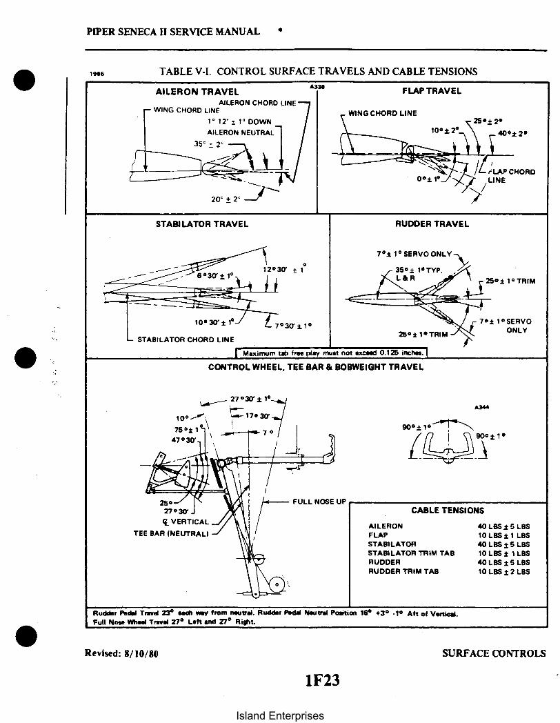
35° 2
-STABILATOR CHORD LINE
PIPER SENECA II SERVICE MANUAL
1966 TABLE V-1. CONTROL SURFACE TRAVELS AND CABLE TENSIONS
AILERON TRAVELAILERON CHORD LINE
WING CHORD LINE
1° 12' 1° DOWN
AILERON NEUTRAL
FLAP TRAVEL
WING CHORD LINE
10+225 2
\ 40± 2
LAPCHORDLAP CHORD
STABILATOR TRAVEL RUDDER TRAVEL
70± 1 SERVO ONLY
25+ 1 TRIM
7 1SERVOONLY25: 1 TRIM
Maximum tab free play must not exceed 0.125 inches.
CONTROL WHEEL, TEE BAR & BOBWEIGHT TRAVEL
A344
FULL NOSE UPCABLE TENSIONS
AILERONFLAPSTABILATORSTABILATOR TRIM TABRUDDERRUDDER TRIM TAB
40 LBS 5 LBS10LBS LBS40 LBS ± 5 LBS10 LBS ± 1 LBS40 LBS 1 5 LBS10 LBS 2 LBS
Rudder Pedel Travel 23 each way from neutral. Rudder Pedel Neutral Position 16 + 1 Aft of Vertical.Full Nose Wheel Travel 27 ° Left and 27 Right.
Revised: 8/10/80 SURFACE CONTROLS
1F23
Island Enterprises

120
110
LL
C
PIPER SENECA II SERVICE MANUAL
PPS-22TABLE V-II. CABLE TENSION VS. AMBIENT TEMPERATURE
100
90
80
70
60
50
40
30
20
-10 - -6 -4 -2 0
SUBTRACT
4 6 10
ADD
RIGGING LOAD CORRECTION, POUNDS
Reissued: 10/11/79 SURFACE CONTROLS
1F24Island Enterprises

2
PIPER SENECA II SERVICE MANUAL
2022
22 2
1. SPROCKET, RIGHT CONTROL WHEEL2. FLEXIBLE JOINT3. BOLT ASSEMBLY4. TUBE, CONTROL WHEEL5. CONTROL WHEEL (L & R)6. TURNBUCKLE7. TEE BAR ASSEMBLYS. O-RING9. WASHER, CONTROL WHEEL
10. PLATE, CONTROL WHEEL11. WASHER, CONTROL WHEEL12. SPACER, STOP13. SPROCKET, LEFT CONTROL WHEEL14. CHAIN, LEFT ROLLER15. IDLER SPROCKET, AFT16. CHAIN, RIGHT ROLLER17. PIN11. IDLER SPROCKET, FORWARD19. BOLT, BUSHING, NUT & COTTER PIN20. PULLEY, STABILATOR21. PULLEYS AILERON22. CABLES, AILERON CONTROL23. CABLES, STABILATOR CONTROL24. BOBWEIGHT ACTUATING ROD
Figure 5-1. Control Column Assembly
Reissued: 10/11/79 SURFACE CONTROLS
1G1
Island Enterprises
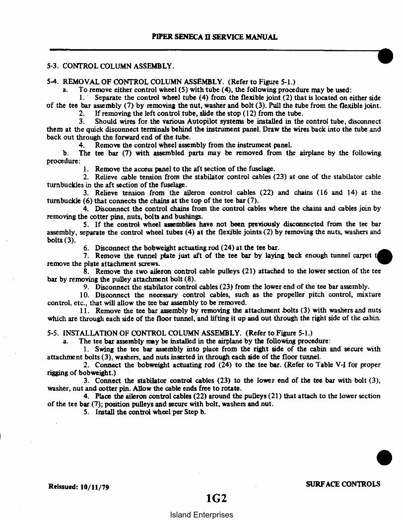
5-3. CONTROL COLUMN ASSEMBLY.
5-4. REMOVAL OF CONTROL COLUMN ASSEMBLY. (Refer to Figure 5-1.)a. To remove either control wheel (5) with tube (4), the following procedure may be used:
1. Separate the control wheel tube (4) from the flexible joint (2) that is located on either sideof the tee bar assembly (7) by removing the nut, washer and bolt (3). Pull the tube from the flexible joint.
2. If removing the left control tube, slide the stop ( 12) from the tube.3. Should wires for the various Autopilot systems be installed in the control tube, disconnect
them at the quick disconnect terminals behind the instrument panel. Draw the wires back into the tube andback out through the forward end of the tube.
4. Remove the control wheel assembly from the instrument panel.b. The tee bar (7) with assembled parts may be removed from the airplane by the following
procedure:1. Remove the access panel to the aft section of the fuselage.2. Relieve cable tension from the stabilator control cables (23) at one of the stabilator cable
turnbuckles in the aft section of the fuselage.3. Relieve tension from the aileron control cables (22) and chains (16 and 14) at the
turnbuckle (6) that connects the chains at the top of the tee bar (7).4. Disconnect the control chains from the control cables where the chains and cables join by
removing the cotter pins, nuts, bolts and bushings.5. If the control wheel assemblies have not been previously disconnected from the tee bar
assembly, separate the control wheel tubes (4) at the flexible joints (2) by removing the nuts, washers andbolts (3).
6. Disconnect the bobweight actuating rod (24) at the tee bar.7. Remove the tunnel plate just aft of the tee bar by laying back enough tunnel carpet
remove the plate attachment screws.8. Remove the two aileron control cable pulleys (21) attached to the lower section of the tee
bar by removing the pulley attachment bolt (8).9. Disconnect the stabilator control cables (23) from the lower end of the tee bar assembly.
10. Disconnect the necessary control cables, such as the propeller pitch control, mixturecontrol, etc., that will allow the tee bar assembly to be removed.
11. Remove the tee bar assembly by removing the attachment .bolts (3) with washers and nutswhich are through each side of the floor tunnel, and lifting it up and out through the right side of the cabin.
5-5. INSTALLATION OF CONTROL COLUMN ASSEMBLY. (Refer to Figure 5-1.)a. The tee bar assembly may be installed in the airplane by the following procedure:
1. Swing the tee bar assembly into place from the right side of the cabin and secure withattachment bolts (3), washers, and nuts inserted in through each side of the floor tunnel.
2. Connect the bobweight actuating rod (24) to the tee bar. (Refer to Table V-I for properrigging of bobweight.)
3. Connect the stabilator control cables (23) to the lower end of the tee bar with bolt (3),washer, nut and cotter pin. Allow the cable ends free to rotate.
4. Place the aileron control cables (22) around the pulleys (21) that attach to the lower sectionof the tee bar (7); position pulleys and secure with bolt, washers and nut.
5. Install the control wheel per Step b.
Reissued: 10/11/79 SURFACE CONTROLS
1G2
PIPER SENECA II SERVICE MANUAL
Island Enterprises

PIPER SENECA ii SERVICE MANUAL
6. Place the control wheels in neutral (centered) position and install the aileron control chains(14 and 16) on the control wheel sprockets (1 and 13) and idler cross-over sprockets (15 and 18). Theturnbuckle (6) must be centered between the two control wheel sprockets.
7. Loosen the connecting bolts (3) of the idler sprockets (15 and 18) to allow the chain to fitsnug around the control wheel sprockets and over the idler sprockets.
8. Connect the aileron control cables (22) to the ends of the chains (14 and 16) with bolts,bushings, nuts and cotter pins (19).
9. Adjust the chain turnbuckle (6) between the two control wheel sprockets to allow thecontrol wheels to be neutral and obtain proper cable tension as given in Table V-I. It may be necessary inorder to have both control wheels neutral to set the chain turnbuckle to neutralize the wheels and then setcable tension with the turnbuckles located under the floor panel aft of the main spar as instructed inParagraph 5-11. Before safetying the turnbuckle, check that when the ailerons are neutral, the controlwheels will be neutral and the chain turnbuckle centered. Also, the aileron bellcranks should contact theirstops before the control wheel hits its stop. Models which have adjustable aileron tee bar stops mustmaintain .030 to .040 clearance between the sprocket pin and the adjustable stop bolts after the bellcrankscontact their stops.
10. Set stabilator cable tension with the turnbuckle in the aft section of the fuselage andinstruction given in Paragraph 5-15. Check safety of all turnbuckles upon completion of adjustments.
11. Tighten the connecting bolts (3) of the idler sprockets (15 and 18).12. Install the floor tunnel plate and secure with screws. Fasten the tunnel carpet in place.
b. Either control wheel assembly may be installed by the following procedure:1. Insert the control wheel tube through the instrument panel.2. Should wires for the various Autopilot systems need to be installed in the control tube,
route them through the hole in the forward side of the tube and out of the small hole in the side. Positionthe rubber grommet in the hole in the side of the tube.
3. On the left control tube, install the stop (12).4. Connect the control wheel tube (4) to the flexible joint (2) of the tee bar assembly. If the
control cables and/or chains have not been removed or loosened, place the ailerons in neutral and install thecontrol tube on the flexible joint to allow the control wheel to be neutral. Install bolt, washer and nut (3)and tighten.
5-6. AILERON CONTROLS.
5-7. REMOVAL OF AILERON CONTROL CABLES. (Refer to Figure 5-2.)a. For the removal of any of the control cables in the fuselage or wings, first remove the floor panel
that is located directly aft of the main spar by removing the center seats, seat belt attachments, and thescrews securing the panel. Lift the panel and remove from airplane.
b. To remove either the right or left primary control cables (8 and 9) that are located in thefuselage, the following procedure may be used:
1. Remove the tunnel plate just aft of the tee bar by laying back enough tunnel carpet toremove the plate attachment screws.
2. Separate the primary control cable (8 or 9) at the turnbuckles (6) located in the flooropening aft of the main spar.
3. Remove the cable pulleys attached to the lower section of the control column tee barassembly by removing the pulley attachment bolt.
4. Move the cable guard (see Sketch B) located under the pulley cluster (7) by removing thecotter pin from the exposed end of the guard and sliding it to the left or right as required.
Reissued: 10/11/79 SURFACE CONTROLS
1G3
Island Enterprises

PIPER SENECA II SERVICE MANUAL
DAMAGEHERE
IMPROPER TOOL (RESULTING IN LOCKED BALL)
A SPECIAL WRENCH MAY BEREQUIRED WITH A LONG THROAT
ONLY CORRECT METHOD
Figure 5-1 a. Correct Method of Installing Rod End Bearing
Reissued: 10/11/79 SURFACE CONTROLS1G4
Island Enterprises

PIPER SENECA II SERVICE MANUAL
1944
SKETCH A 2041
20
SEE DETAIL A
16
Figure 5-2. Aileron Controls
Reissued: 10/11/791G5
SURFACE CONTROLS
Island Enterprises

PIPER SENECA II SERVICE MANUAL
GUARD PIN
SKETCH B SKETCH C
1. BELLCRANK ASSY, RIGHT2. CONTROL ROD, RIGHT3. CABLE, BALANCE, RIGHT4. PULLEY5. CABLE, CONTROL, RIGHT6. TURNBUCKLE, AILERON MAIN7. PULLEY CLUSTER, STA. 64.468. CABLE, CONTROL, LEFT9. CABLE, CONTROL, RIGHT
10. PULLEY11. PULLEYS12. PULLEYS13. TURNBUCKLE, CONTROL CHAINS14. BOBWEIGHT ACTUATOR ROD15. CABLE, BALANCE, LEFT16. CONTROL ROD, LEFT
17. CABLE, CONTROL, LEFT11. BELLCRANK ASSY, LEFT19. BOLT ASSY20. BOLT ASSY21. BOLT ASSY22. CONTROL ROD END23. JAM NUT24. WING SKIN, TOP25. BRACKET26. WASHER27. WASHER21. SPACER29. WASHER (2 REQ.)30. NUT31. WING SKIN, BOTTOM32. TEFLON TUBE
Figure 5-2. Aileron Controls (cont.)
Reissued: 10/11/791G6
SURFACE CONTROLS
Island Enterprises

PIPER SENECA II SERVICE MANUAL
5. Remove the cotter pins used as cable guards at the pulley (11) in the forward area of thefloor opening aft of the main spar.
6. Disconnect the cable (8 or 9) from the control chain at the control column tee bar assemblyby removing the cotter pin, nut, bolt, and bushing that connect the two together. Secure the chains in somemanner to prevent them from unwrapping from around the sprockets.
7. Draw the cable back through the floor tunnel.c. The primary control cable (5 or 17) in either wing may be removed by the following procedure:
1. Remove the access plate to the aileron bellcrank (1 or 18) located on the underside of thewing forward of the aileron center hinge.
2. If not previously disconnected, separate the cable at the turnbuckles (6) located in the flooropening aft of the main spar.
3. Disconnect the cable from the forward end of the aileron bellcrank by removing the cotterpin, nut, washer and bolt.
4. Draw the cable from the wing.d. Either balance cable (3 or 15) may be removed by the following procedure:
1. Separate the balance cable at the turnbuckle in the right side of the floor opening aft of themain spar.
2. If the left balance cable is to be removed, remove the cotter pin used as a cable guard at thepulley (10) in the center of the floor opening.
3. Remove the access plate to the aileron bellcrank (18) located on the underside of the wingforward of the aileron center hinge.
4. Disconnect the cable from the aft end of the aileron bellcrank by removing the cotter pin,nut, washer and bolt.
5. Draw the cable from the wing.
5-8. INSTALLATION OF AILERON CONTROL CABLES. (Refer to Figure 5-2.)a. The installation of either the right or left primary control cable (8 or 9) that is located in the
fuselage may be accomplished as follows:1. Draw the cable through the fuselage floor tunnel.2. Connect the cable to the end of the control chain and secure using bushing, bolt, nut and
cotter pin.3. Place the cable around the pulley (see Sketch B) that is located in the tunnel. Install cable
guard (see Sketch B) and secure with cotter pin.4. Position cables and install the cable pulleys that attach to the lower section of the tee bar
assembly. Secure with bolt, washer and nut. (Refer to Figure 5-1.)5. Place the cable around the pulley (11) that is located in the floor opening just aft of the
main spar and install cotter pin cable guards.6. If the primary control cable in the wing is installed, connect the control cable ends at the
turnbuckle (6) located in the floor opening aft of the main spar.7. Check rigging and adjustment per Paragraph 5-11.8. Position the heat duct and secure with screws.9. Install the tunnel plate aft of tee bar assembly and secure with screws.
10. Put the floor carpet in place and secure.11. Place the fuel selector lever on the selector torque tube and secure with pin and cotter pin.12. Install the lower and upper selector covers and secure with screws.
Reissued: 10/11/79 SURFACE CONTROLS
1G7
Island Enterprises

PIPER SENECA II SERVICE MANUAL
b. The primary control cable (5 or 17) in either wing may be installed by the following procedure:1. Draw the control cable into the wing.2. Connect the cable to the forward end of the aileron bellcrank (I or 18) using a bolt, washer,
nut and cotter pin. Allow the cable end to rotate freely on the bellcrank.3. If the primary control cable in the fuselage is installed, connect the ends at the turnbuckle
(6) located in the floor opening aft of the main spar.4. Check rigging and adjustment per Paragraph 5-11.5. Install the access plate on the underside of the wing.
c. Either balance cable (3 or 15) may be installed by the following procedure:I. Draw the cable into the wing.2. Connect the cable to the aft end of the aileron bellcrank (1 or 18) using a bolt, washer, nut
and cotter pin. Allow the cable end to rotate freely on the bellcrank.3. Connect the balance cable ends at the turnbuckle in the floor opening aft of the main spar.4. If the left cable was removed, install the cotter pin cable guard at the pulley (10) located in
the center of the floor opening.5. Check rigging and adjustment per Paragraph 5-11.6. Install the access plate on the underside of the wing.7. Install the floor panel, seat belt attachments and seats.
5-9. REMOVAL OF AILERON BELLCRANK ASSEMBLY. (Refer to Figure 5-2.)a. Remove the floor panel located directly aft of the main spar by removing the center seats, seat
belt attachments, and the screws securing the floor panel. Lift the panel and remove from the airplane.b. Remove the access plate to the aileron bellcrank (1 or 18) located on the underside of the wing,
forward of the aileron center hinge.c. Relieve tension from the aileron control cables by loosening the balance cable turnbuckle (6)
located in the floor opening aft of the main spar.d. Disconnect the primary (5 or 17) and balance (3 or 15) control cables from the bellcrank
assembly by removing cotter pins, nuts, washers and bolts.e. Disconnect the aileron control rod (16) (Sketch A) at the aft or forward end as desired.f. Remove the nut, pivot bolt (19) (Sketch A) and washers that secure the bellcrank. The nut is
visible from the underside of the wing.g. Remove the bellcrank from within the wing.
5-10. INSTALLATION OF AILERON BELLCRANK ASSEMBLY. (Refer to Figure 5-2.)a. Install first the teflon tube (32) then the spacer (28) in the torque tube portion of the bellcrank
(18). (See Sketch A.)b. Place the bellcrank in position in the wing with a washer located between each end of the torque
tube and the mounting brackets.c. Install the bellcrank pivot bolt (19) (see Sketch A) with the head up. Install a washer and nut on
the bolt and torque nut 20 to 25 inch-pounds. Check that the bellcrank rotates freely with little up-downplay. (Refer to Figure 5-2, Sketch A, Detail A.)
d. Install and adjust control rod (16) (Sketch A) and check aileron travel per Paragraph 5-11.e. Connect the ends of the primary (5 or 17) and balance (3 or 15) control cables to the bellcrank
using bolts, washers, nuts and cotter pins. Allow the cable ends to rotate freely on the bellcrank.f. Tighten the control cables at the balance cable turnbuckle (6) in the floor opening aft of the
main spar. Check cable tension per Paragraph 5-11.g. Install the access plate on the underside of the wing, the floor panel aft of-the main spar, seat belt
attachments and seats.
Reissued: 10/11/79 SURFACE CONTROLS
1G8Island Enterprises

PIPER SENECA II SERVICE MANUAL
1962
IIGGING TOOL
Figure 5-3. Bellcrank Rigging Tool
5-11. RIGGING AND ADJUSTMENT OF AILERON CONTROLS.a. To check and adjust rigging of aileron controls. use the following procedure:
1. Ascertain that the control wheels have been properly rigged. (Refer to Paragraph 5-5.)2. Place the control wheel in the centered position and place the tee bar in the full forward
position. Maintain the wheel and tee bar in these positions. Tee bar may be maintained in the full forwardposition by placing weights on the aft side of the stabilator if the stabilator cables have been previouslytensioned.
3. Remove aileron bellcrank access plates from the underside of the wings. forward of theaileron center hinge.
4. Check bellcranks for neutral position. (The neutral position of the bellcrank is the positionat which the centerline of the cable connection holes are an equal distance from the adjacent outboard wingrib.) A bellcrank rigging tool can be fabricated from dimensions given in Figure 5-16.
5. Affix the bellcrank rigging tool as shown in Figure 5-3 between the arm of each bellcrankand the adjacent rib. The slotted end of the tool fits on the arm forward of and adjacent to the primarycontrol cable end. The other end of the tool is positioned so its side contacts the aft side of the bellcrankstop. The bellcrank must be moved to allow a snug fit of the tool between the bellcrank arm and rib. Todoso. it may be necessary to loosen a primary control cable or balance cable.
b. Adjust primary and balance cable tension as given in Table V-1 by the following procedure:1. Remove floor panel located directly aft of the main spar by removing the center seats. seat
belt attachments and related hardware.2. Ascertain that the control wheels are properly rigged (refer to Paragraph 5-5) and both
bellcranks are at neutral position.
Revised: 8/10/80 SURFACE CONTROLS
1G9
Island Enterprises

A171
Figure 5-4. Aileron Rigging Tool
3. Adjust the turnbuckles on the primary and balance cables to obtain the proper tension asgiven in Table V-1. During adjustment, obtain a little more tension on the primary cable to hold thebellcranks in neutral (against the rigging tools): finish with approximately even tension on all cables. Primarycable tensions may be slightly less than balance cable tension. but should be within the tension specified.
4. Remove bellcrank rigging tools.c. Check and adjust the aileron for neutral position by the following procedure:
1. Ascertain that the bellcrank rigging tools fit snug between the bellcrank and the rib.2. Check the aileron for neutral. (The neutral position is the position at which the chord line
of the aileron forms a 1 12 ± 1° "down" angle with the wing chord at the inboard end of the aileron.) Anaileron rigging tool can be fabricated from dimensions given in Figure 5-17.
3. Place the aileron rigging tool as shown in Figure 5-4 against the underside of the wing andaileron as close as possible to the center of the aileron without contacting any rivets. The tool must bepositioned parallel with the wing ribs and the aft end of the tool even with the trailing edge of the aileron.
4. With the aileron control rod connected between the bellcrank and aileron, check that thesurface of the wing contacts the tool at its forward surface and at the spacer and the trailing edge of theaileron contacts the aft end of the tool. The aileron is neutral at this position. While measuring the neutralposition, a light "up" pressure shall be maintained at the center of the aft edge of the aileron, just sufficientto remove the slack between the bellcrank and the aileron.
5. Should the three points not contact, loosen the jam nut at the aft end of the control rodand rotate the rod until the three points contact. After adjustment, retighten the jam nut.
d. Check the ailerons for correct travel from neutral per dimensions given in Table V-1 by thefollowing procedure:
1. Center the bubble of a protractor over the surface of an aileron at neutral position and notethe reading.
Revised: 8/10/80 SURFACE CONTROLS
PIPER SENECA I SERVICE MANUAL
10
Island Enterprises

PIPER SENECA II SERVICE MANUAL
2. Move the aileron full up and down and check the degree of travel for each direction. Thedegree of travel on the protractor is determined by taking the difference between the protractor reading atneutral and up, and neutral and down. The bubble must be centered at each reading.
3. Should the travel not be correct, the travel may be set by rotating the bellcrank stops in orout. Stops are located in the wing attached to the rib that is adjacent to the aileron bellcrank.
4. Repeat this procedure for the other aileron.5. If the aileron stops are bottomed before the control wheel is turned 90 + 1 degree from centered
position, lengthen the drive cable and shorten the balance cable an equal amount. Recheck cable tension.e. Check the bellcrank stops to assure that the bellcrank contact is made simultaneously but still
have cushion before contacting the control wheel stops. Models which have adjustable aileron tee bar stopsmust maintain .030 to .040 clearance between the sprocket pin and the adjustable stop bolts after the bellcrankscontact their stops.
f. Check control operation and bolts and turnbuckles for safety.g. Install access plates and panels.
NOTE
When an out-of-trim condition persists despite all the riggingcorrections that can be made, there is a possibility that the trailingedge of the aileron has been used to move the aircraft forward.This can result in a slight bulging of the aileron contour at thetrailing edge which will cause an out-of-trim condition that is verydifficult to correct.
5-12. STABILATOR CONTROLS.
5-13. REMOVAL OF STABILATOR CONTROL CABLES. (Refer to Figure 5-5.)a. To remove either the forward or aft stabilator cables, first remove the access panel to the aft
section of the fuselage.b. Relieve cable tension from control system by loosening one of the cable turnbuckles in the aft
section of the fuselage.c. Disconnect the stabilator down springs and clamps (18) from the upper stabilator control cable in
the aft section of the fuselage.d. Either forward stabilator cable (20) may be removed by the following procedure:
1. Remove the floor tunnel cover in the aft area of the cabin by removing the carpet and theheater duct over the tunnel and the cover attachment screws.
2. Remove the cable guard plate (see Sketch B) from the underside of the pulley cluster (5) inthe aft area of the tunnel opening by removing the guard attachment screws.
3. Remove the floor panel located directly aft of the main spar by removing the center seats,seat belt attachments, and the screws securing the panel. Lift the panel and remove from the airplane.
4. Within the floor opening, remove the cable rub blocks (see Sketch A) that are attached tothe spar housing by removing the block attachment screws. Also, remove the cotter pin cable guard at thepulley cluster (4) in the aft area of the opening.
5. Remove the tunnel plate just aft of the tee bar by removing enough carpet from the tunnelto allow the plate attachment screws and plate to be removed.
6. If the right (upper) stabilator control cable (20) is to be removed, remove the cotter pincable guards at the pulley (1) located in the forward area of the tunnel.
7. Disconnect the cables (20) from the lower end of the tee bar by removing cotter pin, nut,washer and bolt.
8. Draw the cable aft through the floor tunnel.
Revised: 8/10/80 SURFACE CONTROLS1G11
Island Enterprises

1G12INTENTIONALLY LEFT BLANK
Island Enterprises

PIPER SENECA II SERVICE MANUAL
149
14
17
2046
SKETCH A
Figure 5-5. Stabilator and Stabilator Trim Controls
SKETCH B
Revised: 8/10/80 SURFACE CONTROLS1G13
Island Enterprises

UPPER STABILATOR
PIPER SENECA II SERVICE MANUAL
ALIGN VERTICALLY ±
SKETCH C
SKETCH DA3
1. PULLEY, STA. 51.912. WHEEL ASSY, TRIM CONTROL3. PULLEYS, STA. 86.704. PULLEY CLUSTER, STA. 127.17 & STA. 130.165. PULLEY CLUSTER, STA. 166.36. PULLEY, STA. 188.7747. CABLES, CONTROL, AFT8. PULLEY, STA. 261.4589. PULLEY, STA. 276.991
10. TRIM SCREW ASSY11. CONTROL ROD12. PULLEYS, STA. 292.3413. PULLEY, STA. 279.4914. BALANCE ARMIS. WEIGHT, BALANCE ARM16. CABLE, TRIM, AFT17. TURNBUCKLE18. SPRINGS, STABILATOR DOWN19. CABLES, TRIM, FORWARD20. CABLES, CONTROL, FORWARD21. BOBWEIGHT22. PIN & COTTER PIN23. BOLT ASSY24. BARREL, TRIM25. CABLE, TRIM, AFT26. BRACKET ASSY27. SHAFT ASSY21. PIN29. LINK ASSY30. EYE BOLT31. JAM NUT32. ROD ASSY33. COTTER PIN34. TAB, STABILATOR TRIM35. BOLT ASSY36. BRACKET, SUPPORT37. BOLT ASSY31. MOUNTING BRACKET39. TEE BAR40. ACTUATOR ROD41. BOBWEIGHT42. NOSE LANDING GEAR MOUNT ASSY
SKETCH E
Figure 5-5. Stabilator and Stabilator Trim Controls (cont.)
Revised: 8/10/80 SURFACE CONTROLS1G14
Island Enterprises

PIPER SENECA I SERVICE MANUAL
e. Either aft stabilator control cable (7) may be removed by the following procedure:1. Disconnect the cable end at the balance arm (14) of the stabilator by removing the cotter
pin, nut, washer and bolt.2. Remove the cotter pin cable guard at the pulleys (9 or 13) located either above or below the
balance arm.3. Remove the cable from the airplane.
5-14. INSTALLATION OF STABILATOR CONTROL CABLES. (Refer to Figure 5-5.)a. The forward stabilator cables (20) may be installed by the following procedure:
1. Draw the control cable through the floor tunnel. Ascertain that the right (upper) cable (20)is routed around the pulley (1) that is in the forward area of the forward floor tunnel.
2. Connect the cables (20) to the lower end of the control column tee bar with bolt, washer,nut and cotter pin. Allow the cable to be free to rotate.
3. If the aft control cable (7) is not installed, install per Step b.4. Connect the forward control cable to the aft cable at the turnbuckles (17) in the aft section
of the fuselage.5. For the right control cable (20), install the cotter pin cable guard at the pulley (1) in the
forward area of the tunnel.6. Within the forward area of the floor opening aft of the main spar, install the cable rub
blocks (see Sketch A) to the spar housing and secure with screws.7. In the area of the floor opening, install the cotter pin cable at the pulley cluster (4).8. Install the cable guard plate (see Sketch B) under the pulley cluster (5) located in the aft
area of the aft floor tunnel and secure with screws.9. Set cable tension per Table V-I and check rigging and adjustment per Paragraph 5-15.
10. Connect stabilator down springs and clamps (18) to upper aft stabilator control cable. (SeeSketch C.)
11. Install the tunnel plate directly aft of the tee bar assembly and secure with screws.12. Put the floor carpet in place and secure.13. Install the floor panel aft of the main spar and secure with screws. Install the seat belt
attachments and seats.14. Install the cover, heat duct, and carpet over the aft floor tunnel.
b. Either aft stabilator control cable (7) may be installed by the following procedure:1. Route the cable (7) around its pulley (9 or 13) located either over or under the balance arm
(14) of the stabilator.2. Connect the cable to the stabilator balance arm and secure with bolt, washer, nut and cotter
pin. (Insure bushing is installed with bolt.)3. Connect the aft cable to the forward cable at the turnbuckle (17) in the aft section of the
fuselage. The upper aft cable (7) connects to the right forward cable (20) and the lower cable (7) to the leftcable (20).
4. Install the cotter pin cable guard at the pulley (9 or 13) where required.5. Connect the stabilator down spring to the upper aft control cable (see Sketch C).6. Set cable tension per Table V-1 and check rigging and adjustment per Paragraph 5-15.
c. Install the access panel to the aft section of the fuselage.
Reissued: 10/11/79 SURFACE CONTROLS
1G15
Island Enterprises

A641 A977
Figure 5-6. Stabilator Rigging Tool Figure 5-7. Methods of Securing Trim Cables
5-15. RIGGING AND ADJUSTMENT OF STABILATOR CONTROLS.a. To check and set the correct degree of stabilator bobweight travel, the following procedure
should be used:1. Position the tee bar at a forward angle of seven degrees (neutral position of tee bar).2. Check the bobweight neutral position (refer to Table V-I).3. Adjust the bobweight actuating rod between the tee bar and bobweight link to obtain the
neutral position.b. To check and set the correct degree of stabilator travel, the following procedure should be used:
1. Level the airplane. (Refer to Leveling, Section II.)2. Place the stabilator in its neutral position. (The neutral position of the stabilator is with the
stabilator cord line parallel with the top of the front seat track.) A stabilator rigging tool can be fabricatedfrom dimensions given in Figure 5-18.
3. Check the stabilator travel by placing a rigging tool on the upper surface of the stabilator asshown in Figure 5-6.
4. Using a bubble protractor, set the number of degrees up travel as given in Table V-1 andplace it on the rigging tool. Raise the trailing edge of the stabilator and determine that when the stabilatorcontacts it stops, the bubble of the protractor is centered.
NOTE
The stabilator should contact both ofits stops before the controlwheel contacts its stops.
Reissued: 10/11/79 SURFACE CONTROLS
PIPER SENECA II SERVICE MANUAL
1G16Island Enterprises

PIPER SENECA II SERVICE MANUAL
5. Set the protractor for the number of degrees down travel as given in Table V-1 and againplace it on the rigging tool. Lower the trailing edge of the stabilator and determine that when the stabilatorcontacts its stops, the bubble of the protractor is centered.
6. Should the stabilator travel be incorrect in either the up or down position, remove the tailcone by removing the attachment screws. Turn the stops located at each stabilator hinge (refer to Figure5-12) to obtain the correct degree of travel.
7. Ascertain that the locknuts of the stop screws are secure and then reinstall the tail cone.c. To check and set stabilator control cable tension, the following procedure should be used:
1. Check to insure that the stabilator travel is correct.2. Remove the access panel to the aft section of the fuselage.3. Disconnect the down springs.4. Position the tee bar at a forward angle of seven degrees (neutral position of tee bar) and
secure in this position with a suitable tool.5. Place the stabilator in neutral (refer to Step b) and maintain in that position.6. Check control cables for the correct tension as given in Table V-I.7. Should tension be incorrect, loosen the turnbuckles in the aft section of the fuselage and
adjust the turnbuckles to obtain the correct tension as stated in Table V-1.
NOTE
Adjust all cables evenly to avoid uneven strain on aircraftcomponents.
8. Check the safety of all turnbuckles and bolts.9. With the stabilator in neutral, adjust the stabilator tab pushrod to streamline the tab with
the stabilator. This is the neutral position of the tab.10. Check the full travel of the control wheel with relation to the full travel of the stabilator to
determine that the stabilator contacts its stops before the control wheel contacts its stops, or the bobweightreaches the limit of its travel.
11. Reconnect the down springs and reinstall the access panels.12. Refer to Paragraph 5-21 for rigging and adjustment of stabilator trim.
5-16. STABILATOR TRIM CONTROLS.
5-17. REMOVAL OF STABILATOR TRIM ASSEMBLY (FORWARD). (Refer to Figure 5-5.)a. To remove the trim control wheel assembly and/or the trim control cables, first remove the panel
to the aft section of the airplane.b. If the aft trim cable (16) is not to be removed, block the cables at the pulleys (12) in the tail
cone to prevent them from unwrapping from the trim drum. (Refer to Figure 5-7.)c. Loosen the cables if the trim control wheel is to be removed or disconnected if the cables are also
to be removed. Do this at the trim cable turnbuckles (17) in the aft section of the fuselage.d. The control wheel with drum may be removed by the following procedure:
1. Remove the control wheel cover by removing the cover attaching screws.2. The wheel assembly may be removed from its mounting brackets by removing nut, washer,
and bolt that secures the wheel between the brackets. Draw the wheel from the brackets. Use caution notto damage trim indicator wire.
3. Unwrap the left cable from the drum.4. The wheel and drum are joined by three screws. Remove screws and separate these two
items with their center bushing and unwrap the right cable.
Revised: 8/10/80 SURFACE CONTROLS1G17
Island Enterprises

PIPER SENECA I SERVICE MANUAL
5. Tie the cables forward to prevent them from slipping back into the floor tunnel.e. The trim control cables (19) may be removed by the following procedure:
1. Remove the center seats and the pilot and rear seats if desired.2. Remove the seat belts attached to the forward floor tunnel by removing attachment nuts,
washers and bolts.3. Unfasten the carpet from the aft portion of the forward floor tunnel and lay it forward.4. Remove the tunnel cover located between the trim control wheel and the spar cover by
removing attachment screws.5. Remove the cable pulleys (3) located in the forward tunnel by removing the cotter pin,
washer and clevis pin.6. Remove the floor panel aft of the main spar by removing the panel attachment screws and
seat belt attachments. Lift the panel and remove from airplane.7. Remove the cable rub blocks (39) located in the floor opening on the aft side of the main
spar by removing the block attachment screws.8. Remove the carpet and the heater duct over the aft floor tunnel.9. Remove the cover plate from the top of the aft floor tunnel by removing attachment screws.
10. Remove the cable guard (see Sketch A) from the underside of the trim cable pulleys (4)located at station 130.167 by removing the cotter pin and withdrawing the roll pin.
11. Remove the cable fairlead (see Sketch B) from the underside of the pulley cluster (5)located at station 166.837 by removing the plate attachment screws.
12. With the cables disconnected from the trim control wheel, draw the cable(s) through thefloor tunnel.
5-18. INSTALLATION OF STABILATOR TRIM ASSEMBLY (FORWARD). (Refer to Figure 5-5.)a. The trim control wheel with drum may be installed by the following procedure:
1. Wrap the right trim cable on the trim drum by inserting the swaged ball of the cable in theslot provided in the side (right side) of the drum that mates with the control wheel, and looking at this side,wrap the drum with three and a half wraps of the cable in a clockwise direction.
2. Attach the control wheel to the cable drum by aligning the long lug of the drum with thelong slot of the wheel and securing the two pieces together with three screws.
3. Wrap the left trim cable on the drum by inserting the swaged ball of the cable in the slotprovided in the flanged side (left side) of the drum and looking at this side, wrap the drum with three and ahalf wraps of the cable in a clockwise direction.
4. Lubricate and install the bushing in the control wheel and drum.5. Align the control cables and position the control wheel assembly between its mounting
brackets. Ascertain that the end of the trim indicator wire is positioned in the spiraled slot of the drumwith no bind on the end. Install the retainer bolt from the left side and install washer and nut.
6. Install the cover over the control wheel and secure with screws, unless the control cableshave yet to be installed.
b. The trim control cables (19) may be installed by the following procedure:1. Draw the cable(s) through the floor tunnel.2. Wrap the cable drum and install the trim control wheel as given in Step a.3. Position the cable pulleys (3) on the mounting bracket and install the clevis pin, washer and
cotter pin.4. Connect the cable (19) to the aft cable (16) at the turnbuckle (17) in the aft section of the
fuselage. Install aft cable (16) if not installed.
Reissued: 10/11/79 SURFACE CONTROLS
1G18Island Enterprises

PIPER SENECA II SERVICE MANUAL
5. Install the cable fairlead (see Sketch B) at the underside of the pulley cluster (5) located atstation 166.837 and secure with screws.
6. Install the roll pin type cable guard (see Sketch A) at the underside of the pulleys (4)located in the forward area of the aft floor tunnel and secure it with a cotter pin.
7. Install the cable rub blocks located on the aft side of the main spar housing and secure withscrews.
8. Remove the blocks that secure the aft trim cable and check that the cables are seated on thepulleys.
9. Set cable tension per Table V-1 and check rigging and adjustment per Paragraph 5-21. Safetyall turnbuckles.
10. Install the tunnel cover on the forward tunnel and secure with screws.11. Install the carpet over the floor tunnel.12. Install the cover over the trim control wheel and secure with screws and special washers.13. Install the seat belts removed from the top of the floor tunnel and secure with bolt, washer
and nut.14. Install the floor panel and seat belt attachments aft of the main spar and secure panel with
screws.15. Install the aft floor tunnel and secure with screws.16. Install the heater duct and carpet over the aft floor tunnel.
c. Install the panel to the aft section of the airplane and the seats.
5-19. REMOVAL OF STABILATOR TRIM CONTROLS (AFT). (Refer to Figure 5-5.)a. Remove the access panel to the aft section of the fuselage.b. Block the trim cables (19) at the first set of pulleys (5) forward of the cable turnbuckles (17) in
the aft section of the fuselage by a method shown in Figure 5-7.c. Remove the tail cone attachment screws and tail cone from the airplane.d. Block the cable (16) at the trim barrel (24) to prevent them from unwrapping at the barrel.e. Disconnect the cables (16 and 19) at the turnbuckles (17).f. Remove the cable guard pins (22) at the trim screw and also at the pulleys (12) located below the
trim mechanism at station 292.34.g. Remove the bolt assembly (23) which connects the forward end of the trim screw with the link
assembly (29).h. Unscrew the screw (27) from the trim barrel (24).i. Remove the four machine screws securing the two parts of the bracket assembly (26) to the
mounting bracket (38).j. Separate the two parts of the bracket assembly (26) and remove the trim barrel and cable. Note
the amount and placement of washers at each end of the barrel to simplify reassembly.k. Remove the barrel and cables from the airplane.
Reissued: 10/11/79 SURFACE CONTROLS
1G19
Island Enterprises

PIPER SENECA II SERVICE MANUAL
5-20. INSTALLATION OF STABILATOR TRIM CONTROLS (AFT). (Refer to Figure 5-5.)a. Wrap the trim barrel (24) by first laying the center (as measured equally from each end to the
center of the cable) of the aft trim cable (16) in the slot of the barrel (24). Bring the upper cable throughthe diagonal slot in the flange at the upper end of the barrel and wrap down in a counterclockwisedirection. Bring the lower cable through the diagonal slot in the lower end of the barrel and wrap up in aclockwise direction. Wrap the cable as evenly as possible to obtain 23 wraps on the barrel as viewed fromthe side opposite the slot and with the cables extending out from the slotted side.
b. Block both cables by clamping them between two pieces of wood laid next to the wraps toprevent them from unwrapping.
c. Install the barrel between the two parts of the bracket assembly (26). Be sure to install thewashers at both ends of the barrel before installing it in the brackets.
d. Secure the barrel and bracket assembly (26) to the mounting bracket (38) with the four machinescrews.
e. Install the screw (27) into the barrel (24) with the drilled bolt hole facing towards the front ofthe airplane.
f. Position the stabilator and trim tab in a neutral position (refer to Paragraph 5-21) and adjust thetrim screw till the bolt hole in the end aligns with the bolt hole in the yoke of the link assembly (29); theninstall the bolt assembly (23) and secure.
g. Route the cable (16) around the pulleys at station 292.34 and forward to the turnbuckles (17) inthe fuselage.
h. Ascertain that the cables are in the pulley grooves; then install the guard pins (22) at the pulleys(12).
i. Connect the cables (16) to the turnbuckles (17) and remove the blocking from both the forwardand aft cables.
j. Set cable tension in accordance with Table V-I and check rigging and adjustment per Paragraph5-21.
k. Install the tail cone and secure with screws.1. Install the access panel to the aft section of the fuselage.
5-21. RIGGING AND ADJUSTMENT OF STABILATOR TRIM. (Refer to Figure 5-5.) PP.00a. Level the airplane. (Refer to Leveling, Section II.)b. Remove the tail cone fairing from the fuselage by removing the attaching screws.c. Remove the access panel to the aft section of the fuselage.d. Secure the stabilator in its neutral position. To find neutral, place a rigging tool on the upper
surface of the stabilator as shown in Figure 5-6. Zero a bubble protractor on the top of the front seattracks; then set it on the rigging tool and tilt the stabilator until the bubble is centered.
e. The following items should be accomplished as a preadjustment check before proceeding with therigging of the trim tab. If these items were accomplished during the installation, proceed with Step f.
1. Ascertain that the cable is wrapped 23 times around the barrel as shown in Figure 5-5.2. The trim screw is adjusted to an initial length of 1.06 inches as shown in Figure 5-5.3. The actuating rod is initially adjusted to 6.62 inches in length as shown in Figure 5-5.4. Set the trim cable tension in accordance with Table V-1. If the cables were disconnected and
replaced, rotate the control wheel several times to allow the cables to seat and then recheck the tension.f. Turn the trim control wheel until the trim tab streamlines with the neutral stabilator.g. Check the bubble of the protractor over the neutral tab and then check the tab travels as given in
Table V-I. The degree of travel on the protractor is determined by taking the difference between theprotractor reading at neutral and up, and neutral and down. The bubble must be centered at each readingwith the airplane level. Total free travel measured at the tab trailing edge must not exceed .125 inch.
Revised: 8/10/80 SURFACE CONTROLS
1G20
Island Enterprises

PIPER SENECA II SERVICE MANUAL
h. To obtain the correct travels, if incorrect, adjust by disconnecting the link (29) at the rod assembly(32) rod end and turning the end in or out as required. Reconnect the rod end to the link.
i. Secure the jam nut (31) on the rod assembly.j. Turn the trim wheel to full travel and check for turnbuckle clearance and location of tab indicator.k. Reinstall the tail cone fairing and aft fuselage access panel.
5-22. RUDDER PEDAL ASSEMBLY.
5-23. REMOVAL OF RUDDER PEDAL ASSEMBLY. (Refer to Figure 5-8.)a. Remove the access panel to the aft section of the fuselage.b. Relieve rudder and stabilator cable tension by loosening one of the rudder and stabilator cable
turnbuckles in the aft section of the fuselage.c. Remove the tunnel plate just aft of the tee bar by laying back enough tunnel carpet to remove
the plate attachment screws.d. Disconnect the stabilator control cable from the lower end of the tee bar assembly and disconnect
the bobweight push rod from the tee bar.e. Remove the tee bar attachment bolts with their washers and nuts which are through each side of
the floor tunnel. Pull the lower end of the tee bar aft.f. Disconnect the control cable (22) ends from the arms on the torque tube by removing the cotter
pins. washers. nuts and bolts (28).g. Disconnect the bungee rods (9) at the control arms by removing nuts and bolts ( 1).h. Disconnect the brake cylinders (5) at the lower end of each cylinder rod (31) by removing the
cotter pins and clevis pins (30).i. Disconnect the vee brace(s) (4) from the torque tube by removing nuts. washers and bolts (8) that
secure the strap bracket (7) to the vee brace.j. Disconnect the torque tube support bracket (23) where it attaches to the floor tunnel by removing
its attachment bolts.k. Remove the two bolts (21) that extend through the torque tube and are located at the center of
the tube assembly over the floor tunnel. Compress the tubes.1. Disconnect the torque tube support blocks (34 and 35) from the support brackets on each side of
the fuselage by removing the attachment nuts. washers and bolts (2).m. Remove the trim side panels if desired.n. Remove the assembly from the airplane. Note the spacer washer (17) on each end and between
the support blocks.
5-24. INSTALLATION OF RUDDER PEDAL ASSEMBLY. (Refer to Figure 5-8.)a. Assemble the torque tube assembly as shown in Figure 5-8. Do not at this time install the two
bolts through the center of the tube assembly.b. Place the upper support blocks (34) on the ends of the torque tube assembly. Note that a washer
(17) is required on each end of the tube.c. Position the support blocks (34 and 35) on their mounting brackets at each side of the fuselage
and secure with bolts, washers and nuts. Note that a bushing is required in the bolt holes of the uppersupport block, and a plate on top of the upper block, between the upper and lower blocks and under theblock mounting bracket.
d. Align the bolt holes in the center area of the torque tube assembly: install bolts, washers and nuts(21) and tighten.
Revised: 8/10/80 SURFACE CONTROLS1G21
Island Enterprises

PIPER SENECA II SERVICE MANUAL
938
1. PLATE2. BOLT & NUT3. TUBE, LEFT, OUTER4. VEE BRACE5. BRAKE CYLINDER6. CLEVIS PIN & COTTER PIN7. BRACKET8. BOLT, WASHER & NUT9. BUNGEE, NOSE WHEEL STEERING
10. JAM NUT11. BOLT & NUT12. ROD END, STEERING13. TUBE, LEFT, CENTER14. BEARING, SUPPORT15. TUBE, RIGHT, OUTER16. SUPPORT BLOCK, LOWER17. WASHER, SPACER18. BRAKE PEDAL
19. RUDDER PEDAL20. CLEVIS ROD21. BOLT, WASHER & NUT22. CONTROL CABLE, RUDDER23. BRACKET, TUBE SUPPORT24. CABLE END25. ROD END26. CLEVIS PIN & COTTER PIN27. STOPS, RUDDER PEDAL28. BOLT, WASHER, NUT & COTTER PIN29. PIN, WASHER & COTTER PIN30. CLEVIS PIN & COTTER PIN31. ROD, BRAKE CYLINDER32. IDLER ARM33. TUBE, RUDDER CONTROL34. SUPPORT BLOCK, UPPER35. SUPPORT BLOCK, LOWER36. TUBE, RUDDER CONTROL
Figure 5-8. Rudder and Brake Pedal Assembly
Reissued: 10/11/791G22
SURFACE CONTROLS
Island Enterprises

PIPER SENECA IISERVICE MANUAL
e. Position the torque tube support bracket (23) on the floor tunnel and secure with bolts.f. Position the vee brace(s) (4) on the torque tube; install the strap bracket (7) around the torque
tube and brace and secure with bolts, washers and nuts (8).g. Connect the ends of the brake cylinder rods (31) and clevis rods (20) to the idler arms (32) and
secure with clevis and cotter pins (30).h. Connect the bungee rods (9) and secure with bolts and nuts ( 1). Check steering rod adjustment
per Alignment of Nose Gear. Section VI.i. Connect the rudder trim to the arm of the torque tube and secure with bolt, washer, nut and
cotter pin. A thin washer is installed under the nut which is tightened only finger tight.j. Connect the ends of the rudder control cables to the arms Drovided on the torque tube and
secure with bolts, washers, nuts and cotter pins (28). Allow the ends free to rotate.k. Swing the tee bar into place and secure with attachment bolts, washers and nuts with the bolts
inserted in through each side of the floor tunnel.1. Connect the stabilator control cables to the lower end of the tee bar with bolt, washer and nut
and secure with cotter pin. Allow the cable ends free to rotate. Connect bobweight push rod to tee bar.m. Set rudder cable tension and check rigging and adjustment per Paragraph 5-32.n. Set stabilator cable tension and check rigging and adjustment per Paragraph 5-15.o. Check aileron cable tension.p. Check safety of bolt and turnbuckles.q. Install the floor tunnel plate and secure with screws. Fasten the tunnel carpet in place.r. Install the access to the aft section of the fuselage.
5-25. RUDDER CONTROLS.
5-26. REMOVAL OF RUDDER CONTROL CABLES. (Refer to Figure 5-9.)a. To remove either the forward (2) or aft (10) rudder cables, first remove the access panel to the
aft section of the fuselage.b. Disconnect the desired cable at the turnbuckles (9) in the aft section of the fuselage.c. Either forward rudder cable (2) may be removed by the following procedure:
1. Remove the tunnel cover in the aft area of the cabin by removing the carpet, heat duct andthe cover attachment screws.
2. Remove the floor panel located directly aft of the main spar by removing the center seats,seat belt attachments and the screws securing the floor panel. Lift and remove the panel from the airplane.
3. Remove the tunnel plate just aft of the tee bar by removing enough carpet from the tunnelto allow the plate attachment screws and the plate to be removed.
4. Remove the cable guard plate (see Sketch C) from the underside of the pulley cluster (8)that is located in the aft area of the floor tunnel, by removing the guard attachment screws.
5. From within the area of the floor opening, remove the cable rub blocks (see Sketch B) thatare attached to the spar housing by removing the block attachment screws.
6. Remove the cable guard pin (see Sketch A) located under the pulley cluster ( 1) by removingthe cotter pin from the exposed end and sliding the pin to the left or right as required.
7. Disconnect the end of the cable from the arm on the rudder pedal torque tube by removingthe cotter pin, nut, washer and bolt. (Refer to Figure 5-8.)
8. Draw the cable from the floor tunnel.
Reissued: 10/11/79 SURFACE CONTROLS
1G23
Island Enterprises

PIPER SENECA II ERVICE MANUAL
d. The aft rudder control cable (10) may be removed by the following procedure:1. Remove the tail cone by removing its attachment screws.2. Disconnect the cable (10) from the rudder sector (13) by removing the two cotter pins at
the aft center portion of the sector and moving the swagged ball and cable out of the recessed hole in thesector.
3. Remove the cable guard pins from the pulley (11) brackets at station 280.091.4. Draw the cable from the fuselage.
5-27. INSTALLATION OF RUDDER CONTROL CABLES. (Refer to Figure 5-9.)a. The forward rudder control cables (2) may be installed by the following procedure:
1. Draw the control cable through the floor tunnel.2. Connect the end of the cable to the arm on the rudder pedal torque tube (refer to Figure
5-8) by installing bolt, washer, nut and cotter pin, allowing the cable end to rotate freely.3. Connect the forward control cable (2) to the aft control cable (10) at the turnbuckles (9) in
the aft section of the fuselage. If the aft control cables are not installed, install them at this time perinstructions in Step b. Ascertain that each cable is in the proper pulley groove.
4. Move the cable guard (see Sketch A) located in the forward tunnel, under the pulley cluster(1) into position, and secure with cotter pin.
5. Within the area of the floor opening aft of the main spar, install the cable rub blocks (seeSketch B) onto the spar housing and secure with screws at the pulley cluster (6).
6. Install the cable guard plate (see Sketch C) under the pulley cluster (8) located in the aftarea of the floor tunnel and secure with screws.
7. Set cable tension as given in Table V-I and check rigging and adjustment per Paragraph 5-28.Safety the turnbuckle.
8. Install the forward tunnel plate aft of the tee bar and secure with screws.9. Put the floor carpet in place and secure.
10. Install the floor panel and seat belt attachment aft of the main spar, securing the panel withscrews and install the seats.
11. Install the cover and carpet of the aft floor tunnel.b. The aft rudder control cable (10) may be installed by the following procedure:
1. Position the control cable in the fuselage with the swaged ball next to the rudder sector(13).
2. Route the cable ends over the pulleys (11) and install the guard pins in the pulley brackets.3. Position the swaged ball of the cable in the recessed hole in the sector (13) and secure in
place with two MS24665-283 cotter pins.4. Connect the cable ends to the forward control cables (2) at the turnbuckles (9) in the aft
section of the fuselage.5. Set cable tension as given in Table V-I and check rigging and adjustment per Paragraph 5-28.
Safety the turnbuckle.6. Install the tail cone and secure with screws.
c. Install the access panel to the aft section of the fuselage.
Reissued: 10/11/79 SURFACE CONTROLS
Reissued: 10/11/79 SURFACE CONTROLS
1G24Island Enterprises

1963
RUDDER CONTROL CABLES
RUDDER CONTROL CABLES
PIPER SENECA II SERVICE MANUAL
GUARD PIN
SKETCH A RUDDER TRIM CABLES
Figure 5-9. Rudder and Rudder Trim Controls
Reissued: 10/11/79 SURFACE CONTROLS1H1
Island Enterprises

1. PULLEY CLUSTER, STA. 64.462. CABLES, CONTROL, FORWARD3. WHEEL ASSY, TRIM CONTROL4. PULLEYS, TRIM5. CABLES, TRIM, FORWARD6. PULLEY CLUSTER, STA. 127.187. FAIRLEADASSY3. PULLEY CLUSTER, STA. 166.649. TURNBUCKLES
10. CABLE CONTROL, AFT11. PULLEYS, STA. 210.09112. SCREW ASSY, TRIM13. SECTOR ASSY, TORQUE TUBE14. PULLEYS, STA. 279.03215. CABLE, TRIM, AFT16. TURNBUCKLES17. BUNGEE, NOSE WHEEL CONTROL18. ARM ASSY, STEERING19. MOUNTING BRACKET20. BOLT ASSY21. SUPPORT ASSY, BARREL MOUNT22. BARREL TRIM23. SUPPORT ASSY, BARREL MOUNT24. ANGLE. TRIM25. ARM ASSY26. RUDDER TRIM TAB ASSY27. CONTROL ROD26. ARM ASSY, TRIM TAB29. JAM NUT30. ROD END31. LINK ASSY32. COTTER PIN33. SHAFT ASSY, TRIM SCREW34. SHIM35. CABLE GUARD36. WASHERS (2 REQ.)37. SPAR38. SHIM
3068
1.559 NEUTRAL
PIPER SENECA II SERVICE MANUAL
RUDDER CONTROL CABLES
RUDDER TRIM SKETCH C
2322
28
23 TURNSOMIT 1 WRAP
SKETCH D
Figure 5-9. Rudder and Rudder trim Controls (cont.)
Revised: 3/16/81 SURFACE CONTROLS1H2
Island Enterprises

PIPER SENECA II SERVICE MANUAL
Figure 5-10. Rudder Rigging Tool Figure 5-11. Clamping Rudder Pedals
5-28. RIGGING AND ADJUSTMENT OF RUDDER CONTROLS.a. To check and set the correct degree of rudder travel, the following procedure may be used:
1. Check the rudder travel by swinging the rudder until it contacts its stop. If the controlcables are connected, use the rudder pedals to swing the rudder.
2. With the rudder against its stop, place a rigging tool against the side of the rudder andvertical stabilizer as shown in Figure 5-10. (Ascertain that the tool is not contacting any rivets.) If no gapexists between the rigging tool and the surface of the rudder and vertical stabilizer, the rudder stop for onedirection of travel is correct as required in Table V-I. (This tool may be fabricated from dimensions given inFigure 5-19.)
3. Swing the rudder in the other direction and check travel as directed in Step 2.4. Should the rudder travel be incorrect showing a gap between the tool and any part of the
control surfaces, the tail cone should be removed and the stops reset to obtain correct rudder travel. (Referto Figure 5-12.)
b. To set cable tension and alignment of the rudder, the following procedure may be used:1. Remove the access panel to the aft section of the fuselage.2. Streamline the rudder and trim tab with the vertical stabilizer and secure in this position.3. Check to insure that the nose gear steering has been aligned and rudder pedals are secured at
neutral. (In neutral position the rudder pedals are tilted aft as shown in Figure 7-4 of Section VII.)
NOTE
The nose wheel must be off the ground for remainder of rudderrigging.
Revised: 8/10/80 SURFACE CONTROLS
1H3
Island Enterprises

PIPER SENECA II SERVICE MANUAL
A198
1. RUDDER STOPS
2. STABILATOR STOPS
Figure 5-12. Rudder and Stabilator Travel Adjustment
4. Adjust the turnbuckles in the aft section of the fuselage to obtain proper cable tension asgiven in Table V-l and to allow the rudder to align at neutral position. Adjust the cables evenly to avoid unevenstrain on aircraft components. Neutral position can be determined by standing behind the airplane andsighting the rudder with the vertical stabilizer or the center of the trim screw.
5. Check safety of turnbuckles.c. With the pilot's left rudder pedal depressed and the rudder against the left stop. adjust the rudder
pedal stop to provide .060 to .120 inch clearance. Repeat this procedure with the copilot's right rudder pedal.(Refer to Figure 5-8.)
NOTE
Do not depress the pedals more than is needed for the rudder tocontact its stops as the control cables may stretch.
d. Install the tail cone and the access panel to the aft section of the fuselage.
Revised: 8/10/80 SURFACE CONTROLS
1H4
Island Enterprises

PIPER SENECA II SERVICE MANUAL
5-29. RUDDER TRIM CONTROLS. (Refer to Figure 5-9.)
5-30. REMOVAL OF RUDDER TRIM CONTROLS (FORWARD). (Refer to Figure 5-9.)a. To remove the trim control wheel assembly and/or trim control cables (5), first remove the panel
to the aft section of the fuselage.b. If the aft trim cable (15) is not being removed, block the cables aft to the turnbuckles (16) to
prevent the cables from unwrapping at the trim barrel (22) in the fin. (Refer to Figure 5-7.)c. If the trim control wheel is to be removed, loosen the cables at the turnbuckles (16) and proceed
with the following steps:I. Remove the trim cover assembly by removing the cover attaching screws.2. Remove the nut, washers and bolt that secures the trim wheel assembly between its
mounting bracket. Draw the wheel from the brackets. Use caution not to damage the trim indicator wire.3. Unwrap the lower cable from the drum.4. The wheel and drum are joined by three screws. Remove screws and separate these two
items and unwrap the upper cable.5. Tie the cables forward to prevent them from slipping back into the floor tunnel.
d. If the trim control wheel and forward cables (5) are to be removed, block the aft cables (15) aftof the turnbuckles (16) and proceed with the following steps:
1. Remove the tunnel cover in the aft area of the cabin by removing the carpet and heater ductover the tunnel and the cover attachment screws.
2. Remove the floor panel located directly aft of the main spar by removing the center seats,seat belt attachments and screws securing the panel. Remove the panel from the airplane.
3. Remove the trim cover assembly to gain access to the trim wheel mounting hardware.4. Disconnect the turnbuckles (16) and remove the guard plate (see Sketch C) at pulley cluster
(8).5. Remove the rub block (see Sketch B) at pulley cluster (6).6. Remove the nut, washers, and bolt securing the rudder trim control wheel and drum
assembly to its mounting bracket and remove the complete assembly with cables. Use caution not todamage the indicator wire.
5-31. INSTALLATION OF RUDDER TRIM CONTROLS (FORWARD). (Refer to Figure 5-9.)a. The trim control wheel with drum may be installed by the following procedure:
1. Wrap the left cable on the trim drum by inserting the swaged ball of the cable in the slotprovided in the upper side of the drum which mates with the control wheel. Looking at this side, proceedto wrap three and a half turns of cable in a clockwise direction.
2. Attach the trim control wheel to the cable drum by aligning the long lug of the drum withthe long slot of the wheel and securing the two pieces together with three screws.
3. Wrap the right cable on the drum by inserting the swaged ball of the cable into the slotprovided in the flanged side (lower) of the drum. Looking at this side, proceed to wrap three and a halfturns of cable in a clockwise direction.
4. Lubricate and install the bushing in the lower side of the drum and the bearing on the upperside of the trim control wheel assembly.
5. Align the trim control cables (5) and position the control wheel assembly between itsmounting brackets. Ascertain that the trim indicator wire is positioned in the spiraled slot of the wheel withno binding on the end. Install the retainer bolt from the upper side, along with the washer and secure withwasher and nut from below.
6. Install the cover assembly over the trim control wheel and secure with screws unless thecontrol cables have yet to be installed.
Reissued: 10/11/79 SURFACE CONTROLS
1H5
Island Enterprises

PIPER SENECA II SERVICE MANUAL
b. The trim control cables (5) may be installed by the following procedure:1. Draw the cables (5) through the floor tunnel and route them through the pulley clusters at
station 127.17 and 166.84. Ascertain that the cables (5) cross at the fairlead (7) between the two pulleyclusters.
2. Wrap the cable drum and install the trim control wheel as given in Step a.3. Position the cables (5) over the proper pulleys (as shown in Sketches B and C of Figure 5-9.)4. Connect the forward cables (5) to the aft cables (15) at the turnbuckles (16) in the aft
section of the fuselage. If the aft cable is not installed, proceed with instructions given in Paragraph 5-33.5. Remove the blocks securing the aft cables and check that the cables (5 and 16) are seated on
the pulleys. Install the rub block and guard plate at the appropriate pulley clusters. (Refer to Sketches Band C of Figure 5-9.)
6. Set trim cable tension in accordance with specifications given in Table V-I and check riggingand adjustment per Paragraph 5-34. Safety both turnbuckles.
7. Install the tunnel cover on the forward tunnel and secure with screws.8. Install the carpet over the floor tunnel.9. Install the cover over the trim control wheels and flap handle and secure with screws.
10. Install the seat belts removed from the top of the floor tunnel and secure with bolt, washerand nut.
11. Install the aft floor tunnel cover, heater duct and carpet.12. Install the carpet over the aft floor plate.
c. Install the panel to the aft section of the fuselage and the seats.
5-32. REMOVAL OF RUDDER TRIM CONTROLS (AFT). (Refer to Figure 5-9.)a. Remove the access panel from the lower side of the fin and the tail cone fairing.b. If the forward trim mechanism is not being removed at this time, block the cables forward of t
turnbuckles (9) to prevent the cables from unwrapping at the forward trim drum. (Refer to Figure 5-7.)c. Secure the trim cables (9) at the aft trim drum barrel (22).d. Disconnect the trim cable turnbuckles (9) in the aft section of the fuselage.e. Remove the cable guards from the pulley (14) bracket located at station 279.032.f. Disconnect the trim screw link assembly (31) from the screw (33).g. Remove the cotter pin (32) from the aft end of the screw.h. Remove the four bolt assemblies securing the forward support (21) to the mounting bracket.i. Remove the screw and barrel assembly (22) along with the aft cables (15) from the airplane.
5-33. INSTALLATION OF RUDDER TRIM CONTROLS (AFT). (Refer to Figure 5-9.)a. Insert the complete trim screw and barrel assembly (22) into the fin. Route the trim cable ends
around the pulleys at station 279.032.b. Insert the trim screw and barrel assembly (22) into the mounting bracket (19). Place the washer
on the forward end of the barrel and install the support assembly in the mounting bracket.
NOTE
Total allowable end play of the barrel in the mounting bracket is.006 to .008 inches. Use 62833-18 laminated shim stock washer asrequired to achieve the correct end play.
Reissued: 10/11/79 SURFACE CONTROLS
1H6Island Enterprises
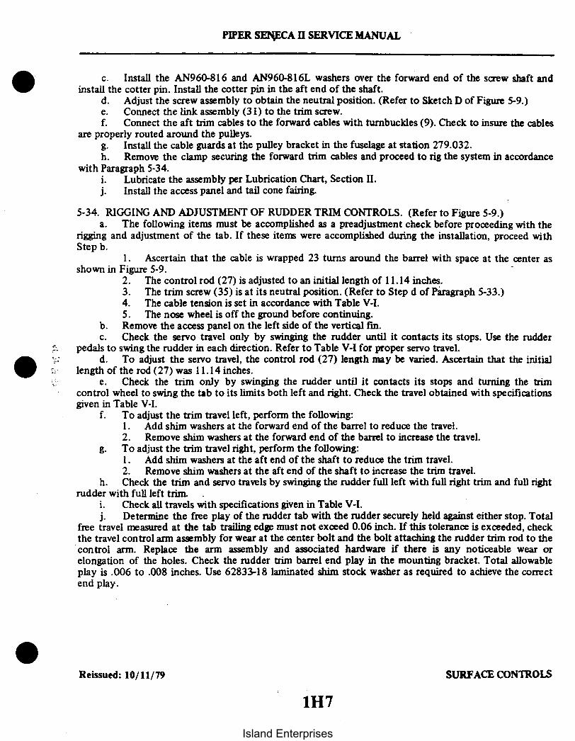
PIPER SENECA II SERVICE MANUAL
c. Install the AN960-816 and AN960-816L washers over the forward end of the screw shaft andinstall the cotter pin. Install the cotter pin in the aft end of the shaft.
d. Adjust the screw assembly to obtain the neutral position. (Refer to Sketch D of Figure 5-9.)e. Connect the link assembly (31) to the trim screw.f. Connect the aft trim cables to the forward cables with turnbuckles (9). Check to insure the cables
are properly routed around the pulleys.g. Install the cable guards at the pulley bracket in the fuselage at station 279.032.h. Remove the clamp securing the forward trim cables and proceed to rig the system in accordance
with Paragraph 5-34.i. Lubricate the assembly per Lubrication Chart, Section II.j. Install the access panel and tail cone fairing.
5-34. RIGGING AND ADJUSTMENT OF RUDDER TRIM CONTROLS. (Refer to Figure 5-9.)a. The following items must be accomplished as a preadjustment check before proceeding with the
rigging and adjustment of the tab. If these items were accomplished during the installation, proceed withStep b.
1. Ascertain that the cable is wrapped 23 turns around the barrel with space at the center asshown in Figure 5-9.
2. The control rod (27) is adjusted to an initial length of 11.14 inches.3. The trim screw (35) is at its neutral position. (Refer to Step d of Paragraph 5-33.)4. The cable tension is set in accordance with Table V-I.5. The nose wheel is off the ground before continuing.
b. Remove the access panel on the left side of the vertical fin.c. Check the servo travel only by swinging the rudder until it contacts its stops. Use the rudder
pedals to swing the rudder in each direction. Refer to Table V-I for proper servo travel.d. To adjust the servo travel, the control rod (27) length may be varied. Ascertain that the initial
length of the rod (27) was 11.14 inches.e. Check the trim only by swinging the rudder until it contacts its stops and turning the trim
control wheel to swing the tab to its limits both left and right. Check the travel obtained with specificationsgiven in Table V-I.
f. To adjust the trim travel left, perform the following:1. Add shim washers at the forward end of the barrel to reduce the travel.2. Remove shim washers at the forward end of the barrel to increase the travel.
g. To adjust the trim travel right, perform the following:1. Add shim washers at the aft end of the shaft to reduce the trim travel.2. Remove shim washers at the aft end of the shaft to increase the trim travel.
h. Check the trim and servo travels by swinging the rudder full left with full right trim and full rightrudder with full left trim.
i. Check all travels with specifications given in Table V-I.j. Determine the free play of the rudder tab with the rudder securely held against either stop. Total
free travel measured at the tab trailing edge must not exceed 0.06 inch. If this tolerance is exceeded, checkthe travel control arm assembly for wear at the center bolt and the bolt attaching the rudder trim rod to thecontrol arm. Replace the arm assembly and associated hardware if there is any noticeable wear orelongation of the holes. Check the rudder trim barrel end play in the mounting bracket. Total allowableplay is .006 to .008 inches. Use 62833-18 laminated shim stock washer as required to achieve the correctend play.
Reissued: 10/11/79 SURFACE CONTROLS
1H7
Island Enterprises

5-35. WING FLAP CONTROLS.
5-36. REMOVAL OF WING FLAP CONTROLS. (Refer to Figure 5-13.)a. The flap torque tube assembly may be removed by the following procedure:
1. Remove the access plate located between the underside of the aft section of each wing andthe fuselage by removing attaching screws.
2. Remove the floor panel located aft of the main spar by removing the center seats, seat beltattachments and the screws securing the panel. Lift the panel and remove from airplane.
3. Disconnect the left and right flap control tubes (rods) (13) at the flaps by removing thenuts, washers and bolts (2) or at the torque tube cranks (arms) (17) by removing the bolts and washers (16)from the inner side of each crank. It will be necessary to remove bolt (16) through a hole in the side skin ofthe fuselage located over the torque tube with the flap handle moved to its 40 degree position.
4. With the flap handle (30), fully extend the flaps and disconnect the flap tension spring (23)at the spar or the aft end of the control cable (24) as desired.
5. Grasp the flap handle (30); release the plunger (31) and allow the flap to return to theretracted position. Use caution as forward pressure will be on the handle with the tension spring (23)disconnected.
6. Disconnect the flap return spring (18) at the spar or return chain (11) as desired.7. Disconnect the control cable from the chain (20) by removing cotter pin, nut, and clevis
bolt (21).8. Remove the tube support bearing blocks (3) by removing the block attachment bolts (7).9. Remove the nuts, washers and bolts (7) securing the right and left cranks (17) and stop
fittings (14) on the torque tube (8).10. From between each wing and the fuselage, remove the cranks (17) from the torque tube.11. Disconnect one bearing block (3) from its mounting brackets (4) by removing nuts, washers
and bolts (5).12. Slide the tube from the bearing block still attached to its brackets; raise the end and lift it
from the floor opening.b. The flap control cable (24) may be removed by the following procedure:
1. If the center seats and floor panel have not been removed, remove the seats and the screwssecuring the floor panel.
2. Disconnect the flap tension spring (23) from the cable (24) if not previously disconnectedby extending the flaps to relieve spring tension.
3. Retract the flap. Use caution as forward pressure will be on the handle with the springdisconnected.
4. Disconnect the cable from the chain (20) by removing cotter pin, nut, clevis pin and bushing(21).
Reissued: 10/11/79 SURFACE CONTROLS
PIPER SENECA II SERVICE MANUAL
1H8Island Enterprises

PIPER SENECA II SERVICE MANUAL
INSPECT THIS BOLTAT EACH 100 HOURS
31
1. BRACKET, ROD ATTACHMENT2. BOLT, WASHER, NUT & COTTER PIN3. BLOCK, BEARING4. BRACKET, BEARING BLOCK5. BOLT, BEARING BLOCK ATTACHMENT6. LOCKNUT7. BOLT ASSY8. TORQUE TUBE9. SPROCKET, TENSION SPRING
10. SPROCKET. RETURN SPRING11. CHAIN, RETURN SPRING12. JAM NUT13. ROD, FLAP CONTROL14. FITTING, TORQUE TUBE STOPIS. SCREW, FLAP ADJUSTMENT16. BOLT, WASHER & BUSHING17. CRANK, ARM, TORQUE TUBE18. SPRING, RETURN19. BRACKET, BEARING BLOCK20. CHAIN, TENSION SPRING21. CLEVIS BOLT, BUSHING. NUT & COTTER PIN22. TURNBUCKLE23. SPRING, TENSION
32
* (SEE LATEST REVISION OFPIPER SERVICE BULLETIN 965)
24. CABLE, FLAP CONTROL25. RUB BLOCK26. PULLEY27. CLEVIS28. SAFETY COTTER PIN29. BRACKET, FLAP HANDLE30. HANDLE, FLAP31. BUTTON, FLAP RELEASE32. CLEVIS BOLT, BUSHING', WASHER, NUT & COTTER PIN
Figure 5-13. Flap Controls
Reissued: 10/11/79Interim Revision: 02/05/97 SURFACE CONTROLS
1H9
Island Enterprises

PIPER SENECA II SERVICE MANUAL
5. Remove the flap handle bracket (29) and trim control wheel cover.6. Remove the aft heat deflectors on each forward floor tunnel by sliding far enough to release the
spring fasteners.7. Lift the aft section of the tunnel carpet far enough to remove the screws securing the tunnel cover
that is between the flap handle and the spar cover. Remove the cover.8. Remove the cotter pin cable guard from the flap cable pulley (26) located inside the floor tunnel
just ahead of the spar housing.9. Remove the cable rub blocks (25) located in the floor opening on the aft side of the spar housing
by removing the attachment screws.10. Disconnect the cable turnbuckle (22) at the end of the cable by removing cotter pin, nut and bolt (21).11. Disconnect the cable clevis (27) from the flap handle arm by removing cotter pin, nut, washer,
bushing*, and bolt (32). Check clevis bolt for wear. Replace bolt if any wear is evident. *(Seelatest revision of Piper Service Bulletin 965.)
c. Remove the flap handle (30) and bracket (29) by removing the bolts securing the bracket to the floortunnel.
5-37. INSTALLATION OF WING FLAP CONTROLS. (Refer to Figure 5-13.)a. The flap torque tube assembly may be installed by the following procedure:
1. Install the chain sprockets (9 and 10) with chains (20 and 11) on the torque tube (8) and securewith bolts, washers and nuts (7).
2. Slide the tube stop fittings (14) on their respective ends of the torque tube.3. Ascertain that one bearing block fitting (3) is installed between its attachment brackets (4).4. Slide the other bearing block over its respective end of the torque tube.5. Position the torque tube by placing the end with the bearing block on it between the mounting
bracket and sliding the other end into the previously attached bearing block.6. Position the remaining bearing block and secure with bolts, washers and nuts (5).7. Push the torque tube cranks (arms) (17) on each end of the torque tube and slide the stop fitting
(14) in place. Align the bolt hole of the crank and stop fitting with the holes in the torque tube andinstall bolts. The holes in the stop fitting are elongated to allow the stop fitting to be pushedagainst the bearing blocks (3) thus allowing no side play of the assembly. Tighten the boltassemblies (7) on the stop fittings.
8. Install the tube support blocks (3) on their support brackets (19) and secure with bolts (7).9. Connect the flap return spring (18) to the return chain (11) and/or at the spar housing.10. Connect the control cable end to the tension chain (20) and secure with bushing, clevis bolt, nut
and cotter pin.11. Pull the flap handle full back and connect the tension spring (23). Release the flap handle to the
forward position. (Rig flap cable in accordance with step c.)12. Connect the flap control tube (13) to the flap and/or torque tube crank (17) and secure. The bolt
(16) and bushing that connects the control tube to the crank is installed through a hole in the sideof the fuselage located over the torque tube.
b. To install the flap handle (30) with bracket (29), place the assembly on the floor tunnel and secure with bolts.c. The flap control cable (24) may be installed by the following procedure:
1. Attach the cable (24) and turnbuckle (22) to the chain (20) with clevis bolt assembly (21).Ascertain that the turnbuckle end is free to rotate on the chain. If the chain is not installed becauseof the torque tube assembly being removed, install the assembly in accordance with instructionsgiven in Step a.
2. Route the cable through the tunnel and spar housing.3. Install the cable rub blocks (25) on the aft side of the spar housing and secure with screws.4. Install cotter pin cable guard over pulley (24) located just ahead of the spar housing in the forward
floor tunnel.
Reissued: 10/11/79 SURFACE CONTROLSInterim Revision: 02/05/97 1H10
Island Enterprises

PIPER SENECA II SERVICE MANUAL
Figure 5-14. Flap Step Adjustment Figure 5-15. Flap Rigging Tool
5. Attach the end of the cable (24) to the flap handle arm and secure with clevis bolt, bushing*,washer, nut, and cotter pin (32). *(See latest revision of Piper Service Bulletin 965.)
6. Adjust cable tension with handle in the FLAPS UP position. (Refer, to Table V-I.)7. Pull the flap handle (30) full back and connect the tension spring (23) to the cable end.
d. Install the tunnel cover and secure with screws. Also, the tunnel carpet and bracket cover.e. Install the floor panel and seat belt attachments. Secure with screws and install seats.
5-38. RIGGING AND ADJUSTMENT OF WING FLAPS.a. Place the flap handle in the full forward position.b. If not previously removed, remove the floor panel just aft of the main spar.c. To adjust the flap up stop and step lock, loosen the jam nut of the right torque tube stop screw, located
in the floor opening along the outer end of the flap torque tube, and tur the stop screw to obtainapproximately 0.60 of an inch between the stop fitting and the bearing block as measured along the topside of the screw. (Refer to Figure 5-14.) It may be necessary to loosen the adjustment screw of the leftstop.
d. Place a 0.125 spacer between the stop fitting and the end of the screw. Determine that when pressure isapplied down on the flap, it will remain in the uplock position. If it extends, turn the adjustment screwout a few threads at a time until the flap remains in the uplock position with the spacer inserted.Tighten the jam nut and remove spacer.
e. Rotate the left stop adjustment screw until it contacts the stop fitting. Tighten the jam nut.f. Set the flap control cable tension (handle next to floor, 0 degrees) as given in Table V-I at the
turnbuckle that is attached to the lower end of the flap handle in the floor tunnel. To do this and if notpreviously removed, remove the flap handle cover and enough tunnel carpet to remove the tunnelcover just aft of the handle. Adjust and resafety the turnbuckle.
Reissued: 10/11/79Interim Revision: 02/05/97
SURFACE CONTROLS
1H11
Island Enterprises

PIPER SENECA II SERVICE MANUAL
NOTE
Do not rotate the torque tube while retensioning the cable ortighten tight enough to allow tube to be pulled away from itsstops.
g. To check up-neutral position of the flaps, place a flap rigging tool as shown in Figure 5-15 againstthe underside of the wing and flap as close as possible to the outboard end of the flap without contactingany rivets. The tool must be positioned parallel with the wing ribs with the aft end of the tool even with thetrailing edge of the flap. (This tool may be fabricated from dimensions given in Figure 5-17.)
h. With the flap control rod connected between the torque tube crank arm and the flap, check thatthe surface of the wing contacts the tool at its forward surface and at the spacer, and the aft end of the flapcontacts the aft end of the tool. The flap is neutral at this position.
i. Should the three points not contact, loosen the jam nuts on each end of the control rod androtate the rod until the three points contact. Apply a slight up pressure (enough to take slack out of linkage)against the trailing edge of the flap while making this adjustment. After adjustment, retighten the jam nuts.
j. Check and adjust the other flap in a like manner.
NOTE
In the event of wing heaviness during flight, the flap on the side ofthe heavy wing can be adjusted down from neutral to remedy thiscondition by lengthening the control rod. Check the inspectionhole in each rod end to ascertain that there are sufficient threadsremaining and a wire cannot be inserted through these holes. Donot raise the flap of the other wing above neutral.
k. Check the flap for full down travel to the degrees required in Table V-I. Should the travel not beas that required, readjust the torque tube stop screw in or out as required. After readjusting the screw, itwill be necessary to review Steps d thru j.
1. Check operation of the flap and flap handle ratchet mechanism.m. Install access plates and panels.
Revised: 8/10/80 SURFACE CONTROLS1H12
Island Enterprises

1.0
PIPER SENECA II SERVICE MANUAL
A291
MATERIAL:.125 X 3.750 X 1.0 ALUM. PLATE
-. 062 R. TYP.
3.750
.125 .625
I.2503.130
Figure 5-16. Fabricated Aileron Bellcrank Rigging Tool
Reissued: 10/11/79 SURFACE CONTROLS1H13
Island Enterprises

PIPER SENECA II SERVICE MANUAL
MATERIAL:.750 X 31.50 X 4.00 ALUM. BAR
-5-
I II lI I
I II I
SEE NOTE 1
13.250
4.0
IIIIII
31.50
NOTE:
1. DRILL AND TAP TO 1/4 - 28 NF. BOLT AND FILETO REQUIRED LENGTH.
Figure 5-17. Fabricated Aileron and Flap Rigging Tool
Reissued: 10/11/79 SURFACE CONTROLS1H14
Island Enterprises

-L SET BCK
o2 5 SET BACK
)2 b-20.59 b17.17 I-
PIPER SENECA II SERVICE MANUAL
SURFACE PARALLEL TO BASE LINE
STABILATOR CONTOUR
I/ 1 -- -
1111~ll~ I
\ --27.45 -24.
BASE LINE
-13.74 b-10.31 16.81
* .. 1
} »10.74--4
0-2.59--
-- 3.45-
-- 5. 16
4.5
.45-. 88
-1.0
LEADING EDGE
MATERIAL:1.0 X 28.45 X 4.5 ALUM. BAR
Figure 5-18. Fabricated Stabilator Rigging Tool
Reissued: 10/11/79H151H15
SURFACE CONTROLS
Island Enterprises
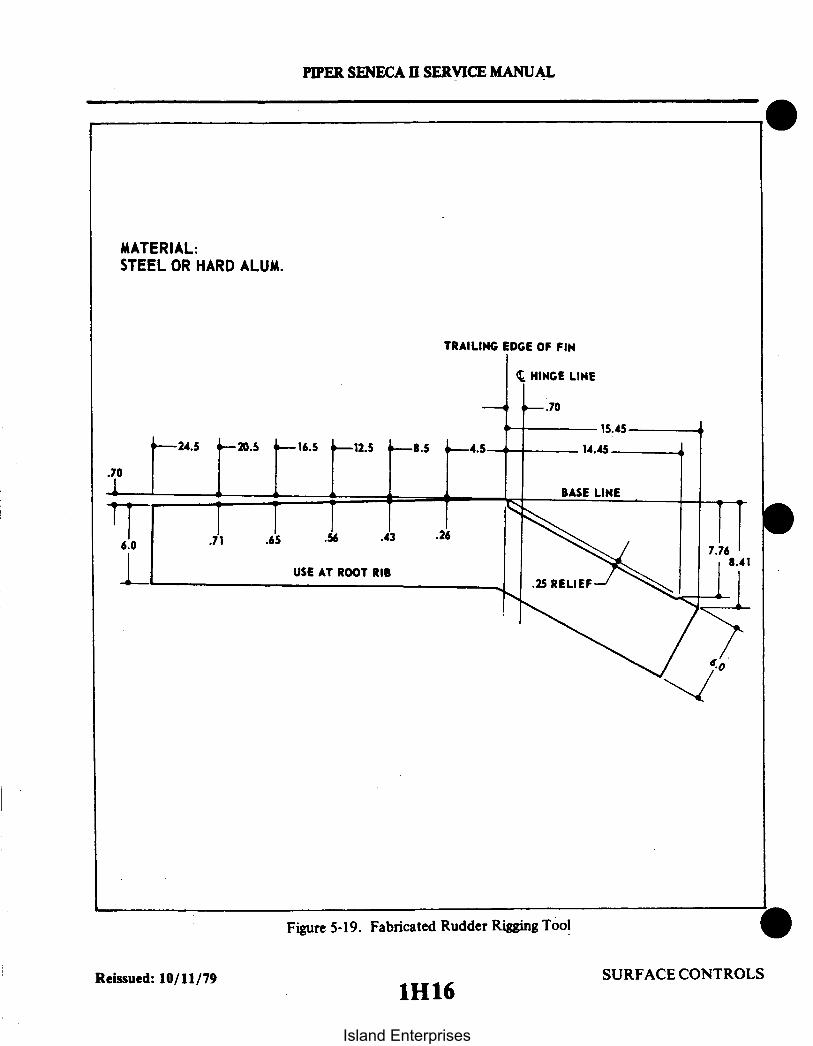
TRAILING EDGE OF FIN
HINGE LINE
24.5 20.5 16.5
6.0 .71 .65
USE AT
12.5 -- 8.5
PIPER SENECA II SERVICE MANUAL
MATERIAL:STEEL OR HARD ALUM.
.26.43
- .70
-- 15.45
-4.5 14.45
BASE LINE
7.76
.25 RELIEFROOT RIB
Figure 5-19. Fabricated Rudder Rigging Tool
SURFACE CONTROLSSURFACE CONTROLSReissued: 10/11/79
1H16
Island Enterprises

PIPER SENECA II SERVICE MANUAL
TABLE V-III. TROUBLESHOOTING CHART (SURFACE CONTROLS)
Trouble Cause Remedy
AILERON CONTROL SYSTEM
Lost motion between con-trol wheel and aileron.
Resistance to controlwheel rotation.
Control wheels notsynchronized.
Cable tension too low.
Linkage loose or worn.
Broken pulley.
Cables not in place onpulleys.
System not lubricatedproperly.
Cable tension too high.
Control column hori-zontal chain improperlyadjusted.
Pulleys binding orrubbing.
Cables not in place onpulleys.
Bent aileron and/orhinge.
Cables crossed orrouted incorrectly.
Incorrect controlcolumn rigging.
Adjust cable tension.(Refer to Paragraph5-11.)
Check linkage andtighten or replace.
Replace pulley.
Install cables correctly.Check cable guards.
Lubricate system.
Adjust cable tension.(Refer to Paragraph5-11.)
Adjust chain tension.(Refer to Paragraph5-5.)
Replace binding pulleysand/or provide clearancebetween pulleys andbrackets.
Install cables correctly.Check cable guards.
Repair or replace aileronand/or hinge.
Check routing of controlcables.
Rig in accordance withParagraph 5-5.
Reissued: 10/11/79 SURFACE CONTROLS
1H17
Island Enterprises

PIPER SENECA II SERVICE MANUAL ,
TABLE V-III. TROUBLESHOOTING CHART (SURFACE CONTROLS) (cont.)
Trouble Cause Remedy
AILERON CONTROL SYSTEM (cont.)
Control wheels not hori-zontal when aileronsare neutral.
Incorrect ailerontravel.
Incorrect rigging ofaileron system.
Aileron control rodsnot adjusted properly.
Rig in accordance withParagraph 5-11.
Adjust in accordancewith Paragraph 5-11.
Aileron bellcrank stopsnot adjusted properly.
Adjust in accordancewith Paragraph 5-11.
Correct aileron travelcannot be obtained byadjusting bellcrankstops.
Control wheel stopsbefore controlsurfaces reach fulltravel.
Incorrect rigging ofaileron cables, controlwheel and control rod.
Incorrect riggingbetween control wheeland control cables.
Rig in accordance withParagraph 5-11.
Rig in accordance withParagraph 5-11.
Reissued: 10/11/79 SURFACE CONTROLS
1H18Island Enterprises

Lost motion between con-trol wheel and stabilator
PIPER SENECA II SERVICE MANUAL
TABLE V-III. TROUBLESHOOTING CHART (SURFACE CONTROLS) (cont.)
Trouble Cause Remedy
STABILATOR CONTROL SYSTEM
between con- Cable tension too low. Adjust cable tensionand stabilator. per Paragraph 5-15.
Linkage loose or worn. Check linkage andtighten or replace.
Broken pulley. Replace pulley.
Cables not in place Install cables correctlyon pulleys.
to stabilator System not lubricated Lubricate system.novement. properly.
Cable tension too high. Adjust cable tensioper Paragraph 5-15.
Binding control column. Adjust and lubricatper Paragraph 5-5.
Pulleys binding or Replace binding purubbing. and/or provide clea
Resistantcontrol
n
e
lleysrance
Cables not in place onpulleys.
Cables crossed orrouted incorrectly.
Bent stabilator hinge.
Binding bob weightlinkage.
Stabilator stopsincorrectly adjusted.
between pulleys andbrackets.
Install cables correctly.
Check routing of controlcables.
Repair or replacestabilator hinge.
Inspect and adjust orreplace.
Adjust stop screws perParagraph 5-15.
Incorrect stabilatortravel.
Reissued: 10/11/79 SURFACE CONTROLS1H19
Island Enterprises

PIPER SENECA 11 SERVICE MANUAL
TABLE V-III. TROUBLESHOOTING CHART (SURFACE CONTROLS) (cont.)
Trouble Cause Remedy
STABILATOR CONTROL SYSTEM (cont.)
Correct stabilatortravel cannot beobtained by adjustingstops.
Stabilator cablesincorrectly rigged.
Bob weight incorrectlyrigged.
Rig cables in accordancewith Paragraph 5-15.
Rig in accordance withParagraph 5-15.
STABILATOR TRIM CONTROL SYSTEM
Lost motion betweentrim control wheeland trim tab.
Cable tension too low.
Cables not in place onpulleys.
Adjust in accordancewith Paragraph 5-21.
Install cables accordingto Paragraphs 5-18 and5-20.
Broken pulley.
Linkage loose or worn.
Replace pulley.
Check linkage andtighten or replace.
Trim control wheelmoves with excessiveresistance.
System not lubricatedproperly.
Cable tension too high.
Lubricate system.
Adjust in accordancewith Paragraph 5-21.
Pulleys binding orrubbing.
Cables not in place onpulleys.
Trim tab hinge binding.
Cables crossed orrouted incorrectly.
Replace binding pulleys.Provide clearance betweenpulleys and brackets.
Refer to Paragraphs5-18 and 5-20.
Lubricate hinge. Ifnecessary, replace.
Check routing of controlcables.
Reissued: 10/11/79 SURFACE CONTROLS
1H20Island Enterprises

PIPER SENECA II SERVICE MANUAL
Trim tabreach ful
TABLE V-II. TROUBLESHOOTING CHART (SURFACE CONTROLS) (cont.)
Trouble Cause Remedy
STABILATOR TRIM CONTROL SYSTEM (cont.)
fails to System incorrectly Check and/or adjusttravel. rigged. rigging per Paragraph
5-21.
Trim drum in- Check and/or adjustcorrectly wrapped. rigging per Paragraph
5-21.
icator fails Trim indicator unit Adjust in accordancete correct not adjusted properly. with Paragraph 5-21.ition.
Trim indto indicatrim posi
Lost motion betweenrudder pedals andrudder.
Excessive resistanceto rudder pedalmovement.
RUDDER CONTROL SYSTEM
Cable tension too low.
Linkage loose or worn.
Broken pulley.
Bolts attaching rudderto bellcrank are loose.
System not lubricatedproperly.
Rudder pedal torquetube bearing in needof lubrication.
Cable tension too high.
Adjust cable tensionper Paragraph 5-28.
Check linkage andtighten or replace.
Replace pulley.
Tighten bellcrank bolts.
Lubricate system.
Lubricate torque tubebearings.
Adjust cable tensionper Paragraph 5-28.
Reissued: 10/11/79 SURFACE CONTROLS
1H21
Island Enterprises
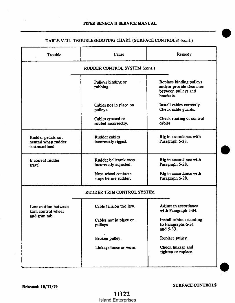
Trouble
PIPER SENECA I SERVICE MANUAL
TABLE V-III. TROUBLESHOOTING CHART (SURFACE CONTROLS) (cont.)
Cause Remedy
RUDDER CONTROL SYSTEM (cont.)
Pulleys binding orrubbing.
Cables not in place onpulleys.
Cables crossed orrouted incorrectly.
Replace binding pulleysand/or provide clearancebetween pulleys andbrackets.
Install cables correctly.Check cable guards.
Check routing of controlcables.
Rudder pedals notneutral when rudderis streamlined.
Incorrect ruddertravel.
Rudder cablesincorrectly rigged.
Rudder bellcrank stopincorrectly adjusted.
Rig in accordance withParagraph 5-28.
Rig in accordance withParagraph 5-28.
Nose wheel contactsstops before rudder.
Rig in accordance withParagraph 5-28.
RUDDER TRIM CONTROL SYSTEM
Lost motion betweentrim control wheeland trim tab.
Cable tension too low.
Cables not in place onpulleys.
Adjust in accordancewith Paragraph 5-34.
Install cables accordingto Paragraphs 5-31and 5-33.
Broken pulley.
Linkage loose or worn.
Replace pulley.
Check linkage andtighten or replace.
SURFACE CONTROLSReissued: 10/11/79
1H22Island Enterprises

PIPER SENECA II SERVICE MANUAL
TABLE V-III. TROUBLESHOOTING CHART (SURFACE CONTROLS) (cont.)
Trouble Cause Remedy
RUDDER TRIM CONTROL SYSTEM (cont.)
Trim control wheelmoves with excessiveresistance.
System not lubricatedproperly.
Pulleys binding orrubbing.
Lubricate system.
Replace binding pulleys.Provide clearance betweenpulleys and brackets.
Cables not in place onpulleys.
Trim tab hinge binding.
Cables crossed orrouted incorrectly.
Install cables accordingto Paragraphs 5-31 and5-33.
Lubricate hinge. Replaceif necessary.
Check routing of controlcables.
Trim tab fails toreach full travel.
System incorrectlyrigged.
Check and/or adjustrigging per Paragraph5-34.
Either or both trimdrums incorrectlywrapped.
Check and/or adjustrigging per Paragraph5-34.
Trim indicator failsto indicate correcttrim position.
Trim indicator unit notadjusted properly.
Adjust in accordancewith Paragraph 5-34.
Reissued: 10/11/79 SURFACE CONTROLS
1H23
Island Enterprises
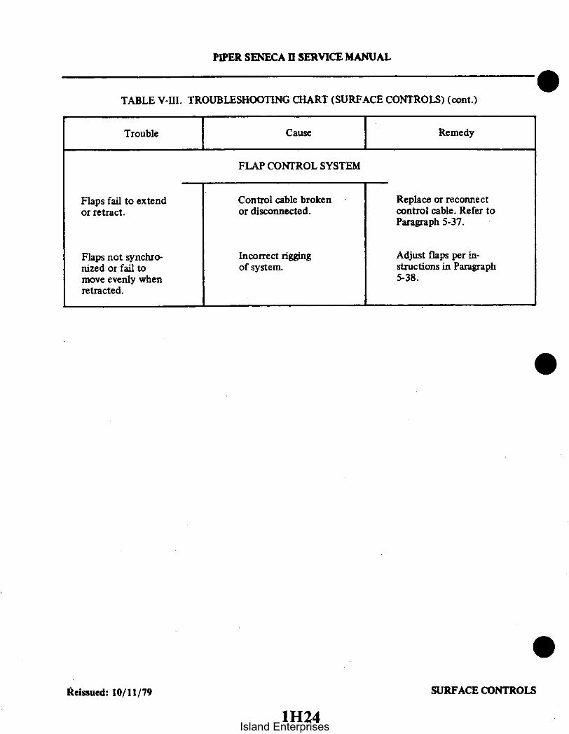
PIPER SENECA II SERVICE MANUAL
TABLE V-III. TROUBLESHOOTING CHART (SURFACE CONTROLS) (cont.)
Trouble Cause Remedy
FLAP CONTROL SYSTEM
Flaps fail to extendor retract.
Flaps not synchro-nized or fail tomove evenly whenretracted.
Control cable brokenor disconnected.
Incorrect riggingof system.
Replace or reconnectcontrol cable. Refer toParagraph 5-37.
Adjust flaps per in-structions in Paragraph5-38.
Reissued: 10/11/79 SURFACE CONTROLS
1H24Island Enterprises

1llINTENTIONALLY LEFT BLANK
Island Enterprises

112INTENTIONALLY LEFT BLANK
Island Enterprises

SECTION VI
HYDRAULIC SYSTEM
AeroficheParagraph Grid No.
6-1. Introduction .............................................................. 1146-2. Description ............................................................... 1146-3. Troubleshooting ............... .......................................... 1156-4. Hydraulic Pump........................................................... 116
6-5. Removal of Hydraulic Pump ....................................... 1166-6. Disassembly of Hydraulic Pump .................................... 1166-7. Cleaning. Inspection and Repairs of Hydraulic Pump.................. 1196-8. Assembly of Hydraulic Pump ...................................... 1196-9. Test and Adjustment of Hydraulic Pump ............................ 11106-10. Installation of Hydraulic Pump ..................................... 1113
6-11. Landing Gear Free-Fall Valve Assembly ................... ............... 11136-12. Inspection and Repair of Free-Fall Valve ............................ 11136-13. Removal of Free-Fall Valve Assembly ............................... 11136-14. Installation of Free-Fall Valve Assembly ............................. 1115
6-15. Gear Actuating Cylinder............................................... 11156-16. Removal of Nose Gear Actuating Cylinder ........................... 11156-17. Removal of Main Gear Actuating Cylinder ........................... 11166-18. Disassembly of Actuating Cylinder .................................. 11166-19. Cleaning. Inspection and Repair of Gear Actuating Cylinder ........... 11196-19a. Installation of T-Rings ........................................... 11196-20. Assembly of Gear Actuating Cylinder ............................... 11196-21. Installation of Nose Gear Actuating Cylinder ......................... 11206-22. Installation of Main Gear Actuating Cylinder ........................ 1120
6-23. Hydraulic Lines .11206-23. Hydraulic Lines ........................................................... 11206-24. Removal and Installation of Hydraulic Lines ......................... 1120
6-25. Testing Hydraulic System ................................................... 11216-26. Servicing Hydraulic Pump/Reservoir ......................................... 1121
Revised: 12/08/83113
Island Enterprises

PIPER SENECA II SERVICE MANUAL
SECTION VI
HYDRAULIC SYSTEM
6-1. INTRODUCTION. The PA-34-200T hydraulic system components covered in this section consist ofthe combination hydraulic pump and reservoir, hydraulic pressure switch, free-fall valve assembly, actuatingcylinders and hydraulic lines. The brake system, although hydraulically operated, is not included in thissection as it has its own hydraulic system independent of the gear retraction system. The brake systemalong with landing gear and components is covered in Section VII.
This section provides instructions for remedying difficulties which may arise in the operation of thehydraulic system. The instructions are organized so that the mechanic can refer to: Description, for a basicunderstanding of the system; Troubleshooting, for a methodical approach in locating difficulty; CorrectiveMaintenance, for the removal, repair and installation of components, and; Adjustments and Checks, for theoperation of the repaired system.
CAUTION
Prior to starting any investigation of the hydraulic system, placethe airplane on jacks. (Refer to Jacking, Section II.)
6-2. DESCRIPTION. Hydraulic fluid to the landing gear actuating cylinders is supplied by an electricallypowered reversible pump located in the right forward area of the fuselage nose section. A reservoir is anintegral part of the pump. The pump is controlled by a selector handle on the instrument panel, to the leftof the control quadrant. As the handle is placed in either the up or down position, the pump directs fluidthrough the particular pressure line to each individual actuating cylinder. As fluid pressure increases at oneside of a cylinder piston, fluid at the other side is directed back through the other line to the pump. Bothlines serve either as pressure or return passages depending on the rotation of the pump to retract or extendthe gear.
A pressure switch is mounted on the pressure line in the right aft side of the nose cone. This switchopens the electrical circuit to the pump solenoid when the gear fully retracts and pressure in the systemincreases to 1800 + 100PSI. The switch will continue to hold the circuit open until pressure in the systemdrops to approximately 1700 psi; when at that time the pump win again operate to build up pressure aslong as the gear selector is in the up position. The down position of the selector handle does not affect thepressure switch.
The hydraulic pump is a gear type unit driven by a 12 volt reversible motor designed to operate in apressure range of 2000 to 2500 psi. To prevent excessive buildup of pressure in the hydraulic system due toexpansion, a primary thermal relief valve is incorporated on early - O models and is located directly abovethe nose gear actuating cylinder. This relief valve will maintain pressure in the system up to 2350 + 50 psi.An additional relief valve is incorporated in the pump which will open at 4000 + 300 psi and allow fluid toflow into the reservoir. On later - 2 models the external thermal relief is not used in the system. The reliefvalve in the pump is used which will open at 2250 + 50 psi. to prevent excessive buildup of pressure in thehydraulic system due to expansion. Other valves in the pump, channel fluid to the proper outlet during,retraction or extension of the gear. A shuttle valve located in the base of the pump allows fluid displaced bythe cylinder pistons to return to the reservoir without backpressure. This shuttle valve has a deliverypressure of 400-800 psi during the extension cycle.
Reissued: 10/11/79 HYDRAULIC SYSTEM
114Island Enterprises

PIPER SENECA II SERVICE MANUAL
A bypass free-fall valve assembly is incorporated in the system to permit extension of the landing gearshould a malfunction in the system occur. This valve is manually operated by means of an emergency gearknob located on the instrument panel. This knob must be fully extended to permit emergency extension.Restrictions in the system prevent the gear from extending too fast.
For a description of the landing gear and electrical switches, refer to Section VII, Landing Gear andBrake System.
CAUTION
Prior to starting any investigation of the hydraulic system, placethe airplane on jacks. With the airplane on jacks, pull the free-fallvalve knob full out thus preventing the buildup of unnecessarypressure on the actuating cylinders and connecting hydraulic lineswhen the gear is raised or lowered manually. Failure to complywith these instructions could result in the buildup of sufficientpressure to unlock the downlock mechanism allowing the gear tocollapse when the wing jacks are removed. Prior to removing theairplane from jacks, push the free-fall valve knob in, turn on themaster switch and select gear down, observe that all three greenlights indicating the landing gear is down and locked are energized.Turn master switch off.
6-3. TROUBLESHOOTING. Malfunctions in the hydraulic system will result in failure of the landing gearto operate properly. When trouble develops, jack up the airplane (refer to Jacking, Section II) and thenproceed to determine the extent of the trouble. Generally, hydraulic system troubles fall into two types;troubles involving the hydraulic supplying system and troubles in the landing gear hydraulic system. TableVI-III at the back of this section, lists the troubles which may be encountered and their probable cause, andsuggests a remedy for the trouble involved. A hydraulic system operational check may be conducted usingFigures 6-1 or 6-2. When the trouble has been recognized, the first step in troubleshooting is isolating thecause. Hydraulic system troubles are not always traceable to one cause. It is possible that a malfunctionmay be the result of more than one difficulty within the system. Starting first with the most obvious andmost probable reasons for the trouble, check each possibility and, in turn, by process of elimination, isolatethe troubles.
NOTE
If it is found that the hydraulic pump is at fault and requiresdisassembly, it is recommended that it be overhauled by anaccredited overhaul facility. Pressure checks with adjustments maybe accomplished in accordance with instructions given inParagraphs 6-6 thru 6-9.
Reissued: 10/11/79 HYDRAULIC SYSTEM115
Island Enterprises

PIPER SENECA II SERVICE MANUAL
6-4. HYDRAULIC PUMP.
6-5. REMOVAL OF HYDRAULIC PUMP. The hydraulic pump with reservoir incorporated is located inthe nose section of the fuselage. Access to the pump is through the access panel in the nose baggagecompartment.
a. Disconnect the pump electrical leads from the pump solenoid relays and the ground wire fromthe battery shelf.
b. Disconnect the hydraulic lines from the pump. Cap the line ends to prevent contamination.c. Remove pump by removing pump attaching bolts.
6-6. DISASSEMBLY OF HYDRAULIC PUMP. (Referto Figure 6-3.) Afterthehydraulicpumphasbeenremoved from the airplane, cap or plug all ports, and clean exterior of pump using a dry cleaning solvent toremove accumulated dirt and dust. The three major components of the pump assembly are the pump base,pump motor, and valve and gear case. These three major components should be disassembled as follows:
a. Pump Base: Remove pump base (16) from valve and gear case by:1. Cutting safety wire and removing bolts (17) with washers securing pump base to pump and
gear case.2. The check valve within the pump base should be removed for cleaning purposes only. To
remove valve, cut safety wire and remove bolt, spring and steel ball. Replace O-ring at reassembly.b. Pump Motor: The pump motor may be removed from the pump and disassembled as follows:
1. Remove thru bolts (4) from head (1) of motor. Using a knife cut the seal coating between themotor head and case.
2. Lift the head up from the case approximately .50 of an inch, this will allow inspection ofbrushes (3) without the brushes unseating from the commutator. (Refer to Paragraph 6-7 for brush inspec-tion.) The brush leads are secured to the head assembly.
3. Raise the head assembly (1) off the armature (8) and note the small thrust ball (7) located be-tween the end of the armature (8) and motor head. Do not misplace this bearing.
4. Draw the armature from the motor frame (9). Note the number of thrust washers ( 1 ) mountedon the drive end of the armature shaft.
5. Remove the motor frame from the pump reservoir (13).c. Valve and Gear Case: Remove valve and gear case (15) from reservoir (13) as follows:
1. Remove eight screws from flange of body and separate the two assemblies (18).2. Pump gears and valves should be removed for cleaning purposes only. To remove cap securing
gears, remove attaching bolts. The two valve springs should be positively identified with their cavities; other-wise, it will be necessary to readjust each valve for proper operating pressure.
Reissued: 10/11/79 HYDRAULIC SYSTEM116
Island Enterprises

RIGHHYDR
UP
DOWN
SERIAL NOS34-757001 TO34-7770148 INCL
PIPER SENECA II SERVICE MANUAL
1938
RESTRICTOR
T MAIN GEARRAULIC CYLINDER
NOSE GEARHYDRAULICCYLINDER
LEFT MAIN GEARHYDRAULIC CYLINDER
UP
DOWN
r----- -
PRESSURE
OPRSWITCH CD
RESTRICTOR
NOTEREFER TO TABLE V1-1 FORLEADING PARTICULARS OFHYDRAULIC SYSTEM.
OFF 1800 + 100 PSION 200-400 PSIDIFFERENTIAL
UP
IDOWN
FREE FALLCONTROL
FREE FALLVALVE
THERMALRELIEFVALVE
USED ON -OONLY 2350 +50 PSI
LOWPRESSURE -CONTROL
650 + 150 PS1
400 to 800 PSI DOWN UPNOTE-2= HYC5005 PUMP0 105476A PUMP
Figure 6-1. Schematic Diagram of Hydraulic System
Reissued: 10/11/79117
HYDRAULIC SYSTEM
Island Enterprises
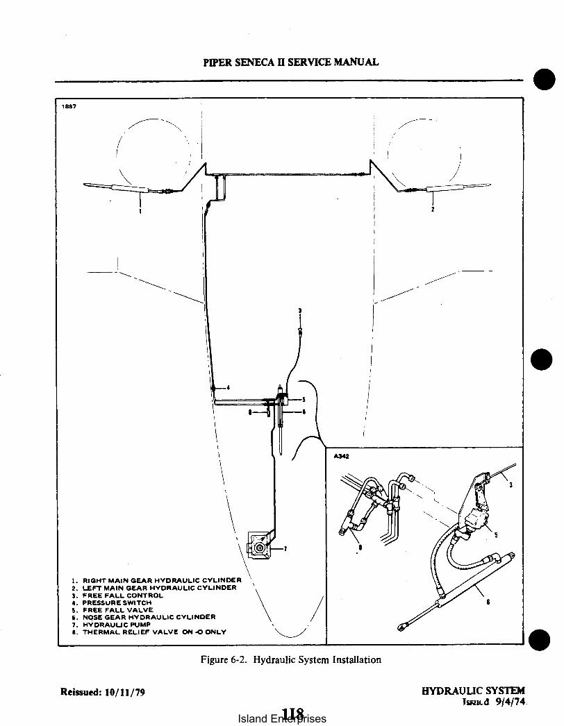
PIPER SENECA II SERVICE MANUAL
1867
A342
1. RIGHT MAIN GEAR HYDRAULIC CYLINDER2. LEFT MAIN GEAR HYDRAULIC CYLINDER3. FREE FALL CONTROL4. PRESSURE SWITCH5. FREE FALL VALVE6. NOSE GEAR HYDRAULIC CYLINDER7. HYDRAULIC PUMP
8. THERMAL RELIEF VALVE ON O ONLY/
Figure 6-2. Hydraulic System Installation
Reissued: 10/11/79 HYDRAULIC SYSTEMIssued 9/4/74
118Island Enterprises

PIPER SENECA II SERVICE MANUAL
6-7. CLEANING. INSPECTION AND REPAIRS OF HYDRAULIC PUMP.
NOTE
Repair facilities must be clean to prevent contamination of pumpcomponents. Proper and careful handling should be exercised toprevent damaging pump components.
a. Discard all O-rings.b. Remove caps or plugs and clean all components with a dry type cleaning solvent and dry
thoroughly.c. Inspect pump components for scatches, scores, chips, cracks and wear.d. Inspect motor for worn brushes (minimum of .218 of an inch brush remains between the braided
and commutator end), excess commutator wear and excess bearing wear.e. Repairs are limited to O-ring and brush replacement as follows:
1. One brush holder has the winding wire attached. Locate this wire and remove by using asoldering gun.
2. The head assembly can now be removed and worked on for ease of brush replacement if re-quired.
3. Remove brush wire and brush from bimetal heat protector.4. Solder new brush wires to head assembly and bimetal heat protector. and wire from winding
to one brush holder.5. Install brush springs and brushes into brush holders and secure in place (temporary) with a
piece of string looped around the brush and holder and tied in a knot.
NOTE
Insure that the braided wire is in the holder slot for proper brushmovement.
6. Install the head assembly with new brushes to the frame and commutator in accordance withinstructions given in Paragraph 6-8, Step a.
6-8. ASSEMBLY OF HYDRAULIC PUMP. (Refer to Figure 6-3.)a. The pump motor may be assembled and installed on the reservoir as follows:
1. Position motor frame (9) on reservoir (13). Note aligning marks on frame and reservoir.2. Place thrust washers ( II), of the same amount removed, on the drive end of the armature (8).3. Lubricate the entire length of the armature shaft, on the drive end, with light grease to protect
O-ring seal from damage. Insert end of shaft in reservoir.4. Saturate felt oiling pad around commutator end bearing with SAE 20 oil. Allow excess oil to
drain off before assembling motor.5. Insert thrust ball (7) in bearing of motor head (1). To hold ball in position, place a small
amount of grease inside the bearing.6. Place head assembly on frame and allow brushes to extend over commutator. Remove the
string securing the brushes in the holders. Push head assembly on frame and insure proper indexing of headand frame assemblies. Secure in place with thru bolts (4).
7. Check freedom of rotation and end play (thrust) of the armature within the assembly. Aminimum of .005 inch end play is permissible. Adjust to this tolerance if necessary by adding or removingthrust washers (II) on drive end of armature shaft.
Reissued: 10/11/79 HYDRAULIC SYSTEM119
Island Enterprises

PIPER SENECA II SERVICE MANUAL
b. Assemble valve and gear case (15) to the reservoir (13) as follows:1. If removed, place pump gears in valve and gear case and install cover. Install cover attaching
bolts and secure.2. Lubricate reservoir seal ring (14) with hydraulic fluid (MIL-H-5606) and place in recess
provided in case (15).3. Position reservoir (13) on valve and gear case (15). Care should be taken when aligning the
armature shaft with the pump gear. Do not run the motor to accomplish this.4. Ascertain that the seal ring ( 14) is properly positioned, and install attaching screws. Tighten'
one screw to hold the assembly together, then, with the motor connected to a 14 volt source and an ammeter inthe circuit, tighten the rest of the screws such that the current drawn does not exceed 12 amperes.
c. Attach the pump base to the pump as follows:1. With pump inverted, lubricate O-ring seals and install them in recesses provided in the valve
and gear case (15).2. Install attaching bolts with washers and torque to 70 inch-pounds.3. Safety attaching bolts with MS20995-C32 wire.
d. Conduct motor operational check not to exceed 10 seconds running time.
6-9. TEST AND ADJUSTMENT OF HYDRAULIC PUMP. (Refer to Figure 6-4.)a. Test Equipment:
1. Hydraulic pump and mounting base.2. Pressure gauge (0 - 1000 psi).3. Pressure gauge (0 - 3000 psi).4. Hoses with fittings to connect base and gauges.5. Power supply (14 VDC).6. Ammeter (0 to 100 amps).7. Fuse or circuit protector (100 amps).
b. Test and Adjustment:
NOTE
Test gauges or gauges of known accuracy should be used whenperforming the following tests.
1. Connect the 0 to 1000 psi gauge to the low pressure port of the pump base.2. Connect the 0 to 3000 psi gauge to the high pressure port of the pump base.3. Connect black lead of pump motor to the negative terminal of the DC power supply.4. Remove the filler plug located on the forward side of the pump. Loosen vent screw and add
fluid, MIL-H-5606, through the filler hole until full. Reinstall the filler plug and tighten the vent screw.5. Bleed air from the attached lines. (Lines may be bled by alternately connecting blue lead
and green lead to the positive terminal of the power supply until all air is exhausted.)6. Connect blue lead to positive terminal of power supply. Pump should operate and the high
pressure gauge should indicate between 2000 and 2500 psi. (Should the gauge indicate a pressure below2000 psi or over 2500 psi, adjust valve "A," Figure 6-3 accordingly to obtain the desired reading.)
NOTE
When increasing pressure, the pump running time must not exceed12 seconds. There should be no external leakage while performingSteps 5 thru 8.
Reissued: 10/11/79 HYDRAULIC SYSTEM1110
Island Enterprises

2
HIGH PRESSURELOW PRESSURE
1. HEAD, MOTOR2. SPRING, BRUSH3. BRUSH4. BOLT, THROUGH5. 0-RING (MS2775-012)6. WIRE LEAD7. BALL, THRUST3. ARMATURE9. FRAME, MOTOR
10. SLEEVE11. WASHER, THRUST12. SCREW, VENT AND FILLER13. RESERVOIR14. SEALIS. CASE, VALVE AND GEAR16. BASE, PUMP17. BOLT18. SCREW (a)
PIPER SENECA II SERVICE MANUAL
2024
7
4
Figure 6-3. Hydraulic Pump/Reservoir, Exploded View
Reissued: 10/11/79 HYDRAULIC SYSTEM1I11
Island Enterprises

PIPER SENECA II SERVICE MANUAL
TABLE VI-I. LEADING PARTICULARS, HYDRAULIC PUMP
Hydraulic Pump: High PressureLow PressureFlow Rate @ 1000 psiHigh Pressure ControlHydraulic FluidRelief valveRelief valve
Shuttle Value Delivered PressureSystem Thermal Relief (AN6245-AB4)Pressure Switch
Open (OFF) PressureClose (ON) Pressure
-O Only-2 Only-0-2-0
2000 to 2500 psi650 + 150 psi45 cu. in. per min.2000 to 2500 psiMIL-H-56064000 + 300 psi2250 + 250 psi400 to 800 psi2350 + 50 psi1800 ± 100 psiPressure decreasing200 to 400 psi
TABLE VI-ll. CHARACTERISTICS, HYDRAULIC PUMP MOTOR
Electrical Characteristics:
VoltageRotationPolarityOperating Current
Operating Time
Overload ProtectionAutomatic Reset TimeLocation, Automatic Reset
12 DCReversibleNegative ground75 amps, max. at 12 volts
(both rotations)12 seconds max. with a current load
of 75 amperes at 77° FThermal circuit breaker12 seconds, max.Commutator end head of motor
Mechanical Characteristics:
Bearings
End Play, Armature
Absorbent bronze(Drive end bearing in upper pumpand valve assembly casting.)
Steel ball(Thrust, between commutatorend head and end of armatureshaft.)
.005 inch, min.(Adjust by selection of thrustwashers on drive end ofarmature shaft.)
Reissued: 10/11/79 HYDRAULIC SYSTEM
1112Island Enterprises

PIPER SENECA II SERVICE MANUAL
7. Disconnect blue lead. The high pressure reading should not drop more than 300 psi in fiveminutes. High pressure may not be selected again for five minutes.
8. Connect green lead to positive terminal of power supply. Pump should operate in reverse,dropping reading on high pressure gauge to zero. The low pressure gauge should indicate 500 to 800 psi.(Should the gauge indicate a pressure below 500 psi or over 800 psi, adjust valve "B," Figure 6-3,accordingly to obtain desired reading.) Disconnect green lead. Both pressure gauges should indicate zero psi.
9. Should it be necessary to check the pump motor, first connect the ammeter in the electricalcircuit with the positive terminal of the meter to the black lead and negative terminal of the meter to thenegative terminal of the DC power supply.
10. Connect the blue lead from the pump motor to the positive terminal of the power supply.With high pressure indication within 2000 to 2500 psi range on the pressure gauge, the ammeter shouldread 75 amperes maximum. Disconnect the blue lead.
11. Connect the green lead from the pump motor to the positive terminal of the power supply.With low pressure indication within the 500 to 800 psi range, the ammeter should read between 15 to 35amperes.
NOTE
In the event any of the various tests do not perform satisfactorily,the pump assembly should be replaced.
12. Disconnect the green lead from the power supply and permit the pressure to drop beforedisconnecting the hydraulic lines.
6-10. INSTALLATION OF HYDRAULIC PUMP. (Refer to Figure 6-5.)a. Align three washers (7) over each hole in shelf (4). Insert grommet (1) through mounting holes in
pump base (2). Insert bushing (3) through hole in each grommet.b. Position pump on washers. Insert bolt (6) with top washer (7) through bushing (3), bottom
washers (7) and shelf (4). Mount nut (8) and washer (5) on bolt and tighten.c. Connect hydraulic lines to pump.d. Connect pump electrical leads. Blue wire to outboard lower solenoid, green wire in inboard
(upper) solenoid, and black wire to ground on bottom shelf.e. Check fluid level in pump. (Refer to Section II for filling instructions.)f. With aircraft on jacks, operate pump to purge hydraulic system of air, and check for leaks. After
operation, recheck fluid level.
6-11. LANDING GEAR FREE-FALL VALVE ASSEMBLY.
6-12. INSPECTION AND REPAIR OF FREE-FALL VALVE. This valve is located directly above the nosewheel actuating cylinder. Inspection is limited to determining if any signs of hydraulic fluid leakage areevident around the seam between the end fitting and valve body, and around the periphery of the pistonassembly shaft. If leaks appear, the valve assembly should be replaced since it is impractical to repair thevalve.
6-13. REMOVAL OF FREE-FALL VALVE ASSEMBLY. (Refer to Figure 6-6.) In the event it becomesnecessary to replace the free-fall valve assembly, proceed as follows:
a. Loosen three screws and clamp securing cable in position and withdraw cable.b. Disconnect hydraulic lines connected to the valve. Place a rag in position to absorb any hydraulic
fluid spillage that may result. Cap the lines to avoid contamination.c. Remove the hex head bolts securing the valve and bracket to the frame and remove the assembly
from the airplane.
Reissued: 10/11/79 HYDRAULIC SYSTEM1113
Island Enterprises

HIGH PRESSURE PORT #1
PIPER SENECA I SERVICE MANUAL
PORT #3 LOW PRESSURE
GROUND-BLACKHIGH PRESS.-BLUELOW PRESS.-GREEN
+14 V.D.C. (ONE ONLY)
A347
-14 V.D.C.
Figure 6-4. Test and Adjustments of Hydraulic Pump
Reissued: 10/11/79 HYDRAULIC SYSTEM
1114Island Enterprises

PIPER SENECA II SERVICE MANUAL
A372 A347
1. GROMMET2. PUMP BASE3. BUSHING4. SHELF5. WASHER6. BOLT7. WASHER (4 REQ.)8. NUT
1. CABLE2. CLAMP3. VALVE BODY4. END FITTING
S. FRAME6. PISTON SHAFT7. BRACKET
8. ARM ASSY.
Figure 6-5. Pump Mounting Figure 6-6. Free-Fall Valve Assembly
d. Remove rivet and nut securing link to piston shaft. Note position of elbow and tee fittings toassure their being replaced in the same position at reassembly. Remove fittings and two bolts securing thevalve to the bracket.
6-14. INSTALLATION OF FREE-FALL VALVE ASSEMBLY. (Refer to Figure 6-6.)a. Apply Lubon#404, or equivalent, to MALE threads of elbows and tees and insert fittings in
valve. Lubon should be applied sparingly to prevent it entering the hydraulic system.b. Install valve on bracket and secure in position. Push piston shaft into the valve until it bottoms.
Align hole in link with hole in piston shaft and insert rivet. Attach nut to rivet.c. Position bracket with valve on frame. Apply Lubon#t404 to MALE threads of tees and connect
hydraulic lines.d. Push arm assembly fully forward. Pull cable full forward. Place clamp over reinforced portion of
cable and tighten screws. Insert loose end of cable through the hole in the bushing of the arm assembly.Tighten lock screw on cable.
6-15. GEAR ACTUATING CYLINDER.
6-16. REMOVAL OF NOSE GEAR ACTUATING CYLINDER.a. Place airplane on jacks. (Refer to Jacking, Section II.)b. Disconnect hydraulic lines from actuating cylinder and cover open line ends to prevent
contamination.
Reissued: 10/11/79 11151115
HYDRAULIC SYSTEM
Island Enterprises

1. END GLAND2. BACK-UP RING3. ORING 9 104. RETAINER RING5. RING
PISTON
Figure 6-7. Gear Actuating Cylinder
c. Disconnect operating rod end from the bracket on the trunnion assembly by removing attachingbolt and nut.
d. Disconnect cylinder from the link assembly. The downlock spring and downlock link are alsoattached to this link assembly. After removing the cylinder, it is suggested the spring and link betemporarily reinstalled until the cylinder is ready for reinstallation.
e. Remove the cylinder from the wheel well.
6-17. REMOVAL OF MAIN GEAR ACTUATING CYLINDER.a. Place airplane on jacks. (Refer to Jacking, Section II.)b. Disconnect hydraulic lines from actuating cylinder and cover open line ends to prevent
contamination.c. Disconnect gear downlock spring from swivel fitting at upper end of spring.d. Remove downlock spring swivel fitting and disconnect cylinder operating rod end from upper
side brace retraction fitting by removing attaching nut, washer and bolt.e. Disconnect cylinder from its attachment by removing nut and bolt.f. Remove cylinder from wheel well.
6-18. DISASSEMBLY OF ACTUATING CYLINDER. (Refer to Figure 6-7.)
NOTE
The following disassembly, cleaning, inspection, repair andassembly instructions apply to nose gear actuator and both maingear actuators.
a. Using hand pressure, push piston rod (6) toward clevis end (9) to remove oil from the cylinder.b. Place clevis in a soft jaw vise and clamp against the clevis bearing (10).c. Install any 1/8-27 pipe fitting into the port on the end gland. This fitting is used for leverage only
and need not be tight. (Refer to Figure 6-8.)
Reissued: 10/11/79 HYDRAULIC SYSTEM
PIPER SENECA I SERVICE MANUAL
1116Island Enterprises

PIPER SENECA II SERVICE MANUAL
C232
INSTALLATION OF SEALINGRING IN ROD END
SKETCH A
INSTALLATION OF SEALINGRING ON PISTON
SKETCH B
INSTALLATION OF NON-EXTRUSIONRINGS IN ROD END
SKETCH C
INSTALLATION OF NON-EXTRUSIONRINGS ON PISTON
SKETCH D
CROSS SECTION OF INSTALLEDT-RING ASSEMBLY
SKETCH E
PROPER MATING OF SCARFCUT ON NON-EXTRUSION RINGS
SKETCH F
Figure 6-7a. Installation of T-Rings
Added: 12/08/83171I17
HYDRAULIC SYSTEM
IIsland Enterprises

PIPER SENECA II SERVICE MANUAL
BEARING END
Figure 6-8. End Gland Locking Device
d. Rotate end gland counterclockwise (with use of fitting) until end of retainer ring (4. Figure 6-7)
shows in slot of cylinder body (7). Reverse rotation of gland (clockwise direction) allowing retainer ring to
move out of slot. (It mav be necessary to give the ring an assist in starting out of the slot. If so. insert a
strong wire pick or other suitable tool in the slot to pry up the end of the retainer ring.)
e. Remove piston (6) and end gland (1) from cylinder body.f. Remove O-rings as required.
HYDRAULIC SYSTEMRevised: 12/08/83 1118Island Enterprises

PIPER SENECA II SERVICE MANUAL
6-19. CLEANING. INSPECTION AND REPAIR OF GEAR ACTUATING CYLINDER.a. Clean cylinder components with a suitable dry type solvent and dry thoroughly.b. Inspect cylinder assembly for the following:
I. Interior walls of cylinder and exterior surface of the piston for scratches, burrs, corrosion.etc.
2. Stripped or damaged threads.3. Rod end fitting and swivel fitting of cylinder for wear and corrosion.4. End fitting retainer slot for excess wear.
c. Repairs to the cylinder are limited to polishing out small scratches, burrs. etc.. and replacingcomponents. (Refer to Parts Catalog for replacement part numbers.)
6-19a. INSTALLATION OF T-RINGS. (Refer to Figure 6-7a.)a. Place synthetic sealing ring into groove. Insure that seal is not twisted and that it lies flat in the
groove. (Refer to Sketches A and B.)b. Orient each non-extrusion ring so that the radiused corner (if there is one) will be mated to the seal
when installed. (Refer to Sketch E.)c. Insert one end of the non-extrusion ring (formed by the scarf cut) into the space between the side
of the groove and the side of the seal. (Refer to Sketch E.)d. Work the entire circumference into this space, insuring that the scarf cut of the non-extrusion
ring is properly mated. (Refer to Sketch F.)e. Repeat Steps c and d for the second non-extrusion ring.f. Spread a few drops of system hydraulic oil evenly around the sealing edge of the packing.
6-20. ASSEMBLY OF GEAR ACTUATING CYLINDER. (Refer to Figure 6-7.)a. Install O-rings (3). (5) and (8) in their respective positions.b. Lubricate areas around O-rings with hydraulic fluid, park-o-lube or vaseline. Slide end gland (1) on
piston rod (6). Slide piston into cylinder body (7).c. Insert hook end of new lock ring (4), (P/N 755 997), in slot of cylinder body and slot in end gland.
Rotate gland counterclockwise to completely wrap lock ring into assembly.d. Align port in end gland and cylinder body.e. Check smoothness of operation of piston and static test unit to check for possible cut O-rings.f. Clean nose cylinder orifices.
Revised: 12/08/83 HYDRAULIC SYSTEM1119
Island Enterprises

PIPER SENECA II SERVICE MANUAL
A340
1. LINK ASSEMBLY2. LINK3. ACTUATING CYLINDER 54. WASHERS5. SPRING6. BUSHING7. BOLT 78. SWITCH9. MOUNT ASSEMBLY 2
10. ROD END BEARING
VIEW A
Figure 6-9. Nose Gear Actuating Cylinder Installation
6-21. INSTALLATION OF NOSE GEAR ACTUATING CYLINDER. (Refer to Figure 6-9.)a. Refer to Paragraph 6-16, d. Remove bolt (7) far enough to position clevis end of actuating
cylinder (3) in the link assembly (1). Reinsert bolt with callouts (1) thru (6) arranged as illustrated inFigure 6-9.
b. Insert the operating rod end into the bracket on the trunnion assembly and secure with bolt, nutand washers.
c. Connect hydraulic lines to their respective fittings on the actuating cylinder.d. Check adjustment of cylinder rod end. (Refer to Adjustment of Nose Landing Gear, Section VII.)e. Operate pump to purge system of air and check fluid level in reservoir.f. Remove airplane from jacks.
6-22. INSTALLATION OF MAIN GEAR ACTUATING CYLINDER.a. Attach the cylinder to its attachment fitting in the wheel well using bolt and nut.b. Attach the operating rod end and downlock spring swivel fitting to the upper side brace
retraction fitting using washer and nut. The swivel fitting must be free to rotate.c. Connect downlock spring to swivel fitting.d. Check adjustment of cylinder rod end. (Refer to Adjustment of Main Landing Gear, Section VII.)e. Operate pump and purge system of air. Check fluid level in reservoir.f. Remove the airplane from jacks.
6-23. HYDRAULIC LINES.
6-24. REMOVAL AND INSTALLATION OF HYDRAULIC LINES. Remove damaged hydraulic lines bydisconnecting fittings at both ends and disconnecting where secured by brackets. Refer to Figure 6-2 as anaid in locating attaching brackets and bends in lines. Provide a small, clean container for draining the lines.Install a new or repaired line in reverse. Operate the pump to purge air from the system. Check fluid level inthe reservoir.
Reissued: 10/11/79 HYDRAULIC SYSTEM
1120Island Enterprises

PIPER SENECA II SERVICE MANUAL
6-25. TESTING HYDRAULIC SYSTEM. The hydraulic system should be tested to determine that itfunctions properly after performing any service or repairs. It is suggested that the airplane be connected toan outside power source in order to conserve the battery. (Refer to External Power Receptacle, Section II.)
CAUTION
Turn master switch OFF before inserting or removing externalpower supply plug.
a. Place airplane on jacks. (Refer to Jacking, Section II.)b. With gear down, master switch ON, and circuit breaker closed, place landing gear selector handle
in the UP position. The pump should immediately start operating and the gear retract. The red gear unsafelight on the instrument panel should light up until the gear is fully retracted. The hydraulic pump shouldstop operating after full retraction of the gear.
c. Place gear selector handle in DOWN position. The gear should extend and lock in position. Geardown lights on the instrument panel will light up when all three gears are locked in position. Inspecthydraulic system for leakage of hydraulic fluid.
d. Recycle the landing gear to determine that it functions properly.e. To check operation of the free-fall valve assembly, retract the landing gear and turn the master
switch off. Pull the free-fall valve knob full out. The landing gear should extend and lock in position.
CAUTION
Prior to removing the airplane from jacks, turn master switch onand determine that all three green lights are energized. This willindicate the landing gear is down and locked.
.6-26. SERVICING HYDRAULIC PUMP/RESERVOIR. The fluid level of the reservoir of the combinationpump and reservoir should be checked every 50 hours by viewing the fluid through the filler plug hole inthe hydraulic pump. Access to the pump is through the panel at the right forward side of the nose baggagecompartment.
To check fluid level, remove the filler plug located on the forward side of the pump and ascertain thatfluid is visible up to the bottom of the filler plug hole. Should fluid be below the hole, add fluid,MIL-H-5606, through the filler hole until full. Reinstall the filler plug and tighten.
NOTE
A small vent hole is located under the vent screw head. Retain1/64 inch clearance between the screw head and the small venthole.
Reissued: 10/11/79 HYDRAULIC SYSTEM1121
Island Enterprises

PIPER SENECA I SERVICE MANUAL
TABLE VI-III. TROUBLESHOOTING CHART (HYDRAULIC SYSTEM)
ouble Cause RemeTro dy
Landing gear retractionsystem fails to operate.
Landing gear actuatorcircuit breaker open.
Reset circuit breakerand determine cause foropen circuit breaker.
Landing gear selectorcircuit breaker open.
Landing gear actuatorcircuit wires broken.
Landing gear selectorcircuit wires broken.
Safety (squat) switchout of adjustment.
Squat switch inoperative.
Pressure switch in-operative.
Pump retraction solenoidinoperative (inboardsolenoid).
Reset circuit breakerand determine cause foropen circuit breaker.
Check wiring.
Check wiring.
Readjust switch. (Referto Adjustment of SafetySwitch, Section VII.)
Replace switch.
Replace switch.
Replace solenoid.
NOTE
If the retracting solenoid of the pump can be heard to actuatewhen operating the gear selector switch, it may be assumed thatthe gear control circuit is operating properly and the actuatorcircuit should be further checked.
Gear selector switchground incomplete.
Gear selector switchinoperative.
Hydraulic pump groundincomplete.
Check ground.
Replace switch.
Check ground.
HYDRAULIC SYSTEMReissued: 10/11/79
1122Island Enterprises

PIPER SENECA II SERVICE MANUAL
TABLE Vl-III. TROUBLESHOOTING CHART (HYDRAULIC SYSTEM) (cont)
Trouble Cause Remedy
Landing gear retractionsystem fails to operate.(cont)
Hydraulic pump inop-erative.
Hydraulic fluid inreservoir below oper-ating level.
Replace or overhaulpump.
Fill reservoir withhydraulic fluid.
Battery low or dead.
Check for internalleakage of freefall valve.
Check for internalleakage of gear upcheck valve in pump.
Check condition ofbattery.
Replace valve.
Replace or overhaulpump.
HYDRAULIC SYSTEMReissued: 10/11/79
1123
Island Enterprises

PIPER SENECA I SERVICE MANUAL
TABLE VI-III. TROUBLESHOOTING CHART (HYDRAULIC SYSTEM) (cont)
Trouble Cause Remedy
Landing gear extensionsystem fails to operate.
Landing gear actuatorcircuit breaker open.
Reset circuit breakerand determine cause foropen circuit breaker.
Landing gear selectorcircuit breaker open.
Landing gear actuatorcircuit wires broken.
Landing gear selectorcircuit wires broken.
Pump extension solenoidinoperative (outboardsolenoid).
Reset circuit breakerand determine cause foropen circuit breaker.
Check wiring.
Check wiring.
Replace solenoid.
NOTE
If the extension solenoid of the pump can be heard to actuatewhen operating the gear selector switch, it may be assumed thatthe gear control circuit is operating properly and the actuatorcircuit should be further checked.
Reissued: 10/11/79 HYDRAULIC SYSTEM
1124Island Enterprises

PIPER SENECA II SERVICE MANUAL
TABLE VI-III. TROUBLESHOOTING CHART (HYDRAULIC SYSTEM) (cont)
Trouble Cause Remedy
Landing gear extensionsystem fails to operate.(cont)
Gear selector switchground incomplete.
Check ground.
Gear selector switchinoperative.
Hydraulic pump groundincomplete.
Hydraulic pump inoper-ative.
Hydraulic fluid inreservoir below oper-ating level.
Low or dead battery.
Replace switch.
Check ground.
Replace or overhaulpump.
Fill reservoir withhydraulic fluid.
Check condition ofbattery.
Landing gear retractionextremely slow.
Hydraulic fluid inreservoir below oper-ating level.
Fill reservoir withhydraulic fluid.
Restriction in hydrauliclines.
Isolate and checkhydraulic lines.
Pump stops during gearretraction.
Landing gear actuatorcircuit breaker opens.
Reset circuit breakerand determine causefor overload.
Landing gear selectorcircuit breaker opens.
Pressure switch out ofadjustment.
Mechanical restrictionor obstruction in hy-draulic system to allowpressure to build up andshut off pump beforegear has retracted.
Reset circuit breakerand determine causefor overload.
Remove and readjustor replace switch.
Place airplane on jacksand run retractioncheck. Isolate anddetermine cause.
HYDRAULIC SYSTEMReissued: 10/11/79
1J1
Island Enterprises

PIPER SENECA II SERVICE MANUAL
TABLE VI-III. TROUBLESHOOTING CHART (HYDRAULIC SYSTEM) (cont)
Trouble Cause Remedy
Pump stops during gearextension.
Landing gear actuatorcircuit breaker opens.
Reset circuit breakerand determine causefor overload.
Landing gear selectorcircuit breaker opens.
Reset circuit breakerand determine causefor overload.
Pump fails to shut offthough gear has fullyretracted.
Pressure switch inop-erative.
Replace switch.
Pressure switch out ofadjustment.
Pump retraction solenoidsticking (inboard sole-noid).
Internal leakage ofsystem.
Replace switch.
Replace solenoid.
Check gear actuating cyl-inders and free fall valvefor internal leakage.
Check for internaldamage to hydraulicpump.
External leakage ofsystem.
Check gear actuatingcylinders for externalleakage.
Check for broken ordamaged hydraulic linesor hoses.
Pump relief valve outof adjustment.
Replace pump.
Reissued: 10/11/79 HYDRAULIC SYSTEM
1J2Island Enterprises

PIPER SENECA II SERVICE MANUAL
TABLE VI-III. TROUBLESHOOTING CHART (HYDRAULIC SYSTEM) (cont)
Trouble Cause Remedy
Pump fails to shut offthough the gear hasfully extended.
Pump extension solenoidsticking (outboard sole-noid).
Replace solenoid.
Nose gear down limitswitch actuator out ofadjustment.
Nose gear down limitswitch failed.
Main gear down limitswitch out of adjust-ment.
Main gear down limitswitch failed.
Adjust switch actuator.(Refer to Adjustment ofNose Gear Down LimitSwitch, Section VII.)
Replace switch.
Adjust switch. (Referto Adjustment of MainGear Down Limit Switch,Section VII.)
Replace switch.
NOTE
The out of adjustment or failed switch may be determined bynoting which down light is not lit.
Pump running inter-mittently after gearhas retracted.
Leakage of high pres-sure check valve.
Remove pump and re-place check valve.
Internal leakage ofsystem.
Check freefall valve forinternal leakage.
Check gear actuatingcylinders for internalleakage.
External leakage ofsystem.
Check gear actuatingcylinders for externalleakage.
Check for broken ordamaged hydraulic lines.
Reissued: 10/11/79 HYDRAULIC SYSTEM1J3
Island Enterprises

Gear stops part wayup, but pump continuesto run.
PIPER SENECA II SERVICE MANUAL
1
TABLE VI-II. TROUBLESHOOTING CHART (HYDRAULIC SYSTEM) (cont)
Trouble Cause Remedy
Pump high pressurerelief valve out ofadjustment.
Internal leakage ofsystem.
Replace pump.
Check gear actuating cyl-inders and free fall valvefor internal leakage.
Check for broken ordamaged hydraulic lines.
Hydraulic fluid inreservoir below oper-ating level.
Fill reservoir withhydraulic fluid.
All gears fail tofree-fall.
Free-fall valve failsto open.
Check valve and replace.
Reissued: 10/11/79 HYDRAULIC SYSTEM1J4
Island Enterprises

SECTION VII
LANDING GEAR AND BRAKE SYSTEM
AeroficParagraph Grid N
7-1. Introduction ....................... ......... ............ l. IJ77-2. Description ............................................ 1. IJ77-3. Troubleshooting .. ................................. ....... IJ77-4. Landing Gear System ................................ IJ87-5. Nose Landing Gear ........................................ IJ8
7-6. Disassembly of Nose Gear Oleo ..................... ........ IJ87-7. Cleaning, Inspection and Repair of Nose Gear Oleo ............... IJ87-8. Assembly of Nose Gear Oleo ........... . .................... 57-9. Removal of Nose Landing Gear ................... .. .............. . IJ157-10. Cleaning, Inspection and Repair of Nose Landing Gear ................ ..J217-11. Installation of Nose Landing Gear .......................... IJ217-12. Alignment of Nose Landing Gear .......................... 1KI7-13. Removal of Nose Gear Door Assembly ....................... K I7-14. Cleaning, Inspection and Repair of Nose Gear Door Assembly .......... K I7-15. Installation of Nose Gear Door Assembly ...................... IK27-16. Adjustment of Nose Gear Door ................... ........ IK3
7-17. Main Landing Gear System .................................... I K37-18. Disassembly of Main Gear Oleo ........................... IK37-19. Cleaning, Inspection and Repair of Main Gear Oleo ................ 1K37-20. Assembly of Main Gear Oleo ................... .......... IK87-21. Removal of Main Landing Gear ........................... IK97-22. Cleaning. Inspection and Repair of Main Landing Gear .............. IK97-23. Installation of Main Landing Gear .......................... K 127-24. Adjustment of Main Landing Gear ............... ........... IK137-25. Alignment of Main Landing Gear .......................... IK147-26. Removal of Main Gear Door Assembly ....................... IK157-27. Cleaning, Inspection and Repair of Main Gear Door Assembly .......... IK157-28. Installation of Main Gear Door Assembly ...................... K 157-29. Adjustment of Main Gear Door Assembly ..................... 1K18
7-30. Landing Gear Limit Switches .................................. IK187-31. Adjustment of Nose Gear Up Limit Switch ..................... 1K187-32. Adjustment of Nose Gear Down Limit Switch .. ...... ........... IK187-33. Adjustment of Main Gear Up Limit Switch ..................... I K187-34. Adjustment of Main Gear Down Limit Switch ................... IK197-35. Adjustment of Landing Gear Safety Switch (Squat Switch) and
Ground Stall Warning Prevention Switch .. ............ . I K20
Revised: 8/10/80lJ5
Island Enterprises

Paragraph
7-36. Landing Gear Warning Switch (Throttle Switch) ........................7-37. Landing Gear Up/Power Reduced Warning Switch ................7-38. Switch Location ...............7-39. Adjustment of Landing Gear Up/Power Reduced Warning Switch ........7-40. Replacement of Landing Gear Up/Power Reduced Warning Switch .......7-40a. Functional Test of Landing Gear Retraction System ................... .
7-41. Wheels7-42.7-43.7-44.7-45.7-46.7-47.7-48.
7-49. Brake7-50.7-51.7-52.7-53.
7-54. Brake7-55.7-56.7-57.7-58.7-59.
7-60. Brake7-61.7-62.7-63.7-64.7-65.
7-66. Brake7-67. Brake
7-68.
Removal and Disassembly of Nose Wheel ..............Inspection of Nose Wheel Assembly .........................Assembly and Installation of Nose Wheel ... . .......... ...Removal and Disassembly of Main Wheel ......................Bearing Cup Replacement .............................................Inspection of Main Wheel Assembly .........................Assembly and Installation of Main Wheel . ......................
System ...........................................Wheel Brake Assembly ................................Removal and Disassembly of Wheel Brake Assembly ..........Cleaning, Inspection and Repair of Wheel Brake Assembly ............Assembly and Installation of Wheel Brake Assembly ..........
Master Cylinder (Hand Parking Brake) ..........................Removal of Brake Master Cylinder .........................Disassembly of Brake Master Cylinder .......................Cleaning, Inspection and Repair of Brake Master Cylinder ...........Assembly of Brake Master Cylinder ...................Installation of Brake Master Cylinder ........................
Cylinder (Toe Brake) ...................................Removal of Brake Cylinder ..............................Disassembly of Brake Cylinder ............................Cleaning, Inspection and Repair of Brake Cylinder ................Assembly of Brake Cylinder . ........................Installation of Brake Cylinder ..........................
Bleeding Procedure (Gravity) ...............................Bleeding Procedure (Pressure) ..............................
Brake System Leak Check .................
AeroficheGrid N
I K20IK20IK20IK201K21IK211K231K231K231K23
1LI1L21L21L2IL21L21L21L31L61L71L71L71L7I I01. 10ILI11LIIILII1L1
LII11L131L131L131L14
Revised: 3/16/81 1J61J6
Island Enterprises

PIPER SENECA II SERVICE MANUAL
SECTION VII
LANDING GEAR AND BRAKE SYSTEM
7-1. INTRODUCTION. This section contains instructions for overhauling, inspecting and adjusting thevarious components of the PA-34-200T landing gear and brake system. Also included are adjustments forthe electrical limit, safety and warning switches. This section does not cover the hydraulic function of thelanding gear, except brakes, this information may be found in Section VI, Hydraulic System.
7-2. DESCRIPTION. The PA-34-200T airplane is equipped with a retractable tricycle air-oil strut typelanding gear, hydraulically raised or extended by an electrically powered reversible pump. A selector switchin the instrument panel to the left of the control quadrant is used to select gear UP or DOWN position.
Gear positions are indicated by three green lights directly above the selector switch when the gear isdown and locked, and a red light at the top of the instrument panel when gear is unsafe. Activation of allthree downlock switches will shut the hydraulic pump off. As the instrument lights are turned on, the greenlights will dim.
As manifold pressure drops below approximately 14 inches of mercury, and if the landing gear has notbeen extended, a throttle switch located in the quadrant will actuate a warning horn indicating to the pilotthe landing gear is still up. The warning horn will continue to operate until the landing gear is down andlocked, at which time three green lights on the instrument panel will energize.
It is preferred the landing gear be extended and retracted by means of the gear selector knob; however,in the event of hydraulic or electrical failure, the gear can be extended by pulling the free-fall valve thuspermitting the gear to fall free. The nose and main gear require no assist springs. Once the gear are downand the downlock hooks engage, a spring maintains pressure on each hook in the locked position untilreleased by hydraulic pressure.
In the event the airplane is sitting on the ground, and the gear selector knob is in the "UP" position, asafety switch (squat switch) located on the left main gear will prevent the hydraulic pump from actuating ifthe main switch should be turned on. When the plane leaves the ground, as in flight, the safety switch willactuate when the oleo extends in excess of 8 inches, and the hydraulic pump will raise the landing gear. Inthe event the airplane is placed on jacks and raised to the extent the oleo will extend in excess of 8 inches,the safety switch will actuate the hydraulic pump, thus raising the landing gear if the landing gear selectorknob is in the "UP" position and the main switch is turned on.
The nose gear is steerable by the use of the rudder pedals. As the gear retracts, the steering linkagebecomes separated from the gear so that rudder pedal action with gear retracted is not impeded by the nosegear operation. A gear centering spring mechanism is incorporated in the nose gear steering mechanism.
The two main wheels are equipped with self-adjusting single disc hydraulic brake assemblies which areactuated by individual toe brake cylinders mounted on the rudder pedals and a handle connected to a brakecylinder located below and forward of the center of the instrument panel. A parking brake is incorporatedwith the handle, and is used by pulling back on the handle and pushing forward on the button to the left ofthe handle. To release the hand brake, pull aft on the handle and allow it to swing forward. The cylindersare supplied hydraulic fluid from a reservoir located on the forward side of the cabin main bulkhead.
7-3. TROUBLESHOOTING. Mechanical and electrical troubles peculiar to the landing gear system arelisted in Table VII-IV at the back of this section. When troubleshooting, first eliminate hydraulic malfunctionsas listed in Section VI. Then proceed to switch malfunctions and last to the mechanical operation of the gearitself, both of which are included in this section.
Reissued: 10/11/79 LANDING GEAR AND BRAKE SYSTEM
1J7
Island Enterprises

PIPER SENECA II SERVICE MANUAL
CAUTION
When it becomes necessary to raise or lower either the nose gear orthe main gear manually, the free-fall valve knob should be pulledfull out thus preventing the buildup of unnecessary pressure onthe actuating cylinders and connecting hydraulic lines. Failure tocomply with these instructions could result in the buildup ofsufficient pressure to unlock the downlock mechanism allowingthe gear to collapse when the wing jacks are removed.
7-4. LANDING GEAR SYSTEM.
7-5. NOSE LANDING GEAR.
7-6. DISASSEMBLY OF NOSE GEAR OLEO. (Refer to Figure 7-1.) The nose gear oleo assembly may beremoved and disassembled from the trunnion assembly with the gear removed from or installed in theairplane.
NOTE
Prior to proceeding with instructions contained in this section, theairplane must be placed on jacks. (Refer to Jacking, Section II.)
a. With the airplane mounted on jacks, place a drip pan under the nose gear to catch spillage.b. Remove air and fluid from the oleo strut assembly. Depress the air valve core pin until strut
pressure is released. Remove the air valve body (15) and, using a thin hose, siphon as much hydraulic fluidfrom the strut as possible.
c. To remove oleo cylinder (26), piston strut (30) and fork (39) from the trunnion assembly (23),cut safety wire (2) and remove four bolts and washers (1) securing the tiller (20) to the top of the oleocylinder.
d. Disconnect nose gear centering spring assembly (11) by removing attaching hardware connectingthe spring assembly to the strut housing.
e. Remove oleo cylinder and fork assembly (39) from the trunnion assembly. The upper and lowershoulder bushings (17 and 22) should remain pressed in the trunnion.
f. To remove the piston strut (30) and fork (39) from the oleo cylinder, first separate upper andlower torque links (33) and remove snap ring (37) from the bottom of the oleo cylinder.
g. Pull the piston strut with components from the cylinder. Remove two pins (28) and slidecomponents from cylinder.
7-7. CLEANING, INSPECTION AND REPAIR OF NOSE GEAR OLEO.a. Clean all parts using a suitable dry type cleaning solvent.b. Inspect components of the landing gear as follows:
1. Bearings and bushings for excessive wear, corrosion, scratches and overall condition.2. Retaining pins for wear.3. Lock rings for cracks, nicks, burrs and overall condition.4. Cylinder and piston strut for excessive wear, corrosion, scratches and nicks.5. Orifice hole for obstruction.6. Fork for misalignment, cracks or other damage.7. Air valve for general condition.
c. Repair of the oleo is limited to smoothing out minor scratches, nicks and dents, and replacementof parts.
Reissued: 10/11/79 LANDING GEAR AND BRAKE SYSTEM
1J8Island Enterprises

PIPER SENECA II SERVICE MANUAL
1. CAP BOLTS & WASHERS2. SAFETY WIRE3. TRUNNION ASSY4. BOLT, BEARING,WASHER, NUT & COTTER PIN5. BOLT, WASHER, NUT & COTTER PIN6. BOLT, BUSHING, WASHER, NUT & COTTER PIN7. AXLE8. TUBE - SPACER9. PLUG - WHEEL END
10. TIE ROD AND NUT (2)11. NOSE GEAR CENTERING SPRING ASSY12. DELETED13. CAP - AIR VALVE14, CORE - AIR VALVE15. BODY - AIR VALVE 1116. WASHER17. BUSHING- SHOULDER (UPPER)18. SCREW. WASHER AND NUT19. ROLLER ASSY AND BUSHING NOTE20. TILLER21 DELETED Hardware must be Installed as21. DELETED
22. BUSHING - SHOULDER (LOWER)23. TRUNNION ASSY24. PLACARD See latest revision of24. PLACARD 40— Piper Service Bulletin 893.25. O-RING26. OLEO CYLINDER27. BEARING28. PIN - RETAINING29. SPACER30. PISTON. STRUT31. O-RING32. BEARING33. LINK. TORQUE34. O-RING35. RING -WIPER36. WASHER 4137. RING - SNAP38 BOLT. WASHER & NUT39. FORK40. NUT (MS20364-428C)41. WASHERS (5 EA.) 42
(AN960-416) 1042. WASHER (62833-123)43. BOLT(AN24-20A)
43
Figure 7-1. Nose Gear Oleo Strut Assembly
Revised: 8/10/80 LANDING GEAR AND BRAKE SYSTEMInterim Revision: 02/05/97
1J9
Island Enterprises
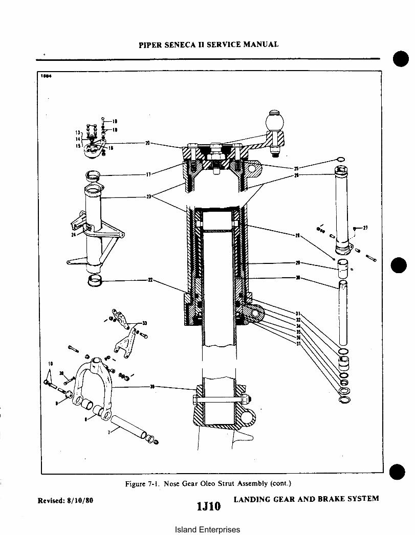
PIPER SENECA II SERVICE MANUAL
Figure 7-1. Nose Gear Oleo Strut Assembly (cont.)
Revised: 8/10/80 LANDING GEAR AND BRAKE SYSTEM1J10
Island Enterprises

PIPER SENECA II SERVICE MANUAL
3190
6-
15-14
Figure 7-1A. Nose Gear Service .Tolerances
LANDING GEAR AND BRAKE SYSTEMAdded: 3/16/81
Island Enterprises

PIPER SENECA II SERVICE MANUAL
TABLE VII-I. NOSE GEAR SERVICE TOLERANCES
No. Part No. Nomenclature Manufacturer'sDimension
ServiceDimension
Tolerances Remarks
1 452-334PS 10020-1-6RX
Downlock LinkRod End Bearing
Bolt Hole:.1900 +.0015
-.0005
2 95061-29
3 95061-30
4 95061-31
Bushing
Bushing
Bushing
.439
.440.004
.312
.311.002
.193
.189.005
5 452-540FF520-10
Steering ArmFlange Bng.
.3765
.3755.002 .002 Press Fit
6 452-552PS 10020-2-3RT
CenteringSpring Bearing
Bolt Hole: .001.2500 +.0015
-.0005
7 95061-89
8 95061-28
Bushing
Bushing
.189 .004
.252
.250.004
9 452-334PS 10020-1-6RX
10 95061-20
11 95061-24
12 95061-25
BungeeBearing
Bushing
Bushing
Bushing
Bolt Hole:.1900 +.0015
-.0005
O.D. 312 x.058
O.D. .312x.058
O.D. 312 x.058
.004
.004
.004
13 95715
14 67026-07
15 67758-00
Upper StrutTube Bearing
Bushing
Trunnion AssemblyBushing
1.7521.750
.004
.313
.314.313.315
.002 Wet ZincChromate,Press Fitand LineReam
2.816 .0022.815
Added: 3/16/81 LANDING GEAR AND BRAKE SYSTEM1J12
Island Enterprises

PIPER SENECA 11 SERVICE MANUAL
TABLE VII-l. SERVICE TOLERANCE (cont.)
No. Part No. Nomenclature Manufacturer'sDimension
ServiceDimension
Tolerances Remarks
16 452-448FF411-4
17 452-331FF310-3
18 95061-27
Upper StrutTube Bearing
Upper StrutTube Bng
Tiller Bushing
.313
.312.002 Line Ream
.376
.375.002
.252
.250.004
Added: 3/16/81 LANDING GEAR AND BRAKE SYSTEM1J13
Island Enterprises

1J14INTENTIONALLY LEFT BLANK
Island Enterprises

PIPER SENECA II SERVICE MANUAL
7-8. ASSEMBLY OF NOSE GEAR OLEO. (Refer to Figure 7-1.) After cleaning and inspectingcomponents as explained in paragraph 7-7 above, reassemble the nose gear oleo As follows:
a. Insert piston strut (30) into its recess in fork (39) and secure in position with hardware (38).b. Install snap ring (37) and washer (36) on piston strut.c Install O-rings (31 and 34) and a new wiper ring (35) on bearing (32).d. Lubricate piston strut using hydraulic fluid (MIL-H-5606) and slide bearing onto piston strut.e. Slide spacer (29) onto strut and align holes. Insert two retaining pins (28).f. Lubricate inner walls of oleo cylinder with hydraulic fluid. Carefully insert piston strut into cylinder
far enough to permit positioning of washer (36) and snap ring (37). (Refer to paragraph b above.)g. Install torque links (33) using appropriate hardware.h. Remove upper and lower shoulder bushings (17 and 22) from trunnion assembly (23).
NOTE
Avoid damaging the upper and lower flanges of the bushing.
i. Slide the lower shoulder bushing down the oleo cylinder until it bottoms above mounting lug securingthe upper torque link.
j. Insert the oleo cylinder into the trunnion assembly (23). The base of the trunnion must seat firmly onthe lower shoulder bushing.
k. Carefully insert the upper shoulder bushing (17) between the oleo cylinder and the trunnion.1. Place O-ring (25) into recess in top of oleo cylinder. Position bearing (21) on oleo cylinder. The tab of
the bearing should be facing forward. Insert the bottom of the tiller (20) into the opening in the top ofthe oleo cylinder and secure in position with four bolts and washer (1) and safety.
m. Install nose gear centering spring assembly (11). (See latest revision of Piper Service Bulletin 893.)
NOTE
Ascertain that bolt is installed with the head down and washers arearranged as shown in Figure 7-1.
n. Lubricate gear assembly. (Refer to Lubrication Chart, Section II.)o. Compress and extend the strut several times to determine the strut will operate freely. The weight of
the tire and fork should allow the strut to extend.p. Install the air valve body (15), core (14) and cap (13) after servicing the oleo cylinder with oil and air.
(Refer to Oleo Struts, Section II.)q. Check main gear for alignment (refer to paragraph 7-25) and operation.
7-9. REMOVAL OF NOSE LANDING GEAR. (Refer to Figure 7-2.)
NOTE
To gain access to the landing gear, remove access panels located in theforward baggage compartment.
a. Place airplane on jacks.b. Disconnect leads to landing lights.c. Retract the landing gear far enough to permit unlocking the downlock mechanism.d. Disconnect downlock spring (44) from aft end of gear actuating cylinder (39).e. Disconnect upper drag link (32) from the strut housing.f. Disconnect the actuating cylinder from the strut housing.
Reissued: 10/11/79 LANDING GEAR AND BRAKE SYSTEMInterim Revision: 02/05/97 1J151J15
Island Enterprises

1. ROD ASSEMBLY - NOSE WHEEL CONTROL
2. BOOT
3. ARM ASSEMBLY - STEERING
4. CHANNEL ASSEMBLY - STEERING
5. TILLER ASSEMBLY
6. CLAMP
7. BOLT, WASHER, NUT & COTTER PIN
8. TUBE ASSEMBLY - NOSE GEAR DOOR ACTUATION
9. STOP ASSEMBLY
10. LINK- UPPER
6
PIPER SENECA II SERVICE MANUAL
1952
29
27
26
Figure 7-2. Nose Gear Installation
Revised: 8/10/80 LANDING GEAR AND BRAKE SYSTEM1J16
Island Enterprises
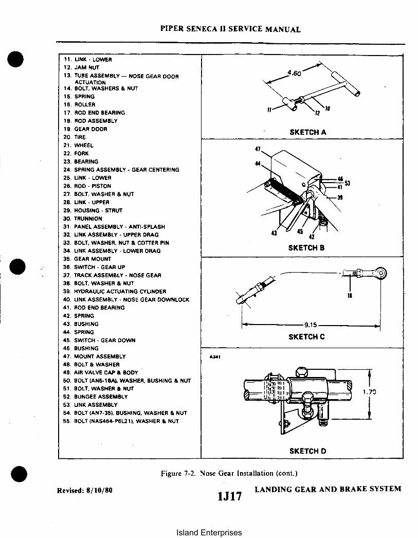
11. LINK - LOWER12. JAM NUT13. TUBE ASSEMBLY - NOSE GEAR DOOR
ACTUATION14. BOLT. WASHERS & NUT15. SPRING16. ROLLER17. ROD END BEARING18. ROD ASSEMBLY19. GEAR DOOR20. TIRE21. WHEEL22. FORK23. BEARING24. SPRING ASSEMBLY - GEAR CENTERING25. LINK - LOWER
26. ROD - PISTON
27. BOLT, WASHER & NUT28. LINK - UPPER29. HOUSING - STRUT
30. TRUNNION31. PANEL ASSEMBLY - ANTI-SPLASH32. LINK ASSEMBLY - UPPER DRAG33. BOLT, WASHER, NUT & COTTER PIN34. LINK ASSEMBLY - LOWER DRAG35. GEAR MOUNT36. SWITCH - GEAR UP
37. TRACK ASSEMBLY - NOSE GEAR38. BOLT, WASHER & NUT39. HYDRAULIC ACTUATING CYLINDER40. LINK ASSEMBLY - NOSE GEAR DOWNLOCK41. ROD END BEARING42. SPRING43. BUSHING44. SPRING45. SWITCH - GEAR DOWN
46. BUSHING47. MOUNT ASSEMBLY48. BOLT & WASHER49. AIR VALVE CAP & BODY50. BOLT (AN5-16A) WASHER, BUSHING & NUT51. BOLT, WASHER & NUT52. BUNGEE ASSEMBLY53. LINK ASSEMBLY54. BOLT (AN7-35), BUSHING, WASHER & NUT55. BOLT (NAS464-P6L21) WASHER & NUT
PIPER SENECA II SERVICE MANUAL
47
4.60
SKETCH A
SKETCH A
SKETCH B
9.15
SKETCH C
A341
SKETCH D
Figure 7-2. Nose Gear Installation (cont.)
LANDING GEAR AND BRAKE SYSTEM1J17
Revised: 8/10/80
Island Enterprises

32
FWDA
(SEE NOTE 1)54
PIPER SENECA II SERVICE MANUAL
SKETCH E
DRAG LINK - TRUSSASSEMBLY
34
.250 OR GREATERNO LESS THEN .190 INCH(SEE BELOW FOR OFFCENTER MEASUREMENT)
OVERCENTER MEASUREMENT
MEASURE.300 OR GREA
BULKHEAD
FWD-
64
STRAIGHT EDGE
TAKING MEASUREMENT
WITHDRAW
iFWD
WITHDRAWBOLT 1/4 IN.
32TRUNNIONRING BLOCK
SECTION A-A'UPPER' DRAG LINK-TO-GEAR CONNECTION
NOTE 1REPLACE UPPER DRAG UNKATTACHMENT BOLT EACH500 HOURS TIME-IN-SERVICE
SECTION B-B
'LOWER' DRAG LINK-TO-MOUNT CONNECTION
Added: 8/10/80Interim Revision: 6/24/96
Figure 7-2. Nose Gear Installation (cont.)
LANDING GEAR AND BRAKE SYSTEM1J18Island Enterprises

1J19INTENTIONALLY LEFT BLANK
Island Enterprises

1J20INTENTIONALLY LEFT BLANK
Island Enterprises

PIPER SENECA II SERVICE MANUAL
g. Remove attaching hardware at strut housing pivot point and remove landing gear from the airplane.h. To remove upper and lower drag links (32, 34), disconnect downlock link (40) from lower drag link
and disconnect lower drag link from its attachment point.
7-10. CLEANING, INSPECTION AND REPAIR OF NOSE LANDING GEAR.a. Clean all parts with a suitable dry type cleaning solvent.b. Inspect gear components for the following unfavorable conditions:
1. Bolts, bearings and bushings for excessive wear, corrosion and damage.2. Gear strut and cylinder, drag links and downlock link assembly for cracks, dents, bends or misalignment.3. Downlock link assembly for damaged threads and bearing.4. Roller assembly for freedom of movement and excessive wobble.
c. Check downlock spring and downlock link spring for excess wear and corrosion, particularly aroundthe hook portion. Springs should be discarded if wear or corrosion exceeds one quarter the diameter ofthe spring. Remove corrosion and paint spring.
d. Check downlock spring for adequate tension. This may be accomplished by observing several lockingactivations and checking for smooth operation with positive locking each time. If hook or down lock
IR movement is slow or has a hesitation or jerky movement, the spring should be replaced. Check downlock link assembly for proper operation and cleanliness. Pin and hole should be carefully inspected forsigns of wear and elongation.
e. Check general condition of limit switches and actuators, wiring for fraying and poor connections orconditions which could lead to failure.
f. Repairs to the landing gear are limited to reconditioning of parts such as smoothing out minor nicksand scratches, repainting areas where paint has chipped or peeled, and replacement of parts.
WARNING
DO NOT attempt to remove the spring from the shaft assembly of thenose gear centering spring assembly. This spring is held undercompression by two bushings and two pins with fused heads.
7-11. INSTALLATION OF NOSE LANDING GEAR. (Refer to Figure 7-2.)
CAUTION
When assembling any units of the landing gear; lubricate bearings, bushings,andfriction surfaces with the proper lubricant as described in Section II.
a. Position the landing gear assembly into the gear mount assembly and ascertain that the tiller assemblyis located in the slot of the steering arm assembly.
b. Align the attachment points on the strut housing with the attachment points on the gear mount assembly.c. Install bolts, washers, and nuts, securing the strut to the mount. Tighten the nuts to a snug fit, yet
allowing the gear to swing free, then install the cotter pins.d. The drag links, retraction cylinder, downlock link and downlock spring may be installed by the
following procedure:1. Ascertain that the upper and lower drag links are assembled.
CA UTION
Upper drag link AN7-35 attachment bolt must be replaced each 500hours time-in-service.
2. Position the drag link assembly with the contact surfaces up, to allow the bolt holes in the links toalign with the bolt holes in the strut housing and gear mount assembly. Install the link attachment bolts.
3. Install washers and nuts on the drag link attachment bolts. Tighten the nuts, yet allow the links to operate freely.
Reissued: 10/11/79 LANDING GEAR AND BRAKE SYSTEMInterim Revision: 02/05/97 1J21
Island Enterprises

PIPER SENECA II SERVICE MANUAL
4. Position the landing gear in the downlocked position and ascertain that the drag links arefully extended and over center when the stop surfaces make contact.
5. Adjust the rod end of the retracting cylinder so that a 0.25 of an inch of rod travel remainsbefore full extension with the gear down.
6. Connect the retraction cylinder rod end to the strut housing and secure with bolt, washersand nut.
7. Connect the downlock link to the lower drag link and the downlock spring to the linkassembly.
8. Adjust the downlock link so it is fully compressed when the gear is down and locked. Onairplanes equipped with an up stop. ascertain that the three pivot points in the downlock link assembly (41)and the link assembly (53) are aligned.
NOTE
The downlock link assembly will move aft slightly with theremainder of the cylinder travel until the link contacts the stop.At this position. the downlock light switch must actuate.
9. Install spring (44) in position on link (53) with drag link assembly fully extended (overcenter with upper faces in solid contact). Adjust the linkage (40) to a fully retracted position and install.
NOTE
The link (40) is fully retracted when the guide pin is bottomed outat the slot.
Free fall the nose gear a minimum of 3 times. Remove linkage (40) and readjust per Note. Shorten linkageby one-half turn clockwise and reinstall.
10. With the following procedure check the drag links for proper "through center" travel. (Refer toFigure 7-2. Sketch E.) Should the distance not meet the required through center travel as follows. notifyVero Beach Customer Service immediately. DO NOT RETURN AIRCRAFT TO SERVICE.
(a) Unbolt the downlock link assembly from the lower drag link, and with the downlock linkrotated up out of the way. tape the link to the bulkhead.
(b) Without removing the bolts. loosen the retaining hardware of the three drag link bolts(50. 54. 55) and withdraw them until about I ' 4 inch of grip is visible. DO NOT REMOVEBOLTS.
(c) Lay a "true" straightedge across the exposed grip of the upper and lower drag link bolts(50. 54). Refer to "Drag Link Measurement." Sketch E. Figure 7-2. for a guide.
(d) Apply pressure to the top of the drag links insuring the upper faces of the drag links arein solid contact. and measure the perpendicular distance between the top surface of theNAS 464-26L21(55) bolt grip and the bottom of the straightedge.
(e) The distance measured should be .300 inch or greater..lf the measured distance is between.300 and .245 + .005. the Customer Service representative should be notified and returnthe aircraft to service. However, if the measured distance is less than .240 inch. DO NOTreturn the aircraft to service, and notify Vero Beach Customer Service.
Revised: 8/10/80 LANDING GEAR AND BRAKE SYSTEM
1J22Island Enterprises

PIPER SENECA I SERVICE MANUAL
e. Rig the nose gear centering spring so that the nose gear has full left and right travel against itsstops. Use a tow bar to reach full travel.
f. Set the up stop to the dimension shown in Figure 7-2, Sketch D. Retract the gear and ifnecessary, readjust the stop to locate the nose gear in the proper retracted position.
NOTE
When stop adjustments are made, cycle the gear to insure that thenose gear strut engages the stop under retraction pressure.
g. Retract the nose gear and check the up limit switch for actuation.h. With the nose gear in the retracted position, adjust the up switch until switch is actuated. Move
switch upward another .02 to .04 inches. Adjust the rod end of the retraction cylinder to allow a minimum of.06 inches of actuator travel remaining in the retracted position.
i. Cycle the gear fully while checking switch actuation, downlock action, and up stop action to includeshort pickup cycles simulating in flight gear sag pickup. Check the actuator travel left to full extension in thedown and locked position. A minimum of .15 inches must remain. Check the up switch override action toinsure the proper operation.
j. Let the gear free fall to determine that the downlock spring returns the body end of the retractioncylinder aft so the downlock link assembly is fully compressed and the drag link arms are over center.
k. With the nose gear turned full left and right against the stops, check and if necessary, adjust theclearance between the steering horn and track. Maximum clearance is 0.06 and minimum clearance is 0.03.
1. Refer to Paragraph 7-16 for rigging of nose gear doors.m. Ascertain that the gear is lubricated per lubrication chart, Section II.n. Check the alignment of the nose gear per Paragraph 7-12. Ascertain that gear is down and locked.o. Remove the airplane from jacks.
Reissued: 10/11/79 LANDING GEAR AND BRAKE SYSTEM
1J23
Island Enterprises

1J24INTENTIONALLY LEFT BLANK
Island Enterprises

PIPER SENECA II SERVICE MANUAL
7-12. ALIGNMENT OF NOSE LANDING GEAR.a. Park the airplane on a smooth level floor which will accomodate the striking of a chalk line.b. Place airplane on jacks and level airplane laterally and longitudinally. (Refer to Leveling, Section
II.)c. Extend a plumb bob from the center of the tail skid and mark the contact point on the floor.d. Extend a chalk line from the mark on the floor below the tail skid to point approximately three
feet forward of the nose wheel. Allow the chalk line to pass under the wheel at the centerline of the tire.Snap the chalk line.
e. Clamp rudder pedals to align in a lateral position. (Refer to Figure 7-3.)f. Adjust the rod end bearings of each steering bungee to align the nose wheel with the chalk line
and to bring the rudder pedals into neutral angle fore and aft. There should be no load on the bungeesprings. This condition exists when the overall measurement taken between the facing sides of the washersat each rod end of the bungee is 13.71 inches. To align the nose wheel straight forward, stand in front ofthe nose gear and align the center rib of the tire with the chalk line or lay a straightedge along the side ofthe tire and parallel with the chalk line. In neutral position, the rudder pedals are tilted aft as shown inFigure 7-4, with the airplane level. Place a bubble protractor against a steering tube to check this angle. Oneend of each steering bungee must be disconnected and the jam nuts loosened to make this adjustment; donot attempt to make the complete adjustment by means of one bearing, but divide the adjustment betweenthe bearings at each end of each rod. Check that the rod ends have sufficient thread engagement bydetermining that a wire will not go through the check hole in the rod. Reinstall bungees, tighten and safetythe jam nuts.
g. To check the nose gear steering for its correct degree of maximum travel, right and left (see TableIl-1 I), use the wheel pivot point as the center point and draw a line at the travel degree angle on each side of thechalked centerline. Use a tow bar to turn the nose gear full travel left and right and overcome the bungeesystem. Should travel in one direction be excessive and not enough in the other, check the steering arm andsteering bungees for damage. Refer to Servicing Steering Bungees, Section 11 for lubrication instructions of thebungee assemblies.
7-13. REMOVAL OF NOSE GEAR DOOR ASSEMBLY. (Refer to Figure 7-2.)a. With nose gear extended, disconnect door retraction rods (18) from doors (19) by removing
attaching hardware.b. To remove doors, straighten bent end of hinge pins and pull the pins out from the opposite end.c. Disconnect spring (15) from arm of upper nose gear actuating tube assembly (13).d. Disconnect link assembly (10) from the upper nose gear actuating tube (13) and remove lower
nose gear actuating tube assembly (8) with roller attached.e. Remove upper actuating tube assembly (13).
7-14. CLEANING, INSPECTION AND REPAIR OF NOSE GEAR DOOR ASSEMBLY.a. Clean all components with a suitable cleaning solvent.b. Inspect doors for damage, loose or damaged hinges and brackets.c. Inspect retraction rods for damage and rod end bearings for corrosion.d. Check door tension spring for wear and tension below minimum allowable tolerance. Reject
spring if load tension is below 12 - 2 pounds with spring extended to 4.1 inches.e. Check general condition of actuating tube assemblies and roller assembly.f. Repairs to doors are limited to replacing hinges and brackets.g. Repairs to the retraction mechanism are limited to painting and replacement of component parts.
Reissued: 10/11/79 LANDING GEAR AND BRAKE SYSTEM
1K1
Island Enterprises

PIPER SENECA IISERVICE MANUAL
VERTORAIL
+30
Figure 7-3. Clamping Rudder Pedalsin Neutral Position
Figure 74. Rudder Pedals atNeutral Angle
7-15. INSTALLATION OF NOSE GEAR DOOR ASSEMBLY. (Refer to Figure 7-2.)a. Install upper nose gear actuating tube assembly (13) in position between two bearing blocks and
secure with attaching hardware.b. Install lower nose gear actuating tube assembly (8) in position between two bearing blocks and
secure with attaching hardware.c. Insert lower link assembly (11) into upper link assembly (10) and adjust as necessary to obtain a
dimension of 4.60 inches between the centerline of each link. Tighten locknut. (Refer to Sketch A.)d. Install assembled link assembly between two upright arms of upper actuating tube assembly and
secure with attaching hardware. Insert the lower link between the two upper holes in actuating tubeassembly (8) and secure with attaching hardware. (Refer to Figure 7-2.)
e. Install roller (16) directly below link (11) on lower actuation tube assembly. Secure in positionwith attaching hardware making certain the roller is free to turn.
NOTE
If cracks or any signs of wear are evident, the roller must bereplaced.
f. Install four washers on stop bolt (14) and insert into bushing on upper actuating tube assembly(13).
g. Adjust both retraction rods (18) to obtain a dimension of 9.15 inches as shown. Attach upperend of retraction rod to arm of upper actuation tube assembly. The lower end should be attached to thedoor bracket. Install tension spring (15). (Refer to Figure 7-2.)
h. Install gear doors by positioning hinge halves and inserting hinge pin. A new hinge pin should beused. Bend end of hinge pin to secure door in place.
Reissued: 10/11/79 LANDING GEAR AND BRAKE SYSTEM
1K2Island Enterprises

PIPER SENECA II SERVICE MANUAL
7-16. ADJUSTMENT OF NOSE GEAR DOOR.a. Place airplane on jacks.b. With link assembly and retraction rods adjusted as explained in Paragraph 7-15, the gear should
swing through the door opening with a clearance of .25 inch between the gear and door at their closestpoint.
c. If clearance between gear and door is less than .25 inch, remove washers from stop bolt until thespecified clearance is obtained. If clearance between the gear and door exceed the specified clearance, addwashers to the stop bolt.
d. If doors sag when fully retracted, tighten link assembly (11, Figure 7-2). If doors are too tight,loosen link assembly.
e. Check all rod ends for adequate thread engagement for safety and tightness of jam nuts.
7-17. MAIN LANDING GEAR SYSTEM.
7-18. DISASSEMBLY OF MAIN GEAR OLEO. (Refer to Figure 7-5.) The main gear oleo assembly maybe removed and disassembled from the gear oleo housing with the gear removed from or installed in theairplane.
a. Place airplane on jacks.b. Place a drip pan under the main gear to catch spillage.c. Remove air and fluid from the oleo. Depress air valve core pin until strut pressure has diminished;
remove the filler plug and with a thin hose siphon as much hydraulic fluid from the strut as possible.d. Disconnect brake line at the joint located in the wheel well.e. To remove piston tube assembly (25) from oleo housing (11), remove the upper and lower torque
or: link connecting bolt assembly (3) and separate links. Note number and thickness of spacer washer(s)between the two links (15 and 16).
f. Compress the piston tube (25); reach up into the tube and release the snap ring (24) from theannular slot at the bottom of the oleo housing.
g. Pull piston tube (25) with component parts from cylinder housing.h. The piston tube (25) components may be removed by reaching in the tube and pushing out the
upper bearing retainer pins (17). Slide off the upper bearing (18), lower bearing (20) with O-rings (19 and20), wiper (22) and washer (23).
i. To remove orifice tube (12) from the oleo housing, remove locknut (6) and washer (7) from topof housing. Draw tube with O-ring (9) and retainer (8) from housing.
j. The orifice plate (13) is removed from the bottom of orifice tube (12) by releasing snap ring (14)holding the plate in position.
k. To remove piston tube plug (26) and O-ring (27) located in the bottom end of the tube, removebolt assembly (29) and insert a rod up through the hole in the body of the fork (28) and push plug withO-ring from top of tube.
7-19. CLEANING, INSPECTION AND REPAIR OF MAIN GEAR OLEO.a. Clean all parts with a suitable dry type cleaning solvent.b. Inspect landing gear oleo assembly components for the following:
1. Bearings and bushings for excess wear, corrosion, scratches and overall damage.2. Retaining pins for wear and damage.3. Lock rings for cracks, burrs, etc.4. Cylinder and orifice tube for corrosion, scratches, nicks and excess wear.5. Orifice plate for hole restriction.6. Fork tube for corrosion, scratches, nicks, dents and misalignment.7. Air valve general condition.
c. Repair of the oleo is limited to smoothing out minor scratches, nicks and dents and replacementof parts.
Reissued: 10/11/79 LANDING GEAR AND BRAKE SYSTEM
1K3
Island Enterprises

PIPER SENECA II SERVICE MANUAL
.
1. BRACKET, SWITCH ACTUATOR2. BOLT, WASHERS, NUT AND COTTER PIN3. BOLT, WASHERS, NUT AND COTTER PIN4. BOLT, WASHERS, NUT AND COTTER PIN5. AXLE NUT6. NUT7. WASHER8. RETAINER9. O-RING
10. VALVE ASSEMBLY11. HOUSING, OLEO STRUT12. ORIFICE TUBE 413. PLATE, ORIFICE14. SNAP RING15. LINK ASSEMBLY, UPPER16. LINK ASSEMBLY, LOWER17. RETAINER PIN, BEARING18. BEARING, UPPER19. O-RING, OUTER20. BEARING, LOWER21. O-RING, INNER22. WIPER STRIP23. WASHER24. SNAP RING25. PISTON TUBE26. PLUG27. O-RING28. FORK ASSEMBLY29. BOLT ASSEMBLY30. BRACKET - SQUAT SWITCH31. PLATE, SPRING ATTACHMENT32. PISTON RING
Figure 7-5. Main Gear Oleo Strut Assembly
3
Reissued: 10/11/79 1K41K4LANDING GEAR AND BRAKE SYSTEM
Island Enterprises

PIPER SENECA II SERVICE MANUAL
Figure 7-5. Main Gear Oleo Strut Assembly (cont.)
1K LANDING GEAR AND BRAKE SYSTEM1K5Reissued: 10/11/79
Island Enterprises

PIPER SENECA II SERVICE MANUAL
3186
Figure 7-5a. Main Gear Service Tolerances
LANDING GEAR AND BRAKE SYSTEM1K6
Added: 3/16/81
Island Enterprises

PIPER SENECA II SERVICE MANUAL
TABLE VII-II. MAIN GEAR SERVICE TOLERANCES
No. Part No. Nomenclature Manufacturer'sDimension
ServiceDimension
Tolerances Remarks
1 452 575PS 10020-10-2
SphericalBearing
.99951.0000
None
2 63900-88
3 63900-130
.312 x .058
Main Gear TrussBushing
.004 No longerused
.250 x .028 .004
4 14175-103
5 452 368(HFX 8G)
78722-02
6 65003-44
Main Gear TrussAssy. Bushing
Rod End LowerSide Brace Link
Rod End LowerSide Brace Link
Lower Side BraceLink Bushing
.161 0 NoRotation
.50 +.0015-.0005
or
.50 +.003-.0005
.0035 34-7670324and below
34-7670325and above
.373.375
.372
.376.004 Line Ream
Press Fit
7 67026-12
8 21822-00
78716-02
9 63900-85
Bracket Bushing
Tapered TrussAssy. Bushing
Tapered TrussAssy. Bushing
Spring AttachmentBushing
.624
.625
.500
.510or
.562
34-760324and below
+.010-.000
34-760325and above
.191 .189.193
.004
10 95061-64 Bushing .250 x .028 .004
Added: 3/16/81 LANDING GEAR AND BRAKE SYSTEM1K7
Island Enterprises

PIPER SENECA IISERVICE MANUAL
7-20. ASSEMBLY OF MAIN GEAR OLEO. (Refer to Figure 7-5.)a. Determine that all parts are cleaned and inspected.b. To install the piston tube plug (26), first lubricate the plug O-ring (27) with hydraulic fluid
(MIL-H-5606) and install it on the plug. Lubricate the inside wall of the tube. Insert the plug into the topof the tube (25) and push it to the fork end. Align the bolt holes of the fork, tube and plug, and install boltassembly.
c. If desired, cement a cork in the hole in the bottom of the fork body to prevent dirt from enteringbetween the fork and tube.
d. To assemble components of orifice tube (12), insert orifice plate (13) into the bottom of thetube and secure with snap ring (14).
e. To install tube (12) in oleo housing (11), insert the tube up through the housing. With the end ofthe tube exposed through the top of the housing, install the O-ring (9), retainer (8), washer (7), and locknut(6). Tighten locknut only finger tight at this time.
f. Assemble components of piston tube (25) on the tube by placing, in order, snap ring (24), washer(23), lower bearing (20) with outer and inner O-ring (19 and 21) and upper bearing (18). Align the two.125 diameter holes and the lock pin holes with the corresponding holes in the piston tube and install pins(17).
g. Lubricate the wall of the cylinder oleo housing (11) and tube (25), and carefully insert the tubeassembly into the housing, guiding the orifice tube (12) into the piston tube. Install the wiper strip (22),slide the washer (23) into position and secure the assembly with snap ring (24).
h. Tighten locknut (6) at top of housing and torque to 300-500 inch pounds.i. Ascertain that the bushings are installed in the upper and lower torque links (15 and 16) and then
install links. The torque link bolt assemblies (2, 3 and 4) should be lubricated and installed with the flat ofthe bolt head hex adjacent to the milled stop of the wide end of the link. (Use the same thickness of spacerwashers between the two links as those removed to maintain correct wheel alignment.) Tighten the boltsonly tight enough to allow no side play in the links, yet be free enough to rotate.
NOTE
Instructions contained in Paragraph "j" below pertain to left oleostrut assemblies only.
j. Assemble squat switch actuator bracket (1) on bolt assembly (2). Insert a rivet through the holeprovided in the bracket into the upper link and install the nut. Install squat switch bracket (30)immediately above the actuator bracket.
k. Attach spring attachment plate (31) to the mounting lug on the base of the housing immediatelyabove the upper link.
1. Connect brake line and bleed the brakes per Paragraph 7-65 or 7-66.m. Lubricate gear assembly. (Refer to Lubrication Chart, Section II.)n. Compress and extend the strut several times to ascertain the strut will operate freely. The weight
of the gear wheel and fork should allow the strut to extend.o. Service oleo strut with fluid and air. (Refer to Oleo Struts, Section II.)p. Check main gear alignment (refer to Paragraph 7-25) and gear operation. Ascertain that gear is
down and locked.q. Remove the airplane from jacks.
Reissued: 10/11/79 LANDING GEAR AND BRAKE SYSTEM
1K8Island Enterprises

PIPER SENECA II SERVICE MANUAL
7-21. REMOVAL OF MAIN LANDING GEAR. (Refer to Figure 7-6.)a. Place the airplane on jacks.b. The side brace link assembly may be removed by the following procedure:
I. With gear in the extended position, disconnect gear downlock spring (18).2. Disconnect rod end (46) of actuating cylinder (24) from retraction fitting (21) on the upper
side brace link (28) by removing nut, washer and bolt (47), and bushing and spring swivel (20).3. Disconnect lower side brace link (33) from gear housing (13) by removing attachment nut,
washer and bolt (7). Note bushings on each side of end bearing.4. Disconnect upper side brace link (28) from side brace support fitting stud (26) by removing
cotter pin, nut, washer and attachment bolt (25).5. The side brace support fitting may be removed by removing the cap bolts securing the
fitting to the web of the spar.6. Remove the assembly, and further disassemble and inspect as needed.
c. The strut housing (13) with components may be removed by the following procedure:1. Disconnect brake line (42) at its upper end in the wheel well.2. Disconnect gear door actuating rod (38) at the gear housing.3. Remove access plate located on underside of wing, aft of landing gear.4. If not previously disconnected, disconnect lower side brace link (33) from the gear housing.5. Disconnect forward support fitting (16) of housing (13) from the web of the main spar by
removing fitting attachment bolts.6. Remove retainer tube (4) in aft support fitting (1) that supports the aft arm of the housing
by reaching through the access opening on the underside of the wing, through the hole in the web andremoving bolt (48) that secures the tube in the housing. Insert a hook through the bolt hole in the tube,and slide it aft from the support fitting. Remove the tube from the wing.
7. Allow the gear to drop free from the wing.8. The aft support fitting (1) may be removed by holding the nuts in position, reaching
through the access opening, and removing the fitting attachment bolts.9. The forward support fitting (16) may be removed from the arm of the housing by removing
the bolt and washer from the base side of the fitting. Slide the fitting from the arm. Remove washer (52)from the arm.
d. Either bearing (53 or 54) installed in the support fittings may be removed by removing the snaprings (2) that hold the bearing in the housing. Push the bearing from the housing.
7-22. CLEANING, INSPECTION AND REPAIR OF MAIN LANDING GEAR.a. Clean all parts with a suitable dry type cleaning solvent.b. Inspect the gear components for the following unfavorable conditions:
1. Bolts, bearing and bushings for excess wear, corrosion and damage.2. Gear housing, side brace links, t rque links and attachment plates for cracks, bends or
misalignment.3. Downlock hook for excessive wear of the bearing surfaces.
c. Inspect the gear downlock spring for the following:1. Excessive wear or corrosion, especially around the hook portion of the spring. A spring
should be rejected if wear or corrosion exceeds one-quarter the diameter of the spring. Clean away allcorrosion and repaint.
2. Check the spring for load tensions below minimum allowable tolerance. The minimumtension of the spring is 48 pounds pull at 7.9 inches. Measurement is taken from the inner side of eachhook.
d. Check the general condition of each limit switch and its actuator, and wiring for fraying, poorconnections or conditions that may lead to failures.
Reissued: 10/11/79 LANDING GEAR AND BRAKE SYSTEM1K9
Island Enterprises

PIPER SENECA II SERVICE MANUAL
TORQUE SUPPORT BRACKET ATTACHMENTBOLTS 50 TO 70 INCH-POUNDS
/NOTE: IT MAY HAVE BEEN NECESSARY TO USE SPECIAL LANDING GEAR ATTACHMENT HARDWAREDURING ASSEMBLY OF THE AIRCRAFT DUE TO MANUFACTURING TOLERANCES, THEREFORE. SPECIALATTENTION SHOULD BE GIVEN WHEN REMOVING HARDWARE TO INSPECT AND INSURE THE SAMEDIAMETER HARDWARE IS USED UPON REASSEMBLY. STANDARD AN4 OR AN5 BOLTS ARE REPLACED BYALTERNATE OVERSIZED BOLTS NAS3004 OR NAS3006. AND STANDARD FLUSH HEAD BOLTSMS24694-S106 ARE REPLACED BY ALTERNATE OVERSIZE BOLTS NAS1604-9R RESPECTIVELY. WHENOVERSIZED HARDWARD IS REQUIRED.
Figure 7-6. Main Gear Installation
Revised: 8/10/80 LANDING GEAR AND BRAKE SYSTEM1K10
Island Enterprises

1. SUPPORT FITTING, AFT2. SNAP RING3. BEARING4. RETAINER, TUBE ASSEMBLY5. FITTING, GREASE6. HINGE, GEAR DOOR7. BOLT, WASHERS AND NUT8. LINK, UPPER9. WASHER, SPACER
10. LNK, LOWER11. DOOR, GEAR12. NUT13. HOUSING, STRUT14. PLUG, HYDRAULIC FLUID15. VALVE ASSEMBLY16. SUPPORT FITTING, FORWARD17. FITTING, GREASE18. SPRING, DOWNLOCK19. TURNBUCKLE20. SWIVEL ASSEMBLY21. RETRACTION FITTING22. JAM NUT23. ROD, PISTON24. CYLINDER, HYDRAULIC ACTUATING25. BOLT, WASHERS, NUT AND COTTER PIN26. STUD, SIDE BRACE SUPPORT27. SUPPORT BRACKET28. LINK, UPPER SIDE BRACE29. PLATE30. HOOK, DOWNLOCK31. BOLT, WASHERS, NUT AND COTTER PIN32. PIN, DOWNLOCK33. LINK. LOWER SIDE BRACE34. BRACKET, SPRING35. SWITCH, SAFETY36. ACTUATOR, SAFETY SWITCH37. BOLT, WASHERS, NUT AND COTTER PIN38. ROD, GEAR DOOR39. BOLT, WASHERS, NUT AND COTTER PIN40. FORK GEAR41. CLAMP42. HOSE, BRAKE43. BRAKE HOUSING44. BRAKE DISC45. TIRE46. ROD END BEARING47. BOLT, WASHER, NUT AND BUSHING48. BOLT49. SHIM WASHER50. BOLT51. WASHER52. WASHER53. BEARING, FORWARD SUPPORT54. BEARING, AFT SUPPORT55. SNAP RING56. ROD END BEARING57. JAM NUT58. BRACKET, SWITCH59. CLIP, SAFETY60. BUSHING, TAPERED
OTE: IF WHEN THE TRUSS ASSEMBLY ISDISMANTLED IT IS FOUND THATTHE BUSHINGS NEED TO BE RE-PLACED, THE HOLES IN THE UPPER.LIK FLANGES FOR THE 14843-16SHOULD BE LINE REAMED TO .376.375. ALL BUSHINGS SHOULD BEPRESS FIT. IF THEY FIT LOOSELY.INSTALL USING LOCKTITE.
2OVER CENTER
59.145 MIN.- 1
.170 MAX.- .32
PIPER SENECA II SERVICE MANUAL
SKETCH A
BUSHINGS14843-16 (2 REQ.)
SEE NOTE
BUSHINGS65003-44(2 REQ.)
SECTION A-A
FILE LINK WHERE SHOWNTO OBTAIN OVER CENTER
FILE HERE
SKETCH B
Figure 7-6. Main Gear Installation (cont.)
Revised: 8/10/801K 11
LANDING GEAR AND BRAKE SYSTEM
Island Enterprises

PIPER SENECA II SERVICE MANUAL
e. Check side brace link through center travel by attaching the upper and lower links, setting themon a surface table, and ascertaining that when the stop surfaces of the two links touch, linkage is not lessthan .145 nor more than .170 of an inch through center. Should the distance exceed the required throughcenter travel and bolt and bushings are tight, replace one or both links.
f. With side brace links assembled and checked, ascertain that when stop surfaces of the two linkscontact, the clearance between each downlock hook and the flat of the downlock pin is not less than 0.010of an inch. Should clearance be less than that required, the hook only may be filed not to exceed a gap ofmore than 0.025 of an inch. The maximum allowable clearance between each hook and the downlock pinthat are service worn is 0.055 of an inch. Should clearance be more than 0.055 of an inch, replace the pin,check clearance and then if still beyond tolerance, replace hooks. The gap between each hook should beequal.
g. Repair of the landing gear is limited to reconditioning of parts such as replacing components,bearings and bushings, smoothing out minor nicks and scratches and repainting areas where paint haschipped or peeled.
7-23. INSTALLATION OF MAIN LANDING GEAR. (Refer to Figure 7-6.)
NOTE
When assembling components of the landing gear, lubricatebearings, bushings, and friction surfaces with proper lubricant asdescribed in Section II.
a. Insert a gear support bearing (53 and 54) in each support fitting (1 or 16) and secure with snaprings (2). Check bearing (53) for excess end play, shim as necessary with shim washers (49) (P/N 62833-44).
b. The gear housing may be installed in the wheel well of the wing by the following procedure:1. Place spacer washer (52) and then forward support fitting (16) on forward arm of the
housing. Determine that barrel nut (55) is properly positioned in the arm and insert attachment bolt (50)through washer (51) and the fitting into the arm. Tighten bolt and ascertain that the bearing is free torotate.
2. Position aft support fitting (1) at its attachment point in the wheel well and secure withbolts, washers and nuts. Install nuts and washers by reaching through the access hole on the underside ofthe wing.
3. With the retainer tube (4) for the aft arm of the housing in hand, reach up through theaccess opening and insert the tube into the support fitting ( ) through the hole in the web.
4. Position the gear housing up in the wheel well and install the forward support fitting (16)with bolts and washers. (One each AN960-416 and AN960-416L washer per bolt.)
5. Push the retainer tube into the arm of the housing and secure with bolt (48).6. Check that the gear rotates freely in its support fittings and recheck thrust.7. Connect the brake line to its mating line in the wheel well and bleed brakes as explained in
Paragraph 7-65 or 7-66.c. The gear side brace link assembly may be installed by the following procedure:
1. Position link support bracket (27) with swivel stud (26) installed at its attachment point onthe web of the spar and secure with bolts and washers.
NOTE
When installing a new wing, it will be necessary to back drill two(2) holes 0.250 inch and countersink 100 x .499 through the sparcap. (Screw head should be flush with spar.) Use hole in thesupport bracket as a guide in the drilling.
Reissued: 10/11/79 LANDING GEAR AND BRAKE SYSTEM1K12
Island Enterprises

PIPER SENECA II SERVICE MANUAL
2. Ascertain that the upper and lower links (28 and 33) are assembled with downlock hook (30),retraction fitting (21), etc., attached, and the through travel of the links and downlock hook clearance checkedaccording to Paragraph 7-22.
3. Attach the upper link to the swivel stud of the support fitting and secure with bolt, bushing,washer, nut and cotter pin (25).
4. Attach lower link assembly (33) to the gear housing (13) and secure with bolt, washers and nut(7). Torque nut to 570 + 30 inch-pounds.
5. The actuating cylinder rod end bearing (46) and lower side brace link (33) may be attached re-spectively to the retraction fitting (21) and strut housing during the adjustment of the landing gear.
d. Ascertain that the landing gear is lubricated per Lubrication Chart.e. Check adjustment of landing gear per Paragraph 7-24.f. Check alignment of the wheel per Paragraph 7-25.g. Install the access plate on the underside of the wing and remove the airplane from jacks.
7-24. ADJUSTMENT OF MAIN LANDING GEAR.a. Place the airplane on jacks.b. Level the airplane laterally and longitudinally. (Refer to Leveling, Section II.)c. Disconnect the gear door actuating rods at either the door or the housing, as desired, by removing
the rod attachment bolt. Secure the door out of the way.d. Adjust rod end on lower side brace link with no load on wheels, to obtain 89° angle between wheel
centerline and level floor line on outboard side of gear.e. Check that the rod end has sufficient thread engagement in the end bearing, align the flat sides of the
bearing casting with the flat side of the bearing and tighten the jam nut.f. Adjust the turnbuckle of the downlock mechanism by first ascertaining that the gear is down and
locked, and then move the retraction fitting outboard until it contacts the stop slot of the side brace link. Hold'the fitting in this position and turn the turnbuckle barrel until the downlock hooks make contact with the lock,pin. Safety the turnbuckle.
g. For easier adjustment of the downlock limit switch, it may be set at this time as explained inParagraph 7-34.
h. Retract and extend the gear manually several times to ascertain that the side brace link falls throughcenter, the downlock hook falls into position and there is no binding of the gear assembly.
i. The gear should be adjusted in the up position to allow the gear fork to press lightly into the rubber: bumper pad on the wing. The adjustment may be accomplished as follows:
NOTE
If it requires less than .125 of an inch to move the gear into thecorrect adjustment, Steps 2 and 6 thru 8 need only be followed.
1. Ascertain that the rod end bearing of the actuating cylinder is disconnected from the re-traction fitting.
2. Actuate the hydraulic system to bring the hydraulic cylinder to the up position by turning themaster switch on and moving the gear selector handle to the up position. The piston of the cylinder should bebottomed.
3. Raise the gear by pushing up on the retraction fitting, thus disengaging the hooks, and pushingup on the pivot point at the bottom of the side brace links to bring the links out of the locked position. Raisethe gear until the fork presses lightly into the rubber pad. Retain the gear in this position.
Revised: 8/10/80 LANDING GEAR AND BRAKE SYSTEM
1K13
Island Enterprises

PIPER SENECA II SERVICE MANUAL
4. Loosen the jam nut on the piston rod of the actuating cylinder and turn the rod end bearingin or out to allow a slip fit of the attachment bolt.
5. Install with the attachment bolt, bushing, spring swivel, and secure with washer and nut.Install the gear downlock spring.
6. When the gear is to within .125 of an inch of correct adjustment, the rod end need not bedisconnected and therefore all that will be required is to loosen the jam nut, place a wrench on the flat atthe end of the piston rod and turn to obtain correct adjustment.
7. Check the rod end bearing for adequate thread engagement and tighten jam nut.8. If the downlock limit switch is properly adjusted, retract and extend the gear
hydroelectrically to ascertain that the gear operates properly.
7-25. ALIGNMENT OF MAIN LANDING GEAR. (Refer to Figure 7-7.)a. Place a straightedge no less than twelve feet long across the front of both main landing gear
wheels. Butt the straightedge against the tire at the hub level of the landing gear wheels. Jack the airplaneup just high enough to obtain a six and one-half inch dimension between the centerline of the strut pistonand the centerline of the center pivot bolt of the gear torque links. Devise a support to hold thestraightedge in this position.
b. Set a square against the straightedge and check to see if its outstanding leg bears on the front andrear side of the brake disc. (It may be necessary to remove the brake assembly to have clear access to thedisc.) If it touches both forward and rear flange, the landing gear is correctly aligned. The toe-in for themain landing gear wheels is 0 1/2 degrees.
NOTE
A carpenter's square, because of its especially long legs, isrecommended for checking main landing gear wheel alignment.
c. If the square contacts the rear side of the disc, leaving a gap between it and the front flange, thewheel is toed-out. If a gap appears at the rear flange, the wheel is toed-in.
d. To rectify the toe-in and toe-out condition, remove the bolt connecting the upper and lowertorque links and remove or add spacer washers to move the wheel in the desired direction. Refer to thechart on the following page.
e. Should a condition exist that all spacer washers have been removed and it is still necessary to movethe wheel further in or out, then it will be necessary to turn the torque link assembly over. (Refer to Figure 7-8).This will put the link connecting point on the opposite side allowing the use of spacers to go in the samedirection.
f. Recheck wheel alignment. If the alignment is correct, safety the castellated nut with cotter pin.g. If a new link on the top left main gear had to be installed or it had to be reversed during the
alignment check, it will be necessary to check the gear safety switch (squat switch) bracket for engagementand locking in place. If the large machine surface of the link is inboard, the bracket is mounted with thesmall rivet hole next to link. (Refer to Sketch A, Figure 7-7.) This hole should be aligned with centerline ofthe link and a .096 inch hole drilled .150 inch deep. Insert an MS20426AD3-3 rivet in the hole. Thislocking rivet is held in place by the flat washer, castellated nut and cotter pin. If link has to be reversed,then the bracket and bolt are also reversed. (Refer to Sketch B, Figure 7-7.)
h. Check adjustment of landing gear safety switch (squat switch) per Paragraph 7-35.
Reissued: 10/11/79 K14 LANDING GEAR AND BRAKE SYSTEM1K14
Island Enterprises

PIPER SENECA II SERVICE MANUAL
TABLE VII-lll. TOE-IN - TOE-OUT CORRECTION CHART
TOE-INTOE-OUTANGLE
SHIMWASHERS
WASHERSUNDER HEAD
WASHERSUNDER NUT
AN 174BOLT
0 AN960-416 AN960-416 (3) -14
00 33"
00 48"
1° 04"
1° 19"
1°35"2 35"
Max. Allow.
AN960-416
AN9604 16LAN960-416
AN960-416 (2)
AN960-416LAN960-416 (2)
AN960-416 (3)AN960-416 (4)
AN960-416
AN960-416
AN960-416
AN960-416L
AN960-416AN960-416
AN960-416 (2)
AN960-416
AN960-416
AN960-416
AN960416 (2)AN960-416
-14
-14
-14
-14
-15-15
AN960-416L Washers .031 Thick AN960-416 Washers .062 Thick
7-26. REMOVAL OF MAIN GEAR DOOR ASSEMBLY.a. With the landing gear extended, disconnect the door retraction rod from the door by removing
nut, washers and bolt.-b. Remove the door from the wing panel by bending the door hinge pin straight and from the other
end pulling out the pin.c. The door retraction rod may be removed from the gear housing by cutting the safety wire and
removing the attachment bolt and washer. Note the number of washers between rod end bearing andhousing.
7-27. CLEANING, INSPECTION AND REPAIR OF MAIN GEAR DOOR ASSEMBLY.a. Clean the door and retraction rod with a suitable cleaning solvent.b. Inspect the door for cracks or damage, loose or damaged hinges and brackets.c. Inspect the door retraction rod and end bearing for damage and corrosion.d. Repairs to a door may be replacement of hinge, repair of fiberglass and painting.
7-28. INSTALLATION OF MAIN GEAR DOOR ASSEMBLY.a. Install the door by positioning the hinge halves of the door and wing, and inserting the hinge pin.
It is recommended a new pin be used. Bend the end of the pin to secure in place.b. Install the door retraction rod by positioning the rod at its attachment points at the door and
strut housing. At the door attachment, thin washers are inserted at each side of the rod end bearing and it issecured with bolt, washer and nut. At the strut housing, place washers between rod end bearing and housingnot to exceed .12 of an inch to obtain proper clearance and secure with bolt. Safety bolt withMS20995C41 wire.
c. Check that the all around clearance between the door and the wing skin is not less than .032 ofan inch.
Reissued: 10/11/79 LANDING GEAR AND BRAKE SYSTEM
1K15
Island Enterprises

RIVET
SKETCH A
BRACKET
PIPER SENECA II SERVICE MANUAL
WASHER
A&B
SKETCH B
Figure 7-7. Aligning Main Gear
Reissued: 10/11/79 LANDING GEAR AND BRAKE SYSTEM1K16
Island Enterprises

PIPER SENECA II SERVICE MANUAL
BRACKET
TORQUE LINK
FOR TOE-IN CORRECTION,REMOVE AND REVERSETORQUE LINKS.
Figure 7-8. Toe-In/Toe-Out Adjustment
THIS SPACE INTENTIONALLY LEFT BLANK
Reissued: 10/11/79 LANDING GEAR AND BRAKE SYSTEM1K17
Island Enterprises

PIPER SENECA II SERVICE MANUAL
7-29. ADJUSTMENT OF MAIN GEAR DOOR ASSEMBLY.a. Place the airplane on jacks.b. Determine that the main gear is properly adjusted for gear up as explained in Paragraph 7-24.c. Adjust retraction rod end at door so that door will pull up tightly when the gear is full up.
Over-tightening may result in door buckling; however, if the door is too loose, it will gap in flight.d. Check all rod ends for adequate thread engagement, for safety and tightness of jam nuts.e. Remove airplane from jacks.
7-30. LANDING GEAR LIMIT SWITCHES.
NOTE
All adjustments of the limit switches should be made with theairplane on jacks. Do not bend actuator springs mounted on thelimit switches.
7-31. ADJUSTMENT OF NOSE GEAR UP LIMIT SWITCH. The gear up limit switch is mounted on abracket attached to the lower inner left tubular member of the nose gear mount, adjacent to the gear rollertrack assembly or mounted on the stop assembly. (Refer to Figure 7-2.)
a. To facilitate adjustment of the limit switch, disconnect gear doors.b. Turn the master switch on; move gear selector switch to the gear up position and raise the landing
gear. Turn the master switch OFF.c. Block the nose gear in the up position and slowly pull the free-fall knob away from the
instrument panel. This will relieve hydraulic pressure and permit the main gear to drop.d. Loosen the attachment screws of the switch and rotate the switch toward the actuator tang until
the switch is heard to actuate. Move the up limit switch upwards .02 to .04 inches after actuation.Retighten the switch attachment screws. Remove the block from under the gear and allow it to extendslowly.
e. Turn master switch on; raise gear and determine that gear lights function properly.
7-32. ADJUSTMENT OF NOSE GEAR DOWN LIMIT SWITCH. (Refer to Figure 7-9.) The nose geardown limit switch is mounted on a bracket located on the forward side of the cabin bulkhead.
a. With landing gear in the retracted position, pull the free-fall valve knob permitting the gear toextend.
b. Check to determine that the downlock spring (1) returns the body end of the actuating cylinder(2) aft.
c. Ascertain that the downlock link assembly (3) is fully retracted and that the drag link arms (4)are over center.
d. In this position, the nose gear green downlock light should energize when the master switch isturned on and the gear selector lever is in the down position.
e. If the nose gear green downlock light does not energize, loosen the attachment screws of theswitch and rotate the switch toward the actuator tang until it is heard to actuate. Tighten the adjustmentscrews.
7-33. ADJUSTMENT OF MAIN GEAR UP LIMIT SWITCH. A gear up limit switch is located in eachwheel well above the gear door hinge. The red "GEAR UNSAFE" light is extinguished when all three gearshave actuated their up limit switches and the gear selector is in the up position.
Reissued: 10/11/79 LANDING GEAR AND BRAKE SYSTEM
1K18Island Enterprises

A334 8841. DOWNLOCK SPRING2. ACTUATING CYLINDER3. DOWNLOCK LINK ASSY.4. DRAG LINK ARMS5. MICRO SWITCH
CABINBULKHEADSTA. 49.50
Figure 7-9. Adjust Nose Gear Figure 7-10. Adjust Main GearDown Limit Switch Down Limit Switch
7-34. ADJUSTMENT OF MAIN GEAR DOWN LIMIT SWITCH. The geardown limit switch is mountedon a bracket attached to the lower drag link of each main gear. The switch should be adjusted to allow it toactuate when the downlock hook has entered the locked position and is within .025 to .035 inch of contactingthe pin thus turning the green light on in the cockpit. (Refer to Figure 7-10.) Adjustment, if necessary, shouldbe made as follows:
a. Determine that the main gear downlock is properly adjusted as described in Paragraph 7-24.' b. Raise the airplane on jacks.
c. Determine that the landing gear is down and pressure is relieved from the hydraulic system. Torelieve pressure, pull the free-fall knob out.
d. Raise the downlock hook assembly and place a .030 inch feeler gauge between the horizontalsurface of the hook that is next to the switch (the surface that contacts the downlock pin) and the roundedsurface of the pin. Lower the hook and allow it to rest on the feeler gauge.
e. Loosen the attaching screws of the switch and, while pushing up on center of the link assembly,rotate the switch toward the hook until it is heard to actuate. Retighten the attaching screws of the switch.
f. Manually move the hook assembly up from the pin until the hook nearly disengages from the pin.Then with pressure against the bottom of the link assembly, move back to determine that the switchactuates within .025 to .035 inch of full lock.
g. Turn the master switch on and raise and lower the landing gear by means of the gear selectorswitch to determine the gear downlock and gear unsafe annunciator lights function properly.
Reissued: 10/11/79 LANDING GEAR AND BRAKE SYSTEM
PIPER SENECA II SERVICE MANUAL
1K19
Island Enterprises

A377
PIPER SENECA II SERVICE MANUAL
THROTTLE
ACTUATOR,
MICRO SWITCH-
A366
THROTTLE CABLES
-BRACKET
SECTION A-A
Figure 7-11. Throttle Warning Switch
7-35. ADJUSTMENT OF LANDING GEAR SAFETY SWITCH (SQUAT SWITCH) AND GROUNDSTALL WARNING PREVENTION SWITCH. The landing gear safety switch and the ground stall warningprevention switch located on the left main gear housing are adjusted so that the switches are actuatedwithin the last quarter inch of gear extension.
a. Compress strut until a distance of 7.875 inches is obtained between the top of the gear fork andthe bottom of the gear housing. Hold the gear at this measurement.
b. Adjust the squat switch and the ground stall warning prevention switch to actuate at this point.Secure the switch.
c. Extend and then compress the strut to ascertain the switches will actuate within the last quarterinch of oleo extension.
7-36. LANDING GEAR WARNING SWITCH (THROTTLE SWITCH).
7-37. LANDING GEAR UP/POWER REDUCED WARNING SWITCH. This switch will automaticallyactivate a warning horn when approaching for a landing with the landing gear up and the throttles pulledbelow 14 inches of manifold pressure.
7-38. SWITCH LOCATION. The landing gear up/power reduced warning switch is located in the controlquadrant behind the throttle levers. Access to the switch is from below and behind the quadrant. Refer toSection XI for electrical schematic of the Landing Gear System.
7-39. ADJUSTMENT OF LANDING GEAR UP/POWER REDUCED WARNING SWITCH. Theadjustment of this switch will require flying the airplane at 1000 feet AGL and at approach speed. (Refer tothe Pilot's Operating Manual.) The following procedure should be used:
a. With the aid of a qualified pilot, fly the airplane to an elevation of 1000 feet above the groundand come to approach speed with propellers set for high RPM. Retard the throttles to 14 ± 2 inches ofmanifold pressure and mark the quadrant cover adjacent to the throttle levers, in such a manner so that thelevers can be returned to the same position after the airplane is landed and the engines shut down.
b. Place the airplane on jacks (refer to Section II of this manual) and retract the landing gear.
Reissued: 10/11/79 LANDING GEAR AND BRAKE SYSTEM
1K20Island Enterprises

PIPER SENECA 11 SERVICE MANUAL
c. Reposition the throttle levers at the location which gave the 14 ± 2 inches of manifold pressure perStep a.
d. With the master switch turned on, loosen the two mounting screws securing the micro switch to thebracket. Move the switch in the direction necessary to make the warning horn operate and tighten themounting screws.
e. With the warning horn operating, lower the landing gear to determine whether the horn ceases tooperate when the gear are down and locked. Turn OFF master switch and remove airplane from jacks.
f. Flight test the airplane to insure proper operation of the gear warning horn with the gear up andpower reduced below 14 ± 2 inches of manifold pressure.
7-40. REPLACEMENT OF LANDING GEAR UP/POWER REDUCED WARNING SWITCH. (Referto Figure 7-11.) When replacing the switch, it is important to determine how many washers are positionedbetween the micro switch and the bracket so that an equal amount are reinstalled. This is necessary since theswitch when properly positioned should be in the middle of the actuators located on each throttle cable.
7-40a. FUNCTIONAL TEST OF LANDING GEAR RETRACTION SYSTEM.
NOTE
During testing, keep hydraulic fluid level in reservoir at 1/2 inchbelow top of filler hole.
a. Jack airplane.b. Apply 12-14 volt auxiliary power.c. Turn all switches off, place gear selector in the down position and place throttles in closed position.d. Turn master switch on.e. Insure that:
1. Three green safe lights are on.2. Red gear unsafe light is off.3. The gear warning horn does not sound.4. Hydraulic pump does not operate.
f. Place gear selector switch up.g. Insure that:
1. Three green safe lights are off.2. Red gear unsafe light is on.3. Gear warning horn sounds.4. All gear retract fully and nose gear doors close.5. Pump motor stops operating.
h. Move the left throttle to mid-travel position. Warning horn should continue to sound and red gearunsafe light should remain on.
i. Close left throttle, then move right throttle mid-travel position. The warning horn should continueto sound and the red unsafe light should remain on.
j. Move both throttles to mid-travel position. The warning horn should stop sounding and the redunsafe light should go out.
k. Leave the gear up for five minutes.1. Check that the pump motor does not operate at any time. (If pump motor operates during this
time, there is a leak in the up line or a component is malfunctioning.) See following step.2. One momentary pump operation is allowable during this five minute period only if the gear
unsafe light is not lit and there is no repeated pump operation for a subsequent 15 minute period.
Revised: 3/16/81 LANDING GEAR AND BRAKE SYSTEM
1K21
Island Enterprises
PIPER SENECA II SERVICE MANUAL
1. Turn master switch off.m. Pull gear free-fall knob. All gear should return to the down and locked position with the down
latches engaged.n. Place gear selector switch down, free-fall knob in and turn master switch on.o. Insure that:
1. Three green safe lights are on.2. The red unsafe light is off.3. The warning horn does not sound.
p. Insert a wedge under the leaf of the squat switch on the left main gear.q. Place throttles in closed position and gear selector switch up.r. Insure that:
1. Pump does not run.2. Three green safe lights remain on.3. Red unsafe light remains on.4. Gear warning horn sounds.
s. Move throttles to mid travel position.t. Insure that:
1. Red unsafe light stays on.2. Gear warning horn continues to sound (S/N's to 34-8170115).
orGear warning horn does not sound (S/N 34-8133001 and up).
u. Place gear selector switch down.v. Insure that:
1. Red gear unsafe light goes off.2. Gear warning horn does not sound.
w. Remove wedge installed in step "P".x. Manually break left main gear down lock.y. Insure that:
1. Pump motor operates.2. Appropriate green safe light goes out.3. Red gear unsafe light goes on.4. Horn does not sound.
z. Repeat step "y" at the right gear down lock.aa. Place gear selector switch up and landing light switches on.ab. Insure that:
1. Pump motor operates.2. Three green safe lights go out.3. The red unsafe light remains on until all gears are up; then off.4. All gears retract fully in less than 10 seconds.5. Pump motor stops operating after gear is up.6. Warning horn does not sound.7. Landing light goes off when gear is fully retracted.
ac. Place gear selector switch down.ad. Insure that:
1. Pump motor operates.2. All gear return to the down and locked position.3. Pump motor stops operating after all gear are in the down and locked position.4. The three green safe lights are on.5. The red unsafe light is off.
Added: 3/16/81 LANDING GEAR AND BRAKE SYSTEM
1K22Island Enterprises

PIPER SENECA II SERVICE MANUAL
6. The warning horn does not sound.
NOTE
Any momentary blinking of the red / green gear lights after the downlocks are engaged indicates an improperly adjusted microswitch.
ae. Turn navigation light switch on. Insure that three green safe lights remain on but become dim.af. Turn navigation light and master switches off.
7-41. WHEELS.
7-42. REMOVAL AND DISASSEMBLY OF NOSE WHEEL. (Refer to Figure 7-12.)a. Jack the airplane enough to raise the nose wheel clear of the ground.b. To remove the nose wheel, first remove the nut from one end of the axle rod and slide out the rod and
axle plugs.c. Lightly tap the axle tube out from the center of the wheel assembly by use of an object of near equal
diameter.
NOTE
Exercise care to avoid damaging axle tube ends. This will makeremoval and installation extremely difficult.
d. Remove spacer tubes and wheel assembly.e. Deflate the tire. Remove wheel bolts (4). Pull wheel halves from the tire by removing the wheel half
opposite the valve stem first and then the other half.f. Remove screws (6), grease seal (8), seal retainers (7) and bearing cones (9). Remove bearing cup (10)
by tapping evenly from the inside.
7-43. INSPECTION OF NOSE WHEEL ASSEMBLY.a. Visually check all parts for cracks, distortion, defects and excess wear.b. Check wheel bolts for stripped or damaged threads.c. Check internal diameter of felt grease seals. Replace the felt grease seal if surface is hard or gritty.d. Check tire for cuts, internal bruises and deterioration.e. Check bearing cones and cups for wear and pitting then relubricate.f. Replace any wheel casting having visible cracks.
7-44. ASSEMBLY AND INSTALLATION OF NOSE WHEEL. (Refer to Figure 7-12.)a. Carefully install bearing cups (10) into each wheel half (1 and 2).b. Install the inner tube in the tire, making certain to align the index marking on the tire with the index
marking on the tube, to insure proper wheel balance.c. Install the tire and tube on the wheel half with the valve stem hole, inserting the valve stem through
the valve hole.
Revised: 3/16/81 LANDING GEAR AND BRAKE SYSTEM
1K23
Island Enterprises

1K24INTENTIONALLY LEFT BLANK
Island Enterprises

PIPER SENECA II SERVICE MANUAL
1. WHEEL HALF2. WHEEL HALF ^3. WASHER4. WHEEL THROUGH BOLT5. NUT6. SCREW7. SEAL RETAINERS8. GREASE SEAL9. BEARING CONES
10. BEARING CUPS
Figure 7-12. Nose Wheel Assembly
d. Place the opposite wheel half inside the tire. Align the wheel bolt holes. install the wheel bolts(4), with washers (3) and nuts (5) to the valve stem side and tighten (draw up) the bolts in a crisscrossfashion. Torque the nuts to 90 inch-pounds and inflate the tire to 46 psi to seat the tire bead, then deflatethe tire to proper inflation. (Refer to Section 11, Table II-1.)
e. Lubricate bearing cones (9) and install cones, inner seal retainers (7) and grease seals (8). Secureouter seal retainer with three screws (6).
f. Place one spacer tube in each side of wheel and position wheel in fork. Align and slide axle tubethrough spacer tubes and wheel assembly. Install axle plugs and tie rod and secure with nuts. Tighten thenuts until no side play is felt. yet allowing the wheel to rotate freely.
7-45. REMOVAL AND DISASSEMBLY OF MAIN WHEEL. (Refer to Figure 7-13.)a. Place airplane on jacks.b. To remove main wheel. remove cap bolts joining brake cylinder housing and back plate lining
assemblies. Remove back plate from between brake disc and wheel.c. Remove the dust cover and cotter pin that safeties axle nut: remove axle nut and bushing and
slide wheel from the axle.d. The wheel halves ( I and 2) may be separated by first deflating the tire. With tire deflated. remove
bolts (9). Pull wheel halves from tire by first removing inner half from the tire then the outer half.e. Wheel bearing assemblies may be removed from each wheel half by removing snap rings ( 13), grease
seal rings (12 and 15), felt grease seals (14) and bearing cone ( I I). Bearing cups (10) should not be removedunless in need of replacement. To remove bearing cups. refer to paragraph 7-46.
Reissued: 10/11/79 LANDING GEAR AND BRAKE SYSTEM
1L1
Island Enterprises

7-46. BEARING CUP REPLACEMENTa. Removal:
1. Insert wheel half into boiling water for 15 minutes or place in an oven not exceeding 250° F(121°C) for 15 minutes.
2. Remove from source of heat and invert wheel half. If the cup does not drop out. tap the cupevenly from the axle bore with a fiber drift pin or suitable arbor press.
b. Installation:1. To replace a new cup, apply one coat of zinc chromate primer to wheel half bearing bore.
NOTE
Never paint working surfaces of the bearing cups.
2. Insert wheel half into boiling water for 15 minutes or place in an oven not exceeding 250° F(121°C) for 15 minutes. Chill new bearing cup in dry ice for a minimum of 15 minutes.
3. Remove wheel half from source of heat and bearing cup from the dry ice. Install the chilledbearing cup into the bearing bore of the heated wheel half. Tap gently to seat evenly in place, using a fiber driftpin or suitable arbor press.
7-47. INSPECTION OF MAIN WHEEL ASSEMBLY. Inspection of the main wheelassemblyisthesameasthat given for the nose wheel. Paragraph 743.
7-48. ASSEMBLY AND INSTALLATION OF MAIN WHEEL. (Refer to Figure 7-13.)a. Determine that the bearing cup (10) is properly installed in each wheel half.b. Install the inner tube in the tire, making certain to align the index marking on the tire with the
index marking on the tube, to insure proper wheel balance.c. Install the tire and tube on the wheel half with the valve stem hole, inserting the valve stem
through the valve hole.d. Place the opposite wheel half inside the tire. Align the wheel bolt holes. Position the brake disc
(3) in the inner wheel half and install the wheel bolts (9) with nuts on the valve stem side. Tighten (drawup) the bolts in a criss-cross fashion. Torque the nuts to 150 inch-pounds and inflate the tire to 70 psi toseat the tire bead, then deflate the tire to proper inflation. (Refer to Section II, Table 11-1.)
e. Lubricate bearing cones (11) and install cones, felt grease seals (14) and grease seal rings (12 and15). Secure with snap rings (13).
f. Slide wheel on the axle and secure with axle nut. Tighten nut sufficiently to prevent side play, yetallow the wheel to rotate freely. Reinstall the dust cover (6).
g. Position brake lining back plates between the wheel and brake disc and the brake cylinder on thetorque plate. Insert spacer blocks between the back plates and cylinder, and install four bolts to secure theassembly. If the brake line was disconnected, reconnect the line and bleed the brakes.
7-49. BRAKE SYSTEM.
7-50. WHEEL BRAKE ASSEMBLY. Adjustment of brake lining clearance is unnecessary since they areself-adjusting. Inspection of the lining is necessary and may be inspected visually while installed on theairplane. The linings are of the riveted type and should be replaced if the thickness of any one segment becomesworn below .099 of an inch or if signs of uneven wear are evident.
7-51. REMOVAL AND DISASSEMBLY OF WHEEL BRAKE ASSEMBLY. (Refer to Figure 7-14.)a. To remove brake assembly, first disconnect brake line from brake cylinder at the elbow (18).b. Remove bolts (14) joining brake cylinder housing (1) and back plate assembly (7). Remove back
plate from between brake disc and wheel.
Reissued: 10/11/79 LANDING GEAR AND BRAKING SYSTEM
1L2
PIPER SENECA II SERVICE MANUAL
Island Enterprises

A
A
10. BEARING CUP11. BEARING CONE
WHEEL DISC MIN SERV s 12. GREASE SEAL RETAINER13. SNAP RING14. GREASE SEAL
40-90A 164-22A = 345 GREASE SEAL RETAINER
40-120 = 164-46 = 405
14
VIEW A-A
Figure 7-13. Main Wheel Assembly
c. Slide brake cylinder housing from torque plate (10).d. Remove pressure plate (4) by sliding it off the anchor bolts (11) of brake cylinder housing.e. The pistons (2) may be removed by injecting low air pressure in the cylinder fluid inlet, forcing
the pistons from the housing.f. Check anchor bolts for wear.g. The following procedure should be used when removing anchor bolts:
1. Position cylinder assembly on a holding fixture. (Refer to Figure 7-15, Step A.)2. Use a suitable arbor press and remove the anchor bolt from the cylinder body.
7-52. CLEANING. INSPECTION AND REPAIR OF WHEEL BRAKE ASSEMBLY.a. Clean the assembly with a suitable solvent and dry thoroughly.b. Check the wall of the cylinder housing and piston for scratches, burrs, corrosion, etc., that may
damage "O" rings.c. Check the general condition of the brake bleeder screw and lines.
NOTE
Heavy duty wheel assemblies and brake discs may be easilyidentified by six (6) bolt hole pattern. Standard wheel assembliesand disc brakes have a three (3) bolt hole pattern.
Reissued: 10/11/79 LANDING GEAR AND BRAKE SYSTEM1L3
PIPER SENECA II SERVICE MANUAL
Island Enterprises

2027
-1 7
A266 30833083
PIPER SENECA SERVICE MANUAL
3046
GROOVE
1. BRAKE CYLINDER2. PISTON3. O-RING4. PRESSURE PLATES. LINING - PRESSURE PLATE6. RIVET7. BACK PLATE8. LINING - BACK PLATE9. RIVET
10. TORQUE PLATE ASSEMBLY11. BOLT -ANCHOR12. WASHER13. NUT14. BOLTIS. BLEEDER SEAT16. BLEEDER SCREW17. BLEEDER CAP18. ELBOW19. O-RING20. SPRING FRICTION21. INSULATOR
Figure 7-14. Wheel Brake Assembly
Reissued: 10/11/79 LANDING GEAR AND BRAKE SYSTEM
1L4Island Enterprises

CYLINDER BODY -,
HOLDING FIXTURE
PRESS
HOLDING FIXTURE
PIPER SENECA II SERVICE MANUAL
A122
PRESS
ANCHOR BOLT
STEP A
BOLT
HOLDINGFIXTURE
CYLINDER BODY
HOLDINGFIXTURE
STEP CSTEP B
CYLINDER BODY
STEP D
Figure 7-15. Removal and Installation of Anchor Bolts
Reissued: 10/11/79 LANDING GEAR AND BRAKE SYSTEM
1L5
Island Enterprises

PIPER SENECA II SERVICE MANUAL
d. Check the brake disc for wear, grooves, scratches or pits. Minimum service thickness of Disc164-22A used on Wheel Assembly 40-90A is .345. A heavy duty brake and wheel assembly is optional. Theminimum disc thickness of Disc 164-46 used on heavy duty Wheel Assembly 40-120 is .405. A single groove orisolated grooves up to .031 of an inch deep would not necessitate replacement, but a grooving of the entiresurface would reduce lining life and should be replaced. Should it be necessary to remove the wheel disc, referto Paragraph 7-44. To inspect the press-on type heavy-cuty brake lining, check the expansion groove. Ifgroove is not showing, replace linings.
e. At each periodic maintenance inspection, visually inspect both wearing surfaces of the brake disc forheat checks. Replace brake disc if crack length exceeds .800, or crack depth exceeds .210. If crack depth is notmeasurable, replace disc if crack length exeeds .400.
NOTE
Any crack. regardless of length and or depth. extending into thewelded seam between the flange and cup. is cause for immediatereplacement.
f. The riveted type lining may be removed from the backing plates by drilling out the old rivets using a5 32 drill. Install a new set of linings using the proper rivets and a rivet set that will properly stake the liningand form a correct flair of the rivet. The snap-on type lining used on optional heavy duty assemblies may beremoved by prying loose with a screwdriver or a thin flat wedge. Install the snap-on type by positioning ontothe pins and applying pressure to snap into position.
NOTE
After replacing brake linings on Cleveland 30-65 brakes, perform aminimum of six light braking applications with time left betweenstops to allow them to cool.
After replacing the brake linings on Cleveland 30-83 brakes, executethree consecutive hard brakings from 45 to 50 mph without allowingthe brake discs to cool substantially between stops.
7-53. ASSEMBLY AND INSTALLATION OF WHEEL BRAKE ASSEMBLY. (Refer to Figure 7-14.)a. If anchor bolts have been removed. they should be reinstalled as follows:
1. Support anchor bolt in a holding fixture. (Refer to Figure 7-15. Step B.)2. Align cylinder body over anchor bolt. (Refer to Figure 7-15. Step C.)3. Lsing a suitable arbor press. apply pressure on the spot face directly over the anchor bolt.
(Refer to Figure 7-15. Step D.)b. .ubricate piston O-rings (3) with hydraulic fluid (MIL-H-5606) and install on pistons (2). Slide
piston into cylinder housing ( I) until flush with surface of housing.c. Slide pressure plate (4) onto anchor bolts ( I ) of housing.d. Slide cylinder housing on torque plate (10).e. Position back plate (7) between wheel and brake disc. Install bolts and torque to 40 inch-pounds
to secure the assembly.f. Connect brake line to cylinder housing and bleed brake system as described in Paragraph 7-66 or
7-67.
Revised: 11/12/82 LANDING GEAR AND BRAKE SYSTEM
1L6Island Enterprises

PIPER SENECA II SERVICE MANUAL
A349
2 3 4 6 7 1 i os 11 12 13 14
1. HOUSING 6. PISTON II. SNAP RING2. SNAP RING 7. DYNA SEAL 12. ROD, PISTON3. BUSHING. RETAINER 5. O-RING 13. SPRING RETAINER4. SPRING 9. GLAND, PACKING 14. ROLL PIN
5. O-RING 10. O-RING 15. WASHER
Figure 7-16. Brake Master Cylinder (Hand, Parking Brake)
7-54. BRAKE MASTER CYLINDER (HAND PARKING BRAKE).
7-55. REMOVAL OF BRAKE MASTER CYLINDER. (Refer to Figure 7-17.)a. To remove brake master cylinder (8), first disconnect inlet supply line (13) from fitting at top of
cylinder and allow fluid to drain from the reservoir and line into a suitable clean container.b. 'Disconnect pressure line from fitting at bottom of cylinder and allow fluid to drain from the
pressure line.c. Disconnect end of cylinder rod from the brake handle (6) by removing the cotter pin that safeties
the connecting clevis pin (12). Remove clevis pin and spacer washers.d. Disconnect the base of the cylinder from its mounting bracket by removing bolt assembly (I 1).e. The handle assembly (6) may be removed by removing attachment bolt assembly securing handle
to its mounting bracket.
7-56. DISASSEMBLY OF BRAKE MASTER CYLINDER. (Refer to Figure 7-16.)a. Remove snap ring (11) from annular slot in rod end of cylinder and withdraw piston rod
assembly.b. Disassemble piston rod assembly by removing snap ring (2) securing retainer bushing (3), spring
(4), piston (6), seal (7), gland (9) and large retaining spring (13).c. Remove O-ring from piston and gland.
7-57. CLEANING, INSPECTION AND REPAIR OF BRAKE MASTER CYLINDER.a. Clean cylinder components using a suitable solvent; then dry thoroughly.b. Inspect interior walls of cylinder for scratches, nicks, burrs, corrosion, etc.c. Inspect general condition of fitting threads.d. Check piston and valve for scratches, burrs and corrosion.e. Repairs to the cylinder are limited to polishing out small scratches and burrs and replacing washer
seal and O-rings.
Reissued: 10/11/79 LANDING GEAR AND BRAKE SYSTEM
1L7
Island Enterprises

1. ARM, RUDDER CABLE ATTACHMENT2. ARM, RUDDER CABLE ATTACHMENT3. ARM, RUDDER STEERING4. CLEVIS PIN, WASHER & COTTER PIN5. CLEVIS ASSEMBLY6. CLEVIS PIN7. ARM, IDLER8. NUT9. CLEVIS PIN, WASHER & COTTER PIN
10. CLEVIS PIN, WASHER & COTTER PIN11. SPRING, RETURN
PIPER SENECA II SERVICE MANUAL
1916
12. BRACKET13. BRACE ASSEMBLY14. CYLINDER ASSEMBLY - HYDRAULIC15. TUBE ASSEMBLY - LEFT16. CLEVIS PIN & COTTER PIN17. HOSE ASSEMBLY
VIEW A-A I . TUBE ASSEMBLY19. PEDAL PADS20. TOE BRAKE PEDAL21. SPRING CLIP
1966
1. BRAKE RESERVOIR2. RIGHT BRAKE AND RUDDER PEDAL3. LEFT BRAKE AND RUDDER PEDAL4. RIGHT BRAKE CYLINDER5. LEFT BRAKE CYLINDER6. BRAKE HANDLE7. HANDLE RELEASE BUTTON8. MASTER CYLINDER ASSEMBLY9. TORQUE TUBE
10. RUDDER PEDAL PADS11. BOLT ASSEMBLY12. CLEVIS PIN13. LINE, INLET
Figure 7-17. Brake System Installation
Reissued: 10/11/79 LANDING GEAR AND BRAKE SYSTEM1L8
Island Enterprises

C579
PIPER SENECA I SERVICE MANUAL
1. HOUSING 5. O-RING 9. O-RING 13. WASHER2. RETAINING RING 6. PISTON 10. O-RING 14. ROLL PIN3. SLEEVE 7. SEAL 11. SPRING4. SPRING B. FITTING 12. PISTON ROD
Figure 7-18. Brake Cylinder(17000) (Toe Brake)
14
10 11 1
I. HOUSING 6. O-RING2. SPRING 7. PACKING GLAND3. PISTON 8. O-RING4. O-RING 9. WIPER WASHER5. SEAL WASHER 10. RETAINING RIN
11. SPRING12. PISTON ROD13. WASHER14. ROLL PIN15. ROLL PIN
Figure 7-19. Brake Cylinder(10-27) (Toe Brake)
Reissued: 10/11/79 LANDING GEAR AND BRAKE SYSTEM1L9
Island Enterprises
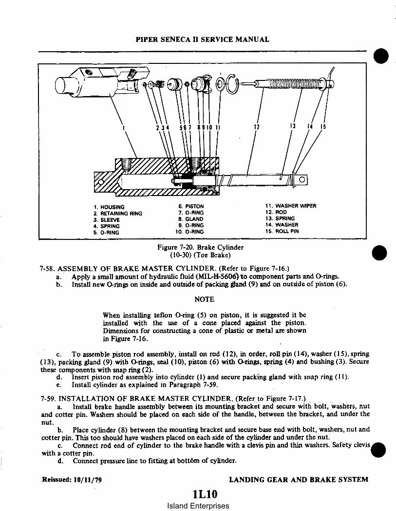
PIPER SENECA II SERVICE MANUAL
1 234 567 910 11 12 13
1. HOUSING2. RETAINING RING3. SLEEVE4. SPRING5. O-RING
6. PISTON7. O-RING8. GLAND9. O-RING
10. O-RING
11. WASHER WIPER12. ROD13. SPRING14. WASHER15. ROLL PIN
Figure 7-20. Brake Cylinder(10-30) (Toe Brake)
7-58. ASSEMBLY OF BRAKE MASTER CYLINDER. (Refer to Figure 7-16.)a. Apply a small amount of hydraulic fluid (MIL-H-5606) to component parts and O-rings.b. Install new O-rings on inside and outside of packing gland (9) and on outside of piston (6).
NOTE
When installing teflon O-ring (5) on piston, it is suggested it beinstalled with the use of a cone placed against the piston.Dimensions for constructing a cone of plastic or metal are shownin Figure 7-16.
c. To assemble piston rod assembly, install on rod (12), in order, roll pin (14), washer (15), spring(13), packing gland (9) with O-rings, seal (10), piston (6) with O-rings, spring (4) and bushing (3). Securethese components with snap ring (2).
d. Insert piston rod assembly into cylinder (1) and secure packing gland with snap ring (11).e. Install cylinder as explained in Paragraph 7-59.
7-59. INSTALLATION OF BRAKE MASTER CYLINDER. (Refer to Figure 7-17.)a. Install brake handle assembly between its mounting bracket and secure with bolt, washers, nut
and cotter pin. Washers should be placed on each side of the handle, between the bracket, and under thenut.
b. Place cylinder (8) between the mounting bracket and secure base end with bolt, washers, nut andcotter pin. This too should have washers placed on each side of the cylinder and under the nut.
c. Connect rod end of cylinder to the brake handle with a clevis pin and thin washers. Safety cleviswith a cotter pin.
d. Connect pressure line to fitting at bott6m of cylinder.
Reissued: 10/11/79 LANDING GEAR AND BRAKE SYSTEM
Island Enterprises

e. Connect inlet supply line (13) to fitting at top of cylinder and secure with spring clamp.f. Bleed brake system as explained in Paragraph 7-66 or 7-67.
7-60. BRAKE CYLINDER (TOE BRAKE).
7-61. REMOVAL OF BRAKE CYLINDER. (Refer to Figure 7-17.)a. Disconnect upper and lower lines from the cylinder (14) being removed. Cap lines to prevent
fluid leakage or drain fluid from brake reservoir and master cylinder.b. Remove cotter pins and clevis pins (4 and 16) securing brake cylinder in position; then remove
brake cylinder.
7-62. DISASSEMBLY OF BRAKE CYLINDER.a. Gar-Kenyon cylinder number 17000. (Refer to Figure 7-18.)
1. Remove the cylinder from its mounting bracket as per Paragraph 7-61.2. To disassemble the cylinder, first remove the piston rod assembly by unscrewing the fitting(8)
from the cylinder.3. The piston rod assembly may be disassembled by first removing the retaining ring (2) securing
the sleeve (3) and then removing the spring (4), piston (6), seal (7), fitting (8), and, if desired, the large returnspring (11).
4. Remove the O-rings from the piston and fitting.b. Cleveland cylinder number 10-27. (Refer to Figure 7-19.)
1. Remove the cylinder from its mounting bracket per Paragraph 7-61.2. To disassemble the cylinder, first remove the piston rod assembly by removing the retaining
ring (10) from the annular slot in the cylinder housing (1). Draw the piston rod assembly from the cylinder.3. The piston rod assembly may be disassembled by first removing the roll pin (15), spring (2), and
then'the piston assembly (3), seal (5) and packing gland (7) and, if desired, the large return spring (11).4. Remove the O-rings from the piston and packing gland.
c. Cleveland cylinder number 10-30. (Refer to Figure 7-20.)1. Remove the cylinder from its mounting bracket per Paragraph 7-61.2. To disassemble the cylinder, first remove the piston rod assembly by removing the retaining
ring from the annular slot in the cylinder housing (1). Draw the piston rod assembly from the cylinder.3. The piston rod assembly may be disassembled by first removing the retaining ring (2), sleeve
(3), spring (4), and then the piston assembly, O-ring (5), and gland (8), and if desired, the return spring (13).4. Remove the O-rings from the piston and packing gland.
7-63. CLEANING, INSPECTION AND REPAIR OF BRAKE CYLINDER.a. Clean cylinder components with a suitable solvent and dry thoroughly.b. Inspect interior walls of cylinder for scratches, burrs, corrosion, etc.c. Inspect general condition of fitting threads.d. Inspect piston for scratches, burrs, corrosion, etc.e. Repairs to the cylinder are limited to polishing out small scratches and burrs, and replacing seal
and O-rings.
7-64. ASSEMBLY OF BRAKE CYLINDER. (Refer to Figures 7-18 and 7-19.)
NOTE
Rub a small amount of hydraulic fluid (MIL-H-5606) on allO-rings and component parts for ease of handling duringreassembly and to prevent damage.
Reissued: 10/11/79 LANDING GEAR AND BRAKE SYSTEM1 L 11
PIPER SENECA II SERVICE MANUAL
Island Enterprises

PIPER SENECA II SERVICE MANUAL
a. Gar-Kenyon cylinder number 17000. (Refer to Figure 7-18.)1. Install new O-rings on the inside and outside of the fitting (8) and on the outside of the
piston (6).2. To assemble the piston rod assembly, install on the rod (12), in order, the roll pin (14),
return spring retainer washer (13), return spring (11), fitting (8) with O-rings, seal (7), piston (6) with0-rings, spring (4) and sleeve (3). Secure these pieces with the retaining ring (2) on the end of the rod.
3. Insert the piston rod assembly in the cylinder (1) and secure fitting (8).4. Install the cylinder per Paragraph 7-65.
b. Cleveland cylinder number 10-27. (Refer to Figure 7-19.)1. Install new O-rings on the inside and on the outside of the piston (3).2. To assemble the piston rod assembly, install on the rod (12), in order, the roll pin (14),
washer (13), spring (11), washer (9), packing gland (7) with O-rings, seal (5), piston assembly (3) withO-rings, spring (2), and roll pin (15).
3. Insert the piston rod assembly in the cylinder (1) and secure with the retaining ring (10).4. Install the cylinder per Paragraph 7-65.
c. Cleveland cylinder number 10-30 (Refer to Figure 7-20.)1. Install new O-rings on the inside and outside of the packing gland (7) and on the outside of the
piston (3).2. To assemble the piston rod assembly, install on the rod (12), in order, the roll pin (14), washer
(13), spring (11), washer (9), packing gland (7) with O-rings, seal (5), piston assembly (3) with O-ring, spring(2), and roll pin (15).
3. Insert the piston rod assembly in the cylinder (1) and secure with the retaining ring (10).4. Install the cylinder per Paragraph 7-65.
Reissued: 10/11/79 LANDING GEAR AND BRAKE SYSTEM1L12
Island Enterprises

PIPER SENECA II SERVICE MANUAL
7-65. INSTALLATION OF BRAKE CYLINDER. (Refer to Figure 7-17.)a. Position brake cylinder (14) at its mounting points and secure in position with clevis pin (4 and 16).
Safety clevis pins with cotter pins.b. Connect brake lines to cylinder fittings. Bleed brakes as explained in Paragraph 7-66 or 7-67.
7-66. BRAKE BLEEDING PROCEDURE (GRAVITY).a. On both main landing gear wheel brake assemblies, attach a clear plastic hose to the brake
bleeders and extend into container partially filled with hydraulic fluid, MIL-H-5606. The ends of this hoseshould be submerged in the fluid. Open both bleeders approximately one and one-half to two turns.
b. Fill the brake reservoir on the fire wall with hydraulic fluid, MIL-H-5606.c. Disconnect the toe brake cylinders from the pedal connection by removing clevis pin, washer and
cotter pin.d. Invert toe brake cylinder to aid in releasing trapped air in the top of the cylinder.e. Check toe brake pedals in the cockpit to insure pedals are pulled full aft.f. Pull the hand brake handle, pumping the master cylinder very slowly approximately 25 times
until fluid is observed passing through the clear plastic hoses at the wheel cylinder.
NOTE
Fluid level in the reservoir must be maintained to prevent air fromentering in the line.
g. Tighten both wheel bleeders.h. Pull hand brake until a firm handle is maintained.
7-67. BRAKE BLEEDING PROCEDURE (PRESSURE).a. Place a small clear plastic hose on the vent tube of the brake reservoir and place a second small
clear plastic hose on the bleeder fitting on one main landing gear. Place the open ends of these tubes in asuitable container to collect the fluid overflow. Open the bleeder fitting one or two turns.
b. On the other main gear, slide the hose of the pressure unit over the bleeder fitting then open thefitting one or two turns and pressure fill the brake system with MIL-H-5606 fluid.
c. With fluid continually flowing through the brake system, SLOWLY and together actuate thehand brake and the toe brake pedal of the side being bled, several times, to purge the cylinders of air. Ondual brake installations, both right and left pedals must be actuated.
NOTE
By watching the fluid pass through the plastic hose at the fluidreservoir and the bleeder fitting on the gear being bled, it can bedetermined whether any air is left in the system. If air bubbles areevident, filling of the system shall be continued until all the air isout of the system and a steady flow of fluid is obtained. Shouldthe brake handle remain spongy, it may be necessary to disconnectthe bottom of the toe brake cylinders (next to the pedal) androtating the cylinder horizontally or even above horizontal and byuse of the hand brake alone, purge the air from the system.
d. Close the open bleeder fitting on the gear being bled. Close the open bleeder fitting to which thepressure hose is attached; then close the pressure unit and remove the hoses from the bleeder fittings. Checkthe brakes for proper pedal pressure. Replace the caps over the bleeder fittings.
Reissued: 10/11/79 LANDING GEAR AND BRAKE SYSTEM
1L13
Island Enterprises

Figure 7-21. Brake Reservoir Figure 7-22. Bleeding Brake
NOTE
It may be necessary to remove any trapped air in the top of thewheel brake unit by applying pressure to the system with the brakehand lever and slowly opening the bleeder and release the handlever.
e. Repeat this procedure. if necessary. on the other gear.f. Drain excess fluid from the reservoir to fluid level line with a syringe.g. Make sure all lines are secure and all fitting are tight. It should be noted that on older master
cylinders where the hole for the bleeder seat is tapered, the bleeder seat/fitting should be torqued at 75 to90 inch-pounds. On the newer cylinders where there is a straight hole torque the seat till the O-ring seals thehole.
7-68. BRAKE SYSTEM LEAK CHECK.a. Pull for a good firm hand brake and lock parking brake mechanism. Allow system to stand for
approximately 10 minutes: then by gripping the parking brake handle. it should not be able to be pulled aftfurther than the original set. Should the handle be able to be pulled towards the panel and feel spongy, aleak is present at some point in the system. This leak may appear at any one of the connections throughoutthe system or internally in the master brake cylinder or wheel brake assemblies.
Added: 8/10/80 LANDING GEAR AND BRAKE SYSTEM
PIPER SENECA II SERVICE MANUAL
1L14
Island Enterprises

PIPER SENECA H SERVICE MANUAL
TABLE VII-IV. TROUBLESHOOTING CHART (LANDING GEAR)
Trouble Cause Remedy
Green gear down lightsdim though positionlight switch is off,and gear is down andlocked.
Green gear down lightsfail to go out withgear in transit orretracted.
Green gear down lightswill go out and notdim when position lightswitch is turned onthough gear is downand locked.
Gear warning lightand horn fail tooperate when throttleis near closed andlanding gear is re-tracted.
Failed instrument panellight control switch.(Lights grounding throughdimming resistor insteadof through position lightswitch.)
Gear down limit switchfailed.
Green light grounddimming resistor open.
Landing gear controlcircuit breaker open.
Replace switch.
Replace switch.
Replace resistor.
Reset circuit breakerand determine cause foropen circuit breaker.
Micro switch atthrottle out of ad-justment.
Micro switch failed.
Warning horn and lightcircuit wire broken.
Adjust micro switch.
Replace switch.
Check wiring.
Green downlock lightsoperate normally withposition lights off butdo not operate at allwith position lights on.
Green lights dimmingresistor open.
Replace resistor.
Reissued: 10/11/79 LANDING GEAR AND BRAKE SYSTEM
1L15
Island Enterprises

PIPER SENECA II SERVICE MANUAL
TABLE VII-IV. TROUBLESHOOTING CHART (LANDING GEAR) (cont)
Trouble Cause Remedy
Red gear unsafe lightremains on with gearretracted and throttlesadvanced.
Landing gear doors failto close completely.
One or more of thelanding gears not fullyretracted. One or moregear up switches out ofadjustment.
Landing gear not re-tracting completely.
Check gears for fullretraction. Adjustup switch (es) asnecessary.
Check adjustment oflanding gear.
Door retraction rodsout of adjustment
Check adjustment doorretraction rods.
Nose landing gearshimmies during fasttaxi, take-off, orlanding.
Internal wear incentering springs.
Replace shimmydampener.
Centering springs orbracket loose at mounting.
Tire out of balance.
Worn or loose wheelbearings.
Worn torque link boltsand/or bushings.
Replace necessary parts.
Check balance and re-place tire if necessary.
Replace and/or adjustwheel bearings.
Replace bolts and/orbushings.
Excessive or unevenwear on nose tire.
Incorrect operating pressure. Inflate tire to correctpressure.
Wear resulting from shimmy. Refer to proceedings forcorrection.
Nose gear fails tosteer properly.
Oleo cylinder binding instrut housing.
Lubricate strut housing(Refer to LubricationChart).
Cylinder and/or struthousing bushings damaged.
Reissued: 10/11/79 LANDING GEAR AND BRAKE SYSTEM
1I16Island Enterprises

PIPER SENECA II SERVICE MANUAL
TABLE VII-IV. TROUBLESHOOTING CHART (LANDING GEAR) (cont)
Trouble Cause Remedy
Nose gear fails tosteer properly. (cont)
One brake dragging. Determine cause andcorrect.
Steering arm rollersheared at top of strut.
Steering bellcrank looseon attachment plate.
Steering bellcrank bearingand/or bolt worn.
Centering springs gallingor binding.
Replace defective roller.
Readjust and tighten.
Replace bearing and/orbolt.
Replace.
Nose gear fails tostraighten when landinggear extends.
Steering arm rollersheared at top of strut.
Replace defective roller.
Incorrect rigging ofnose gear steering.
Check nose gear steeringadjustment.
Nose gear fails tostraighten when landinggear retracts.
Main landing gearshimmies during fasttaxi, take-off, or landing.
Centering guide rollersheared.
Damaged guide.
Tire out of balance.
Worn or loose wheelbearings.
Replace roller.
Replace guide.
Check balance and re-place tire if necessary.
Replace and/or adjustwheel bearings.
Worn torque link boltsand/or bushings.
Replace bolts and/orbushings.
Excessive or unevenwear on main tires.
Incorrect operatingpressure.
Inflate tire to correctpressure.
Wheel out of alignment(toe in or out).
Lower side brace linkout of adjustment,allowing gear to slantin or out.
Check wheel alignment.
Check gear adjustment.
LANDING GEAR AND BRAKE SYSTEMReissued: 10/11/79
1L17
Island Enterprises
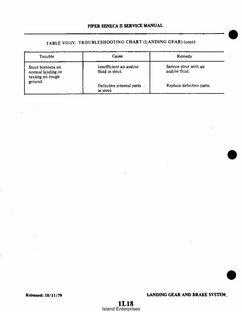
Strut bottoms onnormal landing ortaxiing on roughground.
PIPER SENECA II SERVICE MANUAL
TABLE VII-IV. TROUBLESHOOTING CHART (LANDING GEAR) (cont)
Trouble Cause Remedy
Insufficient air and/orfluid in strut.
Defective internal partsin strut.
Service strut with airand/or fluid.
Replace defective parts.
Reissued: 10/11/79 LANDING GEAR AND BRAKE SYSTEM.
1L18Island Enterprises

1L19 THRU 1L24INTENTIONALLY LEFT BLANK
Island Enterprises

SENECA II
SERVICE MANUALCARD 2 OF 3
PA-34-200T SENECA II
PIPER AIRCRAFT CORPORATION
(PART NUMBER 761 590)2AI
Island Enterprises
PIPER SENECA II SERVICE MANUAL
AEROFICHE EXPLANATION AND REVISION STATUS
Service manual information incorporated in this set of Aerofiche cards is arranged in accordance with thegeneral specifications of Aerofiche adopted by the General Aviation Manufacturer's Association. Informationcompiled in this Aerofiche service manual is kept current by revisions distributed periodically. These revisionssupersede all previous revisions, are complete Aerofiche card replacements, and supersede Aerofiche cards ofthe same number in the set.
Identification of revised material:Revised text and illustrations are indicated by a black vertical line along the left-hand margin of the
frame, opposite revised or added material. Revision lines indicate only current revisions with changes andadditions to existing text and illustrations. Changes in capitalization, spelling, punctuation, indexing,physical location of the material, or complete page additions are not identified by revision lines.
Revisions to Service Manual 761 590 issued October 11, 1979 are as follows:
Effectivity Publication Date Aerofiche Card Effectivity
ORG791011 October 11, 1979 1, 2 and 3PR800810 August 10, 1980 1, 2 and 3PR810316 March 16, 1981 1, 2 and 3PR821112 November 12, 1982 1, 2 and 3PR831208 December 8. 1983 1, 2 and 3IR860730 July 30, 1986 1IR860920 September 20, 1986 1IR870506* June 12, 1987 1
This publication contains material revised as of December 8, 1983(with three interim revisions effective July 30, 1986, September 20,1986, and May 6, 1987).
* INTERIM CHANGERevisions appear in Table III-I of card 1. There are no otherchanges in this service manual. Please discard your currentcard I and replace it with this revised one. DO NOTDISCARD CARDS 2 or 3.
The date on Aerofiche cards must not be earlier than the date noted for the respective card effectivity. Consultthe latest card in this series for current Aerofiche card effectivity.
2A2
Island Enterprises

TABLE OF CONTENTS
AEROFICHE CARD NO. 1 GRID NO.
I INTRODUCTION ................................... 1A13II HANDLING AND SERVICING ...................... 1A16III INSPECTION ....................................... 1 C23IV STRUCTURES ...................................... 1 D12V SURFACE CONTROLS ............................. 1 F21VI HYDRAULIC SYSTEM .............................. 113VII LANDING GEAR AND BRAKE SYSTEM ............ 1J5
AEROFICHE CARD NO. 2
VIII POWERPLANT ..................................... 2A9IX FUEL SYSTEM .................................... 2D4X INSTRUMENTS .................................... 2E8Xl ELECTRICAL SYSTEM ............................. 2F16XII ELECTRONICS ..................................... 2120XIII HEATING AND VENTILATING SYSTEM ............ 2J6
AEROFICHE CARD NO. 3
XIV ACCESSORIES AND UTILITIES .................... 3A6
2A3.
Island Enterprises

PIPER SENECA II SERVICE MANUAL
LIST OF ILLUSTRATIONS
FigureAeroficheGrid No.
8-1.8-2.8-3.8-4.8-5.8-6.8-7.8-8.8-8a.8-9.8-10.8-11.8-12.8-13.8-14.8-15.8-16.8-17.8-18.8-19.8-20.8-21.8-22.8-23.8-24.8-25.8-26.8-27.8-28.8-29.8-30.8-31.8-32.8-33.8-34.8-35.8-36.
Engine Cowling Installation ...................... .............Cowl Flap Installation .......................................Propeller Installation .......................................Typical Nicks and Removal Method ...............................Propeller Governor Installation .................................Engine Installation .........................................Schematic Diagram of Turbocharger System ..........................Induction System Installation ............................ ....Magneto Assembly .........................................Contact Spring Inspection ....................................Contact Points ..........................................Impulse Coupling .........................................Flyweight Clearance of Impulse Coupling ...........................Rotor Holding Tool Installed ................................... .Timing Kit Installed .......................................Cast-In Timing Marks .......................................Fabricated Pointer .........................................Engine Timing Marks ......................... .............Removing Spring From Lead Assembly .............................Assembly Tool ...........................................Assembly Tool Application ....................................Measuring Lead Assembly Length ................................Ferrnle Seating Tool .......................................Measuring Wire From Top of Ferrule ..............................Needle . ................... ..........................Installing Grommet Over Lead Assemblies ...........................Lead Assembly Installed in Grommet .............................Wire Doubled Over For Installation of Eyelet .........................Ignition Schematic .................... ............. . .....Removing Frozen Spark Plug ...................................Lubrication System Maintenance Points ........................Schematic Diagram of Fuel Injection System ........................Fuel Injector Nozzle Assembly ...................... ... .....Engine Controls ...............................Idle Speed and Mixture Adjustment Points ... ...................Sectional View of Altitude Compensating Fuel Pump Assembly .............Exhaust Bypass Valve Screw ..................................
2A142A142A162A172A192A232B52B62B92B112B122B122B132B142B142B152B152B172B192B202B202B202B222B222B222B222B232B232B242C32C62C82C92C102C122C162C18
I Revised: 8/10/80
2A4Island Enterprises

PIPER SENECA II SERVICE MANUAL
LIST OF ILLUSTRATIONS (cont.)
Figure AeroficheGrid No.
9-1. Fuel System Schematic ..................... ......... ....................... 2D79-2. Fuel Cell Installation ....................................................... 2D129-3. Fuel Gauges ............................................................... 2D209-4. Fuel Filter ................................................................ 2D209-5. Fuel Selector Valve ........................................................ 2D239-6. Slider Resistor Terminal .................................................... 2EI9-6a. Resistor Set-Up/Test for Fuel Quantity Gauge ................................ 2E39-6b. Maximum Deviation of Fuel Quantity Gauge Needle ........................... 2E410-1. Gyro Pressure System ...................................................... 2E1410-2. Pitot-Static System, Serial Nos. 34-7570001 to 34-7670136 incl .................. 2E1610-2a. Pitot-Static System, Serial Nos. 34-7670137 and up ............................ 2E1710-3. Instrument Panel .......................................................... 2E1811-1. Switch Panel - For Models Without Primer System ............................ 2F21
11-1a. Switch Panel - For Models With Primer System ............................... 2F2211-2. Removal of Slip Ring End Bearing .......................................... 2G I11-3. Removal of Rectifer ....................................................... 2G I11-4. Testing Rotor for Ground .................................................. 2G411-5. Testing Rotor for Shorts ................................................... 2G411-6. Installation of Rectifier ..................................................... 2G511-7. Terminal Assembly ........................................................ 2G611-8. Slip Ring End Bearing Assembly ............................................ 2G711-9. Testing Alternator ......................................................... 2G711-10. Regulator Diagram ........................................................ 2G1011-11. Testing Regulator ................................................... 2G1211-12. Adjusting Regulator ........................................ ............... 2G1311-13. Application of Overvoltage Control .......................................... 2G 1511-14. Testing Overvoltage Control ................................................ 2G 1511-15. Exploded View of Starting Motor ...................... ........................ 2G 1711-16. Turning Motor Commutator ................................................ 2G 1811-17. Testing Motor Armature for Shorts .......................................... 2G1811-18. Testing Motor Fields for Grounds ................. ......................... 2G1911-19. No-Load Test Hookup ..................... ................................ 2G1911-20. Stall Torque Hookup ...................................................... 2G2011-21. Landing Light Adjustment .................................................. 2HI11-22. Adjusting Lift Detector Micro Switch ........................................ 2H2
NOTE
Electrical Schematics for Section XI. see 2F18
12-1. Two Year. Magnesium Battery Connections ................................... 212212-2. Garrett ELT Schematic .................................................. 212312-3. Communications Components ELT Schematic ................................. 2J12-4. Emergency Locator Transmitter Schematic (Narco) ............................ 2JI
Revised: 11/12/822A5
Island Enterprises

PIPER SENECA II SERVICE MANUAL
LIST OF ILLUSTRATIONS (cont.)
Figure AeroficheGrid No.
12-5. ELT Portable Folding Antenna (Narco) ......................... ............ 2J312-6. ELT Using Fixed Aircraft Antenna (Narco) .............................. ... .. 2J313-1. Cabin Heater, Defroster and Fresh Air Installation ............................ 2J913-2. Heater and Combustion Air Blower Assembly (30,000 BTU) .................... 2J 1213-3. Heater and Combustion Air Blower Assembly (45,000 BTU) .................... 2J 1313-4. Diagramatic Cutaway of Heater to Show Whirling Flame Action ................ 2J 1413-5. Fuel Regulator and Shutoff Valve .................... ....................... 2J 1613-6. Top View - Duct Switch .................................................... 2J1613-7. Wiring Diagram ........................................................... 2J2013-8. Primary Power Circuit ..................................................... 2J2113-9. Starting Power Circuit ..................................................... 2J2213-10. Spark Plug Fixture ................................................... ..... 2J2413-11. Wiring - Test Setup ........................................................ 2J2413-12. Spark Plug Gap Adjustment ................................................ 2KI13-13. Ignition Unit Assembly ..................................................... 2K513-14. Test Setup for Fuel Regulator and Shutoff Valve .............................. 2K813-15. Heater Fuel Pump ................................................ ........ 2K913-16. Suggested Design for Seal Plates, Plugs, and Caps for
Combustion Tube Leakage Test ........................................... 2K1713-17. Test Setup for Combustion Air Pressure Switch ............................... 2K1713-18. Exploded View of Heater Assembly (30,000 BTU) ............................. 2K2113-19. Exploded View of Heater Assembly (45,000 BTU) ............................. 2K2213-20. Exploded View - Combustion Air Blower and Motor Assembly
(30,000 BTU) ........................................................... 2L313-21. Exploded View - Combustion Air Blower and Motor Assembly
(45,000 BTU) ......................................... ............... 2L413-22. Suggested Setup of Heater Operation Test ........................... ......... 2L613-23. Wiring Connections for Heater Operation Test ................................ 2L613-24. Spark Plug Gap Adjustment Tool ........................................... 2L9
Revised: 8/10/80 22A6
Island Enterprises

PIPER SENECA II SERVICE MANUAL
LIST OF TABLES
Table AeroficheGrid No.
Vlll-l.VIII-I.
VIII-III.VIII-IV.VIII-V.VIII-VI.VIII-VII.
IX-I.IX-II.IX-II.IX-IV.X-l.X-II.X-III.X-IV.X-V.X-VI.X-VII.X-VIII.X-IX.X-X.X-XI.X-XII.X-XIII.X-XIV.X-XV.X-XVI.X-XVII.
XI-I.XI-II.XI-III.XI-IV.XI-V.XI-VI.XI-VII.XI-VIII.XI-IX.
XIII-l.XIII-II.XIV-I.XIV-II.XIV-III.
Propeller Specifications ..................................................Propeller Chamber Pressure Requirements..................................Engine Data ............................................................Fuel Flow vs. Engine Speed ..............................................Metered Fuel Assembly Calibration ........................................Limits - Fuel Flow vs. Brake H.P ..........................................Troubleshooting Chart (Engine) ...........................................Fuel Quantity Sender Gauge Tolerances ....................................Fuel Gauge Reading Tolerances ...........................................Gauge Readings/ Resistance with Fuel in Tanks .............................Troubleshooting Chart (Fuel System) ......... .............................Gyro Pressure System ...................................................Directional Gyro Indicator ...............................................Gyro Horizon Indicator ......... .........................................Rate of Climb Indicator .................................................Altimeter ...............................................................Airspeed Tubes and Indicator .............................................Magnetic Compass ......................................................Manifold Pressure Indicator ..............................................Tachometer .............................................................Engine Oil Pressure Gauge ...............................................Turn and Bank Indicator ......... ......... ..............................Fuel Quantity Indicators .................................................Oil Temperature Indicators ...............................................Exhaust Gas Temperature Gauge ..........................................Cylinder Head Temperature Gauge ........................................Fuel Flow Gauge........................................................Instrument Markings ....................................................Index to Electrical Schematics ............................................Alternator Specifications .................................................Starting Motor Specifications .............................................Hydrometer Reading and Battery Charge Percent ............................Troubleshooting Chart (Electrical System) ..................................Lamp Replacement Guide ................................................Electrical Wire Coding ...................................................Electrical Symbols .......................................................Electrical System Component Loads .......................................Inspection ..............................................................Troubleshooting Chart (Janitrol Heater) ....................................Required Materials for Repair of Propeller Deicer ...........................Mixing of Materials .....................................................Electrical Resistance .....................................................
2A182A182A212C172C182C192C202D202E42E52E62E122E202E212E222E232FI2F22F52F62F72F82F92F102F132F142F142F152F182G82G212G232H82H202H212H222H232K52L103B33B53B7
Revised: 3/16/812A7
Island Enterprises

PIPER SENECA II SERVICE MANUAL
Table
XIV-IV.XIV-V.XIV-VI.XIV-VII.XIV-VIII.XIV-IX.XIV-X.XIV-XI.XIV-XII.XIV-XIII.
LIST OF TABLES (cont.)
AeroficheGrid No.
Troubleshooting Chart (Propeller Deicer System) ............................ 3B9Operating Pressures ...................................................... 3B21Materials and Supplies for Cold Repair .......................... ......... . 3B24Troubleshooting Chart (Pneumatic Deicer System) ........................... 3C7Oxygen System Components Limits ........................................ 3C13Troubleshooting Chart (Oxygen System) ....................... ............ 3C21Temperature Pressure Chart ..................................... ......... 3D1Aluminum Tubing Torque ................................................ 3D4Blower System Wire Color Codes ......................................... 3D24Troubleshooting Chart (Air Conditioner) ............................. ...... 3E2
I Revised: 8/10/802A8
Island Enterprises

SECTION VIII
POWER PLANTAerofiche
Paragraph Grid No.
8-1. Introduction ........................................... . 2A I18-2. Description ........ .... ..................... ..... .. 2A I I8-2a. Standard Practices - Engines ................... .... .... . ... 2A II8-3. Troubleshooting . .... ... .................. 2A 128-4. Engine Cowling .......................................... 2A 12
8-5. Removal of Engine Cowling . ... ............ . ....... . 2A128-6. Cleaning, Inspection and Repair of Engine Cowling ................ 2A 128-7. Installation of Engine Cowling ............. ........ .. . . 2A 12
8-8. Engine Cowl Flaps .......................................... . 2A 138-9. Operation and Adjustment of Cowl Flaps ..................... 2A13
8-10. Propeller ................... ........ .................. . 2A158-11. Removal of Propeller ................................. 2A 158-12. Cleaning, Inspection and Repair of Propeller .................... 2A 158-13. .Installation of Propeller ................................ 2A178-14. Checking Propeller Blade Track ........................... 2A 19
8-15. Propeller Governor ........................................ 2A198-16. Removal of Propeller Governor ........................... 2A198-17. Installation of Propeller Governor .................... ..... 2A 198-18. Rigging and Adjustment of Propeller Governor ...... .. 2A19
8-19. Engine ................ ... ........................... 2A228-20. Removal of Engine .................................. 2A228-21. Installation of Engine ................................. 2BI
8-22. Engine Shock Mounts ....................................... 2BI8-23. Replacement of Engine Shock Mounts ....................... 2B1
8-24. Turbocharger ...... .... .............................. 2B28-24a. Turbocharger Nomenclature ............................. 2B28-25. Removal of Turbocharger ............ 2B48-26. Installation of Turbocharger ......................... 2B48-27. Adjustment of Turbocharger ....................... 2B6
8-28. Induction System Air Filter ............................. . 2B68-29. Removal of Air Filter ......................... ........ 2B68-30. Cleaning Induction Air Filter ........................ 2B68-31. Installation of Air Filter .......................... 2B7
8-32. Alternate Air Door .............................. 2B78-33. Ignition System .................................... ..... 2B78-34. Magnetos ................... ....................... 2B7
8-35. Inspection of Magnetos ................................ 2B88-36. Removal of Magneto ................................. 2B108-37. Magneto Timing Procedure (Internal Timing) ................ . 2BIO8-38. Magneto Installation and Timing Procedure
(Magneto to Engine) ............................ ... 2B14
Revised: 8/10/802A9
Island Enterprises

Paragraph
8-39. Harness Assembly ........................................................8-40. Inspection of Harness ............................................8-41. Removal of Harness ..............................................8-42. Maintenance of Harness ..........................................8-43. Installation of Harness ............................................
8-44. Spark Plugs ..............................................................8-45. Removal of Spark Plugs ...........................................8-46. Inspection and Cleaning of Spark Plug ..............................8-47. Installation of Spark Plugs.........................................
8-48. Lubrication System ........................................................8-49. Description ......................................................8-50. Oil Filter Replacement ............................................
8-51. Engine Fuel System ........................................................8-52. Description...............................................................
8-53. Fuel Injection System Maintenance .................................8-54. Fuel Injector Nozzle Assembly ...................................... .......
8-55. Removal of Fuel Injector Nozzles ...................................8-59. Cleaning and Inspection of Fuel Injector Nozzles .....................8-57. Installation of Fuel Injector Nozzles.................................
8-58. Engine and Propeller Controls ..............................................8-59. Rigging Throttle. Mixture and Governor Controls ....................8-60. Engine Setup Procedures ............................ ............
AeroficheGrid No.
2B172B172B182B182C22C22C22C32C52C52C52C62C72C72C72C92C92C92C92CII2CII2C12
Revised: 8/10/802A10
Island Enterprises

PIPER SENECA II SERVICE MANUAL
SECTION VIII
POWER PLANTTURBOCHARGED
8-1. INTRODUCTION. The purpose of this section is to provide instructions for the removal. minor repair.service and installation of the engine and components. For instructions on major repairs and overhauls.consult the appropriate publication of the component manufacturer.
8-2. DESCRIPTION. The PA-34-200T is powered by Teledyne Continental turbocharged. overhead valve.air cooled. horizontally opposed. direct drive, wet sump engines rated 200 hp at sea level.
Each engine is enclosed by cowling consisting of two side panels. an upper and lower section and a nosesection. The cowl flap is an integral part of the lower cowl and is operated manually through a push-pull cablearrangement from the cockpit.
Propellers are Hartzell full feathering. constant speed each controlled by a governor mounted on theengine supplying oil through the propeller shaft at various pressures. Oil pressure from the governor moves theblades into low pitch (high RPM). The centrifugal twisting moment of the blade also tends to move the bladesinto low pitch. Opposing these two forces is a force produced by a compressed air charge between the cylinderhead and the piston which tends to move the blades into high pitch in the absence of governor oil pressure.Thus. feathering is accomplished by compressed air.
Refer to Section IX for description of fuel system and primer operation.
8-2a. STANDARD PRACTICES - ENGINE. The following suggestions should be applied wherever theyare needed when working on the power plant.
a. To insure proper reinstallation and, or assembly, tag and mark all parts. clips, and brackets as totheir location prior to their removal and or disassembly.
b. During removal of various tubes or engine parts. inspect them for indications of scoring. burning orother undesirable conditions. To facilitate reinstallation. observe the location of each part during removal.Tag any unserviceable part and or units for investigation and possible repair.
c. Extreme care must be taken to prevent foreign matter from entering the engine. such as lockwire.washers. nuts. dirt. dust. etc. This precaution applies whenever work is done on the engine. either on or off theaircraft. Suitable protective caps. plugs. and covers must be used to protect all openings as they are exposed.
NOTE
Dust caps used to protect open lines must always be installed OVERthe tube ends and NOT IN the tube ends. Flow through the lines maybe blocked off if lines are inadvertently installed with dust caps in thetube ends.
d. Should any items be dropped into the engine. the assembly process must stop and the item removed.even though this may require considerable time and labor. Insure that all parts are thoroughly clean beforeassembling.
c. Never reuse any lockwire. lockwashers. tablocks. tabwashers or cotter pins. All lockwire and cotterpins must fit snugly in holes drilled in studs and bolts for locking purposes. Cotter pins should be installed sothe head fits into the castellation of the nut. and unless otherwise specified. bend one end of the pin back overthe stud or bolt and the other end down flat against the nut. Use only corrosion resistant steel lockw ire and orcotter pins. Bushing plugs shall be lockwired to the assembly base or case. Do not lockwire the plug to thebushing.
f. All gaskets. packings and rubber parts must be replaced with new items of the same type atreassembly. Insure the new nonmetallic parts being installed show no sign of having deteriorated in storage.
Revised: 8/10/80 2APOWER PLANT2A11
Island Enterprises

PIPER SENECA II SERVICE MANUAL
g. When installing engine parts which require the use of a hammer to facilitate assembly or installa-tion. use only a plastic or rawhide hammer.
h. Whenever adhesive tape has been applied to any part. the tape and all residue must be removed andthoroughly cleaned with petroleum solvents prior to being subjected to high temperature during engine run.This would also apply to parts that have corrosion preventive compounds applied.
8-3. TROUBLESHOOTING. Troubles peculiar to the power plant are listed in Table VIII-ll. along withthe probable causes and suggested remedies. When troubleshooting engines, propellers or fuel system. alwaysground the magneto primary circuit before performing any checks.
Troubles peculiar to the turbocharger system are listed in Table VIII-IV at the end of this section. alongwith the probable causes and suggested remedies.
8-4. ENGINE COWLING.
8-5. REMOVAL OF ENGINE COWLING. (Refer to Figure 8-1.) The procedure for removing the enginecowling is the same for both engines.
a. Release the fasteners securing the two side access panels.b. Remove the fasteners securing the top cowl and then remove the top cowl.c. Disconnect the cowl flap control.d. Support the bottom cowl and remove the screws that attach the cowl to nose cowl. engine mount
and nacelle.e. The nose cowl may be removed by removing the attaching screws and separating the two cowl
halves.
8-6. CLEANING. INSPECTION AND REPAIR OF ENGINE COWLING.a. The cowl should be cleaned with a suitable solvent and then wiped with a clean cloth.b. Inspect the cowling for dents. cracks. loose rivets, damaged or missing fasteners and damaged
fiberglass areas.c. Repair all defects to prevent further damage. Fiberglass repair procedures may be accomplished
according to Fiberglass Repairs. Section IV.
8-7. INSTALLATION OF ENGINE COWLING. (Refer to Figure 8-1.)a. Position the two nose cowl halves on the front of the engine and secure with screw fasteners.b. Position the bottom cowl and secure with screw fasteners to the aft nacelle, engine mount and
nacelle.c. Connect the cowl flap control.d. Position the top cowl and secure with attaching screw fasteners.e. Secure the side cowls to the upper and lower cowling.
Revised: 8/10/80 2 POWER PLANT2A12
Island Enterprises

PIPER SENECA II SERVICE MANUAL
8-8. ENGINE COWL FLAPS. The cowl flaps are all metal flaps located on the rear of the bottom cowls.The flaps are manually operated through a push-pull control from the cockpit. The cowl flaps areconnected to the engine cowls with full length piano type hinges.
8-9. OPERATION AND ADJUSTMENT OF COWl. FLAPS. The cowl flaps operate through threepositions: closed. intermediate and open by control levers located on the console. When the control levers arein the up position. the flaps are closed. To operate the cowl flaps. depress the lock and move the lever down.releasing the lock after the initial down movement will allow the lock to stop the flap travel at the intermediateposition. For full open position. depress the lock and move the control down: release the lock after the initialmovement and continue to move the control down until the lock stops the travel of the control. To raise thecowl flaps reverse the procedure. The cowl flaps should be adjusted as follows:
a. Place the control in the up position.b. Ascertain that the control lock is engaged.c. Check the cowl flap to visually determine that the flap is flush with the bottom of the engine cowl.d. If the flap is not flush. disconnect the push-pull control from the arm on the inboard side of the flap.e. Loosen the jam nut on the clevis end and adjust the clevis to get a flush fit between the cowl flap and
engine cowl.f. Reconnect the control to the flap and operate the cowl flap through its full range a few times: then
place the control in the closed position and visually check the flap to determine if it is flush with the enginecowl.
g. If the cowl flap is not flush. repeat Steps d through f.h When the adjustment is completed. tighten the clevis jam nut and secure the push-pull control to
the cowl flap.
Revised: 8/10/80 2A13 POWER PLANT
Island Enterprises

PIPER SENECA I SERVICE MANUAL
174
1. NOSE COWL ASSEMBLY2. SCREW FASTENER3. OIL FILLER DOOR4. TOP PANEL5. SIDE PANEL6. ACCESS HOLE. ENGINE OIL DRAIN7. BOTTOM COWL
Figure 8-1. Engine Cowling Installation
1975
1. COWL FLAP ASSEMBLY2. CONTROL CABLE3. ROD ASSEMBLY4. TRUNNION ASSEMBLY
Figure 8-2. Cowl Flap Installation
POWER PLANTReissued: 10/11/79
2A14Island Enterprises

PIPER SENECA SERVICE MANUAL
8-10. PROPELLER.
8-11. REMOVAL OF PROPELLER. (Refer to Figure 8-3.)
WARNING
Before performing any work on the propellers, be sure themagneto and master switches are OFF and the mixture control isin the IDLE CUT-OFF position.
a. Remove the hardware that attaches the nose cowl and remove the cowl. The top and side panelsmay be removed for greater accessibility.
b. Remove the safety wire from the propeller mounting nuts and remove the nuts.c. Place a drip pan under the propeller to catch oil spillage and pull the propeller from the engine
shaft.d. If the spinner and spinner bulkhead are to be removed, remove the spinner nose cap attaching
screws and cap. Remove the spinner by removing the safety wire and check nut from the propeller at theforward end of the forward spinner bulkhead and the screws that secure the spinner to the aft bulkhead.The aft spinner bulkhead may be removed from the hub by removing the locknuts.
8-12. CLEANING, INSPECTION AND REPAIR OF PROPELLER.
NOTE
Do not attempt to disassemble the propeller any further thanstated in this manual. For internal repairs and replacement ofparts, the propeller should be referred to the Hartzell Factory orCertified Repair Station.
a. Check for oil and grease leaks.b. Clean the spinner, propeller hub, and blades with a non-corrosive solvent.c. Inspect the hub parts for cracks.d. Steel hub parts should not be permitted to rust. Use aluminum paint to touch up, if necessary, or
replate them during overhaul.e. Check all visible parts for wear and safety.f. Check blades to determine whether they turn freely on the hub pilot tube. This can be done by
rocking the counterweights or blades back and forth through the slight freedom allowed by the pitchchange mechanism. If they appear tight and are properly lubricated, the propeller should be disassembledby an authorized Service Center.
g. Inspect the blades for damage or cracks. Nicks in the leading edges of blades should be filed outand all edges rounded, as cracks sometimes start from such places. Use fine emery cloth for finishing. (Referto Figure 84 for propeller blade care.)
h. Check the condition of the propeller mounting nuts and studs.i. Each blade face should be sanded lightly with fine sandpaper and painted, when necessary, with a
flat black paint to retard glare. A light application of oil or wax may be applied to the surfaces to preventcorrosion.
j. Grease the blade hub through the zerk fittings. Remove one of the two fittings for each propellerblade; alternate the next time. Apply grease through the zerk fitting until fresh grease appears at the fittinghole of the removed fitting. Care should be taken to avoid blowing out the hub gaskets.
k. Check for air leaks by applying a soap solution around the air valve and stop adjustment nut.Internal leakage will show up as air flows through the piston rod.
Reissued: 10/11/79 POWER PLANT2A15
Island Enterprises

1979
PIPER SENECA II SERVICE MANUAL
1. CAP. SPINNER2. SPINNER3. SAFETY WIRE4. CHECK NUT, SPINNER5. BULKHEAD, AFT6. O-RING7. MOUNTING NUT. PROPELLER8. SCREW, SPINNER ATTACHMENT9. AIR VALVE
10. CAP, AIR VALVE11. LOW PITCH ADJUSTMENT12. PROPELLER - R DOME13. BOLT, BULKHEAD14. ENGINE FLANGE15. BLADE PROPELLER
16. COUNTERWEIGHT17. SCREW, CAP ATTACHMENT
Figure 8-3. Propeller Installation
Reissued: 10/11/79 POWER PLANT2A16
Island Enterprises

8-13. INSTALLATION OF PROPELLER. (Refer to Figure 8-3.)
WARNING
Before performing any work around the propellers be sure themagneto and master switches are OFF, and the mixture control is inthe IDLE CUT-OFF position.
a. Clean the propeller and engine flanges.b. Lubricate and install the O-ring in the propeller hub.c. Position the propeller as follows:
1. On Hartzell propellers only, position the propeller and mount it to the engine flange. Tightenthe mounting nuts a few threads at a time until all are tight. Torque the nuts 60 to 70 foot-pounds.
2. On McCauley propellers only, with the #1 cylinder at the top dead center position, mount thepropeller so that the dowel pin is between two blades and in the index hole closest to the upper crankcase splitline. Torque the nuts 60 to 70 foot-pounds.
d. Safety the propeller mounting nuts.e. Install spinner if removed and torque screws 35 to 40 inch-pounds.
CAUTION
To avoid spinner backplate cuff damage on McCauley props, thespinner must be installed prior to running engine.
EXAGGERATED VIEWOF \ EXAGGERATEDVIEWOF EXAGGERATED VIEW OFNICK IN LEADING EDGE / \ SURFACE CRACK NICK IN FACE OF BLADE.
CROSS-SECTION
BLEND DEEPEST PORTIONOF NICKS INTO LEADINGEDGE ALIGNMENT WITHSMOOTH CURVES
CROSS-SECTIONAFTER REPAIR
NOTE RECOMMENDED METHOD FOR REMOVING NICKS.CRACKS. AND SCRATCHES IS BY USING RIFFLEFILE AND/OR CROCUS CLOTH.
Figure 8-4. Typical Nicks and Removal Method
PIPER SENECA II SERVICE MANUAL
Reissued: 10/11/79 POWER PLANT2A17
Island Enterprises

PIPER SENECA II SERVICE MANUAL
TABLE VIII-I. PROPELLER SPECIFICATIONS
Blade AngleLow Pitch (High RPM)
High Pitch (Low RPM)
Propeller RPM SettingEngine Static High RPM
Propeller Torque LimitsDescriptionSpinner Bulkhead (Aft)Propeller MountingLocknut (Low Stop)Spinner Bulkhead Check NutSpinner Attachment Screws
Hartzell14.4° 0.2°(1)
79.3° 2.0° or80° to 81.5°(2j)
2575 RPM max.
Required Torque (Dry)20-22 foot-pounds60-70 foot-pounds15-20 foot-pounds15-20 foot-pounds35-40 inch-pounds
McCauley12.2° 0.2°
11.5° ± 0.2° (1,) up toS/N 7870402 (inclusive)12.0° ± 0.2°
S/N 34-7970001(Inclusive) and up ()81° to 83.5°
2575 RPM max.
20-22 foot-pounds60-70 foot-pounds
35-40 inch-pounds
(1) MEASURED AT 30 INCH STATION.(2) ON PROPELLER HUBS WITH SERIAL NUMBERS PRIOR TO AN343. EITHER SETTING IS APPROPRIATE. AT OWNERS DISCRETION.(3) ONLY THIS SETTING CAN BE USED ON PROPELLER HUBS WITH SERIAL NUMBERS AN343 AND SUBSEQUENT.(4) LEFT ENGINE ONLY.(5) RIGHT ENGINE ONLY.(6) BOTH ENGINES
TABLE VIII-II. HARTZELL PROPELLER CHAMBER PRESSURE REQUIREMENTSWITH TEMPERATURE FOR COUNTERWEIGHT TYPE PROPELLERS
Temp. °F PRESSURE (psi)
FOR PROPELLER HUBS:BHC-C2YF-2CKF andBHC-C2YF-2CLKF
62 257 +254+249+2
FOR PROPELLER HUBS:BHC-C2YF-2CKUF andBHC-C2YF-2CLKUF
22 21721429+2
70 to 10040 to 70
0 to 40-30 to 0
NOTE: Do not check pressure or charge with propeller in feather position.
Revised; 3/16/81 POWER PLANT2A18
Island Enterprises
PIPER SENECA II SERVICE MANUAL
8-14. CHECKING PROPELLER BLADE TRACK. Blade track is the ability of one blade tip to follow theother. while rotating. in almost the same plane. Excessive difference in blade track - more than .0625 inch -may be an indication of bent blades or improper propeller installation. Check blade track as follows:
a. With the engine shut down and blades vertical, secure to the aircraft a smooth board just under thetip of the lower blade. Move the tip fore and aft through its full "blade-shake"travel. making small marks witha pencil at each position. Then center the tip between these marks and scribe a line on the board for the fullwidth of the tip.
b. Carefully rotate propeller by hand to bring the opposite blade down. Center the tip and scribe apencil line as before and check that lines are not separated more than .125 inch.
c. Propellers having excess blade track should be removed and inspected for bent blades. or for partsof sheared O-ring. or foreign particles, which have lodged between hub and crankshaft mounting faces. Bentblades will require repair and overhaul of assembly.
8-15. PROPELLER GOVERNOR.
8-16. REMOVAL OF PROPELLER GOVERNOR. The propeller governor is mounted on the lower leftforward portion of the engine crankcase. Remove the governor as follows:
a. Remove the left side of the nose cowl to gain access to the governor.b. Disconnect the governor control cable end from the governor control arm.c. Remove the governor mounting nuts and withdraw the governor from the mounting pad. Cover
the mounting pad to prevent foreign material from entering the engine.
8-17. INSTALLATION OF PROPELLER GOVERNOR.a. Clean the mounting pad and the governor drive shaft thoroughly.b. Coat the mounting gasket with Dow Corning release agent or equivalent.c. Lubricate the drive shaft with engine oil and install the governor on the mounting pad.d. Tighten the mounting nuts evenly and tighten to a final torque of 140 to 160 inch-pounds.e. Connect the control cable to the control arm. Check to be sure the attachment bolt does not contact
the governor body while moving the control arm through its full travel. Clearance should be .03 minimum.
8-18. RIGGING AND ADJUSTMENT OF PROPELLER GOVERNOR. (Refer to Figure 8-5.)a. Start engine: park 90° to wind direction and warm in normal manner.b. To check high R P M. low pitch setting. move the propeller control all the way forward. At this posi-
tion the governor speed control arm ( I) should be against the high RPM fine adjusting screw. With the throttlefull forward, observe engine RPM. which should stabilize between'2500 and 2575 RPM. A takeoff must beconducted during which the engine RPM should reach 2575 RPM and remain steady.
c. If the engine RPM does not read 2575 RPM in flight, the high RPM setting must be adjusted asfollows:
1. Land. shut down the engine and open the cowl door(s).2. Adjust the governor by means of the fine adjustment screw for 2575 RPM. To do this. loosen
the high RPM fine adjustment screw locknut and turn the screw in a clockwise direction to decrease enginespeed or in a counterclockwise direction to increase engine speed.
NOTE
One revolution of the fine adjustment screw will increase or decreasethe engine speed approximately 20 RPM.
Revised: 8/10/80 POWER PLANT2A19
Island Enterprises

PIPER SENECA II SERVICE MANUAL
HARTZELL 614 WOODWARDI
REFER TO FIGURE 8-33FOR RIGGING
A287
Figure 8-5. Propeller Governor
3. Secure the cowl door(s) and repeat Step b to ascertain proper RPM setting.4. After setting the proper high RPM adjustment, run the self-locking nut on the fine
adjustment screw against the base projection to lock.d. With the high RPM adjustment complete, the control system should be adjusted so that the
governor control arm will contact the high RPM stop when the cockpit control knob is .032 to .047 of aninch from its full forward stop. To adjust the control knob travel, disconnect the control cable end fromthe control arm; loosen the cable end jam nut and rotate the end to obtain the desired level clearance.Reconnect the cable end and tighten jam nut.
e. It is usually only necessary to adjust the high RPM (low pitch) setting of the governor controlsystem, as the action automatically takes care of the positive low RPM (high pitch) setting.
Revised: 8/10/80 POWER PLANT2A20
Island Enterprises

Model (Teledyne Continental)
Type Certificate NumberNumber of CylindersBore (Inches)Stroke (Inches)Displacement (Cubic Inches)Compression RatioType of Propeller Drive, FlangedRated Horsepower at Sea Level, 2575 rpmFuel, Minimum OctaneOil Sump CapacityOil Pressure (P.S.I.):
MinimumNormalMaximum
Oil Temperature ( ° F):MinimumNormalMaximumProbe Location
Cylinder Head Temperature (°F) No. 2 cyl.:MinimumNormalMaximum
MagnetosLeft BankRight Bank
Firing Order:LTSIO-360-E or LTSIO-360-EB (1)TSIO-360-E or TSIO-360-EB (1)
Spark Plugs (Shielded):
PIPER SENECA II SERVICE MANUAL
TABLE VIII-lll. ENGINE DATA
TSIO-360E-1 A or TSIO-360-EB I )LTSIO-360E-IA or LTSIO-360-EB(1)E9CE6 Horizontally Opposed4.443.883607.5:1Direct200100/1308 quarts
3030-8080
100100-200240Above Oil Filter Element
240200-400460Bendix 25 SeriesFires 20° BTC Lower Right, Upper LeftFires 20 BTC Lower Left, Upper Right
1-4-5-2-3-61-6-3-2-5-4Refer to the latest revisionof Teledyne ContinentalAircraft Engine Service BulletinM77-10.
TorqueAlternatorStarterEngine Dry Weight With AccessoriesTurbocharger
12-volt, 65 ampere12-volt, Prestolite385 poundsRajay Model 325E10-1
(1) Replacement Engine on Aircraft models with serial numbers PA 34-7570001 and up.
Revised: 3/16/81 POWER PLANT2A21
Island Enterprises

PIPER SENECA II SERVICE MANUAL
8-19. ENGINE.
8-20. REMOVAL OF ENGINE. (Refer to Figure 8-6.)a. Turn off all electrical switches in the cockpit and disconnect the battery ground wire at the battery.b. Move the fuel selector valve in the cockpit to the OFF position.c. Remove the engine cowling. (Refer to Paragraph 8-5.)d. Remove the propeller. (Refer to Paragraph 8-11.)e. Disconnect the starter positive lead and ground lead at the starter.f. Disconnect the tachometer cable to the engine.g. Disconnect the governor control cable at the governor and cable attachment clamps.h. Disconnect the throttle and mixture cables from the fuel-air control unit.i. Disconnect the air conditioning compressor lines, if compressor is installed.j. Disconnect the cylinder temperature sender wire at No. 2 cylinder.k. Disconnect the fuel pump supply line and vent line from the engine.1. Disconnect the oil cooler lines.
NOTE
In some manner identify all hoses, wires and lines to facilitate in-stallation. Open fuel, oil, vacuum lines and fittings should becovered to prevent contamination.
m. Disconnect the magneto "P" leads at the magnetos.n. Disconnect the engine vent tube at the engine.o. Disconnect the engine oil temperature lead at the aft end of the engine.p. Untie the ignition harness, hoses and lines at the aft end of the engine.q. Disconnect the pneumatic pump lines at pump and remove fittings from pump.r. Disconnect the oil pressure line at the engine.s. Disconnect the fuel flow line at the left rear engine baffle.t. Disconnect the manifold pressure line at the left rear side of the engine.u. Disconnect the alternator leads and the cable attachment clamps.v. Attach a one-half ton (minimum) hoist to the hoisting straps and relieve the tension from the engine
mounts.
NOTE
Place a tail stand under the tail of the airplane before removing anengine.
w. Check the engine for any attachments remaining to obstruct its removal.x. Drain the engine oil.y. Remove the engine mounting bolts and lower mount assembly.z. Carefully raise the engine and pull forward to clear the mount. Check to be certain there are no
connections remaining to obstruct removal of the engine, and remove the engine from the aircraft and place ona suitable stand.
Reissued: 10/11/79 POWER PLANT2A22Island Enterprises

PIPER SENECA I SERVICE MANUAL
1973
B
1. SPARK PLUG2. DECK PRESSURE LINE3. INDUCTION MANIFOLD4. FUEL LINE5. OIL VENT LINE6. THROTTLE BODY7. OIL DIPSTICK8. FUEL MANIFOLD9. OIL FILLER
10. LEFT MAGNETO11. OIL PUMP12. PRESSURE PUMP13. RIGHT MAGNETO14. STARTER15. THROTTLE CABLE16. PRESSURE RELIEF VALVE17. INDUCTION AIR FILTER
18. ENGINE MOUNT19. CHECK VALVE20. TURBOCHARGER21. TAIL PIPE22. OIL VENT23. EXHAUST BYPASS24. ALTERNATOR25. OIL FILTER26. ALTERNATOR COOLING27. OIL COOLER28. SHOCK MOUNT29. EXHAUST STACKS30. PUSH ROD
31. ROCKER COVERS32. UPPER MOUNT33. LOWER MOUNT34. SPACER35. WASHER
Figure 8-6. Engine Installation
Revised: 8/10/80 POWER PLANT2A23
Island Enterprises

PIPER SENECA II SERVICE MANUAL
933
BOLT - (AN7-46A)WASHER - (AN960-716)NUT- (MS20365-720C)TORQUE TO 450-500 IN.-LBS.
SHOCK MOUNT
BOLT - (AN6-10A)WASHER- (AN960-616)NUT-(PS10062-8-624C)TORQUE TO 240-270 IN-LBS
BOLT - (AN6-10A)WASHER - (AN960-616)NUT- (PS10062-8-624C)TORQUE TO 240-270 IN-LBS
VIEW A
VIEW B
Figure 8-6. Engine Installation (cont.)
Revised: 8/10/80 POWER PLANT2A24
Island Enterprises

8-21. INSTALLATION OF ENGINE. (Refer to Figure 8-6.) Prior to installing the engine, be sure to installall items that were removed after the engine was removed from the aircraft.
NOTE
Remove all protective caps and identification tags as each item isinstalled.
a. Install the shock mount in the engine mount and hoist the engine into position on the mount.b. Install the lower shock mount assemblies and mounting bolts. Torque the bolts 450 to 500 inch-
pounds.c. Route and connect the throttle and mixture control cables and adjust.d. Route and connect the propeller governor control cable and adjust.e. Connect the alternate air cable and adjust.f. Reconnect all lines and hoses previously disconnected from the engine.
NOTE
Apply Lubon #404 to all male fuel system fittings. Do not allow toenter system.
g. Route and connect the electrical leads to the appropriate connections on the engine.h. Connect the tachometer drive cable.
NOTE
Secure all cables, hoses and wires with clamps and Ty-strap in thesame location as before removal.
i. Connect the air conditioning compressor lines, if compressor is installed.j. Install the propeller and spinner per Paragraph 8-13.k. Service the engine with the proper grade and quantity of oil; refer to Section II.l. Be certain all switches are in the OFF position and connect the battery cables.m. Install the engine cowling per Paragraph 8-7.n. Make a final check of the security, location and installation of all lines, wires and cables.o. Perform an operational check of the engine; inspect for leaks and make final adjustments to engine
controls as required.
NOTE
Check exhaust pipe clearance. Minimum clearance to structure andcowl flap door opening should be 0.50 of an inch.
8-22. ENGINE SHOCK MOUNTS.
8-23. REPLACEMENT OF ENGINE SHOCK MOUNTS. (Refer to Figure 8-6.)a. Remove the engine cowling per Paragraph 8-5.b. Relieve the engine weight on the mounts using a one-half ton hoist attached to the engine lifting
points.c. Remove the four engine mounting bolts and the lower half of the mount assemblies.d. Carefully raise the engine just enough to remove the shock mounts. Check all lines, wires and cables
for interference. Disconnect any lines and cables if necessary.
Reissued: 10/11/79 2B POWER PLANT
PIPER SENECA II SERVICE MANUAL
Island Enterprises

PIPER SENECA II SERVICE MANUAL
e. Check all components for wear, damage or cracks and install new mounting kit.f. Lower the engine slowly and use mounting bolts to keep the components aligned.g. When the engine is supported by the mount, check the mounts for proper seating.h. Install the mounting bolt, nut, washer and torque 450 to 500 inch-pounds and safety.i. Reconnect any lines, wires or cables that were disconnected and install engine cowling.
8-24. TURBOCHARGER. The turbocharger system consists of a turbine and compressor assembly, groundadjustable waste gate assembly and the necessary hose and engine air intake ducts. The ground adjustablewaste gate assembly allows exhaust gas to bypass the turbine and flow directly overboard. In the closedposition, the waste gate valve diverts the exhaust gases into the turbine. The turbocharger requires littleattention between overhauls. However, it is recommended that the items outlined in the Inspection Report.Section III be checked periodically.
8-24a. TURBOCHARGER NOMENCLATURE. Many unfamiliar terms may appear on the followingpages of this manual. An understanding of these will be helpful. if not necessary, in performing maintenanceand troubleshooting. The following is a list of commonly used terms and names as applied to turbochargingand a brief description.
TERM MEANING
Supercharge To increase the air pressure (density) above or higher than ambientconditions.
Supercharger A device that accomplishes the increase in pressure.
Turbo-supercharger More commonly referred to as a "Turbocharger" this device is driven by aturbine. The turbine is spun by energy extracted from the engine exhaustgas.
Compressor The portion of a turbocharger that takes in ambient air and compresses itbefore discharging it to the engine.
Turbine The exhaust driven end of the turbocharger unit.
Ground Boosted orGround Turbocharged
These phrases indicate that the engine depends on a certain amount ofturbocharging at sea level to produce the advertised horsepower. Anengine that is so designed will usually include a lower compression ratioto avoid detonation.
Deck Pressure The pressure measured in the area downstream of the turbo compressordischarge and upstream of the engine throttle valve. This should not beconfused with manifold pressure.
Manifold Pressure
Normalizing
The pressure measured downstream of the engine throttle valve and isalmost directly proportioned to the engine power output.
If a turbocharger system is used only to regain power losses caused by de-creased air pressure of high altitude. it is considered that the engine hasbeen "normalized."
2B2 POWER PLANT2B2Added: 8/10/80
Island Enterprises

PIPER SENECA II SERVICE MANUAL
Overboost
Overshoot
Bootstrapping
An overboost condition means that manifold pressure is exceeding thelimits at which the engine was tested and FAA certified and can be det-rimental to the life and performance of the engine. Overboost can becaused by malfunctioning controllers or improperly operating wastegatein the automatic system or by pilot error in a manual controlled system.
Overshoot is a condition of the automatic controls not having the abilityto respond quickly enough to check the inertia of the turbocharger speedincrease with rapid engine throttle advance. Overshoot differs from over-boost in that the high manifold pressure lasts only for a few seconds. Thiscondition can usually be overcome by smooth throttle advance. A goodmethod for advancing the throttle is as follows. After allowing the engineoil to warm up to approximately 140° F. advance the throttle to 28"to 30"manifold pressure. hesitate I to 3 seconds and continue advancing to fullthrottle slow and easy. This will eliminate any overshoot due to turbo-charger inertia.
This is a term used in conjunction with turbo machinery. If you were totake all the air coming from a turbocharger compressor and duct it di-rectly back into the turbine of the turbocharger. it would be called a boot-strap system and if no losses were encountered. it would theoretically runcontinuously. It would also be very unstable because if for some reasonthe turbo speed would change. the compressor would pump more air todrive the turbine faster. etc. A turbocharged engine above critical altitude(wastegate closed) is similar to the example mentioned above, except nowthere is an engine placed between the compressor discharge and turbineinlet. Slight system changes caused the exhaust gas to change slightly.which causes the turbine speed to change slightly, which causes the com-pressor air to the engine to change slightly, which in turn again affectsthe exhaust gas. etc.
A turbocharged engine's wastegate will be in a partially open position atsea level. As the aircraft is flown to higher altitude (lower ambient pres-sures) the wastegate closes gradually to maintain the preselected manifoldpressure. At the point where the wastegate reaches its full closed position.the preselected manifold pressure will start to drop and this is consideredcritical altitude.
POWER PLANT2B3
Critical Altitude
Added: 8/10/80
Island Enterprises

PIPER SENECA II SERVICE MANUAL
8-25. REMOVAL OF TURBOCHARGER.a. Remove the engine cowling. (Refer to Paragraph 8-5.)b. Remove the turbocharger compressor and turbine assembly by the following procedure:
1. Disconnect the oil supply and return lines from the center section of the turbo.2. Disconnect the air ducts from the compressor inlet and outlet, and the exhaust system from
the turbine inlet and outlet.3. Disconnect the tail pipe support bracket at the turbocharger and remove the tail pipe and
waste gate assembly.4. Remove the bolts that attach the turbocharger to the mounting bracket and remove the
turbocharger assembly.c. The induction system overboost valve may be removed by the following procedure:
1. Remove the four self-locking nuts, plain washers and bolts.2. Lift the overboost valve assembly from the induction tube.3. Remove the O-ring from the seating surface of the overboost mounting flange on the
induction tube.
8-26. INSTALLATION OF TURBOCHARGER.a. Position the turbocharger assembly in the mounting bracket and secure with mounting hardware.b. Align the exhaust system with the turbo inlet and secure with clamp.c. Position the exhaust tail pipe and waste gate assembly to the turbocharger outlet. Fasten the tail
pipe to the turbo outlet; do not tighten the clamp at this time.d. Position the tail pipe at a 34 degree angle (viewed from the side of the turbo and tail pipe) from
the center of the turbo to the centerline of the tail pipe. Secure the tail pipe support bracket and mountingclamps at this time while maintaining this 34 degree angle.
e. Connect the induction tube to the compressor outlet and the induction air filter assembly to thecompressor inlet.
f. If previously removed, install the overboost valve assembly by the following procedure:1. Install a new O-ring on the overboost mounting flange of the induction tube.2. Position the overboost valve assembly on the mounting flange with the holes in the valve
aligning with the holes in the flange.3. Install the four bolts and secure with plain washers and self-locking nuts.
f. Connect the oil supply and return lines to the turbocharger center section.g. Install the engine cowling. (Refer to Paragraph 8-7.)
INTENTIONALLY LEFT BLANK
Revised: 8/10/80 2B4 POWER PLAN
Island Enterprises

PIPER SENECA II SERVICE MANUAL
2043COMPRESSOR HOUSING MAIN DRIVE HOUSING TAIL PIPE
TUBRINE WHEEL
AMBIENT AIR
TURBOCHARGE AIR
EXHAUST GAS
Figure 8-7. Schematic Diagram of Turbocharger System
Reissued: 10/11/79 POWER PLANT
2B5
Island Enterprises

PIPER SENECA II SERVICE MANUAL
1. FILTER ELEMENT CA-I1 PL
2. BOX ASSEMBLY\ . COVER ASSEMBLY
4. ALTERNATE AIR CONTROL CABLE5. ALTERNATE Al R DOO R
Figure 8-8. Induction System Installation
8-27. ADJUSTMENT OF TURBOCHARGER. (Refer to Paragraph 8-60, Step b.)
NOTE
A complete inspection of the power plant system should beperformed before any turbo adjustments are made.
8-28. INDUCTION SYSTEM AIR FILTER.
8-29. REMOVAL OF AIR FILTER. (Refer to Figure 8-8.)a. Remove the side panel cowl on the right side of the engine.b. Release the stud fasteners; remove the filter cover and withdraw the filter element.
8-30. CLEANING INDUCTION AIR FILTER. The air filter element should be cleaned as often as itbecomes dirty, everyday under severe dust conditions. The filter element should be replaced if any holes ortears exist. When cleaning the filter, it is good practice to remove the filter box assembly and clean with asolvent. Blow the assembly dry and wipe with a clean cloth to remove all traces of dirt.
a. To clean the filter, rap gently on a hard surface to remove embedded debris. Be careful not todamage the sealing ends.
CAUTION
Never wash the filter element in any liquid or soak it in oil. Neverattempt to blow off dirt with compressed air.
Reissued: 10/11/79 POWER PLANT
2B6Island Enterprises
8-31. INSTALLATION OF AIR FILTER. (Refer to Figure 8-8.)a. Install the filter box assembly if removed.b. Position the filter element in the box assembly and secure the cover assembly with the stud
fasteners.
NOTE
Check the induction system to be sure that no air leaks exist at anypoint that would allow unfiltered air to enter the engine.
8-32. ALTERNATE AIR DOOR. The alternate air door is located in the alternate air box to provide asource of air to the engine should there be an air stoppage through the filter system. The following should bechecked during inspection:
a. Check that air door seals are tight and the hinge and torsion spring are secure.b. Adjust the control cable to position the roller on the arm assembly clear of the door in the closed
position. Check that when the cockpit control is in the closed position the door is properly seated in theclosed position.
c. Actuate the door by operating the control lever in the cockpit to determine that it is not stickingor binding.
d. Check the cockpit control cable for free travel.
8-33. IGNITION SYSTEM.
8-34. MAGNETOS.
CAUTION
Ascertain that the primary circuits of both magnetos are groundedbefore working on the engine.
NOTE
The magneto service instructions in this manual cover minor repairsand timing. For further repairs and adjustments of the magnetos. itis recommended that the magneto manufacturer's service instruc-tions be followed. (Refer to the latest revision of Continental ServiceBulletin No. M78-8 for additional Ignition Maintenance.)
NOTE
A pressurized magneto retrofit kit is available. Installation of thiskit (764 921v) will provide pressurized air to the magneto. thusimproving ignition system operation and reducing the frequencyof ignition system maintenance. (Refer to Parts Catalog.)
Revised: 12/08/83 POWER PLANT2B7
PIPER SENECA II SERVICE MANUAL
Island Enterprises

PIPER SENECA II SERVICE MANUAL
8-35. INSPECTION OF MAGNETOS.a. After the first 25 hour and 50 hour periods, and periodically thereafter, the contact assemblies
should be checked. Examine the points for excessive wear or burning. Points which have deep pits orexcessively burned areas should be discarded. Examine the cam follower felt for proper lubrication. Ifnecessary, points can be cleaned by using any hard finished paper. Clean breaker compartment with drycloth.
b. If engine operating troubles develop which appear to be caused by the ignition system, it isadvisable to check the spark plugs and wiring first before working on the magnetos.
c. Should the trouble appear definitely associated with the magneto, the most effective measure isto install a replacement magneto which is known to be in satisfactory condition and send the suspected unitto the overhaul shop for test and repair.
d. Should this not be possible, a visual inspection may disclose the source of trouble. Remove theharness outlet plate from the magneto. Inspect for the presence of moisture and foreign matter on therubber grommet and high tension outlet side of the distributor block. Check height of block contactsprings. The top of the spring must not be more than 0.422 of an inch below the top of the tower as shownin Figure 8-9. If the springs are broken or corroded, replace them.
e. Inspect the distributor block for cracks or burned areas. The wax coating on the block should notbe removed. Do not use solvents.
f. Check for excess oil in the breaker compartment. If present, it may mean a bad oil seal or oil sealbushing at the drive end. Check the magneto manufacturer's overhaul procedure.
g. Remove the breaker cover and harness securing screws and nuts and separate cover from magnetohousing. Check contact assemblies to see that cam follower is securely riveted to its spring. Examine thecontact points for excessive wear or burning. Figure 8-10 shows how the average contact point will lookwhen surfaces are separated for inspection. Desired contact surfaces have a dull gray, sandblasted (almosrough) or frosted appearance over the area where electrical contact is made. This means that points areworn in and mated to each other, thereby providing the best possible electrical contact and highestefficiency of performance.
h. Minor irregularities or roughness of point surfaces are not harmful (refer to Figure 8-10, center),neither are small pits or mounds, if not too pronounced. If there is a possibility of pit becoming deepenough to penetrate pad, Figure 8-10, right, reject contact assembly.
NOTE
No attempt should be made to stone or dress contact points.Should contact assembly have bad points or show excessive wear,the complete contact assembly should be replaced.
i. Check the condition of the cam follower felt. Squeeze felt tightly between thumb and forefinger.If fingers are not moistened with oil, re-oil using 2 or 3 drops of Bendix 10-86527 lubricant. Allowapproximately 30 minutes for felt to absorb the oil. Blot off the excess with a clean cloth. Too much oilmay foul contact points and cause excessive burning.
j. Inspect the felt washer in the distributor block for oil content. If the felt is dry, inspect the bronzebushing for wear. (Refer to the latest revision of the manufacturer's overhaul instruction.) Oil felt washer withBendix Distributor Block Lubricant Part No. 10-391200. Blot excess oil from washer until flat surfaces take ona "frosted" appearance and seat washer in its recess in block.
k. Check the capacitor mounting bracket for cracks or looseness. Using the Bendix 11-1767-1, -2or -3 Condenser Tester or equivalent, check capacitor for capacitance, series resistance and leakage.Capacitance shall be at least 0.30 microfarads. Series resistance should not be over 1 ohm at 500 kc.
Revised: 3/16/81 POWER PLANT
2R8Island Enterprises

14
PIPER SENECA II SERVICE MANUAL
A280
19
12
1. SCREW2. LOCK WASHER3. NUT4. LOCK WASHER5. HOLD DOWN WASHER6. MAGNETO7. GASKET8. COTTER PIN9. NUT
10. GEAR SUPPORT SHAFT11. PIN12. IGNITION CABLE EYELET13. DISTRIBUTOR CABLE GROMMET
14. IGNITION CABLE FERRULE15. DISTRIBUTOR CABLE PLATE16. GROUND TERMINAL KIT17. WASHER11. INSULATING SLEEVE19. INNER FERRULE20. OUTER FERRULE21. COUPLING NUT22. COUPLING BUSHINGS23. RETAINER24. NEEDLE BEARING25. WASHER26. PILOT SLEEVE BUSHING27. MAGNETO DRIVE GEAR
Figure 8-8a. Magneto Assembly
Reissued: 10/11/79 POWER PLANT
2B9
Island Enterprises

1. Inspect coil leads for damaged insulations and terminals for tightness and soldered connection.m. Inspect impulse coupling parts for excessive wear. Particularly check clearance between cam and
flyweights of the cam assembly. Measure the clearance between the cam flyweights using the shank of anew No. 18 drill (0.169 inch diameter). If the drill will fit between cam and flyweight as shown in Figure8-11, the cam assembly must be replaced. Check clearance between both flyweights and the cam of eachcam assembly.
n. Check the clearance between each flyweight and each stop pin as follows:1. Bend the end of a stiff piece of wire into a right angle 0.125 inch long (maximum).2. Hold magneto as shown in Figure 8-12. Pull heel of flyweight outward with the hooked wire
and make certain that feeler gauge of 0.010 inch minimum thickness will pass between stop pin and thehighest point of the flyweight.
NOTE
A true and accurate check of the clearance between flyweight andstop pin can only be obtained by pulling the flyweight outward asdescribed above. Do not attempt the check by pushing in onflyweight at point "A."
o. Check internal timing and reinstall and time magneto to engine.
8-36. REMOVAL OF MAGNETO.a. Remove the side access panel from the engine nacelle.b. Disconnect the "P" lead from the magneto.c. Remove the harness outlet plate from the magneto by removing the four attaching screws.d. Remove the two nuts and washers securing the magneto to the engine accessory housing.e. Pull the magneto from the engine.
8-37. MAGNETO TIMING PROCEDURE (INTERNAL TIMING). When installing or adjusting breakerpoints and before timing the magneto to the engine, it is important that the internal timing of the magnetobe correct. The recommended method of checking the internal timing of the magneto is to use the Bendix11-8150 Timing Kit using the procedure described in sub-paragraph a. However if a timing kit is notavailable, the cast in timing marks in the breaker housing and a fabricated pointer may be used as describedin sub-paragraph b.
a. Check the internal timing with the Bendix 1 1-8150 Timing Kit using the following procedure:1. Remove the magneto from the engine and remove the contact point cover.2. Loosen the nut securing the drive plate to the magneto shaft sufficiently in order to install
the Bendix 11-8465 Rotor Holding Tool under the nut and flat washer as shown in Figure 8-13. Tighten thenut enough to hold the tool securely.
3. Install the Bendix 11-8147 Plate Assembly to the breaker compartment of the magneto asshown in Figure 8-14.
4. Remove the timing inspection plug from the top of the magneto and turn the rotatingmagnet in the direction of normal rotation until the painted chamfered tooth on the distributor gear isapproximately in the center of the inspection window. Then turn it back until rotating magnet locates in itsneutral position. Tighten adjustment knob of 11-8465 Rotor Holding Tool, holding the rotating magnet inthe neutral position.
Reissued: 10/11/79 POWER PLANT
PIPER SENECA II SERVICE MANUAL
2B10Island Enterprises

Figure 8-9. Contact Spring Inspection
CAUTION
Tighten adjusting knob of rotor holding tool only enough to holdmagnet shaft firmly. Do not overtighten.
5. Install the Bendix 11-8149 Pointer Assembly on the cam screw and align pointer with thezero degree mark on the timing plate.
6. Loosen adjusting knob of rotor holding tool and turn rotating magnet in normal direction ofrotation until pointer indexes with the respective 10 ° mark ("E" gap). Tighten adjustment knob of rotorholding tool.
7. With the Bendix 11-9110 Timing Light or equivalent, adjust main breaker contacts to justopen at this position. Loosen holding tool and turn rotating magnet until breaker cam follower is on thehigh point of the cam lobe. Tighten holding tool and measure contact clearance. It must be 0.018 ± 0.006.If not, readjust breaker and recheck to be sure that contacts will open within "E" gap tolerance ± 4° .
Replace breaker assembly if "E" gap tolerances and contact clearance cannot be obtained.8. After timing is complete, tighten breaker securing screws to 20 to 25 inch-pounds and
recheck settings. Remove timing kit parts.b. The internal timing can be checked without a timing kit using the cast in marks in the breaker
compartment. These marks indicate "E" gap and limits (refer to Figure 8-15). The point in the center ofthe "E" gap boss indicates the exact "E" gap position. The width of the boss on either side of the point isthe allowable tolerance of ± 4. In addition to these marks, the cam has an indented line across its end.When the indented line is aligned with the mark at the top of the breaker housing, the rotating magnet is inits "E" gap position. Check the timing using the following procedure:
1. Install the Rotor Holding Tool 11-8465 under the drive shaft nut and washer as shown inFigure 8-13.
Reissued: 10/11/79 POWER PLANT
PIPER SENECA II SERVICE MANUAL
MAX
2B11
Island Enterprises

PIPER SENECA II SERVICE MANUAL
NORMAL POINT IS SMOOTHAND FLAT. SURFACE HASDULL GRAY "SANDBLASTED"APPEARANCE.
MINOR IRREGULARITIESSMOOTH ROLLING HILLSAND DALES WITHOUT ANYDEEP PITS OR HIGH PEAKS.THIS IS A NORMAL CON-DITION OF POINT WEAR.
WELL DEFINED MOUNDEXTENDING NOTICEABLYABOVE SURROUNDINGSURFACE. REJECT POINTS.
Figure 8-10. Contact Points
Figure 8-11. Impulse Coupling
POWER PLANTReissued: 10/11/79
2B12
Island Enterprises
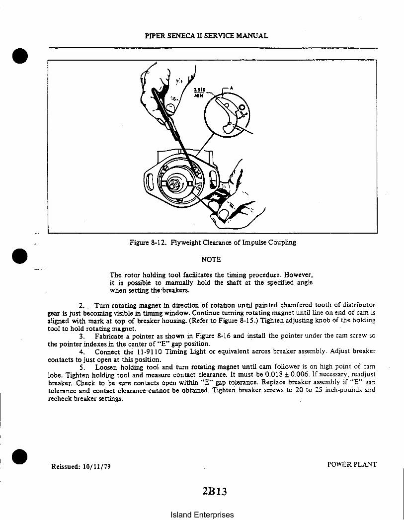
PIPER SENECA II SERVICE MANUAL
Figure 8-12. Flyweight Clearance of Impulse Coupling
NOTE
The rotor holding tool facilitates the timing procedure. However,it is possible to manually hold the shaft at the specified anglewhen setting the-breakers.
2. Turn rotating magnet in direction of rotation until painted chamfered tooth of distributorgear is just becoming visible in timing window. Continue turning rotating magnet until line on end of cam isaligned with mark at top of breaker housing. (Refer to Figure 8-15.) Tighten adjusting knob of the holdingtool to hold rotating magnet.
3. Fabricate a pointer as shown in Figure 8-16 and install the pointer under the cam screw sothe pointer indexes in the center of "E" gap position.
4. Connect the 11-9110 Timing Light or equivalent across breaker assembly. Adjust breakercontacts to just open at this position.
5. Loosen holding tool and turn rotating magnet until cam follower is on high point of camlobe. Tighten holding tool and measure contact clearance. It must be 0.018 ± 0.006. If necessary, readjustbreaker. Check to be sure contacts open within "E" gap tolerance. Replace breaker assembly if "E" gaptolerance and contact clearance-cannot be obtained. Tighten breaker screws to 20 to 25 inch-pounds andrecheck breaker settings.
Reissued: 10/11/79 POWER PLANT
2B13
Island Enterprises

PIPER SENECA II SERVICE MANUAL
Figure 8-13. Rotor Holding Tool Installed Figure 8-14. Timing Kit Installed
8-38. MAGNETO INSTALLATION AND TIMING PROCEDURE (MAGNETO TO ENGINE) (LTSIO ISCOUNTER-ROTATING). (Refer to Figure 8-17.)
a. TSIO timing marks are on the outer edge of the crankshaft counterweight blade between No. 2and No. 4 cylinders. The inspection plug between No. 2 and No. 4 cylinders on the left top side of thecrankcase must be removed to view the marks on the crankshaft. (Refer to Sketch A.)
1. Plug one spark plug hole of the No. 1 cylinder and place a thumb over the other plug hole.Have a second person stand in front of the engine and turn the crankshaft in a counterclockwise directionuntil pressure is felt on the thumb. No. 1 piston is coming up on the compression stroke.
2. Remove the inspection hole plug and turn the crankshaft counterclockwise until the 20 degreeBTC mark appears in the center of the inspection hole. A timing device as described in the latest revision ofService Bulletin M68-2, may also be used.
3. Remove the inspection hole plug from the magneto. Turn the magneto coupling until thepainted chamfered tooth on the distributor gear is approximately centered in the inspection hole. Hold themagneto in its approximate installed position. Note carefully the position of the coupling drive lugs.
4. Lubricate the gear support shaft with clean lubricating oil and install the drive gear assemblyso the slots of the coupling bushings will be in the approximate position for aligning with the drive couplinglugs on the magneto.
5. Insert the retainer into the gear hub slot. Apply a film of Lubriplate grease to each of thenew rubber bushings and insert the bushings into the retainers, rounded long edges first.
6. Place a new gasket on the magneto flange. Install the magneto carefully, so the drivecoupling lugs mate with the slots of the drive bushings. Install and snug down the two sets of attachingscrews. Do not tighten at this time.
POWER PLANTRevised: 3/16/81
2B14Island Enterprises

Figure 8-15. Cast-in Timing Marks Figure 8-16. Fabricated Pointer
7. Breaker point opening may be checked by use of a suitable timing light. Tap the magnetocase with a non-marring hammer, counterclockwise (from the rear) to make certain the points are closed.After the timing light indicates that the points are closed, tap the magneto lightly clockwise until the pointsare open. Tighten the magneto attaching nuts.
8. Check timing by backing up crankshaft approximately 5 degrees and tapping gently forwarduntil the timing light indicates opening of breaker points. If timing is correct, the 20 degree mark (midwaybetween the 16 and 24 stamped on the crankshaft) will appear in the center of the inspection hole. Thecrankshaft has punch marks in 2 degree increments with 16 and 24 at each end. Tighten the magnetoattachment nuts and replace the plug in the inspection hole on top of the engine.
b. LTSIO timing marks are on the outer edge of the crankshaft propeller flange. (Refer to SketchB.)
1. Plug one spark plug hole of the No. 1 cylinder and place a thumb over the other plug hole.Have a second person stand in front of the engine and turn the crankshaft in a clockwise direction untilpressure is felt on the thumb. No. 1 piston is coming up on the compression stroke.
2. Hold a machinist square so its base is along the crankcase vertical parting line above thecrankshaft and the arm of the square is pointing outward past the crankshaft propeller flange.
3. Turn the crankshaft clockwise until the 20 degree Before Top Center mark on the engine isnow in the advanced ignition firing position.
4. Remove the inspection hole plug from the magneto. Turn the magneto coupling unit. Thepainted chamfered tooth on the distributor gear is approximately centered in the inspection hole. Hold themagneto in its approximate installed position. Note carefully the position of the coupling drive lugs.
5. Lubricate the gear support shaft with clean lubricating oil and install the drive gear assemblyso the slots of the coupling bushings will be in the approximate position for aligning with the drive couplinglugs on the magneto.
Reissued: 10/11/79 POWER PLANT
PIPER SENECA II SERVICE MANUAL
2B15
Island Enterprises

PIPER SENECA II SERVICE MANUAL
6. Insert the retainer into the gear hub slot. Apply a film of Lubriplate grease to each of thenew rubber bushings and insert the bushings into the retainers, rounded log edges first.
7. Place a new gasket on the magneto flange. Install the magneto carefully so the drivecoupling lugs mate with the slots of the drive bushings. Install and snug down the two sets of attachingscrews. Do not tighten at this time.
.8. Breaker point opening may be checked by the use of a suitable timing light. Tap themagneto case with a non-marring hammer counterclockwise from the rear to make certain the points areclosed. After the timing light indicates that the points are closed, tap the magneto lightly counterclockwiseuntil the points are open. Tighten the magneto attachment nuts.
POWER PLANTReissued: 10/11/79
2B16
Island Enterprises

PIPER SENECA II SERVICE MANUAL
REMOVE PLUG TO SEE TIMING MARKS.
TIMING MARKS
TS1-360-E
SKETCH A
LTS1-360-E
SKETCH B
TIMING MARKS
VIEW A-A
Figure 8-17. Engine Timing Marks
8-39. HARNESS ASSEMBLY.
8-40. INSPECTION OF HARNESS.a. Check the lead assemblies for nicks, cuts, mutilated braiding, badly worn section or any other
evidence of physical damage. Inspect the spark plug sleeves for chafing or tears and damaged or strippedthreads on coupling nuts. Check the compression spring to see if it is broken or distorted. Inspect thegrommet for tears. Check all the mounting brackets and clamps to see that they are secure and not cracked.
b. Should a harness problem be suspected, integrity of the harness wiring may be checked using anohmmeter, buzzer, or other suitable device such as the Bendix/ECD High Tension Lead Tester Kits, P/N11-8950 or 11-8950-1; check each lead for continuity. If continuity does not exist, harness wire is brokenand must be replaced.
c. If an insulation failure is suspected, the condition of the insulation may be determined using theBendix 11-8950 and the 11-8950-1 High Tension Lead Tester Kits manufactured by the ElectricalComponents Division, The Bendix Corporation, Sidney, New York.
d. Test Unit Preparation:1. Install two "C" cells in the battery holder in accordance with correct position.2. Check that red and black leads are open-circuited.3. Depress PRESS-TO-TEST push-button switch.4. Insure INDICATOR lamp flashes and GAP fires intermittently as long as PRESS-TO-TEST
switch is depressed.5. Interconnect both red and black high voltage leads and again depress PRESS-TO-TEST
switch. INDICATOR lamp only should flash. GAP does not fire.
Reissued: 10/11/79 POWER PLANT
2B17
Island Enterprises

PIPER SENECA II SERVICE MANUAL
6. Disconnect black and red leads.e. Insulation Test:
1. Attach clip of red high voltage test lead to ignition harness lead terminal.2. Attach black test lead clip to lead ferrule.3. Depress PRESS-TO-TEST push-button switch.4. Observe that INDICATOR lamp flashes and GAP fires intermittently as long as
PRESS-TO-TEST switch is held depressed.5. Whenever INDICATOR lamp flashes and gap fails to fire, lead under test is defective.6. When testing leads which are installed on an engine, it may be found that distributed
capacitance causes the tester to reject good leads if the tester and red test lead are allowed to lay in closephysical contact with the engine parts. For best results, keep the tester and the red high voltage lead wellclear of the grounded metal parts of the engine.
7. On some engines, leakage through the magneto distributor to the magneto coil may occur ifthe distributor finger electrode is lined up with the lead under test. If this occurs, the tester will indicate arejection. Before final rejection of a lead which has one end connected to the magneto, turn the engineslightly and repeat test to confirm the reading.
f. A second acceptable method for performing an insulation check is with a high voltage, directcurrent tester such as the TAKK Model 86 or 86A or an equivalent direct current tester capable ofdelivering a test potential of 10,000 volts. Connect ground lead of high voltage tester to outer shieldingbraid of a single lead. Connect plug terminal. Turn tester ON and apply 10,000 volts. The insulationresistance should be 100 megohms minimum. Proceed to check other leads of harness in the same manner.
8-41. REMOVAL OF HARNESS.a. Disconnect the clamps that secure the wires to the engine and accessories.b. Loosen the coupling nuts at the spark plugs and remove the insulators from the spark plug barrel
well. Use caution when withdrawing the insulator so that the insulator spring will not be damaged.c. Place a guard over the harness insulators.d. Remove the harness assembly terminal plate from the magneto.e. Remove the harness from the airplane.
8-42. MAINTENANCE OF HARNESS.a. To replace contact springs, spring retainer assemblies or insulating sleeves, proceed as follows:
1. Using a Bendix 11-7073 Needle or a mechanical pencil with the lead retracted, hook the endof the contact spring as shown in Figure 8-18.
2. Using the needle or pencil, unscrew the spring.3. Slide the insulating sleeve and spring retainer assembly off the end of the lead assembly.4. Replace the defective component and reassemble as follows:
(a) Fabricate a tool as shown in Figure 8-19 for installing the insulating sleeves over thecable terminals.
(b) Push the tool through insulating sleeve and spring retainer assembly as shown in Figure8-20. Screw the cable terminal into the tool.
(c) Work the insulating sleeve and spring retainer assembly into position over the cable andunscrew the tool. Install the contact spring on the cable terminal.
NOTE
It may be necessary to lubricate the cable and insulating sleevewith a thin film of Dow-Coming 200 (200,000 centi-stokes) orcommercial grade alcohol to facilitate assembly.
Reissued: 10/11/79 POWER PLANTIssued: 9/4/74
2B18Island Enterprises

PIPER SENECA II SERVICE MANUAL
Figure 8-18. Removing Spring From Lead Assembly
b. To replace one of the lead assemblies, proceed as follows:1. Remove the clamps and brackets from the applicable lead assembly. Cut the cable ties from
the assembly and discard them.2. Cut off the condemned lead flush with the outer surface of the cable outlet plate.3. Grip the eyelet of the lead with a pair of pliers and pull the short length of conductor out of
grommet and cable outlet plate.4. Using a 3 inch long, 0.270 of an inch diameter drift applied at outer surface of plate, drive
out tapered ferrule and remaining pieces of insulation and shielding.5. To determine what length the new lead assembly should be cut to, proceed as follows:
(a) Measure the length of the condemned lead assembly. Move the coupling nut back onthe lead assembly and measure from the outer end of the ferrule at the spark plug end.(Refer to Figure 8-21.)
NOTE
Spare part leads are supplied in various lengths. Use a lead which islonger than, but nearest to, the desired length.
6. Cut the lead assembly to the length determined in Step 5. Mark the ferrule on the spark plugend of the lead with a metal stamp, scribe or rubber stamp to correspond with the correct cylinder number.
7. Starting at the spark plug location, thread the new cable through the grommets and clampsas necessary for the correct routing of the cut end of the cable to the magneto location.
Reissued: 10/11/79 POWER PLANT
2B19
Island Enterprises

1.250
PIPER SENECA II SERVICE MANUAL
BRAZE
2- IN.
DRILLNO. 47 IN DEEP
TAP 3-48
BLEND O.D. TO I.D.POLISH O.D.
12.000 IN.
MAT: NO. 30 DRILL ROD OR EQUIVALENT
Figure 8-19. Assembly Tool
SPRING RETAINER ASSY
0
Figure 8-20. Assembly Tool Application
REQUIRED LENGTH
Figure 8-21. Measuring Lead Assembly Length
Reissued: 10/11/79 POWER PLANT
2B20Island Enterprises

8. Remove the cable outlet plate from the magneto. Support the plate securely and usingsuitable cutting pliers, split and remove the eyelets from the leads adjacent to the lead being replaced. Whensplitting the eyelet, make certain that the wire strands are not cut. Removal of eyelets on adjacent leads willallow the grommet to be pulled away from the outlet plate to facilitate insertion of the new lead.
9. Assemble the lead to the cable outlet plate following the procedure in Steps 10 through 17.
CAUTION
Insure before every cutting or stripping procedure that braid hasnot worked back on lead by grasping lead in one hand and slidingthe other hand firmly along lead toward the outlet plate. If braidis improperly located on lead, the lead may be trimmed to thewrong length.
10. Pass the lead through the proper hole in outlet plate. Position the Bendix 11-9596 orequivalent Braid Cutting Backup Tube between the braided shielding and insulation to protect theinsulation. Cut enough braid from the lead to have 1-1/4 inch of insulation extending from end of braid.
CAUTION
Be sure the cutting backup tube is completely under the point atwhich the cut is to be made to prevent cutting or nickinginsulation.
11. Slide inner ferrule under the braid. The braid should cover approximately two-thirds of theferrule taper. Remove the blue silicone coating from the end of the braid over ferrule by lightly scrapingwith a knife or wire brush.
CAUTION
When removing silicone coating, care should be taken not todamage the braided wire shielding.
12. Pull the lead assembly back through cable outlet plate until cleaned braid binds in the outletwell. Position the Bendix 11-7074 Ferrule Seating Tool (Figure 8-22) over the insulation and firmly seat theferrule by tapping the seating tool with a hammer or by using an arbor press.
13. Measure 1/2 inch from tapered ferrule and strip remaining insulation from wire. (Refer toFigure 8-23.)
14. Insert Bendix 11-7073 Needle (Figure 8-24) through the small hole of the grommet and overthe stripped end of the wire. (Refer to Figure 8-25.) Slide grommet down needle until it seats tightlyagainst the tapered ferrule.
15. Cut the wire 3/8 inch from the top of the grommet outlet. (See Figure 8-26.) Double thewire over as shown in A of Figure 8-27. Slide the eyelet over the doubled wire until it is firmly seated in therecess of the grommet outlet.
Reissued: 10/11/79 POWER PLANT
2B21
PIPER SENECA II SERVICE MANUAL
Island Enterprises

2.750
2.031
PIPER SENECA II SERVICE MANUAL
0.50
2.375
0.250
MATER IA L - BRASS
Figure 8-22. Ferrule Seating Tool Figure 8-23. Measuring Wire From Top of Ferrule
0.095 DIA
0.047 DIA
1 -7073 NEEDLE
0.047 SPHERICAL RAD2 PLACES
Figure 8-24. Needle Figure 8-25. Installing GrommetOver Lead Assemblies
Reissued: 10/11/79 POWER PLANT
2B22
Island Enterprises

PIPER SENECA II SERVICE MANUAL
A
B
Figure 8-26. Lead Assembly Installed in Grommet Figure 8-27. Wire Doubled OverFor Installation of Eyelet
16. Using a suitable crimping tool or equivalent, crimp the eyelet to the wire. Approximately1/32 inch of wire should extend from the end of the eyelet after crimping. See B of Figure 8-27.
NOTE
If the crimping tool is not available, a satisfactory connection canbe made by soldering with Kester Flux 709 or equivalent and anon-corrosive solder. After soldering, clean solder joints usingdenatured alcohol.
17. Install the clamps and cable ties, as necessary, to secure the lead to the engine.
CAUTION
Leads should be dressed away from hot spots, such as manifoldsand sharp edges which cause chafing.
POWER PLANTReissued: 10/11/79
2B23
Island Enterprises

ON
PIPER SENECA II SERVICE MANUAL
2015
UPPER SPARK PLUGS
LEFTMAGNETO
IGNITIONSWITCHES
RIGHTMAGNETO
LOWER SPARK PLUGS
ENGINE FIRING ORDER:LTSIO-360-E - 14-5-2-3-6TSIO-360-E - 1-6-3-2-5-4
MAGNETO FIRING ORDER:1-2-3-4-5-6
Figure 8-28. Ignition Schematic
Reissued: 10/11/79 POWER PLANT
2B24Island Enterprises

2C1INTENTIONALLY LEFT BLANK
Island Enterprises

PIPER SENECA II SERVICE MANUAL
8-43. INSTALLATION OF HARNESS. Before installing the harness plate on the magneto, check themating surfaces for cleanliness. Spray the entire face of the grommet with a light coat of Plastic MoldSpray, SM-O-O-TH Silicone Spray or equivalent. This will prevent the harness grommet from sticking to themagneto distributor block.
a. Place the harness terminal plate on the magneto and tighten the nuts around the plate alternatelyto seat the cover squarely on the magneto. Torque the nuts to 18 to 22 inch-pounds.
b. Route the ignition wires to their respective cylinders as shown in Figure 8-28.c. Clamp the harness assembly in position.d. Connect the leads to the spark plugs.
8-44. SPARK PLUGS.
8-45. REMOVAL OF SPARK PLUGS.a. Loosen the coupling nut on the harness lead and remove the terminal insulator from the spark
plug barrel well. (A crows foot adapter is needed to remove the lower spark plugs.)
NOTE
When withdrawing the ignition cable lead connection from theplug, care must be taken to pull the lead straight out and in linewith the centerline of the plug barrel; otherwise, a side load will beapplied which frequently results in damage to the barrel insulatorand connector. If the lead cannot be removed easily in thismanner, the resisting contact between the neoprene collar and thebarrel insulator will be broken by a rotary twisting of the collar.Avoid undue distortion of the collar and possible side loading ofthe barrel insulator.
b. Remove the spark plug from the engine. In the course of engine operation, carbon and othercombustion products will be deposited on the end of the spark plug and will penetrate the lower threads tosome degree. As a result, greater torque is frequently required for removing a plug than for its installation.Accordingly, the torque limitations given do not apply to plug removal, and sufficient torque must be usedto unscrew the plug. The higher torque in removal is not as detrimental as in installation, since it cannotstretch the threaded section. It does, however, impose a shearing load on this section and may, ifsufficiently severe, produce a failure in this location.
NOTE
Torque indicating handle should not be used for spark plugremoval because of the greater torque requirement.
c. Place spark plugs in a tray that will identify their position in the engine as soon as they areremoved.
NOTE
Spark plugs should not be used if they have been dropped.
Reissued: 10/11/79 POWER PLANT
2C2
Island Enterprises

PIPER SENECA II SERVICE MANUAL
234
Figure 8-29. Removing Frozen Spark Plug
d. Removal of seized spark plugs in the cylinder may be accomplished by application of liquidcarbon dioxide by a conical metal funnel adapter with a hole at the apex just large enough to accommodatethe funnel of a C02 bottle. (Refer to Figure 8-29.) When a seized spark plug cannot be removed by normalmeans, the funnel adapter is placed over and around the spark plug. Place the funnel of the C02 bottleinside the funnel adapter and release the carbon dioxide to chill and contract the spark plug. Break thespark plug loose with a wrench. A warm cylinder head at the time the carbon dioxide is applied will aid inthe removal of an excessively seized plug.
e. Do not allow foreign objects to enter the spark plug hole.
8-46. INSPECTION AND CLEANING OF SPARK PLUG.a. Visually inspect each spark plug for the following non-repairable defects:
1. Severely damaged shell or shield threads nicked up, stripped or cross-threaded.2. Badly battered or rounded shell hexagons.3. Out-of-round or damaged shielding barrel.4. Chipped, cracked or broken ceramic insulator portions.5. Badly eroded electrodes worn to approximately 50% of original size.
b. Clean the spark plug as required, removing carbon and foreign deposits.c. Set the electrode gap per the latest revision of Teledyne Continental Aircraft Engine Service Bulletin
M77-10.d. Test the spark plug both electrically and for resistance.
Revised: 3/16/81 POWER PLANT
2C3
Island Enterprises

THIS PAGE INTENTIONALLY LEFT BLANK
2C4Island Enterprises

PIPER SENECA II SERVICE MANUAL
8-47. INSTALLATION OF SPARK PLUGS. Before installing spark plugs, ascertain that the threadswithin the cylinder are clean and not damaged.
a. Apply anti-seize compound sparingly on the threads and install gasket and spark plugs. Torque360 to 420 inch-pounds.
CAUTION
Make certain the deep socket is properly seated on the spark plughexagon as damage to the plug could result if the wrench is cockedto one side when pressure is applied.
b. Carefully insert the terminal insulator in the spark plug and tighten the coupling unit.
8-48. LUBRICATION SYSTEM.
8-49. DESCRIPTION. The oil system is a wet sump. force feed system with a capacity of 8 quarts. Aconventional dipstick is provided for determining the oil quantity.
When the engine is running. oil is drawn through a screen and pick up tube which extends from thesump to a port in the crankcase. Oil then flows to the inlet of the gear type. engine driven oil pump and isforced under pressure through the pump outlet. A pressure relief valve prevents excessive oil pressure byallowing excess oil to be returned to the sump. After leaving the pump, the oil under pressure enters a fullflow filter and is passed onto the oil cooler. If the filter element becomes blocked. a bypass relief valve willopen to permit unfiltered oil to flow to the engine. An oil temperature control unit allows oil to bypass theoil cooler when the oil is cold. Some oil flows through the cooler to prevent congealing in cold weather.When the oil temperature reaches approximately 170° F. the oil temperature control unit actuates to closeoff the cooler bypass forcing the oil to fow through the cooler.
From the oil cooler oil enters the crankcase where it is directed to the bearing surfaces and otherengine components requiring lubrication and cooling. The propeller governor boost engine oil pressure foroperation of the propeller. A tap in the side of the crankcase supplies oil pressure for lubrication of theturbocharger bearings. Oil is carried to the turbocharger through an external line. After lubricating theturbocharger bearings it is drawn into a scavenge pump and forced back to the oil sump. Oil within theengine drains. by gravity. back into the sump.
I Added: 8/10/80 POWER PLANT
2C5
Island Enterprises

PIPER SENECA II SERVICE MANUAL
1. OIL FILTER ADAPTER2. SAFETY WIRE3. OIL FILTER ELEMENT4. OIL SCAVENGE SCREEN ASSEMBLY
Figure 8-30. Lubrication System Maintenance Points
8-50. OIL FILTER REPLACEMENT. (Refer to Figure 8-30.) The oil filter element should be replacedafter each 50 hours of engine operation. The filter element is mounted on the lower portion of the engineaccessory case. Replace the filter element as follows:
a. Remove the lockwire between the nut on the filter and the oil filter adapter and unscrew thefilter element.
b. Before installing a new filter, lubricate the gasket on the filter with engine oil.c. Torque the filter 18 to 20 foot-pounds or 3/4 to 1 full turn after the gasket makes contact.
CAUTION
Do not over torque.
d. Run the engine and check for oil leaks; then install lockwire between nut on filter and adapter.
Reissued: 10/11/79 POWER PLANT
2C6Island Enterprises

PIPER SENECA II SERVICE MANUAL
8-51. ENGINE FUEL SYSTEM.
8-52. DESCRIPTION. The fuel injection system is a multi-nozzle, continuous flow, altitude compensatingsystem that regulates fuel flow to match engine operating conditions. The system consists of an enginedriven fuel pump, a throttle body, a fuel manifold valve and fuel discharge nozzles.
The engine driven fuel pump is a positive displacement, rotary vane type pump with an integral vaporseparator and altitude compensating aneroid valve.
The throttle body consists of a rotary valve metering unit attached to an air throttle that controls theflow of air to the engine. The position of the cam shaped edge of the rotary valve across the fuel deliveryport and engine driven pump controls the fuel flow to the manifold valve and nozzles, thus controlling thefuel-air ratio.
The fuel manifold valve is the central point for dividing fuel to the individual cylinders. A diaphragmand plunger valve within the manifold valve raises or lowers by fuel pressure to open or close the individualfuel supply ports simultaneously.
The fuel discharge nozzles are an air bleed type nozzle with a calibrated orifice. A nozzle is installed inthe cylinder head outside each intake valve for each cylinder.
8-53. FUEL INJECTION SYSTEM MAINTENANCE.a. Check all attaching parts for tightness.b. Check all fuel lines for leaks, evidence of damage, or chafing by metal to metal contact.c. Check control connections, levers, and linkages for safety.d. Inspect nozzles for cleanliness with particular attention to air screens and orifices. Use a standard
1/2 inch spark plug type deep socket to remove nozzles. Do not remove shield to clean air screens. Do notuse wire or other object to clean orifices. To clean nozzles, remove from engine and immerse in freshcleaning solvent. Use compressed air to dry.
e. Unscrew strainer plug from fuel injection control valve and clean screen in solvent. Reinstall,safety, and check for leaks.
f. During periodic lubrication, add a drop of engine grade oil on each end of the air throttle shaftand at each end of the linkage between the air throttle and fuel metering valve.
NOTE
Do not use any form of thread compound on fuel line fittings. Useonly a fuel soluble lubricant such as engine oil.
Reissued: 10/11/79 POWER PLANT2 7
Island Enterprises

PIPER SENECA II SERVICE MANUAL
FUEL TANK
Figure 8-31. Schematic Diagram of Fuel Injection System
Reissued: 10/11/79 POWER PLANT2C8
Island Enterprises

PIPER SENECA II SERVICE MANUAL
1. INJECTION MIXTURE OUTLET2. O-RING3. CALIBRATED ORIFICE
2 4. RAM AIR INLET5. FUEL INLET
Figure 8-32. Fuel Injector Nozzle Assembly
8-54. FUEL INJECTOR NOZZLE ASSEMBLY.
8-55. REMOVAL OF FUEL INJECTOR NOZZLES.a. Remove the cowling side access panels.b. Disconnect the fuel line and remove the ram air line from the nozzle.c. Use a standard 1/2 inch spark plug type deep socket to remove the nozzle.
8-56. CLEANING AND INSPECTION OF FUEL INJECTOR NOZZLES.a. To clean the nozzles immerse in fresh cleaning solvent, use compressed air to dry.
CAUTION
Do not use wire or other objects to clean orifices.
b. Inspect the nozzles for cleanliness; pay particular attention to the orifices. Check the conditionof the nozzle and cylinder threads.
8-57. INSTALLATION OF FUEL INJECTOR NOZZLES.a. Carefully start the nozzles by hand to prevent cross-threading. Torque nozzle to 60 inch-pounds.b. Connect the fuel line to the nozzle.c. Reinstall cowling side panels.
Reissued: 10/11/79 POWER PLANT
2C9
Island Enterprises

PIPER SENECA II SERVICE MANUAL
WOODWARD GOVERNOR
HARTZELL GOVERNOR
MIXTURE CONTROL THROTTLE CONTROL
Figure 8-33. Engine Controls
Revised: 8/10/80 POWER PLANT
2C10Island Enterprises

PIPER SENECA II SERVICE MANUAL
8-58. ENGINE AND PROPELLER CONTROLS.
8-59. RIGGING THROTTLE, MIXTURE AND GOVERNOR CONTROLS. (Refer to Figure 8-33.)a. Rig the throttle control as follows:
1. Place the quadrant throttle lever full forward.2. With the control arm on the fuel-air control unit in the full throttle position, rig the throttle
quadrant lever to provide a minimum of .032 inches clearance from the forward stop. With the control armat the idle stop, the quadrant throttle lever must have a minimum clearance of .032 inches from the aftstop.
NOTE
Both throttle controls must be within .25 of an inch in alignmentin the aft position and within 1/2 a knob width in the full forwardposition.
b. Rig the propeller control as follows:1. Place the propeller control lever full forward.2. With the propeller governor control arm in the low pitch (high RPM) position, rig the
quadrant control lever to provide .047/.032 inches clearance from the forward stop.c. Rig the mixture control as follows:
1. Place the mixture control lever full forward.2. With the mixture control arm on the engine fuel pump in the full rich position, rig the
quadrant mixture lever to provide a minimum of .032 inches clearance from the forward stop.3. With the mixture control arm at idle cut-off, the quadrant mixture lever must have a
minimum of .032 inches clearance from the aft stop.
NOTE
Both the mixture and propeller controls must be within .25 of aninch in alignment in the full forward position and within 1/2 aknob width in the full aft position.
Revised: 8/10/80 POWER PLANT2C11
Island Enterprises

IDLE
A276
PIPER SENECA II SERVICE MANUAL
ITHROTTLE ARM STOP
ON EXPOSED ADJUSTING SCREW REMOVE PUTTY FROM BOSSWHICH INCORPORATES THE ADJUSTING SCREW. USE THISLOCATION FOR ALL FUTURE IDLE MIXTURE ADJUSTMENTS. REFERTO THE LATEST REVISION OFTCM SERVICE BULLETIN M76-17. IDLEMIXTURE ADJUSTMENT CW-LEAN AND CCW-RICH.
SPEEDSTMENT
CW - INCREASE RPMCCW - DECREASE RPM
MIXTURE CONTROLUNIT
REMOVE PLUG AND CONNECTGAUGE FOR SETTING UPUNMETERED FUEL.
I
ON EXPOSED ADJUSTING SCREWTURN IDLE MIXTURE ADJUSTINGSCREW FULL IN UNTIL IT SEATS. FILL THE ADJUSTING SCREWBOSS WITH HARDENING PUTTY. USE ABOVE LOCATION FORFUTURE ADJUSTMENTS. REFER TO LATEST REVISION OF TCMSERVICE BULLETIN M76-17.
RIGHT SIDE
THROTTLE CONTROL
LEFT SIDE
Figure 8-34. Idle Speed and Mixture Adjustment Points
8-60. ENGINE SETUP PROCEDURES. The following procedures should be used to check andadjust the power plants to maintain the required operating limits and insure obtaining good setup results. It isimportant that the following leak check be made before proceeding with any actual system adjustments:
a. Leak Check - Gauge Lines:1. Disconnect manifold pressure line at air throttle body, compressor discharge pressure line at
manifold valve and fuel pressure line at manifold valve.2. Connect surgical tubing to the compressor discharge pressure line and evacuate the line until a
10 gallon per hour (maximum) positive indication on the fuel flow gauge is obtained. Clamp off the tubing andobserve the gauge for a steady reading. Any change of this reading would indicate a leak in the system, whichmust be repaired prior to continuing with the setup procedures.
NOTE
A static system test unit can be used to leak check these lines.
3. Check the fuel pressure and manifold pressure lines in the same manner as given in Step 2,except apply positive pressure to the lines. Do not exceed 4 pounds per square inch (psi) on the fuelpressure gauge, or 4 inches of mercury (In. Hg) increase on the manifold pressure gauge.
4. Reconnect and tighten the manifold pressure, compressor discharge pressure and fuel pressurelines.
5. The difference in the static reading on the manifold pressure gauges should not exceed 1/2in. Hg.
6. To reduce the possibility of trapped air in the fuel pressure lines, disconnect the fuel pressureline at the rear of the fuel flow gauge and activate the auxiliary fuel pump long enough to purge the lines; thenreconnect the lines.
Revised: 3/16/81 POWER PLANT
2C12
Island Enterprises

PIPER SENECA II SERVICE MANUAL
b. Exhaust Bypass Check: Ascertain that the exhaust bypass adjusting screw has from eight to ninethreads showing below the jam nut. This screw is preset at the factory and should not require anyadjustment, unless it is known that critical altitude is not correct; in this case, use procedure given in Stepk. (Refer to Figure 8-36.)
c. Idle Performance Check:
NOTE
It is extremely important that both engines are thoroughlywarmed up, operated and adjusted together to keep themmatched. However, excessive engine temperatures must be avoidedsince setup temperature must closely parallel temperatures inflight.
1. Remove the cap from the tee fitting on the right side of the throttle body. (Refer to Figure8-34.)
2. Install a 0-60 psig calibrated pressure gauge (vented to the atmosphere) to the tee, using asuitable length of flexible tube. The gauge should always be at the same level as the fuel manifold valvewhen checking fuel pressure.
3. Purge the air from the tube.
CAUTION
During all engine operations outlined in these instructions, exerciseCAUTION to avoid harm or damage to personnel and equipmentby propeller blast and rotating propeller blades. When required tomake adjustments to the engine in close proximity to the propellerarc, shut the engine down before making adjustments.
d. Check and Adjustment of Idle Fuel Pressure:
NOTE
The following setup procedure is accomplished with the boostpumps OFF, the engines thoroughly warmed up and adjustedtogether to keep them matched.
1. Back off the idle speed adjusting screw two turns. (Refer to Figure 8-34.)2. Start both engines and warm them up at 1,500 to 1,800 RPM until the oil pressures are in
the green arc, cylinder head temperatures are in the lower one-quarter of the green arc, and the oiltemperatures are 160° to 180°F.
3. While maintaining 700 25 RPM, set the idle fuel pressure at 6.5 0.25 psi by adjusting theidle pump adjustment screw (refer to Figure 8-35, item 6); clockwise adjustment increases pressure;counterclockwise adjustment decreases pressure.
e. Check and Adjustment of Idle Mixture: (Refer to Figure 8-34.)1. Operate the engine at 1,500 to 1,800 RPM until cylinder head temperatures are in the lower
one-quarter of the green arc, and the oil temperatures are 160° to 180° F.2. Reduce the engine speed and stabilize it at 700 ± 25 RPM.3. Slowly, but positively, move the mixture control from the full rich position to the idle.
The engine speed should increase 75 RPM minimum, 100 RPM maximum before beginning to drop towardzero. Move the mixture control back to full rich before the engine stops.
Revised: 9/24/81 POWER PLANT
2C13
Island Enterprises

PIPER SENECA II SERVICE MANUAL
4. If the engine speed increase is less than 75 RPM, adjust the idle mixture adjustment to enrichthe mixture (counterclockwise). If the engine speed increase is more than 100 RPM, adjust the idle mixture tolean the mixture (clockwise).
5. After each adjustment, increase RPM to 1500-1700 for 10 seconds to "clean the engine out".6. Double check idle fuel pressure after adjusting idle mixture.
NOTE
Any adjustment of the idle fuel pressure or idle mixture will proba-bly change the other reading. Continue to adjust and cross-checkuntil both are correct.
f. Check and Adjustment of Idle Speed: (Refer to Figure 8-34.)1. With the idle fuel pressure and idle mixture set in accordance with instructions given in
Steps "d" and "e," cylinder head temperatures in the lower one-quarter of the green arc, and oiltemperatures at 160° to 180F, set engine speed at 700 25 RPM.
2. Adjust the idle speed adjusting screw until contact is made with the throttle arm stop.
NOTE
After final adjustment, recheck the idle fuel pressure, idle mixtureand idle speed to ascertain that all are within specifications given inprevious steps.
g. Check and Adjustment for Full Power Performance: (Refer to Figure 8-35.)
CAUTION
Before attempting full power checks, be sure that the brakes areproperly maintained and set, and that the ground conditions willnot permit the wheels to slip during full power check.
NOTE
Fuel flows are given for sea level density altitude. Use Chart VIII-IVto interpolate correct fuel flow for the actual engine RPM.
1. Run both engines at 39.8 to 40.0 in. Hg. manifold pressure (overboost lights activated), andbeat synchronize the engines at 2,500 to 2,575 RPM using the propeller governor controls. Readjust thethrottle controls as required to maintain 39.8 to 40.0 in. Hg. manifold pressure on both engines.
2. Fuel flow should be 21.5 to 22.0 gallons per hour (gph), for each engine with the mixturecontrols in the full rich position. Within this range, the readings shall match.
3. Observe the 0-60 calibrated gauge to cross check performance. High unmetered pressureshould be 42-45 psi.
4. If adjustment is required, shut the engine down, loosen the jam nut on the adjusting screwlocated on the aneroid housing of the fuel pump. (Refer to Figure 8-35, item 2.) Clockwise adjustmentdecreases fuel flow reading; counterclockwise adjustment increases fuel flow reading; one full turn will cause a1.0 to 1.5 gph change. Use CAUTION when loosening and tightening the jam nut so as not to change settings.
Revised: 3/16/81 POWER PLANT
2C14Island Enterprises
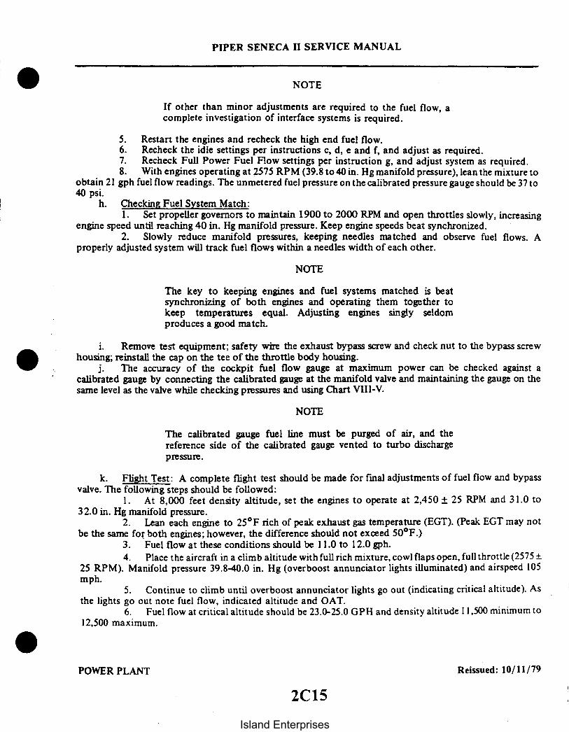
PIPER SENECA II SERVICE MANUAL
NOTE
If other than minor adjustments are required to the fuel flow, acomplete investigation of interface systems is required.
5. Restart the engines and recheck the high end fuel flow.6. Recheck the idle settings per instructions c, d, e and f, and adjust as required.7. Recheck Full Power Fuel Flow settings per instruction g, and adjust system as required.8. With engines operating at 2575 RPM (39.8 to 40 in. Hg manifold pressure), lean the mixture to
obtain 21 gph fuel flow readings. The unmetered fuel pressure on the calibrated pressure gauge should be 37 to40 psi.
h. Checking Fuel System Match:1. Set propeller governors to maintain 1900 to 2000 RPM and open throttles slowly, increasing
engine speed until reaching 40 in. Hg manifold pressure. Keep engine speeds beat synchronized.2. Slowly reduce manifold pressures, keeping needles matched and observe fuel flows. A
properly adjusted system will track fuel flows within a needles width of each other.
NOTE
The key to keeping engines and fuel systems matched is beatsynchronizing of both engines and operating them together tokeep temperatures equal. Adjusting engines singly seldomproduces a good match.
i. Remove test equipment; safety wire the exhaust bypass screw and check nut to the bypass screwhousing; reinstall the cap on the tee of the throttle body housing.
j. The accuracy of the cockpit fuel flow gauge at maximum power can be checked against acalibrated gauge by connecting the calibrated gauge at the manifold valve and maintaining the gauge on thesame level as the valve while checking pressures and using Chart VIII-V.
NOTE
The calibrated gauge fuel line must be purged of air, and thereference side of the calibrated gauge vented to turbo dischargepressure.
k. Flight Test: A complete flight test should be made for final adjustments of fuel flow and bypassvalve. The following steps should be followed:
1. At 8,000 feet density altitude, set the engines to operate at 2,450 25 RPM and 31.0 to32.0 in. Hg manifold pressure.
2. Lean each engine to 25°F rich of peak exhaust gas temperature (EGT). (Peak EGT may notbe the same for both engines; however, the difference should not exceed 50°F.)
3. Fuel flow at these conditions should be 11.0 to 12.0 gph.4. Place the aircraft in a climb altitude with full rich mixture, cowl flaps open, full throttle (2575 +
25 RPM). Manifold pressure 39.8-40.0 in. Hg (overboost annunciator lights illuminated) and airspeed 105mph.
5. Continue to climb until overboost annunciator lights go out (indicating critical altitude). Asthe lights go out note fuel flow, indicated altitude and OAT.
6. Fuel flow at critical altitude should be 23.0-25.0 GPH and density altitude 11,500 minimum to12,500 maximum.
POWER PLANT Reissued: 10/11/79
2C15
Island Enterprises

1. MIXTURE CONTROL2. FULL POWER FUEL PRESSURE ADJUSTMENT3. PRESSURE-DECK4. FUEL PUMP INLET5. VAPOR RETURN
. IDLE PRESSURE RELIEF VALVE ADJUSTMENT7. FUEL PUMP OUTLET
PIPER SENECA II SERVICE MANUAL
A182
5
Figure 8-35. Sectional View of Altitude Compensating Fuel Pump Assembly
7. If a discrepancy in critical altitude was noted, adjust the exhaust bypass valve. (Turning theexhaust bypass valve screw one full turn will alter the critical altitude approximately 1,000 feet.) Adjustmentsof critical altitude in excess of 500 feet may require retrimming of the fuel flows at 100% power.
8. With full rich mixture, cowl flaps open, 2,575 ±25 RPM, 105 MPH airspeed, and 1,000 to 3,000feet density altitude, check the operation of the manifold pressure relief valve. Slowly advance one throttle tothe wide open position. The manifold pressure shall stabilize between 42.0 and 44.0 in. Hg; there shall be noloss of power, and the fuel flow indication shall be well over the red line. Do not exceed 40.0 in. Hg manifoldpressure for more than ten seconds. Repeat this check on the other engine.
NOTE
Idle speed and idle mixture indication is a function of enginetemperatures. Therefore, at normal ground idle temperatures(cylinder and oil temperature indications may or may not be "inthe green") idle speed will be approximately 700 RPM, and theidle mixture check will result in a 25 to 50 RPM increase in enginespeed.
Reissued: 10/11/79 POWER PLANT
2C16Island Enterprises

2013
PIPER SENECA II SERVICE MANUAL
-40 IN. HG. MANIFOLD PRESSURE- FULL RICH MIXTURE
23.0
22.5
22.0
21.5
21.0 -
20.5
20.0
2350 2450 25502400 2500
R.P.M.
TABLE VIII-IV FUEL FLOW VS. ENGINE SPEED
Reissued: 10/11/79 POWER PLANT
2C17Island Enterprises

160
120
100
60
40
TOLERANCE ± .25 p
NOTE - Pressure must be taken at manifold valve andpage must be vented to turbo discharge pressure.
I
A24
PIPER SENECA II SERVICE MANUAL
i
12 14 16 18 20
METERED FUEL PRESSURE - psi
TABLE VIII-V METERED FUEL ASSEMBLY CALIBRATION
EXHAUST BYPASSVALVE SCREWCLOCKWISE- INCREASECOUNTERCLOCKWISE - DECREASE
Figure 8-36. Exhaust Bypass Valve Screw
Reissued: 10/11/79 POWER PLANT
2C18Island Enterprises

WARNING - Continuous operation at fuel flows lowerthan 25 F rich of peak. T.I.T. is prohibitedfor all conditions
150 Continuous operation at T.I.T. in in excessof 1650F is prohibited
140
110
90
60
PIPER SENECA II SERVICE MANUAL
60 80 100 120 140 160 180 200
BRAKE HORSEPOWER
30 40 50 60 70 80 90 100
PERCENT SEA LEVEL POWER
TABLE VIII-VI LIMITS - FUEL FLOW VS. BRAKE H.P
220
P.
Reissued: 10/11/79 POWER PLANT
2C19
Island Enterprises

PIPER SENECA II SERVICE MANUAL
TABLE VIII-VII TROUBLESHOOTING CHART (ENGINE)
Trouble Cause Remedy
Engine will notstart.
No fuel gauge pres-sure - no fuel toengine.
Check fuel control for proper position, auxiliarypump "ON" and operating, feed valves open. Fuelfilters open and tank fuel level.
Have gauge pressure -engine flooded.
Have gauge pres-sure - no fuel toengine.
Turn off auxiliary pump and ignition switch; setthrottle to "FULL OPEN" and fuel control to"IDLE CUTOFF," and crank engine to clear cylin-ders of excess fuel. Repeat starting procedure.
Check for bent or loose fuel lines. Loosen lineat fuel nozzle. If no fuel shows, replace fuelmanifold valve.
Engine starts butfails to keeprunning.
Inadequate fuel tofuel manifold valve.
Set fuel control in "FULL RICH" position; turnauxiliary pump "ON," check to be sure feed linesand filters are not restricted. Clean or replacedefective components.
Defective ignitionsystem.
Check accessible ignition cables and connections.Tighten loose connections. Replace defectivespark plugs.
Engine runs roughat idle.
Improper idle mix-ture adjustment.
Readjust idle setting. Turn adjustment screwclockwise to lean mixture and counterclockwiseto richen mixture.
Fouled sparkplugs.
Discharge nozzleair vent manifoldrestricted or de-fective.
CONTINUED ON NEXT PAGE
Remove and clean plugs, adjust gaps. Replacedefective plugs.
Check for bent or loose connections. Tightenloose connections. Check for restrictions andreplace defective components.
Reissued: 10/11/79 POWER PLANT
2C20Island Enterprises

PIPER SENECA II SERVICE MANUAL
TABLE VIII-VII TROUBLESHOOTING CHART (ENGINE) (cont.)
Trouble Cause Remedy
Engine has pooracceleration.
Idle mixture toolean.
Readjust idle mixture.
Incorrect fuel-airmixture, worn con-trol linkage orrestricted aircleaner.
Defective ignitionsystem.
Malfunctioningturbocharger.
Tighten loose connections. Service air cleaner.
Check accessible cables and connections. Replacedefective spark plugs.
Check operation; listen for unusual noise. Checkwaste gate valve and for exhaust system defects.Tighten loose connections.
Engine runs roughat speeds aboveidle.
Improper fuel-airmixture.
Check manifold connections for leaks. Tightenloose connections. Check fuel control forsetting and adjustment. Check fuel filters andscreens for dirt. Check for proper pump pressureand readjust as necessary.
Restricted fuelnozzle.
Ignition system andspark plugs de-fective.
Remove and clean all nozzles.
Clean and regap spark plugs. Check ignition cablesfor defects. Replace defective components.
Engine lackspower, reductionin maximum man-ifold pressureor critical al-titude.
Incorrectly adjustedthrottle control,"sticky" linkageor dirty air cleaner.
Improperly adjustedwaste gate valve.
Check movement of linkage by moving control fromidle to full throttle. Make proper adjustments andreplace worn components. Service air cleaner.
Check waste gate adjustment. (Refer to Paragraph8-61.)
CONTINUED ON NEXT PAGE
Reissued: 10/11/79 POWER PLANT
2C21Island Enterprises
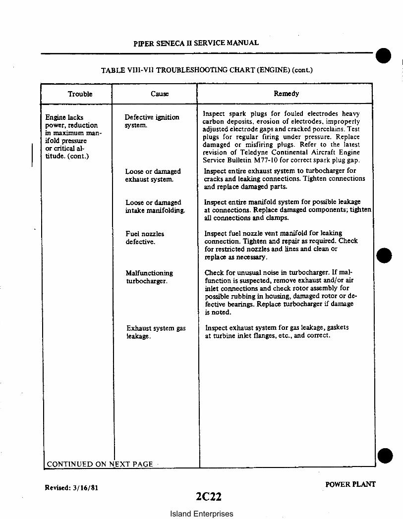
PIPER SENECA II SERVICE MANUAL
TABLE VIII-VII TROUBLESHOOTING CHART (ENGINE) (cont.)
Trouble Cause Remedy
Engine lackspower, reductionin maximum man-ifold pressureor critical al-titude. (cont.)
Defective ignitionsystem.
Loose or damagedexhaust system.
Loose or damagedintake manifolding.
Fuel nozzlesdefective.
Malfunctioningturbocharger.
Exhaust system gasleakage.
Inspect spark plugs for fouled electrodes heavycarbon deposits, erosion of electrodes, improperlyadjusted electrode gaps and cracked porcelains. Testplugs for regular firing under pressure. Replacedamaged or misfiring plugs. Refer to the latestrevision of Teledyne Continental Aircraft EngineService Bulletin M77-10 for correct spark plug gap.
Inspect entire exhaust system to turbocharger forcracks and leaking connections. Tighten connectionsand replace damaged parts.
Inspect entire manifold system for possible leakageat connections. Replace damaged components; tightenall connections and clamps.
Inspect fuel nozzle vent manifold for leakingconnection. Tighten and repair as required. Checkfor restricted nozzles and lines and clean orreplace as necessary.
Check for unusual noise in turbocharger. If mal-function is suspected, remove exhaust and/or airinlet connections and check rotor assembly forpossible rubbing in housing, damaged rotor or de-fective bearings. Replace turbocharger if damageis noted.
Inspect exhaust system for gas leakage, gasketsat turbine inlet flanges, etc., and correct.
CONTINUED ON NEXT PAGE
Revised: 3/16/81 POWER PLANT
2C22Island Enterprises

PIPER SENECA II SERVICE MANUAL
TABLE VIII-VII TROUBLESHOOTING CHART (ENGINE) (cont.)
Trouble Cause Remedy
Low fuel pressure. Restricted flow tofuel metering valve.
Check mixture control for full travel. Check forrestrictions in fuel filters and lines; adjustcontrol and clean filters. Replace damaged parts.
Fuel nozzle ventsystem defectivecausing improperpressure regula-tion.
Fuel control leverinterference.
Incorrect fuel in-jector pump adjust-ment and operation.
Defective fuel in-jector pump reliefvalve.
Air leakage in fuelpump pressurizationline.
Check venting system for leaks at connections andother defects. Tighten connections and replacedefective parts.
Check operation of throttle control and for possiblecontact with cooling shroud. Adjust as required toobtain correct operation.
Check and adjust using appropriate equipment.Replace defective pump.
Replace pump if cleaning and lapping valve does notcorrect problem.
Locate cause of leakage and correct.
High fuelpressure.
Restricted flow be-yond fuel controlassembly.
Check for restricted fuel nozzles or fuel manifoldvalve. Clean or replace nozzles. Replace defectivefuel manifold valve.
Defective reliefvalve operationin fuel in-jector.
Check fuel injector pump control line from turbo-charger for loose connections and defects. Tightenconnections, replace damaged line.
CONTINUED ON NEXT PAGE
Reissued: 10/11/79 POWER PLANT
2C23
Island Enterprises

PIPER SENECA II SERVICE MANUAL
TABLE VIII-VII TROUBLESHOOTING CHART (ENGINE) (cont.)
Trouble Cause Remedy
High fuelpressure.(cont.)
Restricted re-circulation pas-sage in fuel in-jector.
Air leakage in fuelgauge vent pres-surization line.
Replace pump.
Locate cause of leakage and eliminate.
Fluctuating fuelpressure.
Vapor in fuelsystem.
Normally operating the auxiliary pump will clearsystem. Operate auxiliary pump and purge system.
Fuel gauge line leakor improperly purgedlines.
Purge gauge line and tighten connections.
Low oil pressureon engine gauge.
Insufficient oil inoil sump, oil dilu-tion or using im-proper grade oil forprevailing ambienttemperature.
Add oil or change oil to proper viscosity.
High oil temper-ature.
Leaking, damaged orloose oil line con-nections - Re-stricted screensand filter.
CONTINUED ON NEXT PAGE
Defective vernatherm valve in oil cooler; oilcooler restriction. Replace valve or clean oilcooler.
Check for restricted lines and loose connections,and for partially plugged oil filter and screens.Clean parts, tighten connections, and replacedefective parts.
Reissued: 10/11/79 POWER PLANT
2C24Island Enterprises

PIPER SENECA II SERVICE MANUAL
TABLE VIII-VII TROUBLESHOOTING CHART (ENGINE) (cont.)
Trouble Cause Remedy
Low oil pressureon engine gauge.(cont.)
Poor engine idlecutoff.
White smokeexhaust.
Leaking oil sealin turbocharger.
Defective check valvein turbocharger oilsupply line.
Engine getting fuel.
Turbo coking oilforced through sealin turbine housing.
Check for oil in turbocharger exhaust outlet. Re-place turbocharger.
Disassemble and clean valve or replace.
Check fuel control for being in full "IDLE CUTOFF"position. Check auxiliary pump for being "OFF."Check for leaking fuel manifold valve. Replace de-fective components.
Clean or change turbocharger.
Reissued: 10/11/79 POWER PLANT
2D1
Island Enterprises
2D2INTENTIONALLY LEFT BLANK
Island Enterprises

2D3INTENTIONALLY LEFT BLANK
Island Enterprises

SECTION IX
FUEL SYSTEM
AeroficheParagraph Grid No.
9-1. Introduction .............................................................. 2D69-2. Description ......................................... ................... 2D69-3. Troubleshooting .................................... .................. . 2D89-4. Fuel Tanks ............................................................... 2D8
9-5. Inspection and Repair of Fuel Tanks ................................ 2D89-6. Removal of Inboard Fuel Tank ..................................... 2D99-7. Installation of Inboard Fuel Tank ................................... 2D99-8. Removal of Outboard Fuel Tank ................................... 2D99-9. Installation of Outboard Fuel Tank ................................. 2D99-10. Removal of Inboard Fuel Tank (Optional Fuel Cell Installed) .......... 2D 109-11. Installation of Inboard Fuel Tank (Optional Fuel Cell Installed) ........ 2D 109-12. Removal of Outboard Fuel Tank (Optional Fuel Cell Installed) ......... 2D 109-13. Installation of Outboard Fuel Tank (Optional Fuel Cell Installed) ....... 2D 109-14. Removal of Optional Fuel Cell ................................ ..... 2D 109-15. Installation of Optional Fuel Cell .................................. . 2D II9-16. Cleaning and Inspection of Fuel Cells ............................... 2D 119-17. Fuel Cell Compartment ............................................ 2D139-18. Handling and Storage of Fuel Cells ................................. 2D139-19. Repair of Fuel Cells .................................. ............. 2D139-20. Handling of Repair Materials .......................... ........... 2D149-21. Repair Procedures of Good Year Vithane Fuel Cells .................. 2D 149-22. Repair Limitations of Fuel Cells ................................ .... 2D 149-23. Repair Patch (Heat Cure Method) ................................. 2D159-24. Repair Patch (Air Cure Method) ................... ............... 2D179-25. Defect Repairs of Fuel Cell .......................... ............. 2D179-26. Testing Fuel Cell ................................................. 2D179-27. Inspection of Fuel System .......................................... 2D19
9-28. Fuel Quantity Sender Unit .................................................. 2D 199-29. Fuel Quantity Sender/Gauge Check (Installed) ........................ 2D19
9-30. Fuel Filters ......................................................... 2D219-31. Removal of Fuel Filter ................................ .......... 2D219-32. Disassembly of Fuel Filter ........... .............................. 2D219-33. Cleaning, Inspection and Repair of Fuel Filter ........................ 2D219-34. Assembly of Fuel Filter .............................. .............. 2D229-35. Installation of Fuel Filter ............................ ............. 2D22
Revised: 11/12/82
2D4
Island Enterprises

AeroficheGrid No.Paragraph
9-36. Fuel Selector Valve .......................................................9-37. Removal of Fuel Selector Valve ...................................9-38. Disassembly of Selector Valve .....................................9-39. Cleaning, Inspection and Repair of Selector Valve ...................9-40. Assembly of Selector Valve .......................................9-41. Leak Test of Selector Valve .......................................9-42. Installation of Fuel Selector Valve .................................9-43. Rigging of Selector Valve ..........................................9-44. Cleaning Fuel System ............................................
9-45. Electric Fuel Pump .......................................................9-46. Removal and Installation of Electric Fuel Pump .....................
9-47. Auxiliary Fuel System Adjustment .......................................9-48. Auxiliary Fuel System Operational Check ...................................9-49. Calibration and Test of Fuel Quantity Gauges................................
2D222D222D222D232D232D242D242D242D242D242D242EI2E22E2
Revised: 3/16/81
2D5
Island Enterprises

PIPER SENECA II SERVICE MANUAL
SECTION IX
FUEL SYSTEM
9-1. INTRODUCTION. The fuel system components covered in this section consist of fuel tanks, fuelselector valves, filters and electric fuel pumps. Each wing contains interconnected aluminum inboard andoutboard fuel tanks, having a combined capacity of 49 -U.S. gallons, for a total capacity of 98 U.S. gallons,or with optional fuel tanks installed,each wing will have a capacity of 64 U.S. gallons, for a total capacity of128 U.S. gallons.
This section also provides instructions for removal, repair, cleaning, reassembly and testing ofrepairable components of the fuel system. A troubleshooting chart to assist in isolating and correctingtroubles which may occur is also included.
9-2. DESCRIPTION. An independent fuel system is incorporated into each wing permitting each engine tooperate from its own fuel supply. However, the two systems are interconnected by means of a crossfeedthat will permit fuel from one set of tanks to be drawn by the opposite engine in the event of anemergency.
Fuel tanks form an integral part of the wing surface when installed. The inboard and outboard fueltanks in each wing are interconnected allowing fuel from the outboard tank to flow into the inboard tankas the fuel from the inboard tank is being consumed.
Fuel flow for each system is indicated on the gauge located in the instrument panel. A fuel quantitygauge for each system, also located in the instrument panel, indicates the amount of fuel remaining astransmitted by electric fuel quantity sending units located in the wing tanks.
Fuel for each engine is drawn through a finger screen located in the inboard fuel tank to a selectorvalve. From the selector valve, the fuel goes through a fuel filter to the electric pump and into the enginedriven pump which forces the fuel through the metering unit.
Each engine has an engine driven fuel pump that is part of the fuel injection system. On modelswithout a primer system installation, switches for the electric fuel pumps are located on the switch panel tothe left of the pilot. These electric fuel pumps, when activated, pressurize the fuel for priming and vaporsuppression. An integral relief valve assures that activation of the electric fuel pump for vapor suppressionwill not flood the engine. On models with a primer system installed an auxiliary fuel system is provided.The purpose of the electrically powered auxiliary fuel system is to supply fuel to the engine in case ofengine driven fuel pump failure or malfunction, for ground and inflight starting, and for vapor suppression.The two auxiliary fuel pump switches are located on the switch panel to the left of the pilot and consistsof, three position, rocker type switches, LO, HI and center OFF. The LO auxiliary fuel pressure is selectedby pushing the top of the switch. The HI auxiliary fuel pressure is selected by pushing the bottom of theswitch. To prevent accidental activation of the HI position, a switch guard must be unlatched before theswitch is placed in the HI position. When the HI auxiliary fuel pump is activated, an amber light near theannunciator panel is illuminated for each pump. These lights dim whenever the pump pressure reducesautomatically when manifold pressure is below approximately 21 inches.
In case of a failed engine driven fuel pump, auxiliary fuel pressure may be selected. Adequate pressureand fuel flow will be supplied for up to approximately 75% power. Manual leaning to correct fuel flow willbe required at altitudes above 15,000 feet and for RPM's less than 2300. An absolute pressure switchautomatically selects a lower fuel pressure when the throttle is reduced below 21 in. Hg manifold pressureand the HI auxiliary fuel pump is on.
CAUTION
Excessive fuel pressure and very rich fuel/air mixtures will occur ifthe HI position is energized when the engine fuel injection systemis functioning normally.
Reissued: 10/11/79 FUEL SYSTEM2D6
Island Enterprises

OPTIONAL ENGINE PRIMER SYSTEM
(L.H. AND R.H.)PRIMER
,.- . NOZZLE
,· j
PIPER SENECA II SERVICE MANUAL
931
THROTTLEBODY
O IVERTERVALVE
FUELMANIFOLDVALVE
Figure 9-1. Fuel System Schematic
FUEL SYSTEMRevised: 9/24/81
2D7
Island Enterprises

PIPER SENECA II SERVICE MANUAL
Low auxiliary fuel pressure is available and may be used during normal engine operation both on theground and in flight for vapor suppression should it be necessary as evidenced by unstable engine operationduring idle or at high altitudes.
There are two separate spring loaded OFF, primer button type switches, located adjacent to the starterswitches. These switches are used to select the HI auxiliary fuel pump operation for priming, irrespective ofother switch positions. These primer buttons may be used for both hot or cold engine starts.
On airplanes equipped with an optional engine primer system, Piper Service Kit No. 761 094v, theprimer switch location and actuation is the same as the basic airplane. However, this system includes severalparts not found in the basic airplane but which make up an integral part of the engine fuel system. Thecomponents of the system are an electrically operated diverter valve, located on the engine in the meteredfuel supply line between the air throttle valve and the manifold valve, two primer nozzles, located in theintake manifold on each side of the engine, the interconnecting fuel lines, and fine wire spark plugs.Actuation of the engine primer switch operates the auxiliary electric fuel pump on HI and energizes thediverter valve which supplies fuel to each primer nozzle in the intake manifold. The diverter valve does notshut off all fuel flow to the manifold valve, therefore some quantity of fuel is also supplied to each cylindernozzle during priming. Operation of the auxiliary fuel pump on HI and LO is unchanged.
9-3. TROUBLESHOOTING. Table IX-II, located in the back of this section, lists troubles which mayoccur in the mechanical or electrical portions of the fuel system, the probable cause and a suggestedremedy. When troubleshooting, first check from the fuel supply or power source to the item affected. If thesuggested remedy does not eliminate the problem, the trouble probably exists inside the componentinvolved. It will then be necessary to remove the defective component for repair or replace it with anidentical serviceable unit.
9-4. FUEL TANKS.
9-5. INSPECTION AND REPAIR OF FUEL TANKS. Fuel tanks should be completely drained beforeinspection. (Refer to Draining Fuel System, Section II.) Each tank should be carefully inspected for signs ofleaks as indicated by telltale stains. In the event a fuel leak is detected, the fuel tank must be removed asexplained in Paragraph 9-6 or 9-7, and repaired as follows:
a. The fuel tank should be sloshed in accordance with instructions provided on each can ofRandolph Sloshing Sealer No. 802, (MIL-L-6047B), Piper P/N 757 572. One gallon of sealer is required foreach tank. When sloshing, the finger strainer on inboard tank and fuel sender unit on both tanks must beremoved before proceeding. Seal all openings. After sloshing, check for leaks using a water and soapsolution and apply 1.5 pounds of air pressure. Replace finger strainer and fuel senders. If any drain valveshave been removed, apply Parker Hannifin Lube Thread to male pipe threads before reinstalling. Do notallow substance to enter system.
b. If the tank being inspected has previously been sloshed, the interior of the tank should beinspected for signs of peeling or chipping sealer. Particular attention should be given the area around thefiller neck (outboard tank only) as a result of the metal nozzle of the gas filler hose nicking the sealer. Thisinspection can best be accomplished using a mirror and inspection light through the filler neck. If peelingand/or chipping has occurred and separated material is found, the tank should be sloshed as explained inStep a.
Reissued: 10/11/79
2D8Island Enterprises

PIPER SENECA II SERVICE MANUAL
c. After sloshing, reinspect as outlined in Step b at intervals of 100 hours.
NOTE
The fuel tank should be replaced if it has been damaged to theextent it cannot be repaired by above procedures.
9-6. REMOVAL OF INBOARD FUEL TANK.a. Locate and remove cover from access hole located on underside of wing between wing station
138 and wing station 161.b. With fuel completely drained from tank, loosen clamps at hose connections on fuel line and fuel
vent line and slide hose connections away from fuel tank.c. Remove screws from around the perimeter of the tank. Carefully pull tank away from the wing
far enough to gain access to/and remove sender wire and fuel line.d. The tank is now free to be removed.
9-7. INSTALLATION OF INBOARD FUEL TANK.a. Position fuel tank in its recess in the wing. Connect fuel line and fuel sender wires. Slide tank
completely into position and secure with screws around its perimeter.b. Using access hole located on underside of wing, slide hose on interconnecting fuel line and fuel
vent line into position and tighten clamps.c. Fill fuel tanks and check for leaks, unrestricted fuel flow, accurate sender indications on fuel
quantity gauge, and that ground wire is securely attached to interconnecting fuel line, fuel vent line andwing rib at wing station 138.
9-8. REMOVAL OF OUTBOARD FUEL TANK.a. Using the same access hole described in Paragraph 9-6 and with fuel completely drained from the
tank, loosen clamps at hose connections on fuel line and fuel vent line. Slide hose connections away fromfuel tank.
b. Remove screws from around the perimeter of the tank. Carefully pull tank away from the wingfar enough to gain access to remove sender wires and fuel vent line located on outboard side of tank.
c. The tank is now free to be removed.
NOTE
In the event the interconnecting fuel line and fuel vent line arebeing removed, it will be necessary to first disconnect the groundwire attached to the rib at wing station 138.
9-9. INSTALLATION OF OUTBOARD FUEL TANK.a. Position fuel tank in its recess in the wing. Connect vent line on outboard side and fuel sender
wires. Slide tank completely into position and secure with screws around its perimeter.b. Using access hole located on underside of wing, slide hose on interconnecting fuel vent line into
position and tighten clamps.c. Slide hose connection on interconnecting fuel line into position and tighten clamps.d. Fill the fuel tank and check for leaks and unrestricted fuel flow, accurate sender indications on
fuel quantity gauge, and that ground wire is securely attached to interconnecting fuel line, fuel vent lineand wing rib at wing station 138.
Reissued: 10/11/79 FUEL SYSTEM
2D9
Island Enterprises

PIPER SENECA II SERVICE MANUAL
9-10. REMOVAL OF INBOARD FUEL TANK (Optional Fuel Cell Installed).a. Remove optional fuel cell as per Paragraph 9-14 before proceeding.b. With fuel tank completely drained, remove screws from around perimeter of the tank. Carefully pull
tank away from the wing far enough to gain access to and remove sender wire and fuel line.c. The tank is now free to be removed.
9-11. INSTALLATION OF INBOARD FUEL TANK (Optional Fuel Cell Installed).a. Position fuel tank in its recess in the wing. Connect fuel line and fuel sender wires. Slide tank
completely into position and secure with screws around its perimeter.b. Install optional fuel cell as per Paragraph 9-15.c. Fill fuel tanks and check for leaks, unrestricted fuel flow, accurate sender indications on fuel
quantity gauge.
9-12. REMOVAL OF OUTBOARD FUEL TANK (Optional Fuel Cell Installed).a. Remove optional fuel cell per Paragraph 9-14 before proceeding.b. With fuel completely drained from the tank. remove screws from around the perimeter of the tank.
Carefully pull tank away from the wing far enough to gain access to remove sender wires and fuel vent linelocated on outboard side of tank.
c. The tank is now free to be removed.
9-13. INSTALLATION OF OUTBOARD FUEL TANK (Optional Fuel Cell Installed).a. Position fuel tank in its recess in the wing. Connect vent line on outboard side and fuel sender wires.
Slide tank completely into position and secure with screws around its perimeter.b. Install optional fuel cell as per Paragraph 9-15.c. Fill the fuel tank and check for leaks. unrestricted fuel flow and accurate sender indications on fuel
quantity gauge.
9-14. REMOVAL OF OPTIONAL FUEL CELL. (Refer to Figure 9-2.)
WARNING
Observe all fuel system fire hazard precautions throughout allremoval or inspection procedures. Use vapor-proof light forinspection.
a. Drain fuel tanks and remove fuel cell access panel (1) located on top side of wing between wingstation 138 and wing station 161.
b. Reaching through fuel cell opening, remove hose clamp (2) securing fuel cell vent nipple (4) tovent tube (5) of inboard and outboard fuel tanks.
c. Remove wing plugs (6) from underside of wing at wing stations 138 and 161 and using a commonscrewdriver loosen clamp (3) securing 2 inch fuel cell interconnect nipple (7) to inboard and outboard fueltanks.
d. Reaching through fuel cell access hole. gently separate Velcro fasteners holding fuel cell tosurrounding structure.
e. Separate fuel cell vent nipple (4) and fuel cell interconnect nipple (7) from inboard and outboardfuel tanks.
f. Carefully fold fuel cell and remove through fuel cell access hole.
NOTE
Pad edges of access hole to prevent possible damage to fuel cell.
Revised: 8/10/80 FUEL SYSTEM
2D10Island Enterprises

PIPER SENECA I1 SERVICE MANUAL
9-15. INSTALLATION OF OPTIONAL FUEL CELL. (Refer to Figure 9-2.)
WARNING
Observe all fuel system fire hazard precautions throughout allinstallation or inspection procedures. Use vapor-proof light forinspection.
a. Before installing fuel cell inspect airframe cavity for cleanliness.b. Place fuel cell into airframe cavity through access opening making sure no wrinkles exist in fuel cell
upon installation.
NOTE
Pad edges of access hole to prevent possible damage to fuel cell.
c. Install clamp (3) on fuel cell interconnect nipple and tighten finger tight.
NOTE
Position so that screw on clamp will be facing plug hole in undersideof wing.
d. Reaching into fuel cell work fuel cell interconnect nipple (7) onto interconnect fitting(8) of inboardand outboard fuel tanks.
e. Using a common screwdriver and working through plug hole in underside of wing. tighten clamps(3). Torque should be 30 to 35 inch-pounds.
f. Press fuel cell vent nipple (4) onto fuel tank vent fitting (5) of inboard and outboard fuel tanks.Position clamp on nipple fitting so that when tightened the screw body does not contact top of fuel cell. Torqueto 15 inch-pounds.
g. Press outward firmly on sides and top of fuel cell to engage cell with Velcro tape.h. Position gaskets (10) as shown in Figure 9-2. Place access panel over opening and secure with
screws. Torque to 25 in. lbs. per torque valve on fuel cell.i. Reinsert wing plugs (6) in openings on underside of wing.j. Service fuel tanks and inspect for leaks.
9-16. CLEANING AND INSPECTION OF FUEL CELLS.a. Fuel cells may be cleaned by the following procedure:
1. New Cells: It should not be necessary to clean new cells upon removing them from theircontainers, if they are installed in the airframe cavities promptly. If for any reason the cells are not installedimmediately. and become dirty. they should be cleaned with soap and warm water to remove foreign materialprior to installation in a clean cavity.
WARNING
Use a vapor-proof light for inspection.
2. Used Cells: Prior to removal, the cells are to be drained of fuel. purged with fresh air andswabbed out to remove all traces of fuel. Following removal, the cells are to be cleaned inside and out with soapand warm water.
Revised: 8/10/80 FUEL SYSTEM
2D11
Island Enterprises

FU FUEL FUEL CELL FUELTANK (OPTIONAL) TANK
WING LEADING EDGE
12
1. ACCESS PANEL2. HOSE CLAMP (8HL-TORQUE 15 IN. LBS.)3. HOSE CLAMP (32HL-TORQUE 30 TO 50 IN. LBS.)4. FUEL VENT NIPPLE5. FUEL VENT TUBE6. WING PLUG7. FUEL INTERCONNECT NIPPLE8. INTERCONNECT FITTING9. ACCESS PANEL
10. GASKETS11. DOUBLER 812. SKIN13. FUEL CELL14. NUT FLANGE15. SCREW (MS24693-S296)
Figure 9-2. Fuel Cell Installation
Revised: 11/12/82 FUEL SYSTEM
2D12
PIPER SENECA II SERVICE MANUAL
A
OUTBOARD
Island Enterprises
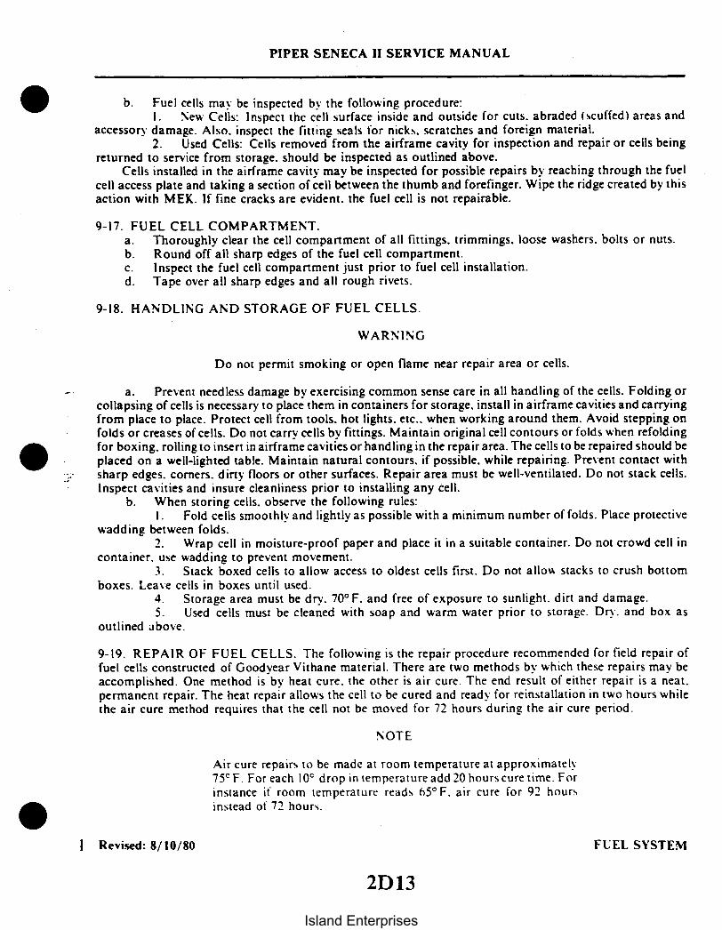
PIPER SENECA II SERVICE MANUAL
b. Fuel cells may be inspected by the following procedure:1. New Cells: Inspect the cell surface inside and outside for cuts. abraded (scuffed) areas and
accessory damage. Also. inspect the fitting seals for nicks, scratches and foreign material.2. Used Cells: Cells removed from the airframe cavity for inspection and repair or cells being
returned to service from storage. should be inspected as outlined above.Cells installed in the airframe cavity may be inspected for possible repairs by reaching through the fuel
cell access plate and taking a section of cell between the thumb and forefinger. Wipe the ridge created by thisaction with MEK. If fine cracks are evident, the fuel cell is not repairable.
9-17. FUEL CELL COMPARTMENT.a. Thoroughly clear the cell compartment of all fittings, trimmings, loose washers. bolts or nuts.b. Round off all sharp edges of the fuel cell compartment.c. Inspect the fuel cell compartment just prior to fuel cell installation.d. Tape over all sharp edges and all rough rivets.
9-18. HANDLING AND STORAGE OF FUEL CELLS.
WARNING
Do not permit smoking or open flame near repair area or cells.
a. Prevent needless damage by exercising common sense care in all handling of the cells. Folding orcollapsing of cells is necessary to place them in containers for storage, install in airframe cavities and carryingfrom place to place. Protect cell from tools. hot lights. etc.. when working around them. Avoid stepping onfolds or creases of cells. Do not carry cells by fittings. Maintain original cell contours or folds when refoldingfor boxing, rolling to insert in airframe cavities or handling in the repair area. The cells to be repaired should beplaced on a well-lighted table. Maintain natural contours. if possible. while repairing. Prevent contact withsharp edges. corners. dirty floors or other surfaces. Repair area must be well-ventilated. Do not stack cells.Inspect cavities and insure cleanliness prior to installing any cell.
b. When storing cells, observe the following rules:I. Fold cells smoothly and lightly as possible with a minimum number of folds. Place protective
wadding between folds.2. Wrap cell in moisture-proof paper and place it in a suitable container. Do not crowd cell in
container, use wadding to prevent movement.3. Stack boxed cells to allow access to oldest cells first. Do not allow stacks to crush bottom
boxes. Lease cells in boxes until used.4. Storage area must be dry. 70° F. and free of exposure to sunlight, dirt and damage.5. Used cells must be cleaned with soap and warm water prior to storage. Dry. and box as
outlined above.
9-19. REPAIR OF FUEL CELLS. The following is the repair procedure recommended for field repair offuel cells constructed of Goodyear Vithane material. There are two methods by which these repairs may beaccomplished. One method is by heat cure. the other is air cure. The end result of either repair is a neat.permanent repair. The heat repair allows the cell to be cured and ready for reinstallation in two hours whilethe air cure method requires that the cell not be moved for 72 hours during the air cure period.
NOTE
Air cure repairs to be made at room temperature at approximately7 5 F. For each 10° drop in temperature add 20 hours cure time. Forinstance if room temperature reads 65° F. air cure for 92 hoursinstead of 72 hours.
Revised: 8/10/80 FUEL SYSTEM
2D13
Island Enterprises

PIPER SENECA II SERVICE MANUAL
9-20. HANDLING OF REPAIR MATERIALS.a. All materials are to be protected from dirt contamination, sunlight, and excessive heat or cold while
in storage. Containers are to be tightly capped and stored at a temperature of 70° F.
CAUTION
80C27 repair cement requires thorough mixing to obtain full adhe-sive values.
b. The repair cement code 80C27 referred to in this text is prepared immediately prior to use by mixingrepair cement 80C27 (pint can with 320gms) with cross-linker 80C28 (4 oz. bottle with 81cc).
CAUTION
All containers for cements and solvents should be properly identi-fied.
c. Repair cement has a pot life of 20 minutes after mixing. The unmixed 80C27 and 80C28 have a shelflife of six months from date of packaging.
9-21. REPAIR PROCEDURES OF GOODYEAR VITHANE FUEL CELLS.
NOTE
The repair of Goodyear Vithane fuel cells is restricted to authorizedpersonnel. Authorized personnel are those who have been certifiedand trained by Goodyear representatives, or those who havereceived their training from persons who have been certified andtrained by Goodyear representatives.
9-22. REPAIR LIMITATIONS OF FUEL CELLS. Repair limitations are as follows:a. FT-192 repair fabric is for repair of simple contours only. Patches referred to in this text are of this
material.b. Inside patches are to lap defect edges a minimum of 1.0 inch in each direction.c. Outside patches are to lap defect edges .25 to .50 of an inch larger than inside patches.d. Outside patches are to be applied and cured prior to applying an inside patch.e. Blisters between inner liner and fabric, larger than .25 of an inch in diameter require an outside and
an inside patch.f. Separations between layers or plies larger than .50 of an inch in diameter require an outside and
inside patch.g. Slits or tears up to 6.0 inches maximum length require an outside and inside patch.h. External abraded or scuffed areas without fabric damage require an outside patch only.i. A loose edge may be trimmed, provided that .50 of an inch minimum lap or seam is maintained.
CAUTION
For each 10° drop in temperature from 75°F. add 20 hours curetime. For example. at 65°F. cure for 92 hours..
Revised: 8/10/80 FUEL SYSTEM
2D14
Island Enterprises

PIPER SENECA II SERVICE MANUAL
j. Air cure repair patches are to remain clamped and undisturbed for 72 hours at room temperature ofapproximately 75° F.
k. All heat cured patches are ready for use when cool.1. Fitting repairs are confined to loose flange edges. seal surface rework and coat stock.m. The maximum number of heat cure repairs in the same area is four.
NOTE
Any damage not covered by the above should be returned to TheGoodyear Tire & Rubber Company. Rockmart. Georgia. for repair.
9-23. REPAIR PATCH (Heat Cure Method).a. Prepare exterior cell wall and exterior patch first. Cut repair patch from FT-192 material to size
required to insure proper lap over injury in all directions. (See Limitations.) (Hold shears at an angle toproduce a beveled edge (feather) on patch.) Round corners of patch. (Dull side or gum contact face of repairpatch should be the largest surface after beveling.)
b. Wash one square foot of cell wall surrounding injury and repair patch contact side with a clean clothsoaked with Methyl Ethyl Ketone solvent.
c. Abrade cell wall surface about injury and contact side of patch with fine emery cloth to removeshine.
d. Repeat Methyl Ethyl Ketone washings two more times. A total of three washings each surface.e. Tape a 8" x 8" piece of cellophane inside cell over injury.f. When all the above preparatory work has been done and cell has been positioned for patch
application on repair table, mix the 80C27 cement (320 gms) with the crosslinker 80C28 (81cc). and stirmixture thoroughly for five minutes.
NOTE
Cement must be at a minimum of 70° F before mixing. Keep awayfrom water and excessive heat.
g. Brush one even coat of mixed repair cement on the cell wall around injury and on the contact side ofrepair patch. Allow to dry for fifteen minutes.
CAUTION
Do not use first can of mixed cement for this coat.
h. Repeat a second mixing of repair cement and brush a second coat.
CAUTION
Make sure cellophane inside cell over injury remains in place as anycement will stick cell walls together without it as a separator.
i. Allow cement to dry approximately five minutes and then center patch over injury. Lay repair patchby rolling down on surface from center to edge without trapping air. Hold the unrolled portion of repair patchoff the cemented surface until roller contact insures an air-free union. At this time repair patch may be movedby hand on wet surface to improve lap. Do not lift repair patch. slide it.
I Revised: 8/10/80 FUEL SYSTEM
2D15
Island Enterprises

PIPER SENECA II SERVICE MANUAL
FUEL CELL REPAIR EQUIPMENT INFORMATION
Repair Kit, Goodyear Drawing No. 2F1-3-37813
Group I Materials
80C27 Repair Cement 8 Pint cans, 320gms in each80C28 Cross-Linker 8 4 oz. bottles, 81cc in eachMethyl Ethyl Ketone 2 Pint cansFT-192 Repair Fabric 2 Sheet 12" x 12"
Group II Materials
The following equipment is necessary to perform the repair.
Group II equipment will be furnished at additional cost, if orderedby customer.
Foam Rubber Cloth Back Sheet, 1/4" x 12" x 12" 2Paint Brush, 1 inch wide 2Aluminum Plates, 1/4" x 6" x 6" 4Measuring Cup (250ml) 1Cellophane (Sheet 12" x 24") 2
Torques For Specific Nipple Fitting Sizes
Fitting Size (I.D.) Clamp Torques (in.-lbs.)
1/4"- 1/2" 12- 163/4"- 1 15-20
1 1/2" 25-302" 30 -353" 35 -40
NOTES
Accessories - order per individual cell requirements.
Phenol plates, phenol plate assemblies and phenol test equipmentcan be ordered as required from cell manufacturer.
Cure Iron (set 240° F) optional.
Reissued: 10/11/79 FUEL SYSTEM2D16
Island Enterprises
PIPER SENECA II SERVICE MANUAL
j. Cover one smooth surface each of two aluminum plates (plates must be larger than patch). withfabric-backed airfoam fabric side out. Tape airfoam in place. Foam must cover edges of plate for protection.Use a cellophane separator to prevent the cement from sticking in the wrong place.
CAUTION
Make sure that cell fold is not clamped between plates. This wouldcause a hard permanent crease. Also make sure that patch does notmove when clamp is tightened.
k. Center a repair iron 2F1-3-25721-1 on the plate over the repair patch. Secure the assembly with a"C" clamp. Tighten by hand. Check cement flow to determine pressure.
1. Connect repair iron into 110-volt electrical outlet and cure repair for two hours. After two hourscure. unplug electric and allow repair iron to cool to touch. Then remove "C" clamp. Wet cellophane to removefrom repair.
CAUTION
Success of applying both an outside and inside repair patch simul-taneously is doubtful and not recommended.
m. Inside patch is applied same as above procedure except for size of repair patch (see limitations) afteroutside patch has been cured.
9-24. REPAIR PATCH (Air Cure Method). Follow procedure for heat cure method. except omit repair ironand cure each patch per air cure limitations (minimum 72 hours), undisturbed, at 75°F.
9-25. DEFECT REPAIRS OF FUEL CELL.a. Blisters: Remove loose material by trimming. Apply an outside and inside repair patch.b. Holes. Punctures. Cuts. Tears and Deep Abraded Areas: Trim away any ragged material and apply
an outside and inside repair patch.c. Loose Seams: Buff loose edge and contact surface with emery cloth. Wash three times with Methyl
Ethyl Ketone. Apply 80C27 mixed cement two coats as with repair patch. Clamp and cure. Either method maybe used. See repair patch. Loose seams may be trimmed if minimum lap remains.
9-26. TESTING FUEL CELLS. Either of the following test procedures may be used to detect leaks in thebladder cells.
a. Soap Suds Test.1. Attach test plates to all fittings.2. Inflate the cell with air to a pressure of 1 4 psi MAXIMUM.3. Apply a soap and water solution to all repaired areas and any areas suspected of leakage.
Bubbles will appear at any point where leakage occurs.4. After test. remove all plates and wipe soap residue from the exterior of the cell.
b. Chemical Test.1. Attach test plates to all fitting openings except one.2. Make up a phenolphthalein solution as follows: Add 40 grams phenolphthalein crystals in 1 2
gallon of ethyl alcohol, mix. then add 1 2 gallon of water.3. Pour ammonia on an absorbent cloth in the ratio of 3ml per cubic foot of cell capacity. Place
the saturated cloth inside the cell and install remaining test plate.4. Inflate the cell with air to a pressure of 1 4 psi MAXIMUM. and maintain pressure for fifteen
minutes.
Revised: 8/10/80 FUEL SYSTEM
2D17
Island Enterprises

PIPER SENECA II SERVICE MANUAL
5. Soak a large white cloth in the phenolphthalein solution. wring it out thoroughly. and spread itsmoothly on the outer surface of the cell. Press the cloth down to insure detection of minute leaks.
6. Check the cloth for red spots which will indicate a leak. Mark any leaks found and move thecloth to a new location. Repeat this procedure until the entire exterior surface of the cell has been covered. Ifred spots appear on the cloth, they may be removed by resoaking the cloth in the solution.
7. The solution and test cloth are satisfactory only as long as they remain clean. Indicator solu-tion that is not in immediate use should be stored in a closed rustproof container to prevent evaporation anddeterioration.
After the test, remove all plates and test equipment. Allow the cell to air out.In conducting either test outlined above, the cell need not be confined by a cage or jig. providing the 1/ 4
psi pressure is not exceeded.
NOTE
The chemical test is the more sensitive and preferred test.
THIS SPACE INTENTIONALLY LEFT BLANK
I Revised: 8/10/80 FUEL SYSTEM
2D18Island Enterprises

PIPER SENECA II SERVICE MANUAL
9-27. INSPECTION OF FUEL SYSTEM. Fill tanks with fuel. Inspect tanks and fuel line connections forleaks. If fuel tanks leak. follow instructions given in Paragraph 9-5. If fuel line connections leak. tightenclamps or replace hose connections after first draining tanks.
9-28. FUEL QUANTITY SENDER UNITS. Each fuel cell contains a sender unit which is interconnectedwith the other units of its particular system to provide the gauge with a combined, calibrated resistance.
The resistances of these units (1.0 ohm maximum at the empty position. and 45 2 ohms at the fullposition) should be checked before installation and if any unit is assumed to be faulty. Full travel of the unitshould be 95° 2° .
9-29. FUEL QUANTITY SENDER/GAUGE CHECK (INSTALLED). Fuel quantity sender units and fuelquantity gauges can be checked while mounted in the airplane by using the following procedure:
a. Put the fuel selector levers in the "OFF" position. Completely drain fuel tanks that relate to thefuel quantity senders and gauge to be checked. (Refer to Draining Fuel System. Section II.)
b. Level airplane laterally (refer to Leveling. Section II) and position the aircraft with a 1 nose upattitude.
NOTE
The electrical system should supply 12 to 14-volts to the gauge.
c. With the master switch in the "OFF" position. the gauge needle should be centered on the whitedot to the left of the "0" radial mark, with a maximum deviation of 1/4 needle width. If not within thistolerance, the gauge should be replaced.
d. With the master switch in the "ON" position and no fuel in the tanks, the gauge needle should becentered on the white dot to the left of the "0" radial mark with a maximum deviation of 1/4 needlewidth. If not within this tolerance. the gauge should be replaced.
e. Place 2-1/2 gallons of fuel in the wing fuel tank that relates to the gauge and sender unit beingchecked.
f. With 12 to 14-volts DC supplied to the electrical system and the master switch in the "ON"position. the needle should be centered on the "O" radial mark: plus O. minus I needle width.
g. If the needle does not read within the above tolerance, remove the sender wire from the rear ofthe gauge and check the resistance to ground through the sender circuit. If the resistance is not within 6.50.5 ohms. replace the inboard sender. Then. recheck as specified above.
h. Add fuel to the tanks in accordance with the information given in Table IX-I until tanks are full.Observe the gauge reading at each 10 gallon increment.
i. With the tanks full and master switch "ON." the needle should be centered on the "F" radial markwithin I needle width. If not within this tolerance, adjust the electrical adjustment (refer to Figure 9-3)adjust sufficiently to bring it within tolerance: do not center the needle.
NOTE
All adjustments required on gauges shall be accomplished using anon-magnetic screwdriver.
Revised: 8/10/80 FUEL SYSTEM2D19
Island Enterprises

WITH STANDARD FUEL TANKS INSTALLED
PIPER SENECA II SERVICE MANUAL
255
2 I
3
ALNTOLE
7
TORQUE 60 T
1. BODY, FILTER2. O-RING SEAL3. TUBE. OUTER4. NUT5. STUD6. DRAIN, FILTER, FITTING7. NUT8. SPRING9. BALL, RELIEF
8
II
12
141
15
I6
IN POUNDS
10. SEAT, RELIEF11. DISCS, FILTER12. WASHERS13. CUP, RETAINER14. NUT, CHECK15. BOWL, FILTER16. WASHER17. SAFETY WIREWITH OPTIONAL FUEL TANKS INSTALLED
I Figure 9-3. Fuel Gauugs Figure 9-4. Fuel Filter
TABLE IX-I. FUEL QUANTITY SENDER/GAUGE TOLERANCES
STANDARD FUEL. SYSTEM OPTIONAL FUEL SYSTEM
Actual FuelWithin TanksU.S. Gallons)
10
20
40
Gauge Reading(U.S. Gallons)
20 (+2)
40 +2)
Total ResistanceOf Senders
(Ohms)
26
44
80
Actual FuelWithin Tanks(U.S. Gallons)
10
20
50
Gauge Reading(U.S. Gallons)
10 (+l)
20 (+2)
50 (+2)
Total ResistanceOf Senders
(Ohms)
26
39
74
NOTE: Value in parentheses are needle-width tolerances.
Revised: 8/10/80 FUEL SYSTEM2D20
Island Enterprises

PIPER SENECA II SERVICE MANUAL
9-30. FUEL FILTERS.
9-31. REMOVAL OF FUEL FILTER. (Refer to Figure 9-4.) The instructions given are for the removal ofthe complete filter from the airplane. For cleaning and servicing purposes, only Steps a and b of thisparagraph are necessary; then proceed to Paragraph 9-32.
a. Position the fuel selector valve to the OFF position.b. Remove the access panel forward of the main spar, at wing station 91.00, on the bottom of the
wing panel.c. Disconnect the filter drain line and fuel lines from the filter assembly. Cap the line ends to
prevent contamination.d. Remove the bolts that secure the filter to its mounting bracket and remove the filter from the
aircraft.
9-32. DISASSEMBLY OF FUEL FILTER. (Refer to Figure 9-4.)a. Cut safety wire (17) and remove cap nut (7) from the bottom of the filter bowl (15).b. Remove the bowl from the filter body (1).c. The O-ring seal (2) may be removed from the body.d. Loosen and remove both the check nut (14) and nut (4) from the stud (5) that holds the filter
cartridge subassembly.e. Slide the filter cartridge from the stud. The filter discs (11) and washers (12) need not be
separated from the element outer tube (3) for normal cleaning.f. If necessary to disassemble the filter cartridge, remove the retainer cup (13) from the outer tube
(3) and slide discs (11) and washers (12) from the outer tube. Do not use a screwdriver or sharp tool thatmay damage the discs.
g. The filter bypass assembly may be removed by using the proper size screwdriver and turning outthe relief seat (10). Remove relief ball (9) and spring (8).
9-33. CLEANING, INSPECTION AND REPAIR OF FUEL FILTER.a. Carefully remove the filter pack from the housing and remove all O-rings, valves, springs, etc. Do
not disassemble the filter pack from the center tube at this time.b. Plug the open ends of the filter and immerse in oil solvent such as Stoddard solvent. Let soak for
30 to 60 minutes.c. Metal valve parts may also be soaked in this cleaner.d. Remove filter and parts (if any) from the cleaner and rinse thoroughly in clean hot flowing tap
water.e. Drain or blow off with filtered low pressure air to dry.f. Inspect the filter discs for damage and/or broken screens.g. Check condition of bowl O-ring seal (2) and washer (6).h. Check for corrosion of filter parts.i. Check movement of bypass valve.j. Normal repairs necessary for the filter are replacement of bowl gaskets and damaged filter discs.
Revised: 8/10/80 FUEL SYSTEM
2D21
Island Enterprises

PIPER SENECA II SERVICE MANUAL
9-34. ASSEMBLY OF FUEL FILTER. (Refer to Figure 9-4.)a. If removed, install bypass valve spring (8), relief ball (9) and seat (10).b. Place the filter pack (assembled) on the housing stud (5). Ascertain that the end of the outer tube
(3) has positioned itself in the filter body (1).c. Secure the filter pack with nut (4). Torque nut 10 to 15 inch-pounds. Torque check nut (14)
against nut (4) 40 to 60 inch-pounds.d. Place the O-ring packing (2) on the housing and install bowl (15), washer (16) and cap nut (7).
Torque cap nut 60 to 80 inch-pounds and safety.e. Install the filter in the aircraft. If the filter was not removed, proceed to Step c of Paragraph 9-35.
9-35. INSTALLATION OF FUEL FILTER.a. Position the filter assembly into the wing. Ascertain that it is positioned properly and secure to
its mounting bracket with two bolts.b. Connect the drain line to the filter bowl.c. Connect the fuel lines to the filter assembly.d. Turn the fuel selector to the ON position and check for any fuel leaks.e. Install the access plate.
9-36. FUEL SELECTOR VALVE.
9-37. REMOVAL OF FUEL SELECTOR VALVE.a. The fuel selector valve need not be removed unless any of the following conditions exist:
1. Failure of selector lever to seat in detent.2. Signs of leakage.3. Difficulty in moving fuel selector lever.
b. In the event it is necessary to remove the fuel selector valve, remove access plate located forwardof the main spar on the underside of the wing and outboard of the nacelle.
c. Drain appropriate fuel tank. (Refer to Draining Fuel Tank, Section II.)d. Disconnect control cable from valve selector lever. Disconnect fuel lines and mounting hardware
and remove fuel selector valve.
NOTE
Except for replacement of O-rings, the fuel selector valve should beoverhauled only when necessary. To remove and replace O-rings,follow instructions in Paragraphs 9-37 and 9-40.
9-38. DISASSEMBLY OF SELECTOR VALVE. (Refer to Figure 9-5.)a. Remove the four screws (14) and washers (15) that attach the cap assembly (9) to the valve body
(2).b. Pull the cap assembly straight from the valve body (2).c. Push the spool (12) from the valve body.d. To disassemble the cap assembly (9), remove the roll pin (3) that secures the gear (21) on its
shaft (4) by driving the pin with a 3/32 straight drift punch.e. Remove the gear and spacer (8) from the shaft.f. Remove the four screws (13) that secure the packing and seal cover (6). Remove the cover.g. Remove old O-rings and seal.h. If fitting (11) is removed, replace O-ring packing (17).
FUEL SYSTEMReissued: 10/11/79
2D22Island Enterprises

3
PIPER SENECA II SERVICE MANUAL
1. PACKING, PREFORMED2. BODY, VALVE3. ROLL PIN4. SHAFT5. LEVER, SELECTOR6. COVER7. SPRING, DETENT
8.SPACER9. CAP ASSEMBLY
12. SPOOL, VALVE13. SCREW, FLAT HEAD14. SCREW, SLOTTED15. WASHER, LOCK16. PACKING, PREFORMED
PACKING, PREFORMED18. PACKING, PREFORMED19. SEAL20 ROLL PIN21. GEAR
Figure 9-5. Fuel Selector Valve
9-39. CLEANING, INSPECTION AND REPAIR OF SELECTOR VALVE.a. Clean the valve components in a dry cleaning solvent.b. Inspect the valve for the following:
1. Check that the friction surfaces of the valve are free from nicks, dents and burrs.2. Check that the teeth of the gear and spool are not damaged.3. Check that the threaded surfaces are not stripped or cross-threaded.4. Check that the selector detent mechanism is operating properly.
c. Repair to the valve is limited to reconditioning of parts, such as smoothing out minor nicks andscratches and the replacing of O-ring packings and seal.
NOTE
Fittings ( 1 ) in valve are special. Do Not use AN fittings.
9-40. ASSEMBLY OF SELECTOR VALVE. (Refer to Figure 9-5.)a. If either fitting ( 11 ) was removed, install the O-ring packing (17) and assemble the fitting on the
valve body (2).b. Lubricate the O-ring packings (17) with a thin coat of stop-lock grease and install on the valve
spool (12).c. Insert and center the spool in the valve body.d. Lubricate the seal (19) and O-ring (16) and install in the cap assembly (9).e. Ascertain that the shaft (4) is in place and install cover (6). Secure with screws ( 13).f. Slide the spacer (8) and gear (21) on the shaft, with the pinholes aligned so that the gear teeth are
opposite the selector lever (5). Secure the gear with roll pin (3).
Reissued: 10/11/79 FUEL SYSTEM
2D23
Island Enterprises

PIPER SENECA II SERVICE MANUAL
g. Install the O-ring packing (18) on the cap assembly.h. Place the selector handle in neutral in relation to the cap and install the cap assembly in the valve
body. Secure the cap assembly with screws (14) and washers (15).i. Check valve operation.
9-41. LEAK TEST OF SELECTOR VALVE.a. Connect the inlet port of the valve assembly to a 25 psi air source.b. Plug the right-hand port and close the left-hand port by placing the control lever to the right.c. Apply pressure to 25 psi. There shall be no evidence of leakage either through the port or around
the fitting and lever when submerged in kerosene or a similar petroleum base fluid for 30 seconds.d. Depressurize; remove the plug from the right-hand port; place on left-hand port and close
right-hand port by placing the lever to left.e. Repeat Step c.f. Disconnect and wipe fluid from exterior.
9-42. INSTALLATION OF FUEL SELECTOR VALVE.a. Position the selector valve in the wing with control lever down and center port forward. Secure to
mounting bracket with four screws and nuts.b. Connect fuel lines to valve and control cable to selector lever.c. Refer to Paragraph 9-43 for rigging of selector valve. Install access panel.
9-43. RIGGING OF SELECTOR VALVE.a. Remove the access panel located on the underside of the wing, forward of the main spar,
outboard of the nacelle.b. Ascertain that the control cable is connected to the selector valve and that the valve is in its
center OFF position. Lubricate the external parts of the selector valve sprocket and control cableattachment ends with ESSO "Beacon 325" grease or equivalent (MIL-G-3278).
c. Place the fuel selector handle in the cockpit, in its OFF position. (The levers centered on theOFF position of the cover placard.) Adjust and connect the cable end to the cockpit lever.
d. Actuate the selector to ascertain that the valve moves into its three detent positions and thecontrol levers have a positive clearance between the lever and cover assembly.
e. Reinstall the access panel.
9-44. CLEANING FUEL SYSTEM.a. To flush fuel tank and selector valve, disconnect the fuel line from the injector.b. Select a fuel tank; turn on the electric pump and flush fuel through the system until the tank is
empty. Agitation of the fuel within the tank during this operation will help pick up and remove dirt andother foreign matter from the fuel tank and selector valve.
c. Repeat this procedure for each fuel tank.d. When all tanks are flushed, clean filter and fuel tank finger screens.
9-45. ELECTRIC FUEL PUMP.
9-46. REMOVAL AND INSTALLATION OF ELECTRIC FUEL PUMP. There is one electric rotary vanetype fuel pump for each engine. The pump is mounted in a bracket on the aft side of the fire wall. Toremove pump, proceed as follows:
a. Remove rectangular hatch assembly located on the top of the nacelle, aft of the fire wall.b. Remove fuel lines from the pump and disconnect the electrical leads.c. Remove straps holding pump in position and withdraw pump through hatch opening.
Reissued: 10/11/79 FUEL SYSTEM2D24
Island Enterprises

d. Do not attempt disassembly or repair of the fuel pump. If fuel pump proves to be defective, it shouldbe replaced.
e. Reinstall pump in reverse order of removal.
SLIDERS
RESISTOR
LOW MED
Figure 9-6. Slider Resistor Terminal, Right or Left (Looking Aft)
9-47. AUXILIARY FUEL SYSTEM ADJUSTMENT. Adjustment of the auxiliary fuelsystem if installed isaccomplished as follows for each engine:
a. Remove the access panels from the top of each engine nacelle to gain access to the slider resistormounted on the nacelle bulkhead.
b. Install a calibrated pressure gauge (31 to 37 psi) in the fuel line forward of the firewall.c. Pull the circuit protector (for the auxiliary fuel pump which is to be adjusted) to the off position and
insure that the aircraft master switch is in the off position also.d. Connect the negative lead from an external DC power source to ground on the aircraft and the
positive lead to the slider resistor high position. (Refer to Figure 9-6.)e. Using a calibrated voltmeter, adjust the external power source to indicate 12.0 to 12.5 volts DC at
the auxiliary fuel pump. Note the voltage reading on the external power source voltmeter.f. The calibrated pressure gauge should indicate 31 to 37 psi.g. Connect the positive lead from the external power source to the slider resistor low position. (Refer
to Figure 9-6.) Adjust the power supply voltage level to the same voltage obtained in Step e.h. Adjust the slider on the variable resistor to obtain a pump pressure of 8 to 10 psi. Readjust the power
supply and slider to insure a pump pressure of 8 to 10 psi, at the power supply voltage noted in Step e. thensecure the slider in position on the resistor.
i. Disconnect the manifold pressure switch located on the firewall, and connect the positive lead fromthe power supply to the slider resistor medium position.
j. Adjust the power supply voltage level to the same voltage obtained in Step e.k. Adjust the slider on the variable resistor to obtain a pump pressure of 23.5 to 24.5 psi. Readjust the
power supply and slider to insure a pump pressure of 23.5 to 24.5 psi, at the power supply voltage noted in Stepe, then secure the slider in position on the resistor and reconnect the manifold pressure switch.
1. Perform Steps a thru k on the opposite engine, then reinstall the access panels.
Revised: 9/24/81 FUEL SYSTEM
PIPER SENECA II SERVICE MANUAL
2El
Island Enterprises

PIPER SENECA II SERVICE MANUAL
m. If the aircraft is equipped with an optional fuel diverter valve, operate the primer switch and insurethat the diverter valve is being energized. Release the primer switch and operate the fuel pump switch in the Hi-Boost position and insure that the fuel pump operates and that the diverter valve does not.
n. Remove calibrated pressure gauge unless auxiliary fuel system operational check (in followingparagraph) is to be performed.
o. Refer to Section VII, Paragraph 8-60, Engine Setup Procedures, for additional adjustmentsrelating to the power plant fuel control system.
9-48. AUXILIARY FUEL SYSTEM OPERATIONAL CHECKa. Disconnect the external power source from the aircraft.b. Disconnect the electrical leads from the manifold pressure switch located on the firewall.c. Insure that all cockpit controllable electrical equipment switches are in the off position, except as
directed in the following steps.d. Turn the aircraft master switch on.e. Place the electric fuel pump switch in the "low" position.f. The calibrated fuel pressure gauge (should indicate a pressure increase which would indicate that the
pump is operating. This pressure should not exceed 10 psi.g. Place the electric fuel pump switch in the "hi" position.h. The calibrated fuel pressure gauge should indicate a pressure above that noted in step f. This
pressure should not exceed 24.5 psi.i. Place the aircraft master switch in the off position.j. Reconnect the leads to the manifold pressure switch.k. With the fuel pump switch still in the "high" position. return the master switch to the on position.1. The calibrated pressure gauge should indicate a pressure above the pressure noted in step h. This
pressure should exceed 37 psi.m. Place the fuel pump switch in the off position and depress the prime switch. The calibrated pressure
gauge shall indicate a pressure above that noted in step h. This pressure should ot exceed 37 psi.n. Repeat these tests on other engine.o. Remove calibrated fuel gauge.
9-49. CALIBRATION AND TEST OF FUEL QUANTITY GAUGES.a. Before placing the gauge in the cluster housing, place it in an upright level position and adjust the
needle to point to the dot to the left of the "O"line, using the mechanical adjustment provided on the rear of thegauge.
NOTE
Use a non-magnetic screwdriver to accomplish all adjustments tothe gauge.
b. Install the gauge in the cluster housing. (This will ground the gauge to the cluster housing, throughthe ground clip.)
c. Fabricate a tester as shown in Figure 9-6a. Hook it up to the gauge as shown.d. With the selector switch in the "B" position (corresponding to the highest numbered radial mark).
Center the gauge needle on that mark using the electrical adjustment located behind the adjustment hole in theface of the instrument.
e. Place the selector switch in the zero resistance position. The gauge needle should be centered on thedot at the left of the "O" mark ± 1/2 needle width.
Revised: 11/12/82 FUEL SYSTEM2E2
Island Enterprises

PIPER SENECA II SERVICE MANUAL
C276
90 OHMS
CLUSTER HOUSING(REAR VIEW) SWITCH M
61.5 OHMS
OHMS14 VOC
TEST SET-UP, GAUGES 96899 AND 38224-0
FIGURE I
CLUSTER HOUSING SWITCH A B 74 OHMS(REAR VIEW)
63 OHMS
D 54 OHMS
14 VOC39 OHMS
f 26OHM S
G 6 5 OHMS
TEST SET-UP, GAUGE 38224-2
Figure 9-6a. Resistor Set-up, Test for Fuel Quantity Gauge
Added: 3/16/81 FUEL SYSTEM2E3
Island Enterprises

PIPER SENECA II SERVICE MANUAL
C277
-1/2 NEEDLE WIDTH
RADIAL MARK OR DOT,
AS APPLICABLE
MAXIMUM DEVIATION FROMCENTERED POSITION
NEEDLE
Figure 9-6b. Maximum Deviation of Fuel Quantity Gauge Needle
f. Place the selector switch in the 6.5 ohms resistance position. The gauge needle should be centered onthe "O" radial mark +0 -1/2 needle width.
g. Sequentially place the selector switch in the positions shown in Table IX-II. The gauge needleshould center on the radial mark indicated within the given tolerance.
TABLE IX-II. FUEL GAUGE READING TOLERANCES
ISwitch Position
FEDCBA
GAUGE P/N 38224-0Radial Mark Tolerance
(Needlewidths)
10 +20 130 ±40 1F ±1
Radial Mark
1020304050F
GAUGE P/N 38224-2
Tolerance(Needlewidths)
±_+1±1
h. Drain aircraft fuel system, if not previously accomplished.i. Add sufficient fuel to left and right wing tank system to allow verification that all fuel trap cavities
are filled. Drain excess fuel.j. Add 2 1/2 gallons of fuel in the left wing fuel tank and 2 1/2 gallons of fuel in the right wing fuel tank.k. With 12-14 VDC supplied to the electrical system, the needle shall be centered on the "O" radial
mark. +0 -1 needle width. If the needle does not read within this tolerance, replace the gauge. If replacing thegauge does not remedy the problem. check the sender. Recheck as specified above.
Revised: 11/12/82 FUEL SYSTEM2E4
Island Enterprises

PIPER SENECA II SERVICE MANUAL
TABLE IX-III. GAUGE READINGS/RESISTANCE WITH FUEL IN TANKS
Model Total Fuel in Tanks(Each Side)
(Gallons)
Required GaugeReading
Tolerance+Needlewidths
Resistance (Reference)(Ohms, Both Senders)
I
Without BladderTanks
With BladderTanks
102040102050
102040102050
221222
264480263974
1. With 14 VDC supplied to the electrical system. master switch in the off position and fuel already inthe tanks as specified in step j add fuel to the left and right tanks to total quantities shown in Table IX-Ill. Thefuel quantity readings should be as specified at each increment. If the readings are not within the statedtolerances, check the resistance of the senders, referring to Table IX-III.
m. If it is necessary to adjust the gauge at the 30,40 or 50 gallon position, recheck the gauge as in steps kand 1. To insure that the gauge is still within tolerance as shown in Table IX-III.
Revised: 11/12/82 FUEL SYSTEM2E5
Island Enterprises

PIPER SENECA II SERVICE MANUAL
TABLE IX-IV. TROUBLESHOOTING CHART (FUEL SYSTEM)
Trouble Cause Remedy
Failure of fuel to flow. Fuel line blocked. Flush fuel system.
Fuel vent cap blocked.
Mechanical or electricalfuel pump failure.
Fuel selector valvein improper position.
Check and clean venthole in cap.
Check and replace ifnecessary.
Reposition as re-quired.
Check for obstructionsin the fuel selectorleverage mechanism.
Check fuel selectorcable for freedom ofmovement.
Damaged fuel selectorvalve.
Replace fuel selectorvalve.
Fuel quantity gaugefails to operate.
Broken wire.
Gauge inoperative.
Check and repair.
Replace gauge.
Fuel sender floatpartially or completelyfilled with fuel.
Circuit breaker open.
Float and arm assemblyof fuel sender sticking.
Bad ground.
Replace sender.
Check and reset.
Check.
Check for good contactat ground lip or rearof gauge.
Reissued: 10/11/79 FUEL SYSTEM
2E6
Island Enterprises
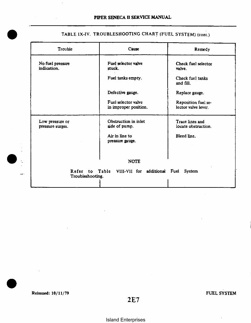
PIPER SENECA II SERVICE MANUAL
TABLE IX-IV. TROUBLESHOOTING CHART (FUEL SYSTEM) (cont.)
Trouble Cause Remedy
No fuel pressure Fuel selector valve Check fuel selectorindication. stuck. valve.
Fuel tanks empty. Check fuel tanksand fill.
Defective gauge. Replace gauge.
Fuel selector valve Reposition fuel se-in improper position. lector valve lever.
Low pressure or Obstruction in inlet Trace lines andpressure surges. side of pump. locate obstruction.
Air in line to Bleed line.pressure gauge.
NOTE
Refer to Table VIII-VII for additional Fuel SystemTroubleshooting.
Reissued: 10/11/79 FUEL SYSTEM
2E7
Island Enterprises

SECTION X
INSTRUMENTS
AeroficheGrid No.Paragraph
10-1. General ....................................10-2. Non-Electrical Instruments .........................10-3. Gyro Pressure System ..............
10-4. General .. .........................10-5. Troubleshooting .. ......................
10-6. Gyro Pressure Gauge ............. . ............10-7. General ... .... ......... ...........10-8. Troubleshooting ............ ...........
10-9. Pressure Regulating Valve ..........................10-10. General ...............10-11. Troubleshooting .........................10-12. Adjustments to Pressure Regulator ...........10-13. Removal and Installation ..........
10-14. Pneumatic Pump .......................... . ....10-15. General ............................10-16. Troubleshooting ............10-17. Removal and Installation .. .................10-17a. Replacing Pump Fittings .....................
10-18. Pitot-Static System .. ..........................10-19. Directional Gyro ...............................
10-20. General ........ ....... ............10-21. Troubleshooting ....................10-22. Removal and Replacement ...................
10-23. Gyro Horizon ................................10-24. General ..............................10-25. Troubleshooting ..... .... ............10-26. Removal and Replacement ...................
10-27. Rate of Climb Indicator ...........................1 0-8. General .. . . .......................10-29. Troubleshooting ...... ........... ......10-30. Removal and Replacement ...................
10-31. Sensitive Altimeter ..............10-32. General ..............................10-33. Troubleshooting .........................10-34. Removal and Replacement .. ................
10-35. Airspeed Indicator .. . . . . ...................10-36. General ....... ..... .. . ........ ....10-37. Troubleshooting ..................
.......... 2E l1......... .. 2E 11....... .... 2E11........ ... 2E11........... 2E11........... . 2E11........... ..2E11........... 2E11........... .2E11........... 2E11........... 2E11........... 2E13........... 2E15............ 2E15........... 2EI........... 2E1
...... 2E15........... 2E15........... 2E15......... .. 2E19........... 2E19........... 2E19........... 2E20........... 2E20........... 2E20.... .... 2E20........... 2E2........... 2E22.......... 2E22
........... 2E22
........... 2E22
........... 2E23........ 2E23
........... 2E23
........... 2E23
........... 2E24...... ..... 2F12F1........... 2F1
.. . 2F110-38. Removal and Replacement ..
Revised: 8/10/80
2E8
Island Enterprises

Paragraph
10-39. Magnetic Compass ...........10-40. General ..........10-41. Adjustment of Compass .10-42. Troubleshooting ......
10-43. Manifold Pressure Gauge System. . .10-44. General .........10-45. Troubleshooting ......10-46. Removal and Replacement
10-47. Tachometer Indicator .........10,48. General ...........10-49. Troubleshooting ......10-50. Removal and Replacement
10-51. Engine Oil Pressure Gauge ......10-52. General ..........10-53. Troubleshooting ......10-54. Removal and Replacement
10-55. Electrical Instruments .........10-56. Turn and Bank Indicator .......
10-57. General .....10-58. Troubleshooting ......10-59. Removal and Replacement
-10-60. Fuel Quantity Indicator........10-61. General ...........10-62. Troubleshooting ......10-63. Removal and Replacement
10-64. Oil Temperature Indicator ...10-65. General . .......10-66. Troubleshooting ......10-67. Removal and Replacement
10-68. Ammeter ........10-69. General ...........10-70. Troubleshooting ......10-71. Removal and Replacement10-72. Removal and Replacement10-73. General ..........10-74. Removal and Replacement10-75. General ...........
AeroficheGrid No.
. . . . . . . . . . . . . . . . . . . . . . . .... . . . . . . . . .. .2 F 2
. . . . . . . . . . . . . . . . . . . . . . . . . . . . . .-2F 2
. . . . . . . . . . . . . . . . . . . . . . . . . . . . . . 2 F 2
. . . . . . . . . . . . . . . . . . . . . . . . . . . . . . 2 F 2
. . . . . . . . . . . . . . . . . . . . . . . . . . . . . ..2F 4
. . . . . . . . . . . . . . . . . . . . . . . . . . .... . . . . . . . 2F 4
. . . . . . . . . . . . . . . . . . . . .. .... . .. . . . . 2F4
... . . . . . .. . . . . . . . . . . ... . . . ... . 2F5
...................... ............... 2F5
. . . . . . . . . . . . . . . . . . . . . . . 2 F 52F6
. . . . . . . . . . . . . . . . . . . . . .-- 2 F 6. . . . . . . . . . 2 F 6....... 2F6. . . . . . . . . . 2F
. 2 F 8...... ........- 2F8
. 2F 8
. . . . . . . . . . . . . . . . . . . . . . . . . . . . . . 2 F 10of Face Mounted Instruments ............ 2F1O. . . . . . . . . . . . . . . . . . . . . . . . . . . . . . 2 F 10
of Cluster Mounted Instruments ........... 2F12. . . . . . . . . . . . . . . . . . . . . . . . . . . . . . 2 F 12
Revised: 8/10/80
2E9
Island Enterprises

Paragraph
10-76. Exhaust Gas Temperature Gauge ............................................10-77. General ..........................................................10-78. Removal of EGT Probe and Gauge .................................10-78a. Cleaning and Inspection ...........................................10-78b. Installation of EGT Probe and Gauge ...............................10-79. Troubleshooting .................................................
10-80. Cylinder Head Temperature Gauge ........................................10-81. General .........................................................10-82. Troubleshooting ..................................................10-83. Removal and Replacement .........................................
10-84. Fuel Flow Gauge ..........................................................10-85. General .........................................................10-86. Troubleshooting ..................................................10-87. Removal and Replacement .........................................
10-88. Piper AutoControl System ..................................................10-89. Annunciator Panel .........................................................
10-90. General .........................................................10-91. Troubleshooting ..................................................10-92. Removal and Replacement .........................................
Revised: 8/10/802E10
AeroficheGrid No.
2F122F122F122F122F122F132F132F132F142F142F142F142F142F152F152F152F152F152F15
Island Enterprises

SECTION X
INSTRUMENTS
10-1. GENERAL. The instrumentation in the Seneca II is designed to give a quick and actual indication ofthe attitude, performance and condition of the airplane. Maintenance, other than described in thesesections, shall be done by the instrument manufacturer or an authorized repair station.
The two types of instruments have been classified in this section as non-electrical and electrical. Thefirst part of this section will pertain to maintenance and troubleshooting of all the instruments and theirsystems which depend on non-electrical sources for their operation. The remaining portion of this section isdirected to maintenance and troubleshooting of all the electrically operated instruments.
10-2. NON-ELECTRICAL INSTRUMENTS.
10-3. GYRO PRESSURE SYSTEM.
10-4. GENERAL. The gyro pressure system is a dry pneumatic engine driven pump system that producessufficient air pressure which is regulated to operate the attitude and directional gyros. The system consistsof two engine driven pneumatic pumps, pressure regulators, in line filters, manifold assembly, pressuregauge, and the necessary tubing and hoses. The system operates at a preset pressure which is monitored atthe pressure gauge mounted in the right side of the instrument panel
10-5. TROUBLESHOOTING. (Refer to Table X-I, Pressure System.)
10-6. GYRO PRESSURE GAUGE.
10-7. GENERAL. The gyro pressure gauge monitors the regulated gyro system pressure. The gauge ismounted in the lower right side of the instrument panel and is calibrated in inches of mercury. The gaugehas two red malfunction indicator buttons.
10-8. TROUBLESHOOTING. (Refer to Table X-I.)
10-9. PRESSURE REGULATING VALVE.
10-10. GENERAL. The pressure regulating valves regulate gyro system pressure at 4.8 to 5.1 inches ofmercury for S/N up to 34-8170091 inclusive or 4.8 to 5.2 inches for S/N 34-8170092 and up. The regulatingvalves are mounted on the aft side of the firewall, and are adjustable to provide the correct system pressure.Incorporated in each valve is an electrical switch that completes a circuit to provide a visual display on theannunciator panel whenever gyro air pressure is insufficient.
10-11. TROUBLESHOOTING. (Refer to Table X-I.)
Revised: 3/16/81 INSTRUMENTS2E11
PIPER SENECA II SERVICE MANUAL
Island Enterprises
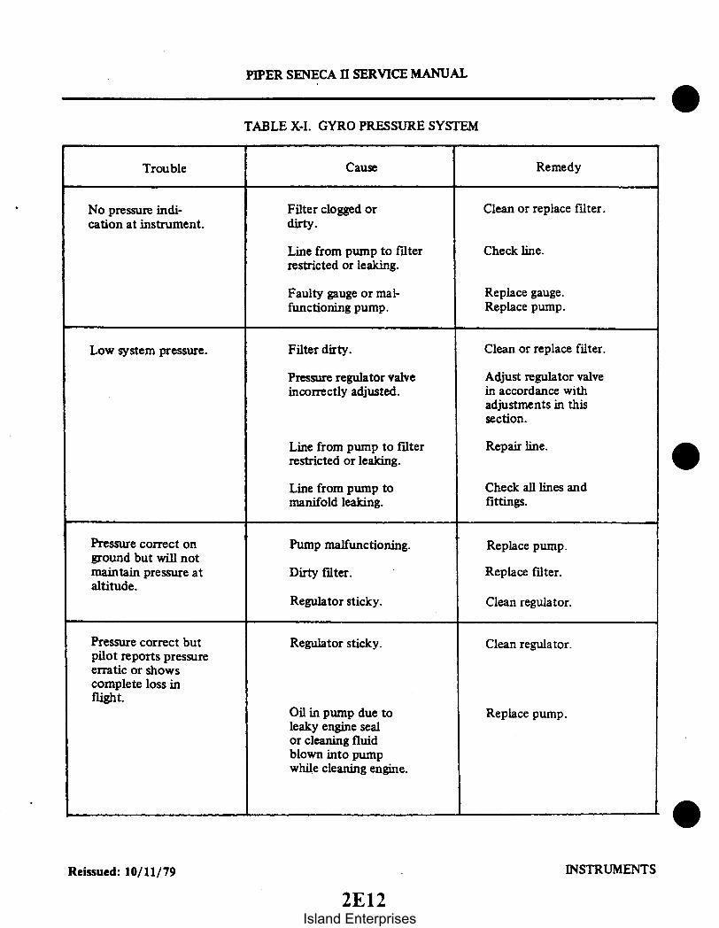
PIPER SENECA II SERVICE MANUAL
TABLE X-I. GYRO PRESSURE SYSTEM
Trouble Cause Remedy
No pressure indi-cation at instrument.
Filter clogged ordirty.
Clean or replace filter.
Line from pump to filterrestricted or leaking.
Check line.
Faulty gauge or mal-functioning pump.
Replace gauge.Replace pump.
Low system pressure. Filter dirty. Clean or replace filter.
Pressure regulator valveincorrectly adjusted.
Line from pump to filterrestricted or leaking.
Line from pump tomanifold leaking.
Adjust regulator valvein accordance withadjustments in thissection.
Repair line.
Check all lines andfittings.
Pressure correct onground but will notmaintain pressure ataltitude.
Pressure correct butpilot reports pressureerratic or showscomplete loss inflight.
Pump malfunctioning.
Dirty filter.
Regulator sticky.
Regulator sticky.
Oil in pump due toleaky engine sealor cleaning fluidblown into pumpwhile cleaning engine.
Replace pump.
Replace filter.
Clean regulator.
Clean regulator.
Replace pump.
Reissued: 10/11/79 INSTRUMENTS
2E12Island Enterprises

For SN 34-8170092 and up:1. Set pressure regulator for one engine at 4.8 to 5.2 inches of mercury with that engine operating
at magneto check RPM and other engine at idle or off.2. Repeat setting procedure for other engine.
PIPER SENECA II SERVICE MANUAL
TABLE X-I. GYRO PRESSURE SYSTEM (cont.)
CauseTrouble Remedy
Pressure can only bemaintained at fullthrottle on ground.
Leak in system.
Worn pump.
Repair or replacelines.
Replace pump.
Stuck regulator. Clean or replaceregulator.
Normal pressure indi-cation but sluggish op-eration of instruments.
High system pressure.
Faulty flight instrument.
Regulator incorrectlyadjusted.
Replace instrument.
Adjust regulator.
Regulator sticking. Clean and check opera-tion of regulator.
Regulator cannot beadjusted to producecorrect pressure.
Lines leaking.
Dirty filter.
Check lines and fittings.
Replace filter.
Pump malfunctioning. Replace pump.
10-12. ADJUSTMENTS TO PRESSURE REGULATOR. (Refer to Figure 10-1.)a. Remove nacelle cover to gain access to the pressure regulator.b. For SN up to 34-8170091 inclusive:
Operate both engines at 2575 RPM; the gyro pressure gauge reading should be 4.8 to 5.1 inchesof mercury.
NOTE
The pressure indicator with one engine at a time running at 2000RPM should be within. 1 inches of mercury of each other. With bothengines operating at 2575 RPM. the reading should not exceed 5.2inches of mercury.
Revised: 3/16/81 INSTRUMENTS
2E13
Island Enterprises

ADJUSTMENT
PIPER SENECA II SERVICE MANUAL
1982
1. PUMP2. AIR FILTER3. INLINE FILTER4. ATTITUDE GYRO. COPILOT5. DIRECTIONAL GYRO, COPILOT6. PRESSURE GAUGE7. ATTITUDE GYRO8. DIRECTIONAL GYRO9. PRESSURE REGULATING VALVE
10. PRESSURE SWITCH
NOTE
INLINE FILTERS (3) MAY BE LOCATED, EITHERBEHIND THE INSTRUMENT PANEL OR THE FIREWALL FOR SERVICE INFORMATION REFER TOSECTION XIV, PARAGRAPH 14-43.
Figure 10-1. Gyro Pressure System
Reissued: 10/11/79 INSTRUMENTS2E14
Island Enterprises

PIPER SENECA II SERVICE MANUAL
3. After settings are made on both engines, check the pressure readings to be sure that it is withinlimits when both engines are operating at mag check RPM.
c. To adjust the regulator, bend the locking tabs on the adjustment screw and adjust the screw asrequired to obtain correct gyro pressure.
d. After adjustment is complete, bend tabs to lock screw in place and recheck pressure. Reinstallnacelle cover.
10-13. REMOVAL AND INSTALLATION.a. Remove the nacelle access cover.b. Loosen the hose clamps on the regulating valve and disconnect the hoses.c. Disconnect the two electrical leads.d. Remove the nut and flat washer securing the regulator to the fire wall and withdraw the
regulator.e. Reinstall the regulator in reverse order of removal.
10-14. PNEUMATIC PUMP.
10-15. GENERAL. The pneumatic pump is a rotary vane, positive displacement dry type pump. Thepump is mounted on the accessory section of each engine and rotates counterclockwise on the left engineand clockwise on the right engine. The drive ratio to the crankshaft is 1.545:1.
10-16. TROUBLESHOOTING. (Refer to Table X-I.)
10-17. REMOVAL AND INSTALLATION.a. Remove the top portion of the engine cowling.b. Disconnect the two hoses at the pump.c. Remove the four mounting nuts, lockwashers and plain washers, and withdraw the pump from
the engine.d. Reinstall the pump in reverse order of removal, noting the following:
1. Place gasket in proper position.
CAUTION
The only dry air pump mounting gasket authorized and approvedfor use on Airborne dry air pump is the Airborne gasket B3-1-2,Piper part number 751 859. Use of any other gasket may result inoil seepage or leakage at the mounting surface.
2. Torque the four mounting nuts to 40-50 inch-pounds.e. Check hose connections and mounting hardware for security.
10-17a. REPLACING PUMP FITTINGS.a. The handling procedures for securing the pump while installing or removing fittings are as
follows:1. Use two soft wood blocks in a vise to protect pump from vise jaws.2. The pump square mounting flange must be held between the wood blocks at right angles to
the vise jaws.3. Use only enough vise pressure to hold pump firmly.
CAUTION
Do not apply vise pressure to outside diameter or overall length ofthe pump.
Revised: 3/16/81 2E15
Island Enterprises

1. PILOTS INSTRUMENTS2. COPILOTS INSTRUMENTS3. STATIC LINE4. SWITCH PANEL5. HEATED PITOT SWITCH6. TEE7. STATIC BUTTON8. PITOT HEAD9. PITOT LINE
10. PITOT DRAIN
PIPER SENECA II SERVICE MANUAL
b. Thread lubricant, if required, should be applied sparingly to the external threads of the fittingonly. Use a powdered moly sulfide or graphite in dry form or in an evaporating vehicle, or employ a siliconespray.
CAUTION
Do not use pipe tape, thread dope, hydrocarbon oil or grease, asthese can contaminate pump and cause malfunction.
c. Use the following steps for fitting installation:1. Secure pump as noted above.2. Insert fittings in pump ports and hand tighten firmly.3. Using a wrench, tighten each fitting from one-half to two additional turns.
1885
3
6
2
10
Figure 10-2. Pitot-Static System(Serial Nos. 34-7570001 to 347670136 incl.)
Reissued: 10/11/79 INSTRUMENTS
2E16Island Enterprises

1. PILOT'S INSTRUMENTS2. COPILOT'S INSTRUMENTS3. STATIC LINE4. SWITCH PANEL5. HEATED PITOT SWITCH6. TEE7. STATIC BUTTON8. PITOT HEAD9. PITOT LINE
10. SUMP ASSEMBLY (DRAIN VALVE)11. CONNECTOR12. GASKET
PIPER SENECA II SERVICE MANUAL
2039
13. ELBOW14. CIRCUIT BREAKER15. ALTERNATE STATIC AIR VALVE
I
Figure 10-2a. Pitot-Static System(Serial Nos. 34-7670137 and up)
Revised: 11/12/82 INSTRUMENTS
2E17
Island Enterprises
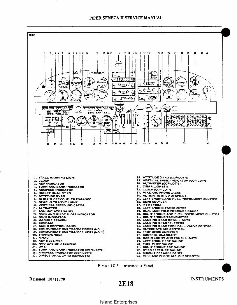
16 II
PIPER SENECA II SERVICE MANUAL
1972
1. STALL WARNING LIGHT2. CLOCK3. ADF INDICATOR4. TURN AND BANK INDICATORS. AIRSPEED INDICATOR6. DIRECTIONAL GYRO7. ATTITUDE GYRO8. GLIDE SLOPE COUPLER ENGAGED9. GEAR IN TRANSIT LIGHT
10. VERTICAL SPEED INDICATOR11. ALTIMETER12. ANNUNCIATOR PANEL13. OMNI AND GLIDE SLOPE INDICATOR14. OMNI INDICATORI5. MARKER BEACON16. COMPASS17. AUDIO CONTROL PANEL
1. COMMUNICATIONS TRANSCEIVERS (NO. 1 )19. COMMUNICATIONS TRANSCEIVERS (NO. 2)20. TRANSPONDER21. R.NAV22. ADF RECEIVER23. NAVIGATION RECEIVER24. DME25. TURN AND BANK INDICATOR (COPILOT'S)26. AI RSPEED INDICATOR (COPILOT-S)27. DIRECTIONAL GYRO (COPILOT'S)
28. ATTITUDE GYRO (COPILOT'S)29. VERTICAL SPEED INDICATOR (COPILOT'S)30. ALTIMETER (COPILOTS)31. CIGAR LIGHTER32. CLOCK (COPILOT'S)33. MIKE AND PHONE JACKS34. ALTIMATIC III C AUTOPILOT35. LEFT ENGINE AND FUEL INSTRUMENT CLUSTER36. OMNI COUPLER37. PITCH TRIM38. LEFT ENGINE TACHOMETER39. DUAL MANIFOLD PRESSURE GAUGE40. RIGHT ENGINE AND FUEL INSTRUMENT CLUSTER41. RIGHT ENGINE TACHOMETER42. LANDING GEAR DOWN LIGHTS43. LANDING GEAR SELECTOR44. LANDING GEAR FREE FALL VALVE CONTROL45. ALTERNATE AIR CONTROL46. PROP DEICE AMMETER47. CONTROL QUADRANT48. RADIO LIGHTS AND PANEL LIGHTS49. LEFT ENGINE EGT GAUGE5O. FUEL FLOW GAUGE51. RIGHT ENGINE EGT GAUGE52. GYRO PRESSURE GAUGE53. CIRCUIT BREAKER PANEL54. MIKE AND PHONE JACKS (COPILOT-S)
Fiure 10-3. Instrument Panei
Reissued: 10/11/79 INSTRUMENTS2E18
Island Enterprises

PIPER SENECA II SERVICE MANUAL
10-18. PITOT-STATIC SYSTEMS. Pitot pressure for the airspeed indicator is sensed by the pitot mastmounted under the left wing. Static pressure for the altimeter, vertical speed and airspeed indicators issensed by two static pressure units, one located on each side of the rear part of the fuselage.
An alternate static source control valve is located below the instrument panel to the right of the powerquadrant. If one or more of the pitot-static instruments malfunctions, these pressure systems should bechecked for leaks, dirt or water. If moisture is present, the static system can be drained by turning on thealternate static system. The selector valve is located at the low point of the system. Another drain isprovided in the lower left front side panel to drain moisture from the pressure line running between thepitot mast and the instrument panel. At any time an instrument, fitting, line, pitot head or static button isdisconnected, tests must be performed prior to the next flight. Refer to Advisory Circular 43-13-1A for thetesting procedures.
10-19. DIRECTIONAL GYRO.
10-20. GENERAL. The directional gyro is a flight instrument incorporating an air driven gyro stabilized inthe vertical plane. The gyro is rotated at high speed by air pressure directed against the gyro bucketsproduced at the engine driven pneumatic pump. Due to gyroscopic inertia, the spin axis continues to pointin the same direction even though the aircraft yaws to the right or left. This relative motion between thegyro and the instrument case is shown on the instrument dial which is similar to a compass card. The dialwhen set to agree with the airplane magnetic compass provides a positive indication free from swing andturning error. However, the directional gyro has no sense of direction and must be set to the magneticcompass. Since the magnetic compass is subject to errors due to magnetic fields, electric instruments, etc.,the directional gyro is only accurate for the heading it has been set for. If the gyro is set on 270°, forinstance, and the aircraft is turned to some other heading, there can be a large error between the gyro andthe magnetic compass due to the error in compass compensation; this will appear as gyro precession. Thegyro should only be checked on the heading on which it was first set; also due to internal friction, spin axiserror, air turbulence and airflow, the gyro should be set at least every 15 minutes for accurate operationwhether it has drifted or not.
Reissued: 10/11/79 INSTRUMENTS
2E19
Island Enterprises
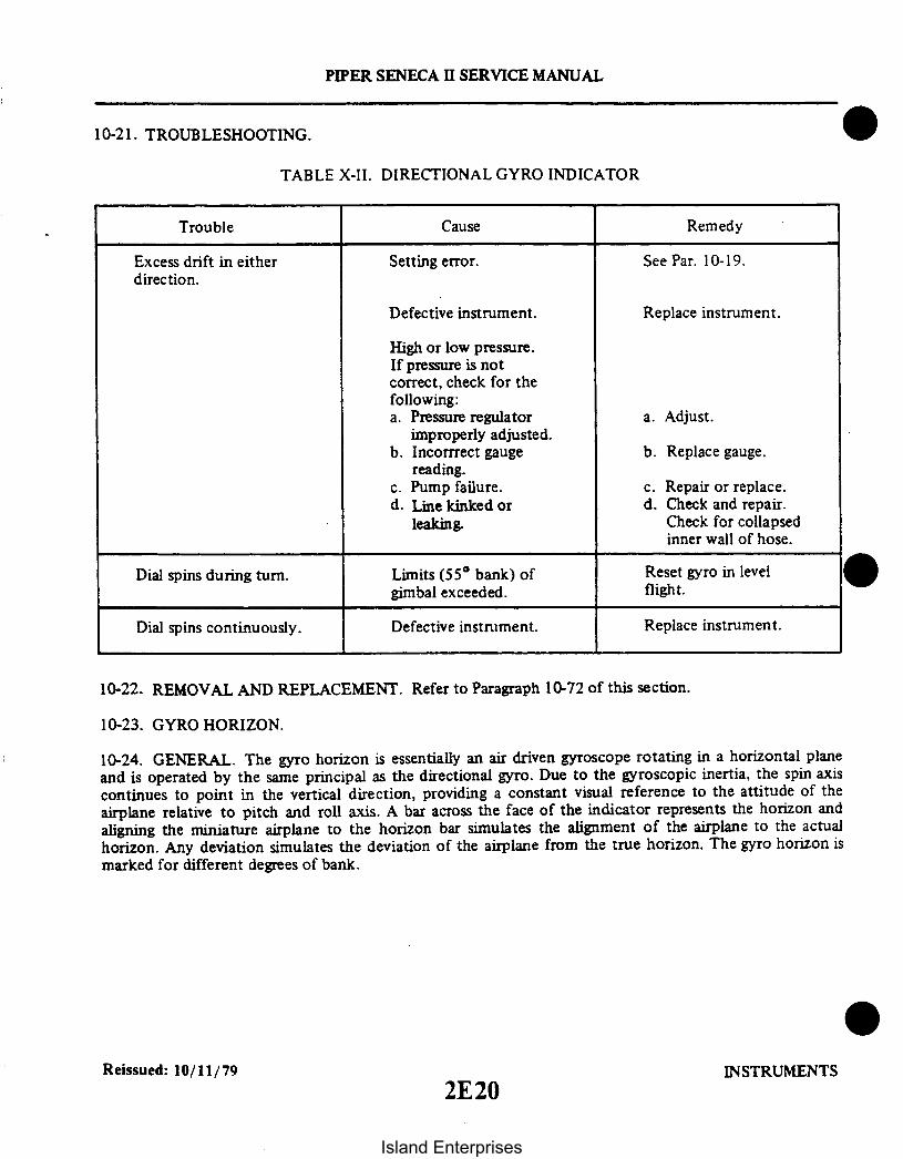
PIPER SENECA II SERVICE MANUAL
10-21. TROUBLESHOOTING.
TABLE X-II. DIRECTIONAL GYRO INDICATOR
Trouble Cause Remedy
Excess drift in eitherdirection.
Setting error. See Par. 10-19.
Defective instrument.
High or low pressure.If pressure is notcorrect, check for thefollowing:a. Pressure regulator
improperly adjusted.b. Incorrrect gauge
reading.c. Pump failure.d. Line kinked or
leaking.
Replace instrument.
a. Adjust.
b. Replace gauge.
c. Repair or replace.d. Check and repair.
Check for collapsedinner wall of hose.
Dial spins during turn.
Dial spins continuously.
Limits (55° bank) ofgimbal exceeded.
Defective instrument.
Reset gyro in levelflight.
Replace instrument.
10-22. REMOVAL AND REPLACEMENT. Refer to Paragraph 10-72 of this section.
10-23. GYRO HORIZON.
10-24. GENERAL. The gyro horizon is essentially an air driven gyroscope rotating in a horizontal planeand is operated by the same principal as the directional gyro. Due to the gyroscopic inertia, the spin axiscontinues to point in the vertical direction, providing a constant visual reference to the attitude of theairplane relative to pitch and roll axis. A bar across the face of the indicator represents the horizon andaligning the miniature airplane to the horizon bar simulates the alignment of the airplane to the actualhorizon. Any deviation simulates the deviation of the airplane from the true horizon. The gyro horizon ismarked for different degrees of bank.
Reissued: 10/11/79 INSTRUMENTS2E20
Island Enterprises

PIPER SENECA II SERVICE MANUAL
10-25. TROUBLESHOOTING.
TABLE X-III. GYRO HORIZON INDICATOR
Trouble
Bar fails to respond.
Bar does not settle.
Bar oscillates orshimmies continuously.
Instrument does notindicate level flight.
Bar high after 180turn.
Instrument tumbles inflight.
Cause
Insufficient pressure.
Filter dirty.
Insufficient pressure.
Incorrect instrument.
Defective instrument.
Instrument loose inpanel.
Pressure too high.
Defective instrument.
Instrument not set properly.
Instrument not levelin panel.
Aircraft out of trim.
Normal, if it does notexceed 1/16 inch.
Low pressure.
Remedy
Check pump and tubing.
Clean or replace filter.
Check line and pump.Adjust valve.
Check part number.
Replace.
Tighten mounting screws.
Adjust valve.
Replace instrument.
Loosen screws and levelinstrument.
Trim aircraft.
Reset regulator.
'
Dirty filter.
Line to filter restricted.
Plug missing or loosein instrument.
Bank or Pitch Limitsexceeded
Clean or replace filter.
Replace line.
Replace or tighten plug.
Reissued: 10/11/79 INSTRUMENTS
2E21
Island Enterprises

PIPER SENECA II SERVICE MANUAL
10-26. REMOVAL AND REPLACEMENT. Refer to Paragraph 10-72 of this section.
10-27. RATE OF CLIMB INDICATOR.
10-28. GENERAL. The rate of climb indicator measures the rate of change in static pressure when theairplane is climbing or descending. By means of a pointer and dial, this instrument will indicate the rate ofascent or descent of the airplane in feet per minute. Due to the lag of the instrument, the aircraft will beclimbing or descending before the instrument gives the correct rate. The instrument will continue to readafter the aircraft has assumed level flight. In rough air this should not be considered a malfunction.
10-29. TROUBLESHOOTING.
TABLE X-IV. RATE OF CLIMB INDICATOR
Trouble Cause Remedy
Pointer does not seton zero.
Pointer fails torespond.
Aging of diaphragm.
Obstruction in staticline.
Reset pointer to zeroby means of settingscrew. Tap instrumentwhile resetting.
Disconnect all instru-ments connected to thestatic line. Clear line.
Pitot-Static head frozen over.
Water in static line.
Obstruction in pitothead.
Check individual instru-ments for obstructionin lines.
Clean lines and head.
Pointer oscillates. Leaks in static lines. Disconnect all instru-ments connected to thestatic line. Checkindividual instrumentsfor leaks. Reconnectinstruments to staticline and test installa-tion for leaks.
Defective mechanism. Replace instrument.
Rate of climb indi-cates when aircraftis banked.
Water in static line. Disconnect static linesand blow out lines fromcockpit out to pitothead.
Reissued: 10/11/79 INSTRUMENTS
2E22
Island Enterprises

PIPER SENECA II SERVICE MANUAL
TABLE X-IV. RATE OF CLIMB INDICATOR (cont)
CauseTrouble Remedy
Pointer has to beset before everyflight.
Pointer cannot bereset to zero.
Instrument reads verylow during climb ordescent.
Temperature compen-sator inoperative.
Diaphragm distorted.
Case of instrument or linebroken or leaking.
Replace instrument.
Replace instrument.
Replace instrument.
10-30. REMOVAL AND REPLACEMENT. Refer to Paragraph 10-72 of this section.
10-31. SENSITIVE ALTIMETER.
10-32. GENERAL. The altimeter indicates altitude in feet above sea level. The indicator has three pointersand a dial scale; the long pointer is read in hundredths of feet; the middle pointer in thousandths of feet,and the short pointer in ten thousandths of feet. A barometric pressure window is located on the right sideof the indicator dial and is set by the knob located on the lower left corner of the instrument. The altimeterconsists of a sealed diaphragm that is connected to the pointers through a mechanical linkage. Theinstrument case is vented to the static air system and as static air pressure decreases, the diaphragmexpands, causing the pointers to move through the mechanical linkage to indicate a higher altitude.
10-33. TROUBLESHOOTING.
TABLE X-V. ALTIMETER
Trouble Cause Remedy
Excessive scale error.
Excessive pointeroscillation.
High or low reading.
Setting knob is hardto turn.
Improper calibrationadjustment.
Defective mechanism.
Improper venting.
Wrong lubrication orlack of lubrication.
Replace instrument.
Replace instrument.
Eliminate leak instatic pressure systemand check alignment ofsensor.
Replace instrument.
Reissued: 10/11/79 INSTRUMENTS
2E23
Island Enterprises

PIPER SENECA II SERVICE MANUAL
TABLE X-V. ALTIMETER (cont)
Trouble Cause Remedy
Altimeter sticks ataltitude or does notchange with change ofaltitude.
Altimeter changesreading as aircraftis banked.
Altimeter requiresresetting frequently.
Inner reference markerfails to move whensetting knob isrotated.
Setting 'knob set screwloose or missing.
Cracked or loosecover glass.
Water or restriction instatic line.
Water in static line.
Temperature compensatorinoperative.
Out of engagement.
Not tight whenaltimeter was reset.
Case gasket hardened.
Remove static linesfrom all instruments,blow line clear fromcockpit to sensor.
Remove static linesfrom all instruments.and blow line clear fromcockpit to sensor.
Change instrument.
Replace instrument.
Tighten instrumentscrew, if loose. Re-place screw, ifmissing.
Replace or repairinstrument.
Dull or discoloredmarkings.
Age. Replace or repairinstrument.
Barometric scale andreference markers outof synchronism withpointers.
Drift in mechanism. Reset pointers, perAC 43.13-1.
INOTE
When any connections in the static system are opened forchecking, system must be rechecked per Part FAR 23.1325.
10-34. REMOVAL AND REPLACEMENT. Refer to Paragraph 10-72 of this section.
Reissued: 10/11/79 INSTRUMENTS
2E24Island Enterprises

PIPER SENECA II SERVICE MANUAL
10-35. AIRSPEED INDICATOR.
10-36. GENERAL. The airspeed indicator provides a means of indicating the speed of the airplane passingthrough the air. The airspeed indication depends on the differential pressure between pitot air pressure andstatic air pressure. This instrument has the diaphragm vented to the pitot air source and the case is ventedto the static air system. As the airplane increases speed, the pitot air pressure increases, causing thediaphragm to expand. A mechanical linkage picks up this motion and moves the instrument pointer to theindicated speed. The instrument dial is calibrated in knots and miles per hour, and also has the necessaryoperating range markings for safe operation of the airplane.
10-37. TROUBLESHOOTING.
TABLE X-VI. AIRSPEED TUBES AND INDICATOR
Trouble Cause Remedy
Pointers of staticinstruments do notindicate properly.
Pointer of instrumentoscillates.
Instrument reads high.
Leak in instrument caseor in static lines.
Defective mechanism.
Pointer not on zero.
Check for leak and seal.
Replace instrument.
Replace instrument.
Leaking static system. Find leak and correct.
Instrument reads low. Pointer not on zero. Replace instrument.
Leaking static system.
Pitot-Static head notaligned correctly.
Find leak and correct.
Realign pitot-static head
Airspeed changes asaircraft is banked.
Water in static line. Remove lines from staticinstruments and blowout lines from cockpitto pitot-static head.
NOTE
When any connections in static system are opened for checking,system must be checked per FAR 23.1325.
10-38. REMOVAL AND REPLACEMENT. Refer to Paragraph 10-72 of this section.
Reissued: 10/11/79 INSTRUMENTS
2F1
Island Enterprises

PIPER SENECA II SERVICE MANUAL
10-39. MAGNETIC COMPASS.
10-40. GENERAL. The magnetic compass is a self-contained instrument. This instrument has an individuallight which is connected to the instrument lighting circuit. The compass correction card is located in thecard holder mounted on the instrument. The compass should be swung whenever instruments or radios arechanged and at least once a year.
10-41. ADJUSTMENT OF COMPASS. Before attempting to compensate compass, every effort should bemade to place the aircraft in simulated flight conditions; check to see that the doors are closed, flaps inretracted position, engines running, throttles set at cruise position and aircraft in level flight attitude.Aircraft master switch, alternator, and radios should be on. All other cockpit controlled electrical switchesshould be in the off position.
a. Set adjustment screws of compensator on zero. Zero position of adjusting screws is when the dotof the screw is lined up with the dot of the frame.
b. Head aircraft on a magnetic North heading. Adjust N-S adjustment screw until compass readsexactly North.
c. Head aircraft on a magnetic East heading and do the same as Step b, adjusting E-W adjustingscrew.
d. Head aircraft on a magnetic South heading and note resulting South error. Adjust N-S adjustingscrew until one-half of this error has been compensated. No compensation adjustments shall be made withthe combustion heater operating.
e. Head aircraft on magnetic West and do same as Step d, adjusting E-W adjustment screw.f. Head aircraft in successive magnetic 30° degree headings and record compass readings on
appropriate deviation card. Deviations must not exceed ± 10 on any heading. An additional deviation cardwill have to be made out for aircraft with combustion heater installed. This second deviation card shall beaccomplished under the above conditions, except the combustion heater shall be operating.
10-42. TROUBLESHOOTING.
TABLE X-VII. MAGNETIC COMPASS
Trouble Cause Remedy
Excessive card error. Compass not properlycompensated.
Compensate instrument.(Refer to Para. 10-41)
External magneticinterference.
Locate magnetic inter-ference and eliminateif possible.
Excessive cardoscillation.
Insufficient liquid. Replace or repair instrument.
Replace or repair instrumentCard sluggish. Weak card magnet.
Excessive pivot fric-tion or broken jewel.
Replace or repair instrument.
Reissued: 10/11/79
I
INSTRUMENTS
2F2Island Enterprises
2F3INTENTIONALLY LEFT BLANK
Island Enterprises
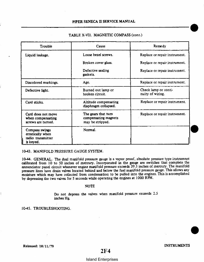
PIPER SENECA II SERVICE MANUAL
TABLE X-VII. MAGNETIC COMPASS (cont.)
CauseTrouble Remedy
Liquid leakage. Loose bezel screws. Replace or repair instrument.
Broken cover glass.
Defective sealinggaskets.
Age.
Replace or repair instrument.
Replace or repair instrument.
Replace or repair instrument.Discolored markings.
Defective light.
Card sticks.
Card does not movewhen compensatingscrews are turned.
Burned out lamp orbroken circuit.
Altitude compensatingdiaphragm collapsed.
The gears that turncompensating magnetsmay be stripped.
Check lamp or conti-nuity of wiring.
Replace or repair instrument.
Replace or repair instrument.
Compass swingserratically whenradio transmitteris keyed.
Normal.
I1043. MANIFOLD PRESSURE GAUGE SYSTEM.
10-44. GENERAL. The dual manifold pressure gauge is a vapor proof, absolute pressure type instrumentcalibrated from 10 to 50 inches of mercury. Incorporated in the gauge are switches that complete theannunciator panel circuit whenever engine manifold pressure exceeds 39.5 inches of mercury. The manifoldpressure lines have drain valves located behind and below the fuel manifold pressure gauge. This allows anymoisture which may have collected from condensation to be pulled into the engines. This is accomplishedby depressing the two valves for 5 seconds while operating the engines at 1000 RPM.
NOTE
Do not depress the valves when manifold pressure exceeds 2.5inches Hg.
1045. TROUBLESHOOTING.
Reissued: 10/11/79 INSTRUMENTS
2F4Island Enterprises
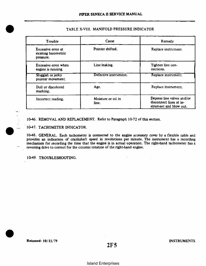
PIPER SENECA II SERVICE MANUAL
TABLE X-VIII. MANIFOLD PRESSURE INDICATOR
CauseTrouble Remedy
Excessive error atexisting barometricpressure.
Excessive error whenengine is running.
Sluggish or jerkypointer movement.
Pointer shifted.
Line leaking.
Defective instrument.
Replace instrument.
Tighten line con-nections.
Replace instrument.
Dull or discoloredmarking.
Age. Replace instrument.
Incorrect reading. Moisture or oil inline.
Depress line valves and/ordisconnect lines at in-strument and blow out.
10-46. REMOVAL AND REPLACEMENT. Refer to Paragraph 10-72 of this section.
10-47. TACHOMETER INDICATOR.
10-48. GENERAL. Each tachometer is connected to the engine accessory cover by a flexible cable andprovides an indication of crankshaft speed in revolutions per minute. The instrument has a recordingmechanism for recording the time that the engine is in actual operation. The right-hand tachometer has areversing drive to correct for the counter rotation of the right-hand engine.
10-49. TROUBLESHOOTING.
Reissued: 10/11/79 INSTRUMENTS2F5
Island Enterprises

PIPER SENECA II SERVICE MANUAL
TABLE X-IX. TACHOMETER
Cause
Broken drive cable.
Trouble
No reading on indica-tor, either permanentor intermittent.
Remedy
Replace cable.
Pointer oscillatesexcessively.
Loose cable connections.
Rough spot on, orsharp bend in cable.
Excessive friction ininstrument.
Tighten cable.
Repair or replace.
Replace instrument.
Indicator changes in Excessive clearance in Replace instrument.climb. speed cup.
Pointer goes all the Excessive lubricant in Replace instruments.way to stop, more instruments.noticeable in coldweather.
Pointer jumps at idle. Speed cup hitting Replace instrument.rotating magnet.
Tachometer cable breaks. Cable bent too sharply. Reroute cable. replace shaft.
10-50. REMOVAL AND REPLACEMENT. Refer to Paragraph 10-72 of this section.
10-51. ENGINE OIL PRESSURE GAUGE.
10-52. GENERAL. The oil pressure gauge is mounted in the cluster on the instrument panel. This gaugewill indicate the amount of oil pressure available at the pressurized engine oil passage in psi.
10-53. TROUBLESHOOTING.
Reissued: 10/11/79 INSTRUMENTS
2F6
Island Enterprises

PIPER SENECA II SERVICE MANUAL
TABLE X-X. ENGINE OIL PRESSURE GAUGE
CauseTrouble Remedy
Excessive error atzero.
Excessive scale error.
Excessive pointeroscillation.
Sluggish operation ofpointer or pressurefails to build up.
NOTEGauge will take longer toindicate in cold weather.
Pointer loose on shaft.Overpressure orseasoning of bourdontube.
Improper calibrationadjustment.
Air in line or roughengine relief.
Engine relief valveopen.
Line restriction toinstrument.
Replace instrument.
Replace instrument.
Disconnect line andfill with light oil.Check for leaks. Iftrouble persists, cleanand adjust relief valve.
Clean and check.
Clean and check.
Loss of oil in engine orother engine failure.
Shut down enginerefer to Table VIII-III.
10-54. REMOVAL AND REPLACEMENT. Refer to Paragraph 10-78 of this section.
Reissued: 10/11/79 INSTRUMENTS2F7
Island Enterprises
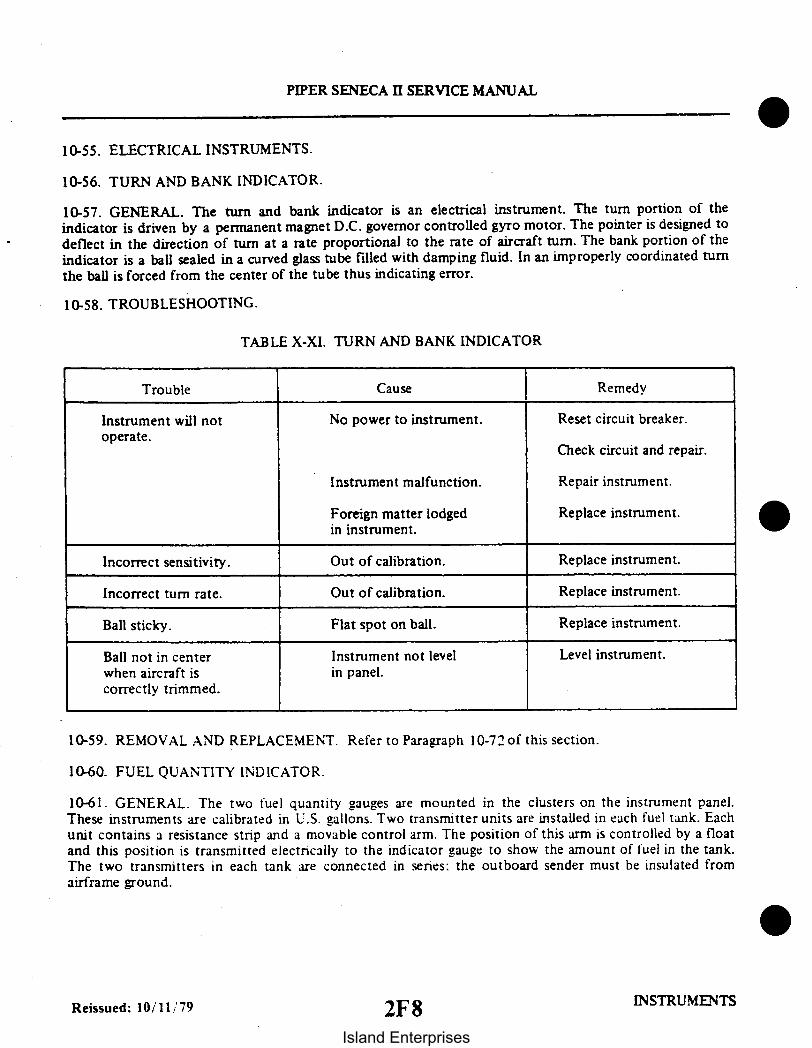
PIPER SENECA II SERVICE MANUAL
10-55. ELECTRICAL INSTRUMENTS.
10-56. TURN AND BANK INDICATOR.
10-57. GENERAL. The turn and bank indicator is an electrical instrument. The turn portion of theindicator is driven by a permanent magnet D.C. governor controlled gyro motor. The pointer is designed todeflect in the direction of turn at a rate proportional to the rate of aircraft turn. The bank portion of theindicator is a ball sealed in a curved glass tube filled with damping fluid. In an improperly coordinated turnthe ball is forced from the center of the tube thus indicating error.
10-58. TROUBLESHOOTING.
TABLE X-XI. TURN AND BANK INDICATOR
Trouble Cause Remedy
Instrument will notoperate.
No power to instrument. Reset circuit breaker.
Check circuit and repair.
Instrument malfunction.
Foreign matter lodgedin instrument.
Repair instrument.
Replace instrument.
Incorrect sensitivity.
Incorrect turn rate.
Ball sticky.
Ball not in centerwhen aircraft iscorrectly trimmed.
Out of calibration.
Out of calibration.
Flat spot on ball.
Instrument not levelin panel.
Replace instrument.
Replace instrument.
Replace instrument.
Level instrument.
10-59. REMOVAL AND REPLACEMENT. Refer to Paragraph 10-72 of this section.
10-60. FUEL QUANTITY INDICATOR.
10-61. GENERAL. The two fuel quantity gauges are mounted in the clusters on the instrument panel.These instruments are calibrated in U.S. gallons. Two transmitter units are installed in each fuel tank. Eachunit contains a resistance stnp and a movable control arm. The position of this arm is controlled by a floatand this position is transmitted electrically to the indicator gauge to show the amount of fuel in the tank.The two transmitters in each tank are connected in senes: the outboard sender must be insulated fromairframe ground.
Reissued: 10/11/79 2F8 INSTRUMENTS
Island Enterprises

PIPER SENECA II SERVICE MANUAL
10-62. TROUBLESHOOTING.
TABLE X-XII. FUEL QUANTITY INDICATORS
Trouble Cause Remedy
Fuel gauge fails toindicate.
Broken wiring. Check and repair.
Gauge not operating. Replace.
Fuel gauge indicatesempty when tanksare full.
Fuel gauge indicatesfull with tanks empty.
Incomplete ground.
Partial short toground.
Check ground con-nections at inboardtransmitter in wings.
Check wiring.
Float arm stuck. Replace fuel transmitter.
Fuel gauge indicatesincorrectly.
Intermittent electricalconnection.
Check ground at inboardtransmitter and electricalconnections.
Replace fuel transmitter.Faulty transmitter.
10-63. REMOVAL AND REPLACEMENT. Refer to Paragraph 10-74 of this section.
10-64. OIL TEMPERATURE INDICATOR.
10-65. GENERAL. The oil temperature indicator is mounted in the instrument cluster on the instrumentpanel. This instrument will provide a temperature indication of the engine oil in degrees Fahrenheit. Theinstrument has a temperature bulb located on the left side of the engine.
Reissued: 10/11/79 INSTRUMENTS
2F9
Island Enterprises

PIPER SENECA H SERVICE MANUAL
10-66. TROUBLESHOOTING.
TABLE X-XIII. OIL TEMPERATURE INDICATORS
Trouble Cause Remedy
Instrument fails toshow any reading.
Excessive error.
Pointer fails to moveas engine is warmed up.
Broken or damaged bulb.Wiring open.
Improper calibrationadjustment.
Broken or damaged bulbor open wiring.
Check engine unit andwiring to instrument.
Replace instrument.
Check engine unit andwiring.
Dull or discoloredmarking.
Age. Replace instrument.
10-67. REMOVAL AND REPLACEMENT. Refer to Paragraph 10-74 of this section.
10-68.; AMMETER.
10-69. GENERAL. The ammeters are mounted in the instrument cluster. This instrument measures the
current going into the entire electrical system including the battery charging demand.
10-70. TROUBLESHOOTING. Refer to Section XI (Alternator Section).
10-71. REMOVAL AND REPLACEMENT. Refer to Paragraph: 10-74 of this section.
10-72. REMOVAL AND REPLACEMENT OF FACE MOUNTED INSTRUMENTS.
10-73. GENERAL. Since all instruments are mounted in a similar manner, a description of a typicalremoval and installation is provided as a guide for the removal and installation of the instruments. Specialcare should be taken when any operation pertaining to the instruments is performed.
a. Remove the face panel.b. With the face panel removed, the mounting screws for the individual instruments will be exposed.
Remove the connections to the instrument prior to removing the mounting screws of the instrument to beremoved.
NOTE
Tag instrument connections for ease of installation.
c. Installation of the instruments will be in the reverse given for removal (Refer to step d. for gyrofitting installation).
Reissued: 10/11/79 INSTRUMENTS
2F10
Island Enterprises

PIPER SENECA II SERVICE MANUAL
CAUTION
DO NOT use thread lube on fittings or in ports of gyros. The use ofthread lube can cause contamination which shortens the lifeexpectancy of the gyro and can cause premature failures. Anyevidence of thread lube will create a WARRANTY VOIDCONDITION. Make sure that all air lines are clean and free of oil,grease, pipe compound or any foreign material and/or residuebefore connecting lines to gyro.
d. The use of 3M-48x¼ teflon pipe thread sealant tape on gyro fitting threads is recommended andshould be installed in the following manner.
1. Carefully lay teflon tape on the threads, allowing one to two lead-in threads to be visible fromthe end of the fitting. Hold in place and wrap in the direction of the threads, so tape will remain tight whenfitting is installed.
2. Apply sufficient tension while winding, to assure that the tape forms into thread grooves. Onefull wrap plus '/" overlap is sufficient.
3. After wrap is complete, maintain tension and tear tape by pulling in direction of wrap. Theragged end is the key to the tape staying in place. (If sheared or cut tape may loosen.)
4. Press tape well into threads.5. Screw fitting into port being careful not to exceed torque requirements as noted on decal
located on cover of gyro.e. After the installation is completed and before replacing the instrument face panel, check all
components for security and clearance of the control column.
INTENTIONALLY LEFT BLANK
INSTRUMENTS Reissued: 10/11/79
2F11
Island Enterprises
10-74. REMOVAL AND REPLACEMENT OF CLUSTER MOUNTED INSTRUMENTS.
10-75. GENERAL.a. Remove the face panel by springing the plastic material from the channels.b. With the face panel held in a vertical position, the screws securing the clusters are accessible. Re-
move the screws and the lens of the cluster to be repaired.c. Remove the plastic light seals adjacent to the instrument to be replaced.d. Remove the wires or tube to the instrument. Tag wires so they can be returned to the same terminal
on the replacement instrument.e. Remove nuts and insulating washers on electrical instruments; then move instrument aft. Me-
chanical instruments have only one large nut and lock washer.f. Replace instrument in the reverse order of removal. Check all mountings and connections for
security.
10-76. EXHAUST GAS TEMPERATURE GAUGE.
10-77. GENERAL. This instrument, which is commonly referred to as EGT, is used to aid the pilot in settingthe economical fuel-air mixture for cruising flight at a power setting of 75% or less. It is a sensing device tomonitor the temperature of exhaust gases leaving the engine cylinders. If it is found defective after checkingwith troubleshooting chart, it should be replaced. If the leads to the gauge are defective in any way, they mustbe replaced. When replacing leads, it is necessary to use the same type and length of wire because the resistanceof the leads is critical for the proper operation of this gauge.
10-78. REMOVAL OF EGT PROBE AND GAUGE.a. Disconnect wires from the EGT gauge at the instrument panel.b. Remove four bolts which secure the gauge to the instrument panel and remove the gauge.c. Remove wires from the wire harness going to the engine.d. Loosen the nut which secures the EGT probe to the exhaust transition area of the exhaust system
and remove the probe.
10-78a. CLEANING AND INSPECTION. Unless mechanical damage such as broken glass, bent or brokenpointer, or broken case, the following checks should be performed before removing the instrument:
a. Remove probe from exhaust transition area and check for broken weld (at tip end) or burnt offend.Measured resistance of probe should be .8 ohms. Clean the connections with steel wool before reassembly.
b. Disconnect lead wires at instrument and measure length and diameter. Resistance with lead wiresconnected to probe should be 3.3 ohms. Clean connections with steel wool before reassembly.
c. With leads connected to instrument, heat probe with propane torch to dull red. The meter shouldread up to the fourth graduation or approximately 1500°F. Before making this check, make sure that the ad-justment screw, which is located in the rear of the instrument case, is in the center of its travel. If this screw hasbeen turned to either end of full travel, it will shut the instrument off and no indication will be shown on thepointer. If meter still does not read, replace it.
CAUTION
Do not connect ohmmeter across meter; it will burn out the move-ment of the meter.
()-78b. INSTALLATION OF EGT PROBE AND GAL GE.a. Lubricate the probe fitting with Fel-Pro C5A Anti-Seize Lube PT 51005 and install the probe into
the hole in the transition area of the exhaust system and secure with locknut.b. Route the thermocouple wires along with the existing wire harness to the instrument panel.c. Install the EGT gauge into the instrument panel and secure with four bolts.d. Connect the thermocouple wires to the rear of the EGT gauge.
Revised: 12/08/83 2F12 INSTRUMENTS2F12
PIPER SENECA II SERVICE MANUAL
Island Enterprises

PIPER SENECA II SERVICE MANUAL
10-79. TROUBLESHOOTING.
TABLE X-XIV. EXHAUST GAS TEMPERATURE GAUGE
Trouble Cause Remedy
Gauge inoperative. Master Switch OFF. Turn switch ON.
Circuit Breaker OUT.
Defective gauge, probeor wiring.
Adjusting potentio-meter turned off scale.
Push breaker IN.
Check probe and leadwires for chafing,breaks or shortingbetween wires and/ormetal structure.
Reset potentiometer.
Fluctuating reading. Loose, frayed or brokenelectrical leads orfaulty connections.
Clean and tightenconnections. Repairor replace defectiveleads.
10-80. CYLINDER HEAD TEMPERATURE GAUGE.
1081.- GENERAL. The cylinder head temperature gauge is in the instrument cluster, located on theinstrument panel. This instrument measures the cylinder head temperature using a sender located in acylinder head. The cylinder head used is determined by the engine manufacturer. This gauge is an electricalinstrument and is wired through the instrument's circuit breaker.
Reissued: 10/11/79 INSTRUMENTS2F13
Island Enterprises

PIPER SENECA I SERVICE MANUAL
10-82. TROUBLESHOOTING.
TABLE X-XV. CYLINDER HEAD TEMPERATURE GAUGE
Trouble
Instrument shows noindication.
Instrument goes allthe way to upper stop.
Cause
Engine is cold.
Power supply wire open.
Defective sender.
Defective instrument.
Open circuit breaker.
Wire grounded betweensender and gauge.
Defective sender.
Remedy
Warm up engine.
Repair wire.
Replace sender.
Replace instrument.
Troubleshoot for fault.
Repair wire.
Replace sender.
10-83. REMOVAL AND REPLACEMENT. Refer to Paragraph- 10-72 of this section.
10-84. FUEL FLOW GAUGE.
10-85. GENERAL. The fuel flow gauge is a non-electric differential pressure gauge mounted in the bottomof the instrument panel.
This instrument measures flow by reading the pressure drop across a fixed orifice located in the fueldivider. With a constant fuel pressure being supplied by the engine driven pump and putting a fixed orificein the fuel divider head and then measuring the pressure drop downstream of the orifice against manifoldpressure, the resultant pressure can be calibrated in gallons per hour flow.
10-86. TROUBLESHOOTING.
TABLE X-XVI. FUEL FLOW GAUGE
Trouble
Pointer oscillates.
Gauge reads low ataltitude.
Pointer does notreturn to zero.
Cause
Air in fuel line.
Vent line restricted.
Fuel in diaphragm ofgauge.
Remedy
Purge line.
Check line and fittings.
Replace gauge.
Reissued: 10/11/79 INSTRUMENTS2F14
Island Enterprises
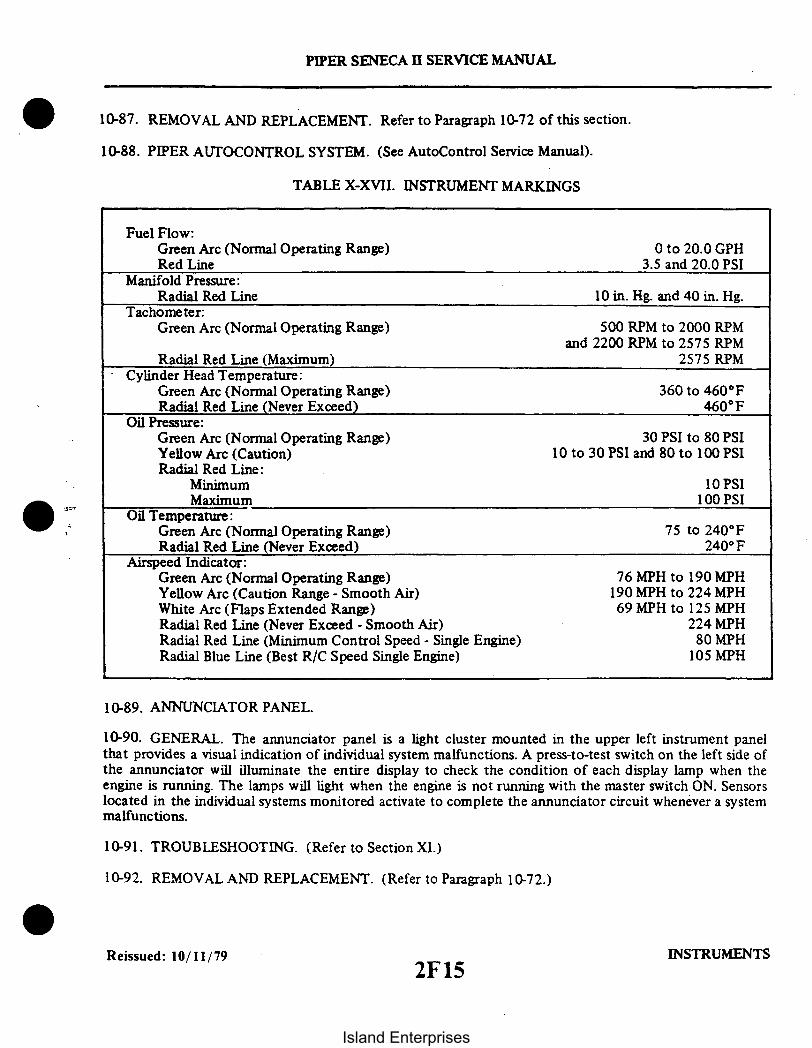
PIPER SENECA II SERVICE MANUAL
10-87. REMOVAL AND REPLACEMENT. Refer to Paragraph 10-72 of this section.
10-88. PIPER AUTOCONTROL SYSTEM. (See AutoControl Service Manual).
TABLE X-XVII. INSTRUMENT MARKINGS
Fuel Flow:Green Arc (Normal Operating Range)Red Line
Manifold Pressure:Radial Red Line
Tachometer:Green Arc (Normal Operating Range)
Radial Red Line (Maximum)Cylinder Head Temperature:
Green Arc (Normal Operating Range)Radial Red Line (Never Exceed)
Oil Pressure:Green Arc (Normal Operating Range)Yellow Arc (Caution)Radial Red Line:
MinimumMaximum
Oil Temperature:Green Arc (Normal Operating Range)Radial Red Line (Never Exceed)
Airspeed Indicator:Green Arc (Normal Operating Range)Yellow Arc (Caution Range - Smooth Air)White Arc (Flaps Extended Range)Radial Red Line (Never Exceed - Smooth Air)Radial Red Line (Minimum Control Speed - Single Engine)Radial Blue Line (Best R/C Speed Single Engine)
0 to 20.0 GPH3.5 and 20.0 PSI
10 in. Hg. and 40 in. Hg.
500 RPM to 2000 RPMand 2200 RPM to 2575 RPM
2575 RPM
360 to 460°F460°F
30 PSI to 80 PSI10 to 30 PSI and 80 to 100 PSI
10 PSI100 PSI
75 to 240°F240 F
76 MPH to 190 MPH190 MPH to 224 MPH69 MPH to 125 MPH
224 MPH80 MPH
105 MPH
10-89. ANNUNCIATOR PANEL.
10-90. GENERAL. The annunciator panel is a light cluster mounted in the upper left instrument panelthat provides a visual indication of individual system malfunctions. A press-to-test switch on the left side ofthe annunciator will illuminate the entire display to check the condition of each display lamp when theengine is running. The lamps will light when the engine is not running with the master switch ON. Sensorslocated in the individual systems monitored activate to complete the annunciator circuit whenever a systemmalfunctions.
10-91. TROUBLESHOOTING. (Refer to Section XI.)
10-92. REMOVAL AND REPLACEMENT. (Refer to Paragraph 10-72.)
Reissued: 10/11/79 INSTRUMENTS2F15
Island Enterprises

SECTION XI
ELECTRICAL SYSTEM
AeroficheParagraph Grid No.
11-1. Introduction . . . . . . . . . . . . . .... . . . . . . . . . . . . . . . 2F2011-2. Description .............. ...... ...................... 2F2011-3. Troubleshooting .......................................... 2F2011-4. Alternator System ............... .. . . .. .......... 2F2011-5. Alternator and Components . . ................................. 2F23
11-6. Description of Alternator ............................. . 2F2311-7. Checking Alternator System ............................. 2F241 1-8. Service Procedures ........... ..... ................ 2G11-9. Overhaul of Alternator ................................ 2G I11-10. Disassembly of Alternator . ............................. 2G211-11. Inspection and Testing of Components ....................... 2G411-12. Assembly of Alternator ................................ 2G511-13. Testing Alternator ...................... ................. ......... 2G611-14. Precautions ......................... .... ....... . 2G711-15. Alternator Service Test Specifications .................... . 2G11-16. Alternator Nomenclature ............................... 2
11-17. Voltage Regulator ......................................... 2G911-18. Regulator Components . .......................... 2G911-19. Operation of Regulator ................................ 2G911-20. Balancing Circuit Operation ..................... 2G1011-21. Preparation for Testing . ............ .............. . 2G II11-22. Testing Regulator ................. 2G1211-23. Adjusting Regulator ..... ................. ...... . 2G 13
11-24. Overvoltage Relay ............................ . . . 2G1411-25. Checking Overvoltage Relay ........................... .. 2G14
11-26. Starting Motors ....... ....... . ...... ........... 2G 1611-27. Description . . . . . ........................... 2G1611-28. Operation .. . . . .. ... ................ ....... 2G 1611-29. Maintenance .......... ..................-...... 2G 1611-30. Overhaul ...................................... 2G 1711-31. Removal . .................................... . 2G 1711-32. Disassembly ............. . .................. ..... 2G 1711-33. Brushes ............. ................. ...... . 2G 1811-34. Armature . ...................................... 2G 1811-35. Field Coils ................................... . 2G 181-36. Brush Holders ....................... ......... ... 2G 1911-37. Assembly ...................................... 2G 1911-38. Bench Tests ....................................... 2G2011-39. Starting Motor Control Circuit............... 2G2011-40. Starting Motor Service Test Specifications 2G21
Revised: 8/10/80
2F16
Island Enterprises

AeroficheParagraph Grid No.
11-41. Battery ................................................................... 2G2111-42. Servicing Battery ................................................. 2G211-43. Removal of Battery ............................................... 2G211-44. Installation of Battery ............................................. 2G22
11-45. Charging Battery ................................................. 2G23I1-46. Battery Box Corrosion Prevention .................................. 2G2311-47. Starting Through External Power Receptacle With Airplane's
Battery Nearly Depleted ......................................... 2G2311-48. Landing and Taxi Lights ................................................... 2G24
11-49. Removal of Landing and Taxi Lights ............................... 2G2411-50. Installation of Landing and Taxi Lights ............................. 2G24
11-51. Stall Warning System ...................................................... 2HI11-52. Removal of Lift Detector .......................................... 2H311-53. Installation of Lift Detector ........................................ 2H3
11-54. Navigation Lights ......................................................... 2H311-55. Removal of Wing Navigation Light ................................. 2H311-56. Installation of Wing Navigation Light ............................... 2H311-57. Removal of Tail Navigation Light .................... ............... 2H311-58. Installation of Tail Navigation Light ................................ 2H311-58a. Anti-Collision Lights .............................................. 2H3
11-59. Removal of Lamp in Anti-Collision Wing Tip Strobe Light ............ 2H41-60. Installation of Lamp in Anti-Collision Wing Tip Strobe Light .......... 2H411-61. Removal of Lamp in Anti-Collision Light ............................ 2H411-62. Troubleshooting Procedure for Anti-Collision and Wing Tip
Strobe Light Systems ............................................ 2H411-63. Installation of Anti-Collision Light .................................. 2H5
11-63a. Reading Lights ............................................... .. 2H511-64. Removal of Lamp in Overhead Reading Lights ....................... 2H511-65. Installation of Lamp in Overhead Reading Lights ..................... 2H5
11-66. Instrument and Panel Lights ................................................ 2H611-67. Removal of Dimmer Control Assembly .............................. 2H611-68. Installation of Dimmer Control Assembly ............................ 2H6
11-69. Annunciator Panel ........................................................ 2H611-70. Description ...................................................... 2H611-71. Annunciator Lights Test ........................................... 2H711-72. Troubleshooting .................................................. 2H7
Revised: 12/08/83 2F172F17
Island Enterprises
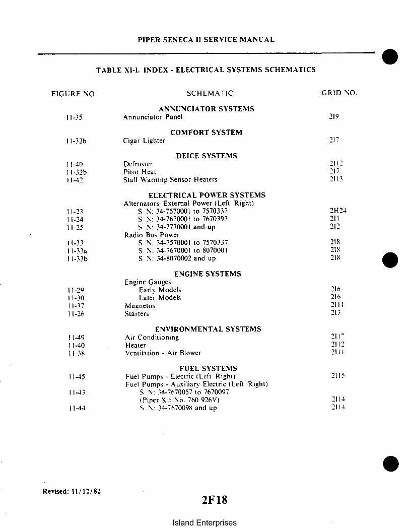
PIPER SENECA II SERVICE MANUAL
TABLE XI-I. INDEX - ELECTRICAL SYSTEMS SCHEMATICS
FIGURE NO. SCHEMATIC GRID NO.
ANNUNCIATOR SYSTEMS11-35 Annunciator Panel 219
COMFORT SYSTEMI -32b Cigar Lighter 217
DEICE SYSTEMS11-40 Defroster 2112I -32b Pitot Heat 21711-42 Stall Warning Sensor Heaters 2113
ELECTRICAL POWER SYSTEMSAlternators External Power (Left Right)
11-23 S N: 34-7570001 to 7570337 2H2411-24 S N: 34-7670001 to 7670393 21111-25 S N: 34-7770001 and up 212
Radio Bus Power11-33 S N: 34-7570001 to 7570337 21811-33a S N: 34-7670001 to 8070001 218l-33b S N: 34-8070002 and up 218
ENGINE SYSTEMSEngine Gauges
11-29 Early Models 21611-30 Later Models 21611-37 Magnetos 211111-26 Starters 213
ENVIRONMENTAL SYSTEMS11-49 Air Conditioning 211111-40 Heater 211211-38 Ventilation - Air Blower 2111
FUEL SYSTEMS11-45 Fuel Pumps - Electric (Left Right) 2115
Fuel Pumps - Auxiliary Electric (Left Right)11-43 S N: 34-7670057 to 7670097
(Piper Kit No. 760 926V) 211411-44 S N: 34-7670098 and up 2114
Revised: 11/12/822F18
Island Enterprises

PIPER SENECA 11 SERVICE MANUAL
TABLE XI-I. INDEX - ELECTRICAL SYSTEMS SCHEMATICS (cont.)
FIGURE NO. SCHEMATIC GRID NO.
INDICATORS11-47 Clock Hour Meter 2116
Engine Gauges11-29 Early Models 21611-30 Later Models 21611-46 Turn and Bank Pictorial Rate 211511-52 Turn and Bank Pictorial Rate Alternate 2119
LANDING GEAR SYSTEM11-27 Landing Gear 214
LIGHTING SYSTEMS - EXTERNAL11-32 Anti-Collision - (Strobe-Fin) 217I -32a Anti-Collision - (Strobe-Wing and Fin) 217I -31 Landing Lights 21711-39 Position Lights 211111-53 Tail Flood (Logo) Optional 2119
LIGHTING SYSTEMS - INTERNALBaggage
11-34 S N: 34-7570001 and up 21911-51 S N: 34-7970105 and up 2118
Courtesy Lighting (Optional)11-50 S N: 34-7970105 and up 211811-28 Panel Lighting 215
Reading11-48 S N: 34-7570001 to 7770441 211611-34 S N: 34-7570001 and up 219
WARNING SYSTEMSAnnunciator - (See Annunciator System)
11-40 Heater Overheat Warning 211211-27 Landing Gear - Warning Light & Horn 21411-41 Stall Warning 2113
Revised: 11/12/82
2F19
Island Enterprises

SECTION XI
ELECTRICAL SYSTEM
11-1. INTRODUCTION. This section contains instructions and schematics for correcting difficulties whichmay arise in the operation of the electrical system.
The instructions are organized so the mechanic can refer to: Description and Principles of Operation,for a basic understanding of the various electrical systems; Troubleshooting, for a methodical approach inlocating the difficulty; Corrective Maintenance, for removal, repair and installation of components; andAdjustments and Tests for operation of the repaired system. Schematics for the individual systems arelocated at the end of this section. For information concerning electronic equipment, refer to Section XII,Electronics.
11-2. DESCRIPTION. Electrical power is supplied by a 14-volt, direct current, negative ground electricalsystem. A 12-volt, 35 ampere hour battery is incorporated in the system to furnish power for starting andas a reserve power source in case of alternator failure; it is located in the nose section of the airplane.
The electrical generating system consists of two engine driven 65 ampere alternators. Two solid stateregulators maintain effective alternator load sharing while regulating the system bus voltage at 14.0-volts.Also, incorporated in the system are overvoltage relays; one for each alternator circuit which preventsdamage to electrical and avionic equipment in case of regulator malfunction. A warning light on theannunciator panel will illuminate if either alternator fails to produce current, accompanied by a zeroindication on the individual ammeter. The loads from the electrical bus system are protected by manualreset type circuit breakers mounted on the lower right-hand instrument panel.
11-3. TROUBLESHOOTING. Troubles peculiar to the electrical system are listed in Table XI-V at theback of this section, along with their probable causes and suggested remedies. The wiring diagrams includedat the end of this section will give a physical breakdown of the different electrical circuits used in thisairplane.
After the trouble has been corrected, check the entire electrical system for security and operation ofits components.
11-4. ALTERNATOR SYSTEM. The alternators are mounted on the accessory case of each engine. Manyadvantages both in operation and maintenance are derived from this system.
The alternators have no armature or commutator and only a small pair of carbon brushes which makecontact with a pair of copper slip rings. The rotating member of the alternator, known as the rotor, isactually the field windings. The rotor draws only 1/20th of the current output. Therefore, there is verylittle friction and negligible wear and heat in this area. The alternating current is converted to direct currentby diodes pressed into the end bell housing of the alternator. The diodes are highly reliable solid statedevices but are easily damaged if current flow is reversed through them.
The alternator system does not require a reverse current relay because of the high back resistance ofthe diodes and the inability of the alternator to draw current or motorize. A current regulator isunnecessary because the windings have been designed to limit the maximum current available. Therefore,the voltage control is the only control needed.
ELECTRICAL SYSTEM
PIPER SENECA II SERVICE MANUAL
Reissued: 10/11/79 2F20Island Enterprises

PIPER SENECA II SERVICE MANUAL
Figure 11-1. Switch Panel - Without Primer Switches
Reissued: 10/11/79 ELECTRICAL SYSTEM
2F21
Island Enterprises

PIPER SENECA II SERVICE MANUAL
Figure 11-la. Switch Panel - With Primer Switches
Reissued: 10/11/79 ELECTRICAL SYSTEM
2F22
Island Enterprises

The circuit breaker panel contains two 5 ampere circuit breakers marked ALT FIELD left and right. Ifthe field circuit breakers trip, it will result in a complete shutdown of power from the particular generatingsystem. After a one or two minute cool-down period, the breakers can be reset manually. If trippingreoccurs and holding the breakers down will not prevent continual tripping, then a short exists in thealternator field.
Unlike previous systems, the ammeters do not indicate battery discharge but displays the load inamperes placed on the particular generating system. With all electrical equipment off (except master), theammeters will indicate the amount of charging current demanded by the battery. This amount will vary,depending on the percentage of charge in the battery at the time. As the battery becomes charged, theamount of current displayed on the ammeters will reduce to approximately two amperes. The amount ofcurrent shown on the ammeters will tell immediately whether or not the alternator systems are operatingnormally if the following principles are kept in mind.
NOTE
The amount of current shown on the ammeter is the load inamperes that is demanded by the electrical system from thealternator. As a check, take for example a condition where thebattery is demanding 10 amperes charging current; then switch onthe anti-collision light. Note, the value in amperes placarded onthe panel for the anti-collision light circuit breaker (10 amps) andmultiply this by 80 percent; you will arrive at a current of 8amperes. This is the approximate current drawn by theanti-collision light. Therefore, when the anti-collision light isswitched on, there will be an increase of current from 10 to 18amperes displayed on the ammeter. As each unit of electricalequipment is switched on, the currents will add up and the total,including the battery, will appear on the ammeter.
11-5. ALTERNATOR AND COMPONENTS.
11-6. DESCRIPTION OF ALTERNATOR. The principal components of the alternator are the brushholder assembly, the slip ring end head, the rectifiers, the stator, the rotor and the drive end head.
a. The brush and holder assembly contains two brushes, two brush springs, a brush holder andinsulators. Each brush is connected to a separate terminal stud and is insulated from ground. The brush andholder assembly can easily be removed for inspection or brush replacement purposes.
b. The slip ring end head provides the mounting for the rectifiers and rectifier mounting plate,output and auxiliary terminal studs, and the brush and holder assembly. The slip ring end head contains aroller bearing and outer race assembly and a grease seal.
c. The rectifiers used in these units are rated at 150 peak inverse voltage (PIV) minimum fortransient voltage protection. Three positive rectifiers are mounted in the rectifier mounting plate while thethree negative rectifiers are mounted in the slip ring end head. Each pair of rectifiers is connected to astator lead with high temperature solder. The stator leads are anchored to the rectifier mounting plate withepoxy cement for vibration protection.
Reissued: 10/11/79 ELECTRICAL SYSTEM2F23
PIPER SENECA II SERVICE MANUAL
Island Enterprises
d. The stator contains a special lead which is connected to the center of the three phase windings. Thestator has been treated with a special epoxy varnish for high temperature resistance.
e. The rotor contains the slip ring end bearing inner race and spacer on the slip ring end of the shaft. Therotor winding and winding leads have been specially treated with a high temperature epoxy cement toprovide vibration and temperature resistance characteristics. High temperature solder is used to securethe winding leads to the slip rings.
f. The drive end head supports a sealed, prelubricated ball bearing in which the drive end of the rotorshaft rotates, and a blast tube connection for ventilation.
11-7. CHECKING ALTERNATOR SYSTEM. Two ammeters are used which enable an independent outputcheck of each alternator, as well as the electrical output-input of the battery. Should either alternator show nooutput on its ammeter, check the appropriate circuit breakers. If a further check of the ammeters show nooutput from both alternators, check the alternator system. (Refer to Combined Schematic Figure 11-23.)
a. Ascertain that the ammeters are operating properly.b. Disconnect the battery lead (+) at the alternator.c. Disconnect field leads at the alternator.d. Ascertain that all electrical units are off and battery is full charged.e. Turn on the master switch.f. To check the alternator output circuit, connect a voltmeter or 12-volt test light to the battery lead and to
ground. If a reading of approximately 12-volts registers on the voltmeter or the test lights, the batterycircuit is operational.
g. Should there be no indication of voltage, trace back through the output circuit until voltage isindicated. A component that allows no voltage to pass through it should be replaced.
Revised: 3/16/81
2F24
PIPER SENECA II SERVICE MANUAL
ELECTRICAL SYSTEM
Island Enterprises

PIPER SENECA II SERVICE MANUAL
Figure 1 1-2. Removal of Slip Ring End Bearing Figure 1 1-3. Removal of Rectifier
h. . Check the field circuit by the following procedure:1. On lead connected to (F ) terminal, connect a voltmeter to the field lead and to ground. If
voltmeter indicates any voltage, the circuit is operational.i. If voltage is indicated at both the battery lead and field lead. the alternator should be checked for
possible malfunction. (Refer to Paragraph 11-9.)
11-8. SERVICE PROCEDURES. Since the alternator and regulator are designed for use on only onepolarity system, the following procedures must be observed when working on the charging circuit. Failureto observe these service procedures will result in serious damage to the electrical equipment.
a. When installing a battery, always make absolutely sure the ground polarity of the battery and theground polarity of the alternator are the same.
b. When connecting a booster battery, make certain to connect the negative battery terminalstogether and the positive battery terminals together.
c. When connecting a charger to the battery, connect the charger positive lead to the batterypositive terminal and the charger negative lead to the battery negative terminal.
d. Never operate the alternator on open circuit. Make absolutely certain all connections in thecircuit are secure.
e. Do not short across or ground any of the terminals on the alternator or regulator.f. Do not attempt to polarize the alternator.
11-9. OVERHAUL OF ALTERNATOR. When repairing the alternator. complete disassembly may not berequired. In some cases, it will only be necessary to perform those operations which are required to effectthe repair. However, in this section. the complete overhaul is covered step-by-step to provide detailedinformation on each operation. In actual service practice. these operations may be used as required.
Reissued: 10/11/79 ELECTRICAL SYSTEM
2G1Island Enterprises

PIPER SENECA II SERVICE MANUAL
1 1-10. DISASSEMBLY OF ALTERNATOR.a. Remove the two Number 10-24 screws holding the brush holder assembly in the slip ring end
head. Remove the brush and holder assembly from the end head.b. Remove the safety wire from the thru bolts and remove the thru bolts.c. Tap the drive end head lightly and separate the drive end head and rotor, as a unit from the stator
and slip ring end head.d. Remove the nuts, lock washers, flat washers, and insulators from the output and auxiliary
terminal studs. Note carefully the correct assembly of the insulator washers and bushings. Using the specialtools shown in Figure 11-3, support the end head and press out the three negative rectifiers. The end headcan now be separated from the stator assembly.
e. To remove the slip ring end bearing and grease seal, it will be necessary to have a hook type orimpact type bearing puller as shown in Figure 11-2. Do not remove the bearing unless replacement isnecessary.
NOTE
The inner race of the slip ring end bearing is pressed onto the rotorshaft. When bearing replacement is necessary, always replace thecomplete bearing assembly including the inner race.
f. Clamp the rotor in a vise and remove the cotter pin, nut, drive gear assembly and woodruff key.
NOTE
The drive assembly used on these alternators are not manufacturedor serviced by Prestolite, but are available from the enginemanufacturer.
g. Support the drive end head and carefully press out the rotor assembly. Remove the retainer platescrews and retainer plate. Support the drive end head and press .out the bearing. Remove the oil seal bypressing from inside of the housing.
Reissued: 10/11/79 ELECTRICAL SYSTEM
2G2
Island Enterprises

2G3INTENTIONALLY LEFT BLANK
Island Enterprises

PIPER SENECA II SERVICE MANUAL
BATTERY
VOLTMETER
Figure 1 1-4. Testing Rotor for Ground Figure 11-5. Testing Rotor for Shorts
11-11. INSPECTION AND TESTING OF COMPONENTS. Upon completion of the disassembly, all partsshould be cleaned and visually inspected for cracks, wear or distortion, and any signs of overheating ormechanical interference.
a. Rotor: The rotor should be tested for grounded or shorted windings. The ground test can bemade with test probes, connected in series with a 110-volt test lamp, an ohmmeter, or any type ofcontinuity tester. (Refer to Figure 11-4.) There must not be any continuity between the slip rings and therotor shaft or poles. To test for shorted turns in the rotor winding, connect a voltmeter, ammeter, andrheostat as shown in Figure 11-5 or use an ohmmeter. Rotor current draw and resistance are listed in theAlternator Service Test Specifications paragraph. Excessive current draw or low ohmmeter reading indicatesshorted windings. No current draw or infinite ohmmeter reading would indicate an open winding.
b. Rectifiers: A diode rectifier tester will detect and pinpoint open or shorted rectifiers withoutgoing through the operation of disconnecting the stator leads. However, if a tester is not available, testprobes and a Number 57 bulb, connected in series with a 12-volt battery, can be used in the followingmanner: Touch one test probe to a rectifier heat sink and the other test probe to a lead from one of therectifiers in that heat sink; then reverse the position of the leads. The test bulb should light in one directionand not light in the other direction. If the test bulb lights in both directions, one or more of the rectifiers inthat heat sink is shorted. To pinpoint the defective rectifier, the stator leads must be disconnected and theabove test repeated on each rectifier. Open rectifiers can only be detected, when using the test bulb, bydisconnecting the stator leads. The test bulb will fail to light in either direction if the rectifier is open.
c. Stator: The stator can be tested for open or grounded windings with a 12-volt test bulb,described in the rectifier section, or an ohmmeter in the following manner: Separate the stator from the slipring end head just far enough to insert a fold of rags or blocks of wood. In other words, insulate the statorfrom the end head. To test for grounded windings, touch one test bulb or ohmmeter probe to the auxiliaryterminal or any stator lead, and the other test bulb or ohmmeter probe to the stator frame. If the test bulblights, or ohmmeter indicates continuity, the stator is grounded. To test for open windings, connect onetest probe to the auxiliary terminal or the stator winding center connection and touch each of the three
Reissued: 10/11/79 ELECTRICAL SYSTEM
2G4
Island Enterprises

PIPER SENECA II SERVICE MANUAL
Figure 11-6. Installation of Rectifier
stator leads. The test bulb must light or the ohmmeter must show continuity. Due to the low resistance inthe stator windings, shorted windings are almost impossible to locate. However, shorted stator windings willusually cause the alternator to "growl" or be noisy during operation and will usually show some signs ofoverheating. If all other electrical checks are normal and alternator fails to supply its rated output, thestator should be replaced to determine whether or not it is the faulty component.
d. Bearings and Seals: Whenever the alternator is overhauled, new bearings and oil or grease sealsare recommended even though the bearings and seals appear to be in good condition. A faulty seal cancause an alternator to fail within a very short period of time.
11-12. ASSEMBLY OF ALTERNATOR.a. Reinstall the oil seal and end head bearing and retainer plate in the drive end head.b. Carefully install the rectifiers in the slip ring end head or rectifier mounting plate by supporting
the unit and using the special tools illustrated in Figure 11-6.
CAUTION
Use an arbor press, do not hammer. Reconnect the stator leads tothe rectifiers. When soldering these connections, use pliers as aheat dam on the lead between the solder joint and the rectifier.Too much heat will damage the rectifiers.
c. Reassemble the rectifier mounting plate studs and insulators, making sure they are in the correctorder. (Refer to Figure 11-7.)
Reissued: 10/11/79 ELECTRICAL SYSTEM
2G5
Island Enterprises

PIPER SENECA II SERVICE MANUAL
NUTLOCKWASHER
FLATWASHERFIBERWASHER
INSULATORRECTIFIER MOUNTING PLATE
TERMINAL STUD
OUTPUT (+)TERMINAL
AUXILIARYTERMINAL
Figure 11-7. Terminal Assembly
d. After the slip ring end head is completely assembled, the stator and rectifier leads must besecured to the rectifier mounting plate with epoxy. Make sure the stator leads are positioned so that theydo not interfere with the rotor.
e. Install the slip ring end bearing and oil seal. Make sure the lip of the oil seal is toward the bearing.Stake the seal in place. Correct assembly of bearing, seal, inner race and spacer as shown in Figure 11-8.
f. Assemble the alternator and install the through bolts. Spin the rotor to make sure there is nomechanical interference. Torque the through bolts to 30 to 35 inch-pounds. Safety wire should be installedafter the unit has been bench tested for output.
g. Install the brush and holder assembly and retaining screws. Spin the rotor and check forinterference between the brush holder and rotor. Check across the field terminals with an ohmmeter.The ohmmeter must indicate the amount of rotor resistance listed in Table XI-II.
11-13. TESTING ALTERNATOR. The alternator should be tested to determine if it is capable ofdelivering its full rated output.
CAUTION
The flange mounted alternator requires a source of ventilation. Donot test these alternators at full rated output for more than 30seconds unless adequate air pressure for cooling is supplied.
a. Wiring connections for bench testing the alternator are shown in Figure 11-9. Output testspecifications are given in Table XI-II. Adjust the carbon pile if necessary to obtain the specified voltage.
b. After bench testing the alternator, install the alternator on the engine, making sure all mountingsurfaces are free of corrosion or foreign materials. Torque the alternator retaining bolts to the specificationslisted in the engine manufacturer's manual.
Reissued: 10/11/79 ELECTRICAL SYSTEM
2G6
Island Enterprises
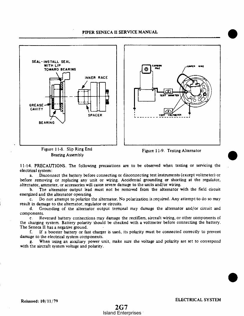
SEAL-INSTALL SEALWITH LIPTOWARD BEARING
SPACER
PIPER SENECA II SERVICE MANUAL
INNER RACE
Figure 1 1-8. Slip Ring End Figure 11-9. Testing AlternatorBearing Assembly
11-14. PRECAUTIONS. The following precautions are to be observed when testing or servicing theelectrical system:
a. Disconnect the battery before connecting or disconnecting test instruments (except voltmeter) orbefore removing or replacing any unit or wiring. Accidental grounding or shorting at the regulator,alternator, ammeter, or accessories will cause severe damage to the units and/or wiring.
b. The alternator output lead must not be removed from the alternator with the field circuitenergized and the alternator operating.
c. Do not attempt to polarize the alternator. No polarization is required. Any attempt to do so mayresult in damage to the alternator, regulator or circuits.
d. Grounding of the alternator output terminal may damage the alternator and/or circuit andcomponents.
e. Reversed battery connections may damage the rectifiers. aircraft wiring, or other components ofthe charging system. Battery polarity should be checked with a voltmeter before connecting the battery.The Seneca 11 has a negative ground.
f. If a booster battery or fast charger is used, its polarity must be connected correctly to preventdamage to the electrical system components.
g. When using an auxiliary power unit, make sure the voltage and polarity are set to correspondwith the aircraft system voltage and polarity.
Reissued: 10/11/79 ELECTRICAL SYSTEM
2G7Island Enterprises

PIPER SENECA II SERVICE MANUAL
11-15. ALTERNATOR SERVICE TEST SPECIFICATIONS. Prestolite specifications for the 14-voltalternators installed as standard equipment on PA-34-200T airplanes are as follows:
TABLE XI-II. ALTERNATOR SPECIFICATIONS
Alternator Model
Voltage
ALY 9402
12 volts
Rated Output
Ground Polarity
Rotation
Rotor:Current Draw (77 ° F)Resistance (77° F)
65 amperes
Negative
Bi-Directional
3.2A nominal4 ohm nominal
4.0 max3 ohm min.
Output Test (77 ° F)VoltsAmperes OutputField AmperesAlternator RPM
14.0 ± .2653.2A nominal5167
11-16. ALTERNATOR NOMENCLATURE.a. Bearings: These units have a sealed ball bearing at the drive end and a two-piece roller bearing at
the slip ring end. The inner race is pressed onto the rotor shaft and the rest of the bearing is in the slip ringend head. When the unit is assembled, the inner race aligns with the bearing. When the bearing is replaced,the new inner race must be installed on the rotor shaft.
b. Lubrication: The slip ring end bearing should be lubricated whenever the alternator isdisassembled. The bearing should be thoroughly cleaned and repacked with Shell Alvania No. 2 or anequivalent bearing lubricant. The cavity behind the bearing should be packed one-third to one-half full withthe same lubricant.
c. Brushes: These units have a separate brush holder assembly that is installed after the alternatorhas been assembled. The brush holder has a small hole that intersects the brush cavities. Use a pin or a pieceof wire to hold the brushes in the holder during assembly. Remove the pin after the brush holder retainingscrews have been tightened. Make a continuity check to be sure the brushes are seated against the slip rings.
Reissued: 10/11/79 ELECTRICAL SYSTEM2G8
Island Enterprises

PIPER SENECA II SERVICE MANUAL
11-17. VOLTAGE REGULATOR.
11-18. REGULATOR COMPONENTS. Alternator output voltage can within limits of the design capabilityof the alternator be controlled by properly varying the average level of current flow in the rotor winding.The solid state electronic regulator is well suited for this purpose. The alternator, due to its design. hasself-limiting current characteristics and therefore needs no current limiting element in the regulator.
a. Transistor: The transistor (Symbol "Q") is an electronic device which can control the flow ofcurrent in an electric circuit. It has no mechanical or moving parts to wear out.
b. Rectifier Diode: The rectifier diode (Symbol "D") will pass current in only one direction(forward direction), and in this respect. it may be compared to a check valve.
c. Zener Diode: The zener diode (Symbol "Z") in addition to passing current in the forwarddirection will also pass current in the reverse direction when a particular value of reverse voltage is applied.This property makes it useful as a voltage reference device in the regulator.
d. Capacitor: The capacitor (Symbol "C") is a device which will store electrical energy for shortperiods of time. This property makes it useful as a filter element to smooth variations of voltage.
e. Resistor: The resistor (Symbol "R") is a device which is used to limit current flow.
11-19. OPERATION OF REGULATOR. (Refer to Figure 11-10.)a. When the alternator is turned on, battery voltage is applied to the "BUS" terminal of the
regulator and via Q4 through the "FIELD" terminal of the regulator to the alternator field terminal F2.The amount of voltage applied to the field of the alternator is controlled automatically by action of theregulator in response to alternator output as described below.
b. Current flow through R6 and Z1 establishes a reference voltage across Z 1.c. Resistors RI and R2/R3 comprise a voltage divider which is adjustable by means of the variable
portion R3. Voltage at the junction of RI and R2 and the reference voltage across Z1 are applied tocomparison transistor Q1. R3 is adjusted so that these voltages are balanced with the desired alternatoroutput voltage present on the "BUS" terminal of the regulator.
d. Thereafter. whenever alternator output voltage (as applied to the "BUS" terminal) falls below thedesired regulation value, the comparison transistor Q will supply increased current to driver transistorsQ2/Q3. which in turn will drive power transistor Q4 to a higher value of field current. This will result inalternator output voltage increasing to a value which will restore balance between the two voltages appliedto Q1.
e. Conversely, if alternator output voltage (as applied to the "BUS" terminal) increases due to agreater engine speed or reduced loading of the electrical system, the comparison transistor Q1 will act toreduce current flow to the driver transistors Q2/Q3. and thus reduce the drive to power transistor Q4. Thiswill result in a reduction of alternator field current and automatically restore balance between the twovoltages applied to comparison transistor Q1.
f. Capacitors C1 and C2 function together with their related transistors in a way to smoothalternator output ripple and voltage spikes so that the alternator field current is controlled at a steadyvalue.
g. The solid state regulator controls alternator field current to a steady value as required by theelectrical load conditions and engine speed. It does not continuously switch field current between high andlow values as do mechanical regulators and the switching type of electronic regulators.
h. The design of this unit is such as to provide an alternator output voltage that does not vary withambient temperature.
Reissued: 10/11/79 ELECTRICAL SYSTEM
2G9Island Enterprises

BUS FIELDC
ENCAPSULATEDCONTROL ASSY.
R 12
6 R17 02 03
CW
GND
Figure 1 1-10. Regulator Diagram
11-20. BALANCING CIRCUIT OPERATION. (Considering two identical alternators and regulators havingthe "PAR" terminals of the regulators connected.)
a. Balancing circuit operation is initiated within one regulator whenever individual field voltagesdelivered by the regulator units to their related alternators are not equal.
b. When a difference in individual field voltages occurs, one-half the difference is impressed acrossR 12 within each regulator and is thus applied to the input of Q5.
c. In that regulator which is delivering the lower field voltage, the polarity of R 2 voltage dropcauses Q5 collector current flow.
d. Q5 collector current flow results in conduction occurring in the collector circuit of Q6.e. Q6 collector current flows from regulator divider R1/R2+R3 through limiting resist., R 17 to
ground.f. Conduction through R17 effectively alters the ratio of the regulator divider RI/R2+R3 in the
direction to increase Q1 collector current flow.g. As described above under REGULATING CIRCUIT OPERATION, increased Q I current results
in increased output from the regulator to the field of its related alternator.h. Feedback action results in Q6 collector current stabilizing at a value that results in nearly equal
field voltage being delivered by the two regulators to their respective alternator fields.i. The balancing circuit will thus automatically maintain, at a low value, the difference voltage
applied to the alternator fields. In a parallel system having identical alternators operating at the same RPM.the output currents of the alternators will thus be maintained nearly equal.
j. In whichever regulator of a pair is set to deliver the highest voltage, the balancing circuits areinactive. Thus. system voltage is determined by the regulator of a pair which is set to higher voltage. Thelower set regulator will adjust itself automatically as described above to deliver the same field voltage as theone which is set higher within the limitsof its design capability.
Reissued: 10/11/79 ELECTRICAL SYSTEM
PIPER SENECA II SERVICE MANUAL
2G10
Island Enterprises

PIPER SENECA II SERVICE MANUAL
k. The balancing regulator system as described provides for automatic load balancing of paralleloperated alternators having independent field excitation circuits. The pilot can while in flight remove eitheralternator system completely from the aircraft system and maintain operation of the other system.
11-21. PREPARATION FOR TESTING. (Regulators may be tested using the aircraft's alternator or analternator test stand.)
CAUTION
Do not interchange regulator leads. This will destroy regulator andvoid warranty.
a. The aircraft technician or other electrical system's specialist must disconnect the battery groundcable at the battery before connecting or disconnecting a test ammeter or other test equipment or beforemaking wiring changes in the electrical system.
b. Voltmeters with test probes or clips are not recommended. Fully insulated bolted terminalconnections are best and these should be attached when all power is removed as described above.
c. When installing a battery in an aircraft, be sure that the battery negative terminal is in a positionso that this terminal can be connected to the battery ground cable for negative ground systems.
d. The regulator under test is to be mounted on a grounded metallic surface using three No. 8screws pulled up tight. For extended test periods the heat transfer from regulator to the mounting surface issignificant.
e. A ground wire between the regulator "GND" terminal and the aircraft or test stand structure isessential for proper operation. The alternator frame must also be solidly bonded to the system ground.
f. The alternator does not need to be polarized; therefore, never connect ground even momentarilyto either the regulator field terminal or to the alternator field terminals. Do not interchange leads toregulator as this will destroy the regulator.
CAUTION
Never under any circumstance permit a ground to contact the fieldcircuit even for an instant while power is applied to the system.
g. The alternator should be in good condition and capable of producing full output. and thealternator drive belt must be adjusted tight enough to prevent slippage.
h. The battery must be in good condition and should be fully charged.i. The voltmeter and ammeter should be of the best quality and should be accurate.j. A carbon pile connected across the battery may be used to load the charging circuit while testing
the regulator.
Reissued: 10/11/79 ELECTRICAL SYSTEM
2G11Island Enterprises

2
PIPER SENECA II SERVICE MANUAL
PAR FIELDREGULATOR
UNDER TEST 5GND BUS
PRECISION 1/2W PRESS-TO-TEST BATTERYV/M 2,200 OHM NORMALLY OPEN
Figure 11-11. Testing Regulator
11-22. TESTING REGULATOR.a. The procedure for testing the regulator whether on the airplane or on the test bench remains the
same. Connect the test meters and regulator wiring as shown in Figure 11-1 1.b. All circuit connections should be clean and tight. This includes the test instrument connections
which must not come loose or open the charging circuit at any time while the system is operating.c. The voltmeter will not indicate the true regulator setting until the regulator has been operating in
the charging system or on the test bench for at least five minutes, at a charge rate of from 10 to 15amperes.
d. With the connections made as shown in Figure 11-11, start the engine and adjust its speed toapproximately 920 to 1250 RPM to obtain 3,000 to 4,000 alternator RPM. Turn on accessories as neededto establish a 10 to 15 ampere load value. Note that the battery charge current is indicated by the ammeter.Therefore, the current value may change downward at the beginning of a test run. This will be especiallytrue if the battery was used for engine starting.
e. After one minute operating time, check the regulator operating voltage as indicated by thevoltmeter. Refer to Alternator Service Test Specifications, Paragraph 11-15 for the correct operatingvoltage. The operating voltage is shown for the ambient temperature in which the regulator is operating.
f. If the voltmeter reading indicates that the operating voltage is not within limits, lift the plasticplug from top of regulator and adjust the voltage to the desired value. Replace the plug after adjustment.Before condemning the regulator, recheck the alternator and the battery. making sure that they are in goodcondition. Recheck all circuit connections and all wiring for unwanted resistance (voltage drop test).Recheck the voltmeter for accuracy and repeat the entire operating test.
Reissued: 10/11/79 , ELECTRICAL SYSTEM2G12
Island Enterprises

PRECI S IONV/M
PIPER SENECA II SERVICE MANUAL
D.C. BUS
CAUTION:FIELD V/M CIRCUIT MUST NOT
TOUCH GROUND.
NOTE:THIS DIAGRAM SHOWS ONLY BASICCONNECTIONS FOR THE PURPOSE OFEXPLAINING ADJUSTMENT PROCEDURE.
Figure 11-12. Adjusting Regulator
11-23. ADJUSTING REGULATOR. These regulators are normally used in parallel alternator systems ofmulti-engine aircraft. Their final adjustment should be made in actual operation in the aircraft system withtest equipment connected as shown in Figure 11-12. The balance adjustment is made while operating onlyone engine, either left or right. The engine to be operated must be selected so as to permit the techniciana completely safe access to both of the regulators, so that they may be adjusted while the engine isoperative without danger.
CAUTION
Extra caution must be exercised due to the proximity of theregulators to the propellers. It is necessary to operate only oneengine for this procedure.
a. Gain access to the regulators by removing the right rear closeout cover in the nose baggagecompartment aft of the nose gear. Remove the plugs from the regulator adjustment holes.
b. Open the paralleling circuit by removing the wire from the "PAR" terminal of either regulatorand insulate the free end so it will not contact other circuits or ground during the adjustment procedure.
Reissued: 10/11/79 ELECTRICAL SYSTEM
2G13Island Enterprises

PIPER SENECA II SERVICE MANUAL
Breaking this circuit disables the balancing circuits in both regulators.c. Operate the "RIGHT" engine at approximately 1750 RPM and at a load of 15 to 30 amperes for
approximately 5 minutes for warm-up; then turn the "LEFT" alternator switch "OFF" and set the RIGHTvoltage regulator (to the left while facing aft) to 14.0-volts; then replace its plug button. This regulatorshould require no further adjustment.
d. Connect a voltmeter between the two "FIELD" terminals, turn the LEFT alternator switch ON,and adjust for minimum voltage; however, the voltage should not exceed 8-volts. This adjustment will be"touchy," and polarity will reverse as zero is passed.
e. Reconnect the PAR wire and note that the voltage as observed in Step 4 drops to less than .5-voltand becomes steady. Check that bus voltage is still 14.0-volts; then shutdown engine.
f. Replace the plug in the regulator; remove all voltmeter leads and test equipment and install thecloseout panel in the baggage compartment.
11-24. OVERVOLTAGE RELAY.
11-25. CHECKING OVERVOLTAGE RELAY. The relay may be tested with the use of a good quality,accurate voltmeter, with a scale of at least 20-volts and a suitable power supply, with an output of at least20-volts, or sufficient batteries with a voltage divider to regulate voltage. The test equipment may beconnected by the following procedure:
a. B+ is connected to "Bat" of the overvoltage control.b. B- is connected to the frame of the overvoltage control.c. Be sure both connections are secure and connected to a clean bright surface.d. Connect the positive lead of the voltmeter to the "Bat" terminal of the overvoltage control.e. Connect the negative lead of the voltmeter to the frame of the overvoltage control.f. The overvoltage control is set to operate between 16.5-volts to 17.5-volts. By adjusting the
voltage an audible "click" may be heard when the relay operates.g. If the overvoltage control does not operate between 16.5 and 17.5-volts, it must be replaced.
Reissued: 10/11/79
2G14ELECTRICAL SYSTEM
Island Enterprises

REGULATOR
YELLOW
OVERVOLTAGECONTROL
OFF ON
OFF ON
PIPER SENECA II SERVICE MANUAL
ALTERNATOR
AMMETER
+
BATTERY
ALTERNATOR ORIGNITION SWITCH
Figure 1 1-13. Application of Overvoltage Control
OVERVOLTAGECONTROL
VOLTMETER
Figure 1 1-14. Testing Overvoltage Control
Reissued: 10/11/79 ELECTRICAL SYSTEM
2G15
Island Enterprises

PIPER SENECA II SERVICE MANUAL
11-26. STARTING MOTORS.
11-27. DESCRIPTION. The starting motor consists of five major components: the commutator end headassembly, the brush set and plate assembly, the frame and field assembly, the armature, and the drive endhead assembly. (Refer to Figure 11-15.)
11-28. OPERATION. When the starting circuit is energized, battery current is applied to the startingmotor terminal. Current flows through the field coils creating a strong magnetic field. At the same time,current flows through the brushes to the commutator through the armature windings to ground. Themagnetic force created in the armature combined with that created in the field windings begins to turn thearmature.
11-29. MAINTENANCE. The starting circuit should be inspected at regular intervals; the frequency ofwhich should be determined by the amount of service and the condition under which the aircraft isoperated. It is recommended that such inspection be made at each 100 hours and include the following:
a. The battery should be checked with a hydrometer to be sure it is fully charged and filled to theproper level with approved water. A load test should be made to determine battery condition. If dirt andcorrosion have accumulated on the battery, it should be cleaned with a solution of baking soda and water.Be sure none of the solution enters the battery cells.
b. The starting circuit wiring should be inspected to be sure that all connections are clean and tightand that the insulation is sound. A voltage loss test should be made to locate any high resistanceconnections that would affect starting motor efficiency. This test is made with a low reading voltmeterwhile cranking the engine or at approximately 100 amperes and the following limits should be used:
1. Voltage loss from insulated battery post to starting motor terminal - 0.3-volt maximum.2. Voltage loss from battery ground post to starter frame - 0.1-volt maximum.
NOTE
If voltage loss is greater than the above limits, additional testsshould be made over each part of the circuit to locate the highresistance connections.
NOTE
If a solderless terminal on an aluminum cable is loose, corroded orotherwise unsatisfactory, it is recommended that the complete cableassembly be replaced instead of replacing or repainng the solderlessterminal.Should replacement of the complete assembly not be practical, it ispermissable to replace the aluminum cable assembly with a coppercable assembly which is two sizes smaller (Ex: an AL-I AluminumCable Assembly is replaced with an AN-3 copper cable assembly).The new cable should be installed in accordance with AC-43-13-2A.
c. No lubrication is required on the starting motor except at the time of overhaul. Soak newabsorbent bronze bearings in SAE 20 oil before installation. Saturate the felt oiling pad in the commutatorend head with SAE 20 oil. Allow excess oil to drain out before installing end head on motor. Put a lightfilm of Lubriplate 777 on the drive end of the armature shaft before and after installing the drive end head.
Revised: 3/16/81 ELECTRICAL SYSTEM2G16
Island Enterprises

PIPER SENECA II SERVICE MANUAL
1. OIL SEAL2. DRIVE END HEAD ASSEMBLY3. DRIVE END BEARING4. THRUST WASHER
. ARMATURE6. THRU BOLT7. FRAME & FIELD ASSEMBLY8. BRUSH SET9. BRUSH SPRING
10. THRUST WASHER11. COMMUTATOR END HEAD
ASSEMBLY
Figure I 1-15. Exploded View of Starting Motor
d. The starting motor should be operated for a few seconds with the ignition switch off. This is todetermine that the starter engages properly and that it turns freely without binding or excessive noise. Startthe engine two or three times to check the starter drive assembly.
NOTE
Refer to the engine manufacturer's service information concerningthe starter drive mechanism.
11-30. OVERHAUL. If during the above inspection any indication of starting motor difficulty is noted,the starting motor should be removed from the engine for cleaning and repair.
11-31. REMOVAL. To remove the starting motor from the engine first disconnect the ground cable fromthe battery post to prevent short circuiting. Disconnect the lead from the starting motor terminal: then takeout the mounting bolts. The motor can then be lifted off and taken to the bench for overhaul.
11-32. DISASSEMBLY.a. Remove the safety wire and thru bolts from the commutator end and pull the end head from the
frame.b. Pull the drive end head and armature from the frame and separate the drive end head from the
armature.c. The drive end bearing may be removed by pressing out of the drive end head.d. Each part should be cleaned and inspected for excessive wear or damage. Bearing should be
checked for proper clearance and evidence of roughness or galling. Oil and dirt should be removed frominsulation and the condition of the insulation checked.
Reissued: 10/11/79 ELECTRICAL SYSTEM
2G17
Island Enterprises

PIPER SENECA II ERVICE MANUAL
Figure 11-16. Turning Motor Commutator Figure 11-17. Testing MotorArmature for Shorts
11-33. BRUSHES. Check the brushes to see that they slide freely in their holders and make full contact onthe commutator. If worn to half their original length or less. they should be replaced.
11-34. ARMATURE.a. Check the commutator for uneven wear. excessive glazing, or evidence of excessive arcing. If only
slightly dirty, glazed or discolored, the commutator can be cleaned with 00 or 000 sandpaper. If thecommutator is rough or worn. it should be turned in a lathe. (Refer to Figure 11-16.)The armature shaftshould be inspected for rough bearing surfaces and rough or damaged splines.
b. To test the armature for grounds, a set of test probes connected in series with a 110-volt lightshould be used. Touch one probe to a commutator segment and the other to the armature core. If the testlamp lights, the armature is grounded and should be replaced.
c. To test for shorted armature coils. a growler is used. (Refer to Figure 11-17.) The armature isplaced on the growler and slowly rotated by hand while a steel strip is held over the core so that it passesover each armature core slot. If a coil is shorted. the steel strip will vibrate.
d. A quick check for opens can be made by inspecting the trailing edge (in direction of rotation) ofthe commutator segments for excessive discoloration. This condition indicates an open circuit.
11-35 FIELD COILS.a. Check the field coils for grounds (refer to Figure 11-18) by placing one test probe on the frame
and the other on the starter terminal. Be sure the brushes are not accidentally touching the frame. If thelamp lights, the fields are grounded. Repair or replace.
b. Inspect all connections to make sure they are clean and tight and inspect insulation fordeterioration.
Reissued: 10/11/79 ELECTRICAL SYSTEM
2G18
Island Enterprises

PIPER SENECA II SERVICE MANUAL
TYPICAL TEST SET-UP
Figure 1 1-18. Testing MotorFields for Grounds
Figure 11-19. No-Load Test Hookup
11-36. BRUSH HOLDERS.a. To test brush holders. touch one test probe to the brush plate and the other to each brush holder.b. The test lamp should light when the grounded brush holders are touched and should not light
when the insulated brush holders are touched.
11-37. ASSEMBLY.a. When assembling the starting motor always use an arbor press and the proper bearing arbor for
installing graphitized bronze bearings.b. Soak new absorbent bronze bearings in SAE 20 oil before installation. Saturate the felt oiling pad
in the commutator end head with SAE 20 oil. Allow excess oil to drain out before installing end head onmotor. Put a light film of Lubriplate 777 on the drive end of the armature shaft before and after installingthe drive end head.
c. New brushes should be properly seated when installing by wrapping a strip of 00 sandpaperaround the commutator (with the sanding side out) 1-1/4 to 1-1/2 times maximum. Drop brushes onsandpaper covered commutator and turn the armature slowly in the direction of rotation. Dust should beblown out of the motor after sanding.
NOTE
The spring tension is 32 to 40 ounces with new brushes. Thistension is measured with the scale hooked under the brush springnear the brush and the reading is taken at right angles to the lineof force exerted by the brush spring.
Reissued: 10/11/79 ELECTRICAL SYSTEM
2G19
Island Enterprises
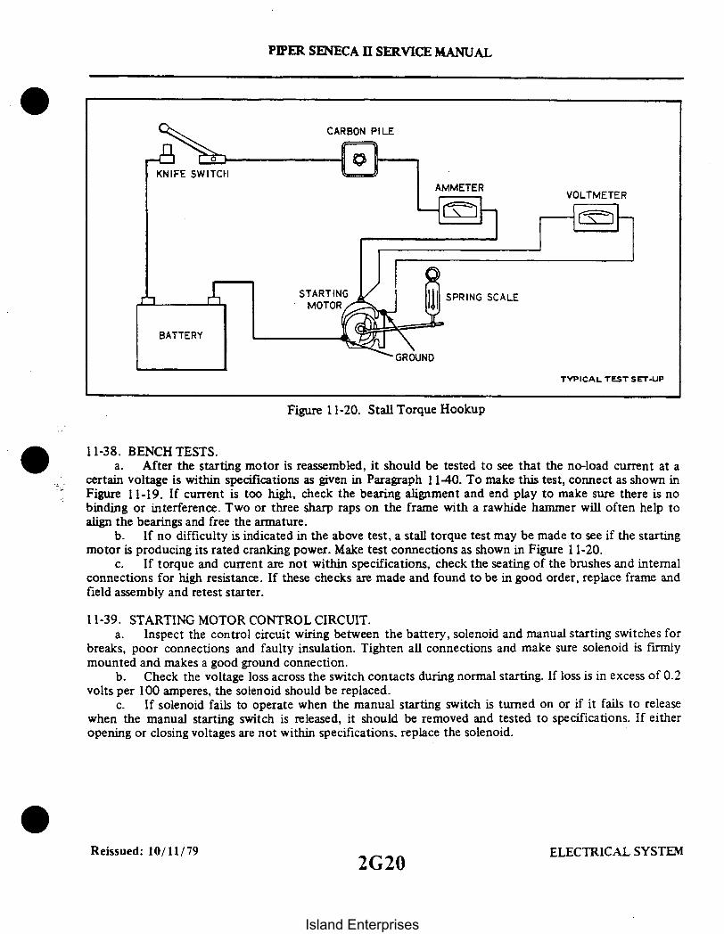
CARBON PILE
KNIFE SWITCHAMMETER VOLTMETER
BATTERY
GROUND
TYPICAL TEST SET-UP
Figure 11-20. Stall Torque Hookup
11-38. BENCH TESTS.a. After the starting motor is reassembled, it should be tested to see that the no-load current at a
certain voltage is within specifications as given in Paragraph 1140. To make this test, connect as shown inFigure 11-19. If current is too high, check the bearing alignment and end play to make sure there is nobinding or interference. Two or three sharp raps on the frame with a rawhide hammer will often help toalign the bearings and free the armature.
b. If no difficulty is indicated in the above test, a stall torque test may be made to see if the startingmotor is producing its rated cranking power. Make test connections as shown in Figure 11-20.
c. If torque and current are not within specifications, check the seating of the brushes and internalconnections for high resistance. If these checks are made and found to be in good order, replace frame andfield assembly and retest starter.
11-39. STARTING MOTOR CONTROL CIRCUIT.a. Inspect the control circuit wiring between the battery, solenoid and manual starting switches for
breaks, poor connections and faulty insulation. Tighten all connections and make sure solenoid is firmlymounted and makes a good ground connection.
b. Check the voltage loss across the switch contacts during normal starting. If loss is in excess of 0.2volts per 100 amperes, the solenoid should be replaced.
c. If solenoid fails to operate when the manual starting switch is turned on or if it fails to releasewhen the manual starting switch is released, it should be removed and tested to specifications. If eitheropening or closing voltages are not within specifications. replace the solenoid.
Reissued: 10/11/79 ELECTRICAL SYSTEM
PIPER SENECA II SERVICE MANUAL
2G20
Island Enterprises

PIPER SENECA II SERVICE MANUAL
11-40. STARTING MOTOR SERVICE TEST SPECIFICATIONS. Prestolite specifications for 12-voltcranking motors installed as standard equipment on the PA-34-200T are as follows:
TABLE XI-III. STARTING MOTOR SPECIFICATIONS
Motor Model MCL-6501
Min. Brush Tension 32 oz. (With NewMax. Brush Tension 40 oz. Brushes)
No-Load Test (75°F):Volt 5Max. Amps 65Min. RPM 4900
Stall Torque:Max. Amps 410Min. Torque, Ft.-Lbs. 8Approx. Volts 2
11-41. BATTERY.
11-42. SERVICING BATTERY. The battery is located in the left forward portion of the nose section. It isenclosed in a fiberglass box with a vent system and a drain. The vents allow fresh air to enter the box anddraw off fumes that may accumulate due to the charging process of the battery. The drain is clamped offfrom the bottom of the fuselage and should be opened occasionally to drain any accumulation of liquid orduring cleaning of the box. The battery should be checked for fluid level but must not be filled above thebaffle plates. A hydrometer check should be performed to determine the percent of charge in the battery.All connections must be clean and tight.
NOTE
Refer to note under paragraph 11-29"Maintenance"when replacingcables in battery circuit.
11-43. REMOVAL OF BATTERY.a. Remove the access cover over nose wheel and battery in the nose baggage compartment.b. Disconnect the battery cables.
NOTE
Always remove the ground cable first and install last to preventaccidental short circuiting or arcing.
c. Lift the battery from the box.
Revised: 12/08/83 2G21 ELECTRICAL SYSTEM2G21
Island Enterprises

*PIPER SENECA II SERVICE MANUAL
11-44. INSTALLATION OF BATTERY.a. Ascertain that the battery and battery box have been cleaned and are free of acid.b. Install the battery in box.c. Connect the positive lead to the positive battery terminal and secure.d. Connect the ground cable to the negative battery terminal and secure.e. Install access panel.
THIS SPACE INTENTIONALLY LEFT BLANK
Reissued: 10/11/79 ELECTRICAL SYSTEM2G22
Island Enterprises

PIPER SENECA II SERVICE MANUAL
11-45. CHARGING BATTERY. If the battery is not up to normal charge, remove the battery andrecharge starting with a charging rate of 4 amperes and finishing with 2 amperes. A fast charge is notrecommended.
TABLE XI-IV. HYDROMETER READING AND BATTERY CHARGE PERCENT
Hydrometer Reading
12801250122011901160
1130 or below
Percent of Charge
100755025
Very little useful capacitydischarged
11-46. BATTERY BOX CORROSION PREVENTION. The battery should be checked for spilledelectrolyte or corrosion at least each 50 hour inspection or at least every 30 days, whichever comes first.Should this be found in the box, on the terminals or around the battery, the battery should be removed andboth the box and battery cleaned by the following procedure:
a. Remove the box drain cap from the under side of the fuselage and drain off any electrolyte thatmay have overflowed into the box.
b. Clean the battery and the box. Corrosion effects may be neutralized by applying a solution ofbaking soda and water mixed to a consistency of thin cream. The application of this mixture should beapplied until all bubbling action has ceased.
CAUTION
Do not allow soda solution to enter battery.
c. Rinse the battery and box with clean water and dry.d. As necessary, paint the battery box with an acid resistant paint. Allow paint to dry thoroughly.e. Place the cap over the battery box drain.f. Reinstall the battery.
11-47. STARTING THROUGH EXTERNAL POWER RECEPTACLE WITH AIRPLANE'S BATTERYNEARLY DEPLETED. The external power receptacle is built-in and located on the left side of the nosesection on early models. On the later ones it can be installed per Piper Service Kit No. 761 085v.
NOTE
Should the hydrometer reading indicate less than 1190, thebattery should be removed and recharged or replaced.
Reissued: 10/11/79 ELECTRICAL SYSTEM
2G23
Island Enterprises

PIPER SENECA II SERVICE MANUAL
a. When using a 12-volt battery for external power starting and the airplane's battery is nearlydepleted, the following procedure should be used:
1. Disconnect the airplane's battery at the negative terminal to prevent excessive loading of theexternal starting battery.
2. Check that all of the airplane's electrical equipment and master switch are turned off.3. Connect the external battery to the external power receptacle and start RIGHT ENGINE
ONLY using normal starting procedures.4. Remove external battery and then reconnect airplane's battery at the negative terminal.5. Turn master switch on and check ammeter for battery charging current.
b. When starting with a power cart and the airplane's battery is nearly depleted, the procedure inStep (a) need not be followed. The capacity of a power cart is sufficient to start an aircraft with a lowbattery. If a six-volt battery is available, it can be connected in series with the 12-volt external battery tosupply 18-volts for starting. In this case, use the same starting procedure as used with a power cart.
CAUTION
If aircraft battery is weak, charging current will be high. Do nottake off until charging current falls below 20 amps.
Never use a 12 or 24-volt battery in place of a six-volt batterysince electrical damage may result.
11-48. LANDING AND TAXI LIGHTS. These lights consist of two 250 watt lamps which are located on amounting fixture secured to the nose gear oleo strut housing. Both lamps are used for landing and one lampis used while taxiing. Each lamp is controlled by a separate switch mounted on the switch panel. (Refer toFigure 11-1.) The lamps are wired to separate 10 amp circuit protectors mounted in the circuit protectorpanel. There is a safety switch mounted on the nose gear strut which will break the circuit to the lightswhen the nose gear is retracted in case the pilot forgets to turn the switches off.
11-49. REMOVAL OF LANDING AND TAXI LIGHTS. (Refer to Figure 11-21.)a. Ascertain the master switch is off prior to doing any work on the landing lights.b. Removal of either lamp from the landing light mounting fixture is accomplished by removing the
screws securing the front lamp attachment plate and removing the attachment plate.
CAUTION
When removing the attachment plate, use caution not to drop thelamps.
c. Disconnect the electrical leads from the lamp being removed.d. To remove the complete assembly from the gear strut, disconnect the electrical leads from both
lamps and release the clamps that secure the assembly to the strut housing.
11-50. INSTALLATION OF LANDING AND TAXI LIGHTS. (Refer to Figure 11-21.)a. To install the landing lamps, attach the electrical leads to the lamp or lamps.b. Place the lamp or lamps against the mounting pad and position the attachment plate on the
mounting fixture and secure with appropriate screws.
Reissued: 10/11/79 ELECTRICAL SYSTEM2G24
Island Enterprises

ADJUSTMENT SCREW
LANDING LIGHT ASS'Y-
PIPER SENECA II SERVICE MANUAL
A291
CLAMP
GEAR DOOR
STRUT
Figure 11-21. Landing Light Adjustment
CAUTION
Tighten the screws just enough to allow the lamps to fit snug inthe mounting fixture.
c. To install the landing light assembly to the strut, position the assembly against the strut housingwith the bottom of the mounting fixture 2.9 inches up from the bottom of the strut housing. (Refer toFigure 11-21.)
d. Align the bracket longitudinally and secure in place with clamps.e. The light beam angle may be adjusted by the adjustment screws at the sides of the bracket and
tilting the mounting fixture as desired.
11-51. STALL WARNING SYSTEM. This system consists of an inboard and outboard lift detector, bothof which are electrically connected to a stall warning horn located behind the instrument panel. The 1975models also included a stall warning light with electrical connection per Figure 11-36. As stalling conditionsare approached with the wing flaps up, the outboard lift detector will activate the warning system. As theflaps are lowered to the 25 and 40° position, a micro switch deactivates the outboard lift detector andactivates the inboard lift detector which will now control the warning system should stall conditions exist.The electrical circuit for this system is protected by a 5 amp circuit protector located in the circuitprotector panel. The stall warning system may be checked for proper operation by performing thefollowing:
Reissued: 10/11/79 ELECTRICAL SYSTEM
2H1
Island Enterprises

PIPER SENECA II SERVICE MANUAL
A366
FIG
MICROSWITCH
FIH
Figure 11-22. Adjusting Lift Detector Micro Switch
NOTE
To check the dual stall warning system, insert microswitch keyunder the leaf of the squat switch on the Left Main Gear.
a. Put the flaps in the full up position and turn on the master switch. Using finger pressure, gentlyraise the sensor blade of the outboard lift detector. The warning system should activate. Gently loweringthe sensor blade should make the system deactivate. If light and horn are installed, ascertain that bothoperate.
b. With the flaps in the 25 and 40 ° down position and the master switch on, raise the sensor bladeof the inboard lift detector. The warning system should activate. Gently lowering the sensor blade shouldmake the system deactivate.
c. With the flaps in the 25° and 40° down position and the master switch on, raise the sensor bladeof the outboard lift detector. The warning system should NOT activate. In the event the warning systemdoes activate, the micro switch is in need of adjustment as follows:
NOTE
The master switch must be off prior to performing any work onthe lift detector, warning light and horn or micro switch.
Reissued: 10/11/79 ELECTRICAL SYSTEM2H2
Island Enterprises

PIPER SENECA II SERVICE MANUAL
1. Refer to Section V, Paragraph 5-36 and proceed to the extent necessary to gain access to themicro switch mounted on a bracket adjacent to the left end of the wing flap torque tube. (Refer to Figure11-22.)
2. Put the flaps in the full up position and determine that the wheel of the micro switchactuator is in contact with the torque tube fitting. Loosen, but do not remove the screws securing the microswitch in position. Move the flaps towards the full down position while moving the micro switch in thedirection necessary to hear it actuate as the flaps assume the 25 down position. Tighten the micro switchmounting screws and repeat Steps a thru c.
11-52. REMOVAL OF LIFT DETECTOR.a. Remove four screws holding the unit in place and remove the unit from the wing.b. Identify the electrical leads to facilitate reinstallation and disconnect the electrical leads.
11-53 INSTALLATION OF LIFT DETECTOR.a. Attach electrical leads to the appropriate terminals of the lift detector.b. Position the unit on the wing, determining that the sensor blade of the unit drops down freely,
and secure in position with four screws previously removed.
11-54. NAVIGATION LIGHTS.
11-55. REMOVAL OF WING NAVIGATION LIGHT.a. Remove screw securing the lens retainer.b. Remove lens and bulb.
NOTE
To remove the complete lamp assembly, the wing tip must beremoved.
11-56. INSTALLATION OF WING NAVIGATION LIGHT.a. Install bulb, lens and lens retainer.b. Secure with appropriate screws.
11-57. REMOVAL OF TAIL NAVIGATION LIGHT.a. To remove bulb, remove the screws securing the light assembly to the rudder tip and remove the
lens.b. Remove the bulb.
NOTE
To remove the complete light assembly, unsolder the electricallead from the base of the light assembly and disconnect theremaining electrical lead at the connector.
11-58. INSTALLATION OF TAIL NAVIGATION LIGHT.a. Install bulb and lens in light assembly.b. Place light assembly in position on rudder tip and secure with appropriate screw.
11-58a. ANTI-COLLISION LIGHT.
Revised: 12/08/83 2H3 ELECTRICAL SYSTEM2H3
Island Enterprises

PIPER SENECA II SERVICE MANUAL
11-59. REMOVAL OF LAMP IN ANTI-COLLISION WING TIP STROBE LIGHT. The lights are locatedin both wing tips next to the navigational lights.
a. Remove the screw securing the navigational light cover and remove cover.b. Remove the three screws securing navigational light bracket assembly and remove light assembly.c. Remove the strobe lamp by cutting the wires on the lamp beneath the mounting bracket.d. Remove the defective lamp.e. Remove and discard the plug with the cut wires from the electrical socket.
11-60. INSTALLATION OF LAMP IN ANTI-COLLISION WING TIP STROBE LIGHT.a. Route the wires from the new lamp down through the hole in the navigational light bracket.b. Insert the wire terminals in the plastic plug supplied with the new lamp. Wire according to the
schematic diagram located at the back of this section.c. Position strobe lamp on navigational light bracket.d. Secure navigational light assembly and bracket with appropriate screws.e. Install navigational light cover and secure with appropriate screws.
11-61. REMOVAL OF LAMP IN ANTI-COLLISION LIGHT. The light is located on the upper section ofthe vertical fin.
a. Loosen the screw in the clamp securing the light cover.b. Remove the light cover.c. Remove the defective lamp from the socket.
11-62. TROUBLESHOOTING PROCEDURE FOR ANTI-COLLISION AND WING TIP STROBE LIGHTSYSTEMS. The strobe light assembly functions as a condenser discharge system. A condenser in the powersupply is charged to approximately 450-volts D.C.; then discharged across the Xenon flash tube at intervalsapproximately 45 flashes per minute. The condenser is parallel across the Xenon flash tube which isdesigned to hold off the 450-volts D.C. applied until the flash tube is triggered by an external pulse. Thispulse is generated by a solid state timing circuit in the power supply.
When troubleshooting the strobe light system, it must first be determined if the trouble is in the flashtube or the power supply. Replacement of the flash tube will confirm if the tube is defective. A normaloperating power system will emit an audible tone of I to 1.5 KHz. If there is no sound emitted, check thesystem according to the following instructions. When troubleshooting the system, utilize the appropriateschematic at the back of this section.
a. Ascertain the input voltage at the power supply is 14-volts.
CAUTION
When disconnecting and connecting the power supply inputconnections, do not get the connection reversed. Reversed polarityof the input voltage for just an instant will permanently damagethe power supply. The reversed polarity destroys a protectivediode in the power supply, causing self-destruction fromoverheating of the power supply. This damage is sometimes notimmediately apparent, but will cause failure of the system in time.
b. Check for malfunction in interconnecting cables.1. Ascertain pins 1 and 3 of interconnecting cable are not reversed.2. Using an ohmmeter, check continuity between pin I and 3 of interconnecting cable. If you
obtain a reading on the meter, the cable is shorted and should be replaced.
ELECTRICAL SYSTEMELECTRICAL SYSTEMReissued: 10/11/79 2H4
Island Enterprises

PIPER SENECA II SERVICE MANUAL
NOTE
A short of the type described in Steps I and 2 will not causepermanent damage to the power supply but the system will beinoperative if such a short exists. Avoid any connection betweenpins I and 3 of the interconnecting cable as this will discharge thecondenser in the power supply and destroy the trigger circuit.
CAUTION
When disconnecting the power supply, allow five minutes of bleeddown time prior to handling the unit.
c. Check interconnecting cables for shorts.I. Disconnect the output cables from the power supply outlets.2. The following continuity checks can be made with an ohmmeter.3. Check for continuity between the connectors of each interconnecting cable by checking
from pin I to pin 1. pin 2 to pin 2. and pin 3 to pin 3. When making these checks if no continuity exists, thecable is broken and should be replaced.
4. Check continuity between pins I and 2. 1 and 3. and 2 and 3 of the interconnect cable. Ifcontinuity exists between any of these connections, the cable is shorted and should be replaced.
5. Check for continuity from pins 1, 2 and 3 to airplane ground. If continuity exists. the cableis shorted and should be replaced.
d. Check the tube socket assembly for shorts.1. Disconnect the tube socket assembly of the anti-collision light from the interconnecting
cable.2. The following continuity checks can be made with an ohmmeter.3. Check for continuity between pin I of AMP connector to pin I of tube socket. pin 2 of
AMP connector to pins 6 and 7 of tube socket and pin 3 of AMP connector to pin 4 of tube socket. Whenmaking these tests if no continuity exists, the tube socket assembly is broken and should be replaced.
11-63. INSTALLATION OF ANTI-COLLISION LIGHT.a. Plug in new lamp using correct number.b. Replace light cover.c. Tighten screw in clamp to secure light cover.
11-63a. READING LIGHTS.
11-64. REMOVAL OF LAMP IN OVERHEAD READING LIGHTS. The lights are located in the centerand rear overhead panels.
a. Grasp the protruding section of the light assembly and turn to remove from its socket.b. Remove the lamp from the light assembly mounting fixture.
11-65. INSTALLATION OF LAMP IN OVERHEAD READING LIGHTS.a. Insert the new lamp using the proper number in the light assembly mounting fixture.b. Install the mounting fixture in the light assembly and turn to secure.
Revised: 12/08/83 2H5 ELECTRICAL SYSTEM2H5
Island Enterprises

PIPER SENECA II SERVICE MANUAL
11-66. INSTRUMENT AND PANEL LIGHTS. The instrument and panel lights are broken up into sixgroups: Main Panel Lights. Copilot Panel Lights, Lower Panel Lights. Overhead Panel Flood Lights. MiddlePanel Lights and the Engine Instrument Cluster Lights. The instrument lights are controlled by a 5 ampcircuit breaker through a transistorized dimmer. The dimmer control is located in the middle of the instrumentpanel just above the pedestal. In earlier model airplanes. there is one control knob connected to a variableresistor that controls the intensity of the instrument lights. There is a second control knob connected to avariable resistor which controls the light intensity for all the avionic equipment. The overboost warninglights on the annunciator panel are dimmed when the instrument lights are dimmed. It may be necessary togain access to the Dimmer Control Assembly, if so, follow the instructions given below.
11-67. REMOVAL OF DIMMER CONTROL ASSEMBLY.a. Access to the Dimmer Control Assembly is from beneath the instrument panel.b. Disconnect the electrical connection from the assembly.c. Remove the knob from panel front.d. Remove the two screws securing the assembly to the instrument panel.e. Remove assembly from the airplane.
11-68. INSTALLATION OF DIMMER CONTROL ASSEMBLY.a. Position the assembly in the instrument panel with the control knobs inserted into their
appropriate slots.b. Secure the assembly to the instrument panel with the two screws previously removed.c. Connect the electrical connection to the assembly.d. Check operation of Dimmer Control Assembly.
11-69. ANNUNCIATOR PANEL.
11-70. DESCRIPTION. The annunciator panel is a light cluster mounted in the upper left instrumentpanel that provides a visual indication of individual system malfunctions by the illumination of a warninglight. A push-to-test switch on the left side of the annunciator is used to illuminate the entire display tocheck the condition of the lights when the engine is running. The gyro air, alt and oil lights will work whenthe engine is not running with the master switch on. Power to the annunciator is supplied from the bus barthrough a 5 amp fuse located behind the left exhaust gas temperature gauge.
The left and right OVER BST. lights are activated whenever the left or right engine manifold pressureexceeds 39.5 inches of mercury. The manifold pressure sensor is incorporated in the manifold pressure gauge.
The OIL warning light is activated by a pressure sensor in the oil pressure line to the oil pressure gaugewhenever the engine oil pressure drops below 30 psi. The sensor is mounted in a special bulkhead T fittingon the aft side of the fire wall.
The GYRO AIR warning light is activated by a pressure sensor mounted in the gyro pressure regulatoron the aft side of the fire wall. The switch will activate when the gyro air pressure is below 4.5 inches ofmercury.
The ALT warning light is activated whenever one or both alternator output circuits fail.
Revised: 12/08/83 ELECTRICAL SYSTEM2H6
Island Enterprises

PIPER SENECA II SERVICE MANUAL
11-71. ANNUNCIATOR LIGHTS TEST
NOTE
The sequence of the following tests may be varied at the option of themechanic.
a. Press the annunciator test button to insure that all annunciators illuminate.b. Start the right engine. operate at 700-1000 RPM and note that the oil and air pressure are normal.c. Start the left engine and note that the GYRO Al R light goes out as the engine starts. Note that the oil
pressure is normal and that the alternator has output.d. Idle one engine at a time while carefully observing its oil pressure gauge to insure that the OIL
annunciator light comes on at 15 psi.
NOTE
The mixture control can be moved to cut-off, then to rich in order toget lower then normal idle speeds.
e. With both engines at approximately 900 RPM place one alternator in the off position at a time.Check that either or both alternator switches in the off position causes the ALT annunciator to illuminate.
f. Use proper caution to insure that the propellers are over hard surface and that the propeller blastwill do no damage. then run up the engines one at a time to check that each OVERBST annunciator comes onat 39.5 + 0.5 inches of mercury manifold pressure.
g. Shut down the right engine first and check that the GYRO AIR illuminates just as the engine slowsto approximately 300 RPM. Check that the other annunciator lights are on.
h. Shut down left engine.
11-72. TROUBLESHOOTING (Refer to Table XI-V.)
Added: 3/16/81 ELECTRICAL SYSTEM2H7
Island Enterprises

PIPER SENECA II SERVICE MANUAL
TABLE XI-V. TROUBLESHOOTING CHART (ELECTRICAL SYSTEM)
Trouble Cause Remedy
ANNUNCIATOR PANEL
All the warning lightsfail to operate.
Blown fuse. Replace the 5 amp fusebehind instrument panel.
No current from bus. Check all wire segments,connections, and thereceptacle at the leftside of the annunciatorpanel.
All the warning lightsfail to extinguishafter engine is running.
Oil or gyro airwarning light failsto extinguish.
Test switch groundedout.
Sensor activates attoo high a setting.
Sensor terminalsbridged.
Check terminals andreplace switch ifnecessary.
Replace.
Remove material betweenterminals.
Defective sensor. Replace.
Oil or gyro airwarning light fails tooperate.
Lamp burned out.
No current to sensor.
Replace.
Check all wire segmentsand connections.
Sensor activates attoo low a setting.
Defective sensor.
Replace.
Replace.
Reissued: 10/11/79 ELECTRICAL SYSTEM
2H8
Island Enterprises

PIPER SENECA II SERVICE MANUAL
TABLE XI-V. TROUBLESHOOTING CHART (ELECTRICAL SYSTEM) (cont.)
Trouble Cause Remedy
ANNUNCIATOR PANEL (cont.)
Overboost warning lightfails to extinguish.
Overboost warning lightfails to activate.
Manifold pressure gaugesensors set too low.
Lamp burned out.
Defective sensorswitches.
Check sensor activation.Sensors should activateat 39.5 inches ofmercury.
Replace.
Check and replace ifnecessary.
Alternator warninglight fails to operate.
Lamp burned out. Replace.
Alternator warninglight fails toextinguish.
Blown fuse or fuses. Replace one or both 5 ampfuses behind instrumentpanel.
Defective alternatoroutput circuit.
Check and repair.
Test switch fails toactivate warning lights.
Bad switch or connections. Check wires and replaceswitch if necessary.
Reissued: 10/11/79 2H9 ELECTRICAL SYSTEM
Island Enterprises

Interruption of voltagethrough any of thesepoints isolates thefaulty component orwire which must bereplaced. (See Figure11-23.)
PIPER SENECA II SERVICE MANUAL
TABLE XI-V. TROUBLESHOOTING CHART (ELECTRICAL SYSTEM) (cont.)
Trouble Cause Remedy
ALTERNATOR
Zero output indicatedon ammeter regardlessof RPM (refer to alter-nator system testprocedure).
Open field circuit. With master switchturned on check forbattery voltage (12V)from ship's main busthrough entire fieldcircuit to alternatorfield terminal. Measurevoltage from ground(-) to the followingpoints (+) in sequence:bus bar, output circuitdiodes, fieldcircuit breaker (5A),field terminals ofmaster switch, voltageregulator and alternatorfield terminal.
Open output circuit. With master switchturned on check forbattery voltage (12V)from ship's main busthrough entire outputcircuit to alternatorbattery post. Measurevoltage from ground (-)to the following points(+) in sequence: busbar. output circuitdiodes, am-meter, and alternatorbattery post.
Reissued: 10/11/79 ELECTRICAL SYSTEM
2H10
Island Enterprises
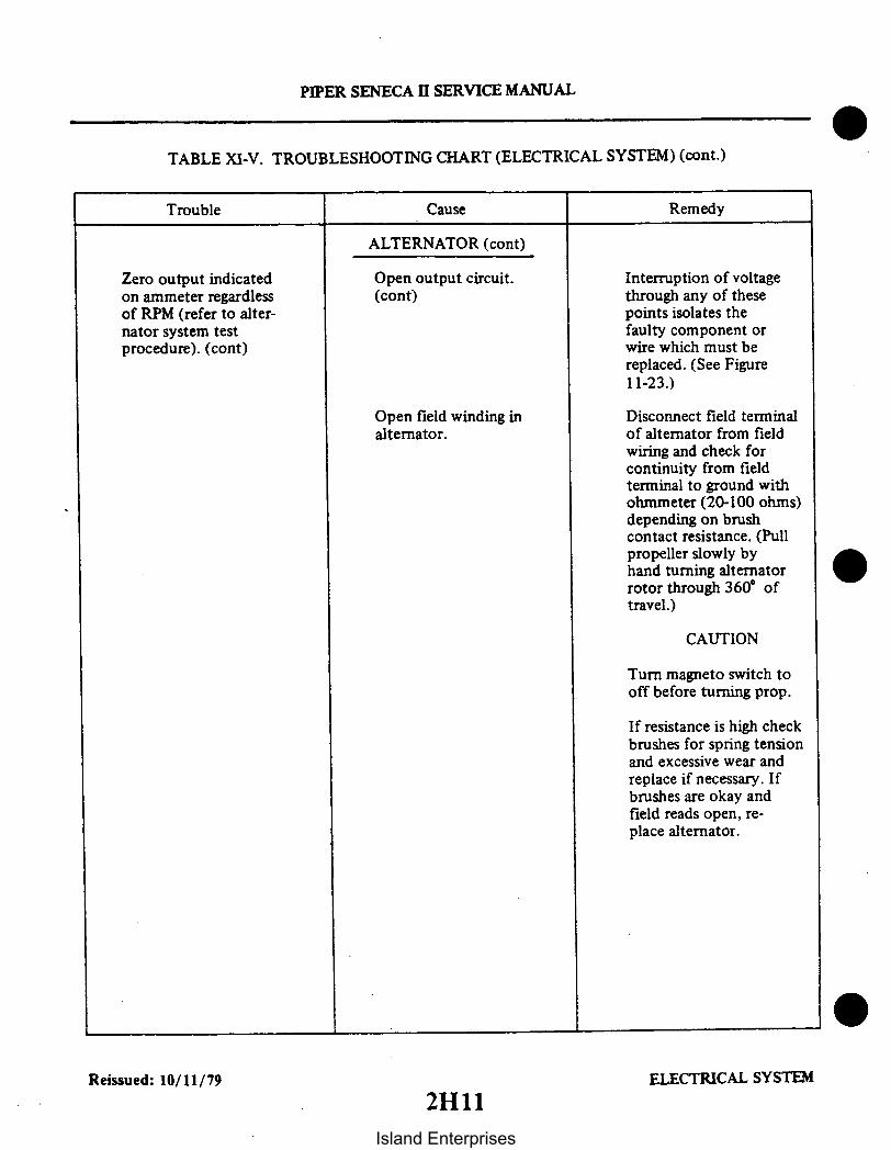
PIPER SENECA II SERVICE MANUAL
TABLE XI-V. TROUBLESHOOTING CHART (ELECTRICAL SYSTEM) (cont.)
Trouble Cause Remedy
ALTERNATOR (cont)
Zero output indicatedon ammeter regardlessof RPM (refer to alter-nator system testprocedure). (cont)
Open output circuit.(cont)
Interruption of voltagethrough any of thesepoints isolates thefaulty component orwire which must bereplaced. (See Figure11-23.)
Open field winding inalternator.
Disconnect field terminalof alternator from fieldwiring and check forcontinuity from fieldterminal to ground withohmmeter (20-100 ohms)depending on brushcontact resistance. (Pullpropeller slowly byhand turning alternatorrotor through 360' oftravel.)
CAUTION
Turn magneto switch tooff before turning prop.
If resistance is high checkbrushes for spring tensionand excessive wear andreplace if necessary. Ifbrushes are okay andfield reads open, re-place alternator.
Reissued: 10/11/79 ELECTRICAL SYSTEM
2H11Island Enterprises

High resistance connec-tions in field or outputcircuit.
PIPER SENECA II SERVICE MANUAL
TABLE XI-V. TROUBLESHOOTING CHART (ELECTRICAL SYSTEM) (cont.)
Trouble Cause Remedy
ALTERNATOR (cont)
Output indicated onammeter does notmeet minimum valuesspecified in alternatorsystem test procedure.
Faulty voltage regulator. Start engine, turn onload (ref. alternatortest procedure), setthrottle at 2300 RPM.Check voltage at busbar (convenient checkpoint, remove cigarlighter and check fromcenter contact (+) toground (-). Voltageshould be 13.5 voltsminimum. If voltage isbelow this value replaceregulator.
Check visually for loosebinding posts at thevarious junction pointsin system, alternatorbattery post, lugs onammeter, connections atvoltage regulator, circuitbreaker, etc., (SeeFigure1 1-23.)Examinecrimped terminal endsfor signs of deteriorationat crimp or strands ofbroken wire at crimp.Tighten any loose bindingposts or replace badwire terminals.
If any of the six recti-fiers pressed into therear bell housing of thealternator open up in-ternally it will resultin a definite limitationon the current that canbe drawn from thealternator. After havingchecked the previous
Open rectifier.
ELECTRICAL SYSTEMReissued: 10/11/79
2H12
Island Enterprises
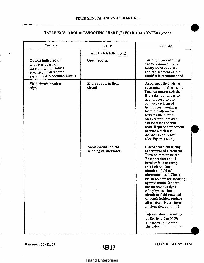
PIPER SENECA II SERVICE MANUAL
TABLE XI-V. TROUBLESHOOTING CHART (ELECTRICAL SYSTEM) (cont.)
Trouble Cause Remedy
ALTERNATOR (cont)
Output indicated onammeter does notmeet minimum valuesspecified in alternatorsystem test procedure. (cont)
Field circuit breakertrips.
Open rectifier.
Short circuit in fieldcircuit.
causes of low output itcan be assumed that afaulty rectifier existsand replacement of therectifier is recommended.
Disconnect field wiringat terminal of alternator.Turn on master switch.If breaker continues totrip, proceed to dis-connect each leg offield circuit, workingfrom the alternatortowards the circuitbreaker until breakercan be reset and willhold. Replace componentor wire which wasisolated as defective.(See Figure 11-23.)
Short circuit in fieldwinding of alternator.
Disconnect field wiringat terminal of alternator.Turn on master switch.Reset breaker and ifbreaker fails to retrip,this isolates shortcircuit to field ofalternator itself. Checkbrush holders for shortingagainst frame. If thereare no obvious signsof a physical shortcircuit at field terminalor brush holder, replacealternator. (Note: Inter-mittent short circuit.)
Internal short circuitingof the field can occurat various positions ofthe rotor, therefore, re-
Reissued: 10/11/79 ELECTRICAL SYSTEM2H13
Island Enterprises
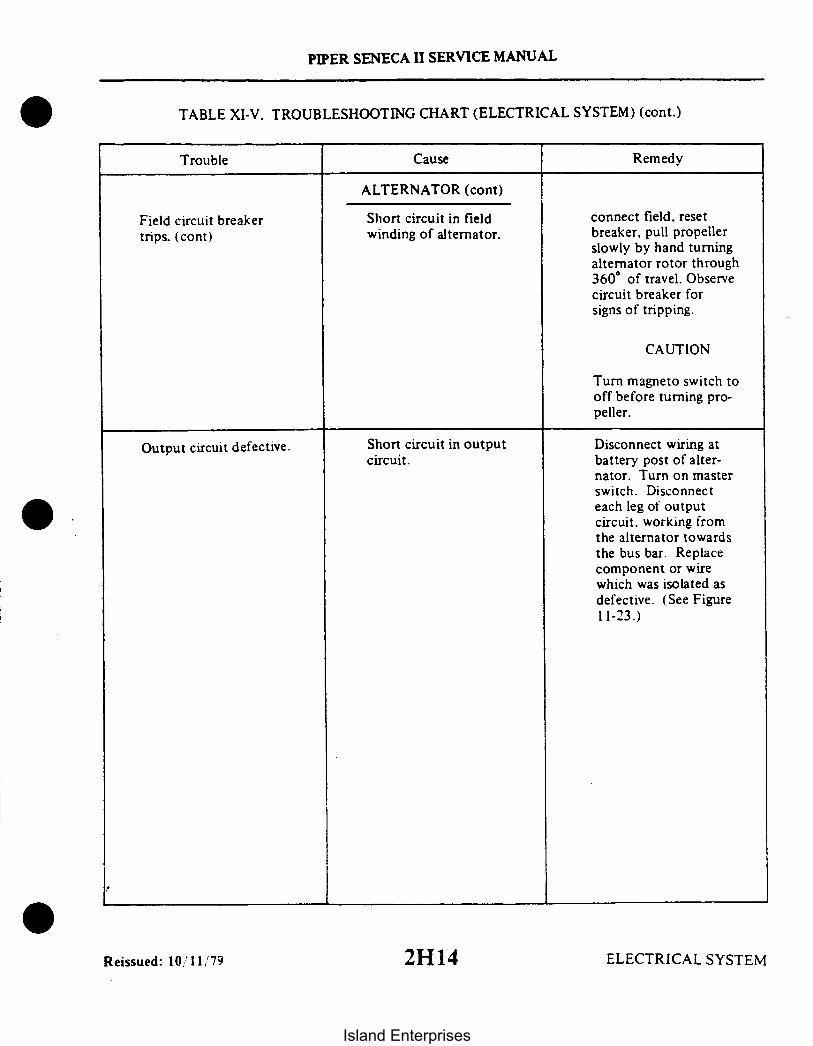
Reissued: 10/11,'79
PIPER SENECA II SERVICE MANUAL
TABLE XI-V. TROUBLESHOOTING CHART (ELECTRICAL SYSTEM) (cont.)
Trouble Cause Remedy
ALTERNATOR (cont)
Field circuit breakertrips. (cont)
Short circuit in fieldwinding of alternator.
connect field, resetbreaker, pull propellerslowly by hand turningalternator rotor through360° of travel. Observecircuit breaker forsigns of tripping.
CAUTION
Turn magneto switch tooff before turning pro-peller.
Output circuit defective. Short circuit in outputcircuit.
Disconnect wiring atbattery post of alter-nator. Turn on masterswitch. Disconnecteach leg of outputcircuit, working fromthe alternator towardsthe bus bar. Replacecomponent or wirewhich was isolated asdefective. (See Figure11-23.)
2H14 ELECTRICAL SYSTEM
Island Enterprises

NOTE
This type of conditioncan only occur in acase where a dischargedbattery has been re-moved from the airplaneand put on a chargerwith the polarity re-versed. This reversalin polarity cannotoccur in the airplanedue to any fault inthe alternator system.
PIPER SENECA II SERVICE MANUAL
TABLE XI-V. TROUBLESHOOTING CHART (ELECTRICAL SYSTEM) (cont.)
Trouble Cause Remedy
ALTERNATOR (cont)
Output circuit defective.(cont.)
Battery installed withreversed polarity.
Remove battery andreinstall with correctpolarity.
Battery charged back-wards.
Remove battery. Connectload such as landinglight lamp or similarload and dischargebattery. Recharge withcorrect polarity andtest each cell forsigns of damage dueto reversed charging.
Excessive ammeterfluctuation.
Defective voltageregulator.
Replace voltage regu-lator.
Excessive resistancein field circuit.
Check all connectionsand wire terminals infield circuit for dete-rioration such as loosebinding posts, brokenwire strands at ter-minals, etc. Tighten allconnections and replacefaulty terminals.
Reissued: 10/11/79 ELECTRICAL SYSTEM
2H15
Island Enterprises

PIPER SENECA II SERVICE MANUAL
TABLE XI-V. TROUBLESHOOTING CHART (ELECTRICAL SYSTEM) (cont.)
Trouble Cause Remedy
STARTER
Low battery charge.Starter fails to operate. Check and recharge ifnecessary.
Defective or improperwiring or looseconnections.
Defective starter solenoidor control switch.
Binding, worn, or im-properly seated brush,or brushes with ex-cessive side play.
Refer to electricalwiring diagram andcheck all wiring.
Replace faulty unit.
Brushes should be afree fit in the brushboxes without excessiveside play. Bindingbrushes and brushboxes should be wipedclean with a gasoline(undoped) moistenedcloth. A new brushshould be run in untilat least 50 percentseated; however, iffacilities are notavailable for runningin brushes, then thebrush should be prop-erly seated by in-serting a strip ofnumber 000 sandpaperbetween the brush andcommutator, with thesanded side next tothe brush. Pull sand-paper in the directionof rotation, beingcareful to keep it inthe same contour asthe commutator.
ELECTRICAL SYSTEMReissued: 10/11/79
2H16
Island Enterprises

PIPER SENECA II SERVICE MANUAL
TABLE XI-V. TROUBLESHOOTING CHART (ELECTRICAL SYSTEM) (cont.)
Trouble Cause Remedy
STARTER (cont.)
Starter fails to operate.(cont)
Binding worn, or im-properly seated brushor brushes with ex-cessive side play.
CAUTION
Do not use coarsesandpaper or emerycloth. After seating,clean thoroughly toremove all sand andmetal particles toprevent excessivewear. Keep motorbearing free fromsand or metal par-ticles.
Dirty commutator.
Shorted. grounded. oropen armature.
Grounded or open fieldcircuit.
If commutator is roughor dirty, smooth andpolish with number0000 sandpaper. If toorough and pitted. re-move and turn down.Blow out all particles.
Remove and replace withan armature known to bein good condition.
Test, repair if possibleor replace with a newpart.
Low motor and crank-ing speed.
Worn. rough. or im-properly lubricatedmotor or startergearing.
Disassemble. clean. in-spect. and relubricate.replacing ball bearingsif worn.
Same electrical causesas listed under "Motorfails to operate."
Same remedies listedfor these troubles.
Excessive arcing ofmotor brushes.
Binding, worn. or im-properly seated brushor brushes with ex-cessive side play.
See information abovedealing with thistrouble.
Reissued: 10/11/79 ELECTRICAL SYSTEM2H17
Island Enterprises

PIPER SENECA II SERVICE MANUAL
TABLE XI-V. TROUBLESHOOTING CHART (ELECTRICAL SYSTEM) (cont.)
Trouble
Excessive arcing ofmotor brushes. (cont)
Excessive wear andarcing of motor brushes.
Cause
STARTER (cont)
Dirty commutator, rough,pitted or scored.
Rough or scored com-mutator.
Armature assembly notconcentric.
Remedy
Clean as outlinedabove.
Remove and turn com-mutator down on alathe.
Reface commutator.
Discharged battery.
Battery life is short.
BATTERY
Battery worn out.
Low electrical systemvoltage.
Standing too long.
Equipment left onaccidentally.
Impurities in elec-trolyte.
Short circuit (ground)in wiring.
Broken cell partitions.
Overcharge due to levelof electrolyte beingbelow top of plates.
Sulfation due to disuse.
Impurities in electro-lyte.
Low charging rate.
Replace battery.
Check voltage regulatorvoltage.
Remove and rechargebattery if left inunused airplane 3weeks or more.
Remove and recharge.
Replace.
Check wiring.
Replace.
Maintain electrolyte.
Replace.
Replace battery.
Check voltage regulatorvoltage.
Reissued: 10/11/79ELECTRICAL SYSTEM
2H18
Island Enterprises

PIPER SENECA II SERVICE MANUAL
TABLE XI-V. TROUBLESHOOTING CHART (ELECTRICAL SYSTEM) (cont.)
Trouble Cause Remedy
BATTERY (cont)
Cracked cell jars. Hold-down bracket loose. Replace battery andtighten.
Frozen battery. Replace.
Compound on top ofbattery melts.
Electrolyte runs outof vent plugs.
Excessive corrosioninside container.
Charging rate too high.
Too much water addedto battery and chargingrate too high.
Spillage from over-filling.
Reduce charging rate.Check voltage regulatorvoltage.
Drain and keep at-properlevel and check voltageregulator voltage.
Use care in addingwater.
Vent lines leaking orclogged.
Charging rate too high.
Repair or clean.
Adjust voltage regulator.
Battery freezes. Discharged battery. Replace.
Water added and batterynot charged immediately.
Always recharge batteryfor 1/2 hour followingaddition of water infreezing weather.
Leaking battery jar. Frozen. Replace.
Battery polarity re-versed.
Battery consumes ex-cessive water.
Connected backwards onairplane or charger.
Charging rate too high(if in all cells).
Battery should be slowlydischarged completelyand then charged cor-rectly and tested.
Correct charging rate.
Cracked jar (one cellonly).
Replace battery.
Reissued: 10/11/79 ELECTRICAL SYSTEM
2H19Island Enterprises

PIPER SENECA II SERVICE MANUAL
TABLE XI-VI. LAMP REPLACEMENT GUIDE
Location
Wing Tips
Taillight
Anti-Collision
Landing Light
Reading Light
Compass Light
Forward Baggage
Stall Warning
Instrument Cluster
Gear - Down
Gear- Up
Annunciator Panel
Instrument Panel
Piper Part No.
751 381
753 431
757 635
472 661
472 054
472 036
572 054
472 054
472 054
472 054
472 072
Lamp No.
1512
1073
A406
4509
93
330
89
330
53
330
330
330
26
Reissued: 10/11/79 ELECTRICAL SYSTEM
2H20
Island Enterprises

TABLE XI-VII. ELECTRICAL WIRE CODING
CIRCUIT IDENTIFICATION
WIRE NUMBER
WIRE SEGMENT LETTER
WIRE GAUGE
CIRCUIT FUNCTIONLETTER
A
C
E
F
G
H
L
P
Q
RP
RG
RZ
J
W
K
PIPER SENECA II SERVICE MANUAL
CIRCUITS
AUTOPILOT
CONTROL SURFACE
ENGINE INSTRUMENT
FLIGHT INSTRUMENT
LANDING GEAR
HEATER - VENTILATING & DEICING
LIGHTING
POWER
FUEL & OIL
RADIO POWER
RADIO GROUND
RADIO AUDIO & INTERPHONE
IGNITION
WARNING
STARTER
HARNESS CONNECTORNUMBER'S AND LOCATIONS
E 100 Series = Left Wing andNacelle.
E 200 Series = Right Wing andNacelle.
E 300 Series = Aft Fuselage
E 400 Series = Forward Fuselage
Revised: 12/08/83 ELECTRICAl. SYSTEM2H21
Island Enterprises

ALTERNATOR
SOLENOID
BUTT CONNECTORS
SHIELDED CONDUCTORS
PIPER SENECA II SERVICE MANUAL
TABLE XI-VIII. ELECTRICAL SYMBOLS
KNIFE CONNECTORS BUS BARC643
BATTERY
SWITCHTYPE
UPUSHYPE
PUSH - PULLTYPE
BEACONTHERMAL SWITCH ELECTRICAL CLUTCH
PNUEMATICSWITCH
O
PRESS. - N.C.OR
VACUUM - N.O.
DIODE
PNUEMATICSWITCH
PRESS.- N.O.OR
VACUUM - N.C
ZENERDIODE
TERMINAL BLOCK
O O
O O
O O
O O
POTENTIOMETER
FUSE RESISTORGROUND
NOISEFILTER
SWITCHPUSH-BUTTON
SWITCHCONDUCTORS
SHIELDED CONNECTOR
SOLENOIDVALVE
'CONDUCTORS. CROSSINGS AND JUNCTIONS OF CONDUCTORSTHE DOT AT THE INTERSECTION INDICATES A JOINING OFCONDUCTORS.
Revised: 11/12/82 ELECTRICAL SYSTEM2H22
Island Enterprises

PIPER SENECA I SERVICE MANUAL
TABLE XI-IX. ELECTRICAL SYSTEM COMPONENT LOADS
Duty CycleCont. Inter.
X
X
XXXXXXX
Equipment
Alternator Field (2)Anti-Collision (Strobe)Cabin Lights (4)Cigar LighterCombustion HeaterDefroster BlowerElectric Pitch TrimFuel Pump (2)Heated WindshieldHydraulic PumpInstrument LightsLanding Lights (2)Master ContactorPitot HeatPosition LightsProp DeiceRed Flood LightsStall Warning Cluster
Stall Warning HeatStarterStarter SolenoidTurn & Bank
CircuitBreaker
51010101510551525510
155
55
105
Load(Amps)
5.04.44.08.013.03.05.010.013.825.03.08.00.613.24.020.05.01.0
7.5175.010.00.5
Optional
X
X
X
XX
XX
XX
X
XXX
X
Reissued: 10/11/79 ELECTRICAL SYSTEM
2H23Island Enterprises

EL 18O37067
PIPER SENECA I SERVICE MANUAL
ALTERNATOR LTETETATRALTERNATOR ALTERATORSWITCH RIGHT
ALTERNATOR
1a P2BRP2CR
OVERVOLT.RELAY
R..OLTAGEGULATO
F
— ALTERNATOR
SA
w3 A)—( TO ANNUNCIATOR
4 ON USTRE
TO STARTER
EXTERNAL WRECEPT.C-E
EXTERNAL E
EXTERNAL POwER
Figure 11-23. Alternator, S/N 34-7570001 to 34-7570337
I ELECTRICAL SYSTEM Revised: 11/12/82
2H24
Island Enterprises

PIPER SENECA II SERVICE MANUAL
EL 180237067
I
IEXTERNAL PWRRECEPTICLE
LEFTALTERNATOR
RIGHTALTERNATOR
1
ANNUNCIATOR
MAIN BUS
EXTERNALPOWER I
-.
EXTERNAL POWER
EXTERNAL POWER
TO STARTER
Figure 11-24. Alternator, S/N 34-7670001 to 34-7670393
211Revised: 11/12/82 ELECTRICAL SYSTEM
Island Enterprises

EL 180337067
EXTERNAL PWRRECEPTICE
_ _ _ _ _ __ _
EXTERNAL POWER
PIPER SENECA I SERVICE MANUAL
LEFTALTERNATOR
RIGHTALTERNATOR
ANNUNCIATOR
MAIN BUS
TO OPTIONAL COURTESY LIGHT PACKAGETO OPTIONAL CLOCK
TO OPTIONAL HOURMETER
Figure 11-25. Alternator, S/N 34-7770001 and up
Revised: 11/12/82 ELECTRICAL SYSTEM
212
Island Enterprises

EL1604
37067
LEFTSTARTERMOTOR
PIPER SENECA II SERVICE MANUAL
STARTERACCESSORY
STARTERSWITCH
RIGHTSTARTERMOTOR
LEFT STARTERSOLENOID
Figure 11-26. Starters, S/N 34-7570001 and up
Revised: 11/12/82 ELECTRICAL SYSTEM
213Island Enterprises

I
PIPER SENECA II SERVICE MANUAL
Figure 11-27. Landing Gear
Revised: 11/12/82 ELECTRICAL SYSTEM214
Island Enterprises

OXYGEN GAUGELIGHT (OPTIONAL)
PIPER SENECA II SERVICE MANUAL
NOTE:1. RESISTORS NOT USED ON SERIAL
NOS. 34-7570207 AND UP; ANDSERIAL NOS. 34-7570002 TO34-7570206. PROVIDING SERVICEBULLETIN NO. 475 HAS BEENACCOMPLISHED.
2. ON MODELS 34-8070178 AND UPWITH UGHTED TURN COORDI-NATORS. SEE "TURN AND BANKSCHEMATICS".
COMPASS
MIDDLE PANEL LTS.
CO-PILOTPANEL LTS.(OPTIONAL)
LOWER PANEL LTS.
Figure 11-28. Panel Lighting
Revised: 11/12/82 2215
ELECTRICAL SYSTEM
Island Enterprises

PIPER SENECA II SERVICE MANUAL
LEFT S AMP
ENGINE GAUGES
RIGHT 5 AMP
Figure 11-29. Engine Gauges (Early Models)
EL1808
LEFT 5 AMP
ENGINE GAUGES
RIGHT 5 AMP
Figure 11-30. Engine Gauges (Later Models)
ELECTRICAL SYSTEMReissued: 10/11/79 ELECTRICAL SYSTEM216
Island Enterprises

EL1I0S
EL1 0 EL 811
PIPER SENECA II SERVICE MANUAL
EL1B1910 AMP
LANDINGLIGHTS10 AMP
ANTI- COLLFIN STROBE10 AMP
8
Figure 11-31. Landing Lights Figure 11-32. Anti-Collision Fin Strobe
ANTI-COLL'N
10 AMPTO STARTER SWITCH
HIA
CIGAR LIGHTER
STARTER aACC. 10 AMP
PITOT HEAT15 AMP
WING TIPS FIN
(OPTIONAL)
Figure 11-32a. Anti-Collision Strobes
Revised: 11/12/82217
Figure 11-32b. Pitot Heat and Cigar Lighter
ELECTRICAL SYSTEM
Island Enterprises

TO MAIN BUS(SEE ALT.)
EL 180537067
PIPER SENECA II SERVICE MANUAL
EL180537067
RADIO BUS
FILTER
Figure 11-33. Radio Bus Power S;N 34-7570001 to 34-7570337
EL80537067 RELAY
MASTER
RADIO MASTER SW.
NORM.
RADIO
BUS
RELAY
Figure 11-33a. Radio Bus Power S/N 34-7670001 to 34-8070001
RADIO MASTER SW.MAIN BUS
OFF ON
PR3B
RBP6
EMERGENCYSWITCH
BUS
Figure 11-33b. Radio Bus Power S N 34-8070002 and up
Revised: 11/12/82 ELECTRICAL SYSTEM218
Island Enterprises

EL1809
TO LEFT & RIGHTALTERNATORBUS CONNECTION
LAMPTEST
PIPER SENECA II SERVICE MANUAL
FORWARD BAGGAGECOMPARTMENT LIGHT S.N 7570001 TO 7770441
INCLUSIVE
ACCESSORYLIGHTS10 AMP
Figure 11-34. Reading and Baggage Lights S/N 34-7570001 and up
EL1809
ANNUNICATORPANEL LTS.
5 AMP
I AIRPRESS.
Figure 11-35. Annunciator Panel
ELECTRICAL SYSTEMRevised: 11/12/82219
Island Enterprises

PIPER SENECA II SERVICE MANUAL
THIS PAGE INTENTIONALLY LEFT BLANK
2110
ELECTRICAL SYSTEM
Island Enterprises

LEFT ENGINE
F/A
PIPER SENECA II SERVICE MANUAL
RIGHTMAGNETO
LEFTMAGNETO
RIGHT ENGINE
STARTERSWITCH
Figure 11-37. Magnetos
MAINUS
WHITE
NAV LIGHTS5 AMP
OPTIONAL
Figure 11-38. Ventilation Air Blower Figure 11-39. Position Lights
Reissued: 10/11/79 ELECTRICAL SYSTEM2111
Island Enterprises
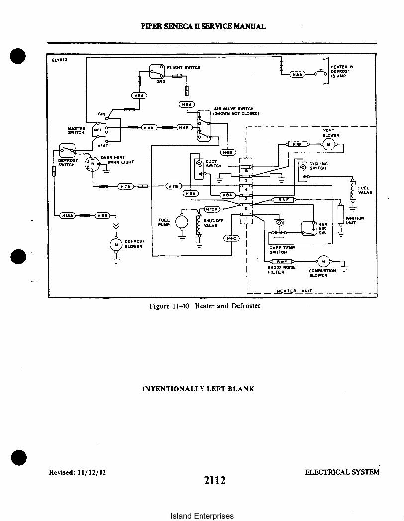
FLIGHT SWITCH
PIPER SENECA II SERVICE MANUAL
EL1B13
FAN
MASTERSWITCH
] HEATER 8DEFROST
- IS AMP
AIR VALVE SWITCH(SHOWN NOT CLOSED)
VENT
I BLOWER
FUELVALVE
IGNITIONUNIT
FUELPUMP
DEFROSTBLOWER
COMBUSTIONBT BLOWER
__ _ _ _HEATER UNIT
Figure 11-40. Heater and Defroster
INTENTIONALLY LEFT BLANK
Revised: 11/12/822112
ELECTRICAL SYSTEM
Island Enterprises

PIPER SENECA II SERVICE MANUAL
STALL WARNLIGHT (SEE NOTE 2)
MAIN BUS
STALLWARNINGS AMP
NOTES:I. GROUND STALL WARN PREVENTION SWITCH
IS USED ON SERIAL NOS. 34-7670001 AND UP
2. STALL WARN LIGHT NOT USED ON SERIALNOS 34-7670001 AND UP
Figure 11-41. Stall Warning
3-WAYSPLICE
STALL WARN.HTR., INBOARD
STALL WARN.HTR.. OUTBOARD
Figure 11-42. Stall Warning (Sensor Heaters)
Reissued: 10/11/79 22113
ELECTRICAL SYSTEM
Island Enterprises

EL1814
37067
PIPER SENECA II SERVICE MANUAL
Figure 11-43. Fuel Pumps (Auxiliary System)SERIAL NOS. 34-7670057 TO 34-7670097 ANDAIRCRAFT MODIFIED BY PIPER MOD. KIT 760 926V.
Figure 11-44. Fuel Pumps (Auxiliary System)
SERIAL NOS. 34-7670098 AND UP
2114Revised: 11/12/82 ELECTRICAL SYSTEM
Island Enterprises

EL1818
LEFT T
AND B
5A
BAI
STANDARD INSTALLATIONALL MODELS
PIPER SENECA II SERVICE MANUAL
LEFT FUEL PUMP8 AMP
RIGHT FUEL PUMP8 AMP
Figure 11-45. Left and Right Fuel Pump
URN
ANKRIGHT TURNAND BANK
LEFT TURNAND BANK
RIGHT TURN
AND BANK
TURN
TO PANEL LIGHTING TO PANEL LIGHTI
NG
TURN AND BANKINSTALLATIONS
LIGHTED TURN COORDINATOR
INSTALLATION (S/N'S 34-8070178 SWP )
Figure 11-46. Turn and Bank Schematics
Revised: 11/12/82 ELECTRICAL SYSTEM
2115Island Enterprises
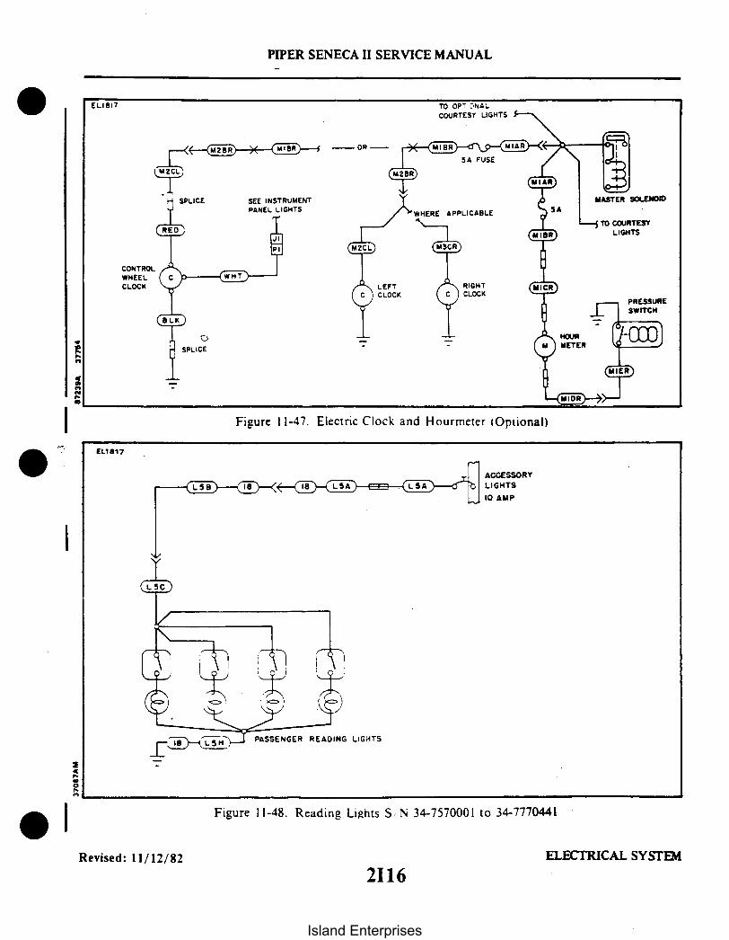
SPLICE
I
PIPER SENECA II SERVICE MANUAL
TO OPTIONALCOURTESY LIGHTS
CONTROLWHEELCLOCK
SEE INSTRUMENTPANEL LIGHTS
I Figure 11-47. Electric Clock and Hourmeter (Optional)
ACCESSORY
10 AMP
PASSENGER READING LIGHTS
Figure 11-48. Reading Lights S N 34-7570001 to 34-7770441
Revised: 11/12/82 ELECTRICAL SYSTEM
2116
Island Enterprises

PIPER SENECA II SERVICE MANUAL
1. A.C. - PWR. OFF2. AIRCRAFT ON GROUND
EL 3. A.C. DOOR FULL CLOSED20
FLIGHT LIMITSWITCHES SHOWN ININ-FLIGHT POSITION
FLT. CLOSELIMIT SW. PRESS. SW.
I Figure 11-49. Air Conditioning
Revised: 11/12/82 21172I17 ELECTRICAL SYSTEM
Island Enterprises

FORWARD CABIN
INTEGRATEDLIGHT/SWITCH
AFT CABIN
INTEGRATED
LIGHT/SWITCH
PIPER SENECA II SERVICE MANUAL
EL1810
HOURMETER OPTION
CLOCK OPTION MASTERSOLENOID
SEEALTERNATOR
AUTOMATICSWITCH
BAG. COMPT.
LIGHT
Figure 11-50. Courtesy Lights (Optional)(Serial Nos. 34-7970105 and up)
EL81O
FORWARD BAG.MASTER
SOLENOID
INTEGRATEDLIGHT/SWITCH
SEEALTERNATOR
IFigure 11-51. Forward Baggage Compartment Lights (Optional)
(Serial Nos. 34-7970105 and up)
Revised: 11/12/822I18
ELECTRICAL SYSTEM
Island Enterprises

I
L.H.
PIPER SENECA II SERVICE MANUAL
RIGHTLEFT
5-
I
INTENTIONALLY LEFT BLANK
Figure 11-52. Alternate Turn and Bank
TAIL FLOOD
LIGHTS
IFigure 11-53. Tail Flood (Logo) (Optional)
Revised: 11/12/82 ELECTRICAL SYSTEM2119
Island Enterprises

SECTION XIIELECTRONICS
Paragraph AeroficheGrid No.
12-1.12-2.12-3.12-4.12-5.12-6.12-7.12-8.12-9.12-10.12-11.12-12.12-13.12-14.12-15.
Introduction ..............................................................Emergency Locator Transmitter .............................................Description ...............................................................Battery Removal and Installation. (Garrett Mfg. Ltd.) (2 Year Magnesium) .......Not used .................................................................Batterv Removal and Installation (Communications Components Corp.) ..........Battery Removal and Installation (Narco) ....................................Description. Operation and Testing of Pilot's Remote Switch ....................Testing Emergency Locator Transmitter ......................................Avionics Master and Emergency Switch Circuit ...............................Description and Operation .................................................Autoflight................................................................G eneral ..................................................................Non-Piper A.F.C.S. Equipment Contacts....................................Piper A.F.C.S. Equipment ..................................................
2121212121212121
212321242J22J22J42J42J42J42J42J5
Revised: 11/12/82 22120
Island Enterprises

PIPER SENECA II SERVICE MANUAL
SECTION XII
ELECTRONICS
12-1. INTRODUCTION. This section of the manual contains information necessary to performoperational checks of the Emergency Locator Transmitter (ELT), with and without a pilot's remote switch.Included are the appropriate removal and installation instructions to facilitate battery replacement.
12-2. EMERGENCY LOCATOR TRANSMITTER
12-3. DESCRIPTION. The electrical power for the ELT is totally supplied by its own self-contained battery.The battery should be replaced on the date marked on the battery. If the transmitter has been used in anemergency situation during this 2 or 5 year period or it has more than one hour of accumulated test time. thebattery must be replaced according to FAA regulations. To replace battery pack in the transmitter, it isnecessary to remove the transmitter from the aircraft.
12-4. BATTERY REMOVAL AND INSTALLTION (GARRETT MFG. LTD.). (2 year, magnesiumbattery, refer to Figure 12-1.) The ELT is located on mounting brackets on the right side of the fuselage aft ofsta. 259.31.
a. Remove the access plate on the right side of the fuselage aft of sta. 259.3 1.b. Set the ON/ARM/OFF switch on the transmitter to the OFF position.c. Disconnect the antenna coax from the transmitter.d. Disconnect the harness to the pilot's remote switch.e. Remove the rear mounting bracket by pulling the plastic knob out. Remove the transmitter from
the airplane.f. Remove the two long or four short screws securing the transmitter plain end cap. Remove the
plain end cap.g. Disconnect the battery connector from the board terminals.h. Withdraw the battery pack from-the transmitter case.i. Before installing the new battery pack, check the replacement date printed on the battery.
Transfer this date onto the outside of the ELT.j. Slide the new battery pack, plain end first, into transmitter. It may be necessary to rotate the
battery slightly to get it seated properly in the transmitter case and to achieve correct orientation of thebattery connector.
k. Connect the battery connector to board terminals.1. Insure O-ring is fitted in plain end cap and correctly seated.m. Refit end cap and secure with the screws previously removed.
NOTE
Do not overtighten the end cap screws.
n. Place transmitter into its mounting bracket; replace rear mounting bracket by pushing plasticknob into place.
o. Connect the pilot's remote switch harness to the transmitter.p. Connect the antenna coax to the transmitter.
Revised: 3/16/81 ELECTRONICS
2121
Island Enterprises

Figure 12-1. Two Year, Magnesium Battery Connections
NOTE
Before installing access plate ascertain that transmitter switch is inthe ARM position. It may also be advisable to test the unitoperation before installing the access panel. (Refer to Paragraph12-9.)
PIPER SENECA II SERVICE MANUAL
LONGSCREWS
ENSURE THATBATTERY LEADS
ARE LOCATEDIN VEE OF
TRANSMITERBOARD
PLAINENDCAP
BATTERYPACK
q. Install the access plate on the right side of theaircraft logbook, including the new battery run out date.
12-5. NOT USED
Revised: 3/16/81
2122
fuselage aft of sta. 259.31. Make an entry in the
ELECTRONICS
Island Enterprises

7
4
PIPER SENECA II SERVICE MANUAL
GARRETT MFG. LTD.
I I IELT
ON/RESET
ARMED
TRANSMITTER N0.627674-1MAG. BATT.
SERIAL NUMBERS: 34-7570001 TO 34-7670303 INCLUSIVE
Figure 12-2. Garrett ELT Schematic
12-6. BATTERY REMOVAL AND INSTALLATION (COMMUNICATIONS COMPONENTS CORP.).The ELT is located on the right side of the airplane tail section, ahead of the stabilator.a. Remove the access plate on the right side of fuselage aft of sta. 259.31.b. Rotate the ON/ARM/OFF switch to the OFF position.c. Disconnect the antenna coax cable (twist left, then pull outward).d. Disconnect the harness to the pilot's remote switch.
THIS SPACE INTENTIONALLY LEFT BLANK
Revised: 3/16/81 ELECTRONICS2123
Island Enterprises

PIPER SENECA II SERVICE MANUAL
e. Remove the forward mounting bracket by pulling the black plastic knob out. Remove the trans-F mitter from the airplane.
f. Remove the six Phillips-head screws securing the transmitter cover. Remove the cover.g. Lift out the old battery pack.h. Copy the expiration date on the battery into the space provided on the external ELT name and date
plate.i. Disconnect and replace with a new battery pack. The nylon battery connector is a friction fit and is
easily removed by pulling on the exposed end.j. Insert transmitter into airplane and fit into place. Replace mounting bracket by pushing the black
plastic knob into place.k. Reconnect the pilot's remote switch harness and the antenna coax cable to the transmitter.1. Set the ON/ARM/OFF switch to the ARM position.m. Reinstall the access plate previously removed.n. Make an entry in the aircraft logbook, including new battery runout date.
NOTE
It may be advisable to test the unit operation before installing theaccess plate. (See Testing Emergency Locator Transmitter.)
Inspect the external whip antenna for any damage. Avoid bendingthe whip. Any sharply bent or kinked whip should be replaced.Antenna damage may cause structural failure of whip in flight.
12-7. BATTERY REMOVAL AND INSTALLATION (NARCO). (Refer to Figures 12-3 and 12-4.)a. Set the ON/OFF/ARM switch on the transmitter to OFF.b. Disconnect antenna coaxial cable from E.L.T.c. Remove ELT from its mounting bracket by releasing the latch on the strap and sliding the ELT off
the bracket.d. Extend the portable antenna.e. Unscrew the four screws that hold the control head to the battery casing and slide apart.f. Disconnect the battery by unsnapping the snap-off battery pigtail terminals from the bottom of the
transmitter printed circuit board.g. Discard old battery pack. (DO NOT EXPOSE TO FLAME.)
CAUTION
The battery pack is shipped with a sealant on the inside lip so that awater tight seal will be retained. DO NOT REMOVE THISSEALANT.
h. Connect new battery pack terminals to the bottom of the circuit board.i. Reinsert the control head section into the battery pack being careful not to pinch any wires, and
replace the four screws. If the four holes do not line up, rotate the battery pack 180° and reinsert.j. Slide the portable antenna back into the stowed position.k. Place transmitter into its mounting bracket and fasten the strap latch.1. Connect the antenna coaxial cable to the ELT and ensure that the contact separator is inserted
between the antenna contact finger and the portable antenna. (Refer to Figure 12-4.)
Revised: 8/10/80 ELECTRONICS2124
Island Enterprises

198
ELT
WH T
ELT
BLACK
PIPER SENECA II SERVICE MANUAL
COMMUNICATIONS COMPONENTS CORP.
REMOTE"RESET"
WHT
SWITCH POSITIONS
OFF/RESET NORMALAUTO/ARM - FLIGHT
ON POSITION
SHIELD
A
REMOTE"ON"
(TEST)+14 VOLT DCTO OVERHEADFLOOD LIGHTCIRCUIT PROTECTORTRANSMITTER NO. CIR-11-2
KEYWAY
BLK -
SHLD . WHT
- RED
VIEW ASERIAL NUMBERS: 34-7670304 AND UP
NOTE: AIRCRAFT POWER USED TO SHUT OFF THE ELT WITH REMOTE SWITCH.
Figure 12-3. Communications Components ELT Schematic
B126
I
WHITE
I
SHIED SHIELDSHIELD 4 SHIELD
REDWHT.
' '
BLACK
ARMED
o ON/RESET
Figure 12-4. Emergency Locator Transmitter Schematic (Narco)
Revised: 3/16/81 ELECTRONICS2J1
Island Enterprises

PIPER SENECA II SERVICE MANUAL
m. Press RESET button and set ON/OFF ARM switch to ARM.n. Make an entry in the aircraft logbook. including the new battery expiration date.o. A unit operational check may now be performed on the ELT. (Refer to Testing Emergency Locator
Transmitter.)
NOTE
Inspect the external whip antenna for any damage. Avoid bendingthe whip. Any sharply bent or kinked whip should be replaced.Antenna damage may cause structural failure of whip in flight.
12-8. DESCRIPTION. OPERATION AND TESTING OF PILOT'S REMOTE SWITCH. (Refer toPilot's Operating Handbook.)
12-9. TESTING EMERGENCY LOCATOR TRANSMITTER. Thetransmitteroperatesontheemergencyfrequencies of 121.5 and 243 MHz: both of these frequencies are monitored by the various FAA installations.Before performing any operational test of the ELT. the following precautions should be observed:
CAUTION
Testing of an ELT should be conducted in a screen room or metalenclosure to ensure that electromagnetic energy is not radiated dur-ing testing. If a shielded enclosure is not available. testing may beperformed in accordance with the following procedures:
1. Test should be no longer than three audio sweeps.2. If the antenna is removed, a dummy load should be sub-
stituted during the test.3. Test should be conducted only within the time period made
up of the first five minutes after any hour.4. If the operational tests must be made at a time not included
within the first five minutes after the hour. the test should becoordinated with the closest FAA Tower or Flight ServiceStation.
Consult FAA Advisory Circular AC 20-81 for detailed infor-mation concerning above cautions.
a. Remove the access plate on the right side of the fuselage aft of sta. 259.31.b. Tune the aircraft communications receiver to 121.5 M Hz and switch the receiver ON; deactivate the
squelch. and turn the receiver volume up until a slight background noise is heard.
NOTE
If the aircraft is not fitted with a communications receiver. requestthat the tower listen for your test.
c. On the transmitter. set the ON ARM OFF switch to the ON position. Keep the switch in this posi-tion for only a few seconds: then set to the OFF position. Return to the ARM position.
Revised: 8/10/80 ELECTRONICS2J2
Island Enterprises

ANTENNA BLADETOUCHESPORTABLEFINGER CONTACT
ANTENNEXTENSIONTAB
PIPER SENECA II SERVICE MANUAL
NOTCH PIN PORTABLESTOP ANTENNA/ OPERATIVE
/ BUT STORED
LATCH
VIEW
PULL TAB
ANTENNAEXTENSIONTAB
SETVIEWA
ANTENNAPOPS OUTOFCHANNEL
r AND DOWN
ON-OFF-ARMSWITCH
TO"ON"
PINSTOP
TO EXTEND TO FULL LENGTH VIEWC
Figure 12-5. ELT Portable Folding Antenna (Narco)
CONTACTB965
ORTABLE ANTENNA BLADENOT
MAKING CONTACT
Figure 12-6. ELT Using Fixed Aircraft Antenna (Narco)
Reissued: 10/11/79 ELECTRONICS2J3
Island Enterprises

PIPER SENECA II SERVICE MANUAL
NOTE
The test transmission should have been picked up by the aircraftcommunications receiver and or control tower. During coldweather, there may be a slight delay before transmission occurs.
d. A transmitter which is functioning properly should emit a characteristic downward swept tone.e. When test is completed. ascertain the transmitter ON/ARM /OFF switch is in the ARM position.f. Place the access panel on the right side of the fuselage aft of sta. 259.31.
WARNING
Whenever the unit is checked by moving the transmitter ON ARMOFF switch from the ARM to the ON position, it must then bemoved to the OFF position before reverting to the ARM positionagain.
CAUTION
Under normal conditions, the transmitter switch must be set to arm.
12-10. AVIONICS MASTER AND EMERGENCY SWITCH CIRCUIT. (Refer to Chapter 11. Figures11-25 and 11-26.)
12-11. DESCRIPTION AND OPERATION. Electrical power for the various avionics components is con-trolled by the Avionics Master Switch located near the top of the instrument panel between the radio stacks. Itcontrols the power to all radios through the aircraft master switch.
An emergency bus switch is also provided to provide auxiliary power to the avionics bus in the event of aradio master switch circuit failure. The emergency bus switch is located between the lower right shin guard leftof the circuit breaker panel.
12-12. AUTOFLIGHT.
12-13. GENERAL. Due to the wide varity of A.F.C.S. (Automated Flight Control System) options, it ismandatory to follow the service literature published by the individual manufacturer of the A.F.C.S.equipment installed in any particular airplane. This includes mechanical service such as; adjusting bridle cabletension, servo removal & installation, servo clutch adjustments, etc.
12-14. NON-PIPER A.F.C.S. EQUIPMENT CONTACTS. Refer to the following list of Autopilot FlightDirector manufacturers to obtain service direction, parts support, and service literature.
Bendix Avionics Division2100 N.W. 62nd StreetFort Lauderdale, Fla. 33310(305) 776-4100/TWX 5109559884
Collins General Aviation DivisionRockwell InternationalCedar Rapids. Iowa. 52406(319) 395-3625 Telex: 464-421
Revised: 11/12/82 ELECTRONICS
2J4
Island Enterprises

PIPER SENECA II SERVICE MANUAL
Edo Corporation - Avionics DivisionBox 610Municipal AirportMineral Wells, Texas, 76067(817) 325-2517 Telex: 76067
King Radio Corporation400 North Rodgers RoadOlathe, Kansas, 66061(913) 782-0400 Telex: 4-2299-Kingrad
Sperry Flight Systems/Avionics Div.8500 Balboa Blvrd.P.O. Box 9028VanNuys, CA, 91409(213) 894-8111 Telex: 65-1367
Global Navigation2144 Michelson DriveIrvine, CA. 92715(714) 851-0119
12-15. PIPER A.F.C.S. EQUIPMENT. In the case of early models. Piper Autopilot equipment bears thePiper name, and the appropriate Piper Autopiloti Flight Director Service Manual shall be used.
NOTE
If a Roll Axis-only Autopilot is installed, or if no Autopilot isinstalled, consult the Piper Pitch Trim Service Manual - 753 771 formanual electric pitch trim service information.
The following is a complete listing of Piper A.F.C.S. equipment service literature. It is imperative to correctlyidentify the Autopilot system by "faceplate" model name, in order to consult the appropriate service manual.Each manual identifies the revision level and revision status as called out on the Master Parts Price List -Aerofiche published monthly by Piper. Consult the aircrafts parts catalog for replacement parts.
NAME PIPER PART NO.
AutoControl 1/11 & AltiMatic 1/I1 753 798AutoControl III and AltiMatic III and IIIB 753 723AutoControl IIIB and AltiMatic IIIB-1 761 502AltiMatic IIIC 761 602AltiMatic V and V-1 761 525AltiMatic V F/D and V F/D-I 761 526AltiMatic X F.D./A.P. & X.A.P. 761 668AutoFlite 753 720AutoFlite II 761 481Piper Pitch Trim (Manual-Electric) 757 771
Added: 11/12/82 ELECTRONICS
2J5
Island Enterprises

SECTION XIIIHEATING AND VENTILATING SYSTEM
Paragraph AeroficheGrid No.
13-1. Introduction ........................................ 2J813-2. Troubleshooting .......................................... ........... 2.18
13-3. Description and Principles of Operation ...................................... 2J813-4. Combustion Heater (Janitrol) .............................................. 2.110
13-5. Heater System - Operational Test ................................... 2J 1013-6. Description of Heater and Basic Components ................................. 2J I
13-7. Spark-Spray Ignition ..................... ......................... 2J I13-8. Fuel Regulator and Shutoff Valve ................................... 2J 1113-9. Duct Switch ...................................................... 2J 1413-10. Combustion Air Blower ........................................ 2J1413-1 1. Ventilating Air Blower ............................................. 2J 1413-12. Operating Controls ................................................ J 1413-13. Operating Procedure ........................................ . 2J1513-14. Maintenance Service ........................................ 2J15
13-15. Inspection of Heater and Heater Components ................................. 2J 1513-16. Daily Inspection ...................... ............... 2J1513-17. 100 Hour Inspection ..................................... 2J173-17a. Overhaul Instructions ................................. ..... : ...... 217
13-18. Removal of Heater (30.000 BTU) ................... .............................. 1813-19. Installation of Heater (30.000 BTU) .................................. 2 1813-20. Removal of Heater (45.000 BTU) ................... ...... ............. J 1913-21. Installation of Heater (45.000 BTU) ................................. 2. 19
13-22. Heater Electrical System Checks ............................................. 2J2013-23. Electrical Check ..................................... 2J2013-24. Vent Blower Power Circuit Check ................................... 2J2113-25. Heater Power Circuit Check ........................... ......... 21
13-26. General Maintenance ....................................................... 2 313-27. Combustion Air Blower ................................... 2313-28. Spark Plug ................................... 2J24
13-29. Ignition Unit....... ................ ...................................... 2K 313-30. Ignition Unit Removal and Installation (30.000 BTU) .................. 2K313-31. Ignition Unit Removal and Installation (45.000 BTU) .................. K313-32. Testing Ignition Unit ......................................... ..... 2K413-33. Operational Test of Ignition Unit .................................. 2K413-34. Vibrator .............................................. ....... 2K413-35. Vibrator Removal and Installation ................ .................. 2K413-36. Inspection of Ignition Unit ..................................... 2K5
13-37. Cycling Switch and Limit (Overheat) Switch (30.000 BTU) ...................... 2K613-38. Cyclin S Switch and Limit (Overheat) Switch (45.000 BTU) . . ............... 2K6
Revised: 12/08/832J6
Island Enterprises

AerofiParagraph Grid N
13-39. Combustion Air Pressure Switch ................................ 2K713-40. Fuel Regulator and Shutoff Valve ..... . . ........ . . 2K7
13-41. Removal of Fuel Regulator ............................. 2K713-42. Adjustment of Fuel Regulator .......... ................. . 2K713-43. Installation of Fuel Regulator ............................ 2K8
13-44. Heater Fuel Pump Maintenance ................................. 2K813-45. Removal of Heater Fuel Pump ............................ 2K813-46. Disassembly of Pump ................................. 2K913-47. Cleaning of Pump ................................... 2K913-48. Inspection and Repair of Pump ............. 2K913-49. Assembly of Pump ................................... 2K1013-50. Installation of Heater Fuel Pump .......................... 2K 10
13-51. Duct Switch ............................................ 2K 1013-52. Overhaul Instructions ....................................... 2K10
13-53. Disassembly (30.000 BTU Heater) .......................... 2K 1113-54. Disassembly of Combustion Air Blower Assembly
(30.000 BTU) ................................... 2K 1213-55. Cleaning .......................................... 2K 1213-56. Cleaning and Inspecting the Combustion Tube Assembly
(30.000 BTU) .. ........... . 2K1313-57. Inspection of Remaining Components (30,000 BTU) ............... 2K1313-58. Disassembly (45,000 BTU Heater) .......................... 2K1513-59. Disassembly of Combustion Air Blower Assembly
(45,000 BTU) ................................... 2K1613-60. Cleaning .......................... ............... 2K 1613- 61. Cleaning and Inspecting the Combustion Tube Assembly
(45,000 BTU) ................................... 2K 1813-62. Inspection of Remaining Components (45,000 BTU) ............... 2K 1813-63. Testing ... .............. .2K 1913-64. Repair of Combustion Tube Assembly ......................... 2K2313-65. Reassembly (30,000 BTU) .............................. 2K2413-66. Reassembly of Combustion Air Blower Assembly
(30.000 BTU) .................................. 2L113-67. Reassembly (45,000 BTU) .............................. 2L213-68. Reassembly of Combustion Air Blower Assembly
(45.000 BTU) . . . . . . . . . . . . . . ..... .. . 2L513-69. Test Procedure .......................... ..... ............ 2L5
13-70. General Information .................................. 2L513-71. Equipment Required ............ ................... 2L713-72. Operation Test (On Test Bench) ........... .. 2L713-73. Inspection of Fuel Nozzle Orifice .......................... 2L813-74. Defroster Blower Removal and Installation ..................... 2L8
Revised: 8/10/802J7
Island Enterprises

PIPER SENECA II SERVICE MANUAL
SECTION XIII
HEATING AND VENTILATING SYSTEM
13-1. INTRODUCTION. This section contains instructions for operating, servicing, inspecting andrepairing the heater, defroster, and ventilating system installed in the PA-34-200T Seneca II. Particularattention should be given to ascertain that the particular heater being serviced is either the 30.000 BTU or45,000 BTU unit. Most of the service information is basic to both units. Areas which differ have beenclarified by the inclusion of the heater size in the particular subject headings.
13-2. TROUBLESHOOTING. A troubleshooting chart is located at the end of this section. The servicetroubles and suggested remedies found in this chart are provided to assist in locating and correcting possiblemalfunctions in the system.
13-3. DESCRIPTION AND PRINCIPLES OF OPERATION. Heated air for the cabin and defrosteroperation is obtained from the combustion heater located in the tail section of the airplane. Fresh air issupplied to the heater from an intake located in the dorsal fin and routed through the heater and into thecabin through six adjustable outlets. Operation of the heater is controlled by a three-position switch locatedon the heater control console between the pilot's and copilot's seats and labeled FAN. OFF and HEATER.The FAN position will operate the ventilation blower on the heater and may be used for cabin ventilationor windshield defogging on the ground when heat is not desired. There is a defroster blower in the samedistribution system to provide additional defrost capability when required. The defroster control switchmust be in the ON position to energize the defroster blower.
For cabin heat, the air intake lever located on the heater control console must be partially or fullyopen and the three-position switch set to HEATER. This will start the fuel flow and ignite the burnersimultaneously. With instant starting and no need for priming, heat should be felt within a few seconds.There are two safety switches installed at the intake valve located aft of the heater unit which are activatedby the intake valve and wired to prevent both fan and heater operation unless the air intake valve is movedoff the closed position.
Regulating the heater and airflow is accomplished by adjusting the levers on the heater controlconsole. The right-hand lever regulates the air intake valve, while the left-hand lever regulates cabintemperature. Cabin temperature and air circulation can be varied to suit individual requirements by variouscombinations of lever settings.
Heat may be supplied before starting the engines by turning on the master switch, opening the airintake valve, and placing the heater switch in the HEATER position.
An overheat limit switch is located in the forward outboard end of the heater vent jacket. which actsas a safety device to render the heater inoperative if a malfunction should occur. A red reset button on theswitch can be reached through the bulkhead access panel into the aft fuselage; operation of this switchresults in illumination of the overheat light located on the heater control console. To prevent activation ofthe overheat limit switch upon normal heater shutdown during ground operation, turn the switch to theFAN position for two minutes, while leaving the air intake lever in the open position, before turning theswitch to the OFF position.
There are six overhead fresh air vents which are supplied by a separate inlet in the dorsal fin. Thissystem can be supplemented by an optional blower.
An optional heater hourmeter is available on S/ N 8170001 and up. It is located on the right hand side ofthe ignition unit.
Revised: 3/16/81 HEATING AND VENTILATING
2J8
Island Enterprises

ON S/N'S 34-807260 AND UP
PIPER SENECA II SERVICE MANUAL
1953
1. HEATER INLET2. FRESH AIR INLET3. OVERHEAD VENT BLOWER - OPTIONAL4. COMBUSTION AIR BLOWER INLET5. COMBUSTION HEATER ASSEMBLY6. FRESH AIR OUTLETS7. HEATER OUTLETS
8. DEFROSTER OUTLETS9. DEFROSTER BLOWER
10. HEATER AND DEFROSTER CONTROL ASSEMBLY
8
//
Figure 13-1. Cabin Heater, Defroster and Fresh Air Installation
Revised: 8/10/80 HEATING AND VENTILATING SYSTEM2J9
Island Enterprises

PIPER SENECA II SERVICE MANUAL
13-4. COMBUSTION HEATER (JANITROL).
a. Check all fittings and connections for condition and security of mounting. Check all ducts, inletsand outlets for freedom from obstruction.
b. Disconnect wire (H IOA) from the heater terminal No. 2; this will remove electrical power to the fuelvalve and pump.
c. Turn the master switch and "HEATER" switch on and open the air intake valve. Both blowers(combustion air and ventilating air) should operate. Check at heater exhaust and ventilating air outlets toinsure airflow. The heater should not ignite.
d. With the aircraft on jacks, the ventilation blower shall stop operating with the gear in the gear upposition. (This step may be accomplished during normal gear retraction tests provided steps a through d havebeen complied with first.)
e. Press the overheat indicator light. It should illuminate.f. Place the air inlet lever in the open position and place the heater switch in the fan position for two
minutes. Then place the heater switch in the off position.g. Place the master switch in the off position.h. Install a 0-10 psi pressure gauge at the fuel drain aft of the heater fuel pump, in the line from the fuel
pump.i. Reconnect wire (H IOA) to the heater terminal strip.j. Place the air intake lever in the open position and the temperature control lever in the center of its
travel limits.k. Turn the master switch and the heater switch on. The heater should ignite and continue to operate
until the thermostat causes it to stop operating. Cycling in this manner should continue until the heater switchis turned off.
1. The pressure shown on the pressure gauge should be 7.5 + 0.5 psi.m. Place the heater switch in the fan position. The heater should stop operating and the ventilation
blower should continue to operate. Allow the blower to continue to operate for two minutes minimum. Thenplace the air intake lever in the closed position. The blower should stop operating.
n. Turn the heater switch and master switch off.o. Remove the 0-10 psi pressure gauge and reconnect the fuel lines.p. Repeat steps i, j and e.
Revised: 3/16/81 HEATING AND VENTILATING2J 10
Island Enterprises

PIPER SENECA II SERVICE MANUAL
13-6. DESCRIPTION OF HEATER AND BASIC COMPONENTS.
13-7. SPARK-SPRAY IGNITION. (Refer to Figure 13-4.) The controlled atomized spray from a speciallydesigned spray nozzle, coupled with high voltage spark plug ignition, insures instant firing and continuousburning under all flight conditions.
Heat is produced by burning a fuel-air mixture in the combustion chamber of the heater. Aviationgasoline is injected into the combustion chamber through the spray nozzle. The resulting cone-shaped fuelspray mixes with combustion air and is ignited by a spark from the spark plug. Electric current for ignitionis supplied by an ignition unit which converts 14-volts to high voltage oscillating current to provide acontinuous spark across the spark plug gap. A shielded, high voltage lead connects the ignition assembly tothe spark plug. Combustion air enters the combustion chamber tangent to its surface and imparts a whirlingor spinning action to the air. This produces a whirling flame that is stable and sustains combustion underthe most adverse conditions because it is whirled around itself many times. Therefore, ignition iscontinuous and the combustion process is self-piloting. The burning gases travel the length of thecombustion tube. flow around the inside of the inner tube, pass through crossover passages into an outerradiating area. then travel the length of this surface and out the exhaust.
Ventilating air passes through the heater between the jacket and combustion tube assembly outersurface and through an inner passage in the assembly. Consequently, ventilating air comes into contact withtwo or more heated cylindrical surfaces.
13-8. FUEL REGULATOR AND SHUTOFF VALVE. (Refer to Figure 13-5.) This unit provides preset.regulated fuel pressure as well as remove shutoff to the heater, regardless of fuel inlet pressure variations. Itis set for 7.5 ± .5 psi. The shutoff valve is operated by a solenoid.
Reissued: 10/11/79 HEATING AND VENTILATING2J11
Island Enterprises

PIPER SENECA II SERVICE MANUAL
A310 I
I
I
I
I
I I
1939
1. HEATER OUTPUT DUCT2. IGNITION VIBRATOR3. IGNITION COIL4. IGNITION UNIT5. TERMINAL STRIP6. PRESSURE SWITCH7. ELBOW ADAPTER8. COMBUSTION AIR BLOWER AND MOTOR9. AIR INLET TUBE
10. AIR DUCT HOSE11. WATER DRAIN TUBE12. HEATER CLAMP13. SPARK PLUG14. HEATER FUEL DRAIN TUBE (HOT FUEL DRAIN)15. FUEL DRAIN TUBE (COLD FUEL DRAIN)16. ADJUSTABLE DUCT SWITCH17. EXHAUST SHROUD1. HEAT OUTLET DUCT19. DUCT SWITCH CONTROL CABLE
Figure 13-2. Heater and Combustion Air Blower Assembly (30,000 BTU)
Reissued: 10/11/79 HEATING AND VENTILATING SYSTEM2J12
Island Enterprises

PIPER SENECA II SERVICE MANUAL
1969
1. HEATER OUTPUT DUCT2. IGNITION VIBRATOR3. IGNITION COIL4. IGNITION UNITS. TERMINAL STRIP6. PRESSURE SWITCH7. ELBOW ADAPTER8. COMBUSTION AIR BLOWER AND MOTOR9. AIRINLETTUBE
10. AIR DUCT HOSE11. WATER DRAIN TUBE12. HEATER CLAMP13. SPARK PLUG14. HEATER FUEL DRAIN TUBE (HOT FUEL DRAIN)15. FUEL DRAIN TUBE (COLD FUEL DRAIN)16. ADJUSTABLE DUCT SWITCH17. EXHAUST SHROUD18. HEAT OUTLET DUCT19. DUCT SWITCH CONTROL CABLE
NOTE
HEATER HOURMETER (OPTIONAL ON S/N 8170001 AND UP) LOCATEDON RIGHT HAND SIDE OF IGNITION UNIT.
Figure 13-3. Heater and Combustion Air Blower Assembly (45,000 BTU)
Revised: 3/16/812J13
HEATING AND VENTILATING SYSTEM
Island Enterprises

HEATED AIR
INLET
EXHAUST GASES
FRESH AIRFROM BLOWER
Figure 13-4. Diagramatic Cutaway of Heater to Show Whirling Flame Action
13-9. DUCT SWITCH. (Refer to Figure 13-6.) This switch is installed in the ventilating air ductdownstream from the heater to sense the ventilating air outlet temperature. To select the desired cabintemperature, the switch may be adjusted manually from a high of 250 F ± 10° downward through a rangeof 146°F ± 6°. The switch has a differential of 15"F ± 5° at any given setting.
13-10. COMBUSTION AIR BLOWER. This centrifugal type blower supplies combustion air to thecombustion chamber of the heater.
13-11. VENTILATING AIR BLOWER. This blower is attached to the inlet end of the heater assembly andprovides a source of ventilating air through the heater. Ram air from the ventilating air intake scoop is usedduring flight.
13-12. OPERATING CONTROLS. (Refer to Figure 13-7.)
NOTE
The schematic diagram (Figure 13-7) shows the heater circuit,including the electrical wiring in the airplane.
PIPER SENECA II SERVICE MANUAL
a. The HEATER SWITCH is connected in the line that supplied electrical power to all heaterequipment and controls. When this switch is in the OFF position, the entire heater system is inoperative.This switch has a FAN position which permits use of the ventilating air blower to circulate cool air throughthe system for summer ground operation. With the switch in FAN position, the heater is inoperative andonly the ventilating air blower is energized.
Reissued: 10/11/79 HEATING AND VENTILATING SYSTEM
2J14
Island Enterprises

PIPER SENECA II SERVICE MANUAL
13-13. OPERATING PROCEDURE.a. Place the master and heater switches in their "ON" position and place the air intake lever in the
"OPEN" position. The ventilating air and combustion air blowers will operate and the heater will ignite.
NOTE
The blowers will not operate and the heater will not ignite withthe air intake lever in the "CLOSED" position.
b. Set the temperature control lever to the desired temperature setting. This controls the ductswitch.
NOTE
If this control is set for ground operating comfort, it may benecessary to reposition it after being airborne, since ram air willincrease the ventilating airflow and heater output.
c. To stop the heater operation, turn the heater switch to the "FAN" position. The heater will shutoff and the ventilating air blower will continue to operate. Allow the blower to operate for two minutes;this will cool down the heater before turning the heater switch off and closing the air intake valve. Refer toParagraph 13-5 for complete operational test of the system. Turn off master switch.
13-14. MAINTENANCE SERVICE. Instructions contained in this section consist of periodic inspection,adjustments, and minor corrections required at normal designated intervals for the purpose of maintainingthe heating system in peak operating condition. These inspections assume that a heating system includesaccessory components mentioned in preceding paragraphs.
13-15. INSPECTION OF HEATER AND HEATER COMPONENTS.a. Inspect all fuel lines and fittings for fuel stains. indicating leakage, and replace lines or tighten
fittings as necessary.b. Check heater for loose bolts, screws and wiring.c. Inspect all electrical connections for corrosion. If corrosion is evident, clean affected components.
and wipe with a lightly oiled cloth.
13-16. DAILY INSPECTION.a. Inspect the ventilating air inlet scoop, combustion air inlet scoop. exhaust outlet and fuel drain for
possible obstructions. Make sure that all of these openings are clear of any restrictions and that no damagehas occurred to air scoop protrusions.
b. Look in the area of the combustion heater exhaust tube for large or unusual accumulation of sooton the aircraft skin. Soot accumulations indicate that the heater is operating at a "fuel rich" condition. A"fuel rich" condition may be caused by incorrect fuel pressure to the heater. restriction in the combustion airinlet line. loss of performance by the combustion air blower, or partially clogged fuel nozzle.
c. Perform an operational check as follows:1. Place the HEATER SWITCH in the ON (or HEAT) position. The ventilating air blower
and combustion air blower should operate and the heater OVER TEMP light should illuminate.2. Operate both the combustion air blower and ventilating air blower and check each for
unusual current draw. noise or vibrations.
Reissued: 10/11/79 HEATING AND VENTILATING SYSTEM2J15
Island Enterprises

PIPER SENECA II SERVICE MANUAL
ADJUSTMENT SCREW
Figure 13-5. Fuel Regulator and Shutoff Valve Figure 13-6. Top View - Duct Switch
THIS SPACE INTENTIONALLY LEFT BLANK
Revised: 12/08/83 HEATING AND VENTILATING SYSTEM2J16
Island Enterprises

NOTE
To proceed with the operational check. follow paragraph entitledOperating Procedures. steps a through c. The above procedureshould be repeated one or more times.
13-17. 100-HOUR INSPECTION. The mandatory 100-Hour Inspection shall be conducted on new heatersor overhauled heaters with a new combustion tube assembly upon accumulation of 500-heater operatinghours or twenty-four months. whichever occurs first. and thereafter at intervals not to exceed 100-heateroperating hours or twenty-four months. whichever occurs first. If an hourmeter is used on the heater assembly.it should be connected across terminals number 2 and 5 on the heater terminal strip. If an hourmeter is notused. count one heater operating hour for each two flight hours for normal aircraft operation. Considerationshould be given for any excessive ground operation of the heating system.
NOTE
The 100-Hour Inspection consists of the functional checks andinspections listed below and the Pressure Decay Test.
a. Inspect ventilating air and combustion air inlets and exhaust outlet for restrictions and security atthe airplane skin line.
b. Inspect the drain line to make sure it is free of obstructions. Run a wire through it if necessary toclear an obstruction.
c. Check all fuel lines for security at joints and shrouds. making sure that no evidence of leaks exists.Also check for security of attachment of fuel lines at the various points in the airplane.
d. Inspect electrical wiring at the heater terminal block and components for loose connectionspossible chafing of insulation. and security of attachment points.
e. Inspect the high-voltage cable connection at the spark plug to make sure it is tight. Also. examinethe cable sheath for any possible indications of arcing. which would be evidenced by burning or discolorationof the sheath.
f. Inspect the combustion air blower assembly for security of mounting and security of connectingtubing and wiring. Tighten any loose electrical terminals and air tube connections.
g. Operate both the combustion and ventilating air blowers and check for unusual noise or vibrations.h. It is recommended that the condition of the spark plug be checked for operation as described in
paragraph titled "Spark Plug."i. Evaluate the condition of the combustion chamber by performing a "Pressure Decay Test" as
described in the latest revision of Janitrol Maintenance and Overhaul Manual P N 24E25-1.j. Following the 100-hour inspection, perform the "Preflight and or Daily Inspection."
NOTE
Janitrol Maintenance and Overhaul Manual P'N 24E25-1 can beobtained from the Midland-Ross Corp.. Janitrol Aero Division.4200 Surface Road. Columbus, Ohio 43228. (Phone: 614-276-3561)
13-17a. OVERHAUL INSTRUCTIONS. The heater assembly shall be overhauled after 1000 hours orwhenever the pressure decay test requirement cannot be met. The heater should be removed from the aircraft.disassembled. all parts thoroughly inspected and necessary repairs and or replacements made prior toreassembly. Detailed step-by-step instructions are included for a complete heater overhaul. In someinstances. however. inspections may reveal that it is unnecessary to remove certain parts. If so. those portionsof the overhaul procedures may be eliminated.
Revised: 12/08/83 HEATING AND VENTILATING SYSTEM
2J17
PIPER SENECA II SERVICE MANUAL
Island Enterprises

PIPER SENECA II SERVICE MANUAL
13-18. REMOVAL OF HEATER (30,000 BTU). (Refer to Figure 13-2.)a. Ascertain that all heater controls are off.b. Remove the access panel to the aft section of the fuselage.c. Disconnect the heater outlet hose from the heater air distribution box by releasing the hose
attachment clamp.d. Disconnect the duct switch control cable from the left side of the air distribution box.e. Note the hookup of the electrical leads to facilitate reinstallation. Disconnect the leads from the
heater terminal block.f. Disconnect the fuel supply line at the heater by removing the cover of the fuel line connection
shroud and disconnecting the line from the solenoid valve.g. Disconnect the fuel and water drains from the bottom of the heater and allow them to slide
down.h. Disconnect the air inlet hose from the inlet end of the heater by releasing the hose attachment
clamp.i. Disconnect the combustion air blower inlet hose from the blower assembly by removing the
cotter key and clevis pin at the blower.j. Loosen the clamps from around the heater and remove the heater from the airplane. The exhaust
shroud should remain in the airplane.k. With the heater removed, the necessary maintenance may be performed as required.
13-19. INSTALLATION OF HEATER (30,000 BTU). (Refer to Figure 13-2.)a. Ascertain that all the heater components are on the heater. Position the exhaust tube shroud on
the tube mounting flange located in the fuselage.b. Position the heater over its mounting brackets and ascertain that the exhaust tube extends into
the exhaust shroud. Lower the heater to its mounting brackets. The exhaust tube should extend out thebottom of the fuselage.
c. Move the heater slightly to obtain the best fit of the exhaust tube shroud and heater. Place theheater clamps around the heater and mounting bracket flanges and secure.
d. Connect the combustion air blower inlet hose to the combustion air blower assembly on theheater and secure in place with the clevis pin and cotter key.
e. Connect the air inlet hose to the inlet end of the heater and secure with clamp.f. Connect the fuel and water drain lines to the bottom of the heater.g. Connect the fuel supply line to the heater and cover over the fuel shroud and secure with four
screws.
Reissued: 10/11/79 HEATING AND VENTILATING SYSTEM
2J18
Island Enterprises

1PIPER SENECA II SERVICE MANUAL
h. Attach the duct switch control cable to the switch; refer to Paragraph 13-9 for complete rigginginstructions.
i. Connect the electrical leads to the heater terminal block on the heater as shown in Figure 13-2.j. Check the operation of the heater per instructions given in Paragraph 13-4.k. Install the access panel to the aft section of the fuselage.
13-20. REMOVAL OF HEATER (45,000 BTU). (Refer to Figure 13-3.)a. Ascertain that all heater controls are off.b. Remove the access panel to the aft section of the fuselage.c. Disconnect the heater outlet hose from the heater air distribution box by releasing the hose
attachment clamp.d. Disconnect the duct switch control cable from the left side of the air distribution box.e. Note the hookup of the electrical leads to facilitate reinstallation. Disconnect the leads from the
heater terminal block.f. Disconnect the fuel supply line at the heater by removing the cover of the fuel line connection
shroud and disconnecting the line from the solenoid valve.g. Disconnect the fuel and water drains from the bottom of the heater and allow them to slide
down.h. Disconnect the air inlet hose from the inlet end of the heater by releasing the hose attachment
clamp.i. Disconnect the combustion air blower inlet hose from the blower assembly by removing the
cotter key and clevis pin at the blower.j. Loosen the clamps from around the heater and remove the heater from the airplane. The exhaust
shroud should remain in the airplane.k. With the heater removed, the necessary maintenance may be performed as required.
13-21. INSTALLATION OF HEATER (45,000 BTU). (Refer to Figure 13-3.)a. Ascertain that all the heater components are on the heater. Position the exhaust tube shroud on
the tube mounting flange located in the fuselage.b. Position the heater over its mounting brackets and ascertain that the exhaust tube extends into
the exhaust shroud. Lower the heater to its mounting brackets. The exhaust tube should extend out thebottom of the fuselage.
c. Move the heater slightly to obtain the best fit of the exhaust tube shroud and heater. Place theheater clamps around the heater and mounting bracket flanges and secure.
d. Connect the combustion air blower inlet hose to the combustion air blower assembly on theheater and secure in place with the clevis pin and cotter key.
e. Connect the air inlet hose to the inlet end of the heater and secure with clamp.f. Connect the fuel and water drain lines to the bottom of the heater.g. Connect the fuel supply line to the heater and cover over the fuel shroud and secure with two
screws.h. Attach the duct switch control cable to the switch. Refer to Paragraph 13-9 for complete rigging
instructions.i. Connect the electrical leads to the heater terminal block on the heater as shown in Figure 13-3.j. Check the operation of the heater per instructions given in Paragraph 13-4.k. Install the access panel to the aft section of the fuselage.
Reissued: 10/11/79 HEATING AND VENTILATING SYSTEM
2J19Island Enterprises

FLIGHT SWITCH
PIPER SENECA II SERVICE MANUAL
FAN
MASTERSWITCH
AIR VALVE SWITCH(SHOWN NOT CLOSED)
FUELVALVE
FUELPUMP
DEFROSTBLOWER
l RADIO NOISEFILTER COMBUSTION
Figure 13-7. Wiring Diagram
13-22. HEATER ELECTRICAL SYSTEM CHECKS.
13-23. ELECTRICAL CHECK. These tests are listed as an aid in isolating open circuited or inoperativecomponents.
NOTE
The schematic wiring diagram (Figures 13-7, 13-8 and 13-9)shows, in addition to the heater circuitry, the aircraft controlcircuit. For the purposes of this manual, the circuitry shown inthese illustrations will be utilized to describe voltage checks.
It must be assumed that power, which is furnished through the heater circuit breaker, is present at theHEATER SWITCH at all times. Always check the circuit breaker before performing voltage checks.
HEATING AND VENTILATING SYSTEMReissued: 10/11/79
2J20
Island Enterprises

PIPER SENECA II SERVICE MANUAL
DEFROST
IR VALVE SWITCHFAN (SHOWN NOT CLOSED
MASTERSWITCH VENT
FUELVALVE
RADIO NOISEFILTER COMBUSTION
Figure 13-8. Primary Power Circuit
13-24. VENT BLOWER POWER CIRCUIT CHECK.a. With the HEATER SWITCH in the FAN position, voltage (14-volts nominal) should be present at
the following locations: (Refer to Figure 13-8.)1. Terminal No. 6 on the heater terminal strip if the air valve is open.2. From terminal No. 6 of the heater terminal strip through the radio noise filter to the
ventilating air motor.3. Electrical ground circuit for the ventilating air motor is provided from terminal No. 5 of the
heater terminal strip. Ventilating air motor is inoperative when the landing gear is up or air valve is closed.
13-25. HEATER POWER CIRCUIT CHECK.a. With the HEATER SWITCH in the HEAT position, voltage should be present at the following
locations: (Refer to Figure 13-9.)
Reissued: 10/11/79 HEATING AND VENTILATING SYSTEM
2J21Island Enterprises

FLIGHT SWITCH
FAN
PIPER SENECA II SERVICE MANUAL
MASTERSWITCH
AIR VALVE SWITCH(SHOWN NOT CLOSED)
HEATERDEFROST
VENTBLOWER
FUELVALVE
FUELPUMP
IGNITIONUNIT
DEFROSTBLOWER
RADIO NOISEFILTER
HEAT UNITHEATER UNIT
Figure 13-9. Starting Power Circuit
NOTE
Power for the ventilating air blower is the same as described aboveexcept that power is now supplied through the HEAT side of theHEATER SWITCH.
1. Terminal No. 1 of the heater terminal strip if the air valve is open.2. From terminal No. 1 of the heater terminal strip through the radio noise filter to the
combustion air motor and to terminal No. 1 of the overheat switch.3. From terminal No. 3 of the overheat switch through the combustion air pressure switch to
terminal No. 2 of the heater terminal strip.4. From terminal No. 2 of the heater terminal strip to the ignition unit to the fuel regulator
and shutoff valve and fuel pump through the adjustable duct switch to terminal No. 3 of the heaterterminal strip.
Reissued: 10/11/79 2J222J22
HEATING AND VENTILATING SYSTEM
Island Enterprises

PIPER SENECA II SERVICE MANUAL
5. From terminal No. 3 of the heater terminal strip through the cycling switch to the fuelsolenoid valve.
In the event that voltage is not present at one or more of the above listed points, the wiring must betraced back to the power source. If components are still inoperative after the wiring inspection, check theindividual inoperative components for voltage and, if necessary, replace them.
13-26. GENERAL MAINTENANCE. Instructions in this paragraph pertain to maintenance of the basicheater and components while the heater is installed in the airplane. Instructions for removal of componentsare included provided the installation permits accessibility.
NOTE
No special service tools are required for normal periodicmaintenance.
13-27. COMBUSTION AIR BLOWER.a. Removal:
1. Disconnect wire at quick-disconnect terminal.2. Disconnect the inlet tubing from the inlet air adapter.3. Loosen the clamps that hold the combustion air blower assembly in the support bracket and
slide the motor out of the bracket.b. Replacing Motor Brushes: (Refer to Figure 13-20 or 13-21.)
1. Remove the brush cap at one of the brush locations. Note position of brush inside the guideand carefully lift the brush and brush spring out of the guide. Be sure to hold the brush so that it can bereinstalled in precisely the same position if no brush replacement is required.
2. Inspect the brush for wear. If brushes are worn to a length of .187 of an inch, they must bereplaced.
3. Looking through the brush guide, inspect the commutator which should be smooth andmedium brown to dark brown in color. Remove all dust from commutator with compressed air. If thecommutator is grooved in the brush track, gouged, scored or shows signs of having burned spots, replace thecomplete motor assembly. If the commutator is in good condition, install new motor brushes and tightenbrush caps into place. Make sure each brush is oriented so that the curved end fits the curvature of thecommutator.
4. After installing new brushes, it is advisable to run in the brushes as follows: Connect themotor to a controlled voltage supply (rheostat in a 14-volt line). Operate the motor at approximately 1/2its normal speed for the first hour; then gradually increase the speed until it is rotating at approximatelynormal speed. Continue the run in operation for at least two hours to properly seat the brushes beforeinstalling the blower in the aircraft.
c. Installation:1. Prior to installing the combustion air blower, inspect all parts of the assembly for loose
screws, loose nuts, and poor ground connection on the blower housing. Make sure the blower wheel is tighton the shaft and properly located in the housing. It should have just enough clearance to rotate at full speedwithout binding against the inlet housing. Blower performance is based upon this close-tolerance clearance.It is recommended that correct voltage be applied for this clearance check.
2. Install the blower inlet adapter in the same orientation as before removal.3. Place the combustion air blower assembly in position in the attaching clamp so the air
tubing can be connected and slide the tubing into position at the point where it was disconnected duringremoval. Do not tighten until after tightening the motor in the attaching strap.
4. Tighten the blower motor mounting strap securely making certain the air tubing is in properalignment.
Reissued: 10/11/79 HEATING AND VENTILATING SYSTEM
2J23Island Enterprises

INTERNALTEST
CIRCUIT
PIPER SENECA II SERVICE MANUAL
EXTERNTEST
CIRCUIT
MOMENTARYSWITCH BATTERY
AMMETER
VOLTMETER
VIBRATOR
.M.
TOTAL RESISTANCE A TO B MUST NOT
EXCEED 0.3 OHMS.
Figure 13-10. Spark Plug Fixture Figure 13-11. Wiring - Test Setup
5. Secure the air tubing by tightening the clamp or installing the sheet metal attaching screws.6. Connect the wire lead at the quick-disconnect terminal.7. Connect the ground lead securely to the mounting bracket.8. Check motor operation. By disconnecting the wire at the No. 3 terminal on heater terminal
strip, blower can be operated without fuel flow to the heater.
13-28. SPARK PLUG.a. Removal: (Refer to Figure 13-18 or 13-19.)
1. Remove the necessary access panels to expose the spark plug area of the heater assembly.
NOTE
Insure that heater electrical circuits are de-energized.
2. Unscrew and remove the high voltage lead connector at the spark plug. Exercise care toavoid fouling or damaging the connector.
3. Remove the grommet (39).4. Using a 7/8 inch deep hex socket, unscrew and remove the spark plug (32). Make sure the
spark plug gasket is removed with the spark plug. It will normally stick on the spark plug threads, but ifgasket should drop into the ventilating air passages of the heater, remove with a wire hook.
Reissued: 10/11/79 HEATING AND VENTILATING SYSTEM2J24
Island Enterprises

PIPER SENECA II SERVICE MANUAL
6
1. SPARK PLUG2. SEATING SURFACE3. COMBUSTION TUBE ASSEMBLY
2 4. GROUND ELECTRODE5. JACKET ASSEMBLY6. COMBUSTION HEAD ASSEMBLY7. MEASURE
3 8. GASKET
4
Figure 13-12. Spark Plug Gap Adjustment
b. Inspection and Servicing (Spark Plug):1. If the spark plug appears to be in good condition, except for a mild coating of oxide on the
porcelain and electrodes, it may be cleaned and reused. Cleaning is accomplished on a conventional airplanetype spark plug cleaner, except that it will be necessary to use two or more adapters in order to raise thelong extension of the plug far enough out of the cleaner nozzle opening to perform an effective job. Plugthe ceramic insert cavity at the terminal end of the plug with a piece of paper or cloth to keep out any ofthe cleaning sand. Wipe this cavity out thoroughly with a cloth wet with carbon tetrachloride. If aftercleaning the spark plug porcelain is white and the electrodes are not eroded, proceed to check the groundelectrode in the heater and adjust the spark gap in accordance with Step c of this paragraph.
NOTE
If the spark plug fails to clean up properly and/or if the electrodesare badly eroded, it should be replaced.
c. Spark Gap Check and Adjustment: (See Figure 13-12.) A spark gap of 0.156 to 0.188 inchesmust be maintained on the P/N 39D 18 spark plug. This gap should be checked any time a plug is replacedor at the time of heater overhaul. A spark gap greater than that specified can shorten the life of the ignitionassembly. There are several methods in which the spark gap of this heater may be checked. Method I isrecommended when the heater is being overhauled and before the installation of the fuel nozzle. Methods IIand III are suitable for checking the gap through the spark plug well when the heater is not disassembled.
Reissued: 10/11/79 HEATING AND VENTILATING SYSTEM2K1
Island Enterprises

PIPER SENECA II SERVICE MANUAL
Method I:1. Using a 5/32 inch drill (0.156) or a piece of 5/32 rod, reach down through the small opening
in the combustion head and find the ground electrode. (It is welded inside the head.)2. Move the drill along the side of the electrode on the spark plug side. (Movement should be
from the outer edge towards the center.) The drill should just pass through the spark plug gap opening.Should the drill fail to pass through this opening, the gap is too narrow. If it passes through too freely, thegap is too wide. In either case, it will be necessary to bend the ground electrode in the direction required.This may be done by removing the spark plug and reaching through the opening.
3. Recheck the gap after repositioning of the ground electrode.Method II:
1. Measure the distance between the seating surface of the spark plug with a new gasketinstalled to the end of the plug electrode.
2. Using a depth gauge, measure the distance between the ground electrode in the heater to thespark plug seating surface in the heater jacket and check this measurement against the measurementobtained in Step 1. The difference should be between 0.156 to 0.188 of an inch.
3. The ground electrode can be bent to obtain the required gap.Method III:
1. Fabricate or purchase from Piper the special tool from dimensions given in Figure 13-24.2. Install the threaded end of the tool into the spark plug hole.3. Slide the rod of the tool into the combustion head until it contacts the ground electrode.4. Check that the indicator ring on the rod lines up with the end of the tool. The ground
electrode may be bent to obtain the required gap.
NOTE
Inspect the ground electrode for erosion. If it is eroded toapproximately half of its original 1/8 inch diameter, it should bereplaced. This can be done as follows:(a) Grind off the head of the rivet where it projects through the
combustion head and remove the electrode.(b) Install a new CRES rivet AN125452 which is 1.500 inches in
length.(c) Heliarc tack weld the rivet head to hold it in place.(d) Check spark gap as noted in Methods I or II.
d. Installation: (Refer to Figure 13-12.)1. If a new spark plug is being installed, be sure to adjust the spark gap as outlined in Step c of
this paragraph. Do not bend the electrode on the spark plug.2. Place a new spark plug gasket on the threads. If the gasket does not hold on the threads and
would be likely to fall off during installation, place a small drop of Aviation Permatex or similar material onthe gasket to stick it temporarily to the plug shell.
3. Screw the spark plug into the heater with a deep socket wrench. Tighten to a torque of 28foot-pounds.
4. Install the grommet (39, Figure 13-18 or 13-19) in the heater jacket opening.5. Carefully insert the spring connector on the high voltage lead into the spark plug shell; press
down gently and start the nut on the threads. Tighten the nut to 20 foot-pounds.6. Operate the heater to check dependability and close all access openings.
Reissued: 10/11/79 HEATING AND VENTILATING
2K2
Island Enterprises

PIPER SENECA II SERVICE MANUAL
13-29. IGNITION UNIT. This unit converts 14-volt DC to high voltage, oscillating current capable ofproducing a continuous spark in the combustion chamber of the heater. This unit remains energized andproduces a continuous spark during heater operation. It contains a condenser, resistor, radio noise filter andvibrator socket. It also has an externally mounted vibrator and ignition coil.
13-30. IGNITION UNIT REMOVAL AND INSTALLATION (30,000 BTU).a. Removal: (Refer to Figure 13-18.)
NOTE
Make sure heater electrical circuits are de-energized.
1. Disconnect the primary wire from the primary terminal of the ignition assembly (2).2. Carefully unscrew and disconnect the high voltage ignition cable at the spark plug. Exercise
care to avoid fouling or damaging the connector.3. Remove the four attaching screws and lock washers and lift the ignition assembly (2) off the
mounting brackets on heater jacket.b. Installation: (Refer to Figure 13-18.)
1. Place the ignition assembly in position on the brackets attached to the heater jacket withthe high voltage cable facing the spark plug end of the heater.
2. Install the four screws and lock washers. Tighten the screws securely.3. Carefully connect the high voltage lead to the spark plug. (Refer to Paragraph 13-28, c.)4. Connect the primary lead to the primary terminal on the ignition unit (2) and tighten the
nut securely.5. Check for proper heater operation.
13-31. IGNITION UNIT REMOVAL AND INSTALLATION (45,000 BTU).a. Removal: (Refer to Figure 13-19.)
NOTE
Make sure heater electrical circuits are de-energized.
1. Disconnect the primary wire from the primary terminal of the ignition assembly (2).2. Carefully unscrew and disconnect the high voltage ignition cable at the spark plug. Exercise
care to avoid fouling or damaging the connector.3. Remove the four attaching screws and lift the ignition assembly (2) off the heater jacket.
b. Installation: (Refer to Figure 13-19.)1. Place the ignition assembly in position on the heater jacket with the high voltage cable
facing the spark plug end of the heater.2. Install the four screws. Tighten the screws securely.3. Carefully connect the high voltage lead to the spark plug. (Refer to Paragraph 13-28, c.)4. Connect the primary lead to the primary terminal on the ignition unit (2) and tighten the
nut securely.5. Check for proper heater operation.
Reissued: 10/11/79 HEATING AND VENTILATING SYSTEM
2K3
Island Enterprises

PIPER SENECA II SERVICE MANUAL
13-32. TESTING IGNITION UNIT. The ignition unit does not require complete overhaul. The followingtest will indicate whether or not the unit is operational and whether the vibrator should be replaced beforereinstallation in the aircraft. The following equipment is required to test the components:
a. A battery that will supply power at approximately 14-volts DC.b. A voltmeter with a range of 0-1 5-volts.c. A lead from the battery to the test fixture in which is included an ammeter with a range of 0-3
amperes and a normally open, momentary-closed switch. The total resistance of the lead including theammeter and switch must not exceed 0.3 ohms.
d. A spark gap of 0.187 inch (plus 0, minus .030). A convenient means of arranging the correctspark gap is to install a spark plug, P/N 39D18, in a test fixture arranged to provide a ground electrode anda .187 inch spark gap. (Refer to Figure 13-10 for information on fabricating this fixture.)
NOTE
Any one of several spark plugs may be used with the spark plugfixture detailed in Figure 13-10. However, the "A" dimension inthat sketch must be varied with the length of spark plug electrodeto provide a gap of .187 inch for all spark plugs.
CAUTION
When testing an ignition unit, do not use a screwdriver as asubstitute for a spark plug and spark plug fixture.
e. The high tension shielded ignition lead between the ignition unit and the spark plug is a part ofthe cover assembly.
f. Arrange the test equipment as shown in Figure 13-11.
13-33. OPERATIONAL TEST OF IGNITION UNIT.a. Close the momentary switch and read the voltmeter and ammeter. Release the momentary switch
immediately.b. The amperage reading at 14-volts DC must be 1.50 + 0.25 amperes.
13-34. VIBRATOR. The vibrators should be replaced after 250 hours of operation. This schedule appliesequally to vibrators installed in new units as well as new vibrators installed in ignition units that have beenin service.
13-35. VIBRATOR REMOVAL AND INSTALLATION. (Refer to Figure 13-13.)a. Remove the clamp.b. Remove the vibrator (5) from the ignition unit; it may require a slight back-and-forth movement
to remove it from the unit. A piece of masking or friction tape around the exposed portion of the vibratorwill help to grip the vibrator for removal.
c. Install the new vibrator with the index marks aligned. The connector pins on the vibrator can befelt entering the pin sockets in the vibrator socket; then press the vibrator fully and firmly into position.Secure with the clamp.
NOTE
If replacement of vibrator fails to correct operational failure,further disassembly and inspection may be required.
Reissued: 10/11/79 HEATING AND VENTILATING SYSTEM
2K4Island Enterprises

PIPER SENECA II SERVICE MANUAL
C174
1 2 3 4
1. COVER ASSEMBLY2. IGNITION BOX3. CLAMP4. IGNITION COIL5. VIBRATOR6. HEATER HOURMETER
(OPTIONAL ON S/N 817001 AND UP)
Figure 13-13. Ignition Unit Assembly
TABLE XIII-I. INSPECTION (See Figure 13-13)
Index No. Nomenclature Inspection
1 Cover Assembly
Ignition Coil
Inspect for security of lead assembly to cover.Ignition cable, grommet, terminal and connectorfor carbon tracks, cracks or distortion. Repairor replace for any of above conditions.
Inspect for broken bakelite, carbon tracks, oilleaks, and dents in coil cover. Replace for anyof the above conditions.
4
13-36. INSPECTION13-13.
OF IGNITION UNIT. Inspect components as directed in Table XIII-I and Figure
NOTE
Replace any component that fails to meet checks listed in TableXIII-I.
Revised: 3/16/81 HEATING AND VENTILATING SYSTEM
2K5
Island Enterprises

13-37. CYCLING SWITCH AND LIMIT (OVERHEAT) SWITCH (30,000 BTU HEATER). (Refer toFigure 13-18.)
a. Removal:1. If the limit switch (25) is damaged or defective, disconnect the three electrical leads from
the switch terminals. Be sure to mark the leads for proper reassembly. (The switch terminals are identifiedby numbers "1," "2," and "3.")
2. Remove the two attaching screws, lock washers and plain washers, and lift the limit switch(25) and spacers (gaskets) (27) from the jacket opening.
3. If the cycling switch (24) is damaged or defective, disconnect the electrical leads being sureto mark them for proper reassembly.
4. Remove the two screws, lock washers and plain washers, and lift the cycling switch (24)from the jacket opening.
NOTE
No attempt should be made to repair either of these switches. Ifthey do not operate properly, they should be replaced. (Refer toParagraph 13-51, m and n for test instructions.)
b. Installation: (Refer to Figure 13-18.)1. Install the limit switch (25) and spacers (gaskets) (27) by placing them in position in the
heater jacket opening and installing two screws, lock washers and plain washers.2. Tighten screws securely; then reconnect the electrical leads in accordance with markings
made during disassembly. (Refer to wiring diagram, Figure 13-7.)3. Install the cycling switch (24, Figure 13-18) by placing it in position in the heater jacket
opening and securing it with the two screws, lock washers and plain washers. Tighten screws securely; thenreconnect the electrical leads to their respective terminals as marked during disassembly. (Refer to wiringdiagram, Figure 13-7.)
13-38. CYCLING SWITCH AND LIMIT (OVERHEAT) SWITCH (45,000 BTU HEATER). (Refer toFigure 13-19.)
a. Removal:1. If the limit switch (25) is damaged or defective, disconnect the three electrical leads from
the switch terminals. Be sure to mark the leads for proper reassembly. (The switch terminals are identifiedby numbers "1," "2" and "3.")
2. Remove the two attaching screws and lift the limit switch (25) and spacers (gaskets) (27)from the jacket opening.
3. If the cycling switch (24) is damaged or defective, disconnect the electrical leads being sureto mark them for proper reassembly.
4. Remove the two screws and lift the cycling switch (24) from the jacket opening.
NOTE
No attempt should be made to repair either of these switches. Ifthey do not operate properly, they should be replaced. (Refer toParagraph 13-72, m and n for test instructions.)
Reissued: 10/11/79 HEATING AND VENTILATING SYSTEM2K6
PIPER SENECA II SERVICE MANUAL
Island Enterprises

PIPER SENECA II SERVICE MANUAL
b. Installation: (Refer to Figure 13-19.)1. Install the limit switch (25) and spacers (gaskets) (27) by placing them in position in the
heater jacket opening and installing two screws.2. Tighten screws securely; then reconnect the electrical leads in accordance with markings
made during disassembly. (Refer to wiring diagram, Figure 13-7.)3. Install the cycling switch (24, Figure 13-19) by placing it in position in the heater jacket
opening and securing it with the two screws. Tighten screws securely; then reconnect the electrical leads totheir respective terminals as marked during disassembly. (Refer to wiring diagram, Figure 13-7.)
13-39. COMBUSTION AIR PRESSURE SWITCH. (Refer to Figure 13-18 or 13-19.)a. Removal:
1. Disconnect electrical leads from the terminals of the combustion air pressure switch (26),being sure to mark them for proper reassembly. Disconnect the tube from the switch cap. Exercise cautionnot to exert excessive bending of the tube. (It is "tacked" to the combustion chamber inside the jacket.)
2. Unscrew and remove the combustion air pressure switch from the fitting on the combustionair inlet tube.
b. Installation:1. Install the combustion air pressure switch (26) by rotating it on the threaded fitting of the
combustion air inlet tube and tighten it securely. Exercise caution not to over-torque the switch as thiscould change the setting.
2. Connect electrical leads to their respective terminals in accordance with markings madeduring removal. If in doubt regarding proper connections, refer to the wiring diagram, Figure 13-6. Connectthe tube to the switch cap.
3. Check for proper heater operation.
13-40 FUEL REGULATOR AND SHUTOFF VALVE. (Refer to Figure 13-1.) The fuel regulator andshutoff valve is located below the floor panel between the main and rear spar on the right side of the cabin.It is enclosed in a special fiberglass box with a removable access panel.
13-41. REMOVAL OF FUEL REGULATOR.a. Ascertain that the left fuel tanks are empty and the fuel selector controls are in the OFF
position.b. Gain access to the regulator and disconnect the electrical leads from regulator and shutoff valve.c. Disconnect the fuel line from the outlet port and remove the regulator from the heater fuel
pump. Cap all open fuel lines to prevent contamination.
13-42. ADJUSTMENT OF FUEL REGULATOR. The fuel regulator and shutoff valve used in this systemis adjustable but not repairable. The following steps cover the proper adjustment of this unit:
a. Install the regulator in a test stand similar to that shown in Figure 13-14.b. Install a 2.0 gph nozzle (Janitrol Part No. C08D09). Gasoline or Stoddard solvent can be used for
testing.c. Apply fluid pressure from fuel pump and energize the solenoid. Outlet pressure should be 7.0 +
.5 psi, if not, correct accordingly.d. Using a screwdriver, break the seal over the adjustment screw and adjust the regulated outlet
pressure to 7.0 ± .5 psi. (Turn clockwise to increase pressure or counterclockwise to decrease pressure.)e. De-energize and energize the solenoid at least twice. The outlet pressure should be 6.5 to 7.5 psi
with the solenoid energized. When the solenoid is de-energized, the pressure should drop to zero and thefuel flow from the nozzle should stop.
f. During the above test, observe for signs of external leakage. Any leakage is cause for rejection ofthe regulator. After satisfactory adjustment has been made, apply Glyptol around the threads of theadjustment screw and in the slot.
Reissued: 10/11/79 HEATING AND VENTILATING SYSTEM
2K7
Island Enterprises

PIPER SENECA II SERVICE MANUAL
386
0-60 PSIG 0.15 PSIGGAGE GAGE
SUPPLYREGULATOR
FUEL FLOWSUPPLY
REGULATOR FUELNOZZLE
ELECTRICALPOWER SUPPLY
Figure 13-14. Test Setup for Fuel Regulator and Shutoff Valve
13-43. INSTALLATION OF FUEL REGULATOR.a. Position the regulator into position between the fuel line and fuel pump. Ascertain that the inlet
side of the regulator is towards the fuel pump.b. Connect the regulator to the pump and the heater fuel line to the regulator outlet port.c. Connect the electrical leads from the regulator.d. Operate the heater to make sure the unit is functioning properly. (Refer to Paragraph 13-5,
Heater System - Operational Test.)
13-44. HEATER FUEL PUMP MAINTENANCE. (Refer to Figure 13-15.) The maintenance required forthis type of fuel pump is very limited, consisting of inspection and replacing parts that are worn or broken.
13-45. REMOVAL OF HEATER FUEL PUMP. The heater fuel pump is located below the cabin floorpanel between the main and rear spar on the right side of the cabin. It is enclosed in a fiberglasscompartment which has a removable access cover.
a. Ascertain that the left fuel tanks are empty and the fuel selector controls are in the OFFposition.
b. Disconnect the electrical lead from the pump.c. Disconnect the fuel line from the inlet end of the pump and the regulator from the outlet end.
Cap all open fuel lines to prevent contamination.d. Remove the bolts which secure the pump to its mounting bracket.
Reissued: 10/11/79 HEATING AND VENTILATING SYSTEM2K8
Island Enterprises
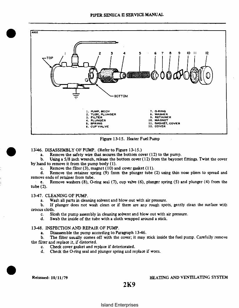
PIPER SENECA II SERVICE MANUAL
A932
6 7 8 9 10 11 12
7. O-RING8. WASHER9. RETAINER
10. MAGNET11. GASKET, COVER12. COVER
BOTTOM
1. PUMP, BODY2. TUBE, PLUNGER3. FILTER4. PLUNGER5. SPRING6. CUP VALVE
Figure 13-15. Heater Fuel Pump
13-46. DISASSEMBLY OF PUMP. (Refer to Figure 13-15.)a. Remove the safety wire that secures the bottom cover (12) to the pump.b. Using a 5/8 inch wrench, release the bottom cover (12) from the bayonet fittings. Twist the cover
by hand to remove it from the pump body (1).c. Remove the filter (3), magnet (10) and cover gasket (11).d. Remove the retainer spring (9) from the plunger tube (2) using thin nose pliers to spread and
remove ends of retainer from tube.e. Remove washers (8), O-ring seal (7), cup valve (6), plunger spring (5) and plunger (4) from the
tube (2).
13-47. CLEANING OF PUMP.a. Wash all parts in cleaning solvent and blow out with air pressure.b. If plunger does not wash clean or if there are any rough spots, gently clean the surface with
crocus cloth.c. Slosh the pump assembly in cleaning solvent and blow out with air pressure.d. Swab the inside of the tube with a cloth wrapped around a stick.
13-48. INSPECTION AND REPAIR OF PUMP.a. Disassemble the pump according to Paragraph 13-46.b. The filter usually comes off with the cover; it may stick inside the fuel pump. Carefully remove
the filter and replace it, if distorted.c. Check cover gasket and replace if deteriorated.d. Check the O-ring seal and plunger spring and replace if worn.
Reissued: 10/11/79 HEATING AND VENTILATING SYSTEM
2K9
Island Enterprises

PIPER SENECA II SERVICE MANUAL
1349. ASSEMBLY OF PUMP. (Refer to Figure 13-15.)a. Insert the plunger (4) into the tube with the buffer spring end first. Check fit by slowly raising
and lowering the plunger in the tube. It should move fully without any tendency to stick. If a click cannotbe heard, the interrupter assembly is not functioning properly in which case the pump should be replaced.
b. Install the plunger spring (5), cup valve (6), O-ring seal (7) and washer (8).c. Compress spring (5) and assembly retainer (9) with ends of retainer in side holes of tube (4).d. Place the cover gasket (11) and magnet (10) in the bottom cover (12) and assemble the filter (3)
and cover assembly.e. Twist the cover by hand to hold in position on pump housing. Using a 5/8 inch wrench, securely
tighten the bottom cover with the bayonet fittings on the pump body and install safety wire.
13-50. INSTALLATION OF HEATER FUEL PUMP.a. Position the fuel pump into the compartment and secure in place with bolts.b. Connect the regulator to the pump outlet and the fuel line to the pump inlet.c. Connect the electrical lead from the pump.d. Operate the heater to make sure the unit is functioning properly. (Refer to Paragraph 13-5,
Heater System - Operational Test.)e. Replace all access Covers removed to service the system.
13-51. DUCT SWITCH. (Refer to Figure 13-20 or 13-21.)a. Removal:
1. Disconnect the electrical leads from the terminals on the exposed face of the switch andmark to facilitate installation.
2. Remove the two attaching screws and washers from the duct switch bracket.3. Carefully lift out the switch and gasket (if gasket is used).
b. Cleaning and Inspection:1. Brush off any dust or lint from the switch operating mechanism (exposed inside the duct)
and wipe the external surfaces with a clean cloth.c. Installation:
1. Insert the switch carefully with gasket (if used) into the ventilating duct opening and securewith the two attaching screws and washers.
2. Connect the two electrical leads to their respective terminals on the face of the switch asmarked during removal.
3. Operate the heater with the duct switch set above ambient temperature to check operation.Refer to Paragraph 13-72, Step 1 for additional switch tests and setting instructions.
13-52. DELETED.
Revised: 12/08/83 HEATING AND VENTILATING SYSTEM2K10
Island Enterprises

PIPER SENECA II SERVICE MANUAL
13-53. DISASSEMBLY (30,000 BTU HEATER). (Refer to Figure 13-18.)a. Remove the screw and slide the elbow adapter (23) off the combustion air inlet tube.b. Disconnect and remove electrical wiring and individual wires from the various components on the
heater. If wires appear to be in good condition, it may be desirable to remove wire harness assembly intact.First, disconnect wires at terminal strip and components. The ventilating air blower housing must beremoved so that the two motor wires quick-disconnect may be released.
NOTE
It is advisable to label all wires, prior to removal, to insure correctconnections during reassembly. Cable straps and clips must bereplaced if removed, as they cannot be re-used.
c. Carefully disconnect the high voltage ignition lead at the spark plug. Handle the spring connectoron the end of this lead with care to prevent fouling or damage.
d. Remove the four screws, lock washers, and cable straps to free the ignition assembly (2) from theheater jacket and remove the ignition assembly. The vibrator may be removed by exerting a firm pullstraightaway from the ignition assembly case after releasing the nut and screw.
e. Remove the grommet (39) from the jacket (5) and remove the spark plug (32) with a 7/8 inchdeep socket. Make sure the spark plug gasket is removed.
f. Remove the two screws, lock washers and plain washers, and lift out the overheat (limit) switch(25) and spacer gaskets (27).
g. Remove the two screws, lock washers and plain washers, and lift out the cycling switch (24).h. Remove the four screws and lock washers to release the terminal strip (35) and insulator (36)
from the jacket (5).i. Disconnect the tube fitting (33) at the cover of the combustion air pressure switch (26). (Refer
to Paragraph 13-39, a, Step 1 for precaution on tube bending.) Unscrew and remove the combustion airpressure switch (26) from the combustion air inlet tube.
j. Remove vent air inlet adapter (16) from the blower housing by removing the three screws andlock washers.
k. Loosen the four screws (20) and rotate the blower and motor housing (11) to disengage thenotched end from the four screws in the end of the heater jacket. Disconnect the motor wiringquick-disconnect.
1. Remove the upper fuel shroud box assembly (10) by removing the screws.m. Reach inside the inlet end of the jacket assembly (5) with a 3/4 inch open-end wrench and while
holding the fuel-tube fitting at the jacket, use a 3/4 inch deep socket to remove the nut (38), washer andgasket (29).
n. Remove the combustion head assembly (6) and the gasket (30) from the combustion tubeassembly (7) by removing the screws and washers.
o. Remove the two screws and lock washers; then carefully withdraw the nozzle holder and valveassembly from the combustion head assembly (6).
p. Remove the screws, lock washers and remaining cable straps, if not previously removed, from theseam of the jacket assembly (5). Note positions of cable straps as they are removed. Spread the jacket (5) atthe seam and remove it from the combustion tube assembly (7). This will free the rope gasket (31), whichcan be removed from the particular part to which it remains attached.
q. Carefully unscrew and remove the spray nozzle (21) from the nozzle holder (8). Remove thegasket (28).
Reissued: 10/11/79 HEATING AND VENTILATING SYSTEM
2K11
Island Enterprises
PIPER SENECA II SERVICE MANUAL
CAUTION
Handle the nozzle with care to avoid damage to the tip. Thematerial around the orifice is very thin and any sharp blow on theface of the nozzle can distort the spray pattern and causemalignition or improper combustion.
r. Remove the fuel solenoid assembly (22) by removing the nipple (37) and elbow (34).s. Loosen the nut and remove the screw, flat washer, and rubber grommet from blower housing
(12).t. Remove the two screws, flat washers, and rubber grommets at the other two locations around the
blower motor housing (12).u. Slide the ventilating air blower motor out of the blower housing (12) with the motor bracket
assembly (19) and blower wheel (17) attached. Loosen the set screw in the blower wheel (17) and slide itoff the end of the motor shaft. The flat washers and rubber washers will fall out when the bracket isremoved. Then remove the motor bracket assembly (19). If these parts are in good condition, they need notbe disassembled further.
v. Remove the screw and lock washer to free the capacitor assembly (18) with attached leads.
13-54. DISASSEMBLY OF COMBUSTION AIR BLOWER ASSEMBLY (30,000 BTU). (Refer to Figure13-20.)
a. Remove the combustion air blower inlet adapter (2) by removing three screws, lock washers,cover plate and gasket.
b. Remove the outlet adapter (5) by removing the two screws (6) and lock washers (7).c. Remove the inlet flange (8) by removing the three screws (9) and lock washers (10).d. Remove screws (12 and 16) and lock washers (13 and 17); then separate the back plate (20), with
motor (25) attached, from the blower housing (15) and free the motor leads and capacitor (11) from theback plate (20).
e. Loosen the set screw in the blower wheel (19) and slide it off the motor shaft.f. Remove the two hex nuts (21), lock washers (23) and flat washers (22), and slide the back plate
(20) off the motor through bolts. The spacer (24) will drop out.g. Install new motor brushes as described in Paragraph 13-27, b. If the motor commutator is badly
worn or if the motor is defective in any respect, it must be replaced.
13-55. CLEANING. (Refer to Figure 13-18.)a. Clean individual metal parts (except those parts containing switches and electrical wiring) and the
combustion tube assembly by immersing them in dry-cleaning solvent, such as Stoddard solvent (FederalSpecification P-D-680). A bristle brush should be used to assist the cleaning process if foreignaccumulations are stubborn to remove.
CAUTION
Do not attempt to buff or scrape off any deposits on face of spraynozzle. The face of the nozzle is very susceptible to damage frommishandling. Carefully repeat cleaning process using only a bristlebrush and repeated applications of solvent to loosen any stubborndeposits.
Reissued: 10/11/79 2K12 HEATING AND VENTILATING SYSTEM
Island Enterprises

PIPER SENECA II SERVICE MANUAL
b. Use compressed air or lintless cloth to dry the parts, unless sufficient time is available for them toair dry.
c. Wipe electrical components with a clean, dry cloth. If foreign material is difficult to remove,moisten the cloth in carbon tetrachloride or electrical contact cleaner and clean all exterior surfacesthoroughly.
13-56. CLEANING AND INSPECTING THE COMBUSTION TUBE ASSEMBLY (30,000 BTU). (Refer toFigure 13-18.)
a. Slight scaling and discoloration of the combustion tube assembly (7) is a normal condition forunits that have been in service up to 1000 airplane hours. The slight scaling condition will appear to bemottled and a small accumulation of blue-gray powder may be present on the surface in certain areas. Thiscondition does not require replacement of the combustion tube assembly, unless severe overheating hasproduced soft spots in the metal.
NOTE
This assembly should be inspected prior to cleaning in order toprevent the removal of visible evidences of damage.
b. Look inside the exhaust outlet to determine if the combustion tube appears to be heavily scaledor mottled. Deformation is more difficult to detect visually but can usually be observed by looking straightthrough the combustion tube assembly and sighting along the outer surface of the inner combustion tube.An assembly that has been obviously deformed should be replaced. Slight deformation will not affectheater operation unless it is extensive and localized enough to reduce the flow of ventilating air through theheater more than 10 percent.
c. The combustion tube assembly may be cleaned by either of two methods:1. One method is to soak the combustion tube assembly overnight in an Oakite M-S Stripper
solution made by mixing one pound of Oakite salts with each gallon of water used. The solution should bemaintained at a temperature of between 190°F and 210°F. After soaking overnight, rinse the combustiontube assembly thoroughly in water to remove all traces of the Oakite solution. In order to reach all areas ofthe combustion tube assembly, it is advisable to let it stand in the rinsing water for as long as 1/2 hour,while occasionally agitating it to circulate the water. All openings should be left open during this operation.Be sure to dry the combustion tube assembly thoroughly after cleaning.
2. A second method of cleaning is what is commonly known as hand "tumbling." Insert shotor other metallic particles through the exhaust outlet opening; then close all openings and shake thecombustion tube assembly vigorously while rotating it and changing from end-to-end frequently. Be sure topour out all of the particles and loosened material; then with all openings uncovered, direct a stream ofcompressed air into the combustion tube assembly from first one opening, then the other. Make sure allloose material is removed.
13-57. INSPECTION OF REMAINING COMPONENTS (30,000 BTU). (Refer to Figure 13-18.)a. Discard all rubber parts such as grommets. gaskets, etc. These items should always be replaced at
overhaul. Also discard the rope gasket (31).b. Inspect all wires and wiring harnesses for damage to insulation, damaged terminals, chafed or
cracked insulation and broken plastic bands. Individual wires can be replaced by making up new wires fromNo. 16 AWG stock and cut to correct length. It is advisable to use an acceptable crimping tool for installingterminals, rather than solder for all heater wiring connections. If wiring harness damage is visible, the entireharness assembly should be replaced. If only one or more wires are damaged, cut the cable ties, make upnew wires, install them in the harnesses and restore all cable ties and clamps. If heater controls wereoperating properly at the time of removal, reinstall them.
Reissued: 10/11/79 HEATING AND VENTILATING SYSTEM
2K13
Island Enterprises

PIPER SENECA II SERVICE MANUAL
c. Inspect all hard parts consisting of bolts, screws, nuts, washers and lock washers. Replacedamaged parts.
d. The combustion air pressure switch (26) must respond to delicate pressure changes and shouldalways be checked and/or replaced at overhaul. (Refer to Paragraph 13-63, c and Figure 13-14.)
e. Replace the vibrator in the ignition unit at each overhaul.f. Inspect the ignition assembly (2, Figure 13-18) for dented case, loose or damaged primary
terminal insulator and broken or obviously damaged high voltage lead. Give particular attention to thecondition of the spring connector at the end of the lead. If the spring is burned off, visibly eroded, orcarbon tracked, the ignition assembly should be replaced.
NOTE
Do not attempt a field repair of the ignition unit, as it is a sealedassembly.
g. Inspect the terminal strip (35) for distortion and cracks, and replace it if either condition exists.h. Inspect radio-noise filters for short circuits by checking from either terminal to ground with an
ohmmeter. An open-circuit reading should be obtained.i. Inspect the spray nozzle (21) with a magnifying glass for any obstructions in the nozzle orifice
and any sign of damage to the slight conical protrusion at the nozzle tip. Use compressed air to removeobstructions and re-examine the orifice to make sure it is open. Exercise care when handling the nozzle toavoid pressing or rapping on the tip face. Do not buff or scrape off deposits on the tip face. After cleaning,it is advisable to store the nozzle in a polyethylene bag until ready for reassembly.
j. Replace the nozzle at overhaul.
NOTE
The nozzle (21) can be spray tested by installing it in the holderand connecting the fuel tube to a 7 psi fuel pressure source.Connect the solenoid leads to a 12-volt battery to open thesolenoid valve. The conical angle spray pattern should be even anddispersed the same in all directions. Exercise caution to keepatomized fuel away from fire.
k. Inspect the nozzle holder and solenoid valve assembly for damaged threads at the fuel-tube fittingand for crimped or cracked fuel line or distorted housing. The only part in this assembly that can bereplaced is the solenoid winding. Check the solenoid for continuity by connecting across each wire leadwith an ohmmeter. A reading of between 18 and 22 ohms should be obtained at room temperature. If notwithin these limits, or if the solenoid winding shows any form of physical damage or overheating, it shouldbe replaced.
1. Remove the brushes, one at a time, from the ventilating air blower motor (13) by removing thebrush cap and carefully withdrawing the brush from its guide. Remove foreign material from the brushguide and commutator with a stream of filtered compressed air. Check for brush wear (refer to Paragraph13-27). Inspect the commutator for grooved brush track, pitting or burning. The commutator surfaceshould be smooth and medium brown in color. Replace the motor if the commutator or other parts showdamage.
m. Inspect the combustion air blower motor as described in the preceding step.n. Inspect the blower wheel for broken or bent vanes and replace it for either condition.
Reissued: 10/11/79 HEATING AND VENTILATING SYSTEM2K14
Island Enterprises

PIPER SENECA II SERVICE MANUAL
13-58. DISASSEMBLY (45,000 BTU HEATER). (Refer to Figure 13-19.)a. Remove the screw and slide the elbow adapter (23) off the combustion air inlet tube.b. Disconnect and remove electrical wiring and individual wires from the various components on the
heater. If wires appear to be in good condition, it may be desirable to remove wire harness assembly intact.First disconnect wires at terminal strip and components.
NOTE
It is advisable to label all wires, prior to removal, to insure correctconnections during reassembly. Cable straps and clips must bereplaced if removed, as they cannot be reused.
c. Carefully disconnect the high voltage ignition lead at the spark plug. Handle the spring connectoron the end of this lead with care to prevent fouling or damage.
d. Remove the four screws and cable straps to free the ignition assembly (2) from the heater jacketand remove the ignition assembly. The vibrator may be removed by releasing the clamp and exerting a firmpull straightaway from the ignition assembly case.
e. Remove the grommet (39) from the jacket (5) and remove the spark plug (32) with a 7/8 inchdeep socket. Make sure the spark plug gasket is removed.
f. Remove the two screws and lift out the overheat (limit) switch (25) and spacer gaskets (27).g. Remove the two screws and lift out the cycling switch (24).h. Remove the four screws to release the terminal strip (35) and insulator (36) from the jacket (5).i. Disconnect the tube fitting (33) at the cover of the combustion air pressure switch (26). Refer to
Paragraph 13-39, a, Step 1 for precaution on tube bending. Unscrew and remove the combustion airpressure switch (26) from the combustion air inlet tube.
j. Remove vent air inlet adapter (16) from the blower housing by removing the three screws.k. Loosen the four screws (20) and rotate the blower and motor housing (11) to disengage the
notched end from the four screws in the end of the heater jacket. Disconnect the motor wiringquick-disconnect.
1. Remove the upper fuel shroud box cover (10) by removing the screws.m. Remove the grommet from the fuel shroud (9) and carefully pull the fuel solenoid wires through
the hole in the shroud.n. With an open end wrench, remove the fuel solenoid assembly being careful not to damage the
wires on the solenoid.o. Reach inside the inlet end of the jacket assembly (5) with a 3/4 inch open-end wrench, and while
holding the fuel-tube fitting at the jacket, use a 3/4 inch deep socket to remove the elbow (34), nut (38),washer (41), gasket (29) and fuel shroud (9).
p. Remove the two screws and carefully withdraw the nozzle holder (8) from the combustion headassembly (6); remove gasket (28).
q. Remove the six screws and withdraw the combustion head assembly (6) from the combustiontube assembly (7). Remove gasket (30).
r. Remove the screws and remaining cable straps, if not previously removed, from the seam of thejacket assembly (5). Note the position of the cable straps as they are removed. Spread the jacket at theseam and remove it from the combustion tube assembly (7). This will free the asbestos gasket (31) whichcan be removed from the particular part to which it remains attached.
s. Carefully unscrew and remove the spray nozzle (21) from the nozzle holder (8). Remove thegasket (28).
Reissued: 10/11/79 HEATING AND VENTILATING SYSTEM2K15
Island Enterprises

PIPER SENECA II SERVICE MANUAL
CAUTION
Handle the nozzle with care to avoid damage to the tip. Thematerial around the orifice is very thin and any sharp blow on theface of the nozzle can distort the spray pattern and causemalignition or improper combustion.
t. Remove the three screws and rubber grommets from the blower housing (12).u. Slide the ventilating air blower motor out of the blower housing with the motor bracket assembly
(19) and blower wheel (17) attached. Loosen the set screw in the blower wheel and slide it off the end ofthe motor shaft. Then remove the motor bracket assembly (19), fasteners (43) and ground bracket (44).
v. Remove the screw and lock washer to free the capacitor assembly (18) with attached leads.
13-59. DISASSEMBLY OF COMBUSTION AIR BLOWER ASSEMBLY (45,000 BTU). (Refer to Figure13-21.)
a. Remove the combustion air blower inlet adapter (2) by removing the screw (18).b. Remove screws (18); then separate the outer housing (3) from the inner housing (8) and free the
motor leads and capacitor (10) from the inner housing.c. Loosen the set screw (6) in the blower wheel (7) and slide it off the motor shaft.d. Remove the two hex nuts (17), lock washers (00) and flat washers (16) and slide the inner
housing (8) off the motor through bolts. The spacer (15) will drop out.e. Install new motor brushes as described in Paragraph 13-27, b. If the motor commutator is badly
worn or if the motor is defective in any respect, it must be replaced.
13-60. CLEANING. (Refer to Figure 13-19.)a. Clean individual metal parts (except those parts containing switches and electrical wiring) and the
combustion tube assembly by immersing them in dry-cleaning solvent, such as Stoddard solvent (FederalSpecification P-D-680). A bristle brush should be used to assist the cleaning process if foreignaccumulations are stubborn to remove.
CAUTION
Do not attempt to buff or scrape off any deposits on face of spraynozzle. The face of the nozzle is very susceptible to damage frommishandling. Carefully repeat cleaning process using only a bristlebrush and repeated applications of solvent to loosen any stubborndeposits.
b. Use compressed air or lintless cloth to dry the parts, unless sufficient time is available for them toair dry.
c. Wipe electrical components with a clean, dry cloth. If foreign material is difficult to remove,moisten the cloth in carbon tetrachloride or electrical contact cleaner and clean all exterior surfacesthoroughly.
Reissued: 10/11/79 HEATING AND VENTILATING SYSTEM
2K16Island Enterprises

4.20DIA.
AIR SUPPLY
1. WATER MANOMETER2. OHMMETER3. NEEDLE VALVE4. TEES. PRESSURE TAP (OPEN)6. ADJUSTING SCREW7. COMBUSTION AIR PRESSURE
PIPER SENECA 11 SERVICE MANUAL
387
.19 DIA. HOLES(6 EQUALLY SPACED)
.125 THICK STOCK
RUBBER STOPPER
DRILL OUT TONECESSARY DIA.
ICLAMP
SEAL CAP
COMBUSTION HEAD OPENING
WING NUT
FLAT WASHER
RUBBER STOPPER
DRILL FOR BOLT
FLAT WASHER
BOLT
EXPANSION PLUG
Figure 13-16. Suggested Design for Seal Plates, Plugs, and Caps for CombustionTube Leakage Test
-2
3
6
5
7
Figure 13-17. Test Setup for Combustion Air Pressure Switch
Reissued: 10/11/79 HEATING AND VENTILATING SYSTEM
2K17
Island Enterprises

PIPER SENECA II SERVICE MANUAL
13-61. CLEANING AND INSPECTING THE COMBUSTION TUBE ASSEMBLY (45,000 BTU). (Refer toFigure 13-19.)
a. Slight scaling and discoloration of the combustion tube assembly (7) is a normal condition forunits that have been in service up to 1000 airplane hours. The slight scaling condition will appear to bemottled and a small accumulation of blue-gray powder may be present on the surface in certain areas. Thiscondition does not require replacement of the combustion tube assembly unless severe overheating hasproduced soft spots in the metal.
NOTE
This assembly should be inspected prior to cleaning in order toprevent the removal of visible evidences of damage.
b. Look inside the exhaust outlet to determine if the combustion tube appears to be heavily scaledor mottled. Deformation is more difficult to detect visually but can usually be observed by looking straightthrough the combustion tube assembly and sighting along the outer surface of the inner combustion tube.An assembly that has been obviously deformed should be replaced. Slight deformation will not affectheater operation unless it is extensive and localized enough to reduce the flow of ventilating air through theheater more than 10 percent.
c. The combustion tube assembly may be cleaned by either of two methods:1. One method is to soak the combustion tube assembly overnight in an Oakite M-S Stripper
solution made by mixing one pound of Oakite salts with each gallon of water used. The solution should bemaintained at a temperature of between 190°F and 210F. After soaking overnight, rinse the combustiontube assembly thoroughly in water to remove all traces of the Oakite solution. In order to reach all areas ofthe combustion tube assembly, it is advisable to let it stand in the rinsing water for as long as 1/2 hourwhile occasionally agitating it to circulate the water. All openings should be left open during this operation.Be sure to dry the combustion tube assembly thoroughly after cleaning.
2. A second method of cleaning is what is commonly known as hand "tumbling." Insert shotor other metallic particles through the exhaust outlet opening; then close all openings and shake thecombustion tube assembly vigorously while rotating it and changing from end-to-end frequently. Be sure topour out all of the particles and loosened material; then with all openings uncovered, direct a stream ofcompressed air into the combustion tube assembly from first one opening, then the other. Make sure allloose material is removed.
13-62. INSPECTION OF REMAINING COMPONENTS (45,000 BTU). (Refer to Figure 13-19.)a. Discard all rubber parts such as grommets, gaskets, etc. These items should always be replaced at
overhaul. Also discard the asbestos gasket (31).b. Inspect all wires and wiring harnesses for damage to insulation, damaged terminals, chafed or
cracked insulation and broken plastic bands. Individual wires can be replaced by making up new wires fromNo. 16 AWG stock and cut to correct length. It is advisable to use an acceptable crimping tool for installingterminals rather than solder for all heater wiring connections. If wiring harness damage is visible, the entireharness assembly should be replaced. If only one or more wires are damaged, cut the cable ties, make upnew wires, install them in the harnesses and restore all cable ties and clamps. If heater controls wereoperating properly at the time of removal, reinstall them.
c. Inspect all hard parts consisting of bolts, screws, nuts, washers and lock washers. Replacedamaged parts.
d. The combustion air pressure switch (26) must respond to delicate pressure changes and shouldalways be checked and/or replaced at overhaul. (Refer to Paragraph 13-63, c and Figure 13-17.)
Reissued: 10/11/79 HEATING AND VENTILATING2K18
Island Enterprises

e. Replace the vibrator in the ignition unit at each overhaul.f. Inspect the ignition assembly (2, Figure 13-19) for dented case, loose or damaged primary
terminal insulator and broken or obviously damaged high voltage lead. Give particular attention to thecondition of the spring connector at the end of the lead. If the spring is burned off, visibly eroded orcarbon tracked, the ignition assembly should be replaced.
NOTE
Do not attempt a field repair of the ignition unit, as it is a sealedassembly.
g. Inspect the terminal strip (35) for distortion and cracks and replace it if either condition exists.h. Inspect radio-noise filters for short circuits by checking from either terminal to ground with an
ohmmeter. An open circuit reading should be obtained.i. Inspect the spray nozzle (21) with a magnifying glass for any obstructions in the nozzle orifice
and any sign of damage to the slight conical protrusion at the nozzle tip. Use compressed air to removeobstructions and re-examine the orifice to make sure it is open. Exercise care when handling the nozzle toavoid pressing or rapping on the tip face. Do not buff or scrape off deposits on the tip face. After cleaning,it is advisable to store the nozzle in a polyethylene bag until ready for reassembly.
j. Replace the nozzle at overhaul.
NOTE
The nozzle (21) can be spray tested by installing it in the holderand connecting the fuel tube to a 7 psi fuel pressure source. Theconical angle spray pattern should be even and dispersed the samein all directions. Exercise caution to keep atomized fuel awayfrom fire.
k. Inspect the nozzle holder assembly for damaged threads at the fuel-tube fitting and for crimpedor cracked fuel line or distorted housing. Check the solenoid for continuity by connecting across each wirelead with an ohmmeter. A reading of between 15 and 40 ohms should be obtained at room temperature. Ifnot within these limits, the solenoid should be replaced.
1. Remove the brushes, one at a time, from the ventilating air blower motor (13) by removing thebrush cap and carefully withdrawing the brush from its guide. Remove foreign material from the brushguide and commutator with a stream of filtered compressed air. Check for brush wear (refer to Paragraph13-25). Inspect the commutator for grooved brush track, pitting or burning. The commutator surfaceshould be smooth and medium brown in color. Replace the motor if the commutator or other parts showdamage.
m. Inspect the combustion air blower motor as described in the preceding step.n. Inspect the blower wheel for broken or bent vanes and replace it for either condition.
13-63. TESTING. The following tests should be performed as outlined in the succeeding paragraphs:a. Check ventilating air and combustion air motors for correct RPM and current draw:
1. Connect motor to 12-volt DC power supply. Rotation should be counterclockwise whenviewed from the shaft end.
2. Both motors should rotate at approximately 7500 RPM at rated voltage. Current draw isapproximately five amperes.
3. If current draw is excessive or if speed is too low, replace the brushes. Recheck both currentdraw and RPM after brushes are properly run in. (Refer to Paragraph 13-27, b.)
4. If after replacing brushes operation is still unsatisfactory, replace the motor.
Reissued: 10/11/79 HEATING AND VENTILATING SYSTEM
2K19
PIPER SENECA II SERVICE MANUAL
Island Enterprises

PIPER SENECA II SERVICE MANUAL
NOTE
The motor checks described above should be made without theblower housing attached. for both the ventilating air andcombustion air motors.
b. Test the combustion tube assembly (7) for leaks as follows:1. . Fashion a sealing plate from approximately I 8 inch thick flat stock to seal the combustion
head opening in the combustion tube assembly. (Refer to Figure 13-16.) Use a rubber gasket under theplate and attach the plate with six screws.
2. Make up seals for all remaining openings. except the one used to connect the air pressuresource. (Refer to Figure 13-16.) Use rubber stoppers as shown. The combustion air inlet tube can be sealedbest with a drilled stopper and clamp. Other openings should be sealed with expansion plugs. The seal usedin the exhaust tube should be formed so that it will not deform the air pressure switch tube which protrudesinto the exhaust.
3. Install plugs and caps in all openings except the one to which the combustion air pressureswitch is attached. (Any opening can be used to connect the air pressure source; however, the combustionair pressure switch opening is usually the most convenient. The drain opening would normally be considered asecond choice.)
4. Connect a regulated air supply to the opening that has not been plugged and apply a pressureof between three and five psi to the combustion tube assembly.
5. Submerge the combustion tube assembly in water for several minutes while watching forbubbles which would indicate leaks. No air leakage is permitted from the combustion tube assembly. No weldor braze repairs are permitted on a combustion tube assembly.
c. Test the combustion air pressure switch as follows:I. Connect an adjustable air pressure line that can be controlled in a range of zero to 5.0 psi
(maximum) of water to the switch opening with a water manometer and needle valve in the line ahead ofswitch. Switch must be tested in 45 degree position as shown in Figure 13-17.
2. Connect an ohmmeter across the switch terminals to determine the exact instant of switchclosing.
3. Apply air pressure allowing it to build up very slowly from zero. The switch contacts shouldclose at 0.5 0. I inches of water which will be indicated on the manometer.
NOTE
The switch cover has a differential pressure tap and this openingmust be left open to atmosphere during test.
4. Make several trials to insure switch reliability. Be sure to increase and decrease the air pressureslowly in order to produce accurate indications.
5. If an adjustment is required, rotate the adjusting screw clockwise to increase settings andcounterclockwise to decrease settings.
d. Test the fuel line and fuel line shroud tube for leaks as follows:I. Using filtered compressed air. apply 20 psi to the shroud drain port located on the surface near
the threaded nozzle cavity.2. Immerse the fuel feed and nozzle holder assembly in clean water with the fuel inlet and nozzle
cavity left open.
Revised: 12/08/83 2K20 HEATING AND VENTILATING SYSTEM2K20
Island Enterprises

PIPER SENECA II SERVICE MANUAL
A309 1. HEATER ASSEMBLY2. IGNIGION ASSEMBLY3. VIBRATOR - IGNITION4. COIL - IGNITIONS. JACKET ASSEMBLY6. HEAD ASSEMBLY COMBUSTION7. TUBE ASSEMBLY -COMBUSTION8. FUEL FEED AND NOZZLE HOLDER ASSEMBLY9. BOX ASSEMBLY - FUEL SHROUD, LOWER
10. BOX ASSEMBLY - FUEL SHROUD, UPPER11. BLOWER ASSEMBLY - VENT AIR12. HOUSING -BLOWER
13. MOTOR ASSEMBLY -VENT AIR BLOWER14. CAP - BRUSH ASSEMBLYIS. BRUSH ASSEMBLY - MOTOR16. ADAPTER17. FAN - VENT AIR BLOWERII. CAPACITOR ASSEMBLY19. BRACKET ASSEMBLY -MOTOR20. FASTENER21. NOZZLE-FUEL22. SOLENOID ASSEMBLY - FUEL23. ADAPTER - ELBOW24. SWITCH - CYCLING25. SWITCH- LIMIT26. SWITCH -PRESSURE
35. STRIP-TERMINAL36. INSULATOR - TERMINAL STRIP37. NIPPLE38. NUT39. GROMMET40. GROMMET41. GROMMET
27. GASKET - LIMIT SWITCH2 . GASKET29. GASKET30. GASKET31. GASKET - ASBESTOS32. PLUG -SPARK33. ELBOW34. ELBOW
Figure 13-18. Exploded View of Heater Assembly (30,000 BTU)
Reissued: 10/11/79 HEATING AND VENTILATING SYSTEM
2K21
Island Enterprises

3068
PIPER SENECA II SERVICE MANUAL
1. HEATER ASSEMBLY2. IGNITION ASSEMBLY3. VIBRATOR - IGNITION4. COIL-IGNITION5. JACKET ASSEMBLY6. HEAD ASSEMBLY - COMBUSTION7. TUBE ASSEMBLY -COMBUSTION8. RUEL FEED AND NOZZLE HOLDER ASSEMBLY9. BOX ASSEMBLY · FUEL SHROUD. LOWER
10. BOX ASSEMBLY - FUEL SHROUD, UPPER
11. BLOWER ASSEMBLY -VENT AIR12. HOUSING- BLOWER13. MOTOR ASSEMBLY - VENT AIR BLOWER14. CAP · BRUSH ASSEMBLY15. BRUSH ASSEMBLY -MOTOR16. ADAPTER
17. FAN - VENT AIR BLOWER18. CAPACITOR ASSEMBLY19. BRACKET ASSEMBLY - MOTOR20. FASTENER21. NOZZLE- UEL22. SOLENOID ASSEMBLY - FUEL23. ADAPTER -ELBOW24. SWITCH- CYCLING25. SWITCH LIMIT26. SWITCH PRESSURE27. GASKET - LIMIT SWITCH21. GASKET29. GASKET30. GASKET31. GASKET - ASBESTOS32. PLUG -SPARK
33. ELBOW34. ELBOW35. STRIP TERMINAL36. INSULATOR
TERMINAL STRIP
37. NIPPLE38. NUT39. GROMMET40. GROMMET41. WASHER42. SCREWS43. FASTENERS44. BRACKET - ROUND4S. GROMMET46. GROMMET47. GROMMET48. OPTIONAL HEATER
HOURMETERI
Figure 13-19. Exploded View of Heater Assembly (45,000 BTU)
HEATING AND VENTILATING2K22
Revised: 3/16/81
Island Enterprises

PIPER SENECA II SERVICE MANUAL
3. Observe for bubbles which would indicate leakage. If bubbles appear at either fuel fitting,there is a leak in the fuel tube. If bubbles appear externally on the shroud tube or at either end of theshroud tube juncture, the shroud tube is leaking.
4. In either of the above cases, the complete fuel feed and nozzle holder assembly must bereplaced.
e. Spray test the nozzle (21, Figure 13-18 or 13-19) as follows:1. Install the nozzle in the fuel feed and nozzle holder assembly and connect the fuel tube to
the fuel solenoid. Connect the solenoid to a 7 psi fuel pressure source.2. Connect the solenoid leads to a 12-volt battery. Connect a switch in the line to open and
close the solenoid when desired.3. With the switch closed (solenoid valve energized) and the fuel line connected, observe the
fuel spray pattern. It should be conical in shape with even dispersion in all directions.
WARNING
Be sure to keep the atomized spray away from fire.
4. Energize and de-energize the solenoid several times. The spray should shut off permanentlyeach time the solenoid is de-energized. There should be no sign of dribbling at the nozzle tip in excess ofone or two drops.
5. If the spray pattern is distorted, check for an obstruction and clean the nozzle as describedin Paragraph 13-57 or 13-62, i. If this fails to provide a normal spray pattern, replace the nozzle.
6. If the nozzle continues to dribble, the solenoid valve is not closing properly and the solenoidvalve must be replaced.
13-64. REPAIR OF COMBUSTION TUBE ASSEMBLY. No weld or braze repairs of the combustion tubeassembly are authorized.
Revised: 12/08/83 2K23 HEATING AND VENTILATING SYSTEM
Island Enterprises

PIPER SENECA II SERVICE MANUAL
13-65. REASSEMBLY (30,000 BTU). (Refer to Figure 13-18.)a. If removed during disassembly, secure the nipple (37) and elbow (34) to the fuel solenoid (22).b. Insert the ventilating air motor (13) into the motor bracket assembly (19); slide the blower wheel
(17) on the end of motor shaft and rotate it until the set screw is aligned with the flat side of the motorshaft. Tighten the set screw just tight enough to hold it at this time.
c. Attach the capacitor and leads assembly (18) to the motor bracket (19) with the screw and lockwasher. Make sure a good electrical ground connection is made at this point.
d. Insert this assembly into the blower housing (12) and position it so the long screw is in alignmentwith the gap on the inner ring of the motor bracket assembly (19). This is the screw used to secure andalign the motor in the bracket.
e. Slide the flat washer and rubber washer into position between the legs of the motor bracket (19)and blower housing (12).
f. Make sure all wires are routed and grommeted as they were prior to disassembly and install thetwo screws, flat washers, and new grommets at the two lower edges securing the motor bracket assembly(19). Then install the grommet, flat washer, nut, and screw in the remaining (upper) corner of the motorbracket assembly (19).
g. Center the motor bracket (19) in the housing and tighten the screw to secure it. The motor (13)should be positioned in the bracket (19) to locate the blower wheel (17) properly in the blower housing(12). The blower wheel should be positioned so it will rotate freely and just clear the contoured spill platein the blower housing. Tighten the Allen-head set screws and spin the blower wheel by hand for a clearancecheck. Then apply appropriate voltage to run the motor as a final clearance check.
h. Attach the inlet adapter (16) to the end of blower housing (12) with three screws and lockwashers.
i. Place a new rope gasket (31) in position on the exhaust outlet; spring the jacket assembly (5)open at the seam and insert the combustion tube assembly (7) carefully into the jacket. Exercise care toclear the pressure switch tube in the exhaust outlet and see that the rope gasket (31) is properly located.Close the gap on the jacket assembly and install screws and lock washers to secure it at the seam. (Twoleads ground under these screws. See notations made during disassembly.) Make sure the tongue andchannel at the seam are in good condition and a tight fit is effected.
j. Install cable straps at locations noted during disassembly.k. Remove the spray nozzle (21) from the polyethylene bag. Screw the nozzle into nozzle holder
and tighten to 75-100 inch-pounds. It is very important to torque the nozzle to this value as incorrecttightening could cause improper heater operation and "drooL"
CAUTION
The spray nozzle has a slight protrusion on the nozzle face. If thisarea has been struck by any object which would make a dent ordestroy the original contour, the nozzle must be replaced. Itcannot be disassembled for cleaning.
1. Install the gasket (30) and combustion head (6) in the combustion tube (7) and secure with thescrews and washers.
m. Insert the fitting on end of nozzle fuel tube through the opening in jacket (5) and attach thenozzle holder to the combustion head assembly (6) with the two screws and lock washers. It may benecessary to place a slight bend in the shrouded fuel tube to permit alignment of screw holes. Be sure to usea new gasket (28).
n. Using a new spark plug gasket, install the spark plug (32) and tighten to a torque of 28foot-pounds. Install the grommet (39) in the jacket around the spark plug.
Reissued: 10/11/79 HEATING AND VENTILATING
2K24Island Enterprises

PIPER SENECA II SERVICE MANUAL
o. Install the ignition assembly (2) on the jacket assembly (5) with the four screws and lockwashers. Connect the high voltage lead to the spark plug and tighten it to 20 foot-pounds.
p. Attach the overheat limit switch (25) and spacer gaskets (27) to the jacket assembly (5) with thetwo screws, lock washers and flat washers. Tighten the screws securely.
q. Attach the cycling switch (24) to the jacket assembly (5) with the two screws, lock washers andflat washers.
r. Place the terminal strip insulation (36) in position on the jacket (5), followed by the terminalstrip (35). Secure both parts by installing the two screws and lock washers. The two screws are located attwo diagonal corners of the terminal strip.
s. Center the fuel fitting in jacket opening. Position the fuel fitting shroud gasket (29) and washer;then install the nut (38) finger tight. Insert a 3/4 inch open-end wrench inside the jacket and hold thefuel-tube fitting while tightening the nut (38) with a 3/4 inch deep socket. Install the fuel solenoid elbow(34).
t. Rotate the combustion air switch (26) onto the threaded fitting on the combustion air tube andtighten it firmly.
u. Connect the tube to the elbow fitting (33) on the combustion air pressure switch (26).v. Install the wiring harness and connect all wire leads to their respective terminals. (Refer to the
wiring diagram, Figure 13-7.) Place the grommet (41, Figure 13-18) in position in the jacket (5); locate theventilating air blower (11) at the end of the jacket. Thread the quick-disconnect on the wiring harnessthrough the grommet and connect it to the mating connector on the motor lead.
w. Place the blower housing in position on the jacket assembly (5) and secure it by installing thefour screws (20), if removed at disassembly. This operation is easier if the screws (20) are started into theirthreads and the blower housing rotated into place, allowing the screws to enter the notched openings inedge of blower housing. Tighten all screws securely.
x. Install the elbow adapter (23) with the screw.y. Install the upper fuel shroud box (10) with the screws. Ascertain that the grommet (40) is
installed.
13-66. REASSEMBLY OF COMBUSTION AIR BLOWER ASSEMBLY (30,000 BTU). (Refer to Figure13-20.)
a. Place the spacer (24) over the end of the motor shaft and attach the motor assembly (25) to theback plate (20) with the two self-locking nuts (21), flat washers (22) and lock washers (23).
b. Slide the blower wheel (19) on the motor shaft and tighten the set screw lightly against the flatportion of the motor shaft.
c. Place the blower housing (15) in position on the back plate (20) and install screws (16) and lockwashers (17).
d. Attach the radio-noise filter (11) at the point shown with the screw (12) and lock washer (13).The motor ground lead terminal (28) can be grounded to the motor support bracket (3).
e. Attach the inlet flange (8) and blower inlet adapter (2) to blower housing (15) with three screws(9) and lock washers (10).
f. Loosen the Allen-head set screw in the blower wheel (19) and shift the wheel on the motor shaftuntil it is near the inlet in the blower housing. Tighten the set screw securely. The blower wheel should justclear the inlet flange when rotated at full RPM. Spin the blower wheel by hand for clearance check; thenapply proper voltage to run motor and recheck for proper clearance.
g. Slide the blower outlet adapter (5) on the blower housing outlet (15) and install the two screws(6) and lock washers (7).
Reissued: 10/11/79 HEATING AND VENTILATING SYSTEM
2L1
Island Enterprises

PIPER SENECA II SERVICE MANUAL
13-67. REASSEMBLY (45,000 BTU). (Refer to Figure 13-19.)a. If removed during disassembly, secure the nipple (37) and elbow (34) to the fuel solenoid (22).b. Insert the ventilating air motor (13) into the motor bracket assembly (19); slide the blower wheel
(17) on the end of the motor shaft and rotate it until the set screw is aligned with the flat side of the motorshaft. Tighten the set screw just tight enough to hold it at this time.
c. Attach the capacitor and leads assembly (18) to the motor bracket (19) with screw and lockwasher. Make sure a good electrical ground connection is made at this point. Install ground bracket (44)and three new fasteners (43).
d. Insert this assembly into the blower housing (12).e. Make sure all wires are routed and grommeted as they were prior to disassembly and then secure
the assembly in the housing with three screws (45).f. The motor (13) should be positioned in the bracket (19) to locate the blower wheel (17)
properly in the blower housing (12). The blower wheel should be positioned so it will rotate freely and justclear the contoured spill plate in the blower housing. Tighten the Allen-head set screw and spin the blowerwheel by hand for a clearance check. Then apply the appropriate voltage to run the motor as a finalclearance check.
g. Attach the inlet adapter (16) to the end of the blower housing (12) with three screws and lockwashers.
h. Place a new asbestos gasket (31) in position on the exhaust outlet; spring the jacket assembly (5)open at the seam and insert the combustion tube assembly (7) carefully into the jacket. Exercise care toclear the pressure switch tube in the exhaust outlet and see that the asbestos gasket (31) is properly located.Close the gap on the jacket assembly and install screws to secure it at the seam. (Solenoid lead wire isgrounded under one of these screws. See notations made during disassembly.) Make sure the seam is in goodcondition and a tight fit is effected.
i. Install cable straps at locations noted during disassembly.j. Remove the spray nozzle (21) from the polyethylene bag. Screw the nozzle into the nozzle
holder and tighten to 75-100 inch-pounds. It is very important to torque the nozzle to this value asincorrect tightening could cause improper heater operation and nozzle "drool."
CAUTION
The spray nozzle has a slight protrusion on the nozzle face. If thisarea has been struck by any object which would make a dent ordestroy the original contour, the nozzle must be replaced.
k. Install a new gasket (30) and the combustion head (6) in the combustion tube (7) and securewith the six screws.
1. Insert the fitting on end of nozzle fuel tube through the opening in jacket (5) and attach thenozzle holder to the combustion head assembly (6) with the two screws. It may be necessary to place aslight bend in the shrouded fuel tube to permit alignment of screw holes. Be sure to use a new gasket (28).
m. Using a new spark plug gasket, install the spark plug (32) and tighten to a torque of 28foot-pounds. Install the grommet (39) in the jacket around the spark plug.
n. Install the ignition assembly (2) on the jacket assembly (5) with the four screws. Connect thehigh voltage lead to the spark plug and tighten it to 20 foot-pounds.
o. Attach the overheat limit switch (25) and two spacer gaskets (27) to the jacket assembly (5) withthe two screws. Tighten the screws securely.
p. Attach the cycling switch (24) to the jacket assembly (5) with the two screws.q. Place the terminal strip insulation (36) in position on the jacket (5), followed by the terminal
strip (35). Secure both parts by installing the two screws.
Reissued: 10/11/79 HEATING AND VENTILATING SYSTEM
2L2Island Enterprises

, PIPER SENECA U SERVICE MANUAL
1. COMBUSTION AIR BLOWER AND MOTOR ASSEMBLY2. ADAPTER ASSEMBLY - BLOWER INLET3. MOUNT -COMBUSTION AIR BLOWER SUPPORT4. COMBUSTION AIR BLOWER AND MOTOR5. ADAPTER - OUTLET6. SCREW -ANS304R6
- 7. WASHER- AN936A6. FLANGE- INLET
9. SCREW - AN530-6R610. WASHER - AN936A6
11. CAPACITOR12. SCREW -AN530-6R613. WASHER -AN936A614. SLEEVE - HIGH TEMPERATUREIS. HOUSING -BLOWER16. SCREW-AN530-6R617. WASHER -AN936A618. GASKET - BACK PLATE19. FAN - COMBUSTION AIR BLOWER20. PLATE-BACK21. NUT - AN345-1022. WASHER-AN960-IOL23. WASHER AN936-31024. SPACER25. MOTOR ASSEMBLY -COMBUSTION AIR BLOWER26. BRUSH ASSEMBLY27. CAP - BRUSH ASSEMBLY28. TERMINAL - PREINSULATED29. STRAP-CABLE30. SWITCH ASSEMBLY - ADJUSTABLE DUCT31. LEVER ASSEMBLY -SWITCH32. SCREW- AN565D8H333. COVER - SWITCH34. SWITCH - ADJUSTABLE DUCT35. SPACER
Figure 13-20. Exploded View - Combustion Air Blower and Motor Assembly (30,000 BTU)
Reissued: 10/11/79 HEATING AND VENTILATING SYSTEM
2L3
Island Enterprises

PIPER SENECA II SERVICE MANUAL
1971
1. COMBUSTION AIR BLOWER AND MOTOR ASSEMBLY2. ADAPTER ASSEMBLY -BLOWER INLET3. HOUSING - BLOWER OUTER HALF4. COMBUSTION AIR BLOWER AND MOTOR5. MOTOR ASSEMBLY - COMBUSTION AIR BLOWER6. SET SCREW . BLOWER FAN7. FAN - COMBUSTION AIR BLOWER8. HOUSING - BLOWER INNER HALF9. STRAP-CABLE
10. CAPACITOR11. BRUSH ASSEMBLY12. CAP - BRUSH ASSEMBLY
13. MOUNT - COMBUSTION AIR BLOWER SUPPORT14. ELECTRICAL LEADIS. SPACER16. WASHER17. LOCK NUT - AN345-10I. SCREWS19. SPACER20. SWITCH - ADJUSTABLE DUCT21. COVER - SWITCH22. SCREW-ANS65 08 H323. LEVER ASSEMBLY - SWITCH
Figure 13-21. Exploded View - Combustion Air Blower and Motor Assembly (45.000 BTU)
HEATING AND VENTILATINGReissued: 10/11/79
2L4Island Enterprises

PIPER SENECA II SERVICE MANUAL
r. Center the fuel fitting in jacket opening. Position the fuel fitting shroud gasket (29), washer (41)and shroud (9); then install the nut (38) finger tight. Insert a 3/4 inch open-end wrench inside the jacketand hold the fuel-tube fitting while tightening the nut (38) with a 3/4 inch deep socket. Install the fuelsolenoid elbow (34) and solenoid (22). Avoid twisting or damaging lead. Install wires through grommet inlower shroud (9).
s. Rotate the combustion air switch (26) onto the threaded fitting on the combustion air tube andtighten it firmly.
t. Install grommet (47) over pressure switch line. Connect the tube to the elbow fitting (33) on thecombustion air pressure switch (26).
u. Install the wiring harness and connect all wire leads to their respective terminals. (Refer to thewiring diagram, Figure 13-7.) Place the grommet (45, Figure 13-19) in position in the jacket (5); locate theventilating air blower (11) at the end of the jacket. Thread the quick-disconnect on the motor leads throughthe grommet and connect it to the mating connector on the wiring harness.
v. Place the blower housing in position on the jacket assembly (5) and secure it by installing thefour screws (20), if removed at disassembly. This operation is easier if the screws (20) are started into theirthreads and the blower housing rotated into place allowing the screws to enter the notched openings in edgeof blower housing. Tighten all screws securely.
w. Install the elbow adapter (23) with the screw.x. After heater is installed in the aircraft and the fuel line is connected, install the upper fuel shroud
box (10) with the screws. Ascertain that the grommet (40) is installed.
13-68. REASSEMBLY OF COMBUSTION AIR BLOWER ASSEMBLY (45,000 BTU). (Refer to Figure13-21.)
a. Place the spacer (15) over the end of the motor shaft and attach the motor assembly (5) to theinner housing (8) with the two self-locking nuts (17), flat washers (16) and lock washers (00).
b. Slide the blower wheel (7) on the motor shaft and tighten the set screw (6) lightly against the flatportion of the motor shaft.
c. Place the outer blower housing (3) in position on the inner housing (8) and install screws (18).d. Attach the radio-noise filter (10) at the point shown with the screw. The motor ground lead
terminal can be grounded to the motor support bracket (13).e. Loosen the Allen-head set screw in the blower wheel (7) and shift the wheel on the motor shaft
until it is near the inlet in the blower housing. Tighten the set screw securely. The blower wheel should justclear the inlet flange when rotated at full RPM. Spin the blower wheel by hand for clearance check; thenapply proper voltage to run motor and recheck for proper clearance.
f. Attach the blower inlet adapter (2) to blower housing (3) with screw (18).
13-69. TEST PROCEDURE.
13-70. GENERAL INFORMATION. A test of all components should have been made after overhaul toinsure proper operation. Some shops may not have complete testing facilities for measuring airflows,pressure drops, and other factors which would be accomplished in a laboratory-type test. If such a testcannot be made, install the heater and check operation on the ground and in the air to determine ifoperation is normal. In shops where complete test equipment is available and a complete functional test canbe performed, the test routine described in subsequent paragraphs should be made.
Reissued: 10/11/79 HEATING AND VENTILATING SYSTEM
2L5
Island Enterprises

COMUSON COMBUSTION AIR BLOWERAIR MANOMETER
COMBUSTION AIRPRESSURE SWITCH
FUEL IN(FROM PUMP)
I
PIPER SENECA II SERVICE MANUAL
391
MIN.
VENTILATINGAIR
CYCLIN
ITCH
SWITCH
VENT. AIR BLOWER TERMIALSTRIP
EXHAUST OUTLET / 2.25 DIA. ORIFICE
DUCT
DUCT SWITCH
12V DC
Figure 13-22. Suggested Setup of Heater Operation Test
- VENT
FUELVALVE
EXTERNAL WIRING __ _ ___ _ _ _ EATER UNIT
REQUIRED FOR BENCH TEST
Figure 13-23. Wiring Connections for Heater Operation Test
Reissued: 10/11/79 HEATING AND VENTILATING
2L6Island Enterprises

PIPER SENECA II SERVICE MANUAL
13-71. EQUIPMENT REQUIRED. (Refer to Figure 13-22.)a. An improvised stand to hold the heater during test. The heater should be located far enough
away from any combustible material or atmosphere to avoid hazard. A location should be chosen whereexhaust can be dispelled. Do not add an excessive extension to the heater exhaust.
b. A source of fuel capable of being regulated at seven psi.c. The combustion air blower to be used with the heater should be used for the test.d. A 12-volt current supply which may be a DC generator with a rheostat, ammeter, and voltmeter
in the line to control and indicate the current draw and voltage output.e. Two water manometers (zero to 5.0 inch water column) for measuring the pressure in the
ventilating air duct and in the combustion air stream.f. A piece of duct to be attached to the downstream end of the heater. It should have a minimum
length of 24 inches and the same diameter as the heater being tested. A 2.25 inch diameter orifice should becentrally located at the outlet end. An aperature should be provided for the thermometer and duct switchand a static tap should be attached as shown in Figure 13-22.
g. A thermometer with 500°F scale.h. A fuel-pressure gauge.i. A controlled source of compressed air for final leakage test.
13-72. OPERATION TEST (ON TEST BENCH). (Refer to Figures 13-22 and 13-23.)a. Connect the heater to the test setup as shown in Figure 13-22. Make sure the combustion air
blower is mounted securely and that the heater is clamped to its supporting stand.b. Insert the duct switch in the sheet metal extension tube at the location shown in Figure 13-22.c. Connect components and heater as outlined in the wiring connection diagram, Figure 13-23. The
power supply switch should be open.d. Connect the power source to the heater.e. Disconnect wire lead from terminal No. 3 on the heater side of heater terminal strip to prevent
the heater from lighting and close the power source switch to check operation of blowers. The combustionair blower and ventilating air blower should operate at full speed with no blower wheel interference. Ifeither blower fails to run, locate and correct the trouble before proceeding with the test.
f. Connect a voltmeter from open side of combustion air pressure switch terminal to ground todetermine if the switch is closed, which would be indicated by a full voltage reading on the meter. If a fullvoltage reading is not obtained, the combustion air supply is either inadequate or the switch is defective orimproperly adjusted. Make necessary corrections.
g. Observe the manometer connected to the ventilating air pressure tap, which should show areading of 1.1 inches of water (minimum) at rated voltage.
h. Observe the manometer connected to the combustion air tube tap, which should show a readingof 1.5 inches of water (minimum) at rated voltage.
i. Open the power supply switch and reconnect the terminal lead disconnected in preceding Step e.j. Close the power supply switch and turn on the fuel supply. The heater should light within five
seconds (may require slightly longer for air to be purged from fuel lines on the first trial).k. Observe operation of duct switch, which should control heater operation according to the switch
setting.1. If the duct switch fails to control the temperature according to the setting, place the control lever
in high "H" position and notice the control variation. A high reading of 250°F ± 10° should be obtained(reading will vary in different applications).
Reissued: 10/11/79 HEATING AND VENTILATING SYSTEM
2L7
Island Enterprises

PIPER SENECA II SERVICE MANUAL
m. Connect a jumper across the terminals of the duct switch to make it inoperative and observeaction of the cycling switch. The cycling switch should cycle to control the outlet air temperature atapproximately 250°F (nominal). This is a function of ambient temperature and airflow conditions. Ifoperation is within a range of 190°F to 290'F, the switch is operating normally. If the switch is out ofrange, it can be reset in the same manner as described for the duct switch, except that no control lever orindicator stop are used. If adjustment fails to restore proper temperature range, replace the switch.
n. With duct switch still jumped,:place a jumper across the cycling switch terminals to checkoperation of the overheat switch. Block the ventilating air outlet and notice if the overheat switch shuts offthe heater. It should open at between 300°F and 400F. (This is also a function of ambient temperatureand airflow.) After the switch shuts off, remove ventilating air restriction; remove jumpers from cycling andduct switches and press firmly on the overheat switch reset button until it "clicks." The heater should lightand operate.
o. Shut down the heater and check all components visually to make sure no damage has occurred toany of them.
p. Remove heater and other components from the test setup and install it in the airplane.
13-73. INSPECTION OF FUEL NOZZLE ORIFICE. (Refer to Figure 13-18 or 13-19.)a. Loosen the four screws (20) and rotate the blower and motor housing (12) to disengage the
ventilating air blower from the end of the heater jacket. It is not necessary to disconnect the electricalconnections to remove the nozzle (21).
b. Remove the fuel shroud cover (10) by removing the screws. Remove solenoid and elbow.c. Reach inside the inlet end of the jacket assembly with a 3/4 inch open-end wrench and, while
holding the fuel-tube fitting of the jacket, use a 3/4 inch deep socket to remove the nut (38), washer andgasket (29) and lower fuel shroud box.
d. Remove the two screws and carefully withdraw the nozzle holder and valve assembly (21) fromthe combustion head assembly (6).
e. Carefully unscrew and remove the spray nozzle (21) from the nozzle holder. Remove the gasket(28).
f. After cleaning the nozzle, reinstall the parts removed in essentially the reverse order fromremoval. Be sure to hold the fuel-tube fitting when tightening the nut (38) to avoid damage to the fueltube.
13-74. DEFROSTER BLOWER REMOVAL AND INSTALLATION. The defroster blower is located onthe upper right forward side of fuselage bulkhead station 49.50. It is covered by a removable trim panel inthe nose baggage compartment. Access to the blower and motor is accomplished by the removal of thebaggage compartment trim panel and removal of the close out panel on the upper right side of bulkheadstation 49.50, which the blower assembly is attached. Disconnect the electrical leads to the blower motor;loosen the clamps which secure the hoses to the blower housing and disconnect the hoses; then remove thetwo bolts which secure the blower assembly to the close out panel. Installation of the assembly isaccomplished in the reverse order of removal.
Reissued: 10/11/79 HEATING AND VENTILATING SYSTEM
2L8Island Enterprises

1.50 .38
PIPER SENECA II SERVICE MANUAL
GAUGE FOR LOCATING GROUND ELECTRODE IN JANITROL HEATERS
6.00
SLIP FIT (.255DIA. HOLE
-- I I- -
18 MM THREAD
.875 HEX STOCK
.250 DIA. ROD 3444
UNDER CUT .010MARK WITH 3.387BLACK PAINT
MATERIAL CAN BE SAE TYPE 303. 321 OR 347 ST. ST. OR ALUMINUM - CASE HARDENED
NOTE
This tool can be purchased from PiperAircraft Corporation under Piper PartNumber 55998-2.
Figure 13-24. Spark Plug Gap Adjustment Tool
Reissued: 10/11/79 HEATING AND VENTILATING SYSTEM
2L9
Island Enterprises

PIPER SENECA II SERVICE MANUAL
TABLE XIII-II. TROUBLESHOOTING CHART (JANITROL HEATER)
Trouble Cause Remedy
Heater fails to light. Heater switch or circuitbreaker off.
Turn on heater switch orclose circuit breaker.
Low voltage supply.
Fuel cut off from tank.
Regulator not operatingproperly.
Apply external powersupply. Attempt to startheater. (Refer to Paragraph13-12.)
Turn on heater switch.
Check for low pressure orreplace regulator. (Referto Paragraph 13-40.)
NOTE
When making the fuel pressure check, be sure fuel is flowingthrough the nozzle. The fuel regulator can be adjusted. Turn theadjusting screw clockwise to increase fuel pressure andcounterclockwise to decrease it.
Restriction in fuelnozzle orifice.
Fuel heater solenoidnot operating.
Fuel lines clogged orbroken.
Remove the nozzle andclean or replace it.(Refer to Paragraph 13-73.)
Remove and check solenoid.Replace if faulty. (Referto Paragraphs 13-53 or13-58, q; 13-57 or 13-62, k;and 13-65 or 13-67, a.)
Inspect all lines andconnections. It may benecessary to disconnectlines at various pointsto determine where therestriction is located.
HEATING AND VENTILATINGReissued: 10/11/792L10
Island Enterprises
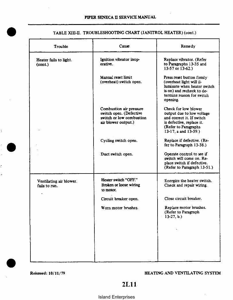
PIPER SENECA II SERVICE MANUAL
TABLE XIII-II. TROUBLESHOOTING CHART (JANITROL HEATER) (cont.)
Trouble Cause Remedy
Heater fails to light.(cont.)
Ignition vibrator inop-erative.
Replace vibrator. (Referto Paragraphs 13-35 and13-57 or 13-62.)
Manual reset limit(overheat) switch open.
Combustion air pressureswitch open. (Defectiveswitch or low combustionair blower output.)
Cycling switch open.
Duct switch open.
Press reset button firmly(overheat light will il-luminate when heater switchis on) and recheck to de-termine reason for switchopening.
Check for low bloweroutput due to low voltageand correct it. If switchis defective, replace it.(Refer to Paragraphs13-17, a and 13-39.)
Replace if defective. (Re-fer to Paragraph 13-38.)
Operate control to see ifswitch will come on. Re-place switch if defective.(Refer to Paragraph 13-51.)
Ventilating air blower.fails to run.
Heater switch "OFF."Broken or loose wiringto motor.
Energize the heater switch.Check and repair wiring.
Circuit breaker open.
Worn motor brushes.
Close circuit breaker.
Replace motor brushes.(Refer to Paragraph13-27, b.)
HEATING AND VENTILATING SYSTEMReissued: 10/11/79
2Lll
Island Enterprises

Motor burned out.
Defective radio-noisefilter.
PIPER SENECA II SERVICE MANUAL
TABLE XIII-II. TROUBLESHOOTING CHART (JANITROL HEATER) (cont.)
Trouble Cause Remedy
Ventilating air blowerfails to run. (cont.)
Blower wheel jammed. Remove and check theventilating air blowerwheel and realign ifnecessary. (Refer to Para-graphs 13-65 or 13-67, g.)
Remove blower assemblyand replace motor. (Re-fer to Paragraphs 13-53or 13-58, 1 and r thru u;13-65 or 13-67, b thru g.)
Replace filter.
Combustion air blowerfails to run.
Faulty wiring to motor. Inspect and replacefaulty wiring.
Poor ground connection.
Worn motor brushes.
Blower wheel jammed.(Usually indicated byhot motor housing.)
Defective radio-noisefilter.
Faulty or burned-outmotor.
Tighten ground screw.
Replace motor brushes.(Refer to Paragraph13-27, b.)
Overhaul the combustionair blower. (Refer toParagraphs 13-53 or13-58 and 13-65 or 13-67.)
Replace filter. (Referto Paragraphs 13-53 or13-58 and 13-65 or 13-67.)
Remove combustion airmotor for overhaul orreplacement of motor.(Refer to Paragraphs13-27, 13-54 or 13-59and 13-66 or 13-68.)
Reissued: 10/11/79 HEATING AND VENTILATING SYSTEM
2L12Island Enterprises

PIPER SENECA II SERVICE MANUAL
TABLE XIII-II. TROUBLESHOOTING CHART (JANITROL HEATER) (cont.)
Trouble Cause Remedy
Heater fires but burnsunsteadily.
Insufficient fuel supply. Inspect fuel supply toheater, including shutoffvalve, solenoid valve andfuel lines. Make nec-essary repairs.
Spark plug partiallyfouled.
Replace spark plug. (Re-fer to Paragraph 13-28.)See Caution.
CAUTION
Do not create a spark gap by holding the lead to the heater jacket.This can result in damage to the lead and ignition unit and theoperator may receive an electrical shock.
Loose primary connectionat ignition assembly.
Faulty vibrator.
Combustion air blowerspeed fluctuates. (Canbe caused by low voltage,loose blower wheel, wornbrushes or motor.
Tighten the connection.
Replace the vibrator. (Re-fer to Paragraph 13-35.)
Remove and overhaul thecombustion air blowerassembly as required orcorrect low voltage con-dition. (Refer to Para-graphs 13-27, 13-54 or13-59, 13-63 and 13-65or 13-68.)
Reissued: 10/11/79 HEATING AND VENTILATING SYSTEM
2L13
Island Enterprises

Inoperative ignitionassembly.
Restriction in fuel noz-zle orifice.
Nozzle loose in retaineror improper spray angle.
PIPER SENECA II SERVICE MANUAL
TABLE XIII-II. TROUBLESHOOTING CHART (JANITROL HEATER) (cont.)
Trouble Cause Remedy
Heater fires but burnsunsteadily. (cont.)
High voltage leak inlead between ignitionassembly and spark plug.
Replace ignition assembly.(Refer to Paragraphs13-30 or 13-31.)
If vibrator is in goodcondition, replace ig-nition assembly only.(Refer to Paragraphs13-30 or 13-31.)
Remove nozzle for clean-ing or replacement. (Re-fer to Paragraph 13-73.)
Tighten or replace thenozzle as required. (Re-fer to Paragraphs 13-56or 13-61, e; 13-65 or13-67, k.) 0
Heater starts then goesout.
Lack of fuel at heater. Check fuel supply throughall components from thetank to the heater. Makenecessary corrections.
Inoperative or chatteringcombustion air pressureswitch.
Inoperative overheatswitch.
Adjust or replace switch.(Refer to Paragraph13-39.)
Replace switch. (Refer toParagraphs 13-38 and13-72.)
Reissued: 10/11/79 HEATING AND VENTILATING SYSTEM
2L14Island Enterprises

PIPER SENECA II SERVICE MANUAL
TABLE XIII-II. TROUBLESHOOTING CHART (JANITROL HEATER) (cont.)
Trouble Cause Remedy
Heater starts then goesout. (cont.)
Inoperative cyclingswitch.
Adjust or replace theswitch. (Refer to Para-graphs 13-38 and 13-72.)
Low voltage. Attach external power.
Heater fails to shut off. Fuel solenoid valve inheater stuck open.
Remove and replace sole-noid assembly. (Refer toParagraphs 13-53 or 13-58,q; 13-57 or 13-62, k; and13-65 or 13-67, a.)
Inoperative duct andcycling switch.
Defective heater switch.
Check and repair. (Referto Paragraphs 13-38 and13-51.)
Replace the heater switch.
HEATING AND VENTILATING SYSTEMReissued: 10/11/79
2L15
Island Enterprises

0
2L16 THRU 2L24INTENTIONALLY LEFT BLANK
Island Enterprises

SENECA II
SERVICE MANUALCARD 3 OF 3
PA-34-200T SENECA II
PIPER AIRCRAFT CORPORATION
PART NUMBER 761 590)3A1
Island Enterprises

PIPER SENECA II SERVICE MANUAL
AEROFICHE EXPLANATION AND REVISION STATUS
Service manual information incorporated in this set of Aerofiche cards is arranged in accordance with thegeneral specifications of Aerofiche adopted by the General Aviation Manufacturer's Association. Informationcompiled in this Aerofiche service manual is kept current by revisionsdistributed periodically. These revisionssupersede all previous revisions, are complete Aerofiche card replacements, and supersede Aerofiche cards ofthe same number in the set.
Identification of revised material:Revised text and illustrations are indicated by a black vertical line along the left-hand margin of the
frame, opposite revised or added material. Revision lines indicate only current revisions with changes andadditions to existing text and illustrations. Changes in capitalization, spelling, punctuation, indexing,physical location of the material, or complete page additions are not identified by revision lines.
Revisions to Service Manual 761 590 issued October 11, 1979 are as follows:
Effectivity Publication Date Aerofiche Card Effectivity
ORG791011 October 11, 1979 1, 2 and 3PR800810 August 10, 1980 1, 2 and 3PR810316 March 16, 1981 1, 2 and 3PR821112 November 12, 1982 1, 2 and 3PR831208 December 8, 1983 1, 2 and 3IR860730 July 30, 1986 1IR860920 September 20, 1986 1IR870506* June 12, 1987 1
This publication contains material revised as of December 8, 1983(with three interim revisions effective July 30, 1986, September 20,1986, and May 6, 1987).
* INTERIM CHANGERevisions appear in Table III-I of card 1. There are no otherchanges in this service manual. Please discard your currentcard I and replace it with this revised one. DO NOTDISCARD CARDS 2 or 3.
The date on Aerofiche cards must not be earlier than the date noted for the respective card effectivity. Consultthe latest card in this series for current Aerofiche card effectivity.
3A2
Island Enterprises

TABLE OF CONTENTS
I
IIIIVVVIVIIVII
AEROFICHE CARD NO. 1 GRID NO.
INTRODUCTION ................................... 1A13HANDLING AND SERVICING ...................... 1A16INSPECTION ....................................... 1 C23STRUCTURES ...................................... 1D12SURFACE CONTROLS ............................. 1F21HYDRAULIC SYSTEM .............................. 113LANDING GEAR AND BRAKE SYSTEM ............ 1J5
AEROFICHE CARD NO. 2
VIIIIXXXIXIIXIII
POWERPLANT .....................................FUEL SYSTEM .....................................INSTRUMENTS ....................................ELECTRICAL SYSTEM .............................ELECTRONICS .....................................HEATING AND VENTILATING SYSTEM ............
AEROFICHE CARD NO. 3
2A92D42E82F1621202J6
XIV ACCESSORIES AND UTILITIES .................... 3A6
3A3
Island Enterprises

PIPER SENECA II SERVICE MANUAL
LIST OF ILLUSTRATIONS
Figure AeroficheGrid No.
14-1. Propeller Deicer Installation ......................... . ...................... 3A1214-2. Electrical Diagram Showing Cycle Sequence - Phase I ......... ................. 3A1314-3. Electrical Diagram Showing Cycle Sequence - Phase II ......................... 3A1314-4. Electrical Diagram Showing Cycle Sequence - Phase III . ..................... 3A1414-5. Electrical Diagram Showing Cycle Sequence - Phase IV ...... ................. 3A 1414-6. Typical Use of Dial Indicator ............... ........................ 3A1614-7. Centering of Brushes on Slip Rings ......................................... 3A1714-8. Wiring Schematic - Electric Propeller Deicing System .......................... 3A1914-9. Brush Block Assembly ....................... .............................. 3A2014-10. Brush Module Assembly .................................................... 3A2214-1Oa. Alternate Module Stacking Arrangement ............... ...... .............. 3A2214-lOb. Modular Brush Assembly 3E2042-1 (2 Bladed Prop) ............ .............. 3A2314-10c. Modular Brush Assembly 3E2062-2 (3 Bladed Prop) ........................... 3A2314-10d. Angle of Contact Brushes to Slip Rings ................... ................... 3A2414-11. Propeller Deicer Installation ................................................ 3BI14-12. Installation of Deicer Boot .................................................. 3B314-13. Wrinkled Deicers .......................................................... 3B614-14. Sealer Application (Boot).............................................. ........ 3B714-15. Pneumatic Deicer System Installation (S/N's to 34-8070144) .................... 3B1514-15a. Pneumatic Deicer Systems Installation (S/N 34-8070i44 and up).. ............... 3B1614-16. Pneumatic Deicer Boots Operation ............. ............... ......... 3B 1814-17. Pneumatic Deicer System Schematic ............................ .......... 3B 1814-18. Ice Detection Light Schematic .............................................. 3C914-19. Portable Oxygen Installation ............................................... 3C 1514-20. Fixed Oxygen System Installation (Optional) .................................. 3C 1614-20a. Oxygen Tubing Installations .... ............................................ 3C 1714-21. Oxygen System Filler Valve Installation ...................................... 3C1814-22. Oxygen Cylinder and Regulator Assembly .................................. 3C1814-23. Oxygen Pressure Gauge Installation ........................................ 3C2014-24. Air Conditioning System Installation ........ .......................... 3C2414-25. Test Gauge and Manifold Set .............. ...... .. ......................... 3D514-26. Manifold Set Operation ................................... ..... ........... . 3D614-27. Leak Test Hookup ............................................... ....... . 3D714-28. Evacuation Hookup .......... ........ ............................... 3D914-29. Charging Stand ....................... ......... ................... 3D1114-30. Charging Hookup ................................ ......................... 3D 1214-31. Top Dead Center Casting Mark (Sankyo Compressor) ....... ................ 3D I514-32. Rotation of Clutch Front Plate (Sankyo Compressor).. . ................... 3D 1514-33. Condenser Air Scoop Installation .................................. 3D 1914-34. Expansion Valve ................ ............. ......................... 3D2014-35. Components Installation .. .... ....................................... ...... 3D2214-36. Air Conditioning Wiring Schematic (Early Models) ................... ......... 3E I14-37. Synchrophaser Wiring Schematic Auto Synch/Manual Switch .... ... ....... 3E I I14-37a. Synchrophaser Wiring Schematic (Phase Adjustment Switch) ................... 3E 1214-38. Engine Synchrophaser Installation ........................................... 3E1314-39. Pulse Generator Installation ................................................ 3E 15
Revised: 3/16/813A4
Island Enterprises

PIPER SENECA II SERVICE MANUAL
LIST OF TABLES
Table AeroficheGrid No.
XIV-I.XIV-II.XIV-III.XIV-IV.XIV-V.XIV-VI.XIV-VII.XIV-VIII.XIV-IX.XIV-X.XIV-XI.XIV-XII.XIV-XIII.
Required Materials for Repair of Propeller Deicer. ..........................Mixing of Materials .....................................................Electrical Resistance.....................................................Troubleshooting Chart (Propeller Deicer System) ...........................Operating Pressures......................................................Materials and Supplies for Cold Repair ....................................Troubleshooting Chart (Pneumatic Deicer System) ..........................Oxygen System Components Limits .......................................Troubleshooting Chart (Oxygen System) ...................................Temperature Pressure Chart..............................................Aluminum Tubing Torque ...............................................Blower System Wire Color Codes .........................................Troubleshooting Chart (Air Conditioner) ...................................
3B33B53B73B93B213B243C73C133C213DI3D43D243E2
I Revised: 8/10/803A5
Island Enterprises

SECTION XIVACCESSORIES AND UTILITIES
Paragraph AeroficheGrid. No.
14-1. Introduction .............................................................. 3A1014-2. Troubleshooting.................................................. ..... 3A1014-3. Propeller Deicing System ................................................... 3A10
14-4. Description and Principles of Operation ............................. 3A1014-5. Deicer System Operational Check ................................... 3A I14-6. Troubleshooting .................................................. 3A1114-7. Using the Ammeter ............................................... 3A1114-8. Helpful Tips ..................................................... 3A11
14-9. Inspection ................................................................ 3A1514-10. 50 Hour Inspection ............................................... 3A1514-11. 100 Hour Inspection .............................................. 3A15
14-12. Repair Procedures for Individual Components ................................ 3A1714-13. Brush Retainer Replacement ....................................... 3A1714-14. Individual Brush Replacement ...................................... 3A1814-15. Alignment of New Brushes ......................................... 3A18
14-16. Slip Rings ................................................................ 3A1814-17. Alignment of Slip Ring Assembly ................. ............. . 3A1814-18. Replacement of Slip Ring Assembly ................................. 3A1814-18a. Replacement of Brush Block with Modular Brush Assemblies .......... 3A2114-18b. Brush Module Replacement ........................................ 3A21
14-19. Deicer Blades ............................................................. 3A2114-20. Resistance Check of Deicer Blade ................................... 3A2114-21. Replacement ..................................................... 3A2114-22. Removal of Deicer ................................................ 3B214-23. Blade Preparation ................................................ 3B214-24. Cement Application ............................................... 3B414-25. Installation of Deicer and Required Materials ........................ 3B414-26. Preparation and Application of Sealer ............................... 3B514-27. Wrinkled Deicers ................................................. 3B614-28. Electrical Check .................................................. 3B614-29. Installation of Deicer Wiring Harness ............................... 3B814-30. Balancing........................................................ 3B814-31. Final Electric Check .............................................. 3B814-32. Other Components......... ........................ .......... 3B814-33. Timer Test ....................................................... 3B8
14-34. Pneumatic Deicing System ........................................... 3B1714-35. Introduction ..................................................... 3B1714-36. Description and Principles of Operation ............................. 3B 17
14-37. Troubleshooting ........................................................... 3B 1714-38. Operational Check ................................................ 3B1714-39. Electrical Test .................................................... 3B1714-40. Pressure Leakage Test ............................................. 3B 1914-41. Pneumatic Regulator Adjustment ........................... ...... 3B 19
Revised: 8/10/803A6
Island Enterprises

Paragraph AeroficheGrid No.
14-42. Component Maintenance and Replacement . .................................. 3B2014-43. Filter Replacement .......................................... . 3B2014-44. Control Valves .................................................. 3B2014-45. Timer ........................................................... 3B2014-46. Inspections ....................................................... 3B2114-47. Ground Procedure ................................................ 3B2114-48. 100 Hour Inspection .............................................. 3B2114-49. Removal of Boots .... . ...................................... 3B2214-50. Repair of Boots ...................................... 3B2214-51. Cold Repair...................................................... 3B2314-52. Vulcanized Repairs................................................ 3C214-53. Installation ....................................... 3C214-54. Preparation of Leading Edges ...................................... 3C214-55. Preparation of Deicer ............................................. 3C214-56. Mounting Deicer on Leading Edge .................................. 3C214-57. Adhesion Test.................................................... 3C414-58. Maintenance..................................................... 3C414-59. Icex Application .................................. 3C514-60. Resurfacing Conductive Cement .................................... 3C5
14-61. Ice Detection Light . . ...................................................... 3C914-62. Introduction ..................................................... 3C914-63. Description and Operation .................... ..................... 3C914-64. Servicing ........................................................ 3C914-65. Removal......................................................... 3C914-66. Installation .............................................. .... ... 3C9
14-67. Heated Windshield Panel ... ................... ....... 3C1014-68. Description ...................................................... 3C 1014-69. Removal and Installation of Heated Panel ........................... 3C10
14-70. Oxygen System ........................................................... 3C I14-71. Description and Principle of Operation .............................. 3C II14-72. Troubleshooting.................................................. 3C1114-73. Safety Precautions................................................ 3C1114-74. Inspection and Overhaul Time Limits ............................... 3C I14-75. Testing for Leaks ................................................. 3C 1214-76. Maintenance ..................................................... 3C 1214-77. Cleaning Operations .............................................. 3C 1214-78. Purging the System ................................. ... 3C 1314-79. Removal of Portable Oxygen Unit .................................. 3C 1414-80. Charging ........................................................ 3C 1414-81. Removal of Outlets .. ....................... 3C1414-82. Installation of Outlets ............................................. 3C 1414-83. Cleaning of Masks (Portable System) ............................... 3C1514-84. Cleaning of Face Masks (Fixed System) ............................. 3C1514-85. Removal of Oxygen Cylinder and Regulator (Fixed System) ........... 3C1614-86. Installation of Oxygen Cylinder and Regulator (Fixed System) ......... 3C 1914-87. Removal of Filler Valve ............................... 3C 1914-88. Installation of Filler Valve ......................................... 3C 1914-88a. Oxygen Tubing Clearance .............. .. ...................... 3C1914-89. Removal of Pressure Gauge........................................ 3C2014-90. Installation of Pressure Gauge ..................................... 3C2014-91. Removal of Outlets ............................................... 3C2014-92. Installation of Outlets............................................. 3C2214-92a. Thread Sealant ..... ................... ......................... 3C22
Revised: 3/16/81 3A73A7
Island Enterprises

Paragraph AeroficheGrid No.
14-93. Air Conditioning Installation ...................... ....................... 3C2314-94. Description ...................................................... 3C2314-95. Air Conditioning System Operation ................................. 3C2314-96. Malfunction Detection ............................................ 3D214-97. Special Servicing Procedures ....................................... 3D314-98. Service Valves .............................................. 3D414-99. Test Gauge and Manifold Set ...................................... 3D514-100. Checking the System for Leaks ..................................... 3D714-101. Leak Check - Method I .................... .............. 3D714-102. Leak Check - Method II .......................................... 3D814-103. Discharging ...................................................... 3D814-104. Evacuating the System ............................................ 3D814-105. Charging the System .............................................. 3D1014-106. With a Charging Stand ........................................... 3D1014-107. Using the Airplane Compressor to Charge the System ................. 3D1114-108. Addition of Partial Charge to System ............................... 3D 1314-109. Compressor Service ............................................... 3D 1314-110. Compressor Removal ............................................. 3D 1414-111. Compressor Installation ........................................... 3D1414-112. Check Compressor Oil ............................................ 3D 1414-113. Adjustment of Drive Belt Tension .................................. 3D1614-114. Refrigerant Lines and Routing .................................... 3D 1614-115. Receiver - Dehydrator ............................................ 3D1614-116. Receiver - Dehydrator Removal .................................... 3D1614-117. Receiver - Dehydrator Installation .................................. 3D1714-118. Condenser ....................................................... 3D1714-119. Cendenser Removal .............................................. 3D1714-120. Condenser Installation ............................................ 3D1714-121. Condenser Scoop Rigging Instructions .............................. 3D 1814-122. Expansion Valve ................................................. 3D2014-123. Expansion Valve Removal ......................................... 3D2014-124. Expansion Valve Installation ....................................... 3D2014-125. Evaporator Assembly ............................................. 3D2114-126. Evaporator Assembly Removal ..................................... 3D2114-127. Evaporator Assembly Installation .................................. 3D2114-128. Pressure Relief Switch (Texas Instruments) .......................... 3D2214-129. Electrical Installation ............................................. 3D2214-130. Fuse Replacement ................................... ..... 3D2214-131. Overhead Vent Blower ............................................ 3D2314-132. Description ...................................................... 3D2314-133. Removal of Blower Assembly ...................................... 3D2314-134. Disassembly of Blower Assembly ................... ................ 3D2314-135. Reassembly of Blower Assembly .................................... 3D2314-136. Installation of Blower Assembly .................................... 3D2314-137. Shoulder Harness Inertia Reel Adjustment ........................... 3D24
Revised: 8/10/803A8
Island Enterprises

Paragraph
14-138. Engine Synchrophaser .....................................................14-139. Description of Synchrophaser System ...............................14-140. System Operating Procedure .......................................14-140a. Inductor and Kit Installations .....................................14-141. Synchrophaser System Check and Adjustment ........................14-142. Ground Checks ..................................................14-143. Flight Check.....................................................14-144. Removal of Computer Assembly ...................................14-145. Installation of Computer Assembly .................................14-146. Removal of Pulse Generator .......................................14-147. Installation of Pulse Generator .....................................
Revised: 8/10/80
3A9
AeroficheGrid No.
3E93E93E93E103EIO3E103E143E 143E143E153E15
Island Enterprises

SECTION XIV
ACCESSORIES AND UTILITIES
14-1. INTRODUCTION. This section covers accessories which are available for this airplane and notcovered in other sections of this Service Manual. This information provides instructions for remedyingdifficulties which may arise in any of the accessories, and the instructions are organized so the mechanicmay refer to whichever component or system he must service.
14-2. TROUBLESHOOTING. A troubleshooting chart is located at the end of each accessory covered inthis section. The various troubles and suggested remedies found in the tables are provided to assist inlocating and correcting malfunctions in the particular system.
14-3. PROPELLER DEICING SYSTEM.
14-4. DESCRIPTION AND PRINCIPLES OF OPERATION. (Refer to Figure 14-1.) The Propeller DeicingSystem consists of an electrically heated deicer (1) bonded to each propeller blade, a slip ring assembly (2)with a brush block assembly (3) to transfer electrical power to the rotating deicers, a timer (4), an ammeter(5), a control switch circuit breaker (7), shunt (6), together with wiring harnesses (8) to complete thecircuit. Power is drawn from the aircraft electrical system (10).
Dual element deicers are utilized on the two blade propeller installation. Each deicer has two separateheaters; one for the outer half and one for the inner half. By heating all outer or inner heaters on only onepropeller at a time, rotational balance is held during deicing. Current is drawn from the airplane electricalsystem through the switch, ammeter and timer. The timer successively delivers current via the slip ring andbrush block arrangement to (phase 1) the outer heaters on the right propeller, (phase 2) the inner heaters onthe same propeller, (phase 3) the outer heaters of the left propeller and (phase 4) the inner heaters on the leftpropeller. The timer energizes each of these four phases in turn for about 34 seconds and then repeats thecycle as long as the control switch is on. The cycling sequence given is vital so that outboard heaters on eachpropeller operate before the inboard heaters. See cycle sequence. (Refer to Figures 14-2 thru 14-5.) Thesystem may be used continuously in flight if needed. To conserve electrical power, current is cycled to thedeicer heaters at timed intervals rather than continuously.
NOTE
Heating may begin at any phase in the cycle depending on the timerposition when the switch was turned off from previous use.
The optional McCauley three bladed propeller installation utilizes single element deicers. When theswitch is turned on power is directed through the brush block and slip ring to all the heating elements onone propeller for approximately 34 seconds. The timer then directs the power to the other propeller forapproximately 34 seconds. This cycle continues until the switch is turned off.
a. Deicers: The deicers contain special heater wires protected by fabric plies and by oil and abrasion-resistant rubber. The side of the deicer cemented to the propeller has a dull finish whereas the air side finish is"glossy."
Dual element deicers have a separate lead for the inboard and outboard heater and a third lead which is acommon ground. These leads are so marked. An unmarked ground can be identified by using an ohmmeteracross the three possible pairs of leads. One pair will show twice the resistance of the other pairs. The latter arethe "hot" leads and the lead excluded from the pair that shows twice the resistance of the other pairs is theground lead.
Single element deicers have only two leads; one input and one ground.
Reissued: 10/11/79 ACCESSORIES AND UTILITIES
3 A10
PIPER SENECA II SERVICE MANUAL
Island Enterprises

PIPER SENECA II SERVICE MANUAL
b. Slip Rings, Brushes and Brush Blocks: To transfer electrical power to the rotating deicers, abrush block assembly is mounted to the engine by means of a bracket and has brushes which arespring-loaded to press against the revolving slip rings.
c. Timer: The timer is a sealed unit. If found inoperative, it must be replaced as an assembly - nofield repairs are authorized.
d. Ammeter: The ammeter is designed for each particular system and it is therefore important thatthe correct replacement part number be used if replacement should be required. In the event of low aircraftbattery voltage (very possible in ground checks), the ammeter readings will be lower than at full voltage.Provided the ammeter needle reads in the shaded range on the scale (full aircraft voltage), current flow isconsidered as normal.
e. Switch: The switch-circuit breaker is mounted in the switch and circuit breaker control panel.
14-5. DEICER SYSTEM OPERATIONAL CHECK.a. Chock the wheels and,operate the engine at near takeoff power.b. Turn deicer system switch ON and observe deicer ammeter for at least two minutes.c. The ammeter needle must "flicker" approximately every 34 seconds as the step switch of the
timer operates.d. With engines stopped, turn deicer switch ON and feel deicers on propellers for proper sequence of
heater operation.e. The starting point is not important but the sequence is vital and must be: Right Outboard, Right
Inboard, Left Outboard, Left Inboard Heaters, in that order.f. Temperature rise should be noticeable and each heater should warm for about 34 seconds.g. Local hot spots indicate surface damage of deicer heaters and should be repaired.
14-6. TROUBLESHOOTING. Troubles peculiar to the deicing system are listed in Table XIV-IV at the endof these instructions, along with their probable causes and suggested remedies.
14-7. USING THE AMMETER. Whether in flight or during ground testing, the ammeter can be used toindicate the general nature of most electrical problems. The troubleshooting chart is primarily based on thisuse of the ammeter and assumes that the user does understand all normal operating modes of the system asgiven in Paragraph 14-4.
NOTE
When troubleshooting, first use the "ammeter test" and "heattest" to determine which circuits are involved. Use circuit diagram,Figure 14-8, for assistance to check voltages or continuity.
14-8. HELPFUL TIPS.a. If the ammeter reading drops to one-third normal current, this indicates that one heater circuit is
open or, on the dual element deicer, possibly improper connections are allowing both inboard and outboardunits to heat at the same time.
b. Excess current reading on the ammeter always indicates a power lead is shorted to ground. Thus,when trouble of this nature is found, it is vital that the grounded power lead be located and corrected.
c. A considerable number of timers that have been returned for repair proved to be fully workablewhen tested. Accomplish the test described in Paragraph 14-33 before concluding that the timer is defective.
Reissued: 10/11/79 ACCESSORIES AND UTILITIES
3All
Island Enterprises

23
PIPER SENECA II SERVICE MANUAL
2029
RREWALLCONNECTOR
1. DE.ICER2. SLIP RING3. BRUSH BLOCK4. TIMERS. AMMETER6. SHUNT7. SWITCH8. WIRING9. CIRCUIT BREAKER
10. AIRCRAFT POWERSOURCE
Figure 14-1. Propeller Deicing Installation
Reissued: 10/11/79 ACCESSORIES AND UTILITIES
3A12Island Enterprises

ELECTRICAL DI AGAMSHOWING CYCLE SEQUENCE
PIPER SENECA II SERVICE MANUAL
ELECTRICAL DIAGRAMSNOWING CYCLE SEQUENCE
Figure 14-2. Electrical Diagram Showing Cycle Sequence - Phase I
Figure 14-3. Electrical Diagram Showing Cycle Sequence - Phase II
Reissued: 10/11/79 ACCESSORIES AND UTILITIES
3A13
Island Enterprises

r
ELECTRICAL DIAGRAMSOWING CYCLE SEQUENCE
r -- --
ELECTRICAL DIAGRAMSNOWING CYCLE SEQUENCE
PIPER SENECA SERVICE MANUAL
DE-ICER
I
PIN 'A' FOR 14 VOLT SYSTEM I
RUSH bLOCK
/ SLIP RINGS
TO POWER SOUCE
PHASE 3
Figure 14-4. Electrical Diagram Showing Cycle Sequence - Phase III
I
PIN 'A FOR 14 VOLT SYSTEM
BRUSH BLOCK
SLIP RINGS
TO POWER SOURCE
PHASE 4
Figure 14-5. Electrical Diagram Showing Cycle Sequence - Phase IV
Reissued: 10/11/79 ACCESSORIES AND UTILITIES
3A14Island Enterprises

PIPER SENECA II SERVICE MANUAL
14-9. INSPECTION.
14-10. 50 HOUR INSPECTION.a. Lock brakes and operate engines at near takeoff power. Turn deicer system switch ON and
observe deicer ammeter for at least two minutes. Ammeter needle must rest within the shaded band exceptfor a "flicker," approximately every 34 seconds, as the step switch of the timer operates. If not, refer to theappropriate entry of the troubleshooting chart.
b. With engines stopped, turn deicer switch ON and feel deicers on propellers for proper sequence ofheater operation. The starting point is not important but sequence is vital and must be: Right Outboard,Right Inboard, Left Outboard and Left Inboard Heaters, in that order. Temperature rise should benoticeable and each heater should warm for about 34 seconds. Local hot spots indicate surface damage ofdeicer heaters; inspect and repair in accordance with Paragraphs 14-21 to 14-24.
c. Remove spinner dome and engine cowling. With assistant observing deicer ammeter and withdeicer switch ON, flex all accessible wiring, particularly the deicer lead straps, leads from slip ring assembly,and the fire wall electrical connectors and their wiring. Any movement of the ammeter needle other thanthe "34 second flicker" of cycling indicates a short or open that must be located and corrected.
14-11. 100 HOUR INSPECTION.a. Remove cowling in accordance with Removal of Engine Cowling, Section VIII.b. Conduct 50 hour inspection.c. Check for radio noise or radio compass interference by operating the engine at near takeoff
power and with radio gear ON while turning deicer switch ON and OFF. If noise or interference occurs withdeicer switch ON and disappears when switch is OFF, see troubleshooting chart.
d. Ascertain that all clamps, clips, mountings and electrical connections are tight. Check for loose,broken or missing safety wire.
e. Deicers: Closely check deicers for wrinkled, loose or torn areas, particularly around the outboardend and where the strap passes under the strap retainer. Look for abrasion or cuts, especially along theleading edge and the flat or thrust face. If heater wires are exposed in damaged areas or if rubber is found tobe tacky, swollen or deteriorated (as from oil or solvent contact), replace the damaged deicer in accordancewith Paragraphs 14-24 to 14-29.
NOTE
Check the strap restrainers are correctly located and secure. Lookfor cracks or other damage. Operate propeller from "full pitch" to"feathering" and check that deicer lead straps do not come undertension or are pinched by propeller blade. (Refer to Figure 14-11.)
Reissued: 10/11/79 ACCESSORIES AND UTILITIES
3A15
Island Enterprises
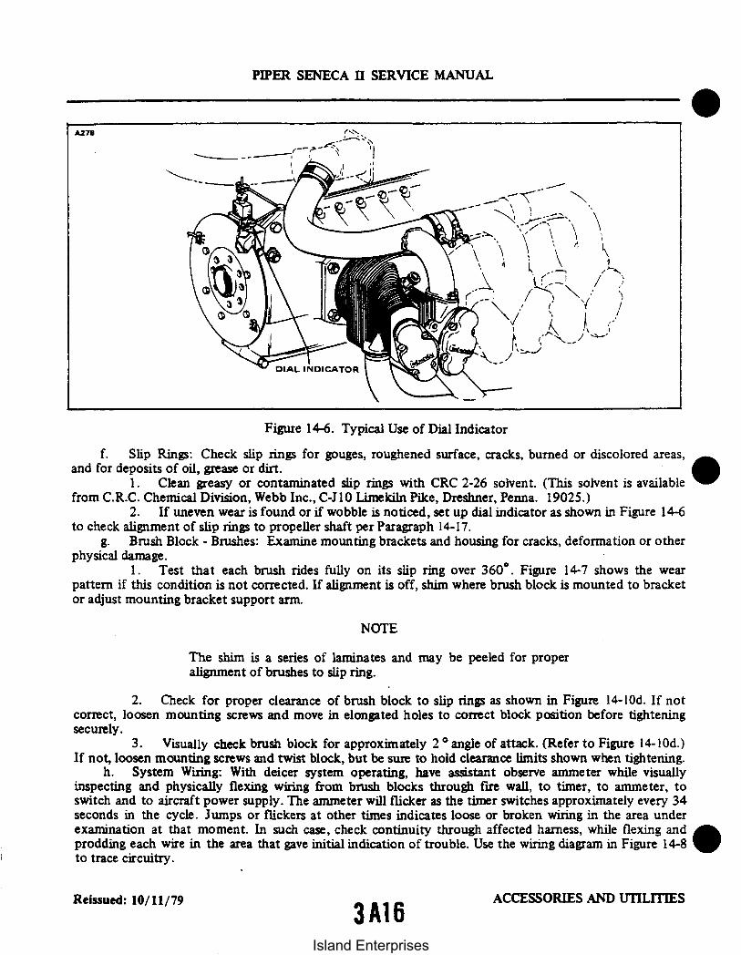
A278
DIAL INDICATOR
Figure 14-6. Typical Use of Dial Indicator
f. Slip Rings: Check slip rings for gouges, roughened surface, cracks, burned or discolored areas,and for deposits of oil, grease or dirt.
1. Clean greasy or contaminated slip rings with CRC 2-26 solvent. (This solvent is availablefrom C.R.C. Chemical Division, Webb Inc., C-J10 Limekiln Pike, Dreshner, Penna. 19025.)
2. If uneven wear is found or if wobble is noticed, set up dial indicator as shown in Figure 14-6to check alignment of slip rings to propeller shaft per Paragraph 14-17.
g. Brush Block - Brushes: Examine mounting brackets and housing for cracks, deformation or otherphysical damage.
1. Test that each brush rides fully on its slip ring over 360. Figure 14-7 shows the wearpattern if this condition is not corrected. If alignment is off, shim where brush block is mounted to bracketor adjust mounting bracket support arm.
NOTE
The shim is a series of laminates and may be peeled for properalignment of brushes to slip ring.
2. Check for proper clearance of brush block to slip rings as shown in Figure 14-10d. If notcorrect, loosen mounting screws and move in elongated holes to correct block position before tighteningsecurely.
3. Visually check brush block for approximately 2 angle of attack. (Refer to Figure 14-10d.)If not, loosen mounting screws and twist block, but be sure to hold clearance limits shown when tightening.
h. System Wiring: With deicer system operating, have assistant observe ammeter while visuallyinspecting and physically flexing wiring from brush blocks through fire wall, to timer, to ammeter, toswitch and to aircraft power supply. The ammeter will flicker as the timer switches approximately every 34seconds in the cycle. Jumps or flickers at other times indicates loose or broken wiring in the area underexamination at that moment. In such case, check continuity through affected harness, while flexing andprodding each wire in the area that gave initial indication of trouble. Use the wiring diagram in Figure 14-8to trace circuitry.
Reissued: 10/11/79 ACCESSORIES AND UTILITIES3A16
PIPER SENECA II SERVICE MANUAL
Island Enterprises

SLIP RING
PIPER SENECA II SERVICE MANUAL
BRUSH LOCATEDINCORRECTLY ONSLIP RING
NOTCH WORN IN BRUSHDUE TO MISALIGNMENT
Figure 14-7. Centering of Brushes on Slip Rings14-12. REPAIR PROCEDURES FOR INDIVIDUAL COMPONENTS.
14-13. BRUSH RETAINER REPLACEMENT. Brushes should be replaced when .375 inch of brushmaterial remains; brushes must be replaced when .250 inch remains. Measure the brushes as shown in Figure14-9. Replace the brush retainer as follows:
a. Remove the brush block assembly from the mounting bracket by removing attachment hardware.b. Remove screws and separate brush retainer assembly from guide block. Note orientation of
terminals.
NOTE
When separating brush retainer block, guide block and brushretainer assembly; move guide block laterally to disengage dowelpin grooves.
c. Discard old brush retainer assembly.d. Determine correct orientation of brushes to receptacle (refer to Figure 14-9) and carefully insert
brushes into brush guide block slots. When reassembling brush retainer assembly, align receptacle as shownin Figure 14-9.
CAUTION
Avoid side loads on brushes; brushes are extremely fragile.
e. Reinstall brush retainer attachment screws.f. Install brush block on mounting bracket with attachment hardware. Safety all bolts and check
alignment of brushes to slip ring.
Reissued: 10/11/79 3A17 ACCESSORIES AND UTILITIES
Island Enterprises

14-14. INDIVIDUAL BRUSH REPLACEMENT.a. Remove brush retainer assembly per Paragraph 14-13.b. Mark receptacle flange and brush retainer block to permit reinstallation in the same position.c. Unsolder brush leads from receptacle pins and discard old brushes and springs.d. Install insulating tubing over brush leads and solder brush leads to receptacle pins; follow pin
identification as shown on Figure 14-9.e. Assemble brushes and springs to brush guide block.f. Align marks and reinstall brush retainer as described in Paragraph 14-13.g. Check freedom of movement of each brush by pressing it into the brush guide block and allowing
the spring to force it back out slowly.
CAUTION
Do not allow brush to snap back.
h. Check resistance from each brush face to the respective receptacle pin with low range ohmmeter.Resistance must not exceed 0.013 ohms. Probe contacting brush should have an area of .062 square inch toprovide an accurate measurement.
i. Check insulation resistance between brushes and from brushes to receptacle housing with 500VDC, 1000 megohm range "Megger" ("Meg" Type Insulation Tester, James G. Biddle Company, PlymouthMeeting, Penna., or equivalent). Resistance should not be less than 10 megohms for one minute.
j. Install assembly on aircraft and check alignment Safety all bolts.
14-15. ALIGNMENT OF NEW BRUSHES. Any time the brush block assembly is dismounted, thealignment at reinstallation must be checked as described in Paragraph 14-11 and Figure 14-7.
14-16. SLIP RINGS.
14-17. ALIGNMENT OF SLIP RING ASSEMBLY. Excessive slip ring run-out will result in severe arcingbetween the slip ring and brushes and cause rapid brush wear. If the run-out is not corrected, rapiddeterioration of the slip ring and brush contact surfaces will result and lead to eventual failure of theDeicing System. Check the slip ring run-out with a dial indicator securely attached to the engine with thepointer resting on the slip ring. (Refer to Figure 14-6.) Rotate the propeller slowly noting the run-outindicated on the gauge. The total run-out must not exceed 0.005 inch ±0.0025 inch and 0.002 inch in any4 inch interval of slip ring travel.
NOTE
Some error may be induced in the readings by pushing in orpulling out on the propeller. Care must be taken to exert auniform push or pull.
Small amounts of run-out may be corrected by varying the torque on the slip ring mounting bolts(AN4-7A) between 40 to 100 inch-pounds to obtain the required flatness.
14-18. REPLACEMENT OF SLIP RING ASSEMBLIES. Slip ring assemblies that are open or shortedelectrically, cracked or damaged structurally, or which have damaged surfaces beyond the scope of minorrepair to clean up, should be replaced.
Reissued: 10/11/79 8 ACCESSORIES AND UTILITIES
3A18
PIPER SENECA II SERVICE MANUAL
Island Enterprises

METER 5 AMP
2009
SHUNT
PIPER SENECA II SERVICE MANUAL
PROPELLERS25 AMP
5 AMP
PROPTIMER
C
LEFTPROPELLER
C C
(RIGHT
PROPELLER
2979
TWO BLADE PROPELLER
IMETER SAMP
SHUNT
PROPELLERS35AMP
PROPTIMER
I
F
A
LEFTPROPELLER
RIGHTPROPELLER
SERIAL NUMBER 34-7900001 AND UP WITHOPTIONAL THREE BLADE PROPELLER
Figure 14-8. Wiring Schematic - Electrical Prop Deicing System
Revised: 8/10/80 ACCESSORIES AND UTILITIES
3A19
Island Enterprises

2030
NOTETHE X DIMENSION IN THE SHOULDREPLACE COLUMN INDICATES 3/8INCH OF BRUSH REMAINS: THE XDIMENSION FOR THE MUSTREPLACE COLUMN INDICATES 1/4INCH REMAINS. DURINGMEASUREMENT ON 1/16 INCH OFBRUSH SHOULD BE ALLOWED TOPROTRUDE FROM BRUSH BLOCK.THIS IS THE NORMAL POSITION OFTHE BRUSH WHEN INSTALLED ONTHE AIRCRAFT.
PIPER SENECA II SERVICE MANUAL
1. BRUSH GUIDE BLOCK2. BRUSHES3. RECEPTACLE4. SPRING5. BRUSH RETAINER BLOCK6. TUBING
BRUSH BLOCK ASSEMBLY
4E-1387-5
3E-2042-1BRUSHES WITH RODSBRUSHES WITHOUT RODS
X DIMENSION (INCHES)SHOULD MUSTREPLACE REPLACE
1 1/2 1 5/8
1S/64 19/64I 5/64 I 9/64
Figure 14-9. Brush Block Assembly
ACCESSORIES AND UTILITIESReissued: 10/11/79 3A20
Island Enterprises
PIPER SENECA II SERVICE MANUAL
14-18a. REPLACEMENT OF BRUSH BLOCK WITH MODULAR BRUSH ASSEMBLIES. Modular brushblock assembly part number 3E2042-1, is a direct replacement for brush block assemblies part numbers4E1837-3 and 4E1837-5. Instructions concerning replacement of brush block assemblies with modularbrush assemblies are given in B.F. Goodrich Service Bulletin E-77-54.
14-18b. BRUSH MODULE REPLACEMENT. Brush modules should be replaced when .375 inch of brushmaterial remains; brush modules must be replaced when .250 inch remains. Measure the brushes as shown inFigure 14-9. Replace brush modules as follows:
NOTE
Brushes are not offered individually as replacements; When a brushwears out, the module containing it should be replaced.
a. Remove the modular brush assembly from the aircraft, by removing the attachment hardware,and disconnect the engine wire harness.
b. Remove assembly screws and separate modules and spacers.
NOTE
The part number of each module is etched into the surface of theplastic housing; replace with the same part number module.
c. Restack modules and spacers as shown in Figure 14-10b. If there is interference between adjacentring terminals, reorient center module as shown in Figure 14-10a.
NOTE
Ascertain flat washer is positioned between star washer andhousing.
d. Reconnect aircraft wire harness and insure adjacent ring terminals are not touching.e. Install assembly on aircraft and check adjustment.
14-19. DEICER BLADES.
14-20. RESISTANCE CHECK OF DEICER BLADE. To determine incorrect resistance, short or open atthe brush-to-slip ring contact, disconnect harness at the timer and use low range ohmmeter to readresistance from each deicer circuit lead (Pins C,D, E and F of harness plug) to ground; it should read .47 to.58. If this reading is not obtained, disconnect the deicer lead harness to measure heater resistancesindividually. Individual heater should be 0.95 to 1.15. If first check is off limits but second check issatisfactory, trouble is probably in the brush-to-slip ring area; if the second check is off limits, the deicer isdamaged and must be replaced.
14-21. REPLACEMENT. If tests show the blade deicer to have an open circuit, to be the wrong resistanceor to be visibly damaged beyond repair as outlined in Paragraph 14-1 of this section, replace the deicer asdirected in Paragraphs 14-24 thru 14-30.
Reissued: 10/11/79 3A21 ACCESSORIES AND UTILITIES
Island Enterprises

PIPER SENECA II SERVICE MANUAL
A485
Figure 14-10. Brush Module Assembly 3E2011. Figure 14-10a. Alternate ModuleStacking Arrangement.
INTENTIONALLY LEFT BLANK
Reissued: 10/11/79 3 A223A22
ACCESSORIES AND UTILITIES
Island Enterprises

1
PIPER SENECA II SERVICE MANUAL
1.
2.3.4.5.6.7.8.9.
Brush Module Assembly 3E2011-1Brush Module Assembly 3E2011-2Brush Module Assembly 3E2011-3SpacerSpacerScrewWasherLockwasherNut
Figure 14-10b. Modular Brush Assembly 3E2042-1 (2 Bladed Prop)I
42
7
1. Brush Module Assembly 3E2011-22. Brush Module Assembly 3E2011-33. Spacer 4E2218-34. Spacer 4E2218-45. Screw MS 24693-S326. Washer AN960C67. Lockwasher MS 35333-378. Nut MS 35649-262
Figure 14-1Oc. Modular Brush Assembly 3E2062-2 (3 Bladed Prop)
Revised: 3/16/81 ACCESSORIES AND UTILITIES
3A23
Island Enterprises

BRUSH BLOCK ASSY.
2
PIPER SENECA II SERVICE MANUAL
1/32 TO 3/32
PORTION OF STARTER RING GEARSLIP RING ASSEMBLY
Figure 14-lOd. Angle of Contact Brushes to Slip Rings
0Reissued: 10/11/79 ACCESSORIES AND UTILITIES
3A24Island Enterprises

2031
2
PIPER SENECA II SERVICE MANUAL
1. PROPELLER DEICER BOOT2. ENGINE FLANGE3 SLIP RING MOUNTING BOLT4. SLIP RING5. SPACER WASHER6. MOUNTING PLATE7. BRUSH BLOCK. BRUSH BLOCK ADJUSTMENT
9. STRAP BUCKLE10. MOUNTING STRAP11 WIRE COVER TUBING12 WINDOW SPLICE TERMINALS13 TIE STRAP14 HARNESS15 SHUNT16. MODULAR BRUSH ASSEMBLY
HARTZELL 2 BLADE PROPELLERINSTALLATION
6
McCAULEY 3 BLADE PROPELLERINSTALLATION (OPTIONAL)
Figure 14-11. Propeller Deicer Installation
Reissued: 10/11/79 ACCESSORIES AND UTILITIES
3B1
Island Enterprises
PIPER SENECA II SERVICE MANUAL
14-22. REMOVAL OF DEICER.a. Disconnect terminals of propeller deicer from studs on the spinner bulkhead.b. Use MEK or Toluol to soften the adhesion line between the deicer and the propeller blade.
CAUTION
Do not allow solvents to leak into propeller hubs and causedamage to seals.
c. Starting at one corner of the deicer, loosen enough of the deicer to grasp in the jaws of vise grippliers or similar tool.
d. Apply a steady pull on the deicer to pull it off the propeller surface. Continue using MEK orToluol to soften the adhesion lines. Unless the deicer being removed is damaged and is to be scrapped,cushion the jaws of any pulling tool used to prevent damage to the deicer surface. Remove very slowly andcarefully. If deicer has failed and is to be returned under request for warranty, extreme care should beexercised so that no additional damage is incurred to the deicer during and after removal.
e. Remove residual cement from blade. Use Turco No. 3 or equivalent to help with dried cements.
14-23. BLADE PREPARATION.a. Mark and cut from masking tape a pattern the size of the propeller deicer. (Refer to Figure
14-12.)b. Place a mark at the hub end of the blade in line with the blade leading edge. The location for this
mark can be determined by sighting along the leading edge. Starting at the hub (see Note below), center thepattern on this mark and stick the pattern to the leading edge. Mark the position of the deicer harness.
NOTE
All deicers on a single propeller must be located the same distancefrom the hub for rotational balance.
c. Remove the pattern and remove any paint in the marked off area. Clean down to bare metal.Next, clean the area thoroughly with MEK or acetone. For final cleaning, wipe the solvent off quickly witha clean, dry lint-free cloth to avoid leaving a film.
CAUTION
Cleanliness of metal and rubber parts cannot be too highlystressed. Only perfectly clean surfaces will assure maximumadhesion.
d. Using a pencil or pen, mark a centerline at the hub of the propeller blade and on the tape at theoutboard edge of the masked area.
Reissued: 10/11/79 ACCESSORIES AND UTILITIES
3B2Island Enterprises
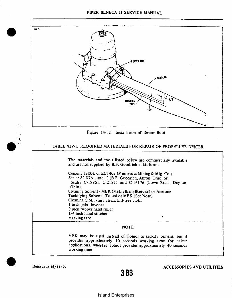
*' -J
TAPE /
1/2
Figure 14-12. Installation of Deicer Boot
TABLE XIV-I. REQUIRED MATERIALS FOR REPAIR OF PROPELLER DEICER
The materials and tools listed below are commercially availableand are not supplied by B.F. Goodrich in kit form:
Cement 1300L or EC 1403 (Minnesota Mining & Mfg. Co.)Sealer 82-076-1 and -2 (B.F. Goodrich, Akron, Ohio. or
Sealer C-19861. C-21871 and C-16176 (Lowe Bros., Dayton,Ohio)
Cleaning Solvent - MEK (MethylEthylKetone) or AcetoneTackifying Solvent - Toluol or MEK (See Note)Cleaning Cloth - any clean, lint-free clothI inch paint brushes2 inch rubber hand roller1./4 inch hand stitcherMasking tape
NOTE
MEK may be used instead of Toluol to tackify cement, but itprovides approximately 10 seconds working time for deicerapplications, whereas Toluol provides approximately 40 secondsworking time.
Reissued: 10/11/79 ACCESSORIES AND UTILITIES
3B3
PIPER SENECA II SERVICE MANUAL
Island Enterprises

PIPER SENECA II SERVICE MANUAL
14-24. CEMENT APPLICATION.a. Using a silver pencil, mark a centerline on the glossy side of the deicer.b. Moisten a clean cloth with MEK or acetone and clean the unglazed surface of the deicer, changing
cloth frequently to avoid contamination of the clean area.c. Thoroughly mix the 1300L cement. Apply one even brush coat of cement to the unglazed back
surface of the deicer. Cement one inch of the deicer lead strap. Allow to air dry for a minimum of one hourat 40' F or above, when the relative humidity is less than 75%. If the humidity is 75% to 90, allow twohours drying time. Do not apply cement if the relative humidity is higher than 90%. After allowing theproper amount of drying time, apply a second even brush coat of 1300L cement.
NOTE
If curling of the deicer edges is a problem, apply masking tape tothe edges of the glazed side before applying cement to theunglazed side. Remove the tape before starting to install thedeicer.
d. Apply an even brush coat of #1300L cement on the cleaned surface of the propeller blade,immediately after the second coat of cement has been applied to the deicer. This timing is important forthe cement on both surfaces to reach the tack stage at the same time.
14-25. INSTALLATION OF DEICER AND REQUIRED MATERIALS. It is imperative that the followinginstructions be followed exactly to insure maximum adhesion to the propeller blades:
a. When the cement coats are tacky (slightly sticky to the touch-like masking tape), dry on both thepropeller surface and deicer surface, position deicer on blade leading edge. Start at hub end, usincenterlines as a guide. (Refer to Figure 14-12.)
b. Make sure that the harness will fall in the previously marked position.c. Working outward toward the tip, tack the deicer centerline to the leading edge of the propeller
blade.d. Use the tackifying solvent as necessary. If deicer is allowed to get off course, pull up with a quick
motion and re-apply deicer.e. If cement is removed from either surface, completely remove the deicer and re-apply cement per
Paragraph 14-24.f. When the deicer is correctly positioned, roll firmly along the centerline with a rubber roller.
(Refer to Figure 14-13.)g. Gradually tilt the rubber roller and carefully work the deicer over either side of the blade contour
to avoid trapping air. Roll outwardly from centerline to edges. Be especially careful to work out excessmaterial at outboard edge of deicer before other edges are completely rolled down. If excess material atedges tends to pucker, work out puckers smoothly and carefully with fingers.
h. Roll the tapered edges, especially inboard edge of the deicer with the metal stitcher.
CAUTION
To avoid damage to deicer resistance wires, do not use metalstitcher on body of deicer. Area where metal stitcher is permittednot to exceed 3/16" along deicer edge.
Reissued: 10/11/79 ACCESSORIES AND UTILITIES3B4
Island Enterprises

PIPER SENECA II SERVICE MANUAL
14-26. PREPARATION AND APPLICATION OF SEALER. Deicers loosened due to destruction ofadhesive bond by lubricants do not respond well to recementing. Therefore, removal, cleaning, andreinstallation of the deicers are recommended. (Refer to Paragraphs 14-22 and 14-25.)
a. Clean an area .500 of an inch wide around the circumference of the deicer down to the baremetal. Use MEK or Acetone and clean thoroughly.
b. Clean outer .500 of an inch of all deicer edges and back under deicer about .250 of an inch on allsides past loosened areas with MEK or Acetone. For final cleaning, quickly wipe off solvent with a clean,dry lint-free cloth to avoid leaving a film.
c. Recement loosened areas of deicers in accordance with Paragraph 14-24.d. Mix the filler, sealer, or paint thoroughly and in the proper proportions by weight, as given in
Table XIV-II.e. Locate masking tape approximately .125 of an inch beyond the cemented area around the deicer
to permit filler material to contact bare metal.f. Apply one even coat of filler to area around the inboard end and sides of the deicer. (Refer to
Figure 14-14.) Immediately remove the masking tape and allow the filler to dry for six hours.g. Apply masking tape about .125 of an inch beyond filler or .250 of an inch beyond cemented area
when no filler is used, to permit sealer to contact bare metal. Apply one even brush coat of sealer to thearea around the deicer. (Refer to Figure 14-14.) Remove masking tape immediately and allow sealer to dry.Allow 12 hours cement curing time before starting engine, allow 24 hours cement curing time beforeoperating the deicers.
TABLE XIV-II. MIXING OF MATERIALS
Material
Filler
Sealer
Manufacturer & No.
3M EC1031 and EC801
BFG 82-076-1 & -2or
Lowe Brothers V66V27, F63B8,& R7K69
Mixing Proportions
Twelve parts EC 1031 with one hundred partsEC801.
Twelve parts -1 with one part -2.
One part V66V27 with seven parts F63B8(and up to two and two-thirds partsR7K69 thinner as needed).
Reissued: 10/11/79 ACCESSORIES AND UTILITIES
3B5
Island Enterprises

PIPER SENECA II SERVICE MANUAL
Figure 14-13. Wrinkled Deicers
14-27. WRINKLED DEICERS. (Refer to Figure 14-13.) If edge of deicer is found wrinkled or loose, tryrecementing. Use MEK or Toluol to loosen the bond for an additional 1/4 inch beyond the loose orwrinkled area. Apply one coat of 1300L cement to the deicer and propeller bonding surfaces and allow toair dry for one hour. Then apply a second coat of 1300L cement to both the deicer and bonding surface.Allow to dry. Retackify with MEK or Acetone and press with fingers to work out wrinkles or to secureloose edges. If material has stretched and will not cement flat, replace the deicer.
14-28. ELECTRICAL CHECK.a. Check the electrical resistance of each of the two elements within the deicer. (Refer to
Schematic, Figure 14-8 and Resistance Readings.) (Refer to Table XIV-III.)b. Check for intermittent open circuits by tensioning the deicer strap slightly while measuring the
resistance. Also, press lightly on the deicer surface in the area adjacent to the harness. Resistance must notvary.
c. Identification of the circuits within the element may be confirmed by referring to the resistancevalues and schematic diagram. Proper identification is necessary in order to make the system cycle properlyand to obtain the correct amperage values during system operation. Minimum and maximum ohms betweencommon ground and either of the other terminals is .095 to 1.15.
NOTE
These resistances apply only to deicers that are not connected toterminal studs.
Reissued: 10/11/79 ACCESSORIES AND UTILITIES
3B6Island Enterprises

PIPER SENECA II SERVICE MANUAL
82-076-1/-2 SEALEROR C-19661/21871/16176 PAINT
OE-ICER
CEMENTED AREA
FILLER 82-075 A/B ORSEALER EC-801
Figure 14-14. Sealer Application (Boot)
TABLE XIV-III. ELECTRICAL RESISTANCE
Resistance Check Max.
1 Blade each Element 1.152 Blades in Parallel 0.58
Min.
0.950.47
Reissued: 10/11/79 33B7
ACCESSORIES AND UTILITIES
Island Enterprises

PIPER SENECA II SERVICE MANUAL
14-29. INSTALLATION OF DEICER WIRING HARNESS. (Refer to Figure 14-11.) The deicer wiringharness must be installed to the propeller counterweight as follows:
a. Place the wires in a configuration as shown in Figure 14-1 1.b. Slide the 5/8 inch I.D. tubing over the wire configuration.c. Feed the wire harness through the hole in the counterweight as shown in Figure 14-11.d. Position the wire bundle on the counterweight and install tie straps with the buckle on the side of
the counterweight as shown in Figure 14-11.e. Route the wire harness and protective tubing under the first tie strap and tighten both tie straps.f. Install terminals of harness to screws on spinner bulkhead and tighten lead clip over harness.
1430. BALANCING. To assure balance of the propeller assembly, the original balancing weights or theirequivalents must be reinstalled. The weights must be left in the original position on the propeller hub. Therestrainer and weights should not interfere with any part of the propeller assembly under any condition. Iffor any reason balance weights were removed, reinstall safety wire on screws. The deicer wire harness mustbe installed on the propeller as described in Paragraph 14-29.
14-31. FINAL ELECTRIC CHECK.a. Make certain that all terminals are tight. Do not over torque.b. Check the electrical resistance between the deicer terminals or between the slip rings. The reading
should be per Table XIV-III.
14-32. OTHER COMPONENTS. Do not attempt internal repairs of the timer, ammeter or switch. Ifinoperative, these components must be replaced with one of the correct part numbers. For any other repairor maintenance problems not covered in this manual, inquire at Aerospace and Defense Products Divisionof the B.F. Goodrich Company, Akron, Ohio 44318.
14-33. TIMER TEST. Field experience indicates that too often the timer is considered at fault when thetrue trouble lies elsewhere. Before removing a timer as defective, perform this test:
a. Disconnect wire harness at timer and with deicer switch ON, check voltage from Pin B of harnessplug to ground. If system voltage is not present, the fault is not in the timer. If system voltage is present atPin B, check ground circuit using ohmmeter from Pin G to ground. If no circuit is shown, the fault is inground lead, not in timer. If ground connection is open, the timer step switch will not change position.
b. When power and ground circuits have been checked, connect a jumper wire from Pin B of harnessto B contact of timer socket to power timer. Connect a jumper wire from Pin G of harness to G contact oftimer socket to complete the power circuit. Now use voltmeter from ground to the timer socket and checkthat timer is cycling to deliver system voltage to C, D, E, and F contacts in that order. (The starting point isnot important but sequence must be as given.) Each of these four contacts must deliver voltage forapproximately 34 seconds, in turn, and there must be zero voltage on the three contacts not energized.
c. If the timer meets these requirements, it is not the cause of the trouble. If it fails to perform asindicated, the trouble does lie in the timer and it should be replaced.
Reissued: 10/11/79 ACCESSORIES AND UTILITIES
3B8Island Enterprises

PIPER SENECA II SERVICE MANUAL
TABLE XIV-IV. TROUBLESHOOTING CHART(PROPELLER DEICER SYSTEM)
CauseTrouble Remedy
Ammeter shows zero cur-rent. (All 4 phases ofthe 2 minute cycle.)
Tripped circuit breakerswitch.
Locate and correct shortbefore setting circuitbreaker.
No power from airplane.
Circuit breaker switchfaulty.
Ammeter faulty. (Ifsome or all deicers heatwith ammeter at zero, re-place the ammeter.)
Open ammeter to timer.
If no voltage into switch.locate and correct open.
If no voltage at switchoutput with voltage atswitch input, replacethe switch. If voltage issatisfactory at switchoutput, go to next step.
Test for voltage up toand out of ammeter. Iflow or zero output andinput satisfactory, re-place ammeter. If novoltage to ammeter, lo-cate and fix open betweenswitch and ammeter.
Disconnect harness attimer and check voltageat Pin B (of harness) toground. If none, locateand correct open.
ACCESSORIES AND UTILITIESReissued: 10/11/79
3B9
Island Enterprises
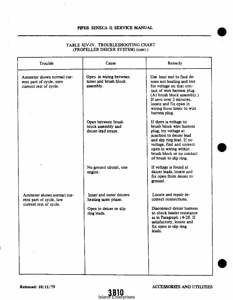
PIPER SENECA II SERVICE MANUAL
TABLE XIV-IV. TROUBLESHOOTING CHART(PROPELLER DEICER SYSTEM) (cont.)
CauseTrouble Remedy
Ammeter shows normal cur-rent part of cycle, zerocurrent rest of cycle.
Open in wiring betweentimer and brush blockassembly.
Use heat test to find de-icers not heating and testfor voltage on that con-tact of wire harness plug.(At brush block assembly.)If zero over 2 minutes,locate and fix open inwiring from timer to wireharness plug.
Open between brushblock assembly anddeicer lead straps.
No ground circuit, oneengine.
If there is voltage tobrush block wire harnessplug, try voltage atjunction to deicer leadand slip ring lead. If novoltage, find and correctopen in wiring withinbrush block or no contactof brush to slip ring.
If voltage is found atdeicer leads, locate andfix open from deicer toground.
Ammeter shows normal cur-rent part of cycle, lowcurrent rest of cycle.
Inner and outer deicersheating same phase.
Open in deicer or slipring leads.
Locate and repair in-correct connections.
Disconnect deicer harnessto check heater resistanceas in Paragraph 14-28. Ifsatisfactory, locate andfix open in slip ringleads.
Reissued: 10/11/79
3B10ACCESSORIES AND UTILITIES
Island Enterprises

High resistance up totimer.
PIPER SENECA II SERVICE MANUAL
TABLE XIV-IV. TROUBLESHOOTING CHART(PROPELLER DEICER SYSTEM) (cont.)
CauseTrouble Remedy
Ammeter shows normal cur-rent part of cycle, lowcurrent rest of cycle.(cont.)
Ammeter shows low cur-rent over entire cycle.
High resistance in cir-cuit with low current.
Aircraft voltage low.
Ammeter faulty.
If not in contact of brushto slip ring (includingground brush), tracewiring to deicer and totimer to fix partiallybroken wire, loose orcorroded connection.
Check voltage into switch.
Test for voltage up to andout of ammeter. If low orzero output and input sat-isfactory, replace am-meter. If no voltage toammeter, locate and fixopen between switch andammeter.
Check for partially brokenwire, loose or corrodedconnection in wiring fromaircraft supply to timerinput.
Ammeter shows excess cur-rent over entire cycle.
Ammeter faulty. Test for voltage up to andout of ammeter. If low orzero output and input sat-isfactory, replace am-meter. If no voltage toammeter, locate and fixopen between switch andammeter.
Reissued: 10/11/79 ACCESSORIES AND UTILITIES
3B11
Island Enterprises

PIPER SENECA II SERVICE MANUAL
TABLE XIV-IV. TROUBLESHOOTING CHART(PROPELLER DEICER SYSTEM) (cont.)
CauseTrouble Remedy
Ammeter shows excess cur-rent over entire cycle.(cont.)
Ammeter shows normal cur-rent part of cycle, excesscurrent rest of cycle.
Ground between ammeterand timer.
Ground between timer andbrush block.
Disconnect harness attimer and with ohmmetercheck from Pin B (ofharness) to ground. Ifground is indicated, lo-cate and correct.
Disconnect leads at brushblock and with ohmmetercheck from power leads toground. If ground is in-dicated, locate and cor-rect.
Ground between brushblock and deicers. (Ex-cluding ground brushcircuit.)
Short between two ad-jacent circuits.
Timer faulty.
If no short exists atbrush-slip ring contact,check for ground from slipring lead to propellerassembly while flexingslip ring and deicer leads.If a ground is indicated,locate and correct.
Check for cuts or low re-sistance between circuits.If any, locate and correct.
Test timer as in Para-graph 14-33.
ACCESSORIES AND UTILITIESReissued: 10/11/79
3B12Island Enterprises

PIPER SENECA II SERVICE MANUAL
TABLE XIV-IV. TROUBLESHOOTING CHART(PROPELLER DEICER SYSTEM) (cont.)
CauseTrouble Remedy
Ammeter does not "flick"approximately every 34seconds.
Timer ground open. Disconnect harness attimer and check withohmmeter from Pin G (ofharness) to ground. If nocircuit, fix open perschematic diagram.
Timer contacts arewelded (caused by shortcircuit in system).
Test timer as in Para-graph 14-33. If timerdoes not cycle withvoltage at Pin B, re-place timer but be sureshort causing originalfailure has been locatedand corrected.
Ammeter flicks between34 second phase periods.
Loose connection betweenaircraft power supply andtimer input.
If trouble occurs overentire cycle, trace wiringfrom power source to timerinput to locate andtighten loose connection.
Loose or poor connectiontimer to deicers.
3B13
If trouble occurs in partof cycle, find which de-icers are affected andcheck for rough or dirtyslip rings causing brushto "skip." If not this,trace circuits to locateand fix loose or poorconnection. (If all de-icers on one propellerare affected, check theground circuit.) Flex de-icer straps for break indeicer straps.
ACCESSORIES AND UTILITIESReissued: 10/11/79
Island Enterprises

PIPER SENECA II SERVICE MANUAL
TABLE XIV-IV. TROUBLESHOOTING CHART(PROPELLER DEICER SYSTEM) (cont.)
Trouble Cause Remedy
Ammeter flicks between34 second phase periods.(cont.)
Radio noise or inter-ference with deicerson.
Timer cycles erratically.
Brushes "arcing."
Test timer as in Para-graph 14-33.
Check brush alignment asshown in Figures 14-7 and14-10. Look for rough ordirty slip rings. If thisis the cause, clean ma-chine or replace slip ringassembly, as required.Check slip ring alignment.(Refer to Paragraph 14-17.)
Loose connection.
Switch faulty.
Wiring located within8 inches of radioequipment wiring.
Refer to "Ammeter flicksbetween 34 second phaseperiod."
Try jumper wire acrossswitch. If radio noisedisappears, replace theswitch.
Relocate at least 8 inchesaway from input wiring toradio equipment.
Cycling sequence notcorrect.
Rapid brush wear orfrequent breakage.
Crossed connections.
Brush block out ofalignment.
Check system wiring cir-cuit diagram for improperconnections. (Refer toFigure 14-8.)
Check brush alignment.(Refer to Paragraph14-15.)
Slip ring wobbles. Check slip ring alignmentwith dial indicator asshown in Figure 14-6.
Reissued: 10/11/79 ACCESSORIES AND UTILITIES
3B14Island Enterprises

PIPER SENECA II SERVICE MANUAL
1981
12
-14
16-
17
,
1. WING DEICER BOOTS2. AIR FILTER3. AIR PUMP4. PILOT GYRO INSTRUMENT5. IN LINE FILTER6. OVERBOARD7. MANIFOLD8. CHECK VALVES9. REGULATOR
10. COPILOT GYRO INSTRUMENT11. PRESSURE GAUGE12. DUAL STAGE PRESSURE REGULATING VALVE13. TIME MODULE14. EJECTOR FLOW CONTROL VALVE15. PRESSURE SWITCH16. TAIL DEICER BOOTS17. STABILATOR DEICER BOOTS
Figure 14-15. Pneumatic Deicer System Installation(Serial Nos. up to 34-8070144)I
Revised: 8/10/803B15
ACCESSORIES AND UTILITIES
Island Enterprises

PIPER SENECA II SERVICE MANUAL
3022
-12
1. WING DEICER BOOTS2. AIR FILTER3. AIR PUMP4. PILOT GYRO INSTRUMENT5. IN LINE FILTER6. OVERBOARD7. MANIFOLD8. CHECK VALVES9. REGULATOR
10. COPILOT GYRO INSTRUMENT11. PRESSURE GAUGE12. DUAL STAGE PRESSURE REGULATING VALVE13. TIME MODULE14. EJECTOR FLOW CONTROL VALVE15. PRESSURE SWITCH16. TAIL DEICER BOOTS17 STABILATOR DEICER BOOTS
Added: 8/10/80
Figure 14-15a. Pneumatic Deicer System Installation(Serial Nos. 34-8070144 and up)
ACCESSORIES AND UTILITIES
3B16Island Enterprises

PIPER SENECA II SERVICE MANUAL
14-34. PNEUMATIC DEICING SYSTEM.
14-35. INTRODUCTION. This portion of Section XIV provides service and maintenance procedures forthe pneumatic deicing system. This information is current as of the time of this issue.
14-36. DESCRIPTION AND PRINCIPLES OF OPERATION. The deicer is essentially a fabric reinforcedrubber sheet containing built-in inflation tubes. The type used in this installation have spanwise inflationtubes. Deicers are attached by means of a cement to the leading edges of the surfaces being protected.There are either aluminum or flexible rubber air connections on the backside of the deicer boots called "airconnection stems." Each stem projects from the underside of the boot into the leading edge, through around hole provided in the metal skin, for connection to the airplane's pneumatic air supply system.
Through an ejector valve, the system will normally apply vacuum to the deicer boots at all times, exceptwhen the boots are being inflated. Deicer inflation is effected by the deicer system control switch. This is amomentary ON type switch which returns to the OFF position when released. Through actuation of themomentary ON type switch, the timer energizes the pneumatic pressure control valves for six seconds. Theboot solenoid valves are energized and air pressure from the engine driven pumps is supplied to the inflatabletubes in the boots. Inflation sequence is controlled by the timer and solenoid operated valves located near thedeicer air inlets. The deicer pressure, normally 18 psig. is regulated by the high stage of the pneumatic pressurecontrol valves. Upon automatic de-energization of the control valves by the timer, the deicer solenoid valvespermit the deicer pressurizing air to return to the solenoid valves and be exhausted overboard. System vacuumis then reapplied to the boots to hold them close to the surface skin. Should reactivation of the boots berequired, the momentary ON type switch is moved to the ON position again and released. The boots inflationcycle will again take place, with all boots inflating simultaneously.
A ply of conductive neoprene is provided on the surface to dissipate static electric charges. Thesecharges, if allowed to accumulate, would eventually discharge through the boot to the metal skin beneath,causing static interference with the radio equipment and possible punctures in the rubber. Also, such staticcharges would constitute a temporary fire hazard after each flight.
14-37. TROUBLESHOOTING. In the utilization of the troubleshooting charts at the end of theseinstructions, it must be assumed that the engine driven pneumatic pumps and the airplane electrical systemare operational. It is further assumed that the deicer system installation was made in an approved manner.
14-38. OPERATIONAL CHECK. The pneumatic deicing system should be checked at least every 100hours. This check can be done on the ground. A visual inspection should be performed to determine thecondition of the deicer boots, and any areas in need of repair should be taken care of before continuingwith the operational check of the system.
With one engine operating, activate the deicing system switch. Observe the operation of the deicerscarefully for evidence of malfunctioning. Look for tubes which leak or fail to inflate and deflate properly.Repeat the procedure for the other engine.
14-39. ELECTRICAL TEST. With engines off, turn airplane battery switch to ON position.a. Timer: Activate the deicer system switch. The timer should begin to operate immediately and
complete one full cycle of the system. If the timer does not function:1. Reset circuit breaker and recheck.2. Check circuit from power source, through circuit breaker, to switch, to timer, to ground.3. Replace timer.
Revised: 3/16/81 3B 7 ACCESSORIES AND UTILITIES
3B17
Island Enterprises

PIPER SENECA II SERVICE MANUAL
ALL
Figure 14-16. Pneumatic Deicer Boots Operation
OE-ICERBOOTS10 AMP
PRESSURESWITCH
Figure 14-17. Pneumatic Deicer System Schematic
Reissued: 10/11/79 ACCESSORIES AND UTILITIES
3B18Island Enterprises

PIPER SENECA II SERVICE MANUAL
b. Solenoid Valves: Check both solenoid valves, one in each nacelle. Activate system switch to ONposition. Solenoid valve should be actuated immediately for 6 seconds, as evidenced by an audible "click"that can be felt if hand is placed on a solenoid. If solenoid valve does not function:
1. Unplug electrical connector at solenoid. Attach test light or other suitable test equipment toconnector and re-actuate system switch. If test equipment does not indicate complete circuit:
(a) Check circuit from timer, to solenoid connector, to ground.(b) Replace timer.
2. Use ohmmeter to check solenoid for open circuit. If solenoid circuit is open, replacesolenoid valve.
3. Remove solenoid safety wire and unscrew solenoid.
CAUTION
Do not lose steel hex actuator pin or valve poppet.
4. Reattach connector to solenoid, insert hex actuator pin into solenoid, and reactuate systemswitch. If pin is not ejected from solenoid, replace control valve.
14-40. PRESSURE LEAKAGE TEST.a. This test can be performed in either the left or right nacelles.b. Cap the overboard ports of the control valve.c. Connect a source of clean air to the inlet port of the control valve. It is necessary that the inlet
pressure be a minimum of 18-20 psig to perform this test.d. Apply 18 psig pressure to the system by means of a hand operated valve, trip the pressure in the
deicer system. Observe the system for leakage. The leakage rate should not exceed a pressure drop of 3.0psig per minute.
e. Remove test equipment, lubricate all threads, and replace all system components.
14-41. PNEUMATIC REGULATOR ADJUSTMENT.a. Remove the left and right pressure lines to the gyro pressure gauge.b. Install a 0 to 25 pounds per square inch (psi) pressure gauge in each line.c. Start the left engine. Operate the left engine at 2400 RPM.
CAUTION
During all engine operation specified herein, exercise caution toavoid harm or damage to personnel and equipment by propellerand propeller blast.
d. Cycle the deicer boot system.e. Adjust the high pressure stage (rear section) of the dual stage pressure regulator which is located
at the fire wall to maintain 18 ± 0.2 psi on the 0 to 25 psi pressure gauge while cycling. Recycle the deicerboot system as required to obtain and check this pressure setting.
f. With the deicer boot system not being cycled (engine at 2400 RPM), adjust the low pressure stage(front section) of the dual stage pressure regulator to maintain 6 + 0.2 psi on the 0 to 25 psi pressure gauge.
g. With the engine at 2400 R PM. adjust the gyro pressure regulator located on the manifold forward ofthe right gyro to maintain 5 + 0.2 -0.1 inches of mercury on the gyro pressure indicator in the instrument panel.
h. Shutdown the left engine. Repeat Steps c through g on the right engine. Further adjustment of thegyro pressure regulator (Step g) should not be required.
i. With both engines operating at 2400 RPM. recheck pressure regulator stage cycling pressure (Stepe. 18 + 0.2 psi). low pressure regulator stage non-cycling pressure (Step f. 6 ± 0.2 psi). and gyro pressureindicator pressure (Step g 5 + 0.2 -0.1 inches of mercury).
Revised: 9/24/81 ACCESSORIES AND UTILITIES
3B19
Island Enterprises
PIPER SENECA II SERVICE MANUAL
j. Visually check all boots for operation. All cells shall inflate fully. The boot cycle time shall be 62 seconds. (Cycle time is defined as the length of time the boots are fully inflated and does not include
inflation and deflation time.)
14-42. COMPONENT MAINTENANCE AND REPLACEMENT.
1443. FILTER REPLACEMENT. The pneumatic system contains two in line filters (1J4-6) and two firewall mounted pump inlet filters (J 1-2).
a. Remove the in line filters (IJ4-6) as follows:1. If filters are located behind the instrument panel on the right and left side of the fuselage,
remove the access panel from the aft wall of the nose baggage compartment. If the filters are located in theengine nacelle, remove the hatch cover from the top of the nacelle.
2. Disconnect the hoses from the filter and remove the filter.
NOTE
The 1J4-6 filters should be replaced at each 500 hours ofoperation.
3. Reinstall the filter in reverse order of removal with the flow indicator toward the hose fromthe manifold assembly. (Refer to Figure 14-20.)
b. Replace the fire wall mounted air filter IJ 1-2 as follows:1. Remove hatch cover from top of nacelle to gain access to the filter, which is mounted o
the aft side of the fire wall and connected to the pneumatic pump with a length of flexible hose.2. Remove the filter by disconnecting the hose and removing the nut and washer attaching the
filter to the fire wall.3. Reinstall the replacement filter in reverse order of removal.
NOTE
The 1JI-2 filter should be cleaned or replaced at each 100 hourinspection.
14-44. CONTROL VALVES. After 100 hours of engine operation, the valve poppet and internal lining ofthe control valve can become coated with a film of dried oil causing the valve to stick. To determine if valvepoppet is sticking, perform electrical test. If solenoid checks satisfactory, remove valve poppet and cleancontrol valve bore and poppet. To clean:
a. Remove safety wire and electrical connector. Unscrew solenoid.
CAUTION
Do not lose steel hex actuator pin.
b. Remove valve poppet. It may be necessary to apply slim nose pliers to pin projection to pullpoppet from valve.
c. Thoroughly clean valve bore and poppet with commercial hydrocarbon type solvent.d. Reassembly valve and resafety wire solenoid.
1445. TIMER. No field maintenance is recommended. For repair or replacement, contact your B.FGoodrich dealer or distributor.
Reissued: 10/11/79 ACCESSORIES AND UTILITIES
3B20Island Enterprises

PIPER SENECA II SERVICE MANUAL
TABLE XIV-V. OPERATING PRESSURES
Recommended Operating Pressure Test PressurePSIG in PSIG
MIN. MAX.
15 13 1718 16 20
14-46. INSPECTIONS. A ground check of the entire deicer system should be made at least every 100hours. To permit ground checking the system without engine operation, a test plug is designed into allsystems, usually between the pressure check valve and the combination unit.
Before checking the system, all deicers should be inspected for damaged areas and repaired accordingto the procedure in this section outlining the cold patch or vulcanized repairs. In order to check the system,refer to Table XIV-V and Paragraph 14-41 for operating pressures and check procedures.
14-47. GROUND PROCEDURE. After the test pressure range is established, connect an external source ofair providing this pressure and a .pressure gauge to the pneumatic deice line at the manifold assembly.Disconnect the deice line from the manifold to accomplish the test. The deicer system should be within onepsig of the recommended operating pressure with each inflation cycle.
If deicers do not reach the operating pressure, check the inflation time to ascertain that the solenoidvalves are open the specified length of time (six seconds). If this is not the cause of trouble or if the bootsdeflate slowly, the lines or valves may be plugged; then the lines should be disconnected and blown clear.
Check the timing of the system through several complete cycles. Boots ON six seconds, then OFF. Thewing and empennage boots operate simultaneously. If cycle time is off the specified time, determine andcorrect the difficulty.
Inflation must be rapid to provide efficient deicing. Deflation should be completed before the nextinflation cycle of the boots.
1448. 100 HOUR INSPECTION. At each 100 hour inspection of the airplane, inspect and operate thedeicer boots. Make checks as follows:
a. Carefully inspect the deicers for evidence of damage or deterioration, and repair or replacedamaged boots.
b. Resurface boots which show signs of considerable wear or deterioration.c. Inspect all hose connections which form a part of the pneumatic deicing system. Replace
deteriorated sections on non-kink hose.d. Check the operation of the boots and the operating pressure of the system as outlined in
Paragraph 14-40 and Table XIV-V.e. If new or replacement boots have been installed, check the tube inflation to make sure that the
air connection stems have been properly connected.f. Disconnect all drain lines in the system and check for proper drainage.g. Check the on-off control switch for freedom of action. Check associated electric wiring.h. Clean or replace the air filters.
Reissued: 10/11/79 ACCESSORIES AND UTILITIES
3B21
Island Enterprises

PIPER SENECA II SERVICE MANUAL
CAUTION
Oil which reaches the deicers will cause rapid deterioration of therubber. In cold weather, extreme care must be taken to see thatengine oil does not collect in critical parts of the system andcongeal. Congealed oil will cause sticking of the control valve anddistributor valve. If sticking of these parts is encountered, removefrom airplane, clean out and replace.
NOTE
This operation may be omitted if the boots were installed on theairplane subsequent to the last previous 100 hour check. On theother hand, if operations are being conducted under cold weatherconditions below 10° F (-12°C), the air filters should be cleanedout at each 100 hour check, or more often if difficulties areencountered with valves sticking due to congealed oil.
14-49. REMOVAL OF BOOTS. The removal of deicer boots should be done in a well ventilated area toavoid difficulty from the fumes of the solvents. Materials required to remove the boots are: Turco 388dried cement remover, Kelite 21, and a pressure handle squirt can. Proceed as follows:
NOTE
Disconnect line fittings from boot fittings.
a. Starting at one comer of the upper trailing edge of the deicer, apply a minimum amount ofsolvent to the seam line while tension is applied to peel back the corner of the deicer.
b. Using a pressure handle squirt can filled with solvent, separate the deicer boot from the surfacefor a distance of 4 inches all the way along the upper trailing edge.
c. The area between the deicer and the wing which has now been separated will act as a reservoir forthe solvent, therefore, the deicer can be pulled down towards the leading edge with a uniform tension.
d. From the center line of the leading edge to the lower trailing edge of the deicer, use the pressurehandle squirt can to soften the bond between the deicer and the wing skin.
e. Use Kelite 21 or Turco 388 to clean the dry cement off the exposed wing area and clean the areathoroughly with MEK (MethylEthylKetone).
14-50. REPAIR OF BOOTS. Deicer repairs are classified as cold (temporary), made on the boot installedon the airplane, and vulcanized, made on the demounted boot in the shop. (Refer to Paragraph 14-54 forvulcanized repairs.)
Reissued: 10/11/79 ACCESSORIES AND UTILITIES
3B22Island Enterprises

PIPER SENECA II SERVICE MANUAL
14-51. COLD REPAIR. The materials and supplies for making cold repairs are listed in Table XIV-VI.a. SCUFF DAMAGE. This type of damage will be most commonly encountered and, fortunately, it
is not necessary in most cases to make a repair. On those rare occasions when the scuff is severe and hascaused the removal of the entire thickness of surface ply in spots (the brown natural rubber underneath isexposed), repair the damage using Part No. 74-451-16 and proceed as follows:
1. Clean the area around the damage with a cloth dampened slightly with solvent. Buff the areaaround the damage with steel wool so that it is moderately but completely roughened. Wipe the buffed areawith a clean cloth slightly dampened with solvent to remove all loose particles.
2. Select a patch of ample size to cover the damaged area. Apply one even thorough coat ofcement, Part No. 74451-20, to the patch and the corresponding damaged area. Allow cement to set acouple of minutes until tacky.
3. Apply the patch to the deicer with an edge, or the center adhering first. Work down theremainder of the patch carefully to avoid trapping air pockets. Thoroughly roll the patch withstitcher-roller, Part No. 74-451-73, and allow to set for ten to fifteen minutes.
4. Wipe the patch and surrounding area from the center outward with a cloth slightlydampened with solvent. Apply one light coat of A-56-B conductive cement, Part No. 74451-11, to thepatched area.
5. Satisfactory adhesion of patch to deicer will be reached in four hours. Deicer may beinflated for checking repair in a minimum of 20 minutes.
b. TUBE AREA DAMAGE. Repair cuts, tears, or ruptures to the tube area with fabric reinforcedpatches, Part No. 74-451-16, depending on size of damage.
1. Select a patch of ample size to cover the damage and to extend to at least 5/8 inch beyondthe ends and edges of the cut or tear. If none of the patches is of proper size, cut one to the size desiredfrom one of the larger patches. If this is done, bevel the edges by cutting with the shears at an angle.
NOTE
These patches are manufactured so that they will stretch in onedirection only. Be sure to cut and apply the patch selected so thatstretch is in the widthwise direction of the inflatable tubes.
2. Buff the area around the damage with buffing stick, Part No. 74451-75, so that the surfaceis thoroughly roughened.
3. Apply the patch to the deicer with the stretch in the widthwise direction of the inflatabletubes, sticking edge of patch in place, working remainder down with slight pulling action so the injury isclosed. Do not trap air between patch and deicer surface.
c. LOOSE SURFACE PLY IN DEAD AREA (NON-INFLATABLE AREA). Peel and trim the loosesurface ply to the point where the adhesion of surface ply to the deicer is good.
1. Scrub (roughen) area in which surface ply is removed with steel wool. Scrubbing motionmust be parallel to cut edge of surface ply to prevent loosening it. Scrub with steel wool and Toluol directlyover all edges, but parallel to edges or surface ply to taper them down to the tan rubber ply.
2. Cut a piece of surface ply material, Part No. 74451-23, to cover the damaged area andextend at least one inch beyond in all directions.
Reissued: 10/11/79 ACCESSORIES AND UTILITIES
3B23
Island Enterprises

PIPER SENECA II SERVICE MANUAL
TABLE XIV-VI. MATERIAL AND SUPPLIES FOR COLD REPAIR
Part No. Quantity Description
74-451-C(FSN 1650-856-7939)
74-451-11
74451-16
74-451-17
74-451-18
74-451-1974-451-20
74451-7074451-7374-451-7574-451-87
1
1/1 pt. can
30 pcs.
30 pcs.
10 pcs.
3 pcs.(2) 1/2 pt.
2161
Cold Patch Repair Kit(B. F. Goodrich Co.)A-56-B Conductive
cementSmall oval patch 1-1/4
x 2-1/2 in.Medium oval patch
2-1/2 x 5 inchLarge oval patch 5 x
10in.Patch 5 x 19 inch.
*No. 4 cement (patchingonly)
Cement brush 1/2 in.1/8 in. Steel stitcherEmery Buffing sticks
Buffing Shield
*This cement will give best results with the patches in this kit.
The following items may be procured from the B. F. Goodrich Co.,Akron, Ohio, or other manufacturer, as required:
74451-2174451-22
74451-2374451-24
(FSN8040-628-4199 and/or FSN8040-514-1880)
74-451-74
6 ft. roll x 6 in. wide15 ft. roll x 2 in. wide
4 ft. long x 8 in. wideI quart
1
Type 21 or 22 filletNeoprene coated splicing
tapeNeoprene surface ply
EC-1403 cement and/orEC-1300 L
2-1/2 in. sponge rubberroller
+Minnesota Mining and Manufacturing Company. Adhesives Division.223-6N-02 3M Center. St. Paul. MN 55144 (612) 733-1237
NOTETABLE XIV.VI CONTINUES ON THE NEXT PAGE.
Revised: 12/08/83 ACCESSORIES AND UTILITIES3B24
Island Enterprises

PIPER SENECA II SERVICE MANUAL
TABLE XIV-VI. MATERIAL AND SUPPLIES FOR COLD REPAIR (cont.)
Part No. I Quantity Description
The following materials may be obtained from local supply:
As required
Rolls1
6 ft. long1
As requiredAs required
ToluolClean, lint-free cloths
(preferably cheesecloth)
1 in. masking tapeSharp knife
Steel measuring tapeFine sharpening stone
Steel wool padsHypodermic needles (22
gauge or smaller)
Methylethylketone (MEK) can be used instead of Toluol, however MEKcauses very rapid drying and provides only 10 seconds working timecompared with 40 seconds for Toluol.
3. Mask off the damaged boot area 1/2 inch larger in length and width than the size of surfaceply patch. Apply one coat of cement, Part No. 74-451-1 1, to damaged area and one coat to patch. Allowcement to set until tacky. Roll the surface ply to the deicer with 2 inch rubber roller, Part No. 74-451-74.Roll edges with stitcher-roller, Part No. 74451-73. Apply just enough tension on the surface ply whenrolling to prevent wrinkling and be careful to prevent trapping air. If air blisters appear after surface ply isapplied, remove them with a hypodermic needle.
4. Clean excess cement from deicer with solvent.d. LOOSE SURFACE PLY IN TUBE AREA. Loose surface ply in tube area is usually an indication
of the deicer starting to flex fail. This type of failure is more easily detected in the form of a blister underthe surface ply when deicer is pressurized. If this type of damage (or void) is detected while still a smallblister (about 1/4 or 3/8 inch diameter) and patched immediately, the service life of the deicer will beappreciably extended. Apply repair patch as outlined in Paragraph a.
e. DAMAGE TO FABRIC BACK PLY OF DEICER DURING REMOVAL. If cement has pulledloose from the wing skin and adhered to the back surface of the deicer, remove it with steel wool and MEK.In those spots where the coating has pulled off the fabric, leaving bare fabric exposed, apply at least twoadditional coats of cement, Part No. 74-451-24. Allow each coat to dry thoroughly.
Reissued: 10/11/79 ACCESSORIES AND UTILITIES
3C1
Island Enterprises

PIPER SENECA II SERVICE MANUAL
14-52. VULCANIZED REPAIRS. Due to the variety of boot damage possible, it is recommended that theB.F. Goodrich Company be contacted so they can determine the extent of damage and whether it isrepairable by the vulcanized method or not. The overall condition of the deicer boot must be given carefulconsideration before deciding on any repairs. Damages can vary from minor punctures which may be easilyrepaired, to extensive ripping of the tube or stretch areas which may make repairs exceedingly difficult oractually impossible. The determination of just where this division between repairable and unrepairabledamage exists will depend upon the careful judgment of the inspector. For this reason, we recommendcontacting the B.F. Goodrich Company at Akron, Ohio.
14-53. INSTALLATION. The following procedure for installing deicers assumes that the airplane hasprovisions for air connections, etc.
NOTE
Balance stabilator per instructions in Section IV of this manual.
14-54. PREPARATION OF LEADING EDGES. If the leading edges are painted, remove all paintincluding zinc chromate primer.
a. With one inch (1) masking tape, mask off leading edge boot area, following 1/2 inch margin fornon-recessed boots. Take care to mask accurately, thus eliminating the need for cleaning off excess cementlater.
b. Clean the metal surfaces thoroughly, at least twice, with MEK or Acetone. For final cleaning,wipe the solvent film off quickly with a clean, dry cloth before it has time to dry.
NOTE
It is permissible to install deicers on alodined or anodized surfaces.
c. Fill gaps of skin splices that lead under deicers with sealing compound EC-801.d. Remove the sump plugs from the air connection grommets. In some cases. it will be necessary to
remove sections of doped fabric used to cover the air connection holes. Draw out the ends of the non-kink hosesection so that they protrude through the connection holes in the leading edge. If hose is cracked or de-teriorated. replace with new hose.
14-55. PREPARATION OF DEICER. Moisten a clean cloth with MEK or Acetone and carefully clean therough, back surface of the boot at least twice. Change cloths frequently to avoid recontamination of thecleaned areas.
14-56. MOUNTING DEICER ON LEADING EDGE. Thoroughly mix EC-1403 cement before using.Apply one even brush coat to the cleaned back surface of the boot and to the cleaned metal surface. Allowthe cement to air dry for a minimum of one hour. Apply a second coat to both surfaces and allow to air drya minimum of one hour. Ambient temperature for installation should be held between 40° and 110 F.However, longer drying time of the cement coats may be required as the humidity approaches 99%. Deicerand leading edge may be cemented for a maximum of 48 hours before actual installation, if cemented partsare covered and kept clean.
Snap a chalk line along the leading edge of the airfoil section. Intensify chalk line on leading edge andthe white reference line on the boot with a ball point pen. Most boots are made with an excess of materialat the inboard and outboard edges for final trimming after installation and some recessed boots trim on theupper and lower edges.
Securely attach hose to deicer connections using clamps or safety wire.
Reissued: 10/11/79 ACCESSORIES AND UTILTIES
3C2Island Enterprises
PIPER SENECA II SERVICE MANUAL
a. Holding the backside of the boot close to the leading edge, fasten the end of each non-kink hoseto the corresponding air connection stem. Tinnerman or other suitable non-kink hose clamps should beused for this purpose. Tighten each clamp with a pair of slip joint pliers but do not squeeze the clamp sotight that the hose is damaged.
NOTE
If non-kink hose clamps are not available, wrap each hoseconnection with several turns of friction tape. Over the tape, wraptwo separate bindings of safety wire, about 1/2 inch apart. Each ofthese bindings should consist of several turns of wire. Twisttogether the ends of each binding to tighten. Press the twistedends down against the hose. Finally, wrap the wire with severaladditional turns of friction tape.
b. Push the hose connections into the leading edge grommets or seals as the case may be. Obtainsufficient personnel to hold boot steady during installation. (Limit handling cemented side of boot withfingers.) Continue installation by reactivating the cement along the center line leading edge surface andboot in spanwise strips approximately six inches wide. Rubber roll the deicer firmly against the wingleading edge, being careful not to trap any air under the deicer. Always roll parallel to the inflatable tubes.Position the deicer center line to coincide with leading edge center line. Hold boot in this position whilereactivating about three inches around connections and around corresponding holes in leading edge, using aclean, lint-free cloth moistened with Toluol. Insert connections in leading edge holes when cement has driedto a tacky state and rubber roll boot to leading edge in tackified area.
c. If the deicer should attach "off course," use MEK to remove and reposition properly. Avoidtwisting or sharp bending of the deicer.
d. Rubber roll, apply pressure over entire surface of the deicer. All rolling should be done parallel tothe inflatable tubes. Roll trailing edges with a narrow stitcher-roller.
CAUTION
Avoid excessive soaking or rubbing of the cement which couldremove the cement from the surface.
Remove all masking tapes and clean surfaces carefully with Toluol so that no solvent will run underdeicer edges.
e. Apply masking tape to deicer edges where exposed trimmed ends or gaps between sections are tobe filled with MMM EC-801 sealing compound.
Apply masking tape to deicer approximately 1/4 inch in from trailing edges and tape wing skinapproximately 1/4 inch from trailing edges, both forming a neat, straight line.
f. Apply a brush coat of A-56-B cement to surfaces between tapes and to EC-802 seams, being surethat the conductive coating (A-56-B) is continuous from the deicer surface to the wing painted surface.
g. Remove tapes immediately after applying A-56-B cement (before cement dries).
NOTE
Application of A-56-B conductive cement is not necessary ondeicers that have "CONDUCTIVE" noted on labels.
Reissued: 10/11/79 ACCESSORIES AND UTILITIES
3C3
Island Enterprises

PIPER SENECA II SERVICE MANUAL
CAUTION
The cements and solvents used for installation are flammable andtheir fumes slightly toxic. Therefore, all work should be done in awell ventilated area away from any sparks or flames. (Use ofsolvent resistant type gloves is recommended.)
In the event it becomes necessary to remove or loosen installed boots, use Toluol to soften the"adhesion" line. A minimum of this solvent should be applied to the seam line while tension is applied topeel back the boot. This removal should be slow enough to allow the solvent to undercut the cement, thuspreventing injury to the part. Excessive quantities of solvent must be avoided.
14-57. ADHESION TEST. Using excess boot material trimmed from the ends of any wing and empennagedeicers, prepare one test specimen for each deicer installed. This specimen should be a 1 x 8 inch fullthickness strip of boot material cemented to the wing skin adjacent to installed boot following the identicalprocedure used for installation. Leave one inch of the strip uncemented to attach a clamp. Four hours ormore after the installation, attach a spring scale to the uncemented end of each strip and measure the forcerequired to remove strip at the rate of one inch per minute. The pull should be applied 180° to the surface.(Strip doubled back on itself.)
A minimum of five pounds tension (pull) shall be required to remove the test strip. If less than fivepounds is required, then acceptability of the boot adhesion shall be based on the following tests:
a. Carefully lift one corner of boot in question sufficiently to attach a spring clamp.b. Attach a spring scale to this clamp and pull with force 180 to the surface and in such a direction
that the boot tends to be removed on the diagonal.c. If a force of five pounds per inch of width can be exerted under these conditions, the installation
shall be considered satisfactory. Remember, the width increases as the corner peels back.d. Re-cement corner following previous procedure.e. Failure to meet this requirement shall result in reinstallation of the boot.
NOTE
Possible reasons for failure are: dirty surfaces, cement notreactivated properly, cement not mixed thoroughly. Corrosion ofthe metal skin may occur if good adhesion is not attained,especially around rivet heads and metal skin splices.
If these adhesion requirements are met, the airplane may be flown immediately. Do not inflate deicerswithin 12 hours of installation or until adhesion strength of 8 to 10 pounds is obtained.
1458. MAINTENANCE. Clean deicers when the airplane is washed with a mild soap and water solution.In cold weather, wash the boots with the airplane inside a warm hangar if possible. If the cleaning is to bedone outdoors, heat the soap and water solution before taking it out to the airplane. If difficulty isencountered with the water freezing on the boots, direct a blast of warm air along the region being cleaned,using a portable type ground heater.
As alternates, use Benzol or non-leaded gasoline. Moisten the cleaning cloth in solvent, scrub lightly,and then with a clean, dry cloth, wipe dry so that the cleaner does not have time to soak into the rubber.Petroleum products such as these are injurious to rubber and, therefore, should be used sparingly.
Reissued: 10/11/79 ACCESSORIES AND UTILITIES
3C4Island Enterprises
PIPER SENECA II SERVICE MANUAL
14-59. ICEX APPLICATION. B.F. Goodrich Icex is silicone base material specifically compounded tolower the strength of adhesion between ice and the rubber surfaces of airplane deicers. Icex will not harmrubber and offers added ozone protection.
Properly applied and renewed at recommended intervals, Icex provides a smooth polished film thatevens out the microscopic irregularities on the surface of rubber parts. Ice formations have less chance tocling. Ice is removed faster and cleaner when deicers are operated.
It should be emphasized that Icex is not a cure-all for icing problems. Icex will not prevent or removeice formations. Its only function is to keep ice from initially getting a strong foothold, thus making removaleasier.
One 16 ounce pressurized can of Icex will cover deicer surfaces of the average light twin-engine planeapproximately three times. It is also available in quart cans (unpressurized).
Before applying Icex, thoroughly clean deicer or other rubber surfaces with a rag dampened withnon-leaded gasoline. Follow by a scrub wash of mild soap and water. Allow time for surfaces to dry.
Shake the Icex can well. Hold the nozzle approximately 12 inches from the surface and spray. Applysparingly. If the application is too heavy, it results in a sticky surface which is very undesirable because itwill pick up runway dust and prevent best ice removing efficiency.
Due to the natural abrasive effects on leading edges of deicers during flight, reapply Icex every 150flight hours on wings and empennage deicers.
14-60. RESURFACING CONDUCTIVE CEMENT. The following materials are required to remove andreplace the old, damaged coating:
a. Fine grit sandpaper.b. Two inch paint brush.c. One inch masking tape.d. Conductive neoprene cement, No. A-56-B, B.F. Goodrich Company.e. Isopropyl Acetate, Federal Specification TT-1-72 1. as cleaning or thinning solvent.f. Alternate solvent (Toluol or Toluene may be used as an alternate for Isopropyl Acetate).
CAUTION
Cements and solvents used for resurfacing are flammable and theirfumes slightly toxic. Therefore, all work should be done in a wellventilated area away from any sparks or flames.
Reissued: 10/11/79 ACCESSORIES AND UTILITIES
3C5
Island Enterprises
PIPER SENECA II SERVICE MANUAL
During cold weather, place the airplane in a warm hangar and locate so that the boots are in line withone or more blast heaters. Do resurfacing before any other work on the airplane to allow as much time aspossible for the new coat to cure.
NOTE
If for some reason the resurfacing cannot be done indoors, it maybe deferred at the discretion of the inspector until a warm, clearday permits the work to be satisfactorily accomplished outdoors.However, if the deicers are in such condition that immediateresurfacing is required, remove them from the airplane andresurface in a shop.
Clean deicer thoroughly with Isopropyl Acetate.a. Roughen entire surface of boot, using a fine grit sandpaper.b. Clean surface again with clean, lint-free cloth moistened with cleaning solvent.c. Apply masking tape beyond upper and lower trailing edges, leaving a 1/4 inch gap of bare metal.d. Mask off any legible deicer brands.e. Apply one brush coat of A-56-B cement to deicer and allow to dry at least one hour. Then apply
second coat and allow to dry at least four hours before operating deicers. Plane may be flown as soon ascement is dry.
NOTE
If A-56-B cement has aged 3 months or over, it may be necessaryto dilute the cement with Isopropyl Acetate to obtain properbrushing consistency. Mix thoroughly, approximately 5 partscement to one part Isopropyl Acetate.
Reissued: 10/11/79 ACCESSORIES AND UTILITIES
3C6Island Enterprises

PIPER SENECA II SERVICE MANUAL
TABLE XIV-VII. TROUBLESHOOTING CHART(PNEUMATIC DEICER SYSTEM)
CauseTrouble Remedy
Deicers do not inflate.Both engines operatingat minimum cruise RPMor either engine at 2575RPM.
Open circuit breaker.
System connection looseor wire broken.
Push circuit breaker toreset.
Tighten or repair asrequired.
Timer not functioning.
Control valves notfunctioning.
Lines blocked or notconnected.
Test or replace as re-quired.
Make electrical test.Check for sticking poppet.Clean.
Blow out lines and inspectconnections. Make airleakage test.
Deicers inflate slowly(inflation time - 6seconds).
Lines partially blockedor not connected se-curely.
Blow out lines and inspectconnections. Make airleakage test.
Deicer valve notfunctioning.
System pressure not beingreached.
Deicer puncture.
Check fitting in deicerport for proper in-stallation.
Check performance to man-ufacturers specifications.
Repair per specificationor replace.
Deicers deflate slowly. Pressure regulator settoo low.
Readjust pressureregulator.
Lines partially blocked. Inspect and blow outlines.
Overboard line from con-trol valve partiallyblocked.
Inspect and blow outlines.
Revised: 9/24/81 ACCESSORIES AND UTILITIES
3C7
Island Enterprises
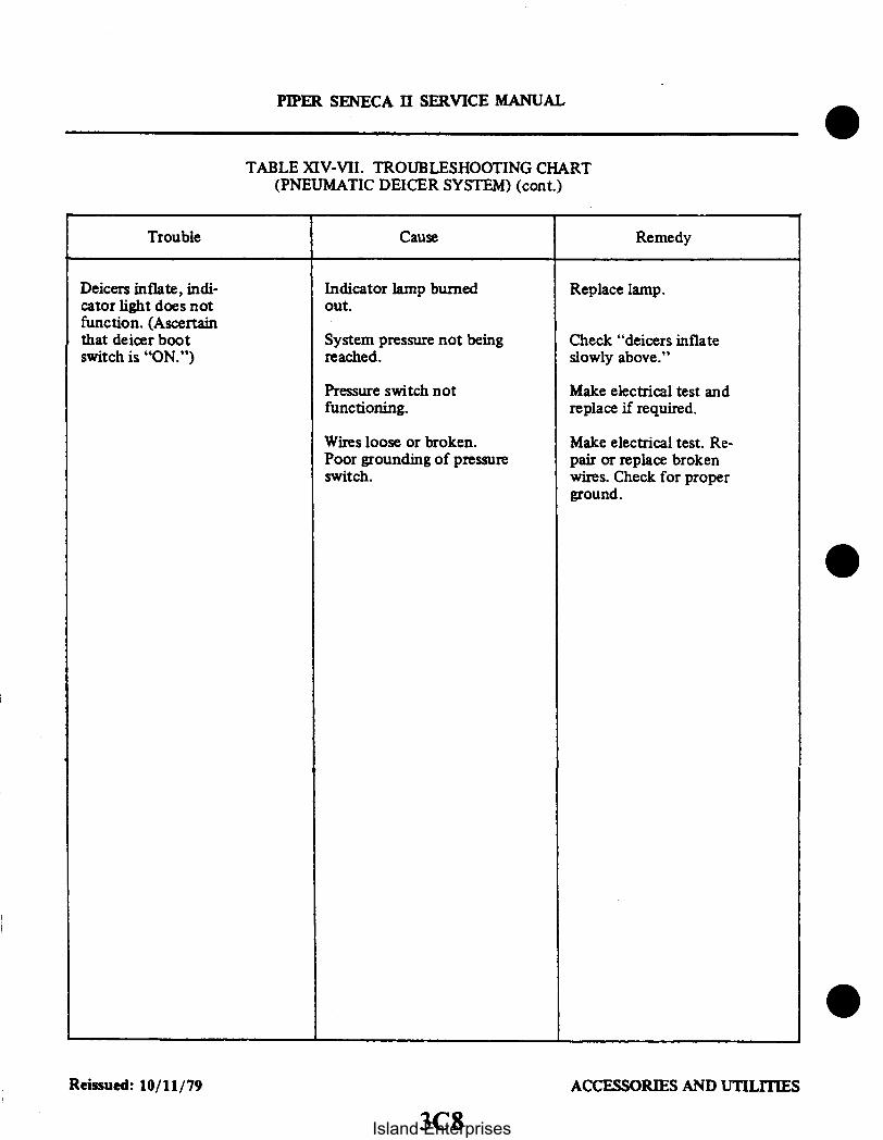
PIPER SENECA II SERVICE MANUAL
TABLE XIV-VII. TROUBLESHOOTING CHART(PNEUMATIC DEICER SYSTEM) (cont.)
Trouble Cause Remedy
Deicers inflate, indi-cator light does notfunction. (Ascertainthat deicer bootswitch is "ON.")
Indicator lamp burnedout.
System pressure not beingreached.
Replace lamp.
Check "deicers inflateslowly above."
Pressure switch notfunctioning.
Wires loose or broken.Poor grounding of pressureswitch.
Make electrical test andreplace if required.
Make electrical test. Re-pair or replace brokenwires. Check for properground.
0
Reissued: 10/11/79 ACCESSORIES AND UTILITIES
3C8Island Enterprises

PIPER SENECA II SERVICE MANUAL
2009
SWITCH
o 0218— — A LIGHT5 AMP
ICE UGHT
Figure 14-18. Ice Detection Light Schematic
14-61. ICE DETECTION LIGHT.
14-62. INTRODUCTION. This light is used in conjunction with the pneumatic deicing system and will aidthe pilot to detect any ice formation on the left wing leading edge during night flying operations.
14-63. DESCRIPTION AND OPERATION. The light is mounted in the left outboard edge of the leftnacelle just above leading edge of the wing. It is a sealed beam, 12-volt unit, which is controlled from a rockertype switch mounted on the switch panel. The light is positioned in the nacelle to illuminate the leading edgeof the wing when the switch is activated in the cockpit.
14-64. SERVICING. The only service required of this unit is the replacement of a burned out lamp with anew lamp GE1383.
14-65. REMOVAL.a. Be sure the switch is in the off position.b. Remove the top access panel from the left nacelle.c. Within the nacelle, remove the screws that secure the socket in the retainer.d. Pull the socket aft and remove the lamp.
14-66. INSTALLATION.a. Position the new lamp in the receptacle of the socket, then secure the socket in the retainer with
the screws.b. Activate the switch in the cockpit to check the lamp operation.c. Replace the nacelle access panel with the attachment hardware.
Reissued: 10/11/79 ACCESSORIES AND UTILITIES
3C9
Island Enterprises

PIPER SENECA II SERVICE MANUAL
14-67. HEATED WINDSHIELD PANEL.
14-68. DESCRIPTION. The heated windshield panel is a rectangular glass panel containing electricallyheated wires imbeded in the glass which is mounted in a metal frame. The assembly is mounted on theexterior side of the pilot's windshield and is hinged at its base to facilitate windshield cleaning. The heatedpanel is operated by a circuit breaker type switch located in the console below the throttle quadrant.
14-69. REMOVAL AND INSTALLATION OF HEATED PANEL.a. Disconnect the electrical connector located next to the heated panel on the exterior side of the
windshield, by removing the two screws and pulling the plug out of the receptacle.b. Remove the two screws which attach the panel assembly to the windshield collar and remove the
panel from the airplane.c. If the airplane is to be flown with the heated panel removed, rotate the receptacle plate 180 and
replace it to cover the holes in the fuselage skin, also replace the windshield collar screws.d. Installation of the heated windshield panel is accomplished in the reverse order of removal.
INTENTIONALLY LEFT BLANK
Reissued: 10/11/79 ACCESSORIES AND UTILITIES
3C10Island Enterprises

PIPER SENECA II SERVICE MANUAL
14-70. OXYGEN SYSTEM.
14-71. DESCRIPTION AND PRINCIPLE OF OPERATION. The standard oxygen system for the PA-34-200T consists of two automatic, constant flow, portable oxygen units. The two units are secured betweenthe two middle seats and act as an armrest. The two systems serve as a safety feature, the pilot on one systemand the copilot on the other. The four passengers obtain their oxygen from the "Y"adapters on each system.Each oxygen cylinder is an ICC regulation 3AA with a 22 cubic foot capacity.
A fixed oxygen system to provide supplementary oxygen for the crew and passengers during highaltitude flights (above 10,000 feet) is available as optional equipment. The major components of the Scottoxygen system are a 63 cubic foot oxygen cylinder, an oxygen supply gauge, an on-off flow control knob, apressure regulator, six plug in receptacles and six oxygen masks.
The oxygen cylinder is mounted aft in the tail cone. When fully charged, the cylinder contains oxygen ata pressure of 1850 psi at 70° F. The oxygen supply gauge is mounted in the aft overhead vent duct. Theoxygen flow control knob, labeled "Pull-On" is mounted in the pilot's overhead panel. The pressure regulatoris mounted directly on the oxygen cylinder, once the oxygen flow control knob is on, each of the oxygen plug-in receptacles operates as an automatic on-off valve. The oxygen cylinder can be recharged through the fillervalve aft of the cabin door on the right side of the fuselage (fuselage sta. 222.43). When oxygen is required, thecontrol knob should be pulled forward to the ON position, allowing oxygen to flow from the cylinderthrough the system. Connecting the constant flow mask fitting to a receptacle and turning it 90 degreesclockwise, automatically releases oxygen to the mask through the on-off valve feature of the receptacle. Theoccupant then dons the mask and breathes normally for a sufficient supply of oxygen.
Each mask assembly oxygen line incorporates a flow indicator. When the red pellet in the indicatordisappears, oxygen is flowing through the line normally. If the red indicator appears in any of the lines duringa period when oxygen use is essential, the airplane should be lowered to a safe altitude immediately.
To stop the flow of oxygen through the system, the control knob should be pushed aft to the OFFposition. To bleed down low pressure lines, it is recommended that the mask assembly be left connected to theoutlet for at least three minutes after the control knob is turned off.
When not in use, mask may be stowed in the storage pockets behind the front and center seats. Alwaysremove fittings from the oxygen receptacles and stow the mask when they are not in use. If the control knob ispulled on and the fitting is in the receptacle, oxygen will flow through the mask continuously. Masks may bedamaged if they are not properly stowed.
14-72. TROUBLESHOOTING. A troubleshooting chart is located at the back of the oxygen system portionof this section.
14-73. SAFETY PRECAUTIONS. Utmost care must be exercised in servicing, handling and inspection ofthe oxygen system. A fully charged oxygen cylinder contains enough pressure to cause serious injury topersonnel and damage to equipment. Keep hands, tools and working area clean and post NO SMOKINGsigns. Keep all components of the system free from oil, grease, fuel and all ready combustible material. Neverallow electrical equipment to come in contact with the oxygen cylinder. Keep fire and heat away from oxygenequipment and take care not to generate sparks with carelessly handled tools.
14-74. INSPECTION AND OVERHAUL TIME LIMITS. It is recommended that inspection and overhaulbe conducted by an FAA Approved Station or the manufacturer, Scott Aviation. The following checks andchart gives recommended inspection and overhaul time for the various parts of the oxygen system:
Reissued: 10/11/79 ACCESSORIES AND UTILITIES
3C1l
Island Enterprises

PIPER SENECA II SERVICE MANUAL
a. Standardweight cylinders(ICC or DOT 3AA1800classification) must behydrostatictestedevery 5years. The lightweight cylinders (ICC or DOT 3HT 1850 classification) must be hydrostatic tested every 3years and must be retired from service after 15 years or 4380 pressurizations, whichever occurs first. Themonth and year of the last test is stamped on the cylinder beneath the ICC or DOT identification.
b. The outlets should be checked for leakage both in the non-use condition and for leakage around aninserted connector.
c. The high pressure gauge may be checked for accuracy by comparing its indicated pressure with thatof a gauge of known accuracy.
d. Inspection of the regulator may be effected by introducing into an outlet a mask connector to whichis attached a 100 psi gauge. With one other outlet flowing through a plugged in mask, the indicated regulatoroutput pressure shall be not less than 45 psi at sea level with 200 psi supply cylinder pressure. It should benoted that the permissible leakage through the 1/16 diameter vent hole in the side of the upper regulatorhousing is 10 cc/min. maximum, when the regulator is turned on. There shall be no external leakageanywhere on the regulator when it is turned off. All fittings shall be leak free.
14-75. TESTING FOR LEAKS. Apply detector fluid type CD-I solution or its equivalent. The solutionshould be shaken to obtain suds or foam. The suds or foam should be applied sparingly to the joints of aclosed system. Look for traces of bubbles. No visible leakage should be found. Repair or replace any defectiveparts and retest system. With the system pressurized to service pressure, further tests can be made. The rate ofany leak should not exceed one percent of the total supply per 24 hour period. All traces of the detector fluidshould be wiped off at the conclusion of the examination.
14-76. MAINTENANCE.a. Check that all lines have sufficient clearance between all adjacent structures and are secured in
place. Also check the cylinder to be sure it is securely mounted (See Figure 14-20a ).b. Check the cylinder for the ICC identification number and for the date of the last FAA inspection
and test.c. If cylinder is completely empty, it must be completely disassembled and inspected in an FAA
approved facility before recharging.d. Any lines that are defective should be replaced with factory replacements.e. Clean all lines and fittings as described in Paragraph 14-77.f. Use Ribbon Dope Thread Sealant (Permacel 412) on male ends of fittings only. Wrap thread in
direction of thread spiral, beginning with the second thread on the fitting. Avoid getting any sealant into thelines.
14-77. CLEANING OPERATIONS. To remove oil and grease from tubing and fittings, one of the followingcleaning methods may be used:
a. First Method:1. A vapor degreasing with stabilized Trichlorethylene conforming to Specification MIL-T-7003
or Piper safety solvent (914 905).2. Blow tubing clean and dry with a stream of clean, dry filtered air or nitrogen. Care shall be
taken to insure that the interior of the tubing and fittings are thoroughly cleaned.b. Second Method:
1. Flush with naphtha conforming to Specification TT-N-95.2. Blow clean and dry off all solvent with clean. dry, filtered (oil-free) air.3. Flush with isopropyl alcohol.4. Rinse thoroughly with fresh water.5. Dry thoroughly with a stream of clean, dried, filtered air (oil free) or by heating at a
temperature of 250° to 300° F one half hour.
Revised: 12/08/83 3C12 ACCESSORIES AND UTILITIES3C 12Island Enterprises

PIPER SENECA II SERVICE MANUAL
TABLE XIV-VIII. OXYGEN SYSTEM COMPONENTS LIMITS
PARTS INSPECTION OVERHAUL
RegulatorPressure GaugeHigh Pressure LinesLow Pressure LinesOutletsExternal Recharge ValveMasks
300 Flight300 Flight300 Flight300 Flight300 FlightEach UseEach Use
Hrs.Hrs.Hrs.Hrs.Hrs.
5 Yrs.5 Yrs.
5 Yrs.Replace Every 5 Yrs.Replace as Necessary
6. The solvents may be reused provided they do not become excessively contaminated with oil.This condition shall be determined as follows:
(a) Completely evaporate 100 milliliters of the liquid in a weighed glass dish. Evaporation may beaccomplished by heating at 200° F for approximately one-half hour.
(b) After evaporation, cool and weigh the residue. The solvent shall not be used if the residueexceeds 100 miligrams in weight.
c. Third Method:I. Flush with hot inhibited alkaline cleaner until free from oil and grease.2. Rinse thoroughly with fresh water.3. Dry thoroughly with a stream of clean, dry, filtered (oil-free) air or by heating at a temperature
of 250° to 300° for one half hour minimum.
CAUTION
To preclude the possibility of fire by spontaneous combustion, oil,grease, paint, hydraulic fluid and other flammable material shouldbe kept away from oxygen equipment.
14-78. PURGING THE SYSTEM. The system should be purged whenever the cylinder pressure falls below50 psi or if any lines are left open for any length of time. Also, whenever there are any offensive odors present,it will be necessary to purge the system. Use the following procedure:
a. Park the airplane in a NO SMOKING area.b. Keep all doors and windows open.c. Be sure all electrical systems are shut off.d. Connect the oxygen recharging unit to the filler valve.e. Plug the oxygen masks into the outlet valves and turn on the system.f. Set the recharging unit pressure regulator to deliver 50 psi and let the system purge for one hour. If
any odor is still present, repeat the procedure for one or more hours. If the odor persists after the secondpurging, replace the cylinder.
Revised: 3/16/81 ACCESSORIES AND UTILITIES
3C13
Island Enterprises

PIPER SENECA II SERVICE MANUAL
14-79. REMOVAL OF PORTABLE OXYGEN UNIT. (Refer to Figure 14-19).
- WARNING -
Do not use grease or any grease type fittings on any hardware thatconnects to the oxygen bottle or system hardware. When workingwith the system make sure hands, clothing, and tools arefree of oilgrease and dirt when working with the oxygen system.
The oxygen unit can be released from its cradle by pulling down on the ring under the cradle, sliding theunit forward, and lifting it out of its cradle.
CAUTION
Use only aviation breathing oxygen when having the oxygenbottles charged. M I L-0-27210C specifies that the moisture contentof aviation breathing oxygen must not exceed 0.005 milligrams ofwater vapor per liter of gas at a temperature of 70° F and a pressureof 760 millimeters of Hg.
14-80. CHARGING. For recharging a low pressure aircraft oxygen system or portable cylinders, it isessential that the oxygen trailer or cart have a pressure-reducing regulator. Military types E-2 or C- reducingregulators are satisfactory. These types of regulators reduce the large cylinder pressure from 2000 psi to a linepressure of 450 psig.
CAUTION
When refilling the low pressure system, open the oxygen filler tankvalve slowly to allow the system to be filled at a slow rate. After therefilling operation is completed, check for leaks with a leakdetector.
a. Inspect the cylinder being charged for damage, cleanliness, and date of hydrostatic test.b. Connect cylinder valve outlet to the refilling manifold.c. Slowly open value of cylinder to be charged and observe pressure on gauge of manifold system.d. Slowly open valve of cylinder on manifold system having the lowest pressure and allow pressure to
equalize.e. Close cylinder valve on manifold system and slowly open valve of cylinder having next highest
pressure. Continue this procedure until the cylinder has been charged.
14-81. REMOVAL OF OUTLETS.1. Make sure control valve is in full OFF position.2. Connect a mask or connector to the valve to release any pressure.3. Using a suitable wrench, remove the outlet.4. The outlet can now be removed from the low pressure line.
14-82. INSTALLATION OF OUTLETS.1. Apply sealant (Permacel 412) to the male end of the fitting.2. Install the outlet to the regulator extension with a suitable spanner wrench.3. Torque the fittings into the outlets approximately 30 inch-pounds. Do not overtorque as this could
damage the outlet.
Reissued: 10/11/79 ACCESSORIES AND UTILITIES
3C14Island Enterprises

2806
4
1. PORTABLE OXYGEN UNIT(SI2. BRACKET SUPPORT3. FACE MASK4 AFT FACING SEAT (RIGHT)
2
Figure 14-19. Portable Oxygen Installation
14-83. CLEANING OF FACE MASKS. (PORTABLE SYSTEM)The disposable masks are designed for one-time use and require no maintenance. The pilot's and
copilot's masks can be cleaned as follows:1. Remove the microphone from the mask.2. Remove the sponge rubber discs from the mask turrents. Do not use soap to clean sponge rubber
discs. as this would deteriorate the rubber and give off unpleasant odors. Clean in clear water and squeeze-dry.
3. Wash the rest of the mask with a very mild solution of soap and water.
PIPER SENECA II SERVICE MANUAL
4. Rinse the mask thoroughly to remove all traces of soap.5. Make sure the sides of the breathing bag do not stick together while drying. as this may decrease the
life of the rubber in the bag. The mask can be sterilized with a solution of 70 percent ethyl alcohol.
14-84. CLEANING OF FACE MASKS. (Fixed System)a. Remove the sponge rubber discs from the mask turrents. Do not use soap to clean sponge rubber
discs. as this would deteriorate the rubber and give off unpleasant odors. Clean in clear water and squeezedry.
b. Wash the rest of the mask with a very mild solution of soap and water.c. Rinse the mask thoroughly to remove all traces of soap.d. Make sure the sides of the breathing bag do not stick together while drying. as this may decrease the
life of the rubber in the bag. The mask can be sterilized with a solution of 70 percent ethyl alcohol.
Revised: 8/10/80 ACCESSORIES AND UTILITIES
3C15
Island Enterprises

B114 /
ON-OFF CONTROL2. OXYGEN OUTLET3. LOW PRESSURE OXYGEN LINE4. PRESSURE GAUGE5 HIGH PRESSURE OXYGEN LINE6 OXYGEN BOTTLE7. REGULATOR VALVE8 FILLER VALVE
Figure 14-20. Fixed Oxygen System Installation (Optional)
14-85. REMOVAL OF OXYGEN CYLINDER AND REGULATOR. (Fixed System) (Refer to Figures14-21 and 14-22.) The oxygen cylinder is located in the tail section at station 222.437.
a. Remove the rear bulkhead door assembly.
CAUTION
Be sure the valve on the cylinder is closed before disconnecting anylines from the regulator.
b. Remove the oxygen cylinder shroud clamps.c. Remove control cable from the regulator assembly.d. Remove the two screws securing the halves of the oxygen cylinder shroud together.e. Carefully slide the shroud halves apart.f. Disconnect the pressure lines from the regulator.
Revised: 8/10/80 ACCESSORIES AND UTILITIES3C16
Island Enterprises

B871
1/8 MIN
MIL-I-631 TYPE F. FORMULA.GRADE C. CLASS 2 CATEGORY1 PLASTIC SLEEVING OR NEO-PRENE HOSE MAY BE SLIT TOFIT OVER TUBING SECUREWITH MS3367 CABLE TIES PO-SITION SLIT AWAY FROMWIRES. ETC
CORRECT
PIPER SENECA II SERVICE MANUAL
t1/8 MIN.
6" MINI/8" MIN.
SKETCH A SKETCH B
GROMMET
INCORRECT
SKETCH D
CLAMP WIRE BUNDLEEVERY 2" AT CROSS-O
a
SKETCH C
Figure 14-20a. Oxygen Tubing Installations
3C 17 ACCESSORIES AND UTILITIES3C17Revised: 12/08/83
Island Enterprises

I
I
(
i
PIPER SENECA II SERVICE MANUAL
CAUTION
ASCERTAIN THAT REGULATOR VALVE IS CLOSEDBEFORE DISCONNECTING HIGH PRESSURE LINEFROM FILLER VALVE.
4
3 1. VENT TUBE2. FILLER VALVE SHROUD3. FILLER VALVE ASSEMBLY4. RUBBER GROMMET5. FILLER VALVE ACCESS6. DISH ASSEMBLY7. HIGH PRESSURE LINE
Figure 14-21. Oxygen System Filler Valve Installation
8 5
REGULATOR VALVE2. OXYGEN CYLINDER3. SHROUD CLAMP4. SHROUD CLAMP5. SHROUD6. CONTROL CABLE7. LOW PRESSURE8. HIGH PRESSURE9. OXYGEN
CYLINDERCLAMP
Figure 14-22. Oxygen Cylinder and Regulator Assembly
ACCESSORIES AND UTILITIESReissued: 10/11/79
3C18
Island Enterprises

g. Remove the clamps securing the oxygen cylinder to the oxygen bottle shelf assembly and removethe cylinder from the airplane.
CAUTION
Ascertain that the cylinder is empty before removing regulator.
14-86. INSTALLATION OF OXYGEN CYLINDER AND REGULATOR. (Fixed System)a. Place the cylinder and regulator assembly into position through bulkhead door assembly. Align
regulator with control cable and secure cylinder with clamps.b. Connect the pressure lines to the regulator.c. Slide the shroud halves together and secure with two clamps and two screws.d. Attach control cable to the regulator assembly.e. Check for security of installation and install rear bulkhead door assembly.f. Recharge the oxygen cylinder if not already accomplished.
14-87. REMOVAL OF FILLER VALVE. (Figure 14-21)a. Remove the rear bulkhead access panel.b. Ascertain that the valve on the regulator is closed.c. Remove the three screws and washers which secure the filler valve shroud (2) to the filler valve dish
(6) assembly. Slide shroud away from dish.d. Disconnect the high pressure line (7) from the filler valve (3).e. Remove the three screws, washers and nuts which secure the filler valve (3) to the dish assembly (6)
and remove the filler valve.
14.88. INSTALLATION OF FILLER VALVE (Figure 14-21)a. Place the valve into position and secure with three nuts, washers and screws.b. Connect the high pressure line (7) to the valve (3).c. Slide the filler valve shroud (2) into position and secure with screws and washers.d. Install the rear bulkhead access panel.
14-88a. OXYGEN TUBING CLEARANCE (Referto Figure 14-20a.) When installing oxygen tubing forthefixed oxygen system maintain the following clearances between the tubing and components.
a. Maintain a two inch minimum clearance between the oxygen tubing and all flexible moving parts(such as flexible control cables) of the aircraft. If this is not possible. protection from abrasion should beprovided.
b. Maintain a one-half inch minimum clearance between oxygen tubes and all rigid moving parts of theaircraft such as levers and rigid control rods.
c. Maintain a six inch minimum separation between oxygen tubes and hydraulic system tubing andcomponents. fuel system tubing and components and electrical wiring.
d. If the condtions of the previous step cannot be met, the following requirements must be compliedwith.
1. Electrical cables, other tubing (etc.) will be supported at least every two inches so that theycannot chafe the protective tubing over the oxygen tubing. (Refer to sketch c of Fig. 14-20a.)
2. The oxygen tube will be protected by a rubber neoprene hose or plastic sleeving per Sketch Cof Figurc 14-20a.
e. For open type clamps, the rubber pad of the clamp provides sufficient clearance. pro iding thecenter-line of the tube remains parallel to the clamp support bracket. (Refer to sketch a of Fig. 14-20a.)
f. Where an oxygen tube passes through a grommet (sketch D. Figure 4-20a). the tube must not bearon the grommet in such a way as to cause cutting of the grommet in service.
Revised: 12/08/83 C 19 ACCESSORIES AND UTILITIES3C 1 9
PIPER SENECA II SERVICE MANUAL
Island Enterprises

PIPER SENECA II SERVICE MANUAL
NOTE
SHIM HERE WITH AN960-10 AND-10LWASHERS FOR FORE AND AFT GAUGEBRACKET ADJUSTMENT
1. OXYGEN PRESSURE GAUGE2. POST LIGHT3. OXYGEN GAUGE FITTING4. DUCTWORK5. GAUGE SUPPORT BRACKET6. HIGH PRESSURE LINE
Figure 14-23. Oxygen Pressure Gauge Installation
g. Maintain a minimum 1/8" clearance between an oxygen tube and a projection such as a bolt. nut (etc.)when there is no relative motion. If relative motion will exist in service. allow a sufficient initial clearancewhich will allow, under the maximum relative motion, a minimum clearance of 1/8". This applies to lowpressure distribution lines only. High pressure distribution lines require a 1/2" minimum clearance.
14-89. REMOVAL OF PRESSURE GAUGE. (Refer Figure 14-23)The oxygen pressure gauge is mounted in the overhead ductwork just forward of the cabin rear
bulkhead. Ascertain that the control valve is closed and there is no pressure in the system.a. Remove the overhead ductwork surrounding the pressure gauge.b. Disconnect the high pressure line from the oxygen pressure gauge fitting.c. Loosen and remove the retainer nut and clamp securing the gauge to the bracket and remove the
gauge.
14-90. INSTALLATION OF PRESSURE GAUGE. (Refer Figure 14-23)a. Place the gauge in its support bracket and secure with the clamp and retainer nut previously
removed.b. Connect the high pressure line to the gauge fitting.c. Install the ductwork previously removed.
14-91. REMOVAL OF OUTLETS.a. Using a suitable spanner wrench, remove the outer half of the outlet.b. Remove the screws holding the trim panel and remove the panel.c. The outlet can now be removed from the low pressure line.
Revised: 3/16/81 ACCESSORIES AND UTILITIES3C20
Island Enterprises

Trouble
Pressure indicationnormal but no oxygenflowing.
PIPER SENECA II SERVICE MANUAL
TABLE XIV-IX. TROUBLESHOOTING CHART (OXYGEN SYSTEM)
Cause Remedy
No indication of pres-sure on pressuregauge.
Cylinder empty or leakin system has ex-hausted pressure.
Change system andcheck for leaks.
Pressure gauge defec-tive.
Defective regulator.
Replace pressuregauge.
Replace regulator
Oxygen cylinder reg-ulator assemblydefective.
Replace regulator as-sembly.
Control out of adjustment. Adjust control.
Offensive odors inoxygen.
Cylinder pressurebelow 50 psi.Foreign matter hasentered the systemduring previous ser-vicing.
Purge the oxygen sys-tem. Refer to Para-graph 14-12.
Reissued: 10/11/79 ACCESSORIES AND UTILITIES3C21
Island Enterprises

PIPER SENECA II SERVICE MANUAL
14-92. INSTALLATION OF OUTLETS.a. Apply a sealant to the male end of the fitting.b. Connect the outlet to the low pressure line.c. Position the trim panel and secure with screws.d. Position the outer half outlet and secure with a suitable spanner wrench.e. Torque the fittings into the outlets approximately 30 inch-pounds. Do not over torque as this could
damage the outlet.
14-92a. THREAD SEALANT. Teflon tape (3M No. 48) shall be used on all tapered pipe threads. Do notuse teflon tape on straight threads. Do not use any other lubricant on any fitting threads.
a. Wrap tape on male threads in the direction of the thread spiral. Circle the threads and join the endsof the tape with a slight overlap.
b. The tape shall not extend beyond the first thread.
INTENTIONALLY LEFT BLANK
Revised: 3/16/81 ACCESSORIES AND UTILITIES3C22
Island Enterprises

PIPER SENECA II SERVICE MANUAL
14-93. AIR CONDITIONING INSTALLATION.
14-94. DESCRIPTION. This installation consists of a compressor with its special bracketr . an evaporator.a condenser. a receiver-dehvdrator. circulating fan. thermal expansion valve. and related plumbing.
The evaporator filters. dehumidifies and cools the air. The evaporator is mounted in a fabricated housingalong with the receiver-dehydrator. circulating fan. thermal expansion valve and related plumbing. This hous-ing is located at the rear of the cabin. aft of the baggage area. The compressor is a piston type unit which issupported by special bracketrv at the rear of the engine. A V-belt connection drives the compressor through amagnetic clutch. (Refer to Figure 14-24.) The condenser is installed in the left nacelle aft of the firewall. be-tween stations 78.00 and 98.00. The condenser scoop is mounted to allow extension into the airstream duringsystem operation and is electrically activated.
The system is protected by a pressure switch which automatically controls the condenser maximum headpressures by temporarily de-clutching the compressor in the event the pressure becomes excessively high.Controls for operating the air conditioning system are located on the instrument panel just to the right of thecopilot's control column. Two switches. an air condition ON-OFF control and three position (LOW-OFF-HIGH) fan switch. and a radial thermostat make up the controls.
The system design is such that there is no increase in drag to the aircraft during its take-off flight condi-tions. During maximum power demands the compressor is de-clutched and the condenser door is auto-matically retracted.
14-95. AIR CONDITIONING SYSTEM OPERATION. The air conditioning system in this airplane is arecirculating. independent unit. It filters. dehumidifies and cools the air as it cycles through the evaporator.From the controls as previously described. the system can be operated in two ways. (Refer to schematic Figure1 1-49.) The fan (blower) switch. being the main power control switch to the system. can be operated solely toprovide circulation at high or low blower. or in conjunction with the air conditioning ON-OFF switch. provideair conditioning at high or low blower. It is important to note that the "FAN" switch must be in low or highto provide power to the "Air Conditioning ON-OFF" switch and the rest of the system. A thermostatic switchis also provided to control temperature.
The air conditioning system uses Refrigerant 12 as the refrigerant. The refrigerant enters the compressoras a vapor. The compressor pressurizes the heat-laden vapor until its pressure and heat reach a point muchhotter than the outside air. The compressor then pumps the vapor to the condenser where it cools and changesto a liquid. The liquid then passes to the receiver-dehydrator. Its function is to filter. remove any moisture andinsure a steady flow of liquid refrigerant into the evaporator through the expansion valve. The expansionvalve is a temperature controlled metering valve which regulates the flow of the liquid refrigerant to the evap-orator. The evaporator absorbs the heat from the air passing over the coils. From the evaporator the re-frigerant vapor returns to the compressor where the cycle is repeated.
NOTE
A table at the end of these instructions will assist in locating andcorrecting malfunctions which may arise in this system.
Revised: 8/10/80 ACCESSORIES AND UTILITIES
3C23
Island Enterprises

A483
PIPER SENECA II SERVICE MANUAL
AIR COND. CONTROLAIR CONO. FAN TEMP
ON COOLER
OFFLOW
OFF WARNINGAIR CONDITIONER MUST BE OFF PRIOR TOTAKE OFF AND LANDING AND FOR ALL ONEENGE INOPERATIVE OPERATIONS.
VIEW A-A
EVAPORATOR AND DUCT
Figure 14-24. Air Conditioning System Installation
Revised: 8/10/80 ACCESSORIES AND UTILITIES3C24
Island Enterprises

PIPER SENECA II SERVICE MANUAL
TABLE XIV-X. TEMPERATURE PRESSURE CHART
Evaporator PressureGauge Reading
p.s.i.
02.44.5
10.111.212.313.414.615.817.118.319.72122.423.123.824.625.326.126.827.628.429.23030.931.732.533.434.335.13636.937.938.839.741.743.645.648.749.855.46064.9
EvaporatorTemperature
°F.
-21-15-10
2468
101214161820222324252627282930313233343536373839404142434547495253576266
High PressureGauge Reading
p.s.i.
7286
105109113117122126129132134137140144148152156160162165167170172175177180182185187189191193195200205210215220228236260275290
AmbientTemperature
°F.
40506062646668707172737475767778798081828384858687888990919293949596979899
100102104110115120
Reissued: 10/11/79 ACCESSORIES AND UTILITIES3D1
Island Enterprises

PIPER SENECA I SERVICE MANUAL
NOTE
The air conditioning system should be operated at least once amonth to prevent sticking valves and keep the system lubricated.
14-96. MALFUNCTION DETECTION. The detection of system malfunction largely depends on themechanic's ability to interpret the gauge pressure readings into system problems. A system operatingnormally will have a low side gauge pressure reading that will correspond with the temperature of therefrigerant evaporating in the evaporator, allowing for a few degrees temperature rise due to loss in the tubewalls and fins. The high side will have a gauge pressure that will correspond with the temperature of therefrigerant condensing in the condenser, allowing for a few degrees temperature drop due to loss in the tubewalls and fins.
Any deviation from that which is normal indicates a malfunction within the system due to a faultycontrol device, obstruction, defective part, or improper installation.
Detection of system malfunction is made easier with the knowledge that the temperature and pressureof Refrigerant 12 is in close proximity between the pressures of twenty and eighty pounds per square inch(psi). A glance at the temperature-pressure chart will show that there is only a slight variation between thetemperature and pressure of the refrigerant in the lower range.
It is correct to assume that for every pound of pressure added to the low side, a temperature increaseof about one degree Fahrenheit takes place. For instance, a pressure of 23.8 on the chart indicates atemperature of 24F. A change of pressure of almost one pound to 24.6 psi gives us a temperature increaseto 25F.
NOTE
For each 1,000 feet of elevation above sea level, the gauge readingswill be about one inch of mercury or 1/2 psi higher than the chartindicates.
It must be pointed out that the actual temperature of the air passing over the coils of the evaporatorwill be several degrees warmer allowing for a temperature rise caused by the loss in the fins and tubing ofthe evaporator.
The importance of a seasonal check up of the air conditioning system should be brought to theattention of the customer whenever possible. A thorough check of the system performed in a methodicalmanner will reveal trouble the customer is often not aware of. Locating and repairing the trouble early willusually result in savings to the customer both in time and additional troubles that too often result fromneglect.
A Performance Test of the system is the only positive way in which the complete system can bechecked for efficient operation. The air conditioning system should be given this test before work is begunon the system whenever possible, however, if the system is completely inoperative, repairs must beperformed before the system can be properly tested. The test can uncover further work that must beperformed before the system is brought to its full operating efficiency. The Performance Test should alwaysbe performed after repair work has been done and before the aircraft is released to the customer. Theserviceman performing this test carefully will insure that the repairs have been properly performed and thatthe system will operate satisfactorily.
The Performance Test when properly performed includes a thorough examination of the outside ofthe system as well as the inside. Many related parts are overlooked because it is felt they are of no bearingon the operating efficiency of the unit. For this reason, a thorough visual inspection of the complete systemshould be performed, followed by an operating inspection of the system.
Reissued: 10/11/79 ACCESSORIES AND UTILITIES3D2
Island Enterprises
PIPER SENECA II SERVICE MANUAL
14-97. SPECIAL SERVICING PROCEDURES. The air conditioning system should be serviced by aqualified shop with trained personnel. The following procedures and precaution's should be observed.
The efficiency of this system depends upon the pressure-temperature relationship of pure refrigerant.As long as the system contains only pure refrigerant plus a specified amount of compressor oil (which ismixed with the refrigerant), it is considered to be chemically stable. Foreign materials within the systemwill affect the chemical stability, contaminate the system, and decrease its efficiency.
I. GENERAL REFRIGERATION SYSTEM PROCEDURES.A. REFRIGERANT SAFETY PRECAUTIONS.
1. Refrigerant 12 (commonly known as R-12 or "Freon" 12) is odorless and colorless ineither the liquid or gaseous state. R-12 for charging refrigeration systems is supplied inpressurized containers (approx. 70 psi at 70°F) in liquid form. Since this material isessentially inert at room temperatures the dangers are primarily associated with thepressure and the refrigeration effects of the release and subsequent evaporation of thispressurized liquid.
2. Wear suitable eye protection when handling R-12 due to the possibility of freezing ofthe eye if contacted by escaping liquid refrigerant. If liquid R-12 does strike the eye,the following actions should be taken:a. DO NOT RUB THE EYE.b. Splash large quantities of cool water into the eye to raise the temperature.c. Tape on an eye patch to avoid the possibility of dirt entering the eye.d. Rush to a physician or hospital for immediate professional aid.e. DO NOT ATTEMPT TO TREAT IT YOURSELF.
3. If liquid R-12 strikes the skin frostbite can occur. Treat with cool water and protectwith petroleum jelly.
4. Do not discharge large quantities of R-12 into closed rooms. It may displace most ofthe air in the room and this could cause oxygen starvation. Gaseous R-12 is heavierthan air and flows to the bottom of a container.
5. Do not discharge R-12 into an open flame or onto a very hot surface (500°F+).Poisonous phosgene gas is generated by the action of the heat on the refrigerant.
6. Do not apply direct flame or other high heat source to a R-12 container due to thehigh pressures which will result. If any heating is done to R-12 containers the containerpressure should be monitored and kept below 150 psi.
B. SYSTEM SERVICING PRECAUTIONS.1. Systems should be discharged slowly to prevent the escape of liquid refrigerant and the
loss of the lubricating oil.2. Systems should not be left open to the atmosphere when discharged. Mositure and
other contamination may enter and damage open systems.3. Never introduce anything but pure refrigerant and refrigerant oil into a system.4. Keep refrigerant oil containers tightly sealed and clean to prevent absorption of
moisture or other contamination.5. Use only approved refrigeration oil in the compressor. If any doubt exists about the
cleanliness of the compressor oil, replace it with new oil.6. Never reuse oil removed from the system. Discard it.7. When Loctite Refrigerant Sealant has been used on a joint it must be heated to 400 F
prior to disassembly. Loctite must be used to seal any pipe threads in the system lines.8. Replace the receiver-dehydrator assembly on any system which has been operating
with a leak allowing air to enter the system. If a receiver-dehydrator is left open to theatmosphere it should be replaced due to the loss of effectiveness of the dryingcompound it contains.
Reissued: 10/11/79 3D3 ACCESSORIES AND UTILITIES3D3
Island Enterprises

PIPER SENECA II SERVICE MANUAL
NOTE
A very strong acid (HCL) is formed when R-12 comes in contactwith moisture.
A new receiver-dehydrator should be opened and connected to thesystem only when ready to charge the system with refrigerant.
9. Recommended torque values must be used on all flare fitting and O-ring joints. SeeTable XIV-XI.
TABLE XIV-XI. ALUMINUM TUBING TORQUE
Metal TubeO.D.
Thread and FittingSize
Alum. TubingTorque
1/43/81/25/83/4
7/165/83/47/8
1-1/16
5-7 ft.-lbs.11-13 ft.-lbs.15-20 ft.-lbs.21-27 ft.-lbs.28-33 ft.-lbs.
14.98. SERVICE VALVES. The purpose of the service valve is to service the air conditioning system.(Testing, Bleeding, Evacuating and Charging). This aircraft is equipped with service valves mounted in thesuction and discharge lines of the evaporator assembly. These valves are the "2" position type Schradervalves. All normal air conditioning service should be performed at the evaporator assembly mounted valves.
NOTE
Service valves are also located on the compressor. However, use ofthese valves in servicing is not recommended.
NOTE
If a Schrader servicemust be replaced.
valve is not serviceable, the core assembly
ACCESSORIES AND UTILITIES3D4
Reissued: 10/11/79
Island Enterprises

COMPOUND
PRESSURE GAGE
C
TO SUCTION
SERVICE VALVE
PIPER SENECA II SERVICE MANUAL
HIGH PRESSUREGAGE
TO DISCHARGE
SERVICE VALVETO VACUUM PUMP OR
REFRIGERANT CYLINDER
Figure 14-25. Test Gauge and Manifold Set
14-99.TEST GAUGE AND MANIFOLD SET.The proper testing and diagnosis of the air conditioningsystem require that a manifold gauge set be attached into the system. This set consists of two gaugesmounted to a manifold. One gauge is a high pressure gauge used in the discharge side of the system. Theother is a low pressure gauge used in-the suction side of the system. The manifold is a device having fittingsfor both gauges and connection hoses with provisions for controlling the flow of refrigerant through themanifold. See Figures 14-25 and 14-26.
The center port of the manifold set is used for charging or evacuation procedures, or any other servicethat may be necessary.
Both the high and low side of the manifold have hand shut-off valves. When the hand valve is turnedall the way in, in a clockwise direction, the manifold is closed. The pressures on the side of the system will,however, be recorded on the gauge above the hose.
Cracking the hand valve, in the counterclockwise direction, opens the system to the middle serviceport of the manifold set. This is desirable only when it is necessary to let refrigerant out or into the system.Refer to Figure 14-25 and 14-26.
Reissued: 10/11/79 ACCESSORIES AND UTILITIES3D5
Island Enterprises

DIAGRAM A
DIAGRAM C
PIPER SENECA II SERVICE MANUAL
DIAGRAM B
DIAGRAM D
Figure 14-26. Manifold Set Operation
Reissued: 10/11/79 ACCESSORIES AND UTILITIES3D6
Island Enterprises

COMPOUNDGAGE 50 P.S.I. PRESSURE GAGE
n SCHRADER VALVE
E THEN CLOSEL H SCHRADER VALVE
Figure 14-27. Leak Test Hookup
14-100. CHECKING THE SYSTEM FOR LEAKS.There are several methods of doing this operation,depending on the type of equipment which is available. Two methods of performing this check will becovered in the following paragraphs.
NOTE
Evacuate system prior to leak check.
14-101. LEAK CHECK - METHOD 1.a. Connect the manifold gauge set into the system and determine if there is any refrigerant in the
system. A minimum of 50 psi refrigerant pressure in the system is needed for leak detection. (Refer toFigure 14-27.)
b. Purge the hoses of air by allowing some refrigerant to escape from the connections at the servicevalves. Then tighten connections at the service valve.
c. Close the low side manifold valve and open the high side manifold valve.d. Open the refrigerant container service valve and allow the pressure at the low side gauge to reach
50 psi at which time close the high side manifold valve.e. Close the refrigerant container service valve and remove the hose if no leaks are evident.f. It is advisable to use an electronic leak detector to check this system instead of an open flame
leak detector due to the possible presence of gasoline fumes in the engine area.g. If any leaks are found, purge the system of refrigerant, make the necessary repairs and check the
compressor oil.h. Add oil, if required, (Refer to Paragraph 14-112and Table XIV-XI)then repeat Steps a thru e.i. If no further leaks are found, the system may be evacuated and charged. Refer to Paragraphs
14-104 and 14-105.
Reissued: 10/11/79 ACCESSORIES AND UTILITIES
PIPER SENECA II SERVICE MANUAL
3D7
Island Enterprises
PIPER SENECA II SERVICE MANUAL
14-102. LEAK CHECK - METHOD 11.a. Remove the access panel at the rear of the cabin to gain access to the service valves.b. Remove the protective cap on the high pressure Schrader valve fitting and connect a charging
hose with a shut-off valve arrangement to the fitting. The charging hose must have a Schrader fitting oradapter to fit the valve.
c. Connect the other end of the charging hose to a small cylinder of refrigerant and purge the hoseby allowing a slight amount of refrigerant gas to escape from the Schrader valve fitting.
d. The cylinder of refrigerant should be placed upright in a container of warm (125° F max.) water ona small scale.
e. Allow approximately 1/2 pound of refrigerant to enter the system by opening the valve on thecharging hose and observing the weight change on the scale.
f. Using an electronic leak detector, check all joints and repair any leaks.g. After completion of repair of any leaks, proceed to check the system in accordance with one of
the methods outlined for any other leaks.h. If no further repair is required on the system, it is now ready to evacuate in accordance with
Paragraph 14-104.
14-103. DISCHARGING.(Required only if system contains refrigerant.)
NOTE
Applies to Kent Moore J23500 or similar charging station. Referto Figure 14-29.
a. Close all valves on charging station.b. Connect red high pressure charging line to high pressure Schrader valve at the evaporator fitting.c. Open valve 8 (high pressure control) on charging station one turn.d. Hold end of blue low pressure charging line in a shop rag and slowly open valve 2 (low pressure
control) on charging station allowing refrigerant to exhaust from system into shop rag.
CAUTION
Refrigerant can cause freezing of skin. Be particularly careful notto allow contact with the eyes.
Do not allow refrigerant to escape too rapidly, as excessive oil maybe carried out of system. When hissing stops, system is empty andvalve should be closed if no further work is planned.
14-104. EVACUATING THE SYSTEM.If the system has been operated in a discharged condition oranytime the system has been open to atmospheric pressure, the receiver-dehydrator must be replaced andthe system evacuated to remove any trapped air and moisture which has entered it. A vacuum pumpcapable of pulling 29 inches of mercury or better should be used. As we lower the pressure in the airconditioning system, we lower the boiling temperature of the water (moisture) that may be present. Thenwe are able to pull this water, in the form of vapor, out of the system. The following table demonstrates theeffectiveness of moisture removal under a given vacuum.
Reissued: 10/11/79 ACCESSORIES AND UTILITIES3D8
Island Enterprises

VACUUM PUMP
PIPER SENECA II SERVICE MANUAL
988
COMPOUND GAGEPULL 26 TO 28 PRESSURE GAGE
SCHRADERVALVE
NOTE: OPEN BOTH SERVICE VALVES(COUNTERCLOCKWISE) ONE TURN
Figure 14-28. Evacuation Hookup
EVAPORATOR ASS'Y
System Vacuum
COMPOUND GAUGEREADING IN INCHESOF MERCURY VACUUM
27.9928.8929.4029.7129.8229.88
Temperature F.
10080604020
0
NOTE
For each 1,000 feet of elevation above sea level, the compoundgauge reading will be about one inch lower, numerically.
The following steps should be of help when performing this operation.a. Remove access panel at the rear of the cabin to gain access to the Schrader service valves.
CAUTION
Ascertain that all system pressure is released before attempting theevacuation. (Refer to Paragraph 14-97.)
Reissued: 10/11/79 ACCESSORIES AND UTILITIES3D9
Island Enterprises

PIPER SENECA II SERVICE MANUAL
b. Connect the manifold gauge set to the airplane service values. (Refer to Figure 14-28.)c. The high and low manifold hand valves should be in the closed position. (Refer to Figures 14-25
and 14-26.)d. Connect the center manifold hose to the inlet of the vacuum pump.
NOTE
Make sure the exhaust port on the vacuum pump is open to avoiddamage to the vacuum pump.
e. Start the vacuum pump and open the low side manifold hand valve. Observe the compound, lowpressure gauge needle, it should show a slight vacuum.
f. Continue to operate the vacuum pump until 26 to 28 inches of vacuum is attained on the lowpressure gauge, then extend the operation for another 25 minutes.
g. If the system cannot maintain 26 to 28 inches of vacuum, close both manifold hand valves andobserve the compound gauge.
h. Should the compound gauge show a loss of vacuum, there is a leak in the system which must berepaired before continuing with evacuation.
i. If no leaks are evident, reopen both manifold hand valves and continue the evacuation foranother 30 minutes.
j. Close both manifold hand valves, stop vacuum pump and disconnect center manifold hose fromthe vacuum pump.
k. Proceed to charge the system in accordance with Paragraph 14-105.
NOTE
The system should be charged as soon as it has been evacuated.
14-105. CHARGING THE SYSTEM.When the system is completely evacuated in accordance withinstructions given in Paragraph. 14-104,one of the following procedures should be used to charge the system.
14-106. WITH A CHARGING STAND. This is the preferred method of charging the system.
NOTE
The following instructions apply to Kent Moore, J23500 chargingstand. Refer to Figure 14-29.
a. With the system discharged and evacuated, proceed to hook-up the charging stand. (Refer toFigure 14-30.)
b. Fill the charging cylinder by opening the valve at the base of the charging cylinder and filling thesight glass with two pounds of liquid refrigerant.
c. As refrigerant stops filling the sight glass, open the valve at the top of the gauge neck assemblyintermittently to relieve head pressure and allow refrigerant to continue filling the sight glass to therequired amount.
d. When refrigerant reaches the required level in the sight glass, close both the valve at the base ofthe cylinder and the valve at the bottom of refrigerant tank. Be sure the top valve is fully closed.
Reissued: 10/11/79 ACCESSORIES AND UTILITIES3D10
Island Enterprises

PIPER SENECA II SERVICE MANUAL
1. CYLINDER PRESSURE GAUGE2 COMPOUND GAUGE3. VALVE, LOW PRESSURE CONTROL 14. VALVE, VACUUM CONTROL 2 9 24
. CHARGING CYLINDER6. BRACKET 107. SIGHT GLASS 19
. CYLINDER BASE VALVE9. HIGH PRESSURE GAUGE - 12
10. VALVE, HIGH PRESSURE CONTROL 111. VALVE, REFRIG. CONTROL 512. CHARGIN LINE HOSE HOLDER13. BRACKET
14 LOW PRESSURE CHARGING LINE 6 215. HIGH PRESSURE CHARGING LINE16. HEATING ELEMENT PLUG17. VACUUM PUMP
18. OIL FILL LOCATION
19. NECK ASSEMBLY 161 2120. REFRIGERANT DRUM SUPPORT21. REFRIGERANT DRUM VALVE22. VACUUM PUMP VALVE
23. VACUUM PUMP EXHAUST PORT 1724. TOP CYLINDER VALVE25. REFRIGERANT DRUM26. WEB STRAP 3027. REFRIGERANT DRUM REDUCER28. CHARGING CYLINDER HOSE / 3129. VACUUM PUMP INTAKE HOSE30. VACUUM PUMP SWITCH31. VACUUM PUMP POWER CORD
Figure 14-29. Charging Stand
NOTE
If bubbling occurs in sight glass, reopen the cylinder base valvemomentarily to equalize drum and cylinder pressure.
e. Connect the heating element plug to a 110 volt outlet.f. Turn cylinder sight glass to match pressure reading on cylinder pressure gauge. This scale should
be used during entire charging operation.g. Close valve 1 (low pressure control), fully open valve 4 (refrigerant control) and allow all the
liquid refrigerant contained in the charging cylinder to enter high side of aircraft system.h. When the full charge of refrigerant has entered the system, close valve 4 (refrigerant control) and
valve 2 (high pressure control).i. After completion of charging, close all valves on the charging stand. Disconnect the high and low
pressure charging lines from the aircraft system. (A small amount of refrigerant remaining in the lines willescape). Replace lines on holder of charging stand to keep air and dirt out of lines. Open the valve at thetop of cylinder to relieve any remaining pressure, then reclose the valve.
j. Reinstall protective caps of Schrader valves and any access panels previously removed.
14-107. USING THE AIRPLANE COMPRESSOR TO CHARGE THE SYSTEM. This method is the leastdesirable due to the requirement of operating the airplane's engine to run the compressor.
WARNING
If the airconditioner is to be operated during ground servicing, thetest area should be clean and free of any loose objects lying on theramp. Only the service valve located on the evaporator assemblyshould be used for testing.
Reissued: 10/11/79 ACCESSORIES AND UTILITIES3D11
Island Enterprises

DISCHARGE UNE
PIPER SENECA II SERVICE MANUAL
CONDENSER I
SUCTION UNE
THIS END OF HMUST HAVE
REFRIGERANT TO DEPRESS
R OFWARM WATER
(125'F)
OPTIONAL METHOD PRE
Figure 14-30. Charging Hookup
FERRED METHOD
a. With the system evacuated as outlined in Paragraph 14-104, connect the refrigerant charging hoseto the manifold (refer to Figure 14-30) and purge the charging hose of air.
b. Place the refrigerant container on a scale to observe the amount of refrigerant entering thesystem. Open the high pressure valve and add as much refrigerant as possible.
c. Close the high pressure valve, start the engine and operate it at 900 to 1000 RPM.d. Operate the air conditioner and set controls to maximum cooling.e. Open the low pressure valve and complete charging the system.f. Close the low pressure valve after two pounds of refrigerant has been added to the system.g. With the system still operating, observe the sight glass in the top of the receiver-dehydrator by
removing the plastic plug.h. The sight glass should be clear of any bubbles or foam. If bubbles or foam are seen passing
through the sight glass, it is an indication of a low refrigerant charge in the system and more refrigerant isrequired. This check should be made with OAT of 70F or higher and with the air conditioner operating.
i. If more refrigerant must be added to the system, open the low pressure valve and increase enginespeed to 2000 RPM and observe the sight glass. After the sight glass has cleared, close the low pressure valveand observe the pressure gauges. At 1000 RPM the gauge pressure should be 15 to 20 psi on the low sideand 150 to 200 on the high side.
NOTE
Suspect leaks or an inaccurate scale if two pounds of refrigerantdoes not fill the system.
j. Shut off the air conditioning system and airplane engine. Then, remove the charging lines fromthe Schrader valves with care due to the refrigerant remaining in the hose
Reissued: 10/11/79 ACCESSORIES AND UTILITIES3D12
Island Enterprises

PIPER SENECA II SERVICE MANUAL
NOTE
A shop cloth should be used to divert escaping refrigerant whendisconnecting the charging hose from the Schrader valve. Recapthe valve.
14-108. ADDITION OF PARTIAL CHARGE TO SYSTEM. It is possible to top off this system withrefrigerant by the following method:
a. Remove the access panel at the rear of the cabin.b. Connect a charging hose to a refrigerant cylinder and also to the Schrader valve fitting on the
suction line. (Refer to Figure 14-30.)c. .Purge the charging hose by allowing a small amount of refrigerant gas to escape at the Schrader
valve fitting.d. Start the engine and operate at 1000 RPM and turn the air conditioner on maximum cool.e. Remove the plastic plug from the sight glass in the top of the receiver-dehydrator.f. With a low refrigerant charge in the system, bubbles will be seen passing thru the sight glass when
the system is operating.g. Open the valve on the refrigerant cylinder.h. Allow refrigerant to flow into the system until the bubbles disappear from the sight glass.i. Close the refrigerant valve and check to see that the sight glass remains clear during system
operation.j. When the sight glass stays clear of bubbles, add an additional I /4 pound of refrigeran to the system.
(Engine should be operating at 1000 RPM.)
NOTE
This should be done with OAT at 70° F, or higher, with the airconditioner operating.
k. Shut off the air conditioner and engine. Remove the charging hose from the Schrader valve withcare due to refrigerant remaining in the line.
1. Replace the access panels.
14-109. COMPRESSOR SERVICE. It is not advisable to service the compressor in the field. It should bedone by a qualified shop which has the special equipment and trained personnel required to properlyservice the unit.
Maintenance to the Sankyo compressor is limited to replacement of worn drive belt. Contact SankyoInternational. 10710 Sanden Dr., Dallas, Texas 75238 (214) 349-3030 for special tools and instructions fordetailed compressor maintenance.
NOTE
An important factor in air conditioning servicing is cleanliness andcare should be exercised to prevent dirt or foreign material fromentering the system. All hose and tubing ends should be cappedimmediately. Any lubrication required in the assembly of thecomponents should be refrigerant oil of the type used in thecompressor.
Revised: 12/08/83 3D13 ACCESSORIES AND UTILITIES
Island Enterprises

PIPER SENECA II SERVICE MANUAL
14-110.COMPRESSOR REMOVAL. (The removal of the compressor requires a complete system dis-charge.) (See Paragraph 14-103.)The removal instructions for the Sankyo compressor are as follows:
a. Ascertain that air conditioning circuit protector is in the off position.b. Remove engine cowling.c. Disconnect the electrical leads to the magnetic clutch on the compressor.d. Depressurize the air conditioning system.e. Remove the suction and discharge line from the service valves on the compressor.
NOTE
All open lines should be capped immediately to prevent dirt andmoisture from entering the system.
f. Loosen the four bolts securing the compressor in the mounting brackets. Rotate the compressorin the bracket slots to disconnect drive belt.
g. Support compressor and remove the attachment bolts.
14-111.COMPRESSOR INSTALLATION. The installation instructions for the Sankyo compressor are asfollows:
a. Place the compressor in the mounting brackets and install attachment bolts. Do not torque attach-ment bolts at this time.
b. Install compressor drive belt. Rotate compressor drive belt. Rotate compressor in mountingbracket slots to obtain a belt tension of 85 to 90 pounds. Torque the four attachment bolts 300 to 350 inch-pounds. (Refer to Paragraph 14-113.)
c. Check the oil level in the compressor in accordance with instructions given in Paragraph 14-112.d. Connect the discharge and suction lines to their respective fittings.e. Evacuate and charge the system per Paragraphs 14-104 and 14-105.
WARNING
If the air conditioner is to be operated on the ground for servicing.the test area should be clean and free of any loose objects lying onthe ramp. Only the service valves located on the evaporatorassembly should be used for testing.
14-112.CH ECK COM PRESSOR OIL. The oil levelshould be checked any time the system is discharged. Usethe following instructions for checking Sankyo compressor oil level:
a. Run the compressor for 10 minutes with engine at 1900 RPM.
WARNING
If the air conditioner is to be operated during ground servicing. thetest area should be clean and free of any loose objects lying on theramp. Only the service valve located on the evaporator assemblyshould be used for testing.
b. Discharge the system per Paragraph 14-103; be careful not to lose any oil.c. Remove the oil fill plug.d. Position the rotor to top dead center (refer to Figure 14-31) by rotating the clutch front plate until
the casting mark is visible in the center of the hole.
Reissued: 10/11/79 3D14 ACCESSORIES AND UTILITIES
Island Enterprises

(TOP VIEW)
DIPSTICK-
CLUTCHFRONT PLATE
PIPER SENECA II SERVICE MANUAL
OIL FILLERHOLE
I
THRUST BEARING
CAST-IRON CAM ROTOR
CASTING MARK SHOWINGROTOR AT TOP DEAD CENTER
I~~~~~~~~~~~~~~
Figure 14-31. Top Dead Center Casting Mark (Sankyo Compressor)
TURN CLUTCH FRONTPLATE CLOCKWISE BY 110°
(APPROXIMATELY)
Figure 14-32. Rotation of Clutch Front Plate (Sankyo Compressor Oil Check)
Reissued: 10/11/79 3D153D15
ACCESSORIES AND UTILITIES
Island Enterprises

PIPER SENECA II SERVICE MANUAL
e. Rotate the clutch front plate clockwise by approximately 110. (Refer to Figure 14-32.)f. Insert dipstick No. 32447 purchased from Sankyo. (See Paragraph 14-109 for Sankyo address.)g. Remove the dipstick and count the number of increments of oil. The acceptable oil level in incre-
ments is 7 to 10. This represents between 2.6 and 4.4 fluid ounces.h. When oil is added, refrigerant oil No. 9500 (Napa Temp Prod.), Sun Oil Suniso No. 5, Texaco
Copella E or Copella E (Wax Free) or equivalent 500 viscosity refrigerant oil must be used.i. When installing the oil filler plug, make sure the sealing O-ring is not twisted and that no dirt or
particles are on the O-ring or seat. Torque the plug to 6-9 foot-pounds. Do not overtighten the plug to stop aleak: remove the plug and install a new O-ring.
j. Evacuate and charge the system. (Refer to Paragraphs 14-104 and 14-105.)
CAUTION
The oil plug should not be removed with pressure in the system.
14-113. ADJUSTMENT OF DRIVE BELT TENSION. Adjust the Sankyo compressor as follows:a. Rotate the compressor to obtain tension of 100 pounds for new belt or 85 to 90 pounds for old belt.b. Run the engine for a 15 minute period at 1900 RPM with the compressor engaged.
WARNING
If the air conditioner is to be operated during ground servicing, thetest area should be clean and free of any loose objects lying on theramp. Only the service valve located on the evaporator assemblyshould be used for testing.
c. Shut down engine and recheck the belt tensions. New belt tension should fall back to desired tensionof 85 to 90 pounds. Old belts reinstalled should retain the 85 to 90 pounds span tension.
d. This tension check should be made at every 100 hours or annual inspection whichever occurs first.
14-114. REFRIGERANT LINES AND ROUTING. The refrigerant lines in this aircraft are flexible highpressure hoses and should be handled accordingly. The hoses in the power plant area are routed so as to pro-vide maximum protection from heat and abrasion. They couple at the firewall to hoses routed through the twoinboard, external hat section on the bottom of the fuselage, up through the floor to the condenser and evap-orator in the tail cone. The discharge is in the right hat section and the suction in the left.
NOTE
Before any of the hose couplings are uncoupled, the system must becompletely discharged. (See Paragraph 14-103.)
14-115. RECEIVER-DEHYDRATOR.
14-116. RECEIVER-DEHYDRATOR REMOVAL. This unit is mounted on the inboard side of the evap-orator assembly housing.
a. Discharge the system of all refrigerant. (See Paragraph 14-103.)b. Uncouple the refrigerant lines at the receiver-dehydrator. (See Paragraph 14-97. B-7.)
Revised: 12/08/83 3D16 ACCESSORIES AND UTILITIES3D 16
Island Enterprises

PIPER SENECA II SERVICE MANUAL
c. Remove the clamp attaching the unit to the evaporator housing.
NOTE
This part is not serviceable, it must be replaced. The receiver-dehydrator should be replaced when the system has been operatedwithout a charge or is left open.
14-117. RECEIVER-DEHYDRATOR INSTALLATION..a. Slip the mounting bracket around the receiver and put it in place on the evaporator housing with
the tube fitting on top. Align the fittings to the proper line before securing the mounting bracket.
NOTE
Torque the fittings. (See Table XIV-XI.)
b. Evacuate and recharge the system in accordance with Paragraphs 14-104 and 14-105.
14-118. CONDENSER. The condenser is located in the left nacelle aft of the firewall, between stations78.00 and 98.00.
14-119. CONDENSER REMOVAL.a. Remove the hatch cover assembly.b. With the system completely discharged, disconnect the suction and discharge hoses at the condenser
fitting. (See Paragraph 14-97, B-7.)
NOTE
Cap the open lines to prevent moisture and dust from contaminatingthe system.
c. Remove the screws which hold the condenser to the mounting brackets.d. Remove the condenser from the nacelle, being careful not to bend the fins of the core or damage
connecting tubes.
NOTE
Cap the lines till reinstalled.
14-120. CONDENSER INSTALLATION.a. Place the condenser in the left nacelle with the line connections on the outboard side.b. Attach the condenser to the mounting brackets.
NOTE
It is advisable to change the receiver-dehydrator whenever thesystem has been open to the atmosphere.
c. Seal and couple the hose fittings. Apply a small amount of Loctite refrigerant sealant to the flareonly to insure leak free connections.
Revised: 8/10/80 3D17 ACCESSORIES AND UTILITIES3D17
Island Enterprises

PIPER SENECA II SERVICE MANUAL
d. With the condenser secured, proceed to evacuate and recharge the system.e. When the system is completely charged, check it for any leaks.f. Replace and secure hatch cover assembly.
14-121. CONDENSER SCOOP RIGGING INSTRUCTIONS. (Refer to Figure 14-33.) The condenserassembly is actuated by an electric motor through bellcranks, push rods and limit switches. The scoop rigginginstructions are as follows:
a. Disconnect the actuating arm from the condenser scoop by removing the nut and bolt, that attachesthe arm to the scoop.
b. Remove the nut, washer and bolt, that attaches the actuating arm to the vent door.c. Place the air condition toggle switch in the off position. Apply power by turning the master switch
to the on position.
CAUTION
Looking outboard the motor should drive the mechanism clockwiseto the closed position. If the motor turns in the opposite direction,turn off power and check wiring.
d. With the system in full closed (clockwise) position, the length of the actuator arms can be adjustedto hold the scoop and vent doors firmly closed.
e. Connect the actuating arms to the scoop and vent door and secure with attachment hardware.f. The scoop can now be operated by turning the fan switch to the low or high position. The scoop and
vent door opening dimensions can be checked by the following outlined procedure:1. Place the fan switch to the low or high position.2. Depress the air condition squat switch located on the right hand main gear.3. Place the air condition toggle switch to the on position. The scoop will then open to the flight
position. The flight position should be adjusted to .8 ± .1 inch. (Refer to Figure 14-33.)4. Release the air condition squat switch. The scoop will then open to the ground or full open
position. The full open position should be adjusted to 2.00 ± .10 inches. (Refer to Figure 14-33.)5. Depress the air condition squat switch, the scoop will return to the flight position.6. Place the air condition toggle switch to the off position, the scoop will return to the closed
position.
NOTE
If the scoop and vent doors do not open to the proper distance, ad-justments may be accomplished by adjusting the ground and flightposition limit switches. DO NOT bend the actuator arms to adjust.
7. Cycle scoop and vent doors to ensure proper operation, by turning the air condition toggleswitch on and off.
NOTE
The squat switch must be depressed for the scoop to stop in theflight position.
8. Turn fan and air condition switches to the off position. The scoop and vent doors will thenreturn to the closed position.
9. Turn off the master switch.
Reissued: 10/11/79 3D18 ACCESSORIES AND UTILITIES3D 18Island Enterprises
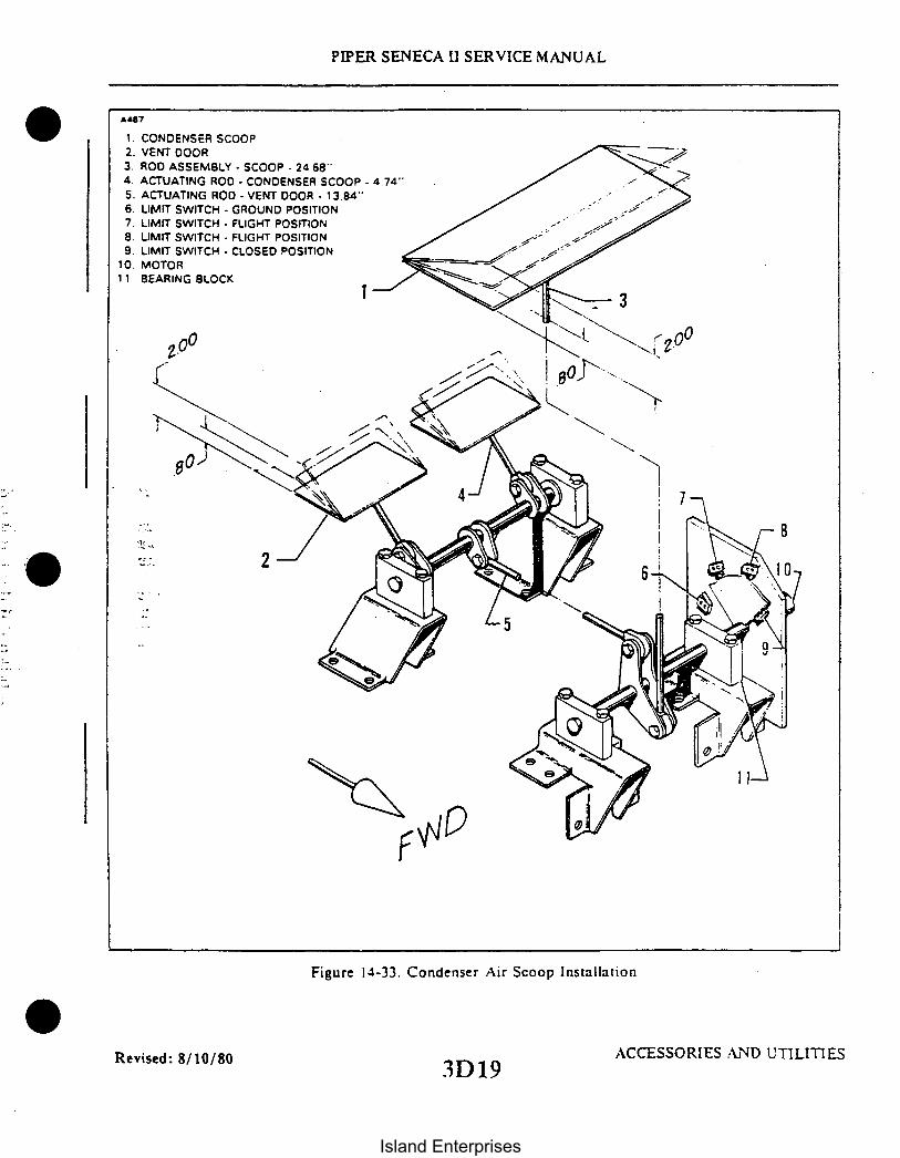
1. CONDENSER SCOOP2. VENT DOOR3. ROD ASSEMBLY - SCOOP - 24 68'4. ACTUATING ROD - CONDENSER SCOOP - 4.74"5. ACTUATING ROD - VENT DOOR - 13.84"6. LIMIT SWITCH - GROUND POSITION7. LIMIT SWITCH - FLIGHT POSITION8. LIMIT SWITCH - FLIGHT POSITION9. LIMIT SWITCH - CLOSED POSITION
10. MOTOR11 BEARING BLOCK
PIPER SENECA II SERVICE MANUAL
A487
8
2
Figure 14-33. Condenser Air Scoop Installation
Revised: 8/10/80 ACCESSORIES AND UTILITIES3D19
Island Enterprises

PIPER SENECA II SERVICE MANUAL
TO EVAPORATOR
VALVE ASS'Y
CAPILLARY COIL
FROM RECEIVERDEHYDRATOR
Figure 14-34. Expansion Valve
14-122. EXPANSION VALVE. (See Figure 14-34.)
14-123. EXPANSION VALVE REMOVAL. The expansion valve is located in the evaporator assemblybetween the receiver drier and the evaporator inlet. The capillary coil is attached to the evaporator outletline.
a. Remove the necessary access panels and discharge system.b. Remove the capillary coil from the outlet line. (Do not link the capillary tube.)c. Uncouple all related tube fittings. (See Paragraph 14-97, B-7.)
NOTE
If this part is not serviceable, it must be replaced with a new part.
14-124. EXPANSION VALVE INSTALLATION.a. Install the expansion valve in the inlet line of the evaporator core by coupling the related fittings.
(Seal all couplings with sealant applied to tube flanges only.) Torque fittings per Table XIV-X.b. Secure the capillary coil to the evaporator outlet line.c. Evacuate and charge the system. (See Paragraphs 14-104 and 14-105.) Check for leaks. (See
Paragraph 14-100.)d. Replace access panels.
Reissued: 10/11/79 ACCESSORIES AND UTILITIES3D20
Island Enterprises

PIPER SENECA II SERVICE MANUAL
14-125. EVAPORATOR ASSEMBLY. The evaporator assembly consists of the evaporator core.receiver-dehydrator. expansion valve. circulating fan and pressure switch together with necessary housingand plumbing. The housing is fabricated of Cycolac type material. The condensed moisture is dumped overboard through a hose clamped to a fitting on the bottom of the evaporator housing.
14-126. EVAPORATOR ASSEMBLY REMOVAL. The evaporator assembly is located behind the cabinrear panel. attached to the mounting panel with 12 screws and washers and a bracket securing the back tothe mounting panel.
a. Remove air conditioning filter cover. filter and rear access panels.
NOTE
Discharge the system before disassembling. (Refer to Paragraph14-34.)
b. Uncouple the liquid line from the inlet side of the receiver-dehydrator and the suction line fromthe evaporator core outlet. (See Paragraph 14-97. B-7.)
c. Disconnect the related electrical wires.d. Remove flexible air duct from housing outlet. Remove drain hose from housing.e. Remove temperature probe from evaporator housing.f. Remove the screws attaching the support bracket and evaporator housing to the mounting panel.
Remove the assembly through the access hole in the bulkhead.
14-127. EVAPORATOR ASSEMBLY INSTALLATION.a. Cement gasket in place on the flanges of the evaporator housing and attach the large end of the
mounting gasket to the back of the housing.b. Install the housing through the access hole with the air duct outlet on top. Mate the mounting
flanges to the mating surface of the mounting panel and insert the screws. (Do not tighten at this time.)c. Line up the mounting bracket with mating holes in mounting panel insert screws and tighten.
Tighten screws in the flange at this time. Be certain gasket is in place. The flange must have an air tight seal.-- d. Couple the suction and discharge lines to their respective fittings (apply Loctite refrigerant
sealant to tube flanges only).e. Evacuate and charge system. (See Paragraphs 14-104.)f. Check for leaks. (See Paragraph 14-100.) If no leaks are detected. seal and install access panel on
evaporator housing.g. Couple flexible air duct and drain tube.h. Make and check electrical connections.i. Check operation of blower and refrigerant systems.j. Install rear bulkhead panels. Be certain to seal. (See WARNING.)
WARNING
Whenever it is necessary to remove and replace the cabin rearpanel. it should be replaced and sealed in the original manner toprevent exhaust gases from entering the cabin. After removing andreplacing the rear panel. conduct a carbon monoxide test on theground and in flight with and without the air conditioner operating.Presence of CO shall not exceed one part in 20.000.
Revised: 8/10/80 ACCESSORIES AND UTILITIES3D21
Island Enterprises

PIPER SENECA II SERVICE MANUAL
WRAP TAPE AROUND THERMOSTATCAPILLARY LEAVING SERVICEPORT ACCESSIBLE.
I. SIGHT GLASS2. SERVICE VALVE (SCHRAOER) (HI)3. CAPILLARY COIL4. HOUSING ASS'5. SERVICE VALVE (SCHRADER)( LOW)6. RECEIVER DEHYORATOR CLAMP7. RECEIVER DEHYDRATOR8. PRESSURE RELIEF SWITCH (RANCO)9. EXPANSION VALVE
10. OUTLET HOSE
Figure 14-35. Components Installation
14-128. PRESSURE RELIEF SWITCH (Texas Instruments). The pressure relief switch automaticallyprevents the system from over pressurization by breaking the electrical circuit to the magnetic clutch, stoppingthe compressor until pressure is reduced. The switch is located in the line between the receiver and expansionvalve, and set to cut out at 350 ± 10 psi and cut in at 250 + 10 psi
NOTE
Before the relief switch is removed, the air conditioning systemmust be discharged. (See Paragraph 14-34.)
14-129. ELECTRICAL INSTALLATION. The electrical system, routing and component are installed androuted in the conventional aircraft manner. The wiring harness is connected to switches in the climate controlcenter on the right side of the instrument panel. The harnesses cross the instrument panel to the left side wheretwo (2) wires are taken off for the compressor clutch. The harness then passes aft along the left side of the fuse-lage where it connects to the blower motor, pressure relief switch and the condenser actuating motor.
14-130. FUSE REPLACEMENT. There are three fuses located behind the air conditioning system controlpanel. A 20 amp circuit breaker mounted in the circuit breaker panel protects the complete air conditioningelectrical system.
0
Reissued: 10/11/79 ACCESSORIES AND UTILITIES3D22
Island Enterprises

PIPER SENECA II SERVICE MANUAL
14-131. OVERHEAD VENT BLOWER
14-132. DESCRIPTION. The blower is mounted in the aft section of the fuselage and is connected to theoverhead vent system. The blower draws air in from the dorsal fin and forces it through the ducting when-ever desired. The four position blower switch is mounted in the overhead panel and controls the three speedblower.
14-133. REMOVAL OF BLOWER ASSEMBLY.a. Remove the access door from the aft wall of the baggage area.b. With the master switch off, disconnect the plug assemblies at the blower assembly.c. Remove the inlet and outlet hoses from the blower assembly by removing the clamps.d. Remove the screws, washers, and nuts that secure the blower assembly to the hanger braces.e. Remove the screws and washers which secure the blower assembly to the retainer and hangers.f. Remove the blower assembly from the aircraft.
14-134. DISASSEMBLY OF BLOWER ASSEMBLY.a. Remove the hose duct from the forward edge of the blower assembly by removing the nuts.
washers and screws.b. Remove the cover from the blower assembly by removing the nuts, washers and screws.c. Remove the blower fan from the motor shaft by removing the set screw.d. For removal of the motor, proceed as follows:
1. Separate the plate from the motor cover by carefully drilling out the connecting rivets.2. Cut the motor wires at the edge of the receptacle and plug and remove the wire ends from
the blocks.3. Remove the motor from the mounting plate by removing the nuts, washers and bolts.
14-135. REASSEMBLY OF BLOWER ASSEMBLY.a. Mount the motor on the plate and secure it with the bolts, washers and nuts. Be sure that the
motor nuts are snug and the shaft spins freely.b. Position the cover over the motor plate with the motor wires protruding through the cover
grommet.c. With the holes in the cover matching the holes in the motor plate, secure the two parts together
with rivets.d. Apply PRC-5000 sealant to fill any opening left after the wires are brought through the grommet.e. Install the wires in the plug and receptacle according to Table XIV-XII.f. Position the blower fan on the motor shaft and secure with set screw.g. Secure the cover to the blower assembly with screws, washers and nuts.h. Position the hose duct on the blower assembly and secure it with screws, washers and nuts. The
screws must be installed with their heads inside the duct.i. After cleaning the surfaces of all old sealant, use white rubber caulk PRC-5000 sealant to seal
where the duct attaches to the blower assembly.
14-136. INSTALLATION OF BLOWER ASSEMBLY.a. Position the blower assembly in the hangers and retainer and install the washers and screws.b. Install the nuts, washers, and screws securing the blower assembly to the hanger braces.c. Seal all hose joints with Arno No. C-520 gray tape; then install the inlet and outlet hoses securing
them with the clamps.d. With the master switch off, connect the plug and receptacles at the blower.e. Check the blower for the proper operation.f. Install the access door to the aft wall of the baggage area and secure with the attaching hardware.
ACCESSORIES AND UTILITIES Reissued: 10/11/79
3D23
Island Enterprises

PIPER SENECA II SERVICE MANUAL
TABLE XIV-XII. BLOWER SYSTEM WIRE COLOR CODES
MOTOR WIRES
YY1S062Pon ESB - Universal
. Elect. Company
AIRCRAFTWIRES
Aircraft PinHarness Nos.
Ground
Low Speed
High Speed
2 Brown
1 Yellow
AC26A
Black
Red
2-
1
2. I Orange
NOTEPin number 1 is at the pointed side of the plug and receptacle.
14-137. SHOULDER HARNESS INERTIA REEL ADJUSTMENT.a. Allow tue harness to wind up on the reel as much as possible.b. On the end of the reel, pry off the plastic cap over the spring, making sure the spring does note
come out of the plastic cap and set cap aside.c. Unwind the harness completely, then measure and mark the harness 24 inches from the reel
center.d. Wind the harness onto the reel until the 24 inch mark is reached, then hold reel and place cap
with spring over the reel shaft end.e. Aligning slot in shaft with spring tang, wind spring 6 turns ± 1/2 turn and snap the plastic cover
into holes in reel end shaft.f. Release harness and allowing it to wind up, extend the harness a few times to check reel for
smooth operation.g. With reel fully wound, hold with inertia mechanism end and pry off plastic cap over mechanism
and set reel aside.h. Install nut in plastic cap so that stud in cap is flush with nut surface, then reposition cap over reel
end and orientating properly, snap in place. Extend harness a few times to make sure action is correct.
Revised: 8/10/80 ACCESSORIES AND UTILITIES3D24
Island Enterprises

NO.FlF2F3KIK2DlD2All
2178
PIPER SENECA II SERVICE MANUAL
COMPONENTFuseFuseFuseRelayRelayDiodeDiodeTerminal Strip
LOCATIONInstrument PanelInstrument PanelInstrument PanelLeft Engine Nacell:Left Engine NacelleTerminal StripTerminal StripLeft Engine Nacelle
BLOWERMOTOR
LOS
Figure 14-36. Air Conditioning Wiring Schematic (Early Models)
Reissued: 10/11/79 3E3E 1
ACCESSORIES AND UTILITIES
Island Enterprises

PIPER SENECA II SERVICE MANUAL
TABLE XIV-XIII. TROUBLESHOOTING CHART (AIR CONDITIONER)TABLE XIV-XIII. TROUBLESHOOTING CHART (AIR CONDITIONER)
Gauge Indication Probable Causes Remedy
High discharge pressure. Overcharge ofrefrigerant.
Purge excess re-frigerant.
Air in system.
Overheated condenserdue to blocking airpassage.
Flooded evaporatorindicated by heavyfrosting on suctionline and compressorsuction service valve.
Restriction in liquidline from condenser.
Check for leaks. Bleedcharge from system.Evacuate and rechargesystem
Clean bugs and dirtfrom condenser fins.Straighten fins ifbent.
Check that capillarybulb is securelyclamped to suctionline. If capillarybulb OK replaceexpansion valve.
Check for kinked hosesand stopped up filter.
Low discharge pressure. Undercharge of re-frigerant. Sight glassshows bubbles or foam.
Add refrigerant untilbubbles disappear. Checksystem leaks
Damaged compressorvalves or dirt undervalves.
Damaged compressor.Worn or broken pistonor piston rings.
Replace compressor.
Replace compressor
Reissued: 10/11/79 ACCESSORIES AND UTILITIES3E2
Island Enterprises

PIPER SENECA II SERVICE MANUAL
TABLE XIV-XIII. TROUBLESHOOTING CHART (AIR CONDITIONER) (cont.)
Gauge Indication Probable Causes Remedy
Low suction pressure.(Accompanied by icingevaporator.)
Low air supply throughevaporator.
Repair blower orblower motor. Cleanstoppage in air ducts.
Very dirty evaporatorfins and coils.
Clean and flush withwater.
Low suction pressure.(Evaporator not coldenough) suction gaugemay read a vacuum in-dicating evaporatorlacks refrigerant.
Undercharge ofrefrigerant Moisturefreezing in expansionvalve. Valve will showfrost. Expansion valveinlet screen clogged.Inoperative expansionvalve. Valve stuckclosed or capillarybulb has lost itscharge.
Add refrigerant.Install new dryer.Evacuate and recharge
Remove screen.Clean with solventand replace. Warmcapillary by holdingin hand. If suctionpressure does notchange. replace ex-pansion valve.
Restriction anywherein liquid line. Re-striction will showfrost.
Locate restrictionand repair.
High suction pressure. Capillary bulb clamploose on suction line.Suction line showsfrost.
Clean contact surfacesof suction line andcap bulb. Tightenclamp.
Expansion valve notclosing. Evaporatorflooded. Suction linefrosted to compressor.
Replace expansionvalve.
ACCESSORIES AND UTILITIESReissued: 10/11/79
3E3
Island Enterprises

PIPER SENECA I SERVICE MANUAL
TABLE XIV-XIII. TROUBLESHOOTING CHART (AIR CONDITIONER) (cont.)
Gauge Indication Probable Causes Remedy
High suction pressure.(cont.)
Compressor drive beltslipping.
Adjust belt tension.
Magnetic clutchslipping.
Leaking or brokencompressor valves.
Cause
Check electricalcircuit for correctvoltage to clutchcoil. Clean clutchsurfaces of oil.
Replace compressor.
RemedyTrouble
Door will not closewhen air conditionerswitch is in OFFposition.
Faulty relay "K-2." Replace relay.
System produces nocooling.
Electrical.
Blown fuse incontrol head.
Open circuit breaker.
Broken or disconnectedelectrical wire.
Broken or disconnectedground wire.
Clutch coil burned outor disconnected.
Replace fuse.
Reset circuit breaker.
Check all terminalsfor loose connections;check wiring for hiddenbreaks.
Check ground wire toto see if loose, broken,or disconnected.
Check current flow toclutch, replace ifinoperative.
ACCESSORIES AND UTILITIESReissued: 10/11/793E4
Island Enterprises

PIPER SENECA II SERVICE MANUAL
TABLE XIV-XIII. TROUBLESHOOTING CHART (AIR CONDITIONER) (cont.)
Trouble Cause Remedy
System produces nocooling. (cont.)
Electrical. (cont.)
Thermostat sensingelement defective.
Check thermostat andcabin comfort controlpanel.
Blower motor dis-connected or burnedout.
Check current flowto blower motor.Repair or replace ifinoperative.
Mechanical
Loose or broken drivebelt.
Compressor partiallyor completely frozen.
Expansion valve stuckin open position.
Replace drive beltsand/or tighten tospecifications
Remove compressor forservice or replacement,
Replace expansionvalve.
O
Refrigeration
Broken regrigerantline.
Leak in system.
Examine all lines forevidence of breakageby external stress orrubbing wear.
Evacuate system, applystatic charge, leaktest system, and repairleak as necessary.
ACCESSORIES AND UTILITIESReissued: 10/11/793E5
Island Enterprises
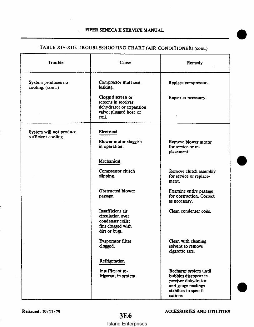
PIPER SENECA II SERVICE MANUAL
TABLE XIV-XIII. TROUBLESHOOTING CHART (AIR CONDITIONER) (cont.)
Trouble Cause Remedy
System produces nocooling. (cont.)
Compressor shaft sealleaking.
Replace compressor.
Clogged screen orscreens in receiverdehydrator or expansionvalve; plugged hose orcoil.
Repair as necessary.
System will not producesufficient cooling.
Electrical
Blower motor sluggishin operation.
Remove blower motorfor service or re-placement.
Mechanical
Compressor clutchslipping.
Obstructed blowerpassage.
Insufficient aircirculation overcondenser coils;fins clogged withdirt or bugs.
Evaporator filterclogged.
Remove clutch assemblyfor service or replace-ment.
Examine entire passagefor obstruction. Correctas necessary.
Clean condenser coils.
Clean with cleaningsolvent to removecigarette tars.
Refrigeration
Insufficient re-frigerant in system.
Recharge system untilbubbles disappear inreceiver dehydratorand gauge readingsstabilize to specifi-cations.
ACCESSORIES AND UTILITIESReissued: 10/11/793E6
Island Enterprises

PIPER SENECA I SERVICE MANUAL
TABLE XIV-XIII. TROUBLESHOOTING CHART (AIR CONDITIONER) (cont.)
Trouble Cause Remedy
Excessively noisysystem. (cont.)
Electrical
Compressor noisy. Check mountings andrepair; remove com-pressor for serviceor replacement.
Compressor oil levellow.
Fill with correctamount of specifiedoil.
Refrigeration
Excessive charge insystem.
Low charge in system.
Excessive moisture insystem.
Discharge excess freonuntil high pressuregauge drops withinspecifications.
Check system forleaks; charge system.
Replace dehydrator;purge, evacuate, andcharge system.
ACCESSORIES AND UTILITIESReissued: 10/11/793E7
Island Enterprises

PIPER SENECA II SERVICE MANUAL
TABLE XIV-XIII. TROUBLESHOOTING CHART (AIR CONDITIONER) (cont.)
Trouble Cause Remedy
System will notproduce sufficientcooling. (cont.)
Mechanical
Clogged screen inexpansion valve.
Expansion valvethermal bulb haslost charge.
Clogged screen inreceiver dehydrator.
Excessive mositurein system.
Air in system.
Purge system and re-place expansion valve.
Purge system; replaceexpansion valve.
Purge system; replacereceiver dehydrator.
Purge system; replacereceiver dehydrator.
Purge, evacuate andcharge system (Re -place receiver de-hydrator.)
0
Excessively noisysystem.
Electrical
Defective winding orimproper connectionin compressor clutchcoil.
Replace or repairas necessary.
Mechanical
Loose or excessivelyworn drive belts.
Noisy clutch.
Tighten or replace asrequired
Remove clutch forservice or replace-ment as necessary.
ACCESSORIES AND UTILITIESReissued: 10/11/793E8
Island Enterprises

PIPER SENECA II SERVICE MANUAL
14-138. ENGINE SYNCHROPHASER.
14-139. DESCRIPTION OF SYNCHROPHASER SYSTEMS. Two types of synchrophasing systems arebeing used in the Seneca II, one utilizing an "AUTO SYNCH/MANUAL" (ASM) control, the other an"OFF/PHASE ADJUSTMENT" (OPA) control. The functional equipment is the same for both systems, andconsists of right and left pulse generators, phasing computer, and a 5 amp circuit breaker. Schematic descrip-tions for the two systems can be found in Figures 14-37 and 14-37a.
The two systems are designed to hold the engines in synch, or phase, after the engines have been manuallysynchronized to within 30 to 40 RPM. The computer senses the out of synch/ phase condition with the switchesturned on, and automatically tunes the slave (right) engine with that of the master (left) engine. Should thecircuit breaker be pulled, master switch switched off, or an electrical failure occur, the slave engine will returnto the controlled (selected) RPM. plus approximately 25 RPM "out of synch" regardless of the position of thecontrol switch. Both systems must be turned off (or in manual) during taxi. takeoff, landing, and single engineoperation.
The "Auto Synch/ Manual" (AS M) control system operates on a fixed phase angle basis and only controlsthe synchronization through the particular phase angle of the master engine. This system cannot be adjustedin flight.
With the "Phase Adjustment" (OPA) control system, the phase angle of the propellers can be adjusted byrotating the switch in the "Phase Adjustment" range to obtain the smoothest operation.
14-140. SYSTEM OPERATING PROCEDURE. The selector switch must be in the manual or off positionduring engine start, warm-up, taxi, and take-off.
NOTE
With full throttle and full RPM the governors should be set withinthe synchrophasing range; if not consult Section VIII of thisService Manual for high RPM setting adjustment.
Upon reaching cruise configuration the propellers should be synchronized manually to within approxi-mately 30 RPM for the ASM control system, and 40 RPM for the OPA system. For system activation theASM switch should be moved to the "Auto Sync" position and the OPA rotary switch moved slightly into the"Phase Adjustment" position. The particular system should synchronize the propellers in a few seconds butoccasionally may take up to a full minute for the ASM system or 30 seconds for the OPA system.
The ASM control system should synchronize or phase in the engines as previously described: however.if the power settings are changed. or if an RPM differential between the two engines exceeds 50 RPM. theswitch should be placed in "Manual" for 30 to 40 seconds and the procedure reinitiated.
The OPA system has the advantage over the ASM system in that the phase angle of the propellers can beadjusted by rotating the switch to obtain the smoothest operation. After any adjustment remember to wait atleast 30 seconds. When changing power settings the system should be turned off and the previous proceduresreinitiated.
Revised: 8/10/80 ACCESSORIES AND UTILITIES
3E9
Island Enterprises

PIPER SENECA II SERVICE MANUAL
14-140a. INDUCTOR AND KIT INSTALLATIONS. (Refer to Figures 14-37 and 14-37a.) On earlyinstallations which used the "Auto Synch Manual" controlled system. an inductor was not incorporated inthe system but was added later to remove radio interference. If the inductor or a newer computer (which hasthe inductor incorporated) have not been retrofitted. the schematics herein and available kits should beappropriately considered.
14-141. SYNCHROPHASER SYSTEM CHECK AND ADJUSTMENT. The following wiring harnesschecks require the use of Hartzell Test Set B-4467.
a. Power light operating-indicates power supply to the system computer is of the proper polarity.b. Right or Left engine lights operating-indicates pulse generator for applicable engine is operating
properly and correctly wired.c. AUTO SYNC or MANUAL light operating-aircraft system AUTO SYNC/MANUAL switch is
wired correctly.d. Coil light operating-governor solenoid coil is wired correctly.e. Coil light not operating-open circuit. or wire on Pin Number 8 is grounded.f. Coil short light operating-short circuit in governor solenoid coil or a short between coil leads.
14-142. GROUND CHECKS.a. Disconnect the synchrophaser computer from the wiring harness.b. Connect Hartzell Test Set B-4467 to wiring harness at point where computer was disconnected.c. Turn battery master switch ON and place synchrophaser mode switch in AUTO SYNC position. Test
set power light and coil light should be lighted.
NOTE
Other lights on the test set may be lighted, but should be ignoredwith this exception: if coil short light is lighted, place aircraftmaster switch in off position and replace governor solenoid coil.
d. If either the right or left engine lights are lighted, attempt to extinguish the light by rotatingappropriate propeller in direction of normal rotation. If lights are not lighted, attempt to light by rotatingpropeller.
e. Place synchrophaser mode switch in the manual position. The test set manual light should light andthe phase light should extinguish. Placing mode switch in AUTO SYNC position should cause the reverse tooccur.
Revised: 8/10/80 3 ACCESSORIES AND UTIIIES3E 10
Island Enterprises

PIPER SENECA II SERVICE MANUAL
2843A
I COMPUTER
(HARTZELL C-4362-2)
SYNCHROPHASER
MODE SWITCH
C/B PANEL INDUCTOR
AMP
RIGHT PULSEGENERATOR
LEFT PULSEGENERATOR
RIGHTGOVERNOR
Figure 14-37. Synchrophaser Wiring Schematic - Auto Synch/Manual SwitchI
Revised: 8/10/80 ACCESSORIES AND UTILITIES3Ell
Island Enterprises
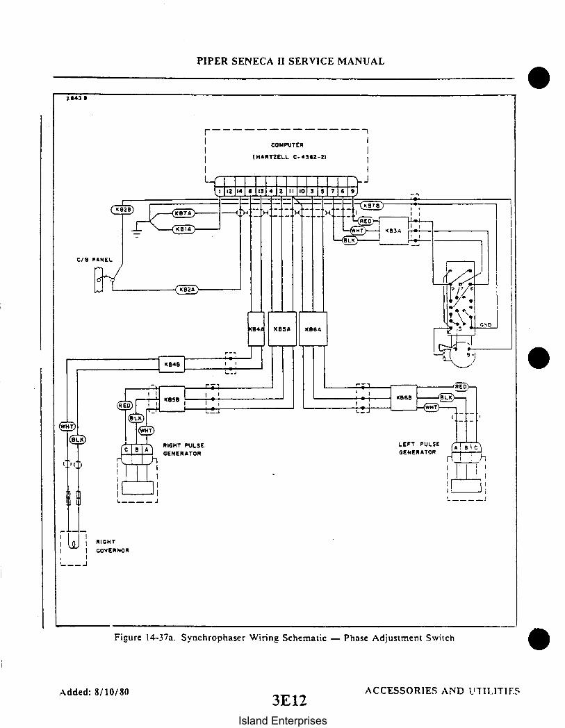
I _
C/B
WHT
(B)K
'
PIPER SENECA II SERVICE MANUAL
2 243 B
-- ---| COMPUTER
(HARTZELL C-4362-2)
I
. -J
RIGHT PULSEGENERATOR
LEFT PULSE
GENERATOR
-
L__J
RIGHT
GOVERNOR
Figure 14-37a. Synchrophaser Wiring Schematic - Phase Adjustment Switch
Added: 8/10/803E12
ACCESSORIES AND TIL.ITIF
Island Enterprises

11
PIPER SENECA II SERVICE MANUAL
A A5
1. MOUNTING BRACKET2. COMPUTER3. PULSE GENERATOR4 TACHOMETERS5. TACH CABLE6. TACH CABLE
7. WIRING HARNESS8. TACH DRIVE9. SLAVE GOVERNOR ASSEMBLY
10 CONTROL PEDESTAL11 SYNCHROPHASER CONTROL SWITCH12. SYNCHROPHASER POTENTIOMETER CONTROL
12
J
la
"AUTO-SYNCH"(FIXED PHASE)INSTALLATION
"PHASE ADJUSTMENT"(VARIABLE PHASE)INSTALLATION
Figure 14-38. Engine Synchrophaser Installation
Revised: 8/10/80 ACCESSORIES AND UTILITIES3E13
Island Enterprises

PIPER SENECA II SERVICE MANUAL
NOTE
Failure of tesf lights to operate may indicate a defective wiringharness. Should the wiring harness prove to be good, but theengine lights or coil light fail to function properly, replace theapplicable pulse generator or governor.
f. Disconnect the test set from the aircraft and reconnect the computer.
14-143. FLIGHT CHECK.a. At cruise altitude, set the engine controls at 75 percent power.b. Beat synchronize the propellers.c. With the propeller control, increase or decrease right engine speed approximately 50 revolutions per
minute (RPM).d. Place the synchrophaser mode switch in the AUTO SYNC position. The propellers will synchronize
automatically if the system is operating properly. If synchronization is not attained return mode switch toMANUAL for 30 to 45 seconds. Resynchronize the engines manually to within 25 to 30 RPM of each other.Return the mode switch to the AUTO SYNC position. If synchronization is again not attained, repeat 14-143above, then repeat flight check.
NOTE
Place synchrophaser mode switch in manual position for all take-off, landing and engine-out operations.
14-144. REMOVAL OF COMPUTER ASSEMBLY.The computer assembly is located in the nose section of the aircraft at station 49.50. It is mounted on the
de-ice mounting bracket which is in turn attached to the nose gear mount lower tubes.a. Remove baggage compartment trim panels to gain access to the computer.b. Disconnect the electrical plug from the computer assembly.c. Remove the four (4) screws and washers securing the computer assembly to the mounting bracket.d. Remove the computer assembly from the airplane.
14-145. INSTALLATION OF COMPUTER ASSEMBLY.a. Position the computer assembly on the mounting bracket and secure with screws and washers
previously removed.b. Reconnect electrical plug to computer assembly.c. Install baggage compartment trim panels previously removed.
Reissued: 10/11/79 ACCESSORIES AND UTILITIES3E14
Island Enterprises

7
1. PULSE GENERATOR ASSEMBLY 92. TACHOMETER SHAFT3. TACHOMETER SHAFT4. WASHER5. BRACKET6. BRACKET7. TAB WASHER8. ELECTRICAL PLUG9. HEX NUT
Figure 14-39. Pulse Generator Installation
14-146. REMOVAL OF PULSE GENERATOR (Figure 14-39.)There is a pulse generator on each engine. They are mounted on the engine mount tubes at the top of the
engine.a. Remove the engine cowling right access panel.b. Remove the electrical plug (8) from the pulse generator (1).c. Loosen the knurled nuts securing the tachometer shafts to the pulse generator and remove the shafts
from the pulse generator assembly.d. Remove the two hex nuts (9), tab washers (7) and washers (4).e. Loosen the screws and nuts securing the mounting brackets (5 & 6) to the engine mount tubes.f. Spread the brackets sufficiently to allow the pulse generator to be removed.
14-147. INSTALLATION OF PULSE GENERATOR (Figure 14-39.)a. Place the pulse generator in position between the mounting brackets (5 & 6).b. Press brackets together and install washer (4), a new tab washer (7) and the hex nut (9).c. Tighten the nuts and screws securing the brackets to the engine mount tubes.d. Attach tachometer shafts (2 & 3) to pulse generator.e. Attach the electrical plug to the pulse generator.
Reissued: 10/11/79 ACCESSORIES AND UTILITES
PIPER SENECA II SERVICE MANUAL
3E15
Island Enterprises

3E16 THRU 3L24INTENTIONALLY LEFT BLANK
Island Enterprises