
7005/7015 User Manual - TEquipment
60
Model 7005/7015 Calibration Bath User Manual Rev. 932601
-
Upload
khangminh22 -
Category
Documents
-
view
3 -
download
0
Transcript of 7005/7015 User Manual - TEquipment
Model7005/7015CalibrationBath
UserManual
Rev. 932601

2
© Copyright,1995 All Rights Reserved
Hart Scientific799 E. Utah Valley DriveAmerican Fork, Utah 84003-9775Telephone: (801) 763-1600 • Fax: (801) 763-1010Internet: http://www.hartscientific.com
WARNINGTo ensure the safety of operating personnel, and to avoid damage to this unit:
DO NOT operate this unit without a properly grounded, properly polarized power cord.DO NOT connect this unit to a non-grounded, non-polarized outlet.
DO use a ground fault interrupt device.
WARNINGEXTREMELY COLD TEMPERATURES PRESENT
in this equipment.FREEZER BURNS AND FROSTBITE
may result if personnel fail to observe safety precautions.
WARNINGHIGH TEMPERATURES PRESENT
in this equipment.FIRES AND SEVERE BURNS
may result if personnel fail to observe safety precautions.
WARNINGFluids used in this bath may produce
NOXIOUS OR TOXIC FUMESunder certain circumstances.
Consult the fluid manufacturer’s MSDS (Material Safety Data Sheet).PROPER VENTILATION AND
SAFETY PRECAUTIONS MUST BE OBSERVED.
WARNINGCALIBRATION EQUIPMENT SHOULD ONLY BE USED BY TRAINED PERSONNEL.
a
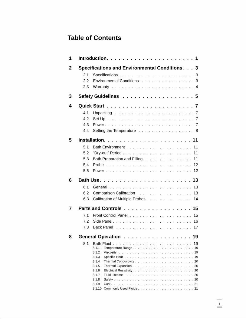
Table of Contents
1 Introduction. . . . . . . . . . . . . . . . . . . . . . 1
2 Specifications and Environmental Conditions . . . 32.1 Specifications . . . . . . . . . . . . . . . . . . . . . . . 3
2.2 Environmental Conditions . . . . . . . . . . . . . . . . 3
2.3 Warranty . . . . . . . . . . . . . . . . . . . . . . . . . 4
3 Safety Guidelines . . . . . . . . . . . . . . . . . . 5
4 Quick Start . . . . . . . . . . . . . . . . . . . . . . 74.1 Unpacking . . . . . . . . . . . . . . . . . . . . . . . . 7
4.2 Set Up . . . . . . . . . . . . . . . . . . . . . . . . . . 7
4.3 Power . . . . . . . . . . . . . . . . . . . . . . . . . . . 7
4.4 Setting the Temperature . . . . . . . . . . . . . . . . . 8
5 Installation. . . . . . . . . . . . . . . . . . . . . . 115.1 Bath Environment . . . . . . . . . . . . . . . . . . . . 11
5.2 “Dry-out” Period . . . . . . . . . . . . . . . . . . . . . 11
5.3 Bath Preparation and Filling . . . . . . . . . . . . . . . 11
5.4 Probe . . . . . . . . . . . . . . . . . . . . . . . . . . 12
5.5 Power . . . . . . . . . . . . . . . . . . . . . . . . . . 12
6 Bath Use. . . . . . . . . . . . . . . . . . . . . . . 136.1 General . . . . . . . . . . . . . . . . . . . . . . . . . 13
6.2 Comparison Calibration . . . . . . . . . . . . . . . . . 13
6.3 Calibration of Multiple Probes . . . . . . . . . . . . . . 14
7 Parts and Controls . . . . . . . . . . . . . . . . . 157.1 Front Control Panel . . . . . . . . . . . . . . . . . . . 15
7.2 Side Panel . . . . . . . . . . . . . . . . . . . . . . . . 16
7.3 Back Panel . . . . . . . . . . . . . . . . . . . . . . . 17
8 General Operation . . . . . . . . . . . . . . . . . 198.1 Bath Fluid . . . . . . . . . . . . . . . . . . . . . . . . 19
8.1.1 Temperature Range . . . . . . . . . . . . . . . . . . . . . . . 198.1.2 Viscosity. . . . . . . . . . . . . . . . . . . . . . . . . . . . . 198.1.3 Specific Heat . . . . . . . . . . . . . . . . . . . . . . . . . . 198.1.4 Thermal Conductivity . . . . . . . . . . . . . . . . . . . . . . 208.1.5 Thermal Expansion . . . . . . . . . . . . . . . . . . . . . . . 208.1.6 Electrical Resistivity . . . . . . . . . . . . . . . . . . . . . . . 208.1.7 Fluid Lifetime . . . . . . . . . . . . . . . . . . . . . . . . . . 208.1.8 Safety . . . . . . . . . . . . . . . . . . . . . . . . . . . . . . 208.1.9 Cost . . . . . . . . . . . . . . . . . . . . . . . . . . . . . . . 218.1.10 Commonly Used Fluids . . . . . . . . . . . . . . . . . . . . . 21
i
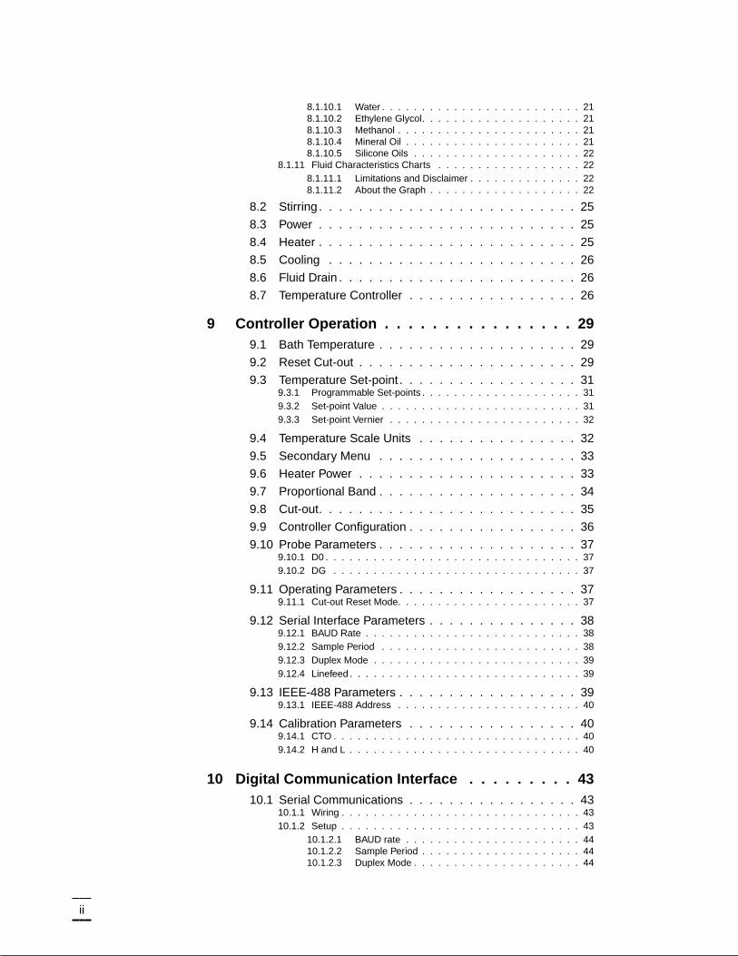
8.1.10.1 Water . . . . . . . . . . . . . . . . . . . . . . . . . 218.1.10.2 Ethylene Glycol. . . . . . . . . . . . . . . . . . . . 218.1.10.3 Methanol . . . . . . . . . . . . . . . . . . . . . . . 218.1.10.4 Mineral Oil . . . . . . . . . . . . . . . . . . . . . . 218.1.10.5 Silicone Oils . . . . . . . . . . . . . . . . . . . . . 22
8.1.11 Fluid Characteristics Charts . . . . . . . . . . . . . . . . . . 228.1.11.1 Limitations and Disclaimer . . . . . . . . . . . . . . 228.1.11.2 About the Graph . . . . . . . . . . . . . . . . . . . 22
8.2 Stirring . . . . . . . . . . . . . . . . . . . . . . . . . . 25
8.3 Power . . . . . . . . . . . . . . . . . . . . . . . . . . 25
8.4 Heater . . . . . . . . . . . . . . . . . . . . . . . . . . 25
8.5 Cooling . . . . . . . . . . . . . . . . . . . . . . . . . 26
8.6 Fluid Drain . . . . . . . . . . . . . . . . . . . . . . . . 26
8.7 Temperature Controller . . . . . . . . . . . . . . . . . 26
9 Controller Operation . . . . . . . . . . . . . . . . 299.1 Bath Temperature . . . . . . . . . . . . . . . . . . . . 29
9.2 Reset Cut-out . . . . . . . . . . . . . . . . . . . . . . 29
9.3 Temperature Set-point . . . . . . . . . . . . . . . . . . 319.3.1 Programmable Set-points . . . . . . . . . . . . . . . . . . . . 319.3.2 Set-point Value . . . . . . . . . . . . . . . . . . . . . . . . . 319.3.3 Set-point Vernier . . . . . . . . . . . . . . . . . . . . . . . . 32
9.4 Temperature Scale Units . . . . . . . . . . . . . . . . 32
9.5 Secondary Menu . . . . . . . . . . . . . . . . . . . . 33
9.6 Heater Power . . . . . . . . . . . . . . . . . . . . . . 33
9.7 Proportional Band . . . . . . . . . . . . . . . . . . . . 34
9.8 Cut-out. . . . . . . . . . . . . . . . . . . . . . . . . . 35
9.9 Controller Configuration . . . . . . . . . . . . . . . . . 36
9.10 Probe Parameters . . . . . . . . . . . . . . . . . . . . 379.10.1 D0 . . . . . . . . . . . . . . . . . . . . . . . . . . . . . . . . 379.10.2 DG . . . . . . . . . . . . . . . . . . . . . . . . . . . . . . . 37
9.11 Operating Parameters . . . . . . . . . . . . . . . . . . 379.11.1 Cut-out Reset Mode. . . . . . . . . . . . . . . . . . . . . . . 37
9.12 Serial Interface Parameters . . . . . . . . . . . . . . . 389.12.1 BAUD Rate . . . . . . . . . . . . . . . . . . . . . . . . . . . 389.12.2 Sample Period . . . . . . . . . . . . . . . . . . . . . . . . . 389.12.3 Duplex Mode . . . . . . . . . . . . . . . . . . . . . . . . . . 399.12.4 Linefeed . . . . . . . . . . . . . . . . . . . . . . . . . . . . . 39
9.13 IEEE-488 Parameters . . . . . . . . . . . . . . . . . . 399.13.1 IEEE-488 Address . . . . . . . . . . . . . . . . . . . . . . . 40
9.14 Calibration Parameters . . . . . . . . . . . . . . . . . 409.14.1 CTO . . . . . . . . . . . . . . . . . . . . . . . . . . . . . . . 409.14.2 H and L . . . . . . . . . . . . . . . . . . . . . . . . . . . . . 40
10 Digital Communication Interface . . . . . . . . . 4310.1 Serial Communications . . . . . . . . . . . . . . . . . 43
10.1.1 Wiring . . . . . . . . . . . . . . . . . . . . . . . . . . . . . . 4310.1.2 Setup . . . . . . . . . . . . . . . . . . . . . . . . . . . . . . 43
10.1.2.1 BAUD rate . . . . . . . . . . . . . . . . . . . . . . 4410.1.2.2 Sample Period . . . . . . . . . . . . . . . . . . . . 4410.1.2.3 Duplex Mode . . . . . . . . . . . . . . . . . . . . . 44
ii
10.1.2.4 Linefeed . . . . . . . . . . . . . . . . . . . . . . . 4410.1.3 Serial Operation. . . . . . . . . . . . . . . . . . . . . . . . . 44
10.2 IEEE-488 Communication (optional) . . . . . . . . . . 4510.2.1 Setup . . . . . . . . . . . . . . . . . . . . . . . . . . . . . . 45
10.2.1.1 IEEE-488 Interface Address . . . . . . . . . . . . . 4510.2.2 IEEE-488 Operation. . . . . . . . . . . . . . . . . . . . . . . 45
10.3 Interface Commands . . . . . . . . . . . . . . . . . . 45
10.4 Power Control Functions . . . . . . . . . . . . . . . . 4710.4.1 Heater Control . . . . . . . . . . . . . . . . . . . . . . . . . 4810.4.2 Cooling Control . . . . . . . . . . . . . . . . . . . . . . . . . 48
11 Calibration Procedure . . . . . . . . . . . . . . . 4911.1 Calibration Points . . . . . . . . . . . . . . . . . . . . 49
11.2 Measuring the Set-point Error . . . . . . . . . . . . . . 49
11.3 Computing D0 and Dg. . . . . . . . . . . . . . . . . . 49
11.4 Calibration Example . . . . . . . . . . . . . . . . . . . 50
12 Charging Instructions . . . . . . . . . . . . . . . 5312.1 Preparation . . . . . . . . . . . . . . . . . . . . . . . 53
12.2 Charging. . . . . . . . . . . . . . . . . . . . . . . . . 53
13 Maintenance. . . . . . . . . . . . . . . . . . . . . 5513.1 Draining the Bath . . . . . . . . . . . . . . . . . . . . 56
14 Troubleshooting. . . . . . . . . . . . . . . . . . . 5714.1 Troubleshooting . . . . . . . . . . . . . . . . . . . . . 57
14.1.1 Master Reset Sequence . . . . . . . . . . . . . . . . . . . . 59
14.2 Wiring Diagram . . . . . . . . . . . . . . . . . . . . . 60
iii
iv
Figures and Tables
Figure 1 Bath Assembly . . . . . . . . . . . . . . . . . . . . . . . . 1Table 1 Specifications. . . . . . . . . . . . . . . . . . . . . . . . . 3Figure 2 Front Panel . . . . . . . . . . . . . . . . . . . . . . . . . 15Figure 3. Refrigeration Controls - Side Panel . . . . . . . . . . . . . 16Figure 4 Back Panel . . . . . . . . . . . . . . . . . . . . . . . . . 18Figure 5 Chart of various bath fluids and their properties . . . . . . 23Table 2 Table of various bath fluids and their properties . . . . . . 24Figure 6 Controller Operation Flowchart . . . . . . . . . . . . . . . 30Figure 7 Bath temperature fluctuation at various proportional
band settings . . . . . . . . . . . . . . . . . . . . . . . . 34Table 3 Proportional Band — Fluid Table . . . . . . . . . . . . . . 35Figure 8 Serial Communications Cable Wiring . . . . . . . . . . . . 43Table 4 Interface Command Summary. . . . . . . . . . . . . . . . 46Table 4 Digital Communications Commands continued . . . . . . . 47Table 5 Serial Power Control Functions . . . . . . . . . . . . . . . 48Table 6 Temperature Range Control Functions . . . . . . . . . . . 48Figure 9 Sample Calibration Computations . . . . . . . . . . . . . 51Figure 10 Wiring Diagram . . . . . . . . . . . . . . . . . . . . . . . 60
1 Introduction
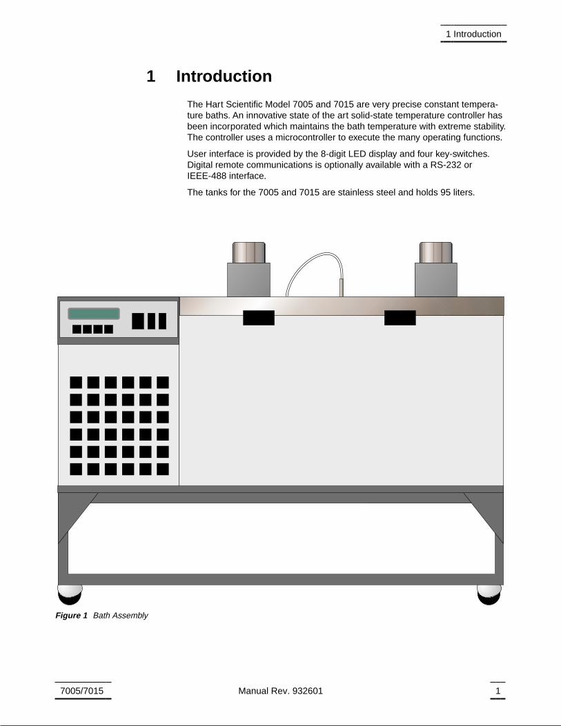
The Hart Scientific Model 7005 and 7015 are very precise constant tempera-ture baths. An innovative state of the art solid-state temperature controller hasbeen incorporated which maintains the bath temperature with extreme stability.The controller uses a microcontroller to execute the many operating functions.
User interface is provided by the 8-digit LED display and four key-switches.Digital remote communications is optionally available with a RS-232 orIEEE-488 interface.
The tanks for the 7005 and 7015 are stainless steel and holds 95 liters.
7005/7015 Manual Rev. 932601 1
1 Introduction
Figure 1 Bath Assembly
2 Specifications and EnvironmentalConditions
2.1 Specifications
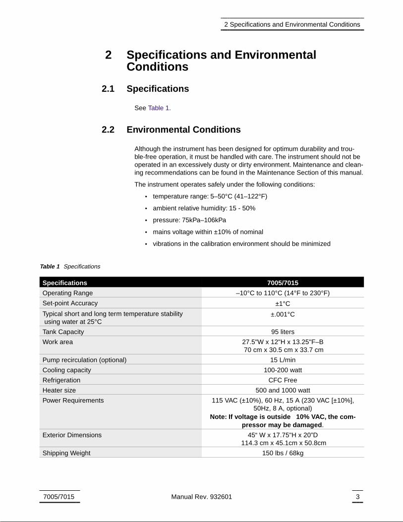
See Table 1.
2.2 Environmental Conditions
Although the instrument has been designed for optimum durability and trou-ble-free operation, it must be handled with care. The instrument should not beoperated in an excessively dusty or dirty environment. Maintenance and clean-ing recommendations can be found in the Maintenance Section of this manual.
The instrument operates safely under the following conditions:
• temperature range: 5–50°C (41–122°F)
• ambient relative humidity: 15 - 50%
• pressure: 75kPa–106kPa
• mains voltage within ±10% of nominal
• vibrations in the calibration environment should be minimized
7005/7015 Manual Rev. 932601 3
2 Specifications and Environmental Conditions
Specifications 7005/7015
Operating Range –10°C to 110°C (14°F to 230°F)
Set-point Accuracy ±1°C
Typical short and long term temperature stabilityusing water at 25°C
±.001°C
Tank Capacity 95 liters
Work area 27.5"W x 12"H x 13.25"F–B70 cm x 30.5 cm x 33.7 cm
Pump recirculation (optional) 15 L/min
Cooling capacity 100-200 watt
Refrigeration CFC Free
Heater size 500 and 1000 watt
Power Requirements 115 VAC (±10%), 60 Hz, 15 A (230 VAC [±10%],50Hz, 8 A, optional)
Note: If voltage is outside 10% VAC, the com-pressor may be damaged.
Exterior Dimensions 45“ W x 17.75"H x 20”D114.3 cm x 45.1cm x 50.8cm
Shipping Weight 150 lbs / 68kg
Table 1 Specifications

• altitude does not effect the performance or safety of the unit
2.3 Warranty
Hart Scientific, Inc. (Hart) warrants this product to be free from defects in ma-terial and workmanship under normal use and service for a period as stated inour current product catalog from the date of shipment. This warranty extendsonly to the original purchaser and shall not apply to any product which, inHart’s sole opinion, has been subject to misuse, alteration, abuse or abnormalconditions of operation or handling.
Software is warranted to operate in accordance with its programmed instruc-tions on appropriate Hart products. It is not warranted to be error free.
Hart’s obligation under this warranty is limited to repair or replacement of aproduct which is returned to Hart within the warranty period and is determined,upon examination by Hart, to be defective. If Hart determines that the defect ormalfunction has been caused by misuse, alteration, abuse or abnormal condi-tions or operation or handling, Hart will repair the product and bill the pur-chaser for the reasonable cost of repair.
To exercise this warranty, the purchaser must forward the product after callingor writing Hart for authorization. Hart assumes NO risk for in-transit damage.
For service or assistance, please contact the manufacturer.
Hart Scientific, Inc.
799 East Utah Valley Drive
American Fork, UT 84003-9775
Phone: (801) 763-1600Fax: (801) 763-1010
E-mail: [email protected]
THE FOREGOING WARRANTY IS PURCHASER’S SOLE AND EXCLUSIVEREMEDY AND IS IN LIEU OF ALL OTHER WARRANTIES, EXPRESS OR IM-PLIED, INCLUDING BUT NOT LIMITED TO ANY IMPLIED WARRANTY ORMERCHANTABILITY, OR FITNESS FOR ANY PARTICULAR PURPOSE ORUSE. HART SHALL NOT BE LIABLE FOR ANY SPECIAL, INDIRECT, INCI-DENTAL, OR CONSEQUENTIAL DAMAGES OR LOSS WHETHER IN CON-TRACT, TORT, OR OTHERWISE.
4 Manual Rev. 932601 Hart Scientific
2 Specifications and Environmental Conditions
3 Safety Guidelines
• Operate the bath in room temperatures between 5-50°C (41-122°F).Allowsufficient air circulation by leaving at least 6 inches of space between thebath and nearby objects. Overhead clearance needs to allow for safe andeasy insertion and removal of probes for calibration.
• If the bath is used at higher temperatures where fluid vaporization is signif-icant, a fume hood should be used.
• The bath is a precision instrument. Although it has been designed for opti-mum durability and trouble free operation, it must be handled with care.The instrument should not be operated in excessively dusty or dirty envi-ronments. Do not operate near flammable materials.
• The bath generates extreme temperatures. Precautions must be taken toprevent personal injury or damage to objects. Probes may be extremelyhot or cold when removed from the bath. Cautiously handle probes to pre-vent personal injury. Carefully place probes on a heat/cold resistant sur-face or rack until they are at room temperature.
• Use only a grounded AC mains supply of the appropriate voltage to powerthe bath.The bath requires 15 amps at 115 VAC (±10%), 60 Hz. (8 amps at230 VAC [±10%], 50 Hz, optional)
• Before initial use, after transport, and anytime the instrument has not beenenergized for more than 10 days, the bath needs to be energized for a“dry-out” period of 1-2 hours before it can be assumed to meet all of thesafety requirements of the IEC 1010-1.
• The bath is equipped with operator accessible fuses. If a fuse blows, it maybe due to a power surge or failure of a component. Replace the fuse once.If the fuse blows a second time, it is likely caused by failure of a componentpart. If this occurs, contact Hart Scientific Customer Service. Always re-place the fuse with one of the same rating, voltage, and type. Never re-place the fuse with one of a higher current rating.
• If a mains supply power fluctuation occurs, immediately turn off the bath.Power bumps from brown-outs and black-outs can damage the compres-sor. Wait until the power has stabilized before re-energizing the bath.
• This bath is not designed to be portable.Therefore, moving the bath once ithas been installed should be kept to a minimum.Never move a bath that isfull of fluid. This action could be extremely dangerous and could result inpersonal injury to the person moving the bath. If the bath is going to beplaced in an area where it will need to be moved frequently, a special cartcan be designed to accommodate the bath making the bath much moreportable. Hart sells carts designed for these baths. However, even with acart the bath should not be moved full of fluid.The fluid can splash causinginjury or if the bath and cart tip, the fluid could cause damage to the sur-rounding area and personal injury to personnel.
• If the bath must be moved, be sure to drain the fluid to prevent any injury.The side of the bath with the compressor is heavier than the tank side. Tosafely move the bath, two people are required.
7005/7015 Manual Rev. 932601 5
3 Safety Guidelines
4 Quick Start
CAUTIONREAD SECTION 6 ENTITLED
BATH USEbefore placing the bath in service.
Incorrect handling can damage the bath and void the warranty.
This section gives a brief summary of the steps required to set up and operatethe 7005/7015 bath. This should be used as a general overview and referenceand not as a substitute for the remainder of the manual. Please read Section 5through 7 carefully before operating the bath.
4.1 Unpacking
Unpack the bath carefully and inspect it for any damage that may have oc-curred during shipment. If there is shipping damage, notify the carrier immedi-ately.
Verify that all components are present:
• 7005/7015 Bath
• Controller Probe
• Access Hole Cover
• Manual
If you are missing any item, please call Hart Scientific Customer Service at801-763-1600.
4.2 Set Up
Set up of the bath requires careful unpacking and placement of the bath, fillingthe bath with fluid, installing the probe and connecting power. Consult Section5 for detailed instructions for proper installation of the bath. Be sure to placethe bath in a safe, clean and level location.
Fill the bath tank with an appropriate liquid. For operation at moderate bathtemperatures, clean distilled water works well. Carefully pour the fluid into thebath tank through the large rectangular access hole above the tank avoidingspilling any fluid. The fluid must not exceed a height of 1/2 inch below the bathlid.
The control probe must be inserted through the lid into the bath and pluggedinto the socket at the back of the bath.
4.3 Power
Plug the bath power cord into a mains outlet of the proper voltage, frequency,and current capability. Typically this will be 115 VAC (±10%), 60 Hz, 15 A (230VAC [±10%] 50 Hz, 8 A optional). Set the “HEATER” switch on the front panel
7005/7015 Manual Rev. 932601 7
4 Quick Start
to position “LOW” and turn the bath on using the front panel “POWER” switch.The bath will turn on and begin to heat or cool to reach the previously pro-grammed temperature set-point. The front panel LED display will indicate theactual bath temperature.
4.4 Setting the Temperature
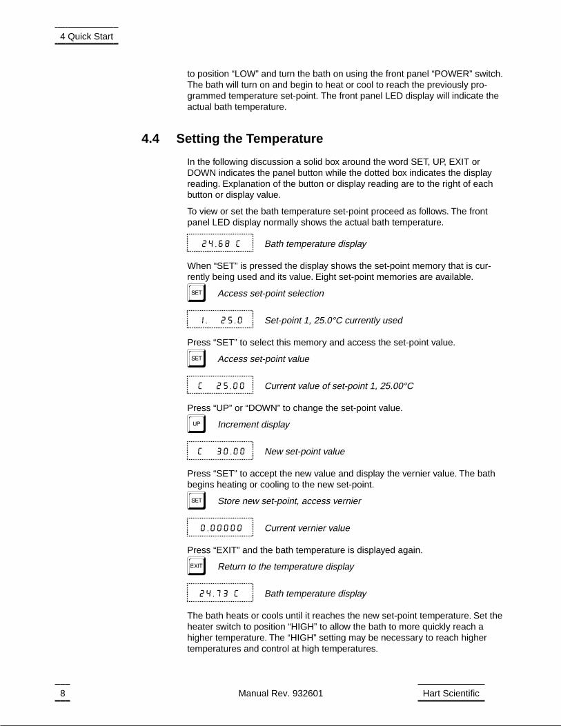
In the following discussion a solid box around the word SET, UP, EXIT orDOWN indicates the panel button while the dotted box indicates the displayreading. Explanation of the button or display reading are to the right of eachbutton or display value.
To view or set the bath temperature set-point proceed as follows. The frontpanel LED display normally shows the actual bath temperature.
24.68 C Bath temperature display
When “SET” is pressed the display shows the set-point memory that is cur-rently being used and its value. Eight set-point memories are available.
S Access set-point selection
1. 25.0 Set-point 1, 25.0°C currently used
Press “SET” to select this memory and access the set-point value.
S Access set-point value
C 25.00 Current value of set-point 1, 25.00°C
Press “UP” or “DOWN” to change the set-point value.
U Increment display
C 30.00 New set-point value
Press “SET” to accept the new value and display the vernier value. The bathbegins heating or cooling to the new set-point.
S Store new set-point, access vernier
0.00000 Current vernier value
Press “EXIT” and the bath temperature is displayed again.
E Return to the temperature display
24.73 C Bath temperature display
The bath heats or cools until it reaches the new set-point temperature. Set theheater switch to position “HIGH” to allow the bath to more quickly reach ahigher temperature. The “HIGH” setting may be necessary to reach highertemperatures and control at high temperatures.
8 Manual Rev. 932601 Hart Scientific
4 Quick Start

When setting the set-point temperature be careful not to exceed the tempera-ture limit of the bath fluid. The over-temperature cut-out should be correctly setto prevent this from happening. See Section 9.8.
If operating the bath below 45 °C set the COOLING power switch to ON. Thecooling temperature may require adjustment to provide the proper amount ofcooling. See Section 8.5.
To obtain optimum control stability adjust the proportional band as discussedin Section 9.7.
7005/7015 Manual Rev. 932601 9
4 Quick Start
5 Installation
CAUTIONREAD SECTION 6 ENTITLED
BATH USEbefore placing the bath in service.
Incorrect handling can damage the bath and void the warranty.
This bath is not designed to be portable. Therefore, moving the bath once ithas been installed should be kept to a minimum.
Never move a bath that is full of fluid. This action could be extremelydangerous and could result in personal injury to the person moving thebath.
If the bath is going to be placed in an area where it will need to be moved fre-quently, a special cart can be designed to accommodate the bath making thebath much more portable. Hart sells carts designed for these baths. However,even with a cart the bath should not be moved full of fluid. The fluid can splashcausing injury or if the bath and cart tip, the fluid could cause damage to thesurrounding area and personal injury to personnel.
If the bath must be moved, be sure to drain the fluid to prevent any injury. Theside of the bath with the compressor is heavier than the tank side. To safelymove the bath, two people are required.
5.1 Bath Environment
The Model 7005 and 7015 Baths are precision instrumenst which should belocated in an appropriate environment. The location should be free of drafts,extreme temperatures and temperature changes, dirt, etc. The surface wherethe bath is placed must be level.
If used at higher temperatures where fluid vaporization is significant, a fumehood should be used.
5.2 “Dry-out” Period
Before initial use, after transport, and any time the instrument has not beenenergized for more than 10 days, the bath will need to be energized for a“dry-out” period of 1-2 hours before it can be assumed to meet all of the safetyrequirements of the IEC 1010-1.
5.3 Bath Preparation and Filling
The Model 7005 and 7015 Baths are not provided with a fluid. Various fluidsare available from Hart Scientific and other sources. Depending on the desiredtemperature range, any of the following fluids, as well as others, may be usedin the bath:
• Water
7005/7015 Manual Rev. 932601 11
5 Installation
• Ethylene Glycol/Water
• Methanol
• Mineral oil
• Silicone oil
Fluids are discussed in detail in Section 8.1.
Remove any access hole cover from the bath and check the tank for foreignmatter (dirt, remnant packing material, etc.). Use clean unpolluted fluid. Care-fully fill the bath through the large square access hole to a level that will allowfor stirring and thermal expansion. The fluid should never exceed a height of1/2" below the top of the tank. Carefully monitor the bath fluid level as the bathtemperature rises to prevent overflow or splashing. Remove excess fluid if nec-essary and with caution if the fluid is hot.
Be careful to prevent bath fluid from spilling on the stirring motor while filling.Note: Underfilling may reduce bath performance and may possibly dam-age the bath heater.
5.4 Probe
Inspect the bath controller probe. This probe should not be bent or damaged inany way. Reasonable caution should be used in handling this probe as it con-tains a precision thermistor sensor. If damaged, the probe can be replaced.Contact Hart Scientific Customer Service for assistance.
Insert the probe into the 1/4 inch probe hole at the top left side of the bath lid.The tip of the probe must be well immersed in the fluid. The probe connector isplugged into the rear of the bath into the socket labelled “PROBE”.
5.5 Power
With the bath power switch off, plug the bath into an AC mains outlet of the ap-propriate voltage, frequency, and current capacity. Normally this will be 115VAC (±10%), 60 Hz, 15 A (or 230 VAC [±10%], 50 Hz, 8 A optional).
Be sure the stirring motor power cord is plugged into the “STIRRER” socket atthe back of the bath.
12 Manual Rev. 932601 Hart Scientific
5 Installation
6 Bath Use
READ BEFORE PLACING THE BATH IN SERVICE
The information in this section is for general information only. It is not designedto be the basis for calibration laboratory procedures. Each laboratory will needto write their own specific procedures.
6.1 General
Be sure to select the correct fluid for the temperature range of the calibration.Bath fluids should be selected to operate safely with adequate thermal proper-ties to meet the application requirements. Also, be aware that some fluids ex-pand and could overflow the bath if not watched. Refer to General Operation,section 8, for information specific to fluid selection and to the MSDS sheetspecific to the fluid selected. Generally, baths are set to one temperature andused to calibrate probes only at that single temperature. This means that thetype of bath fluid does not have to change. Additionally, the bath can be leftenergized reducing the stress on the system.
The bath generates extreme temperatures. Precautions must be taken to pre-vent personal injury or damage to objects. Probes may be extremely hot orcold when removed from the bath. Cautiously handle probes to prevent per-sonal injury. Carefully place probes on a heat/cold resistant surface or rack un-til they are at room temperature. It is advisable to wipe the probe with a cleansoft cloth or paper towel before inserting it into another bath. This prevents themixing of fluids from one bath to another. If the probe has been calibrated inliquid salt, carefully wash the probe in warm water and dry completely beforetransferring it to another fluid. Always be sure that the probe is completely drybefore inserting it into a hot fluid. Some of the high temperature fluids react vi-olently to water or other liquid mediums. Be aware that cleaning the probe canbe dangerous if the probe has not cooled to room temperature. Additionally,high temperature fluids may ignite the paper towels if the probe has not beencooled.
For optimum accuracy and stability, allow the bath adequate stabilization timeafter reaching the set-point temperature.
6.2 Comparison Calibration
Comparison calibration involves testing a probe (unit under test, UUT) againsta reference probe. After inserting the probes to be calibrated into the bath, al-low sufficient time for the probes to settle and the temperature of the bath tostabilize.
One of the significant dividends of using a bath rather than a dry-well to cali-brate multiple probes is that the probes do not need to be identical in construc-tion. The fluid in the bath allows different types of probes to be calibrated at thesame time. However, stem effect from different types of probes is not totallyeliminated. Even though all baths have horizontal and vertical gradients, thesegradients are minimized inside the bath work area. Nevertheless, probesshould be inserted to the same depth in the bath liquid. Be sure that all probes
7005/7015 Manual Rev. 932601 13
6 Bath Use
are inserted deep enough to prevent stem effect. From research at Hart Scien-tific, we suggest a general rule-of-thumb for immersion depth to reduce thestem effect to a minimum: 15 x the diameter of the UUT + the sensor length.Do not submerge the probe handles. If the probe handles get too warm dur-ing calibration at high temperatures, a heat shield could be used just below theprobe handle. This heat shield could be as simple as aluminum foil slid overthe probe before inserting it in the bath or as complicated as a specially de-signed reflective metal apparatus.
When calibrating over a wide temperature range, better results can generallybe achieved by starting at the highest temperature and progressing down tothe lowest temperature.
Probes can be held in place in the bath by using probe clamps or drilling holesin the access cover. Other fixtures to hold the probes can be designed. Theobject is to keep the reference probe and the probe(s) to be calibrated asclosely grouped as possible in the working area of the bath. Bath stability ismaximized when the bath working area is kept covered.
In preparing to use the bath for calibration start by:
• Placing the reference probe in the bath working area.
• Placing the probe to be calibrated, the UUT, in the bath working area asclose as feasibly possible to the reference probe.
6.3 Calibration of Multiple Probes
Fully loading the bath with probes increases the time required for the tempera-ture to stabilize after inserting the probes. Using the reference probe as theguide, be sure that the temperature has stabilized before starting the calibra-tion.
14 Manual Rev. 932601 Hart Scientific
6 Bath Use
7 Parts and Controls
7.1 Front Control Panel
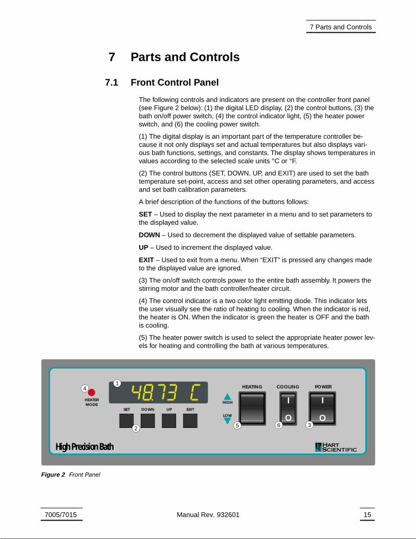
The following controls and indicators are present on the controller front panel(see Figure 2 below): (1) the digital LED display, (2) the control buttons, (3) thebath on/off power switch, (4) the control indicator light, (5) the heater powerswitch, and (6) the cooling power switch.
(1) The digital display is an important part of the temperature controller be-cause it not only displays set and actual temperatures but also displays vari-ous bath functions, settings, and constants. The display shows temperatures invalues according to the selected scale units °C or °F.
(2) The control buttons (SET, DOWN, UP, and EXIT) are used to set the bathtemperature set-point, access and set other operating parameters, and accessand set bath calibration parameters.
A brief description of the functions of the buttons follows:
SET – Used to display the next parameter in a menu and to set parameters tothe displayed value.
DOWN – Used to decrement the displayed value of settable parameters.
UP – Used to increment the displayed value.
EXIT – Used to exit from a menu. When “EXIT” is pressed any changes madeto the displayed value are ignored.
(3) The on/off switch controls power to the entire bath assembly. It powers thestirring motor and the bath controller/heater circuit.
(4) The control indicator is a two color light emitting diode. This indicator letsthe user visually see the ratio of heating to cooling. When the indicator is red,the heater is ON. When the indicator is green the heater is OFF and the bathis cooling.
(5) The heater power switch is used to select the appropriate heater power lev-els for heating and controlling the bath at various temperatures.
7005/7015 Manual Rev. 932601 15
7 Parts and Controls
SET
HEATERMODE
DOWN UP EXIT
HIGH
LOW
POWERCOOLINGHEATING
High Precision Bath
O
I
O
I
1
23
4
5 6
Figure 2 Front Panel

(6) The cooling power switch controls power to the cooling compressor andcooling fan.
7.2 Side Panel
The side panel has three features (see Figure 3): 1) the back pressure valve,2) the cooling temperature regulating valve, and 3) the cooling temp gauge.With the interface option an extra cooling valve (HIGH) is provided.
1) The back pressure valve adjustment is used to control the amount of cool-ing supplied to the system. This valve reduces the cooling capacity by re-stricting the flow of refrigerant to the bath, allowing the adjustment of theheating to cooling percentage. Under normal operation the valve should befully open (counter clockwise).
2) The cooling temperature regulating valve is used to adjust the temperatureat which the refrigerant evaporates, which determines cooling efficiency.The ideal temperature for operation is about 5-10 degrees Celsius belowthe desired bath temperature. Refer to the label below the gauge for ap-proximate psi and evaporative temperature settings. The following table isreproduced from the label.
16 Manual Rev. 932601 Hart Scientific
7 Parts and Controls
Back PressureCooling
Temperature
1 2 3
Back Pressure Low High
CoolingTemperature
1 2 3
Standard
With Interface(optional)
Figure 3. Refrigeration Controls - Side Panel
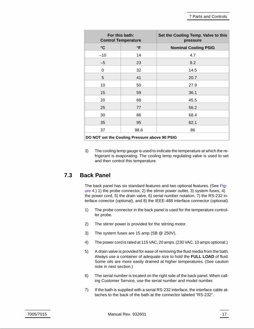
For this bath:Control Temperature
Set the Cooling Temp. Valve to thispressure
°C °F Nominal Cooling PSIG
–10 14 4.7
–5 23 9.2
0 32 14.5
5 41 20.7
10 50 27.9
15 59 36.1
20 68 45.5
25 77 56.2
30 86 68.4
35 95 82.1
37 98.6 86
DO NOT set the Cooling Pressure above 90 PSIG
3) The cooling temp gauge is used to indicate the temperature at which the re-frigerant is evaporating. The cooling temp regulating valve is used to setand then control this temperature.
7.3 Back Panel
The back panel has six standard features and two optional features. (See Fig-ure 4.) 1) the probe connector, 2) the stirrer power outlet, 3) system fuses, 4)the power cord, 5) the drain valve, 6) serial number notation, 7) the RS-232 in-terface conector (optional), and 8) the IEEE-488 interface connector (optional).
1) The probe connector in the back panel is used for the temperature control-ler probe.
2) The stirrer power is provided for the stirring motor.
3) The system fuses are 15 amp (SB @ 250V).
4) The power cord is rated at 115 VAC, 20 amps.(230 VAC, 10 amps optional.)
5) A drain valve is provided for ease of removing the fluid media from the bath.Always use a container of adequate size to hold the FULL LOAD of fluid.Some oils are more easily drained at higher temperatures. (See cautionnote in next section.)
6) The serial number is located on the right side of the back panel. When call-ing Customer Service, use the serial number and model number.
7) If the bath is supplied with a serial RS-232 interface, the interface cable at-taches to the back of the bath at the connector labeled “RS-232”.
7005/7015 Manual Rev. 932601 17
7 Parts and Controls
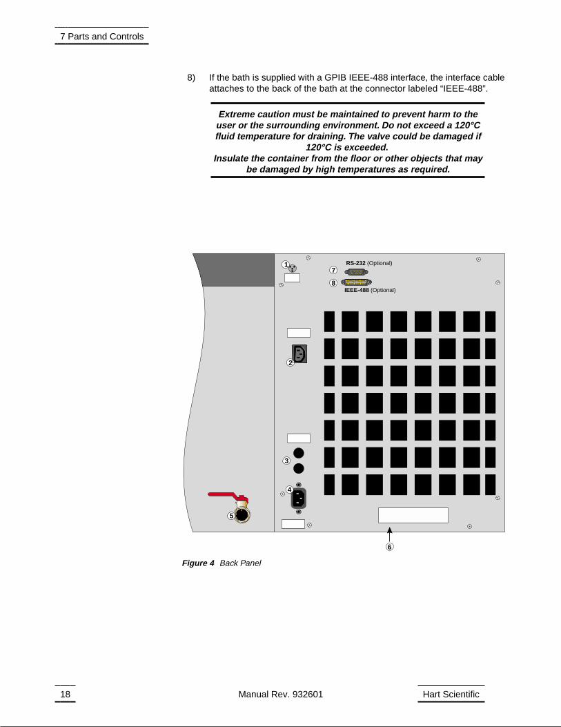
8) If the bath is supplied with a GPIB IEEE-488 interface, the interface cableattaches to the back of the bath at the connector labeled “IEEE-488”.
Extreme caution must be maintained to prevent harm to theuser or the surrounding environment. Do not exceed a 120°Cfluid temperature for draining. The valve could be damaged if
120°C is exceeded.Insulate the container from the floor or other objects that may
be damaged by high temperatures as required.
18 Manual Rev. 932601 Hart Scientific
7 Parts and Controls
1
6
3
RS-232 (Optional)
IEEE-488 (Optional)
7
8
5
2
4
Figure 4 Back Panel
8 General Operation
8.1 Bath Fluid
Many fluids will work with 7005/7015 bath. Choosing a fluid requires consider-ation of many important characteristics of the fluid. Among these are tempera-ture range, viscosity, specific heat, thermal conductivity, thermal expansion,electrical resistivity, fluid lifetime, safety, and cost.
8.1.1 Temperature Range
One of the most important characteristics to consider is the temperature rangeof the fluid. Few fluids work well throughout the complete temperature range ofthe bath. The temperature at which the bath is operated must always be withinthe safe and useful temperature range of the fluid. The lower temperaturerange of the fluid is determined by the freeze point of the fluid or the tempera-ture at which the viscosity becomes too great. The upper temperature is usu-ally limited by vaporization, flammability, or chemical breakdown of the fluid.Vaporization of the fluid at higher temperatures may affect temperature stabil-ity because of cool condensed fluid dripping into the bath from the lid.
The bath temperature should be limited by setting the safety cut-out so that thebath temperature cannot exceed the safe operating temperature limit of thefluid.
8.1.2 Viscosity
Viscosity is a measure of the thickness of a fluid, how easily it can be pouredand mixed. Viscosity affects the temperature stability of the bath. With low vis-cosity, fluid mixing is better which creates a more uniform temperaturethroughout the bath. This improves the bath response time which allows it tomaintain a more constant temperature. For good control the viscosity shouldbe less than 10 centistokes. 50 centistokes is about the upper limit of allowableviscosity. Viscosities greater than this cause very poor control stability and mayalso overheat or damage the stirring motor. With oils viscosity may vary greatlywith temperature.
When using fluids with higher viscosities the controller proportional band mayneed to be increased to compensate for the reduced response time. Otherwisethe temperature may begin to oscillate.
8.1.3 Specific Heat
Specific heat is the measure of the heat storage ability of the fluid. Specificheat, though to a lesser degree, also affects the control stability and the heat-ing and cooling rates. Generally, a lower specific heat causes slightly bettercontrol stability and quicker heating and cooling. With fluids with higher spe-cific heat the controller may require a decreased proportional band to compen-sate for the decrease in sensitivity of the bath temperature to heat input.
7005/7015 Manual Rev. 932601 19
8 General Operation
8.1.4 Thermal Conductivity
Thermal conductivity measures how easily heat flows through the fluid. Ther-mal conductivity of the fluid affects the control stability, temperature uniformity,and probe temperature settling time. Fluids with higher conductivity distributeheat more quickly and evenly improving bath performance.
8.1.5 Thermal Expansion
Thermal expansion describes how the volume of the fluid changes with tem-perature. Thermal expansion of the fluid used must be considered since the in-crease in fluid volume as the bath temperature changes may cause overflow.Excessive thermal expansion may also be undesirable in applications whereconstant liquid level is important. Oils typically have significant thermal expan-sion.
8.1.6 Electrical Resistivity
Electrical resistivity describes how well the fluid insulates against the flow ofelectric current. In some applications, such as measuring the resistance ofbare temperature sensors, it may be important that little or no electrical leak-age occur through the fluid. In this case consider a fluid with very high resistiv-ity.
8.1.7 Fluid Lifetime
Many fluids degrade over time because of evaporization, water absorption,gelling, or chemical breakdown. Often the degradation becomes significantnear the upper temperature limit of the fluid.
8.1.8 Safety
When choosing a fluid always consider the safety issues associated. Obvi-ously, where there are extreme temperatures there can be danger to person-nel and equipment. Fluids may also be hazardous for other reasons. Somefluids may be considered toxic. Contact with eyes, skin, or inhalation of vaporsmay cause injury. A proper fume hood must be used if hazardous or bother-some vapors are produced.
WARNINGFluids at high temperatures. May pose danger from BURNS,FIRE, and TOXIC fumes. Use appropriate caution and safety
equipment.
Fluids may be flammable and require special fire safety equipment and proce-dures. An important characteristic of the fluid to consider is the flash point. Theflash point is the temperature at which there is sufficient vapor given off so thatwhen there is sufficient oxygen present and an ignition source is applied thevapor will ignite. This does not necessarily mean that fire will be sustained atthe flash point. The flash point may be either of the open cup or closed cup
20 Manual Rev. 932601 Hart Scientific
8 General Operation
type. Either condition may occur in a bath situation. The closed cup tempera-ture is always the lower of the two. The closed cup represents the containedvapors inside the tank and the open cup represents the vapors escaping thetank. Oxygen and an ignition source will be less available inside the tank.
Environmentally hazardous fluids require special disposal according to appli-cable federal or local laws after use.
8.1.9 Cost
Cost of bath fluids may vary greatly, from cents per gallon for water to hun-dreds of dollars per gallon for synthetic oils. Cost may be an important consid-eration when choosing a fluid.
8.1.10 Commonly Used Fluids
Below is a description of some of the more commonly used fluids and theircharacteristics
8.1.10.1 Water
Water is often used because of its very low cost, availability, and excellent tem-perature control characteristics. Water has very low viscosity and good thermalconductivity and heat capacity which makes it among the best fluids for controlstability at low temperatures. Temperature stability is much poorer at highertemperatures because water condenses on the lid, cools and drips into thebath. Water is safe and relatively inert. The electrical conductivity of water mayprevent its use in some applications. Water has a limited temperature range,from a few degrees above 0°C to a few degrees below 100°C. At higher tem-peratures evaporation becomes significant. Water used in the bath should bedistilled or softened to prevent mineral deposits. Consider using an algicidechemical in the water to prevent contamination.
8.1.10.2 Ethylene Glycol
The temperature range of water may be extended by using a solution of 1 partwater and 1 part ethylene glycol (antifreeze). The characteristics of the ethyl-ene glycol-water solution are similar to water. Use caution with ethylene glycolsince the fluid is very toxic. Ethylene glycol must be disposed of properly.
8.1.10.3 Methanol
Methanol or methyl alchohol is often used at low temperatures below 0°C.Methanol is relatively inexpensive, has good control characteristics, and has alow freeze point. Methanol is very toxic so care must be taken when using anddisposing of this fluid.
8.1.10.4 Mineral Oil
Mineral oil or paraffin oil is often used at moderate temperatures above therange of water. Mineral oil is relatively inexpensive. At lower temperatures min-eral oil is quite viscous and control may be poor. At higher temperatures vaporemission becomes significant. The vapors may be dangerous and a fume hoodshould be used. As with most oils mineral oil will expand as temperature in-creases so be careful not to fill the bath too full that it overflows when heated.
7005/7015 Manual Rev. 932601 21
8 General Operation
The viscosity and thermal characteristics of mineral oil is poorer than water sotemperature stability will not be as good. Mineral oil has very low electricalconductivity. Use caution with mineral oil since it is flammable and may alsocause serious injury if inhaled or ingested.
8.1.10.5 Silicone Oils
Silicone oils are available which offer a much wider operating temperaturerange than mineral oil. Like most oils, silicone oils have temperature controlcharacteristics which are somewhat poorer than water. The viscosity changessignificantly with temperature and thermal expansion also occurs. These oilshave very high electrical resistivity. Silicon oils are fairly safe. These oils arerelatively expensive.
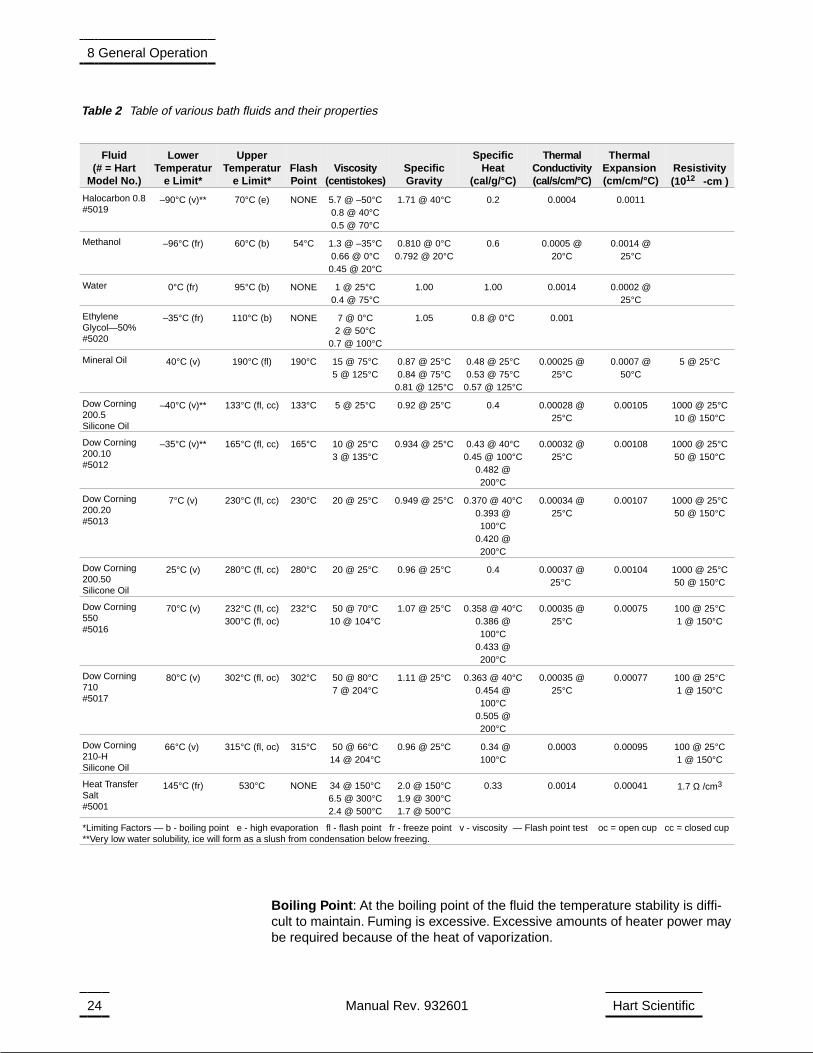
8.1.11 Fluid Characteristics Charts
Table 2 and Figure 5 have been created to provide help in selecting a heat ex-change fluid media for your constant temperature bath. The charts provideboth a visual and numerical representation of most of the physical qualities im-portant in making a selection. The list is not all inclusive, many usable fluidsmay not have been shown in this listing.
8.1.11.1 Limitations and Disclaimer
Every effort has gone into making these charts accurate, however, the datahere does not imply any guarantee of fitness of use for a particular application.Working near the limits of a property such as the flash point or viscosity limitcan compromise safety or serviceability. Sources of information sometimesvary for particular properties. Your company’s safety policies as well as per-sonal judgment regarding flash points, toxicity, etc. must also be considered.You are responsible for reading the Material Safety Data Sheets and making ajudgment here. Cost may require some compromises as well. Hart Scientificcannot be liable for the suitability of application or for any personal injury, dam-age to equipment, product or facilities in using these fluids.
The charts include information on a variety of fluids which are often used asheat transfer fluid in baths. Because of the temperature range some fluids maynot be useful with your bath.
8.1.11.2 About the Graph
The fluid graph visually illustrates some of the important qualities of the fluidsshown.
Temperature Range: The temperature scale is shown in degrees Celsius. Asense of the fluid’s general range of application is indicated. Qualities includingpour point, freeze point, important viscosity points, flash point, boiling pointand others may be shown.
Freezing Point: The freezing point of a fluid is an obvious limitation to stirring.As the freezing point is approached high viscosity may also limit good stirring.
Pour Point: This represents a handling limit for the fluid.
Viscosity: Points shown are at 50 and 10 centistokes. Greater than 50 centi-stokes stirring is very poor and unsatisfactory for bath applications. At 10 centi-
22 Manual Rev. 932601 Hart Scientific
8 General Operation
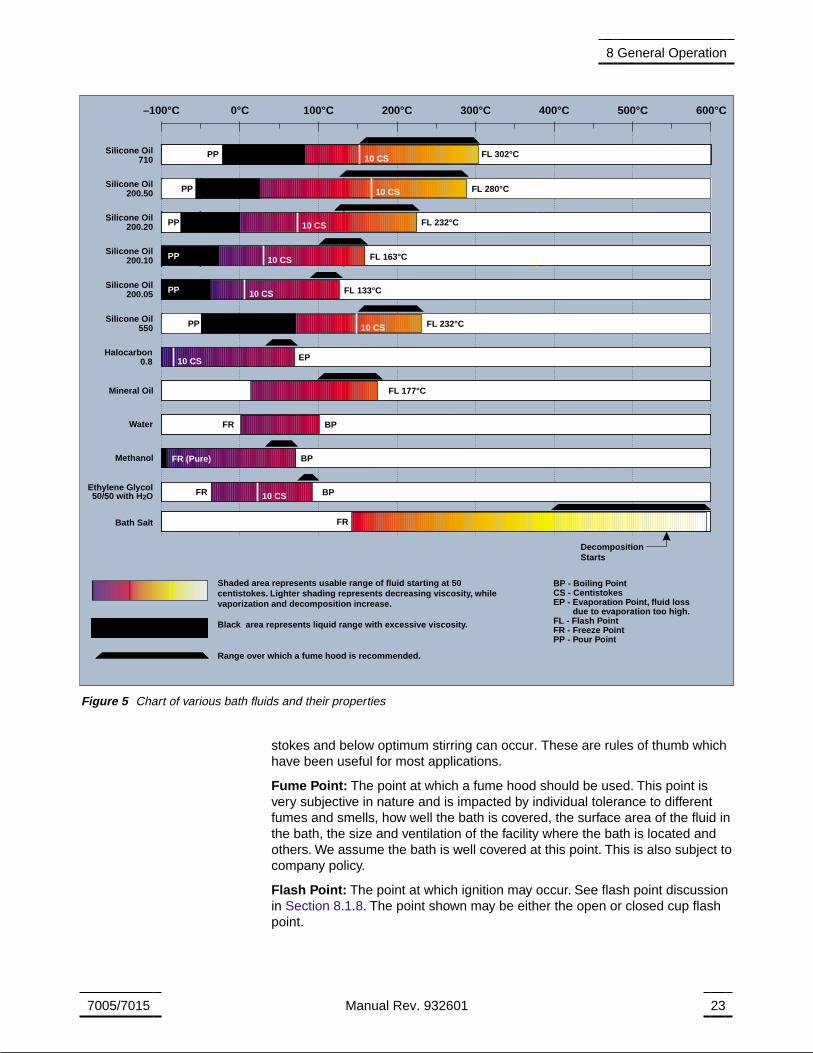
stokes and below optimum stirring can occur. These are rules of thumb whichhave been useful for most applications.
Fume Point: The point at which a fume hood should be used. This point isvery subjective in nature and is impacted by individual tolerance to differentfumes and smells, how well the bath is covered, the surface area of the fluid inthe bath, the size and ventilation of the facility where the bath is located andothers. We assume the bath is well covered at this point. This is also subject tocompany policy.
Flash Point: The point at which ignition may occur. See flash point discussionin Section 8.1.8. The point shown may be either the open or closed cup flashpoint.
7005/7015 Manual Rev. 932601 23
8 General Operation
–100°C 0°C 100°C 200°C 300°C 400°C 500°C 600°C
BP - Boiling PointCS - CentistokesEP - Evaporation Point, fluid loss
due to evaporation too high.FL - Flash PointFR - Freeze PointPP - Pour Point
Shaded area represents usable range of fluid starting at 50centistokes. Lighter shading represents decreasing viscosity, whilevaporization and decomposition increase.
Black area represents liquid range with excessive viscosity.
Range over which a fume hood is recommended.
10 CS FL 302°CPPSilicone Oil710
Silicone Oil200.50 10 CS FL 280°CPP
Silicone Oil200.20 10 CS FL 232°CPP
Silicone Oil200.10 10 CS FL 163°CPP
Silicone Oil200.05 10 CS FL 133°CPP
10 CS FL 232°CSilicone Oil550 PP
10 CS EPHalocarbon0.8
FL 177°CMineral Oil
BPWater FR
BPMethanol FR (Pure)
10 CS BPEthylene Glycol50/50 with H O2
FR
DecompositionStarts
Bath Salt FR
Figure 5 Chart of various bath fluids and their properties
Boiling Point: At the boiling point of the fluid the temperature stability is diffi-cult to maintain. Fuming is excessive. Excessive amounts of heater power maybe required because of the heat of vaporization.
24 Manual Rev. 932601 Hart Scientific
8 General Operation
Fluid(# = Hart
Model No.)
LowerTemperatur
e Limit*
UpperTemperatur
e Limit*FlashPoint
Viscosity(centistokes)
SpecificGravity
SpecificHeat
(cal/g/°C)
ThermalConductivity(cal/s/cm/°C)
ThermalExpansion(cm/cm/°C)
Resistivity(1012 -cm )
Halocarbon 0.8#5019
–90°C (v)** 70°C (e) NONE 5.7 @ –50°C0.8 @ 40°C0.5 @ 70°C
1.71 @ 40°C 0.2 0.0004 0.0011
Methanol –96°C (fr) 60°C (b) 54°C 1.3 @ –35°C0.66 @ 0°C0.45 @ 20°C
0.810 @ 0°C0.792 @ 20°C
0.6 0.0005 @20°C
0.0014 @25°C
Water 0°C (fr) 95°C (b) NONE 1 @ 25°C0.4 @ 75°C
1.00 1.00 0.0014 0.0002 @25°C
EthyleneGlycol—50%#5020
–35°C (fr) 110°C (b) NONE 7 @ 0°C2 @ 50°C
0.7 @ 100°C
1.05 0.8 @ 0°C 0.001
Mineral Oil 40°C (v) 190°C (fl) 190°C 15 @ 75°C5 @ 125°C
0.87 @ 25°C0.84 @ 75°C
0.81 @ 125°C
0.48 @ 25°C0.53 @ 75°C
0.57 @ 125°C
0.00025 @25°C
0.0007 @50°C
5 @ 25°C
Dow Corning200.5Silicone Oil
–40°C (v)** 133°C (fl, cc) 133°C 5 @ 25°C 0.92 @ 25°C 0.4 0.00028 @25°C
0.00105 1000 @ 25°C10 @ 150°C
Dow Corning200.10#5012
–35°C (v)** 165°C (fl, cc) 165°C 10 @ 25°C3 @ 135°C
0.934 @ 25°C 0.43 @ 40°C0.45 @ 100°C
0.482 @200°C
0.00032 @25°C
0.00108 1000 @ 25°C50 @ 150°C
Dow Corning200.20#5013
7°C (v) 230°C (fl, cc) 230°C 20 @ 25°C 0.949 @ 25°C 0.370 @ 40°C0.393 @100°C
0.420 @200°C
0.00034 @25°C
0.00107 1000 @ 25°C50 @ 150°C
Dow Corning200.50Silicone Oil
25°C (v) 280°C (fl, cc) 280°C 20 @ 25°C 0.96 @ 25°C 0.4 0.00037 @25°C
0.00104 1000 @ 25°C50 @ 150°C
Dow Corning550#5016
70°C (v) 232°C (fl, cc)300°C (fl, oc)
232°C 50 @ 70°C10 @ 104°C
1.07 @ 25°C 0.358 @ 40°C0.386 @100°C
0.433 @200°C
0.00035 @25°C
0.00075 100 @ 25°C1 @ 150°C
Dow Corning710#5017
80°C (v) 302°C (fl, oc) 302°C 50 @ 80°C7 @ 204°C
1.11 @ 25°C 0.363 @ 40°C0.454 @100°C
0.505 @200°C
0.00035 @25°C
0.00077 100 @ 25°C1 @ 150°C
Dow Corning210-HSilicone Oil
66°C (v) 315°C (fl, oc) 315°C 50 @ 66°C14 @ 204°C
0.96 @ 25°C 0.34 @100°C
0.0003 0.00095 100 @ 25°C1 @ 150°C
Heat TransferSalt#5001
145°C (fr) 530°C NONE 34 @ 150°C6.5 @ 300°C2.4 @ 500°C
2.0 @ 150°C1.9 @ 300°C1.7 @ 500°C
0.33 0.0014 0.00041 1.7 Ω /cm3
*Limiting Factors — b - boiling point e - high evaporation fl - flash point fr - freeze point v - viscosity — Flash point test oc = open cup cc = closed cup**Very low water solubility, ice will form as a slush from condensation below freezing.
Table 2 Table of various bath fluids and their properties
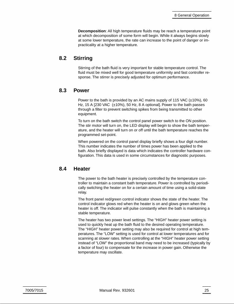
Decomposition: All high temperature fluids may be reach a temperature pointat which decomposition of some form will begin. While it always begins slowlyat some lower temperature, the rate can increase to the point of danger or im-practicality at a higher temperature.
8.2 Stirring
Stirring of the bath fluid is very important for stable temperature control. Thefluid must be mixed well for good temperature uniformity and fast controller re-sponse. The stirrer is precisely adjusted for optimum performance.
8.3 Power
Power to the bath is provided by an AC mains supply of 115 VAC (±10%), 60Hz, 15 A [230 VAC (±10%), 50 Hz, 8 A optional]. Power to the bath passesthrough a filter to prevent switching spikes from being transmitted to otherequipment.
To turn on the bath switch the control panel power switch to the ON position.The stir motor will turn on, the LED display will begin to show the bath temper-ature, and the heater will turn on or off until the bath temperature reaches theprogrammed set-point.
When powered on the control panel display briefly shows a four digit number.This number indicates the number of times power has been applied to thebath. Also briefly displayed is data which indicates the controller hardware con-figuration. This data is used in some circumstances for diagnostic purposes.
8.4 Heater
The power to the bath heater is precisely controlled by the temperature con-troller to maintain a constant bath temperature. Power is controlled by periodi-cally switching the heater on for a certain amount of time using a solid-staterelay.
The front panel red/green control indicator shows the state of the heater. Thecontrol indicator glows red when the heater is on and glows green when theheater is off. The indicator will pulse constantly when the bath is maintaining astable temperature.
The heater has two power level settings. The “HIGH” heater power setting isused to quickly heat up the bath fluid to the desired operating temperature.The “HIGH” heater power setting may also be required for control at high tem-peratures. The “LOW” setting is used for control at lower temperatures and forscanning at slower rates. When controlling at the “HIGH” heater power settinginstead of “LOW” the proportional band may need to be increased (typically bya factor of four) to compensate for the increase in power gain. Otherwise thetemperature may oscillate.
7005/7015 Manual Rev. 932601 25
8 General Operation

8.5 Cooling
The back pressure control valve limits the cooling capacity of the unit. It willnormally be open all the way (full CCW) for temperature slewing and opera-tion. If during operation the front panel meter indicates excessive cooling, thisvalve is closed partially (turn CW) until the percentage of heating to cooling isbrought into line. It is necessary to wait a few minutes after each adjustmentuntil the system settles.
Set the COOLING TEMPERATURE to 5-10°C below the SET TEMPERATUREfor near ambient and below operation. For temperature above 16°C set theCOOLING TEMPERATURE at 7°C. The cooling temperature should NOT beset above 7°C or 90 psig. About 45°C the refrigeration will not be required asthere is sufficient cooling to the room. Wait a few minutes after each adjust-ment until the system establishes itself. Readjust if required after settling for awhile.
For maximum cooling for slewing to lower temperatures, the BACK PRES-SURE valve should be fully open and the COOLING TEMPERATURE set to0°C. Readjust higher or lower as required after set temperature is reached.
8.6 Fluid Drain
The drain at the back of the bath (see Figure 4 and Figure on pages 18 and )may be used to remove fluid from the bath. During operation of the bath thedrain must be closed.
8.7 Temperature Controller
The bath temperature is controlled by Hart Scientific’s unique hybrid digital/an-alog temperature controller. The controller offers the tight control stability of ananalog temperature controller as well as the flexibility and programmability of adigital controller.
The bath temperature is monitored with a thermistor resistance sensor in thecontrol probe. The signal is electronically compared with the programmablereference signal, amplified, and then fed to a pulse-width modulator circuitwhich controls the amount of power applied to the bath heater.
The bath is operable within the temperature range given in the specifications.For protection against solid-state relay failure or other circuit failure, themicrocontroller automatically turns off the heater with a second mechanical re-lay anytime the bath temperature is more than a certain amount above theset-point temperature. As a second protection device, the controller is alsoequipped with a separate thermocouple temperature monitoring circuit whichshuts off the heater if the temperature exceeds the cut-out set-point.
The controller allows the operator to set the bath temperature with high resolu-tion, set the cut-out, adjust the proportional band, monitor the heater outputpower, and program the controller configuration and calibration parameters.The controller may be operated in temperature units of degrees Celsius orFahrenheit. The controller is operated and programmed from the front controlpanel using the four key switches and digital LED display. The controller mayalso be optionally equipped with a serial RS-232 or IEEE-488 GPIB digital in-
26 Manual Rev. 932601 Hart Scientific
8 General Operation

terface for remote operation. Operation of the controller using the front controlpanel is discussed in Section 9. Operation using the digital interfaces is dis-cussed in Section 10.
When the controller is set to a new set-point the bath heats or cool to the newtemperature. Once the new temperature is reached the bath usually takes10-15 minutes for the temperature to settle and stabilize. There may be a smallovershoot or undershoot of about 0.5°C.
7005/7015 Manual Rev. 932601 27
8 General Operation

9 Controller Operation
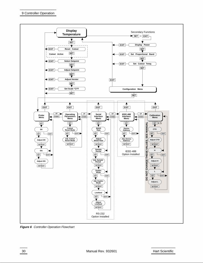
This section discusses in detail how to operate the bath temperature controllerusing the front control panel. Using the front panel key switches and LED dis-play the user may monitor the bath temperature, set the temperature set-pointin degrees C or F, monitor the heater output power, adjust the controller pro-portional band, set the cut-out set-point, and program the probe calibration pa-rameters, operating parameters, serial and IEEE-488 interface configuration,and controller calibration parameters. Operation is summarized in Figure 6.
9.1 Bath Temperature
The digital LED display on the front panel allows direct viewing of the actualbath temperature. This temperature value is what is normally shown on thedisplay. The units, C or F, of the temperature value are displayed at the right.For example,
25.00 C Bath temperature in degrees Celsius
The temperature display function may be accessed from any other function bypressing the “EXIT” button.
9.2 Reset Cut-out
If the over-temperature cut-out has been triggered then the temperature dis-play will alternately flash,
cut-out Indicates cut-out condition
The message continues to flash until the temperature is reduced and thecut-out is reset.
The cut-out has two modes — automatic reset and manual reset. The modedetermines how the cut-out is reset which allows the bath to heat up again.When in automatic mode, the cut-out resets itself as soon as the temperatureis lowered below the cut-out set-point. With manual reset mode the cut-outmust be reset by the operator after the temperature falls below the set-point.
When the cut-out is active and the cut-out mode is set to manual (“reset”) thenthe display will flash “cut-out” until the user resets the cut-out. To access thereset cut-out function press the “SET” button.
S Access cut-out reset function
The display will indicate the reset function.
rESEt ? Cut-out reset function
Press “SET” once more to reset the cut-out.
S Reset cut-out
7005/7015 Manual Rev. 932601 29
9 Controller Operation
30 Manual Rev. 932601 Hart Scientific
9 Controller Operation
SET/EXIT
CalibrationMenu
CTO
Adjust CTO
H
Adjust H
L
Adjust L
SET/EXIT
IEEE-488Interface
Menu
DeviceAddress
Adj. DeviceAddress
UP UP UP UP
DOWN DOWN DOWN DOWN
SET SET SET SET
SET/EXIT
OperatingParameters
Menu
SET
EXIT EXIT EXIT
EXITEXIT
EXIT
EXIT
EXIT
EXIT
EXIT EXITSET SET SET
SETSET
SET
SET
SET
SET
SET SET
SET/EXIT
SET/EXIT SET/EXIT SET/EXIT
SET/EXITSET/EXIT
SET/EXIT
ProbeMenu
D0
DG
Adjust D0
Adjust DG
SET/EXIT
SerialInterface
Menu
BAUDRate
AdjustBAUD Rate
SamplePeriod
Adj. SamplePeriod
DuplexMode
Adj. DuplexMode
Linefeed
AdjustLinefeed
EXITEXITEXIT EXIT EXIT
EXIT
EXIT
EXIT
EXIT
EXITSET +
Display Power
Set Proportional Band
Set Cutout Temp.
EXIT
EXIT
EXIT
SET
SET
SET
SET
SET
SET
SET
SET
SET
SET
Reset Cutout
Select Setpoint
Adjust Setpoint
EXIT
EXIT Adjust Vernier
Set Scale °C/°F
Cutout Active
DisplayTemperature
CutoutReset Mode
Adj. CutoutReset Mode
X 5
SET/EXIT
CalibrationMenu
CTO
Adjust CTO
H
Adjust H
L
Adjust L
SET
EXIT
EXIT
EXIT
SET
SET
SET
SET/EXIT
SET/EXIT
X 5
DO
NO
T C
HA
NG
ET
HE
SE
VAL
UE
S. S
EE
MA
NU
AL
Configuration Menu
Secondary Functions
IEEE-488Option Installed
RS-232Option Installed
Figure 6 Controller Operation Flowchart
This switchs the display to the set temperature function. To return to displayingthe temperature press the “EXIT” button. If the cut-out is still in theover-temperature fault condition the display continues to flash “cut-out”. Thebath temperature must drop a few degrees below the cut-out set-point beforethe cut-out can be reset.
9.3 Temperature Set-point
The bath temperature can be set to any value within the range and with resolu-tion as given in the specifications. The temperature range of the particular fluidused in the bath must be known by the operator and the bath should only beoperated well below the upper temperature limit of the liquid. In addition, thecut-out temperature should also be set below the upper limit of the fluid.
Setting the bath temperature involves three steps: (1) select the set-pointmemory, (2) adjust the set-point value, and (3) adjust the vernier if desired.
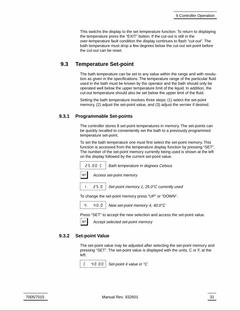
9.3.1 Programmable Set-points
The controller stores 8 set-point temperatures in memory. The set-points canbe quickly recalled to conveniently set the bath to a previously programmedtemperature set-point.
To set the bath temperature one must first select the set-point memory. Thisfunction is accessed from the temperature display function by pressing “SET”.The number of the set-point memory currently being used is shown at the lefton the display followed by the current set-point value.
25.00 C Bath temperature in degrees Celsius
S Access set-point memory
1. 25.0 Set-point memory 1, 25.0°C currently used
To change the set-point memory press “UP” or “DOWN”.
4. 40.0 New set-point memory 4, 40.0°C
Press “SET” to accept the new selection and access the set-point value.
S Accept selected set-point memory
9.3.2 Set-point Value
The set-point value may be adjusted after selecting the set-point memory andpressing “SET”. The set-point value is displayed with the units, C or F, at theleft.
C 40.00 Set-point 4 value in °C
7005/7015 Manual Rev. 932601 31
9 Controller Operation
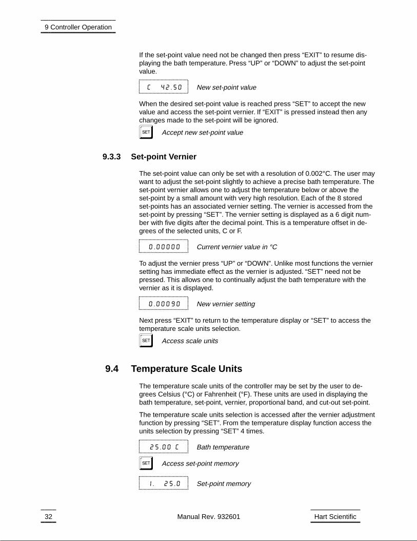
If the set-point value need not be changed then press “EXIT” to resume dis-playing the bath temperature. Press “UP” or “DOWN” to adjust the set-pointvalue.
C 42.50 New set-point value
When the desired set-point value is reached press “SET” to accept the newvalue and access the set-point vernier. If “EXIT” is pressed instead then anychanges made to the set-point will be ignored.
S Accept new set-point value
9.3.3 Set-point Vernier
The set-point value can only be set with a resolution of 0.002°C. The user maywant to adjust the set-point slightly to achieve a precise bath temperature. Theset-point vernier allows one to adjust the temperature below or above theset-point by a small amount with very high resolution. Each of the 8 storedset-points has an associated vernier setting. The vernier is accessed from theset-point by pressing “SET”. The vernier setting is displayed as a 6 digit num-ber with five digits after the decimal point. This is a temperature offset in de-grees of the selected units, C or F.
0.00000 Current vernier value in °C
To adjust the vernier press “UP” or “DOWN”. Unlike most functions the verniersetting has immediate effect as the vernier is adjusted. “SET” need not bepressed. This allows one to continually adjust the bath temperature with thevernier as it is displayed.
0.00090 New vernier setting
Next press “EXIT” to return to the temperature display or “SET” to access thetemperature scale units selection.
S Access scale units
9.4 Temperature Scale Units
The temperature scale units of the controller may be set by the user to de-grees Celsius (°C) or Fahrenheit (°F). These units are used in displaying thebath temperature, set-point, vernier, proportional band, and cut-out set-point.
The temperature scale units selection is accessed after the vernier adjustmentfunction by pressing “SET”. From the temperature display function access theunits selection by pressing “SET” 4 times.
25.00 C Bath temperature
S Access set-point memory
1. 25.0 Set-point memory
32 Manual Rev. 932601 Hart Scientific
9 Controller Operation
S Access set-point value
C 25.00 Set-point value
S Access vernier
0.00000 Vernier setting
S Access scale units selection
Un= C Scale units currently selected
Press “UP” or “DOWN” to change the units.
Un= F New units selected
Press “SET” to accept the new selection and resume displaying the bath tem-perature.
S Set the new units and resume temperature display
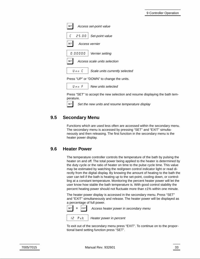
9.5 Secondary Menu
Functions which are used less often are accessed within the secondary menu.The secondary menu is accessed by pressing “SET” and “EXIT” simulta-neously and then releasing. The first function in the secondary menu is theheater power display.
9.6 Heater Power
The temperature controller controls the temperature of the bath by pulsing theheater on and off. The total power being applied to the heater is determined bythe duty cycle or the ratio of heater on time to the pulse cycle time. This valuemay be estimated by watching the red/green control indicator light or read di-rectly from the digital display. By knowing the amount of heating to the bath theuser can tell if the bath is heating up to the set-point, cooling down, or control-ling at a constant temperature. Monitoring the percent heater power will let theuser know how stable the bath temperature is. With good control stability thepercent heating power should not fluctuate more than ±1% within one minute.
The heater power display is accessed in the secondary menu. Press “SET”and “EXIT” simultaneously and release. The heater power will be displayed asa percentage of full power.
S+E Access heater power in secondary menu
12 Pct Heater power in percent
To exit out of the secondary menu press “EXIT”. To continue on to the propor-tional band setting function press “SET”.
7005/7015 Manual Rev. 932601 33
9 Controller Operation
9.7 Proportional Band
In a proportional controller such as this the heater output power is proportionalto the bath temperature over a limited range of temperatures around theset-point. This range of temperature is called the proportional band. At the bot-tom of the proportional band the heater output is 100%. At the top of the pro-portional band the heater output is 0. Thus as the bath temperature rises theheater power is reduced, which consequently tends to lower the temperatureback down. In this way the temperature is maintained at a fairly constant tem-perature.
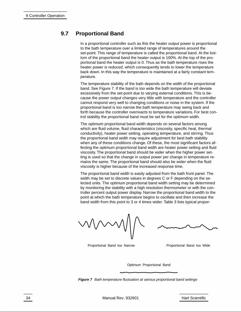
The temperature stability of the bath depends on the width of the proportionalband. See Figure 7. If the band is too wide the bath temperature will deviateexcessively from the set-point due to varying external conditions. This is be-cause the power output changes very little with temperature and the controllercannot respond very well to changing conditions or noise in the system. If theproportional band is too narrow the bath temperature may swing back andforth because the controller overreacts to temperature variations. For best con-trol stability the proportional band must be set for the optimum width.
The optimum proportional band width depends on several factors amongwhich are fluid volume, fluid characteristics (viscosity, specific heat, thermalconductivity), heater power setting, operating temperature, and stirring. Thusthe proportional band width may require adjustment for best bath stabilitywhen any of these conditions change. Of these, the most significant factors af-fecting the optimum proportional band width are heater power setting and fluidviscosity. The proportional band should be wider when the higher power set-ting is used so that the change in output power per change in temperature re-mains the same. The proportional band should also be wider when the fluidviscosity is higher because of the increased response time.
The proportional band width is easily adjusted from the bath front panel. Thewidth may be set to discrete values in degrees C or F depending on the se-lected units. The optimum proportional band width setting may be determinedby monitoring the stability with a high resolution thermometer or with the con-troller percent output power display. Narrow the proportional band width to thepoint at which the bath temperature begins to oscillate and then increase theband width from this point to 3 or 4 times wider. Table 3 lists typical propor-
34 Manual Rev. 932601 Hart Scientific
9 Controller Operation
Proportional Band too Narrow Proportional Band too Wide
Optimum Proportional Band
Figure 7 Bath temperature fluctuation at various proportional band settings
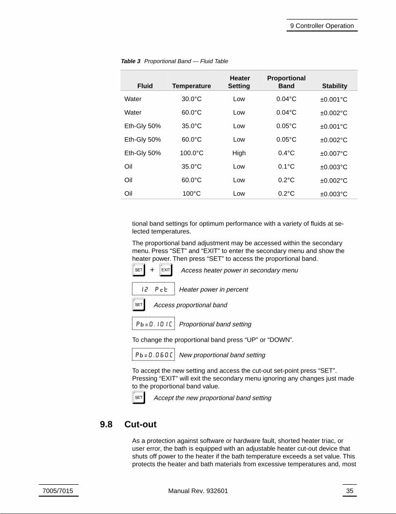
tional band settings for optimum performance with a variety of fluids at se-lected temperatures.
The proportional band adjustment may be accessed within the secondarymenu. Press “SET” and “EXIT” to enter the secondary menu and show theheater power. Then press “SET” to access the proportional band.
S+E Access heater power in secondary menu
12 Pct Heater power in percent
S Access proportional band
Pb=0.101C Proportional band setting
To change the proportional band press “UP” or “DOWN”.
Pb=0.060C New proportional band setting
To accept the new setting and access the cut-out set-point press “SET”.Pressing “EXIT” will exit the secondary menu ignoring any changes just madeto the proportional band value.
S Accept the new proportional band setting
9.8 Cut-out
As a protection against software or hardware fault, shorted heater triac, oruser error, the bath is equipped with an adjustable heater cut-out device thatshuts off power to the heater if the bath temperature exceeds a set value. Thisprotects the heater and bath materials from excessive temperatures and, most
7005/7015 Manual Rev. 932601 35
9 Controller Operation
Fluid TemperatureHeaterSetting
ProportionalBand Stability
Water 30.0°C Low 0.04°C ±0.001°C
Water 60.0°C Low 0.04°C ±0.002°C
Eth-Gly 50% 35.0°C Low 0.05°C ±0.001°C
Eth-Gly 50% 60.0°C Low 0.05°C ±0.002°C
Eth-Gly 50% 100.0°C High 0.4°C ±0.007°C
Oil 35.0°C Low 0.1°C ±0.003°C
Oil 60.0°C Low 0.2°C ±0.002°C
Oil 100°C Low 0.2°C ±0.003°C
Table 3 Proportional Band — Fluid Table
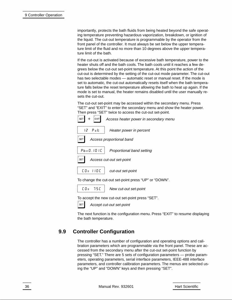
importantly, protects the bath fluids from being heated beyond the safe operat-ing temperature preventing hazardous vaporization, breakdown, or ignition ofthe liquid. The cut-out temperature is programmable by the operator from thefront panel of the controller. It must always be set below the upper tempera-ture limit of the fluid and no more than 10 degrees above the upper tempera-ture limit of the bath.
If the cut-out is activated because of excessive bath temperature, power to theheater shuts off and the bath cools. The bath cools until it reaches a few de-grees below the cut-out set-point temperature. At this point the action of thecut-out is determined by the setting of the cut-out mode parameter. The cut-outhas two selectable modes — automatic reset or manual reset. If the mode isset to automatic, the cut-out automatically resets itself when the bath tempera-ture falls below the reset temperature allowing the bath to heat up again. If themode is set to manual, the heater remains disabled until the user manually re-sets the cut-out.
The cut-out set-point may be accessed within the secondary menu. Press“SET” and “EXIT” to enter the secondary menu and show the heater power.Then press “SET” twice to access the cut-out set-point.
S+E Access heater power in secondary menu
12 Pct Heater power in percent
S Access proportional band
Pb=0.101C Proportional band setting
S Access cut-out set-point
CO= 110C cut-out set-point
To change the cut-out set-point press “UP” or “DOWN”.
CO= 75C New cut-out set-point
To accept the new cut-out set-point press “SET”.
S Accept cut-out set-point
The next function is the configuration menu. Press “EXIT” to resume displayingthe bath temperature.
9.9 Controller Configuration
The controller has a number of configuration and operating options and cali-bration parameters which are programmable via the front panel. These are ac-cessed from the secondary menu after the cut-out set-point function bypressing “SET.” There are 5 sets of configuration parameters — probe param-eters, operating parameters, serial interface parameters, IEEE-488 interfaceparameters, and controller calibration parameters. The menus are selected us-ing the “UP” and “DOWN” keys and then pressing “SET”.
36 Manual Rev. 932601 Hart Scientific
9 Controller Operation
9.10 Probe Parameters
The probe parameter menu is indicated by,
PrObE Probe parameters menu
Press “SET” to enter the menu. The probe parameters menu contains the pa-rameters, D0 and Dg, which characterize the resistance-temperature relation-ship of the thermistor control probe. These parameters may be adjusted toimprove the accuracy of the bath. This procedure is explained in detail in Sec-tion 11.
The probe parameters are accessed by pressing “SET” after the name of theparameter is displayed. The value of the parameter may be changed using the“UP” and “DOWN” buttons. After the desired value is reached press “SET” toset the parameter to the new value. Pressing “EXIT” will cause the parameterto be skipped ignoring any changes that may have been made.
9.10.1 D0
This probe parameter refers to the resistance of the control probe at 0°C.Normally this is set for –25.2290 ohms.
9.10.2 DG
This probe parameter refers to the average sensitivity of the probe between 0and 100°C. Normally this is set for 186.9740
9.11 Operating Parameters
The operating parameters menu is indicated by,
PAr Operating parameters menu
Press “SET” to enter the menu. The operating parameters menu contains thecut-out reset mode setting.
9.11.1 Cut-out Reset Mode
The cut-out reset mode determines whether the cut-out resets automaticallywhen the bath temperature drops to a safe value or must be manually reset bythe operator.
The parameter is indicated by,
CtorSt Cut-out reset mode parameter
Press “SET” to access the parameter setting. Normally the cut-out is set forautomatic mode.
Cto=Auto Cut-out set for automatic reset
7005/7015 Manual Rev. 932601 37
9 Controller Operation

To change to manual reset mode press “UP” and then “SET”.
Cto=rSt Cut-out set for manual reset
9.12 Serial Interface Parameters
The 7005/7015 bath may optionally be fitted with an RS-232 interface. The se-rial RS-232 interface parameters menu is indicated by,
SErIAL Serial RS-232 interface parameters menu
The serial interface parameters menu contains parameters which determinethe operation of the serial interface. These controls only apply to baths fittedwith the serial interface. The parameters in the menu are — BAUD rate, sam-ple period, duplex mode, and linefeed.
9.12.1 BAUD Rate
The BAUD rate is the first parameter in the menu. The BAUD rate setting de-termines the serial communications transmission rate.
The BAUD rate parameter is indicated by,
BAUd Serial BAUD rate parameter
Press “SET” to choose to set the BAUD rate. The current BAUD rate value willthen be displayed.
1200 b Current BAUD rate
The BAUD rate of the bath serial communications may be programmed to300,600,1200, or 2400 BAUD. Use “UP” or “DOWN” to change the BAUD ratevalue.
2400 b New BAUD rate
Press “SET” to set the BAUD rate to the new value or “EXIT” to abort the oper-ation and skip to the next parameter in the menu.
9.12.2 Sample Period
The sample period is the next parameter in the serial interface parametermenu. The sample period is the time period in seconds between temperaturemeasurements transmitted from the serial interface. If the sample rate is set to5, the bath transmits the current measurement over the serial interface approx-imately every five seconds. The automatic sampling is disabled with a sampleperiod of 0. The sample period is indicated by,
SAmPLE Serial sample period parameter
Press “SET” to choose to set the sample period. The current sample periodvalue will be displayed.
38 Manual Rev. 932601 Hart Scientific
9 Controller Operation
SA= 1 Current sample period (seconds)
Adjust the value with “UP” or “DOWN” and then use “SET” to set the samplerate to the displayed value.
SA= 60 New sample period
9.12.3 Duplex Mode
The next parameter is the duplex mode. The duplex mode may be set to fullduplex or half duplex. With full duplex any commands received by the bath viathe serial interface are immediately echoed or transmitted back to the deviceof origin. With half duplex the commands are executed but not echoed. Theduplex mode parameter is indicated by,
dUPL Serial duplex mode parameter
Press “SET” to access the mode setting.
dUP=FULL Current duplex mode setting
The mode may be changed using “UP” or “DOWN” and pressing “SET”.
dUP=HALF New duplex mode setting
9.12.4 Linefeed
The final parameter in the serial interface menu is the linefeed mode. This pa-rameter enables (on) or disables (off) transmission of a linefeed character (LF,ASCII 10) after transmission of any carriage-return. The linefeed parameter isindicated by,
LF Serial linefeed parameter
Press “SET” to access the linefeed parameter.
LF= On Current linefeed setting
The mode may be changed using “UP” or “DOWN” and pressing “SET”.
LF= OFF New linefeed setting
9.13 IEEE-488 Parameters
Baths may optionally be fitted with an IEEE-488 GPIB interface. In this casethe user may set the interface address within the IEEE-488 parameter menu.This menu does not appear on baths not fitted with the interface. The menu isindicated by,
IEEE IEEE-488 parameters menu
7005/7015 Manual Rev. 932601 39
9 Controller Operation
Press “SET” to enter the menu.
9.13.1 IEEE-488 Address
The IEEE-488 interface must be configured to use the same address as theexternal communicating device. The address is indicated by,
AddrESS IEEE-488 interface address
Press “SET” to access the address setting.
Add= 22 Current IEEE-488 interface address
Adjust the value with “UP” or “DOWN” and then use “SET” to set the addressto the displayed value.
Add= 15 New IEEE-488 interface address
9.14 Calibration Parameters
The operator of the bath controller has access to a number of the bath calibra-tion constants namely CTO, H, and L. These values are set at the factory andmust not be altered. The correct values are important to the accuracy andproper and safe operation of the bath. Access to these parameters is availableto the user only so that in the event that the controller’s memory fails the usermay restore these values to the factory settings. The user should have a list ofthese constants and their settings with the manual.
DO NOT change the values of the bath calibration constantsfrom the factory set values. The correct setting of these pa-
rameters is important to the safety and proper operation of thebath.
The calibration parameters menu is indicated by,
CAL Calibration parameters menu
Press “SET” five times to enter the menu.
9.14.1 CTO
Parameter CTO sets the calibration of the over-temperature cut-out. This is notadjustable by software but is adjusted with an internal potentiometer. For the7005/7015 baths this parameter should read between 120.
9.14.2 H and L
These parameters set the upper and lower set-point limits of the bath. DONOT change the values of these parameters from the factory set values. To do
40 Manual Rev. 932601 Hart Scientific
9 Controller Operation

so may present danger of the bath exceeding its temperature range causingdamage or fire.
7005/7015 Manual Rev. 932601 41
9 Controller Operation
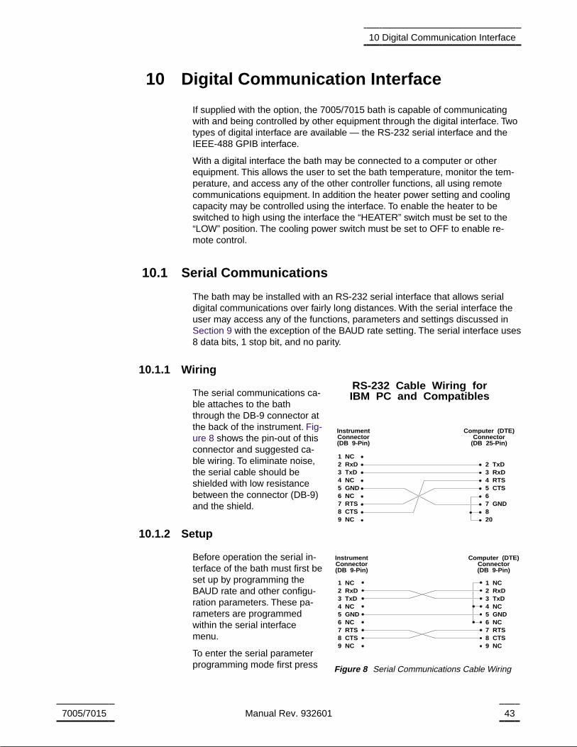
10 Digital Communication Interface
If supplied with the option, the 7005/7015 bath is capable of communicatingwith and being controlled by other equipment through the digital interface. Twotypes of digital interface are available — the RS-232 serial interface and theIEEE-488 GPIB interface.
With a digital interface the bath may be connected to a computer or otherequipment. This allows the user to set the bath temperature, monitor the tem-perature, and access any of the other controller functions, all using remotecommunications equipment. In addition the heater power setting and coolingcapacity may be controlled using the interface. To enable the heater to beswitched to high using the interface the “HEATER” switch must be set to the“LOW” position. The cooling power switch must be set to OFF to enable re-mote control.
10.1 Serial Communications
The bath may be installed with an RS-232 serial interface that allows serialdigital communications over fairly long distances. With the serial interface theuser may access any of the functions, parameters and settings discussed inSection 9 with the exception of the BAUD rate setting. The serial interface uses8 data bits, 1 stop bit, and no parity.
10.1.1 Wiring
The serial communications ca-ble attaches to the baththrough the DB-9 connector atthe back of the instrument. Fig-ure 8 shows the pin-out of thisconnector and suggested ca-ble wiring. To eliminate noise,the serial cable should beshielded with low resistancebetween the connector (DB-9)and the shield.
10.1.2 Setup
Before operation the serial in-terface of the bath must first beset up by programming theBAUD rate and other configu-ration parameters. These pa-rameters are programmedwithin the serial interfacemenu.
To enter the serial parameterprogramming mode first press
7005/7015 Manual Rev. 932601 43
10 Digital Communication Interface
1 NC2 RxD3 TxD4 NC5 GND6 NC7 RTS8 CTS9 NC
1 NC2 RxD3 TxD4 NC5 GND6 NC7 RTS8 CTS9 NC
1 NC2 RxD3 TxD4 NC5 GND6 NC7 RTS8 CTS9 NC
2 TxD3 RxD4 RTS5 CTS67 GND820
RS-232 Cable Wiring forIBM PC and Compatibles
InstrumentConnector(DB 9-Pin)
InstrumentConnector(DB 9-Pin)
Computer (DTE)Connector
(DB 25-Pin)
Computer (DTE)Connector(DB 9-Pin)
Figure 8 Serial Communications Cable Wiring

“EXIT” while pressing “SET” and release to enter the secondary menu. Press“SET” repeatedly until the display reads “ProbE”. This is the menu selection.Press “UP” repeatedly until the serial interface menu is indicated with “SE-rIAL”. Finally press “SET” to enter the serial parameter menu. In the serial in-terface parameters menu are the BAUD rate, the sample rate, the duplexmode, and the linefeed parameter.
10.1.2.1 BAUD rate
The BAUD rate is the first parameter in the menu. The display will prompt withthe BAUD rate parameter by showing “BAUd”. Press “SET” to choose to setthe BAUD rate. The current BAUD rate value will then be displayed. The BAUDrate of the 7005/7015 serial communications may be programmed to300,600,1200, or 2400 BAUD. The BAUD rate is pre-programmed to 1200BAUD. Use “UP” or “DOWN” to change the BAUD rate value. Press “SET” toset the BAUD rate to the new value or “EXIT” to abort the operation and skip tothe next parameter in the menu.
10.1.2.2 Sample Period
The sample period is the next parameter in the menu and prompted with“SAmPLE”. The sample period is the time period in seconds between tempera-ture measurements transmitted from the serial interface. If the sample rate isset to 5, the 7005/7015 transmits the current measurement over the serial in-terface approximately every five seconds. The automatic sampling is disabledwith a sample period of 0. Press “SET” to choose to set the sample period. Ad-just the period with “UP” or “DOWN” and then use “SET” to set the sample rateto the displayed value.
10.1.2.3 Duplex Mode
The next parameter is the duplex mode indicated with “dUPL”. The duplexmode may be set to half duplex (“HALF”) or full duplex (“FULL”). With full du-plex any commands received by the thermometer via the serial interface areimmediately echoed or transmitted back to the device of origin. With half du-plex the commands are executed but not echoed. The default setting is full du-plex. The mode may be changed using “UP” or “DOWN” and pressing “SET”.
10.1.2.4 Linefeed
The final parameter in the serial interface menu is the linefeed mode. This pa-rameter enables (“On”) or disables (“OFF”) transmission of a linefeed charac-ter (LF, ASCII 10) after transmission of any carriage-return. The default settingis with linefeed on. The mode may be changed using “UP” or “DOWN” andpressing “SET”.
10.1.3 Serial Operation
Once the cable has been attached and the interface set up properly the con-troller immediately begins transmitting temperature readings at the pro-grammed rate. The set-point and other commands may be sent to the bath viathe serial interface to set the bath and view or program the various parame-ters. The interface commands are discussed in Section 10.3. All commandsare ASCII character strings terminated with a carriage-return character (CR,ASCII 13).
44 Manual Rev. 932601 Hart Scientific
10 Digital Communication Interface

10.2 IEEE-488 Communication (optional)
The IEEE-488 interface is available as an option. Baths supplied with this op-tion may be connected to a GPIB type communication bus which allows manyinstruments to be connected and controlled simultaneously. To eliminate noise,the GPIB cable should be shielded.
10.2.1 Setup
To use the IEEE-488 interface first connect an IEEE-488 standard cable to theback of the bath. Next set the device address. This parameter is programmedwithin the IEEE-488 interface menu.
To enter the IEEE-488 parameter programming menu first press “EXIT” whilepressing “SET” and release to enter the secondary menu. Press “SET” repeat-edly until the display reaches “PrObE”. This is the menu selection. Press “UP”repeatedly until the IEEE-488 interface menu is indicated with “IEEE”. Press“SET” to enter the IEEE-488 parameter menu. The IEEE-488 menu containsthe IEEE-488 address parameter.
10.2.1.1 IEEE-488 Interface Address
The IEEE-488 address is prompted with “AddrESS”. Press “SET” to programthe address. The default address is 22. Change the device address of the bathif necessary to match the address used by the communication equipment bypressing “UP” or “DOWN” and then “SET”.
10.2.2 IEEE-488 Operation
Commands may now be sent via the IEEE-488 interface to read or set thetemperature or access other controller functions. All commands are ASCIIcharacter strings and are terminated with a carriage-return (CR, ASCII 13). In-terface commands are listed below.
10.3 Interface Commands
The various commands for accessing the bath controller functions via the digi-tal interfaces are listed in this section (see Table 4). These commands areused with both the RS-232 serial interface and the IEEE-488 GPIB interface. Ineither case the commands are terminated with a carriage-return character.The interface makes no distinction between upper and lower case letters,hence either may be used. Commands may be abbreviated to the minimumnumber of letters which determines a unique command. A command may beused to either set a parameter or display a parameter depending on whetheror not a value is sent with the command following a “=” character. For example“s”<CR> will return the current set-point and “s=50.00”<CR> will set theset-point to 50.00 degrees.
In the following list of commands, characters or data within brackets, “[” and “]”,are optional for the command. A slash, “/”, denotes alternate characters ordata. Numeric data, denoted by “n”, may be entered in decimal or exponentialnotation. Characters are shown in lower case although upper case may beused. Spaces may be added within command strings and will simply be ig-
7005/7015 Manual Rev. 932601 45
10 Digital Communication Interface
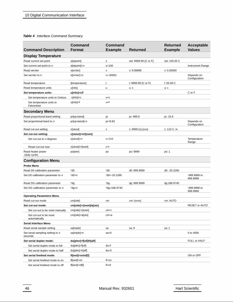
46 Manual Rev. 932601 Hart Scientific
10 Digital Communication Interface
Command DescriptionCommandFormat
CommandExample Returned
ReturnedExample
AcceptableValues
Display TemperatureRead current set-point s[etpoint] s set: 9999.99 C or F set: 100.00 C
Set current set-point to n s[etpoint]=n s=100 Instrument Range
Read vernier v[ernier] v v: 9.99999 v: 0.00000
Set vernier to n v[ernier]=n v=.00001 Depends onConfiguration
Read temperature t[emperature] t t: 9999.99 C or F t: 55.69 C
Read temperature units u[nits] u u: x u: c
Set temperature units: u[nits]=c/f C or F
Set temperature units to Celsius u[nits]=c u=c
Set temperature units toFahrenheit
u[nits]=f u=f
Secondary MenuRead proportional band setting pr[op-band] pr pr: 999.9 pr: 15.9
Set proportional band to n pr[op-band]=n pr=8.83 Depends onConfiguration
Read cut-out setting c[utout] c c: 9999 x,xxx c: 110 C, in
Set cut-out setting: c[utout]=n/r[eset]
Set cut-out to n degrees c[utout]=n c=110 TemperatureRange
Reset cut-out now c[utout]=r[eset] c=r
Read heater power(duty cycle)
po[wer] po po: 9999 po: 1
Configuration MenuProbe Menu
Read D0 calibration parameter *d0 *d0 d0: 999.9999 d0: -25.2290
Set D0 calibration parameter to n *d0=n *d0=-25.2290 -999.9999 to999.9999
Read DG calibration parameter *dg *dg dg: 999.9999 dg:186.9740
Set DG calibration parameter to n *dg=n *dg=186.9740 -999.9999 to999.9999
Operating Parameters Menu
Read cut-out mode cm[ode] cm cm: xxxx cm: AUTO
Set cut-out mode: cm[ode]=r[eset]/a[uto] RESET or AUTO
Set cut-out to be reset manually cm[ode]=r[eset] cm=r
Set cut-out to be resetautomatically
cm[ode]=a[uto] cm=a
Serial Interface Menu
Read serial sample setting sa[mple] sa sa: 9 sa: 1
Set serial sampling setting to nseconds
sa[mple]=n sa=0 0 to 4000
Set serial duplex mode: du[plex]=f[ull]/h[alf] FULL or HALF
Set serial duplex mode to full du[plex]=f[ull] du=f
Set serial duplex mode to half du[plex]=h[alf] du=h
Set serial linefeed mode: lf[eed]=on/of[f] ON or OFF
Set serial linefeed mode to on lf[eed]=on lf=on
Set serial linefeed mode to off lf[eed]=of[f] lf=of
Table 4 Interface Command Summary.
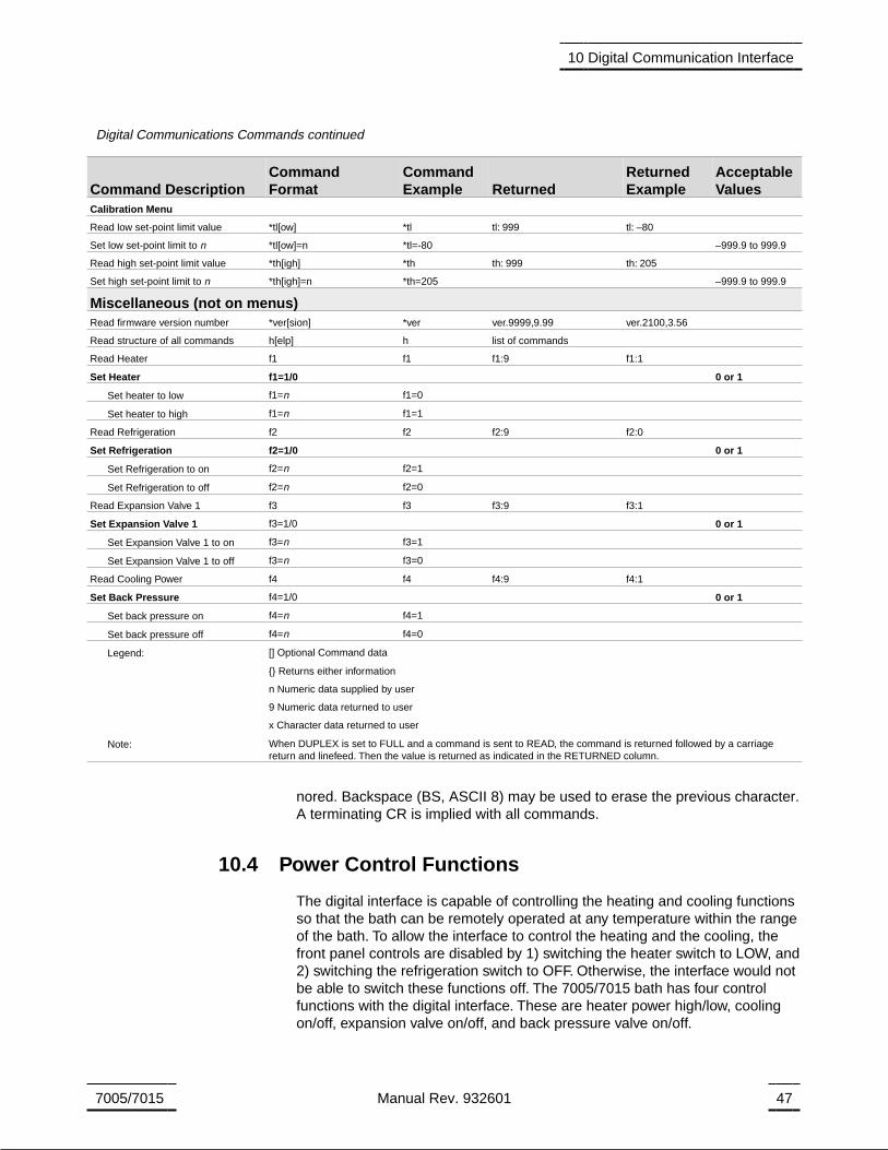
nored. Backspace (BS, ASCII 8) may be used to erase the previous character.A terminating CR is implied with all commands.
10.4 Power Control Functions
The digital interface is capable of controlling the heating and cooling functionsso that the bath can be remotely operated at any temperature within the rangeof the bath. To allow the interface to control the heating and the cooling, thefront panel controls are disabled by 1) switching the heater switch to LOW, and2) switching the refrigeration switch to OFF. Otherwise, the interface would notbe able to switch these functions off. The 7005/7015 bath has four controlfunctions with the digital interface. These are heater power high/low, coolingon/off, expansion valve on/off, and back pressure valve on/off.
7005/7015 Manual Rev. 932601 47
10 Digital Communication Interface
Command DescriptionCommandFormat
CommandExample Returned
ReturnedExample
AcceptableValues
Calibration Menu
Read low set-point limit value *tl[ow] *tl tl: 999 tl: –80
Set low set-point limit to n *tl[ow]=n *tl=-80 –999.9 to 999.9
Read high set-point limit value *th[igh] *th th: 999 th: 205
Set high set-point limit to n *th[igh]=n *th=205 –999.9 to 999.9
Miscellaneous (not on menus)Read firmware version number *ver[sion] *ver ver.9999,9.99 ver.2100,3.56
Read structure of all commands h[elp] h list of commands
Read Heater f1 f1 f1:9 f1:1
Set Heater f1=1/0 0 or 1
Set heater to low f1=n f1=0
Set heater to high f1=n f1=1
Read Refrigeration f2 f2 f2:9 f2:0
Set Refrigeration f2=1/0 0 or 1
Set Refrigeration to on f2=n f2=1
Set Refrigeration to off f2=n f2=0
Read Expansion Valve 1 f3 f3 f3:9 f3:1
Set Expansion Valve 1 f3=1/0 0 or 1
Set Expansion Valve 1 to on f3=n f3=1
Set Expansion Valve 1 to off f3=n f3=0
Read Cooling Power f4 f4 f4:9 f4:1
Set Back Pressure f4=1/0 0 or 1
Set back pressure on f4=n f4=1
Set back pressure off f4=n f4=0
Legend: [] Optional Command data
Returns either information
n Numeric data supplied by user
9 Numeric data returned to user
x Character data returned to user
Note: When DUPLEX is set to FULL and a command is sent to READ, the command is returned followed by a carriagereturn and linefeed. Then the value is returned as indicated in the RETURNED column.
Digital Communications Commands continued
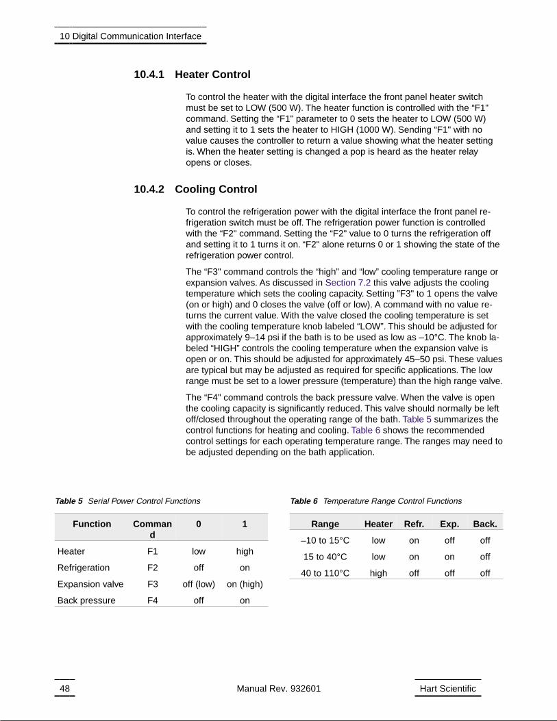
10.4.1 Heater Control
To control the heater with the digital interface the front panel heater switchmust be set to LOW (500 W). The heater function is controlled with the “F1"command. Setting the “F1" parameter to 0 sets the heater to LOW (500 W)and setting it to 1 sets the heater to HIGH (1000 W). Sending “F1" with novalue causes the controller to return a value showing what the heater settingis. When the heater setting is changed a pop is heard as the heater relayopens or closes.
10.4.2 Cooling Control
To control the refrigeration power with the digital interface the front panel re-frigeration switch must be off. The refrigeration power function is controlledwith the “F2" command. Setting the “F2" value to 0 turns the refrigeration offand setting it to 1 turns it on. “F2" alone returns 0 or 1 showing the state of therefrigeration power control.
The “F3" command controls the “high” and “low” cooling temperature range orexpansion valves. As discussed in Section 7.2 this valve adjusts the coolingtemperature which sets the cooling capacity. Setting ”F3" to 1 opens the valve(on or high) and 0 closes the valve (off or low). A command with no value re-turns the current value. With the valve closed the cooling temperature is setwith the cooling temperature knob labeled “LOW”. This should be adjusted forapproximately 9–14 psi if the bath is to be used as low as –10°C. The knob la-beled “HIGH” controls the cooling temperature when the expansion valve isopen or on. This should be adjusted for approximately 45–50 psi. These valuesare typical but may be adjusted as required for specific applications. The lowrange must be set to a lower pressure (temperature) than the high range valve.
The “F4" command controls the back pressure valve. When the valve is openthe cooling capacity is significantly reduced. This valve should normally be leftoff/closed throughout the operating range of the bath. Table 5 summarizes thecontrol functions for heating and cooling. Table 6 shows the recommendedcontrol settings for each operating temperature range. The ranges may need tobe adjusted depending on the bath application.
48 Manual Rev. 932601 Hart Scientific
10 Digital Communication Interface
Function Command
0 1
Heater F1 low high
Refrigeration F2 off on
Expansion valve F3 off (low) on (high)
Back pressure F4 off on
Table 5 Serial Power Control Functions
Range Heater Refr. Exp. Back.
–10 to 15°C low on off off
15 to 40°C low on on off
40 to 110°C high off off off
Table 6 Temperature Range Control Functions
11 Calibration Procedure
In some instances the user may want to calibrate the bath to improve the tem-perature set-point accuracy. Calibration is done by adjusting the controllerprobe calibration constants DO and DG so that the temperature of the bath asmeasured with a standard thermometer agrees more closely with the bathset-point. The thermometer used must be able to measure the bath fluid tem-perature with higher accuracy than the desired accuracy of the bath. By usinga good thermometer and carefully following the procedure the bath can be cal-ibrated to an accuracy of better than 0.1°C over a range of 50 degrees.
11.1 Calibration Points
In calibrating the bath DO and DG are adjusted to minimize the set-point errorat each of two different bath temperatures. Any two reasonably separated bathtemperatures may be used for the calibration however best results are ob-tained when using bath temperatures which are just within the most useful op-erating range of the bath. The farther apart the calibration temperatures thelarger will be the calibrated temperature range but the calibration error will alsobe greater over the range. If for instance 20°C and 80°C are chosen as the cal-ibration temperatures, the bath may achieve an accuracy of say ±0.2°C overthe range 20 to 80°C. Choosing 30°C and 70°C may allow the bath to have abetter accuracy of maybe ±0.05°C over the range 30 to 70°C but outside thatrange the accuracy may be only ±0.5°C.
11.2 Measuring the Set-point Error
The first step in the calibration procedure is to measure the temperature errors(including sign) at the two calibration temperatures. First set the bath to thelower set-point which we will call tL. Wait for the bath to reach the set-point andallow 15 minutes to stabilize at that temperature. Check the bath stability withthe thermometer. When both the bath and the thermometer have stabilizedmeasure the bath temperature with the thermometer and compute the temper-ature error errL which is the actual bath temperature minus the set-point tem-perature. If for example the bath is set for a lower set-point of tL=20°C and thebath reaches a measured temperature of 19.7°C then the error is -0.3°C.
Next, set the bath for the upper set-point tH and after stabilizing measure thebath temperature and compute the error errH. For our example we will supposethe bath was set for 80°C and the thermometer measured 80.1°C giving an er-ror of +0.1°C.
11.3 Computing D0 and DG
Before computing the new values for D0 and DG the current values must beknown. The values may be found by either accessing the probe calibrationmenu from the controller panel or by inquiring through the digital interface. Theuser should keep a record of these values in case they may need to be re-stored in the future. The new values DO′ and DG′ are computed by entering
7005/7015 Manual Rev. 932601 49
11 Calibration Procedure

the old values for DO and DG, the calibration temperature set-points tL and tH,and the temperature errors errL and errH into the following equations,
Derr t D err t D
t tDL H H L
H L
00 0
0′ = − − −−
+( ) ( )
DGerr err
t tDGH L
H L
′ = −−
+
1
If for example D0 and DG were previously set for –25.229 and 186.9740 re-spectively and the data for tL, tH, errL, and errH were as given above then thenew values D0′ and DG′ would be computed as –25.831 and 188.220 respec-tively. Program the new values D0 and DG into the controller. The new con-stants will be used the next time the bath temperature is set. Check thecalibration by setting the temperature to tL and tH and measuring the errorsagain. If desired the calibration procedure may be repeated again to further im-prove the accuracy.
11.4 Calibration Example
The bath is to be used between 25 and 75°C and it is desired to calibrate thebath as accurately as possible for operation within this range. The current val-ues for D0 and DG are –25.229 and 186.974 respectively. The calibrationpoints are chosen to be 25.00 and 75.00°C. The measured bath temperaturesare 24.869 and 74.901°C respectively. Refer to Figure 9 for applying equationsto the example data and computing the new probe constants.
50 Manual Rev. 932601 Hart Scientific
11 Calibration Procedure
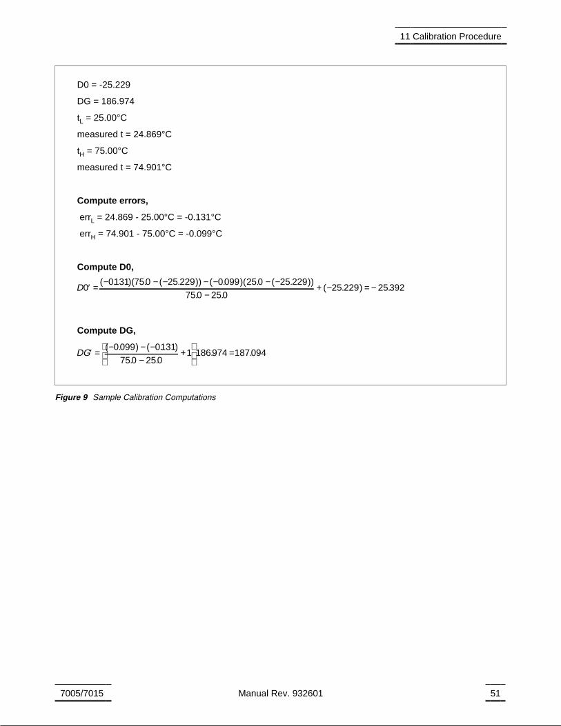
7005/7015 Manual Rev. 932601 51
11 Calibration Procedure
D0 = -25.229
DG = 186.974
tL = 25.00°C
measured t = 24.869°C
tH = 75.00°C
measured t = 74.901°C
Compute errors,
errL = 24.869 - 25.00°C = -0.131°C
errH = 74.901 - 75.00°C = -0.099°C
Compute D0,
D00131 750 25 229 0099 250 25 22′ = − − − − − − −( . )( . ( . )) ( . )( . ( . 9
750 25025 229 25392
))
. .( . ) .
−+ − = −
Compute DG,
DG′ = − − −−
+
=( . ) ( . )
. .. .
0099 0131
750 2501 186974 187094
Figure 9 Sample Calibration Computations
12 Charging Instructions
12.1 Preparation
Remove the refrigeration cover by removing the four screws that hold it on.This provides access to the compressor. The refrigeration system must be leakchecked and then evacuated to 50 microns. After the unit is evacuated, it isready to be charged.
12.2 Charging
After the system has been evacuated, pressurize it with R-134a. Next, turn onthe main unit power and the refrigeration power. Check to make sure that theback pressure valve is completely open (CCW) and that there is room temper-ature (approx. 25°C) fluid in the bath. Using the cooling power valve located onthe side of the unit, adjust the pressure reading to 10 psi. Charge with 15 oz. ofR-134a. If a gauge or scale is not available, add R-134a slowly through the lowpressure side until the sight glass located at the back of the unit is full. Thissight glass should begin to show gas between 15 and 20 psi, but should be fullbelow that pressure.
7005/7015 Manual Rev. 932601 53
12 Charging Instructions
13 Maintenance
• The calibration instrument has been designed with the utmost care. Easeof operation and simplicity of maintenance have been a central theme inthe product development. Therefore, with proper care the instrumentshould require very little maintenance. Avoid operating the instrument indirty or dusty environments.
• The bath should be cleaned regularly to prevent a buildup of oil or dust.Use a paint safe cleaning agent on all painted surfaces. Solvents such asTrichloroethylene or Acetone may dull or dissolve the paint. The stainlesssteel surfaces may be cleaned with solvents as necessary to remove oils.
• The stirring motor should be clean to allow proper cooling. Normally onlythe outside surfaces require any attention. If the inside of the motor has be-come heavily loaded with oily dust, blow it out with compressed air. Follownormal safety procedures when using pressurized gasses.
• Periodically check the fluid level in the bath to ensure that the level has notdropped.A drop in the fluid level affects the stability of the bath.Changes influid level are dependent upon several factors specific to the environmentin which the equipment is used. A schedule cannot be outlined to meeteach environmental setting. Therefore, the first year the bath should bechecked weekly with notes kept as to changes in bath fluid. After the firstyear, the user can set up a maintenance schedule based on the data spe-cific to the application.
• Heat transfer medium lifetime is dependent upon the type of medium andthe environment. The fluid should be checked at least every month for thefirst year and regularly thereafter. This fluid check provides a baseline forknowledge of bath operation with clean, usable fluid. Once some fluidshave become compromised, the break down can occur rapidly. Particularattention should be paid to the viscosity of the fluid.A significant change inthe viscosity can indicate that the fluid is contaminated, being used outsideof its temperature limits, contains ice particles, or is close to a chemicalbreakdown.Once data has been gathered, a specific maintenance sched-ule can be outline for the instrument. Refer to the General Operation sec-tion (Section 8) for more information about the different types of fluids usedin calibration baths.
• If a hazardous material is spilt on or inside the equipment, the user is re-sponsible for taking the appropriate decontamination steps as outlined bythe national safety council with respect to the material. MSDS sheets ap-plicable to all fluids used in the baths should be kept in close proximity tothe instrument.
• If the mains supply cord becomes damaged, replace it with a cord with theappropriate gauge wire for the current of the bath. If there are any ques-tions, call Hart Scientific Customer Service for more information.
• Before using any cleaning or decontamination method except those rec-ommended by Hart, users should check with Hart Scientific CustomerService to be sure that the proposed method will not damage the equip-ment.
7005/7015 Manual Rev. 932601 55
13 Maintenance
• If the instrument is used in a manner not in accordance with the equipmentdesign, the operation of the bath may be impaired or safety hazards mayarise.
• The over-temperature cut-out should be checked every 6 months to seethat it is working properly. In order to check the user selected cut-out, followthe controller directions (Section 9.8) for setting the cut-out.Both the man-ual and the auto reset option of the cut-out should be checked.Set the bathtemperature higher than the cut-out. Check to see if the display flashescut-out and the temperature is decreasing. Note: When checking theover-temperature cut-out, be sure that the temperature limits of the bathfluid are not exceeded. Exceeding the temperature limits of the bath fluidcould cause harm to the operator, lab, and instrument.
• The constant temperature bath depends upon the certain qualities of thefluid medium in order to maintain a uniform and stable temperature envi-ronment. Some oils change their characteristics or become dirty after aperiod of use. Always remove any foreign materials from the bath.
• Silicone oils as well as others may evaporate off their lighter componentsover a period of time leaving the very viscous components remaining. Inaddition, some decomposition occurs which may impair the temperaturestability of the bath. When this happens, the fluid is generally very dark toblack and viscous. Vegetable oils polymerize (turn plastic like) after theyhave been used for a time at high temperatures making them very difficultto remove. When the oil has become unusable it should be changed. Theinstructions for removing the oil is as follows.
13.1 Draining the Bath
The drain is located on the back of the bath. See Figure 4 on page 18. Locatethe drain plug on the end of the drain tube. This drain plug is to be fluid tightuntil the time of draining. The following information is helpful when draining thebath. Always use a container capable of holding the entire load of fluid. Usingan adequate size (about 8 gallons or 1 cubic foot), heat proof fluid container isextremely important. Use safety equipment as appropriate.
1. Water and low viscosity fluids - Drain at room temperature. Normal caremust be taken for fluids that may have corrosive or damaging effects onthe surrounding facility or equipment.
2. High viscosity oils - The fluid should be sufficiently low in viscosity todrain efficiently. Some oils such as 710 silicone oil may need to be heatedto 80°C to be fluid enough to drain well. The viscosity affects how rapidly itdrains as well as how well it flows off of the walls. Heat proof containersand appropriate safety equipment such as face shields, gloves and bodycovering are recommended.
WARNINGExtreme danger of BURNS and FIRE. Use safety equipment,
use proper equipment and have fire safety equipmentstanding by.
56 Manual Rev. 932601 Hart Scientific
13 Maintenance
14 Troubleshooting
14.1 Troubleshooting
In the event the bath appears to function abnormally this section may help tofind and solve the problem. Several possible problem conditions are describedalong with likely causes and solutions. If a problem arises please read thissection carefully and attempt to understand and solve the problem. If the bathseems faulty or the problem cannot otherwise be solved, then contact HartScientific Customer Service for assistance. When contacting Customer Ser-vice please have the following infomation:
Model Number
Serial Number
AC Voltage
Company Name
A wiring diagram is also included. Opening the unit without contacting HartScientific Customer Service may void the warranty.
The heater indicator LED stays red but the temperature does not in-crease
• The display does not show “cut-out” nor displays an incorrect bath temper-ature, but the controller otherwise appears to operate normally. The prob-lem may be either insufficient heating or no heating at all or too muchcooling. Insufficient heating may be caused by the heater power settingbeing too low, especially at higher operating temperatures. Switching tothe higher heater power switch setting, if available, may solve the problem.Try reducing cooling capacity by increasing the cooling temperature,switching the cooling power switch to “LOW”, or switching off the coolingaltogether.
• One or more burned out heaters or blown heater fuses may also cause thisproblem. If the heaters seem to be burned out, contact Hart Scientific Cus-tomer Service for assistance.
The controller display flashes “CUT-OUT” and the heater does not oper-ate
• The display will flash “CUT-OUT” alternately with the process temperature.If the process temperature displayed seems grossly in error perform theMaster Reset Sequence, Section 14.1.1. Normally, the cut-out discon-nects power to the heater when the bath temperature exceeds the cut-outset-point causing the temperature to drop back down to a safe value. If thecut-out mode is set to “AUTO”, the heater switches back on when the tem-perature drops. If the mode is set to “RESET”, the heater only comes onagain when the temperature is reduced and the cut-out is manually resetby the operator. See Section 9.8. Check that the cut-out set-point is ad-justed to 10 or 20°C above the maximum bath operating temperature andthat the cut-out mode is set as desired.
• If the cut-out activates when the bath temperature is well below the cut-outset-point or the cut-out does not reset when the bath temperature dropsand it is manually reset, then the cut-out circuitry may be faulty or the
7005/7015 Manual Rev. 932601 57
14 Troubleshooting
cut-out thermocouple sensor may be faulty or disconnected. Contact HartScientific Customer Service for assistance.
The display flashes “CUT-OUT” and an incorrect process temperature
• The problem may be that the controller’s voltmeter circuit is not functioningproperly.A problem could exist with the memory back-up battery. If the bat-tery voltage is insufficient to maintain the memory, data may becomescrambled causing problems. A nearby large static discharge may also af-fect data in memory.
• If the problem reoccurs then the battery should be replaced. Contact HartScientific Customer Service for assistance. If initializing the memory doesnot remedy the problem, there may be a failed electronic component.Con-tact Hart Scientific Customer Service for assistance.
The displayed process temperature is in error and the controller remainsin the cooling or the heating state at any set-point value
• Possible causes may be either a faulty control probe or erroneous data inmemory. The probe may be disconnected, burned out, or shorted. Checkthat the probe is connected properly. The probe may be checked with anohmmeter to see if it is open or shorted.The probe is a platinum 4-wire Din43760 type, therefore, the resistance should read 0.2 to 2.0 ohms betweenpins 1 and 2 on the probe connector and 0.2 to 2.0 ohms between pins 3and 4. The resistance should read from 100 to 300 ohms between pins 1and 4 depending on the temperature. If the probe is defective, contact HartScientific Customer Service for assistance.
• If the problem is not the probe, erroneous data in memory may be thecause. Perform the Master Reset Sequence, Section 14.1.1. If the prob-lem remains, the cause may be a defective electronic component.ContactHart Scientific Customer Service for assistance.
The controller controls or attempts to control at an inaccurate tempera-ture
• The controller operates normally except when controlling at a specifiedset-point. At this set-point, the temperature does not agree with that mea-sured by the user’s reference thermometer to within the specified accu-racy. This problem may be caused by an actual difference in temperaturebetween the points where the control probe and thermometer probe mea-sure temperature, by erroneous bath calibration parameters, or by a dam-aged control probe.
• Check that the bath has an adequate amount of fluid in the tank and thatthe stirrer is operating properly.
• Check that the thermometer probe and control probe are both fully in-serted into the bath to minimize temperature gradient errors.
• Check that the calibration parameters are all correct according to the cer-tification sheet. If not then reprogram the constants. The memory backupbattery may be weak causing errors in data.
• Check that the control probe has not been struck, bent, or damaged. If thecause of the problem remains unknown, contact Hart Scientific CustomerService for assistance.
58 Manual Rev. 932601 Hart Scientific
14 Troubleshooting

The controller shows that the output power is steady but the processtemperature is unstable
• If the bath temperature does not achieve the expected degree of stabilitywhen measured using a thermometer, try adjusting the proportional bandto a narrower width as discussed in Section 9.7.
The controller alternately heats for a while then cools
• This oscillation is typically caused by the proportional band being too nar-row. Increase the width of the proportional band until the temperature sta-bilizes as discussed in Section 9.7.
The controller erratically heats then cools, control is unstable
• If both the bath temperature and output power do not vary periodically butin a very erratic manner, the problem may be excess noise in the system.Noise due to the control sensor should be less than 0.001°C. However, ifthe probe has been damaged or has developed an intermittent short, er-ratic behavior may exist. Check for a damaged probe or poor connectionbetween the probe and bath.
• Intermittent shorts in the heater or controller electronic circuitry may alsobe a possible cause. Contact Hart Scientific Customer Service for assis-tance.
The bath does not achieve low temperatures
• This problem can be caused by too much heating or not enough cooling.Check that the control indicator glows green showing that the controller isattempting to cool. The heaters may be disabled as a test by temporarilyremoving the heater fuses.
• Maximize cooling by switching the cooling on, setting the cooling power tohigh, if applicable, and setting the cooling temperature to 10–15°C belowthe bath set-point (see the chart on the bath).
• Insufficient cooling may be caused by lack of refrigerant because of a leakin the system. Refer to Section 12, Charging Instruction.
14.1.1 Master Reset Sequence
Hold the “SET” and “EXIT” keys down at the same time while powering up theunit. The display shows “-init”, the model number, and the firmware version.Each of the controller parameters and calibration constants must bere-programmed. The values can be found on the Report of Calibration that wasshipped with the instrument.
7005/7015 Manual Rev. 932601 59
14 Troubleshooting
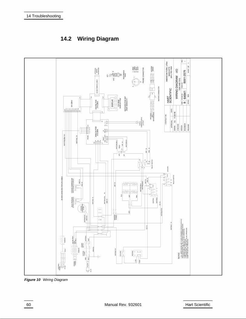
14.2 Wiring Diagram
60 Manual Rev. 932601 Hart Scientific
14 Troubleshooting
(801
)7
63-1
600
840
03-9
775
AM
ER
ICA
NF
OR
K,U
TA
H
SC
IEN
TIF
ICH
AR
T
64
84
1R
EL
EA
SE
EN
GIN
EE
R
DE
SIG
N
CH
EC
KE
D
DR
AW
N
DA
TE
AP
PR
OV
AL
CO
NT
RA
CT
NO
.
RE
V.
DW
GN
O.
FS
CM
NO
.S
IZE
SH
EE
TO
FS
CA
LE
:
KJ
11-0
5-9
6
GR
Y
B00
1-2
S7
6
700
5A
ND
70
15
BR
NW
HT
/BL
K
WH
T
GR
N/Y
EL
BLU
FU
SE
SS
YS
TE
MS
WIT
CH
PO
WE
R
FE
RR
ITE
FE
RR
ITE
8A
MP
FO
R230
VA
CO
PE
RA
TIO
N3.S
YS
TE
MF
US
E:15
AM
PF
OR
115
VA
CO
PE
RA
TIO
N3
AM
PF
OR
230
VA
CO
PE
RA
TIO
N2.H
EA
TE
RF
US
E:6
AM
PF
OR
115
VA
CO
PE
RA
TIO
N
GR
N18
FU
SE
S
FIL
TE
R
-B
GR
Y
4-
WH
T3
-B
LK
2-
GR
N1
-R
ED
PR
OB
EC
ON
NE
CT
OR
43
2
1
HE
AT
ER
CO
NN
EC
TO
R
WIR
ES
HE
AT
ER
WH
T/R
ED
/BL
KG
RY
WH
T/R
ED
TR
IAC
RE
FE
RE
NC
E
MT
2G
MT
1
7
RE
LA
YS
WIT
CH
GR
Y1
8
WH
T/R
ED
/BL
K
GR
Y1
8
WH
T/R
ED
/BL
K
VIO
18
WH
T/B
LK
18
18
WH
T/Y
EL
/BL
K1
8
WH
T/Y
EL
18
INS
ULA
TIO
NR
AT
ED
@1
05
CU
NLE
SS
OT
HE
RW
ISE
NO
TE
D.
1.A
LL
WIR
ES
SH
OW
NA
RE
16
AW
GS
TR
AN
DE
DC
OP
PE
RW
ITH
PV
C
NO
TE
S:
HE
AT
ER
WH
T/O
RG
/BL
K
N76
J2
543210H
001-2
B43
J1 J5
PA
RT
#00003117
MA
TC
HE
DP
CB
SE
T
DIS
PLA
YP
CB
DIG
ITA
LP
CB
AN
ALO
GP
CB
DIS
PLA
Y
J1
J4
RE
LA
YS
WIT
CH
TR
IAC
CU
TO
UT
TH
ER
MO
CO
UP
LE
TY
PE
K
J2
J1
01
0-2
B06
010-2
B04
010-2
B05
18
18
18
18
G
MT
2
MT
1
54
32
1
PR
OB
EJ2
VIO
WH
T/O
RG
GR
Y
OR
G
8 9
4 6
BA
RE
LA
Y
J8
TR
IAC
J6
GNH
AC
J1
-+
TC
J7
MT
1G
MT
2
BLK
18
WH
T/B
LU
VIO
18
WH
T/B
LK
BLU
WH
T/B
LU
/BL
K
PO
WE
RS
TIR
RE
R
AC
IN
GR
N
RE
D
WH
T/B
LK
/VIO
WH
T/Y
EL
18
OR
G18
RE
D18
HIG
HR
AN
GE
SO
LE
NO
IDC
OO
LIN
GT
EM
PE
RA
TU
RE
BY
PA
SS
SO
LE
NO
IDB
AC
KP
RE
SS
UR
E
N/A
CO
OL
ING
HE
AT
ING
BA
64
98
7
BA
64
98
7
-I/O
OP
TIO
NA
L
26
AW
GR
IBB
ON
CA
BL
E
INT
ER
FA
CE
SE
RIA
L
&F
AN
WIR
ING
DIA
GR
AM
WH
T/V
IO
WH
T/B
LK
/VIO
CO
OLIN
GC
OM
PR
ES
SO
R
CO
OL
ING
WH
T/R
ED
11
26
AW
GS
HIE
LD
ED
TE
FLO
NC
AB
LE
PR
OB
EC
ON
TR
OL
LO
W
HIG
H
18
SH
LD
PT
100
T
HE
AT
ING
WH
T/B
LK
/YE
L
Figure 10 Wiring Diagram


