70 years Safety in fl ying - Tost Flugzeuggerätebau
65
Product Catalog 70 years Safety in flying
-
Upload
khangminh22 -
Category
Documents
-
view
1 -
download
0
Transcript of 70 years Safety in fl ying - Tost Flugzeuggerätebau

Product Catalog
70 years
Safety in fl ying

Dear Fellow Aviators, Dear Customers
you hold in your hands one hot off the press copy of our Product Catalog, which we designed newly on the occasion of the 70th anniversary of Tost.
Since the very beginning of Tost it is our aim to be your reliable partner for all questions related to safe equipment for gliding and aviation. Our EASA approvals as Design Organisation, Production Organisation and Maintenance Organisation show the diversity of our family run business. Our own ex-periences during soaring and on the airfi eld go directly into all product de-velopments, as well as those of our fellow aviators. We are always amenable to suggestions also from your side.
This cataloge provides manifold useful information for you. At the same time, it should be a pleasure to turn its pages to check out for details. The unique photos of German glider pilot Claus Dieter Zink, who show the beauty of soaring, are contributing their part.
We may wish you many terrifi c fl ights and always Happy Landings!
Michael Dörfl einSusanne DupontBarbara Dörfl ein München, April 2015
EASA Production Organisation DE.21G.0065EASA Maintenance Organisation DE.145.0411Design Organisation EASA.AP230
Thalkirchner Straße 6280337 MünchenDeutschland Tel. +49-89-544 599-0 Fax +49-89-544 [email protected]
Tost-QualityMade in Germany
How to order: per phone +49 - (0)89-544 599-0
per fax +49 - (0)89-544 599-70 per email [email protected]
www.tost.de
Aircraft WheelsBroad delivery programm of aircraft wheels in various
dimensions: support and tail wheels, landing wheels,
drum brake wheels, disk brake wheels
5
91
109
83
115
73
47
35
121
126
Aircraft Tires / TubesSpecialised in aircraft tires, we offer a wide range of all
common brands for General Aviation, always with the
suitable tubes
Tost Hydraulic Brake SystemA complete hydraulic brake system with matching compo-
nents: brake assembly, hydraulic hoses, master cylinder,
parking valve, fi ttings
Tow Cable Retractor WinchA Tow Cable Retractor Winch stands for additional safety
during aero tows. Overview over all types, modules and
spare parts.
Tow ReleasesTost releases are the standard for the safe glider start:
nose and tail releases, center-of-gravity releases and
further types
Towing / Launching EquipmentWeak links, connecting elements, cable parachutes,
cables/ropes: everything for failure-free and safe towing
and launching operations
Accessories / ToolsControl cables and tools for steel cables like Nicopress
sleeves and tools and thimbles
Helicopter EquipmentThe Tost rope down securing unit is used succesfully
during rope down operations: best possible safety for
special operation teams
Special Purpose SolutionsWe offer special solutions for further applications of
wheels, releases, weak links as well as extensive
technical services
Tost MilestonesAviators in action for aviators for 70 years. Innovations
and product development for the safety in fl ying
Pilots in action for pilots
ww
w.fo
toka
lend
er-s
egel
flieg
en.d
e •
Pho
to: C
laus
Die
ter Z
ink

54
AIRCRAFT WHEELS
Landing wheels ........................................................................ 7Mini 150 +180 landing wheels
3″ Landing wheel Moritz and Moritz II
3,5″ Landing wheel Max and Max II
4″ Landing wheel Classic
4″ Landing wheel Tria
5″ Landing wheel Classic
5″ Landing wheel Penta
6″ Landing wheel Classic
6″ Landing wheel Ultralight
10″ Landing wheel Classic
Shoe brake wheels ................................................................ 154″ Shoe brake wheel Liliput
4″ Shoe brake wheel Kobold
4″ Shoe brake wheel Gnom
5″ Shoe brake wheel Standard
5″ Shoe brake wheel Bimbo
6″ Shoe brake wheel Super
Retrofi t to shoe brake wheel for Bocian
Disk brake wheels ................................................................. 18Disk brake wheel Mini
3,5″ Disk brake wheel Max II
4″ Disk brake wheel Classic
4″ Disk brake wheel Tria
4″ Disk brake wheel Gnom
5″ Disk brake wheel Classic
5″ Disk brake wheel Penta
6″ Disk brake wheel Classic
6″ Disk brake wheel Penta
6″ Disk brake wheel Ultraleicht
Retrofit to disk brake wheels ................................................ 24
Spare parts ............................................................................. 26Brake disks
Spare parts for shoe brake wheels
Wheel selection table ............................................................ 31

76
P/N Description Install.widthmm
Bearing Ø
mm
Tire size Mass kg
w/o tire
Type of hub
031512 LR Mini 150 30 12 mm 150 x 30 300
031513 LR Mini 150 30 12 mm 150 x 30 300 special valve hole
031515 LR Mini 150 30 0.5″ 150 x 30 300 axle in inch
031582 LR Mini 150 F 30 12 mm 150 x 30 300 foam-filled tire
031592 LR Mini 150 30 12 mm 150 x 30 300 with valve hole cover
031812 LR Mini 180 35 12 mm 180 x 35 330
Aircraft wheels In 60 years of development and production of high-grade aircraft wheels, we have created a vast product variety and delivery programm.
Tost wheels are worldwide used in gliders, motor gliders, aircrafts, ultralights, amphibium aircrafts and helicopters. Also in heavy-duty applications Tost wheels convince with high load factors and customer oriented solutions.
High serviceability is an important feature of an aircraft wheel. That’s why we persue our philosophy of wheel hubs for tube type tires. You can easily change the tire with standard tools, even on the airfield.
The operation of Tost wheels is very economic. Not only the quality and life time persuade, but also the ease of main-tenance: the wheel hubs are maintenance-free and fitted with high-quality groove ball bearings. We can supply spare parts over decades and offer maintenance and repair of your wheels.
In case you do not find “your” wheel for your aircraft: we manufacture custom-made wheels regarding installation width and ball bearing diameter.
As a matter of course, we also deliver completely mounted wheels. Our wide range of aircraft tires and tubes are avai-lable from stock.
Being an EASA certified production and maintenance organisation, we supply our wheels with EASA Form 1.
Tost wheels MADE IN GERMANY are a synonym for highest quality and reliability.
Landing wheelsWe offer landing wheels for use as nose wheel, tail wheel, support wheel or as unbraked main wheel, in various dimensions and constructions.
Landing wheel MiniThe smallest available wheel with pneumatic tire with the advantage of good suspension. Easy tire mounting despite very narrow dimensions! Tire diameter 150 mm respectively 180 mm, installation width only 30 mm / 35 mm. Ideal for narrow installation space. For retrofit of tail wheels, also for steerable tail wheels. Anodised in blue or in silver.
Landing wheelsAircraft wheels
Landing wheel Mini 150 (031513)
Landing wheel Mini 150 (031512)
Landing wheel Mini 180 (031812)
5″ Disk brake wheel Penta 135-30 with brake assembly BZT2

98
3″ Landing wheel Moritz and Moritz IIOur well-tried 3″ tail wheel is available in 2 versions: As sturdy aluminium die cast wheel hub with fins sector Moritz and as a 2-part wheel hub CNC milled from aluminium Moritz II. The fins sector system ensures emergeny roll capability also with extremely hard landings.The CNC milled wheel hub Moritz II attracts by a bit lower weight and the considerably easier tire mounting, due to the 2-part wheel structure. Thanks to its anodized surface the Moritz II wheel hub shows a maximum of corrosion protection.
P/N Description Install.widthmm
Bearing Ø
mm
Tire size Mass kg
w/o tire
Type of hub
032100 3″ LR Moritz 50 20 210 x 65 360 one-part
032112 3″ LR Moritz II 50 12 210 x 65 335 two-part
032120 3″ LR Moritz II 50 20 210 x 65 330 two-part
P/N Description Install.widthmm
Bearing Ø
mm
Tire size Mass kg
w/o tire
Type of hub
032501 3″ LR Moritz II brass
50 20 210 x 65 1490 two-part
032502 3″ LR Moritz II brass
50 12 210 x 65 1510 two-part
3″ Landing wheel Moritz II from brassTo achieve good flight characteristics and the maximum aircraft performance the ideal position of the aircraft's center-of gravity is significant. By using our heavy wheel hub Moritz II, manufactered from brass, you can compensate too top-heavy moments, without performing changes at the aircraft.
3″ Landing wheel Moritz (032100)
3″ Landing wheel Moritz II (032112)
3″ Landing wheel Moritz II brass (032502)
3.5″ Landing wheel Max and Max IIThe tire size 200 x 50 is one of the well-established sizes for tail wheels of gli-ders and motor gliders. In addition to the for decades well-proven one-part die-cast wheel hub Max we now offer with the wheel hub Max II also a light-weight, 2-part version. The Max II combines most simple tire mounting with lowest possible mass. Thanks to its anodized surface, the Max II wheel hub shows a maximum of corro-sion protection.
P/N Description Install.widthmm
Bearing Ø
mm
Tire size Mass kg
w/o tire
Type of hub
033100 3.5″ LR Max 50 20 200 x 50 430 one-part
033112 3.5″ LR Max II 50 12 200 x 50 300 two-part
033120 3.5″ LR Max II 50 20 200 x 50 340 two-part
033412 3.5″ LR Max II Version Arcus
50 12 200 x 50 360 two-part, valve hole
further outside
033420 3.5″ LR Max II Version Antares
50 20 200 x 50 350 two-part, valve hole
further outside
P/N Description Install.widthmm
Bearing Ø
mm
Tire size Mass kg
w/o tire
Type of hub
033502 3.5″ LR Max II brass
50 12 200 x 50 2105 two-part
033501 3.5″ LR Max II brass
50 20 200 x 50 2080 two-part
033542 3.5″ LR Max II brass Version Arcus
50 12 200 x 50 2105 two-part
3.5″ Landing wheel Max II from brassAlso the wheel Max II is available in a brass version, to compensate too top-heavy moments, without performing changes at the aircraft
3.5″ Landing wheel Max (033100)
3.5″ Landing wheel Max II (033112)
3.5″ Landing wheel Max II brass (033501)
Landing wheelsLanding wheels
1110
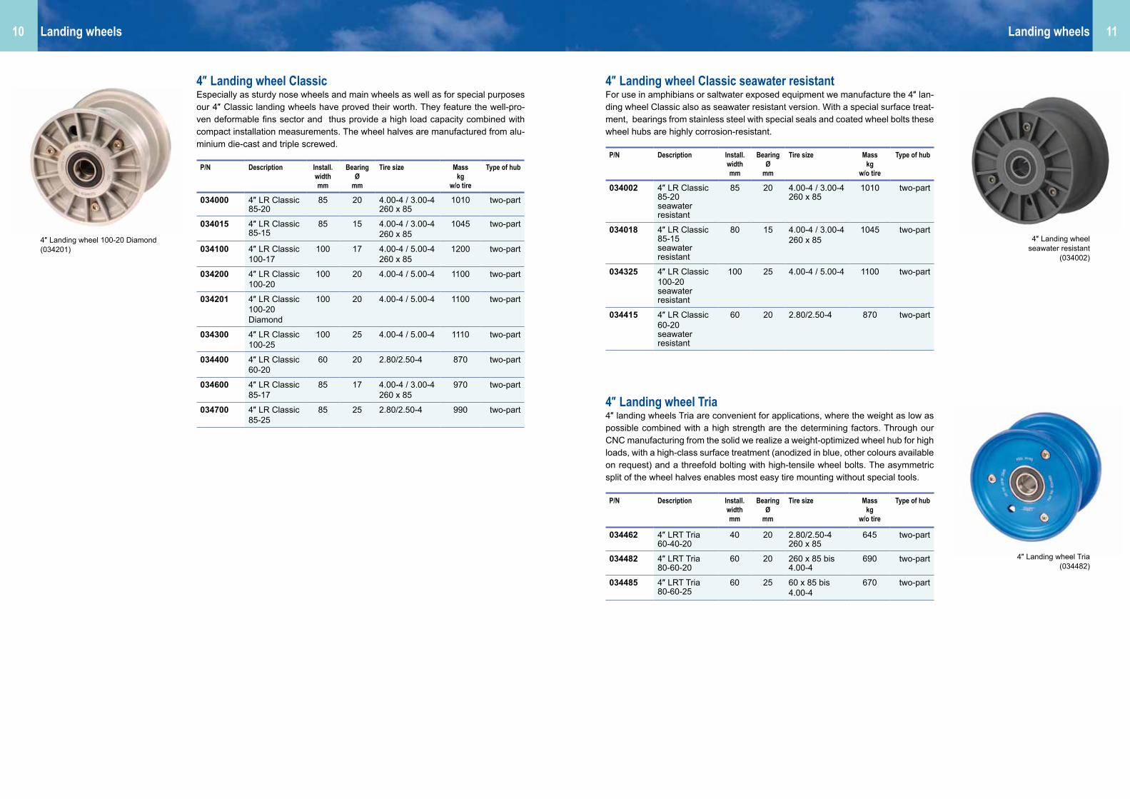
4″ Landing wheel ClassicEspecially as sturdy nose wheels and main wheels as well as for special purposes our 4″ Classic landing wheels have proved their worth. They feature the well-pro-ven deformable fins sector and thus provide a high load capacity combined with compact installation measurements. The wheel halves are manufactured from alu-minium die-cast and triple screwed.
P/N Description Install.widthmm
Bearing Ø
mm
Tire size Mass kg
w/o tire
Type of hub
034002 4″ LR Classic85-20 seawater resistant
85 20 4.00-4 / 3.00-4 260 x 85
1010 two-part
034018 4″ LR Classic85-15 seawater resistant
80 15 4.00-4 / 3.00-4 260 x 85
1045 two-part
034325 4″ LR Classic100-20 seawater resistant
100 25 4.00-4 / 5.00-4 1100 two-part
034415 4″ LR Classic60-20 seawater resistant
60 20 2.80/2.50-4 870 two-part
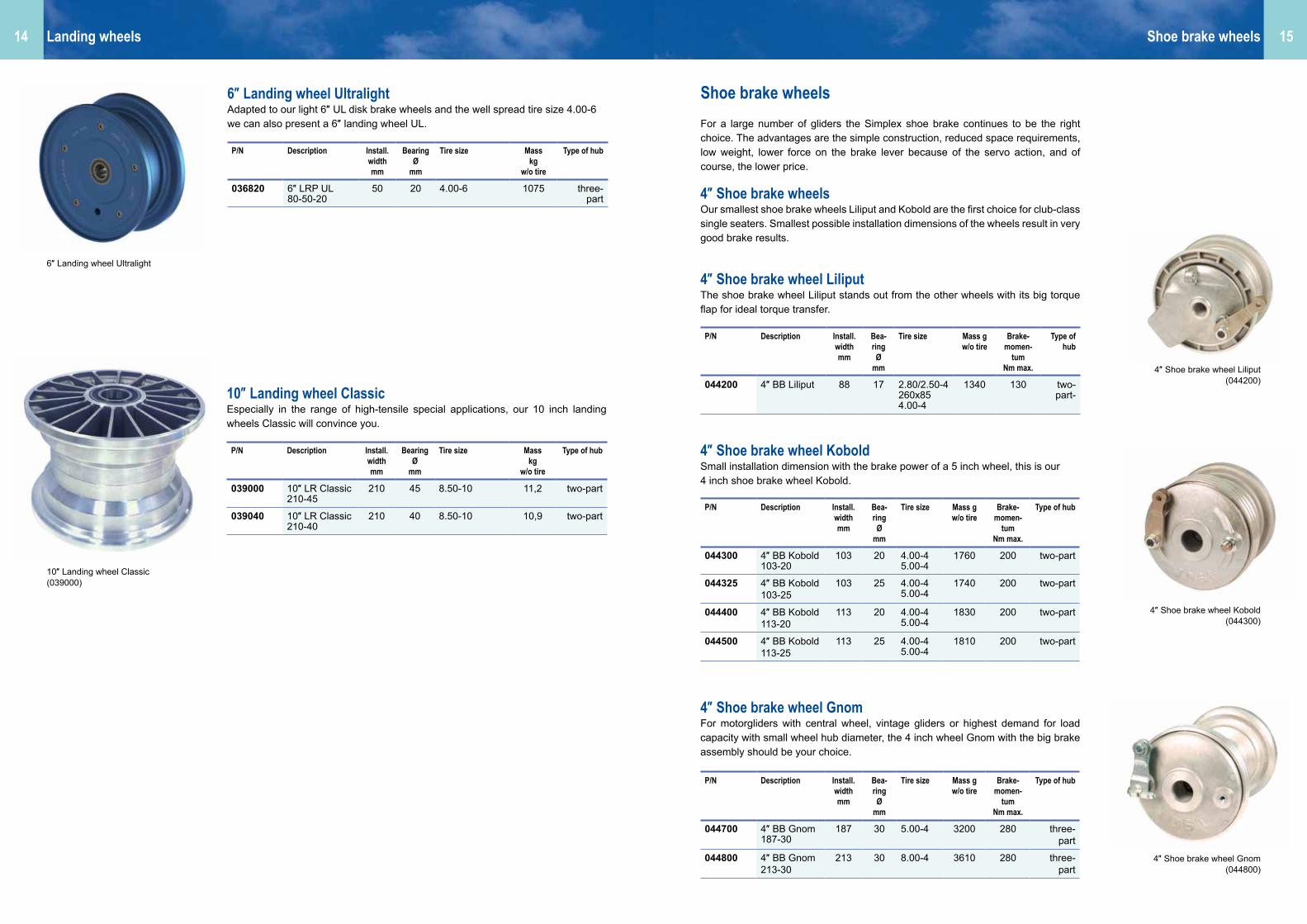
4″ Landing wheel Classic seawater resistantFor use in amphibians or saltwater exposed equipment we manufacture the 4″ lan-ding wheel Classic also as seawater resistant version. With a special surface treat-ment, bearings from stainless steel with special seals and coated wheel bolts these wheel hubs are highly corrosion-resistant.
P/N Description Install.widthmm
Bearing Ø
mm
Tire size Mass kg
w/o tire
Type of hub
034462 4″ LRT Tria 60-40-20
40 20 2.80/2.50-4260 x 85
645 two-part
034482 4″ LRT Tria 80-60-20
60 20 260 x 85 bis 4.00-4
690 two-part
034485 4″ LRT Tria 80-60-25
60 25 60 x 85 bis 4.00-4
670 two-part
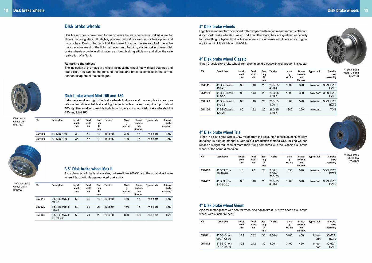
4″ Landing wheel Tria4″ landing wheels Tria are convenient for applications, where the weight as low as possible combined with a high strength are the determining factors. Through our CNC manufacturing from the solid we realize a weight-optimized wheel hub for high loads, with a high-class surface treatment (anodized in blue, other colours available on request) and a threefold bolting with high-tensile wheel bolts. The asymmetric split of the wheel halves enables most easy tire mounting without special tools.
Landing wheelsLanding wheels
4″ Landing wheel 100-20 Diamond (034201)
4″ Landing wheel Tria (034482)
4″ Landing wheel seawater resistant
(034002)
P/N Description Install.widthmm
Bearing Ø
mm
Tire size Mass kg
w/o tire
Type of hub
034000 4″ LR Classic85-20
85 20 4.00-4 / 3.00-4 260 x 85
1010 two-part
034015 4″ LR Classic85-15
85 15 4.00-4 / 3.00-4 260 x 85
1045 two-part
034100 4″ LR Classic100-17
100 17 4.00-4 / 5.00-4 260 x 85
1200 two-part
034200 4″ LR Classic100-20
100 20 4.00-4 / 5.00-4 1100 two-part
034201 4″ LR Classic100-20 Diamond
100 20 4.00-4 / 5.00-4 1100 two-part
034300 4″ LR Classic100-25
100 25 4.00-4 / 5.00-4 1110 two-part
034400 4″ LR Classic60-20
60 20 2.80/2.50-4 870 two-part
034600 4″ LR Classic85-17
85 17 4.00-4 / 3.00-4 260 x 85
970 two-part
034700 4″ LR Classic85-25
85 25 2.80/2.50-4 990 two-part

1312
5″ Landing wheel ClassicThe 5 inch landing wheels Classic are used as nose wheel in aircraft. Also for heavy duty applications; wheel hub with six-fold bolting, manufactured from aluminium die-cast with deformable fins sector.
5″ Landing wheel Pentathe 5 inch Penta landing wheels can be used to save weight and as possible repla-cement for landing wheels equipped with inch bearings. They are CNC milled from the solid and feature with a low weight and stable high load capacity, due to the high-tensile aluminium alloy. The wheel halves are fivefold screwed. Thanks to the set distance bushing a distortion of the bearings on the axle is not possible. Due to the asymmetric splitting of the wheel hub and the use of tire and tube, a fast and straightforward change of the tire – without special tools and special repair shop equipment – is possible. The anodized surface of the Penta wheel hubs provides the maximum corrosion protection.
6″ Landing wheel MikeBeside the “small” landing wheels we also manufacture unbraked, approved lan-ding wheels in big sizes. For high loads our 6″ landing wheels Mike from aluminium die cast with deformable fins sector are particularly suitable.
P/N Description Install.widthmm
Bearing Ø
mm
Tire size Mass kg
w/o tire
Type of hub
035000 5″ LR Classic 102-20
102 20 5.00-5336 x 115-5
1480 two-part
035100 5″ LR Classic 102-30
102 30 5.00-5336 x 115-5
1450 two-part
035110 5″ LR Classic100-30
100 30 5.00-5336 x 115-5
1870 two-part
035150 5″ LR Classic105-20
105 20 5.00-5336 x 115-5
1500 two-part
035170 5″ LR Classic102-25
102 25 5.00-5336 x 115-5
1450 two-part
035200 5″ LR Classic115-20
115 20 5.00-5380 x 150350 x 135336 x 115-5
1550 two-part
035255 5″ LR Classic115-25 B
115 25 5.00-5380 x 150350 x 135336 x 115-5
1720 two-part
035305 5″ LR Classic115-30 B
115 30 5.00-5380 x 150350 x 135336 x 115-5
1780 two-part
035400 5″ LR Classic125-17v
125 17 5.00-5380 x 150350 x 135336 x 115-5
11590 two-part
035420 5″ LR Classic125-20
125 20 5.00-5380 x 150350 x 135336 x 115-5
1600 two-part
035450 5″ LR Classic125-25
125 25 5.00-5380 x 150350 x 135336 x 115-5
1600 two-part
035505 5″ LR Classic115-30 B
115 30 5.00-5380 x 150350 x 135336 x 115-5
1590 two-part
P/N Description Install.widthmm
Bearing Ø
mm
Tire size Mass kg
w/o tire
Type of hub
035520 5″ LRP Penta100-51-20
51 20 mm 5.00-5336 x 115-5
1480 two-part
035530 5″ LRP Penta100-55-30
55 30 mm 5.00-5336 x 115-5
1450 two-part
035531 5″ LRP Penta101-77-1/1/4
77 1/1/4″ 5.00-5380 x 150336x115-5
1670 two-part
P/N Description Install.widthmm
Bearing Ø
mm
Tire size Mass kg
w/o tire
Type of hub
036630 6″ LR Mike 144-95-30
95 30 6.00-6, 7.00-6, 15x6.00-6, 8.00-6
2650 two-part
036650 6″ LR Mike 144-95-40
95 40 6.00-6, 7.00-6, 15x6.00-6, 8.00-6
3170 two-part
Landing wheelsLanding wheels
5″ Landing wheel Classic (035420)
5″ Landing wheel Penta (035531)
6″ Landing wheel Mike (036650)
5″ Landing wheel Classic seawater resistantFor use in amphibians or saltwater exposed equipment we manufacture the 5 inch landing wheel Classic also as a seawater resistant version. With a special surface treatment, bearings from stainless steel with special seals and coated wheel bolts these wheel hubs are highly corrosion-resistant.
P/N Description Install.widthmm
Bearing Ø
mm
Tire size Mass kg
w/o tire
Type of hub
035301 5″ LR Classic115-30sea water resistant
115 30 5.00-5380 x 150350 x 135336x115-5
1780 two-part
1514
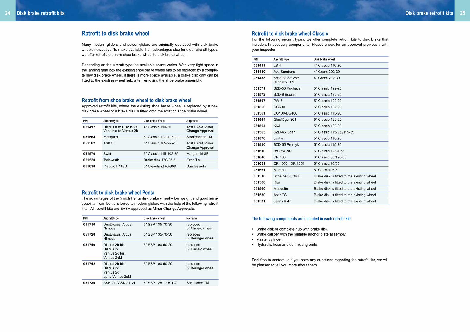
10″ Landing wheel ClassicEspecially in the range of high-tensile special applications, our 10 inch landing wheels Classic will convince you.
6″ Landing wheel UltralightAdapted to our light 6″ UL disk brake wheels and the well spread tire size 4.00-6 we can also present a 6″ landing wheel UL.
P/N Description Install.widthmm
Bearing Ø
mm
Tire size Mass kg
w/o tire
Type of hub
036820 6″ LRP UL80-50-20
50 20 4.00-6 1075 three-part
P/N Description Install.widthmm
Bearing Ø
mm
Tire size Mass kg
w/o tire
Type of hub
039000 10″ LR Classic210-45
210 45 8.50-10 11,2 two-part
039040 10″ LR Classic210-40
210 40 8.50-10 10,9 two-part
10″ Landing wheel Classic (039000)
Shoe brake wheelsFor a large number of gliders the Simplex shoe brake continues to be the right choice. The advantages are the simple construction, reduced space requirements, low weight, lower force on the brake lever because of the servo action, and of course, the lower price.
4″ Shoe brake wheelsOur smallest shoe brake wheels Liliput and Kobold are the first choice for club-class single seaters. Smallest possible installation dimensions of the wheels result in very good brake results.
4″ Shoe brake wheel KoboldSmall installation dimension with the brake power of a 5 inch wheel, this is our 4 inch shoe brake wheel Kobold.
4″ Shoe brake wheel GnomFor motorgliders with central wheel, vintage gliders or highest demand for load capacity with small wheel hub diameter, the 4 inch wheel Gnom with the big brake assembly should be your choice.
P/N Description Install. width mm
Bea-ring Ø
mm
Tire size Mass gw/o tire
Brake- momen-
tumNm max.
Type of hub
044200 4″ BB Liliput 88 17 2.80/2.50-4260x854.00-4
1340 130 two-part-
P/N Description Install. width mm
Bea-ring Ø
mm
Tire size Mass gw/o tire
Brake- momen-
tumNm max.
Type of hub
044300 4″ BB Kobold103-20
103 20 4.00-45.00-4
1760 200 two-part
044325 4″ BB Kobold103-25
103 25 4.00-45.00-4
1740 200 two-part
044400 4″ BB Kobold113-20
113 20 4.00-45.00-4
1830 200 two-part
044500 4″ BB Kobold113-25
113 25 4.00-45.00-4
1810 200 two-part
P/N Description Install. width mm
Bea-ring Ø
mm
Tire size Mass gw/o tire
Brake- momen-
tumNm max.
Type of hub
044700 4″ BB Gnom187-30
187 30 5.00-4 3200 280 three-part
044800 4″ BB Gnom213-30
213 30 8.00-4 3610 280 three-part
4″ Shoe brake wheel Liliput (044200)
4″ Shoe brake wheel Kobold (044300)
4″ Shoe brake wheel Gnom (044800)
4″ Shoe brake wheel LiliputThe shoe brake wheel Liliput stands out from the other wheels with its big torque flap for ideal torque transfer.
6″ Landing wheel Ultralight
Shoe brake wheelsLanding wheels

1716
5″ Shoe brake wheel StandardFor single seater or double-seater gliders, motorgliders or aircrafts: our shoe brake wheel Standard presents a huge selection of installation dimensions in the well established wheel size 5 inch.
5″ Shoe brake wheel BimboFor double seaters made from glass fibre construction, a higher brake momentum is needed due to the higher mass and landing speed. With its clearly bigger brake drum, bigger brake shoes and an optimised brake lever transmission, the 5 inch wheel Bimbo fulfills those increased requirements.
P/N Description Install. width mm
Bea-ring Ø
mm
Tire size Mass gw/o tire
Brake- momen-
tumNm max.
Type of hub
045000 5″ BB Standard95-20
95 20 3.50-5336x115-55.00-5
2170 200 two-part
045100 5″ BB Standard113-20
113 20 336x115-55.00-5
2300 200 two-part
045255 5″ BB Standard115-25
115 25 336x115-55.00-5350x135
2330 200 two-part
045200 5″ BB Standard115-30
115 30 336x115-55.00-5
2350 200 two-part
045417 5″ BB Standard125-17v
125 17 336x115-55.00-5380x150
2500 200 two-part
045400 5″ BB Standard125-20
125 20 336x115-55.00-5380x150
2450 200 two-part
045600 5″ BB Standard125-25
125 25 336x115-55.00-5380x150
2460 200 two-part
045430 5″ BB Standard125-30
125 30 336x115-55.00-5380x150
2440 200 two-part
045500 5″ BB Standard130-20
130 20 336x115-55.00-5380x150
2440 200 two-part
045700 5″ BB Standard130-30
130 30 336x115-55.00-5380x150
2440 200 two-part
045810 5″ BB Standard130-35
130 35 336x115-55.00-5380x150
2460 200 two-part
P/N Description Install. width mm
Bea-ring Ø
mm
Tire size Mass gw/o tire
Brake- momen-
tumNm max.
Type of hub
045950 5″ BB Bimbo 155 30 380 x 150 2870 280 two-part
Shoe brake wheelsShoe brake wheels
6″ Shoe brake wheel SuperFor many different 6 inch tires we can offer our 6 inch shoe brake wheel Super with strong brake-momentum.
Bear in mind the following hints during installation and maintenance:
• Make sure the brake cable is laid correctly: as short and direct as possible, but without tight bends.
• Use a Bowden cable with a set screw.• Adjust brake lever at regular intervals.• Roughen brake linings with emery paper.• Check minimum lining thickness.
Shoe brake wheel retrofit for BocianWe offer a retrofit kit to shoe brake wheel 5″ Standard 115-25 for Bocian to improve its braking capacity. The kit consists of the shoe brake wheel, an axle with diameter 25 mm, the torque plate kit and optional a new tire 5.00-5 with tube.
P/N Description Install. width mm
Bea-ring Ø
mm
Tire size Mass gw/o tire
Brake- momentum
Nm max.
Type of hub
046100 6″ BB Super
154 30 6.00-67.00-68.00-6
3150 270 two-part
P/N Description Remarks
045910 5″ Retrofit kit Bocian with new tire
045911 5″ Retrofit kit Bocian without new tire
5″ Shoe brake wheel Standard (045700)
5″ Shoe brake wheel Bimbo (045950)
6″ Shoe brake wheel Super (046100)
1918
Disk brake wheelsDisk brake wheels have been for many years the first choice as a braked wheel for gliders, motor gliders, Ultralights, powered aircraft as well as for helicopters and gyrocopters. Due to the facts that the brake force can be well-applied, the auto-matic re-adjustment of the lining abrasion and the high, stable braking power disk brake wheels provide in all situations an ideal braking efficiency and allow the safe realisation of a flight.
Remark to the tables:The indication of the mass of a wheel includes the wheel hub with ball bearings and brake disk. You can find the mass of the tires and brake assemblies in the corres-pondent chapters of the catalogue.
Disk brake wheel Mini 150 and 180Extremely small and light disk brake wheels find more and more application as ope-rational and differential brake at flight objects with an all-up weight of up to about 100 kg. The smallest possible installation space show our disk brake wheels Mini 150 und Mini 180:
3.5″ Disk brake wheel Max IIA combination of highly stressable, but small tire 200x50 and the small disk brake wheel Max II with flange-mounted brake disk:
Disk brake wheels Disk brake wheels
3.5″ Disk brake wheel Max II (053020)
Disk brake wheel Mini (051150)
4″ Disk brake wheelsHigh brake momentum combined with compact installation measurements offer our 4 inch disk brake wheels Classic und Tria. Therefore they are qualified especially for retrofitting of hydraulic disk brake wheels in single-seated gliders or as original equipment in Ultralights or LSA/VLA.
4″ Disk brake wheel Tria4 inchTria disk brake wheel CNC milled from the solid, high-tensile aluminium alloy, anodized in blue as standard. Due to our production method CNC milling we can realize a weight reduction of more than 500 g compared with the Classic disk brake wheel of the same dimension.
4″ Disk brake wheel GnomAlso for motor gliders with central wheel and ballon tire 8.00-4 we offer a disk brake wheel with 4 inch tire seat:
P/N Description Install. width mm
Total width mm
Bea-ring Ø
mm
Tre size Mass g
w/o tire
Brake- momen-
tumNm max.
Type of hub Suitable brake
assembly
054462 4″ SRT Tria90-40-20
40 90 20 2.80 / 2.50-4260x85
1330 370 two-part 30-9, BZT, BZT2
054482 4″ SRT Tria110-60-20
60 110 20 260x854.00-4
1380 370 two-part 30-9, BZT, BZT2
P/N Description Install. width mm
Total width mm
Bea-ring Ø
mm
Tre size Mass g
w/o tire
Brake- momen-
tumNm max.
Type of hub Suitable brake
assembly
054111 4″ SB Classic110-20
85 110 20 260x854.00-4
1900 370 two-part 30-9, BZT, BZT2
054131 4″ SB Classic113-20
85 113 20 260x854.00-4
1900 380 two-part 30-9, BZT, BZT2
054125 4″ SB Classic110-25
85 110 25 260x854.00-4
1885 370 two-part 30-9, BZT, BZT2
054100 4″ SB Classic122-20
85 122 20 260x854.00-4
1840 260 two-part TOG
P/N Description Install. width mm
Total width mm
Bea-ring Ø
mm
Tre size Mass g
w/o tire
Brake- momen-
tumNm max.
Type of hub Suitable brake
assembly
053012 3.5″ SB Max II50-12
50 62 12 200x50 460 15 two-part BZM
053020 3.5″ SB Max II50-20
50 62 20 200x50 450 15 two-part BZM
053030 3.5″ SB Max II71-50-20
50 71 20 200x50 860 100 two-part BZT
P/N Description Install. width mm
Total width mm
Bea-ring Ø
mm
Tre size Mass g
w/o tire
Brake- momen-
tumNm max.
Type of hub Suitable brake
assembly
051150 SB Mini 150 30 42 12 150x30 390 15 two-part BZM
051180 SB Mini 180 35 47 12 180x35 420 15 two-part BZM
P/N Description Install. width mm
Total width mm
Bea-ring Ø
mm
Tre size Mass g
w/o tire
Brake- momen-
tumNm max.
Type of hub Suitable brake
assembly
054811 4″ SB Gnom202-172-30
172 202 30 8.00-4 3400 450 three-part
30-63A, BZT2
054812 4″ SB Gnom212-172-30
172 212 30 8.00-4 3400 450 three-part
30-63A, BZT2
4″ Disk brake wheel Classic
(054111)
4″ Disk brake wheel Tria (054482)
4″ Disk brake wheel Classic4 inch Classic disk brake wheel from aluminium die-cast with well-proven fins sector

2120
5″ Disk brake wheel ClassicWheels with a tire seat of 5 inch are the standard size for the main landing gear of many gliders, motor gliders and powered aircraft of various approval classes. For this wheel and tire size we can offer a wide range of disk brake wheels from stock. We should be pleased to make out an offer for you also for the production of special dimensions.
Well-proven for decades are our 5 inch disk brake wheels Classic, made from alu-minium die-cast with their specific deformable fins sector.
Disk brake wheels Disk brake wheels
5″ Disk brake wheel PentaThe 5 inch disk brake wheels of our series Penta captivate with their extra light wheel hub, the asymmetic split for easy tire mounting (the tube cannot be pinched between the wheel halves) and the high-grade, maintenance-free precision ball be-arings. The compact wheel body prevents from grabbing foreign particles. Thanks to the sturdy tire and tube system it is possible to change the tire fast and straight-forward, without special tools and repair shop equipment.
The disk brake wheels are anodized in in blue as standard colour. Other colours (red, silver, black, orange, green) are available on request.
5″ Disk brake wheel Penta
(055538)
5″ Disk brake wheel Classic (055161)
P/N Description Install. width mm
Total width mm
Bea-ring Ø
mm
Tre size Mass g
w/o tire
Brake- momen-
tumNm max.
Type of hub Suitable bra-ke assembly
055520 5″ SBP Penta100-50-20
50 100 20 mm
5.00-5336x115-5
1650 370 two-part 30-9, BZT, BZT2
055530 5″ SBP Penta110-55-30
55 110 30 mm
5.00-5336x115-5380x150
1880 370 two-part 30-9
055531 5″ SBP Penta115-55-30
55 115 30 mm
5.00-5336x115-5380x150
1830 370 two-part 30-9, BZT, BZT2
055535 5″ SBP Penta110-55-30
55 110 30 mm
5.00-5336x115-5380x150
1700 370 two-part 30-9, BZT, BZT2
055536 5″ SBP Penta130-75-30
75 130 30 mm
5.00-5336x115-5380x150
1880 370 two-part 30-9, BZT, BZT2
055538 5″ SBP Penta135-75-30
75 135 30 mm
5.00-5336x115-5380x150
1980 370 two-part 30-9, BZT, BZT2
055544 5″ SBP Penta120-85-30
85 120 30 mm
5.00-5336x115-5380x150
1800 370 two-part 30-9, BZT, BZT2
055572 5″ SBP Penta125-77.5-1¼″
77.5 125 1¼″ 5.00-5336x115-5380x150
1860 370 two-part 30-9, BZT, BZT2
055560 5″ SBP Penta120-55-30
55 120 30 5.00-5336x115-5
2020 260 two-part TOG
P/N Description Install. width mm
Total width mm
Bea-ring Ø
mm
Tre size Mass g
w/o tire
Brake- momen-
tumNm max.
Type of hub Suitable bra-ke assembly
055188 5″ SB Classic109-92-20
92 109 20 5.00-5336x115-5
2300 370 two-part 30-9, BZT, BZT2
055191 5″ SB Classic115-102-20
102 115 20 5.00-5336x115-5
2365 370 two-part 30-9, BZT, BZT2
055192 5″ SB Classic115-102-25
102 115 25 5.00-5336x115-5
2360 370 two-part 30-9, BZT, BZT2
055152 5″ SB Classic122-105-20
105 122 20 5.00-5336x115-5
2450 370 two-part 30-9, BZT, BZT2
055145 5″ SB Classic122-105-25
105 122 25 5.00-5336x115-5
2290 370 two-part 30-9, BZT, BZT2
055151 5″ SB Classic122-105-30
105 122 30 5.00-5336x115-5
2415 370 two-part 30-9, BZT2
055153 5″ SB Classic134-115-30
115 134 30 5.00-5336x115-5380x150
2510 370 two-part 30-9, BZT2
055155 5″ SB Classic134-115-35
115 134 35 5.00-5336x115-5380x150
2520 370 two-part 30-9, BZT2
055161 5″ SB Classic145-115-30
115 145 30 5.00-5336x115-5380x150
2765 400 two-part 30-9, BZT2
055162 5″ SB Classic145-115-30v
115 145 30 5.00-5336x115-5380x150
2920 400 two-part 30-9, BZT2
055171 5″ SB Classic154-115-30
115 154 30 5.00-5336x115-5380x150
2840 400 two-part 30-9, BZT2
055213 5″ SB Classic122.5-77.5-30
77.5 122.5 30 5.00-5336x115-5380x150
2600 370 two-part 30-9, BZT2
055212 5″ SB Classic127-77.5-30
77.5 127 30 5.00-5336x115-5380x150
2620 370 two-part 30-9, BZT2
055110 5″ SB Classic135-115-30
115 135 30 5.00-5336x115-5
2500 260 two-part TOG
055120 5″ SB Classic135-115-35
115 135 35 5.00-5336x115-5
2500 260 two-part TOG

2322
6″ Disk brake wheel ClassicWith our extremely high-stressable 6 inch disk brake wheels from aluminium die-cast with the big brake assemblies 30-63A and BZT2 we can offer an ideal combi-nation for high landing speed and total-up weight:
6″ Disk brake wheel Classic seawater resistantFor use in amphibians or saltwater exposed equipment we manufacture the 6 inch disk brake wheel Classic also as seawater resistant version. With a special surface treatment, bearings from stainless steel with special seals and coated wheel bolts these wheel hubs are highly corrosion-resistant.
6″ Disk brake wheel PentaParticularly for double-seated glider of the 20 m class or open class our light 6 inch Penta disk brake wheel is highly quailfied. It offers the same advantages as the 5 inch Penta disk brake wheel.
6″ Disk brake wheel UltralightFor Ultralights every gramm counts – that's why we designed a light disk brake wheel with compact 6-piston brake assembly. The tire seat is adapted to the well-spread Ultralight tire size 4.00-6.
Important advices for the operation of hydraulic brake systems:
If the brake performance of your hydraulic disk brake wheel is getting worse, this can have several reasons. Please check the following points which canbe causative for the problem, singularly or in combination with each other.
• Condition and thickness of brake disk?• Condition and thickness of brake pads?• Condition of seals/O-ring?• Condition of the brake fluid? Period of use?• Correct fluid in the system? (see Operating Manual)• Air in the hydraulic system (pressure point)?• All connections are tightened? Any Leakage?
Disk brake wheels Disk brake wheels
6″ Disk brake wheel Ultralight
(056820)
6″ Disk brake wheel Classic (056650)
6″ Disk brake wheel Penta
(056960)
P/N Description Install. width mm
Total width mm
Bea-ring Ø
mm
Tre size Mass g
w/o tire
Brake- momen-
tumNm max.
Type of hub Suitable brake
assembly
056820 6″ SBP UL105-50-20
50 105 20 4.00-6 1350 two-part BZ-UL
P/N Description Install. width mm
Total width mm
Bea-ring Ø
mm
Tre size Mass g
w/o tire
Brake- momen-
tumNm max.
Type of hub Suitable brake
assembly
056640 6″ SB Classic140-95-40seawater resistant
95 140 40 6.00-615x6.00-67.00-6
3200 450 two-part 30-63A, BZT2
P/N Description Install. width mm
Total width mm
Bea-ring Ø
mm
Tre size Mass g
w/o tire
Brake- momen-
tumNm max.
Type of hub Suitable brake
assembly
056960 6″ SBP Penta138-110-30
110 138 30 6.00-615x6.00-67.00-6
2070 370 two-part 30-9, BZT2
P/N Description Install. width mm
Total width mm
Bea-ring Ø
mm
Tre size Mass g
w/o tire
Brake- momen-
tumNm max.
Type of hub Suitable brake
assembly
056161 6″ SB Super151-113-30
113 151 30 mm
6.00-615x6.00-67.00-6
3500 420 two-part 30-63A, BZT2
056607 6″ SB Classic148,5-85-1½″
85 148,5 1½″ 6.00-615x6.00-67.00-6
3500 450 two-part 30-63A, BZT2
056650 6″ SB Classic140-95-40
95 140 40 mm
6.00-615x6.00-67.00-6
3200 450 two-part 30-63A, BZT2
056652 6″ SB Classic140-80-50
80 140 50 mm
6.00-615x6.00-67.00-6
3150 370 two-part 30-9, BZT2
2524
Retrofit to disk brake wheelMany modern gliders and power gliders are originally equipped with disk brake wheels nowadays. To make available their advantages also for elder aircraft types, we offer retrofit kits from shoe brake wheel to disk brake wheel.
Depending on the aircraft type the available space varies. With very tight space in the landing gear box the existing shoe brake wheel has to be replaced by a comple-te new disk brake wheel. If there is more space available, a brake disk only can be fitted to the existing wheel hub, after removing the shoe brake assembly.
Retrofit from shoe brake wheel to disk brake wheelApproved retrofit kits, where the existing shoe brake wheel is replaced by a new disk brake wheel or a brake disk is fitted onto the existing shoe brake wheel.
Retrofit to disk brake wheel PentaThe advantages of the 5 inch Penta disk brake wheel – low weight and good servi-ceability – can be transferred to modern gliders with the help of the following retrofit kits. All retrofit kits are EASA approved as Minor Change Approvals.
Retrofit to disk brake wheel ClassicFor the following aircraft types, we offer complete retrofit kits to disk brake that include all necessary components. Please check for an approval previously with your inspector.
The following components are included in each retrofit kit:
• Brake disk or complete hub with brake disk• Brake calliper with the suitable anchor plate assembly• Master cylinder• Hydraulic hose and connecting parts
Feel free to contact us if you have any questions regarding the retrofit kits, we will be pleased to tell you more about them.
P/N Aircraft type Disk brake wheel Approval
051412 Discus a to Discus 2aVentus a to Ventus 2b
4″ Classic 110-20 Tost EASA Minor Change Approval
051564 Mosquito 5″ Classic 122-105-20 Streifeneder TM
051562 ASK13 5″ Classic 109-92-20 Tost EASA Minor Change Approval
051570 Swift 5″ Classic 115-102-25 Marganski SB
051520 Twin-Astir Brake disk 170-35-5 Grob TM
051810 Piaggio P149D 8″ Cleveland 40-98B Bundeswehr
P/N Aircraft type Disk brake wheel Remarks
051710 DuoDiscus, Arcus, Nimbus
5″ SBP 135-70-30 replaces 5″ Classic wheel
051720 DuoDiscus, Arcus, Nimbus
5″ SBP 135-70-30 replaces 5″ Beringer wheel
051740 Discus 2b bis Discus 2cTVentus 2c bis Ventus 2cM
5″ SBP 100-50-20 replaces 5″ Classic wheel
051742 Discus 2b bis Discus 2cTVentus 2c up to Ventus 2cM
5″ SBP 100-50-20 replaces 5″ Beringer wheel
051730 ASK 21 / ASK 21 Mi 5″ SBP 125-77.5-1¼″ Schleicher TM
P/N Aircraft type Disk brake wheel
051411 LS 4 4″ Classic 110-20
051430 Avo Samburo 4″ Gnom 202-30
051433 Scheibe SF 25BSlingsby T61
4″ Gnom 212-30
051571 SZD-50 Puchacz 5″ Classic 122-25
051572 SZD-9 Bocian 5″ Classic 122-25
051567 PW-6 5″ Classic 122-20
051566 DG600 5″ Classic 122-20
051561 DG100-DG400 5″ Classic 115-20
051564 Glasflügel 304 5″ Classic 122-20
051564 Kiwi 5″ Classic 122-20
051565 SZD-45 Ogar 5″ Classic 115-25 /115-35
051570 Jantar 5″ Classic 115-25
051550 SZD-55 Promyk 5″ Classic 115-25
051610 Bölkow 207 6″ Classic 128-1.5″
051640 DR 400 6″ Classic 80/120-50
051651 DR 1050 / DR 1051 6″ Classic 95/50
051661 Morane 6″ Classic 95/50
051510 Scheibe SF 34 B Brake disk is fitted to the existing wheel
051560 Kiwi Brake disk is fitted to the existing wheel
051560 Mosquito Brake disk is fitted to the existing wheel
051530 Astir CS Brake disk is fitted to the existing wheel
051531 Jeans Astir Brake disk is fitted to the existing wheel
Disk brake retrofit kits Disk brake retrofit kits
2726
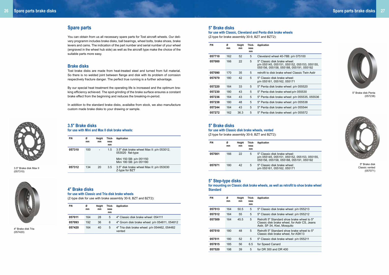
Spare partsYou can obtain from us all necessary spare parts for Tost aircraft wheels. Our deli-very programm includes brake disks, ball bearings, wheel bolts, brake shoes, brake levers and cams. The indication of the part number and serial number of your wheel (engraved in the wheel hub side) as well as the aircraft type make the choice of the suitable parts more easy.
Brake disksTost brake disks are made from heat-treated steel and turned from full material. So there is no welded joint between flange and disk with its problem of corrosion respectively fracture danger. The perfect true running is a further advantage.
By our special heat treatment the operating life is increased and the optimum bra-king efficiency achieved. The spot-grinding of the brake surface ensures a constant brake effect from the beginning and reduces the breaking-in-period.
In addition to the standard brake disks, availalbe from stock, we also manufacture custom made brake disks to your drawing or sample.
3.5″ Brake disks for use with Mini and Max II disk brake wheels:
4″ Brake disks for use with Classic and Tria disk brake wheels(Z-type disk for use with brake assembly 30-9, BZT and BZT2):
5″ Brake disks for use with Classic, Cleveland and Penta disk brake wheels (Z-type for brake assembly 30-9, BZT and BZT2):
5″ Brake disks for use with Classic disk brake wheels, vented(Z-type for brake assembly 30-9, BZT and BZT2):
5″ Step-type disks for mounting on Classic disk brake wheels, as well as retrofit to shoe brake wheel Standard
Spare parts brake disks Spare parts brake disks
P/N Ømm
Heightmm
Thick-nessmm
Application
057310 100 - 1.5 3.5″ disk brake wheel Max II: p/n 053012, 053020 flat-type
Mini 150 SB: p/n 051150Mini 180 SB: p/n 051180
057312 134 20 3.5 3.5″ disk brake wheel Max II: p/n 053030 Z-type for BZT
P/N Ømm
Heightmm
Thick-nessmm
Application
057011 164 28 5 4″ Classic disk brake wheel: 054111
057093 192 36 6 4″ Gnom disk brake wheel: p/n 054811, 054812
057420 164 40 5 4″ Tria disk brake wheel: p/n 054462, 054482vented
P/N Ømm
Heightmm
Thick-nessmm
Application
057710 162 52 5 Cleveland wheel 40-78B: p/n 075100
057000 166 22 5 5″ Classic disk brake wheel:p/n 055145, 055151, 055152, 055153, 055155, 055156, 055158, 055188, 055191, 055192
057090 170 35 5 retrofit to disk brake wheel Classic Twin Astir
057070 180 42 5 5″ Classic disk brake wheel:p/n 055161, 055162, 055171
057220 164 33 5 5″ Penta disk brake wheel: p/n 055520
057230 180 43 5 5″ Penta disk brake wheel:p/n 055530
057236 164 43 5 5″ Penta disk brake wheel: p/n 055535, 055536
057238 180 48 5 5″ Penta disk brake wheel: p/n 055538
057244 164 43 5 5″ Penta disk brake wheel: p/n 055544
057272 162 36.3 5 5″ Penta disk brake wheel: p/n 055572
P/N Ømm
Heightmm
Thick-nessmm
Application
057001 166 22 5 5″ Classic disk brake wheel:p/n 055145, 055151, 055152, 055153, 055155, 055156, 055158, 055188, 055191, 055192
057071 180 42 5 5″ Classic disk brake wheel:p/n 055161, 055162, 055171
P/N Ømm
Heightmm
Thick-nessmm
Application
057513 164 50.5 5 5″ Classic disk brake wheel: p/n 055213
057512 164 55 5 5″ Classic disk brake wheel: p/n 055212
057509 164 45.5 5 Retrofit 5″ Standard shoe brake wheel to 5″ Classic disk brake wheel, for Astir CS, Jeans Astir, SF-34, Kiwi, Mosquito
057510 180 48 5 Retrofit 5″ Standard shoe brake wheel to 5″ Classic disk brake wheel, for ASK13
057511 180 52 5 5″ Classic disk brake wheel: p/n 055211
057815 185 56 6.5 for Speed Canard
057520 198 39 5 for DR 300 and DR 400
5″ Brake disk Classic vented
(057071)3.5″ Brake disk Max II (057310)
4″ Brake disk Tria (057420)
5″ Brake disk Penta (057238)

2928
Maintenance notes for brake disks1. Inspect brake disk for cracks, excessive wear and tear, grooves, corrosion and
deformation.2. Remove corrosion and smooth smaller nicks with fine emery paper (400 grain).3. Replace the brake disk, if it is worn beyond the wear limit (see below). Measure this minimum at two or three spots.4. Replace the brake disk if it has an axial throw of 0.2 mm.5. Brake disks are surface-treated only for special applications. A rust film of varying
degree may form on the brake disk which can be removed with one or two par-king brake operations.
6. If rust has progressed further, it may be necessary to dismantle the disk from the wheel so that both disk surfaces can be cleaned properly. First use a steel brush, then follow with 220 grain emery paper. Finally polish with 400 grain emery paper.
This procudure may allow you to continue using the brake disk.
5″ U-type disks for use with TOG brake assembly with Classic and Penta disk brake wheels
6″ Brake disks for use with Classic, Cleveland and Penta disk brake wheels (Z-type for brake assembly 30-9, 30-63A and BZT2):
6″ Brake disks for use with UL Penta disk brake wheels (flat-type for brake assembly BZ-UL):
Special brake disks flat-type for special aircraft types:
Spare parts brake disks Spare sparts shoe brake wheels
P/N Ømm
Heightmm
Thick-nessmm
Application
057030 160 42 4 5″ Classic disk brake wheel: p/n 055110, 055120, 055130, 055135, 055140
057040 160 53 4 5″ Penta disk brake wheel: p/n 055560
P/N Ømm
Heightmm
Thick-nessmm
Application
057075 184 25 5 6″ Classic disk brake wheel: p/n 056131
057091 184 44 6 6″ Classic disk brake wheel: p/n 056161 (Fournier RF-5)
057095 192 52 6 6″ Classic disk brake wheel: p/n 056650 (Ruschmeyer R90)
057720 190.5 54 6 Cleveland wheel 40-97A: p/n 076100
057260 180 35 5 6″ Penta disk brake wheel: p/n 057260
P/N Ømm
Heightmm
Thick-nessmm
Application
057316 185 - 2 6" UL-Penta disk brake wheel p/n 056820
P/N Ømm
Heightmm
Thick-nessmm
Application
057314 145 - 5,5 AMS Carat A
057317 178 - 5 Klemm Kl 35
5″ Brake disk TOG (057040)
6″ Brake disk Classic (057095)
6″ Brake disk UL (057316)
Wear limits
Disk thickness mm Wear limit mm
1.5 1.3
2.0 1.7
3.5 2.7
4.0 3.5
Disk thickness mm Wear limit mm
5.0 4.3
6.0 5.2
6.5 5.5
Spare parts for shoe brake wheelsAll spare parts for Tost wheels are available from stock. We can supply spare parts also for 40 years old wheels. Prolong the life time of your wheel by regular main-tenance and repair.
Anchor plates Anchor plates are completely fitted with all components: brake shoes with springs, anchor bolt, brake lever and cam.
P/N Description Application Anchor bolt
048428 Anchor plate 4″ 4″ Liliput BB wheel -
048422 Anchor plate 5″ 4″ Kobold BB wheel -
048520 Anchor plate 5″ 5″ Standard BB wheel M8
048521 Anchor plate 5″ 5″ Standard BB wheel M10x1
048620 Anchor plate 6″ 6″ Super BB wheel Inside thread M8
048421 Anchor plate Gnom / Bimbo
4″ Gnom and Bimbo BB wheel
Inside thread M8
Anchor plate 5″ complete( 048521)
Please indicate with your order type of aircraft, axle diameter and anchor bolt.

3130
Beside the complete anchor plates, we can also offer all spare parts for shoe brake wheels solely:
Anchor boltfitted with flanged nut
Brake lever and camare sold only as set due to the indentation of both parts
Brake shoeswith springs
Axles and axle sets for shoe brake wheels
Important advise:We can supply for all types of Tost aircraft wheels - landing wheels, tail and support wheels, shoe brake wheels and disk brake wheels - with indication of the serial number and part number: wheel bolts, distance bushings and ball bearings.
Spare sparts shoe brake wheels Wheel selection table
P/N Thread size Thread length mm Flange height of nut mm
048418 M10x1 25 6
048419 M10x1 30 3
048417 M10x1 30 6
048518 M8 25 6
048519 M8 30 3
P/N Description Application Remarks
048475 Brake shoes Liliput 4″ Liliput BB wheel
048576 Brake shoes Kobold 4″ Kobold BB wheel
048575 Brake shoes Standard 5″ Standard BB wheel
048675 Brake shoes Gnom/Bimbo
BB wheel Gnom or Bimbo
from y.o.c. 1978
048685 Brake shoes Super 6″ Super BB-Rad also: Gnom and Bimbo up to y.o.c. 1977
P/N Description Application Remarks
048478 Brake lever and cam, set 4″ Liliput BB wheel
048570 Brake lever and cam, set 4″ Kobold BB wheel5″ Standard BB wheel
048672 Brake lever and cam, set 4″ Gnom BB wheel5″ Bimbo BB wheel6″ Super BB wheel
replaces p/n 048671
P/N Description Application Remarks
045450 Axle 17 mm 4″ Liliput BB wheel with bushings
048461 Axle 20 mm 4″ Kobold BB wheel 103-20 p/n 044300
048465 Complete axle set Gnom 4″ Gnom BB wheel
048660 Complete axle set Super 6″ Super BB wheel
048665 Torque arm p/n 048465 and 048660
Brake lever and cam
Anchor bolt M10x1 (048417)
Complete axle set(048465)
Wheel selection table
Manufacturer / aircraft type Main wheel Dimen. Tire Nose wheel Dimen. Tire Tail wheel Dimen. Tire
Aero ATAT-3 2 x 5″ Laufrad 115-25 5.00-5 Laufrad 4″ 100-20 5.00-4
BinderEB 28 SB 5″ 145-30 380x150 Moritz 50-20 210x65EB 29 SB 5″ Penta 110-30 380x150 Moritz 50-20 210x65
Brasov/Rumänien IS 28 B / B2, 28 M S / G / GR Standard 5″ 130-35 5.00-5 Moritz 50-20 210x65
IS 29 D Standard 5″ 95-20 3.50-5 Moritz 50-20 210x65
Celair Celstar GA 1 SB 5″ 115-20 5.00-5 Max 50-20 200x50
Centrair Marianne SB 5″ 115-20 5.00-5 Laufrad 4″ 85-17 4.00-4SF 34 SB 5″ 115-20 5.00-5 Laufrad 4″ 85-20 260x85
Comco IkarusC 42 2 x 6″ SB UL 105-20 4.00-6 Aero
DG-FlugzeugbauDG 100 / 200 / 300 / 400 / 600 Standard 5″
or SB 5″ Retrofit125-20 5.00-5
DG 800 Standard 5″or SB 5″
125-20122-20
5.00-5 #
DG 500 / 505, DG 1000 S / T SB 5″ 134-30 380x150 Laufrad 4″ 85-20 260x85 # 200x50DG 1001 M SB 5″ Penta 130-30 380x150 Laufrad 4″ 85-20 260x85 # 200x50LS 8 / LS 10 Standard 5″ 113-20 5.00-5 # 210x65
Diamond Aircraft Dimona / Super Dimona Cleveland 5.00-5
380x150Laufrad 4″ 60-20 2.80/
2.50-4Katana Cleveland 380x150 Laufrad 4″ 100-20 4.00-4
5.00-4
Eiri / IssoirePIK 20 E / D / PIK 16 C Standard 5″ 113-20 5.00-5
FFT (Gyroflug) Speed Canard Cleveland 40-78B
or Retrofit Tost BS
185-56-6,5
5.00-5
Kiwi Standard 5″ orSB 5″ Retrofit
113-20122-20
5.00-5
Frank & Waldenberger Salto Liliput 4″ 88-17 4.00-4
Glasflügel (Streifeneder)Libelle 301 / Standard LibelleClub Libelle
Liliput 4″ 88-17 4.00-4
604 / Kestrel Standard 5″ 125-20 5.00-5Hornet Standard 5″
or SB 5″ Retrofit113-20122-20
5.00-5
Mosquito / 304 B Standard 5″ or SB 5″ Retrofit
113-20122-20
5.00-5 # 210x65
Gomolzig (Caproni)Calif A 21 S Standard 5″
or Kobold 4″95-20103-20
3.50-54.00-4
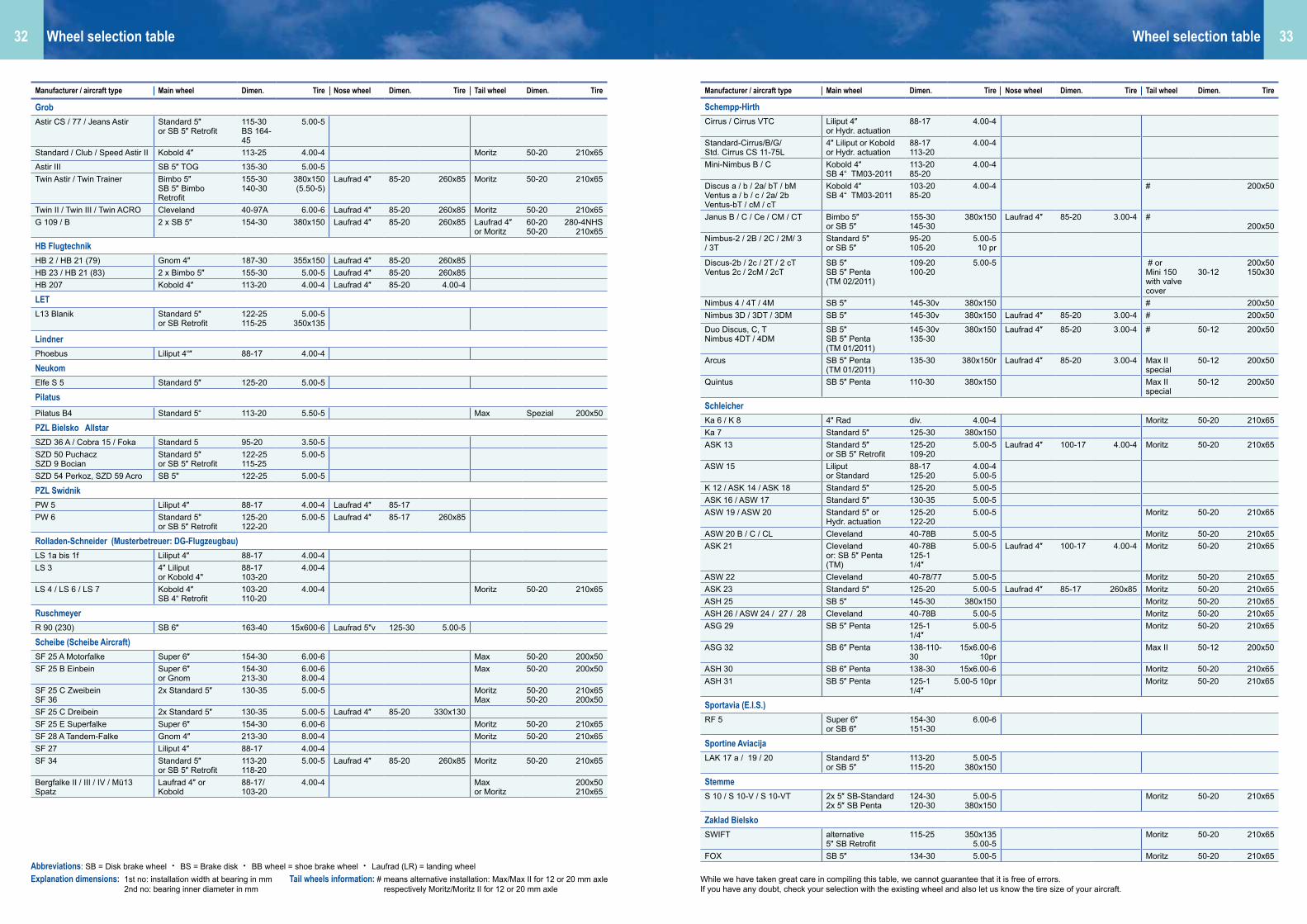
Explanation dimensions: 1st no: installation width at bearing in mm 2nd no: bearing inner diameter in mm
Abbreviations: SB = Disk brake wheel • BS = Brake disk • BB wheel = shoe brake wheel • Laufrad (LR) = landing wheelTail wheels information: # means alternative installation: Max/Max II for 12 or 20 mm axle respectively Moritz/Moritz II for 12 or 20 mm axle
3332 Wheel selection tableWheel selection table
Explanation dimensions: 1st no: installation width at bearing in mm 2nd no: bearing inner diameter in mm
Abbreviations: SB = Disk brake wheel • BS = Brake disk • BB wheel = shoe brake wheel • Laufrad (LR) = landing wheelTail wheels information: # means alternative installation: Max/Max II for 12 or 20 mm axle respectively Moritz/Moritz II for 12 or 20 mm axle
While we have taken great care in compiling this table, we cannot guarantee that it is free of errors.If you have any doubt, check your selection with the existing wheel and also let us know the tire size of your aircraft.
Manufacturer / aircraft type Main wheel Dimen. Tire Nose wheel Dimen. Tire Tail wheel Dimen. Tire
GrobAstir CS / 77 / Jeans Astir Standard 5″
or SB 5″ Retrofit115-30BS 164-45
5.00-5
Standard / Club / Speed Astir II Kobold 4″ 113-25 4.00-4 Moritz 50-20 210x65
Astir III SB 5″ TOG 135-30 5.00-5Twin Astir / Twin Trainer Bimbo 5″
SB 5″ Bimbo Retrofit
155-30140-30
380x150 (5.50-5)
Laufrad 4″ 85-20 260x85 Moritz 50-20 210x65
Twin II / Twin III / Twin ACRO Cleveland 40-97A 6.00-6 Laufrad 4″ 85-20 260x85 Moritz 50-20 210x65G 109 / B 2 x SB 5″ 154-30 380x150 Laufrad 4″ 85-20 260x85 Laufrad 4″
or Moritz60-2050-20
280-4NHS210x65
HB FlugtechnikHB 2 / HB 21 (79) Gnom 4″ 187-30 355x150 Laufrad 4″ 85-20 260x85HB 23 / HB 21 (83) 2 x Bimbo 5″ 155-30 5.00-5 Laufrad 4″ 85-20 260x85HB 207 Kobold 4″ 113-20 4.00-4 Laufrad 4″ 85-20 4.00-4
LETL13 Blanik Standard 5″
or SB Retrofit122-25115-25
5.00-5350x135
LindnerPhoebus Liliput 4“″ 88-17 4.00-4
NeukomElfe S 5 Standard 5″ 125-20 5.00-5
PilatusPilatus B4 Standard 5“ 113-20 5.50-5 Max Spezial 200x50
PZL Bielsko AllstarSZD 36 A / Cobra 15 / Foka Standard 5 95-20 3.50-5SZD 50 PuchaczSZD 9 Bocian
Standard 5″or SB 5″ Retrofit
122-25115-25
5.00-5
SZD 54 Perkoz, SZD 59 Acro SB 5" 122-25 5.00-5
PZL SwidnikPW 5 Liliput 4″ 88-17 4.00-4 Laufrad 4″ 85-17PW 6 Standard 5"
or SB 5″ Retrofit125-20122-20
5.00-5 Laufrad 4″ 85-17 260x85
Rolladen-Schneider (Musterbetreuer: DG-Flugzeugbau)LS 1a bis 1f Liliput 4″ 88-17 4.00-4LS 3 4″ Liliput
or Kobold 4"88-17103-20
4.00-4
LS 4 / LS 6 / LS 7 Kobold 4″SB 4“ Retrofit
103-20110-20
4.00-4 Moritz 50-20 210x65
RuschmeyerR 90 (230) SB 6″ 163-40 15x600-6 Laufrad 5"v 125-30 5.00-5
Scheibe (Scheibe Aircraft)SF 25 A Motorfalke Super 6″ 154-30 6.00-6 Max 50-20 200x50SF 25 B Einbein Super 6″
or Gnom154-30213-30
6.00-68.00-4
Max 50-20 200x50
SF 25 C Zweibein SF 36
2x Standard 5″ 130-35 5.00-5 MoritzMax
50-2050-20
210x65200x50
SF 25 C Dreibein 2x Standard 5″ 130-35 5.00-5 Laufrad 4″ 85-20 330x130SF 25 E Superfalke Super 6″ 154-30 6.00-6 Moritz 50-20 210x65SF 28 A Tandem-Falke Gnom 4″ 213-30 8.00-4 Moritz 50-20 210x65SF 27 Liliput 4″ 88-17 4.00-4SF 34 Standard 5″
or SB 5″ Retrofit113-20118-20
5.00-5 Laufrad 4″ 85-20 260x85 Moritz 50-20 210x65
Bergfalke II / III / IV / Mü13Spatz
Laufrad 4″ or Kobold
88-17/103-20
4.00-4 Maxor Moritz
200x50210x65
Manufacturer / aircraft type Main wheel Dimen. Tire Nose wheel Dimen. Tire Tail wheel Dimen. Tire
Schempp-HirthCirrus / Cirrus VTC Liliput 4″
or Hydr. actuation88-17 4.00-4
Standard-Cirrus/B/G/Std. Cirrus CS 11-75L
4″ Liliput or Koboldor Hydr. actuation
88-17113-20
4.00-4
Mini-Nimbus B / C Kobold 4″SB 4“ TM03-2011
113-2085-20
4.00-4
Discus a / b / 2a/ bT / bMVentus a / b / c / 2a/ 2bVentus-bT / cM / cT
Kobold 4″SB 4“ TM03-2011
103-2085-20
4.00-4 # 200x50
Janus B / C / Ce / CM / CT Bimbo 5″or SB 5″
155-30145-30
380x150 Laufrad 4″ 85-20 3.00-4 #200x50
Nimbus-2 / 2B / 2C / 2M/ 3 / 3T
Standard 5″or SB 5″
95-20105-20
5.00-5 10 pr
Discus-2b / 2c / 2T / 2 cTVentus 2c / 2cM / 2cT
SB 5″SB 5″ Penta (TM 02/2011)
109-20100-20
5.00-5 # or Mini 150with valve cover
30-12200x50150x30
Nimbus 4 / 4T / 4M SB 5″ 145-30v 380x150 # 200x50Nimbus 3D / 3DT / 3DM SB 5″ 145-30v 380x150 Laufrad 4″ 85-20 3.00-4 # 200x50
Duo Discus, C, TNimbus 4DT / 4DM
SB 5″SB 5″ Penta (TM 01/2011)
145-30v135-30
380x150 Laufrad 4″ 85-20 3.00-4 # 50-12 200x50
Arcus SB 5″ Penta (TM 01/2011)
135-30 380x150r Laufrad 4″ 85-20 3.00-4 Max II special
50-12 200x50
Quintus SB 5″ Penta 110-30 380x150 Max II special
50-12 200x50
SchleicherKa 6 / K 8 4″ Rad div. 4.00-4 Moritz 50-20 210x65Ka 7 Standard 5″ 125-30 380x150ASK 13 Standard 5″
or SB 5″ Retrofit125-20109-20
5.00-5 Laufrad 4″ 100-17 4.00-4 Moritz 50-20 210x65
ASW 15 Liliput or Standard
88-17125-20
4.00-45.00-5
K 12 / ASK 14 / ASK 18 Standard 5″ 125-20 5.00-5ASK 16 / ASW 17 Standard 5″ 130-35 5.00-5ASW 19 / ASW 20 Standard 5″ or
Hydr. actuation125-20122-20
5.00-5 Moritz 50-20 210x65
ASW 20 B / C / CL Cleveland 40-78B 5.00-5 Moritz 50-20 210x65ASK 21 Cleveland
or: SB 5″ Penta (TM)
40-78B125-1 1/4″
5.00-5 Laufrad 4″ 100-17 4.00-4 Moritz 50-20 210x65
ASW 22 Cleveland 40-78/77 5.00-5 Moritz 50-20 210x65ASK 23 Standard 5″ 125-20 5.00-5 Laufrad 4″ 85-17 260x85 Moritz 50-20 210x65ASH 25 SB 5″ 145-30 380x150 Moritz 50-20 210x65ASH 26 / ASW 24 / 27 / 28 Cleveland 40-78B 5.00-5 Moritz 50-20 210x65ASG 29 SB 5″ Penta 125-1
1/4″5.00-5 Moritz 50-20 210x65
ASG 32 SB 6″ Penta 138-110-30
15x6.00-6 10pr
Max II 50-12 200x50
ASH 30 SB 6″ Penta 138-30 15x6.00-6 Moritz 50-20 210x65ASH 31 SB 5″ Penta 125-1
1/4″5.00-5 10pr Moritz 50-20 210x65
Sportavia (E.I.S.)RF 5 Super 6″
or SB 6″154-30151-30
6.00-6
Sportine AviacijaLAK 17 a / 19 / 20 Standard 5″
or SB 5″113-20115-20
5.00-5380x150
Stemme S 10 / S 10-V / S 10-VT 2x 5″ SB-Standard
2x 5″ SB Penta124-30120-30
5.00-5380x150
Moritz 50-20 210x65
Zaklad BielskoSWIFT alternative
5″ SB Retrofit115-25 350x135
5.00-5Moritz 50-20 210x65
FOX SB 5″ 134-30 5.00-5 Moritz 50-20 210x65

3534
AIRCRAFT TIRES / TUBES
Aircraft tires and tubes ..........................................................36
Tire size indicator ...................................................................36
Tires for Mini 150 and Mini 180 .............................................37
3″ Tires.................................................................................... 37
3.5″ Tires .................................................................................38
4″ Tires..................................................................................... 39
5″ Tires..................................................................................... 40
6″ Tires.....................................................................................41
6,5″ Tires .................................................................................42
8″ Tires.................................................................................... 42
10″ Tires ..................................................................................43
Valve extensions .....................................................................43
Notes to tires and tubes .........................................................44Tire exchange
Used inner tubes
Tire maintenance instructions

3736
Aircraft tires and tubesWe have a great selection of aircraft tires from 3 inch to 10 inch available from stock.
Being authorised Michelin Distributor we can supply all Michelin brands: Condor, Michelin Aviator and Michelin AIR. Typical tire sizes for General aviation are shown in the following tables. More sizes up to Commercial aviation are available on request.
For more than 30 years now we manufacture aircraft tires exclusively under the brand TOST AERO in the dimensions: 200x50, 260x85, 4.00-4 and 336x115-5. Characteristics are: long lifetime, very robust, for high load and speed.
Tires for Mini 150 and Mini 180Tires
3″ TiresTires
Tubes
Tubes
P/N Size PR Manufacturer Profile Dimensions(mounted)
Massg
Static load kg
Remarks
Outer Ømm
Widthmm
062151 150x30 6 Industry Rib 150 30 135 for Mini 150
062181 180x35 4 Industry Rib 180 35 195 for Mini 180, tube p/n 063192
P/N Size PR Manufacturer Profile Dimensions(mounted)
Massg
Static load kg
Remarks
Outer Ømm
Widthmm
063591 255x110 4 Aero Rib 260 110 1250 195 Bugrad Puchacz
062091 210x65 2 Industry Rib 205 65 480 Light tire for reduced requirements
Tire size indicatorTwo-part indication of tire size: N – DN = tire width at the largest point, indication in inchD = diameter of the tire seat, indication in inch, equal to the wheel hub size
Example: 5.00-5 = tire width 5″ respectively 127 mm and tire seat 5″4.00-6 = tire width 4″ respectively 102 mm and tire seat 6″
Two-part indication of tire size: M x NM = outer diameter of the tire, indication in mm or in inchN = tire width at the largest point, indication in mm or in inch
Example: 210x65 = Outer diameter of the tire 210 mm, tire width 65 mm
Three-part indication of tire size: M x N – DM = outer diameter of the tire, indication in mm or in inchN = tire width at the largest point, indication in mm or in inchD = diameter of the tire seat, indication in inch, equal to the wheel hub size
Example:380x150-5 = outer diameter of the tire 380 mm, lire width 150 mm, tire seat 5″ respectively 127 mm 15x6.00-5 = outer diameter tire 15″ / 380 mm, tire width 6″ / 150 mm, tire seat 5″
Please note that deviations of the outer diameter of the mounted tire are possible, depending on the wheel hub.
P/N Size Valve Massg
Remarks
062152 150x30 45° 25G 43 for Mini 150
063192 200x50 90° 90° 28G 80 for Max II, two-partand Mini 180
P/N Size Valve Massg
Remarks
063592 255x110 90° 45G 310 Nose wheel Puchacz
062093 2.50-3(210x65)
90° 28G 120 for LW Moritz
TiresAircraft tires
Tire Michelin Aviator

3938
4″ TiresTires
3.5″ TiresTires
Tubes
Tubes
P/N Size PR Manufacturer Profile Dimensions(mounted)
Massg
Static load kg
Remarks
Outer Ømm
Widthmm
064591 2.80/2.50-4 4 STA ZigZag Rib
230 61 840 195 Tail wheel Dimona
064181 10x3.50-4 4 Aircraft Rib 260 85 1080 230
064991 260x85 6 TOST AERO
Rib 260 83 880 400
064491 4.00-4 8 TOST AERO
Rib 300 100 1380 600
064391 5.00-4 6 Goodyear Rib 329 117 2050 540 replaces 330x130
064791 8.00-4 4 Goodyear Rib 440 202 4700 500
064891 3.00-4 4 Industry Rib 250 79 810 Light tire for reduced requirements
064881 4.00-4 4 Industry Rib 300 100 800 Light tire for reduced requirements
064831 4.10/3.50-4 4 Industry ZigZag Rib
260 85 940 Light tire for reduced requirements
P/N Size PR Manufacturer Profile Dimensions(mounted)
Massg
Static load kg
Remarks
Outer Ømm
Widthmm
063191 200x50 6 TOST AERO
Rib 190 54 450 250 for Max and Max II
P/N Size Valve Massg
Remarks
064582 2.80/2.50-4to3.00-4
90° TR87 110 Mulit purpose tube
064292 260x853.00-4
90° 32G 160 Valve length 32 mm
064692 4.00-4 90° 32G 190 Valve length 32 mm
064832 260x853.00-44.10/3.50-44.00-4
90° 28G 250 Multi purpose tubevalve length 28 mm
064492 260x853.00-44.00-4
90° 39G 250 Multi purpose tubevalve length 39 mm
064392 5.00-4 90° TR67 470 Valve length 55 mm
064792 8.00-4 TR12 1020 Aero Classic
064832 4.10/3.50-4 90° TR87 120 also for 4.00-4
P/N Size Valve Massg
Remarks
063093 200x50 90° 30° 28G 80 for Max, one-part
063192 200x50 90° 90° 28G 80 for Max II, two-partand Mini 180
TiresTires

4140
6″ TiresTires
5″ TiresTires
Tubes
Tubes
P/N Size PR Manufacturer Profile Dimensions(mounted)
Massg
Static load kg
Remarks
Outer Ømm
Widthmm
066688 4.00-6 6 Aero Classic
Rib 358 90 1640 260 for UL
066788 4.00-6 8 Aero Classic
Rib 2840 385 for UL
066091 6.00-6 6 Michelin Condor
Rib 433 142 4300 795
068611 6.00-6 6 Michelin Aviator
Rib 444 160 4200 795
066881 6.00-6 8 Michelin Condor
Rib 444 160 4400 1065
066591 15x6.00-6 6 Michelin Condor
Rib 380 160 3400 885
068621 15x6.00-6 6 Michelin Aviator
Rib 380 160 3300 885
066381 7.00-6 8 Michelin Condor
Rib 471 182 5300 1160
068711 7.00-6 8 Michelin Aviator
Rib 471 182 5400 1160
068721 8.00-6 6 Michelin Aviator
Rib 495 202 5800 1270
066681 4.10/3.50-6 4 Industry Rib 310 100 1200 Light tire for reduced requirements
066691 4.00-6 4 Industry Rib 350 80 1000 Light tire for reduced requirements
066981 13x5.00-6 4 Industry Rib 300 105 1520 Light tire for reduced requirements
066789 15x6.00-6 6 Industry Rib 325 140 2250 Light tire for reduced requirements
P/N Size PR Manufacturer Profile Dimensions(mounted)
Massg
Static load kg
Remarks
Outer Ømm
Widthmm
065221 336x115-5 10 TOST AERO
Rib 336 115 2650 975 for narrow landing gear space (eg. Schempp-Hirth single seater)
065091 5.00-5 6 Michelin Condor
Rib 353 115 2700 580
068511 5.00-5 6 Michelin Aviator
Rib 361 126 2700 580
067511 5.00-5 6 MichelinAir
Rib 361 126 2530 580
065791 5.00-5 10 Michelin Condor
Rib 345 115 2700 980
065681 380x150(15x6.00-5)
6 MichelinAir
Rib 377 131 3100 725 replaces 5.50-5
065891 350x135 4 AERO Rib 350 120 2700 650 eg. for L-13 Blanik
065881 400x140 4 Stomil TL Rib 409 149 4500 800 Suitable tube: 5.00-5
065191 3.40/3.00-5 4 Industry ZigZag Rib
260 83 985 Light tire for reduced requirements
065185 3.50-5(4.10/3.50-5)
4 Industry Rib 285 88 1000 Light tire for reduced requirements
065381 4.00-5 4 Industry Rib 320 85 1300 Light tire for reduced requirements
065488 11x4.00-5 8 Aero Classic
Rib 1750 295
065481 11x4.00-5 4 Industry Rib 280 115 1000 Light tire for reduced requirements
P/N Size Valve Massg
Remarks
066682 4.10/3.50-6 TR13 225 for tire 4.00-6
066692 4.10/3.50-6 TR87 240 for tire 4.00-6
066092 6.00-6 TR20 750 Michelin Airstop
066992 6.00-6 70° 41,5G 730 for shoe brake wheel 6″ Super 046100
066993 6.00-6 90° TR87 925 Short bent valve
066492 15x6.00-6 TR20 550 Michelin Airstop
066382 7.00/8.00-6 TR20 880 Michelin Airstop
066792 15x6.00-6 90° TR87 380 Light tube
066793 15x6.00-6 straight 370 Light tube, valve length 35 mm
066982 13x5.00-6 90° 280 Light tube, valve length 32 mm
066983 13x5.00-6 straight 270 Light tube. valve length 35 mm
P/N Size Valve Massg
Remarks
065092 5.00-5 90° TR67 450 Michelin Airstop, standard valve length 55 mm,also for tire 380x150 and 350x135
065995 5.00-5 90° TR87 500 Short valve 28 mm, for 5″ Penta LW and SBP,also for tire 380x150 and 350x135
065193 3.40/3.00-5 90° 28G 190 Light tube
065192 4.10/3.50-5 90° TR87 270 Light tubealso for tire 4.00-5
065482 11x4.00-5 gerade 200 Light tubeValve length 32 mm
065483 11x4.00-5 90° 200 Light tubeValve length 32 mm
TiresTires

4342
10″ TiresTires
Valve extensionsTo fill or refill the tire pressure or to check the correct tire pressure, the valve extension is indispensable. We offer suitable types for all possible installation or operation situations:
6,5″ TiresTires
8″ TiresTires
Tubes
Tubes
Tubes
Set tire and tube
P/N Size PR Manufacturer Profile Dimensions(mounted)
Massg
Static load kg
Remarks
Outer Ømm
Widthmm
068891 6.50-10 10 Michelin Aviator
Rib 552 164 8000 2150
068871 8.50-10 8 Michelin Aviator
Rib 640 215 11400 2610
068981 8.50-10 10 Michelin Aviator
Rib 637 215 11300 2000
P/N Size PR Manufacturer Profile Dimensions(mounted)
Massg
Static load kg
Remarks
Outer Ømm
Widthmm
067391 420x150(6.00-6½)
4 Aero Classic Rib 420 150 3200 795
P/N Size PR Manufacturer Profile Dimensions(mounted)
Massg
Static load kg
Remarks
Outer Ømm
Widthmm
068391 6.50-8 8 Michelin Condor
Rib 495 172 5640 1430
P/N Size Valve Massg
Remarks
068892 6.50-10 TR25 860 Michelin Airstop
068292 8.50-10 TR25 1590 Michelin Airstop
P/N Type Length Remark
069981 straight 24 mm, with short valve thread
incl. cap with valve key
069980 straight 24 mm incl. cap
069987 90° 35 mm incl. cap
069986 straight 94 mm incl. cap
P/N Size Valve Massg
Remarks
067392 15x6.00-6 TR20 620 Multi purpose tube for tire420x150 (6.00-6½)
067492 15x6.00-6 90° TR67 600 Multi purpose tube for tire420x150 (6.00-6½)
P/N Size Valve Massg
Remarks
068392 6.50/7.00-8 TR15 1070 Michelin Airstop
P/N Size PR Valve Massg
Remarks
068481 4.00-8 6 TR87 3050 Light tire for reduced requirements
TiresTires
Valve extensions

4544
Notes on inner tubes
Aircraft tubes are made from natural rubber and they are slightly underdimensioned so that it is easier to install them in a new tire. The layers of an aircraft tire are made of nylon – they therefore tend to become larger with use.
The inner tube also increases in size, adapting to the larger inside diameter of the tire. If a tube enlarged in this way is later fitted in a new tire, it can happen that it is too big for the inside of the tire, with the result that the tube may crease.These creases may rub through during operation, causing the tube to loose pressu-re. Rubbing through slowly results in slow pressure loss – the pilot is thus warned before a dangerous situation arises. If the tube tears during a start, the pilot will fail to notice that he is flying with a flat tire.
Taking into consideration all the risks involved with fitting an old tube into a new tire, it is advisable always to fit new inner tubes in new tires.
Tire maintenance instructions
1. Maintain stipulated air pressure, check at regular intervals! Underpressure results in reduced load capacity and shortens service life.2. Inspect tires at regular intervals for damages, shredding, flat areas and foreign
objects.3. Wheel units must be mounted perfectly balanced. Wheel imbalance can result
in a damage to bearings and brake drums.4. Keep tires free of oil, grease, brake fluid and tar. Clean tires with rag soaked
with petrol, then wash off with soap and water.
Notes to aircraft tiresTire exchange
Removal:
1. Jack up aircraft at specified point.2. Deflate tire completely before removing wheel unit.3. Do not unscrew the valve insert until the tire pressure has dropped to 0.2 bar.4. Remove wheel from axle.5. Loosen wheel bead from the hub shoulder with a rubber or plastic hammer.6. Undo wheel bolts (with 5 mm hexagon key), remove bolts and washers, split
hub halves.
Mounting:
1. Tires and wheel hubs must be clean and dry.2. Do not apply excessive force when replacing a wheel.3. Apply a dehesive agent (or talcum powder) to the hub shoulder.4. Remove dirt, sand, labels, etc. from the tire. Apply a moderate amount of tal-
cum powder to reduce friction between tube and tire. Caution: Too much talcum has the opposite effect.5. Fill air into tube (placed in the tire) until it is evenly round. Remove nut and
washer from valve.6. Place tire (red mark at valve hole) and tube on the wheel half with the valve
hole, push valve through valve hole. 7. Push other wheel half onto tire, match bolt holes with centring shaft.8. Insert wheel bolts, washers and any nuts, and tighten to the correct torque
(M6: 9 to 10 Nm). Tighten bolts diagonally.9. Place a tire in a safety cage, when inflating it to mounting pressure for the first
time. If you do not have a safety cage, take great care when inflating the tire. Inflate the tire to mounting pressure. The mounting pressure is 10% more than the specified operating pressure. Check carefully for leaks. Leave to adjust at this pressure for 12 to 24 hours. Once the tire shows no leaks and is at operating pressure, the wheel unit can be mounted on the aircraft.
10. Make sure that the wheel unit is mounted perfectly balanced to avoid vibration and excessive wear.
Red Dot: Larger aircraft tires are marked with a red dot. This is an indication of the lightest spot of the tire. The valve must be placed at this point to eliminate or minimize a balance/vibration problem of the tire.
Maintenance of tires and tubesTire exchange
Red Dot marking on larger aircraft tires
An inflated tire is a potentially explosive device – treat it with the correct equipment and precautions!
WARNING

4746
HYDRAULIC BRAKE SYSTEM TOST
Hydraulic brake system Tost .................................................48
Brake assemblies ..................................................................49Brake assembly BZT and BZTM
Brake assembly BZT2
Brake assembly 30-9
Brake assembly 30-63A
TOG Brake assembly
UL Brake assembly
Brake assembly BMZ
Master cylinder ......................................................................56HBG
HBGD
HBGSH
PHBZ
Typ 10-30
Universal master cylinder Form 3, 4 and 7
UL brake handle
Master cylinder Max and Mini HBM
Parking valves .......................................................................61Single circuit paking valve
Dual circuit parking valve
Parking valve 60-5
Hydraulic drum brakes ...........................................................62
Hydraulic hoses .....................................................................63Stahlfl ex hoses
Standard hydraulic hoses
Hydraulic fittings ............................................................. ......66Fittings
Male stud couplings
Hollow screws
Accessories ...........................................................................69Torque plates
Fluids
Reservoirs
Bleeder valves
Service kits
Filling tools
4948
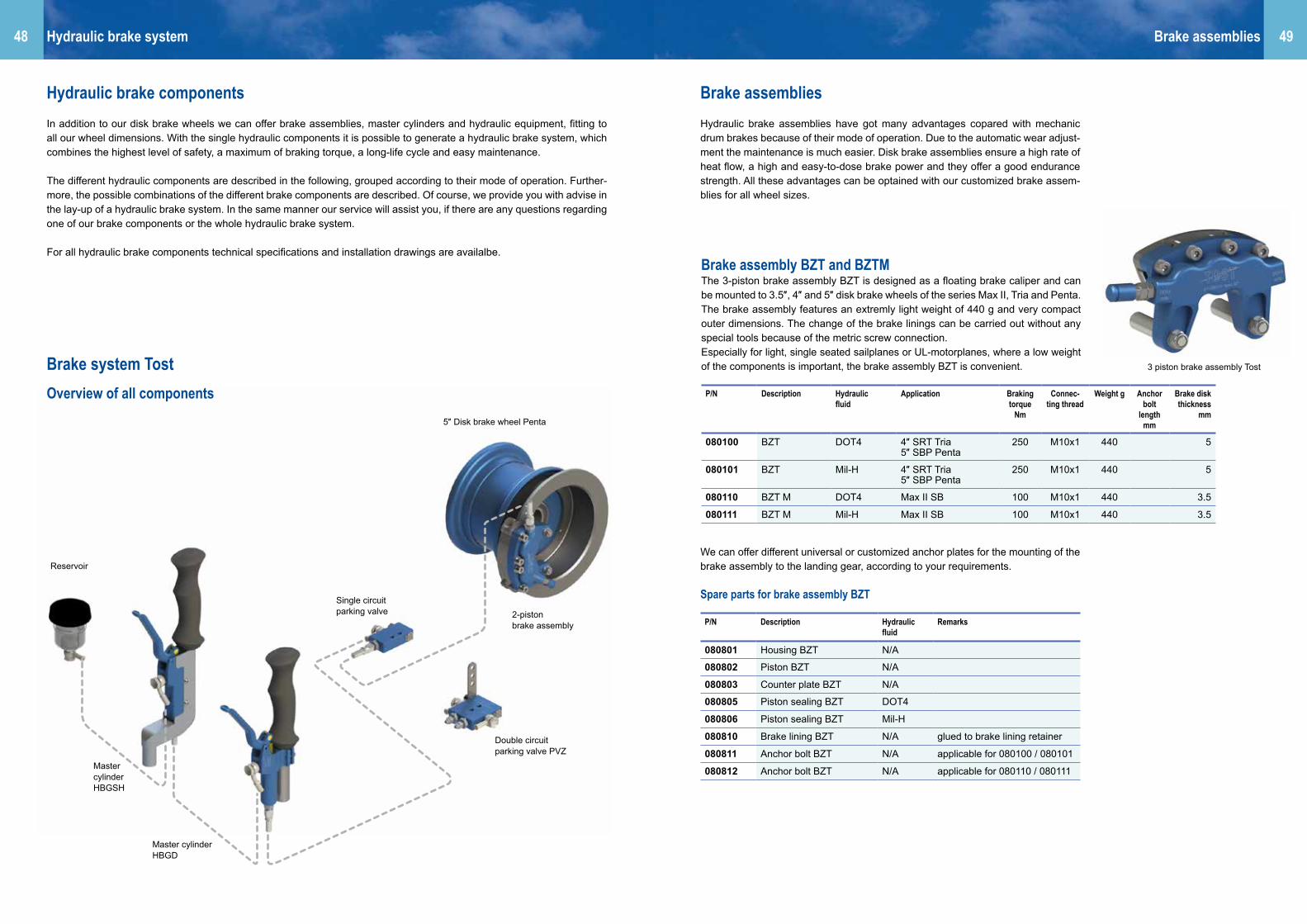
Hydraulic brake componentsIn addition to our disk brake wheels we can offer brake assemblies, master cylinders and hydraulic equipment, fitting to all our wheel dimensions. With the single hydraulic components it is possible to generate a hydraulic brake system, which combines the highest level of safety, a maximum of braking torque, a long-life cycle and easy maintenance.
The different hydraulic components are described in the following, grouped according to their mode of operation. Further-more, the possible combinations of the different brake components are described. Of course, we provide you with advise in the lay-up of a hydraulic brake system. In the same manner our service will assist you, if there are any questions regarding one of our brake components or the whole hydraulic brake system.
For all hydraulic brake components technical specifications and installation drawings are availalbe.
Brake system TostOverview of all components
Double circuit parking valve PVZ
2-pistonbrake assembly
Master cylinder HBGSH
Master cylinder HBGD
Single circuit parking valve
Reservoir
5″ Disk brake wheel Penta
Brake assembly BZT and BZTMThe 3-piston brake assembly BZT is designed as a floating brake caliper and can be mounted to 3.5″, 4″ and 5″ disk brake wheels of the series Max II, Tria and Penta. The brake assembly features an extremly light weight of 440 g and very compact outer dimensions. The change of the brake linings can be carried out without any special tools because of the metric screw connection.Especially for light, single seated sailplanes or UL-motorplanes, where a low weight of the components is important, the brake assembly BZT is convenient.
We can offer different universal or customized anchor plates for the mounting of the brake assembly to the landing gear, according to your requirements.
Spare parts for brake assembly BZT
P/N Description Hydraulic fluid
Application Braking torque
Nm
Connec-ting thread
Weight g Anchor bolt
length mm
Brake disk thickness
mm
080100 BZT DOT4 4″ SRT Tria5″ SBP Penta
250 M10x1 440 5
080101 BZT Mil-H 4″ SRT Tria5″ SBP Penta
250 M10x1 440 5
080110 BZT M DOT4 Max II SB 100 M10x1 440 3.5
080111 BZT M Mil-H Max II SB 100 M10x1 440 3.5
3 piston brake assembly Tost
P/N Description Hydraulic fluid
Remarks
080801 Housing BZT N/A
080802 Piston BZT N/A
080803 Counter plate BZT N/A
080805 Piston sealing BZT DOT4
080806 Piston sealing BZT Mil-H
080810 Brake lining BZT N/A glued to brake lining retainer
080811 Anchor bolt BZT N/A applicable for 080100 / 080101
080812 Anchor bolt BZT N/A applicable for 080110 / 080111
Brake assembliesHydraulic brake system
Brake assembliesHydraulic brake assemblies have got many advantages copared with mechanic drum brakes because of their mode of operation. Due to the automatic wear adjust-ment the maintenance is much easier. Disk brake assemblies ensure a high rate of heat flow, a high and easy-to-dose brake power and they offer a good endurance strength. All these advantages can be optained with our customized brake assem-blies for all wheel sizes.

5150
P/N Description Hydraulic fluid
Remarks
080815 Washer anchor bolt BZT N/A
080816 Nut anchor bolt BZT N/A
080817 Housing screw BZT N/A
080819 Retainer screw BZT N/A
080820 Washer housing or retainer screw
N/A
Spare parts for brake assembly BZT (continuation)
Brake lining wear limit:The minimum replacement thickness on organic linings is 0.7 mm.The total thickness of brake linings at any point must not be less than this value.
Installation note:After mounting the brake assembly, tighten the hexagonal bolt with a tightening tor-que of 6 Nm.
Brake assembly BZT2The 2-piston brake assembly BZT2 is designed as a floating brake caliper and can be mounted to 5″ and 6″ disk brake wheels of the series Penta and Classic. Due to the two pistons with big diameter and special sealings, high braking torques can be achieved, which ensures a save operation of heavy airplanes with high touch down speeds. The brake linings are designed to achieve a good cold braking performan-ce with its big connecting surface. They can be replaced easily and quickly. Like for the BZT no special tools are needed to carry out a replacement of the brake linings.
Spare parts for brake assembly BZT2
We can offer different universal or customized anchor plates for the mounting of the brake assembly to the landing gear, according to your requirements.
Brake lining wear limit:The minimum replacement thickness on organic linings is 0.7 mm.The total thickness of brake linings at any point must not be less than this value.
Installation note:After mounting the brake assembly, tighten the hexagonal bolt with a tightening torque of 10 Nm.
P/N Description Hydraulic fluid
Application Braking torque
Nm
Connec-ting thread
Weightg
Valve position
Disk brake thickness
mm
080200 BZT2 5L DOT4 5″ / 6″ SBP Penta5″ SBR CLassic
480 M10x1 580 LH 5
080201 BZT2 5L Mil-H 5″/ 6″ SBP Penta5″ SBR CLassic
480 M10x1 580 LH 5
080230 BZT2 5R DOT4 5″/ 6″ SBP Penta5″ SBR CLassic
480 M10x1 580 RH 5
080231 BZT2 5R Mil-H 5″/ 6″ SBP Penta5″ SBR CLassic
480 M10x1 580 RH 5
080210 BZT2 6L DOT4 6″ SBR Classic 480 M10x1 580 LH 6
080211 BZT2 6L Mil-H 6″ SBR CLassic 480 M10x1 580 LH 6
080240 BZT2 6R DOT4 6″ SBR CLassic 480 M10x1 580 RH 6
080241 BZT2 6R Mil-H 6″ SBR CLassic 480 M10x1 580 RH 6
P/N Description Hydraulic fluid
Remarks
080901 Housing BZT2 N/A
080902 Piston BZT2 N/A
080903 Counter plate BZT2 5 N/A 080200 / 080201 / 080230 / 080231
080904 Counter plate BZT2 6 N/A 080210 / 080211 / 080240 / 080241
080905 Piston sealing BZT2 DOT4
080906 Piston sealing BZT2 Mil-H
080910 Brake lining BZT2 N/A glued to brake lining retainer
080911 Anchor bolt BZT2 N/A applicable for 080100 / 080100
080815 Washer anchor bolt N/A
080816 Nut anchor bolt N/A
080817 Housing screw BZT2 N/A
080818 Washer housing screw BZT2
N/A
Brake assembly 30-9The brake assembly 30-9 from Cleveland is designed as a floating brake caliper and can be used with 4″, 5″ and 6″ disk brake wheels of the series Penta, Tria and Classic and the 5″ Cleveland wheels. The simple but robust design of the brake assembly ensures a long service time and easy maintenance with good deceleration values.
Further brake assemblies 30-9 for hydraulic fluid Mil-H see next page.
P/N Descrip-tion
Hydraulic fluid
Application Bracking torque
Nm
Connecting thread
Weight g
Anchor bolt
lengthmm
Brake disk thickness
mm
incl. Anchor
plate
075820 30-9 DOT4 4″ SB Classic4″ SRT Tria5″ SB Classic
370 1/8″ NPT 700 31 5 shorte-ned
075821 30-9 DOT4 4″ SB Classic5″ SB Classic
370 1/8″ NPT 700 29 5 shorte-ned
075823 30-9 DOT4 5″ SBP Penta6″ SBP Penta
370 1/8″ NPT 700 44,5 5 shorte-ned
075822 30-9 Mil-H 4″ SB Classic4″ SRT Tria5″ SB Classic
370 1/8″ NPT 700 31 5 Type I
2-piston brake asembly BZT2
Brake assembly 30-9
Brake assembliesBrake assemblies

5352
Brake lining wear limit:The minimum replacement thickness on organic linings is 2.5 mm.The total thickness of brake linings at any point must not be less than this value.
Installation note:After mounting the brake assembly, tighten the hexagonal bolt with a tightening torque of (60 in-lb) and secure with locking wire 0.8 mm Spec. MS-20995.
P/N Description Hydraulic fluid
Remarks
075829 Piston housing N/A
075825 Piston N/A
075834 O-ring Mil-H
075835 O-ring DOT4
075870 Anchor bolt N/A 5″ Cleveland, 5″/ 6″ SBP Penta
075869 Anchor bolt N/A 4″ SRT Tria, 4″ SB Classic, 5″ SB Classic
075881 Nut anchor bolt N/A
075882 Washer anchor bolt N/A
075873 Housing bolt N/A
075882 Washer housing bolt N/A
075832 Bleeder valve complete N/A also Stahlbus bleeder valve possible, quod vide
075872 Back plate N/A
075862 Brake lining N/A
075861 Rivet brake lining N/A
075871 Back plate with brake lining
N/A
075865 Service kit for brake lining replacement
N/A 2 x brake lining, 6 x rivet
075891 Anchor plate for brake assy. 30-9, original, for brake disks Ø 162 mm
075892 Anchor plate for brake assy. 30-9, shortened for Tost-wheels
Brake assembly 30-63AThe brake assembly 30-63A from Cleveland is designed as a floating brake caliper and can be mounted to 6″ disk brake wheels of the series Classic and Cleveland. The simple but robust design of the brake assembly ensures a long service time and easy maintenance with good deceleration values.
P/N Descrip-tion
Hydraulic fluid
Application Braking torque
Nm
Connecting thread
Weight g
Brake disk thickness
mm
076810 30-63A Mil-H 6″ SB Classic 450 1/8″ NPT 840 6
076820 30-63A DOT4 6″ SB Classic6“ Cleveland
450 1/8″ NPT 840 6
The anchor plate for the mounting to the landing gear is part of the scope of delivery. Customized anchor plates can be offered according to your requirements.
Spare parts brake assembly 30-63A
Spare parts brake assembly 30-9
Brake lining wear limit:The minimum replacement thickness on organic linings is 2.5 mm.The total thickness of brake linings at any point must not be less than this value.
Installation note:After mounting the brake assembly, tighten the hexagonal bolt with a tightening torque of (60 in-lb) and secure with locking wire 0.8 mm Spec. MS-20995.
P/N Description Hydraulic fluid
Remarks
076829 Piston housing N/A
076825 Piston N/A
076834 O-ring Mil-H
076835 O-ring DOT4
075870 Anchor bolt N/A
075881 Nut anchor bolt N/A
075882 Washer anchor bolt N/A
075873 Housing bolt N/A
075882 Washer housing bolt N/A
075832 Bleeder valve complete N/A also Stahlbus bleeder valve possible, quod vide
076872 Pressure plate with brake lining
N/A
076862 Brake lining N/A
075861 Rivet brake lining N/A
076871 Back plate with brake lining
N/A
076865 Service kit for brake lining replacement
N/A 2 x brake lining, 4 x rivet
076891 Anchor plate for brake assy. 30-63A
Brake assembly 30-9 (continuation)
The anchor plate for the mounting to the landing gear is part of the scope of delivery. Customized anchor plates can be offered according to your requirements.
P/N Descrip-tion
Hydraulic fluid
Application Braking torque
Nm
Connecting thread
Weight g Anchor bolt
length mm
Brake disk thickness
mm
incl. An-chor plate
075819 30-9 Mil-H 5″ Cleveland5″ SBP Penta6″ SBP Penta
370 1/8″ NPT 700 44.5 5 original form
075818 30-9 Mil-H 4″ SB Classic4″ SRT Tria5″ SB Classic
370 1/8″ NPT 700 31 5 shorte-ned
075810 30-9 Mil-H 5″ SBP Penta6″ SBP Penta5“ Cleveland
370 1/8″ NPT 700 44.5 5 original form
Brake assembly 30-63A
Brake assemblyBrake assemblies

5554
P/N Descrip-tion
Hydraulic fluid
Application Braking torque
Nm
Connec-ting
thread
Weight g Brake disk thickness
mm
058110 TOG DOT4 5″ SB Classic5″ SBP Penta
260 M10x1 460 4
TOG Brake assemblyThe brake assembly TOG is designed as a fixed caliper brake and can be mounted to 5″ disk brake wheels of the series Penta and Classic. Due to the simple but ro-bust design the brake assembly ensures a long servie time and easy maintenance with good deceleration values.
Spare parts
Brake lining wear limit:The minimum replacement thickness on organic linings is 1.5 mm.The total thickness of brake linings at any point must not be less than this value.
Installation note:1. Mount brake assembly vertically, maximum 15° inclination.2. Tightening torque of fastening bolts M8x45 at assembly with 20 Nm, maximum
22 Nm.3. The brake assembly is tested to 120 bar prior to delivery. On delivery the brake
assembly may still contain brake fluid.4. The M6 hexagonal bolts are tightened to a torque of 12 Nm. This torque must be
maintained to prevent pressure loss.5. Only use DOT4 brake fluid.
P/N Description Hydraulic fluid
Remarks
058530 Seal kit DOT4
058533 Separation sealing DOT4
058534 Bleeder valve DOT4
058512 Set brake linings
058511 Split pins
UL brake assemblymblThe brake assembly UL is designed as a fixed caliper brake with 6 pistons and can be mounted to the 6 inch disk brake wheel UL. The design with 6 pistons makes it possible to achieve good deceleration values with a minimum of component weight.
Brake assembly BMZThe brake assembly BZM is designed as a really small fixed caliper brake with one piston. In combination with the disk brake wheel Max II or Mini 150/180 it is the smallest variant of a hydraulic brake system. It is suitable for very light aircraft as differential brake for steering or as assisting brake for deceleration after touch down.
Spare parts UL brake assembly
Spare parts brake assembly BMZ
P/N Descrip-tion
Hydraulic fluid
Application Braking torque
Nm
Connec-ting
thread
Weight g
Brake disk thickness
mm
058820 BZ-UL Mil-H 6″ SB UL 100 M6 170 2
P/N Descrip-tion
Hydraulic fluid
Application Braking torque
Nm
Connec-ting
thread
Weight g
Brake disk thickness
mm
058222 BZM Mil-H Max II SBMini 150 SBMini 180 SB
M5 31 2
P/N Description Hydraulic fluid
Remarks
047711 Set brake linings
P/N Description Hydraulic fluid
Remarks
058223 Set brake linings
Brake lining wear limit:The minimum replacement thickness on organic linings is 0.5 mm.The total thickness of brake linings at any point must not be less than this value.
Brake lining wear limit:The minimum replacement thickness on organic linings is 0.5 mm.The total thickness of brake linings at any point must not be less than this value.
TOG brake assembly UL brake assembly
Brake assembly BMZ
Brake assemblyBrake assemblies

5756 Master cylinderMaster cylinder
HBGThe master cylinder HBG represents the smallest brake cylinder for an integrated mounting at the control stick. Due to high quality materials and optimized pressure sealings it ensures a fast response characteristic and a very good dosability of bra-king force.
P/N Description Hydraulic fluid
Application (suitable brake assembly)
Max. opera-ting press.
bar
Connec-ting thread
Weight g
050100 HBG DOT4 BZT, BZT2, 30-9, 30-63A
100 M10x1 125
050101 HBG Mil-H BZT, BZT2, 30-9, 30-63A
100 M10x1 125
Master cylinderMaster cylinder are the components in hydraulic brake system, which produce the necessary brake respectively hydraulic pressure to push the brake linings against the brake disk. In addition to our brake assemblies we manufacture a wide variety of master cylinders, availalbe from stock, which can be used in different combiations. In general, three types of master cylinder can be classified:• Hydraulic brake lever, which can be mounted directly to the control stick. The actuation is carried out directly by the pilot. e.g.: HBG, HBGD, HBGSH• Rudder pedal master cylinder, which can be mounted to additional small pedals
on the rudder pedals or at a user-defined place in the fuselage. If the installaton is not realized at the rudder pedals, the acutation has to be realized with a bow-den cable or push-rods.
e.g.: PHBZ, 10-30• Universal master cylinder for user-defined installation in the fuselage. The acutation has to be realized with a bowden cable or push-rods. e.g.: Form 7
We recommend to use our thin and high flexible hydraulic lining Stahlflex (p/n 058002) for the feed and the pressure line, if the master cylinder is mounted to the control stick.
HBGDThe HBGD represents a compact master cylinder for direct mounting at the control stick. Due to high quality materials and optimized pressure sealings it ensures a fast response characteristic and a very good dosability of braking force.
The mounting to the control stick is realized with retaining clamps, including a quick fastener. Fitting retaining clamps are available for a various control stick diameters (Ø 18 mm, Ø 19 mm, Ø 20 mm, Ø 24 mm). Further diameters are customized accor-ding to your requirements.
A valve-based control mechanism ensures that always the higher braking pressure will reach the brake assembly. Especially in double seated planes that will offers you a great benefit of safety.
HBGSHThe master cylinder HBGSH has got the same hydraulic design as the master cylin-der HBGD, which ensures a fast response characteristic and a very good dosability of braking force and the overflow function. The installation is realized with four thread bores.
We recommend to use our thin and high flexible hydraulic lining Stahlflex (p/n 058002) for the feed and the pressure line, if the master cylinder is mounted to the control stick.
We recommend to use our thin and high flexible hydraulic lining Stahlflex (p/n 058002) for the feed and the pressure line, if the master cylinder is mounted to the control stick.
P/N Description Hydraulic fluid
Application (suitable brake assembly)
Max. opera-ting press.
bar
Connec-ting thread
Weight g
050200 HBGD DOT4 BZT, BZT2, 30-9, 30-63A
100 M10x1 150
050201 HBGD Mil-H BZT, BZT2, 30-9, 30-63A
100 M10x1 150
P/N Description Hydraulic fluid
Application (suitable brake assembly)
Max. opera-ting press.
bar
Connec-ting thread
Weight g
050220 HBGSH DOT4 BZT, BZT2, 30-9, 30-63A
100 M10x1 150
050221 HBGD Mil-H BZT, BZT2, 30-9, 30-63A
100 M10x1 150Master cylinder HBG
Hauptbremszylinder HBGD
Hauptbremszylinder HBGD

5958 Master cylinderMaster cylinder
PHBZFast response characteristic and a good dosability of braking force can also be re-alized with the master cylinder PHBZ. It is suitable for direct mounting at the rudder peddal and can either be fitted with fork head or rod end. Besides the installation at the rudder pedals an alternative installation in the fuselage is possible, because of the flexible mounting length. The master cylinder PHBZ has also got the overflow function.
Type 10-30Sturdy and high load capable pedal master cylinder from Clevland with overflow function.
Spare parts
P/N Description Remarks
078240 Sealing kit N/A
P/N Description Hydraulic fluid
Application (suitable brake assembly)
Max. opera-ting press.
bar
Connec-ting thread
Weight g
078230 10-30 Mil-H BZT, BZT2, 30-9, 30-63A
70 NPT 1/8″
263
P/N Description Hydraulic fluid
Application (suitable brake assembly)
Max. opera-ting press.
bar
Connec-ting thread
Mounting device
Weight g
050300 PHBZ DOT4 BZT, BZT2,30-9, 30-63A
100 M10x1 Fork head
135
050300 PHBZ Mil-H BZT, BZT2, 30-9, 30-63A
100 M10x1 Fork head
135
050310 PHBZ DOT4 BZT, BZT2, 30-9, 30-63A
100 M10x1 Rod end 140
050311 PHBZ DOT4 BZT, BZT2, 30-9, 30-63A
100 M10x1 Rod end 140
Master cylinder for pedals
Master cylinder with overflow function(078230)
Universal Master cylinder Model 3
Universal Master cylinder Model 4
Universal Master cylinder Model 7with reservoir
Universal Master cylinder Models 3, 4 and 7Suitabel for many different installation situations: our universal master cylinder. Due to the integrated actuation lever a remarkable enhancement of the actuation force is realized, what generates very high braking pressures. The solid design together with high quality sealings ensures long service intervals.
Spare parts
P/N Description Remarks
058541 Sealing kit master cylinder Model 7 DOT4 N/A
058544 Sealing kit master cylinder Model 7 Mil-H N/A
058543 Sealing kit master cylinder Model 3, Form 4 N/A
058271 Sealing kit master cylinder Model 7 DOT4 N/A
058269 Sealing kit master cylinder Model 7 Mil-H N/A
P/N Description Hydraulic fluid
Application(suitable brake assembly)
Max. opera-ting press.
bar
Connec-ting thread
Weightg
Remarks
058230 Model 3 DOT4 BZT, BZT2, 30-9, 30-63A, TOG
100 M10x1 400
058240 Model 4 DOT4 BZT, BZT2, 30-9, 30-63A, TOG
100 M10x1 400
058270 Model 7 DOT4 BZT, BZT2, 30-9, 30-63A, TOG
100 M10x1 360 Seperate mounting of reservoir possible
058279 Model 7 Mil-H BZT, BZT2, 30-9, 30-63A
100 M10x1 360 Seperate mounting of reservoir possible
Installation guidelines for master cylinders Model 3, 4 und 7:
1. The master cylinder must be installed in the speciefied position, maximum devia-tion 5°, ascending in direction of flight.
2. The available brake lever travel must allow for the necessary piston stroke.3. The active stroke of the master cylinder piston must not be exceeded. The brake
lever travel must therefore be restricted in both directions (take care not to da-mage the piston collars).
4. There must be play of 1 mm between piston and brake lever in release position.5. The brake lever must be pulled back to release position by a return spring. The
spring must be attached to a fixed strucktural element.6. The mounting bracket for the master cylinder must not yield when the brake is
activated.
Important note:Brake fluid DOT4 is strongly hygroscopic, ie, it absorbs water (this is the reason why old brake fluid has a corrosive effect). Replace brake fluid DOT4 once a year according to manufacturer‘s maintenance manual.

6160 Parking valvesMaster cylinder
UL brake handleThe compact and lightweight brake handle UL can control one or two brake assem-blies UL, according to the installation situation. With the help of a mechanic locking lever it can also be used as a parking brake.
Master cylinder Max and Mini HBMSuitable for our smaller brake assembly BZM we offer the master cylinder HBM. It features compact outer dimensions, an universal actuation and an easy installation. With the produced braking pressure, one or two brake assemblies BZM can be ope-rated.
P/N Description Hydraulic fluid
Application (suitable brake assembly)
Max. opera-ting press.
bar
Connec-ting thread
Weight g
058220 HBM Mil-H BZM 80 M5 69
P/N Description Hydraulic fluid
Application (suitable brake assembly)
Max. opera-ting press.
bar
Connec-ting thread
Weight g
058228 UL brake handle
Mil-H BZ-UL 80 M6 200
Master cylinder Max and Mini
Parking valvesEspecially when operating powered aircraft, a permanent brake is essential for parking and to perform the run-up. With the help of so-called parking valves it is possible to hold a once produced hydraulic pressure in the brake system, without actuating permanently the normal master cylinder. Suitable for our hydraulic brake components we offer parking valves for single circuit or double circuit use.
Single circuit parking valveFor smallest space requirements and for different kinds of actuation, our single circuit parking valve is the proper choice. The installation is realized with two bores or two thread bores. It is actuated via a turning handle or a turnable actuation lever. The hydraulic connection can be realized individually with different hydraulic fittings.
Parking valve 60-5The parking valve 60-5, made from Cleveland, is a very sturdy double circuit parking valve for the use with hydraulic fluid Mil-H.The mounting is realized with two bores and the acutation is car-ried out by a lever.
Double circuit parking valveIf a differential brake is installed, we recommend our double circuit parking valve PVZ. The mounting is realized with two bores, the actuation is carried out with a lever, turnable mounted on the control shaft. The hydraulic connection can be rea-lized individually with different hydraulic fittings.
P/N Description Hydraulic fluid
Max. opera-ting press.
bar
Connec-ting thread
Weight g
079610 60-5 Mil-H 103 NPT1/8″ or JIC03
150
P/N Description Hydraulic fluid
Max. opera-ting press.
bar
Connec-ting thread
Weight g
Remarks
050090 PVZ DOT4 100 M10x1 100 Actuating lever
050091 PVZ Mil-H 100 M10x1 100 Actuating lever Double circuit parking valve
Sinlge circuit parking valve
Parking valve 60-5
P/N Description Hydraulic fluid
Max. opera-ting press.
bar
Connec-ting thread
Weight g
Remarks
050094 PVE DOT4 100 M10x1 60 Actuation lever
050095 PVE Mil-H 100 M10x1 60 Actuation lever
050096 PVEmA DOT4 100 M10x1 80 Mech. stop and turning handle
050099 PVEmA Mil-H 100 M10x1 80 Mech. stop and turning handle

6362
Hydraulic shoe brake wheelTo increase the braking force of the 4 inch and 5 inch shoe brake wheels, they can be fitted with a hydraulic actuated anchor plate. The advantage is that the friction of the mechanic actuating cables is omitted due to the hydraulic actuation. Thus, the brake gains power and is better dosable. The effort of the modification is very low: only the anchor plate has to be exchanged. All connecting dimensions of the wheel (installation width, position of the anchor bolt) remain unchanged.
The hydraulic actuated anchor plates are supplied including master cylinder, hy-draulic hose and detailed working instructions.
Please indicate with your order aircraft type, axle diameter and type of anchor bolt, so that we can deliver the suitable anchor plate. If the wheel is more than 30 years old, we recommand a technical consultation prior to the modification.
Conversion kit for Schempp-Hirth CirrusFor the Schempp-Hirth Cirrus, we can supply a complete conversion kit from the 4 inch Liliput wheel to 5 inch Kobold wheel with hydraulic actuation of the shoe brake wheel. The kit is EASA approved per Minor Change Approval.
Hydraulic hosesHydraulic shoe brake wheel
P/N Description Hydraulic fluid Connec-ting thread
Remarks
045930 Hydraulic actuation 4″ Liliput
Tost Hydraulic fluid M5 Technical consultation recom-manded prior to modification
045940 Hydraulic actuation 4″ Kobold
Tost Hydraulic fluid M5
045945 Hydraulic actuation 5″ Standard
Tost Hydraulic fluid M5 Axle diameter 20 mm
045943 Hydraulic actuation 5″ Standard
Tost Hydraulic fluid M5 Axle diameter 30 mm
P/N Description Hydraulic fluid Connec-ting thread
Remarks
045921 Conversion kit for Cirrus Tost Hydraulic fluid M5 including full documentation and Minor Change Approval
Hydraulic hosesJust as important as the brake components (master cylinder, brake assembly) is their connection with each other. Here should only be used high-quality hydraulic hoses, which are adequate for the specific hydraulic fluid and for the arising ope-rational and maximum pressure. Withour hoses, eady manufactured for you, we offer you for every application and for every type of connection the correct hydraulic hose.
Stahlflex hosesSteelflex hoses are the standard for highly stressed hydraulic systems how they get employed in the scope of aviation, motor sport or industrial plants.The multilayered structure of steelflex hoses (high pressure stable Teflon core and encasing stain-less steel meshwork) provide tightest bending radii for very high operating pres- sure, without pressure loss also in extended hose lengths.
A special feature of our steelflex hoses are the pressed-in connection fittings. The pressing process provides a maximum of leak tightness, also after a long time of operation under high hydraulic pressure.
Stahlflex hose StandardOur standard steelflex hose features beside the stainless steel meshwork a further protective coating from PVC. Thus offering a perfect scoring protection, especially in tight fuselage spaces from fibre composit.
P/N Description Hydraulic fluid
Operational pressure
bar
Bursting pressure
bar
Possible connecting fittings (pressed into the hose)
058001 Stahlflex hydraulic hose, PVC coated
Mil-H, DOT4
290 870 banjo fitting for hollow screw M10x1 (straight, 20° cranked, 90° cranked)spigot nut JIC03
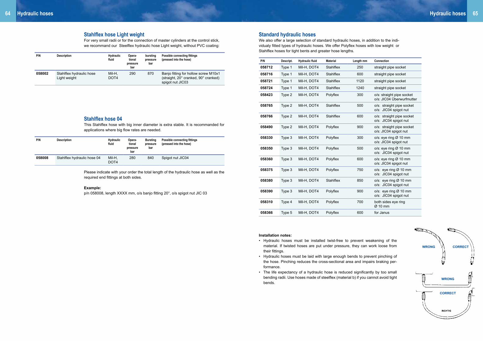
6564
Stahlflex hose Light weightFor very small radii or for the connection of master cylinders at the control stick, we recommand our Steelflex hydraulic hose Light weight, without PVC coating:
Stahlflex hose 04This Stahlflex hose with big inner diameter is extra stable. It is recommanded for applications where big flow rates are needed.
Please indicate with your order the total length of the hydraulic hose as well as the required end fittings at both sides.
Example:p/n 058008, length XXXX mm, o/s banjo fitting 20°, o/s spigot nut JIC 03
Hydraulic hoses
P/N Description Hydraulic fluid
Opera-tional
pressure bar
bursting pressure
bar
Possible connecting fittings (pressed into the hose)
058002 Stahlflex hydraulic hose Light weight
Mil-H, DOT4
290 870 Banjo fitting for hollow screw M10x1 (straight, 20° cranked, 90° cranked)spigot nut JIC03
P/N Description Hydraulic fluid
Opera-tional
pressure bar
Bursting pressure
bar
Possible connecting fittings (pressed into the hose)
058008 Stahlflex hydraulic hose 04 Mil-H, DOT4
280 840 Spigot nut JIC04
Standard hydraulic hosesWe also offer a large selection of standard hydraulic hoses, in addition to the indi-vidualy fitted types of hydraulic hoses. We offer Polyflex hoses with low weight or Stahlflex hoses for tight bents and greater hose lengths.
Installation notes:• Hydraulic hoses must be installed twist-free to prevent weakening of the
material. If twisted hoses are put under pressure, they can work loose from their fittings.
• Hydraulic hoses must be laid with large enough bends to prevent pinching of the hose. Pinching reduces the cross-sectional area and impairs braking per-formance.
• The life expectancy of a hydraulic hose is reduced significantly by too small bending radii. Use hoses made of steelflex (material b) if you cannot avoid tight bends.
Hydraulic hoses
P/N Descript. Hydraulic fluid Material Length mm Connection
058712 Type 1 Mil-H, DOT4 Stahlflex 250 straight pipe socket
058716 Type 1 Mil-H, DOT4 Stahlflex 600 straight pipe socket
058721 Type 1 Mil-H, DOT4 Stahlflex 1120 straight pipe socket
058724 Type 1 Mil-H, DOT4 Stahlflex 1240 straight pipe socket
058423 Type 2 Mil-H, DOT4 Polyflex 300 o/s: straight pipe socketo/s: JIC04 Überwurfmutter
058765 Type 2 Mil-H, DOT4 Stahlflex 500 o/s: straight pipe socketo/s: JIC04 spigot nut
058766 Type 2 Mil-H, DOT4 Stahlflex 600 o/s: straight pipe socketo/s: JIC04 spigot nut
058490 Type 2 Mil-H, DOT4 Polyflex 900 o/s: straight pipe socketo/s: JIC04 spigot nut
058330 Type 3 Mil-H, DOT4 Polyflex 300 o/s: eye ring Ø 10 mmo/s: JIC04 spigot nut
058350 Type 3 Mil-H, DOT4 Polyflex 500 o/s: eye ring Ø 10 mmo/s: JIC04 spigot nut
058360 Type 3 Mil-H, DOT4 Polyflex 600 o/s: eye ring Ø 10 mmo/s: JIC04 spigot nut
058375 Type 3 Mil-H, DOT4 Polyflex 750 o/s: eye ring Ø 10 mmo/s: JIC04 spigot nut
058380 Type 3 Mil-H, DOT4 Stahlflex 850 o/s: eye ring Ø 10 mmo/s: JIC04 spigot nut
058390 Type 3 Mil-H, DOT4 Polyflex 900 o/s: eye ring Ø 10 mmo/s: JIC04 spigot nut
058310 Type 4 Mil-H, DOT4 Polyflex 700 both sides eye ring Ø 10 mm
058366 Type 5 Mil-H, DOT4 Polyflex 600 for Janus
WRONG CORRECT
CORRECT
WRONG

6766
Hydraulic fittingsFor the connection of hydraulic components (master cylinder, brake assembly etc.) or the relevant hydraulic hoses, so-called connection fittings or male stud couplings are required. We offer the suitable connectors for all our hydraulic components to joint the hydraulic hoses.
We are pleased to give you advise at any time to select the correct fitting for your brake system.
Connecting fittigsconnecting fitting from aluminium, one-sided with Standard screwing JIC-03
Fittings from aluminiumone-sided with Standard screwing JIC-04
Male stud connectorsa further option for the connection of hydraulic components are copper pipes.
The connection of copper pipes to the hydraulic component is done with male stud couplings.
To interconnect copper pipes or copper pipes with hydraulic hoses: straight couplings or T-couplings are the correct type of connector.
Assembly notes for male stud couplings(p/n 058630, 058640, 058670, 058680)• Cut off pipe at right angle (do not use pipe cutter)• Debur pipe on the inside and outside (caution: do not bevel)• Lightly lubricate thread and cone of male stud coupling• Lubricate cutting ring and spigot nut (on inside)• Push spigot nut and cutting ring over pipe end • Tighten spigot nut by hand• Push pipe against stop of inner cone• A mark on the spigot nut helps to check on the correct number of turns• Turn spigot nut approx. 1½ turns (pipe must remain stationary). The tightening
force increases with pressure against the stop face
Check:• Release spigot nut and check weather visible bead fills space in front of the cut-
ting ring face. If not, tighten spigot nut more.• Cutting ring may turn, but may not be able to move in axial direction.
Hydraulic fittingsHydraulic fittings
P/N Description
058695 Cu pipe 6x1
P/N Description Thread size 1
Thread size 2
Thread size 3
Form
075850 Fitting straightNPT 1/8″-JIC03
JIC03 NPT 1/8″ N/A straight
075851 Fitting 45°NPT 1/8″-JIC03
JIC03 NPT 1/8″ N/A 45°
075853 Fitting 90°NPT 1/8″-JIC03
JIC03 NPT 1/8″ N/A 90°
058050 Fitting straightM10x1-JIC03
JIC03 M10x1 N/A straight
058051 Fitting 45°M10x1-JIC03
JIC03 M10x1 N/A 45°
058053 Fitting 90°M10x1-JIC03
JIC03 M10x1 N/A 90°
058058 T-Fitting JIC03 JIC03 JIC03 JIC03 T-Fitting
P/N Descr. Form Connecting thread 1
Connecting thread 2
Remarks
058630 C1 straight NPT 1/8″ M10x1 with spigot nut and cutting ring
058640 C2 90° NPT 1/8″ M10x1 with spigot nut and cutting ring
056870 C3 straight M10x1 taper thread M10x1 with spigot nut and cutting ring
058680 C4 90° M10x1 taper thread M10x1 with spigot nut and cutting ring
058651 C5 straight M10x1 M10x1 with copper gaskets, for connection of Master cylinder model 7 with reservoir
P/N Description Connecting thread 1
Connecting thread 2
Connecting thread 3
Remarks
058620 Straight coupling M10x1 M10x1 M10x1 with spigot nut and cutting ring
058610 T-coupling M M10x1 M10x1 with spigot nut and cutting ring
P/N Description Thread size 1
Thread size 2
Thread size 3
Form
075830 Fitting straightNPT 1/8″-JIC04
JIC04 NPT 1/8″ N/A straight
075831 Fitting 45°NPT 1/8″-JIC04
JIC04 NPT 1/8″ N/A 45°
075833 Fitting 90°NPT 1/8″-JIC04
JIC04 NPT 1/8″ N/A 90°
058054 Fitting straightM10x1-JIC04
JIC04 M10x1 N/A straight
075838 T-Fitting JIC04 JIC04 JIC04 JIC04 T-Fitting
Fitting straight(058050)
Fitting straight(075850)
Fitting 90°(075853)
Fitting 45°(075851)
T-Fitting JIC03(058058)

6968
AccessoriesWe offer all necessary accessories and tools for the first installation or maintenance of a hydraulic brake system
Hollow screwsFor the connection of hydraulic hoses and hydraulic components, hollow scews are a very good choice. The angle between hose and axis of the hollow screw is to be defined freely.
Torque plateYou can realise the easy mounting of a floating brake assembly (BZT, BZT2) to the landing gear structure with the help of our Universal torque plate.
FluidsHydraulic brake systems in aviation are used with two different fluids: Hydraulic fluid to Spec MIL-H5606, based on mineral oil, or brake fluid DOT4, based on polygly-col. Both fluids may not be mixed or interchanged, as the sealings in the hydraulic system would be affected and destroyed. Please always refer to the indications in the Maintenance Manual of your aircraft.
ReservoirSo-called open hydraulic systems – like the majority of hydraulic systems – need a fluid reservoir or slops tank. With the help of the following fluid the wear on the brake pads is balanced.
On request, we can manufacture individual torque plates (5-axis CNC milled) to your requirements. Please ask for an offer.
Suitable washers as spare parts:
Remark:Gaskets (from aluminium or copper) may be used only once!
AccessoriesHydraulic fittings
P/N Description Application
058283 Copper gasket for hollow screw p/n 058620
058289 Aluminium gasket for hollow screw p/n 058281
P/N Description Packing
059940 Hydraulic fluid Aeroshell 41 1.0 l
059950 Brake fluid DOT4 0.5 l
059951 Brake fluid DOT4 1.0 l
P/N Description Fixation Application
075992 Universal torque plate
4 x bore Ø 6.5 mm BZT, BZT2
P/N Description Connecting thread
Application Gasket
058620 Hollow screw M10
M10x1 Standard hydraulic hosep/n 058330, 058350, 058360, 058375, 058380, 058390, 058310
2 x Cu gasket, included in p/n 058620
058281 Hollow screw M10 VA
M10x1 Stahlflex hydraulic hose and Stahlflex hydraulic hose lightweightp/n 058001, 058002
2 x Aluminium gasket, included in p/n 058281
P/N Description Hydraulic fluid Volume Connecting thread
058910 Reservoir 100 Mil-H 60 cm³ NPT 1/8″
058271 Fluid reservoir HB 7 DOT4 30 cm³ M10x1
058269 Fluid reservoir HB 7 Mil-H 30 cm³ M10x1 Reservoir HB 7
Universal torque plate

7170
Stahlbus bleeder valvesThe filling and bleeding of hydraulic brake systems is one typical task in the main-tenance field. We recommend the Stahlbus bleeder valve to simplify this task con-siderably. In every Tost brake assembly the Stahlbus bleeder valve is mounted as a standard, in all other brake assemblies it can be retrofitted easily. One person can perform the filling “from bottom to top” thanks to an integrated non-return valve. When filling the system “from bottom to top”, the additional integrated gasket eases the procedure clearly.
Filling tools
Vacuum filling and bleeding pumpThe vacuum filling and bleeding pumps are helpful tools for fast and easy filling and bleeding. You can use them to evacuate the brake fluid at the brake assembly when filling “from top to bottom”. The other option is to absorb brake fluid and to fill it into the system with pressure – when filling from the brake assembly “from bottom to top”.
Brake fluid gunDevice for initial charging and bleeding of hydraulic brake systems. Simple hand-ling, high filling pressure and a big filling volume. Supplied with complete operating instructions.
The brake fluid gun is always supplied with lever mechanic, tube and quick-screw-connector (for connection to the bleeder valve).
Quick-screw-connectorSuitable for the brake fluid gun Type B and H, we supply quick-screw-connectors for a simple, fast and clean connection of the brake fluid gun to the respective bleeder valve.
AccessoriesAccessories
P/N Description Volume ml
059300 Vacuum filling and bleeding pump 50
059330 Vacuum filling and bleeding pump, big 150
P/N Description Hydraulic fluid
059020 Brake fluid gun Type B DOT4
059030 Brake fluid gun Type H DOT4 and Mil-H
P/N Description Connection
075890 Quick-screw-connector, Standard to all Standard Cleveland bleeder valves
075899 Quick-screw-connector, Stahlbus to all Stahlbus bleeder valves
P/N Description Hydraulic fluid
Volume Valve type
059100 Stahlbus bleeder valve NPT 1/8″ DOT4 screw-in valve
059200 Stahlbus bleeder valve NPT 1/8″ Mil-H screw-in valve
059102 Stahlbus bleeder valve M10x1 DOT4 screw-in valve
059202 Stahlbus bleeder valve M10x1 Mil-H screw-in valve
059105 Stahlbus bleeder valve M10x1,5 DOT4 screw-in valve
059101 Stahlbus bleeder valve M6x1 DOT4 screw-in valve
059201 Stahlbus bleeder valve M6x1 Mil-H screw-in valve
059221 Stahlbus bleeder valve M6x1, shortened
Mil-H screw-in valve
059231 Stahlbus bleeder valve M8x1,25 DOT4 screw-in valve
059205 Stahlbus bleeder valve 1/4″-28UNF-16
Mil-H screw-in valve
059206 Stahlbus bleeder valve 3/8″-24UNF-22
Mil-H screw-in valve
059400 Stahlbus hollow screw M10x1 DOT4 hollow screw
Service kitsWe supply service kits for the installation and the filling and bleeding of the small hydraulic systems Max II SB with BZM, 6″ UL SBP with BZ-UL, hydraulic actuation of shoe brake wheels. In every service kit you will find all necessary fittings, filling tools, hydraulic hoses and hydraulic fluid.
Artikel-Nr. Bezeichnung
058202 Service kit hydraulic actuation of shoe brake wheels
058229 Service kit Max II disk brake wheel with BZM
058211 Service kit 6″ UL SBP with BZ-UL
Stahlbus bleeder valve
Stahlbus hollow screw(059400)
Quick-screw-connector(075899)
Brake fluid gun(059020)
Vacuum filling and bleeding pump

7372
CRG
Schematics of Aero Towing ...................................................74
CRG - Tow Cable Retractor Winch with Guillotine ..............75
CRG Modules ......................................................................... 76
CRG Optional Equipment ..................................................... 77
CRG for Motor Gliders .......................................................... 78
CRG for Aircraft ..................................................................... 79
CRG for Ultralight .................................................................. 80
CRG Spare Parts .................................................................... 81

7574
CRG – Tow Cable Retractor Winch with Guillotine
Schematics Aero Tow CRG – Tow Cable Retractor Winch with Guillotine
The tow cable retractor winch with guillotine allows the tow cable to be retracted during descent, and, in the event of danger, to be chopped. This has substantial safety and cost benefits compared with conventional aero tow:
• No cable drop with potential risk to people or aircraft• Considerably diminished noise levels since aircraft can land right away• More economical operation through elimination of cable drop and reduced flight time• No delays in aircraft starts due to tracing and retrieving tow cables• In the event of danger, the tow cable can be chopped anytime to sever the link between glider and tug, also under high loads and large cable angles
The retractor winch is installed in the fuselage (baggage compartment); the load is taken up by the cable stop plate unit mounted to the tow support in the aircraft tail. Once the glider pilot has released the tow cable, the tug pilot retracts the cable and is ready for the next towing job.
Since 1981, about 750 of these CRGs (previously known as System Feuerstein) have been successfully deployed all over the world. Refer to the tables for a list of EASA-approved installations.
CRGs are installed as standard by aircraft manufacturers, but retrofitting older aircraft is also possible and is done very often by gliding clubs. We consult you profoundly.
The requirements of the regional authorities for airfield approvals are increasing. With the installation of a CRG in the towing aircraft those requirements can be fulfilled more easy. Also the neighbours will profit from the decreasing emissions.
Tow cable
Winch unit in baggage compartment
Cable duct aluminium or plastic
Load take-up by cable stop plate unit with guillotine
Schematics
102000 Connecting ring pair
113400 Shackle
110010 Complete weak link
300061 End piece
Tow releaseE 85 or E 22
Aero Tow RopeLength 40 – 60 m
Complete weak linkwith connecting ring pair
Nose releaseE 85 or E 22
End piecewith connecting ring pair and weak link
Cable stop plate and guillotine
CRG cable50 or 60 m
CRGDesign of winchunit depends on aircraft type
Schematics to SBOin current version

7776
CRG Modules
Winch unitDepending on the model, the retractor winch is mounted either on a base plate or a motor support and installed in the fuselage of the tug, either behind the seat or in the baggage compartment. If necessary, the winch unit can be dismantled quickly. The main components are a 12 V (standard) or 24 V (optional) motor with a worm gear, motor bracket, cable drum and cable cover.
The tow cable passes through or under the fuselage, in an aluminium or plastic cable duct, to the cable stop plate unit.
Cable stop plate unit with guillotineFor tugs of type Robin and Morane, or for motor gliders or ultralights, the new cable stop plate is bolted to the existing tow support. For tail wheel aircraft, eg, Piper, Maule or Husky, the system is supplied with a new tow support on which the cable stop plate with guillotine is mounted.
The guillotine is activated by the existing release cable. The cable is simply trans-ferred to the guillotine lever. A tow release can be used optionally, eg, for banner tows or double tows by transferring the cable from the guillotine back to the tow release. Please note: only one of the two towing devices may be used at one time.
The cable load is taken up by the stop plate via a sleeve screwed over a knot in the tow cable. The cable load is not taken by the winch unit. The permitted cable load is equivalent to the permitted towing capacity of the tug.
A rubber funnel takes up the conical end-piece after rewinding the tow cable. The fuselage is protected against damages.
Electric switch unitRewinding the cable is started by means of a toggle switch fitted with a control light. The switch unit (switch, fuse and cable set for standard 12 V on-board voltage) is prewired and assembled on an aluminium plate for mounting on the instrument panel in the pilot‘s line of sight.
Once the glider has been released, the electrical switch unit starts the retractor winch. Operation can be checked in the rear-view mirror. The control light in the panel is on during the whole duration of rewinding. After the cable has been fully rewound, an overload switch switches the motor off automatically. If the cable re-traction sensor is installed, the motor will be cut-off immediately.
Tow cableThe tow cable with 6.1 mm diameter has a standard length of 50 m. The cable is terminated by an aluminium end piece, complete with weak link and connecting ring pair. Breaking load of the weak link to your requirements. Unless otherwise speci-fied with the order, we supply a standard 500 daN white weak link.
The kit is ready-to-tow, ie, you receive all necessary parts for the installation. You can commence operation immediately after the approval. The aluminium cable duct is not supplied as part of the standard kit due to the high transport cost. We can include this item on request in the scope of delivery correctly flared.
CRG Optional EquipmentCable retraction sensor with cut-off It is not always possible to observe the cable retraction in the rear-view mirror. The solution: an approximation switch permits contactless detection of the end piece and a control light indicates that the cable is completely retracted. The drive switches off immediately and cannot be switched on again. Benefits: increased safety because of monitored cable retraction, longer motor ser-vice life. Easy to upgrade on all systems.We recommend this option for all original installations. Retrofitting is also possible in all units already in operation.
Powerful Driving Unit PM 42Higher torque and higher rpm for faster cable retraction, also during fast descents. The increased performance ensures a longer service life especially under tough long-term operation. Available for 12 V and 24 V.
Winch unit for DR 400 with strongTendo driving unit
Cable stop plate unit with guillotine with rubber funnel and end piece
P/N Description
300200 Cable retraction sensor with cut-off
300942 Driving unit PM 42 12 V
300020 Cable drum for 60 m cable
300556 60 m cable
CRG Modules CRG Optional Equipment
Cable drum for 60 m cable
Modification to 60 m cable length For flight students, the use of a 60 m cable is more comfortable. This is why we offer a modification kit to 60 m cable length for the existing CRGs. The cable drum needs to be exchanged only, there is not required a bigger installation space than for the 50 m cable drum. With smaller root diameter, the 60 m drum is optimised to match the motor torque.
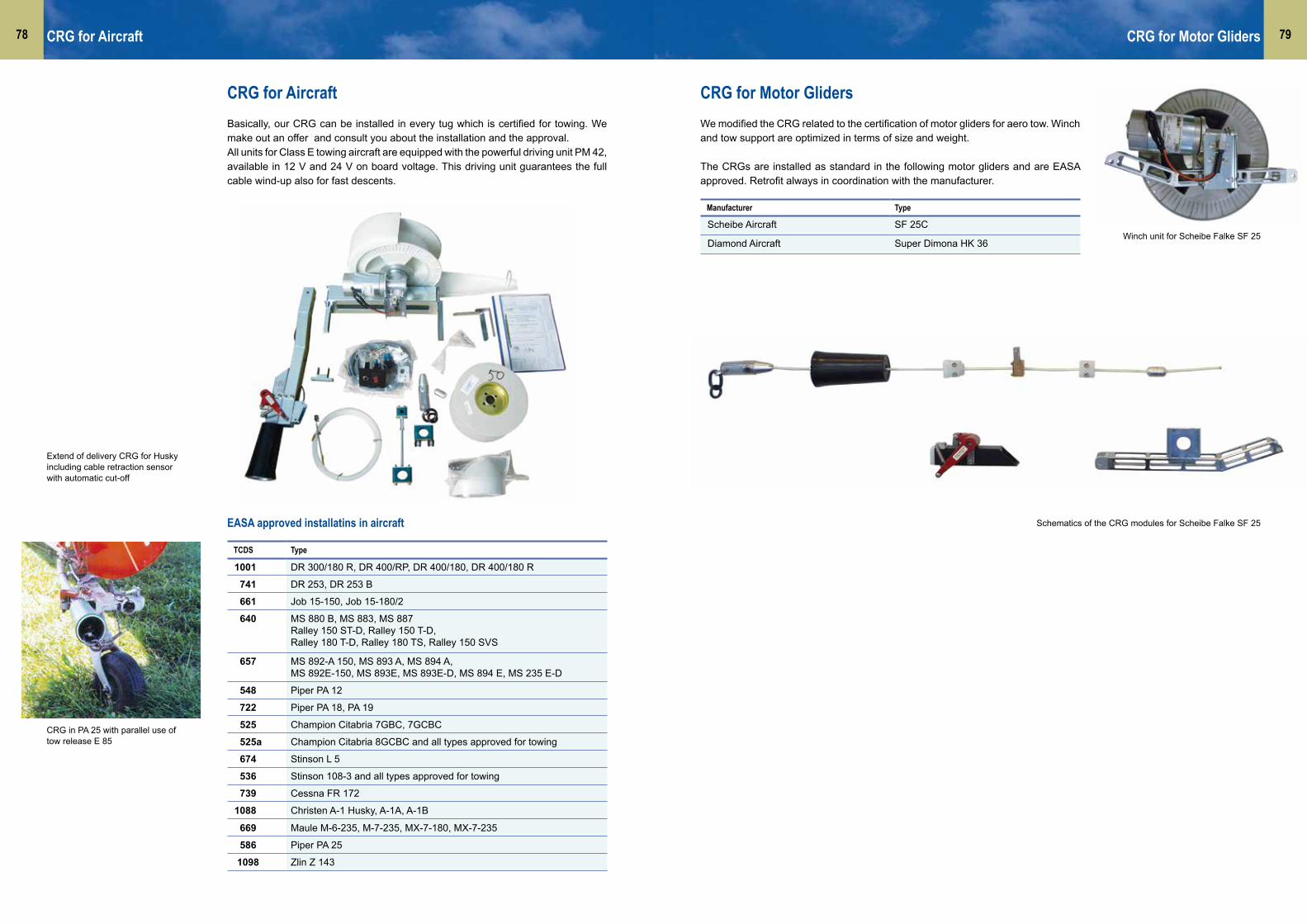
7978
CRG for AircraftBasically, our CRG can be installed in every tug which is certified for towing. We make out an offer and consult you about the installation and the approval. All units for Class E towing aircraft are equipped with the powerful driving unit PM 42, available in 12 V and 24 V on board voltage. This driving unit guarantees the full cable wind-up also for fast descents.
EASA approved installatins in aircraft
TCDS Type
1001 DR 300/180 R, DR 400/RP, DR 400/180, DR 400/180 R
741 DR 253, DR 253 B
661 Job 15-150, Job 15-180/2
640 MS 880 B, MS 883, MS 887Ralley 150 ST-D, Ralley 150 T-D,Ralley 180 T-D, Ralley 180 TS, Ralley 150 SVS
657 MS 892-A 150, MS 893 A, MS 894 A, MS 892E-150, MS 893E, MS 893E-D, MS 894 E, MS 235 E-D
548 Piper PA 12
722 Piper PA 18, PA 19
525 Champion Citabria 7GBC, 7GCBC
525a Champion Citabria 8GCBC and all types approved for towing
674 Stinson L 5
536 Stinson 108-3 and all types approved for towing
739 Cessna FR 172
1088 Christen A-1 Husky, A-1A, A-1B
669 Maule M-6-235, M-7-235, MX-7-180, MX-7-235
586 Piper PA 25
1098 Zlin Z 143
CRG for Aircraft
CRG for Motor GlidersWe modified the CRG related to the certification of motor gliders for aero tow. Winch and tow support are optimized in terms of size and weight.
The CRGs are installed as standard in the following motor gliders and are EASA approved. Retrofit always in coordination with the manufacturer.
Manufacturer Type
Scheibe Aircraft SF 25C
Diamond Aircraft Super Dimona HK 36
CRG for Motor Gliders
CRG in PA 25 with parallel use of tow release E 85
Extend of delivery CRG for Husky including cable retraction sensor with automatic cut-off
Winch unit for Scheibe Falke SF 25
Schematics of the CRG modules for Scheibe Falke SF 25

8180
CRG for UltralightAll components of our minimal version for Ultralight are weight- and volume-optimi-zed. With driving unit PM 41 in 12 V. For installation in the baggage compartment; if required, the winch unit can be disassembled easily.
Mass: Winch 4.4 kg, stop plate and guillotine 1.2 kg
Approval through manufacturer of Ultralight, installation as standard in:
CRG Spare PartsWhen have you had a closer look at your retraction winch the last time?When have you checked if all components are okay? If the cable drum and the rubber funnel are still in good shape?The complete spare parts list helps you to check everything. And you will find there product improvements like the advanced terminator with steel bush. Especially for previous models those improved spare parts could be of interest. You can easily exchange them and they will optimize the function of your CRG.All spare parts available from stock, so that you can overcome AOG situations fast.
“Bestseller”
Rubber funnelfrom UV-resistant material; the alu ring stiffens the rubber funnel and impedes the falling out of the end piece.
End piecefrom aluminium, smaller, less mass, slides better into the rubber funnel. Complete with weak link, ring pair and silicon sleeve. Please specify required breaking load of weak link according to the Flight Manual. As standard, we put a white weak link = 500 daN breaking load. Good to know: only one weak link is needed, which sticks in a narrow version of the protective sleeve (111030).
CRG Cable50 m on cardboard reel, 60 m on cardboard reel or250 m on cardboard reel – the big cable reel with the most economic price. You can cut the cable to length, recommended eg. for flight schools.
Those installations have already been performed:Zodiak 601/602ZenairFlight Design CTLSStemme S6C 42
In preparation:DR 400 Ecoflyer
Please ask for further installation options, we will be pleased to offer you a solution. We conituously enlarge the range of application of the CRG in Ultralight.
Manufacturer Type
Dyn Aero MCR R100
Aerospool Dynamic
Aeropro Eurofox
A2 CZ Elipse Spirit
Winch unit installed in Dynamic
Cable stop plate with guillotine for UL
End piece
Terminator with steel bush
Cable stop plate unit with guillotine andrubber funnel in MCR
Cable drum 50 m
Mirror black with ball-and-socket-joint
309000 CRG for UL
CRG for Ultralight CRG Spare Parts
300150 Terminator with steel bush 275
300071 Mirror, colour white, mounting on left side or right side 318
300070 Mirror, colour black, mounting on left side or right side 318
300116 Drum hub for cable drum 500
300057 Aluminium sleeve, from aluminium, two-part 30
A30120 Cable drum for 50 m cablewith attachment
755
300031 Helical drum cover 382
300148 Complete guillotine for CRG, knifes from niro steel 220
CRG Spare Parts - ExcerptPlease ask for the complete Spare Parts List.
P/N Description Mass g
300149 Rubber funnel 190
300061 End piece 230
300550 CRG cable 50 m on cardboard reel 1920
300556 CRG cable 60 m on cardboard reel 2250
300560 CRG cable 250 m on cardboard reel 8700

8382
TOW RELEASES
Centre-of-gravity releases .....................................................85G88 series
S 72 / SH 72 / Piccolo release series
Nose and tail releases ............................................................86E 85 series
E 22 series
Hang glider retaining release ................................................87
Release supports ....................................................................87
KT 12 adapter for Tost releases ............................................87
Vehicle tow device ..................................................................88
Overhaul of Tost releases ......................................................88
Exchange releases .................................................................88
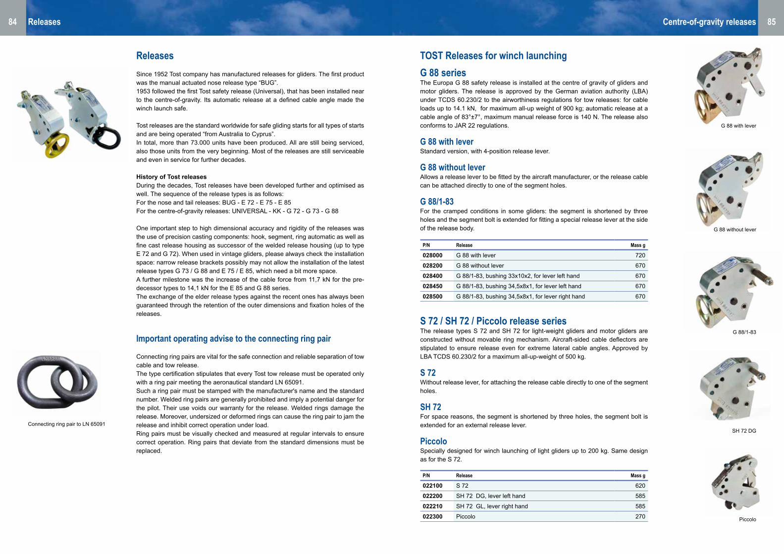
8584
TOST Releases for winch launchingG 88 seriesThe Europa G 88 safety release is installed at the centre of gravity of gliders and motor gliders. The release is approved by the German aviation authority (LBA) under TCDS 60.230/2 to the airworthiness regulations for tow releases: for cable loads up to 14.1 kN, for maximum all-up weight of 900 kg; automatic release at a cable angle of 83°±7°, maximum manual release force is 140 N. The release also conforms to JAR 22 regulations.
G 88 with leverStandard version, with 4-position release lever.
G 88 without leverAllows a release lever to be fitted by the aircraft manufacturer, or the release cable can be attached directly to one of the segment holes.
G 88/1-83 For the cramped conditions in some gliders: the segment is shortened by three holes and the segment bolt is extended for fitting a special release lever at the side of the release body.
P/N Release Mass g
028000 G 88 with lever 720
028200 G 88 without lever 670
028400 G 88/1-83, bushing 33x10x2, for lever left hand 670
028450 G 88/1-83, bushing 34,5x8x1, for lever left hand 670
028500 G 88/1-83, bushing 34,5x8x1, for lever right hand 670
S 72 / SH 72 / Piccolo release seriesThe release types S 72 and SH 72 for light-weight gliders and motor gliders are constructed without movable ring mechanism. Aircraft-sided cable deflectors are stipulated to ensure release even for extreme lateral cable angles. Approved by LBA TCDS 60.230/2 for a maximum all-up-weight of 500 kg.
S 72 Without release lever, for attaching the release cable directly to one of the segment holes.
SH 72 For space reasons, the segment is shortened by three holes, the segment bolt is extended for an external release lever.
Piccolo Specially designed for winch launching of light gliders up to 200 kg. Same design as for the S 72.
P/N Release Mass g
022100 S 72 620
022200 SH 72 DG, lever left hand 585
022210 SH 72 GL, lever right hand 585
022300 Piccolo 270
Centre-of-gravity releasesReleases
Connecting ring pair to LN 65091
ReleasesSince 1952 Tost company has manufactured releases for gliders. The first product was the manual actuated nose release type “BUG”.1953 followed the first Tost safety release (Universal), that has been installed near to the centre-of-gravity. Its automatic release at a defined cable angle made the winch launch safe. Tost releases are the standard worldwide for safe gliding starts for all types of starts and are being operated “from Australia to Cyprus”.In total, more than 73.000 units have been produced. All are still being serviced, also those units from the very beginning. Most of the releases are still serviceable and even in service for further decades.
History of Tost releases During the decades, Tost releases have been developed further and optimised as well. The sequence of the release types is as follows:For the nose and tail releases: BUG - E 72 - E 75 - E 85 For the centre-of-gravity releases: UNIVERSAL - KK - G 72 - G 73 - G 88
One important step to high dimensional accuracy and rigidity of the releases was the use of precision casting components: hook, segment, ring automatic as well as fine cast release housing as successor of the welded release housing (up to type E 72 and G 72). When used in vintage gliders, please always check the installation space: narrow release brackets possibly may not allow the installation of the latest release types G 73 / G 88 and E 75 / E 85, which need a bit more space.A further milestone was the increase of the cable force from 11,7 kN for the pre-decessor types to 14,1 kN for the E 85 and G 88 series.The exchange of the elder release types against the recent ones has always been guaranteed through the retention of the outer dimensions and fixation holes of the releases.
Important operating advise to the connecting ring pair Connecting ring pairs are vital for the safe connection and reliable separation of tow cable and tow release.The type certification stipulates that every Tost tow release must be operated only with a ring pair meeting the aeronautical standard LN 65091.Such a ring pair must be stamped with the manufacturer's name and the standard number. Welded ring pairs are generally prohibited and imply a potential danger for the pilot. Their use voids our warranty for the release. Welded rings damage the release. Moreover, undersized or deformed rings can cause the ring pair to jam the release and inhibit correct operation under load.Ring pairs must be visually checked and measured at regular intervals to ensure correct operation. Ring pairs that deviate from the standard dimensions must be replaced.
G 88/1-83
SH 72 DG
G 88 with lever
G 88 without lever
Piccolo
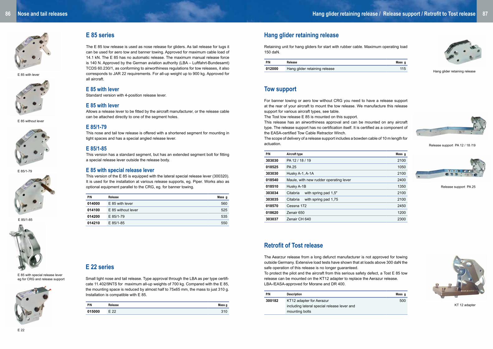
8786
Hang glider retaining release Retaining unit for hang gliders for start with rubber cable. Maximum operating load 150 daN.
Retrofit of Tost release The Aearzur release from a long defunct manufacturer is not approved for towing outside Germany. Extensive load tests have shown that at loads above 300 daN the safe operation of this release is no longer guaranteed.To protect the pilot and the aircraft from this serious safety defect, a Tost E 85 tow release can be mounted on the KT12 adapter to replace the Aerazur release. LBA-/EASA-approved for Morane and DR 400.
Tow support For banner towing or aero tow without CRG you need to have a release support at the rear of your aircraft to mount the tow release. We manufacture this release support for various aircraft types, see table. The Tost tow release E 85 is mounted on this support.This release has an airworthiness approval and can be mounted on any aircraft type. The release support has no certification itself. It is certified as a component of the EASA-certified Tow Cable Retractor Winch.The scope of delivery of a release support includes a bowden cable of 10 m length for actuation.
E 85 series The E 85 tow release is used as nose release for gliders. As tail release for tugs it can be used for aero tow and banner towing. Approved for maximum cable load of 14.1 kN. The E 85 has no automatic release. The maximum manual release force is 140 N. Approved by the German aviation authority (LBA – Luftfahrt-Bundesamt) TCDS 60.230/1, as conforming to airworthiness regulations for tow releases, it also corresponds to JAR 22 requirements. For all-up weight up to 900 kg. Approved for all aircraft.
E 85 with lever Standard version with 4-position release lever.
E 85 with leverAllows a release lever to be fitted by the aircraft manufacturer, or the release cable can be attached directly to one of the segment holes.
E 85/1-79 This nose and tail tow release is offered with a shortened segment for mounting in tight spaces and has a special angled release lever.
E 85/1-85 This version has a standard segment, but has an extended segment bolt for fitting a special release lever outside the release body.
E 85 with special release leverThis version of the E 85 is equipped with the lateral special release lever (300320). It is used for the installation at various release supports, eg. Piper. Works also as optional equipment parallel to the CRG, eg. for banner towing.
E 22 series Small light nose and tail release. Type approval through the LBA as per type certifi-cate 11.402/9NTS for maximum all-up weights of 700 kg. Compared with the E 85, the mounting space is reduced by almost half to 75x65 mm, the mass to just 310 g. Installation is compatible with E 85.
P/N Release Mass g
014000 E 85 with lever 560
014100 E 85 without lever 525
014200 E 85/1-79 535
014210 E 85/1-85 550
P/N Release Mass g
015000 E 22 310
P/N Release Mass g
012000 Hang glider retaining release 115
Nose and tail releases Hang glider retaining release / Release support / Retrofit to Tost release
P/N Aircraft type Mass g
303030 PA 12 / 18 / 19 2100
018525 PA 25 1050
303030 Husky A-1, A-1A 2100
018540 Maule, with new rudder operating lever 2400
018510 Husky A-1B 1350
303034 Citabria with spring pad 1,5″ 2100
303035 Citabria with spring pad 1,75 2100
018570 Cessna 172 2450
018620 Zenair 650 1200
303037 Zenair CH 640 2300
P/N Description Mass g
300182 KT12 adapter for Aerazur including lateral special release lever and mounting bolts
500
Release support PA 12 / 18 /19
Release support PA 25
KT 12 adapter
Hang glider retaining release
E 22
E 85/1-79
E 85 with lever
E 85 without lever
E 85/1-85
E 85 with special release levereg for CRG and release support

88
Vehicle tow device An alternative way of getting up in the air is being used again, known from former times: the vehicle tow. The pilot just needs an airfield and a helper with a car, to get up into the air. The vehicle tow device is fixed at the trailer hitch of the car, the neccessary tools are included in the extend of delivery. A self-launching glider or at least an auxiliary power unit are recommended.
Overhaul of tost releases Releases are approved aeronautical parts. Tost company, as EASA Maintenance organisation, has the right to maintain own products. This certification excludes at the same time, that others perform the overhaul of Tost products. The overhaul of Tost releases is only permitted in the Tost premises in Munich.
During the overhaul procedure, the release spring is exchanged, the life time li-miting element in a release. The maximum possible number of 10.000 actuations result in the regulation of the TBO of 2000 starts. Simultanious, all components of the release are being checked on their conditi-on and exchanged, if needed. Often, this is the case with the release hook, the connection to the connection ring pair and thus the glider. Furthermore, manual release force and release angle are being testet and newly adjusted.The overhauled release goes back to the customer with new issued EASA Fom1.
Release for vehicle tow
Tow releases are approval obligated aircraft parts. Only through the com-pliance with the mandatory maintenance intervals the safety and the life time of the releases are ensured. After 10.000 actuations (corresponding to 2000 starts) the general overhaul and retesting at the manufacturer is stipulated.
We recommend the general overhaul after 4 years as through environmental influences corrosion and sluggishness can occur which can result in malfunction.The aircraft holder is responsible for the supervision and compliance of the maintenance intervals.
IMPORTANT ADVISE: GENERAL OVERHAUL OF TOST RELEASES
Exchange releases The offer of exchange releases is a customer service:If the release is due for overhaul in the middle of the gliding season, you can save time with an exchange release. The customer will receive an exchange release out of our stocks, suitable for his aircraft (subject to prior sale). The demounting of his own release and the mounting of the exchange release can be done at the same time. Thus, the glider can fly again immediately. The demounted release is sent to Tost company, overhauled and goes into the stock of exchange releases. The customer keeps the exchange release, this means that the serial number of his release will change.
Vehicle tow device
ww
w.fo
toka
lend
er-s
egel
flieg
en.d
e •
Pho
to: C
laus
Die
ter Z
ink

9190
TOWING / LAUNCHING EQUIPMENT
Weak links ............................................................................. 92Shackles
Protective sleeves
Connecting ring pair
Connectors / Quick-release links ......................................... 95Tost notch-type connector
Tost clasp-type connector, screw-type connector
Connecting rings
Winch launch ..........................................................................96Schematics
Steel winch cables ..................................................................97Swivel
Cable preamble and cable parachutes
Synthetic winch cables .......................................................101Cable preamble and cable parachutes
Aero tow ...............................................................................104Schematics
Aero tow cable / ropes ........................................................105Cable for CRG
Aero tow rope RED STAR
Aero tow rope for banner tow
Aero tow rope ELASTIK
Aero tow rope EXKLUSIV

9392
Tost weak linksTost weak links in optimized format combine the following improvements: • Longer service life• Correct marking with load group and manufacturer’s name• Made of high-quality certified aircraft steel• Clear determination from inferior copies• Manufacturing tolerance only 5% (10 % are demanded in the requirements)Like our type-approved products, also our weak links are manufactured according to EASA- appro-ved production methods. Each batch is tested on computerized test equipment and the results are documented. This guarantees consistent high quality and traceability.
Important Notes• Weak links protect your aircraft against overloading• Use only the weak link stipulated in your aircraft TCDS or aircraft manual• Checking the cable preamble is mandatory according to SBO (German Gliding Operation Regulations); this includes the inspection of weak links• Replace the weak link immediately in the case of a visible damage• We recommend that the weak link insert are be replaced after 200 starts: an insert exchanged in time is always safer and cheaper than one single aborted launch• Always use the protective steel sleeve• Use only the correct shackles: they prevent the weak link and the steel sleeve from twisting, leading to an increase of the breaking load• Never use two equal inserts, eg, both with round holes, in a reserve system weak link, since this
would double the breaking load
WarningUsing combinations of weak link inserts from different manufacturers can double the breaking load because of the elongation of inferior inserts
Weak linksWeak links
InsertNo.
Coulour BruchlastBreaking load
Single insert round hole
P/N
Reserve insertoval hole
P/N
1 Black 1000±100 110101 110121
2 Brown 850±85 110102 110122
3 Red 750±75 110103 110123
4 Blue 600±60 110104 110124
5 White 500±50 110105 1101256 Yellow 400±40 110106 110126
7 Green 300±30 110107 110127
InsertNo.
Colour Breaking loaddaN
Single insert round hole
P/N
Reserve insertoval hole
P/N
8 Mauve 200±20 110108 110128
9 Grey 150±15 110109 110129
14 Turquoise 120±10 110114 110134
11 Orange 80±10 110111 110131
Load tableWinch launch and aero tow
Load tableKites, hang gliders, ultralights
Tost weak links - examplesTow cable and fan assembly
Weak link insert - round holefor
single-insert system
Weak link insert - ovel holefor
reserve-insert system
Examplewithout protective sleeve
with protective sleeve
Notch-type connector
Clasp-type connector
← Winch Glider →
Screw-type connector
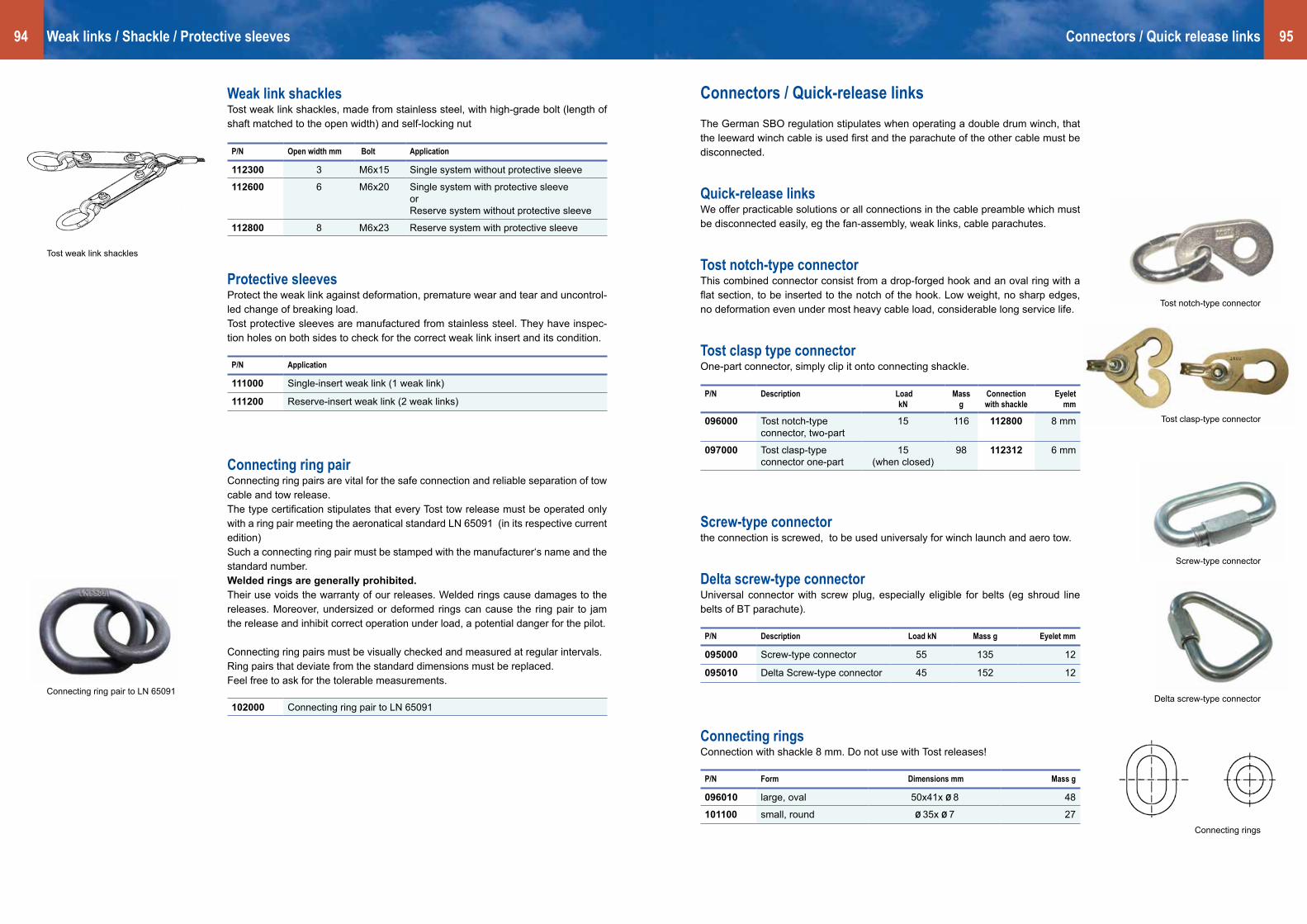
9594
P/N Open width mm Bolt Application
112300 3 M6x15 Single system without protective sleeve
112600 6 M6x20 Single system with protective sleeveorReserve system without protective sleeve
112800 8 M6x23 Reserve system with protective sleeve
P/N Application
111000 Single-insert weak link (1 weak link)
111200 Reserve-insert weak link (2 weak links)
Weak link shacklesTost weak link shackles, made from stainless steel, with high-grade bolt (length of shaft matched to the open width) and self-locking nut
Protective sleevesProtect the weak link against deformation, premature wear and tear and uncontrol-led change of breaking load.Tost protective sleeves are manufactured from stainless steel. They have inspec-tion holes on both sides to check for the correct weak link insert and its condition.
P/N Description Load kN
Massg
Connection with shackle
Eyeletmm
096000 Tost notch-type connector, two-part
15 116 112800 8 mm
097000 Tost clasp-type connector one-part
15 (when closed)
98 112312 6 mm
P/N Description Load kN Mass g Eyelet mm
095000 Screw-type connector 55 135 12
095010 Delta Screw-type connector 45 152 12
Connectors / Quick-release linksThe German SBO regulation stipulates when operating a double drum winch, that the leeward winch cable is used first and the parachute of the other cable must be disconnected.
Quick-release linksWe offer practicable solutions or all connections in the cable preamble which must be disconnected easily, eg the fan-assembly, weak links, cable parachutes.
Tost notch-type connector This combined connector consist from a drop-forged hook and an oval ring with a flat section, to be inserted to the notch of the hook. Low weight, no sharp edges, no deformation even under most heavy cable load, considerable long service life.
Tost clasp type connector One-part connector, simply clip it onto connecting shackle.
Screw-type connectorthe connection is screwed, to be used universaly for winch launch and aero tow.
Delta screw-type connectorUniversal connector with screw plug, especially eligible for belts (eg shroud line belts of BT parachute).
Connectors / Quick release linksWeak links / Shackle / Protective sleeves
Connecting ring pairConnecting ring pairs are vital for the safe connection and reliable separation of tow cable and tow release. The type certification stipulates that every Tost tow release must be operated only with a ring pair meeting the aeronatical standard LN 65091 (in its respective current edition) Such a connecting ring pair must be stamped with the manufacturer‘s name and the standard number.Welded rings are generally prohibited.Their use voids the warranty of our releases. Welded rings cause damages to the releases. Moreover, undersized or deformed rings can cause the ring pair to jam the release and inhibit correct operation under load, a potential danger for the pilot. Connecting ring pairs must be visually checked and measured at regular intervals. Ring pairs that deviate from the standard dimensions must be replaced.Feel free to ask for the tolerable measurements.
102000 Connecting ring pair to LN 65091
Connecting ringsConnection with shackle 8 mm. Do not use with Tost releases!
P/N Form Dimensions mm Mass g
096010 large, oval 50x41x Ø 8 48
101100 small, round Ø 35x Ø 7 27
Delta screw-type connector
Connecting rings
Screw-type connector
Tost notch-type connector
Tost weak link shackles
Connecting ring pair to LN 65091
Tost clasp-type connector

9796 Winch launch
Schematics
205050 Dynalauchsynthetic winch cable
200004 - 200612
Steel winch cable
096000 Stipulated connector 096000 Stipulated connector
133600 Cable parachute Kuwi 133000 133500
Cable parachute
095000 Connector (Example) 095000 Connector (Example)
121006 Safety cable 121003 Safety cable (Example)
102000 Connecting ring pair 102000 Connecting ring pair
028000 Centre-of-gravity release (Example)
028000 Centre-of-gravity release (Example)
096000 Connector 096000 Connector
110000 Weak link unit inFan assembly
110000 Weak link unit inFan assembly
121012 121017
Intermediate cable 121002 121007
Intermediate cable
Synthetic cable Steel cable
Steel winch cables
Steel winch cables
Winch cable Ø 4.2 mm6x7x0.45 mm construction with one 7x0.50 steel core, right-hand cross-lay, un- galvanized, non-rotating, stress-free, breaking load 14.8 kN, mass 7 kg per 100 m.Standard length 1200 m from stock, other lengths available on short notice.
200012 Winch launching cable 4.2 mmon disposable wooden reel
200612 Winch launching cable 4.6 mm on disposable wooden reel
Winch cable Ø 4.6 mm6x7x0.52 mm construction with one 7 x 0.60 steel core, rest see aboveBreaking load 17.7 kN, mass 8 kg per 100 m.Standard length 1200 m from stock, other lengths available on short notice.
Operating instructionsTo improve the life time of your winch launching cable, you should observe the fol-lowing hints (excerpt from the operating instruction) • Wind on the cable with lowest drum torque• Use swivel only if necessary. Never use the swivel during the launch, only during
pulling out the cable• Only experienced winch drivers should do the launching with a new cable• Increase the load gradually up to the maximum load capacity of the cable• Always retrieve the cable with constant, moderate speed. We deliver our winch cables with a detailed operating instruction for the correct “Cable treatment”.
Swivel Maintenance-free, rugged, with high grade ball bearings. Connect with 14 mm shackle. Operating instruction is included.Caution: use only when pulling out the cable, never during launching!
P/N Description Length mm Mass g
215000 Swivel 85 175
Steel winch launching cable
Swivel

9998
Cable preamble winch launchThe German Gliding Operation Order (SBO), latest edition, also newly regulates the winch cable equipment, however considerung the Air Technical Note LTA 73-16: Connecting sequence• 3 m safety cable with connecting ring pair• Weak link• Intermediate Cable: Length 2 m or 10 m Please see picture of the connecting sequence on page 96“Schematics Winch Launch”. Safety CableTo reduce the danger of loops and cable hangups at the glider, at the beginning of the launch a “stiffened” safety cable of 3 m length is stipulated.
Weak linkSelect the correct breaking load according to the manual or TCDS of the towed glider. Now the weak link position can also be between Connecting ring pair and safety cable.
Quick release linkWhen using a double drum winch the leeward winch cable has to be used first. The parachute of the other cable must be disconnected. Please look for suitable parts on page “Connectors / Quick Release Links”.
Intermediate CableWith a diameter of the parachute canopy of 1.5 to 2.0 m to the LTA 73-16, a distance of at least 13 m between the release of the glider and the parachute vent is stipula-ted. In addition to the 3 m safety cable an intermediate cable of 10 m must be used.With a canopy diameter of less than 1.5 m the distance between the release and the parachute vent can be less, the minimum distance however is 5 m; that means the use of a intermediate cable of 2 m length.
Cable parachuteThe maximum permissible canopy diameter of the cable parachute is 2.0 m.
Winch launch – Steel cables
Cable preamble – Equipment for steel winch cablesSafety Cable 3 m Manufactured from steel cable encased with a rubber tubing.We use a red tubing for a better finding of the safety cable in the field.Both ends are fitted with Tost aluminium solid thimbles, for an optimal durability.At the glider side the connecting ring pair is fitted with an 8 mm shackle.Connect the appropriate weak link to the winch cable side. An 8 mm shackle is pre-assembled.
Intermediate cables The length depends on the canopy diameter of the cable parachute.Manufactured from steel wire encased with a rubber tubing. We use a red tubing for a better finding of the safety cable in the field. The stiffening rubber tubing is not stipulated for the intermediate cable, but it is recommendable.Both ends are fitted with Tost aluminium solid thimbles, for optimal durability, and 8 mm shackles.
P/N Description Colour Canopy Ø m Length m
121002 Intermediate cable from steel red up to 1.5 2
121007 Intermediate cable from steel red more than 1.5 10
P/N Description Colour Length m
121003 Safety cable from steel red 3
Winch launch – Steel cables
Safety cable from steel
Intermediate cable from steel

101100
Cable parachutes for steel winch cablesBT Cable parachute The durable parachute with high life expetancy. The large canopy enables pulling-in of the winch cable at a low engine torque. Available in two colours: yellow and red – for better distinction between the leeward and windward cable of a double drum winch. DescriptionFour-segment canopy, material nylon, UV-resistant. With 8 ea. one-piece shroud belts in black, reinforced parachute edges, the upper belts are doubled.The long shroud belts are exchangeable. When damaged you can order replace-ment belts and can exchange them by yourselves.The shroud lines are belt together in a delta screw-type connector.
P/N Description Colour Canopy base Ø m (in flight)
Lengthparachute mm
Mass g
133000 BT Cable parachute yellow 1800 3500 2400
red
133500 Cross-panel cable parachute
white 1400 1500
Important notes for the use of the BT cable parachuteExcerpt from the LTA 73-16 (aeronautical technical advice) which is part of the SBO:The diameter of the open parachute may not exceed 2 meters.The total length of the parachute – with closed canopy and stretched shroud belts – may not exceed 4 meters.The distance between tow release and canopy vent is stipulated with at least 13 m.The sequence is thus: 3 m safety cable – weak link element (can also be positioned between connecting ring pair and safety cable) – 10 m intermediate cable.
Cross-panel cable parachuteThis light parachute combines high strength with a very good price/performance ratio. Its special construction means the parachute descend very slowly and nearly non-rotating.
DesriptionCanopy made of 2 polyamide panels stitched together cross-shaped. The canopy edges are reinforced with belts. Parachute colour: white. Eight shroud lines are belt together at top and bottom in large leather thimbles. The shroud belts are knotted through loops at the canopy base.
Important notes for the use of the cross-panel cable parachuteThe canopy diameter is less than 1.5 meters.Thus the sequence is: 3 m safety cable – weak link element (can also be positioned between connecting ring pair and safety cable) – 2 m intermediate cable.
Winch launch – Cable parachutes for steel cables
Synthetic winch cable DYNALAUNCHThe synthetic winch cable DYNALAUNCH has been specially designed for winch launching. It stands out through an improved protection against abrasive wear thanks to a special impregnation
Advantages of DYNALAUNCH to steel cable• More launching heigth• Minor weight – only 15% of a steel cable• Easy handling • Simple to splice• Extented service life
Technical data• Material 100 % Dyneema • 12-fold plaited• Special impregnation • Best UV-resistance• Water and soil repellent
Special offer - from Tost company only:With your first order of at least 1000 m cable length we offer you a free splicing kit:• A premium splicing needle• A detailed, illustrated splicing instruction• Important hints how to adapt your winch • 2 Jumbo solid thimbles from aluminium We can supply every cable length at customer‘s choice from stock.Due to the minor weight, the cable can be shipped as standard post parcel.
Winch launch – Synthetic cables
P/N Description Colour Ø mm
Breaking load kN
Mass g/100 m
205050 Dynalaunch blue 5 25 1240
Splicing needle for synthetic winch cableA well designed tool, made from aluminium, for splicing of sythetic winch cables. The wire basket can be opened to catch the synthetic cable. The wire loops are being spread and take up the cable strands. Close the wire basket and it holds tight the synthetic winch cable. You can start to splice. A detailed instruction is included.
P/N Description Length mm
Mass g
205050 Splicing needle 25 35
Synthetic winch cableDYNALAUNCH
BT cable parachute
Cross-panel cable parachute
Splicing needle for synthetic winch cable

102
Intermediate cablesLength depends from diameter of the cable parachute.Manufactured from Dyneema rope with high load capability. At both ends our solid aluminium thimbles “Jumbo” are spliced in. The splices are double protected trough a shrinkable tubing and a synthetic cover. Into the bore of our “Jumbo” thimbles the screw type connector can be fitted directly.
Cable preamble – Equipment for synthetic cablesSafety cable 3 m Manufactured from stiff synthetic rope, accessory parts sewed in directly to the rope ends: at the glider side the connecting ring pair, at the winch cable side a large oval ring, to fit here the appropriate weak link. The special construction of the synthetic rope – multi layer construction with tight braided cover – shows a very smooth surface and a high stiffness, it corresponds to the requirements of the SBO. An additional stiffening cover is not longer stipu-lated.Stitching and junction at the rope ends are protected with a shrunk-on hose. No sharp edges can damage the glider. This safety cable can also be used with steel winch cables.
Cable parachutes for sythetic winch cablesCross-panel cable parachute Kuwi This light parachute combines high strength with a very good price/performance ratio. Its special construction means the parachute descend very slowly and nearly non-rotating. This smaller canopy is specially constructed for the use with synthetic winch launching cable.DescriptionCanopy made of 2 polyamide panels stitched together cross-shaped. The canopy edges are reinforced with belts. Parachute colour: white. Eight shroud lines are belt together at top and bottom in large leather thimbles. The shroud belts are knotted through loops at the canopy base.
Important operating notes for the use of the cross-panel parachute KUWIThe canopy diameter is less than 1.5 meters.Thus the sequence is: 3 m safety cable – weak link element (can also be positioned between connecting ring pair and safety cable) – 2 m intermediate cable.
P/N Description Length in m for canopy Ø
121012 Intermediate cable from Dyneema 2 up to 1.5 m
121017 Intermediate cable from Dyneema 10 over 1.5 m
P/N Description Canopy basis Ø m(open during flight)
LengthSchirm mm
Mass g
133600 Cross-panel cable parachute Kuwi
1200 3400 1200
121006 Safety cable, colour white, length 3 m with oval ring and connecting ring pair
Winch launch – Synthetic cables
ww
w.fo
toka
lend
er-s
egel
flieg
en.d
e •
Pho
to: C
laus
Die
ter Z
ink
Safety cable for synthetic cables 3 m length
Intermediate cable for synthetic cable 10 m length
Cross-panel cable parachute Kuwi

105104
Aero tow ropesWe distinguish between the special cable for the Tow cable retraction winch and ropes for aero towing.
Cable for CRGSynthetic cable in multi layer construction, smooth surface for knot-free cable re-traction. The cable is delivered on a cardboard reel, for direct winding onto the cable drum in the aircraft‘s fuselage.
Aero tow ropes RED STAR, ELASTIK, EXKLUSIVAll aero tow ropes from Tost are delivered completely fitted “ready to tow”.
• At the tug side equipped with connecting ring pair to LN 65091• At the glider side equipped with complete weak link unit in reserve system including protective sleeve and connecting ring pair
As standard, the white weak link No. 5 with a breaking load of 500 daN is fitted. Please note on your order if you need an other weak link breaking load. In this case we shall fit the required weak link ex works.
Excerpt from the SBORegarding aero tow ropes, please refer to section 2.2 for single tow and2.3 for double tow. The following rope lengths are stipulated:Single tow 40 - 60 m lengthDouble tow short rope 30 - 40 m lengthLee-position long rope 50 - 60 m must be releases first The difference between the short and the long rope hast to be at least 20 m.
Aero tow
2-part aluminium sleeve
screwed over the knot in the cable
Cable for CRG
Overhand knot(half hitch)
Aero tow cable / ropes
P/N Desription Length m
Max. load daN
Colour Ø mm
Mass g
300550 Cable for CRG, standard length
50 1160 white 6,1 1920
300556 Cable for CRG 60 1160 white 6,1 2250
300560 Cable for CRG, cut to length
250 1160 white 6,1 8700
Aluminium sleeve
Schematics Aero tow
102000 Connecting ring pair
113400 Connecting shackle
110010 Complete weak link
300061 End piece
Tow releaseE 85 or E 22
Aero tow ropesLength 40 – 60 m
Complete weak linkwith connecting ring pair
Nose release E 85 or E 22
End piecewith connecting ring pair and weak link
Cable stop platewith guillotine
CRG cable50 or 60 m
CRGForm of winch unitdepending on aircraft type
Schematics to SBO in current edition

107106
Aero tow rope EXKLUSIV The high-grade, durable rope for hard operational demands
Material PES, cable-laid, UV-resistant
High load capability and ruggedness make the EXKLUSIV to a rope for all range of application with expect a long service life. At both ends are fitted with knots the Alu end pieces. As additional protection we use stable rubber sheaths.
In case of wear and tear at the rope ends an easy do-it-yearself repair is possible, just make new knots, see picture (knot is called “rose knot”).
Aero tow rope ELASTIKThe lightest and most comfortable aero tow rope
Material crimpe crepe white, hawser-laid
Stretching more than 30 % under normal load results in a particularly elastic tow, without dangerous recoil.The ELASTIK rope put itself forward especially for the motor glider tow and the Ultralight tow. With this elastic rope a smooth tow can be achieved, too, with these not so powerful tugs. To save weight we do the ELASTIK rope without aluminium end pieces and rubber sheaths. The connecting parts are spliced directly into the rope ends.
The declaration of rope length is in stretched condition, under normal load.
P/N Description Length m
Minimumbreaking load daN
Colour Ø mm
Mass g
183300 Rope ELASTIK 40 870 white 10 1500
183400 Rope ELASTIK 50 870 white 10 1900
183500 Rope ELASTIK 60 870 white 10 2100
P/N Description Length m
Minimumbreaking load daN
Colour Ø mm
Mass g
181400 Rope EXKLUSIV 40 1000 white 10 3700
181500 Rope EXKLUSIV 50 1000 white 10 4400
181600 Rope EXKLUSIV 60 1000 white 10 5200
Aero tow cable / ropes
Aero tow rope RED STARThe allrounder of tow aero tow cables with an excellent price/performance ratio:
• Step-index fibre from polyester, 32-fold casing• Code colour red• Rope diameter 9 mm• Minimum breaking load 11 kN• On both sides spliced-in rope eye, with directly fitted connecting parts one side connecting ring pair to LN 65091 other side large oval ring• On glider side equipped with complete weak link unit in reserve system with protection sleeve and connecting ring pair to LN 65091
Advantages • High grade and long living rope thanks to step-in-fibre construction • Easy to find on the airfield due to its code colour red• Connecting parts are directly spliced-in. Rope ends protected with scoring coating• There are no sharp edges which could damage the aircraft fuselage. Metal parts are reduced to the minimum.
P/N Description Length m
Minimumbreaking load
daN
Colour Ø mm
Mass g
185400 Rope RED STAR 40 1100 red 9 2550
185500 Rope RED STAR 50 1100 red 9 3110
185600 Rope RED STAR 60 1100 red 9 3690
Banner tow rope Step-index fibre rope from Polyester, spliced rope eye at both ends, Connecting parts directly fitted to the eyes:One side oval ringother side complete weak link in reserve system with connecting ring pair to LN 65091
P/N Description Length m
Minimumbreaking load
daN
Colour Ø mm
Mass g
185900 Banner tow rope 25 1100 red 9 1720
Rope repair with „Rose knot“
Aero tow rope EXKLUSIV
Aero tow rope ELASTIK
Aero tow rope RED STAR
Aero tow cable / ropes

109108
ACCESSORIES AND TOOLS
Cable tools ........................................................................... 110Nicopress sleeves/ Stop sleeves
Nicopress tools
Tost cable crimping tool
Cable clamps and tools ....................................................... 111Tost Top and bottom tool
Cable Cutter
Splicing needle
Control Cables ...................................................................... 112 Control cables
Tost solid thimbles from aluminium
Steel thimbles
Connectors ............................................................................ 113Connecting shackles
Safety pins
Locking wire

111110
Nicopress sleeves and toolsfor Nicopress sleeves from copper
Operating notes (excerpt):• Grease crimping gauge before each crimping• Follow correct sequence for partial crimping• Never re-crimp a sleeve at the same pointDetailed operating instructions supplied with the tool
Nicopress Stop sleevesFor proper crimping of cable ends of control cables with a Nicopress tool. The stop sleeve prevents the cable end from uncoiling.
Allocation Nicopress sleeve to cable and tool
Nicopress toolDetailed operating instructions supplied with the tool
Tost Cable crimping toolCompact, without long lever arms. Tool can be used in cramped spaces of the fuselage. The most economic alternative to nicopress tools.
P/N sleeve Cable Ø mm Grimping gauge P/N tool
217280 1.2 stainless steel VB4 217221217291 1.5 - 2.0 stainless C 217000, 217221, 217240217281 1.5 - 2.0 C 217000, 217221, 217240218282 2.4 - 2.6 G 217000, 217200, 217221, 217240217283 3.0 - 3.2 M 217000, 217100, 217200217284 4.0 - 4.2 P 217000, 217100, 217200217286 4.6 - 5.0 X 217100
P/N Cable Ø in mm Pressspur Length mm Handle mm Mass g
217200 2.4 - 4.2 G, M, P 280 160 390
P/N Cable Ø mm Crimping gauge Length mm Handle / Hebel mm Mass g
217000 1.5 - 4.2 C, G, M, P 520 370 2530
217100 3.0 - 5.0 M, P, X 520 370 2530
217221 1.2 - 2.6 VB4, C, G 296 220 1000
217240 1.8 - 2.6 C, G 296 220 1000Nicopress tool (217221)
Nicopress tool (217100)
Nicopress Stop sleeves
Tost Cable crimping tool
Nicopress sleeve from copper
Tost Top and bottom tool
Cable cutter
Splicing needle
Cable clamp from Aluminium
Aluminium cable clamps and tools for cable clamps from aluminium
Tost Top and bottom tool for aluminium cable clampsFor making of simple and economical cable connections using cable clamps made of aluminium, type A, cylindrical.Tool sizes 2-5, forged steel, specially hardened, extra strong version, replace-able guide pins. Tool length 185 mm, mass 1580 g.
Operating notes:• Grease the bore hole well before pressing• Stand the tool on a thick steel plate• Choose the correct combination of cable/clamp/tool• Put the tool halves together correctlyDetailed operating instructions supplied with the tool
P/N tool Cable Ø in mm Tool No. P/N clamp
220200 1.2 - 1.6 2 221200220250 1.7 - 2.1 2.5 221250220300 2.2 - 2.6 3 221300220350 2.7 - 3.1 3.5 221350220400 3.2 - 3.6 4 221400220450 3.7 - 4.1 4.5 221450220500 4.2 - 4.6 5 221500
P/N Cable Ø in mm
Type of cable Length mm
Mass g
216070 up to 5 mm Steel cable withsteel or hemp corealso stainless steel cable
170 290
P/N Length mm
Length of needle mm
Mass g
212000 210 90 85
Cable cutterFor proper cutting of steel cables • Proper cut, no deformation or crushing• Single strands do not uncoil• Cutting without excessive effort, easy one-handed operation• Suitable for use inside aircraft fuselage
Splicing needleFor splicing and thimble splicing of steel cables. Tool with wooden handleand hardened needle with strand groove.
P/N Cable Ø in mm Crimping gauge
217371 1.5 - 2.0 C
217372 2.4 - 2.6 G
217373 3.0 - 3.2 G
Cable toolsCable tools
Allocation cable clamp to cable and tool

113112
Control Cables Aircraft control cable to DIN ISO 2020 (previously LN 9374), steel galvanized, low twist, low stress, flexible.
Delivered in coils of 10, 15, 20, 25, 50, 100 and 200 m. Available ex stock.Certificate of Conformance on request.
Other cables or dimensions available on request.
Connecting shacklesStainless steel shackle, with spacer bushing, high-strength bolt and self-locking nut.
P/N Diameter mm
Wire construction
Minimum breaking load
Mass g/m
200024 2,4 7 x 7 4.1 kN 24 g/m
200032 3,2 7 x 19 8.9 kN 43 g/m
P/N Width mm Eylet mm Bolt mm
113000 10 14 M6x22
113212 12 14 M6x26
113400 14 14 M6x30
113900 19 19 M6x35
Steel thimbles Made in Germany, for control cables and steel winch cables
Tost solid thimbles from aluminium • From Tost production• Light weight, high load capacity, keep the form• High strength prevents the thimble from deforming to protect the winch cable
from damage• We recommand the Jumbo solid thimble especially for the use with synthetic
winch cables, which lays well protected in the notch
P/N Description Cable in mm Material
222200 Heart-shaped thimble 2 1.5-2.0 stainless steel
222300 Heart-shaped thimble 3 2.1-3.0 stainless steel
222350 Thimble 3,5 3.1-4.0 galvanized
222500 Heart-shaped thimble 5 4.1-5.0 galvanized
222600 “Strong” thimble 6 for safety cable 4.6-6.0 galvanized
P/N Description Cable in mm Connection
222500 Round thimble 4.2 - 5.0 Shackle 8 mm
222700 Solid thimble 4.2 - 5.0 Schackle 8 mm
227500 Solid thimble Jumbo 4.2 - 5.0 Screw-type connector
Manufacturing of thimbles to your requirements, also with anodised surface in your brand colour.
Safety pinsMaterial: spring wire
Locking wireto MS 20995-C-32, for aircraft.Material: stainless steel 0.8 mm Ø (0.032 Zoll)
P/N Width mm(Breite)
Lw mm Wire mm(Draht)
920010 5 20 1,4
920011 12 35 1,2
920012 8 51 1,3
920080 Roll with approx. 0.5 kg
ConnectorsControl Cables, Thimbles
Heart-shaped Thimblethimble
Solid thimble Solid thimble Jumbo
Round thimble
Control cable
Connecting shackle
Safety pin
Locking wire

115114
HELICOPTER-EQUIPMENT
Rope down securing unit .................................................... 116Attachment to the fl oor unit, inside
Attachment outside, type „External“
Helicopter equipment ........................................................... 118Rescue cages
Drag anchor
Cable Cutter / Pocket Assy
Load cables
Connectors

117116
Helicopter EquipmentWe develop and manufacture equipment for various applications: • For the descend of task forces through internal or external attached rope down
securing units• Rescue cages for picking-up people or for transport of high loads• Cable Cutter as redundant safety system for cable winches, with suitable pockets• Load cables for the transportation of external loads, hanging under the helicopter• High-tensile connectors
Tost Rope down securing unitHelicopters are used worldwide as a fast and safe means of transport. Fire-fighting teams or police task forces are quickly brought into an operational area by helicop-ters. They can reach sites which are inaccessible for surface transport. Landing in tight spaces, however, entails great risks for any helicopter To expand the mission scope of helicopters we developed our “rope-down securing unit” to ensure the safe descend of rescue teams. They rope-down to a precise location while the helicopter hovers in position overhead. During the rope-down operation, members of the task force are safely attached to the helicopter via the Tost rope-down securing unit, installed internal or external of the helicopter. On completion of the rope-down operation, the pilot or a crew mem-ber disconnects the rope with 1 pull to release the team members, either singly or in groups. The helicopter is ready for the next mission immediately. Apart from standard police or fire-fighting missions, the rope-down securing unit can be used in a number of special applications, eg:• Fighting forest fires• Flood rescue operations• Mountain and sea rescue operations• Fire in multistorey buildings• Dropping emergency personnel• Redundant safety system • Operations of special forces teams
2-person rope down securing unit “External” for EC 135 and BK117 C-2
Attachment to the floor unit, insidefor 1-, 2-, 4-, 6- or 8-man teams • with self-centering snap-on connectors in airline rails • fixed to stretcher adapter rail• bolted directly to the floor unit All Tost-rope down securing units for internal installation can be loaded by 15 kN Ultimate Load per attaching point, and can also be released under this load. That means that the load capability is only limited through the load capacity of the heli-copter or the fixing points.
Used in: BO 105 / BO 105 S / BO 105 CBS, BK 117, BK 117 C2, EC135, EC145, EC155 MD Explorer, Bell 212, PZL Sokol
Manufacturing for other types on request.
Attachment outside, Type “External”for 1- or 2-man teams (per side) The Tost rope down securing unit is appropriate for the technique of Fast-Roping or Rapelling, as the fixation point is above the cabin. The person can start the rope down procedure directly into the tight rope. Attachment• on existing winch fittings with ball lock pins• attachment either left hand, right hand or on both sides For version 192141 left hand and version 192142 right hand, the Ultimate Load to JAR 29 is 8 kN = 800 kg per attaching point.
Used in: EC 135, BK 117 C-2
The installation in the helicopter is compleded with edge protection mats.
Tost Rope down securing unitTost Rope down securing unit
1-man Rope down securing unit with protection mat
Tost-External Rope down securing unit
1-man Rope down securing unit
4-man Rope down securing unit
6-man Rope down securing unit
P/N Attachment Number persons
192141 External, attachment left hand 1-2
192142 External, attachment right hand 1-2
P/N Description Number of persons
190162 Rope down securing unit with snap-on connectors 1
190143 Rope down securing unit for EC135/MD ExplorerAttachment with self-centering snap-on connectors
2
190121 Rope down securing unit EC 135Attachment with self-centering snap-on connectors
4
190080 Rope down securing unit HEXA für EC 155Attachment with self-centering snap-on connectors
6
190030 Rope down securing unit Attachment with self-centering snap-on connectors
8

119118
Rescue cagesThe rescue cage is used to pick up or drop people (also injured people) in difficult terrain, from water, etc.The frame is made of nonrusting and acidproof tubing, the cage mesh is made of polypropylene rope. Rope material is light, rot-resistant and unsinkable. Colour bright orange. The rescue cage can swim through the optional mounting of floating bodies.
Drag anchorfor stabilizing rescue cages; prevents twisting of cage. The drag anchor consists of a textile funnel with a sewn-in retaining ring and the cable harness to attach to the rescue cage. Two spring hooks allow the drag anchor to be attached in different positions from the rescue cage (load-dependent).
Cable CutterManual cable cutter for cutting winch cables in the event of on-board power failure. The catching of the cable is eased through the integrated capture angle brackets. The Cable Cutter cuts steel wire cables up to 6 mm diameter. It can also be sup-plied with safety wrist strap.
Pocket AssyThe Cable Cutter can be stored in a handy leather pouch, attached to the cabin wall. With defined attachment points. Can be delivered optional with opening for the safety wrist strap. Different pocket types for BO 105/BK 117 and EC 135 available.
Load cables for transportation of loads, fixed under the helicopter• Manufacturing to your drawing or requirements• End fittings either cable fittings or thimbles• Cable diameter: 6.4 or 8 mm• Test load from 17 up to 30 kN (breaking load from 29 to 44 kN)Alternative load cables on request.
Helicopter equipmentHelicopter equipment
P/N Description LoadkN
Load capacity kN
Breaking load kN
Mass g
113410113428 113435
Load shackles for all connections 152838
34120208
215020 Load swivel, eye diamter 30 mm 20 495
096062 Suspension ring for heavy-duty releases eyelet 75x135 mm
830
095500 Delta scew-type connectorto hang in harnesses
25 400
095014095100
Screw-type connectors for all connections
1520
270270
102010 Connecting ring pair, high tensile 30 70
191300 Edge protection mat, width 1000 mm, Width can be adapted, with self-centering snap-on connectors
5000
190300 Drag anchor 1080
216160 Cable Cutter with safety wrist strap 950
216161 Cable Cutter 925
216166 Cable Cutter Pocket Assy, with openingfor safety wrist strap, for 216160
570
216167 Cable Cutter Pocket Assy, without openingfor safety wrist strap, for 216161
575
P/N Description Mass g
190211 Rescue cage for 1 person 6000
190210 Rescue cage for 2 person 14000
Connectors
Rescue cage for 1 person
Rescue cage for 2 person
Drag anchor
Cable Cutter with safety wrist-strap
Load cable

121120
SPECIAL PURPOSE SOLUTIONS
Weak link elements for special applications .....................122
Releases for special applications ...................................... 123Heavy duty releases
Fail safe releases
Wheels for special applications ..........................................124
Cable retractors with guillotine ..........................................124
Hydraulic components .........................................................124
Construction, design, simulation, contract manufacturing .................................. 125
Testing infrastructure ...........................................................125

123122
Weak links for special applicationsWe manufacture custom made weak link elements to your requirements with de-fined breaking load. We can cover the low load range of 100 N to 10 kN; beyond that, also the demand in the high load range of 11 kN to 50 kN can be mm. By the use of different materials we can meet your requirements regarding corrosion pro-tection, food compatibility or any other standard. An individual marking of the weak links, according to customer request (e.g. with corporate logo) can be carried out easily.
Application examples: • Bracing of antennas• Retaining of flagpoles• Testing of parachutes• Ship rigging• Off-Shore-operations• Harbor tugs• Balloon mooring• Fair constructions• Food industry• Mechanical Engineering Configuration of weak link element3- to 5-part weak link element, with or without protective sleeve, weak link inserts in single or reserve system, with two heavy duty shackles, in the load range of 11 kN to 50 kN.
Special tow releasesBeside our aviation releases we offer a wide variety of special tow releases for defined holding and determined release of loads.The specific load range and the type of remote activation (mechanical, electric, hydraulic, pneumatic) can be varied.
Application examples:• Test rigs• Drop tests• Harbor tugs• Cable positioning• Towing of oil barriers• Rope down securing units• Mining and surface mining• Automotive engineering• Towing and securing units Please contact us for an offer for your special application.
Heavy duty releasesThe load release E 85 L is available in different variants, including a seawater proof type, with mechanical activation, with electrical remote activation or special side plates. Further special versions of the load release are realised according to your requirements (e.g. with mounting supports, hydraulic or pneumatic activation etc.).
ReleasesWeak links
P/N Description Load range
190550 Heavy-duty weak link element, 5 pcs., in reserve system
11 to 20 kN
190560 Heavy-duty weak link element,4 pcs.,in single system
20 to 50 kN
190561 Weak link insert for p/n 190560
P/N Description Max. load
011320 Heavy duty release E 85 L 20 kN
011321 Heavy duty release E 85 L seewater proof 20 kN
011395 Heavy duty release E 85 L with mechanical acitvation+ side plates
20 kN
011390 Heavy duty release E 85 L with electrical remote activa-tion+ side plates
20 kN
011490 Heavy duty release E 85 L with electrical remote activa-tion+ side plates
30 kN
Heavy duty release E 85 L with electrical remote actuation
and side plates
E 22 Fail Safe
Fail safe releaseContrary to all other release variants the unactuated setting of the fail safe release is open. By applying an electric voltage the release is locked. The release opens immediately, when the voltage is removed.
015100 E 22 Fail Safe 20 kN
4-part weak link element,single circuit
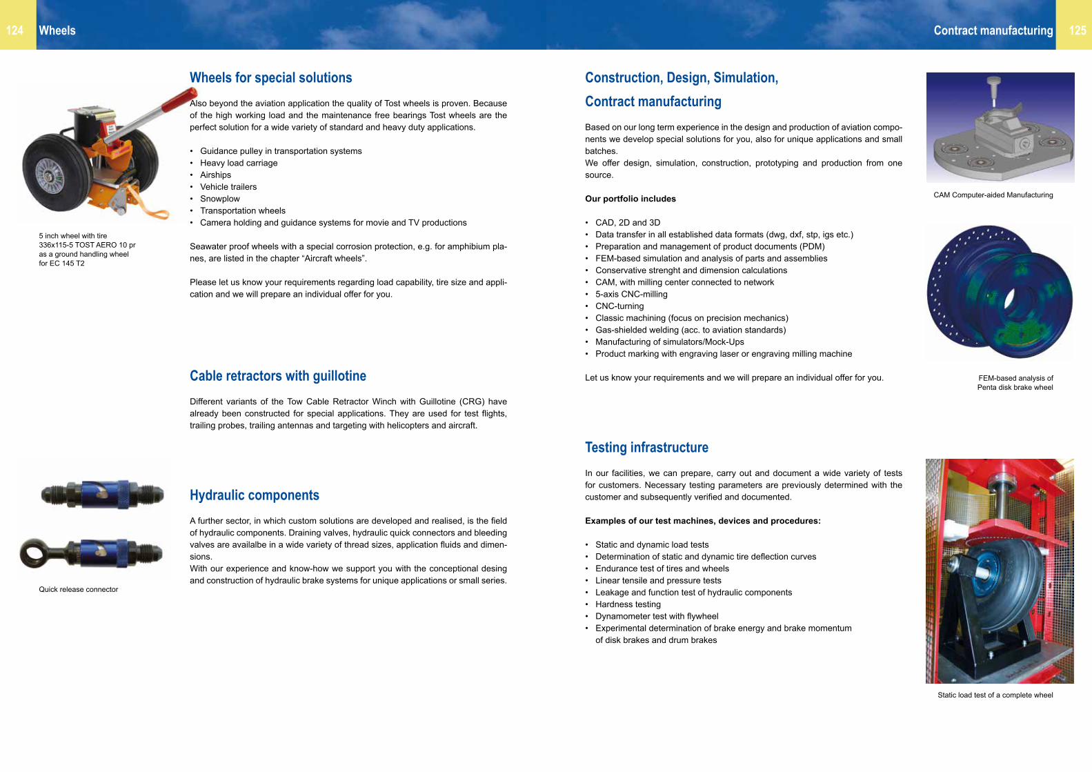
125124 Wheels
Construction, Design, Simulation,Contract manufacturingBased on our long term experience in the design and production of aviation compo-nents we develop special solutions for you, also for unique applications and small batches.We offer design, simulation, construction, prototyping and production from one source.
Our portfolio includes
• CAD, 2D and 3D• Data transfer in all established data formats (dwg, dxf, stp, igs etc.)• Preparation and management of product documents (PDM)• FEM-based simulation and analysis of parts and assemblies• Conservative strenght and dimension calculations• CAM, with milling center connected to network• 5-axis CNC-milling• CNC-turning• Classic machining (focus on precision mechanics)• Gas-shielded welding (acc. to aviation standards)• Manufacturing of simulators/Mock-Ups• Product marking with engraving laser or engraving milling machine
Let us know your requirements and we will prepare an individual offer for you.
Testing infrastructureIn our facilities, we can prepare, carry out and document a wide variety of tests for customers. Necessary testing parameters are previously determined with the customer and subsequently verified and documented.
Examples of our test machines, devices and procedures:
• Static and dynamic load tests• Determination of static and dynamic tire deflection curves• Endurance test of tires and wheels• Linear tensile and pressure tests• Leakage and function test of hydraulic components• Hardness testing• Dynamometer test with flywheel• Experimental determination of brake energy and brake momentum of disk brakes and drum brakes
Contract manufacturing
Wheels for special solutionsAlso beyond the aviation application the quality of Tost wheels is proven. Because of the high working load and the maintenance free bearings Tost wheels are the perfect solution for a wide variety of standard and heavy duty applications.
• Guidance pulley in transportation systems• Heavy load carriage• Airships• Vehicle trailers• Snowplow• Transportation wheels• Camera holding and guidance systems for movie and TV productions Seawater proof wheels with a special corrosion protection, e.g. for amphibium pla-nes, are listed in the chapter “Aircraft wheels”.
Please let us know your requirements regarding load capability, tire size and appli-cation and we will prepare an individual offer for you.
Cable retractors with guillotineDifferent variants of the Tow Cable Retractor Winch with Guillotine (CRG) have already been constructed for special applications. They are used for test flights, trailing probes, trailing antennas and targeting with helicopters and aircraft.
Hydraulic componentsA further sector, in which custom solutions are developed and realised, is the field of hydraulic components. Draining valves, hydraulic quick connectors and bleeding valves are availalbe in a wide variety of thread sizes, application fluids and dimen-sions.With our experience and know-how we support you with the conceptional desing and construction of hydraulic brake systems for unique applications or small series.
5 inch wheel with tire336x115-5 TOST AERO 10 pras a ground handling wheel for EC 145 T2
Quick release connector
FEM-based analysis of Penta disk brake wheel
Static load test of a complete wheel
CAM Computer-aided Manufacturing

1945 Foundation of Tost company as a locksmith’s shop
1951 Gliding is again permitted in Germany. Tost begins developing safety equipment for gliding
1952 Manufacture of the first Tost nose release
1953 Type approval of the Tost weak link.The first Tost safety releases are produced in series. Today over 70.000 Tost releases are used day in, day out, all over the world
1955 Start of manufacture of aircraft wheels: Landing wheels, shoe brake wheels and hydraulic disk brake wheels for use in gliders, motor gliders and aircraft
1958 Development and production of Shoulder harness release for aircraft
1978 Start of development and manufacture of rescue cages and rope-down securing units to ensure the safety of rescue teams
1981 Focus on the core business of safety equipment, tow releases and wheels
1982 Start of production of a proprietary aircraft tire: TOST AERO 4.00-4, 260x85, 200x50
1987 Development of retrofit kits for disk brake wheels for gliders and motor gliders
1992 Tost production of Tow Cable Retractor Winch with Guillotine
1998 Rope-down device External for EC 135
1999 LBA approval as production organisation LBA.G.0065
Founder Richard Tost in the first workshop 1948
Richard Tost with the young pilots Barbara + Hans-Jürgen
First solo of Hans Jürgen Fenzl 1960
Air show Valbrembo 19823 generations of enthusiastic aviators: Susanne, Barbara + Anneliese
2000 For helicopter rescue teams: 1-man rope down securing unit for fast mounting in airline rails
2001 Distributor for Condor Aircraft tires
2002 Distributor for Michelin Aircraft tires
2003 LBA approval of the small, light tow release E22
2004 Certification as EASA production organisation DE.21G.0065
2006 Redesign of the Tost premises
2007 Tost weak links in optimised format
2008 Stahlbus bleeder valve – exclusive distribution for aviation Split tail wheels Max II and Moritz II Brass tail wheels Max II and Moritz II
2009 Certification as EASA Development Organization and EASA Maintenance Organization Light weight wheels 5″ Penta and 4″ Tria
2010 65th anniversary of the company Hydraulic actuation of shoe brake wheels
2011 6″ Disk brake wheel for UL 6″ Disk brake wheel Penta
2012 Mini 180 Disk brake wheel Special Tire 336x115 TOST AERO 10 pr for narrow landing gear boxes
2013 New development of Tost Hydraulic Brake System
2014 Landing wheel Mini 150 F foam-filled
2015 70th anniversary of Tost
Barbara Dörflein, Michael Dörflein, Susanne Dupont Continous improvement
The Tost Team 2010

Tost GmbH Flugzeuggerätebau München
Thalkirchner Strasse 6280337 MünchenDeutschland
Tel. +49-89-544 599-0 Fax +49-89-544 [email protected] • www.tost.de
EASA Production Organisation DE.21G.0065EASA Maintenance Organisation DE.145.0411EASA Design Organisation EASA.AP230
Ord
er y
our c
opy
of th
e G
lidin
g ca
lend
ar a
t ww
w.fo
toka
lend
er-s
egel
flieg
en.d
e •
Pho
to: C
laus
Die
ter Z
ink