TF(FL) USA FOREWORD.QXP - Lawrence Kia
509
-
Upload
khangminh22 -
Category
Documents
-
view
0 -
download
0
Transcript of TF(FL) USA FOREWORD.QXP - Lawrence Kia


kkiiaa,, tthhee ccoommppaannyy
Thank you for becoming the owner of a new Kia vehicle.
As a global car manufacturer focused on building high-quality, value
for money prices, Kia Motors is dedicated to providing you with a
customer service experience that exceeds your expectations.
All information contained in this Owner’s Manual is accurate at the
time of publication. However, Kia reserves the right to make changes
at any time so that our policy of continual product improvement can
be carried out.
This manual applies to all models of this vehicle and includes descrip-
tions and explanations of optional as well as standard equipment. As a
result, you may encounter material in this manual that is not applica-
ble to your specific Kia vehicle.
Drive safely and enjoy your Kia!

i
Thank you for choosing a Kia vehicle.
When you require service, remember that your Kia dealerknows your vehicle best. Your dealer has factory-trained tech-nicians, recommended special tools, genuine Kia replacementparts and is dedicated to your complete satisfaction.
Because subsequent owners require this important informationas well, this publication should remain with the vehicle if it issold.
This manual will familiarize you with operational, mainte-nance and safety information about your new vehicle. It is sup-plemented by a Warranty and Consumer Information manualthat provides important information on all warranties regardingyour vehicle.
We urge you to read these publications carefully and follow therecommendations to help assure enjoyable and safe operationof your new vehicle.
Kia offers a great variety of options, components and featuresfor its various models. Therefore, some of the equipmentdescribed in this manual, along with the various illustrations,may not be applicable to your particular vehicle.
The information and specifications provided in this manualwere accurate at the time of printing. Kia reserves the right todiscontinue or change specifications or design at any timewithout notice and without incurring any obligation. If youhave questions, always check with your Kia dealer.
We assure you of our continuing interest in your motoringpleasure and satisfaction in your Kia vehicle.
© 2013 Kia MOTORS AMERICA, Inc.
All rights reserved. May not be reproduced or translated inwhole or in part without the written consent of Kia MOTORSAMERICA, Inc.
Printed in U.S.A
Foreword

ii
1
2
3
4
5
6
7
8
I
IntroductionHow to use this manual / Fuel requirements / Vehicle break-in process /Vehicle data collection and event data recorders
Your vehicle at a glanceExterior overview / Interior overview / Instrument panel overview / Engine compartment
Safety features of your vehicleSeats / Seat belts / Child restraint system / Air bag
Features of your vehicleKeys / Door locks / Trunk / Windows / Hood / Fuel filler lid / Sunroof / Steering wheel / Mirrors / Instrumentcluster / Lighting / Wipers & Washers / Climate control system / Audio system / Etc.
Driving your vehicleBefore driving / Engine start/stop button / Transaxle / Brake system / Cruise control systemActive ECO system / BSD (Blind Spot Detection) system / Winter driving / Vehicle load limit / Etc.
What to do in an emergencyRoad warning / Emergency while driving / Emergency starting / Engine overheat / TPMS / Flat tire / Towing / Etc.
MaintenanceEngine compartment / Maintenance service / Engine oil / Engine coolant / Brake fluid / Washer fluid /Parking brake / Air cleaner / Wiper blades / Battery / Tire and wheels / Fuses / Light bulbs / Etc.
Specifications, Consumer information and Reporting safety defects
Index
table of contents

Introduction
How to use this manual . . . . . . . . . . . . . . . . . . . . . . 1-2Fuel requirements . . . . . . . . . . . . . . . . . . . . . . . . . . 1-3
• Gasoline containing alcohol and methanol . . . . . . . . . 1-3• Do not use methanol . . . . . . . . . . . . . . . . . . . . . . . . . . . 1-4• Fuel Additives . . . . . . . . . . . . . . . . . . . . . . . . . . . . . . . . 1-4• Operation in foreign countries . . . . . . . . . . . . . . . . . . . 1-4
Vehicle break-in process . . . . . . . . . . . . . . . . . . . . . 1-4Vehicle data collection and event data recorders. . 1-5
1
Introduction
21
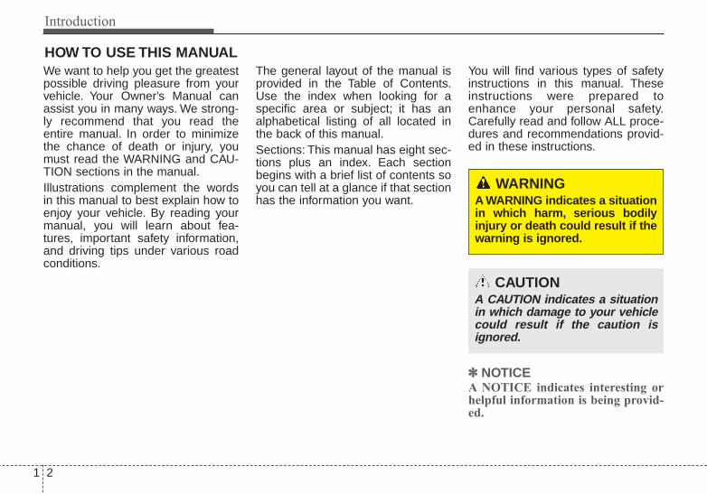
We want to help you get the greatestpossible driving pleasure from yourvehicle. Your Owner’s Manual canassist you in many ways. We strong-ly recommend that you read theentire manual. In order to minimizethe chance of death or injury, youmust read the WARNING and CAU-TION sections in the manual.Illustrations complement the wordsin this manual to best explain how toenjoy your vehicle. By reading yourmanual, you will learn about fea-tures, important safety information,and driving tips under various roadconditions.
The general layout of the manual isprovided in the Table of Contents.Use the index when looking for aspecific area or subject; it has analphabetical listing of all located inthe back of this manual.Sections: This manual has eight sec-tions plus an index. Each sectionbegins with a brief list of contents soyou can tell at a glance if that sectionhas the information you want.
You will find various types of safetyinstructions in this manual. Theseinstructions were prepared toenhance your personal safety.Carefully read and follow ALL proce-dures and recommendations provid-ed in these instructions.
✽✽ NOTICEA NOTICE indicates interesting orhelpful information is being provid-ed.
HOW TO USE THIS MANUAL
WARNING A WARNING indicates a situationin which harm, serious bodilyinjury or death could result if thewarning is ignored.
CAUTIONA CAUTION indicates a situationin which damage to your vehiclecould result if the caution isignored.

1 3
Introduction
Your new Kia vehicle is designed touse only unleaded fuel having apump octane number ((R+M)/2) of87 (Research Octane Number 91) orhigher.
Your new vehicle is designed toobtain maximum performance withUNLEADED FUEL, as well as mini-mize exhaust emissions and sparkplug fouling.
Never add any fuel system cleaningagents to the fuel tank other thanwhat has been specified. (Consult anauthorized Kia dealer for details.)
Gasoline containing alcohol andmethanolGasohol, a mixture of gasoline andethanol (also known as grain alco-hol), and gasoline or gasohol con-taining methanol (also known aswood alcohol) are being marketedalong with or instead of leaded orunleaded gasoline.Pursuant to EPA regulations, ethanolmay be used in your vehicle.Do not use gasohol containing morethan 10% ethanol, and do not usegasoline or gasohol containing anymethanol. Ethanol provides lessenergy than gasoline and it attractswater, and it is thus likely to reduceyour fuel efficiency and could loweryour MPG results.Methanol may cause drivability prob-lems and damage to the fuel system.Discontinue using gasohol of anykind if drivability problems occur.Vehicle damage or drivability prob-lems may not be covered by themanufacturer’s warranty if they resultfrom the use of:
1. Gasoline or gasohol containingmethanol.
2. Leaded fuel or leaded gasohol.
"E85" fuel is an alternative fuel com-prised of 85 percent ethanol and 15percent gasoline, and is manufac-tured exclusively for use in FlexibleFuel Vehicles. “E85” is not compati-ble with your vehicle. Use of “E85”may result in poor engine perform-ance and damage to your vehicle'sengine and fuel system. Kia recom-mends that customers do not usefuel with an ethanol content exceed-ing 10 percent.
✽✽ NOTICEYour New Vehicle LimitedWarranty does not cover damage tothe fuel system or any performanceproblems caused by the use of “E85”fuel.
FUEL REQUIREMENTS
WARNING - Refueling• Do not "top off" after the nozzle
automatically shuts off.Attempts to force more fuelinto the tank can cause fueloverflow onto you and theground causing a risk of fire.
• Always check that the fuel capis installed securely to preventfuel spillage in the event of anaccident.
Introduction
41
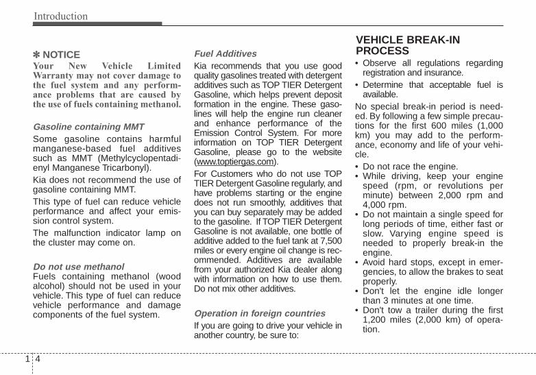
✽✽ NOTICEYour New Vehicle LimitedWarranty may not cover damage tothe fuel system and any perform-ance problems that are caused bythe use of fuels containing methanol.
Gasoline containing MMTSome gasoline contains harmfulmanganese-based fuel additivessuch as MMT (Methylcyclopentadi-enyl Manganese Tricarbonyl).Kia does not recommend the use ofgasoline containing MMT.This type of fuel can reduce vehicleperformance and affect your emis-sion control system.The malfunction indicator lamp onthe cluster may come on.
Do not use methanolFuels containing methanol (woodalcohol) should not be used in yourvehicle. This type of fuel can reducevehicle performance and damagecomponents of the fuel system.
Fuel AdditivesKia recommends that you use goodquality gasolines treated with detergentadditives such as TOP TIER DetergentGasoline, which helps prevent depositformation in the engine. These gaso-lines will help the engine run cleanerand enhance performance of theEmission Control System. For moreinformation on TOP TIER DetergentGasoline, please go to the website(www.toptiergas.com).For Customers who do not use TOPTIER Detergent Gasoline regularly, andhave problems starting or the enginedoes not run smoothly, additives thatyou can buy separately may be addedto the gasoline. If TOP TIER DetergentGasoline is not available, one bottle ofadditive added to the fuel tank at 7,500miles or every engine oil change is rec-ommended. Additives are availablefrom your authorized Kia dealer alongwith information on how to use them.Do not mix other additives.
Operation in foreign countriesIf you are going to drive your vehicle inanother country, be sure to:
• Observe all regulations regardingregistration and insurance.
• Determine that acceptable fuel isavailable.
No special break-in period is need-ed. By following a few simple precau-tions for the first 600 miles (1,000km) you may add to the perform-ance, economy and life of your vehi-cle.• Do not race the engine.• While driving, keep your engine
speed (rpm, or revolutions perminute) between 2,000 rpm and4,000 rpm.
• Do not maintain a single speed forlong periods of time, either fast orslow. Varying engine speed isneeded to properly break-in theengine.
• Avoid hard stops, except in emer-gencies, to allow the brakes to seatproperly.
• Don't let the engine idle longerthan 3 minutes at one time.
• Don't tow a trailer during the first1,200 miles (2,000 km) of opera-tion.
VEHICLE BREAK-INPROCESS
1 5
Introduction
This vehicle is equipped with anevent data recorder (EDR). Themain purpose of an EDR is torecord, in certain crash or nearcrash-like situations, such as anair bag deployment or hitting aroad obstacle, data that will assistin understanding how a vehicle'ssystems performed. The EDR isdesigned to record data related tovehicle dynamics and safety sys-tems for a short period of time,typically 30 seconds or less. TheEDR in this vehicle is designed torecord such data as:• How various systems in your
vehicle were operating;• Whether or not the driver and
passenger safety belts werebuckled/ fastened;
• How far (if at all) the driver wasdepressing the acceleratorand/or brake pedal; and,
• How fast the vehicle was travel-ing.
These data can help provide a bet-ter understanding of the circum-stances in which crashes andinjuries occur. NOTE: EDR dataare recorded by your vehicle onlyif a non-trivial crash situationoccurs; no data are recorded bythe EDR under normal drivingconditions and no personal data(e.g., name, gender, age, andcrash location) are recorded.However, other parties, such aslaw enforcement, could combinethe EDR data with the type of per-sonally identifying data routinelyacquired during a crash investiga-tion.
To read data recorded by an EDR,special equipment is required, andaccess to the vehicle or the EDR isneeded. In addition to the vehiclemanufacturer, other parties, suchas law enforcement, that have thespecial equipment, can read theinformation if they have access tothe vehicle or the EDR.
VEHICLE DATA COLLECTION AND EVENT DATA RECORDERS

Your vehicle at a glance
Exterior overview . . . . . . . . . . . . . . . . . . . . . . . . . . . 2-2Interior overview . . . . . . . . . . . . . . . . . . . . . . . . . . . 2-4Instrument panel overview . . . . . . . . . . . . . . . . . . . 2-5Engine compartment . . . . . . . . . . . . . . . . . . . . . . . . 2-6 2

Your vehicle at a glance
22
EXTERIOR OVERVIEW
1. Hood .....................................................4-29
2. Head lamp...................................4-98, 7-79
3. Fog lamp ...................................4-102, 7-84
4. Wheel and tire ....................................7-147
5. Outside rearview mirror ........................4-51
6. Front windshield wiper blades ...4-103, 7-41
7. Windows ...............................................4-24
OTF014003N
■ Front view
❈ The actual shape may differ from the illustration.

2 3
Your vehicle at a glance
8. Door locks.............................................4-17
9. Fuel filler lid ..........................................4-31
10. Rear combination lamp.......................7-85
11. High mounted stop lamp ....................7-88
12. Trunk ...................................................4-21
13. Antenna ............................................4-145
14. Back-up warning system ....................4-92
15. Rear camera display...........................4-95
OTF014004
■ Rear view
❈ The actual shape may differ from the illustration.

Your vehicle at a glance
42
INTERIOR OVERVIEW
1. Driver position memory system ........4-38
2. Door lock/unlock button ....................4-17
3. Outside rearview mirror control switch ................................................4-51
4. Power window lock button ................4-28
5. Power window switches ....................4-24
6. Central door lock switch....................4-18
7. Instrument panel illuminationcontrol knob ......................................4-55
8. ESC OFF button ...............................5-38
9. Steering wheel heater On/Off button ..4-42
10. BSD On/Off button..........................5-53
11. Steering wheel tilt lever...................4-41
12. Fuse box .........................................7-61
13. Hood release lever..........................4-29
14. Parking brake pedal ........................5-25
15. Brake pedal.....................................5-23
16. Accelerator pedal...................5-11, 5-12
17. Fuel filler lid release lever ...............4-31
18. Trunk lid release lever .....................4-21
OTF014001N❈ The actual shape may differ from the illustration.

2 5
Your vehicle at a glance
INSTRUMENT PANEL OVERVIEW
1. Instrument cluster .............................4-54
2. Light control / Turn signals.....4-98, 4-101
3. Wiper/Washer .................................4-103
4. Horn ..................................................4-41
5. Steering wheel audio control ..........4-146
6. Auto cruise control ............................5-45
7. Driver’s air bag..................................3-45
8. Steering wheel ..................................4-40
9. Ignition switch or ENGINE START/STOP button.....5-6, 5-8
10. Digital clock...................................4-142
11. Hazard ..............................................6-2
12. Audio.............................................4-145
13. Climate control system ......4-111, 4-120
14. Shift lever...............................5-14, 5-17
15. Aux, USB and iPod® port ..............4-147
16. Power outlet ..................................4-141
17. Seat warmer .....................................3-9
18. Passenger’s air bag ........................3-45
19. Glove box......................................4-137
20. Electric parking brake .....................5-27
21. Auto HOLD control button...............5-33
OTF014002N
❈ The actual shape may differ from the illustration.
Your vehicle at a glance
62
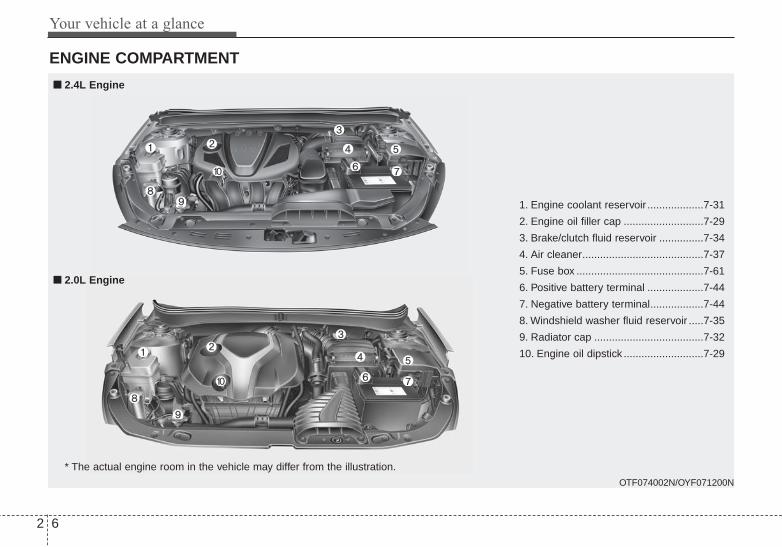
ENGINE COMPARTMENT
1. Engine coolant reservoir ...................7-31
2. Engine oil filler cap ...........................7-29
3. Brake/clutch fluid reservoir ...............7-34
4. Air cleaner.........................................7-37
5. Fuse box ...........................................7-61
6. Positive battery terminal ...................7-44
7. Negative battery terminal..................7-44
8. Windshield washer fluid reservoir .....7-35
9. Radiator cap .....................................7-32
10. Engine oil dipstick ...........................7-29
OTF074002N/OYF071200N
* The actual engine room in the vehicle may differ from the illustration.
■■ 2.4L Engine
■■ 2.0L Engine

Safety features of your vehicle
Seat. . . . . . . . . . . . . . . . . . . . . . . . . . . . . . . . . . . . . . . 3-2• Front seat adjustment - manual. . . . . . . . . . . . . . . . . . 3-4• Front seat adjustment - power. . . . . . . . . . . . . . . . . . . 3-6• Seat warmer (front). . . . . . . . . . . . . . . . . . . . . . . . . . . . 3-9• Air ventilation seat . . . . . . . . . . . . . . . . . . . . . . . . . . . 3-11• Rear seat adjustment . . . . . . . . . . . . . . . . . . . . . . . . . 3-13• Seat warmer (rear) . . . . . . . . . . . . . . . . . . . . . . . . . . . 3-14• Folding the rear seat . . . . . . . . . . . . . . . . . . . . . . . . . . 3-15
Seat belts . . . . . . . . . . . . . . . . . . . . . . . . . . . . . . . . . 3-17• Seat belt restraint system . . . . . . . . . . . . . . . . . . . . . . 3-17• Pre-tensioner seat belt . . . . . . . . . . . . . . . . . . . . . . . . 3-22• Seat belt precautions . . . . . . . . . . . . . . . . . . . . . . . . . . 3-24• Care of seat belts . . . . . . . . . . . . . . . . . . . . . . . . . . . . . 3-26
Child restraint system . . . . . . . . . . . . . . . . . . . . . . 3-27• Using a child restraint system . . . . . . . . . . . . . . . . . . 3-28• Tether anchorage system . . . . . . . . . . . . . . . . . . . . . . 3-31• Lower anchor system . . . . . . . . . . . . . . . . . . . . . . . . . 3-32
Air bag - advanced supplemental restraint system . . . . . . . . . . . . . . . . . . . . . . . . . . . . . . . . . . 3-34• How does the air bag system operate . . . . . . . . . . . . 3-35• Air bag warning light . . . . . . . . . . . . . . . . . . . . . . . . . 3-37• SRS components and functions . . . . . . . . . . . . . . . . . 3-38• Occupant detection system. . . . . . . . . . . . . . . . . . . . . 3-40• Driver's and passenger's front air bag . . . . . . . . . . . 3-45• Side air bag . . . . . . . . . . . . . . . . . . . . . . . . . . . . . . . . . 3-48
• Curtain air bag . . . . . . . . . . . . . . . . . . . . . . . . . . . . . . 3-49• Inflation and non-inflation conditions of the air bag . . 3-50• SRS Care . . . . . . . . . . . . . . . . . . . . . . . . . . . . . . . . . . . 3-55• Air bag warning label . . . . . . . . . . . . . . . . . . . . . . . . . 3-56
3

Safety features of your vehicle
23
Driver’s seat(1) Seat adjustment, forward / back-
ward(2) Seatback recliner(3) Seat adjustment, height(4) Lumbar support(5) Driver position memory system(6) Seat warmer switch(7) Headrest
Front passenger’s seat(8) Seat adjustment, forward / back-
ward(9) Seatback recliner(10) Seat warmer switch(11) Headrest
Rear seat(12) Seat warmer(13) Armrest(14) Headrest(15) Seat-back folding lever
SEAT
OTF034001L

3 3
Safety features of your vehicle
WARNING - Driver’s seat• Never attempt to adjust the
seat while the vehicle is mov-ing. This could result in lossof control of your vehicle.
• Do not allow anything to inter-fere with the normal positionof the seatback. Storing itemsagainst a seatback or in anyother way interfering withproper locking of a seatbackcould result in a serious orfatal injury in a sudden stopor collision.
• Sit as far back as possiblefrom the steering wheel whilestill maintaining comfortablecontrol of your vehicle. A dis-tance of at least 10" from yourchest to the steering wheel isrecommended. Failure to doso could result in airbag infla-tion injuries to the driver.
WARNING - Uprightingseat
Do not press the release leveron a manual seatback withoutholding and controlling theseatback. The seatback willspring upright possibly impact-ing you or other passengers.
WARNING - Looseobjects
Do not place anything in the dri-ver's foot well or under the frontseats. Loose objects in the dri-ver's foot area could interferewith the operation of the footpedals.
WARNING - Driverresponsibility for passen-gers
The driver must advise the pas-senger to keep the seatback inan upright position wheneverthe vehicle is in motion. If a seatis reclined during an accident,the restraint system's ability torestrain will be greatly reduced.
WARNING Do not use a cushion thatreduces friction between the seatand the passenger. The passen-ger's hips may slide under thelap portion of the seat belt duringan accident or a sudden stop.Serious or fatal internal injuriescould result because the seatbelt cannot operate normally.
Safety features of your vehicle
43
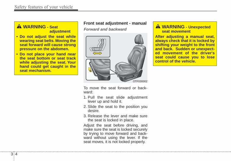
Front seat adjustment - manualForward and backward
To move the seat forward or back-ward:1. Pull the seat slide adjustment
lever up and hold it.2. Slide the seat to the position you
desire.3. Release the lever and make sure
the seat is locked in place.Adjust the seat before driving, andmake sure the seat is locked securelyby trying to move forward and back-ward without using the lever. If theseat moves, it is not locked properly.
WARNING - Seat adjustment
• Do not adjust the seat whilewearing seat belts. Moving theseat forward will cause strongpressure on the abdomen.
• Do not place your hand nearthe seat bottom or seat trackwhile adjusting the seat. Yourhand could get caught in theseat mechanism.
WARNING - Unexpectedseat movement
After adjusting a manual seat,always check that it is locked byshifting your weight to the frontand back. Sudden or unexpect-ed movement of the driver'sseat could cause you to losecontrol of the vehicle.
OTF030002

3 5
Safety features of your vehicle
Seatback angle
To recline the seatback:1. Lean forward slightly and lift up the
seatback recline lever.2. Carefully lean back on the seat
and adjust the seatback of theseat to the position you desire.
3. Release the lever and make surethe seatback is locked in place.(The lever MUST return to its orig-inal position for the seatback tolock.)
Seat Cushion height (for driver's seat)
To change the height of the seatcushion push the lever upwards ordownwards.• To lower the seat cushion, push the
lever down several times.• To raise the seat cushion, push the
lever up several times.
Lumbar support (for driver’s seat)
Press the front portion of the switch toincrease support, or the rear portionof the switch to decrease support.
OTF030003
OTF030004 OTF030005

Safety features of your vehicle
63
Front seat adjustment - power (if equipped)The front seat can be adjusted byusing the control switch located onthe outside of the seat cushion.Before driving, adjust the seat to theproper position so as to easily con-trol the steering wheel, pedals andswitches on the instrument panel.
Forward and backward
Push the control switch forward orbackward to move the seat to thedesired position. Release the switchonce the seat reaches the desiredposition.
WARNINGThe power seat is operable withthe ignition OFF.Therefore, children shouldnever be left unatteded in thevehicle.
CAUTION• The power seat is driven by an
electric motor. Stop operatingonce the adjustment is com-pleted. Excessive operationmay damage the electricalequipment.
• When in operation, the powerseat consumes a large amountof electrical power. To preventunnecessary charging systemdrain, don’t adjust the powerseat longer than necessarywhile the engine is not running.
• Do not operate two or morepower seat control switches atthe same time. Doing so mayresult in power seat motor orelectrical component malfunc-tion.
OTF030006

3 7
Safety features of your vehicle
Seatback angle
Push the control switch forward orbackward to move the seatback tothe desired angle. Release theswitch once the seat reaches thedesired position.
Seat cushion height (for driver's side)
Pull the front portion of the controlswitch up to raise or down to lowerthe front part of the seat cushion. Pullthe rear portion of the control switchup to raise or down to lower the rearpart of the seat cushion. Release theswitch once the seat reaches thedesired position.
Lumbar support (for driver’s seat, if equipped)
The lumbar support can be adjustedby pressing the lumbar supportswitch on the side of the driver'sseat. Press the front portion of theswitch to increase support, or therear portion of the switch to decreasesupport.
OTF030007
OTF030008 OTF030009

Safety features of your vehicle
83
Headrest
The driver's and front passenger'sseats are equipped with a headrestfor the occupant's safety and com-fort.The headrest not only provides com-fort for the driver and front passen-ger, but also helps protect the headand neck in the event of a collision.For maximum effectiveness in caseof an accident, the headrest shouldbe adjusted so the middle of theheadrest is at the same height of thecenter of gravity of an occupant'shead. Generally, the center of gravityof most people's head is similar withthe height of the top of their eyes.
Also, adjust the headrest as close toyour head as possible.For this reason, the use of a cushionthat holds the body away from theseatback is not recommended.
Forward and backward adjustment
The headrest may be adjusted for-ward to 4 different positions bypulling the headrest forward to thedesired detent. To adjust the head-rest to it’s full rearward position, pullit fully forward to the farthest positionand release it. Adjust the headrest sothat it properly supports the headand neck.
OMG038400
WARNING - Headrestremoval/adjustment
• Do not operate the vehiclewith the headrests removed.Headrests can provide criticalneck and head support in acrash.
• Do not adjust the headrestheight while the vehicle is inmotion. Driver may lose con-trol of the vehicle.
OTF030012

3 9
Safety features of your vehicle
Adjusting the height up and down
To raise the headrest, pull it up to thedesired position (1). To lower theheadrest, push and hold the releasebutton (2) on the headrest supportand lower the headrest to the desiredposition (3).
Removal and installation
To remove the headrest, raise it asfar as it can go then press therelease button (1) while pulling theheadrest up (2).To reinstall the headrest, put theheadrest poles (3) into the holeswhile pressing the release button (1).Then adjust it to the appropriateheight.
Seat warmer (if equipped)
The seat warmers are provided towarm the front seats during coldweather. With the ignition switch inthe ON position, push either of theswitches to warm the driver's seat orthe front passenger's seat.
OTF030010 OTF030011 OTF034014
OTF034045

Safety features of your vehicle
103
During mild weather or under condi-tions where the operation of the seatwarmer is not needed, keep theswitches in the OFF position.With the seat warmer switch in theON position, the heating system inthe seat turns off or on automaticallydepending on the seat temperature.• Each time you push the button, the
temperature setting of the seat ischanged as follows :
• When pressing the switch for morethan 1.5 seconds with the seatwarmer operating, the seat warmerwill turn OFF.
• The seat warmer defaults to theOFF position whenever the enginestart/stop button (the ignitionswitch) is turned on.
CAUTION - Seat damage• When cleaning the seats, do
not use an organic solventsuch as paint thinner, ben-zene, alcohol and gasoline.Doing so may damage the sur-face of the heater or seats.
• To prevent overheating theseat warmer, do not place any-thing on the seats that insu-lates against heat, such asblankets, cushions or seatcovers while the seat warmeris in operation.
• Do not place heavy or sharpobjects on seats equippedwith seat warmers. Damage tothe seat warming componentscould occur.
WARNING - Seat warmerburns
Passengers should use extremecaution when using seat warm-ers due to the possibility ofexcess heating or burns. Theseat warmer may cause burnseven at low temperatures, espe-cially if used for long periods oftime. The occupants must beable to feel if the seat is becom-ing too warm and to turn theseat warmer off.In particular, the driver mustexercise extreme care for thefollowing types of passengers:1. Infants, children, elderly or
disabled persons, or hospitaloutpatients
2. Persons with sensitive skinor those that burn easily
3. Fatigued individuals4. Intoxicated individuals5. Individuals taking medication
that can cause drowsiness orsleepiness (sleeping pills,cold tablets, etc.)
OFF → HIGH ( ) → LOW ( )
→

3 11
Safety features of your vehicle
Air ventilation seat (if equipped)
The air ventilation is provided to coolthe driver’s seat during hot weather byblowing air through small vent holeson the surface of the seat and seat-back. While the engine is running,press the switch to cool the seat.
When the operation of the air ventila-tion is not needed, keep the switchesin the OFF position.• Each time you press the switch,
the airflow will change as follows:
• When pressing the switch for morethan 1.5 seconds with the seatcooler operating, the seat coolerwill turn OFF.
• When the air ventilation seat isturned on, the seat may get coolerafter about 5 minutes.
• Because the air ventilation usesthe air in the vehicle, cooling effi-ciency depends on the tempera-ture of the air. In order to improvecooling efficiency, use the air con-ditioning system together.
• The air ventilation seat defaults tothe OFF position whenever theignition switch is turned to the ONposition.
CAUTION• The air ventilation seat is a
supplementary cooling/heat-ing system. Use the air venti-lation seat when the climatecontrol system is on. Usingthe air ventilation seat for pro-longed periods of time withthe climate control system offcould cause the air ventilationseat performance to impair.
• When cleaning the seats, donot use an organic solventsuch as paint thinner, ben-zene, alcohol and gasoline.Doing so may damage the sur-face of the seats.
• Do not spill liquid such aswater or beverages on the sur-face of the front seats andseatbacks, or the air ventholes may be blocked and pre-vented from working properly.
(Continued)
OFF → HIGH ( ) → LOW ( )
→
OTF034015
OTF034046

Safety features of your vehicle
123
Seatback pocket
The seatback pocket is provided onthe back of the front passenger’sseatback.
OTF030016
WARNING - Seatbackpocket
Do not put heavy or sharpobjects in the seatback pocket.An occupant could contact suchobjects in a crash. Heavyobjects in the front passengerseatback could also interferewith the air bag sensing system.
(Continued)• Do not place materials such
as plastic bags or newspapersunder the seats. The air ventmay not work properly as theair intake can be blocked.
• When the air vent does notoperate, restart the vehicle. Ifthere is no change, have yourvehicle inspected by anauthorized Kia dealer.

3 13
Safety features of your vehicle
Rear seat adjustmentHeadrest
The rear seat is equipped with head-rests in all the seating positions forthe occupant's safety and comfort.The headrest not only provides com-fort for passengers, but also helpsprotect the head and neck in theevent of a collision.
For maximum effectiveness in caseof an accident, the headrest shouldbe adjusted so the middle of theheadrest is at the same height of thecenter of gravity of an occupant'shead. Generally, the center of gravityof most people's head is similar withthe height as the top of their eyes.Also adjust the headrest as close toyour head as possible. For this rea-son, the use of a cushion that holdsthe body away from the seatback isnot recommended. Adjusting the height up and down
(if equipped)
To raise the headrest, pull it up to thedesired position (1). To lower theheadrest, push and hold the releasebutton (2) on the headrest supportand lower the headrest to the desiredposition (3).
OMG038401
OTF030017

Safety features of your vehicle
143
Removal and installation
To remove the headrest, raise it asfar as it can go then press therelease button (1) while pulling theheadrest upward (2).To reinstall the headrest, put theheadrest poles (3) into the holeswhile pressing the release button (1).Then adjust it to the appropriateheight and ensure that it locks inposition.Make sure the headrest locks inposition after adjusting.
Seat warmer (if equipped)
The seat warmer is provided to warmthe rear seats during cold weather.With the ignition switch in the ONposition, push either of the switches towarm the seat.During mild weather or under condi-tions where the operation of the seatwarmer is not needed, keep theswitches in the OFF position.
• Each time you press the button,the temperature setting of the seatwill change as follows :
• The seat warmer defaults to theOFF position whenever the ignitionswitch is turned on.
✽✽ NOTICEWith the seat warmer switch in theON position, the heating system inthe seat turns off or on automaticallydepending on the seat temperature.
OTF030018
OTF034025
OFF → HIGH( ) → LOW( )
→
3 15
Safety features of your vehicle
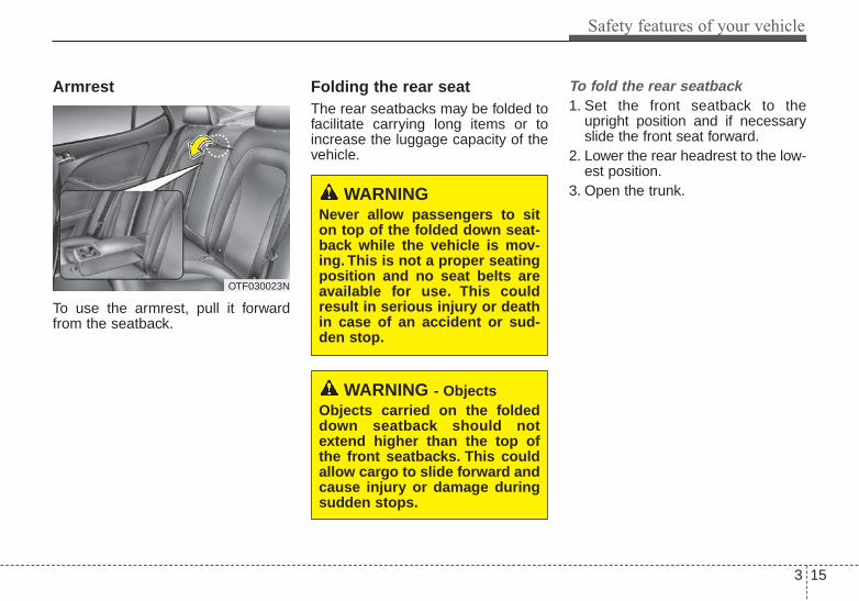
Armrest
To use the armrest, pull it forwardfrom the seatback.
Folding the rear seatThe rear seatbacks may be folded tofacilitate carrying long items or toincrease the luggage capacity of thevehicle.
To fold the rear seatback1. Set the front seatback to the
upright position and if necessaryslide the front seat forward.
2. Lower the rear headrest to the low-est position.
3. Open the trunk.WARNING Never allow passengers to siton top of the folded down seat-back while the vehicle is mov-ing. This is not a proper seatingposition and no seat belts areavailable for use. This couldresult in serious injury or deathin case of an accident or sud-den stop.
WARNING - ObjectsObjects carried on the foldeddown seatback should notextend higher than the top ofthe front seatbacks. This couldallow cargo to slide forward andcause injury or damage duringsudden stops.
OTF030023N

Safety features of your vehicle
163
4. Pull the lock release lever (1) andfold the rear seatback forward anddown firmly.If the seat belt locks after unfoldingthe rear seatback, pull out thelocked seat belt, release it thenpull it out again.
To unfold the rear seat1. To use the rear seat, lift and pull
the seatback rearward. Pull theseatback firmly until it clicks intoplace. Make sure the seatback islocked in place. When you returnthe seatback to its upright posi-tion, always be sure it has lockedinto position by pushing on the topof the seatback.If you can not see the red line atthe bottom of folding lever, itmeans the seatback is lockedcompletely.
2. Return the rear seat belt to theproper position.
3. When the seatback is completelyinstalled, check the seatback fold-ing lever again.
When returning the rear seatbacks tothe upright position, remember toreturn the rear shoulder belts to theirproper position.
WARNING - CargoDo not place heavy objects inthe rear seats, since they can-not be properly secured andmay hit vehicle occupants in afrontal collision.
WARNING - Rear seat-backWhen returning the rear seat-back from a folded to an uprightposition, hold the seatback andreturn it slowly. Ensure that theseatback is completely lockedinto its upright position bypushing on the top of the seat-back. In an accident or suddenstop, the unlocked seatbackcould allow cargo to move for-ward with great force and enterthe passenger compartment.
OTF034020

3 17
Safety features of your vehicle
Seat belt restraint systemSeat belts are designed to bear uponthe bony structure of the body, andshould be worn low across thepelvis, chest and shoulders as appli-cable. Wearing the lap section of thebelt across the abdominal area mustbe avoided.Seat belts should be adjusted asfirmly as possible, consistent withcomfort, to provide the protection forwhich they have been designed.A slack belt will greatly reduce theprotection afforded to the wearer.Care should be taken to avoid con-tamination of the webbing with pol-ishes, oils and chemicals, and partic-ularly battery acid. Cleaning maysafely be carried out using mild soapand water. The belt should bereplaced if webbing becomes frayed,contaminated or damaged.• For maximum restraint system pro-
tection, the seat belts must alwaysbe used whenever the vehicle ismoving. A properly positionedshoulder belt should be positionedmidway over your shoulder acrossyour collarbone.
• Never allow children to ride in thefront passenger seat. See childrestraint system section for furtherdiscussion.
SEAT BELTS
WARNING - Shoulder beltNever wear the shoulder beltunder your arm or behind yourback. An improperly positionedshoulder belt cannot protect theoccupant in a crash.
WARNING - Damagedseat belt
Replace the entire seat beltassembly if any part of the web-bing or hardware is damaged asyou can no longer be sure that adamaged seat belt will provideprotection in a crash.
WARNING - Twisted seatbelt
Make sure your seat belt is nottwisted when worn. A twistedseat belt may not properly pro-tect you in an accident andcould even cut into your body.
WARNING - Seat belt buckle
Do not allow foreign material(gum, crumbs, coins, etc.) toobstruct the seat belt buckle.This may prevent the seat beltfrom fastening securely.

Safety features of your vehicle
183
Seat belt warning (for driver’s seat)
The driver's seat belt warning lightand chime will activate to the follow-ing table when the ignition switch isin "ON" position. *1 Warning pattern repeats 11 times with
an interval of 24 seconds. If the driver'sseat belt is buckled, the light will stopwithin 6 seconds and chime will stopimmediately.
*2 The light will stop within 6 seconds andchime will stop immediately.
Seat belt warning (for front passenger’s seat)
The front passenger's seat beltwarning light will activate to the fol-lowing table when the ignition switchis in "ON" position.
1GQA2083
Conditions Warning Pattern
Seat BeltVehicle
SpeedLight-Blink
Chime-
Sound
Unbuckled 6 seconds
Buckled 6 seconds None
Buckled →Unbuckled
Below 3 mph
(5 km/h)6 seconds None
3 mph~
6 mph6 seconds
Above 6 mph
(10 km/h)
6 sec. on / 24 sec. off
(11 times)
Unbuckled
Above 6 mph
(10 km/h)
↓
Below 3 mph
(5 km/h)
6 seconds *1
↓
Stop *2
OTF034085N

3 19
Safety features of your vehicle
*1 The seat belt warning light will go off ifthe vehicle speed decreases below 3mph (5 km/h). If the vehicle speedincreases above 3 mph (5 km/h), thewarning light will blink again.
• You can find the front passenger'sseat belt warning light on the cen-ter fascia panel.
• Although the front passenger seatis not occupied, the seat belt warn-ing light will blink for 6 seconds.
• The seat belt warning light canblink when a briefcase or purse isplaced on the front passengerseat.
Seat belt - Driver's 3-point systemwith emergency locking retractor
To fasten your seat belt:
To fasten your seat belt, pull it out ofthe retractor and insert the metal tab(1) into the buckle (2). There will bean audible "click" when the tab locksinto the buckle.The seat belt automatically adjusts tothe proper length only after the lapbelt portion is adjusted manually sothat it fits snugly around your hips. Ifyou lean forward in a slow, easymotion, the belt will extend and letyou move around. If there is a sud-den stop or impact, however, the beltwill lock into position.
Conditions Warning Pattern
Seat BeltVehicle
SpeedLight-Blink
Unbuckled 6 seconds
UnbuckledAbove 6mph
(10 km/h)Continuously
Buckled 6 seconds
Buckled →Unbuckled
Above 6mph
(10 km/h)Continuously *1
Below 6mph
(10 km/h)None
B180A01NF-1
WARNINGRiding in an improper positionadversely affects the front pas-senger's seat belt warning sys-tem. It is important for the driverto instruct the passenger as tothe proper seating instructionsas contained in this manual.

Safety features of your vehicle
203
It will also lock if you try to lean for-ward too quickly.If you are unable to pull out the seatbelt from the retractor, firmly pull thebelt out and release it. Then you willbe able to pull the belt out smoothly.
Height adjustment
You can adjust the height of theshoulder belt anchor to one of the 4positions for maximum comfort andsafety.The height of the adjusting seat beltshould not be too close to your neck.The shoulder portion should beadjusted so that it lies across yourchest and midway over your shouldernearest the door and not your neck.To adjust the height of the seat beltanchor, lower or raise the heightadjuster into an appropriate position.
To raise the height adjuster, pull it up(1). To lower it, push it down (3) whilepressing the height adjuster button (2).Release the button to lock the anchorinto position. Try sliding the heightadjuster to make sure that it haslocked into position.
WARNING - Shoulder beltpositioning
Never position the shoulder beltacross your neck or face.
WARNING - Seat beltreplacement
Replace your seat belts afterbeing in an accident. Failure toreplace seat belts after an acci-dent could leave you with dam-aged seat belts that will not pro-vide protection in the event ofanother collision.
OMG035038

3 21
Safety features of your vehicle
You should place the lap belt portionas low as possible and snugly acrossyour hips. If the lap belt is located toohigh on your waist, it may increasethe chance of injury in the event of acollision.The arm closest to the seat beltbuckle should be over the belt whilethe other arm should be under thebelt as shown in the illustration.
Seat belts - Front passenger andrear seat 3-point system withcombination locking retractorTo fasten your seat belt
Combination retractor type seat beltsare installed in the rear seat posi-tions to help accommodate theinstallation of child restraint systems.Although a combination retractor isalso installed in the front passengerseat position, it is strongly recom-mended that children always beseated in the rear seat. NEVERplace an infant restraint system inthe front seat of the vehicle.This type of seat belt combines thefeatures of both an emergency lock-ing retractor seat belt and an auto-matic locking retractor seat belt. Tofasten your seat belt, pull it out of theretractor and insert the metal tab intothe buckle. There will be an audible"click" when the tab locks into thebuckle. When not securing a childrestraint, the seat belt operates in thesame way as the driver's seat belt(Emergency Locking Retractor Type).
It automatically adjusts to the properlength only after the lap belt portionof the seat belt is adjusted manuallyso that it fits snugly around your hips.When the seat belt is fully extendedfrom the retractor to allow the instal-lation of a child restraint system, theseat belt operation changes to allowthe belt to retract, but not to extend(Automatic Locking Retractor Type).Refer to “Using a child restraint sys-tem” in this section.To convert from the automatic lock-ing feature to the emergency lockingoperation mode, allow the unbuckledseat belt to fully retract.
B200A01NF
Safety features of your vehicle
223
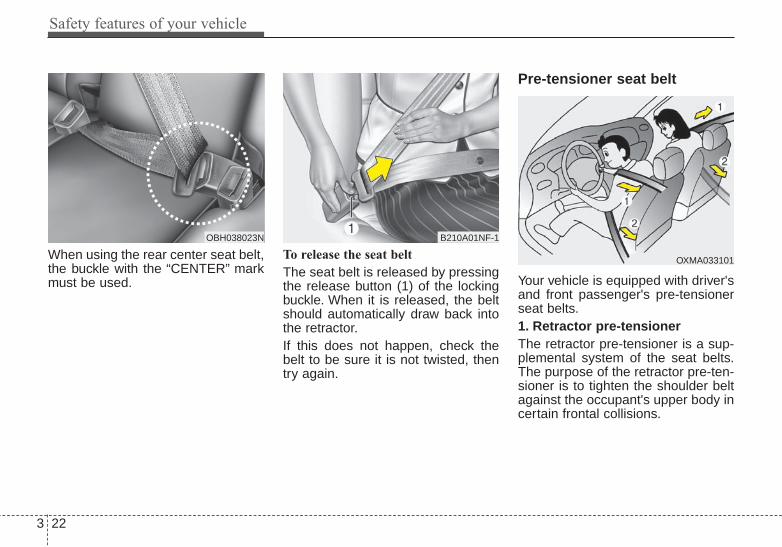
When using the rear center seat belt,the buckle with the “CENTER” markmust be used.
To release the seat belt
The seat belt is released by pressingthe release button (1) of the lockingbuckle. When it is released, the beltshould automatically draw back intothe retractor.If this does not happen, check thebelt to be sure it is not twisted, thentry again.
Pre-tensioner seat belt
Your vehicle is equipped with driver'sand front passenger's pre-tensionerseat belts.1. Retractor pre-tensionerThe retractor pre-tensioner is a sup-plemental system of the seat belts.The purpose of the retractor pre-ten-sioner is to tighten the shoulder beltagainst the occupant's upper body incertain frontal collisions.
B210A01NF-1OBH038023N
OXMA033101

3 23
Safety features of your vehicle
2. Emergency Fastening Device(EFD)
The Emergency Fastening Device(EFD) is a supplemental system ofthe seat belts. The purpose of theEFD is to tighten the lap belt againstthe occupant's pelvis in certainfrontal collisions.
The pretensioner seat belts may beactivated together with the air bagsupon a severe enough collision.When the vehicle stops suddenly, orif the occupant tries to lean forwardtoo quickly, the seat belt retractormay lock into position. In certainfrontal collisions (or side collisions),the pre-tensioner may activate andpull the seat belt into tighter contactagainst the occupant's body.If the system senses excessive ten-sion on the driver or passenger'sseat belt when the pre-tensioner acti-vates, the load limiter inside theretractor pre-tensioner will releasesome of the pressure on the affectedseat belt.
The seat belt pre-tensioner systemconsists mainly of the following com-ponents.Their locations are shown inthe illustration:1. SRS air bag warning light2. Retractor pre-tensioner assembly3. SRS control module4. Emergency fastening device (EFD)
Both the driver's and front passen-ger's pre-tensioner seat belts may beactivated in certain frontal collisions.The pre-tensioners will not be acti-vated if the seat belts are not beingworn at the time of the collision.
✽✽ NOTICEWhen the pre-tensioner seat beltsare activated, a loud noise may beheard and fine dust, which mayappear to be smoke, may be visiblein the passenger compartment.These are normal operating condi-tions and are not hazardous.
WARNING - Skin irritationWash all exposed skin areasthoroughly after an accident inwhich the pre-tensioner seatbelts were activated. The finedust from the pre-tensioneractivation may cause skin irrita-tion and should not be breathedfor prolonged periods.
ODMESA2024/Q

Safety features of your vehicle
243
Because the sensor that activatesthe SRS air bag is connected withthe pre-tensioner seat belt, the SRSair bag warning light ( ) on theinstrument panel will illuminate forapproximately 6 seconds after theignition switch has been turned to theON position, and then it should turnoff.If the pre-tensioner seat belt doesnot work properly, this warning lightwill illuminate even if the SRS air baghas not malfunctioned. If the SRS airbag warning light does not illuminatewhen the ignition switch is turnedON, or if it remains illuminated afterilluminating for approximately 6 sec-onds, or if it illuminates while thevehicle is being driven, please havean authorized Kia dealer inspect thepre-tensioner seat belt or SRS airbag system as soon as possible.
✽✽ NOTICEDo not attempt to service or repairthe pre-tensioner seat belt system inany manner. Do not attempt toinspect or replace the pre-tensionerseat belts yourself. This must bedone by an authorized Kia dealer.
Pre-tensioners are designed to oper-ate only one time. After activation,pre-tensioner seat belts must bereplaced. If the pre-tensioner mustbe replaced, contact an authorizedKia dealer.
Seat belt precautionsInfant or small childAll 50 states have child restraintlaws. You should be aware of thespecific requirements in your state.Child and/or infant seats must beproperly placed and installed in therear seat. For more informationabout the use of these restraints,refer to “Child restraint system” in thissection.
WARNING - Hot pre- tensioner
Do not touch the pre-tensionerseat belt assemblies for severalminutes after they have beenactivated. When the pre-ten-sioner seat belt mechanismfires during a collision the pre-tensioner becomes hot and canburn you.

3 25
Safety features of your vehicle
Larger childrenChildren who are too large for childrestraint systems should always occu-py the rear seat and use the availablelap/shoulder belts. The lap portionshould be fastened snug on the hipsand as low as possible. Periodicallycheck belt fit. A child's squirming couldput the belt out of position. Childrenare given the most safety in the eventof an accident when they arerestrained by a proper restraint systemin the rear seat. If a larger child (overage 12) must be seated in the frontseat, the child should be securelyrestrained by the available lap/shoul-der belt and the seat should be placedin the rearmost position. Children age12 and under should be restrainedsecurely in the rear seat. NEVERplace a child age 12 and under in thefront seat. NEVER place a rear facingchild seat in the front seat of a vehicle.If the shoulder belt portion slightlytouches the child’s neck or face, tryplacing the child closer to the center ofthe vehicle. If the shoulder belt stilltouches their face or neck they need tobe returned to a child restraint system.
Restraint of pregnant women Pregnant women should wearlap/shoulder belt assemblies when-ever possible according to specificrecommendations by their doctors.The lap portion of the belt should beworn AS SNUGLY AND LOW ASPOSSIBLE on the hips, not acrossthe abdomen.
WARNING - Small chil-dren
Do not allow small children toride in the vehicle without anappropriate child restraint sys-tem.
WARNING - Pregnantwomen
Pregnant women must neverplace the lap portion of the seatbelt above or on the abdomenwhere the fetus is located. Theforce of the seat belt during acollision will crush the fetus.

Safety features of your vehicle
263
Injured personA seat belt should be used when aninjured person is being transported.When this is necessary, you shouldconsult a physician for recommenda-tions.
One person per beltTwo people (including children)should never attempt to use a singleseat belt. This could increase theseverity of injuries in case of an acci-dent.
Do not lie downTo reduce the chance of injuries in theevent of an accident and to achievemaximum effectiveness of therestraint system, all passengersshould be sitting up and the frontseats should be in an upright positionwhen the vehicle is moving. A seatbelt cannot provide proper protectionif the person is lying down in the rearseat or if the front seat is in a reclinedposition.
Care of seat beltsSeat belt systems should never bedisassembled or modified. In addi-tion, care should be taken to assurethat seat belts and belt hardware arenot damaged by seat hinges, doorsor other abuse.
Periodic inspectionAll seat belts should be inspectedperiodically for wear or damage ofany kind. Any damaged parts shouldbe replaced as soon as possible.
Keep belts clean and drySeat belts should be kept clean anddry. If belts become dirty, they can becleaned by using a mild soap solu-tion and warm water. Bleach, dye,strong detergents or abrasivesshould not be used because theymay damage and weaken the fabric.
When to replace seat beltsThe entire in-use seat belt assemblyor assemblies should be replaced ifthe vehicle has been involved in anaccident. This should be done even ifno damage is visible. Additionalquestions concerning seat belt oper-ation should be directed to anauthorized Kia dealer.

3 27
Safety features of your vehicle
CHILD RESTRAINT SYSTEMChildren riding in the car should sit inthe rear seat and must always beproperly restrained to minimize therisk of injury in an accident, suddenstop or sudden maneuver. Accordingto accident statistics, children aresafer when properly restrained in therear seats than in the front seat.Larger children who are not in a childrestraint should use one of the seatbelts provided.You should be aware of the specificrequirements in your state. Childand/or infant safety seats must beproperly placed and installed in therear seat. You must use a commer-cially available child restraint systemthat meets the requirements of theFederal Motor Vehicle SafetyStandards (FMVSS).Child restraint systems are designedto be secured in vehicle seats by seatbelt, or by a tether anchor and/orLATCH anchors (if equipped).
Children could be injured or killed ina crash if their restraints are notproperly secured. For small childrenand babies, a child seat or infant seatmust be used. Before buying a par-ticular child restraint system, makesure it fits your car seat and seatbelts, and fits your child. Follow allthe instructions provided by the man-ufacturer when installing the childrestraint system.
When the child restraint system isnot in use, store it in the luggagearea or fasten it with a seat belt sothat it will not be thrown forward incase of a sudden stop or an acci-dent.
WARNING- Restraint location
Never install a child or infantseat on the front passenger'sseat.A child riding in the front pas-senger seat can be forcefullystruck by an inflating airbag.
WARNING- Hot childrestraint
A child restraint system canbecome very hot if it is left in aclosed vehicle on a sunny day.Be sure to check the seat cover,buckles and latches beforeplacing a child in the restraintsystem.

Safety features of your vehicle
283
Using a child restraint system
For small children and babies, theuse of a child seat or infant seat isrequired. This child seat or infantseat should be of appropriate size forthe child and should be installed inaccordance with the manufacturer'sinstructions.
For safety reasons, we recommendthat the child restraint system beused in the rear seats.Since all passenger seat belts movefreely under normal conditions andonly lock under extreme or emer-gency conditions (emergency lockmode), you must manually changethese seat belts to the auto lockmode to secure a child restraint.If the seat belt does not operate asdescribed in this section, have thesystem checked immediately by yourauthorized Kia dealer.
WARNING - Holding children
Never hold a child in your armsor lap when riding in a vehicle.The violent forces created dur-ing a crash will tear the childfrom your arms and throw thechild against the car’s interior.Always use a child restraintsystem which is appropriate foryour child's height and weight.
WARNING - Seat belt useDo not use one seat belt for twooccupants at the same time.This will eliminate any safetybenefit provided by the seat beltto the occupants.
CRS09
OTQ037038
Rear- facing child restraint system
Forward-facing child restraint system

3 29
Safety features of your vehicle
Placing a passenger seat beltinto the auto lock mode
The auto lock mode will help preventthe normal movement of the child inthe vehicle from causing the seat beltto loosen and compromise the childrestraint system. To secure a childrestraint system, use the followingprocedure.
To install a child restraint system onthe outboard or center rear seats, dothe following:1. Place the child restraint system in
the seat and route the lap/shoul-der belt around or through therestraint, following the restraintmanufacturer’s instructions. Besure the seat belt webbing is nottwisted.
2. Fasten the lap/shoulder belt latchinto the buckle. Listen for the dis-tinct “click” sound.
Position the release button so that itis easy to access in case of an emer-gency.
WARNING - Child seatinstallation
• Always follow the instructionsprovided by the child restraintsystem manufacturer. Childrestraint system manufactur-ers know their products best.
• Failure to observe this manu-al's instructions regardingchild restraint system and theinstructions provided with thechild restraint system couldresult in the improper installa-tion of the child restraint sys-tem which may reduce theprotection to your child in acrash or a sudden stop.
E2MS103005
OEN036101

Safety features of your vehicle
303
3. Pull the shoulder portion of theseat belt all the way out. When theshoulder portion of the seat belt isfully extended, it will shift theretractor to the “Auto Lock” (childrestraint) mode.
4. Slowly allow the shoulder portionof the seat belt to retract and listenfor an audible “clicking” or “ratchet-ing” sound. This indicates that theretractor is in the “Auto Lock”mode. If no distinct sound isheard, repeat steps 3 and 4.
5. Remove as much slack from thebelt as possible by pushing downon the child restraint system whilefeeding the shoulder belt back intothe retractor.
6. Push and pull on the child restraintsystem to confirm that the seatbelt is holding it firmly in place. If itis not, release the seat belt andrepeat steps 2 through 6.
7. Double check that the retractor isin the “Auto Lock” mode byattempting to pull more of the seatbelt out of the retractor. If you can-not, the retractor is in the “AutoLock” mode.
OEN036102 OEN036103 OEN036104

3 31
Safety features of your vehicle
The lap/shoulder belt automaticallyreturns to the “emergency lockmode” whenever the belt is allowedto retract fully.Therefore, the preceding sevensteps must be followed each time achild restraint is installed.To remove the child restraint, pressthe release button on the buckle andthen pull the lap/shoulder belt out ofthe restraint and allow the seat beltto retract fully.
Securing a child restraint seatwith tether anchorage system
Child restraint hook holders arelocated on the package tray.
This symbol indicates theposition of the tether anchor.
1.Route the child restraint seat teth-er strap over the seatback.For vehicles with adjustable head-rests, route the tether strap underthe headrest and between theheadrest posts, otherwise routethe tether strap over the top of theseatback.
2. Connect the tether strap hook tothe appropriate child restrainthook holder and tighten to securethe child restraint seat.
WARNING - Auto lockmode
Set the retractor to AutomaticLock mode when installing anychild restraint system.If the retractor is not in the AutoLock mode, the child restraintcan move when your vehicleturns or stops suddenly.
OTF030029N
OTF030030N

Safety features of your vehicle
323
Check that the child restraint systemis secure by pushing and pulling it indifferent directions. Incorrectly fittedchild restraints may swing, twist, tipor separate causing death or seriousinjury.
Securing a child restraint seat withchild seat lower anchor system
Some child seat manufacturersmake child restraint seats that arelabeled as LATCH or LATCH-com-patible child restraint seats. LATCHstands for "Lower Anchors andTethers for Children". These seatsinclude two rigid or webbing mount-ed attachments that connect to twoLATCH anchors at specific seatingpositions in your vehicle. This type ofchild restraint seat eliminates theneed to use seat belts to attach thechild seat in the rear seats.
Child restraint symbols are locatedon the left and right rear seat backsto indicate the position of the loweranchors for child restraints.
WARNING - Tether strapNever mount more than onechild restraint to a single tetheror to a single lower anchoragepoint. The increased loadcaused by multiple seats maycause the tethers or anchoragepoints to break.
B230D01NF
OTF030031N
Lower AnchorPosition Indicator
Lower Anchor
WARNING - Unused rearseatbelts
Always fasten the seatbeltsbehind the child restraint seatwhen they are not used tosecure the child seat. Failure todo so may result in child stran-gulation.

3 33
Safety features of your vehicle
LATCH anchors have been providedin your vehicle. The LATCH anchorsare located in the left and right out-board rear seating positions. Theirlocations are shown in the illustration.There is no LATCH anchor providedfor the center rear seating position.The LATCH anchors are locatedbetween the seatback and the seatcushion of the rear seat left and rightoutboard seating positions.When you install your child's restraintsystem using the LATCH anchorsbuckle the shoulder lap belt, then lockthe retractor and pull the belt toremove the slack in the belt so it liesflat against the vehicle seat.
Follow the child seat manufacturer’sinstructions to properly install childrestraint seats with LATCH orLATCH-compatible attachments.Once you have installed the LATCHchild restraint, assure that the seat isproperly attached to the LATCH andtether anchors.Also, test the child restraint seatbefore you place the child in it. Tiltthe seat from side to side. Also try totug the seat forward. Check to see ifthe anchors hold the seat in place.
OTD039037N
WARNING - LATCH loweranchors
Never attempt to attach aLATCH equipped seat in thecenter seating position. LATCHlower anchors are only to beused with the left and right rearoutboard seating positions. Youmay damage the anchors or theanchors may fail and break in acollision.

Safety features of your vehicle
343
(1) Driver’s front air bag(2) Passenger’s front air bag(3) Side air bag(4) Curtain air bag
Even in vehicles with air bags, youand your passengers must alwayswear the safety belts provided inorder to minimize the risk and sever-ity of injury in the event of a collisionor rollover.
AIR BAG - ADVANCED SUPPLEMENTAL RESTRAINT SYSTEM
OYF039050
❈ The actual air bags in the vehicle may differ from the illustration.

3 35
Safety features of your vehicle
How does the air bag systemoperate • Air bags are activated (able to
inflate if necessary) only when theignition switch is turned to the ONor START the appropriate position.
• Air bags inflate instantly in theevent of serious frontal or side col-lision (if equipped with side air bagor curtain air bag) in order to helpprotect the occupants from seriousphysical injury.
• There is no single speed at whichthe air bags will inflate.Generally, air bags are designed toinflate based upon the severity of acollision and its direction. Thesetwo factors determine whether thesensors produce an electronicdeployment/ inflation signal.
• Air bag deployment depends on anumber of complex factors includ-ing vehicle speed, angles of impactand the density and stiffness of thevehicles or objects which yourvehicle hits in the collision.Though,factors are not limited to thosementioned above.
• The front air bags will completelyinflate and deflate in an instant.It is virtually impossible for you tosee the air bags inflate during anaccident. It is much more likely thatyou will simply see the deflated airbags hanging out of their storagecompartments after the collision.
• In order to help provide protectionin a severe collision, the air bagsmust inflate rapidly. The speed ofair bag inflation is a consequenceof extremely short time in which acollision occurs and the need to getthe air bag between the occupantand the vehicle structures beforethe occupant impacts those struc-tures. This speed of inflationreduces the risk of serious or life-threatening injuries in a severe col-lision and is thus a necessary partof air bag design.However, air bag inflation can alsocause injuries which can includefacial abrasions, bruises and bro-ken bones because the inflationspeed also causes the air bags toexpand with a great deal of force.
• There are even circumstancesunder which contact with thesteering wheel air bag can causefatal injuries, especially if theoccupant is positioned exces-sively close to the steeringwheel.

Safety features of your vehicle
363
Noise and smokeWhen the air bags inflate, they makea loud noise and they leave smokeand powder in the air inside of thevehicle. This is normal and is a resultof the ignition of the air bag inflator.After the air bag inflates, you mayfeel substantial discomfort in breath-ing due to the contact of your chestto both the seat belt and the air bag,as well as from breathing the smokeand powder. Open your doorsand/or windows as soon as possi-ble after the impact in order toreduce discomfort and preventprolonged exposure to smoke andpowder.Though smoke and powder are non-toxic,They may cause irritation to theskin (eyes, nose, and throat, etc). Ifthis is the case, wash and rinse withcold water immediately and consult adoctor if the symptom persists.
Installing a child restraint on afront passenger’s seat is forbidden
Never place a rear-facing childrestraint in the front passenger’sseat. If the air bag deploys, it wouldimpact the rear-facing child restraint,causing serious or fatal injury.In addition, do not place front-facingchild restraint in the front passen-ger’s seat either. If the front passen-ger air bag inflates, it would causeserious or fatal injuries to the child.
1JBH3051
WARNING - Hot components
Do not touch the air bag storagearea's internal componentsimmediately after airbag infla-tion. The air bag related parts inthe steering wheel, instrumentpanel and the roof rails abovethe front and rear doors arevery hot. Hot components canresult in burn injuries.

3 37
Safety features of your vehicle
Air bag warning light
The purpose of the air bag warninglight in your instrument panel is toalert you of a potential problem withyour air bag - Supplemental RestraintSystem (SRS).When the ignition switch is turnedON, the indicator light should illumi-nate for approximately 6 seconds,then go off.Have the system checked by anauthorized Kia dealer if:• The light does not turn on briefly
when you turn the ignition ON.
• The light stays on after illuminatingfor approximately 6 seconds.
• The light comes on while the vehi-cle is in motion.
W7-147
WARNING - Air bagdeployment
When children are seated in therear outboard seats of a vehicleequipped with side and/or cur-tain air bags, install the childrestraint system as far awayfrom the door side as possible.Inflation of the side and/or cur-tain air bags could impact thechild.

Safety features of your vehicle
383
SRS components and functions
The SRS consists of the followingcomponents:1. Driver's front air bag module2. Passenger's front air bag module3. Side air bag modules4. Curtain air bag modules5. Retractor pre-tensioner assem-
blies*6. Air bag warning light7. SRS control module (SRSCM)8. Front impact sensors9. Side impact sensors
10. PASSENGER AIR BAG “OFF”indicator (Front passenger’s seatonly)
11. Occupant detection system (Front passenger’s seat only)
12. Driver’s and front passenger’sseat belt buckle sensors
13. Anchor pre-tensioner assembly*: if equipped
The SRSCM continually monitors allSRS components while the ignitionswitch is ON to determine if a crashimpact is severe enough to requireair bag deployment or pre-tensionerseat belt deployment.The SRS air bag warning light on theinstrument panel will illuminate forabout 6 seconds after the ignitionswitch is turned to the ON position,after which the air bag warning lightshould go out.If any of the following conditionsoccurs, this indicates a malfunctionof the SRS. Have an authorized Kiadealer inspect the air bag system assoon as possible.• The light does not turn on briefly
when you turn the ignition ON.• The light stays on after illuminating
for approximately 6 seconds.• The light comes on while the vehi-
cle is in motion.
OTF032049N/Q
3 39
Safety features of your vehicle
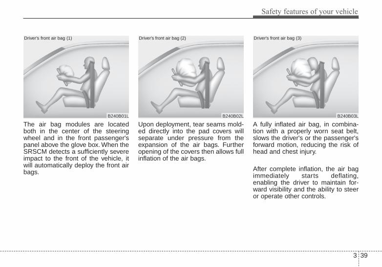
The air bag modules are locatedboth in the center of the steeringwheel and in the front passenger'spanel above the glove box. When theSRSCM detects a sufficiently severeimpact to the front of the vehicle, itwill automatically deploy the front airbags.
Upon deployment, tear seams mold-ed directly into the pad covers willseparate under pressure from theexpansion of the air bags. Furtheropening of the covers then allows fullinflation of the air bags.
A fully inflated air bag, in combina-tion with a properly worn seat belt,slows the driver's or the passenger'sforward motion, reducing the risk ofhead and chest injury.
After complete inflation, the air bagimmediately starts deflating,enabling the driver to maintain for-ward visibility and the ability to steeror operate other controls.
B240B01L
Driver’s front air bag (1)
B240B02L
Driver’s front air bag (2)
B240B03L
Driver’s front air bag (3)

Safety features of your vehicle
403
✽✽ NOTICEBefore you replace a fuse or discon-nect a battery terminal, turn theignition switch to the LOCK posi-tion and remove the ignition key.Never remove or replace the air bagrelated fuse(s) when the ignitionswitch is in the ON position. Failureto heed this warning will cause theSRS air bag warning light to illumi-nate.
Occupant detection system
Your vehicle is equipped with anoccupant detection system in thefront passenger's seat.The occupant detection system isdesigned to detect the presence of aproperly-seated front passenger anddetermine if the passenger's front airbag should be enabled (may inflate)or not. The driver's front air bag is notaffected or controlled by the occu-pant detection system.
B240B05L
Passenger’s front air bag
WARNING - Air bagobstructions
Do not install or place anyaccessories on the steeringwheel, instrument panel, or onthe front passenger's panelabove the glove box in a vehicleSuch objects may become dan-gerous projectiles if the air bagdeploys.
OTF034084N

3 41
Safety features of your vehicle
Main components of occupantdetection system• A detection device located within
the front passenger seat track.• Electronic system to determine
whether passenger air bag sys-tems should be activated or deac-tivated.
• An indicator light located on theinstrument panel which illuminatesthe words PASSENGER AIR BAG“OFF” indicating the front passen-ger air bag system is deactivated.
• The instrument panel air bag warn-ing light is interconnected with theoccupant detection system.
If the front passenger seat is occu-pied by a person that the systemdetermines to be of adult size, andhe/she sits properly (sitting uprightwith the seatback in an upright posi-tion, centered on the seat cushionwith their seat belt on, legs comfort-ably extended and their feet on thefloor), the PASSENGER AIR BAG“OFF” indicator will turn off and thefront passenger's air bag will be ableto inflate, if necessary, in frontalcrashes.You will find the PASSENGER AIRBAG “OFF” indicator on the centerfacia panel. This system detects theconditions 1~4 in the following tableand activates or deactivates the frontpassenger air bag based on theseconditions.Always be sure that you and all vehi-cle occupants are seated andrestrained properly (sitting uprightwith the seat in an upright position,centered on the seat cushion, withthe person’s legs comfortablyextended, feet on the floor, and wear-ing the safety belt properly) for themost effective protection by the airbag and the safety belt.
• The ODS (Occupant DetectionSystem) may not function properly ifthe passenger takes actions whichcan defeat the detection system.These include:
(1) Failing to sit in an upright position.(2) Leaning against the door or center
console.(3) Sitting towards the sides or the
front of the seat.(4) Putting legs on the dashboard or
resting them on other locationswhich reduce the passengerweight on the front seat.
(5) Improperly wearing the safetybelt.
(6) Reclining the seat back.

Safety features of your vehicle
423
WARNING - ODS systemRiding in an improper positionadversely affects the occupantdetection system (ODS) andmay result in the deactivation offront passenger airbag. It isimportant for the driver toinstruct the passenger as to theproper seating instructions ascontained in this manual.
(Continued)
Condition and operation in the front passenger occupant detectionsystem
*1) The system judges a person of adult size as an adult. When a smaller adult sits in the frontpassenger seat, the system may recognize him/her as a child depending on his/her physiqueand posture.
*2) Do not allow children to ride in the front passenger seat. When a smaller child than the sameage sits in the front passenger seat, the system may recognize him/her as an infant depend-ing on his/her physique or posture.
*3) Never install a child restraint system on the front passenger seat.
*4) The PASSENGER AIR BAG "OFF" indicator may turn on or off when a child above 12months to 12 years old (with or without child restraint system) sits in the front passengerseat. This is a normal condition.
Condition detected by the occu-pant detection system
Indicator/Warning light Devices
PASSENGER AIRBAG “OFF” indicator
lightSRS warning light
Front passengerair bag
1. Adult *1 or child age 13 and up*2 Off Off Activated
2. Infant or child restraint systemwith 12 months old*3 *4
On Off Deactivated
3. Unoccupied On Off Deactivated
4. Malfunction in the system Off On Activated

3 43
Safety features of your vehicle
1KMN3663
1KMN3664
1KMN3665
- Never sit with the hips shiftedtowards the front of the seat.
- Never lean on the door or cen-ter console.
- Never sit on one side of thefront passenger seat.
- Never place the feet on thedashboard.
B990A08O
1KMN3662
- Never put a heavy load in thefront passenger seat.
- Never excessively recline thefront passenger seatback.
OVQ036014N
- Never place the feet on thefront passenger seatback.
(Continued)

Safety features of your vehicle
443
When an adult is seated in the frontpassenger seat, if the PASSENGERAIR BAG “OFF” indicator is on, turnthe ignition switch to the LOCK posi-tion and ask the passenger to sitproperly (sitting upright with the seatback in an upright position, centeredon the seat cushion with their seatbelt on, legs comfortably extendedand their feet on the floor). Restartthe engine and have the personremain in that position. This will allowthe system to detect the person andto enable the passenger air bag.
If the PASSENGER AIR BAG “OFF”indicator is still on, ask the passen-ger to move to the rear seat.
✽✽ NOTICEThe PASSENGER AIR BAG “OFF”indicator illuminates for about 4 sec-onds after the ignition switch isturned to the ON position or afterthe engine is started. If the frontpassenger seat is occupied, the occu-pant detection sensor will then clas-sify the front passenger after severalmore seconds.
B990A01O
WARNING - “AIR BAGOFF” light
Do not allow an adult passengerto ride in the front seat when thePASSENGER AIR BAG “OFF”indicator is illuminated,because the air bag will notdeploy in the event of a crash.The driver must instruct thepassenger to reposition himselfin the seat. Failure to properlyposition yourself may lead toairbag deactivation resulting inairbag non-deployment and in acollision. If the PASSENGERAIR BAG “OFF” indicatorremains illuminated after thepassenger repositions them-selves properly and the car isrestarted, it is recommendedthat passenger move to the rearseat because the passenger'sfront air bag will not deploy.

3 45
Safety features of your vehicle
Any child age 12 and under shouldride in the rear seat. Children toolarge for child restraints should usethe available lap/shoulder belts. Nomatter what type of crash, children ofall ages are safer when restrained inthe rear seat.
✽✽ NOTICEDo not modify or replace the frontpassenger seat. Don't place anythingon or attach anything such as a blan-ket, front seat covers or after marketseat heater to the front passengerseat. This can adversely affect theoccupant detection system.
If the occupant detection system isnot working properly, the SRS airbag warning light on the instru-ment panel will illuminate becausethe passenger's front air bag is con-nected with the occupant detectionsystem. If there is a malfunction ofthe occupant detection system, thePASSENGER AIR BAG “OFF” indi-cator will not illuminate and the pas-senger's front air bag will inflate infrontal impact crashes even if there isno occupant in the front passenger'sseat.
Driver's and passenger's frontair bag
Your vehicle is equipped with anAdvanced Supplemental Restraint(Air Bag) System and lap/shoulderbelts at both the driver and passen-ger seating position.
OTF034033
OTF030034
Driver’s front air bag
Passenger’s front air bag

Safety features of your vehicle
463
The indications of the system's pres-ence are the letters "AIR BAG"embossed on the air bag pad coverin the steering wheel and the pas-senger's side front panel pad abovethe glove box.
The SRS consists of air bagsinstalled under the pad covers in thecenter of the steering wheel and thepassenger's side front panel abovethe glove box.The purpose of the SRS is to providethe vehicle's driver and/or the frontpassenger with additional protectionthan that offered by the seat belt sys-tem alone in case of a frontal impactof sufficient severity. The SRS usessensors to gather information aboutthe driver's seat position, the driver'sand front passenger's seat beltusage and impact severity.
The advanced SRS offers the abilityto control the air bag inflation withtwo levels. A first stage level is pro-vided for moderate-severity impacts.A second stage level is provided formore severe impacts.
The passenger’s front air bag isdesigned to help reduce the injury ofchildren sitting close to the instru-ment panel in low speed collisions.However, children are safer if theyare restraint in the rear seat.
According to the impact severity,seating position and seat belt usage,the SRSCM (SRS Control Module)controls the air bag inflation. Failureto properly wear seat belts canincrease the risk or severity of injuryin an accident.
Additionally, your vehicle is equippedwith an occupant detection system inthe front passenger's seat. The occu-pant detection system detects thepresence of a passenger in the frontpassenger's seat and will turn off thefront passenger's air bag under cer-tain conditions. For more detail, see"Occupant detection system" in thissection.Do not place any objects that maycause magnetic fields near the frontseat.These may cause a malfunctionof the seat track position sensor.

3 47
Safety features of your vehicle
1JBB3520
1JBA3514
1JBA3522
Side impact
Rear impact
Rollover
Manufacturers are required by gov-ernment regulations to provide acontact point concerning modifica-tions to the vehicle for persons withdisabilities, which modifications mayaffect the vehicle’s advanced air bagsystem. That contact is Kia’s toll-freeCustomer Assistance center at 1-800-333-4KIA. However, Kia doesnot endorse nor will it support anychanges to any part or structure ofthe vehicle that could affect theadvanced air bag system, includingthe occupant detection system.
Advanced air bags are combinedwith pre-tensioner seat belts to helpprovide enhanced occupant protec-tion in frontal crashes. Front air bagsare not intended to deploy in colli-sions in which sufficient protectioncan be provided by the pre-tensionerseat belt alone.
Front air bags are not intended todeploy in side-impact, rear-impact orrollover crashes. In addition, front airbags will not deploy in frontal crash-es below the deployment threshold.
WARNING - Replacement/modifications
The front passenger seat, dash-board or door should not bereplaced except by an author-ized Kia dealer using originalKia parts designed for this vehi-cle and model. Any other suchreplacement or modificationcould adversely affect the oper-ation of the occupant detectionsystem and your advanced airbags.
WARNING - SRS WiringDo not tamper with or discon-nect SRS wiring or other com-ponents of the SRS system.Doing so could result in injury,due to accidental deployment ofthe air bags or by rendering theSRS inoperative.

Safety features of your vehicle
483
Side air bag
❈ The actual air bags in the vehicle may differfrom the illustration.
Your vehicle is equipped with a sideair bag in each front seat.
The purpose of the air bag is to pro-vide the vehicle's driver and/or thefront passenger with additional pro-tection than that offered by the seatbelt alone.The side air bags are designed todeploy only during certain side-impact collisions, depending on thecrash severity, angle, speed andpoint of impact. The side air bags arenot designed to deploy in all sideimpact situations.
The side air bag is supplemental tothe driver's and the passenger's seatbelt systems and is not a substitutefor them. Therefore your seat beltsmust be worn at all times while thevehicle is in operation.For best protection from the side airbag system and to avoid beinginjured by the deploying side air bag,both front seat occupants should sitin an upright position with the seatbelt properly fastened. The driver'shands should be placed on the steer-ing wheel at the 9:00 and 3:00 posi-tions. The passenger's arms andhands should be placed on their laps.
WARNING - Unexpecteddeployment
Avoid impact to the side air bagsensor when the ignition switchis ON to prevent unexpecteddeployment of the side air bag.
OTD030035
OTD030036
Front
WARNING - DeploymentDo not install any accessoriesincluding seat covers, on theside or near the side air bag asthis may affect the deploymentof the side air bags.
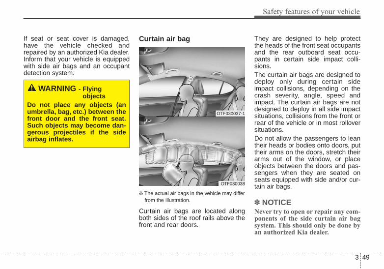
3 49
Safety features of your vehicle
If seat or seat cover is damaged,have the vehicle checked andrepaired by an authorized Kia dealer.Inform that your vehicle is equippedwith side air bags and an occupantdetection system.
Curtain air bag
❈ The actual air bags in the vehicle may differfrom the illustration.
Curtain air bags are located alongboth sides of the roof rails above thefront and rear doors.
They are designed to help protectthe heads of the front seat occupantsand the rear outboard seat occu-pants in certain side impact colli-sions.The curtain air bags are designed todeploy only during certain sideimpact collisions, depending on thecrash severity, angle, speed andimpact. The curtain air bags are notdesigned to deploy in all side impactsituations, collisions from the front orrear of the vehicle or in most rolloversituations.Do not allow the passengers to leantheir heads or bodies onto doors, puttheir arms on the doors, stretch theirarms out of the window, or placeobjects between the doors and pas-sengers when they are seated onseats equipped with side and/or cur-tain air bags.
✽✽ NOTICENever try to open or repair any com-ponents of the side curtain air bagsystem. This should only be done byan authorized Kia dealer.
WARNING - Flyingobjects
Do not place any objects (anumbrella, bag, etc.) between thefront door and the front seat.Such objects may become dan-gerous projectiles if the sideairbag inflates.
OTF030037-1
OTF030038

Safety features of your vehicle
503
Why didn’t my air bag go off ina collision? (Inflation and non-inflation conditions of the airbag)There are many types of accidentsin which the air bag would not beexpected to provide additionalprotection.These include rear impacts, sec-ond or third collisions in multipleimpact accidents, as well as lowspeed impacts.
OTF034039N/OTF034040/OTF034041/OMG035053/OTF030048N
(1) SRS control module(2) Front impact sensor
(3) Side impact sensor(4) Side impact sensor
Air bag collision sensors

3 51
Safety features of your vehicle
Problems may arise if the sensorinstallation angles are changed dueto the deformation of the frontbumper, body or B pillar where sidecollision sensors are installed. Havethe vehicle checked and repaired byan authorized Kia dealer.Installing aftermarket bumper guardsor replacing a bumper with non-gen-uine parts may adversely affect yourvehicle’s collision and air bag deploy-ment performance.
Air bag inflation conditions
Front air bags
Front air bags are designed to inflatein a frontal collision depending onthe intensity, speed or angles ofimpact of the front collision.
WARNING - Air bag sensors
• Do not hit or allow any objectsto impact the locations whereair bag or sensors are installed.This may cause unexpectedair bag deployment, whichcould result in serious per-sonal injury or death.
• If the installation location orangle of the sensors is alteredin any way, the air bags maydeploy when they should notor they may not deploy whenthey should.Therefore, do not try to per-form maintenance on oraround the air bag sensors.Have the vehicle checked andrepaired by an authorized Kiadealer.
1JBA3513

Safety features of your vehicle
523
❈ The actual air bags in the vehicle may differfrom the illustration.
Side air bags
Side air bags (side and/or curtain airbags) are designed to inflate whenan impact is detected by side colli-sion sensors depending on thestrength, speed or angles of impactresulting from a side impact collision.
Although the front air bags (driver’sand front passenger’s air bags) aredesigned to inflate in frontal colli-sions, they also may inflate in othertypes of collisions if the front impactsensors detect a sufficient frontalforce in another type of impact. Sideand curtain air bags are designed toinflate in certain side impact colli-sions. They may inflate in other typeof collisions where a side force isdetected by the sensors.If the vehicle chassis is impacted bybumps or objects on unimprovedroads or sidewalks, air bags maydeploy. Drive carefully on unim-proved roads or on surfaces notdesigned for vehicle traffic to preventunintended air bag deployment.
Air bag non-inflation conditions
• In certain low-speed collisions theair bags may not deploy. The airbags are designed not to deploy insuch cases because they may notprovide benefits beyond the pro-tection of the seat belts in such col-lisions.
1JBA3516
OUN026090
1JBA3515

3 53
Safety features of your vehicle
• Air bags are not designed to inflatein rear collisions, because occu-pants are moved backward by theforce of the impact. In this case,inflated air bags would not be ableto provide any additional benefit.
• Front air bags may not inflate inside impact collisions, becauseoccupants move to the direction ofthe collision, and thus in sideimpacts, front air bag deploymentwould not provide additional occu-pant protection.
• In a slant or angled collision, theforce of impact may direct theoccupants in a direction where theair bags would not be able to pro-vide any additional benefit, andthus the sensors may not deployany air bags.
OED036100 1JBA35211JBA3516

Safety features of your vehicle
543
• Just before impact, drivers oftenbrake heavily. Such heavy brakinglowers the front portion of the vehi-cle causing it to “ride” under a vehi-cle with a higher ground clearance.Air bags may not inflate in this"under-ride" situation becausedeceleration forces that are detect-ed by sensors may be significantlyreplaced by such “under-ride” colli-sions.
• Air bags may not inflate in rolloveraccidents because the vehicle cannot detect rollover accident.However, side and/or curtain airbags may inflate when the vehicleis rolled over following (or after)side impact collision.
• Air bags may not inflate if the vehi-cle collides with objects such asutility poles or trees, where thepoint of impact is concentrated toone area and the full force of theimpact is not delivered to the sen-sors.
1JBA3517 1JBA3522 1JBA3518

3 55
Safety features of your vehicle
SRS CareThe SRS is virtually maintenance-freeand there are no parts you can safelyservice by yourself. If the SRS air bagwarning light does not illuminate, orcontinuously remains on, have yourvehicle immediately inspected by anauthorized Kia dealer.
Any work on the SRS system, suchas removing, installing, repairing, orany work on the steering wheel mustbe performed by an authorized Kiadealer. Improper handling of the SRSsystem may result in serious person-al injury.
For cleaning the air bag pad covers,use only a soft, dry cloth or onewhich has been moistened with plainwater. Solvents or cleaners couldadversely affect the air bag coversand proper deployment of the sys-tem.
If components of the air bag systemmust be discarded, or if the vehiclemust be scrapped, certain safetyprecautions must be observed. Anauthorized Kia dealer knows theseprecautions and can give you thenecessary information. Failure to fol-low these precautions and proce-dures could increase the risk of per-sonal injury.
Adding equipment to or modi-fying your air bag-equippedvehicleIf you modify your vehicle by chang-ing your vehicle's frame, bumper sys-tem, front end or side sheet metal orride height, this may affect the opera-tion of your vehicle's air bag system.
WARNING - Tamperingwith SRS
Do not tamper with or discon-nect SRS wiring, or other com-ponents of the SRS system.Doing so could result in theaccidental inflation of the airbags or by rendering the SRSinoperative.

Safety features of your vehicle
563
Air bag warning label
Air bag warning labels, somerequired by the U.S. NationalHighway Traffic Safety Administration(NHTSA), are attached to alert thedriver and passengers of potentialrisks of the air bag system.
OTF030043-1
OTF030044-1

Features of your vehicle
Keys . . . . . . . . . . . . . . . . . . . . . . . . . . . . . . . . . . . . . . 4-4• Record your key number . . . . . . . . . . . . . . . . . . . . . . . 4-4• Key operations . . . . . . . . . . . . . . . . . . . . . . . . . . . . . . . . 4-4
Smart key . . . . . . . . . . . . . . . . . . . . . . . . . . . . . . . . . 4-6• Smart key functions . . . . . . . . . . . . . . . . . . . . . . . . . . . 4-6• Smart key precautions . . . . . . . . . . . . . . . . . . . . . . . . . 4-7• Remote keyless entry system operations. . . . . . . . . . . 4-9
Remote keyless entry . . . . . . . . . . . . . . . . . . . . . . . . 4-9• Transmitter precautions . . . . . . . . . . . . . . . . . . . . . . . 4-10• Battery replacement . . . . . . . . . . . . . . . . . . . . . . . . . . 4-11• Immobilizer system . . . . . . . . . . . . . . . . . . . . . . . . . . . 4-12
Theft-alarm system . . . . . . . . . . . . . . . . . . . . . . . . 4-14• Armed stage . . . . . . . . . . . . . . . . . . . . . . . . . . . . . . . . . 4-14• Theft-alarm stage . . . . . . . . . . . . . . . . . . . . . . . . . . . . 4-15• Disarmed stage. . . . . . . . . . . . . . . . . . . . . . . . . . . . . . . 4-15
Door locks . . . . . . . . . . . . . . . . . . . . . . . . . . . . . . . . 4-17• Operating door locks from outside the vehicle . . . . 4-17• Operating door locks from inside the vehicle. . . . . . 4-17• Impact sensing door unlock system. . . . . . . . . . . . . . 4-19• Auto door lock/unlock feature . . . . . . . . . . . . . . . . . . 4-19• Child-protector rear door lock . . . . . . . . . . . . . . . . . 4-20
Trunk . . . . . . . . . . . . . . . . . . . . . . . . . . . . . . . . . . . . 4-21• Opening the trunk. . . . . . . . . . . . . . . . . . . . . . . . . . . . 4-21• Emergency trunk lid release cable . . . . . . . . . . . . . . 4-22• Closing the trunk. . . . . . . . . . . . . . . . . . . . . . . . . . . . . 4-22
• Emergency trunk safety release. . . . . . . . . . . . . . . . . 4-23Windows . . . . . . . . . . . . . . . . . . . . . . . . . . . . . . . . . 4-24
• Power windows . . . . . . . . . . . . . . . . . . . . . . . . . . . . . . 4-25• Power window lock button . . . . . . . . . . . . . . . . . . . . . 4-28
Hood. . . . . . . . . . . . . . . . . . . . . . . . . . . . . . . . . . . . . 4-29• Opening the hood . . . . . . . . . . . . . . . . . . . . . . . . . . . . 4-29• Closing the hood . . . . . . . . . . . . . . . . . . . . . . . . . . . . . 4-30
Fuel filler lid . . . . . . . . . . . . . . . . . . . . . . . . . . . . . 4-31• Opening the fuel filler lid . . . . . . . . . . . . . . . . . . . . . . 4-31• Closing the fuel filler lid . . . . . . . . . . . . . . . . . . . . . . . 4-31• Emergency fuel filler lid release. . . . . . . . . . . . . . . . . 4-33
Sunroof . . . . . . . . . . . . . . . . . . . . . . . . . . . . . . . . . . 4-34• Sliding the sunroof . . . . . . . . . . . . . . . . . . . . . . . . . . . 4-34• Closing the sunroof . . . . . . . . . . . . . . . . . . . . . . . . . . . 4-35• Tilting the sunroof . . . . . . . . . . . . . . . . . . . . . . . . . . . 4-36• Sunshade . . . . . . . . . . . . . . . . . . . . . . . . . . . . . . . . . . . 4-37• Resetting the sunroof . . . . . . . . . . . . . . . . . . . . . . . . . 4-37
Driver position memory system . . . . . . . . . . . . . . 4-38• Storing positions . . . . . . . . . . . . . . . . . . . . . . . . . . . . . 4-38• Easy access function . . . . . . . . . . . . . . . . . . . . . . . . . . 4-39
Steering wheel. . . . . . . . . . . . . . . . . . . . . . . . . . . . . 4-40• Electric power steering . . . . . . . . . . . . . . . . . . . . . . . . 4-40• Tilt and telescoping steering. . . . . . . . . . . . . . . . . . . . 4-41• Horn . . . . . . . . . . . . . . . . . . . . . . . . . . . . . . . . . . . . . . . 4-41• Heated steering wheel . . . . . . . . . . . . . . . . . . . . . . . . . 4-42
4

Mirrors . . . . . . . . . . . . . . . . . . . . . . . . . . . . . . . . . . 4-43• Inside rearview mirror . . . . . . . . . . . . . . . . . . . . . . . . 4-43• Outside rearview mirror . . . . . . . . . . . . . . . . . . . . . . 4-51
Instrument cluster . . . . . . . . . . . . . . . . . . . . . . . . . 4-54• Instrument Cluster Control . . . . . . . . . . . . . . . . . . . . 4-55• LCD Display Control . . . . . . . . . . . . . . . . . . . . . . . . . 4-55• Gauges . . . . . . . . . . . . . . . . . . . . . . . . . . . . . . . . . . . . . 4-56• Transaxle Shift Indicator . . . . . . . . . . . . . . . . . . . . . . 4-59
LCD Display . . . . . . . . . . . . . . . . . . . . . . . . . . . . . . 4-60• LCD Modes . . . . . . . . . . . . . . . . . . . . . . . . . . . . . . . . . 4-60• Service Mode . . . . . . . . . . . . . . . . . . . . . . . . . . . . . . . . 4-61• User Settings Mode . . . . . . . . . . . . . . . . . . . . . . . . . . . 4-63• Warning Messages. . . . . . . . . . . . . . . . . . . . . . . . . . . . 4-66
Trip computer. . . . . . . . . . . . . . . . . . . . . . . . . . . . . 4-75• Overview. . . . . . . . . . . . . . . . . . . . . . . . . . . . . . . . . . . . 4-75• Fuel Economy . . . . . . . . . . . . . . . . . . . . . . . . . . . . . . . 4-76• Trip A/B . . . . . . . . . . . . . . . . . . . . . . . . . . . . . . . . . . . . 4-78
Warning and indicator lights . . . . . . . . . . . . . . . . 4-80• Warning lights . . . . . . . . . . . . . . . . . . . . . . . . . . . . . . . 4-80• Indicator Lights . . . . . . . . . . . . . . . . . . . . . . . . . . . . . . 4-88
Back-up warning system . . . . . . . . . . . . . . . . . . . . 4-92• Operation of the back-up warning system . . . . . . . . 4-92• Non-operational conditions of back-up warning
system . . . . . . . . . . . . . . . . . . . . . . . . . . . . . . . . . . . . . 4-93• Back-up warning system precautions . . . . . . . . . . . . 4-93
• Self-diagnosis . . . . . . . . . . . . . . . . . . . . . . . . . . . . . . . . 4-94Rear camera display . . . . . . . . . . . . . . . . . . . . . . . 4-95Welcome system . . . . . . . . . . . . . . . . . . . . . . . . . . . 4-96
• Welcome light. . . . . . . . . . . . . . . . . . . . . . . . . . . . . . . . 4-96• Escort welcome . . . . . . . . . . . . . . . . . . . . . . . . . . . . . . 4-96• Interior light . . . . . . . . . . . . . . . . . . . . . . . . . . . . . . . . 4-96
Lighting . . . . . . . . . . . . . . . . . . . . . . . . . . . . . . . . . . 4-97• Battery saver function. . . . . . . . . . . . . . . . . . . . . . . . . 4-97• Headlight escort function . . . . . . . . . . . . . . . . . . . . . . 4-97• Headlight leveling device . . . . . . . . . . . . . . . . . . . . . . 4-97• Daytime running light. . . . . . . . . . . . . . . . . . . . . . . . . 4-98• Lighting control . . . . . . . . . . . . . . . . . . . . . . . . . . . . . . 4-98• High beam operation . . . . . . . . . . . . . . . . . . . . . . . . 4-100• Turn signals and lane change signals . . . . . . . . . . . 4-101• Front fog light . . . . . . . . . . . . . . . . . . . . . . . . . . . . . . 4-102
Wipers and washers . . . . . . . . . . . . . . . . . . . . . . . 4-103• Windshield wipers . . . . . . . . . . . . . . . . . . . . . . . . . . . 4-103• Windshield washers. . . . . . . . . . . . . . . . . . . . . . . . . . 4-104
Interior light . . . . . . . . . . . . . . . . . . . . . . . . . . . . . 4-106• Automatic turn off function . . . . . . . . . . . . . . . . . . . 4-106• Map lamp . . . . . . . . . . . . . . . . . . . . . . . . . . . . . . . . . 4-106• Room lamp . . . . . . . . . . . . . . . . . . . . . . . . . . . . . . . . 4-107• Trunk room lamp . . . . . . . . . . . . . . . . . . . . . . . . . . . 4-108• Glove box lamp . . . . . . . . . . . . . . . . . . . . . . . . . . . . . 4-109• Vanity mirror lamp . . . . . . . . . . . . . . . . . . . . . . . . . . 4-109
4

Defroster . . . . . . . . . . . . . . . . . . . . . . . . . . . . . . . . 4-110• Rear window defroster . . . . . . . . . . . . . . . . . . . . . . . 4-110
Manual climate control system . . . . . . . . . . . . . . 4-111• Heating and air conditioning . . . . . . . . . . . . . . . . . . 4-112• System operation . . . . . . . . . . . . . . . . . . . . . . . . . . . . 4-117• Climate control air filter. . . . . . . . . . . . . . . . . . . . . . 4-119
Automatic climate control system. . . . . . . . . . . . 4-120• Automatic heating and air conditioning . . . . . . . . . 4-121• Manual heating and air conditioning . . . . . . . . . . . 4-122• System operation . . . . . . . . . . . . . . . . . . . . . . . . . . . . 4-128
Windshield defrosting and defogging. . . . . . . . . 4-131• Manual climate control system . . . . . . . . . . . . . . . . 4-131• Automatic climate control system . . . . . . . . . . . . . . 4-132• Defogging logic. . . . . . . . . . . . . . . . . . . . . . . . . . . . . . 4-133
Storage compartment. . . . . . . . . . . . . . . . . . . . . . 4-137• Center console storage . . . . . . . . . . . . . . . . . . . . . . . 4-137• Glove box . . . . . . . . . . . . . . . . . . . . . . . . . . . . . . . . . . 4-137• Cool box . . . . . . . . . . . . . . . . . . . . . . . . . . . . . . . . . . . 4-138• Sunglass holder . . . . . . . . . . . . . . . . . . . . . . . . . . . . . 4-138
Interior features . . . . . . . . . . . . . . . . . . . . . . . . . . 4-140• Cup holder . . . . . . . . . . . . . . . . . . . . . . . . . . . . . . . . . 4-140• Sunvisor . . . . . . . . . . . . . . . . . . . . . . . . . . . . . . . . . . . 4-141• Power outlet . . . . . . . . . . . . . . . . . . . . . . . . . . . . . . . . 4-141• Digital clock . . . . . . . . . . . . . . . . . . . . . . . . . . . . . . . 4-142• Clothes hanger . . . . . . . . . . . . . . . . . . . . . . . . . . . . . . 4-143
• Floor mat anchor(s). . . . . . . . . . . . . . . . . . . . . . . . . . 4-143• Navigation system . . . . . . . . . . . . . . . . . . . . . . . . . . . 4-144
Audio system. . . . . . . . . . . . . . . . . . . . . . . . . . . . . 4-145• Glass antenna. . . . . . . . . . . . . . . . . . . . . . . . . . . . . . . 4-145• Steering wheel audio controls . . . . . . . . . . . . . . . . . 4-146• Aux, USB and iPod® port . . . . . . . . . . . . . . . . . . . . . 4-147
4

Features of your vehicle
44
Record your key numberThe key code num-ber is stamped onthe key code tagattached to the keyset. Should you
lose your keys, this number willenable an authorized Kia dealer toduplicate the keys easily. Removethe key code tag and store it in a safeplace. Also, record the key codenumber and keep it in a safe andhandy place, but not in the vehicle.
Key operationsType A
To unfold the key, press the releasebutton and the key will unfold auto-matically.To fold the key, fold the key manuallywhile pressing the release button.
KEYS
WARNING - Aftermarketkeys
Use only Kia original parts forthe ignition key in your vehicle.If an aftermarket key is used, theignition switch may not return toON after START. If this happens,the starter will continue to oper-ate causing possible fire due toexcessive current in the wiring.
OTF044371N
CAUTION - Key buttonoperation
Do not fold the key withoutpressing the release button.This may damage the key.

4 5
Features of your vehicle
Type B
To remove the mechanical key, pressand hold the release button andremove the mechanical key.To reinstall the mechanical key, putthe key into the hole and push it untila click sound is heard.
OYDDCO2002
WARNING - Ignition key(Smart key)
Leaving children unattended ina vehicle with the ignition key(smart key) is dangerous even ifthe key is not in the ignitionswitch or start button is ACC orON position.Children copy adults and theycould place the key in the igni-tion switch or press the startbutton. The ignition key (smartkey) would enable children tooperate power windows orother controls, or even makethe vehicle move, which couldresult in serious bodily injury oreven death. Never leave thekeys in your vehicle with unsu-pervised children, when theengine is running.

Features of your vehicle
64
With a smart key, you can lock orunlock a door and even start theengine without inserting the key.The functions of the buttons on asmart key are similar to the remotekeyless entry. (Refer to the "Remotekeyless entry" in this chapter.)
Smart key functionsCarrying the smart key, you may lockand unlock the vehicle doors. Also,you may start the engine. Refer tothe following, for more details.
Locking
Pressing the button of the front out-side door handles with all doorsclosed and any door unlocked, locksall the doors. The hazard warninglights will blink and the chime willsound once to indicate that all doorsare locked. The button will only oper-ate when the smart key is within28~40 in. (0.7~1 m) from the outsidedoor handle. If you want to makesure that a door has locked or not,you should check the door lock but-ton inside the vehicle or pull the out-side door handle.
SMART KEY (IF EQUIPPED)
OYDDCO2007
OTF040008

4 7
Features of your vehicle
Even though you press the button,the doors will not lock and the chimewill sound for 3 seconds if any of thefollowing occurs:• The smart key is in the vehicle.• The ignition switch is in the ACC or
ON position.• Any door except the trunk is
opened.
Unlocking Pressing the button of the driver'soutside door handle with all doorsclosed and locked, unlocks the dri-ver's door. The hazard warning lightswill blink and the chime will soundtwice to indicate that the driver's dooris unlocked.Pressing the button in the front pas-senger's outside door handle with alldoors closed and locked, unlocks allthe doors. The hazard warning lightswill blink and the chime will soundtwice to indicate that all doors areunlocked. The button will only oper-ate when the smart key is within28~40 in. (0.7~1 m) from the outsidedoor handle.
Start-upYou can start the engine withoutinserting the key. For detailed infor-mation refer to "Starting the enginewith a smart key" in chapter 5.
Smart key precautions• If you lose your smart key, you will
not be able to start the engine. Towthe vehicle, if necessary, and con-tact an authorized Kia dealer.
• A maximum of 2 smart keys can beregistered to a single vehicle. Ifyou lose a smart key, you shouldimmediately take the vehicle andkey to your authorized Kia dealerto protect it from potential theft.
• The smart key will not work if anyof following occurs:- The smart key is close to a radio
transmitter such as a radio sta-tion or an airport which can inter-fere with normal operation of thesmart key.
- The smart key near a mobile two-way radio system or a cellularphone.
- Another vehicle’s smart key is beingoperated close to your vehicle.
When the smart key does not workcorrectly, open and close the doorwith the mechanical key. If youhave a problem with the smart key,contact an authorized Kia dealer.

Features of your vehicle
84
• If the smart key is in close proximityto your cell phone or smart phone,the signal from the smart key couldbe blocked by normal operation ofyour cell phone or smart phone.This is especially important whenthe phone is active such as makingcall, receiving calls, text messaging,and/or sending/receiving emails.Avoid placing the smart key andyour cell phone or smart phone inthe same pants or jacket pocket andmaintain adequate distancebetween the two devices.
This device complies with Part 15of the FCC rules.Operation is subject to the followingtwo conditions:1. This device may not cause harm-
ful interference, and 2. This device must accept any inter-
ference received, including inter-ference that may cause undesiredoperation.
✽✽ NOTICEChanges or modifications notexpressly approved by the partyresponsible for compliance could voidthe user’s authority to operate theequipment. If the keyless entry sys-tem is inoperative due to changes ormodifications not expressly approvedby the party responsible for compli-ance, it will not be covered by yourmanufacturer’s vehicle warranty.
CAUTION - TransmitterKeep the smart key away fromwater or any liquid as it canbecome damaged and not func-tion properly.

4 9
Features of your vehicle
REMOTE KEYLESS ENTRY (IF EQUIPPED)Remote keyless entry systemoperations
Lock (1)All doors are locked if the lock buttonis pressed. If all doors (and trunk) areclosed, the hazard warning lights willblink once to indicate that all doors(and trunk) are locked.Also, if the lock button is pressedonce more within 4 seconds, thehazard warning lights will blink andthe chime will sound once to confirmthat the door is locked.However, if any door remains open,the hazard warning lights (and/or thechime) will not operate. But if alldoors are closed after the lock buttonis pressed, the hazard warning lightswill blink once.
Unlock (2) The driver's door is unlocked if theunlock button is pressed once. Thehazard warning lights will blink (forsmart key, the chime also sounds)twice to indicate that the driver's dooris unlocked.All doors are unlocked if the unlockbutton is pressed once more within 4seconds. The hazard warning lightswill blink (for smart key, the chimealso sounds) twice again to indicatethat all doors are unlocked. Afterpressing this button, the doors willlock automatically unless you openany door within 30 seconds.
✽✽ NOTICEIf the keyless entry system is inoper-ative due to exposure to water or liq-uids, it will not be covered by yourmanufacturer's vehicle warranty.
OYDDCO2004
■ Type B
■ Type A
OYDDCO2003

Features of your vehicle
104
Trunk open (3)The trunk is opened if the button ispressed for more than 1 second.Once the trunk is opened and thenclosed, the trunk will lock automatically.
Alarm (4)The horn sounds and the hazardwarning lights blink for about 30 sec-onds if this button is pressed formore than 0.5 seconds. To stop thehorn and lights, press any button onthe transmitter.
Transmitter precautionsThe transmitter (or smart key) will notwork if any of following occurs:• The ignition key is in the ignition
switch.• You exceed the operating distance
limit (about 90 feet [30 m]).• The battery in the transmitter (or
smart key) is weak.• Other vehicles or objects may be
blocking the signal.• The weather is extremely cold.• The transmitter (or smart key) is
close to a radio transmitter such asa radio station or an airport whichcan interfere with normal operationof the transmitter.
When the transmitter (or smart key)does not work properly, open andclose the door with the ignition key. Ifyou have a problem with the trans-mitter (or smart key), contact anauthorized Kia dealer.
• If the transmitter is in close proximi-ty to your cell phone or smart phone,the signal from the transmitter couldbe blocked by normal operation ofyour cell phone or smart phone.Thisis especially important when thephone is active such as making call,receiving calls, text messaging,and/or sending/receiving emails.Avoid placing the transmitter andyour cell phone or smart phone inthe same pants or jacket pocket andmaintain adequate distancebetween the two devices.

4 11
Features of your vehicle
This device complies with Part 15of the FCC rules.Operation is subject to the followingtwo conditions:1. This device may not cause harm-
ful interference, and 2. This device must accept any inter-
ference received, including inter-ference that may cause undesiredoperation.
✽✽ NOTICEChanges or modifications notexpressly approved by the partyresponsible for compliance could voidthe user’s authority to operate theequipment. If the keyless entry sys-tem is inoperative due to changes ormodifications not expressly approvedby the party responsible for compli-ance, it will not be covered by yourmanufacturer’s vehicle warranty.
Battery replacement
A battery should last for severalyears, but if the transmitter or smartkey is not working properly, tryreplacing the battery with a new one.If you are unsure how to use orreplace the battery, contact anauthorized Kia dealer.
Type A1. Pry open the transmitter cover.2. Replace the battery with a new
battery (CR2032). When replacingthe battery, make sure the batteryposition.
3. Install the battery in the reverseorder of removal.
Type B1. Remove the mechanical key.2. Pry open the rear cover.3. Replace the battery with a new
battery (CR2032). When replacingthe battery, make sure the batteryposition.
4. Install the battery in the reverseorder of removal.
OTF044001N
■ Type B
■ Type A
OYDDCO2005

Features of your vehicle
124
• The transmitter or smart key isdesigned to give you years of trou-ble-free use, however it can mal-function if exposed to moisture orstatic electricity. If you are unsurehow to use or replace the battery,contact an authorized Kia dealer.
• Using the wrong battery can causethe transmitter or smart key to mal-function. Be sure to use the correctbattery.
• An inappropriately dis-posed battery can be harm-ful to the environment andhuman health. Dispose thebattery according to yourlocal law(s) or regulation.
Immobilizer system (if equipped)Your vehicle may be equipped withan electronic engine immobilizer sys-tem to reduce the risk of unautho-rized vehicle use.Your immobilizer system is com-prised of a small transponder in theignition key and electronic devicesinside the vehicle.With the immobilizer system, when-ever you insert your ignition key intothe ignition switch and turn it to ON,it checks and determines and verifiesthat the ignition key is valid.If the key is determined to be valid,the engine will start.If the key is determined to be invalid,the engine will not start.
To deactivate the immobilizersystem:Insert the ignition key into the keycylinder and turn it to the ON position.
To activate the immobilizer system:Turn the ignition key to the OFF posi-tion. The immobilizer system acti-vates automatically. Without a validignition key for your vehicle, theengine will not start.Your Immobilizer password is a cus-tomer unique password and shouldbe kept confidential. Do not leave thisnumber anywhere in your vehicle.
✽✽ NOTICEKeep each key separately in order toavoid a starting malfunction.
CAUTION - Transmitterdamage
Do not drop, wet or expose thekeyless entry system transmit-ter to heat or sunlight.

4 13
Features of your vehicle
Do not put metal accessories nearthe ignition switch.Metal accessories may interrupt thetransponder signal and may preventthe engine from being started.If you need additional keys or loseyour keys, consult an authorized Kiadealer.
This device complies with Part 15of the FCC rules.Operation is subject to the followingtwo conditions:1. This device may not cause harm-
ful interference, and 2. This device must accept any inter-
ference received, including inter-ference that may cause undesiredoperation.
WARNINGChanges or modifications notexpressly approved by the partyresponsible for compliancecould void the user's authorityto operate the equipment.
CAUTION - Immobilizerdamage
Do not expose your immobilizersystem to moisture, static elec-tricity and rough handling. Thismay damage your immobilizer.
CAUTION - Immobilizeralterations
Do not change, alter or adjustthe immobilizer system becauseit could cause the immobilizersystem to malfunction.

Features of your vehicle
144
This system is designed to provideprotection from unauthorized entryinto the vehicle. This system is oper-ated in three stages: the first is the"Armed" stage, the second is the"Theft-alarm" stage, and the third isthe "Disarmed" stage. If triggered,the system provides an audiblealarm with blinking of the hazardwarning lights.
Armed stagePark the vehicle and stop the engine.Arm the system as described below.1. Remove the ignition key from the
ignition switch and exit the vehicle.2. Make sure that all doors (and
trunk) and engine hood are closedand latched.
3. • Lock the doors by depressing thedoor lock button on the transmit-ter (or smart key).After completion of the stepsabove, the hazard warning lightswill blink once to indicate that thesystem is armed.If any door, trunk or engine hoodremains open, the hazard warn-ing lights won’t operate andtheft-alarm will not arm. Afterthis, if all doors, trunk and enginehood are closed, the hazardwarning lights blink once.
• Lock the doors by pressing thebutton of the front outside doorhandles with the smart key inyour possession.After completion of the stepsabove, the hazard warning lightswill blink once to indicate that thesystem is armed.If any door remains open, thehazard warning lights won’t oper-ate and theft-alarm will not arm.Close the door and try again tolock the doors.If trunk or engine hood remainsopen, the hazard warning lightswon’t operate and theft-alarm willnot arm. Close the trunk orengine hood. The hazard warninglights blink once and theft-alarmarms.
THEFT-ALARM SYSTEM (IF EQUIPPED)
Armed
stage
Theft-alarm
stageDisarmed
stage

4 15
Features of your vehicle
The theft-alarm system by the keycan be activated by an authorizedKia dealer.If you want this feature, consult anauthorized Kia dealer.
Do not arm the system until allpassengers have left the vehicle. Ifthe system is armed while a pas-senger(s) remains in the vehicle,the alarm may be activated whenthe remaining passenger(s)leaves the vehicle. If any door (ortrunk) or engine hood is openedwithin 30 seconds after the sys-tem enters the armed stage, thesystem will be disarmed to pre-vent unnecessary alarm.
Theft-alarm stageThe alarm will be activated if any ofthe following occurs while the systemis armed.• A front or rear door is opened with-
out using the transmitter (or smartkey).
• The trunk is opened without usingthe transmitter (or smart key).
• The engine hood is opened.The horn will sound and the hazardwarning lights will blink continuouslyfor approximately 27 seconds. Toturn off the system, unlock the doorswith the transmitter (or smart key).
Disarmed stageThe system will be disarmed when:
Transmitter- The door unlock button is pressed.- The engine is started. (within 3
seconds)- The ignition switch is in the “ON”
position for 30 seconds or more.
Smart key- The door unlock button is pressed.- The button of the front outside door
is pressed while carrying the smartkey.
- The engine is started. (within 3seconds)
After the doors are unlocked, the haz-ard warning lights will blink twice toindicate that the system is disarmed.After pressing the unlock button, ifany door (or trunk) is not openedwithin 30 seconds, the system will berearmed.

Features of your vehicle
164
• Avoid trying to start the enginewhile the alarm is activated. Thevehicle starting motor is disabledduring the theft-alarm stage.If the system is not disarmed withthe transmitter, insert the key intothe ignition switch, turn the ignitionswitch to the ON position and waitfor 30 seconds. Then the systemwill be disarmed.
• If you lose your keys, consult yourauthorized Kia dealer.
• If the system is not disarmed withthe transmitter, insert the key intothe ignition switch and start theengine. Then the system will bedisarmed.
• If you lose your keys, consult yourauthorized Kia dealer.

4 17
Features of your vehicle
DOOR LOCKS Operating door locks fromoutside the vehicle
• Turn the key toward the rear of thevehicle to unlock and toward thefront of the vehicle to lock.
• If you lock/unlock the door with akey, all vehicle doors willlock/unlock automatically. (ifequipped with power door locks)
• From the driver’s door, turn the keytoward the rear of the vehicle onceto unlock the driver’s door andonce more within 4 seconds tounlock all doors. (if equipped withpower door locks)
• Doors can also be locked andunlocked with the transmitter key(or smart key). (if equipped)
• Once the doors are unlocked, theymay be opened by pulling the doorhandle.
• When closing the door, push thedoor by hand. Make sure the doorsare closed securely.
✽✽ NOTICE• In cold and wet climates, door lock
and door mechanisms may notwork properly due to freezing con-ditions.
• If the door is locked/unlockedmultiple times in rapid successionwith either the vehicle key or doorlock switch, the system may stopoperating temporarily in order toprotect the circuit and preventdamage to system components.
Operating door locks frominside the vehicleWith the door lock button
• To unlock a door, push the doorlock button (1) to the “Unlock” posi-tion.The red mark (2) on the buttonwill be visible.
• To lock a door, push the door lockbutton (1) to the “Lock” position. Ifthe door is locked properly, the redmark (2) on the door lock buttonwill not show.
• To open a door, pull the door han-dle (3) outward.
OTF044009
Lock Lock
Unlock Unlock
OTF044011
Lock
Unlock

Features of your vehicle
184
• If the inner door handle of the frontdoor is pulled when the door lockbutton is in the lock position, thebutton will unlock and the door willopen. (if equipped)
• Front doors cannot be locked if theignition key is in the ignition switch(or if the smart key is in the vehicle)and any front door is opened. (ifequipped)
If a power door lock ever fails to func-tion while you are in the vehicle, tryone or more of the following tech-niques to exit:• Operate the door unlock feature
repeatedly (both electronic andmanual) while simultaneouslypulling on the door handle.
• Operate the other door locks andhandles, front and rear.
• Lower a front window and use thekey to unlock the door from out-side.
With central door lock switch (if equipped)
Operate by pressing the central doorlock switch.• Press the switch to the "Lock" posi-
tion (1), all vehicle doors will lock.
OTF040012N
OTF040013
Driver's door
Passenger’s door

4 19
Features of your vehicle
• Press the switch to the "Unlock"position (2), all vehicle doors willunlock.
• If the key is in the ignition switch (orif the smart key is in the vehicle)and any front door is opened, thedoors will not lock when the “Lock”position (1) of the central door lockswitch is pressed. (if equipped)
Impact sensing door unlocksystemAll doors will automatically unlockwhen an impact causes the air bagsto deploy.
Auto door lock/unlock feature• All doors will automatically lock
when the transaxle shift lever isshifted out of P (Park).
• All doors will automatically unlockwhen the transaxle shift lever isshifted into P (Park).
An authorized Kia dealer can acti-vate or deactivate some auto doorlock/ unlock features as follows;• Auto door unlock by using the dri-
ver's door lock button• Auto door lock/unlock by shifting
the transaxle shift lever out of P(Park) or into P (Park)
• Auto door unlock when the ignitionkey is removed from the ignitionswitch (for smart key, when theENGINE START/STOP button isturned to the OFF position)
If you want to activate or deactivatesome door lock/unlock feature, referto "user setting mode" in this chapter.
WARNING - Unattendedchildren/animals
Never leave children or animalsunattended in your vehicle.An enclosed vehicle canbecome extremely hot, causingdeath or severe injury to unat-tended children or animals whocannot escape the vehicle.
WARNING - DoorsThe doors should always befully closed and locked while thevehicle is in motion to preventaccidental opening of the door.

Features of your vehicle
204
Child-protector rear door lock
The child safety lock is provided tohelp prevent children from acciden-tally opening the rear doors frominside the vehicle. The rear doorsafety locks should be used whenev-er children are in the vehicle.1. Open the rear door.2. Insert a key (or screwdriver) into the
hole and turn it to the lock ( ) posi-tion. The child safety lock (1) locat-ed on the rear edge of the door tothe lock position. When the childsafety lock is in the lock position,rear door will not open even whenthe inner door handle is pulled.
3. Close the rear door.To open the rear door, pull the out-side door handle (2).Even though the doors may beunlocked, the rear door will not openby pulling the inner door handle untilthe rear door child safety lock isunlocked.
OTF040014

4 21
Features of your vehicle
Opening the trunk
• Press the trunk unlock button formore than 1 second on the trans-mitter (or smart key).
• Press the button on the trunk han-dle with the smart key in your pos-session.Once the trunk is opened and thenclosed, the trunk locks automati-cally.
• To open the trunk from inside thevehicle, pull the trunk lid releasebutton.Once the trunk is opened and thenclosed, the trunk locks automati-cally.
✽✽ NOTICEIn cold and wet climates, trunk lockand trunk mechanisms may notwork properly due to freezing condi-tions.
TRUNK
OTF040016
OTF044015
CAUTIONMake certain that you close thetrunk before driving your vehi-cle. Possible damage may occurto the trunk lift cylinders andattached hardware if the trunk isnot closed prior to driving.
WARNINGThe trunk swings upward. Makesure no objects or people arenear the rear of the vehiclewhen opening the trunk.
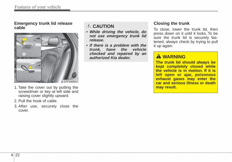
Features of your vehicle
224
Emergency trunk lid releasecable
1. Take the cover out by putting thescrewdriver or key at left side andraising cover slightly upward.
2. Pull the hook of cable.3. After use, securely close the
cover.
Closing the trunkTo close, lower the trunk lid, thenpress down on it until it locks. To besure the trunk lid is securely fas-tened, always check by trying to pullit up again.
OTF040017
CAUTION• While driving the vehicle, do
not use emergency trunk lidrelease.
• If there is a problem with thetrunk, have the vehiclechecked and repaired by anauthorized Kia dealer. WARNING
The trunk lid should always bekept completely closed whilethe vehicle is in motion. If it isleft open or ajar, poisonousexhaust gases may enter thecar and serious illness or deathmay result.

4 23
Features of your vehicle
Emergency trunk safetyrelease
Your vehicle is equipped with anemergency trunk release lever locat-ed inside the trunk. If someone isinadvertently locked in the trunk,moving the handle in the direction ofthe arrow will release the trunk latchmechanism and open the trunk.
WARNING• No one should be allowed to
occupy the trunk at any time.The trunk is a very dangerouslocation in the event of a crash.
• Use the release lever foremergencies only. Useextreme caution, especiallywhile the vehicle is in motion.
OTF044018

Features of your vehicle
244
(1) Driver’s door power windowswitch
(2) Front passenger’s door powerwindow switch
(3) Rear door (left) power windowswitch
(4) Rear door (right) power windowswitch
(5) Window opening and closing(6) Automatic power window down(7) Power window lock button
WINDOWS
OTF040019N
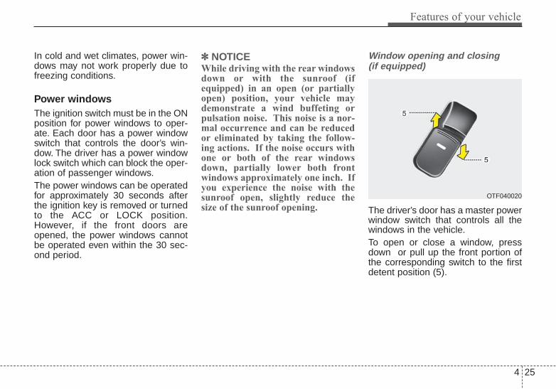
4 25
Features of your vehicle
In cold and wet climates, power win-dows may not work properly due tofreezing conditions.
Power windowsThe ignition switch must be in the ONposition for power windows to oper-ate. Each door has a power windowswitch that controls the door’s win-dow. The driver has a power windowlock switch which can block the oper-ation of passenger windows.The power windows can be operatedfor approximately 30 seconds afterthe ignition key is removed or turnedto the ACC or LOCK position.However, if the front doors areopened, the power windows cannotbe operated even within the 30 sec-ond period.
✽✽ NOTICEWhile driving with the rear windowsdown or with the sunroof (ifequipped) in an open (or partiallyopen) position, your vehicle maydemonstrate a wind buffeting orpulsation noise. This noise is a nor-mal occurrence and can be reducedor eliminated by taking the follow-ing actions. If the noise occurs withone or both of the rear windowsdown, partially lower both frontwindows approximately one inch. Ifyou experience the noise with thesunroof open, slightly reduce thesize of the sunroof opening.
Window opening and closing (if equipped)
The driver’s door has a master powerwindow switch that controls all thewindows in the vehicle.To open or close a window, pressdown or pull up the front portion ofthe corresponding switch to the firstdetent position (5).
OTF040020

Features of your vehicle
264
Auto down window (if equipped) (Driver’s window)
Pressing the power window switchmomentarily to the second detentposition (6) completely lowers thedriver’s window even when theswitch is released. To stop the win-dow at the desired position while thewindow is in operation, momentarilypull up the switch to the oppositedirection of the window movement.
Auto up/down window (if equipped)
Pressing or pulling up the power win-dow switch momentarily to the sec-ond detent position (6) completelylowers or lifts the window even whenthe switch is released. To stop thewindow at the desired position whilethe window is in operation, pull up orpress and release the switch to theopposite direction of the movement.
If the power window is not operatedcorrectly, the automatic power win-dow system must be reset as follows:1. Turn the ignition switch to the ON
position.2. Close the window and continue
pulling up on the driver’s powerwindow switch for at least 1 secondafter the window is completelyclosed.
OTF040021 OTF040022

4 27
Features of your vehicle
Automatic reversal
If the upward movement of the win-dow is blocked by an object or part ofthe body, the window will detect theresistance and will stop upwardmovement. The window will thenlower approximately 11.8 in. (30 cm)to allow the object to be cleared.If the window detects the resistancewhile the power window switch ispulled up continuously, the windowwill stop upward movement thenlower approximately 1 in. (2.5 cm).
And if the power window switch ispulled up continuously again within 5seconds after the window is loweredby the automatic window reversalfeature, the automatic window rever-sal will not operate.
The automatic reverse feature for thedriver’s window is only active whenthe “auto up” feature is used by fullypulling up the switch. The automaticreverse feature will not operate if thewindow is raised using the halfwayposition on the power window switch.
OUN026013
WARNINGAlways check for obstructionsbefore raising any window toavoid injuries or vehicle damage.If an object less than 0.16 in. (4mm) in diameter is caughtbetween the window glass andthe upper window channel, theautomatic reverse window maynot detect the resistance and willnot stop and reverse direction.

Features of your vehicle
284
Power window lock button (if equipped)
The driver can disable the powerwindow switches on the rear passen-gers' doors by pressing the powerwindow lock switch to the lock posi-tion (pressed).
When the power window lockswitch is pressed:• The driver's master control can
operate all the power windows.• The front passenger's control
can operate the front passen-ger's power window.
• The rear passenger's controlcannot operate the rear passen-ger's power window. Always double check to make sure
all arms, hands, head and otherobstructions are safely out of the waybefore closing a window.
CAUTION - Opening / closing Window
To prevent possible damage tothe power window system, donot open or close two windowsor more at the same time. Thiswill also ensure the longevity ofthe fuse.
WARNING - Power windows
Do not allow children to playwith the power windows. Keepthe driver’s door power windowlock switch in the LOCK posi-tion (pressed).
OTF040023

4 29
Features of your vehicle
Opening the hood
1. Pull the release lever to unlatchthe hood. The hood should popopen slightly.
Open the hood after turning off theengine on a flat surface, shifting theshift lever to the P(Park) position forautomatic transaxle and to the1st(First) gear or R(Reverse) formanual transaxle, and setting theparking brake.
2. Go to the front of the vehicle, raisethe hood slightly, pull the second-ary latch (1) inside of the hoodcenter and lift the hood (2).
3. Raise the hood. It will raise com-pletely by itself after it has beenraised about halfway.
HOOD
OTF040024
OTF044025
WARNING • Always double check to be
sure that the hood is firmlylatched before driving away. Ifit is not latched, the hoodcould fly open while the vehi-cle is being driven, causing atotal loss of visibility, whichmight result in an accident.
• Do not move the vehicle withthe hood raised. The view willbe blocked and the hoodcould fall or be damaged.
Features of your vehicle
304
Closing the hood1. Before closing the hood, check the
following:• All filler caps in engine compart-
ment must be correctly installed.• Gloves, rags or any other com-
bustible material must be removedfrom the engine compartment.
2. Lower the hood halfway and pushdown to securely lock in place.
WARNING• Before closing the hood,
ensure that all obstructionsare removed from the hoodopening. Closing the hoodwith an obstruction present inthe hood opening may resultin property damage or severepersonal injury.
• Do not leave gloves, rags orany other combustible materi-al in the engine compartment.Doing so may cause a heat-induced fire.

4 31
Features of your vehicle
Opening the fuel filler lid
The fuel filler lid must be openedfrom inside the vehicle by pushing upthe fuel filler lid opener.If the fuel filler lid does not openbecause ice has formed around it,tap lightly or push on the lid to breakthe ice and release the lid. Do not pryon the lid. If necessary, spray aroundthe lid with an approved de-icer fluid(do not use radiator anti-freeze) ormove the vehicle to a warm placeand allow the ice to melt.
1. Stop the engine.2. To open the fuel filler lid, push the
fuel filler lid opener up.3. Pull open the fuel filler lid (1) out to
fully open.4. To remove the cap turn the fuel
filler cap (2) counterclockwise.5. Refuel as needed.
Closing the fuel filler lid1. To install the cap, turn it clockwise
until it "clicks" once. This indicatesthat the cap is securely tightened.
2. Close the fuel filler lid and push itlightly and make sure that it issecurely closed.
FUEL FILLER LID
OTF040026
OTF040027
WARNING - RefuelingAlways remove the fuel capcarefully and slowly. If the capis venting fuel or if you hear ahissing sound, wait until thecondition stops before com-pletely removing the cap.If pressurized fuel sprays out, itcan cover your clothes or skinand subject you to the risk offire and burns.

Features of your vehicle
324
Always check that the fuel cap isinstalled securely to prevent fuelspillage in the event of an accident.
✽✽ NOTICEWhen using an approved portablefuel container, be sure to place thecontainer on the ground prior torefueling. Static electricity dischargefrom the container can ignite fuelvapors causing a fire. Once refuelinghas begun, contact with the vehicleshould be maintained until the fill-ing is complete. Use only approvedportable plastic fuel containersdesigned to carry and store gasoline.
WARNING - Fire/explo-sion risk
Read and follow all warningsposted at the gas station facili-ty. Failure to follow all warningswill result in severe personalinjury, severe burns or deathdue to fire or explosion.
WARNING - Cell phonefires
Do not use cellular phoneswhile refueling. Electric currentand/or electronic interferencefrom cellular phones can poten-tially ignite fuel vapors causinga fire.
WARNING - Static electricity
• Before touching the fuel noz-zle, you should eliminatepotentially dangerous staticelectricity discharge by touch-ing another metal part of thevehicle, a safe distance awayfrom the fuel filler neck, noz-zle, or other gas source.
• Do not get back into a vehicleonce you have begun refuel-ing since you can generatestatic electricity by touching,rubbing or sliding against anyitem or fabric (polyester, satin,nylon, etc.) capable of produc-ing static electricity. Staticelectricity discharge canignite fuel vapors resulting inrapid burning. If you must re-enter the vehicle, you shouldonce again eliminate poten-tially dangerous static elec-tricity discharge by touching ametal part of the vehicle, awayfrom the fuel filler neck, noz-zle or other gasoline source.

4 33
Features of your vehicle
Make sure to refuel your vehicleaccording to the "Fuel requirements"suggested in chapter 1.If the fuel filler cap requires replace-ment, use only a genuine Kia cap orthe equivalent specified for your vehi-cle. An incorrect fuel filler cap canresult in a serious malfunction of thefuel system or emission control sys-tem.
Emergency fuel filler lid release
If the fuel filler lid does not openusing the remote fuel filler lidrelease, you can open it manually.Remove the panel in the cargo area.Pull the handle out slightly.
CAUTION - Exterior paintDo not spill fuel on the exteriorsurfaces of the vehicle. Anytype of fuel spilled on paintedsurfaces may damage the paint.
WARNING - Refueling&Vehicle fires
When refueling, always shut theengine off. Sparks produced byelectrical components relatedto the engine can ignite fuelvapors causing a fire. Oncerefueling is complete, check tomake sure the filler cap andfiller door are securely closed,before starting the engine.
WARNING - SmokingDO NOT use matches or a lighterand DO NOT SMOKE or leave alit cigarette in your vehicle whileat a gas station especially duringrefueling. Automotive fuel ishighly flammable and can, whenignited, result in fire.
CAUTIONDo not pull the handle exces-sively, otherwise the luggagecompartment area trim orrelease handle may be damaged.
OTF044031

Features of your vehicle
344
If your vehicle is equipped with asunroof, you can slide or tilt yoursunroof with the sunroof control leverlocated on the overhead console.The sunroof can only be opened,closed, or tilted when the ignitionswitch is in the ON position.
In cold and wet climates, the sunroofmay not work properly due to freez-ing conditions.After the vehicle is washed or in arainstorm, be sure to wipe off anywater that is on the sunroof beforeoperating it.
The sunroof cannot slide when it is inthe tilt position nor can it be tiltedwhile in an open or slide position.
Sliding the sunroof
When the sunshade is closedIf you pull the sunroof control leverbackward to the second detent posi-tion, the sunshade will slide all theway open then the sunroof glass willslide all the way open. To stop thesunroof movement at any point, pullor push the sunroof control levermomentarily.
SUNROOF (IF EQUIPPED)
CAUTION - Sunroof control lever
Do not continue to press the sun-roof control lever after the sun-roof is fully opened, closed, ortilted. Damage to the motor orsystem components could occur.
OTF044404N
OTF044405N

4 35
Features of your vehicle
When the sunshade is openedIf you pull the sunroof control leverbackward, the sunroof glass will slideall the way open. To stop the sunroofmovement at any point, pull or pushthe sunroof control lever momentarily.
Closing the sunroofTo close the sunroof glass onlyPush the sunroof control lever for-ward to the first detent position orpull the lever downward.
To close the sunroof glass withthe sunshade Push the sunroof control lever for-ward to the second detent position.The sunroof glass will close then thesunshade close automatically.To stop the sunroof movement at anypoint, pull or push the sunroof controllever momentarily.
Automatic reversal
If an object or part of the body isdetected while the sunroof glass orsunshade is closing automatically, itwill reverse the direction, and thenstop.The auto reverse function does notwork if a tiny obstacle is between thesliding glass or sunshade and thesunroof sash. You should alwayscheck that all passengers andobjects are away from the sunroofbefore closing it.
OYF049215

Features of your vehicle
364
Tilting the sunroof
When the sunshade is closedIf you push the sunroof control leverupward, the sunshade will slide allthe way open then the sunroof glasswill tilt.To stop the sunroof movement at anypoint, pull or push the sunroof controllever momentarily.
When the sunshade is openedIf you push the sunroof control leverupward, the sunroof glass will tilt.To stop the sunroof movement at anypoint, pull or push the sunroof controllever momentarily.
CAUTION - Sunroof motordamage
If you try to open the sunroofwhen the temperature is belowfreezing or when the sunroof iscovered with snow or ice, theglass or the motor could bedamaged.
OTF044034N
WARNING - SunroofDo not extend the face, neck,arms or body outside throughthe sunroof opening while driv-ing or operating the sunroof.
CAUTION• Periodically remove any dirt
that may accumulate on theguide rail.
• If you try to open the sunroofwhen the temperature isbelow freezing or when thesunroof is covered with snowor ice, the glass or the motorcould be damaged.
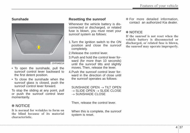
4 37
Features of your vehicle
Sunshade
• To open the sunshade, pull thesunroof control lever backward tothe first detent position.
• To close the sunshade when thesunroof glass is closed, push thesunroof control lever forward.
To stop the sliding at any point, pullor push the sunroof control levermomentarily.
✽✽ NOTICEIt is normal for wrinkles to form onthe blind because of its materialcharacteristic.
Resetting the sunroofWhenever the vehicle battery is dis-connected or discharged, or relatedfuse is blown, you must reset yoursunroof system as follows:
1.Turn the ignition switch to the ONposition and close the sunroofcompletely.
2.Release the control lever.3.Push and hold the control lever for-
ward (for more than 10 seconds)until the sunroof tilts and slightlymoves. Then, release the lever.
4.Push the sunroof control lever for-ward in the direction of close untilthe sunroof operates as follows:
SUNSHADE OPEN → TILT OPEN→ SLIDE OPEN → SLIDE CLOSE→ SUNSHADE CLOSE
Then, release the control lever.
When this is complete, the sunroofsystem is reset.
❈ For more detailed information,contact an authorized Kia dealer.
✽✽ NOTICEIf the sunroof is not reset when thevehicle battery is disconnected ordischarged, or related fuse is blown,the sunroof may operate improperly.
OYF049214
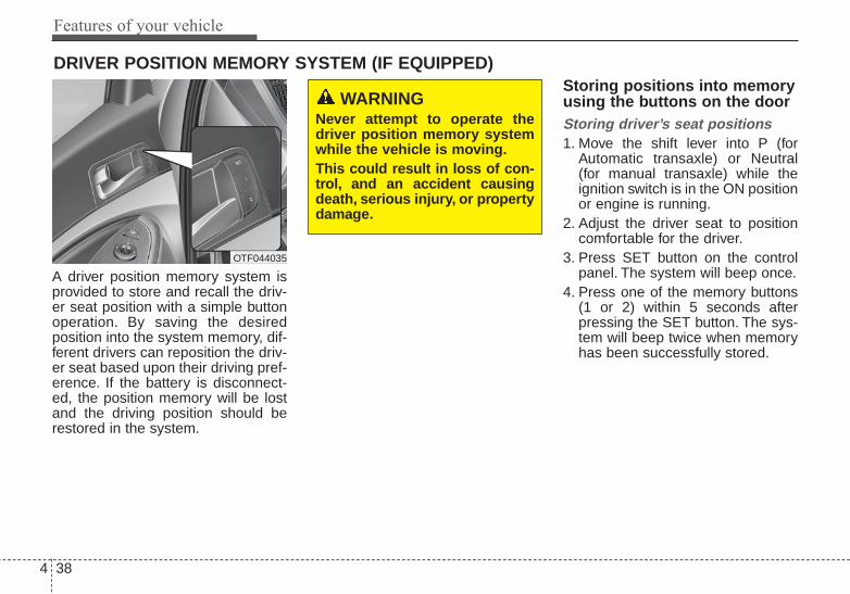
Features of your vehicle
384
A driver position memory system isprovided to store and recall the driv-er seat position with a simple buttonoperation. By saving the desiredposition into the system memory, dif-ferent drivers can reposition the driv-er seat based upon their driving pref-erence. If the battery is disconnect-ed, the position memory will be lostand the driving position should berestored in the system.
Storing positions into memoryusing the buttons on the doorStoring driver’s seat positions1. Move the shift lever into P (for
Automatic transaxle) or Neutral(for manual transaxle) while theignition switch is in the ON positionor engine is running.
2. Adjust the driver seat to positioncomfortable for the driver.
3. Press SET button on the controlpanel. The system will beep once.
4. Press one of the memory buttons(1 or 2) within 5 seconds afterpressing the SET button. The sys-tem will beep twice when memoryhas been successfully stored.
DRIVER POSITION MEMORY SYSTEM (IF EQUIPPED)
OTF044035
WARNING Never attempt to operate thedriver position memory systemwhile the vehicle is moving.This could result in loss of con-trol, and an accident causingdeath, serious injury, or propertydamage.

4 39
Features of your vehicle
Recalling positions from memory1. The shift lever is in P or N (for
Automatic transaxle) or Neutral(for manual transaxle) with one ofthe condition below:- The ignition switch in the ON
position or engine running.- The ignition switch in the
LOCK/OFF or ACC positionwhile the driver's door is opened.
- The ignition switch in theLOCK/OFF or ACC position andwithin 30 seconds after the driver'sdoor was closed.
2. Press the desired memory button(1 or 2). The system will beeponce, then the driver’s seat willautomatically adjust to the storedposition.
Adjusting the control switch for thedriver seat while the system is recall-ing the stored position will cause themovement to stop and move in thedirection that the control switch ismoved.
Easy access function (if equipped)With the shift lever in the P position,the system will move the driver's seatautomatically as follows:• Without smart key system
- It will move the driver’s seat rear-ward when the ignition key isremoved and front driver’s door isopened.
- It will move the driver’s seat for-ward when the ignition key isinserted.
• With smart key system- It will move the driver’s seat rear-
ward when the engine start/stopbutton is turned to the OFF posi-tion and front driver’s door isopened.
- It will move the driver’s seat for-ward when the engine start/stopbutton is turned to the ACC orSTART position.
You can activate or deactivate thisfeature. Refer to "User settings" inchapter 4.
WARNING Use caution when recallingadjustment memory while sit-ting in the vehicle. Push the seatposition control knob to thedesired position immediately ifthe seat moves too far in anydirection.

Features of your vehicle
404
Electric power steeringPower steering uses the motor toassist you in steering the vehicle. Ifthe engine is off or if the power steer-ing system becomes inoperative, thevehicle may still be steered, but it willrequire increased steering effort.The motor driven power steering iscontrolled by the power steering con-trol unit which senses the steeringwheel torque and vehicle speed tocommand the motor.The steering wheel becomes heavieras the vehicle’s speed increases andbecomes lighter as the vehicle’sspeed decreases for better control ofthe steering wheel.Should you notice any change in theeffort required to steer during normalvehicle operation, have the powersteering checked by an authorizedKia dealer.
✽✽ NOTICEThe following symptoms may occurduring normal vehicle operation:• The steering effort is increased
immediately after turning the igni-tion switch on. This happens as thesystem performs the EPS systemdiagnostics. When the diagnosticsare completed, the steering wheelwill return to its normal condition
• A click noise may be heard fromthe EPS relay after the ignitionswitch is turned to the ON orLOCK position.
• Motor noise may be heard whenthe vehicle is at a stop or at a lowdriving speed.
• The steering effort increases if thesteering wheel is rotated continuous-ly when the vehicle is not in motion.However, after a few minutes, it willreturn to its normal conditions.
• When you operate the steeringwheel in low temperature, abnor-mal noise could occur. If tempera-ture rises, the noise will disappear.This is a normal condition.
If the Electric Power Steering Systemdoes not operate normally, the warn-ing light will illuminate on the instru-ment cluster.The steering wheel maybecome difficult to control or operateabnormally. Take your vehicle to anauthorized Kia dealer and have thevehicle checked as soon as possible.
STEERING WHEEL

4 41
Features of your vehicle
Tilt and telescoping steeringTilt steering allows you to adjust thesteering wheel before you drive. Youcan also raise it to give your legsmore room when you exit and enterthe vehicle.
The steering wheel should be posi-tioned so that it is comfortable foryou to drive, while permitting you tosee the instrument panel warninglights and gauges.
To change the steering wheel angle,pull down the lock release lever (1),adjust the steering wheel to thedesired angle (2) and height (3), thenpull up the lock-release lever (4) tolock the steering wheel in place. Besure to adjust the steering wheel tothe desired position before driving.
Horn
To sound the horn, press the hornsymbol on your steering wheel.Check the horn regularly to be sure itoperates properly.To sound the horn, press the areaindicated by the horn symbol on yoursteering wheel (see illustration). Thehorn will operate only when this areais pressed.
WARNING - Steering wheel adjustment
Never adjust the angle andheight of the steering wheelwhile driving. You may losesteering control
OTF044037 OTF044039

Features of your vehicle
424
Heated steering wheel (if equipped)
With the ENGINE START/STOP but-ton in the ON position, pressing theheated steering wheel button warmsthe steering wheel. The indicator onthe button will illuminate.To turn the heated steering wheel off,press the button once again. Theindicator on the button will turn off.It will turn off automatically approxi-mately 30 minutes after the heatedsteering wheel is turned on.
If you turn on the ignition again afterturning off your engine in half anhour (after operating heater button),the heating system will be main-tained in its 'on' condition.
CAUTION• Do not install any grip to oper-
ate the steering wheel. Thiscauses damage to the heatedsteering wheel system.
• When cleaning the heatedsteering wheel, do not use anorganic solvent such as paintthinner, benzene, alcohol andgasoline. Doing so may dam-age the surface of the steeringwheel.
• If the surface of the steeringwheel is damaged by a sharpobject, damage to the heatedsteering wheel componentscould occur.
OTF044038N

4 43
Features of your vehicle
Inside rearview mirrorAdjust the rearview mirror so that thecenter view through the rear windowis seen. Make this adjustment beforeyou start driving.Do not place objects in the rear seatwhich would interfere with your visionthrough the rear window.
Day/night rearview mirror (if equipped)
Make this adjustment before youstart driving and while the day/nightlever is in the day position.Pull the day/night lever toward you toreduce the glare from the headlightsof the vehicles behind you duringnight driving.Remember that you lose somerearview clarity in the night position.
Electric chromic mirror (ECM)with HomeLink® system and compass (if equipped)Your vehicle may be equipped with aGentex Automatic-Dimming Mirrorwith a Z-Nav® Electronic CompassDisplay and an Integrated HomeLink®
Wireless Control System.During nighttime driving, this featurewill automatically detect and reducerearview mirror glare while the com-pass indicates the direction the vehi-cle is pointed. The HomeLink®
Universal Transceiver allows you toactivate your garage door(s), electricgate, home lighting, etc.
* HomeLink® is a registered trade-mark of Johnson Controls, Inc.
MIRRORS
WARNING - Mirror adjustment
Do not adjust the rearview mirrorwhile the vehicle is moving. Thiscould result in loss of control.
OTF040040
Day
Night

Features of your vehicle
444
(1) Channel 1 button(2) Channel 2 button(3) Status indicator LED(4) Channel 3 button(5) Rear light sensor(6) Dimming ON/OFF button(7) Compass control button(8) Compass display
Automatic-Dimming Night VisionSafety® (NVS®) Mirror
The NVS® Mirror in your vehicle isthe most advanced way to reduceannoying glare in the rearview mirrorduring any driving situation. For moreinformation regarding NVS® mirrorsand other applications, please referto the Gentex website:www.gentex.com
Automatic-dimming functionYour mirror will automatically dimupon detecting glare from the vehi-cles traveling behind you. The auto-dimming function can be controlledby the Dimming ON/OFF Button:
1. Pressing the button turns theauto-dimming function OFF whichis indicated by the green StatusIndicator LED turning off.
2. Pressing the button again turnsthe auto-dimming function ONwhich is indicated by the greenStatus Indicator LED turning on.
✽✽ NOTICEThe mirror defaults to the ON posi-tion each time the vehicle is started.
Z-Nav™ Compass Display
The NVS® Mirror in your vehicle isalso equipped with a Z-Nav®
Compass that shows the vehicleCompass heading in the DisplayWindow using the 8 basic cardinalheadings (N, NE, E, SE, etc.).
CAUTIONThe NVS® Mirror automaticallyreduces glare during drivingconditions based upon light lev-els monitored in front of the vehi-cle and from the rear of the vehi-cle. These light sensors are visi-ble through openings in the frontand rear of the mirror case. Anyobject that obstructs either lightsensor will degrade the automat-ic dimming control feature.
OYF049230C

4 45
Features of your vehicle
Compass functionThe Compass can be turned ON andOFF and will remember the last statewhen the ignition is cycled. To turnthe display feature ON/OFF:1. Press and release the button to
turn the display feature OFF.2. Press and release the button
again to turn the display back ON.Additional options can be set withpress and hold sequences of the button and are detailed below.
There is a difference between mag-netic north and true north. The com-pass in the mirror can compensatefor this difference when it knows theMagnetic Zone in which it is operat-ing. This is set either by the dealer orby the user. The operating ZoneNumbers for North America areshown in the figure on the followingsection.
B520C05NF

Features of your vehicle
464
To adjust the Zone setting:1. Determine the desired Zone
Number based upon your currentlocation on the Zone Map.
2. Press and hold the button formore than 3 but less than 6 sec-onds, the current Zone Numberwill appear on the display.
3. Pressing and holding the buttonagain will cause the numbers toincrement (Note: they will repeat…13, 14, 15, 1, 2, …). Releasingthe button when the desired ZoneNumber appears on the displaywill set the new Zone.
4. Within about 5 seconds the com-pass will start displaying a com-pass heading again.
There are some conditions that cancause changes to the vehicle mag-nets, such as installing a ski rack or aCB antenna. Body repair work on thevehicle can also cause changes to thevehicle's magnetic field. In these situa-tions, the compass will need to be re-calibrated to quickly correct for thesechanges. To re-calibrate the compass:
1. Press and hold the button formore than 6 seconds. When thecompass memory is cleared a "C"will appear in the display.
2. To calibrate the compass, drivethe vehicle in 2 complete circles atless than 5 mph (8 km/h).
Integrated HomeLink® WirelessControl System
The HomeLink® Wireless ControlSystem provides a convenient way toreplace up to three hand-held radio-frequency (RF) transmitters with asingle built-in device. This innovativefeature will learn the radio frequencycodes of most current transmitters tooperate devices such as gate opera-tors, garage door openers, entrydoor locks, security systems, evenhome lighting. Both standard androlling code-equipped transmitterscan be programmed by following theoutlined procedures. AdditionalHomeLink® information can be foundat: www.homelink.com or by calling1-800-355-3515.
CAUTIONBefore programmingHomeLink® to a garage dooropener or gate operator, makesure that people and objects areout of the way of the device toprevent potential harm or dam-age. Do not use HomeLink® withany garage door opener thatlacks the safety stop andreverse features required byU.S. federal safety standards(this includes any garage dooropener model manufacturedbefore April 1, 1982). A garagedoor that cannot detect anobject - signaling the door tostop and reverse - does notmeet current U.S. federal safetystandards. Using a garage dooropener without these featuresincreases the risk of seriousinjury or death.

4 47
Features of your vehicle
Retain the original transmitter of theRF device you are programming foruse in other vehicles as well as forfuture HomeLink® programming. It isalso suggested that upon the sale ofthe vehicle, the programmedHomeLink® buttons be erased forsecurity purposes.
Programming HomeLink®
✽✽ NOTICE• When programming a garage
door opener, it is advised to parkthe vehicle outside of the garage.
• It is recommended that a new bat-tery be placed in the hand-heldtransmitter of the device being pro-grammed to HomeLink® for quick-er training and accurate transaxleof the radio-frequency signal.
• Some vehicles may require theignition switch to be turned to thesecond (or "accessories") positionfor programming and/or opera-tion of HomeLink®.
• In the event that there are still pro-gramming difficulties or questionsafter following the programmingsteps listed below, contactHomeLink® at: www.homelink.comor 1-800-355-3515.
Standard programmingTo train most devices, follow theseinstructions:1. For first-time programming, press
and hold the two outside buttons,HomeLink® Channel 1 andChannel 3 Buttons, until the indi-cator light begins to flash (after 20seconds). Release both buttons.Do not hold the buttons for longerthan 30 seconds.
2. Position the end of your hand-heldtransmitter 1-3 inches (2-8 cm)away from the HomeLink® buttonswhile keeping the indicator light inview.
3. Simultaneously press and holdboth the HomeLink® and hand-held transmitter button. DO NOTrelease the buttons until step 4has been completed.
4. While continuing to hold the but-tons the red Indicator Status LEDwill flash slowly and then rapidlyafter HomeLink® successfullytrains to the frequency signal fromthe hand-held transmitter. Releaseboth buttons.

Features of your vehicle
484
5. Press and hold the just-trainedHomeLink® button and observethe red Status Indicator LED. If theindicator light stays on constantly,programming is complete andyour device should activate whenthe HomeLink® button is pressedand released.
6. To program the remaining twoHomeLink® buttons, follow steps 2through 5.
Rolling code programmingRolling code devices which are"code-protected" and manufacturedafter 1996 may be determined by thefollowing:• Reference the device owner's
manual for verification.• The handheld transmitter appears
to program the HomeLink®
Universal Transceiver but does notactivate the device.
• Press and hold the trainedHomeLink® button. The device hasthe rolling code feature if the indi-cator light flashes rapidly and thenturns solid after 2 seconds
To train rolling code devices, followthese instructions:1. At the garage door opener receiv-
er (motor-head unit) in the garage,locate the "learn" or "smart" but-ton. This can usually be foundwhere the hanging antenna wire isattached to the motor-head unit.Exact location and color of the but-ton may vary by garage dooropener brand.If there is difficulty locating the train-ing button, reference the deviceowner's manual or please visit ourWeb site at www.homelink.com.
2. Firmly press and release the"learn" or "smart" button (whichactivates the "training light").
✽✽ NOTICEThere are 30 seconds in which to ini-tiate step 3.

4 49
Features of your vehicle
3. Return to the vehicle, firmly pressand hold for two seconds thedesired HomeLink® button thenrelease. Repeat the"press/hold/release" sequence asecond time to complete the pro-gramming. (Some devices mayrequire you to repeat thissequence a third time to completethe programming.)
4. Press and hold the just-trainedHomeLink® button and observethe red Status Indicator LED. If theindicator light stays on constantly,programming is complete andyour device should activate.
5. To program the remaining twoHomeLink® buttons, follow eithersteps 1 through 4 above for otherRolling Code devices or steps 2through 5 in Standard Programmingfor standard devices.
Gate operator & Canadian pro-grammingDuring programming, your handheldtransmitter may automatically stoptransmitting. Continue to press theIntegrated HomeLink® WirelessControl System button (note steps 2through 4 in the StandardProgramming portion of this docu-ment) while you press and re-press("cycle") your handheld transmitterevery two seconds until the frequen-cy signal has been learned. The indi-cator light will flash slowly and thenrapidly after several seconds uponsuccessful training.
Operating HomeLink®
To operate, simply press and releasethe programmed HomeLink® button.Activation will now occur for thetrained device (i.e. garage dooropener, gate operator, security sys-tem, entry door lock, home/officelighting, etc.). For convenience, thehand-held transmitter of the devicemay also be used at any time.
Reprogramming a singleHomeLink® buttonTo program a new device to a previ-ously trained HomeLink® button, fol-low these steps:1. Press and hold the desired
HomeLink® button. Do NOT releaseuntil step 4 has been completed.
2. When the indicator light begins toflash slowly (after 20 seconds),position the handheld transmitter 1to 3 inches away from theHomeLink® surface.
3. Press and hold the handheldtransmitter button.The HomeLink®
indicator light will flash, first slowlyand then rapidly.
4. When the indicator light begins toflash rapidly, release both buttons.
5. Press and hold the just-trainedHomeLink® button and observethe red Status Indicator LED. If theindicator light stays on constantly,programming is complete andyour new device should activate.

Features of your vehicle
504
Erasing HomeLink® buttonsIndividual buttons cannot be erased.However, to erase all three pro-grammed buttons:1. Press and hold the two outer
HomeLink® buttons until the indi-cator light begins to flash-after 20seconds.
2. Release both buttons. Do not holdfor longer than 30 seconds.
The Integrated HomeLink® WirelessControl System is now in the training(learn) mode and can be pro-grammed at any time following theappropriate steps in theProgramming sections above.
FCC ID: NZLZTVHL3IC: 4112A-ZTVHL3
This device complies with Part 15of the FCC Rules.Operation is subject to the followingtwo conditions:1. This device may not cause harm-
ful interference, and2. This device must accept any inter-
ference received, including inter-ference that may cause undesiredoperation.
NVS® and ZNav® are registeredtrademarks. Nav® are of GentexCorporation, Zeeland, Michigan.HomeLink® is a registered trade-mark owned by Johnson ControlsTechnology Company, Holland,Michigan.
WARNINGThe transceiver has been testedand complies with FCC andIndustry Canada rules. Changesor modifications not expresslyapproved by the party responsi-ble for compliance could voidthe user's authority to operatethe device.
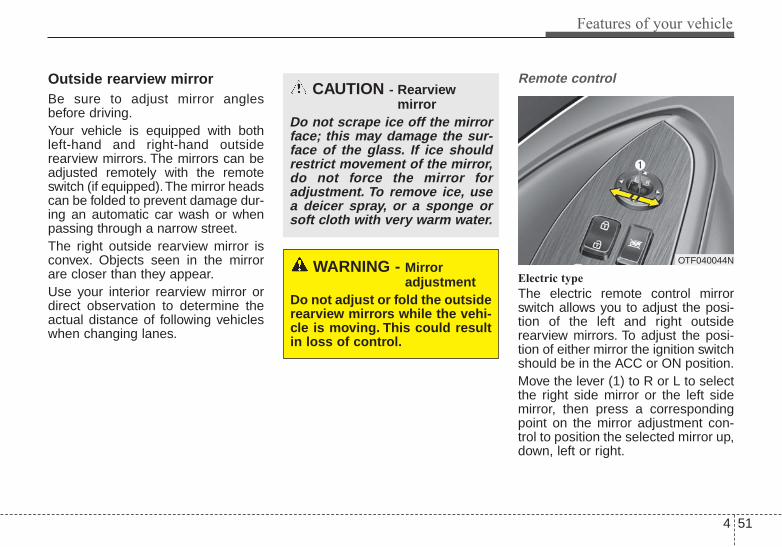
4 51
Features of your vehicle
Outside rearview mirror Be sure to adjust mirror anglesbefore driving.Your vehicle is equipped with bothleft-hand and right-hand outsiderearview mirrors. The mirrors can beadjusted remotely with the remoteswitch (if equipped).The mirror headscan be folded to prevent damage dur-ing an automatic car wash or whenpassing through a narrow street.The right outside rearview mirror isconvex. Objects seen in the mirrorare closer than they appear.Use your interior rearview mirror ordirect observation to determine theactual distance of following vehicleswhen changing lanes.
Remote control
Electric type
The electric remote control mirrorswitch allows you to adjust the posi-tion of the left and right outsiderearview mirrors. To adjust the posi-tion of either mirror the ignition switchshould be in the ACC or ON position.Move the lever (1) to R or L to selectthe right side mirror or the left sidemirror, then press a correspondingpoint on the mirror adjustment con-trol to position the selected mirror up,down, left or right.
CAUTION - Rearview mirror
Do not scrape ice off the mirrorface; this may damage the sur-face of the glass. If ice shouldrestrict movement of the mirror,do not force the mirror foradjustment. To remove ice, usea deicer spray, or a sponge orsoft cloth with very warm water.
WARNING - Mirror adjustment
Do not adjust or fold the outsiderearview mirrors while the vehi-cle is moving. This could resultin loss of control.
OTF040044N

Features of your vehicle
524
After the adjustment, put the leverinto neutral (center) position to pre-vent inadvertent adjustment.
Folding the outside rearview mirror
Electric Type (if equipped)
To fold the outside rearview mirror,depress the button.To unfold it, depress the buttonagain.
CAUTION - Outside mirror• The mirrors stop moving when
they reach the maximumadjusting angles, but themotor continues to operatewhile the switch is pressed.Do not press the switch longerthan necessary, the motormay be damaged.
• Do not attempt to adjust theoutside rearview mirror byhand. Doing so may damagethe parts.
CAUTION - Electric typeoutside rearview mirror
The electric type outsiderearview mirror operates eventhough the ignition switch is inthe OFF position. However, toprevent unnecessary batterydischarge, do not adjust themirrors longer than necessarywhile the engine is not running.In case it is an electric type out-side rearview mirror, don’t fold itby hand. It could cause motorfailure.
OTF040046

4 53
Features of your vehicle
Manual type
To fold outside rearview mirror, graspthe housing of mirror and then fold ittoward the rear of the vehicle.
OTF040045

Features of your vehicle
544
INSTRUMENT CLUSTER
1. Tachometer
2. Speedometer
3. Engine coolant temperature gauge
4. Fuel gauge
5. Turn signal indicators
6. Warning and indicator lights
7. LCD display
OTF044050N/OTF044051N
■■ Type A
❈ The actual cluster in the vehicle may differfrom the illustration.For more details refer to the "Gauges" inthe next pages.
■■ Type B

4 55
Features of your vehicle
Instrument Cluster ControlAdjusting Instrument ClusterIllumination
The instrument panel illuminationintensity can be adjusted by pressingthe control switch with the headlightswitch in any position when the igni-tion switch is in the ON position.The illumination intensity is shown onthe instrument cluster LCD display.
• If you hold the illumination controlbutton (" " or " "), the bright-ness will be changed continuously.
• If the brightness reaches to themaximum or minimum level, analarm will sound.
LCD Display Control
The LCD display modes can bechanged by using the control buttonson the steering wheel.
(1) : MODE button for changingmodes
(2) OK : SELECT/RESET button forsetting or resetting theselected item
(3) : MOVE button for changingitems
❈ For the LCD modes, refer to "LCDDisplay" in this chapter.
OTF044052
OTF044111L
OTF044112L
■ Type A
■ Type B
OTF044363L

Features of your vehicle
564
GaugesSpeedometer
The speedometer indicates the for-ward speed of the vehicle.The speedometer is calibrated inmiles per hour and/or kilometers perhour.
Tachometer
The tachometer indicates theapproximate number of engine revo-lutions per minute (rpm).Use the tachometer to select the cor-rect shift points and to prevent lug-ging and/or over-revving the engine.
The tachometer pointer may moveslightly when the ignition switch is inACC or ON position with the engineOFF. This movement is normal andwill not affect the accuracy of thetachometer once the engine is run-ning.
OTF044053N
OTF044054N
■ Type A
■ Type C
OTF044055
OTF044056
■ Type A
■ Type B
CAUTION - Red zoneDo not operate the engine with-in the tachometer's RED ZONE.This may cause severe enginedamage.

4 57
Features of your vehicle
Engine coolant temperature gauge
This gauge shows the temperatureof the engine coolant when the igni-tion switch is ON.Do not continue driving with an over-heated engine. If your vehicle over-heats, refer to "If the engine over-heats" in chapter 6.If the gauge pointer moves beyondthe normal range area toward the "H"position, it indicates overheating thatmay damage the engine.
Fuel gauge
The fuel gauge indicates the approx-imate amount of fuel remaining in thefuel tank. The fuel tank capacity isgiven in chapter 8. The fuel gauge issupplemented by a low fuel warninglight, which will illuminate when thefuel tank is nearly empty.On inclines or curves, the fuel gaugepointer may fluctuate or the low fuelwarning light may come on earlierthan usual due to the movement offuel in the tank.
WARNING - Fuel gaugeStop and obtain additional fuelas soon as possible after thewarning light comes on or whenthe gauge indicator comesclose to the E level. Running outof fuel can expose vehicle occu-pants to danger.
CAUTION - Low fuelAvoid driving with extremelylow fuel level. Running out offuel could cause the engine tomisfire, damaging the catalyticconverter.
OTF044057
■ Type A ■ Type B
OTF044058L
■ Type A ■ Type B

Features of your vehicle
584
Odometer
Odometer
The odometer indicates the total dis-tance the vehicle has been driven.You will also find the odometer usefulto determine when periodic mainte-nance should be performed.
Outside Temperature Gauge
This gauge indicates the current out-side air temperatures by 1°F (1°C).- Temperature range : -40 °F ~ 140
°F (-40°C ~ 60°C)
The outside temperature on the dis-play may not change immediatelylike a Hg thermometer to prevent thedriver from being inattentive.
The temperature unit (from °C to °For from °F to °C) can be changed byusing the “User Settings” mode of theLCD display or While pressing theOFF button, press the AUTO buttonfor 3 seconds or more. (for automaticclimate control system)
❈ For more details, refer to “LCDDisplay” in this chapter.
OTF044120N
OTF044121N
■ Type A
■ Type B
OTF044124N
OTF044123N
■ Type A
■ Type B
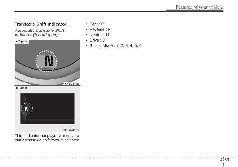
4 59
Features of your vehicle
Transaxle Shift IndicatorAutomatic Transaxle ShiftIndicator (if equipped)
This indicator displays which auto-matic transaxle shift lever is selected.
• Park : P• Reverse : R• Neutral : N• Drive : D• Sports Mode : 1, 2, 3, 4, 5, 6
OTF044364
OTF044125L
■ Type A
■ Type B

Features of your vehicle
604
LCD DISPLAY (IF EQUIPPED)
Modes Symbol Explanation
Trip Computer This mode displays driving information like the tripmeter, fuel economy, and so on.For more details, refer to “Trip Computer” in this chapter.
ServiceThis mode informs of service interval (mileage or days) and warning messagesrelated to TPMS and so on.
Master warning
User Settings On this mode, you can change settings of the doors, lamps, etc.
❈ For controlling the LCD modes, refer to "LCD Display Control" in this chapter.
LCD Modes (for Type B cluster)

4 61
Features of your vehicle
Service ModeService Interval
Service in
It calculates and displays when youneed a scheduled maintenanceservice (mileage or days).
If the remaining mileage or timereaches 900 mi. (1,500 km) or 30days, "Service in" message is dis-played for several seconds each timeyou set the ignition switch or EngineStart/Stop Button to the ON position.
Service required
If you do not have your vehicle serv-iced according to the already inputtedservice interval, "Service required"message is displayed for several sec-onds each time you set the ignitionswitch or Engine Start/Stop Button tothe ON position (The mileage andtime changes to "---").
OTF044411N
OTF044131L
■ Type A
■ Type B
OTF044412N
OTF044196L
■ Type A
■ Type B

Features of your vehicle
624
To reset the service interval to themileage and days you inputtedbefore:- Press the SELECT/RESET button
OK for more than 1 second.
Service in OFF
If the service interval is not set,"Service in OFF" message is dis-played on the LCD display.
✽✽ NOTICE If any of the following conditionsoccurs, the mileage and days may beincorrect.- The battery cable is disconnected.- The fuse switch is turned off.- The battery is discharged.
OTF044414L
OTF044192L
■ Type A
■ Type B

4 63
Features of your vehicle
Master Warning Mode (if equipped)
• This warning light informs the driv-er the following situations- Low washer fluid- TPMS (if equipped)- Service reminder
The Master Warning Light illumi-nates when more than one of theabove warning situations occur. Atthis time, the LCD Modes Icon willchange from ( ) to ( ).If the warning situation is solved, themaster warning light will be turned offand the LCD Modes Icon will bechanged back to its previous icon ( ).(ex : refill the washer fluid)
User Settings ModeDescription
On this mode, you can change set-ting of the doors, lamps, and so on.
DoorAuto Door Lock (if equipped)
• Off:The auto door lock operation willbe deactivated.
• Speed:All doors will be automaticallylocked when the vehicle speedexceeds 15km/h (9.3mph).
• Shift Lever:All doors will be automaticallylocked if the automatic transaxleshift lever is shifted from the P(Park) position to the R (Reverse),N (Neutral), or D (Drive) position.
OTF044133L
OTF044134L
■ Type A
■ Type B

Features of your vehicle
644
Auto Door Unlock (if equipped)
• Off:The auto door unlock operation willbe canceled.
• Key Out or Power Off:All doors will be automaticallyunlocked when the ignition key isremoved from ignition switch orEngine Start/Stop Button is set tothe OFF position.
• Shift Lever:All doors will be automaticallyunlocked if the automatic transaxleshift lever is shifted to the P (Park)position.
Two Press Unlock (if equipped)
• Off:The two press unlock function willbe deactivated.Therefore, all doorswill unlock if the door is unlocked.
• On:The driver’s door will unlock if thedoor is unlocked. When the door isunlocked again within 4 seconds,all doors will unlock.
Horn Feedback (if equipped)
• Off:The Horn feedback operation willbe deactivated.
• On:After locking the door by pressingthe lock button on the transmitter, ifyou press the lock button againwithin 4 seconds, the warningsound will operate once to indicatethat all doors are locked.
LampOne Touch Turn Lamp (if equipped)
If this item is checked, the lanechange signals will blink 3, 5 or 7times when the turn signal lever ismoved slightly.
Head Lamp Delay (if equipped)
If this item is checked, the headlampdelay and headlamp welcome func-tion will be activated.
Welcome Light (if equipped)
If this item is checked, the welcomelight function of the puddle lamp willbe activated.

4 65
Features of your vehicle
ConvenienceLanguage
Choose the language you preferwithin the LCD.
Temperature Unit
Convert the temperature unit from °Cto °F or from °F to °C.
AVG Fuel Eco Reset
• Auto Reset:The average fuel economy willreset automatically when refueling.
• Manual Reset:The average fuel economy will notreset automatically whenever refu-eling.
For more details, refer to "TripComputer" in this chapter.
Seat Easy Access (if equipped)
If this item is checked, the driver’sseat will automatically move forwardor rearward for the driver to enter orexit the vehicle comfortably.
Welcome Sound
If this item is checked, the welcomesound function will be activated.
Steering Position (if equipped)
If this item is checked, the warningfunction regarding the steering wheelalignment will be activated.For more details, refer to "WarningMessages" in this chapter.
Driving Assist (if equipped)RCTA
If this item is checked RCTA (Rearcross traffic alert) function in BSD(Blind spot detection) system will beactivated.For more details, refer to Blind spotdetection system in chapter 5.

Features of your vehicle
664
Service Interval
On this mode, you can activate theservice interval function with mileage(mi. or km) and period (months).
Warning MessagesShift to "P" position (for smart keysystem and automatic transaxle)
• This warning message illuminates ifyou try to turn off the engine withoutthe shift lever in P (Park) position.
• At this time, the Engine Start/StopButton turns to the ACC position (Ifyou press the Engine Start/StopButton once more, it will turn to theON position).
OTF044147L
OTF044148L
■ Type A
■ Type B
OTF044135N
OPS043133
■ Type A
■ Type B

4 67
Features of your vehicle
Low Key Battery (for smart key system)
• This warning message illuminatesif the battery of the smart key isdischarged when the EngineStart/Stop Button changes to theOFF position.
Press START button while turningwheel (for smart key system)
• This warning message illuminatesif the steering wheel does notunlock normally when the EngineStart/Stop Button is pressed.
• It means that you should press theEngine Start/Stop Button whileturning the steering wheel rightand left.
OTF044141L
OTF044142L
■ Type A
■ Type B
OTF044173L
OTF044187L
■ Type A
■ Type B

Features of your vehicle
684
Steering wheel unlocked (for smart key system)
• This warning message illuminatesif the steering wheel does not lockwhen the Engine Start/Stop Buttonchanges to the OFF position.
Check steering wheel lock system (for smart key system)
• This warning message illuminatesif the steering wheel does not locknormally when the EngineStart/Stop Button changes to theOFF position.
Press brake pedal to start engine (for smart key system and auto-matic transaxle)
OTF044174L
OTF044188L
■ Type A
■ Type B
OTF044175L
OTF044189L
■ Type A
■ Type B OTF044151L
OTF044152L
■ Type A
■ Type B

4 69
Features of your vehicle
• This warning message illuminatesif the Engine Start/Stop Buttonchanges to the ACC position twiceby pressing the button repeatedlywithout depressing the brakepedal.
• It means that you should depressthe brake pedal to start the engine.
Press clutch pedal to start engine(for smart key system and manualtransaxle)
• This warning message illuminates ifthe Engine Start/Stop Buttonchanges to the ACC position twiceby pressing the button repeatedlywithout depressing the clutch pedal.
• It means that you should depressthe clutch pedal to start the engine.
OTF044155L
OTF044190L
■ Type A
■ Type B

Features of your vehicle
704
Key not in vehicle (for smart key system)
• This warning message illuminatesif the smart key is not in the vehiclewhen you press the EngineStart/Stop Button.
• It means that you should alwayshave the smart key with you.
Key not detected (for smart key system)
• This warning message illuminatesif the smart key is not detectedwhen you press the EngineStart/Stop Button.
Press START button again (for smart key system)
• This warning message illuminatesif you can not operate the EngineStart/Stop Button when there is aproblem with the Engine Start/StopButton system.
OTF044137L
OTF044138L
■ Type A
■ Type B
OTF044143L
OTF044144L
■ Type A
■ Type B
OTF044139L
OTF044140L
■ Type A
■ Type B

4 71
Features of your vehicle
• It means that you could start theengine by pressing the EngineStart/ Stop Button once more.
• If the warning illuminates eachtime you press the EngineStart/Stop Button, have your vehi-cle inspected by an authorized Kiadealer.
Press start button with smart key(for smart key system)
• This warning message illuminatesif you press the Engine Start/StopButton while the warning message"Key not detected" is illuminating.
• At this time, the immobilizer indica-tor light blinks.
Check BRAKE SWITCH fuse(for smart key system and auto-matic transaxle)
• This warning message illuminatesif the brake switch fuse is discon-nected.
OTF044145L
OTF044146L
■ Type A
■ Type B OTF044156L
OTF044157L
■ Type A
■ Type B

Features of your vehicle
724
• It means that you should replacethe fuse with a new one. If that isnot possible, you can start theengine by pressing the EngineStart/Stop Button for 10 seconds inthe ACC position.
Shift to "P" or "N" to start engine (for smart key system and auto-matic transaxle)
• This warning message illuminatesif you try to start the engine withthe shift lever not in the P (Park) orN (Neutral) position.
✽✽ NOTICEYou can start the engine with theshift lever in the N (Neutral) posi-tion. But, for your safety, you shouldstart the engine with the shift leverin the P (Park) position.
OTF044149L
OTF044150L
■ Type A
■ Type B

4 73
Features of your vehicle
Door Open
• It means that any door is open.
Trunk Open
• It means that the trunk is open.
Low Washer Fluid
• This warning message illuminateson the service reminder mode ifthe washer fluid level in the reser-voir is nearly empty.
• It means that you should refill thewasher fluid.
OTF044160
OTF044161
■ Type A
■ Type B
OTF044162
OTF044163
■ Type A
■ Type B
OTF044158L
OTF044159L
■ Type A
■ Type B

Features of your vehicle
744
Turn on "FUSE SWITCH" (if equipped)
• This warning message illuminatesif the fuse switch on the fuse box isOFF.
• It means that you should turn thefuse switch on.
For more details, refer to "Fuses" inchapter 7.
Align steering wheel (if equipped)
• This warning message illuminatesif you start the engine when thesteering wheel is turned to morethan 90 degrees to the left or right.
• It means that you should turn thesteering wheel and make the angleof the steering wheel be less than30 degrees.
OTF044153L
OTF044154L
■ Type A
■ Type BOTF044166L
■ Type B

4 75
Features of your vehicle
OverviewDescription
The trip computer is a microcomput-er-controlled driver information sys-tem that displays information relatedto driving.
✽✽ NOTICESome driving information stored inthe trip computer (for exampleAverage Vehicle Speed) resets if thebattery is disconnected.
Trip Modes (Type A) Trip Modes (Type B)
TRIP COMPUTER
*1 : To enter the user settings mode,press the MODE ( ) button.
Tripmeter A
Average Fuel Economy
Instant Fuel Economy
Average Vehicle Speed
Elapsed Time
Service mode
User settings *1
↕↕
→→
→→Tripmeter B
Distance to empty↕↕
↕↕
↕↕
↕↕
↕↕
↕↕
• Tripmeter [B]• Average Vehicle Speed [B]• Elapsed Time [B]
TRIP B
• Tripmeter [A]• Average Vehicle Speed [A]• Elapsed Time [A]
TRIP A
• Distance To Empty• Average Fuel Economy• Instant Fuel Economy
FUEL ECONOMY
To change the trip mode, press theMOVE ( ) button.
↕↕
↕↕
→→
→→

Features of your vehicle
764
Fuel EconomyDistance to empty (Range) (1)
• The Distance to empty (range) isthe estimated distance the vehiclecan be driven with the remainingfuel.- Distance range : 30 ~ 1999 mi or
50 ~ 1999 km.• If the estimated distance is below
30 mi. (50 km), the trip computer willdisplay "---" as distance to empty.
✽✽ NOTICE• If the vehicle is not on level ground
or the battery power has beeninterrupted, the distance to emptyfunction may not operate correctly.
• The distance to empty may differfrom the actual driving distance asit is an estimate of the availabledriving distance.
• The trip computer may not regis-ter additional fuel if less than 6liters (1.6 gallons) of fuel areadded to the vehicle.
• The fuel economy and distance toempty may vary significantly basedon driving conditions, drivinghabits, and condition of the vehicle.
OTF044169N
OTF044193N
■ Type A
■ Type B

4 77
Features of your vehicle
Average Fuel Economy (2)• The average fuel economy is calcu-
lated by the total driving distanceand fuel consumption since the lastaverage fuel economy reset.- Fuel economy range: 0.0 ~ 99.9
MPG or L/100km• The average fuel economy can be
reset both manually and automati-cally.
Manual reset
To clear the average fuel economymanually, press the SELECT/RESETbutton OK on the steering wheel formore than 1 second when the aver-age fuel economy is displayed.
Automatic reset
To make the average fuel economybe reset automatically whenever refu-eling, select the "Auto Reset" mode inUser Setting menu of the LCD display(Refer to "LCD Display").Under "Auto Reset" mode, the aver-age fuel economy will be cleared tozero (---) when the vehicle speedexceeds 1 km/h after refueling morethan 1.6 gallons (6 liters).
✽✽ NOTICEThe average fuel economy is not dis-played for more accurate calculationif the vehicle does not drive more than10 seconds or 0.03 miles (50 meters)since the ignition switch or EngineStart/Stop button is turned to ON.
Instant Fuel Economy (3)• This mode displays the instant fuel
economy during the last few sec-onds when the vehicle speed ismore than 6.2 MPH (10 km/h).- Fuel economy range: 0 ~ 50 MPG
or 0 ~ 30 L/100km

Features of your vehicle
784
Trip A/BTripmeter (1)
• The tripmeter is the total drivingdistance since the last tripmeterreset.- Distance range: 0.0 ~ 9999.9 mi.
or km• To reset the tripmeter, press the
SELECT/RESET button OK on thesteering wheel for more than 1second when the tripmeter is dis-played.
Average Vehicle Speed (2)• The average vehicle speed is cal-
culated by the total driving dis-tance and driving time since thelast average vehicle speed reset.- Speed range: 0 ~ 160MPH
(260km/h)• To reset the average vehicle speed,
press the SELECT/RESET buttonOK on the steering wheel for morethan 1 second when the averagevehicle speed is displayed.
✽✽ NOTICE• The average vehicle speed is not
displayed if the driving distance isless than 0.03 miles (50 meters) orthe driving time is less than 10 sec-onds since the ignition switch orEngine Start/Stop button is turnedto ON.
• Even if the vehicle is not inmotion, the average vehicle speedkeeps going while the engine isrunning.
OTF044167N
OTF044194N
■ Type A
■ Type B
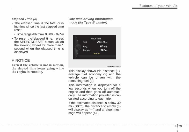
4 79
Features of your vehicle
Elapsed Time (3)• The elapsed time is the total driv-
ing time since the last elapsed timereset.- Time range (hh:mm): 00:00 ~ 99:59
• To reset the elapsed time, pressthe SELECT/RESET button OK onthe steering wheel for more than 1second when the elapsed time isdisplayed.
✽✽ NOTICEEven if the vehicle is not in motion,the elapsed time keeps going whilethe engine is running.
One time driving informationmode (for Type B cluster)
This display shows trip distance (1),average fuel economy (2) and thevehicle can be driven with theremaining fuel (3).This information is displayed for afew seconds when you turn off theengine and then goes off automati-cally. The information provided is cal-culated according to each trip.If the estimated distance is below 30mi. (50km), the distance to empty (3)will display as "---" and a refuel mes-sage will appear (4).
OTF044367N
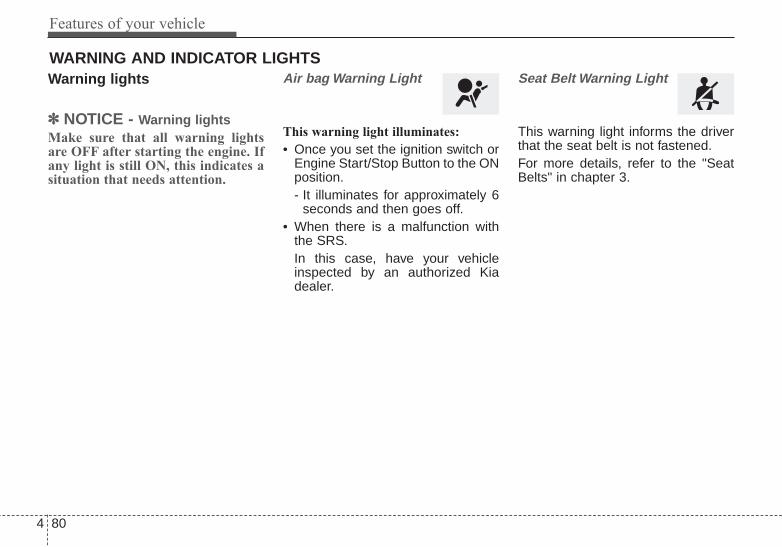
Features of your vehicle
804
Warning lights
✽✽ NOTICE - Warning lightsMake sure that all warning lightsare OFF after starting the engine. Ifany light is still ON, this indicates asituation that needs attention.
Air bag Warning Light
This warning light illuminates:
• Once you set the ignition switch orEngine Start/Stop Button to the ONposition.- It illuminates for approximately 6
seconds and then goes off.• When there is a malfunction with
the SRS.In this case, have your vehicleinspected by an authorized Kiadealer.
Seat Belt Warning Light
This warning light informs the driverthat the seat belt is not fastened.For more details, refer to the "SeatBelts" in chapter 3.
WARNING AND INDICATOR LIGHTS

4 81
Features of your vehicle
Parking Brake & BrakeFluid Warning Light
This warning light illuminates:
• Once you set the ignition switch orEngine Start/Stop Button to the ONposition.- It illuminates for approximately 3
seconds- It remains on if the parking brake
is applied.• When the parking brake is applied.• When the brake fluid level in the
reservoir is low.- If the warning light illuminates
with the parking brake released, itindicates the brake fluid level inreservoir is low.
If the brake fluid level in the reservoiris low:
1. Drive carefully to the nearest safelocation and stop your vehicle.
2. With the engine stopped, checkthe brake fluid level immediatelyand add fluid as required (Formore details, refer to "Brake Fluid"in chapter 7).Then check all brake componentsfor fluid leaks. If any leak on thebrake system is still found, thewarning light remains on, or thebrakes do not operate properly, donot drive the vehicle.In this case, have your vehicletowed to an authorized Kia dealerand inspected.
Dual-diagonal braking system
Your vehicle is equipped with dual-diagonal braking systems. Thismeans you still have braking on twowheels even if one of the dual sys-tems should fail.
With only one of the dual systemsworking, more than normal pedaltravel and greater pedal pressure arerequired to stop the vehicle.Also, the vehicle will not stop in asshort a distance with only a portionof the brake system working.If the brakes fail while you are driv-ing, shift to a lower gear for addition-al engine braking and stop the vehi-cle as soon as it is safe to do so.
WARNING - ParkingBrake & Brake FluidWarning Light
Driving the vehicle with a warn-ing light ON is dangerous. If theParking Brake & Brake FluidWarning Light illuminates withthe parking brake released, itindicates that the brake fluidlevel is low.In this case, have your vehicleinspected by an authorized Kiadealer.

Features of your vehicle
824
Anti-lock Brake System(ABS) Warning Light
This warning light illuminates:
• Once you set the ignition switch orEngine Start/Stop Button to the ONposition.- It illuminates for approximately 3
seconds and then goes off.• When there is a malfunction with
the ABS (The normal braking sys-tem will still be operational withoutthe assistance of the anti-lockbrake system).In this case, have your vehicleinspected by an authorized Kiadealer.
ElectronicBrake forceDistribution(EBD) SystemWarning LightThese two warning lights illuminate atthe same time while driving:
• When the ABS and regular brakesystem may not work normally.In this case, have your vehicleinspected by an authorized Kiadealer.
✽✽ NOTICE - Electronic Brakeforce Distribution(EBD) SystemWarning Light
When the ABS Warning Light is onor both ABS and Parking Brake &Brake Fluid Warning Lights are on,the speedometer, odometer, or trip-meter may not work. Also, the EPSWarning Light may illuminate andthe steering effort may increase ordecrease.In this case, have your vehicle inspect-ed by an authorized Kia dealer assoon as possible.WARNING - Electronic
Brake force Distribution(EBD) System WarningLight
When both ABS and ParkingBrake & Brake Fluid WarningLights are on and stay on, thebrake system will not work nor-mally during sudden braking.In this case, avoid high speeddriving and abrupt braking.Have your vehicle inspected byan authorized Kia dealer assoon as possible.

4 83
Features of your vehicle
Electric Parking Brake(EPB) Warning Light(if equipped)
This warning light illuminates:
• Once you set the ignition switch orEngine Start/Stop Button to the ONposition.- It illuminates for approximately 3
seconds and then goes off.• When there is a malfunction with
the EPB.In this case, have your vehicleinspected by an authorized Kiadealer.
✽✽ NOTICE - Electric ParkingBrake (EPB)Warning Light
The Electric Parking Brake (EPB)Warning Light may illuminateswhen the Electronic Stability control(ESC) Indicator Light comes on toindicates that the ESC is not work-ing properly (This does not indicatemalfunction of the EPB).
AUTO HOLD IndicatorLight (if equipped)
This indicator light illuminates:
• [White] When you activate the autohold system by pressing the AUTOHOLD button.
• [Green] When you stop the vehiclecompletely by depressing thebrake pedal with the auto hold sys-tem activated.
• [Yellow] When there is a malfunc-tion with the auto hold system.In this case, have your vehicleinspected by an authorized Kiadealer.
❈ For more details, refer to “AutoHold” in chapter 5.
Electronic PowerSteering (EPS) WarningLight (if equipped)
This warning light illuminates:
• Once you set the ignition switch orEngine Start/Stop Button to the ONposition.- It remains on until the engine is
started.• When there is a malfunction with
the EPS.In this case, have your vehicleinspected by an authorized Kiadealer.
EPB AUTOHOLD

Features of your vehicle
844
Malfunction IndicatorLamp (MIL)
This warning light illuminates:
• Once you set the ignition switch orEngine Start/Stop Button to the ONposition.- It remains on until the engine is
started.• When there is a malfunction with
the emission control system.In this case, have your vehicleinspected by an authorized Kiadealer.
Charging SystemWarning Light
This warning light illuminates:
• Once you set the ignition switch orEngine Start/Stop Button to the ONposition.- It remains on until the engine is
started.• When there is a malfunction with
either the alternator or electricalcharging system.
If there is a malfunction with eitherthe alternator or electrical chargingsystem:
1. Drive carefully to the nearest safelocation and stop your vehicle.
2. Turn the engine off and check thealternator drive belt for loosenessor breakage.If the belt is adjusted properly,there may be a problem in theelectrical charging system.In this case, have your vehicleinspected by an authorized Kiadealer as soon as possible.
CAUTION - MalfunctionIndicatorLamp (MIL)
Driving with the MalfunctionIndicator Lamp (MIL) on maycause damage to the emissioncontrol systems which couldeffect drivability and/or fueleconomy.
CAUTION - GasolineEngine
If the Malfunction IndicatorLamp (MIL) illuminates, poten-tial catalytic converter damageis possible which could result inloss of engine power.In this case, have your vehicleinspected by an authorized Kiadealer as soon as possible.

4 85
Features of your vehicle
Engine CoolantTemperature WarningLight (if equipped)
This warning light illuminates:
• When the engine coolant tempera-ture is above 120°C (248°F). Thismeans that the engine is overheat-ed and may be damaged.If your vehicle is overheated, referto "Overheating" in chapter 6.
Engine Oil PressureWarning Light
This warning light illuminates:
• Once you set the ignition switch orEngine Start/Stop Button to the ONposition.- It remains on until the engine is
started.• When the engine oil pressure is low.
If the engine oil pressure is low:
1. Drive carefully to the nearest safelocation and stop your vehicle.
2. Turn the engine off and check theengine oil level (For more details,refer to "Engine Oil" in section 7). Ifthe level is low, add oil as required.If the warning light remains onafter adding oil or if oil is not avail-able, have your vehicle inspectedby an authorized Kia dealer assoon as possible.
CAUTION - EngineOverheating
Do not drive the vehicle whenthe Engine Coolant TemperatureWarning Light is illuminated orthe engine is overheated.Continuing to drive the vehiclewhile it is overheated may dam-age the engine.
CAUTION - Engine OilPressure Warning Light
• If the engine is not stoppedimmediately after the EngineOil Pressure Warning Light isilluminated, severe damagecould result.
• If the warning light stays onwhile the engine is running,there may be serious enginedamage. In this case,1. Stop the vehicle as soon as
it is safe to do so.2. Turn off the engine and
check the oil level. If the oillevel is low, fill the engineoil to the proper level.
3. Start the engine again. If thewarning light stays on afterthe engine is started, turnthe engine off immediately.In this case, have your vehi-cle inspected by an author-ized Kia dealer.

Features of your vehicle
864
Low Fuel Level WarningLight
This warning light illuminates:
When the fuel tank is nearly empty.
If the fuel tank is nearly empty:
Add fuel as soon as possible.
Low Tire PressureWarning Light (if equipped)
This warning light illuminates:
• Once you set the ignition switch orEngine Start/Stop Button to the ONposition.- It illuminates for approximately 3
seconds and then goes off.• When one or more of your tires are
significantly underinflated. (Thelocation of the underinflated tiresare displayed on the LCD display).For more details, refer to "TirePressure Monitoring System(TPMS)" in chapter 6.
This warning light remains on afterblinking for approximately 60 secondsor repeats blinking and off at theintervals of approximately 3 seconds:
• When there is a malfunction withthe TPMS.In this case, have your vehicleinspected by an authorized Kiadealer as soon as possible.For more details, refer to "TirePressure Monitoring System(TPMS)" in chapter 6.CAUTION - Low Fuel
LevelDriving with the Low Fuel Levelwarning light on or with the fuellevel below can cause theengine to misfire and damagethe catalytic converter (ifequipped).

4 87
Features of your vehicle
Door Ajar Warning Light
This warning light illuminates:
When a door is not closed securely.
Trunk Open WarningLight
This warning light illuminates:
When the trunk is not closed secure-ly.
Master Warning light
• This warning light informs the driv-er of the following situations- Low washer fluid- TPMS (if equipped)- Service required
The Master Warning Light illumi-nates when more than one of theabove warning situations occur. Atthis time, the LCD Modes Icon willchange from ( ) to ( ).If the warning situation is solved, themaster warning light will be turned offand the LCD Modes Icon will bechanged back to its previous icon ( ).(ex : refill the washer fluid)
WARNING - SafeStopping
• The TPMS cannot alert you tosevere and sudden tire damagecaused by external factors.
• If you notice any vehicle insta-bility, immediately take yourfoot off the accelerator pedal,apply the brakes gradually withlight force, and slowly move toa safe position off the road.
WARNING - Low tirepressure
• Significantly low tire pressuremakes the vehicle unstableand can contribute to loss ofvehicle control and increasedbraking distances.
• Continued driving or lowpressure tires will cause thetires to overheat and fail.

Features of your vehicle
884
Indicator LightsElectronic StabilityControl (ESC) IndicatorLightThis indicator light illuminates:
• Once you set the ignition switch orEngine Start/Stop Button to the ONposition.- It illuminates for approximately 3
seconds and then goes off.• When there is a malfunction with
the ESC system.In this case, have your vehicleinspected by an authorized Kiadealer.
This indicator light blinks:
While the ESC is operating.
For more details, refer to "ElectronicStability Control (ESC)" in chapter 5.
Electronic StabilityControl (ESC) OFFIndicator Light
This indicator light illuminates:
• Once you set the ignition switch orEngine Start/Stop Button to the ONposition.- It illuminates for approximately 3
seconds and then goes off.• When you deactivate the ESC sys-
tem by pressing the ESC OFF but-ton.
For more details, refer to "ElectronicStability Control (ESC)" in chapter 5.
ECOMINDER® indicator
Active ECO system
This indicator light illuminates:
When the Active ECO button ispressed the ECOMINDER® indicator(green) will illuminate to show thatthe Active ECO is operating.For more detailed information, referto "Active ECO" or "Drive mode" inchapter 5.
SPORT Mode IndicatorLight (if equipped)
This indicator light illuminates:
• When you select “SPORT” modeas drive mode.
❈ For more details, refer to “DriveMode” in chapter 5.
ECO
SPORT

4 89
Features of your vehicle
Immobilizer IndicatorLight (Without Smart Key)(if equipped)
This indicator light illuminates:
• When the vehicle detects theimmobilizer in your key properlywhile the ignition switch is ON.- At this time, you can start the
engine.- The indicator light goes off after
starting the engine.
This indicator light blinks:
• When there is a malfunction withthe immobilizer system.In this case, have your vehicleinspected by an authorized Kiadealer.
Immobilizer IndicatorLight (With Smart Key) (if equipped)
This indicator light illuminates for upto 30 seconds:
• When the vehicle detects thesmart key in the vehicle properlywhile the Engine Start/Stop Buttonis ACC or ON.- At this time, you can start the
engine.- The indicator light goes off after
starting the engine.
This indicator light blinks for a fewseconds:
• When the smart key is not in thevehicle.- At this time, you can not start the
engine.
This indicator light illuminates for 2seconds and goes off:
• When the vehicle can not detectthe smart key which is in the vehi-cle while the Engine Start/StopButton is ON.In this case, have your vehicleinspected by an authorized Kiadealer.
This indicator light blinks:
• When the battery of the smart keyis weak.- At this time, you can not start the
engine. However, you can start theengine if you press the EngineStart/Stop Button with the smartkey. (For more details, refer to"Starting the Engine" in section 5).
• When there is a malfunction withthe immobilizer system.In this case, have your vehicleinspected by an authorized Kiadealer.

Features of your vehicle
904
Turn Signal IndicatorLight
This indicator light blinks:
• When you turn the turn signal lighton.
If any of the following occurs, theremay be a malfunction with the turnsignal system. In this case, have yourvehicle inspected by an authorizedKia dealer.
- The indicator light does not blinkbut illuminates.
- The indicator light blinks morerapidly.
- The indicator light does not illumi-nate at all.
High Beam IndicatorLight
This indicator light illuminates:
• When the headlights are on and inthe high beam position.
• When the turn signal lever is pulledinto the Flash-to-Pass position.
Light ON Indicator Light
This indicator light illuminates:
• When the tail lights or headlightsare on.
Front Fog IndicatorLight (if equipped)
This indicator light illuminates:
• When the front fog lights are on.

4 91
Features of your vehicle
Cruise Indicator Light (if equipped)
This indicator light illuminates:
• When the cruise control system isenabled.
For more details, refer to "CruiseControl System" in chapter 5.
Cruise SET IndicatorLight (if equipped)
This indicator light illuminates:
• When the cruise control speed is set.
For more details, refer to "CruiseControl System" in chapter 5.
KEY OUT Indicator Light(if equipped)
When the ENGINE START/STOPbutton is in the ACC or ON position,if any door is open, the systemchecks for the smart key.
This indicator light blinks:
When the smart key is not in thevehicle and any door is open with theignition switch or Engine Start/Stopbutton in the ACC or ON position.- At this time, if you close all doors,
the chime will also sound forapproximately 5 seconds.
- The indicator will go off while thevehicle is moving.
KEYOUTCRUISE
SET

Features of your vehicle
924
The back-up warning system assiststhe driver during backward move-ment of the vehicle by chiming if anyobject is sensed within a distance of47 in. (120 cm) behind the vehicle.This system is a supplemental sys-tem and it is not intended to nor doesit replace the need for extreme careand attention of the driver. The sens-ing range and objects detectable bythe back sensors are limited.Whenever backing-up, pay as muchattention to what is behind you asyou would in a vehicle without theback-up warning system.
Operation of the back-upwarning systemOperating condition• This system will activate when
backing up with the ignition switchON.
• The sensing distance while theback-up warning system is in oper-ation is approximately 47 in. (120cm).
• When more than two objects aresensed at the same time, the clos-est one will be recognized first.
Types of warning sound• When an object is 47 in. to 24 in.
(120 cm to 61 cm) from the rearbumper: Buzzer beeps intermittently.
• When an object is 23 in. to 12 in. (61cm to 31 cm) from the rear bumper:Buzzer beeps more frequently.
• When an object is within 11 in. (30cm) of the rear bumper:Buzzer sounds continuously.
BACK-UP WARNING SYSTEM (IF EQUIPPED)
OTF044101Sensors
WARNINGThe back-up warning system isa supplementary function only.The operation of the back-upwarning system can be affectedby several factors (includingenvironmental conditions). It isthe responsibility of the driverto always check the area behindthe vehicle before and whilebacking up.

4 93
Features of your vehicle
Non-operational conditions ofback-up warning systemThe back-up warning system maynot operate properly when:1. Moisture is frozen to the sensor. (It
will operate normally when themoisture has been cleared.)
2. The sensor is covered with foreignmatter, such as snow or water, orthe sensor cover is blocked. (It willoperate normally when the materi-al is removed or the sensor is nolonger blocked.)
3. Driving on uneven road surfaces.(unpaved roads, gravel, bumps,gradient.)
4. Objects generating excessivenoise (vehicle horns, loud motor-cycle engines, or truck air brakes)are within range of the sensor.
5. Heavy rain or water spray exists.6. Wireless transmitters or mobile
phones are within range of thesensor.
7. The sensor is covered with snow.8. Trailer towing.
The detecting range may decreasewhen:1. The sensor is stained with foreign
matter such as snow or water.(The sensing range will return tonormal when removed.)
2. Outside air temperature isextremely hot or cold.
The following objects may not berecognized by the sensor:1. Sharp or slim objects such as
ropes, chains or small poles.2. Objects which tend to absorb the
sensor frequency such as clothes,spongy material or snow.
3. Undetectable objects smaller than40 in. (1 m) in height and narrowerthan 6 in. (14 cm) in diameter.
back-up warning system pre-cautions• The back-up warning system may
not sound sequentially dependingon the speed and shapes of theobjects detected.
• The back-up warning system maymalfunction if the vehicle bumperheight or sensor installation hasbeen modified or damaged. Anynon-factory installed equipment oraccessories may also interfere withthe sensor performance.
• The sensor may not recognizeobjects less than 11 in. (30 cm)from the sensor, or it may sense anincorrect distance. Use caution.
• When the sensor is frozen or stainedwith snow, dirt, or water, the sensormay be inoperative until the stainsare removed using a soft cloth.
• Do not push, scratch or strike thesensor. Sensor damage could occur.

Features of your vehicle
944
✽✽ NOTICEThis system can only sense objectswithin the range and location of thesensors. It can not detect objects inother areas where sensors are notinstalled. Also, small or slim objects,such as poles or objects locatedbetween sensors may not be detectedby the sensors.Always visually check behind thevehicle when backing up.Be sure to inform any drivers of thevehicle that may be unfamiliar withthe system regarding the systemscapabilities and limitations.
Self-diagnosisIf you don’t hear an audible warningsound or if the buzzer sounds inter-mittently when shifting the gear to theR (Reverse) position, this may indi-cate a malfunction in the back-upwarning system. If this occurs, haveyour vehicle checked by an author-ized Kia dealer as soon as possible.

4 95
Features of your vehicle
The rear camera display will activatewhen the back-up light is ON with theignition switch ON and the shift leverin the R (Reverse) position.
Note- during initial start up, systemmay not display instantly due to theaudio system booting up.2 ~ 4 seconds may be required beforedisplaying during initial reverse selec-tion. This occurs when starting andimmediately shifting to reverse.This system is a supplemental sys-tem that shows behind the vehiclethrough the UVO audio or navigationdisplay backing-up.Always keep the camera lens clean. Iflens is covered with foreign matter,the camera may not operate normally.
REAR CAMERA DISPLAY (IF EQUIPPED)
WARNING - Rear cameradisplay
The rear camera display is not asafety device. It only serves toassist the driver in identifyingobjects directly behind the mid-dle of the vehicle. The cameradoes NOT cover the completearea behind the vehicle.
WARNING - Relying onthe Rear-Camera Display
Never rely solely on the rearcamera display when backing.
OTF044102
OTF044103
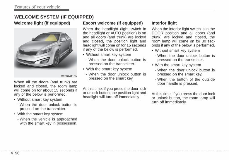
Features of your vehicle
964
Welcome light (if equipped)
When all the doors (and trunk) arelocked and closed, the room lampwill come on for about 15 seconds ifany of the below is performed.• Without smart key system
- When the door unlock button ispressed on the transmitter.
• With the smart key system- When the vehicle is approached
with the smart key in possession.
Escort welcome (if equipped)When the headlight (light switch inthe headlight or AUTO position) is onand all doors (and trunk) are lockedand closed, the position light andheadlight will come on for 15 secondsif any of the below is performed.• Without smart key system
- When the door unlock button ispressed on the transmitter.
• With the smart key system- When the door unlock button is
pressed on the smart key.
At this time, if you press the door lockor unlock button, the position light andheadlight will turn off immediately.
Interior light When the interior light switch is in theDOOR position and all doors (andtrunk) are locked and closed, theroom lamp will come on for 30 sec-onds if any of the below is performed.• Without smart key system
- When the door unlock button ispressed on the transmitter.
• With the smart key system- When the door unlock button is
pressed on the smart key.- When the button of the outside
door handle is pressed.
At this time, if you press the door lockor unlock button, the room lamp willturn off immediately.
WELCOME SYSTEM (IF EQUIPPED)
OTF044113N

4 97
Features of your vehicle
Battery saver function• The purpose of this feature is to
prevent the battery from being dis-charged. The system automaticallyturns off the parking lights whenthe driver removes the ignition keyand opens the driver-side door.
• With this feature, the parking lightswill turn off automatically if the driv-er parks on the side of the road atnight.If necessary, to keep the lights onwhen the ignition key is removed,perform the following:1) Open the driver-side door.2) Turn the parking lights OFF and
ON again using the light switchon the steering column.
Headlight escort function (if equipped)The headlights (and/or taillights) willremain on for approximately 5 min-utes after the ignition key is removedor turned to the ACC or LOCK posi-tion. However, if the driver’s door isopened and closed, the headlightsare turned off after 15 seconds.The headlights can be turned off bypressing the lock button on the trans-mitter (or smart key) twice or turningoff the light switch from the headlightor Auto light position.
Headlight leveling device (if equipped)Automatic typeIt automatically adjusts the headlightbeam level according to the numberof passengers and the loadingweight in the luggage area.And it offers the proper headlightbeam under various conditions.
LIGHTING
WARNINGIf the headlights are not work-ing properly have your vehicleinspected by an authorized Kiadealer.Don't attempt to inspect orreplace the wiring yourself toprevent malfunction.
CAUTIONIf the driver gets out of the vehi-cle through other doors (exceptdriver's door), the battery saverfunction does not operate andthe headlight escort functiondoes not turn off automatically.Therefore, causing the batteryto be discharged. In this case,make sure to turn off the lampbefore getting out of the vehicle.
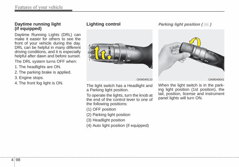
Features of your vehicle
984
Daytime running light (if equipped)Daytime Running Lights (DRL) canmake it easier for others to see thefront of your vehicle during the day.DRL can be helpful in many differentdriving conditions, and it is especiallyhelpful after dawn and before sunset.The DRL system turns OFF when:1. The headlights are ON.2. The parking brake is applied.3. Engine stops.4. The front fog light is ON.
Lighting control
The light switch has a Headlight anda Parking light position.To operate the lights, turn the knob atthe end of the control lever to one ofthe following positions:(1) OFF position(2) Parking light position(3) Headlight position(4) Auto light position (if equipped)
Parking light position ( )
When the light switch is in the park-ing light position (1st position), thetail, position, license and instrumentpanel lights will turn ON.
OAM049041OXM049110

4 99
Features of your vehicle
Headlight position ( )
When the light switch is in the head-light position (2nd position) the head,tail, position, license and instrumentpanel lights will turn ON.The ignition switch must be in the ONposition to turn on the headlights.
Auto light position (if equipped)
When the light switch is in the AUTOlight position, the taillights and head-lights will turn ON or OFF automati-cally depending on the amount oflight outside the vehicle.Never place anything over the sensor(1) located on the instrument panel.This will ensure better auto-light sys-tem control.Do not clean the sensor using a win-dow cleaner, the cleaner may leave alight film which could interfere withsensor operation.
If your vehicle has window tint orother types of metallic coating on thefront windshield, the Auto light sys-tem may not work properly.
OAM049042 OVG049181
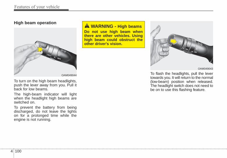
Features of your vehicle
1004
High beam operation
To turn on the high beam headlights,push the lever away from you. Pull itback for low beams.The high-beam indicator will lightwhen the headlight high beams areswitched on.To prevent the battery from beingdischarged, do not leave the lightson for a prolonged time while theengine is not running.
To flash the headlights, pull the levertowards you. It will return to the normal(low-beam) position when released.The headlight switch does not need tobe on to use this flashing feature.
OAM049044
WARNING - High beams Do not use high beam whenthere are other vehicles. Usinghigh beam could obstruct theother driver's vision.
OAM049043
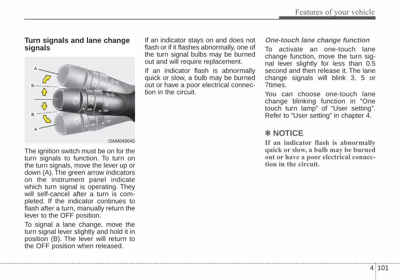
4 101
Features of your vehicle
Turn signals and lane changesignals
The ignition switch must be on for theturn signals to function. To turn onthe turn signals, move the lever up ordown (A). The green arrow indicatorson the instrument panel indicatewhich turn signal is operating. Theywill self-cancel after a turn is com-pleted. If the indicator continues toflash after a turn, manually return thelever to the OFF position.To signal a lane change, move theturn signal lever slightly and hold it inposition (B). The lever will return tothe OFF position when released.
If an indicator stays on and does notflash or if it flashes abnormally, one ofthe turn signal bulbs may be burnedout and will require replacement.If an indicator flash is abnormallyquick or slow, a bulb may be burnedout or have a poor electrical connec-tion in the circuit.
One-touch lane change functionTo activate an one-touch lanechange function, move the turn sig-nal lever slightly for less than 0.5second and then release it. The lanechange signals will blink 3, 5 or7times.You can choose one-touch lanechange blinking function in “Onetouch turn lamp” of “User setting”.Refer to “User setting” in chapter 4.
✽✽ NOTICEIf an indicator flash is abnormallyquick or slow, a bulb may be burnedout or have a poor electrical connec-tion in the circuit.
OAM049045

Features of your vehicle
1024
Front fog light (if equipped)
Fog lights are used to provideimproved visibility when visibility ispoor due to fog, rain or snow, etc. Thefog lights will turn on when the fog lightswitch (1) is turned to the on positionafter the headlights are turned on.To turn off the fog lights, turn theswitch (1) to the off position.When in operation, the fog lightsconsume large amounts of vehicleelectrical power. Only use the foglights when visibility is poor.
OAM049046N

4 103
Features of your vehicle
A : Wiper speed control (front)· HI – High wiper speed· LO – Low wiper speed· INT – Intermittent wipe · AUTO* – Automatic control wipe· OFF – Off· MIST – Single wipe
B : Intermittent control wipe timeadjustment
C : Wash with brief wipes (front)
* : if equipped
Windshield wipersOperates as follows when the igni-tion switch is turned ON.MIST : For a single wiping cycle,
push the lever upward andrelease it. The wipers willoperate continuously if thelever is held in this position.
OFF : Wiper is not in operationINT : Wiper operates intermittently at
the same wiping intervals. Usethis mode in a light rain or mist.To vary the speed setting, turnthe speed control knob.
LO : Normal wiper speedHI : Fast wiper speed
If there is a heavy accumulation ofsnow or ice on the windshield, defrostthe windshield for about 10 minutes,or until the snow and/or ice isremoved before using the windshieldwipers to ensure proper operation.
AUTO (Automatic) control (if equipped)
The rain sensor located on the upperend of the windshield glass sensesthe amount of rainfall and controlsthe wiping cycle for the proper inter-val. The more it rains, the faster thewiper operates. When the rain stops,the wiper stops.
WIPERS AND WASHERS
OAM049100L
OYF049103
Rain sensor

Features of your vehicle
1044
To vary the speed setting, turn thespeed control knob (1).If the wiper switch is set in AUTOmode when the ignition switch is ON,the wiper will operate once to per-form a self-check of the system. Setthe wiper to OFF position when thewiper is not in use.Always remove all snow and ice anddefrost the windshield properly priorto operating the windshield wipers.
✽✽ NOTICE - Sensor coverDo not remove the sensor coverlocated on the upper end of the pas-senger side windshield glass as thismay damage the sensor system.
✽✽ NOTICE - Winter drivingAlways set the auto wiper switch tothe off position in the winter to avoidauto activation during icy conditionswhich may damage the windshieldwipers.
Windshield washers
In the OFF position, pull the levergently toward you to spray washerfluid on the windshield and to run thewipers 1-3 cycles.Use this function when the wind-shield is dirty.The spray and wiper operation willcontinue until you release the lever. Ifthe washer does not work, check thewasher fluid level.If the fluid level is not sufficient, youadd appropriate non-abrasive wind-shield washer fluid to the washerreservoir.
CAUTION - Wiper position
When washing the vehicle, setthe wiper switch in the OFFposition to stop the auto wiperoperation.The wiper may operate and bedamaged if the switch is set inthe AUTO mode while washingthe vehicle.
OYF049101

4 105
Features of your vehicle
The reservoir filler neck is located inthe front of the engine compartmenton the passenger side.
CAUTION - Washerpump
To prevent possible damage tothe washer pump, do not oper-ate the washer when the fluidreservoir is empty.
WARNING - Obscured visibility
Do not use the washer in freez-ing temperatures without firstwarming the windshield withthe defrosters; the washer solu-tion could freeze on the wind-shield and obscure your vision.
CAUTION - Wipers & windshields
• To prevent possible damageto the wipers or windshield,do not operate the wiperswhen the windshield is dry.
• To prevent damage to thewiper blades, do not use gaso-line, kerosene, paint thinner,or other solvents on or nearthem.
• To prevent damage to thewiper arms and other compo-nents, do not attempt to movethe wipers manually.

Features of your vehicle
1064
Do not use the interior lights forextended periods when the engine isnot running.It may cause battery discharge.
Automatic turn off function (if equipped)The interior lights automatically turnoff approximately 20 minutes afterthe ignition switch is turned off.If your vehicle is equipped with thetheft alarm system, the interior lightsautomatically turn off approximately3 seconds after the system is inarmed stage.
Map lamp
Push the lens (1) to turn the map lampon or off. This light produces a spotbeam for convenient use as a maplamp at night or as a personal lamp forthe driver and front passenger.
INTERIOR LIGHT
WARNING - Interior lightDo not use the interior lightswhen driving in the dark. Theglare from the interior lightsmay obstruct your view andcause an accident.
OTF044107

4 107
Features of your vehicle
• DOOR (2) :In the DOOR position, the map lampand the room lamp come on when anydoor is opened regardless of the igni-tion switch position. When doors areunlocked by the transmitter (or smartkey), the map lamp and the room lampcome on for approximately 30 sec-onds as long as any door is not open.The map lamp and the room lamp goout gradually after approximately 30seconds if the door is closed.However, if the ignition switch is ONor all doors are locked, the map lampand the room lamp will turn off imme-diately. If a door is opened with theignition switch in the ACC or LOCKposition, the map lamp and the roomlamp stays on for about 20 minutes.However, if a door is opened with theignition switch in the ON position, themap lamp and the room lamp stayson continuously. If the type B roomlamp switch is OFF, it doesn't work.
• OFF (2) : The lights turn off even ifa door is opened.When the lamp isturned ON by pressingthe lens (1), the lampdoes not turn off evenif the switch (2) is in theOFF position.
• ON (2) : The map lamp and theroom lamp stay on at alltimes.
Room lamp
■■ Type ATo turn the room lamp push lens (3).
OTF040108
OTF040109
■ Type A
■ Type B

Features of your vehicle
1084
■■ Type B• DOOR :In the DOOR position, the map lampand the room lamp come on when anydoor is opened regardless of the igni-tion switch position. When doors areunlocked by the transmitter (or smartkey), the map lamp and the room lampcome on for approximately 30 sec-onds as long as any door is not open.The map lamp and the room lamp goout gradually after approximately 30seconds if the door is closed.However, if the ignition switch is ONor all doors are locked, the map lampand the room lamp will turn off imme-diately. If a door is opened with theignition switch in the ACC or LOCKposition, the map lamp and the roomlamp stay on for about 20 minutes.However, if a door is opened with theignition switch in the ON position, themap lamp and the room lamp stay oncontinuously.
• OFF : The lights turn off even if adoor is opened.
• ON : The room lamp stays on at alltimes.
Trunk room lamp (if equipped)
The trunk room lamp comes onwhen the trunk is opened.
OTF044110
CAUTIONThe trunk room lamp comes ononly with the trunk lid open. Toprevent battery discharge, closethe trunk lid securely afteraccessing the trunk.

4 109
Features of your vehicle
Glove box lamp (if equipped)
The glove box lamp comes on whenthe glove box is opened.
Vanity mirror lamp (if equipped)
Push the switch to turn the light on oroff.• : The lamp will turn on if this
button is pressed.• : The lamp will turn off if this
button is pressed.Always have the switch in the offposition when the vanity mirror lampis not in use. If the sunvisor is closedwithout turning the lamp off, it maydischarge the battery or damage thesunvisor.
OLM049105OTF040112
CAUTIONTo prevent unnecessary charg-ing system drain, close theglove box securely after use.

Features of your vehicle
1104
DEFROSTER
If you want to defrost and defog thefront windshield, refer to “WindshieldDefrosting and Defogging” in thischapter.
Rear window defroster
The defroster heats the window toremove frost, fog and thin ice fromthe interior and exterior of the rearwindow, while the engine is running.To activate the rear windowdefroster, press the rear windowdefroster button located in the centerfacia switch panel. The indicator onthe rear window defroster button illu-minates when the defroster is on.If there is heavy accumulation ofsnow on the rear window, brush it offbefore operating the rear defroster.
The rear window defroster automati-cally turns off after approximately 20minutes or when the ignition switch isturned off. To turn off the defrostermanually, press the rear windowdefroster button again.
Outside mirror defroster (if equipped)If your vehicle is equipped with theoutside rearview mirror defrosters,they will operate at the same time youturn on the rear window defroster.
Wiper deicer (if equipped)If your vehicle is equipped with thewiper deicer, it will operate at thesame time you turn on the rear win-dow defroster.
CAUTION - ConductorsTo prevent damage to the con-ductors bonded to the insidesurface of the rear window,never use sharp instruments orwindow cleaners containingabrasives to clean the window.
OTF044114L

4 111
Features of your vehicle
MANUAL CLIMATE CONTROL SYSTEM
1. Fan speed control knob
2. Front windshield defroster button
3. Rear window defroster button
4. Temperature control knob
5. Air intake control button
6. Mode selection button
7. Air conditioning button
OTF044311

Features of your vehicle
1124
Heating and air conditioning1. Start the engine.2. Set the mode to the desired posi-
tion.To improve the effectiveness ofheating and cooling :- Heating:- Cooling:
3. Set the temperature control to thedesired position.
4. Set the air intake control to theoutside (fresh) air or recirculatedair position.
5. Set the fan speed control to thedesired speed.
6. If air conditioning is desired, turnthe air conditioning system (ifequipped) on.
OTF044314
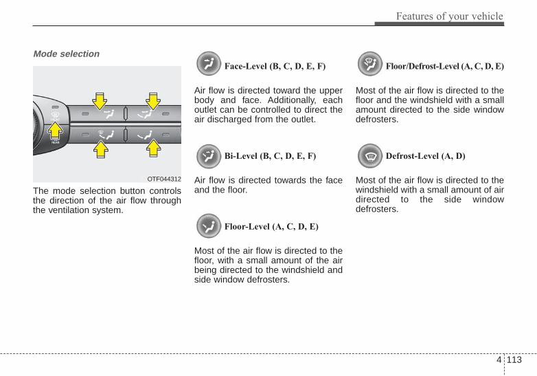
4 113
Features of your vehicle
Mode selection
The mode selection button controlsthe direction of the air flow throughthe ventilation system.
Face-Level (B, C, D, E, F)
Air flow is directed toward the upperbody and face. Additionally, eachoutlet can be controlled to direct theair discharged from the outlet.
Bi-Level (B, C, D, E, F)
Air flow is directed towards the faceand the floor.
Floor-Level (A, C, D, E)
Most of the air flow is directed to thefloor, with a small amount of the airbeing directed to the windshield andside window defrosters.
Floor/Defrost-Level (A, C, D, E)
Most of the air flow is directed to thefloor and the windshield with a smallamount directed to the side windowdefrosters.
Defrost-Level (A, D)
Most of the air flow is directed to thewindshield with a small amount of airdirected to the side windowdefrosters.
OTF044312

Features of your vehicle
1144
MAX A/C-Level (B, D) (if equipped)
The MAX A/C mode is used to coolthe inside of the vehicle faster.In this mode, the air conditioning andthe recirculated air position will beselected automatically.
Instrument panel vents
The outlet vents can be opened orclosed separately using the thumb-wheel.Also, you can adjust the direction ofair delivered from these vents usingthe vent control lever as shown.
Temperature control
The temperature control knob allowsyou to control the temperature of theair flowing from the ventilation sys-tem.To change the air temperature inthe passenger compartment, turnthe knob to the right for warm air orleft for cooler air.
OTF044315 OTF044316
OTF044317

4 115
Features of your vehicle
Air intake control
This is used to select outside (fresh)air position or recirculated air posi-tion.To change the air intake control posi-tion, push the control button.
Recirculated air position
The indicator light on thebutton illuminates whenthe recirculated air posi-tion is selected.With the recirculated airposition selected, airfrom the passengercompartment will bedrawn through the heat-ing system and heatedor cooled according tothe function selected.
Outside (fresh) air position
The indicator light on thebutton will not illuminatewhen the outside (fresh)air position is selected.With the outside (fresh)air position selected, airenters the vehicle fromoutside and is heated orcooled according to thefunction selected.
Prolonged operation of the heater inthe recirculated air position (without airconditioning selected) may cause fog-ging of the windshield and side win-dows and the air within the passengercompartment may become stale.In addition, prolonged operation ofthe air conditioning with the recircu-lated air position selected will resultin excessively dry air in the passen-ger compartment.
OTF044318L

Features of your vehicle
1164
Fan speed control
The ignition switch must be in the ONposition for fan operation.The fan speed control knob allowsyou to control the fan speed of the airflowing from the ventilation system.To change the fan speed, turn theknob to the right for higher speed orleft for lower speed.Setting the fan speed control knob tothe “0” position turns off the fan.
To turn off the blowers
To turn off the blowers, turn the fanspeed control knob to the "0" posi-tion.
Air conditioning (if equipped)
Press the A/C button to turn the airconditioning system on (indicatorlight will illuminate). Press the buttonagain to turn the air conditioning sys-tem off.
OTF044319L OTF044320LOTF044403

4 117
Features of your vehicle
System operationVentilation1. Set the mode to the position.2. Set the air intake control to the
outside (fresh) air position.3. Set the temperature control to the
desired position.4. Set the fan speed control to the
desired speed.
Heating1. Set the mode to the position.2. Set the air intake control to the
outside (fresh) air position.3. Set the temperature control to the
desired position.4. Set the fan speed control to the
desired speed.5. If dehumidified heating is desired,
turn the air conditioning system (ifequipped) on.
• If the windshield fogs up, set themode to the , position.
Operation Tips
• To prevent dust or unpleasantfumes from entering the vehiclethrough the ventilation system,temporarily set the air intake con-trol to the recirculated air position.Be sure to return the control to thefresh air position when the irritationhas passed to keep fresh air in thevehicle. This will help keep the driv-er alert and comfortable.
• Air for the heating/cooling systemis drawn in through the grilles justahead of the windshield. Careshould be taken that these are notblocked by leaves, snow, ice orother obstructions.
• To prevent interior fog on the wind-shield, set the air intake control tothe fresh air position and fan speedto the desired position, turn on theair conditioning system, and adjustthe temperature control to desiredtemperature.
Air conditioning (if equipped) Kia Air Conditioning Systems arefilled with R-134a refrigerant.1. Start the engine. Push the air con-
ditioning button.2. Set the mode to the position.3. Set the air intake control to the
recirculated air position. However,prolonged operation in the recircu-lated air position will excessivelydry the air. In this case, change theair position.
4. Adjust the fan speed control andtemperature control to maintainmaximum comfort.
• When maximum cooling is desired,set the temperature control to theextreme left position, set the modecontrol to the MAX A/C position,then set the fan speed control tothe highest speed.

Features of your vehicle
1184
Air conditioning system operation tips
• If the vehicle has been parked indirect sunlight during hot weather,open the windows for a short timeto let the hot air inside the vehicleescape.
• To help reduce moisture inside ofthe windows on rainy or humiddays, decrease the humidity insidethe vehicle by operating the airconditioning system.
• During air conditioning systemoperation, you may occasionallynotice a slight change in enginespeed as the air conditioning com-pressor cycles. This is a normalsystem operation characteristic.
• Use the air conditioning systemevery month only for a few minutesto ensure maximum system per-formance.
• When using the air conditioningsystem, you may notice clear waterdripping (or even puddling) on theground under the passenger sideof the vehicle. This is a normal sys-tem operation characteristic.
• Operating the air conditioning sys-tem in the recirculated air positionprovides maximum cooling, how-ever, continual operation in thismode may cause the air inside thevehicle to become stale.
• During cooling operation, you mayoccasionally notice a misty air flowbecause of rapid cooling andhumid air intake. This is a normalsystem operation characteristic.
CAUTION - ExcessiveAC
While using the air conditioningsystem, monitor the tempera-ture gauge closely while drivingup hills or in heavy traffic whenoutside temperatures are high.Air conditioning system opera-tion may cause engine over-heating and potential enginedamage. If the temperaturegauge indicates overheating,turn off the a/c, safely stop thevehicle, turn off the engine andcontact your authorized Kiadealer.

4 119
Features of your vehicle
Climate control air filter
The climate control air filter installedbehind the glove box filters the dustand other pollutants that come intothe vehicle from the outside throughthe heating and air conditioning sys-tem. If dust or other pollutants accu-mulate in the filter over a period oftime, the air flow from the air ventsmay decrease, resulting in moistureaccumulation on the inside of thewindshield even when the outside(fresh) air position is selected. If thishappens, have the climate control airfilter replaced by an authorized Kiadealer.
✽✽ NOTICE• Replace the filter according to the
Maintenance Schedule.If the vehicle is being driven insevere conditions such as dusty,rough roads, more frequent cli-mate control air filter inspectionsand changes are required.
• When the air flow rate suddenlydecreases, the system should bechecked at an authorized Kiadealer.
Checking the amount of airconditioner refrigerant andcompressor lubricantWhen the amount of refrigerant islow, the performance of the air con-ditioning is reduced. Overfilling alsohas a negative influence on the airconditioning system.Therefore, if abnormal operation isfound, have the system inspected byan authorized Kia dealer.
The air conditioning system shouldbe serviced by an authorized Kiadealer.
CAUTION - Compressordamage
It is important that the correcttype and amount of oil andrefrigerant is used. Otherwise,damage to the compressor andabnormal system operation mayoccur.
OMG075033
Outside air
Recirculatedair
Climate controlair filter
Blower
Evaporatorcore
Heater core

Features of your vehicle
1204
AUTOMATIC CLIMATE CONTROL SYSTEM (IF EQUIPPED)
OTF044322/OTF044323
1. Driver’s temperature control knob
2. AUTO (automatic control) button
3. Front windshield defroster button
4. Rear window defroster button
5. Fan speed control button
6. OFF button
7. Mode selection button
8. Air conditioning button
9. Air intake control button
10. Passenger's temperature control knob
11. Dual temperature control selection button
12. Climate control display
13. Climate information screen selection button
■■ Type A
■■ Type B

4 121
Features of your vehicle
Automatic heating and air con-ditioning
1. Push the AUTO button. Themodes, fan speeds, air intake andair-conditioning will be controlledautomatically by temperature set-ting.
2. Turn the temperature control knobto set the desired temperature.
✽✽ NOTICE• To turn the automatic operation
off, select any button or switch ofthe following:- Mode selection button- Air conditioning button- Front windshield defroster button- Air intake control button- Fan speed control buttonThe selected function will be con-trolled manually while other func-tions operate automatically.
• For your convenience and toimprove the effectiveness of theclimate control, use the AUTObutton and set the temperature to73°F° (23°C).
OTF044324L
OTF044328L

Features of your vehicle
1224
✽✽ NOTICENever place anything over the sen-sor located on the instrument panelto ensure better control of the heat-ing and cooling system.
Manual heating and air condi-tioningThe heating and cooling system canbe controlled manually by pushingbuttons other than the AUTO button.In this case, the system workssequentially according to the order ofbuttons selected.1. Start the engine.2. Set the mode to the desired posi-
tion.To improve the effectiveness ofheating and cooling :- Heating:- Cooling:
3. Set the temperature control to thedesired position.
4. Set the air intake control to theoutside (fresh) air or recirculatedair position.
5. Set the fan speed control to thedesired speed.
6. If air conditioning is desired, turnthe air conditioning system on.
Press the AUTO button in order toconvert to full automatic control ofthe system.
Mode selection
The mode selection button controlsthe direction of the air flow throughthe ventilation system.Every time you press the modeselection button, the mode willchange as follows:
Refer to the illustration in the“Manual climate control system”.
OTF044325L
OTF040132

4 123
Features of your vehicle
Face-Level (B, C, D, E, F)
Air flow is directed toward the upperbody and face. Additionally, eachoutlet can be controlled to direct theair discharged from the outlet.
Bi-Level (B, C, D, E, F)
Air flow is discharged towards theface and floor.
Floor-Level (C, A, D, E)
Most of the air flow is directed to thefloor, with a small amount of the airbeing directed to the windshield andside window defroster.
Floor/Defrost-Level (A, C, D, E)
Most of the air flow is directed to thefloor and the windshield with a smallamount directed to the side windowdefrosters.
Defrost-level
Most of the air flow is directed to thewindshield with a small amount of airdirected to the side windowdefrosters.
OTF044326L

Features of your vehicle
1244
Instrument panel vents
The outlet vents can be opened orclosed separately using the thumb-wheel.Also, you can adjust the direction ofair delivered from these vents usingthe vent control lever as shown.
Temperature control
The temperature control knob allowsyou to control the temperature of theair flowing from the ventilation sys-tem.To change the air temperature inthe passenger compartment, turnthe knob to the right for warm air orleft for cooler air.
Adjusting the driver and passengerside temperature individually
1. Press the DUAL button to operatethe driver and passenger sidetemperature individually. Pressingthe right temperature control but-ton will automatically switch to theDUAL mode as well.
2. Operate the left temperature con-trol to adjust the driver side tem-perature. Operate the right tem-perature control to adjust the pas-senger side temperature.
OTF044329LOTF044316
OTF044328

4 125
Features of your vehicle
Adjusting the driver and passengerside temperature equally
1. Press the DUAL button again todeactivate DUAL mode. The pas-senger side temperature will beset to the same temperature asthe driver side temperature.
2. Operate the driver side tempera-ture control switch. The driver andpassenger side temperature willbe adjusted equally.
Temperature conversion
You can switch the temperaturemode between Fahrenheit toCentigrade as follows:While pressing the OFF, press theAUTO button for 3 seconds or more.The display will change fromFahrenheit to Centigrade, or fromCentigrade to Fahrenheit.The temperature unit (from °C to °For from °F to °C) can be changed byusing the “User Settings” mode of theLCD display.If the battery has been discharged ordisconnected, the temperature modedisplay will reset to Fahrenheit.
WARNING• Continue using the climate
control system in the recircu-lated air position may allowhumidity to increase insidethe vehicle which may fog theglass and obscure visibility.
• Do not sleep in a vehicle withthe air conditioning or heatingsystem on. It may cause seri-ous harm or death due to adrop in the oxygen leveland/or body temperature.
• Continue using the climatecontrol system in the recircu-lated air position can causedrowsiness or sleepiness,and loss of vehicle control.Set the air intake control tothe outside (fresh) air positionas much as possible whiledriving.

Features of your vehicle
1264
Outside thermometer The current outside temperature isdisplayed in 1°F (1°C) increments.The temperature range is between -40°F~140°F (-40°C ~ 60°C).• The outside temperature on the
display may not change immedi-ately like a general thermometer toprevent the driver from being inat-tentive.
• The outside temperature on thedisplay will update as the vehicle isdriven.
Air intake control
The air intake control is used toselect outside (fresh) air position orrecirculated air position.To change the air intake control posi-tion, push the control button.
Recirculated air position
With the recirculated airposition selected, airfrom the passengercompartment will bedrawn through the heat-ing system and heatedor cooled according tothe function selected.
Outside (fresh) air position
With the outside (fresh)air position selected, airenters the vehicle fromoutside and is heated orcooled according to thefunction selected.
OTF044330L
■ Type A ■ Type B
■ Type A
■ Type B

4 127
Features of your vehicle
Fan speed control
The fan speed can be set to thedesired speed by pressing the fanspeed control switch.To change the fan speed press the
part of the switch for higherspeed or press the part of theswitch for lower speed.To turn the fan speed control off,press the OFF button.
Air conditioning
Press the A/C button to turn the airconditioning system on (indicatorlight will illuminate).Press the button again to turn the airconditioning system off.
OFF mode
Press the OFF button to turn off theair climate control system. Howeveryou can still operate the mode andair intake buttons as long as the igni-tion switch is in the ON position.
OTF044333LOTF044331L OTF044332L
■ Type A ■ Type B

Features of your vehicle
1284
Climate information screen selec-tion (if equipped)
Press the climate information screenselection button to display climateinformation on the screen.
System operationVentilation1. Set the mode to the position.2. Set the air intake control to the
outside (fresh) air position.3. Set the temperature control to the
desired position.4. Set the fan speed control to the
desired speed.
Heating1. Set the mode to the position.2. Set the air intake control to the
outside (fresh) air position.3. Set the temperature control to the
desired position.4. Set the fan speed control to the
desired speed.5. If dehumidified heating is desired,
turn the air conditioning system (ifequipped) on.
• If the windshield fogs up, set themode to the or position.
Operation Tips
• To keep dust or unpleasant fumesfrom entering the vehicle throughthe ventilation system, temporarilyset the air intake control to therecirculated air position. Be sure toreturn the control to the fresh airposition when the irritation haspassed to keep fresh air in thevehicle. This will help keep the driv-er alert and comfortable.
• Air for the heating/cooling systemis drawn in through the grilles justahead of the windshield. Careshould be taken that these are notblocked by leaves, snow, ice orother obstructions.
• To prevent interior fog on the wind-shield, set the air intake control tothe fresh air position and fan speedto the desired position, turn on theair conditioning system, and adjustthe temperature control to desiredtemperature.
OTF044334

4 129
Features of your vehicle
Air conditioningKia Air Conditioning Systems arefilled with environmentally friendly R-134a refrigerant.1. Start the engine. Press the air con-
ditioning button.2. Set the mode to the position.3. Set the air intake control to the
outside air or recirculated air posi-tion.
4. Adjust the fan speed control andtemperature control to maintainmaximum comfort.
• When maximum cooling is desired,set the temperature control to theextreme left position, then set thefan speed control to the highestspeed.
✽✽ NOTICE• When using the air conditioning
system, monitor the temperaturegauge closely while driving uphills or in heavy traffic when out-side temperatures are high. Airconditioning system operationmay cause engine overheating.Continue to use the blower fan butturn the air conditioning systemoff if the temperature gauge indi-cates engine overheating.
• When opening the windows inhumid weather air conditioningmay create water droplets insidethe vehicle. Since excessive waterdroplets may cause damage toelectrical equipment, air condi-tioning should only be used withthe windows closed.
Air conditioning system operation tips
• If the vehicle has been parked indirect sunlight during hot weather,open the windows for a short timeto let the hot air inside the vehicleescape.
• To help reduce moisture inside ofthe windows on rainy or humiddays, decrease the humidity insidethe vehicle by operating the airconditioning system.
• During air conditioning systemoperation, you may occasionallynotice a slight change in enginespeed as the air conditioning com-pressor cycles. This is a normalsystem operation characteristic.
• Use the air conditioning systemevery month only for a few minutesto ensure maximum system per-formance.

Features of your vehicle
1304
• When using the air conditioningsystem, you may notice clear waterdripping (or even puddling) on theground under the passenger sideof the vehicle. This is a normal sys-tem operation characteristic.
• Operating the air conditioning sys-tem in the recirculated air positionprovides maximum cooling, how-ever, continual operation in thismode may cause the air inside thevehicle to become stale.
• During cooling operation, you mayoccasionally notice a misty air flowbecause of rapid cooling andhumid air intake. This is a normalsystem operation characteristic.
• If you operate air conditionerexcessively, the difference betweenthe temperature of the outside airand that of the windshield couldcause the outer surface of thewindshield to fog up, causing lossof visibility. In this case, set themode selection knob or button tothe position and fan speedcontrol to the lower speed.

4 131
Features of your vehicle
WINDSHIELD DEFROSTING AND DEFOGGING• For maximum defrosting, set the
temperature control to the extremeright/hot position and the fan speedcontrol to the highest speed.
• If warm air to the floor is desiredwhile defrosting or defogging, set themode to the floor-defrost position.
• Before driving, clear all snow andice from the windshield, rear win-dow, outside rear view mirrors, andall side windows.
• Clear all snow and ice from thehood and air inlet in the cowl grill toimprove heater and defroster effi-ciency and to reduce the probabili-ty of fogging up the inside of thewindshield.
Manual climate control systemTo defog inside windshield
1. Select any fan speed except “0”position.
2. Select desired temperature.3. Select the or position.4. The outside (fresh) air will be
selected automatically.If the outside (fresh) air position isnot selected automatically, press thecorresponding button manually.
OTF044336
WARNING - Windshieldheating
Do not use the or posi-tion during cooling operation inextremely humid weather toreduce the likelyhood of fog up.

Features of your vehicle
1324
To defrost outside windshield
1. Set the fan speed to the highest(extreme right) position.
2. Set the temperature to theextreme hot position.
3. Select the position.4. The outside (fresh) air will be
selected automatically.
Automatic climate control sys-temTo defog inside windshield
1. Select desired fan speed.2. Select desired temperature.3. Press the defroster button ( ).4. The outside (fresh) air position will
be selected automatically.If the outside (fresh) air position isnot selected automatically, adjust thecorresponding button manually.
OTF044338
OTF044340
OTF044341
■ Type A
■ Type B
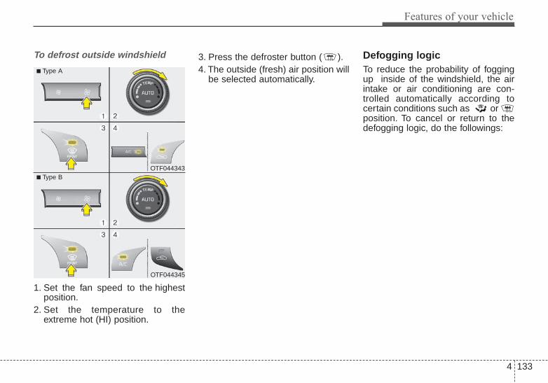
4 133
Features of your vehicle
To defrost outside windshield
1. Set the fan speed to the highestposition.
2. Set the temperature to theextreme hot (HI) position.
3. Press the defroster button ( ).4. The outside (fresh) air position will
be selected automatically.
Defogging logicTo reduce the probability of foggingup inside of the windshield, the airintake or air conditioning are con-trolled automatically according tocertain conditions such as or position. To cancel or return to thedefogging logic, do the followings:
OTF044343
OTF044345
■ Type A
■ Type B

Features of your vehicle
1344
Manual climate control system
1. Turn the ignition switch to the ONposition.
2. Press the defrost button ( ).3. Within 10 seconds after press the
defrost button, press the air intakecontrol button ( ) at least 5times within 3 seconds.
The indicator light in the air intakecontrol button will blink 3 times with0.5 second of interval. It indicates thatthe defogging logic is canceled orreturned to the programmed status.
If the battery has been discharged ordisconnected, it resets to the defoglogic status.
Automatic climate control system
1. Turn the ignition switch to the ONposition.
2. Press the defrost button ( ).
OTF044346
OTF044349
OTF044350
■ Type A
■ Type B

4 135
Features of your vehicle
3. While pressing the air conditioningbutton (A/C), press the air intakecontrol button ( ) at least 5times within 3 seconds.
The indicator light in the air intakecontrol button will blink 3 times with0.5 second of interval. It indicates thatthe defogging logic is canceled orreturned to the programmed status.
If the battery has been discharged ordisconnected, it resets to the defoglogic status.
Auto defogging system (Only forautomatic climate control system,if equipped)
Auto defogging reduces the probabil-ity of fogging up the inside of thewindshield by automatically sensingthe moisture inside the windshield.The auto defogging system operateswhen the heater or air conditioning ison.
This indicator illuminateswhen the auto defoggingsystem senses the mois-ture inside the windshieldand operates.
If more moisture is in the vehicle,higher steps operate as follows. Forexample, if auto defogging does notdefog inside thewindshield at step 1 Outside air posi-tion, it tries to defog again at step 2Blowing air toward the windshield.
Step 1 : Operating the air conditioning Step 2 : Outside air positionStep 3 : Blowing air toward the wind-
shieldStep 4 : Increasing air flow toward
the windshield
OTF044178N
Features of your vehicle
1364
If your vehicle is equipped with theauto defogging system, it is automati-cally activated when the conditionsare met. However, if you would like tocancel the auto defogging system,press the front defroster button 4times within 2 seconds while pressingthe AUTO button. To use the system,repeat the above procedure again.
- When cancelled : The indicator inthe front defroster button will blink 3times (interval of 1 seconds) to noti-fy you that the system is cancelled.
- When activated : The indicator inthe front defroster button will blink 6times (interval of 0.5 seconds) tonotify you that the system is set.
If the battery has been disconnectedor discharged, it resets to the autodefogging status.
✽✽ NOTICEIf the A/C off or recirculated airposition is manually selected whilethe auto defogging system is on, theauto defogging indicator will blink 3times to give notice that manualoperation is canceled.
CAUTIONDo not remove the sensor coverlocated on the upper end of thedriver side windshield glass.Damage to the system partscould occur and may not be cov-ered by your vehicle warranty.

4 137
Features of your vehicle
STORAGE COMPARTMENT These compartments can be used tostore small items.To avoid possible theft, do not leavevaluables in the storage compartment.Always keep the storage compart-ment covers closed while driving.
Center console storage (if equipped)
To open the center console storage,pull the lever up.
Glove box
To open the glove box, push the but-ton (1) and the glove box will auto-matically open. Close the glove boxafter use.
OTF040152
OTF040171
■ Type A
■ Type BOTF040153
WARNING - Flammablematerials
Do not store flammable/explo-sive materials in the vehicle.These items may catch fireand/or explode if the vehicle isexposed to hot temperatures forextended periods.

Features of your vehicle
1384
Cool box (if equipped)
You can keep beverage cans or otheritems cool in the glove box.1. Turn on the air conditioning.2. Slide the open/close lever of the
vent installed in the glove box tothe open position.
3. When the cool box is not used,slide the lever to the closed posi-tion.
If some items in the cool box blockthe vent, the cooling effectiveness ofthe coolbox is reduced.
✽✽ NOTICEDo not put perishable food in thecool box because it may not main-tain the necessary consistent tem-perature to keep the food fresh.
✽✽ NOTICEIf the temperature control knob is inthe warm or hot position, warm orhot air will flow into the glove box.
Sunglass holder
To open the sunglass holder, pressthe cover and the holder will slowlyopen. Place your sunglasses with thelenses facing out.To close the sunglass holder, push itup.Do not place other items in the sun-glass holder.
OTF044351 OTF040155N

4 139
Features of your vehicle
WARNING - Avoid distracted driving
• Do not keep objects exceptsunglasses inside the sun-glass holder. Such objects canbe thrown from the holder inthe event of a sudden stop oran accident, possibly injuringthe passengers in the vehicle.
• Do not open the sunglassholder while the vehicle ismoving. The rear view mirrorof the vehicle can be blockedby an open sunglass holder.
• Do not put the glasses forciblyinto a sunglass holder to pre-vent breakage or deformationof the glasses. It may causepersonal injury if you try toopen it forcibly when the glass-es are jammed in the holder.

Features of your vehicle
1404
INTERIOR FEATURES Cup holder Cups or small beverage cans may be
placed in the cup holders.
WARNING - Hot liquids• Do not place uncovered cups
of hot liquid in the cup holderwhile the vehicle is in motion.If the hot liquid spills, you mayburn yourself. Such a burn tothe driver could lead to loss ofcontrol of the vehicle.
• To reduce the risk of personalinjury in the event of a suddenstop or collision, do not placeuncovered or unsecured bot-tles, glasses, cans, etc., in thecup holder while the vehicle isin motion.
OTF040158N
OTF040159
OTF040160
• Type B
■ Front • Type A
■ Rear
WARNINGKeep cans or bottles out ofdirect sun light and do not putthem in a vehicle that is heatedup. It may explode.

4 141
Features of your vehicle
Sunvisor
Use the sunvisor to shield direct lightthrough the front or side windows.To use the sunvisor, pull it downward.To use the sunvisor for the side win-dow, pull it downward, unsnap it fromthe bracket (1) and swing it to theside (2).Adjust the sunvisor extension for-ward or backward (3).To use the vanity mirror, pull down thevisor and slide the mirror cover (4).The ticket holder (5) is provided forholding a tollgate ticket (if equipped).
Power outlet (if equipped)
The power outlet is designed to pro-vide power for mobile telephones orother devices designed to operatewith vehicle electrical systems. Thedevices should draw less than 10amps with the engine running.Use the power outlet only when theengine is running and remove theaccessory plug after use. Using theaccessory plug for prolonged periodsof time with the engine off couldcause the battery to discharge.
OVG049174
CAUTION - Vanity mirrorlamp
Close the vanity mirror coversecurely and return the sunvi-sor to its original position afteruse. If the vanity mirror is notclosed securely, the lamp willstay on and could result in bat-tery discharge and possiblesunvisor damage.
* : if equipped
OTF044353

Features of your vehicle
1424
Only use 12V electric accessorieswhich are less than 10A in electriccapacity.Adjust the air-conditioner or heater tothe lowest operating level whenusing the power outlet.
Close the cover when not in use.Some electronic devices can causeelectronic interference when pluggedinto a vehicle’s power outlet. Thesedevices may cause excessive audiostatic and malfunctions in other elec-tronic systems or devices used inyour vehicle.
Digital clock
Whenever the battery terminals orrelated fuses are disconnected, youmust reset the time.When the ignition switch is in theACC or ON position, the clock but-tons operate as follows:
WARNING - Electricshock
Do not put a finger or a foreignelement (pin, etc.) into a poweroutlet and do not touch with awet hand. You may get an elec-tric shock.
WARNINGDo not adjust the clock whiledriving.You may lose your steer-ing control and cause severepersonal injury or accidents.
OTF044368
OTF044356
■ Type A
■ Type B

4 143
Features of your vehicle
• HOUR (1) :Pressing the 'H" button willadvance the time display by onehour.
• MINUTE (2) :Pressing the "M" button willadvance the time display by oneminute.
• Display conversion:To change the 12 hour format tothe 24 hour format, press the "H"and "M" button at the same time formore than 5 seconds.For example, if the time is 10:15p.m., the display will change to22:15.
Clothes hanger (if equipped)
To use the hanger, pull down theupper portion of the hanger.
Floor mat anchor(s)
When using a floor mat on the floorcarpet, make sure it attaches to thefloor mat anchor(s) in your vehicle.This keeps the floor mat from slidingforward.CAUTION - Hanging
clothingDo not hang heavy clothes,since those may damage thehook.
OUN026348 OTFNC02001
For driver’s side For passenger’s side
WARNING - After marketfloor mat
Do not install aftermarket floormats that are not capable ofbeing securely attached to thevehicle's floor mat anchors.Unsecured floor mats can inter-fere with pedal operation.

Features of your vehicle
1444
The following must be observedwhen installing ANY floor mat in thevehicle.• Ensure that the floor mats are
securely attached to the vehicle'sfloor mat anchor(s) before drivingthe vehicle.
• Do not use ANY floor mat that can-not be firmly attached to the vehi-cle's floor mat anchors.
• Do not stack floor mats on top ofone another (e.g. ,all-weather rub-ber mat on top of a carpeted floormat). Only a single floor mat shouldbe installed in each position.
IMPORTANT - Your vehicle wasmanufactured with driver's side floormat anchors that are designed tosecurely hold the floor mat in place.To avoid any interference with pedaloperation, Kia recommends that onlythe Kia floor mat designed for use inyour vehicle be installed.
Navigation system (if equipped)The navigation system ascertainsthe present position of your vehicleby using information from satellitesand guides you to the place youassign as the destination.Detailed information for the naviga-tion system is described in a sepa-rately supplied manual.
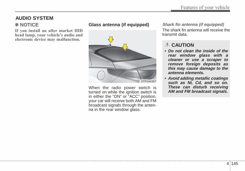
4 145
Features of your vehicle
AUDIO SYSTEM✽✽ NOTICE If you install an after market HIDhead lamp, your vehicle’s audio andelectronic device may malfunction.
Glass antenna (if equipped)
When the radio power switch isturned on while the ignition switch isin either the “ON” or “ACC” position,your car will receive both AM and FMbroadcast signals through the anten-na in the rear window glass.
Shark fin antenna (if equipped)The shark fin antenna will receive thetransmit data.
OTF044357
CAUTION• Do not clean the inside of the
rear window glass with acleaner or use a scraper toremove foreign deposits asthis may cause damage to theantenna elements.
• Avoid adding metallic coatingssuch as Ni, Cd, and so on.These can disturb receivingAM and FM broadcast signals.

Features of your vehicle
1464
Steering wheel audio controls (if equipped)
The steering wheel may incorporateaudio control buttons.
VOLUME ( / ) (1)• Press the lever upward ( ) to
increase the volume.• Press the lever downward ( ) to
decrease the volume.
SEEK/PRESET ( / ) (2)The SEEK/PRESET button has dif-ferent functions based on the systemmode. For the following functions thebutton should be pressed for 0.8 sec-onds or more.
RADIO mode
It will function as the AUTO SEEKselect button.
CD/USB/iPod mode
It will function as the FF/REW button.
If the SEEK/PRESET button ispressed for less than 0.8 seconds, itwill work as follows in each mode.
RADIO mode
It will function as the PRESET STA-TION buttons.
CD/USB/iPod mode
It will function as TRACK UP/DOWNbutton.
MODE (3)Press the button to change audiosource.FM(1~2)➟AM➟SAT(1~3)➟CD➟USBAUX(iPod)➟FM...In addition to mode change, Poweron/off can be made by pressing thisbutton when the ignition switch is onACC or ON.- Power ON: Press the button when
the audio is off- Power OFF: Press the button for
more than 0.8 seconds when theaudio is on.
MUTE (4, if equipped)• Press the button to mute the
sound.• Press the button to turn off the
microphone during a telephonecall.
Detailed information for audio controlbuttons are described in the followingpages in this section.
CAUTIONDo not operate audio remotecontrol buttons simultaneously.
OTF044358
OTF044359
■ Type A
■ Type B

4 147
Features of your vehicle
Aux, USB and iPod®* port
If your vehicle has an aux and/orUSB(universal serial bus) port oriPod® port, you can use an aux portto connect audio devices and anUSB port to plug in an USB and alsoan iPod® port to plug in an iPod®.
✽✽ NOTICEWhen using a portable audio deviceconnected to the power outlet, noisemay occur during playback. If thishappens, use the power source of theportable audio device.
* iPod® is a Registered trademark of AppleInc.
OTF044360

Features of your vehicle
1484
How vehicle audio works
AM and FM radio signals are broad-cast from transmitter towers locatedaround your city. They are intercept-ed by the radio antenna on your vehi-cle. This signal is then processed bythe radio and sent to your vehiclespeakers.However, in some cases the signalcoming to your vehicle may not bestrong and clear.This can be due to factors, such asthe distance from the radio station,closeness of other strong radio sta-tions or the presence of buildings,bridges or other large obstructions inthe area.
AM broadcasts can be received atgreater distances than FM broad-casts. This is because AM radiowaves are transmitted at low fre-quencies. These long distance,lowfrequency radio waves can follow thecurvature of the earth rather thantravelling straight. In addition, theycurve around obstructions resultingin better signal coverage.
FM broadcasts are transmitted athigh frequencies and do not bend tofollow the earth's surface. Becauseof this, FM broadcasts generallybegin to fade within short distancesfrom the station. Also, FM signals areeasily affected by buildings, moun-tains, and obstructions. This can leadto undesirable or unpleasant listen-ing conditions which might lead youto believe a problem exists with yourradio. The following conditions arenormal and do not indicate radiotrouble:
¢ ¢¢ ¢ ¢¢
JBM002
AM reception
¢ ¢¢
JBM001
FM reception
JBM003
FM radio station

4 149
Features of your vehicle
WARNINGDo not use a cellular phonewhile driving. Stop at a safelocation to use a cellular phone.
• Fading - As your vehicle movesaway from the radio station, thesignal will weaken and sound willbegin to fade. When this occurs,we suggest that you select anotherstronger station.
• Flutter/Static - Weak FM signals orlarge obstructions between thetransmitter and your radio can dis-turb the signal causing static orfluttering noises to occur. Reducingthe treble level may lessen thiseffect until the disturbance clears.
• Station Swapping - As an FM sig-nal weakens, another more power-ful signal near the same frequencymay begin to play. This is becauseyour radio is designed to lock ontothe clearest signal. If this occurs,select another station with astronger signal.
• Multi-Path Cancellation - Radiosignals being received from sever-al directions can cause distortionor fluttering. This can be caused bya direct and reflected signal fromthe same station, or by signalsfrom two stations with close fre-quencies. If this occurs, selectanother station until the conditionhas passed.
Using a cellular phone or a two-way radioWhen a cellular phone is used insidethe vehicle, noise may be producedfrom the audio system. This does notmean that something is wrong withthe audio equipment. In such a case,try to operate mobile devices as farfrom the audio equipment as possi-ble.
JBM005JBM004 CAUTIONWhen using a communicationsystem such as a cellular phoneor a radio set inside the vehicle,a separate external antennamust be fitted. When a cellularphone or a radio set is usedwith an internal antenna alone,it may interfere with the vehi-cle's electrical system andadversely affect safe operationof the vehicle.

Features of your vehicle
1504
Caring for disc• If the temperature inside the car is too
high, open the car windows to venti-late before using the system.
• It is illegal to copy and useMP3/WMA files without permission.Use CDs that are created only bylawful means.
• Do not apply volatile agents, suchas benzene and thinner, normalcleaners and magnetic spraysmade for analogue disc onto CDs.
• To prevent the disc surface fromgetting damaged, hold CDs by theedges or the center hole only.
• Clean the disc surface with a pieceof soft cloth before playback (wipeit from the center to the outsideedge).
• Do not damage the disc surface orattach pieces of sticky tape orpaper.
• Make certain only CDs are insert-ed into the CD player (Do not insertmore than one CD at a time).
• Keep CDs in their cases after use toprotect them from scratches or dirt.
• Depending on the type of CD-R/CD-RW CDs, certain CDs maynot operate normally according tothe manufacturing companies. Insuch circumstances, continueduse may cause malfunctions toyour audio system.
✽✽ NOTICE - Playing an Incompatible
Copy Protected Audio CDSome copy protected CDs, which donot comply with international audioCD standards (Red Book), may notplay on your car audio. Please notethat inabilities to properly play acopy protected CD may indicatethat the CD is defective, not the CDplayer.
NOTE:Order of playing files (folders) :1. Song playing order : to
sequentially.2. Folder playing order :❋ If no song file is contained in the
folder, that folder is not displayed.

4 151
Features of your vehicle
CAUTION• Operating the audio system
while driving could lead toaccidents due to a lack ofattention to external sur-roundings. First park the vehi-cle before operating thedevice.
• Adjust the volume to levelsthat allow the driver to hearsounds from outside of thevehicle. Driving in a statewhere external sounds cannotbe heard may lead to acci-dents.
• Pay attention to the volumesetting when turning thedevice on. A sudden output ofextreme volume upon turningthe device on could lead tohearing impairment. (Adjustthe volume to a suitable levelsbefore turning off the device.)
(Continued)
WARNING• Do not stare at the screen
while driving. Staring at thescreen for prolonged periodsof time could lead to trafficaccidents.
• Do not disassemble, assem-ble, or modify the audio sys-tem. Such acts could result inaccidents, fire, or electricshock.
• Using the phone while drivingmay lead to a lack of attentionof traffic conditions andincrease the likelihood ofaccidents. Use the phonefeature after parking the vehi-cle.
• Heed caution not to spill wateror introduce foreign objectsinto the device. Such actscould lead to smoke, fire, orproduct malfunction.
(Continued)
(Continued)• Please refrain from use if the
screen is blank or no soundcan be heard as these signsmay indicate product mal-function. Continued usein such conditions could leadto accidents(fires, electricshock) or product malfunc-tions.
• Do not touch the antenna dur-ing thunder or lightening assuch acts may lead to light-ning induced electric shock.
• Do not stop or park in park-ing-restricted areas to operatethe product. Such acts couldlead to traffic accidents.
• Use the system with the vehi-cle ignition turned on.Prolonged use with the igni-tion turned off could result inbattery discharge.

Features of your vehicle
1524
(Continued)• Turn on the car ignition before
using the audio system. Donot operate the audio systemfor long periods of time withthe ignition turned off as suchoperations may lead to batterydischarge.
• Do not subject the device tosevere shock or impact. Directpressure onto the front side ofthe monitor may cause dam-age to the LCD or touchscreen.
• When cleaning the device,make sure to turn off theaudio system and use a dryand smooth cloth. Never usetough materials, chemicalcloths, or solvents (alcohol,benzene, thinners, etc.) assuch materials may damagethe device panel or causecolor/quality deterioration
(Continued)
(Continued)• Do not place beverages close
to the audio system. Spillingbeverages may lead to systemmalfunction.
• In case of product malfunction,please contact your place of pur-chase or After Service center.
• Placing the audio systemwithin an electromagneticenvironment may result innoise interference.
• Prevent caustic solutionssuch as perfume and cosmet-ic oil from contacting thedashboard because they maycause damage or discol-oration.

4 153
Features of your vehicle
USING THE USB DEVICE• To use an external USB device,
make sure the device is not con-nected when starting up thevehicle. Connect the device afterstarting up.
• If you start the engine when theUSB device is connected, it maydamage the USB device. (USBflashdrives are very sensitive toelectric shock.)
• If the engine is started up orturned off while the external USBdevice is connected, the externalUSB device may not work.
• The System may not play unau-thenticated MP3 or WMA files.1) It can only play MP3 files with
the compression ratebetween 8Kbps ~ 320Kbps.
2) It can only play WMA musicfiles with the compressionrate between 8Kbps ~320Kbps.
• Take precautions for static elec-tricity when connecting or discon-necting the external USB device.
(Continued)
(Continued)• An encrypted MP3 PLAYER is
not recognizable.• Depending on the condition of
the external USB device, theconnected external USB devicecan be unrecognizable.
• When the formatted byte/sectorsetting of External USB device isnot either 512BYTE or2048BYTE, then the device willnot be recognized.
• Use only a USB device format-ted to FAT 12/16/32.
• USB devices without USB I/Fauthentication may not be recog-nizable.
• Make sure the USB connectionterminal does not come in con-tact with the human body orother objects.
• If you repeatedly connect or dis-connect the USB device in ashort period of time, it may breakthe device.
(Continued)
(Continued)• You may hear a strange noise
when connecting or disconnect-ing a USB device.
• If you disconnect the externalUSB device during playback inUSB mode, the external USBdevice can be damaged or maymalfunction. Therefore, discon-nect the external USB devicewhen the audio is turned off or inanother mode. (e.g, Radio, CD)
• Depending on the type andcapacity of the external USBdevice or the type of the filesstored in the device, there is adifference in the time for recogni-tion the device.
• Do not use the USB device forpurposes other than playingmusic files.
• Playing videos through the USBis not supported.
• Use of USB accessories such asrechargers or heaters using USBI/F may lower performance orcause trouble.
(Continued)
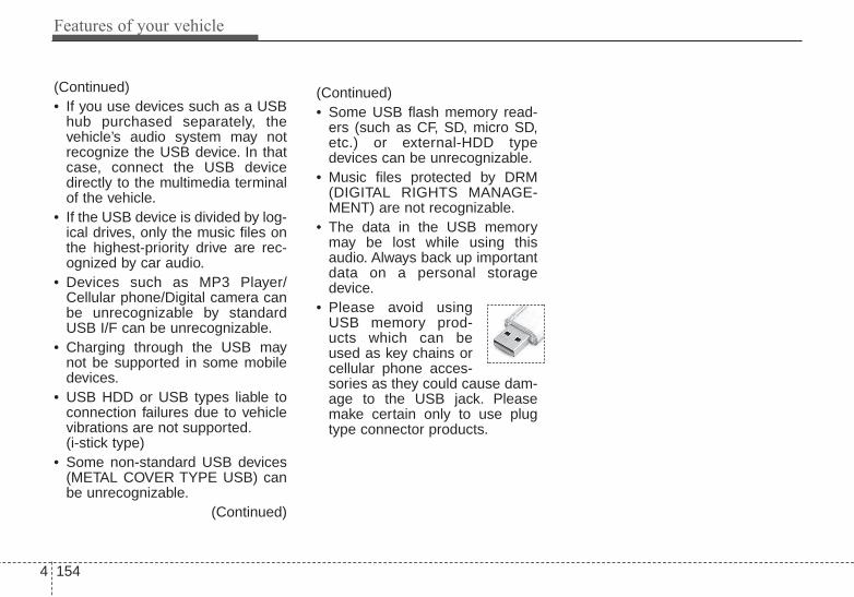
Features of your vehicle
1544
(Continued)• Some USB flash memory read-
ers (such as CF, SD, micro SD,etc.) or external-HDD typedevices can be unrecognizable.
• Music files protected by DRM(DIGITAL RIGHTS MANAGE-MENT) are not recognizable.
• The data in the USB memorymay be lost while using thisaudio. Always back up importantdata on a personal storagedevice.
• Please avoid usingUSB memory prod-ucts which can beused as key chains orcellular phone acces-sories as they could cause dam-age to the USB jack. Pleasemake certain only to use plugtype connector products.
(Continued)• If you use devices such as a USB
hub purchased separately, thevehicle’s audio system may notrecognize the USB device. In thatcase, connect the USB devicedirectly to the multimedia terminalof the vehicle.
• If the USB device is divided by log-ical drives, only the music files onthe highest-priority drive are rec-ognized by car audio.
• Devices such as MP3 Player/Cellular phone/Digital camera canbe unrecognizable by standardUSB I/F can be unrecognizable.
• Charging through the USB maynot be supported in some mobiledevices.
• USB HDD or USB types liable toconnection failures due to vehiclevibrations are not supported.(i-stick type)
• Some non-standard USB devices(METAL COVER TYPE USB) canbe unrecognizable.
(Continued)

4 155
Features of your vehicle
USING iPod® DEVICEiPod® is a registered trademark ofApple Inc.iPhone® is a registered grademarkof Apple inc.• Some iPod® models may not
support communication protocoland files may not properly play.Supported iPod® models:- iPhone® 3GS/4- iPod® touch 1st~4th generation- iPod® nano 1st~6th generation- iPod® classic
• The order of search or playbackof songs in the iPod® can be dif-ferent from the order searched inthe audio system.
• If the iPod® is disabled due to itsown malfunction, reset theiPod®. (Reset: Refer to iPod®
manual)• An iPod® may not operate nor-
mally on low battery.(Continued)
(Continued)• Some iPod® devices, such as the
iPhone®, can be connectedthrough the Bluetooth® WirelessTechnology interface. The devicemust have audio Bluetooth®
Wireless Technology capability(such as for stereo headphoneBluetooth® Wireless Technology).The device can play, but it will notbe controlled by the audio system.
• To use iPod® features within theaudio, use the cable providedupon purchasing an iPod® device.
• Skipping or improper operationmay occur depending on thecharacteristics of your iPod®/iPhone® device.
• If your iPhone® is connected toboth the Bluetooth® WirelessTechnology and USB, the soundmay not be properly played. Inyour iPhone®, select the Dockconnector or Bluetooth® WirelessTechnology to change the soundoutput (source).
(Continued)
(Continued)• When connecting iPod® with the
iPod® Power Cable, insert theconnector to the multimediasocket completely. If not insertedcompletely, communicationsbetween iPod® and audio maybe interrupted.
• When adjusting the soundeffects of the iPod® and theaudio system, the sound effectsof both devices will overlap andmight reduce or distort the qual-ity of the sound.
• Deactivate (turn off) the equaliz-er function of an iPod® whenadjusting the audio system’s vol-ume, and turn off the equalizerof the audio system when usingthe equalizer of an iPod®.
• When not using iPod® with caraudio, detach the iPod® cablefrom iPod®. Otherwise, iPod®
may remain in accessory mode,and may not work properly.

Features of your vehicle
1564
Bluetooth® WirelessTechnology
Bluetooth® Wireless TechnologyThe Bluetooth® word mark and logosare registered trademarks owned byBluetooth SIG, lnc. and any use ofsuch marks by Kia is under license.A Bluetooth® enabled call phone isrequired to use Bluetooth® wirelesstechnology.
Before Using the Bluetooth®
Wireless Technology Handsfree
What is Bluetooth® ?• Bluetooth® refers to a short-dis-
tance wireless networking technol-ogy which uses a 2.4GHz ~2.48GHz frequency to connect var-ious devices within a certain dis-tance.
• Supported within PCs, externaldevices, Bluetooth® phones, PDAs,various electronic devices, andautomotive environments,Bluetooth® allows data to be trans-mitted at high speeds without hav-ing to use a connector cable.
• Bluetooth® Handsfree refers to adevice which allows the user to con-veniently make phone calls withBluetooth® mobile phones throughthe audio system.
• Bluetooth® Handsfree may not besupported in some mobile phones.To learn more about mobile devicecompatibility, visit www.kia.com.
Precautions for Safe Driving
• Bluetooth® Handsfree is a featurethat enables drivers to practice safedriving. Connecting the head unitwith a Bluetooth® phone allows theuser to conveniently make andreceive calls and use contacts.Before using Bluetooth®, carefullyread the contents of this user’smanual.
• Excessive use or operations whiledriving may lead to negligent driv-ing practices and result in acci-dents. Refrain from excessive oper-ations while driving.
• Viewing the screen for prolongedperiods of time is dangerous andmay lead to accidents. When driv-ing, view the screen only for shortperiods of time.
WARNINGDriving while distracted canresult in a loss of vehicle controlthat may lead to an accident,severe personal injury, anddeath. The driver’s primaryresponsibility is in the safe andlegal operation of a vehicle, anduse of any handheld devices,other equipment, or vehicle sys-tems which take the driver’seyes, attention and focus awayfrom the safe operation of a vehi-cle or which are not permissibleby law should never be used dur-ing operation of the vehicle.
4 157
Features of your vehicle
When connecting a Bluetooth®
Phone
• Before connecting the head unitwith the mobile phone, check tosee that the mobile phone sup-ports Bluetooth® features.
• Even if the phone supportsBluetooth®, the phone will not befound during device searches ifthe phone has been set to hiddenstate or the Bluetooth® power isturned off. Disable the hiddenstate or turn on the Bluetooth®
power prior to searching/connect-ing with the Head unit.
• If you do not want automatic con-nection with your Bluetooth®
device, turn off the Bluetooth®
feature within your mobile phone.• The Handsfree call volume and
quality may differ depending onthe mobile phone.
• Park the vehicle when connectingthe head unit with the mobilephone.
• Bluetooth® connection maybecome intermittently discon-nected in some mobile phones.Follow these steps to try again.1. Within the mobile phone, turn
the Bluetooth® function off/onand try again.
2. Turn the mobile phone powerOff/On and try again.
3. Reboot the audio system andtry again.
4. Delete all paired devices, pairand try again.
• Handsfree call quality and volumemay differ depending on themodel of your mobile phone.

Features of your vehicle
1584
Voice Recognition
• When using the voice recognitionfeature, only commands listed with-in the user's manual are supported.
• Be aware that during the operationof the voice recognition system,pressing any key other than the
key terminate voice recognitionmode.
• For superior voice recognition per-formance, position the microphoneused for voice recognition abovethe head of the driver’s seat andmaintain a proper position whensaying commands.
• Within the following situations,voice recognition may not functionproperly due to external sound.- When the windows and sunroof
are open- When the blower AC/heater is set
to high- When entering and passing
through tunnels(Continued)
(Continued)- When driving on rugged and
uneven roads- During severe rain (heavy rains,
windstorms)• Phone related voice commands
can be used only when aBluetooth® Wireless Technologydevice is connected.
• When making calls by stating aname, the corresponding contactmust be downloaded and storedwithin the audio system.
• After downloading the Bluetooth®
Wireless Technology phone book, ittakes some times to convert thephone book data into voice infor-mation. During this time, voicerecognition may not properly oper-ate.
• Pronounce the voice commandsnaturally and clearly as if in a nor-mal conversation.

4 159
Features of your vehicle
■■ CD Player : AM1A0TKAN,8V, AM1A0TKKN,8V
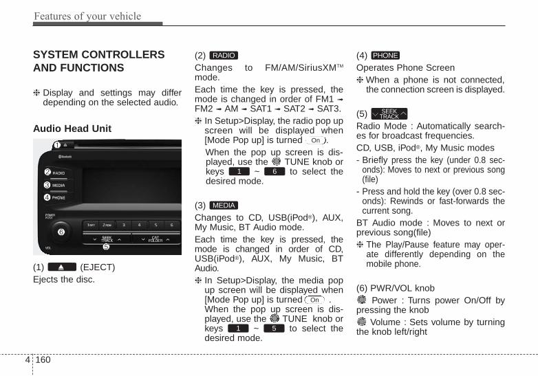
Features of your vehicle
1604
SYSTEM CONTROLLERSAND FUNCTIONS
❈ Display and settings may differdepending on the selected audio.
Audio Head Unit
(1) (EJECT)Ejects the disc.
(2) Changes to FM/AM/SiriusXMTM
mode.Each time the key is pressed, themode is changed in order of FM1 ➟
FM2 ➟ AM ➟ SAT1 ➟ SAT2 ➟ SAT3.❈ In Setup>Display, the radio pop up
screen will be displayed when[Mode Pop up] is turned .When the pop up screen is dis-played, use the TUNE knob orkeys ~ to select thedesired mode.
(3) Changes to CD, USB(iPod®), AUX,My Music, BT Audio mode.Each time the key is pressed, themode is changed in order of CD,USB(iPod®), AUX, My Music, BTAudio.❈ In Setup>Display, the media pop
up screen will be displayed when[Mode Pop up] is turned .When the pop up screen is dis-played, use the TUNE knob orkeys ~ to select thedesired mode.
(4) Operates Phone Screen❈ When a phone is not connected,
the connection screen is displayed.
(5) Radio Mode : Automatically search-es for broadcast frequencies.CD, USB, iPod®, My Music modes- Briefly press the key (under 0.8 sec-
onds): Moves to next or previous song(file)
- Press and hold the key (over 0.8 sec-onds): Rewinds or fast-forwards thecurrent song.
BT Audio mode : Moves to next orprevious song(file)❈ The Play/Pause feature may oper-
ate differently depending on themobile phone.
(6) PWR/VOL knobPower : Turns power On/Off by
pressing the knobVolume : Sets volume by turning
the knob left/right
SEEKTRACK
PHONE
51
On
MEDIA
61
On
RADIO

4 161
Features of your vehicle
(7) Each time the button is pressed, itsets the screen Off ➟ Screen On ➟
Screen Off❈ Audio operation is maintained and
only the screen will be turned Off.In the screen Off state, press anykey to turn the screen On again.
(8) Radio Mode- Shortly press the key : Previews
each broadcast for 5 secondseach.
- Press and hold the key (over 0.8seconds): Previews the broadcastssaved in Preset ~ for 5seconds each.
❈ Press the key again tocontinue listening to the currentfrequency.
❈ SAT Radio does not support thePreset scan feature.
CD, USB, My Music mode- Shortly press the key (under 0.8
seconds): Previews each song(file) for 10 seconds each.
❈ Press the key again tocontinue listening to the currentsong (file).
(9) Briefly press the key (under 0.8 sec-onds) : Moves to the Display, Sound,Clock, Phone, System setting modesPress and hold the key (over 0.8 sec-onds) : Move to the Time setting screen
(10) Displays menus for the current mode.❈ iPod® List : Move to parent category
(11) Radio Mode- SiriusXMTM RADIO : Category Search- MP3, CD, USB mode : Folder
Search
CATFOLDER
MENU
SETUP
SCAN
SCAN
61
SCAN
DISP

Features of your vehicle
1624
(12) TUNE knobAM/FM Mode : Changes frequencyby turning the knob left/right.CD, USB, iPod®, My Music Mode:Searches songs (files) by turning theknob left/right.SiriusXMTM Radio Mode:- Changes the station by turning the
knob left/right. Press knob to selectstation.
❈ When the desired song is displayed,press the knob to play the song.
Moves focus in all selection menusand selects menus.
(13) ~ (Preset)Radio Mode: Saves frequencies(channels) or receives saved fre-quencies (channels)CD, USB, iPod®, My Music mode- : Repeat- : RandomIn the Radio, Media, Setup, andMenu pop up screen, the numbermenu is selected.
2 RDM
1 RPT
61

4 163
Features of your vehicle
SETUP
Display Settings
Press the key Select [Display]through TUNE knob or keySelect menu through TUNE knob
Mode Pop up[Mode Pop up] Changes /selection mode• During On state, press the
or key to display the modechange pop up screen.
Text Scroll[Text Scroll] Set /• : Maintains scroll• : Scrolls only one (1) time.
Media DisplayWhen playing an MP3 file, select thedesired display info from ‘Folder/File’or ‘Album/Artist/Song’.
Off
On
OffOn
MEDIARADIO
OffOn
1SETUP

Features of your vehicle
1644
SOUND SETTINGS
Press the key Select [Sound]through TUNE knob or keySelect menu through TUNE knob
Sound SettingsThis menu allows you to set the‘Bass, Middle, Treble’ and the SoundFader and Balance.Select [Sound Settings] Selectmenu through TUNE knob Turn
TUNE knob left/right to set• Bass, Middle, Treble : Selects the
sound tone.• Fader, Balance : Moves the sound
fader and balance.• Default : Restores default settings.❈ Back : While adjusting values,
pressing the TUNE knob willrestore the parent menu.
Speed Dependent Volume ControlThis feature will gradually increasethe volume as speed increases tooffset outside noise.Select [Speed Dependent Vol.] Setin 4 levels [Off/Low/Mid/High] ofTUNE knob
Voice Recognition VolumeAdjusts voice recognition volume.Select [Voice Recognition Vol.] Setvolume of TUNE knob
2SETUP

4 165
Features of your vehicle
SYSTEM SETTINGS
Press the key Select[System] Select menu through
TUNE knob
Memory InformationDisplays currently used memory andtotal system memory.Select [Memory Information] OKThe currently used memory is dis-played on the left side while the totalsystem memory is displayed on theright side.
Prompt FeedbackThis feature is used to change voicecommand feedback between Normaland Expert modes.Select [Prompt Feedback] Setthrough TUNE knob• On : This mode is for beginner
users and provides detailedinstructions during voice commandoperation.
• Off : This mode is for expert usersand omits some information duringvoice command operation. (Whenusing Expert mode, guidanceinstructions can be heard throughthe [Help] or [Menu] commands.
LanguageThis menu is used to set the displayand voice recognition language.Select [Language] Set through
TUNE knob
❈ The system will reboot after thelanguage is changed.
❈ Language support by region- English, Francais, Espanol
SETUP
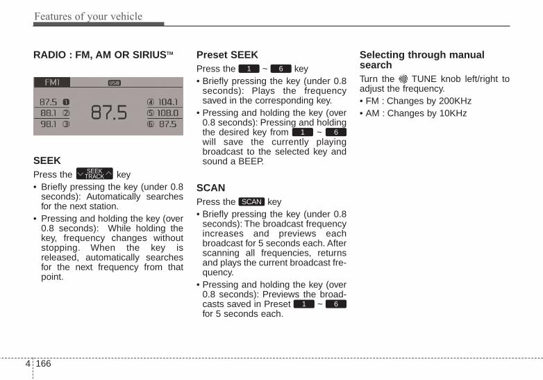
Features of your vehicle
1664
RADIO : FM, AM OR SIRIUSTM
SEEKPress the key• Briefly pressing the key (under 0.8
seconds): Automatically searchesfor the next station.
• Pressing and holding the key (over0.8 seconds): While holding thekey, frequency changes withoutstopping. When the key isreleased, automatically searchesfor the next frequency from thatpoint.
Preset SEEKPress the ~ key• Briefly pressing the key (under 0.8
seconds): Plays the frequencysaved in the corresponding key.
• Pressing and holding the key (over0.8 seconds): Pressing and holdingthe desired key from ~ will save the currently playingbroadcast to the selected key andsound a BEEP.
SCANPress the key• Briefly pressing the key (under 0.8
seconds): The broadcast frequencyincreases and previews eachbroadcast for 5 seconds each. Afterscanning all frequencies, returnsand plays the current broadcast fre-quency.
• Pressing and holding the key (over0.8 seconds): Previews the broad-casts saved in Preset ~ for 5 seconds each.
Selecting through manualsearchTurn the TUNE knob left/right toadjust the frequency.• FM : Changes by 200KHz• AM : Changes by 10KHz
61
SCAN
61
61
SEEKTRACK

4 167
Features of your vehicle
MENUWithin key are the A.Store(Auto Store) and Info functions.
A.Store
Press the key Set [A.Store]through TUNE knob or key.Saves broadcasts with superiorreception to ~ keys. If nofrequencies are received, then themost recently received frequency willbe broadcast.
61
1
MENU
MENU

Features of your vehicle
1684
Satellite Radio channels:SiriusXMTM Satellite Radio has over130 channels, including 69 channelsof 100% commercial-free music, plussports, news, talk and entertainmentavailable nationwide in your vehicle.For more information and a completelist of SiriusXMTM Satellite Radiochannels, visit sirius.com in theUnited States, sirius-canada.ca inCanada, or call SiriusXMTM at 1-800-643-2112.
Satellite Radio reception factors:To receive the satellite signal, yourvehicle has been equipped with asatellite radio antenna located on theroof of your vehicle. The vehicle roofprovides the best location for anunobstructed, open view of the sky, arequirement of a satellite radio sys-tem. Like AM/FM, there are severalfactors that can affect satellite radioreception performance:• Antenna obstructions: For optimal
reception performance, keep theantenna clear of snow and icebuild-up and keep luggage andother material as far away from theantenna as possible.
• Terrain: Hills, mountains, tall build-ings, bridges, tunnels, freewayoverpasses, parking garages,dense tree foliage and thunder-storms can interfere with yourreception.
SiriusXMTM Satellite Radio service:SiriusXMTM Satellite Radio is a sub-scription-based satellite radio serv-ice that broadcasts music, sports,news and entertainment program-ming to radio receivers, which areavailable for installation in motorvehicles or factory installed, as wellas for the home, portable and wire-less devices, and through an Internetconnection on personal computer.Vehicles that are equipped with afactory installed SiriusXMTM SatelliteRadio system include:• Hardware and an introductory trial
subscription term, which begins onthe date of sale or lease of thevehicle.
• For a small upgrade fee, access toSiriusXMTM music channels, andother select channels over theInternet using any computer con-nected to the Internet (U.S. cus-tomers only).
For information on extended sub-scription terms, contact SiriusXMTM
at 1-800-643-2112.
NOTE:SiriusXMTM service requires a sub-scription, sold separately, after 3-month trial included with vehiclepurchase. If you decide to contin-ue your SiriusXMTM service at theend of your trial subscription, theplan you choose will automatical-ly renew and bill at then-currentrates until you call SiriusXMTM at 1-866-635-2349 to cancel. See ourCustomer Agreement for com-plete terms at www.siriusxm.com.Programming subject to change.Sirius satellite service is availableonly to those at least 18 and olderin the 48 contiguous USA, D.C.,and PR (with coverage limita-tions). Traffic information notavailable in all markets. See sir-iusxm.com/traffic for details.Sirius, XM and all related marksand logos are trademarks of SiriusXM Radio Inc.
SiriusXMTM Satellite Radio information

4 169
Features of your vehicle
SiriusXMTM RADIO
Using SiriusXMTM SatelliteRadioYour Kia vehicle is equipped with a 3month complimentary period ofSiriusXMTM Satellite Radio so youhave access to over 130 channels ofmusic, information, and entertain-ment programming.
ActivationIn order to extend or reactivate yoursubscription to SiriusXMTM SatelliteRadio, you will need to contact SIR-IUSTM Customer Care at 800-643-2112. Have your 12 digit SID (SiriusIdentification Number) / ESN(Electronic Serial Number) ready. Toretrieve the SID / ESN, turn on theradio, press the [RADIO] button, andtune to channel zero.
Please note that the vehicle will needto be turned on, in Sirius mode, andhave an unobstructed view of the skyin order for the radio to receive theactivation signal.
SEEKPress the key• Shortly pressing the key (under 0.8
seconds): select previous or nextchannel.
• Pressing and holding the key (over0.8 seconds): continuously moveto previous or next channel.
❈ If the “Category” icon is displayed,channels are changed within thecurrent category.
SCANPress the key• Shortly pressing the key (under 0.8
seconds): Previews each broad-cast for 5 seconds each
❈ Press the key again to con-tinue listening to the current fre-quency
❈ If the “Category” icon is displayed,channels are changed within thecurrent category.
SCAN
SCAN
SEEKTRACK

Features of your vehicle
1704
CategoryPress the key Set throughthe TUNE knob• The display will indicate the category
menus, highlight the category thatthe current channel belongs to.
• In the Category List Mode, pressthe key to navigate cat-egory list.
• Press the tune knob to select thelowest channel in the highlightedcategory.
❈ If channel is selected by selectingcategory, then the “CATEGORY”icon is displayed at the top of thescreen.
PresetPress the key ~ • Briefly pressing the key (under 0.8
seconds): Plays the frequencysaved in the corresponding key.
• Pressing and holding the key (over0.8 seconds): Pressing and holdingthe desired key from ~ will save the current broadcast tothe selected key and sound aBEEP.
✽✽ Troubleshooting1. Antenna Error
If this message is displayed, the anten-na or antenna cable is broken orunplugged. Please consult with yourKia dealership.
2. Acquiring SignalIf this message is displayed, it meansthat the antenna is covered and that theSIRIUSTM Satellite Radio signal is notavailable. Ensure the antenna is uncov-ered and has a clear view of the sky.
Tune• Rotate TUNE knob : Changes
the channel number or scrolls cate-gory list.
• Press TUNE knob : Selects themenu.
MenuSelect category menu through the
TUNE knob Press the keySelect [ Info] through the TUNE
knob or key
Info (Information)Displays the Artist/Song info of thecurrent song.
1 RPT
MENU
61
61RADIO
CATFOLDER
CATFOLDER

4 171
Features of your vehicle
BASIC METHOD OF USE :Audio CD / MP3 CD / USB /iPod® / My Music
Press the key to change themod mode in order of CD ➟
USB(iPod®) ➟ AUX ➟ My Music ➟ BTAudio.The folder/file name is displayed onthe screen.
<Audio CD>
<CD MP3>
<USB>
<My Music>
❈ The CD is automatically playedwhen a CD is inserted.
❈ The USB music is automaticallyplayed when a USB is connected.
RepeatWhile song (file) is playing(RPT) keyAudio CD, MP3 CD, USB, iPod®, MyMusic mode: RPT on screen• To repeat one song (press the key)
: Repeats the current song.MP3 CD, USB mode: FLD.RPT onscreen• To repeat folder (pressing twice):
repeats all files within the currentfolder.
❈ Press the key again to turnoff repeat.
RandomWhile song (file) is playing(RDM) keyAudio CD, My Music mode: RDM onscreen• Random (press the key) : Plays all
songs in random order.
2 RDM
1 RPT
1 RPT
MEDIA

Features of your vehicle
1724
MP3 CD, USB mode: FLD.RDM onscreen• Folder Random (press the key) :
Plays all files within the current fold-er in random order.
iPod® mode: ALL RDM on screen• All Random (press the key) : Plays
all files in random order.MP3 CD, USB : ALL RDM on screen• All Random (pressing twice): Plays
all files in random order.❈ Press the key again to turn
off random.
Changing Song/FileWhile song (file) is playing
key• Shortly pressing the key : Plays the
current song from the beginning.❈ If the key is pressed
again within 2 second, the previ-ous song is played.
• Pressing and holding the key (over0.8 seconds): Rewinds the song.
While song (file) is playingkey
• Shortly pressing the key : Plays thenext song.
• Pressing and holding the key (over0.8 seconds): Fast forwards thesong.
ScanWhile song (file) is playingkey• Shortly pressing the key : Scans all
songs from the next song for 10seconds each.
❈ Press the key again to turnoff.
❈ The SCAN function is not support-ed in iPod® mode.
Folder Search : MP3 CD, USBModeWhile file is playing(Folder Up) key• Searches the next folder.While file is playing(Folder Down) key• Searches the parent folder.❈ If a folder is selected by pressing
the TUNE knob, the first filewithin the selected folder will beplayed.
❈ In iPod® mode, moves to theParent Folder.
Searching Songs (File)• Turning TUNE knob : Searches
for songs (files)• Pressing TUNE knob : Plays
selected song (file).
CATFOLDER
CATFOLDER
SCAN
SCAN
SEEKTRACK
SEEKTRACK
SEEKTRACK
2 RDM

4 173
Features of your vehicle
MENU : Audio CDPress the CD MP3 mode keyto set the Repeat, Random,Information features.
RepeatPress the key Set [ RPT]through the TUNE knob or key to repeat the current song.❈ Press RPT again to turn off.
RandomPress the key Set [ RDM]through the TUNE knob or key to randomly play songs withinthe current folder.❈ Press RDM again to turn off.
InformationPress the key Set [ Info]through the TUNE knob or key to display information of the cur-rent song.❈ Press the key to turn off
info display.
MENU : MP3 CD / USBPress the CD MP3 mode keyto set the Repeat, Folder Random,Folder Repeat, All Random,Information, and Copy features.
RepeatPress the key Set [ RPT]through the TUNE knob or key to repeat the current song.❈ Press RPT again to turn off.
1 RPT
MENU
MENU
MENU
3MENU
2 RDM
MENU
1 RPT
MENU
MENU

Features of your vehicle
1744
Folder RandomPress the key Set [ F.RDM]through the TUNE knob or key to randomly play songs within thecurrent folder.❈ Press F.RDM again to turn off.
Folder RepeatPress the key Set [ F.RPT]through the TUNE knob or key to repeat songs within the cur-rent folder.❈ Press F.RPT again to turn off.
All RandomPress the key Set [ A.RDM]through the TUNE knob or keyto randomly play all songs within theCD.❈ Press A.RDM again to turn off.
InformationPress the key Set [ Info]through the TUNE knob or key to display information of the cur-rent song.❈ Press the key to turn off
info display.
CopyPress the key Set [ Copy]through the TUNE knob or key. This is used to copy the currentsong into My Music. You can playthe copied Music in My Musicmode.
❈ If another key is pressed whilecopying is in progress, a pop upasking you whether to cancelcopying is displayed.
❈ If another media is connected orinserted (USB, CD, iPod®, AUX)while copying is in progress, copy-ing is canceled.
❈ Music will not be played whilecopying is in progress.
6MENU
MENU
5MENU
4MENU
3MENU
2 RDM
MENU

4 175
Features of your vehicle
MENU : iPod®
In iPod® mode, press the keyto set the Repeat, Random,Information and Search features.
RepeatPress the key Set [ RPT]through the TUNE knob or key to repeat the current song.❈ Press RPT again to turn repeat off.
RandomPress the key Set [ RDM]through the TUNE knob or key.Plays all songs within the currentlyplaying category in random order.❈ Press RDM again to turn off.
InformationPress the key Set [ Info]through the TUNE knob or key.Displays information of the currentsong.❈ Press the key to turn off
info display.
SearchPress the key Set [ Search]through the TUNE knob or key.Displays iPod® category list.❈ Searching iPod® category is
key pressed, move to par-ent category.MENU
4MENU
MENU
3MENU
2 RDM
MENU
1 RPT
MENU
MENU

Features of your vehicle
1764
MENU : My Music Mode
In My Music mode, press the key to set the Repeat, Random,Information, Delete, Delete All, andDelete Selection features.
RepeatPress the key Set [ RPT]through the TUNE knob or key.Repeats the currently playing song.❈ Press RPT again to turn repeat off.
RandomPress the key Set [ RDM]through the TUNE knob or key.Plays all songs in random order.❈ Press RDM again to turn random off.
InformationPress the key Set [ Info]through the TUNE knob or key.Displays information of the currentsong.❈ Press the key to turn off
info display.
DeletePress the key Set [ Delete]through the TUNE knob or key. Deletes currently playing file
In the play screen, pressing deletewill delete the currently playing song. Deletes file from list
➀ Select the file you wish to deleteby using the TUNE knob.
➁ Press the key and selectthe delete menu to delete theselected file.
Delete AllPress the key Set [ Del.All]through the TUNE knob or key.
Deletes all songs of My Music.
5
MENU
MENU
4MENU
MENU
3MENU
2 RDM
MENU
1 RPT
MENU
MENU

4 177
Features of your vehicle
Delete SelectionPress the key Set [Del.Sel] through the TUNE knobor key.Songs within My Music are selectedand deleted.➀ Select the songs you wish to
delete from the list.
➁ After selecting, press keyand select the delete menu.
My Music• Even if memory is available, a
maximum of 6,000 songs can bestored.
• The same song can be copied upto 1,000 times.
• Memory info can be checked in theSystem menu of Setup.
AUXAUX is used to play external MEDIAcurrently connected with the AUXterminal.AUX mode will automatically startwhen an external device is connect-ed with the AUX terminal.If an external device is connected,you can also press the key tochange to AUX mode.
❈ AUX mode cannot be startedunless there is an external deviceconnected to the AUX terminal.
AUXFully insert the AUX cable into theAUX terminal for use.
MEDIA
MENU
6
MENU

Features of your vehicle
1784
Bluetooth® Wireless TechnologyAUDIO
What is Bluetooth® WirelessTechnology?Bluetooth® Wireless Technologyallows devices to be connected in ashort distance, including hands-freedevices, stereo headsets, wirelessremote controllers, etc. For moreinformation, visit the Bluetooth®
Wireless Technology website atwww.Bluetooth.com
Before using Bluetooth® WirelessTechnology audio features• Bluetooth® Wireless Technology
audio may not be supported depend-ing on the compatibility of yourBluetooth® Wireless Technologymobile phone.
• In order to use Bluetooth® WirelessTechnology audio, you must firstpair and connect the Bluetooth®
Wireless Technology mobile phone.
• The Bluetooth® word mark andlogos are registered trademarksowned by Bluetooth SIG, Inc. andany use of such marks by Kia isunder license. Other trademarksand trade names are those of theirrespective owners. A Bluetooth®enabled cell phone is required touse Bluetooth® Wireless Technology
• Bluetooth® Wireless Technologyaudio can be used only when the[Audio Streaming] of Phone isturned .
❈ Setting Bluetooth® WirelessTechnology Audio Streaming : Pressthe key Select [Phone] Select [Audio Streaming] throughthe TUNE knob Set / OffOn
SETUP
On
WARNINGDriving while distracted canresult in a loss of vehicle controlthat may lead to an accident,severe personal injury, anddeath. The driver’s primaryresponsibility is in the safe andlegal operation of a vehicle, anduse of any handheld devices,other equipment, or vehicle sys-tems which take the driver’seyes, attention and focus awayfrom the safe operation of a vehi-cle or which are not permissibleby law should never be used dur-ing operation of the vehicle.

4 179
Features of your vehicle
Starting Bluetooth® WirelessTechnology Audio• Press the key to change the
mode in order of CD ➟ USB ➟ AUX➟ My Music ➟ BT Audio.
• If BT Audio is selected, Bluetooth®
Wireless Technology audio will startplaying.
❈ Audio may not automatically startplaying in some mobile phones.
Using the Bluetooth® WirelessTechnology audio features• Play / StopPress the TUNE knob to play andpause the current song.
• Previous / Next songPress or to playprevious or next song.❈ The previous song / next song /
play / pause functions may not besupported in some mobile phones.
SEEKTRACK
SEEKTRACK
MEDIA

Features of your vehicle
1804
PHONE
Before using the Bluetooth® WirelessTechnology phone features• In order to use Bluetooth® Wireless
Technology phone, you must firstpair and connect the Bluetooth®
Wireless Technology mobile phone.• If the mobile phone is not paired or
connected, it is not possible toenter Phone mode. Once a phoneis paired or connected, the guid-ance screen will be displayed.
• If Priority is set upon vehicle igni-tion (IGN/ACC ON), the Bluetooth®
Wireless Technology phone will beautomatically connected. Even ifyou are outside, the Bluetooth®
Wireless Technology phone will beautomatically connected once youare in the vicinity of the vehicle. Ifyou do not want automaticBluetooth® Wireless Technologyphone connection, set theBluetooth® Wireless Technologypower to OFF
Making a call using theSteering-wheel mounted con-trols
(1) MUTE button : Mute the micro-phone during a call.
(2) VOLUME button : Raises or low-ers speaker volume.
(3) button : Places and transfers calls.
(4) button : Ends calls or cancels functions.
(5) button : Activates voice recog-nition.
• Check call history and making call➀ Briefly press (under 0.8 seconds)
the key on the steeringremote controller.
➁ The call history list will be dis-played on the screen.
➂ Press the key again to con-nect a call to the selected number.
• Redialing the most recently callednumber
➀ Press and hold (over 0.8 seconds)the key on the steeringremote controller.
➁ The most recently called numberis redialed.

4 181
Features of your vehicle
Bluetooth® Wireless Technology
Pairing a Bluetooth® WirelessTechnology Device
What is Bluetooth® WirelessTechnology Pairing?Pairing refers to the process of syn-chronizing your Bluetooth® WirelessTechnology phone or device with thecar audio system for connection.Pairing is necessary to connect anduse the Bluetooth® WirelessTechnology feature.The Bluetooth® word mark and logosare registered trademarks owned byBluetooth SIG, Inc. and any use ofsuch marks by Kia is under license.Other trademarks and trade namesare those of their respective owners.A Bluetooth® enabled cell phone isrequired to use Bluetooth® WirelessTechnology
WARNINGDriving while distracted canresult in a loss of vehicle controlthat may lead to an accident,severe personal injury, anddeath. The driver’s primaryresponsibility is in the safe andlegal operation of a vehicle, anduse of any handheld devices,other equipment, or vehicle sys-tems which take the driver’seyes, attention and focus awayfrom the safe operation of a vehi-cle or which are not permissibleby law should never be used dur-ing operation of the vehicle.

Features of your vehicle
1824
Pairing Key / Keyon the Steering RemoteController
When No Devices have beenPaired1.Press the key or the
key on the steering remote controller.The following screen is displayed.
2.Select [OK] button to enter the PairPhone screen.
1)Car Name : Name of device asshown when searching from yourBluetooth® Wireless Technologydevice
2) Passkey : Passkey used to pairthe device
3. From your Bluetooth® WirelessTechnology device (i.e. MobilePhone), search and select yourcar audio system.
[Non SSP supported device](SSP: Secure Simple Pairing)4. After a few moments, a screen is
displayed where the passkey isentered. Hear, enter the passkey“0000” to pair your Bluetooth®
Wireless Technology device withthe car audio system.
[SSP supported device]4. After a few moments, a screen is
displayed 6 digits passkey.Hear, check the passkey on yourBluetooth® Wireless Technologydevice and confirm.
5. Once pairing is complete, the fol-lowing screen is displayed.
PHONE
PHONE

4 183
Features of your vehicle
During the pairing process, makesure that all connection requests onthe phone are accepted for phone-book download and to allow accept-ance of all future connection requests.and Visit http://www.kia.com/#/blue-tooth for additional information onpairing your Bluetooth-enabledmobile phone, and to view a phonecompatibility list.
• If Bluetooth® Wireless Technologydevices are paired but none arecurrently connected, pressing the
key or the key on thesteering wheel displays the follow-ing screen. Select [Pair] button topair a new device or select[Connect] to connect a previouslypaired device.
PHONE

Features of your vehicle
1844
Pairing through [PHONE]Setup
Press the key Select[Phone] Select [Pair Phone] Select TUNE knob
1. The following steps are the sameas those described in the section"When No Devices have beenPaired" on the previous page.
• Bluetooth® Wireless Technologyfeatures supported within the vehi-cle are as follows. Some featuresmay not be supported dependingon your Bluetooth® WirelessTechnology device.- Outgoing/Incoming Handsfree
calls- Operations during a call (Switch
to Private, Switch to call waiting,MIC on/off)
- Downloading Call History- Downloading Mobile Contacts- Bluetooth® Wireless Technology
device auto connection- Bluetooth Audio Streaming
• Up to five Bluetooth® WirelessTechnology devices can be pairedto the Car Handsfree system.
• Only one Bluetooth® device can beconnected at a time.
• Only one Bluetooth® WirelessTechnology device can be connect-ed at a time.
• Other devices cannot be pairedwhile a Bluetooth® WirelessTechnology device is connected.
• Only Bluetooth® Wireless TechnologyHandsfree and Bluetooth audio relat-ed features are supported.
• Bluetooth related operations arepossible only within devices that sup-port Handsfree or audio features,such as a Bluetooth® WirelessTechnology mobile phone or aBluetooth audio device.
• If a connected Bluetooth® WirelessTechnology device becomes discon-nected due to being out of communi-cation range, turning the device OFF,or a Bluetooth® Wireless Technologycommunication error, correspondingBluetooth® Wireless Technologydevices are automatically searchedand reconnected.
• If the system becomes unstable dueto communication errors betweenthe car Handsfree and the Bluetooth®
Wireless Technology device, resetthe device by turning off and back onagain. Upon resetting Bluetooth®
Wireless Technology device, the sys-tem will be restored.
SETUP

4 185
Features of your vehicle
• After pairing is complete, a con-tacts download request is sentonce to the mobile phone. Somemobile phones may require confir-mation upon receiving a downloadrequest, ensure your mobile phoneaccepts the connection. Refer toyour phones user’s manual foradditional information regardingphone pairing and connections.
Connecting a Device
Press the key Select[Phone] Select [Phone List]
1) Connected Phone : Device that iscurrently connected
2) Paired Phone : Device that ispaired but not connected
From the paired phone list, select thedevice you want to connect andselect [Connect].
SETUP

Features of your vehicle
1864
Changing Priority
What is Priority?It is possible to pair up to fiveBluetooth® Wireless Technologydevices with the car audio system.The "Change Priority" feature is usedto set the connection priority ofpaired phones.
Press the key Select[Phone] Select [Phone List]
From the paired phone list, selectthe phone you want to switch to thehighest priority, then select [ChangePriority] button from the Menu. Theselected device will be changed tothe highest priority.
• Priority icon will be displayed whenthe selected phone is set as a pri-ority phone.
SETUP

4 187
Features of your vehicle
Disconnecting a Device
Press the key Select[Phone] Select [Phone List]
From the paired phone list, select thecurrently connected device andselect [Disconnect] button.
Deleting a Device
Press the key Select[Phone] Select [Phone List]
From the paired phone list, select thedevice you want to delete and select[Delete] button.
• When deleting the currently con-nected device, the device will auto-matically be disconnected to pro-ceed with the deleting process.
• If a paired Bluetooth® WirelessTechnology device is deleted, thedevice’s call history and contactsdata will also be deleted.
• To re-use a deleted device, youmust pair the device again.
SETUPSETUP

Features of your vehicle
1884
USING Bluetooth® WirelessTechnology
Phone Menu Screen
Phone MenusWith a Bluetooth® WirelessTechnology device connected, pressthe key to display the Phonemenu screen.
1) Favorite : Up to 20 frequently usedcontacts saved for easy access.
2) Call History : Displays the call his-tory list screen
3) Contacts : Displays the Contactslist screen
4) Setup : Displays Phone relatedsettings.
• If you select the [Call History] but-ton but there is no call history data,a prompt is displayed which asks todownload call history data.
• If you select the [Contacts] buttonbut there is no contacts datastored, a prompt is displayed whichasks to download contacts data.
• This feature may not be supportedin some mobile phones. For moreinformation on download support,refer to your mobile phone user’smanual.
Answering Calls
Answering a CallAnswering a call with a Bluetooth®
Wireless Technology device connect-ed will display the following screen.To accept the call, press key onthe steering wheel while the call isincoming.
1) Caller : Displays the other party’sname when the incoming caller issaved within your contacts
2) Incoming Number : Displays theincoming number
PHONE

4 189
Features of your vehicle
• When an incoming call pop-up isdisplayed, most Audio and SETUPmode features are disabled. Onlythe call volume will operate.
• The telephone number may not beproperly displayed in some mobilephones.
• When a call is answered with themobile phone, the call mode willautomatically revert to Privatemode.
Favorites
Press the key Select[Favorites]
1) Saved favorite contact : Connectscall upon selection
2) To add favorite : Downloaded con-tacts be saved as favorite.
• To save Favorite, contacts shouldbe downloaded.
• Contact saved in Favorites will notbe automatically updated if thecontact has been updated in thephone. To update Favorites, deletethe Favorite and create a newFavorite.
Call History
Press the key Select [CallHistory]
A list of incoming, outgoing andmissed calls is displayed.• Call history may not be saved in the
call history list in some mobilephones.
• Calls received with hidden caller IDwill not be saved in the call historylist.
• Calling through the call history is notpossible when there is no call historystored or a Bluetooth® WirelessTechnology phone is not connected.
• Up to 20 received, dialed and missedcalls are stored in Call History.
• Time of received/dialed calls and calltime information are not stored inCall History.
PHONE PHONE

Features of your vehicle
1904
Contacts
Press the key Select[Contacts]
The list of saved phone book entriesis displayed.
NOTE:Find a contact in an alphabeticalorder, press the key.
• Up to 1,000 contacts saved in yourBluetooth® Wireless Technologyphone can be downloaded into thecar contacts. Contacts that havebeen downloaded to the car cannotbe edited or deleted on the phone.
• Mobile phone contacts are man-aged separately for each pairedBluetooth® Wireless Technologydevice (max 5 devices x 1,000 con-tacts each). Previously downloadeddata is maintained even if theBluetooth® Wireless Technologydevice has been disconnected.(However, the contacts and call his-tory saved to the phone will bedeleted if a paired phone is delet-ed.)
• It is possible to download contactsduring Bluetooth streaming audio.
• When downloading contacts, theicon will be displayed within the sta-tus bar.
• It is not possible to begin down-loading a contact list when the con-tact download feature has beenturned off within the Bluetooth®
Wireless Technology device. Inaddition, some devices may requiredevice authorization upon attempt-ing to download contacts. If down-loading does not normally occur,check the Bluetooth® WirelessTechnology device settings or thescreen state.
• The contacts download feature maynot be supported in some mobilephones. For more information ofsupported Bluetooth® devices andfunction support, refer to yourphone’s user manual.
MENU
PHONE

4 191
Features of your vehicle
Bluetooth® WirelessTechnology Setting
The Bluetooth® word mark and logosare registered trademarks owned byBluetooth SIG, Inc. and any use ofsuch marks by Kia is under license.Other trademarks and trade namesare those of their respective owners.A Bluetooth® enabled cell phone isrequired to use Bluetooth® WirelessTechnology
Pairing a New DevicePress the key Select[Phone] Select [Pair Phone]
Bluetooth® Wireless Technologydevices can be paired with the audiosystem.For more information, refer to the“Pairing through Phone Setup” sec-tion within Bluetooth® WirelessTechnology.
Viewing Paired Phone ListPress the key Select[Phone] Select [Phone List]
This feature is used to view mobilephones that have been paired withthe audio system. Upon selecting apaired phone, the setup menu is dis-played.For more information, refer to the“Setting Bluetooth® WirelessTechnology Connection” section with-in Bluetooth® Wireless Technology.
SETUPSETUP
WARNINGDriving while distracted canresult in a loss of vehicle controlthat may lead to an accident,severe personal injury, anddeath. The driver’s primaryresponsibility is in the safe andlegal operation of a vehicle, anduse of any handheld devices,other equipment, or vehicle sys-tems which take the driver’seyes, attention and focus awayfrom the safe operation of a vehi-cle or which are not permissibleby law should never be used dur-ing operation of the vehicle.

Features of your vehicle
1924
1) Connect/Disconnect Phone :Connect/ disconnects currentlyselected phone
2) Change Priority : Sets currentlyselected phone to highest connec-tion priority
3) Delete : Deletes the currentlyselected phone
4) Return : Moves to the previousscreen
• To learn more about whether yourmobile phone supports contactsdownloads, refer to your mobilephone user’s manual.
• The contacts for only the connectedphone can be downloaded
Downloading ContactsPress the key Select[Phone] Select [Contacts Download]
As the contacts are downloadedfrom the mobile phone, a downloadprogress bar is displayed.
• Upon downloading phone contacts,the previous corresponding data isdeleted.
• This feature may not be supportedin some mobile phones.
• Voice Recognition may not operatewhile contacts are being down-loaded.
Auto Download (Contacts)Press the key Select[Phone] Select [Auto Download]
This feature is used to automaticallydownload mobile contacts entriesonce a Bluetooth® WirelessTechnology phone is connected.
✽✽ NOTICE • The Auto Download feature will
download mobile contacts entriesevery time the phone is connected.The download time may differdepending on the number of savedcontacts entries and the communi-cation state.
• Before downloading contacts, firstcheck to see that your mobilephone supports the contactsdownload feature.
SETUP SETUP

4 193
Features of your vehicle
Audio StreamingPress the key Select[Phone] Select [Audio Streaming]
When Audio Streaming is turned on,you can play music files saved inyour Bluetooth® Wireless Technologydevice through the audio system.
Outgoing VolumePress the key Select[Phone] Select [Outgoing Volume]
Use TUNE knob to adjust the out-going volume level.
• While on a call, the volume can bechanged by using the key.
Turning Bluetooth System OffPress the key Select[Phone] Select [Bluetooth SystemOff]Once Bluetooth® Wireless Technologyis turned off, Bluetooth® WirelessTechnology related features will not besupported within the audio system.
• To turn Bluetooth® WirelessTechnology back on, go to
[Phone] and select “Yes”.SETUP
SETUP
SEEKTRACK
SETUPSETUP
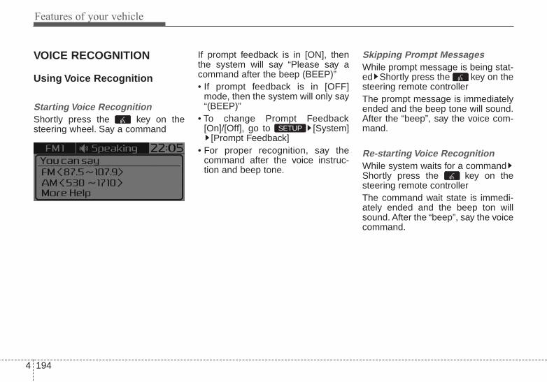
Features of your vehicle
1944
VOICE RECOGNITION
Using Voice Recognition
Starting Voice RecognitionShortly press the key on thesteering wheel. Say a command
If prompt feedback is in [ON], thenthe system will say “Please say acommand after the beep (BEEP)”• If prompt feedback is in [OFF]
mode, then the system will only say“(BEEP)”
• To change Prompt Feedback[On]/[Off], go to [System]
[Prompt Feedback]• For proper recognition, say the
command after the voice instruc-tion and beep tone.
Skipping Prompt MessagesWhile prompt message is being stat-ed Shortly press the key on thesteering remote controllerThe prompt message is immediatelyended and the beep tone will sound.After the “beep”, say the voice com-mand.
Re-starting Voice RecognitionWhile system waits for a commandShortly press the key on thesteering remote controllerThe command wait state is immedi-ately ended and the beep ton willsound. After the “beep”, say the voicecommand.
SETUP

4 195
Features of your vehicle
ENDING VOICERECOGNITION
While Voice Recognition is operatingPress and hold the key on the
steering remote controller
• While using voice command,pressing any steering wheel con-trol or a different key will end voicecommand.
• When the system is waiting for avoice command, say “cancel” or“end” to end voice command.
• When the system is waiting for avoice command, press and holdthe key on the steering wheelto end voice command.
Voice Recognition and PhoneContact Tips:The Kia Voice Recognition Systemmay have difficulty understandingsome accents or uncommonnames. When using VoiceRecognition to place a call, speak ina moderate tone, with clear pronun-ciationTo maximize the use of VoiceRecognition, consider these guide-lines when storing contacts:• Do not store single-name entries
(e.g., “Bob”, “Mom”, etc.). Instead,always use full names (includingfirst and last names) for these con-tacts
• Do not use special characters(e.g., '@', '-', '*', '&', etc.)
• Do not use abbreviations (i.e., use"Lieutenant" instead of "Lt.") oracronyms (i.e., use "CountyFinance Department" instead of"C. F. D."; Be sure to say the nameexactly as it is entered in the con-tacts list
Contact List Best Practices1)Do not use acronyms (i.e., use
“County Finance Department”instead of “CFD”).
2)If a name is not recognized fromthe contact list, change it to a moredescriptive name (e.g., use“Grandpa Joseph” instead of “PaJoe”).

Features of your vehicle
1964
Illustration on using voice commands
• Starting voice command.Shortly pressing the key (under 0.8 seconds):
• Skipping Voice RecognitionBriefly pressing the key (under 0.8 seconds):
• End voice command.Briefly pressing the key (under 0.8 seconds):
while guidance message is being stated
More Help
Contacts
Cancel
More Help
Please say a command afterthe beep (BEEP)
Please say a...
Contacts.Please say the name of the contact you want to call.
(BEEP)
(BEEP)
Beep Beep.. (end beep)Briefly pressing the key (under 0.8 seconds)
Beep~
More HelpHere are some examples of mode commands.You can say a radio type like 'FM', 'AM', or 'Satellite'.You can also say a media source like 'USB', 'MyMusic', or 'iPod'.Additionally, there are phone commands like"Contacts', 'Call History', or 'Dial Number".You can find more detailed commands in the user'smanual.Please say a command after the beep.
More HelpHere are some examples of mode commands.You can say a radio type like 'FM', 'AM', or 'Satellite'.You can also say a media source like 'USB', 'MyMusic', or 'iPod'.Additionally, there are phone commands like"Contacts', 'Call History', or 'Dial Number".You can find more detailed commands in the user'smanual.Please say a command after the beep.

4 197
Features of your vehicle
Voice Command List• Common Commands: These commands can be used in most operations. (However a few commands may not be
available during certain operations)
Command FunctionMore Help Provides guidance on commands that can be
used anywhere in the system.
Help Provides guidance on commands that can beused within the current mode.
Call<Name> Calls <Name> saved in ContactsEx) Call “John Smith”
Phone Provides guidance on Phone related com-mands. After saying this command, say“Favorites”,“Call History”, “Contacts” or ”DialNumber” execute corresponding functions.
Favorites Display the Favorite screen.
Call History Displays the Call History screen.
Contacts Displays the Contacts screen. After sayingthis command, say the name of a contactsaved in the Contacts to automatically con-nect the call.
Dial Number Display the Dial number screen. After sayingthis command, you can say the number thatyou want to call.
Redial Connects the most recently called number.
Tutorial Provide guidance on how to use voice recognition and Bluetooth® connections
Command Function• When listening to the radio, displays the next
radio screen. (FM1➟FM2➟AM➟SAT1➟
SAT2➟SAT3➟FM1)
Radio • When listening to a different mode, displaysthe most recently played radio screen.
• When currently listening to the FM radio,maintains the current state.
• When listening to a different mode, displaysthe most recently played FM screen.
FM1(FM One) Displays the FM1 screen.
FM2(FM Two) Displays the FM2 screen.
AM Displays the AM screen.
FM Preset 1~6 Plays the most recently played broadcastsaved in FM Preset 1~6.
AM Preset 1~6 Plays the broadcast saved in AM Preset 1~6.
FM 87.5~107.9 Plays the FM broadcast of the correspondingfrequency.
AM 530~1710 Plays the AM broadcast of the correspondingfrequency.
• When currently listening to the SIRIUSTM,maintains the current state.
• When listening to a different mode, displaysthe most recently played SIRIUSTM screen.
SiriusXMTM
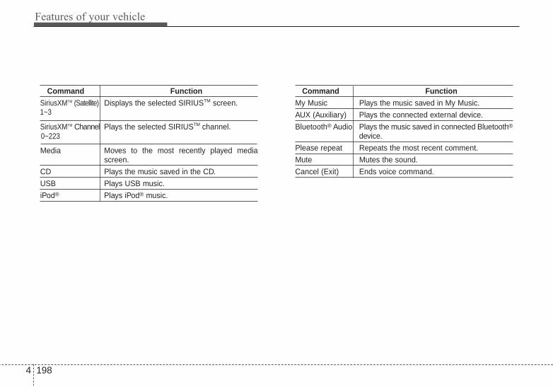
Features of your vehicle
1984
Command FunctionSiriusXMTM (Satellite) Displays the selected SIRIUSTM screen.
SiriusXMTM Channel Plays the selected SIRIUSTM channel.
Media Moves to the most recently played mediascreen.
CD Plays the music saved in the CD.
USB Plays USB music.
iPod® Plays iPod® music.
Command FunctionMy Music Plays the music saved in My Music.
AUX (Auxiliary) Plays the connected external device.
Bluetooth® Audio Plays the music saved in connected Bluetooth®
device.
Please repeat Repeats the most recent comment.
Mute Mutes the sound.
Cancel (Exit) Ends voice command.
0~223
1~3

4 199
Features of your vehicle
• FM/AM radio commands: Commands available duringFM, AM radio operation.
• Satellite radio commands: Commands that can beused while listening to Satellite Radio.
Command FunctionPreset 1~6 Plays the broadcast station saved in Preset 1~6.
Scan Scans receivable frequencies from the currentbroadcast and plays for 10 seconds each.
Preset Scan Moves to the next preset from the currentpresent and plays for 10 seconds each.
Information Displays the information of the current broad-cast.(This feature can be used when receivingRBDS broadcasts.)
Command FunctionChannel 0~223 Plays the selected Satellite Radio channel.
Scan Scans receivable channels from the currentbroadcast and plays for 10 seconds each.
Preset 1~6 Plays the broadcast saved in Preset 1~6.
Information Displays the information of the current broad-cast.

Features of your vehicle
2004
• Audio CD commands: Commands available duringAudio CD operation.
• MP3 CD / USB commands: Commands available dur-ing USB and MP3 CD operation.
Command FunctionRandom Randomly plays the tracks within the CD.
Random Off Cancels random play to play tracks in sequen-tial order.
Repeat Repeats the current track.
Repeat Off Cancels repeat play to play tracks in sequen-tial order.
Track 1~30 Plays the desired track number.
Command FunctionRandom Randomly plays the files within the current
folder.
Random Off Cancels random play to play files in sequentialorder.
Repeat Repeats the current file.
Repeat Off Cancels repeat play to play files in sequentialorder.
Information Displays the information screen of the currentfile.
Next Folder Play the first file in the next folder.
Previous Folder Play the first file in the previous folder.

4 201
Features of your vehicle
• iPod® Commands: Commands available during iPod®
operation.• My Music Commands: Commands available during
My Music operation.
Command FunctionRandom Randomly plays the songs within the current
category.
Random Off Cancels random play to play songs in sequen-tial order.
Repeat Repeats the current song.
Repeat Off Cancels repeat play to play songs in sequen-tial order.
Command FunctionRandom Randomly plays all saved files.
Random Off Cancels random play to play files in sequentialorder.
Repeat Repeats the current file.
Repeat Off Cancels repeat play to play files in sequentialorder.
Delete Deletes the current file. You will bypass anadditional confirmation process.

Command FunctionPlay Plays the currently paused song.
Pause Pauses the current song.
• Bluetooth® Wireless Technology Audio Commands:Commands available during Bluetooth® WirelessTechnology audio streaming from mobile phone oper-ation Command Operation
iPod® is a registered trademark of Apple Inc. iPod®
mobile digital device sold separately. TheBluetooth® word mark and logos are registeredtrademarks owned by Bluetooth SIG, Inc. and anyuse of such marks by Kia is under license. ABluetooth® enabled cell phone is required to useBluetooth® wireless technology. SiriusXM™ servicerequires a subscription, sold separately, after 3-month trial included with vehicle purchase. If youdecide to continue your SiriusXM™ service at theend of the trial subscription, the plan you choosewill automatically renew and bill at the current ratesuntil you call SiriusXM™ at 1-866-635-2349 to can-cel. See our Customer Agreement for completeterms at www.siriusxm.com. Sirius satellite serviceis available only to those at least 18 and older in the48 contiguous United States, D.C., and P.R. (withcoverage limitations). SiriusXM™ Traffic availablein select markets. See siriusxm.com/traffic for moreinformation. Sirius, XM and all related marks andlogos are trademarks of Sirius XM Radio Inc.
4 202
Features of your vehicle

Driving your vehicle
Before driving . . . . . . . . . . . . . . . . . . . . . . . . . . . . . . 5-4• Before entering vehicle . . . . . . . . . . . . . . . . . . . . . . . . . 5-4• Necessary inspections . . . . . . . . . . . . . . . . . . . . . . . . . . 5-4• Before starting . . . . . . . . . . . . . . . . . . . . . . . . . . . . . . . . 5-4
Key positions. . . . . . . . . . . . . . . . . . . . . . . . . . . . . . . 5-6• Illuminated ignition switch. . . . . . . . . . . . . . . . . . . . . . 5-6• Ignition switch position. . . . . . . . . . . . . . . . . . . . . . . . . 5-6
Engine start/stop button . . . . . . . . . . . . . . . . . . . . . 5-8• Illuminated engine start/stop button . . . . . . . . . . . . . . 5-8• Engine start/stop button position. . . . . . . . . . . . . . . . . 5-8
Starting the engine . . . . . . . . . . . . . . . . . . . . . . . . . 5-11• Starting the engine with an ignition key . . . . . . . . . . 5-11• Starting the engine with a smart key . . . . . . . . . . . . 5-12
Manual transaxle . . . . . . . . . . . . . . . . . . . . . . . . . . 5-14• Manual transaxle operation . . . . . . . . . . . . . . . . . . . . 5-14• Good driving practices . . . . . . . . . . . . . . . . . . . . . . . . 5-16
Automatic transaxle . . . . . . . . . . . . . . . . . . . . . . . . 5-17• Automatic transaxle operation. . . . . . . . . . . . . . . . . . 5-17• Good driving practices . . . . . . . . . . . . . . . . . . . . . . . . 5-22
Brake system. . . . . . . . . . . . . . . . . . . . . . . . . . . . . . 5-23• Power brakes . . . . . . . . . . . . . . . . . . . . . . . . . . . . . . . . 5-23• Parking brake . . . . . . . . . . . . . . . . . . . . . . . . . . . . . . . 5-25• Electric parking brake (EPB) . . . . . . . . . . . . . . . . . . 5-27• Auto hold . . . . . . . . . . . . . . . . . . . . . . . . . . . . . . . . . . . 5-33• Anti-lock brake system (ABS) . . . . . . . . . . . . . . . . . . 5-36• Electronic stability control (ESC) . . . . . . . . . . . . . . . 5-38• Hill-start assist control (HAC) . . . . . . . . . . . . . . . . . . 5-41• Vehicle stability management (VSM) . . . . . . . . . . . . 5-42• Good braking practices. . . . . . . . . . . . . . . . . . . . . . . . 5-44
Cruise control system. . . . . . . . . . . . . . . . . . . . . . . 5-45• To set cruise control speed . . . . . . . . . . . . . . . . . . . . . 5-45• To increase cruise control set speed. . . . . . . . . . . . . . 5-46• To decrease the cruising speed . . . . . . . . . . . . . . . . . . 5-46• To temporarily accelerate with the cruise
control on . . . . . . . . . . . . . . . . . . . . . . . . . . . . . . . . . . 5-47• To cancel cruise control, do one of the following . . . 5-47• To resume cruising speed at more than
approximately 25 mph (40 km/h) . . . . . . . . . . . . . . 5-48• To turn cruise control off, do one of the following. . . 5-48
5

Active ECO system. . . . . . . . . . . . . . . . . . . . . . . . . 5-49• Active ECO operation. . . . . . . . . . . . . . . . . . . . . . . . . 5-49• When active ECO is activated . . . . . . . . . . . . . . . . . . 5-49• Limitation of active ECO operation . . . . . . . . . . . . . 5-49
Drive mode integrated control system . . . . . . . . . 5-50• Drive mode . . . . . . . . . . . . . . . . . . . . . . . . . . . . . . . . . . 5-50
Blind spot detection system (BSD) . . . . . . . . . . . . 5-52• BSD (Blind Spot Detection) /
LCA (Lane Change Assist). . . . . . . . . . . . . . . . . . . . 5-53• RCTA (Rear cross traffic alert) . . . . . . . . . . . . . . . . . 5-56• Non-operating condition . . . . . . . . . . . . . . . . . . . . . . . 5-58• This device complies with Part 15 of the
FCC rules. . . . . . . . . . . . . . . . . . . . . . . . . . . . . . . . . . 5-59Economical operation . . . . . . . . . . . . . . . . . . . . . . 5-60Special driving conditions . . . . . . . . . . . . . . . . . . . 5-62
• Hazardous driving conditions . . . . . . . . . . . . . . . . . . 5-62• Rocking the vehicle . . . . . . . . . . . . . . . . . . . . . . . . . . . 5-62• Smooth cornering . . . . . . . . . . . . . . . . . . . . . . . . . . . . 5-63• Driving at night . . . . . . . . . . . . . . . . . . . . . . . . . . . . . . 5-63• Driving in the rain. . . . . . . . . . . . . . . . . . . . . . . . . . . . 5-64• Driving in flooded areas . . . . . . . . . . . . . . . . . . . . . . . 5-64• Driving off-road. . . . . . . . . . . . . . . . . . . . . . . . . . . . . . 5-65• Highway driving . . . . . . . . . . . . . . . . . . . . . . . . . . . . . 5-65
Winter driving . . . . . . . . . . . . . . . . . . . . . . . . . . . . 5-66• Snowy or Icy conditions . . . . . . . . . . . . . . . . . . . . . . . 5-66• Use high quality ethylene glycol coolant . . . . . . . . . . 5-68• Check battery and cables . . . . . . . . . . . . . . . . . . . . . . 5-68• Change to "winter weight" oil if necessary . . . . . . . 5-68• Check spark plugs and ignition system. . . . . . . . . . . 5-68• To keep locks from freezing . . . . . . . . . . . . . . . . . . . . 5-69• Use approved window washer anti-freeze in
system . . . . . . . . . . . . . . . . . . . . . . . . . . . . . . . . . . . . . 5-69• Don't let your parking brake freeze . . . . . . . . . . . . . 5-69• Don't let ice and snow accumulate underneath . . . . 5-69• Carry emergency equipment . . . . . . . . . . . . . . . . . . . 5-69
Vehicle load limit . . . . . . . . . . . . . . . . . . . . . . . . . . 5-70• Tire and loading information label . . . . . . . . . . . . . . 5-70• Certification label . . . . . . . . . . . . . . . . . . . . . . . . . . . . 5-73
Vehicle weight . . . . . . . . . . . . . . . . . . . . . . . . . . . . . 5-75
5

5 3
Driving your vehicle
Be sure the exhaust systemdoes not leak.The exhaust system should bechecked whenever the vehicle israised to change the oil or for anyother purpose. If you hear a changein the sound of the exhaust or if youdrive over something that strikes theunderneath side of the vehicle, havethe exhaust system checked as soonas possible by an authorized Kiadealer.
WARNING - Engineexhaust
Do not inhale exhaust fumes orleave your engine running in anenclosed area for a prolongedtime.Exhaust fumes contain carbonmonoxide, a colorless, odorlessgas that can cause uncon-sciousness and death byasphyxiation.
WARNING - Open trunkDo not drive with the trunkopen.Poisonous exhaust gases canenter the passenger compart-ment. If you must drive with thetrunk open proceed as follows:1. Close all windows.2. Open side vents.3. Set the air intake control at
"Fresh", the air flow control at"Floor" or "Face" and the fanat the highest speed.
WARNING - Californiaproposition65
Engine exhaust and a wide vari-ety of automobile componentsand parts, including compo-nents found in the interior fur-nishings in a vehicle, contain oremit chemicals known to theState of California to cause can-cer and birth defects and repro-ductive harm. In addition, cer-tain fluids contained in vehiclesand certain products of compo-nent wear contain or emit chem-icals known to the State ofCalifornia to cause cancer andbirth defects or other reproduc-tive harm.

Driving your vehicle
45
Before entering vehicle• Be sure that all windows, outside
mirror(s), and outside lights areclean.
• Check the condition of the tires.• Check under the vehicle for any
sign of leaks.• Be sure there are no obstacles
behind you if you intend to back up.
Necessary inspections Fluid levels, such as engine oil,engine coolant, brake fluid, andwasher fluid should be checked on aregular basis, with the exact intervaldepending on the fluid. Furtherdetails are provided in chapter 7,“Maintenance”.
Before starting • Close and lock all doors.• Position the seat so that all con-
trols are easily reached.• Buckle your seat belt.• Adjust the inside and outside
rearview mirrors.• Be sure that all lights work.• Check all gauges.• Check the operation of warning
lights when the ignition switch isturned to the ON position.
• Release the parking brake andmake sure the brake warning lightgoes off.
For safe operation, be sure you arefamiliar with your vehicle and itsequipment.
BEFORE DRIVING
WARNING - Distracteddriving
Focus on the road while driving.The driver's primary responsi-bility is in the safe and legaloperation of the vehicle. Use ofany hand held devices, otherequipment or vehicle systemsthat distract the driver shouldnot be used during vehicleoperation.
WARNING - Check sur-rounding
Always check the surroundingareas near your vehicle for peo-ple, especially children, beforeputting a vehicle into D (Drive)or R (Reverse).

5 5
Driving your vehicle
WARNING - Fire riskWhen you intend to park or stopthe vehicle with the engine on,be careful not to depress theaccelerator pedal for a longperiod of time. It may overheatthe engine or exhaust systemand cause a fire.
WARNING - Driving whileintoxicated
Do not drive while intoxicated.Drinking and driving is danger-ous. Even a small amount ofalcohol will affect your reflexes,perceptions and judgment.Driving while under the influ-ence of drugs is as dangerousas or more dangerous than driv-ing drunk.
WARNING - Loose objectSecurely store items in yourvehicle. When you make a sud-den stop or turn the steeringwheel rapidly, loose objectsmay drop on the floor and itcould interfere with the opera-tion of the foot pedals, possiblycausing an accident.

Driving your vehicle
65
Illuminated ignition switch (if equipped)
Whenever a front door is opened, theignition switch will illuminate for yourconvenience, provided the ignitionswitch is not in the ON position. Thelight will go off immediately when theignition switch is turned on. It willalso go off after about 30seconds after the door is closed.
Ignition switch position
LOCKThe steering wheel locks to protectagainst theft. The ignition key can beremoved only in the LOCK position.When turning the ignition switch tothe LOCK position, push the keyinward at the ACC position and turnthe key toward the LOCK position.The anti-theft steering column lock isnot a substitute for the parking brake.
Before leaving the driver’s seat,always make sure the shift lever isengaged in 1st gear for the manualtransaxle or P (Park) for the auto-matic transaxle, set the parkingbrake fully and shut the engine off.
ACC (Accessory)The steering wheel is unlocked andelectrical accessories are operative.If difficulty is experienced turning theignition switch to the ACC position,turn the key while turning the steer-ing wheel right and left to release thetension.
ONThe warning lights can be checkedbefore the engine is started. This isthe normal running position after theengine is started.Do not leave the ignition switch ON ifthe engine is not running to preventbattery discharge.
OTF050001
KEY POSITIONS
OTF054002

5 7
Driving your vehicle
STARTTurn the ignition switch to the STARTposition to start the engine. Theengine will crank until you releasethe key; then it returns to the ONposition. The brake warning light canbe checked in this position.
WARNING - Ignitionswitch
Never turn the ignition switch toLOCK or ACC while the vehicleis moving. This would result inloss of directional control andbraking function, which couldcause an accident.
WARNING - Steeringwheel
Never reach for any controlsthrough the steering wheelwhile the vehicle is in motion.The presence of your hand orarm in this area could cause aloss of vehicle control.
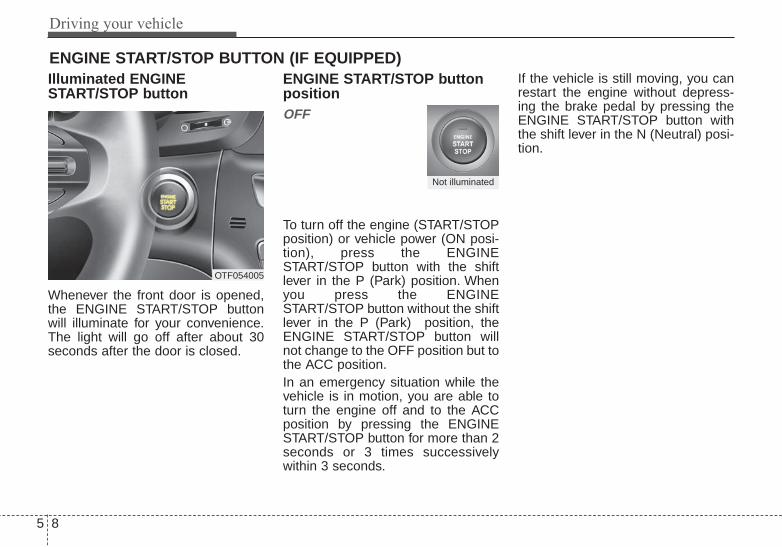
Driving your vehicle
85
Illuminated ENGINESTART/STOP button
Whenever the front door is opened,the ENGINE START/STOP buttonwill illuminate for your convenience.The light will go off after about 30seconds after the door is closed.
ENGINE START/STOP buttonpositionOFF
To turn off the engine (START/STOPposition) or vehicle power (ON posi-tion), press the ENGINESTART/STOP button with the shiftlever in the P (Park) position. Whenyou press the ENGINESTART/STOP button without the shiftlever in the P (Park) position, theENGINE START/STOP button willnot change to the OFF position but tothe ACC position.In an emergency situation while thevehicle is in motion, you are able toturn the engine off and to the ACCposition by pressing the ENGINESTART/STOP button for more than 2seconds or 3 times successivelywithin 3 seconds.
If the vehicle is still moving, you canrestart the engine without depress-ing the brake pedal by pressing theENGINE START/STOP button withthe shift lever in the N (Neutral) posi-tion.
ENGINE START/STOP BUTTON (IF EQUIPPED)
OTF054005
Not illuminated

5 9
Driving your vehicle
ACC(Accessory)
Press the ENGINE START/STOPbutton while it is in the OFF positionwithout depressing the brake pedal.The steering wheel unlocks andelectrical accessories are opera-tional.If the ENGINE START/STOP buttonis in the ACC position for more than1 hour, the button is turned off auto-matically to prevent battery dis-charge.
ON
Press the ENGINE START/STOPbutton while it is in the ACC positionwithout depressing the brake pedal.The warning lights can be checkedbefore the engine is started. Do notleave the ENGINE START/STOPbutton in the ON position for a longtime. The battery may discharge,because the engine is not running.
START/RUN
To start the engine, depress thebrake pedal and press the ENGINESTART/STOP button with the shiftlever in the P (Park) or the N(Nuetral) position. For your safety,start the engine with the shift lever inthe P (Park) position.If you press the ENGINESTART/STOP button withoutdepressing the brake pedal, theengine will not start and the buttonwill change as follows:OFF ➔ ACC ➔ ON ➔ OFF
Green indicator Not illuminated Orange indicator
Driving your vehicle
105
If you leave the ENGINE START/STOP button in the ACC or ON posi-tion for a long time, the battery willdischarge.
WARNING - Starting vehicle
Never press the ENGINESTART/STOP button while thevehicle is in motion. This wouldresult in loss of directional con-trol and braking function, whichcould cause an accident.

5 11
Driving your vehicle
Starting the engine with anignition key (if equipped) 1.Make sure the parking brake is
applied.2.Manual Transaxle - Depress the
clutch pedal fully and shift thetransaxle into Neutral. Keep theclutch pedal and brake pedaldepressed while turning the igni-tion switch to the start position.Automatic Transaxle - Place thetransaxle shift lever in P (Park).Depress the brake pedal fully.You can also start the engine whenthe shift lever is in the N (Neutral)position.
3.Turn the ignition switch to STARTand hold it there until the enginestarts (a maximum of 10 seconds),then release the key.
4.In extremely cold weather (below 0°F / -18°C) or after the vehicle hasnot been operated for several days,let the engine warm up withoutdepressing the accelerator.
Whether the engine is cold or warm,it should be started withoutdepressing the accelerator.
If the engine stalls while the vehicleis in motion, do not attempt to movethe shift lever to the P (Park) posi-tion. If traffic and road conditions per-mit, you may put the shift lever in theN (Neutral) position while the vehicleis still moving and turn the ignitionswitch to the START position in anattempt to restart the engine.
STARTING THE ENGINE
WARNING - Properfootwear
Always wear appropriate shoeswhen operating your vehicle.Unsuitable shoes (high heels,ski boots, sandals, etc.) mayinterfere with your ability to usethe brake and accelerator ped-als.
CAUTION - StarterDo not engage the starter formore than 10 seconds. If theengine stalls or fails to start,wait 5 to 10 seconds before re-engaging the starter. Improperuse of the starter may damageit.

Driving your vehicle
125
Starting the engine with asmart key (if equipped)
1.Carry the smart key or leave itinside the vehicle.
2.Make sure the parking brake isfirmly applied
3.Place the transaxle shift lever in P(Park).
4.Press the ENGINE START/STOPbutton while depressing the brakepedal.
5.In extremely cold weather (below0°F / -18°C) or after the vehicle hasnot been operated for several days,let the engine warm up withoutdepressing the accelerator.
Whether the engine is cold or warm,it should be started without depress-ing the accelerator.• Even if the smart key is in the vehi-
cle, but is far away from you, theengine may not start.
• When the ENGINE START/STOPbutton is in the ACC position orabove, if any door is opened, thesystem checks for the smart key. Ifthe smart key is not in the vehicle,the warning "Key not in vehicle" willilluminate on the LCD display. Andif all doors are closed, the chimewill sound for 5 seconds. The indi-cator or warning will turn off whilethe vehicle is moving. Always havethe smart key with you.
The engine will start only when thesmart key is in the vehicle.
WARNING - Unintendedvehicle movement
Never leave the smart key in thevehicle with children or vehicleoccupants who are unfamiliarwith the vehicle operation.Pushing the ENGINESTART/STOP button while thesmart key is in the vehicle mayresult in unintended engineactivation and/or unintendedvehicle movement.
OTF054007

5 13
Driving your vehicle
• If the battery is weak or the smartkey does not work correctly, youcan start the engine by pressingthe engine start/stop button withthe smart key.The side with the lock buttonshould contact the enginestart/stop button directly.When you press the enginestart/stop button directly with thesmart key, the smart key shouldcontact the button at a right angle.
• When the stop lamp fuse is blown,you can't start the engine normally.Replace the fuse with a new one. Ifit is not possible, you can start theengine by pressing the ENGINESTART/STOP button for 10 sec-onds while it is in the ACC posi-tion. The engine can start withoutdepressing the brake pedal. But foryour safety always depress thebrake pedal before starting theengine.
Do not press the ENGINE START/STOP button for more than 10 sec-onds except when the stop lamp fuseis blown.
OTF054006

Driving your vehicle
145
Manual transaxle operationThe manual transaxle has 6 forwardgears.This shift pattern is imprinted on theshift knob. The transaxle is fully syn-chronized in all forward gears soshifting to either a higher or a lowergear is easily accomplished.Depress the clutch pedal down fullywhile shifting, then release it slowly.If your vehicle is equipped with anignition lock switch, the engine willnot start when starting the enginewithout depressing the clutch pedal.The shift lever must be returned tothe neutral position before shiftinginto R (Reverse). Push the buttonlocated immediately below the shiftknob and pull the gearshift lever tothe left sufficiently, and then shift intoreverse (R) gear position.Make sure the vehicle is completelystopped before shifting into R(Reverse) position.Never operate the engine with thetachometer (rpm) in the red zone.
MANUAL TRANSAXLE (IF EQUIPPED)
CAUTION - DownshiftingDo not downshift more than 2gears or downshift the gearwhen the engine is running athigh speed (5,000 RPM or high-er). Such downshifting maydamage the engine.
OYDDDR2101
The shift lever can be moved without-pressing the button.
The button (1) should be pressed whenmoving the shift lever into reverse.

5 15
Driving your vehicle
• During cold weather, shifting maybe difficult until the transaxle lubri-cant is warmed up. This is normaland not harmful to the transaxle.
• If you've come to a complete stopand it's hard to shift into 1st or R(Reverse), leave the shift lever atneutral position and release theclutch. Depress the clutch pedaland then shift into 1st or R(Reverse) gear position.
Using the clutchThe clutch should be depressed allthe way to the floor before shifting,then released slowly. The clutchpedal should always be fullyreleased while driving. Do not restyour foot on the clutch pedal whiledriving. This can cause unnecessarywear. Do not partially engage theclutch to hold the vehicle on anincline. This causes unnecessarywear. Use the foot brake or parkingbrake to hold the vehicle on anincline. Do not operate the clutchpedal rapidly and repeatedly.
DownshiftingWhen you must slow down in heavytraffic or while driving up steep hills,downshift before the engine starts tolabor. Downshifting reduces thechance of stalling and gives betteracceleration when you need toincrease your speed again. When thevehicle is traveling down steep hills,downshifting helps maintain safespeed and prolongs brake life.
CAUTION - Prematurewear
Do not use the shift lever as ahandrest during driving, as thiscan result in premature wear ofthe transaxle shift forks.
WARNING - Incline parking
Before leaving the driver’s seat,always set the parking brakefully and shut the engine off.Then make sure the transaxle isshifted into 1st gear when thevehicle is parked on a level oruphill grade, and shifted into R(Reverse) gear on a downhillgrade. Unexpected and suddenvehicle movement can occur ifthese precautions are not fol-lowed in the order identified.

Driving your vehicle
165
Good driving practices• Never take the vehicle out of gear
and coast down a hill. This isextremely hazardous. Always leavethe vehicle in gear.
• Don't "ride" the brakes. This cancause them to overheat and mal-function. Instead, when you aredriving down a long hill, shift to alower gear. When you do this,engine braking will help slow downthe vehicle.
• Slow down before shifting to alower gear. This will help avoidover-revving the engine, which cancause damage.
• Slow down when you encountercross winds. This gives you muchbetter control of your vehicle.
• Be sure the vehicle is completelystopped before you attempt to shiftinto R (Reverse).The transaxle canbe damaged if you do not.
• Exercise extreme caution whendriving on a slippery surface. Beespecially careful when braking,accelerating or shifting gears. On aslippery surface, an abrupt changein vehicle speed can cause thedrive wheels to lose traction andthe vehicle to go out of control.
• Always buckle-up! In a collision,an unbelted occupant is signifi-cantly more likely to be seriouslyinjured or killed than a properlybelted occupant.
• Never exceed posted speed limits.
WARNING - Vehicle handling
Avoid high speeds when cor-nering or turning. High speedcornering and turning increas-es the risk of vehicle rolloverdue to loss of vehicle control.Rollover accidents are extreme-ly violent and unpredictable.

5 17
Driving your vehicle
Automatic transaxle operationThe automatic transaxle has 6 for-ward speeds and one reverse speed.The individual speeds are selectedautomatically, depending on theposition of the shift lever.
✽✽ NOTICEThe first few shifts on a new vehicleor if the battery has been discon-nected, may be somewhat abrupt.This is a normal condition, and theshifting sequence will adjust aftershifts are cycled a few times by theTCM (Transaxle Control Module)or PCM (Powertrain ControlModule).
AUTOMATIC TRANSAXLE (IF EQUIPPED)
OTF054010
+ (UP)
Button
Shift lever
- (DOWN)
To shift, depress the brake pedal and press the button.
The shift lever can be shifted freely.
Press the button when shifting.

Driving your vehicle
185
For smooth operation, depress thebrake pedal when shifting from N(Neutral) to a forward or reversegear.
When stopped on an incline, do nothold the vehicle with engine power.Use the service brake or the parkingbrake.
Transaxle rangesThe indicator light in the instrumentcluster displays the shift lever posi-tion when the ignition switch is in theON position.
P (Park)
Always come to a complete stopbefore shifting into P (Park). Thisposition locks the transaxle and pre-vents the front wheels from rotating.
Shifting into P (Park) while the vehi-cle is in motion will cause the drivewheels to lock which will cause youto lose control of the vehicle.
CAUTION - TransaxleTo avoid damage to yourtransaxle, do not accelerate theengine in R (Reverse) or any for-ward gear position with thebrakes on.The transaxle may bedamaged if you shift into P(Park) while the vehicle is inmotion.

5 19
Driving your vehicle
R (Reverse)
Use this position to drive the vehiclebackward.
N (Neutral)
The wheels and transaxle are notengaged. The vehicle will roll freelyeven on the slightest incline unlessthe parking brake or service brakesare applied.
D (Drive)
This is the normal forward drivingposition. The transaxle will automati-cally shift through a 6-gearsequence, providing the best fueleconomy and power.
For extra power when passing anoth-er vehicle or climbing grades,depress the accelerator fully, atwhich time the transaxle will auto-matically downshift to the next lowergear. Sports mode
Whether the vehicle is stopped or inmotion, sports mode is selected bypushing the shift lever from the D(Drive) position into the manual gate.To return to D (Drive) range opera-tion, push the shift lever back into themain gate.
In sports mode, moving the shiftlever backwards and forwards willallow you to make gearshifts rapidly.In contrast to a manual transaxle, thesports mode allows gearshifts withthe accelerator pedal depressed.
CAUTION - ShiftingAlways come to a complete stopbefore shifting into or out of R(Reverse); you may damage thetransaxle if you shift into R(Reverse) while the vehicle is inmotion, except when “Rockingthe Vehicle” explained in thischapter.
OTF054012
++++ ((((UUUUPPPP))))
- (DOWN)
Sports mode

Driving your vehicle
205
Up (+) : Push the lever forwardonce to shift up one gear.
Down (-) : Pull the lever backwardsonce to shift down onegear.
• In sports mode, the driver mustexecute upshifts in accordancewith road conditions, taking care tokeep the engine speed below thered zone.
• In sports mode, only the 6 forwardgears can be selected. To reverseor park the vehicle, move the shiftlever to the R (Reverse) or P (Park)position as required.
• In sports mode, downshifts aremade automatically when the vehi-cle slows down. When the vehiclestops, 1st gear is automaticallyselected.
• In sports mode, when the enginerpm approaches the red zone shiftpoints are varied to upshift auto-matically.
• To maintain the required levels ofvehicle performance and safety,the system may not execute cer-tain gearshifts when the shift leveris operated.
• When driving on a slippery road,push the shift lever forward into the+(up) position. This causes thetransaxle to shift into the 2nd gearwhich is better for smooth drivingon a slippery road. Push the shiftlever to the -(down) side to shiftback to the 1st gear.
Paddle shifter (if equipped)
The paddle shifter is available whenthe shift lever is in the D position orthe sport mode.
OTF054142L

5 21
Driving your vehicle
With the shift lever in the D position
The paddle shifter can operate whenthe vehicle speed is more than 6.2mph (10 km/h).Pull the [+] or [-] paddle shifter onceto shift up or down one gear and thesystem changes from automaticmode to manual mode.If the vehicle speed is lower than 6.2mph (10km/h), if you depress theaccelerator pedal for more than 5seconds or if you shift the shift leverfrom D to sports mode and shift itfrom sports mode to D again, thesystem change from manual mode toautomatic mode.
With the shift lever in the sports mode
Pull the [+] or [-] paddle shifter onceto shift up or down one gear.
If you pull the [+] and [-] paddleshifters at the same time, you can'tshift the gear.
Shift lock systemFor your safety, the automatictransaxle has a shift lock systemwhich prevents shifting the transaxleout of P (Park) unless the brakepedal is depressed.To shift the transaxle from P (Park)into R (Reverse):1.Depress and hold the brake pedal.2.Start the engine or turn the ignition
switch to the ON position.3.Move the shift lever.If the brake pedal is repeatedlydepressed and released with theshift lever in the P (Park) position, achattering noise near the shift levermay be heard. This is a normal con-dition.
Shift-lock override (with smart keysystem)
If the shift lever cannot be movedfrom the P (Park) or N (Neutral) posi-tion into the R (Reverse) positionwith the brake pedal depressed, con-tinue depressing the brake, then dothe following:1.Carefully remove the cap (1) cover-
ing the shift-lock access hole.2.Insert a screwdriver into the
access hole and press down onthe screwdriver.
3.Move the shift lever.4.Have your vehicle inspected by an
authorized Kia dealer immediately.
WARNING - Shifting frompark
Always fully depress the brakepedal before and while shiftingout of the P (Park) position intoanother position to avoid inad-vertent motion of the vehicle.
OTF054011N
Driving your vehicle
225
Ignition key interlock system (if equipped)The ignition key cannot be removedunless the shift lever is in the P(Park) position.
Good driving practices• Never move the shift lever from P
(Park) or N (Neutral) to any otherposition with the accelerator pedaldepressed.
• Never move the shift lever into P(Park) when the vehicle is inmotion.
• Slow down before shifting to alower gear. Otherwise, the lowergear may not be engaged.
• Always use the parking brake. Donot depend on placing thetransaxle in P (Park) to keep thevehicle from moving.
• Optimum vehicle performance andeconomy is obtained by smoothlydepressing and releasing theaccelerator pedal.
Moving up a steep grade from astanding startTo move up a steep grade from astanding start, depress the brakepedal, shift the shift lever to D(Drive). Select the appropriate geardepending on load weight and steep-ness of the grade, and release theparking brake. Depress the accelera-tor gradually while releasing theservice brakes.

5 23
Driving your vehicle
Power brakes Your vehicle has power-assistedbrakes that adjust automaticallythrough normal usage.In the event that the power-assistedbrakes lose power because of astalled engine or some other reason,you can still stop your vehicle byapplying greater force to the brakepedal than you normally would. Thestopping distance, however, will belonger.When the engine is not running, thereserve brake power is partiallydepleted each time the brake pedalis applied. Do not pump the brakepedal when the power assist hasbeen interrupted.Pump the brake pedal only whennecessary to maintain steering con-trol on slippery surfaces.
Wet brakes may impair the vehicle’sability to safely slow down; the vehi-cle may also pull to one side whenthe brakes are applied. Applying thebrakes lightly will indicate whetherthey have been affected in this way.To dry the brakes, apply them lightlywhile maintaining a safe forwardspeed until brake performancereturns to normal.
BRAKE SYSTEM
WARNING - Steep hillbraking
Avoid continuous application ofthe brakes when descending along or steep hill by shifting to alower gear. Continuous brakeapplication will cause thebrakes to overheat and couldresult in a temporary loss ofbraking performance.
CAUTION - Brake pedalDo not drive with your foot rest-ing on the brake pedal. This willcreate abnormally high braketemperatures which can causeexcessive brake lining and padwear.

Driving your vehicle
245
In the event of brake failure If service brakes fail to operate whilethe vehicle is in motion, you canmake an emergency stop with theparking brake. The stopping dis-tance, however, will be much greaterthan normal.
Disc brakes wear indicator When your brake pads are worn andnew pads are required, you will heara high-pitched warning sound fromyour front brakes or rear brakes (ifequipped). You may hear this soundcome and go or it may occur when-ever you depress the brake pedal.Please remember that some drivingconditions or climates may cause abrake squeal when you first apply (orlightly apply) the brakes. This is nor-mal and does not indicate a problemwith your brakes.
Always replace the front or rearbrake pads as pairs.
CAUTION - Replace brakepads
Do not continue to drive withworn brake pads. Continuing todrive with worn brake pads candamage the braking system andresult in costly brake repairs.
WARNING - Brake wearDo not ignore high pitched wearsounds from your brakes. If youignore this audible warning, youwill eventually lose braking per-formance, which could lead to aserious accident.
WARNING - Parking brakeAvoid applying the parkingbrake to stop the vehicle while itis moving except in an emer-gency situation. Applying theparking brake while the vehicleis moving at normal speeds cancause a sudden loss of controlof the vehicle. If you must usethe parking brake to stop thevehicle, use great caution inapplying the brake.
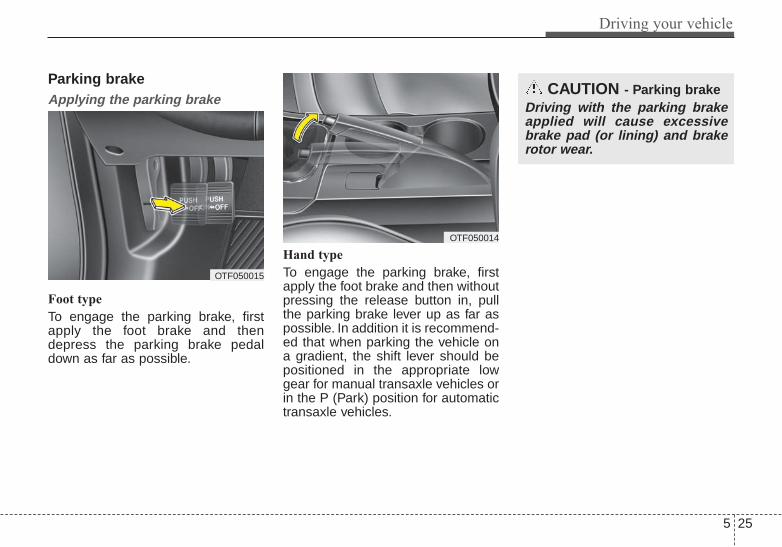
5 25
Driving your vehicle
Parking brake Applying the parking brake
Foot type
To engage the parking brake, firstapply the foot brake and thendepress the parking brake pedaldown as far as possible.
Hand type
To engage the parking brake, firstapply the foot brake and then withoutpressing the release button in, pullthe parking brake lever up as far aspossible. In addition it is recommend-ed that when parking the vehicle ona gradient, the shift lever should bepositioned in the appropriate lowgear for manual transaxle vehicles orin the P (Park) position for automatictransaxle vehicles.
CAUTION - Parking brakeDriving with the parking brakeapplied will cause excessivebrake pad (or lining) and brakerotor wear.
OTF050014
OTF050015

Driving your vehicle
265
Releasing the parking brake
Foot type
To release the parking brake,depress the parking brake pedal asecond time while applying the footbrake. The pedal will automaticallyextend to the fully released position.
Hand type
To release the parking brake, firstapply the foot brake and pull up theparking brake lever slightly.Secondly, press the release button(1) and lower the parking brake lever(2) while holding the button.
OTF050017
OTF050016
WARNING - Parking brakeuse
All vehicles should always havethe parking brake fully engagedwhen parking to avoid inadver-tent movement of the vehiclewhich can injure occupants orpedestrians.

5 27
Driving your vehicle
Check the brake warning light byturning the ignition switch ON (do notstart the engine). This light will illumi-nate when the parking brake isapplied with the ignition switch in theSTART or ON position.Before driving, be sure the parkingbrake is fully released and the brakewarning light is off.If the brake warning light remains onafter the parking brake is releasedwhile the engine is running, theremay be a malfunction in the brakesystem. Immediate attention is nec-essary.
If at all possible, stop driving thevehicle immediately. If that is not pos-sible, use extreme caution whileoperating the vehicle and only con-tinue to drive the vehicle until youcan reach a safe location or repairshop.
Electric parking brake (EPB) (if equipped)Applying the parking brake
To apply the EPB (electric parkingbrake):
1. Depress the brake pedal.2. Pull up the EPB switch.Make sure the warning light comeson.
Also, the EPB is applied automatical-ly if the Auto Hold button is on whenthe engine is turned off. However, ifyou press the EPB switch after theengine is turned off, the EPB will notbe Applied.
W-75
OTFS054093

Driving your vehicle
285
✽✽ NOTICEOn a steep incline or when pulling atrailer, if the vehicle does not remainat a standstill, do as follows:1. Apply the EPB.2. Pull up the EPB switch for more
than 3 seconds.
✽✽ NOTICEA click or electric brake motorwhine sound may be heard whileoperating or releasing the EPB, butthese conditions are normal andindicate that the EPB is functioningproperly.
Releasing the parking brake
To release the EPB (electric parkingbrake), press the EPB switch in thefollowing condition:
• Have the ignition switch or enginestart/stop button in the ON posi-tion.
• Depress the brake pedal.Make sure the brake warning lightgoes off.
To release EPB (electric parkingbrake) automatically:
• Shift lever in P (Park)With the engine running depressthe brake pedal and shift out of P(Park) to R (Reverse) or D (Drive).
• Shift lever in N (Neutral)With the engine running depressthe brake pedal and shift out of N(Neutral) to R (Reverse) or D(Drive).
• Automatic transaxle vehicle1. Start the engine.2. Fasten the driver's seat belt.3. Close the driver's door, engine
hood and trunk.4. Depress the accelerator pedal
while the shift lever is in R(Rear), D (Drive) or Sportsmode.
Make sure the brake warning lightgoes off.
CAUTIONDo not operate the parkingbrake /EPB while the vehicle ismoving except in an emergencysituation. OTFS054094

5 29
Driving your vehicle
✽✽ NOTICE• For your safety, you can engage
the EPB even though the ignitionswitch or engine stop/start buttonis in the OFF position, but youcannot release it.
• For your safety, depress the brakepedal and release the parkingbrake manually with the EPBswitch when you drive downhill orwhen backing up the vehicle.
Do not follow the above procedurewhen driving on a flat level ground.The vehicle may suddenly move for-ward.
EPB (electric parking brake) may beautomatically applied when:
• The EPB is overheated• Requested by other systems
✽✽ NOTICEIf the driver turns the engine off bymistake while Auto Hold is operat-ing, EPB will be automaticallyapplied. (Vehicles equipped withAuto Hold)
CAUTION• If the parking brake warning
light is still on even thoughthe EPB has been released,have the system checked byan authorized Kia dealer.
• Do not drive your vehicle withthe EPB applied. It may causeexcessive brake pad andbrake rotor wear.
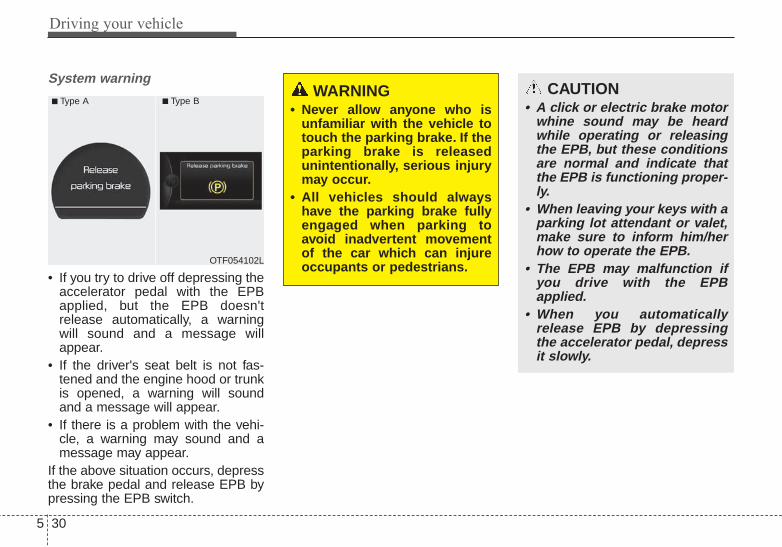
Driving your vehicle
305
System warning
• If you try to drive off depressing theaccelerator pedal with the EPBapplied, but the EPB doesn'trelease automatically, a warningwill sound and a message willappear.
• If the driver's seat belt is not fas-tened and the engine hood or trunkis opened, a warning will soundand a message will appear.
• If there is a problem with the vehi-cle, a warning may sound and amessage may appear.
If the above situation occurs, depressthe brake pedal and release EPB bypressing the EPB switch.
OTF054102L
■ Type A ■ Type BWARNING
• Never allow anyone who isunfamiliar with the vehicle totouch the parking brake. If theparking brake is releasedunintentionally, serious injurymay occur.
• All vehicles should alwayshave the parking brake fullyengaged when parking toavoid inadvertent movementof the car which can injureoccupants or pedestrians.
CAUTION• A click or electric brake motor
whine sound may be heardwhile operating or releasingthe EPB, but these conditionsare normal and indicate thatthe EPB is functioning proper-ly.
• When leaving your keys with aparking lot attendant or valet,make sure to inform him/herhow to operate the EPB.
• The EPB may malfunction ifyou drive with the EPBapplied.
• When you automaticallyrelease EPB by depressingthe accelerator pedal, depressit slowly.
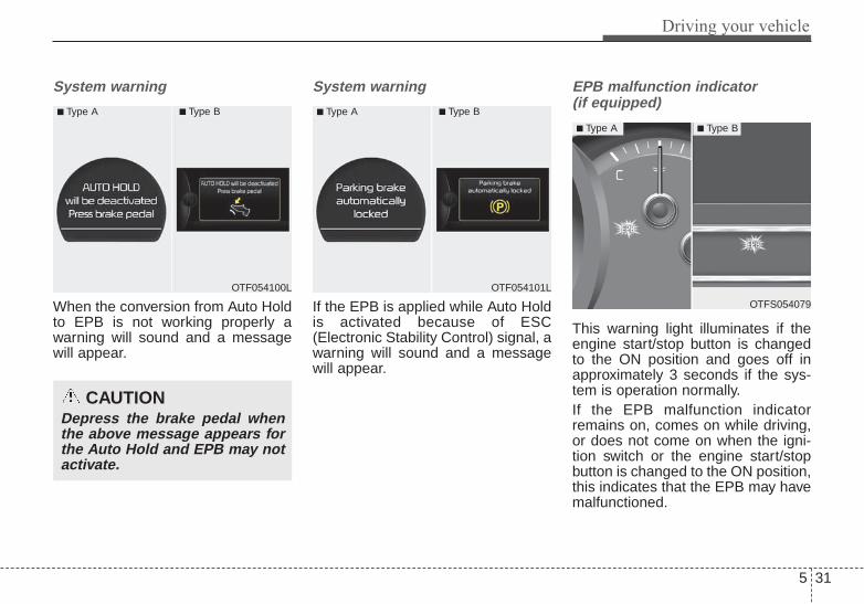
5 31
Driving your vehicle
System warning
When the conversion from Auto Holdto EPB is not working properly awarning will sound and a messagewill appear.
System warning
If the EPB is applied while Auto Holdis activated because of ESC(Electronic Stability Control) signal, awarning will sound and a messagewill appear.
EPB malfunction indicator (if equipped)
This warning light illuminates if theengine start/stop button is changedto the ON position and goes off inapproximately 3 seconds if the sys-tem is operation normally.If the EPB malfunction indicatorremains on, comes on while driving,or does not come on when the igni-tion switch or the engine start/stopbutton is changed to the ON position,this indicates that the EPB may havemalfunctioned.
CAUTIONDepress the brake pedal whenthe above message appears forthe Auto Hold and EPB may notactivate.
OTF054100L
■ Type A ■ Type B
OTF054101L
■ Type A ■ Type B
OTFS054079
■ Type A ■ Type B
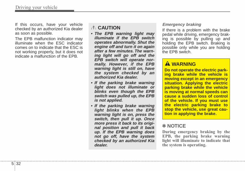
Driving your vehicle
325
If this occurs, have your vehiclechecked by an authorized Kia dealeras soon as possible.The EPB malfunction indicator mayilluminate when the ESC indicatorcomes on to indicate that the ESC isnot working properly, but it does notindicate a malfunction of the EPB.
Emergency brakingIf there is a problem with the brakepedal while driving, emergency brak-ing is possible by pulling up andholding the EPB switch. Braking ispossible only while you are holdingthe EPB switch.
✽✽ NOTICEDuring emergency braking by theEPB, the parking brake warninglight will illuminate to indicate thatthe system is operating.
CAUTION• The EPB warning light may
illuminate if the EPB switchoperates abnormally. Shut theengine off and turn it on againafter a few minutes. The warn-ing light will go off and theEPB switch will operate nor-mally. However, if the EPBwarning light is still on, havethe system checked by anauthorized Kia dealer.
• If the parking brake warninglight does not illuminate orblinks even though the EPBswitch was pulled up, the EPBis not applied.
• If the parking brake warninglight blinks when the EPBwarning light is on, press theswitch, then pull it up. Oncemore press it back to its origi-nal position and pull it backup. If the EPB warning doesnot go off, have the systemchecked by an authorized Kiadealer.
WARNINGDo not operate the electric park-ing brake while the vehicle ismoving except in an emergencysituation. Applying the electricparking brake while the vehicleis moving at normal speeds cancause a sudden loss of controlof the vehicle. If you must usethe electric parking brake tostop the vehicle, use great cau-tion in applying the brake.

5 33
Driving your vehicle
When the EPB (electric parkingbrake) is not releasedIf the EPB does not release normal-ly, take your vehicle to an authorizedKia dealer by loading the vehicle ona flatbed tow truck and have the sys-tem checked.
AUTO HOLD (if equipped)The Auto Hold maintains the vehiclein a standstill even though the brakepedal is not depressed after the driv-er brings the vehicle to a completestop by depressing the brake pedal.
1.Depress the brake pedal, start theengine and then press the AutoHold button. The white AUTOHOLD indicator will come on indi-cating the system is in standby.Before the Auto Hold will engage,the driver's door, engine hood andtrunk must be closed and the dri-ver's seat belt must be fastened.
CAUTIONIf you notice a continuous noiseor burning smell when the EPBis used for emergency braking,have your vehicle checked by anauthorized Kia dealer.
OTFS054095
WWWWhhhhiiii tttteeee
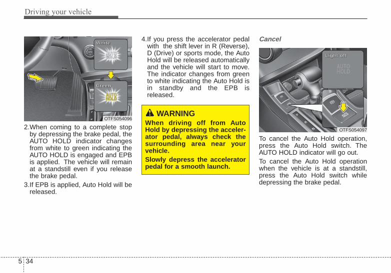
Driving your vehicle
345
2.When coming to a complete stopby depressing the brake pedal, theAUTO HOLD indicator changesfrom white to green indicating theAUTO HOLD is engaged and EPBis applied. The vehicle will remainat a standstill even if you releasethe brake pedal.
3.If EPB is applied, Auto Hold will bereleased.
4.If you press the accelerator pedalwith the shift lever in R (Reverse),D (Drive) or sports mode, the AutoHold will be released automaticallyand the vehicle will start to move.The indicator changes from greento white indicating the Auto Hold isin standby and the EPB isreleased.
Cancel
To cancel the Auto Hold operation,press the Auto Hold switch. TheAUTO HOLD indicator will go out.To cancel the Auto Hold operationwhen the vehicle is at a standstill,press the Auto Hold switch whiledepressing the brake pedal.
OTFS054096
WWWWhhhhiiii tttteeee
GGGGrrrreeeeeeeennnn
WARNINGWhen driving off from AutoHold by depressing the acceler-ator pedal, always check thesurrounding area near yourvehicle.Slowly depress the acceleratorpedal for a smooth launch.
OTFS054097
LLLLiiiigggghhhhtttt ooooffff ffff

5 35
Driving your vehicle
✽✽ NOTICE• The following are conditions when
the Auto Hold will not engage(Auto Hold light will not turngreen and the Auto Hold systemremains in stand by):- The driver's seat belt is unfas-
tened and driver's door is opened- The engine hood is opened- The trunk is opened- The shift lever is in P (Park)- The EPB is applied
• For your safety, the Auto Holdautomatically switches to EPBunder any of the following condi-tions (Auto Hold light remainswhite and the EPB automaticallyapplies):- The driver's seat belt is unfas-
tened and driver's door is opened- The engine hood is opened- The trunk is opened- The vehicle is in a standstill for
more than 10 minutes- The vehicle is standing on a steep
slope- The vehicle moved several times
(Continued)
(Continued)In these cases, the brake warninglight comes on, the AUTO HOLDindicator changes from green towhite, and a warning sounds and amessage will appear to inform youthat EPB has been automaticallyengaged. Before driving off again,press foot brake pedal, check thesurrounding area near your vehi-cle and release parking brakemanually with the EPB switch.
• If the AUTO HOLD indicatorlights up yellow, the Auto Hold isnot working properly. Take yourvehicle to an authorized Kia deal-er and have the system checked.
✽✽ NOTICEA click or electric brake motorwhine sound may be heard whileoperating or releasing the EPB, butthese conditions are normal andindicate that the EPB is functioningproperly.
WARNINGFor your safety, cancel the AutoHold when you drive downhill orback up the vehicle or park thevehicle.
CAUTIONIf there is a malfunction with thedriver’s door, engine hood ortrunk open detection system,the Auto Hold may not workproperly.Take your vehicle to an author-ized Kia dealer and have thesystem checked.

Driving your vehicle
365
Anti-lock brake system (ABS)ABS (or ESC) will not prevent acci-dents due to improper or dangerousdriving maneuvers. Even thoughvehicle control is improved duringemergency braking, always maintaina safe distance between you andobjects ahead. Vehicle speedsshould always be reduced duringextreme road conditions.The vehicle should be driven atreduced speeds in the following cir-cumstances:• When driving on rough, gravel or
snow-covered roads• When driving with tire chains
installed• When driving on roads where the
road surface is pitted or has differ-ent surface heights.
Driving in these conditions increasesthe stopping distance for your vehi-cle.
The ABS continuously senses thespeed of the wheels. If the wheelsare going to lock, the ABS systemrepeatedly modulates the hydraulicbrake pressure to the wheels.When you apply your brakes underconditions which may lock thewheels, you may hear a “tik-tik’’sound from the brakes, or feel a cor-responding sensation in the brakepedal. This is normal and it meansyour ABS is active.In order to obtain the maximum ben-efit from your ABS in an emergencysituation, do not attempt to modulateyour brake pressure and do not try topump your brakes. Press your brakepedal as hard as possible or as hardas the situation allows the ABS tocontrol the force being delivered tothe brakes.
✽✽ NOTICEA click sound may be heard in theengine compartment when the vehi-cle begins to move after the engine isstarted. These conditions are normaland indicate that the anti-lock brakesystem is functioning properly.
• Even with the anti-lock brake sys-tem, your vehicle still requires suf-ficient stopping distance. Alwaysmaintain a safe distance from thevehicle in front of you.
• Always slow down when cornering.The anti-lock brake system cannotprevent accidents resulting fromexcessive speeds.
• On loose or uneven road surfaces,operation of the anti-lock brakesystem may result in a longer stop-ping distance than for vehiclesequipped with a conventionalbrake system.
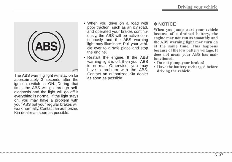
5 37
Driving your vehicle
The ABS warning light will stay on forapproximately 3 seconds after theignition switch is ON. During thattime, the ABS will go through self-diagnosis and the light will go off ifeverything is normal. If the light stayson, you may have a problem withyour ABS but your regular brakes willwork normally. Contact an authorizedKia dealer as soon as possible.
• When you drive on a road withpoor traction, such as an icy road,and operated your brakes continu-ously, the ABS will be active con-tinuously and the ABS warninglight may illuminate. Pull your vehi-cle over to a safe place and stopthe engine.
• Restart the engine. If the ABSwarning light is off, then your ABSis normal. Otherwise, you mayhave a problem with the ABS.Contact an authorized Kia dealeras soon as possible.
✽✽ NOTICEWhen you jump start your vehiclebecause of a drained battery, theengine may not run as smoothly andthe ABS warning light may turn onat the same time. This happensbecause of the low battery voltage. Itdoes not mean your ABS has mal-functioned.• Do not pump your brakes!• Have the battery recharged before
driving the vehicle.W-78

Driving your vehicle
385
Electronic stability control(ESC)
The Electronic Stability control(ESC) system is designed to stabi-lize the vehicle during corneringmaneuvers. ESC checks where youare steering and where the vehicle isactually going. ESC applies thebrakes on individual wheels andintervenes with the engine manage-ment system to stabilize the vehicle.
Electronic stability control (ESC) willnot prevent accidents. Excessivespeed in turns, abrupt maneuversand hydroplaning on wet surfacescan still result in serious accidents.Only a safe and attentive driver canprevent accidents by avoidingmaneuvers that cause the vehicle tolose traction. Even with ESCinstalled, always follow all the normalprecautions for driving - includingdriving at safe speeds for the condi-tions.The Electronic Stability Control(ESC) system is an electronic sys-tem designed to help the driver main-tain vehicle control under adverseconditions. It is not a substitute forsafe driving practices. Factors includ-ing speed, road conditions and driv-er steering input can all affectwhether ESC will be effective in pre-venting a loss of control. It is still yourresponsibility to drive and corner atreasonable speeds and to leave asufficient margin of safety.
When you apply your brakes underconditions which may lock thewheels, you may hear a “tik-tik’’sound from the brakes, or feel a cor-responding sensation in the brakepedal. This is normal and it meansyour ESC is active.
OTF054018

5 39
Driving your vehicle
ESC operationESC ON condition
• When the ignition is turnedON, ESC and ESC OFFindicator lights illuminatefor approximately 3 sec-onds, then ESC is turnedon.
• Press the ESC OFF but-ton for at least half a sec-ond after turning the igni-tion ON to turn ESC off.(ESC OFF indicator willilluminate). To turn theESC on, press the ESCOFF button (ESC OFFindicator light will go off).
• When starting the engine,you may hear a slight tick-ing sound. This is the ESCperforming an automaticsystem self-check anddoes not indicate a prob-lem.
When operating
When the ESC is in opera-tion, ESC indicator lightblinks.• When the Electronic
Stability Control is operat-ing properly, you can feel aslight pulsation in the vehi-cle. This is only the effectof brake control and indi-cates nothing unusual.
• When moving out of themud or slippery road,pressing the acceleratorpedal may not cause theengine rpm (revolutionsper minute) to increase.
ESC operation offESC OFF state
This car has 2 kinds of ESCoff states.If the engine stops whenESC is off, ESC remains off.Upon restarting the engine,the ESC will automaticallyturn on again.
-

Driving your vehicle
405
• ESC off state 1To cancel ESC operation, press theESC OFF button (ESC OFF )shortly (ESC OFF indicator light(ESC OFF ) illuminates). At thisstate, the engine control functiondoes not operate. It means the trac-tion control function does not oper-ate. Brake control function only oper-ates.
• ESC off state 2To cancel ESC operation, press theESC OFF button (ESC OFF ) formore than 3 seconds. ESC OFF indi-cator light (ESC OFF ) illuminatesand ESC OFF warning chime willsound. At this state, the engine con-trol function and brake control func-tion do not operate. It means the carstability control function does notoperate any more.
Indicator light
When the ignition switch is turnedON, the indicator light illuminates,then goes off if ESC system is oper-ating normally.The ESC indicator light blinks when-ever ESC is operating.The ESC indicator light blinks when-ever ESC is operating or illuminateswhen ESC fails to operate.The ESC OFF indicator light comeson when the ESC is turned off withthe button.
■ ESC indicator light
■ ESC OFF indicator light
OTF054111LOTF054110L
5 41
Driving your vehicle
Driving with varying tire or wheelsizes may cause the ESC system tomalfunction. When replacing tires,make sure they are the same size asyour original tires.
ESC OFF usageWhen driving
• It’s a good idea to keep the ESCturned on for daily driving whenev-er possible.
• To turn ESC off while driving, pressthe ESC OFF button while drivingon a flat road surface.
Never press the ESC OFF buttonwhile ESC is operating (ESC indica-tor light blinks).If ESC is turned off while ESC isoperating, the vehicle may slip out ofcontrol.
Hill-start assist control (HAC)Hill start Assist Control is a comfortfunction. The main intent is to pre-vent the vehicle from rolling back-wards while driving uphill on aninclined surface. HAC holds the brak-ing pressure builtup by driver duringstopping procedure for 2 secondsafter releasing brake pedal.During the pressure-hold period, thedriver has enough time to press theaccelerator pedal to drive off.The braking pressure is reduced assoon as the system detects the dri-ver’s intention to drive off.
WARNING - OperatingESC
Never press the ESC OFF but-ton while ESC is operating.If the ESC is turned off whileESC is operating, the vehiclemay go out of control.
WARNING - Electronicstability control
Drive carefully even thoughyour vehicle has ElectronicStability Control. It can onlyassist you in maintaining con-trol under certain circum-stances.
WARNING - ActivatingHAC
Drivers should pay close atten-tion when activating the HAC.The vehicle may roll backwardcausing an accident due toinsufficient brake hold pres-sure.

Driving your vehicle
425
• The HAC does not operate whenthe transaxle shift lever is in the P(Park) or N (Neutral) position.
• The HAC activates even thoughthe ESC is off but it does not acti-vate when the ESC has malfunc-tioned.
Vehicle stability management(VSM)This system provides furtherenhancements to vehicle stabilityand steering responses when a vehi-cle is driving on a slippery road or avehicle detected changes in coeffi-cient of friction between right wheelsand left wheels when braking.
VSM operationWhen the vehicle stability manage-ment is operating properly, you canfeel a slight pulsation in the vehicle.This is only the effect of brake controland indicates nothing unusual.
The VSM does not operate when:
• Driving on bank road such as gra-dient or incline
• Driving rearward• ESC OFF indicator light ( )
remains on the instrumentcluster
• ESC indicator light remains on theinstrument cluster
VSM operation offIf you press the ESC OFF button toturn off the ESC, the VSM will alsocancel and the ESC OFF indicatorlight ( ) illuminates.To turn on the VSM, press the buttonagain. The ESC OFF indicator lightgoes out.
5 43
Driving your vehicle
Malfunction indicatorThe VSM can be deactivated even ifyou don’t cancel the VSM operationby pressing the ESC OFF button. Itindicates that a malfunction hasbeen detected somewhere in theElectric Power Steering system orVSM system. If the ESC indicatorlight ( ) or ESC warning lightremains on, take your vehicle to anauthorized Kia dealer and have thesystem checked.• The VSM is designed to function
above approximately 9 mph (15km/h) on curves.
• The VSM is designed to functionabove approximately 18 mph (30km/h) when a vehicle is braking ona split-mu road. The split-mu roadis made of surfaces which have dif-ferent friction forces.
• The Vehicle Stability Managementsystem is not a substitute for safedriving practices but a supplemen-tary function only. It is the respon-sibility of the driver to always checkthe speed and the distance to thevehicle ahead. Always hold thesteering wheel firmly while driving.
• Your vehicle is designed to reactaccording to the driver’s intention,even with installed VSM. Alwaysfollow all the normal precautionsfor driving at safe speeds for theconditions – including driving ininclement weather and on a slip-pery road.
WARNING - Tire/Wheelsize
When replacing tires andwheels, make sure they are thesame size as the original tiresand wheels installed. Drivingwith varying tire or wheel sizesmay diminish any supplementalsafety benefits of the VSM sys-tem.

Driving your vehicle
445
Good braking practices• Check to be sure the parking brake
is not engaged and that the park-ing brake indicator light is outbefore driving away.
• Driving through water may get thebrakes wet. They can also get wetwhen the vehicle is washed. Wetbrakes can be dangerous! Yourvehicle will not stop as quickly if thebrakes are wet. Wet brakes maycause the vehicle to pull to oneside.To dry the brakes, apply the brakeslightly until the braking actionreturns to normal, taking care tokeep the vehicle under control atall times. If the braking action doesnot return to normal, stop as soonas it is safe to do so and call anauthorized Kia dealer for assis-tance.
• Don't coast down hills with thevehicle out of gear.This is extreme-ly hazardous. Keep the vehicle ingear at all times, use the brakes toslow down, then shift to a lowergear so that engine braking willhelp you maintain a safe speed.
• Don't "ride" the brake pedal.Resting your foot on the brakepedal while driving can be danger-ous because the brakes mightoverheat and lose their effective-ness. It also increases the wear ofthe brake components.
• If a tire goes flat while you are driv-ing, apply the brakes gently andkeep the vehicle pointed straightahead while you slow down. Whenyou are moving slowly enough for itto be safe to do so, pull off the roadand stop in a safe place.
• If your vehicle is equipped with anautomatic transaxle, don't let yourvehicle creep forward. To avoidcreeping forward, keep your footfirmly on the brake pedal when thevehicle is stopped.
• Be cautious when parking on a hill.Firmly engage the parking brakeand place the shift lever in P (auto-matic transaxle) or in first orreverse gear (manual transaxle). Ifyour vehicle is facing downhill, turnthe front wheels into the curb tohelp keep the vehicle from rolling.
If your vehicle is facing uphill, turnthe front wheels away from thecurb to help keep the vehicle fromrolling. If there is no curb or if it isrequired by other conditions tokeep the vehicle from rolling, blockthe wheels.
• Under some conditions your park-ing brake can freeze in theengaged position. This is most like-ly to happen when there is anaccumulation of snow or icearound or near the rear brakes or ifthe brakes are wet. If there is a riskthat the parking brake may freeze,apply it only temporarily while youput the shift lever in P (automatictransaxle) or in first or reverse gear(manual transaxle) and block therear wheels so the vehicle cannotroll. Then release the parkingbrake.
• Do not hold the vehicle on theupgrade with the acceleratorpedal.This can cause the transaxleto overheat. Always use the brakepedal or parking brake.
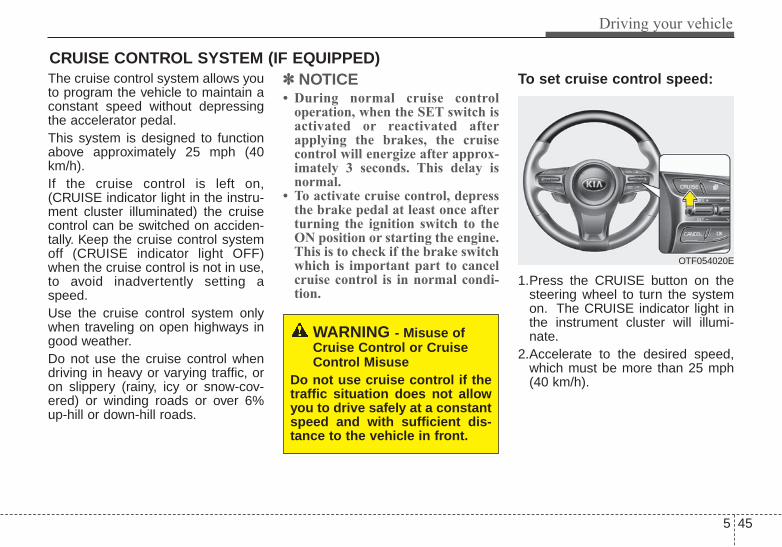
5 45
Driving your vehicle
The cruise control system allows youto program the vehicle to maintain aconstant speed without depressingthe accelerator pedal.This system is designed to functionabove approximately 25 mph (40km/h).If the cruise control is left on,(CRUISE indicator light in the instru-ment cluster illuminated) the cruisecontrol can be switched on acciden-tally. Keep the cruise control systemoff (CRUISE indicator light OFF)when the cruise control is not in use,to avoid inadvertently setting aspeed.Use the cruise control system onlywhen traveling on open highways ingood weather.Do not use the cruise control whendriving in heavy or varying traffic, oron slippery (rainy, icy or snow-cov-ered) or winding roads or over 6%up-hill or down-hill roads.
✽✽ NOTICE• During normal cruise control
operation, when the SET switch isactivated or reactivated afterapplying the brakes, the cruisecontrol will energize after approx-imately 3 seconds. This delay isnormal.
• To activate cruise control, depressthe brake pedal at least once afterturning the ignition switch to theON position or starting the engine.This is to check if the brake switchwhich is important part to cancelcruise control is in normal condi-tion.
To set cruise control speed:
1.Press the CRUISE button on thesteering wheel to turn the systemon. The CRUISE indicator light inthe instrument cluster will illumi-nate.
2.Accelerate to the desired speed,which must be more than 25 mph(40 km/h).
CRUISE CONTROL SYSTEM (IF EQUIPPED)
WARNING - Misuse ofCruise Control or CruiseControl Misuse
Do not use cruise control if thetraffic situation does not allowyou to drive safely at a constantspeed and with sufficient dis-tance to the vehicle in front.
OTF054020E

Driving your vehicle
465
3.Move the lever (1) down (to SET-),and release it at the desired speed.The SET indicator light in theinstrument cluster will illuminate.Release the accelerator at thesame time. The desired speed willautomatically be maintained.
On a steep grade, the vehicle mayslow down or speed up slightly whilegoing downhill.
To increase cruise control setspeed:
Follow either of these procedures:• Move the lever (1) up (to RES+)
and hold it. Your vehicle will accel-erate. Release the lever at thespeed you want.
• Move the lever (1) up (to RES+)and release it immediately. Thecruising speed will increase by 1.0mph (2 km/h ) each time the lever isoperated in this manner.
To decrease the cruisingspeed:
Follow either of these procedures:• Move the lever (1) down (to SET-)
and hold it. Your vehicle will gradu-ally slow down. Release the leverat the speed you want to maintain.
• Move the lever (1) down (to SET-)and release it immediately. Thecruising speed will decrease by 1.0mph (2 km/h) each time the lever isoperated in this manner.
OTF054021E
OTF054022E OTF054021E
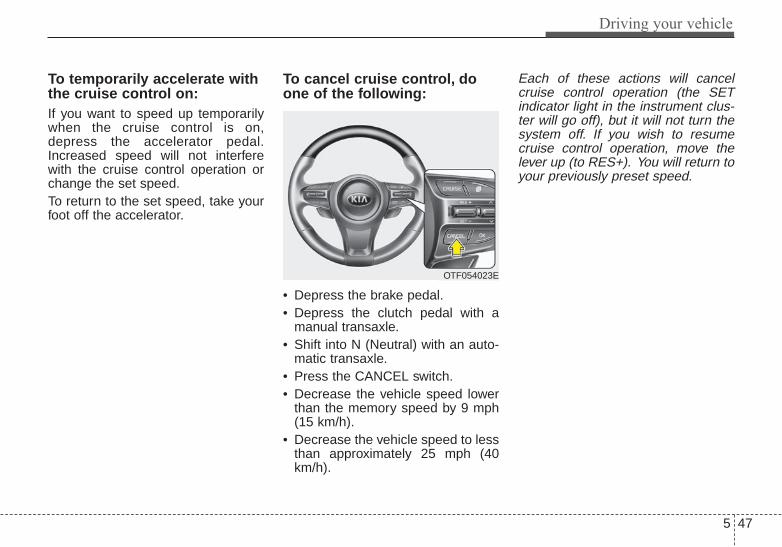
5 47
Driving your vehicle
To temporarily accelerate withthe cruise control on:If you want to speed up temporarilywhen the cruise control is on,depress the accelerator pedal.Increased speed will not interferewith the cruise control operation orchange the set speed.To return to the set speed, take yourfoot off the accelerator.
To cancel cruise control, doone of the following:
• Depress the brake pedal.• Depress the clutch pedal with a
manual transaxle.• Shift into N (Neutral) with an auto-
matic transaxle.• Press the CANCEL switch.• Decrease the vehicle speed lower
than the memory speed by 9 mph(15 km/h).
• Decrease the vehicle speed to lessthan approximately 25 mph (40km/h).
Each of these actions will cancelcruise control operation (the SETindicator light in the instrument clus-ter will go off), but it will not turn thesystem off. If you wish to resumecruise control operation, move thelever up (to RES+). You will return toyour previously preset speed.
OTF054023E

Driving your vehicle
485
To resume cruising speed atmore than approximately 25mph (40 km/h):
If any method other than theCRUISE ON-OFF switch was usedto cancel cruising speed and the sys-tem is still activated, the most recentset speed will automatically resumewhen you move the lever up.It will not resume, however, if thevehicle speed has dropped belowapproximately 25 mph (40 km/h).
To turn cruise control off, doone of the following:• Press the CRUISE button (the
CRUISE indicator light in theinstrument cluster will go off).
• Turn the ignition off.Both of these actions will cancel thecruise control operation. If you wantto resume the cruise control opera-tion, repeat the steps provided in “Toset cruise control speed” on the pre-vious page.
OTF054022E

5 49
Driving your vehicle
ACTIVE ECO SYSTEM (IF EQUIPPED)Active ECO operation
Active ECO helps improve fuel effi-ciency by controlling the engine andtransaxle. But fuel-efficiency can beaffected by the driver's driving habitsand road conditions.• When the Active ECO button is
pressed the ECO indicator (green)will illuminate to show that theActive ECO is operating.
• When the Active ECO is activated,it does not turn off even though theengine is restarted again. To turnoff the system, press the activeECO button again.
• If Active ECO is turned off, it willreturn to the normal mode.
When Active ECO is activated:• The engine noise may get louder.• The vehicle speed may slightly be
reduced.• The air conditioner performance
may be affected.
Limitation of Active ECO oper-ation:If the following conditions occur whileActive ECO is operating, the systemoperation is limited even thoughthere is no change in the ECO indi-cator.• When the coolant temperature is
low:The system will be limited untilengine performance becomes nor-mal.
• When driving up a hill:The system will be limited to gainpower when driving uphill becausethe engine torque is restricted.
• When using sports mode:The system will be limited accord-ing to the shift location.
• When the accelerator pedal isdeeply pressed for a few seconds:The system will be limited,as it hasdetermined that the driver hasaccelerated judging that the driverwants to speed up.
OTF054024

Driving your vehicle
505
DRIVE mode
The drive mode may be selectedaccording to the driver’s preferenceor road condition.The system initializes to the normalmode after the engine has beenturned off and on.The mode changes whenever theDRIVE MODE button is pressed.
❈ When normal mode is selected, itis not displayed on the cluster.
ECO mode (Active ECO)Active ECO helps improvefuel efficiency by control-ling certain engine andtransaxle system operat-ing parameters. Fuel effi-ciency depends on thedriver's driving habit androad condition.• When the DRIVE MODE
button is pressed andthe ECO mode is select-ed, the ECO indicator(green) will illuminate toshow that the ActiveECO is operating.
• When the Active ECO isactivated, and theengine start/stop buttonis turned off and on it willchange to NORMALmode. To turn on theECO mode press theDRIVE MODE button tillit is selected.
When Active ECO is activated:• The acceleration may slightly be
reduced eventhough you depressthe accelerator fully.
• The air conditioner performancemay be limited
• The shift pattern of the automatictransaxle may change.
• The engine noise may get louder.
The above situations are normalconditions when the active eco sys-tem is activated to improve fuel effi-ciency.
DRIVE MODE INTEGRATED CONTROL SYSTEM
NORMAL
SPORT ECO
OTF054105
ECO

5 51
Driving your vehicle
Limitation of Active ECO opera-tion:If the following conditions occur whileActive ECO is operating, the systemoperation is limited even thoughthere is no change in the ECO indi-cator.• When the coolant temperature is
low:The system will be limited untilengine performance becomes nor-mal.
• When driving up a hill:The system will be limited to gainpower when driving uphill becausethe engine torque is restricted.
• When using manual mode:The system will be limited accord-ing to the shift location.
• When the accelerator pedal isdeeply depressed for a few sec-onds:The system will be limited, judgingthat the driver wants to speed up.
SPORT modeSPORT mode focuses ondynamic driving by auto-matically controlling thesteering wheel, engineand transaxle system.• When the DRIVE MODE
button is pressed andthe SPORT mode isselected, the SPORTindicator (yellow) will illu-minate.
• When the SPORT modeis activated, and theengine start/stop buttonis turned off and on it willchange to NORMALmode. To turn on theSPORT mode pressDRIVE MODE buttonagain.
• If the system is activat-ed:- While holding vehicle
speed, it maintains thegear and RPM forsome time eventhough the acceleratorpedal is notdepressed.
- Up-shifting is delayed.
✽✽ NOTICEIn Sport drive mode, the fuel effi-ciency may decrease.
SPORT
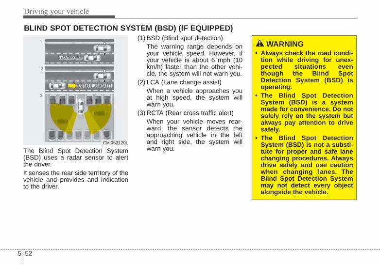
Driving your vehicle
525
The Blind Spot Detection System(BSD) uses a radar sensor to alertthe driver.It senses the rear side territory of thevehicle and provides and indicationto the driver.
(1) BSD (Blind spot detection)The warning range depends onyour vehicle speed. However, ifyour vehicle is about 6 mph (10km/h) faster than the other vehi-cle, the system will not warn you.
(2) LCA (Lane change assist)When a vehicle approaches youat high speed, the system willwarn you.
(3) RCTA (Rear cross traffic alert)When your vehicle moves rear-ward, the sensor detects theapproaching vehicle in the leftand right side, the system willwarn you.
BLIND SPOT DETECTION SYSTEM (BSD) (IF EQUIPPED)
OVI053129L
WARNING • Always check the road condi-
tion while driving for unex-pected situations eventhough the Blind SpotDetection System (BSD) isoperating.
• The Blind Spot DetectionSystem (BSD) is a systemmade for convenience. Do notsolely rely on the system butalways pay attention to drivesafely.
• The Blind Spot DetectionSystem (BSD) is not a substi-tute for proper and safe lanechanging procedures. Alwaysdrive safely and use cautionwhen changing lanes. TheBlind Spot Detection Systemmay not detect every objectalongside the vehicle.

5 53
Driving your vehicle
BSD (Blind Spot Detection) / LCA (Lane Change Assist)Operating conditions
The indicator on the switch will illumi-nate when the Blind Spot DetectionSystem (BSD) switch is pressed withthe Engine Start/Stop Button ON.If vehicle speed exceeds 18.6 mph (30 km/h), the system will activate.If you press the switch again, theswitch indicator and system will beturned off.If the ignition switch is turned OFFand ON the system returns to theprevious state.
When the system is not used turn thesystem off by turning off the switch.When the system is turned on thewarning light will illuminate for 3 sec-onds on the outside rearview mirror.
Warning typeThe system will activate when:1.The system is on 2.Vehicle speed is above 18.6 mph
(30 km/h)3.Other vehicles are detected in the
rear side
OTF054143N

Driving your vehicle
545
If a vehicle is detected within theboundary of the system, a warninglight will illuminate on the outsiderearview mirror.If the detected vehicle is not indetecting range, the warning will turnoff according to driving conditions.
The second stage alarm will activatewhen:1.The first stage alert is on2.The turn signal is on to change a
lane
When the second stage alert is acti-vated, a warning light will blink on theoutside rearview mirror and a alarmwill sound.If you move the turn signal switch tothe original position, the secondstage alert will be deactivated.
Detecting sensor
The sensors are located inside of therear bumper.Always keep the rear bumper cleanfor the system to work properly.
OTF054107
1st stage
OTF054108
2nd stage
OTF054109

5 55
Driving your vehicle
Warning message
The message will appear to notifythe driver if there are foreign sub-stances on the rear bumper or it ishot near the rear bumper. The lighton the switch and the system willturn off automatically.
Remove the foreign matter on therear bumper.
If the system does not work normallyeven though the foreign matter isremoved, take your vehicle to anauthorized Kia dealer and have thesystem checked.
If the system does not work properly,a warning message will appear andthe light on the switch will turn off.The system will turn off automatical-ly.
Have your vehicle inspected by anauthorized Kia dealer.
OTF054131
OTF054104L
OTF054132
OTF054103L

Driving your vehicle
565
RCTA (Rear cross traffic alert)
When your vehicle moves backwardsfrom a parking position, the sensordetects approaching vehicles to theleft or right side direction and givesinformation to the driver.
Operating conditions
• Select RCTA (Rear Cross TrafficAlert) in "User Settings" under"Driving Assist" on the instrumentcluster. The system will turn on andstandby to activate.
• Select RCTA again, to turn the sys-tem off.
• If the vehicle is turned off and onagain, the RCTA system will returnto the state right before the vehiclewas turned off. Always turn theRCTA system off when not in use.
• The system operates when thevehicle speed is below 6.2 mph (10km/h) with the shift lever in R(Reverse).
• The RCTA (Rear Cross TrafficAlert) detecting range is 0.5m ~20m based on the side direction. Ifthe approaching vehicle speed is 2.5 mph (4 km/h) ~ 22 mph (36km/h) within sensing range, it isdetected. However, the systemsensing range is different base onconditions. Always pay attention tothe surrounding.OVI053131 OTF054112N1
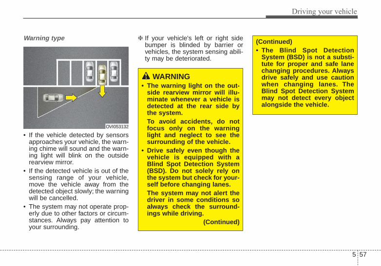
5 57
Driving your vehicle
Warning type
• If the vehicle detected by sensorsapproaches your vehicle, the warn-ing chime will sound and the warn-ing light will blink on the outsiderearview mirror.
• If the detected vehicle is out of thesensing range of your vehicle,move the vehicle away from thedetected object slowly; the warningwill be cancelled.
• The system may not operate prop-erly due to other factors or circum-stances. Always pay attention toyour surrounding.
❈ If your vehicle's left or right sidebumper is blinded by barrier orvehicles, the system sensing abili-ty may be deteriorated.
OVI053132
WARNING • The warning light on the out-
side rearview mirror will illu-minate whenever a vehicle isdetected at the rear side bythe system.To avoid accidents, do notfocus only on the warninglight and neglect to see thesurrounding of the vehicle.
• Drive safely even though thevehicle is equipped with aBlind Spot Detection System(BSD). Do not solely rely onthe system but check for your-self before changing lanes.The system may not alert thedriver in some conditions soalways check the surround-ings while driving.
(Continued)
(Continued)• The Blind Spot Detection
System (BSD) is not a substi-tute for proper and safe lanechanging procedures. Alwaysdrive safely and use cautionwhen changing lanes. TheBlind Spot Detection Systemmay not detect every objectalongside the vehicle.

Driving your vehicle
585
Non-operating conditionDriver's AttentionThe driver must be cautious in thebelow situations for the system maynot assist the driver and may notwork properly.
- Curved roads, tollgates, etc.- The surrounding of the sensor is
polluted with rain, snow, mud, etc- The rear bumper near the sensor is
covered or hidden with a foreignmatter such as a sticker, bumperguard, bicycle stand etc.
- The rear bumper is damaged or thesensor is out of place.
- The height of the vehicle showsmuch change such as when thetrunk is loaded with heavy objects,abnormal tire pressure etc.
- Due to bad weather such as heavyrain or snow.
- A fixed object is near such as aguardrail, etc.
- A lot of amount of metal sub-stances are near the vehicles suchas a construction area.
- A big vehicle is near such as a busor truck.
- A motorcycle or bicycle is near.- A flat trailer like vehicle is near.- If the vehicle has started at the
same time as the vehicle next to itand has accelerated.
- When the other vehicle passes byvery fast.
- When changing lanes.- When going down or up a steep
road where the height of the lane isdifferent.
- When the other vehicle drives atthe rear very nearby or drives veryclose.
- When a trailer or carrier is installed.- When the temperature of rear
bumper is high.- When the sensors are covered by
the vehicle, wall and pillar of park-ing lot.
- When your vehicle moves back, ifthe detected vehicle also movesback.
- If there is small things like shoppingcart and baby carriage.
CAUTION• The system may not work
properly if the bumper hasbeen replaced or if a repairwork has been done near thesensor.
• The detection area differsaccording to the roads width.If the road is narrow the sys-tem may detect other vehiclesin the next lane.
• On the contrary, if the road isvery wide the system may notdetect other vehicles.
• The system may turn off dueto strong electromagneticwaves.

5 59
Driving your vehicle
- If there is a vehicle with decreasedride height (lowered).
- When the vehicle is close to anoth-er vehicle.
Outside rearview mirror may notalert the driver when:- The outside rearview mirror hous-
ing is severely polluted- The window is severely polluted- The windows are severely tinted.
This device complies with Part15 of the FCC rules.Operation is subject to the followingtwo conditions:1.This device may not cause harmful
interference, and 2.This device must accept any inter-
ference received, including inter-ference that may cause undesiredoperation.

Driving your vehicle
605
Your vehicle's fuel economy dependsmainly on your style of driving, whereyou drive and when you drive.Each of these factors affects howmany miles (kilometers) you can getfrom a gallon (liter) of fuel.To operateyour vehicle as economically as pos-sible, use the following driving sug-gestions to help save money in bothfuel and repairs:• Drive smoothly. Accelerate at a
moderate rate. Don't make "jack-rabbit" starts or full-throttle shiftsand maintain a steady cruisingspeed. Don't race between stop-lights. Try to adjust your speed tothe traffic so you don't have tochange speeds unnecessarily.Avoid heavy traffic whenever pos-sible. Always maintain a safe dis-tance from other vehicles so youcan avoid unnecessary braking.This also reduces brake wear.
• Drive at a moderate speed. Thefaster you drive, the more fuel yourvehicle uses. Driving at a moderatespeed, especially on the highway,is one of the most effective ways toreduce fuel consumption.
• Don't "ride" the brake pedal. Thiscan increase fuel consumption andalso increase wear on these com-ponents. In addition, driving withyour foot resting on the brake pedalmay cause the brakes to overheat,which reduces their effectivenessand may lead to more serious con-sequences.
• Take care of your tires. Keep theminflated to the recommended pres-sure. Incorrect inflation, either toomuch or too little, results in unnec-essary tire wear. Check the tirepressures at least once a month.
• Be sure that the wheels arealigned correctly. Improper align-ment can result from hitting curbsor driving too fast over irregularsurfaces. Poor alignment causesfaster tire wear and may also resultin other problems as well asgreater fuel consumption.
• Keep your vehicle in good condi-tion. For better fuel economy andreduced maintenance costs, main-tain your vehicle in accordancewith the maintenance schedule inchapter 7. If you drive your vehiclein severe conditions, more frequentmaintenance is required (seechapter 7 for details).
• Keep your vehicle clean. For maxi-mum service, your vehicle shouldbe kept clean and free of corrosivematerials. It is especially importantthat mud, dirt, ice, etc. not beallowed to accumulate on theunderside of the vehicle. This extraweight can result in increased fuelconsumption and also contribute tocorrosion.
• Travel lightly. Don't carry unneces-sary weight in your vehicle. Weightreduces fuel economy.
• Don't let the engine idle longerthan necessary. If you are waiting(and not in traffic), turn off yourengine and restart only whenyou're ready to go.
ECONOMICAL OPERATION

5 61
Driving your vehicle
• Remember, your vehicle does notrequire extended warm-up. Afterthe engine has started, allow theengine to run for 10 to 20 secondsprior to placing the vehicle in gear.In very cold weather, however, giveyour engine a slightly longer warm-up period.
• Don't "lug" or "over-rev" the engine.Lugging is driving too slowly in avery high gear resulting in enginebucking. If this happens, shift to alower gear. Over-revving is racingthe engine beyond its safe limit.This can be avoided by shifting atthe recommended speed.
• Use your air conditioning sparingly.The air conditioning system isoperated by engine power so yourfuel economy is reduced when youuse it.
• Open windows at high speeds canreduce fuel economy.
• Fuel economy is reduced by cross-winds and headwinds. To help off-set some of this loss, slow downwhen driving in these conditions.
Keeping a vehicle in good operatingcondition is important both for econ-omy and safety. Therefore, have anauthorized Kia dealer performscheduled inspections and mainte-nance.
WARNING - Engine offduringmotion
Never turn the engine off tocoast down hills or anytime thevehicle is in motion. The powersteering and power brakes willnot function properly withoutthe engine running. In addition,turning off the ignition whiledriving could engage the steer-ing wheel lock resulting in lossof vehicle steering. Keep theengine on and downshift to anappropriate gear for enginebraking effect.

Driving your vehicle
625
Hazardous driving conditions When hazardous driving conditionsare encountered such as water,snow, ice, mud, sand, or similar haz-ards, follow these suggestions:• Drive cautiously and allow extra
distance for braking.• Avoid sudden braking or steering.• When braking with non-ABS
brakes pump the brake pedal witha light up-and-down motion untilthe vehicle is stopped.
Do not pump the brake pedal on avehicle equipped with ABS.• If stalled in snow, mud, or sand,
use second gear. Accelerate slow-ly to avoid spinning the drivewheels.
• Use sand, rock salt, tire chains, orother non-slip material under thedrive wheels to provide tractionwhen stalled in ice, snow, or mud.
Rocking the vehicle If it is necessary to rock the vehicleto free it from snow, sand, or mud,first turn the steering wheel right andleft to clear the area around yourfront wheels. Then, shift back andforth between 1st (First) and R(Reverse) in vehicles equipped witha manual transaxle or R (Reverse)and any forward gear in vehiclesequipped with an automatictransaxle. Do not race the engine,and spin the wheels as little as pos-sible. If you are still stuck after a fewtries, have the vehicle pulled out by atow vehicle to avoid engine overheat-ing and possible damage to thetransaxle.The ESC system should be turnedOFF prior to rocking the vehicle.
SPECIAL DRIVING CONDITIONS
WARNING - DownshiftingDo not downshift with an auto-matic transaxle while driving onslippery surfaces. The suddenchange in tire speed couldcause the tires to skid andresult in an accident.
CAUTION - Vehicle rocking
Prolonged rocking may causeengine overheating, transaxledamage or failure, and tire dam-age.
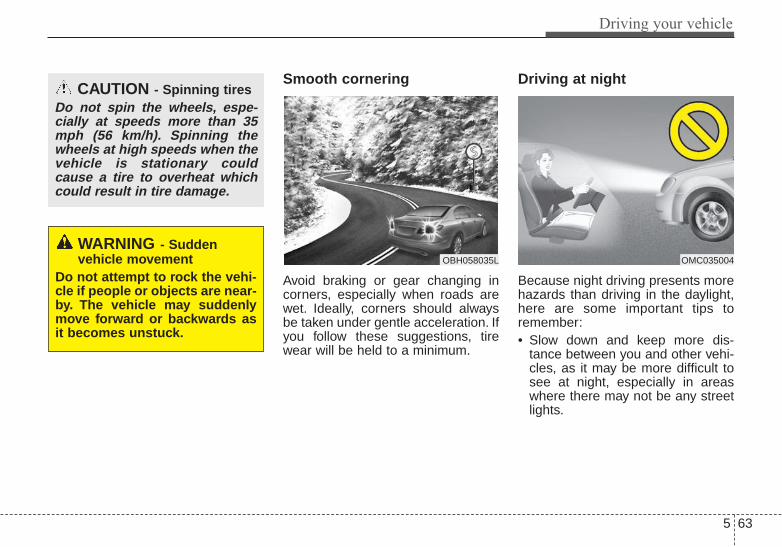
5 63
Driving your vehicle
Smooth cornering
Avoid braking or gear changing incorners, especially when roads arewet. Ideally, corners should alwaysbe taken under gentle acceleration. Ifyou follow these suggestions, tirewear will be held to a minimum.
Driving at night
Because night driving presents morehazards than driving in the daylight,here are some important tips toremember:• Slow down and keep more dis-
tance between you and other vehi-cles, as it may be more difficult tosee at night, especially in areaswhere there may not be any streetlights.
OBH058035L OMC035004
WARNING - Sudden vehicle movement
Do not attempt to rock the vehi-cle if people or objects are near-by. The vehicle may suddenlymove forward or backwards asit becomes unstuck.
CAUTION - Spinning tiresDo not spin the wheels, espe-cially at speeds more than 35mph (56 km/h). Spinning thewheels at high speeds when thevehicle is stationary couldcause a tire to overheat whichcould result in tire damage.

Driving your vehicle
645
• Adjust your mirrors to reduce theglare from other driver's head-lights.
• Keep your headlights clean andproperly aimed on vehicles notequipped with the automatic head-light aiming feature. Dirty orimproperly aimed headlights willmake it much more difficult to seeat night.
• Avoid staring directly at the head-lights of oncoming vehicles. Youcould be temporarily blinded, and itwill take several seconds for youreyes to readjust to the darkness.
Driving in the rain
Rain and wet roads can make drivingdangerous, especially if you’re notprepared for the slick pavement.Here are a few things to considerwhen driving in the rain:• A heavy rainfall will make it harder
to see and will increase the dis-tance needed to stop your vehicle,so slow down.
• Keep your windshield wipingequipment in good shape. Replaceyour windshield wiper blades whenthey show signs of streaking ormissing areas on the windshield.
• If your tires are not in good condi-tion, making a quick stop on wetpavement can cause a skid andpossibly lead to an accident. Besure your tires are in good shape.
• Turn on your headlights to make iteasier for others to see you.
• Driving too fast through large pud-dles can affect your brakes. If youmust go through puddles, try todrive through them slowly.
• If you believe you may have gottenyour brakes wet, apply them lightlywhile driving until normal brakingoperation returns.
Driving in flooded areas Avoid driving through flooded areasunless you are sure the water is nohigher than the bottom of the wheelhub. Drive through any water slowly.Allow adequate stopping distancebecause brake performance may beaffected.After driving through water, dry thebrakes by gently applying them sev-eral times while the vehicle is movingslowly.
1JBB3303

5 65
Driving your vehicle
Driving off-roadDrive carefully off-road because yourvehicle may be damaged by rocks orroots of trees. Become familiar withthe off-road conditions where youare going to drive before you begindriving.
Highway drivingTires Adjust the tire inflation pressures tospecification. Low tire inflation pres-sures will result in overheating andpossible failure of the tires.Avoid using worn or damaged tireswhich may result in reduced tractionor tire failure.Never exceed the maximum tireinflation pressure shown on the tires.
Fuel, engine coolant and engineoilHigh speed travel consumes morefuel than urban motoring. Do not for-get to check both the engine coolantand engine oil.
Drive beltA loose or damaged drive belt mayoverheat the engine.
WARNING - Tire treadAlways check the tire treadbefore driving your vehicle.Worn-out tires can result in lossof vehicle control. Worn-outtires should be replaced assoon as possible. For furtherinformation and tread limits,refer to "Tires and wheels" inchapter 7.
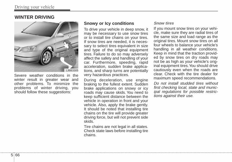
Driving your vehicle
665
Severe weather conditions in thewinter result in greater wear andother problems. To minimize theproblems of winter driving, youshould follow these suggestions:
Snowy or Icy conditionsTo drive your vehicle in deep snow, itmay be necessary to use snow tiresor to install tire chains on your tires.If snow tires are needed, it is neces-sary to select tires equivalent in sizeand type of the original equipmenttires. Failure to do so may adverselyaffect the safety and handling of yourcar. Furthermore, speeding, rapidacceleration, sudden brake applica-tions, and sharp turns are potentiallyvery hazardous practices.During deceleration, use enginebraking to the fullest extent. Suddenbrake applications on snowy or icyroads may cause skids. You need tokeep sufficient distance between thevehicle in operation in front and yourvehicle. Also, apply the brake gently.It should be noted that installing tirechains on the tire will provide greaterdriving force, but will not prevent sideskids.Tire chains are not legal in all states.Check state laws before installing tirechains.
Snow tiresIf you mount snow tires on your vehi-cle, make sure they are radial tires ofthe same size and load range as theoriginal tires. Mount snow tires on allfour wheels to balance your vehicle’shandling in all weather conditions.Keep in mind that the traction provid-ed by snow tires on dry roads maynot be as high as your vehicle's orig-inal equipment tires.You should drivecautiously even when the roads areclear. Check with the tire dealer formaximum speed recommendations.Do not install studded tires withoutfirst checking local, state and munic-ipal regulations for possible restric-tions against their use.
WINTER DRIVING
1JBB3305

5 67
Driving your vehicle
Tire chains
Since the sidewalls of radial tires arethinner, they can be damaged bymounting some types of snow chainson them. Therefore, the use of snowtires is recommended instead ofsnow chains. Do not mount tirechains on vehicles equipped withaluminum wheels; snow chains maycause damage to the wheels. If snowchains must be used, use wire-typechains with a thickness of less than0.47 in (12 mm). Damage to yourvehicle caused by improper snowchain use is not covered by yourvehicle manufacturers warranty.
Install tire chains only on the fronttires.
The snow chain connecting hooksmay be damaged from contactingvehicle components causing thesnow chains to come loose from thetire. Make sure the snow chains areSAE class “S” certified.Always check chain installation forproper mounting after drivingapproximately 0.3 to 0.6 miles (0.5 to1 km) to ensure safe mounting.Retighten or remount the chains ifthey are loose.
Chain installation
When installing chains, follow themanufacturer's instructions andmount them as tightly as you can.Drive slowly with chains installed. Ifyou hear the chains contacting thebody or chassis, stop and tightenthem. If they still make contact, slowdown until it stops. Remove thechains as soon as you begin drivingon cleared roads.When mounting snow chains, parkthe vehicle on level ground awayfrom traffic. Turn on the vehicleHazard Warning flashers and place atriangular emergency warning devicebehind the vehicle if available.
CAUTION - Snow chainsMake sure the snow chains arethe correct size and type foryour tires. Incorrect snowchains can cause damage to thevehicle body and suspensionand may not be covered by yourvehicle manufacturer's warran-ty.
1JBA4068

Driving your vehicle
685
• The use of chains may adverselyaffect vehicle handling.
• Do not exceed 20 mph (30 km/h)or the chain manufacturer’s recom-mended speed limit, whichever islower.
• Drive carefully and avoid bumps,holes, sharp turns, and other roadhazards, which may cause thevehicle to bounce.
• Avoid sharp turns or locked-wheelbraking.
Use high quality ethylene gly-col coolantYour vehicle is delivered with highquality ethylene glycol coolant in thecooling system. It is the only type ofcoolant that should be used becauseit helps prevent corrosion in the cool-ing system, lubricates the waterpump and prevents freezing. Be sureto replace or replenish your coolantin accordance with the maintenanceschedule in chapter 7. Before winter,have your coolant tested to assurethat its freezing point is sufficient forthe temperatures anticipated duringthe winter.
Check battery and cablesWinter puts additional burdens onthe battery system. Visually inspectthe battery and cables as describedin chapter 7. The level of charge inyour battery can be checked by anauthorized Kia dealer or a servicestation.
Change to "winter weight" oilif necessaryIn some climates it is recommendedthat a lower viscosity "winter weight"oil be used during cold weather. Seechapter 8 for recommendations. Ifyou aren't sure what weight oil youshould use, consult an authorizedKia dealer.
Check spark plugs and igni-tion systemInspect your spark plugs asdescribed in chapter 7 and replacethem if necessary. Also check allignition wiring and components to besure they are not cracked, worn ordamaged in any way.
CAUTION - Snow chains• Chains that are the wrong size
or improperly installed candamage your vehicle's brakelines, suspension, body andwheels.
• Stop driving and retighten thechains any time you hear themhitting the vehicle.

5 69
Driving your vehicle
To keep locks from freezingTo keep the locks from freezing,squirt an approved de-icer fluid orglycerine into the key opening. If alock is covered with ice, squirt it withan approved de-icing fluid to removethe ice. If the lock is frozen internally,you may be able to thaw it out byusing a heated key. Handle the heat-ed key with care to avoid injury.
Use approved window washeranti-freeze in systemTo keep the water in the windowwasher system from freezing, add anapproved window washer anti-freezesolution in accordance with instruc-tions on the container. Window wash-er anti-freeze is available from anauthorized Kia dealer and most autoparts outlets. Do not use enginecoolant or other types of anti-freezeas these may damage the paint fin-ish.
Don't let your parking brakefreezeUnder some conditions your parkingbrake can freeze in the engagedposition. This is most likely to hap-pen when there is an accumulationof snow or ice around or near therear brakes or if the brakes are wet.If there is a risk the parking brakemay freeze, apply it only temporarilywhile you put the shift lever in P(automatic transaxle) or in first orreverse gear (manual transaxle) andblock the rear wheels so the vehiclecannot roll. Then release the parkingbrake.
Don't let ice and snow accu-mulate underneathUnder some conditions, snow andice can build up under the fendersand interfere with the steering. Whendriving in severe winter conditionswhere this may happen, you shouldperiodically check underneath thecar to be sure the movement of thefront wheels and the steering com-ponents is not obstructed.
Carry emergency equipmentDepending on the severity of theweather you should carry appropri-ate emergency equipment. Some ofthe items you may want to carryinclude tire chains, tow straps orchains, flashlight, emergency flares,sand, a shovel, jumper cables, a win-dow scraper, gloves, ground cloth,coveralls, a blanket, etc.
TRAILER TOWINGWe do not recommend using thisvehicle for trailer towing.

Driving your vehicle
705
Tire and loading informationlabelThe label located on the driver's doorsill gives the original tire size, coldtire pressures recommended for yourvehicle, the number of people thatcan be in your vehicle and vehiclecapacity weight.
Vehicle capacity weight:904 lbs. (410 kg)
Vehicle capacity weight is the maxi-mum combined weight of occupantsand cargo. If your vehicle is equippedwith a trailer, the combined weightincludes the tongue load.
VEHICLE LOAD LIMIT
OTF054040N/OTF054041N/OTF050042N/OTF054043N/OTF054044N/OTF054045N
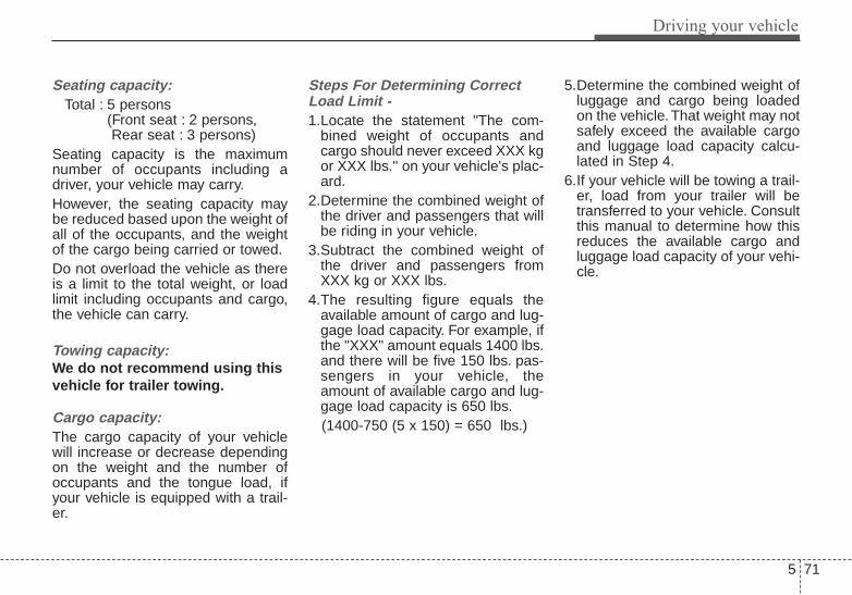
5 71
Driving your vehicle
Seating capacity:Total : 5 persons
(Front seat : 2 persons, Rear seat : 3 persons)
Seating capacity is the maximumnumber of occupants including adriver, your vehicle may carry.However, the seating capacity maybe reduced based upon the weight ofall of the occupants, and the weightof the cargo being carried or towed.Do not overload the vehicle as thereis a limit to the total weight, or loadlimit including occupants and cargo,the vehicle can carry.
Towing capacity:We do not recommend using thisvehicle for trailer towing.
Cargo capacity:The cargo capacity of your vehiclewill increase or decrease dependingon the weight and the number ofoccupants and the tongue load, ifyour vehicle is equipped with a trail-er.
Steps For Determining CorrectLoad Limit -1.Locate the statement "The com-
bined weight of occupants andcargo should never exceed XXX kgor XXX lbs.'' on your vehicle's plac-ard.
2.Determine the combined weight ofthe driver and passengers that willbe riding in your vehicle.
3.Subtract the combined weight ofthe driver and passengers fromXXX kg or XXX lbs.
4.The resulting figure equals theavailable amount of cargo and lug-gage load capacity. For example, ifthe "XXX" amount equals 1400 lbs.and there will be five 150 lbs. pas-sengers in your vehicle, theamount of available cargo and lug-gage load capacity is 650 lbs.(1400-750 (5 x 150) = 650 lbs.)
5.Determine the combined weight ofluggage and cargo being loadedon the vehicle. That weight may notsafely exceed the available cargoand luggage load capacity calcu-lated in Step 4.
6.If your vehicle will be towing a trail-er, load from your trailer will betransferred to your vehicle. Consultthis manual to determine how thisreduces the available cargo andluggage load capacity of your vehi-cle.
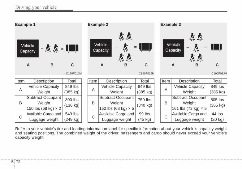
Driving your vehicle
725
C190F03JM
Item Description Total
AVehicle Capacity 849 lbs
Weight (385 kg)Subtract Occupant
B Weight 805 lbs
161 lbs (73 kg) × 5(365 kg)
CAvailable Cargo and 44 lbs
Luggage weight (20 kg)
A B C
Example 3
C190F02JM
Item Description Total
AVehicle Capacity 849 lbs
Weight (385 kg)Subtract Occupant
B Weight 750 lbs
150 lbs (68 kg) × 5(340 kg)
CAvailable Cargo and 99 lbs
Luggage weight (45 kg)
A B C
Example 2
C190F01JM
Item Description Total
AVehicle Capacity 849 lbs
Weight (385 kg)Subtract Occupant
B Weight 300 lbs
150 lbs (68 kg) × 2(136 kg)
CAvailable Cargo and 549 lbs
Luggage weight (249 kg)
Example 1
A B C
Refer to your vehicle’s tire and loading information label for specific information about your vehicle's capacity weightand seating positions. The combined weight of the driver, passengers and cargo should never exceed your vehicle'scapacity weight.

5 73
Driving your vehicle
Certification label
The certification label is located onthe driver's door sill at the center pil-lar.This label shows the maximumallowable weight of the fully loadedvehicle. This is called the GVWR(Gross Vehicle Weight Rating). TheGVWR includes the weight of thevehicle, all occupants, fuel andcargo.This label also tells you the maxi-mum weight that can be supportedby the front and rear axles, calledGross Axle Weight Rating (GAWR).
To find out the actual loads on yourfront and rear axles, you need to goto a weigh station and weigh yourvehicle.Your dealer can help you withthis. Be sure to spread out your loadequally on both sides of the center-line.
The label will help you decide howmuch cargo and installed equipmentyour vehicle can carry.
If you carry items inside your vehicle- like suitcases, tools, packages, oranything else - they are moving asfast as the vehicle. If you have to stopor turn quickly, or if there is a crash,the items will keep going and cancause an injury if they strike the driv-er or a passenger.
OEN056020
WARNING - Over loadingNever exceed the GVWR foryour vehicle, the GAWR foreither the front or rear axle andvehicle capacity weight.Exceeding these ratings canaffect your vehicle’s handlingand braking ability.

Driving your vehicle
745
✽✽ NOTICEOverloading your vehicle may causedamage. Repairs would not be cov-ered by your warranty. Do not over-load your vehicle.
WARNING - Over loadingDo not overload your vehicle.Overloading your vehicle cancause heat buildup in your vehi-cle's tires and possible tire fail-ure, increased stopping dis-tances and poor vehicle han-dling--all of which may result ina crash.
WARNING - Loose cargoDo not travel with unsecuredblunt objects in the passengercompartment of your vehicle(e.g. suit cases or unsecuredchild seats). These items maystrike occupant during a sud-den stop or crash.

5 75
Driving your vehicle
This chapter will guide you in theproper loading of your vehicle and/ortrailer, to keep your loaded vehicleweight within its design rating capa-bility, with or without a trailer.Properly loading your vehicle willprovide maximum return of the vehi-cle design performance. Before load-ing your vehicle, familiarize yourselfwith the following terms for determin-ing your vehicle's weight ratings, withor without a trailer, from the vehicle'sspecifications and the compliancelabel:
Base curb weight This is the weight of the vehicleincluding a full tank of fuel and allstandard equipment. It does notinclude passengers, cargo, or option-al equipment.
Vehicle curb weightThis is the weight of your new vehiclewhen you picked it up from your deal-er plus any aftermarket equipment.
Cargo weightThis figure includes all weight addedto the Base Curb Weight, includingcargo and optional equipment.
GAW (Gross axle weight)This is the total weight placed oneach axle (front and rear) - includingvehicle curb weight and all payload.
GAWR (Gross axle weight rating)This is the maximum allowableweight that can be carried by a singleaxle (front or rear). These numbersare shown on the compliance label.The total load on each axle mustnever exceed its GAWR.
GVW (Gross vehicle weight)This is the Base Curb Weight plusactual Cargo Weight plus passen-gers.
GVWR (Gross vehicle weight rating)This is the maximum allowableweight of the fully loaded vehicle(including all options, equipment,passengers and cargo). The GVWRis shown on the certification labellocated on the driver’s door sill.
VEHICLE WEIGHT

What to do in an emergency
Road warning . . . . . . . . . . . . . . . . . . . . . . . . . . . . . . 6-2• Hazard warning flasher . . . . . . . . . . . . . . . . . . . . . . . . 6-2
In case of an emergency while driving. . . . . . . . . . 6-3• If the engine stalls at a crossroad or crossing. . . . . . . 6-3• If you have a flat tire while driving . . . . . . . . . . . . . . . 6-3• If engine stalls while driving . . . . . . . . . . . . . . . . . . . . 6-3
If the engine will not start . . . . . . . . . . . . . . . . . . . . 6-4• If engine doesn’t turn over or turns over slowly . . . . 6-4• If engine turns over normally but does not start . . . . 6-4
Emergency starting . . . . . . . . . . . . . . . . . . . . . . . . . 6-5• Jump starting. . . . . . . . . . . . . . . . . . . . . . . . . . . . . . . . . 6-5• Push-starting . . . . . . . . . . . . . . . . . . . . . . . . . . . . . . . . . 6-7
If the engine overheats . . . . . . . . . . . . . . . . . . . . . . . 6-8Tire Pressure Monitoring System (TPMS) . . . . . . 6-9
• Low tire pressure indicator . . . . . . . . . . . . . . . . . . . . 6-10• TPMS malfunction indicator . . . . . . . . . . . . . . . . . . . 6-11• Changing a tire with TPMS . . . . . . . . . . . . . . . . . . . . 6-12
If you have a flat tire (with Spare Tire) . . . . . . . . 6-15• Jack and tools . . . . . . . . . . . . . . . . . . . . . . . . . . . . . . . 6-15• Removing and storing the spare tire . . . . . . . . . . . . . 6-16• Changing tires . . . . . . . . . . . . . . . . . . . . . . . . . . . . . . . 6-16• Use of temporary compact spare tire . . . . . . . . . . . . 6-21
If you have a flat tire (with Tire Mobility Kit) . . 6-23• Introduction . . . . . . . . . . . . . . . . . . . . . . . . . . . . . . . . . 6-23• Components of the Tire Mobility Kit . . . . . . . . . . . . 6-25• Using the Tire Mobility Kit . . . . . . . . . . . . . . . . . . . . 6-26• Distributing the sealant. . . . . . . . . . . . . . . . . . . . . . . . 6-27• Producing the tire inflation pressure. . . . . . . . . . . . . 6-27• Notes on the safe use of the Tire Mobility Kit . . . . . 6-28• Technical Data . . . . . . . . . . . . . . . . . . . . . . . . . . . . . . . 6-28
Towing . . . . . . . . . . . . . . . . . . . . . . . . . . . . . . . . . . . 6-29• Towing service . . . . . . . . . . . . . . . . . . . . . . . . . . . . . . . 6-29• Removable towing hook (front) . . . . . . . . . . . . . . . . . 6-30• Emergency towing . . . . . . . . . . . . . . . . . . . . . . . . . . . . 6-30
6

What to do in an emergency
26
ROAD WARNING Hazard warning flasher
The hazard warning flasher servesas a warning to other drivers to exer-cise extreme caution whenapproaching, overtaking, or passingyour vehicle.
It should be used whenever emer-gency repairs are being made orwhen the vehicle is stopped near theedge of a roadway.Depress the flasher switch with theignition switch in any position. Theflasher switch is located in the centerconsole switch panel. All turn signallights will flash simultaneously.
• The hazard warning flasher oper-ates whether your vehicle is run-ning or not.
• The turn signals do not work whenthe hazard flasher is on.
• Care must be taken when usingthe hazard warning flasher whilethe vehicle is being towed.
OTF064017

6 3
What to do in an emergency
If the engine stalls at a cross-road or crossingIf the engine stalls at a crossroad orcrossing, set the shift lever in the N(Neutral) position and then push thevehicle to a safe place.
If you have a flat tire whiledrivingIf a tire goes flat while you are driv-ing:1.Take your foot off the accelerator
pedal and let the vehicle slowdown while driving straight ahead.Do not apply the brakes immedi-ately or attempt to pull off the roadas this may cause a loss of control.When the vehicle has slowed downto such a speed that it is safe to doso, brake carefully and pull off theroad. Drive off the road as far aspossible and park on a firm levelground. If you are on a dividedhighway, do not park in the medianarea between the two traffic lanes.
2.When the vehicle is stopped, turnon your emergency hazard flash-ers, set the parking brake and putthe transaxle in P (automatictransaxle) or reverse (manualtransaxle).
3.Have all passengers get out of thevehicle. Be sure they all get out onthe side of the vehicle that is awayfrom traffic.
4.When changing a flat tire, followthe instruction provided later in thischapter.
If engine stalls while driving1.Reduce your speed gradually,
keeping a straight line. Move cau-tiously off the road to a safe place.
2.Turn on your emergency flashers.3.Try to start the engine again. If your
vehicle will not start, contact anauthorized Kia dealer or seek otherqualified assistance.
IN CASE OF AN EMERGENCY WHILE DRIVING

What to do in an emergency
46
IF THE ENGINE WILL NOT STARTIf the engine doesn't turn overor turns over slowly1.If your vehicle has an automatic
transaxle, be sure the shift lever isin N (Neutral) or P (Park) and theemergency brake is set.
2.Check the battery connections tobe sure they are clean and tight.
3.Turn on the interior light. If the lightdims or goes out when you operatethe starter, the battery is dis-charged.
4.Check the starter connections tobe sure they are securely tight-ened.
5.Do not push or pull the vehicle tostart it. See instructions for "Jumpstarting".
If engine turns over normallybut does not start1.Check fuel level.2.With the ignition switch in the
LOCK position, check all connec-tors at the ignition coil and sparkplugs. Reconnect any that may bedisconnected or loose.
3.Check the fuel line in the enginecompartment.
4.If the engine still does not start, callan authorized Kia dealer or seekother qualified assistance.
WARNING - Push/pullstart
Do not push or pull the vehicleto start it. Push or pull startingmay cause the catalytic con-verter to overload and create afire hazard.

6 5
What to do in an emergency
EMERGENCY STARTING
Connect cables in numerical orderand disconnect in reverse order.
Jump starting Jump starting can be dangerous ifdone incorrectly. Therefore, to avoidharm to yourself or damage to yourvehicle or battery, follow these jumpstarting procedures. If in doubt, westrongly recommend that you have acompetent technician or towing serv-ice jump start your vehicle.
CAUTION - 12 volt batteryUse only a 12-volt jumper sys-tem. You can damage a 12-voltstarting motor, ignition system,and other electrical partsbeyond repair by use of a 24-volt power supply (either two12-volt batteries in series or a24-volt motor generator set).
WARNING - BatteryKeep all flames or sparks awayfrom the battery. The batteryproduces hydrogen gas whichwill explode if exposed to flameor sparks.
WARNING - BatteryNever attempt to check the elec-trolyte level of the battery asthis may cause the battery torupture or explode.
WARNING - Frozen batteries
Do not attempt to jump start thevehicle if the discharged batteryis frozen or if the electrolytelevel is low as the battery mayrupture or explode.
WARNING - Sulfuric acidrisk
When jump starting your vehi-cle be careful not to get acid onyourself, your clothing or on thevehicle. Automobile batteriescontain sulfuric acid. This ispoisonous and highly corro-sive.
1VQA4001
Discharged battery
Jumper Cables
Booster battery
(-)
(+)
(+)(-)

What to do in an emergency
66
Jump starting procedure Absorbent Glass Matt (AGM) batter-ies are maintenance-free and shouldonly be serviced by an authorizedKia dealer. For charging your AGMbattery, use only fully automatic bat-tery chargers that are speciallydeveloped for AGM batteries.When replacing the AGM battery,use only the Kia genuine battery forthe ISG system.
✽✽ NOTICEIf the AGM battery is reconnectedor replaced, ISG function will notoperate immediately.If you want to use the ISG function,the battery sensor needs to be cali-brated for approximately 4 hourswith the ignition off and then, turnthe engine on and off 2 or 3 times.
1.Make sure the booster battery is12-volt and that its negative termi-nal is grounded.
2.If the booster battery is in anothervehicle, do not allow the vehicles totouch.
3.Turn off all unnecessary electricalloads.
4.Connect the jumper cables in theexact sequence shown in the illus-tration. First connect one end of ajumper cable to the positive termi-nal of the discharged battery (1),then connect the other end to thepositive terminal on the boosterbattery (2).Proceed to connect one end of theother jumper cable to the negativeterminal of the booster battery (3),then the other end to a solid, sta-tionary, metallic point (for example,the engine lifting bracket) awayfrom the battery (4). Do not con-nect it to or near any part thatmoves when the engine is cranked.
CAUTION - AGM batterycap
Do not open or remove the capon top of the battery. This maycause the leak of dangerousinternal electrolytes.

6 7
What to do in an emergency
Do not allow the jumper cables tocontact anything except the correctbattery terminals or the correctground. Do not lean over the bat-tery when making connections.
5.Start the engine of the vehicle withthe booster battery and let it run at2,000 rpm, then start the engine ofthe vehicle with the dischargedbattery.
If the cause of your battery discharg-ing is not apparent, you should haveyour vehicle checked by an author-ized Kia dealer.
Push-starting Your manual transaxle-equippedvehicle should not be push-startedbecause it might damage the emis-sion control system.Vehicles equipped with automatictransaxle cannot be push-started.Follow the directions in this chapterfor jump-starting.
WARNING - Tow startingvehicle
Never tow a vehicle to start itbecause the sudden surge for-ward when the engine startscould cause a collision with thetow vehicle.
CAUTION - Battery cablesDo not connect the jumpercable from the negative terminalof the booster battery to thenegative terminal of the dis-charged battery. This can causethe discharged battery to over-heat and crack, releasing bat-tery acid.
What to do in an emergency
86
IF THE ENGINE OVERHEATSIf your temperature gauge indicatesoverheating, you will experience aloss of power, or hear loud pinging orknocking, the engine is probably toohot. If this happens, you should:
1.Pull off the road and stop as soonas it is safe to do so.
2.Place the shift lever in P (automat-ic transaxle) or neutral (manualtransaxle) and set the parkingbrake. If the air conditioning is on,turn it off.
3.If engine coolant is running outunder the vehicle or steam is com-ing out from underneath the hood,stop the engine. Do not open thehood until the coolant has stoppedrunning or the steaming hasstopped. If there is no visible lossof engine coolant and no steam,leave the engine running andcheck to be sure the engine cool-ing fan is operating. If the fan is notrunning, turn the engine off.
4.Check to see if the water pumpdrive belt is missing. If it is notmissing, check to see that it istight. If the drive belt seems to besatisfactory, check for coolant leak-ing from the radiator, hoses orunder the vehicle. (If the air condi-tioning had been in use, it is nor-mal for cold water to be drainingfrom it when you stop).
5.If the water pump drive belt is bro-ken or engine coolant leaks, stopthe engine immediately and callthe nearest authorized Kia dealerfor assistance.
6.If you cannot find the cause of theoverheating, wait until the enginetemperature has returned to nor-mal. Then, if coolant has been lost,carefully add coolant to the reser-voir to bring the fluid level in thereservoir up to the halfway mark.
7.Proceed with caution, keepingalert for further signs of overheat-ing. If overheating happens again,call an authorized Kia dealer forassistance.
Serious loss of coolant indicatesthere is a leak in the cooling systemand this should be checked as soonas possible by an authorized Kiadealer.
WARNING - Under thehood
While the engine is running,keep hair, hands and clothingaway from moving parts suchas the fan and drive belts.
WARNING - Radiator capDo not remove the radiator capwhen the engine is hot.This canallow coolant to be blown out ofthe opening and cause seriousburns.

6 9
What to do in an emergency
TIRE PRESSURE MONITORING SYSTEM (TPMS)
(1) Low tire pressure telltale / TPMS malfunction indicator
(2) Low tire pressure position telltale.(shown on the LCD display)
Each tire, including the spare (if pro-vided), should be checked monthlywhen cold and inflated to the inflationpressure recommended by the vehi-cle manufacturer on the vehicle plac-ard or tire inflation pressure label. (Ifyour vehicle has tires of a differentsize than the size indicated on thevehicle placard or tire inflation pres-sure label, you should determine theproper tire inflation pressure forthose tires.)As an added feature, your vehiclehas been equipped with a tire pres-sure monitoring system (TPMS) thatilluminates a low tire pressure telltalewhen one or more of your tires is sig-nificantly under-inflated. Accordingly,when the low tire pressure telltaleilluminates, you should stop andcheck your tires as soon as possible,and inflate them to the proper pres-sure. Driving on a significantly under-inflated tire causes the tire to over-heat and can lead to tire failure.Under-inflation also reduces fuel effi-ciency and tire tread life, and mayaffect the vehicle’s handling andstopping ability.
Please note that the TPMS is not asubstitute for proper tire mainte-nance, and it is the driver’s responsi-bility to maintain correct tire pres-sure, even if under-inflation has notreached the level to trigger illumina-tion of the TPMS low tire pressuretelltale.Your vehicle has also been equippedwith a TPMS malfunction indicator toindicate when the system is notoperating properly. The TPMS mal-function indicator is combined withthe low tire pressure telltale. Whenthe system detects a malfunction,the telltale will flash for approximate-ly one minute and then remain con-tinuously illuminated. This sequencewill continue upon subsequent vehi-cle start-ups as long as the malfunc-tion exists. When the malfunctionindicator is illuminated, the systemmay not be able to detect or signallow tire pressure as intended. TPMSmalfunctions may occur for a varietyof reasons, including the installationof replacement or alternate tires orwheels on the vehicle that preventthe TPMS from functioning properly.
OTF064001■ Type A ■ Type B
OTF044169L/OTF044185L

What to do in an emergency
106
Always check the TPMS malfunctiontelltale after replacing one or moretires or wheels on your vehicle toensure that the replacement or alter-nate tires and wheels allow theTPMS to continue to function proper-ly.
✽✽ NOTICEIf any of the below happens, havethe system be checked by an author-ized Kia dealer.1.The low tire pressure telltale/
TPMS malfunction indicator donot illuminate for 3 seconds whenthe ignition switch is turned to theON or engine is running.
2.The TPMS malfunction indicatorremains illuminated after blinkingfor approximately 1 minute.
3.The Low tire pressure positiontelltale remains illuminated.
Low tire pressuretelltale
Low tire pressure position tell-tale
When the tire pressure monitoringsystem warning indicators are illumi-nated and warning massage dis-played on the cluster LCD display,one or more of your tires is signifi-cantly under-inflated. The low tirepressure position telltale light willindicate which tire is significantlyunder-inflated by illuminating the cor-responding position light.
If the telltale illuminates, immediatelyreduce your speed, avoid hard cor-nering and anticipate increased stop-ping distances. You should stop andcheck your tires as soon as possible.Inflate the tires to the proper pres-sure as indicated on the vehicle’splacard or tire inflation pressure labellocated on the driver’s side center pil-lar outer panel. If you cannot reach aservice station or if the tire cannothold the newly added air, replace thelow pressure tire with the spare tire.Then the Low Tire Pressure telltalemay flash for approximately oneminute and then remain continuouslyilluminated after restarting and about20 minutes of continuous drivingbefore you have the low pressure tirerepaired and replaced on the vehicle.In winter or cold weather, the low tirepressure telltale may be illuminated ifthe tire pressure was adjusted to therecommended tire inflation pressurein warm weather. It does not meanyour TPMS is malfunctioningbecause the decreased temperatureleads to a proportional lowering oftire pressure.
OTF044169L/OTF044185L
■ Type A ■ Type B

6 11
What to do in an emergency
When you drive your vehicle from awarm area to a cold area or from acold area to a warm area, or the out-side temperature is greatly higher orlower, you should check the tire infla-tion pressure and adjust the tires tothe recommended tire inflation pres-sure.
TPMS (Tire PressureMonitoring System)malfunction indicator
The TPMS malfunction indicator willilluminate after it blinks for approxi-mately one minute when there is aproblem with the Tire PressureMonitoring System. Have the systemchecked by an authorized Kia dealeras soon as possible to determine thecause of the problem.
✽✽ NOTICEIf there is a malfunction with theTPMS, the low tire pressure positiontelltale will not be displayed eventhough the vehicle has an under-inflated tire.
The TPMS malfunction indicator maybe illuminated if the vehicle is movingaround electric power supply cablesor radios transmitter such as atpolice stations, government and pub-lic offices, broadcasting stations, mil-itary installations, airports, or trans-mitting towers, etc. This can interferewith normal operation of the TirePressure Monitoring System(TPMS).The TPMS malfunction indicator mayilluminate if snow chains or someseparately purchased devices suchas notebook computers, mobilecharger, remote starter, navigationetc. are used in the vehicle. This caninterfere with normal operation of theTire Pressure Monitoring System(TPMS).
WARNING - Low pressuredamage
Significantly low tire pressuremakes the vehicle unstable andcan contribute to loss of vehiclecontrol and increased brakingdistances.Continued driving on low pres-sure tires can cause the tires tooverheat and fail.
What to do in an emergency
126
Changing a tire with TPMSIf you have a flat tire, the Low TirePressure will come on. Have the flattire repaired by an authorized Kiadealer as soon as possible orreplace the flat tire with the sparetire.
Each wheel is equipped with a tirepressure sensor mounted inside thetire behind the valve stem. You mustuse TPMS specific wheels. It is rec-ommended that you always haveyour tires serviced by an authorizedKia dealer.
Even if you replace the low pressuretire with the spare tire, the Low TirePressure telltale will blink or remainon until the low pressure tire isrepaired and placed on the vehicle.After you replace the low pressuretire with the TPMS spare tire, theLow Tire Pressure telltale may blinkor illuminate after a few minutesbecause the TPMS sensor mountedon the spare wheel is not initiated.Once the low pressure tire is reinflat-ed to the recommended pressureand installed on the vehicle or theTPMS sensor mounted on thereplaced spare wheel is initiated byan authorized Kia dealer, the TPMSmalfunction indicator and the low tirepressure telltale will extinguish withina few minutes of driving.If the indicator is not extinguishedafter a few minutes of driving, pleasevisit an authorized Kia dealer.
CAUTIONNEVER use a puncture-repair-ing agent to repair and/or inflatea low pressure tire. The tiresealant can damage the tirepressure sensor. If used, youwill have to replace the tire pres-sure sensor.
CAUTIONIf an original mounted tire isreplaced with the spare tire, theTPMS sensor on the replacedspare wheel should be initiatedand the TPMS sensor on theoriginal mounted wheel shouldbe deactivated. If the TPMS sen-sor on the original mountedwheel located in the spare tirecarrier still activates, the tirepressure monitoring systemmay not operate properly. Havethe tire with TPMS serviced orreplaced by an authorized Kiadealer.

6 13
What to do in an emergency
You may not be able to identify a lowtire by simply looking at it. Alwaysuse a good quality tire pressuregauge to measure the tire's inflationpressure. Please note that a tire thatis hot (from being driven) will have ahigher pressure measurement than atire that is cold (from sitting station-ary for at least 3 hours and drivenless than 1 mile (1.6 km) during that3 hour period).Allow the tire to cool before measur-ing the inflation pressure. Always besure the tire is cold before inflating tothe recommended pressure.
A cold tire means the vehicle hasbeen sitting for 3 hours and driven forless than 1 mile (1.6 km) in that 3hour period.
CAUTIONDo not use any tire sealant ifyour vehicle is equipped with aTire Pressure MonitoringSystem. The liquid sealant candamage the tire pressure sen-sors.
WARNING - TPMS• The TPMS cannot alert you to
severe and sudden tire dam-age caused by external fac-tors such as nails or roaddebris.
• If you feel any vehicle instabil-ity, immediately take your footoff the accelerator, apply thebrakes gradually and withlight force, and slowly move toa safe position off the road.

What to do in an emergency
146
This device complies with Part15 of the FCC rules.Operation is subject to the followingtwo conditions:1.This device may not cause harmful
interference, and 2.This device must accept any inter-
ference received, including inter-ference that may cause undesiredoperation.
WARNING - ProtectingTPMS
Tampering with, modifying, ordisabling the Tire PressureMonitoring System (TPMS)components may interfere withthe system's ability to warn thedriver of low tire pressure con-ditions and/or TPMS malfunc-tions. Tampering with, modify-ing, or disabling the TirePressure Monitoring System(TPMS) components may voidthe warranty for that portion ofthe vehicle.
WARNING Changes or modifications notexpressly approved by the partyresponsible for compliancecould void the user’s authorityto operate the equipment.
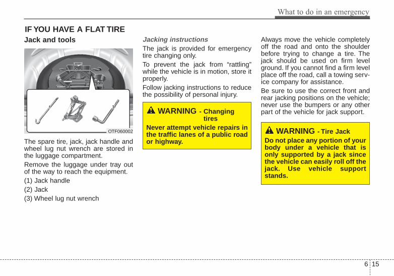
6 15
What to do in an emergency
IF YOU HAVE A FLAT TIREJack and tools
The spare tire, jack, jack handle andwheel lug nut wrench are stored inthe luggage compartment.Remove the luggage under tray outof the way to reach the equipment.(1) Jack handle(2) Jack(3) Wheel lug nut wrench
Jacking instructions The jack is provided for emergencytire changing only.To prevent the jack from “rattling”while the vehicle is in motion, store itproperly.Follow jacking instructions to reducethe possibility of personal injury.
Always move the vehicle completelyoff the road and onto the shoulderbefore trying to change a tire. Thejack should be used on firm levelground. If you cannot find a firm levelplace off the road, call a towing serv-ice company for assistance.Be sure to use the correct front andrear jacking positions on the vehicle;never use the bumpers or any otherpart of the vehicle for jack support.
WARNING - Tire JackDo not place any portion of yourbody under a vehicle that isonly supported by a jack sincethe vehicle can easily roll off thejack. Use vehicle supportstands.
WARNING - Changingtires
Never attempt vehicle repairs inthe traffic lanes of a public roador highway.
OTF060002

What to do in an emergency
166
Do not allow anyone to remain in thevehicle while it is on the jack.Make sure any children present arein a secure place away from the roadand from the vehicle to be raised withthe jack.
Removing and storing thespare tire
Turn the tire hold-down wing boltcounterclockwise.Store the tire in the reverse order ofremoval.To prevent the spare tire and toolsfrom “rattling” while the vehicle is inmotion, store them properly.
Changing tires
1.Park on a level surface and applythe parking brake firmly.
2.Shift the shift lever into R(Reverse) for manual transaxle orP (Park) for automatic transaxle.
3.Activate the hazard warning flash-er.
OED066033
WARNING - Runningvehicle on jack
Do not start or run the engine ofthe vehicle while the vehicle ison the jack as this may causethe vehicle to fall off the jack.
ONF068004

6 17
What to do in an emergency
4.Remove the wheel lug nut wrench,jack, jack handle, and spare tirefrom the vehicle.
5.Block both the front and rear of thewheel that is diagonally oppositethe jack position.
To prevent vehicle movement whilechanging a tire, always set the park-ing brake fully, and always block thewheel diagonally opposite the wheelbeing changed.We recommend that the wheels ofthe vehicle be chocked, and that noperson remain in a vehicle that isbeing jacked.
6.Loosen the wheel lug nuts counter-clockwise one turn each, but donot remove any nut until the tirehas been raised off the ground.
1JBA6504 OTF064004

What to do in an emergency
186
7.Place the jack at the front (1) orrear (2) jacking position closest tothe tire you are changing. Place thejack at the designated locationsunder the frame. The jacking posi-tions are plates welded to theframe with two tabs and a raiseddot to index with the jack.
8.Insert the jack handle into the jackand turn it clockwise, raising thevehicle until the tire just clears theground. This measurement isapproximately 1 in (30 mm). Beforeremoving the wheel lug nuts, makesure the vehicle is stable and thatthere is no chance for movementor slippage.
9.Loosen the wheel nuts and removethem with your fingers. Slide thewheel off the studs and lay it flat soit cannot roll away. To put thewheel on the hub, pick up thespare tire, line up the holes withthe studs and slide the wheel ontothem. If this is difficult, tip the wheelslightly and get the top hole in thewheel lined up with the top stud.Then jiggle the wheel back andforth until the wheel can be slidover the other studs.
OTF064020
OTF064019
OTF064008
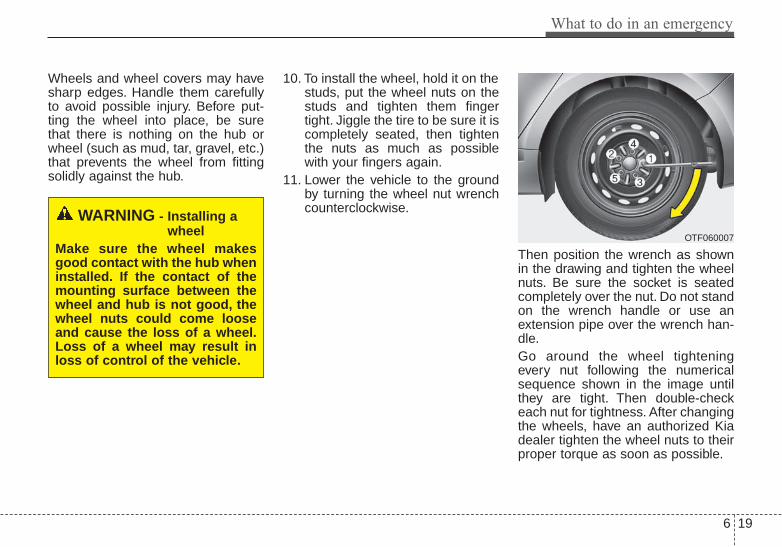
6 19
What to do in an emergency
Wheels and wheel covers may havesharp edges. Handle them carefullyto avoid possible injury. Before put-ting the wheel into place, be surethat there is nothing on the hub orwheel (such as mud, tar, gravel, etc.)that prevents the wheel from fittingsolidly against the hub.
10. To install the wheel, hold it on thestuds, put the wheel nuts on thestuds and tighten them fingertight. Jiggle the tire to be sure it iscompletely seated, then tightenthe nuts as much as possiblewith your fingers again.
11. Lower the vehicle to the groundby turning the wheel nut wrenchcounterclockwise.
Then position the wrench as shownin the drawing and tighten the wheelnuts. Be sure the socket is seatedcompletely over the nut. Do not standon the wrench handle or use anextension pipe over the wrench han-dle.Go around the wheel tighteningevery nut following the numericalsequence shown in the image untilthey are tight. Then double-checkeach nut for tightness. After changingthe wheels, have an authorized Kiadealer tighten the wheel nuts to theirproper torque as soon as possible.
WARNING - Installing awheel
Make sure the wheel makesgood contact with the hub wheninstalled. If the contact of themounting surface between thewheel and hub is not good, thewheel nuts could come looseand cause the loss of a wheel.Loss of a wheel may result inloss of control of the vehicle.
OTF060007
What to do in an emergency
206
Wheel nut tightening torque:Steel wheel & aluminium alloy wheel:65~79 lb.ft (9~11 kg.m)
If you have a tire gauge, remove thevalve cap and check the air pressure.If the pressure is lower than recom-mended, drive slowly to the nearestservice station and inflate to the cor-rect pressure. If it is too high, adjustit until it is correct. Always reinstallthe valve cap after checking oradjusting the tire pressure. If the capis not replaced, air may leak from thetire. If you lose a valve cap, buyanother and install it as soon as pos-sible.After you have changed wheels,always secure the flat tire in its placeand return the jack and tools to theirproper storage locations.
Note that most lug nuts do not havemetric threads. Be sure to useextreme care in checking for threadstyle before installing aftermarket lugnuts or wheels. If in doubt, consult anauthorized Kia dealer.
To prevent the jack, jack handle,wheel lug nut wrench and spare tirefrom rattling while the vehicle is inmotion, store them properly.
CAUTION - Reducing lugnuts
Make certain during wheelremoval that the same nuts thatwere removed are reinstalled -or, if replaced, that nuts withmetric threads and the samechamfer configuration are used.Your vehicle has metric threadson the wheel studs and nuts.Installation of a non-metricthread nut on a metric stud willnot secure the wheel to the hubproperly and will damage thestud so that it must be replaced.
WARNING - Wheel studsDo not drive your vehicle withdamaged wheel studs. If thestuds are damaged, they maylose their ability to retain thewheel. This could lead to theloss of the wheel and a colli-sion.
WARNING - Inadequatespare tire pressure
Check the inflation pressuresas soon as possible afterinstalling the spare tire. Adjustit to the specified pressure, ifnecessary. Refer to “Tires andwheels” in chapter 8.

6 21
What to do in an emergency
Important - use of compact sparetire (if equipped)Your vehicle is equipped with a com-pact spare tire. This compact sparetire takes up less space than a regu-lar-size tire. This tire is smaller than aconventional tire and is designed fortemporary use only.
The compact spare should be inflat-ed to 60 psi (420 kPa).
✽✽ NOTICECheck the inflation pressure afterinstalling the spare tire. Adjust it tothe specified pressure, as necessary.
When using a compact spare tire,observe the following precautions:• Under no circumstances should
you exceed 50 mph (80 km/h); ahigher speed could damage thetire.
• Ensure that you drive slowlyenough for the road conditions toavoid all hazards. Any road hazard,such as a pothole or debris, couldseriously damage the compactspare.
• Any continuous road use of this tirecould result in tire failure, loss ofvehicle control, and possible per-sonal injury.
• Do not exceed the vehicle’s maxi-mum load rating or the load-carry-ing capacity shown on the sidewallof the compact spare tire.
• Avoid driving over obstacles. Thecompact spare tire diameter issmaller than the diameter of a con-ventional tire and reduces theground clearance approximately 1 inch (25 mm), which could resultin damage to the vehicle.
CAUTION• You should drive carefully
when the compact spare is inuse. The compact spareshould be replaced by theproper conventional tire andrim at the first opportunity.
• The operation of this vehicleis not recommended withmore than one compact sparetire in use at the same time.
WARNINGThe compact spare tire is foremergency use only. Do notoperate your vehicle on thiscompact spare at speeds over50 mph (80 km/h). The originaltire should be repaired orreplaced as soon as possible toavoid failure of the spare possi-bly leading to personal injury ordeath.
What to do in an emergency
226
• Do not take this vehicle through anautomatic car wash while the com-pact spare tire is installed.
• Do not use tire chains on the com-pact spare tire. Because of thesmaller size, a tire chain will not fitproperly. This could damage thevehicle and result in loss of thechain.
• The compact spare tire should notbe installed on the front axle if thevehicle must be driven in snow oron ice.
• Do not use the compact spare tireon any other vehicle because thistire has been designed especiallyfor your vehicle.
• The compact spare tire’s tread lifeis shorter than a regular tire.Inspect your compact spare tireregularly and replace worn com-pact spare tires with the same sizeand design, mounted on the samewheel.
• The compact spare tire should notbe used on any other wheels, norshould standard tires, snow tires,wheel covers or trim rings be usedwith the compact spare wheel. Ifsuch use is attempted, damage tothese items or other car compo-nents may occur.
• Do not use more than one compactspare tire at a time.
• Do not tow a trailer while the com-pact spare tire is installed.
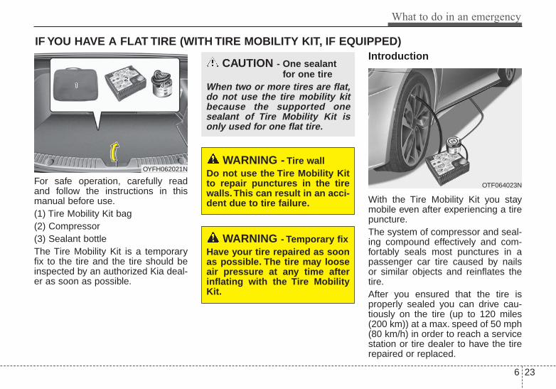
6 23
What to do in an emergency
IF YOU HAVE A FLAT TIRE (WITH TIRE MOBILITY KIT, IF EQUIPPED)
For safe operation, carefully readand follow the instructions in thismanual before use.(1) Tire Mobility Kit bag(2) Compressor(3) Sealant bottleThe Tire Mobility Kit is a temporaryfix to the tire and the tire should beinspected by an authorized Kia deal-er as soon as possible.
Introduction
With the Tire Mobility Kit you staymobile even after experiencing a tirepuncture.The system of compressor and seal-ing compound effectively and com-fortably seals most punctures in apassenger car tire caused by nailsor similar objects and reinflates thetire.After you ensured that the tire isproperly sealed you can drive cau-tiously on the tire (up to 120 miles(200 km)) at a max. speed of 50 mph(80 km/h) in order to reach a servicestation or tire dealer to have the tirerepaired or replaced.
OTF064023N
OYFH062021NWARNING - Tire wall
Do not use the Tire Mobility Kitto repair punctures in the tirewalls. This can result in an acci-dent due to tire failure.
WARNING - Temporary fixHave your tire repaired as soonas possible. The tire may looseair pressure at any time afterinflating with the Tire MobilityKit.
CAUTION - One sealantfor one tire
When two or more tires are flat,do not use the tire mobility kitbecause the supported onesealant of Tire Mobility Kit isonly used for one flat tire.
What to do in an emergency
246
It is possible that some tires, espe-cially with larger punctures or dam-age to the sidewall, cannot be sealedcompletely.Air pressure loss in the tire mayadversely affect tire performance.For this reason, you should avoidabrupt steering or other drivingmaneuvers, especially if the vehicleis heavily loaded or if a trailer is inuse.The Tire Mobility Kit is not designedor intended as a permanent tirerepair method and is to be used forone tire only.This instruction shows you step bystep procedure to temporarily sealthe puncture.Read the section "Notes on the safeuse of the Tire Mobility Kit".
Notes on the safe use of theTire Mobility Kit• Park your car at the side of the
road so that you can work with theTire Mobility Kit away from movingtraffic.
• To be sure your vehicle will notmove, even when you're on fairlylevel ground, always set your park-ing brake.
• Only use the Tire Mobility Kit forsealing/inflation passenger cartires. Only punctured areas locatedwithin the tread region of the tirecan be sealed using the tire mobil-ity kit.
• Do not use on motorcycles, bicy-cles or any other type of tires.
• When the tire and wheel are dam-aged, do not use Tire Mobility Kitfor your safety.
• Use of the Tire Mobility Kit may notbe effective for tire damage largerthan approximately 0.24 in (6 mm).Please contact the nearest Kiadealership if the tire cannot bemade roadworthy with the TireMobility Kit.
• Do not use the Tire Mobility Kit if atire is severely damaged by drivingrun flat or with insufficient air pres-sure.
• Do not remove any foreign objectssuch as nails or screws that havepenetrated the tire.
• Provided the car is outdoors, leavethe engine running. Otherwiseoperating the compressor mayeventually drain the car battery.
• Never leave the Tire Mobility Kitunattended while it is being used.
• Do not leave the compressor run-ning for more than 10 min. at a timeor it may overheat.
• Do not use the Tire Mobility Kit ifthe ambient temperature is below -22°F (-30°C).

6 25
What to do in an emergency
0. Speed restriction label1. Sealant bottle and label with
speed restriction2. Filling hose from sealant bottle to
wheel3. Connectors and cable for the
power outlet direct connection
4. Holder for the sealant bottle5. Compressor6. On/off switch7. Pressure gauge for displaying the
tire inflation pressure8. Button for reducing tire inflation
pressure
9. Hose to connect compressor andsealant bottle or compressor andwheel
Connectors, cable and connectionhose are stored in the compressorhousing.
Strictly follow the specifiedsequence, otherwise the sealantmay escape under high pressure.
OEL069020
WARNING - Sealant• Keep out of reach of children.• Avoid contact with eyes.• Do not swallow.
Components of the TireMobilityKit
WARNING - Expiredsealant
Do not use the Tire sealant afterthe sealant has expired (i.e.pasted the expiration date onthe sealant container). This canincrease the risk of tire failure.
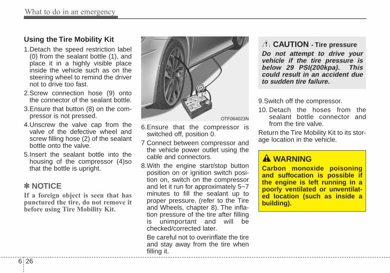
What to do in an emergency
266
Using the Tire Mobility Kit1.Detach the speed restriction label
(0) from the sealant bottle (1), andplace it in a highly visible placeinside the vehicle such as on thesteering wheel to remind the drivernot to drive too fast.
2.Screw connection hose (9) ontothe connector of the sealant bottle.
3.Ensure that button (8) on the com-pressor is not pressed.
4.Unscrew the valve cap from thevalve of the defective wheel andscrew filling hose (2) of the sealantbottle onto the valve.
5.Insert the sealant bottle into thehousing of the compressor (4)sothat the bottle is upright.
✽✽ NOTICEIf a foreign object is seen that haspunctured the tire, do not remove itbefore using Tire Mobility Kit.
6.Ensure that the compressor isswitched off, position 0.
7 Connect between compressor andthe vehicle power outlet using thecable and connectors.
8.With the engine start/stop buttonposition on or ignition switch posi-tion on, switch on the compressorand let it run for approximately 5~7minutes to fill the sealant up toproper pressure. (refer to the Tireand Wheels, chapter 8). The infla-tion pressure of the tire after fillingis unimportant and will bechecked/corrected later.Be careful not to overinflate the tireand stay away from the tire whenfilling it.
9.Switch off the compressor.10. Detach the hoses from the
sealant bottle connector andfrom the tire valve.
Return the Tire Mobility Kit to its stor-age location in the vehicle.
WARNINGCarbon monoxide poisoningand suffocation is possible ifthe engine is left running in apoorly ventilated or unventilat-ed location (such as inside abuilding).
OTF064023N
CAUTION - Tire pressureDo not attempt to drive yourvehicle if the tire pressure isbelow 29 PSI(200kpa). Thiscould result in an accident dueto sudden tire failure.

6 27
What to do in an emergency
Distributing the sealant11. Immediately drive approximately
4~6miles (7~10km or, about10min) to evenly distribute thesealant in the tire.
Do not exceed a speed of 50 mph(80 km/h). If possible, do not fallbelow a speed of 12 mph (20 km/h).While driving, if you experience anyunusual vibration, ride disturbance ornoise, reduce your speed and drivewith caution until you can safely pulloff of the side of the road.Call for road side service or towing.When you use the Tire Mobility Kit,the tire pressure sensor valve stemand wheel may be stained bysealant. After use wipe off sealantresidue and inspect. Consult you Kiadealership if necessary.
Checking the tire inflationpressure1.After driving approximately 4 ~ 6
miles (7 ~ 10 km or about 10 min),stop at a safe location.
2.Connect connection hose (9) of thecompressor directly to the tirevalve.
3.Plug the compressor power cordinto the vehicle power outlet.
4.Adjust the tire inflation pressure tothe recomended tire inflation.With the ignition switch on, pro-ceed as follows.- To increase the inflation pres-
sure : Switch on the compressor,position I. To check the currentinflation pressure setting, brieflyswitch off the compressor.
✽✽ NOTICEThe pressure gauge may show high-er than actual reading when thecompressor is running. To get anaccurate tire reading, the compres-sor needs to be turned off.
- To reduce the inflation pres-sure: Press the button 8 on thecompressor.
CAUTION - Tire pressuresensor
When you use the Tire MobilityKit including sealant notapproved by Kia, the tire pres-sure sensors may be damagedby sealant. The sealant on thetire pressure sensor and wheelshould be removed when youreplace the tire with a new oneand inspect the tire pressuresensors at an authorized dealer.

What to do in an emergency
286
Notes on the safe use of theTire Mobility Kit• Park your car at the side of the
road so that you can work with theTMK away from moving traffic.Place your warning triangle in aprominent place to make passingvehicles aware of your location.
• To be sure your vehicle will notmove, even when you're on fairlylevel ground, always set your park-ing brake.
• Only use the TMK for sealing/infla-tion passenger car tires. Do notuse on motorcycles, bicycles orany other type of tires.
• Do not remove any foreign objects-such as nails or screws -that havepenetrated the tire.
• Before using the TMK, read theprecautionary advice printed onthe sealant bottle!
• Provided the car is outdoors, leavethe engine running. Otherwiseoperating the compressor mayeventually drain the car battery.
• Never leave the TMK unattendedwhile it is being used.
• Do not leave the compressor run-ning for more than 10 min. at a timeor it may overheat.
• Do not use the TMK if the ambienttemperature is below -22°F (-30°C).
• When the tire and wheel are dam-aged, do not use Tire Mobility Kitfor your safety.
Technical DataSystem voltage: DC 12 VWorking voltage: DC 10 - 15 VAmperage rating: max. 15 ASuitable for use at temperatures:
-22 ~ +158°F (-30 ~ +70°C)Max. working pressure:
87 psi (6 bar)Size Compressor: 6.6 x 5.9 x 2.7 in.
(168 x 150 x 68 mm)Sealant bottle: 4.1 x ø 3.3 in.
(104 x ø 85 mm)Compressor weight:
2.31 lbs (1.05 kg)Sealant volume:
18.3 cu. in. (300 ml)Sealant warranty:
5 years (sealant.)

6 29
What to do in an emergency
TOWINGTowing service
If emergency towing is necessary,we recommend having it done by anauthorized Kia dealer or a commer-cial tow-truck service. Proper liftingand towing procedures are neces-sary to prevent damage to the vehi-cle. The use of wheel dollies orflatbed is recommended.For trailer towing guidelines informa-tion, refer to “Trailer towing” in chap-ter 5.It is acceptable to tow the vehiclewith the rear wheels on the ground(without dollies) and the front wheelsoff the ground.
If any of the loaded wheels or sus-pension components are damagedor the vehicle is being towed with thefront wheels on the ground, use atowing dolly under the front wheels.When being towed by a commercialtow truck and wheel dollies are notused, the front of the vehicle shouldalways be lifted, not the rear.
✽✽ NOTICEIf the EPB does not release normal-ly, take your vehicle to an author-ized Kia dealer by loading the vehi-cle on a flatbed tow truck and havethe system checked.
CAUTION - Towing• Do not tow the vehicle back-
wards with the front wheels onthe ground as this may causedamage to the vehicle.
• Do not tow with sling-typeequipment. Use wheel lift orflatbed equipment.
OMC045012
A
BHXD02
HXD03
ddddoooo llll llll yyyy
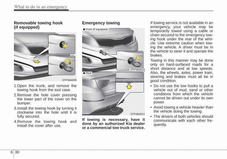
What to do in an emergency
306
Removable towing hook (if equipped)
1.Open the trunk, and remove thetowing hook from the tool case.
2.Remove the hole cover pressingthe lower part of the cover on thebumper.
3.Install the towing hook by turning itclockwise into the hole until it isfully secured.
4.Remove the towing hook andinstall the cover after use.
Emergency towing
If towing is necessary, have itdone by an authorized Kia dealeror a commercial tow truck service.
If towing service is not available in anemergency, your vehicle may betemporarily towed using a cable orchain secured to the emergency tow-ing hook under the rear of the vehi-cle. Use extreme caution when tow-ing the vehicle. A driver must be inthe vehicle to steer it and operate thebrakes.Towing in this manner may be doneonly on hard-surfaced roads for ashort distance and at low speeds.Also, the wheels, axles, power train,steering and brakes must all be ingood condition.• Do not use the tow hooks to pull a
vehicle out of mud, sand or otherconditions from which the vehiclecannot be driven out under its ownpower.
• Avoid towing a vehicle heavier thanthe vehicle doing the towing.
• The drivers of both vehicles shouldcommunicate with each other fre-quently.
OTF064009
OTF064010
OTF064011
■ Front (if equipped)
■ Rear

6 31
What to do in an emergency
• Before emergency towing, checkthat the hook is not broken or dam-aged.
• Fasten the towing cable or chainsecurely to the hook.
• Do not jerk the hook. Apply steadyand even force.
• To avoid damaging the hook, donot pull from the side or at a verti-cal angle. Always pull straightahead.
• Use a towing strap less than 16feet (5 m) long. Attach a white orred cloth (about 12 inches (30 cm)wide) in the middle of the strap foreasy visibility.
• Drive carefully so that the towingstrap is not loosened during tow-ing.
CAUTION• Attach a towing strap to the
tow hook.• Using a portion of the vehicle
other than the tow hooks fortowing may damage the bodyof your vehicle.
• Use only a cable or chainspecifically intended for usein towing vehicles. Securelyfasten the cable or chain tothe towing hook provided.
WARNING Use extreme caution when tow-ing the vehicle.• Avoid sudden starts or erratic
driving maneuvers whichwould place excessive stresson the emergency towinghook and towing cable orchain. The hook and towingcable or chain may break andcause serious injury or dam-age.
• If the disabled vehicle isunable to be moved, do notforcibly continue the towing.Contact an authorized Kiadealer or a commercial towtruck service for assistance.
• Tow the vehicle as straightahead as possible.
• Keep away from the vehicleduring towing.
OYF069017

What to do in an emergency
326
Emergency towing precautions• Place the ignition switch in ACC so
the steering wheel isn’t locked.• Place the transaxle shift lever in N
(Neutral).• Release the parking bake.• Press the brake pedal with more
force than normal since you willhave reduced brake performance.
• More steering effort will berequired because the power steer-ing system will be disabled.
• If you are driving down a long hill,the brakes may overheat and brakeperformance will be reduced. Stopoften and let the brakes cool off.
When towing your vehicle in anemergency without wheel dollies :1.Set the ignition switch in the ACC
position.2.Place the transaxle shift lever in N
(Neutral).3.Release the parking brake.
CAUTION - Automatictransaxle
• If the car is being towed withall four wheels on the ground,it can be towed only from thefront. Be sure that thetransaxle is in neutral. Be surethe steering is unlocked byplacing the ignition switch inthe ACC position. A drivermust be in the towed vehicleto operate the steering andbrakes.
• To avoid serious damage tothe automatic transaxle, limitthe vehicle speed to 10 mph(15 km/h) and drive less than1 mile (1.5 km) when towing.
• Before towing, check the auto-matic transaxle for fluid leaksunder your vehicle. If the auto-matic transaxle fluid is leak-ing, a flatbed equipment ortowing dolly must be used.
CAUTION - Towing gear position
Always place the transaxle shiftlever in Neutral (N) when towingyour vehicle. Failure to place thetransaxle shift lever in N(Neutral) may cause internaldamage to the transaxle.

Maintenance
7
Engine compartment . . . . . . . . . . . . . . . . . . . . . . . . 7-3Maintenance services . . . . . . . . . . . . . . . . . . . . . . . . 7-4
• Owner’s responsibility . . . . . . . . . . . . . . . . . . . . . . . . . 7-4• Owner maintenance precautions . . . . . . . . . . . . . . . . . 7-5
Owner maintenance . . . . . . . . . . . . . . . . . . . . . . . . . 7-6• Owner maintenance schedule. . . . . . . . . . . . . . . . . . . . 7-6
Scheduled maintenance service. . . . . . . . . . . . . . . . 7-8Explanation of scheduled maintenance items . . . 7-25Engine oil. . . . . . . . . . . . . . . . . . . . . . . . . . . . . . . . . 7-29
• Checking the engine oil level . . . . . . . . . . . . . . . . . . . 7-29• Changing the engine oil and filter . . . . . . . . . . . . . . . 7-30
Engine coolant . . . . . . . . . . . . . . . . . . . . . . . . . . . . 7-31• Checking the coolant level . . . . . . . . . . . . . . . . . . . . . 7-31• Changing the coolant . . . . . . . . . . . . . . . . . . . . . . . . . 7-33
Brake/clutch fluid. . . . . . . . . . . . . . . . . . . . . . . . . . 7-34• Checking the brake/clutch fluid level . . . . . . . . . . . . 7-34
Washer fluid . . . . . . . . . . . . . . . . . . . . . . . . . . . . . . 7-35• Checking the washer fluid level . . . . . . . . . . . . . . . . . 7-35
Parking brake . . . . . . . . . . . . . . . . . . . . . . . . . . . . . 7-36• Checking the parking brake. . . . . . . . . . . . . . . . . . . . 7-36
Air cleaner. . . . . . . . . . . . . . . . . . . . . . . . . . . . . . . . 7-37• Filter replacement . . . . . . . . . . . . . . . . . . . . . . . . . . . . 7-37
Climate control air filter . . . . . . . . . . . . . . . . . . . . 7-39• Filter inspection . . . . . . . . . . . . . . . . . . . . . . . . . . . . . . 7-39
• Filter replacement . . . . . . . . . . . . . . . . . . . . . . . . . . . . 7-39Wiper blades . . . . . . . . . . . . . . . . . . . . . . . . . . . . . . 7-41
• Blade inspection. . . . . . . . . . . . . . . . . . . . . . . . . . . . . . 7-41• Blade replacement . . . . . . . . . . . . . . . . . . . . . . . . . . . . 7-41
Battery . . . . . . . . . . . . . . . . . . . . . . . . . . . . . . . . . . . 7-44• For best battery service . . . . . . . . . . . . . . . . . . . . . . . 7-44• Battery recharging . . . . . . . . . . . . . . . . . . . . . . . . . . . 7-46• Reset items . . . . . . . . . . . . . . . . . . . . . . . . . . . . . . . . . . 7-46
Tires and wheels . . . . . . . . . . . . . . . . . . . . . . . . . . . 7-47• Tire care . . . . . . . . . . . . . . . . . . . . . . . . . . . . . . . . . . . . 7-47• Recommended cold tire inflation pressures . . . . . . . 7-47• Checking tire inflation pressure. . . . . . . . . . . . . . . . . 7-48• Tire rotation . . . . . . . . . . . . . . . . . . . . . . . . . . . . . . . . . 7-49• Wheel alignment and tire balance . . . . . . . . . . . . . . . 7-50• Tire replacement . . . . . . . . . . . . . . . . . . . . . . . . . . . . . 7-51• Wheel replacement . . . . . . . . . . . . . . . . . . . . . . . . . . . 7-52• Tire traction . . . . . . . . . . . . . . . . . . . . . . . . . . . . . . . . . 7-52• Tire maintenance . . . . . . . . . . . . . . . . . . . . . . . . . . . . . 7-52• Tire sidewall labeling . . . . . . . . . . . . . . . . . . . . . . . . . 7-52
Fuses . . . . . . . . . . . . . . . . . . . . . . . . . . . . . . . . . . . . 7-61• Fuse/relay panel description. . . . . . . . . . . . . . . . . . . . 7-66
Light bulbs . . . . . . . . . . . . . . . . . . . . . . . . . . . . . . . 7-79• Front light replacement . . . . . . . . . . . . . . . . . . . . . . . 7-79• Side repeater light bulb replacement . . . . . . . . . . . . 7-83• Rear combination light bulb replacement . . . . . . . . 7-85

• High mounted stop light bulb replacement . . . . . . . 7-88• License plate light bulb replacement. . . . . . . . . . . . . 7-88• Interior light bulb replacement . . . . . . . . . . . . . . . . . 7-91
Appearance care . . . . . . . . . . . . . . . . . . . . . . . . . . . 7-92• Exterior care . . . . . . . . . . . . . . . . . . . . . . . . . . . . . . . . 7-92• Interior care . . . . . . . . . . . . . . . . . . . . . . . . . . . . . . . . . 7-97
Emission control system . . . . . . . . . . . . . . . . . . . . 7-99California perchlorate notice . . . . . . . . . . . . . . . 7-102
7

7 3
Maintenance
ENGINE COMPARTMENT
1. Engine coolant reservoir
2. Engine oil filler cap
3. Brake/clutch fluid reservoir
4. Air cleaner
5. Fuse box
6. Positive battery terminal
7. Negative battery terminal
8. Windshield washer fluid reservoir
9. Radiator cap
10. Engine oil dipstick
OTF074002N/OYF071200N
■■ 2.4L Engine
■■ 2.0L Engine
* The actual engine room in the vehicle may differ from the illustration.

Maintenance
47
MAINTENANCE SERVICESYou should exercise the utmost careto prevent damage to your vehicleand injury to yourself whenever per-forming any maintenance or inspec-tion procedures.Should you have any doubts con-cerning the inspection or servicing ofyour vehicle, we strongly recom-mend that you have an authorizedKia dealer perform this work.An authorized Kia dealer has factory-trained technicians and genuine Kiaparts to service your vehicle proper-ly. For expert advice and quality serv-ice, see an authorized Kia dealer.Inadequate, incomplete or insuffi-cient servicing may result in opera-tional problems with your vehicle thatcould lead to vehicle damage, anaccident, or personal injury.
Owner’s responsibility
✽✽ NOTICEMaintenance Service and RecordRetention are the owner's responsi-bility. You should retain documents thatshow proper maintenance has beenperformed on your vehicle in accor-dance with the scheduled mainte-nance service charts shown on thefollowing pages. You need this infor-mation to establish your compliancewith the servicing and maintenancerequirements of your vehicle war-ranties.Detailed warranty information isprovided in your Warranty &Consumer Information manual.
Repairs and adjustments required asa result of improper maintenance ora lack of required maintenance arenot covered.We recommend you have your vehi-cle maintained and repaired by anauthorized Kia dealer. An authorizedKia dealer meets Kia’s high servicequality standards and receives tech-nical support from Kia in order to pro-vide you with a high level of servicesatisfaction.

7 5
Maintenance
Owner maintenance precau-tions Improper or incomplete service mayresult in problems. This section givesinstructions only for the maintenanceitems that are easy to perform.As explained earlier in this section,several procedures can be done onlyby an authorized Kia dealer with spe-cial tools.
✽✽ NOTICEImproper owner maintenance dur-ing the warranty period may affectwarranty coverage. For details, readthe separate Warranty & ConsumerInformation manual provided withthe vehicle. If you're unsure aboutany servicing or maintenance proce-dure, have it done by an authorizedKia dealer.
WARNING - Maintenancework
Do not wear jewelry or looseclothing while working underthe hood of your vehicle withthe engine running. These canbecome entangled in movingparts, if you must run theengine while working under thehood, make certain that youremove all jewelry (especiallyrings, bracelets, watches, andnecklaces) and all neckties,scarves, and similar looseclothing before getting near theengine or cooling fans.

Maintenance
67
OWNER MAINTENANCE The following lists are vehicle checksand inspections that should be per-formed by the owner or an author-ized Kia dealer at the frequenciesindicated to help ensure safe,dependable operation of your vehi-cle.Any adverse conditions should bebrought to the attention of your deal-er as soon as possible.These Owner Maintenance Checksare generally not covered by war-ranties and you may be charged forlabor, parts and lubricants used.
Owner maintenance schedule When you stop for fuel:• Check the engine oil level.• Check the coolant level in coolant
reservoir.• Check the windshield washer fluid
level.• Look for low or under-inflated tires.
While operating your vehicle:• Note any changes in the sound of
the exhaust or any smell ofexhaust fumes in the vehicle.
• Check for vibrations in the steeringwheel. Notice any increased steer-ing effort or looseness in the steer-ing wheel, or change in its straight-ahead position.
• Notice if your vehicle constantlyturns slightly or “pulls” to one sidewhen traveling on smooth, levelroad.
• When stopping, listen and checkfor unusual sounds, pulling to oneside, increased brake pedal travelor “hard-to-push” brake pedal.
• If any slipping or changes in theoperation of your transaxle occurs,check the transaxle fluid level.
• Check the automatic transaxle P(Park) function.
• Check the parking brake.• Check for fluid leaks under your
vehicle (water dripping from the airconditioning system during or afteruse is normal).
WARNING - Hot coolantBe careful when checking yourengine coolant level when theengine is hot. Scalding hotcoolant and steam may blowout under pressure.
7 7
Maintenance
At least monthly:• Check the coolant level in the
engine coolant reservoir.• Check the operation of all exterior
lights, including the stoplights, turnsignals and hazard warning flash-ers.
• Check the inflation pressures of alltires including the spare.
At least twice a year (i.e., every Spring and Fall) :• Check the radiator, heater and air
conditioning hoses for leaks ordamage.
• Check the windshield washerspray and wiper operation. Cleanthe wiper blades with clean clothdampened with washer fluid.
• Check the headlight alignment.• Check the muffler, exhaust pipes,
shields and clamps.• Check the lap/shoulder belts for
wear and function.• Check for worn tires and loose
wheel lug nuts.
At least once a year :• Clean the body and door drain
holes.• Lubricate the door hinges and
check the hood hinges.• Lubricate the door and hood locks
and latches.• Lubricate the door rubber weather-
strips.• Check the air conditioning system.• Check the power steering fluid
level.• Inspect and lubricate automatic
transaxle linkage and controls.• Clean the battery and terminals.• Check the brake/clutch fluid level.

Maintenance
87
SCHEDULED MAINTENANCE SERVICE Follow the Normal MaintenanceSchedule if the vehicle is usuallyoperated where none of the followingconditions apply. If any of the followingconditions apply, follow theMaintenance Under Severe UsageConditions.• Repeated short distance driving.• Driving in dusty conditions or
sandy areas.• Extensive use of brakes.• Driving in areas where salt or other
corrosive materials are being used.• Driving on rough or muddy roads.• Driving in mountainous areas.• Extended periods of idling or low
speed operation.• Driving for a prolonged period in
cold temperatures and/or extreme-ly humid climates.
• More than 50% driving in heavycity traffic during hot weatherabove 90°F (32°C).
If your vehicle is operated under theabove conditions, you shouldinspect, replace or refill more fre-quently than the following NormalMaintenance Schedule. After 120months or 150,000 miles continue tofollow the prescribed maintenanceintervals.

7 9
Maintenance
NORMAL MAINTENANCE SCHEDULEThe following maintenance services must be performed to ensure good emission control and performance. Keepreceipts for all vehicle emission services to protect your warranty. Where both mileage and time are shown, the fre-quency of service is determined by whichever occurs first.
*1 : If TOP TIER Detergent Gasoline is not available, one bottle of additive is recommended. Additives are available from yourauthorized Kia dealer along with information on how to use them. Do not mix other additives.
*2 : Fuel filter & Fuel tank air filter are considered to be maintenance free but periodic inspection is recommended for this mainte-nance schedule depends on fuel quality. If there are some important safety matters like fuel flow restriction, surging, loss ofpower, hard starting problem etc, replace the fuel filter immediately regardless of maintenance schedule and consult an author-ized Kia dealer for details.
*3 : The drive belt should be replaced when cracks occur or tension is reduced excessively.*4 : Inspect for excessive tappet noise and/or engine vibration and adjust if necessary.

Maintenance
107
NORMAL MAINTENANCE SCHEDULE (CONT.)
3,000 miles (5,000 km) or 6 months
❑ Replace engine oil and filter (2.0 T-GDI)(At first, replace at 3,000 miles (5,000 km) or 6 months,after that, every 5,000 miles (8,000 km) or 6 months.)
7,500 miles (12,000 km) or 6 months
❑ Inspect air cleaner filter❑ Inspect vacuum hose❑ Replace engine oil and filter (2.4 GDI)
(7,500 miles (12,000 km) or 12 months)❑ Add fuel additive *1
(Every 7,500 miles (12,000 km) or 12 months)
15,000 miles (24,000 km) or 12 months
❑ Inspect air cleaner filter❑ Inspect vacuum hose❑ Inspect air conditioning refrigerant❑ Inspect brake hoses and lines❑ Inspect drive shafts and boots❑ Inspect exhaust pipe and muffler❑ Inspect front disc brake/pads, calipers and rotors❑ Inspect steering gear box, linkage & boots/lower arm ball
joint, upper arm ball joint❑ Inspect suspension mounting bolts❑ Replace climate control air filter
(for evaporator and blower unit)❑ Inspect rear disc brake/pads, parking brake❑ Replace engine oil and filter (2.4 GDI)
(15,000 miles (24,000 km) or 24 months)❑ Add fuel additive *1
(Every 7,500 miles (12,000 km) or 12 months)
❈ Inspect : Inspect and if necessary, adjust, correct, clean orreplace.
❈ Inspect : Inspect and if necessary, adjust, correct, clean orreplace.

7 11
Maintenance
22,500 miles (36,000 km) or 18 months
❑ Inspect air cleaner filter❑ Inspect vacuum hose❑ Replace engine oil and filter (2.4 GDI)
(22,500 miles (36,000 km) or 36 months)❑ Add fuel additive *1
(Every 7,500 miles (12,000 km) or 12 months)
NORMAL MAINTENANCE SCHEDULE (CONT.)
❈ Inspect : Inspect and if necessary, adjust, correct, clean orreplace.
30,000 miles (48,000 km) or 24 months
❑ Inspect vacuum hose❑ Inspect air conditioning refrigerant❑ Inspect brake hoses and lines❑ Inspect drive shafts and boots❑ Inspect exhaust pipe and muffler❑ Inspect front disc brake/pads, calipers and rotors❑ Inspect steering gear box, linkage & boots/lower arm ball
joint, upper arm ball joint❑ Inspect suspension mounting bolts❑ Inspect brake/clutch (if equipped) fluid ❑ Inspect fuel filter *2
❑ Inspect fuel lines, fuel hoses and connections❑ Inspect fuel tank air filter (if equipped) *2
❑ Inspect rear disc brake/pads, parking brake❑ Inspect vapor hose and fuel filler cap, fuel tank❑ Replace climate control air filter
(for evaporator and blower unit)❑ Replace air cleaner filter❑ Replace engine oil and filter (2.4 GDI)
(30,000 miles (48,000 km) or 48 months)❑ Add fuel additive *1
(Every 7,500 miles (12,000 km) or 12 months)
❈ Inspect : Inspect and if necessary, adjust, correct, clean orreplace.

Maintenance
127
NORMAL MAINTENANCE SCHEDULE (CONT.)
37,500 miles (60,000 km) or 30 months
❑ Inspect air cleaner filter❑ Inspect vacuum hose❑ Inspect manual transaxle fluid (if equipped)❑ Replace engine oil and filter (2.4 GDI)
(37,500 miles (60,000 km) or 60 months)❑ Add fuel additive *1
(Every 7,500 miles (12,000 km) or 12 months)
❈ Inspect : Inspect and if necessary, adjust, correct, clean orreplace.
45,000 miles (72,000 km) or 36 months
❑ Inspect air cleaner filter❑ Inspect vacuum hose❑ Inspect air conditioning refrigerant❑ Inspect brake hoses and lines❑ Inspect drive shafts and boots❑ Inspect exhaust pipe and muffler❑ Inspect front disc brake/pads, calipers and rotors❑ Inspect steering gear box, linkage & boots/lower arm ball
joint, upper arm ball joint❑ Inspect suspension mounting bolts❑ Replace climate control air filter
(for evaporator and blower unit)❑ Inspect rear disc brake/pads, parking brake❑ Replace engine oil and filter (2.4 GDI)
(45,000 miles (72,000 km) or 72 months)❑ Add fuel additive *1
(Every 7,500 miles (12,000 km) or 12 months)❑ Replace spark plugs (iridium coated, 2.0 T-GDI)
❈ Inspect : Inspect and if necessary, adjust, correct, clean orreplace.
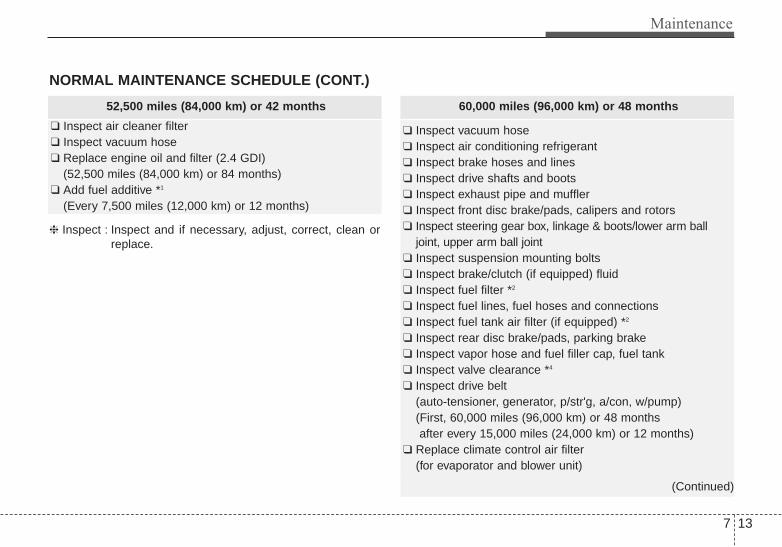
7 13
Maintenance
NORMAL MAINTENANCE SCHEDULE (CONT.)
52,500 miles (84,000 km) or 42 months
❑ Inspect air cleaner filter❑ Inspect vacuum hose❑ Replace engine oil and filter (2.4 GDI)
(52,500 miles (84,000 km) or 84 months)❑ Add fuel additive *1
(Every 7,500 miles (12,000 km) or 12 months)
❈ Inspect : Inspect and if necessary, adjust, correct, clean orreplace.
60,000 miles (96,000 km) or 48 months
❑ Inspect vacuum hose❑ Inspect air conditioning refrigerant❑ Inspect brake hoses and lines❑ Inspect drive shafts and boots❑ Inspect exhaust pipe and muffler❑ Inspect front disc brake/pads, calipers and rotors❑ Inspect steering gear box, linkage & boots/lower arm ball
joint, upper arm ball joint❑ Inspect suspension mounting bolts❑ Inspect brake/clutch (if equipped) fluid ❑ Inspect fuel filter *2
❑ Inspect fuel lines, fuel hoses and connections❑ Inspect fuel tank air filter (if equipped) *2
❑ Inspect rear disc brake/pads, parking brake❑ Inspect vapor hose and fuel filler cap, fuel tank❑ Inspect valve clearance *4
❑ Inspect drive belt (auto-tensioner, generator, p/str'g, a/con, w/pump)(First, 60,000 miles (96,000 km) or 48 months after every 15,000 miles (24,000 km) or 12 months)
❑ Replace climate control air filter (for evaporator and blower unit)
(Continued)

Maintenance
147
NORMAL MAINTENANCE SCHEDULE (CONT.)
(Continued)
❑ Replace air cleaner filter❑ Replace engine oil and filter (2.4 GDI)
(60,000 miles (96,000 km) or 96 months)❑ Replace coolant
(First, 60,000 miles (96,000 km) or 60 months after every 30,000 miles (48,000 km) or 24 months)
❑ Add fuel additive *1
(Every 7,500 miles (12,000 km) or 12 months)
❈ Inspect : Inspect and if necessary, adjust, correct, clean orreplace.
67,500 miles (108,000 km) or 54 months
❑ Inspect air cleaner filter❑ Inspect vacuum hose❑ Inspect manual transaxle fluid (if equipped)❑ Replace engine oil and filter (2.4 GDI)
(37,500 miles (60,000 km) or 60 months)❑ Add fuel additive *1
(Every 7,500 miles (12,000 km) or 12 months)
❈ Inspect : Inspect and if necessary, adjust, correct, clean orreplace.

7 15
Maintenance
NORMAL MAINTENANCE SCHEDULE (CONT.)
75,000 miles (120,000 km) or 60 months
❑ Inspect air cleaner filter❑ Inspect vacuum hose❑ Inspect air conditioning refrigerant❑ Inspect brake hoses and lines❑ Inspect drive shafts and boots❑ Inspect exhaust pipe and muffler❑ Inspect front disc brake/pads, calipers and rotors❑ Inspect steering gear box, linkage & boots/lower arm ball
joint, upper arm ball joint❑ Inspect suspension mounting bolts ❑ Inspect manual transaxle fluid (if equipped)❑ Inspect drive belt
(auto-tensioner, generator, p/str'g, a/con, w/pump)(First, 60,000 miles (96,000 km) or 48 months after every 15,000 miles (24,000 km) or 12 months)
❑ Replace climate control air filter (for evaporator and blower unit)
❑ Inspect rear disc brake/pads, parking brake❑ Replace engine oil and filter (2.4 GDI)
(75,000 miles (120,000 km) or 120 months)❑ Add fuel additive *1
(Every 7,500 miles (12,000 km) or 12 months)
❈ Inspect : Inspect and if necessary, adjust, correct, clean orreplace.
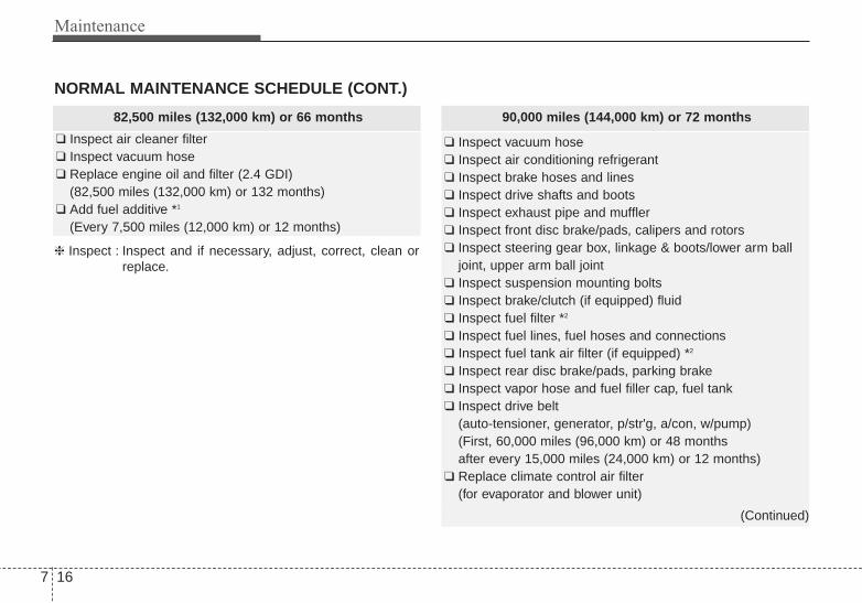
Maintenance
167
NORMAL MAINTENANCE SCHEDULE (CONT.)
82,500 miles (132,000 km) or 66 months
❑ Inspect air cleaner filter❑ Inspect vacuum hose❑ Replace engine oil and filter (2.4 GDI)
(82,500 miles (132,000 km) or 132 months)❑ Add fuel additive *1
(Every 7,500 miles (12,000 km) or 12 months)
❈ Inspect : Inspect and if necessary, adjust, correct, clean orreplace.
90,000 miles (144,000 km) or 72 months
❑ Inspect vacuum hose❑ Inspect air conditioning refrigerant❑ Inspect brake hoses and lines❑ Inspect drive shafts and boots❑ Inspect exhaust pipe and muffler❑ Inspect front disc brake/pads, calipers and rotors❑ Inspect steering gear box, linkage & boots/lower arm ball
joint, upper arm ball joint❑ Inspect suspension mounting bolts❑ Inspect brake/clutch (if equipped) fluid ❑ Inspect fuel filter *2
❑ Inspect fuel lines, fuel hoses and connections❑ Inspect fuel tank air filter (if equipped) *2
❑ Inspect rear disc brake/pads, parking brake❑ Inspect vapor hose and fuel filler cap, fuel tank❑ Inspect drive belt
(auto-tensioner, generator, p/str'g, a/con, w/pump)(First, 60,000 miles (96,000 km) or 48 months after every 15,000 miles (24,000 km) or 12 months)
❑ Replace climate control air filter (for evaporator and blower unit)
(Continued)
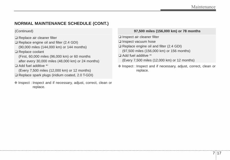
7 17
Maintenance
NORMAL MAINTENANCE SCHEDULE (CONT.)
(Continued)
❑ Replace air cleaner filter❑ Replace engine oil and filter (2.4 GDI)
(90,000 miles (144,000 km) or 144 months)❑ Replace coolant
(First, 60,000 miles (96,000 km) or 60 months after every 30,000 miles (48,000 km) or 24 months)
❑ Add fuel additive *1
(Every 7,500 miles (12,000 km) or 12 months)❑ Replace spark plugs (iridium coated, 2.0 T-GDI)
❈ Inspect : Inspect and if necessary, adjust, correct, clean orreplace.
97,500 miles (156,000 km) or 78 months
❑ Inspect air cleaner filter❑ Inspect vacuum hose❑ Replace engine oil and filter (2.4 GDI)
(97,500 miles (156,000 km) or 156 months)❑ Add fuel additive *1
(Every 7,500 miles (12,000 km) or 12 months)
❈ Inspect : Inspect and if necessary, adjust, correct, clean orreplace.

Maintenance
187
NORMAL MAINTENANCE SCHEDULE (CONT.)
105,000 miles (168,000 km) or 84 months
❑ Inspect air cleaner filter❑ Inspect vacuum hose❑ Inspect air conditioning refrigerant❑ Inspect brake hoses and lines❑ Inspect drive shafts and boots❑ Inspect exhaust pipe and muffler❑ Inspect front disc brake/pads, calipers and rotors❑ Inspect steering gear box, linkage & boots/lower arm ball
joint, upper arm ball joint❑ Inspect suspension mounting bolts❑ Inspect drive belt
(auto-tensioner, generator, p/str'g, a/con, w/pump)(First, 60,000 miles (96,000 km) or 48 months after every 15,000 miles (24,000 km) or 12 months)
❑ Replace climate control air filter (for evaporator and blower unit)
❑ Inspect rear disc brake/pads, parking brake❑ Replace spark plugs (iridium coated, 2.4 GDI)
(First, 105,000 miles or 84 months after every 105,000miles or 84 months)
❑ Replace engine oil and filter (2.4 GDI)(105,000 miles (168,000 km) or 168 months)
(Continued)
(Continued)
❑ Add fuel additive *1
(Every 7,500 miles (12,000 km) or 12 months)
❈ Inspect : Inspect and if necessary, adjust, correct, clean orreplace.
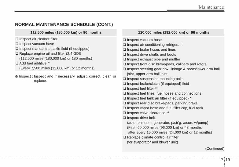
7 19
Maintenance
NORMAL MAINTENANCE SCHEDULE (CONT.)
112,500 miles (180,000 km) or 90 months
❑ Inspect air cleaner filter❑ Inspect vacuum hose❑ Inspect manual transaxle fluid (if equipped)❑ Replace engine oil and filter (2.4 GDI)
(112,500 miles (180,000 km) or 180 months)❑ Add fuel additive *1
(Every 7,500 miles (12,000 km) or 12 months)
❈ Inspect : Inspect and if necessary, adjust, correct, clean orreplace.
120,000 miles (192,000 km) or 96 months
❑ Inspect vacuum hose❑ Inspect air conditioning refrigerant❑ Inspect brake hoses and lines❑ Inspect drive shafts and boots❑ Inspect exhaust pipe and muffler❑ Inspect front disc brake/pads, calipers and rotors❑ Inspect steering gear box, linkage & boots/lower arm ball
joint, upper arm ball joint❑ Inspect suspension mounting bolts❑ Inspect brake/clutch (if equipped) fluid ❑ Inspect fuel filter *2
❑ Inspect fuel lines, fuel hoses and connections❑ Inspect fuel tank air filter (if equipped) *2
❑ Inspect rear disc brake/pads, parking brake❑ Inspect vapor hose and fuel filler cap, fuel tank❑ Inspect valve clearance *4
❑ Inspect drive belt (auto-tensioner, generator, p/str'g, a/con, w/pump)(First, 60,000 miles (96,000 km) or 48 months after every 15,000 miles (24,000 km) or 12 months)
❑ Replace climate control air filter (for evaporator and blower unit)
(Continued)

Maintenance
207
NORMAL MAINTENANCE SCHEDULE (CONT.)
(Continued)
❑ Replace air cleaner filter❑ Replace engine oil and filter (2.4 GDI)
(120,000 miles (192,000 km) or 192 months)❑ Replace coolant
(First, 60,000 miles (96,000 km) or 60 months after every 30,000 miles (48,000 km) or 24 months)
❑ Add fuel additive *1
(Every 7,500 miles (12,000 km) or 12 months)
❈ Inspect : Inspect and if necessary, adjust, correct, clean orreplace.
127,500 miles (204,000 km) or 102 months
❑ Inspect air cleaner filter❑ Inspect vacuum hose❑ Replace engine oil and filter (2.4 GDI)
(127,500 miles (204,000 km) or 204 months)❑ Add fuel additive *1
(Every 7,500 miles (12,000 km) or 12 months)
❈ Inspect : Inspect and if necessary, adjust, correct, clean orreplace.

7 21
Maintenance
NORMAL MAINTENANCE SCHEDULE (CONT.)
135,000 miles (216,000 km) or 108 months
❑ Inspect air cleaner filter❑ Inspect vacuum hose❑ Inspect air conditioning refrigerant❑ Inspect brake hoses and lines❑ Inspect drive shafts and boots❑ Inspect exhaust pipe and muffler❑ Inspect front disc brake/pads, calipers and rotors❑ Inspect steering gear box, linkage & boots/lower arm ball
joint, upper arm ball joint❑ Inspect suspension mounting bolts❑ Inspect drive belt
(auto-tensioner, generator, p/str'g, a/con, w/pump)(First, 60,000 miles (96,000 km) or 48 months after every 15,000 miles (24,000 km) or 12 months)
❑ Replace climate control air filter (for evaporator and blower unit)
❑ Inspect rear disc brake/pads, parking brake❑ Replace engine oil and filter (2.4 GDI)
(135,000 miles (216,000 km) or 216 months)❑ Add fuel additive *1
(Every 7,500 miles (12,000 km) or 12 months)❑ Replace spark plugs (iridium coated, 2.0 T-GDI)
❈ Inspect : Inspect and if necessary, adjust, correct, clean orreplace.
142,500 miles (228,000 km) or 114 months
❑ Inspect air cleaner filter❑ Inspect vacuum hose❑ Replace engine oil and filter (2.4 GDI)
(142,500 miles (228,000 km) or 228 months)❑ Add fuel additive *1
(Every 7,500 miles (12,000 km) or 12 months)
❈ Inspect : Inspect and if necessary, adjust, correct, clean orreplace.

Maintenance
227
NORMAL MAINTENANCE SCHEDULE (CONT.)
No check, No service required
❑ Automatic transaxle fluid (if equipped)
150,000 miles (240,000 km) or 120 months
❑ Inspect vacuum hose❑ Inspect air conditioning refrigerant❑ Inspect brake hoses and lines❑ Inspect drive shafts and boots❑ Inspect exhaust pipe and muffler❑ Inspect front disc brake/pads, calipers and rotors❑ Inspect steering gear box, linkage & boots/lower arm ball
joint, upper arm ball joint❑ Inspect suspension mounting bolts❑ Inspect brake/clutch (if equipped) fluid ❑ Inspect fuel filter *2
❑ Inspect fuel lines, fuel hoses and connections❑ Inspect fuel tank air filter (if equipped) *2
❑ Inspect rear disc brake/pads, parking brake❑ Inspect vapor hose and fuel filler cap, fuel tank❑ Inspect manual transaxle fluid (if equipped)❑ Inspect drive belt
(auto-tensioner, generator, p/str'g, a/con, w/pump)(First, 60,000 miles (96,000 km) or 48 months after every 15,000 miles (24,000 km) or 12 months)
❑ Replace climate control air filter (for evaporator and blower unit)
(Continued)
(Continued)
❑ Replace air cleaner filter❑ Replace engine oil and filter (2.4 GDI)
(150,000 miles (240,000 km) or 240 months)❑ Replace coolant
(First, 60,000 miles (96,000 km) or 60 months after every 30,000 miles (48,000 km) or 24 months)
❑ Add fuel additive *1
(Every 7,500 miles (12,000 km) or 12 months)
❈ Inspect : Inspect and if necessary, adjust, correct, clean orreplace.

7 23
Maintenance
MAINTENANCE UNDER SEVERE USAGE CONDITIONSThe following items must be serviced more frequently on cars normally used under severe driving conditions. Referto the chart below for the appropriate maintenance intervals.R : Replace I : Inspect and, after inspection, clean, adjust, repair or replace if necessary
MAINTENANCE ITEMMAINTENANCE
OPERATIONMAINTENANCE INTERVALS
DRIVING CONDITION
Engine oil and filter2.4L R
Every 3,750 miles (6,000 km) or 6 months A, B, C, D, E, F, G,
H, I, K2.0L R
Every 3,000 miles (5,000 km) or 3 months
Air cleaner filter R More frequently C, E
Spark plugs R More frequently A, B, H, I, K
Automatic transaxle fluid R Every 60,000 miles (96,000 km) A, C, E, F, G, I
Manual transaxle fluid R Every 75,000 miles (120,000 km) C, F, G, I, J
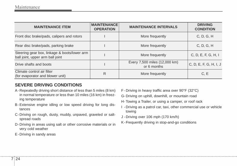
Maintenance
247
MAINTENANCE ITEMMAINTENANCE
OPERATIONMAINTENANCE INTERVALS
DRIVING CONDITION
Front disc brake/pads, calipers and rotors I More frequently C, D, G, H
Rear disc brake/pads, parking brake I More frequently C, D, G, H
Steering gear box, linkage & boots/lower armball joint, upper arm ball joint
I More frequently C, D, E, F, G, H, I
Drive shafts and boots IEvery 7,500 miles (12,000 km)
or 6 monthsC, D, E, F, G, H, I, J
Climate control air filter (for evaporator and blower unit)
R More frequently C, E
SEVERE DRIVING CONDITIONSA-Repeatedly driving short distance of less than 5 miles (8 km)
in normal temperature or less than 10 miles (16 km) in freez-ing temperature
B-Extensive engine idling or low speed driving for long dis-tances
C-Driving on rough, dusty, muddy, unpaved, graveled or salt-spread roads
D-Driving in areas using salt or other corrosive materials or invery cold weather
E-Driving in sandy areas
F -Driving in heavy traffic area over 90°F (32°C)
G-Driving on uphill, downhill, or mountain road
H-Towing a Trailer, or using a camper, or roof rack
I -Driving as a patrol car, taxi, other commercial use or vehicletowing
J -Driving over 106 mph (170 km/h)
K-Frequently driving in stop-and-go conditions

7 25
Maintenance
EXPLANATION OF SCHEDULED MAINTENANCE ITEMSEngine oil and filterThe engine oil and filter should bechanged at the intervals specified inthe maintenance schedule. If the caris being driven in severe conditions,more frequent oil and filter changesare required.
Drive beltsInspect all drive belts for evidence ofcuts, cracks, excessive wear or oilsaturation and replace if necessary.Drive belts should be checked peri-odically for proper tension andadjusted as necessary.
Fuel filterA clogged filter can limit the speed atwhich the vehicle may be driven,damage the emission system andcause multiple issues such as hardstarting. If an excessive amount offoreign matter accumulates in thefuel tank, the filter may requirereplacement more frequently.After installing a new filter, run theengine for several minutes, andcheck for leaks at the connections.Fuel filters should be installed by anauthorized Kia dealer.
Fuel lines, fuel hoses and con-nectionsCheck the fuel lines, fuel hoses andconnections for leakage and dam-age. Have an authorized Kia dealerreplace any damaged or leakingparts immediately.
Vapor hose and fuel filler capThe vapor hose and fuel filler capshould be inspected at those inter-vals specified in the maintenanceschedule. Make sure that a newvapor hose or fuel filler cap is cor-rectly replaced.

Maintenance
267
Vacuum crankcase ventilationhosesInspect the surface of hoses for evi-dence of heat and/or mechanicaldamage. Hard and brittle rubber,cracking, tears, cuts, abrasions, andexcessive swelling indicate deterio-ration. Particular attention should bepaid to examine those hose surfacesnearest to high heat sources, suchas the exhaust manifold.Inspect the hose routing to assurethat the hoses do not come in con-tact with any heat source, sharpedges or moving component whichmight cause heat damage ormechanical wear. Inspect all hoseconnections, such as clamps andcouplings, to make sure they aresecure, and that no leaks are pres-ent. Hoses should be replacedimmediately if there is any evidenceof deterioration or damage.
Air cleaner filterA Genuine Kia air cleaner filter isrecommended when the filter isreplaced.
Spark plugsMake sure to install new spark plugsof the correct heat range.
Valve clearance Inspect excessive valve noise and/orengine vibration and adjust if neces-sary. An authorized Kia dealershould perform the operation.
Cooling systemCheck cooling system components,such as radiator, coolant reservoir,hoses and connections for leakageand damage. Replace any damagedparts.
CoolantThe coolant should be changed atthe intervals specified in the mainte-nance schedule.
Manual transaxle fluid (if equipped)Inspect the manual transaxle fluidaccording to the maintenance sched-ule.

7 27
Maintenance
Automatic transaxle fluid (if equipped)Automatic transaxle fluid should notbe checked under normal usageconditions.But in severe conditions, the fluidshould be changed at an authorizedKia dealer in accordance to thescheduled maintenance at the begin-ning of this chapter.
✽✽ NOTICEAutomatic transaxle fluid color isbasically red. As the vehicle is driven, the auto-matic transaxle fluid will begin tolook darker.It is normal condition and youshould not judge the need to replacethe fluid based upon the changedcolor.
Brake hoses and linesVisually check for proper installation,chafing, cracks, deterioration andany leakage. Replace any deteriorat-ed or damaged parts immediately.
Brake/clutch fluidCheck brake fluid level in the brakefluid reservoir. The level should bebetween “MIN” and “MAX” marks onthe side of the reservoir. Use onlyhydraulic brake fluid conforming toDOT 3 or DOT 4 specification.
Parking brakeInspect the parking brake systemincluding the parking brake pedaland cables.
Brake discs, pads, calipersand rotorsCheck the pads for excessive wear,discs for run out and wear, andcalipers for fluid leakage.
Exhaust pipe and mufflerVisually inspect the exhaust pipes,muffler and hangers for cracks, dete-rioration, or damage. Start theengine and listen carefully for anyexhaust gas leakage. Tighten con-nections or replace parts as neces-sary.
Suspension mounting boltsCheck the suspension connectionsfor looseness or damage. Retightento the specified torque.

Maintenance
287
Steering gear box, linkage &boots/lower arm ball jointWith the vehicle stopped and engineoff, check for excessive free-play inthe steering wheel.Check the linkage for bends or dam-age. Check the dust boots and balljoints for deterioration, cracks, ordamage. Replace any damagedparts.
Drive shafts and bootsCheck the drive shafts, boots andclamps for cracks, deterioration, ordamage. Replace any damagedparts and, if necessary, repack thegrease.
Air conditioning refrigerant Check the air conditioning lines andconnections for leakage and dam-age.

7 29
Maintenance
ENGINE OILChecking the engine oil level
1. Be sure the vehicle is on levelground.
2. Start the engine and allow it toreach normal operating tempera-ture.
3. Turn the engine off and wait for afew minutes (about 5 minutes) forthe oil to return to the oil pan.
4. Pull the dipstick out, wipe it clean,and reinsert it fully.
5. Pull the dipstick out again andcheck the level. The level shouldbe between F and L.
If it is near or at L, add enough oil tobring the level to F. Do not overfill.
Use a funnel to help prevent oilfrom being spilled on engine com-ponents.
WARNING - Radiatorhose
Be very careful not to touch theradiator hose when checking oradding the engine oil as it maybe hot enough to burn you.
CAUTION - Replaceengine oil
Do not overfill with engine oil.Engine damage may result.
OYF079003N
OYF071003N-1
■■ 2.4 engine
■■ 2.0 engine
OYF079004N
OYF071004N-1
■■ 2.4 engine
■■ 2.0 engine
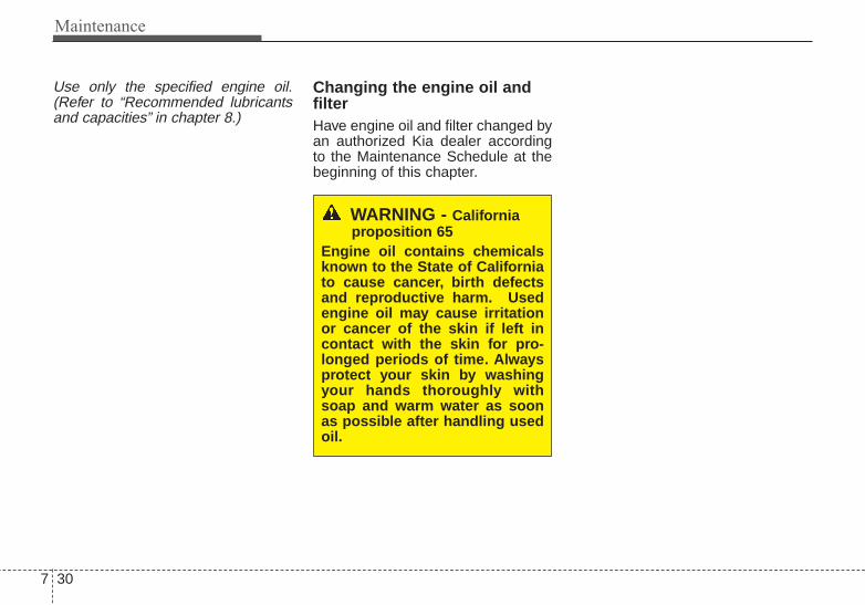
Maintenance
307
Use only the specified engine oil.(Refer to “Recommended lubricantsand capacities” in chapter 8.)
Changing the engine oil andfilterHave engine oil and filter changed byan authorized Kia dealer accordingto the Maintenance Schedule at thebeginning of this chapter.
WARNING - Californiaproposition 65
Engine oil contains chemicalsknown to the State of Californiato cause cancer, birth defectsand reproductive harm. Usedengine oil may cause irritationor cancer of the skin if left incontact with the skin for pro-longed periods of time. Alwaysprotect your skin by washingyour hands thoroughly withsoap and warm water as soonas possible after handling usedoil.

7 31
Maintenance
ENGINE COOLANTThe high-pressure cooling systemhas a reservoir filled with year-roundantifreeze coolant. The reservoir isfilled at the factory.Check the antifreeze protection andcoolant level at least once a year, atthe beginning of the winter season,and before traveling to a colder cli-mate.
Checking the coolant level
Check the condition and connectionsof all cooling system hoses andheater hoses. Replace any swollenor deteriorated hoses.The coolant level should be filledbetween F (MAX) and L (MIN) markson the side of the coolant reservoirwhen the engine is cool.
If the coolant level is low, add enoughspecified coolant to provide protec-tion against freezing and corrosion.Bring the level to F (MAX), but do notoverfill. If frequent coolant addition isrequired, see an authorized Kia deal-er for a cooling system inspection.
WARNING - Cooling fanUse caution whenworking near theblade of the coolingfan. The electricmotor (cooling fan) is
controlled by engine coolanttemperature, refrigerant pres-sure and vehicle speed. It maysometimes operate even whenthe engine is not running.
OTF070006

Maintenance
327
WARNING Radiator cap
Do not remove the radiator capwhen the engine and radiatorare hot. Scalding hot coolantand steam may blow out underpressure.
Recommended engine coolant• When adding coolant, use only
deionized water or soft water foryour vehicle and never mix hardwater in the coolant filled at the fac-tory. An improper coolant mixturecan result in serious malfunction orengine damage.
• The engine in your vehicle has alu-minum engine parts and must beprotected by an ethylene-glycol-based coolant to prevent corrosionand freezing.
• DO NOT USE alcohol or methanolcoolant or mix them with the spec-ified coolant.
• Do not use a solution that containsmore than 60% antifreeze or lessthan 35% antifreeze, which wouldreduce the effectiveness of thesolution.
For mixture percentage, refer to thefollowing table.
5°F (-15°C) 35 65
-13°F (-25°C) 40 60
-31°F (-35°C) 50 50
-49°F (-45°C) 60 40
AmbientTemperature
Mixture Percentage (volume)
Antifreeze Water
OTF072007
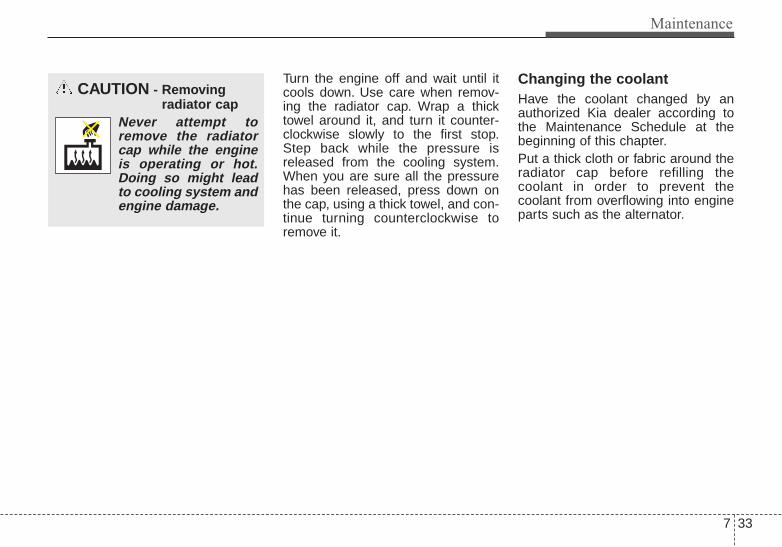
7 33
Maintenance
Turn the engine off and wait until itcools down. Use care when remov-ing the radiator cap. Wrap a thicktowel around it, and turn it counter-clockwise slowly to the first stop.Step back while the pressure isreleased from the cooling system.When you are sure all the pressurehas been released, press down onthe cap, using a thick towel, and con-tinue turning counterclockwise toremove it.
Changing the coolantHave the coolant changed by anauthorized Kia dealer according tothe Maintenance Schedule at thebeginning of this chapter.Put a thick cloth or fabric around theradiator cap before refilling thecoolant in order to prevent thecoolant from overflowing into engineparts such as the alternator.
CAUTION - Removingradiator cap
Never attempt toremove the radiatorcap while the engineis operating or hot.Doing so might leadto cooling system andengine damage.

Maintenance
347
BRAKE/CLUTCH (IF EQUIPPED) FLUID Checking the brake/clutch*fluid level
Check the fluid level in the reservoirperiodically. The fluid level should bebetween MAX and MIN marks on theside of the reservoir.Before removing the reservoir capand adding brake/clutch* fluid, cleanthe area around the reservoir capthoroughly to prevent brake/clutch*fluid contamination.
* if equipped
If the level is low, add fluid to theMAX level. The level will fall withaccumulated mileage. This is a nor-mal condition associated with thewear of the brake linings and/orclutch disc (if equipped). If the fluidlevel is excessively low, have thebrake/clutch* system checked by anauthorized Kia dealer.
Use only the specified brake/clutch*fluid. (Refer to “Recommended lubri-cants and capacities” in chapter 8.)
Never mix different types of fluid.
In the event the brake/clutch* systemrequires frequent additions of fluid,the vehicle should be inspected byan authorized Kia dealer.When changing and addingbrake/clutch* fluid, handle it carefully.Do not let it come in contact withyour eyes. If brake/clutch* fluidshould come in contact with youreyes, immediately flush them with alarge quantity of fresh tap water.Have your eyes examined by a doc-tor as soon as possible.
Brake/clutch* fluid, which has beenexposed to open air for an extendedtime should never be used as itsquality cannot be guaranteed. Itshould be disposed of properly.
CAUTION - Brake/clutchfluid
Do not allow brake/clutch* fluidto contact the vehicle's bodypaint, as paint damage willresult.
CAUTION - Proper fluidOnly use brake/clutch fluid inbrake/clutch system. Smallamounts of improper fluids(such as engine oil) can causedamage to the brake/clutch sys-tem.
OTF070008

7 35
Maintenance
WASHER FLUIDChecking the washer fluidlevel
Check the fluid level in the washerfluid reservoir and add fluid if neces-sary. Plain water may be used ifwasher fluid is not available.However, use washer solvent withantifreeze characteristics in cold cli-mates to prevent freezing.
WARNING - Windshield
fluidDo not drink the windshieldwasher fluid. The windshieldwasher fluid is poisonous tohumans and animals.
WARNING - Flammable
fluidDo not allow the washer fluid tocome in contact with openflames or sparks. The wind-shield washer fluid reservoir isflammable under certain cir-cumstances.This can result in afire.
OTF074010

Maintenance
367
PARKING BRAKEChecking the parking brake Type A
Check whether the stroke is withinspecification when the parking brakepedal is depressed with 44 lb (20 kg,196 N) of force. Also, the parkingbrake alone should securely hold thevehicle on a fairly steep grade.
Type B
Check the stroke of the parkingbrake by counting the number of“clicks’’ heard while fully applying itfrom the released position. Also, theparking brake alone should securelyhold the vehicle on a fairly steepgrade. If the stroke is more or lessthan specified, have the parkingbrake adjusted by an authorized Kiadealer.
Stroke : 6~8 “clicks’’ at a force of 44lbs (20 kg, 196 N).
OTF050015
■ Type A
OTF050014
■ Type B
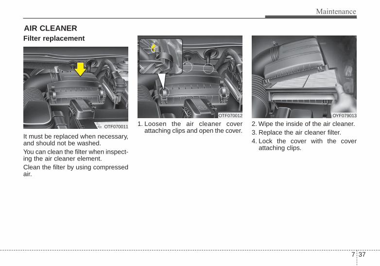
7 37
Maintenance
Filter replacement
It must be replaced when necessary,and should not be washed.You can clean the filter when inspect-ing the air cleaner element.Clean the filter by using compressedair.
1. Loosen the air cleaner coverattaching clips and open the cover.
2. Wipe the inside of the air cleaner.3. Replace the air cleaner filter.4. Lock the cover with the cover
attaching clips.
AIR CLEANER
OTF070011
OTF070012 OYF079013

Maintenance
387
Replace the filter according to theMaintenance Schedule.If the vehicle is operated in extreme-ly dusty or sandy areas, replace theelement more often than the usualrecommended intervals. (Refer to“Maintenance under severe usageconditions” in this chapter.)
CAUTION - Air filter maintenance
• Do not drive with the air clean-er removed; this will result inexcessive engine wear.
• When removing the air cleanerfilter, be careful that dust ordirt does not enter the airintake, or damage may result.
• Use a Kia genuine part. Use ofnongenuine part could dam-age the air flow sensor.

7 39
Maintenance
CLIMATE CONTROL AIR FILTER (IF EQUIPPED)Filter inspectionThe climate control air filter shouldbe replaced according to theMaintenance Schedule. If the vehicleis operated in severely air-pollutedcities or on dusty rough roads for along period, it should be inspectedmore frequently and replaced earlier.When you replace the climate controlair filter, replace it performing the fol-lowing procedure, and be careful toavoid damaging other components.
Filter replacement
1. Open the glove box.
2. Remove the climate control air fil-ter cover while pressing the lockon the right side of the cover.
3. Push the right side of the climatecontrol air filter and pull the cli-mate control air filter out.
OTF070014
OTF070015
OTF070013

Maintenance
407
4. Replace the climate control air fil-ter.
5. Reassemble in the reverse orderof disassembly.
When replacing the climate controlair filter install it properly. Otherwise,the system may produce noise andthe effectiveness of the filter may bereduced.
OMG079027

7 41
Maintenance
WIPER BLADES Blade inspection
Commercial hot waxes applied byautomatic car washes have beenknown to make the windshield diffi-cult to clean.
Contamination of either the wind-shield or the wiper blades with for-eign matter can reduce the effective-ness of the windshield wipers.Common sources of contaminationare insects, tree sap, and hot waxtreatments used by some commer-cial car washes. If the blades are notwiping properly, clean both the win-dow and the blades with a goodcleaner or mild detergent, and rinsethoroughly with clean water.
Blade replacement When the wipers no longer cleanadequately, the blades may be wornor cracked, and require replacement.To prevent damage to the wiper armsor other components, do not attemptto move the wipers manually.The use of a non-specified wiperblade could result in wiper malfunc-tion and failure.
1JBA5122CAUTION - Wiper blades
To prevent damage to the wiperblades, do not use gasoline,kerosene, paint thinner, or othersolvents on or near them.

Maintenance
427
Front windshield wiper blade
Type A
1. Raise the wiper arm and turn thewiper blade assembly to exposethe plastic locking clip.
✽✽ NOTICEDo not allow the wiper arm to fallagainst the windshield
2. Open the cover of the blade.3. Compress the clip behind the
wiper arm and lift it off the arm.
4. Install the blade assembly until itclicks into place
5. Close the cover of blade.6. Return the wiper arm to the prop-
er position.
OED070112
OED070113 OED070114

7 43
Maintenance
Type B
1. Raise the wiper arm.
2. Turn the wiper blade clip. Then liftup the blade clip.
3. Push the clip (1) and push up thewiper arm (2).
4. Push down the wiper arm (3) andinstall the new blade assembly inthe reverse order of removal.
5. Return the wiper arm on the wind-shield.
CAUTIONDo not allow the wiper arm tofall against the windshield,since it may chip or crack thewindscreen.
OHM078059
OSBL071001
OSBL071003
OSBL071002

Maintenance
447
BATTERYFor best battery service
• Keep the battery securely mount-ed.
• Keep the battery top clean and dry.• Keep the terminals and connec-
tions clean, tight, and coated withpetroleum jelly or terminal grease.
• Rinse any spilled electrolyte fromthe battery immediately with asolution of water and baking soda.
• If the vehicle is not going to beused for an extended time, discon-nect the battery cables.
WARNING - Risk of explosion
Keep lit cigarettes andall other flames orsparks away from thebattery.The battery containshydrogen -- a highlycombustible gas whichwill explode if it comesin contact with a flame orspark.
WARNING - Sulfuric acidin batteries
Keep batteries out of thereach of childrenbecause batteries con-tain highly corrosiveSULFURIC ACID andelectrolytes. Do notallow battery acid tocontact your skin, eyes,clothing or paint finish.Wear eye protectionwhen charging or work-ing near a battery.Always provide ventila-tion when working in anenclosed space.
OTF070016

7 45
Maintenance
Always read the followinginstructions carefully whenhandling a battery.If any electrolyte gets intoyour eyes, flush your eyeswith clean water for at least15 minutes and get immedi-ate medical attention.If electrolyte gets on yourskin, thoroughly wash thecontacted area. If you feelpain or burning sensation,get medical attention imme-diately.
An inappropriately disposedbattery can be harmful to theenvironment and humanhealth. Dispose the batteryaccording to your local law(s)or regulation.The battery contains lead. Donot dispose of it after use.Please return the battery toan authorized Kia dealer tobe recycled.
When you don’t use the vehicle for along time in the low temperaturearea, separate the battery and keepit indoors.
WARNING - Recharging
batteryNever attempt to recharge thebattery when the battery cablesare connected.
WARNING - Risk of elec-
trocutionNever touch the electrical igni-tion system while the vehicle isrunning. This system workswith high voltage which can"zap" you.
WARNING - California proposition65
Battery posts, terminals, andrelated accessories containlead and lead compounds,chemicals known to the State ofCalifornia to cause cancer, birthdefects and reproductive harm.Batteries also contain otherchemicals known to the State ofCalifornia to cause cancer.Wash hands after handling.

Maintenance
467
Battery recharging Your vehicle has a maintenance-free,calcium-based battery.• If the battery becomes discharged
in a short time (because, for exam-ple, the headlights or interior lightswere left on while the vehicle wasnot in use), recharge it by slowcharging (trickle) for 10 hours.
• If the battery gradually dischargesbecause of high electric load whilethe vehicle is being used, rechargeit at 20-30A for two hours.
When recharging the battery,observe the following precautions:• The battery must be removed from
the vehicle and placed in an areawith good ventilation.
• Watch the battery during charging,and stop or reduce the chargingrate if the battery cells begingassing (boiling) violently or if thetemperature of the electrolyte ofany cell exceeds 120°F (49°C).
• Wear eye protection when check-ing the battery during charging.
• Disconnect the battery charger inthe following order.1. Turn off the battery charger main
switch.2. Unhook the negative clamp from
the negative battery terminal.3. Unhook the positive clamp from
the positive battery terminal.• Before performing maintenance or
recharging the battery, turn off allaccessories and stop the engine.
• The negative battery cable must beremoved first and installed lastwhen the battery is disconnected.
Reset itemsItems should be reset after the bat-tery has been discharged or the bat-tery has been disconnected.• Auto down window (See chapter 4)• Sunroof (See chapter 4)• Trip computer (See chapter 4)• Climate control system
(See chapter 4)• Clock (See chapter 4)• Audio (See chapter 4)
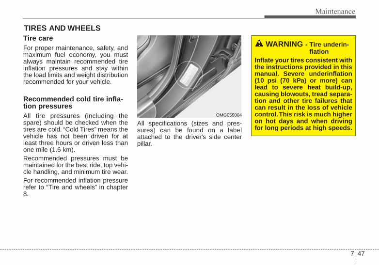
7 47
Maintenance
TIRES AND WHEELS Tire care For proper maintenance, safety, andmaximum fuel economy, you mustalways maintain recommended tireinflation pressures and stay withinthe load limits and weight distributionrecommended for your vehicle.
Recommended cold tire infla-tion pressures All tire pressures (including thespare) should be checked when thetires are cold. “Cold Tires” means thevehicle has not been driven for atleast three hours or driven less thanone mile (1.6 km).Recommended pressures must bemaintained for the best ride, top vehi-cle handling, and minimum tire wear.For recommended inflation pressurerefer to “Tire and wheels” in chapter8.
All specifications (sizes and pres-sures) can be found on a labelattached to the driver’s side centerpillar.
WARNING - Tire underin-flation
Inflate your tires consistent withthe instructions provided in thismanual. Severe underinflation(10 psi (70 kPa) or more) canlead to severe heat build-up,causing blowouts, tread separa-tion and other tire failures thatcan result in the loss of vehiclecontrol.This risk is much higheron hot days and when drivingfor long periods at high speeds.
OMG055004

Maintenance
487
• Underinflation also results inexcessive wear, poor handling andreduced fuel economy. Wheeldeformation also is possible. Keepyour tire pressures at the properlevels. If a tire frequently needsrefilling, have it checked by anauthorized Kia dealer.
• Overinflation produces a harshride, excessive wear at the centerof the tire tread, and a greater pos-sibility of damage from road haz-ards.
• Warm tires normally exceed rec-ommended cold tire pressures by 4to 6 psi (28 to 41 kPa). Do notrelease air from warm tires toadjust the pressure or the tires willbe underinflated.
• Be sure to reinstall the tire inflationvalve caps. Without the valve cap,dirt or moisture could get into thevalve core and cause air leakage. Ifa valve cap is missing, install anew one as soon as possible.
Always observe the following:• Check tire pressure when the tires
are cold. (After vehicle has beenparked for at least three hours orhasn't been driven more than onemile (1.6 km) since startup.)
• Check the pressure of your sparetire each time you check the pres-sure of other tires.
• Never overload your vehicle. Becareful not to overload a vehicleluggage rack if your vehicle isequipped with one.
Checking tire inflation pres-sureCheck your tires once a month ormore.Also, check the tire pressure of thespare tire.
How to checkUse a good quality gauge to checktire pressure. You can not tell if yourtires are properly inflated simply bylooking at them. Radial tires maylook properly inflated even whenthey're underinflated.Check the tire's inflation pressurewhen the tires are cold. - "Cold"means your vehicle has been sittingfor at least three hours or driven nomore than 1 mile (1.6 km).
7 49
Maintenance
Remove the valve cap from the tirevalve stem. Press the tire gauge firm-ly onto the valve to get a pressuremeasurement. If the cold tire inflationpressure matches the recommendedpressure on the tire and loadinginformation label, no further adjust-ment is necessary. If the pressure islow, add air until you reach the rec-ommended amount.If you overfill the tire, release air bypushing on the metal stem in thecenter of the tire valve. Recheck thetire pressure with the tire gauge. Besure to put the valve caps back onthe valve stems. They help preventleaks by keeping out dirt and mois-ture.
• Inspect your tires frequently forproper inflation as well as wear anddamage. Always use a tire pres-sure gauge.
• Tires with too much or too littlepressure wear unevenly causingpoor handling, loss of vehicle con-trol, and sudden tire failure leadingto accidents, injuries, and evendeath. The recommended cold tirepressure for your vehicle can befound in this manual and on the tirelabel located on the driver's sidecenter pillar.
• Remember to check the pressureof your spare tire. Kia recommendsthat you check the spare everytime you check the pressure of theother tires on your vehicle.
Tire rotation To equalize tread wear, it is recom-mended that the tires be rotatedevery 7,500 miles (12,000 km) orsooner if irregular wear develops.During rotation, check the tires forcorrect balance.When rotating tires, check for unevenwear and damage. Abnormal wear isusually caused by incorrect tire pres-sure, improper wheel alignment, out-of-balance wheels, severe braking orsevere cornering. Look for bumps orbulges in the tread or side of tire.Replace the tire if you find either ofthese conditions. Replace the tire iffabric or cord is visible. After rotation,be sure to bring the front and rear tirepressures to specification and checklug nut tightness.Refer to “Tire and wheels” in chapter8.

Maintenance
507
Disc brake pads should be inspectedfor wear whenever tires are rotated.
Rotate radial tires that have anasymmetric tread pattern only fromfront to rear and not from right to left.Do not use the compact spare tire fortire rotation.
Wheel alignment and tire bal-ance The wheels on your vehicle werealigned and balanced carefully at thefactory to give you the longest tire lifeand best overall performance.In most cases, you will not need tohave your wheels aligned again.However, if you notice unusual tirewear or your vehicle pulling one wayor the other, the alignment may needto be reset.If you notice your vehicle vibratingwhen driving on a smooth road, yourwheels may need to be rebalanced.
WARNING - Mixing tiretypes
Do not mix bias ply and radialply tires under any circum-stances.This may cause unusu-al handling characteristics.
S2BLA790A
CBGQ0707A
Without a spare tire
Directional tires (if equipped)
CAUTION - Wheel weightImproper wheel weights candamage your vehicle's alu-minum wheels. Use onlyapproved wheel weights.

7 51
Maintenance
Tire replacement
If the tire is worn evenly, a tread wearindicator will appear as a solid bandacross the tread. This shows there isless than 1/16 inch (1.6 mm) of treadleft on the tire. Replace the tire whenthis happens.Do not wait for the band to appearacross the entire tread before replac-ing the tire.
The ABS works by comparing thespeed of the wheels. Tire size canaffect wheel speed. When replacingtires, all 4 tires must use the samesize originally supplied with the vehi-cle. Using tires of a different size cancause the ABS (Anti-lock BrakeSystem) and ESC (ElectronicStability Control) (if equipped) towork irregularly.
Compact spare tire replacement A compact spare tire has a shortertread life than a regular size tire.Replace it when you can see thetread wear indicator bars on the tire.The replacement compact spare tireshould be the same size and designtire as the one provided with yournew vehicle and should be mountedon the same compact spare tirewheel. The compact spare tire is notdesigned to be mounted on a regularsize wheel, and the compact sparetire wheel is not designed for mount-ing a regular size tire.
OEN076053
Tread wear indicator

Maintenance
527
Wheel replacement When replacing the metal wheels forany reason, make sure the newwheels are equivalent to the originalfactory units in diameter, rim widthand offset.A wheel that is not the correct sizemay adversely affect wheel andbearing life, braking and stoppingabilities, handling characteristics,ground clearance, body-to-tire clear-ance, snow chain clearance,speedometer and odometer calibra-tion, headlight aim and bumperheight.
Tire tractionTire traction can be reduced if youdrive on worn tires, tires that areimproperly inflated or on slipperyroad surfaces. Tires should bereplaced when tread wear indicatorsappear. Slow down whenever thereis rain, snow or ice on the road, toreduce the possibility of losing con-trol of the vehicle.
Tire maintenance In addition to proper inflation, correctwheel alignment helps to decreasetire wear. If you find a tire is wornunevenly, have your dealer check thewheel alignment.When you have new tires installed,make sure they are balanced. Thiswill increase vehicle ride comfort andtire life. Additionally, a tire shouldalways be rebalanced if it is removedfrom the wheel.
Tire sidewall labeling
This information identifies anddescribes the fundamental charac-teristics of the tire and also providesthe tire identification number (TIN)for safety standard certification. TheTIN can be used to identify the tire incase of a recall.
1. Manufacturer or brand nameManufacturer or Brand name isshown.
CAUTION - WheelWheels that do not meet Kia'sspecifications may fit poorlyand result in damage to thevehicle or unusual handling andpoor vehicle control.
I030B04JM
1
1
23
4
5,6
7

7 53
Maintenance
2. Tire size designation A tire’s sidewall is marked with a tiresize designation. You will need thisinformation when selecting replace-ment tires for your car. The followingexplains what the letters and num-bers in the tire size designationmean.Example tire size designation:(These numbers are provided as anexample only; your tire size designa-tor could vary depending on yourvehicle.)P205/55R16 89H
P - Applicable vehicle type (tiresmarked with the prefix “P’’ areintended for use on passengervehicles or light trucks; however,not all tires have this marking).
205 - Tire width in millimeters.55 - Aspect ratio. The tire’s section
height as a percentage of itswidth.
R - Tire construction code (Radial).16 - Rim diameter in inches.
89 - Load Index, a numerical codeassociated with the maximumload the tire can carry.
H - Speed Rating Symbol. See thespeed rating chart in this sectionfor additional information.
Wheel size designation
Wheels are also marked with impor-tant information that you need if youever have to replace one. The follow-ing explains what the letters andnumbers in the wheel size designa-tion mean.
Example wheel size designation:6.0JX16
6.0 - Rim width in inches.J - Rim contour designation.16 - Rim diameter in inches.
Tire speed ratings
The chart below lists many of the dif-ferent speed ratings currently beingused for passenger vehicles. Thespeed rating is part of the tire sizedesignation on the sidewall of thetire. This symbol corresponds to thattire's designed maximum safe oper-ating speed.
S 112 mph (180 km/h)T 118 mph (190 km/h)H 130 mph (210 km/h)V 149 mph (240 km/h)Z Above 149 mph (240 km/h)
Maximum SpeedSpeedRatingSymbol

Maintenance
547
3. Checking tire life (TIN : TireIdentification Number)
Any tires that are over 6 years old,based on the manufacturing date,(including the spare tire) should bereplaced by new ones. You can findthe manufacturing date on the tiresidewall (possibly on the inside of thewheel), displaying the DOT Code.The DOT Code is a series of num-bers on a tire consisting of numbersand English letters. The manufactur-ing date is designated by the last fourdigits (characters) of the DOT code.
DOT : XXXX XXXX OOOOThe front part of the DOT means aplant code number, tire size andtread pattern and the last four num-bers indicate week and year manu-factured.For example:DOT XXXX XXXX 1613 representsthat the tire was produced in the 16thweek of 2013.
4. Tire ply composition and mate-rial
The number of layers or plies of rub-ber-coated fabric in the tire. Tiremanufacturers also must indicate thematerials in the tire, which includesteel, nylon, polyester, and others.The letter "R" means radial ply con-struction; the letter "D" means diago-nal or bias ply construction; and theletter "B" means belted-bias ply con-struction.
5. Maximum permissible inflationpressure
This number is the greatest amountof air pressure that should be put inthe tire. Do not exceed the maximumpermissible inflation pressure. Referto the Tire and Loading Informationlabel for recommended inflationpressure.
6. Maximum load ratingThis number indicates the maximumload in kilograms and pounds thatcan be carried by the tire. Whenreplacing the tires on the vehicle,always use a tire that has the sameload rating as the factory installedtire.
WARNING - Tire ageReplace tires within the recom-mended time frame. Failure toreplace tires as recommendedcan result in sudden tire failure,which could lead to a loss ofcontrol and an accident.

7 55
Maintenance
7. Uniform tire quality grading Quality grades can be found whereapplicable on the tire sidewallbetween tread shoulder and maxi-mum section width.For example:TREADWEAR 440 TRACTION A TEMPERATURE A
Tread wear
The tread wear grade is a compara-tive rating based on the wear rate ofthe tire when tested under controlledconditions on a specified govern-ment test course. For example, a tiregraded 150 would wear one-and-a-half times (1½) as well on the gov-ernment course as a tire graded 100.The relative performance of tiresdepends upon the actual conditionsof their use, however, and maydepart significantly from the normdue to variations in driving habits,service practices and differences inroad characteristics and climate.
Tires degrade over time, even whenthey are not being used. Regardlessof the remaining tread, we recom-mend that tires be replaced afterapproximately six (6) years of nor-mal service. Heat caused by hot cli-mates or frequent high loading con-ditions can accelerate the agingprocess.These grades are molded on theside-walls of passenger vehicle tires.The tires available as standard oroptional equipment on your vehiclesmay vary with respect to grade.
Traction - AA, A, B & C
The traction grades, from highest tolowest, are AA, A, B and C. Thosegrades represent the tires ability tostop on wet pavement as measuredunder controlled conditions on spec-ified government test surfaces ofasphalt and concrete. A tire markedC may have poor traction perform-ance.The traction grade assigned to thistire is based on straight-ahead brak-ing traction tests, and does notinclude acceleration, cornering,hydroplaning, or peak traction char-acteristics.

Maintenance
567
Temperature -A, B & C
The temperature grades are A (thehighest), B and C representing thetire’s resistance to the generation ofheat and its ability to dissipate heatwhen tested under controlled condi-tions on a specified indoor laboratorytest wheel.Sustained high temperature cancause the material of the tire todegenerate and reduce tire life, andexcessive temperature can lead tosudden tire failure. The grade C cor-responds to a level of performancewhich all passenger car tires mustmeet under the Federal MotorVehicle Safety Standard No. 109.Grades B and A represent higherlevels of performance on the labora-tory test wheel than the minimumrequired by law.
Tire terminology and definitionsAir Pressure: The amount of airinside the tire pressing outward onthe tire. Air pressure is expressed inpounds per square inch (psi) or kilo-pascal (kPa).Accessory Weight: This means thecombined weight of optional acces-sories. Some examples of optionalaccessories are, automatictransaxle, power seats, and air con-ditioning.Aspect Ratio: The relationship of atire's height to its width.Belt: A rubber coated layer of cordsthat is located between the plies andthe tread. Cords may be made fromsteel or other reinforcing materials.Bead: The tire bead contains steelwires wrapped by steel cords thathold the tire onto the rim.Bias Ply Tire: A pneumatic tire inwhich the plies are laid at alternateangles less than 90 degrees to thecenterline of the tread.
Cold Tire Pressure: The amount ofair pressure in a tire, measured inpounds per square inch (psi) or kilo-pascals (kPa) before a tire has builtup heat from driving.Curb Weight: This means the weightof a motor vehicle with standard andoptional equipment including themaximum capacity of fuel, oil andcoolant, but without passengers andcargo.DOT Markings: A code molded intothe sidewall of a tire signifying thatthe tire is in compliance with the U.S.Department of Transportation motorvehicle safety standards. The DOTcode includes the Tire IdentificationNumber (TIN), an alphanumeric des-ignator which can also identify thetire manufacturer, production plant,brand and date of production.GVWR: Gross Vehicle Weight RatingGAWR FRT: Gross Axle WeightRating for the Front Axle.GAWR RR: Gross Axle WeightRating for the Rear axle.

7 57
Maintenance
Intended Outboard Sidewall: Theside of an asymmetrical tire, thatmust always face outward whenmounted on a vehicle.Kilopascal (kPa): The metric unit forair pressure.Load Index: An assigned numberranging from 1 to 279 that corre-sponds to the load carrying capacityof a tire.Maximum Inflation Pressure: Themaximum air pressure to which acold tire may be inflated. The maxi-mum air pressure is molded onto thesidewall.Maximum Load Rating: The loadrating for a tire at the maximum per-missible inflation pressure for thattire.Maximum Loaded Vehicle Weight:The sum of curb weight; accessoryweight; vehicle capacity weight; andproduction options weight.Normal Occupant Weight: Thenumber of occupants a vehicle isdesigned to seat multiplied by 150pounds (68 kg).
Occupant Distribution: Designatedseating positions.Outward Facing Sidewall: The sideof a asymmetrical tire that has a par-ticular side that faces outward whenmounted on a vehicle. The outwardfacing sidewall bears white letteringor bears manufacturer, brand, and/ormodel name molding that is higher ordeeper than the same moldings onthe inner facing sidewall.Passenger (P-Metric) Tire: A tireused on passenger cars and somelight duty trucks and multipurposevehicles.Recommended Inflation Pressure:Vehicle manufacturer's recommend-ed tire inflation pressure and shownon the tire placard.Radial Ply Tire: A pneumatic tire inwhich the ply cords that extend to thebeads are laid at 90 degrees to thecenterline of the tread.Rim: A metal support for a tire andupon which the tire beads are seat-ed.Sidewall: The portion of a tirebetween the tread and the bead.
Speed Rating: An alphanumericcode assigned to a tire indicating themaximum speed at which a tire canoperate.Traction: The friction between thetire and the road surface. Theamount of grip provided.Tread: The portion of a tire thatcomes into contact with the road.Treadwear Indicators: Narrowbands, sometimes called "wearbars," that show across the tread of atire when only 2/32 inch of treadremains.UTQGS: Uniform Tire QualityGrading Standards, a tire informationsystem that provides consumers withratings for a tire's traction, tempera-ture and treadwear. Ratings aredetermined by tire manufacturersusing government testing proce-dures. The ratings are molded intothe sidewall of the tire.Vehicle Capacity Weight: The num-ber of designated seating positionsmultiplied by 150 lbs. (68 kg) plus therated cargo and luggage load.
Maintenance
587
Vehicle Maximum Load on theTire: Load on an individual tire due tocurb and accessory weight plusmaximum occupant and cargoweight.Vehicle Normal Load on the Tire:Load on an individual tire that isdetermined by distributing to eachaxle its share of the curb weight,accessory weight, and normal occu-pant weight and driving by 2.Vehicle Placard: A label permanent-ly attached to a vehicle showing theoriginal equipment tire size and rec-ommended inflation pressure.
All season tires Kia specifies all season tires onsome models to provide good per-formance for use all year round,including snowy and icy road condi-tions. All season tires are identifiedby ALL SEASON and/or M+S (Mudand Snow) on the tire sidewall. Snowtires have better snow traction thanall season tires and may be moreappropriate in some areas.
Summer tires Kia specifies summer tires on somemodels to provide superior perform-ance on dry roads. Summer tire per-formance is substantially reduced insnow and ice. Summer tires do nothave the tire traction rating M+S(Mud and Snow) on the tire side wall.If you plan to operate your vehicle insnowy or icy conditions, Kia recom-mends the use of snow tires or allseason tires on all four wheels.
Snow tiresIf you equip your car with snow tires,they should be the same size andhave the same load capacity as theoriginal tires. Snow tires should beinstalled on all four wheels; other-wise, poor handling may result.Snow tires should carry 4 psi (28kPa) more air pressure than thepressure recommended for the stan-dard tires on the tire label on the dri-ver's side of the center pillar, or up tothe maximum pressure shown on thetire sidewall, whichever is less.Do not drive faster than 75 mph (120km/h) when your vehicle is equippedwith snow tires.

7 59
Maintenance
Tire chainsTire chains, if necessary, should beinstalled on the front wheels.Be sure that the chains are installedin accordance with the manufactur-er's instructions.To minimize tire and chain wear, donot continue to use tire chains whenthey are no longer needed.• When driving on roads covered
with snow or ice, drive at less than20 mph (30 km/h).
• Use the SAE “S” class or wirechains.
• If you hear noise caused by chainscontacting the body, retighten thechain to avoid contact with thevehicle body.
• To prevent body damage, retightenthe chains after driving 0.3~0.6miles (0.5~1.0 km).
• Do not use tire chains on vehiclesequipped with aluminum wheels.In unavoidable circumstances, usea wire type chain.
• Use wire chains less than 0.59inches (15 mm) to prevent damageto the chain’s connection.
Radial-ply tiresRadial-ply tires provide improvedtread life, road hazard resistance andsmoother high speed ride. The radi-al-ply tires used on this vehicle areof belted construction and are select-ed to complement the ride and han-dling characteristics of your vehicle.Radial-ply tires have the same loadcarrying capacity as bias-ply or biasbelted tires of the same size and usethe same recommended inflationpressure. Mixing of radial-ply tireswith bias-ply or bias belted tires isnot recommended. Any combina-tions of radial-ply and bias-ply or biasbelted tires when used on the samevehicle will seriously deterioratevehicle handling. The best rule to fol-low is: identical radial-ply tires shouldalways be used as a set of four.
Longer wearing tires can be moresusceptible to irregular tread wear. Itis very important to follow the tirerotation interval shown in this sectionto achieve the tread life potential ofthese tires. Cuts and punctures inradial-ply tires are repairable only inthe tread area, because of sidewallflexing. Consult your tire dealer forradial-ply tire repairs.

Maintenance
607
Low aspect ratio tire(if equipped)Low aspect ratio tires, whose aspectratio is lower than 50, are providedfor sporty looks.Because the low aspect ratio tiresare optimized for handling and brak-ing, it may be more uncomfortable toride in and there is more noise com-pare with normal tires.
CAUTIONBecause the sidewall of the lowaspect ratio tire is shorter thanthe normal, the wheel and tire ofthe low aspect ratio tire is easi-er to be damaged. So, follow theinstructions below.- When driving on a rough road
or off road, drive cautiouslybecause tires and wheels maybe damaged. And after driv-ing, inspect tires and wheels.
- When passing over a pothole,speed bump, manhole, or curbstone, drive slowly so that thetires and wheels are not dam-aged.
- If the tire is impacted, we rec-ommend that you inspect thetire condition or contact anauthorized Kia dealer.
- To prevent damage to the tire,inspect the tire condition andpressure every 1,900 miles(3,000 km).
CAUTION• It is not easy to recognize the
tire damage with your owneyes. But if there is the slight-est hint of tire damage, eventhough you cannot see the tiredamage with your own eyes,have the tire checked orreplaced because the tiredamage may cause air leak-age from the tire.
• If the tire is damaged by driv-ing on a rough road, off road,pothole, manhole, or curbstone, it will not be covered bythe warranty.
• You can find out the tire infor-mation on the tire sidewall.

7 61
Maintenance
FUSESA vehicle’s electrical system is pro-tected from electrical overload dam-age by fuses.This vehicle has 2 fuse panels, onelocated in the driver’s side panel bol-ster, the other in the engine compart-ment near the battery.If any of your vehicle’s lights, acces-sories, or controls do not work, checkthe appropriate circuit fuse. If a fusehas blown, the element inside thefuse will melt.If the electrical system does notwork, first check the driver’s sidefuse panel.Before replacing a blown fuse, dis-connect the negative battery cable.Always replace a blown fuse withone of the same rating.If the replacement fuse blows, thisindicates an electrical problem. Avoidusing the system involved and imme-diately consult an authorized Kiadealer.Three kinds of fuses are used: bladetype for lower amperage rating, car-tridge type, and multi fuse for higheramperage ratings.
WARNING - Fuse replace-ment
• Never replace a fuse with any-thing but another fuse of thesame rating.
• A higher capacity fuse couldcause damage and possibly afire.
• Never install a wire or alu-minum foil instead of theproper fuse - even as a tem-porary repair. It may causeextensive wiring damage anda possible fire.
CAUTION - Fuse replace-ment
Do not use a screwdriver or anyother metal object to removefuses because it may cause ashort circuit and damage thesystem.
OLM079051N
Normal
Normal
Blade type
Cartridge type
Multi fuse
Main fuse
Blown
Blown
Normal Blown
Normal Blown

Maintenance
627
✽✽ NOTICEThe actual fuse/relay panel labelmay differ from equipped items.
Instrument panel fuse replace-ment
1. Turn the ignition switch and allother switches off.
2. Open the fuse panel cover.
CAUTION• When replacing a blown fuse
or relay with a new one, makesure the new fuse or relay fitstightly into the clips Theincomplete fastening fuse orrelay may cause the vehiclewiring and electric systemsdamage and a possible fire.
• Do not remove fuses, relaysand terminals fastened withbolts or nuts.The fuses, relaysand terminals may be fas-tened incompletely, and it maycause a possible fire. If fuses,relays and terminals fastenedwith bolts or nuts are blown,we recommend that you con-sult with an authorized Kiadealer.
• Do not input any other objectsexcept fuses or relays intofuse/relay terminals such as adriver or wiring. It may causecontact failure and systemmalfunction.
OTF074017

7 63
Maintenance
3. Pull the suspected fuse straightout. Use the fuse puller provided inthe engine compartment fusepanel.
4. Check the removed fuse; replace itif it is blown.
5. Push in a new fuse of the samerating, and make sure it fits tightlyin the clips.
If it fits loosely, consult an authorizedKia dealer.If you do not have a spare, use a fuseof the same rating from a circuit youmay not need for operating the vehi-cle, such as the cigar lighter fuse.
If the headlights or other electricalcomponents do not work and thefuses are OK, check the fuse block inthe engine compartment. If a fuse isblown, it must be replaced.
Memory fuse
Your vehicle is equipped with a fuseswitch to prevent battery discharge ifyour vehicle is parked without beingoperated for prolonged periods. Usethe following procedures beforeparking the vehicle for prolongedperiods.1. Turn off the engine.2. Turn off the headlights and tail
lights.3. Open the driver’s side panel cover
and move the switch lever to theoff position
OTF070018
OTF074019

Maintenance
647
✽✽ NOTICE• If the memory fuse is pulled up
from the fuse panel, the warningchime, audio, clock and interiorlamps, etc., will not operate. Someitems must be reset after replace-ment. Refer to “Battery” in thischapter.
• Even when the memory fuse ispulled up, the battery can still bedischarged by operation of theheadlights or other electricaldevices.
Engine compartment panel fusereplacement
1. Turn the ignition switch and allother switches off.
2. Remove the fuse box cover bypressing the tap and pulling up thecover.
3. Check the removed fuse; replace itif it is blown. To remove or insertthe fuse, use the fuse puller in theengine compartment fuse panel.
4. Push in a new fuse of the samerating, and make sure it fits tightlyin the clips. If it fits loosely, consultan authorized Kia dealer.
OTF074020N
CAUTION - Fuse panel covers
After checking the fuse panel inthe engine compartment,securely install the fuse panelcover to prevent electrical fail-ures which may occur fromwater leaking in.

7 65
Maintenance
Main fuse
If the main fuse is blown, it must beremoved as follows:1. Turn off the engine.2. Disconnect the negative battery
cable.3. Remove the nuts shown in the pic-
ture above.4. Replace the fuse with a new one
of the same rating.5. Reinstall in the reverse order of
removal.
Multi fuse
If the multi fuse is blown, it must beremoved as follows:1. Remove the fuse panel in the
engine compartment.2. Remove the nuts shown in the pic-
ture above.3. Replace the fuse with a new one
of the same rating.4. Reinstall in the reverse order of
removal.
OTF070021 OVG079022

Maintenance
667
Instrument fuse panel
✽✽ NOTICENot all fuse panel descriptions inthis manual may be applicable toyour vehicle. It is accurate at thetime of printing. When you inspectthe fuse panel in your vehicle, referto the fuse panel label.
OTF074084N
OTF070023
Fuse/relay panel descriptionInside the fuse/relay panel covers, you can find the fuse/relay label describing fuse/relay name and capacity.

7 67
Maintenance
Inner Fuse panel
Description Fuse Rating Protected Component
MULTIMEDIA 15A ISG LDC AUDIO,AUDIO_UVO, AUDIO(PA30A,B), NAVI1.5, NAVI_3.0, NAVI_4.0, TMU
PDM 1 25A Smart Key Control Module (With Smart Key)
SPARE 10A -
PDM2 10A SMK UNIT, BUTTON START SW
P/SEAT(PASS) 20A Passenger Seat Manual Switch
AMP 30A AMP
P/SEAT(DRV) 30A Driver IMS Module, Driver Seat Manual Switch, Driver Lumbar Support Switch (2WAY)
MEMORY 2 7.5A PIC_RF_RECEIVER
TRUNK 10A Trunk Lid Relay, Trunk Room Lamp
MODULE 7 10A SPORT_MODE_SW, RR POWER WINDOW SW
DR LOCK 20A Door Lock/Unlock Relay, Dead Lock Relay (RHD), Turn Signal Lamp Sound Relay
S/HEATER(RR) 20A Rear Seat Warmer Relay LH/RH
P/WDW(RH) 25ADriver Safety Power Window Module (RHD), Passenger Safety Power Window Module (LHD),Rear Safety Power Window Module RH, Power Window RH Relay
P/WDW(LH) 25ADriver Safety Power Window Module (LHD), Passenger Safety Power Window Module (RHD), Rear Safety Power, Window Module LH, Power Window LH Relay
MODULE 2 10A BCM, Panorama Sunroof, Rain Sensor
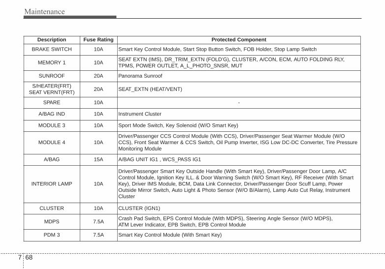
Maintenance
687
Description Fuse Rating Protected Component
BRAKE SWITCH 10A Smart Key Control Module, Start Stop Button Switch, FOB Holder, Stop Lamp Switch
MEMORY 1 10ASEAT EXTN (IMS), DR_TRIM_EXTN (FOLD’G), CLUSTER, A/CON, ECM, AUTO FOLDING RLY,TPMS, POWER OUTLET, A_L_PHOTO_SNSR, MUT
SUNROOF 20A Panorama Sunroof
S/HEATER(FRT)SEAT VERNT(FRT)
20A SEAT_EXTN (HEAT/VENT)
SPARE 10A -
A/BAG IND 10A Instrument Cluster
MODULE 3 10A Sport Mode Switch, Key Solenoid (W/O Smart Key)
MODULE 4 10ADriver/Passenger CCS Control Module (With CCS), Driver/Passenger Seat Warmer Module (W/OCCS), Front Seat Warmer & CCS Switch, Oil Pump Inverter, ISG Low DC-DC Converter, Tire PressureMonitoring Module
A/BAG 15A A/BAG UNIT IG1 , WCS_PASS IG1
INTERIOR LAMP 10A
Driver/Passenger Smart Key Outside Handle (With Smart Key), Driver/Passenger Door Lamp, A/CControl Module, Ignition Key ILL. & Door Warning Switch (W/O Smart Key), RF Receiver (With SmartKey), Driver IMS Module, BCM, Data Link Connector, Driver/Passenger Door Scuff Lamp, PowerOutside Mirror Switch, Auto Light & Photo Sensor (W/O B/Alarm), Lamp Auto Cut Relay, InstrumentCluster
CLUSTER 10A CLUSTER (IGN1)
MDPS 7.5ACrash Pad Switch, EPS Control Module (With MDPS), Steering Angle Sensor (W/O MDPS), ATM Lever Indicator, EPB Switch, EPB Control Module
PDM 3 7.5A Smart Key Control Module (With Smart Key)

7 69
Maintenance
Description Fuse Rating Protected Component
EPB 10A EPB
SPARE 20A -
IG 1 25A E/R BOX IG1
SPARE 10A -
POWER OUTLET 20A Front Power Outlet
MODULE 1 10A
Auto Head Lamp Leveling Device Module (Auto HLLD), Head Lamp Leveling Device Switch (ManualHLLD), Head Lamp Leveling Device Actuator LH/RH, BCM, Front Smart Parking Assist Sensor Module,Instrument Cluster, Electro Chromic Mirror, A/C Control Module, Driver IMS Module, Rear ParkingAssist Buzzer, Lane Keeping Assist Module
START 7.5A B/ALARM RLY
HTD STRG 15A Steering Wheel Heater
MODULE 5 7.5ASmart Key Control Module (With Smart Key), Rear Seat, Warmer Relay LH/RH, E/R Fuse & Relay Box(RLY.2), Diesel Box (Fuel Filter Relay)
A/CON 7.5A A/C Control Module, E/R Fuse & Relay Box (RLY.14)
SPARE 15A -
WIPER 25A E/R BOX WIPER RLY
C/LIGHTER 20A Cigarette Lighter
MODULE 6 7.5A PANORAMA SUNROOF (IG2), IONIZER, DSL_BOX, RR_SEAT_WARMER
HTD MIRR 10A Driver/Passenger Power Outside Mirror

Maintenance
707
Engine compartment fusepanel (for Theta 2.4 GDI)
✽✽ NOTICENot all fuse panel descriptions inthis manual may be applicable toyour vehicle. It is accurate at thetime of printing. When you inspectthe fuse panel in your vehicle, referto the fuse panel label.
OTF074086N
OVG079025L

7 71
Maintenance
Engine Compartment fuse panel(for theta 2.4 GDI)
Description Fuse Rating Protected Component
RR HTD 40A E/R BOX RR HTD RLY COIL
HORN 15A HORN (LH, RH)
F/PUMP 20A FUEL PUMP MTR
ECU 3 15A PCU (GDI) BATT. DIRECT
SENSOR 1 15A DN O2 SENSOR (GDI), UP O2 SENSOR (GDI)
INJECTOR 10A E/R BOX F/PUMP RLY COIL
SENSOR 3 10A CMP1, 2 (GDI, TGDI), SMATRA IMMOBILIZER
SENSOR 2 10A CKP (GDI), VIS (GDI), OCV1, 2 (GDI), PCSV (GDI), CCV (GDI)
IGN COIL 20A ENGINE IG COIL
ECU 1 30A ECU RLY
SPARE 10A -
SPARE 15A -
SPARE 20A -
WIPER 10A BCM, RAIN SNSR, WIPER MTR
AMS 10A BATTERY SENSOR

Maintenance
727
Description Fuse Rating Protected Component
TCU 1 20A TCU
STOP LAMP 15A RLY.10 (HAC Relay), STOP LAMP RELAY
DEICER 20A RLY.7 (Deicer Relay)
IG1 40A IGN SW
B+ 1 50A B+
B+ 2 60A B+
BLOWER 40A RLY.14 (Blower Relay)
IG 2 40A IGN SW, IG2 RLY
ESC 1 40A ESP UNIT MOTOR B+, DIAGNOSIS ABS A/B VALVE B+
ESC 2 40A ESP UNIT SOLENOID B+
RR HTD 40A RLY.1 (RR HTD Relay)
B+ 3 60A B+
MDPS 80A EPS Control Module
SPARE 25A -
C/FAN 50A E/R BOX C/FAN1 RLY SWITCH
INVERTER 50A O_P_INVERTER
EPB 2 30A EPB UNIT BATT2

7 73
Maintenance
Description Fuse Rating Protected Component
EPB 1 30A EPB UNIT BATT1
ECU 2 40A EMS BOX (B+)
ECU 4 10A ENGINE ECU
TCU 2 15A SPEED SNSR, POSITION SW, O_P_INVERTER
ESC 3 10A ESP UNIT IGN1
B/UP LAMP 10A ELECTRO CHROMIC MIRROR, BCM, REAR COMBINATION LAMP (IN) LH/RH
A/CON 10A A/C CONTROL MODULE (Auto A/C)

Maintenance
747
Engine compartment fusepanel (for Theta 2.0 T-GDI)
✽✽ NOTICENot all fuse panel descriptions inthis manual may be applicable toyour vehicle. It is accurate at thetime of printing. When you inspectthe fuse panel in your vehicle, referto the fuse panel label.
OVG079025L
OTF074086L

7 75
Maintenance
Engine Compartment fuse panel(for theta 2.0 T- GDI)
Description Fuse Rating Protected Component
RR HTD - E/R BOX RR HTD RLY COIL
HORN 15A HORN (LH, RH)
F/PUMP 20A FUEL PUMP MTR
ECU 3 15A PCU (TGDI) BATT. DIRECT
SENSOR 1 15A DN O2 SENSOR (TGDI), UP O2 SENSOR (TGDI), COOLING FAN RLY COIL (TGDI)
INJECTOR 10A E/R BOX F/PUMP RLY COIL
SENSOR 3 10A CMP1, 2 (TGDI), SMATRA IMMOBILIZER
SENSOR 2 10A CKP (TGDI), VIS (GDI), OCV1, 2 (TGDI), PCSV (TGDI), RCV (TGDI)
IGN COIL 20A ENGINE IG COIL
ECU 1 30A ECU RLY
SPARE 10A -
SPARE 15A -
SPARE 20A -
WIPER 10A BCM, RAIN SNSR, WIPER MTR
VACUUM PUMP 20A BRAKE VACUUM PUMP IG1
AMS 10A BATTERY SENSOR

Maintenance
767
Description Fuse Rating Protected Component
TCU 1 20A TCU
STOP LAMP 15A RLY.10 (HAC Relay), STOP LAMP RELAY
DEICER 20A RLY.7 (Deicer Relay)
IG1 40A IGN SW
B+ 1 50A B+
B+ 2 60A B+
C/ FAN 2 60A
IG 2 40A IGN SW, IG2 RLY
ESC 1 40A ESP UNIT MOTOR B+ , DIAGNOSIS ABS A/B VALVE B+
ESC 2 40A ESP UNIT SOLENOID B+
RR HTD 40A RLY.1 (RR HTD Relay)
B+ 3 60A B+
MDPS 80A EPS CONTROL MODULE
SPARE 25A -
C/FAN 1 50A COOLING FAN RLY TGDI
BLOWER 40A E/R BOX BLOWER RLY SWITCH

7 77
Maintenance
Description Fuse Rating Protected Component
EPB 2 30A EPB UNIT BATT2
EPB 1 30A EPB UNIT BATT1
ECU 2 40A EMS BOX (B+)
ECU 4 10A ENGINE ECU
TCU 2 15A SPEED SNSR, POSITION SW, O_P_INVERTER
ESC 3 10A ESP UNIT IGN1
B/UP LAMP 10A ELECTRO CHROMIC MIRROR, BCM, REAR COMBINATION LAMP (IN) LH/RH
A/CON 10A A/C CONTROL MODULE (Auto A/C)

Maintenance
787
Engine room (Battery terminal cover)
✽✽ NOTICENot all fuse panel descriptions inthis manual may be applicable toyour vehicle. It is accurate at thetime of printing. When you inspectthe fuse panel in your vehicle, referto the fuse panel label
OTF074089N
OVG079026
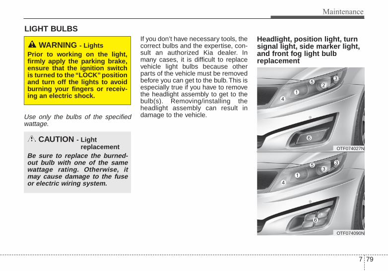
7 79
Maintenance
LIGHT BULBS
Use only the bulbs of the specifiedwattage.
If you don’t have necessary tools, thecorrect bulbs and the expertise, con-sult an authorized Kia dealer. Inmany cases, it is difficult to replacevehicle light bulbs because otherparts of the vehicle must be removedbefore you can get to the bulb. This isespecially true if you have to removethe headlight assembly to get to thebulb(s). Removing/installing theheadlight assembly can result indamage to the vehicle.
Headlight, position light, turnsignal light, side marker light,and front fog light bulbreplacement
WARNING - LightsPrior to working on the light,firmly apply the parking brake,ensure that the ignition switchis turned to the “LOCK” positionand turn off the lights to avoidburning your fingers or receiv-ing an electric shock.
CAUTION - Light replacement
Be sure to replace the burned-out bulb with one of the samewattage rating. Otherwise, itmay cause damage to the fuseor electric wiring system.
OTF074027N
OTF074090N

Maintenance
807
(1) Headlight (High)(2) Headlight (Low)(3) Side marker(4) Front turn signal light
(and Front position light*)(5) Front position light*(6) Front fog light*
* : if equipped
Headlight bulb Always handle them carefully, andavoid scratches and abrasions. If thebulbs are lit, avoid contact with liq-uids. Never touch the glass with barehands. Residual oil may cause thebulb to overheat and burst when lit. Abulb should be operated only wheninstalled in a headlight.If a bulb becomes damaged orcracked, replace it immediately andcarefully dispose of it.Wear eye protection when changinga bulb. Allow the bulb to cool downbefore handling it.
OHD076046
WARNING - Halogenbulbs
Handle halogen bulbs with care.Halogen bulbs contain pressur-ized gas that will produce flyingpieces of glass if broken.

7 81
Maintenance
Headlight (bulb type)
1. Turn off the engine.2. Open the hood.3. Remove the headlight bulb cover
by turning it counterclockwise.4. Disconnect the headlight bulb
socket-connector.5. Remove the bulb from the head-
light assembly.6. Install a new headlight bulb.7. Connect the headlight bulb socket-
connector.8. Install the headlight bulb cover by
turning it clockwise.
If the headlight aiming adjustment isnecessary after the headlightassembly is reinstalled, consult anauthorized Kia dealer.
OEN076051

Maintenance
827
Front side marker/Front turn sig-nal lightFront side marker
1.Turn off the engine.2.Open the hood3.Remove the intake folder and
screws.4.Remove the bumper cover and
under pad by rotating the screw.5.Remove the nuts of headlamp
assembly.6.Remove the socket from the
assembly by turning the socketcounterclockwise until the tabs onthe socket align with the slots onthe assembly.
7.Remove the bulb from the socketby pressing it in and rotating itcounterclockwise until the tabs onthe bulb align with the slots in thesocket. Pull the bulb out of thesocket.
8.Insert a new bulb by inserting it intothe socket and rotating it until itlocks into place.
OTF070065/OTF074066N/OTF074069 OTF070068/OTF070050N/OTF070051N
Front side marker
Front turn signal light

7 83
Maintenance
9.Install the socket in the assemblyby aligning the tabs on the socketwith the slots in the assembly.Push the socket into assembly andturn the socket clockwise.
10. Reinstall the headlamp assem-bly, under pad and bumper to thebody of the vehicle.
Front turn signal light
1.Turn off the engine.2.Open the hood3.Remove the socket from the
assembly by turning the socketcounterclockwise until the tabs onthe socket align with the slots onthe assembly.
4.Remove the bulb from the socketby pressing it in and rotating itcounterclockwise until the tabs onthe bulb align with the slots in thesocket. Pull the bulb out of thesocket.
5.Insert a new bulb by inserting it intothe socket and rotating it until itlocks into place.
6.Install the socket in the assemblyby aligning the tabs on the socketwith the slots in the assembly.Push the socket into assembly andturn the socket clockwise.
Side repeater light bulbreplacement Type A
If the light bulb does not operate,have the vehicle checked by anauthorized Kia dealer.
OTF070029

Maintenance
847
Type B
If the light bulb does not operate,have the vehicle checked by anauthorized Kia dealer.
Front fog light
1.Turn off the engine.2.Remove the under cover by rotat-
ing the screws.3.Reach your hand into the back of
the front bumper.4.Disconnect the power connector.5.Remove the bulb-socket from the
housing by turning the socketcounter clockwise until the tabs onthe socket align with the slots onthe housing.
CAUTIONWhen you remove the siderepeater cover, be careful not todamage the side repeater coverand vehicle surface.
OTF074067NOTF070048N

7 85
Maintenance
6.Install the new bulb-socket into thehousing by aligning the tabs on thesocket with the slots in the hous-ing.Push the socket into the housingand turn the socket clockwise.
7.Connect the power connector.8.Reinstall the front under cover.
Rear combination light bulbreplacement
(1) Stop and tail light(2) Tail light(3) Rear turn signal light(4) Back-up light(5) Rear side marker
OTF074083
OTF074030

Maintenance
867
Type BIf the light (LED) does not operate,have the vehicle checked by anauthorized Kia dealer.
Stop and tail light / Rear turn sig-nal light1.Turn off the engine.2.Open the trunk.3.Open the service cover.
4.Remove the socket from theassembly by turning the socketcounterclockwise until the tabs onthe socket align with the slots onthe assembly.
5.Remove the bulb from the socketby pressing it in and rotating itcounterclockwise until the tabs onthe bulb align with the slots in thesocket. Pull the bulb out of thesocket.
6.Insert a new bulb by inserting it intothe socket and rotating it until itlocks into place.
7.Install the socket in the assemblyby aligning the tabs on the socketwith the slots in the assembly.Push the socket into the assemblyand turn the socket clockwise.
8.Install the service cover by pullingit into the service hole.
OTF070031
OTF070032
Stop and tail light / Rear turn signal light

7 87
Maintenance
Backup light/Tail light (if equipped)
1.Turn off the engine.2.Open the trunk.3.Loosen the retaining screw of the
trunk lid cover and then remove thecover.
4.Disconnect the cable and thenremove the nuts by turning the nutscounter clockwise.
5.Take the light assembly out.6.Insert a new bulb by inserting it into
the socket.7.Install the light assembly to the
trunk.8.Reinstall the nuts and connector
and then the trunk lid cover bypushing in the screw.
OTF070033
OTF074052
Backup light
OTF074054
OTF074055
Backup light-1
Backup light-2

Maintenance
887
License plate light bulbreplacement
1.Turn off the engine.2.Open the trunk.
3.Loosen the retaining screw of thetrunk lid cover and then remove thecover.
4.Take out the light.5.Insert a new bulb by inserting it into
the socket.6.Reinstall the trunk lid cover by
pushing in the screw.
High mounted stop lightreplacement (if equipped)
OTF070036
OTF070033
OTF074037
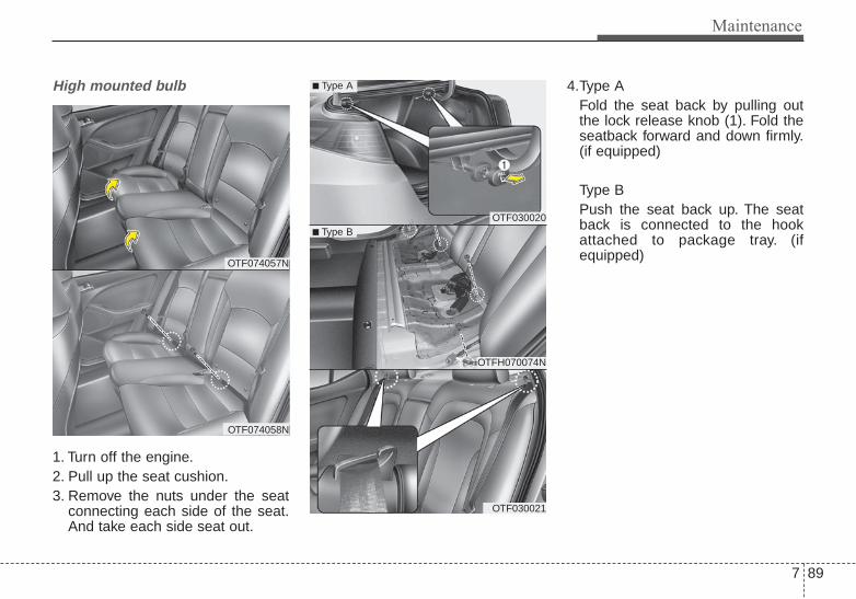
7 89
Maintenance
High mounted bulb
1. Turn off the engine.2. Pull up the seat cushion.3. Remove the nuts under the seat
connecting each side of the seat.And take each side seat out.
4.Type AFold the seat back by pulling outthe lock release knob (1). Fold theseatback forward and down firmly.(if equipped)
Type BPush the seat back up. The seatback is connected to the hookattached to package tray. (ifequipped)
OTF074057N
OTF074058N
OTF030020
OTFH070074N
OTF030021
■ Type B
■ Type A

Maintenance
907
5. Take the C-pillar out carefully. Ifyou pull the C-pillar strongly, itwill be broken.
6. Disconnect the cable attached onthe panel.
7. Remove the screws and packagetray.
8. Remove the fabric and nuts.9. Change the HMSL to a new one.10. Reinstall all package tray, cable
and side seat. Lift and push theseat back backward firmly until itclicks into place.
11. Reinstall the seat by pushing itdown firmly.
OTF070059N
OTF070060N
OTF070061N
OTF070062N
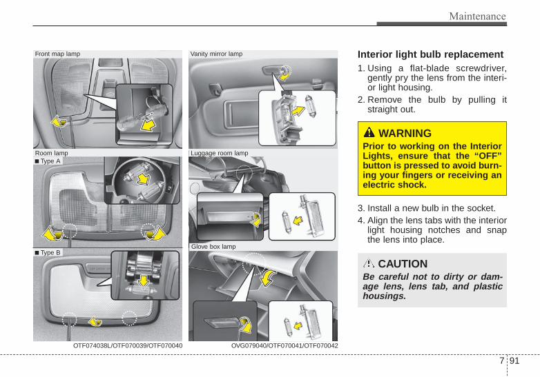
7 91
Maintenance
Interior light bulb replacement1. Using a flat-blade screwdriver,
gently pry the lens from the interi-or light housing.
2. Remove the bulb by pulling itstraight out.
3. Install a new bulb in the socket.4. Align the lens tabs with the interior
light housing notches and snapthe lens into place.
WARNING Prior to working on the InteriorLights, ensure that the “OFF”button is pressed to avoid burn-ing your fingers or receiving anelectric shock.
CAUTIONBe careful not to dirty or dam-age lens, lens tab, and plastichousings.
■ Type A
Front map lamp
OTF074038L/OTF070039/OTF070040
Room lamp
■ Type B
Vanity mirror lamp
Luggage room lamp
Glove box lamp
OVG079040/OTF070041/OTF070042

Maintenance
927
APPEARANCE CAREExterior careExterior general caution It is very important to follow the labeldirections when using any chemicalcleaner or polish. Read all warningand caution statements that appearon the label.
Finish maintenanceWashing
To help protect your vehicle’s finishfrom rust and deterioration, wash itthoroughly and frequently at leastonce a month with lukewarm or coldwater.If you use your vehicle for off-roaddriving, you should wash it after eachoff-road trip. Pay special attention tothe removal of any accumulation ofsalt, dirt, mud, and other foreignmaterials. Make sure the drain holesin the lower edges of the doors androcker panels are kept clear andclean.Insects, tar, tree sap, bird droppings,industrial pollution and similardeposits can damage your vehicle’sfinish if not removed immediately.Even prompt washing with plainwater may not completely remove allthese deposits. A mild soap, safe foruse on painted surfaces, may beused.After washing, rinse the vehicle thor-oughly with lukewarm or cold water.Do not allow soap to dry on the fin-ish.
After washing the vehicle, test thebrakes while driving slowly to see ifthey have been affected by water. Ifbraking performance is impaired, drythe brakes by applying them lightlywhile maintaining a slow forwardspeed.
CAUTION - HeadlightLens
To prevent damage, do notclean headlight lens with chem-ical solvents or strong deter-gents.

7 93
Maintenance
Waxing
Wax the vehicle when water will nolonger bead on the paint.Always wash and dry the vehiclebefore waxing. Use a good qualityliquid or paste wax, and follow themanufacturer’s instructions. Wax allmetal trim to protect it and to main-tain its luster.Removing oil, tar, and similar materi-als with a spot remover will usuallystrip the wax from the finish. Be sureto re-wax these areas even if the restof the vehicle does not yet need wax-ing.
CAUTION - Wetting engine• Water washing in the engine
compartment including highpressure water washing maycause the failure of electricalcircuits located in the enginecompartment.
• Never allow water or other liq-uids to come in contact withelectrical/electronic compo-nents inside the vehicle asthis may damage them.
OJB037800
CAUTION - Drying vehicle• Wiping dust or dirt off the
body with a dry cloth willscratch the finish.
• Do not use steel wool, abra-sive cleaners, or strong deter-gents containing highly alka-line or caustic agents onchrome-plated or anodizedaluminum parts. This mayresult in damage to the pro-tective coating and cause dis-coloration or paint deteriora-tion.

Maintenance
947
Finish damage repair Deep scratches or stone chips in thepainted surface must be repairedpromptly. Exposed metal will quicklyrust and may develop into a majorrepair expense.If your vehicle is damaged andrequires any metal repair or replace-ment, be sure the body shop appliesanti-corrosion materials to the partsrepaired or replaced.
Bright-metal maintenance• To remove road tar and insects,
use a tar remover, not a scraper orother sharp object.
• To protect the surfaces of bright-metal parts from corrosion, apply acoating of wax or chrome preser-vative and rub to a high luster.
• During winter weather or in coastalareas, cover the bright metal partswith a heavier coating of wax orpreservative. If necessary, coat theparts with non-corrosive petroleumjelly or other protective compound.
Underbody maintenanceCorrosive materials used for ice andsnow removal and dust control maycollect on the underbody. If thesematerials are not removed, acceler-ated rusting can occur on underbodyparts such as the fuel lines, frame,floor pan and exhaust system, eventhough they have been treated withrust protection.Thoroughly flush the vehicle under-body and wheel openings with luke-warm or cold water once a month,after off-road driving and at the endof each winter. Pay special attentionto these areas because it is difficultto see all the mud and dirt. It will domore harm than good to wet downthe road grime without removing it.The lower edges of doors, rockerpanels, and frame members havedrain holes that should not beallowed to clog with dirt; trappedwater in these areas can cause rust-ing.
7 95
Maintenance
Aluminum or chrome wheel main-tenance The aluminum or chrome wheels arecoated with a clear protective finish.• Do not use any abrasive cleaner,
polishing compound, solvent, orwire brushes on aluminum orchrome wheels. They may scratchor damage the finish.
• Clean the wheel when it hascooled.
• Use only a mild soap or neutraldetergent, and rinse thoroughlywith water. Also, be sure to cleanthe wheels after driving on saltedroads. This helps prevent corro-sion.
• Avoid washing the wheels withhigh-speed car wash brushes.
• Do not use any alkaline or aciddetergent. It may damage and cor-rode the aluminum or chromewheels coated with a clear protec-tive finish.
Corrosion protectionProtecting your vehicle from corro-sion
By using the most advanced designand construction practices to combatcorrosion, we produce vehicles ofthe highest quality. However, this isonly part of the job. To achieve thelong-term corrosion resistance yourvehicle can deliver, the owner'scooperation and assistance is alsorequired.
Common causes of corrosion
The most common causes of corro-sion on your vehicle are:• Road salt, dirt and moisture that is
allowed to accumulate underneaththe vehicle.
• Removal of paint or protectivecoatings by stones, gravel, abra-sion or minor scrapes and dentswhich leave unprotected metalexposed to corrosion.
High-corrosion areas
If you live in an area where your vehi-cle is regularly exposed to corrosivematerials, corrosion protection isparticularly important. Some of thecommon causes of accelerated cor-rosion are road salts, dust controlchemicals, ocean air and industrialpollution.
Moisture breeds corrosion
Moisture creates the conditions inwhich corrosion is most likely tooccur. For example, corrosion isaccelerated by high humidity, partic-ularly when temperatures are justabove freezing. In such conditions,the corrosive material is kept in con-tact with the vehicle surfaces bymoisture that is slow to evaporate.Mud is particularly corrosivebecause it dries slowly and holdsmoisture in contact with the vehicle.Although the mud appears to be dry,it can still retain the moisture andpromote corrosion.

Maintenance
967
High temperatures can also acceler-ate corrosion of parts that are notproperly ventilated so the moisturecan be dispersed. For all these rea-sons, it is particularly important tokeep your vehicle clean and free ofmud or accumulations of other mate-rials. This applies not only to the vis-ible surfaces but particularly to theunderside of the vehicle.
To help prevent corrosion
You can help prevent corrosion fromgetting started by observing the fol-lowing:
Keep your vehicle cleanThe best way to prevent corrosion isto keep your vehicle clean and freeof corrosive materials. Attention tothe underside of the vehicle is partic-ularly important.
• If you live in a high-corrosion area— where road salts are used, nearthe ocean, areas with industrialpollution, acid rain, etc.—, youshould take extra care to preventcorrosion. In winter, hose off theunderside of your vehicle at leastonce a month and be sure to cleanthe underside thoroughly whenwinter is over.
• When cleaning underneath thevehicle, give particular attention tothe components under the fendersand other areas that are hiddenfrom view. Do a thorough job; justdampening the accumulated mudrather than washing it away willaccelerate corrosion rather thanprevent it. Water under high pres-sure and steam are particularlyeffective in removing accumulatedmud and corrosive materials.
• When cleaning lower door panels,rocker panels and frame mem-bers, be sure that drain holes arekept open so that moisture canescape and not be trapped insideto accelerate corrosion.
Keep your garage dryDon't park your vehicle in a damp,poorly ventilated garage. This cre-ates a favorable environment for cor-rosion. This is particularly true if youwash your vehicle in the garage ordrive it into the garage when it is stillwet or covered with snow, ice ormud. Even a heated garage can con-tribute to corrosion unless it is wellventilated so moisture is dispersed.
7 97
Maintenance
Keep paint and trim in good con-ditionScratches or chips in the finishshould be covered with "touch-up"paint as soon as possible to reducethe possibility of corrosion. If baremetal is showing through, the atten-tion of a qualified body and paintshop is recommended.
Bird droppings : Bird droppings arehighly corrosive and may damagepainted surfaces in just a few hours.Always remove bird droppings assoon as possible.
Don't neglect the interiorMoisture can collect under the floormats and carpeting and cause corro-sion. Check under the mats periodi-cally to be sure the carpeting is dry.Use particular care if you carry fertil-izers, cleaning materials or chemi-cals in the car.These should be carried only inproper containers and any spills orleaks should be cleaned up, flushedwith clean water and thoroughlydried.
Interior careInterior general precautions Prevent chemicals such as perfume,cosmetic oil, sun cream, hand clean-er, and air freshener from contactingthe interior parts because they maycause damage or discoloration. Ifthey do contact the interior parts,wipe them off immediately. See theinstructions for the proper way toclean vinyl.
CAUTION - Electrical components
Never allow water or other liq-uids to come in contact withelectrical/electronic compo-nents inside the vehicle as thismay damage them.
CAUTION - LeatherWhen cleaning leather products(steering wheel, seats etc.), useneutral detergents or low alco-hol content solutions. If you usehigh alcohol content solutionsor acid/alkaline detergents, thecolor of the leather may fade orthe surface may get stripped off.

Maintenance
987
Cleaning the upholstery and inte-rior trim Vinyl
Remove dust and loose dirt fromvinyl with a whisk broom or vacuumcleaner. Clean vinyl surfaces with avinyl cleaner.
Fabric
Remove dust and loose dirt from fab-ric with a whisk broom or vacuumcleaner. Clean with a mild soap solu-tion recommended for upholstery orcarpets. Remove fresh spots imme-diately with a fabric spot cleaner. Iffresh spots do not receive immediateattention, the fabric can be stainedand its color can be affected. Also, itsfire-resistant properties can bereduced if the material is not proper-ly maintained.Using anything but recommendedcleaners and procedures may affectthe fabric’s appearance and fire-resistant properties.
Cleaning the lap/shoulder beltwebbing Clean the belt webbing with any mildsoap solution recommended forcleaning upholstery or carpet. Followthe instructions provided with thesoap. Do not bleach or re-dye thewebbing because this may weakenit.
Cleaning the interior windowglass If the interior glass surfaces of thevehicle become fogged (that is, cov-ered with an oily, greasy or waxyfilm), they should be cleaned withglass cleaner. Follow the directionson the glass cleaner container.
CAUTION - Rear windowsDo not scrape or scratch theinside of the rear window. Thismay result in damage to the rearwindow defroster grid.

7 99
Maintenance
EMISSION CONTROL SYSTEMThe emission control system of yourvehicle is covered by a written limitedwarranty. Please see the warrantyinformation contained in theWarranty & Consumer Informationmanual in your vehicle.Your vehicle is equipped with anemission control system to meet allapplicable emission regulations.There are three emission controlsystems, as follows.
(1) Crankcase emission control sys-tem
(2) Evaporative emission control sys-tem
(3) Exhaust emission control system
In order to assure the proper functionof the emission control systems, it isrecommended that you have yourvehicle inspected and maintained byan authorized Kia dealer in accor-dance with the maintenance sched-ule in this manual.
Caution for the Inspection andMaintenance Test (With ElectronicStability Control (ESC) system)• To prevent the vehicle from mis-
firing during dynamometer test-ing, turn the Electronic StabilityControl (ESC) system off bypressing the ESC switch.
• After dynamometer testing iscompleted, turn the ESC systemback on by pressing the ESCswitch again.
1. Crankcase emission controlsystem
The positive crankcase ventilationsystem is employed to prevent airpollution caused by blow-by gasesbeing emitted from the crankcase.This system supplies fresh filtered airto the crankcase through the airintake hose. Inside the crankcase,the fresh air mixes with blow-bygases, which then pass through thePCV valve into the induction system.
2. Evaporative emission con-trol (including ORVR:Onboard Refueling VaporRecovery) system
The Evaporative Emission ControlSystem is designed to prevent fuelvapors from escaping into the atmos-phere.(The ORVR system is designed toallow the vapors from the fuel tank tobe loaded into a canister while refu-eling at the gas station, preventingthe escape of fuel vapors into theatmosphere.)

Maintenance
1007
CanisterFuel vapors generated inside the fueltank are absorbed and stored in theonboard canister. When the engine isrunning, the fuel vapors absorbed inthe canister are drawn into the surgetank through the purge control sole-noid valve.
Purge Control Solenoid Valve(PCSV)The purge control solenoid valve iscontrolled by the Engine ControlModule (ECM); when the enginecoolant temperature is low duringidling, the PCSV closes so that evap-orated fuel is not taken into theengine. After the engine warms upduring ordinary driving, the PCSVopens to introduce evaporated fuel tothe engine.
3. Exhaust emission control system
The Exhaust Emission ControlSystem is a highly effective systemwhich controls exhaust emissionswhile maintaining good vehicle per-formance.
Vehicle modifications This vehicle should not be modified.Modification of your vehicle couldaffect its performance, safety ordurability and may even violate gov-ernmental safety and emissions reg-ulations.In addition, damage or performanceproblems resulting from any modifi-cation may not be covered underwarranty.• If you use unauthorized electronic
devices, it may cause the vehicle tooperate abnormally, wire damage,battery discharge and fire. For yoursafety, do not use unauthorizedelectronic devices.
Engine exhaust gas precautions(carbon monoxide) • Carbon monoxide can be present
with other exhaust fumes.Therefore, if you smell exhaustfumes of any kind inside your vehi-cle, have it inspected and repairedimmediately. If you ever suspectexhaust fumes are coming intoyour vehicle, drive it only with allthe windows fully open. Have yourvehicle checked and repairedimmediately.
WARNING - ExhaustEngine exhaust gases containcarbon monoxide (CO). Thoughcolorless and odorless, it isdangerous and could be lethal ifinhaled. Follow the instructionson this page to avoid CO poi-soning.

7 101
Maintenance
• Do not operate the engine in con-fined or closed areas (such asgarages) any more than what isnecessary to move the vehicle in orout of the area.
• When the vehicle is stopped in anopen area for more than a shorttime with the engine running,adjust the ventilation system (asneeded) to draw outside air into thevehicle.
• Never sit in a parked or stoppedvehicle for any extended time withthe engine running.
• When the engine stalls or fails tostart, excessive attempts to restartthe engine may cause damage tothe emission control system.
Operating precautions for catalyt-ic converters (if equipped)
Your vehicle is equipped with a cat-alytic converter emission controldevice.Therefore, the following precautionsmust be observed:
• Use only UNLEADED FUEL forgasoline engines.
• Do not operate the vehicle whenthere are signs of engine malfunc-tion, such as misfire or a noticeableloss of performance.
• Do not misuse or abuse theengine. Examples of misuse arecoasting with the ignition off anddescending steep grades in gearwith the ignition off.
• Do not operate the engine at highidle speed for extended periods (5minutes or more).
• Do not modify or tamper with anypart of the engine or emission con-trol system. All inspections andadjustments must be made by anauthorized Kia dealer.
• Avoid driving with a extremely lowfuel level. Running out of fuel couldcause the engine to misfire, dam-aging the catalytic converter.
Failure to observe these precautionscould result in damage to the catalyt-ic converter and to your vehicle.Additionally, such actions could voidyour warranties.
WARNING - Fire• Do not park, idle or drive the
vehicle over or near flamma-ble objects, such as grass,vegetation, paper, leaves, etc.A hot exhaust system canignite flammable items underyour vehicle.
• Also, do not remove the heatsink around the exhaust sys-tem, do not seal the bottom ofthe vehicle or do not coat thevehicle for corrosion control.It may present a fire risk undercertain conditions.
WARNING - Catalytic converter
Keep away from the catalyticconverter and exhaust systemwhile the vehicle is running orimmediately thereafter. Theexhaust and catalytic systemsare very hot and may burn you.

Maintenance
1027
CALIFORNIA PERCHLORATE NOTICEPerchlorate Material-special han-dling may apply, Seewww.dtsc.ca.gov/hazardouswaste/perchlorate.
Notice to California VehicleDismantlers:Perchlorate containing materials,such as air bag inflators, seatbeltpretensioners and keyless remoteentry batteries, must be disposed ofaccording to Title 22 California Codeof Regulations Section 67384.10 (a).

Specifications & Consumer information
Dimensions . . . . . . . . . . . . . . . . . . . . . . . . . . . . . . . . 8-2Engine . . . . . . . . . . . . . . . . . . . . . . . . . . . . . . . . . . . . 8-2Gross vehicle weight. . . . . . . . . . . . . . . . . . . . . . . . . 8-3Luggage volume . . . . . . . . . . . . . . . . . . . . . . . . . . . . 8-3Bulb wattage . . . . . . . . . . . . . . . . . . . . . . . . . . . . . . . 8-4Tires and wheels . . . . . . . . . . . . . . . . . . . . . . . . . . . . 8-5Recommended lubricants and capacities . . . . . . . 8-6
• Recommended sae viscosity number . . . . . . . . . . . . . . 8-8Vehicle identification number (VIN) . . . . . . . . . . . 8-9Vehicle certification label. . . . . . . . . . . . . . . . . . . . . 8-9Tire specification and pressure label . . . . . . . . . . 8-10Engine number . . . . . . . . . . . . . . . . . . . . . . . . . . . . 8-10Refrigerant label. . . . . . . . . . . . . . . . . . . . . . . . . . . 8-11Consumer assistance (U.S. Only) . . . . . . . . . . . . . 8-11Electrical equipment (U.S. Only) . . . . . . . . . . . . . 8-13Reporting safety defects (U.S. Only) . . . . . . . . . . 8-14Online factory authorized manuals
(U.S. Only) . . . . . . . . . . . . . . . . . . . . . . . . . . . . . . 8-15
8

Specifications, Consumer information, Reporting safety defects
28
DIMENSIONS
Item 2.4 GDI 2.0 T-GDI
Displacement [cu.in(cc)] 143.96 cu.in (2,359 cc) 121.92 cu.in (1,998 cc)
Bore x Stroke [in(mm)]3.46 x 3.46 in (86 x 86 mm)
3.46 x 3.82 mm (88 x 97 mm)
Firing order 1 → 3 → 4 → 2 1 → 3 → 4 → 2
No. of cylinders 4, In-line 4, In-line
Item in. (mm)
Overall length 190.7 (4,845)
Overall width 72.0 (1,830)
Overall height 57.1 (1,450)
Front tread 63.0 (1,601)*1/62.8 (1,595)*2/62.6 (1,591)*3
Rear tread 63.0 (1,601)*1/62.8 (1,595)*2/62.6 (1,591)*3
Wheelbase 110.0 (2,795)
*1 : with R16 tire*2 : with R17 tire*3 : with R18 tire
ENGINE

8 3
Specifications, Consumer information, Reporting safety defects
GROSS VEHICLE WEIGHT
LUGGAGE VOLUME
ltem Gasoline 2.4L Gasoline 2.0L
SAE 15.4 cu ft (437l)
ITEM Gasoline 2.4L Gasoline 2.0L
Gross vehicle weightM/T 4,299 lbs (1,950 kg) -
A/T 4,365 lbs (1,980 kg) 4,497 lbs (2,040 kg)

Specifications, Consumer information, Reporting safety defects
48
BULB WATTAGE
* : if equipped
Light Bulb Wattage Bulb type
Front
Headlamps (Low) 55 H118BHeadlamps (Low) - HID type* 35 D1SHeadlamps (High) 55 H1L/H7LFront turn signal lamps 28 P28/8WFront position lamps 8/LED P28/8W/LEDFront fog lamps* 35/LED H8L/LEDSide Repeater lamps* 5/LED WY5W/LEDSmart cornering lamp* 55 55Side marker LED LED
Rear
Rear fog lamps* 21 P21W
Bulb typeRear Stop/Tail lamps (outside) 28/8 P28/8WRear tail lamps (Inside) 27/8, 28/8 P27/8W, P28/8W
LED typeRear Stop/Tail lamps (outside) LED LEDRear tail lamps (Inside) LED LED
Rear turn signal lamps 21/27 P21W/P27WBack-up lamps 16 #921High mounted stop lamp* LED LEDLicense plate lamps 5 W5W
Interior
Map lamps 10 W10W
Room lamps 10 C10W
Vanity mirror lamps 5 C5W
Glove box lamp 5 C5W
Trunk lamp 5 C5W

8 5
Specifications, Consumer information, Reporting safety defects
TIRES AND WHEELS
CAUTIONWhen replacing tires, use the same size originally supplied with the vehicle.Using tires of a different size can damage the related parts or make it work irregularly.
*1 : Normal load : Up to 3 persons*2 : If your vehicle is not equipped with a compact spare tire, you will be equipped with a Tire Mobility Kit
Inflation pressure
kPa (psi)
Front Rear Front Rear
205/65R16 95H 6.5J×16 225 (33) 225 (33) 225 (33) 225 (33)
215/55R17 94V 6.5J×17 225 (33) 225 (33) 225 (33) 225 (33)
225/45R18 95V 7.5J×18 240 (35) 240 (35) 240 (35) 240 (35)
T125/80D16 97M 4.0T×16420 420 420 420
(60) (60) (60) (60)
T135/80D17 103M 4.0T×17420 420 420 420
(60) (60) (60) (60)
Full size tire
Compactspare tire*2
Wheel lug nut torque
lb•ft (kg•m, N•m)
65~79
(9~11, 88~107)
ItemTire
sizeWheel size
Normal load *1 Maximum load

Specifications, Consumer information, Reporting safety defects
68
RECOMMENDED LUBRICANTS AND CAPACITIESTo help achieve proper engine and powertrain performance and durability, use only lubricants of the proper quality.The correct lubricants also help promote engine efficiency that results in improved fuel economy.These lubricants and fluids are recommended for use in your vehicle.
Lubricant Volume Classification
Engine oil *1 *2 (drain and refill)Recommends
2.0 T-GDI5.28 US qt.
(5.0 l)
ACEA A5 or above*3
2.4 GDI API Service SM*3, ILSAC GF-4 or aboveACEA A5 or above
Manual transaxle fluid 1.90 US qt. (1.8 l)API GL-4, SAE 75W/85, fill for-life
or other brands meeting the GL-4 speciticationapproved by Kia Motors Corp.
Automatic transaxle fluid2.0 T-GDI 8.24 US qt. (7.8 l) MICHANG ATF SP-IV, SK ATF SP-IV
NOCA ATF SP-IV, Kia genuine ATF SP-IV or otherbrands meeting the above specification approved by
Kia Motors Corp.2.4 GDI 7.50 US qt. (7.1 l)
Coolant 2.0 T-GDI 6.87 ~ 6.97 US qt.
(6.5 ~ 6.6 l) Mixture of antifreeze and water (Ethylene glycol base coolant for aluminum radiator)
2.4 GDI 7.18 US qt. (6.8 l)
Brake/clutch fluid0.7~0.8 US qt.
(0.7~0.8 l)FMVSS116 DOT-3 or DOT-4
Fuel 18.49 US gal. (70 l) Unleaded gasoline
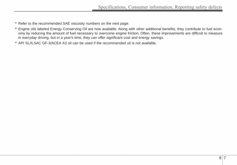
8 7
Specifications, Consumer information, Reporting safety defects
*1 Refer to the recommended SAE viscosity numbers on the next page.
*2 Engine oils labeled Energy Conserving Oil are now available. Along with other additional benefits, they contribute to fuel econ-omy by reducing the amount of fuel necessary to overcome engine friction. Often, these improvements are difficult to measurein everyday driving, but in a year’s time, they can offer significant cost and energy savings.
*3 API SL/ILSAC GF-3/ACEA A3 oil can be used if the recommended oil is not available.

Specifications, Consumer information, Reporting safety defects
88
Recommended SAE viscositynumber Always be sure to clean the areaaround any filler plug, drain plug, ordipstick before checking or drainingany lubricant. This is especiallyimportant in dusty or sandy areasand when the vehicle is used onunpaved roads. Cleaning the plugand dipstick areas will prevent dirtand grit from entering the engine andother mechanisms that could bedamaged.
Engine oil viscosity (thickness) hasan effect on fuel economy and coldweather operation (engine start andengine oil flowability). Lower viscosi-ty engine oils can provide better fueleconomy and cold weather perform-ance, however, higher viscosityengine oils are required for satisfac-tory lubrication in hot weather.
Using oils of any viscosity other thanthose recommended could result inengine damage.When choosing an oil, consider therange of temperature your vehicle willbe operated in before the next oilchange. Proceed to select the recom-mended oil viscosity from the chart.
Temperature Range for SAE Viscosity Numbers
Temperature
Engine Oil (2.4 GDI) *1
Engine Oil(2.0 T-GDI)
°C(°F)
-30 -20 -10 0 10 20 30 40 50-10 0 20 40 60 80 100 120
10W-30
5W-20, 5W-30
*1. For better fuel economy, it is recommended to use the engine oil ofa viscosity grade SAE 5W-20 (API SM / ILSAC GF-4). However, ifthe engine oil is not available in your country, select the properengine oil using the engine oil viscosity chart.
20W-50
10W-30
15W-40
5W-30, 5W-40

8 9
Specifications, Consumer information, Reporting safety defects
VEHICLE IDENTIFICATION NUMBER (VIN)
The vehicle identification number(VIN) is the number used in register-ing your vehicle and in all legal mat-ters pertaining to its ownership, etc.
VIN label
The VIN is also on a plate attachedto the top of the dashboard. Thenumber on the plate can easily beseen through the windshield fromoutside.
The vehicle certification labelattatched on the driver’s side centerpillar gives the vehicle identificationnumber (VIN).
VEHICLE CERTIFICATIONLABEL
OVQ076002N
VIN Label (if equipped)
OTF080001
OTF080002

Specifications, Consumer information, Reporting safety defects
108
The tires supplied on your new vehi-cle are chosen to provide the bestperformance for normal driving.The tire label located on the driver'sside center pillar gives the tire pres-sures recommended for your vehicle.
The engine number is stamped onthe engine block as shown in thedrawing.
The refrigerant label is located onthe underside of the hood.
REFRIGERANT LABELTIRE SPECIFICATION ANDPRESSURE LABEL
OTFH081005N
OMG055004
OTF080004
OYF081013N
■■ 2.4 engine
■■ 2.0 engine
ENGINE NUMBER

8 11
Specifications, Consumer information, Reporting safety defects
Roadside Assistance is provided on all new currentmodel year Kia Vehicles from the date the vehicle is deliv-ered to the first retail buyer or otherwise put into use (in-service date), whichever is earlier, for a period of 60months or 60,000 miles, whichever is earlier, subject tothe terms, conditions and exclusions set forth in the KiaWarranty and Consumer Information Manual applicableto your model year vehicle.KMA reserves the right to limit or deny services or otherbenefits to any owner or driver when, in KMA's judgment,the claims and/or service requests are excessive in fre-quency or type of occurrence.
Toll free consumer assistanceKia's toll-free Consumer Assistance hot line is staffedfrom 5:00 AM to 6:00 PM PST, Monday through Fridayand is accessible by dialing 1-800-333-4Kia (4542).For more information regarding assistance available,please refer to your Kia Warranty & ConsumerInformation Manual.
Emergency roadside assistanceKia's toll free Roadside Assistance hot line is staffed 24hours a day, 365 days a year and is accessible by dialing1-800-333-4Kia (4542).Please note that you must provide your VehicleIdentification Number (VIN) to verify coverage at the timeof your call.
The VIN can be found on the dash of your vehicle on thedriver’s side, on the door jamb of the driver’s door, yourvehicle’s registration or proof of insurance card.Kia utilizes a network of over 17,000 roadside assistanceproviders. Should you accidentally run out of fuel, requirea battery jump, or need help changing a tire, a KiaRoadside Assistance Representative will dispatch some-one to deliver a small quantity of gas, change a flat tirewith your inflated spare, or arrange a battery jump toallow you to proceed to your destination. We have accessto a network of over 10,000 locksmiths to help you shouldyou become locked out of your Kia.In the event that mechanical difficulty renders your vehi-cle undriveable due to a warranty-related concern, Kia’sRoadside Assistance Representative will arrange totransport your vehicle to the nearest Kia dealer or to analternative service location.Your vehicle must be accessible to our dispatch transportvehicle, as determined by our driver, to receive this serv-ice.
✽✽ NOTICERoadside Assistance benefits are not available for anyKia vehicle that has ever been or should be issued a “sal-vage” title or similar “branded” title under any state’slaw or has been declared a “total loss” or equivalent bya financial institution or insurance company.
CONSUMER ASSISTANCE (U.S. ONLY)

Specifications, Consumer information, Reporting safety defects
128
Trip interruptionTrip interruption expense benefits are provided in theevent that a warranty-related disablement occurs morethan 150 miles from your home, and the repairs requiremore than 24 hours to complete. Reasonable reimburse-ment is included for meals, lodging, or rental car expens-es. Trip interruption coverage is limited to $100 per daysubject to a three day maximum limit per incident. Youmust contact the Kia Roadside Assistance Center toobtain pre-authorization of expenses. Once the KiaRoadside Assistance Center gives authorization for tripinterruption benefits, they will assist you in making thenecessary arrangements. Insurance deductibles,expenses, and claims paid by your insurance company orother providers are not eligible for reimbursement.Fleet vehicles are excluded from reimbursement underKia’s Trip Interruption Policy.
Registering your vehicle in a foreign countryIf you plan to register your vehicle in a foreign country,you should confirm that it conforms to the regulations inthat country. Even if you successfully register the vehiclein a foreign country, you may experience the followingproblems and should therefore consider the possibility ofhaving to deal with them:
1. The fuel specified for your vehicle may be unavailable.If other than the specified fuel is used, it could causedamage to the engine, the fuel injection system, andother fuel-related parts which may not be coveredunder your New Vehicle Emissions Limited Warranty.
2. We must, therefore, clearly state that when you leavethe country in which you purchased your Kia new andregister it in another country, problems arising from theuse of fuel other than the specified fuel are not subjectto manufacturer’s warranty. Because vehicles likeyours may not be marketed in the new country of reg-istration, parts, servicing techniques and tools neces-sary to maintain and repair your vehicle may beunavailable.Even if vehicles like yours are sold there, mechanicalspecifications required by the government may varyenough from the country of purchase to cause addi-tional problems.
3. There may not be an Authorized Kia Dealer in the areain which you plan to register your vehicle. You mayadditionally experience difficulty in obtaining servicesin a foreign country for any number of reasons.
Further, we cannot assume any responsibility for prob-lems that result from unsatisfactory service or lack ofservice outside of the United States.

8 13
Specifications, Consumer information, Reporting safety defects
The electrical system of your vehicle is designed to per-form under all reasonably expected operating conditions.However,before any additional electrical equipment isinstalled in your vehicle, consult an Authorized KiaDealer, in order to ensure that you do not void your war-ranty.Certain electrical equipment, or the way in which it isinstalled, may adversely affect the operation of your vehi-cle, includingsuch systems as the engine control system,the audio system and the electrical charging system andthus potentially void all or part of your warranty.We assume no responsibility for any expense you mayincur or for any malfunction of your vehicle or any of itscomponents or systems that may result from the installa-tion of additional electrical equipment that is not supplied,or recommended for installation by, Kia.
Installation of a mobile two-way radio systemIf a mobile two-way radio system is installed improperly,or if an excessively powerful type of system is used, otherelectronic systems may be adversely affected. To avoiddamage to your vehicle, consult an Authorized Kia Dealerconcerning the proper equipment and installation.
ELECTRICAL EQUIPMENT (U.S. ONLY)

Specifications, Consumer information, Reporting safety defects
148
Kia motor vehicles are designed and manufactured tomeet or exceed all applicable safety standards.
For your safety, however, we strongly urge you to readand follow all directions in this Owner's Manual, particu-larly the information under the headings "NOTICE","CAUTION" and "WARNING".
If, after reading this manual, you have any questionsregarding the operation of your vehicle, safety issues anddefects please contact your Kia's toll-free ConsumerAssistance hot line as below:
National Consumer Affairs ManagerKia Motors America, Inc.P.O. Box 52410Irvine, CA 92619-24101-800-333-4Kia (4542)
If you believe that your vehicle has a defect which couldcause a crash or could cause injury or death, you shouldimmediately inform the National Highway Traffic SafetyAdministration (NHTSA) in addition to notifying KiaMotors America, Inc.
If NHTSA receives similar complaints, it may open aninvestigation, and if it finds that a safety defect exists in agroup of vehicles, it may order a recall and remedy cam-paign. However, NHTSA cannot become involved in indi-vidual problems between you, your dealer, or Kia MotorsAmerica, Inc.
To contact NHTSA, you may call the Vehicle SafetyHotline toll-free at 1-888-327-4236 (TTY: 1-800-424-9153); go to http://www.safercar.gov; or write to:Administrator, NHTSA, 1200 New Jersey Ave, SE., WestBuilding Washington, DC 20590. You can also obtainother information about motor vehicle safety fromhttp://www.safercar.gov.
REPORTING SAFETY DEFECTS (U.S. ONLY)

8 15
Specifications, Consumer information, Reporting safety defects
The following publications are available onwww.KiaTechinfo.com at no charge.
Service manual:This manual covers maintenance and recommended pro-cedures for repair to engine and chassis components. Itis written for the Journeyman mechanic, but is simpleenough for most mechanically inclined owners to under-stand.
Electrical troubleshooting manual:This manual complements the Service Manual by provid-ing indepth troubleshooting information for each electricalcircuit in your vehicle.
Owner's manual:This manual describes the overall features and operatingprocedures for the vehicle.
ONLINE FACTORY AUTHORIZED MANUALS (U.S. ONLY)

Index
I

Index
2I
Active ECO. . . . . . . . . . . . . . . . . . . . . . . . . . . . . . . . . . 5-49Air bag warning label . . . . . . . . . . . . . . . . . . . . . . . . . . 3-56Air bag warning light . . . . . . . . . . . . . . . . . . . . . . . . . . 3-37Air bags. . . . . . . . . . . . . . . . . . . . . . . . . . . . . . . . . . . . . 3-34
Air bag warning label. . . . . . . . . . . . . . . . . . . . . . . . 3-56Air bag warning light . . . . . . . . . . . . . . . . . . . . . . . . 3-37Curtain air bag . . . . . . . . . . . . . . . . . . . . . . . . . . . . . 3-49Driver's and passenger's front air bag . . . . . . . . . . . 3-45Inflation and non-inflation conditions . . . . . . . . . . 3-50Occupant detection system. . . . . . . . . . . . . . . . . . . . 3-40Operation . . . . . . . . . . . . . . . . . . . . . . . . . . . . . . . . . 3-35Side air bag. . . . . . . . . . . . . . . . . . . . . . . . . . . . . . . . 3-48SRS Care . . . . . . . . . . . . . . . . . . . . . . . . . . . . . . . . . 3-55SRS components and functions . . . . . . . . . . . . . . . . 3-38
Air cleaner . . . . . . . . . . . . . . . . . . . . . . . . . . . . . . . . . . 7-37Air ventilation seat . . . . . . . . . . . . . . . . . . . . . . . . . . . . 3-11Airconditioning system. . . . . . . . . . . . . . . . . . . . . . . . 4-140Automatic climatecontrol system . . . . . . . . . . . . . . . . 4-120Alarm system . . . . . . . . . . . . . . . . . . . . . . . . . . . . . . . . 4-14Antenna see the Glass antenna . . . . . . . . . . . . . . . . . . 4-145Anti-lock brake system (ABS) . . . . . . . . . . . . . . . . . . . 5-36Appearance care . . . . . . . . . . . . . . . . . . . . . . . . . . . . . . 7-92
Exterior care . . . . . . . . . . . . . . . . . . . . . . . . . . . . . . . 7-92Interior care . . . . . . . . . . . . . . . . . . . . . . . . . . . . . . . 7-97
Armrest (rear) . . . . . . . . . . . . . . . . . . . . . . . . . . . . . . . . 3-15
Audio system . . . . . . . . . . . . . . . . . . . . . . . . . . . . . . . 4-145Aux, USB and iPod port . . . . . . . . . . . . . . . . . . . . 4-147Glass antenna . . . . . . . . . . . . . . . . . . . . . . . . . . . . . 4-145Steering wheel audio controls . . . . . . . . . . . . . . . . 4-146
Auto defogging system. . . . . . . . . . . . . . . . . . . . . . . . 4-135Auto Hold . . . . . . . . . . . . . . . . . . . . . . . . . . . . . . . . . . . 5-33Auto light position . . . . . . . . . . . . . . . . . . . . . . . . . . . . 4-99Automatic climate control system . . . . . . . . . . . . . . . 4-120
Air conditioning . . . . . . . . . . . . . . . . . . . . . . . . . . . 4-129Automatic heating and air conditioning. . . . . . . . . 4-121Manual heating and air conditioning . . . . . . . . . . . 4-122
Automatic transaxle . . . . . . . . . . . . . . . . . . . . . . . . . . . 5-17Paddle shifter . . . . . . . . . . . . . . . . . . . . . . . . . . . . . . 5-20Shift-lock override . . . . . . . . . . . . . . . . . . . . . . . . . . 5-21Sports mode . . . . . . . . . . . . . . . . . . . . . . . . . . . . . . . 5-19
Aux, USB and iPod port. . . . . . . . . . . . . . . . . . . . . . . 4-147
Back-up warning system . . . . . . . . . . . . . . . . . . . . . . . 4-92Non-operational conditions . . . . . . . . . . . . . . . . . . . 4-93Operation . . . . . . . . . . . . . . . . . . . . . . . . . . . . . . . . . 4-92
Battery. . . . . . . . . . . . . . . . . . . . . . . . . . . . . . . . . . . . . . 7-44Battery saver function. . . . . . . . . . . . . . . . . . . . . . . . . . 4-97Before driving . . . . . . . . . . . . . . . . . . . . . . . . . . . . . . . . . 5-4Blind spot detection system(BSD) . . . . . . . . . . . . . . . . 5-52
BSD (Blind Spot Detection) /LCA (Lane Change Assist) . . . . . . . . . . . . . . . . . . 5-53
A
B

I 3
Index
RCTA (Rear cross traffic alert) . . . . . . . . . . . . . . . . 5-56Brake system. . . . . . . . . . . . . . . . . . . . . . . . . . . . . . . . . 5-23
Anti-lock brake system (ABS). . . . . . . . . . . . . . . . . 5-36Electronic stability control (ESC) . . . . . . . . . . . . . . 5-38Hill-start assist control (HAC) . . . . . . . . . . . . . . . . . 5-41Parking brake . . . . . . . . . . . . . . . . . . . . . . . . . . . . . 5-25Power brakes . . . . . . . . . . . . . . . . . . . . . . . . . . . . . . 5-23Vehicle stability management (VSM) . . . . . . . . . . . 5-42
Brakes/clutch fluid . . . . . . . . . . . . . . . . . . . . . . . . . . . . 7-34Bulb replacement . . . . . . . . . . . . . . . . . . . . . . . . . . . . . 7-79Bulb wattage . . . . . . . . . . . . . . . . . . . . . . . . . . . . . . . . . . 8-4Button start/stop, see engine start/stop button . . . . . . . . 5-8
Camera see the Rear camera display . . . . . . . . . . . . . . 4-95Capacities (Lubricants) . . . . . . . . . . . . . . . . . . . . . . . . . . 8-6Care
Exterior care . . . . . . . . . . . . . . . . . . . . . . . . . . . . . . . 7-92Interior care . . . . . . . . . . . . . . . . . . . . . . . . . . . . . . . 7-97Tire care . . . . . . . . . . . . . . . . . . . . . . . . . . . . . . . . . . 7-47
Center console storage . . . . . . . . . . . . . . . . . . . . . . . . 4-137Central door lock switch. . . . . . . . . . . . . . . . . . . . . . . . 4-18Certification label . . . . . . . . . . . . . . . . . . . . . . . . . . . . . 5-73Chains
Tire chains . . . . . . . . . . . . . . . . . . . . . . . . . . . . . . . . 5-67Checking tire inflation pressure . . . . . . . . . . . . . . . . . . 7-48Child restraint system . . . . . . . . . . . . . . . . . . . . . . . . . . 3-27
Lower anchor system . . . . . . . . . . . . . . . . . . . . . . . . 3-32Seat belt . . . . . . . . . . . . . . . . . . . . . . . . . . . . . . . . . . 3-28Tether anchor system . . . . . . . . . . . . . . . . . . . . . . . . 3-31
Child-protector rear door lock . . . . . . . . . . . . . . . . . . . 4-20Climate control air filter . . . . . . . . . . . . . . . . . . . . . . . . 7-39Clothes hanger . . . . . . . . . . . . . . . . . . . . . . . . . . . . . . 4-143Combined instrument, see instrument cluster . . . . . . . 4-54Compact spare tire . . . . . . . . . . . . . . . . . . . . . . . . . . . . 6-21Compact spare tire replacement . . . . . . . . . . . . . . . . . . 7-51Cool box . . . . . . . . . . . . . . . . . . . . . . . . . . . . . . . . . . . 4-138Coolant . . . . . . . . . . . . . . . . . . . . . . . . . . . . . . . . . . . . . 7-31Cooling fluid, see engine coolant . . . . . . . . . . . . . . . . . 7-31Crankcase emission control system . . . . . . . . . . . . . . . 7-99Cruise control system . . . . . . . . . . . . . . . . . . . . . . . . . . 5-45
To set cruise control speed. . . . . . . . . . . . . . . . . . . . 5-45Cup holder . . . . . . . . . . . . . . . . . . . . . . . . . . . . . . . . . 4-140Curtain air bag . . . . . . . . . . . . . . . . . . . . . . . . . . . . . . . 3-49
Dashboard illumination, see instrument panelillumination . . . . . . . . . . . . . . . . . . . . . . . . . . . . . . . 4-55
Dashboard, see instrument cluster . . . . . . . . . . . . . . . . 4-54Day/night rearview mirror . . . . . . . . . . . . . . . . . . . . . . 4-43Daytime running light . . . . . . . . . . . . . . . . . . . . . . . . . 4-98Defogging (Windshield) . . . . . . . . . . . . . . . . . . . . . . . 4-131Defogging logic . . . . . . . . . . . . . . . . . . . . . . . . . . . . . 4-133
Auto defogging system . . . . . . . . . . . . . . . . . . . . . 4-135
C
D

Index
4I
Defroster . . . . . . . . . . . . . . . . . . . . . . . . . . . . . . . . . . 4-110Outside mirror defroster. . . . . . . . . . . . . . . . . . . . . 4-110Rear window defroster . . . . . . . . . . . . . . . . . . . . . . 4-110Wiper deicer . . . . . . . . . . . . . . . . . . . . . . . . . . . . . . 4-110
Defrosting (Windshield) . . . . . . . . . . . . . . . . . . . . . . . 4-131Digital clock . . . . . . . . . . . . . . . . . . . . . . . . . . . . . . . 4-142Dimensions . . . . . . . . . . . . . . . . . . . . . . . . . . . . . . . . . . . 8-2Display illumination, see instrument panel illumination . . 4-55Displays, see instrument cluster . . . . . . . . . . . . . . . . . . 4-54Door locks. . . . . . . . . . . . . . . . . . . . . . . . . . . . . . . . . . . 4-17
Central door lock switch . . . . . . . . . . . . . . . . . . . . . 4-18Child-protector rear door lock . . . . . . . . . . . . . . . . . 4-20
Drinks holders, see cup holders . . . . . . . . . . . . . . . . . 4-140Drive mode integrated control system . . . . . . . . . . . . . 5-50Driver position memory system . . . . . . . . . . . . . . . . . . 4-38
Easy access function . . . . . . . . . . . . . . . . . . . . . . . . 4-39Recalling positions . . . . . . . . . . . . . . . . . . . . . . . . . . 4-39Storing positions. . . . . . . . . . . . . . . . . . . . . . . . . . . . 4-38
Driver's and passenger's front air bag. . . . . . . . . . . . . . 3-45Driving at night. . . . . . . . . . . . . . . . . . . . . . . . . . . . . . . 5-63Driving in flooded areas . . . . . . . . . . . . . . . . . . . . . . . . 5-64Driving in the rain. . . . . . . . . . . . . . . . . . . . . . . . . . . . . 5-64Driving off-road . . . . . . . . . . . . . . . . . . . . . . . . . . . . . . 5-65
Economical operation . . . . . . . . . . . . . . . . . . . . . . . . . . 5-60Electric chromic mirror (ECM) . . . . . . . . . . . . . . . . . . 4-43Electric parking brake (EPB) . . . . . . . . . . . . . . . . . . . . 5-27
EPB malfunction indicator. . . . . . . . . . . . . . . . . . . . 5-27Electric power steering . . . . . . . . . . . . . . . . . . . . . . . . . 4-40Electronic stability control (ESC) . . . . . . . . . . . . . . . . 5-38Emergency starting . . . . . . . . . . . . . . . . . . . . . . . . . . . . . 6-5
Jump starting . . . . . . . . . . . . . . . . . . . . . . . . . . . . . . . 6-5Emergency while driving . . . . . . . . . . . . . . . . . . . . . . . . 6-3Emission control system. . . . . . . . . . . . . . . . . . . . . . . . 7-99
Crankcase emission control system . . . . . . . . . . . . . 7-99Evaporative emission control System . . . . . . . . . . . 7-99Exhaust emission control system . . . . . . . . . . . . . . 7-100
Engine . . . . . . . . . . . . . . . . . . . . . . . . . . . . . . . . . . . . . . . 8-2Engine coolant . . . . . . . . . . . . . . . . . . . . . . . . . . . . . . . 7-31Engine Coolant Temperature guage . . . . . . . . . . . . . . . 4-57Engine number . . . . . . . . . . . . . . . . . . . . . . . . . . . . . . . 8-10Engine oil . . . . . . . . . . . . . . . . . . . . . . . . . . . . . . . . . . . 7-29Engine overheats. . . . . . . . . . . . . . . . . . . . . . . . . . . . . . . 6-8Engine start/stop button . . . . . . . . . . . . . . . . . . . . . . . . . 5-8Engine will not start . . . . . . . . . . . . . . . . . . . . . . . . . . . . 6-4Escort welcome. . . . . . . . . . . . . . . . . . . . . . . . . . . . . . . 4-96Evaporative emission control System. . . . . . . . . . . . . . 7-99Exhaust emission control system . . . . . . . . . . . . . . . . 7-100Explanation of scheduled maintenance items . . . . . . . 7-25Exterior care . . . . . . . . . . . . . . . . . . . . . . . . . . . . . . . . . 7-92
E

I 5
Index
Flat tire . . . . . . . . . . . . . . . . . . . . . . . . . . . . . . . . . . . . . 6-15Changing tires . . . . . . . . . . . . . . . . . . . . . . . . . . . . . 6-16Compact spare tire . . . . . . . . . . . . . . . . . . . . . . . . . . 6-21Jack and tools . . . . . . . . . . . . . . . . . . . . . . . . . . . . . . 6-15Removing and storing the spare tire . . . . . . . . . . . . 6-16Tire mobility kit . . . . . . . . . . . . . . . . . . . . . . . . . . . . 6-23
Floor mat anchor(s) . . . . . . . . . . . . . . . . . . . . . . . . . . 4-143Fluid
Brakes/clutch fluid . . . . . . . . . . . . . . . . . . . . . . . . . . 7-34Washer fluid . . . . . . . . . . . . . . . . . . . . . . . . . . . . . . . 7-35
Fog light (front) . . . . . . . . . . . . . . . . . . . . . . . . . . . . . 4-102Folding the rear seat . . . . . . . . . . . . . . . . . . . . . . . . . . . 3-15Front seat adjustment - Manual . . . . . . . . . . . . . . . . . . . 3-4Front seat adjustment - power . . . . . . . . . . . . . . . . . . . . 3-6Fuel Economy. . . . . . . . . . . . . . . . . . . . . . . . . . . . . . . . 4-76Fuel filler lid . . . . . . . . . . . . . . . . . . . . . . . . . . . . . . . . . 4-31
Emergency fuel filler lid release . . . . . . . . . . . . . . . 4-33Fuel Gauge . . . . . . . . . . . . . . . . . . . . . . . . . . . . . . . . . . 4-57Fuses . . . . . . . . . . . . . . . . . . . . . . . . . . . . . . . . . . . . . . . 7-61
Fuse/relay panel description. . . . . . . . . . . . . . . . . . . 7-66Instrument panel fuse . . . . . . . . . . . . . . . . . . . . . . . . 7-62Memory fuse . . . . . . . . . . . . . . . . . . . . . . . . . . . . . . 7-63Multi fuse . . . . . . . . . . . . . . . . . . . . . . . . . . . . . . . . . 7-65
Gauges . . . . . . . . . . . . . . . . . . . . . . . . . . . . . . . . . . . . . 4-56Glass antenna . . . . . . . . . . . . . . . . . . . . . . . . . . . . . . . 4-145Glove box . . . . . . . . . . . . . . . . . . . . . . . . . . . . . . . . . . 4-137Glove box lamp. . . . . . . . . . . . . . . . . . . . . . . . . . . . . . 4-109Gross vehicle weight. . . . . . . . . . . . . . . . . . . . . . . . . . . . 8-3
Hazard warning flasher. . . . . . . . . . . . . . . . . . . . . . . . . . 6-2Hazardous driving conditions . . . . . . . . . . . . . . . . . . . . 5-62Headlight (Headlamp) escort function . . . . . . . . . . . . . 4-97Headlight bulb replacement . . . . . . . . . . . . . . . . . . . . . 7-81Headlight position. . . . . . . . . . . . . . . . . . . . . . . . . . . . . 4-99Headrest(front) . . . . . . . . . . . . . . . . . . . . . . . . . . . . . . . . 3-8Headrest(rear) . . . . . . . . . . . . . . . . . . . . . . . . . . . . . . . . 3-13Heated steering wheel. . . . . . . . . . . . . . . . . . . . . . . . . . 4-42Heater
Automatic climate control system . . . . . . . . . . . . . 4-120Manual climate control system . . . . . . . . . . . . . . . 4-111
High - beam operation . . . . . . . . . . . . . . . . . . . . . . . . 4-100Hight adjustment (front seat belt). . . . . . . . . . . . . . . . . 3-20Highway driving . . . . . . . . . . . . . . . . . . . . . . . . . . . . . . 5-65Hill-start assist control (HAC) . . . . . . . . . . . . . . . . . . . 5-41HomeLink® system. . . . . . . . . . . . . . . . . . . . . . . . . . . . 4-43Hood . . . . . . . . . . . . . . . . . . . . . . . . . . . . . . . . . . . . . . . 4-29Horn . . . . . . . . . . . . . . . . . . . . . . . . . . . . . . . . . . . . . . . 4-41
F G
H

Index
6I
Immobilizer system . . . . . . . . . . . . . . . . . . . . . . . . . . . 4-12Indicator light . . . . . . . . . . . . . . . . . . . . . . . . . . . . . . . . 4-88Inside rearview mirror . . . . . . . . . . . . . . . . . . . . . . . . . 4-43Inside rearview mirror with compass . . . . . . . . . . . . . . 4-43Instrument cluster . . . . . . . . . . . . . . . . . . . . . . . . . . . . . 4-54
Gauges . . . . . . . . . . . . . . . . . . . . . . . . . . . . . . . . . . . 4-56Instrument panel illumination . . . . . . . . . . . . . . . . . 4-55LCD Display Control . . . . . . . . . . . . . . . . . . . . . . . . 4-55Transaxle Shift Indicator . . . . . . . . . . . . . . . . . . . . . 4-59
Instrument panel fuse . . . . . . . . . . . . . . . . . . . . . . . . . . 7-62Interior care. . . . . . . . . . . . . . . . . . . . . . . . . . . . . . . . . . 7-97Interior features. . . . . . . . . . . . . . . . . . . . . . . . . . . . . . 4-140
Clothes hanger . . . . . . . . . . . . . . . . . . . . . . . . . . . . 4-143Cup holder . . . . . . . . . . . . . . . . . . . . . . . . . . . . . . . 4-140Digital clock . . . . . . . . . . . . . . . . . . . . . . . . . . . . . 4-142Floor mat anchor(s) . . . . . . . . . . . . . . . . . . . . . . . . 4-143Power outlet . . . . . . . . . . . . . . . . . . . . . . . . . . . . . . 4-141Sunvisor . . . . . . . . . . . . . . . . . . . . . . . . . . . . . . . . . 4-141
Interior lamp AUTO turn off function . . . . . . . . . . . . 4-106Interior light . . . . . . . . . . . . . . . . . . . . . . . . . . . . . . . . 4-106
Glove box lamp . . . . . . . . . . . . . . . . . . . . . . . . . . . 4-109Interior lamp AUTO turn off function . . . . . . . . . . 4-106Map lamp . . . . . . . . . . . . . . . . . . . . . . . . . . . . . . . . 4-106Room lamp . . . . . . . . . . . . . . . . . . . . . . . . . . . . . . . 4-107Trunk room lamp . . . . . . . . . . . . . . . . . . . . . . . . . . 4-108Vanity mirror lamp . . . . . . . . . . . . . . . . . . . . . . . . . 4-109
Interior light welcome . . . . . . . . . . . . . . . . . . . . . . . . . 4-96
Jack and tools . . . . . . . . . . . . . . . . . . . . . . . . . . . . . . . . 6-15Jump starting. . . . . . . . . . . . . . . . . . . . . . . . . . . . . . . . . . 6-5
Key operations . . . . . . . . . . . . . . . . . . . . . . . . . . . . . . . . 4-4Key positions . . . . . . . . . . . . . . . . . . . . . . . . . . . . . . . . . 5-6Keys . . . . . . . . . . . . . . . . . . . . . . . . . . . . . . . . . . . . . . . . 4-4
Battery replacement . . . . . . . . . . . . . . . . . . . . . . . . . 4-11Immobilizer system . . . . . . . . . . . . . . . . . . . . . . . . . 4-12Key operations . . . . . . . . . . . . . . . . . . . . . . . . . . . . . . 4-4Record your key number . . . . . . . . . . . . . . . . . . . . . . 4-4Remote keyless entry . . . . . . . . . . . . . . . . . . . . . . . . . 4-9Smart key . . . . . . . . . . . . . . . . . . . . . . . . . . . . . . . . . . 4-6
LabelAir bag warning label. . . . . . . . . . . . . . . . . . . . . . . . 3-56Certification label . . . . . . . . . . . . . . . . . . . . . . . . . . . 5-73Refrigerant label. . . . . . . . . . . . . . . . . . . . . . . . . . . . 8-11Tire and loading information label. . . . . . . . . . . . . . 5-70Tire sidewall labeling . . . . . . . . . . . . . . . . . . . . . . . . 7-52Tire specification and pressure label . . . . . . . . . . . . 8-10
Lane change signals . . . . . . . . . . . . . . . . . . . . . . . . . . 4-101Lap/shoulder belt (3-Point system) . . . . . . . . . . . . . . . 3-19
J
K
L
I
I 7
Index
LCD display . . . . . . . . . . . . . . . . . . . . . . . . . . . . . . . . . 4-60LCD modes . . . . . . . . . . . . . . . . . . . . . . . . . . . . . . . 4-60Master warning mode . . . . . . . . . . . . . . . . . . . . . . . 4-63Service Mode . . . . . . . . . . . . . . . . . . . . . . . . . . . . . . 4-61User Settings Mode . . . . . . . . . . . . . . . . . . . . . . . . . 4-63Warning Messages . . . . . . . . . . . . . . . . . . . . . . . . . . 4-66
LCD Display Control . . . . . . . . . . . . . . . . . . . . . . . . . . 4-55LCD modes. . . . . . . . . . . . . . . . . . . . . . . . . . . . . . . . . . 4-60Light bulbs . . . . . . . . . . . . . . . . . . . . . . . . . . . . . . . . . . 7-79Lighting. . . . . . . . . . . . . . . . . . . . . . . . . . . . . . . . . . . . . 4-97
Battery saver function . . . . . . . . . . . . . . . . . . . . . . . 4-97Daytime running light . . . . . . . . . . . . . . . . . . . . . . . 4-98Front fog light . . . . . . . . . . . . . . . . . . . . . . . . . . . . 4-102Headlight (Headlamp) escort function. . . . . . . . . . . 4-97High - beam operation . . . . . . . . . . . . . . . . . . . . . . 4-100Lane change signals . . . . . . . . . . . . . . . . . . . . . . . . 4-101Lighting control . . . . . . . . . . . . . . . . . . . . . . . . . . . . 4-98Turn signals . . . . . . . . . . . . . . . . . . . . . . . . . . . . . . 4-101
Lighting controlAuto light position . . . . . . . . . . . . . . . . . . . . . . . . . . 4-99Headlight position . . . . . . . . . . . . . . . . . . . . . . . . . . 4-99Parking light position . . . . . . . . . . . . . . . . . . . . . . . . 4-98
Lower anchor system . . . . . . . . . . . . . . . . . . . . . . . . . . 3-32Lubricants and capacities . . . . . . . . . . . . . . . . . . . . . . . . 8-6Luggage volume . . . . . . . . . . . . . . . . . . . . . . . . . . . . . . . 8-3
MaintenanceExplanation of scheduledmaintenance items . . . . . . 7-25Maintenance services . . . . . . . . . . . . . . . . . . . . . . . . . 7-4Owner maintenance . . . . . . . . . . . . . . . . . . . . . . . . . . 7-6Scheduled maintenance service . . . . . . . . . . . . . . . . . 7-8Tire maintenance . . . . . . . . . . . . . . . . . . . . . . . . . . . 7-52
Maintenance schedule. . . . . . . . . . . . . . . . . . . . . . . . . . . 7-9Maintenance services . . . . . . . . . . . . . . . . . . . . . . . . . . . 7-4Manual climate control system. . . . . . . . . . . . . . . . . . 4-111
Air conditioning . . . . . . . . . . . . . . . . . . . . . . . . . . . 4-117Climate control air filter. . . . . . . . . . . . . . . . . . . . . 4-119Heating and air conditioning . . . . . . . . . . . . . . . . . 4-112
Manual transaxle. . . . . . . . . . . . . . . . . . . . . . . . . . . . . . 5-14Map lamp . . . . . . . . . . . . . . . . . . . . . . . . . . . . . . . . . . 4-106Master warning mode . . . . . . . . . . . . . . . . . . . . . . . . . 4-63Memory fuse. . . . . . . . . . . . . . . . . . . . . . . . . . . . . . . . . 7-63Mirrors . . . . . . . . . . . . . . . . . . . . . . . . . . . . . . . . . . . . . 4-43
Day/night rearview mirror . . . . . . . . . . . . . . . . . . . . 4-43Electric chromic mirror (ECM) . . . . . . . . . . . . . . . . 4-43HomeLink® system . . . . . . . . . . . . . . . . . . . . . . . . . 4-43Inside rearview mirror . . . . . . . . . . . . . . . . . . . . . . . 4-43Inside rearview mirror with compass. . . . . . . . . . . . 4-43Outside rearview mirror . . . . . . . . . . . . . . . . . . . . . . 4-51
Moonroof, see sunroof . . . . . . . . . . . . . . . . . . . . . . . . . 4-34Multi fuse . . . . . . . . . . . . . . . . . . . . . . . . . . . . . . . . . . . 7-65
M

Index
8I
Occupant detection system . . . . . . . . . . . . . . . . . . . . . . 3-40Odometer . . . . . . . . . . . . . . . . . . . . . . . . . . . . . . . . . . . 4-58ODS see the Occupant detection system . . . . . . . . . . . 3-40Oil (Engine) . . . . . . . . . . . . . . . . . . . . . . . . . . . . . . . . . 7-29Outside rearview mirror . . . . . . . . . . . . . . . . . . . . . . . . 4-51
Folding the outside rearview mirror. . . . . . . . . . . . . 4-52Remote control . . . . . . . . . . . . . . . . . . . . . . . . . . . . . 4-51
Outside Temperature Gauge . . . . . . . . . . . . . . . . . . . . . 4-58Overheats . . . . . . . . . . . . . . . . . . . . . . . . . . . . . . . . . . . . 6-8Owner maintenance . . . . . . . . . . . . . . . . . . . . . . . . . . . . 7-6
Paddle shifter . . . . . . . . . . . . . . . . . . . . . . . . . . . . . . . . 5-20Parking brake . . . . . . . . . . . . . . . . . . . . . . . . . . . 5-25, 7-36Parking light position . . . . . . . . . . . . . . . . . . . . . . . . . . 4-98Power brakes. . . . . . . . . . . . . . . . . . . . . . . . . . . . . . . . . 5-23Power outlet . . . . . . . . . . . . . . . . . . . . . . . . . . . . . . . . 4-141Power window lock button . . . . . . . . . . . . . . . . . . . . . . 4-28Pre-tensioner seat belt. . . . . . . . . . . . . . . . . . . . . . . . . . 3-22
Rear camera display . . . . . . . . . . . . . . . . . . . . . . . . . . . 4-95Rear seat adjustment . . . . . . . . . . . . . . . . . . . . . . . . . . . 3-13
Folding the rear seat . . . . . . . . . . . . . . . . . . . . . . . . . 3-15
Recommended cold tire inflation pressures . . . . . . . . . 7-47Recommended lubricants and capacities . . . . . . . . . . . . 8-6
Recommended SAE viscosity number. . . . . . . . . . . . 8-8Record your key number . . . . . . . . . . . . . . . . . . . . . . . . 4-4Refrigerant label . . . . . . . . . . . . . . . . . . . . . . . . . . . . . . 8-11Remote keyless entry . . . . . . . . . . . . . . . . . . . . . . . . . . . 4-9Replacement light bulb . . . . . . . . . . . . . . . . . . . . . . . . . 7-79Road warning . . . . . . . . . . . . . . . . . . . . . . . . . . . . . . . . . 6-2Rocking the vehicle . . . . . . . . . . . . . . . . . . . . . . . . . . . 5-62Room lamp . . . . . . . . . . . . . . . . . . . . . . . . . . . . . . . . . 4-107Rotation (Tire) . . . . . . . . . . . . . . . . . . . . . . . . . . . . . . . 7-49
Scheduled maintenance service . . . . . . . . . . . . . . . . . . . 7-8Seat belt Precautions. . . . . . . . . . . . . . . . . . . . . . . . . . . 3-24Seat belt warning . . . . . . . . . . . . . . . . . . . . . . . . . . . . . 3-18Seat belts . . . . . . . . . . . . . . . . . . . . . . . . . . . . . . . . . . . . 3-17
Hight adjustment (front seat belt) . . . . . . . . . . . . . . 3-20Lap/shoulder belt (3-Point system) . . . . . . . . . . . . . 3-19Pre-tensioner seat belt . . . . . . . . . . . . . . . . . . . . . . . 3-22Seat belt Precautions . . . . . . . . . . . . . . . . . . . . . . . . 3-24Seat belt warning . . . . . . . . . . . . . . . . . . . . . . . . . . . 3-18
Seat cooler see air ventilation seat . . . . . . . . . . . . . . . . 3-11Seat warmer (front). . . . . . . . . . . . . . . . . . . . . . . . . . . . . 3-9Seat warmer (rear) . . . . . . . . . . . . . . . . . . . . . . . . . . . . 3-14Seatback pocket . . . . . . . . . . . . . . . . . . . . . . . . . . . . . . 3-12Seats . . . . . . . . . . . . . . . . . . . . . . . . . . . . . . . . . . . . . . . . 3-2
O
P
R
S

I 9
Index
Armrest (rear). . . . . . . . . . . . . . . . . . . . . . . . . . . . . . 3-15Front seat adjustment - Manual . . . . . . . . . . . . . . . . . 3-4Front seat adjustment - power . . . . . . . . . . . . . . . . . . 3-6Headrest(front) . . . . . . . . . . . . . . . . . . . . . . . . . . . . . . 3-8Headrest(rear). . . . . . . . . . . . . . . . . . . . . . . . . . . . . . 3-13Rear seat adjustment . . . . . . . . . . . . . . . . . . . . . . . . 3-13Seat cooler see air ventilation seat . . . . . . . . . . . . . . 3-11Seat warmer (front) . . . . . . . . . . . . . . . . . . . . . . . . . . 3-9Seat warmer (rear) . . . . . . . . . . . . . . . . . . . . . . . . . . 3-14Seatback pocket . . . . . . . . . . . . . . . . . . . . . . . . . . . . 3-12
Service Mode . . . . . . . . . . . . . . . . . . . . . . . . . . . . . . . . 4-61Shift-lock override . . . . . . . . . . . . . . . . . . . . . . . . . . . . 5-21Side air bag . . . . . . . . . . . . . . . . . . . . . . . . . . . . . . . . . . 3-48Smart key . . . . . . . . . . . . . . . . . . . . . . . . . . . . . . . . . . . . 4-6Smooth cornering . . . . . . . . . . . . . . . . . . . . . . . . . . . . . 5-63Snow tires . . . . . . . . . . . . . . . . . . . . . . . . . . . . . . . . . . . 5-66Spare tire
Changing tires . . . . . . . . . . . . . . . . . . . . . . . . . . . . . 6-16Compact spare tire . . . . . . . . . . . . . . . . . . . . . . . . . . 6-21Compact spare tire replacement. . . . . . . . . . . . . . . . 7-51Removing and storing the spare tire . . . . . . . . . . . . 6-16
Special driving conditions . . . . . . . . . . . . . . . . . . . . . . 5-62Driving at night . . . . . . . . . . . . . . . . . . . . . . . . . . . . 5-63Driving in flooded areas. . . . . . . . . . . . . . . . . . . . . . 5-64Driving in the rain . . . . . . . . . . . . . . . . . . . . . . . . . . 5-64Driving off-road . . . . . . . . . . . . . . . . . . . . . . . . . . . . 5-65Hazardous driving conditions . . . . . . . . . . . . . . . . . 5-62Highway driving. . . . . . . . . . . . . . . . . . . . . . . . . . . . 5-65
Rocking the vehicle . . . . . . . . . . . . . . . . . . . . . . . . . 5-62Smooth cornering . . . . . . . . . . . . . . . . . . . . . . . . . . . 5-63
Speedometer . . . . . . . . . . . . . . . . . . . . . . . . . . . . . . . . . 4-56Sports mode . . . . . . . . . . . . . . . . . . . . . . . . . . . . . . . . . 5-19SRS Care. . . . . . . . . . . . . . . . . . . . . . . . . . . . . . . . . . . . 3-55SRS components and functions . . . . . . . . . . . . . . . . . . 3-38Starting difficulties, see engine will not start . . . . . . . . . 6-4Starting the engine . . . . . . . . . . . . . . . . . . . . . . . . . . . . 5-11
With a smart key . . . . . . . . . . . . . . . . . . . . . . . . . . . 5-12With an ignition key. . . . . . . . . . . . . . . . . . . . . . . . . 5-11
Steering wheel . . . . . . . . . . . . . . . . . . . . . . . . . . . . . . . 4-40Electric power steering. . . . . . . . . . . . . . . . . . . . . . . 4-40Heated steering wheel . . . . . . . . . . . . . . . . . . . . . . . 4-42Horn . . . . . . . . . . . . . . . . . . . . . . . . . . . . . . . . . . . . . 4-41Tilt and telescopic steering. . . . . . . . . . . . . . . . . . . . 4-41
Steering wheel audio controls . . . . . . . . . . . . . . . . . . 4-146Storage compartment . . . . . . . . . . . . . . . . . . . . . . . . . 4-137
Center console storage . . . . . . . . . . . . . . . . . . . . . . 4-137Cool box . . . . . . . . . . . . . . . . . . . . . . . . . . . . . . . . . 4-138Glove box . . . . . . . . . . . . . . . . . . . . . . . . . . . . . . . . 4-137Sunglass holder . . . . . . . . . . . . . . . . . . . . . . . . . . . 4-138
Sunglass holder. . . . . . . . . . . . . . . . . . . . . . . . . . . . . . 4-138Sunroof . . . . . . . . . . . . . . . . . . . . . . . . . . . . . . . . . . . . . 4-34Sunvisor . . . . . . . . . . . . . . . . . . . . . . . . . . . . . . . . . . . 4-141
Index
10I
Tachometer . . . . . . . . . . . . . . . . . . . . . . . . . . . . . . . . . . 4-56Tether anchor system . . . . . . . . . . . . . . . . . . . . . . . . . . 3-31Theft-alarm system . . . . . . . . . . . . . . . . . . . . . . . . . . . . 4-14Tilt and telescopic steering . . . . . . . . . . . . . . . . . . . . . . 4-41Tire chains. . . . . . . . . . . . . . . . . . . . . . . . . . . . . . . . . . . 5-67Tire mobility kit . . . . . . . . . . . . . . . . . . . . . . . . . . . . . . 6-23Tire pressure monitoring system . . . . . . . . . . . . . . . . . . 6-9Tire rotation . . . . . . . . . . . . . . . . . . . . . . . . . . . . . . . . . 7-49Tire specification and pressure label . . . . . . . . . . . . . . 8-10Tires and wheels . . . . . . . . . . . . . . . . . . . . . . . . . . . . . . . 8-5
Checking tire inflation pressure . . . . . . . . . . . . . . . . 7-48Compact spare tire replacement. . . . . . . . . . . . . . . . 7-51Low aspect ratio tire. . . . . . . . . . . . . . . . . . . . . . . . . 7-60Recommended cold tire inflation pressures. . . . . . . 7-47Tire care . . . . . . . . . . . . . . . . . . . . . . . . . . . . . . . . . . 7-47Tire maintenance . . . . . . . . . . . . . . . . . . . . . . . . . . . 7-52Tire replacement. . . . . . . . . . . . . . . . . . . . . . . . . . . . 7-51Tire rotation . . . . . . . . . . . . . . . . . . . . . . . . . . . . . . . 7-49Tire sidewall labeling . . . . . . . . . . . . . . . . . . . . . . . . 7-52Tire traction . . . . . . . . . . . . . . . . . . . . . . . . . . . . . . . 7-52Wheel alignment and tire balance . . . . . . . . . . . . . . 7-50Wheel replacement. . . . . . . . . . . . . . . . . . . . . . . . . . 7-52
Towing . . . . . . . . . . . . . . . . . . . . . . . . . . . . . . . . . . . . . 6-29Emergency towing . . . . . . . . . . . . . . . . . . . . . . . . . . 6-30Removable towing hook. . . . . . . . . . . . . . . . . . . . . . 6-30
TransaxleAutomatic transaxle . . . . . . . . . . . . . . . . . . . . . . . . . 5-17Manual transaxle . . . . . . . . . . . . . . . . . . . . . . . . . . . 5-14
Transaxle Shift Indicator . . . . . . . . . . . . . . . . . . . . . . . 4-59Trip A/B . . . . . . . . . . . . . . . . . . . . . . . . . . . . . . . . . . . . 4-78Trip computer . . . . . . . . . . . . . . . . . . . . . . . . . . . . . . . . 4-75
Fuel Economy . . . . . . . . . . . . . . . . . . . . . . . . . . . . . 4-76Trip A/B . . . . . . . . . . . . . . . . . . . . . . . . . . . . . . . . . . 4-78
Trunk. . . . . . . . . . . . . . . . . . . . . . . . . . . . . . . . . . . . . . . 4-21Emergency trunk lid release cable . . . . . . . . . . . . . . 4-22Emergency trunk safety release . . . . . . . . . . . . . . . . 4-23
Trunk room lamp . . . . . . . . . . . . . . . . . . . . . . . . . . . . 4-108Turn signals. . . . . . . . . . . . . . . . . . . . . . . . . . . . . . . . . 4-101
User Settings Mode . . . . . . . . . . . . . . . . . . . . . . . . . . . 4-63
Vanity mirror lamp . . . . . . . . . . . . . . . . . . . . . . . . . . . 4-109Vehicle identification number (VIN) . . . . . . . . . . . . . . . 8-9Vehicle load limit . . . . . . . . . . . . . . . . . . . . . . . . . . . . . 5-70
Tire and loading information label. . . . . . . . . . . . . . 5-70Vehicle stability management (VSM) . . . . . . . . . . . . . 5-42Vehicle weight . . . . . . . . . . . . . . . . . . . . . . . . . . . . . . . 5-75
T
U
V
I 11
Index
Warning light . . . . . . . . . . . . . . . . . . . . . . . . . . . . . . . . 4-80Warning Messages . . . . . . . . . . . . . . . . . . . . . . . . . . . . 4-66Washer fluid . . . . . . . . . . . . . . . . . . . . . . . . . . . . . . . . . 7-35Welcome light . . . . . . . . . . . . . . . . . . . . . . . . . . . . . . . . 4-96Welcome system . . . . . . . . . . . . . . . . . . . . . . . . . . . . . . 4-96
Escort welcome . . . . . . . . . . . . . . . . . . . . . . . . . . . . 4-96Interior light welcome . . . . . . . . . . . . . . . . . . . . . . . 4-96Welcome light . . . . . . . . . . . . . . . . . . . . . . . . . . . . . 4-96
Wheel alignment and tire balance . . . . . . . . . . . . . . . . 7-50Wheel replacement . . . . . . . . . . . . . . . . . . . . . . . . . . . . 7-52Windows . . . . . . . . . . . . . . . . . . . . . . . . . . . . . . . . . . . . 4-24
Power window lock button. . . . . . . . . . . . . . . . . . . . 4-28Windshield defrosting and defogging. . . . . . . . . . . . . 4-131Windshield washers . . . . . . . . . . . . . . . . . . . . . . . . . . 4-104Windshield wipers . . . . . . . . . . . . . . . . . . . . . . . . . . . 4-103Winter driving. . . . . . . . . . . . . . . . . . . . . . . . . . . . . . . . 5-66
Snow tires. . . . . . . . . . . . . . . . . . . . . . . . . . . . . . . . . 5-66Tire chains . . . . . . . . . . . . . . . . . . . . . . . . . . . . . . . . 5-67
Wiper blades . . . . . . . . . . . . . . . . . . . . . . . . . . . . . . . . . 7-41Wipers and washers . . . . . . . . . . . . . . . . . . . . . . . . . . 4-103
Windshield washers . . . . . . . . . . . . . . . . . . . . . . . . 4-104Windshield wipers . . . . . . . . . . . . . . . . . . . . . . . . . 4-103
W