6. PIPELINE AND FACILITIES LOCATION CONTEXT - PNG LNG
46
Environmental Impact Statement PNG LNG Project Coffey Natural Systems 1284_9_Ch06_v3.doc 6-1 PGGP-EN-SRENV-000001-001 Rev0 6. PIPELINE AND FACILITIES LOCATION CONTEXT The purpose of this chapter is to highlight the main pipeline routing and facilities siting decisions that have been made to reduce potential impacts on the environmental and social values of the project area (Sections 6.1, 6.2 and 6.3). The chapter also provides the reader with an appreciation of the varied and noteworthy natural features of the area where the pipelines and facilities will be developed. This is done by taking the reader on a ‘travelogue’ (Sections 6.4 and 6.5) along the right of ways (ROWs) of proposed pipelines between Juha and Hides, other co- located pipelines from Hides to Kutubu and along the main LNG Project Gas Pipeline to Caution Bay. Pipeline installation techniques and ROW width will be established in accordance with ExxonMobil land use and pipeline routing standards, as discussed in Section 3.3.1, Pipeline Routing Standards. The pipelines ROW has been divided into 25 segments from Juha in the northwest to Caution Bay in the southeast. The beginning and end of each segment have been selected on the basis of geographic features, such as villages and watercourses or major project facilities. The travelogue for the associated facilities is described in four separate segments, namely, the Agogo Gas Pipeline (segment 26), the Kutubu Gas Pipeline (segment 27), the South East Hedinia Spineline (segment 28) and the Gobe Gas Pipeline (segment 29). 6.1 Routing Process 6.1.1 Routing Constraints and Criteria Pipeline routing within the project area is highly constrained by environmental, physical and social factors, which severely curtail route options (see Chapter 10, Receiving Onshore Environment: Upstream Facilities and Onshore Pipelines, Chapter 14, Cultural heritage Environment: Upstream Facilities and Pipelines and Chapter 15, Socio-economic Environment: Upstream Facilities and Pipelines). 6.1.1.1 Routing Criteria Route selection will be primarily based on the physical ground conditions. Consideration during route selection will be given to factors outlined in Table 6.1. Table 6.1 Pipeline route selection criteria Criteria Considerations (where practicable) Route selection • Reducing pipeline length. • Locating the right of way (ROW): – Close to existing infrastructure. – Parallel to, or using, existing linear disturbances. – Away from existing habitation. • Facility siting. Watercourse crossing • Reducing number, complexity and width of crossings.
-
Upload
khangminh22 -
Category
Documents
-
view
1 -
download
0
Transcript of 6. PIPELINE AND FACILITIES LOCATION CONTEXT - PNG LNG

Environmental Impact Statement PNG LNG Project
Coffey Natural Systems 1284_9_Ch06_v3.doc
6-1 PGGP-EN-SRENV-000001-001 Rev0
6. PIPELINE AND FACILITIES LOCATION CONTEXT
The purpose of this chapter is to highlight the main pipeline routing and facilities siting decisions that have been made to reduce potential impacts on the environmental and social values of the project area (Sections 6.1, 6.2 and 6.3). The chapter also provides the reader with an appreciation of the varied and noteworthy natural features of the area where the pipelines and facilities will be developed. This is done by taking the reader on a ‘travelogue’ (Sections 6.4 and 6.5) along the right of ways (ROWs) of proposed pipelines between Juha and Hides, other co-located pipelines from Hides to Kutubu and along the main LNG Project Gas Pipeline to Caution Bay. Pipeline installation techniques and ROW width will be established in accordance with ExxonMobil land use and pipeline routing standards, as discussed in Section 3.3.1, Pipeline Routing Standards.
The pipelines ROW has been divided into 25 segments from Juha in the northwest to Caution Bay in the southeast. The beginning and end of each segment have been selected on the basis of geographic features, such as villages and watercourses or major project facilities.
The travelogue for the associated facilities is described in four separate segments, namely, the Agogo Gas Pipeline (segment 26), the Kutubu Gas Pipeline (segment 27), the South East Hedinia Spineline (segment 28) and the Gobe Gas Pipeline (segment 29).
6.1 Routing Process
6.1.1 Routing Constraints and Criteria
Pipeline routing within the project area is highly constrained by environmental, physical and social factors, which severely curtail route options (see Chapter 10, Receiving Onshore Environment: Upstream Facilities and Onshore Pipelines, Chapter 14, Cultural heritage Environment: Upstream Facilities and Pipelines and Chapter 15, Socio-economic Environment: Upstream Facilities and Pipelines).
6.1.1.1 Routing Criteria
Route selection will be primarily based on the physical ground conditions. Consideration during route selection will be given to factors outlined in Table 6.1.
Table 6.1 Pipeline route selection criteria
Criteria Considerations (where practicable) Route selection • Reducing pipeline length.
• Locating the right of way (ROW):
– Close to existing infrastructure.
– Parallel to, or using, existing linear disturbances.
– Away from existing habitation.
• Facility siting.
Watercourse crossing • Reducing number, complexity and width of crossings.

Environmental Impact Statement PNG LNG Project
Coffey Natural Systems 1284_9_Ch06_v3.doc
6-2 PGGP-EN-SRENV-000001-001 Rev0
Table 6.1 Pipeline route selection criteria (cont’d)
Criteria Considerations (where practicable) Geotechnical • Avoiding steep, unstable longitudinal slopes.
• Avoiding landslide areas.
• Minimising side slopes.
• Minimising active fault crossings.
• Avoiding sinkholes in karst terrain.
• Minimising exposure to liquefied soils.
Environmental • Avoiding areas used for gardens, plantation agriculture, commercial logging.
• Avoiding site-specific sensitive wildlife habitat and important cultural or archaeological sites.
• Socio-economic implications.
Construction • Reducing length of steep, longitudinal and side hill slopes.
• Reducing pipeline length through wet and swampy areas.
• Reducing required grading.
• Access – shoo-fly road, main road, etc.
• Minimising difficult ground conditions.
• Reducing number of water crossings.
• Providing adequate workspace.
• Reducing sinkhole risk.
• Optimising slope stability.
6.1.1.2 Physical Constraints
Physical constraints are severe throughout large parts of the project area and include:
• Extremely steep terrain throughout large sections of the northern and central parts of the project area.
• Very rugged areas of karst such as the Darai Plateau.
• Steep ridges providing limited manoeuvrability.
• Unstable volcanic and/or alluvial soils such as between Homa and Idauwi and at the Baia River between Hides and Juha.
• Numerous landslides in steep terrain.
• Numerous active faults.
• Many deep, very fast-flowing rivers.
• Large areas of impeded drainage, particularly in lowland areas.
• Very high rainfall engendering high erosion potential in some soils.
• A need to maintain distance from and avoid damage to existing oil pipelines.

Environmental Impact Statement PNG LNG Project
Coffey Natural Systems 1284_9_Ch06_v3.doc
6-3 PGGP-EN-SRENV-000001-001 Rev0
6.1.1.3 Environmental Constraints
The project is located in a largely undisturbed and very remote area of one of the world’s most biodiverse nations. The project area has a very low population density and high environmental and biodiversity values (see Chapter 10, Receiving Onshore Environment: Upstream Facilities and Onshore Pipelines and Appendix 1, Biodiversity Impact Assessment). The conservation assets of the project area have been the dominant factor in guiding route choice. Biodiversity and other environmental constraints include:
• The majority of the project area being forested in continuous undisturbed primary tropical forests and swamps.
• Large numbers of conservation-listed species throughout the project area.
• Numerous watercourses remaining largely uncontaminated by human activity.
• The south of the project area containing large areas of swampland.
• Numerous caves and specialised cave fauna.
• Large areas completely free of exotic weeds and pests.
6.1.1.4 Social Constraints
Social constraints effect the pipeline route throughout large parts of the project area and include:
• Villages. • Areas of subsistence resources (forest gardens). • Numerous and often cryptic cultural sites. • Buried archaeological sites in forest.
These constraints all have a geographical dimension but differ widely in the scale and accuracy at which they are mapped. It is impossible in the project area or even within a corridor surrounding any proposed alignment to exhaustively map all constraints, particularly those with a small surface footprint such as caves or buried archaeological sites. Routing, therefore, had to be approached at two scales: a broad scale that identified the route as it appears in this EIS using data at the scale of existing regional mapping supplemented by rapid assessment field surveys on the ground (see Appendix 1, Biodiversity Impact Assessment); and a fine scale that will take advantage of preconstruction surveys to identify small-scale and cryptic constraints to be avoided by tactical routing at a local scale of tens or hundreds of metres at most (see Section 2.4.2, Preconstruction Survey).
6.1.2 Evolution of the Route
The project has applied a hierarchical system of guidelines as follows.
6.1.2.1 First Level Guidelines • L1A: follow as closely as possible the existing crude oil export pipeline and the few existing
roads and other infrastructure, with alignments adjusted at the local scale to take advantage of existing roads and to avoid villages. This provided the backbone for the route.
• L1B: deviations from the crude oil export pipeline for reasons of cost should meet the second level guidelines.

Environmental Impact Statement PNG LNG Project
Coffey Natural Systems 1284_9_Ch06_v3.doc
6-4 PGGP-EN-SRENV-000001-001 Rev0
6.1.2.2 Second Level Guidelines • L2A: the shortest and most readily constructible corridor would be adopted in greenfield areas
of continuous forest with no corridors or other large cleared areas. In this case, construction costs, time, workforce and public safety in general, align well with environmental objectives of minimising disturbance, because – all things being equal – the shortest and most readily constructible route will overall clear the least habitat, minimise the safety and sidecasting constraints of steep slopes, and have the fewest and most straightforward river crossings.
• L2B: the shortest route would then be modified, where practicable, according to the following criteria:
– Routing in areas where the pipeline could be physically and safely built.
– Routing in areas where the crossing of active faults is minimal.
– Routing to avoid or minimise traversing terrain prone to landslides.
– Routing where passing through villages is either avoided or minimised.
– Routing to avoid or minimise traversing a government wildlife management area or WWF noteworthy area for special protection measures is avoided or reduced (see Chapter 10, Receiving Onshore Environment: Upstream Facilities and Onshore Pipeline Route and Appendix 1, Biodiversity Impact Assessment).
– Routing to avoid or minimise passing through areas or sites of high cultural significance.
– Routing to minimise traversing swamplands or other areas prone to flooding.
– Routing to optimise traversing terrain containing clearings, logged or degraded forest.
– Routing to avoid or minimise terrain containing longitudinal or side slopes.
– Routing to avoid or minimise crossing of large watercourses.
– Routing to optimise traversing terrain where soils are stable and not prone to erosion.
6.1.2.3 Third Level Guideline
The L2B constraints were applied in areas of existing petroleum production infrastructure, with the addition of the safety considerations: avoiding or minimising areas congested with existing pipelines; and minimising the number of oil pipeline crossings.
6.1.2.4 Fourth Level Guideline
Constraints too localised at the scale of mapping were added to a catalogue of constraints to be identified for tactical routing in a preconstruction survey (see Section 2.4.1, Preconstruction Survey).
6.2 PNG LNG Project Pipeline Routes: Broad Scale The project’s principal pipeline routes have been divided into the four sections; Juha Production Facility to Hides Gas Conditioning Plant, Hides Gas Conditioning Plant to Kutubu Central Processing Facility, Kutubu Central Processing Facility to Omati River Landfall, and Omati River Landfall to the LNG Facilities site.

Environmental Impact Statement PNG LNG Project
Coffey Natural Systems 1284_9_Ch06_v3.doc
6-5 PGGP-EN-SRENV-000001-001 Rev0
6.2.1 Section A: Juha Production Facility to Hides Gas Conditioning Plant
There is no option to deliver gas from Juha to Hides Gas Conditioning Plant except through largely uninhabited and undisturbed primary tropical forest. In other words, the Juha–Hides Rich Gas Pipeline and Juha–Hides Liquids Pipeline will break new ground wherever they are located. The route alignment, therefore, is the shortest that can be constructed safely and avoids unstable terrain. This broadly equates to the lowest level of forest clearance and ground disturbance.
6.2.2 Section B: Hides Gas Field to Kutubu Central Processing Facility
The LNG Project Gas Pipeline starts at Hides and, with the Hides–Kutubu Condensate Line, comprises segments 4 to 8 (as defined in Section 6.4.2, Hides Gas Field to Hides Gas Conditioning Plant, and Section 6.4.3, Hides to Moro). Within the vicinity of this pipeline route section is the Agogo Gas Pipeline (segment 26). This pipeline will generally parallel the existing crude oil export pipeline ROW from Agogo to the Kutubu Central Processing Facility (see Section 6.5.1, Segment 26: Agogo Gas Pipeline).
6.2.2.1 Eastern or Western Routes
Options for this section involved first a high-level choice between routes east and west of the Tagari and Hegigio rivers (Figure 6.1).
The western option was some 40 km shorter over an area of more stable ground and easier construction. However, this advantage would be offset by taking the pipeline some distance from the Angore gas field, by the fact that most of this route would cross land undisturbed for all but the first few kilometres south of Hides, and by the logistical and practical issues of crossing the large highland Hegigio River as it exists at the Hegigio Gorge.
The eastern option broadly followed a route chosen for the 2005 PNG Gas Project and its features are largely the inverse of the western route. Much of the route has been lightly disturbed by human activity and there are roads at either end. It avoids a major crossing of the Hegigio River and it is more conveniently located in relation to Angore and existing roads. These factors outweigh the distance and terrain advantages of the western route and the eastern route has been selected on this basis.
6.2.2.2 Options within the Eastern Route
The eastern route will be able to take advantage of the roads and human disturbance at either end in line with the Level 1A guideline. However, alternatives were identified between Homa and Idauwi and again at Wage Creek, north of Lake Kutubu, which offered optimisations from the 2005 PNG Gas Project route.
Between Homa and Idauwi
This section forms part of Segment 6, Benaria River to Mandali River (see Section 6.4.3.2, Segment 6: Benaria River to Mandali River) and is constrained by lack of access roads or tracks, continuous forest cover and very unstable soils. The requirement of the 2002 Gas Agreement to facilitate a future public road took the original Option A through unstable volcanic soils on steep slopes, where major earthworks were needed with the attendant issues of unstable slopes,


Environmental Impact Statement PNG LNG Project
Coffey Natural Systems 1284_9_Ch06_v3.doc
6-7 PGGP-EN-SRENV-000001-001 Rev0
erosion, large footprint, tight working space, workforce and public safety and the disposal of cut spoil.
A longer route (Option B) running east, then south (as opposed to generally southeast) was able to take advantage of more stable soils and ridge tops (Figure 6.2). It involved more direct clearing of forest, but this was outweighed by the stability, safety and the other environmental advantages of much reduced earthwork volumes, less sidecast and lower fugitive sediment potential. Table 6.2 lists the factors driving this realignment.
Table 6.2 Factors for the route west of Homa
Construction • Reduces construction in side slopes.
• Reduced transit of landslide-prone country.
• Better terrain conditions.
• Avoids three river crossings and improves one river crossing location.
• Avoids populated areas.
Cost • Neutral.
Environment • Much reduced earthworks makes for smaller
footprint and less cut spoil.
• Fewer river crossings.
• More forest cleared.
• Fewer communities along the pipeline route.
Safety • Lower geotechnical risk.
• Smaller number of river crossings reduces construction risk.
• Safer working conditions.
Wage Creek
The original alignment (Option A) along the valley of Wage Creek to a point near Lake Kutubu was the shortest constructible route between Homa and Moro, but faced a number of environmental constraints. Wage Creek occupies a narrow and steep valley and flows directly into Lake Kutubu, which is a Ramsar-listed site. Major earthworks would increase sedimentation in Wage Creek and through its delta. As well, the route traversed previously undisturbed terrain and an area of ecologically significant swamp forest.
Option B, as proposed for the PNG Gas Project, followed an existing road. The pipeline ROW was longer by 12 km but largely avoided the constraints of Option A. The decision by the PNG LNG Project to use the ring road between Moro Junction, Poroma, Tari, Idauwi and Hides as the southern logistics route (see Section 5.2.3.2, Upstream Roadways: Overview) has separated the pipeline ROW from the logistics route and has resulted in the pipelines ROW between Homa and Moro no longer having to meet the shallower slope angle required for construction. Subsequent route optimisation (Option C) has taken advantage of this opportunity to route the pipeline over steeper terrain, which has shortened the ROW by approximately 8 km along this section, with associated reduced clearing and disturbance impacts (see Figure 6.2). Option C satisfies the L2A guideline to adopt the shortest route.


Environmental Impact Statement PNG LNG Project
Coffey Natural Systems 1284_9_Ch06_v3.doc
6-9 PGGP-EN-SRENV-000001-001 Rev0
6.2.3 Section C: Kutubu Central Processing Facility to Omati River Mouth
This section comprises segments 9 to 16 (as defined in Section 6.4.4, Moro to Omati River Landfall) and Segment 17 (as defined in Section 6.4.5.1, Segment 17: Omati River Landfall to Omati River Mouth). While generally following the ROW easement of the existing crude oil export pipeline, the presence of this pipeline in the Kikori River raises safety and operability constraints for what would otherwise have been the most direct way out to sea. Therefore, the next-best landfall, through the delta of the Omati River to the west, was chosen.
The route basically follows the crude oil export pipeline route but significant options were considered and adopted in two important sections: Moro to the Ai’io River, and Kikori River Crossing to Omati River Landfall. A third option to align the pipeline between the Kutubu Central Processing Facility and the Mubi River along the valley of the Digimu River (see Figure 6.1) crosses undisturbed country and was rejected under the Level 1A guideline to follow existing infrastructure.
6.2.3.1 Moro to the Ai’io River
Two options were considered between Moro and the Ai’io River (as defined in Sections 6.4.4.1, Segment 9: Moro to Kutubu Central Processing Facility Turnoff and 6.4.4.2, Segment 10: Kutubu Central Processing Facility Turnoff to Ai’io River Valley) (see Figure 6.2). Option A was to follow the existing crude oil export pipeline and existing roads in line with guideline L1A (follow existing infrastructure). However, this would have placed a large gas pipeline in a very narrow corridor weaving between limestone peaks and dolines close to the crude oil export pipeline and crossing numerous oil flowlines. Extensive extra cutting and damage to limestone peaks would be needed to provide a safe working platform, with corresponding constraints of constructability, safety, caves and erosion. The large earthworks could have produced very wide open gaps and thereby increased barrier effects for fauna (see Section 18.7.4, Residual Impact Assessment and Appendix 1, Biodiversity Impact Assessment).
A route east and north of the existing corridors (Option B) would be able to avoid both the safety, constructability and environmental constraints of the steep karst around the Kutubu Central Production Facility and the safety conflicts with numerous existing oil flowlines. This alternative has been adopted for these reasons (Table 6.3).
6.2.3.2 Kikori River Crossing to Omati River Landfall
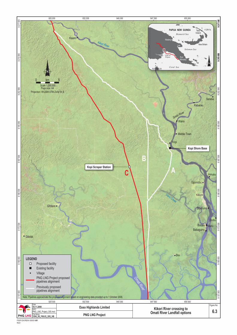
Option A followed the crude oil export pipeline through Kopi in accordance with guideline Level 1A (follow existing infrastructure), before turning south to the landfall on the Omati River. However, the area around Kopi is rich in caves and cultural sites in limestone pinnacles and attempts to avoid these constraints by fine-scale rerouting had only mixed success. This section was for these and social and engineering reasons subject to a full review based on two new options (Figure 6.3).

Environmental Impact Statement PNG LNG Project
Coffey Natural Systems 1284_9_Ch06_v3.doc
6-10 PGGP-EN-SRENV-000001-001 Rev0
Table 6.3 Moro to the Ai’io River route factors Construction • Avoids multiple oil flowline crossings. • Avoids construction in existing road. • Better terrain conditions. • Avoids construction boxed between steep side
slopes and existing flowlines. • Reduces earthworks. • Avoids construction in populated areas. • Avoids interference with existing road traffic and
need to open road each night. Safety • Reduces traffic on existing road. • Avoids blasting next to operating flowlines. • Avoids construction equipment operating near
aboveground operating flowlines.
• Separation from existing flowlines reduces reciprocal failure risk.
Environment • Reduces environmental footprint. • Avoids commitment to have road open to traffic
every night. • Reduces damage to limestone peaks. • Reduced sidecast. • Less damage to caves. • Smaller barrier effects. Cost • Lower construction costs due to faster lay rate and
shorter schedule. • Shortens pipeline length by approximately 4 km.
Option B cut due south just before reaching Kopi and Option C ran directly from the Kikori River crossing to the Omati River Landfall. Table 6.4 shows the advantages of Option C, which became the preferred route.
Table 6.4 Kikori River crossing to Omati River Landfall route factors Option A Construction • Longest. • Numerous crossings of
crude oil export pipeline. • Complex negotiation of
pipe through pinnacles at Kopi.
Safety • Impacts local traffic on
existing road. • Separation from existing
crude oil export pipeline reduces risk in case of oil line failure.
Environment • Within crude oil export
pipeline disturbance footprint.
• Potential damage to pinnacles at Kopi.
• Crosses long sections of swamp forest.
Social • Impacts several
communities along route.
Option B Construction • Avoids some crude oil export
pipeline crossings. Safety • Some avoidance of impacting
local traffic on existing road. Environment • Pinnacles at Kopi avoided
entirely.
Option C Construction • Avoids most crude oil export pipeline
crossings. • Shortest and lowest cost. Safety • Mostly avoids impacting local traffic on
existing road. • Separation from existing crude oil export
pipeline reduces risk in case of oil line failure.
Environment • Pinnacles at Kopi avoided entirely. • Traverses mostly logged forest. • Least amount of swamp forest traversed. • Fewest stream crossings. • Avoids one horizontal directional drilling
crossing. Social • Reduces impact to a number of
communities along the pipeline route.
Both the original route and options B and C must run overland from the valley of the Kikori River to the Omati River and none can avoid the two main intervening topographic features: the low limestone Veiru Hills to the south of Kopi and the swamp forest in the route down to the landfall location.

Environmental Impact Statement PNG LNG Project
Coffey Natural Systems 1284_9_Ch06_v3.doc
6-12 PGGP-EN-SRENV-000001-001 Rev0
6.2.3.3 Digimu River Option between Moro and the Mubi River
The crude oil export pipeline again traverses steep karst terrain as it descends from near Kantobo into the lowlands and the crossing of the Mubi River (Section 6.4.4.4, Segment 12: Wassi Falls to Mubi River Crossing). This descent requires a roadway to be constructed through this steep karst separate to the pipeline ROW. An option running northeast of the crude oil export pipeline along the Digimu River valley was developed in order to avoid this descent, reduce damage to the karst and speed up construction (see Figure 6.1). However, this option entailed an incursion into a very sparsely populated and hitherto little disturbed valley, and was for these reasons not pursued further.
6.2.4 Section D: Omati River Landfall to LNG Facilities Site Landfall
From the Omati River Landfall to the Caution Bay Landfall at the LNG Facilities site, the LNG Project Gas Pipeline base case runs 407 km past existing oil export facilities and across two broad subsea environments: the sediments of the Gulf of Papua prograding offshore from the deltas of the Kikori and Purari rivers; and the reefs and coral sand lagoons approaching landfall at Caution Bay (see Chapter 11, Receiving Marine Environment: Offshore Pipeline).
The alternative for this section is to take the pipeline overland to Port Moresby. This would entail an almost entirely greenfield route, with environmental impacts, land access issues, a number of large river crossings and constraints imposed by special features, such as caves and archaeological sites. The preferred option by sea avoids these issues.
Alternative alignments have not been established and compared for the offshore section because, regardless of where it runs, the pipeline must traverse or negotiate the same features of the seafloor: the generally muddy, stable gulf seafloor, interspersed with waterlogged vegetation debris, including dead trees that have fallen into the rivers from areas of dynamic bank erosion; and the coral sand and reefs to the west of the zone of sedimentation from the large rivers draining into the head of the Gulf of Papua.
The routing criteria for the offshore section of the pipeline were therefore the most direct route that was able to avoid the oil export infrastructure and unstable areas close to the continental shelf edge.
The offshore section of the Kutubu crude oil export pipeline runs to the Kumul Marine Terminal 35 km south of Cape Blackwood. The LNG Project Gas Pipeline runs parallel to, but to the west of, the oil pipeline until it can turn east-southeast safely to seaward of the platform and tanker anchorage at the Kumul Marine Terminal.
The route and its environmental and resource features are described in Chapter 11, Receiving Marine Environment: Offshore Pipeline. There is no route across the western part of this area that can avoid the prawn trawl grounds of the ubiquitous muddy seafloor at the head of the Gulf of Papua.
Approaching landfall, the route is able to enter Caution Bay through a gap in the barrier reef, which avoid the main coral reefs without difficulty. A narrow fringing reef has to be crossed to reach the shore.

Environmental Impact Statement PNG LNG Project
Coffey Natural Systems 1284_9_Ch06_v3.doc
6-13 PGGP-EN-SRENV-000001-001 Rev0
6.3 PNG LNG Project Pipeline Routes: Fine Scale A preconstruction survey will be carried out prior to final route alignment, in order to locate and avoid constraints only detectable at a fine scale. (See also Section 3.3.1.1, Onshore Pipeline Routing).
6.4 PNG LNG Project Proposed Pipelines: Travelogue
6.4.1 Juha Gas Field to Hides Gas Conditioning Plant
This section provides travelogues of the pipeline ROW segments (i.e., segments 1, 2 and 3) between the Juha Gas Field and the Hides Gas Conditioning Plant.
The proposed Juha gathering system will consist of flowlines, spinelines and mono-ethylene glycol (MEG) pipelines. The spinelines collect well fluids from three wellpads and transport the well fluids to the Juha Production Facility. The MEG pipelines originate from the Juha Production Facility and deliver MEG to each wellpad.
The subsequent well stream product will be transported from the Juha Production Facility to the Hides Gas Conditioning Plant via the Juha–Hides Rich Gas Pipeline and Juha–Hides Liquids Pipeline.
There is no separate road proposed into the Juha Production Facility. After pipeline installation, the Juha–Hides pipeline ROW will become the project road (closed to the public) to the Juha Production Facility. The corridor in which these pipelines and access way are planned to be contained is referred to as the Juha–Hides pipeline ROW or ROW. If the pipelines and access way are separated, it will be evaluated during Phase 4 detailed design considering environmental and routing factors.
6.4.1.1 Segment 1: Juha Gas Field to the Baia River Catchment
This 22-km-long segment begins at Juha gas field (950 m ASL) and terminates just inside the boundary of the Baia River catchment (Figure 6.4). The route was selected to provide the shortest distance possible while avoiding steep contours. For the first 7 km, the spineline traverses a rugged karst plateau cloaked in intact low-altitude, medium-crowned forest (Plate 6.1) before reaching the Juha Production Facility. Similar vegetation covers the steep karst and sedimentary rock terrain at the proposed Juha Production Facility. From the Juha Production Facility, the Juha–Hides pipeline ROW travels southeast through undisturbed forest skirting between karst and sedimentary landforms before crossing a tributary of the Wai Asia River after 9 km. This river will be crossed by trenching. From this crossing, the ROW traverses another 6 km of undisturbed forest at around 900 m ASL and then enters the unstable landforms of the central Baia River catchment. Throughout this segment, the vegetation has distinct montane characteristics despite being classified as a low-altitude forest. There is largely no human habitation and the forest is undisturbed except for the old, isolated Juha wellpads. Streams frequently descend into sinkholes in the karst (Plate 6.2).


Environmental Impact Statement PNG LNG Project
Coffey Natural Systems 1284_9_Ch06_v3.doc
6-16 PGGP-EN-SRENV-000001-001 Rev0
6.4.1.2 Segment 2: Baia River Catchment to South Karius
This segment of the Juha–Hides pipeline ROW is approximately 28 km long (see Figure 6.4). Throughout its length, the ROW traverses the upper catchment of the Baia River, crossing the Baia River itself after about 9 km, reaching its lowest point at about 380 m ASL. After the crossing, the ROW traverses more unstable terrain with numerous large landslides (Plate 6.3). The ROW tracks the edge of the more stable northern part of the catchment before climbing around a steep spur ascending eastwards through lower montane, small-crowned forest to the swamplands of the South Karius area at about 1,450 m ASL. This swampy valley, between Mount Sisa and the Karius Range, supports the first human settlements along the ROW (Plate 6.4). The ROW continues generally eastward into a narrow valley up to the catchment boundary of the Baia River immediately south of the Karius Range. In total, this segment traverses 16 km of low-altitude, medium-crowned forest and 12 km of lower montane, small-crowned forest.
6.4.1.3 Segment 3: South Karius to the Hides Gas Conditioning Plant
This 12-km-long segment takes the Juha–Hides pipeline ROW from South Karius to the Hides Gas Conditioning Plant (see Figure 6.4). For the first 5 km, the ROW traverses a narrow valley south of the Karius Range in good quality lower montane, small-crowned forest with Nothofagus before entering the more settled areas around Laite village and Komo village at about 1,800 m ASL. The route generally avoids the cultivated areas by skirting the southeastern footslopes of the Karius Range, also avoiding a concentration of archaeological sites southeast of Togayu village.
6.4.2 Hides Gas Field to Hides Gas Conditioning Plant
This section provides a travelogue of the spineline and gathering system (flowlines), which will convey wellstream fluids from Hides gas field on Hides Ridge to the Hides Gas Conditioning Plant. The Hides Spineline will generally follow the ridgeline to minimise side cuts and reduce the quantity of sidecast spoil. In very steep terrain, the access track will be constructed parallel to the ROW on the side of the ridge to reduce the amount of sidecasting required (see Section 7.10.1.3, ROW Formation Earthworks on Hides Ridge). A similar separation of ROW and access track or roadway for other sections of steep terrain along the pipeline alignment will be examined during FEED and detailed design. The ridge area contains sites of cultural value to local landowners and fine-scale routing will be used to avoid these where practicable (see Section 6.3, PNG LNG Project Pipeline Routes: Fine Scale). After pipeline installation, the Hides Spineline ROW will become the access way to the Hides wellpads.
6.4.2.1 Segment 4: Hides Ridge; Wellpad G to Wellpad A
This segment starts at the most remote project location on Hides Ridge at wellpad G. For the first 19 km, the spineline traverses rugged polygonal karst terrain between elevations of 2,800 m ASL and 2,000 m ASL (see Figure 6.4). The wellpads are on hilltops (Plate 6.5) and the ROW steers its way along the top of the range. The vegetation of the Hides Ridge is lower montane, small-crowned forest with Nothofagus (Plate 6.6) and very small-crowned forest with Nothofagus (Plate 6.7). Above 1,800 m ASL, the high-altitude Nothofagus forest on karst is noteworthy for its biodiversity features. The epiphytes and ferns in this forest type are the major component of plant biodiversity, the trees being the structure upon which this is developed.


Environmental Impact Statement PNG LNG Project
Coffey Natural Systems 1284_9_Ch06_v3.doc
6-19 PGGP-EN-SRENV-000001-001 Rev0
For the final 2 km to Wellpad A, the spineline descends through the polygonal karst to about 1,800 m ASL. Along Hides Ridge, there are numerous sinkholes, some of which contain swamps (Plate 6.8), and caves. The spineline is planned to avoid these sinkhole swamps and cave habitats or the project will implement mitigation and management measures to reduce potential impacts on them (see Section 7.10.1.3, ROW Formation Earthworks on Hides Ridge).
6.4.3 Hides to Moro
This section provides a travelogue of the proposed pipeline ROW (segments 5 to 8) between the Hides Gas Conditioning Plant and Moro to the west of Lake Kutubu. Between the Hides Gas Conditioning Plant and the Kutubu Central Processing Facility to the south of Moro, the Hides–Kutubu Condensate Pipeline is contained in the same trench as the proposed LNG Project Gas Pipeline. From the Angore gas field, the ROW also contains spinelines from the Angore wells to the Hides Gas Conditioning Plant, and the MEG pipelines.
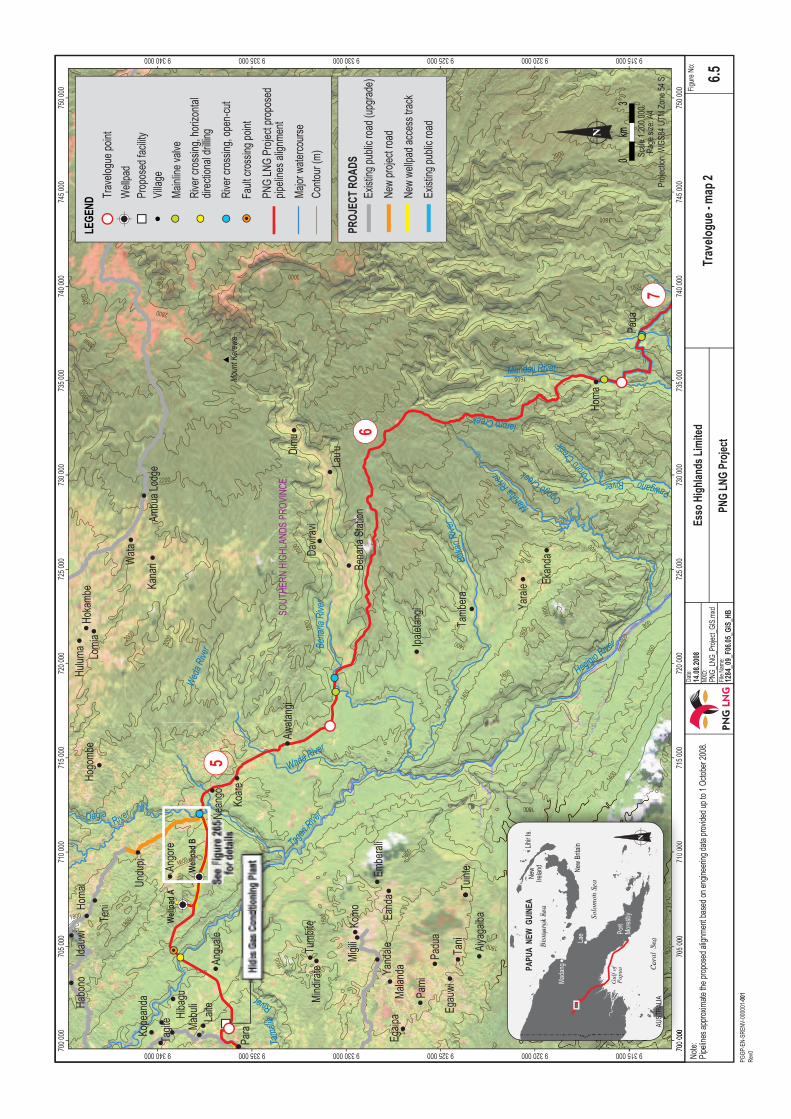
6.4.3.1 Segment 5: Hides Gas Conditioning Plant to Benaria River
This 22-km-long segment begins at the Hides Gas Conditioning Plant and terminates 1 km northwest of Benaria River crossing (Figure 6.5). The proposed Hides Gas Conditioning Plant site is located in a complex of gardens and regrowth near the village of Laite. The site is located on a ridge drained by numerous streams feeding into the Tagari River to the north and the Tamalia River to the south. From the Hides Gas Conditioning Plant site, the ROW traverses eastward for about 6 km through rolling and heavily gardened country (Plate 6.9) to the Tagari River crossing. The pipeline crossing of the Tagari River will most likely be conducted by horizontal direction drilling due to the large size and fast-flowing nature of the watercourse, in addition to its use as a fresh water and food (fish) resource by the local people. Alternatively, an open cut method may be used. From the crossing, the ROW climbs steeply out of the Tagari River valley into volcanic terrain rising steeply to 1,400 m ASL at about 10 km from the Hides Gas Conditioning Plant. Limestone outcrops exist to the east with the area being mostly forested in lower montane, small-crowned forest on alluvial plains, which, except for the banks of the Tagari River, has been disturbed to some extent by gardening and other activities.
Between the Tagari and Dagia rivers, pipeline route optimisation subsequent to the PNG Gas Project has realigned the ROW to avoid the Honeanda Complex and associated Araucaria cunninghamii (hoop pines), a large area of archaeological and cultural significance to the local landowners (Guideline L2B) that was previously crossed by the PNG Gas Project ROW (Figure 6.6).
The ROW crosses the Dagia River, which will most likely be trenched, at about 14 km from the Hides Gas Conditioning Plant. The Angore gas field, in which two new wellpads will be constructed, is situated between the Tagari and Dagia rivers. The new wellpads, Angore wellpad A and Angore wellpad B (see Figure 6.5), will both be located in lower montane, small-crowned forest.
From the Dagia River crossing, the ROW traverses southeast over hilly volcanic country through small-crowned forest toward Benaria River. In between the Dagia and Benaria rivers, the small-crowned forest becomes more continuous with fewer clearings as the ROW crosses rolling volcanic hills at altitudes between 1,200 m and 1,400 m ASL. The ROW is aligned near the old Tari road to the Benaria River through a corridor of regrowth forest.


Environmental Impact Statement PNG LNG Project
Coffey Natural Systems 1284_9_Ch06_v3.doc
6-22 PGGP-EN-SRENV-000001-001 Rev0
6.4.3.2 Segment 6: Benaria River to Mandali River
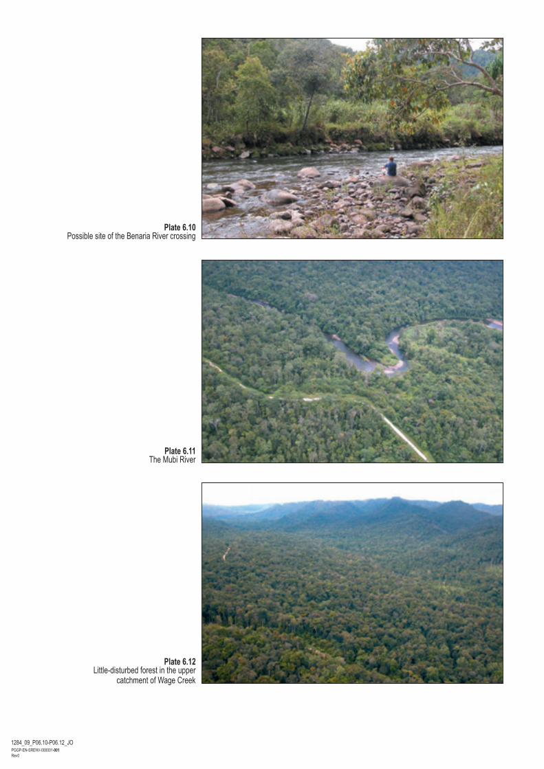
This ROW is a 33-km-long segment beginning 1 km northwest of the Benaria River crossing and terminating at the Mandali River crossing (see Figure 6.5). The ROW and the old Tari road cross the Benaria River at the same location (Plate 6.10) where the river will be crossed by open cut trenching. From the Benaria River crossing, the ROW leaves the old Tari road, climbs steeply to the east up a ridge with advanced regrowth forest past a concentration of archaeological sites, rapidly rising to around 2,100 m ASL into lower montane, small-crowned forest with Nothofagus and rounding the upper headwaters of the Bakari and Maruba rivers. The ROW then traverses south along the western escarpment of the Mandali River for approximately 5 km before descending on to the village of Homa. From Homa the ROW continues south to cross the Mandali River some 2.5 km south of Homa. The area of the ROW in this segment is generally not settled and, with the exception of the first 5 km after the Benaria River, the ROW traverses mostly undisturbed forest.
6.4.3.3 Segment 7: Mandali River to North of Lake Kutubu
This 25-km-long segment begins at the Mandali River crossing and terminates on a hilltop 1 km to the northwest of Lake Kutubu (Figure 6.7). From the Mandali River, the ROW generally follows the existing roadway from Homa to Moro and traverses a densely forested pass north of Mount Barena and then to Paua village, which lies in the cultivated Aiu River valley. There is a concentration of archaeological sites centred on the area between Homa and Paua villages, and the ROW and the upgrading of the existing Homa to Moro road will be planned, at fine scale, to avoid noteworthy archaeological, cultural heritage or spiritual sites within this area. The valleys of the Mubi and Aiu rivers consist primarily of medium-crowned to small-crowned forest complexes and are settled (Plate 6.11) and cultivated.
The ROW follows the existing roadway across the Humphries Range and descends to the upper valley of Kaimari Creek, where the ROW alignment deviates from the existing roadway to take a more direct crossing of the creek. This 1-km-long deviation avoids bends along the existing roadway, which exceed the turning radius of the pipeline. The ROW alignment rejoins the existing roadway and continues through the upper valley of Wage Creek to the Mubi River valley at about 940 m ASL, (Plate 6.12) where it passes through intact, small-crowned forest on the western side of the valley. The ROW then leaves the Homa to Moro road and continues on the watershed between Mubi River and Tibi Creek on polygonal karst to the northwest corner of Lake Kutubu.
6.4.3.4 Segment 8: North of Lake Kutubu to Moro
This 8-km-long segment runs between the swamp forests (Plates 6.13 and 6.14) north of Lake Kutubu and the karst beyond. Initially the ROW follows the existing Homa-to-Moro road; however, the ROW deviates where the road bends to the south towards Lake Kutubu. The ROW then routes directly to Moro Camp after traversing the swamp forests northwest of the lake, recrossing Wage Creek and traversing a section of karst terrain (see Figure 6.7). The karst ridges support low altitude, medium-crowned forest.
At about 2.5 km northeast of Moro Camp the ROW crosses Wage Creek, which will be trenched.
A major portion of this segment lies within the catchment of Lake Kutubu, which is recognised as a wetland of international conservation importance under the Ramsar Convention.


Environmental Impact Statement PNG LNG Project
Coffey Natural Systems 1284_9_Ch06_v3.doc
6-26 PGGP-EN-SRENV-000001-001 Rev0
6.4.4 Moro to Omati River Landfall
This section contains a travelogue of the proposed pipeline ROW (segments 9 to 16) between the Kutubu Central Processing Facility and the Omati River Landfall. The existing Hides–Kutubu Condensate Pipeline terminates at the existing Kutubu Central Processing Facility, and from there to the Omati River Landfall, the ROW contains only the proposed LNG Project Gas Pipeline.
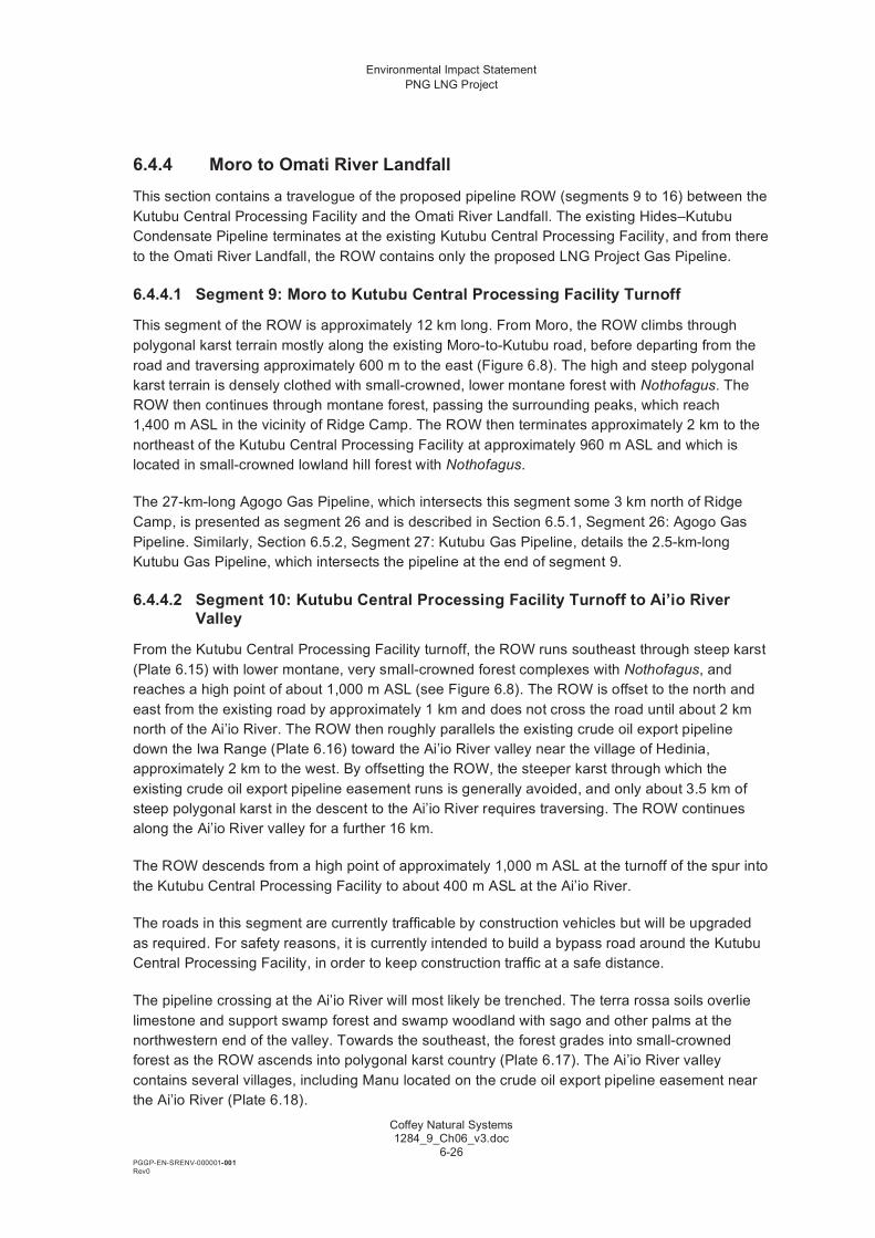
6.4.4.1 Segment 9: Moro to Kutubu Central Processing Facility Turnoff
This segment of the ROW is approximately 12 km long. From Moro, the ROW climbs through polygonal karst terrain mostly along the existing Moro-to-Kutubu road, before departing from the road and traversing approximately 600 m to the east (Figure 6.8). The high and steep polygonal karst terrain is densely clothed with small-crowned, lower montane forest with Nothofagus. The ROW then continues through montane forest, passing the surrounding peaks, which reach 1,400 m ASL in the vicinity of Ridge Camp. The ROW then terminates approximately 2 km to the northeast of the Kutubu Central Processing Facility at approximately 960 m ASL and which is located in small-crowned lowland hill forest with Nothofagus.
The 27-km-long Agogo Gas Pipeline, which intersects this segment some 3 km north of Ridge Camp, is presented as segment 26 and is described in Section 6.5.1, Segment 26: Agogo Gas Pipeline. Similarly, Section 6.5.2, Segment 27: Kutubu Gas Pipeline, details the 2.5-km-long Kutubu Gas Pipeline, which intersects the pipeline at the end of segment 9.
6.4.4.2 Segment 10: Kutubu Central Processing Facility Turnoff to Ai’io River Valley
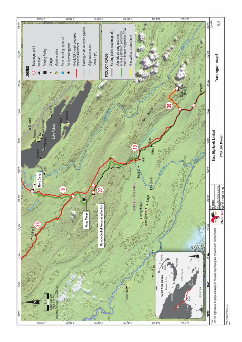
From the Kutubu Central Processing Facility turnoff, the ROW runs southeast through steep karst (Plate 6.15) with lower montane, very small-crowned forest complexes with Nothofagus, and reaches a high point of about 1,000 m ASL (see Figure 6.8). The ROW is offset to the north and east from the existing road by approximately 1 km and does not cross the road until about 2 km north of the Ai’io River. The ROW then roughly parallels the existing crude oil export pipeline down the Iwa Range (Plate 6.16) toward the Ai’io River valley near the village of Hedinia, approximately 2 km to the west. By offsetting the ROW, the steeper karst through which the existing crude oil export pipeline easement runs is generally avoided, and only about 3.5 km of steep polygonal karst in the descent to the Ai’io River requires traversing. The ROW continues along the Ai’io River valley for a further 16 km.
The ROW descends from a high point of approximately 1,000 m ASL at the turnoff of the spur into the Kutubu Central Processing Facility to about 400 m ASL at the Ai’io River.
The roads in this segment are currently trafficable by construction vehicles but will be upgraded as required. For safety reasons, it is currently intended to build a bypass road around the Kutubu Central Processing Facility, in order to keep construction traffic at a safe distance.
The pipeline crossing at the Ai’io River will most likely be trenched. The terra rossa soils overlie limestone and support swamp forest and swamp woodland with sago and other palms at the northwestern end of the valley. Towards the southeast, the forest grades into small-crowned forest as the ROW ascends into polygonal karst country (Plate 6.17). The Ai’io River valley contains several villages, including Manu located on the crude oil export pipeline easement near the Ai’io River (Plate 6.18).

Environmental Impact Statement PNG LNG Project
Coffey Natural Systems 1284_9_Ch06_v3.doc
6-29 PGGP-EN-SRENV-000001-001 Rev0
The ROW roughly parallels the existing crude oil export pipeline access way for much of the Ai’io River valley.
This segment is approximately 27 km long.
The 5-km-long South East Hedinia Spineline, which intersects this segment some 26 km south of the Kutubu Central Processing Facility, is presented as segment 28 and is described in Section 6.5.3, Segment 28: South East Hedinia Spineline.
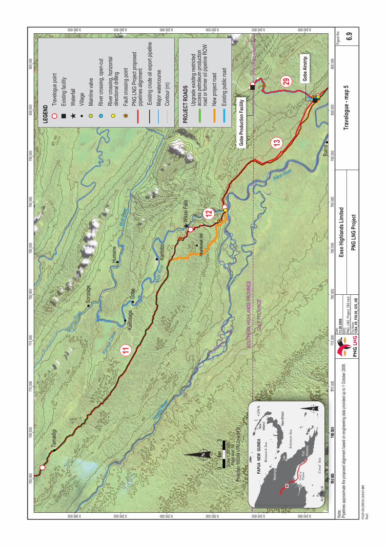
6.4.4.3 Segment 11: Ai’io River Valley to Wassi Falls
In this 33-km-long segment (Figure 6.9), the ROW leaves the Ai’io River valley and enters an uplifted area of polygonal karst clothed in medium-crowned, lowland hill forest and small-crowned, lowland hill forest to a point 13 km from the Ai’io River (Plate 6.19). From here, the ROW descends via a long, narrow valley into the Mubi River valley and overlooks Kantobo village (Plate 6.20). The karst terrain in this segment has many areas where the drainage is impeded. Sinkholes, small valleys and sections of the existing crude oil export pipeline access way retain water during periods of high or sustained rainfall. Plate 6.21 shows an example of flooding.
The ROW roughly parallels the crude oil export pipeline access way and will be constructed either directly alongside or offset to leave a strip of forest between the two. The ROW is currently trafficable and the existing road will most likely be upgraded to act as a logistics route.
6.4.4.4 Segment 12: Wassi Falls to Mubi River Crossing
This short 5-km-long segment forms a major descent of the ROW towards the Kikori River lowlands (40 m ASL) via steep terrain approximately 1 km west of the Wassi Falls (see Figure 6.9). The ROW continues to parallel the existing crude oil export pipeline ROW down the range (Plate 6.22) and, after descending through an area of terra rossa clays, the ROW crosses the Mubi River near its junction with the Hegigio River, at which point the Kikori River begins.
The Mubi River at the crossing is 100 m wide (Plate 6.23). A three-span bridge will be built to accommodate project logistics traffic but the pipeline will most likely be crossed by horizontal direction drilling; however, open cut may be used as an alternative crossing method.
A 12-km-long bypass project access road will be built along this section, as project traffic cannot negotiate the steep grades of the existing crude oil export pipeline easement down what is known as ‘Heartbreak Hill’. This bypass road will start some 56 km south of the Kutubu Central Processing Facility and will be constructed through intact medium-crowned to small-crowned forest complexes, linking up with the ROW at the Mubi River crossing.
6.4.4.5 Segment 13: Mubi River Crossing to Gobe Production Facility Turnoff
In this 17-km-long segment (see Figure 6.9), the ROW follows the existing crude oil export pipeline easement, which is currently overgrown with regrowth and untrafficable. After crossing the Mubi River, the ROW runs along the northern side of the Kikori River for about 8 km, traversing mudstone overlain with terra rossa clays developed on a karst plain. This section is vegetated by medium-crowned, lowland hill forest (Plate 6.24). From here, the soils become very thin and the vegetation is lowland open forest. The ROW then traverses polygonal karst terrain,


Environmental Impact Statement PNG LNG Project
Coffey Natural Systems 1284_9_Ch06_v3.doc
6-33 PGGP-EN-SRENV-000001-001 Rev0
which is vegetated by medium-crowned, lowland hill forest, as it approaches the Gobe Airstrip (Plate 6.25). This is a difficult section for construction as the ROW traverses cockpit karst in places, as well as areas of unstable terra rossa soils and mudstones. The Gobe Gas Pipeline will tie in to the LNG Project Gas Pipeline near the Gobe Airstrip approximately 82 km from the Kutubu Central Processing Facility. The Gobe Gas Pipeline is presented as segment 29 and is described in Section 6.5.4, Segment 29: Gobe Gas Pipeline.
6.4.4.6 Segment 14: Gobe Production Facility Turnoff to Kikori River Crossing
In this 36-km-long segment (Figure 6.10), the ROW continues along the existing crude oil export pipeline easement across karst plains before approaching the Kikori River upstream of the Kaiam ferry crossing (Plate 6.26). In this segment, sinkholes and pinnacles occur frequently, particularly at the Kikori River crossing. As in the previous segment, the vegetation of the karst plains is lowland open forest, with medium-crowned, lowland hill forest on polygonal karst.
At about 1 km from the Kikori River, the access road is planned to deviate from the ROW to take a westerly crossing over the Kikori River via a new 120-m-wide, two-span bridge, which will accommodate project construction traffic and replace the ferry. The crossing of the Kikori River is planned to be constructed by horizontal directional drilling; however, open cut may be used as an alternative crossing method. Another large bridge (46 m wide) is planned to be built across the Wah River 13 km south of the Gobe Production Facility turnoff and this crossing will also be by horizontal directional drilling. As before, however, open cut may be used as an alternative crossing method.
6.4.4.7 Segment 15: Kikori River Crossing to Veiru Creek
In this 43-km-long segment, the ROW separates from the crude oil export pipeline access way and traverses southeast before terminating at Vieru Creek (Figure 6.11). Initially the ROW crosses through the small-crowned, lowland forests of the Kikori River floodplain before skirting the eastern footslopes of a large mass of polygonal karst clothed in medium-crowned to small-crowned forest complexes. After approximately 10 km, the ROW traverses logged small-crowned lowland forests and medium-crowned to small-crowned forest complexes on limestone plateau with narrow karst corridors. The vegetation in this area generally grows on very shallow to non-existent soils and may simply consist of root mat and litter on a limestone platform with patches of swamp forest in low-lying areas.
Approximately 29 km southeast of the Kikori River crossing, the ROW crosses a small range of polygonal karst before descending once more on to limestone plateau. Within these plateau drainage is more impeded and swamp vegetation becomes more frequent.
The ROW then skirts the swamplands at the headwaters of Veiru Creek before terminating in logged forest on rugged limestone karst hills that rise out of the swamplands some 13 km southwest of Kopi.
6.4.4.8 Segment 16: Vieru Creek to Omati River Landfall
After crossing the headwaters of Veiru Creek, the ROW runs south 23 km before terminating at the Omati River Landfall (Figure 6.12). It passes isolated karst pinnacles just south of a small range then enters medium crowned to small crowned forest complexes and swamp forest


Environmental Impact Statement PNG LNG Project
Coffey Natural Systems 1284_9_Ch06_v3.doc
6-38 PGGP-EN-SRENV-000001-001 Rev0
complexes (Plate 6.27). The karst range here has been logged with logging tracks visible as thin pale lines to the west of the Omati–Kikori delta in Figure 6.12. From this point, the forest becomes wetter and swampy. Sago palms become dominant except near the edge of the Omati River, which is lined with a thin fringe of nypa palm (Nypa fruiticans) (Plate 6.28 and 6.29). The sands, silts and muds overlying the karst plain are not deep. Broad-leaved trees dominate on raised areas within the karst plain and the lower areas are dominated by extensive stands of sago palms.
The existing system of logging roads may be upgraded to transport pipe loads and other equipment from Kopi, under negotiations with existing logging operators.
6.4.5 Omati River Landfall to the LNG Facilities Site
The offshore pipeline route begins at the Omati River Landfall and follows the river before crossing the Gulf of Papua south-eastwards to the Caution Bay Landfall near the northern boundary of the LNG Facilities site (Figure 6.13). This section presents travelogues of segments 17 to 25 of the offshore pipeline route.
6.4.5.1 Segment 17: Omati River Landfall to Omati River Mouth
The length of the offshore pipeline route in this segment is about 25 km (see Figure 6.13). The water depth in the lower Omati River ranges from 3.5 to 8.3 m below mean sea level and the tidal range is approximately 5.3 m (Moroka, 2005). The alignment of the offshore pipeline route within the lower Omati River will be generally mid channel, keeping away from very shallow areas where pipeline installation vessels may have difficulty operating. This approach also avoids riparian socio-cultural heritage and archaeological sites (see Chapter 16, Cultural Heritage Environment: LNG and Marine Facilities) along the river banks and mid-river islands in this segment. The village of Goare lies approximately 1 km to the east of the pipeline alignment at the Omati River mouth.
The lower Omati River is characterised by mobile bedforms, such as ripples and megaripples, as well as sandbanks and sandbars. Bed topography is generally shallow and variable, with intermittent scour holes, which are created by high currents and river flows, particularly during the wet season. Bed material is mainly soft silty muds and sand of variable thickness.
The fish fauna of the lower Omati River is characterised by the presence of sediment-tolerant freshwater and estuarine species, such as barramundi, sawfish, fork-tailed catfish, mangrove jack and threadfin salmon. The lower Omati River may also be frequented by Irrawaddy, Indian Ocean bottlenose and Indo-Pacific humpbacked dolphins, which occur in the Omati–Kikori delta.
6.4.5.2 Segments 18 to 23: Omati River Mouth to Caution Bay
This 360-km-long section of the offshore pipeline route (see Figure 6.13) leaves the Omati River mouth and travels through the Gulf of Papua, along the shoreward side of a continental shelf, to Caution Bay. From the river mouth, the continental shelf extends 160 km. The seafloor then drops to depths of greater than 1,000 m. The continental shelf is relatively flat near the outfall, due to the sediment influxes from the river systems. It becomes narrower as it continues eastward along the PNG coast and away from the influence of the Fly, Omati, Kikori and Purari rivers, and is approximately 20 km wide near Caution Bay.


Environmental Impact Statement PNG LNG Project
Coffey Natural Systems 1284_9_Ch06_v3.doc
6-41 PGGP-EN-SRENV-000001-001 Rev0
Most of this section of the offshore pipeline route was subject to an engineering and environmental survey in March and April 2008 (see Section 11.3.1, Habitats and Seafloor Characteristics). This survey did not identify any coral, seagrass or unusual habitats. Sediment and infauna sampling revealed that the substrate type is fairly uniform along the pipeline route.
In the absence of environmental constraints, the strategy used for alignment of this section of the offshore pipeline was primarily based on:
• Avoidance of seafloor features. • Avoidance of depths much greater than approximately 100 m. • Minimisation of areas requiring span rectification. • Minimisation of pipeline length.
Further refinement of the offshore route will take place prior to construction.
Segment 18
The offshore pipeline route leaves the Omati River mouth, where water depth is approximately 6 m, and travels southeast for approximately 55 km to avoid the Kumul Marine Terminal, loading tanker anchoring zone and the marine section of the existing crude oil export pipeline, before turning to the east for a further 10 km. Approximately 15 km of this segment passes through prawn trawling grounds to the southwest of the Kumul Marine Terminal (see Section 11.4.1, Commercial Fisheries). The seafloor in this section is gently sloping, increasing to a depth of approximately 45 m.
Segment 19
Once beyond the Kumul Marine Terminal, the offshore pipeline is routed eastwards for approximately 110 km. The maximum water depth along this segment is approximately 105 m. An isolated raised seafloor feature was identified along this segment during a survey in March and April 2008, and subsequently avoided. The seafloor along this segment of the offshore pipeline route is characterised by sandwaves and pockmarks1, and consequently spans may require rectification along this segment of pipeline.
Segment 20
This 50 km segment of the offshore pipeline route runs southeast in water depths approximately ranging from 57 m to 75 m. The seafloor in this segment is generally smooth; however, pockmarks are present, particularly in the deeper waters. Some of the pockmark crossings may require span rectification.
Segment 21
The initial area surveyed for this segment was highly populated with pockmarks that would have resulted in numerous spans. As a result, a shallower, slightly longer route closer to shore of approximately 60 km and requiring less span rectification was selected. This segment traverses water depths of approximately 50 m to 75 m.
1 Pockmarks are craters in the seafloor resulting from the natural release of gas (usually methane) or liquid.
Environmental Impact Statement PNG LNG Project
Coffey Natural Systems 1284_9_Ch06_v3.doc
6-42 PGGP-EN-SRENV-000001-001 Rev0
Segment 22
Segment 22 of the offshore pipeline is approximately 45 km long and traverses water depths ranging from approximately 35 m to 55 m. The route travels southeast, close to the coastline and is approximately 4 km from the coastline at its nearest point to the west of Cape Suckling. This segment passes approximately 7 km offshore of Yule Island and the seafloor is generally smooth.
Segment 23
This segment traverses water depths ranging between approximately 31 m and 57 m, and is approximately 40 km in length. It runs southeast and has been aligned to avoid a raised seafloor feature located approximately half way along the segment. Like segment 22, the seafloor along this area is generally smooth.
6.4.5.3 Segment 24: Caution Bay to Caution Bay Landfall
In this 20-km-long segment (Figure 6.14) the offshore pipeline route enters Caution Bay, crosses the proposed shipping access channel at right angles and makes landfall near (and within) the northern boundary of the LNG Facilities site. The route traverses the seafloor at depths of up to 47 m.
The majority of the Caution Bay seafloor is characterised by terrigenous, silt and clay sediments with evidence of epibenthic faunal activity in the form of mounds and burrows that range in size and abundance across the various locations. The deeper waters (30 m to 50 m water depth) have a predominately muddy seafloor and visible biota are generally sparse. The shallow areas (less than 30 m) closer to the coast are characterised by coarser sands and coral rubble.
Further inshore there is a scattering of coral bommies, which the offshore pipeline avoids. Most of these bommies have been degraded by local fishing and have a low percentage cover of live coral. Nevertheless, they support sponges, soft corals, whip corals, gorgonians, Halimeda, emergent fauna (tube worms, sea pens) and a diversity of fish including surgeonfish, damselfishes and wrasses.
As the offshore pipeline route approaches the shore, it runs at right angles through strips of fringing reef and seagrass before traversing across mangrove and saltflat habitats for approximately 500 m, and terminating at the Caution Bay Landfall.
6.4.5.4 Segment 25: LNG Facilities Site
From the Caution Bay Landfall, the ROW travels southeast through grassland/open woodland habitat before terminating at the inlet facilities of the LNG Plant (Figure 6.15). There is a concentration of archaeological sites immediately north of the ROW alignment that this alignment generally avoids and which will be subject to further investigation and fine scale route design as part of preconstruction surveys.
Like the offshore pipeline approach, the jetty runs at right angles through strips of fringing reef, seagrass and mangrove. The jetty does not intercept any coral bommies.


Environmental Impact Statement PNG LNG Project
Coffey Natural Systems 1284_9_Ch06_v3.doc
6-45 PGGP-EN-SRENV-000001-001 Rev0
The LNG Facilities site is situated on the coast approximately 20 km northwest of Port Moresby between the coastal settlements of Boera and Papa (see Figure 6.14). The site consists of highly modified savanna and grassland habitats. Much of the site was cleared early in the twentieth century for agriculture on what was then Fairfax Station. Original, intact vegetation at the LNG Facilities site is largely restricted to mangroves, areas of melaleuca woodland and the saltflats that persist along the coast and the Vaihua River. The mangroves are widest (approximately 600 m) along the Vaihua River and narrow to a break with a small beach just north of the northern boundary of the site. Other remnant vegetation includes areas of gallery forest that persist along the Vaihua River between the mangroves and existing Lea Lea road and isolated pandanus and low trees on shallow drainage lines running into the Vaihua River.
6.5 Associated Facilities
6.5.1 Segment 26: Agogo Gas Pipeline
A 26-km-long gas pipeline, Agogo Gas Pipeline, will be installed from the Agogo Production Facility to connect with the LNG Project Gas Pipeline ROW some 7 km north of the Kutubu Central Processing Facility (see Figure 6.7). This segment presents a travelogue of the first 19 km of the Agogo Gas Pipeline to its intersection with the proposed LNG Project Gas Pipeline near Ridge Camp. The remaining 7 km of the Agogo Gas Pipeline to the Kutubu Central Processing Facility are already described in the travelogue of Segment 9 (see Section 6.4.4.1, Segment 9: Moro to Kutubu Central Processing Facility Turnoff).
From the Agogo Production Facility, at about 800 m ASL, the ROW traverses steep and rugged polygonal karst clothed in small-crowned, lowland hill forest with Nothofagus for about 10 km, then descends to about 760 m ASL and into medium-crowned lowland hill forest with Nothofagus and areas of swamp forest with sago palms in a perched valley with mostly terra rossa soils. From this valley, the ROW and existing access way climb rapidly onto high, rugged karst terrain that is densely clothed with very-small-crowned, lower montane forest with Nothofagus. This segment terminates at its junction with the existing Moro to Kutubu road.
6.3.2 Segment 27: Kutubu Gas Pipeline
In this segment, the Kutubu Gas Pipeline runs 2.5 km from the Kutubu Central Processing Facility to the ROW of the PNG LNG Project Gas Pipeline (see Figure 6.8). This segment traverses small-crowned lowland hill forest with Nothofagus south then west before terminating approximately 1,000 m ASL.
6.5.3 Segment 28: South East Hedinia Spineline
The first 5 km of the South East Hedinia Spineline will be installed from the South East Hedinia field to connect with the LNG Project Gas Pipeline ROW and travels some 26 km north to the Kutubu Central Processing Facility (see Figure 6.8). The spineline traverses northwest through lower montane very small crowned forest complexes with Nothofagus for about 4 km, then through medium-crowned to small-crowned forest complexes with Nothofagus for another kilometre before it joins with the main LNG Project Gas Pipeline ROW. The South East Hedinia wellpads are situated in polygonal karst at approximately 1,150 m ASL.

Environmental Impact Statement PNG LNG Project
Coffey Natural Systems 1284_9_Ch06_v3.doc
6-46 PGGP-EN-SRENV-000001-001 Rev0
6.5.4 Segment 29: Gobe Gas Pipeline
The gas pipeline ROW from the Gobe Production Facility follows the existing Gobe crude oil pipeline ROW for some 10 km to tie in with the LNG Project Gas Pipeline ROW at about 82 km east of the Kutubu Central Processing Facility (see Figure 6.9). In this 10-km segment, the ROW traverses polygonal karst with small- to medium-crowned, lowland hill forest complexes.