6 IV April 2018
7
6 IV April 2018 http://doi.org/10.22214/ijraset.2018.4343
-
Upload
khangminh22 -
Category
Documents
-
view
0 -
download
0
Transcript of 6 IV April 2018

6 IV April 2018
http://doi.org/10.22214/ijraset.2018.4343

International Journal for Research in Applied Science & Engineering Technology (IJRASET) ISSN: 2321-9653; IC Value: 45.98; SJ Impact Factor: 6.887
Volume 6 Issue IV, April 2018- Available at www.ijraset.com
©IJRASET (UGC Approved Journal): All Rights are Reserved 2029
Auto Selection of Any Available Phase in 3 Phase Supply System
Prof. Praful Kumbhare1, Pramod Donode2, Mahesh Nimbulkar3, Harshada Kale4, Mayur Waghamare5, Akansha Patil6, 1, 2, 3, 4, 5, 6Department of Electrical Engineering, GNIT Nagpur
Abstract: Phase absence is a very common and severe problem in any industry, home or office. Many times one or two phases may not be live in three phase supply. Because of this, many times, some electrical appliances will be on in one room and OFF in another room. This creates a big disturbance to our routine work. This project is designed to check the availability of any live phase, and the load will be connected to the particular live phase only. Even a single phase is available, and then also, the load will be in ON condition. This project is designed with ATMega328. This controller continuously checks for live condition of all phases connected to it, and the controller connects the load to the active phase using a Relay. This relay is driven with a transistor. If two or three phases are live, the load will be connected to Phase 1 only. An LCD is provided to display the status of the phase condition. Contrast control preset is given for LCD contrast control. This project uses regulated 12V, 500mA power supply. 7805 three terminal voltage regulator is used for voltage regulation. Bridge type full wave rectifier is used to rectify the ac output of secondary of 230/12V step down transformer Keywords: ATMega328, Relay Driver IC ULN2003, Relay
I. INTRODUCTION The project is designed to provide uninterrupted AC mains supply i.e., 230 volt to a single phase load. This is achieved by automatic changeover of the load from the missing phase to the next available phase in a 3 phase system. In developing countries like Nigeria, India, there is always the problem of interrupted power supply as insufficient power is being generated to provide consumers with continuous services and satisfactory quality. This leads to constant power failure which in turn affects both the public and private sectors of the economy. Industries, banks, hospitals and so many other public and private establishment all have major critical loads that needs to be powered at all times in order to carry out various processes efficiently. While most domestic loads are connected to single phase supply and if the fault occurs in any one of the phases and the power is available in other phases, we cannot utilize that power. Automatic three phase selector is an integral part of the process of power generation, allowing smooth and instant transfer of electric current between multiple sources and load. According to this paper, we have connected relay to the supply phase and also used microcontroller for controlling all over the circuit and relay’s condition in supply circuit. There are given bypass connection to microcontroller from phases. For this we have connected bridge rectifier circuit in that bypass way to give connection to microcontroller. The controller circuit senses the fault and according to that working of relay should be done.
II. LITRATURE REVIEW F. U. Nweke et.al, discussed in his paper “Design and Construction of Automatic Three Phase Power System Selector” that the automatic three phase power system selector was designed and constructed. The device automatically switches over to the alternative phase that has current when there is power outage or extremely low current in the phase which the load is connected without the power being off. The selector links the load and the other phases and relay switches allowing the usage of the remaining phases where there is outage on the mains source without disturbing or interrupting the load. It maintains constant power supply to the load by automatically activating the phases when the need arises. This safeguards the outages which are paramount in under developed and developing countries.
International Journal for Research in Applied Science & Engineering Technology (IJRASET) ISSN: 2321-9653; IC Value: 45.98; SJ Impact Factor: 6.887
Volume 6 Issue IV, April 2018- Available at www.ijraset.com
©IJRASET (UGC Approved Journal): All Rights are Reserved 2030
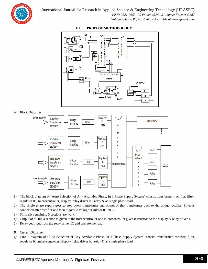
III. PROPOSE METHODOLOGY
A. Block Diagram
1) The block diagram of ‘Auto Selection of Any Available Phase, In 3 Phase Supply System’ consist transformer, rectifier, filter, regulator IC, microcontroller, display, relay driver IC, relay & ac single phase load.
2) The single phase supply goes to step down transformer and output of that transformer goes to the bridge rectifier. Filter is connected after rectifier and then it goes to voltage regulator IC 7805.
3) Similarly remaining 3 sections are work. 4) Output of all the 4 section is given to the microcontroller and microcontroller gives instruction to the display & relay driver IC. 5) Relay get input from the relay driver IC and operate the load. B. Circuit Diagram 1) Circuit diagram of ‘Auto Selection of Any Available Phase, In 3 Phase Supply System’ consist transformer, rectifier, filter,
regulator IC, microcontroller, display, relay driver IC, relay & ac single phase load.

International Journal for Research in Applied Science & Engineering Technology (IJRASET) ISSN: 2321-9653; IC Value: 45.98; SJ Impact Factor: 6.887
Volume 6 Issue IV, April 2018- Available at www.ijraset.com
©IJRASET (UGC Approved Journal): All Rights are Reserved 2031
2) The single phase supply goes to step down transformer and output (12 volt 500 m amps) of that transformer goes to the bridge rectifier. Capacitor Filter is connected between the two terminals of the rectifier and positive terminal goes to voltage regulator IC 7805.
3) Similarly remaining 3 sections are work. 4) Output of all the 4 section is given to the microcontroller pins i.e. 2,3,4,5 and microcontroller gives instruction to the display by
pin no 13, 14, 15,16,17,18 & relay driver IC through pin no 25,26,27,28. 5) Relay get input from the relay driver IC pin no13, 14, 15, and 16. and operate the load.
C. Hardware Component 1) Microcontroller ATMega328: The Atmega328 is a very popular microcontroller chip produced by Atmel. Atmega328 is used
for store the program and give the instruction to operate the relay, and show the output and the information about the active phase. And also give the information about the load that is, on which phase load are operated. It is an 8-bit microcontroller that has 32K of flash memory, 1K of EEPROM, and 2K of internal SRAM. The Atmega328 is one of the microcontroller chips that are used with the popular Arduino Duemilanove boards. The Arduino Duemilanove board comes with either 1 of 2 microcontroller chips, the Atmega168 or the Atmega328. Of these 2, the Atmega328 is the upgraded, more advanced chip. Unlike the Atmega168 which has 16K of flash program memory and 512 bytes of internal SRAM, the Atmega328 has 32K of flash program memory and 2K of Internal SRAM. The Atmega328 has 28 pins .It has 14 digital I/O pins, of which 6 can be used as PWM outputs and 6 analog input pins. These I/O pins account for 20 of the pins.
The pin diagram of Atmega328 is given below:
2) Electromagnetic Relay: A relay is an electromagnetic switch operated by a relatively small electric current that can turn on or
off a much larger electric current. The heart of a relay is an electromagnet (a coil of wire that becomes a temporary magnet when electricity flows through it).
3) Relay Driver IC ULN2003: ULN2003 is very famous relay driver integrated circuit. Relay driver IC uln2003 is high voltage and high current integrated IC which used Darlington array. It contains seven Darlington pair of transistor which has high voltage and high current carrying capability. Its mean ULN3002 can drive up to seven relay at a time

International Journal for Research in Applied Science & Engineering Technology (IJRASET) ISSN: 2321-9653; IC Value: 45.98; SJ Impact Factor: 6.887
Volume 6 Issue IV, April 2018- Available at www.ijraset.com
©IJRASET (UGC Approved Journal): All Rights are Reserved 2032
4) Transformer (step down): Transformer is a device which is transfer voltage and current without changing it frequency. 1Rating: 230V 5 amp /12V 500 m amp
5) Voltage Regulator IC ULN 2003: To provide the constant 5 V supply that regulator IC we are used here. 6) Crystal Oscillator: Provide the clock pulse for the operation of the microcontroller ATMega328. Rating: 16 MHz. 7) Capacitor: The capacitor is used as a filter for remove the remaining ac component. Rating: 22pf 8) Preset Resistor: For setting the contrast of the display preset resistor is use. Rating: 10KΩ 9) Display: To show the output i.e. whose phase are activated & on which phase load are activated display are use. Rating: 16*2
(16 column & 2 row) 10) Free Willing Diode: To avoid the back emf, this is given out from the relay.
IV. WORKING
Single phase 230v, 5 amps are given to the step down transformer which is convert voltage or current into 12 volt or 500 m amp. Then these goes to bridge rectifier, which is convert ac supply to dc supply. Their it goes to voltage regulator ic 7805 which give constant 5 v supply to the microcontroller pin no 2,3,4,5.for the operation of the microcontroller crystal oscillator are connected between pin no 9 & 10 , which is provide clock pulse to the microcontroller for the logical operation . By using program it detect the faulty phase. And remove the load from faulty phase and shifted to the active phase, And also give the information about the active phase and on which phase load are connected. Power supply to the microcontroller and display circuit are given from the inverter, which is connected to pin no 7 & 8. Display(16*2) pin R/S,E,D7,D6,D5,D4are connected to the pin no. 13,14,15,16,17,18 of the microcontroller/W are grounded. The signal of microcontroller are goes through pin no 25,26,27&28 to the Relay driver IC ULN 2003 pin no 1,2,3,4 and , Which is connected for operating the multiple relay. And Darlington pair is also in it which gives the necessary current to operate relay properly. Supply to the relay is come from the relay driver IC ULN 2003 through the pin no. 13,14,15,16. And the relay is operating the particular single phase load.
V. ADVANTAGES 1) Highly sensitive 2) Works according to the phase availability 3) Low cost and reliable circuit 4) Complete elimination of manpower 5) Can handle heavy loads up to 7A
VI. APPLICATION
1) Hostels and Hotels 2) Hospitals 3) Colleges 4) Offices 5) Industries
International Journal for Research in Applied Science & Engineering Technology (IJRASET) ISSN: 2321-9653; IC Value: 45.98; SJ Impact Factor: 6.887
Volume 6 Issue IV, April 2018- Available at www.ijraset.com
©IJRASET (UGC Approved Journal): All Rights are Reserved 2033
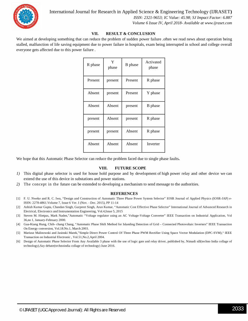
VII. RESULT & CONCLUSION We aimed at developing something that can reduce the problem of sudden power failure .often we read news about operation being stalled, malfunction of life saving equipment due to power failure in hospitals, exam being interrupted in school and college overall everyone gets affected due to this power failure .
We hope that this Automatic Phase Selector can reduce the problem faced due to single phase faults.
VIII. FUTURE SCOPE 1) This digital phase selector is used for house hold purpose and by development of high power relay and other device we can
extend the use of this device in substations and power stations. 2) The concept in the future can be extended to developing a mechanism to send message to the authorities.
REFERENCES[1] F. U. Nweke and R. C. Iwu, “Design and Construction of Automatic Three Phase Power System Selector” IOSR Journal of Applied Physics (IOSR-JAP) e-
ISSN: 2278-4861.Volume 7, Issue 6 Ver. I (Nov. - Dec. 2015), PP 11-14 [2] Ashish Kumar Gupta, Chandan Singh, Gurpreet Singh, Arun Kumar, “Automatic Cost Effective Phase Selector” International Journal of Advanced Research in
Electrical, Electronics and Instrumentation Engineering, Vol.4,Issue 5, 2015 [3] Steven M. Hietpas, Mark Naden,”Automatic “Voltage regulator using an AC Voltage-Voltage Converter” IEEE Transaction on Industrial Application, Vol
36,no 1, January-February 2000. [4] Gua-Kiang Hung, Chih- chang Chang, “Automatic Phase Shift Method for Islanding Detection of Grid – Connected Photovoltaic Inverters” IEEE Transaction
On Energy conversion, Vol.18.No.1, March 2003. [5] Mariusz Malinowski and Jasinski Marek,”Simple Direct Power Control Of Three Phase PWM Rectifier Using Space Vector Modulation (DPC-SVM),“ IEEE
Transaction on Industrial Electronic , Vol.51,No.2,April 2004. [6] Design of Automatic Phase Selector From Any Available 3 phase with the use of logic gate and relay driver, published by, Nimadi sill(techno India collage of
technology),Say debate(technoindia collage of technology) June 2016.
R phase Y phase
B phase Activated phase
Present present Present R phase
Absent present Present Y phase
Absent Absent present B phase
present Absent present R phase
present present Absent R phase
Absent Absent Absent Inverter