515RTAENI-N34 Protocol Gateway - Real Time Automation
47
Real Time Automation, Inc. 1 1-800-249-1612 515RTAENI-N34 Protocol Gateway Product User Guide Firmware Version 4.25
-
Upload
khangminh22 -
Category
Documents
-
view
2 -
download
0
Transcript of 515RTAENI-N34 Protocol Gateway - Real Time Automation

Real Time Automation, Inc. 1 1-800-249-1612
515RTAENI-N34
Protocol Gateway Product User Guide
Firmware Version 4.25

Real Time Automation, Inc. 2 1-800-249-1612
Trademarks
CompactLogix, ControlLogix, PLC-5, MicroLogix, RSLogix 500, SLC, and PanelView are registered trademarks of Rockwell
Automation, Inc. EtherNet/IP is a trademark of the ODVA. Microsoft, Windows, and Internet Explorer are registered trademarks
of Microsoft Corporation. Kepware is a registered trademark of Kepware Technologies, a software development business of PTC
Inc. All other trademarks and registered trademarks are the property of their holders.
Limited Warranty
Real Time Automation, Inc. warrants that this product is free from defects and functions properly.
EXCEPT AS SPECIFICALLY SET FORTH ABOVE, REAL TIME AUTOMATION, INC. DISCLAIMS ALL OTHER WARRANTIES, BOTH
EXPRESSED AND IMPLIED, INCLUDING BUT NOT LIMITED TO IMPLIED WARRANTIES OF MERCHANTABILITY OR FITNESS FOR AN
APPLICATION. THIS LIMITED WARRANTY GIVES YOU SPECIFIC LEGAL RIGHTS. YOU MAY ALSO HAVE OTHER RIGHTS, WHICH VARY
FROM STATE TO STATE.
The examples and diagrams in this manual are included solely for illustrative purposes. Because of the many variables and
requirements associated with any application, Real Time Automation, Inc. cannot assume responsibility or liability for actual use
based on the examples and diagrams. Except as specifically set forth above, Real Time Automation and its distributors and
dealers will in no event be liable for any damages whatsoever, either direct or indirect, including but not limited to loss of
business profits, income, or use of data. Some states do not allow exclusion or limitation of incidental or consequential
damages; therefore, the limitations set forth in this agreement may not apply to you.
No patent liability is assumed by Real Time Automation with respect to use of information, circuits, equipment, or software
described in this manual.
Government End-Users
If this software is acquired by or on behalf of a unit or agency of the United States Government, this provision applies: The
software (a) was developed at private expense, is existing computer software, and was not developed with government funds;
(b) is a trade secret of Real Time Automation, Inc. for all purposes of the Freedom of Information Act; (c) is “restricted
computer software” submitted with restricted rights in accordance with subparagraphs (a) through (d) of the Commercial
“Computer Software-Restricted Rights” clause at 52.227-19 and its successors; (d) in all respects is proprietary data belonging
solely to Real Time Automation, Inc.; (e) is unpublished and all rights are reserved under copyright laws of the United States.
For units of the Department of Defense (DoD), this software is licensed only with “Restricted Rights”: as that term is defined in
the DoD Supplement of the Federal Acquisition Regulation 52.227-7013 (c) (1) (ii), rights in Technical Data and Computer
Software and its successors, and: Use, duplication, or disclosures is subject to restrictions as set forth in subdivision (c) (1) (ii) of
the Rights in Technical Data and Computer Software clause at 52.227-7013. If this software was acquired under GSA schedule,
the U.S. Government has agreed to refrain from changing or removing any insignia or lettering from the Software or
documentation that is provided or from producing copies of the manual or media. Real Time Automation, Inc.
© 2020 Real Time Automation, Inc. All rights reserved.

Real Time Automation, Inc. 3 1-800-249-1612
Contents Revision History ............................................................................................................................................ 5
Overview ....................................................................................................................................................... 6
Hardware – N34 ............................................................................................................................................ 7
Physical Specifications 7
Mounting with a DIN Rail .............................................................................................................................. 8
Installing 8
Removing 8
Powering the Gateway .................................................................................................................................. 9
Pinouts & Wiring ......................................................................................................................................... 11
Pinouts 11
Wiring 11
Accessing the Main Page............................................................................................................................. 12
Error: Main Page Does Not Launch 13
Web Configuration Tabs ............................................................................................................................. 14
Committing Changes to the Gateway ......................................................................................................... 15
Network Tab ................................................................................................................................................ 16
Ethernet Settings 16
Changing from DHCP to Static IP 17
Additional Fields under Ethernet Settings .......................................................................................... 17
Serial Settings 18
Email Settings 19
Email Alarms and Messages 20
Email Message Example 21
Data View Tab ............................................................................................................................................. 22
Mapping Tab ............................................................................................................................................... 23
Utility Tab .................................................................................................................................................... 25
Export/Import Configuration 25
Import Configuration 25
Export Configuration 25
Restart Gateway 26
Upgrade Firmware 26
EDS File 26

Real Time Automation, Inc. 4 1-800-249-1612
Other References 26
Reference Links 26
NET ENI Event Log Values 27
Security Configuration 28
Home Tab (Diagnostics) .............................................................................................................................. 30
DF1 Status 30
DF1 Counters 30
Ethernet Status 31
Ethernet Status: Counters 31
Logging 32
Msg Log Tab 32
Serial Diagnostic Tab 33
Ethernet Diagnostics Tab 34
LED Behavior ............................................................................................................................................... 35
DF1 Node Descriptions Reference Table .................................................................................................... 36
Use of Existing 1761-NET-ENI/W Tools ....................................................................................................... 41
Easily replace an existing NETENI device 41
Using RSLinx ................................................................................................................................................ 42
Ethernet Driver 42
Troubleshooting RSLinx and RSLogix Comms ............................................................................................. 43
Application Specific Tips ............................................................................................................................. 44
PanelView Plus Comms 44
Kepware Communications 47

Real Time Automation, Inc. 5 1-800-249-1612
Revision History
Version Date Notes
4.02 7/26/2017 Bug Fixes
1. Updated web UI diagnostics and counters. 2. Added support for RSLinx straight Ethernet driver. 3. Optimized message queue servicing. 4. Added ability to download EDS file from webpage. 5. Removed BOOTP support. 6. Improved IP configuration implementation. 7. Enabled force of at least 1 Admin when security is enabled. 8. Minor webpage layout fixes.
4.16 7/3/2018 Bug Fixes
1. Minor Web Updates 2. EDS File Updated 3. Node 244 and 245 removed
Node 248 functional
4.18 12/14/2018 Features Added
4. 1. Updated RTA Images
4.21 9/28/2020 Features Added
1. Added functionality to work with Ingear PC based application.
2. EDS file Updated 3. Added additional diagnostic logging 4. Improved functionality/performance
4.25 4/14/2021 Features Added 1. Improved functionality/performance with 6 connections
using UCMM explicit and connected explicit messaging

Real Time Automation, Inc. 6 1-800-249-1612
Overview
The 515RTAENI is a replacement for the Allen-Bradley 1761-NET-ENI and 1761-NET-ENIW modules. The
515RTAENI gateway:
• Provides the same Ethernet connectivity for all DF1 serial controllers, PanelView Standard
Terminals, and other DF1 full-duplex devices
• Communicates between Allen-Bradley Logix and legacy controllers
• Generates email messages via Simple Mail Transport Protocol (SMTP)
• Allows ability to easily upload and download programs using standard Rockwell Automation
tools
• Writes to Ethernet controllers like ControlLogix
However, the interface is improved by providing web browser configuration, allowing up to 6 Ethernet
connections, adding support for string data types, and improving diagnostic functionality.
If at any time you need further assistance do not hesitate to call Real Time Automation support.
Support Hours are Monday-Friday 8am-5pm CST
Toll free: 1-800-249-1612
Email: [email protected]

Real Time Automation, Inc. 7 1-800-249-1612
Hardware – N34
Physical Specifications
POWER Operating range of 8-28VDC, 125mA at 24VDC Power can be received over serial cable
TEMPERATURE Industrial Temperature Range -40°C to +85°C
CERTIFICATIONS UL, C/UL, CE, FCC, CLASS 1 DIV 2
MOUNTING Din Rail, Panel
SIZE 4.2” x 3.25” x 1”
WEIGHT 5 oz.
COMMUNICATION PORTS
SERIAL 1 RS232
ETHERNET 1 10/100 Mbps BaseT Ethernet Port

Real Time Automation, Inc. 8 1-800-249-1612
Mounting with a DIN Rail
Installing Follow these steps to install your unit.
1) Mount your DIN Rail.
2) Hook the bottom mounting flange under the DIN Rail.
3) While pressing the 515RTAENI against the rail, press up to engage the spring-loaded lower
clip and rotate the unit parallel to the DIN Rail.
4) Release upward pressure.
Removing Follow these steps to remove your unit.
1. Press up on the unit to engage the spring-loaded lower clip.
2. Swing top of the unit away from the DIN rail
Spring Loaded Lower Clip
DIN Rail

Real Time Automation, Inc. 9 1-800-249-1612
Powering the Gateway
The following steps will allow you to properly and safely power the gateway.
1. Connect a 24VDC power source to the gateway.
a. The unit draws 125 mA at 24VDC
b. The gateway has a voltage operating range from 8-28VDC; 24VDC is recommended.
Hazardous Environment Power & Installation Instructions
This equipment is suitable for use in Class I, Division 2, Groups A, B, C and D, or non-
hazardous locations only.
WARNING – EXPLOSION HAZARD - Do not disconnect equipment unless power has been removed or
the area is known to be non-hazardous.
WARNING – EXPLOSION HAZARD - Substitution of components may impair suitability for Class I,
Division 2.
THIS EQUIPMENT IS AN OPEN-TYPE DEVICE AND IS MEANT TO BE INSTALLED IN AN ENCLOSURE SUITABLE FOR THE ENVIRONMENT SUCH THAT THE EQUIPMENT IS ONLY ACCESSIBLE WITH THE USE OF A TOOL.
WARNING – POWER JACK (Barrel Connector, J1) IS FOR MAINTENANCE USE ONLY AND MAY ONLY BE
USED WHILE THE AREA IS KNOWN TO BE FREE OF IGNITIBLE CONCENTRATIONS OF FLAMMABLE GASES
OR VAPORS. IT IS NOT TO BE CONNECTED UNDER NORMAL OPERATION.
In a Hazardous Environment, the unit must be powered with between 12-24 VDC; 860 mA (6 W) max.
Supervised. The unit is certified to be operated at -40C to 50°C.
Warning improper wiring will cause unit failure
Use the Barrel Connector OR the Screw
Terminals power connection, NOT both

Real Time Automation, Inc. 10 1-800-249-1612
Hazardous Environment Power & Installation
Instructions
Cet équipement est conçu pour être utilisé uniquement dans des lieux de classe I, division 2, groupes A, B, C et D, ou non dangereux.
AVERTISSEMENT - RISQUE D'EXPLOSION - Ne débranchez pas l'équipement à moins que le courant ne soit coupé ou que la zone ne présente aucun danger. AVERTISSEMENT - RISQUE D'EXPLOSION - La substitution de composants peut compromettre l'adéquation à la classe I, division 2. CET APPAREIL EST UN DISPOSITIF DE TYPE OUVERT ET IL FAUT L'INSTALLER DANS UN ENCEINTE ADAPTÉ À L'ENVIRONNEMENT TEL QU'IL N'EST ACCESSIBLE À L'UTILISATION D'UN OUTIL. AVERTISSEMENT - LE POWER JACK (bornes à vis, J1) est destiné exclusivement à la maintenance et ne peut être utilisé que lorsque la zone est connue pour être exempte de concentrations inintéressantes de gaz ou de vapeurs inflammables. IL NE DOIT PAS ÊTRE CONNECTÉ SOUS UN FONCTIONNEMENT NORMAL.
Dans les environnements dangereux, l'unité doit être alimentée entre 12-24 VDC, 860 mA (6 W) max.
Supervisé. L'appareil est certifié pour fonctionner entre -40 ° C et 50 ° C.

Real Time Automation, Inc. 11 1-800-249-1612
Pinouts & Wiring
Pinouts The gateway has two connectors for communication: T-Strip (Port 0) and DB9 port (Port 1). Either port
can be used for RS-232 communications using the pinouts in the diagram below.
DB9 pinouts are as follows:
Pin 2 – RX
Pin 3 – TX
Pin 5 – GND
CABLE INFORMATION:
Wiring It is recommended to use the following programming cables:
• 1761-CBL-PM02
o https://www.rtautomation.com/product/generic-micrologix-programming-cable/
• CBL-FF-6
o https://www.rtautomation.com/product/null-modem-cable/
• 1784-CP10
o https://www.rtautomation.com/product/1784-cbl/
IMPORTANT: The 1761-CBL-PM02 Ser. C when used with a SLC5/04 has a different pin out and will
cause 515RTAENI hardware failure. Any 1761-CBL-PM02 cable is only to be used for MicroLogix PLCs.
It is highly recommended to follow wiring recommendations regarding the Allen-Bradley serial cables.
Failure to do so may result in poor or inoperable intermittent communications.
NOTE: Only one physical port can be used at a time.

Real Time Automation, Inc. 12 1-800-249-1612
Accessing the Main Page
The following steps will help you access the browser-based configuration of the gateway. By default, DHCP is enabled. If the gateway fails to obtain an IP address over DHCP, it will Auto IP with 169.254.X.Y. For more information on your operating system network setting, refer to the Access Browser Configuration Doc on the CD or download it from our support web site, https://www.rtautomation.com/515rtaenisupport/
1) Insert the provided CD-ROM into a computer also on the network.
2) Run the IPSetup.exe program from the CD-ROM.
3) Find the unit under “Select a Unit.”
a. Change the gateway’s IP address to match that of your PC if DHCP has failed.
i. You will know DHCP has failed if the gateway’s IP address is AutoIP at 169.254.X.Y.
ii. If successful, it will say DHCP’d at ex: 192.168.0.100 or however your DCHP client is set up.
b. If you do not see the gateway in this tool, then your PC is most likely set up as a static IP.
i. Change your PC’s network settings to be Obtain and Address Automatically. If DHCP fails, it will change to be on the 169.254.x.y network.
ii. Disable your Wireless.
iii. Relaunch the IP Setup tool to see if gateway can be discovered now.
4) Click Launch Webpage. The main page should appear.
Note: If more assistance needed, please refer to our Accessing_Browser_Configuration.pdf that
can be found on the CD provided or on our website:
https://www.rtautomation.com/515rtaenisupport/

Real Time Automation, Inc. 13 1-800-249-1612
Error: Main Page Does Not Launch If the main page does not launch, please verify the following:
1) Check that the PC is set for a valid IP Address
a. Open a MS-DOS Command Prompt
b. Type “ipconfig” and press enter
c. Note the PC’s IP Address, Subnet, and Default Gateway
2) The gateway must be on the same Network/Subnet as the PC whether it’s set up
for DHCP or Static.
Once you have both devices on the same network, you should be able to ping the
gateway using a MS- DOS Command Prompt.
The Screenshot above shows an example of what a successful ping looks like.
If you can successfully ping your gateway, open a browser and try to view the main page
of the gateway by entering the IP Address of the gateway as the URL.

Real Time Automation, Inc. 14 1-800-249-1612
Web Configuration Tabs
The 515RTAENI gateway has a built-in web server that can be accessed by entering the IP address of the
gateway into a web browser’s address bar.
All configurable fields inside the gateway are grouped into 5 different tabs. Below is a list of tabs and
what information can be found on each one:
1) Home – used for diagnostics and status messages for both the DF1 and Ethernet sides
2) Data View – used to read, write, and display data from the controller
3) Network – used to configure all Ethernet, email, and serial port settings
4) Mapping – used to configure all the IP address DF1 node mappings
5) Utility – used for revision information, downloading the EDS file, updating firmware, configuring
security settings, and saving/importing gateway configuration

Real Time Automation, Inc. 15 1-800-249-1612
Committing Changes to the Gateway
1) To make changes to the gateway, find the tab identifying which information to change. Next to the
section to modify, there is an Edit button.
2) Once the Edit button has been clicked, the icon will change into a Save button and any editable fields under that section will change into text boxes or dropdown lists. See the screenshot below as an example. The only field in this section that isn’t configurable is the Serial Mode.
3) Changes will not take effect until the Save button is clicked. While the save is in progress, the Save
button will change into the icon to indicate that the gateway is currently saving those settings.
4) If the Ethernet settings are changed, the gateway will reboot, and a message will be displayed prompting the user to enter the new IP address.

Real Time Automation, Inc. 16 1-800-249-1612
Network Tab
Ethernet Settings
By default, the gateway is configured for DHCP.
There are 2 different options for the gateway to get an IP address:
1) DHCP – Attempts to receive an IP Address every time that the gateway is powered up. If DHCP fails,
then an AutoIP address is used to make the webpages accessible and DHCP will continue to attempt
to get an address.
2) Static IP – An IP address is statically set and will never change until the option is modified.

Real Time Automation, Inc. 17 1-800-249-1612
When configuring a static IP address, be sure to update the appropriate values in IP Address, Subnet
Mask, and Gateway fields.
Changing from DHCP to Static IP
1) Click the Edit button next to Ethernet Settings on the Network Tab in the gateway. 2) Change the dropdown of the IP Settings field to be Static IP. 3) Change the field IP Address, Subnet Mask, and Gateway. 4) Click the Save button.
Additional Fields under Ethernet Settings
Field
Description
DNS This is the IP of the DNS server on the network where the gateway looks up IP addresses. This is mandatory for email.
PLC Security Mask 1
This field limits what controllers can connect to and communicate with the gateway based on their IP address. This can only be used to allow a specific IP address or a specific IP address range. The value 255 is the wildcard value. A value of 0.0.0.0 or 255.255.255.255 allows any Ethernet device to connect. Security Mask 1 takes precedence over Security Mask 2.
PLC Security Mask 2 Secondary security mask field that is only used when PLC Security Mask 1 fails.

Real Time Automation, Inc. 18 1-800-249-1612
Serial Settings By default, the gateway is configured for the following settings:
1) Baud Rate: 19200
2) DF1 Error Detection: CRC
3) Serial Mode (fixed): DF1 Full-duplex, RS232, 8 data bits, parity none, 1 stop bit
These settings should match what is configured in the DF1 serial device, including the DLE parameters of
DLE NAK Retries, DLE ENQ Retries, and DLE Embedded Response.
See table below for more explanation:
Value Description
Baud Rate Set the baud rate to match the baud rate configured for the 515RTAENI. 38,400 and 19,200 are the most used baud rates.
Serial Mode Cannot be changed: DF1 RS232,8N1 (8N1 meaning 8 data bits, no parity bit, 1 stop bit)
Timeout (ms) Elapsed time in milliseconds for sending or receiving data before an error is reported.
DLE NAK Retries Response that signals that a message frame was not received successfully.
DLE ENQ Retries Requests retransmission of a response.
DLE Embedded Response Per the DF1 protocol, this allows a response to a previous message to be embodied in a new message.
Error Detection DF1 error detection algorithm.
Duplicate Msg Detection In the case of a duplicate, an error is reported in the attached PLC.
NOTE: Auto-baud is NOT supported. The 1761-NET-ENI/W serial PC Config Utility has an Auto-baud option, but this setting is not supported by the 515RTAENI gateway.

Real Time Automation, Inc. 19 1-800-249-1612
Email Settings This optional section can be filled out if alarms and messages need to be emailed out on the network.
To configure, the following fields can be modified:
Field
Description
Email server This is the TCP/IP address or name (maximum of 64 characters) of SMTP server.
Username & Password
These fields are filled in if the email Server requires SMTP authentication. If the email server does not require SMTP authentication, the values here will be ignored and can be left blank. The maximum length for these fields is 64 characters.
“From Email” Address This is an ASCII string that cannot be left blank, so by default it is filled in with a default value that can be modified. This is the message that is sent with any email message initiated by the gateway.
SMTP Port This is the TCP port of the email server configured. Typically, this value is 25.

Real Time Automation, Inc. 20 1-800-249-1612
Email Alarms and Messages
This optional section can be filled out if alarms and messages need to be emailed out on the network.
Under the “To:” section, up to 50 email addresses (up to 64 characters) can be configured and stored.
The “Config” column represents the node numbers (150 to 199) that are used to store the actual email
address. The “Destn” column represents the node ID, any messages sent to that node ID, will be
forwarded to the associated “To” address.
The controller will send a 485CIF write message to the DF1 destination node that is mapped to the
destination email address. For the 515RTAENI to successfully send an email message, the
Email Settings configuration needs to be set up correctly. The 515RTAENI stores the destination email
address but does not store the actual data that is sent.
Field
Description
Destn Messages to the node in this column will be sent to the associated “To” email address.
Config Stores the defined node for each email address.
“To” User can manually enter114 one email address for every individual “To” line.

Real Time Automation, Inc. 21 1-800-249-1612
Email Message Example The email message data is a string that contains valid ASCII text as shown in the example below:
The controller would send a 485CIF write message with the write data being the email text to send, to
the destination node (50 to 99) that corresponds to the destination email address. In this case, since we
are writing to node address 50, the email address that will be use is the email address configured in
node address 150 in the gateway’s webpage. The format of the email “subject” line is
“515RTAENI.MSG”. This is how the MSG instruction would look:
NOTE: The two screenshots above display File Name ST10: 0 as a specific example. For the user, the email message data would display whatever String value they have chosen.

Real Time Automation, Inc. 22 1-800-249-1612
Data View Tab
The Data View Tab shows the data that has been sent to the 515RTAENI from the attached serial
controller. Using this page, data can also be written back to the serial controller. This page is designed to
act as a “scratch-pad” function to show the data transfer with the serial controller.
0
This screen allows 40 user configurable descriptions for the reads and writes associated with the data
table address ranges of N50:0-27, used in node #202, and F51:0-11, used in node #203.
Depending on the refresh rate configured at the top of the screen, values written from that location in
the controller will display in the “Write from Controller” column. Values can be entered in the “Write to
Controller” column and when the Write button is pressed, those values will be sent to the appropriate
location. The gateway will send a separate DF1 w rite for each value entered.

Real Time Automation, Inc. 23 1-800-249-1612
Mapping Tab
The Mapping page creates a routing table to associate DF1 Nodes with IP addresses.
All messages received from a remote controller are decoded and the messages are transmitted to the
local controller.
Configurable Mapping
Node #
The 515RTAENI can route a DF1 message received from the attached controller to a compatible destination TCP/IP device, using DF1 node addresses 0 through 49.
Node 45 – 49 must be used if talking to CompactLogix/ControlLogix/FlexLogix
Config 515RTAENI node addresses 100 through 149 store destination IP addresses.
IP Address When the 515RTAENI receives a write message to nodes 100 to 149, it stores the destination IP address in the corresponding map register.

Real Time Automation, Inc. 24 1-800-249-1612
IP Routing Table example
Configure Node # 100
Function Configure route 0 address
Execute Node # 0
Function # Send message to IP address @ DF1 node 100
Real Time Automation, Inc. 25 1-800-249-1612
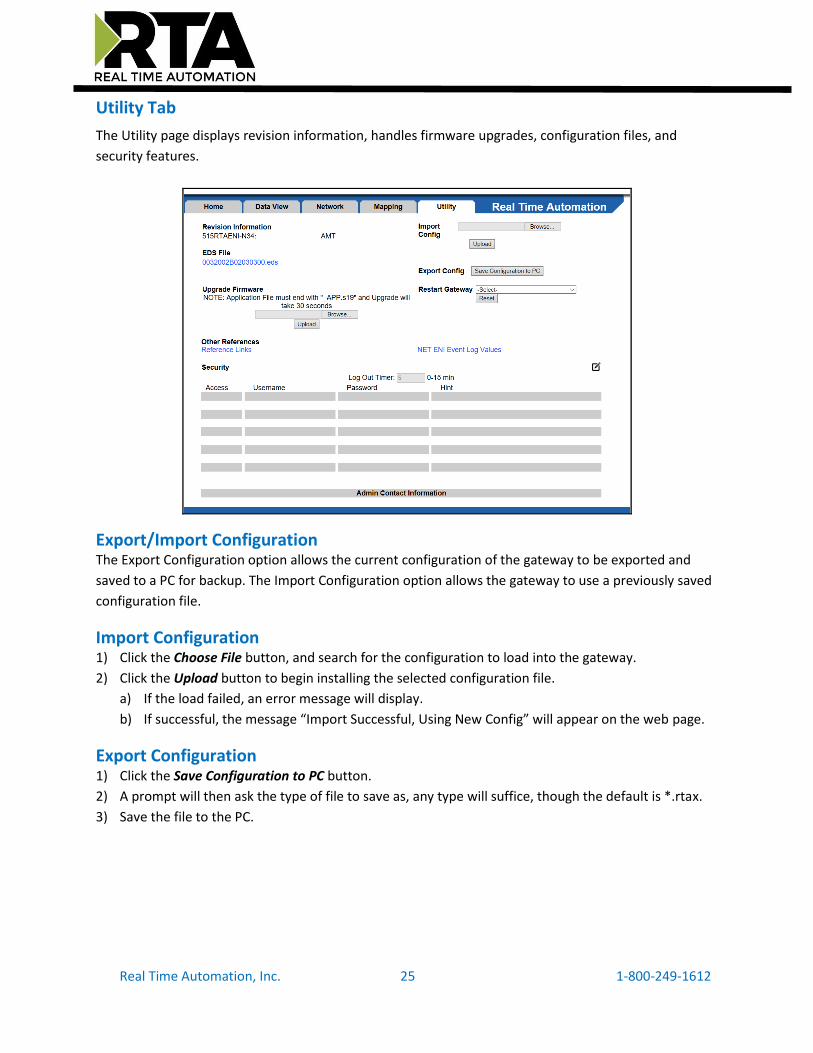
Utility Tab
The Utility page displays revision information, handles firmware upgrades, configuration files, and
security features.
Export/Import Configuration The Export Configuration option allows the current configuration of the gateway to be exported and
saved to a PC for backup. The Import Configuration option allows the gateway to use a previously saved
configuration file.
Import Configuration 1) Click the Choose File button, and search for the configuration to load into the gateway.
2) Click the Upload button to begin installing the selected configuration file.
a) If the load failed, an error message will display.
b) If successful, the message “Import Successful, Using New Config” will appear on the web page.
Export Configuration 1) Click the Save Configuration to PC button.
2) A prompt will then ask the type of file to save as, any type will suffice, though the default is *.rtax.
3) Save the file to the PC.

Real Time Automation, Inc. 26 1-800-249-1612
Restart Gateway There are 3 options to restart the gateway:
● Simple Reset—performs a software reboot.
● Reset out of box defaults—brings the device back to its original manufacturing defaults,
including setting the gateway to DHCP mode.
● Reset out of box defaults except IP—brings the device back to its original manufacturing
defaults, except the current network settings.
Upgrade Firmware This option allows the gateway’s firmware to be upgraded from the web page.
1) Click the Choose File button and select the new firmware file to be installed in the gateway.
2) Click the Upload button to start the firmware upgrade process.
The firmware will automatically install, and the gateway will automatically reboot after the new
firmware has been upgraded. The upgrade process will take approximately 30 seconds.
EDS File This link allows the EDS file to be downloaded directly from the gateway’s web server. Right click on the
file name link below and select “Save Link/Target As…” to store the EDS file to the client PC.
Other References Reference Links
The Reference Links page allows the user to select 10 user-defined URL links for the application. These
URL links are not validated by the gateway and can be up to 64 characters in length. The URL is opened
in a new browser window when the user clicks on the link.
NOTE: If the user wants to access an external link, he or she must type http:// as part of the address (see screen below).

Real Time Automation, Inc. 27 1-800-249-1612
NET ENI Event Log Values The NET ENI Event Log values page is a scratch pad where the PLC can write log values. Up to 50 data
strings can be displayed here by writing to node 204 at element 0, with the newest event log displayed
at the top. Writing a string to node 205 or a click on the Clear Event Log button will clear the buffer. If
the event log is full and a new event is received, the new event will overwrite the oldest event in the list.

Real Time Automation, Inc. 28 1-800-249-1612
Security Configuration Access to the web pages inside the 515RTAENI gateway can be controlled by creating different access
privileges. The first time the edit button is clicked, only one user can be configured. This is the primary
account and will always have full access rights. Once the primary account is configured, the user can
then log in to the primary account and create up to nine secondary accounts with different access
privileges. Note that if the primary account is deleted, all the other accounts will be deleted with it.
Field Description
Log Out Timer
The system will automatically log inactive users off after a length of time.
NOTE: A time of 0 means that the user will not be automatically logged off. Instead, they must manually click the Log Out button at the top of the page.
Access Users can either have “Full Access” or “View Only” access to all the gateway’s configuration pages.
Username Enter a name for the security user, up to 32 characters.
Password Enter a password for the security user, up to 32 characters, case sensitive.
Hint Enter an optional hint that can be displayed for the security user, up to 32 characters.
Admin Contact Information
Enter up to 63 different characters worth of information on who to contact if security info is lost.
THIS IS NOT A TOTAL SECURITY FEATURE The security feature offers a way to password protect access to diagnostics and configuration on
the network. The security feature does not protect against “Air Gap” threats. If the gateway can
be physically accessed, security can be reset. All security can be disabled if physical contact can
be made. From the login page, click the Reset Password button twice. You will be forced to do a
hard reboot (power down) on the gateway within 15 minutes of clicking the button. This process
should be used in the event a password is forgotten.

Real Time Automation, Inc. 29 1-800-249-1612

Real Time Automation, Inc. 30 1-800-249-1612
Home Tab (Diagnostics)
The Home tab displays diagnostic counters that show the current gateway status. These diagnostics are
useful for troubleshooting communication problems. There is also a logging table that can be used to
further troubleshoot the Ethernet, Serial, and general gateway problems.
DF1 Status
DF1 Counters The counters under DF1 Status can help determine the state of the serial communication:
Field
Description
Total Num Messages Transmitted
Displays the total number of DF1 messages transmitted to the attached serial controller.
Total Num Messages Received Displays the total number of DF1 messages received from the attached serial controller.
Total Num Messages Enqueued Displays the total number of DF1 messages that are placed into the “Waiting to be processed” queue.
Total Num Messages Dequeued Displays the total number of DF1 messages that are removed from the “Waiting to be processed” queue.
Total Num Bad BCC/CRC Frames Displays the total number of corrupted DF1 messages that have been received.
Total Num Message Timeouts
Displays the total number of messages that have been received within the configured timeout period configured on the Network tab.

Real Time Automation, Inc. 31 1-800-249-1612
Ethernet Status
Ethernet Status: Counters The counters under Ethernet Status can help determine the state of the Ethernet communication:
Field Description
Total Num Messages Transmitted Displays the total number of Ethernet messages transmitted by the gateway.
Total Num Messages Received Displays the total number of Ethernet messages received by the gateway.
Total Num Message Timeouts Displays the total number of Ethernet messages that have timed out. Timeout period is set to 2 minutes.
Total Num Messages Discarded Displays the total number of Ethernet messages that have been discarded.
Total Num Bad Packets Displays the total number of corrupted Ethernet messages that have been received. This should be 0.
Current Num Sockets Used
Displays the current number of open TCP sockets used by the gateway. The gateway can support up to 6 sockets at a single time.
Max Num Sockets Used Displays the maximum number of TCP sockets that have been used by the gateway since power-up.
Total Num Out-of-Connection Errors
Displays the number of times the gateway had to reject a TCP connection due to too many sockets open at a single time.

Real Time Automation, Inc. 32 1-800-249-1612
Logging
Msg Log Tab This tab displays the gateway’s internal system status log messages and is only used for advanced
troubleshooting. The log can be filtered by Start Up, Error, Event, Assertion, Serial, or TCP messages.

Real Time Automation, Inc. 33 1-800-249-1612
Serial Diagnostic Tab The numbers under the DF1 Status can be further broken down by DF1 node by using the Serial
Diagnostics table at the bottom of this page. Here, the user can filter a specific DF1 node, if desired, as
well as use the following filters: Display All, Display Timeouts, Display Bad BCC/CRC, or Display Queue
Full.
The columns are briefly described as follows:
Field Description
DF1 Node DF1 message destination or source node.
Req TX Number of requests transmitted.
Rsp RX Number of responses received.
Req RX Number of requests received.
Rsp TX Number of responses transmitted.
Timeouts Number of message timeouts for that DF1 node.
Queue Full Number of times the processing queue was full for that DF1 node. Any new messages will be lost when the processing queue is full.

Real Time Automation, Inc. 34 1-800-249-1612
Ethernet Diagnostics Tab The numbers under the Ethernet Status can be further broken down by connection by using the
Ethernet Diagnostics table at the bottom of this page. Here, the user can filter a specific IP address, if
desired.
The columns are briefly described as follows:
Field Description
IP Address IP Address associated with the connection.
Port Remote Port associated with the connection.
TX Number of packets transmitted.
RX Number of packets received.
IN/OUT Identifies a connection as either a client (OUT) or server (IN).
Errors Number of connection errors.
IP Blocked Number of blocked connection attempts.

Real Time Automation, Inc. 35 1-800-249-1612
LED Behavior
LED 1: Serial Port Status
Solid Green Serial communications are active and is communicating to the gateway within the Inactivity Timeout configured
Blink Green No active communications (Idle)
Blink Red No active communications (Timeout)
Solid Red Fatal Error
LED 2: Ethernet Status
Solid Green Ethernet communication is active, and messages are successful
Blink Green No active communications (Idle)
Blink Red Ethernet cable is connected but there are no active/valid communications (Idle/Timeout)
Solid Red Fatal Error
Off Ethernet cable is unplugged

Real Time Automation, Inc. 36 1-800-249-1612
DF1 Node Descriptions Reference Table
This table shows the DF1 nodes the 515RTAENI supports and what they are used for.
Node Options/Description
0-49 Used to forward messages from the serial device to an IP address. A message sent to node n is sent to the IP address at node n+100. Therefore, a message sent to node 0 is sent to the IP address stored in node 100. Mapping Tab, p23
50-99
Writes to nodes 50-99 are used by the serial controller to send email messages. The controller generates a 485CIF write message with the email text as the data, to a node number that maps to the email destination address. Email Alarms and Messages, p20.
100-149 IP addresses mapped with nodes 0-49. Mapping Tab, p23.

Real Time Automation, Inc. 37 1-800-249-1612
150-199 Nodes 150-199 give the email addresses used for messages sent to nodes 50-99. There is 1 address per message, so each node is in a 1-1 relationship with the other. Email Alarms and Messages, p20.
200 Defines URL links. These are shown in the 515RTAENI web configuration in the Reference Links tab on the Utility tab. The 515RTAENI does not validate the URL. The serial controller sends a write message to node 200 and the URL offset to define a new link on the Reference Links web page. Only one link is sent per write message. The controller uses a 485CIF write, where the URL string data is the write data, and the Offset value defines which URL link to define. Each URL string can be up to 45 characters. Reference Links, p26.
Offset Link
4 1
6 2
8 3
10 4
12 5
14 6
16 7
18 8
20 9
22 10
201
A write to node 201 is used to change the Data Description column displayed on the Data View web page. Up to 40 elements can be written, since there are 40 labels, but each element is written as one data transmission. In other words, the string and the element offset is written 40 different times to write 40 labels. Each write has the form of label/offset. Data View Tab, p22.
202 Integer data for display on the Data View page is written to node 202, offset elements 0 to 27. The Integer data written is displayed in the “Write from Controller” column. Data View Tab, p22.
203 Floating-point data for display on the Data View page is written to node 203, offsets elements 0 through 11. The data written is displayed in the “Write from Controller” column. Data View Tab, p22.

Real Time Automation, Inc. 38 1-800-249-1612
204
The controller writes event strings to node 204. They show up on the NET ENI Event Log Values on the Utility page: it is a place for the serial controller to log events that can then be viewed in the 515RTAENI Event Log page. The Event Log page can display the 50 most recent event messages, and when the event list displays 50 event strings (i.e. event list full) a new event string written to the list will overwrite the oldest event displayed. The most recent events are displayed at the top of the NET ENI Event Log Values page, and older events are pushed down the page when new events are added.
205 A controller write to node 205 will clear all events displayed on the NET ENI Event Log Values page (i.e. Clears the event list).
241
A controller write to node 241 sets the Ethernet speed.
Offset Operation
0 Auto Negotiate
1 10Mbps Half Duplex
2 10Mbps Full Duplex
3 100Mbps Half Duplex
4 100Mbps Full Duplex
Ethernet Settings, p16.
242 A controller write to node 242 sets the SMTP username.
Email Settings, p19.
243 A controller write to node 243 sets the SMTP password.
Email Settings, p19.
248
A controller write to node 248 will cause the 515RTAENI gateway to save configuration settings and re-initialize.
Offset Operation
0 Save Configuration to Flash
1 Simple Reset
2 Reset to out-of-box
3 Reset to out-of-box (Except IP)

Real Time Automation, Inc. 39 1-800-249-1612
249
Email address. The 2nd element is the length of the email address and the 3rd is the email
address. The “ST15:0” is a file and offset in the target Ethernet device. That will, of course,
vary by device.
Email Settings, p19.
ST15:0 17 [email protected]
250
A controller write to node 250 can assign IP address settings to the 515RTAENI.
Function Data Type Operation
IP Address
Integer 4 words
Format aaa.bbb.ccc.ddd (decimal).
First octet is between 1-223, not 127 First octet is not 169.254 or 169.255 0.0.0.0 returns an error
Subnet Mask
Integer 4 words
Class A address (First octet is 1 to 126) 255.0.0.0 Class B address (First octet is 128 to 191) 255.255.0.0 Class C address (First octet is 192 to 223) 255.255.255.0
Gateway Integer 4 words
Only needed if there is a Default Gateway on the network.
Security Mask 1 Integer
4 words
Default is set to 000.000.000.000
Security Mask 2
Default is set to 000.000.000.000
Ethernet Settings, p16.
251 515RTAENI from email address. Messages sent will have this “From” address.
Email Settings, p19
252
● BootP Initially (Unsupported by RTAENI, will default to DHCP) ● BootP Fallback (Unsupported by RTAENI, will default to DHCP) ● BootP Always (Unsupported by RTAENI, will default to DHCP) ● DHCP Only
Offset Operation
1 Use static IP address
4 Use DHCP to acquire IP address

Real Time Automation, Inc. 40 1-800-249-1612
dynamically
Ethernet Settings, p16.
253
A controller write to node 253 can set the serial baud rate in the 515RTAENI. NOTE: Auto-baud is NOT supported by the 515RTAENI gateway.
Value Baud Rate
1 1200
2 2400
3 4800
4 9600
5 19200
6 38400
Serial Settings, p18.

Real Time Automation, Inc. 41 1-800-249-1612
Use of Existing 1761-NET-ENI/W Tools
Easily replace an existing NETENI device The 515RTAENI supports the old Allen-Bradley ENI / ENIW Utility configuration tool. If you are doing a
device replacement, use the ENI /ENIW Utility tool to get the configuration file from the old ENI and
then do a “Save To” the 515RTAENI gateway. Note: If you were previously using a BOOTP IP acquisition
mode with your 1761-NET-ENI, the 515RTAENI will revert to DHCP. The BOOTP modes are not supported
by the 515RTAENI.

Real Time Automation, Inc. 42 1-800-249-1612
Using RSLinx
Ethernet Driver
This driver is used to communicate to PLCs with serial RS232 DF1 communication.
To configure the RSLinx/RSLogix to use the Ethernet driver, first ensure that you have configured the
515RTAENI to match the serial settings on your serial PLC and that you have configured the Ethernet
Network settings to something suitable to your network.
1) In RSLinx, select ‘Configure Drivers…’ from the ‘Communications’ menu.
2) If you already have an Ethernet driver configured and wish to add the 515RTAENI to that driver,
simply add a new node to the driver with the 515RTAENI’s IP address.
3) If you do not have an Ethernet driver configured, select ‘Ethernet Devices’ from the ‘Available Driver
Types’ dropdown then click ‘Add New…’ and supply it with a suitable name in the resulting popup.
4) Enter the IP address of the 515RTAENI into the ‘Host Name’ entry for Station 0 and click OK.
5) Your serial PLC should now be accessible via the Ethernet driver. If not accessible, verify the serial
settings in the 515RTAENI with your PLC. If you do not know the serial settings for your PLC, then
reference the PLC Serial Setting section of the 515RTAENI Use Case doc located on the CD.
a. I
IMPORTANT: In RSLinx, the EDS file for the 515RTAENI must be installed for RSLinx to recognize the
device type. The EDS file can be downloaded from the product CD or via the Utilities tab of the
515RTAENI web user interface. Use the Rockwell EDS Hardware Installation Tool on the computer with
RSLinx to install the 515RTAENI EDS file. Please note that the Rockwell EDS Hardware Installation Tool
may require you to first copy the EDS file from the CD to your computer.
Hardware Installation Tool may require you to first copy the EDS file from the CD to your computer.
Note: EtherNet/IP drivers may still be used. It’s best to use Ethernet drivers, that way you can
see all 515RTAENI IP addresses that have been entered in manually. The disadvantage of an
EtherNet/IP driver is any PLC connected serially won’t show in the EtherNet/IP driver sections.
Reference page 5 or 6 of the 515RTAENI Use Case doc located on the CD.

Real Time Automation, Inc. 43 1-800-249-1612
Troubleshooting RSLinx and RSLogix Comms
When attempting to configure the 515RTAENI in RSLinx I see “unrecognized device” and a yellow question mark. Why do I see this?
In RSLinx, when using EtherNet/IP, the EDS file for the 515RTAENI must be installed for RSLinx to recognize the device type. RTA recommends that you use the Ethernet driver. Using RSLinx , pg. 41
When attempting to configure the RSLogix Controller Communications Comms Path, why do I get a 0x10 error after clicking the “Apply” button.
The 0x10 error indicates that either the serial baud rates do not match or there is an issue with the serial cable (version of cable, pg. 10). Verify that the serial baud rate configured in the 515RTAENI is the same baud rate configured in the controller (reference 515RTAENI Use Case document located on CD pg. 20), also verify that the serial cable is the correct cable and is properly connected.
Why are the LEDs flashing red when connected to the 515RTAENI using RSLinx/RSLogix?
Please reference pg. 35 for the LED behavior.

Real Time Automation, Inc. 44 1-800-249-1612
Application Specific Tips
PanelView Plus Comms
The following instructions are for communications set up in RSView. The 515RTAENI EDS file must be
installed. Use the Rockwell EDS Hardware Installation Tool to install the EDS file supplied on the product
CD. The EDS file may need to first be copied off the CD to your computer for the EDS installation tool to
successfully install the file. Once the EDS file is installed and the Ethernet and serial settings have been
set, you should be able to discover the 515RTAENI gateway in RSLinx.
Figure xx - 515RTAENI RSLinx EDS file and Icon file
Figure xx - Rockwell RSLinx EDS Hardware Installation Tool
For PanelView Plus communications set up in RSView, verify RSLinx Enterprise finds the 515RTAENI
module. Unplug the Ethernet cable to the 515RTAENI gateway. Then right click the unit, and delete it
from the communications tree. See image below.

Real Time Automation, Inc. 45 1-800-249-1612
Right click the Ethernet Driver and select Add Device. From the Device Selection tool, select the NETENI-
connected PCCC devices, select the appropriate processor family folder, and then choose your PLC from
the list in the processor folder and click OK. The example screens below show the selection of a
MicroLogix 1200 controller.

Real Time Automation, Inc. 46 1-800-249-1612
Enter the IP address assigned to the 515RTAENI gateway, and click Apply.
The RSView software should now be able to communicate over Ethernet to the serial input of the
controller using the 515RTAENI gateway. If this procedure doesn’t work the first time, delete the original
target and rebuild the Comms as described above.
IMPORTANT: When using a PanelView Plus terminal the Duplicate Packet Detect option in the serial
controller must be DISABLED, otherwise there may be a loss of communications.

Real Time Automation, Inc. 47 1-800-249-1612
Kepware Communications In the Kepware server there is a NETENI driver for NETENI to MicroLogix communications, but this will
not work with the 515RTAENI gateway. In the Kepware server you need to do the following to gather
data from a SLC 5/03, SLC 5/04, or MicroLogix using the 515RTAENI.
1) Create a new item, name it, and then select a channel to use. For that channel, select the Device
driver of Allen-Bradley ControlLogix Ethernet, see the image below.
2) After selecting the Device driver, select the Device model to use on the channel as MicroLogix 1100,
see the image below.
3) Enter the IP address to access that device.