502914 - Orbit3 Module Manual - Solartron Metrology
65
502914 - Orbit3 Module Manual Issue 29 Page 1 Of 65 Orbit ® 3 Module Manual
-
Upload
khangminh22 -
Category
Documents
-
view
3 -
download
0
Transcript of 502914 - Orbit3 Module Manual - Solartron Metrology

502914 - Orbit3 Module Manual Issue 29 Page 1 Of 65
Orbit®3 Module Manual

1.1 DOCUMENTATION CROSS REFERENCE
502990 Orbit3 System manual Details on installation and electrical requirements for the OrbitLibrary compatible products
502989 Orbit3 Software manual Details on programming and using the Orbit System with the OrbitLibrary, specific to the Microsoft .NET Framework
For module connecting details see the relevant section of this manual.For updated information, troubleshooting guide and to see our full range of products, visitour website: http://www.solartronmetrology.com
1.2 TRADEMARKS AND COPYRIGHTS
Microsoft®, Windows®7, Windows®8, Windows®10, Excel®, VBA, VB and the .NET Framework are registered trademarks or trademarks of Microsoft Corporation in the United States and/or other countries.
Orbit® is a registered trademark of Solartron Metrology Ltd
1.3 CONTACT INFORMATION
For updated information, troubleshooting guide and to see our full range of products, visitour website:http://www.solartronmetrology.com
502914 - Orbit3 Module Manual Issue 29 Page 2 Of 65

2 TABLE OF CONTENTS
1.1 DOCUMENTATION CROSS REFERENCE................................................................2
1.2 TRADEMARKS AND COPYRIGHTS.........................................................................2
1.3 CONTACT INFORMATION.........................................................................................2
2 TABLE OF CONTENTS.................................................................................................3
3 INTRODUCTION............................................................................................................7
3.1 Scope..........................................................................................................................7
3.2 Navigate This document...........................................................................................8
4 SAFETY SUMMARY (ALL MODULES).........................................................................9
5 GLOSSARY....................................................................................................................9
6 NEW FEATURES WITH ORBIT3.................................................................................10
7 ORBIT3 MODULES POWER REQUIREMENTS AND ENVIRONMENT....................11
7.1 Module Current Consumption (From Orbit +5V)..................................................11
7.2 Module Operating Environment.............................................................................12
8 ANALOGUE INPUT MODULE.....................................................................................13
8.1 Introduction..............................................................................................................13
8.2 Technical Specification - Standard AIM................................................................138.2.1 AIM Inputs...........................................................................................................................................................138.2.2 AIM Performance.................................................................................................................................................138.2.3 AIM Environment................................................................................................................................................148.2.4 Connection Details Voltage AIM........................................................................................................................148.2.5 Connection Details Current AIM.........................................................................................................................15
8.3 Technical Specification - PT100 AIM.....................................................................168.3.1 PT100 AIM relationship between Temperature and Resistance..........................................................................168.3.2 PT100 Temperature and Resistance Tolerance Table...........................................................................................168.3.3 AIM PT100 Accuracy..........................................................................................................................................178.3.4 Connection Details PT100...................................................................................................................................17
9 ENCODER INPUT MODULE.......................................................................................18
9.1 Introduction..............................................................................................................18
9.2 Technical Specification...........................................................................................18
502914 - Orbit3 Module Manual Issue 29 Page 3 Of 65

9.3 EIM CONNECTION DETAILS...................................................................................209.3.1 Basic EIM Wired Ended Connections.................................................................................................................209.3.2 Quadrature Mode.................................................................................................................................................209.3.3 CountAB Mode Up..............................................................................................................................................219.3.4 CountAB Mode Down.........................................................................................................................................219.3.5 CountDir Mode Up..............................................................................................................................................229.3.6 CountDir Mode Down.........................................................................................................................................22
10 DIGIMATIC INTERFACE MODULE...........................................................................23
10.1 Introduction............................................................................................................23
10.2 Connections...........................................................................................................23
11 DIGITAL INPUT OUTPUT MODULE V2....................................................................24
11.1 Introduction............................................................................................................24
11.2 Debounce................................................................................................................24
11.3 DIOM2 as a Master.................................................................................................24
11.4 Technical Information............................................................................................2511.4.1 User Connections...............................................................................................................................................2511.4.2 Ground Connections...........................................................................................................................................2511.4.3 5V Supply..........................................................................................................................................................2511.4.4 Output Supply In................................................................................................................................................2511.4.5 Inputs..................................................................................................................................................................2611.4.6 Outputs...............................................................................................................................................................28
12 DIGITAL INPUT OUTPUT MODULE.........................................................................31
12.1 Introduction............................................................................................................31
12.2 Reading...................................................................................................................31
12.3 Debounce................................................................................................................32
12.4 Example Application.............................................................................................3312.4.1 Explanation of example circuit.........................................................................................................................33
12.5 Technical Information............................................................................................3412.5.1 User Connections...............................................................................................................................................3412.5.2 Ground Connection............................................................................................................................................3512.5.3 Input Port...........................................................................................................................................................3512.5.4 Output Port.........................................................................................................................................................36
13 WIRELESS CONNECTION MODULE.......................................................................39
13.1 Introduction............................................................................................................3913.1.1 WCM related software.......................................................................................................................................3913.1.2 Compatibility.....................................................................................................................................................39
13.2 System Overview...................................................................................................40
502914 - Orbit3 Module Manual Issue 29 Page 4 Of 65

13.3 Understanding WCM operation............................................................................4113.3.1 Reading Rates....................................................................................................................................................4113.3.2 Tagged readings.................................................................................................................................................42
13.4 Configuration / Operation.....................................................................................4213.4.1 Important Information........................................................................................................................................4213.4.2 Recommended mode of operation - with wireless devices present...................................................................4313.4.3 Alternate mode of operation – wireless devices not present..............................................................................43
13.5 WCM Configurator Software.................................................................................4513.5.1 WCM Selection..................................................................................................................................................4513.5.2 Standard Settings................................................................................................................................................4513.5.3 Advanced settings..............................................................................................................................................4613.5.4 Device Configuration Settings...........................................................................................................................47
13.6 Wireless Device Settings......................................................................................4813.6.1 WHT Configuration Settings.............................................................................................................................4813.6.2 WHT-M Configuration Settings.........................................................................................................................5013.6.3 Excluded Settings...............................................................................................................................................51
14 AIR GAUGE MODULE (AGM)...................................................................................51
14.1 Introduction............................................................................................................51
14.2 Compatibility..........................................................................................................5214.2.1 Non Orbit library applications...........................................................................................................................5214.2.2 Solartron Readouts.............................................................................................................................................5214.2.3 Output pressure as 14-bit scaled to 0-30psi.......................................................................................................52
14.3 Safety......................................................................................................................52
14.4 AGM-A.....................................................................................................................5214.4.1 Connection example...........................................................................................................................................5214.4.2 On Screen Display.............................................................................................................................................5314.4.3 Menus & Buttons...............................................................................................................................................5314.4.4 Mastering via the menu......................................................................................................................................5514.4.5 AGM-A Interface Module..................................................................................................................................55
14.5 AGM-B.....................................................................................................................5614.5.1 AGM-B Interface Module..................................................................................................................................56
14.6 AGM Utility..............................................................................................................5714.6.1 AGM Configuration Using the Utility...............................................................................................................5814.6.2 Mastering Using the AGM Utility.....................................................................................................................60
14.7 Mastering................................................................................................................61
14.8 End-Band explanation...........................................................................................6214.8.1 Extended EndBands exceeding pressure measurement range...........................................................................63
14.9 Orbit Interface........................................................................................................6314.9.1 Orbit Notify Command......................................................................................................................................6314.9.2 Orbit Errors........................................................................................................................................................63
14.10 AGM Accessory...................................................................................................63
502914 - Orbit3 Module Manual Issue 29 Page 5 Of 65

15 REVISION HISTORY..................................................................................................64
502914 - Orbit3 Module Manual Issue 29 Page 6 Of 65
3 INTRODUCTION
3.1 SCOPE
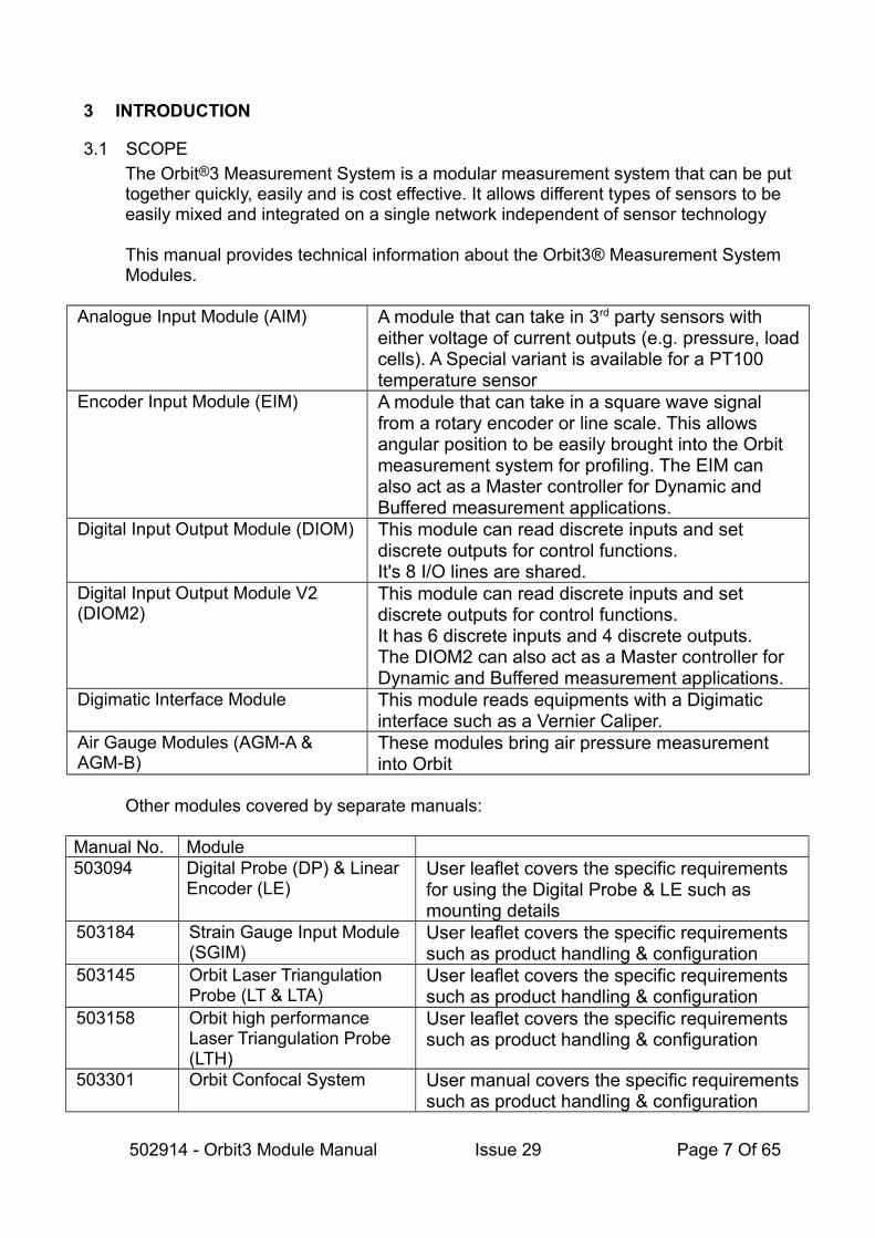
The Orbit®3 Measurement System is a modular measurement system that can be put together quickly, easily and is cost effective. It allows different types of sensors to be easily mixed and integrated on a single network independent of sensor technology
This manual provides technical information about the Orbit3® Measurement System Modules.
Analogue Input Module (AIM) A module that can take in 3rd party sensors with either voltage of current outputs (e.g. pressure, loadcells). A Special variant is available for a PT100 temperature sensor
Encoder Input Module (EIM) A module that can take in a square wave signal from a rotary encoder or line scale. This allows angular position to be easily brought into the Orbit measurement system for profiling. The EIM can also act as a Master controller for Dynamic and Buffered measurement applications.
Digital Input Output Module (DIOM) This module can read discrete inputs and set discrete outputs for control functions.It's 8 I/O lines are shared.
Digital Input Output Module V2 (DIOM2)
This module can read discrete inputs and set discrete outputs for control functions.It has 6 discrete inputs and 4 discrete outputs. The DIOM2 can also act as a Master controller for Dynamic and Buffered measurement applications.
Digimatic Interface Module This module reads equipments with a Digimatic interface such as a Vernier Caliper.
Air Gauge Modules (AGM-A & AGM-B)
These modules bring air pressure measurement into Orbit
Other modules covered by separate manuals:
Manual No. Module503094 Digital Probe (DP) & Linear
Encoder (LE)User leaflet covers the specific requirements for using the Digital Probe & LE such as mounting details
503184 Strain Gauge Input Module (SGIM)
User leaflet covers the specific requirements such as product handling & configuration
503145 Orbit Laser Triangulation Probe (LT & LTA)
User leaflet covers the specific requirements such as product handling & configuration
503158 Orbit high performance Laser Triangulation Probe (LTH)
User leaflet covers the specific requirements such as product handling & configuration
503301 Orbit Confocal System User manual covers the specific requirementssuch as product handling & configuration
502914 - Orbit3 Module Manual Issue 29 Page 7 Of 65

All of the modules can be mixed together with other Orbit products to generate a measurement system.
Examples
Combine an Encoder Module with a rotary encoder to give angular position and then use this to take readings from Digital Probes to profile a round part.
Add an AIM with a PT100 to monitor the temperature during the measurement cycle
Add an AIM with a load cell to weigh the part.
Several AIMs can be used with PT100 to monitor and record clean room temperatures for audit trails.
Use the Digital Input Output Module to trigger a PLC to advise a measured part is Ok or not OK.
Use a DIOM2 to monitor interlock relays
Use a DIOM2 to trigger a Dynamic collection from a set of Orbit Modules
Use an AGM to measure bores using air gauging techniques.
3.2 NAVIGATE THIS DOCUMENT
This is a large document, which is a useful reference when writing Orbit applications. Hyperlinks are included to aid navigation.
To return to the point where you have jumped from, most pdf readers havea ‘Previous Page View’ button, alternatively use the keyboard shortcut 'ALT' + left arrow key.
502914 - Orbit3 Module Manual Issue 29 Page 8 Of 65

4 SAFETY SUMMARY (ALL MODULES)
Products with their own manuals may contain additional safety information.
WARNING statements identify conditions or practices that could result in personal injury or loss of life.
CAUTION statements identify conditions or practices that could result in damage to the equipment or other property
Symbols in this manual
Indicates cautionary or other information
Warnings and Cautions
Warning: Do not operate in an explosive atmosphere.
Warning: this equipment is not intended for safety critical applications
Warning: do not exceed maximum ratings as specified in this document under individual modules.
Caution: Low VoltageThis equipment operates below the SELV and is therefore outside the scope of the Low Voltage Directive
Service and Repair
CAUTION: This equipment contains no user serviceable parts. Return to supplier for all service and repair
All of the Orbit Modules are CE marked and comply with EN61000-6-3 Electrical Emissions and EN61000-6-2 Electrical Immunity
5 GLOSSARY
Please refer to the Orbit3 System manual for information regarding terms used in this document. The Orbit3 System manual provides a good introduction to the Orbit®3 Measurement System and should be read in conjunction with this document.
502914 - Orbit3 Module Manual Issue 29 Page 9 Of 65

6 NEW FEATURES WITH ORBIT3
The Orbit3 system provides the following improvements over Orbit2, while still retaining backward compatibility.
• All DP, AIM and DIOM Modules now have Buffered capability supplied as standard.
• All modules have diagnostic/status LEDs , providing indication for:• Orbit Bus communication • Low or High Orbit Voltage warning • Hardware fault • Hot Swap Fault/Error.
For further details of Orbit3 improvements, see the Orbit3 System manual.
502914 - Orbit3 Module Manual Issue 29 Page 10 Of 65
7 ORBIT3 MODULES POWER REQUIREMENTS AND ENVIRONMENT
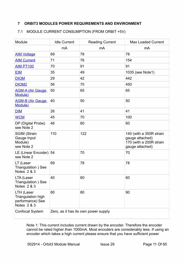
7.1 MODULE CURRENT CONSUMPTION (FROM ORBIT +5V)
Module Idle Current Reading Current Max Loaded Current
mA mA mA
AIM Voltage 69 78 78
AIM Current 71 76 154
AIM PT100 70 91 91
EIM 35 49 1035 (see Note1)
DIOM 29 42 442
DIOM2 56 70 450
AGM- A (Air Gauge Module)
50 65 65
AGM- B (Air Gauge Module)
40 50 50
DIM 26 41 41
WCM 45 70 100
DP (Digital Probe) see Note 2
46 60 60
SGIM (Strain Gauge Input Module)see Note 2
110 122 140 (with a 350R strain gauge attached)170 (with a 200R strain gauge attached)
LE (Linear Encoder)see Note 2
54 70 70
LT (Laser Triangulation ) See Notes 2 & 3
69 78 78
LTA (Laser Triangulation ) See Notes 2 & 3
40 60 60
LTH (Laser Triangulation high performance) See Notes 2 & 3
80 80 90
Confocal System Zero, as it has its own power supply
Note 1: This current includes current drawn by the encoder. Therefore the encoder cannot be rated higher than 1000mA. Most encoders are considerably less. If using an encoder which takes a high current please ensure that you have sufficient power
502914 - Orbit3 Module Manual Issue 29 Page 11 Of 65

available from the Orbit Network. Refer to the Orbit3 System manual for further information.
Note 2: The Digital Probe, Strain Gauge Input module, Laser Triangulation probes, Linear Encoder & Confocal system are not covered in this manual but the current has been included here for completeness. For further details see the Orbit3 catalog and their individual user leaflets.
Note 3: The Laser Triangulation probes also require an auxiliary +24V DC supply in addition to the standard +5V DC supply. This may be provided by an Auxiliary AC PSIM/24 or DC PSIM/24/5.
• LT probes consume typically 40mA from the 24Vdc supply• LTA probes consume typically 60mA from the 24Vdc supply• LTH probes consume typically 60mA from the 24Vdc supply
7.2 MODULE OPERATING ENVIRONMENT
Temperature Operating: 0ºC to + 60ºC
Storage: -20ºC to + 85ºC
Sealing IP43
502914 - Orbit3 Module Manual Issue 29 Page 12 Of 65
8 ANALOGUE INPUT MODULE
8.1 INTRODUCTION
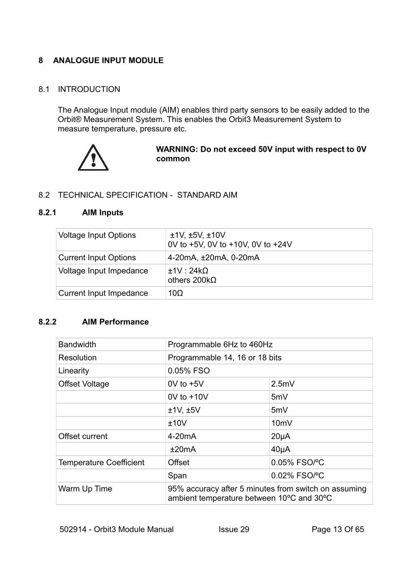
The Analogue Input module (AIM) enables third party sensors to be easily added to the Orbit® Measurement System. This enables the Orbit3 Measurement System to measure temperature, pressure etc.
WARNING: Do not exceed 50V input with respect to 0V common
8.2 TECHNICAL SPECIFICATION - STANDARD AIM
8.2.1 AIM Inputs
Voltage Input Options ±1V, ±5V, ±10V0V to +5V, 0V to +10V, 0V to +24V
Current Input Options 4-20mA, ±20mA, 0-20mA
Voltage Input Impedance ±1V : 24kΩothers 200kΩ
Current Input Impedance 10Ω
8.2.2 AIM Performance
Bandwidth Programmable 6Hz to 460Hz
Resolution Programmable 14, 16 or 18 bits
Linearity 0.05% FSO
Offset Voltage 0V to +5V 2.5mV
0V to +10V 5mV
±1V, ±5V 5mV
±10V 10mV
Offset current 4-20mA 20μA
±20mA 40μA
Temperature Coefficient Offset 0.05% FSO/ºC
Span 0.02% FSO/ºC
Warm Up Time 95% accuracy after 5 minutes from switch on assuming ambient temperature between 10ºC and 30ºC
502914 - Orbit3 Module Manual Issue 29 Page 13 Of 65

8.2.3 AIM Environment
Energizing See Module Power Consumption and Environment table
Temperature
Sealing IP43
8.2.4 Connection Details Voltage AIM
502914 - Orbit3 Module Manual Issue 29 Page 14 Of 65
Analogue Input Module
White
Black
Blue
+ve Voltage Input
0V Common (Screen)
-ve Voltage Input
ORBIT
Voltage Source
V+
-
Voltage Input Configuration(Shown for wire ended option)
Screen
0V Common(Optional)

8.2.5 Connection Details Current AIM
502914 - Orbit3 Module Manual Issue 29 Page 15 Of 65
Analogue Input Module
Green
Black
Current Input
0V Common (Screen)
ORBIT
Current Source
+
-
Current Input Configuration forany current type
(shown for wire ended option)
I
Screen
10 Ohms
ANSI/ISA Type 3 & 4
Analogue Input Module
Yellow
Green
4-20mA Loop Supply +12 Volts
Current Input (4-20mA return)
ORBIT4-20 mA Loop Configuration only(shown for wire ended option)
4 - 20 mA Device(Current sink)
+
-
Screen
+
-I
ANSI/ISA Type 2

8.3 TECHNICAL SPECIFICATION - PT100 AIM
8.3.1 PT100 AIM relationship between Temperature and Resistance
The PT100 AIM is a special module for use with a PT100 temperature sensor. The PT100 is a widely used sensor in which the resistance varies as a function of temperature. The equation for the PT100 is:-
Rt=R0(1+at+Bt2)
Where t = temperature in ºCRt = resistance at temperature t in ΩR0 = resistance at 0ºCA = alpha coefficient 0.391 Ω/ºCB = beta coefficient -5.78 x 10⁻⁷
The beta term is used to correct for non linearity. The exact values used for alpha and beta vary according to the specified operating range. This equation allows temperature to be accurately measured using a resistance measurement. The PT100 AIM is calibrated against a series of precision resistors.
8.3.2 PT100 Temperature and Resistance Tolerance Table
The PT100 sensor itself has a tolerance, there are two types A and B. The following table shows the PT100 sensor tolerance as specified in IEC 751 Standard. The PT100 AIM tolerance can never be better than the tolerance of the PT100 sensor.
Temperature Resistance Tolerance
Class A Class B
ºC Ω ±ºC Ω ±ºC Ω
-200 18.52 0.55 0.24 1.3 0.56
-100.00 60.26 0.35 0.12 0.8 0.32
0.00 100.00 0.15 0.06 0.3 0.12
100.00 138.51 0.35 0.13 0.8 0.30
200.00 175.86 0.55 0.20 1.3 0.48
300.00 212.05 0.75 0.27 1.8 0.64
400.00 247.09 0.95 0.33 2.3 0.79
500.00 280.98 1.15 0.38 2.8 0.93
600.00 313.71 1.35 0.43 3.3 1.06
650.00 329.64 1.45 0.46 3.6 1.13
700.00 345.28 3.8 1.17
800.00 375.70 4.3 1.28
850.00 390.48 4.6 1.34
502914 - Orbit3 Module Manual Issue 29 Page 16 Of 65

8.3.3 AIM PT100 Accuracy
Apart from the tolerance of the PT100 sensor the PT100 AIM accuracy is effected by the connection method. The PT100 AIM is designed to be connected as a four wire connection. If the PT100 AIM is connected in any other way then the accuracy will be compromised. Ensure that the sense wires are connected close to the sensor to avoid unwanted lead effects.
8.3.4 Connection Details PT100
502914 - Orbit3 Module Manual Issue 29 Page 17 Of 65
Analogue Input Module
Yellow
White
Green
Black
Blue
Red
6 4-20mA Loop Supply +12 Volts
5 +ve Voltage Input
4 Current Input (4-20mA return)
3 0V Common (Screen)
2 -ve Voltage Input
1 +2.50 Volt Reference
ORBIT
n/c
n/c
n/c
Strain Guage Configuration Screen
Analogue Input Module
White
Black
Blue
Red
5 +ve Voltage Input
3 0V Common (Screen)
2 -ve Voltage Input
1 +2.50 Volt Reference
ORBIT
Four Wire Sensor
Pt100 Temperature Sensor Configuration
Screen
Pt100Sensor

9 ENCODER INPUT MODULE
9.1 INTRODUCTION
The Encoder Input Module (EIM) is an Orbit Module which can interface to incremental and rotary encoders with square wave outputs, allowing these sensors to be interfaced into the Orbit Measurement System. Using rotary encoders via the EIM in conjunction with linear measurement sensors allows the Orbit Measurement System to perform part profiling.
9.2 TECHNICAL SPECIFICATION
Inputs
Input Signal Type
Single ended or differential square waves with open collector or push pull outputs.
Voltage Range: 0 to 30V Max
Differential Input Signal Switching levels
High, VID > 0.2VLow, VID < 0.2V
Single EndedInput Switching Voltage
High > 2.4VLow < 1V
Frequency 1.2MHz MaxUsing higher frequency may make the EIM read incorrectly
Operational Modes
The EIM can be used like any other Orbit Module where a controller reads from the EIMon command. The EIM can form part of a dynamic collection. The EIM can be handed control and provide synchronization for a dynamic collection.
See the Orbit3 Software manual for further information on using the EIM.
502914 - Orbit3 Module Manual Issue 29 Page 18 Of 65

Programmable Parameters
Inputs Single EndedDifferential
Interpolation X1 (default)X2X4Count ABCount DIR
Reference Pulse Do nothing
Reset counter on reference pulse
Preset counter on reference Pulse
Reset counter on first reference pulse only
Preset counter on first reference pulse only
Reset counter on first reference pulse only and enable, Synch, Transmit and Holdoff functions
Preset counter on first reference pulse only and enable, Synch, Transmit and Holdoff functions
Please see the Orbit3 Software manual for further information on using the EIM.
Power consumption and environment is detailed in ORBIT3 MODULES POWER REQUIREMENTS AND ENVIRONMENT
502914 - Orbit3 Module Manual Issue 29 Page 19 Of 65

9.3 EIM CONNECTION DETAILS
9.3.1 Basic EIM Wired Ended Connections
Wire Colour DescriptionBlue +5V (out to encoder) 300mA
MaxPink or White A-Red A+Green B-Yellow B+Orange Ref-Brown Ref+Grey Error Note1
Black 0V
Count Direction: the EIM will provide an increasing count when A leads B
Note 1For encoders that provide an Error output signal, the EIM returns an Orbit error code when the EIM detects a change of state on the 'Error' input.
9.3.2 Quadrature Mode
Input Type – Single Ended Input Type DifferentialEncoder Signal EIM Input Encoder Signal EIM InputA Out A+ A+ Out A+No Connection A- A- Out A-B Out B+ B+ Out B+No Connection B- B- Out B-Ref Out Ref+ Ref Out Ref+No Connection Ref- Ref- Out Ref-
NoteThe inputs to the EIM that have No Connection must be left unconnected. If the encoderhas no reference output the EIM Ref+ input can be connected to the EIM 0V to improve noise immunity.
502914 - Orbit3 Module Manual Issue 29 Page 20 Of 65

9.3.3 CountAB Mode Up
Input Type – Single Ended Input Type DifferentialEncoder Signal EIM Input Encoder Signal EIM InputSignal to Count(Low toHigh)
A+ Signal to Count(Lowto High)
A+
No Connection A- Inverted A+ Signal A-EIM +5V B+ No Connection B+No Connection B- EIM 0V B-EIM 0V Ref+ EIM 0V Ref+No Connection Ref- No Connection Ref-
See note under quadrature mode
9.3.4 CountAB Mode Down
Input Type – Single Ended Input Type DifferentialEncoder Signal EIM Input Encoder Signal EIM InputEIM +5V A+ No Connection A+No Connection A- EIM 0V A-Signal to Count(Low toHigh)
B+ Signal to Count(Lowto High)
B+
No Connection B- Inverted B+ B-EIM 0V Ref+ EIM 0V Ref+No Connection Ref- No Connection Ref-
See note under quadrature mode
502914 - Orbit3 Module Manual Issue 29 Page 21 Of 65

9.3.5 CountDir Mode Up
Input Type – Single Ended Input Type DifferentialEncoder Signal EIM Input Encoder Signal EIM InputSignal to Count(Low toHigh)
A+ Signal to Count(Lowto High)
A+
No Connection A- Inverted A+ A-EIM 0V B+ EIM 0V B+No Connection B- No Connection B-EIM 0V Ref+ EIM 0V Ref+No Connection Ref- No Connection Ref-
See note under quadrature mode
9.3.6 CountDir Mode Down
Input Type – Single Ended Input Type DifferentialEncoder Signal EIM Input Encoder Signal EIM InputSignal to Count(Low toHigh)
A+ Signal to Count(Lowto High)
A+
No Connection A- Inverted A+ A-EIM +5V B+ No Connection B+No Connection B- EIM 0V B-EIM 0V Ref+ EIM 0V Ref+No Connection Ref- No Connection Ref-
See note under quadrature mode
502914 - Orbit3 Module Manual Issue 29 Page 22 Of 65

10 DIGIMATIC INTERFACE MODULE
10.1 INTRODUCTION
The Digimatic Input (DIM) Module is designed to connect to any Digital gauge with a Digimatic ((code) Output. The connection to the Digital gauge is via a 10 way male connector which will connect to any Mitutoyo Digimatic compatible gauge.
10.2 CONNECTIONS
Pin Signal Description Direction1 GND Signal Ground2 DATA Data Output To DIM3 CLOCK Synchronized Clock Output To DIM4 DATA SW Gauge Data Switch (if fitted) To DIM5 REQ# Data Transmission Request From DIM6 Not used7 Not used8 Not used9 Not used10 Not used
For Power Consumption and Environmental Specification refer to ORBIT3 MODULES POWER REQUIREMENTS AND ENVIRONMENT
Note: Pin4 Data SW is not always available on all gauges.
502914 - Orbit3 Module Manual Issue 29 Page 23 Of 65

11 DIGITAL INPUT OUTPUT MODULE V2
11.1 INTRODUCTION
The Digital Input Output Module V2 (DIOM2) provides an interface between the Orbit® Measurement System and the external world. It is an enhanced version of the DIOM product, providing 6 dedicated discrete signal lines and 4 dedicated discrete output lines. This provides a simple interface to control switches, PLC etc.A DIOM2 input can also be used as an external Master, see DIOM2 as a Master
The four digital outputs have 3 modes of operation that can be configured by software: NPN, Logic or PNP.
• All outputs share the mode set.
By default (on power-up), all 6 discrete input signal lines are configured active Low.All 4 discrete output lines are configured as NPN and OFF.
Please refer to the Orbit3 Software manual for further details on using the Orbit Library to read the DIOM2 inputs and to configure output pins and their options.
11.2 DEBOUNCE
External switches can sometimes bounce, be disturbed by vibration, harsh electrical environments can cause spikes. All of these can cause an incorrect reading. Taking multiple readings of an input can help with the elimination of spurious results caused by the former.
The DIOM2 has a built in debounce functionality designed to filter out spurious readings. The debounce times available (for all inputs) are: 0 (default), 5, 10, 25, 50mS
See the Orbit3 Software manual for information on using the Orbit Library to set the DIOM2's input debounce function.
11.3 DIOM2 AS A MASTER
The DIOM2 can also be used provide synchronization for a Dynamic collection (ExternalMaster Mode). Similarly, it can be used to Externally trigger/sample readings inBuffered mode.
Notes.• Input1 is used as the trigger.• When being used as a trigger, it it not possible to read its other inputs. If digital
inputs are needed to be read as part of a Dynamic collection, then a separate DIOM2 or DIOM must be used.
See the Orbit3 Software manual for further information on using the DIOM2.
502914 - Orbit3 Module Manual Issue 29 Page 24 Of 65
11.4 TECHNICAL INFORMATION
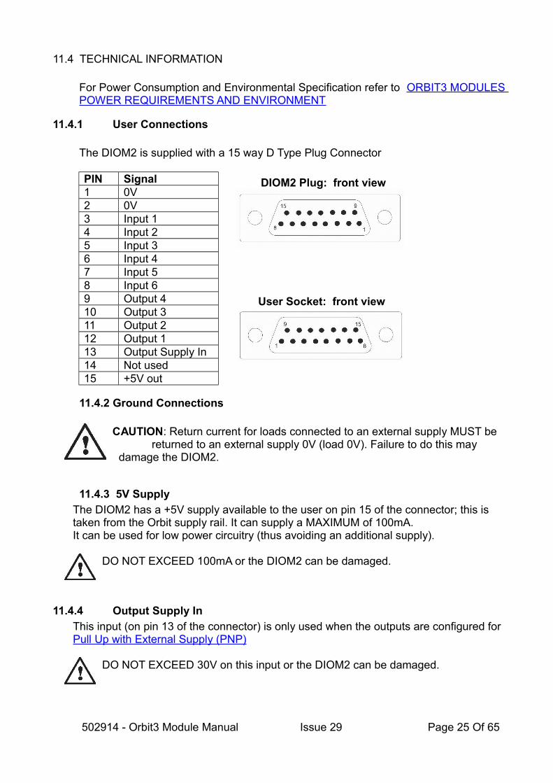
For Power Consumption and Environmental Specification refer to ORBIT3 MODULES POWER REQUIREMENTS AND ENVIRONMENT
11.4.1 User Connections
The DIOM2 is supplied with a 15 way D Type Plug Connector
PIN Signal1 0V2 0V3 Input 14 Input 25 Input 36 Input 47 Input 58 Input 69 Output 410 Output 311 Output 212 Output 113 Output Supply In14 Not used15 +5V out
11.4.2 Ground Connections
CAUTION: Return current for loads connected to an external supply MUST be returned to an external supply 0V (load 0V). Failure to do this may
damage the DIOM2.
11.4.3 5V Supply
The DIOM2 has a +5V supply available to the user on pin 15 of the connector; this is taken from the Orbit supply rail. It can supply a MAXIMUM of 100mA.It can be used for low power circuitry (thus avoiding an additional supply).
DO NOT EXCEED 100mA or the DIOM2 can be damaged.
11.4.4 Output Supply In
This input (on pin 13 of the connector) is only used when the outputs are configured for Pull Up with External Supply (PNP)
DO NOT EXCEED 30V on this input or the DIOM2 can be damaged.
502914 - Orbit3 Module Manual Issue 29 Page 25 Of 65
User Socket: front view
DIOM2 Plug: front view

11.4.5 Inputs
• The input pins have internal pull ups (1KΩ to 5V), therefore unconnected pins read HIGH.
• Input pins can be individually set active High or active Low.• Please refer to the Orbit3 Software manual for further details on configuring
DIOM2 input pins.• The six digital inputs may be connected as shown below:
11.4.5.1Specification
Usage• Contact switched• Logic voltages
Logic Polarity• Selectable by software as active high or active low.
Input Voltages• Absolute Minimum Input Voltage -5V• Absolute Maximum Input Voltage +40V
Input Frequency• Minimum Freq. DC• Maximum Freq. 1kHz
Logic Switching Levels • Low level 0.80V min, typically 1.3V• High level 2.90V max, typically 2.29V• Hysteresis 0.54V min, typically 1.0V
Hardware timing• Dependent on source resistance
For contact switching:-• Low to High Transition typically <1 uS• High to Low Transition typically <1 uS
502914 - Orbit3 Module Manual Issue 29 Page 26 Of 65

11.4.5.2Single Contact Input
11.4.5.3Switched Voltage Input
11.4.5.4Logic Input
502914 - Orbit3 Module Manual Issue 29 Page 27 Of 65

11.4.6 Outputs
• The four digital outputs have 3 modes of operation that can be configured by software: NPN, Logic or PNP. ◦ All outputs share the mode set.
• Output pins can be individually set active High or active Low.• All outputs are de-activated on start-up
Please refer to the Orbit3 Software manual for details on configuring and switching DIOM2 output pins.
11.4.6.1Output example
If a user has a requirement to drive a relay to turn ON their process:• Use NPN (or PNP if desired) output mode.• Set the Active state of the output pin to the required state to activate the relay.
When the DIOM2 power is cycled, the DIOM2 output pin will start up in the deactivated state. i.e. the relay will not be turned on.
• This means that the process will default to OFF when the power is first applied. After that, the controlling software can control the output.
11.4.6.2Specification
Output Modes• 5V Logic Output• Pull up to Externally applied positive supply (PNP)• Pull down using Load connected to a positive supply (NPN)
5V Logic Output• Pull up from 5V via 1KΩ resistor• 2 standard TTL loads capability.
External supply limits• +10 volts to +30 volts
Current Limits• Pull Up - 150mA• Pull Down - 150mA
Maximum In-rush Current• Pull-up 600mA & duration <200mS• Pull-down 600mA & duration <200mS
Rise/Fall times• Pull-up <500nS (Typically 460nS)• Pull-up Release Dependent on load (typically <1.5uS)• Pull-down <300nS (Typically 290nS)• Pull-down Release Dependent on load (typically <2.5uS)
502914 - Orbit3 Module Manual Issue 29 Page 28 Of 65

Back-emf Clamping Voltage• In pull-up mode one forward diode drop (~0.7V)• In pull-down mode 36V +/- 10%
502914 - Orbit3 Module Manual Issue 29 Page 29 Of 65

11.4.6.3Pull Down with External Supply (NPN)
11.4.6.4Pull Down Logic 5V
11.4.6.5Pull Up with External Supply (PNP)
For this option, the user must connect their power supply to pin 13 of the DIOM2.
502914 - Orbit3 Module Manual Issue 29 Page 30 Of 65

12 DIGITAL INPUT OUTPUT MODULE
12.1 INTRODUCTION
The Digital Input Output Module (DIOM) provides an interface between the Orbit® Measurement System and the external world.For the more flexible DIOM2 product, see DIGITAL INPUT OUTPUT MODULE V2
The DIOM provides 8 discrete signal lines that can be configured via software as an input or an output. This provides a simple interface to control switches, PLC etc.
By default (on power-up), all 8 discrete signal lines are configured as inputs.
When configuring a signal line, it can be set to an:• Input
◦ See Input Port for details◦ Once configured as an input, it's state can be read via software
• Output◦ Open drain style output. See Output Port
▪ Able to sink current to turn on LEDs, relay coils etc when switched LOW.▪ Limited source current when switched HIGH
◦ This can be connected to switch:▪ An external supply▪ using the DIOM's own +5V supply
◦ Once configured as an output, it can be switched LOW or HIGH via software. Please refer to the Orbit3 Software manual for further details on switching DIOM output pins.
12.2 READING
When reading a DIOM, the 8 lines of I/O are returned as an eight bit byte (0 to 255) that is made up of the following:
Bit 7 6 5 4 3 2 1 0
Value I/O Pin 8 I/O Pin 7 I/O Pin 6 I/O Pin 5 I/O Pin 4 I/O Pin 3 I/O Pin 2 I/O Pin 1
• If the I/O Pin state is low (logical 0), then the value for that bit is returned as 0.• If the I/O Pin state is high (logical 1), then the value for that bit is returned as 1.• If the I/O Pin is configured to be an output, then the value for that bit is returned as
the state it is set to (I.e. if set LOW, then reads 0, if set HIGH, then reads 1)
For example, in the DIOM Example Application, all input bits high and output bits set low would return a reading of 11110000 binary = 240 decimal.
Please refer to the Orbit3 Software manual for further details on using the Orbit Library toread the DIOM.
502914 - Orbit3 Module Manual Issue 29 Page 31 Of 65

12.3 DEBOUNCE
External switches can sometimes bounce, be disturbed by vibration, harsh electrical environments can cause spikes. All of these can cause an incorrect reading. Taking multiple readings of an input can help with the elimination of spurious results caused by the former.
The DIOM has a built in debounce functionality designed to filter out spurious readings. The debounce times available (for all inputs) are: 0 (default), 5, 10, 25, 50mS
See the Orbit3 Software manual for information on using the Orbit Library to set the DIOM's input debounce function.
502914 - Orbit3 Module Manual Issue 29 Page 32 Of 65

12.4 EXAMPLE APPLICATION
The circuit, shown next, illustrates an example application of a DIOM.
Example of Connection to the DIOM
CAUTION: Inductive loads must be suppressed using diodes
0V load must be connected to supply 0V
12.4.1 Explanation of example circuit
I/O Pin State Function
1 Output When set LOW, sinks current through 30V resistive load
2 Output When set LOW, sinks current through 12V inductive load (e.g. relay coil)
3 Output When set LOW, sinks current through 5V LED circuitry (LED = on)When set HIGH, no current flows through 5V LED circuitry (LED = off)
4 Output As for Pin 3
5 Input State will be HIGH or LOW, dependent on switch position
6 Input State will be permanently pulled HIGH (as not externally connected)
7 Input State will be HIGH or LOW, dependent on buffer state
8 Input State will be HIGH or LOW, dependent on switch position. This example uses the HIGH internal pull up
502914 - Orbit3 Module Manual Issue 29 Page 33 Of 65

12.5 TECHNICAL INFORMATION
For Power Consumption and Environmental Specification refer to ORBIT3 MODULES POWER REQUIREMENTS AND ENVIRONMENT
12.5.1 User Connections
The DIOM is supplied with a 15 way D Type Socket Connector
PIN Signal1 I/O 12 I/O 23 I/O 34 I/O 45 I/O 56 I/O 67 I/O 78 I/O 89 0V10 0V11 0V12 0V13 +5V14 Not used15 Not used
502914 - Orbit3 Module Manual Issue 29 Page 34 Of 65
User Plug: front view
DIOM Socket: front view

12.5.2 Ground Connection
This details important rules for connecting of 0V signals when using an external supply.
CAUTION: Return current for load connected to an external supply MUST be returned to an external supply 0V (load 0V). Failure to do this may damage the DIOM.
12.5.3 Input Port
• When a pin is configured to be an input, the Output driver is switched off.• As this has an internal pull up, an unconnected pin reads HIGH.
The table, next has detailed technical data:Detail Value Basic Circuit of the I/O port
Input Port Pull Up Resistor
4k7 (to Orbit +5V supply)
High Switching Voltage
≥ 3.15V
Low Switching Voltage
≤ 1.35V
Maximum input rating
-0.5V to +30V
Source current ≤ 1mA
502914 - Orbit3 Module Manual Issue 29 Page 35 Of 65

12.5.4 Output Port
The output driver is open drain• When a pin is configured to be an output HIGH, the Output driver is switched off
and no current (I) flows.• When a pin is configured to be an output LOW, the Output driver is switched on,
which allows the pin to sink current (I).
12.5.4.1 With External Supply
This section details how to connect a DIOM output to switch a load (external supply).For example to directly switch a +24V relay coil.The table, next has detailed technical data:
Detail Value Basic Circuit of the I/O port
Driver Type Open Drain (requires external Pull UPor load to external supply
High Switching Voltage
≥ 3.15V
Low Output Voltage
≤ 0.2V
Maximum output rating
-0.5V to +30V
Sink current ≤ 50mA
502914 - Orbit3 Module Manual Issue 29 Page 36 Of 65

12.5.4.2 Using Orbit Supply
The DIOM has an internal +5V supply available, which can be used for low power circuitry (thus avoiding an additional supply). This section details connecting a DIOM output using this supply.
Orbit +5V supply(PIN13 DIOM).
This can supply a MAXIMUM of 50mA whichcan be used for low powerswitching of external devices.
DO NOT EXCEED 50mA or the DIOM can be damaged.
502914 - Orbit3 Module Manual Issue 29 Page 37 Of 65

12.5.4.3 Interfacing to Logic
This details connecting a DIOM output directly to logic circuitry.
Detail Value Basic Circuit of the I/O portInput Port Pull Up Resistor
4k7 (to Orbit+5V supply)
Low SwitchingVoltage
≤ 0.2V
The EIM can also act as a pseudo controller for Dynamic measurement applications.
502914 - Orbit3 Module Manual Issue 29 Page 38 Of 65

13 WIRELESS CONNECTION MODULE
13.1 INTRODUCTION
The Wireless Connection Module (WCM) provides an interface between the Orbit® Measurement System and Bluetooth devices (e.g. Wireless handtools).This removes the need for the devices to be connected to the PC via a Bluetooth dongle.
The WCM behaves as a standard Orbit Module and can be configured to connect via Bluetooth with up to 6 wireless devices and obtain readings from them (see System Overview).
The WCM continuously reads the connected wireless devices and stores their reading information in its buffer – available to be read by Orbit. This means that the slower reading rate of wireless devices does not slow down the Orbit reading rate.
Each wireless device can be read independently via the WCM. Compatible devices are:
• WHT - single channel (only channel 1 reading is valid)• WHT-M - multichannel (multiple channel readings are valid, - max = 8)
Each Wireless device could feasibly be a WHT-M with up to 8 channels each, therefore the WCM is able to provide data from up to 48 channels (6 x 8) from one WCM.
Although there is no limit to the number of WCMs allowed on an Orbit network, we recommend only 6. This limits the total number of Bluetooth devices/channels to 36. Although Bluetooth cantheoretically support 79 devices/channels we do not recommend having more than 36 within a separation distance that could create interference. It is not practical to define a separation distance as it depends on the local environment and the Bluetooth power setting.
A PSIM must be used if using a USBIM with more than 2 WCMs.
13.1.1 WCM related software
The 'Orbit3 C# example' includes a simple example of taking Wireless device readings via a configured WCM.
The Orbit3 Software manual details WCM specific Orbit Library functionality.
13.1.2 Compatibility
• The WCM is not designed to work with the Orbit ACS family (SI100,200,400) or SI3500, SI5500, SI1500 and DR600/700 readouts.
• The WCM does not work with the older Orbit COM/DLL library.
502914 - Orbit3 Module Manual Issue 29 Page 39 Of 65

13.2 SYSTEM OVERVIEW
-----------------------------------------------------------------------------------------------------------
502914 - Orbit3 Module Manual Issue 29 Page 40 Of 65

13.3 UNDERSTANDING WCM OPERATION
Once connected, the WCM continuously reads the configured Wireless device(s) reading data and puts the latest reading and a timestamp (of when the reading was received) into a buffer.
As with any wireless battery powered device, there are limitations; the device may not be currently connected, may be out of range, powered off. Therefore, the reading data retrieved from the WCM is controlled by the 'Max Reading Age' device setting (see Advanced settings) and only valid reading data recently received from the Wireless device is returned.If the reading data from a device is out of date (i.e. outside allowed the reading 'age'), an error code is returned instead.
• The reason for this setting is to avoid the WCM having Wireless device readings in its buffer that are out of date.◦ For example, the Wireless device may have since gone out of range (hence;
unobtainable) and so when a reading is requested by the user's software, the user would get very old readings (i.e. from when the device was in range) instead of current ones.
Note that out of date readings do not apply to Tagged readings.
All the while reading data is being requested for a device, the WCM will maintain the Bluetooth™ connection to the Wireless device and obtain reading data; returning the most recent reading data available when a reading is requested.
When readings are no longer being requested, the Disconnect Period timer starts.
The wireless device will be automatically disconnected after the Disconnect Period Setting (see Advanced settings) has elapsed. If readings are subsequently requested, an error code will be returned while the WCM attempts to re-connect with the device and obtain reading data.
Although typically a connection is established and data retrieved within 1-5 seconds, connection errors can occur. Therefore any software using this mechanism should poll for data for at least 20 seconds (to allow time for the Bluetooth™ connection to be established with the device (and readings obtained) - before declaring the device truly unobtainable / offline.Note: Once data has been requested, the WCM will continue to attempt to connect with the device indefinitely (unless the WCM is power cycled), until the device is found and readings obtained.
13.3.1 Reading Rates
The Orbit can run at up to 4000 readings per second, however the wireless network will run much slower; its total speed will be dependent on number of sensors.So that an Orbit system using Readburst is not compromised by any connected WCMs, the WCM will respond, but will return a '0' reading. It is up to the user to ignore the invalid WCM reading.
502914 - Orbit3 Module Manual Issue 29 Page 41 Of 65

13.3.2 Tagged readings
The Wireless handtool devices can ‘Tag’ a reading which is then transmitted over the Bluetooth link to the WCM with a tag index number.For this function, the devices must be configured to provide tagged readings when pressing a button – refer to Device Configuration Settings.
The tag number increments by 1, each time the device's tag button is pressed. Any readings that the WCM receives as tagged are stored (along with the tag number) in a separate buffer to normal (not tagged) readings. Therefore, both normal & tagged readings can be read, sequentially, if desired.
Note that only the last tagged reading and the tag number for each device are stored.
Once a tagged reading has been received by the WCM it will remain available to be read until the next tagged reading has been received.
Therefore, if you do multiple reads without further tags, the WCM will return the same tagged reading and number.
When a Tagged read for a particular device is requested from the WCM, it returns the reading from its tagged buffer. There is no ‘reading age' applicable to this, as it dependson when the tag was taken on the device.
Refer to the Orbit Software manual for a tagged readings example.
13.4 CONFIGURATION / OPERATION
The WCM itself is set up using the 'WCM Configurator' application, which is installed as part of the Orbit suite of programs.• It allows the user to configure which Wireless devices are to be connected to a
particular WCM.• It provides a demonstration tab that displays readings from a configured WCM (if the
Wireless devices are powered up / present).• It can be configured without the Wireless devices being present (apart from device
settings).• The WCM configuration is retained on a power cycle.• It allows device settings to be configured (if the Wireless devices are powered up /
present).Note that different settings are available for WHT and WHT-M devices. Refer to Device Configuration Settings.
Zero, Preset and Absolute functions are provided as settings for the single channel Wireless Handtools only.
13.4.1 Important Information
• The Wireless devices must be powered on before the WCM is powered (since the WCM scans for devices on power up).
502914 - Orbit3 Module Manual Issue 29 Page 42 Of 65

• While the WCM is scanning for devices, readings cannot be taken. Therefore any user software must have a startup delay to deal with this.
• It is up to the user to make sure that they do not select the same Wireless device to work on more than one WCM.
13.4.2 Recommended mode of operation - with wireless devices present
1. Connect up WCM to an Orbit network2. Turn on handtools3. Run WCM Configurator4. Select which Wireless devices you want the WCM to communicate with5. Click ‘Apply’
1. Configurator will check the WCM connection to the Wireless devices1. if 'None' is displayed for any selected devices, then...
1. Check device is on and the battery is OK2. Check device is in Bluetooth range (< 15 metres)3. Re-try 'Apply'
6. Once all required devices have responded, go to the ‘WCM Read..’ tab and click 'Start Reading' to see actual readings from the devices.
7. The list of devices (and their Type) will be saved in the WCM, ready for use later on.
8. Each device can have its settings altered by changing its configuration / settings ('Config' button).
9. Now come out of the Configurator application and connect to the WCM with your own program via the Orbit Library.
13.4.3 Alternate mode of operation – wireless devices not present
E.g. where the system needs to be configured at a different location to the devices
13.4.3.1 Stage 1
1. Connect up WCM to an Orbit network.2. Run WCM Configurator.3. Select which devices you want the WCM to communicate with.4. Click ‘Apply’.5. The list of devices will be saved in the WCM, ready for use later on.6. Now come out of the Configurator application.
13.4.3.2 Stage 2
1. Move the WCM to the location of the devices.2. Turn on wireless devices.3. Connect WCM to the Orbit network and power on4. Re-run the WCM Configurator and select the WCM, check that the 'Type' field is
defined (i.e. not 'None') indicating that the WCM has found the wireless device(s). If not, re-click ‘Apply’ to find all devices,
5. Each device can have its settings altered by changing its configuration / settings ('Config' button).
6. Use the 'WCM Read..' tab to connect to devices and check readings are OK.
502914 - Orbit3 Module Manual Issue 29 Page 43 Of 65

7. Now come out of the Configurator application and connect to the WCM with your own program via the Orbit Library.
502914 - Orbit3 Module Manual Issue 29 Page 44 Of 65
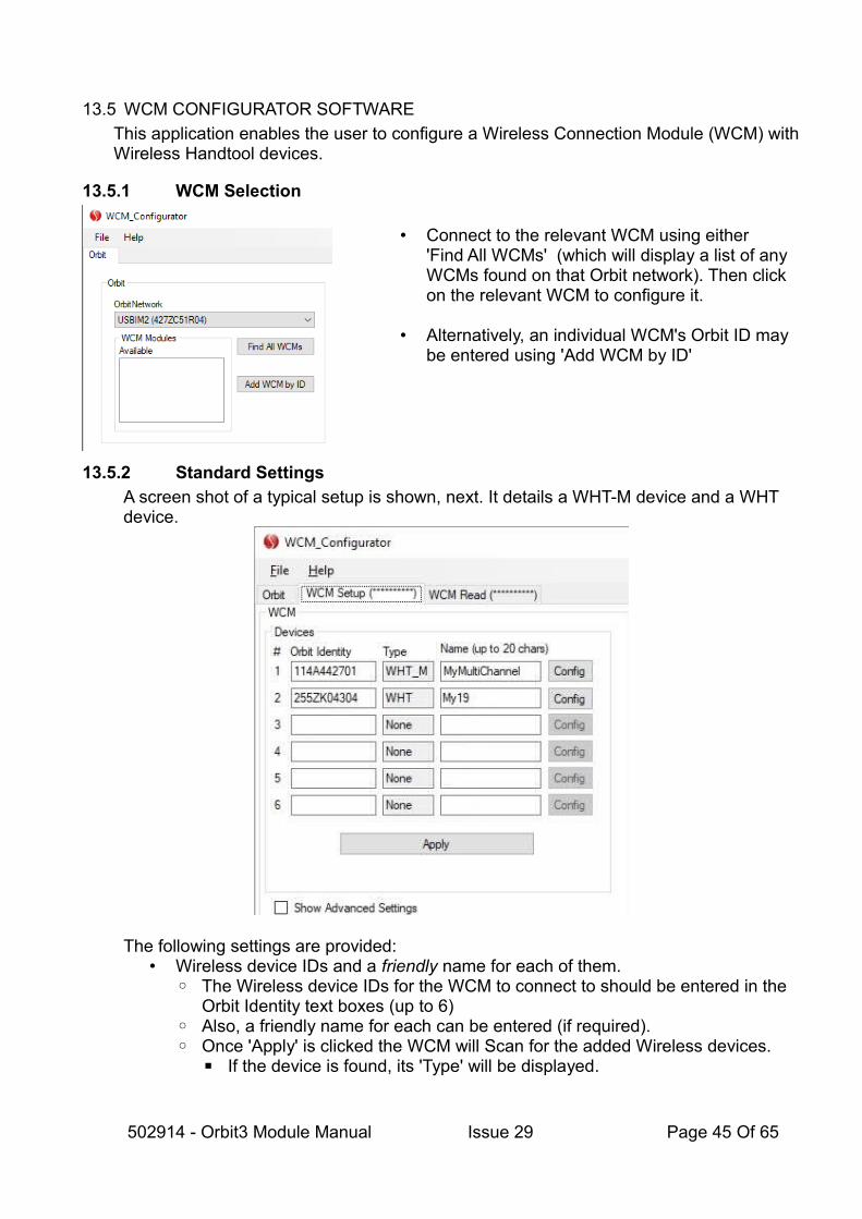
13.5 WCM CONFIGURATOR SOFTWARE
This application enables the user to configure a Wireless Connection Module (WCM) withWireless Handtool devices.
13.5.1 WCM Selection
• Connect to the relevant WCM using either 'Find All WCMs' (which will display a list of any WCMs found on that Orbit network). Then click on the relevant WCM to configure it.
• Alternatively, an individual WCM's Orbit ID may be entered using 'Add WCM by ID'
13.5.2 Standard Settings
A screen shot of a typical setup is shown, next. It details a WHT-M device and a WHT device.
The following settings are provided:• Wireless device IDs and a friendly name for each of them.
◦ The Wireless device IDs for the WCM to connect to should be entered in the Orbit Identity text boxes (up to 6)
◦ Also, a friendly name for each can be entered (if required).◦ Once 'Apply' is clicked the WCM will Scan for the added Wireless devices.
▪ If the device is found, its 'Type' will be displayed.
502914 - Orbit3 Module Manual Issue 29 Page 45 Of 65
▪ Each device has its own configuration – altered via its 'Config' button. Thisallows the device settings to be altered. Note that a WHT has different settings to that of a WHT-M. See Device Settings
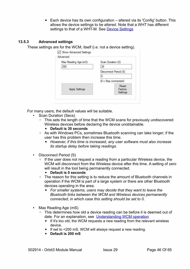
13.5.3 Advanced settings
These settings are for the WCM, itself (i.e. not a device setting).
For many users, the default values will be suitable.• Scan Duration (Secs)
◦ This sets the length of time that the WCM scans for previously undiscovered Wireless devices before declaring the device unobtainable.▪ Default is 30 seconds
◦ As with Windows PCs, sometimes Bluetooth scanning can take longer; if the user has this problem then increase this time.▪ However, if this time is increased, any user software must also increase
its startup delay before taking readings.
• Disconnect Period (S)◦ If the user does not request a reading from a particular Wireless device, the
WCM will disconnect from the Wireless device after this time. A setting of zerowill result in the tool being permanently connected.▪ Default is 0 seconds
◦ The reason for this setting is to reduce the amount of Bluetooth channels in operation if the WCM is part of a large system or there are other Bluetooth devices operating in the area.▪ For smaller systems, users may decide that they want to leave the
Bluetooth links between the WCM and Wireless devices permanently connected, in which case this setting should be set to 0.
• Max Reading Age (mS)◦ This determines how old a device reading can be before it is deemed out of
date. For an explanation, see Understanding WCM operation▪ If it's too old, the WCM requests a new reading from the relevant wireless
device.▪ If set to <200 mS, WCM will always request a new reading.▪ Default is 200 mS
502914 - Orbit3 Module Manual Issue 29 Page 46 Of 65

13.5.4 Device Configuration Settings
Configuration settings can be modified via the WCM (using the device's 'Config' button).Separate settings exists for WHT and WHT-M devices.
13.5.4.1 WHT devices
Refer to WHT Configuration Settings section for a list.
13.5.4.2 WHT-M devices
Refer to WHT-M Configuration Settings section for a list.
502914 - Orbit3 Module Manual Issue 29 Page 47 Of 65

An 'Advanced' check box is provided on these forms, that when checked, allows legacy serial commands to be sent and received. These are not required for normal operation with Orbit.Refer to the Wireless Handtool Serial commands manual for details (installed as part of the Wireless Support Pack for Windows – available from the Solartron website).
13.6 WIRELESS DEVICE SETTINGS
This section details the available configuration settings can be modified via the WCM. Note that separate settings exist for WHT and WHT-M devices.
13.6.1 WHT Configuration Settings
Setting Description Available Options
Default
Reset to factory defaults
Resets the settings to their default value. Occurs after next re-powering of the device
- -
Passcode Enable
Enables the pass-code feature that adds extra security to Bluetooth communications.
EnabledDisabled
Disabled
Bluetooth class
Allows the maximum Bluetooth Power to be altered to Class 1/2/3
Class1Class2Class3
Class 1
Auto Power Off
Allows the WHT to automatically power offafter the allotted time (in seconds). If Disabled, the device will not auto power off.
Integer(0 = Disabled)
Disabled
Button Functions
This allows the function of the WHT buttons to be altered
TagZeroPreset
Tag Reading
Power Off This allows which buttons are used to power off the device.
None, Button1,Button2,Either, Both
Either button
Display resolution
This allows the reading resolution (number of decimal places) displayed to be altered
2, 3, 4, 5 3
Display orientation
This allows the display to rotate by 90 degree multiples.
0o
90o
180o
270o
Auto-rotate
Auto-rotate
Display layout
Set the screen layout to either standard layout (with more information) or large display (larger font size)
Standard,Large
Standard
Large Set the reading 'source' to use when the Current Current
502914 - Orbit3 Module Manual Issue 29 Page 48 Of 65

Display Reading Source
large (simplified) display layout is used. Can be set to “Current” (live) or “Computed” (reading mode value – Max / Min / Tagged etc)Has no effect on standard display layout.
Computed
Limits Enable
If enabled, allows an upper and lower limitto be set.
Enabled, Disabled
Disabled
Limits Upper and Lower Limit (threshold) values Floating point
Preset Presets the reading to 'Preset Value'. -
Preset Value
Value to preset to Floating point(0 = no preset)
No Preset
Zero Zeroes the reading. - No Zero
Absolute Returns the reading to absolute mode (i.e.clears any preset or zero).
- Yes
Save Zero Saves any zero and preset to the WHT's memory, so that it is automatically re-applied next time the WHT is powered on.
-
Reset Min/ Max
Resets the maximum and minimum readings (when running in other than normal Operation Mode)
- -
Operation mode
This changes the type of readings obtained from the WHT (Normal, max, minetc.)
Normal, Max, Min, Diff, NormalTagged, MaxTagged, MinTagged, DiffTagged
Normal
Button Buzzer Enable
Enables the buzzer for when a button is pressed to tag a reading
EnabledDisabled
Enabled
Limit Buzzer Enable
Enables the buzzer for when a reading is tagged that is outside of limits.Note. If the Button buzzer setting is enabled, an additional ‘beep’ will be heard
EnabledDisabled
Disabled
Limit Buzzer Rate
Changes the buzzer rate for when limit buzzer is enabled
ThreeFastOnFailOnceSlowOnFail
ThreeFastOnFail
Limit LED Changes which LEDs will illuminate if the limit is reached.
NoneGreenRedBoth
None
502914 - Orbit3 Module Manual Issue 29 Page 49 Of 65

13.6.2 WHT-M Configuration Settings
Setting Description Available Options
Default
Reset factory settings
Resets the settings to their default value. - -
Passcode Enable
Enables the pass-code feature that adds extra security to Bluetooth communications.
EnabledDisabled
Disabled
Bluetooth class
Allows the maximum Bluetooth Power to be alteredto Class 1 / 2 / 3
Class1Class2Class3
Class 1
Off Time Allows the device to automatically power off after the allotted time. If Disabled, the device will not auto power off.
Integer(0 = Disabled)
300
Button1 Function
This allows the function of button1 to be altered. None,Tag Reading,Power Off
Power Off
Button2 Function
This allows the function of button2 to be altered. None,Tag Reading,Power Off
Tag Reading
Display resolution
This allows the reading resolution (decimal places) displayed to be altered for each channel
2, 3, 4, 5 4
Display orientation
This allows the display to rotate by 90 degree multiples.
0o
90o
180o
270o
Auto-rotate
Auto-rotate
Display mode
Set the screen layout to either textual or bar chart display
ChartsText
Charts
Stream Channels
Changes the channels that are displayed on the WHT-M and included within reading data.The ‘Value’ of this setting is a bit-wise value i.e. Each ‘bit’ in the binary representation of the value represents a channel within the device (with bits 7/8 ignored).Set the bit ‘On’ to include the channel in streamed data and ‘Off’ to exclude it.
255 (0xff) = All Channels
1 = channel 1 only
All Channels
LED1 Function
Change how LED1 is used Off, Streaming,RangeError,AllOk, LowBatt
Streaming
LED2 Function
Change how LED2 is used Off, Streaming,RangeError,AllOk, LowBatt
LowBatt
LED3 Function
Change how LED3 is used Off, Streaming,RangeError,AllOk, LowBatt
Off
Buzzer Function
Changes how the buzzer is configured OffTagTaken
TagTaken
502914 - Orbit3 Module Manual Issue 29 Page 50 Of 65

13.6.3 Excluded Settings
The following, advanced device settings are internally used by the WCM (e.g. StreamRate), and are therefore not provided to the user.For information only, these 'excluded' settings are listed, next.
Wireless Device
Excluded Setting & State
Device Serial Command
WHT StreamRate = 100milliseconds SET DELAY 100
WHT-M IncludePreamble = On
IncludeBattStatus = On
IncludeTag = On
StreamMode = Binary
StreamRate = 100milliseconds
SetIncludePreamble Off
SetIncludeBattStatus On
SetIncludeTag On
SetStreamMode Binary
SetStreamRate 100
14 AIR GAUGE MODULE (AGM)
14.1 INTRODUCTION
The Orbit Air Gauge Interface Module (AGM) makes connecting Air gauge Measurement Probes to Orbit simple, allowing the user to mix air gauges with all of our contact and non contact sensors to fully utilize the full performance of the Orbit Digital Measurement Network. Key features are:
• Very high stability• Pressure range 0 to 30 psi• Easy Setup and Mastering using PC or on-board display• Settings are stored in non volatile memory (i.e. they are saved and restored on
power-up).•
There are two types of AGM:• AGM-A
◦ This is a standard AGM that has an On Screen Display ◦ It can be used as a standalone Orbit Air Gauge Readout◦ Its Interface Module provides a link to the Orbit bus and provides Orbit Hot
Swap capability and Orbit Status LEDs.• AGM-B
◦ This is a slimline version that has no display, but does have Orbit Status LEDs.◦ AGM-B modules are designed to be used in a multiple stack to save space and
have been designed to be linked together and to share an Interface module.▪ Up to 20 AGM-B modules can be connected per stack.
◦ As its Interface Module is shared by multiple AGM-B modules, it does not have Orbit Hot Swap capability or Orbit Status LEDs.
The AGM can be configured & mastered in 3 ways:• Via the AGM Utility (which is installed as part of the Orbit suite of programs).• Locally, using On Screen Display (AGM-A only)
502914 - Orbit3 Module Manual Issue 29 Page 51 Of 65

• Via user code using the Orbit Library – refer to the Orbit Software manual for details
Once an AGM is 'Mastered' the Orbit Library provides readings as per a standard Orbit module.
14.2 COMPATIBILITY
If not using the Orbit Library, extra steps have to be taken to get the true reading. This because internally, to preserve reading resolution with larger measured parts, we remove the Master Min value from the Orbit reading provided by the module.We also add EndBand’s above and below the Master values to avoid the Orbit Under & Over range errors when over or under sized parts are measured. See End-Band explanation
14.2.1 Non Orbit library applications
For software that does not use the Orbit .NET Library it is recommended to perform ‘mastering’ then ‘zero’ the reading with the Master Min sample. The ‘Reading’ will then provide zero to mastering range with 30um end-bands beyond mastering samples. To get the true value, just add the Master Min value.
14.2.2 Solartron Readouts
Where possible (not available on all readouts), add a manual offset (or ‘Preset’) of the Master Min value. When this is done the ‘reading’ will show the true reading (which will mirror the reading shown by the AGM-A display).
14.2.3 Output pressure as 14-bit scaled to 0-30psi
An option is provided to allow the raw pressure to be outputted as a 14-bit number representing the full pressure range of the device (0-30psi). To achieve this set the “Output Pressure Instead of Reading” checkbox within the AGM configuration utility (seesection 14.6.1 for more information). It is not settable via the AGM-A menu/display. This setting is non-volatile.It is up to the user, in their own software, to manage the Mastering & measurements that the pressures relate to.
14.3 SAFETY
The AGM and associated Air Gauging heads use compressed air and are for industrial use only by competent personnel. The air supply must be dry and filtered to prevent ingress of contamination into the AGM.
WARNING: Do not exceed 30 PSI input pressure
14.4 AGM-A
14.4.1 Connection example
The illustration shows 4 x AGM-A connected to an Orbit network.
502914 - Orbit3 Module Manual Issue 29 Page 52 Of 65

14.4.2 On Screen Display
The AGM-A has its own on-screen colour display, complete with 5 buttons. This enablesthe reading, along with a simple menu, to be displayed.
A split screen reading is available to display pressure (in psi), as well as the reading.
The measurement chart shows Limit levels with triangular markers and the chart colour changes from Green to Red if Limit levels are exceeded.
To switch between the above two screen modes, change the setting “Show PSI” found in the menu and setup application.
14.4.3 Menus & Buttons
The menu system uses the key pad buttons (▲▼►◄) to navigate and the ● button to select / enter menu.
502914 - Orbit3 Module Manual Issue 29 Page 53 Of 65

Key Main reading Screen Menu Entering Values
● Enter menu Select Select
▲ - Next Menu Item Increment digit
▼ - Previous Menu Item Decrement digit
► - - Move to next digit
◄ - Cancel / Up onemenu level
Move to previousdigit
A user pass code can be set to prevent unauthorised access to menus.If passcode set (non zero) then
• Prompt to enter on pressing the ● button (from main reading screen)• Incorrect entry will fail to launch menu• 3 Attempts allowed before returning to main screen
502914 - Orbit3 Module Manual Issue 29 Page 54 Of 65

14.4.3.1 Available Settings
The following settings are available to be configured via the menu:
Setting Type Setting Description Default
Measurement Units Of Measure Select on screen units for readings mm
Display Rotate Changes the screen orientation 0 degrees
Display Show PSI Changes the reading screen Normal (no PSI)
Miscellaneous Rotate Keys Changes the keypad orientation to matchthe display
Off
Miscellaneous Reset Defaults Resets all settings to defaults (including mastering settings)
-
Limits Limit Lo Low limit threshold 0.0
Limits Limit Hi High limit threshold 0.0
14.4.4 Mastering via the menu
For an explanation of the Mastering process, see Mastering
Follow these steps:• Enter the menu, select the mastering option and select start.• Select Master A (can be Master ‘Max’ or ‘Min’).• Enter Master A Dimension (this is the value of the Master A Setpoint)• Set Pressure with needle valve
◦ A suitable pressure for the master-sample range between 2 and 28psi should be obtained
◦ Once finished, the AGM will automatically sample the pressure• Select Master B (can be Master ‘Max’ or ‘Min’ and must be opposite to Master A).• Enter Master B Dimension (this is the value of the Master B Setpoint)
◦ Once selected, the AGM will automatically sample the pressure• Review master set-points. Select to accept or cancel.
◦ When accepted, the AGM will apply and save the mastering values.
14.4.5 AGM-A Interface Module
Each AGM-A has an interface module which connects it to the Orbit Bus. The module's Status LEDs operate as per a standard Orbit module.
502914 - Orbit3 Module Manual Issue 29 Page 55 Of 65

14.5 AGM-B
This has no display (and hence no menu), but has 1 button (the Solartron logo is the button) for responding to the Orbit Notify function. See Orbit Notify Command
14.5.1 AGM-B Interface Module
AGM-B modules can share an Interface module (see AGM Accessory) as they are designed to be used in a multiple stack to save space.
• If sharing an interface modules, they are connected together with the supplied AGM-B link cable.
• Up to 20 AGM-B modules can be connected per stack.
As the AGM-B has its own status LEDs, the Interface module only has a power light.Also, the AGM-B Interface module does not have the Orbit Hot Swap capability.
502914 - Orbit3 Module Manual Issue 29 Page 56 Of 65

14.6 AGM UTILITY
This application allows an Air Gauge Module (AGM) to be mastered from a PC. Additionally, the AGM display settings can be configured, the menu pass code set and the module reset back to factory settings.
On starting the Air Gauge Utility, the screen below is shown:
The Orbit Networks list contains every Orbit Network found. The Air Gauge Modules list contains every AGM module found on that network.
First, select the network the Orbit Module you wish to master/configure is attached to using the drop down list and then add AGM modules to that network. Modules can be added using the standard Orbit Methods:
Find All This queries the network and adds every AGM Module found.Find Hot-Swapped This adds AGM modules previously connected to an Orbit
Network (provided it is connected via a compatible TCON).Enter Module ID This option adds an AGM module to the network by manual
entry of its ten digit Orbit identity (from the label).Notify This option initiates an Orbit Notify operation. AGMs will prompt
the operative to press a key on the keypad, once the key is pressed on the AGM it will be added to the network. Press escape or click the stop button to exit notify mode without adding the module.
On selecting a module, an information panel will appear with the configured master set points, reading and other module properties.
502914 - Orbit3 Module Manual Issue 29 Page 57 Of 65

14.6.1 AGM Configuration Using the Utility
After adding a module using the steps in the section AGM Utility, click the Config Module to access the Module Configuration screen.
The settings below can be changed:
502914 - Orbit3 Module Manual Issue 29 Page 58 Of 65

AGM-A only:
Screen Rotation: The rotation of the AGM screen (None,90, 180 and 270 degrees or Auto).
Rotate Keyboard If ticked the AGM keyboard rotates to match the screen rotation.
Show Pressure Reading If ticked the AGM screen shows pressure and measurement reading, if unchecked only measurement reading is shown.
Display Units of Measure This sets the display units of the AGM unit. This does not affect the Units of Measure read across the Orbit Network, which are always mm.
High Limit (uom) This sets the High alarm limit for the display only. It does not affect the Orbit reading.
Low Limit (uom) This sets the Low alarm limit for the display only. It doesnot affect the Orbit reading.
Set Pass Code This sets the pass code to access the AGM menu.
AGM-A and AGM-B:
Output Pressure Instead of ReadingIf ticked the ‘ReadInCounts’ communications command provides a 14-bit number scaled to represent the current Pressure in PSI from 0-30psi. No other scaling or mastering is applied to the outputted value. Note: Performing a ReadInUOM will still continue to yield the Mastered value.
Reset To Factory Defaults This resets the AGM module back to factory defaults.
502914 - Orbit3 Module Manual Issue 29 Page 59 Of 65

14.6.2 Mastering Using the AGM Utility
For an explanation of the Mastering process, see Mastering
After adding a module using the above steps, click the Master button on the Air Gauge Utility to begin the mastering process. The operative will be given easy to follow prompts at every step during the process.
Step 1: Enter the Master A and B readings (35.000 and 35.050mm in the above example).
Step 2: Insert the probe into the Master A sample.
Step 3: Set the pressure using the needle valve (consider master sample sizes and a sample range that needs to be within 2-28psi for both samples i.e. Set pressure to the higher end of the range for the smaller sample and to the lower end of therange if sampling the larger master first. See illustrations for example pressures).
Step 4: Insert the probe into the maximum master.
502914 - Orbit3 Module Manual Issue 29 Page 60 Of 65

Step 5: Mastering is complete. Click Close to return to the AGM module list. The AGM will automatically add the end bands to the reading, see End-Band explanation
14.7 MASTERING
The AGM must be ‘mastered’ over two points (typically max and min). Once mastered, readings are calculated using a linear scale between the master points.
Important.
• As re-mastering changes the stroke of the module, it is important to re-read the AGM module's information to retrieve up-to-date information before taking furtherreadings. Failure to do this causes an Orbit module error condition. See Orbit Interface
◦ What this means in practice on standalone products, such as Orbit readouts, it is best to re-notify the AGM after it has been re-mastered, so that the new stroke is picked up. On Orbit Library based solutions, the 'UpdateInfo' AGM Module method should be used.
Notes: -
1. Maximum allowed span (abs(MasterA – MasterB) is 65mm (or equivalent in configuredUOM).
A) If this is exceeded, an error screen will be shown at the end of the mastering sequence and the results discarded.
2. MasterA and MasterB can be set anywhere between -999.999mm and +999.999mm (or equivalent in configured UOM), however total ‘Span’ must be within limits.
3. If any of the above conditions are not met the parameter “HasBeenMastered” will remain FALSE and the display (AGM-A only) will show “INVALID MASTERING”.
502914 - Orbit3 Module Manual Issue 29 Page 61 Of 65

14.8 END-BAND EXPLANATION
Once mastered the AGM expands the sample range with ‘EndBands’ to allow measurement beyond the range of the samples provided. These ‘EndBands’ add 30 microns to each end of the sample range.
For example, if Mastering range is 50 microns, the total ‘span’ of the device will be 110 microns to provide the included ‘EndBands’.
Over Orbit this can seem confusing, for instance if a master min of 35.000mm is used and a master max of 35.050mm is used, the ‘mastering range’ is 0.050mm, however theAGM will expand this to cover 0.110mm including a 30um ‘end-band’ at either end - to keep the mastering points within the range of the device.
Graphical representation – including Orbit reading values (communicated over the Orbit Network and displayed on readouts).
Graphical representation – ReadingInUnits values when using the Orbit Library.
502914 - Orbit3 Module Manual Issue 29 Page 62 Of 65

14.8.1 Extended EndBands exceeding pressure measurement range
It is possible to correctly sample masters within the full pressure range of the device (2-28psi working range, 0-30psi measurable range) and the extension of this range using the EndBands can take the full mastered range outside of the working pressure range ofthe device. In this situation, any measurement that exceeds the working pressure range of the device will result in the corresponding reading being declared out of range also.
Therefore readings within the EndBand regions can become ‘OutOfRange’ due to pressure limits, without exceeding the extended Mastered range.
14.9 ORBIT INTERFACE
The AGM has a standard Orbit interface. Refer to the Orbit Software Manual and the Orbit Library UML diagram for more details.
See AGM-A Interface Module and AGM-B Interface Module for status LED differences
14.9.1 Orbit Notify Command
This software command is used to obtain the Orbit Identity of the AGM and thus start Orbit communications. The AGM does not notify on reading change (as do some other modules – e.g. Digital probe) but on pressing any button (AGM-A) or the notify button (AGM-B).
14.9.2 Orbit Errors
The AGM uses standard Orbit error codes with an additional code to denote that the module'sinformation needs re-reading. See the AGM section of the Orbit Software Manual.
14.10 AGM ACCESSORY
The AGM-A has no accessories, whereas AGM-B has the following:
• AGM-B Interface Module◦ This allows up to 20 AGM-B modules to be connected to the Orbit bus.
▪ However, power requirements must be considered. Use the “Orbit3 Network Power Calculator” to assist you. (installed as part of the Orbit3 Suite).
502914 - Orbit3 Module Manual Issue 29 Page 63 Of 65
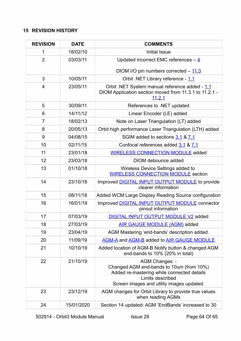
15 REVISION HISTORY
REVISION DATE COMMENTS
1 18/02/10 Initial Issue
2 03/03/11 Updated incorrect EMC references – 4
DIOM I/O pin numbers corrected – 11.3
3 10/05/11 Orbit .NET Library reference - 1.1
4 23/05/11 Orbit .NET System manual reference added - 1.1DIOM Application section moved from 11.3.1 to 11.2.1 -
11.2.1
5 30/09/11 References to .NET updated
6 14/11/12 Linear Encoder (LE) added
7 18/02/13 Note on Laser Triangulation (LT) added
8 20/05/13 Orbit high performance Laser Triangulation (LTH) added
9 04/08/15 SGIM added to sections 3.1 & 7.1
10 02/11/15 Confocal references added 3.1 & 7.1
11 23/01/18 WIRELESS CONNECTION MODULE added
12 23/03/18 DIOM debounce added
13 01/10/18 Wireless Device Settings added to WIRELESS CONNECTION MODULE section
14 23/10/18 Improved DIGITAL INPUT OUTPUT MODULE to provideclearer information
15 08/11/18 Added WCM Large Display Reading Source configuration
16 16/01/19 Improved DIGITAL INPUT OUTPUT MODULE connectorpinout information
17 07/03/19 DIGITAL INPUT OUTPUT MODULE V2 added
18 27/03/19 AIR GAUGE MODULE (AGM) added
19 23/04/19 AGM Mastering ‘end-bands’ description added.
20 11/09/19 AGM-A and AGM-B added to AIR GAUGE MODULE
21 10/10/19 Added location of AGM-B Notify button & changed AGMend-bands to 10% (20% in total)
22 21/10/19 AGM Changes: -Changed AGM end-bands to 10um (from 10%)
Added re-mastering while connected detailsLimits described
Screen images and utility images updated.
23 23/12/19 AGM changes for Orbit Library to provide true valueswhen reading AGMs
24 15/01/2020 Section 14 updated: AGM ‘EndBands’ increased to 30
502914 - Orbit3 Module Manual Issue 29 Page 64 Of 65
microns. Mastering description updated to reflect it can beperformed either way round.
Option to output counts as 14-bit pressure added.
25 20/07/2020 Network maximum modules increased from 150 to 200.
26 24/08/2020 Improved Understanding WCM operation section
27 26/10/2020 Removed limit of 6 from WCM with a USBIM & added note about number of Bluetooth channels
28 25/11/2020 DIOM2 section moved to before DIOM
29 29/10/2021 Orbit Laser Triangulation (LTA) added
502914 - Orbit3 Module Manual Issue 29 Page 65 Of 65