48in, 52in, or 60in TITAN 1500, 2000, or 2500 Series ... - Hire Express
88
Form No. 3405-604 Rev D 48in, 52in, or 60in TITAN ® HD 1500, 2000, or 2500 Series Riding Mower Model No. 74450—Serial No. 400010798 and Up Model No. 74451—Serial No. 400010798 and Up Model No. 74452—Serial No. 400010798 and Up Model No. 74460—Serial No. 400010798 and Up Model No. 74461—Serial No. 400010798 and Up Model No. 74462—Serial No. 400010798 and Up Model No. 74463—Serial No. 400010798 and Up Model No. 74470—Serial No. 400010798 and Up Model No. 74471—Serial No. 400010798 and Up Model No. 74472—Serial No. 400010798 and Up Model No. 78450—Serial No. 400010798 and Up Register at www.Toro.com. Original Instructions (EN) *3405-604* D
-
Upload
khangminh22 -
Category
Documents
-
view
0 -
download
0
Transcript of 48in, 52in, or 60in TITAN 1500, 2000, or 2500 Series ... - Hire Express

Form No. 3405-604 Rev D
48in, 52in, or 60in TITAN® HD1500, 2000, or 2500 Series RidingMowerModel No. 74450—Serial No. 400010798 and UpModel No. 74451—Serial No. 400010798 and UpModel No. 74452—Serial No. 400010798 and UpModel No. 74460—Serial No. 400010798 and UpModel No. 74461—Serial No. 400010798 and UpModel No. 74462—Serial No. 400010798 and UpModel No. 74463—Serial No. 400010798 and UpModel No. 74470—Serial No. 400010798 and UpModel No. 74471—Serial No. 400010798 and UpModel No. 74472—Serial No. 400010798 and UpModel No. 78450—Serial No. 400010798 and Up
Register at www.Toro.com.Original Instructions (EN) *3405-604* D

WARNINGCALIFORNIA
Proposition 65 WarningThis product contains a chemicalor chemicals known to the State of
California to cause cancer, birth defects,or other reproductive harm.
The engine exhaust from this productcontains chemicals known to the State ofCalifornia to cause cancer, birth defects,
or other reproductive harm.
This spark ignition system complies with CanadianICES-002
It is a violation of California Public Resource CodeSection 4442 or 4443 to use or operate the engine onany forest-covered, brush-covered, or grass-coveredland unless the engine is equipped with a sparkarrester, as defined in Section 4442, maintained ineffective working order or the engine is constructed,equipped, and maintained for the prevention of fire.
Because in some areas there are local, state, orfederal regulations requiring that a spark arrester beused on the engine of this machine, a spark arrester isavailable as an option. If you require a spark arrester,contact your Authorized Toro Dealer.
Genuine Toro spark arresters are approved by theUSDA Forestry Service.
WARNINGRemoving standard original equipment partsand accessories may alter the warranty,traction, and safety of the machine. Failure touse original Toro parts could cause seriousinjury or death. Making unauthorized changesto the engine, fuel or venting system, mayviolate EPA and CARB regulations.Replace all parts including, but not limitedto, tires, belts, blades, and fuel systemcomponents with original Toro parts.
For all models that do not have Toro engines,please refer to the engine manufacturer’sinformation included with the machine.Labeled power ratings are supplied by the enginemanufacturer in accordance with SAE testing andgross/net power rating standards (J1940, J1995,J1349).Important: If you are using a machine with a Toroengine above 1500 m (5,000 ft) for a continuous
period, ensure that the High Altitude Kit has beeninstalled so that the engine meets CARB/EPAemission regulations. The High Altitude Kitincreases engine performance while preventingspark-plug fouling, hard starting, and increasedemissions. Once you have installed the kit, attachthe high-altitude label next to the serial decal onthe machine. Contact any Authorized Toro ServiceDealer to obtain the proper High Altitude Kit andhigh-altitude label for your machine. To locatea dealer convenient to you, access our websiteat www.Toro.com or contact our Toro CustomerCare Department at the number(s) listed in yourEmission Control Warranty Statement.Remove the kit from the engine and restore theengine to its original factory configuration whenrunning the engine under 1500 m (5,000 ft). Donot operate an engine that has been convertedfor high-altitude use at lower altitudes; otherwise,you could overheat and damage the engine.If you are unsure whether or not your machine hasbeen converted for high-altitude use, look for thefollowing label (Figure 3).
decal127-9363
Figure 3
© 2017—The Toro® Company8111 Lyndale Avenue SouthBloomington, MN 55420 2
Contact us at www.Toro.com.Printed in the USAAll Rights Reserved

IntroductionThis rotary-blade, riding lawn mower is intended to beused by residential homeowners or professional, hiredoperators. It is designed primarily for cutting grass onwell-maintained lawns on residential or commercialproperties. It is not designed for cutting brush or foragricultural uses.
Read this information carefully to learn how to operateand maintain your product properly and to avoidinjury and product damage. You are responsible foroperating the product properly and safely.
You may contact Toro directly at www.Toro.comfor product safety and operation training materials,accessory information, help finding a dealer, or toregister your product.
Whenever you need service, genuine Toro parts, oradditional information, contact an Authorized ServiceDealer or Toro Customer Service and have the modeland serial numbers of your product ready. Figure 1identifies the location of the model and serial numberson the product. Write the numbers in the spaceprovided.
g036742
Figure 1
1. Model and serial number location
Model No.
Serial No.
This manual identifies potential hazards and hassafety messages identified by the safety-alert symbol(Figure 2), which signals a hazard that may causeserious injury or death if you do not follow therecommended precautions.
g000502
Figure 2
1. Safety-alert symbol
This manual uses 2 words to highlight information.Important calls attention to special mechanicalinformation and Note emphasizes general informationworthy of special attention.
ContentsSafety ....................................................................... 5
General Safety ................................................... 5Slope Indicator ................................................... 6Safety and Instructional Decals .......................... 7
Product Overview ................................................... 14Controls ........................................................... 14Specifications .................................................. 15
Before Operation ................................................. 16Before Operation Safety ................................... 16Recommended Fuel ......................................... 17Using Stabilizer/Conditioner ............................. 17Filling the Fuel Tank.......................................... 17Checking the Engine-Oil Level.......................... 17Using the Rollover-Protection System(ROPS) ......................................................... 18
Think Safety First.............................................. 19Using the Safety-Interlock System.................... 20Positioning the Seat.......................................... 20Changing the Seat Suspension......................... 20Breaking in a NewMachine .............................. 21Using Attachments and Accessories................. 21
During Operation ................................................. 21During Operation Safety ................................... 21Operating the Parking Brake............................. 23Operating the Mower Blade-Control Switch(PTO) ............................................................ 23
Operating the Throttle....................................... 23Operating the Choke......................................... 24Operating the Ignition Switch ............................ 24Starting the Engine ........................................... 24Shutting Off the Engine..................................... 25Driving Forward or Backward............................ 26Adjusting the Height-of-Cut............................... 28Adjusting the Anti-Scalp Rollers........................ 28Adjusting the Side Bumpers.............................. 29Stopping the Machine....................................... 29Using the Side Discharge ................................. 30Operating Tips ................................................. 30
After Operation .................................................... 31After Operation Safety ...................................... 31Using the Fuel-Shutoff Valve............................. 31Using the Drive-Wheel-Release Valves ............ 31
3

Transporting the Machine ................................. 32Loading the Machine ........................................ 33
Maintenance ........................................................... 35RecommendedMaintenance Schedule(s) ........... 35Pre-Maintenance Procedures .............................. 37Maintenance and Storage................................. 37
Lubrication .......................................................... 38Greasing the Machine....................................... 38Lubricating the Caster-Wheel Hubs .................. 39
Engine Maintenance ........................................... 40Engine Safety ................................................... 40Servicing a Kawasaki® Engine.......................... 41Servicing a Kohler® Engine............................... 46Servicing a Toro Engine .................................... 50Checking the Spark Arrester ............................. 55Replacing the Emissions-Air IntakeFilter.............................................................. 55
Fuel SystemMaintenance ................................... 55Replacing the Fuel Filter ................................... 55Servicing the Fuel Tank..................................... 56
Electrical SystemMaintenance ........................... 56Electrical System Safety ................................... 56Servicing the Battery......................................... 56Servicing the Fuses .......................................... 58
Drive SystemMaintenance .................................. 59Checking the Seat Belt ..................................... 59Checking the Rollover-Protection-System(ROPS) Knobs .............................................. 59
Adjusting the Tracking ...................................... 60Checking the Tire Pressure............................... 60Checking theWheel Lug Nuts........................... 60
Cooling SystemMaintenance .............................. 61Cleaning the Engine Screen ............................. 61
Brake Maintenance ............................................. 61Adjusting the Parking Brake.............................. 61
Belt Maintenance ................................................ 63Inspecting the Belts .......................................... 63Replacing the Mower Belt for Side DischargeMower Decks ................................................ 63
Replacing the Mower Belt for Rear DischargeMower Decks ................................................ 64
Replacing the Hydraulic Pump-DriveBelt................................................................ 66
Controls SystemMaintenance ............................. 67Adjusting the Control-Handle Position .............. 67Adjusting theMotion-Control Linkage ............... 67
Hydraulic SystemMaintenance ........................... 69Hydraulic System Safety................................... 69Servicing the Hydraulic System ........................ 69Changing the Hydraulic-System Filters andFluid .............................................................. 70
Mower Deck Maintenance.................................... 72Leveling the Mower Deck.................................. 72Servicing the Cutting Blades............................. 74Removing the Mower Deck............................... 78Replacing the Grass Deflector .......................... 78
Cleaning .............................................................. 79Cleaning under the Mower................................ 79
Disposing of Waste........................................... 79Storage ................................................................... 80
Cleaning and Storage....................................... 80Troubleshooting ...................................................... 81Schematics ............................................................. 83
4

SafetyThis machine has been designed in accordance withANSI B71.4-2012.
General SafetyThis product is capable of amputating hands andfeet and of throwing objects. Always follow all safetyinstructions to avoid serious personal injury.
Using this product for purposes other than its intendeduse could prove dangerous to you and bystanders.• Read and understand the contents of this
Operator’s Manual before you start the engine.Ensure that everyone using this product knowshow to use it and understands the warnings.
• Do not put your hands or feet near movingcomponents of the machine.
• Do not operate the machine without all guardsand other safety protective devices in place andworking on the machine.
• Keep clear of any discharge opening. Keepbystanders a safe distance from the machine.
• Keep children out of the operating area. Neverallow children to operate the machine.
• Stop the machine and shut off the engine beforeservicing, fueling, or unclogging the machine.
Improperly using or maintaining this machine canresult in injury. To reduce the potential for injury,comply with these safety instructions and always payattention to the safety-alert symbol, which meansCaution, Warning, or Danger—personal safetyinstruction. Failure to comply with these instructionsmay result in personal injury or death.
You can find additional items of safety information intheir respective sections throughout this manual.
5

Slope Indicator
g011841
Figure 4This page may be copied for personal use.
1. The maximum slope you can safely operate the machine on is 15 degrees. Use the slope chart to determine the degree of slopeof hills before operating. Do not operate this machine on a slope greater than 15 degrees. Fold along the appropriate lineto match the recommended slope.
2. Align this edge with a vertical surface, a tree, building, fence pole, etc.3. Example of how to compare slope with folded edge
6

Safety and Instructional DecalsSafety decals and instructions are easily visible to the operator and are located near any areaof potential danger. Replace any decal that is damaged or missing.
decaloemmarkt
Manufacturer's Mark
1. Indicates the blade is identified as a part from the originalmachine manufacturer.
decal93-7818
93-7818
1. Warning—read the Operator's Manual for instructions ontorquing the blade bolt/nut to 115-149 N∙m (85-110 ft-lb).
decal106-5517
106-5517
1. Warning—do not touch the hot surface.
decal107-3069
107-3069
1. Warning–there is no rollover protection when the roll bar isdown.
2. To avoid injury or death from a rollover accident, keep theroll bar in the raised and locked position and wear the seatbelt. Lower the roll bar only when absolutely necessary; donot wear the seat belt when the roll bar is down.
3. Read the Operator's Manual; drive slowly and carefully.
decal109-6014
109-6014
7

decal109-6035
109-60352500 Series Side Discharge Machines Only
decal109-6036
109-6036Rear Discharge Machines Only
1. Read the Operator’s Manual.2. Remove the ignition key and read the instructions before
servicing or performing maintenance.3. Height of cut
decal112-3858
112-38581500 and 2000 Series Side Discharge Machines Only
1. Read the Operator'sManual.
3. Remove the ignition keybefore adjusting the heightof cut.
2. Read the instructionsbefore servicing orperforming maintenance.
4. Height-of-cut settings.
decal112-9028
112-9028
1. Warning—stay away from moving parts; keep all guards inplace.
decal115-9625
115-9625
1. Parkingbrake—disengaged
2. Parking brake—engaged
decalhourmessagedisplay-116-5610
Message Display
1. Hour 4. Neutral2. PTO 5. Operator-presence switch3. Parking brake 6. Battery
8

decal116-8588
116-8588
1. Read the Operator’s Manual.2. Rotate the drive release knob to loosen, slide the knob,
and tighten.3. Push the machine.
decal117-1194
117-11941500 and 2000 Series Side-Discharge Machines Only
1. Engine
decal117-2718
117-2718
decal117-3848
117-3848
1. Thrown object hazard—keep bystanders a safe distancefrom the machine.
2. Thrown object hazard, mower—do not operate the machinewithout deflector, discharge cover, or grass collectionsystem in place.
3. Cutting/dismemberment of hand or foot—stay away frommoving parts; keep all guards and shields in place.
decal126-0768
126-0768Rear Discharge Units Only
decal126-4363
126-4363
1. Cutting/dismemberment hazard, fan and entanglementhazard, belt. Shut off the engine and remove key beforeadjusting, servicing or cleaning.
9

decal126-4784
126-4784
1. Height of cut
decal126-6599
126-6599Rear Discharge Units
1. Thrown objects hazard- keep bystanders asafe distance from themachine.
2. Cutting/dismembermentof hand - stay away frommoving parts; keep allguards and shields inplace.
decal126-8161
126-8161
1. Read the Operator’sManual.
3. Press down on latch tounlock seat
2. Slide seat forward 4. Rotate seat
decal126-9939
126-9939
1. Read the Operator’sManual
2. Fill to bottom of filler neck;warning–do not overfill thetank
decal127-0326
127-03262500 Series Side Discharge Machines Only
1. Read the Operator'sManual.
3. Remove the key fromthe ignition and read theOperator's Manual beforeperforming maintenanceor servicing the machine.
2. Height of cut
10

decal127-6662
127-6662Rear Discharge Mowers Only
1. Attention—read theOperator's Manual.
3. Remove the bolt by turningit counter clockwise.
2. Remove the nut by turningit clockwise.
decal131-1097
131-1097Toro Engines Only
1. Oil drain
decal136-1305
136-1305
1. Fast 4. Choke2. Continuous variable setting 5. Work light (optional)3. Slow 6. Power point
11

decalptosymbols
PTO Switch Symbols
1. PTO–disengage 2. PTO–engage
decaltransportlock
Transport Lock
1. Height of cut 2. Pull up to unlock thetransport lock
decalmotioncntrllh-126-6194
Left Motion Control
1. Machine speed 4. Neutral2. Fast 5. Reverse3. Slow
decalmotioncntrlrh-126-6183
Right Motion Control
1. Machine speed 4. Neutral2. Fast 5. Reverse3. Slow
decalbatterysymbols
Battery SymbolsSome or all of these symbols are on your battery.
1. Explosion hazard 6. Keep bystanders a safedistance from the battery.
2. No fire, open flame, orsmoking
7. Wear eye protection;explosive gases cancause blindness and otherinjuries.
3. Caustic liquid/chemicalburn hazard
8. Battery acid can causeblindness or severe burns.
4. Wear eye protection. 9. Flush eyes immediatelywith water and get medicalhelp fast.
5. Read the Operator'sManual.
10. Contains lead; do notdiscard
12

decal126-8151
126-8151
1. Read the instructions before servicing or performingmaintenance
4. Refer to the Operator's Manual for grease instructions
2. Time interval 5. Check the hydraulic-fluid level and refer to the Operator'sManual or further instructions
3. Check oil level 6. Check tire pressure
decal126-8383
126-8383
1. Warning-Read the Operator's Manual. Do not operate thismachine unless you are trained. Wear hearing protection.
4. Bodily harm hazard - look behind you when mowing inreverse.
2. Cutting and pinching hazard - keep hands and feet away frommoving parts; keep all guards and shields in place.
5. Thrown object hazard - keep bystanders away.
3. Ramp hazard - when loading onto a trailer, do not use dualramps; only use a singular ramp wide enough for the machineand that has an incline less than 15 degrees; back up theramp (in reverse) and drive forward off the ramp.
6. Tipping hazard on slopes - do not use on slopes near openwater; do not use on slopes greater than 15 degrees.
13
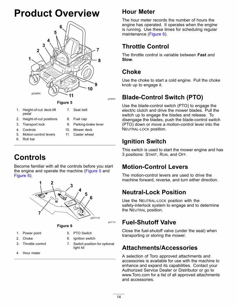
Product Overview
g036854
Figure 5
1. Height-of-cut deck-liftpedal
7. Seat belt
2. Height-of-cut positions 8. Fuel cap3. Transport lock 9. Parking-brake lever4. Controls 10. Mower deck5. Motion-control levers 11. Caster wheel6. Roll bar
ControlsBecome familiar with all the controls before you startthe engine and operate the machine (Figure 5 andFigure 6).
g037119
Figure 6
1. Power point 5. PTO Switch2. Choke 6. Ignition switch3. Throttle control 7. Switch position for optional
light kit4. Hour meter
Hour MeterThe hour meter records the number of hours theengine has operated. It operates when the engineis running. Use these times for scheduling regularmaintenance (Figure 6).
Throttle ControlThe throttle control is variable between Fast andSlow.
ChokeUse the choke to start a cold engine. Pull the chokeknob up to engage it.
Blade-Control Switch (PTO)Use the blade-control switch (PTO) to engage theelectric clutch and drive the mower blades. Pull theswitch up to engage the blades and release. Todisengage the blades, push the blade-control switch(PTO) down or move a motion-control lever into theNEUTRAL-LOCK position.
Ignition SwitchThis switch is used to start the mower engine and has3 positions: START, RUN, and OFF.
Motion-Control LeversThe motion-control levers are used to drive themachine forward, reverse, and turn either direction.
Neutral-Lock PositionUse the NEUTRAL-LOCK position with thesafety-interlock system to engage and to determinethe NEUTRAL position.
Fuel-Shutoff ValveClose the fuel-shutoff valve (under the seat) whentransporting or storing the mower.
Attachments/AccessoriesA selection of Toro approved attachments andaccessories is available for use with the machine toenhance and expand its capabilities. Contact yourAuthorized Service Dealer or Distributor or go towww.Toro.com for a list of all approved attachmentsand accessories.
14

SpecificationsNote: Specifications and design are subject to change without notice.Width—Machines with Side Discharge Mower Decks
48-inch Deck 52-inch Deck 60-inch Deck
Without mower deck 121 cm (47-1/2 inches) 124 cm (49 inches) 133 cm (52 inches)
Deflector up 133 cm (53 inches) 144 cm (56-3/4 inches) 161 cm (63-1/2 inches)
Deflector down 160 cm (63-1/4 inches) 171 cm (67-1/4 inches) 191 cm (75-1/4 inches)
Width—Machines with Rear Discharge Mower Decks60-inch Deck
Without mower deck 133 cm (52 inches)
With mower deck 168 cm (66 inches)
Length—Machines with Side Discharge Mower Decks48-inch Deck 52-inch Deck 60-inch Deck
Length 208 cm (82 inches) 208 cm (82 inches) 209 cm (83 inches)
Length—Machines with Rear Discharge Mower Decks60-inch Deck
With mower deck 215 cm (84-1/2 inches)
HeightRoll Bar - Up Roll Bar - Down
179 cm (70-1/2 inches) 49 inches (125 cm)
WeightMachines Weight
48-inch side-discharge machines 385 to 425 kg (849 to 937 lb)
52-inch side-discharge machines 391 to 434 kg (862 to 957 lb)
60-inch side-discharge machines 409 to 456 kg (901 to 1006 lb)
60-inch rear-discharge machines 459 kg (1012 lb)
15

OperationNote: Determine the left and right sides of themachine from the normal operating position.
Before OperationBefore Operation SafetyGeneral Safety• Never allow children or untrained people to
operate or service the machine. Local regulationsmay restrict the age of the operator. The owneris responsible for training all operators andmechanics.
• Become familiar with the safe operation of theequipment, operator controls, and safety signs.
• Know how to stop the machine and engine quickly.• Check that operator-presence controls, safety
switches, and shields are attached and functioningproperly. Do not operate the machine unless theyare functioning properly.
• Before mowing, always inspect the machine toensure that the blades, blade bolts, and cuttingassemblies are in good working condition.Replace worn or damaged blades and bolts in setsto preserve balance.
• Inspect the area where you will use the machineand remove all objects that the machine couldthrow.
• Evaluate the terrain to determine the appropriateequipment and any attachments or accessoriesrequired to operate the machine properly andsafely.
Fuel Safety• To avoid personal injury or property damage, use
extreme care in handling fuel. Fuel vapors areflammable and explosive.
• Extinguish all cigarettes, cigars, pipes, and othersources of ignition.
• Use only an approved fuel container.• Do not remove the fuel cap or add fuel to the fuel
tank while the engine is running or while hot.• Do not refuel the machine indoors.• Do not store the machine or fuel container where
there is an open flame, spark, or pilot light, suchas on a water heater or on other appliances.
• Do not fill containers inside a vehicle or on a truckor trailer bed with a plastic liner. Always placecontainers on the ground, away from your vehiclebefore filling.
• Remove the equipment from the truck or trailerand refuel it while it is on the ground. If this is notpossible, then refuel from a portable containerrather than a fuel-dispenser nozzle.
• Do not operate the machine without the entireexhaust system in place and in proper workingcondition.
• Keep the fuel-dispenser nozzle in contact withthe rim of the fuel tank or container opening atall times until fueling is complete. Do not use anozzle lock-open device.
• If you spill fuel on your clothing, change yourclothing immediately. Wipe up any gasoline thatspills.
• Never overfill the fuel tank. Replace the fuel capand tighten it securely.
• Store gasoline in an approved container and keepit out of the reach of children. Never buy morethan a 30-day supply of gasoline.
• Do not fill the fuel tank completely full. Addgasoline to the fuel tank until the level is 6 to 13mm (1/4 to 1/2 inch) below the bottom of the fillerneck. This empty space in the tank allows gasolineto expand.– Avoid prolonged breathing of vapors.– Keep your face away from the nozzle and gas
tank opening.– Avoid contact with skin; wash off spills with
soap and water.
16

Recommended Fuel• For best results, use only clean, fresh (less than
30 days old), unleaded gasoline with an octanerating of 87 or higher ((R+M)/2 rating method).
• Ethanol: Gasoline with up to 10% ethanol(gasohol) or 15% MTBE (methyl tertiary butylether) by volume is acceptable. Ethanol andMTBE are not the same. Gasoline with 15%ethanol (E15) by volume is not approved for use.Never use gasoline that contains more than10% ethanol by volume, such as E15 (contains15% ethanol), E20 (contains 20% ethanol), or E85(contains up to 85% ethanol). Using unapprovedgasoline may cause performance problems and/orengine damage which may not be covered underwarranty.
• Do not use gasoline containing methanol.• Do not store fuel either in the fuel tank or fuel
containers over the winter unless a fuel stabilizeris used.
• Do not add oil to gasoline.
UsingStabilizer/ConditionerUse a fuel stabilizer/conditioner in the machine toprovide the following benefits:• Keeps gasoline fresh during storage of 90 days or
less. For longer storage it is recommended thatthe fuel tank be drained.
• Cleans the engine while it runs• Eliminates gum-like varnish buildup in the fuel
system, which causes hard starting
Important: Do not use fuel additivescontaining methanol or ethanol.Add the correct amount of gasolinestabilizer/conditioner to the gasoline.
Note: A fuel stabilizer/conditioner is most effectivewhen mixed with fresh gasoline. To minimize thechance of varnish deposits in the fuel system, usefuel stabilizer at all times.
Filling the Fuel TankNote: Do not fill the fuel tank completely full. Fill thefuel tank to the bottom of the filler neck. The emptyspace in the tank allows the gasoline to expand.1. Park the machine on level ground.2. Shut the engine off and set the parking brake.3. Clean around the fuel-tank cap.
4. Fill the fuel tank to the bottom of the filler neck.5. Ensure that there is empty space in the tank to
allow the gasoline to expand (Figure 7).
g036751
Figure 7
Checking the Engine-OilLevelBefore you start the engine and use the machine,check the oil level in the engine crankcase. ForKawasaki engines refer to Servicing a Kawasaki®Engine (page 41), for Kohler engines refer to Servicinga Kohler® Engine (page 46), and for Toro enginesrefer to Servicing a Toro Engine (page 50).
17

Using theRollover-Protection System(ROPS)
WARNINGTo avoid injury or death from rollover: keepthe roll bar in the fully raised, locked positionand use the seat belt.Ensure that the seat is secured to themachine.
WARNINGThere is no rollover protection when the rollbar is in the down position.• Lower the roll bar only when absolutely
necessary.• Do not wear the seat belt when the roll bar
is in the down position.• Drive slowly and carefully.• Raise the roll bar as soon as clearance
permits.• Check carefully for overhead clearances
(i.e., branches, doorways, electrical wires)before driving under any objects, and donot contact them.
Important: Ensure that the seat is secured tothe machine.1. To lower the roll bar, apply forward pressure to
the upper part of the roll bar.2. Pull both knobs out and rotate them 90 degrees
so they are not engaged (Figure 8).3. Lower the roll bar to the down position (Figure
8).
g036746
Figure 8
1. Roll bar in the uprightposition
4. Rotate the ROPS knob 90degrees.
2. ROPS knob in the latchedposition
5. ROPS knob in theunlatched position
3. Pull the ROPS knob out. 6. Roll bar in the foldedposition
4. To raise the roll bar, raise the roll bar to theoperating position and rotate the knobs untilthey move partially into the grooves (Figure 8).
5. Raise the roll bar to the full upright position whilepushing on the upper roll bar so that the pinssnap into position when the holes align with thepins (Figure 8).
6. Push on the roll bar and ensure that both pinsare engaged.
Important: Always use the seat belt with the rollbar in the raised position.
18

Think Safety FirstPlease read all safety instructions and symbols in thesafety section. Knowing this information could helpyou or bystanders avoid injury.
DANGEROperating the machine on wet grass or steepslopes can cause sliding and loss of control.• Do not operate on slopes greater than 15
degrees.• Reduce speed and use extreme caution on
slopes.• Do not operate the machine near water.
DANGERWheels dropping over edges can causerollovers, which may result in serious injury,death, or drowning.Do not operate the machine near drop-offs.
DANGEROperating the machine while the roll bar isdown may lead to serious injury or death inthe event of a rollover.Always keep the roll bar in the fully raised andlocked position and use the seat belt.
g000963
Figure 9
1. Safe Zone—use themachine here on slopesless than 15 degrees orflat areas.
3. Water
2. Danger Zone—use awalk-behind mower and/ora hand trimmer on slopesgreater than 15 degrees,near drop-offs and water.
CAUTIONThis machine produces sound levels inexcess of 85 dBA at the operator’s ear andcan cause hearing loss through extendedperiods of exposure.Wear hearing protection when operating thismachine.
The use of protective equipment for eyes, ears,hands, feet, and head is recommended.
g009027
Figure 10
1. Wear eye protection. 2. Wear hearing protection
19

Using the Safety-InterlockSystem
CAUTIONIf the safety-interlock switches aredisconnected or damaged, the machine couldoperate unexpectedly, causing personalinjury.• Do not tamper with the interlock switches.• Check the operation of the interlock
switches daily and replace any damagedswitches before operating the machine.
Understanding theSafety-Interlock SystemThe safety-interlock system is designed to prevent theengine from starting unless:• The parking brake is engaged.• The blade-control switch (PTO) is disengaged.• The motion-control levers are in the NEUTRAL-LOCK
position.
The safety-interlock system also is designed to shut offthe engine when you move the traction controls fromthe locked position with the parking brake engaged orif you rise from the seat when the PTO is engaged.
Testing the Safety-InterlockSystemService Interval: Before each use or daily
Test the safety-interlock system before you use themachine each time. If the safety system does notoperate as described below, have an AuthorizedService Dealer repair the safety system immediately.1. Sit on the seat, engage the parking brake and
move the blade-control switch (PTO) to the ONposition. Try starting the engine; the engineshould not crank.
2. Sit on the seat, engage the parking brake andmove the blade-control switch (PTO) to the OFFposition. Move either motion-control lever (outof the NEUTRAL-LOCK position). Try starting theengine; the engine should not crank. Repeat forother control lever.
3. Sit on the seat, engage the parking brake,move the blade-control switch (PTO) to the OFFposition, and move the motion-control levers tothe NEUTRAL-LOCK position. Start the engine.
While the engine is running, release the parkingbrake, engage the blade-control switch (PTO),and rise slightly from the seat; the engine shouldshut off.
4. Sit on the seat, engage the parking brake,move the blade-control switch (PTO) to the OFFposition, and move the motion-control leversto NEUTRAL-LOCK position. Start the engine.While the engine is running, center eithermotion-control lever and move it forward orreverse; the engine should shut off. Repeat forother motion-control lever.
5. Sit on the seat, disengage the parking brake,move the blade-control switch (PTO) to the OFFposition, and move the motion-control levers toNEUTRAL-LOCK position. Try starting the engine;the engine should not crank.
Positioning the SeatThe seat can move forward and backward (Figure 11).Position the seat where you have the best control ofthe machine and are most comfortable.
g028272
Figure 11
Changing the SeatSuspensionThe seat is adjustable to provide a smooth andcomfortable ride. Position the seat where you aremost comfortable.
To adjust it, turn the knob in front either direction toprovide the best comfort (Figure 12).
20

g024881
Figure 12
1. Seat-suspension knob
Breaking in a New MachineNew engines take time to develop full power. Mowerdecks and drive systems have higher friction whennew, placing additional load on the engine. Allow40 to 50 hours of break-in time for new machines todevelop full power and best performance.
Using Attachments andAccessoriesUse only Toro approved attachments and accessories.
If more than one accessory-mount kit (i.e. bucket kit oruniversal mount kit) is added to any of the 4 locationsshown in Figure 13, add a front-weight kit. Contactyour authorized service dealer for the front-weight kit.
g037417
Figure 13
1. Add a front-weight kit when 2 or more accessory-mount kitsare installed at these positions.
During OperationDuring Operation SafetyGeneral Safety• The owner/operator can prevent and is responsible
for accidents that may cause personal injury orproperty damage.
• Wear appropriate clothing, including eyeprotection; slip-resistant, substantial footwear; andhearing protection. Tie back long hair and do notwear jewelry.
• Do not operate the machine while ill, tired, orunder the influence of alcohol or drugs.
• Never carry passengers on the machine and keepbystanders and pets away from the machineduring operation.
• Operate the machine only in good visibility to avoidholes or hidden hazards.
• Avoid mowing on wet grass. Reduced tractioncould cause the machine to slide.
• Ensure that all drives are in neutral, the parkingbrake is engaged, and you are in the operatingposition before you start the engine.
• Keep your hands and feet away from the cuttingunits. Keep clear of the discharge opening at alltimes.
• Look behind and down before backing up to besure of a clear path.
• Use care when approaching blind corners, shrubs,trees, or other objects that may obscure yourvision.
• Do not mow near drop-offs, ditches, orembankments. The machine could suddenly rollover if a wheel goes over the edge or if the edgegives way.
• Stop the blades whenever you are not mowing.• Stop the machine and inspect the blades after
striking an object or if there is an abnormalvibration in the machine. Make all necessaryrepairs before resuming operation.
• Slow down and use caution when making turnsand crossing roads and sidewalks with themachine. Always yield the right-of-way.
• Disengage the drive to the cutting unit and shutoff the engine before adjusting the height ofcut (unless you can adjust it from the operatingposition).
• Never run an engine in an area where exhaustgases are enclosed.
• Never leave a running machine unattended.
21

• Before leaving the operating position (includingto empty the catchers or to unclog the chute), dothe following:– Stop the machine on level ground.– Disengage the power take-off and lower the
attachments.– Set the parking brake.– Shut off the engine and remove the key.– Wait for all moving parts to stop.
• Do not operate the machine when there is the riskof lightning.
• Do not use the machine as a towing vehicle.• Do not change the governor speed or overspeed
the engine.• Use accessories and attachments approved by
Toro only.
Rollover Protection System(ROPS) Safety• Do not remove the ROPS from the machine.• Ensure that the seat belt is attached and that you
can release it quickly in an emergency.• Always wear your seat belt when the ROPS is up.• Check carefully for overhead obstructions and do
not contact them.• Keep the ROPS in safe operating condition by
thoroughly inspecting it periodically for damageand keeping all the mounting fasteners tight.
• Replace a damaged ROPS. Do not repair or alterit.
Slope Safety• Establish your own procedures and rules for
operating on slopes. These procedures mustinclude surveying the site to determine whichslopes are safe for machine operation. Alwaysuse common sense and good judgment whenperforming this survey.
• Slopes are a major factor related to loss-of-controland tip-over accidents, which can result in severeinjury or death. Operating the machine on anyslope requires extra caution.
• Operate the machine at a lower speed when youare on a slope.
• If you feel uneasy operating the machine on aslope, do not do it.
• Watch for holes, ruts, bumps, rocks, or otherhidden objects. Uneven terrain could overturn themachine. Tall grass can hide obstacles.
• Choose a low ground speed so you will not haveto stop or shift while on a slope.
• A rollover can occur before the tires lose traction.• Avoid operating the machine on wet grass. Tires
may lose traction; regardless if the brakes areavailable and functioning.
• Avoid starting, stopping, or turning the machineon a slope.
• Keep all movement on slopes slow and gradual.Do not suddenly change the speed or direction ofthe machine.
• Do not operate the machine near drop-offs,ditches, embankments, or bodies of water. Themachine could suddenly roll over if a wheel goesover the edge or the edge caves in. Establish asafety area between the machine and any hazard(2 machine widths).
22
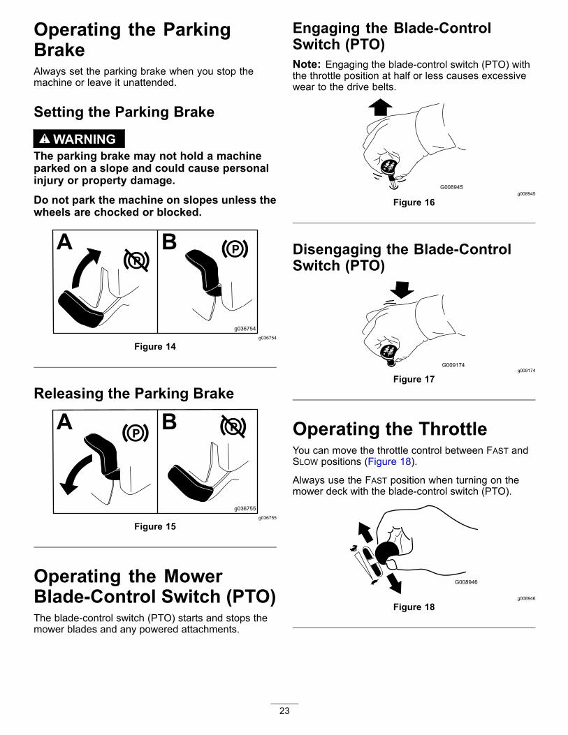
Operating the ParkingBrakeAlways set the parking brake when you stop themachine or leave it unattended.
Setting the Parking Brake
WARNINGThe parking brake may not hold a machineparked on a slope and could cause personalinjury or property damage.Do not park the machine on slopes unless thewheels are chocked or blocked.
g036754
Figure 14
Releasing the Parking Brake
g036755
Figure 15
Operating the MowerBlade-Control Switch (PTO)The blade-control switch (PTO) starts and stops themower blades and any powered attachments.
Engaging the Blade-ControlSwitch (PTO)Note: Engaging the blade-control switch (PTO) withthe throttle position at half or less causes excessivewear to the drive belts.
g008945
Figure 16
Disengaging the Blade-ControlSwitch (PTO)
g009174
Figure 17
Operating the ThrottleYou can move the throttle control between FAST andSLOW positions (Figure 18).
Always use the FAST position when turning on themower deck with the blade-control switch (PTO).
g008946
Figure 18
23

Operating the ChokeUse the choke to start a cold engine.1. If the engine is cold, use the choke to start the
engine.2. Pull up the choke knob to engage the choke
before using the ignition switch (Figure 19).3. Push down the choke knob to disengage the
choke after starting the engine (Figure 19).
g008959
Figure 19
1. ON position 2. OFF position
Operating the IgnitionSwitch1. Turn the ignition key to the START position
(Figure 20).
Note: When the engine starts, release the key.
Important: Do not engage the starter formore than 5 seconds at a time. If the enginefails to start, wait 15 seconds betweenattempts. Failure to follow these instructionscan burn out the starter motor.
Note: You may need multiple attempts to startthe engine when you start it the first time afterthe fuel system has been without fuel completely.
g008947
Figure 20
2. Turn the ignition key to the STOP position to shutoff the engine.
Starting the Engine1. Raise the ROPS up, lock it into place, sit on the
seat, and fasten the seat belt.2. Move the motion controls to NEUTRAL-LOCK
position.3. Set the parking brake; refer to Setting the
Parking Brake (page 23).4. Move the blade-control switch (PTO) to the OFF
position (Figure 17).5. Move the throttle lever midway between the
SLOW and FAST positions.
24

g036838
Figure 21
6. Turn the ignition key to the START position(Figure 22).Note: When the engine starts, release the key.Important: Do not engage starter for morethan 5 seconds at a time. If the engine failsto start, allow a 15 second cool-down periodbetween attempts. Failure to follow theseinstructions can burn out the starter motor.Note: You may need to attempt to start theengine multiple times when you start it for thefirst time after the fuel system has been withoutfuel completely.
g008947
Figure 22
1. Off 3. Start2. Run
Shutting Off the EngineNote: Refer to Figure 40 to determine which engineyou have.
CAUTIONChildren or bystanders may be injured if theymove or attempt to operate the machine whileit is unattended.Always remove the ignition key and set theparking brake when leaving the machineunattended, even if just for a few minutes.
Shutting Off Kawasaki and KohlerEnginesLet the engine idle at slow throttle for 60 secondsbefore turning the ignition switch off.
g036839
Figure 23
Important: Make sure that the fuel-shutoffvalve is closed before transporting or storingthe machine, as fuel leakage may occur. Set theparking brake before transporting. Remove thekey as the fuel pump may run and cause thebattery to lose charge.
25

Shutting Off Toro EnginesNote: Ensure the throttle is in the FAST positionbefore shutting off the engine.
g037049
Figure 24
Important: Make sure that the fuel-shutoffvalve is closed before transporting or storingthe machine, as fuel leakage may occur. Set theparking brake before transporting. Remove thekey as the fuel pump may run and cause thebattery to lose charge.
Driving Forward orBackwardThe throttle control regulates the engine speed asmeasured in rpm (revolutions per minute). Placethe throttle control in the FAST position for bestperformance. Always operate in the full throttleposition when mowing.
CAUTIONMachine can spin very rapidly. You may losecontrol of the machine and injure yourself ordamage the machine.• Use caution when making turns.• Slow the machine down before making
sharp turns.
Using the Motion-Control Levers
c:\data\documentum\checkout\g004532
Figure 25
1. Motion-controllever—NEUTRAL-LOCKposition
4. Backward
2. Center, unlocked position 5. Front of machine3. Forward
26

Driving ForwardNote: The engine shuts off if you move thetraction-control levers with the parking brake engaged.
To stop the machine, pull the motion-control leversto the NEUTRAL position.1. Release the parking brake; refer to Releasing
the Parking Brake (page 23).2. Move the levers to the center, unlocked position.3. To go forward, slowly push the motion-control
levers forward (Figure 26).
g008952
Figure 26
Driving Backward1. Move the levers to the center, unlocked position.2. To go backward, slowly pull the motion-control
levers rearward (Figure 27).
g008953
Figure 27
27

Adjusting the Height-of-CutUsing the Transport LockThe transport lock has 2 positions, and is used withthe deck-lift pedal. There is a LOCK position andan UNLOCK position for the transport position of themower deck (Figure 28).
g037050
Figure 28Transport-Lock Positions
1. Transport lock knob 3. UNLOCK position—Themower deck does not lockinto the transport position.
2. LOCK position—Themower deck locks into thetransport position.
Adjusting the Height-of-Cut PinAdjust the height-of-cut from 38 to 127 mm (1-1/2 to 5inches) in 6 mm (1/4 inch) increments by moving theheight-of-cut pin into different hole locations.1. Move the transport lock to the LOCK position.2. Push on the deck-lift pedal with your foot and
raise the mower deck to the TRANSPORT position(also the 127 mm or 5 inch cutting-heightposition) as shown in Figure 29.
3. To adjust, remove the pin from the height-of-cutbracket (Figure 29).
4. Select a hole in the height-of-cut bracketcorresponding to the height-of-cut desired, andinsert the pin (Figure 29).
5. Push on the deck lift, pull up on the transportlock knob, and slowly lower the mower deck.
g036745
Figure 29
1. Deck-lift pedal 3. Height-of-cut pin2. Height-of-cut holes 4. Transport lock knob
Adjusting the Anti-ScalpRollersWhenever you change the height-of-cut, adjust theheight of the anti-scalp rollers.1. Disengage the blade-control switch (PTO), move
the motion-control levers to the NEUTRAL-LOCKposition, and set the parking brake.
2. Shut off the engine, remove the key, and waitfor all moving parts to stop before leaving theoperating position.
28

g038079
Figure 302500 series mower deck shown
1. Anti-scalp roller 4. Flange nut2. Spacer 5. Bolt3. Bushing
g036848
Figure 311500 and 2000 series mower deck shown
1. Flange nut 4. Anti-scalp roller2. Bolt 5. Spacer3. Bushing
Adjusting the SideBumpers(Rear Discharge Machines Only)Install the side bumpers in the top holes whenoperating in a height of cut higher than 64 mm (2-1/2inches) and in the center holes when operating in aheight of cut lower than 64 mm (2-1/2 inches).
Note: When the bumpers become worn, switch thebumpers to the opposite sides of the mower and flipthem over. This allows the bumpers to be used longerbefore replacing them.1. Disengage the blade-control switch (PTO), turn
the ignition key to off, move the levers to the
NEUTRAL-LOCK position, apply the parking brake,and remove the key.
2. Shut off the engine, remove the key, and wait forall moving parts to stop.
3. Raise the mower to the transport position.4. Remove the bolts and nuts from each bumper
(Figure 32).
g037862
Figure 32
1. Bolt 3. Nut2. Bumper
5. Move each bumper to the desired position andsecure them with the bolts and nuts.
Note: Use only the top or center sets of holes toadjust the bumpers. Use the bottom holes whenswitching sides, at which time they become thetop holes on the other side of the mower.
Stopping the MachineTo stop the machine, move the motion-control leversto neutral and then to the NEUTRAL-LOCK position,disengage the blade-control switch (PTO), and turnthe ignition key to the OFF position.
Set the parking brake when you leave the machine;refer to Setting the Parking Brake (page 23). Removethe key from the ignition switch.
CAUTIONChildren or bystanders may be injured if theymove or attempt to operate the machine whileit is unattended.Always remove the ignition key and set theparking brake when leaving the machineunattended, even if just for a few minutes.
29

Using the Side DischargeThe mower has a hinged grass deflector thatdisperses clippings to the side and down toward theturf.
DANGERWithout a grass deflector, discharge cover, ora complete grass-catcher assembly mountedin place, you and others are exposed to bladecontact and thrown debris. Contact withrotating mower blade(s) and thrown debriscause injury or death.• Never remove the grass deflector from
the machine because the grass deflectorroutes material down toward the turf. If thegrass deflector is ever damaged, replace itimmediately.
• Never put your hands or feet under themower.
• Never try to clear the discharge areaor mower blades unless you move theblade-control switch (PTO) to the OFFposition, rotate the ignition key to the OFFposition, and remove the key.
• Make sure that the grass deflector is in thedown position.
Operating TipsUsing the Fast Throttle SettingFor best mowing and maximum air circulation, operatethe engine at the FAST position. Air is required tothoroughly cut grass clippings, so do not set theheight-of-cut so low as to totally surround the mowerin uncut grass. Always try to have 1 side of the mowerfree from uncut grass, which allows air to be drawninto the mower.
Cutting a Lawn for the First TimeCut grass slightly longer than normal to ensure thatthe cutting height of the mower does not scalp anyuneven ground. However, the cutting height used inthe past is generally the best one to use. When cuttinggrass longer than 15 cm (6 inches) tall, you may wantto cut the lawn twice to ensure an acceptable qualityof cut.
Cutting a Third of the Grass BladeIt is best to cut only about a third of the grass blade.Cutting more than that is not recommended unless
grass is sparse, or it is late fall when grass growsmore slowly.
Alternating the Mowing DirectionAlternate the mowing direction to keep the grassstanding straight. This also helps disperse clippingswhich enhances decomposition and fertilization.
Mowing at Correct IntervalsGrass grows at different rates at different times ofthe year. To maintain the same cutting height, mowmore often in early spring. As the grass growth rateslows in mid summer, mow less frequently. If youcannot mow for an extended period, first mow at ahigh cutting height, then mow again 2 days later at alower height setting.
Using a Slower Cutting SpeedTo improve cut quality, use a slower ground speedin certain conditions.
Avoiding Cutting Too LowWhen mowing uneven turf, raise the cutting heightto avoid scalping the turf.
Stopping the MachineIf you must stop the forward motion of the machinewhile mowing, a clump of grass clippings maydrop onto your lawn. To avoid this, move onto apreviously cut area with the blades engaged or youcan disengage the mower deck while moving forward.
Keeping the Underside of theMower CleanClean clippings and dirt from the underside of themower after each use. If grass and dirt build up insidethe mower, cutting quality will eventually becomeunsatisfactory.
Maintaining the Blade(s)Maintain a sharp blade throughout the cutting seasonbecause a sharp blade cuts cleanly without tearing orshredding the grass blades. Tearing and shreddingturns grass brown at the edges, which slows growthand increases the chance of disease. Check themower blades after each use for sharpness, andfor any wear or damage. File down any nicks andsharpen the blades as necessary. If a blade isdamaged or worn, replace it immediately with agenuine Toro replacement blade.
30

After OperationAfter Operation SafetyGeneral Safety• Clean grass and debris from the cutting units,
mufflers, and engine compartment to help preventfires. Clean up oil or fuel spills.
• Shut off the fuel before storing or transporting themachine.
• Disengage the drive to the attachment wheneveryou are transporting or not using the machine.
• Use full-width ramps for loading the machine intoa trailer or truck.
• Tie the machine down securely using straps,chains, cable, or ropes. Both front and rear strapsshould be directed down and outward from themachine.
• Allow the engine to cool before storing the machinein any enclosure.
• Shut off the fuel before storing or transporting themachine.
• Never store the machine or fuel container wherethere is an open flame, spark, or pilot light, suchas on a water heater or on other appliances.
Using the Fuel-ShutoffValveThe fuel-shutoff valve is located behind the seat.
Close the fuel-shutoff valve for transport, maintenance,and storage.
Ensure that the fuel-shutoff valve is open whenstarting the engine.
g036849
g008948
Figure 33
1. ON position 2. OFF position
Using theDrive-Wheel-ReleaseValves
WARNINGHands may become entangled in the rotatingdrive components below the engine deck,which could result in serious injury.Shut off the engine, remove the key, and allowall moving parts to stop before accessing thedrive-wheel-release valves.
WARNINGThe engine and hydraulic-drive units canbecome very hot. Touching a hot engine orhydraulic-drive units can cause severe burns.Allow the engine and hydraulic-drive unitsto cool completely before accessing thedrive-wheel-release valves.The drive-wheel-release valves are located on the leftand right sides underneath the engine deck.1. Disengage the blade-control switch (PTO), turn
the ignition key to off, move the levers to the
31
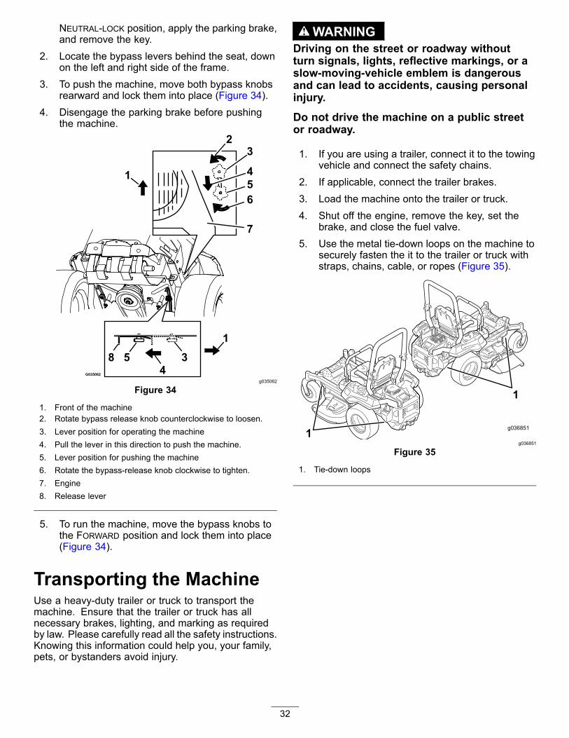
NEUTRAL-LOCK position, apply the parking brake,and remove the key.
2. Locate the bypass levers behind the seat, downon the left and right side of the frame.
3. To push the machine, move both bypass knobsrearward and lock them into place (Figure 34).
4. Disengage the parking brake before pushingthe machine.
g035062
Figure 34
1. Front of the machine2. Rotate bypass release knob counterclockwise to loosen.3. Lever position for operating the machine4. Pull the lever in this direction to push the machine.5. Lever position for pushing the machine6. Rotate the bypass-release knob clockwise to tighten.7. Engine8. Release lever
5. To run the machine, move the bypass knobs tothe FORWARD position and lock them into place(Figure 34).
Transporting the MachineUse a heavy-duty trailer or truck to transport themachine. Ensure that the trailer or truck has allnecessary brakes, lighting, and marking as requiredby law. Please carefully read all the safety instructions.Knowing this information could help you, your family,pets, or bystanders avoid injury.
WARNINGDriving on the street or roadway withoutturn signals, lights, reflective markings, or aslow-moving-vehicle emblem is dangerousand can lead to accidents, causing personalinjury.Do not drive the machine on a public streetor roadway.
1. If you are using a trailer, connect it to the towingvehicle and connect the safety chains.
2. If applicable, connect the trailer brakes.3. Load the machine onto the trailer or truck.4. Shut off the engine, remove the key, set the
brake, and close the fuel valve.5. Use the metal tie-down loops on the machine to
securely fasten the it to the trailer or truck withstraps, chains, cable, or ropes (Figure 35).
g036851
Figure 35
1. Tie-down loops
32

Loading the MachineUse extreme caution when loading or unloading themachine onto a trailer or a truck. Use a full-width rampthat is wider than the machine for this procedure.Back the machine up the ramps and drive it forwarddown the ramps (Figure 36).
g028043
Figure 36
1. Back the machine up theramps.
2. Drive the machine forwarddown the ramps.
Important: Do not use narrow individual rampsfor each side of the machine.
Ensure that the ramp is long enough so that the anglewith the ground does not exceed 15 degrees (Figure37). On flat ground, this requires a ramp to be at least4 times as long as the height of the trailer or truck bedto the ground. A steeper angle may cause mowercomponents to get caught as the machine moves fromthe ramp to the trailer or truck. Steeper angles mayalso cause the machine to tip or lose control. If youare loading the machine on or near a slope, positionthe trailer or truck so that it is on the down side ofthe slope and the ramp extends up the slope. Thisminimizes the ramp angle.
WARNINGLoading a machine onto a trailer or truckincreases the possibility of a tip-over andcould cause serious injury or death.• Use extreme caution when operating a
machine on a ramp.• Ensure that the ROPS is in the up position
and use the seat belt when loading orunloading the machine. Ensure that theROPS clears the top of an enclosed trailer.
• Use only a full-width ramp; do not useindividual ramps for each side of themachine.
• Do not exceed a 15-degree angle betweenthe ramp and the ground or between theramp and the trailer or truck.
• Ensure that the length of ramp is at least 4times as long as the height of the trailer ortruck bed to the ground. This ensures thatramp angle does not exceed 15 degrees onflat ground.
• Back the machine up the ramps and driveit forward down the ramps.
• Avoid sudden acceleration or decelerationwhile driving the machine on a ramp as thiscould cause a loss of control or a tip-over.
33

g027996
Figure 37
1. Full-width ramp in stowedposition
4. The ramp is at least 4times as long as the heightof the trailer or truck bedto the ground.
2. Side view of full-widthramp in loading position
5. H= height of the trailer ortruck bed to the ground
3. Not greater than15 degrees
6. Trailer
34

MaintenanceRecommended Maintenance Schedule(s)
Maintenance ServiceInterval Maintenance Procedure
After the first 5 hours • For Toro engines—change the engine oil and filter.
After the first 75 hours • Change the hydraulic-system filters and fluid.
Before each use or daily
• Check the safety-interlock system.• For Kawasaki engines—check the engine-oil level.• For Kohler engines—check the air cleaner for dirty, loose or damaged parts.• For Kohler engines—check the engine-oil level.• Clean the blower housing (more often under dusty, dirty conditions).• For Toro engines—check the engine-oil level.• Check the seat belt.• Check the rollover-protection-system (ROPS) knobs.• Clean the engine screen and the area around the engine.• Clean around the engine-exhaust system.• Check the hydraulic fluid level in the expansion tank.• Inspect the blades.• Clean the mower deck.
Every 25 hours
• For 1500 and 2000 Series machines—Grease the front caster axles. (more often indirty or dusty conditions).
• For Kohler engines—service or replace the air-cleaner foam element (more oftenunder dusty, dirty conditions).
• For Toro engines—clean the air-cleaner foam element (more often in dusty, dirtyconditions).
Every 50 hours
• For 2500 Series machines—Grease the mower deck-idler pivot.• Grease the pump-idler pivot.• Check spark arrester (if equipped).• Check the tire pressure.• Inspect the belts for cracks and wear.
Every 100 hours
• For Kawasaki engines—change the engine oil (more often in dirty or dustyconditions).
• For Kawasaki engines—replace or clean and gap the spark plug.• For Kohler engines—replace the air-cleaner paper element (more often under dusty,dirty conditions).
• For Kohler engines—change the engine oil and the engine-oil filter.• For Kohler engines—clean the cooling fins (more often under dusty, dirty conditions).• For Toro engines—replace the air-cleaner foam element (more often in dusty,dirty conditions).
• For Toro engines—service the air-cleaner paper element (more often in dusty,dirty conditions).
• For Toro engines—change the engine oil and oil filter (more often in dusty, dirtyconditions).
• For Toro engines—check the spark plug(s).
Every 200 hours
• For Kawasaki engines—change the engine-oil filter (more often in dirty or dustyconditions).
• For Kohler engines—check the spark plug(s).• For Toro engines—replace the air-cleaner paper element (more often in dusty,dirty conditions).
• For Toro engines—replace the spark plug(s).
35

Maintenance ServiceInterval Maintenance Procedure
Every 250 hours
• For Kawasaki engines—replace the primary air filter (more often in dusty or sandyconditions).
• For Kawasaki engines—check the safety air filter.• After the initial change—change the hydraulic-system filters and fluid when usingMobil 1 15W50 fluid (change it more often under severe conditions).
Every 300 hours • For Kawasaki engines—Check and adjust the valve clearance. See an AuthorizedService Dealer.
Every 500 hours
• For Kawasaki engines—replace the safety air filter.• For Kohler engines—Check and adjust the valve clearance. See an AuthorizedService Dealer.
• For Kohler engines—replace the spark plug(s).• Replace the emissions-air intake filter.• Replace the fuel filter (more often in dusty, dirty conditions).• Check the parking brake adjustment.• After the initial change—change the hydraulic-system filters and fluid when usingToro® HYPR-OIL™ 500 oil (change it more often under severe conditions).
Monthly • Check the battery charge.
Yearly • For 2500 Series machines—Lubricate the caster-wheel hubs.
Yearly or before storage • Paint chipped surfaces.• Check all maintenance procedures listed above before storage.
CAUTIONIf you leave the key in the ignition switch, someone could accidently start the engine andseriously injure you or other bystanders.Remove the key from the ignition before you do any maintenance.
36

Pre-MaintenanceProceduresMaintenance and Storage• Before repairing the machine do the following:
– Disengage the drives.– Set the parking brake.– Shut off the engine and remove the key.– Disconnect the spark-plug wire.
• Park the machine on a level surface.• Clean grass and debris from the cutting unit, drives, mufflers, and engine to help prevent fires.• Clean up oil or fuel spills.• Let the engine cool before storing the machine.• Do not store the machine or fuel near flames or drain the fuel indoors.• Do not allow untrained personnel to service the machine.• Use jack stands to support the machine and/or components when required.• Carefully release pressure from components with stored energy.• Disconnect the battery or remove the spark-plug wire before making any repairs. Disconnect the negative
terminal first and the positive terminal last. Connect the positive terminal first and negative last.• Use care when checking the blades. Wrap the blade(s) or wear thickly padded gloves, and use caution
when servicing them. Only replace blades; do not straighten or weld them.• Keep hands and feet away from moving parts. If possible, do not make adjustments with the engine running.• Keep all parts in good working condition and all hardware tightened, especially the blade-attachment bolts.
Replace all worn or damaged decals.• Never interfere with the intended function of a safety device or reduce the protection provided by a safety
device. Check their proper operation regularly.• To ensure optimum performance and continued safety certification of the machine, use only genuine Toro
replacement parts and accessories. Replacement parts and accessories made by other manufacturerscould be dangerous, and such use could void the product warranty.
• Check the parking brake operation frequently. Adjust and service as required.
37

LubricationGrease more frequently when operating conditionsare extremely dusty or sandy.
Grease Type: No. 2 lithium or molybdenum grease1. Disengage the blade-control switch (PTO), move
the motion-control levers to the NEUTRAL-LOCKposition, and set the parking brake.
2. Shut off the engine, remove the key, and waitfor all moving parts to stop before leaving theoperating position.
3. Clean the grease fittings with a rag.
Note: Make sure to scrape any paint off thefront of the fitting(s).
4. Connect a grease gun to the fitting, and pumpgrease into the fittings.
5. Wipe up any excess grease.
Greasing the MachineService Interval: Every 25 hours—For 1500 and
2000 Series machines—Grease thefront caster axles. (more often indirty or dusty conditions).
Every 50 hours—For 2500 Seriesmachines—Grease the mower deck-idlerpivot.Every 50 hours—Grease the pump-idler pivot.
1. Disengage the blade-control switch (PTO), movethe motion-control levers to the NEUTRAL-LOCKposition, and set the parking brake.
2. Shut off the engine, remove the key, and waitfor all moving parts to stop before leaving theoperating position.
3. Grease the mower deck and pump idler-pulleypivot with 1 or 2 pumps of grease (Figure 38).
4. For 1500 and 2000 Series machines, grease thefront caster axles (Figure 38).
g037570
Figure 38
1. Pump-idler pivot 3. Mower deck idler-pulleypivot (2500 Seriesmachines only)
2. Caster axle (1500 and2000 Series machinesonly)
38

Lubricating theCaster-Wheel Hubs2500 Series Machines OnlyService Interval: Yearly—For 2500 Series
machines—Lubricate thecaster-wheel hubs.
1. Shut off the engine, wait for all moving parts tostop, remove the key, and engage the parkingbrake.
g006115
Figure 39
1. Seal guard 2. Spacer nut with wrenchflats
2. Remove the caster wheel from the caster forks.3. Remove the seal guards from the wheel hub.4. Remove a spacer nut from the axle assembly in
the caster wheel.Note: Thread-locking compound has beenapplied to lock the spacer nuts to the axle.
5. Remove the axle (with the other spacer nut stillassembled to it) from the wheel assembly.
6. Pry out seals and inspect bearings for wear ordamage and replace if necessary.
7. Pack the bearings with a general-purposegrease.
8. Insert 1 bearing and 1 new seal into the wheel.Note: Replace the seals.
9. If both spacer nuts have been removed (orbroken loose) from the axle assembly, apply athread-locking compound to 1 spacer nut andthread it onto the axle with the wrench flatsfacing outward.Note: Do not thread the spacer nut all ofthe way onto the end of the axle. Leaveapproximately 3 mm (1/8 inch) from the outersurface of the spacer nut to the end of the axleinside the nut.
10. Insert the assembled nut and axle into the wheelon the side with the new seal and bearing.
11. With the open end of the wheel facing up, fillthe area inside the wheel around the axle full ofgeneral-purpose grease.
12. Insert the second bearing and new seal into thewheel.
13. Apply a thread-locking compound to the secondspacer nut and thread it onto the axle with thewrench flats facing outward.
14. Torque the nut to 8 to 9 N∙m (75 to 80 in-lb),loosen the nut, then torque it to 2 to 3 N∙m (20to 25 in-lb).
Note: Make sure that the axle does not extendbeyond either nut.
15. Install the seal guards over the wheel hub andinsert wheel into the caster fork.
16. Install the caster bolt and tighten the nut fully.
Important: To prevent seal and bearing damage,check the bearing adjustment often. Spin thecaster tire. The tire should not spin freely (morethan 1 or 2 revolutions) or have any side play. Ifthe wheel spins freely, adjust the torque on thespacer nut until there is a slight amount of drag.Apply another layer of thread-locking compound.
39

Engine MaintenanceUse the following graphic to identify the engine you have and proceed to the section listed below for service(Figure 40).
g036852
Figure 40
1. Kawasaki engine 2. Kohler engine 3. Toro engine
• For Kawasaki engine maintenance, refer toServicing a Kawasaki® Engine (page 41).
• For Kohler engine maintenance, refer to Servicinga Kohler® Engine (page 46).
• For Toro engine maintenance, refer to Servicing aToro Engine (page 50).
WARNINGContact with hot surfaces may cause personal injury.Keep your hands, feet, face, clothing and other body parts away the muffler and other hotsurfaces.
Engine SafetyShut off the engine before checking the oil or addingoil to the crankcase.
40

Servicing a Kawasaki®EngineThis section is only for machines with Kawasakiengines. If your engine looks like the one shown inFigure 41, you have a Kawasaki engine.
Important: Refer to your engine manufacturer’sinformation for additional maintenanceprocedures.
g036714
Figure 41
Servicing the Air CleanerService Interval: Every 250 hours—For Kawasaki
engines—replace the primary airfilter (more often in dusty or sandyconditions).
Every 250 hours—For Kawasakiengines—check the safety air filter.Every 500 hours—For Kawasakiengines—replace the safety air filter.
Note: Check the filters more frequently if theoperating conditions are extremely dusty or sandy.
Removing the Filters1. Disengage the blade-control switch (PTO), move
the motion-control levers to the NEUTRAL-LOCKposition, and set the parking brake.
2. Shut off the engine, remove the key, and waitfor all moving parts to stop before leaving theoperating position.
3. Release the latches on the air cleaner and pullthe air-cleaner cover off the air-cleaner body(Figure 42).
g001883
Figure 42
1. Air-cleaner body 4. Air-cleaner cover2. Primary filter 5. Safety filter3. Latch
4. Clean the inside of the air-cleaner cover withcompressed air.
5. Gently slide the primary filter out of theair-cleaner body (Figure 42).
Note: Avoid knocking the filter into the side ofthe body.
41

6. Remove the safety filter only if you intend toreplace it.
Important: Do not attempt to clean thesafety filter. If the safety filter is dirty, thenthe primary filter is damaged. Replace bothfilters.
7. Inspect the primary filter for damage by lookinginto the filter while shining a bright light on theoutside of the filter.
Note: Holes in the filter appear as bright spots.If the filter is damaged, discard it.
Servicing the Primary Filter• If the primary filter is dirty, bent, or damaged,
replace it.• Do not clean the primary filter.
Servicing the Safety FilterReplace the safety filter, never clean it.
Important: Do not attempt to clean the safetyfilter. If the safety filter is dirty, then the primaryfilter is damaged. Replace both filters.
Installing the FiltersImportant: To prevent engine damage, alwaysoperate the engine with both air filters and thecover installed.1. If installing new filters, check each filter for
shipping damage.
Note: Do not use a damaged filter.2. If you are replacing the safety filter, carefully
slide it into the filter body (Figure 42).3. Carefully slide the primary filter over the safety
filter (Figure 42).
Note: Ensure that the primary filter is fullyseated by pushing on its outer rim while installingit.
Important: Do not press on the soft insidearea of the filter.
4. Install the air-cleaner cover with the sideindicated as up facing upward and secure thelatches (Figure 42).
Servicing the Engine OilOil Type: Detergent oil (API service SF, SG, SH, SJ,or SL)
Crankcase Capacity: with a filter change, 2.1 L (71oz); without a filter change, 1.8 L (61 oz)
Viscosity: See the table below.
g037096
Figure 43
Note: Although 10W-40 engine oil is recommendedfor most conditions, you may need to change oilviscosity to accommodate atmospheric conditions.Using 20W-50 engine oil in higher ambienttemperatures can reduce oil consumption.
Checking the Engine-Oil LevelService Interval: Before each use or daily
Note: Check the oil when the engine is cold.
WARNINGContact with hot surfaces may cause personalinjury.Keep hands, feet, face, clothing, and otherbody parts away from the muffler and otherhot surfaces.
Important: Do not overfill the crankcase with oilbecause that could damage engine. Do not runengine with oil below the Low mark because theengine may be damaged.1. Disengage the blade-control switch (PTO), move
the motion-control levers to the NEUTRAL-LOCKposition, and set the parking brake.
2. Shut off the engine, remove the key, and waitfor all moving parts to stop before leaving theoperating position (Figure 44).
42

g036856
g225269
Figure 44
Changing the Engine OilService Interval: Every 100 hours (more often in dirty
or dusty conditions).Note: Dispose of the used oil at a recycling center.1. Start the engine and let it run for 5 minutes.
Note: This warms the oil so that it drains better.2. Park the machine so that the rear is slightly
lower than the front to ensure that the oil drainscompletely.
3. Disengage the blade-control switch (PTO), movethe motion-control levers to the NEUTRAL-LOCKposition, and set the parking brake.
4. Shut off the engine, remove the key, and waitfor all moving parts to stop before leaving theoperating position (Figure 45).
g036856
g225280
Figure 45
43

5. Slowly pour approximately 80% of the specifiedoil into the filler tube and slowly add theadditional oil to bring it to the Full mark (Figure46).
g027660
Figure 46
6. Start the engine and drive to a flat area.7. Check the oil level again.
Changing the Engine-Oil FilterService Interval: Every 200 hours—For Kawasaki
engines—change the engine-oilfilter (more often in dirty or dustyconditions).
1. Drain the oil from the engine; refer to Changingthe Engine Oil (page 43).
2. Change the engine-oil filter (Figure 47).
g036856
g027477
Figure 47
Note: Ensure that the oil-filter gasket touchesthe engine, and then turn the oil filter an extra3/4 turn.
3. Fill the crankcase with the proper type of newoil; refer to Servicing the Engine Oil (page 42).
44

Servicing the Spark PlugService Interval: Every 100 hours
Make sure that the air gap between the center andside electrodes is correct before installing the sparkplug. Use a spark plug wrench for removing andinstalling the spark plug(s) and a gapping tool/feelergauge to check and adjust the air gap. Install a newspark plug(s) if necessary.
Type of Spark Plug: NGK® BPR4ES or equivalent
Air Gap: 0.76 mm (0.03 inch)
Removing the Spark Plug1. Shut off the engine, remove the key, and wait
for all moving parts to stop before leaving theoperating position.
2. Disengage the blade-control switch (PTO), movethe motion-control levers to the NEUTRAL-LOCKposition, and set the parking brake.
3. Locate and remove the spark plugs (Figure 48).
g036857
g027478
Figure 48
Checking the Spark PlugImportant: Do not clean the spark plug(s).Always replace the spark plug(s) when it has: ablack coating, worn electrodes, an oily film, orcracks.
If you see light brown or gray on the insulator, theengine is operating properly. A black coating on theinsulator usually means the air cleaner is dirty.
Set the gap to 0.76 mm (0.03 inch).
g027479
Figure 49
Installing the Spark PlugTighten the spark plug(s) to 22 N∙m (16 ft-lb).
g027735
Figure 50
45

Servicing a Kohler® EngineThis section is only for machines with Kohler engines.If your engine looks like the one shown in Figure 51,you have a Kohler engine.
Important: Refer to your engine manufacturer’sinformation for additional maintenanceprocedures.
g036713
Figure 51
Servicing the Air CleanerService Interval: Before each use or daily—For
Kohler engines—check the aircleaner for dirty, loose or damagedparts.
Every 25 hours—For Kohler engines—serviceor replace the air-cleaner foam element (moreoften under dusty, dirty conditions).Every 100 hours—For Kohler engines—replacethe air-cleaner paper element (more often underdusty, dirty conditions).
This engine is equipped with a replaceable,high-density paper and foam air-cleaner element.Check the air cleaner daily or before starting theengine. Check for a buildup of dirt and debris aroundthe air-cleaner system. Keep this area clean. Also,check for loose or damaged components. Replace allbent or damaged air-cleaner components.
Note: Operating the engine with loose or damagedair-cleaner components could allow unfiltered air intothe engine, causing premature wear and failure.
Note: Service the air cleaner more often under dusty,dirty conditions.
Removing the Elements1. Rotate the latches outward.
2. Remove the cover to access the air-cleanerelements (Figure 52).
g028105
Figure 52
1. Air-cleaner cover 2. Air-cleaner latch
3. Remove the foam and paper elements (Figure53).
4. Remove the foam element from the paperelement (Figure 53).
g028106
Figure 53
1. Air-cleaner cover 3. Paper element2. Foam element
Servicing the Foam Element1. Wash the foam element in warm water and
detergent.2. Rinse and allow it to air dry.3. Lightly oil the foam element with new oil and
squeeze out excess oil.
Servicing the Paper Element1. Gently tap the paper element to dislodge dirt.
Note: Do not wash the paper element or usepressurized air, as this will damage the element.
46

Note: Replace a dirty, bent, or damagedelement. Handle the new element carefully;do not use if the sealing surfaces are bent ordamaged.
2. Clean the air-cleaner base as required, andcheck the condition.
Installing the Elements1. Install the foam element onto the paper element.2. Install the elements onto the air-cleaner base
(Figure 53).3. Install the cover, and secure it with the latches
(Figure 52).
Servicing the Engine OilOil Type: Detergent oil (API service SJ or higher)
Crankcase Capacity: 1.9 L (64 oz) when the filteris changed
Viscosity: See the table below.
g017552
Figure 54
Checking the Engine-Oil LevelService Interval: Before each use or daily1. Park the machine on a level surface, disengage
the blade-control switch, shut off the engine,and remove the key.
2. Make sure that the engine is shut off, level, andis cool, so the oil has time to drain into the sump.
3. Check the engine-oil level (Figure 55).
g027515
Figure 55
Changing the Engine Oil and the Engine-OilFilterService Interval: Every 100 hours—For Kohler
engines—change the engine oil andthe engine-oil filter.
Note: The drain plug is attached to the drain hose.Note: Dispose of the used oil at a recycling center.Fill with oil as specified in the “Viscosity Grades” table(Figure 54).1. Park the machine, so that the drain side is
slightly lower than the opposite side, to ensurethat the oil drains completely.
2. Disengage the blade-control switch and movethe motion controls outward to the PARK position.
3. Shut off the engine, remove the key, and waitfor all moving parts to stop before leaving theoperating position.
47

g027934
Figure 56
4. Torque the plug to 14 N∙m (10 ft-lb).5. Change the engine-oil filter as shown in Figure
57.
g038074
Figure 57
6. Slowly pour approximately 80% of the specifiedoil into the filler tube (Figure 58).
48

g027517
Figure 58
Servicing the Spark PlugService Interval: Every 200 hours—For Kohler
engines—check the spark plug(s).Every 500 hours—For Kohler engines—replacethe spark plug(s).
The spark plug is RFI compliant. Equivalent alternatebrand plugs can also be used.
Type: Champion XC12YC
Air Gap: 0.76 mm (0.03 inch)
Removing the Spark Plug1. Disengage the blade-control switch, move the
motion controls outward to the park position,shut off the engine, and remove the key.
2. Before removing the spark plug(s), clean thearea around the base of the plug to keep dirtand debris out of the engine.
3. Remove the spark plug (Figure 59).
g027478
Figure 59
Checking the Spark PlugImportant: Do not clean the spark plug(s).Always replace the spark plug(s) when it has: ablack coating, worn electrodes, an oily film, orcracks.
Note: If you see light brown or gray on the insulator,the engine is operating properly. A black coating onthe insulator usually means the air cleaner is dirty.
Set the gap to 0.76 mm (0.03 inch).
g027479
Figure 60
49

Installing the Spark PlugTighten the spark plug to 27 N∙m (20 ft-lb) as shownin Figure 61.
g028109
Figure 61
Cleaning the Blower HousingEvery 100 hours/Yearly (whichever comesfirst)—For Kohler engines—clean the coolingfins (more often under dusty, dirty conditions).
To ensure proper cooling, ensure that the grassscreen, cooling fins, and other external surfaces of theengine are kept clean at all times.
For Kohler engines, remove the blower housing, andany other cooling shrouds. Clean the cooling fins andexternal surfaces as necessary. Make sure that thecooling shrouds are installed.
Important: Operating the engine with a blockedgrass screen, dirty or plugged cooling fins, and/orcooling shrouds removed, will cause enginedamage due to overheating.
Servicing a Toro EngineThis section is only for machines with Toro engines.If your engine looks like what is shown in Figure 62,you have a Toro engine.
g036715
Figure 62
Servicing the Air CleanerService Interval: Every 25 hours/Monthly
(whichever comes first)—ForToro engines—clean the air-cleanerfoam element (more often in dusty,dirty conditions).
Every 100 hours/Yearly (whichever comesfirst)—For Toro engines—replace theair-cleaner foam element (more often in dusty,dirty conditions).Every 100 hours/Yearly (whichever comesfirst)—For Toro engines—service the air-cleanerpaper element (more often in dusty, dirtyconditions).Every 200 hours/Every 2 years (whichevercomes first)—For Toro engines—replace theair-cleaner paper element (more often in dusty,dirty conditions).
Removing the Elements1. Park the machine on a level surface and
disengage the blade-control switch (PTO).2. Engage the parking brake, shut off the engine,
remove the key, and wait for all moving parts tostop before leaving the operating position.
3. Clean around the air-cleaner cover to preventdirt from getting into the engine and causingdamage.
4. Lift the cover and rotate the air-cleaner assemblyout of the engine (Figure 63).
50

g027800
g027801
Figure 63
5. Remove the foam element from the paperelement (Figure 64).
g027802
Figure 64
Servicing the Foam ElementWash the foam element with water and replace it ifit is damaged.
Servicing the Paper Element1. Lightly tap the element on a flat surface to
remove dust and dirt.2. Inspect the element for tears, an oily film, and
damage to the seal.
Important: Do not clean the paper elementwith pressurized air or liquids, such assolvent, gas, or kerosene. Replace the paperelement if it is damaged or cannot be cleanedthoroughly.
Servicing the Engine OilOil Type: Detergent oil (API service SF, SG, SH, SJ,or SL)
Crankcase Capacity: 2.4 L (80 oz) with oil filterViscosity: See the table below.
g029683
Figure 65
Checking the Engine-Oil LevelService Interval: Before each use or daily—For Toro
engines—check the engine-oil level.
Note: Check the oil when the engine is cold.
WARNINGContact with hot surfaces may cause personalinjury.Keep hands, feet, face, clothing, and otherbody parts away the muffler and other hotsurfaces.
Important: Do not overfill the crankcase with oil,because damage to the engine may result. Do notrun engine with oil below the Low mark, becausethe engine may be damaged.1. Park the machine on a level surface, disengage
the blade-control switch, shut off the engine,engage the parking brake, and remove the key.
2. Make sure that the engine is shut off, level, andis cool so that the oil has had time to drain intothe sump.
3. To keep dirt, grass clippings, etc., out of theengine, clean the area around the oil-fill cap anddipstick before removing it (Figure 66).
51

g029368
Figure 66
Changing the Engine Oil and Oil FilterService Interval: After the first 5 hours/After the first
month (whichever comes first)—ForToro engines—change the engineoil and filter.
Every 100 hours/Yearly (whichever comesfirst)—For Toro engines—change the engineoil and oil filter (more often in dusty, dirtyconditions).
Note: Dispose of the used oil at a recycling center.1. Park the machine on a level surface to ensure
the oil drains completely.2. Disengage the PTO and engage the parking
brake.3. Shut off the engine, remove the key, and wait
for all moving parts to stop before leaving theoperating position.
4. Drain the engine oil (Figure 67).
g027799
g029570
Figure 67
52

5. Change the engine-oil filter (Figure 68).
g027477
Figure 68
Note: Ensure that the oil-filter gasket touchesthe engine and then turn the filter an extra 3/4turn.
6. Slowly pour approximately 80% of the specifiedoil into the filler tube and slowly add theadditional oil to bring it to the Full mark (Figure69).
g027484
Figure 69
Servicing the Spark PlugService Interval: Every 100 hours/Yearly
(whichever comes first)—ForToro engines—check the sparkplug(s).
Every 200 hours/Every 2 years (whichevercomes first)—For Toro engines—replace thespark plug(s).
Make sure that the air gap between the center andside electrodes is correct before installing the sparkplug. Use a spark-plug wrench to remove and installthe spark plug(s) and a gapping tool/feeler gauge tocheck and adjust the air gap. Install a new sparkplug(s) if necessary.
Type: Champion RN9YC or NGK BPR6ES
Air gap: 0.76 mm (0.03 inch)
53

Removing the Spark Plug1. Disengage the PTO and engage the parking
brake.2. Shut off the engine, remove the key, and wait
for all moving parts to stop before leaving theoperating position.
g027478
Figure 70
Note: Due to the deep recess around the sparkplug, blowing out the cavity with compressed airis usually the most effective method for cleaning.The spark plug is most accessible when theblower housing is removed for cleaning.
Checking the Spark PlugImportant: Do not clean the spark plug(s).Always replace the spark plug(s) when it has: ablack coating, worn electrodes, an oily film, orcracks.
If you see light brown or gray on the insulator, theengine is operating properly. A black coating on theinsulator usually means the air cleaner is dirty.
Set the gap to 0.76 mm (0.030 inch).
g027479
Figure 71
Installing the Spark PlugTighten the spark plug(s) to 25 to 30 N∙m (19 to 22ft-lb).
g027735
Figure 72
Cleaning the Cooling SystemClean the air-intake screen from grass and debrisbefore each use.1. Disengage the blade-control switch and engage
the parking brake.2. Shut off the engine, remove the key, and wait
for all moving parts to stop before leaving theoperating position.
3. Remove the air filter from the engine.4. Remove the engine shroud.5. To prevent debris entering the air intake, install
the air filter to the filter base.6. Clean debris and grass from the parts.7. Remove the air filter and install the engine
shroud.8. Install the air filter.
54

Checking the SparkArresterFor Machines with a SparkArresterService Interval: Every 50 hours
WARNINGHot exhaust system components may ignitegasoline vapors even after you shut off theengine. Hot particles exhausted during engineoperation may ignite flammable materials.Fire may result in personal injury or propertydamage.Do not refuel or run the engine unless a sparkarrester is installed.
1. Shut off the engine, wait for all moving parts tostop, and remove key. Engage parking brake.
2. Wait for muffler to cool.3. If there are any breaks in the screen or welds,
replace the arrester.4. If the screen is plugged, remove the arrester
and shake the loose particles out of the arresterand clean the screen with a wire brush (soak itin solvent if necessary). Install the arrester onthe exhaust outlet.
Replacing theEmissions-Air Intake FilterService Interval: Every 500 hours1. Shut off the engine, wait for all moving parts to
stop, and remove key. Engage parking brake.2. Remove the filter from the vent hose.3. Insert a new filter into the end of the vent hose.
Fuel SystemMaintenanceReplacing the Fuel FilterService Interval: Every 500 hours/Yearly (whichever
comes first) (more often in dusty,dirty conditions).
Important: Install the fuel line hoses and securewith plastic ties the same as they were originallyinstalled at the factory to keep the fuel line awayfrom components that can cause fuel line damage.
The fuel filter is located near the engine on the leftfront of the engine.1. Disengage the blade-control switch (PTO), move
the motion-control levers to the NEUTRAL-LOCKposition, and set the parking brake.
2. Shut off the engine, remove the key, and waitfor all moving parts to stop before leaving theoperating position.
3. Allow the machine to cool down.4. Close the fuel-shutoff valve under the seat
(Figure 33).
55

g029685
Figure 73Kohler engine filter shown
5. Open the fuel-shutoff valve.
Servicing the Fuel TankDo not attempt to drain the fuel tank. Ensure that anAuthorized Service Dealer drains the fuel tank andservices any components of the fuel system.
Electrical SystemMaintenanceElectrical System Safety• Disconnect the battery before repairing the
machine. Disconnect the negative terminal firstand the positive last. Connect the positive terminalfirst and the negative last.
• Charge the battery in an open, well-ventilatedarea, away from sparks and flames. Unplug thecharger before connecting or disconnecting thebattery. Wear protective clothing and use insulatedtools.
WARNINGCALIFORNIA
Proposition 65 WarningBattery posts, terminals, and relatedaccessories contain lead and leadcompounds, chemicals known tothe State of California to cause
cancer and reproductive harm. Washhands after handling.
Servicing the BatteryService Interval: Monthly
DANGERBattery electrolyte contains sulfuric acid,which is a deadly poison and causes severeburns.Do not drink electrolyte and avoid contactwith skin, eyes, or clothing. Wear safetyglasses to shield your eyes and wear rubbergloves to protect your hands.
56

Removing the Battery
WARNINGBattery terminals or metal tools could shortagainst metal machine components, causingsparks. Sparks can cause the battery gassesto explode, resulting in personal injury.• When removing or installing the battery,
do not allow the battery terminals to touchany metal parts of the machine.
• Do not allow metal tools to short betweenthe battery terminals and metal parts of themachine.
WARNINGIncorrect battery cable routing could damagethe machine and cables, causing sparks.Sparks can cause the battery gasses toexplode, resulting in personal injury.• Always disconnect the negative (black)
battery cable before disconnecting thepositive (red) cable.
• Always connect the positive (red) batterycable before connecting the negative(black) cable.
1. Disengage the blade-control switch (PTO), movethe motion-control levers to the NEUTRAL-LOCKposition, and set the parking brake.
2. Shut off the engine, remove the key, and waitfor all moving parts to stop before leaving theoperating position.
3. Disconnect the negative battery cable (black)from the negative (-) battery terminal (Figure 74).
4. Slide the red terminal boot off the positive (red)battery terminal, and remove the positive (+)battery cable (Figure 74).
5. Remove the rubber strap (Figure 74).6. Remove the battery.
g036853
g036855
Figure 74
57

Installing the Battery1. Position the battery in the tray with the terminal
posts opposite from the hydraulic tank (Figure74).
2. Install the positive (red) battery cable to thepositive (+) battery terminal.
3. Install the negative (black) battery cable andground wire to the negative (-) battery terminal.
4. Secure the cables with 2 bolts, 2 washers, and2 locknuts (Figure 74).
5. Slide the red terminal boot onto the positive (+)battery terminal.
6. Secure the battery with the rubber strap (Figure74).
Charging the Battery
WARNINGCharging the battery produces gasses thatcan explode.Never smoke near the battery and keep sparksand flames away from the battery.
Important: Always keep the battery fully charged(1.265 specific gravity). This is especiallyimportant to prevent battery damage when thetemperature is below 0°C (32°F).1. Charge battery for 10 to 15 minutes at 25 to 30
A or for 30 minutes at 10 A.2. When the battery is fully charged, unplug
the charger from the electrical outlet, thendisconnect the charger leads from the batteryposts (Figure 75).
3. Install the battery in the machine and connectthe battery cables; refer to Installing the Battery(page 58).
Note: Do not run the machine with the batterydisconnected; electrical damage may occur.
g000960
Figure 75
1. Positive battery post 3. Red (+) charger lead2. Negative battery post 4. Black (-) charger lead
Servicing the FusesThe electrical system is protected by fuses. It requiresno maintenance, however, if a fuse blows check thecomponent and circuit for a malfunction or short.
The fuses are located on the right console next to theseat (Figure 76).1. To replace the fuses, pull out the fuse to remove
it.2. Install a new fuse (Figure 76).
g036858
Figure 76
1. Fuse cover 3. Fuel-shutoff valve2. Fuse holder
58

Drive SystemMaintenanceChecking the Seat BeltService Interval: Before each use or daily
Inspect the seat belt for wear, cuts, and properoperation of the retractor and buckle. Replace theseat belt if it is damaged.
Checking theRollover-Protection-System(ROPS) KnobsService Interval: Before each use or daily
WARNINGTo avoid injury or death from rollover, keepthe roll bar in the fully raised, locked positionand use the seat belt.Ensure that the seat is secured to themachine.
• Check that both the mounting hardware and theknobs are in good working condition.
• Make sure that the knobs are fully engaged withthe ROPS in the raised position.
Note: The upper hoop of the roll bar may needto be pushed forward or pulled rearward to fullyengage both knobs (Figure 77 and Figure 78).
g036746
Figure 77
1. Roll bar in the uprightposition
4. Rotate the ROPS knob 90degrees.
2. ROPS knob in the latchedposition
5. ROPS knob in theunlatched position
3. Pull the ROPS knob outand rotate it 90 degrees.
6. Roll bar in the foldedposition
g034593
Figure 78
1. Engaged 2. Partially engaged—do notoperate with the ROPS inthis position.
59

Adjusting the Tracking1. Disengage the blade-control switch (PTO).2. Drive to an open, flat area and move the
motion-control levers to the NEUTRAL-LOCKposition.
3. Move the throttle midway between the FAST andSLOW positions.
4. Move both motion-control levers forward untilthey both hit the stops in the T-slot.
5. Check which way the machine tracks.6. If the machine tracks to the right, insert a
3/16-inch hex wrench through the access hole inthe right front cover panel and rotate the trackingscrew clockwise or counterclockwise to adjustthe travel of the lever (Figure 79).
7. If the machine tracks to the left, insert a3/16-inch hex wrench through the access hole inthe right front cover panel and rotate the trackingscrew clockwise or counterclockwise to adjustthe travel of the lever (Figure 79).
8. Drive the machine and check the full forwardtracking.
9. Repeat the adjustment until the desired trackingis obtained.
g035859
Figure 79Left control lever shown
1. Access hole on front coverpanel
2. Tracking screw
Checking the Tire PressureService Interval: Every 50 hours/Monthly (whichever
comes first)
Maintain the air pressure in the front and rear tiresat 90 kPa (13 psi). Uneven tire pressure can causeuneven cut. Check the tires when they are cold to getthe most accurate pressure reading.
g001055
Figure 80
Checking the Wheel LugNutsCheck and torque the wheel lug nuts to 122 to 136N∙m (90 to 100 ft-lb).
60

Cooling SystemMaintenanceCleaning the Engine ScreenService Interval: Before each use or daily
Before each use or daily
Before each use remove any buildup of grass, dirt, orother debris from the engine screen, engine exhaust,and the area around the engine. This helps ensureadequate cooling and correct engine speed andreduces the possibility of overheating and mechanicaldamage to the engine.
Brake MaintenanceAdjusting the ParkingBrakeService Interval: Every 500 hours
Note: Make sure to follow this procedure when abrake component has been removed or replaced.1. Drive the machine onto a level surface.2. Disengage the blade-control switch (PTO), move
the motion-control levers to the NEUTRAL-LOCKposition, and set the parking brake.
3. Shut off the engine, remove the key, and waitfor all moving parts to stop before leaving theoperating position.
4. Setup the machine to be pushed by hand. Referto Using the Drive-Wheel-Release Valves (page31).
5. Raise the back of the machine up and supportthe machine with jack stands.
CAUTIONRaising the machine for serviceor maintenance relying solely onmechanical or hydraulic jacks could bedangerous. The mechanical or hydraulicjacks may not be enough support or maymalfunction allowing the machine to fall,which could cause injury.Do not rely solely on mechanicalor hydraulic jacks for support. Useadequate jack stands or equivalentsupport.
6. Engage and disengage the parking brake andcheck each drive tire to ensure that each brakeengages and disengages.
7. If an adjustment is necessary, disengage theparking brake. Remove the cotter pin from thebrake linkage shaft (Figure 81).
61

g036752
Figure 81
1. Cotter pin 3. Brake linkage shaft2. Parking brake
8. Check both spring lengths as shown in Figure82. If an adjustment is necessary, turn thetop nut clockwise to shorten the spring andcounterclockwise to lengthen it.
g036100
Figure 82
1. Top nut 3. 44 mm (1-3/4 inches)2. Spring
9. Push the parking brake lever all the way forwardand down.
10. Rotate the brake-linkage shaft until the endaligns with the hole in the lever.• Shorten the linkage by turning it clockwise.• Lengthen the linkage by turning it
counterclockwise.11. Insert the brake-linkage shaft into the
parking-brake hole and secure with the cotterpin. Repeat step 6 and adjust if necessary.
12. When adjustment is complete, remove the jackstands or equivalent support and lower themachine.
13. Place the machine into the OPERATING position.Refer to Using the Drive-Wheel-Release Valves(page 31).
62

Belt MaintenanceInspecting the BeltsService Interval: Every 50 hours
Replace the belt if it is worn. The signs of a worn beltinclude squealing while the belt is rotating; the bladesslipping while cutting grass; and frayed edges, burnmarks, and cracks on the belt.
Replacing the Mower Beltfor Side Discharge MowerDecks1. Disengage the blade-control switch (PTO), move
the motion-control levers to the NEUTRAL-LOCKposition, and set the parking brake.
2. Shut off the engine, remove the key, and waitfor all moving parts to stop before leaving theoperating position.
3. Lower the mower to the 76 mm (3 inch)height-of-cut.
4. Remove the belt covers (Figure 83).
g027729
Figure 83
5. Remove the spring tension from thespring-loaded idler pulley. Refer to Figure 84or Figure 86.
Note: For 1500 and 2000 Series mowerdecks, use the spring removal tool (Toro PartNo. 92–5771) to remove the spring from themower-deck post (Figure 85).
Note: For 2500 Series mower decks, use aratchet in the square hole in the idler arm toremove tension on the idler spring (Figure 86).
6. Remove the belt from the mower-deck pulleysand the clutch pulley.
7. Install the new belt around the mower pulleysand the clutch pulley under the engine (Figure84 or Figure 86).
g036861
Figure 841500 and 2000 Series Mower Decks
1. Clutch pulley 3. Spring-loaded idler pulley2. Mower belt 4. Spring
g028279
Figure 851500 and 2000 Series Mower Decks
1. Spring-removal tool (ToroPart No. 92–5771)
4. Idler arm
2. Idler spring 5. Mower belt3. Mower-deck post
63

g036865
Figure 862500 Series Mower Decks
1. Clutch pulley 4. Ratchet2. Mower belt 5. Square hole in the idler
arm for the ratchet3. Spring-loaded idler pulley
8. Install the idler spring (Figure 84 or Figure 86).
Note: Make sure to seat the spring ends in theanchor grooves.
9. Install the belt covers (Figure 87).
g027730
Figure 87
Replacing the Mower Beltfor Rear Discharge MowerDecksReplacing the Counter-RotatingBelt1. Disengage the blade-control switch (PTO), move
the motion-control levers to the NEUTRAL-LOCKposition, and set the parking brake.
2. Shut off the engine, remove the key, and waitfor all moving parts to stop before leaving theoperating position.
3. Lower the mower to the 76 mm (3 inches) heightof cut.
4. Lift the floor pan up to gain access to the centerpulley.
5. Remove the plastic belt cover (Figure 89).6. Remove the 3 bolts holding the metal belt cover
in place and remove the metal belt cover.
g036862
Figure 88
1. Idler spring 4. Idler pulley2. Counter-rotating belt 5. Square hole in the idler
arm for the ratchet3. Double pulley
7. Use a ratchet in the square hole in the idler armto remove tension on the idler spring (Figure 88).
8. Remove the belt from the mower deck pulley(Figure 88).
9. Remove the belt from the remaining pulleys(Figure 88).
10. Route the new belt abound the mower pulleys.
64
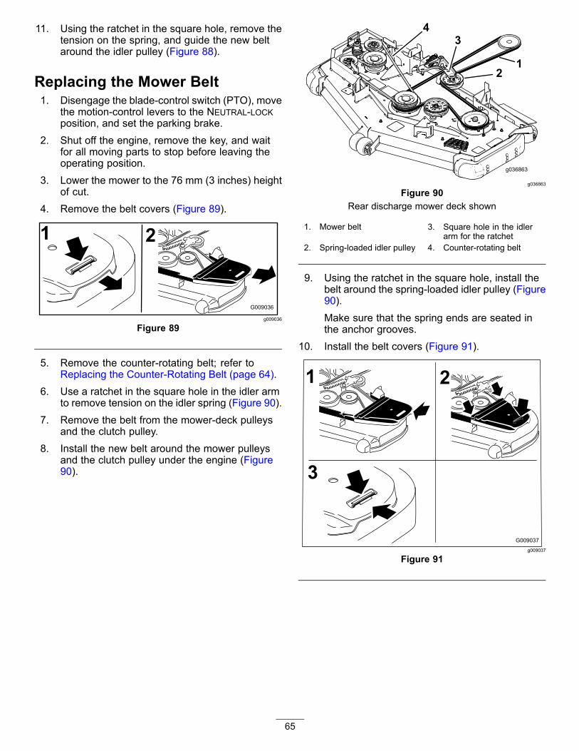
11. Using the ratchet in the square hole, remove thetension on the spring, and guide the new beltaround the idler pulley (Figure 88).
Replacing the Mower Belt1. Disengage the blade-control switch (PTO), move
the motion-control levers to the NEUTRAL-LOCKposition, and set the parking brake.
2. Shut off the engine, remove the key, and waitfor all moving parts to stop before leaving theoperating position.
3. Lower the mower to the 76 mm (3 inches) heightof cut.
4. Remove the belt covers (Figure 89).
g009036
Figure 89
5. Remove the counter-rotating belt; refer toReplacing the Counter-Rotating Belt (page 64).
6. Use a ratchet in the square hole in the idler armto remove tension on the idler spring (Figure 90).
7. Remove the belt from the mower-deck pulleysand the clutch pulley.
8. Install the new belt around the mower pulleysand the clutch pulley under the engine (Figure90).
g036863
Figure 90Rear discharge mower deck shown
1. Mower belt 3. Square hole in the idlerarm for the ratchet
2. Spring-loaded idler pulley 4. Counter-rotating belt
9. Using the ratchet in the square hole, install thebelt around the spring-loaded idler pulley (Figure90).Make sure that the spring ends are seated inthe anchor grooves.
10. Install the belt covers (Figure 91).
g009037
Figure 91
65

Replacing the HydraulicPump-Drive Belt1. Disengage the blade-control switch (PTO) and
set the parking brake.2. Shut off the engine, remove the key, and wait
for all moving parts to stop before leaving theoperating position.
3. Remove the mower belt; refer to Replacing theMower Belt for Side Discharge Mower Decks(page 63) or Replacing the Mower Belt for RearDischarge Mower Decks (page 64).
4. Raise the machine and support it with jackstands (Figure 93).
5. Remove the clutch stop (Figure 92).
g036860
Figure 92
1. Clutch stop
6. Remove the idler spring from the post (Figure93).
7. Remove the existing belt from thehydraulic-unit-drive pulleys and the enginepulley.
8. Install the new belt around the engine pulley andthe 2 hydraulic-pump pulleys (Figure 93).
g036859
Figure 93
1. Idler pulley 4. Pump-drive belt2. Idler-spring post 5. Right hydraulic-pump
pulley3. Engine pulley 6. Left hydraulic-pump pulley
9. Install the clutch stop (Figure 92).10. Install the mower belt; refer to Belt Maintenance
(page 63).
66

Controls SystemMaintenanceAdjusting theControl-Handle Position1. Disengage the blade-control switch (PTO), move
the motion-control levers to the NEUTRAL-LOCKposition, and set the parking brake.
2. Shut off the engine, remove the key, and waitfor all moving parts to stop before leaving theoperating position.Adjusting the height:You can adjust the motion control levers higheror lower for maximum comfort.A. Remove the hardware holding the control
lever to the control-arm shaft.
g035858
Figure 94
1. Bolts 3. Control lever2. Slotted hole 4. Control-arm shaft
B. Move the control lever to the next set ofholes. Secure the lever with the hardware.
C. Repeat the adjustment for the oppositecontrol lever.
Adjusting the TiltA. Loosen the upper bolt holding the control
lever to the control arm shaft.B. Loosen the lower bolt just enough to pivot
the control lever fore or aft. Tighten bothbolts to secure the control in the newposition.
C. Repeat the adjustment for the oppositecontrol lever.
g009195
Figure 95
3. If the ends of the levers hit against each other,refer to Adjusting the Motion-Control Linkage(page 67).
Adjusting theMotion-Control LinkageLocated on either side of the machine, below the seatare the pump control linkages. Rotating the end nutwith a 1/2 inch deep socket wrench allows fine tuningadjustments so that the machine does not move inneutral. Any adjustments should be made for neutralpositioning only.
WARNINGEngine must be running and drive wheelsmust be turning so adjustments can beperformed. Contact with moving parts or hotsurfaces may cause personal injury.Keep your fingers, hands, and clothing clearof rotating components and hot surfaces.1. Prior to starting the engine, push the deck lift
pedal and remove the height of cut pin. Lowerdeck to the ground.
2. Raise the rear of machine up and support withjack stands (or equivalent support) just highenough to allow drive wheels to turn freely.
3. Remove the electrical connection from the seatsafety switch, located under the bottom cushionof the seat.
67

Note: The switch is a part of the seat assembly.4. Temporarily install a jumper wire across the
terminals in the connector of the main harness.5. Start the engine. Run the engine at full throttle
and release the parking brake.
Note: Ensure that the parking brake is engagedand that the motion-control levers are out to startthe engine. You do not have to be in the seat.
6. Run the machine at least 5 minutes with thedrive levers in the full forward speed to bringhydraulic fluid up to operating temperature.
Note: The motion-control lever must bein neutral while making any necessaryadjustments.
7. Bring the motion-control levers into the NEUTRALposition.
8. Check and ensure that the control-plate tabstouch the return-to-neutral plates on thehydraulic units.
9. Adjust the pump-control-rod lengths by turningthe nut in the appropriate direction until thewheels slightly creep in reverse (see Figure 96).
10. Move the motion-control levers to the REVERSEposition and while applying slight pressure tothe lever, allow the reverse indicator springs tobring the levers back to neutral.
Note: The wheels must stop turning or slightlycreep in reverse.
Note: You may need to remove themotion-control cover to gain access.
g036753
Figure 96
1. Nut 4. Return-to-neutral plate2. Stationary plate 5. Tabs touching return to
neutral plate3. Control plate
11. Shut off the machine.12. Remove the jumper wire from the wire harness
and plug the connector into the seat switch.13. Remove the jack stands.14. Raise the mower deck and install the height of
cut pin.15. Check and ensure that the machine does not
creep in neutral with the park brake disengaged.
68

Hydraulic SystemMaintenanceHydraulic System Safety• Ensure that all hydraulic-fluid hoses and
lines are in good condition and all hydraulicconnections and fittings are tight beforeapplying pressure to the hydraulic system.
• Keep your body and hands away from pinholeleaks or nozzles that eject high-pressurehydraulic fluid.
• Use cardboard or paper to find hydraulic leaks.• Safely relieve all pressure in the hydraulic
system before performing any work on thehydraulic system.
• Seek immediate medical attention if fluidis injected into skin. Injected fluid must besurgically removed within a few hours by adoctor.
Servicing the HydraulicSystemHydraulic Fluid Type: Toro® HYPR-OIL™ 500hydraulic fluid (preferred) or Mobil 1 15W-50 oil.
Important: Use the fluid specified. Other fluidscould cause system damage.
Hydraulic System Capacity (with filters removed):4.45 L (150 oz)
Checking the Hydraulic Fluid LevelService Interval: Before each use or daily1. Allow the hydraulic fluid to cool down. Check
the oil level when the oil is cold.2. Check expansion reservoir and if necessary
add Toro® HYPR-OIL™ 500 hydraulic fluid to theFULL COLD line.
g037051
Figure 97
1. Engine 2. Expansion tank
69

Changing theHydraulic-System Filtersand FluidService Interval: After the first 75 hours—Change the
hydraulic-system filters and fluid.Every 500 hours—After the initialchange—change the hydraulic-systemfilters and fluid when using Toro® HYPR-OIL™500 oil (change it more often under severeconditions).Every 250 hours—After the initialchange—change the hydraulic-systemfilters and fluid when using Mobil 1 15W50 fluid(change it more often under severe conditions).
Change the filters and oil at the same time. Do notuse the oil again. Purge any air in the system after youinstall the new filters and add oil. Refer to Bleedingthe Hydraulic System (page 72).
Repeat the bleeding process until the oil remainsat the FULL COLD line in the reservoir after purging.Failure to properly perform this procedure canresult in irreparable damage to the transaxle drivesystem.
Removing Hydraulic-SystemFilters1. Shut off the engine, wait for all moving parts to
stop, allow the engine to cool, remove the key,and engage the parking brake.
2. Locate the filter and guards on eachtransaxle-drive system (Figure 98).
3. Remove the 3 screws securing the filter guardand guard (Figure 98).
g017444
Figure 98Right side shown
1. Transaxle drive 4. Screws2. Oil filter 5. Vent plug3. Filter guard
4. Carefully clean the area around the filters.
Important: Do not allow dirt to enter thehydraulic system, or contamination mayoccur.
5. Place a drain pan below the filter to catch theoil that drains when the filter and vent plugs areremoved.
6. Locate and remove the vent plug on eachtransmission
7. Unscrew the filter to remove it, and allow the oilto drain from the drive system.
8. Repeat this procedure for both filters.
70

Installing the Hydraulic-SystemFilters1. Apply a thin coat of oil on the surface of the
rubber seal of each filter.2. Turn the filter clockwise until the rubber seal
contacts the filter adapter, then tighten the filteran additional 3/4 to 1 full turn.
3. Repeat for the opposite filter.4. Install the filter guards over each filter that you
previously removed.5. Use the 3 screws to secure the filter guards.6. Verify that the vent plugs are removed before
adding the oil.7. Slowly pour the specified oil through the
expansion reservoir until oil comes out of 1 ofthe vent-plug holes.
8. Install the vent plug.9. Torque the plug to 20 N∙m (15 ft-lb).10. Continue to add oil through the expansion
reservoir until oil comes out of the remainingvent-plug hole on the second transmission.
11. Install the opposite vent plug.12. Torque the plug to 20 N∙m (15 ft-lb).13. Continue to add oil through the expansion
reservoir until it reaches the FULL COLD line onthe expansion reservoir.
14. Proceed to Bleeding the Hydraulic System(page 72).
Important: Failure to perform the Bleedingthe Hydraulic System procedure afterchanging hydraulic filters and oil can resultin irreparable damage to the transaxle drivesystem.
g027477
Figure 99
71

Bleeding the Hydraulic System1. Raise the rear of machine and support it with
jack stands (or equivalent support) just highenough to allow the drive wheels to turn freely.
g017625
Figure 100
1. Jacking points
2. Start the engine, move the throttle control aheadto the 1/2 throttle position, and disengage theparking brake.A. Move the bypass levers into the pushing the
machine position. With the bypass valvesopen and the engine running, slowly movethe motion-control levers in both forwardand reverse 5 or 6 times.
B. Move the bypass levers into the operatingthe machine position.
C. With the bypass valve closed and theengine running, slowly move the controllever in both forward and reverse directions5 to 6 times.
D. Shut off the engine and check the oil level inthe expansion reservoir. Add the specifiedoil until it reaches the FULL COLD line on theexpansion reservoir.
3. Repeat step 2 until all the air is completelypurged from the system.
Note: When the transaxle operates at normalnoise levels, moves smoothly forward, andreverses at normal speeds, it is purged.
4. Check the oil level in the expansion reservoir afinal time. Add the specified oil as until it reachesthe FULL COLD line on the expansion reservoir.
Mower DeckMaintenanceLeveling the Mower DeckAdjusting the Side-to-SideLeveling and the Blade Slope1. Position the mower on a flat surface.2. Disengage the blade-control switch (PTO), move
the motion-control levers to the NEUTRAL-LOCKposition, and set the parking brake.
3. Shut off the engine, remove the key, and waitfor all moving parts to stop before leaving theoperating position.
4. Check the tire pressure in the drive tires. Referto Checking the Tire Pressure (page 60).
5. Position the mower deck in the transport-lockposition.
6. Carefully rotate the blades from side to side.7. Measure between the blade tip and the flat
surface (Figure 101). If both measurements arenot within 5 mm (3/16 inch), adjust the leveling;continue with this procedure.
g037879
Figure 101
1. Blades side to side 3. Measure from the tip of theblade to the flat surfacehere.
2. Blade tip
8. Check the front-to-rear blade level (Figure 102).Ensure the front blade tip is lower than the rearblade tip as shown in the block height and raketable. If adjustment is needed, continue with thisprocedure.
72

g037880
Figure 102
1. Blades front to rear 3. Measure from the tip of theblade to the flat surfacehere.
2. Blade tip
9. Set the anti-scalp rollers to top holes or removethem completely for this adjustment.
10. For 60-inch mower decks only:A. Raise the deck to the transport position
(12.7 cm or 5 inches).B. Slowly loosen the adjusting screw on the
lift-assist spring until you can remove thescrew (see Figure 103).
Note: Save the screw for installation.
g035850
Figure 103Rear discharge mower deck shown
1. Adjusting screw 3. Set the gap to 22 to 29mm (7/8 to 1-1/8 inch).
2. Bracket
11. Place 2 blocks (see Block Height and RakeTable) under the rear edge of the cutting deckskirt; 1 on each side of the cutting deck (Figure104).
12. Set the height-of-cut lever to the 3 inch (76 mm)position.
13. Place 2 blocks under each side of the front edgeof the deck, but not under the anti-scalp rollerbrackets or welds.
g038090
Figure 104Bottom view
1. Block—7.3 cm (2.87inches)
2. Welds
Block Height and Rake TableDeckSize
Front Block Height Rake
All mowerdecks
7.3 cm (2.87 inches) 4.8 to 6.4 mm (3/16 to 1/4inch)
14. Carefully rotate the blades side to side (Figure101).
15. Loosen the locknuts (Figure 105) on all 4corners and ensure that the mower deck issitting securely on all 4 blocks.
16. Remove any slack from the deck hangers andmake sure the deck-lift foot lever is pushed backagainst the stop.
17. Tighten the 4 locknuts.
73

g035851
Figure 105
1. Locknuts 3. Deck hanger2. Deck lift arm 4. Chain
18. Ensure that the blocks fit snugly under the deckskirt and that all attachment bolts are tight
19. Continue leveling the deck by checking thefront-to-rear blade slope.
20. Check the blades for levelness and repeat deckleveling procedure if necessary.
21. For 60-inch mower decks only:A. Raise the deck to the transport position
(12.7 cm or 5 inches).B. Install the lift-assist spring adjusting screw
previously removed in step 10.C. Set the gap between the spring and the
bracket to 22 to 29 mm (7/8 to 1-1/8 inch).
Servicing the CuttingBladesTo ensure a superior quality of cut, keep the bladessharp. For convenient sharpening and replacement,keep extra blades on hand.
Blade SafetyA worn or damaged blade can break, and a pieceof the blade could be thrown at you or bystanders,resulting in serious personal injury or death. Trying torepair a damaged blade may result in discontinuedsafety certification of the product.• Inspect the blade periodically for wear or damage.• Use care when checking the blades. Wrap the
blades or wear gloves, and use caution whenservicing the blades. Only replace or sharpen theblades; never straighten or weld them.
• On multi-bladed machines, take care as rotating 1blade can cause other blades to rotate.
Before Inspecting or Servicing theBlades1. Park the machine on a level surface, Disengage
the blade-control switch (PTO), and set theparking brake.
2. Turn the ignition key to off. Remove the key, anddisconnect the spark-plug wires from the sparkplugs.
74

Inspecting the BladesService Interval: Before each use or daily1. Inspect the cutting edges (Figure 106).2. If the edges are not sharp or have nicks, remove
and sharpen the blade; refer to Sharpening theBlades (page 77).
3. Inspect the blades, especially in the curved area.4. If you notice any cracks, wear, or a slot forming
in this area, immediately install a new blade(Figure 106).
g006530
Figure 106
1. Cutting edge 3. Wear/slot forming2. Curved area 4. Crack
Checking for Bent Blades1. Disengage the blade-control switch (PTO), move
the motion-control levers to the NEUTRAL-LOCKposition, and set the parking brake.
2. Shut off the engine, remove the key, and waitfor all moving parts to stop before leaving theoperating position.
3. Rotate the blades until the ends face forwardand backward (Figure 107).
4. Measure from a level surface to the cuttingedge, position A, of the blades (Figure 107).
g000975
Figure 107
1. Measure here from bladeto hard surface
2. Position A
5. Rotate the opposite ends of the blades forward.6. Measure from a level surface to the cutting edge
of the blades at the same position as in step 4.
Note: The difference between the dimensionsobtained in steps 4 and 5 must not exceed 3 mm(1/8 inch).
Note: If this dimension exceeds 3 mm(1/8 inch), the blade is bent and must bereplaced.
WARNINGA blade that is bent or damaged couldbreak apart and could seriously injure orkill you or bystanders.• Always replace bent or damaged
blade with a new blade.• Do not file or create sharp notches in
the edges or surfaces of the blade.
75

Changing the Blades for SideDischarge Mower DecksRemoving the Blades for Side DischargeMower DecksReplace a blade if it hits an object, if the blade is outof balance, or if the blade is bent. To ensure optimumperformance and continued safety conformance ofthe machine, use genuine Toro replacement blades.Replacement blades made by other manufacturersmay result in nonconformance with safety standards.1. Hold the spindle shaft with a wrench.2. Remove the blade bolt, curved washer, and
blade from the spindle shaft (Figure 108).
g017443
Figure 108
1. Sail area of the blade 4. Blade bolt2. Blade 5. Spindle shaft3. Curved washer
Installing the Blades for Side DischargeMower Decks1. Install the blade onto the spindle shaft (Figure
108).
Important: The curved part of the blademust point upward toward the inside of themower to ensure proper cutting.
2. Install the curved washer and blade bolt (Figure108).
Note: Install the curved-washer cone towardthe bolt head.
3. Torque the blade bolt to 115 to 150 N∙m (85 to110 ft-lb).
Changing the Blades for RearDischarge Mower Decks
Removing the Blades for Rear DischargeMower DecksReplace a blade if it hits an object, is out of balance,or if it is bent. To ensure optimum performance andcontinued safety conformance of the machine, usegenuine Toro replacement blades. Replacementblades made by other manufacturers may result innonconformance with safety standards.1. Hold the blade end using a rag or a thickly
padded glove.2. Remove the left and center blade bolt, curved
washer, and blade from the spindle shaft (Figure109).
3. Remove the right blade bolt (left-hand threadedbolt), curved washer, and blade from the spindleshaft (Figure 110).
Note: Note the type blade and where eachblade is installed. See Figure 110 for the correctposition.
g017443
Figure 109Left and Center Spindle Shown
1. Sail area of the blade 4. Blade bolt2. Blade 5. Spindle shaft3. Curved washer
Installing the Blades for Rear DischargeMower DecksImportant: The right blade on this mowerdeck is counter-rotating and uses a left-hand
76

threaded blade bolt. Use Figure 110 for the correctplacement of the mower blades.1. Install the left and center blades, curved
washers, and blade bolts to the spindle shafts(Figure 109 and Figure 110).Note: Ensure the curved part of the blade ispointing upward toward the inside of the mowerdeck to ensure proper cutting.Note: Ensure the curved-washer cone isinstalled toward the bolt head (Figure 109).
2. Install the right blade, curved washer, and bladebolt (left-hand threaded bolt) to the spindle shaft(Figure 109 and Figure 110).
3. Torque the blade bolts to 115 to 150 N∙m (85 to110 ft-lb); refer to Figure 110.
g024248
Figure 110
1. Front of mower deck 4. Counter-rotating blade2. Right-hand threaded blade
bolts5. Left-hand threaded blade
bolt3. Regular blades
Sharpening the Blades1. Use a file to sharpen the cutting edge at both
ends of the blade (Figure 111).Note: Maintain the original angle.Note: The blade retains balance if you removethe same amount of material from both cuttingedges.
g000276
Figure 111
1. Sharpen at the original angle
2. Check the balance of the blade by putting it ona blade balancer (Figure 112).
Note: If the blade stays in a horizontal position,the blade is balanced and ready to use.
g000277
Figure 112
1. Blade 2. Balancer
3. If the blade is not balanced, file some metal offthe end of the sail area only (Figure 108).
4. Repeat this procedure until the blade isbalanced.
77

Removing the Mower DeckBefore servicing or removing the mower deck, lockout the spring-loaded deck arms.1. Shut off the engine, wait for all moving parts
to stop, and remove key. Engage the parkingbrake.
2. Remove the height adjustment pin and lower thedeck to the ground.
3. Place the height-adjustment pin in the 7.6 cm (3inch) cutting-height location.
4. Remove the belt covers.5. Loosen the mower deck idler and remove the
mower belt; refer to Belt Maintenance (page 63).6. Remove the bolts and nuts from the front of the
plate under the footrest.7. Remove and retain the bolts and nuts on both
sides of the machine (Figure 113).
g036866
Figure 113
1. Remove the nuts and bolts here.2. Remove the nuts and bolts here.
8. Slide the deck out to the right side of themachine.
Replacing the GrassDeflectorSide Discharge Mowers Only
WARNINGAn uncovered discharge opening could allowthe lawn mower to throw objects toward youor bystanders, resulting in serious injury.Also, contact with the blade could occur.Do not operate the lawn mower unless youinstall a cover plate, mulch plate, grassdeflector, or bagger.
1. Remove the locknut, bolt, spring, and spacerholding the deflector to the pivot brackets(Figure 114).
2. Remove the damaged or worn grass deflector(Figure 114).
g015594
Figure 114
1. Bolt 5. Spring installed2. Spacer 6. Grass deflector3. Locknut 7. J-hook end of spring4. Spring
3. Place the spacer and the spring onto grassdeflector.
4. Place 1 J-hook end of the spring behind thedeck edge.Note: Make sure that 1 J-hook end of thespring is installed behind the deck edge beforeinstalling the bolt as shown in Figure 114.
5. Install the bolt and the nut.6. Place 1 J-hook end of the spring around the
grass deflector (Figure 114).Important: The grass deflector must be ableto rotate. Lift the deflector up to the full open
78

position and ensure that it rotates into thefull down position. Cleaning
Cleaning under the MowerService Interval: Before each use or daily1. Disengage the blade-control switch (PTO), move
the motion-control levers to the NEUTRAL-LOCKposition, and set the parking brake.
2. Shut off the engine, remove the key, and waitfor all moving parts to stop before leaving theoperating position.
3. Raise the mower to the TRANSPORT position.
Disposing of WasteEngine oil, batteries, hydraulic fluid, and enginecoolant are pollutants to the environment. Dispose ofthese according to your state and local regulations.
79

StorageCleaning and Storage1. Disengage the blade-control switch (PTO), set
the parking brake, and turn the ignition key tooff. Remove the key.
2. Remove grass clippings, dirt, and grime fromthe external parts of the entire machine,especially the engine and hydraulic system.Clean dirt and chaff from the outside of theengine-cylinder-head fins and blower housing.Important: You can wash the machinewith mild detergent and water. Do notpressure-wash the machine. Avoidexcessive use of water, especially near thecontrol panel, engine, hydraulic pumps, andmotors.
3. Check the brake.4. Service the air cleaner; refer to Engine
Maintenance (page 40).5. Grease the machine; refer to Lubrication (page
38).6. Change the crankcase oil; refer to Engine
Maintenance (page 40).7. Check the tire pressure; refer to Checking the
Tire Pressure (page 60).8. Change the hydraulic filters; refer to Changing
the Hydraulic-System Filters and Fluid (page70).
9. Charge the battery; refer to Charging the Battery(page 58).
10. Scrape any heavy buildup of grass and dirtfrom the underside of the mower, then wash themower with a garden hose.Note: Run the machine with the blade-controlswitch (PTO) engaged, and the engine at highidle for 2 to 5 minutes after washing.
11. Check the condition of the blades; refer toServicing the Cutting Blades (page 74).
12. Prepare the machine for storage when non-useoccurs over 30 days. Prepare the machine forstorage as follows:A. Add a petroleum-based
stabilizer/conditioner to fuel in thetank. Follow mixing instructions fromthe stabilizer manufacturer. Do not usean alcohol-based stabilizer (ethanol ormethanol).Note: A fuel stabilizer/conditioner is mosteffective when mixed with fresh fuel andused at all times.
B. Run the engine to distribute conditioned fuelthrough the fuel system (5 minutes).
C. Shut off the engine, allow it to cool, anddrain the fuel tank; refer to Servicing theFuel Tank (page 56).
D. Start the engine and run it until it shuts off.E. Dispose of fuel properly. Recycle as per
local codes.
Important: Do not storestabilizer/conditioned fuel over90 days.
13. Check and tighten all bolts, nuts, and screws.Repair or replace any part that is damaged.
14. Paint all scratched or bare metal surfaces. Paintis available from your Authorized Service Dealer.
15. Store the machine in a clean, dry garage orstorage area.
16. Remove the key from the ignition switchand keep it out of reach of children or otherunauthorized users.
17. Cover the machine to protect it and keep it clean.
80

TroubleshootingProblem Possible Cause Corrective Action
1. The blade-control switch (PTO) isengaged.
1. Move the blade-control switch (PTO)to the disengaged position.
2. The parking brake is not engaged. 2. Set the parking brake.3. The motion-control levers are not in
the NEUTRAL-LOCK position.3. Ensure that the motion-control levers
are in the NEUTRAL-LOCK position.4. The operator is not seated. 4. Sit on the seat.5. The battery is dead. 5. Charge the battery.6. The electrical connections are
corroded or loose.6. Check the electrical connections for
good contact.7. The fuse is blown. 7. Replace the fuse.
The starter does not crank.
8. The relay or switch is worn ordamaged.
8. Contact an Authorized Service Dealer.
1. The fuel tank is empty. 1. Fill the fuel tank.
2. The fuel-shutoff valve is closed. 2. Open the fuel-shutoff valve.3. The oil level in the crankcase is low. 3. Add oil to the crankcase.4. The throttle is not in the correct
position.4. Be sure that the throttle control is
midway between the slow and fastpositions.
5. There is dirt in the fuel filter. 5. Replace the fuel filter.6. There is dirt, water, or stale fuel in the
fuel system.6. Contact an Authorized Service Dealer.
7. The air cleaner is dirty. 7. Clean or replace the air-cleanerelement.
8. The seat switch is not functioningproperly.
8. Check the seat-switch indicator.Replace the seat if necessary.
9. The electrical connections arecorroded, loose, or damaged.
9. Check the electrical connectionsfor good contact. Clean theconnector terminals thoroughly withelectrical-contact cleaner, applydielectric grease, and make theappropriate connections.
10.The relay or switch is worn ordamaged.
10.Contact an Authorized Service Dealer.
11. The spark plug is fouled or improperlygapped.
11. Adjust or replace the spark plug.
The engine does not start, starts hard, orfails to keep running.
12.The spark-plug wire is not connected. 12.Check the spark-plug wire connection.
1. The engine load is excessive. 1. Reduce the ground speed.
2. The air cleaner is dirty. 2. Clean the air-cleaner element.3. The oil level in the crankcase is low. 3. Add oil to the crankcase.4. The cooling fins and the air passages
above the engine are plugged.4. Remove the obstruction from the
cooling fins and the air passages.5. The vent hole in the fuel cap is plugged. 5. Clean or replace the fuel cap.6. There is dirt in the fuel filter. 6. Replace the fuel filter.
The engine loses power.
7. There is dirt, water, or stale fuel in thefuel system.
7. Contact an Authorized Service Dealer.
1. The engine load is excessive. 1. Reduce the ground speed.
2. The oil level in the crankcase is low. 2. Add oil to the crankcase.
The engine overheats.
3. The cooling fins and the air passagesabove the engine are plugged.
3. Remove the obstruction from thecooling fins and the air passages.
1. The tracking needs adjustment 1. Adjust the tracking.The mower pulls to the left or right (withlevers fully forward) 2. The tire pressure in the drive tires is
not correct.2. Adjust the tire pressure in the drive
tires.
81

Problem Possible Cause Corrective Action
1. The bypass valves are not closed tight. 1. Tighten the bypass valves.
2. The pump belt is worn, loose, orbroken.
2. Change the belt.
3. The pump belt is off a pulley. 3. Change the belt.4. The idler spring is broken or missing. 4. Replace the spring.
The machine does not drive.
5. The hydraulic oil level is low or too hot. 5. Add hydraulic oil to the reservoirs orlet it cool down.
1. The cutting blade(s) is/are bent orunbalanced.
1. Install new cutting blade(s).
2. The blade mounting bolt is loose. 2. Tighten the blade mounting bolt.3. The engine mounting bolts are loose. 3. Tighten the engine mounting bolts.4. The engine pulley, idler pulley, or blade
pulley is loose.4. Tighten the appropriate pulley.
5. The engine pulley is damaged. 5. Contact an Authorized Service Dealer.6. The blade spindle is bent. 6. Contact an Authorized Service Dealer.
The machine vibrates abnormally.
7. The motor mount is loose or worn. 7. Contact an Authorized Service Dealer.
1. The blade(s) is/are not sharp. 1. Sharpen the blade(s).
2. The cutting blade(s) is/are bent. 2. Install new cutting blade(s).3. The mower deck is not level. 3. Level the mower deck from side-to-side
and front-to-rear.4. The underside of mower is dirty. 4. Clean the underside of the mower.5. The tire pressure is not correct. 5. Adjust the tire pressure.
The machine produces an uneven cuttingheight.
6. The blade spindle is bent. 6. Contact an Authorized Service Dealer.
1. The mower deck belt is damaged,worn, loose, or broken.
1. Install a new deck belt.
2. The mower deck belt is off the pulley. 2. Install the mower belt on the deckpulley and check the idler pulley, idlerarm, and spring for correct positionand function.
3. The pump drive belt is worn, loose, orbroken.
3. Check the belt tension or install a newbelt.
The blades do not rotate.
4. The idler spring is broken or missing. 4. Replace the spring.
1. The fuse is blown. 1. Replace the fuse. Check the coilresistance, battery charge, chargingsystem, and wiring connections, andreplace components if necessary.
2. There is low voltage supply at theclutch.
2. Check the coil resistance, batterycharge, charging system, and wiringconnections and replace parts ifnecessary.
3. The coil is damaged. 3. Replace the clutch.4. There is inadequate current supply. 4. Repair or replace the clutch lead
wire or electrical system. Clean theconnector contacts.
The clutch does not engage.
5. The rotor/armature air gap is too large. 5. Remove the shim or replace the clutch.
82

Schematics
g036150
Wire Diagram—Toro Engines (Rev. A)
83
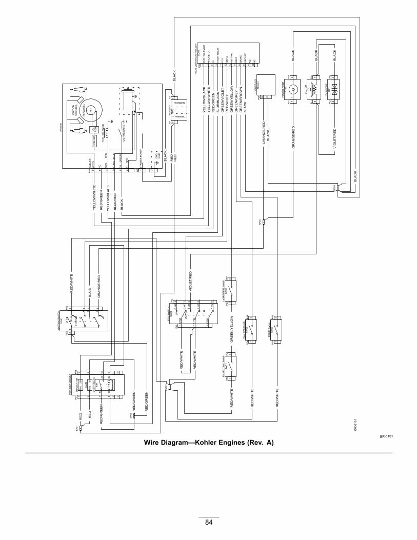
g036151
Wire Diagram—Kohler Engines (Rev. A)
84

g037072
Wire Diagram—Kawasaki Engines (Rev. A)
85

Notes:

Notes:

The Toro Warranty LandscapeA Limited Warranty (see warranty periods below) Contractor
Equipment(LCE)
Conditions and Products Covered
The Toro Company and its affiliate, Toro Warranty Company, pursuant to an agreementbetween them, jointly promise to repair the Toro Products listed below if defective inmaterials or workmanship.
The following time periods apply from the original date of purchase:
Products Warranty Period21 in. Mowers 2 years Residential Use1
1 year Commercial Use•Engines3 Honda – 2 years
Kawasaki – 3 years
30 in. Mowers 2 years Residential Use1
1 year Commercial Use
•Engines3 Kawasaki – 3 years
Mid-Size Walk-Behind Mowers 2 years
•Engines3 Kawasaki – 3 years
Grand Stand® Mowers 5 years or 1,200 hours2
•Engines3 3 yearsZ Master® 2000 Series Mowers 4 years or 500 hours2
•Engines3 3 yearsZ Master® 3000 Series Mowers 5 years or 1,200 hours2•Engines3 3 yearsZ Master® 5000 Series Mowers 5 years or 1,200 hours2
•Engines3 Kohler Command – 2 yearsKohler EFI – 3 years
Z Master® 6000 Series Mowers 5 years or 1,200 hours2
•Engines3 Kawasaki – 3 yearsZ Master®7000 Series Mowers 5 years or 1,200 hours2
•Engines3 2 yearsZ Master®8000 Series Mowers 2 years or 1,200 hours2
•Engines3 2 yearsTITAN HD 1500 Series 4 years or 500 Hours 2
•Engines Toro – 4 years or 500 hoursTITAN HD 2500 Series 4 years or 1,000 Hours 2
•Engines3 Kawasaki – 3 yearsTITAN HD 2000 Series 4 years or 750 Hours 2
•Engines3 Kohler – 3 yearsAll Mowers•Battery 90 days Parts and Labor
1 year Parts only
•Belts and Tires 90 days
•Attachments 1 year
1Residential use means use of the product on the same lot as your home. Use at more than onelocation is considered commercial use and the commercial warranty would apply.
2Whichever occurs first.
3Some engines used on Toro Products are warranted by the engine manufacturer.
Owner Responsibilities
You must maintain your Toro Product by following the maintenance proceduresdescribed in the Operator's Manual. Such routine maintenance, whether performed bya dealer or by you, is at your expense.
Instructions for Obtaining Warranty Service
If you think that your Toro Product contains a defect in materials or workmanship,follow this procedure:
1. Contact any Authorized Toro Service Dealer to arrange service at theirdealership. To locate a dealer convenient to you, access our web site atwww.Toro.com. You may also call the numbers listed in item #3 to use the24-hour Toro Dealer locator system.
2. Bring the product and your proof of purchase (sales receipt) to the ServiceDealer. The dealer will diagnose the problem and determine if it is coveredunder warranty.
3. If for any reason you are dissatisfied with the Service Dealer’s analysis or withthe assistance provided, contact us at:
Toro Warranty CompanyCustomer Care Department, RLC Division8111 Lyndale Avenue SouthBloomington, MN 55420-1196888-865-5676 (U.S. Customers)888-865-5691 (Canada customers)
Items and Conditions Not Covered
There is no other express warranty except for special emission system coverageand engine warranty coverage on some products. This express warranty does notcover the following:
• Cost of regular maintenance service or parts, such as filters, fuel, lubricants, oilchanges, spark plugs, air filters blade sharpening or worn blades, cable/linkageadjustments, or brake and clutch adjustments
• Components failing due to normal wear
• Any product or part which has been altered or misused or neglected or requiresreplacement or repair due to accidents or lack of proper maintenance
• Pickup and delivery charges
• Repairs or attempted repairs by anyone other than an Authorized Toro ServiceDealer
• Repairs necessary due to failure to follow recommended fuel procedure (consultOperator's Manual for more details)
– Removing contaminants from the fuel system is not covered
– Use of old fuel (more than one month old) or fuel which contains more than10% ethanol or more that 15% MTBE
– Failure to drain the fuel system prior to any period of non-use over onemonth
General Conditions
All repairs covered by these warranties must be performed by an Authorized ToroService Dealer using Toro approved replacement parts.
Neither The Toro Company nor Toro Warranty Company is liable for indirect,incidental or consequential damages in connection with the use of the ToroProducts covered by this warranty, including any cost or expense of providingsubstitute equipment or service during reasonable periods of malfunction ornon-use pending completion of repairs under this warranty.
All implied warranties of merchantability (that the product is fit for ordinary use)and fitness for use (that the product is fit for a particular purpose) are limited tothe duration of the express warranty.
Some states do not allow exclusions of incidental or consequential damages,or limitations on how long an implied warranty lasts, so the above exclusionsand limitations may not apply to you.
This warranty gives you specific legal rights, and you may also have other rightswhich vary from state to state.
Countries Other than the United States or Canada
Customers who have purchased Toro products outside the United States or Canada should contact their Toro Distributor (Dealer) to obtain guarantee policies for your country,province, or state. If for any reason you are dissatisfied with your Distributor's service or have difficulty obtaining guarantee information, contact the Toro importer. If all otherremedies fail, you may contact us at Toro Warranty Company.
Australian Consumer Law: Australian customers will find details relating to the Australian Consumer Law either inside the box or at your local Toro Dealer.
374-0252 Rev I