
4.8.2 Rate of Flow
19
Section 4: Water Supply and Distribution EBCS-9 2013 Plumbing Services of Buildings 52 ͶǤͺǤʹ 1) Pipes and fittings shall be sized so that the flow rates for individual draw-offs are equal to the design flow rates shown in table 4.8 and during simultaneous discharges the minimum flow rates shall be maintained on each tap. Table 4-8 Design flow rates and loading units Outlet fitting Design flow rate (l/s) Minimum flow rate l/s Loading units WC flushing cistern single or dual flush – to fill in 2 minutes WC trough cistern Wash basin tap size ½ DN 15 Spray tap or spray mixer Bidet Bath tap, nominal size ¾ DN 20 Bath tap, nominal size 1 – DN 25 Shower head (will vary with type of head) Sink tap, nominal size ½ DN 15 Sink tap, nominal size 3/4 DN 20 0.13 0.15 per WC 0.15 per tap 0.05 per tap 0.20 per tap 0.30 0.60 0.20 hot or cold 0.20 0.30 0.60 0.20 hot or cold 0.15 0.004 per position served 0.05 0.10 0.10 0.03 0.10 0.20 0.40 0.10 0.10 0.20 0.40 0.15 0.10 0.002 2 2 1.5 to 3 – 1 10 22 3 3 5 – 3 – Source: BS 6700 Notes: 1. Flushing troughs are advisable where likely use of WCs is more than once per minute. 2. Mixer fittings use less water than separate taps, but this can be disregarded in sizing. 3. Flow rates to shower mixers vary according to type fitted. Manufacturers should be consulted. 4. Manufacturers should be consulted for flow rates to washing machines and dishwashers for other than a single dwelling. 5. For cistern fed urinals demand is very low and can usually be ignored. Alternatively, use the continuous flow.
-
Upload
khangminh22 -
Category
Documents
-
view
2 -
download
0
Transcript of 4.8.2 Rate of Flow

Section 4: Water Supply and Distribution
EBCS-9 2013 Plumbing Services of Buildings 52
1) Pipes and fittings shall be sized so that the flow rates for individual draw-offs are equal to
the design flow rates shown in table 4.8 and during simultaneous discharges the minimum flow rates shall be maintained on each tap.
Table 4-8 Design flow rates and loading units
Outlet fitting Design flow rate
(l/s)
Minimum flow rate
l/s
Loading units
WC flushing cistern single or dual flush – to fill in 2 minutes
WC trough cistern Wash basin tap size ½ DN 15
Spray tap or spray mixer Bidet Bath tap, nominal size ¾ DN 20
Bath tap, nominal size 1 – DN 25 Shower head (will vary with type of head)
Sink tap, nominal size ½ DN 15
Sink tap, nominal size 3/4 DN 20
0.13
0.15 per WC 0.15 per tap 0.05 per tap 0.20 per tap 0.30
0.60 0.20 hot or cold
0.20
0.30
0.60 0.20 hot or cold 0.15 0.004 per positionserved
0.05 0.10 0.10 0.03 0.10 0.20
0.40 0.10
0.10
0.20
0.40 0.15 0.10 0.002
2
2 1.5 to 3
– 1
10
22 3
3
5
–
3 –
Source: BS 6700
Notes:
1. Flushing troughs are advisable where likely use of WCs is more than once per minute.
2. Mixer fittings use less water than separate taps, but this can be disregarded in sizing.
3. Flow rates to shower mixers vary according to type fitted. Manufacturers should be consulted.
4. Manufacturers should be consulted for flow rates to washing machines and dishwashers for other than a single dwelling.
5. For cistern fed urinals demand is very low and can usually be ignored. Alternatively, use the continuous flow.

Section 4: Water Supply and Distribution
EBCS-9 2013 Plumbing Services of Buildings 53
(2) Loading units should not be used for outlet fittings having high peak demands, e.g. those in industrial installations. In these cases use the continuous flow.
(3) BS 6700 does not give loading units for sink tap DN 20 or pressure flushing valve for WCs or urinals.
Pipe sizes shall ensure adequate flow rates at appliances and avoid problems that lead to (see Figure 4.3):
(1) Over-sizing that shall cause a) additional and unnecessary installation costs; b) delays in obtaining hot water at outlets; c) increased heat losses from hot water distributing pipes.
(2) Under-sizing that shall cause: a) inadequate delivery from outlets and possibly no delivery at some outlets during
simultaneous use; b) some variation in temperature and pressure at outlets, especially showers and other
mixers; c) some increase in noise levels.
Figure 4-3 Pipe sizing considerations (Source: BS 6700)

Section 4: Water Supply and Distribution
EBCS-9 2013 Plumbing Services of Buildings 54
(3) In smaller, straightforward installations such as single dwellings, pipes are often sized on the basis of experience and convention.
(4) In larger and more complex buildings, or with supply pipes that are very long, it is
necessary to use a recognized method of calculation such as that shown in sections 4.8.3.1 and 4.8.3.2.
4.8.3.1 Sizing procedure for supply pipes
The procedure below is followed by an explanation of each step with appropriate examples. (1) Assume a pipe diameter. (2) Determine the flow rate:
(a) by using loading units; (b) for continuous flows; (c) obtain the design flow rate by adding (a) and (b).
(3) Determine the effective pipe length: (d) work out the measured pipe length; (e) work out the equivalent pipe length for fittings; (f) work out the equivalent pipe length for draw-offs; (g) obtain the effective pipe length by adding (d), (e) and (f).
(4) Calculate the permissible loss of head: (h) determine the available head: (i) determine the head loss per metre run through pipes; (j) determine the head loss through fittings; (k) calculate the permissible head loss.
(5) Determine the pipe diameter: (l) decide whether the assumed pipe size will give the design flow rate in (c) without exceeding the permissible head loss in (k).
Explanation of the procedure Assume a pipe diameter (1) In pipe sizing it is usual to make an assumption of the expected pipe size and then prove whether or not the assumed size will carry the required flow. Determine the flow rate (2) In most buildings it is unlikely that all the appliances installed will be used simultaneously. As the number of outlets increases the likelihood of them all being used at the same time decreases. Therefore it is economic sense to design the system for likely peak flows based on probability theory using loading units, rather than using the possible maximum flow rate.
(a) Loading units. A loading unit is a factor or number given to an appliance which relates the flow rate at its terminal fitting to the length of time in use and the frequency of use for a particular type and use of building (probable usage). Loading units for various appliances are given in table 4.8. By multiplying the number of each type of appliance by its loading unit and adding the results, a figure for the total loading units can be obtained. This is converted to a design flow rate using Figure 4.4. An example using loading units is given in Figure 4.5. (b) Continuous flows. For some appliances, such as automatic flushing cisterns, the flow rate must be considered as a continuous flow instead of applying probability theory and using

Section 4: Water Supply and Distribution
EBCS-9 2013 Plumbing Services of Buildings 55
loading units. For such appliances the full design flow rate for the outlet fitting must be used, as given in Table 4.8. However, in the example shown in Figure 4.5, the continuous flow for the two urinals of 0.008 l/s (from table 4.8) is negligible and can be ignored for design purposes. (c) Design flow rate. The design flow rate for a pipe is the sum of the flow rate determined
from loading units (a) and the continuous flows (b).
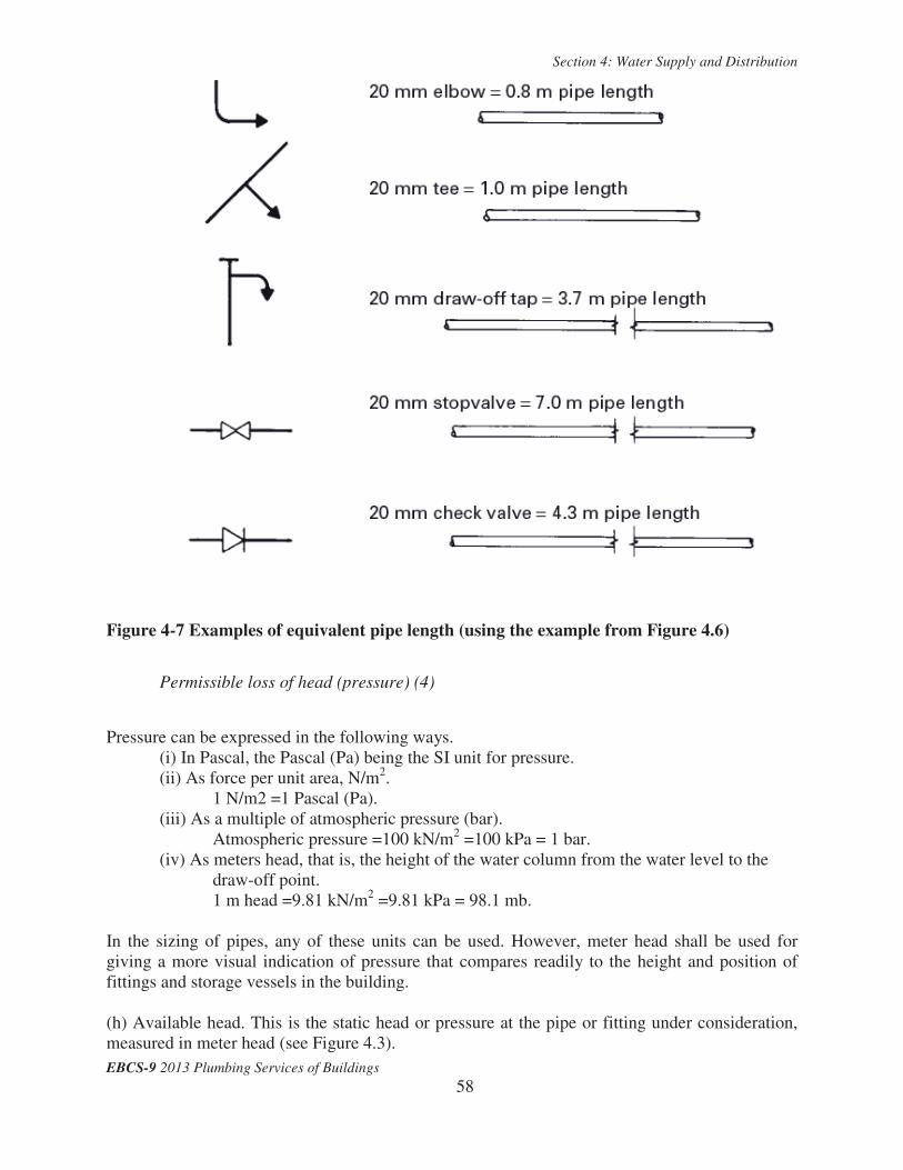
Determine the effective pipe length (3) (d) Find the measured pipe length. Figure 4.6 is an example showing how the measured pipe length is found. Therefore, from figure 4.4, the required flow rate for the system is 0.7 l/s. (e, f ) Find the equivalent pipe lengths for fittings and draw-offs. For convenience the frictional resistances to flow through fittings are expressed in terms of pipe lengths having the same resistance to flow as the fitting. Hence the term ‘equivalent pipe length’ (see table 4.9). For example, a 20 mm elbow offers the same resistance to flow as a 20 mm pipe 0.8 m long. Figure 4.7 shows the equivalent pipe lengths for the fittings in the example in Figure 4.6.
Table 4-9 Equivalent pipe length (copper, galvanized steel and plastics)
(g) Effective pipe length. The effective pipe length is the sum of the measured pipe length (d) and the equivalent pipe lengths for fittings (e) and draw-offs (f). Therefore, for the example shown in Figure 4.6 the effective pipe length would be: Measured pipe length 4.75 m Equivalent pipe lengths
elbows 2 × 0.8 = 1.6 m tee 1 × 1.0 = 1.0 m stopvalve 1 × 7.0 = 7.0 m taps 2 × 3.7 = 7.4 m check valves 2 × 4.3 = 8.6 m Effective pipe length = 30.35 m

Section 4: Water Supply and Distribution
EBCS-9 2013 Plumbing Services of Buildings 56
Figure 4-4 Conversion chart - loading unit to flow rate

Section 4: Water Supply and Distribution
EBCS-9 2013 Plumbing Services of Buildings 57
Figure 4-5 Example of use of loading units
Figure 4-6 Example of measured pipe length
Section 4: Water Supply and Distribution
EBCS-9 2013 Plumbing Services of Buildings 58
Figure 4-7 Examples of equivalent pipe length (using the example from Figure 4.6)
Permissible loss of head (pressure) (4)
Pressure can be expressed in the following ways.
(i) In Pascal, the Pascal (Pa) being the SI unit for pressure. (ii) As force per unit area, N/m2.
1 N/m2 =1 Pascal (Pa). (iii) As a multiple of atmospheric pressure (bar).
Atmospheric pressure =100 kN/m2 =100 kPa = 1 bar. (iv) As meters head, that is, the height of the water column from the water level to the
draw-off point. 1 m head =9.81 kN/m2 =9.81 kPa = 98.1 mb.
In the sizing of pipes, any of these units can be used. However, meter head shall be used for giving a more visual indication of pressure that compares readily to the height and position of fittings and storage vessels in the building. (h) Available head. This is the static head or pressure at the pipe or fitting under consideration, measured in meter head (see Figure 4.3).

Section 4: Water Supply and Distribution
EBCS-9 2013 Plumbing Services of Buildings 59
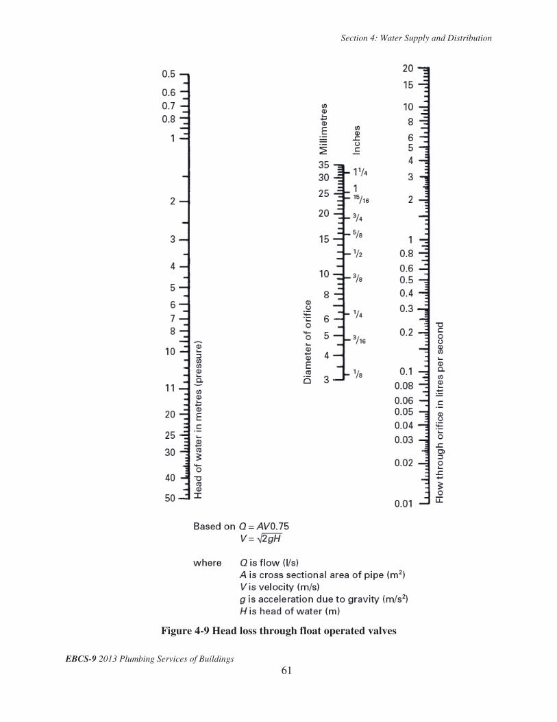
(i) Head loss through pipes. The loss of head (pressure) through pipes due to frictional resistance to water flow is directly related to the length of the pipe run and the diameter of the pipe. Pipes of different materials will have different head losses, depending on the roughness of the bore of the pipe and on the water temperature. Copper, stainless steel and plastics pipes have smooth bores and only pipes of these materials are considered in this section. (j) Head loss through fittings. In some cases it is preferable to subtract the likely resistances in fittings (particularly draw-offs) from the available head, rather than using equivalent pipe lengths. Table 4.10 gives typical head losses in taps for average flows compared with equivalent pipe lengths. Figures 4.8 and 4.9 provide a method for determining head losses through stop valves and float-operated valves respectively. Note: Where meters are installed in a pipeline the loss of head through the meter shall be deducted from the available head.
Table 4-10 Typical head losses and equivalent pipe lengths for taps
Determine the pipe diameter (5)
In the example in Figure 4.6 a pipe size of 20 mm has been assumed. This pipe size must give the design flow rate without the permissible head loss being exceeded. If it does not, a fresh pipe size must be assumed and the procedure worked through again. Figure 4.10 relates pipe size to flow rate, flow velocity and head loss. Knowing the assumed pipe size and the calculated design flow rate, the flow velocity and the head loss can be found from the figure as follows. (1) Draw a line joining the assumed pipe size (20 mm) and the design flow rate (0.4 l/s). (2) Continue this line across the velocity and head loss scales. (3) Check that the loss of head (0.12 m/m run) does not exceed the calculated permissible head loss of 1.48 m/m run. (4) Check that the flow velocity (1.4 m/s) is not too high by referring to 4.11.

Section 4: Water Supply and Distribution
EBCS-9 2013 Plumbing Services of Buildings 60
Table 4-11 Maximum recommended flow velocities
Figure 4-8 Head loss through stop valves
Section 4: Water Supply and Distribution
EBCS-9 2013 Plumbing Services of Buildings 61
Figure 4-9 Head loss through float operated valves

Section 4: Water Supply and Distribution
EBCS-9 2013 Plumbing Services of Buildings 62
Figure 4-10 Determination of pipe diameter

Section 4: Water Supply and Distribution
EBCS-9 2013 Plumbing Services of Buildings 63
4.8.3.2 Tabular method of pipe sizing The tabular method uses a work sheet which can be completed as each of the steps is followed in the pipe sizing procedure. An example of the method follows with some explanation of each step. Explanation of the tabular method
Pipe work diagram (1) Make a diagram of the pipeline or system to be considered (see Figure 4.11). (2) Number the pipes beginning at the point of least head, numbering the main pipe run first, then the branch pipes. (3) Make a table to show the loading units and flow rates for each stage of the main run. Calculate and enter loading units and flow rates; see Figure 4.11. Calculate flow demand
(1) Calculate maximum demand (see Figure 4.11): a) add up loading units for each stage (each floor level); b) convert loading units to flow rates; c) add up flow rates for each stage.
(2) Calculate probable demand (see Figure 4.11): a) add up loading units for all stages; b) convert total loading units to flow rate.
(3) Calculate percentage demand (number of stages for which frictional resistances need be allowed). See Figure 4.13.
Work through the calculation sheet See Figure 4.12, using the data shown in Figures 4.11 and 4.13.
Estimated maximum demand = 1.4 l/s Probable demand = 0.85 l/s
Therefore only 60% of the installation need be considered. For example, if we were designing for a multi-storey building 20 storeys high, only the first 12 storeys need to be calculated. However, in the example followed here, the whole system has been sized because the last fitting on the run has a high flow rate in continuous use. For branches only the pipes to the largest draw off, i.e. the bath tap, need be sized.

Section 4: Water Supply and Distribution
EBCS-9 2013 Plumbing Services of Buildings 64
Refer also Figure 4.13
Figure 4-11 Pipe sizing diagram

Section 4: Water Supply and Distribution
EBCS-9 2013 Plumbing Services of Buildings 65
Enter pipe references on calculation sheet (1) Pipe reference
Determine loading unit (table 4.8) (2) Loading units
Convert loading units to flow rate (figure 4.4) (3) Flow rate (l/s)
Make assumption as to pipe size (inside diameter) (4) Pipe size (mm diameter)
Work out frictional resistance per metre (figure 4.10) (5) Loss of head (m/m run)
Determine velocity of flow (figure 4.10) (6) Flow velocity (m/s)
Measure length of pipe under consideration (7) Measured pipe run (m)
Consider frictional resistances in fittings (table 4.11 and figures 4.8 and 4.9 (8) Equivalent pipe length (m)
Add totals in columns 7 and 8 (9) Effective pipe length (m)
Head consumed-multiply column 5 by column 9 (10) Head consumed (m)
Add head consumed in column 10 to progressive head in previous row of (11) Progressive head (m)
Record available head at point of delivery (12) Available head (m)
Compare progressive head with available head to confirm pipe diameter or not (13) Final pipe size (mm)
Notes (14) Remarks
Figure 4-12 Calculation sheet – explanation of use

Section 4: Water Supply and Distribution
EBCS-9 2013 Plumbing Services of Buildings 66
Refer also fig. 4.11
Figure 4-13 Calculation sheet – example of use

Section 4: Water Supply and Distribution
EBCS-9 2013 Plumbing Services of Buildings 67
4.8.4.1. Direct Supply System
(1) This system shall be adopted when adequate pressure is available throughout the day at the municipal water distribution line which can satisfy the functionality requirements of the building or that is sufficient to reach an elevated water tank; and municipal water supply interruption is not expected.
4.8.4.1.1. Direct Supply to fixtures
(1) The water supply distribution line after the water meter shall be directly connected to
sanitary fixtures without any storage.
4.8.4.1.2. Direct Supply to Elevated Water Tank
(1) The water distribution line after water meter shall be directly connected to elevated water
tank and the fixtures are supplied via gravity from the elevated water tank.
4.8.4.2. Pumping System
The system shall be adopted when the requirement under 4.8.4.1(1) is not fulfilled. The system shall be used where a constant and reliable supply of power is ensured.
4.8.4.2.1. Direct Pumping from the Water Supply Line
(1) Direct pumping from a water supply line could affect the municipal water supply system depending on the pressure in the system. Therefore, special approval from the water supply authorities be obtained before designing such a system. (2) Direct pumping from water supply line to sanitary fixtures
a) The pump shall be connected to a water distribution line after the water meter and
provides water to all fixtures without any storage.
b) Direct pumping systems shall be used for buildings where a certain amount of constant use of water is always occurring.
(3) Direct pumping from water supply line to elevated water tank
a) The pump shall be connected to a water distribution line after the water meter and delivers to an elevated water tank from which fixtures are supplied via gravity.

Section 4: Water Supply and Distribution
EBCS-9 2013 Plumbing Services of Buildings 68
4.8.4.2.2. Direct Pumping from ground reservoir to elevated water tank
The municipal water shall be stored at ground or low level water reservoir and be pumped to elevated or roof water tanks as shown in Figure 4.14.
Water collected in the elevated or overhead tank shall be distributed to the various parts of the building or fixtures via gravity system.
Care shall be taken to avoid dry running of pump when the water level in the lower reservoir reaches its minimum level.
The system shall ensure automatic operation of the pumps by providing level control switches in the elevated water tank or approved control methods.
4.8.4.2.3. Direct pumping from ground reservoir using Hydro-Pneumatic Systems
An operation of the pumps shall be regulated using an air-tight pressure vessel as shown in Figure 4.15.
The vessel capacity shall be based on the cut-in and cut-out pressure of the pumping system depending upon allowable start/stops of the pumps and capacity shall be determined by approved standard or manufacturer recommendation.
Adequate capacity clean/filtered and free from oil of compressed air shall be connected to feed air into the vessel, so as to maintain the required air-water ratio within the system.
4.8.4.2.4. Direct pumping from ground reservoir using Variable Speed Drive Pumps
(1) Variable speed drive pumping system shall be used where a pump with a large variation
in its pressure-discharge and speed of the pump is efficiently used to deliver water at rates of flow as required by the system by changing its speed by varying it with the assistance of an electronic device which will reduce the rate of flow from speed of the motor about 960 rpm to 3000 rpm.
(2) Proper dry running protection shall be provided to protect bearings and shaft seals from being damaged using inlet pressure of the booster system or the level in the water reservoir.
(3) Expansion joints shall be installed in the suction and delivery sides of the pump system to:
(a) absorb expansion/contractions in the pipe work caused by changing liquid temperature (b) reduce mechanical strains in connection with pressure surges in the pipe work (c) isolate mechanical structure born noise in the pipe work (only rubber bellows expansion
joints) (4) It is advisable to isolate the booster system foundation from building parts by means of
vibration dampers to prevent the transmission of vibration to buildings.

Section 4: Water Supply and Distribution
EBCS-9 2013 Plumbing Services of Buildings 69

Section 4: Water Supply and Distribution
EBCS-9 2013 Plumbing Services of Buildings 70