
445 Series - Elliott Tool Technologies
22
www.elliott-tool.com Tube & Pipe Cleaners Tube Testers Tube Plugs Tube Removal Tube Installation 445 Series Stall Torque Pneumatic Rolling Motors Operating and Maintenance Instructions
-
Upload
khangminh22 -
Category
Documents
-
view
0 -
download
0
Transcript of 445 Series - Elliott Tool Technologies

www.elliott-tool.com
Tube & Pipe Cleaners Tube Testers Tube Plugs Tube Removal Tube Installation
445 SeriesStall Torque Pneumatic Rolling Motors
Operating and Maintenance Instructions


TABLE OF CONTENTS
Introduction .......................................................................................................... 4
Safety Guidelines ................................................................................................. 5
Operation Instructions .......................................................................................... 8
Technical Information ......................................................................................... 10
Parts List & Diagrams ......................................................................................... 11
Maintenance Instructions ................................................................................... 19
Warranty ............................................................................................................. 20

4 Stall Torque Right Angle Rolling Motor
INTRODUCTIONThank you for purchasing this Elliott product. More than 100 years of experience have been employed in the design and manufacture of this control, representing the highest standard of quality, value and durability. Elliott tools have proven themselves in thousands of hours of trouble-free field operation.
If this is your first Elliott purchase, welcome to our company; our products are our ambassadors. If this is a repeat purchase, you can rest assured that the same value you have received in the past will continue with all of your purchases, now and in the future.
Elliott’s Right Angle Rolling Motor has been designed for the following types of equipment:
Heat Exchangers
Chillers
Boilers - Firetube
Feedwater Heaters
Fin Fan Coolers
If you have any questions regarding this product, manual or operating instructions, please call Elliott at +1 800 332 0447 toll free (USA only) or +1 937 253 6133, or fax us at +1 937 253 9189 for immediate service.
Stall Torque Right Angle Rolling Motor 5
SAFETY GUIDELINESRead and save all instructions. Before use, be sure everyone using this machine reads and understands this manual, as well as any labels packaged with or attached to the machine.
• Know Your Elliott Tool. Read this manual carefully to learn your tool’s application and limitations as well as the potential hazards specific to this tool.
• Avoid Dangerous Environments. Do not use power tools in damp or wet locations
• Keep Work Area Clean and Well Lit. Cluttered, dark work areas invite accidents.
• Dress Properly. Do not wear loose clothing or jewelry. Wear a protective hair covering to contain long hair. It is recommended that the operator wear safety glasses with side shields or a full face shield eye protection. Gloves and water repellant, nonskid footwear are also recommended. Keep hands and gloves away from moving parts.
• Use Safety Equipment. Everyone in the work area should wear safety goggles or glasses with side shields complying with current safety standards. Wear hearing protection during extended use, respirator for a confined space and a dust mask for dusty operations. Hard hats, face shields, safety shoes, respirators, etc. should be used when specified or necessary. Keep a fire extinguisher nearby.
• Keep Bystanders Away. Bystanders should be kept at a safe distance from the work area to avoid distracting the operator and contacting the blade.
• Use The Right Tools. Do not force a tool or attachment to do a job or operate at a speed it was not designed for.
• Use Proper Accessories. Use Elliott accessories only. Be sure accessories are properly installed and maintained.
• Repetitive Motion. Repetitive work motions and/or vibration can injure hands and arms.
• Entanglement Risk. Use minimum hand grip force consistent with proper control and safe operation.
• Check for Damaged Parts. Inspect guards and other parts before use. Check for misalignment, binding of moving parts, improper mounting, broken parts or any other conditions that may affect operation. If abnormal noise or vibration occurs, turn the tool off immediately and have the problem corrected before further use. Do not use a damaged tool. Tag damaged tools “Do Not Use” until repaired. A damaged part should be properly repaired or replaced by an Elliott service facility. For all repairs, insist on only identical replacement parts.
• Keep Hands Away from All Moving Parts.
• Do Not Overreach. Maintain Control. Keep proper footing and balance at all times.
• Stay Alert. Watch what you are doing, and use common sense. DO NOT use a tool when you are tired, distracted or under the influence of drugs, alcohol or any medication causing decreased control.
• Maintain Labels and Nameplates. These carry important information and will assist you in ordering spare and replacement parts. If unreadable or missing, contact an Elliott service facility for a replacement.
6 Stall Torque Right Angle Rolling Motor
• These tools are designed to operate on 90 psi (6.2 bar) maximum air pressure. If the tool is properly sized and applied, higher air pressure is unnecessary. Excessive air pressure increases the loads and stresses on the tool parts, sockets, and fasteners and may result in breakage. Installation of a filter-regulator-lubricator in the air supply line ahead of the tool is recommended. Only use approved air lubrication.
• Before the tool is connected to the air supply, check the throttle for proper operation (i.e., throttle moves freely and returns to closed position). Clear the air hose of accumulated dust and moisture.
• Be careful not to endanger adjacent personnel. Before removing a tool from service or changing sockets, make sure the airline is shut off and drained of air. This will prevent the tool from operating if the throttle is accidentally engaged.
• It is essential for safe operation for any operator of a rolling motor to use good balance, sure footing, and proper posture in anticipation of a torque reaction. Insure that the operator’s hand will not be wedged or pinched between the work and the tool when operating. Always use ambient light to ensure safe operation.
• Higher torque right angle motors are supplied with splined torque reaction mounting plates which accept torque reaction bars. These bars can be braced against the work, adjacent tubes, or other suitable points to absorb and relieve the operator of the torque reaction transmitted by the tool. Tool balance arms are also available to absorb the torque reaction transmitted by the tool. Due to their squared design, the reaction mounting plates also prevent the motor from rolling off the work station, preventing further injury. Tool balance arms are also available to absorb the torque reaction of the tool for improved ergonomic applications if work is accessible.
CAUTION!
When using right angle motors, be sure the throttle is positioned relative to the right angle head so the throttle will not become wedged against an adjacent object in the “ON” position due to torque reaction. The angle head may be repositioned with respect to the lever (on tools with levers) to accommodate proper location for task. If tool is to be reversed, locate throttle lever in a neu-tral position that will prevent entrapment. Refer to operating instructions for additional information.
CAUTION!
Operator must be prepared to resist stall torque until throttle is released. ALWAYS use torque reaction bar.
SAFETY GUIDELINES

Stall Torque Right Angle Rolling Motor 7
SAFETY GUIDELINES
WARNING!REPETITIVE MOTION: Repetitive work motions and/or vibration can injure hands and arms.
Tasks should be performed in such a manner that the wrists are maintained in a neutral position, which is not flexed, hyperextended or turned side to side.
Stressful postures should be avoided and can be controlled through tool selection and work location.
Any user suffering from prolonged symptoms of tingling, numbness, blanching of fingers, clumsiness or weakened grip, nocturnal pain in the hand, or any other disorder of the shoulders, arms, wrists or fingers is advised to consult with a physician. If it is determined that the symptoms are job related or aggravated by movements and postures dictated by the job design, it may be necessary for the employer to take steps to prevent further occurrences. These steps might include, but are not limited to, repositioning the workpiece or redesigning the workstation, reassigning workers to other jobs, rotating jobs, altering work pace, and/or changing the type of tool used so as to minimize stress on the operator. Some tasks may require more than one type of tool to obtain the optimum operator/tool/task relationship.
The following recommendations will help reduce or moderate the effects of repetitive work motions and/or extended vibration exposure:
1. Use a minimum handgrip force consistent with proper control and safe operation.
2. Keep wrists as straight as possible.
3. Keep body and hands warm and dry.
4. Avoid anything that inhibits blood circulation (smoking tobacco, cold temperatures, certain drugs, etc.)
5. Avoid highly repetitive movements of hands and wrists and continuous vibration exposure.

8 Stall Torque Right Angle Rolling Motor
OPERATION INSTRUCTIONS
WARNING!HIGH TORQUE TOOL: Always use proper reaction bar.
NOTE: The reaction bracket, PN: 445-6001, must fully engage the spline on the right angle head. Position the bracket forward on the small diameter of the head and then move it rearward to engage the spline. Securely tighten screws and jam nuts.
NOTE: USE ONLY SOCKETS APPROVED FOR POWER TOOL SERVICE.
CAUTION!
ALWAYS WEAR APPROVED EYE PROTECTION. (See the latest edition of ANSI Z87.1 American National Standard for Occupational and Educational Eye and Face Protection). Position exhaust deflector 180º away from face, eyes, etc.
CAUTION!
READ, UNDERSTAND, AND PRACTICE the requirement of ANSI B186.1, Safety Code for portable air tools. Standards are available from the American National Standards Institute, Inc. 1430 Broadway, New York, NY 19918.
The Right Angle Rolling Motor is designed to operate on 90 PSI (t2 bar) air pressure using a ½” hose up to 8 ft. in length. The Right Angle Rolling Motors are designed to operate on 90 PSI air pressure, but do not depend on controlled air pressure to maintain accurate torque. Accurate torque is achieved by setting the clutch to the desired torque on the application. The tool will shut off automatically at the torque. Releasing the throttle will allow the tool to reset for the next cycle.
Motor ActivationThere are two models available, a roll throttle style and lever throttle style. The lever style is activated by simply pressing down the lever and is de-activated by releasing the lever. For the roll throttle style, simply rotate the handle in either direction. This will automatically engage a direction of rotation while simultaneously activating the motor. To shut off motor, simply release the handle and it will return to its center off position. With the angle head end facing away, rotate the handle in a clockwise direction to drive the motor in a forward direction (marked by an ‘F’ on the handle). Rotate the handle in a counter-clockwise direction to drive the motor in a reverse direction (marked by an ‘R’ on the handle).

Stall Torque Right Angle Rolling Motor 9
OPERATION INSTRUCTIONSCAUTION!
If the motor has stalled, do not attempt to apply additional torque by rotating the motor as if it were an air ratchet. This will break the rotor paddles and may damage the motor cylinder.
Operational CheckGrip tool securely and be prepared to counteract stall torque in case clutch is improperly adjusted. Use proper reaction bar.
Air SupplyAn automatic in-line filter-lubricator is highly recommended. This will supply the tool with clean, dry, lubricated air; keep it in sustained operation; and increase tool life. A mesh screen is supplied in the motor to help prevent debris from entering motor. This should be removed and cleaned regularly.For maximum performance, use a ½” I.D. air hose no longer than 8’ in length. If additional length is required, a ¾” or larger hose should be connected to the ½” hose. The air hose should be cleared or accumulated dirt and moisture, then one (1) teaspoon of pneumatic oil or a good grade of 10W machine oil should be poured into the tool’s air inlet before connecting the hose to the tool. Always position air hose as to prevent it from being crushed or pose a threat as a trip hazard.
LubricationThe in-line lubricator should be checked and filled regularly with a good grade of 10W machine oil, as well as, set to provide 2-3 drops of oil per minute.
Safety CheckAfter repair or replacement of parts, tools equipped with an automatic shutoff device should be tested to verify that they are functioning properly.
WARNING!ENTANGLEMENT RISK: To prevent hand entrapment from torque reaction, the square drive should be positioned from the throttle as shown below.

10 Stall Torque Right Angle Rolling Motor
TECHNICAL INFORMATION
445L1753-190ST 445R1753-190ST 445L1752-90ST 445R1752-90ST
Tube OD Range* 2” - 3” (50.8 - 76.2mm)
2” - 4” (50.8 - 101.6mm)
Free Speed RPM 190 90
Torque Range** 70 - 155 ft lbs (95 - 210 Nm)
150 - 325 ft lbs (200 - 440 Nm)
Throttle Type Lever Roll Lever Roll
Weight 17 (7.7kg) 19 (8.6kg)
Air Usage 70 cfm @ po PSI
Air Supply Hose 3/4” (19.05mm)
Spindle Drive Size 5/8” Sq. Male 3/4”
Standard Drive Socket 3/4” Fem. Sq. 1” Fem. Sq.
*May vary due to tube wall, material and tube sheet thickness. **Measured using industry standard Hard Joint Torque.
Operating Noise Level: 116 dBA
Spares Kit (445SK-ST)
Qty Part Number Description1 P8309-119 O-Ring
1 445-1024 Muffler
1 P8309-138 O-Ring
1 P8309-24 O-Ring
2 P8309-38 O-Ring
5 445-2002-5 Paddle Set
2 PC80-6000ZZ Bearing
1 445-7005 Bearing Seat Tool
1 445-7006 Hex Drive
1 P8263C Locknut
1 41-9722K25 Shim
Stall Torque Right Angle Rolling Motor 11
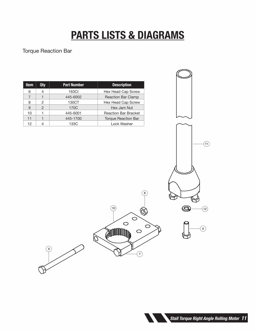
PARTS LISTS & DIAGRAMSTorque Reaction Bar
9
10
8
11
12
6
7
Item Qty Part Number Description6 4 163CI Hex Head Cap Screw7 1 445-6002 Reaction Bar Clamp8 2 130CT Hex Head Cap Screw9 2 170C Hex Jam Nut10 1 445-6001 Reaction Bar Bracket11 1 445-1700 Torque Reaction Bar12 4 133C Lock Washer

12 Stall Torque Right Angle Rolling Motor
PARTS LISTS & DIAGRAMS90 RPM Head Assembly
Item Qty Part Number Description
1 445H0090 90 RPM Head2 1 445-5011 Bearing Retainer3 1 PC80-6004ZZ Bearing 4 1 445-5003-90 90 RPM Gear
Set5 1 PC80BH-1812 Needle Bearing6 1 445-5001-90 Right Angle
Head7 1 445-5007-90 Drive Shaft8 1 PC80M-12121 Needle Bearing9 1 41-4534K39 Plug10 1 PC80R16ZZ Bearing11 1 445-5005-90 Bearing Cap12 1 128T Set Screw13 2 445-5015 Split Ring14 1 Split Ring Nut 1
2
3
4
5
6
7
4 8
9
6
14
13
10
1112

Stall Torque Right Angle Rolling Motor 13
PARTS LISTS & DIAGRAMS190 RPM Head Assembly
Item Qty Part Number Description
445H0190 190 RPM Head2 1 445-5011 Bearing Retainer3 1 PC80-6004ZZ Bearing 4 1 445-5003-190 190 RPM Gear Set5 1 PC80BH-1812 Needle Bearing6 1 445-5001-190 Right Angle Head7 1 445-5007-190 Drive Shaft8 1 PC80M-10121 Needle Bearing9 1 41-4534K39 Plug10 1 PC80-6905RS Bearing11 1 445-5005-190 Bearing Cap12 1 128T Set Screw13 2 445-5015 Split Ring14 1 445-5014 Split Ring Nut
2
3
4
5
7
48
9
6
14
13
10
1112

14 Stall Torque Right Angle Rolling Motor
PARTS LISTS & DIAGRAMSLever Throttle Assembly
Item Qty Part Number Description1 1 445-8000 Spacer
2 1 445-2000 Air Motor3 1 539R Shoulder Screw, #10-32 x 1/44 1 445-1019 Reversing Valve5 1 P8309-138 O-Ring, 3/32 x 2-1/836 1 445-1020 Spacer7 1 P8309-24 O-Ring, 1/16 x 1-1/88 1 445-1201 Lever Handle Body9 1 P8384-14 Spring Pin, 3/16 x 7/810 1 445-1208 Valve Pin11 1 445-1216 Throttle Lever12 1 P8309-118 O-Ring, 3/32 x 7/813 1 445-1002 Throttle Valve Seat14 1 445-1004 Throttle Valve
Item Qty Part Number Description15 1 37-TA-2102 Tapered Compression Spring
16 1 445-1006 Filter Screen17 2 P8286-275 Retaining Ring, Spiral,
External, 2 Turn, 2-3/418 2 P8309-38 O-Ring, 1/16 x 2-5/819 1 445-1024 Muffler20 1 445-1025 Exhaust Deflector21 1 445-1026 Exhaust Muffler Retainer22 1 445-1211 Reversing Ring23 1 445-1210 Valve Block24 1 P8309-119 O-Ring, 3/32 x 15/1625 1 445-1005 Inlet Bushing
PARTS LISTDESCRIPTIONPART NUMBERQTYITEM
SPACER445-800011AIR MOTOR445-200012SHOULDER SCREW, #10-32 X 1/4539R13REVERSING VALVE445-101914O-RING, 3/32 X 2-1/83P8309-13815SPACER445-102016O-RING, 1/16 X 1-1/8P8309-2417LEVER HANDLE BODY445-120118SPRING PIN, 3/16 X 7/8P8384-1419VALVE PIN445-1208110THROTTLE LEVER445-1216111O-RING, 3/32 X 7/8P8309-118112THROTTLE VALVE SEAT445-1002113THROTTLE VALVE445-1004114TAPERED COMPRESSION SPRING37-TA-2102115FILTER SCREEN445-1006116RETAINING RING, SPIRAL, EXTERNAL, 2 TURN, 2-3/4P8286-275217O-RING, 1/16 X 2-5/8P8309-38218MUFFLER445-1024119EXHAUST DEFLECTORE445-1025120EXHAUST MUFFLER RETAINER445-1026121REVERSING RING445-1211122VALVE BLOCK445-1210123O-RING, 3/32 X 15/16P8309-119124INLET BUSHING445-1005125
PART NO.
SUPE
RSED
ES
445-1200ST
445-
1200
STPA
RT N
O.
THIS DRAWING CONTAINS INFORMATION OF APROPRIETARY NATURE AND IS ISSUED FOR REFERENCE USE ONLY AND MAY NOT BE COPIED,REPRODUCED OR USED TO MANUFACTURE ANYTHINGSHOWN HEREON WITHOUT WRITTEN PERMISSION.
ENG
CHECK
DRAW DATE TOOL NO.
CHECK DATE PART NO.
PROJECT NO.
DESCRIPTION
MAT'L SPEC MAT'L REQUIRED
HARDNESS PROCESS SPEC
FINISH
WEIGHT (LBS.) VOLUME (CU. IN.)
TOLERANCESUNLESS OTHERWISE SPECIFIED
.XX = ±.02
.XXX = ±.005ANGLES = ±.5°
BREAK SHARP CORNERS .030" MAX.
MACHINED SURFACES - 125 MICRO. MAX.
DIMENSIONS ENCLOSED IN PARENTHESIS
ARE FOR REFERENCE ONLY
DIAMETERS ON COMMON CENTERSTO BE CONCENTRIC WITHIN .003" T.I.R.
DO NOT SCALE DRAWING
MARKING METHODM
REV ECN DATE ENG DESCRIPTION
445-1200ST
LEVER THROTTLE HANDLE, STALL TORQUE
8/20/2020
2
34
5
6
1110
9
8
1213
1415
16
17
18
19
20
18
21
17
22
2324
25
7
1

Stall Torque Right Angle Rolling Motor 15
PARTS LISTDESCRIPTIONPART NUMBERQTYITEM
SPACER445-800011AIR MOTOR445-200012SHOULDER SCREW, #10-32 X 1/4539R13REVERSING VALVE445-101914O-RING, 3/32 X 2-1/83P8309-13815SPACER445-102016ROLL HANDLE BODY445-130117DOWEL PIN, 3/16 X 5/8580-1818BALL, STEEL, 5/16109HA19VALVE PIN445-1308110O-RING, 3/32 X 7/8P8309-118111THROTTLE VALVE SEAT445-1002112THROTTLE VALVE445-1004113TAPERED COMPRESSION SPRING37-TA-2102114FILTER SCREEN445-1006115RETAINING RING, SPIRAL, EXTERNAL, 2 TURN, 2-3/4P8286-275216O-RING, 1/16 X 2-5/8P8309-38217MUFFLER445-1024118EXHAUST DEFLECTORE445-1025119EXHAUST MUFFLER RETAINER445-1026120ALIGNMENT PIN445-2009121SPRING RETAINER445-1312122SPRING37-70902123REVERSING RING445-1313124ROLL THROTTLE SLEEVE445-1316125THROTTLE RETAINER445-1315126O-RING, 3/32 X 15/16P8309-119127INLET BUSHING445-1005128
PART NO.
SUPE
RSED
ES
445-1300ST
445-
1300
STPA
RT N
O.
THIS DRAWING CONTAINS INFORMATION OF APROPRIETARY NATURE AND IS ISSUED FOR REFERENCE USE ONLY AND MAY NOT BE COPIED,REPRODUCED OR USED TO MANUFACTURE ANYTHINGSHOWN HEREON WITHOUT WRITTEN PERMISSION.
ENG
CHECK
DRAW DATE TOOL NO.
CHECK DATE PART NO.
PROJECT NO.
DESCRIPTION
MAT'L SPEC MAT'L REQUIRED
HARDNESS PROCESS SPEC
FINISH
WEIGHT (LBS.) VOLUME (CU. IN.)
TOLERANCESUNLESS OTHERWISE SPECIFIED
.XX = ±.02
.XXX = ±.005ANGLES = ±.5°
BREAK SHARP CORNERS .030" MAX.
MACHINED SURFACES - 125 MICRO. MAX.
DIMENSIONS ENCLOSED IN PARENTHESIS
ARE FOR REFERENCE ONLY
DIAMETERS ON COMMON CENTERSTO BE CONCENTRIC WITHIN .003" T.I.R.
DO NOT SCALE DRAWING
MARKING METHODM
REV ECN DATE ENG DESCRIPTION
445-1300ST
ROLL THROTTLE HANDLE, STALL TORQUE
8/20/2020
2
34
5
6
7
8
910
1112
1314
1516
17
18
19
17
20
1621
2223
24
25
2627
28
1
PARTS LISTS & DIAGRAMSRoll Throttle Assembly
Item Qty Part Number Description1 1 445-8000 Space
2 1 445-2000 Air Motor3 1 539R Shoulder Screw, #10-32 x 1/44 1 445-1019 Reversing Valve5 1 P8309-138 O-Ring, 3/32 x 2-1/836 1 445-1020 Spacer7 1 445-1301 Roll Handle Body8 1 580-18 Dowel Pin, 3/16 x 5/89 1 109HA Ball, Steel, 5/16
10 1 445-1308 Valve Pin11 1 P8309-118 O-Ring, 3/32 x 7/812 1 445-1002 Throttle Valve Seat13 1 445-1004 Throttle Valve14 1 37-TA-2102 Tapered Compression Spring15 1 445-1006 Filter Screen16 2 P8286-275 Retaining Ring, Spiral,
External, 2 Turn, 2-3/4
Item Qty Part Number Description17 2 P8309-38 O-Ring, 1/16 - 2-5/8
18 1 445-1024 Muffler19 1 445-1025 Exhaust Deflector20 1 445-1026 Exhaust Motor Retainer21 1 445-2009 Alignment Pin22 1 445-1312 Spring Retainer23 1 37-70902 Spring24 1 445-1313 Reversing Ring25 1 445-1316 Roll Throttle Sleeve26 1 445-1315 Throttle Retainer27 1 P8309-119 O-Ring, 3/32 x 15/1628 1 445-1005 Inlet Bushing

16 Stall Torque Right Angle Rolling Motor
PARTS LISTS & DIAGRAMS90 RPM Gearbox Assembly
Item Qty Part Number Description
445-4000-90 90 RPM Gearbox Assembly
2 1 445-4001 Gear Case3 1 445-4005 Second Stage Spider4 3 445-4008 Second Stage Planet Gear5 39 P8573-27 Needle Roller6 3 445-4013 Gear Pin7 1 445-4004 First Stage Spider8 3 445-4007 First Stage Planet Gear
2
3
4
5
6
7
8

Stall Torque Right Angle Rolling Motor 17
PARTS LISTS & DIAGRAMS190 RPM Gearbox Assembly
2
3
4
5
6
7
8
Item Qty Part Number Description
445-4000-190 190 RPM Gearbox Assembly
2 1 445-4001 Gear Case3 1 445-4012 Second Stage Spider4 3 445-4011 Second Stage Planet
Gear5 39 P8573-27 Needle Roller6 3 445-4013 Gear Pin7 1 445-4010 First Stage Spider8 3 445-4007 First Stage Planet Gear

18 Stall Torque Right Angle Rolling Motor
PARTS LISTS & DIAGRAMSAir Motor
PARTS LISTDESCRIPTIONPART NUMBERQTYITEM
RADIAL BALL BEARINGPC80-6000ZZ21FRONT BEARING PLATE445-200712ALIGNMENT PIN445-200913CYLINDER445-200514ROTOR ASSEMBLED445-200115SPRING PIN, 1/8 X 3/8P8382-616REAR BEARING PLATE445-200417FLEX-LOC NUT, 3/8-24P8263C18CUP POINT SET SCREW, #10-32 X 1/4128P19PADDLE445-2002510
PART NO.
SUPE
RSED
ES
445-2000
445-
2000
PART
NO.
THIS DRAWING CONTAINS INFORMATION OF APROPRIETARY NATURE AND IS ISSUED FOR REFERENCE USE ONLY AND MAY NOT BE COPIED,REPRODUCED OR USED TO MANUFACTURE ANYTHINGSHOWN HEREON WITHOUT WRITTEN PERMISSION.
ENG
CHECK
DRAW DATE TOOL NO.
CHECK DATE PART NO.
PROJECT NO.
DESCRIPTION
MAT'L SPEC MAT'L REQUIRED
HARDNESS PROCESS SPEC
FINISH
WEIGHT (LBS.) VOLUME (CU. IN.)
TOLERANCESUNLESS OTHERWISE SPECIFIED
.XX = ±.02
.XXX = ±.005ANGLES = ±.5°
BREAK SHARP CORNERS .030" MAX.
MACHINED SURFACES - 125 MICRO. MAX.
DIMENSIONS ENCLOSED IN PARENTHESIS
ARE FOR REFERENCE ONLY
DIAMETERS ON COMMON CENTERSTO BE CONCENTRIC WITHIN .003" T.I.R.
DO NOT SCALE DRAWING
MARKING METHODM
REV ECN DATE ENG DESCRIPTION
445-2000
AIR MOTOR
8/21/2020
1
2
4
5
6
7
1
89
10
3
Item Qty Part Number Description
1 2 PC80-6000ZZ Radial Ball Bearing
2 1 445-2007 Front Bearing Plate3 1 445-2009 Alignment Pin4 1 445-2005 Cylinder5 1 445-2001 Rotor Assembled6 1 P8382-6 Spring Pin, 1/8 x 3/87 1 445-2004 Rear Bearing Plate8 1 P8263C Flex-Loc Nut, 3/8-249 1 128P Cup Point Set Screw, #10-32 x 1/410 5 445-2002 Paddle

Stall Torque Right Angle Rolling Motor 19
MAINTENANCE INSTRUCTIONSThe proper performance and service life of every machine depends on how well it is maintained. The following should become a regular routine of operations.
1. It is recommended that the right angle gears receive a generous amount of No. 2 moly grease through the grease plug (located on top of right angle head) after 40 hours of operation.
2. A wire mesh screen is included in motor to prevent introduction of large debris particles into the motor. This should be checked regularly and cleaned accordingly.
3. Within the exhaust deflector is an exhaust filter. This should be checked regularly and changed accordingly. This will be dependent on the amount of lubrication used, clean lines of air, etc.
4. When changing the bearings, it is recommended to use the specially designed Bearing Seat Tool (445-7005) that is included in the Spares Kit (445SK-ST).

20 Stall Torque Right Angle Rolling Motor
WARRANTYShould any part, of Seller’s own manufacture, prove to have been defective in material or workmanship when shipped (as determined by Seller), Seller warrants that it will, at its sole option, repair or replace said part f.o.b., point of manufacture, provided that Buyer notifies, in writing, of such defect within twelve (12) months from date of shipment from the manufacturing plant.
On request of Seller, the part claimed to be defective will be returned, transportation, insurance, taxes and duties prepaid, to the factory where made, for inspection. Any item, which has been purchased by Seller, is warranted only to the extent of the original manufacturer’s warranty to Seller. Seller shall not be liable for any damages or delays caused by defective material or workmanship.
No allowance will be made for repairs or alterations made by others without Seller’s written consent or approval. If repairs or alterations are attempted without Seller’s consent, Seller’s warranty is void.
THE WARRANTIES PROVIDED IN THE OBLIGATIONS AND LIABILITIES OF SELLER HEREUNDER, AND THE RIGHTS AND REMEDIES OF BUYER HEREUNDER ARE EXCLUSIVE AND IN SUBSTITUTION FOR, AND BUYER HEREBY WAIVES ALL OTHER WARRANTIES, GUARANTEES, OBLIGATIONS, CLAIMS FOR LIABILITIES, RIGHTS AND REMEDIES, EXPRESS OR IMPLIED, ARISING BY LAW OR OTHERWISE, INCLUDING BUT NOT LIMITED TO THE IMPLIED WARRANTY FOR MERCHANTABILITY AND FITNESS FOR PURPOSE. Seller’s total liability is limited to the lower of the cost of repair or replacement.

This page intentionally left blank.

Elliott Tool Technologies, Ltd. 1760 Tuttle Avenue Dayton, Ohio 45403-3428Phone: +1 937 253 6133 • +1 800 332 0447 Fax: +1 937 253 9189www.ell iott-tool.com
Printed in the USA©08/2020 Elliott Tool Technologies, Ltd.TM-147PL-127
Elliott Tool offers a complete line of precision tube tools to meet your needs. Contact us or your local support.
Contact Us
www.elliott-tool.com/support
Locally Supported By: