3D Line Textures and the Visualization of Condence in Architecture UUCS-07-005
10
Volume xx (200y), Number z, pp. 1–10 3D Line Textures and the Visualization of Confidence in Architecture UUCS-07-005 Kristin Potter, Amy Gooch†, Bruce Gooch†, Peter Willemsen‡, Joe Kniss * , Richard Riesenfeld and Peter Shirley University of Utah † University of Victoria ‡ University of Minnesota Duluth * University of New Mexico Abstract This work introduces a technique for interactive walkthroughs of non-photorealistically rendered (NPR) scenes using 3D line primitives to define architectural features of the model, as well as indicate textural qualities. Line primitives are not typically used in this manner in favor of texture mapping techniques which can encapsulate a great deal of information in a single texture map, and take advantage of GPU optimizations for accelerated rendering. However, texture mapped images may not maintain the visual quality or aesthetic appeal that is possible when using 3D lines to simulate NPR scenes such as hand-drawn illustrations or architectural renderings. In addition, line textures can be modified interactively, for instance changing the sketchy quality of the lines, and can be exported as vectors to allow the automatic generation of illustrations and further modification in vector-based graphics programs. The technique introduced here extracts feature edges from a model, and using these edges, generates a reduced set of line textures which indicate material properties while maintaining interactive frame rates. A clipping algorithm is presented to enable 3D lines to reside only in the interior of the 3D model without exposing the underlying triangulated mesh. The resulting system produces interactive illustrations with high visual quality that are free from animation artifacts. 1. Introduction Presentation graphics are communicative illustrations often employed by architects and other design professionals to ex- press not only the features of a design or model, but also informative aspects such as material property, confidence or completion levels, and other important characteristics. These illustrations typically avoid the factual connotations associ- ated with realistic imagery and instead use rendering styles that align better with the conceptual ideas being expressed. Images that resemble photographs are often interpreted as complete and unchangeable, while loose, sketchy illustra- tions can express malleable characteristics of a model or de- sign. The degree of looseness of rendered lines is often as- sociated with the variation of characteristics within a model. This line “sketchiness” can vary within a single image, vi- sually revealing the change of a model attribute, and quickly expressing a great amount of information in a concise and compact way. An example of such an illustration can be seen in the archaeological reconstruction shown in Figure 1 which uses our technique to automatically place feature and tex- ture lines on the model, and allows a user to modify the line characteristics while walking through the scene at interac- tive frame rates. In this illustration, the sketchiness of the feature edges and material property lines is modified based on the confidence of the specific areas of the reconstruc- tion. Thus, the base of the Mayan Temple is rendered with straight, clean lines because this area of the model has the highest confidence level, while the hut at the top has a very low level of confidence and is rendered with loose, sketchy lines, and does not have any textural detail. The methods pre- sented in this paper use 3D line primitives rather than tradi- tional texture mapping in order to maintain high visual line quality, allow real-time modification of line characteristics and automatically generate vector illustrations from within an interactive walkthrough of the scene. When creating an interactive line drawing system, the fol- lowing important characteristics must be considered: 1. high visual quality of individual frames; 2. animation free of dynamic artifacts, such as popping; 3. high frame rate; and submitted to COMPUTER GRAPHICS Forum (2/2007).
-
Upload
independent -
Category
Documents
-
view
0 -
download
0
Transcript of 3D Line Textures and the Visualization of Condence in Architecture UUCS-07-005

Volume xx (200y), Number z, pp. 1–10
3D Line Textures and the Visualization ofConfidence in Architecture
UUCS-07-005
Kristin Potter, Amy Gooch†, Bruce Gooch†, Peter Willemsen‡, Joe Kniss∗, Richard Riesenfeld and Peter Shirley
University of Utah † University of Victoria ‡ University of Minnesota Duluth ∗University of New Mexico
AbstractThis work introduces a technique for interactive walkthroughs of non-photorealistically rendered (NPR) scenesusing 3D line primitives to define architectural features of the model, as well as indicate textural qualities. Lineprimitives are not typically used in this manner in favor of texture mapping techniques which can encapsulatea great deal of information in a single texture map, and take advantage of GPU optimizations for acceleratedrendering. However, texture mapped images may not maintain the visual quality or aesthetic appeal that is possiblewhen using 3D lines to simulate NPR scenes such as hand-drawn illustrations or architectural renderings. Inaddition, line textures can be modified interactively, for instance changing the sketchy quality of the lines, and canbe exported as vectors to allow the automatic generation of illustrations and further modification in vector-basedgraphics programs. The technique introduced here extracts feature edges from a model, and using these edges,generates a reduced set of line textures which indicate material properties while maintaining interactive framerates. A clipping algorithm is presented to enable 3D lines to reside only in the interior of the 3D model withoutexposing the underlying triangulated mesh. The resulting system produces interactive illustrations with high visualquality that are free from animation artifacts.
1. Introduction
Presentation graphics are communicative illustrations oftenemployed by architects and other design professionals to ex-press not only the features of a design or model, but alsoinformative aspects such as material property, confidence orcompletion levels, and other important characteristics. Theseillustrations typically avoid the factual connotations associ-ated with realistic imagery and instead use rendering stylesthat align better with the conceptual ideas being expressed.Images that resemble photographs are often interpreted ascomplete and unchangeable, while loose, sketchy illustra-tions can express malleable characteristics of a model or de-sign. The degree of looseness of rendered lines is often as-sociated with the variation of characteristics within a model.This line “sketchiness” can vary within a single image, vi-sually revealing the change of a model attribute, and quicklyexpressing a great amount of information in a concise andcompact way. An example of such an illustration can be seenin the archaeological reconstruction shown in Figure 1 whichuses our technique to automatically place feature and tex-
ture lines on the model, and allows a user to modify the linecharacteristics while walking through the scene at interac-tive frame rates. In this illustration, the sketchiness of thefeature edges and material property lines is modified basedon the confidence of the specific areas of the reconstruc-tion. Thus, the base of the Mayan Temple is rendered withstraight, clean lines because this area of the model has thehighest confidence level, while the hut at the top has a verylow level of confidence and is rendered with loose, sketchylines, and does not have any textural detail. The methods pre-sented in this paper use 3D line primitives rather than tradi-tional texture mapping in order to maintain high visual linequality, allow real-time modification of line characteristicsand automatically generate vector illustrations from withinan interactive walkthrough of the scene.
When creating an interactive line drawing system, the fol-lowing important characteristics must be considered:
1. high visual quality of individual frames;2. animation free of dynamic artifacts, such as popping;3. high frame rate; and
submitted to COMPUTER GRAPHICS Forum (2/2007).

2 Potter et al. / 3D Line Textures and the Visualization ofConfidence in ArchitectureUUCS-07-005
4. ability to directly create manipulatable 2D illustrations.
The first two items suggest using 3D line primitives, as theycan be anti-aliased in screen space, thus producing high vi-sual quality. In addition, line primitives do not need level-of-detail management to maintain constant width or bright-ness in screen space. However, it is natural to think that inte-rior lines should be rendered using texture mapping for effi-ciency. Indeed, texture mapping has been used effectively toaccomplish interior line rendering by others [FMS01], whoused careful generation of MIP mapped line textures to avoiddynamic artifacts. Unfortunately, this technique makes theline textures static, so line sketchiness cannot be varied atruntime. Also, texture mapping does not allow for the directcreation of 2D illustrations. Our method directly generatespostscript illustrations in which each texture and feature linecan be manipulated after creation.
The question remains whether 3D line primitives can beused while maintaining an interactive frame rate. Althoughlines are not used in most graphics programs, they are highlyoptimized by hardware makers because of the CAD market.Using lines directly has several advantages over texture map-ping:
• line primitives can be anti-aliased without a multi-pass al-gorithm
• line primitives can have their sketchiness varied at runtimeby perturbing vertices in a hardware vertex program
• line primitives preserve their width in screen space evenfor extreme close-ups.
The last item could be viewed as an advantage or a disad-vantage depending on one’s priorities; having constant widthlines in screen-space makes for a clean drawing reminiscentof the type drawn by human draftsmen, but exchanges line-
Figure 1: An example illustration from an interactive ses-sion of an archaeological reconstruction with the sketchi-ness of the line primitives varied according to the level ofconfidence in the data. The base of the structure is renderedusing clean lines, the midsection is rendered with a sketchyline texture, and the “top hut” is a matter of conjecture andis rendered without texture and very sketchy feature lines.
width depth cues for line-density depth cues, which can bevisually distracting.
This paper’s main contributions are creating a systemthat allows for the automatic placement of texture across amodel, the interactive manipulation of viewpoint in a 3Dscene, and the creation of 2D vector illustrations. The suc-cess of the system is demonstrating that high frame rates canbe achieved using line primitives in scenes of realistic com-plexity. An algorithm is provided to automatically place linetextures on objects in order to perform material property “in-dication,” i.e., a small number of texture elements indicatesthe material properties of the entire surface. Finally, we showthat an interactive system using 3D lines is relatively simpleto design and build, making line primitives a practical alter-native to texture mapping with respect to software engineer-ing as well as efficiency issues.
2. Background
The style of illustration used to create an image has a pro-found effect on the interpretation of that image [SPR∗94].Photographic images, like the ones traditionally generatedby computers, give the sense that the scene is complete andunchangeable, not inviting discussions about design, or indi-cating the actual confidence level of the underlying model.Conversely, hand-drawn illustrations have a transient qual-ity, the viewer is more comfortable talking about modifica-tions to the scene [SSRL96], and is often more actively en-gaged with the image. Because of the difference in the effectof rendering style, determining which style to use is veryimportant. It is also possible to use multiple styles withina single image, allowing for differing interpretations acrossthe image [SMI99].
In addition to decisions on rendering style, specific fea-tures of a scene must be identified in order to create acommunicative illustration. Feature lines such as silhou-ettes, creases, boundary and contour edges aid in the un-derstanding of geometric shape and should be accented[ST90, SFWS03]. Likewise, how these lines are accented,as well as how other lines in the illustration appear is criti-cal. For instance, in line drawings, the type of line, such asdashed, dotted, thick or thin, can express direction, distanceand location, and end conditions can convey the relation ofthe line with respect to other lines and surfaces in the scene[DC90]. Such conventions are standard in hand-drawn illus-trations, and can be adopted for use in computer generatedimagery.
Translating artistic techniques from the human hand toa computer process requires that inherent characteristicsof the traditional media be explicity defined. There hasbeen much work in simulating charcoal, ink, watercolor,and other artistic mediums on the computer [GG01, SS02].These methods simulate the variations in thickness, wavi-ness, weight, and direction of the marks left by the media, as
submitted to COMPUTER GRAPHICS Forum (2/2007).

Potter et al. / 3D Line Textures and the Visualization ofConfidence in ArchitectureUUCS-07-005 3
well as their interaction with paper or canvas. Typically, thestrokes left by artistic techniques are texture mapped ontothe model. Alternatively, actual geometry can be used inthe form of graftals, a method which randomly places parti-cles across a surface, from which artistic details can “grow”[KMN∗99, KGC00, MMK∗00]. While the physical simula-tion of the physical properties of artistic media is challeng-ing, a harder problem is simulating the artistic hand.
It is very difficult to completely automate where an artistplaces strokes, and most systems rely on human interactionto aid in the generation of illustrations. For example, in workby Salisbury et al. [SABS94, SWHS97], the user controlswhere collections of strokes are placed on a model by “paint-ing” on areas of interest. The Piranesi system [Sch96, RS95]allows users to paint artistic effects onto CAD models, creat-ing images that are closer to the images handmade by archi-tectural designers. The SKETCH system [ZHH96] uses ges-tural input as a method for modeling, simulating the artistsketching out a preliminary design on paper. Dollner andWalther [DW03] create a system that uses not only NPRtechniques, but also cartographic and cognitive principlesto render 3D city models with enhanced feature edges, twoor three-tone shading, texture mapped details and simulatedshadows. These types of systems aid in creating images thatmaintaining a human quality and allow for computer specificadditions such as walkthroughs and interactive revisions.
Many interactive NPR algorithms suffer from a lack offrame-to-frame coherence in which the texture or geometryused to express the artistic detail pops in or out of the scene,or the strokes do not match up from one frame to another.This problem arises from the fact that the artistic techniquesbeing simulated are meant to be seen as a single instance,rather than in repetition. Solutions to this problem involvefading detail into the background [MMK∗00], or variationson texture and MIP mapping techniques. Texture mappinghardware can be used to maintain tone and detail via hatchand ink maps [FMS01], as well as to add fine tone controland reduce aliasing artifacts [WPFH02]. Maintaining coher-ence in an image based approach can be done by using artmaps which maintain the width of NPR strokes in the scene,and rip maps eliminate artifacts that occur at oblique viewingangles [KLK∗00].
The approach presented in this paper is novel in its useof three dimensional line primitives as an alternative to tex-ture mapping. Line primitives have an advantage in thatthey maintain constant screen space throughout an interac-tive session, and require no special algorithms to preserveframe-to-frame coherence. Feature edges and texture are ex-pressed through the placement of the 3D lines which is doneautomatically. Similarly to the approach by [WS94], textureis placed densely so as to accent feature edges, and sparselyacross the rest of the model to “indicate” the texture. To cre-ate a hand-drawn quality and describe confidence levels inthe underlying model, the endpoints of the lines can be in-
Figure 2: Texture is increased around crease and boundaryedges to enhance the features of the model.
teractively perturbed using graphics hardware, a feature thatis difficult to achieve using texture mapping. Another bene-fit of using 3D line primitives to express model boundaries,features and texture is the ability to output 2D vector illustra-tions, allowing for scale, resolution, and display independentreproduction [SALS96].
3. Algorithm
The algorithm presented here to create renderings with tex-ture indicated by 3D lines consists of preprocessing themodel to find important edges, determining the placementof and laying the texture, and finally clipping the textureto the model. New techniques include using 3D lines asan alternative to texture mapping, automating the indica-tion of texture such that texture is minimized and placedsparsely across the model as well as along important edges,and creating sketchy lines through vertex programs. The sys-tem uses simple algorithms and currently supports a vari-ety of textures such as bricks, stone work, shingles, thatch,stucco, and siding, while other materials could easily be sup-ported [Yes79, Miy90].
3.1. Feature Edge Detection
An important cue to understanding the shape of an archi-tectural model is emphasizing feature edges [ST90]. Theseedges include outlines separating the model from space,creases distinguishing interior features, and boundaries be-tween materials. To find feature edges in the triangulatedmesh used to represent the model, the model is first divided
submitted to COMPUTER GRAPHICS Forum (2/2007).

4 Potter et al. / 3D Line Textures and the Visualization ofConfidence in ArchitectureUUCS-07-005
Figure 3: A model with silhouette feature edges. Since thetexturing algorithm is a pre-process, texture is neither popu-lated nor clipped against silhouette edges (left). Adding sil-houette edges aides in the understanding of the model, with-out needing to modify the texture algorithm.
into material groups such as bricks or grass. The test foroutlines and material boundaries is then simplified into abrute force search for edges contained in only a single poly-gon. The search for crease edges identifies edges that adjointwo polygons whose surface normals have a dihedral anglegreater than θ, for some threshold value of θ. The featureedges are then explicitly drawn with a 3D line and texture isplaced at a higher density close to these important areas asillustrated in Figure 2.
Because the feature edge and texture generation algo-rithms are designed as pre-processes, view-dependent sil-houette edges (i.e., edges between front facing and back fac-ing polygons) are not accented with texture. This raises prob-lems for models, such as the one shown in Figure 3 that haveborder edges that can only be defined as silhouettes. In suchmodels, texture is not populated or clipped about silhouettefeature edges, which does not emphasize the feature edgeand texture can possibly lie outside of the model. Movingthe texture generation process to runtime would allow sil-houette lines to be treated as stationary feature edges, how-ever, the texture lines would need to be recalculated eachtime the viewpoint changed, leading to disturbing artifactsbetween frames. While there is no obvious solution to thetexturing problem, 3D silhouette edges can be added as ahardware process at runtime, as shown in Figure 3, right, al-lowing such models to be displayed in our system.
3.2. Texture Generation
Line texture synthesis across interior surfaces is carried outaccording to a heuristic that thresholds Perlin solid noise[Per85] to place clusters of texture. An atomic texture ele-ment (e.g., a single brick or blade of grass) is placed on thetriangle if the function:
1+3× N(kx,ky,kz)2
,
is above a threshold, (where N is the Perlin function).This function gives a uniformly random distribution of tex-
Figure 4: The texture generation process. Top left: textureis placed along feature edges. Top right: atomic texture el-ements are placed based on Perlin noise. Bottom left: tex-ture is clustered about the atomic elements. Bottom right: acomplete textured cube with clipping (note: due to randomselection of texture library elements, actual texture elementplacement varies.)
ture without excessive accumulations or concentrations. Thethreshold can be changed to allow more or less texture onany portion of a model.
The algorithm for texture placement iterates through thetexture space of the model, calculating the noise function ateach location where texture would be placed for full cov-erage of texture on the model. If the noise function returnsa value indicating that the location should be textured, thetexture lines corresponding to an atomic texture element aretransformed into model space. Feature edges are embeddedinto the noise function such that the return value always in-dicates that these areas should be textured. The top two im-ages in Figure 4 demonstrate this initial texture placement.On the left, texture is placed along the feature edges; on theright atomic texture elements (in red) are placed throughoutthe interior of the model.
Once an atomic texture element is placed, a texture clusteris populated around it. A texture cluster is a pleasing groupof texture elements. The aesthetic quality of these group-ings is critical to creating a good image. While automaticgeneration is possible, we have found that the criteria forwhat makes a good texture cluster are not obvious. Thus,we created a library of human generated clusters that arereused. The bottom images in Figure 4 show the final stagesof texture placement. On the left, texture is clustered aroundatomic elements, and on the right is the final, clipped result,with enough texture added to pleasingly cover the surface.
submitted to COMPUTER GRAPHICS Forum (2/2007).
Potter et al. / 3D Line Textures and the Visualization ofConfidence in ArchitectureUUCS-07-005 5
A side-effect of the texture library is the repetition of textureelements, especially in very regular textures such as brick.This occurs when the texture clusters generated by the li-brary place texture elements on top of already placed tex-ture. The drawback is that this increases the line count, andmay effect performance, however this does not occur on ran-dom textures such as the grass, which make up the bulk oftexture lines. While these repetitive lines can easily be re-moved through a pre-process sort, we have chosen to keepthe duplicate lines, since they are perturbed independentlywhen the sketchiness is increased. This results in a qualitythat more closely resembles hand-drawn, since an artist willoften draw repetitive lines when sketching.
4. Texture Clipping
Following the placement of the texture lines on the model,all lines are clipped against the crease and boundary edgesof the model. Clipping against the feature edges maintainsthe unity of the model, while clipping against single trian-gles would reveal the underlying triangulation. Thus, clip-ping is performed after all texture has been generated. How-ever, clipping 3D lines against the 3D feature edges is not atrivial task.
The algorithm to clip texture along feature edges can bebroken into two steps. First, all texture lines that are com-pletely outside of the model are removed. Second, the re-maining texture lines are clipped against the feature edges.
4.1. Outside Line Removal
The main goal of the texturing algorithm is to maintain visu-ally appealing texture across the model. To hide the triangu-lation of the underlying representation, texture lines extendacross the boundaries of the generating triangle and are of-ten drawn completely outside of the model. These exteriorlines will not be removed by the clipping algorithm sincethey do not intersect any feature edges. Instead, every tex-ture line must be tested against every triangle in the modelto determine if either endpoint is contained by the model.
The first step in removing outside edges is to find the dis-tance, d, from the texture line, l, to the current triangle witha vertex tx, and normal N:
d = min((lx − tx) ·N
||N||,
(ly − tx) ·N||N||
). (1)
If the distance is close to zero, the endpoints of the textureline are projected onto the plane of the triangle, by first cre-ating two directed lines from the endpoints of the textureline pointing in the direction of the triangle normal. Each ofthese directed lines, w, are intersected with the plane of thetriangle described by the triangle normal, N, and a point inthe triangle, p:
u =(p−wx) ·N(wy −wx) ·N
.
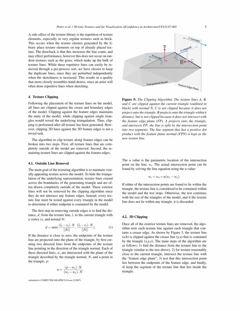
Figure 5: The Clipping Algorithm. The texture lines A, B,and C are clipped against the current triangle (outlined inblack) with normal N. C is not clipped because it does notproject onto the triangle. B projects onto the triangle within εdistance, but is not clipped because it does not intersect withthe feature edge plane (FP). A projects onto the triangle,and intersects FP; the line is split by the intersection pointinto two segments. The line segment that has a positive dotproduct with the feature plane normal (FPN) is kept as thenew texture line.
The u value is the parametric location of the intersectionpoint on the line, wi. The actual intersection point can befound by solving the line equation using the u value:
wi = wx +u(wy −wx).
If either of the intersection points are found to lie within thetriangle, the texture line is considered to be contained withinthe model and the test stops. Otherwise, the test continueswith the rest of the triangles of the model, and if the textureline does not lie within any triangle, it is discarded.
4.2. 3D Clipping
Once all of the exterior texture lines are removed, the algo-rithm tests each texture line against each triangle that con-tains a crease edge. As shown by Figure 5, the texture line(a,b) is clipped against the crease line (y,z) that is containedby the triangle (x,y,z). The main steps of the algorithm areas follows: 1) find the distance from the texture line to thetriangle (similar to the test above), 2) for texture reasonablyclose to the current triangle, intersect the texture line withthe “feature edge plane”, 3) test that this intersection pointlies between the endpoints of the feature edge, and finally,4) keep the segment of the texture line that lies inside thetriangle.
submitted to COMPUTER GRAPHICS Forum (2/2007).

6 Potter et al. / 3D Line Textures and the Visualization ofConfidence in ArchitectureUUCS-07-005
4.2.1. Distance Test
The first step in 3D clipping is to determine the distance fromthe texture line to the current triangle using Equation 1. Tex-ture lines will only be clipped by feature edges that are spa-tially close (i.e. the distance function is within some thresh-old). This eliminates “ghosting” effects that occur when tex-ture lines are clipped by distant feature edges.
4.2.2. Find Feature Edge Plane
The next step in the clipping algorithm is to find the “featureedge plane” (FP). This is the plane that contains the featureedge, and is perpendicular to the triangle. It is defined by tak-ing the cross product of the feature edge, f , and the trianglenormal, N, (i.e. FP = f ×N). The normal to the feature edgeplane should point into the triangle, making the dot productof the feature plane normal with an edge of the triangle pos-itive. In the case in which it is not, the feature edge planenormal is flipped.
4.2.3. Intersect Feature Edge Plane
The next step is to intersect the texture line with the featureedge plane. This intersection point will be the new endpointof the texture line, however we must test that this intersectionline actually lies between the endpoints of the feature edge.To do this, we project the intersection point onto the triangleplane by intersecting the line formed using this intersectionpoint and the triangle normal, with the triangle plane. Thisgives a new intersection point that lies along the intersectionline of the crease plane and triangle plane. To determine ifthe intersection point lies inside the crease edge, two vectorsare formed using each crease line endpoint, and the intersec-tion point that lies on the triangle plane. The dot product ofthese two vectors is taken, and if the dot product is zero, thenwe know the intersection point is within the crease line.
Once it has been found that the texture line should beclipped by the crease plane, which segment of the textureline to discard must be determined. This is done by formingtwo new vectors, using the endpoints of the texture line andthe new crease plane intersection point. These vectors willpoint in opposite directions. The dot product of the creaseplane normal and the two new vectors is computed, with thevector resulting in a positive dot product kept as the new tex-ture line, and the rest of the line thrown out.
4.3. Vertex Perturbation
Once all of the lines of a texture have been placed andclipped, it is possible to adjust the sketchiness of the lines.To achieve “sketchiness” the endpoints of the texture andfeature edge lines are randomly perturbed. A sketchy qual-ity of the lines adds to the hand-drawn look of the imagery,and can be modified independently in different areas of themodel, allowing each area to have a unique sketchy qualityand maintain the unity of the scene. It is hard to determine
Figure 6: Four levels of sketchiness.
the amount of sketchiness desired for the model, so allowingthe user to modify the sketch quality parameter is desirable.Examples of varying levels of sketchiness are shown in Fig-ure 6.
Using a hardware vertex program coded with the OpenGLShading Language, the modification of the original line tex-ture to sketchy lines can be done interactively. The goal ofour vertex program is to maintain the basic line texture struc-ture while adding a slight random offset to the original ver-tices. For each line vertex, the vertex program generates aperturbed line vertex coordinate by adding a perturbationvector to the original vertex. This 3D vector is randomlygenerated and stored in the multi-texture coordinate vertexattribute during the creation of the line texture vertex buffers.We also set the normal vector for each vertex to be the nor-mal of the face on which the line texture is being rendered.These are the only vertex attributes that need to be set for thevertex program to execute.
Once running, the vertex program projects the randomperturbation vector onto the plane determined by the nor-mal, and then uses this projected vector to slightly changethe location of the original vertex. The projection computa-tion forces the modified vertices to remain in the plane ofthe polygon in which the line texture resides. To remove z-fighting, we also add a small offset in the direction of the facenormal to lift the vertex off the surface slightly. We do notperform additional clipping at this stage to stop sketchy linesfrom extruding outside of the polygon face. The OpenGLShading Language code to modify the vertices of our linetextures can be found in the appendix. The fragment pro-gram used in our implementation simply sets the input coloras the output fragment color.
submitted to COMPUTER GRAPHICS Forum (2/2007).

Potter et al. / 3D Line Textures and the Visualization ofConfidence in ArchitectureUUCS-07-005 7
4.4. Creating Two Dimensional Illustrations
Representing feature edges and texture as 3D line primitivesallows the direct creation of 2D vector illustrations. This isespecially useful for fine manipulation of the illustration af-ter creation. The creation of a two dimensional illustration isstraightforward. Once the user chooses a suitable viewpointin the 3D scene, GL2PS [Geu] is used to convert the lineprimitives to vectors.
5. Discussion
Using only the indication of texture in which the materialproperties are hinted at rather than fully illustrated is in-triguing for the viewer. Large amounts of line textures aredistracting, and the imagination of the viewer is engaged tofill in the texture where it is omitted. In addition, the num-ber of lines used to suggest texture is reduced, which helpsmaintain performance. Implementing indication automati-cally is a difficult problem because it is hard for artists todescribe the process of deciding where to place texture. Inprevious implementations, systems have relied on the artistto input areas of the model that should be enhanced by tex-ture [WS94]. Looking at the images created by these sys-tems, it seems that the feature edges are common areas toreceive more texture. Although feature edges may not be theonly such areas to receive texture indication, this method en-hances feature edges because they are so often enhanced byartists. It has also been shown that the enhancement of theseedges aids in the understanding of the model. Additionally,material boundaries are typically enhanced by more textureindication, another phenomenon captured by this implemen-tation. The remaining areas of the model receive sparse tex-ture to reduce clutter, increase efficiency and maintain aclean look [Lin97].
An interesting feature of our texture placement algorithmis maintaining the density of the texture with distance. Thisapproach allows the tone of the image to vary with depth soobjects farther away will have a higher texture density andthus a darker tone, which can be seen in Figure 7, left. Thetone of the image can be thought of as the ratio of blackink to white paper. Allowing the tone to vary is a methodoften adopted by artists to create the illusion of depth in theimage. Traditionally computer graphics techniques decimatetexture density with distance to maintain tone across an im-age. Thus, the density of texture on an object in the fore-ground would be at a level equal to the density of textureon a distant object. This is done to preserve the visual ap-peal of the image because the texture in the background canquickly become too dense, creating a very dark tone that isdistracting and unappealing. However, removing texture canbe perceptually confusing and lead to misperceived distance,results that conflict with the goals of this system. Thus, theimplementation presented herein does not eliminate texturein the distance. A benefit of using indication is that in the dis-tance, the texture density is still lower than if the entire sur-
Figure 7: An example of a fully textured wall whose tonegets too dark in the distance. While this implementation usesindication to lessen the amount of texture, and thus reducethe problem of dark tone in the distance, we also use coloredlines which eases the problem of tone in the distance.
face was textured. This keeps the tone at an appealing levelthroughout the scene while preserving the property that thetone is darker in the distance. A possible drawback to thisapproach is that the size of the environments is limited. Theassumption that partial textures will maintain appeal at fardistances may not hold when the model becomes very largeand extend a long way into the distance. The lines used toconvey the texture are colored lines which are not as distract-ing as black lines when grouped tightly, and may not be asunappealing in the background, as shown in Figure 7, right.Artists, instead of removing texture in the distance, will usea lighter line when drawing texture in the background. Thus,a possible solution for a texture density that is too high in thedistance is to fade with distance the lines that make up thetexture.
Another addition to the system to aid in aesthetic appealis entourage. Entourage refers to the use of familiar objectsof known size in the scene and is used to create the effect ofscale [Bur95]. The system uses hand-generated people andtrees, which are placed in non-distracting areas of the scenesuch as near a corner of a building or in the background. Tomaintain the overall look, the trees resemble the pen and inktrees of Deussen [DS00].
6. Implementation
Scene Polygons Line Count frames/secMayan Temple 1,259 58,276 149.1Castle 9,734 27,910 102.4Olympic Village 20,467 1,054,559 11.0
Table 1: Polygon count, line count, and frame display timesaveraged across 125 frames for interactive walkthroughs us-ing our system at an image resolution of 1000x1000.
Our system runs on a dual-core, 3.0GHz Intel PentiumD machine with 2GB RAM and an NVIDIA GeForce 7800
submitted to COMPUTER GRAPHICS Forum (2/2007).

8 Potter et al. / 3D Line Textures and the Visualization ofConfidence in ArchitectureUUCS-07-005
GTX graphics co-processor. The implementation is fairlystraightforward, requiring approximately 3000 lines of code.The code is written in C++ using OpenGL libraries. The sys-tem’s only drawing primitives are 3D constant-colored linesand 3D constant-colored polygons. Table 1 gives the poly-gon and line count as well as frame rates for a 1000x1000pixel image. Figure 8 shows screen shots of an interactivesession of our system using a model of the Salt Lake CityOlympic Village.
7. Future Research
We have shown that interactive frame rates can be achievedusing line primitives on scenes of realistic complexity. Theapproach presented is a nice alternative to texture mappingin that it is easy to implement, automates the indication oftexture, allows for the runtime manipulation of the sketchyquality of the lines, and can be used as vector graphics toautomatically produce 2D illustrations.
There are several further directions of research stemmingfrom our system. First, it may be possible to use fewer lineelements to indicate the material properties of a surface.Such an investigation is likely to involve perceptual psychol-ogists. Alternative methods for texture placement could beinvestigated; perceptually or artistically based noise func-tions could be used instead of Perlin noise. The entourageelements are static 2D billboards. Depending on the appli-cation, 3D models or animated billboards could be used,or moved about in the scene. Finally, we have avoided theLOD management issue by limiting ourselves to medium-scale environments. For very large sized environments, someLOD management system may be needed.
8. Conclusion
When creating renderings that simulate hand-drawn illustra-tions, line quality and aesthetic appeal are important. Thesecharacteristics are difficult to achieve using texture mappingtechniques. 3D line primitives, however, maintain high vi-sual quality independent of viewpoint, suggest the aestheticnature of hand-drawn illustration, are free of dynamic arti-facts and can be manipulated in an interactive setting.
9. Acknowledgments
This work was supported in part by NSF grant (03-12479).All opinions, ndings, conclusions or recommendations ex-pressed in this document are those of the author and do notnecessarily reect the views of the sponsoring agencies.
References
[Bur95] BURDEN E. E.: Entourage: A Tracing File forArchitects and Interior Design. McGraw-HillProfessional Publishing, 1995. 7
[DC90] DOOLEY D., COHEN M. F.: Automatic illus-tration of 3d geometric models: Lines. In Pro-ceedings of the Symposium on Interactive 3DGraphics (1990), pp. 77–82. 2
[DS00] DEUSSEN O., STROTHOTTE T.: Computer-generated pen-and-ink illustration of trees. InProceedings of ACM SIGGRAPH 2000 (2000),pp. 13–18. 7
[DW03] DOLLNER J., WALTHER M.: Real-time ex-pressive rendering of city models. In Proceed-ings of Information Visualization 2003 (2003),pp. 245–250. 3
[FMS01] FREUDENBERG B., MASUCH M.,STROTHOTTE T.: Walk-through illustra-tions: Frame-coherent pen-and-ink style in agame engine. Computer Graphics Forum: Pro-ceedings of Eurographics 2001 20, 3 (2001),184–191. 2, 3
[Geu] GEUZAINE C.: Gl2ps: an opengl to postscriptprinting library. http://www.geuz.org/gl2ps/. 7
[GG01] GOOCH B., GOOCH A.: Non-PhotorealisticRendering. A.K. Peters, 2001. 2
[KGC00] KAPLAN M., GOOCH B., COHEN E.: Interac-tive artistic rendering. In Proceedings of the 1stInternational Symposium on Non-PhotorealisticAnimation and Rendering (2000), pp. 67–74. 3
[KLK∗00] KLEIN A. W., LI W. W., KAZHDAN
M. M., CORREA W. T., FINKELSTEIN
A., FUNKHOUSER T. A.: Non-photorealisticvirtual environments. In Proceedings ACMSIGGRAPH 2000 (2000), pp. 527–534. 3
[KMN∗99] KOWALSKI M. A., MARKOSIAN L.,NORTHRUP J., BOURDEVY L., BARZEL
R., HOLDEN L. S., HUGHES J. F.: Art-based rendering of fur, grass, and trees. InProceedings of ACM SIGGRAPH 99 (1999),pp. 433–438. 3
[Lin97] LIN M. W.: Drawing and Designing With Con-fidence : A Step-By-Step Guide. John Wiley &Sons, 1997. 7
[Miy90] MIYATA K.: A method of generating stone wallpatterns. In Proceedings of ACM SIGGRAPH90 (1990), pp. 387–394. 3
[MMK∗00] MARKOSIAN L., MEIER B. J., KOWALSKI
M. A., HOLDEN L. S., NORTHRUP J. D.,HUGHES J. F.: Art-based rendering withcontinuous levels of detail. In Proceedingsof the 1st International Symposium on Non-Photorealistic Animation and Rendering (NPAR2000) (2000), pp. 59–66. 3
submitted to COMPUTER GRAPHICS Forum (2/2007).

Potter et al. / 3D Line Textures and the Visualization ofConfidence in ArchitectureUUCS-07-005 9
Figure 8: Screen shot of an interactive session using the Olympic Village model
[Per85] PERLIN K.: An image synthesizer. In ComputerGraphics, Vol. 19, No. 3. (1985), pp. 287–296.4
[RS95] RICHENS P., SCHOFIELD S.: Interactive com-puter rendering. Architectural Research Quar-terly 1, 1 (1995), 1–18. 3
[SABS94] SALISBURY M. P., ANDERSON S. E., BARZEL
R., SALESIN D. H.: Interactive pen-and-ink il-lustration. In Proceedings of ACM SIGGRAPH94 (1994), pp. 101–108. 3
[SALS96] SALISBURY M., ANDERSON C., LISCHINSKI
D., SALESIN D. H.: Scale-dependent reproduc-tion of pen-and-ink illustrations. In Proceedingsof ACM SIGGRAPH 96 (1996), pp. 461–468. 3
[Sch96] SCHOFIELD S.: Piranesi: A 3-d paint system. InEurographics UK 96 Conference Proceedings(1996). 3
[SFWS03] SOUSA M. C., FOSTER K., WYVILL B.,SAMAVATI F.: Precise ink drawing of 3d mod-els. Computer Graphics Forum 22, 3 (2003),369–379. 2
[SMI99] STROTHOTTE T., MASUCH M., ISENBERG T.:Visualizing knowledge about virtual reconstruc-tions of ancient architecture. In Proceedings ofComputer Graphics International (June 1999),pp. 36–43. 2
[SPR∗94] STROTHOTTE T., PREIM B., RAAB A., SCHU-MANN J., FORSEY D. R.: How to render
frames and influence people. Computer Graph-ics Forum, Proceedings of EuroGraphics 199413, 3 (1994), 455–466. 2
[SS02] STROTHOTTE T., SCHLECHTWEG S.: Non-Photorealistic Computer Graphics. Modelling,Animation, and Rendering. Morgan Kaufmann,2002. 2
[SSRL96] SCHUMANN J., STROTHOTTE T., RAAB A.,LASER S.: Assessing the effect of non-photorealistic rendered images in cad. In Pro-ceedings of the SIGCHI Conference on Hu-man Factors in Computing Systems: CommonGround (1996), pp. 35–41. 2
[ST90] SAITO T., TAKAHASHI T.: Comprehensiblerendering of 3-d shapes. Proceedings of ACMSIGGRAPH 90 24, 4 (1990), 197–206. 2, 3
[SWHS97] SALISBURY M. P., WONG M. T., HUGHES
J. F., SALESIN D. H.: Orientable texturesfor image-based pen-and-ink illustration. InProceedings of ACM SIGGRAPH 97 (1997),pp. 401–406. 3
[WPFH02] WEBB M., PRAUN E., FINKELSTEIN A.,HOPPE H.: Fine tone control in hardware hatch-ing. In Proceedings of the 2nd InternationalSymposium on Non-Photorealistic Animationand Rendering (NPAR 2002) (2002), pp. 53–58.3
[WS94] WINKENBACH G., SALESIN D. H.: Computer-
submitted to COMPUTER GRAPHICS Forum (2/2007).

10 Potter et al. / 3D Line Textures and the Visualization ofConfidence in ArchitectureUUCS-07-005
generated pen-and-ink illustration. In Proceed-ings of ACM SIGGRAPH 94 (1994), pp. 91–100. 3, 7
[Yes79] YESSIOS C. I.: Computer drafting of stones,wood, plant and ground materials. 190–198. 3
[ZHH96] ZELEZNIK R. C., HERNDON K. P., HUGHES
J. F.: Sketch: An interface for sketching 3dscenes. In Proceedings of ACM SIGGRAPH 96(1996), pp. 163–170. 3
Appendix: OpenGL Shading Language Vertex Program
uniform float k;void main(void){
vec3 face_normal = vec3(gl_Normal);normalize(face_normal);
vec3 perturb = vec3(gl_MultiTexCoord1.x,gl_MultiTexCoord1.y, gl_MultiTexCoord1.z);
normalize(perturb);
vec3 v = cross(face_normal, perturb);vec3 u = cross(face_normal, v);mat3 plane = mat3(u, v, face_normal);mat3 plane_inv = mat3(u.x, v.x, face_normal.x,
u.y, v.y, face_normal.y,u.z, v.z, face_normal.z);
mat3 ortho_proj = mat3(1.0, 0.0, 0.0,0.0, 1.0, 0.0, 0.0, 0.0, 0.0);
perturb = plane_ori * ortho_proj * plane * perturb;normalize(perturb);
vec3 mod_v = vec3(gl_Vertex) + k * (perturb * 0.1) +(face_normal * 0.01);
gl_Position = gl_ModelViewProjectionMatrix *vec4(mod_v, 1.0);
gl_FrontColor = gl_Color;}
submitted to COMPUTER GRAPHICS Forum (2/2007).