
30GTN PRODUCT DATA.pdf
32
Copyright 1999 Carrier Corporation Form 30GTN-2PD Features/Benefits • Simple and easy to use ComfortLink™ communicating controls • Wide operating envelope from –28 to 52 C (–20 to 125 F). • Accurate temperature control with return fluid compensation. • Value added features built-in; dual chiller control, reset from return. • Precise multiple-step capacity. ComfortLink control Your link to a world of simple and easy to use air-cooled chillers that offer out- standing performance and value. The 30GTN liquid chillers employ more than the latest advanced microproces- sor controls, they utilize an expandable platform that grows as your needs change. From stand-alone operation to remotely monitored and operated multi-chiller plants, ComfortLink con- trols can keep you plugged in. ComfortLink controls are fully communicating, and are cable ready for connection to a Carrier Comfort Network (CCN). Occupancy schedul- ing, temperature and pressure read-outs, and the ComfortLink scroll- ing marquee clear language display complement the standard features, linking you to a world of carefree com- fort. The 30GTN chillers are built on the legendary performance of the Carrier model 30G Flotronic™ chiller and share many of the same time-prov- en features and technologies providing easy operation, quick installation, and start-ups that save you money! Superior temperature control equals potential for greater productivity Whether in the classroom, on the pro- duction floor, or in the office, ComfortLink controls can help you to adapt to changing weather and 30GTN Packaged Air-Cooled Reciprocating Chillers 50/60 Hz 60 Hz — 15 to 35 Nominal Tons (53 to 123 Nominal kW) 50 Hz — 15 to 30 Nominal Tons (53 to 106 Nominal kW) Product Data MODEL 30GTN (025 Shown)
-
Upload
khangminh22 -
Category
Documents
-
view
2 -
download
0
Transcript of 30GTN PRODUCT DATA.pdf

Copyright 1999 Carrier Corporation Form 30GTN-2PD
Features/Benefits• Simple and easy to use
ComfortLink™ communicatingcontrols
• Wide operating envelope from –28to 52 C (–20 to 125 F).
• Accurate temperature control withreturn fluid compensation.
• Value added features built-in; dualchiller control, reset from return.
• Precise multiple-step capacity.ComfortLink controlYour link to a world of simple and easy to use air-cooled chillers that offer out-standing performance and value. The 30GTN liquid chillers employ more than the latest advanced microproces-sor controls, they utilize an expandable platform that grows as your needs change. From stand-alone operation to remotely monitored and operated multi-chiller plants, ComfortLink con-trols can keep you plugged in.
ComfortLink controls are fully communicating, and are cable ready for connection to a Carrier Comfort Network (CCN). Occupancy schedul-ing, temperature and pressure read-outs, and the ComfortLink scroll-ing marquee clear language display complement the standard features, linking you to a world of carefree com-fort. The 30GTN chillers are built on the legendary performance of the Carrier model 30G Flotronic™ chiller and share many of the same time-prov-en features and technologies providing easy operation, quick installation, and start-ups that save you money!
Superior temperature control equals potential for greater productivityWhether in the classroom, on the pro-duction floor, or in the office, ComfortLink controls can help you to adapt to changing weather and
30GTNPackaged Air-Cooled
Reciprocating Chillers50/60 Hz
60 Hz — 15 to 35 Nominal Tons (53 to 123 Nominal kW)50 Hz — 15 to 30 Nominal Tons (53 to 106 Nominal kW)
ProductData
MODEL 30GTN(025 Shown)
2
business conditions. Accurate tempera-ture control provided by the Carrier ComfortLink™ system helps to main-tain higher levels of indoor air quality, thermal comfort, and productivity space.
While many air-cooled chillers use only leaving fluid temperature control, the 30GTN chillers utilize leaving fluid temperature control with a standard entering fluid temperature compensa-tion. This Carrier exclusive provides smart control and intelligent machine capacity staging. Unlike many chillers, Carrier model 30GTN chillers do not require constant fluid flow. The ability to operate with variable flow also al-lows building owners to realize even greater overall system energy savings of up to 85% in the chilled water pumping system, and not just at the chiller.
Energy management made easyWhile 30GTN chillers have many stand-ard features such as network communi-cations capability and temperature re-set based on return fluid temperature, they can also expand as needs change. Supply temperature reset based on outside air or space temperature is as easy as adding a thermistor. The Ener-gy Management option can allow you to take advantage of changing utility rate structures with easy-to-use load shedding, demand limiting, and tem-perature reset capabilities. Reset trig-gered via 4 to 20 mA signal makes in-tegrating from an existing building management system simple.
The Energy Management option can be factory-supplied or can be added in the field at a later date as needs change.
Full and part load efficiency advantageThe 30GTN chillers with ComfortLink control offer outstanding efficiencies (EER [Energy Efficiency Ratio], COP [coefficient of performance], and IPLV [integrated part load value]) in both full (up to 9.9 EER) and part load opera-tion (IPLVs up to 12.9). Increased part load efficiency is provided by dual inde-pendent refrigeration circuits, suction cut-off unloading, and return fluid tem-perature compensation.
The fully integrated ComfortLink control system maintains efficient con-trol over the compressors, unloaders, and condenser fans to optimize perfor-mance as conditions change.
Building design flexibilityDesign and consulting engineers will appreciate the broad selection of sizes and wide operating range offered by the 30GTN chillers. With built-in dual chiller control, imaginative large ton-nage systems can be easily engineered and controlled with smaller, easier to handle modules. Modular design allows engineers to consider side-by-side, off-set, or angled placement to fit the awk-ward spaces that architects sometimes leave for mechanical systems. Or, in the case of planned expansion, addi-tional cooling can be brought on-line and controlled from the same system.
With the range of 4 (50 Hz) or 5 (60 Hz) popular sizes from 53 to106 kW for 50 Hz (15 to 30 tons) or 15 to 35 tons for 60 Hz (53 to123 kW), there is a size for virtually ev-ery commercial building need. There is a complete line of factory-installed op-tions and field-installed accessories that permits unit tailoring to a variety of job specifications and requirements. Cop-per fin/copper tube condenser coils are also available as standard production items. Model 30GTN is made to order for both new and retrofit applications.
Operating reliability featuresQuality features include proven semi-hermetic 06D (60 Hz only) and 06E compressors. Fan motors are direct-drive propeller type. Condenser coil is horizontal design which helps to pre-vent damage to fins during transit and handling. Year-round dependability is also assured by the control system which prevents rapid cycling of
compressor, high- and low-pressure switches, thermostatically controlled cooler heating cable, control relays, calibrated magnetic trip circuit break-ers, and crankcase heater. Reliability is enhanced by the reduced refrigerant charge. The condenser is constructed of aluminum, or copper fins mechani-cally bonded to seamless copper tubes.
The Carrier McMinnville, Tennessee (U.S.A.) plant is an ISO 9001:2000 registered facility, as are many ofCarrier’s other component and assem-bly plants throughout the world.
Easier installation and rigging The smaller and lighter packaging saves even more dollars for the build-ing owner. The units are shipped job-ready, and arrive at the jobsite factory assembled and tested, with a full R-22 operating charge. A 23 to 32% lower profile due to the compact, streamlined design helps eliminate many architec-tural problems. Horizontally positioned condenser eliminates need for low-ambient wind baffles or hail guards.Vibration isolation is factory installed. Just a simple hookup to power and water lines (both are located on the same side of the unit) completes the in-stallation procedure in a cost-saving minimum amount of time. The 60 Hz (208/230, 460, 575-v units are UL (Underwriters’ Laboratories U.S.A.) and CSA (Canadian Standards Associ-ation) approved, making electrical in-spections more convenient.
Table of contents Page
Features/Benefits . . . . . . . . . . . . . . . . . . . . . . . . . . . . . . . . . . . . . . . . . . .1-3Model Number Nomenclature . . . . . . . . . . . . . . . . . . . . . . . . . . . . . . . . . . . 4Physical Data . . . . . . . . . . . . . . . . . . . . . . . . . . . . . . . . . . . . . . . . . . . . . . . 5Factory-Installed Options. . . . . . . . . . . . . . . . . . . . . . . . . . . . . . . . . . . . . . . 6Field-Installed Accessories . . . . . . . . . . . . . . . . . . . . . . . . . . . . . . . . . . . . . . 7Base Unit Dimensions . . . . . . . . . . . . . . . . . . . . . . . . . . . . . . . . . . . . . .8-10Application Data . . . . . . . . . . . . . . . . . . . . . . . . . . . . . . . . . . . . . . . . .11-15Selection Procedure . . . . . . . . . . . . . . . . . . . . . . . . . . . . . . . . . . . . . . . . . 16Performance Data . . . . . . . . . . . . . . . . . . . . . . . . . . . . . . . . . . . . . . . .17-21Electrical Data . . . . . . . . . . . . . . . . . . . . . . . . . . . . . . . . . . . . . . . . . . . . . 22Controls . . . . . . . . . . . . . . . . . . . . . . . . . . . . . . . . . . . . . . . . . . . . . . .23-25Typical Wiring Schematic . . . . . . . . . . . . . . . . . . . . . . . . . . . . . . . . . . . . . 26Typical Piping and Wiring . . . . . . . . . . . . . . . . . . . . . . . . . . . . . . . . . . . . . 27Guide Specifications . . . . . . . . . . . . . . . . . . . . . . . . . . . . . . . . . . . . . . .28-30

3
06E SEMI-HERMETIC COMPRESSOR
LEAVING FLUID TEMPERATURE 44.1° FRun Status
Service Test
Temperature
Pressures
Setpoints
Inputs
Outputs
Configuration
Time Clock
Operating Modes
Alarms
Alarm Status
ENTER
MODE
ESCAPE
AVAILABLE SCROLLING MARQUEE CLEAR LANGUAGE DISPLAY
Features/Benefits (cont)

4
LEGENDAl — Aluminum
Cu — Copper
Model number nomenclature
®ISO
9001:2000 #A2260
Quality Assurance
Approvals:
ISO 9001
EN 9000:2000
5
* Uses hot gas bypass at capacities less than 50%.
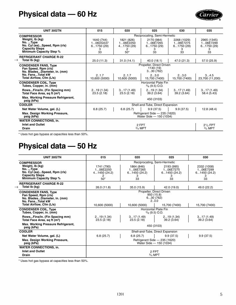
Physical data — 50 Hz
* Uses hot gas bypass at capacities less than 50%.
UNIT 30GTN 015 020 025 030 035
COMPRESSORWeight, lb (kg)No. ...TypeNo. Cyl (ea)...Speed, Rpm (r/s)Capacity StepsMinimum Capacity Step %
Reciprocating, Semi-Hermetic1640 (744)
1...06DG5376...1750 (29)
333
1821 (826)1...06E22504...1750 (29)
250*
2170 (984)1...06E72656...1750 (29)
333
2268 (1029)1...06E72756...1750 (29)
333
2965 (1345)1...06E72996...1750 (29)
333
REFRIGERANT CHARGE R-22Total lb (kg) 25.0 (11.3) 31.0 (14.1) 40.0 (18.1) 47.0 (21.3) 57.0 (25.9)
CONDENSER FANS, TypeFan Speed, Rpm (r/s)No. Blades...Diameter, in. (mm)No. Fans...Total kWTotal Airflow, Cfm (L/s)
Propeller, Direct Driven1140 (19)
3...30 (762)2..1.7
10,600 (5000)2..1.7
10,600 (5000)2...3.0
15,700 (7400)2...3.0
15,700 (7400)3...4.5
23,700 (11,200)CONDENSER COIL, Type
Tubes, Copper, in. (mm)Horizontal Plate Fin
3/8 (9.5) O.D.Rows...Fins/in. (Fin Spacing mm)Total Face Area, sq ft (m2)
2...19 (1.34)23.5 (2.18)
3...17 (1.49)23.5 (2.18)
2...19 (1.34)39.2 (3.64)
3...17 (1.49)39.2 (3.64)
3...17 (1.49)58.4 (5.43)
Max. Working Pressure Refrigerant,psig (kPa) 450 (3103)
COOLERNet Water Volume, gal. (L)
Shell-and-Tube, Direct Expansion6.8 (25.7) 6.8 (25.7) 9.9 (37.5) 9.9 (37.5) 12.8 (48.4)
Max. Design Working Pressure,psig (kPa)
Refrigerant Side — 235 (1620)Water Side — 150 (1034)
WATER CONNECTIONS, in.Inlet and OutletDrain
2 FPT3/4 MPT
21/2 FPT3/4 MPT
UNIT 30GTN 015 020 025 030
COMPRESSORWeight, lb (kg)No. ...TypeNo. Cyl (ea)...Speed, Rpm (r/s)Capacity StepsMinimum Capacity Step %
Reciprocating, Semi-Hermetic1741 (790)
1...06E22504...1450 (24.2)
250*
1864 (846)1...06E7265
6...1450 (24.2)3
33
2193 (995)1...06E7275
6...1450 (24.2)3
33
2332 (1058)1...06E7299
6...1450 (24.2)3
33
REFRIGERANT CHARGE R-22Total lb (kg) 26.0 (11.8) 35.0 (15.9) 42.0 (19.0) 49.0 (22.2)
CONDENSER FANS, TypeFan Speed, Rpm (r/s)No. Blades...Diameter, in. (mm)No. Fans...Total kWTotal Airflow, Cfm (L/s)
Propeller, Direct Driven950 (15.8)6...30 (762)
2..3.010,600 (5000) 10,600 (5000) 15,700 (7400) 15,700 (7400)
CONDENSER COIL, TypeTubes, Copper, in. (mm)
Horizontal Plate Fin3/8 (9.5) O.D.
Rows...Fins/in. (Fin Spacing mm)Total Face Area, sq ft (m2)
2...19 (1.34)23.5 (2.18)
3...17 (1.49)23.5 (2.18)
2...19 (1.34)39.2 (3.64)
3...17 (1.49)39.2 (3.64)
Max. Working Pressure Refrigerant,psig (kPa) 450 (3103)
COOLERNet Water Volume, gal. (L)
Shell-and-Tube, Direct Expansion6.8 (25.7) 6.8 (25.7) 9.9 (37.5) 9.9 (37.5)
Max. Design Working Pressure,psig (kPa)
Refrigerant Side — 235 (1620)Water Side — 150 (1034)
WATER CONNECTIONS, in.Inlet and OutletDrain
2 FPT3/4 MPT
Physical data — 60 Hz
1201
→
→
6
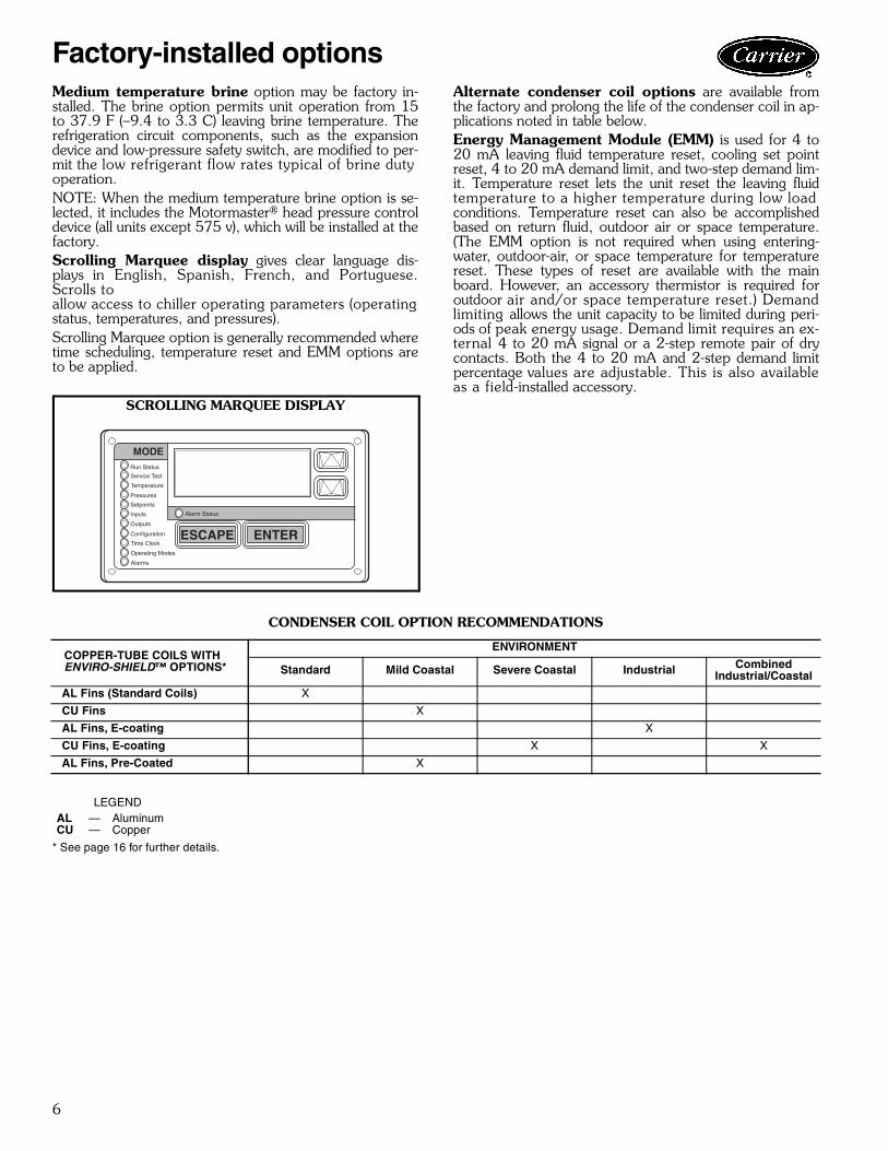
Medium temperature brine option may be factory in-stalled. The brine option permits unit operation from 15to 37.9 F (–9.4 to 3.3 C) leaving brine temperature. Therefrigeration circuit components, such as the expansiondevice and low-pressure safety switch, are modified to per-mit the low refrigerant flow rates typical of brine dutyoperation.NOTE: When the medium temperature brine option is se-lected, it includes the Motormaster® head pressure controldevice (all units except 575 v), which will be installed at thefactory.Scrolling Marquee display gives clear language dis-plays in English, Spanish, French, and Portuguese.Scrolls toallow access to chiller operating parameters (operatingstatus, temperatures, and pressures).Scrolling Marquee option is generally recommended wheretime scheduling, temperature reset and EMM options areto be applied.
Alternate condenser coil options are available fromthe factory and prolong the life of the condenser coil in ap-plications noted in table below.Energy Management Module (EMM) is used for 4 to20 mA leaving fluid temperature reset, cooling set pointreset, 4 to 20 mA demand limit, and two-step demand lim-it. Temperature reset lets the unit reset the leaving fluidtemperature to a higher temperature during low loadconditions. Temperature reset can also be accomplishedbased on return fluid, outdoor air or space temperature.(The EMM option is not required when using entering-water, outdoor-air, or space temperature for temperaturereset. These types of reset are available with the mainboard. However, an accessory thermistor is required foroutdoor air and/or space temperature reset.) Demandlimiting allows the unit capacity to be limited during peri-ods of peak energy usage. Demand limit requires an ex-ternal 4 to 20 mA signal or a 2-step remote pair of drycontacts. Both the 4 to 20 mA and 2-step demand limitpercentage values are adjustable. This is also availableas a field-installed accessory.
CONDENSER COIL OPTION RECOMMENDATIONS
* See page 16 for further details.
Run Status
Service Test
Temperature
Pressures
Setpoints
Inputs
Outputs
Configuration
Time Clock
Operating Modes
Alarms
Alarm Status
ENTER
MODE
ESCAPE
SCROLLING MARQUEE DISPLAY
COPPER-TUBE COILS WITHENVIRO-SHIELD™ OPTIONS*
ENVIRONMENT
Standard Mild Coastal Severe Coastal Industrial CombinedIndustrial/Coastal
AL Fins (Standard Coils) X
CU Fins X
AL Fins, E-coating X
CU Fins, E-coating X X
AL Fins, Pre-Coated X
LEGENDAL — AluminumCU — Copper
Factory-installed options
7
Motormaster® head pressure control package allowsunit operation to –20 F (–29 C) ambient temperature bymodulating condenser-fan motor speed in response to re-frigerant condensing temperature.Chilled water flow switch prevents unit operation ifchilled water flow stops.Compressor oil safety switch package provides pro-tection against loss of oil pressure. One required for eachcompressor.Gage panel package provides a suction and a dischargepressure gage foreach refrigerant circuit.Energy Management Module (EMM) is used for 4 to20 mA leaving fluid temperature reset, cooling set pointreset, 4 to 20 mA demand limit, and two-step demand lim-it. Temperature reset lets the unit reset the leaving fluidtemperature to a higher temperature during low load con-ditions. Temperature reset can also be accomplished basedon return fluid, outdoor air, or space temperature. (TheEMM option is not required when using entering-water,outdoor-air, or space temperature for temperature reset.These types of reset are available with the main board.However, an accessory thermistor is required for outdoorair and/or space temperature reset.) Demand limiting al-lows the unit capacity to be limited during periods of peak
energy usage. Demand limit requires an external 4 to20 mA signal or a 2-step remote pair of dry contacts. Boththe 4 to 20 mA and 2-step demand limit percentage valuesare adjustable. This is also available as a factory-installedoption.Hot gas bypass valve allows hot gas to pass directly intocooler circuit as an additional step of unloading, maintainsconstant suction pressure, and permits unit to operate atlower loads with less compressor cycling (standard on 020,60 Hz and 015, 50 Hz).Control transformer provides control power where oth-er source is not available.Part wind start reduces instantaneous current flow (ICF)and locked rotor amps on start-up. Contact your localCarrier representative for more information.Thermistor accessory is available for field installation(all sizes).Chillervisor System Manager III control can be usedto regulate up to 8 30GTN chillers.Current ground fault sensor monitors all phases of the3-phase power supply to the compressor. At the first signof a short to ground, the sensor shuts down the compressor.
Field-installed accessories
8
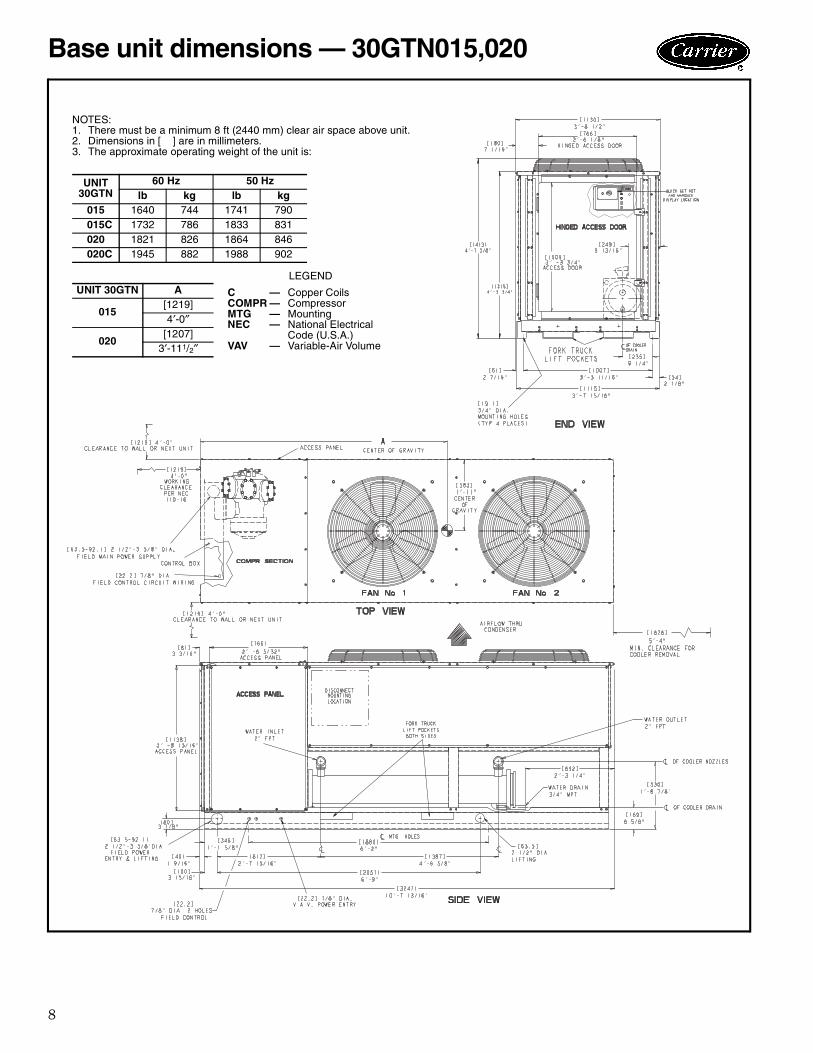
NOTES:1. There must be a minimum 8 ft (2440 mm) clear air space above unit.2. Dimensions in [ ] are in millimeters.3. The approximate operating weight of the unit is:
UNIT30GTN
60 Hz 50 Hzlb kg lb kg
015 1640 744 1741 790015C 1732 786 1833 831020 1821 826 1864 846020C 1945 882 1988 902
UNIT 30GTN A CCOMPRMTGNEC
VAV
————
—
Copper CoilsCompressorMountingNational ElectricalCode (U.S.A.)Variable-Air Volume
015[1219]4′-0″
020[1207]
3′-111/2″
LEGEND
Base unit dimensions — 30GTN015,020
9
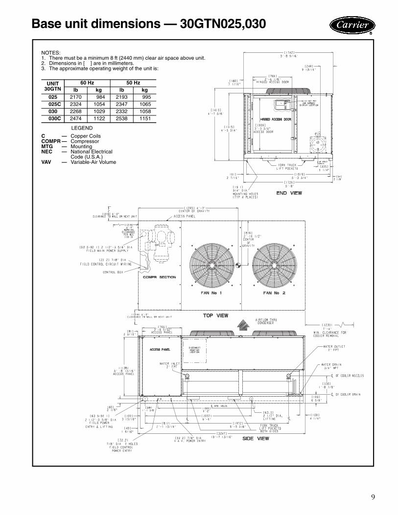
Base unit dimensions — 30GTN025,030
NOTES:1. There must be a minimum 8 ft (2440 mm) clear air space above unit.2. Dimensions in [ ] are in millimeters.3. The approximate operating weight of the unit is:
LEGEND
UNIT30GTN
60 Hz 50 Hzlb kg lb kg
025 2170 984 2193 995025C 2324 1054 2347 1065030 2268 1029 2332 1058030C 2474 1122 2538 1151
C — Copper CoilsCOMPR — CompressorMTG — MountingNEC — National Electrical
Code (U.S.A.)VAV — Variable-Air Volume
10
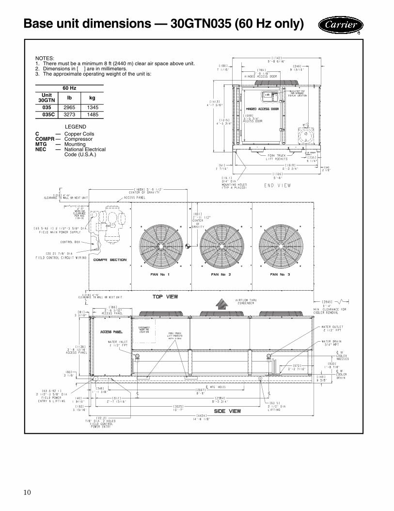
NOTES:1. There must be a minimum 8 ft (2440 m) clear air space above unit.2. Dimensions in [ ] are in millimeters.3. The approximate operating weight of the unit is:
60 HzUnit
30GTN lb kg
035 2965 1345035C 3273 1485
CCOMPRMTGNEC
————
Copper CoilsCompressorMountingNational ElectricalCode (U.S.A.)
LEGEND
Base unit dimensions — 30GTN035 (60 Hz only)

11
Leveling unitUnit must be level within 1/8 in. per ft when installed toensure proper oil return to the compressor.
While most outdoor locations are suitable for 30GTNunits, the roof is a common site that represents a problemif roof has been pitched to aid in water removal. To assureproper oil return, be sure that unit is level, particularly inits major lengthwise dimension, as compressor oil returnpiping runs in that direction.
It should be determined prior to installation if anyspecial treatment is required to assure a level installation.
General electrical information 1. It is recommended that the 115-1-60, 220-1-60, and
230-1-50 control circuit power be from a separatesource, through a field-supplied fused disconnectrated at a maximum of 7 amps.
2. Power entry is at one end only.3. Maximum field wire sizes allowed by lugs on terminal
block are: 350 kcmil for models 30GTN030,035 (208/
230-3-60). 2/0 for all other models.
4. Terminals for field power supply are suitable for cop-per, copper-clad aluminum, or aluminum conductors.Insulation must be rated 167 F (75 C) minimum.
Cooler temperature1. Maximum leaving chilled water temperature (LCWT)
for standard 30GTN units is 60 F (16 C). Unit canstart and pull down with up to 95 F (35 C) entering-water temperature due to MOP (maximum operatingpressure) feature of the expansion valve. For sus-tained operation, it is recommended that enteringwater temperature not exceed 85 F (29.4 C).
2. Minimum LCWT for standard 30GT units is 38 F(3.3 C).
3. Special order medium temperature brine units mustbe ordered for operation with leaving water tempera-tures in the range of 37.9 F (3.3 C) to 15 F (– 9 C).For ratings below 38 F (3.3 C) LCWT, contact yourlocal Carrier representative.
Medium temperature brine applicationApplication of chiller for brine duty within the 37.9 to15 F (3.3 to –9.4 C) range is possible by ordering theproper factory-installed brine option. For ratings below 38 F(3.3 C) LCWT, contact your local Carrier representative.
Leaving-fluid temperature reset The Energy Management Module (EMM) is required for 4to 20 mA reset of LCWT in constant fluid systems. Resetby return fluid, outdoor-air temperature, or space tempera-ture does not require this option. Reset reduces compres-sor power usage at part load when design LCWT is notnecessary. Humidity control should be considered sincehigher coil temperatures resulting from reset will reduce la-tent heat capacity. Three reset options are offered, basedon the following:
Return-fluid temperature — Increase LCWT tem-perature set point as return (or entering) fluid temperaturedecreases (indicating load decrease). Option may be usedin any application where return fluid provides accurateload indication. Limitation of return fluid reset is that
LCWT may only be reset to value of design return fluidtemperature.Outdoor-air temperature — Increases LCWT as out-door ambient temperature decreases (indicating load de-crease). This reset should be applied only where outdoorambient temperature is an accurate indication of load. Anaccessory thermistor is required. Space temperature — Increases LCWT as space tem-perature decreases (indicating load decrease). This resetshould be applied only where space temperature is an accurate indication of load. An accessory thermistor is required.
Cooler flow rangeRatings and performance data in this publication are for acooling range of 10 F (5.6 C). 30GTN chillers may be op-erated at a 5 to 15 F (2.8 to 8.3 C) temperature rangeprovided flow limits are not exceeded. For minimum flowrates, see Minimum/Maximum Cooler Flow Rates andMinimum Loop Volume table on page 12. If outside thisrange, a change of controls is required.Variable cooler flow rates may be applied to standard30GTN chillers. However, the unit will attempt to maintaina constant leaving chilled-water temperature. In suchcases, minimum flow must be in excess of minimum flowgiven in Minimum Cooler and Condenser Water FlowRates and Minimum Loop Volume table, and flow ratemust change in steps of less than 10% per minute. Apply6 gal. per ton (6.5 L per kW) water loop volume minimumif flow rate changes more rapidly.NOTE: Always set variation (deadband) to cover the rangefor the worst possible case.Minimum cooler flow (maximum cooler temperaturerange) for standard units is shown in Minimum/MaximumCooler Flow Rates and Minimum Loop Volume table onpage 12. When gpm (L/s) required is lower (or rangehigher), follow recommendations below:
1. Multiple smaller chillers may be applied in series, eachproviding a portion of the design temperature range.
2. Cooler water may be recirculated to raise flow rate.However, mixed temperature entering cooler must bemaintained at a minimum of 6° F (3.3° C) above theleaving chilled-water temperature.
3. Special cooler baffling is required to allow minimumflow rate to be reduced 12%.
NOTE: Recirculation flow is shown below.
RECIRCULATION FLOW
Application data

12
Maximum cooler flow (> 5 gpm/ton or < 5 F range[> 0.09 L/s • kW or < 2.7 C range]) results in practicalmaximum pressure drop through cooler.
1. Return water may bypass the cooler to keep pressuredrop through cooler within acceptable limits. Thispermits a higher ∆T with lower water flow throughcooler and mixing after the cooler.
2. Special cooler baffling is available by special order topermit a cooler flow rate increase of 10%.
NOTE: Bypass flow is shown below.
MINIMUM/MAXIMUM COOLER FLOWRATES AND RECOMMENDED
MINIMUM LOOP VOLUME
NOTES:1. Operation below recommended minimum loop volumes will reduce
accuracy of loop temperature control.2. Minimum flow based on 1.5 fps (0.46 m/s) velocity in cooler without
special cooler baffling.3. Minimum Loop Volumes
Gallons = V x ARI Cap. (tons)Liters = N x ARI Cap. (kW)
Water loop volume should range from 3 to 6 gallons pernominal ton of cooling (3.25 to 6.5 liters per kW) for tem-perature stability and accuracy in normal air conditioningapplications. (For example, a 30GTN025 would require75 gallons (285 liters) in circulation in system loop — see
Minimum/Maximum Cooler Flow Rates and Minimum-Loop Volume table above.) For process jobs where accura-cy is vital, there should be from 6 to 10 gallons per ton(6.5 to 10.8 liters per kW). To achieve this volume, it is of-ten necessary to install a tank in the loop. Tank should bebaffled to ensure there is no stratification and that water(or brine) entering tank is thoroughly mixed with liquid intank. Refer to ASHRAE (American Society of Heating,Refrigeration and Air Conditioning Engineers, U.S.A.)guides or similar publication for information on storagetank design.NOTE: Tank installation is shown below.
Cooler fouling factor used to calculate tabulated ratingswas 0.00010 ft2 • hr • ° F/Btu (0.000018 m2 • K/W). Asfouling factor is increased, both unit capacity and compres-sor power decrease. Standard ratings should be correctedusing following multipliers:
FOULING FACTOR CORRECTION
Condenser altitude correction factors must be appliedto standard ratings of altitudes above 2000 ft (610 m) us-ing following multipliers.
ALTITUDE CORRECTION FACTORS
UNIT30GTN
MINIMUMFLOW
MAXIMUMFLOW
RECOMMENDEDMINIMUM
LOOP VOLUMEGpm L/s Gpm L/s G L
015020025030035
2525303034
22222
134163230250326
910151621
45607590
105
171228285342399
LEGEND
ARI — Air Conditioning and RefrigerationInstitute (U.S.A.)
N — Liters per kWV — Gallons per Ton
APPLICATION V NNormal Air ConditioningProcess Type CoolingLow Ambient Unit Operation
3 to 66 to 106 to 10
3.25 to 16.56.50 to 10.86.50 to 10.8
BYPASS FLOW
FOULING FACTORCAPACITY
MULTIPLIER
COMPRESSORPOWER
MULTIPLIEREnglish(ft2 • hr
• ºF/Btu)
SI(m2 • K/W)
0.000100.000750.00175
0.0000180.0001320.000308
1.000.970.91
1.000.980.91
ALTITUDECAPACITY
MULTIPLIER
COMPRESSORPOWER
MULTIPLIEREnglish
(ft)SI
(m)0
2,0004,0006,0008,000
10,000
0610
1220183024403050
1.000.990.980.970.960.95
1.001.011.021.031.041.05
TANK INSTALLATION
Application data (cont)
1201
→
13
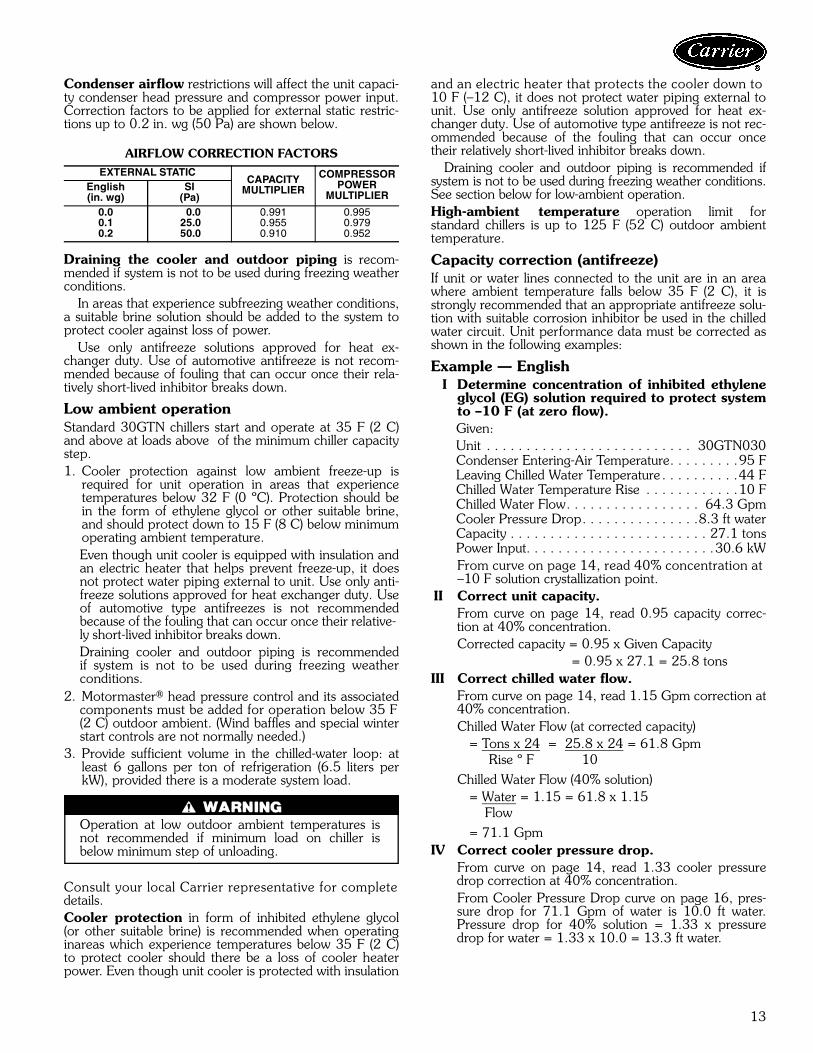
Condenser airflow restrictions will affect the unit capaci-ty condenser head pressure and compressor power input.Correction factors to be applied for external static restric-tions up to 0.2 in. wg (50 Pa) are shown below.
AIRFLOW CORRECTION FACTORS
Draining the cooler and outdoor piping is recom-mended if system is not to be used during freezing weatherconditions.
In areas that experience subfreezing weather conditions,a suitable brine solution should be added to the system toprotect cooler against loss of power.
Use only antifreeze solutions approved for heat ex-changer duty. Use of automotive antifreeze is not recom-mended because of fouling that can occur once their rela-tively short-lived inhibitor breaks down.
Low ambient operationStandard 30GTN chillers start and operate at 35 F (2 C)and above at loads above of the minimum chiller capacitystep.1. Cooler protection against low ambient freeze-up is
required for unit operation in areas that experiencetemperatures below 32 F (0 ºC). Protection should bein the form of ethylene glycol or other suitable brine,and should protect down to 15 F (8 C) below minimumoperating ambient temperature.Even though unit cooler is equipped with insulation andan electric heater that helps prevent freeze-up, it doesnot protect water piping external to unit. Use only anti-freeze solutions approved for heat exchanger duty. Useof automotive type antifreezes is not recommendedbecause of the fouling that can occur once their relative-ly short-lived inhibitor breaks down. Draining cooler and outdoor piping is recommendedif system is not to be used during freezing weatherconditions.
2. Motormaster® head pressure control and its associatedcomponents must be added for operation below 35 F(2 C) outdoor ambient. (Wind baffles and special winterstart controls are not normally needed.)
3. Provide sufficient volume in the chilled-water loop: atleast 6 gallons per ton of refrigeration (6.5 liters perkW), provided there is a moderate system load.
Operation at low outdoor ambient temperatures isnot recommended if minimum load on chiller isbelow minimum step of unloading.
Consult your local Carrier representative for completedetails.Cooler protection in form of inhibited ethylene glycol(or other suitable brine) is recommended when operatinginareas which experience temperatures below 35 F (2 C)to protect cooler should there be a loss of cooler heaterpower. Even though unit cooler is protected with insulation
and an electric heater that protects the cooler down to 10 F (–12 C), it does not protect water piping external tounit. Use only antifreeze solution approved for heat ex-changer duty. Use of automotive type antifreeze is not rec-ommended because of the fouling that can occur oncetheir relatively short-lived inhibitor breaks down.
Draining cooler and outdoor piping is recommended ifsystem is not to be used during freezing weather conditions.See section below for low-ambient operation.High-ambient temperature operation limit forstandard chillers is up to 125 F (52 C) outdoor ambienttemperature.
Capacity correction (antifreeze)If unit or water lines connected to the unit are in an areawhere ambient temperature falls below 35 F (2 C), it isstrongly recommended that an appropriate antifreeze solu-tion with suitable corrosion inhibitor be used in the chilledwater circuit. Unit performance data must be corrected asshown in the following examples:
Example — EnglishI Determine concentration of inhibited ethylene
glycol (EG) solution required to protect systemto –10 F (at zero flow).Given:Unit . . . . . . . . . . . . . . . . . . . . . . . . . . 30GTN030 Condenser Entering-Air Temperature. . . . . . . . .95 FLeaving Chilled Water Temperature . . . . . . . . . .44 FChilled Water Temperature Rise . . . . . . . . . . . .10 FChilled Water Flow. . . . . . . . . . . . . . . . . 64.3 GpmCooler Pressure Drop. . . . . . . . . . . . . . .8.3 ft waterCapacity . . . . . . . . . . . . . . . . . . . . . . . . . 27.1 tonsPower Input. . . . . . . . . . . . . . . . . . . . . . . .30.6 kWFrom curve on page 14, read 40% concentration at –10 F solution crystallization point.
II Correct unit capacity.From curve on page 14, read 0.95 capacity correc-tion at 40% concentration.Corrected capacity = 0.95 x Given Capacity
= 0.95 x 27.1 = 25.8 tonsIII Correct chilled water flow.
From curve on page 14, read 1.15 Gpm correction at40% concentration.Chilled Water Flow (at corrected capacity) = Tons x 24 = 25.8 x 24 = 61.8 Gpm Rise º F 10 Chilled Water Flow (40% solution) = Water = 1.15 = 61.8 x 1.15 Flow = 71.1 Gpm
IV Correct cooler pressure drop.From curve on page 14, read 1.33 cooler pressuredrop correction at 40% concentration.From Cooler Pressure Drop curve on page 16, pres-sure drop for 71.1 Gpm of water is 10.0 ft water.Pressure drop for 40% solution = 1.33 x pressuredrop for water = 1.33 x 10.0 = 13.3 ft water.
EXTERNAL STATICCAPACITY
MULTIPLIER
COMPRESSORPOWER
MULTIPLIEREnglish(in. wg)
SI(Pa)
0.00.10.2
0.025.050.0
0.9910.9550.910
0.9950.9790.952

14
V Correct compressor power input.On Power Correction curve below, read 0.97 correc-tion factor at 40% concentration.Corrected Power Input = 0.97 x 30.6 = 29.7 kW
Example — SII Determine concentration of inhibited ethylene
glycol (EG) solution required to protect systemto –23 C (at zero flow). Given:Unit . . . . . . . . . . . . . . . . . . . . . . . . . . 30GTN030 Condenser Entering-Air Temperature. . . . . . . . 35 CLeaving Chilled Water Temperature . . . . . . . . . . 7 CChilled Water Temperature Rise . . . . . . . . . . . 5.6 CChilled Water Flow. . . . . . . . . . . . . . . . . . . 4.2 L/sCooler Pressure Drop. . . . . . . . . . . . . . . . 24.3 kPaCapacity . . . . . . . . . . . . . . . . . . . . . . . . . .96.5 kWPower Input. . . . . . . . . . . . . . . . . . . . . . . .30.9 kWFrom curve on this page, read 40% concentration at–23 C solution crystallization point.
II Correct unit capacity.From curve below, read 0.95 capacity correction at40% concentration.Corrected capacity = 0.95 x Given Capacity = 0.95 x 96.5 = 91.7 kW
III Correct chilled water flow.From curve below, read 1.15 Gpm correction at 40%concentration.
Chilled Water Flow (at corrected capacity) = Capacity (kW) = 91.7 = 3.9 L/s 4.2 x Rise º C 4.2 x 5.6 Chilled Water Flow (40% solution) = Water x 1.15 = 3.9 x 1.15 Flow = 4.48 L/s
IV Correct cooler pressure drop.From curve below, read 1.33 cooler pressure dropcorrection at 40% concentration.From Cooler Pressure Drop curve on page 16, pres-sure drop for 4.48 L/s of water is 30 kPa. Pressuredrop for 40% solution = 1.33 x pressure drop for water = 1.33 x 34.5 = 45.9 kPa.
V Correct compressor power input.On Power Correction curve below, read 0.97 correc-tion factor at 40% concentration.Corrected Power Input = 0.97 x 30.9 = 30.0 kW
Oversizing chillersDo not oversize chillers by more than 15% at design condi-tions as the system operating efficiency will be adverselyaffected (resulting in greater or excessive electrical de-mand). When future expansion of equipment is anticipat-ed, install a single chiller to meet present load require-ments and add a second chiller to meet the additional loaddemand.
Installation of 2 smaller chillers should also be consid-ered where operation at minimum load is critical. The op-eration of a smaller chiller loaded to a greater percent ofminimum is preferred to operating a single chiller at ornear its minimum recommended value.
Hot gas bypass should not be used to allow oversizing ofchillers. Hot gas bypass should be given considerationwhere substantial operating time is anticipated below theminimum unloading step.
Multiple chillersWhere chiller capacities greater than 30 tons (106 kW) arerequired, or where stand-by capability is desired, chillers-may be installed in parallel. Units should be of equal sizeto ensure balanced water flows. Where a large tempera-ture drop (> 25 F [13.9 C]) is desired, chillers may be in-stalled in series. Water temperature sensors need not beremoved for multiple chiller operation. An additional tem-perature sensor (dual chiller leaving fluid temperature) mustbe installed and connected to the master chiller. An 8 ft(2.4 m) separation is required between units for airflow,and a 4 ft (1.2 m ) distance is required from units to ob-structions. See Multiple Unit Separation figure below. Seedimensional drawings for service clearances.
INHIBITED ETHYLENE GLYCOL PERFORMANCE CORRECTION FACTORS AND
SOLUTION CRYSTALLIZATION POINTS
MULTIPLE UNIT SEPARATION
Application data (cont)
15
Electrical/utility interestsEnergy management — Use of energy managementpractices can significantly reduce operating costs, especial-ly during off-peak modes of operation. Demand limitingand temperature reset are 2 techniques for accomplishingefficient energy management. See Demand Limiting (alsocalled load shedding) section below and Leaving-FluidTemperature Reset section on page 11 for further details. Demand limiting (also called load shedding) — Whena utility’s demand for electricity exceeds a certain level,loads are shed to keep electricity demand below a pre-scribed maximum level. Typically, this happens on hotdays when air conditioning is most needed. The EnergyManagement Module (EMM) can be added to accomplishthis reduction.
Demand may be limited on unit by resetting fluid tem-perature, or by unloading the chiller to a given predeter-mined percentage of the load. Demand limit may also bedriven by an external 4 to 20 mA signal. These featuresrequire a signal from an intelligent central control. Do notcycle demand limiter for less than 10 minutes on and5 minutes off.
Duty cycling cycles electrical loads at regular intervals re-gardless of need. This reduces the electrical operatingcosts of building by “fooling” demand indicating devices.Duty cycling of compressors or fans is not recommendedsince motor winding and bearing life suffer from con-stant cycling.
Remote on-off controlRemote on-off control may be applied by hard-wired con-nection (see Controls and Troubleshooting literature) or byconnection to a Carrier Comfort Network (CCN).
Part-wind startThis is not generally required on 30GTN chillers due touse of multiple compressors allowing smaller electrical loadincrements, but is available if required. Maximum instanta-neous current flow (see ICF in Electrical Data tableon page 22) should be used in determining need.
StrainersIt is recommended that a strainer with a minimum of20 mesh be installed in the cooler fluid inlet line, justahead of and as close as possible to the cooler.
Condenser coil protection (Enviro-Shield™)Pre-coated aluminum-fin coils have a durable epoxy-phenolic coating applied to the fin prior to the fin stamp-ing process to provide protection in mildly corrosive coast-al environments. Pre-coated coils have an inert barrierbetween the aluminum fin and copper tube. This barrierelectrically disconnects the dissimilar metals to minimizethe potential for galvanic corrosion. This economical op-tion provides substantial corrosion protection beyond thestandard uncoated coil construction.Copper-fin coils provide increased corrosion resistancein moderate coastal environments where industrial air pol-lution is not present. All copper coils eliminate bi-metallicconstruction to eliminate the potential for galvanic corro-sion. Application in industrial environments is not recom-mended due to potential attack from sulfur, sulfur oxide,nitrogen oxides, carbon and several other industrial air-borne contaminants. In moderate seacoast environ-ments, copper-fin coils have extended life compared tostandard or pre-coated aluminum-fin coils.E-Coated aluminum-fin coils have an extremely flexibleand durable epoxy coating uniformly applied to all surfaces.Unlike brittle phenolic dip and bake coatings. E-Coat pro-vides superior protection with unmatched flexibility, edgecoverage, metal adhesion, thermal performance, and mostimportantly, corrosion resistance. E-Coated coils providethis protection since all coil surfaces are completely encap-sulated from environmental contamination. Specify E-Coated aluminum-fin coils for industrial environments withhigh levels of air pollution. This option also provides betterprotection compared to standard or pre-coated aluminum-fin coils in industrial environments.E-Coated copper-fin coils have the same flexible anddurable epoxy coating as E-Coated aluminum-fin coils.However, this option combines the natural salt and envi-ronmental resistance of all-copper construction with thehighest level of corrosion protection. Specify E-Coatedcopper-fin coils in the harshest combination of coastal andindustrial environments.
16
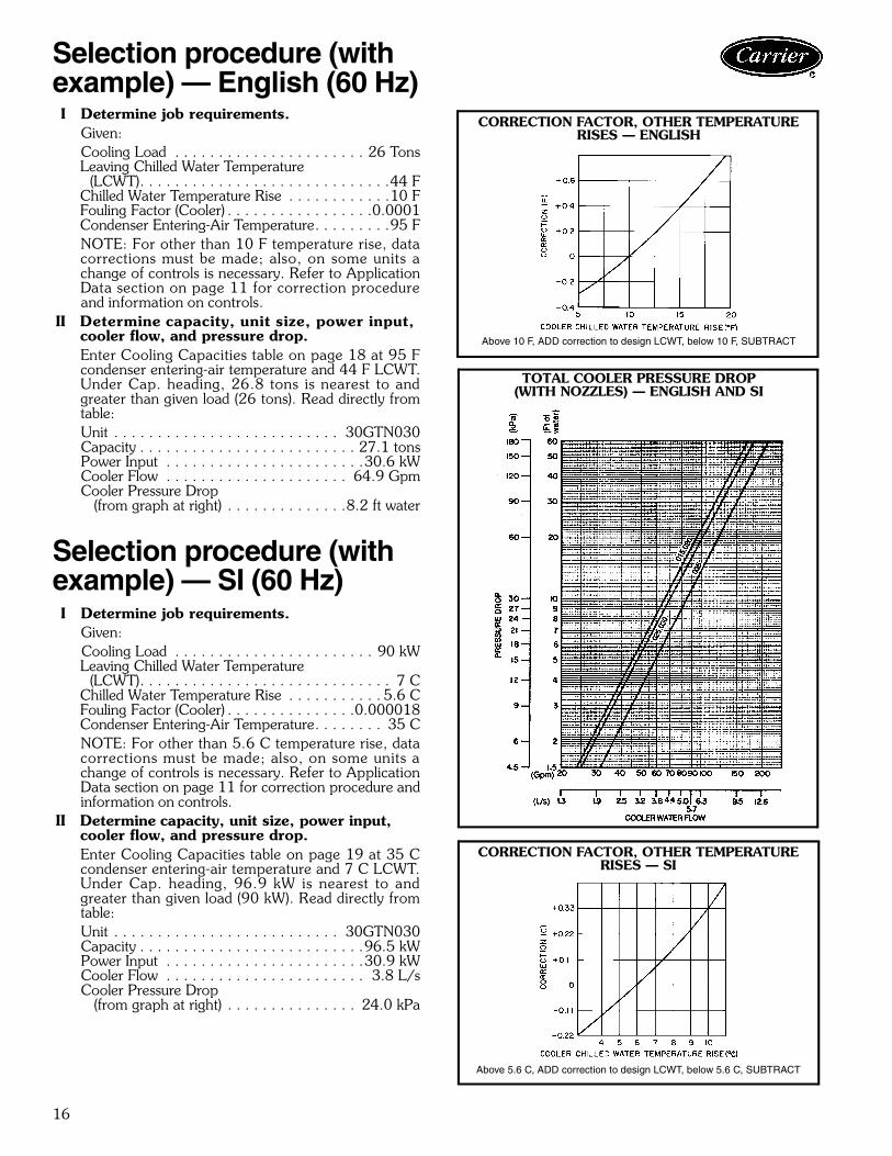
I Determine job requirements.Given:Cooling Load . . . . . . . . . . . . . . . . . . . . . . 26 TonsLeaving Chilled Water Temperature (LCWT). . . . . . . . . . . . . . . . . . . . . . . . . . . . .44 FChilled Water Temperature Rise . . . . . . . . . . . .10 FFouling Factor (Cooler) . . . . . . . . . . . . . . . . .0.0001Condenser Entering-Air Temperature. . . . . . . . .95 FNOTE: For other than 10 F temperature rise, datacorrections must be made; also, on some units achange of controls is necessary. Refer to ApplicationData section on page 11 for correction procedureand information on controls.
II Determine capacity, unit size, power input, cooler flow, and pressure drop.Enter Cooling Capacities table on page 18 at 95 Fcondenser entering-air temperature and 44 F LCWT.Under Cap. heading, 26.8 tons is nearest to andgreater than given load (26 tons). Read directly fromtable:Unit . . . . . . . . . . . . . . . . . . . . . . . . . . 30GTN030Capacity . . . . . . . . . . . . . . . . . . . . . . . . . 27.1 tonsPower Input . . . . . . . . . . . . . . . . . . . . . . .30.6 kWCooler Flow . . . . . . . . . . . . . . . . . . . . . 64.9 GpmCooler Pressure Drop
(from graph at right) . . . . . . . . . . . . . .8.2 ft water
Selection procedure (withexample) — SI (60 Hz)I Determine job requirements.
Given:Cooling Load . . . . . . . . . . . . . . . . . . . . . . . 90 kWLeaving Chilled Water Temperature (LCWT). . . . . . . . . . . . . . . . . . . . . . . . . . . . . 7 CChilled Water Temperature Rise . . . . . . . . . . . 5.6 CFouling Factor (Cooler) . . . . . . . . . . . . . . .0.000018Condenser Entering-Air Temperature. . . . . . . . 35 CNOTE: For other than 5.6 C temperature rise, datacorrections must be made; also, on some units achange of controls is necessary. Refer to ApplicationData section on page 11 for correction procedure andinformation on controls.
II Determine capacity, unit size, power input, cooler flow, and pressure drop.Enter Cooling Capacities table on page 19 at 35 Ccondenser entering-air temperature and 7 C LCWT.Under Cap. heading, 96.9 kW is nearest to andgreater than given load (90 kW). Read directly fromtable:Unit . . . . . . . . . . . . . . . . . . . . . . . . . . 30GTN030Capacity . . . . . . . . . . . . . . . . . . . . . . . . . .96.5 kWPower Input . . . . . . . . . . . . . . . . . . . . . . .30.9 kWCooler Flow . . . . . . . . . . . . . . . . . . . . . . . 3.8 L/sCooler Pressure Drop
(from graph at right) . . . . . . . . . . . . . . . 24.0 kPa
Selection procedure (withexample) — English (60 Hz)
CORRECTION FACTOR, OTHER TEMPERATURE RISES — ENGLISH
Above 10 F, ADD correction to design LCWT, below 10 F, SUBTRACT
TOTAL COOLER PRESSURE DROP(WITH NOZZLES) — ENGLISH AND SI
CORRECTION FACTOR, OTHER TEMPERATURE RISES — SI
Above 5.6 C, ADD correction to design LCWT, below 5.6 C, SUBTRACT

17
ARI* STANDARD RATINGS — 60 Hz
ARI* STANDARD RATINGS — 50 Hz
* Air Conditioning and Refrigeration Institute (U.S.A.)
NOTES:
1. Rated in accordance with ARI Standard 550/590-98 at standard ratingconditions.
2. Standard rating conditions are as follows:Cooler Conditions
Leaving water temperature: 44 F (6.7 C)Entering water temperature: 54 F (12.2 C)
Fouling Factor: 0.00010 ft2 x hr x °F/Btu (0.000018 m2 x °K/W)Condenser Conditions:
Entering Air Temperature: 95 F (35 C)
3. IPLV is a single number part-load efficiency value calculated from the systemfull-load efficiency values and corrected for a typical building air-conditioningapplication.
4. All data in this table is rated in accordance with ARI Standard 550/590 asrepresented in the Packaged Chiller Selection Program (E-Cat) Version 2.00.
UNIT30GTN
CAPACITY COMPRESSORPOWER INPUT
(kW)
FAN POWER(kW)
COOLER WATERPRESSURE DROP EER COP IPLV
Tons kW ft water kPa015 14.3 50.4 15.7 1.7 2.9 8.6 9.9 2.90 12.9020 17.4 61.2 19.9 1.7 4.1 12.3 9.7 2.83 11.4025 24.4 85.7 27.1 3.0 6.7 20.0 9.7 2.85 12.8030 27.1 95.4 30.6 3.0 8.4 25.0 9.7 2.84 12.4035 35.2 123.8 40.4 4.5 13.2 39.5 9.4 2.76 11.3
UNIT30GTN
CAPACITY COMPRESSORPOWER INPUT
(kW)
FAN POWER(kW)
COOLER WATERPRESSURE DROP EER COP IPLV
Tons kW ft water kPa015 15.5 54.5 16.7 3.0 3.3 9.9 9.5 2.77 10.1020 19.9 70.0 22.8 3.0 5.3 15.8 9.2 2.71 11.7025 23.6 83.0 25.7 3.0 6.3 18.7 9.9 2.89 12.3030 30.0 105.4 36.6 3.0 10.3 30.7 9.1 2.66 11.4
LEGEND
COP — Coefficient of Performance (Capacity [kW] ÷ Input Power [kW])EER — Energy Efficiency Ratio (Capacity [Btuh] ÷ Input Power [W])IPLV — Integrated Part-Load Value
Performance data
18
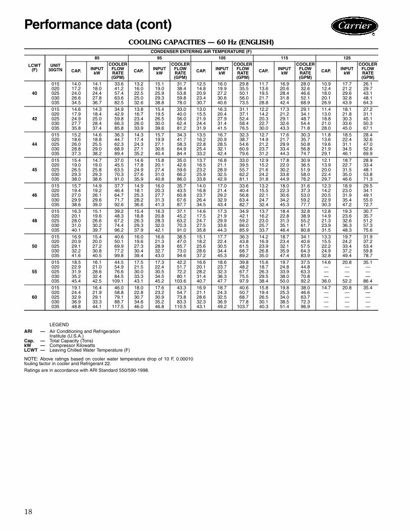
COOLING CAPACITIES — 60 Hz (ENGLISH)
NOTE: Above ratings based on cooler water temperature drop of 10 F, 0.00010fouling factor in cooler and Refrigerant 22.Ratings are in accordance with ARI Standard 550/590-1998.
CONDENSER ENTERING AIR TEMPERATURE (F)
LCWT(F)
UNIT30GTN
85 95 105 115 125
CAP. INPUTkW
COOLERFLOWRATE(GPM)
CAP. INPUTkW
COOLERFLOWRATE(GPM)
CAP. INPUTkW
COOLERFLOWRATE(GPM)
CAP. INPUTkW
COOLERFLOWRATE(GPM)
CAP. INPUTkW
COOLERFLOWRATE(GPM)
40
015020025030035
14.017.224.026.634.5
14.118.024.427.836.7
33.641.257.463.682.5
13.216.022.525.032.6
15.119.025.929.338.8
31.738.453.859.878.0
12.514.820.923.430.7
16.019.927.230.640.6
29.835.550.156.073.5
11.713.619.521.728.8
16.920.628.431.842.4
28.032.646.652.168.9
10.912.418.020.126.9
17.721.229.632.843.9
26.129.743.148.164.3
42
015020025030035
14.617.924.927.735.8
14.318.425.028.437.4
34.942.959.866.385.8
13.816.723.426.033.9
15.419.526.530.039.6
33.040.056.062.481.2
13.015.521.924.431.9
16.320.427.931.441.5
31.137.152.458.476.5
12.214.220.322.730.0
17.321.229.132.643.3
29.134.148.754.471.8
11.413.018.821.028.0
18.121.830.333.645.0
27.231.145.150.367.1
44
015020025030035
15.218.626.028.837.3
14.618.825.529.038.2
36.344.762.368.989.4
14.317.424.327.135.2
15.719.927.130.640.4
34.341.758.364.984.4
13.516.222.825.433.2
16.720.928.532.142.4
32.338.754.660.979.6
12.714.921.223.731.2
17.621.729.933.444.3
30.335.750.856.874.7
11.813.619.621.929.1
18.522.431.134.546.1
28.432.647.052.669.9
45
015020025030035
15.419.026.529.338.0
14.719.025.829.338.6
37.045.563.570.391.0
14.617.824.927.635.9
15.820.127.431.040.8
35.042.659.666.286.0
13.716.523.225.933.8
16.821.128.932.542.9
33.039.555.762.281.1
12.915.221.624.231.8
17.822.030.233.844.9
30.936.551.958.076.2
12.113.920.022.429.7
18.722.731.535.046.6
28.933.448.153.871.3
46
015020025030035
15.719.427.029.938.6
14.919.226.129.639.0
37.746.464.771.792.6
14.918.125.328.236.6
16.020.327.731.341.3
35.743.560.867.687.7
14.016.823.726.434.5
17.021.429.232.943.4
33.640.456.863.482.7
13.215.522.124.732.4
18.022.330.634.245.3
31.637.353.059.277.7
12.314.220.522.930.3
18.923.031.935.447.2
29.534.149.155.072.7
48
015020025030035
16.320.128.031.040.1
15.119.626.630.239.7
39.248.367.274.496.2
15.418.826.329.337.9
16.320.828.332.042.1
37.145.263.270.391.0
14.617.524.727.535.8
17.321.929.933.644.3
34.942.159.266.085.9
13.716.223.025.733.7
18.422.831.335.146.4
32.838.955.261.780.8
12.814.921.323.931.5
19.323.632.636.348.3
30.735.751.257.375.6
50
015020025030035
16.920.929.132.241.6
15.420.027.230.840.5
40.650.169.977.299.8
16.019.627.330.439.4
16.621.328.932.743.0
38.547.065.773.094.6
15.118.225.628.637.2
17.722.430.534.445.3
36.343.861.568.789.2
14.216.923.926.835.0
18.723.432.135.947.4
34.140.657.564.383.9
13.315.522.224.932.8
19.724.233.437.249.4
31.937.253.459.878.7
55
015020025030035
18.522.931.935.245.4
16.121.028.632.442.5
44.554.976.684.5
109.1
17.521.530.033.343.1
17.322.430.534.545.2
42.251.772.280.1
103.6
16.620.128.231.440.7
18.623.732.336.347.7
39.848.267.775.597.9
15.618.726.329.538.4
19.724.833.938.050.0
37.544.863.370.892.2
14.6———
36.0
20.8———
52.2
35.1———
86.4
60
015020025030035
19.124.432.936.948.8
16.421.929.133.344.1
46.058.879.188.7
117.5
18.022.830.734.646.0
17.623.230.935.246.8
43.354.773.883.3
110.5
16.921.128.632.343.1
18.724.332.536.949.2
40.650.768.777.8
103.7
15.819.426.530.140.3
19.825.334.038.551.4
38.046.663.772.396.9
14.7————
20.8————
35.4————
LEGENDARI — Air Conditioning and Refrigeration
Institute (U.S.A.)Cap. — Total Capacity (Tons)kW — Compressor KilowattsLCWT — Leaving Chilled Water Temperature (F)
Performance data (cont)

19
COOLING CAPACITIES — 60 Hz (SI)
NOTE: Above ratings based on cooler water temperature drop of 5.6 C, 0.000018fouling factor in cooler and Refrigerant 22.
Ratings are in accordance with ARI Standard 550/590-1998.
CONDENSER ENTERING AIR TEMPERATURE (C)
LCWT(C)
UNIT30GTN
30 35 40 45 50
CAP. INPUTkW
COOLERFLOWRATE(L/s)
CAP. INPUTkW
COOLERFLOWRATE(L/s)
CAP. INPUTkW
COOLERFLOWRATE(L/s)
CAP. INPUTkW
COOLERFLOWRATE(L/s)
CAP. INPUTkW
COOLERFLOWRATE(L/s)
5
015020025030035
50.161.485.795.0
123.3
14.318.324.928.337.3
2.02.43.43.84.9
47.657.780.889.9
117.1
15.219.326.229.739.2
1.92.33.23.64.7
45.153.876.084.8
111.0
16.120.127.530.941.0
1.82.13.03.44.4
42.649.971.279.5
104.8
16.920.828.632.042.6
1.72.02.83.24.2
40.146.066.574.298.7
17.721.429.633.044.0
1.61.82.63.03.9
6
015020025030035
51.963.788.998.4
127.4
14.618.725.428.838.0
2.12.53.53.95.1
49.359.883.893.2
121.2
15.519.726.830.340.0
2.02.43.33.74.8
46.756.078.988.0
114.9
16.420.528.031.641.8
1.92.23.13.54.6
44.152.074.082.6
108.7
17.221.329.232.743.4
1.82.12.93.34.3
41.647.969.177.1
102.3
18.021.930.333.745.0
1.71.92.73.14.1
7
015020025030035
53.766.092.0
101.9131.9
14.819.125.929.438.7
2.12.63.74.15.3
51.062.186.996.5
125.5
15.820.127.330.940.7
2.02.53.53.85.0
48.358.081.891.2
119.0
16.721.028.632.242.6
1.92.33.33.64.7
45.754.076.885.8
112.5
17.621.729.933.544.3
1.82.23.13.44.5
43.150.071.880.3
106.1
18.422.431.034.545.9
1.72.02.93.24.2
8
015020025030035
55.568.395.2
105.5136.5
15.019.426.429.939.4
2.22.73.84.25.4
52.864.390.0
100.1129.7
16.020.527.831.541.5
2.12.63.64.05.2
50.160.384.794.5
123.1
17.021.429.232.943.4
2.02.43.43.84.9
47.356.179.689.0
116.5
17.922.230.534.245.2
1.92.23.23.54.6
44.652.074.583.3
109.9
18.822.931.735.346.9
1.82.13.03.34.4
9
015020025030035
57.470.798.5
109.0141.1
15.319.826.930.540.1
2.32.83.94.35.6
54.666.693.1
103.6134.1
16.320.928.432.142.2
2.22.73.74.15.3
51.862.587.998.0
127.4
17.321.929.833.644.2
2.12.53.53.95.1
49.058.382.592.2
120.6
18.222.731.134.946.1
2.02.33.33.74.8
46.254.077.386.5
113.8
19.123.532.436.147.9
1.82.23.13.44.5
10
015020025030035
59.373.1
102.0112.7145.7
15.520.127.431.140.8
2.42.94.14.55.8
56.468.996.4
107.1138.7
16.621.329.032.743.0
2.32.73.84.35.5
53.664.790.9
101.4131.7
17.622.330.434.345.1
2.12.63.64.05.3
50.760.585.695.7
124.7
18.523.231.835.747.0
2.02.43.43.85.0
47.856.280.189.7
117.8
19.524.033.136.948.9
1.92.23.23.64.7
13
015020025030035
65.380.6
112.5124.2160.4
16.321.329.032.843.0
2.63.24.55.06.4
62.276.3
106.6118.3152.9
17.422.530.734.745.4
2.53.04.34.76.1
59.171.8
100.6112.3145.4
18.523.732.336.447.7
2.42.94.04.55.8
56.067.294.2
106.0137.8
19.624.733.737.949.8
2.22.73.84.25.5
52.8———
130.3
20.6———
51.9
2.1———5.2
16
015020025030035
67.085.4
114.9129.0170.9
16.522.029.333.544.4
2.73.44.65.26.8
63.480.1
108.1121.9161.8
17.623.230.935.246.8
2.53.24.34.96.5
59.974.8
101.3114.7152.7
18.624.232.436.849.0
2.43.04.04.66.1
56.469.494.6
107.4143.7
19.625.133.738.251.0
2.32.83.84.35.7
52.9———
134.8
20.5———
52.8
2.1———5.4
LEGENDARI — Air Conditioning and Refrigeration
Institute (U.S.A.)Cap. — Total Capacity (Kilowatts)kW — Compressor KilowattsLCWT — Leaving Chilled Water Temperature (C)
20
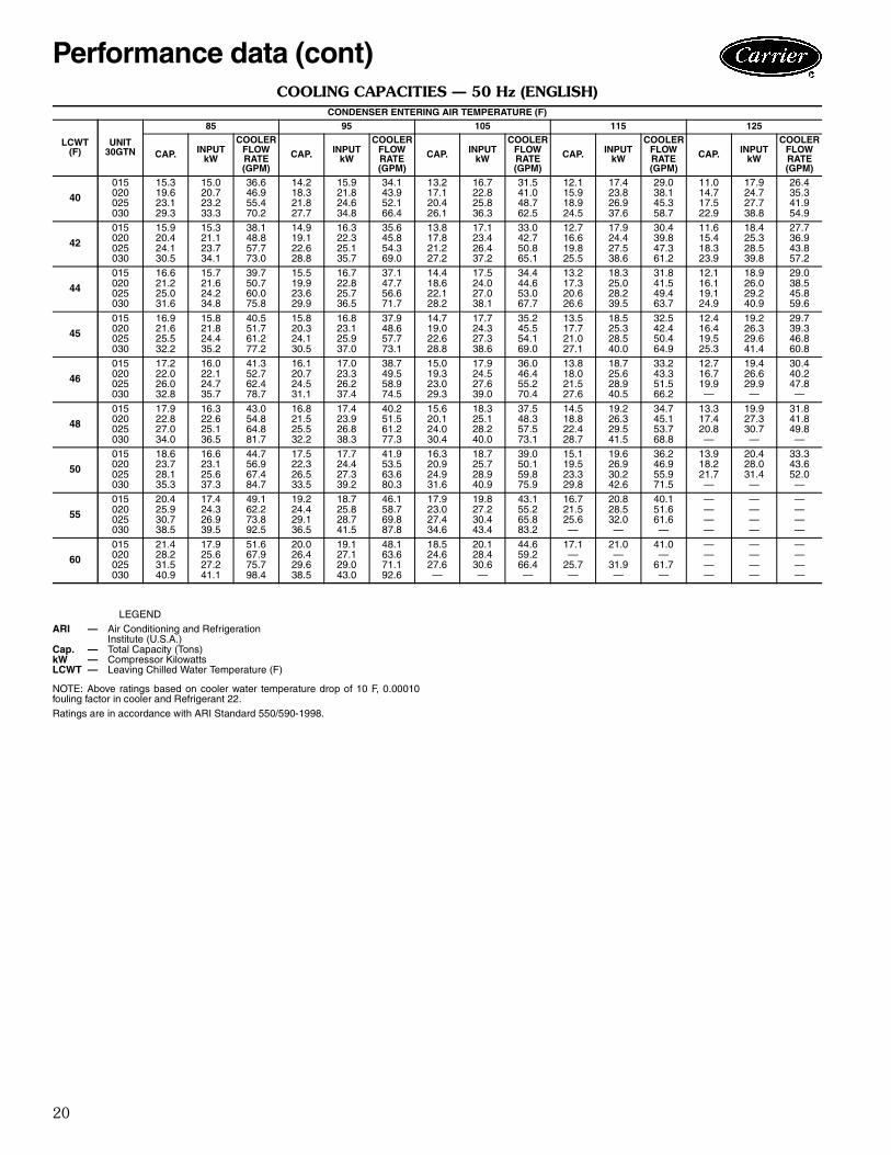
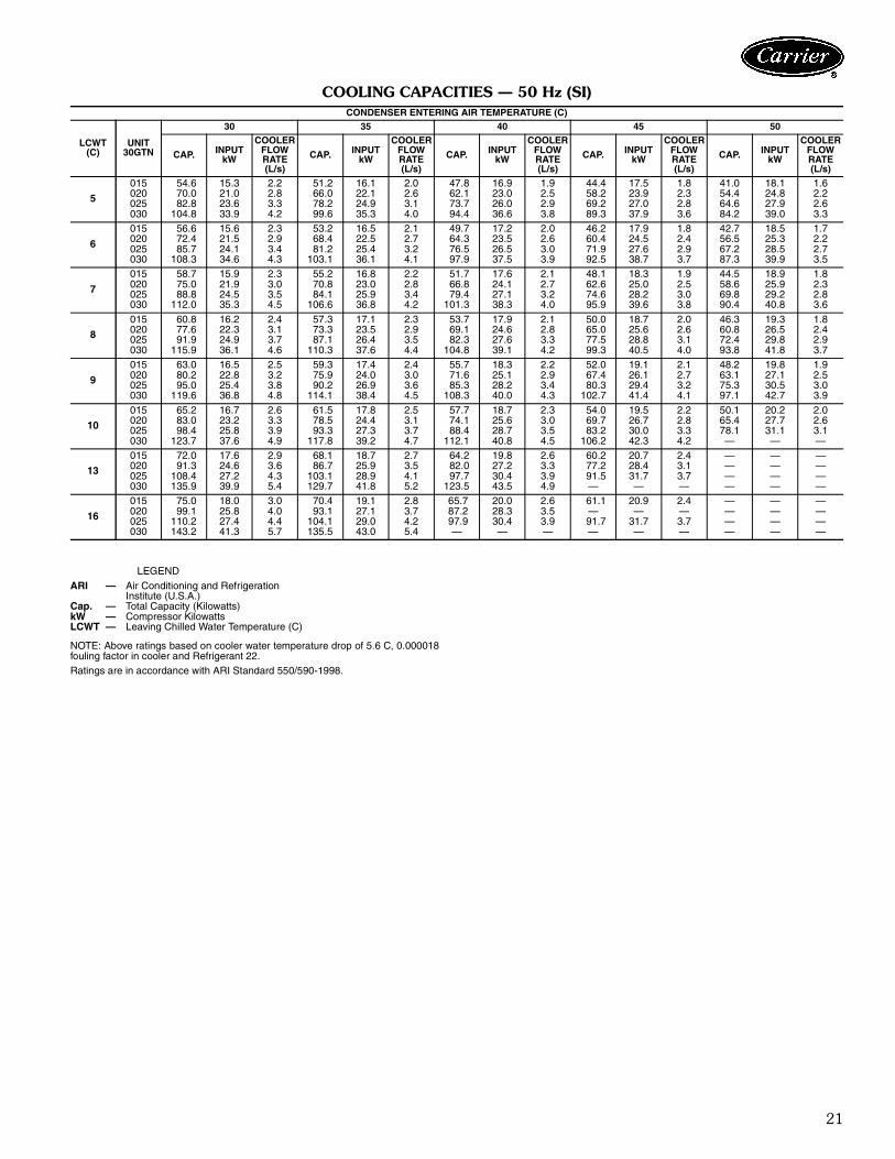
COOLING CAPACITIES — 50 Hz (ENGLISH)
NOTE: Above ratings based on cooler water temperature drop of 10 F, 0.00010fouling factor in cooler and Refrigerant 22.Ratings are in accordance with ARI Standard 550/590-1998.
CONDENSER ENTERING AIR TEMPERATURE (F)
LCWT(F)
UNIT30GTN
85 95 105 115 125
CAP. INPUTkW
COOLERFLOWRATE(GPM)
CAP. INPUTkW
COOLERFLOWRATE(GPM)
CAP. INPUTkW
COOLERFLOWRATE(GPM)
CAP. INPUTkW
COOLERFLOWRATE(GPM)
CAP. INPUTkW
COOLERFLOWRATE(GPM)
40
015020025030
15.319.623.129.3
15.020.723.233.3
36.646.955.470.2
14.218.321.827.7
15.921.824.634.8
34.143.952.166.4
13.217.120.426.1
16.722.825.836.3
31.541.048.762.5
12.115.918.924.5
17.423.826.937.6
29.038.145.358.7
11.014.717.522.9
17.924.727.738.8
26.435.341.954.9
42
015020025030
15.920.424.130.5
15.321.123.734.1
38.148.857.773.0
14.919.122.628.8
16.322.325.135.7
35.645.854.369.0
13.817.821.227.2
17.123.426.437.2
33.042.750.865.1
12.716.619.825.5
17.924.427.538.6
30.439.847.361.2
11.615.418.323.9
18.425.328.539.8
27.736.943.857.2
44
015020025030
16.621.225.031.6
15.721.624.234.8
39.750.760.075.8
15.519.923.629.9
16.722.825.736.5
37.147.756.671.7
14.418.622.128.2
17.524.027.038.1
34.444.653.067.7
13.217.320.626.6
18.325.028.239.5
31.841.549.463.7
12.116.119.124.9
18.926.029.240.9
29.038.545.859.6
45
015020025030
16.921.625.532.2
15.821.824.435.2
40.551.761.277.2
15.820.324.130.5
16.823.125.937.0
37.948.657.773.1
14.719.022.628.8
17.724.327.338.6
35.245.554.169.0
13.517.721.027.1
18.525.328.540.0
32.542.450.464.9
12.416.419.525.3
19.226.329.641.4
29.739.346.860.8
46
015020025030
17.222.026.032.8
16.022.124.735.7
41.352.762.478.7
16.120.724.531.1
17.023.326.237.4
38.749.558.974.5
15.019.323.029.3
17.924.527.639.0
36.046.455.270.4
13.818.021.527.6
18.725.628.940.5
33.243.351.566.2
12.716.719.9—
19.426.629.9—
30.440.247.8—
48
015020025030
17.922.827.034.0
16.322.625.136.5
43.054.864.881.7
16.821.525.532.2
17.423.926.838.3
40.251.561.277.3
15.620.124.030.4
18.325.128.240.0
37.548.357.573.1
14.518.822.428.7
19.226.329.541.5
34.745.153.768.8
13.317.420.8—
19.927.330.7—
31.841.849.8—
50
015020025030
18.623.728.135.3
16.623.125.637.3
44.756.967.484.7
17.522.326.533.5
17.724.427.339.2
41.953.563.680.3
16.320.924.931.6
18.725.728.940.9
39.050.159.875.9
15.119.523.329.8
19.626.930.242.6
36.246.955.971.5
13.918.221.7—
20.428.031.4—
33.343.652.0—
55
015020025030
20.425.930.738.5
17.424.326.939.5
49.162.273.892.5
19.224.429.136.5
18.725.828.741.5
46.158.769.887.8
17.923.027.434.6
19.827.230.443.4
43.155.265.883.2
16.721.525.6—
20.828.532.0—
40.151.661.6—
————
————
————
60
015020025030
21.428.231.540.9
17.925.627.241.1
51.667.975.798.4
20.026.429.638.5
19.127.129.043.0
48.163.671.192.6
18.524.627.6—
20.128.430.6—
44.659.266.4—
17.1—
25.7—
21.0—
31.9—
41.0—
61.7—
————
————
————
LEGENDARI — Air Conditioning and Refrigeration
Institute (U.S.A.)Cap. — Total Capacity (Tons)kW — Compressor KilowattsLCWT — Leaving Chilled Water Temperature (F)
Performance data (cont)
21
COOLING CAPACITIES — 50 Hz (SI)
NOTE: Above ratings based on cooler water temperature drop of 5.6 C, 0.000018fouling factor in cooler and Refrigerant 22.Ratings are in accordance with ARI Standard 550/590-1998.
CONDENSER ENTERING AIR TEMPERATURE (C)
LCWT(C)
UNIT30GTN
30 35 40 45 50
CAP. INPUTkW
COOLERFLOWRATE(L/s)
CAP. INPUTkW
COOLERFLOWRATE(L/s)
CAP. INPUTkW
COOLERFLOWRATE(L/s)
CAP. INPUTkW
COOLERFLOWRATE(L/s)
CAP. INPUTkW
COOLERFLOWRATE(L/s)
5
015020025030
54.670.082.8
104.8
15.321.023.633.9
2.22.83.34.2
51.266.078.299.6
16.122.124.935.3
2.02.63.14.0
47.862.173.794.4
16.923.026.036.6
1.92.52.93.8
44.458.269.289.3
17.523.927.037.9
1.82.32.83.6
41.054.464.684.2
18.124.827.939.0
1.62.22.63.3
6
015020025030
56.672.485.7
108.3
15.621.524.134.6
2.32.93.44.3
53.268.481.2
103.1
16.522.525.436.1
2.12.73.24.1
49.764.376.597.9
17.223.526.537.5
2.02.63.03.9
46.260.471.992.5
17.924.527.638.7
1.82.42.93.7
42.756.567.287.3
18.525.328.539.9
1.72.22.73.5
7
015020025030
58.775.088.8
112.0
15.921.924.535.3
2.33.03.54.5
55.270.884.1
106.6
16.823.025.936.8
2.22.83.44.2
51.766.879.4
101.3
17.624.127.138.3
2.12.73.24.0
48.162.674.695.9
18.325.028.239.6
1.92.53.03.8
44.558.669.890.4
18.925.929.240.8
1.82.32.83.6
8
015020025030
60.877.691.9
115.9
16.222.324.936.1
2.43.13.74.6
57.373.387.1
110.3
17.123.526.437.6
2.32.93.54.4
53.769.182.3
104.8
17.924.627.639.1
2.12.83.34.2
50.065.077.599.3
18.725.628.840.5
2.02.63.14.0
46.360.872.493.8
19.326.529.841.8
1.82.42.93.7
9
015020025030
63.080.295.0
119.6
16.522.825.436.8
2.53.23.84.8
59.375.990.2
114.1
17.424.026.938.4
2.43.03.64.5
55.771.685.3
108.3
18.325.128.240.0
2.22.93.44.3
52.067.480.3
102.7
19.126.129.441.4
2.12.73.24.1
48.263.175.397.1
19.827.130.542.7
1.92.53.03.9
10
015020025030
65.283.098.4
123.7
16.723.225.837.6
2.63.33.94.9
61.578.593.3
117.8
17.824.427.339.2
2.53.13.74.7
57.774.188.4
112.1
18.725.628.740.8
2.33.03.54.5
54.069.783.2
106.2
19.526.730.042.3
2.22.83.34.2
50.165.478.1—
20.227.731.1—
2.02.63.1—
13
015020025030
72.091.3
108.4135.9
17.624.627.239.9
2.93.64.35.4
68.186.7
103.1129.7
18.725.928.941.8
2.73.54.15.2
64.282.097.7
123.5
19.827.230.443.5
2.63.33.94.9
60.277.291.5—
20.728.431.7—
2.43.13.7—
————
————
————
16
015020025030
75.099.1
110.2143.2
18.025.827.441.3
3.04.04.45.7
70.493.1
104.1135.5
19.127.129.043.0
2.83.74.25.4
65.787.297.9—
20.028.330.4—
2.63.53.9—
61.1—91.7—
20.9—
31.7—
2.4—3.7—
————
————
————
LEGEND
ARI — Air Conditioning and RefrigerationInstitute (U.S.A.)
Cap. — Total Capacity (Kilowatts)kW — Compressor KilowattsLCWT — Leaving Chilled Water Temperature (C)
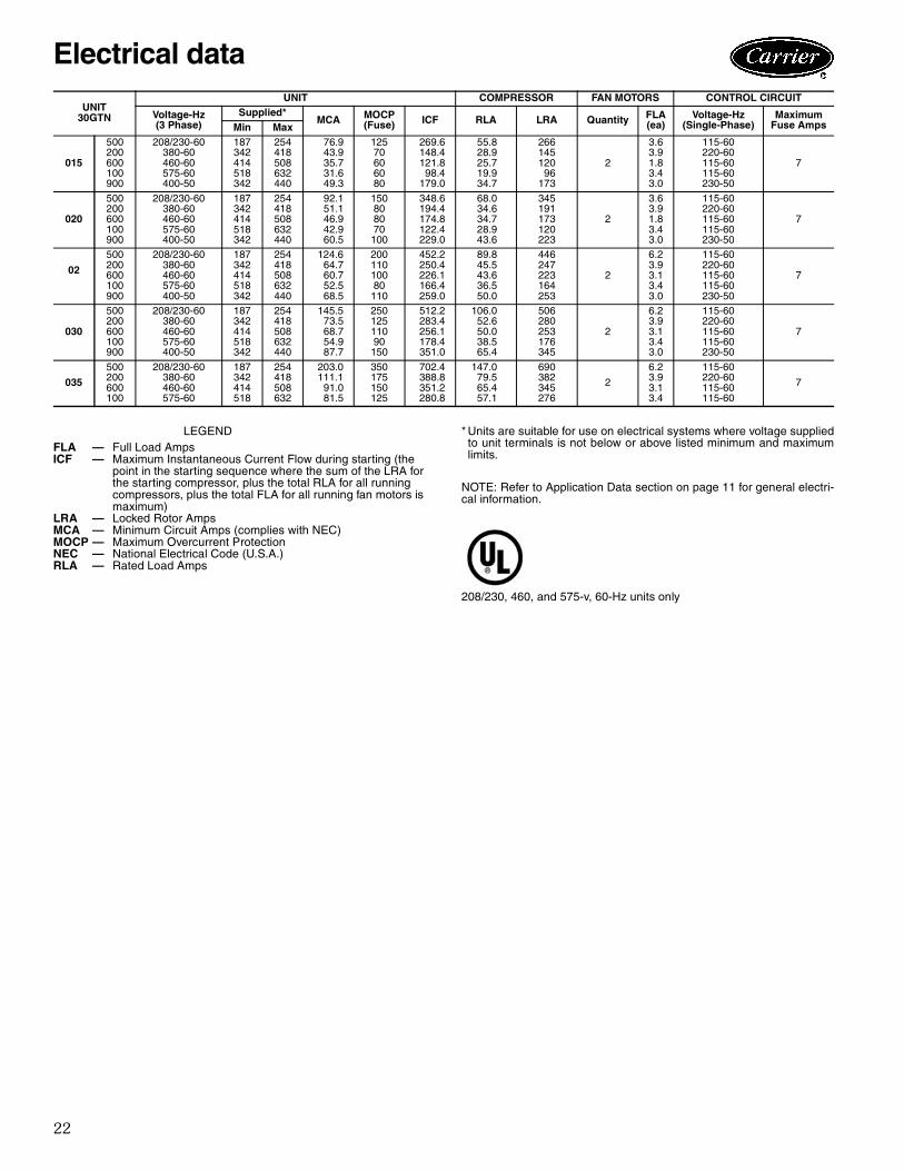
22
* Units are suitable for use on electrical systems where voltage suppliedto unit terminals is not below or above listed minimum and maximumlimits.
NOTE: Refer to Application Data section on page 11 for general electri-cal information.
208/230, 460, and 575-v, 60-Hz units only
UNIT30GTN
UNIT COMPRESSOR FAN MOTORS CONTROL CIRCUIT
Voltage-Hz(3 Phase)
Supplied*MCA MOCP
(Fuse) ICF RLA LRA Quantity FLA(ea)
Voltage-Hz(Single-Phase)
MaximumFuse AmpsMin Max
015
500200600100900
208/230-60380-60460-60575-60400-50
187342414518342
254418508632440
76.943.935.731.649.3
12570606080
269.6148.4121.898.4
179.0
55.828.925.719.934.7
26614512096
173
2
3.63.91.83.43.0
115-60220-60115-60115-60230-50
7
020
500200600100900
208/230-60380-60460-60575-60400-50
187342414518342
254418508632440
92.151.146.942.960.5
150808070100
348.6194.4174.8122.4229.0
68.034.634.728.943.6
345191173120223
2
3.63.91.83.43.0
115-60220-60115-60115-60230-50
7
02
500200600100900
208/230-60380-60460-60575-60400-50
187342414518342
254418508632440
124.664.760.752.568.5
20011010080110
452.2250.4226.1166.4259.0
89.845.543.636.550.0
446247223164253
2
6.23.93.13.43.0
115-60220-60115-60115-60230-50
7
030
500200600100900
208/230-60380-60460-60575-60400-50
187342414518342
254418508632440
145.573.568.754.987.7
25012511090150
512.2283.4256.1178.4351.0
106.052.650.038.565.4
506280253176345
2
6.23.93.13.43.0
115-60220-60115-60115-60230-50
7
035
500200600100
208/230-60380-60460-60575-60
187342414518
254418508632
203.0111.1
91.081.5
350175150125
702.4388.8351.2280.8
147.079.565.457.1
690382345276
2
6.23.93.13.4
115-60220-60115-60115-60
7
LEGENDFLA — Full Load AmpsICF — Maximum Instantaneous Current Flow during starting (the
point in the starting sequence where the sum of the LRA forthe starting compressor, plus the total RLA for all runningcompressors, plus the total FLA for all running fan motors ismaximum)
LRA — Locked Rotor AmpsMCA — Minimum Circuit Amps (complies with NEC)MOCP — Maximum Overcurrent ProtectionNEC — National Electrical Code (U.S.A.)RLA — Rated Load Amps
Electrical data
23
Microprocessor The ComfortLink™ microprocessor controls overall unitoperation. Its central executive routine controls a numberof processes simultaneously. These include internal timers,reading inputs, analog to digital conversions, fan control,display control, diagnostic control, output relay control,demand limit, capacity control, head pressure control, andtemperature reset. Some processes are updated almostcontinuously, others every 2 to 3 seconds, and some every30 seconds.
The microprocessor routine is started by switching theEmergency ON-OFF circuit breaker switch (switch 2) toON position.
When the unit receives a call for cooling (either from theinternal control or CCN network command), the unit stag-es up in capacity to maintain the cooler fluid set point. Thefirst compressor starts 1 to 3 minutes after the call forcooling.
The ComfortLink microprocessor controls the capacityof the chiller by unloading compressors at a rate to satisfyactual dynamic load conditions. The control maintainsleaving-fluid temperature set point shown on quick setscrolling marquee display board through intelligent cyclingof unloaders. Accuracy depends on loop volume, loop flowrate, load, outdoor-air temperature, number of stages, andparticular stage being cycled off. No adjustment for coolingrange or cooler flow rate is required, because the controlautomatically compensates for cooling range by measuringboth return-fluid temperature and leaving-fluid tempera-ture. This is referred to as leaving-fluid temperature con-trol with return-fluid temperature compensation.
The basic logic for determining when to add or removea stage is a time band integration of deviation from setpoint plus rate of change of leaving-fluid temperature.When leaving-fluid temperature is close to set point andslowly moving closer, logic prevents addition of anotherstage. If leaving-fluid temperature is less than 34 F (1.1 C)for water, or 6° F (3.3° C) below the set point for brineunits, the unit is shut off until the fluid temperature goes to34 F (1.1 C) or to 6° F (3.3° C) above the set point to pro-tect against freezing.
If 1° F per minute (0.6° C per minute) pulldown controlhas been selected (factory setting), no additional steps ofcapacity are added as long as difference between leaving-fluid temperature and set point is greater than 4° F(2.2° C) and rate of change in leaving-fluid temperature isless than 1° F per minute (0.6° C per minute).
If it has been less than 90 seconds since the last capacitychange, compressors will continue to run unless a safetydevice trips. This prevents rapid cycling and also helps re-turn oil during short on periods.
The control also performs other special functions whenturning on or off. When a circuit is to be turned off, liquidline solenoid valve (LLSV) is closed first, and compressor isrun until conditions are met to terminate pumpout toremove refrigerant that was in the cooler. At start-up, if a
circuit has not run in the last 15 minutes, circuit is runto remove any refrigerant that has migrated to the cooler.The oil pressure switch is bypassed for 2 minutes duringstart-up and for 1 minute during normal operation.
ThermistorsThree thermistors are used for temperature-sensing inputsto microprocessor. Additional sensors may be used asremote temperature sensors for optional LCWT reset.
• Cooler leaving chilled fluid temperature (T1)• Cooler entering fluid (return) temperature (T2)• Saturated condensing temperature (T3)• Cooler saturation temperature
The microprocessor uses these temperatures to controlcapacity and fan cycling.
Control sequenceOff cycle — During unit off cycle, crankcase heater is en-ergized. If ambient temperature is below 36 F (2 C), coolerheaters (if equipped) are also energized.Start-up — After control circuit switches on, prestart pro-cess takes place, then microprocessor checks itself andwaits for temperature to stabilize. The controlled pulldownfeature limits compressor loading on start-up to reduce de-mand on start-up and unnecessary compressor usage. Themicroprocessor limits supply-fluid temperature decrease(start-up only) to 1° F (0.6° C) per minute.Capacity control — On first call for cooling, micropro-cessor starts initial compressor and fan stage on lead cir-cuit. The LLSV remains closed, permitting a pumpout onstart-up. After pumpout, the valves open and, if necessary,additional outdoor fans are energized. Crankcase heatersare deenergized when a compressor is started. As addi-tional cooling is required, unloaders are deenergized.Speed at which capacity is added or reduced is controlledby 1) temperature deviation from set point and 2) rate oftemperature change of chilled fluid.
The Main Base Board (MBB) responds to temperatureof supply chilled water to cycle the compressor and to con-trol compressor unloading and loading steps.
Solenoid-operated cylinder bank unloaders, energizedby the MBB, vary compressor capacity by unloading andloading cylinders to match cooling load requirements.
Hot gas bypass valve, standard on 30GTN015 (50 Hz)and 30GTN020 (60 Hz), is energized by the MBB. Valveallows hot gas to pass directly into the cooler circuit on thefinal step of unloading. Hot gas bypass maintains constantsuction pressure and permits unit to operate at lower loadswith less compressor cycling. Valve starts to open whensuction pressure drops to about 62 psig (427 kPa). Ifchilled water set point is lower or higher than 44 F (6.7 C),decrease or increase the valve setting for proper operation.
Controls

24
When no further cooling is called for, LLSV closes andcompressor and fans continue to run while pumping downthe cooler.
CAPACITY CONTROL STEPS
*Uses hot gas bypass.
Standard Quickset DisplayStandard control includes a single set point dial and analarm light. Where time scheduling, temperature reset,and EMM options are to be applied with Quickset, Com-fortWORKS® software or CCN field service tool are re-quired to configure those options.
30GTN ComfortLink™ controls with Scrolling Marquee display moduleAn optional four-digit alphanumeric display shows all ofthe ComfortLink control codes (with expandable clear lan-guage), plus set points, time of day, temperatures, pres-sures, and superheat. Additional information can be dis-played all at once with the accessory Navigator display.
Low-temperature overrideThis feature prevents LCWT from overshooting the setpoint and possibly causing a nuisance trip-out by the freezeprotection.
High-temperature overrideThis feature allows chiller to add capacity quickly duringrapid load variations.
Abnormal conditionsAll control safeties in chiller operate through compressorprotection board or control relay and microprocessor.High-pressure switch directly shuts down compressor(s)through compressor protection board or control relay. Forother safeties, microprocessor makes appropriate decisionto shut down a compressor due to a safety trip or bad sen-sor reading and displays appropriate failure code on thedisplay. Chiller holds in safety mode until reset. It then re-verts to normal control when unit is reset.Oil pressure safety — Factory installed on units withbrine option. Field-installed accessory available for stand-ard units. This safety switch cuts out if the oil-pressure dif-ferential is below minimum. Safety is bypassed for 2 min-utes on start-up and must be open for 1 minute during op-eration thereafter for unit to shut down.Loss-of-charge safety — Safety cuts out if system pres-sure drops below minimum.High-pressure cutout — Switch shuts down compres-sors if compressor discharge pressure increases to426 psig (2937 kPa). Ground current safety — Safety opens on sensing acurrent-to-ground in compressor windings in excess of2.5 amps (accessory for all sizes).Compressor anti-cycling — This feature limits com-pressor cycling. Loss of flow protection — Additional protection is pro-vided by temperature differences between entering andleaving fluid temperature sensors if cooler temperaturedrops to 34 F (1.1 C). Proof of flow switches are requiredto be installed.Sensor failures — Failures are detected by themicroprocessor.
UNIT30GTN Hz CONTROL
STEPS%
CAPACITYOPERATING
CYCLES
015
50*12
—50
100
224
60123
3367
100
246
020
50123
3367
100
246
60*12
—50
100
224
025,030 50/60123
3367
100
246
035 60123
3367
100
246
ALARM STATUS SETPOINT
-20°F C
-30°
0°
-20°-10° -0°
-10°
20°
20° 30°40°
50°
70°
Run Status
Service Test
Temperature
Pressures
Setpoints
Inputs
Outputs
Configuration
Time Clock
Operating Modes
Alarms
Alarm Status
ENTER
MODE
ESCAPE
Controls (cont)
25
Accessory controls Demand can be further limited by controlling the chiller ca-pacity through the demand limit control (the Energy Man-agement Module is required for this function). This FIOP/accessory interfaces with microprocessor to control unit sothat chiller’s kW demand does not exceed its setting. It isactivated from an external switch.
The standard ComfortLink™ control is programmed toaccept various accessory temperature reset options (basedon return-fluid temperature, outdoor-air temperature, orspace temperature), that reset the LCWT. An accessorythermistor (T9 or T10) is required if outdoor-air tempera-ture or space temperature reset is selected. The EnergyManagement Module (EMM) is only required for tempera-ture reset that is initiated by a 4 to 20 mA signal.Demand limit — If applied, limits the total power drawof unit to selected point by controlling number of opera-tional compressors during periods of peak electrical de-mand. The Energy Management Module is required for either 2-stage or 4 to 20 mA demand limit.Temperature reset — If applied, microprocessor com-pares either return fluid, space temperature, or outdoor-airtemperature with the accessory board settings, and adjustsLCWT appropriately. The Energy Management Modulecan also be added for 4 to 20 mA reset.
Thermostatic expansion valve — The TXV controlsrefrigerant flow to the cooler for different operating condi-tions. An equalization line and temperature-controlledsensing bulb are used to maintain a fixed setting of super-heated refrigerant leaving the cooler. Diagnostics — For units with optional scrolling marqueedisplay, the microprocessor may be put through a servicetest (see Controls, Start-Up, Operation, Service, and Trou-bleshooting literature) with the optional scrolling marqueedisplay. Service test confirms microprocessor is functional,informs observer through display the condition of eachsensor and switch in chiller, and allows observer to checkfor proper operation of fans and compressors.
Default settingsTo faci l i tate quick start-ups, 30GTN chil lers withComfortLink™ controls are pre-configured with a defaultsetting that assumes stand-alone operation supplying 44 F(6.7 C) chilled water.
Configuration setting will be based on any options or ac-cessories included with the unit at the time of manufactur-ing. Date and time are set to U.S.A. Central Time zoneand will need reconfiguring based on location and localtime zone. If operation based on occupancy scheduling isdesired, this will also need to be set during installation.
26
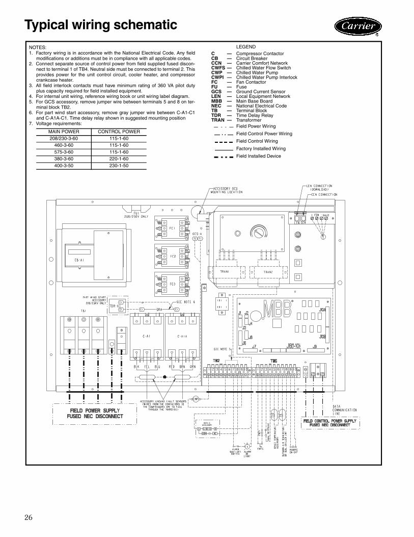
NOTES:1. Factory wiring is in accordance with the National Electrical Code. Any field
modifications or additions must be in compliance with all applicable codes.2. Connect separate source of control power from field supplied fused discon-
nect to terminal 1 of TB4. Neutral side must be connected to terminal 2. Thisprovides power for the unit control circuit, cooler heater, and compressorcrankcase heater.
3. All field interlock contacts must have minimum rating of 360 VA pilot dutyplus capacity required for field installed equipment.
4. For internal unit wiring, reference wiring book or unit wiring label diagram.5. For GCS accessory, remove jumper wire between terminals 5 and 8 on ter-
minal block TB2.6. For part wind start accessory, remove gray jumper wire between C-A1-C1
and C-A1A-C1. Time delay relay shown in suggested mounting position7. Voltage requirements:
MAIN POWER CONTROL POWER208/230-3-60 115-1-60
460-3-60 115-1-60
575-3-60 115-1-60380-3-60 220-1-60
400-3-50 230-1-50
LEGENDC — Compressor ContactorCB — Circuit BreakerCCN — Carrier Comfort NetworkCWFS — Chilled Water Flow SwitchCWP — Chilled Water PumpCWPI — Chilled Water Pump InterlockFC — Fan ContactorFU — FuseGCS — Ground Current SensorLEN — Local Equipment NetworkMBB — Main Base BoardNEC — National Electrical CodeTB — Terminal BlockTDR — Time Delay RelayTRAN — Transformer
Field Power Wiring
Field Control Power Wiring
Field Control Wiring
Factory Installed Wiring
Field Installed Device
Typical wiring schematic
27
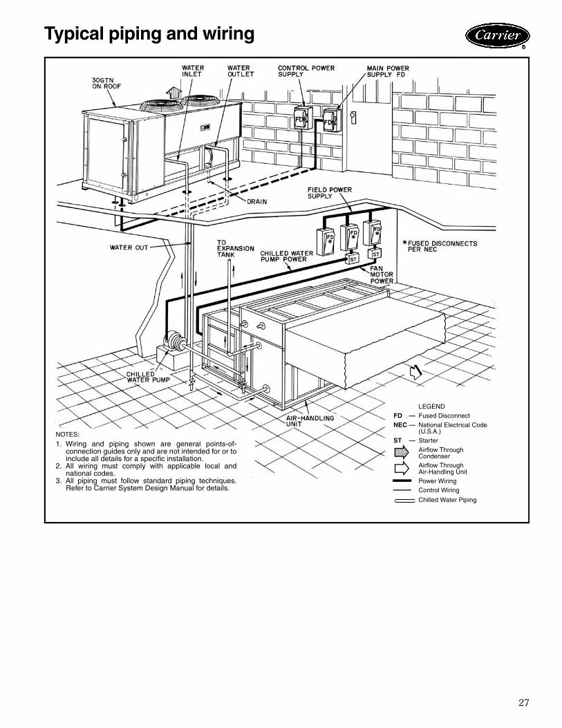
NOTES:
1. Wiring and piping shown are general points-of-connection guides only and are not intended for or toinclude all details for a specific installation.
2. All wiring must comply with applicable local andnational codes.
3. All piping must follow standard piping techniques.Refer to Carrier System Design Manual for details.
LEGENDFD — Fused Disconnect
NEC — National Electrical Code(U.S.A.)
ST — Starter
Airflow ThroughCondenserAirflow ThroughAir-Handling UnitPower WiringControl Wiring
Chilled Water Piping
Typical piping and wiring
28
Reciprocating Air-Cooled Liquid Chiller
HVAC Guide SpecificationsSize Range:15 to 30 tons (53 to 106 kW),
Nominal (50 Hz) 15 to 35 tons (53 to 123 kW),Nominal (60 Hz)
Carrier Model Number: 30GTN
Part 1 — General1.01 SYSTEM DESCRIPTION
Microprocessor controlled, air-cooled liquid chillerutilizing reciprocating compressor and thermalexpansion valves.
1.02 QUALITY ASSURANCEA. Unit shall be rated in accordance with ARI Standard
550/590, latest edition (U.S.A.)B. Unit construction shall comply with ANSI/ASHRAE
15, latest revision, NEC, and ASME applicablecodes (all U.S.A. codes).
C. Unit cabinet shall be capable of withstanding FederalTest Method Standard No. 141 (method 6061)500-hour salt spray test (U.S.A.).
D. Cooler shall be tested and stamped in accordancewith ASME Code (U.S.A.) for a refrigerant working-side pressure of 235 psig (1620 kPa), andshall have a maximum water-side pressure of150 psig (1034 kPa).
E. Air-cooled condenser coils shall be leak testedat 150 psig (1034 kPa) and pressure tested at480 psig (3309 kPa).
F. Unit shall be manufactured in accordance withISO 9001:2000 manufacturing and engineeringquality standard.
1.03 DELIVERY, STORAGE AND HANDLINGA. Unit shall be shipped as a single package only.B. Unit shall be stored and handled per unit manufac-
turer’s recommendations.Part 2 — Products2.01 EQUIPMENT
A. General:Factory-assembled, single-piece, air-cooled liquidchiller. Contained within the cabinet shall be all fac-tory wiring, piping, controls, refrigerant charge(R-22), and special features required prior to fieldstart-up.
B. Unit Cabinet:Galvanized steel casing (zinc phosphatized) with pre-painted enamel finish.
C. Fans: Condenser fans shall be direct-driven propeller typedischarging air vertically upward.
1. Equipped with permanently lubricatedbearings.
2. Equipped with PVC-coated steel wire safetyguards.
3. Shafts shall have inherent corrosion resistance.4. Statically and dynamically balanced.
D. Compressor:1. Reciprocating semi-hermetic type only.2. Each equipped with an automatically revers-
ible oil pump, operating oil charge, suctionand discharge shutoff valves, and an insert-type factory sized crankcase heater to controloil dilution.
3. Each mounted on spring vibration isolators withan isolation efficiency of no less than 95%.
4. Speed shall not exceed 1750 rpm (29.2 r/s).5. Compressor shall unload using suction cutoff
unloading.E. Cooler:
1. Shell-and-tube type with removable heads.2. Tubes shall be seamless copper type rolled
into tube sheets.3. Equipped with threaded-type water
connections.4. Shell shall be insulated with 3/4-in.
(17 mm) closed-cell PVC foam with a maxi-mum K factor of 0.28.
5. Shall be equipped with electric heater alongthe shell under the insulation to protectagainst cooler freeze-up.
F. Condenser:Coil shall be air-cooled with integral subcooler, con-structed of aluminum fins mechanically bonded toseamless copper tubes which are then cleaned,dehydrated, and sealed.
G. Refrigeration Components:Refrigeration circuit components shall included hotgas muffler, high-side pressure relief device, liquidline shutoff valve, suction and discharge shutoffvalves, filter drier, moisture indicating sight glass,thermal type expansion valve, complete operatingcharge of refrigerant R-22, and compressor oil.
H. Controls and Safeties:1. Controls:
a. Unit controls shall include the following min-imum components:
1) Microprocessor.2) Power and control circuit terminal
blocks.3) Enable/off/remote control switch.4) Single set point dial.5) Thermistor installed to measure satu-
rated condensing temperature, as anoption and cooler entering and leavingfluid temperatures.
b. Unit controls shall be capable of performingthe following functions:
1) Pumpout at beginning and end ofevery circuit cycle.
2) Capacity control based on leavingchilled fluid temperature and compen-sated by rate of change of return-fluidtemperature.
3) Limiting of the chilled fluid temperaturepulldown rate at start-up to 1° F(.56°C) per minute to prevent exces-sive demand spikes (charges) at start-up.
Guide specification — 50/60 Hz
29
2. Safeties:a. Unit shall be equipped with thermistors and
all necessary components in conjunctionwith the control system to provide the unitwith the following protections:
1) Loss of refrigerant charge protection.2) Low fluid flow detection.3) Low chilled fluid temperature
protection.4) Low and high superheat protection.5) Low control voltage (to unit) protection.6) High-pressure switch.
b. Compressors shall be equipped with the fol-lowing manual-reset type protections:
1) Pressure overload.2) Electrical overload through the use
of definite-purpose contactors and cali-brated, ambient compensated, mag-netic trip circuit breakers. Circuitbreakers shall open all 3 phases in theevent of an overload in any one phase(single-phasing condition).
3) Fan motors shall have inherent over-current protection.
I. Operating Characteristics:1. Unit shall be capable of starting and running
fully loaded at outdoor ambient temperaturesup to 125 F (52 C).
2. Unit shall be capable of starting up with upto 95 F (35 C) entering-water temperatureto the cooler.
J. Motors:1. Compressor motors shall be cooled by suc-
tion gas passing around motor windings.2. Condenser fan motors shall be 3-phase
type with permanently lubricated bearingsand class B insulation.
K. Electrical Requirements:1. Unit primary electrical power supply shall
be connected to a single point.2. Unit shall operate on 3-phase, 60 Hz or
50 Hz power at the voltage shown in theequipment schedule.
L. Special Features:Certain standard features are not applicable whenfeatures designated by * are specified. *1. Low-Ambient Operation:
Unit shall be capable of starting and runningat outdoor ambient temperatures down to–20 F (– 28.9 C) with the addition of brine inthe cooler circuit and accessory head pressurecontrol.
2. Gage Panel: Unit shall be equipped with suction anddischarge pressure gages with manualshutoff valves.
3. Optional Condenser Coil Materials: a. Pre-Coated Aluminum-Fin Coils:
Shall have a durable epoxy-phenolic coatingto provide protection in mildly corrosivecoastal environments. Coating shall beapplied to the aluminum fin stock prior tothe fin stamping process to create an inertbarrier between the aluminum fin andcopper tube. Epoxy-phenolic barrier shallminimize galvanic action between dissimilarmetals.
b. Copper-fin coils shall be constructed ofcopper fins mechanically bonded to coppertubes. Galvanized steel tube sheets shall notbe acceptable. A polymer strip shallprevent coil assembly from contactingsheet metal coil pan to minimize potentialfor galvanic corrosion between the coil andpan. All copper construction shall pro-vide protection in moderate coastalenvironments.
c. E-Coated aluminum fin coils shall havea flexible epoxy polymer coating uni-formly applied to all coil sur face areaswithout material bridging betweenfins. Coating process shall ensure com-plete coil encapsulation. Color shall be highgloss black with gloss –60° of 65 to 90%per ASTM D523-89. Uniform dry filmthickness from 0.8 to 1.2 mil on all sur-face areas including fin edges. Supe-rior hardness characteristics of 2H perASTM D3363-92A and cross hatch adhe-sion of 4B-5B per ASTM D3359-93.Impact resistance shall be up to160 in./lb (ASTM D2794-93). Humidityand water immersion resistance shall beup to minimum 1000 and 250 hoursrespectively (ASTM D2247-92 and ASTMD870-92). Corrosion durability shall be con-firmed through testing to no less than1000 hours salt spray per ASTM B117-90. Coil construction shall be aluminumfins mechanically bonded to copper tubes.
d. E-Coated copper fin coils shall have a flexi-ble epoxy polymer coating uniformly appliedto all coil surface areas without materialbridging between fins. Coating processshall ensure complete coil encapsulation.Color shall be high gloss black with gloss–60° of 65 to 90% per ASTM D523-89.Uniform dry film thick-ness from 0.8 to1.2 mil on all surface areas including finedges. Superior hardness characteristics of2H per ASTM D3363-92A and crosshatch adhesion of 4B-5B per ASTM3359-93. Impact resistance shall be up to60 in./lb (ASTM D2794-93). Humidity andater immersion resistance shall be up to min-imum 1000 and 250 hours respec-tively (ASTM D2247-91 and ASTM D870-92). Corrosion durability shall be con-firmed through testing to no less than1000 hours salt spray per ASTM B117-90.

30
Coil construction shall be copper finsmechanically bonded to copper tubeswith copper tube sheets. Galvanized steeltube sheets shall not be acceptable. Apolymer strip shall prevent coil assemblyfrom contacting sheet metal coil panto maintain coating integrity andminimize corrosion potential between thecoil and pan.
4. Compressor Oil Safety Switch:This switch senses differential oil pressure andprevents unit operation at low oil pressures.
5. Hot Gas Bypass Valve (standard on 015, 50 Hzand 020, 60 Hz):This field-installed accessory shall permit chillerunloading capacity down to 10% of maximumloaded capacity.
6. Part-Wind Start:Part-wind start shall be field installed to reducecompressor inrush current.
7. Medium Temperature Brine: Special modifications shall be made at the fac-tory to permit operation with leaving chilledwater temperatures between 15 to 37.9 F(–9.4 to 3.3 C).
8. Chilled Water Flow Switch: This field-installed accessory shall sense waterpressure differential across the chiller, and shallprevent unit operation if chilled water flowstops.
9. Control Transformer:This field-installed accessory shall provide atransformer sized to supply the control circuit,and shall source the power from the main unitpower connection.
10. Multi-Chiller Control:The multi-chiller control shall be field installed,and shall sequence up to 8 chillers in parallel.Both the leaving fluid temperature and proof-of-flow inputs shall be monitored by the control.
11. Scrolling Marquee Display:a. Single leaving water temperature set
point potentiometer.b. The diagnostic display module shall be capa-
ble of indicating the safety lockout conditionby displaying a code for which an expla-nation may be scrolled at the display.Information included for display shall be:
1) Compressor lockout.2) Loss of charge.3) Low fluid flow.4) Low oil pressure.5) Cooler freeze protection.6) High or low suction superheat.7) Thermistor malfunction.8) Entering and leaving-fluid temperature.9) All set points.
10) Time of day.c. Display module, in conjunction with the
microprocessor, must also be capable ofdisplaying the output (results) of a servicetest. Service test shall verify operation ofevery switch, thermistor, fan and compres-sor before chiller is started.
12. Energy Management Module (EMM):EMM shall be capable of:a. Leaving temperature reset form space tem-
perature, outdoor temperature, or 4 to20 mA signal.
b. Demand limit or load shed via field sup-plied to 20-mA signal or 2-step discrete con-tact closure.
Guide specifications — 50/60 Hz (cont)

31

Manufacturer reserves the right to discontinue, or change at any time, specifications or designs without notice and without incurring obligations.Pg 32 Catalog No. 523-059 Printed in U.S.A. PC 903 Form 30GTN-2PD
Replaces: 30GT-3PDBook 2Tab 5c
Carrier Corporation • Syracuse, New York 13221 1203 11-99
Book 3Tab RC2
New