
LNG Floating Regasification Unit (FRU) Side-by-Side Mooring ...
Upload
khangminh22Category
view
1download
0
43
3. Discussions
3 DISCUSSIONS BETWEEN THE BIH SIDE AND THE STUDY TEAM
The Team visited BiH in March 2003 to start the first phase of the Study. The first meeting of the
Coordinating Committee was held in Sarajevo on March 12, where the Team gave a briefing to the
meeting on the four - year study project and presented the Inception Report to explain the details.
More meetings were held on March 13, 18, 19, 21, 24 and 27 to discuss the basic matters and
finalize the minutes of meetings. (Minutes of Meetings 2)
On the other hand, detailed discussions about topographic map features to be included in the new
topographic maps for the Principal 21 Cities started on March 25. After the BiH side determined
the items of topographic map feature, several technical meetings were held for discussing detailed
matters, such as definitions of each feature, specifications for data acquisition and specifications
for map symbols, and these matters were finalized before aerial photo - interpretation and field
identification began. At the same time, layer specifications for the GIS data were discussed.
At the start of the second phase in September 2003, a Coordinating Committee meeting was held
to discuss additional matters. Both sides signed the minutes of meetings on these matters, i.e.
specifications of map symbols and marginal information, layer specifications for the GIS data, and
specifications of the equipment for technology transfer sessions. (Minutes of Meetings 3) The layer
specifications for the GIS data are compiled in the specifications' section is in this volume.
In the end of the second phase in February 2004, a Coordinating Committee meeting was held,
where the Team presented the Interim Report to explain details of the works carried out during
the first and the second phases and discussed implementation for the next phases. Main subjects
were such as installation of the equipment for technology transfer sessions in BiH, presentation
of national boundaries on the new maps, provision of the position data of public facilities from
the BiH side, and selection of new map sheets to be offset - printed as final products. After the
meeting, both sides had a technical meeting on the specifications of map symbols and letters for the
new maps. (Minutes of Meetings 4)
During the technology transfer sessions in the third phase, May 2004, the Team had some
discussions with the BiH side about implementation of the succeeding works.
In the process of field completion from September to October 2004, the Team found several
problems especially on specifications of topographic map features and geographic names. So both
sides discussed to find solutions and agreed upon. (Minutes of Meetings 5)

Digital Topographic Maps for Bosnia and Herzegovina
44
In the end of the third phase in January 2005, a Coordinating Committee meeting was held, where
the Team presented the Progress Report to explain the details of the works carried out during
the third phase and discussed implementation for the final phase of the Study. Main subject was
preparation of the Seminar in BiH in the last stage of this project. (Minutes of Meetings 6)
In the end of the forth (final) phase in September 2005, a meeting of the Coordinating Committee
was held, where the Team presented the Draft Final Report explaining the achievement of the
Study and presenting recommendations to the Government of BiH on the future data updating and
servicing. (Minutes of Meeting 7)
Principal matters discussed at the above meetings are described below.
(1) Ellipsoid and ProjectionIn accordance with suggestion of the JICA preparatory study team, the Team presented a proposal
to the BiH side that the digital topographic mapping for the Principal 21 Cities would be based
on WGS - 84 and UTM. The BiH side conditionally agreed on the proposal but requested that
the paper map sheets to be printed would be based on Bessel and Gauss - Kruger because of the
regulation of BiH. After a discussion, the Team accepted it on the condition that additional gridlines
and coordinate values of UTM would be printed in a different color for user’s convenience. (Minutes
of Meetings 2)
(2) Mapping AreasThe Team presented a plan that the mapping areas of the Principal 21 Cities would be those given
in the scope of work agreement in 2002. The BiH side, however, requested the Team to make small
changes of mapping areas by shifting from viewpoint of giving priority to more important areas.
The Team accepted the request on the condition that the map sheets to be printed would be based on
the exiting sheet line system. As a result, some paper map sheets will be partly blank. The mapping
areas accepted are given in Figure 1 - 1. (Minutes of Meetings 2)
A new JICA project the “Study on Sustainable Development through Eco - Tourism in Bosnia
and Herzegovina” was agreed between the government of Japan and the government of Bosnia
and Herzegovina, and the scope of work was signed in August 2003. The eco - tourism areas are
the catchments of the Pliva River and the Velez Mountain range area. The study requires new
topographic maps based on the aerial photos taken in 2003. Therefore, it was agreed on between
the BiH side and the Team that an additional topographic mapping at a scale of 1:25,000 should
be done. The work started in September 2003. The Federal Administration for Geodetic and Real
Property Affairs in the Federation Bosnia and Herzegovina; and the Administration for Geodetic
and Real Property Affairs, the Republic of Srpska have cooperated in the control point survey,
45
3. Discussions
aerial photo interpretation, field identification and field completion. The work, equivalent to ten
map sheets, for the eco - tourism study ended at the end of March 2004. (Minutes of Meetings 2)
(3) Control Point SurveyThe Team presented a proposal that GPS observation would be performed in order to set new points
as the ground control points instead of using existing points. The Team explained that this method
is effective enough for the mapping and more efficient and more economical than conventional
ones and it can keep the surveyors from mine risk. The BiH side, however, requested the Team to
set up aerial signals at existing points as ground control points. After discussion, the Team accepted
the strong request on the condition that, where no suitable existing point is available, a new point
should be established by GPS observation.
The Team also presented a plan that leveling would be performed for vertical control where
necessary. But, the BiH side suggested that, since a lot of existing points with elevation data are
available in the mapping areas, new leveling is not necessarily needed and promised to provide the
Team with these data. The Team accepted the suggestion. (Minutes of Meetings 2)
(4) Topographic Map FeaturesSo many items of topographic map features are included in the existing 1:25,000 topographic maps
made under the regime of the former Socialist Federal Republic of Yugoslavia. Many of these
items do not meet the current condition of BiH. Based on the existing items, both sides discussed
reorganizing the content items for the new topographic maps from a standpoint of meeting the
current needs. As a result, the total number of items has been reduced from 356 to 286. (Minutes
of Meetings 3)
(5) Specifications of the OJT EquipmentRecently GIS technology has been introduced to the Ministries concerned and some other
institutions in BiH. The BiH side mentions that the Ministry of Civil Affairs, Federal Admini
- stration for Geodetic and Real Property Affairs, Federation of BiH, Republic Administration
for Geodetic and Real Property Affairs, Republic of Srpska, and Public Records Department of
the Government of Brcko District have full of responsibility to other Ministries concerned as
topographic and related data supplier. The BiH side also mentions that Arc/Info has been the
prevailing GIS software over these data users. Taking account of the reasons, the BiH side has
an opinion that this software is the most preferable for the Study and the future undertakings, and
requested the Team to transfer the technology of digital mapping through OJT using this software.
In response to the request, the Team proposed a design of the system for digital photogrammetry,
digital plotting and editing, digital map symbolization and GIS. The BiH side accepted it. (Minutes
of Meetings 3)

Digital Topographic Maps for Bosnia and Herzegovina
46
(6) National BoundariesIn the early stage of the project, it was the Team’s understanding that national boundaries would
not be presented on the new maps. But at the meeting, the BiH side proposed that the boundaries
should be presented and the Team accepted it. The BiH side agreed to provide the Team with the
boundary data. It was also confirmed that, if the BiH National Boundary Commission makes a
specific instruction, the mapping mission should follow it. (The data were delivered to the Team
in March 2004, which are image data of boundaries manually drawn on the existing 1:25,000 scale
topographic maps.) (Minutes of Meetings 4)
(7) Mapping Area across the National BoundariesFor the map sheets in which BiH shares the boundary with neighboring countries, it is necessary to
define how far to present neighboring territories. It is foreseen that a map sheet whose presentation
is restricted to the boundary would be inconvenient for map users. So it was confirmed by both
sides that, in case of a section of boundary that is defined by a river course, map presentation should
cover the water surface as far as the opposite shoreline. In case of a section that is not defined by
rivers, the presentation should cover as far as about two centimeters beyond the boundary on the
map. (Minutes of Meetings 4)
(8) Map Sheets to be PrintedA total of fifty - eight (58) sheets for the Principal 21 Cities had been mapped through the processes
of photo interpretation, field identification and digital plotting. According to the original plan,
forty - seven (47) map sheets are to be printed in the last phase of this project and delivered to BiH
accompanied with the plate films. The rest (11 sheets) are to be delivered to BiH only in the form
of data. So the BiH side selected the map sheets to be printed and gave the sheet number list to the
Team. (Minutes of Meetings 4) After the selection, additional ten map sheets for the Eco - tourism
Study areas were specified to be printed.
(9) Map Sheet Names and Geographic NamesIt was foreseen that some sheet names should be renamed for the new maps due to change of
geographic names, etc. So the BiH side promised to provide these names to the Team by September
2004. (Minutes of Meetings 4 and Minutes of Meetings 6)
(10) Position Data of Public FacilitiesPublic facilities such as power lines, gas pipelines, water pipelines and radio wave towers were
foreseen to have changed since the last topographic mapping of the former Yugoslavia. For
presenting up - to - date information on the new maps, the BiH side agreed to provide the Team
with new authorized position data of those by September 2004. (Minutes of Meetings 4)

47
3. Discussions
(11) Specifications of Map Symbols and LettersSpecifications of map symbols and letters for the new maps were agreed as shown in the Interim
Report. But, various unforeseen problems are much likely to happen during digital plotting,
symbolization and field completion processes. So it was also agreed that if some improvement
is needed during the succeeding processes, both sides should discuss amendment. (Several
modifications, additions and cancellations were made during those processes. Those are described
later in Chapter 4. (Minutes of Meetings 4)
(12) Marginal InformationAccording to the agreement between both sides, the Team prepared a sample sheet showing the
layout of marginal information of the new maps and presented the BiH side at the meeting. This
layout was adopted with small amendments. The note regarding the Mapping Project was translated
into local language. (Minutes of Meetings 4)
(13) GIS Data of Additional Mapping AreasDuring the creation of GIS data based on the existing topographic maps, additional mapping of ten
sheets started for Eco - tourism study areas. So it was confirmed that the data for these areas should
be replaced with the new data resulting from the additional mapping. (Minutes of Meetings 5)
(14) Image of the New MapThe Team prepared sample copies of symbolized map sheets in Japan and showed them to collect
comments from the BiH side in May 2004. The Team also brought an offset - printed sheet (Raska
Gora) from Japan and showed it to the BiH side so as to check the image of final printed maps.
This one was prepared to be similar to the existing 1:25,000 topographic maps. JP Geodetski Zavod
tested printing the same sheet using the films brought by the Team. (Minutes of Meetings 6)
(15) Official CheckThe Team explained the technical approach adopted for lettering geographic names on the new
maps. Both sides confirmed that the BiH side should make an official check for the national
boundaries and all the lettered geographic names on the draft symbolized map sheets during field
completion.
(16) Partly Blank Sheets
Both sides reconfirmed that, among the forty - seven (47) sheets to be printed, nine (9) sheets would be partly blank due to lack of data.
(17) Delivery of the Results for Eco - tourism Study Areas
Both sides confirmed that the results of 1:25,000 topographic mapping for eco - tourism study areas
should be delivered to the Ministry of Civil Affairs.

Digital Topographic Maps for Bosnia and Herzegovina
48
(18) SeminarIt was confirmed that a one - day seminar should be held in Sarajevo in September 2005 aiming to
publicize the new digital topographic maps to the public. It was also confirmed that the Ministry of
Civil Affairs, BiH and the Team should jointly organize the seminar. (Minutes of Meetings 6)
(19) RecommendationsAccepting the Draft Final Report at the meeting of the Coordinating Committee on September
27, 2005, the BiH side mentioned an intention to prepare its official report based on the
recommendations given by the Team and to present it to the Ministry of Civil Affairs, the Council
of Minister of BiH and others concerned in the BiH authorities. The Team supported the intention.
(Minutes of Meetings 7)
(20) Others
During field completion process, the Team requested the BiH side to provide names of the new map sheets and names of the adjoining map sheets. The BiH side satisfied the request in December 2004.
The BiH side requested the Team to provide the BiH counterparts with supplementary instructions on digital plotting. The Team extended its stay for two weeks and gave instructions both in Sarajevo and Bijeljina.
49
4. Processes
4 PROCESSESThe topographic data production, which is the new mapping and GIS data creation, was conducted through the following processes.
4-1 Control Point Survey and Signalization of Control PointsFor the new mapping, the Principal 21 Cities were divided into 14 blocks for control point survey and aerial triangulation first. Then, another two blocks were added for the Eco-tourism Study.
4-1-1 Initial Plan and Actual Works
The Team's initial plan to prepare ground control points (GCPs) was to perform GPS observation and pricking at newly selected points and also to perform leveling where necessary vertical data lacked. Signalization of control points was planned only at the points where it would be difficult to prick due to monotonous land cover.
But the BiH side mentioned in the discussions that, since there are a number of existing control points available, no more new points have to be established and they requested the Team to signalize control points at the existing control points.
The Team recommended the initial plan under apprehension that many of the existing control points must be missing or the description of points must have become obsolete due to a long lapse of time and big land use changes. The Team mentioned that even if the points exist, it must be difficult and time-wasting to access them because of unfavorable conditions such as steep slopes, forests, possible land mines and inaccessibility by vehicles. After discussion, both sides came to an agreement that signals would be set at the existing points, but when easily identifiable control points do not exist within the planned areas, new control points should be established by GPS survey and pricking at the sites that would be easily recognizable on the photos.
The BiH side suggested that the Team should use the uniformly distributed existing control points instead of conducting the leveling work because these points have three dimensional coordinate val-ues that satisfy the precision requirement for the height correction. The Team acknowledged the suggestion and received the list of the coordinates (about 5,000 points).
After aerial photography, several points were found to be in need of pricking because the signals were unrecognized on the photos. Pricking works were performed by the Team during field identification survey from September to October 2003.
4-1-2 Details of the work
(1) Selection of Control Points
Based on a tentative plan prepared in Japan, existing control points marked on the existing 1:25,000 scale topographic maps were examined in order to select the GCPs suitable for the new mapping. The points were confirmed in the field.
(2) Signalization of Control Points
Digital Topographic Maps for Bosnia and Herzegovina
50
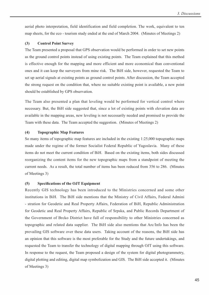
Signalization of existing control points was done for preparing GCPs for each block in locations suited for aerial triangulation. In order to avoid unfavorable locations such as forests, minefields, and mountainous areas, the forth order control points near roads or in arable lands were selected. Where the existing control points were missing or inaccessible, signals were set up at new points not far from the planned locations. (Photo 4-1)
Photo 4 - 1 Control Point Survey Planning
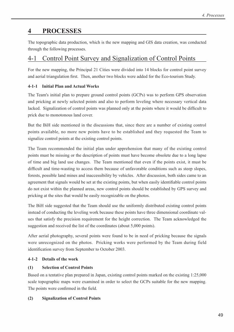
Signals with three 1m × 3m wings in a radial pattern were set at the existing control points where stone markers were confirmed during the fieldwork. At a location where the stone marker was not confirmed and no other points were available in proximity, a new stone marker was set up at a new control point and a signal was established. (Photo 2-5, 2-7, 4-2, 4-3)
Photo 4-2 Aerial Signal 1 Photo 4-3 Aerial Signal 2

51
4. Processes
(3) GPS Observation
A total of ten sessions of GPS observation were conducted in the Federation side for all the control points, and three sessions were conducted in the Republic side including three new control points in Block 8 and Block 12.
The maximum of five the dual frequency receivers, Trimble 4000SSE, of the counterpart agencies were used for the static method of observation. The general observation time was set to two hours.
All the sessions of the GPS base line analysis and the closure precision observation resulted in precision of less than several centimeters (± 2ppm or less). Based on the results of the base line analysis, the coordinate values of the BiH National Coordinate System were calculated by the network adjustment processing by block.
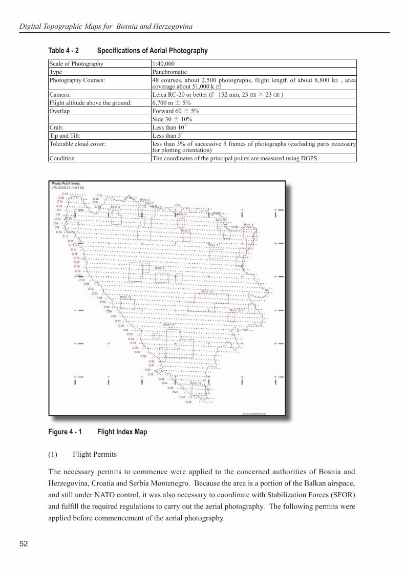
4-2 Aerial PhotographyThe aerial photography at a scale of 1:40,000 was performed for the whole territory of BiH, about 51,000 km2, from July to August 2003 by a sub-contractor, FM-International Oy FINNMAP. Flight courses totaled 48 and 2,702 photos were taken. The flight index map was prepared in the Auto-Cad-format and delivered in the diskette.
The aerial photography mission was based at the Sarajevo International Airport. The survey aircraft, Rockwell Turbo Commander 690, N91384 was mobilized to Sarajevo on June 28, 2003. After the test flight on July 2, 2003, the aerial photography started on July 3, 2003. Flights were performed when the weather conditions allows the photography. The entire area was completed on August 9, 2003. Totally 23 aerial photography flights were performed to complete the aerial photography. The demobilization took place on August 12, 2003 after the quality of the aerial photography was guaranteed.
Table 4 - 1 Output of the Aerial PhotographyItem Quantity
Original film negatives 1 setRush prints 1 setContact prints 2 setsFlight Index 1 set List of photo center coordinates 1 setFlight records 1 setFinal Report 1 set
Digital Topographic Maps for Bosnia and Herzegovina
52
Table 4 - 2 Specifi cations of Aerial PhotographyScale of Photography 1:40,000Type PanchromaticPhotography Courses: 48 courses, about 2,500 photographs, flight length of about 8,800 ㎞ , area
coverage about 51,000 k ㎡ Camera: Leica RC-20 or better (f= 152 mm, 23 ㎝ × 23 ㎝ ) Flight altitude above the ground: 6,700 m± 5% Overlap Forward 60 ± 5%
Side 30 ± 10% Crab: Less than 10°Tip and Tilt: Less than 5°Tolerable cloud cover: less than 3% of successive 5 frames of photographs (excluding parts necessary
for plotting orientation)Condition The coordinates of the principal points are measured using DGPS.
Figure 4 - 1 Flight Index Map
(1) Flight Permits
The necessary permits to commence were applied to the concerned authorities of Bosnia and Herzegovina, Croatia and Serbia Montenegro. Because the area is a portion of the Balkan airspace, and still under NATO control, it was also necessary to coordinate with Stabilization Forces (SFOR) and fulfi ll the required regulations to carry out the aerial photography. The following permits were applied before commencement of the aerial photography.

53
4. Processes
Table 4 - 3 Permits for Aerial PhotographyIssuing Authority Issued Date Note
NATO/SFOR May 16, 2003 General Permission
Republic Serbia and MontenegroMay 27, 2003 The permit for border crossing of the border between
Bosnia and Herzegovina – Republic Serbia and Montenegro
Federal Ministry of Defense of the Federation Bosnia and Herzegovina
May 30, 2003 Permit from Military
Ministry of Defense of Srpska Republic June 10, 2003 Permit from Military
Republic of CroatiaJune 18, 2003 The permit for border crossing of the border between
Bosnia and Herzegovina - CroatiaJune 30, 2003 Final corrected permit
Directorate Depar tment of Civi l Aviation, BiH
June 26, 2003 Landing PermitJuly 1, 2003 Authorization to carry out the aerial photography flights
(2) Aerial photographing
Aerial photography was carried out according to the Technical Specification. All the flight lines were planned using WWMP-software. The aerial photography area was divided into the four (4) blocks according to the ground elevation.
KODAK AERO LX 2408 and Agfa Aviphot Pan 80 black and white aerial photography film were used for the project.
Table 4 - 4 Summary of Aerial PhotographyProject Manager Mr. Timo JärvinenAssit. Project Manager and ADGPS Computations Mr. Jussi-Pekka SaariPilot Ms. Ciara McGurkNavigator Mr. Ian McDougallAircraft Model Rockwell Turbo Commander 690 A, N91384
Camera
Camera Type Leica RC 20Lens Type 15/4 UAGA-FNo. 13158Calibration date 02.10.2000
GPS Navigation System CCNS 4
Differential GPS Registration
BASE STATION Ashtech Z-12 Dual frequency receiver 10 Mb memory
AIRCRAFT B
Rockwell Turbo Commander 690 N91384
Ashtech Z-12 Dual frequency receiver
10 Mb memory Photo option
Data recording interval 1 second
The coordinates of base station were observed from the existing first order geodetic station No.833 at Kosevo Stadium in Sarajevo. All the data was processed daily after the aerial photography by Ashtech (PNAV) Precision Navigation -software using forward and backward processing method.
The eccentricity components between camera perspective and aircraft phase centers were as in the following table:

Digital Topographic Maps for Bosnia and Herzegovina
54
Table 4 - 5 Eccentricity ComponentsX (m) Y(m) Z(m)
Rockwell Turbo Commander 690 N91384
+0.300 -0.205 +1.255
(3) Photographic Processing
Processing of the aerial photographs was carried out in FM-Kartta Oy’ s photography laboratory in Helsinki, Finland. KODAK black and white film processor was used for film developing. Contact prints were printed with SPEC automatic dodging printer. The film annotation was carried out according to the Technical Specifications and the instruction by the Study Team. The letter included the following data: (1) JICA MAPPING PROJECT; (2) Scale of photography 1:40000; (3) Flight course number; (4) Serial number of camera & lens; (5) Flight altitude; and (6) Photo number.
4-3 Photo Interpretation and Field IdentificationThe Team members for this work were dispatched to BiH twice in 2003. The first work was conducted from June 21, 2003 to August 19th, 2003; the second was from September 17th, 2003 to November 30, 2003. A total of eleven persons from the counterpart agencies participated in this work. Their names are listed in Table 2 - 4.
During the first work, because of delay in start of aerial photography, sixty aerial signals had to be inspected. Damaged or missing signals were repaired by the counterparts. The aerial signals inspected are as follows:
Table 4 - 6 Aerial Signal Inspection
Block PointsBlock1 0101, 0102, 0103, 0104Block2 0201, 0202, 0203, 0204Block3 0301, 0302, 0304, 0305, 0306, 0307Block4 0401, 0402, 0403, 0404Block5 0501, 0502, 0503, 0504Block6 0601, 0602, 0603, 0604Block7 0701, 0702, 0703, 0704Block8 0801, 0802, 0803, 0804, 0805, 0806, 0807Block9 0901, 0902, 0903, 0904, 0905, 0906, 0907Block10 1001, 1002Block11 1101, 1102, 1103, 1104, 1105, 1106, 1107Block13 1301, 1302, 1303, 1304, 1305, 1306, 1307
55
4. Processes
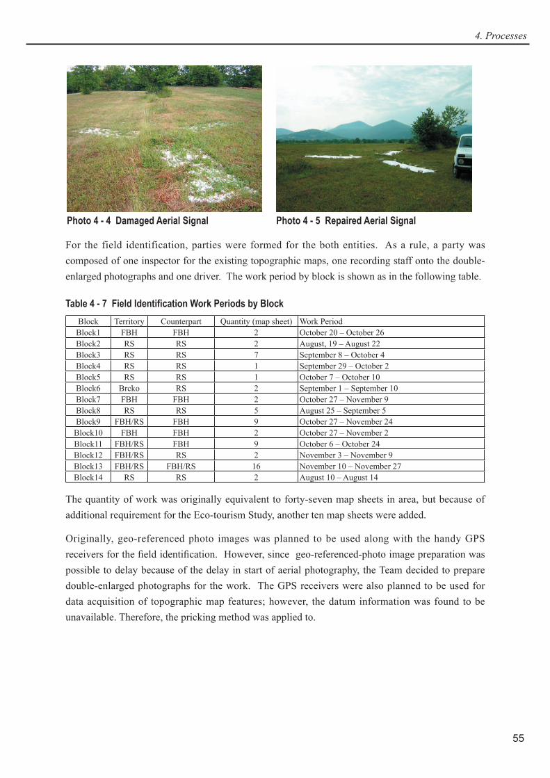
Photo 4 - 4 Damaged Aerial Signal Photo 4 - 5 Repaired Aerial Signal
For the field identification, parties were formed for the both entities. As a rule, a party was composed of one inspector for the existing topographic maps, one recording staff onto the double-enlarged photographs and one driver. The work period by block is shown as in the following table.
Table 4 - 7 Field Identification Work Periods by BlockBlock Territory Counterpart Quantity (map sheet) Work PeriodBlock1 FBH FBH 2 October 20 – October 26Block2 RS RS 2 August, 19 – August 22Block3 RS RS 7 September 8 – October 4Block4 RS RS 1 September 29 – October 2Block5 RS RS 1 October 7 – October 10Block6 Brcko RS 2 September 1 – September 10Block7 FBH FBH 2 October 27 – November 9Block8 RS RS 5 August 25 – September 5Block9 FBH/RS FBH 9 October 27 – November 24
Block10 FBH FBH 2 October 27 – November 2Block11 FBH/RS FBH 9 October 6 – October 24Block12 FBH/RS RS 2 November 3 – November 9Block13 FBH/RS FBH/RS 16 November 10 – November 27Block14 RS RS 2 August 10 – August 14
The quantity of work was originally equivalent to forty-seven map sheets in area, but because of additional requirement for the Eco-tourism Study, another ten map sheets were added.
Originally, geo-referenced photo images was planned to be used along with the handy GPS receivers for the field identification. However, since geo-referenced-photo image preparation was possible to delay because of the delay in start of aerial photography, the Team decided to prepare double-enlarged photographs for the work. The GPS receivers were also planned to be used for data acquisition of topographic map features; however, the datum information was found to be unavailable. Therefore, the pricking method was applied to.

Digital Topographic Maps for Bosnia and Herzegovina
56
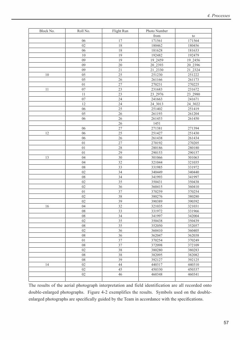
Table 4 - 8 Double-Enlarged Photographs for Field IdentificationBlock No. Roll No. Flight Run Photo Number
from to1 BOSNIA 03 7 7_0569 7_0575 07 8 81798 81792
07 9 9_1800 9_180707 10 101907 101901
2 03 4 40798 4079403 5 50703 5070703 6 60549 6054603 6 60699 6069607 7 70587 7059307 8 81779 81774
3 04 2 20824 2082104 3 30858 3086503 4 40787 4077903 5 50714 5072103 6 60688 6068403 7 70604 7060807 8 81769 8176207 9 91836 9183007 10 101878 10187209 11 112261 112255
4 03 5 50731 5073303 6 60675 6067103 7 70618 7062110 8 82537 82541
5 10 8 82541 8254307 9 91849 9185207 10 101859 10185510 11 112564 112568
6 03 6 60658 6065403 7 70638 7063310 8 82554 8255810 8 82688 8269110 9 92676 9266810 10 102643 102647
7 10 13 132748 13274110 14 142713 14271911 15 152789 152796
8 03 7 70645 7065010 8 82695 8270110 9 92664 9265810 10 102651 10265710 11 112588 11259310 12 122601 12259510 13 132736 13273210 14 142724 14272911 15 152800 15280411 16 162811 162807
9 09 19 19_2467 19_246109 20 20_2383 20_239109 21 21_2322 21_2318
15 07 15 151709 15170606 16 161604 16159806 17 171554 17155811 17 172871 172866
57
4. Processes
Block No. Roll No. Flight Run Photo Numberfrom to
06 17 171561 17156402 18 180462 18045606 18 181628 18163310 19 192482 19247909 19 19_2459 19_245609 20 20_2393 20_239609 21 21_2330 21_2324
10 05 25 251230 25122205 26 261166 26117301 27 270231 270225
11 07 23 231683 23167211 23 23_2976 23_298007 24 241663 24167112 24 24_3013 24_302206 25 251402 25141905 26 261193 26120406 26 261453 261450 26 1451 06 27 271381 271394
12 06 25 251427 25143006 26 261438 26143401 27 270192 27020501 28 280186 28018001 29 290153 290157
13 04 30 301066 30106304 32 321044 32103508 33 331985 33197202 34 340449 34044008 34 341993 34199702 35 350431 35043802 36 360415 36041001 37 370259 37025402 38 380276 38028002 39 390389 390392
16 04 32 321035 32103108 33 331972 33196608 34 341997 34200402 35 350438 35043908 35 352050 35205702 36 360410 36040508 36 362047 36203801 37 370254 37024908 37 372098 37210902 38 380280 38028308 38 382095 38208208 39 392127 392125
14 02 44 440317 44031002 45 450330 45033702 46 460348 460341
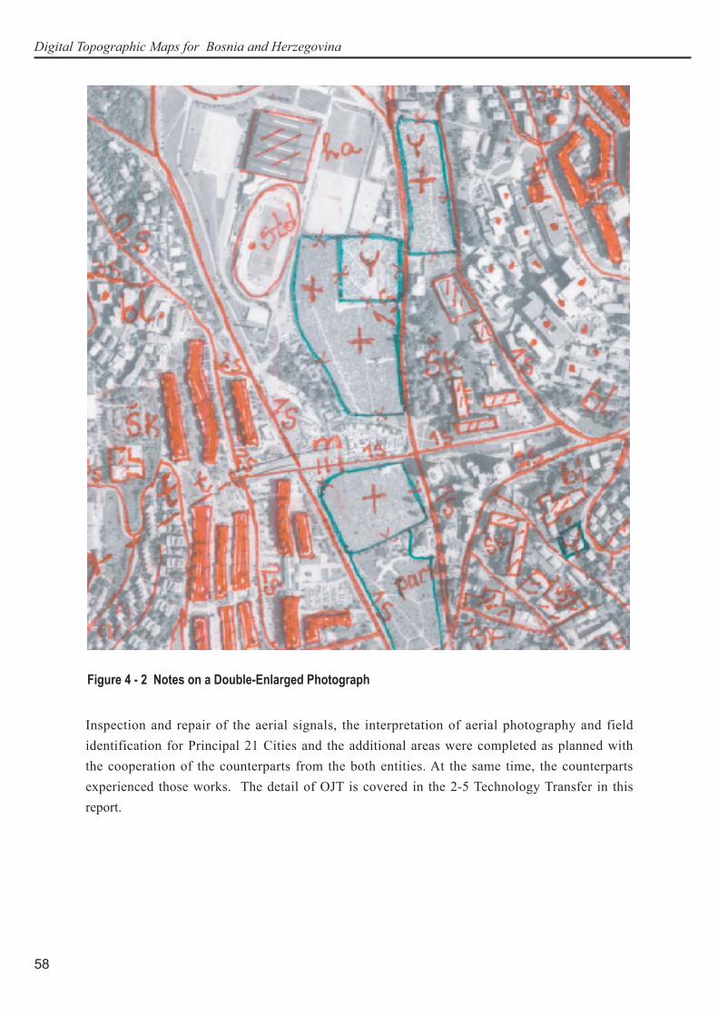
The results of the aerial photograph interpretation and field identification are all recorded onto double-enlarged photographs. Figure 4-2 exemplifies the results. Symbols used on the double-enlarged photographs are specifically guided by the Team in accordance with the specifications.
Digital Topographic Maps for Bosnia and Herzegovina
58
Inspection and repair of the aerial signals, the interpretation of aerial photography and field identification for Principal 21 Cities and the additional areas were completed as planned with the cooperation of the counterparts from the both entities. At the same time, the counterparts experienced those works. The detail of OJT is covered in the 2-5 Technology Transfer in this report.
Figure 4 - 2 Notes on a Double-Enlarged Photograph
59
4. Processes
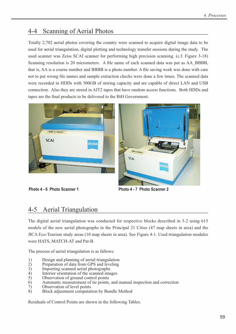
4-4 Scanning of Aerial PhotosTotally 2,702 aerial photos covering the country were scanned to acquire digital image data to be used for aerial triangulation, digital plotting and technology transfer sessions during the study. The used scanner was Zeiss SCAI scanner for performing high precision scanning. (c.f. Figure 3-18) Scanning resolution is 20 micrometers. A file name of each scanned data was put as AA_BBBB, that is, AA is a course number and BBBB is a photo number. A file saving work was done with care not to put wrong file names and sample extraction checks were done a few times. The scanned data were recorded in HDDs with 500GB of storing capacity and are capable of direct LAN and USB connection. Also they are stored in AIT2 tapes that have random access functions. Both HDDs and tapes are the final products to be delivered to the BiH Government.
Photo 4 - 6 Photo Scanner 1 Photo 4 - 7 Photo Scanner 2
4-5 Aerial TriangulationThe digital aerial triangulation was conducted for respective blocks described in 3-2 using 615 models of the new aerial photographs in the Principal 21 Cities (47 map sheets in area) and the JICA Eco-Tourism study areas (10 map sheets in area). See Figure 4-1. Used triangulation modules were HATS, MATCH-AT and Pat-B.
The process of aerial triangulation is as fallows:
1) Design and planning of aerial triangulation2) Preparation of data from GPS and leveling3) Importing scanned aerial photographs4) Interior orientation of the scanned images5) Observation of ground control points6) Automatic measurement of tie points, and manual inspection and correction7) Observation of level points8) Block adjustment computation by Bundle Method
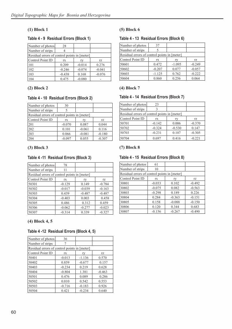
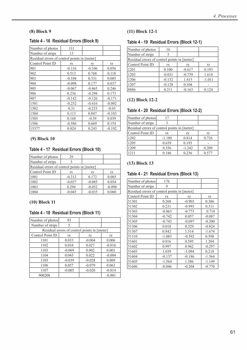
Residuals of Control Points are shown in the following Tables.
Digital Topographic Maps for Bosnia and Herzegovina
60
(1) Block 1
Table 4 - 9 Residual Errors (Block 1)Number of photos 28Number of strips 4Residual errors of control points in [meter]Control Point ID rx ry rz101 0.209 -0.014 0.276102 -0.246 -0.074 -0.041103 -0.438 0.168 -0.076104 0.475 -0.080 -
(2) Block 2
Table 4 - 10 Residual Errors (Block 2)Number of photos 30Number of strips 5Residual errors of control points in [meter]Control Point ID rx ry rz201 -0.070 0.087 0.044202 0.101 -0.061 0.116203 0.066 -0.081 -0.180204 -0.097 0.055 -0.307
(3) Block 3
Table 4 -11 Residual Errors (Block 3)Number of photos 78Number of strips 11Residual errors of control points in [meter]Control Point ID rx ry rz50301 -0.129 0.149 -0.78450302 -0.017 -0.039 -0.163 50303 0.439 -0.487 -0.48750304 -0.403 0.003 0.45850305 0.486 0.312 0.45950306 -0.062 -0.277 -0.02350307 -0.314 0.339 -0.327
(4) Block 4, 5
Table 4 -12 Residual Errors (Block 4, 5)Number of photos 36Number of strips 7Residual errors of control points in [meter]Control Point ID rx ry rz50401 -0.013 -1.136 0.57050402 0.859 -0.677 0.157 50403 -0.234 0.219 0.62850404 -0.804 1.381 -0.46350501 0.476 0.089 0.286 50502 0.010 0.542 0.55350503 -0.716 -0.183 0.92650504 0.421 -0.234 0.640
(5) Block 6
Table 4 - 13 Residual Errors (Block 6)Number of photos 37Number of strips 5Residual errors of control points in [meter]Control Point ID rx ry rz50601 0.472 -1.095 -0.24950602 -0.207 0.077 -0.05750603 -1.125 0.762 -0.22250604 0.860 0.256 0.064
(4) Block 7
Table 4 - 14 Residual Errors (Block 7)Number of photos 23Number of strips 3Residual errors of control points in [meter]Control Point ID rx ry rz50701 -0.142 0.006 -0.370 50702 -0.324 -0.530 0.14750703 -0.231 0.107 -0.30550704 0.697 0.416 -0.221
(7) Block 8
Table 4 - 15 Residual Errors (Block 8)Number of photos 61Number of strips 10Residual errors of control points in [meter]Control Point ID rx ry rz30801 -0.033 0.102 -0.49230802 -0.075 0.082 -0.56330803 -0.298 0.189 0.22630804 0.284 -0.363 -0.151 30805 0.158 -0.088 -0.150 30806 0.120 0.344 0.68330807 -0.156 -0.267 -0.490
61
4. Processes
(8) Block 9
Table 4 - 16 Residual Errors (Block 9)Number of photos 111Number of strips 13Residual errors of control points in [meter]Control Point ID rx ry rz901 -0.116 -0.106 0.056902 0.513 0.768 0.118903 -0.104 0.331 0.085904 -0.098 0.177 0.037905 -0.067 -0.465 0.246906 0.236 -0.298 0.173907 -0.142 -0.126 -0.1711501 -0.252 -0.416 -0.0921502 0.31 -0.233 -0.031504 0.113 0.047 -0.1031505 0.168 -0.59 0.0391506 -0.586 0.669 0.15415377 0.024 0.243 -0.192
(9) Block 10
Table 4 - 17 Residual Errors (Block 10)Number of photos 29Number of strips 3Residual errors of control points in [meter]Control Point ID rx ry rz1001 -0.212 0.172 0.0851002 -0.037 -0.085 0.0541003 0.294 -0.052 -0.0981004 -0.045 -0.035 0.060
(10) Block 11
Table 4 - 18 Residual Errors (Block 11)Number of photos 93Number of strips 5
Residual errors of control points in [meter]Control Point ID rx ry rz
1101 0.033 -0.004 0.0061102 0.034 0.027 -0.0161103 -0.069 0.002 0.0011104 0.045 0.022 -0.0041105 -0.039 -0.028 0.0091106 0.057 -0.079 0.0631107 -0.005 -0.020 -0.014900208 -0.001
(11) Block 12-1
Table 4 - 19 Residual Errors (Block 12-1)Number of photos 16Number of strips 3Residual errors of control points in [meter]Control Point ID rx ry rz1201 0.100 -0.617 0.1931203 -0.031 -0.739 1.6141206 -0.152 1.415 -1.0111207 -0.128 0.104 -8886 0.211 -0.163 0.124
(12) Block 12-2
Table 4 - 20 Residual Errors (Block 12-2)Number of photos 17Number of strips 3Residual errors of control points in [meter]Control Point ID rx ry rz1202 -1.180 0.814 0.7261205 0.639 0.193 -1209 0.356 -1.242 0.2091211 0.186 0.236 0.577
(13) Block 13
Table 4 - 21 Residual Errors (Block 13)Number of photos 176Number of strips 9Residual errors of control points in [meter]Control Point ID rx ry rz51301 0.268 -0.903 0.38651302 0.231 -0.993 0.311 51303 -0.063 -0.773 0.71851304 -0.742 0.057 -0.08751305 -0.743 -0.097 -0.20051306 0.018 0.329 -0.82451307 0.842 1.514 -1.67451310 -1.083 -0.592 0.59851601 0.016 0.595 1.204 51602 0.997 0.962 -0.297 51603 1.039 -1.094 0.21851604 -0.137 -0.186 -1.56451605 -1.564 1.386 -1.14951606 -0.046 -0.204 -0.770

Digital Topographic Maps for Bosnia and Herzegovina
62
(14) Block 14
Table 4 - 22 Residual Errors (Block 14)Number of photos 24Number of strips 3Residual errors of control points in [meter]Control Point ID rx ry rz1401 -0.014 -0.004 0,0131402 -0.001 0.003 -0.0101403 0.000 -0.001 -0.0011404 0.003 -0.005 0.005401 0.015 0.017 0.008402 -0.007 0.003 0.004403 0.004 -0.013 -0.002
Inspection of Aerial Triangulation Results
The values of the standard deviation for the residual errors (rx, ry and rz) of the coordinates of the control points need to be 0.02% of the heights above ground or lower, and the maximum value of the residual errors shall not exceed 0.04% of the heights above ground. The height above ground is about 6,000 meters; 0.02% of 6,000 meters is 1.2 meters. Therefore, all the values satisfy the standard.
After the adjustment calculation, the triangulation results were imported to the digital plotter and the following inspection was conducted on the stereoscopic models. There was no problem with the inspection result.
1. No existence of y-parallax.2. Good connection between adjacent models and adjacent courses3. Correctness of the check points coordinates
4-6 Digital PlottingA total number of map symbols from the existing topographic maps were 356. The total number is reduced to 286 after the study team reorganized the map symbols to be plotted without losing the amount of information.
The total area of mapping for the Principal 21 Cities is 6,400 km2 or 47 in terms of full sheets. But the actual count of map sheets covering the mapping areas has increased to 58, since several of the mapping areas were partially shifted in response to the request of the BiH side in March 2003.
In addition, ten (10) more map sheets were mapped for the JICA Eco-tourism Study areas. Consequently, the total count of the sheets is 68.
The digital plotting systems used were as follows:
1) DiAp (based on MicroStation software)2) Summit Evolution (based on AutoCAD or MicroStation software)3) Socet Set (based on MicroStation software)The main processes of digital plotting were as follows:

63
4. Processes
1) Importing of the aerial triangulation results2) Importing of the stereo-pair images3) Plotting viewing three-dimensional images4) Extracted data check5) Data storing in CAD formatThe digital plotting work was done according to the following instructions:
1. To acquire the data based on the “Specifications for Digital Topographic Data Acquisi-tion” agreed between the BiH side and the Team. The specifications are compiled in the specificaitons section of this volume.
2. The plotting area is the following;
1) Where the national boundary is defined by a wide river, plotting should be done as far as the opposite shoreline.
2) Where the national boundary is not defined by a wide river, plotting should be done as far as about 2cm beyond the national boundary at the scale of 1:25,000.
3. To put the neat lines of the existing maps.4. Each polygon feature should have a point with the code number inside.5. When there are blank areas inside of a polygon (layer number: XXXX), input XXXXin into
the layer number attribute of the blank polygons.6. To acquire the data of roads, railways, rivers, canals, waterways, various pipelines, power
lines, or contour lines as the continuous line.7. To acquire the line type bridge/tunnel data copying the road/railway data, if the road/railway
passes on the bridge. The same way should be used between overlapped line features.8. The destroyed houses, whose walls remain, should be acquired as buildings.9. If small individual buildings (3522) exist densely, make groups of two or three buildings
and acquire only one center point of each group as one small individual building.10. Destroyed large factories or closed large factories should be acquired as large individual
buildings (3718).11. Each mosque is sure to have the steeple. Confirm it.12. To check and correct the contour lines three-dimensionally if you make them automatically
using DTM, etc.13. To put 7 or 8 spot heights including control points and elevation values of contour lines in a
area of 10 cm x 10 cm on the 1:25,000 scale map.14. To see the existing maps in case the photo-interpretation is difficult.Character of the final data is the following;
1. The data format is DXF ASCII format version 12.2. The used data types were only Point, Line, Polyline or Single line text.GIS data were also created by ArcGIS software using these plotted data. The particulars are given later in this section.
Digital Topographic Maps for Bosnia and Herzegovina
64
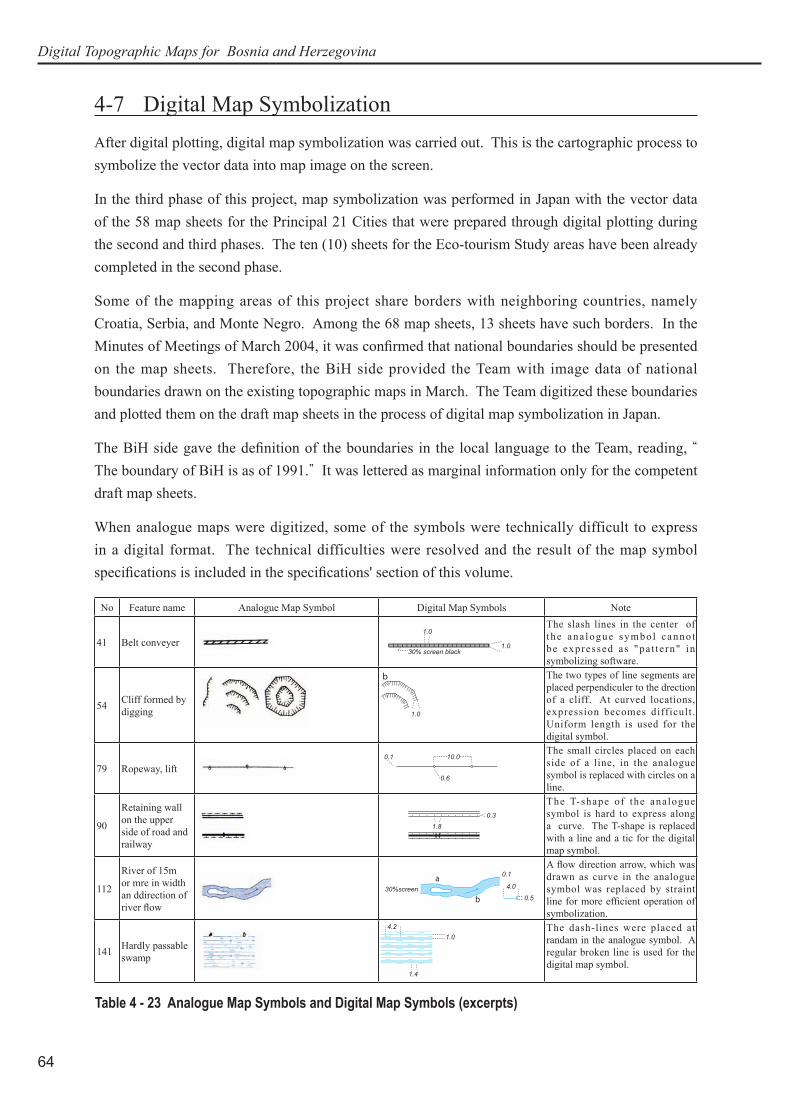
4-7 Digital Map SymbolizationAfter digital plotting, digital map symbolization was carried out. This is the cartographic process to symbolize the vector data into map image on the screen.
In the third phase of this project, map symbolization was performed in Japan with the vector data of the 58 map sheets for the Principal 21 Cities that were prepared through digital plotting during the second and third phases. The ten (10) sheets for the Eco-tourism Study areas have been already completed in the second phase.
Some of the mapping areas of this project share borders with neighboring countries, namely Croatia, Serbia, and Monte Negro. Among the 68 map sheets, 13 sheets have such borders. In the Minutes of Meetings of March 2004, it was confi rmed that national boundaries should be presented on the map sheets. Therefore, the BiH side provided the Team with image data of national boundaries drawn on the existing topographic maps in March. The Team digitized these boundaries and plotted them on the draft map sheets in the process of digital map symbolization in Japan.
The BiH side gave the defi nition of the boundaries in the local language to the Team, reading, “ The boundary of BiH is as of 1991.” It was lettered as marginal information only for the competent draft map sheets.
When analogue maps were digitized, some of the symbols were technically difficult to express in a digital format. The technical difficulties were resolved and the result of the map symbol specifi cations is included in the specifi cations' section of this volume.
No Feature name Analogue Map Symbol Digital Map Symbols Note
41 Belt conveyer 1.030% screen black
1.0The slash lines in the center of the ana logue symbol canno t be expressed as "pa t te rn" in symbolizing software.
54 Cliff formed by digging
�
1.0
The two types of line segments are placed perpendiculer to the drection of a cliff. At curved locations, expression becomes difficult . Uniform length is used for the digital symbol.
79 Ropeway, lift 10.00.1
0.6
The small circles placed on each side of a line, in the analogue symbol is replaced with circles on a line.
90
Retaining wall on the upper side of road and railway
1.80.3
The T-shape of the analogue symbol is hard to express along a curve. The T-shape is replaced with a line and a tic for the digital map symbol.
112
River of 15m or mre in width an ddirection of river fl ow
�
�
0.1
4.0
0.530%screen
A fl ow direction arrow, which was drawn as curve in the analogue symbol was replaced by straint line for more effi cient operation of symbolization.
141 Hardly passable swamp
1.0
1.4
4.2 The dash-lines were placed at randam in the analogue symbol. A regular broken line is used for the digital map symbol.
Table 4 - 23 Analogue Map Symbols and Digital Map Symbols (excerpts)

65
4. Processes
4-8 Field CompletionAfter digital plotting and digital map symbolization, field completion is carried out. This is the process for completing final data to be presented in draft maps by checking and correcting the symbolized draft maps on the spot and by referring to some latest authorized source materials on facilities, administrative boundaries, geographical names, etc.
In this project, first of all, the Team brought five sets of sixty-eight (68) symbolized draft map sheets from Japan to BiH in the beginning of September. Using these sheets, the Team members and BiH counterparts in closer cooperation performed the field completion process from September to October 2004.
Field completion in this project covers four kinds of works, namely, (1) field check, (2) reference of existing source materials, (3) national boundary check, and (4) lettering check.
The Team prepared a manual for field completion in the local language. It covers (1) work planning and general preparation, (2) preparatory marking of objects to be checked on the map, (3) selection of surveying routes, (4) items to take notice of in surveying, (5) final compilation of the results, and (6) reference of collected source materials. (Minutes of Meetings 3)
The objective of field check is to check the features and letters on the spot, which remained questionable or omitted in the processes of field identification, digital plotting and symbolization. The following notices are essential to take.
1. Whether the objects acquired in the field identification process of the last phase have been put on the exact positions in the map or not, for example, school, hospital, factory, religious building, bridge and cemetery,
2. Whether the objects, which should have been acquired in the field identification process, are omitted or not, for example, road and its type, railroad and its type.
3. Omitted letterings4. The objects to be lettered with abbreviations such as hotel, motel, gas station, wide
pedestrian bridge5. Identification of vegetations along surveying routes6. Spelling of lettering7. Marginal informationThe following notices are essential for compiling final materials from the results of the field completion.
1. To be careful in manual transcription of the results to the final material (maps)2. To mark with clear block letters3. Abbreviation letters to be used in material compilation are A (add), D (delete), and CG
(change or correct).The following objects are checked or acquired from the source materials provided by the BiH side.
1. Existing control points2. National boundaries3. Main power lines4. Gas pipeline between Belgrade and Sarajevo5. Electrified or non-electrified sections of railroad

Digital Topographic Maps for Bosnia and Herzegovina
66
After a short field training near Sarajevo and Bijeljina, field check started in the middle of September. As scheduled, all map sheets were thoroughly checked and corrected and a set of final materials (maps) were compiled by the end of October. The Team members finally checked these materials and took them to Japan. The results of the field completion were indicated on the draft-symbolized maps as Figure 4-3.
During the field completion, several technical problems were discussed between both sides and agreed upon. These matters are described later in the next sections of the supplementary digital plotting and supplementary digital map symbolization.
4-9 Supplementary Digital PlottingAfter field completion, supplementary digital plotting was performed in Japan. This is the process for correcting, adding and deleting topographic map features with digital plotter according to the results of field completion. According to the results shown on the final materials (maps) prepared through the process of field check and also to the source materials collected from the authorities concerned to public facilities, operators stereoscopically reidentified the objects that were omitted or mistakenly entered to the enlarged photo prints in the process of field identification in 2003 or mistakenly acquired in the process of digital plotting. And then, they corrected or added or deleted those topographic map features. The final data format is DXF ASCII format version 12.
During the field completion, several agreements about additional layers to acquire were made between both sides as follows.
(1) Wide bridge (more than 17.5 m in width) with piers Line code: 2500
(2) Wide bridge (more than 17.5 m in width) without piers Line code: 2505
(3) Industrial reservoir (more than 35 m in length or diameter) Polygon code: 5542
(4) Pond (less than 35 m in length or diameter) Point code: 5345
This layer is acquired from the existing topographic map.
The following agreements about layer acquisition were made as well.
(1) In case of swamps covered by trees, these overlapping layers shall be acquired independently. (But, only swamp shall be entered to the GIS data.)
(2) All tunnels of abandoned railroads shall be acquired as they are on the existing map.
(3) Power lines shall be acquired referring to the source materials collected from JP Elek-troprivrede. For acquiring the feature, it is desirable to stereoscopically identify pylons.
(4) Gas pipelines shall be acquired referring to the source materials collected from BH Gasa.
(5) Water pipelines shall be acquired as they are on the existing map.

67
4. Processes
Figure 4 - 3 Results of the Field Completion Marked on Draft Map
Copyright © 2022 FDOKUMEN