2D simulation of generation of difference-frequency radiation by few-cycle laser pulse in thin...
14
ISSN 1060992X, Optical Memory and Neural Networks (Information Optics), 2012, Vol. 21, No. 3 pp. 145–158. © Allerton Press, Inc., 2012. 145 1 1. INTRODUCTION Recently a considerable success has been achieved in generation and detection of coherent pulsed radi ation at midinfrared frequencies of the order of several tens of THz [1–3]. Furthermore, using pulsed midinfrared radiation, one could investigate a class of fundamental effects in the spectroscopy of liquids, gases and solids, especially semiconductors [2]. At present various materials have been studied for gener ation and detection of DFR in midinfrared. Currently DFR generators exist [1, 2] with the pulse duration of about one hundred fs and spectrum width of 0.2–70 THz, with the energy conversion efficiency 10 –6 . The radiation typically produced using DFR has no ionizing property as distinct from the Xray radiation. Generation of DFR in nonlinearoptical crystals is described by the parametric interaction of pump pulses [4]. For theoretical description of DFR generation due to the interaction of a spatially limited lin earlypolarized fewcycle laser pulse with a nonlinear crystal, the diffractive spatial and dispersive tempo ral spreading of a broadband laser pulse should be taken into account, which in its turn leads to imposing a limit on the crystal length. At the same time it’s evident that decreasing the thickness of nonlinear crystal will allow decreasing the temporal dispersive spreading. At nonlinear interaction of a fewcycle laser pulse with a nonlinear crystal, some pairs of frequency components may be extracted the mixing of which results in DFR generation. For efficient generation of DFR pulses in the process of nonlinear interaction of the spatially limited fs pulse, the beam waist should not vary during propagation in nonlinear crystal. In this case DFR generation can be considered in the same way as for a plane wave. If the phase matching con dition is met, the fields generated in each point of the crystal will be at the crystal output added with con structive interference, and the resulting signal will be proportional to the crystal thickness. Thereat, for describing this way of DFR generation, the frequency dependence of the crystal refraction index should be taken into account in both optical and DFR ranges. For generation of DFR radiation an isotropic GaAs crystal having a transparency band 0.9–17 μm and the absorption coefficient less than 5 cm –1 in the range lower than 3 THz is widely used [5]. The coefficient of nonlinear susceptibility of GaAs is sufficiently large 1 The article was translated by the authors. 2D Simulation of Generation of DifferenceFrequency Radiation by FewCycle Laser Pulse in Thin Crystal of GaAs 1 D. L. Hovhannisyan a , A. H. Hovhannisyan a , V.O. Chaltikyan b , G. D. Hovhannisyan a , and K. A. Hovhannisyan a a Department of Radiophysics, Chair of Microwave Engineering and Communication, Yerevan State University, Armenia b Institute for Physical Research, National Academy of Sciences, Ashtarak, Armenia e mail: [email protected], [email protected] Received April 2, 2012; in final form, June 6, 2012 Abstract—We present the results of theoretical study of generation of difference frequency radiation in interaction of fewcycle laser pulse with a GaAs thin crystal. 2D numerical timeintegration of sys tem of nonlinear Maxwell equations for the TE y mode has been performed by the finitedifference method. We consider the interaction of linearly–polarized pulse having the central wavelength of 1.98 μm, duration of 17.16 fs and the electric field amplitude Ex0,max = 100 MV/m, propagating along the normal to the 〈110〉 plane in the 14.74 μmthickness GaAs crystal. The beam waist of ini tial linearly polarized pulse varies from 5.94 μm to 9.9 μm. The process of generation of difference frequency radiation (DFR) pulses arising at the output of nonlinear crystal via spectral filtration of formed supercontinuum is studied. The dependence of difference frequency generation efficiency on the beam waist is examined. Keywords: optical rectification, few cycle pulse, difference frequency, supercontinuum, mid infrared DOI: 10.3103/S1060992X12030022
-
Upload
independent -
Category
Documents
-
view
7 -
download
0
Transcript of 2D simulation of generation of difference-frequency radiation by few-cycle laser pulse in thin...
ISSN 1060�992X, Optical Memory and Neural Networks (Information Optics), 2012, Vol. 21, No. 3 pp. 145–158. © Allerton Press, Inc., 2012.
145
1 1. INTRODUCTION
Recently a considerable success has been achieved in generation and detection of coherent pulsed radi�ation at mid�infrared frequencies of the order of several tens of THz [1–3]. Furthermore, using pulsedmid�infrared radiation, one could investigate a class of fundamental effects in the spectroscopy of liquids,gases and solids, especially semiconductors [2]. At present various materials have been studied for gener�ation and detection of DFR in mid�infrared. Currently DFR generators exist [1, 2] with the pulse durationof about one hundred fs and spectrum width of 0.2–70 THz, with the energy conversion efficiency 10–6.The radiation typically produced using DFR has no ionizing property as distinct from the X�ray radiation.Generation of DFR in nonlinear�optical crystals is described by the parametric interaction of pumppulses [4]. For theoretical description of DFR generation due to the interaction of a spatially limited lin�early�polarized few�cycle laser pulse with a nonlinear crystal, the diffractive spatial and dispersive tempo�ral spreading of a broadband laser pulse should be taken into account, which in its turn leads to imposinga limit on the crystal length. At the same time it’s evident that decreasing the thickness of nonlinear crystalwill allow decreasing the temporal dispersive spreading. At nonlinear interaction of a few�cycle laser pulsewith a nonlinear crystal, some pairs of frequency components may be extracted the mixing of which resultsin DFR generation. For efficient generation of DFR pulses in the process of nonlinear interaction of thespatially limited fs pulse, the beam waist should not vary during propagation in nonlinear crystal. In thiscase DFR generation can be considered in the same way as for a plane wave. If the phase matching con�dition is met, the fields generated in each point of the crystal will be at the crystal output added with con�structive interference, and the resulting signal will be proportional to the crystal thickness. Thereat, fordescribing this way of DFR generation, the frequency dependence of the crystal refraction index shouldbe taken into account in both optical and DFR ranges. For generation of DFR radiation an isotropic GaAscrystal having a transparency band 0.9–17 μm and the absorption coefficient less than 5 cm–1 in the rangelower than 3 THz is widely used [5]. The coefficient of nonlinear susceptibility of GaAs is sufficiently large
1 The article was translated by the authors.
2D Simulation of Generation of Difference�Frequency Radiation by Few�Cycle Laser Pulse in Thin Crystal of GaAs1
D. L. Hovhannisyana, A. H. Hovhannisyana, V.O. Chaltikyanb, G. D. Hovhannisyana, and K. A. Hovhannisyana
a Department of Radiophysics, Chair of Microwave Engineering and Communication, Yerevan State University, Armeniab Institute for Physical Research, National Academy of Sciences, Ashtarak, Armenia
e� mail: [email protected], [email protected] April 2, 2012; in final form, June 6, 2012
Abstract—We present the results of theoretical study of generation of difference frequency radiationin interaction of few�cycle laser pulse with a GaAs thin crystal. 2D numerical time�integration of sys�tem of nonlinear Maxwell equations for the TEy mode has been performed by the finite�differencemethod. We consider the interaction of linearly–polarized pulse having the central wavelength of1.98 µm, duration of 17.16 fs and the electric field amplitude Ex0,max = 100 MV/m, propagatingalong the normal to the ⟨110⟩ plane in the 14.74 µm�thickness GaAs crystal. The beam waist of ini�tial linearly polarized pulse varies from 5.94 µm to 9.9 µm. The process of generation of differencefrequency radiation (DFR) pulses arising at the output of nonlinear crystal via spectral filtration offormed supercontinuum is studied. The dependence of difference frequency generation efficiency onthe beam waist is examined.
Keywords: optical rectification, few cycle pulse, difference frequency, supercontinuum, mid infrared
DOI: 10.3103/S1060992X12030022
146
OPTICAL MEMORY AND NEURAL NETWORKS (INFORMATION OPTICS) Vol. 21 No. 3 2012
HOVHANNISYAN et al.
and comparable with that of such crystals as ZnTe, GaP, GaSe, which are also widely used for generationof DFR. It should be noted that the wavelength of the pumping fs pulse should be longer than 1.75 μm,since at this wavelength two�photon absorption takes place in the GaAs crystal. So, for generation of DFRusing parametric interaction of fs few�cycle laser pulses propagating in a GaAs crystal, it is very prospectiveto use fiber�optical lasers which generate fs pulses in infrared wavelength range of 2 μm [6]. An interestobserved recently to finite�difference methods of direct numerical time integration in femtosecond proc�esses is explained by the fact that this approach allows sufficiently simple modelling of a variety of nonlin�ear optical phenomena of few�cycle laser pulses using only information on the optical properties of themedium. This model is rather universal and allows modelling both the simplest case of the free space andvarious combinations of nonlinear and dispersive media [7]. In the present work we present the results oftheoretical study and 2D computational modeling of the DFR generation by interaction of few cycle laserpulses with a GaAs thin crystal. We have performed numerical time�integration of the system of nonlinearMaxwell equations by the finite−difference method. We considered the laser pulse with central wavelength1.98 μm, duration 17.16 fs, beam waist varying from 5.94 to 9.9 μm, electric field amplitude 100 MV/mand intensity 3.93 GW/cm2, propagating along the normal to the ⟨110⟩ plane in 14.74 μm thick GaAs crys�tal. In the nonlinear part of the medium polarization we take into account the second�order instantaneousnonlinear susceptibility. The process of DFR pulse generation obtained from spectral filtration of super�continuum formed in the pump�pulse spectrum at the output of nonlinear crystal is investigated.
2. MODEL DESCRIPTION
2.1. 2D Mathematical Model for Description of Nonlinear Interaction of Spatially�Limited Linearly–Polarized Femtosecond Laser Pulse with a GaAs crystal
Let us assume that neither the electromagnetic field excitation nor the model geometry has any varia�tion in the y�direction, which coincides with the normal to the ⟨110⟩�plane of a GaAs crystal. That is, weassume that all partial derivatives of the fields with respect to y equal zero, and that the structure beingmodeled extends to infinity in the y�direction with no change in the shape or position of its transversecross section. We now proceed with Maxwell equations for the TEy mode [7]. Neglecting magnetic andelectric losses, the following system of Maxwell equations for the electric (Ez, Ex) and magnetic (Hy) fieldscan be written:
(1)
(2)
where ε0 is the permittivity of free space, μ0 is magnetic permeability of free space, Dx, Dz are the Cartesiancomponents of the electric induction, PxL, PzL are the components of the linear part of the medium polar�ization, and PxNL and PzNL are those of nonlinear parts.
The components Dz, Dx of the electric induction are determined from constitutive equations, wherelinear dispersion as well as nonlinear polarization of the medium are successively taken into account,
(3)
(4)
For the chosen geometry the nonlinear polarization of the medium caused by the quadratic suscepti�bility may in the quasistatic approximation be represented as
(5)
where d14 = = 150 × 10–12 m/V is the coefficient of nonlinear susceptibility of the GaAs crystal.
0
,
,
1 ,
yz
yx
y z x
HD
t xHD
t zH E E
t x z
∂∂=
∂ ∂∂∂ = −
∂ ∂∂ ∂ ∂⎛ ⎞= −⎜ ⎟∂ μ ∂ ∂⎝ ⎠
( ) ( )
0 0
, ,x xL xNL z zL zNLx z
D P P D P PE E
− + − +
= =
ε ε
0 ,z z zL zNLD E P P= ε + +
0 ,x x xL xNLD E P P= ε + +
( ) ( )
( ) ( ) ( )
20 14
0 14
,
2,
zNL x
xNL z x
P t d E t
P t d E t E t
= ε
= ε
(2) 2xyzχ
OPTICAL MEMORY AND NEURAL NETWORKS (INFORMATION OPTICS) Vol. 21 No. 3 2012
2D SIMULATION OF GENERATION OF DIFFERENCE�FREQUENCY RADIATION 147
We consider as an isotropic nonlinear dispersive medium a GaAs crystal, which is transparent in thespectral range (0.97–17) μm and the linear susceptibility of which may be, according to [5], represented as
(6)
where
b0 = 4.372514, b1 = 27.83972, b2 = 0.031764 + 4.35 × 10⁻⁵ΔT + 4.664 × 10⁻⁷ΔT 2,
b3 = 0.00143636, λ1 = (0.4431307 + 0.50564 × 10⁻⁴ΔT) μm,
λ2 = (0. 8746453 + 0.1913 × 10⁻³ ΔT – 4.882 × 10⁻⁷ΔT2) μm,
λ3 = (36.9166 – 0.011622ΔT) μm (λi = 2πc/ωi), and ΔT is the deviation of the temperature from roomtemperature t = 22 °C (T = 293 K).
As shown in [8], the second order nonlinear susceptibility describing the difference�frequency (Ω)generation can be represented as
(7)
where ω0 ± ΔΩ/2 are spectral components shifted by ΔΩ/2 from the oscillation frequency and contained
in the pump pulse spectral bandwidth. For DFR bandwidth
(where τ0 = 17.16 fs is the pulse duration) it can be shown from (6) and (7) that
is equal to 0.057 at λ0 = 1.98 μm. At the same time, as shown in [9], in the framework of the method ofslowly�varying amplitude, contribution of dispersion of second order susceptibility becomes essentialwhen T0/(2πτ0) increases. In particular, when λ0 = 1.98 μm, (T0 = 6.6 fs), τ0 = 17.16 fs and T0/(2πτ0) =0.061. Consequently, in infrared range of wavelengths, 3–18 μm, we can use the quasistatic approxima�tion, which corresponds to instantaneous nonlinear response of the medium. In accordance with (6), thelinear response of the medium is determined by the following expression:
(8)
The system of Eq. (8) may be written in the form of a system of differential equations in the followingway:
(9)
(10)
where i = 1, 2, 3.Equations (9) and (10) describe linear dispersive properties of the medium in the transparency band in
accordance with the classical Lorentz model.We see from the analysis above that the optical�to�difference frequency conversion process is consid�
ered when we don’t take into account absorption in the crystal. For optical pump pulse at 2 μm (1.5 THz)the absorption coefficient (α) of GaAs is about 1.05 cm–1 [10] and at crystal length L = 1/α = 9.5 mm thepump pulse attenuation should be taken into account. At 16 μm the absorption is less than 0.5 cm–1 [11],and consequently at crystal length 20 mm the difference frequency pulse attenuation also should be takeninto account. Thus, the radiation absorption can be neglected if the GaAs crystal length does not exceed1 mm.
By taking into account (5) and (8), the components Dz and Dx of the electric induction may bewritten as
(11)
( )( ) ( )
( )3 2
1 20 2 2
1
21 ,i
ii
b cn b
=
πχ ω = ω − = +
ω − ω∑
( )( )
( )( )
( )( )
( )( )
2 1 1 10 0 0 0; 2, 2 ~ 2 2χ Ω ω + ΔΩ ω − ΔΩ χ Ω χ ω + ΔΩ χ ω − ΔΩ
( ) THz02 2 ln 2 2 43.68Δν = πτ = ΔΩ π =
( )( ) ( )( )0 0
2 2
ω ω
∂χ ∂Ω ΔΩ χ
( )( ) ( ) ( )
3 32
, 0 0 , 0 0 , ,2 2
1 1
2( ) .i
xL zL x z x z ixL izLii i
b cP b E b E P
= =
⎛ ⎞πω = ε + ω = ε ω + ω⎜ ⎟
⎜ ⎟ω − ω⎝ ⎠∑ ∑
( )( )
22
02 2 2
21 ,iizLizL z
i i
b cPP E t
t
π∂+ = ε
ω ∂ ω
( )( )
22
02 2 2
21 ,iixLixL x
i i
b cPP E t
t
π∂+ = ε
ω ∂ ω
32
0 0 0 0 14
1
,z z z izL x
i
D E b E P d E=
= ε + ε + + ε∑
148
OPTICAL MEMORY AND NEURAL NETWORKS (INFORMATION OPTICS) Vol. 21 No. 3 2012
HOVHANNISYAN et al.
(12)
We applied the above�described classical model for theoretical investigation and computational mod�elling of the difference frequency generation by interaction of few cycle laser pulses in a GaAs crystal inplane wave approximation [12].
The same model is adopted in the present work and it is used for 2D modelling and studies of DFRgeneration by the spatially�limited linearly polarized femtosecond few�cycle laser pulse propagating in14.74 μm thick GaAs crystal. A case is considered where the carrier wavelength of the pulse is λ0 = 1.98μm. Since considered crystal is assumed to be thin, the two photon absorption taking place at wavelengthsbelow 1.75 μm can be neglected.
2.2. The Perfectly Matched Layer (PML). Numerical Integration Scheme of the System of NonlinearMaxwell’s Equations by the Time�Domain Finite�Difference Method
The size of the area that can be simulated using FDTD is limited by computer resources. For instance,in the two dimensional simulation of the above described problem, the program will contain two�dimen�sional matrices for the values of all fields, as well as matrices to hold the parameters. And when the initialpulse propagates outwards, it will eventually come to the edge of the allowed computational space. If noth�ing were done to address this, unpredictable reflections would be generated that would go back inwards.Consequently, there would be no way to determine which the real wave is and which the reflected junk.This is the reason that absorbing boundary conditions (ABC) have been used for as long as FDTD has beenused. There have been numerous approaches to this problem. One of the most flexible and efficient ABCis the perfectly matched layer (PML) developed by Berenger [13]. The basic idea is that when wave is prop�agating in medium 1 and it impinges upon medium 2, the amount of reflection is dictated by the intrinsicimpedances of the two media
(13)
which are determined by the dielectric constants ε and permeabilities μ of the two media Usu�ally it’s assumed that μ is a constant, so when a propagating pulse went from ε1 to ε2 it should be observeda change in impedance. However, if μ changed with ε so η remained a constant, Γ would be zero and noreflection would occur. This still doesn’t solve the problem, because the pulse will continue propagatingin the new medium. It’s necessary to have a medium with losses, so the pulse will die out before it hits theboundary. This is implemented by adding the perfectly matched layer (PML) where both ε and μ are com�plex, because the imaginary parts cause decay. So the system of Maxwell Eqs. (1) with taking into accountthe PML can in Fourier domain be represented as
(14)
were σ is a nonphysical parameter that allows adding absorption in PML. In order to simulate the pro�cesses described by Eqs. (8)–(12) and (14) we pass to mesh functions for the fields Ez, Ex and Hy, for theelectric induction Dz, Dx, and for linear and nonlinear responses PzL, PxL, PzNL, PxNL. We define the meshfor these functions by kΔx and mΔz (Δx = Δz = Δ) in coordinates and nΔt in time. We choose the step ofthe coordinate to be λ0/100 = 19.8 nm (λ0 = 1.98 μm). The time step is determined by the condition
and equals 0.033 fs. The numbers of PML in x and z directions (length_pml_x andlength_pml_z) are in simulations chosen to be 20 cells. Values of the magnetic field are given between theknots of the coordinates x and z on the intermediate time layer. The number of cells for numerical grid K2
3
0 0 0 0 14
1
2 .x x x ixL z x
i
D E b E P d E E=
= ε + ε + + ε∑
1 2
1 2
,η − η
Γ =η + η
.η = μ ε
( ) ( )
( ) ( )
( ) ( )
1
0 0
1
0 0
1
0 0 0
1 1 ,
1 1 ,
11 1 ,
yz
yx
z xy
Hx zj D
j j x
Hx zj D
j j z
x z E Ej H
j j x z
−
−
−
∂σ σ⎛ ⎞⎛ ⎞ω + + =⎜ ⎟⎜ ⎟ωε ωε ∂⎝ ⎠⎝ ⎠
∂σ σ⎛ ⎞⎛ ⎞ω + + = −⎜ ⎟⎜ ⎟ωε ωε ∂⎝ ⎠⎝ ⎠
σ σ ∂⎛ ⎞⎛ ⎞ ⎛ ⎞∂ω + + = −⎜ ⎟⎜ ⎟⎜ ⎟ωε ωε μ ∂ ∂⎝ ⎠⎝ ⎠⎝ ⎠
�
�
�
�
� �
�
2t cΔ = Δ
OPTICAL MEMORY AND NEURAL NETWORKS (INFORMATION OPTICS) Vol. 21 No. 3 2012
2D SIMULATION OF GENERATION OF DIFFERENCE�FREQUENCY RADIATION 149
used in simulations were 256⋅104 (K = 1600). Numerical integration is performed for the following nor�malized quantities:
(15)
The detailed description of computer code related to the FDTD realization of the considered problem ispresented in appendix.
2.3. Dispersion Properties and Stability of the Numerical SchemeThe basic problem in realization of numerical integration schemes for nonlinear Maxwell equations is
the stability of the algorithm and numerical dispersion relation. In the present work we use the finite�dif�ference scheme of solution of nonlinear Maxwell equations realised in [12]. As shown in [12], the finite�difference scheme has a good stability and dispersion characteristics, and allowance for nonlinearity doesnot lead to divergence of the numerical scheme for the considered value of electric field amplitude of laserpulse equal to 100 MV/m and the thickness of nonlinear crystal 14.74 μm. The numerical estimationshows that relative error of phase velocity is less than 0.18% and the relative error of group velocity is lessthan 0.63%.
3. RESULTS OF NUMERICAL SIMULATION AND DISCUSSION
In this section we consider formation of a x� and z�polarized DFR pulses obtained via spectral filtrationof supercontinuum appearing in the spectrum of the pump pulse at the output of the nonlinear crystal inthe spectral range 3–15 μm. We also present the results of calculations of spectra of x� and z�polarizedfew�cycle pulses propagating in an isotropic GaAs crystal. Numerical simulation was performed for thefollowing initial conditions:
(16)
where λ0 = 1.98 μm is the central wavelength, 2τ0 = 17.16 fs the duration of the pulse, and Ex0 = 100MV/m the initial pulse amplitude. In simulations the value of beam waist 2σ0 was swept from 3λ0 = 5.94μm to 5λ0 = 9.9 μm. The medium length was chosen to be L = 14.74 μm. Let’s estimate the characteristiclengths, which describe the pulse interaction with nonlinear medium. The path length of nonlinear trans�formation Lnx = λx0/(2γx) ≈ 46.67 μm corresponds to the maximal field strength 100 MV/m. Length of dis�persion broadening for the pulse with 17.16 fs duration, estimated in frames of slowly�varying amplitude(SVA) with taking into account the third order dispersion term [9], is about 284 μm at 1.98 μm central
wavelength. The diffractive spreading length varies from 28 μm to 78 μm when beam waist 2σ0
varies from 5.94 μm to 9.9 μm. So, for the pulse parameters and GaAs crystal thickness considered in thisarticle, according to above estimated values of dispersive and diffractive spreading lengths, the x�polarizedinitial pulse propagates in crystal without essential temporal and spatial broadening. Appearance of z�polarized pulse, during the propagation of x�polarized pulse is caused by medium nonlinear response
(see (5)). The effective interaction between x�polarized pulse and z�polarized DFpulse takes place at the distance Lw when the temporal walk�off is less than or equal to pump pulse dura�tion,
(17)
where
and
are the group velocities of the x� and z�polarized pulses. For a special case where λ0 = 1.98 μm and the walk�off distance is about 99 μm. Consequently, after travelling the distance 14.74 μm
in GaAs the x� and z�polarized pulses overlap temporally. Efficiency of interaction is also determined by
0 0, , , , , , 14 14
0 0 0 00 0
1 1, , , , .z x z x z x z x y y zL xL zL xLE E D D H H P P d dε μ
= = = = =
μ ε μ εε μ
( ) ( )2 2
0 2 200 0
2, , 0 exp exp cos , , , 0 0,x x zt x cE t x z E t E t x z
⎛ ⎞ ⎛ ⎞ ⎛ ⎞π= = − − = =⎜ ⎟ ⎜ ⎟ ⎜ ⎟λτ σ ⎝ ⎠⎝ ⎠ ⎝ ⎠
20 02πσ λ
( ) ( )2
0 14zNL xP t d E t= ε
0 ,1 1
wx z
Lτ
≤ν − ν
( ) ( )( )0
0 0, ,x c n T dn T dλ=λ
ν = λ Δ − λ λ Δ λ
( ) ( )( ), , ,DF
z DF DFc n T dn T dλ=λ
ν = λ Δ − λ λ Δ λ
m15DFλ = μ
150
OPTICAL MEMORY AND NEURAL NETWORKS (INFORMATION OPTICS) Vol. 21 No. 3 2012
HOVHANNISYAN et al.
the length of the group delay, which is described by the group�velocity detuning. This delay determines thepattern of nonlinear interaction:
(18)
where Δω is the width of the pumping laser pulse spectrum and kDF(ω), ko(ω) are the wave vectors of thedifference frequency and laser pulses. For z�polarized pulse at 5 μm Lg = 104 μm and at 15–224 μm. Itfollows that at the crystal length of 14.74 μm, for the z polarized wave the regime of stationary generationof DFR takes place within the whole considered infrared range. In order to derive the phase�matchingcondition for the x�polarized DFR, we determine from (6) the length of the phase coherence in the caseunder consideration. This length is
(19)
where Δk(λx,DF,ΔT) is the detuning of wave vectors. The length of the phase coherence varies from 60 to74 μm, when the wavelength varies from 5 to 15 μm. So, DFR generation takes place, in considered case,in phase�matching regime. At the same time, according to [14, 15], for DFR wavelengths satisfying theinequality the efficiency of DFR generation is mainly caused by the temporal profileof pumping laser pulse. The parameter increases from 1.56 to 1.59 μm when DFR wave�length varies from 5 to 15 μm and is smaller than , which varies in simulations from 2.97 to 4.95μm. For considered beam waist values and DFR spectral range, the efficiency of DFR generation is deter�mined by both the temporal profile and spatial distribution of pump beam. When the beam waist increases, the effect of beam spatial distribution on DFR generation efficiency also increases. Accordingto [14], for increasing the DFR generation efficiency the choice of pumping beam radius is determined bythe condition
(20)
( )( ) ( )
1
2 ,THz
DF ok kLg
−
ω=ω
⎛ ⎞∂ ω ∂ ωπω = −⎜ ⎟Δω ∂ω ∂ω⎝ ⎠
( )( ) ( ) ( )[ ]
,,
, 0 ,
, ,, 2 , ,
x DFxc x DF
x DF DF x DF
L Tk T n T n T
λπλ Δ = =
Δ λ Δ λ Δ − λ Δ
( )0 0 DF DFc nσ < τ λ
( )0 DF DFc nτ λ
DFλ 0σ
0σ
( ) ( )0 ,
sinDF
effDF DFn
λσ ≤ σ =
π λ α
70
60
50
40
30
20
10
α, deg
10864λDF, μm
2018161412
10
7
7
7
6
6
6
6
8
8
8
9
9
9
5
5
5
5
4
4
4
4
3
3
3
3
2
2
2
2
1
1
1
σeff(λDF, α)
10
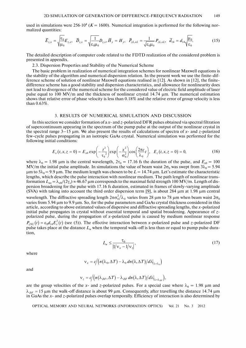
Fig. 1. The effective radius of pumping beam versus DFR wavelength and divergence angle.
OPTICAL MEMORY AND NEURAL NETWORKS (INFORMATION OPTICS) Vol. 21 No. 3 2012
2D SIMULATION OF GENERATION OF DIFFERENCE�FREQUENCY RADIATION 151
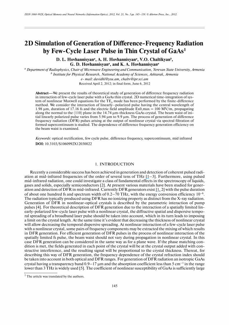
where, α is the angle between the DFR wave vector and the z�axis. Therefore, to increase the DFR gen�eration efficiency in the finite spectral range, the beam radius should be shorter than the DFR wavelengthin the crystal. The angular divergence of the generated DFR is, according to (20),
(21)
Figure 1 shows the dependence of pumping beam effective radius (21) on the DFR wave�length and the angle α as a contour plot with levels and values of α indicated.
As seen in Fig. 1 and follows from Eq. (20), for and at we observe but at the value is observed; for and at but at In other words, at fixed value of the pumping beam width the angulardivergence of generated DFR increases with the increase in its wavelength, but at a fixed value of theopening decreases with the increase in the pumping beam radius.
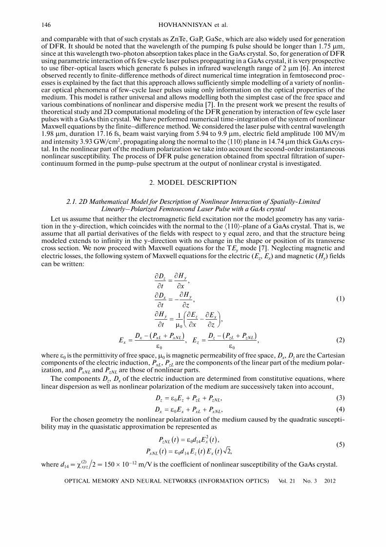
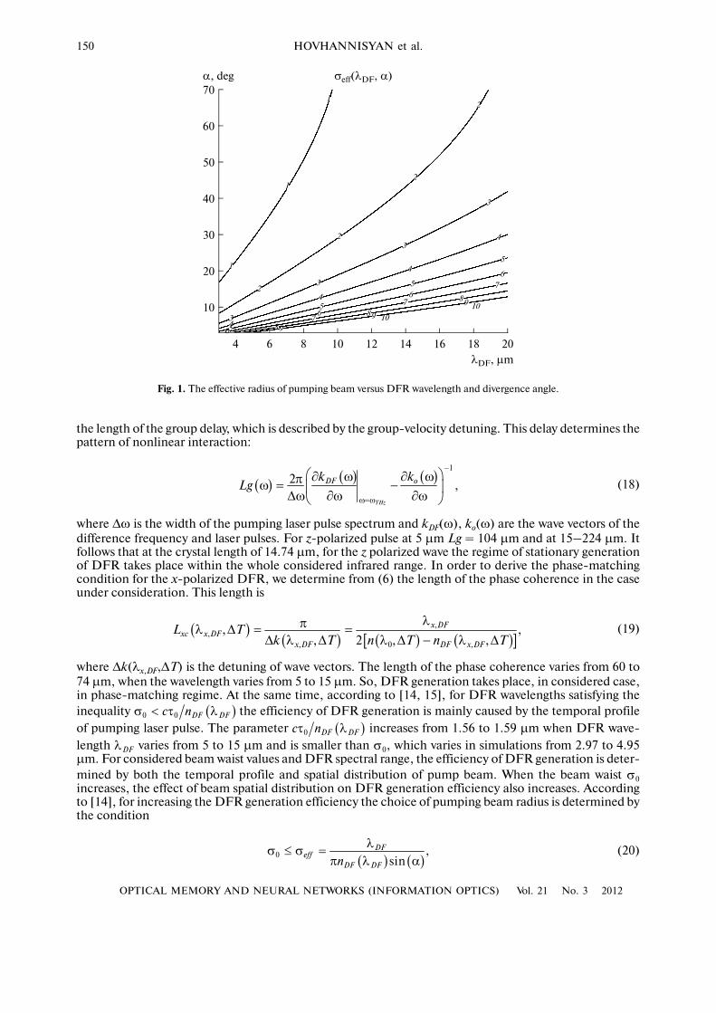
Figure 2 demonstrates the 3D representation of the propagation of the x� and z�polarized pulses at thetime 33, 66, 99 and 132 fs for the initial x�polarized Gaussian pump beam diameter of 9.9 μm (a) and 5.94μm (b), respectively.
( )0
0
arcsin .DF
DF DFn
⎧ ⎫λα = ⎨ ⎬
π λ σ⎩ ⎭
( ),eff DFσ λ α
m5DFλ = μ ( ),eff DFσ λ α 0 9.32 ,α = °
m0 4.95σ = μ 0 5.57α = ° 15DF mλ = μ 0 2.97 mσ = μ 0 29.12 ,α = °
0 4.95 mσ = μ 0 16.97 .α = °
DFλ
5
–8
–6
–4
–2
0
2
4
6
8
10 15
33 fs 66 fs 99 fs 132 fs
z, μm
x, μm
5
–8
–6
–4
–2
0
2
4
6
8
10 15
33 fs 66 fs 99 fs 132 fs
z, μm
x, μm
5
–8
–6
–4
–2
0
2
4
6
8
10 15
33 fs 66 fs 99 fs 132 fs
z, μm
x, μm
5
–8
–6
–4
–2
0
2
4
6
8
10 15
33 fs 66 fs 99 fs 132 fs
z, μm
x, μmEx(x, z) Ez(x, z)
Ex(x, z) Ez(x, z)
(a)
(b)
Fig. 2. The three dimensional representation of the propagation of the x� and z�polarized pulses at the times 33, 66, 99,and 132 fs for the initial x�polarized Gaussian pump beam diameter 9.9 μm (a) and 5.94 μm (b).
152
OPTICAL MEMORY AND NEURAL NETWORKS (INFORMATION OPTICS) Vol. 21 No. 3 2012
HOVHANNISYAN et al.
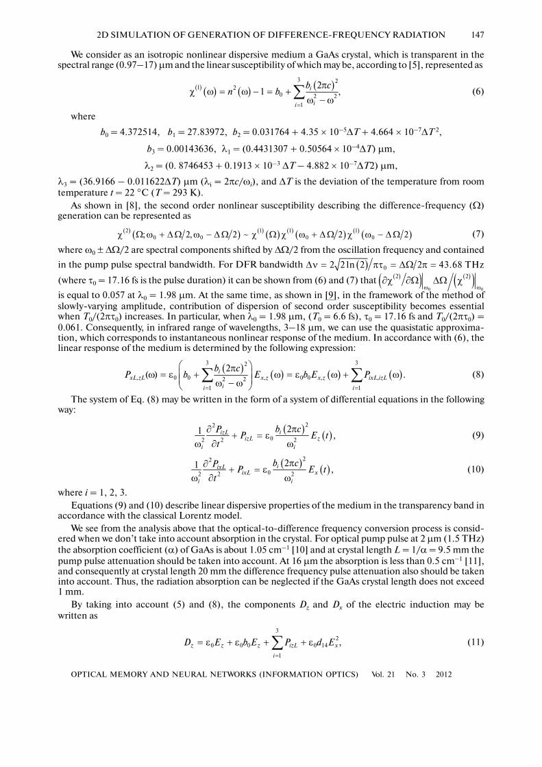
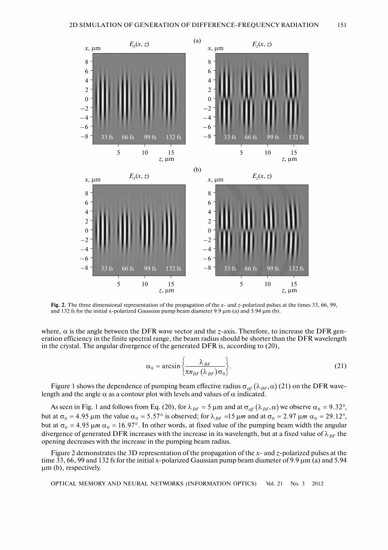
Figure 3 shows the wavelength dependence of the power density for x� and z�polarized pulses at crystaloutput
(22)
at lateral coordinates δx = 0; ±σ0/2 and beam diameters 9.9 μm (a) and 5.94 μm (b); the values of thepower density are scaled to the power density of the initial x�polarized pulse at δx = 0.
The spectral distributions at the crystal output, shown in Figs. 3a and 3b, are obtained with use of thereflection coefficients for normal incidence at the air�GaAs interface, which equals—5.367 dB at 1.98μm. Formation of spectral supercontinuum in the range of difference frequencies is well seen in these fig�ures.
Figure 3 also shows that the spectral distribution of power density at the beam axis (δx = 0) of z�polar�ized pulse contains spectral components only in the range of sum ( ) and difference frequencies andnone around λ0. Spectral components around λ0 arise at the distance δx = ±σ0/2 from the axis. The powerdensity of the z�polarized pulse in the range from 10 to 14 μm is about –64.5 dB for beam radius σ0 = 9.9μm and –60 dB for beam radius σ0 = 5.94 μm. The pattern of spectral distribution of the x� polarized pulseis seen in Fig. 3 to be opposite. Spectral components at δx = 0 are observed only around λ0, whereas at δx= ±σ0/2 components arise in the range of sum and difference frequencies. Power density for x�polarizedpulse in the range from 10 to 14 μm is about –50 dB for both values of beam radius σ0 = 9.9 and 5.94 μm.
( )
( ) { }
( ) { }
2
,
,, 2
,max
2, , exp
, , 10 lg 10 log
2, 0, 0 exp
x z
x zx z
x
x
ctE t z L x j dtS
P z L xS
ctE t z x j dt
∞
−∞
∞
−∞
⎛ ⎞π⎜ ⎟= δ
⎜ ⎟λ⎛ ⎞ ⎜ ⎟λ = δ = =⎜ ⎟⎜ ⎟⎝ ⎠
π⎜ ⎟= δ =⎜ ⎟λ⎝ ⎠
∫
∫
2D Fλ
0
–20
–40
–60
2
12 141084 62
1 – δx = 02 – δx = σ/23 – δx = –σ/2
1
3
Px(λ) –25
–35
–45
–602
12 141084 62
1 – δx = 02 – δx = σ/23 – δx = –σ/2
1
3
Pz(λ)
–30
–35
–45
–602
1 – δx = 02 – δx = σ/23 – δx = –σ/2
1
3
Pz(λ)0
–20
–40
–60
2
1 – δx = 02 – δx = σ/23 – δx = –σ/2
1
3
Px(λ)
–40
–50
–65
–55
–70
–40
–55
–65
–70
–30
–50
λ, nm
dB
Fig. 3. The wavelength dependences of the power density of x� and z�polarized pulses at crystal output at lateral coordi�nates δx = 0; ±σ0/2 and beam diameters 9.9 μm (a) and 5.94 μm (b).
OPTICAL MEMORY AND NEURAL NETWORKS (INFORMATION OPTICS) Vol. 21 No. 3 2012
2D SIMULATION OF GENERATION OF DIFFERENCE�FREQUENCY RADIATION 153
For numerical simulations of filtration of DFR from spectral supercontinuum formed at the crystal out�put, we used a low pass filter with the following transfer function:
(23)
where νc = 81.71 THz (c/νc = 3.67 μm). It should be noted that at filtration by means of such an idealizedmathematical filter, the phase relation between the spectral components in the range of difference fre�quencies remains in the transmission band of the filter the same as it is formed in the process of pulse prop�agation through the crystal. It is, however, obvious that if the realistic filters are employed, this phase rela�tion is determined by also the phase�frequency characteristic of the filter.
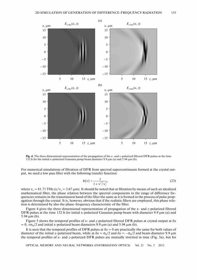
Figure 4 gives the three dimensional representation of propagation of the x� and z�polarized filteredDFR pulses at the time 132 fs for initial x�polarized Gaussian pump beam with diameter 9.9 μm (a) and5.94 μm (b).
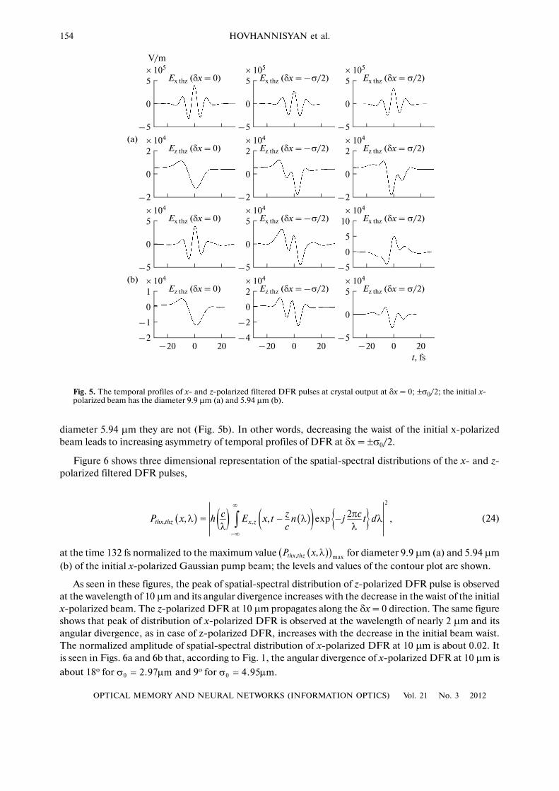
Figure 5 shows the temporal profiles of x� and z�polarized filtered DFR pulses at crystal output at δx= 0; ±σ0/2 and initial x�polarized beam diameters 9.9 μm (a) and 5.94 μm (b).
It is seen that the temporal profiles of DFR pulses at δx = 0 are practically the same for both values ofdiameter of the initial x�polarized beam, while at δx = σ0/2 and δx = –σ0/2 and beam diameter 9.9 μmthe temporal profiles of x� and z�polarized DFR pulses are mutually inverted in time (Fig. 5a), but for
( ) 2 21 ,
1 c
h ν =
+ ν ν
5
–15
–10
0
5
10
15
10 15 z, μm
x, μmEx thz(x, z)
–5
5
–15
–10
0
5
10
15
10 15 z, μm
x, μmEz thz(x, z)
–5
5
–15
–10
0
5
10
15
10 15 z, μm
x, μmEx thz(x, z)
–5
5
–15
–10
0
5
10
15
10 15 z, μm
x, μmEz thz(x, z)
–5
(a)
(b)
Fig. 4. The three dimensional representation of the propagation of the x� and z�polarized filtered DFR pulses at the time132 fs for the initial x�polarized Gaussian pump beam diameter 9.9 μm (a) and 5.94 μm (b).
154
OPTICAL MEMORY AND NEURAL NETWORKS (INFORMATION OPTICS) Vol. 21 No. 3 2012
HOVHANNISYAN et al.
diameter 5.94 μm they are not (Fig. 5b). In other words, decreasing the waist of the initial x�polarizedbeam leads to increasing asymmetry of temporal profiles of DFR at δx = ±σ0/2.
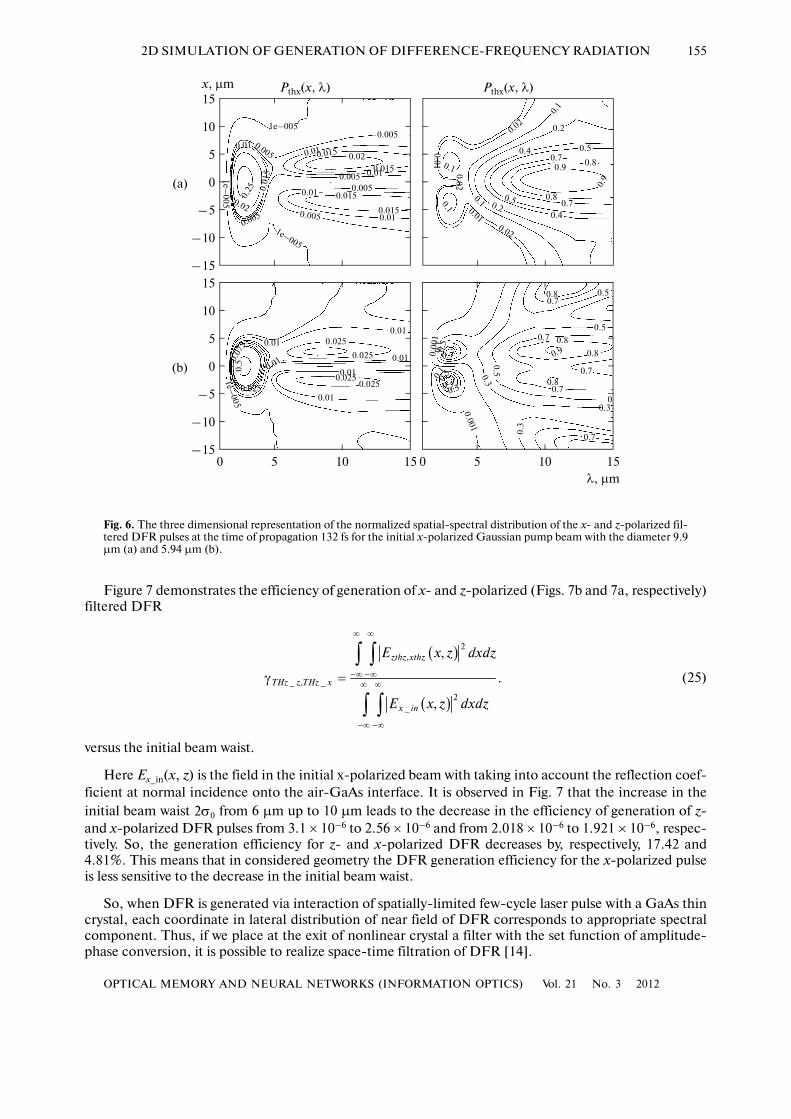
Figure 6 shows three dimensional representation of the spatial�spectral distributions of the x� and z�polarized filtered DFR pulses,
(24)
at the time 132 fs normalized to the maximum value for diameter 9.9 μm (a) and 5.94 μm(b) of the initial x�polarized Gaussian pump beam; the levels and values of the contour plot are shown.
As seen in these figures, the peak of spatial�spectral distribution of z�polarized DFR pulse is observedat the wavelength of 10 μm and its angular divergence increases with the decrease in the waist of the initialx�polarized beam. The z�polarized DFR at 10 μm propagates along the δx = 0 direction. The same figureshows that peak of distribution of x�polarized DFR is observed at the wavelength of nearly 2 μm and itsangular divergence, as in case of z�polarized DFR, increases with the decrease in the initial beam waist.The normalized amplitude of spatial�spectral distribution of x�polarized DFR at 10 μm is about 0.02. Itis seen in Figs. 6a and 6b that, according to Fig. 1, the angular divergence of x�polarized DFR at 10 μm is
about 18o for and 9o for
( ) ( ) ( )( ) { }2
, ,2, , exp ,thx thz x z
c z cP x h E x t n j t dc
∞
−∞
πλ = − λ − λ
λ λ∫
( )( ), max,thx thzP x λ
m0 2.97σ = μ m.0 4.95σ = μ
1
0
–1
–2–20 200
× 104
Ez thz (δx = 0)
5
0
–5
× 104
Ex thz (δx = 0)
2
0
–2
× 104
Ez thz (δx = 0)
5
0
–5
× 105
Ex thz (δx = 0) 5
0
–5
× 105
Ex thz (δx = –σ/2) 5
0
–5
× 105
Ex thz (δx = σ/2)
2
0
–2
× 104
Ez thz (δx = σ/2)2
0
–2
× 104
Ez thz (δx = –σ/2)
5
0
–5
× 104
Ex thz (δx = –σ/2) 10
5
0
–5
× 104
Ex thz (δx = σ/2)
5
0
–5–20 200
× 104
Ez thz (δx = σ/2)2
0
–2
–4–20 200
× 104
Ez thz (δx = –σ/2)
t, fs
V/m
(a)
(b)
Fig. 5. The temporal profiles of x� and z�polarized filtered DFR pulses at crystal output at δx = 0; ±σ0/2; the initial x�polarized beam has the diameter 9.9 μm (a) and 5.94 μm (b).
OPTICAL MEMORY AND NEURAL NETWORKS (INFORMATION OPTICS) Vol. 21 No. 3 2012
2D SIMULATION OF GENERATION OF DIFFERENCE�FREQUENCY RADIATION 155
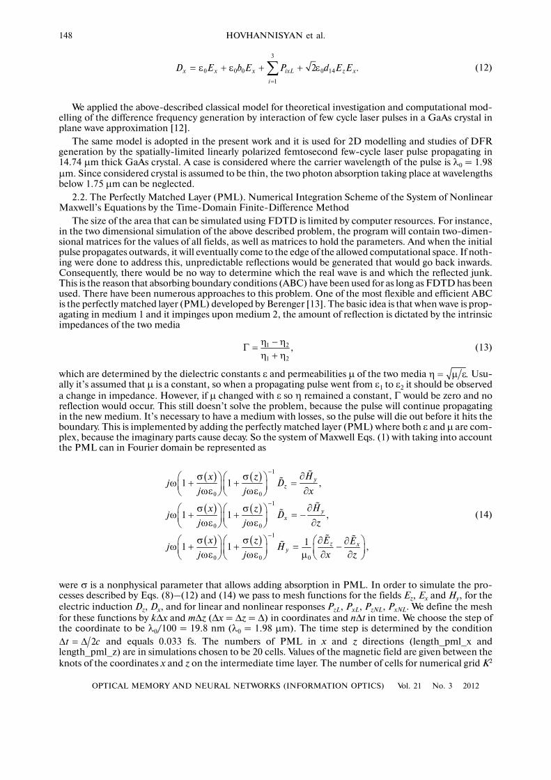
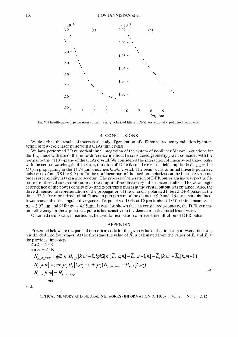
Figure 7 demonstrates the efficiency of generation of x� and z�polarized (Figs. 7b and 7a, respectively)filtered DFR
(25)
versus the initial beam waist.
Here Ex_in(x, z) is the field in the initial x�polarized beam with taking into account the reflection coef�ficient at normal incidence onto the air�GaAs interface. It is observed in Fig. 7 that the increase in theinitial beam waist from 6 µm up to 10 µm leads to the decrease in the efficiency of generation of z�and x�polarized DFR pulses from 3.1 × 10⁻⁶ to 2.56 × 10⁻⁶ and from 2.018 × 10⁻⁶ to 1.921 × 10⁻⁶, respec�tively. So, the generation efficiency for z� and x�polarized DFR decreases by, respectively, 17.42 and4.81%. This means that in considered geometry the DFR generation efficiency for the x�polarized pulseis less sensitive to the decrease in the initial beam waist.
So, when DFR is generated via interaction of spatially�limited few�cycle laser pulse with a GaAs thincrystal, each coordinate in lateral distribution of near field of DFR corresponds to appropriate spectralcomponent. Thus, if we place at the exit of nonlinear crystal a filter with the set function of amplitude�phase conversion, it is possible to realize space�time filtration of DFR [14].
( )
( )
2,
_ , _
2_
,
.
,
zthz xthz
THz z THz x
x in
E x z dxdz
E x z dxdz
∞ ∞
−∞ −∞
∞ ∞
−∞ −∞
γ =
∫ ∫
∫ ∫
02σ
15
10
5
0
–5
–10
–15151050
0.01
151050
Pthx(x, λ)15
10
5
0
–5
–10
–15
Pthx(x, λ)
0.010.025
0.0250.025
0.01
0.025 0.01
0.01
0.01
0.025
0.5
1e–005
0.07
5
0.0051e–005
0.01
0.01
0.010.015 0.02
0.0150.010.005
0.0150.005
0.0150.005
1e–005
0.005
0.005
1e–005 0.
25
0.02
0.01
0.01
5
0.2
0.4 0.50.70.9 0.8
0.9
0.80.7
0.4
0.02
0.02
0.02
0.01
0.01
0.1
0.1
0.1
0.1 0.20.5
0.80.7
0.7
0.7
0.7
0.8
0.8
0.5
0.5
0.7
0.3
0.3
0.3
0.5
0.9
0.8
0
0.001
0.3
0.00
10.
50.
1
0.7
0.7
0.50.1
λ, μm
x, μm
(a)
(b)
Fig. 6. The three dimensional representation of the normalized spatial�spectral distribution of the x� and z�polarized fil�tered DFR pulses at the time of propagation 132 fs for the initial x�polarized Gaussian pump beam with the diameter 9.9µm (a) and 5.94 µm (b).
156
OPTICAL MEMORY AND NEURAL NETWORKS (INFORMATION OPTICS) Vol. 21 No. 3 2012
HOVHANNISYAN et al.
4. CONCLUSIONS
We described the results of theoretical study of generation of difference frequency radiation by inter�action of few�cycle laser pulse with a GaAs thin crystal.
We have performed 2D numerical time�integration of the system of nonlinear Maxwell equations forthe TEy mode with use of the finite�difference method. In considered geometry y�axis coincides with thenormal to the <110>�plane of the GaAs crystal. We considered the interaction of linearly�polarized pulsewith the central wavelength of 1.98 µm, duration of 17.16 fs and the electric field amplitude Ex0,max = 100MV/m propagating in the 14.74 µm�thickness GaAs crystal. The beam waist of initial linearly polarizedpulse varies from 5.94 to 9.9 µm. In the nonlinear part of the medium polarization the inertialess secondorder susceptibility is taken into account. The process of generation of DFR pulses arising via spectral fil�tration of formed supercontinuum at the output of nonlinear crystal has been studied. The wavelengthdependence of the power density of x� and z�polarized pulses at the crystal output was obtained. Also, thethree dimensional representation of the propagation of the x� and z�polarized filtered DFR pulses at thetime 132 fs, for x�polarized initial Gaussian pump beam of the diameter 9.9 and 5.94 µm, was obtained.It was shown that the angular divergence of x�polarized DFR at 10 µm is about 18o for initial beam waist
and 9o for . It was also shown that, in considered geometry, the DFR genera�tion efficiency for the x�polarized pulse is less sensitive to the decrease in the initial beam waist.
Obtained results can, in particular, be used for realization of space�time filtration of DFR pulse.
APPENDIX
Presented below are the parts of numerical code for the given value of the time step n. Every time�stepn is divided into four stages. At the first stage the value of Hy is calculated from the values of Ex and Ez atthe previous time�step:
for k = 2 : Kfor m = 2 : K
(1a)
end.
m0 2.97σ = μ m.0 4.95σ = μ
[ ] [ ] [ ] [ ] [ ] [ ] [ ]( )[ ] [ ] [ ] [ ] [ ]( )[ ]
end
_ _ _
_ _ _
_ _ _
3 , 0.5 2 , 1, , , 1
, 3 , 2 ,
,
y h temp y h z z x x
y y y h temp y h
y h y h temp
H gk k H k m gk k E k m E k m E k m E k m
H k m gm m H k m gm m H H k m
H k m H
= + − − − + −
= + −
=
3.2
3.1
3.0
2.9
2.8
2.7
2.6
2.597 86
(a)× 10–6
2.02
2.00
1.98
1.96
1.94
1.92
97 862σ0, nm
(b)× 10–4
Fig. 7. The efficiency of generation of the x� and z�polarized filtered DFR versus initial x�polarized beam waist.
OPTICAL MEMORY AND NEURAL NETWORKS (INFORMATION OPTICS) Vol. 21 No. 3 2012
2D SIMULATION OF GENERATION OF DIFFERENCE�FREQUENCY RADIATION 157
At the second stage the values of Ex and Ez are calculated:
for k = 1:KE�1for m = 1:KE�1
(2a)
end.
In (1a) and (2a) PML vectors for k = 1,2, …, (length_pml_x) and for m = 1,2, …,(length_pml_z) are determined as
(3a)
where
(4a)
At the third stage the calculated instantaneous nonlinear response of the medium at n�th discrete step oftime may be obtained from (5):
(5a)
where the initial values at the beginning of iteration process (n = 0), are zero. Atthe last stage the linear responses of the medium are calculated. The differences corresponding to the lin�ear response of the medium and enabling us to determine the values of PixL, PizL at the n�th discrete stepof time, may be, according to (9) and (10), represented as
(6a)
where
(7a)
are the values of the linear polarization of the medium at (n–1)�th and (n–
2)�th discrete steps, while are the values of the electric field at the n�th step, and
(8a)
[ ] [ ]
[ ] [ ] [ ]
[ ] [ ] [ ] [ ] [ ] [ ]
[ ] [ ] [ ] [ ]( ) [ ] [ ]( )
[ ] [ ] [ ]( )
_ 1, ,
, , 1 _
, 3 , 0.5 2 _ 2 ,
, 3 , 3 1 , ,
0.5 2 _ 2 ,
y y
dz dz
z z dz
z z zL
dz
Curl h H k m H k m
I k m I k m gm m Curl h
D k m fk k D k m fk k Curl h fk k I k m
E k m fk k E k m fk k ga iz k m P k m ga
fk k Curl h fk k I k m
= + −
= +
= + +
= + − + +
+
[ ] [ ]
[ ] [ ] [ ]
[ ] [ ] [ ] [ ] [ ] [ ]
[ ] [ ] [ ] [ ]( ) [ ] [ ]( )
[ ] [ ] [ ]( )
e n d
_ , , 1
, , 1 _
, 3 , 0 .5 2 _ 2 ,
, 3 , 3 1 , ,
0 .5 2 _ 2 ,
y y
d x d x
x x dx
x x xL
dx
C u r l h H k m H k m
I k m I k m g k k C u r l h
D k m fm m D k m fm m C u rl h fm m I k m
E k m fm k E k m fm k g a ix k m P k m g a
fm k C u r l h fm k I k m
= − +
= +
= + +
= + − + +
+
( )01 1 ,ga b= +
[ ] [ ] [ ]( ) [ ]( ) [ ] [ ] [ ]( )
[ ] [ ]
[ ] [ ] [ ]( ) [ ]( ) [ ] [ ] [ ]( )
[ ] [ ]
3 3 1 1 , 2 2 1 1 ,
1
3 3 1 1 , 2 2 1 1 ,
1
gk k fk k xn k xn k gk k fk k xn k
gk k xn k
gm m fm m zn m zn m gm m fm m zn m
gm k zn k
= = − + = = +
=
= = − + = = +
=
( ) ( ) ( ) ( )3 30.333 _ _ , 0.333 _ _xn k k length pml x zn m m length pml z= =
[ ] [ ] [ ]( )[ ] [ ] [ ] [ ]
2114
114
, , ,
, , 2 , ,
nn nx
n nn nx z
iz k m iz k m d E k m
ix k m ix k m d E k m E k m
−
−
= +
= +
( )0, ,niz k m =
( )0, ,nix k m =
[ ] [ ] [ ] [ ]3 3
, ,
1 1
, , , , , ,n n n n
xL i xL zL i zL
i i
P k m P k m P k m P k m= =
= =∑ ∑
[ ] [ ] [ ] [ ]
[ ] [ ] [ ] [ ]
1 2, , ,
1 2, , ,
, , , ,
, , , ,
n n n ni xL i i xL i xL i x
n n n ni zL i i zL i zL i z
P k m al P k m P k m cl E k m
P k m al P k m P k m cl E k m
− −
− −
= − +
= − +
[ ]1
, , , ,n
i xL zLP k m−
[ ]2
, , ,n
i xL zLP k m−
( ), ,n
x zE k m
( ) ( )2 22 , 2 .i i i ial t cl b c t= − ω Δ = π Δ
158
OPTICAL MEMORY AND NEURAL NETWORKS (INFORMATION OPTICS) Vol. 21 No. 3 2012
HOVHANNISYAN et al.
REFERENCES1. Lee, Y., Principles of Terahertz Science and Technology, Springer, 2009, p. 125.2. Dexheimer, S.L., Terahertz Spectroscopy Principles and Applications, Taylor & Francis Group, LLC, 2008.3. Sakai, K., Terahertz Optoelectronics, Berlin/Heidelberg: Springer�Verlag, 2005.4. Ding, Y. and Zotova, I., Opt. Quantum. Electron., 2000, vol. 32, p. 531.5. Skauli, T., Kuo, P.S., Vodopyanov, K.L., Pinguet, T.J., Levi, O., Eyres, L.A., Harris, J.S., Fejer, M.M.,
Ginzton, E.L., Gerard, B., Becouarn, L., and Lallier, E., J. Appl. Phys., 2003, vol. 94, p. 6447.6. Imeshev, G., Fermann, M.E., Vodopyanov, K.L., Fejer, M.M., Ginzton, E.L., Yu, X., and Harris, J.S., Opt.
Express., 2006, vol. 14, p. 4439.7. Taflov, A. and Hagness, S.C., Computational Electrodynamics the Finite�Difference Time�Domain Method, Bos�
ton: Artech House, 1995.8. Boyd, R.W., Nonlinear Optics, 3rd ed., Burlington: Elsevier, MA, 2008.9. Akhmanov, S.A., Vysloukh, V.A., and Chirkin, A.S., Optics of Femtosecond Laser Pulses, New York: AIP, 1992.
10. Vodopyanov, K.L., Opt. Express., 2006, vol. 14, p. 2263.11. Zheng, D., Gordon, L.A., Fejer, M.M., Byer, R.L., and Vodopyanov, K.L., Lasers and Electro�Optics,
CLEO’98; Technical Digest, 10.1109/CLEO676556, 1998.12. Hovhannisyan, D.L., Hakhoumian, A.A., Martirosyan, R.M., Nikoghosyan, A.S., Laziev, E.M., and Hovhan�
nisyan, G.D., J. Modern Opt., 2010, vol. 57, no. 14–15, p. 1228.13. B´erenger, Jean�Pierre, Perfectly Matched Layer (PML) for Computational Electromagnetics, Morgan & Clay�
pool, 2007.14. Martirosyan, A.S., Hovhannisyan, D.L., Chaltikyan, V.O., and Hovhannisyan, G.D., Proceedings Paper, SPIE
Photonics Europe, Conferences, 2010, Belgium Photonics Europe 2010, DOI: 10.1117/12.852578.15. L’Huillier, J.A., Torosyan, G., Theuer, M., Avetisyan, Yu., and Beigang, R., Appl. Phys., Ser. B, 2007, vol. 86,
p. 185.
1
1
SPELL: 1. Phys