2('{2 - Časopis Vlákna a textil
40
Rodnik 19. 2('{2 tssN1335-061 Indexed in: Chemical Abstracts, World Textile Abstracts EMDASE Elsevier Biobase Elsevier GeoAbstracts
-
Upload
khangminh22 -
Category
Documents
-
view
0 -
download
0
Transcript of 2('{2 - Časopis Vlákna a textil
Rodnik 19.2('2
tssN1335-0617
Indexed in:
ChemicalAbstracts,
World TextileAbstracts
EMDASE
ElsevierBiobase
ElsevierGeoAbstracts
Fibres and Textiles (4) 2012 Vlákna a textil (4) 2012
Content Obsah TEXTILE TECHNOLOGIES TEXTILNÉ TECHNOLÓGIE
3 M. Bachurová and J. Wiener The behaviour of water drops on modified polyethylene terephthalate surfaces
3 M. Bachurová a J. Wiener Chováni se vodných kapek na modifikovaných polyetyléntereftalátových povrzích
10 M. Nejedlá
Transformation of designed pieces to 2D CAD systems using a macro module
10 M. Nejedlá Transformace střihových dílů do 2D CAD systémů využitím makra
18 M. Prášil, L. Martinková and J. Wiener
Hydrophobic finishing of polyester clothing textiles
18 M. Prášil, L. Martinková a J. Wiener Hydrofobní úprava polyesterových oděvních textilií
27 Ľ. Balogová, J. Šesták, V. Remeková,
A. Džupaj, M. Gála and B. Babušiak The study of effect of structure of special types of blend yarns on their electroconductive properties
27 Ľ. Balogová, J. Šesták, V. Remeková, A. Džupaj, M. Gála a B. Babušiak Štúdium vplyvu štruktúry špeciálnych typov zmesných priadzí na ich elektrovodivé vlastnosti
NEWS FROM DEPARTMENTS Z VEDECKO-VÝSKUMNÝCH
A VÝVOJOVÝCH PRACOVÍSK
35 L. Sodomka Magnetic liquids as catalyzers of nanofibers production
35 L. Sodomka Magnetické kapaliny jako katalyzátory produkce nanovláken
37 M. Hricová
Information about 7th Central European Conference 2012 „FIBRE-GRADE POLYMERS, CHEMICAL FIBRES AND SPECIAL TEXTILES“ held on September 15.-17.2012 in Portorose, Slovenia
37 M. Hricová Informácia o 7th Central European Conference 2012 „FIBRE-GRADE POLYMERS, CHEMICAL FIBRES AND SPECIAL TEXTILES“ konanej 15.-17. septembra 2012 v Portoroži, Slovinsko
39 J. Ryba
Information about 6th International Textile, Clothing & Design Conference „MAGIC WORLD OF TEXTILES“ held on October 7.-10.2012 in Dubrovnik, Croatia
39 J. Ryba Informácia o 6th International Textile, Clothing & Design Conference „MAGIC WORLD OF TEXTILES“ konanej 7.-10. októbra 2012 v Dubrovníku, Chorvátsko
Vlákna a textil (4) 2012 1
Textilné technológie Textile Technologies
THE BEHAVIOUR OF WATER DROPS ON MODIFIED POLYETHYLENE TEREPHTHALATE SURFACES
M. Bachurová and J. Wiener
Department of Textile Chemistry, Faculty of Textile Engineering
Technical University of Liberec, Czech Republic [email protected]
Abstract: It is interesting to observe wetting contact angles on roughness and smooth surfaces for various materials and their contact angle hysteresis. Wetting parameters can be affected by various modifications of the surface material. In our case, the surface was hydrophobised by two types of hydrophobic agents. In order to study this behaviour, we measured advancing and receding contact angles. From the experimental results, values of contact angle hysteresis were determined. Further, the behaviour of drops was observed in both types of water repellent agents. The study was carried out using polyethylene terephthalate textile from monofilaments. Keywords: advancing contact angle; receding contact angle; contact angle hysteresis; polyethylene terephthalate; hydrophobisation.
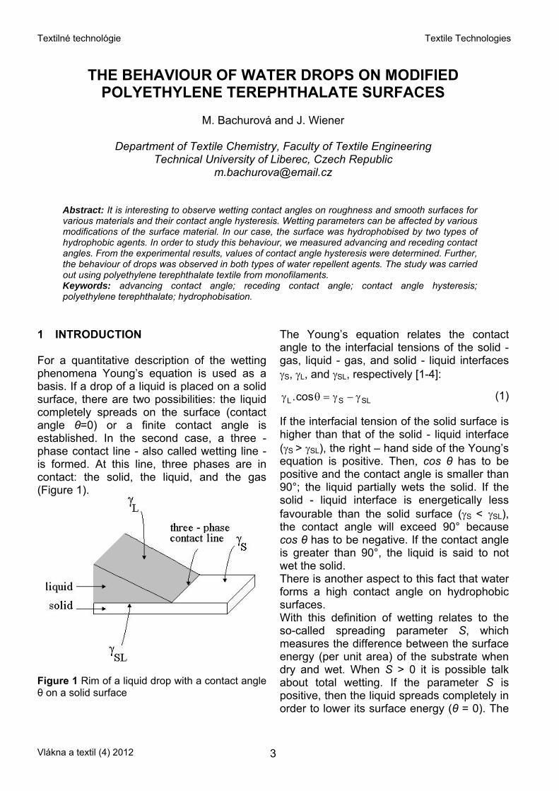
1 INTRODUCTION For a quantitative description of the wetting phenomena Young’s equation is used as a basis. If a drop of a liquid is placed on a solid surface, there are two possibilities: the liquid completely spreads on the surface (contact angle θ=0) or a finite contact angle is established. In the second case, a three - phase contact line - also called wetting line - is formed. At this line, three phases are in contact: the solid, the liquid, and the gas (Figure 1).
Figure 1 Rim of a liquid drop with a contact angle θ on a solid surface
The Young’s equation relates the contact angle to the interfacial tensions of the solid - gas, liquid - gas, and solid - liquid interfaces γS, γL, and γSL, respectively [1-4]:
SLSL cos. γ−γ=θγ (1) If the interfacial tension of the solid surface is higher than that of the solid - liquid interface (γS > γSL), the right – hand side of the Young’s equation is positive. Then, cos θ has to be positive and the contact angle is smaller than 90°; the liquid partially wets the solid. If the solid - liquid interface is energetically less favourable than the solid surface (γS < γSL), the contact angle will exceed 90° because cos θ has to be negative. If the contact angle is greater than 90°, the liquid is said to not wet the solid. There is another aspect to this fact that water forms a high contact angle on hydrophobic surfaces. With this definition of wetting relates to the so-called spreading parameter S, which measures the difference between the surface energy (per unit area) of the substrate when dry and wet. When S > 0 it is possible talk about total wetting. If the parameter S is positive, then the liquid spreads completely in order to lower its surface energy (θ = 0). The
Vlákna a textil (4) 2012 3
Textilné technológie Textile Technologies
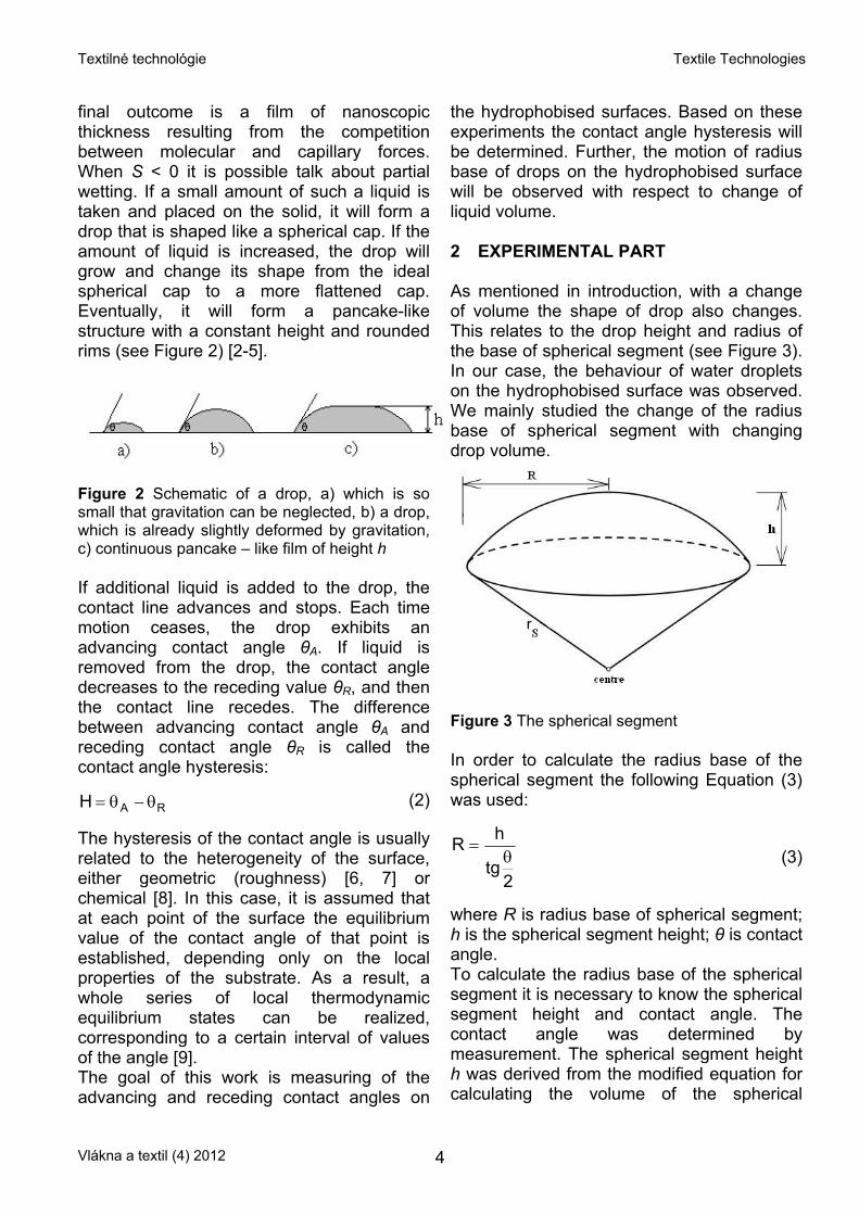
final outcome is a film of nanoscopic thickness resulting from the competition between molecular and capillary forces. When S < 0 it is possible talk about partial wetting. If a small amount of such a liquid is taken and placed on the solid, it will form a drop that is shaped like a spherical cap. If the amount of liquid is increased, the drop will grow and change its shape from the ideal spherical cap to a more flattened cap. Eventually, it will form a pancake-like structure with a constant height and rounded rims (see Figure 2) [2-5].
Figure 2 Schematic of a drop, a) which is so small that gravitation can be neglected, b) a drop, which is already slightly deformed by gravitation, c) continuous pancake – like film of height h If additional liquid is added to the drop, the contact line advances and stops. Each time motion ceases, the drop exhibits an advancing contact angle θA. If liquid is removed from the drop, the contact angle decreases to the receding value θR, and then the contact line recedes. The difference between advancing contact angle θA and receding contact angle θR is called the contact angle hysteresis:
RAH θ−θ= (2) The hysteresis of the contact angle is usually related to the heterogeneity of the surface, either geometric (roughness) [6, 7] or chemical [8]. In this case, it is assumed that at each point of the surface the equilibrium value of the contact angle of that point is established, depending only on the local properties of the substrate. As a result, a whole series of local thermodynamic equilibrium states can be realized, corresponding to a certain interval of values of the angle [9]. The goal of this work is measuring of the advancing and receding contact angles on
the hydrophobised surfaces. Based on these experiments the contact angle hysteresis will be determined. Further, the motion of radius base of drops on the hydrophobised surface will be observed with respect to change of liquid volume. 2 EXPERIMENTAL PART As mentioned in introduction, with a change of volume the shape of drop also changes. This relates to the drop height and radius of the base of spherical segment (see Figure 3). In our case, the behaviour of water droplets on the hydrophobised surface was observed. We mainly studied the change of the radius base of spherical segment with changing drop volume.
Figure 3 The spherical segment In order to calculate the radius base of the spherical segment the following Equation (3) was used:
2tg
hRθ
= (3)
where R is radius base of spherical segment; h is the spherical segment height; θ is contact angle. To calculate the radius base of the spherical segment it is necessary to know the spherical segment height and contact angle. The contact angle was determined by measurement. The spherical segment height h was derived from the modified equation for calculating the volume of the spherical
Vlákna a textil (4) 2012 4
Textilné technológie Textile Technologies
segment, where we know the volume of liquid V and the contact angle θ, which is formed by the liquid in contact with the surface:
3 12
2tg
3
V6
h+
⎟⎠⎞
⎜⎝⎛ θ
π⋅
= (4)
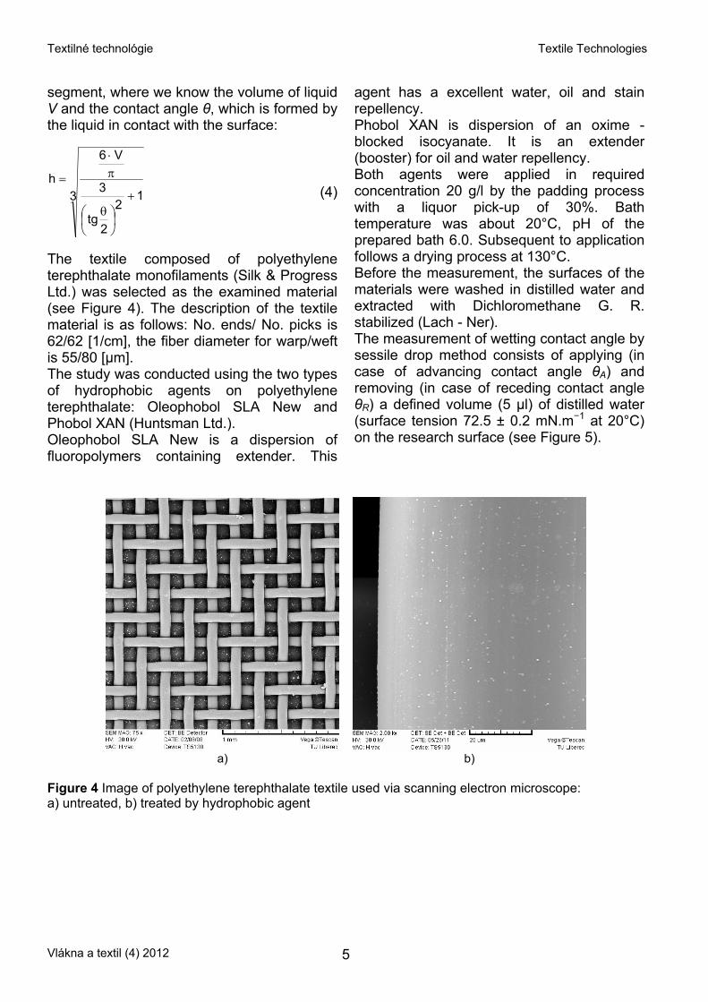
The textile composed of polyethylene terephthalate monofilaments (Silk & Progress Ltd.) was selected as the examined material (see Figure 4). The description of the textile material is as follows: No. ends/ No. picks is 62/62 [1/cm], the fiber diameter for warp/weft is 55/80 [μm]. The study was conducted using the two types of hydrophobic agents on polyethylene terephthalate: Oleophobol SLA New and Phobol XAN (Huntsman Ltd.). Oleophobol SLA New is a dispersion of fluoropolymers containing extender. This
agent has a excellent water, oil and stain repellency. Phobol XAN is dispersion of an oxime - blocked isocyanate. It is an extender (booster) for oil and water repellency. Both agents were applied in required concentration 20 g/l by the padding process with a liquor pick-up of 30%. Bath temperature was about 20°C, pH of the prepared bath 6.0. Subsequent to application follows a drying process at 130°C. Before the measurement, the surfaces of the materials were washed in distilled water and extracted with Dichloromethane G. R. stabilized (Lach - Ner). The measurement of wetting contact angle by sessile drop method consists of applying (in case of advancing contact angle θA) and removing (in case of receding contact angle θR) a defined volume (5 μl) of distilled water (surface tension 72.5 ± 0.2 mN.m−1 at 20°C) on the research surface (see Figure 5).
a) b) Figure 4 Image of polyethylene terephthalate textile used via scanning electron microscope: a) untreated, b) treated by hydrophobic agent
Vlákna a textil (4) 2012 5
Textilné technológie Textile Technologies
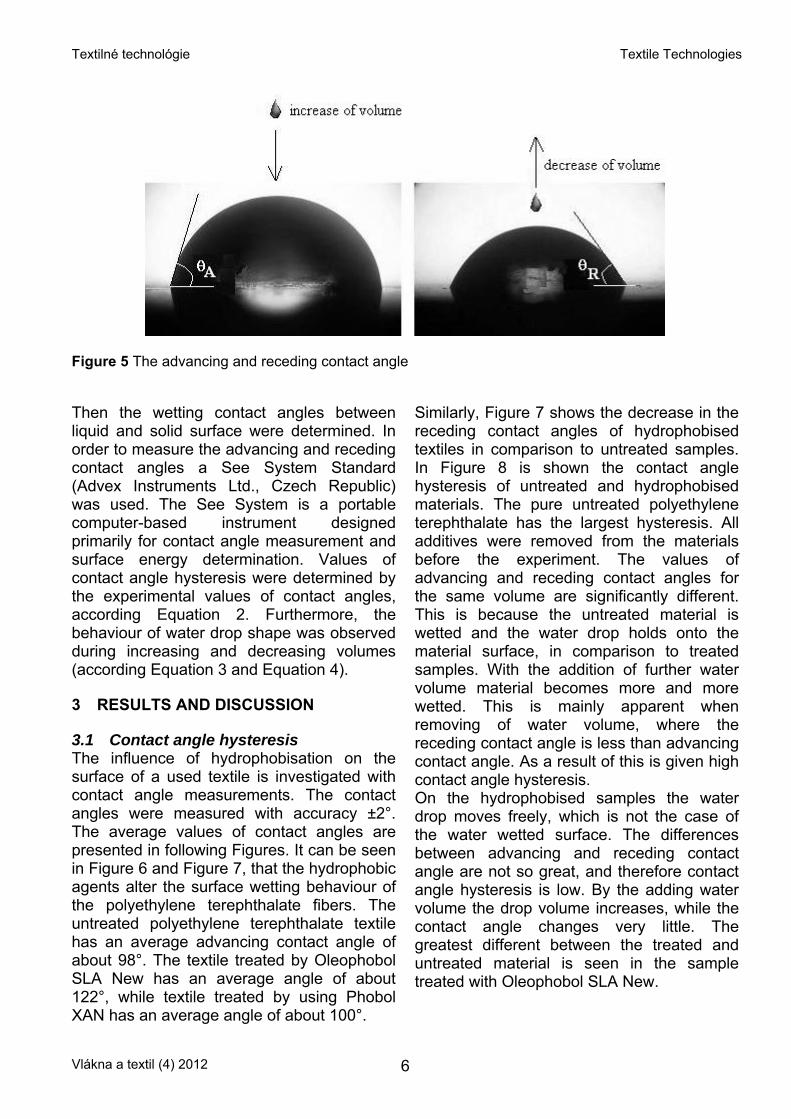
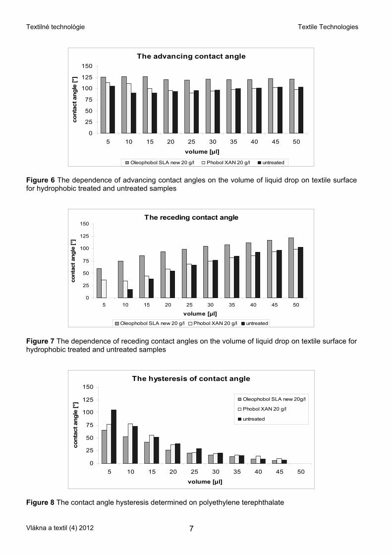
Figure 5 The advancing and receding contact angle Then the wetting contact angles between liquid and solid surface were determined. In order to measure the advancing and receding contact angles a See System Standard (Advex Instruments Ltd., Czech Republic) was used. The See System is a portable computer-based instrument designed primarily for contact angle measurement and surface energy determination. Values of contact angle hysteresis were determined by the experimental values of contact angles, according Equation 2. Furthermore, the behaviour of water drop shape was observed during increasing and decreasing volumes (according Equation 3 and Equation 4). 3 RESULTS AND DISCUSSION 3.1 Contact angle hysteresis The influence of hydrophobisation on the surface of a used textile is investigated with contact angle measurements. The contact angles were measured with accuracy ±2°. The average values of contact angles are presented in following Figures. It can be seen in Figure 6 and Figure 7, that the hydrophobic agents alter the surface wetting behaviour of the polyethylene terephthalate fibers. The untreated polyethylene terephthalate textile has an average advancing contact angle of about 98°. The textile treated by Oleophobol SLA New has an average angle of about 122°, while textile treated by using Phobol XAN has an average angle of about 100°.
Similarly, Figure 7 shows the decrease in the receding contact angles of hydrophobised textiles in comparison to untreated samples. In Figure 8 is shown the contact angle hysteresis of untreated and hydrophobised materials. The pure untreated polyethylene terephthalate has the largest hysteresis. All additives were removed from the materials before the experiment. The values of advancing and receding contact angles for the same volume are significantly different. This is because the untreated material is wetted and the water drop holds onto the material surface, in comparison to treated samples. With the addition of further water volume material becomes more and more wetted. This is mainly apparent when removing of water volume, where the receding contact angle is less than advancing contact angle. As a result of this is given high contact angle hysteresis. On the hydrophobised samples the water drop moves freely, which is not the case of the water wetted surface. The differences between advancing and receding contact angle are not so great, and therefore contact angle hysteresis is low. By the adding water volume the drop volume increases, while the contact angle changes very little. The greatest different between the treated and untreated material is seen in the sample treated with Oleophobol SLA New.
Vlákna a textil (4) 2012 6
Textilné technológie Textile Technologies
The advancing contact angle
0
25
50
75
100
125
150
5 10 15 20 25 30 35 40 45 50
volume [μl]
cont
act a
ngle
[°]
Oleophobol SLA new 20 g/l Phobol XAN 20 g/l untreated
Figure 6 The dependence of advancing contact angles on the volume of liquid drop on textile surface for hydrophobic treated and untreated samples
The receding contact angle
0
25
50
75
100
125
150
5 10 15 20 25 30 35 40 45 50
volume [μl]
cont
act a
ngle
[°]
Oleophobol SLA new 20 g/l Phobol XAN 20 g/l untreated
Figure 7 The dependence of receding contact angles on the volume of liquid drop on textile surface for hydrophobic treated and untreated samples
The hysteresis of contact angle
0
25
50
75
100
125
150
5 10 15 20 25 30 35 40 45 50
volume [μl]
cont
act a
ngle
[°] Oleophobol SLA new 20g/l
Phobol XAN 20 g/l
untreated
Figure 8 The contact angle hysteresis determined on polyethylene terephthalate
Vlákna a textil (4) 2012 7
Textilné technológie Textile Technologies
3.2 The change of radius base of spherical segment
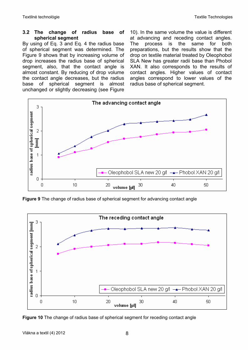
By using of Eq. 3 and Eq. 4 the radius base of spherical segment was determined. The Figure 9 shows that by increasing volume of drop increases the radius base of spherical segment, also, that the contact angle is almost constant. By reducing of drop volume the contact angle decreases, but the radius base of spherical segment is almost unchanged or slightly decreasing (see Figure
10). In the same volume the value is different at advancing and receding contact angles. The process is the same for both preparations, but the results show that the drop on textile material treated by Oleophobol SLA New has greater radii base than Phobol XAN. It also corresponds to the results of contact angles. Higher values of contact angles correspond to lower values of the radius base of spherical segment.
Figure 9 The change of radius base of spherical segment for advancing contact angle
Figure 10 The change of radius base of spherical segment for receding contact angle
Vlákna a textil (4) 2012 8
Textilné technológie Textile Technologies
4 CONCLUSION The advancing and receding contact angles of water drops on polyethylene terephthalate were measured in this study. The contact angle hysteresis was observed from the contact angle values. The textile surface was modified by hydrophobic treatment. We found that the pure untreated polyethylene terephthalate has the largest hysteresis compared to treated samples. Next, the radius base of spherical segment was observed depending on the change of drop volume. Increase in volume caused increases in the radius base of spherical segment. By reducing the volume the radius base of spherical segment is almost unchanged or slightly decreasing.
5 REFERENCES 1. de Gennes P.G.: Wetting: statics and dynamics,
Reviews of Modern Physics 57, 1985,.827-863 2. Young T.: An essay on the cohesion of fluids,
Philos. Trans. R. Soc. London 95, 1805, 65-87 3. de Laplace P.S: Mécanique Céleste, suppl. au
Livre, X., Croucier, Paris, 1805 4. Butt H.J. & Kappl M.: Surface and Interfacial
Forces, Weinhaim: Wiley VCH, 2010 5. de Gennes P.G., Brochard-Wyart F. & Quere D.:
Capillarity and Wetting Phenomena, New York: Springer, 2004
6. Wenzel R.: Resistance of solid surfaces to wetting by water, Ind. Eng. Chem. 28, 1936, 988-994
7. Deryagin B.V.: Dokl. Akad. Nauk SSSR (in Russian) 51, 1946, 357
8. Johnson R.E. & Dettre R.H.: Wettability and contact angles, Surface and Colloid Science 2, New York: Wiley, 1969, 85-153
9. Starov V.M., Velarde M.G. & Radke C.J.: Wetting and spreading dynamics, New York: Taylor & Francis Group, LLC, 2007
CHOVÁNI SE VODNÝCH KAPEK NA MODIFIKOVANÝCH POLYETYLÉNTEREFTALÁTOVÝCH POVRZÍCH
Translation of the article
The behaviour of water drops on modified polyethylene terephthalate surfaces Smáčecí parametry a podobně hystereze kontaktního úhlu, mohou být kromě faktorů týkajících se struktury textilie ovlivněny i různými finálními úpravami aplikovanými na povrch materiálu. V této práci byla textilie hydrofobizována dvěma typy hydrofobních přípravků. Na takto upravených materiálech byly měřeny postupující a ustupující kontaktní úhly, z nichž byly zjištěny hodnoty hystereze kontaktního úhlu. Studie byla provedena na polyetyléntereftalátové textilii z monofilu. Z výsledků vyplynulo, že neupravený materiál vykazuje větší hodnoty hystereze ve srovnání s upravenými vzorky. Dále byla v této práci pozorována změna poloměru podstavy kapky v závislosti na změně jejího objemu. Při zvyšování objemu kapky docházelo k nárůstu poloměru podstavy. Při snižování objemu se poloměr podstavy téměř neměnil resp. docházelo k mírnému poklesu. To odpovídá i výsledkům kontaktního úhlu. Vyšší hodnoty kontaktního úhlu odpovídají nižším hodnotám poloměru podstavy kapky.
Vlákna a textil (4) 2012 9
Textilné technológie Textile Technologies
TRANSFORMATION OF DESIGNED PIECES TO 2D CAD SYSTEMS USING A MACRO MODULE
M. Nejedlá
Technical University of Liberec, Faculty of Textile Engineering, Department of Clothing
technology, Studentská 2, 461 17 Liberec, Czech Republic [email protected]
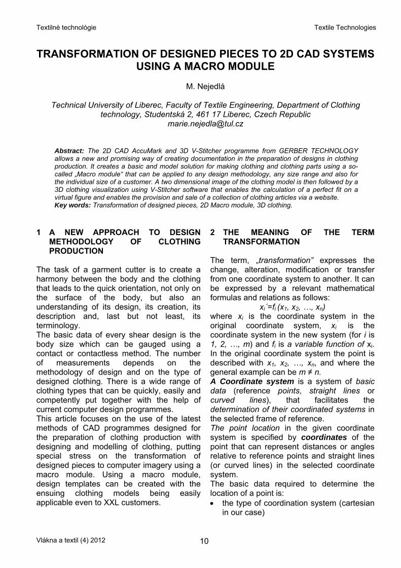
Abstract: The 2D CAD AccuMark and 3D V-Stitcher programme from GERBER TECHNOLOGY allows a new and promising way of creating documentation in the preparation of designs in clothing production. It creates a basic and model solution for making clothing and clothing parts using a so-called „Macro module“ that can be applied to any design methodology, any size range and also for the individual size of a customer. A two dimensional image of the clothing model is then followed by a 3D clothing visualization using V-Stitcher software that enables the calculation of a perfect fit on a virtual figure and enables the provision and sale of a collection of clothing articles via a website. Key words: Transformation of designed pieces, 2D Macro module, 3D clothing.
1 A NEW APPROACH TO DESIGN
METHODOLOGY OF CLOTHING PRODUCTION
The task of a garment cutter is to create a harmony between the body and the clothing that leads to the quick orientation, not only on the surface of the body, but also an understanding of its design, its creation, its description and, last but not least, its terminology. The basic data of every shear design is the body size which can be gauged using a contact or contactless method. The number of measurements depends on the methodology of design and on the type of designed clothing. There is a wide range of clothing types that can be quickly, easily and competently put together with the help of current computer design programmes. This article focuses on the use of the latest methods of CAD programmes designed for the preparation of clothing production with designing and modelling of clothing, putting special stress on the transformation of designed pieces to computer imagery using a macro module. Using a macro module, design templates can be created with the ensuing clothing models being easily applicable even to XXL customers.
2 THE MEANING OF THE TERM TRANSFORMATION
The term, „transformation” expresses the change, alteration, modification or transfer from one coordinate system to another. It can be expressed by a relevant mathematical formulas and relations as follows:
xi´=fi (x1, x2, …, xn) where xi is the coordinate system in the original coordinate system, xi
´ is the coordinate system in the new system (for i is 1, 2, …, m) and fi is a variable function of xi. In the original coordinate system the point is described with x1, x2, …, xn, and where the general example can be m ≠ n. A Coordinate system is a system of basic data (reference points, straight lines or curved lines), that facilitates the determination of their coordinated systems in the selected frame of reference. The point location in the given coordinate system is specified by coordinates of the point that can represent distances or angles relative to reference points and straight lines (or curved lines) in the selected coordinate system. The basic data required to determine the location of a point is: • the type of coordination system (cartesian
in our case)
Vlákna a textil (4) 2012 10

Textilné technológie Textile Technologies
• the chosen origin of the coordinate system (starting point)
• the orientation and character of coordinate axes
• the units, with their multiples and parts of the values of the coordinates declared.
The implementation of a coordinate system facilitates the research of geometric figures by analytical methods. If all the coordinate axes are straight lines we call it a „rectilinear coordinate system“. One such rectilinear coordinate system is a cartesian system. All the macro module data in 2D CAD systems used for the creation of design documentation are processed in this cartesian system. 2.1 The Methods of transforming
designed pieces onto the computer The term „transformation“ in the technical preparation of clothing production refers to the transformation of designed pieces from the paper template to the electronic one with the help of digitalization or using a scanner. Another method of getting the designed pieces onto the computer is by direct design using tools available in the computer programme. Now there is an innovative way of transforming the designed pieces onto the computer using a macro module. A macro module is a list of working instructions necessary for clothing design which is a part of a computer programme combined with the design parameters in a general template with different values which are body size or body size supplements. The macro module follows the list of working instructions, performing them in the order they were programmed. The macro module is applicable if the same working instructions performed in the same order will lead to the same result of production. A macro module can be created: • in an absolute regime, that means, that
the macro module is created for a fixed body size and retains the initial values for the whole processing time
• or the macro module respects general formulas with special reference to size tables, design dimensions and supplements in which one or more sizes,
or the net of sizes must be selected at start-up.
If the design is to be repeated, the new macro module will run based on the variables, namely the body sizes, without further operator input. 2.2 Dealing with macro modules in 2D
CAD systems The programme which creates the macro-modules is part of AccuMark 8.4 CAD System which is a GERBER TECHNOLOGY product. It begins in the PDS (Patter Design System) created section and links to the size and design size table, made in the „MeasureChartEditor“ programme. AccuMark CAD system enables macro module making specifically in: • basic clothing design for any design
methodology • model solution making • parts of clothing modelling Macro module commands are created by the programme author. It is a kind of indirect way to design. It allows macro module recordings, macro module starting and editing and it is created in a design and model office. Macro modules in AccuMark CAD system are created in several steps: • creation of design size table for a
specified size range with a marked basic size
• recording of the basic design macro module of the selected clothing type according to the selected methodology using basic sized CAD system tools
• running the basic design macro module for the selected clothing type and testing the functionality of the macro module and its effectivity for specific sizes and its corresponding proportions
• editing the macro module, leading to macro module formation or its modification
2.2.1 The data for AccuMark CAD system
macro module creation Macro modules have their own procedures bound by size table design, design procedure and design formulas. They have also their
Vlákna a textil (4) 2012 11

Textilné technológie Textile Technologies
own text saved to „Script“. Observing certain conditions we can combine or link together the macro modules to get an order sequence for a variety of design sizes. The basic data of each macro module is: • clothing product technical drawing • size range of the produced clothing
product and size parking • design methodology for the clothing
product • initial body proportions needed for clothing
product design • creation of design proportions tables,
completed with additions for loose-fitting clothing and tables of coefficients and absolute values
The first step when creating a macro module is to make a body size table in the „Measure Chart Editor“ programme Figure 1 and save it to „AccuMark script chart“. 2.2.2 Script-making for a macro module
recording Making a macro module in AccuMark programme begins, in the PDS section by opening the „Guide“ icon Figure 2 and by recording the size table and opening the „Script“, where all the records of macro module, with symbols of tools for the design of the part, point, line, curve, take place, see Figure 3, and its calculations coming out from
the design measurements, design samples or distances that can be set with the help of tools of the expressional calculator, see Figure 4.
Figure 2 Opening the „Guide“ and revealing the scroll menu for macro module creation, record, start up and edit in AccuMark CAD system
Figure 3 Possibilities for line-making in AccuMark CAD system
Figure 1 An example of design measurements table of a ladies suit [1]
Vlákna a textil (4) 2012 12

Textilné technológie Textile Technologies
Figure 4 Size setting of the design line segments A Macro module is created for a basic size and can be created in two ways. One way is to write in the working area of AccuMark CAD system, see Figure 5, and another way is separately in the text editor, see Figure 6. It is an internal instruction and its text is licensed by the authors of AccuMark programme. A macro module can be created for basic designs of any kind of clothing product and can be saved in a databank. In a design department it is used as a basis for model solutions according to fashionable designs, structure variations, modifications of breast and waist selection etc. The second phase of a macro solution is a model solution.
The third phase of a macro solution is designing the constituent elements of the clothing product separately. All three phases of the solution are justifiable when preparing a design for production. It is advisable to preserve this categorisation and based on this structure variation, it is advisable to establish a databank that will turn into a base for countless solutions regarding the wide range of selection opportunities when designing collections of clothing products. 2.2.3 Running the designed macro
module and its editing Running the „Script“ of the designed macro module is possible in; the basic size; one selected size or in more sizes that are all included in the design measurement tables. However it cannot be run in all sizes as a design net, see Figure 7. Running a macro module is a good way not only to see it, but also for checking the correct running of the macro, even an unfinished one, for the whole variety of sizes included in the design size table. Starting a macro module can be found in the „Guide“ menu as „Start“. The illustration of running macro module is its particular phases as seen in Figures 8 and 9.
Figure 5 An example of making a „Script“ macro module and a macro text for a ladies suit [1]
Vlákna a textil (4) 2012 13
Textilné technológie Textile Technologies
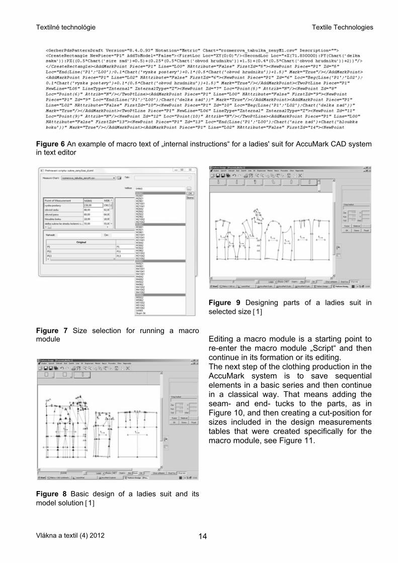
Figure 6 An example of macro text of „internal instructions“ for a ladies' suit for AccuMark CAD system in text editor
Figure 7 Size selection for running a macro module
Figure 8 Basic design of a ladies suit and its model solution [1]
Figure 9 Designing parts of a ladies suit in selected size [1] Editing a macro module is a starting point to re-enter the macro module „Script“ and then continue in its formation or its editing. The next step of the clothing production in the AccuMark system is to save sequential elements in a basic series and then continue in a classical way. That means adding the seam- and end- tucks to the parts, as in Figure 10, and then creating a cut-position for sizes included in the design measurements tables that were created specifically for the macro module, see Figure 11.
Vlákna a textil (4) 2012 14
Textilné technológie Textile Technologies
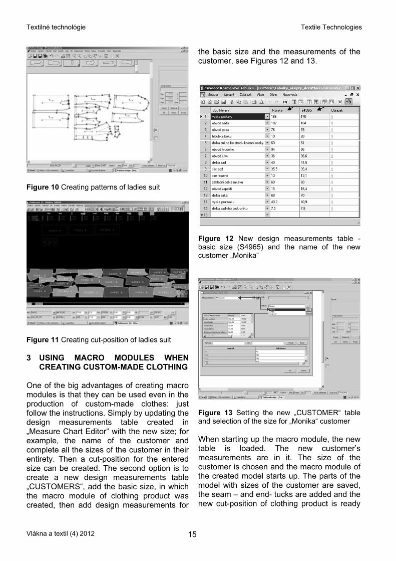
Figure 10 Creating patterns of ladies suit
Figure 11 Creating cut-position of ladies suit 3 USING MACRO MODULES WHEN
CREATING CUSTOM-MADE CLOTHING One of the big advantages of creating macro modules is that they can be used even in the production of custom-made clothes: just follow the instructions. Simply by updating the design measurements table created in „Measure Chart Editor“ with the new size; for example, the name of the customer and complete all the sizes of the customer in their entirety. Then a cut-position for the entered size can be created. The second option is to create a new design measurements table „CUSTOMERS“, add the basic size, in which the macro module of clothing product was created, then add design measurements for
the basic size and the measurements of the customer, see Figures 12 and 13.
Figure 12 New design measurements table - basic size (S4965) and the name of the new customer „Monika“
Figure 13 Setting the new „CUSTOMER“ table and selection of the size for „Monika“ customer When starting up the macro module, the new table is loaded. The new customer’s measurements are in it. The size of the customer is chosen and the macro module of the created model starts up. The parts of the model with sizes of the customer are saved, the seam – and end- tucks are added and the new cut-position of clothing product is ready
Vlákna a textil (4) 2012 15
Textilné technológie Textile Technologies
to be sent to a separate manufacturing process for automatic trimming. The next step is making the clothing product in the workshop and sending it to the customer. So, that is how to produce a clothing product tailored to the needs of anyone. And with the help of macro modules, we can even design clothing solutions for handicapped people sitting in a wheelchair etc. There is one option that saves the basic parts of clothing products in the selected base size for which the macro is created. Subsequently, the classical way, i.e. modelling CAD system makes a PDS model, the solution is automatically projected into all sizes contained in the dimension table relative to the macro. It is also possible to make the created model sewing positions for any size contained in the dimension table macros. 4 3D PROJECTION OF THE DESIGNET
MODEL OF CLOTHING Nowadays we are able to transform the 2D model to a 3D programme. This follow-on „V-stitcher“ programme is a Gerber Technology product too. It enables 3D visualization of clothing, using a virtual dummy of a man, woman, boy or girl. The virtual clothing programme proceeds from 2D patterns creating a clothing model designed in AccuMark software. The working procedure for the virtual visualization of the clothing designed in 2D and its transformation to 3D visualization needs the following: • Preparation of a database that includes
clothing sources, size range, size marking and definition of measurements
• Import of pattern parts and their preparation for seaming and sewing, see Figure14
• Parameter selection and adjustment concerning the textile material relating to the constituent parts of the clothing with the application of fashion accessories and various kinds of stitches
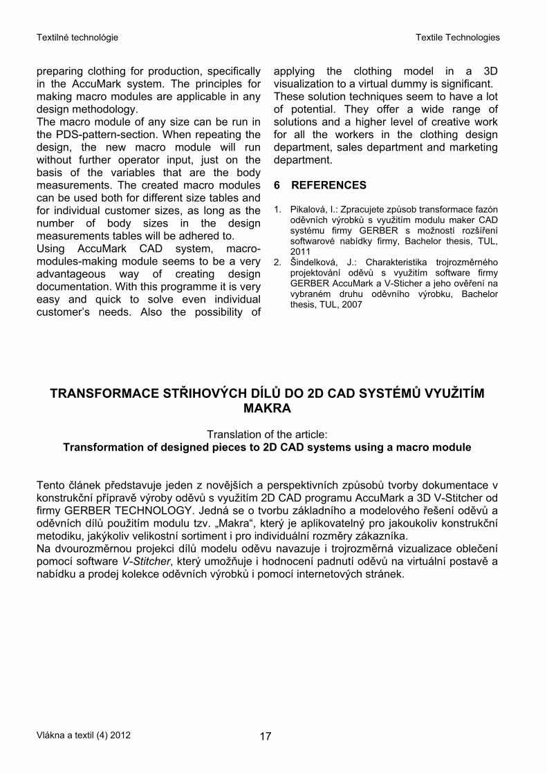
• Selection of a figure and its size Figure 15 and visualizations of the model parts on the virtual dummy, see Figure 16
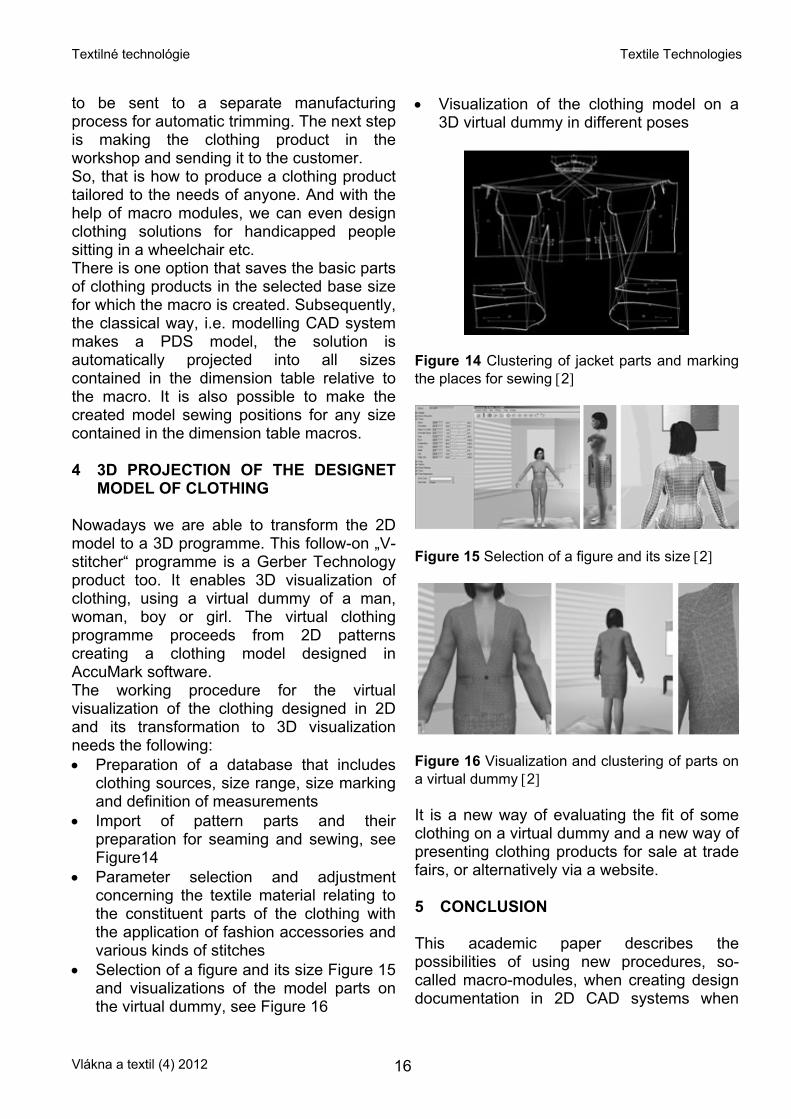
• Visualization of the clothing model on a 3D virtual dummy in different poses
Figure 14 Clustering of jacket parts and marking the places for sewing [2]
Figure 15 Selection of a figure and its size [2]
Figure 16 Visualization and clustering of parts on a virtual dummy [2] It is a new way of evaluating the fit of some clothing on a virtual dummy and a new way of presenting clothing products for sale at trade fairs, or alternatively via a website. 5 CONCLUSION This academic paper describes the possibilities of using new procedures, so-called macro-modules, when creating design documentation in 2D CAD systems when
Vlákna a textil (4) 2012 16
Textilné technológie Textile Technologies
preparing clothing for production, specifically in the AccuMark system. The principles for making macro modules are applicable in any design methodology. The macro module of any size can be run in the PDS-pattern-section. When repeating the design, the new macro module will run without further operator input, just on the basis of the variables that are the body measurements. The created macro modules can be used both for different size tables and for individual customer sizes, as long as the number of body sizes in the design measurements tables will be adhered to. Using AccuMark CAD system, macro-modules-making module seems to be a very advantageous way of creating design documentation. With this programme it is very easy and quick to solve even individual customer’s needs. Also the possibility of
applying the clothing model in a 3D visualization to a virtual dummy is significant. These solution techniques seem to have a lot of potential. They offer a wide range of solutions and a higher level of creative work for all the workers in the clothing design department, sales department and marketing department. 6 REFERENCES 1. Pikalová, I.: Zpracujete způsob transformace fazón
oděvních výrobků s využitím modulu maker CAD systému firmy GERBER s možností rozšíření softwarové nabídky firmy, Bachelor thesis, TUL, 2011
2. Šindelková, J.: Charakteristika trojrozměrného projektování oděvů s využitím software firmy GERBER AccuMark a V-Sticher a jeho ověření na vybraném druhu oděvního výrobku, Bachelor thesis, TUL, 2007
TRANSFORMACE STŘIHOVÝCH DÍLŮ DO 2D CAD SYSTÉMŮ VYUŽITÍM MAKRA
Translation of the article:
Transformation of designed pieces to 2D CAD systems using a macro module Tento článek představuje jeden z novějších a perspektivních způsobů tvorby dokumentace v konstrukční přípravě výroby oděvů s využitím 2D CAD programu AccuMark a 3D V-Stitcher od firmy GERBER TECHNOLOGY. Jedná se o tvorbu základního a modelového řešení oděvů a oděvních dílů použitím modulu tzv. „Makra“, který je aplikovatelný pro jakoukoliv konstrukční metodiku, jakýkoliv velikostní sortiment i pro individuální rozměry zákazníka. Na dvourozměrnou projekci dílů modelu oděvu navazuje i trojrozměrná vizualizace oblečení pomocí software V-Stitcher, který umožňuje i hodnocení padnutí oděvů na virtuální postavě a nabídku a prodej kolekce oděvních výrobků i pomocí internetových stránek.
Vlákna a textil (4) 2012 17
Textilné technológie Textile Technologies
HYDROPHOBIC FINISHING OF POLYESTER CLOTHING TEXTILES
M. Prášil1, L. Martinková2 and J. Wiener1
1Technical University of Liberec, Textile Faculty, Department of Textile Chemistry
Studentská 2, 461 17 Liberec 1, Czech Republic 2INOTEX s r.o., Štefánikova 1208, 544 01 Dvůr Králové n.L.,Czech Republic
Abstract: The aim of this study was to prepare and evaluate functional polyester textiles with hydrophobic finishing applied by impregnation and back-coating using selected waterproof finishing systems. Results of impregnation and coating systems and the combination of these processes in both sequences (preimpregnation – coating and coating-postimpregnation) were evaluated in terms of hydrophobicity: hydrostatic head, spray-test, influence on air permeability and water vapour permeability. Two polyester woven fabrics with different square weight and construction have been finished and compared. For impregnation, fluorochemical has been utilized. This reagent has an ability to reduce the surface tension of the fabric considerably; hence it repels both water and oily liquids. Fluorochemical also exhibits good chemical and thermal stability. Furthermore, has low reactivity due to their incompatibility with water and oil. For coating, two resins namely: acrylic and acrylic/polyurethane (80:20) were used and therefore their performance being compared for properties mentioned above, whereby Werner Mathis CH-8155 laboratory foulard was utilized to carry out both impregnation and coating using floating knife technique for coating. Key words: hydrophobic finishing, impregnation, coating.
1 INTRODUCTION Functionalized textiles are nowadays very frequently used not only in category of industrial textiles. But also they are frequently required to be used for protective and functional outer apparel for sports and everyday clothing. That is why optimum types of hydrophobic finishing are to be selected with regards to achieve water repellency and also to physiological parameters influence [1, 2]Water repellency is conferred to the textile substrate by impregnating the substrate with the chemical agents whose surface tensions are lower than those of a fabric, because in order for textile substrate to be hydrophobic it is necessary to have lower surface tension of substrate in comparison to the solvent (water or organic solvents). Meanwhile coating is an application of a polymeric resin on the textile substrate; it can be done on one side or both depending on
the desired outcomes. The quality of the coated textile depends on the nature of the fiber, construction of the substrate whether is a woven, non-woven or knitted fabric, the kind of resin applied as well as the method of application (machine used). Therefore in this study, both the impregnation and coating methods of hydrophilic finishing shall be compared to see which one yields better results by utilizing polyester fabrics of different construction and compositions. Furthermore the study seeks to determine how both impregnated and coated fabric will behave when tested with spray test, hydrostatic pressure test, air permeability as well as water vapour permeability test [2-4].
Vlákna a textil (4) 2012 18
Textilné technológie Textile Technologies
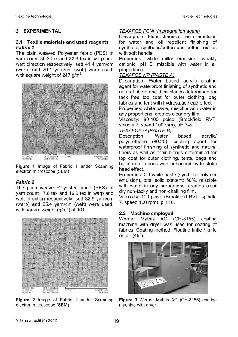
2 EXPERIMENTAL 2.1 Textile materials and used reagents Fabric 1 The plain weaved Polyester fabric (PES) of yarn count 36.2 tex and 32.6 tex in warp and weft direction respectively; sett 41.4 yarn/cm (warp) and 29.1 yarn/cm (weft) were used, with square weight of 247 g/m2.
Figure 1 Image of Fabric 1 under Scanning electron microscope (SEM) Fabric 2 The plain weave Polyester fabric (PES) of yarn count 17.8 tex and 16.0 tex in warp and weft direction respectively; sett 32.9 yarn/cm (warp) and 25.4 yarn/cm (weft) were used, with square weight (g/m2) of 101.
Figure 2 Image of Fabric 2 under Scanning electron microscope (SEM)
TEXAFOB FCNI (Impregnation agent) Description: Fluorochemical resin emulsion for water and oil repellent finishing of synthetic, synthetic/cotton and cotton textiles with soft handle. Properties: white milky emulsion, weakly cationic, pH 5, miscible with water in all proportions. TEXAFOB NP (PASTE A) Description: Water based acrylic coating agent for waterproof finishing of synthetic and natural fibers and their blends determined for tack free top coat for outer clothing, bag fabrics and tent with hydrostatic head effect. Properties: white paste, miscible with water in any proportions, creates clear dry film. Viscosity: 80-100 poise (Brookfield RVT, spindle 7, speed 100 rpm), pH 7-8. TEXAFOB G (PASTE B) Description: Water based acrylic/ polyurethane (80:20), coating agent for waterproof finishing of synthetic and natural fibers as well as their blends determined for top coat for outer clothing, tents, bags and bulletproof fabrics with enhanced hydrostatic head effect. Properties: Off-white paste (synthetic polymer emulsion), total solid content: 50%, miscible with water in any proportions, creates clear dry non-tacky and non-chalking film. Viscosity: 100 poise (Brookfield RVT, spindle 7, speed 100 rpm), pH 10. 2.2 Machine employed Werner Mathis AG (CH-8155) coating machine with dryer was used for coating of fabrics. Coating method: Floating knife / knife on air (45°).
Figure 3 Werner Mathis AG (CH-8155) coating machine with dryer
Vlákna a textil (4) 2012 19
Textilné technológie Textile Technologies
2.3 Procedure 1. TEXAFOB FCNI IMPREGNATION 50 g/l TEXAFOB FCNI 8 g/l TEXAPRET TP-10 (Cross linker) 0.5 ml/l Acetic acid (pH) Four samples (two of fabric 1 and two of fabric 2) were impregnated with TEXAFOB FCNI, then dried for 2 min at 120°C and finally fixed at 180°C for 1 minute.
2. TEXAFOB FCNI PREIMPREGNATION + COATING PASTE A a) Preimpregnation 50 g/l TEXAFOB FCNI 8 g/l TEXAPRET TP-10 (Cross linker) 0.5 ml/l Acetic acid (pH) Eight samples (four of fabric 1 and four of fabric 2) were impregnated with TEXAFOB FCNI and then dried for 2 min at 120°C. b) Coating Paste A Paste A x Coating (1) Four samples (two of fabric 1 and two of fabric 2) were coated once with Paste A using knife over roller technique at 45°. Paste A x Coating (2) Remaining four samples (two of fabric 1 and two of fabric 2) were coated twice with Paste A using knife over roller technique at 45°. All eight samples were then cured at 180°C for 1 minute.
3. TEXAFOB FCNI PREIMPREGNATION + COATING PASTE B a) Preimpregnation 50 g/l TEXAFOB FCNI 8 g/l TEXAPRET TP-10 (Cross linker) 0.5 ml/l Acetic acid (pH) Eight samples (four of fabric 1 and four of fabric 2) were impregnated with TEXAFOB FCNI, and then dried for 2 min at 120°C. b) Coating Paste B Paste B x Coating (1) Four samples (two of fabric 1 and two fabric of 2) were coated once with Paste B using knife over roller technique at 45°. Paste B x Coating (2) Remaining four samples (two of fabric 1 and two of fabric 2) were coated twice with Paste B using knife over roller technique at 45°. All eight samples were then cured at 180°C for 1 minute.
4. COATING PASTE A + POSTIMPREGNA-TION TEXAFOB FCNI a) Coating Paste A Paste A x Coating (1) Four samples (two of fabric1 and two of fabric 2) were coated once with Paste A using knife over roller technique at 45°. Paste A x Coating (2) Remaining four samples (two of fabric 1 and two of fabric 2) were coated twice with Paste A using knife over roller technique at 45°. The samples were then dried at 120°C for 2 min. b) Postimpregnation 50 g/l TEXAFOB FCNI 8 g/l TEXAPRET TP-10 (Cross linker) 0.5 ml/l Acetic acid (pH) Eight samples from a) (four of fabric 1 and four of fabric 2) were impregnated with TEXAFOB FCNI and then cured at 180°C for 1 min.
5. COATING PASTE B + POSTIMPREGNATION TEXAFOB FCNI a) Coating Paste B Paste B x Coating (1) Four samples (two of fabric 1 and two of fabric 2) were coated once with Paste B using knife over roller technique at 45°. Paste B x Coating (2) Remaining four samples (two of fabric 1 and two of fabric 2) were coated twice with Paste B using knife over roller technique at 45°. The samples were then dried at 120°C for 2 min. b) Postimpregnation 50 g/l TEXAFOB FCNI 8 g/l TEXAPRET TP-10 (Cross linker) 0.5 ml/l Acetic acid (pH) Eight samples from a) (four of fabric 1 and four of fabric 2) were impregnated with TEXAFOB FCNI and then cured at 180°C for 1 min. 2.4 Testing methods and devices The hydrostatic head tester (FX 3000 HYDROTESTER III) was used to determine the resistance to water penetration of the samples, as in accordance with EN 20811 standards. The Spray tester was used to determine the resistance to surface wetting of fabrics according to EN 24920 standards.
Vlákna a textil (4) 2012 20
Textilné technológie Textile Technologies
The air permeability tester (FX 3300 LABOTESTER III) was utilized to determine the permeability of fabrics to air according to EN ISO 9237 standards.
2. Samples were impregnated with Texafob FCNI, then coated (Preimpregnation)
3. Samples were coated, then impregnated with Texafob FCNI afterwards (Postimpregnation) The Sensora Permetester was used to
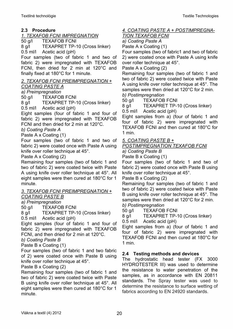
determine the water vapour permeability (breathability) according to EN ISO 15496 standards. 3 RESULTS AND DISCUSSION 3.1 Waterproof (Hydrostatic head) The fabrics were treated with fluorine-based water repellent agent (Texafob FCNI) as well as coated with Acrylic first coat (AC 1x), Acrylic second coat (AC 2x), Acrylic/Polyurethane first coat (AC/PU 1x) and Acrylic/Polyurethane second coat (AC/PU 2x).
As illustrated by the Figure 4, AC/PU (acrylic/polyurethane) had good waterproof resistance. Both pre-impregnated and post-impregnated samples, particularly when applied twice (2x). Therefore coated samples had better waterproof in comparison to impregnated sample (Texafob FCNI). Furthermore, second coats have higher value in comparison to the first coats only.
The samples were divided into three categories: 1. Samples were coated without
impregnation
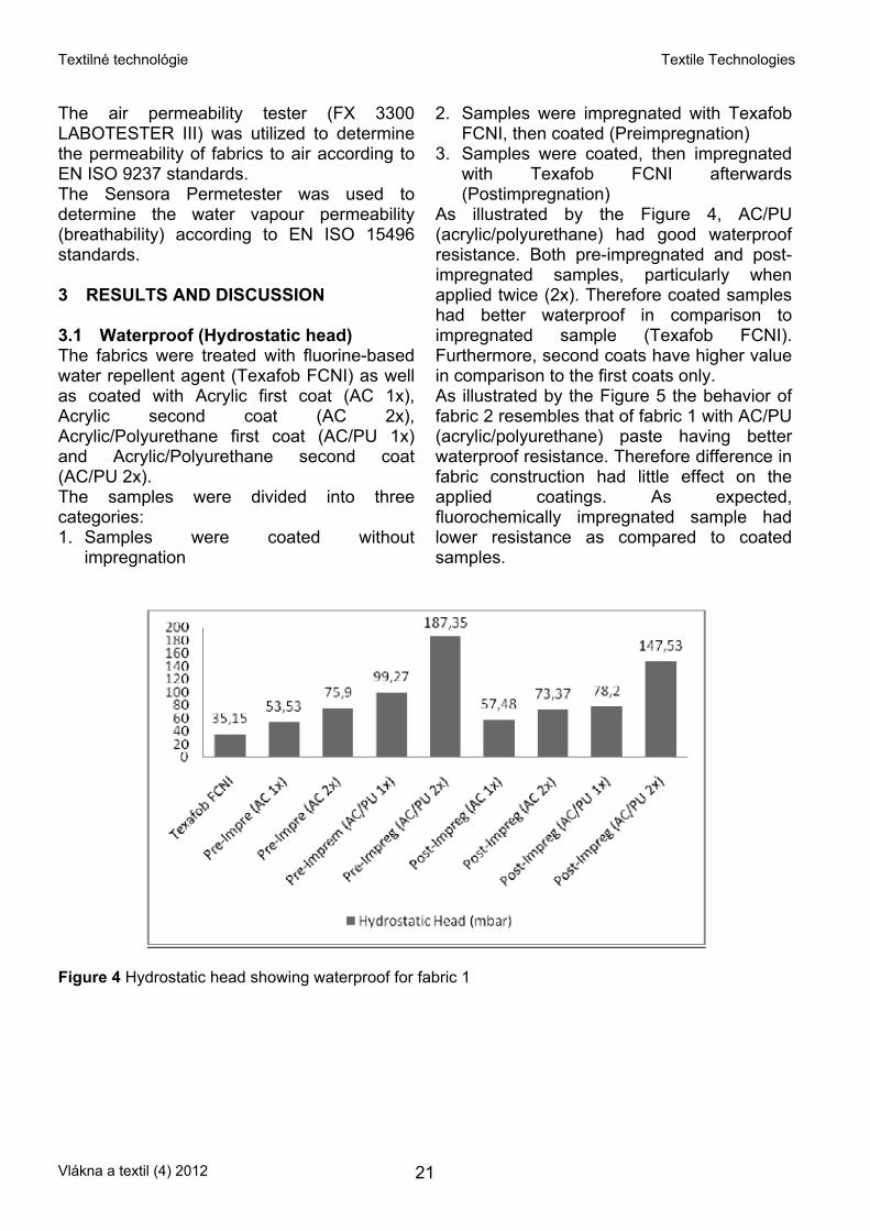
As illustrated by the Figure 5 the behavior of fabric 2 resembles that of fabric 1 with AC/PU (acrylic/polyurethane) paste having better waterproof resistance. Therefore difference in fabric construction had little effect on the applied coatings. As expected, fluorochemically impregnated sample had lower resistance as compared to coated samples.
Figure 4 Hydrostatic head showing waterproof for fabric 1
Vlákna a textil (4) 2012 21
Textilné technológie Textile Technologies
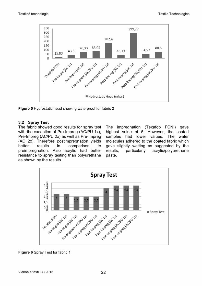
Figure 5 Hydrostatic head showing waterproof for fabric 2 3.2 Spray Test The fabric showed good results for spray test with the exception of Pre-Impreg (AC/PU 1x), Pre-Impreg (AC/PU 2x) as well as Pre-Impreg (AC 2x). Therefore postimpregnation yields better results in comparison to preimpregnation. Also acrylic had better resistance to spray testing than polyurethane as shown by the results.
The impregnation (Texafob FCNI) gave highest value of 5. However, the coated samples had lower values. The water molecules adhered to the coated fabric which gave slightly wetting as suggested by the results, particularly acrylic/polyurethane paste.
Figure 6 Spray Test for fabric 1
Vlákna a textil (4) 2012 22
Textilné technológie Textile Technologies
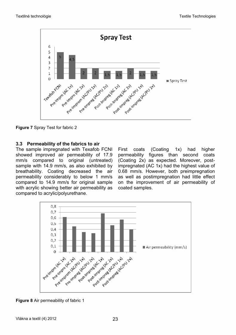
Figure 7 Spray Test for fabric 2 3.3 Permeability of the fabrics to air The sample impregnated with Texafob FCNI showed improved air permeability of 17.9 mm/s compared to original (untreated) sample with 14.9 mm/s, as also exhibited by breathability. Coating decreased the air permeability considerably to below 1 mm/s compared to 14.9 mm/s for original sample with acrylic showing better air permeability as compared to acrylic/polyurethane.
First coats (Coating 1x) had higher permeability figures than second coats (Coating 2x) as expected. Moreover, post-impregnated (AC 1x) had the highest value of 0.68 mm/s. However, both preimpregnation as well as postimpregnation had little effect on the improvement of air permeability of coated samples.
Figure 8 Air permeability of fabric 1
Vlákna a textil (4) 2012 23
Textilné technológie Textile Technologies
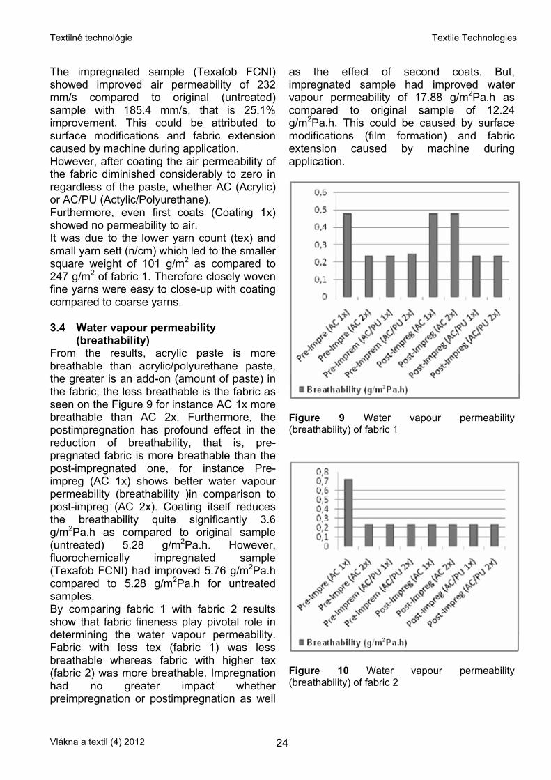
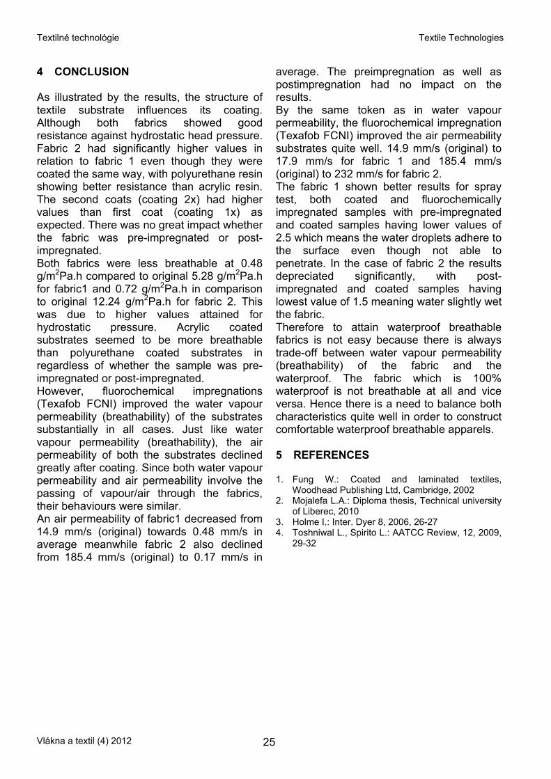
The impregnated sample (Texafob FCNI) showed improved air permeability of 232 mm/s compared to original (untreated) sample with 185.4 mm/s, that is 25.1% improvement. This could be attributed to surface modifications and fabric extension caused by machine during application. However, after coating the air permeability of the fabric diminished considerably to zero in regardless of the paste, whether AC (Acrylic) or AC/PU (Actylic/Polyurethane). Furthermore, even first coats (Coating 1x) showed no permeability to air. It was due to the lower yarn count (tex) and small yarn sett (n/cm) which led to the smaller square weight of 101 g/m2 as compared to 247 g/m2 of fabric 1. Therefore closely woven fine yarns were easy to close-up with coating compared to coarse yarns. 3.4 Water vapour permeability
(breathability) From the results, acrylic paste is more breathable than acrylic/polyurethane paste, the greater is an add-on (amount of paste) in the fabric, the less breathable is the fabric as seen on the Figure 9 for instance AC 1x more breathable than AC 2x. Furthermore, the postimpregnation has profound effect in the reduction of breathability, that is, pre-pregnated fabric is more breathable than the post-impregnated one, for instance Pre-impreg (AC 1x) shows better water vapour permeability (breathability )in comparison to post-impreg (AC 2x). Coating itself reduces the breathability quite significantly 3.6 g/m2Pa.h as compared to original sample (untreated) 5.28 g/m2Pa.h. However, fluorochemically impregnated sample (Texafob FCNI) had improved 5.76 g/m2Pa.h compared to 5.28 g/m2Pa.h for untreated samples. By comparing fabric 1 with fabric 2 results show that fabric fineness play pivotal role in determining the water vapour permeability. Fabric with less tex (fabric 1) was less breathable whereas fabric with higher tex (fabric 2) was more breathable. Impregnation had no greater impact whether preimpregnation or postimpregnation as well
as the effect of second coats. But, impregnated sample had improved water vapour permeability of 17.88 g/m2Pa.h as compared to original sample of 12.24 g/m2Pa.h. This could be caused by surface modifications (film formation) and fabric extension caused by machine during application.
Figure 9 Water vapour permeability (breathability) of fabric 1
Figure 10 Water vapour permeability (breathability) of fabric 2
Vlákna a textil (4) 2012 24
Textilné technológie Textile Technologies
4 CONCLUSION As illustrated by the results, the structure of textile substrate influences its coating. Although both fabrics showed good resistance against hydrostatic head pressure. Fabric 2 had significantly higher values in relation to fabric 1 even though they were coated the same way, with polyurethane resin showing better resistance than acrylic resin. The second coats (coating 2x) had higher values than first coat (coating 1x) as expected. There was no great impact whether the fabric was pre-impregnated or post-impregnated. Both fabrics were less breathable at 0.48 g/m2Pa.h compared to original 5.28 g/m2Pa.h for fabric1 and 0.72 g/m2Pa.h in comparison to original 12.24 g/m2Pa.h for fabric 2. This was due to higher values attained for hydrostatic pressure. Acrylic coated substrates seemed to be more breathable than polyurethane coated substrates in regardless of whether the sample was pre-impregnated or post-impregnated. However, fluorochemical impregnations (Texafob FCNI) improved the water vapour permeability (breathability) of the substrates substantially in all cases. Just like water vapour permeability (breathability), the air permeability of both the substrates declined greatly after coating. Since both water vapour permeability and air permeability involve the passing of vapour/air through the fabrics, their behaviours were similar. An air permeability of fabric1 decreased from 14.9 mm/s (original) towards 0.48 mm/s in average meanwhile fabric 2 also declined from 185.4 mm/s (original) to 0.17 mm/s in
average. The preimpregnation as well as postimpregnation had no impact on the results. By the same token as in water vapour permeability, the fluorochemical impregnation (Texafob FCNI) improved the air permeability substrates quite well. 14.9 mm/s (original) to 17.9 mm/s for fabric 1 and 185.4 mm/s (original) to 232 mm/s for fabric 2. The fabric 1 shown better results for spray test, both coated and fluorochemically impregnated samples with pre-impregnated and coated samples having lower values of 2.5 which means the water droplets adhere to the surface even though not able to penetrate. In the case of fabric 2 the results depreciated significantly, with post-impregnated and coated samples having lowest value of 1.5 meaning water slightly wet the fabric. Therefore to attain waterproof breathable fabrics is not easy because there is always trade-off between water vapour permeability (breathability) of the fabric and the waterproof. The fabric which is 100% waterproof is not breathable at all and vice versa. Hence there is a need to balance both characteristics quite well in order to construct comfortable waterproof breathable apparels. 5 REFERENCES 1. Fung W.: Coated and laminated textiles,
Woodhead Publishing Ltd, Cambridge, 2002 2. Mojalefa L.A.: Diploma thesis, Technical university
of Liberec, 2010 3. Holme I.: Inter. Dyer 8, 2006, 26-27 4. Toshniwal L., Spirito L.: AATCC Review, 12, 2009,
29-32
Vlákna a textil (4) 2012 25
Textilné technológie Textile Technologies
HYDROFOBNÍ ÚPRAVA POLYESTEROVÝCH ODĚVNÍCH TEXTILIÍ
Translation of the article Hydrophobic finishing of polyester clothing textiles
Abstrakt: Cílem studie bylo připravit a testovat polyesterové oděvní textilie s hydrofobní úpravou aplikovanou impregnací, zátěrem a jejich kombinací. Hodnocení vhodnosti úprav pro oděvní účely bylo testováno zjišťováním prodyšnosti a propustnosti vodních par upravenými polyesterovými textiliemi.
Vlákna a textil (4) 2012 26
Textilné technológie Textile Technologies
ŠTÚDIUM VPLYVU ŠTRUKTÚRY ŠPECIÁLNYCH TYPOV ZMESNÝCH PRIADZÍ NA ICH ELEKTROVODIVÉ VLASTNOSTI
Ľ. Balogová1, J. Šesták1, V. Remeková1, A. Džupaj1, M. Gála2 a B. Babušiak2
1 VÚTCH-CHEMITEX, spol. s r.o., Rybníky 954, 011 68 Žilina, Slovenská republika,
2 Katedra teoretickej elektrotechniky a biomedicínskeho inžinierstva, Elektrotechnická fakulta, Žilinská univerzita, Žilina, Slovenská republika,
[email protected], [email protected], [email protected] [email protected], [email protected]
Abstrakt: Príspevok je zameraný na prípravu špeciálnych typov zmesných priadzí s elektrovodivými vlastnosťami pre aplikáciu do textilných senzorov určených na snímanie fyziologických funkcií človeka , ako napr. monitorovanie EKG, krvného tlaku, dýchania, telesnej teploty a pod. Orientuje sa na štúdium vplyvu štruktúry vyvinutých špeciálnych typov zmesných priadzí na ich elektrovodivé vlastnosti z hľadiska charakteru tvorby zmesnej priadze, počtu zákrutov a počtu vodivých vlákien v zmesnej priadzi. V príspevku sú publikované výsledky výskumných prác zameraných na vývoj nových typov špeciálnych priadzí na báze zmesi elektricky nevodivých a vodivých vlákien, pripravených technológiou zosúkavania na multifunkčnom zosúkavacom zariadení DirecTwist 2B a výsledky merania elektrických vlastností týchto priadzí. Kľúčové slová: elektrovodivé vlákna, zmesné priadze, textilné senzory, inteligentné odevy, elektrická vodivosť, elektrický odpor.
1 ÚVOD Svetový trend v oblasti textilných a odevných technológií zaznamenal v posledných rokoch prudký rozvoj, orientovaný na inováciu sortimentu štandardných materiálov cielene smerujúcu k príprave multifunkčných materiálov a odevných výrobkov s vysokou, až nadštandardnou pridanou hodnotou. Vývoj v oblasti textilných materiálov prepojený na výskum v oblasti mikrosystémov, nanotechnológií, spracovania informácií a komunikačných technológií umožnil miniaturizáciu a neinvazívne inteligentné monitorovanie fyziologických funkcií človeka pomocou tzv. „smart“ materiálov a „inteligentných“ textílií (nazývaných tiež elektronické textílie alebo e-textílie), ktoré dokážu samostatne vnímať a reagovať na podnety prostredia [1, 2]. Integráciou mikroelektroniky a nových textilných prvkov, ktoré vďaka vzájomnému prepojeniu zvyšujú svoj efekt, sa dosahuje nová kvalita multifunkčných inteligentných výrobkov s komplexnou vnútornou štruktúrou a so stálymi nadštandardnými funkčnými
vlastnosťami [3]. Pokračujúci a neustále napredujúci multi-disciplinárny výskum v oblasti textilných vlákien, špeciálnych priadzí, biomedicínskych textilných senzorov, bezdrôtovej a mobilnej telekomunikácie spojenej s telemedicínou dnes smeruje najmä k vývoju progresívnych inteligentných biomedicínskych odevov [1]. Mobilné monitorovanie fyziologických funkcií človeka pomocou inteligentných odevov umožňuje snímať, zaznamenávať, spracovávať a prenášať namerané životné signály ako sú napr. aktivita svalstva (dýchanie), aktivita srdca (EKG), aktivita nervového systému (EEG), telesná teplota a ďalšie impulzy. Aktívnym (citlivým) prvkom inteligentného odevu sú tzv. textilné senzory – elektródy, ktoré môžu byť integrované do konštrukcie odevu, alebo sa môžu používať nezávisle (samostatne) a v kontakte s pokožkou sú vlastne snímacím prvkom elektrických signálov generovaných telom človeka [4, 5]. Na výrobu textilných senzorov sa používajú špeciálne typy priadzí, ktoré vo svojej konštrukcii obsahujú vlákna s vysokou
Vlákna a textil (4) 2012 27
Textilné technológie Textile Technologies
elektrickou vodivosťou, ktoré znižujú odpor na rozhraní pokožka – elektróda [6]. V súčasnej dobe, po rokoch intenzívneho vývoja, je na trhu viacero druhov vodivých vlákien, ako sú napr. kovové vlákna (vlákna z nehrdzavejúcej ocele, medené vlákna), pokovované vlákna (postriebrené polyamidové vlákna) resp. vlákna obsahujúce dispergované fázy vodivých materiálov (napr. uhlíka) [7]. Všetky tieto vlákna možno jednoducho inkorporovať do konštrukcie textilnej priadze. Aktívne súčasti textilných priadzí vo forme elektrovodivých vlákien by mali reagovať na zmeny elektrickej hodnoty a teploty človeka a súčasne by mali byť schopné viesť signály vznikajúce interakciou textilných elektród a biologického objektu (človeka). Vodivé vlákna sú do priadze zosúkané spolu so štandardnými vláknami, ako napr. bavlna, polyamid, Lycra a pod. Okrem základných funkčných vlastností a dobrej spracovateľnosti účel ich použitia vyžaduje zabezpečiť aj pružnosť, stálosť v praní a odolnosť proti cyklickým mechanickým deformáciám [3]. Pri tvorbe textilných priadzí s elektrovodivými vlastnosťami je potrebné rešpektovať požiadavky kladené na vlastnosti vodivých priadzí. Súčasne je potrebné zohľadniť aj spôsoby akými sa dá dosiahnuť vyhovujúca vodivosť pri rešpektovaní špecifických vlastností a podmienok použitia odevov so zabudovanou elektronikou [8]. Pre dosiahnutie požadovanej úrovne funkčnosti špeciálnej elektricky vodivej priadze, z hľadiska snímania fyziologických funkcií človeka a prenosu životných signálov, sa preto v mnohých literárnych a patentových odkazoch veľká pozornosť venuje správnemu výberu materiálového zloženia a vhodnej konštrukcie priadze. V príspevku sú publikované doterajšie výsledky výskumných prác zameraných na prípravu špeciálnych typov elektrovodivých priadzí s cieľom ich využitia pri príprave textilných senzorov určených na monitorovanie fyziologických funkcií, snímanie a prenos životných signálov človeka. Výskum bol orientovaný najmä na štúdium vplyvu štruktúry dvoch typov
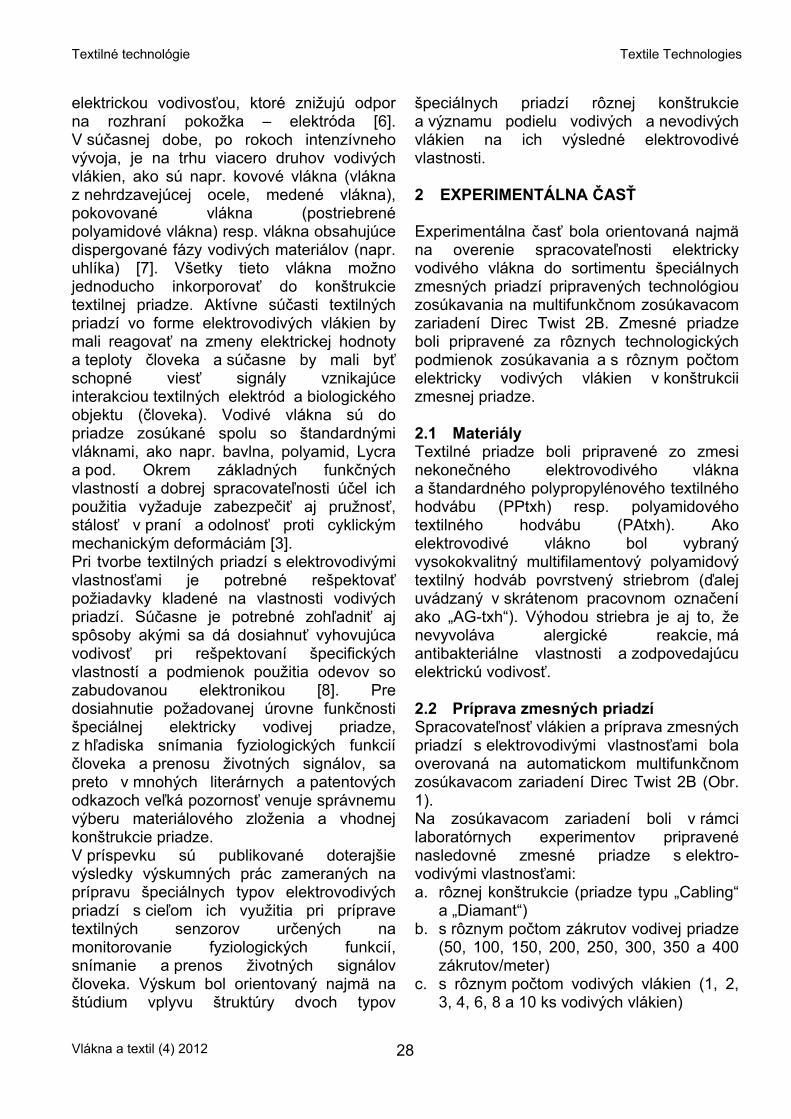
špeciálnych priadzí rôznej konštrukcie a významu podielu vodivých a nevodivých vlákien na ich výsledné elektrovodivé vlastnosti. 2 EXPERIMENTÁLNA ČASŤ Experimentálna časť bola orientovaná najmä na overenie spracovateľnosti elektricky vodivého vlákna do sortimentu špeciálnych zmesných priadzí pripravených technológiou zosúkavania na multifunkčnom zosúkavacom zariadení Direc Twist 2B. Zmesné priadze boli pripravené za rôznych technologických podmienok zosúkavania a s rôznym počtom elektricky vodivých vlákien v konštrukcii zmesnej priadze. 2.1 Materiály Textilné priadze boli pripravené zo zmesi nekonečného elektrovodivého vlákna a štandardného polypropylénového textilného hodvábu (PPtxh) resp. polyamidového textilného hodvábu (PAtxh). Ako elektrovodivé vlákno bol vybraný vysokokvalitný multifilamentový polyamidový textilný hodváb povrstvený striebrom (ďalej uvádzaný v skrátenom pracovnom označení ako „AG-txh“). Výhodou striebra je aj to, že nevyvoláva alergické reakcie, má antibakteriálne vlastnosti a zodpovedajúcu elektrickú vodivosť. 2.2 Príprava zmesných priadzí Spracovateľnosť vlákien a príprava zmesných priadzí s elektrovodivými vlastnosťami bola overovaná na automatickom multifunkčnom zosúkavacom zariadení Direc Twist 2B (Obr. 1). Na zosúkavacom zariadení boli v rámci laboratórnych experimentov pripravené nasledovné zmesné priadze s elektro-vodivými vlastnosťami: a. rôznej konštrukcie (priadze typu „Cabling“
a „Diamant“) b. s rôznym počtom zákrutov vodivej priadze
(50, 100, 150, 200, 250, 300, 350 a 400 zákrutov/meter)
c. s rôznym počtom vodivých vlákien (1, 2, 3, 4, 6, 8 a 10 ks vodivých vlákien)
Vlákna a textil (4) 2012 28
Textilné technológie Textile Technologies
Navrhnutá štruktúra elektrovodivých priadzí pozostáva z nevodivého jadra (PPtxh, resp. PAtxh) špirálovite ovinutého vodivým vláknom (AG-txh). Proces ovíjania vodivého vlákna bol dvojaký: - ovíjanie jedným smerom pri priadzi typu
„Cabling“ - ovíjanie oboma smermi pri priadzi typu
„Diamant“.
Obrázok 1 Multifunkčné zosúkavacie zariadenie Direc Twist 2B Pre overenie vplyvu počtu zákrutov na zmenu odporu priadze boli pripravené priadze s rôznym počtom zákrutov/meter hotovej priadze v rozsahu 50 až 400 zákrutov/meter. Z hľadiska zabezpečenia vhodnej kvality zmesných priadzí s tak širokým rozpätím zákrutov bolo na ovinutie nevodivého vlákna použitých 5 elektrovodivých vlákien. Počas procesu tvorby zmesných priadzí bolo potrebné pre stabilizáciu výrobného procesu dvakrát upravovať technologické podmienky zosúkavania vlákien (pri počte 100 zákrutov/meter a 350 zákrutov/meter) s dôrazom na vzájomný pomer rýchlosti a napätia jednotlivých vlákien vstupujúcich do procesu zosúkavania. Úprava technologických podmienok tvorby zmesnej priadze bola nevyhnutá, aby bol dodržaný konštrukčný pomer jednotlivých vlákenných komponentov v zmesnej priadzi. Tretiu skupinu tvoria priadze, u ktorých nevodivé jadro priadze bolo ovinuté rôznym
počtom vodivých vlákien (max. 10 vlákien). Predpokladali sme, že zvýšenie počtu vodivých vlákien pri súčasnom zvýšení počtu kontaktných bodov medzi jednotlivými vodivými vláknami môže byť efektívny spôsob pre dosiahnutie čo najvyššej elektrickej vodivosti pripravených zmesných priadzí. 2.3 Metodológia Pri realizácii bioelektród (elektrických senzorov) je dôležité docieliť dobrú elektrickú vodivosť, aby signál snímaný z povrchu ľudského tela bol čo najmenej tlmený. Vodivosť je priamo spätá s elektrickým odporom podľa nasledujúceho vzorca (1):
G1R = [Ω] (1)
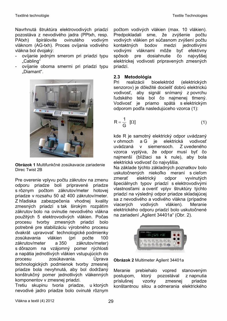
kde R je samotný elektrický odpor uvádzaný v ohmoch a G je elektrická vodivosť uvádzaná v siemensoch. Z uvedeného vzorca vyplýva, že odpor musí byť čo najmenší (blížiaci sa k nule), aby bola elektrická vodivosť čo najvyššia. Na základe týchto základných poznatkov bolo uskutočnených niekoľko meraní s cieľom zmerať elektrický odpor vyvinutých špeciálnych typov priadzí s elektrovodivými vlastnosťami a overiť vplyv štruktúry týchto priadzí na výsledný odpor priadze skladajúcej sa z nevodivého a vodivého vlákna (prípadne viacerých vodivých vlákien). Meranie elektrického odporu priadzí bolo uskutočnené na zariadení „Agilent 34401a“ (Obr. 2).
Obrázok 2 Multimeter Agilent 34401a
Meranie prebiehalo vopred stanoveným postupom, ktorý pozostával z napnutia príslušnej vzorky zmesnej priadze konštantnou silou a odmerania elektrického
Vlákna a textil (4) 2012 29
Textilné technológie Textile Technologies
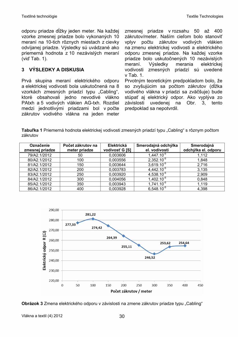
odporu priadze dĺžky jeden meter. Na každej vzorke zmesnej priadze bolo vykonaných 10 meraní na 10-tich rôznych miestach z cievky odvíjanej priadze. Výsledky sú uvádzané ako priemerná hodnota z 10 nezávislých meraní (viď Tab. 1). 3 VÝSLEDKY A DISKUSIA Prvá skupina meraní elektrického odporu a elektrickej vodivosti bola uskutočnená na 8 vzorkách zmesných priadzí typu „Cabling“, ktoré obsahovali jedno nevodivé vlákno PAtxh a 5 vodivých vlákien AG-txh. Rozdiel medzi jednotlivými priadzami bol v počte zákrutov vodivého vlákna na jeden meter
zmesnej priadze v rozsahu 50 až 400 zákrutov/meter. Naším cieľom bolo stanoviť vplyv počtu zákrutov vodivých vlákien na zmenu elektrickej vodivosti a elektrického odporu zmesnej priadze. Na každej vzorke priadze bolo uskutočnených 10 nezávislých meraní. Výsledky merania elektrickej vodivosti zmesných priadzí sú uvedené v Tab. 1. Prvotným teoretickým predpokladom bolo, že so zvyšujúcim sa počtom zákrutov (dĺžka vodivého vlákna v priadzi sa zväčšuje) bude stúpať aj elektrický odpor. Ako vyplýva zo závislosti uvedenej na Obr. 3, tento predpoklad sa nepotvrdil.
Tabuľka 1 Priemerná hodnota elektrickej vodivosti zmesných priadzí typu „Cabling“ s rôznym počtom zákrutov
Označenie zmesnej priadze
Počet zákrutov na meter priadze
Elektrická vodivosť G [S]
Smerodajná odchýlka el. vodivosti
Smerodajná odchýlka el. odporu
79/A2.1/2012 50 0,003606 1,447.10-5 1,112 80/A2.1/2012 100 0,003556 2,352.10-5 1,848 81/A2.1/2012 150 0,003644 3,619.10-5 2,716 82/A2.1/2012 200 0,003783 4,442.10-5 3,135 83/A2.1/2012 250 0,003920 4,538.10-5 2,909 84/A2.1/2012 300 0,004056 1,402.10-5 0,848 85/A2.1/2012 350 0,003943 1,741.10-5 1,119 86/A2.1/2012 400 0,003928 6,548.10-5 4,398
Obrázok 3 Zmena elektrického odporu v závislosti na zmene zákrutov priadze typu „Cabling“
Vlákna a textil (4) 2012 30

Textilné technológie Textile Technologies
V grafe sú viditeľné dva zlomové body. Prvým zlomovým bodom je zmena el. odporu pri počte 100 zákrutov/meter, kedy sa uvedený teoretický predpoklad čiastočne naplnil. So zvyšujúcim sa počtom zákrutov až po hodnotu 300 zákrutov/meter ale elektrický odpor klesal a následne pri 350 zákrutoch/meter začal opäť stúpať. Daný jav, kedy elektrický odpor so vzrastajúcim počtom zákrutov klesal sa dá vysvetliť napríklad tým, že výsledný odpor zmesnej priadze okrem dĺžky vodivého vlákna môže závisieť aj od prierezu vodivého vlákna, ktorý je ovplyvnený nastaveným napínacím napätím pri výrobe samotnej priadze. Tento predpoklad vyjadruje aj vzťah (2), ktorý hovorí o tom, že veľkosť elektrického odporu závisí od elektrického merného odporu ρ, dĺžky vodiča l a prierezu samotného vodiča S.
S1R ρ= [Ω] (2)
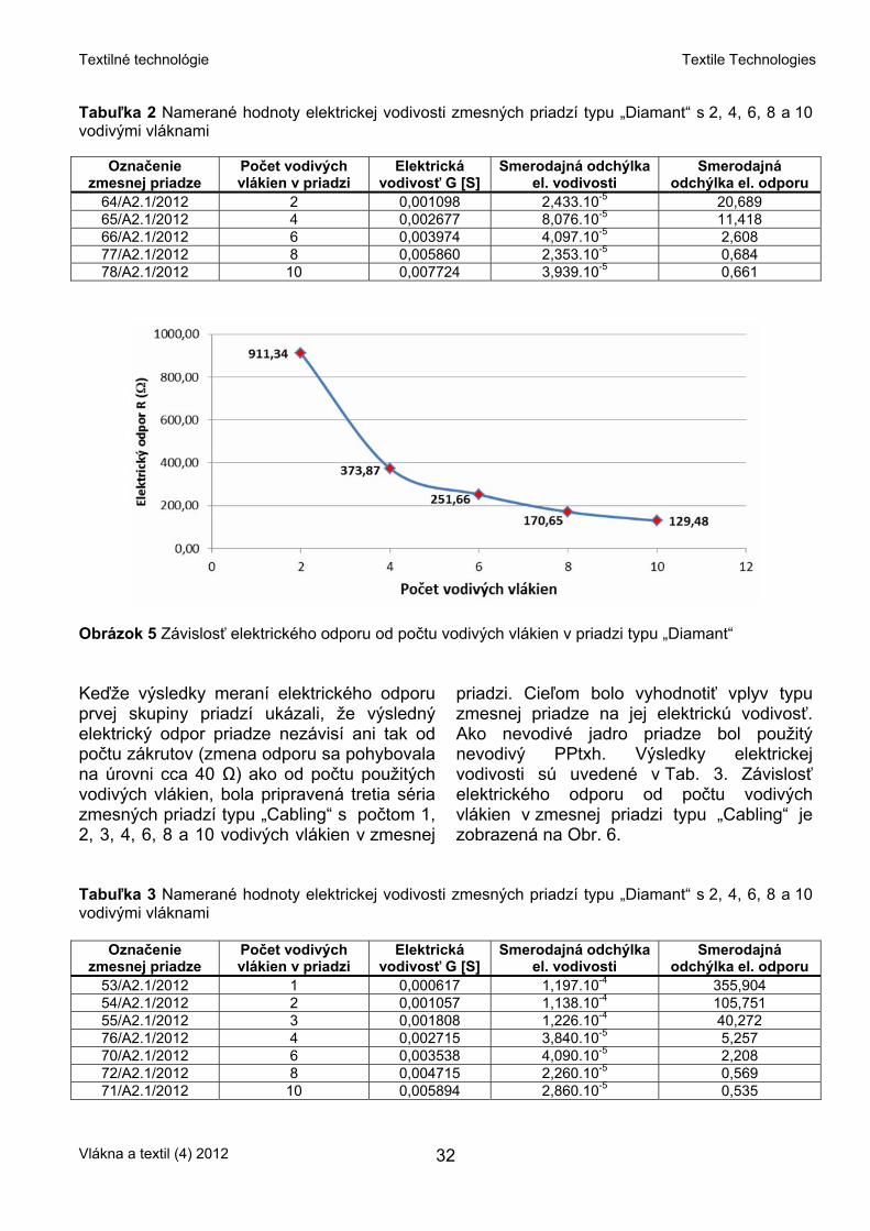
Z toho môžeme predpokladať, že dĺžka vodivého vlákna sa síce zväčšovala, čím mal stúpať aj elektrický odpor, ale zároveň pri stúpajúcom počte zákrutov bolo potrebné z hľadiska spracovateľnosti upraviť (uvoľniť) napätie vlákien a tým napínacie napätie klesalo. Predpokladáme preto, že uvoľnenie napätia vlákien mohlo zapríčiniť zväčšenie prierezu vlákna a tým došlo poklesu výsledného elektrického odporu. Tento predpoklad bude predmetom ďalšieho skúmania a riešenia danej problematiky. Z hľadiska elektrického odporu, ako aj z hľadiska ďalšej textilnej spracovateľnosti boli ako najvhodnejšie pre aplikáciu do textilných senzorov vyšpecifikované zmesné priadze s 200, 250 a 300 zákrutmi/meter, ktorých výsledný odpor sa pohyboval v rozmedzí 246 až 264 Ω/m. Ďalšiu skúmanú skupinu tvorili priadze typu „Diamant“ s jedným nevodivým vláknom PAtxh a s 2, 4, 6, 8 a 10 vodivými vláknami Ag-txh. Cieľom bolo stanoviť vplyv počtu vodivých vlákien v zmesnej priadzi na zmenu
jej elektrického odporu. Tento spôsob výroby priadze vytvára v skutočnosti sériovo paralelnú kombináciu vodivých vlákien (Obr. 4), čím dochádza k poklesu celkového elektrického odporu.
Obrázok 4 Sériovo paralelná kombinácia vodivých vlákien priadze typu „Diamant“ (ilustračný obrázok) Na každej vzorke zmesnej priadze bolo uskutočnených 10 meraní, pričom hodnotu výsledného elektrického odporu je možné vyjadriť nasledujúcim vzťahom (3):
∑== +
=n
1y1x yx
yx
RRRR
R.
[Ω] (3)
kde Rx a Ry sú elektrické odpory paralelne zapojených rezistorov (Obr. 4). Výsledky elektrickej vodivosti sú uvedené v Tab. 2. Závislosť elektrického odporu od počtu vodivých vlákien v zmesnej priadzi typu „Diamant“ je zobrazená na Obr. 5. Z Tab. 2 a následne aj z grafickej závislosti na Obr. 5 vyplýva, že elektrický odpor so vzrastajúcim počtom vodivých vlákien v zmesnej priadzi klesá. Z hľadiska dosiahnutej elektrickej vodivosti sa ako najvhodnejšia pre prípravu textilných senzorov z tejto skupiny priadzí javí zmesná priadza typu „Diamant“ s počtom 10 vodivých vlákien vo svojej konštrukcii, pri ktorej bola dosiahnutá najnižšia hodnota elektrického odporu na úrovni 129 Ω/m.
Vlákna a textil (4) 2012 31
Textilné technológie Textile Technologies
Tabuľka 2 Namerané hodnoty elektrickej vodivosti zmesných priadzí typu „Diamant“ s 2, 4, 6, 8 a 10 vodivými vláknami
Označenie zmesnej priadze
Počet vodivých vlákien v priadzi
Elektrická vodivosť G [S]
Smerodajná odchýlka el. vodivosti
Smerodajná odchýlka el. odporu
64/A2.1/2012 2 0,001098 2,433.10-5 20,689 65/A2.1/2012 4 0,002677 8,076.10-5 11,418 66/A2.1/2012 6 0,003974 4,097.10-5 2,608 77/A2.1/2012 8 0,005860 2,353.10-5 0,684 78/A2.1/2012 10 0,007724 3,939.10-5 0,661
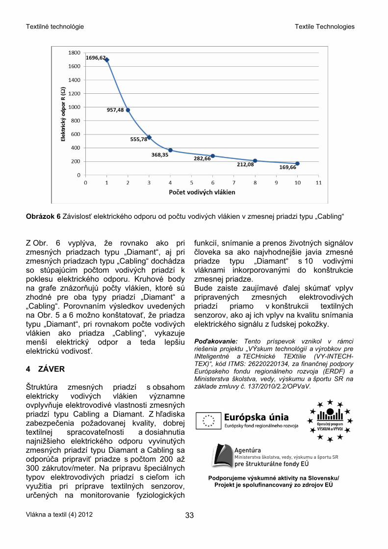
Obrázok 5 Závislosť elektrického odporu od počtu vodivých vlákien v priadzi typu „Diamant“ Keďže výsledky meraní elektrického odporu prvej skupiny priadzí ukázali, že výsledný elektrický odpor priadze nezávisí ani tak od počtu zákrutov (zmena odporu sa pohybovala na úrovni cca 40 Ω) ako od počtu použitých vodivých vlákien, bola pripravená tretia séria zmesných priadzí typu „Cabling“ s počtom 1, 2, 3, 4, 6, 8 a 10 vodivých vlákien v zmesnej
priadzi. Cieľom bolo vyhodnotiť vplyv typu zmesnej priadze na jej elektrickú vodivosť. Ako nevodivé jadro priadze bol použitý nevodivý PPtxh. Výsledky elektrickej vodivosti sú uvedené v Tab. 3. Závislosť elektrického odporu od počtu vodivých vlákien v zmesnej priadzi typu „Cabling“ je zobrazená na Obr. 6.
Tabuľka 3 Namerané hodnoty elektrickej vodivosti zmesných priadzí typu „Diamant“ s 2, 4, 6, 8 a 10 vodivými vláknami
Označenie zmesnej priadze
Počet vodivých vlákien v priadzi
Elektrická vodivosť G [S]
Smerodajná odchýlka el. vodivosti
Smerodajná odchýlka el. odporu
53/A2.1/2012 1 0,000617 1,197.10-4 355,904 54/A2.1/2012 2 0,001057 1,138.10-4 105,751 55/A2.1/2012 3 0,001808 1,226.10-4 40,272 76/A2.1/2012 4 0,002715 3,840.10-5 5,257 70/A2.1/2012 6 0,003538 4,090.10-5 2,208 72/A2.1/2012 8 0,004715 2,260.10-5 0,569 71/A2.1/2012 10 0,005894 2,860.10-5 0,535
Vlákna a textil (4) 2012 32
Textilné technológie Textile Technologies
Obrázok 6 Závislosť elektrického odporu od počtu vodivých vlákien v zmesnej priadzi typu „Cabling“ Z Obr. 6 vyplýva, že rovnako ako pri zmesných priadzach typu „Diamant“, aj pri zmesných priadzach typu „Cabling“ dochádza so stúpajúcim počtom vodivých priadzí k poklesu elektrického odporu. Kruhové body na grafe znázorňujú počty vlákien, ktoré sú zhodné pre oba typy priadzí „Diamant“ a „Cabling“. Porovnaním výsledkov uvedených na Obr. 5 a 6 možno konštatovať, že priadza typu „Diamant“, pri rovnakom počte vodivých vlákien ako priadza „Cabling“, vykazuje menší elektrický odpor a teda lepšiu elektrickú vodivosť. 4 ZÁVER Štruktúra zmesných priadzí s obsahom elektricky vodivých vlákien významne ovplyvňuje elektrovodivé vlastnosti zmesných priadzí typu Cabling a Diamant. Z hľadiska zabezpečenia požadovanej kvality, dobrej textilnej spracovateľnosti a dosiahnutia najnižšieho elektrického odporu vyvinutých zmesných priadzí typu Diamant a Cabling sa odporúča pripraviť priadze s počtom 200 až 300 zákrutov/meter. Na prípravu špeciálnych typov elektrovodivých priadzí s cieľom ich využitia pri príprave textilných senzorov, určených na monitorovanie fyziologických
funkcií, snímanie a prenos životných signálov človeka sa ako najvhodnejšie javia zmesné priadze typu „Diamant“ s 10 vodivými vláknami inkorporovanými do konštrukcie zmesnej priadze. Bude zaiste zaujímavé ďalej skúmať vplyv pripravených zmesných elektrovodivých priadzí priamo v konštrukcii textilných senzorov, ako aj ich vplyv na kvalitu snímania elektrického signálu z ľudskej pokožky. Poďakovanie: Tento príspevok vznikol v rámci riešenia projektu „VÝskum technológií a výrobkov pre INteligentné a TECHnické TEXtílie (VY-INTECH-TEX)“, kód ITMS: 26220220134, za finančnej podpory Európskeho fondu regionálneho rozvoja (ERDF) a Ministerstva školstva, vedy, výskumu a športu SR na základe zmluvy č. 137/2010/2.2/OPVaV.
Podporujeme výskumné aktivity na Slovensku/ Projekt je spolufinancovaný zo zdrojov EÚ
Vlákna a textil (4) 2012 33
Textilné technológie Textile Technologies
5 LITERATÚRA 1. Lymberis A., Olsson S.: Intelligent biomedical
clothing for personal health and disease management: State of art and future vision, Telemedicine Journal and e-Health, Vol. 9 (4), 2003, 379-386
2. Smart textiles and clothing, http://www.wearable.ethz.ch
3. Zięba J., Frydrysiak M.: Textronics – Electrical and Electronic Textiles. Sensors for Breathing Frequency Measurement, Fibres and Textiles in Eastern Europe, Vol. 5, 2006, 43-48
4. Patent No.US 7308294: Textile-based electrode system, 2006
5. Patent No.US 6970731: Fabric-based sensor for monitoring vital signs, 2005
6. Patent No.US 7474910: Textile-based electrode, 2008
7. Silva, M. Catarino, A., Carvalho, H., Rocha, A., Monteiro, J., Montagna, G.: Textile sensors for ECG and respiratory frequency on swimsuits, International Conference Intelligent Textiles and Mass Customisation 2009, 12-14
8. Samarin A.: Elektronika vstrojennaja v odeždu – technologii i perspektivy, Komponenty i technologii, Vol. 4, 2007, 221-228
Vlákna a textil (4) 2012 34

Z vedecko-výskumných a vývojových pracovísk News from Departments
MAGNETICKÉ KAPALINY JAKO KATALYZÁTORY PRODUKCE NANOVLÁKEN
L. Sodomka
Adhesiv, TUL, Liberec
Abstrakt: Při přípravě a výrobě jakýchkoliv produktů je snahou získat v daném čase co nejvíce produktů a tím i zvýšit produktivitu. Stejně je tomu u při přípravě nanovláken. První stadium při přípravě nanovláken je vytváření Taylorova kužele, ze kterého se pak vytahují nanovlákna. Taylorovy kužele vznikají řízeně u zvlákňujících trysek nebo samovolně působením elektrického pole při beztryskovém elektrozvlákňování. Tehdy je třeba zvýšit počet vzniku Taylorových kuželů řízeně. Ukázalo se, že je to možné využitím magnetických kapalin, což je předmětem článku.
Magnetické kapaliny, zkráceně ferokapaliny, nemají příliš dlouhou historii. Byly objeveny v laboratořích NASA pro aplikaci řízeného toku kapalin. Jsou tvořené disperzemi fero-, nebo feri- nanočástic rozměrů kolem 10 nm (A) pokrytých povrchově aktivní látkou (B) v disperzi v kapalině (C) v poměru 5A:5B:90C objemových procent. Povrchově aktivované magnetické nanočástice nazveme feročástice. Povrchově aktivní látky mají elektrický náboj k vzájemnému oddělení nanočástic v roztoku od sebe. Do pyramidových shluků (Obr. 1) , klastrů, se dostávají feročástice působením magnetického pole. Magnetické nanočástice mohou být feromagnetika častěji však ferimagnetika, ferity, z nichž nejčastěji užívaný je magnezit Fe3O4. Je možné používat i jiných feritů [1]. Jako vzorovou ferokapalinu uvádí NASA částice magnezitu v obalu kyseliny olejové v disperzi ve vodě či jiné kapalině, která je komerčně dostupná. Ferokapaliny lze podle požadavků objednat (viz google). Působením magnetického pole o intenzitě H vznikají ve ferokapalině pyramidové ostny, jak ukazuje Obr. 1. Vložením feročástic do roztoku či taveniny polymerů jako suroviny pro nanovlákna do homogenního magnetického pole získáme zvrásnění povrchu ferokapaliny do tvarů Taylorových pseudokuželů (Obr. 2, Obr. 3), z nichž je pak možné táhnout nanovlákna vhodným elektrickým polem E a dosáhnout tak současného řízeného tažení většího množství monofilních nanovláken. Zvrásnění
povrchu kapaliny působením magnetického pole na ferokapalinu je na Obr. 2.
Obr. 1 Tvorba ostnů ve ferokapalině působením magnetu
Obr. 2 Vytváření Taylorových pseudokuželů v magnetické kapalině magnetickým polem pro tvorbu nanovláken Pro tvorbu nanovláken je třeba využívat roztoky či taveniny vláknových polymerů s pětiprocentním přídavkem feročástic, z nichž vytvoří intenzita magnetického pole Taylorovy hyperboloidové pseudokužele (Obr. 2) s nabitým povrchem, z nichž je pak možné působením elektrického pole E
Vlákna a textil (4) 2012 35

Z vedecko-výskumných a vývojových pracovísk News from Departments
táhnout paralelní nanovlákna a využívat je jako oddělená nanovlákna nebo ukládat na transportní pás a vytvářet tak soustavu s paralelními vlákny pro další textilní zpracování do kabílků či přízí. Tak je možné využívat i magnetické kapaliny [2, 3] k tvorbě nanovláken, jak ukázali Yarin a Zussman [4]. Podstata metody je na Obr. 3. V něm H značí směr intenzity magetického a E směr intenzity elektrického pole ve směru spojnice protilehlých hrotů.
Obr. 3 Experimentální sestava pro tažení velkého počtu vláken
Použitím magnetických kapalin v polymerech lze zvýšit řízenou produktivitu tvorby nanovláken elektrozvlákňováním za užití nenáročných technologických úprav (Obr.3) a zvýšit tak podstatně produktivitu nanovláken. Tak se mohou stát magnetické kapaliny jakýmsi katalyzátorem výroby nanovláken elektrostatickým zvlákňováním. 1 LITERATURA 1. Sodomka L., Fiala J.: Fyzika a chemie
kondenzovaných látek 1, 2, Adhesiv Liberec 2003, 303
2. Mayer D: Magnetické kapaliny a jejich použití (1. část), Elektro 17(3), 2007, 78-79
3. Mayer D.: Magnetické kapaliny a jejich použití (2. část), Elektro 17(4), 2007, 4-8
4. Yarin A.L., Zussman E.: Upward needleless electrospinning of multiple nanofibers, Polymer 45(9), 2004, 2977
MAGNETIC LIQUIDS AS CATALYZERS OF NANOFIBERS PRODUCTION
Translation of the article Magnetické kapaliny jako katalyzátory produkce nanovláken
Abstract: In the paper the possibility of enhancing the nanofibers productivity is being solved using the magnetic liquids. Magnetic liquids are being created pyramid bodies, which are nuclei of Taylor cones. The quantity of these cones can be controlled through the action of magnetic field.
Vlákna a textil (4) 2012 36
Z vedecko-výskumných a vývojových pracovísk News from Departments
Informácia o 7th Central European Conference 2012 „FIBRE-GRADE POLYMERS, CHEMICAL FIBRES AND SPECIAL
TEXTILES“ konanej 15.-17. septembra 2012 v Portoroži, Slovinsko
M. Hricová
Oddelenie vlákien a textilu, Ústav polymérnych materiálov, FCHPT STU v Bratislave,
Radlinského 9, 812 37 Bratislava, SK [email protected]
Univerzita v Maribore, Katedra textilných materiálov a dizajnu bola organizátorom siedmej stredoeurópskej konferencie zameranej na vláknotvorné polyméry, chemické vlákna a špeciálne textílie. Stredoeurópska konferencia sa koná každé dva roky vždy v inej usporiadateľskej krajine. Na organizácii sa striedajú: - Slovenská technická univerzita v Bratislave,
Slovenská republika - Inštitút biopolymérov a chemických vlákien,
Lodž, Poľsko - Univerzita Maribor, Slovinsko - Technická univerzita Liberec, Česká
republika - Univerzita Bielsko-Biala, Poľsko. Výskumní pracovníci z akademickej obce, odborníci z priemyselnej oblasti, ako aj študenti dostali možnosť prezentovať a diskutovať o výsledkoch svojich prác z týchto oblastí: - textilné vlákna - technické textílie
- progresívne materiály - inteligentné textílie - modifikácia vlákien - povrchy vlákien - recyklácia textilu - udržateľné materiály - textilná „zelená chémia“ - textilný výskum a testovanie - dizajn. Program konferencie zahájil plenárnou prednáškou Prof. A. P. Aneja na tému globálnej otázky udržateľnosti súčasného stavu v textilnom priemysle. Ďalšími pozvanými prednášateľmi boli Ettore Rossini (eXtreme Materials), Anna Ujhelyiová (STU Bratislava, SK) a Dr. Michiel Scheffer (CEO of Noeton Policy in Innovation, Professor at Saxion University). Celkovo odznelo 30 prednášok a bolo prezentovaných 19 posterov od účastníkov z Európy, Ázie i USA.
Vlákna a textil (4) 2012 37
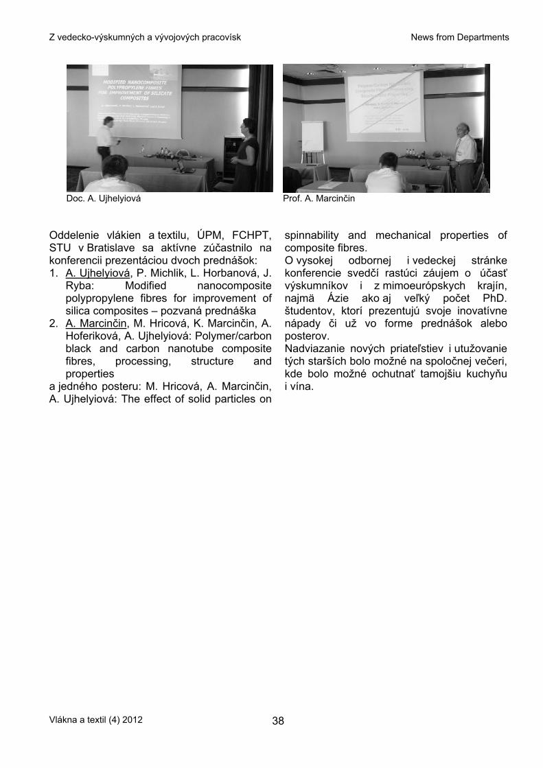
Z vedecko-výskumných a vývojových pracovísk News from Departments
Doc. A. Ujhelyiová Prof. A. Marcinčin Oddelenie vlákien a textilu, ÚPM, FCHPT, STU v Bratislave sa aktívne zúčastnilo na konferencii prezentáciou dvoch prednášok: 1. A. Ujhelyiová, P. Michlik, L. Horbanová, J.
Ryba: Modified nanocomposite polypropylene fibres for improvement of silica composites – pozvaná prednáška
2. A. Marcinčin, M. Hricová, K. Marcinčin, A. Hoferiková, A. Ujhelyiová: Polymer/carbon black and carbon nanotube composite fibres, processing, structure and properties
a jedného posteru: M. Hricová, A. Marcinčin, A. Ujhelyiová: The effect of solid particles on
spinnability and mechanical properties of composite fibres. O vysokej odbornej i vedeckej stránke konferencie svedčí rastúci záujem o účasť výskumníkov i z mimoeurópskych krajín, najmä Ázie ako aj veľký počet PhD. študentov, ktorí prezentujú svoje inovatívne nápady či už vo forme prednášok alebo posterov. Nadviazanie nových priateľstiev i utužovanie tých starších bolo možné na spoločnej večeri, kde bolo možné ochutnať tamojšiu kuchyňu i vína.
Vlákna a textil (4) 2012 38
Z vedecko-výskumných a vývojových pracovísk News from Departments
Informácia o 6th International Textile, Clothing & Design Conference
„MAGIC WORLD OF TEXTILES“ konanej 7.-10. októbra 2012 v Dubrovníku, Chorvátsko
J. Ryba
Oddelenie vlákien a textilu, Ústav polymérnych materiálov, FCHPT, STU v Bratislave,
Radlinského 9, 812 37 Bratislava, SK [email protected]
V dňoch 7.-10. októbra 2012 usporiadala Fakulta textilnej technológie, Univerzity v Záhrebe v historickom srdci Dalmácie v meste Dubrovník šiestu medzinárodnú konferenciu z oblasti textilu, oblečenia a dizajnu. Táto konferencia bola súčasne spojená s významnými jubileami a to: - 60 rokov publikovania časopisu Tekstil,
ktorý je jedným z najstarších odborných časopisov v Chorvátsku
- 20 rokov osamostatnenia sa Fakulty textilnej technológie
- 50 rokov univerzitného vzdelávania v oblasti textilu v Chorvátsku.
Konferencia sa uskutočnila pod záštitou: Ministry of Science, Education and Sport, University of Zagreb, Croatian Academy of Engineering, Croatian Chamber of Economy, Ministry of Entrepreneurship and Trade, Danube Adria Association for Automation & Manufacturing-DAAM, Association of Universities for Textile – AUTEX, American Association of Textile Chemists and Colorists – AATCC, European System of Cooperative Research Networks in Agriculture - ESCORENA, International Federation of Knitting Technologists, Croatian Society of Chemical Engineers - HDKI, Croatian Association of Textile Engineers - HIST, International Technical Committee for Textile Care, Croatian Zeolite Association - CROZA, Croatian Academic and Research Network - CARNet. Program konferencie bol rozdelený do siedmych sekcií A) textilné vlákna a progresívne materiály B) výroba tkanín, textílií a netkaných textílií
C) zušľachťovanie textílii, farbenie a ošetrovanie
D) odevné technológie a technika E) analýza, testovanie a kontrola kvality F) dizajn a marketing textilu a odievania G) ochrana životného prostredia, ekologický
a energetický manažment. Konferencie sa zúčastnili autori z 38 krajín sveta, ktorí vo svojich 125 príspevkoch rozoberali aktuálne trendy v modernom vláknarenskom a textilnom vývoji a priemysle. Organizátori zahájili túto medzinárodnú prednášku plenárnou prednáškou emeritného profesora Rona Postla z Univerzity v Novom Južnom Walese (Austrália) na tému: Mechanika a fyzika jemných materiálov: Pleteniny. Oddelenie vlákien a textilu, ÚPM, FCHPT STU v Bratislave sa taktiež aktívne podieľalo na naplnení vedeckého programu tejto medzinárodnej konferencie a to jednou prednáškou na tému: Vlastnosti modifikovaných polypropylénových vlákien pre vystužené betóny (J. Ryba) a dvoma príspevkami vo forme posterov: Zmena koloristických vlastností a oterová stálosť vlnených textilných materiálov po upravení plazmou, Vplyv nanoaditív na termomechanické a mechanické vlastnosti plnených polypropylénových vlákien (A. Ujhelyiová). Organizátori spestrili účastníkom konferencie pobyt v Dubrovníku taktiež spoločenskými udalosťami vo forme večerného koncertu v miestnom kostole, spoločenským večerom či výletom loďou k ostrovu a ochutnávkou tamojšej kuchyne.
Vlákna a textil (4) 2012 39
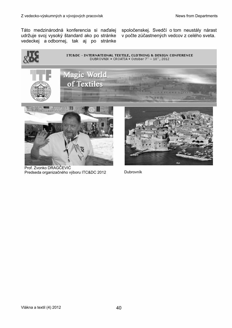
Z vedecko-výskumných a vývojových pracovísk News from Departments
Táto medzinárodná konferencia si naďalej udržuje svoj vysoký štandard ako po stránke vedeckej a odbornej, tak aj po stránke
spoločenskej. Svedčí o tom neustály nárast v počte zúčastnených vedcov z celého sveta.
Prof. Zvonko DRAGČEVIĆ Predseda organizačného výboru ITC&DC 2012
Dubrovník
Vlákna a textil (4) 2012 40