2018-008389CUA - Executive Summary - SF Planning
89
www.sfplanning.org Executive Summary Conditional Use Authorization HEARING DATE: DECEMBER 20, 2018 Record No.: 2018-008389CUA Project Address: 88 King Street Zoning: SB-DTR (South Beach Downtown Residential) Zoning District 105/200-R Height and Bulk District Block/Lot: 3793/005 Project Sponsor: Sean Prior Precision Site Development LLC for Sprint 1524 Rainbow Street Roseville, CA 95747 Property Owner: Clive Lainge One Embarcadero South Owners Association 88 King Street San Francisco, CA 94107 Staff Contact: Ashley Lindsay – 415-575-9178 [email protected] PROJECT DESCRIPTION The Project includes installation of (6) new panel antennas; (12) new RRUs; (1) new microwave antenna; and (1) GPS antenna. All antennas will be located on the rooftop behind screen walls and are proposed to be painted to match the existing building. Ancillary equipment will be located inside the rooftop penthouse equipment room. REQUIRED COMMISSION ACTION In order for the Project to proceed, the Commission must grant a Conditional Use Authorization for a wireless telecommunications facility pursuant to Planning Code Section 303(c) and 829 to allow installation of a macro wireless telecommunications facility in a SB-DTR Zoning District. ISSUES AND OTHER CONSIDERATIONS ƒ Public Comment & Outreach. Pursuant to the Wireless Telecommunications Facilities Siting guidelines, the Project Sponsor held a community meeting on Wednesday, May 16, 2018, at the Potrero Library, Branch Meeting Room, 1616 20 th Street, San Francisco, CA 94107. No members of the community attended the meeting. As of December 10, 2018, the Department has not received any calls or testimony raising concerns about, or expressing support for the proposed project.
-
Upload
khangminh22 -
Category
Documents
-
view
0 -
download
0
Transcript of 2018-008389CUA - Executive Summary - SF Planning

www.sfplanning.org
Executive SummaryConditional Use Authorization
HEARING DATE: DECEMBER 20, 2018
Record No.: 2018-008389CUAProject Address: 88 King StreetZoning: SB-DTR (South Beach Downtown Residential) Zoning District
105/200-R Height and Bulk DistrictBlock/Lot: 3793/005Project Sponsor: Sean Prior
Precision Site Development LLC for Sprint1524 Rainbow StreetRoseville, CA 95747
Property Owner: Clive LaingeOne Embarcadero South Owners Association88 King StreetSan Francisco, CA 94107
Staff Contact: Ashley Lindsay – [email protected]
PROJECT DESCRIPTIONThe Project includes installation of (6) new panel antennas; (12) new RRUs; (1) new microwave antenna;and (1) GPS antenna. All antennas will be located on the rooftop behind screen walls and are proposedto be painted to match the existing building. Ancillary equipment will be located inside the rooftoppenthouse equipment room.
REQUIRED COMMISSION ACTION
In order for the Project to proceed, the Commission must grant a Conditional Use Authorization for awireless telecommunications facility pursuant to Planning Code Section 303(c) and 829 to allowinstallation of a macro wireless telecommunications facility in a SB-DTR Zoning District.
ISSUES AND OTHER CONSIDERATIONSƒ Public Comment & Outreach. Pursuant to the Wireless Telecommunications Facilities Siting
guidelines, the Project Sponsor held a community meeting on Wednesday, May 16, 2018, at thePotrero Library, Branch Meeting Room, 1616 20th Street, San Francisco, CA 94107. No membersof the community attended the meeting. As of December 10, 2018, the Department has notreceived any calls or testimony raising concerns about, or expressing support for the proposedproject.

Executive Summary CASE NO. 2018-008389CUAHearing Date: December 20, 2018 88 King Street
2
BASIS FOR RECOMMENDATIONThe Department finds that the Project is, on balance, consistent with the Wireless TelecommunicationsServices Facilities Siting Guidelines and the Objectives and Policies of the General Plan. The proposedfacility would be screened from view by virtue of proposed enclosures and their placement on therooftop of the Project site. The proposal would not significantly detract from views of the Subjectbuilding or from view of other surrounding buildings, nor would it detract from adjacent streetscapes,and vistas.. The Department also finds the project to be necessary, desirable, and compatible with thesurrounding neighborhood, and not to be detrimental to persons or adjacent properties in the vicinity.
ATTACHMENTS:Draft Motion – Conditional Use AuthorizationExhibit A – Conditions of ApprovalExhibit B – Plans and RenderingsExhibit C – Environmental DeterminationExhibit D – Community Outreach SummaryExhibit E – Maps and Context PhotosExhibit F - Radio Frequency ReportExhibit G - Department of Public Health ApprovalExhibit H – Coverage MapsExhibit I – Independent EvaluationExhibit J – Alternatives Site Analysis

www.sfplanning.org
Planning Commission Draft MotionHEARING DATE: DECEMBER 20, 2018
Record No.: 2018-008389CUAProject Address: 88 King StreetZoning: SB-DTR (South Beach Downtown Residential) Zoning District
105/200-R Height and Bulk DistrictBlock/Lot: 3793/005Project Sponsor: Sean Prior
Precision Site Development LLC for Sprint1524 Rainbow StreetRoseville, CA 95747
Property Owner: Clive LaingeOne Embarcadero South Owners Association88 King StreetSan Francisco, CA 94107
Staff Contact: Ashley Lindsay – [email protected]
ADOPTING FINDINGS RELATING TO A CONDITIONAL USE AUTHORIZATION PURSUANTTO PLANNING CODE SECTIONS 303(C) AND 829, TO INSTALL A SPRINT MACRO WIRELESSTELECOMMUNICATIONS FACILITY WHICH CONSISTS OF (6) NEW PANEL ANTENNAS; (12)NEW RRUS; (1) NEW MICROWAVE ANTENNA; AND (1) GPS ANTENNA. ALL ANTENNAS WILLBE LOCATED BEHIND SCREEN WALLS AND ARE PROPOSED TO BE PAINTED TO MATCH THEEXISTING BUILDING. ANCILLARY EQUIPMENT WILL BE LOCATED INSIDE THE ROOFTOPPENTHOUSE EQUIPMENT ROOM AS PART OF THE SPRINT TELECOMMUNICATIONSNETWORK. THE SUBJECT PROPERTY IS LOCATED AT 88 KING STREET, LOTS 005 INASSESSOR’S BLOCK 3793, WITHIN THE SB-DTR (SOUTH BEACH DOWNTOWN RESIDENTIAL)ZONING DISTRICT AND 105/200-R HEIGHT AND BULK DISTRICT, AND ADOPTINGFINDINGS UNDER THE CALIFORNIA ENVIRONMENTAL QUALITY ACT.
PREAMBLEOn June 13, 2018, Sean Prior of Precision Site Development LLC (hereinafter "Project Sponsor") filedApplication No. 2018-008389CUA (hereinafter “Application”) with the Planning Department (hereinafter“Department”) for a Conditional Use Authorization to construct a new macro WirelessTelecommunications Facility for Sprint (hereinafter “Project”) at 88 King Street, Block 3793 Lots 005(hereinafter “Project Site”).
On December 20, 2018, the San Francisco Planning Commission (hereinafter “Commission”) conducted aduly noticed public hearing at a regularly scheduled meeting on Conditional Use AuthorizationApplication No. 2018-008389CUA.

Draft Motion RECORD NO. 2018-008389CUAJune 2, 2018 88 King Street
2
On November 19, 2018 the Project was determined to be exempt from the California EnvironmentalQuality Act (“CEQA”) as a Class 3 Categorical Exemption under CEQA as described in the determinationcontained in the Planning Department files for this Project;
The Planning Department Commission Secretary is the custodian of records; the File for Record No. 2018-008389CUA is located at 1650 Mission Street, Suite 400, San Francisco, California.
The Commission has heard and considered the testimony presented to it at the public hearing and hasfurther considered written materials and oral testimony presented on behalf of the applicant, Departmentstaff, and other interested parties.
MOVED, that the Commission hereby authorizes the Conditional Use Authorization as requested inApplication No. 2018-008389CUA, subject to the conditions contained in “EXHIBIT A” of this motion,based on the following findings:
FINDINGSHaving reviewed the materials identified in the preamble above, and having heard all testimony andarguments, this Commission finds, concludes, and determines as follows:
1. The above recitals are accurate and constitute findings of this Commission.
2. Project Description. The Project includes installation of (6) new panel antennas; (12) new RRUs;(1) new microwave antenna; and (1) GPS antenna. All antennas will be located on the rooftopbehind screen walls and are proposed to be painted to match the existing building. Ancillaryequipment will be located inside the rooftop penthouse equipment room.
3. Site Description and Present Use. The Project is located on the side of the view screen wallaround mechanical equipment above the roof of the southern of two towers at 88 King Streetwith frontage along 2nd Street and King Street. The Project Site contains two 16-story high risesconsisting of 230 residential condominiums.
4. Surrounding Properties and Neighborhood. The Project Site is located within the SB-DTRZoning Districts in the East SoMa. The immediate context is mixed in character with high-densityresidential and supporting commercial and institutional. The immediate neighborhood includesone-to-four-story mixed use-office to the north, three-to-ten story mixed use-office to the west, aseries of four-story residential and supporting commercial properties to the east, and South BeachPark and AT&T Park to the south.
5. Public Outreach and Comments. Pursuant to the Wireless Telecommunications Facilities Sitingguidelines, the Project Sponsor held a community meeting on Wednesday, May 16, 2018, at thePotrero Library, Branch Meeting Room, 1616 20th Street, San Francisco, CA 94107. No members of

Draft Motion RECORD NO. 2018-008389CUAJune 2, 2018 88 King Street
3
the community attended the meeting. As of December 10, 2018, the Department has not receivedany calls or testimony raising concerns about, or expressing support for the proposed project.
6. Past History and Actions. The Planning Commission adopted the Wireless TelecommunicationsServices (WTS) Facilities Siting Guidelines (“Guidelines”) for the installation of wirelesstelecommunications facilities in 1996. These Guidelines set forth the land use policies andpractices that guide the installation and approval of wireless facilities throughout San Francisco.A large portion of the Guidelines was dedicated to establishing location preferences for theseinstallations. The Board of Supervisors, in Resolution No. 635-96, provided input as to wherewireless facilities should be located within San Francisco. The Guidelines were updated by theCommission in 2003 and again in 2012, requiring community outreach, notification, and detailedinformation about the facilities to be installed.
Section 8.1 of the Guidelines outlines Location Preferences for wireless facilities. There are fiveprimary areas were the installation of wireless facilities should be located:
1. Publicly-used Structures: such facilities as fire stations, utility structures, communityfacilities, and other public structures;
2. Co-Location Site: encourages installation of facilities on buildings that already havewireless installations;
3. Industrial or Commercial Structures: buildings such as warehouses, factories, garages,service stations;
4. Industrial or Commercial Structures: buildings such as supermarkets, retail stores, banks;and
5. Mixed-Use Buildings in High Density Districts: buildings such as housing abovecommercial or other non-residential space.
Section 8.1 of the WTS Siting Guidelines further stipulates that the Planning Commission will notapprove WTS applications for Preference 5 or below Location Sites unless the applicationdescribes (a) what publicly-used building, co-location site or other Preferred Location Sites arelocated within the geographic service area; (b) what good faith efforts and measures were takento secure these more Preferred Locations, (c) explains why such efforts were unsuccessful; and (d)demonstrates that the location for the site is essential to meet demands in the geographic servicearea and the Applicant’s citywide networks.
Before the Planning Commission can review an application to install a wireless facility, theProject Sponsor must submit a five-year facilities plan, which must be updated biannually, anemissions report and approval by the Department of Public Health, Section 106 Declaration ofIntent, an independent evaluation verifying coverage and capacity, a submittal checklist anddetails about the facilities to be installed.

Draft Motion RECORD NO. 2018-008389CUAJune 2, 2018 88 King Street
4
Under Section 704(B)(iv) of the 1996 Federal Telecommunications Act, local jurisdictions cannotdeny wireless facilities based on Radio Frequency (RF) radiation emissions so long as suchfacilities comply with the FCC’s regulations concerning such emissions.
7. Location Preference. The WTS Facilities Siting Guidelines identify different types of zoningdistricts and building uses for the siting of wireless telecommunications facilities. Based on thezoning and land use, the proposed WTS facility is at a Location Preference 5 Site (Mixed UseBuildings in High Density Districts) according to the WTS Facilities Siting Guidelines, making it adesired location.
8. Radio Waves Range. The Project Sponsor has stated that the proposed wireless network isdesigned to address coverage and capacity needs in the area. The network will operate in the 690,2940, and 4120 Megahertz (MHZ) bands, which are regulated by the Federal CommunicationsCommission (FCC) and must comply with the FCC-adopted health and safety standards forelectromagnetic radiation and radio frequency radiation.
9. Radiofrequency (RF) Emissions: The Project Sponsor retained Hammett & Edison, Inc., a radioengineering consulting firm, to prepare a report describing the expected RF emissions from theproposed facility. Pursuant to the Guidelines, the Department of Public Health reviewed thereport and determined that the proposed facility complies with the standards set forth in theGuidelines.
10. Department of Public Health Review and Approval. The Project was referred to theDepartment of Public Health (DPH) for emissions exposure analysis. Radio-Frequency (RF)levels from the proposed Sprint transmitters at any nearby publicly accessible building or areawould 0.24% of the FCC public exposure limit.
There are 0 antennas existing operated by Sprint installed on the roof top of the building at 88King St. Existing RF levels at ground level were around 1% of the FCC public exposure limit. Noother antennas were observed within 100 feet of this site. Sprint proposes to install 3 newantennas. The antennas are mounted at a height of 152.5 feet above the ground and 11 feet abovethe roof. The estimated ambient RF field from the proposed Sprint transmitters at ground level iscalculated to be 0.0015 mW/sq cm., which is 0.17% of the FCC public exposure limit. The threedimensional perimeter of RF levels equal to the public exposure limit extends 30 feet and doesnot reach any publicly accessible areas. Warning signs must be posted at the antennas and roofaccess points in English, Spanish and Chinese. Workers should not have access to within 6 feet ofthe front of the antennas while they are in operation. Due to the mounting locations and height,the antennas would not be accessible to unauthorized persons.
11. Coverage and Capacity Verification. The maps, data, and conclusion provided by Sprint todemonstrate the need for outdoor and indoor coverage and capacity have been determined byEBI Consulting, an engineering consultant and independent third party, to accurately representthe carrier’s present and post-installation conclusions.

Draft Motion RECORD NO. 2018-008389CUAJune 2, 2018 88 King Street
5
12. Maintenance Schedule. The facility would operate without on-site staff but with a maintenancecrew visiting the property to service and monitor the facility.
13. Planning Code Compliance. The Commission finds that the Project is consistent with therelevant provisions of the Planning Code in the following manner:
A. Use. Per Planning Code Section 829, a Conditional Use Authorization is required for a macroWTS facility (Utility and Infrastructure Use).
14. Conditional Use Findings. Planning Code Section 303 establishes criteria for the PlanningCommission to consider when reviewing applications for Conditional Use authorization. Onbalance, the project complies with said criteria in that:
A. The proposed new uses and building, at the size and intensity contemplated and at theproposed location, will provide a development that is necessary or desirable, and compatiblewith, the neighborhood or the community.
The Project at 88 King Street is generally desirable and compatible with the surrounding neighborhoodbecause the Project will not conflict with the existing uses of the property and will be designed to becompatible with the surrounding neighborhood. The overall location, setback from public streets, heightand design of the proposed facility, including visible screening elements is situated so as to avoidintrusion into public vistas, and to insure harmony with the existing neighborhood character andpromote public safety. The Project is necessary in order to achieve LTE coverage and data capacity.
B. The proposed project will not be detrimental to the health, safety, convenience or generalwelfare of persons residing or working in the vicinity. There are no features of the projectthat could be detrimental to the health, safety or convenience of those residing or workingthe area, in that:
(1) Nature of proposed site, including its size and shape, and the proposed size, shape andarrangement of structures;
The Project height and bulk of the existing building will remain the same and will not significantlyalter the existing appearance or character of the project vicinity. The proposed work will not affectthe building envelope, yet the inclusion of outside seating will alter the use of the property.
(2) The accessibility and traffic patterns for persons and vehicles, the type and volume of suchtraffic, and the adequacy of proposed off-street parking and loading;

Draft Motion RECORD NO. 2018-008389CUAJune 2, 2018 88 King Street
6
The Planning Code does not require parking or loading for a telecommunications wireless facility.The proposed use is designed to meet the needs of the immediate neighborhood and should notgenerate significant amounts of vehicular trips from the immediate neighborhood or citywide.
(3) The safeguards afforded to prevent noxious or offensive emissions such as noise, glare,dust and odor;
While some noise and dust may result from the installation of the antennas and transceiverequipment, noise or noxious emissions from continued use are not likely to be significantly greaterthan ambient conditions due to the operation of the wireless communication network.
(4) Treatment given, as appropriate, to such aspects as landscaping, screening, open spaces,parking and loading areas, service areas, lighting and signs;
The facility will not affect landscaping, open space, required parking, lighting or signage at theProject Site or surrounding area.
C. That the use as proposed will comply with the applicable provisions of the Planning Codeand will not adversely affect the General Plan.
The Project complies with all relevant requirements and standards of the Planning Code and isconsistent with objectives and policies of the General Plan as detailed below.
15. General Plan Compliance. The Project is, on balance, consistent with the following Objectivesand Policies of the General Plan:
HOUSING ELEMENTObjectives and Policies
OBJECTIVE 12:BALANCE HOUSING GROWTH WITH ADEQUATE INFRASTRUCTURE THAT SERVES THECITY’S GROWING POPULATION.
Policy 12.3:Ensure new housing is sustainable supported by the City’s public infrastructure systems.
The Project will improve Sprint’s coverage and capacity within the South of Market neighborhood.
COMMERCE AND INDUSTRY ELEMENT

Draft Motion RECORD NO. 2018-008389CUAJune 2, 2018 88 King Street
7
Objectives and Policies
OBJECTIVE 1:MANAGE ECONOMIC GROWTH AND CHANGE TO ENSURE ENHANCEMENT OF THETOTAL CITY LIVING AND WORKING ENVIRONMENT.
Policy 1.1:Encourage development, which provides substantial net benefits and minimizes undesirableconsequences. Discourage development, which has substantial undesirable consequences thatcannot be mitigated.
Policy 1.2:Assure that all commercial and industrial uses meet minimum, reasonable performancestandards.
The Project will enhance the total city living and working environment by providing communicationservices for residents and workers within the City. Additionally, the Project would comply with Federal,State and Local performance standards.
OBJECTIVE 2:MAINTAIN AND ENHANCE A SOUND AND DIVERSE ECONOMIC BASE AND FISCALSTRUCTURE FOR THE CITY.
Policy 2.1:Seek to retain existing commercial and industrial activity and to attract new such activity to thecity.
Policy 2.3:Maintain a favorable social and cultural climate in the city in order to enhance its attractivenessas a firm location.
The Site will be an integral part of a new wireless communications network that will enhance the City’sdiverse economic base.
OBJECTIVE 4:IMPROVE THE VIABILITY OF EXISTING INDUSTRY IN THE CITY AND THEATTRACTIVENESS OF THE CITY AS A LOCATION FOR NEW INDUSTRY.
Policy 4.1:Maintain and enhance a favorable business climate in the City.
Policy 4.2:Promote and attract those economic activities with potential benefit to the City.

Draft Motion RECORD NO. 2018-008389CUAJune 2, 2018 88 King Street
8
The Project will benefit the City by enhancing the business climate through improved communicationservices for residents and workers.
VISITOR TRADE
OBJECTIVE 8:ENHANCE SAN FRANCISCO'S POSITION AS A NATIONAL CENTER FOR CONVENTIONSAND VISITOR TRADE.
Policy 8.3:Assure that areas of particular visitor attraction are provided with adequate public services forboth residents and visitors.
The Project will ensure that residents and visitors have adequate public service in the form of Sprinttelecommunications.
COMMUNITY SAFETY ELEMENT
Objectives and Policies
OBJECTIVE 3:ESTABLISH STRATEGIES TO ADDRESS THE IMMEDIATE EFFECTS OF A DISASTER.
Policy 1.20Increase communication capabilities in preparation for all phases of a disaster and ensurecommunication abilities extend to hard-to-reach areas and special populations.
Policy 2.4Bolster the Department of Emergency Management’s role as the City’s provider of emergencyplanning and communication, and prioritize its actions to meet the needs of San Francisco.
Policy 2.15Utilize advancing technology to enhance communication capabilities in preparation for all phasesof a disaster, particularly in the high-contact period immediately following a disaster.
Policy 3.7:Develop a system to convey personalized information during and immediately after a disaster.
The Project will enhance the ability of the City to protect both life and property from the effects of a fire ornatural disaster by providing communication services.

Draft Motion RECORD NO. 2018-008389CUAJune 2, 2018 88 King Street
9
16. Planning Code Section 101.1(b) establishes eight priority-planning policies and requires reviewof permits for consistency with said policies. On balance, the project complies with said policiesin that:
A. That existing neighborhood-serving retail uses be preserved and enhanced and futureopportunities for resident employment in and ownership of such businesses be enhanced.
The wireless communications network will enhance personal communication services for businessesand customers in the surrounding area.
B. That existing housing and neighborhood character be conserved and protected in order topreserve the cultural and economic diversity of our neighborhoods.
No residential uses will be displaced or altered in any way by the granting of this Authorization.
C. That the City's supply of affordable housing be preserved and enhanced,
The Project will have no adverse effect on housing in the vicinity.
D. That commuter traffic not impede MUNI transit service or overburden our streets orneighborhood parking.
Due to the nature of the Project and minimal maintenance or repair, municipal transit service will notbe significantly impeded and neighborhood parking will not be overburdened.
E. That a diverse economic base be maintained by protecting our industrial and service sectorsfrom displacement due to commercial office development, and that future opportunities forresident employment and ownership in these sectors be enhanced.
The Project will not cause any displacement of industrial and service sector activity.
F. That the City achieve the greatest possible preparedness to protect against injury and loss oflife in an earthquake.
The Project will be designed and will be constructed to conform to the structural and seismic safetyrequirements of the Building Code. This proposal will not impact the property’s ability to withstandan earthquake.
G. That landmarks and historic buildings be preserved.
Currently, the Project Site does not contain any City Landmarks or historic buildings.

Draft Motion RECORD NO. 2018-008389CUAJune 2, 2018 88 King Street
10
H. That our parks and open space and their access to sunlight and vistas be protected fromdevelopment.
The Project will not adversely affect parks or open space, nor their access to sunlight or public vistas.
17. The Project is consistent with and would promote the general and specific purposes of the Codeprovided under Section 101.1(b) in that, as designed, the Project would contribute to the characterand stability of the neighborhood and would constitute a beneficial development.
18. The Commission hereby finds that approval of the Conditional Use Authorization wouldpromote the health, safety and welfare of the City.

Draft Motion RECORD NO. 2018-008389CUAJune 2, 2018 88 King Street
11
DECISIONThat based upon the Record, the submissions by the Applicant, the staff of the Department and otherinterested parties, the oral testimony presented to this Commission at the public hearings, and all otherwritten materials submitted by all parties, the Commission hereby APPROVES Conditional UseAuthorization Application No. 2018-008389CUA subject to the following conditions attached hereto as“EXHIBIT A” in general conformance with plans on file, dated October 15, 2018, and stamped “EXHIBITB”, which is incorporated herein by reference as though fully set forth.
APPEAL AND EFFECTIVE DATE OF MOTION: Any aggrieved person may appeal this ConditionalUse Authorization to the Board of Supervisors within thirty (30) days after the date of this Motion. Theeffective date of this Motion shall be the date of this Motion if not appealed (after the 30-day period hasexpired) OR the date of the decision of the Board of Supervisors if appealed to the Board of Supervisors.For further information, please contact the Board of Supervisors at (415) 554-5184, City Hall, Room 244, 1Dr. Carlton B. Goodlett Place, San Francisco, CA 94102.
Protest of Fee or Exaction: You may protest any fee or exaction subject to Government Code Section66000 that is imposed as a condition of approval by following the procedures set forth in GovernmentCode Section 66020. The protest must satisfy the requirements of Government Code Section 66020(a) andmust be filed within 90 days of the date of the first approval or conditional approval of the developmentreferencing the challenged fee or exaction. For purposes of Government Code Section 66020, the date ofimposition of the fee shall be the date of the earliest discretionary approval by the City of the subjectdevelopment.
If the City has not previously given Notice of an earlier discretionary approval of the project, thePlanning Commission’s adoption of this Motion, Resolution, Discretionary Review Action or the ZoningAdministrator’s Variance Decision Letter constitutes the approval or conditional approval of thedevelopment and the City hereby gives NOTICE that the 90-day protest period under Government CodeSection 66020 has begun. If the City has already given Notice that the 90-day approval period has begunfor the subject development, then this document does not re-commence the 90-day approval period.
I hereby certify that the Planning Commission ADOPTED the foregoing Motion on December 20, 2018.
Jonas P. IoninCommission Secretary
AYES:
NAYS:
ABSENT:

Draft Motion RECORD NO. 2018-008389CUAJune 2, 2018 88 King Street
12
ADOPTED: December 20, 2018

Draft Motion RECORD NO. 2018-008389CUAJune 2, 2018 88 King Street
13
EXHIBIT AAUTHORIZATIONWith Plans. This authorization is for a conditional use to allow a wireless telecommunications facility(d.b.a. Sprint) located at 88 King Street, Block 3793, and Lot 005 pursuant to Planning Code Section(s)303(c) and 829 within the SB-DTR District and a 105/200-R Height and Bulk District; in generalconformance with plans, dated October 15, 2018, and stamped “EXHIBIT B” included in the docket forRecord No. 2018-008389CUA and subject to conditions of approval reviewed and approved by theCommission on December 20, 2018 under Motion No XXXXXX. This authorization and the conditionscontained herein run with the property and not with a particular Project Sponsor, business, or operator.
RECORDATION OF CONDITIONS OF APPROVALPrior to the issuance of the building permit or commencement of use for the Project the ZoningAdministrator shall approve and order the recordation of a Notice in the Official Records of the Recorderof the City and County of San Francisco for the subject property. This Notice shall state that the project issubject to the conditions of approval contained herein and reviewed and approved by the PlanningCommission on December 20, 2018 under Motion No XXXXXX.
PRINTING OF CONDITIONS OF APPROVAL ON PLANSThe conditions of approval under the 'Exhibit A' of this Planning Commission Motion No. XXXXXX shallbe reproduced on the Index Sheet of construction plans submitted with the site or building permitapplication for the Project. The Index Sheet of the construction plans shall reference to the ConditionalUse authorization and any subsequent amendments or modifications.
SEVERABILITYThe Project shall comply with all applicable City codes and requirements. If any clause, sentence, sectionor any part of these conditions of approval is for any reason held to be invalid, such invalidity shall notaffect or impair other remaining clauses, sentences, or sections of these conditions. This decision conveysno right to construct, or to receive a building permit. “Project Sponsor” shall include any subsequentresponsible party.
CHANGES AND MODIFICATIONSChanges to the approved plans may be approved administratively by the Zoning Administrator.Significant changes and modifications of conditions shall require Planning Commission approval of anew Conditional Use authorization.
awoods
Text Box

Draft Motion RECORD NO. 2018-008389CUAJune 2, 2018 88 King Street
14
Conditions of Approval, Compliance, Monitoring, and ReportingPERFORMANCE
1. Validity. The authorization and right vested by virtue of this action is valid for three (3) yearsfrom the effective date of the Motion. The Department of Building Inspection shall have issued aBuilding Permit or Site Permit to construct the project and/or commence the approved use withinthis three-year period.For information about compliance, contact Code Enforcement, Planning Department at 415-575-6863,www.sf-planning.org
2. Expiration and Renewal. Should a Building or Site Permit be sought after the three (3) yearperiod has lapsed, the project sponsor must seek a renewal of this Authorization by filing anapplication for an amendment to the original Authorization or a new application forAuthorization. Should the project sponsor decline to so file, and decline to withdraw the permitapplication, the Commission shall conduct a public hearing in order to consider the revocation ofthe Authorization. Should the Commission not revoke the Authorization following the closure ofthe public hearing, the Commission shall determine the extension of time for the continuedvalidity of the Authorization.For information about compliance, contact Code Enforcement, Planning Department at 415-575-6863,www.sf-planning.org
3. Diligent pursuit. Once a site or Building Permit has been issued, construction must commencewithin the timeframe required by the Department of Building Inspection and be continueddiligently to completion. Failure to do so shall be grounds for the Commission to considerrevoking the approval if more than three (3) years have passed since this Authorization wasapproved.For information about compliance, contact Code Enforcement, Planning Department at 415-575-6863,www.sf-planning.org
4. Extension. All time limits in the preceding three paragraphs may be extended at the discretion ofthe Zoning Administrator where implementation of the project is delayed by a public agency, anappeal or a legal challenge and only by the length of time for which such public agency, appeal orchallenge has caused delay.For information about compliance, contact Code Enforcement, Planning Department at 415-575-6863,www.sf-planning.org
5. Conformity with Current Law. No application for Building Permit, Site Permit, or otherentitlement shall be approved unless it complies with all applicable provisions of City Codes ineffect at the time of such approval.For information about compliance, contact Code Enforcement, Planning Department at 415-575-6863,www.sf-planning.org

Draft Motion RECORD NO. 2018-008389CUAJune 2, 2018 88 King Street
15
DESIGN – COMPLIANCE AT PLAN STAGE6. Final Materials. The Project Sponsor shall continue to work with Planning Department on the
building design. Final materials, glazing, color, texture, landscaping, and detailing shall besubject to Department staff review and approval. The architectural addenda shall be reviewedand approved by the Planning Department prior to issuance.For information about compliance, contact the Case Planner, Planning Department at 415-558-6378,www.sf-planning.org
7. Rooftop Mechanical Equipment. Pursuant to Planning Code 141, the Project Sponsor shallsubmit a roof plan to the Planning Department prior to Planning approval of the building permitapplication. Rooftop mechanical equipment, if any is proposed as part of the Project, is requiredto be screened so as not to be visible from any point at or below the roof level of the subjectbuilding.For information about compliance, contact the Case Planner, Planning Department at 415-558-6378,www.sf-planning.org
8. Plan Drawings - WTS. Prior to the issuance of any building or electrical permits for theinstallation of the facilities, the Project Sponsor shall submit final scaled drawings for review andapproval by the Planning Department ("Plan Drawings"). The Plan Drawings shall describe:
A. Structure and Siting. Identify all facility related support and protection measures to beinstalled. This includes, but is not limited to, the location(s) and method(s) of placement,support, protection, screening, paint and/or other treatments of the antennas and otherappurtenances to insure public safety, insure compatibility with urban design,architectural and historic preservation principles, and harmony with neighborhoodcharacter.
B. For the Project Site, regardless of the ownership of the existing facilities. Identify thelocation of all existing antennas and facilities; and identify the location of all approved(but not installed) antennas and facilities.
C. Emissions. Provide a report, subject to approval of the Zoning Administrator, thatoperation of the facilities in addition to ambient RF emission levels will not exceedadopted FCC standards with regard to human exposure in uncontrolled areas.
For information about compliance, contact the Case Planner, Planning Department at 415-558-6378,www.sf-planning.org
9. Screening - WTS. To the extent necessary to ensure compliance with adopted FCC regulationsregarding human exposure to RF emissions, and upon the recommendation of the ZoningAdministrator, the Project Sponsor shall:
A. Modify the placement of the facilities;B. Install fencing, barriers or other appropriate structures or devices to restrict access to the
facilities;

Draft Motion RECORD NO. 2018-008389CUAJune 2, 2018 88 King Street
16
C. Install multi-lingual signage, including the RF radiation hazard warning symbolidentified in ANSI C95.2 1982, to notify persons that the facility could cause exposure toRF emissions;
D. Implement any other practice reasonably necessary to ensure that the facility is operatedin compliance with adopted FCC RF emission standards.
E. To the extent necessary to minimize visual obtrusion and clutter, installations shallconform to the following standards:
F. Antennas and back up equipment shall be painted, fenced, landscaped or otherwisetreated architecturally so as to minimize visual effects;
G. Rooftop installations shall be setback such that back up facilities are not viewed from thestreet;
H. Antennae attached to building facades shall be so placed, screened or otherwise treatedto minimize any negative visual impact; and
I. Although co location of various companies' facilities may be desirable, a maximumnumber of antennas and back up facilities on the Project Site shall be established, on acase by case basis, such that "antennae farms" or similar visual intrusions for the site andarea is not created.
For information about compliance, contact the Case Planner, Planning Department at 415-558-6378,www.sf-planning.org
MONITORING - AFTER ENTITLEMENT10. Enforcement. Violation of any of the Planning Department conditions of approval contained in
this Motion or of any other provisions of Planning Code applicable to this Project shall be subjectto the enforcement procedures and administrative penalties set forth under Planning CodeSection 176 or Section 176.1. The Planning Department may also refer the violation complaints toother city departments and agencies for appropriate enforcement action under their jurisdiction.For information about compliance, contact Code Enforcement, Planning Department at 415-575-6863,www.sf-planning.org
11. Revocation due to Violation of Conditions. Should implementation of this Project result incomplaints from interested property owners, residents, or commercial lessees which are notresolved by the Project Sponsor and found to be in violation of the Planning Code and/or thespecific conditions of approval for the Project as set forth in Exhibit A of this Motion, the ZoningAdministrator shall refer such complaints to the Commission, after which it may hold a publichearing on the matter to consider revocation of this authorization.For information about compliance, contact Code Enforcement, Planning Department at 415-575-6863,www.sf-planning.org
12. Implementation Costs - WTS. The Project Sponsor, on an equitable basis with other WTSproviders, shall pay the cost of preparing and adopting appropriate General Plan policies related

Draft Motion RECORD NO. 2018-008389CUAJune 2, 2018 88 King Street
17
to the placement of WTS facilities. Should future legislation be enacted to provide for costrecovery for planning, the Project Sponsor shall be bound by such legislation.
The Project Sponsor or its successors shall be responsible for the payment of all reasonable costsassociated with implementation of the conditions of approval contained in this authorization,including costs incurred by this Department, the Department of Public Health, the Department ofTechnology, Office of the City Attorney, or any other appropriate City Department or agency.The Planning Department shall collect such costs on behalf of the City.
The Project Sponsor shall be responsible for the payment of all fees associated with theinstallation of the subject facility, which are assessed by the City pursuant to all applicable law.For information about compliance, contact Code Enforcement, Planning Department at 415-575-6863,www.sf-planning.org
13. Implementation and Monitoring - WTS. In the event that the Project implementation reportincludes a finding that RF emissions for the site exceed FCC Standards in any uncontrolledlocation, the Zoning Administrator may require the Applicant to immediately cease and desistoperation of the facility until such time that the violation is corrected to the satisfaction of theZoning Administrator.For information about compliance, contact Code Enforcement, Planning Department at 415-575-6863,www.sf-planning.org
14. Project Implementation Report - WTS. The Project Sponsor shall prepare and submit to theZoning Administrator a Project Implementation Report. The Project Implementation Report shall:
A. Identify the three dimensional perimeter closest to the facility at which adopted FCCstandards for human exposure to RF emissions in uncontrolled areas are satisfied;
B. Document testing that demonstrates that the facility will not cause any potentialexposure to RF emissions that exceed adopted FCC emission standards for humanexposure in uncontrolled areas.
C. The Project Implementation Report shall compare test results for each test point withapplicable FCC standards. Testing shall be conducted in compliance with FCCregulations governing the measurement of RF emissions and shall be conducted duringnormal business hours on a non-holiday weekday with the subject equipment measuredwhile operating at maximum power.
D. Testing, Monitoring, and Preparation. The Project Implementation Report shall beprepared by a certified professional engineer or other technical expert approved by theDepartment. At the sole option of the Department, the Department (or its agents) maymonitor the performance of testing required for preparation of the ProjectImplementation Report. The cost of such monitoring shall be borne by the ProjectSponsor pursuant to the condition related to the payment of the City’s reasonable costs.
E. Notification and Testing. The Project Implementation Report shall set forth the testingand measurements undertaken pursuant to Conditions 2 and 4.

Draft Motion RECORD NO. 2018-008389CUAJune 2, 2018 88 King Street
18
F. Approval. The Zoning Administrator shall request that the Certification of FinalCompletion for operation of the facility not be issued by the Department of BuildingInspection until such time that the Project Implementation Report is approved by theDepartment for compliance with these conditions.
For information about compliance, contact the Environmental Health Section, Department of PublicHealth at (415) 252-3800, www.sfdph.org
15. Coverage and Capacity Verification. Use is authorized as long as an independent evaluator,selected by the Planning Department, determines that the information and conclusions submittedby the wireless service provider in support of its request for conditional use are accurate. Thewireless service provider shall fully cooperate with the evaluator and shall provide any and alldata requested by the evaluator to allow the evaluator to verify that the maps, data, andconclusions about service coverage and capacity submitted are accurate. The wireless serviceprovider shall bear all costs of said evaluation. The independent evaluator, upon request by thewireless service provider shall keep the submitted data confidential and shall sign aconfidentiality agreement acceptable to the wireless service provider. The independent evaluatorshall be a professional engineer licensed by the State of California.For information about compliance, contact the Case Planner, Planning Department at 415-575-9079,www.sf-planning.org .
16. Notification prior to Project Implementation Report - WTS. The Project Sponsor shallundertake to inform and perform appropriate tests for residents of any dwelling units locatedwithin 25 feet of the transmitting antenna at the time of testing for the Project ImplementationReport.
A. At least twenty calendar days prior to conducting the testing required for preparation ofthe Project Implementation Report, the Project Sponsor shall mail notice to theDepartment, as well as to the resident of any legal dwelling unit within 25 feet of atransmitting antenna of the date on which testing will be conducted. The Applicant willsubmit a written affidavit attesting to this mail notice along with the mailing list.
B. When requested in advance by a resident notified of testing pursuant to subsection (a),the Project Sponsor shall conduct testing of total power density of RF emissions withinthe residence of that resident on the date on which the testing is conducted for the ProjectImplementation Report.
For information about compliance, contact Code Enforcement, Planning Department at 415-575-6863,www.sf-planning.org
17. Installation - WTS. Within 10 days of the installation and operation of the facilities, the ProjectSponsor shall confirm in writing to the Zoning Administrator that the facilities are beingmaintained and operated in compliance with applicable Building, Electrical and other Coderequirements, as well as applicable FCC emissions standards.For information about compliance, contact Code Enforcement, Planning Department at 415-575-6863,www.sf-planning.org

Draft Motion RECORD NO. 2018-008389CUAJune 2, 2018 88 King Street
19
18. Periodic Safety Monitoring - WTS. The Project Sponsor shall submit to the ZoningAdministrator 10 days after installation of the facilities, and every two years thereafter, acertification attested to by a licensed engineer expert in the field of EMR/RF emissions, that thefacilities are and have been operated within the then current applicable FCC standards forRF/EMF emissions.For information about compliance, contact the Environmental Health Section, Department of PublicHealth at (415) 252-3800, www.sfdph.org
OPERATION19. Community Liaison. Prior to issuance of a building permit to construct the project and
implement the approved use, the Project Sponsor shall appoint a community liaison officer todeal with the issues of concern to owners and occupants of nearby properties. The ProjectSponsor shall provide the Zoning Administrator and all registered neighborhood groups for thearea with written notice of the name, business address, and telephone number of the communityliaison. Should the contact information change, the Zoning Administrator and registeredneighborhood groups shall be made aware of such change. The community liaison shall report tothe Zoning Administrator what issues, if any, are of concern to the community and what issueshave not been resolved by the Project Sponsor.For information about compliance, contact Code Enforcement, Planning Department at 415-575-6863,www.sf-planning.org
20. Out of Service – WTS. The Project Sponsor or Property Owner shall remove antennae andequipment that has been out of service or otherwise abandoned for a continuous period of sixmonths.For information about compliance, contact Code Enforcement, Planning Department at 415-575-6863,www.sf-planning.org
21. Emissions Conditions – WTS. It is a continuing condition of this authorization that the facilitiesbe operated in such a manner so as not to contribute to ambient RF/EMF emissions in excess ofthen current FCC adopted RF/EMF emission standards; violation of this condition shall begrounds for revocation.For information about compliance, contact the Environmental Health Section, Department of PublicHealth at (415) 252-3800, www.sfdph.org
22. Noise and Heat – WTS. The WTS facility, including power source and cooling facility, shall beoperated at all times within the limits of the San Francisco Noise Control Ordinance. The WTSfacility, including power source and any heating/cooling facility, shall not be operated so as tocause the generation of heat that adversely affects a building occupant.For information about compliance, contact the Environmental Health Section, Department of PublicHealth at (415) 252-3800, www.sfdph.org

Draft Motion RECORD NO. 2018-008389CUAJune 2, 2018 88 King Street
20
23. Transfer of Operation – WTS. Any carrier/provider authorized by the Zoning Administrator orby the Planning Commission to operate a specific WTS installation may assign the operation ofthe facility to another carrier licensed by the FCC for that radio frequency provided that suchtransfer is made known to the Zoning Administrator in advance of such operation, and allconditions of approval for the subject installation are carried out by the new carrier/provider.For information about compliance, contact Code Enforcement, Planning Department at 415-575-6863,www.sf-planning.org
24. Compatibility with City Emergency Services – WTS. The facility shall not be operated orcaused to transmit on or adjacent to any radio frequencies licensed to the City for emergencytelecommunication services such that the City’s emergency telecommunications systemexperiences interference, unless prior approval for such has been granted in writing by the City.For information about compliance, contact the Department of Technology, 415-581-4000,http://sfgov3.org/index.aspx?page=1421

TITLE SHEET &
PROJECT DATA
T-1
100% Plan Check
No. C11535
T-16503-41
JVM
MTD
SAN FRANCISCO, CA 94107
88 KING STREET
SF25XC213-A
PIER 48 RELO
10/15/18
Plot
Dat
e:10
/15/
2018
5:4
5:13
PM
F
ile N
ameT
:\20
16\T
-165
03_P
reci
sion
Site
Dev
elop
men
t LLC
\SF2
5XC
213-
41\S
F25X
C21
3\Sh
eets
\Bui
ldin
g A
\T-1
Titl
e Sh
eet &
Pro
ject
Dat
a.d
wg
Pl
otte
d B
y:Jo
hn M
cDon
nell
REV DESCRIPTIONDATE
SHEET TITLE
SHEET NUMBER
CHECKED BY:
DRAWN BY:
PROJECT NO:
IT IS A VIOLATION OF LAW FOR ANY
PERSON, UNLESS THEY ARE ACTING
UNDER THE DIRECTION OF A LICENSED
PROFESSIONAL ENGINEER, TO ALTER
THIS DOCUMENT.
1478 STONE POINT DRIVE, SUITE 350
ROSEVILLE CA 95661
TEL
FAX
borgesarch.com
916 782 7200
916 773 3037
San Ramon, CA 9458312657 Alcosta Blvd., Suite 300
1524 RAINBOW TROUT STREETROSEVILLE, CA 95747
007/18/18
90% CD SUBMITTAL
1 08/15/18100% CD SUBMITTAL
2 10/15/18 100% PLAN CHECK
DRAWING INDEX
SHEET NO: SHEET TITLE
APPLICABLE CODES
ALL WORK AND MATERIALS SHALL BE PERFORMED AND INSTALLED IN
ACCORDANCE WITH THE CURRENT EDITIONS OF THE FOLLOWING
CODES AS ADOPTED BY THE LOCAL GOVERNING AUTHORITIES.
NOTHING IN THESE PLANS IS TO BE CONSTRUED TO PERMIT WORK
NOT CONFORMING TO THESE CODES.
PROJECT DESCRIPTION
AREA MAP
SPECIAL INSPECTIONS
SITE INFORMATION
TITLE SHEET & PROJECT DATAT-1
ENLARGED SITE & EQUIPMENT PLANSA-1.2A
A-2A
STEALTH SCREEN DETAILSS-1
EQUIPMENT DETAILS
A-4.1
ENLARGED ANTENNA PLAN
INSTALL AN UNMANNED TELECOMMUNICATIONS FACILITY.
1. INSTALL (2) (P) & (2) (F) EQUIPMENT CABINETS ON (P) STEEL SKID
PLATFORM INSIDE ROOFTOP PENTHOUSE EQUIPMENT ROOM.
2. INSTALL PPC CABINET, DISCONNECT, TELCO CABINET & CIENA
CABINET WITH UAM WITHIN EQUIPMENT LEASE AREA
3. INSTALL (1) PANEL ANTENNA PER SECTOR, (3) TOTAL
3. INSTALL MOUNTS FOR (F) PANEL ANTENNA PER SECTOR, (3) TOTAL
4. INSTALL (3) RRHs PER SECTOR, (9) TOTAL BELOW PARAPET FOR
SECTOR A OR INSIDE ROOFTOP MECHANICAL WALL AT SECTORS B &
C. ALL OUT OF PUBLIC VIEW.
5. INSTALL (1) MICROWAVE ANTENNA FLUSH MOUNTED TO WALL
6. INSTALL (1) GPS ANTENNA MOUNTED INSIDE SCREEN WALL OUT OF
PUBLIC VIEW.
7. INSTALL STEALTH SCREEN AT SECTORS A, B, & C. PAINT AND
TEXTURE TO MATCH EXISTING BUILDING
SITE NAME:
CASCADE #:
SITE ADDRESS:
SITE TYPE:
PIER 48 RELO
SF25XC213-A
88 KING STREET
ROOFTOP
SAN FRANCISCO, CA 94107
PROJECT NAME: NEW SITE BUILD
DRIVING DIRECTIONS: 12657 ALCOSTA BLVD. SAN RAMON, CA, 94583
1. DEPART ALCOSTA BLVD TOWARD BISHOP RANCH FIFTEEN
2. MAKE A U-TURN AT HOSPITAL
3. TURN LEFT ONTO CROW CANYON RD
4. TAKE RAMP RIGHT FOR I-680 NORTH TOWARD SACRAMENTO
5. TAKE RAMP RIGHT FOR CA-24 TOWARD OAKLAND / LAFAYETTE
6. TAKE RAMP RIGHT FOR I-580 WEST TOWARD SACRAMENTO / SAN FRANCISCO
7. TAKE RAMP LEFT FOR I-80 WEST TOWARD SAN FRANCISCO
8. KEEP RIGHT ONTO I-80 W
9. TOLL ROAD
10. AT EXIT 2B, TAKE RAMP LEFT FOR HARRISON ST TOWARD EMBARCADERO
11. TURN RIGHT ONTO HARRISON ST
12. TURN RIGHT ONTO THE EMBARCADERO
1) 2016 CALIFORNIA ADMINISTRATIVE CODE, CHAPTER 10, PART 1,
TITLE 24 CODE OF REGULATIONS
2) 2016 CALIFORNIA BUILDING CODE (CBC) WITH CALIFORNIA
AMENDMENTS, BASED ON THE 2015 IBC (PART 2, VOL 1-2)
3) 2016 CALIFORNIA RESIDENTIAL CODE (CRC) WITH APPENDIX H,
PATIO COVERS, BASED ON THE 2015 IRC (PART 2.5)
4) 2016 CALIFORNIA GREEN BUILDINGS STANDARDS CODE
(CALGREEN) (PART 11)
(AFFECTED ENERGY PROVISIONS ONLY
5) 2016 CALIFORNIA FIRE CODE (CFC), BASED ON THE 2015 IFC,
WITH CALIFORNIA AMENDMENTS (PART 9)
6) 2016 CALIFORNIA MECHANICAL CODE (CMC), BASED ON THE 2015
UMC (PART 4)
7) 2016 CALIFORNIA PLUMBING CODE (CPC), BASED ON THE 2015
UPC (PART 5)
8) 2016 CALIFORNIA ELECTRICAL CODE (CEC) WITH CALIFORNIA
AMENDMENTS, BASED ON THE 2015 NEC (PART 3)
9) 2016 CALIFORNIA ENERGY CODE (CEC)
10) ANSI / EIA-TIA-222-H
11) 2015 NFPA 101, LIFE SAFETY CODE
12) 2016 NFPA 72, NATIONAL FIRE ALARM CODE
13) 2016 NFPA 13, FIRE SPRINKLER CODE
ELEVATIONSA-3.1A
PROPERTY OWNER:
ONE EMBARCADERO SOUTH
OWNERS ASS.
CLIVE LAINGE
88 KING STREET
SAN FRANCISCO, CA 94107
PH: (415) 341-2869
SITE ADDRESS:
88 KING STREET
SAN FRANCISCO, CA 94107
COUNTY:
SAN FRANCISCO COUNTY
ZONING JURISDICTION:
CITY OF SAN FRANCISCO
ZONING DISTRICT:
SAN FRANCISCO COUNTY
ARCHITECT:
BORGES ARCHITECTURAL GROUP, INC.
1478 STONE POINT DRIVE, SUITE 350
ROSEVILLE, CA 95661
contact: Matthew Dougherty
ph: (916) 782-7200
email: [email protected]
APN:
3793-005
CONSTRUCTION
MANAGER:
SPRINT
12657 ALCOSTA BLVD, SUITE 300
SAN RAMON, CA 94583
contact: MOISES PALACIOS
ph: (925) 380-2223
email: [email protected]
DISABLED ACCESS REQUIREMENTS
FACILITY IS UNMANNED AND NOT FOR HUMAN HABITATION, ACCESSIBILITY REQUIREMENTS ARE NOT
REQUIRED, IN ACCORDANCE WITH CALIFORNIA BUILDING CODE, CODE OF REGULATIONS, TITLE 24, PART 2,
VOLUME 1, CHAPTER 11B, DIVISION 2, SECTION 11B-203.5
GROUND ELEVATION: +/- 15.6' AMSL
STRUCTURAL ENGINEER:
PZSE
1478 STONE POINT DR., 190
ROSEVILLE, CA 95661
contact: PAUL ZACHER, S.E.,MSLE
ph: (916) 961-3960
POWER COMPANY:
PG&E CORPORATION
1 MARKET STREET, SPEAR TOWER
SAN FRANCISCO, CA 94105-1126
ph: (800) 743-5000
TELEPHONE COMPANY:
AT&T CALIFORNIA
525 MARKET STREET
SAN FRANCISCO, CA 94105
ph: (800) 310-2355
NOTE:
NO PLUMBING ON SITE
SITE ACQUISITION:
PRECISION SITE DEVELOPMENT LLC
1524 RAINBOW TROUT STREET
ROSEVILLE, CA 95747
contact: JEREMY JORDAN
ph: (916) 918-9322
email: [email protected]
ZONING MANAGER:
PRECISION SITE DEVELOPMENT LLC
1524 RAINBOW TROUT STREET
ROSEVILLE, CA 95747
contact: JEREMY JORDAN
ph: (916) 918-9322
email: [email protected]
APPLICANT:
SPRINT
12657 ALCOSTA BLVD, SUITE 300
SAN RAMON, CA 94583
SITE
MICROWAVE SPECIFICATIONA-5
SITE SURVEYC-1
AREA MAP
K
I
N
G
S
T
.
T
O
W
N
S
E
N
D
S
T
.
2
N
D
S
T
.
TH
E E
MB
AR
CA
DE
RO
OVERALL SITE PLANA-1.1
ELEVATIONSA-3.2A
SECTOR C- LATITUDE (NAD83):
37° 46' 49.45" N (NAD83)
SECTOR C-LONGITUDE (NAD83):
122° 23' 23.21" W (NAD83)
STEALTH SCREEN DETAILSS-2
G-1 GROUNDING NOTES & DETAILS
ELECTRICAL SCHEDULE & SINGLE LINE DIAGRAME-1
BUILDING INFORMATION:
TYPE OF CONSTRUCTION: WOOD OR STEEL FRAME
NO. OF STORIES: 12
PRESENT USE: COMMERCIAL STORE CONDO
OCCUPANCY CLASS:
HEIGHTS & BULK DISTRICTS: 105/200-R
GENERAL NOTESGN-1
GENERAL NOTESGN-2
DETAILS
A-4.2
DETAILS
A-4.3
EME REPORTEME-1
PHOTOSIMSPS-1
PHOTOSIMSPS-2
ENLARGED SITE & EQUIPMENT PLANSA-1.2B
A-2B ENLARGED ANTENNA PLAN
ELEVATIONSA-3.1B
ELEVATIONSA-3.2B
ZONING INFORMATION:
SB-DTR
awoods
Rounded Exhibit Stamp

GENERAL NOTES
GN-1
100% Plan Check
No. C11535
T-16503-41
JVM
MTD
SAN FRANCISCO, CA 94107
88 KING STREET
SF25XC213-A
PIER 48 RELO
10/15/18
Plot
Dat
e:10
/15/
2018
5:4
5:18
PM
F
ile N
ameT
:\20
16\T
-165
03_P
reci
sion
Site
Dev
elop
men
t LLC
\SF2
5XC
213-
41\S
F25X
C21
3\Sh
eets
\Bui
ldin
g A
\GN
-1 G
ENER
AL
NO
TES.
dw
g
Plot
ted
By:
John
McD
onne
ll
REV DESCRIPTIONDATE
SHEET TITLE
SHEET NUMBER
CHECKED BY:
DRAWN BY:
PROJECT NO:
IT IS A VIOLATION OF LAW FOR ANY
PERSON, UNLESS THEY ARE ACTING
UNDER THE DIRECTION OF A LICENSED
PROFESSIONAL ENGINEER, TO ALTER
THIS DOCUMENT.
1478 STONE POINT DRIVE, SUITE 350
ROSEVILLE CA 95661
TEL
FAX
borgesarch.com
916 782 7200
916 773 3037
San Ramon, CA 9458312657 Alcosta Blvd., Suite 300
1524 RAINBOW TROUT STREETROSEVILLE, CA 95747
007/18/18
90% CD SUBMITTAL
1 08/15/18100% CD SUBMITTAL
2 10/15/18 100% PLAN CHECK
THE WORK:
SHALL COMPLY WITH APPLICABLE NATIONAL CODES AND STANDARDS, LATEST EDITION, AND
PORTIONS THEREOF.
PRECEDENCE:
SHOULD CONFLICTS OCCUR BETWEEN THE STANDARD CONSTRUCTION SPECIFICATIONS FOR
WIRELESS SITES INCLUDING THE STANDARD CONSTRUCTION DETAILS FOR WIRELESS SITES AND THE
CONSTRUCTION DRAWINGS, THE MORE STRINGENT REQUIREMENT SHALL TAKE PRECEDENCE.
SITE FAMILIARITY:
CONTRACTOR SHALL BE RESPONSIBLE FOR FAMILIARIZING HIMSELF WITH ALL CONTRACT
DOCUMENTS, FIELD CONDITIONS AND DIMENSIONS PRIOR TO PROCEEDING WITH CONSTRUCTION.
ON-SITE SUPERVISION:
THE CONTRACTOR SHALL SUPERVISE AND DIRECT THE WORK AND SHALL BE RESPONSIBLE FOR
CONSTRUCTION MEANS, METHODS, TECHNIQUES, SEQUENCES, AND PROCEDURES IN ACCORDANCE
WITH THE CONTRACT DOCUMENTS.
DRAWINGS, SPECIFICATIONS AND DETAILS REQUIRED AT JOBSITE:
THE CONSTRUCTION CONTRACTOR SHALL MAINTAIN A FULL SET OF THE CONSTRUCTION DRAWINGS
AT THE JOBSITE FROM MOBILIZATION THROUGH CONSTRUCTION COMPLETION.
THESE OUTLINE SPECIFICATIONS IN CONJUNCTION WITH THE SPRINT STANDARD CONSTRUCTION SPECIFICATIONS, INCLUDING CONTRACT DOCUMENTS AND THE
CONSTRUCTION DRAWINGS DESCRIBE THE WORK TO BE PERFORMED BY THE CONTRACTOR.
SECTION 01 100 - SCOPE OF WORK
SECTION 01 200 - COMPANY FURNISHED MATERIAL AND EQUIPMENT
SECTION 01 300 - CELL SITE CONSTRUCTION CO.
SECTION 01 400 - SUBMITTALS & TESTS
QUALITY ASSURANCE:
SECTION 09 900 - PAINTING
A. DETAILS ARE INTENDED TO SHOW DESIGN INTENT. PROVIDE ALL MATERIALS AND LABOR AS
REQUIRED TO PROVIDE A COMPLETE AND FUNCTIONING SYSTEM. MODIFICATIONS MAY BE
REQUIRED TO SUIT JOB DIMENSIONS OR CONDITIONS, AND SUCH MODIFICATIONS SHALL BE
INCLUDED AS PART OF THE WORK.
B. CONTRACTOR SHALL NOTIFY SPRINT CONSTRUCTION MANAGER OF ANY VARIATIONS PRIOR
TO PROCEEDING WITH THE WORK.DIMENSIONS SHOWN ARE TO FINISH SURFACES UNLESS
NOTED OTHERWISE. MODIFICATIONS MAY BE REQUIRED TO SUIT JOB DIMENSIONS OR
CONDITIONS, AND SUCH MODIFICATIONS SHALL BE INCLUDED AS PART OF THE WORK.
C. MARK THE FIELD SET OF DRAWINGS IN RED, DOCUMENTING ANY CHANGES FROM THE
CONSTRUCTION DOCUMENTS.
METHODS OF PROCEDURE (MOPS) FOR CONSTRUCTION:
CONTRACTOR SHALL PERFORM WORK AS DESCRIBED IN THE FOLLOWING INSTALLATION AND COMMISSIONING
MOPS.
A. TOP HAT
B. HOW TO INSTALL A NEW CABINET
C. BASE BAND UNIT IN EXISTING UNIT
D. INSTALLATION OF BATTERIES
E. INSTALLATION OF HYBRID CABLE
F. INSTALLATION OF RRU'S
G. CABLING
H. TS-0200 REV 4 - ANTENNA LINE ACCEPTANCE STANDARDS
I. SPRINT CELL SITE ENGINEERING NOTICE - EN 2012-001, REV 1.
J. COMMISSIONING MOPS
COMPANY FURNISHED MATERIAL AND EQUIPMENT IS IDENTIFIED ON THE RF DATA SHEET IN THE
CONSTRUCTION DRAWINGS.
CONTRACTOR IS RESPONSIBLE FOR SPRINT PROVIDED MATERIAL AND EQUIPMENT TO ENSURE IT IS
PROTECTED AND HANDLED PROPERLY THROUGHOUT THE CONSTRUCTION DURATION.
CONTRACTOR RESPONSIBLE FOR RECEIPT OF SPRINT FURNISHED EQUIPMENT AT CELL SITE OR
CONTRACTORS LOCATION. CONTRACTOR TO COMPLETE SHIPPING AND RECEIPT DOCUMENTATION IN
ACCORDANCE WITH COMPANY PRACTICE.
NOTICE TO PROCEED:
NO WORK SHALL COMMENCE PRIOR TO COMPANY'S WRITTEN NOTICE TO PROCEED AND THE
ISSUANCE OF WORK ORDER.
SITE CLEANLINESS:
CONTRACTOR SHALL KEEP THE SITE FREE FROM ACCUMULATING WASTE MATERIAL, DEBRIS, AND
TRASH. AT THE COMPLETION OF THE WORK, CONTRACTOR SHALL REMOVE FROM THE SITE ALL
REMAINING RUBBISH, IMPLEMENTS, TEMPORARY FACILITIES, AND SURPLUS MATERIALS.
ALTERNATES:
AT THE COMPANY'S REQUEST, ANY ALTERNATIVES TO THE MATERIALS OR METHODS SPECIFIED
SHALL BE SUBMITTED TO SPRINTS CONSTRUCTION MANAGER FOR APPROVAL. SPRINT WILL REVIEW
AND APPROVE ONLY THOSE REQUESTS MADE IN WRITING. NO VERBAL APPROVALS WILL BE
CONSIDERED,
TESTS AND INSPECTIONS:
A. THE CONTRACTOR SHALL BE RESPONSIBLE FOR ALL CONSTRUCTION TESTS, INSPECTIONS AND
PROJECT DOCUMENTATION.
B. CONTRACTOR SHALL ACCOMPLISH TESTING INCLUDING BUT NOT LIMITED TO THE FOLLOWING:
1. COAX SWEEPS AND FIBER TESTS PER TS-0200 REV 4 ANTENNA LINE ACCEPTANCE STANDARDS.
2. AGL, AZIMUTH AND DOWNTILT PROVIDE AN AUTOMATED REPORT UPLOADED TO SITERRA USING
A COMMERCIAL MADE-FOR THE PURPOSE ELECTRONIC ANTENNA ALIGNMENT TOOL (AAT).
INSTALLED AZIMUTH, CENTERLINE AND DOWNTILT MUST CONFORM WITH RF CONFIGURATION
DATA
3. CONTRACTOR SHALL BE RESPONSIBLE FOR ANY AND ALL CORRECTIONS TO ANY WORK
IDENTIFIED AS UNACCEPTABLE IN SITE INSPECTION ACTIVITIES AND/OR AS A RESULT OF
TESTING.
4. ALL TESTING REQUIRED BY APPLICABLE INSTALLATION MOPS.
C. REQUIRED CLOSEOUT DOCUMENTATION INCLUDES, BUT IS NOT LIMITED TO THE FOLLOWING;
1. AZIMUTH, DOWNTILT, AGL FROM SUNSIGHT INSTRUMENTS - ANTENNALIGN ALIGNMENT
TOOL (AAT)
2. SWEEP AND FIBER TESTS
3. SCANABLE BARCODE PHOTOGRAPHS OF TOWER TOP AND INACCESSIBLE SERIALIZED
EQUIPMENT
4. ALL AVAILABLE JURISDICTIONAL INFORMATION
5. PDF SCAN OF REDLINES PRODUCED IN FIELD
6. A PDF SCAN OF REDLINE MARK-UPS SUITABLE FOR USE IN ELECTRONIC AS-BUILT DRAWING
PRODUCTION
7. LIEN WAIVERS
8. FINAL PAYMENT APPLICATION
9. REQUIRED FINAL CONSTRUCTION PHOTOS
10. CONSTRUCTION AND COMMISSIONING CHECKLIST COMPLETE WITH NO DEFICIENT ITEMS
11. ALL POST NTP TASKS INCLUDING DOCUMENT UPLOADS COMPLETED IN SITERRA (SPRINTS
DOCUMENT REPOSITORY OF RECORD).
12. CLOSEOUT PHOTOGRAPHS:
a PROVIDE PHOTOGRAPHS OF FINAL PROJECT PER THE FOLLOWING LIST. ADDITIONAL
PHOTOGRAPHS MAY BE REQUIRED TO SUPPORT ACCEPTANCE PROCESSES
(i) BACK MAIN HYBRID CABLE ROUTE (MINIMUM TWO PHOTOS)
(ii) OF EACH ANTENNA AND RRU
(iii) MANUFACTURERS NAME TAG FOR ALL SERIALIZED EQUIPMENT
(iv) PULL AND DISTRIBUTION BOXES INTERMEDIATE BETWEEN RRU'S AND MMBS (DOOR OPEN)
(v) MMBS CABINET WITH DOOR OPEN SHOWING MODIFICATIONS
(vi) POWER CABINET, DOORS OPEN, BATTERIES INSTALLED
(vii) BREAK OUT CYLINDERS
(viii) ASR SIGNAGE FOR SPRINT OWNED TOWERS
(ix) RADIATION EXPOSURE WARNING SIGNS
(x) PHOTOGRAPH FROM EACH SECTOR FROM APPROXIMATELY RAD CENTER OF ANY NEW
ANTENNA AT HORIZON.
b LOAD PHOTOS TO SITERRA PROJECT LIBRARY I5. IN I5 CREATE NEW CATEGORY; 2.5
DEPLOYMENT, AND SECTION; PERMANENT CONSTRUCTION. LABEL PHOTOS WITH SITE CASCADE
AND VIEW BEING DEPICTED. CAMERAS USED TO TAKE PHOTOGRAPHS SHALL GPS ENABLED SUCH
THAT THE GPS COORDINATES ARE INCLUDED IN THE PHOTO MEDIA-FILE INFORMATION.
COMMISSIONING:
PERFORM ALL COMMISSIONING AS REQUIRED BY APPLICABLE MOPS
INTEGRATION:
PERFORM ALL INTEGRATION ACTIVITIES AS REQUIRED BY APPLICABLE MOPS
A. COMPLY WITH GOVERNING CODES AND REGULATIONS. PROVIDE PRODUCTS OF ACCEPTABLE
MANUFACTURERS WHICH HAVE BEEN IN SATISFACTORY USE IN SIMILAR SERVICE FOR THREE
YEARS. USE EXPERIENCED INSTALLERS. DELIVER, HANDLE, AND STORE MATERIALS IN
ACCORDANCE WITH MANUFACTURER'S INSTRUCTIONS.
B. COMPLY WITH ALL ENVIRONMENTAL REGULATIONS FOR VOLATILE ORGANIC COMPOUNDS.
MATERIALS:
A. MANUFACTURERS: BENJAMIN MOORE, ICI DEVOE COATINGS, PPG, SHERWIN WILLIAMS OR
APPROVED EQUAL. PROVIDE PREMIUM GRADE, PROFESSIONAL-QUALITY PRODUCTS FOR COATING
SYSTEMS
PAINT SCHEDULE:
A. EXTERIOR ANTENNAE AND ANTENNA MOUNTING HARDWARE: ONE COAT OF PRIMER AND TWO
FINISH COATS. PAINT FOR ANTENNAE SHALL BE NON-METALLIC BASED AND CONTAIN NO
METALLIC PARTICLES. PROVIDE COLORS AND PATTERNS AS REQUIRED TO MASK APPEARANCE
OF ANTENNAE ON ADJACENT BUILDING SURFACES AND AS ACCEPTABLE TO THE OWNER. REFER
TO ANTENNA MANUFACTURER'S INSTRUCTIONS WHENEVER POSSIBLE.
B. WATER TANKS: TOUCH UP - PREPARE SURFACES TO BE REPAIRED. FOLLOW INDUSTRY
STANDARDS AND REQUIREMENTS OF OWNER TO MATCH EXISTING COATING AND FINISH.
1. INSPECT SURFACES, REPORT UNSATISFACTORY CONDITIONS IN WRITING; BEGINNING WORK MEANS
ACCEPTANCE OF SUBSTRATE.
2. COMPLY WITH MANUFACTURER'S INSTRUCTIONS AND RECOMMENDATIONS FOR PREPARATION,
PRIMING AND COATING WORK. COORDINATE WITH WORK OF OTHER SECTIONS.
3. MATCH APPROVED MOCK-UPS FOR COLOR, TEXTURE, AND PATTERN. RE-COAT OR REMOVE AND
REPLACE WORK WHICH DOES NOT MATCH OR SHOWS LOSS OF ADHESION.
4. CLEAN UP, TOUCH UP AND PROTECT WORK.
PAINTING APPLICATION:
1. GALVANIZING DAMAGE AND ALL BOLTS AND NUTS SHALL BE TOUCHED UP AFTER TOWER ERECTION
WITH “GALVANOX,” “DRY GALV,” OR “ZINC-IT.”
2. FIELD TOUCHUP PAINT SHALL BE DONE IN ACCORDANCE WITH THE MANUFACTURER'S WRITTEN
INSTRUCTIONS.
3. ALL METAL COMPONENTS SHALL BE HANDLED WITH CARE TO PREVENT DAMAGE TO THE
COMPONENTS, THEIR PRESERVATIVE TREATMENT, OR THEIR PROTECTIVE COATINGS.
TOUCHUP PAINTING:
SUMMARY:
THIS SECTION SPECIFIES INSTALLATION OF ANTENNAS, RRU'S, AND CABLE EQUIPMENT, INSTALLATION, AND
TESTING OF COAXIAL FIBER CABLE.
ANTENNAS AND RRU'S:
THE NUMBER AND TYPE OF ANTENNAS AND RRU'S TO BE INSTALLED IS DETAILED ON THE CONSTRUCTION
DRAWINGS.
HYBRID CABLE:
HYBRID CABLE WILL BE DC/FIBER AND FURNISHED FOR INSTALLATION AT EACH SITE. CABLE SHALL BE
INSTALLED PER THE CONSTRUCTION DRAWINGS AND THE APPLICABLE MANUFACTURER'S REQUIREMENTS.
JUMPERS AND CONNECTORS:
INSTALL 1/2" COAX JUMPER CABLES BETWEEN THE RRU'S AND ANTENNAS. JUMPERS FURNISHED BY
SPRINT FOR INSTALLATION BY CONTRACTOR PER CURRENT SPRINT STANDARDS. JUMPERS BETWEEN THE
RRU'S AND ANTENNAS OR TOWER TOP AMPLIFIERS SHALL CONSIST OF 1/2 INCH FOAM DIELECTRIC,
OUTDOOR RATED COAXIAL CABLE, MIN LENGTH FOR JUMPER SHALL BE 10"-0".
SECTION 11 700 - ANTENNA ASSEMBLY, REMOTE RADIO UNITS AND CABLE
INSTALLATION
MISCELLANEOUS:
INSTALL SPLITTERS, COMBINERS, FILTERS PER RF DATA SHEET, FURNISHED BY SPRINT.
ANTENNA INSTALLATION:
THE CONTRACTOR SHALL ASSEMBLE ALL ANTENNAS ONSITE IN ACCORDANCE WITH THE INSTRUCTIONS
SUPPLIED BY THE MANUFACTURER. ANTENNA HEIGHT, AZIMUTH, AND FEED ORIENTATION INFORMATION
SHALL BE A DESIGNATED ON THE CONSTRUCTION DRAWINGS.
REMOTE ELECTRICAL TILT (RET) CABLES: INSERT SPEC
A. THE CONTRACTOR SHALL POSITION THE ANTENNA ON TOWER PIPE MOUNTS SO THAT THE BOTTOM
STRUT IS LEVEL. THE PIPE MOUNTS SHALL BE PLUMB TO WITHIN
1 DEGREE.
B. ANTENNA MOUNTING REQUIREMENTS: PROVIDE ANTENNA MOUNTING HARDWARE AS INDICATED ON
THE DRAWINGS.
HYBRID CABLES INSTALLATION:
A. THE CONTRACTOR SHALL ROUTE, TEST, AND INSTALL ALL CABLES AS INDICATED ON THE
CONSTRUCTION DRAWINGS AND IN ACCORDANCE WITH THE MANUFACTURER'S RECOMMENDATIONS.
B. THE INSTALLED RADIUS OF THE CABLES SHALL NOT BE LESS THAN THE MANUFACTURER'S
SPECIFICATIONS FOR BENDING RADII.
C. EXTREME CARE SHALL BE TAKEN TO AVOID DAMAGE TO THE CABLES DURING HANDLING AND
INSTALLATION.
1. FASTENING MAIN HYBRID CABLES: ALL CABLES SHALL BE PERMANENTLY FASTENED TO THE COAX
LADDER AT 4'-0” OC USING NON-MAGNETIC STAINLESS STEEL CLIPS.
2. FASTENING INDIVIDUAL FIBER AND DC CABLES ABOVE BREAKOUT ENCLOSURE (MEDUSA), WITHIN
THE MMBS CABINET AND ANY INTERMEDIATE DISTRIBUTION BOXES:
a. FIBER: SUPPORT FIBER BUNDLES USING ½” VELCRO STRAPS OF THE REQUIRED
LENGTH @ 18” OC. STRAPS SHALL BE UV, OIL AND WATER RESISTANT AND SUITABLE FOR
INDUSTRIAL INSTALLATIONS AS MANUFACTURED BY TEXTOL OR APPROVED EQUAL.
b. DC: SUPPORT DC BUNDLES WITH ZIP TIES OF THE ADEQUATE LENGTH. ZIP TIES TO BE UV
STABILIZED, BLACK NYLON, WITH TENSILE STRENGTH AT 12,000 PSI AS MANUFACTURED BY
NELCO PRODUCTS OR EQUAL.
3. FASTENING JUMPERS: SECURE JUMPERS TO THE SIDE ARMS OR HEAD FRAMES USING STAINLESS
STEEL TIE WRAPS OR STAINLESS STEEL BUTTERFLY CLIPS.
4. CABLE INSTALLATION:
a. INSPECT CABLE PRIOR TO USE FOR SHIPPING DAMAGE, NOTIFY THE CONSTRUCTION MANAGER.
b. CABLE ROUTING: CABLE INSTALLATION SHALL BE PLANNED TO ENSURE THAT THE LINES WILL
BE PROPERLY ROUTED IN THE CABLE ENVELOP AS INDICATED ON THE DRAWINGS. AVOID
TWISTING AND CROSSOVERS.
c. HOIST CABLE USING PROPER HOISTING GRIPS. DO NOT EXCEED MANUFACTURES
RECOMMENDED MAXIMUM BEND RADIUS.

GENERAL NOTES
GN-2
100% Plan Check
No. C11535
T-16503-41
JVM
MTD
SAN FRANCISCO, CA 94107
88 KING STREET
SF25XC213-A
PIER 48 RELO
10/15/18
Plot
Dat
e:10
/15/
2018
5:4
5:24
PM
F
ile N
ameT
:\20
16\T
-165
03_P
reci
sion
Site
Dev
elop
men
t LLC
\SF2
5XC
213-
41\S
F25X
C21
3\Sh
eets
\Bui
ldin
g A
\GN
-2 G
ENER
AL
NO
TES.
dw
g
Plot
ted
By:
John
McD
onne
ll
REV DESCRIPTIONDATE
SHEET TITLE
SHEET NUMBER
CHECKED BY:
DRAWN BY:
PROJECT NO:
IT IS A VIOLATION OF LAW FOR ANY
PERSON, UNLESS THEY ARE ACTING
UNDER THE DIRECTION OF A LICENSED
PROFESSIONAL ENGINEER, TO ALTER
THIS DOCUMENT.
1478 STONE POINT DRIVE, SUITE 350
ROSEVILLE CA 95661
TEL
FAX
borgesarch.com
916 782 7200
916 773 3037
San Ramon, CA 9458312657 Alcosta Blvd., Suite 300
1524 RAINBOW TROUT STREETROSEVILLE, CA 95747
007/18/18
90% CD SUBMITTAL
1 08/15/18100% CD SUBMITTAL
2 10/15/18 100% PLAN CHECK
5. GROUNDING OF TRANSMISSION LINES: ALL TRANSMISSION LINES SHALL BE GROUNDED AS
INDICATED ON DRAWINGS.
6. HYBRID CABLE COLOR CODING: ALL COLOR CODING SHALL BE AS REQUIRED IN TS 0200 REV
4.
7. HYBRID CABLE LABELING: INDIVIDUAL HYBRID AND DC BUNDLES SHALL BE LABELED
ALPHA-NUMERICALLY ACCORDING TO SPRINT CELL SITE ENGINEERING NOTICE - EN 2012-001,
REV 1
CONTINUE FROM SP-1
A. ALL FIBER & COAX CONNECTORS AND GROUND KITS SHALL BE WEATHERPROOFED.
B. WEATHERPROOFED USING ONE OF THE FOLLOWING METHODS. ALL INSTALLATIONS MUST BE
DONE IN ACCORDANCE WITH THE MANUFACTURER'S RECOMMENDATIONS AND INDUSTRY BEST
PRACTICES.
WEATHERPROOFING EXTERIOR CONNECTORS AND HYBRID CABLE GROUND KITS:
1. COLD SHRINK: ENCOMPASS CONNECTOR IN COLD SHRINK TUBING AND PROVIDE A DOUBLE
WRAP OF 2” ELECTRICAL TAPE EXTENDING 2” BEYOND TUBING. PROVIDE 3M COLD SHRINK
CXS SERIES OR EQUAL.
2. SELF-AMALGAMATING TAPE: CLEAN SURFACES. APPLY A DOUBLE WRAP OF
SELF-AMALGAMATING TAPE 2” BEYOND CONNECTOR. APPLY A SECOND WRAP OF
SELF-AMALGAMATING TAPE IN OPPOSITE DIRECTION. APPLY DOUBLE WRAP OF 2” WIDE
ELECTRICAL TAPE EXTENDING 2” BEYOND THE SELF-AMALGAMATING TAPE.
3. 3M SLIM LOCK CLOSURE 716 OR OTHER SPRINT APPROVED WEATHER PROOFING
ENCLOSURE.
4. OPEN FLAME ON JOB SITE IS NOT ACCEPTABLE
SECTION 11 800 - INSTALLATION OF MULTIMODAL BASE STATIONS (MMBS) AND
RELATED EQUIPMENT
SUMMARY:
A. THIS SECTION SPECIFIES MMBS CABINETS, POWER CABINETS, AND INTERNAL EQUIPMENT
INCLUDING BY NOT LIMITED TO RECTIFIERS, POWER DISTRIBUTION UNITS, BASE BAND UNITS,
SURGE ARRESTORS, BATTERIES, AND SIMILAR EQUIPMENT FURNISHED BY THE COMPANY FOR
INSTALLATION BY THE CONTRACTOR (OFCI).
B. CONTRACTOR SHALL PROVIDE AND INSTALL ALL MISCELLANEOUS MATERIALS AND PROVIDE ALL
LABOR REQUIRED FOR INSTALLATION EQUIPMENT IN EXISTING CABINET OR NEW CABINET AS
SHOWN ON DRAWINGS AND AS REQUIRE BY THE APPLICABLE INSTALLATION MOPS.
C. COMPLY WITH MANUFACTURERS INSTALLATION AND START-UP REQUIREMENTS
DC CIRCUIT BREAKER LABELING
A. LABEL CIRCUIT BREAKERS ACCORDING TO SPRINT CELL SITE ENGINEERING NOTICE - EN 2012-001,
REV 1.
SUMMARY:
THIS SECTION SPECIFIES BASIC ELECTRICAL REQUIREMENTS FOR SYSTEMS AND COMPONENTS.
SECTION 26 100 - BASIC ELECTRICAL REQUIREMENTS
QUALITY ASSURANCE:
A. ALL EQUIPMENT FURNISHED UNDER DIVISION 26 SHALL CARRY UL LABELS AND LISTINGS WHERE
SUCH LABELS AND LISTINGS ARE AVAILABLE IN THE INDUSTRY.
B. MANUFACTURERS OF EQUIPMENT SHALL HAVE A MINIMUM OF THREE YEARS EXPERIENCE WITH
THEIR EQUIPMENT INSTALLED AND OPERATING IN THE FIELD IN A USE SIMILAR TO THE PROPOSED
USE FOR THIS PROJECT.
C. MATERIALS AND EQUIPMENT: ALL MATERIALS AND EQUIPMENT SPECIFIED IN DIVISION 26 OF THE
SAME TYPE SHALL BE OF THE SAME MANUFACTURER AND SHALL BE NEW, OF THE BEST QUALITY
AND DESIGN, AND FREE FROM DEFECTS
SUPPORTING DEVICES:
A. ALL EQUIPMENT FURNISHED UNDER DIVISION 26 SHALL CARRY UL LABELS AND LISTINGS WHERE
SUCH LABELS AND LISTINGS ARE AVAILABLE IN THE INDUSTRY.
B. MANUFACTURERS OF EQUIPMENT SHALL HAVE A MINIMUM OF THREE YEARS EXPERIENCE WITH
THEIR EQUIPMENT INSTALLED AND OPERATING IN THE FIELD IN A USE SIMILAR TO THE PROPOSED
USE FOR THIS PROJECT.
C. MATERIALS AND EQUIPMENT:
ALL MATERIALS AND EQUIPMENT SPECIFIED IN DIVISION 26 OF THE SAME TYPE SHALL BE OF THE
SAME MANUFACTURER AND SHALL BE NEW, OF THE BEST QUALITY AND DESIGN, AND FREE FROM
DEFECTS
SUPPORTING DEVICES:
A. MANUFACTURED STRUCTURAL SUPPORT MATERIALS: SUBJECT TO COMPLIANCE WITH
REQUIREMENTS, PROVIDE PRODUCTS BY THE FOLLOWING:
1. ALLIED TUBE AND CONDUIT
2. B-LINE SYSTEM
3. SUNISTRUT DIVERSIFIED PRODUCTS
4. THOMAS & BETTS
B. FASTENERS: TYPES, MATERIALS, AND CONSTRUCTION FEATURES AS FOLLOWS:
1. EXPANSION ANCHORS: CARBON STEEL WEDGE OR SLEEVE TYPE.
2. POWER-DRIVEN THREADED STUDS: HEAT-TREATED STEEL, DESIGNED SPECIFICALLY FOR
THE INTENDED SERVICE.
3. FASTEN BY MEANS OF WOOD SCREWS ON WOOD.
4. TOGGLE BOLTS ON HOLLOW MASONRY UNITS.
5. CONCRETE INSERTS OR EXPANSION BOLTS ON CONCRETE OR SOLID MASONRY.
6. MACHINE SCREWS, WELDED THREADED STUDS, OR SPRING-TENSION CLAMPS ON STEEL.
7. EXPLOSIVE DEVICES FOR ATTACHING HANGERS TO STRUCTURE SHALL NOT BE PERMITTED.
8. DO NOT WELD CONDUIT, PIPE STRAPS, OR ITEMS OTHER THAN THREADED STUDS TO STEEL
STRUCTURES.
9. IN PARTITIONS OF LIGHT STEEL CONSTRUCTION, USE SHEET METAL SCREWS.
SUPPORTING DEVICES:
A. INSTALL SUPPORTING DEVICES TO FASTEN ELECTRICAL COMPONENTS SECURELY AND
PERMANENTLY IN ACCORDANCE WITH NEC.
B. COORDINATE WITH THE BUILDING STRUCTURAL SYSTEM AND WITH OTHER TRADES.
C. UNLESS OTHERWISE INDICATED ON THE DRAWINGS, FASTEN ELECTRICAL ITEMS AND THEIR
SUPPORTING HARDWARE SECURELY TO THE STRUCTURE IN ACCORDANCE WITH THE FOLLOWING:
D. ENSURE THAT THE LOAD APPLIED BY ANY FASTENER DOES NOT EXCEED 25 PERCENT OF THE
PROOF TEST LOAD.
E. USE VIBRATION AND SHOCK-RESISTANT FASTENERS FOR ATTACHMENTS TO CONCRETE SLABS.
ELECTRICAL IDENTIFICATION:
A. UPDATE AND PROVIDE TYPED CIRCUIT BREAKER SCHEDULES IN THE MOUNTING BRACKET, INSIDE
DOORS OF AC PANEL BOARDS WITH ANY CHANGES MADE TO THE AC SYSTEM.
B. BRANCH CIRCUITS FEEDING AVIATION OBSTRUCTION LIGHTING EQUIPMENT SHALL BE CLEARLY
IDENTIFIED AS SUCH AT THE BRANCH CIRCUIT PANELBOARD.
A. RIGID GALVANIZED STEEL (RGS) CONDUIT SHALL BE USED FOR EXTERIOR LOCATIONS ABOVE
GROUND AND IN UNFINISHED INTERIOR LOCATIONS AND FOR ENCASED RUNS IN CONCRETE.
RIGID CONDUIT AND FITTINGS SHALL BE STEEL, COATED WITH ZINC EXTERIOR AND INTERIOR BY
THE HOT DIP GALVANIZING PROCESS. CONDUIT SHALL BE PRODUCED TO ANSI SPECIFICATIONS
C80.1, FEDERAL SPECIFICATION WW-C-581 AND SHALL BE LISTED WITH THE UNDERWRITERS'
LABORATORIES. FITTINGS SHALL BE THREADED - SET SCREW OR COMPRESSION FITTINGS WILL
NOT BE ACCEPTABLE. RGS CONDUITS SHALL BE MANUFACTURED BY ALLIED, REPUBLIC OR
WHEATLAND.
B. UNDERGROUND CONDUIT IN CONCRETE SHALL BE POLYVINYLCHLORIDE (PVC) SUITABLE FOR
DIRECT BURIAL AS APPLICABLE. JOINTS SHALL BE BELLED, AND FLUSH SOLVENT WELDED IN
ACCORDANCE WITH MANUFACTURER'S INSTRUCTIONS. CONDUIT SHALL BE CARLON ELECTRICAL
PRODUCTS OR APPROVED EQUAL.
C. TRANSITIONS BETWEEN PVC AND RIGID (RGS) SHALL BE MADE WITH PVC COATED METALLIC
LONG SWEEP RADIUS ELBOWS.
D. EMT OR RIGID GALVANIZED STEEL CONDUIT MAY BE USED IN FINISHED SPACES CONCEALED IN
WALLS AND CEILINGS. EMT SHALL BE MILD STEEL, ELECTRICALLY WELDED,
ELECTRO-GALVANIZED OR HOT-DIPPED GALVANIZED AND PRODUCED TO ANSI SPECIFICATION
C80.3, FEDERAL SPECIFICATION WW-C-563, AND SHALL BE UL LISTED. EMT SHALL BE
MANUFACTURED BY ALLIED, REPUBLIC OR WHEATLAND, OR APPROVED EQUAL. FITTINGS SHALL
BE METALLIC COMPRESSION. SET SCREW CONNECTIONS SHALL NOT BE ACCEPTABLE.
E. LIQUID TIGHT FLEXIBLE METALLIC CONDUIT SHALL BE USED FOR FINAL CONNECTION TO
EQUIPMENT. FITTINGS SHALL BE METALLIC GLAND TYPE COMPRESSION FITTINGS, MAINTAINING
THE INTEGRITY OF CONDUIT SYSTEM. SET SCREW CONNECTIONS SHALL NOT BE ACCEPTABLE.
MAXIMUM LENGTH OF FLEXIBLE CONDUIT SHALL NOT EXCEED 6-FEET. LFMC SHALL BE
PROTECTED AND SUPPORTED AS REQUIRE BY NEC. MANUFACTURERS OF FLEXIBLE CONDUITS
SHALL BE CAROL, ANACONDA METAL HOSE OR UNIVERSAL METAL HOSE, OR APPROVED EQUAL.
F. MINIMUM SIZE CONDUIT SHALL BE 3/4 INCH (21MM).
SECTION 26 200 - ELECTRICAL MATERIALS AND EQUIPMENT
CONDUIT:
HUBS AND BOXES:
A. AT ENTRANCES TO CABINETS OR OTHER EQUIPMENT NOT HAVING INTEGRAL THREADED HUBS
PROVIDE METALLIC THREADED HUBS OF THE SIZE AND CONFIGURATION REQUIRED. HUB SHALL
INCLUDE LOCKNUT AND NEOPRENE O-RING SEAL. PROVIDE IMPACT RESISTANT 105 DEGREE C
PLASTIC BUSHINGS TO PROTECT CABLE INSULATION.
B. CABLE TERMINATION FITTINGS FOR CONDUIT
1. CABLE TERMINATORS FOR RGS CONDUITS SHALL BE TYPE CRC BY O-Z/GEDNEY OR EQUAL.
2. CABLE TERMINATORS FOR LFMC SHALL BE ETCO - CL2075; OR MADE FOR THE PURPOSE
PRODUCTS BY ROXTEC.
C. EXTERIOR PULL BOXES AND PULL BOXES IN INTERIOR INDUSTRIAL AREAS SHALL BE PLATED CAST
ALLOY, HEAVY DUTY, WEATHERPROOF, DUST PROOF, WITH GASKET, PLATED IRON ALLOY COVER
AND STAINLESS STEEL COVER SCREWS, CROUSE-HINDS WAB SERIES OR EQUAL.
D. CONDUIT OUTLET BODIES SHALL BE PLATED CAST ALLOY WITH SIMILAR GASKETED COVERS.
OUTLET BODIES SHALL BE OF THE CONFIGURATION AND SIZE SUITABLE FOR THE APPLICATION.
PROVIDE CROUSE-HINDS FORM 8 OR EQUAL.
E. MANUFACTURER FOR BOXES AND COVERS SHALL BE HOFFMAN, SQUARE "D", CROUSE-HINDS,
COOPER, ADALET, APPLETON, O-Z GEDNEY, RACO, OR APPROVED EQUAL.
SUPPLEMENTAL GROUNDING SYSTEM
A. FURNISH AND INSTALL A SUPPLEMENTAL GROUNDING SYSTEM AS INDICATED ON THE DRAWINGS.
SUPPORT SYSTEM WITH NON-MAGNETIC STAINLESS STEEL CLIPS WITH RUBBER GROMMETS.
GROUNDING CONNECTORS SHALL BE TINNED COPPER WIRE, SIZES AS INDICATED ON THE
DRAWINGS. PROVIDE STRANDED OR SOLID BARE OR INSULATED CONDUCTORS AS INDICATED.
B. SUPPLEMENTAL GROUNDING SYSTEM: ALL CONNECTIONS TO BE MADE WITH CAD WELDS, EXCEPT
AT EQUIPMENT USE LUGS OR OTHER AVAILABLE GROUNDING MEANS AS REQUIRED BY
MANUFACTURER; AT GROUND BARS USE TWO HOLE SPADES WITH NO OX.
C. STOLEN GROUND-BARS: IN THE EVENT OF STOLEN GROUND BARS, CONTACT SPRINT CM FOR
REPLACEMENT INSTRUCTION USING THREADED ROD KITS.
EXISTING STRUCTURE:
A. EXISTING EXPOSED WIRING AND ALL EXPOSED OUTLETS, RECEPTACLES, SWITCHES, DEVICES,
BOXES, AND OTHER EQUIPMENT THAT ARE NOT TO BE UTILIZED IN THE COMPLETED PROJECT
SHALL BE REMOVED OR DE-ENERGIZED AND CAPPED IN THE WALL, CEILING, OR FLOOR SO THAT
THEY ARE CONCEALED AND SAFE. WALL, CEILING, OR FLOOR SHALL BE PATCHED TO MATCH THE
ADJACENT CONSTRUCTION.
CONDUIT AND CONDUCTOR INSTALLATION:
A. CONDUITS SHALL BE FASTENED SECURELY IN PLACE WITH APPROVED NON-PERFORATED STRAPS
AND HANGERS. EXPLOSIVE DEVICES FOR ATTACHING HANGERS TO STRUCTURE WILL NOT BE
PERMITTED. CLOSELY FOLLOW THE LINES OF THE STRUCTURE, MAINTAIN CLOSE PROXIMITY TO
THE STRUCTURE AND KEEP CONDUITS IN TIGHT ENVELOPES. CHANGES IN DIRECTION TO ROUTE
AROUND OBSTACLES SHALL BE MADE WITH CONDUIT OUTLET BODIES. CONDUIT SHALL BE
INSTALLED IN A NEAT AND WORKMANLIKE MANNER, PARALLEL AND PERPENDICULAR TO
STRUCTURE WALL AND CEILING LINES. ALL CONDUIT SHALL BE FISHED TO CLEAR OBSTRUCTIONS.
ENDS OF CONDUITS SHALL BE TEMPORARILY CAPPED TO PREVENT CONCRETE, PLASTER OR DIRT
FROM ENTERING. CONDUITS SHALL BE RIGIDLY CLAMPED TO BOXES BY GALVANIZED MALLEABLE
IRON BUSHING ON INSIDE AND GALVANIZED MALLEABLE IRON LOCKNUT ON OUTSIDE AND INSIDE.
B. CONDUCTORS SHALL BE PULLED IN ACCORDANCE WITH ACCEPTED GOOD PRACTICE.


EME REPORT
EME-1
100% Plan Check
No. C11535
T-16503-41
JVM
MTD
SAN FRANCISCO, CA 94107
88 KING STREET
SF25XC213-A
PIER 48 RELO
10/15/18
Plot
Dat
e:10
/15/
2018
5:4
5:29
PM
F
ile N
ameT
:\20
16\T
-165
03_P
reci
sion
Site
Dev
elop
men
t LLC
\SF2
5XC
213-
41\S
F25X
C21
3\Sh
eets
\Bui
ldin
g A
\EM
E-1
EME
Repo
rt.d
wg
Pl
otte
d B
y:Jo
hn M
cDon
nell
REV DESCRIPTIONDATE
SHEET TITLE
SHEET NUMBER
CHECKED BY:
DRAWN BY:
PROJECT NO:
IT IS A VIOLATION OF LAW FOR ANY
PERSON, UNLESS THEY ARE ACTING
UNDER THE DIRECTION OF A LICENSED
PROFESSIONAL ENGINEER, TO ALTER
THIS DOCUMENT.
1478 STONE POINT DRIVE, SUITE 350
ROSEVILLE CA 95661
TEL
FAX
borgesarch.com
916 782 7200
916 773 3037
San Ramon, CA 9458312657 Alcosta Blvd., Suite 300
1524 RAINBOW TROUT STREETROSEVILLE, CA 95747
007/18/18
90% CD SUBMITTAL
1 08/15/18100% CD SUBMITTAL
2 10/15/18 100% PLAN CHECK

PHOTOSIMS
PS-1
100% Plan Check
No. C11535
T-16503-41
JVM
MTD
SAN FRANCISCO, CA 94107
88 KING STREET
SF25XC213-A
PIER 48 RELO
10/15/18
Plot
Dat
e:10
/15/
2018
5:4
5:36
PM
F
ile N
ameT
:\20
16\T
-165
03_P
reci
sion
Site
Dev
elop
men
t LLC
\SF2
5XC
213-
41\S
F25X
C21
3\Sh
eets
\Bui
ldin
g A
\PS-
1 PH
OTO
SIM
S.d
wg
Pl
otte
d B
y:Jo
hn M
cDon
nell
REV DESCRIPTIONDATE
SHEET TITLE
SHEET NUMBER
CHECKED BY:
DRAWN BY:
PROJECT NO:
IT IS A VIOLATION OF LAW FOR ANY
PERSON, UNLESS THEY ARE ACTING
UNDER THE DIRECTION OF A LICENSED
PROFESSIONAL ENGINEER, TO ALTER
THIS DOCUMENT.
1478 STONE POINT DRIVE, SUITE 350
ROSEVILLE CA 95661
TEL
FAX
borgesarch.com
916 782 7200
916 773 3037
San Ramon, CA 9458312657 Alcosta Blvd., Suite 300
1524 RAINBOW TROUT STREETROSEVILLE, CA 95747
007/18/18
90% CD SUBMITTAL
1 08/15/18100% CD SUBMITTAL
2 10/15/18 100% PLAN CHECK

PHOTOSIMS
PS-2
100% Plan Check
No. C11535
T-16503-41
JVM
MTD
SAN FRANCISCO, CA 94107
88 KING STREET
SF25XC213-A
PIER 48 RELO
10/15/18
Plot
Dat
e:10
/15/
2018
5:4
5:50
PM
F
ile N
ameT
:\20
16\T
-165
03_P
reci
sion
Site
Dev
elop
men
t LLC
\SF2
5XC
213-
41\S
F25X
C21
3\Sh
eets
\Bui
ldin
g A
\PS-
2 PH
OTO
SIM
S.d
wg
Pl
otte
d B
y:Jo
hn M
cDon
nell
REV DESCRIPTIONDATE
SHEET TITLE
SHEET NUMBER
CHECKED BY:
DRAWN BY:
PROJECT NO:
IT IS A VIOLATION OF LAW FOR ANY
PERSON, UNLESS THEY ARE ACTING
UNDER THE DIRECTION OF A LICENSED
PROFESSIONAL ENGINEER, TO ALTER
THIS DOCUMENT.
1478 STONE POINT DRIVE, SUITE 350
ROSEVILLE CA 95661
TEL
FAX
borgesarch.com
916 782 7200
916 773 3037
San Ramon, CA 9458312657 Alcosta Blvd., Suite 300
1524 RAINBOW TROUT STREETROSEVILLE, CA 95747
007/18/18
90% CD SUBMITTAL
1 08/15/18100% CD SUBMITTAL
2 10/15/18 100% PLAN CHECK

17
1"=20'
OVERALL SITE PLAN
K
I
N
G
S
T
R
E
E
T
2
N
D
S
T
R
E
E
T
APN: 3793-005
P
R
O
P
E
R
T
Y
B
O
U
N
D
A
R
Y
P
R
O
P
E
R
T
Y
B
O
U
N
D
A
R
Y
P
R
O
P
E
R
T
Y
B
O
U
N
D
A
R
Y
S
E
C
T
O
R
A
Z
I
M
U
T
H
3
0
A
S
E
C
T
O
R
A
Z
I
M
U
T
H
1
6
0
B
S
E
C
T
O
R
A
Z
I
M
U
T
H
2
2
5
C
A-1.2
9
T
O
W
N
S
E
N
D
S
T
R
E
E
T
ENLARGED
SITE PLAN
ELECTRICAL ROOM LOCATED ON
FLOOR 1, (P) P.O.C. FOR POWER
P
R
O
P
E
R
T
Y
B
O
U
N
D
A
R
Y
3
5
'
-
8
"
(E) BUILDING
BELOW
(E) UPPER
ROOF DECK
(E) LOWER
ROOF DECK
(E) MID ROOF
DECK
4
3
'
-
5
"
(E) MID ROOF
DECK
(E) LOWER
ROOF DECK
(E) LOWER
ROOF DECK
(E) BUILDING
BELOW
(P) 151 SQ. FT. SPRINT LEASE AREA
2
2
7
'
-
7
"
OVERALL SITE PLAN
A-1.1
100% Plan Check
No. C11535
T-16503-41
JVM
MTD
SAN FRANCISCO, CA 94107
88 KING STREET
SF25XC213-A
PIER 48 RELO
10/15/18
Plot
Dat
e:10
/15/
2018
5:4
6:03
PM
F
ile N
ameT
:\20
16\T
-165
03_P
reci
sion
Site
Dev
elop
men
t LLC
\SF2
5XC
213-
41\S
F25X
C21
3\Sh
eets
\Bui
ldin
g A
\A-1
.1 O
vera
ll Site
Pla
n.d
wg
Pl
otte
d B
y:Jo
hn M
cDon
nell
REV DESCRIPTIONDATE
SHEET TITLE
SHEET NUMBER
CHECKED BY:
DRAWN BY:
PROJECT NO:
IT IS A VIOLATION OF LAW FOR ANY
PERSON, UNLESS THEY ARE ACTING
UNDER THE DIRECTION OF A LICENSED
PROFESSIONAL ENGINEER, TO ALTER
THIS DOCUMENT.
1478 STONE POINT DRIVE, SUITE 350
ROSEVILLE CA 95661
TEL
FAX
borgesarch.com
916 782 7200
916 773 3037
San Ramon, CA 9458312657 Alcosta Blvd., Suite 300
1524 RAINBOW TROUT STREETROSEVILLE, CA 95747
007/18/18
90% CD SUBMITTAL
1 08/15/18100% CD SUBMITTAL
2 10/15/18 100% PLAN CHECK
1"=20'-0"
20' 10' 20' 40'00
N

1
1" = 10'-0"
ENLARGED SITE PLAN - EXISTING
K
I
N
G
S
T
R
E
E
T
APN: 3793-005
P
R
O
P
E
R
T
Y
B
O
U
N
D
A
R
Y
2
N
D
S
T
R
E
E
T
OPEN MECH. AREA
MID LEVEL ROOF
OPEN MECH. AREA
MID LEVEL ROOF
MID-LEVEL
OVERHANG
FACE EXTERIOR WALL
LOWER LEVEL
PARAPET WALL
C
O
N
C
R
E
T
E
P
A
V
E
R
S
C
O
N
C
R
E
T
E
P
A
V
E
R
S
C
O
N
C
R
E
T
E
P
A
V
E
R
S
P
R
O
P
E
R
T
Y
B
O
U
N
D
A
R
Y
H.V.A.C.
3
'
-
0
"
N
O
N
-
E
X
C
L
U
S
I
V
E
U
T
I
L
I
T
Y
E
A
S
E
M
E
N
T
H.V.A.C.
H.V.A.C.
UPPER ROOF
ACCESS
MECHANICAL ROOM AT
ROOFTOP LEVEL
ENLARGEDSITE PLAN
A-1.2A
100% Plan Check
No. C11535
T-16503-41
JVM
MTD
SAN FRANCISCO, CA 94107
88 KING STREET
SF25XC213-A
PIER 48 RELO
10/15/18
Plot
Dat
e:10
/15/
2018
5:4
6:14
PM
F
ile N
ameT
:\20
16\T
-165
03_P
reci
sion
Site
Dev
elop
men
t LLC
\SF2
5XC
213-
41\S
F25X
C21
3\Sh
eets
\Bui
ldin
g A
\A-1
.2A
Enl
arge
d S
ite P
lan.
dw
g
Plot
ted
By:
John
McD
onne
ll
REV DESCRIPTIONDATE
SHEET TITLE
SHEET NUMBER
CHECKED BY:
DRAWN BY:
PROJECT NO:
IT IS A VIOLATION OF LAW FOR ANY
PERSON, UNLESS THEY ARE ACTING
UNDER THE DIRECTION OF A LICENSED
PROFESSIONAL ENGINEER, TO ALTER
THIS DOCUMENT.
1478 STONE POINT DRIVE, SUITE 350
ROSEVILLE CA 95661
TEL
FAX
borgesarch.com
916 782 7200
916 773 3037
San Ramon, CA 9458312657 Alcosta Blvd., Suite 300
1524 RAINBOW TROUT STREETROSEVILLE, CA 95747
007/18/18
90% CD SUBMITTAL
1 08/15/18100% CD SUBMITTAL
2 10/15/18 100% PLAN CHECK

9
1"=10'-0"
ENLARGED SITE PLAN
K
I
N
G
S
T
R
E
E
T
APN: 3793-005
P
R
O
P
E
R
T
Y
B
O
U
N
D
A
R
Y
A-1.2
17ENLARGED
EQUIPMENT PLAN
2
N
D
S
T
R
E
E
T
A-2
9
A-2
11
OPEN MECH. AREA
MID LEVEL ROOF
OPEN MECH. AREA
MID LEVEL ROOF
MID-LEVEL
OVERHANG
FACE EXTERIOR WALL
LOWER LEVEL
PARAPET WALL
C
O
N
C
R
E
T
E
P
A
V
E
R
S
C
O
N
C
R
E
T
E
P
A
V
E
R
S
C
O
N
C
R
E
T
E
P
A
V
E
R
S
A-2
19
PROPOSED ANTENNA
LAYOUT - SECTOR B
S
E
C
T
O
R
A
Z
I
M
U
T
H
3
0
A
S
E
C
T
O
R
A
Z
I
M
U
T
H
1
6
0
C
S
E
C
T
O
R
A
Z
I
M
U
T
H
2
2
5
B
P
R
O
P
E
R
T
Y
B
O
U
N
D
A
R
Y
H.V.A.C.
3
'
-
0
"
N
O
N
-
E
X
C
L
U
S
I
V
E
U
T
I
L
I
T
Y
E
A
S
E
M
E
N
T
H.V.A.C.
H.V.A.C.
PROPOSED ANTENNA
LAYOUT - SECTOR C
PROPOSED ANTENNA
LAYOUT - SECTOR A
3
'
-
0
"
N
O
N
-
E
X
C
L
U
S
I
V
E
U
T
I
L
I
T
Y
E
A
S
E
M
E
N
T
UPPER ROOF
ACCESS
EQUIPMENT LOCATED
IN MECHANICAL ROOM
AT ROOFTOP LEVEL
+/- 500' (P) POWER & (P) TELCO CONDUIT TO
RUN ALONG EXISTING POWER FEED FROM
(E) UTILITY ROOM. (P) WALL, CEILING, AND
FLOOR PENETRATIONS AS NECESSARY
REFER TO DETAIL
A-4.3
1
A-4.3
5
A-4.1
13
(F) MMBS
CABINET
36"
CLR
36"
CLR
(P) PPC CABINET
MOUNTED TO UNISTRUT
(F) BBU
CABINET
17
3/8" = 1'-0"
ENLARGED EQUIPMENT PLAN
(E) 6'-0" X 10'-0"
WATER TANK
(P) STEEL SKID
PLATFORM
(P) 151 SQ. FT.
SPRINT LEASE
AREA
(P) TELCO
CABINET
MOUNTED TO
UNISTRUT
(P) HYBRID ROUTE ALONG
LOWER WALL AT CONCRETE,
TYP. ATTACHED PER
3
'
-
0
"
N
O
N
E
X
C
L
U
S
I
V
E
U
T
I
L
I
T
Y
E
A
S
E
M
E
N
T
(E) WALL MOUNTED
LADDER
(E) MECHANICAL
EQUIPMENT
(E) EXTERIOR ROOF
OVERHANG
(E) ROOF DECK
(E) EXTERIOR ROOF
OVERHANG
(E) INTERIOR
MECHANICAL ROOM
(E) MECHANICAL
EQUIPMENT
(E) PARAPET
WALL
(E) PARAPET WALL
(E) ROOF DECK
(P) MMBS
CABINET
(P) BBU
CABINET
(
P
)
1
0
'
-
0
"
S
P
R
I
N
T
L
E
A
S
E
E
Q
U
I
P
M
E
N
T
L
E
A
S
E
A
R
E
A
(
P
)
1
6
'
-
2
1
/
2
"
S
P
R
I
N
T
L
E
A
S
E
E
Q
U
I
P
M
E
N
T
L
E
A
S
E
A
R
E
A
(
P
)
1
4
'
-
0
"
S
P
R
I
N
T
L
E
A
S
E
E
Q
U
I
P
M
E
N
T
L
E
A
S
E
A
R
E
A
(
P
)
1
0
'
-
3
"
S
P
R
I
N
T
L
E
A
S
E
E
Q
U
I
P
M
E
N
T
L
E
A
S
E
A
R
E
A
(P) DISCONNECT
(P) CIENA MOUNTED
TO UNISTRUT
A-4.2
4
A-4.1
13
(P) POWER CONDUIT ROUTED ALONG WALL AT
CONCRETE, TYP. INSIDE PENTHOUSE - ATTACHED PER
A-4.1
13
(P) TELCO CONDUIT ROUTED ALONG WALL AT
CONCRETE, TYP. INSIDE PENTHOUSE - ATTACHED PER
A-4.1
13
ENLARGED SITE &
EQUIPMENT PLANS
A-1.2B
100% Plan Check
No. C11535
T-16503-41
JVM
MTD
SAN FRANCISCO, CA 94107
88 KING STREET
SF25XC213-A
PIER 48 RELO
10/15/18
Plot
Dat
e:10
/15/
2018
5:4
6:32
PM
F
ile N
ameT
:\20
16\T
-165
03_P
reci
sion
Site
Dev
elop
men
t LLC
\SF2
5XC
213-
41\S
F25X
C21
3\Sh
eets
\Bui
ldin
g A
\A-1
.2B
Enla
rged
Site
& E
quip
men
t Pla
ns.d
wg
Pl
otte
d B
y:Jo
hn M
cDon
nell
REV DESCRIPTIONDATE
SHEET TITLE
SHEET NUMBER
CHECKED BY:
DRAWN BY:
PROJECT NO:
IT IS A VIOLATION OF LAW FOR ANY
PERSON, UNLESS THEY ARE ACTING
UNDER THE DIRECTION OF A LICENSED
PROFESSIONAL ENGINEER, TO ALTER
THIS DOCUMENT.
1478 STONE POINT DRIVE, SUITE 350
ROSEVILLE CA 95661
TEL
FAX
borgesarch.com
916 782 7200
916 773 3037
San Ramon, CA 9458312657 Alcosta Blvd., Suite 300
1524 RAINBOW TROUT STREETROSEVILLE, CA 95747
007/18/18
90% CD SUBMITTAL
1 08/15/18100% CD SUBMITTAL
2 10/15/18 100% PLAN CHECK
10' 5' 10' 20'
1"=10'-0"
00
4' 2' 4' 8'0
3/8"=1'-0"
N
N

7
1/2" = 1'-0"
EXISTING ANTENNA LAYOUT - SECTOR A
MID LEVEL ROOF
LOWER ROOF DECK
OPEN MECHANICAL AREA
(E) EXTERIOR WALL
(E) OVERHANG
5
1/2" = 1'-0"
EXISTING ANTENNA LAYOUT - SECTOR B
LOWER ROOF DECK
(E) PARAPET
(E) EXTERIOR WALL
(E) OVERHANG
15
1/2" = 1'-0"
EXISTING ANTENNA LAYOUT - SECTOR C
LOWER ROOF DECK
OPEN MECHANICAL AREA
MID LEVEL ROOF
(E) OVERHANG
(E) EXTERIOR WALL
ENLARGEDANTENNA PLANS
A-2A
100% Plan Check
No. C11535
T-16503-41
JVM
MTD
SAN FRANCISCO, CA 94107
88 KING STREET
SF25XC213-A
PIER 48 RELO
10/15/18
Plot
Dat
e:10
/15/
2018
5:4
8:16
PM
F
ile N
ameT
:\20
16\T
-165
03_P
reci
sion
Site
Dev
elop
men
t LLC
\SF2
5XC
213-
41\S
F25X
C21
3\Sh
eets
\Bui
ldin
g A
\A-2
A E
nlar
ged
Ant
enna
Pla
ns.d
wg
Pl
otte
d B
y:Jo
hn M
cDon
nell
REV DESCRIPTIONDATE
SHEET TITLE
SHEET NUMBER
CHECKED BY:
DRAWN BY:
PROJECT NO:
IT IS A VIOLATION OF LAW FOR ANY
PERSON, UNLESS THEY ARE ACTING
UNDER THE DIRECTION OF A LICENSED
PROFESSIONAL ENGINEER, TO ALTER
THIS DOCUMENT.
1478 STONE POINT DRIVE, SUITE 350
ROSEVILLE CA 95661
TEL
FAX
borgesarch.com
916 782 7200
916 773 3037
San Ramon, CA 9458312657 Alcosta Blvd., Suite 300
1524 RAINBOW TROUT STREETROSEVILLE, CA 95747
007/18/18
90% CD SUBMITTAL
1 08/15/18100% CD SUBMITTAL
2 10/15/18 100% PLAN CHECK

19
1/2" = 1'-0"
PROPOSED ANTENNA LAYOUT - SECTOR C
4
'
-
0
"
(F) SPRINT ANTENNA
MOUNTED ON (P) PIPE
MOUNT
(P) 2'-0" SPRINT
MICROWAVE
(P) SPRINT GPS
ANTENNA
ATTACHED TO WALL
3
'
-
8
"
N
O
N
-
E
X
C
L
U
S
I
V
E
U
T
I
L
I
T
Y
E
A
S
E
M
E
N
T
LOWER ROOF DECK
OPEN MECHANICAL AREA
MID LEVEL ROOF
S
E
C
T
O
R
A
Z
I
M
U
T
H
2
2
5
C
(E) OVERHANG
MIC
RO
WA
VE
AZ
IMU
TH
274.7
4
(P) SPRINT 2.5 RRH MOUNTED
ON (P) UNISTRUT BELOW
PARAPET WALL OUT OF
PUBLIC VIEW
(P) SPRINT TRI-BAND
ANTENNA MOUNTED ON (P)
PIPE
(P) SPRINT 1900 RRH MOUNTED
ON (P) UNISTRUT A BELOW
PARAPET WALL OUT OF PUBLIC
VIEW
(E) EXTERIOR WALL
4
'
-
0
"
(P) SPRINT 4 PORT 800 RRH
MOUNTED ON (P) UNISTRUT
BELOW PARAPET WALL OUT OF
PUBLIC VIEW
(P) STEALTH SCREEN, PAINT &
TEXTURE TO MATCH (E)
BUILDING
S-1
17A-4.1
18
A-4.1
19
A-4.1
14
A-4.1
3
A-4.1
20
A-5
S
E
C
T
O
R
A
Z
I
M
U
T
H
1
6
0
B
9
1/2" = 1'-0"
PROPOSED ANTENNA LAYOUT - SECTOR B
3
'
-
0
"
N
O
N
-
E
X
C
L
U
S
I
V
E
U
T
I
L
I
T
Y
E
A
S
E
M
E
N
T
LOWER ROOF DECK
3
'
-
6
"
(E) PARAPET
(E) EXTERIOR WALL
(F) SPRINT ANTENNA
MOUNTED ON (P) PIPE
MOUNT
(P) SPRINT 1900 RRH MOUNTED
ON (P) UNISTRUT BEHIND
MECHANICAL CONCEALMENT
WALL
(P) SPRINT 4 PORT 800 RRH
MOUNTED ON (P) UNISTRUT BEHIND
MECHANICAL CONCEALMENT WALL
(P) SPRINT 2.5 RRH MOUNTED ON
(P) UNISTRUT BEHIND
MECHANICAL CONCEALMENT
WALL
(P) SPRINT TRI-BAND ANTENNA
MOUNTED ON (P) PIPE
(P) STEALTH SCREEN, PAINT &
TEXTURE TO MATCH (E) BUILDING
NOTE:
(P) STEALTH SCREEN TO BE
LOCATED ON THE TWO CENTER
DECORATIVE INSETS WITH TWO
INSETS ON EACH SIDE
(E) OVERHANG
S-1
9
A-4.1
18
A-4.1
19
A-4.1
14
A-4.1
3
11
1/2" = 1'-0"
PROPOSED ANTENNA LAYOUT - SECTOR A
S
E
C
T
O
R
A
Z
I
M
U
T
H
3
0
A
4
'
-
0
"
(F) SPRINT ANTENNA
MOUNTED ON (P) PIPE
MOUNT
MID LEVEL ROOF
LOWER ROOF DECK
OPEN MECHANICAL AREA
(P) SPRINT 4 PORT 800 RRH
MOUNTED ON (P) UNISTRUT
BELOW PARAPET WALL OUT OF
PUBLIC VIEW
(P) SPRINT 2.5 RRH MOUNTED ON (P)
UNISTRUT BELOW PARAPET WALL OUT OF
PUBLIC VIEW
(P) SPRINT TRI-BAND
ANTENNA MOUNTED ON (P)
PIPE
3
'
-
0
"
N
O
N
-
E
X
C
L
U
S
I
V
E
U
T
I
L
I
T
Y
E
A
S
E
M
E
N
T
(P) STEALTH SCREEN, PAINT
& TEXTURE TO MATCH (E)
BUILDING
(E) EXTERIOR WALL
(E) OVERHANG
(P) SPRINT 1900 RRH MOUNTED ON (P)
UNISTRUT A BELOW PARAPET WALL OUT OF
PUBLIC VIEW
S-1
5
A-4.1
18
A-4.1
19
A-4.1
14
A-4.1
3
1
1/2" = 1'-0"
ANTENNA SCHEDULE
SECTOR
A
L
P
H
A
B
E
T
A
ANTENNA MODEL NO.AZIMUTH RAD CENTER
ANTENNA SCHEDULE
160°B1
G
A
M
M
A
225°C1
KMW ETCR-654L12H6
KMW ETCR-654L12H6
30°
KMW ETCR-654L12H6
A2
30°152'-7"
DT465B-2XR (FUTURE)
A1
160°
225°
B2
C2
DT465B-2XR (FUTURE)
DT465B-2XR (FUTURE)
152'-7"
152'-7"
152'-7"
152'-7"
152'-7"
ENLARGED
ANTENNA PLANS
A-2B
100% Plan Check
No. C11535
T-16503-41
JVM
MTD
SAN FRANCISCO, CA 94107
88 KING STREET
SF25XC213-A
PIER 48 RELO
10/15/18
Plot
Dat
e:10
/15/
2018
5:4
9:19
PM
F
ile N
ameT
:\20
16\T
-165
03_P
reci
sion
Site
Dev
elop
men
t LLC
\SF2
5XC
213-
41\S
F25X
C21
3\Sh
eets
\Bui
ldin
g A
\A-2
Enl
arge
d A
nten
na P
lan.
dw
g
Plot
ted
By:
John
McD
onne
ll
REV DESCRIPTIONDATE
SHEET TITLE
SHEET NUMBER
CHECKED BY:
DRAWN BY:
PROJECT NO:
IT IS A VIOLATION OF LAW FOR ANY
PERSON, UNLESS THEY ARE ACTING
UNDER THE DIRECTION OF A LICENSED
PROFESSIONAL ENGINEER, TO ALTER
THIS DOCUMENT.
1478 STONE POINT DRIVE, SUITE 350
ROSEVILLE CA 95661
TEL
FAX
borgesarch.com
916 782 7200
916 773 3037
San Ramon, CA 9458312657 Alcosta Blvd., Suite 300
1524 RAINBOW TROUT STREETROSEVILLE, CA 95747
007/18/18
90% CD SUBMITTAL
1 08/15/18100% CD SUBMITTAL
2 10/15/18 100% PLAN CHECK
GRAPHICS LEGEND
FENCE:
WOOD/IRON FENCE:
LEASE AREA:
POWER:
TELCO:
HYBRID:
X X X
ICE BRIDGE:
CABLE TRAY:
WALL/PARTITION:
NOTES
1. CONDUIT ROUTING IS DIAGRAMMATICALLY SHOWN ON PLANS AND ARE
ONLY APPROXIMATIONS. THE EXACT LOCATION AND ROUTING SHALL BE
FIELD VERIFIED.
2. ALL ELECTRICAL EQUIPMENT AND CONTROLLING DEVICES SHALL BE
PROVIDED WITH LAMI COLD NAMEPLATES, INDICATING THE CIRCUITS
ORIGINATION AND ALL EQUIPMENT TERMINATIONS
3. CONTRACTOR SHALL SUPPLY BREAKERS, CONDUITS AND CIRCUIT
CONDUCTORS, AS REQUIRED FOR A COMPLETED SYSTEM AND SHALL BE IN
COMPLIANCE WITH MANUFACTURER SPECIFICATIONS.
Pwr Pwr Pwr
Tel Tel Tel
Hyb Hyb Hyb
ACRONYM LEGEND
BBU: BATTERY BACKUP UNIT
CAB: CABINET
CDMA: CODE DIVISION MULTIPLE ACCESS
CMU: CONCRETE MASONRY UNIT
(E): EXISTING
GND: GROUND
GPS: GLOBAL POSITIONING SYSTEM
HVAC: HEATING VENTILATION AIR CONDITIONING
HYB: HYBRID LINE
MMBS: MULTI MODAL BASE STATION
(N): NEW
(P): PROPOSED
PPC: POWER PROTECTION UNIT
PRI: LEGACY PRIMARY CABINET
PWR: POWER
RAD: RADIATION CENTER
RET: REMOTE ELECTRICAL TILT
RF: RADIO FREQUENCY
RFP: REINFORCED FIBERGLASS PANEL
RRU: REMOTE RADIO UNIT
TEL: TELCO
HFC: HYDROGEN FUEL CELL
HSM: HYDROGEN STORAGE MODULE
1/2"=1'-0"
1'2' 2' 4'
N
1/2"=1'-0"
1'2' 2' 4'
N
1/2"=1'-0"
1'2' 2' 4'
N

0'-0"
FINISH GRADE
+/-165'-0"
TOP OF (E) BUILDING
+/-143'-8"
TOP OF (E) PARAPET
17
3/32" = 1'-0"
PROPOSED NORTHEAST ELEVATION
(E) BUILDING
(E) PENTHOUSE
ELEVATIONS
A-3.1A
100% Plan Check
No. C11535
T-16503-41
JVM
MTD
SAN FRANCISCO, CA 94107
88 KING STREET
SF25XC213-A
PIER 48 RELO
10/15/18
Plot
Dat
e:10
/15/
2018
5:4
9:39
PM
F
ile N
ameT
:\20
16\T
-165
03_P
reci
sion
Site
Dev
elop
men
t LLC
\SF2
5XC
213-
41\S
F25X
C21
3\Sh
eets
\Bui
ldin
g A
\A-3
.1A
Ele
vatio
ns.d
wg
Pl
otte
d B
y:Jo
hn M
cDon
nell
REV DESCRIPTIONDATE
SHEET TITLE
SHEET NUMBER
CHECKED BY:
DRAWN BY:
PROJECT NO:
IT IS A VIOLATION OF LAW FOR ANY
PERSON, UNLESS THEY ARE ACTING
UNDER THE DIRECTION OF A LICENSED
PROFESSIONAL ENGINEER, TO ALTER
THIS DOCUMENT.
1478 STONE POINT DRIVE, SUITE 350
ROSEVILLE CA 95661
TEL
FAX
borgesarch.com
916 782 7200
916 773 3037
San Ramon, CA 9458312657 Alcosta Blvd., Suite 300
1524 RAINBOW TROUT STREETROSEVILLE, CA 95747
007/18/18
90% CD SUBMITTAL
1 08/15/18100% CD SUBMITTAL
2 10/15/18 100% PLAN CHECK

17
3/32" = 1'-0"
PROPOSED NORTHEAST ELEVATION
0'-0"
FINISH GRADE
+/-165'-0"
TOP OF (E) BUILDING
SECTOR A- (F) SPRINT ANTENNA
MOUNTED ON (P) PIPE MOUNT
SECTOR A- SPRINT TRI-BAND
ANTENNA MOUNTED ON (P) PIPE
+/-156'-2"
TOP OF (P) ANTENNAS & STEALTH SCREEN
(P) STEALTH EQUIPMENT ENCLOSURE,
PAINT & TEXTURE TO MATCH (E) BUILDING
+/-152'-7"
RAD CENTER OF (P) ANTENNAS
+/-143'-8"
TOP OF (E) PARAPET
(1) (P) 1900 RRH MOUNTED ON (P) UNISTRUT
BELOW PARAPET WALL OUT OF PUBLIC VIEW
(P) SPRINT 4 PORT 800 RRH MOUNTED ON (P)
UNISTRUT BELOW PARAPET WALL OUT OF
PUBLIC VIEW
Pwr
Pwr
Pwr
Pwr
Pwr
Pwr
Pwr
Pwr
Pwr
Pwr
Pwr
Pwr
Pwr
Pwr Pwr Pwr
Tel
Tel
Tel
Tel
Tel
Tel
Tel
Tel
Tel
Tel
Tel
Tel
Tel
Tel Tel Tel
POWER & TELCO POINT OF
CONNECTION AT (E)
GARAGE UTILITY ROOM
+/- (P) POWER & (P) TELCO CONDUIT TO RUN ALONGSIDE
EXISTING POWER FEED FROM (E) UTILITY ROOM. (P) WALL,
CEILING, AND FLOOR PENETRATIONS AS NECESSARY
REFER TO DETAIL
1
A-4.3
5
A-4.3
13
A-4.1
(P) 2.5 RRH, MOUNTED ON (P) UNISTRUT
BELOW PARAPET WALL OUT OF PUBLIC
VIEW
ELEVATIONS
A-3.1B
100% Plan Check
No. C11535
T-16503-41
JVM
MTD
SAN FRANCISCO, CA 94107
88 KING STREET
SF25XC213-A
PIER 48 RELO
10/15/18
Plot
Dat
e:10
/15/
2018
5:4
9:29
PM
F
ile N
ameT
:\20
16\T
-165
03_P
reci
sion
Site
Dev
elop
men
t LLC
\SF2
5XC
213-
41\S
F25X
C21
3\Sh
eets
\Bui
ldin
g A
\A-3
.1 E
LEV
ATIO
NS.
dw
g
Plot
ted
By:
John
McD
onne
ll
REV DESCRIPTIONDATE
SHEET TITLE
SHEET NUMBER
CHECKED BY:
DRAWN BY:
PROJECT NO:
IT IS A VIOLATION OF LAW FOR ANY
PERSON, UNLESS THEY ARE ACTING
UNDER THE DIRECTION OF A LICENSED
PROFESSIONAL ENGINEER, TO ALTER
THIS DOCUMENT.
1478 STONE POINT DRIVE, SUITE 350
ROSEVILLE CA 95661
TEL
FAX
borgesarch.com
916 782 7200
916 773 3037
San Ramon, CA 9458312657 Alcosta Blvd., Suite 300
1524 RAINBOW TROUT STREETROSEVILLE, CA 95747
007/18/18
90% CD SUBMITTAL
1 08/15/18100% CD SUBMITTAL
2 10/15/18 100% PLAN CHECK
16' 8' 16' 32'0
3/32"=1'-0"

0'-0"
FINISH GRADE
+/-165'-0"
TOP OF (E) BUILDING
+/-143'-8"
TOP OF (E) PARAPET
9
3/32" = 1'-0"
EXISTING SOUTHEAST ELEVATION
(E) BUILDING
(E) PENTHOUSE
+/-165'-0"
TOP OF (E) BUILDING
+/-143'-8"
TOP OF (E) PARAPET
17
3/32" = 1'-0"
EXISTING SOUTHWEST ELEVATION
0'-0"
FINISH GRADE
(E) BUILDING
(E) PENTHOUSE
ELEVATIONS
A-3.2A
100% Plan Check
No. C11535
T-16503-41
JVM
MTD
SAN FRANCISCO, CA 94107
88 KING STREET
SF25XC213-A
PIER 48 RELO
10/15/18
Plot
Dat
e:10
/15/
2018
5:4
9:51
PM
F
ile N
ameT
:\20
16\T
-165
03_P
reci
sion
Site
Dev
elop
men
t LLC
\SF2
5XC
213-
41\S
F25X
C21
3\Sh
eets
\Bui
ldin
g A
\A-3
.2A
Ele
vatio
ns.d
wg
Pl
otte
d B
y:Jo
hn M
cDon
nell
REV DESCRIPTIONDATE
SHEET TITLE
SHEET NUMBER
CHECKED BY:
DRAWN BY:
PROJECT NO:
IT IS A VIOLATION OF LAW FOR ANY
PERSON, UNLESS THEY ARE ACTING
UNDER THE DIRECTION OF A LICENSED
PROFESSIONAL ENGINEER, TO ALTER
THIS DOCUMENT.
1478 STONE POINT DRIVE, SUITE 350
ROSEVILLE CA 95661
TEL
FAX
borgesarch.com
916 782 7200
916 773 3037
San Ramon, CA 9458312657 Alcosta Blvd., Suite 300
1524 RAINBOW TROUT STREETROSEVILLE, CA 95747
007/18/18
90% CD SUBMITTAL
1 08/15/18100% CD SUBMITTAL
2 10/15/18 100% PLAN CHECK

9
3/32" = 1'-0"
PROPOSED SOUTHEAST ELEVATION
0'-0"
FINISH GRADE
+/-165'-0"
TOP OF (E) BUILDING
(P) RRHs ATTACHED TO INTERIOR
WALL AT SECTOR B, OUT OF PUBLIC
VIEW
SECTOR B- (P) STEALTH SCREEN TO
BE LOCATED ON THE TWO CENTER
DECORATIVE INSETS WITH TWO
INSETS ON EACH SIDE
+/-156'-2"
TOP OF (P) ANTENNAS & STEALTH SCREEN
+/-152'-7"
RAD CENTER OF (P) ANTENNAS
+/-143'-8"
TOP OF (E) PARAPET
SECTOR B- (F) SPRINT
ANTENNA MOUNTED ON (P)
PIPE MOUNT
SECTOR B- SPRINT TRI-BAND
ANTENNA MOUNTED ON (P) PIPE
(P) 2.5 RRH, MOUNTED ON (P) UNISTRUT BEHIND
MECHANICAL CONCEALMENT WALL OUT OF PUBLIC VIEW
(1) (P) 1900 RRH MOUNTED ON (P) UNISTRUT
BEHIND MECHANICAL CONCEALMENT WALL
OUT OF PUBLIC VIEW
(P) SPRINT 4 PORT 800 RRH MOUNTED ON (P)
UNISTRUT BEHIND MECHANICAL
CONCEALMENT WALL OUT OF PUBLIC VIEW
(P) STEALTH EQUIPMENT ENCLOSURE,
PAINT & TEXTURE TO MATCH (E) BUILDING
PwrPwr
Pwr
Pwr
Pwr
Pwr
Pwr
Pwr
Pwr
Pwr
Pwr
Pwr
Pwr
Pwr
Pwr
Pwr
TelTel
Tel
Tel
Tel
Tel
Tel
Tel
Tel
Tel
Tel
Tel
Tel
Tel
Tel
Tel
+/- 500' (P) POWER & (P) TELCO CONDUIT TO RUN
ALONGSIDE EXISTING POWER FEED FROM (E)
UTILITY ROOM. (P) WALL, CEILING, AND FLOOR
PENETRATIONS AS NECESSARY
REFER TO DETAIL
1
A-4.3
5
A-4.3
13
A-4.1
17
3/32" = 1'-0"
PROPOSED SOUTHWEST ELEVATION
0'-0"
FINISH GRADE
+/-165'-0"
TOP OF (E) BUILDING
(P) RRHs ATTACHED TO INTERIOR
WALL AT SECTOR B, OUT OF PUBLIC
VIEW
(P) 2' MICROWAVE MOUNTED ON (P) PIPE
MOUNT, PAINT TO MATCH (E) BUILDING
SECTOR C- (F) SPRINT ANTENNA
MOUNTED ON (P) PIPE MOUNT
SECTOR C- SPRINT TRI-BAND
ANTENNA MOUNTED ON (P) PIPE
(P) STEALTH EQUIPMENT ENCLOSURE,
PAINT & TEXTURE TO MATCH (E) BUILDING
(P) 2.5 RRH, MOUNTED ON (P) UNISTRUT
BELOW PARAPET WALL OUT OF PUBLIC VIEW
17
A-4.2
ENLARGED STEALTH DESIGN ELEVATION
+/-156'-2"
TOP OF (P) ANTENNAS & STEALTH SCREEN
+/-152'-7"
RAD CENTER OF (P) ANTENNAS
+/-143'-8"
TOP OF (E) PARAPET
Pwr Pwr Pwr Pwr Pwr Pwr
Pwr
Pwr
Pwr
Pwr
Pwr
Pwr
Pwr
Pwr
Pwr
Pwr
Pwr
Pwr
Pwr
Tel Tel Tel Tel Tel Tel
Tel
Tel
Tel
Tel
Tel
Tel
Tel
Tel
Tel
Tel
Tel
Tel
Tel
+/- 500' (P) POWER & (P) TELCO CONDUIT TO RUN
ALONGSIDE EXISTING POWER FEED FROM (E) UTILITY
ROOM. (P) WALL, CEILING, AND FLOOR PENETRATIONS
AS NECESSARY. REFER TO DETAIL
1
A-4.3
5
A-4.3
13
A-4.1
(1) (P) 1900 RRH MOUNTED ON (P) UNISTRUT
BELOW PARAPET WALL OUT OF PUBLIC VIEW
(P) SPRINT 4 PORT 800 RRH MOUNTED ON (P) UNISTRUT
BELOW PARAPET WALL OUT OF PUBLIC VIEW
ELEVATIONS
A-3.2B
100% Plan Check
No. C11535
T-16503-41
JVM
MTD
SAN FRANCISCO, CA 94107
88 KING STREET
SF25XC213-A
PIER 48 RELO
10/15/18
Plot
Dat
e:10
/15/
2018
5:5
0:03
PM
F
ile N
ameT
:\20
16\T
-165
03_P
reci
sion
Site
Dev
elop
men
t LLC
\SF2
5XC
213-
41\S
F25X
C21
3\Sh
eets
\Bui
ldin
g A
\A-3
.2B
Elev
atio
ns.d
wg
Pl
otte
d B
y:Jo
hn M
cDon
nell
REV DESCRIPTIONDATE
SHEET TITLE
SHEET NUMBER
CHECKED BY:
DRAWN BY:
PROJECT NO:
IT IS A VIOLATION OF LAW FOR ANY
PERSON, UNLESS THEY ARE ACTING
UNDER THE DIRECTION OF A LICENSED
PROFESSIONAL ENGINEER, TO ALTER
THIS DOCUMENT.
1478 STONE POINT DRIVE, SUITE 350
ROSEVILLE CA 95661
TEL
FAX
borgesarch.com
916 782 7200
916 773 3037
San Ramon, CA 9458312657 Alcosta Blvd., Suite 300
1524 RAINBOW TROUT STREETROSEVILLE, CA 95747
007/18/18
90% CD SUBMITTAL
1 08/15/18100% CD SUBMITTAL
2 10/15/18 100% PLAN CHECK
16' 8' 16' 32'0
3/32"=1'-0"
16' 8' 16' 32'0
3/32"=1'-0"

RRH
MPO BOX
FIBER JUNCTION
CYLINDER
TO HYBRID CABLE
8
3/4" = 1'-0"
JUNCTION CYLINDER DETAIL
POWER JUNCTION
CYLINDER
FIBER JUNCTION
CYLINDER
INPUT FIBER
CABLE GLAND
1 15
/16
"
7 7/8"
3 1/8"
10 1
/4"
SIDE VIEW
TOP VIEW
12
1 1/2" = 1'-0"
FIBER JUNCTION CYLINDER
POWER JUNCTION
CYLINDER
INPUT FIBER
CABLE GLAND
1 15/16"
7 1/16"
3 1/8"
10 1/4"
SIDE VIEW
TOP VIEW
11
1 1/2" = 1'-0"
POWER JUNCTION CYLINDER
1
1 1/2" = 1'-0"
BATTERY BACKUP CABINET
FRONT VIEWFRONT VIEW
AC INPUT CIRCUIT
BREAKER
BATTERY BREAKER #4
BATTERY BREAKER #3
BATTERY BREAKER #2
BATTERY BREAKER #1
BATTERY CABLE
TERMINAL
GROUND BAR
CABLE ENTRENCE
1ST BATTERY SHELF
2ND BATTERY SHELF
3RD BATTERY SHELF
4TH BATTERY SHELF
BATTERY CABINET
(P) BATTERIES
5
1 1/2" = 1'-0"
MMBS WITH 2.5 EQUIPMENT
DS3 SURGE PROTECTOR
POWER INJECTOR 5-8
7210 SAS-M 2
POWER INJECTOR 1-4
7210 SAS-M 1
7205 SAR-8
LTE-BBU 2.5GHz
LTE-BBU FDD
CDMA MT-BBU GROWTH
CDMA MT-BBU PRIMARY
PDP1
PDP2
15MHz SPLITTER
ETHERNET HUB SEC-B
PRIMARY PROTECTION T1
SEC-B #1, #1 & #3
RECTIFIER SHELF 2.5GHz
RECTIFIER SHELF
PRIMARY
FRONT VIEW
7
6" = 1'-0"
HYBRID BREAK OUT
BREAK OUT
CYLINDER
FIBER BREAK
OUT
DC POWER BREAK OUT
BREAK OUTS TO
RRU
INSTALL CABLE TERMINATION
ENCLOSURE (LOCATION PER
PLAN)
INSTALL (1) HYBRID 1
5/8" HYBRID CABLE
14
NOT TO SCALE
1.9GHz RRU MECHANICAL SPECIFICATIONS
1'-1 3/4"
1'-11 3/4"
9"
OPTIC PORT
FGND
ANT 0 ANT 1 ANT 2 ANT 3
ANTENNA PORTS
POWER
PORT
RET
PORT
GROUND
DIMENSIONS
HEIGHT: 350mm(13.8")
WIDTH: 605mm (23.8")
DEPTH: 228mm (9")
WEIGHT
(w/ FILTER): 65lbs
18
NOT TO SCALE
2.5 RRUS
SIDE
VIEW
FRONT
VIEW
PLAN
VIEW
LED INDICATORS
POWER
15.03"
25
.1
"
NOTES
GENERAL CONTRACTOR TO
ENSURE THAT ALL RRU'S
RECEIVE ELECTRICAL POWER
WITHIN 24 HOURS OF BEING
REMOVED FROM THE
MANUFACTURER'S
PACKAGING. DO NOT OPEN
RRU PACKAGES IN THE RAIN.
21
.1
"
9.45"
RF
CALIBRATION
PORT
RET CONNECTOR
AMPHENOL
FIBER MPO
CONNECTOR
(8) RF OUTPUT
PORTS
MODEL #: SAMSUNG RRH
SIZE: 15.03" X 9.45" X 21.1"
WEIGHT: 59.52 lbs
MOUNTING
BRACKET: 15 lbs
TOTAL
WEIGHT: 74.52 LBS
MOUNTING
BRACKET
15
3/4" = 1'-0"
ANTENNA & RRU MOUNTING DETAIL
(P) SPRINT ANTENNA MOUNTED TO
(P) 3" STD MOUNTING PIPE
(P) MOUNTING BRACKET SUPPLIED
BY ANTENNA MANUFACTURER
(P) SPRINT RRH MOUNTED BEHIND
(P) SPRINT ANTENNA ON (P) PIPE
MOUNT, TYP. OF (3) PER SECTOR
(P) MOUNTING BRACKET SUPPLIED
BY RRH MANUFACTURER
MOUNT POWER JUNCTION AND
FIBER JUNCTION SIDE BY SIDE
INSTALL CABLE TERMINATION
ENCLOSURES
INSTALL FIBER AND DC BUNDLES
FROM BREAK OUT CYLINDER
(P) 3" STD ANTENNA
MOUNTING PIPE
20
3/4" = 1'-0"
GPS MOUNT DETAIL
THE ELEVATION AND LOCATION OF THE GPS
ANTENNA SHALL BE IN ACCORDANCE WITH THE
FINAL RF REPORT.
GPS UNIT
1/2" COAX TYP UNO
P1000 UNISTRUT WALL
ATTACHMENT MIN 24' LONG.
LAG SCREW OR MOLLY BOLT
TO EXISTING FRAMING AT
EA END. SEAL
PENETRATIONS
BUILDING WALL
PIPE CLAMP ALTERNATE
WHERE ATTACHING TO
POST IN LIEU
NOTES:
13
NOT TO SCALE
VERTICAL CONDUIT AT WALL
VERTICAL "UNISTRUT" P1000 'T' SERIES LENGTH
BASED ON NUMBER OF CONDUIT TO BE MOUNTED
EXISTING WALL/CEILING
FIMO OR BUTTERFLY CLAMP AS REQUIRED
5
3
1
4
3
4
5
4
5
1
3
1
5
3
1
4
3
4
5
1
SPACE UNITS @ 5'-0" O,C, LENGTH OF RUN
NOTE:
USE GALVANIZED HARDWARE FOR WALL MOUNT
AND CONNECTION OF CHANNELS
3/8"ØHILTI HY-150 WITH SCREEN,
MINIMUM EMBEDMENT 2-1/2"
3/8"Ø HILTI HY-20 WITH SCREEN,
MINIMUM EMBEDMENT 2-1/2"
USE
3/8"Ø LAG SCREW
3/8"ØTOGGLE BOLT
(HOLLOW)
HOLLOW
CONCRETE BLOCK
HOLLOW, AT STUD
TYPE
CONCRETE (SOLID)
CONSTRUCTION
WALL
2
2
2 #2 AWG STRANDED INSULATED GROUNDING
CONDUCTOR TO RUN ALONG HYBRID CABLE
HYBRID CABLE OR CONDUIT FOR
ELECTRIC/TELEPHONE OR FIBER
UNISTRUT MOUNTING CHART
17
3/4" = 1'-0"
RRU MOUNTING DETAIL ON UNISTRUT
RRH MOUNTING
BRACKET
OR
90mm
61mm
RRH TO DROP
DOWN ONTO
SINGLE FIXTURE
POLE MOUNTS
RRH
SINGLE FIXTURE
WALL MOUNT
WALL MOUNTING
BRACKET,
TOP & BOTTOM
SINGLE FIXTURE
WALL
MOUNT, TOP &
BOTTOM
RRH
P1000 UNISTRUT
16
3/4" = 1'-0"
ANTENNA MOUNTING DETAIL
(P) MOUNTING BRACKET
SUPPLIED BY ANTENNA
MANUFACTURER
(P) 3" STD ANTENNA
MOUNTING PIPE
(P) 1/2"Ø HILTI KWIK
BOLT TZ W/ 3 1/4"
EMBED, TYP. OF (2)
PER MOUNT.
SELF-ADHERING
WATERPROOF
MEMBRANE AT WALL
CONNECTIONS, TYP.
(E) WALL
SECTOR A, B, C
(P) CANTILEVER WALL
MOUNT, SITE PRO1
PART #: SP250-6, TOP
& BOTTOM
SECTOR MW
(P) 1119 UNISTRUT
PIPE CLAMP, TOP &
BOTTOM
(P) SPRINT ANTENNA
MOUNTED TO (P) 3"
STD MOUNTING PIPE
19
1" = 1'-0"
4 PORT 800 RRH
PLAN VIEW
FRONT VIEWREAR VIEW
7.68"
15.10"
7.68"
15.10"
15.10"
12.59"
MAKE & MODEL: SAMSUNG REFD01F SERIES
DIMENSIONS
HEIGHT: 15.10"
WIDTH: 12.59"
DEPTH: 7.68
WEIGHT: 48.50 LB
MOUNTING BRACKET
PROVIDED W/ RRH
MOUNTING BRACKET
PROVIDED W/ RRH
3
3/8" = 1'-0"
KMW ETCR-654L-12HS
MODEL: KMW ETCR-654L-12HS
HEIGHT: 2156mm (84.9")
WIDTH: 533mm (21.0")
DEPTH: 160mm (6.3")
WEIGHT: 38.5kg (84.9 lbs)
CONNECTOR:(8) 7/16" DIN (FEMALE), 8 x MINI DIN(FEMALE),
1 x N TYPE (CAL PORT, FEMALE) / BOTTOM
21.0"
84
.9
"
6.3
"
ANTENNA
SUPPORT PIPE
BRACKET
BY ANTENNA
MANUFACTURER
PLAN VIEW
FRONT VIEW SIDE VIEW
ANTENNA MAKE AND MODE
MANUFACTURER: COMMSCOPE
MODEL: DT465B-2XR
DIMENSIONS, HxWxD.in(min): 71.9" x 13.8"x8.2" (IN)
ANTENNA WEIGHT : 58.0 lbs
CONNECTIONS: 8x MINI DIN, 1 CALIBRATION PORT (N TYPE, FEMALE)
FRONT VIEW
SIDE VIEW
TOP VIEW
13.8"
71
.9
"
8.2"
8.2
"
13.8"
4
1/2" = 1'-0"
COMMSCOPE DT465B-2XR
100% Plan Check
No. C11535
T-16503-41
JVM
MTD
SAN FRANCISCO, CA 94107
88 KING STREET
SF25XC213-A
PIER 48 RELO
10/15/18
Plot
Dat
e:10
/15/
2018
5:5
0:26
PM
F
ile N
ameT
:\20
16\T
-165
03_P
reci
sion
Site
Dev
elop
men
t LLC
\SF2
5XC
213-
41\S
F25X
C21
3\Sh
eets
\Bui
ldin
g A
\A-4
.1 E
quip
men
t Det
ails.
dw
g
Plot
ted
By:
John
McD
onne
ll
REV DESCRIPTIONDATE
SHEET TITLE
SHEET NUMBER
CHECKED BY:
DRAWN BY:
PROJECT NO:
IT IS A VIOLATION OF LAW FOR ANY
PERSON, UNLESS THEY ARE ACTING
UNDER THE DIRECTION OF A LICENSED
PROFESSIONAL ENGINEER, TO ALTER
THIS DOCUMENT.
1478 STONE POINT DRIVE, SUITE 350
ROSEVILLE CA 95661
TEL
FAX
borgesarch.com
916 782 7200
916 773 3037
San Ramon, CA 9458312657 Alcosta Blvd., Suite 300
1524 RAINBOW TROUT STREETROSEVILLE, CA 95747
007/18/18
90% CD SUBMITTAL
1 08/15/18100% CD SUBMITTAL
2 10/15/18 100% PLAN CHECK
EQUIPMENT
DETAILS
A-4.1

3
3" = 1'-0"
FRP SCREEN DETAIL
(P) FRP ANGLE
(P) FRP SCREEN
RF FRIENDLY RIGID
INSULTATED STYRAFOAM
3"
7"
17
1" = 1'-0"
ENLARGED STEALTH DESIGN ELEVATION TYP. EACH SECTOR
VARIES PER SECTOR
VARIES PER SECTOR
MATCH (E)MATCH (E)
±12'-5"
MA
TC
H (E
)
MA
TC
H (E
)
MA
TC
H (E
)
MA
TC
H (E
)
MA
TC
H (E
)
MA
TC
H (E
)
±7'-9"
±1'-6"
MATCH (E)
±1'-9"
A-4.2
3
(P) STEALTH SCREEN,
PAINT & TEXTURE TO
MATCH (E) BUILDING
S-1
5
(E) WALL
(P) STEALTH SCREEN,
PAINT & TEXTURE TO
MATCH (E) BUILDING
S-1
5
FRONT VIEW
SIDE VIEW
NOTE:
· FIELD VERIFY ALL DIMENSIONS
· STEALTH DESIGN TO MATCH EXISTING BUILDING DESIGN
· STEALTH COLOR AND TEXTURE TO MATCH EXISTING BUILDING
FRP SCREEN DETAIL
(E) BUILDING
3'-9" B
OT
TO
M O
F (P
)
ST
EA
LT
H S
CR
EE
N T
O (E
)
RO
OF
D
EC
K, T
YP
.
(E) ROOF DECK (E) ROOF DECK
3'-9" B
OT
TO
M O
F (P
)
ST
EA
LT
H S
CR
EE
N T
O (E
)
RO
OF
D
EC
K
(P) SPRINT 2.5 RRU MOUNTED ON
(P) UNISTRUT BELOW PARAPET
WALL OUT OF PUBLIC VIEW
(P) SPRINT 4 PORT 800 RRU
MOUNTED ON (P) UNISTRUT
BELOW PARAPET WALL OUT OF
PUBLIC VIEW
(P) SPRINT 1900 RRU MOUNTED
ON (P) UNISTRUT BELOW
PARAPET WALL OUT OF PUBLIC
VIEW
(P) 2'-0" SPRINT MICROWAVE
MOUNTED TO (E) BUILDING BEHIND
STEALTH SCREEN
(P) SPRINT TRI-BAND ANTENNA
MOUNTED TO (E) BUILDING BEHIND
STEALTH SCREEN
(P) SPRINT COMMSCOPE ANTENNA
MOUNTED TO (E) BUILDING BEHIND
STEALTH SCREEN
4
1 1/2" = 1'-0"
STEEL SKID CONNECTION
W8X18 STEEL
SKID
LUG 1/4"
2"-3
1/4"
1/2"Ø BOLT
∠3X3X1/4" AS
REQD
1/2" DIA. HILTI KB-TZ
(ESR-1917) W/ MIN.
2-1/4" EMBEDMENT
INTO (E) CONCRETE,
TYP., CONTRACTOR TO
VERIFY (MIN. OF (4)
PER CABINET)
3/8" DIA. A307 BOLT (TOTAL
OF 4) (6 REQD IN
EARTHQUAKE ZONES)
EQUIPMENT CABINET
BASE FRAME
DETAILS
A-4.2
100% Plan Check
No. C11535
T-16503-41
JVM
MTD
SAN FRANCISCO, CA 94107
88 KING STREET
SF25XC213-A
PIER 48 RELO
10/15/18
Plot
Dat
e:10
/15/
2018
5:5
0:35
PM
F
ile N
ameT
:\20
16\T
-165
03_P
reci
sion
Site
Dev
elop
men
t LLC
\SF2
5XC
213-
41\S
F25X
C21
3\Sh
eets
\Bui
ldin
g A
\A-4
.2 D
etai
ls.d
wg
Pl
otte
d B
y:Jo
hn M
cDon
nell
REV DESCRIPTIONDATE
SHEET TITLE
SHEET NUMBER
CHECKED BY:
DRAWN BY:
PROJECT NO:
IT IS A VIOLATION OF LAW FOR ANY
PERSON, UNLESS THEY ARE ACTING
UNDER THE DIRECTION OF A LICENSED
PROFESSIONAL ENGINEER, TO ALTER
THIS DOCUMENT.
1478 STONE POINT DRIVE, SUITE 350
ROSEVILLE CA 95661
TEL
FAX
borgesarch.com
916 782 7200
916 773 3037
San Ramon, CA 9458312657 Alcosta Blvd., Suite 300
1524 RAINBOW TROUT STREETROSEVILLE, CA 95747
007/18/18
90% CD SUBMITTAL
1 08/15/18100% CD SUBMITTAL
2 10/15/18 100% PLAN CHECK

3
1 1/2" = 1'-0"
CONDUIT PENETRATION DETAIL
CONCRETE FLOOR PENETRATION
CONCRETE WALL PENETRATION
FRAMED WALL PENETRATION
"A
"
5/8"
1. CONTRACTOR TO X-RAY PRIOR TO DRILLING OR CORING TO LOCATE (E)
RE-BAR AND CONDUITS. DO NOT CUT RE-BAR OR CONDUITS. 2. CONTRACTOR
TO INSURE WATER- TIGHTNESS AT ALL WALL AND FLOOR PENETRATIONS.
NOTE:
"A" = DIA. OF CROWN CROWN
DIAMETER TO BE THE DIAMETER
OF THE WALL OPENING PLUS 1"
FIRE-RATED GYPBD/STUD WALL
ASSEMBLY
6" MAX. DIA. MTL. PIPE. PROVIDE
NOM. 1" ANNULAR SPACE AROUND
PIPE
OPTIONAL FORMING MATERIAL -
RECESSED 1/2" FROM THE
SURFACE FOR FS900 MATERIAL
(MINERAL WOOL,
POLYSTYRENE,..ETC.)
FLAMESAFE IPC FS/FST900
SERIES COMPOUND APPLIED 1/2"
DEEP INTO ANNULAR SPACE
ADD. MATERIAL ADDED TO FORM
5/8" CROWN AROUND CONDUIT
AND LAPPING 1" BEYOND
OPENING
3 1/4" MIN. CONC. WALL OR CMU.
OPENING TO PROVIDE 3/4" MAX.
ANNULAR SPACE AROUND PIPE
4" MAX. DIAM. METAL PIPE
FLAMESAFE IPC FSP1000 PUTTY
APPLIED INTO THE OPENING - 1/2"
THICKNESS AT EA. WALL
SURFACE
MINERAL WOOL (4 PCF) PACKED
INTO SPACE AND RECESSED 1/2"
ANNULAR FROM WALL SURFACES
CONDUIT PER PLAN (4"Ø MAX.)
FLAMESAFE IPC FS900 MIN. 1/2"
THK. FLUSH WITH FLOOR (UL
SYSTEM CAJ1105) 3 HR. RATED
CONDUIT FLOOR CLAMP, TYP.
(E) CONCRETE FLOOR
UL # WJ 1020
UL# WL 1001
1. Wall Assembly -- The 1 or 2 hr fire rated gypsum board/stud wall assembly shall be constructed
of the materials and in the manner specified in the individual U300, U400 or V400 Series Wall and
Partition Designs in the UL Fire Resistance Directory and shall include the following construction
features.
A. Studs -- Wall framing shall consist of either wood studs or steel channel studs. Wood studs to
consist of nom 2 by 4 in. (51 by 102 mm) lumber spaced 16 in. (406 mm) OC. Steel studs to be
min 2-1/2 in. (64 mm) wide and spaced max 24 in. (610 mm) OC.
B. Gypsum Board* -- Nom 5/8 in. (16 mm) thick, 4 ft (1.22 m) wide with square or tapered edges.
The gypsum board type, thickness, number of layers, fastener type and sheet orientation shall
be as specified in the individual U300, U400 or V400 Series Design in the Fire Resistance
Directory. Max diam of opening is 32 in. (813 mm).
The hourly F Rating of the firestop system is equal to the hourly fire rating of the wall assembly
in which it is installed.
2. Through Penetrant -- One metallic pipe, conduit or tubing installed concentrically or eccentrically
within the firestop system. Pipe, conduit or tubing may be installed at an angle not greater than 45
degrees from perpendicular. Pipe, conduit or tube to be rigidly supported on both sides of wall
assembly. The annular space between the pipe, conduit or tube and periphery of the opening
shall be min 0 in (0 mm, point contact) to max 2 in. (51 mm) in 2 hr fire rated walls and min 0 in (0
mm, point contact) to max 1 in. (25 mm) in 1 hr fire rated walls. The following types and sizes of
metallic pipes, conduit or tube may be used:
A. Steel Pipe -- Nom 30 in. (762 mm) diam (or smaller) Schedule 40 (or heavier) steel pipe.
B. Iron Pipe -- Nom 30 in. (762 mm) diam (or smaller) cast or ductile iron pipe.
C. Conduit -- Nom 4 in. (102 mm) diam (or smaller) steel electrical metallic tubing (EMT) or 6 in.
diam steel conduit.
D. Copper Tube -- Nom 6 in. (152 mm) diam (or smaller) Type L (or heavier) copper tube.
E. Copper Pipe -- Nom 6 in. (152 mm) diam (or smaller) Regular (or heavier) copper pipe.
3. Fill, Void or Cavity Material*-Sealant -- Min 5/8 in. (16 mm) or 1-1/4 in. (32 mm) thickness of fill
material applied within the annulus, flush with both surfaces of wall, for 1 hr and 2 hr fire rated wall
assemblies, respectively. A min 1/2 in. (13 mm) diam bead of fill material shall be applied at the
pipe/wall interface at the point contact location.
HILTI CONSTRUCTION CHEMCIALS, DIV OF HILTI INC -- CP606 Flexible Firestop Sealant
*Bearing the UL Classification Mark
F Ratings -- 1 and 2 Hr (See Item 1)
T Rating -- 0 Hr
L Rating at Ambient -- Less than 1 CFM/Sq Ft
L Rating at 400° F -- Less than 1 CFM/Sq Ft
C
CL
ASS I F IED
R
Classified by
Underwriters Laboratories,
Inc.
to UL 1479 and
CAN/ULC-S115
US
3
6" = 1'-0"
CONDUIT PENETRATION DETAIL
System No. W-L-1297
3
WL 1297
Hilti Firestop Systems
1
2
3
100% Plan Check
No. C11535
T-16503-41
JVM
MTD
SAN FRANCISCO, CA 94107
88 KING STREET
SF25XC213-A
PIER 48 RELO
10/15/18
Plot
Dat
e:10
/15/
2018
5:5
0:43
PM
F
ile N
ameT
:\20
16\T
-165
03_P
reci
sion
Site
Dev
elop
men
t LLC
\SF2
5XC
213-
41\S
F25X
C21
3\Sh
eets
\Bui
ldin
g A
\A-4
.3 D
etai
ls.d
wg
Pl
otte
d B
y:Jo
hn M
cDon
nell
REV DESCRIPTIONDATE
SHEET TITLE
SHEET NUMBER
CHECKED BY:
DRAWN BY:
PROJECT NO:
IT IS A VIOLATION OF LAW FOR ANY
PERSON, UNLESS THEY ARE ACTING
UNDER THE DIRECTION OF A LICENSED
PROFESSIONAL ENGINEER, TO ALTER
THIS DOCUMENT.
1478 STONE POINT DRIVE, SUITE 350
ROSEVILLE CA 95661
TEL
FAX
borgesarch.com
916 782 7200
916 773 3037
San Ramon, CA 9458312657 Alcosta Blvd., Suite 300
1524 RAINBOW TROUT STREETROSEVILLE, CA 95747
007/18/18
90% CD SUBMITTAL
1 08/15/18100% CD SUBMITTAL
2 10/15/18 100% PLAN CHECK
DETAILS
A-4.3

MICROWAVE
SPECIFICATIONS
A-5
100% Plan Check
No. C11535
T-16503-41
JVM
MTD
SAN FRANCISCO, CA 94107
88 KING STREET
SF25XC213-A
PIER 48 RELO
10/15/18
Plot
Dat
e:10
/15/
2018
5:5
0:51
PM
F
ile N
ameT
:\20
16\T
-165
03_P
reci
sion
Site
Dev
elop
men
t LLC
\SF2
5XC
213-
41\S
F25X
C21
3\Sh
eets
\Bui
ldin
g A
\A-5
Mic
row
ave
Spec
ifica
tions
.dw
g
Plot
ted
By:
John
McD
onne
ll
REV DESCRIPTIONDATE
SHEET TITLE
SHEET NUMBER
CHECKED BY:
DRAWN BY:
PROJECT NO:
IT IS A VIOLATION OF LAW FOR ANY
PERSON, UNLESS THEY ARE ACTING
UNDER THE DIRECTION OF A LICENSED
PROFESSIONAL ENGINEER, TO ALTER
THIS DOCUMENT.
1478 STONE POINT DRIVE, SUITE 350
ROSEVILLE CA 95661
TEL
FAX
borgesarch.com
916 782 7200
916 773 3037
San Ramon, CA 9458312657 Alcosta Blvd., Suite 300
1524 RAINBOW TROUT STREETROSEVILLE, CA 95747
007/18/18
90% CD SUBMITTAL
1 08/15/18100% CD SUBMITTAL
2 10/15/18 100% PLAN CHECK

2
'
-
0
"
6
'
-
4
"
6'-4"
2'-0"
(P) FRP STEALTH
PANEL. FRP SKIN-
TO MATCH
BUILDING COLOR
AND TEXTURE
(P) L 4"X4"X1/4"
FRP ANGLES TYP.
5
3/4" = 1'-0"
STEALTH DETAIL- SECTOR A
S-2
3
S-2
1
S-2
2
(E) EXTERIOR WALL
(P) L 4"X4"X1/4"
FRP ANGLES TYP.
(P) FRP STEALTH
PANEL. FRP SKIN- TO
MATCH BUILDING
COLOR AND TEXTURE
PLAN
FRONT SIDE
NOTE:
FRP SKIN TO MATCH BUILDING
COLOR AND TEXTURE
ALL DIMENSIONS TO BE VERIFIED
PRIOR TO MANUFACTURE
(E) WALL.
S-2
5
S-2
6
12
'-6
"
(P) RIGID
INSULATED
STYRAFOAM
1'-4"
S-2
5
S-2
1
1
'
-
4
"
6
'
-
6
"
(P) FRP STEALTH
PANEL. FRP SKIN- TO
MATCH BUILDING
COLOR AND TEXTURE
(P) L 4"X4"X1/4"
FRP ANGLES TYP.
(E) EXTERIOR WALL
6'-6"
(P) FRP STEALTH
PANEL. FRP SKIN-
TO MATCH
BUILDING COLOR
AND TEXTURE
(P) L 4"X4"X1/4"
FRP ANGLES TYP.
9
3/4" = 1'-0"
STEALTH DETAIL- SECTOR B
S-2
3
PLAN
FRONTSIDE
NOTE:
FRP SKIN TO MATCH BUILDING
COLOR AND TEXTURE
ALL DIMENSIONS TO BE VERIFIED
PRIOR TO MANUFACTURE
(E) WALL.
S-2
6
12'-6"
(P) RIGID
INSULATED
STYRAFOAM
17
3/4" = 1'-0"
STEALTH DETAIL- SECTOR C
1
'
-
6
"
1
0
'
-
5
"
(P) L 4"X4"X1/4"
FRP ANGLES TYP.
(P) FRP STEALTH
PANEL. FRP SKIN- TO
MATCH BUILDING
COLOR AND TEXTURE
3
'
-
5
"
3
'
-
5
"
S-2
1
S-2
4
(E) EXTERIOR WALL
1'-6"
12
'-6
"
10'-5"
(P) FRP STEALTH
PANEL. FRP SKIN-
TO MATCH
BUILDING COLOR
AND TEXTURE
(P) L 4"X4"X1/4"
FRP ANGLES TYP.
1
'
-
3
1
/
2
"
2
'
-
9
1
/
2
"
S-2
2
PLAN
FRONT SIDE
NOTE:
FRP SKIN TO MATCH BUILDING
COLOR AND TEXTURE
ALL DIMENSIONS TO BE VERIFIED
PRIOR TO MANUFACTURE
(E) WALL.
S-2
6
S-2
5
(P) RIGID
INSULATED
STYRAFOAM
S-1
100% Plan Check
No. C11535
T-16503-41
JVM
MTD
SAN FRANCISCO, CA 94107
88 KING STREET
SF25XC213-A
PIER 48 RELO
10/15/18
Plot
Dat
e:10
/15/
2018
5:5
1:03
PM
F
ile N
ameT
:\20
16\T
-165
03_P
reci
sion
Site
Dev
elop
men
t LLC
\SF2
5XC
213-
41\S
F25X
C21
3\Sh
eets
\Bui
ldin
g A
\S-1
Ste
alth
des
ign.
dw
g
Plo
tted
By:
John
McD
onne
ll
REV DESCRIPTIONDATE
SHEET TITLE
SHEET NUMBER
CHECKED BY:
DRAWN BY:
PROJECT NO:
IT IS A VIOLATION OF LAW FOR ANY
PERSON, UNLESS THEY ARE ACTING
UNDER THE DIRECTION OF A LICENSED
PROFESSIONAL ENGINEER, TO ALTER
THIS DOCUMENT.
1478 STONE POINT DRIVE, SUITE 350
ROSEVILLE CA 95661
TEL
FAX
borgesarch.com
916 782 7200
916 773 3037
San Ramon, CA 9458312657 Alcosta Blvd., Suite 300
1524 RAINBOW TROUT STREETROSEVILLE, CA 95747
007/18/18
90% CD SUBMITTAL
1 08/15/18100% CD SUBMITTAL
2 10/15/18 100% PLAN CHECK
2' 1' 2' 4'0
3/4"=1'-0"
2' 1' 2' 4'0
3/4"=1'-0"
2' 1' 2' 4'0
3/4"=1'-0"
STEALTH DESIGN

4
3" = 1'-0"
CORNER WALL CONNECTION- PLAN VIEW
(E) WALL
FRP SHIM BETWEEN
HORIZONTAL ANGLE &
FRP & WALL
FRP STEALTH PANEL. FRP
SKIN- TO MATCH BUILDING
COLOR AND TEXTURE
** REFER TO STRUCTURAL
CALCULATIONS FOR STEALTH
CONNECTION CALCULATIONS
L 4"x4"xFRP
ANGLES
BRACKET TYP.
L 4"X4"XFRP ANGLES TYP.
FOR CONCRETE CONNECTIONS:
1/2"Ø HILTI KWIK BOLT TZ w/ 3 1/4"
EMBED @ EA VERT SUPPORT, 8" O.C.
FOR METAL STUD CONNECTIONS:
#12-14 METAL SCREWS @ 12" O.C.
SELF-ADHERING WATERPROOFING
MEMBRANE AT WALL CONNECTIONS, TYP.
6
3" = 1'-0"
WALL CONNECTION- ELEVATION VIEW
(E) WALL
FRP SHIM BETWEEN
HORIZONTAL ANGLE &
FRP PANEL
FRP STEALTH PANEL. FRP
SKIN- TO MATCH BUILDING
COLOR AND TEXTURE
1/2" Ø FRP BOLTS, TYP.
** REFER TO STRUCTURAL
CALCULATIONS FOR STEALTH
CONNECTION CALCULATIONS
FOR CONCRETE CONNECTIONS:
1/2"Ø HILTI KWIK BOLT TZ w/ 3 1/4"
EMBED @ EA VERT SUPPORT, 8" O.C.
FOR METAL STUD CONNECTIONS:
#12-14 METAL SCREWS @ 12" O.C.
L 4"X4"XFRP
ANGLES TYP.
L 4"x4"xFRP
ANGLES
BRACKET TYP.
SELF-ADHERING WATERPROOFING
MEMBRANE AT WALL CONNECTIONS, TYP.
5
3" = 1'-0"
OUTSIDE TOP CORNER- ELEVATION VIEW
FRP STEALTH PANEL. FRP SKIN-
TO MATCH BUILDING COLOR
AND TEXTURE
FRP SHIM BETWEEN HORIZONTAL
ANGLE & 3/8" FRP PANEL
L 4"X4"XFRP ANGLES TYP.
1/2" Ø FRP BOLTS TYP.
L 4"x4"xFRP
ANGLES
BRACKET TYP.
** REFER TO STRUCTURAL
CALCULATIONS FOR STEALTH
CONNECTION CALCULATIONS
1
3" = 1'-0"
OUTSIDE CORNER- PLAN VIEW
1/2" Ø FRP BOLTS TYP.
FRP STEALTH PANEL. FRP
SKIN- TO MATCH BUILDING
COLOR AND TEXTURE
FRP SHIM BETWEEN HORIZONTAL
ANGLE & 3/8" FRP PANEL
L 4"X4"XFRP ANGLES TYP.
L 4"x4"xFRP
ANGLES
BRACKET TYP.
** REFER TO STRUCTURAL
CALCULATIONS FOR STEALTH
CONNECTION CALCULATIONS
EMBED @ EA VERT SUPPORT, 8" O.C.
2
3" = 1'-0"
MID SPAN WITH SUPPORT BRACE- PLAN VIEWMID SPAN CONNECTION DETAIL- ELEVATION VIEW
** REFER TO STRUCTURAL
CALCULATIONS FOR STEALTH
CONNECTION CALCULATIONS
1/2" Ø FRP BOLTS TYP.
L 4"x4"xFRP ANGLES TYP.
FRP STEALTH PANEL. FRP
SKIN- TO MATCH BUILDING
COLOR AND TEXTURE
FRP SHIM BETWEEN
HORIZONTAL ANGLE &
3/8" FRP PANEL
3
3" = 1'-0"
WALL CONNECTION- PLAN VIEW
(E) WALL
FRP SHIM BETWEEN
HORIZONTAL ANGLE &
FRP PANEL
FRP STEALTH PANEL. FRP
SKIN- TO MATCH BUILDING
COLOR AND TEXTURE
1/2" Ø FRP
BOLTS, TYP.
** REFER TO STRUCTURAL
CALCULATIONS FOR STEALTH
CONNECTION CALCULATIONS
L 4"X4"XFRP ANGLES TYP.
L 4"x4"xFRP
ANGLES
BRACKET TYP.
EMBED @ EA VERT SUPPORT, 8" O.C.
FOR CONCRETE CONNECTIONS:
1/2"Ø HILTI KWIK BOLT TZ w/ 3 1/4"
EMBED @ EA VERT SUPPORT, 8" O.C.
FOR METAL STUD CONNECTIONS:
#12-14 METAL SCREWS @ 12" O.C.
SELF-ADHERING WATERPROOFING
MEMBRANE AT WALL CONNECTIONS, TYP.
STEALTH DETAILS
S-2
100% Plan Check
No. C11535
T-16503-41
JVM
MTD
SAN FRANCISCO, CA 94107
88 KING STREET
SF25XC213-A
PIER 48 RELO
10/15/18
Plot
Dat
e:10
/15/
2018
5:5
1:10
PM
F
ile N
ameT
:\20
16\T
-165
03_P
reci
sion
Site
Dev
elop
men
t LLC
\SF2
5XC
213-
41\S
F25X
C21
3\Sh
eets
\Bui
ldin
g A
\S-2
Ste
alth
Det
ails.
dw
g
Plo
tted
By:
John
McD
onne
ll
REV DESCRIPTIONDATE
SHEET TITLE
SHEET NUMBER
CHECKED BY:
DRAWN BY:
PROJECT NO:
IT IS A VIOLATION OF LAW FOR ANY
PERSON, UNLESS THEY ARE ACTING
UNDER THE DIRECTION OF A LICENSED
PROFESSIONAL ENGINEER, TO ALTER
THIS DOCUMENT.
1478 STONE POINT DRIVE, SUITE 350
ROSEVILLE CA 95661
TEL
FAX
borgesarch.com
916 782 7200
916 773 3037
San Ramon, CA 9458312657 Alcosta Blvd., Suite 300
1524 RAINBOW TROUT STREETROSEVILLE, CA 95747
007/18/18
90% CD SUBMITTAL
1 08/15/18100% CD SUBMITTAL
2 10/15/18 100% PLAN CHECK

13
1' = 1'-0"
ONE LINE DIAGRAM AND PANEL SCHEDULE
BCW BARE COPPER WIREC CONDUITCEC CALIFORNIA ELECTRICAL CODE(E) EXISTINGEG EQUIPMENT GROUNDFACP FIRE ALARM CONTROL PANELG GROUND FAULT CIRCUIT INTERRUPTERIG ISOLATED GROUNDIMC INTERMEDIATE METAL CONDUITLFMC LIQUID TIGHT FLEXIBLE METAL CONDUITMCM MILLION CIRCULAR MILLSMP&S SEE MECHANICAL PLANS & SPECIFICATIONS(N) NEWNEC NATIONAL ELECTRICAL CODE - NFPA 70NEMA NATIONAL ELECTRICAL MANUFACTURER'S ASSOCIATIONNL NIGHT LIGHT - FIXTURE TO BE UNSWITCHEDPFB PROVISION FOR FUTURE BREAKERPVC POLYVINYL CHLORIDE CONDUIT(R) RELOCATE AS INDICATED(RV) REMOVE - RESTORE CONTINUITY TO REMAINING DEVICES.TYP TYPICALUON UNLESS OTHERWISE NOTEDWP WEATHERPROOFGFCI GROUND FAULT CIRCUIT INTERRUPTER
NOT TO SCALE
PANEL SCHEDULE
RG
MI
200A 200A
RU
N
(P) TELCO SERVICE
G
60/2
100/2(P) TVSS SURGE ARRESTER
PHASE A AND B
(P) DISTRIBUTION PANEL
200 AMP, 1 PHASE,
120/240V AC AUTOMATIC
TRANSFER DEVICE, 12
POSITION LOAD CENTER,
20 AMP GFI RECEPTACLE,
AC SURGE ARRESTOR
WITH ALARMS,
(P) MMBS
CABINET
15/2
(P) 2" IMC W/ (E)
(3) #3/0 COPPER
(1) #4 GROUND
(P) RELAY ALARM CABLES
FROM PANEL TO TELCO BOX
(P) 2"Ø IMC CONDUIT
(P) TELCO BOX
(P) #2 AWG GROUND
FUTURE NID
(F) #2 AWG GROUND
6" MAX
(P) BBU
CABINET
ELECTRICAL PANEL SCHEDULE
LTE-BBU
2.5 GHZ
RECTIFIER
SHELF 2.5
GHZ
77.50 AMPERES
(P) SPRINT PANEL
18.60
18.60
0.00
SURFACE
100/2 TRANSFER DEVICE
120/240 V, 1 PHASE, 3 WIRE
200 AMPS
CONNECTED LOAD:
25% LARGEST MOTOR
CONNECTED LOAD
TOTAL CONNECTED LOAD
25% LIGHTING
5
6
2
1
4
3
7
KVACBNO NO
MOUNTING:
TYPE:
KVA CBLOAD
BUS:
VOLTAGE:
NEMA 3R
22,000
LOAD
ENCLOSURE:
AIC RATING:
2
8
9
10
11
12
60
2
FAN
10
1
0.12
17.50
20
SURGE0.00
15
0.80
0.18
BATTERY
STRING 2.5 GHZ
NOTE:
1. CONDUIT ROUTING IS DIAGRAMMATICALLY SHOWN ON PLANS AND
ARE ONLY APPROXIMATIONS. THE EXACT LOCATION AND ROUTING
SHALL BE FIELD VERIFIED.
2. ALL ELECTRICAL EQUIPMENT AND CONTROLLING DEVICES SHALL BE
PROVIDED WITH LAMI COLD NAMEPLATES, INDICATING THE CIRCUITS
ORIGINATION AND ALL EQUIPMENT TERMINATIONS
3. CONTRACTOR SHALL SUPPLY BREAKERS, CONDUITS AND CIRCUIT
CONDUCTORS, AS REQUIRED FOR A COMPLETED SYSTEM AND SHALL
BE IN COMPLIANCE WITH MANUFACTURER SPECIFICATIONS.
BBU CABINET
GFI1
0.00 SPACE
MMBS CABINET
SPACE
SPACE
100
2
0.00
0.00
SPACE 0.00
(P) SERVICE DISCONNECT,
200A, 120/240 VAC, 1 PHASE
N
(P) #2 AWG GROUND
CONNECTOR
(P) 200A 120/240V POWER
METER LOCATED IN (E)
ELECTRICAL ROOM
(P) 400 MCM W/ (N)
(3) #2 THWN COPPER
(1) #6 COPPER GROUND
(E) 3000 AMP, 208/120V 3PH-4W
MAIN BUILDING SERVICE
1. ALL ELECTRICAL WORK SHALL BE DONE IN ACCORDANCE WITH
CURRENT NATIONAL ELECTRICAL CODES AND ALL LOCAL AND STATE
CODE, LAWS, AND ORDINANCES. PROVIDE ALL COMPONENTS AND
WIRING SIZES AS REQUIRED TO MEET NEC STANDARDS.
2. CONTRACTOR SHALL COORDINATE WITH LOCAL POWER COMPANY FOR
REQUIREMENTS OF POWER SERVICE LINE TO THE METER BASE.
POWER SERVICE REQUIREMENT IS COMMERCIAL AC NOMINAL 120/208
VOLT OR 120/240 VOLT, SINGLE PHASE WITH 200 AMP RATING.
3. CONTRACTOR SHALL COORDINATE WITH LOCAL TELEPHONE COMPANY
FOR REQUIREMENTS OF "T1" SERVICE LINE TO TERMINATE AT THE PPC
CABINET.
4. CONTRACTOR SHALL FURNISH AND INSTALL ELECTRIC METER BASE
AND 200A DISCONNECT SWITCH PER SITE PLAN AND DETAIL DRAWINGS.
THE METER BASE SHOULD BE LOCATED IN A MANNER WHERE
ACCESSIBLE BY THE LOCAL POWER COMPANY.
5. LOCAL POWER COMPANY SHALL PROVIDE 200 AMP ELECTRIC METER.
CONTRACTOR SHALL COORDINATE INSTALLATION OF METER WITH
LOCAL POWER COMPANY.
6. UNDERGROUND POWER AND TELCO SERVICE LINES SHALL BE ROUTED
IN A COMMON TRENCH. ALL UNDERGROUND CONDUIT SHALL BE PVC
SCHEDULE 40 AND CONDUIT EXPOSED ABOVE GROUND SHALL BE RIGID
GALVANIZED STEEL UNLESS OTHERWISE INDICATED.
7. ALL TELCO CONDUIT LINES SHALL BE 4" SCH. 40 PVC CONDUIT UNLESS
OTHERWISE INDICATED. THE TELCO CONDUIT FROM THE PPC SHALL BE
ROUTED AND TERMINATED AT DESIGNATED TELCO DEMARCATION OR
2-FEET OUTSIDE FENCED AREA, NEAR UTILITY POLE (IN FENCED AREA),
OR END CAP OFF AND PROVIDE MARKER STAKE PAINTED BRIGHT
ORANGE WITH DESIGNATION FOR TELCO SERVICE.
8. CONDUITS INSTALLED AT PCS EQUIPMENT ENDS PRIOR TO THE
EQUIPMENT INSTALLATION SHALL BE STUBBED AND CAPPED AT 6"
ABOVE GRADE OR PLATFORM. IF SERVICE LINES CAN'T BE INSTALLED
INITIALLY, PROVIDE NYLON PULL CORD IN CONDUITS.
9. THE SPRINT CABINET, INCLUDING 200 AMP LOAD PANEL AND TELCO
PANEL, SHALL BE PROVIDED BY OWNER AND INSTALLED BY THE
CONTRACTOR. CONTRACTOR IS TO INSTALL BREAKER(S) NOT
PROVIDED BY MANUFACTURER. SEE PANEL SCHEDULE ON THIS SHEET
FOR BREAKER REQUIREMENTS.
10. LOCATION OF ELECTRIC METER AND DISCONNECT SWITCH TO BE
COORDINATED BY ELECTRICAL CONTRACTOR AND FIELD
CONSTRUCTION MANAGER.
11. #2 WIRE TO BE UTILIZED IN ELECTRIC SERVICE RUNS EXCEEDING 100'.
12. CONTRACTOR SHALL INSPECT THE EXISTING CONDITIONS PRIOR TO
SUBMITTING BID. ANY QUESTIONS ARISING DURING THE BID PERIOD IN
REGARDS TO THE CONTRACTORS FUNCTIONS, THE SCOPE OF WORK, OR
ANY OTHER ISSUE RELATED TO THIS PROJECT SHALL BE BROUGHT UP
DURING THE BID PERIOD WITH THE PROJECT MANAGER FOR
CLARIFICATION, NOT AFTER THE CONTRACT HAS BEEN AWARDED.
13. LOCATION OF EQUIPMENT, CONDUIT AND DEVICES SHOWN ON THE
DRAWINGS ARE APPROXIMATE AND SHALL BE COORDINATED WITH FIELD
CONDITIONS PRIOR TO ROUGH-IN.
14. THE CONDUIT RUNS AS SHOWN ON THE PLANS ARE APPROXIMATE. EXACT
LOCATION AND ROUTING SHALL BE PER EXISTING FIELD CONDITIONS.
15. PROVIDE PULL BOXES AND JUNCTION BOXES WHERE SHOWN OR REQUIRED
BY NEC.
16. ALL CONDUITS SHALL BE MET WITH BENDS MADE IN ACCORDANCE WITH NEC
TABLE 346-10. NO RIGHT ANGLE DEVICE OTHER THAN STANDARD CONDUIT
ELBOWS WITH 12" MINIMUM INSIDE SWEEPS FOR ALL CONDUITS 2" OR
LARGER.
17. ALL CONDUIT TERMINATIONS SHALL BE PROVIDED WITH PLASTIC THROAT
INSULATING GROUNDING BUSHINGS.
18. ALL WIRE SHALL BE TYPE THWN, SOLID, ANNEALED COPPER UP TO SIZE #10
AWG (#8 AND LARGER SHALL BE CONCENTRIC STRANDED) 75 DEGREE C,
(167 DEGREES F), 98% CONDUCTIVITY, MINIMUM #12.
19. ALL WIRES SHALL BE TAGGED AT ALL PULL BOXES, J-BOXES, EQUIPMENT
BOXES AND CABINETS WITH APPROVED PLASTIC TAGS, ACTION CRAFT,
BRADY, OR APPROVED EQUAL.
20. ALL NEW MATERIAL SHALL HAVE A U.L. LABEL.
21. CONDUIT ROUGH-IN SHALL BE COORDINATED WITH THE MECHANICAL
EQUIPMENT TO AVOID LOCATION TO CONFLICTS. VERIFY WITH MECHANICAL
CONTRACTOR AND COMPLY AS REQUIRED.
22. ALL PANEL DIRECTORIES SHALL BE TYPEWRITTEN NOT HAND WRITTEN.
23. INSTALL AN EQUIPMENT GROUNDING CONDUCTOR IN ALL CONDUITS PER
THE SPECIFICATIONS AND NEC. THE EQUIPMENT GROUNDING
CONDUCTORS SHALL BE BONDED AT ALL JUNCTION BOXES, PULL BOXES,
AND ALL DISCONNECT SWITCHES, STARTERS, AND EQUIPMENT CABINETS.
24. THE CONTRACTOR SHALL PREPARE AS-BUILT DRAWINGS, DOCUMENT ANY
AND ALL WIRING AND EQUIPMENT CONDITIONS AND CHANGES WHILE
COMPLETING THIS CONTRACT. SUBMIT AT SUBSTANTIAL COMPLETION.
25. ALL DISCONNECT SWITCHES AND OTHER CONTROLLING DEVICES SHALL BE
PROVIDED WITH ENGRAVED PHENOLIC NAMEPLATES INDICATING
EQUIPMENT CONTROLLED, BRANCH CIRCUITS INSTALLED ON, AND PANEL
FIELD LOCATIONS FED FROM (NO EXCEPTIONS.)
26. ALL ELECTRICAL DEVICES AND INSTALLATIONS OF THE DEVICES SHALL
COMPLY WITH (ADA) AMERICANS WITH DISABILITIES ACT AS ADOPTED BY
THE APPLICABLE STATE.
27. PROVIDE CORE DRILLING AS NECESSARY FOR PENETRATIONS OR RISERS
THROUGH BUILDING. DO NOT PENETRATE STRUCTURAL MEMBERS
WITHOUT CONSTRUCTION MANAGERS APPROVAL. SLEEVES AND/OR
PENETRATIONS IN FIRE RATED CONSTRUCTION SHALL BE PACKED WITH
FIRE RATED MATERIAL WHICH SHALL MAINTAIN THE FIRE RATING OF THE
WALL OR STRUCTURE. FILL FOR FLOOR PENETRATIONS SHALL PREVENT
PASSAGE OF WATER, SMOKE, FIRE AND FUMES. ALL MATERIAL SHALL BE UL
APPROVED FOR THIS PURPOSE.
28. ELECTRICAL CHARACTERISTICS OF ALL EQUIPMENT (NEW AND EXISTING)
SHALL BE FIELD VERIFIED WITH THE OWNER'S REPRESENTATIVE AND
EQUIPMENT SUPPLIER PRIOR TO ROUGH-IN OF CONDUIT AND WIRE. ALL
EQUIPMENT SHALL BE PROPERLY CONNECTED ACCORDING TO THE
NAMEPLATE DATA FURNISHED ON THE EQUIPMENT (THE DESIGN OF THESE
PLANS ARE BASED UPON BEST AVAILABLE INFORMATION AT THE TIME OF
DESIGN AND SOME EQUIPMENT CHARACTERISTICS MAY VARY FROM
DESIGN AS SHOWN ON THESE DRAWINGS).
29. LOCATION OF ALL OUTLET, BOXES, ETC., AND THE TYPE OF CONNECTION
(PLUG OR DIRECT) SHALL BE CONFIRMED WITH THE OWNER'S
REPRESENTATIVE PRIOR TO ROUGH-IN.
M
200/2
14
16
18
20
22
24
13
23
21
15
17
19
SINGLE LINE
DIAGRAM & POWER
PANEL SCHEDULE
E-1
100% Plan Check
No. C11535
T-16503-41
JVM
MTD
SAN FRANCISCO, CA 94107
88 KING STREET
SF25XC213-A
PIER 48 RELO
10/15/18
Plot
Dat
e:10
/15/
2018
5:5
1:16
PM
F
ile N
ameT
:\20
16\T
-165
03_P
reci
sion
Site
Dev
elop
men
t LLC
\SF2
5XC
213-
41\S
F25X
C21
3\Sh
eets
\Bui
ldin
g A
\E-1
sing
le lin
e d
iagr
am &
pow
er p
anel
sche
dul
e.d
wg
Pl
otte
d B
y:Jo
hn M
cDon
nell
REV DESCRIPTIONDATE
SHEET TITLE
SHEET NUMBER
CHECKED BY:
DRAWN BY:
PROJECT NO:
IT IS A VIOLATION OF LAW FOR ANY
PERSON, UNLESS THEY ARE ACTING
UNDER THE DIRECTION OF A LICENSED
PROFESSIONAL ENGINEER, TO ALTER
THIS DOCUMENT.
1478 STONE POINT DRIVE, SUITE 350
ROSEVILLE CA 95661
TEL
FAX
borgesarch.com
916 782 7200
916 773 3037
San Ramon, CA 9458312657 Alcosta Blvd., Suite 300
1524 RAINBOW TROUT STREETROSEVILLE, CA 95747
007/18/18
90% CD SUBMITTAL
1 08/15/18100% CD SUBMITTAL
2 10/15/18 100% PLAN CHECK

12
NOT TO SCALE
TWO HOLE LUG
DO NOT
DISCONNECT
1"
MIN
S/S NUT
S/S LOCK
WASHER
S/S FLAT
WASHER
3/8"Øx1 1/2"
CLEAR HEAT
SHRINK
TINNED COPPER
GROUNDING BAR
S/S BOLT (1 OF 2)
S/S FLAT WASHER
"DO NOT DISCONNECT" TAG
ON ALL GROUNDING BAR
INTERCONNECTS AND
EQUALIZERS
1/4"
MIN
LABEL
CLEAR
HEAT
SHRINK
EXTERNAL
TOOTHED
BUTT CONDUCTOR
INSULATION UP
AGAINST THE
CONNECTOR BARREL
INSPECTION WINDOW
REQUIRED FOR ALL
INTERIOR TWO-HOLE
CONNECTORS
APPLY
NO-OX
11
NOT TO SCALE
CONNECTION OF GROUNDING KIT TO ANTENNA CABLE
ANTENNA CABLE
WEATHERPROOFING
KIT (SEE NOTE 7 & 8 IN
GROUNDING DETAILS
ON THIS SHEET)
CABLE GROUNDING KIT
6 AWG STRANDED COPPER
CONDUCTOR WITH GREEN, 600V,
THWN-2 INSULATION GROUNDED
TO GROUNDING BAR
(SEE NOTE 6 IN GROUNDING
DETAILS ON THIS SHEET)
12"
.2
27
3" D
IA
MA
X
5
NOT TO SCALE
GROUNDING NOTES
1. COMPRESSION CONNECTIONS (2), 2 AWG BARE TINNED SOLID COPPER CONDUCTORS TO GROUNDING BAR.
ROUTE CONDUCTORS TO BURIED GROUNDING RING AND PROVIDE PARALLEL EXOTHERMIC WELD.
2. EC SHALL USE PERMANENT MARKER TO DRAW THE LINES BETWEEN EACH SECTION AND LABEL
EACH SECTION ("P", "A", "N", "I") WITH 1" HIGH LETTERS.
3. ALL HARDWARE 18-8 STAINLESS STEEL, INCLUDING LOCK WASHERS, COAT ALL SURFACES WITH AN
ANTI-OXIDANT COMPOUND BEFORE MATING. ALL HARDWARE SHALL BE STAINLESS STEEL 3/8 INCH DIAMETER OR LARGER.
4. FOR GROUND BOND TO STEEL ONLY: INSERT A CADMIUM FLAT WASHER BETWEEN LUG AND
STEEL, COAT ALL SURFACES WITH AN ANTI-OXIDANT COMPOUND BEFORE MATING.
5. NUT & WASHER SHALL BE PLACED ON THE FRONT SIDE OF THE GROUNDING BAR AND BOLTED ON THE BACK SIDE. INSTALL BLACK HEAT-SHRINKING TUBE,
600 VOLT INSULATION, ON ALL GROUNDING TERMINATIONS. THE INTENT IS TO WEATHERPROOF THE COMPRESSION CONNECTION.
6. NUMBER OF GROUNDING BARS MAY VARY DEPENDING ON THE TYPE OF TOWER, ANTENNA LOCATION, AND CONNECTION ORIENTATION. PROVIDE AS REQUIRED.
7. GROUNDING KIT SHALL BE TYPE AND PART NUMBER AS SUPPLIED OR RECOMMENDED BY CABLE MANUFACTURER.
8. WEATHERPROOFING SHALL BE TYPE AND PART NUMBER AS SUPPLIED OR RECOMMENDED BY CABLE MANUFACTURER.
9. GROUND RESISTANCE NOT TO EXCEED 10 OHMS.
10. WHEN THE SCOPE OF WORK REQUIRES THE ADDITION OF A GROUNDING BAR TO AN EXISTING TOWER, THE SUBCONTRACTOR SHALL OBTAIN APPROVAL FROM
THE TOWER OWNER PRIOR TO MOUNTING THE GROUNDING BAR TO THE TOWER.
11. EXTEND TWO (2) 2 AWG TINNED CU CONDUCTOR FROM BURIED GROUNDING RING AND CONNECT TO THE PROPOSED TOWER. FOLLOW MANUFACTURERS
RECOMMENDATIONS FOR GROUNDING CONNECTIONS TO THE TOWER. (APPLICABLE TO NEW TOWERS ONLY.)
12. NUMBER OF GROUNDING BARS MAY VARY DEPENDING ON THE TYPE OF TOWER, ANTENNA LOCATION, AND CONNECTION ORIENTATION.
THE SUBCONTRACTOR SHALL BE RESPONSIBLE FOR INSTALLING ADDITIONAL GROUNDING BARS AS REQUIRED, PROVIDING 50% SPARE CONNECTION POINTS.
6
1/2" = 1'-0"
GROUNDING RISER DIAGRAM
RECTIFIER
POWER
RACK
BATTERY
STRING
BBU 2.5GHz
(E) N.V.
MMBS RACK
EQUIPMENT GROUND
GROUND TO EXISTING
BUILDING STEEL
UPPER GROUND
BAR
SECTOR GROUND
BARS (TYP)
RR
U
RR
U
RR
U
SE
CT
OR
- 1
SE
CT
OR
- 2
SE
CT
OR
- 3
INSTALL MOUNTING PIPE (TYP)
INSTALL ANTENNA (TYP)
INSTALL RRU (TYP)
JUMPER CABLES (TYP)
FIBER & DC CABLES (TYP)
BREAK OUT CYLINDERS (TYP)
EXOTHERMIC CONNECTION
MECHANICAL CONNECTION
SYMBOL LEGEND
10
3/8" = 1'-0"
GROUNDING CONDUCTOR TO GROUNDING BAR
#4 OR #6 AWG STRANDED CU
CONDUCTOR WITH GREEN, 600V,
THWN-2 INSULATION
1. APPLY NO-OX TO LUG AND BAR CONTACT SURFACE. DO
NOT COAT INLINE LUG.
2. IF STOLEN GROUND BARS ARE ENCOUNTERED,
CONTACT SPRINT CM FOR REPLACEMENT THREADED
ROD KIT.
NOTES
(E) GROUNDING BAR
ON WALL, FLOOR, OR
ON ANTENNA TOWER
TWO HOLE SPADE, TO BE USED
TO CONNECT TO GROUND BAR
#2 AWG SOLID BARE
TINNED COPPER
GROUNDING
NOTES & DETAILS
G-1
100% Plan Check
No. C11535
T-16503-41
JVM
MTD
SAN FRANCISCO, CA 94107
88 KING STREET
SF25XC213-A
PIER 48 RELO
10/15/18
Plot
Dat
e:10
/15/
2018
5:5
1:23
PM
F
ile N
ameT
:\20
16\T
-165
03_P
reci
sion
Site
Dev
elop
men
t LLC
\SF2
5XC
213-
41\S
F25X
C21
3\Sh
eets
\Bui
ldin
g A
\G-1
Gro
und
ing
note
s & D
etai
ls.d
wg
Pl
otte
d B
y:Jo
hn M
cDon
nell
REV DESCRIPTIONDATE
SHEET TITLE
SHEET NUMBER
CHECKED BY:
DRAWN BY:
PROJECT NO:
IT IS A VIOLATION OF LAW FOR ANY
PERSON, UNLESS THEY ARE ACTING
UNDER THE DIRECTION OF A LICENSED
PROFESSIONAL ENGINEER, TO ALTER
THIS DOCUMENT.
1478 STONE POINT DRIVE, SUITE 350
ROSEVILLE CA 95661
TEL
FAX
borgesarch.com
916 782 7200
916 773 3037
San Ramon, CA 9458312657 Alcosta Blvd., Suite 300
1524 RAINBOW TROUT STREETROSEVILLE, CA 95747
007/18/18
90% CD SUBMITTAL
1 08/15/18100% CD SUBMITTAL
2 10/15/18 100% PLAN CHECK
TWO HOLE - LONG BARREL LENGTH
FIELD FABRICATED GREENSTRANDED INSULATED
TYPE 2-YA-2TYPE HS TYPE PT
CABLE DOWN AT 45° TO RANGE OFVERTICAL PIPES
TYPE VS
THROUGH CABLE TO TOP OFGROUND ROD
TYPE GT
CABLE DOWN AT 45°TO VERTICAL STEEL SURFACE
INCLUDING PIPETYPE VS TYPE YA-2
PARALLEL THROUGH CONNECTIONOF HORIZONTAL CABLES
OR APPROVED EQUAL
TO FLAT STEEL SURFACE ORHORIZONTAL PIPE
OR APPROVED EQUAL
TYPICAL CADWELD TYPE CONNECTIONSNO SCALE
1 ALL ELECTRICAL AND GROUNDING AT THE CELL SITE SHALL COMPLY WITH THE NATIONAL ELECTRICAL CODE (NEC), NATIONAL FIRE
PROTECTION ASSOCIATION (NFPA) 780 (LATEST EDITION), AND MANUFACTURER SPECIFICATION.
2 IF THE AC PANEL IN THE POWER CABINET IS WIRED AS SERVICE ENTRANCE, THE AC SERVICE GROUND CONDUCTOR SHALL BE
CONNECTED
TO GROUND ELECTRODE SYSTEM. WHEN THE AC PANEL IN THE POWER CABINET IS CONSIDERED A SUB-PANEL, THE GROUND WIRE
SHALL BE
INSTALLED IN THE AC POWER CONDUIT. THE INSTALLATION SHALL BE
PER LOCAL AND NATIONAL ELECTRIC CODE (NFPA-70).
3 EXOTHERMIC WELDING IS RECOMMENDED FOR GROUNDING CONNECTION WHERE PRACTICAL. OTHERWISE, THE CONNECTION SHALL
BE
MADE USING COMPRESSION TYPE-2 HOLES. LONG BARREL LUGS OR DOUBLE CRIMP CLAMP "C" CLAMP. THE COPPER CABLES SHALL
BE
COATED WITH ANTIOXIDANT (COPPER SHIELD) BEFORE MAKING THE CONNECTIONS. THE MANUFACTURER'S TORQUING
RECOMMENDATIONS
ON THE BOLT ASSEMBLY TO SECURE CONNECTIONS SHALL BE FOLLOWED.
4 THE ANTENNA CABLES SHALL BE GROUNDED AT THE TOP AND BOTTOM OF THE VERTICAL RUN FOR LIGHTING PROTECTION. THE
ANTENNA CABLE SHIELD SHALL BE BONDED TO A COPPER GROUND BUSS AT THE LOWER MOST POINT OF A VERTICAL RUN JUST
BEFORE IT BEGINS TO BEND TOWARD THE HORIZONTAL PLANE. WIRE RUNS TO GROUND SHALL BE KEPT AS STRAIGHT AND SHORT AS
POSSIBLE. ANTENNA CABLE SHIELD SHALL BE GROUNDED JUST BEFORE ENTERING THE CELL CABINET. ANY ANTENNA CABLES OVER
200 FEET IN LENGTH SHALL ALSO BE EQUIPPED WITH ADDITIONAL GROUNDING AT MID-POINT.
5 ALL GROUNDING CONDUCTORS INSIDE THE BUILDING SHALL BE RUN IN CONDUIT RACEWAY SYSTEM, AND SHALL BE INSTALLED AS
STRAIGHT AS PRACTICAL WITH MINOR BENDS TO AVOID OBSTRUCTIONS. THE BENDING RADIUS OF ANY #2 GROUNDING CONDUCTOR
IS 8". PVC RACEWAY MAY BE FLEXIBLE OR RIGID PER THE FIELD CONDITIONS. GROUNDING CONDUCTORS SHALL NOT MAKE CONTACT
WITH ANY METALLIC CONDUITS, SURFACES OR EQUIPMENT.
6 PROVIDE PVC SLEEVES WHERE GROUNDING CONDUCTORS PASS THROUGH THE BUILDING WALLS AND /OR CEILINGS.
7. INSTALL GROUND BUSHINGS ON ALL METALLIC CONDUITS AND BOND TO THE EQUIPMENT GROUND BUSS IN THE PANEL BOARD.
8 GROUND ANTENNA BASES, FRAMES, CABLE RACKS AND OTHER METALLIC COMPONENTS WITH #2 GROUNDING CONDUCTORS AND
CONNECT TO INSULATED SURFACE MOUNTED GROUND BARS. CONNECTION DETAILS SHALL FOLLOW MANUFACTURER'S
SPECIFICATIONS FOR GROUNDING.
9. ALL PROPOSED GROUNDING CONDUCTORS SHALL BE ROUTED AND CONNECTED TO THE MAIN GROUND BAR OR EXISTING GROUND
RING.
GROUNDING NOTES
CADWELD CONNECTION (EXOTHERMIC WELD)
EXISTING GROUND RING
MECHANICAL CONNECTION
GROUNDING LEGEND
GROUND ROD
AutoCAD SHX Text
%%uBURNDY CONNECTIONS
AutoCAD SHX Text
%%UVERTICAL PIPE
AutoCAD SHX Text
THROUGH CABLE TO GROUND ROD
AutoCAD SHX Text
%%UVERTICAL STEEL SURFACE
AutoCAD SHX Text
%%uCOPPER LUGS
AutoCAD SHX Text
%%uCADWELD CONNECTIONS
AutoCAD SHX Text
PARALLEL HORIZONTAL CONDUCTORS
AutoCAD SHX Text
%%UHORIZONTAL STEEL SURFACE
AutoCAD SHX Text
%%uBOND JUMPER

Precision Site Development1524 Rainbow Trout Street, Roseville CA 95747
Contact: Jeremy [email protected] (916) 918 9322
Sprint - SF25XC21388 King Street,
San Francisco, CA View of front of building from King St.
Photo simulations based on photographs taken December 12, 2017
Before

Precision Site Development1524 Rainbow Trout Street, Roseville CA 95747
Contact: Jeremy [email protected] (916) 918 9322
Sprint - SF25XC21388 King Street,
San Francisco, CA View of front of building from King St.
Photo simulations based on photographs taken December 12, 2017
After

Precision Site Development1524 Rainbow Trout Street, Roseville CA 95747
Contact: Jeremy [email protected] (916) 918 9322
Sprint - SF25XC21388 King Street,
San Francisco, CA Partial view of building from Embarcadero
Photo simulations based on photographs taken December 12, 2017
Before
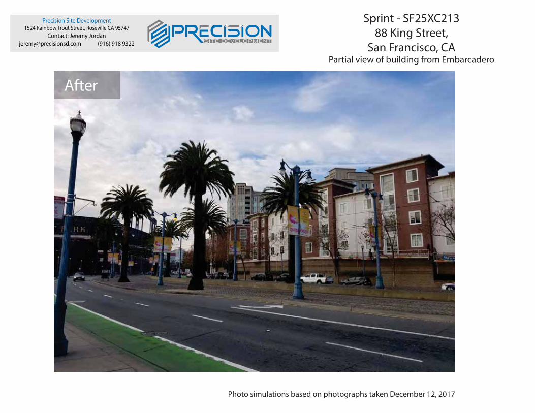
Precision Site Development1524 Rainbow Trout Street, Roseville CA 95747
Contact: Jeremy [email protected] (916) 918 9322
Sprint - SF25XC21388 King Street,
San Francisco, CA Partial view of building from Embarcadero
Photo simulations based on photographs taken December 12, 2017
After

Precision Site Development1524 Rainbow Trout Street, Roseville CA 95747
Contact: Jeremy [email protected] (916) 918 9322
Sprint - SF25XC21388 King Street,
San Francisco, CA Partial view of building from King Street
Photo simulations based on photographs taken December 12, 2017
Before

Precision Site Development1524 Rainbow Trout Street, Roseville CA 95747
Contact: Jeremy [email protected] (916) 918 9322
Sprint - SF25XC21388 King Street,
San Francisco, CA Partial view of building from King Street
Photo simulations based on photographs taken December 12, 2017
After

CEQA Categorical Exemption Determination
PROPERTY INFORMATION/PROJECT DESCRIPTION
Project Address
88 KING ST
Block/Lot(s)
Project description for Planning Department approval.
Permit No.
Addition/
Alteration
Demolition (requires HRE for
Category B Building)
New
Construction
88 King Street - Sprint Wireless Facility New Site Build: Project proposal is to install (2) (P) and (2) (F)
equipment cabinets on (P) steel skid platform inside Penthouse equipment room. Install PPC cabinet,
disconnect, Telco cabinet and ciena cabinet with UAM within equipment lease area. Install (2) panel antennas
per sector, (6) total, (4) RRHs, (12) total below parapet for sector A or inside rooftop mechanical wall at sectors
B and C. Install (1) microwave antenna flush mounted to wall, (1) GPS antenna mounted inside screen wall.
Install stealth screen at sectors A, B & C, paint and texture to match existing building.
Case No.
2018-008389PRJ
3793005
STEP 1: EXEMPTION CLASS
*Note: If neither class applies, an Environmental Evaluation Application is required.*
Class 1 - Existing Facilities. Interior and exterior alterations; additions under 10,000 sq. ft.
Class 3 - New Construction. Up to three new single-family residences or six dwelling units in one
building; commercial/office structures; utility extensions; change of use under 10,000 sq. ft. if principally
permitted or with a CU.
Class 32 - In-Fill Development. New Construction of seven or more units or additions greater than
10,000 sq. ft. and meets the conditions described below:
(a) The project is consistent with the applicable general plan designation and all applicable general plan
policies as well as with applicable zoning designation and regulations.
(b) The proposed development occurs within city limits on a project site of no more than 5 acres
substantially surrounded by urban uses.
(c) The project site has no value as habitat for endangered rare or threatened species.
(d) Approval of the project would not result in any significant effects relating to traffic, noise, air quality, or
water quality.
(e) The site can be adequately served by all required utilities and public services.
FOR ENVIRONMENTAL PLANNING USE ONLY
Class ____

STEP 2: CEQA IMPACTSTO BE COMPLETED BY PROJECT PLANNER
If any box is checked below, an Environmental Evaluation Application is required.
Air Quality: Would the project add new sensitive receptors (specifically, schools, day care facilities,
hospitals, residential dwellings, and senior-care facilities within an Air Pollution Exposure Zone? Does the
project have the potential to emit substantial pollutant concentrations (e.g., backup diesel generators,
heavy industry, diesel trucks, etc.)? (refer to EP _ArcMap > CEQA Catex Determination Layers > Air Pollution
Exposure Zone)
Hazardous Materials: If the project site is located on the Maher map or is suspected of containing
hazardous materials (based on a previous use such as gas station, auto repair, dry cleaners, or heavy
manufacturing, or a site with underground storage tanks): Would the project involve 50 cubic yards or
more of soil disturbance ‐ or a change of use from industrial to residential? If yes, this box must be
checked and the project applicant must submit an Environmental Application with a Phase I
Environmental Site Assessment. Exceptions: do not check box
if the applicant presents documentation of enrollment in the San Francisco Department of Public Health
(DPH) Maher program, a DPH waiver from the Maher program, or other documentation from
Environmental Planning staff that hazardous material effects would be less than significant (refer to
EP_ArcMap > Maher layer).
Transportation: Does the project create six (6) or more net new parking spaces or residential units?
Does the project have the potential to adversely affect transit, pedestrian and/or bicycle safety (hazards)
or the adequacy of nearby transit, pedestrian and/or bicycle facilities?
Archeological Resources: Would the project result in soil disturbance/modification greater than two
(2) feet below grade in an archeological sensitive area or eight (8) feet in a non -archeological sensitive
area? (refer to EP_ArcMap > CEQA Catex Determination Layers > Archeological Sensitive Area)
Subdivision/Lot Line Adjustment: Does the project site involve a subdivision or lot line adjustment
on a lot with a slope average of 20% or more? (refer to EP_ArcMap > CEQA Catex Determination Layers >
Topography)
Slope = or > 20%: Does the project involve any of the following: (1) square footage expansion greater
than 1,000 sq. ft. outside of the existing building footprint, (2) excavation of 50 cubic yards or more of
soil, (3) new construction? (refer to EP_ArcMap > CEQA Catex Determination Layers > Topography) If box is
checked, a geotechnical report is required.
Seismic: Landslide Zone: Does the project involve any of the following: (1) square footage expansion
greater than 1,000 sq. ft. outside of the existing building footprint, (2) excavation of 50 cubic yards or
more of soil, (3) new construction? (refer to EP_ArcMap > CEQA Catex Determination Layers > Seismic Hazard
Zones) If box is checked, a geotechnical report is required.
Seismic: Liquefaction Zone: Does the project involve any of the following: (1) square footage
expansion greater than 1,000 sq. ft. outside of the existing building footprint, (2) excavation of 50
cubic yards or more of soil, (3) new construction? (refer to EP_ArcMap > CEQA Catex Determination Layers >
Seismic Hazard Zones) If box is checked, a geotechnical report will likely be required.
If no boxes are checked above, GO TO STEP 3. If one or more boxes are checked above, an
Environmental Evaluation Application is required, unless reviewed by an Environmental Planner.
Comments and Planner Signature (optional): Ashley Lindsay

STEP 3: PROPERTY STATUS - HISTORIC RESOURCETO BE COMPLETED BY PROJECT PLANNER
PROPERTY IS ONE OF THE FOLLOWING: (refer to Parcel Information Map)
Category A: Known Historical Resource. GO TO STEP 5.
Category B: Potential Historical Resource (over 45 years of age). GO TO STEP 4.
Category C: Not a Historical Resource or Not Age Eligible (under 45 years of age). GO TO STEP 6.
STEP 4: PROPOSED WORK CHECKLIST
TO BE COMPLETED BY PROJECT PLANNER
Check all that apply to the project.
1. Change of use and new construction. Tenant improvements not included.
2. Regular maintenance or repair to correct or repair deterioration, decay, or damage to building.
3. Window replacement that meets the Department’s Window Replacement Standards. Does not include
storefront window alterations.
4. Garage work. A new opening that meets the Guidelines for Adding Garages and Curb Cuts, and/or
replacement of a garage door in an existing opening that meets the Residential Design Guidelines.
5. Deck, terrace construction, or fences not visible from any immediately adjacent public right-of-way.
6. Mechanical equipment installation that is not visible from any immediately adjacent public
right-of-way.
7. Dormer installation that meets the requirements for exemption from public notification under Zoning
Administrator Bulletin No. 3: Dormer Windows.
8. Addition(s) that are not visible from any immediately adjacent public right -of-way for 150 feet in each
direction; does not extend vertically beyond the floor level of the top story of the structure or is only a
single story in height; does not have a footprint that is more than 50% larger than that of the original
building; and does not cause the removal of architectural significant roofing features.
Note: Project Planner must check box below before proceeding.
Project is not listed. GO TO STEP 5.
Project does not conform to the scopes of work. GO TO STEP 5.
Project involves four or more work descriptions. GO TO STEP 5.
Project involves less than four work descriptions. GO TO STEP 6.
STEP 5: CEQA IMPACTS - ADVANCED HISTORICAL REVIEWTO BE COMPLETED BY PROJECT PLANNER
Check all that apply to the project.
1. Project involves a known historical resource (CEQA Category A) as determined by Step 3 and
conforms entirely to proposed work checklist in Step 4.
2. Interior alterations to publicly accessible spaces.
3. Window replacement of original/historic windows that are not “in-kind” but are consistent with
existing historic character.
4. Façade/storefront alterations that do not remove, alter, or obscure character-defining features.
5. Raising the building in a manner that does not remove, alter, or obscure character -defining
features.
6. Restoration based upon documented evidence of a building’s historic condition, such as historic
photographs, plans, physical evidence, or similar buildings.

7. Addition(s), including mechanical equipment that are minimally visible from a public right -of-way
and meet the Secretary of the Interior’s Standards for Rehabilitation .
8. Other work consistent with the Secretary of the Interior Standards for the Treatment of Historic
Properties (specify or add comments):
9. Other work that would not materially impair a historic district (specify or add comments):
(Requires approval by Senior Preservation Planner/Preservation Coordinator)
10. Reclassification of property status. (Requires approval by Senior Preservation
Planner/Preservation
Reclassify to Category A
a. Per HRER dated
b. Other (specify):
(attach HRER)
Reclassify to Category C
Note: If ANY box in STEP 5 above is checked, a Preservation Planner MUST check one box below.
Further environmental review required. Based on the information provided, the project requires an
Environmental Evaluation Application to be submitted. GO TO STEP 6.
Project can proceed with categorical exemption review. The project has been reviewed by the
Preservation Planner and can proceed with categorical exemption review. GO TO STEP 6.
Comments (optional):
Preservation Planner Signature:
TO BE COMPLETED BY PROJECT PLANNER
STEP 6: CATEGORICAL EXEMPTION DETERMINATION
Further environmental review required. Proposed project does not meet scopes of work in either
(check all that apply):
Step 2 - CEQA Impacts
Step 5 - Advanced Historical Review
STOP! Must file an Environmental Evaluation Application.
Project Approval Action: Signature:
If Discretionary Review before the Planning Commission is requested,
the Discretionary Review hearing is the Approval Action for the project.
Once signed or stamped and dated, this document constitutes a categorical exemption pursuant to CEQA Guidelines and Chapter
31of the Administrative Code.
In accordance with Chapter 31 of the San Francisco Administrative Code, an appeal of an exemption determination can only be
filed within 30 days of the project receiving the first approval action.
Please note that other approval actions may be required for the project. Please contact the assigned planner for these approvals.
Ashley Lindsay
11/19/2018
No further environmental review is required. The project is categorically exempt under CEQA.
There are no unusual circumstances that would result in a reasonable possibility of a significant
effect.
Commission Hearing

TO BE COMPLETED BY PROJECT PLANNER
STEP 7: MODIFICATION OF A CEQA EXEMPT PROJECT
In accordance with Chapter 31 of the San Francisco Administrative Code, when a California Environmental
Quality Act (CEQA) exempt project changes after the Approval Action and requires a subsequent approval, the
Environmental Review Officer (or his or her designee) must determine whether the proposed change
constitutes a substantial modification of that project. This checklist shall be used to determine whether the
proposed changes to the approved project would constitute a “substantial modification” and, therefore, be
subject to additional environmental review pursuant to CEQA.
PROPERTY INFORMATION/PROJECT DESCRIPTION
Project Address (If different than front page) Block/Lot(s) (If different than
front page)
Case No. Previous Building Permit No. New Building Permit No.
Plans Dated Previous Approval Action New Approval Action
88 KING ST
2018-008389PRJ
Commission Hearing
3793/005
Modified Project Description:
DETERMINATION IF PROJECT CONSTITUTES SUBSTANTIAL MODIFICATION
Compared to the approved project, would the modified project:
Result in expansion of the building envelope, as defined in the Planning Code;
Result in the change of use that would require public notice under Planning Code
Sections 311 or 312;
Result in demolition as defined under Planning Code Section 317 or 19005(f)?
Is any information being presented that was not known and could not have been known
at the time of the original determination, that shows the originally approved project may
no longer qualify for the exemption?
If at least one of the above boxes is checked, further environmental review is required.
DETERMINATION OF NO SUBSTANTIAL MODIFICATION
Planner Name:
The proposed modification would not result in any of the above changes.
If this box is checked, the proposed modifications are categorically exempt under CEQA, in accordance with prior project
approval and no additional environmental review is required. This determination shall be posted on the Planning
Department website and office and mailed to the applicant, City approving entities, and anyone requesting written notice.
Date:

COMMUNITY OUTREACH MEETING ON A WIRELESS COMMUNICATION FACILITY PROPOSED IN YOUR NEIGHBORHOOD
To: Neighbors within 500 feet of 88 King St., San Francisco, CA 94107
Meeting Information Date: Wednesday, May 16, 2018 Time: 6 p.m. -7:00 p.m. Where: Potrero library Branch Meeting Room 1616 20th St. San Francisco, CA 94107
Applicant Sprint c/o Precision Site Development
Precision Site Development 1524 Rainbow Trout Rd. Roseville, CA 95747
Sprint Site Information Address: 88 King St., San Francisco, CA 94107 APN: 3793-005
Zoning: SB-DTR
Contact Information Jeremy Jordan (916) 918-9322
1524 Rainbow Trout Rd. Roseville, CA 95747 [email protected]
*This is not a Library Sponsored Program
Sprint has applied for zoning approval to install a rooftop wireless facility located at 88 King St., San Francisco. This site will replace an existing site that will be closing down. Continuing coverage at this location is vital to the Sprint network and local emergency services and will also improve service for Sprint customers with significantly improved call quality and faster data rates for both uploading and downloading. The proposed facility will enhance Sprints network by closing gaps in coverage and adding more spectrum, resulting in faster and more reliable data streaming.
You are invited to attend an informational community meeting on Wednesday, May 16th from 6:00 - 7:00 p.m. at the Potrero Library in the Branch Meeting Room. This project will be scheduled for a Planning Commission public hearing after the neighborhood meeting. Architectural plans and photo simulations will be available for your review at the meeting.
If you are unable to attend the meeting and would like to request information, please contact Jeremy Jordan at (916) 918-9322 or [email protected]
If you have any questions about the zoning process, you may contact CPC Wireless Team with the San Francisco Planning Department at [email protected]
NOTE: If you require an interpreter to be present at the meeting, please contact our office at (916) 918-9322 or [email protected] no later than May 7th and we will make every effort to provide you with an interpreter.
REUNIÓN DE DIFUSIÓN COMUNITARIA SOBRE LA INSTALACIÓN DE COMUNICACIÓN INALÁMBRICA PROPUESTA EN SU VECINDARIO
Para: Los vecinos que vivan a una distancia de menos de 500 pies de 88 King St., San Francisco, CA 94107
Información de la reunión Fecha: Miér, 16 de mayo de 2018 Hora: 6 p.m. -7:00 p.m. Dónde: Biblioteca de Potrero Sala de Juntas de la Sucursal 1616 20th St. San Francisco, CA 94107
Solicitante Sprint c/o Precision Site Development
Precision Site Development 1524 Rainbow Trout Rd. Roseville, CA 95747
Información del sitio de Sprint Dirección: 88 King St., San Francisco, CA 94107 APN: 3793-005 Zonificación: SB-DTR
Información de contacto Jeremy Jordan (916) 918-9322
1524 Rainbow Trout Rd. Roseville, CA 95747
*Este no es un programa patrocinado por la Biblioteca
Sprint solicitó la aprobación de zonificación para poner una instalación de comunicación inalámbrica en el techo, en 88 King St., San Francisco. Esta instalación reemplazará a la existente, que cerrará próximamente. La continuidad de la cobertura en este sitio es crucial para la red de Sprint y para los servicios locales de emergencia, y también mejorará el servicio para los clientes de Sprint, al mejorar significativamente la calidad de las llamadas y la velocidad de transferencia de datos, tanto de subida como de bajada. La instalación propuesta mejorará la red de Sprint al disminuir la brecha de cobertura y añadir un mayor espectro, lo cual resultará en una transferencia de datos más rápida y confiable.
Se le invita a que asista a la reunión comunitaria informativa el miércoles 16 de mayo, de 6:00 a 7:00 p.m. en la Biblioteca de Potrero, en la Sala de Juntas de la Sucursal. Este proyecto se programará para una audiencia pública de la Comisión de Planificación después de la reunión del vecindario. En la reunión habrá disponibles planos arquitectónicos y simulaciones fotográficas para que usted las estudie.
Si no puede asistir a la reunión y desea solicitar información, por favor comuníquese con Jeremy Jordan al (916) 918-9322 o [email protected]
Si tiene alguna pregunta sobre el proceso de zonificación, puede comunicarse con el Equipo Inalámbrico de CPC en el Departamento de Planificación de San Francisco en [email protected]
NOTA: Si requiere de un intérprete para la reunión, por favor comuníquese con nuestra oficina al (916) 918-9322 o [email protected] a más tardar el 7 de mayo, y haremos lo posible para conseguirle un intérprete.

提議在您的社區設立無線通信設施的社區宣傳會議
致: 88 King St., San Francisco, CA 94107 的 500 英尺範圍之內的居民
會議信息
日期: 2018 年 5 月 16 日,星期三
時間: 下午 6 點至下午 7 點
地址: Potrero 圖書館
分館會議室
1616 20th St. San Francisco, CA 94107
申請者 Sprint c/o Precision Site
Development Precision Site Development
1524 Rainbow Trout Rd. Roseville, CA 95747
Sprint 地點信息
地址: 88 King St.,
San Francisco, CA 94107
物業編號(APN): 3793-005
區域劃分: SB-DTR
聯繫信息
Jeremy Jordan (916) 918-9322 1524 Rainbow Trout Rd. Roseville, CA 95747
*這不是圖書館贊助的計劃
Sprint 已申請區域劃分許可證,以便在三藩市的 88 King St.安裝屋頂無線設施。該地
點將取代即將關閉的現有地點。繼續為該地點提供覆蓋服務對於 Sprint 網絡和本地緊
急服務至關重要,其將改善 Sprint 為客戶提供的服務,顯著改進通話質量及提高上傳
和下載數據的速度。提議的設施將通過縮小覆蓋範圍差距及增加更多頻譜來增強
Sprint 網絡,從而實現更快、更可靠的數據流。
誠邀您來參加 5 月 16 日星期三下午 6 點到 7 點的社區信息會議,地點在 Potrero 圖
書館分館會議室。在社區會議舉行之後,將對該項目安排一個規劃委員會的公眾聽證
會。會議上將有建築計劃和模擬圖片供您審查。
如果您無法出席會議並希望索取信息,請致電(916) 918-9322 或電郵至
[email protected] 與 Jeremy Jordan 聯繫。
如果您對區域劃分過程有任何疑問,可以電郵至 [email protected] 與三藩市規劃
部門 (San Francisco Planning Department)的 CPC 無線小組聯繫。
注意: 如果您在會議上需要口譯員,請在 5 月 7 日之前,致電 (916) 918-9322 或電郵
至 [email protected] 與我們辦公室聯繫,我們將盡一切努力為您提供口譯員。
PULONG NG PAGLILINGKOD SA KOMUNIDAD TUNGKOL SA ISANG WIRELESS COMMUNICATION NA PASILIDAD NA NAPANUKALA SA INYONG KOMUNIDAD
Para sa: Mga Kapit-bahay sa loob ng 500 piye ng 88 King St., San Francisco, CA 94107
Impormasyon sa Pulong Petsa: Miyerkules, Mayo 16, 2018 Oras: 6 p.m. -7:00 p.m. Saan: Potrero library Branch Meeting Room 1616 20th St. San Francisco, CA 94107
Aplikante Sprint c/o Precision Site Development Precision Site Development
1524 Rainbow Trout Rd. Roseville, CA 95747
Impormasyon sa Sprint Site Address: 88 King St., San Francisco, CA 94107 APN: 3793-005 Zoning: SB-DTR
Kontak na Information Jeremy Jordan (916) 918-9322
1524 Rainbow Trout Rd. Roseville, CA 95747 [email protected]
*Hindi ito isang Programa na Inisponsor ng Library
Ang Sprint ay nag-aplay para sa pag-aproba ng pagsosona upang mag-instila ng isang rooftop wireless facility na nasa 88 King St., San Francisco. Ang site na ito ay papalit sa kasalukuyang site na magsasara na. Ang patuloy na sakop sa lugar na ito ay mahalaga sa network ng Sprint at lokal na mga serbisyo sa emerhensiya at magpapabuti rin sa serbisyo para sa mga kustomer ng Sprint na may makabuluhang pagpapabuti ng kalidad ng pagtawag at mas mabilis na mga data rate para sa parehong pag-upload at pag-download. Ang napanukalang pasilidad ay mapapahusay ang network ng Sprint sa pamamagitan ng pagpupunan ng mga puwang sa nasasakop at pagdaragdag ng mas maraming spectrum, na magreresulta sa mas mabilis at mas maaasahang pagdaloy ng mga datos (data streaming).
Inaanyayahan kayong dumalo sa pang-impormasyong pulong ng komunidad sa Miyerkules, Mayo 16 mula 6:00 - 7:00 p.m. sa Branch Meeting Room ng Potrero Library. Ang proyektong ito ay magtatakda ng iskedyul para sa isang pampublikong pagdinig ng Planning Commission pagkatapos ng pulong ng komunidad. Ang mga planong pang-arkitektura at mga photo simulation ay maaaring makuha sa oras ng pulong para sa inyong pagsusuri.
Kung hindi kayo maaaring dumalo sa pulong at nais ninyong humiling ng impormasyon, mangyari lamang na kontakin si Jeremy Jordan sa (916) 918-9322 o [email protected]
Kung mayroon kayong anumang katanungan tungkol sa proseso ng pagsosona, maaari ninyong kontakin ang CPC Wireless Team sa San Francisco Planning Department sa [email protected]
PAALALA: Kung kailangan ninyo ng isang interpreter na naroon sa pulong, mangyari lamang na kontakin ang aming tanggapan sa (916) 918-9322 o [email protected] nang hindi lalampas sa Mayo 7 at gagawin namin ang lahat ng pagsisikap na magkaroon kayo ng isang interpreter.

Sprint Proposed Cell Site @ 88 King Street Community Meeting Summary Sheet
Meeting Information: Date: Wednesday, May 16, 2018 Time: 6:00-7:00pm. Where: Potrero Library
1616 20th St.
San Francisco, CA 94107
Sprint Representatives/Attendees:
• Jeremy Jordan - Precision Site Development • Sean Prior - Precision Site Development • Bill Hammett -Hammett & Edison RF Consultants • Chris Cubansky - Sprint RF Engineer
Neighborhood Attendees • No neighborhood attendees concerning Sprint's modification at 88 King St. Meeting notes: • N/A Neighborhood Emails Received: • No emails were received concerning Sprint's proposed cell site at 88 King St. Neighborhood Phone Calls Received • No phone calls were received concerning Sprint’s proposed cell site at 88 King St.

Neighborhood Meeting Comment Sheet
Potrero Library 1616 20th St. San Francisco, CA 94107
Wednesday, May 16, 2018 at 6:00-7:00pm
88 King St., San Francisco, CA 94107
Sprint # SF25XC213 – Pier 48 Relo
NAME CONTACT INFORMATION COMMENT
No Attendees 05.16.2018 7:10pm


Block Book Map
Case Number 2018-008389CUASprintMacro WTS Facility88 King Street
SUBJECTPROPERTIES

Sanborn Map*
Case Number 2018-008389CUASprintMacro WTS Facility88 King Street
*The Sanborn Maps in San Francisco have not been updated since 1998, and this map may not accurately reflect existing conditions.
SUBJECTPROPERTIES

Zoning Map
Case Number 2018-008389CUASprintMacro WTS Facility88 King Street
SUBJECTPROPERTIES

Aerial Photo
Case Number 2018-008389CUASprintMacro WTS Facility88 King Street
SUBJECTPROPERTIES

Precision Site Development1524 Rainbow Trout Street, Roseville CA 95747
Contact: Jeremy Jordan
[email protected] (916) 918 9322
~~ I~~~CI~ION■ ■-
Sprint - SF25XC21388 King Street,
San Francisco, CA
88 King Street, site of the proposed stealth Wireless Telecommunications Facility; as seenin the context of the current streetscape, with neighboring facades and building heights.
Photographs taken on December 12, 2017

Precision Site Development1524 Rainbow Trout Street, Roseville CA 95747 ~
Contact: Jeremy Jordan ~ ~C ~ I = I O
[email protected] (916) 918 9322 ~ ~
_, ̀~ . _ __—__.. _ ___.A____..__--__
Sprint - SF25XC21388 King Street,
San Francisco, CA
Above: Proposed indoor and screened equipment areas
Photographs taken on December 12, 2017
Sector A-Antenna location sector B-Antenna location Sector C-Antenna location

Sprint • Proposed Base Station (Site No. SF25xc213) 88 King Street • San Francisco, California
cV6SP Page 1 of 4
Statement of Hammett & Edison, Inc., Consulting Engineers
The firm of Hammett & Edison, Inc., Consulting Engineers, has been retained by Sprint, a personal wireless telecommunications carrier, to evaluate the base station (Site No. SF25xc213) proposed to be located at 88 King Street in San Francisco, California, for compliance with appropriate guidelines limiting human exposure to radio frequency (“RF”) electromagnetic fields.
Executive Summary
Sprint proposes to install directional panel antennas above the roof of the 14-story building located at 88 King Street in San Francisco. The proposed operation will comply with the FCC guidelines limiting public exposure to RF energy.
Prevailing Exposure Standards
The U.S. Congress requires that the Federal Communications Commission (“FCC”) evaluate its actions for possible significant impact on the environment. A summary of the FCC’s exposure limits is shown in Figure 1. These limits apply for continuous exposures and are intended to provide a prudent margin of safety for all persons, regardless of age, gender, size, or health. The most restrictive FCC limit for exposures of unlimited duration to radio frequency energy for several personal wireless services are as follows:
Wireless Service Frequency Band Occupational Limit Public Limit Microwave (Point-to-Point) 5–80 GHz 5.00 mW/cm2 1.00 mW/cm2 WiFi (and unlicensed uses) 2–6 5.00 1.00 BRS (Broadband Radio) 2,600 MHz 5.00 1.00 WCS (Wireless Communication) 2,300 5.00 1.00 AWS (Advanced Wireless) 2,100 5.00 1.00 PCS (Personal Communication) 1,950 5.00 1.00 Cellular 870 2.90 0.58 SMR (Specialized Mobile Radio) 855 2.85 0.57 700 MHz 700 2.40 0.48 [most restrictive frequency range] 30–300 1.00 0.20
General Facility Requirements
Base stations typically consist of two distinct parts: the electronic transceivers (also called “radios” or “channels”) that are connected to the traditional wired telephone lines, and the passive antennas that send the wireless signals created by the radios out to be received by individual subscriber units. The transceivers are often located at ground level and are connected to the antennas by coaxial cables. A small antenna for reception of GPS signals is also required, mounted with a clear view of the sky. Because of the short wavelength of the frequencies assigned by the FCC for wireless services, the

Sprint • Proposed Base Station (Site No. SF25xc213) 88 King Street • San Francisco, California
cV6SP Page 2 of 4
antennas require line-of-sight paths for their signals to propagate well and so are installed at some height above ground. The antennas are designed to concentrate their energy toward the horizon, with very little energy wasted toward the sky or the ground. This means that it is generally not possible for exposure conditions to approach the maximum permissible exposure limits without being physically very near the antennas.
Computer Modeling Method
The FCC provides direction for determining compliance in its Office of Engineering and Technology Bulletin No. 65, “Evaluating Compliance with FCC-Specified Guidelines for Human Exposure to Radio Frequency Radiation,” dated August 1997. Figure 2 describes the calculation methodologies, reflecting the facts that a directional antenna’s radiation pattern is not fully formed at locations very close by (the “near-field” effect) and that at greater distances the power level from an energy source decreases with the square of the distance from it (the “inverse square law”). The conservative nature of this method for evaluating exposure conditions has been verified by numerous field tests.
Site and Facility Description
Based upon information provided by Sprint, including zoning drawings by Borges Architectural Group, Inc., dated January 25, 2018, it is proposed to install three KMW Model ETCR-654L12H6* directional panel antennas† on the side of the view screen wall around mechanical equipment above the roof of the southern of two 14-story residential towers located at 88 King Street in San Francisco. The antennas would employ 8° downtilt, would be mounted at an effective height of about 152½ feet above ground, 11 feet above the roof, and would be oriented toward 30°T, 160°T, and 225°T. The maximum effective radiated power in any direction would be 7,750 watts, representing simultaneous operation at 2,940 watts for BRS, 4,120 watts for PCS, and 690 watts for SMR service. Also proposed to be located on the side of the penthouse is one RFS Model SC2-220BIPN microwave “dish” antenna, mounted at an effective height of about 149½ feet above ground, 8 feet above the roof, for interconnection of this site with others in the Sprint network. There are reported no other wireless telecommunications base stations at the site.
Study Results
For a person anywhere at ground, the maximum RF exposure level due to the proposed Sprint operation, including the contribution of the microwave antenna, is calculated to be 0.0015 mW/cm2, which is 0.17% of the applicable public exposure limit. The maximum calculated level for a person
* Manufacturer’s data sheet attached to this report. † The drawings show that mounting space is included next to the antennas for three “future” antennas, the make and
model of which are not identified.

Sprint • Proposed Base Station (Site No. SF25xc213) 88 King Street • San Francisco, California
cV6SP Page 3 of 4
on the top floor of the subject building is 1.2% of the public exposure limit; the maximum calculated level for a person on the top floor of the northern tower is 7.8% of the public exposure limit. The maximum calculated level at any other building nearby‡ is 0.24% of the public exposure limit. It should be noted that these results include several “worst-case” assumptions and therefore are expected to overstate actual power density levels from the proposed operation.
Recommended Mitigation Measures
Due to their mounting location and height, the Sprint antennas would not be accessible to unauthorized persons, and so no mitigation measures are necessary to comply with the FCC public exposure guidelines. To prevent occupational exposures in excess of the FCC guidelines, it is recommended that appropriate RF safety training, to include review of personal monitor use and lockout/tagout procedures, be provided to all authorized personnel who have access to the roof, including employees and contractors of Sprint and of the property owner. No access within 6 feet directly in front of the Sprint antennas themselves, such as might occur during certain maintenance activities above the roof, should be allowed while the pertinent antennas are in operation, unless other measures can be demonstrated to ensure that occupational protection requirements are met. It is recommended that explanatory signs§ be posted at the roof access door and at the panel antennas, readily visible from any angle of approach to persons who might need to work within that distance. Operation of the microwave antenna is intrinsically compliant with the FCC exposure guidelines.
Conclusion
Based on the information and analysis above, it is the undersigned’s professional opinion that operation of the base station proposed by Sprint at 88 King Street in San Francisco, California, will comply with the prevailing standards for limiting public exposure to radio frequency energy and, therefore, will not for this reason cause a significant impact on the environment. The highest calculated level in publicly accessible areas is much less than the prevailing standards allow for exposures of unlimited duration. This finding is consistent with measurements of actual exposure conditions taken at other operating base stations. Training authorized personnel and posting explanatory signs are recommended to establish compliance with occupational exposure limits.
‡ Including the nine-story residential building located about 80 feet to the southwest, based on photographs from
Google Maps. § Signs should comply with OET-65 color, symbol, and content recommendations. Contact information should be
provided (e.g., a telephone number) to arrange for access to restricted areas. The selection of language(s) is not an engineering matter, and guidance from the landlord, local zoning or health authority, or appropriate professionals may be required.

Sprint • Proposed Base Station (Site No. SF25xc213) 88 King Street • San Francisco, California
cV6SP Page 4 of 4
Authorship
The undersigned author of this statement is a qualified Professional Engineer, holding California Registration Nos. E-13026 and M-20676, which expire on June 30, 2019. This work has been carried out under his direction, and all statements are true and correct of his own knowledge except, where noted, when data has been supplied by others, which data he believes to be correct.
_________________________________ William F. Hammett, P.E. 707/996-5200 March 30, 2018

FCC Radio Frequency Protection Guide
FCC GuidelinesFigure 1
Frequency (MHz)
1000
100
10
1
0.1
0.1 1 10 100 103 104 105
Occupational Exposure
Public Exposure
PCSCell
FM
Pow
erD
ensi
ty(m
W/c
m2 )
The U.S. Congress required (1996 Telecom Act) the Federal Communications Commission (“FCC”)to adopt a nationwide human exposure standard to ensure that its licensees do not, cumulatively, havea significant impact on the environment. The FCC adopted the limits from Report No. 86, “BiologicalEffects and Exposure Criteria for Radiofrequency Electromagnetic Fields,” published in 1986 by theCongressionally chartered National Council on Radiation Protection and Measurements (“NCRP”).Separate limits apply for occupational and public exposure conditions, with the latter limits generallyfive times more restrictive. The more recent standard, developed by the Institute of Electrical andElectronics Engineers and approved as American National Standard ANSI/IEEE C95.1-2006, “SafetyLevels with Respect to Human Exposure to Radio Frequency Electromagnetic Fields, 3 kHz to300 GHz,” includes similar limits. These limits apply for continuous exposures from all sources andare intended to provide a prudent margin of safety for all persons, regardless of age, gender, size, orhealth.
As shown in the table and chart below, separate limits apply for occupational and public exposureconditions, with the latter limits (in italics and/or dashed) up to five times more restrictive:
Frequency Electromagnetic Fields (f is frequency of emission in MHz) Applicable
Range(MHz)
ElectricField Strength
(V/m)
MagneticField Strength
(A/m)
Equivalent Far-FieldPower Density
(mW/cm2)
0.3 – 1.34 614 614 1.63 1.63 100 1001.34 – 3.0 614 823.8/ f 1.63 2.19/ f 100 180/ f2
3.0 – 30 1842/ f 823.8/ f 4.89/ f 2.19/ f 900/ f2 180/ f2
30 – 300 61.4 27.5 0.163 0.0729 1.0 0.2300 – 1,500 3.54 f 1.59 f f /106 f /238 f/300 f/1500
1,500 – 100,000 137 61.4 0.364 0.163 5.0 1.0
Higher levels are allowed for short periods of time, such that total exposure levels averaged over six orthirty minutes, for occupational or public settings, respectively, do not exceed the limits, and higherlevels also are allowed for exposures to small areas, such that the spatially averaged levels do notexceed the limits. However, neither of these allowances is incorporated in the conservative calculationformulas in the FCC Office of Engineering and Technology Bulletin No. 65 (August 1997) forprojecting field levels. Hammett & Edison has built those formulas into a proprietary program thatcalculates, at each location on an arbitrary rectangular grid, the total expected power density from anynumber of individual radio sources. The program allows for the description of buildings and uneventerrain, if required to obtain more accurate projections.

RFR.CALC™ Calculation Methodology
Assessment by Calculation of Compliance with FCC Exposure Guidelines
MethodologyFigure 2
The U.S. Congress required (1996 Telecom Act) the Federal Communications Commission (“FCC”) toadopt a nationwide human exposure standard to ensure that its licensees do not, cumulatively, have asignificant impact on the environment. The maximum permissible exposure limits adopted by the FCC(see Figure 1) apply for continuous exposures from all sources and are intended to provide a prudentmargin of safety for all persons, regardless of age, gender, size, or health. Higher levels are allowed forshort periods of time, such that total exposure levels averaged over six or thirty minutes, foroccupational or public settings, respectively, do not exceed the limits.
Near Field. Prediction methods have been developed for the near field zone of panel (directional) and whip(omnidirectional) antennas, typical at wireless telecommunications base stations, as well as dish(aperture) antennas, typically used for microwave links. The antenna patterns are not fully formed inthe near field at these antennas, and the FCC Office of Engineering and Technology Bulletin No. 65(August 1997) gives suitable formulas for calculating power density within such zones.
For a panel or whip antenna, power density S = 180��BW
�0.1� Pnet� �D2 � h
, in mW/cm2,
and for an aperture antenna, maximum power density Smax = 0.1 � 16 � � � Pnet
� � h2 , in mW/cm2,
where �BW = half-power beamwidth of the antenna, in degrees, andPnet = net power input to the antenna, in watts,
D = distance from antenna, in meters,h = aperture height of the antenna, in meters, and� = aperture efficiency (unitless, typically 0.5-0.8).
The factor of 0.1 in the numerators converts to the desired units of power density.
Far Field. OET-65 gives this formula for calculating power density in the far field of an individual RF source:
power density S = 2.56 �1.64 �100 � RFF2 � ERP
4 �� �D2 , in mW/cm2,
where ERP = total ERP (all polarizations), in kilowatts,RFF = relative field factor at the direction to the actual point of calculation, and
D = distance from the center of radiation to the point of calculation, in meters.
The factor of 2.56 accounts for the increase in power density due to ground reflection, assuming areflection coefficient of 1.6 (1.6 x 1.6 = 2.56). The factor of 1.64 is the gain of a half-wave dipolerelative to an isotropic radiator. The factor of 100 in the numerator converts to the desired units ofpower density. This formula has been built into a proprietary program that calculates, at each locationon an arbitrary rectangular grid, the total expected power density from any number of individualradiation sources. The program also allows for the description of uneven terrain in the vicinity, toobtain more accurate projections.

817~869MHz, XX-pol., H68º / V8º, ET0~8º1850~1995MHz, XX-pol., H58º / V5º, ET0~8º2496~2690MHz, XXXX-pol., H73º / V5º, ET0~6º
www.kmwcomm.com
EDTA (Electrical Down Tilt Antenna)Field Replaceable Internal RET
● Electrical Specification
Cross Pole Configuration @2600MHz 0.65λ
Broadcastingbeam
Gain, dBi 17.5
Horizontal Beamwidth, deg. 65˚ ± 5˚
Service beam boresightGain, dBi 22.5 ±0.5
Horizontal BW, deg. 20˚
Dimension (Length x Width x Depth) 2156mm x 533mm x 160mm(84.9” x 21.0” x 6.3”)
Antenna Weight 38.5kg / 84.9lbs
Adjustable Clamp Weight 6.4kg / 14.1lbs
Fixed Clamp Weight 1.8kg / 4.0lbs
Max. Wind Speed 67m/s (150mph)
Wind Load (@100mph), Front / Side / Rear 1763 N /529 N /1763 N (397 lbf /119 lbf /397 lbf)
Connector (Type / Position) 8 x 7/16” DIN(Female), 8 x MINI DIN(Female),1 x N type(Cal Port, Female) / Bottom
● Beamforming Specification
● Mechanical Specification
Product Number ETCR-654L12H6
Frequency Range 817~869MHz 1850~1995MHz 2496~2690MHz
3dB Beam-Width
Horizontal 68 ±5˚ 58 ±5˚ 73 ±5˚
Vertical 8˚ ±1˚ 5˚ ±1˚ 5˚ ±1˚
Gain (dBi) 15.0 ±0.5 18.8 ±0.5 18.3 ±0.5
Electrical Down Tilt Range 0 ~ 8˚ 0 ~ 8˚ 0 ~ 6˚
1st Upper Sidelobe Suppression > 18dB (up to 15˚ EL) > 18dB (up to 10˚ EL) > 18dB (up to 10˚ EL)
Front-to-Back Ratio @180±15° (Total power) > 24dB > 28dB > 28dB
Polarization Type Dual, Slant ±45˚ Dual, Slant ±45˚ Dual, Slant ±45˚
Cross –PolarDiscrimination(XPD)
-3dB HBW > 15dB > 15dB > 13dB
±60° > 10dB > 10dB > 7dB
Input Maximum CW Power 250W 250W 250W
Impedance 50Ω 50Ω 50Ω
VSWR < 1.43 : 1 < 1.43 : 1 < 1.43 : 1
Port Isolation
Intra Array >26dB >28dB >26dB
Inter Array >28dB, Co Pol. >24dB, Co Pol.
Inter Band800MHz // 1900MHz : > 28dB800MHz // 2600MHz : > 28dB1900MHz // 2600MHz : > 28dB
Passive Intermodulation, IM3 (@2x43dBm) ≤ -110dBm ≤ -110dBm ≤ -105dBm
Operation temperature -40˚C to +55˚C
Antenna Control Interface Field Replaceable Internal RET, AISG2.0
• Specifications are subject to change without notice. 5/5/16

0°
90°
180°
270°
10°
20°
30°
40°
50°
60°
70°
80°
100°
110°
120°
130°
140°
150°
160°
170°190°
200°
210°
220°
230°
240°
250°
260°
280°
290°
300°
310°
320°
330°
340°
350°
0°
90°
180°
270°
10°
20°
30°
40°
50°
60°
70°
80°
100°
110°
120°
130°
140°
150°
160°
170°190°
200°
210°
220°
230°
240°
250°
260°
280°
290°
300°
310°
320°
330°
340°
350°
SMR Elevation Pattern
SMR Azimuth Pattern

0°
90°
180°
270°
10°
20°
30°
40°
50°
60°
70°
80°
100°
110°
120°
130°
140°
150°
160°
170°190°
200°
210°
220°
230°
240°
250°
260°
280°
290°
300°
310°
320°
330°
340°
350°
0°
90°
180°
270°
10°
20°
30°
40°
50°
60°
70°
80°
100°
110°
120°
130°
140°
150°
160°
170°190°
200°
210°
220°
230°
240°
250°
260°
280°
290°
300°
310°
320°
330°
340°
350°
PCS Elevation Pattern
PCS Azimuth Pattern

0°
90°
180°
270°
10°
20°
30°
40°
50°
60°
70°
80°
100°
110°
120°
130°
140°
150°
160°
170°190°
200°
210°
220°
230°
240°
250°
260°
280°
290°
300°
310°
320°
330°
340°
350°
0°
90°
180°
270°
10°
20°
30°
40°
50°
60°
70°
80°
100°
110°
120°
130°
140°
150°
160°
170°190°
200°
210°
220°
230°
240°
250°
260°
280°
290°
300°
310°
320°
330°
340°
350°
BRS Azimuth Pattern
BRS Elevation Pattern

San Francisco City and County Department of Public Health
Mark Farrell, Mayor Barbara Garcia, Director of Health
Environmental Health Branch
Stephanie K.J. Cushing, MSPH, CHMM, REHS Director of Environmental Health
Review of Cellular Antenna Site Proposals
Planner: Elizabeth Watty
RF Engineer Consultant: Hammett & Edison Phone Number: (707) 996-5200
Project Sponsor : Sprint
Project Address/Location: 88 King St
Site ID: 3049 SiteNo.: SF25xc213
0
Yes No
X
X
X
X
X
X
X
X
2
1. The location, identity and total number of all operational radiating antennas installed at this site was provided. (WTS-FSG, Section 10.4.1, Section 11, 2b)
Number of Existing Antennas:
2. A list of all radiating antennas located within 100 feet of the site which could contribute to the cumulative radio frequency energy at this location was provided. (WTS-FSG, Section 10.5.2)
3. A narrative description of the proposed work for this project was provided. The description should be consistent with scope of work for the final installation drawings. (WTS-FSG, Section 10)
Yes No
4. An inventory of the make and model of antennas or transmitting equipment being installed or removed was provided. The antenna inventory included the proposed installation height above the nearest walking/working surface, the height above ground level and the orientations of the antennas. (WTS-FSG, Section 10.5.2)
5. A description of the existing radio frequency energy environment at the nearest walking/working surface to the antennas and at ground level was provided. A description of any assumptions made when doing the calculations was also provided. (WTS-FSG, Section 10.4.1a, Section 10.4.1c, Section 10.5)
Yes No
Yes No
6. The maximum effective radiated power per sector for the proposed installation was provided along with the frequency bands used by the antennas. (WTS-FSG, Section 10.1.2, Section 10.5.1)
7750Maximum Effective Radiated Power: Watts
7. Based on the antenna orientation, the maximum cumulative predicted radio frequency energy level for any nearby publicly accessible building or area was provided. (WTS-FSG, Section 10.4, Section 10.5.1)
80Distance to this nearby building or structure: feet
0.24Maximum percent of applicable FCC public standard at the nearest building or structure: %
8. The estimated maximum cumulative radio frequency fields for the proposed site at ground level. (WTS-FSG, Section 10.5)
0.0015Maximum RF Exposure: mW/cm 0.17Maximum RF Exposure Percent: %
The following information is required to be provided before approval of this project can be made. These information requirements are established in the San Francisco Planning Department Wireless Telecommunications Services Facility Sitting Guidelines dated August 1996.
In order to facilitate quicker approval of this project, it is recommended that the project sponsor review this document before submitting the proposal to ensure that all requirements are included.
3/8/2018Report Dated:

There are 0 antennas existing operated by Sprint installed on the roof top of the building at 88 King St. Existing RF levels at ground level were around 1% of the FCC public exposure limit. No other antennas were observed within 100 feet of this site. Sprint proposes to install 3 new antennas. The antennas are mounted at a height of 152.5 feet above the ground and 11 feet above the roof. The estimated ambient RF field from the proposed Sprint transmitters at ground level is calculated to be 0.0015 mW/sq cm., which is 0.17% of the FCC public exposure limit. The three dimensional perimeter of RF levels equal to the public exposure limit extends 30 feet and does not reach any publicly accessible areas. Warning signs must be posted at the antennas and roof access points in English, Spanish and Chinese. Workers should not have access to within 6 feet of the front of the antennas while they are in operation. Due to the mounting locations and height, the antennas would not be accessible to unauthorized persons.
Approved. Based on the information provided the following staff believes that the project proposal will comply with the current Federal Communication Commission safety standards for radiofrequency radiation exposure. FCC standard Approval of the subsequent Project Implementation Report is based on project sponsor completing recommendations by project consultant and DPH.
Comments:
Not Approved, additional information required.
Not Approved, does not comply with Federal Communication Commission safety standards for radiofrequency radiation exposure. FCC Standard
Hours spent reviewing
Charges to Project Sponsor (in addition to previous charges, to be received at time of receipt by Sponsor)
Public Exclusion Area
Occupational Exclusion Area
X
X
CFR47 1.1310
X
1
6/27/2018Dated:
9. The maximum distance (in feet) the three dimensional perimeter of the radio frequency energy level equal to the public and occupational exposure limit is calculated to extend from the face of the antennas was provided. Any potential walking/working surfaces exceeding regulatory standards were identified. (WTS-FSG, Section 10.9.2)
30Public Exclusion In Feet:
6Occupational Exclusion In Feet:
10. A description of whether or not the public has access to the antennas was provided. A description was also provided of any existing or proposed warning signs, barricades, barriers, rooftop stripping or other safety precautions for people nearing the equipment as may be required by any applicable FCC-adopted standards. All signs will be provided in English, Spanish and Chinese. (WTS-FSG, Section 9.5, Section 10.9.2)
Yes No
11. Statement regarding the engineer who produced the report and their qualifications was provided. The engineer is licensed in the State of California. (WTS-FSG, Section 11,8)
Yes No
X
Arthur Duque Environmental Health Management Section San Francisco Dept. of Public Health 1390 Market St., Suite 210, San Francisco, CA. 94102 (415) 252-3966
Signed:

Precision Site Development1524 Rainbow Trout Street, Roseville CA 95747
Contact: Jeremy [email protected] (916) 918 9322
Service Area De�nitionSprint: SF25XC213
88, King Street, San FranciscoLocation of Proposed Wireless Communications Site
88 King Street relocated from Pier 48
Best Signal Level
Best Signal Level
Best Signal Level

Precision Site Development1524 Rainbow Trout Street, Roseville CA 95747
Contact: Jeremy [email protected] (916) 918 9322
Service Area De�nitionSprint: SF25XC212
Pier 48, San FranciscoO� Air Map
Best Signal Level
Best Signal Level
Best Signal Level
* Signi�cant and important areas are left without any coverage including the AT&T Park stadium, which would be a vital coverage area especially for access and contact with Emergency Services and First Responders.
*

Precision Site Development1524 Rainbow Trout Street, Roseville CA 95747
Contact: Jeremy [email protected] (916) 918 9322
Service Area De�nitionSprint: SF25XC212
Pier 48, San FranciscoLocation of Wireless Communications
Site to be Relocated
Pier 48 with Existing Coverage Map - To be Relocated
Best Signal Level
Best Signal Level
Best Signal Level

Web: www.h-e.com • [email protected] E0D5 Delivery: 470 Third Street West • Sonoma, California 95476 Telephone: 707/996-5200 San Francisco • 707/996-5280 Fax • 202/396-5200 D.C.
WILLIAM F. HAMMETT, P.E. RAJAT MATHUR, P.E. ROBERT P. SMITH, JR.
ANDREA L. BRIGHT, P.E. NEIL J. OLIJ, P.E. BRIAN F. PALMER
AMELIA NGAI MANAS REDDY M. DANIEL RO ___________
ROBERT L. HAMMETT, P.E. 1920-2002
EDWARD EDISON, P.E. 1920-2009 ___________
DANE E. ERICKSEN, P.E. CONSULTANT
BY E-MAIL [email protected]
October 15, 2018
Mr. Sean Prior Precision Site Development LLC 1524 Rainbow Trout Street Roseville, California 95747 Dear Sean:
As requested, we have conducted the review required by the City of San Francisco of the coverage maps that Sprint will submit as part of its application package for the base station proposed to be located at 88 King Street (Site No. SF25xc213). This is to fulfill the submittal requirements for Planning Department review.
Executive Summary We concur with the maps, data, and conclusions provided by Sprint for this proposed site relocation.
Sprint presently has installed directional panel antennas above the roof of Pier 48. It is proposed to remove those antennas and to install three KMW Model ETCR-654L12H6 directional panel antennas* on the side of the view screen wall around mechanical equipment above the roof of the southern of two 14-story residential towers located at 88 King Street in San Francisco, about 1,800 feet northwest of the Sprint Pier 48 site. The antennas would employ 8° downtilt, would be mounted at an effective height of about 152½ feet above ground, 11 feet above the roof, and would be oriented toward 30°T, 160°T, and 225°T. The maximum effective radiated power in any direction would be 7,750 watts, representing simultaneous operation at 2,940 watts for BRS, 4,120 watts for PCS, and 690 watts for SMR service.
Sprint provided for review three coverage maps, attached for reference. The maps show Sprint’s existing PCS (1950 MHz) LTE coverage in the area from the Pier 48 site, the coverage without the Pier 48 site, and the coverage with the relocated site at 88 King Street. The maps show five levels of coverage, which Sprint colors and defines as follows:
Green Excellent Coverage Yellow Good Coverage Blue Fair Coverage Red Marginal Coverage Black Poor/No Coverage
* The drawings show that mounting space is included next to the antennas for three “future” antennas, the
make and model of which are not identified.

Mr. Sean Prior, page 2 October 15, 2018
We obtained information from Sprint on the software and the service thresholds that were used to generate its coverage maps. This carrier uses commercially available software to develop its coverage maps. The service thresholds that Sprint uses to estimate coverage are in line with industry standards, similar to the thresholds used by other wireless service providers.
As this proposal is simply the relocation of an existing site, measurements of the existing coverage in the area would not be relevant. We note that the map showing coverage without the Pier 48 site shows Marginal and Poor/No Coverage in the areas that the proposed relocation is intended to improve.
We appreciate the opportunity to be of service. Please let us know if any questions arise on this matter. Sincerely yours,
William F. Hammett, P.E. lw Enclosures
cc: Mr. Jeremy Jordan (w/encls) – BY E-MAIL [email protected] Mr. Chris Cubanske (w/encls) – BY E-MAIL [email protected] Mr. Moises Palacios (w/encls) – BY E-MAIL [email protected]

©2015 Sprint. This information is subject to Sprint policies regarding use and is the property of Sprint and/or its relevant affiliates and may contain restricted, confidential or privileged materials intended for the sole use of the intended recipient. Any review, use, distribution or disclosure is prohibited without authorization.
#MoveForward 1Template Version: 16:9MF1.1
Version Date: 10/23/15
Existing Coverage
--ExcellentCoverage--GoodCoverage--FairCoverage--MarginalCoverage--Poor/NoCoverage

©2015 Sprint. This information is subject to Sprint policies regarding use and is the property of Sprint and/or its relevant affiliates and may contain restricted, confidential or privileged materials intended for the sole use of the intended recipient. Any review, use, distribution or disclosure is prohibited without authorization.
#MoveForward 2Template Version: 16:9MF1.1
Version Date: 10/23/15
Coverage Without Pier 48 Relo (SF25XC213) & SF25XC212
--ExcellentCoverage--GoodCoverage--FairCoverage--MarginalCoverage--Poor/NoCoverage

©2015 Sprint. This information is subject to Sprint policies regarding use and is the property of Sprint and/or its relevant affiliates and may contain restricted, confidential or privileged materials intended for the sole use of the intended recipient. Any review, use, distribution or disclosure is prohibited without authorization.
#MoveForward 3Template Version: 16:9MF1.1
Version Date: 10/23/15
Coverage With Pier 48 Relo (SF25XC213)
--ExcellentCoverage--GoodCoverage--FairCoverage--MarginalCoverage--Poor/NoCoverage

1524 Rainbow Trout St., Roseville, CA 95747
916-918-9322 • [email protected]
FS25XC213 Location Preference The Proposed antenna facility is considered a Preference 5 per section 8.1. Per the description in the WTS Facilities Guidelines it is a Preferred Location as it is in a SB-DTR District.
Sprint’s existing antenna facility located on Pier 48 was originally installed in 2003. The surrounding sites have been designed and modified over the last 15 years to create the best possible service coverage in this area. Since the existing site is being decommissioned due to pending re-development at the subject property, we had to work within 1 block either direction up and down King Street in order to maintain coverage, and at the same time avoid interference with the surrounding sites by relocating too close. The new candidate also needed to have similar characteristics to the existing site as far as heights, location on the block, and even side of the street so as to maintain coverage and avoid interference.
Due to the proximity of other existing Sprint sites around this location, the proposed site at 88 King Street offers optimal replacement coverage for the existing site. The building is located within .6 miles (3168 feet) of the previous location. It will provide similar antenna heights.
Sprint looked into the possibility of modifying the existing sites around this location in order to eliminate the need for this relocation. However, all projected modifications left significant coverage degradation along King Street, Embarcadero and AT&T Park due to the height of the buildings along King Street. The building heights also projected more interference to the surrounding sites. Please contact Jeremy Jordan @ (916) 918-9322 or [email protected] with any questions or for additional information