2015.TEL.7978 Title: State of the art survey of baggage handl
73
Delft University of Technology FACULTY MECHANICAL, MARITIME AND MATERIALS ENGINEERING Department Maritime and Transport Technology Mekelweg 2 2628 CD Delft the Netherlands Phone +31 (0)15-2782889 Fax +31 (0)15-2781397 www.mtt.tudelft.nl This report consists of 68 pages and 1 appendices. It may only be reproduced literally and as a whole. For commercial purposes only with written authorization of Delft University of Technology. Requests for consult are only taken into consideration under the condition that the applicant denies all legal rights on liabilities concerning the contents of the advice. Specialization: Transport Engineering and Logistics Report number: 2015.TEL.7978 Title: State of the art survey of baggage handling systems control and automated equipment Author: L.L.P. van Rijen (4036670) Title (in Dutch) Voortgang en huidige stand van techniek in de automatiserings en besturingstechnologien voor baggagesystemen. Assignment: literature Confidential: no Initiator (university): dr.ir. Y. Pang Supervisor: dr.ir. Y. Pang Date: 26-01-2016
-
Upload
khangminh22 -
Category
Documents
-
view
3 -
download
0
Transcript of 2015.TEL.7978 Title: State of the art survey of baggage handl
Delft University of Technology
FACULTY MECHANICAL, MARITIME AND
MATERIALS ENGINEERING Department Maritime and Transport Technology
Mekelweg 2 2628 CD Delft the Netherlands Phone +31 (0)15-2782889 Fax +31 (0)15-2781397 www.mtt.tudelft.nl
This report consists of 68 pages and 1 appendices. It may only be reproduced literally and as a whole. For
commercial purposes only with written authorization of Delft University of Technology. Requests for consult are only taken into consideration under the condition that the applicant denies all legal rights on liabilities concerning the contents of the advice.
Specialization: Transport Engineering and Logistics Report number: 2015.TEL.7978 Title: State of the art survey of baggage
handling systems control and automated equipment
Author: L.L.P. van Rijen (4036670)
Title (in Dutch) Voortgang en huidige stand van techniek in de automatiserings en besturingstechnologien voor baggagesystemen.
Assignment: literature
Confidential: no
Initiator (university): dr.ir. Y. Pang
Supervisor: dr.ir. Y. Pang
Date: 26-01-2016
TU Delft FACULTY OF MECHANICAL, MARITIME AND mKammy] t.;liVi.-,i:i(W::^|r!lüïK|i,Vi Department of Marine and Transport Teclinology Delft University of Technology
Mekelweg 2 2628 CD Delft the Netherlands Phone +31 (0)15-2782889 Fax +31 (0)15-2781397 www.mtt.tudelft.nl
Student: Supervisor: Specialization:
L. L. P. van Rijen Y. Pang TEL
Assignment type: Literature Report number: 2015.TEL.7978 Confidential: No
Creditpoints (EC): 10
Subject: State of the art of automation and system control in baggage handling
Modern airport baggage handling concerns improving the processes from check-in through screening until departure, arrival and claims. Various automated baggage handling technologies are worldwide applied from sortation, transport, tracing and tracking, storage and retrieval. Together with integrated system control smooth handling processes and operations can be achieved with respect to handling speed, safety and efficiency.
This literature assignment is to survey the state of the art of automated equipment and technologies applied in the field of airport baggage handling. Further, the principles and approaches of integrated baggage handling system control will be investigated. The survey of this assignment should cover the following:
- to review the general airport baggage handling process including the description of sub-processes and involved equipment;
- to summarize the functions and operations that can be automated; - to investigate the technologies to achieve automation and to describe relative applications; - to survey the existing and feasible concepts, methods and principles for the control of
baggage handling systems.
This report should be arranged in such a way that all data is structurally presented in graphs, tables, and lists with belonging descriptions and explanations in text.
The report should comply with the guidelines of the section. Details can be found on the website.
The mentor.
Dr. ir. Y. Pang

i
Preface This work has been made to fulfill a literature assignment from the department Transport Engineering
and Logistics concerning baggage handling systems. It adds knowledge over the developments and
state of the art of baggage handling systems, airports in particular. Baggage handling systems, being
challenging transport infrastructures, are from a mechanical and control point of view very relevant
and interesting to the department and myself. This work has been written in such a way that it can be
understood by people with an academic background in this particular field.
Summary
The ongoing trend of worldwide air passenger growth and the corresponding growth of major airports
hubs caused more and more throughput in these major airports hubs. As a consequence the baggage
handling systems (BHS) grew simultaneously larger and more complex. At the same time, like many
other industrial sectors automation experienced a vast increase. This report aims to survey the state
of the art automated baggage handling equipment in which commercialized equipment is reviewed as
well as radical new concepts which might give a glance into the future of automation in BHS. The
increasing complexity and new challenges within large modern BHS impact the control of these
particular systems as well. The mostly academic research into this specific field of control will hence
be analysed as well. In this way, a complete review of BHS is realized, from the point a passenger
deposits its bag up to the point the bag is placed inside the aircraft and back up to where the
passenger picks up its bag again.
The BHS can be divided in different parts, each with their unique equipment. The first
concerns baggage drop-off and reclaim, the only parts coming into contact with the passenger.
Automated baggage drop-off, one of the most recent additions to the automated equipment, is special
since it is the only part which has interaction with the passenger. Screening follows after drop-off. The
most modern screening equipment has high throughput and advanced 3D scanning techniques. In this
way one pre-scanning step can be omitted, resulting in less rejections. Subsequently inner terminal
transport and sorting is realised. The focus of new equipment is on speed and throughput. Destination
coded vehicle systems are more and more common with the increased demand for higher velocities in
continuously expanding airports. Many sorting options exist although they often have their own
infrastructure which makes the choice also very dependents on the existing transport infrastructure.
Early baggage systems are present in larger hub airports and exist in different forms. The make-up
area including inbound unloading (when baggage has been brought back to the terminal) has seen a
significant amount of new automated equipment being installed. From robotics to baggage
aligning/orienting equipment. Automated carts and unit load device (ULD) unloaders have also been
commercialized. The last part of the journey of the bag (from an outbound perspective) reaches up to
the belly of the plane. Automation is much more scarcely present compared to the other parts of the
BHS since a significant part is mechanised and/or realised with human involvement. New ideas
however have emerged through patens which aim to realize more automation. The control chapter
starts with an introduction to low and high level control and equipment for control. The following
section about control challenges in BHS seeks to find the difficulties and opportunities in terms of
ii
control. The state of the art high level control is discussed afterwards followed by an overview of
research in the field of control of BHS. The main topics discussed are model predictive control (MPC)
and multi agent systems (MAS).
Due to the significant amount of research related to control of BHS, especially if control of
material handling systems in general is included, the focus has been towards high level control and to
largest topics MPC and MAS in particular. These topics covered to a large extent most of the research
from recent years. Research in these topics specifically dedicated to BHS started between 2005 and
2010. MPC in a hierarchical control structure shows the most promise together with centralized MPC
with a pre-calculated initial best guess to speed up computation time. For both fields of research
remains still many research left to do before it can be introduced in real BHS.
Automation seems to be expanding throughout the whole BHS. The most modern additions include
the automated drop-off solutions and automated loading and unloading equipment for carts and ULD.
For the remaining parts which rely still heavily on human involvement it can be argued that they will
be automated as well. The technological progression and the trend of continuous automation up till
today support this statement.
List of abbreviations
ABD: Automated baggage drop-off
AMS: Amsterdam Airport Schiphol
BHS: Baggage handling system(s)
BPH: Bags per hour
CTM: Container transfer module(s)
DCV: Destination coded vehicle(s)
EBS: Early bag storage(s)
EDS: Explosive detection system(s)
HBS: Hold baggage screening
ICAO: International civil aviation organization
ICS: Individual carrier system(s)
IED: Improvised explosive device(s)
MAS: Multi agent system(s)
MPC: Model predictive control
PEC: Photo electric cell
RFID: Radio frequency identification
SOA: State of the art
iii
Contents
Preface .......................................................................................................................................... i Summary ....................................................................................................................................... i List of abbreviations ....................................................................................................................... ii 1. Introduction ........................................................................................................................... 1 2. The baggage handling process ................................................................................................ 3 3. Baggage handling equipment .................................................................................................. 4
3.1 Baggage drop-off and reclaim ............................................................................................... 4 3.2 Baggage screening ............................................................................................................. 10 3.3 Internal transport ............................................................................................................... 15 3.4 Early baggage storage ........................................................................................................ 27 3.5 Make-up area ..................................................................................................................... 30 3.6 External transport and loading of the airplane ...................................................................... 38
4. Control of baggage handling systems .................................................................................... 42 4.1 An introduction to PLC’s ...................................................................................................... 42 4.2 The challenges of control of baggage handling systems ........................................................ 43 4.3 Control architectures ........................................................................................................... 45 4.4 The traditional state of the art method ................................................................................. 46 4.5 Multi agent systems ............................................................................................................ 47 4.6 Model predictive control ...................................................................................................... 50
5. Conclusions .......................................................................................................................... 58 6. Bibliography ......................................................................................................................... 60 Appendix A .................................................................................................................................. 67
1
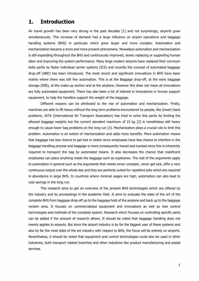
1. Introduction
Air travel growth has been very strong in the past decades [1] and not surprisingly, airports grew
simultaneously. This increase of demand had a large influence on airport operations and baggage
handling systems (BHS) in particular which grew larger and more complex. Automation and
mechanization became a more and more present phenomena. Nowadays automation and mechanization
is still expanding throughout the BHS and continuously improved, slowly replacing or supporting human
labor and improving the system performance. Many large modern airports have replaced their conveyor
belts partly by faster individual carrier systems (ICS) and recently the concept of automated baggage
drop-off (ABD) has been introduced. The most recent and significant innovations in BHS have been
mainly where there was still few automation. This is at the Baggage drop-off, at the early baggage
storage (EBS), at the make-up section and at the airplane. However this does not mean all innovations
are fully automated equipment. There has also been a lot of interest in innovations in human support
equipment, to help the handlers support the weight of the baggage.
Different reasons can be attributed to the rise of automation and mechanization. Firstly,
machines are able to lift heavy without the long term problems encountered by people, like (lower) back
problems. IATA (International Air Transport Association) has tried to solve this partly by limiting the
allowed baggage weights but the current standard maximum of 23 kg [2] is nonetheless still heavy
enough to cause lower bag problems on the long run [3]. Mechanization plays a crucial role to limit this
problem. Automation is an extent of mechanization and adds more benefits. More automation means
that baggage has less chance to get lost or stolen since employees have less chance to interfere in the
baggage handling process and baggage is more consequently traced and tracked since this is inherently
required to transport the bag by automated means. It also decreases the chance that maleficent
employees can place anything inside the baggage such as explosives. The rest of the arguments apply
to automation in general such as the arguments that robots never complain, never get sick, offer a very
continuous output over the whole day and they are perfectly suited for repetitive jobs which are required
in abundance in large BHS. In countries where minimal wages are high, automation can also lead to
cost savings in the long run.
This research aims to get an overview of the present BHS technologies which are offered by
the industry and by proceedings in the academic field. It aims to evaluate the state of the art of the
complete BHS from baggage drop-off up to the baggage hold of the airplane and back up to the baggage
reclaim area. It focuses on commercialized equipment and innovations as well as new control
technologies and methods of the complete system. Research which focuses on controlling specific parts
can be added if the amount of research allows. It should be noted that baggage handling does not
merely applies to airports. But since the airport industry is by far the biggest user of these systems and
also by far the most state of the art industry with respect to BHS, the focus will be entirely on airports.
Nevertheless, it should be noted that equipment and control technologies could also be used in other
industries, both transport related branches and other industries like product manufacturing and postal
services.
2
The time span which the review of BHS system control will have is depending significantly on
the research itself found by the author. The goal is to investigate the research from 5 years old but if it
seems obvious to take somewhat older research into consideration, it is reasonable to take that research
into account. Concerning the automated equipment, patents have mostly been used for those parts of
the BHS which have still no automated commercialized equipment. Other use of patents is clarification
of working principles of state of the art equipment or promising competitive concepts. The main sources
of this survey will be relevant academic papers, mostly for control technologies, patents and company
information, in particular for equipment innovation, and finally interviews with experts if deemed
necessary. The research is deemed complete if the complete BHS, the entire journey of the bag, has
been surveyed and if all important novelties in the field of control of BHS have been addressed.
The report starts with a brief schematic overview of the BHS. It is shown here how all these processes
are interrelated. It will continue with the main topic of this survey, commercialized equipment and
innovations, where it will elaborate on the different parts or processes of the BHS in the consecutive
sections. Since all these parts are not generally distinguishable they are defined by the author. The
reason why certain processes and equipment are grouped together is due to similarities, their place
inside the BHS and/or the size of the content regarding certain processes. The chapter will start with a
section about Baggage drop-off and reclaim followed by baggage screening. The next section about
internal transport includes sorting equipment, but does not include any form of transport between the
make-up area and up to the airplane. This distinction is made because this transport differs significantly
from the regular BHS. To highlight this distinction this section is called internal transport. The chapter
continuous with a section concerning EBS followed by a section with all equipment related to the make-
up area. This includes inbound baggage feed into the baggage conveyor system inside the terminal.
Alignment and orientation equipment which is predominantly used at this inbound feed is for that reason
also discussed here. The chapter will conclude with a section about the complete final journey of the
bag up to the aircraft hold.
Subsequently the report will give an overview of the proceedings in the field of control
technologies where the challenge of control of BHS will be discussed, the current state of the art control
method and finally the novelties from academic research. Finally, the report will end with a conclusion
where it will present the findings of the survey.
3
2. The baggage handling process
The baggage handling system needs to accomplish three different goals which are scanning, tracking
and routing. Scanning, i.e. screening, is performed by screening equipment [4]. Tracking is
accomplished by the use of sensors and the ability to store data and show data to the operators.
Routing refers to the physical movement of individual bags between the passenger and the aircraft.
The largest part of this study involves equipment aiming to achieve the goal of routing (1) but
attention is also given to sensors which are necessary for the working of this equipment.
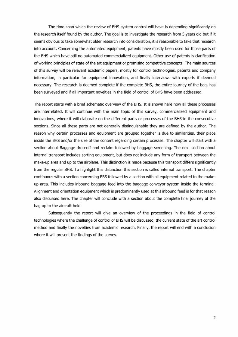
Figure 1 shows the complete baggage handling process in a typical modern large airport hub
[5], showing all processes form the highest level. Left of the dotted line is public space, right of the
dotted line is secured space not accesible by non-authorized people. Security, meaning minimization
of chance of potentially hazardeous human interference with the baggage such as the placement of
explosives, is especially important after inbound screening. Each block represents a separate
subsystem of the BHS. The blue blocks represent outbound flow and the red blocks inbound. With
‘Transport over tarmac’ and ‘Transport into/out of the airplane’ there is no difference between
outbound and inbound except the direction of the flow.
Figure 1 The overall baggage handling process in a typical modern large airport [5].
The blocks represent different processes. Sorting is not represented in this figure as a separate
process but it belongs to transport in this case as mentioned before. The difference between small
and large airports is the flow of transferbaggage. In small airports the only option is to retrieve your
baggage as a passenger and re-enter it at the baggage drop-off. The storage facility, called the early
bag storage (EBS) is also non-existent since baggage is usually just stored at the make-up. Sometimes
baggage is manually put aside if necessary. Another difference is the size of the BHS. This has an
impact of the infrastructure of the BHS. Large BHS may have a loop where different parts of the BHS
can connect to. In this way different terminals can connect with different EBS and gates without the
need for a direct connection between all of them. Amsterdam Schiphol (AMS) for instance calls it the
backbone since it is the main transport line [6]. Another typical feature of large airports are the long
distances. Large distances demand high velocities to be able to to achieve short connection times and
short drop-off to airplane times. These high velocities are only achieved by state of the art equipment.
Internal Transport (within terminal building)
Baggage drop-off
Screening
Storage(EBS)
Make-upTransport over
tarmacTransport into the airplane
Transport out of the airplane
Transport over tarmac
Baggage feed into the internal transport system
Reclaim Screening(optional)

4
3. Baggage handling equipment
This chapter will show a state of the art equipment overview where it tries to give a comparison between
current applied and commercially available automated technologies. Each section will start with a brief
introduction of the subject followed by a functional diagram of the (sub) system under observation to
provide the insight in the functions linked to the processes which are to be automated. The main focus
will be on the operation of the relevant equipment. Moreover, the (dis)advantages of the relevant
equipment and a comparison between them will be listed if applicable. Finally, if necessary,
representative specification will be given by figures delivered by equipment manufacturers. Most
sections will start with a clear definition to clarify, or in the case a good or appropriate one could not be
found with a description by the author.
It is important to distinguish two different terms, automation and mechanisation. Automation can be
defined as: ‘the technique, method, or system of operating or controlling a process by highly automatic
means, as by electronic devices, reducing human intervention to a minimum’ [7] whereas mechanisation
merely means ‘to operate or perform by or as if by machinery’ [8]. From the first definition it can be
deduced that human involvement is not necessarily completely omitted. Especially on the tarmac some
equipment is deployed by humans but once in place it has the ability to work (partly) autonomous with
the aid of sensors. If any confusion on whether it would be automated or not might arise, the equipment
is still surveyed. Nowadays most of the modern equipment in BHS is automated. Some mechanisation
is still present however in even the most state of the art airports. The focus however remains solely on
automation.
3.1 Baggage drop-off and reclaim
Figure 2 Automated Baggage drop-off at Amsterdam Airport Schiphol (AMS) [9].
This section is divided in two parts. The first part will concern automated baggage drop-off systems,
such as illustrated in figure 2. The second part, which is considerably smaller, will elaborate on reclaim
systems.
Automated baggage drop-off systems
Description by author: Baggage drop-off refers to the drop-off process for excess baggage which is not
allowed to be taken into the passenger compartment of the aircraft. It is one of the entering points of
the BHS for baggage and the only one accessible to passengers.
5
The system is designed to interact with humans, which makes it a special part of the BHS and
only partly automated. The parts which are automated are the instructions to the passenger, the check
if the label is placed correctly and the check that the baggage has authorised weight, dimensions and
conveyability (round objects for instance are not conveyable). It also makes sure that there are no
humans or animals introduced into the baggage handling system.
The first patents related to Common Use Self-Service (CUSS) were filed in the late 1980’s [10].
After ten years, in the 1990’s, a patent was released for an automated bag drop-off (ABD) [11].
However, it is only recently, in the past decade that these innovations actually became reality. First
automated check-ins, later ABD were deployed in the past five years. Since the successful entrance of
low cost carriers into the air transport market, the industry realised that the best possible service was
not a must for most passengers. The increase of competition (low cost carriers and Middle East carriers)
also forced the airlines to cut down costs in all possible ways to be able to compete. It started with the
self-printing of the boarding card and after this was completely accepted by the passengers it was time
to start with automating the baggage drop-off process. Common Use Self-Service (CUSS) technologies
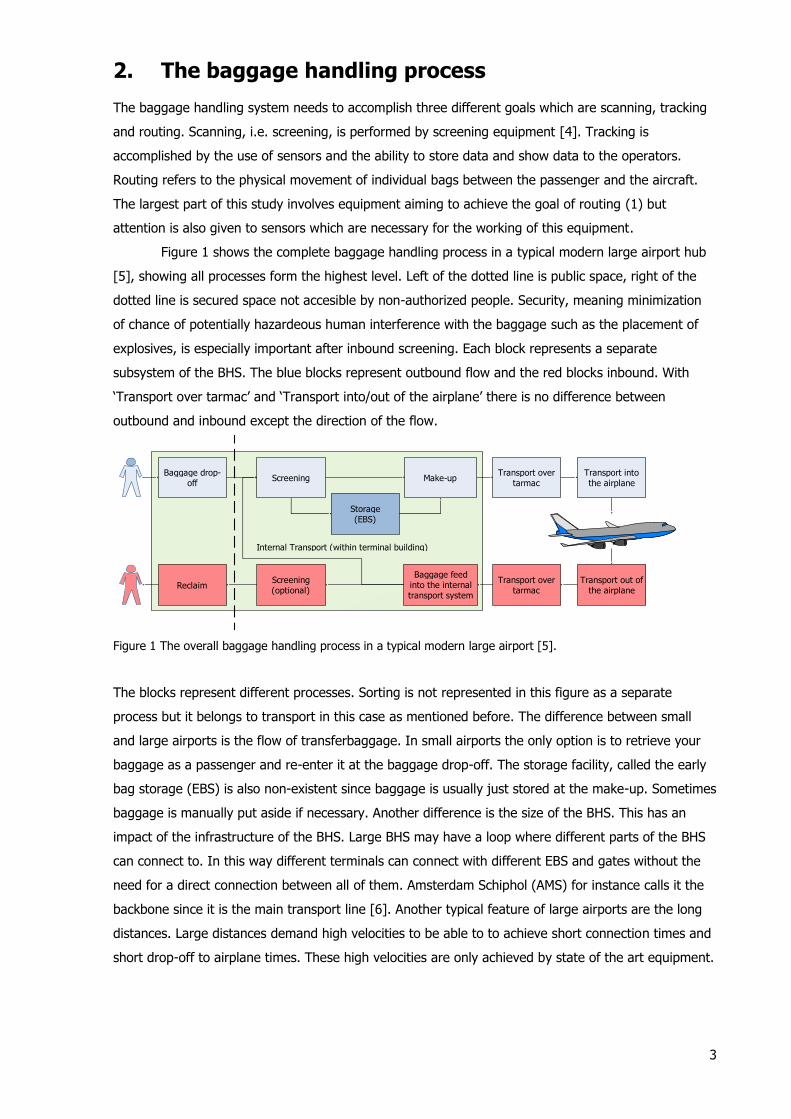
became a more frequent presence at airports. A typical ABD process, as present at AMS and
commercialized by BagDrop, will look as shown in Figure 3.
Figure 3 A typical ABD process as present at AMS, provided by BagDrop [12] [13].
The return loop is for additional pieces baggage a passenger may have. The warning is released after
it fails one of the checks. When observing other ABD systems, some differences might occur. In Paris
Charles de Gaulle for instance, the baggage label should be printed in advance at another CUSS system
[14].
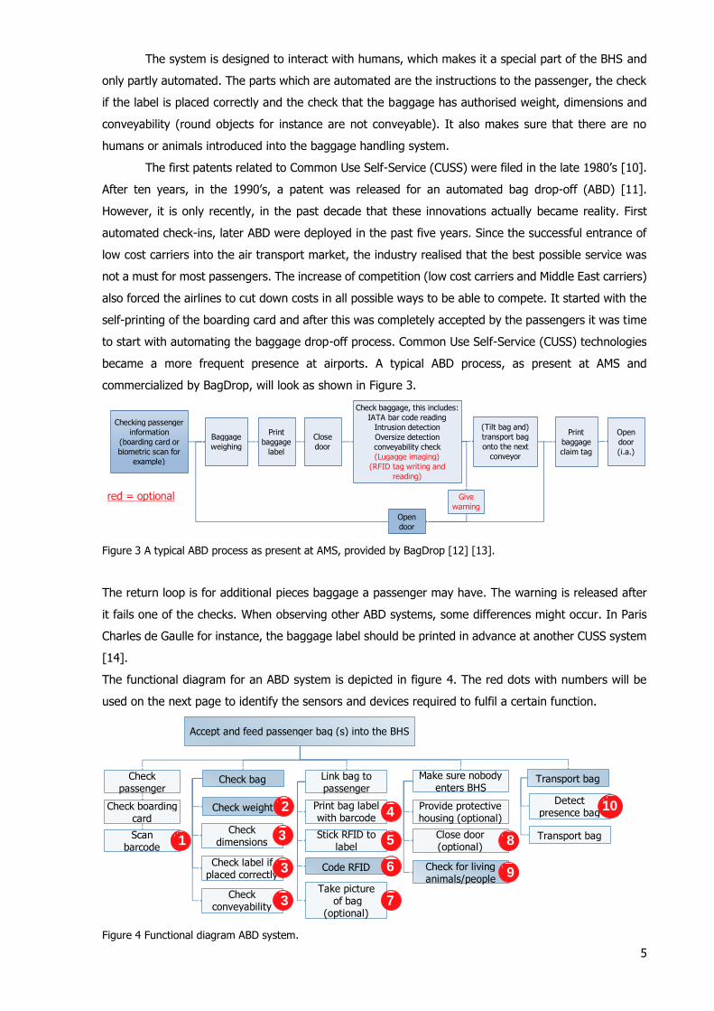
The functional diagram for an ABD system is depicted in figure 4. The red dots with numbers will be
used on the next page to identify the sensors and devices required to fulfil a certain function.
Figure 4 Functional diagram ABD system.
Checking passenger
information
(boarding card or
biometric scan for
example)
Check baggage, this includes:
IATA bar code reading
Intrusion detection
Oversize detection
conveyability check
(Lugagge imaging)
(RFID tag writing and
reading)
baggage
label
Baggage
weighing
(Tilt bag and)
transport bag
onto the next
conveyor
Close
door
Open
door
(i.a.)
Open
door
Give
warning
red = optional
baggage
claim tag
Accept and feed passenger bag (s) into the BHS
Make sure nobody enters BHS
Check dimensions
Transport bagCheck passenger
Check boarding card
Scan barcode
Link bag to passenger
Print bag label with barcode
Close door (optional)
Check for living animals/people
Check weight
Check bag
Code RFIDCheck label if placed correctly
Check conveyability
1
2
3
3
6
4
8
Provide protective housing (optional)
Stick RFID to label
5
Take picture of bag
(optional) 7
9
3
Detect presence bag
Transport bag
10
6
This equipment in particular contains a great amount of specific sensors and other devices. The
complete list, based on the red dots in figure 4, is as follows:
1. Barcode scanner to check the barcode [15];
2. Weight sensors for weight allowance, load cells for instance [13];
3. Measuring automation light can be used oversize detection and ‘conveyability check’ [15].
Oversize detection is also possible with Photoelectric cells [16].
4. Label printer [18];
5. Device which connects (sticks) the RFID tag to the label [18];
6. RFID reader for reading and writing RFID tags [15];
7. Camera for luggage imaging if applicable [18]. This image could be used later in the handling
or in case the bag would get lost it would provide useful extra information;
8. Safety light curtains ‘to prevent the risk of jamming or an accident when closing’[17];
9. 2D laser scanners can be used for intrusion detection [18] as well as infrared cameras, carbon
dioxide detectors or movement detectors [19] They cannot detect however the presence of
humans or animals within a suitcase. Load cell fluctuations can therefore be used to solve this
problem [13].
10. 2D lasers for detecting baggage on receiving conveyor for conveyance to the BHS. This is
necessary since ABD usually contain two conveyors if multiple baggage input is desired which
is often the case [15].
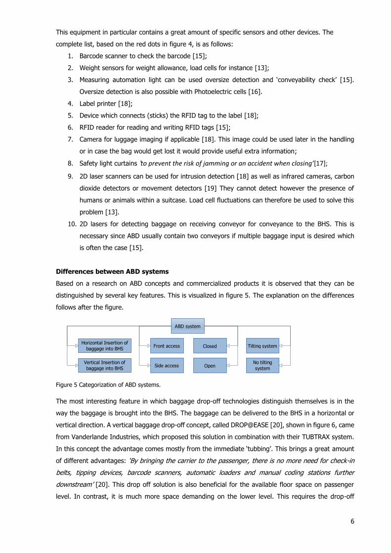
Differences between ABD systems
Based on a research on ABD concepts and commercialized products it is observed that they can be
distinguished by several key features. This is visualized in figure 5. The explanation on the differences
follows after the figure.
Figure 5 Categorization of ABD systems.
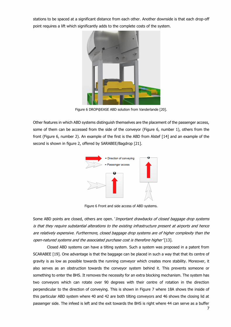
The most interesting feature in which baggage drop-off technologies distinguish themselves is in the
way the baggage is brought into the BHS. The baggage can be delivered to the BHS in a horizontal or
vertical direction. A vertical baggage drop-off concept, called DROP@EASE [20], shown in figure 6, came
from Vanderlande Industries, which proposed this solution in combination with their TUBTRAX system.
In this concept the advantage comes mostly from the immediate ‘tubbing’. This brings a great amount
of different advantages: ‘By bringing the carrier to the passenger, there is no more need for check-in
belts, tipping devices, barcode scanners, automatic loaders and manual coding stations further
downstream’ [20]. This drop off solution is also beneficial for the available floor space on passenger
level. In contrast, it is much more space demanding on the lower level. This requires the drop-off
ABD system
Front accessHorizontal Insertion of
baggage into BHS
Vertical Insertion of
baggage into BHSSide access
Tilting system
No tilting
system
Closed
Open
7
stations to be spaced at a significant distance from each other. Another downside is that each drop-off
point requires a lift which significantly adds to the complete costs of the system.
Figure 6 DROP@EASE ABD solution from Vanderlande [20].
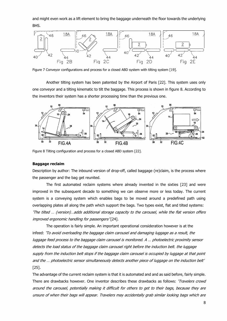
Other features in which ABD systems distinguish themselves are the placement of the passenger access,
some of them can be accessed from the side of the conveyor (Figure 6, number 1), others from the
front (Figure 6, number 2). An example of the first is the ABD from Alstef [14] and an example of the
second is shown in figure 2, offered by SARABEE/Bagdrop [21].
Figure 6 Front and side access of ABD systems.
Some ABD points are closed, others are open. ‘Important drawbacks of closed baggage drop systems
is that they require substantial alterations to the existing infrastructure present at airports and hence
are relatively expensive. Furthermore, closed baggage drop systems are of higher complexity than the
open-natured systems and the associated purchase cost is therefore higher’ [13].
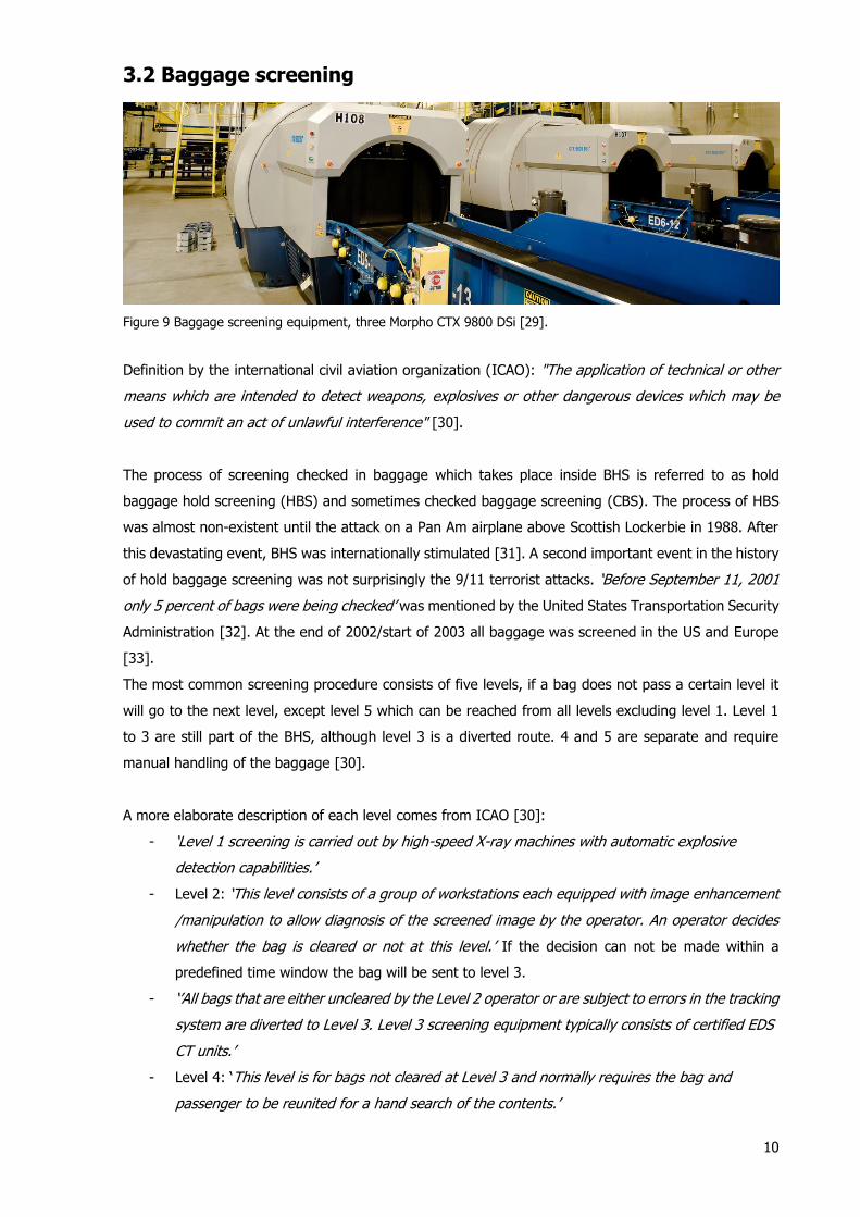
Closed ABD systems can have a tilting system. Such a system was proposed in a patent from
SCARABEE [19]. One advantage is that the baggage can be placed in such a way that that its centre of
gravity is as low as possible towards the running conveyor which creates more stability. Moreover, it
also serves as an obstruction towards the conveyor system behind it. This prevents someone or
something to enter the BHS. It removes the necessity for an extra blocking mechanism. The system has
two conveyors which can rotate over 90 degrees with their centre of rotation in the direction
perpendicular to the direction of conveying. This is shown in Figure 7 where 18A shows the inside of
this particular ABD system where 40 and 42 are both tilting conveyors and 46 shows the closing lid at
passenger side. The infeed is left and the exit towards the BHS is right where 44 can serve as a buffer
8
and might even work as a lift element to bring the baggage underneath the floor towards the underlying
BHS.
Figure 7 Conveyor configurations and process for a closed ABD system with tilting system [19].
Another tilting system has been patented by the Airport of Paris [22]. This system uses only
one conveyor and a tilting kinematic to tilt the baggage. This process is shown in figure 8. According to
the inventors their system has a shorter processing time than the previous one.
Figure 8 Tilting configuration and process for a closed ABD system [22].
Baggage reclaim
Description by author: The inbound version of drop-off, called baggage (re)claim, is the process where
the passenger and the bag get reunited.
The first automated reclaim systems where already invented in the sixties [23] and were
improved in the subsequent decade to something we can observe more or less today. The current
system is a conveying system which enables bags to be moved around a predefined path using
overlapping plates all along the path which support the bags. Two types exist, flat and tilted systems:
‘The tilted … (version)…adds additional storage capacity to the carousel, while the flat version offers
improved ergonomic handling for passengers’ [24].
The operation is fairly simple. An important operational consideration however is at the
infeed: ‘To avoid overloading the baggage claim carousel and damaging luggage as a result, the
luggage feed process to the baggage claim carousel is monitored. A … photoelectric proximity sensor
detects the load status of the baggage claim carousel right before the induction belt. the luggage
supply from the induction belt stops if the baggage claim carousel is occupied by luggage at that point
and the … photoelectric sensor simultaneously detects another piece of luggage on the induction belt’
[25].
The advantage of the current reclaim system is that it is automated and and as said before, fairly simple.
There are drawbacks however. One inventor describes these drawbacks as follows: ‘Travelers crowd
around the carousel, potentially making it difficult for others to get to their bags, because they are
unsure of when their bags will appear. Travelers may accidentally grab similar looking bags which are

9
not theirs. Such as system may lead to anxiety in travelers as they try to find their bags while hoping
that their bags are not lost’ [26].
Inventions tried to reduce or eliminate this problem with different solutions. The inventions which stay
within the scope of the research are listed here1:
- Current existing equipment but in addition notify the passenger about the arrival of their bag
(their bag in specific). This can be done with a personal indentifaction code automatically shown
on a public screen or with a message automatically send to a passengers personal mobile
communcation device [26]. This solution reduces the problem, although it remains possible to
take the wrong bag. An advantage of this solution is that it requires limited modifactions to the
current system which makes it cheap. Bag identification sensors would be required to be able
to notify the passenger.
- Block baggage unless passenger indentity is confirmed. Baggage is placed inside a locking
mechanism which releases the bag when the passenger indentifies himself [27]. This eliminates
the problem completely but has major drawbacks regarding costs and the fixed baggage spots
make this concept more space demanding.
That there is potential for improvement regarding the reclaim process is emphasized by Rein Scholing,
a logistic expert from Tebodin Consultants & Engineers: ‘Taking the passengers’ perspective, baggage
reclaim is clearly an underdeveloped area – would it not be logical to upgrade this function to the quality
level of the check-in process? ….The answer to all these questions is ‘yes’. There is ample potential for
improvements and time and cost savings. However, this requires true willingness of parties to cooperate
and rethink the baggage handling process together to develop into a system which can cope with ever-
growing baggage flows’ [28].
1 One other invention which aims to solve the problem, not mentioned in the text because it remains outside of the
scope of this survey is the following: Check passenger + bag combination when leaving the reclaim area [151]. A
viable option. It reduces any unintentional mistaken baggage. Since labels can be switched baggage weight can be
checked to minimize the chance of stolen baggage. The downside of this system is that passengers are delayed
when leaving the area.
10
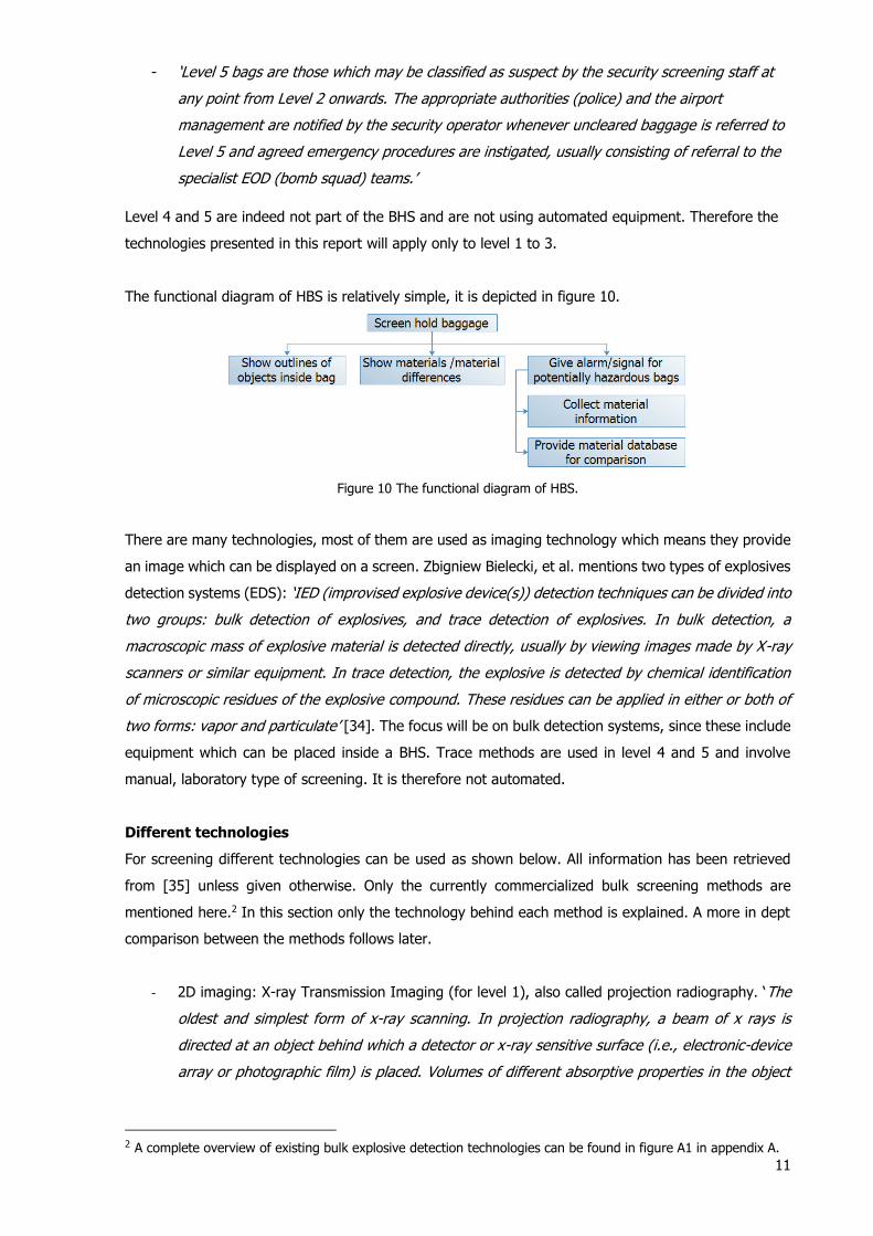
3.2 Baggage screening
Figure 9 Baggage screening equipment, three Morpho CTX 9800 DSi [29].
Definition by the international civil aviation organization (ICAO): "The application of technical or other
means which are intended to detect weapons, explosives or other dangerous devices which may be
used to commit an act of unlawful interference" [30].
The process of screening checked in baggage which takes place inside BHS is referred to as hold
baggage hold screening (HBS) and sometimes checked baggage screening (CBS). The process of HBS
was almost non-existent until the attack on a Pan Am airplane above Scottish Lockerbie in 1988. After
this devastating event, BHS was internationally stimulated [31]. A second important event in the history
of hold baggage screening was not surprisingly the 9/11 terrorist attacks. ‘Before September 11, 2001
only 5 percent of bags were being checked’ was mentioned by the United States Transportation Security
Administration [32]. At the end of 2002/start of 2003 all baggage was screened in the US and Europe
[33].
The most common screening procedure consists of five levels, if a bag does not pass a certain level it
will go to the next level, except level 5 which can be reached from all levels excluding level 1. Level 1
to 3 are still part of the BHS, although level 3 is a diverted route. 4 and 5 are separate and require
manual handling of the baggage [30].
A more elaborate description of each level comes from ICAO [30]:
- ‘Level 1 screening is carried out by high-speed X-ray machines with automatic explosive
detection capabilities.’
- Level 2: ‘This level consists of a group of workstations each equipped with image enhancement
/manipulation to allow diagnosis of the screened image by the operator. An operator decides
whether the bag is cleared or not at this level.’ If the decision can not be made within a
predefined time window the bag will be sent to level 3.
- ‘’All bags that are either uncleared by the Level 2 operator or are subject to errors in the tracking
system are diverted to Level 3. Level 3 screening equipment typically consists of certified EDS
CT units.’
- Level 4: ‘This level is for bags not cleared at Level 3 and normally requires the bag and
passenger to be reunited for a hand search of the contents.’
11
- ‘Level 5 bags are those which may be classified as suspect by the security screening staff at
any point from Level 2 onwards. The appropriate authorities (police) and the airport
management are notified by the security operator whenever uncleared baggage is referred to
Level 5 and agreed emergency procedures are instigated, usually consisting of referral to the
specialist EOD (bomb squad) teams.’
Level 4 and 5 are indeed not part of the BHS and are not using automated equipment. Therefore the
technologies presented in this report will apply only to level 1 to 3.
The functional diagram of HBS is relatively simple, it is depicted in figure 10.
Figure 10 The functional diagram of HBS.
There are many technologies, most of them are used as imaging technology which means they provide
an image which can be displayed on a screen. Zbigniew Bielecki, et al. mentions two types of explosives
detection systems (EDS): ‘IED (improvised explosive device(s)) detection techniques can be divided into
two groups: bulk detection of explosives, and trace detection of explosives. In bulk detection, a
macroscopic mass of explosive material is detected directly, usually by viewing images made by X-ray
scanners or similar equipment. In trace detection, the explosive is detected by chemical identification
of microscopic residues of the explosive compound. These residues can be applied in either or both of
two forms: vapor and particulate’ [34]. The focus will be on bulk detection systems, since these include
equipment which can be placed inside a BHS. Trace methods are used in level 4 and 5 and involve
manual, laboratory type of screening. It is therefore not automated.
Different technologies
For screening different technologies can be used as shown below. All information has been retrieved
from [35] unless given otherwise. Only the currently commercialized bulk screening methods are
mentioned here.2 In this section only the technology behind each method is explained. A more in dept
comparison between the methods follows later.
- 2D imaging: X-ray Transmission Imaging (for level 1), also called projection radiography. ‘The
oldest and simplest form of x-ray scanning. In projection radiography, a beam of x rays is
directed at an object behind which a detector or x-ray sensitive surface (i.e., electronic-device
array or photographic film) is placed. Volumes of different absorptive properties in the object
2 A complete overview of existing bulk explosive detection technologies can be found in figure A1 in appendix A.
12
absorb and scatter the incident x rays to different degrees, causing an x ray shadow to be cast
on the detecting surface. This shadow pattern is the x-ray image.’
- 2D imaging: X-ray Backscatter Imaging. ‘“Backscatter” consists of waves that are reflected back
from an obstacle. In backscatter imaging, x rays are beamed at a target object and a sensor
co-located with the beam source records reflected (backscattered) waves.’
- 2.5D imaging: Stereoscopic X-ray (for level 1), 3D impression from Transmission X-ray
information;
- Full 3D imaging: Computed Tomography (CT) X-ray. With this method ’a hollow tube that
surrounds the bag. The X-ray mechanism revolves slowly around it, bombarding it with X-rays
and recording the resulting data. The CT scanner uses all of this data to create a very detailed
tomogram (slice) of the bag.’ It is a complex, time-consuming and expensive technology and
therefore mostly used at level 3) [36] [37];
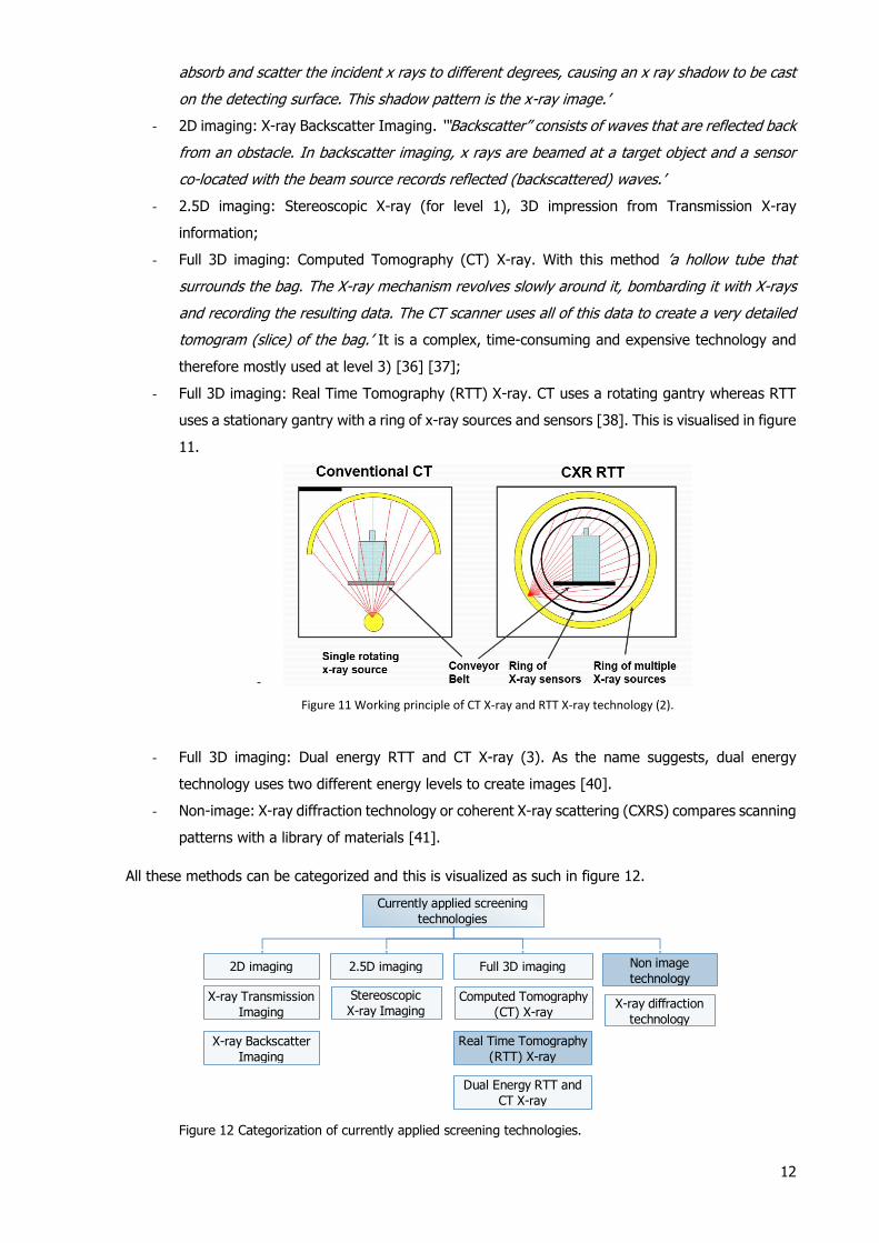
- Full 3D imaging: Real Time Tomography (RTT) X-ray. CT uses a rotating gantry whereas RTT
uses a stationary gantry with a ring of x-ray sources and sensors [38]. This is visualised in figure
11.
-
Figure 11 Working principle of CT X-ray and RTT X-ray technology (2).
- Full 3D imaging: Dual energy RTT and CT X-ray (3). As the name suggests, dual energy
technology uses two different energy levels to create images [40].
- Non-image: X-ray diffraction technology or coherent X-ray scattering (CXRS) compares scanning
patterns with a library of materials [41].
All these methods can be categorized and this is visualized as such in figure 12.
Figure 12 Categorization of currently applied screening technologies.
Currently applied screening
technologies
2D imaging 2.5D imaging Non image
technologyFull 3D imaging
X-ray Transmission
Imaging
X-ray Backscatter
Imaging
Stereoscopic
X-ray ImagingComputed Tomography
(CT) X-ray
Dual Energy RTT and
CT X-ray
Real Time Tomography
(RTT) X-ray
X-ray diffraction
technology

13
As for the 2D techniques, the most commonly applied technique for baggage screening is transmission
X-ray. In contrast to backscatter it is a certainty that all concealed objects are more or less visible and
the image is sharper (objects have sharper definitions) than that of backscatter [42]. However, in certain
cases, transmission X-ray can result in such high complexity images that can barely be readably or some
details vanish in the total complexity of the image. In such cases, backscatter might give more valuable
information [43]. Moreover, backscatter shows better results with organic and plastic materials. This is
clearly visible in figure 13 where a plastic pistol on the right is clearly more visible with backscatter
imaging. Both technologies are complementary and are therefore preferably combined.
Figure 13 Transmission (a) and Backscatter (b) comparison [44].
Since full 3D imaging has been too expensive and to slow in the past to use at level one, conventional
2D X-ray has usually been used at that particular level. The results of this conventional X-ray however
are less clear and will therefore result in more declined baggage, baggage which has eventually to pass
through level 3 equipment which increases the processing time of the bag. Nowadays more advanced
full 3D imaging systems called RTT X-ray are able to reach higher throughputs, equal to 2D X-ray at
lower prices compared to conventional CT X-ray which make them a viable option for level 1 and level
2 screening. The main difference between CT and RTT is the gantry as mentioned before which allows
higher throughput but it is also less costly regarding operational costs and service costs due to a smaller
amount of moving parts [37] [45].
Dual energy technology which can be applied to both conventional CT as to RTT offers to
possibility to retrieve both atomic number information and density information, instead of only density
information. Both measurements can be used to improve the knowledge regarding the materials inside
a bag. In addition, Ying, et al. mentioned the following: ‘For example, water and the explosive ANFO
(Ammonium Nitrate and fuel oil) can have similar physical densities. However, they differ significantly
in effective atomic numbers. Therefore, water and ANFO can be better discriminated from each other
by a dual energy CT scanner. It has also been shown on non-CT-based x-ray systems that using both
atomic number and density measurements for explosive detection can achieve a lower false alarm rate
than using density measurements alone’ [39].
X-ray diffraction is a different method which is used in combination with CT or RTT equipment
to decrease false alarm rates. It identifies material based on its material composition by comparing x-
ray scatter spectra with those of substance samples from a library [46].
Both X-ray diffraction and backscatter are used only in addition to one of the other methods to
decrease false alarm rates. In itself they are not sufficient.
14
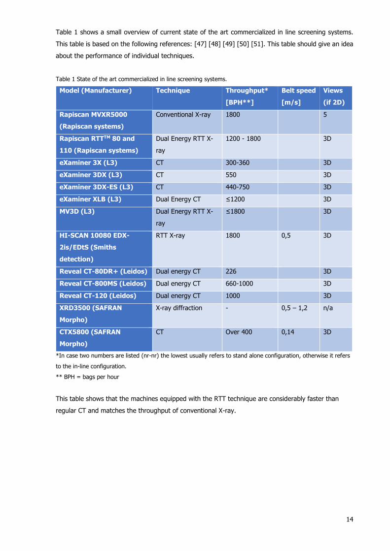
Table 1 shows a small overview of current state of the art commercialized in line screening systems.
This table is based on the following references: [47] [48] [49] [50] [51]. This table should give an idea
about the performance of individual techniques.
Table 1 State of the art commercialized in line screening systems.
Model (Manufacturer) Technique Throughput*
[BPH**]
Belt speed
[m/s]
Views
(if 2D)
Rapiscan MVXR5000
(Rapiscan systems)
Conventional X-ray 1800 5
Rapiscan RTTTM 80 and
110 (Rapiscan systems)
Dual Energy RTT X-
ray
1200 - 1800 3D
eXaminer 3X (L3) CT 300-360 3D
eXaminer 3DX (L3) CT 550 3D
eXaminer 3DX-ES (L3) CT 440-750 3D
eXaminer XLB (L3) Dual Energy CT ≤1200 3D
MV3D (L3) Dual Energy RTT X-
ray
≤1800 3D
HI-SCAN 10080 EDX-
2is/EDtS (Smiths
detection)
RTT X-ray 1800 0,5 3D
Reveal CT-80DR+ (Leidos) Dual energy CT 226 3D
Reveal CT-800MS (Leidos) Dual energy CT 660-1000 3D
Reveal CT-120 (Leidos) Dual energy CT 1000 3D
XRD3500 (SAFRAN
Morpho)
X-ray diffraction - 0,5 – 1,2 n/a
CTX5800 (SAFRAN
Morpho)
CT Over 400 0,14 3D
*In case two numbers are listed (nr-nr) the lowest usually refers to stand alone configuration, otherwise it refers
to the in-line configuration.
** BPH = bags per hour
This table shows that the machines equipped with the RTT technique are considerably faster than
regular CT and matches the throughput of conventional X-ray.

15
3.3 Internal transport
Figure 14 The BEUMER autover®, an independent carrier system (ICS) [52].
Description by author: Transport refers to the general displacement of baggage which is required all
over the BHS. This displacement is necessary to get a bag from its initial drop-off point to its final
destination. More elaborately, displacement can mean horizontal displacement, vertical displacement
or diverting.
Nowadays there is a large variety in transport equipment. Horizontal transport is the most
prevalent process in BHS, since it is required to cover the distances inside a BHS. Vertical transport
can be used throughout the BHS. Vertical distances can be covered using regular horizontal
transportation equipment when the equipment is place under an inclined direction. However, for
confined spaces or if limitation of space is desired dedicated equipment can be used to perform
vertical transport. Baggage diversion is required for both redundancy and sortation purposes and this
process may take place throughout the BHS. The basic functional diagram of baggage transport is
shown in figure 15.
Figure 15 The functional diagram of baggage transport.
This section will start with a discussion about the main transport systems currently in practice,
including a thorough comparison. Afterwards this sections elaborates on how these systems process
bags and which sensors and communication technologies are used in order to do so. This sections
ends with vertical transport and sortation which are processes which require special attention due to
the dedicated equipment used for these processes.
Transport baggage
Divert baggageTransport baggage horizontally/vertically
Divert baggage horizontally/verticallyMove baggage
Track location baggageRetrieve information path/destination bag(streams)
Check if bag has reached divertion point
Know current position divertion equipment
Perform divertion
16
Different transport systems
In BHS two main transport concepts currently exist: conventional systems (conveyors) and advanced
systems like ICS which uses destination coded vehicles (DCV). Both have their own equipment and
technologies. ICS is improving on one important requirement for new and future BHS which is
throughput [53]. Throughput is important to ensure minimum connection times (MCT) in large hub
airports and inbound travel time of baggage which is important regarding customer satisfaction. The
speed (which influences throughput) of ICS can be considerably higher as will be shown in a
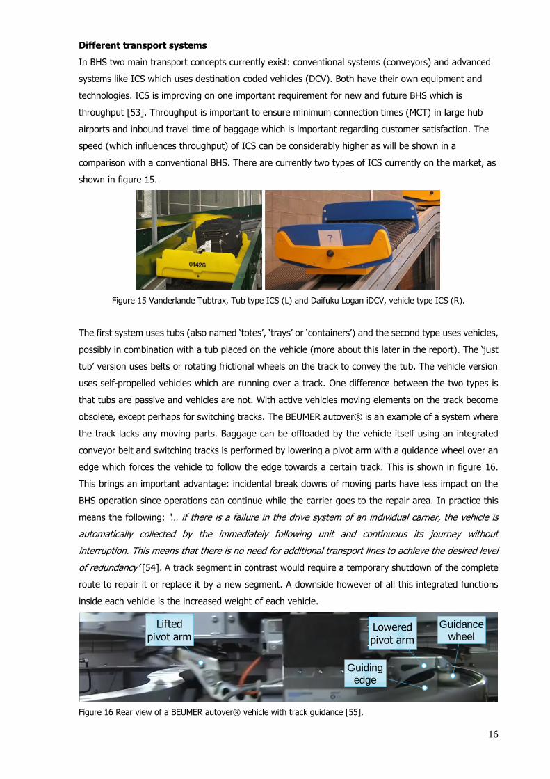
comparison with a conventional BHS. There are currently two types of ICS currently on the market, as
shown in figure 15.
Figure 15 Vanderlande Tubtrax, Tub type ICS (L) and Daifuku Logan iDCV, vehicle type ICS (R).
The first system uses tubs (also named ‘totes’, ‘trays’ or ‘containers’) and the second type uses vehicles,
possibly in combination with a tub placed on the vehicle (more about this later in the report). The ‘just
tub’ version uses belts or rotating frictional wheels on the track to convey the tub. The vehicle version
uses self-propelled vehicles which are running over a track. One difference between the two types is
that tubs are passive and vehicles are not. With active vehicles moving elements on the track become
obsolete, except perhaps for switching tracks. The BEUMER autover® is an example of a system where
the track lacks any moving parts. Baggage can be offloaded by the vehicle itself using an integrated
conveyor belt and switching tracks is performed by lowering a pivot arm with a guidance wheel over an
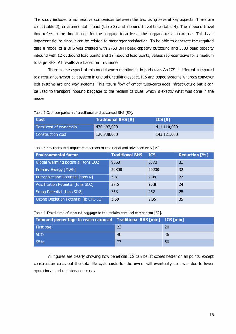
edge which forces the vehicle to follow the edge towards a certain track. This is shown in figure 16.
This brings an important advantage: incidental break downs of moving parts have less impact on the
BHS operation since operations can continue while the carrier goes to the repair area. In practice this
means the following: ‘… if there is a failure in the drive system of an individual carrier, the vehicle is
automatically collected by the immediately following unit and continuous its journey without
interruption. This means that there is no need for additional transport lines to achieve the desired level
of redundancy’ [54]. A track segment in contrast would require a temporary shutdown of the complete
route to repair it or replace it by a new segment. A downside however of all this integrated functions
inside each vehicle is the increased weight of each vehicle.
Figure 16 Rear view of a BEUMER autover® vehicle with track guidance [55].
Lowered pivot arm
Guidance wheel
Guiding edge
Lifted pivot arm

17
The second difference is the mode of control. A tub will have no on-board intelligence which means the
track routes the tub whereas a vehicle in contrast does has an embedded controller. An example of an
operation of a vehicle based ICS is explained by Alstef, supplier of the BEUMER autover® system:
‘Each autoca® fills its mission independantly from the others and waits for the next order. The autoca®
sets its speed according to the track section that can be straight, a curve or a junction. Each autoca®
is in communication with the autoca® ahead and rear in order to keep a safe distance, and to get into
the traffic without stopping the main flow. The autoca® itself selects the best route according to the
traffic. The central controller sends orders to the autoca®’ [56].
As already mentioned it is possible to combine a vehicle with a tub. The ‘Bagtrax’ system from
Vanderlande allows the container (top part) to be removed from the wheel-supported frame in order to
use this system efficiently in combination with an EBS. This system is for instance used in AMS [57].
Figure 17, as retrieved from [58], illustrates this concept.
Figure 17 Vanderlande concept for separation of container and wheel-supported frame.
The categorization of baggage transport systems can be visualised as in figure 18.
Figure 18 Categorization of transport systems for baggage.
Very recently, the mechanical and electrical engineering consultancy firm Swanson Rink did an extensive
study regarding the benefits of ICS compared to conventional BHS [59]. An important advantage of ICS
is that vertical storage in for example an EBS becomes much more feasible since all tubs are equipped
with RFID. With individual baggage RFID tagging this would introduce a significant difficulty since the
RFID placement is not fixed anymore which makes it harder to relocate the bag. EBS becomes also
probably more complicated and expensive without tubs.
Transport systems
Individual carrier system (ICS) Conveyor system
Vehicle version Combined version (vehicle and tub)
Tub version
18
The study included a numerative comparison between the two using several key aspects. These are
costs (table 2), environmental impact (table 3) and inbound travel time (table 4). The inbound travel
time refers to the time it costs for the baggage to arrive at the baggage reclaim carousel. This is an
important figure since it can be related to passenger satisfaction. To be able to generate the required
data a model of a BHS was created with 2750 BPH peak capacity outbound and 3500 peak capacity
inbound with 12 outbound load points and 18 inbound load points, values representative for a medium
to large BHS. All results are based on this model.
There is one aspect of this model worth mentioning in particular. An ICS is different compared
to a regular conveyor belt system in one other striking aspect. ICS are looped systems whereas conveyor
belt systems are one way systems. This return flow of empty tubs/carts adds infrastructure but it can
be used to transport inbound baggage to the reclaim carousel which is exactly what was done in the
model.
Table 2 Cost comparison of traditional and advanced BHS [59].
Cost Traditional BHS [$] ICS [$]
Total cost of ownership 470,497,000 411,110,000
Construction cost 120,738,000 143,121,000
Table 3 Environmental impact comparison of traditional and advanced BHS [59].
Environmental factor Traditional BHS ICS Reduction [%]
Global Warming potential [tons CO2] 9560 6570 31
Primary Energy [MWh] 29800 20200 32
Eutrophication Potential [tons N] 3.81 2.99 22
Acidification Potential [tons SO2] 27.5 20.8 24
Smog Potential [tons SO2] 363 262 28
Ozone Depletion Potential [lb CFC-11] 3.59 2.35 35
Table 4 Travel time of inbound baggage to the reclaim carousel comparison [59].
Inbound percentage to reach carousel Traditional BHS [min] ICS [min]
First bag 22 20
50% 40 36
95% 77 50
All figures are clearly showing how beneficial ICS can be. It scores better on all points, except
construction costs but the total life cycle costs for the owner will eventually be lower due to lower
operational and maintenance costs.

19
Table 5 shows an overview of different commercialized ICS provided by the market.
Table 5 An overview of different commercial ICS.
System (Manufacturer) Type Speed [m/s] Source
BTS (Daifuku Logan) Tub 10 (max), 1,5 (curve/merge/
diverge/incline), 1,2 (discharge)
[60]
iDCV (Daifuku Logan) Vehicle 10 (max) [61]
Tubtrax (Vanderlande) Tub 6 (max) [62]
Bagtrax (Vanderlande) Combined 14 (max) [62]
CrisBag® (BEUMERGROUP) Tub 10 (max), 3000 totes/h [63]
BEUMER autover®(BEUMERGROUP) Vehicle 10 (max) [64]
This table shows the speed difference between tub and vehicle type is in general not that big. Compared
to conveyor systems which reach around 3 m/s [65] the speed difference is much larger however.
Tracking, checking and communication
As mentioned earlier tracking is one the key tasks of a BHS. Each bag location must be able to be
tracked throughout the BHS and at the same the exact position is required for diversion inside the BHS.
Barcode identification for tracking individual bags throughout a conveyor system is still common.
Recently however identification technology has been replaced or extended throughout the industry with
a more modern radio frequency identification (RFID). The benefits include a better accuracy and no
requirement for a clear line of sight [66]. An example of a RFID implementation and how the information
from the bag is used, is given by Fred Marten, a controls engineering manager at Vanderlande
Industries, when talking about the new Terminal 3 at McCarran International Airport in Las Vegas:
‘When a bag is placed on the conveyor, it passes under a reader that interrogates the RFID inlay's
unique identifier and forwards that ID number to … VIBES (Vanderlande control software)… residing on
the airport's database. The software manages baggage-handling-based data (for example, which
luggage is destined for a particular flight), provides localized controls for the conveyor system's
programmable logic controller (PLC)—to send instructions to the conveyor system indicating the
direction in which a bag should be routed, for instance—and manages the RFID read data’[65]. The
exact position of baggage on the belt is determined with additional equipment and methods: ‘…baggage
is tracked using ‘photo-eye’ sensors and belt speed to determine its location’ [67]. Typically, each
conveyor section is equipped with a photoelectric sensor (also referred to as photo electric cell or PEC).
‘This sensor projects a beam of light across the conveyor and is projected back using a reflector. When
this beam is broken, the tracking system knows that a bag is present at this location’ [4]. Further
tracking of the bag can be done either by the conveyor speed or by the use of a tachometer in the
rollers. The last option adds more accuracy but is more expensive and adds at the same time more
complexity to the system. In general these PEC’s can fulfil a broad range of functions (source is [68]
unless listed otherwise):
20
1. Overheight detection. Placed at a certain height at input sections of the BHS. Some input
sections however can use dedicated equipment to check for both overheight and conveyability
such as the BAGCHECK from Vanderlande or the built in sensors of an ABD.
2. Overlength detection. Placed at input sections of the BHS. The blocking time of the sensor signal
determines the bag length.
3. Cascade stop. If a bag runs past the PEC while the downstream conveyor is stopped, the
resulting signal blocks the conveyor.
4. Jam detection. This is present right in front of potential jam sections such as power turns, incline
conveyors and merges. If the signal is blocked for a certain amount of time, while the conveyor
is still running, it will stop the conveyor and the downstream conveyor as well.
5. Merge and sort control. Placed in front of merge sections and sortation devices. If a bag runs
past the PEC, the conveyor can either be stopped or the sortation equipment can be activated.
6. Collision detection. Mounted for example on vertical sortation equipment, specifically below the
infeed conveyor and below the upper outfeed conveyor. This should prevent something (or less
likely, someone) is crushed between the moving infeed conveyor and outfeed conveyor [69].
7. Energy saving. Conveyors can be stopped if baggage is not detected for a predetermined time.
New baggage will reactivate the conveyors [70].
For ICS the use of radio frequency for communicating unique bag information is very common. In
independent vehicle type carrier systems such as the BEUMER autover® communication needs to go
both ways since the carrier needs to know where to discharge or how to route itself which eliminates
barcode technology as an option since barcode technology can merely be used for one way
communication. The BHS communicates however only with the carrier so the information of bag and
carrier need to be merged together when the bag is loaded inside the carrier [71]. The following text
explains as an example how SEAP Automation GmbH, the company responsible for the control and
electrical engineering at Frankfurt airport, implemented communication equipment and sensors to
realise automation:‘The proximity switches are used to detect the oncoming transport boxes and their
transport chassis. The chassis is made out of metal and it carries a transport box made of synthetic
material, which contains one piece of luggage at a time. While a barcode is attached to the boxes, the
chassis is equipped with reflectors that allow an easy identification on the basis of the so called
Hamming-Code. The Hamming-Code is a linear block code that allows an automatic error correction,
which makes the machine very reliable. In front of the switches, a barcode scanner reads the barcode
attached to the boxes, while an optical code-reader station reads the reflector's code which is attached
to the outside of the chassis. In addition to the optical sensors that are integrated into the reading
stations, SEAP Automation used light curtains, light sensors and barriers for the transport route. While
the light curtains are used to check the luggage overhang and the height control, the other optical
sensors ensure a smooth operation of the system by recording every oncoming transport box and giving
the signal to accelerate or slowdown the box if needed’ [72].
Before tubs are stacked or accept bags they an ‘empty check’ is required: ‘Before a robot
transports the baggage tubs to the inspection station…2D laser scanners control the tubs. The scanners
check that the tubs are empty and not stacked inside each other and that the tub elements required for
21
further transport are available’ [73]. At this inspection station the inspection of tubs can also be fully
automated: ‘The … 3D vision sensor checks the baggage tubs for deviations from target values. This
makes it possible to detect damage to baggage tubs, such as the tiniest cracks, deformations and
contour changes, and to replace defective tubs quickly’ [74].’Such techniques can also be applied to
vehicle type ICS.
In Frankfurt airport the carriers are passive. With ICS using self-propelled vehicles however the
number of sensors can decrease significantly. In the BEUMER autover® system for instance each carrier
uses radio frequency to a far greater extent: ‘Each autoca® is in communication with the autoca®
ahead and rear in order to keep a safe distance, and to get into the traffic without stopping the main
flow’ [56].
Vertical transport
For space reasons it might be better to transport baggage in a straight vertical way. For this several
options exist. One option is a continuous vertical conveyor (CVC). This can be either a lift system or a
spiral conveyor. Discontinuous systems like discontinuous lifts are available but would not be able to
meet the required throughput demand in most of the cases. One exception is at the drop-off where for
instance where a single drop off point is combined with one lift. This is shown in figure 6. Separate
discontinuous lifts for BHS are offered by Transnorm, whose lift accelerate with 3 m/s2 and are able to
reach a top speed of 2 m/s [75]. Throughput depends obviously on the elevation height. A larger
distance will decrease the throughput which makes the system less suitable for bigger height
differences.
Not much companies offer lift systems dedicated to BHS, most probably since the product is
very complex and the demand low. NERAK offers their solution for both trays and loose baggage with
a capacity up to 1400 units per hour for height differences up to 40 meter [76]. This system is shown
in figure A2 in appendix A. Both configurations are shown there. Logan ksec offers also a similar product
with capacities >400 bags/hour [77]. The major disdvantage of the system is the price, due to limited
amount of suppliers and the complexity. Other problems are capacity, unflexible loading, reltively large
footprint of lift and lift regulations [78] .The capacity is indeed low, when observing for instance the
values for modern screening equipment. This means the lift system could become a bottleneck.
A different solution for upward vertical transport is the spiral conveyor. This system uses a
slowly inclining belt revolting upwards around a supporting member. The drawbacks of this system are
the large footprint compared to a lift system and the system remains quite complex and thus expensive.
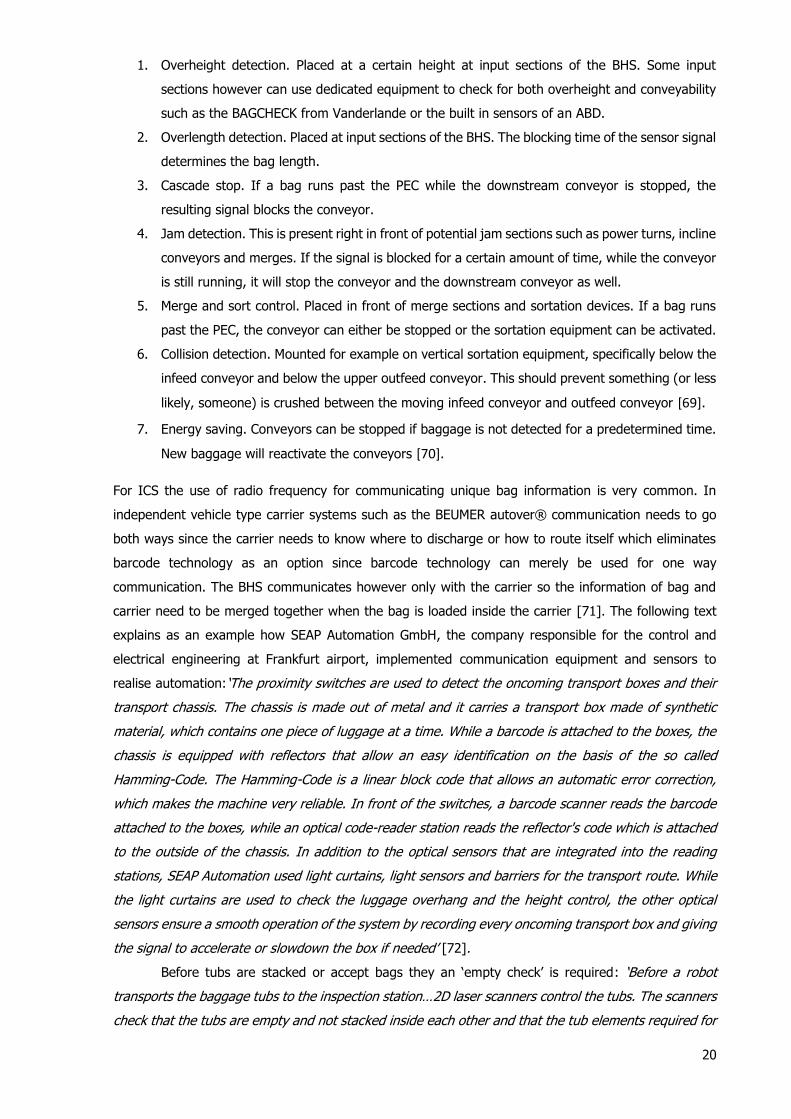
Moreover, loose baggage could cause problems as a result of mounted wheels. Tubs have a very large
area and a low friction coefficient. A DCV system with tubs or demountable containers (Vanderlande
Bagtrax) can therefore not be combined with a friction belt but chain push systems as visualised in
figure 19 could solve this problem although they are not commercially available. An extra advantage is
that such a system could significantly increase the incline. A company offering spiral conveyors suitable
for BHS is Ambaflex [79].
22
Figure 19 Visualisation of a push chain system.
With a speed of up to 1.5 m/s [79] for friction based systems a throughput of around 5400 units of
loose baggage per hour could be feasible in theory. Even with half this throughput this easily exceeds
the throughput of lift systems and screening systems.
The last solution for downward only transportation is the spiral chute. This is a very simple
cheap solution but speed control of bags is impossible. This is not necessarily a bad thing since baggage
can be blocked and released at the bottom after the position of the bag is known again by the use of
scanning equipment. Spiral chutes are offered by many companies like Transnorm [80] or Daifuku Logan
[81].
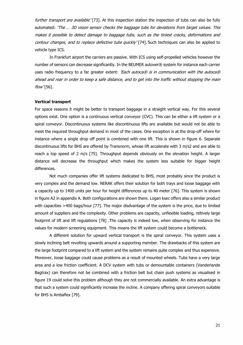
To summarize, the vertical transport equipment can be categorized as shown in figure 20.
Figure 20 Overview of vertical transport equipment.
Due to the significant disadvantages of lifts and spiral conveyors vertical transport are to be avoided as
much as possible. DCV systems can use inclining and declining track segments instead is space allows.
Sortation
Sortation can happen anywhere in the BHS. For instance at the screening area to separate cleared and
non-cleared baggage. Sortation equipment can also be used to divert baggage for redudancy purposes.
For concentional conveyor belts two types of sortation ways exist, the horizontal and the vertical
method. Pushers/horizontal diverters perform horizontal sorting and vertical sortation units perform
vertical sorting. DCV/ICS systems, however require their own dedicated equipment and methods.
Finally, integrated sorters, specifically designed for sorting, can be used in case sortation is very
predominant in a compact area and in case capacity requirements are high. This could be the case at
the make-up area. Integrated sorters will be discussed first. Note however, that ICS systems may have
their own integrated sorting equipment as well.
TubPushing/support element
Vertical transport
Both directions Downward only
Continuous Discontinuous Spiral chute
Discontinuous
lift
Continuous vertical
conveyors (CVC)
Spiral conveyors
23
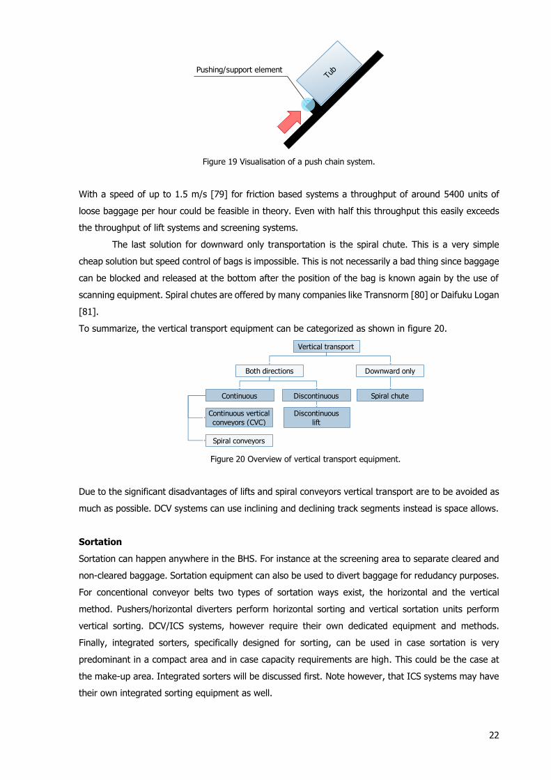
Integrated sortation systems exist in three types. The first type uses moveable pushing blocks
(Figure 21A), a system where blocks (black in Figure 21A) slide over a flat transport surface to push the
baggage off track. The second uses built in cross mounted conveyors (Figure 21B) and the third uses
tilting trays (Figure 21C) to slide the baggage off by the use of gravity.
Figure 21 Three types of integrated sortation systems.
A disadvantage of the first system (Figure 21A) is that it allows the system to sort baggage only to one
side since the moveable pushing block is always obstructing one side.
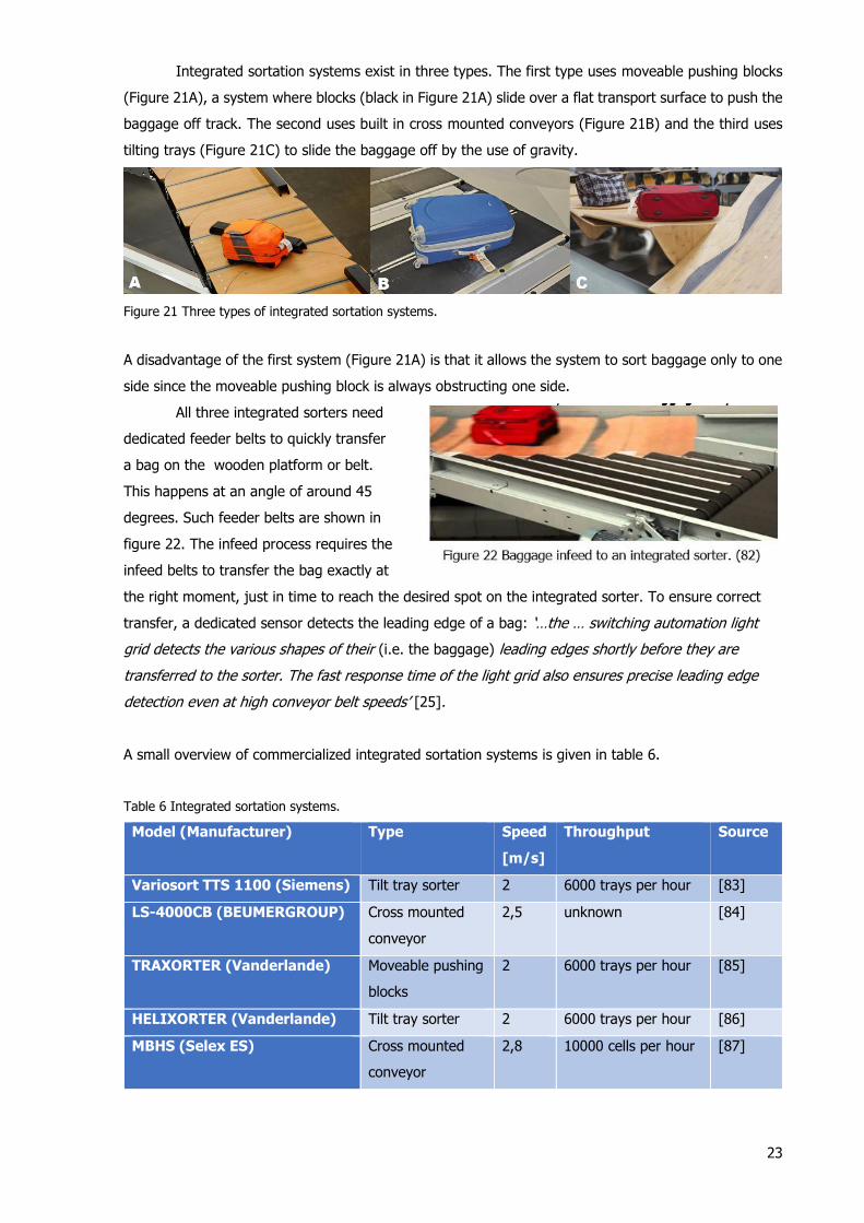
All three integrated sorters need
dedicated feeder belts to quickly transfer
a bag on the wooden platform or belt.
This happens at an angle of around 45
degrees. Such feeder belts are shown in
figure 22. The infeed process requires the
infeed belts to transfer the bag exactly at
the right moment, just in time to reach the desired spot on the integrated sorter. To ensure correct
transfer, a dedicated sensor detects the leading edge of a bag: ‘…the … switching automation light
grid detects the various shapes of their (i.e. the baggage) leading edges shortly before they are
transferred to the sorter. The fast response time of the light grid also ensures precise leading edge
detection even at high conveyor belt speeds’ [25].
A small overview of commercialized integrated sortation systems is given in table 6.
Table 6 Integrated sortation systems.
Model (Manufacturer) Type Speed
[m/s]
Throughput Source
Variosort TTS 1100 (Siemens) Tilt tray sorter 2 6000 trays per hour [83]
LS-4000CB (BEUMERGROUP) Cross mounted
conveyor
2,5 unknown [84]
TRAXORTER (Vanderlande) Moveable pushing
blocks
2 6000 trays per hour [85]
HELIXORTER (Vanderlande) Tilt tray sorter 2 6000 trays per hour [86]
MBHS (Selex ES) Cross mounted
conveyor
2,8 10000 cells per hour [87]

24
Currently, based on table 6, the largest throughput available on the market is delivered by cross
mounted conveyor systems. This observation is confirmed by John Sarineck, chief sales officer for
Beumer Group, when speaking about material handling in general: ‘When you require volumes of 15,000
units per hour, a cross-belt sorter is more accurate, can service more destinations and operate at higher
speeds than other types of equipment’ [88]. If this throughput is actually necessary depends obviously
on the specific situation.
Horizontal sortation is conventional conveyor belts. Three different types of equipment exist as
shown in figure 23 on the next page. Push plates or pushers (Figure 23A), diverter arms (Figure 23B)
and diverter belts (Figure 23C). Pushers push the baggage off track by hitting the bag perpendicular to
the track. Diverter arms and diverter belts direct the baggage off track. Diverter belts have a working
belt, diverter arms do not. Pushers have a downside that hitting a bag is much rougher compared to
blocking a bag’s path to divert it. This could potentially lead to damaged bags/object in bags.
Figure 23 Different types of sortation equipment.
Table 7 shows an overview of this equipment offered by baggage handling equipment suppliers.
Table 7 Sortation equipment for baggage conveyor belts.
Equipment (Manufacturer) Type Throughput [BPH] Source
Vertibelt (Vanderlande) Diverter arm 1200 [89]
Parallel Pusher (Vanderlande) Push plate 1800 [89]
HCD (Vanderlande) Diverter belt 3600 [89]
Model 656A (Daifuku Logan) Diverter belt 1500 [90]
Diverter (Glidepath) Push plate 3300* [91]
Powered plough (Glidepath) Diverter belt 3600 [91]
Flip action pusher (GT) Diverter arm 2660 [92]
Super Pusher (G&T conveyor company) Push plate 4800 [93]
*3600 (in double configuration)
It can be concluded that there is a large range in terms of throughput. Push plates can potentially reach
very high throughput rates, however with the disadvantage of rough handling as mentioned before.

25
Vertical sortation is currently only done in one way which is by the use of a lower mounted inclined belt
which can be put in a declined state and a higher mounted declined belt which can be lifted in a neutral
or inclined state or vice versa (An example of such vertical sortation unit can be found in the appendix,
figure A3). By using two conveyors sortation speed can be increased. A (brief) overview of vertical
sortation units provided by BHS equipment suppliers is shown in table 8.
Table 8. Vertical sortation units.
Model (Manufacturer) Throughput Source
Vertisorter (Vanderlande) 1800 bags per hour [94]
VERTICAL SORTER (G&T) 2100 bags per hour [95]
Vertipath (Glidepath) 2100 bags per hour [96]
Model 595ML/MS (Daifuku Logan) 2700 bags per hour/1500 trays per hour [97] [60]
The last sortation equipment under consideration is equipment dedicated to ICS. Once again a
differentiation can be made between tub type ICS and car type ICS. The discharge of tubs is done by
tilting a part of the track which results in a gravity forced discharge of the baggage. An increase of
tilting elements increases system throughput but it increases system complexity. Figure 24 shows how
this discharge is done. 24A shows discharge with many elements, 24B shows discharge with one large
single element. Tub discharge can be performed at 2.5 m/s with a throughput of 2400 BPH [98] up to
3000 BPH [98]. 20C shows an integrated sorter which is able to discharge baggage from tubs. A small
edge prevents sliding of the tub. Tubs always need to be reorientated before they can be transferred
upon a platform. Once the reorientation emplacement is reached the bag is lifted at two side and turned
by around 45 degrees. The rest of the transfer process goes similar as that required for integrated
sorters for loose baggage [100].
Figure 24 Baggage discharge from tub type ICS.
Discharge of vehicle type ICS occurs differently. Two methods are currently in operation. Vanderlande
makes the vehicle drive over a tilted track which releases the bag by gravitational force (Figure 25A).
BEUMERGROUP and Daifuku Logan have a cross mounted conveyor installed on their carriers (Figure
25B). Discharge with cross mounted conveyors has a throughput limit of 2400 BPH [64] which is
comparable to tub discharge but both stay behind in comparison to the fastest methods realised with
conveyor belts.
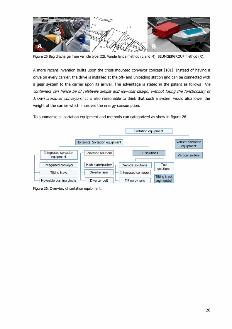
26
Figure 25 Bag discharge from vehicle type ICS, Vanderlande method (L and M), BEUMGERGROUP method (R).
A more recent invention builts upon the cross mounted conveyor concept [101]. Instead of having a
drive on every carrier, the drive is installed at the off- and unloading station and can be connected with
a gear system to the carrier upon its arrival. The advantage is stated in the patent as follows ‘The
containers can hence be of relatively simple and low-cost design, without losing the functionality of
known crossover conveyors.’ It is also reasonable to think that such a system would also lower the
weight of the carrier which improves the energy consumption.
To summarize all sortation equipment and methods can categorized as show in figure 26.
Figure 26. Overview of sortation equipment.
Horizontal Sortation equipment
ICS solutionsConveyor solutionsIntegrated sortation
equipment
Integrated conveyor
Tilting by railsTilting track
segment(s)
Vehicle solutions Tub
solutionsIntegrated conveyor
Tilting trays
Moveable pushing blocks
Push plate/pusher
Diverter arm
Diverter belt
Vertical Sortation
equipment
Vertical sorters
Sortation equipment

27
3.4 Early baggage storage
Figure 27 An EBS installed by Vanderlande at terminal 5 at London Heathrow.
A Definition of EBS came from the first patented EBS: ‘This invention relates to the art of systems for
the discrete storage and retrieval of baggage on demand. In the preferred embodiment, the invention
is a system for the storage of "early" bags. As used herein, the term "early bag" means a baggage item
that enters the baggage handling system of an airport prior to the time it can be received at the make-
up area of its departing flight’ [102].
Before the automated EBS existed, ‘early bags’ where put aside on carts until the make-up
area was released for the concerning flight. The manual labour involved in this process was significant
and the costs resulting from this labour were therefore also high. In the 90’s an automated EBS was
invented. It was initially designed as a very long continuously running endless conveyor system with
an infeed and one or multiple exit sections depending on the size of the airport [102]. Halfway the
00’s it was recognized that this system required a lot of conveying equipment and was very space
demanding. Therefore a stacked fixed storage was invented. According to the invention: ‘In an
advantageous further development of the invention it may be provided that the mechanical means
provided for handling the early baggage at each intermediate storage place for early baggage are in
each case constructed as robots that arrange the early baggage in stationary stacks, whereby the
mechanical means used at each intermediate storage place are preferably multi-axle robots.’ [103].
This method is currently still applied to modern day large baggage handling systems. However lane
storage still remains an option for smaller airports. Large EBS systems applied in large airports such as
Paris CDG or Dubai Airport can store over 5000 bags [104] [105].
The functional diagram of an EBS is depicted in figure 28.
Figure 28 The functional diagram of an EBS.
Store baggage
Receive baggage Retrieve baggage
Retrieve location of
bag
Move bag out of
storage area
Find free storage
location
Move bag to free
storage location
Store information
location bag
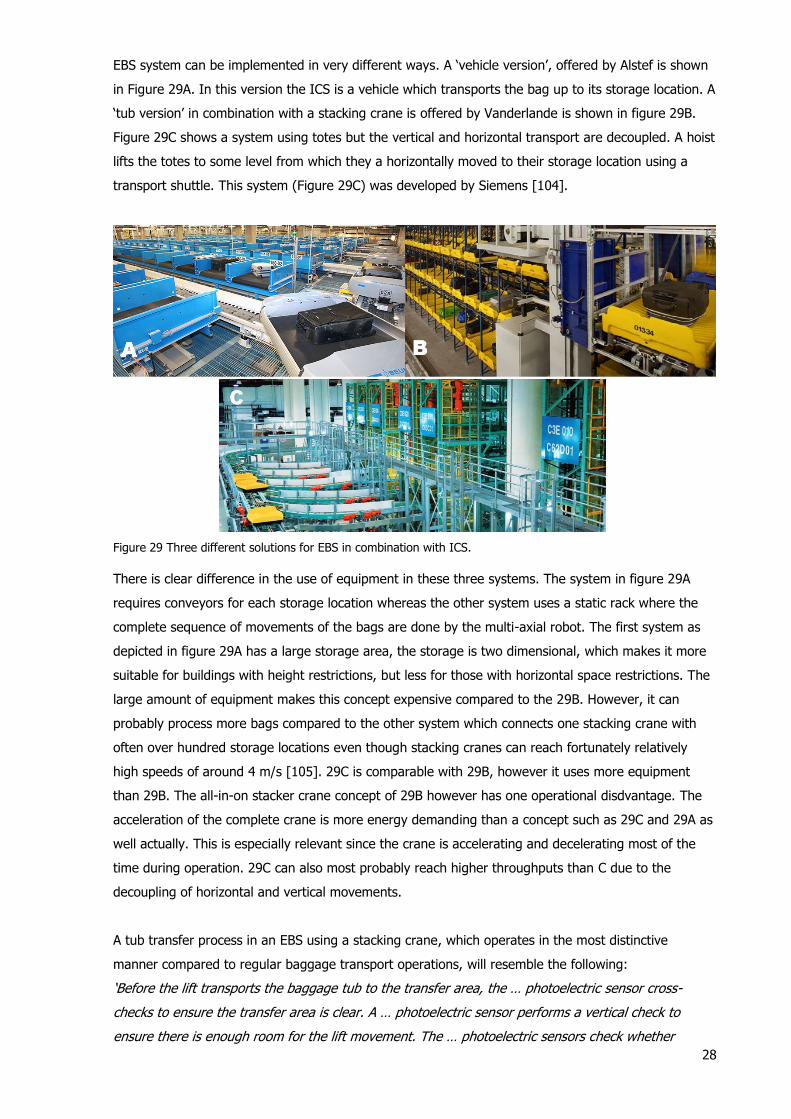
28
EBS system can be implemented in very different ways. A ‘vehicle version’, offered by Alstef is shown
in Figure 29A. In this version the ICS is a vehicle which transports the bag up to its storage location. A
‘tub version’ in combination with a stacking crane is offered by Vanderlande is shown in figure 29B.
Figure 29C shows a system using totes but the vertical and horizontal transport are decoupled. A hoist
lifts the totes to some level from which they a horizontally moved to their storage location using a
transport shuttle. This system (Figure 29C) was developed by Siemens [104].
Figure 29 Three different solutions for EBS in combination with ICS.
There is clear difference in the use of equipment in these three systems. The system in figure 29A
requires conveyors for each storage location whereas the other system uses a static rack where the
complete sequence of movements of the bags are done by the multi-axial robot. The first system as
depicted in figure 29A has a large storage area, the storage is two dimensional, which makes it more
suitable for buildings with height restrictions, but less for those with horizontal space restrictions. The
large amount of equipment makes this concept expensive compared to the 29B. However, it can
probably process more bags compared to the other system which connects one stacking crane with
often over hundred storage locations even though stacking cranes can reach fortunately relatively
high speeds of around 4 m/s [105]. 29C is comparable with 29B, however it uses more equipment
than 29B. The all-in-on stacker crane concept of 29B however has one operational disdvantage. The
acceleration of the complete crane is more energy demanding than a concept such as 29C and 29A as
well actually. This is especially relevant since the crane is accelerating and decelerating most of the
time during operation. 29C can also most probably reach higher throughputs than C due to the
decoupling of horizontal and vertical movements.
A tub transfer process in an EBS using a stacking crane, which operates in the most distinctive
manner compared to regular baggage transport operations, will resemble the following:
‘Before the lift transports the baggage tub to the transfer area, the … photoelectric sensor cross-
checks to ensure the transfer area is clear. A … photoelectric sensor performs a vertical check to
ensure there is enough room for the lift movement. The … photoelectric sensors check whether

29
enough room is available on both sides of the shuttle. Protruding luggage or baggage tubs must not
impede the shuttle’s movement. Prior to depositing luggage in early baggage storage, the …
photoelectric sensor checks whether the respective bay is free. Only then can the baggage tub be
temporarily stored in early baggage storage. The optical data transmission system … exchanges data
between the shuttle and early baggage storage’s management system using infrared light. This
eliminates the need for fieldbus cabling. A … linear measurement sensor determines the position of
the shuttle using bar code tapes. They are affixed horizontally on one side in early baggage storage.
Inductive proximity sensors detect the end positions of the lifting forks on the load-carrying unit. This
information is needed to position the luggage shuttle’s lifting forks’ [25].
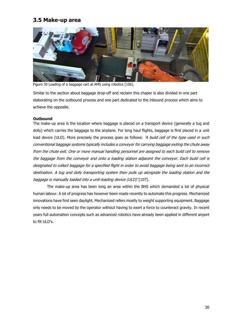
30
3.5 Make-up area
Figure 30 Loading of a baggage cart at AMS using robotics [106].
Similar to the section about baggage drop-off and reclaim this chaper is also divided in one part
elaborating on the outbound process and one part dedicated to the inbound process which aims to
achieve the opposite.
Outbound
The make-up area is the location where baggage is placed on a transport device (generally a tug and
dolly) which carries the baggage to the airplane. For long haul flights, baggage is first placed in a unit
load device (ULD). More precisely the process goes as follows: ‘A build cell of the type used in such
conventional baggage systems typically includes a conveyor for carrying baggage exiting the chute away
from the chute exit. One or more manual handling personnel are assigned to each build cell to remove
the baggage from the conveyor and onto a loading station adjacent the conveyor. Each build cell is
designated to collect baggage for a specified flight in order to avoid baggage being sent to an incorrect
destination. A tug and dolly transporting system then pulls up alongside the loading station and the
baggage is manually loaded into a unit-loading device (ULD)’ [107].
The make-up area has been long an area within the BHS which demanded a lot of physical
human labour. A lot of progress has however been made recently to automate this progress. Mechanized
innovations have first seen daylight. Mechanized refers mostly to weight supporting equipment. Baggage
only needs to be moved by the operator without having to exert a force to counteract gravity. In recent
years full automation concepts such as advanced robotics have already been applied in different airport
to fill ULD’s.
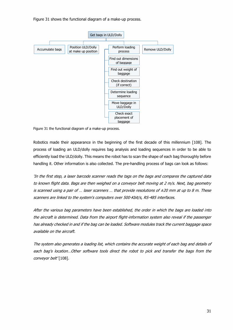
31
Figure 31 shows the functional diagram of a make-up process.
Figure 31 the functional diagram of a make-up process.
Robotics made their appearance in the beginning of the first decade of this millennium [108]. The
process of loading an ULD/dolly requires bag analysis and loading sequences in order to be able to
efficiently load the ULD/dolly. This means the robot has to scan the shape of each bag thoroughly before
handling it. Other information is also collected. The pre-handling process of bags can look as follows:
‘In the first step, a laser barcode scanner reads the tags on the bags and compares the captured data
to known flight data. Bags are then weighed on a conveyor belt moving at 2 m/s. Next, bag geometry
is scanned using a pair of … laser scanners … that provide resolutions of ±20 mm at up to 8 m. These
scanners are linked to the system's computers over 500-Kbit/s, RS-485 interfaces.
After the various bag parameters have been established, the order in which the bags are loaded into
the aircraft is determined. Data from the airport flight-information system also reveal if the passenger
has already checked in and if the bag can be loaded. Software modules track the current baggage space
available on the aircraft.
The system also generates a loading list, which contains the accurate weight of each bag and details of
each bag's location…Other software tools direct the robot to pick and transfer the bags from the
conveyor belt’ [108].
Get bags in ULD/Dolly
Position ULD/Dolly
at make up position
Move baggage in
ULD/Dolly
Accumulate bags Remove ULD/Dolly
Find out dimensions
of baggage
Find out weight of
baggage
Check destination
(if correct)
Perform loading
process
Check exact
placement of
baggage
Determine loading
sequence
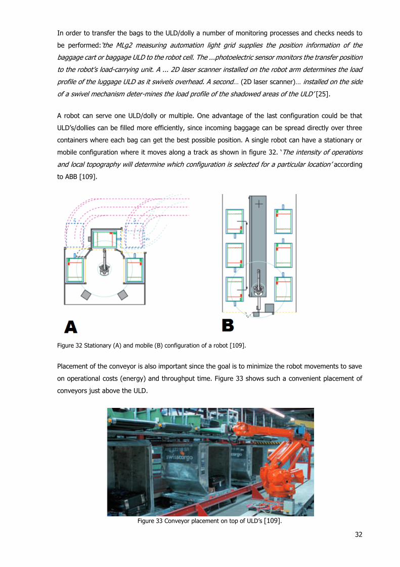
32
In order to transfer the bags to the ULD/dolly a number of monitoring processes and checks needs to
be performed:‘the MLg2 measuring automation light grid supplies the position information of the
baggage cart or baggage ULD to the robot cell. The ...photoelectric sensor monitors the transfer position
to the robot’s load-carrying unit. A ... 2D laser scanner installed on the robot arm determines the load
profile of the luggage ULD as it swivels overhead. A second… (2D laser scanner)… installed on the side
of a swivel mechanism deter-mines the load profile of the shadowed areas of the ULD’ [25].
A robot can serve one ULD/dolly or multiple. One advantage of the last configuration could be that
ULD’s/dollies can be filled more efficiently, since incoming baggage can be spread directly over three
containers where each bag can get the best possible position. A single robot can have a stationary or
mobile configuration where it moves along a track as shown in figure 32. ‘The intensity of operations
and local topography will determine which configuration is selected for a particular location’ according
to ABB [109].
Figure 32 Stationary (A) and mobile (B) configuration of a robot [109].
Placement of the conveyor is also important since the goal is to minimize the robot movements to save
on operational costs (energy) and throughput time. Figure 33 shows such a convenient placement of
conveyors just above the ULD.
Figure 33 Conveyor placement on top of ULD’s [109].
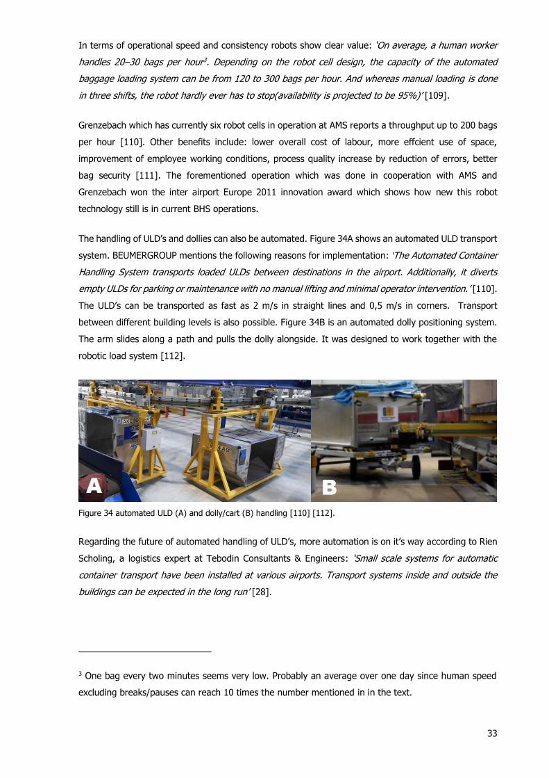
33
In terms of operational speed and consistency robots show clear value: ‘On average, a human worker
handles 20–30 bags per hour3. Depending on the robot cell design, the capacity of the automated
baggage loading system can be from 120 to 300 bags per hour. And whereas manual loading is done
in three shifts, the robot hardly ever has to stop(availability is projected to be 95%)’ [109].
Grenzebach which has currently six robot cells in operation at AMS reports a throughput up to 200 bags
per hour [110]. Other benefits include: lower overall cost of labour, more effcient use of space,
improvement of employee working conditions, process quality increase by reduction of errors, better
bag security [111]. The forementioned operation which was done in cooperation with AMS and
Grenzebach won the inter airport Europe 2011 innovation award which shows how new this robot
technology still is in current BHS operations.
The handling of ULD’s and dollies can also be automated. Figure 34A shows an automated ULD transport
system. BEUMERGROUP mentions the following reasons for implementation: ‘The Automated Container
Handling System transports loaded ULDs between destinations in the airport. Additionally, it diverts
empty ULDs for parking or maintenance with no manual lifting and minimal operator intervention.’ [110].
The ULD’s can be transported as fast as 2 m/s in straight lines and 0,5 m/s in corners. Transport
between different building levels is also possible. Figure 34B is an automated dolly positioning system.
The arm slides along a path and pulls the dolly alongside. It was designed to work together with the
robotic load system [112].
Figure 34 automated ULD (A) and dolly/cart (B) handling [110] [112].
Regarding the future of automated handling of ULD’s, more automation is on it’s way according to Rien
Scholing, a logistics expert at Tebodin Consultants & Engineers: ‘Small scale systems for automatic
container transport have been installed at various airports. Transport systems inside and outside the
buildings can be expected in the long run’ [28].
3 One bag every two minutes seems very low. Probably an average over one day since human speed
excluding breaks/pauses can reach 10 times the number mentioned in in the text.

34
Inbound
The inbound flow of baggage does not pass the make-up area. However, the infeed of baggage from
the dollies and tugs coming from arrivals represents a similar process but then reversed. ULD and carts
(loose baggage) must be emptied and feed into the internal BHS. This process has also been automated
in recent years. Although this could be potentially be performed by robotics other specialized equipment
has been invented for this job. The functional diagram of this process is shown in figure 35:
Figure 35 The functional diagram of the inbound empying process of ULD and carts.
Unloading equipment exist for both carts and ULD as pictured in figure 36. They tilt the the cart/ULD to
unload baggage. Sometimes unloading equipment can vibrate to force (stuck) baggage out. 36A and B
show a ULD unloading device from BEUMERGROUP [113]. It works for different type of ULD’s and is
capable of unloading 24 ULD’s per hour/900 bags per hour. 36C shows a cart unloader from Grenzebach
[114]. ‘Once the cart is positioned onto the platform, the equipment is tilted to 35°and the load-unit is
lifted along a moving belt. The bags can slight out of the cart layer by layer and are delivered either
directly to the passenger reclaim area or to the infeed of the baggage handling system.’ The system
should be able to unload 40 bags in two minutes and is also capable of unloading different types of
carts.
Figure 36 Automated unloading of ULD (A&B) and baggage cart (C) [113] [114].
Get bags out of ULD/Dolly and make them enter
the inbound conveyor system
Place ULD/Dolly at
offload position
Remove ULD/Dolly at
offload position
Remove baggage
from ULD/Dolly
Provide correct
orientation bagProvide correct
spacing bags
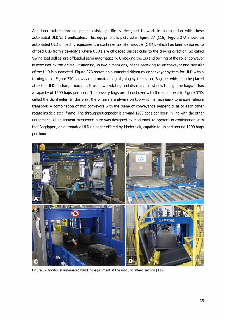
35
Additional automation equipment exist, specifically designed to work in combination with these
automated ULD/cart undloaders. This equipment is pictured in figure 37 [115]. Figure 37A shows an
automated ULD unloading equipment, a container transfer module (CTM), which has been designed to
offload ULD from side-dolly’s where ULD’s are offloaded perpedicular to the driving direction. So called
‘swing-bed dollies’ are offloaded semi-automatically. Unlocking the UD and turning of the roller conveyor
is executed by the driver. Positioning, in two dimensions, of the receiving roller conveyor and transfer
of the ULD is automated. Figure 37B shows an automated driven roller conveyor system for ULD with a
turning table. Figure 37C shows an automated bag aligning system called Bagliner which can be placed
after the ULD discharge machine. It uses two rotating and displaceable wheels to align the bags. It has
a capacity of 1200 bags per hour. If necessary bags are tipped over with the equipment in Figure 37D,
called the Upwheeler. In this way, the wheels are always on top which is necessary to ensure reliable
transport. A combination of two conveyors with the plane of conveyance perpendicular to each other
rotate inside a steel frame. The throughput capacity is around 1200 bags per hour, in line with the other
equipment. All equipment mentioned here was designed by Moderniek to operate in combination with
the ‘Bagtipper’, an automated ULD unloader offered by Moderniek, capable to unload around 1200 bags
per hour.
Figure 37 Additional automated handling equipment at the inbound infeed section [115].
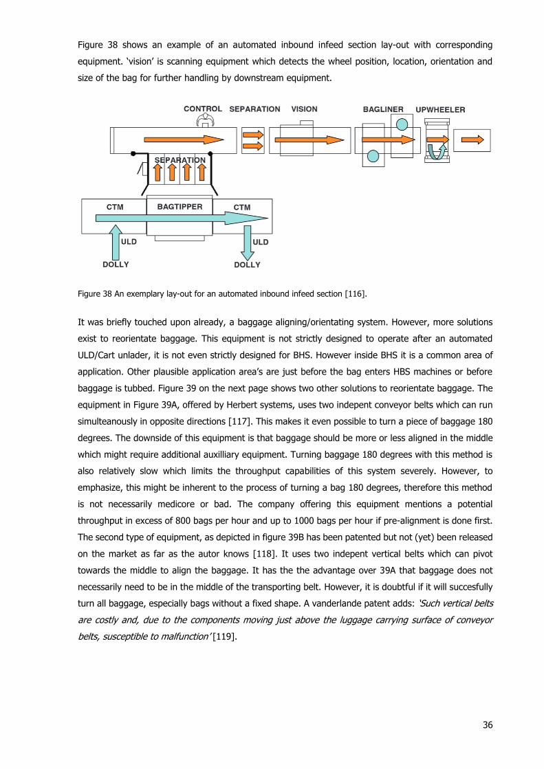
36
Figure 38 shows an example of an automated inbound infeed section lay-out with corresponding
equipment. ‘vision’ is scanning equipment which detects the wheel position, location, orientation and
size of the bag for further handling by downstream equipment.
Figure 38 An exemplary lay-out for an automated inbound infeed section [116].
It was briefly touched upon already, a baggage aligning/orientating system. However, more solutions
exist to reorientate baggage. This equipment is not strictly designed to operate after an automated
ULD/Cart unlader, it is not even strictly designed for BHS. However inside BHS it is a common area of
application. Other plausible application area’s are just before the bag enters HBS machines or before
baggage is tubbed. Figure 39 on the next page shows two other solutions to reorientate baggage. The
equipment in Figure 39A, offered by Herbert systems, uses two indepent conveyor belts which can run
simulteanously in opposite directions [117]. This makes it even possible to turn a piece of baggage 180
degrees. The downside of this equipment is that baggage should be more or less aligned in the middle
which might require additional auxilliary equipment. Turning baggage 180 degrees with this method is
also relatively slow which limits the throughput capabilities of this system severely. However, to
emphasize, this might be inherent to the process of turning a bag 180 degrees, therefore this method
is not necessarily medicore or bad. The company offering this equipment mentions a potential
throughput in excess of 800 bags per hour and up to 1000 bags per hour if pre-alignment is done first.
The second type of equipment, as depicted in figure 39B has been patented but not (yet) been released
on the market as far as the autor knows [118]. It uses two indepent vertical belts which can pivot
towards the middle to align the baggage. It has the the advantage over 39A that baggage does not
necessarily need to be in the middle of the transporting belt. However, it is doubtful if it will succesfully
turn all baggage, especially bags without a fixed shape. A vanderlande patent adds: ‘Such vertical belts
are costly and, due to the components moving just above the luggage carrying surface of conveyor
belts, susceptible to malfunction’ [119].
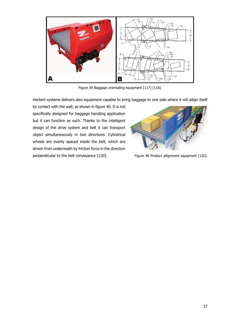
37
Figure 39 Baggage orientating equipment [117] [118].
Herbert systems delivers also equipment capable to bring baggage to one side where it will allign itself
by contact with the wall, as shown in figure 40. It is not
specifically designed for baggage handling application
but it can function as such. Thanks to the intelligent
design of the drive system and belt it can transport
object simultaneaously in two directions. Cylindrical
wheels are evenly spaced inside the belt, which are
driven from underneath by friction force in the direction
perpendicular to the belt conveyance [120]. Figure 40 Product allignment equipment [120].
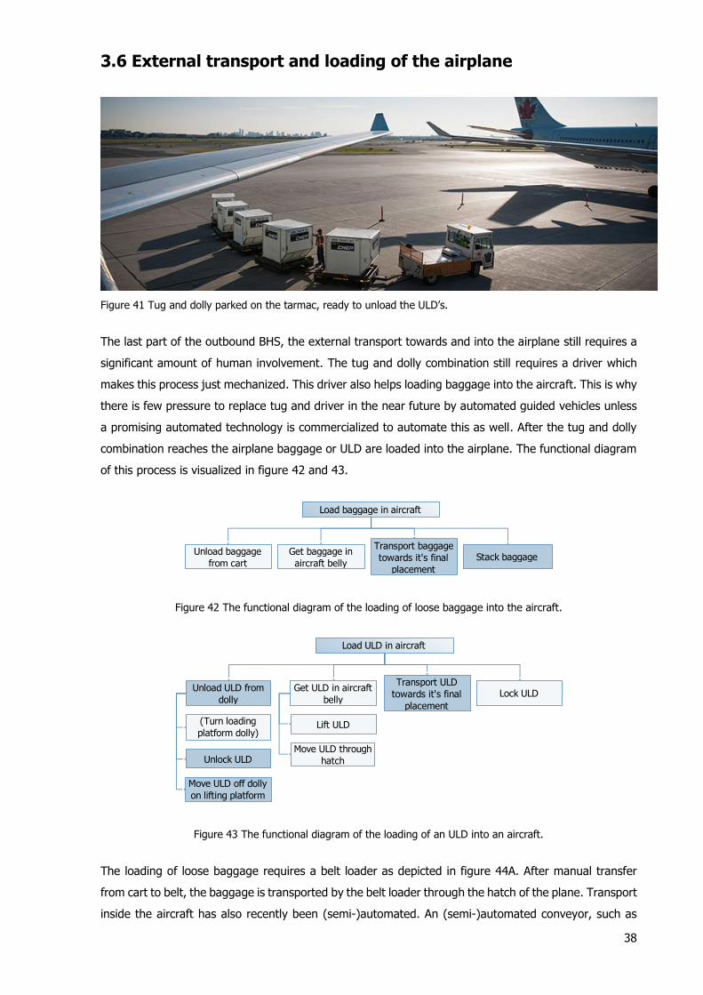
38
3.6 External transport and loading of the airplane
Figure 41 Tug and dolly parked on the tarmac, ready to unload the ULD’s.
The last part of the outbound BHS, the external transport towards and into the airplane still requires a
significant amount of human involvement. The tug and dolly combination still requires a driver which
makes this process just mechanized. This driver also helps loading baggage into the aircraft. This is why
there is few pressure to replace tug and driver in the near future by automated guided vehicles unless
a promising automated technology is commercialized to automate this as well. After the tug and dolly
combination reaches the airplane baggage or ULD are loaded into the airplane. The functional diagram
of this process is visualized in figure 42 and 43.
Figure 42 The functional diagram of the loading of loose baggage into the aircraft.
Figure 43 The functional diagram of the loading of an ULD into an aircraft.
The loading of loose baggage requires a belt loader as depicted in figure 44A. After manual transfer
from cart to belt, the baggage is transported by the belt loader through the hatch of the plane. Transport
inside the aircraft has also recently been (semi-)automated. An (semi-)automated conveyor, such as
Load baggage in aircraft
Unload baggage
from cart
Get baggage in
aircraft belly
Transport baggage
towards it's final
placement
Stack baggage
Load ULD in aircraft
Unload ULD from
dolly
Get ULD in aircraft
belly
Transport ULD
towards it's final
placement
Lock ULD
Lift ULD
Move ULD through
hatchUnlock ULD
Move ULD off dolly
on lifting platform
(Turn loading
platform dolly)

39
the one pictured in figure 44B and 44C transports the baggage up to the handler. At the end of the
conveyor, a small angled conveyor (loading head) lifts the baggage for optimal handling. An
advantageous feature of both products is that the conveyor part which goes inside the airplane is
extendable and fully retractable inside the belt loader. Figure 39B shows a design with rollers, offered
by Powerstow [121]. The conical shape of the rollers ensures baggage is centered towards the middle
and due to this shape , it is able to convey units up to 3 metre. The roller conveyor can support units
up to 300 kg with a throughput of 20 units (<1 metre) per minute. Figure 44C shows a different design
with small belt conveyor element instead of rollers and 39D a comparable but larger loading head. This
patented design, called RampSnake®, is offered by JBT Aerotech [122] [123]. It is able to lift pieces
up to 400 kg and serves approximately 15-18 bags per minute [124].
Figure 44 Equipment for baggage loading into aircrafts [121] [122] [123 [124].
One other product, which takes a different approach than the previous ones, is an in-built system, which
means it is permanently installed. The product, called Sliding Carpet® and shown in figure 45, consists
of a poly-coated Kevlar® conveyor belt which can move baggage through the airplane hold. Baggage
can be stacked against a fake wall, which can be moved simultaneously with the belt to free up space
for more luggage. With this system, the handler can stay in place, near the hatch of the airplane hold.
When unloading, baggage is again moved towards the opening of the airplane hold [125].
Figure 45 Sliding Carpet®, an integrated loading system [125].
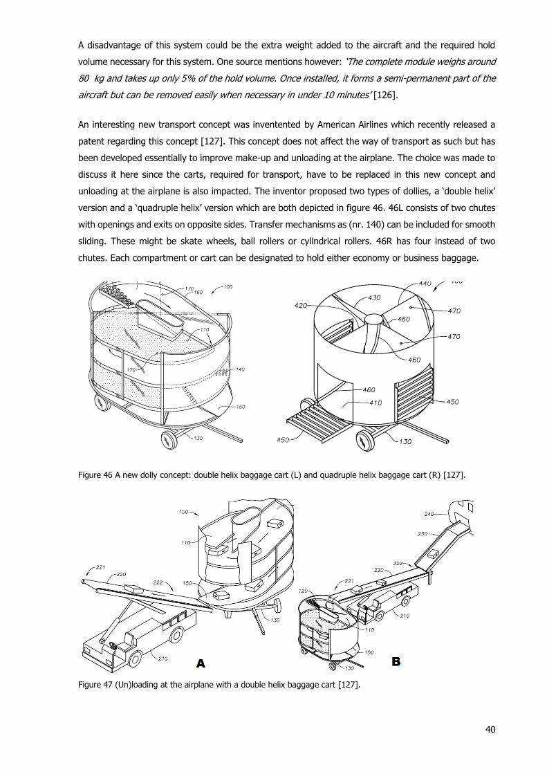
40
A disadvantage of this system could be the extra weight added to the aircraft and the required hold
volume necessary for this system. One source mentions however: ‘The complete module weighs around
80 kg and takes up only 5% of the hold volume. Once installed, it forms a semi-permanent part of the
aircraft but can be removed easily when necessary in under 10 minutes’ [126].
An interesting new transport concept was inventented by American Airlines which recently released a
patent regarding this concept [127]. This concept does not affect the way of transport as such but has
been developed essentially to improve make-up and unloading at the airplane. The choice was made to
discuss it here since the carts, required for transport, have to be replaced in this new concept and
unloading at the airplane is also impacted. The inventor proposed two types of dollies, a ‘double helix’
version and a ‘quadruple helix’ version which are both depicted in figure 46. 46L consists of two chutes
with openings and exits on opposite sides. Transfer mechanisms as (nr. 140) can be included for smooth
sliding. These might be skate wheels, ball rollers or cylindrical rollers. 46R has four instead of two
chutes. Each compartment or cart can be designated to hold either economy or business baggage.
Figure 46 A new dolly concept: double helix baggage cart (L) and quadruple helix baggage cart (R) [127].
Figure 47 (Un)loading at the airplane with a double helix baggage cart [127].
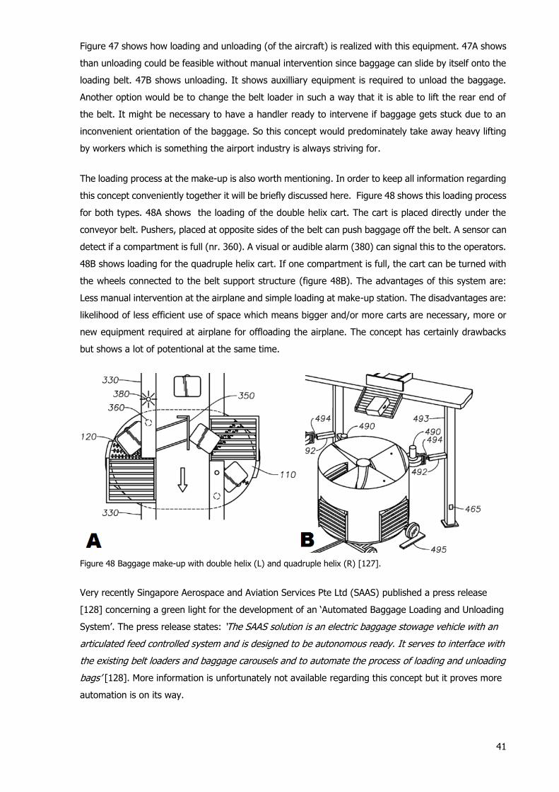
41
Figure 47 shows how loading and unloading (of the aircraft) is realized with this equipment. 47A shows
than unloading could be feasible without manual intervention since baggage can slide by itself onto the
loading belt. 47B shows unloading. It shows auxilliary equipment is required to unload the baggage.
Another option would be to change the belt loader in such a way that it is able to lift the rear end of
the belt. It might be necessary to have a handler ready to intervene if baggage gets stuck due to an
inconvenient orientation of the baggage. So this concept would predominately take away heavy lifting
by workers which is something the airport industry is always striving for.
The loading process at the make-up is also worth mentioning. In order to keep all information regarding
this concept conveniently together it will be briefly discussed here. Figure 48 shows this loading process
for both types. 48A shows the loading of the double helix cart. The cart is placed directly under the
conveyor belt. Pushers, placed at opposite sides of the belt can push baggage off the belt. A sensor can
detect if a compartment is full (nr. 360). A visual or audible alarm (380) can signal this to the operators.
48B shows loading for the quadruple helix cart. If one compartment is full, the cart can be turned with
the wheels connected to the belt support structure (figure 48B). The advantages of this system are:
Less manual intervention at the airplane and simple loading at make-up station. The disadvantages are:
likelihood of less efficient use of space which means bigger and/or more carts are necessary, more or
new equipment required at airplane for offloading the airplane. The concept has certainly drawbacks
but shows a lot of potentional at the same time.
Figure 48 Baggage make-up with double helix (L) and quadruple helix (R) [127].
Very recently Singapore Aerospace and Aviation Services Pte Ltd (SAAS) published a press release
[128] concerning a green light for the development of an ‘Automated Baggage Loading and Unloading
System’. The press release states: ‘The SAAS solution is an electric baggage stowage vehicle with an
articulated feed controlled system and is designed to be autonomous ready. It serves to interface with
the existing belt loaders and baggage carousels and to automate the process of loading and unloading
bags’ [128]. More information is unfortunately not available regarding this concept but it proves more
automation is on its way.

42
4. Control of baggage handling systems
In this section attention will be given to the control of BHS. Unlike the developments with respect to
BHS equipment, the way BHS are controlled has barely changed in recent decades. One specific event
in particular triggered this conservative view of the airport industry on control: the famous Denver
Airport case in 1993 [129]. Among the complete range of problems this new airport faced were also the
very challenging control novelties: ‘The original plan for the BHS … was also extremely challenging,
even compared to many BHS built today. Instead of moving totes by conveyors the BHS in Denver is
based on more than 4,000 autonomous DCV running at impressive speeds of up to 32 kph on the 30
km long rail system. It was a kind of agent-based with many computers coordinating the task, but the
first serious troubles was caused by the overloaded 10Mbit Ethernet. Also the optimistic plan of loading
and unloading DCVs while running caused DCVs to collide, baggage to be damaged or thrown out of
the DVCs. Even unloading a bag from one running DVC into another was part of the original plan,
whereas many systems today still stops a tote or DCV before unloading, even at stationary discharging
points’ [130]. Although the failure could be contributed to the large amount of ambitious new innovative
concepts incorporated in this project it caused much more caution among BHS manufacturers and their
clients regarding future BHS projects.
4.1 An introduction to PLC’s
Although high level control will be the main focus of the survey, a quick introduction of the low level
control operation, as currently applied, will be given since it is important to understand the complete
system, from high level control down to the lowest level. On a low level, programmable logic controllers
(PLC) are used to control most individual equipment. The PLC is a special purpose digital computer
which enables the user to remotely control and monitor the system. The versatility and robustness,
among some other advantageous characteristics mentioned hereafter, make it ideal for a wide range of
industrial applications [131]. Moreover, they are easily customizable, off-the shelf solutions, reliable,
durable and intuitive to control engineers [132]. A general diagram of a PLC as applied in BHS
applications is shown in figure 49 [133].
Figure 49 A general diagram of a PLC [133].
Output module
(Analog output
and digital I/O)Memory
CPUInput module
(Analog input and
digital I/O)
Fieldbus
Powersupply
Sensors
Switches
Actuators
Alarms
Indicator lights
Other PLC unitsOther PLC units
Feedback loop

43
The PLC runs a continuous feedback loop called ‘scanning’, where it reads the
inputs, reads communication from the fieldbus, runs the user created program
logic, writes the output, does the housekeeping (communicates through fieldbus,
runs internal diagnostics) and finally repeats the cycle [131] [134]. This process,
which takes a few milliseconds in general, is pictured in figure 50.
Figure 50 ‘Scanning’.
Different programming languages are used for PLC. The most important are Ladder Diagram (Based on
Relay logic, most commonly used), Function Block diagram (‘very useful for expressing the
interconnection of control system algorithms and logic’), Structured text (the language structure
resembles Pascal), Instruction list and Sequential function chart [134]. In these programs a combination
of if statements is used (graphical or textual) to start an action. Timers and counters can also be
included.
Existing approaches using aforementioned languages, from standard IEC 61131, have become more
outdated in recent years. In general the current software is not very modular which makes modification
and maintenance more challenging and reduces scalability [135]. A new standard released in 2005,
called IEC 61499, uses improved function blocks. The new standardized event driven function blocks
remain idle until any event activates them. This has several advantages including improved efficiency
and a reduction of communication bandwidth and computation power. The function blocks also increase
reusability [136]. Finally they are more suitable for distributed/decentralized control, which promises
more reliability (no single point of failure) and more flexibility. So in the future we might see PLC’s
replaced by IEC61499 compatible embedded controllers.
4.2 The challenges of control of baggage handling systems
One can say that the main challenge in the control of BHS lies in the dynamic and unpredictable nature
of the baggage in- and output caused by the environment of the system [130]. The complexity in
general of large scale BHS should not be underestimated: ‘Looking into this "blackbox" (i.e. the BHS)
one will experience a complex system unlike many others’ [130]. K. Hallenborg [130] identified the
following main characteristics of the environment which can be related to this challenging nature:
1. ‘Arriving baggage from either flights or check-in are not sorted, but arrives mixed from different
destinations.
2. Identity and destination of bags are unknown until the bag is scanned at the input facilities,
thus preplanning and traditional scheduling is not an option.
3. Constant changes in flight schedules, due to both weather conditions and delayed flights.’
Moreover, baggage can have priority if it is coming in late. In the worst case, so called ‘Rushed’ bags
will be handled manually. It is important to note that each airport emphasizes on the greatest
importance to minimize delayed baggage due to the costs, efforts and bad publicity involved as a result
of a bag which missed its flight.

44
Robustness and reliability of the control system are as a consequence an important features of a BHS.
Deadlock situations and breakdowns which may potentially result in large amounts of delayed baggage
are to be avoided at all times to prevent an airports ultimate nightmare.
Control inside a BHS happens on multiple levels. Different higher level control problems or challenges
are presented in different literature [137] [138]:
1. ‘Routing and scheduling’. The assignment of a route for an individual carrier and the scheduling
of a bag. Scheduling is related to routing since the route is an important parameter when a bag
is scheduled. It determines the time it takes to its destination. An important challenge here is
‘load balancing’ which means that baggage should be routed away from congested areas. If
problems occur which lead to a partial shutdown of the system, rerouting is the only option. If
the system blocks somewhere without any possibility to reroute, it can lead to baggage missing
their flight which may result in severe costs. Redundancy in the system is therefore very
important.
2. Line balancing and empty cart management. Empty DCV’s need to be assigned in a correct way
to bags waiting to be transported.
3. ‘Prevention of buffer overflow’. Buffers in a BHS system include the EBS and the buffers at the
make-up area.
Volume regulation [139] is not considered a real challenge and therefore not mentioned here, it is
however very important for control purposes. If there are too many bags in the system or in any part
of the BHS the system may get overloaded. Any of the above mentioned challenges might get impossible
to solve. Volume regulation takes place at the infeed. If the maximum volume is reached the infeed
must be blocked/stopped. It is important to note however that the system must be able to reroute
baggage as much as possible away from the congested areas in order to lower the threshold of BHS
overflow. BHS overflow is one of the worst scenarios which shows the importance of preventing this.
Low level control problems (although not considered very challenging) are the following:
1. Merge control. In merging process balancing is important. If only one infeed channel is
prioritized queues can form when there is a lot of traffic. Due to this nature it merge control
has both a high level and a low level control component.
2. Control of individual conveyors or DCV’s to prevent bags or carts running into each other.
3. Synchronize bag and DCV for loading and coordinate unloading.
Note that the above mentioned challenges are not always present. In an airport equipped solely with
conveyors for instance, there is no need for empty cart management. Most of the literature is dedicated
to high level control problems and this is also the area of the largest interest to the author, so this report
is focusing on high level control problems. Time also requires this part to be bounded. To emphasize
again, the proceedings in low level control, especially in the field of embedded systems and industrial
informatics, such as an implementation of the IEC61499 standard in BHS discussed in [135], can
however not be completely ignored since high level and low level are closely connected.
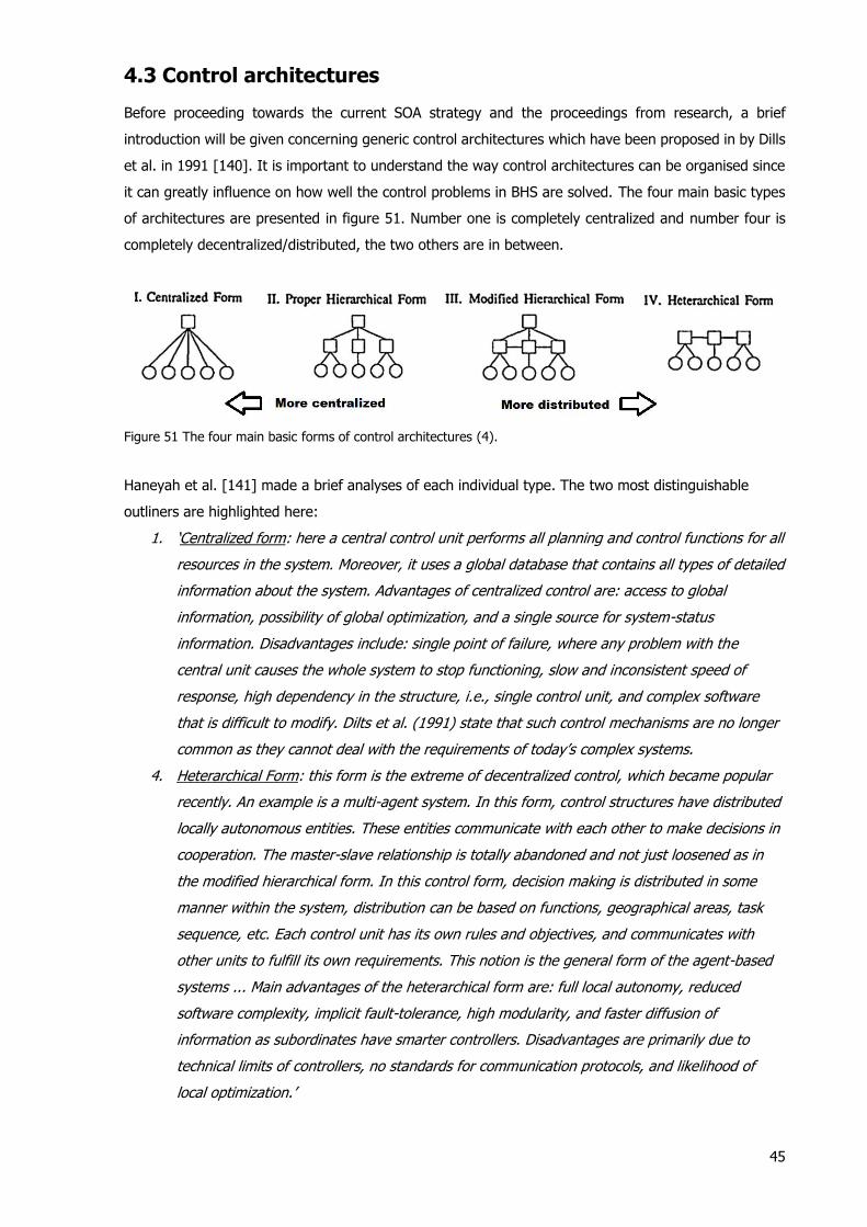
45
4.3 Control architectures
Before proceeding towards the current SOA strategy and the proceedings from research, a brief
introduction will be given concerning generic control architectures which have been proposed in by Dills
et al. in 1991 [140]. It is important to understand the way control architectures can be organised since
it can greatly influence on how well the control problems in BHS are solved. The four main basic types
of architectures are presented in figure 51. Number one is completely centralized and number four is
completely decentralized/distributed, the two others are in between.
Figure 51 The four main basic forms of control architectures (4).
Haneyah et al. [141] made a brief analyses of each individual type. The two most distinguishable
outliners are highlighted here:
1. ‘Centralized form: here a central control unit performs all planning and control functions for all
resources in the system. Moreover, it uses a global database that contains all types of detailed
information about the system. Advantages of centralized control are: access to global
information, possibility of global optimization, and a single source for system-status
information. Disadvantages include: single point of failure, where any problem with the
central unit causes the whole system to stop functioning, slow and inconsistent speed of
response, high dependency in the structure, i.e., single control unit, and complex software
that is difficult to modify. Dilts et al. (1991) state that such control mechanisms are no longer
common as they cannot deal with the requirements of today’s complex systems.
4. Heterarchical Form: this form is the extreme of decentralized control, which became popular
recently. An example is a multi-agent system. In this form, control structures have distributed
locally autonomous entities. These entities communicate with each other to make decisions in
cooperation. The master-slave relationship is totally abandoned and not just loosened as in
the modified hierarchical form. In this control form, decision making is distributed in some
manner within the system, distribution can be based on functions, geographical areas, task
sequence, etc. Each control unit has its own rules and objectives, and communicates with
other units to fulfill its own requirements. This notion is the general form of the agent-based
systems ... Main advantages of the heterarchical form are: full local autonomy, reduced
software complexity, implicit fault-tolerance, high modularity, and faster diffusion of
information as subordinates have smarter controllers. Disadvantages are primarily due to
technical limits of controllers, no standards for communication protocols, and likelihood of
local optimization.’
46
Both other types consist of multiple control levels where each level controls its subordinate beneath
him. In contrast to number two, number three has some degree of coordination between local
controllers on a certain level.
Although a centralized approach may result in a global optimization one important downside was
mentioned, namely a slow speed of response. This contrast with the highly dynamic nature of BHS as
mentioned two sections earlier. Certain routing issues such as ‘load balancing’ would be cumbersome
with such a control approach. Another clear point made by the author was about the inability of the
centralized approach to cope with complex systems. The decentralized method in contrast may be an
improvement to the centralized approach regarding the aforementioned issues with a ‘faster diffusion
of information’.
4.4 The traditional state of the art method
BHS nowadays operate (mostly) with a centralized control architecture tailor-made to be operated in a
specific lay-out. The traditional solution for the complex problem of baggage handling in large airports
is to calculate the shortest paths for each bag [142]. In state of the art (SOA) control in BHS a set of
routes is calculated based on several predefined events, before the start of the BHS operation [138].
Each junction has its own routing table which includes a collection of shortest routes for each existing
destination. The predefined events are usually baggage jams and do not include queues. This system
is simple and was thus believed to be more reliable in that sense. It ignores however some
characteristics of the high level control challenges mentioned above. Baggage is not rerouted away from
congested areas if the time of departure of the respective piece of baggage allows the system to do so.
This would free capacity for ‘rushed’ baggage. Moreover, it is often not necessary to rush the bag to
the final destination since the bag is only required when it is loaded in a ULD or cart. It may arrive in a
predefined time window which is equal to the opening time of a make-up section. So with this in mind,
the shortest path method is actually not very suitable to BHS. In general it can be stated that the SOA
method fails to guarantee optimal performance. An improved system would therefore be more
intelligent. New approaches should also seek for a more flexible routing method which adapts better to
the dynamic nature of BHS. Fortunately, not really by coincidence, new research into BHS control
investigates new control solutions which promise improvements: MAS and Model Predictive Control
(MPC). A worth mentioning quote however comes from Rien Scholing, a logistics expert from Tebodin
Consultants & Engineers who is proposing another challenging solution to tackle current issues faced in
BHS control: ‘The most promising – but probably the hardest – option for upgrading the handling process
is to take a true supply chain approach to baggage handling and try to avoid queues, double handling
and sub-optimisation. Important factors in this respect are the sharing of information between parties,
full cooperation in design and in the execution of the total process and dedication and process ownership
with the personnel’ [28].’ This idea has not been researched so far.
47
4.5 Multi agent systems
Intelligent control and in particular the concept of multi agent systems (MAS) as an approach to
distributed control has been an important research topic within the field of BHS control in the past
decade. First studied for material handling systems in general the research has now also been focused
on BHS. This new approach has been attempted to improve on several issues which the centralized SOA
method had difficulties to cope with. These issues, already mentioned in the previous two sections, are
mainly related to the inherent dynamic and complex nature of BHS.
First an introduction by definition will be given regarding agents and MAS. The definition of MAS
can be as follows: ‘MAS can be described as goal-oriented communities of cooperative/self-interested
agents in a certain environment…. They explore the principles of artificial intelligence for reasoning,
communication and cooperation. The important attribute of each agent is its autonomy – the agent
resides on a computer platform where it autonomously carries out a particular task/functionality. The
agent owns only a part of the global information about the goals of the community that is sufficient for
its local decision-making and behaviour. However, in some situations, for example, when the agent is
not capable of cooperation with other agents (asking them for help) usually via message sending. The
agents asked for cooperation…can either agree on cooperation or can even refuse to cooperate (e.g.,
due to lack of their own resources). The cooperation among the agents supported by their social
behaviour is the dominant feature of the activities of the agents in the community. The term social
behaviour means that the agents are able to communicate, to understand the goals, states, capabilities,
etc. of the others and to respect the general rules and constraints of behaviour valid for each of the
community members‘ [143].
Agents can be mobile or stationary. Mobile agents are injected in the system in order to collect
information concerning delays experienced throughout the system. Obviously mobile agents, in the form
of phantom bags, negatively influence the capacity of a BHS so agents will always need to be stationary
[142]. Unless a method is found to combine an agent with a useful entity, for instance a DCV
transporting a bag and in this way be routed back to the EBS or loading stations. In that case probably
all DCV’s would have to be agents. And this is a problem on low peak moments. Although one could
argue that most control problems will vanish anyway, so it could be feasible when implemented
correctly.
MAS have been developed already three decades ago with the main focus of research on
manufacturing systems. Kasper Hallenborg was one of the main contributors to do research specifically
on the implementation of MAS in BHS. In his first paper regarding this topic dating from 2006 he
immediately points out that a strategy of global planning and scheduling can be a bad strategy when
implemented in systems influenced by major dynamical factors which is definitely the case for BHS
[144]. This kind of system feature is what MAS can very well deal with. Another point is the installation
process for a new BHS where fine-tuning is often costly and time consuming. MAS promise faster and
cheaper installation if it can be developed in a more generic way.
To elaborate on MAS classification it is shown that the BHS problem demands a more coordination
centred approach in contrast to a more negotiation centred approach for AGV’s in a shop floor
environment as shown in figure 52. ‘Coordination is the process by which an agent reasons about its
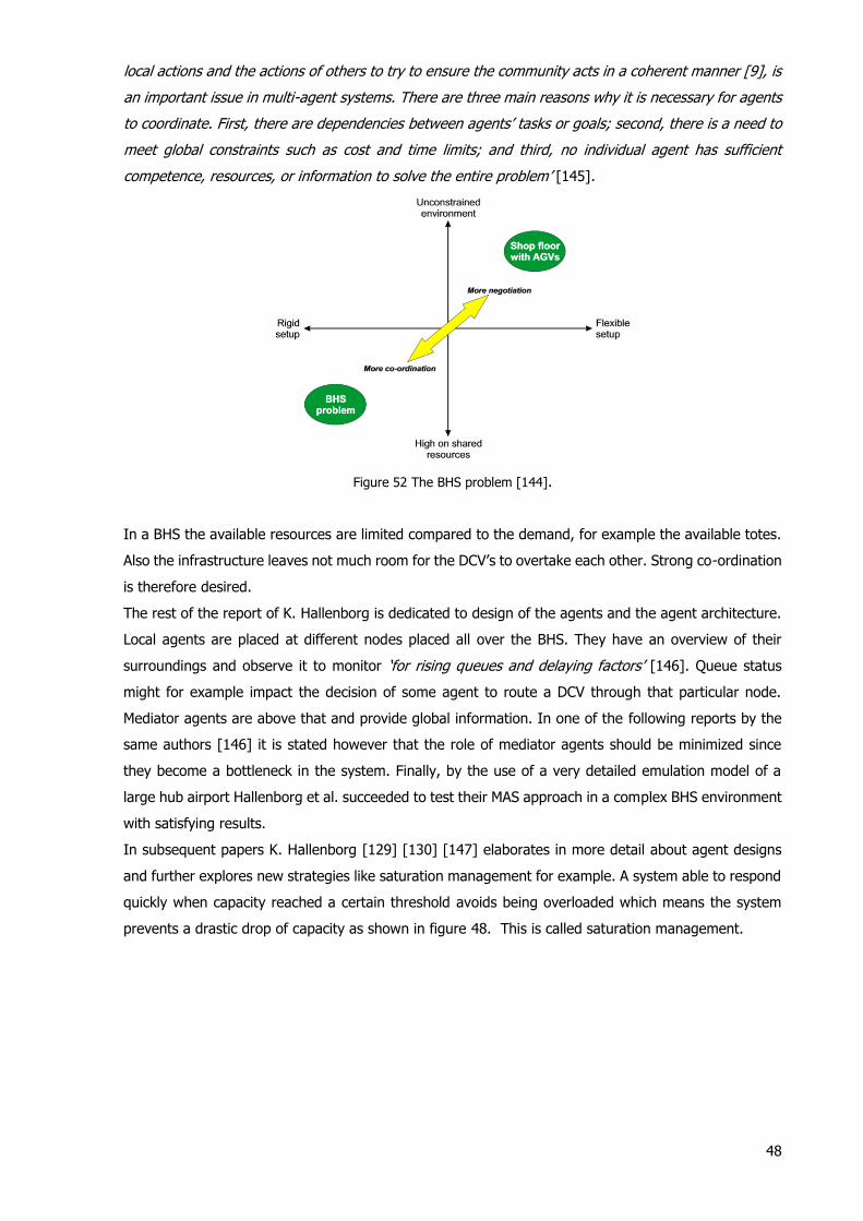
48
local actions and the actions of others to try to ensure the community acts in a coherent manner [9], is
an important issue in multi-agent systems. There are three main reasons why it is necessary for agents
to coordinate. First, there are dependencies between agents’ tasks or goals; second, there is a need to
meet global constraints such as cost and time limits; and third, no individual agent has sufficient
competence, resources, or information to solve the entire problem’ [145].
Figure 52 The BHS problem [144].
In a BHS the available resources are limited compared to the demand, for example the available totes.
Also the infrastructure leaves not much room for the DCV’s to overtake each other. Strong co-ordination
is therefore desired.
The rest of the report of K. Hallenborg is dedicated to design of the agents and the agent architecture.
Local agents are placed at different nodes placed all over the BHS. They have an overview of their
surroundings and observe it to monitor ‘for rising queues and delaying factors’ [146]. Queue status
might for example impact the decision of some agent to route a DCV through that particular node.
Mediator agents are above that and provide global information. In one of the following reports by the
same authors [146] it is stated however that the role of mediator agents should be minimized since
they become a bottleneck in the system. Finally, by the use of a very detailed emulation model of a
large hub airport Hallenborg et al. succeeded to test their MAS approach in a complex BHS environment
with satisfying results.
In subsequent papers K. Hallenborg [129] [130] [147] elaborates in more detail about agent designs
and further explores new strategies like saturation management for example. A system able to respond
quickly when capacity reached a certain threshold avoids being overloaded which means the system
prevents a drastic drop of capacity as shown in figure 48. This is called saturation management.
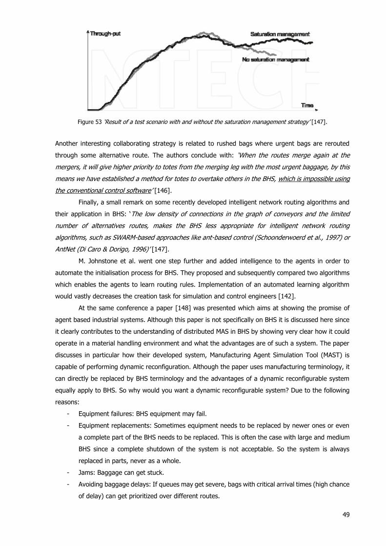
49
Figure 53 ‘Result of a test scenario with and without the saturation management strategy’ [147].
Another interesting collaborating strategy is related to rushed bags where urgent bags are rerouted
through some alternative route. The authors conclude with: ‘When the routes merge again at the
mergers, it will give higher priority to totes from the merging leg with the most urgent baggage, by this
means we have established a method for totes to overtake others in the BHS, which is impossible using
the conventional control software’ [146].
Finally, a small remark on some recently developed intelligent network routing algorithms and
their application in BHS: ‘The low density of connections in the graph of conveyors and the limited
number of alternatives routes, makes the BHS less appropriate for intelligent network routing
algorithms, such as SWARM-based approaches like ant-based control (Schoonderwoerd et al., 1997) or
AntNet (Di Caro & Dorigo, 1996)’ [147].
M. Johnstone et al. went one step further and added intelligence to the agents in order to
automate the initialisation process for BHS. They proposed and subsequently compared two algorithms
which enables the agents to learn routing rules. Implementation of an automated learning algorithm
would vastly decreases the creation task for simulation and control engineers [142].
At the same conference a paper [148] was presented which aims at showing the promise of
agent based industrial systems. Although this paper is not specifically on BHS it is discussed here since
it clearly contributes to the understanding of distributed MAS in BHS by showing very clear how it could
operate in a material handling environment and what the advantages are of such a system. The paper
discusses in particular how their developed system, Manufacturing Agent Simulation Tool (MAST) is
capable of performing dynamic reconfiguration. Although the paper uses manufacturing terminology, it
can directly be replaced by BHS terminology and the advantages of a dynamic reconfigurable system
equally apply to BHS. So why would you want a dynamic reconfigurable system? Due to the following
reasons:
- Equipment failures: BHS equipment may fail.
- Equipment replacements: Sometimes equipment needs to be replaced by newer ones or even
a complete part of the BHS needs to be replaced. This is often the case with large and medium
BHS since a complete shutdown of the system is not acceptable. So the system is always
replaced in parts, never as a whole.
- Jams: Baggage can get stuck.
- Avoiding baggage delays: If queues may get severe, bags with critical arrival times (high chance
of delay) can get prioritized over different routes.
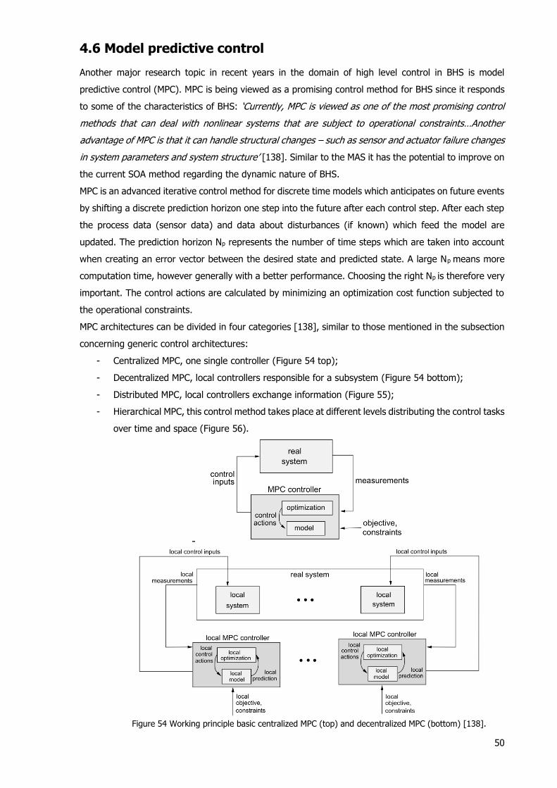
50
4.6 Model predictive control
Another major research topic in recent years in the domain of high level control in BHS is model
predictive control (MPC). MPC is being viewed as a promising control method for BHS since it responds
to some of the characteristics of BHS: ‘Currently, MPC is viewed as one of the most promising control
methods that can deal with nonlinear systems that are subject to operational constraints…Another
advantage of MPC is that it can handle structural changes – such as sensor and actuator failure changes
in system parameters and system structure’ [138]. Similar to the MAS it has the potential to improve on
the current SOA method regarding the dynamic nature of BHS.
MPC is an advanced iterative control method for discrete time models which anticipates on future events
by shifting a discrete prediction horizon one step into the future after each control step. After each step
the process data (sensor data) and data about disturbances (if known) which feed the model are
updated. The prediction horizon Np represents the number of time steps which are taken into account
when creating an error vector between the desired state and predicted state. A large Np means more
computation time, however generally with a better performance. Choosing the right Np is therefore very
important. The control actions are calculated by minimizing an optimization cost function subjected to
the operational constraints.
MPC architectures can be divided in four categories [138], similar to those mentioned in the subsection
concerning generic control architectures:
- Centralized MPC, one single controller (Figure 54 top);
- Decentralized MPC, local controllers responsible for a subsystem (Figure 54 bottom);
- Distributed MPC, local controllers exchange information (Figure 55);
- Hierarchical MPC, this control method takes place at different levels distributing the control tasks
over time and space (Figure 56).
-
Figure 54 Working principle basic centralized MPC (top) and decentralized MPC (bottom) [138].
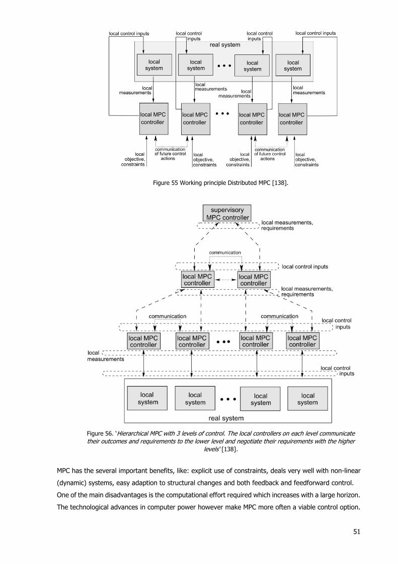
51
Figure 55 Working principle Distributed MPC [138].
Figure 56. ‘Hierarchical MPC with 3 levels of control. The local controllers on each level communicate
their outcomes and requirements to the lower level and negotiate their requirements with the higher
levels‘ [138].
MPC has the several important benefits, like: explicit use of constraints, deals very well with non-linear
(dynamic) systems, easy adaption to structural changes and both feedback and feedforward control.
One of the main disadvantages is the computational effort required which increases with a large horizon.
The technological advances in computer power however make MPC more often a viable control option.
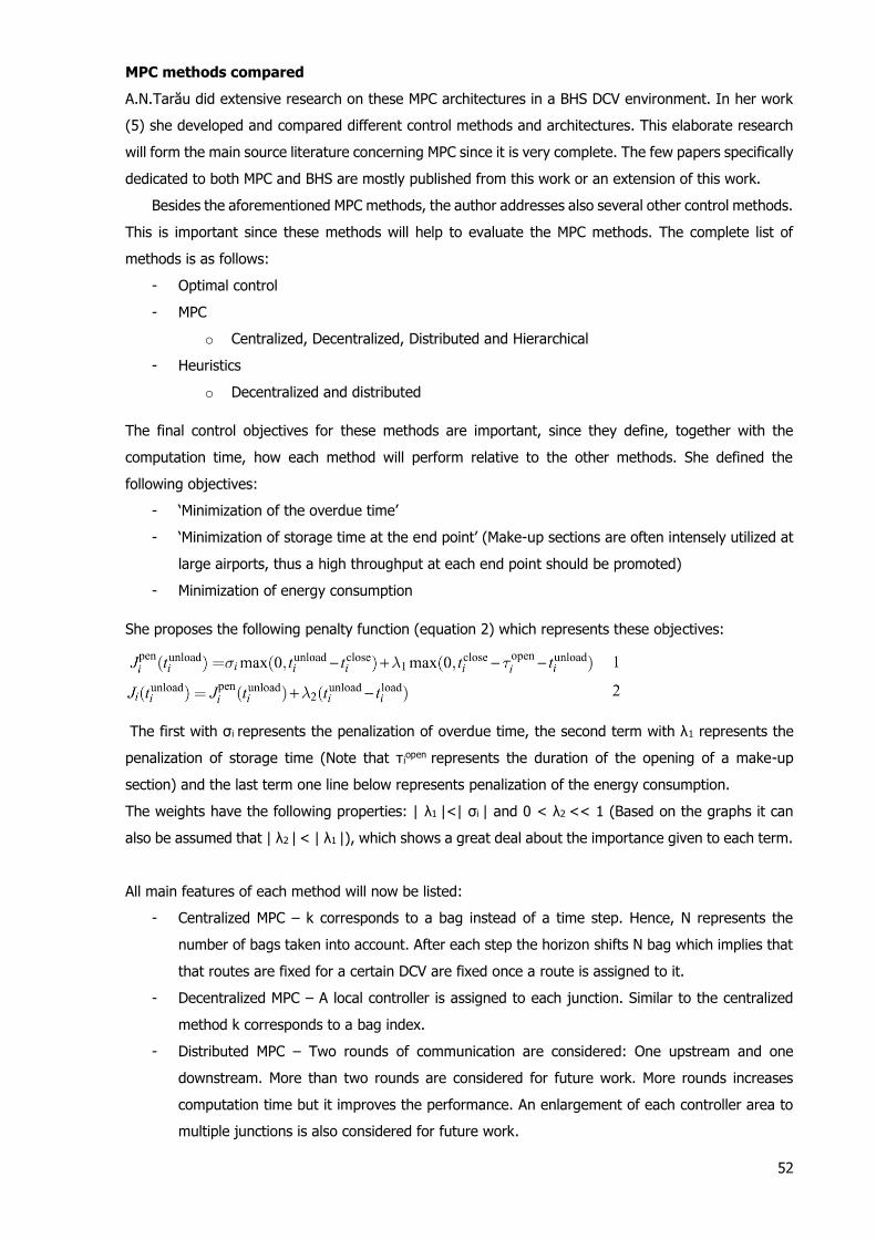
52
MPC methods compared
A.N.Tarău did extensive research on these MPC architectures in a BHS DCV environment. In her work
(5) she developed and compared different control methods and architectures. This elaborate research
will form the main source literature concerning MPC since it is very complete. The few papers specifically
dedicated to both MPC and BHS are mostly published from this work or an extension of this work.
Besides the aforementioned MPC methods, the author addresses also several other control methods.
This is important since these methods will help to evaluate the MPC methods. The complete list of
methods is as follows:
- Optimal control
- MPC
o Centralized, Decentralized, Distributed and Hierarchical
- Heuristics
o Decentralized and distributed
The final control objectives for these methods are important, since they define, together with the
computation time, how each method will perform relative to the other methods. She defined the
following objectives:
- ‘Minimization of the overdue time’
- ‘Minimization of storage time at the end point’ (Make-up sections are often intensely utilized at
large airports, thus a high throughput at each end point should be promoted)
- Minimization of energy consumption
She proposes the following penalty function (equation 2) which represents these objectives:
The first with σi represents the penalization of overdue time, the second term with λ1 represents the
penalization of storage time (Note that τiopen represents the duration of the opening of a make-up
section) and the last term one line below represents penalization of the energy consumption.
The weights have the following properties: | λ1 |<| σi | and 0 < λ2 << 1 (Based on the graphs it can
also be assumed that | λ2 | < | λ1 |), which shows a great deal about the importance given to each term.
All main features of each method will now be listed:
- Centralized MPC – k corresponds to a bag instead of a time step. Hence, N represents the
number of bags taken into account. After each step the horizon shifts N bag which implies that
that routes are fixed for a certain DCV are fixed once a route is assigned to it.
- Decentralized MPC – A local controller is assigned to each junction. Similar to the centralized
method k corresponds to a bag index.
- Distributed MPC – Two rounds of communication are considered: One upstream and one
downstream. More than two rounds are considered for future work. More rounds increases
computation time but it improves the performance. An enlargement of each controller area to
multiple junctions is also considered for future work.
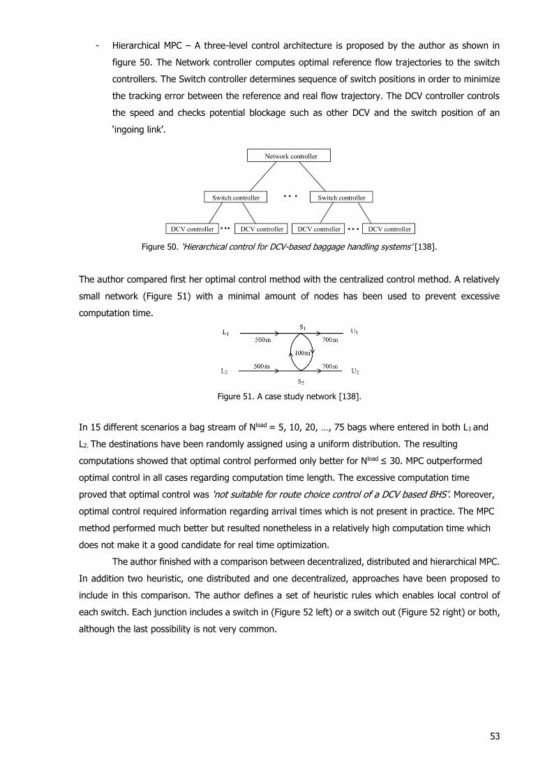
53
- Hierarchical MPC – A three-level control architecture is proposed by the author as shown in
figure 50. The Network controller computes optimal reference flow trajectories to the switch
controllers. The Switch controller determines sequence of switch positions in order to minimize
the tracking error between the reference and real flow trajectory. The DCV controller controls
the speed and checks potential blockage such as other DCV and the switch position of an
‘ingoing link’.
Figure 50. ‘Hierarchical control for DCV-based baggage handling systems’ [138].
The author compared first her optimal control method with the centralized control method. A relatively
small network (Figure 51) with a minimal amount of nodes has been used to prevent excessive
computation time.
Figure 51. A case study network [138].
In 15 different scenarios a bag stream of Nload = 5, 10, 20, …, 75 bags where entered in both L1 and
L2. The destinations have been randomly assigned using a uniform distribution. The resulting
computations showed that optimal control performed only better for Nload ≤ 30. MPC outperformed
optimal control in all cases regarding computation time length. The excessive computation time
proved that optimal control was ‘not suitable for route choice control of a DCV based BHS’. Moreover,
optimal control required information regarding arrival times which is not present in practice. The MPC
method performed much better but resulted nonetheless in a relatively high computation time which
does not make it a good candidate for real time optimization.
The author finished with a comparison between decentralized, distributed and hierarchical MPC.
In addition two heuristic, one distributed and one decentralized, approaches have been proposed to
include in this comparison. The author defines a set of heuristic rules which enables local control of
each switch. Each junction includes a switch in (Figure 52 left) or a switch out (Figure 52 right) or both,
although the last possibility is not very common.
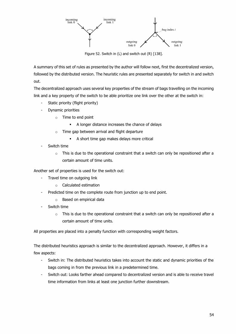
54
Figure 52. Switch in (L) and switch out (R) [138].
A summary of this set of rules as presented by the author will follow next, first the decentralized version,
followed by the distributed version. The heuristic rules are presented separately for switch in and switch
out.
The decentralized approach uses several key properties of the stream of bags travelling on the incoming
link and a key property of the switch to be able prioritize one link over the other at the switch in:
- Static priority (flight priority)
- Dynamic priorities
o Time to end point
A longer distance increases the chance of delays
o Time gap between arrival and flight departure
A short time gap makes delays more critical
- Switch time
o This is due to the operational constraint that a switch can only be repositioned after a
certain amount of time units.
Another set of properties is used for the switch out:
- Travel time on outgoing link
o Calculated estimation
- Predicted time on the complete route from junction up to end point.
o Based on empirical data
- Switch time
o This is due to the operational constraint that a switch can only be repositioned after a
certain amount of time units.
All properties are placed into a penalty function with corresponding weight factors.
The distributed heuristics approach is similar to the decentralized approach. However, it differs in a
few aspects:
- Switch in: The distributed heuristics takes into account the static and dynamic priorities of the
bags coming in from the previous link in a predetermined time.
- Switch out: Looks farther ahead compared to decentralized version and is able to receive travel
time information from links at least one junction further downstream.
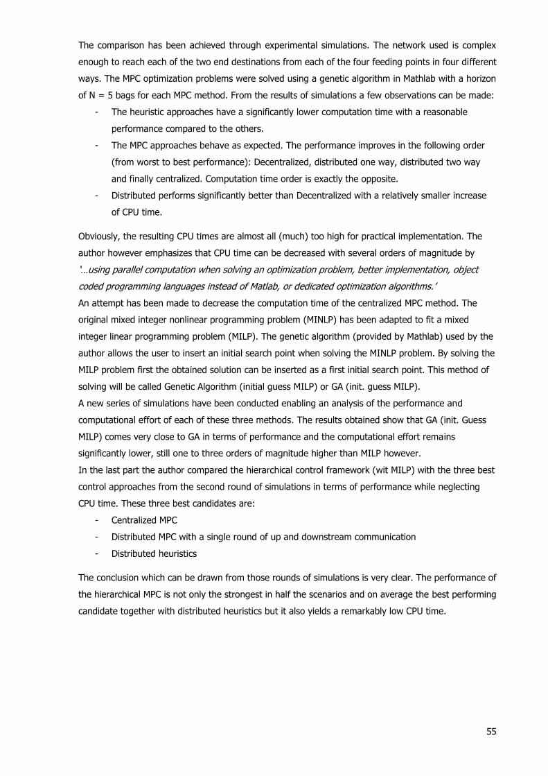
55
The comparison has been achieved through experimental simulations. The network used is complex
enough to reach each of the two end destinations from each of the four feeding points in four different
ways. The MPC optimization problems were solved using a genetic algorithm in Mathlab with a horizon
of N = 5 bags for each MPC method. From the results of simulations a few observations can be made:
- The heuristic approaches have a significantly lower computation time with a reasonable
performance compared to the others.
- The MPC approaches behave as expected. The performance improves in the following order
(from worst to best performance): Decentralized, distributed one way, distributed two way
and finally centralized. Computation time order is exactly the opposite.
- Distributed performs significantly better than Decentralized with a relatively smaller increase
of CPU time.
Obviously, the resulting CPU times are almost all (much) too high for practical implementation. The
author however emphasizes that CPU time can be decreased with several orders of magnitude by
‘…using parallel computation when solving an optimization problem, better implementation, object
coded programming languages instead of Matlab, or dedicated optimization algorithms.’
An attempt has been made to decrease the computation time of the centralized MPC method. The
original mixed integer nonlinear programming problem (MINLP) has been adapted to fit a mixed
integer linear programming problem (MILP). The genetic algorithm (provided by Mathlab) used by the
author allows the user to insert an initial search point when solving the MINLP problem. By solving the
MILP problem first the obtained solution can be inserted as a first initial search point. This method of
solving will be called Genetic Algorithm (initial guess MILP) or GA (init. guess MILP).
A new series of simulations have been conducted enabling an analysis of the performance and
computational effort of each of these three methods. The results obtained show that GA (init. Guess
MILP) comes very close to GA in terms of performance and the computational effort remains
significantly lower, still one to three orders of magnitude higher than MILP however.
In the last part the author compared the hierarchical control framework (wit MILP) with the three best
control approaches from the second round of simulations in terms of performance while neglecting
CPU time. These three best candidates are:
- Centralized MPC
- Distributed MPC with a single round of up and downstream communication
- Distributed heuristics
The conclusion which can be drawn from those rounds of simulations is very clear. The performance of
the hierarchical MPC is not only the strongest in half the scenarios and on average the best performing
candidate together with distributed heuristics but it also yields a remarkably low CPU time.

56
The author promised more research which builds upon this work and proposed a significant amount of
changes, improvements, possibilities to research. These propositions included:
- The development of control methods with the focus on the line balancing problem and empty
cart management.
- Research with consideration of EBS. In addition, give answer to the question whether pre-
sorting inside the EBS results in an improved system performance? An additional MPC controller
can be used in this case.
- Increase complexity of the case studies used to test these control methods.
- Improve the heuristic control methods, e.g.:
o Take into account the ‘density of DCVs on the links of the network’.
o Research extent of communication in distributed heuristics. How much links should be
taken into account?
- Combine MPC with heuristics, e.g.:
o Use the heuristics solution as a first good guess input to the more computation intensive
MPC optimization.
- Extent research in distributed control
o ‘multiple up and down rounds of optimizations’
o Adapt hierarchical control to allow communication between different levels.
o Experiment with larger control areas (multiple nodes).
- Research the impact of platooning on control (more about platooning will follow)
- Introduce (advanced) control methods for DCV route choice, e.g.:
o Neural networks. This is a form of AI. It is capable to adapt to a dynamic input and has
a learning ability.
o Fuzzy control. The author does not elaborate on this statement. It would be interesting
to know her thoughts about fuzzy control, since high level problems such as DCV route
choice involves discrete actions and discrete streams of DCV. Continuous input will have
to be converted eventually in discrete output which has to take into account discrete
constraints (DCV flowing through the system). It is difficult to see how fuzzy control
will help in this.
- Research in network optimization, sensor use optimization, DCV number optimization, all with
respect to BHS performance.
An interesting concept is ‘platooning’. To improve computational times DCV’s with similar destinations
can be grouped together as a train and guided through the BHS. In comparison with a regular stream
of DCV’s the individual distances between them are considerably smaller. Computational time is reduced
since routes are computed for platoons instead of individual DCV’s. The main question is if it is possible
to group them together.
A very limited number of propositions have indeed yielded some papers in recent years. In fact, only
the first one. This shows there is a significant amount of research options left for the future.

57
An integrated approach
The first proposal regarding line balancing and empty cart management was addressed in 2012 [149]
were they call it the first integrated approach to MPC in BHS. However, a more recent and extended
study was presented in [150]. In this study, the authors investigated first the feasibility of a nonlinear
problem (NLP) approach to the MPC problem. Not surprisingly the optimization problem appeared to be
intractable for a full scale BHS. For this reason a linear problem (LP) approach was adopted. At the
same time an iterative LP (ILP) approach was introduced to improve the inaccurate predictions obtained
when solving the LP approach. They compared all three methods with a state of the art (SOA) method
based on look up tables, a method which does not necessarily lead to an optimal solution for complex
networks. The authors succeeded to present a relatively successful control approach (ILP) which yields
results close to the NLP method, with much lower computation times. It outperforms the SOA with a
reasonable decrease in computational efficiency. The objective function penalized high energy
consumption and baggage arriving before or after the predefined time windows. For future work the
authors propose a more detailed analysis of the ILP approach to investigate the trade-off between
performance and CPU time. Another comparison is proposed between the previous approach and
method based on calculating the exact travel times of a DCV.
58
5. Conclusions
The aim of this report was to survey the complete state of the art automated equipment and control of
BHS. This goal has been achieved to a great extent. However, due to the large amount of literature
available concerning research in the field of control in BHS, the scope of the research has been set on
high level control and the focus has been towards the two main novelties presented by literature, multi
agent systems and model predictive control. It should be noted that this covered the literature of recent
years for a very large part which supports the decision to focus on these two topics. The observation
that the research in MPC and MAS cover most of the research and made also the biggest contribution
in terms of novelty is an important conclusion which can be drawn based upon this literature survey
regarding control.
The amount of research proposals presented in the literature regarding MPC makes it clear there is still
a significant amount of research required before MPC can be successfully applied to BHS. The main
challenge for MPC remains real time control in BHS which demands fast computation time. The non-
linear, non-convex optimization problems is intractable in practice due to the excessive computational
demand. Promising solutions have been proposed by research such a recasting the original problem
towards a more simplified linear version of the problem, possibly with an iterative approach or to use a
solution of the simplified version as an good initial guess in the non-linear optimization problem. The
most promising architectures include hierarchical MPC and centralized MPC with a first good initial guess
as a way to speed up calculations.
The research of MAS in a BHS environment has still more progress to make as research is still in a
premature state. It lacks comparison between different methods for instance.
Finally, it can be concluded that this particular application, BHS, of MAS and some MPC control methods
showed moderate to good promise which prove these approaches should be investigated further in the
future.
Automated BHS equipment
The research in BHS automation showed that the automation in BHS is still continuing and only a small
part remains without commercialized automated solutions. The most recent applications of automated
equipment in BHS has been the automated drop-off of baggage and the automated (un)loading of
baggage in ULD’s and carts inside the terminal, which both have been introduced in the past five years.
The remaining parts include transport over and (un)loading on the tarmac. The first is likely to be
automated for several reasons. The car industry is working on automated cars and trucks and the
capabilities of these automated vehicles are increasing at a high rate. Automated guided vehicles are
already operating at large transport hubs like the Rotterdam ship terminal although the operating
conditions are more favorable compared to an airport like much less ground personnel and simpler
parking conditions at the offload point. The (un)loading of carts/ULD next to the aircraft has already
resulted in a patent. The unloading of ULD could definitely be completely automated since it requires
moving one object off a trolley onto a lifting device. The reason this has never been fully automated is
that the driver of the truck trolley combination is already present. His main job is to unlock the ULD.
The last part of the bags journey ends up in the belly of the aircraft where the bag is stacked on top of
59
other bags. The displacement of bags through the belly has been (semi-)automated, the stacking has
not however. Stacking is so complicated it will require robotics to achieve automation. Although the
literature survey did not reveal any ideas to achieve this, it could still be realized in the future. The robot
could for instance be attached to the already present transport device and scan the belly before it starts
stacking. A more detailed feasibility analysis and possibly a concept design would be interesting and
helpful in that respect. The new ‘Automated baggage Loading and Unloading concept’ from SAAS which
recently got green light indicate automation might be more present in this part of the BHS in the near
future.
Although there are enough apparent reasons to automate (which have been mentioned at the start of
the report), a manager BHS development of Schiphol [57] said they are mostly focused on mechanising
and less on automating for the future. Apparently the advantages of automation are not large enough,
that it becomes a race to the most automated system achievable. If the past however is any indication
of some future trend, it can be very well argued that the future will eventually lead us towards a more
automated future and the BHS might one day be completely automated, especially with technologic
improvements which are to be expected especially in robotics.
60
6. Bibliography
1. ICAO. World Aviation and the World Economy Facts and Figures. ICAO. [Online] [Cited:
06 07, 2015.] http://www.icao.int/sustainability/Pages/Facts-Figures_WorldEconomyData.aspx. 2. Checking in a bag. IATA. [Online] IATA. [Cited: 05 18, 2015.] http://www.iata.org/whatwedo/ops-infra/baggage/Pages/check-bag.aspx.
3. Dell, G. The causes and prevention of airline baggage handler back injuries: safe designs required where behaviour and administrative solutions have had limited affect. University of Ballarat : s.n., 2007.
4. Cran, G. Baggage Handling Systems: Automating the Journey from Terminal to Plane. Aversan. [Online] [Cited: 07 14, 2015.] http://www.aversan.com/baggage-handling-
systems-automating-the-journey-from-terminal-to-plane/.
5. Innovative systems. Vanderlande. [Online] [Cited: 05 23, 2015.] https://www.vanderlande.com/baggage-handling/innovative-systems/.
6. Schiphol Group Corporate Communications & Public. Press release: Amsterdam Airport Schiphol invests in expansion and quality of baggage system. Schiphol. [Online] 12 04,
2009. http://hugin.info/135966/R/1359180/331216.pdf. 7. Dictionary.com. [Online] [Cited: 11, 2015.]
http://dictionary.reference.com/browse/automation.
8. Dictionary.com. [Online] [Cited: 11, 2015.] http://dictionary.reference.com/browse/mechanize.
9. Airport baggage drop-off. Reframing studio. [Online] [Cited: 05 2015.] http://www.reframingstudio.com/sites/default/files/styles/grootenbreed/public/projec
ts/project_klm_baggagedropoff_image1.jpg?itok=-rsnnYu6.
10. Mekata, Y. Automatic checkin apparatus. 4984156 Kusatsu, Japan, International filling date: 12 02, 1987.
11. Yamazaki, M. Baggage receiving and handling method in airport, baggage receiving and handling system in airport, and baggage automatic handling apparatus. 5793639 Nishikamo-gun, Japan, International filling date: 09 10, 1996. 12. KLM. KLM self service drop off point. YouTube. [Online] 10 20, 2009. [Cited: 11,
2015.] https://www.youtube.com/watch?v=skHdxlGPDF8.
13. Naber, J., et al. Method and system for depositing and checking of baggage into airline flights. WO2013151436 A3 Netherlands, International filling date: 04 03, 2013.
14. BAGXpress®. Alstef. [Online] [Cited: 07 09, 2015.] http://www.alstef.com/BAGXpress-automatic-baggage-drop-off.
15. Qantas automates self-check-in with SICK technology. SICK. [Online] [Cited: 12,
2015.] https://www.sick.com/de/en/c/p294949. 16. Checking if luggage items are too long. SICK. [Online] [Cited: 12, 2015.]
https://www.sick.com/gb/en/c/p420153. 17. Sick. No more long lines at the airport baggage counter: BAGXPress automatic
baggage check-in system. sickinsight. [Online] 07 17, 2013. [Cited: 12, 2015.]
http://www.sickinsight-online.com/no-more-long-lines-at-the-airport-baggage-counter-bag-xpress-automatic-baggage-check-in-system/.
18. Intrusion detection and height control. SICK. [Online] [Cited: 01, 2016.] https://www.sick.com/de/en/c/p420157.
19. Tan, M. Baggage deposit system. WO 2008/082300 A1 Zuid Beijerland, Netherlands, International filling date: 01 07, 2008.
20. Vanderlande DROP@EASE. Youtube. [Online] 10 07, 2013. [Cited: 05 22, 2015.]
https://www.youtube.com/watch?v=shiFSDPATVA. 21. BagDrop Modular Compact. BAGDROP. [Online] BAGDROP. [Cited: 11, 2015.]
http://bagdrop.com/?page_id=153. 22. Mame, M., Camus, C. and Gilbert, P-H. Automated self-serve baggage drop-off device. WO 2012/052400 A1 Paris, France, International filling date: 10 17, 2011.
23. Johnston, D.B. and Nicholas, G.C. Baggage handling turntable assembly. US3180483 A USA, International filling date: 01 31, 1962.
24. Baggage reclaim carousels. vanderlande. [Online] [Cited: 12, 2015.] https://www.vanderlande.com/baggage-handling/innovative-systems/reclaim.
25. Airport. Sick. [Online] [Cited: 12, 2015.] https://www.mysick.com/saqqara/pdf.aspx?id=im0061722.
61
26. McGrath, A. Baggage delivery notification system and method. US2014210623 A1 USA, International filling date: 01 30, 2013.
27. 何晗春. RFID tag-based airport baggage claim method and system. CN103489241 A
China, International filling date: 09 18, 2013.
28. Scholing, R. Baggage handling: Achieving operational excellence. International airport review. [Online] 02 2014, 24. [Cited: 01, 2016.] http://www.internationalairportreview.com/16104/airport-extra/baggage-handling-
achieving-operational-excellence/. 29. Allett, T. Morpho Receives $38m Order From TSA. airportsinternational.com. [Online]
04 24, 2012. [Cited: 11, 2015.] http://www.airportsinternational.com/2012/04/morpho-
receives-38m-order-from-tsa/8071. 30. IATA. GUIDANCE MATERIAL TO FACILITATE THE IMPLEMENTATION OF HOLD
BAGGAGE SCREENING ON A GLOBAL BASIS. ICAO. [Online] 03 31, 2006. [Cited: 05 28, 2015.]
www.icao.int/SAM/Documents/GREPECAS/2006/AVSCOMM05/avseccomm05wp06.pdf. 31. Hoff, R. Bagage op schiphol de route van uw koffer op een internationale luchthaven.
observation-systems. [Online] [Cited: 05 28, 2015.] http://www.observation-
systems.nl/web/pub/BASS-TourguideNederlandsDigitaal.pdf. 32. Media, TSA. TSA Meeting December 31 Deadline for Screening All Checked Baggage.
TSA. [Online] 12 30, 2002. [Cited: 05 29, 2015.] http://www.tsa.gov/es/node/264. 33. Johnstone, R. 9/11 and the Future of Transportation Security. s.l. : Praeger, 2006.
34. Sensors and Systems for the Detection of Explosive Devices - An Overview. Bielecki,
Z., et al. 1, 03 20, 2012, Metrology and Measurement Systems, Vol. 19, pp. 3-28. 35. Kunte, Kiron. Technology updates: baggage scanners. industrial safety review. [Online] 10 2014. [Cited: 01, 2016.] http://www.ind-safety.com/Articles/baggage-scanners/191625/5255775/5251050.
36. The development of an ‘on-belt tomosynthesis’ system for cost-effective (3D) baggage screening. Kolokytha, S., Speller, R. and Robson, S. Baltimore : Broach, T.; Isaac,
J.s;, 2013. Detection and Sensing of Mines, Explosive Objects, and Obscured Targets
XVIII. p. 20. 37. Scatter in an uncollimated x-ray CT machine based on a Geant4 Monte Carlo simulation. Wadeson, N., Morton, E. and Lionheart, W. Manchester : SPIE, 2010. 38. Morton, E. Position Sensitive Detectors in Security: User Perspectives. [Online] 05
2010. [Cited: 11, 2015.] http://www.qi3.co.uk/wp-content/uploads/2010/05/Ed-
Morton.pdf. 39. Dual energy computed tomography for explosive detection. Ying, Z., Naidu, R. and
Crawford, C. 4, Peabody, USA : IOS Press, 2006, ournal of X-Ray Science and Technology, Vol. 14, pp. 235-256.
40. Coucher, Dr. John. Dual Energy CT Scan. InsideRadiology. [Online] 12 24, 2013.
[Cited: 11, 2015.] http://www.insideradiology.com.au/pages/view.php?T_id=128&ref_info#.VltyXL-W7SQ.
41. High-throughput baggage scanning employing x-ray diffraction for accurate explosives detection. Green, M. C. and Partain, L. D. San Diego, CA : SPIE, 2003.
Nondestructive Detection and Measurement for Homeland Security. 42. X-ray scanning-optimising systems for security. 3dx-ray. [Online] [Cited: 06 03,
2015.] http://www.3dxray.com/clientfiles/File/Technical/
Optimising_x_ray_scanning_systems_for_security.pdf. 43. Mastronardi, R. Inside cargo. Intersec The journal of internation security. [Online] 11
19, 2014. http://www.intersecmag.co.uk/cargo-nov14/. 44. Committee on the Review of Existing and Potential Standoff Explosives Detection
Techniques, Board on Chemical Sciences and Technology, Division on Earth and Life
Studies, National Research Council. Existing and Potential Standoff Explosives Detection Techniques. s.l. : National Academies Press, 2004.
45. Real Time Tomography. Rapiscan systems. [Online] [Cited: 06 04, 2015.] http://www.rapiscansystems.com/en/technologies/real_time_tomography.
46. XRD 3500 explosives detection down to the molecular signature. Morpho. [Online] [Cited: 06, 2015.] http://www.morpho.com/IMG/pdf/Morpho_XRD_3500_DAT.pdf.
47. Hold Baggage screening. Rapiscan systems. [Online] [Cited: 06, 2015.]
http://www.rapiscansystems.com/en/products/hbs. 48. Explosive detection systems. L3 security and detection systems. [Online] [Cited: 06,
2015.] http://www.sds.l-3com.com/products/explosivedetect.htm.
62
49. Checked baggage screening. Smiths detection. [Online] [Cited: 06, 2015.] http://www.smithsdetection.com/index.php/show/content/74-checked-baggage-
screening/?lang=en. 50. Safety & Security. Leidos. [Online] [Cited: 06, 2015.]
https://www.leidos.com/products/security.
51. Transportation. Safran Morpho. [Online] [Cited: 06, 2015.] http://www.morpho.com/detection/transportation-310/?lang=en.
52. Press Releases BEUMER Group:. a1kommunikation. [Online] [Cited: 12, 2015.] http://www.a1kommunikation.com/fileadmin/user_upload/Beumer/Texte_englisch/Be
umer_autover_picture1.JPEG.
53. New Developments in Airport Baggage Handling Systems. Rijsenbrij, J. C. and Ottjes, J.A. 4, s.l. : Routledge, 2007, Transportation Planning and Technology , Vol. 30, p. 16.
54. Fast mover. 2014, Surrey, UK : UKIP Media&Events Ltd, 2014, Passenger terminal world.
55. BEUMER autover® at Nice Côte d’Azur Airport. Youtube. [Online] [Cited: 12, 2015.] https://www.youtube.com/watch?v=qC0a6utYrP8.
56. Destination Coded Vehicles. ALSTEF. [Online] [Cited: 12, 2015.]
http://www.alstef.com/mediatheque/manutention_bagages/produits/dcv/DCV_format2013_ENG_print.pdf.
57. Opdam, Ton. Senior Project Manager at Schiphol Group and Manager Baggage Systems Development. Schiphol, 10 2015.
58. Bodewes, H.J.A,, Vervoort, P.T.C. and Van den Goor, J.M. Method and installation for transporting goods, as well as a combination of a container and a wheel-supported frame for transporting goods. US6540064 B1 Veghel Netherlands, International filling date: 05
18, 1999. 59. Bennett, S.W. and Gibbs, W.J. Individual carrier systems. Swanson Rink. [Online] 03
2015. [Cited: 06, 2015.] http://www.swansonrink.com/uploaded-files/ICS%20White%20Paper.pdf.
60. Baggage Tray system. Daifuku Logan. [Online] [Cited: 06, 2015.]
http://www.daifuku-logan.com/Baggage_Tray_System.html. 61. iDCV intelligent DCV. Daifuku Logan. [Online] Daifuku Logan. [Cited: 06, 2015.]
http://www.daifuku-logan.com/DCV.html. 62. ICS. VANDERLANDE. [Online] [Cited: 06, 2015.]
https://www.vanderlande.com/baggage-handling/innovative-
systems/transportation/ics. 63. Crisplant CrisBag®. BEUMER GROUP. [Online] BEUMER GROUP, 2015.
https://www.beumergroup.com/uploads/tx_bbbrochures/Crisplant_CrisBag.pdf. 64. BEUMER autover ICS brochure. BEUMERGROUP. [Online] [Cited: 06, 2015.]
http://www.beumergroup.com/uploads/tx_bbbrochures/BEUMER_autover_EN.pdf.
65. Conveyors (Raw baggage). Vanderlande. [Online] [Cited: 01 15, 2016.] https://www.vanderlande.com/baggage-handling/innovative-
systems/transportation/conveyors-raw-baggage. 66. Swedberg, C. McCarran International Airport Expands Its RFID Baggage-Handling
System. RFID Journal. [Online] 10 12, 2012. [Cited: 01, 2016.] http://www.rfidjournal.com/articles/view?9809/.
67. Bennett, S. and Gibbs, W. The way forward? Swansonrink. [Online] 10/11 2015.
[Cited: 01, 2016.] http://www.swansonrink.com/uploaded-files/The%20way%20forward.pdf.
68. lawa. TBIT BHS Train the Trainer Training Presentation . Los Angeles World Airports. [Online] [Cited: 09 10, 2015.]
https://www.lawa.org/uploadedfiles/AirOps/bhs/BHS_Training_Materials2.pdf.
69. Jansen, S.W.F. Design and implementation of model-based controllers for baggage handling systems. Eindhoven University of Technology. [Online] 07 10, 2014.
https://static.tue.nl/uploads/media/2014_SWF_Jansen_Non_Confidential.pdf. 70. Design and Implementation of the Key Technologies for Baggage Handling Control System. Xu, C. and Yu, H. Changsha City : IEEE, 2010. International Conference on Measuring Technology and Mechatronics Automation (ICMTMA), 2010. Vol. 1.
71. Case study Singapore Changi Airport. Beumgergroup. [Online] [Cited: 01, 2016.]
https://www.beumergroup.com/uploads/tx_bbbrochures/Crisplant_Singapore_Changi_Airport_Case_Study.pdf.

63
72. Jochen, M. Luggage Inspection At Frankfurt Airport. IEN. [Online] 11 12, 2010. [Cited: 1, 2016.] http://www.ien.eu/article/luggage-inspection-at-frankfurt-airport/.
73. Tub control. SICK. [Online] [Cited: 01, 2016.] https://www.sick.com/gb/en/c/p420163.
74. Tub inspection. SICK. [Online] [Cited: 01, 2016.]
https://www.sick.com/gb/en/c/p420164. 75. Vertical Conveyor VC51 Airport. Transnorm. [Online] [Cited: 06 21, 2015.]
https://www.transnorm.com/index.php?id=1349. 76. NERAK. Vertical S-Conveyor for boxes and totes. NERAK Fördertechnik. [Online] 05
30, 2015. [Cited: 06, 2015.]
http://www.nerak.de/fileadmin/downloads/senkrechtfoerderer/sfoerderer_airport_de_neu.pdf.
77. Model GL12 Continuous lifting conveyor. Logan ksec baggage handling system and solution. [Online] 05 30, 2015. [Cited: 06, 2015.] http://en.logan-ksec.com/web-60-
159.html. 78. Coppoolse, J. Development of VertiGO an innovative way to move baggage vertically. Delft : TU Delft, 2010.
79. SpiralVeyor® SVe-series. AmbaFlex science in spirals. [Online] 06 01, 2015. http://www.ambaflex.com/products/spiralveyor-sve/.
80. Transnorm. Safeglide(R) Spiral Chutes. Transnorm. [Online] 06 01, 2015. http://www.transnorm.com/index.php?id=1179&L=1#panel1187.
81. LOGAN, DAIFUKU. Baggage delivery chutes. DAIFUKU LOGAN . [Online] 06 01, 2015.
http://www.daifuku-logan.com/baggage_delivery_chutes.html. 82. Airports International Magazine. Helixorter. Youtube. [Online] AirportsInternation, 06
13, 2013. [Cited: 12, 2015.] https://www.youtube.com/watch?v=_yKNkqKrhqY. 83. Variosort TTS 1100. Siemens. [Online] 2014. [Cited: 12, 2015.]
http://www.theairportshow.com/Portal/assets/download/5c51989a/Vario%20Sort%20TTS%201100.pdf.aspx.
84. LS-4000CB CROSS-BELT SORTER FOR AIRPORTS. BEUMERGROUP. [Online] [Cited: 06
02, 2015.] http://www.beumergroup.com/uploads/tx_bbbrochures/Crisplant_LS_4000CB_Cross_B
elt_Sorter.pdf. 85. TRAXORTER. VANDERLANDE. [Online] [Cited: 06 02, 2015.]
https://www.vanderlande.com/en/Baggage-Handling/Products-and-
Solutions/Sortation/TRAXORTER.htm. 86. HELIXORTER. VANDERLANDE. [Online] [Cited: 06 02, 2015.]
https://www.vanderlande.com/en/Baggage-Handling/Products-and-Solutions/Sortation/HELIXORTER.htm.
87. Multi-sorting Baggage Handling System (MBHS). Selex ES A Finmeccanica Company. [Online] [Cited: 06 02, 2015.] http://www.selex-es.com/documents/737448/17673250/body_mm07865_MBHS_LQ_.pdf.
88. Trebilcock, B. Equipment Report: Sorting it all out. Modern materials handling. [Online] 02 01, 2013. [Cited: 12, 2015.]
http://www.mmh.com/article/equipment_report_sorting_it_all_out. 89. Pushers and diverters. VANDERLANDE. [Online] [Cited: 06 04, 2015.]
https://www.vanderlande.com/baggage-handling/innovative-
systems/sortation/pushersdiverters/. 90. Model 656A. Daifuku Logan. [Online] [Cited: 06 04, 2015.] http://www.daifuku-
logan.com/downloads/Model%20656A_Fast%20Acting%20Belt%20Plough-WEB.pdf. 91. Glidepath Product specifications. glidepath. [Online] [Cited: 06 04, 2015.]
http://www.glidepathgroup.com/en/baggage-handling/product-specifications/.
92. Flip action pusher. GT Gate technologies. [Online] [Cited: 06 04, 2015.] http://www.gate-
tech.ru/en/produkciya/konveyernoe_oborudovanie/tolkatel_bagazha.html. 93. G&T Super Pusher. G&T conveyor company. [Online] [Cited: 06 04, 2015.]
http://www.gtconveyor.com/pdf/product/super_pusher_2015.pdf. 94. Vertical sortation. VANDERLANDE. [Online] [Cited: 06, 2015.]
https://www.vanderlande.com/en/Baggage-Handling/Products-and-
Solutions/Sortation/Vertical-sortation.htm. 95. Vertical Sorter / Merge. Florida export directory. [Online] G&T Conveyor Company,
2015. [Cited: 06, 2015.]
64
http://floridaexportdirectory.com/search/ProductDetail.aspx?styp=None&HierarchyId=0&productId=2405&page=1&pageSize=10.
96. Vertipath. Glidepath. [Online] [Cited: 06, 2015.] http://www.glidepathgroup.com/files/1514/0124/4506/31_Vertipath.pdf.
97. Vertical sortation units. Daifuku Logan. [Online] [Cited: 06, 2015.]
http://www.daifuku-logan.com/Vertical_Sortation_Unit.html. 98. Passenger Terminal Today. EXPO news: Siemens launches Baggage Vision System and SmartTilter. [Online] 03 27, 2014. [Cited: 06 10, 2015.] http://www.passengerterminaltoday.com/viewnews.php?NewsID=57465.
99. CrisBag®. BEUMERGROUP. [Online] 06 04, 2015.
http://www.beumergroup.com/uploads/tx_bbbrochures/Crisplant_CrisBag.pdf. 100. Barcelona Airport . Youtube. [Online] AirportsInternation, 05 31, 2013.
https://www.youtube.com/watch?v=ofOG0Fs_sOs. 101. Baum, I., et al. Container for transporting piece goods, particularly pieces of luggage. US7987963 B2 Munich Germany, 03 06, 2008. 102. Taylor, R. K. and Anderson, D. L. Early bag storage system. WO9510467 (A1) MI USA,
International filling date: 10 12, 1994.
103. Koini, M.., Baier, G.. and Nagel, G. Method and apparatus for storing travel luggage. US7021449 (B2) Germany, International filling date: 07 16, 2004.
104. Airport logistics news. Siemens. [Online] 03 2013. [Cited: 06 10, 2015.] https://www.mobility.siemens.com/mobility/global/SiteCollectionDocuments/en/news/
customer-magazines-and-newsletters/airport-logistics-newsletter/airport-logistics-
issue-10-13-en.pdf. 105. Case studies Air France. Alstef. [Online] [Cited: 06 10, 2015.]
http://www.alstef.com/Air-France-138. 106. Tech, Digi Robotics. [Online] 11 04, 2014. [Cited: 12, 2015.]
https://www.youtube.com/watch?v=n2Wy_tduq5k. 107. Aimable-Lima, D., Fransen, D. and Hypolyt, V. Baggage system. WO2009098439 A2 Great Britain, International filling date: 01 30, 2009.
108. Robotic baggage-handling system does the lifting. Vision Systems design. [Online] 06 01, 2002. http://www.vision-systems.com/articles/print/volume-7/issue-
6/technology-trends/industrial/robotic-baggage-handling-system-does-the-lifting.html. 109. Weight lifter. ABB. [Online] 2002. [Cited: 06 12, 2015.]
https://library.e.abb.com/public/b99c9844095cff83c1256ddd00346f51/25-
29%20M753.pdf. 110. Automated Baggage handling. GRENZEBACH. [Online] 2014. [Cited: 06 12, 2015.]
http://www.grenzebach.com/index.php/grenzebach/technologien/airport/downloads_mediathek/brochures.
111. BAGLOAD. Robot loading (BAGLOAD). [Online] [Cited: 06 12, 2015.]
https://www.vanderlande.com/baggage-handling/innovative-systems/make-up/robot-loading-bagload/.
112. Grenzebach Automation GmbH. Airport suppliers. [Online] [Cited: 06 16, 2015.] http://www.airport-suppliers.com/supplier/Grenzebach_Automation_GmbH/.
113. Automated container unloader. BEUMERGROUP. [Online] [Cited: 06 18, 2015.] http://www.beumergroup.com/uploads/tx_bbbrochures/Crisplant_Automated_Containe
r_Unloader_08.pdf.
114. Offloader Datasheet. GRENZEBACH. [Online] [Cited: 06 18, 2015.] http://www.grenzebach.com/index.php/grenzebach/technologien/airport/downloads_
mediathek/brochures. 115. Aviation Equipment. Moderniek. [Online] [Cited: 06 22, 2015.]
http://www.moderniek.nl/products/aviation-equipment/.
116. Bagtipper sheet. Moderniek. [Online] [Cited: 06 22, 2015.] http://www.moderniek.nl/media/pdf/Bagtipper%20sheet.pdf.
117. Baggage orientation. Herbert systems. [Online] [Cited: 06 22, 2015.] http://www.herbertsystems.co.uk/baggage-orientation.
118. Holmgren, K.B. Baggage positioner for baggage conveyor. WO2005054096 USA/Utah, 11 24, 2004.
119. Weijenberg, A.M. and Joseph, G. Method for transporting an object with an automatically controllable vehicle in an object processing system, vehicle and object processing system. EP2821324 A1 Netherlands, International filling date: 07 07, 2014.

65
120. Baggage alignment. Herbert systems. [Online] [Cited: 06 23, 2015.] http://www.herbertsystems.co.uk/baggage-alignment.
121. Extendable belt loading system. Powerstow. [Online] [Cited: 06 30, 2015.] http://www.powerstow.com/en-gb/product/product-features.aspx.
122. RampSnake® Bulk Loading System. JBT AeroTech. [Online] [Cited: 06 30, 2015.]
http://www.jbtaerotech.com/Solutions/Business-Units/Ground-Support-Equipment/Cargo-Loaders/RampSnake-Bulk-Loading-System.
123. Thogersen, L. Apparatus for loading and unloading aircrafts. US 7,033,125 B2 Denmark, International filling date: 01 10, 2001.
124. Rane, T. JBTAeroTech regional director. 07 14, 2015.
125. Sliding Carpet® Loading System. Telair international. [Online] [Cited: 06 27, 2015.] http://www.telair.com/narrowBody_slidingCarpet.html.
126. Sliding carpet. EUREKA. [Online] 12 11, 2001. [Cited: 06 27, 2015.] http://www.eurekanetwork.org/sites/default/files/publications/e1152-sliding-
carpet.pdf. 127. Snook, J.D. Baggage cart handling system. US8556084 B1 USA/Texas, International
filling date: 04 29, 2011.
128. Press release: Automated Baggage Loading and Unloading. Singapore Aerospace and Aviation Services. [Online] 09 25, 2015. [Cited: 01, 2016.]
http://www.singaporeaaservices.com/yahoo_site_admin/assets/docs/SAAS_Press_Release_-_Aviation_Challenge_-_25_September_2015.287211659.pdf.
129. Domain of impact for agents collaborating in a baggage handling system. Hallenborg, K. s.l. : Springer US, 2007, Vol. 247, pp. pp 243-250. 130. DECIDE: Applying Multi-agent Design and Decision Logic to a Baggage Handling System. Hallenborg, K. and Demazeau, Y. s.l. : Springer Berlin Heidelberg, 2008, Vol. 5049, pp. pp 148-165`.
131. Gopal, M. Programmable logic controllers. Digital Control and State Variable Methods. New Delhi : Tata McGraw-Hill, 2009, p. 787.
132. Vyatkin, V., et al. Now that's smart! Industrial Electronics Magazine, IEEE. 12 26,
2007, Vol. 1, 4, pp. 17-29. 133. Laumeister, B. How Signal Chains and PLCs Impact Our Lives. maxim integrated. [Online] Maxim Integrated Products, Inc., 03 29, 2012. [Cited: 07 10, 2015.] http://www.maximintegrated.com/en/app-notes/index.mvp/id/4490.
134. What Is A PLC? AMCI. [Online] [Cited: 09 13, 2015.]
http://www.amci.com/tutorials/tutorials-what-is-programmable-logic-controller.asp. 135. Vyatkin, V., Black, G. Intelligent Component-Based Automation of Baggage Handling
Systems With IEC 61499. april 05, 2010, Vol. 7, 2, pp. p 337 - 351. 136. A case study on migration from IEC 61131 PLC to IEC 61499 function block control . Vyatkin, V. and Dai, W.W. Cardiff, Wales : IEEE, 2009 . 7th IEEE International Conference
on Industrial Informatics, 2009. . pp. 79 - 84 . 137. Johansson, R. and Rantzer, A. Distributed Decision Making and Control, Lecture Notes in Control and Information Sciences (Book 417). s.l. : Springer, 2012. p. 360. 138. Tar˘au, A.N. Model-Based Control for Postal and Baggage Handling. Delft,
Netherlands : A.N.Tar˘au, 2010. ISBN978-90-5584-123-3. 139. Industries served > Baggage handling. Conpass Engineering Group. [Online] [Cited:
09 24, 2015.] http://www.compasseng.com/industries/baggage-handling.
140. Dilts, D.M., Boyd, N.P. and Worms, H.H. The evolution of control architectures for automated manufacturing systems. 1991, Vol. 10, 1, pp. 79-93.
141. S.W.A. Haneyah, J.M.J. Schutten, P.C. Schuur, W.H.M. Zijm. A generic material flow control model for two different industries. Eindhoven : BETA Research school for
operation managment and logistics, 2012.
142. Johnstone, M., Creighton, D. and Nahavandi, S. Status-based routing in baggage handling systems: searching verses learning. 02 17, 2010, Vol. 40, 2.
143. Zurawski, R. The industrial information technology handbook. San Fransisco, CA : CRC PRESS, 2005. pp. P107-2, P107-3.
144. Dynamical Control in Large-Scale Material Handling Systems through Agent Technology . Hallenborg, K. and Demazeau, Y. Hong Kong : IEEE, 2006. IEEE/WIC/ACM
International Conference on Intelligent Agent Technology, 2006. IAT '06. pp. P637 - 645 .
145. IEEE/WIC International Conference on Intelligent Agent Technology, 2003. IAT 2003. li, X. and Soh, L. s.l. : IEEE, 2003.

66
146. DECIDE: Agents controlling a BHS of an airport hub. Hallenborg, K. and Risager, C. Warsaw : s.n., 2007. Workshop on European Scientific and Industrial Collaboration on
promoting Advanced Technologies in Manufacturing, WESIC'07. 147. Hallenborg, K. Decentralized scheduling of baggage handling using multi-agent
technologies. [book auth.] Eugene Levner. Multiprocessor Scheduling : Theory and Applications. Vienna : I-Tech Education and Publishing KG, 2007. 148. Vrba, Pavel and Marík, Vladimír. Capabilities of Dynamic Reconfiguration of
Multiagent-Based Industrial Control Systems. IEEETRANSACTIONS ONSYSTEMS,MAN,ANDCYBERNETICS—PARTA:SYSTEMS ANDHUMANS. 2010, Vol. 40, 2.
149. A Model Predictive Approach for Baggage Handling Systems. Zeinaly, Y., De Schutter,
B. and Hellendoorn, H. The Hague : IEEE, 2013. 150. Yashar Zeinaly, Bart De Schutter, Hans Hellendoorn. An Integrated Model Predictive
Scheme for Baggage-Handling Systems:Routing, Line Balancing, and Empty-Cart Management. IEEE TRANSACTIONS ON CONTROL SYSTEMS TECHNOLOGY. Vol. 23, 04.
151. Eswaran, Kapali P. Baggage claiming method and apparatus. US5650768 A USA, 03 04, 1996.
152. System Sketch Vertical C-Conveyor. NERAK. [Online]
http://www.nerak.de/fileadmin/flash/c-foerderer.swf. 153. System Sketch Vertical S-Conveyor. NERAK. [Online]
http://www.nerak.de/fileadmin/flash/s-foerderer.swf. 154. VERTISORTER and VERTICROSS. VANDERLANDE. [Online]
https://www.vanderlande.com/baggage-handling/innovative-
systems/sortation/vertisorterverticross.
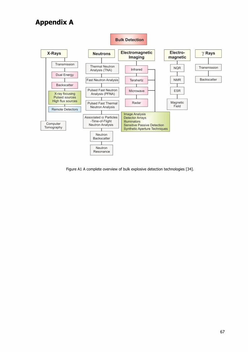
67
Appendix A
Figure A1 A complete overview of bulk explosive detection technologies [34].
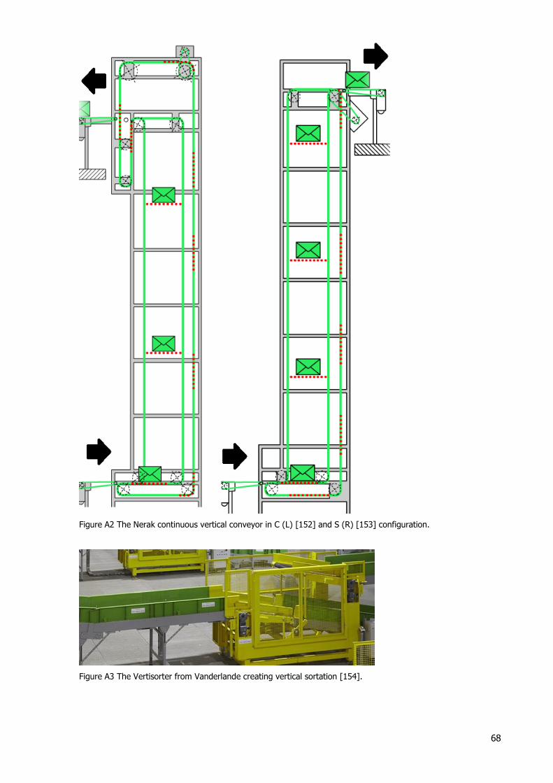
68
Figure A2 The Nerak continuous vertical conveyor in C (L) [152] and S (R) [153] configuration.
Figure A3 The Vertisorter from Vanderlande creating vertical sortation [154].