20152016 NASA USLI Preliminary Design Review (PDR ...
66
20152016 NASA USLI Preliminary Design Review (PDR) Rensselaer Rocket Society (RRS) Rensselaer Polytechnic Institute 1999 Burdett Avenue Troy, NY 12180 Project Name: Red Gemini Task 3.1.1 – Atmospheric Measurements Task 3.1.6 – Aerodynamic Analysis Friday, November 6, 2015
-
Upload
khangminh22 -
Category
Documents
-
view
3 -
download
0
Transcript of 20152016 NASA USLI Preliminary Design Review (PDR ...

20152016 NASA USLI Preliminary Design Review (PDR)
Rensselaer Rocket Society (RRS)
Rensselaer Polytechnic Institute 1999 Burdett Avenue
Troy, NY 12180
Project Name: Red Gemini Task 3.1.1 – Atmospheric Measurements
Task 3.1.6 – Aerodynamic Analysis
Friday, November 6, 2015

1. Table of Contents
Table of Contents 2. Executive Summary
2.1 Team Summary 2.2 Launch Vehicle Summary 2.3 Payload Summary
3. Changes Made Since Proposal 3.1 Vehicle Changes 3.2 Payload Changes 3.3 Project Plan Changes
4. Vehicle Criteria 4.1 Selection, Design, and Verification of Launch Vehicle 4.2 Recovery Subsystem 4.3 Mission Performance Predictions 4.4 Interfaces and Integration 4.5 Safety
5. Payload Criteria 5.1 Selection, Design, and Verification of Payload 5.2 Payload Concept Features and Definition 5.3 Science Value
6. Project Plan 6.1 Budget Plan 6.2 Funding Plan 6.3 Timeline 6.4 Educational Engagement Plan and Status
7. Conclusion Appendix Appendix A: Example Milestone Review Flysheet Appendix B: Scientific Payload Schematics Appendix C: Structural Design Assembly Drawings
2. Executive Summary 2.1 Team Summary This report was produced by the Rensselaer Rocket Society (RRS) of Rensselaer Polytechnic Institute (RPI). The RRS operates out of the Ricketts Building at RPI. The mailing address for the RRS will be the same as that for RPI: 1999 Burdett Ave, Troy, NY 12180. The Community Mentor for the RRS is John Sicker, who is certified to Level 2 with the National Association of Rocketry (NAR) and Level 3 with the Tripoli Rocketry Association (TRA). 2.2 Launch Vehicle Summary The launch vehicle design originated with the Liberty 4 from Giant Leap Rocketry. However, the rocket will be approximately 96 inches in height and will have a body 4.02 inches in diameter. The rocket will have a mass of about 0.342 slugs. The launch vehicle will be propelled by an Aerotech K1103X motor for a 54mm motor mount. The recovery system will consist of a main and a drogue parachute that shall be deployed via electronic deployment. This deployment will be controlled by one of two altimeters to be used for redundancy. The primary deployment altimeter is the Jolly Logic Altimeter Two, an accelerometer based altimeter, and the secondary, scoring altimeter is the PerfectFlite ALT15K/WD Rev2, a barometric altimeter. The altimeters will only be connected to their independent power supplies and the deployment ejection charges. See Appendix A for the Milestone Review Flysheet. 2.3 Payload Summary The rocket payload, the Red Hawk, will be composed of two, physically separate systems. The Drag Flap Analysis Module will focus on accomplishing Task 3.1.6, An Aerodynamic Analysis of Structural Protuberances. The Environmental Analysis Module will focus on accomplishing Task 3.1.1, Atmospheric Measurements. The Drag Flap Analysis system will chart the movement of the launch vehicle and compare the computer projected path of the rocket to the actual movement of the rocket. After the motor has completed its burn, the onboard computer will determine the angle at which the flaps should be deployed in order to apply an appropriate drag force to ensure the rocket hits the target apogee. After deployment of the four drag flaps, barometric pressure sensors hidden below the flaps will take readings of the pressure behind these structural protuberances and compare this data to readings forward of the drag flaps. The Environmental Analysis Module will take readings from several sensors to measure ambient conditions during the rocket’s descent. It will also consist of a gravityguided camera system that will take the required pictures during descent and after landing. The

camera will be oriented correctly through a weight that allows the camera to rotate around the center axis. The camera will be able to see out of the launch vehicle through a plexiglass ring that will form part of the rocket body.
3. Changes Made Since Proposal 3.1 Vehicle Changes The vehicle system underwent several significant changes since the proposal. Instead of heavily modifying a Giant Leap Rocketry Liberty 4 kit, the vehicle will now be constructed without the use of a kit, utilizing phenolic resin tubing and G10 fiberglass fins form Public Missiles Ltd. The fins themselves have been dramatically changed to reduce mass and vehicle profile without loss of stability, and now feature a slightly swept back shape. Additionally, the rocket has grown in length to accommodate the needs of the payload and recovery systems. 3.2 Payload Changes The updated payload now utilizes a single camera that is allowed to rotate freely on a collar. In order to meet the requirement for the photos taken during descent and after landing to be oriented correctly (i.e. sky towards the top and ground towards bottom), the photos will be rotated digitally when needed. It was determined that the electronic lock was not necessary and so the camera assembly is able to rotate freely at all times. These changes were made to reduce the mechanical complexity of the camera system and remove points of failure from the design. 3.3 Project Plan Changes The project plan has been updated to more closely represent the remaining design, construction, and testing that will occur during the project. The project plan has been updated to include all events during the launch vehicle construction, including insertion of the fin can into the lower airframe and the preparation of the nose cone. The project plan also includes much more detail in the project development of the payload sections, including stress testing of the drag flaps and programming for the camera system.
4. Vehicle Criteria 4.1 Selection, Design, and Verification of Launch Vehicle
4.1.1 Mission Statement The launch vehicle will safely power the payload to a one mile apogee with a purposeful overshoot of the target by the rocket, allowing for an apogee correction by the payload during the coast phase of the launch. The launch vehicle will subsequently be safely and gently lowered to the ground by a dualdeploy recovery system.

4.1.2 Requirements and Mission Success Criteria The rocket will launch with a course that would lead to an apogee between 5,280 ft and 5,600 ft if left unaltered. This requirement will be successful if the vehicle travels between 5,000 ft and 5,600 ft, leaving room for error resulting from error in the payload. To facilitate the measurement and reading of this requirement, a barometric altimeter with the audible beep delivery system will be used for scoring purposes.
The launch vehicle will be reusable with fewer than four (4) independent, separable sections. These requirements will be successful if the rocket is able to be prepared for a relaunch immediately after landing, and if the rocket design includes fewer than four independent sections.
The launch vehicle will be powered by a single stage. The single stage will use a commercially available solid motor propulsion system using ammonium perchlorate composite propellant (APCP) which is approved and certified by the National Association of Rocketry (NAR) and Tripoli Rocketry Association (TRA). The motor will less than an Lclass motor and will be launched by a standard 12 volt direct current (DC) firing system. This requirement will be met by the design parameters of the rocket if it is powered by one stage, if the motor used is approved by the NAR and TRA, if the motor is less than an Lclass motor, and if the motor is capable of being launched on a standard 12volt DC firing system. The recovery system of the launch vehicle will be electronic dual deploy with a drogue parachute deployed at apogee and a main parachute deployed at a much lower height afterwards. The stages will be held together by removable shear pins, and, at landing, each independent section of the launch vehicle will have a kinetic energy of less than 75 ftlbf. The requirements will be met if the launch vehicle successfully deploys its drogue parachute at apogee and the main parachute much later, after breaking the shear pins that hold each parachute in place. The kinetic energy requirement will be met in the design parameters of the parachutes and if the launch vehicle is able to sustain the landing forces associated with its kinetic energy at landing. The recovery system electrical circuits will consist of redundant altimeters that are physically and electronically separate from any payload electronics and power supply. Each altimeter will have a designated power supply and arming switch. These requirements will be met by the launch vehicle design. 4.1.3 System Level Design The launch vehicle consists of three subsystems: recovery, aerodynamics and flight stability, structural. The recovery subsystem encompasses the recovery electronics, the ejection charges, the shear pins, the parachutes, and all features necessary for proper recovery of the launch vehicle. Information about the recovery subsystem will be covered in detail in Section 4.2. The aerodynamics and flight stability subsystem

encompasses the selection and preparation of the nosecone and the fins. The main goals of this subsystem are to maintain a low drag coefficient, monitor the stability of the rocket with respect to the center of pressure and center of gravity, and to integrate the launch vehicle with the recovery and payload sections with respect to the aerodynamics of the launch. The structural subsystem encompasses the analysis of stresses and forces on all of the rocket body components. The structural subsystem will ensure that the launch vehicle is able to withstand the forces associated with the launch and recovery of the rocket and payload. The aerodynamics and flight stability subsystem is a critical portion of the development of the launch vehicle, as well as its integration with the payload. A standard, highstrength plastic nose cone was chosen as the rocket nose cone, as seen in Figure 1. This design was chosen over highspeed nosecones because of the projected maximum velocity of the rocket. This launch vehicle should not exceed .8 mach. Standard shaped nosecones have a proven record of flying faster than 1 mach. Our rocket will not near the speeds necessary to cause a change in the aerodynamic profile of the nose cone.
Figure 1: Nosecone Selection
The fin shape was derived from the original fin profile of the Giant Leap Rocketry Liberty 4, See Figure 2, however it was significantly manipulated. The planform area of the Liberty 4 fins was extremely large. In addition, the profile of the fin had a large drag coefficient that limited the apogee of the launch vehicle.
Figure 2: Liberty 4 Fin Shape
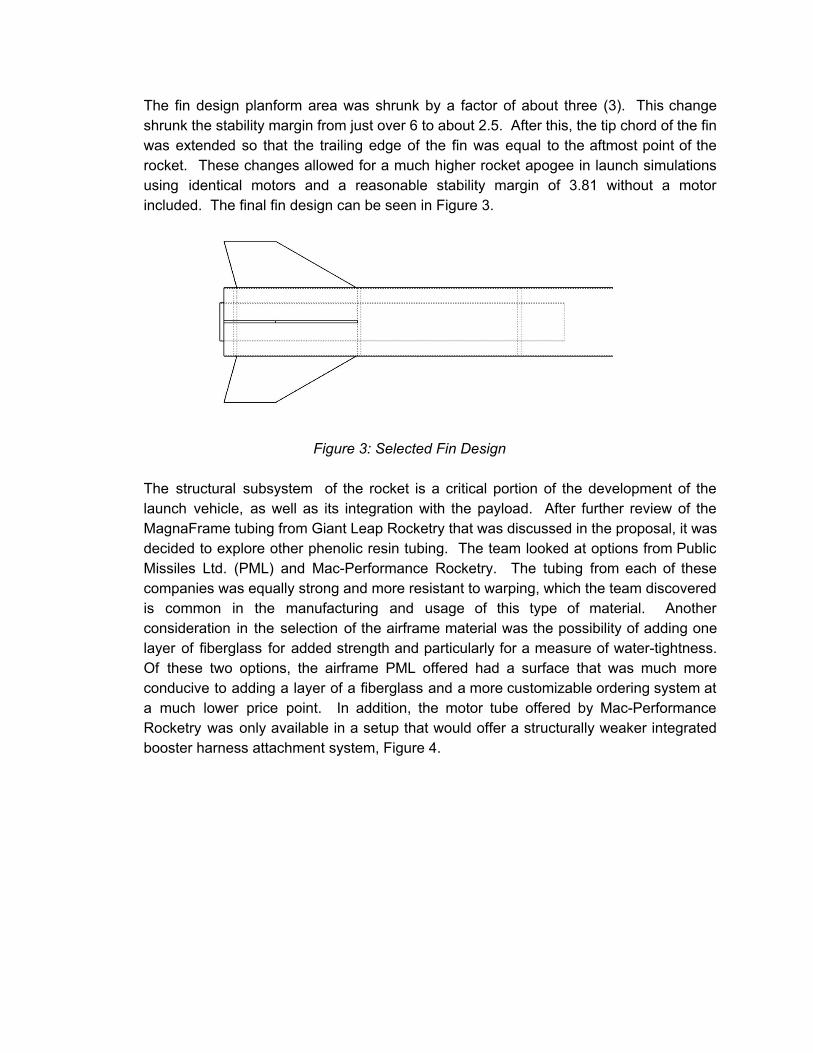
The fin design planform area was shrunk by a factor of about three (3). This change shrunk the stability margin from just over 6 to about 2.5. After this, the tip chord of the fin was extended so that the trailing edge of the fin was equal to the aftmost point of the rocket. These changes allowed for a much higher rocket apogee in launch simulations using identical motors and a reasonable stability margin of 3.81 without a motor included. The final fin design can be seen in Figure 3.
Figure 3: Selected Fin Design
The structural subsystem of the rocket is a critical portion of the development of the launch vehicle, as well as its integration with the payload. After further review of the MagnaFrame tubing from Giant Leap Rocketry that was discussed in the proposal, it was decided to explore other phenolic resin tubing. The team looked at options from Public Missiles Ltd. (PML) and MacPerformance Rocketry. The tubing from each of these companies was equally strong and more resistant to warping, which the team discovered is common in the manufacturing and usage of this type of material. Another consideration in the selection of the airframe material was the possibility of adding one layer of fiberglass for added strength and particularly for a measure of watertightness. Of these two options, the airframe PML offered had a surface that was much more conducive to adding a layer of a fiberglass and a more customizable ordering system at a much lower price point. In addition, the motor tube offered by MacPerformance Rocketry was only available in a setup that would offer a structurally weaker integrated booster harness attachment system, Figure 4.

Figure 4: MacPerformance Rocketry Motor Tube
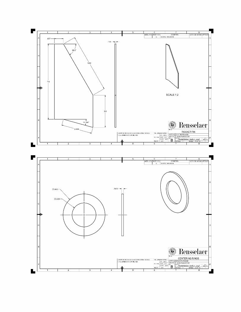
The structure subsystem of the launch vehicle continued to use the 4.0 in outer diameter rocket body and 54mm motor tube, as described in the proposal. In order to accommodate increased size requirements by the payload team, the rocket was lengthened to about 104 in long. The fins will be made of fiberglass, and will be ⅛ in thick, to avoid unwanted fin flapping. A schematic of the rocket structure can be seen below in Figure 5. More detailed drawings can be found in Appendix C.
Figure 5: Launch Vehicle Structure
4.1.4 Verification Plan
Requirement Design Feature
Verification Design Phase Construction Phase Testing Phase
Apogee between 5,280 ft and 5,600 ft if left unaltered
Rocket Mass, Rocket Motor, Design
OpenRocket Simulations, Payload Mass, Rocket material
selection, Motor Selection
Stay as close as possible to original Mass Estimates
Read apogee at several launches in different weather
conditions
Reusable
Body Strength (fins,
airframe, parachutes,
etc.)
Stress Analysis of Vulnerable
Components, Use of Large Factors of Safety in Critical Components
Use HighStrength Epoxies, Store all components Safely,
Design Followed, Components inspected upon order arrival show no signs
of damage
Launch in appropriate weather
multiple times

Four or fewer Independent Sections
General Design
Design fewer than four independent Sections (Nosecone section, Payload/Avionics
Section, Lower Body Section)
Design Followed
Rocket is launched and recovered in less than four independent sections
Single Stage General Design,
Motor Design
Design only a single stage rocket
Design Followed Rocket is launched with only a single stage motor
Commercially available solid
motor propulsion
system under Class L
Motor
Ensure Mass and General Rocket Design allow for a
motor well under Class L motor approved by the TRA and NAR
Design Followed, stay as close as possible to original
mass estimates
Motor under Class L is used at several launches in different weather conditions
Capable of Launch by 12 V
DC firing system
Motor, motor retainer
Select a motor retainer that allows for access to motor, select a motor able to be
launched with 12V DC firing system
Design Followed, safely store motors
Launch rocket on standard 12 V DC
firing system multiple times
Electronic Dual Deploy
General Recovery Design
(parachutes, shock cord, ejection charges, etc.)
General Design is DualDeploy, Use of a Drogue and Main
Parachute, Design for Multiple Separation
Points
Design Followed
Rocket launched with appropriate recovery system, Drogue and Main parachutes deploy at different points in
flight
Drogue Deploys at
Apogee, Main Parachute Deploys at much lower altitude
Parachutes, ejection charges, General Rocket Design, Altimeters
General Design has Drogue Parachute at First Separation Point and Main Parachute at another, Simulations run with required
deployment locations
Design Followed, Set Altimeters to required
ejection charge deployments (and keep track of which side is deployed when)
Rocket launched multiple times with
parachute deployment at required times
Shear Pins hold rocket sections together until Parachute Deployment
Shear Pins, Ejection Charges
Shear Pin Strength Accurately Calculated and inserted into Recovery Design, Ejection Charge
Strength Accurately Calculated
Design Followed, Shear Pins show no signs of damage
before install
Rocket launched multiple times with
parachute deployment at required times
Independent Sections have less than 75
General Rocket Design
Kinetic Energy of Each Independent Section Analyzed Accurately
Design Followed, stay as close as possible to original mass estimates, Parachutes
and Recovery system
No damage or hard landing evident in any section after multiple test

ftlb of KE at Landing
(Mass), Parachutes
components show no signs of damage upon order arrival
launches in varied flight conditions
Redundant, Safe Altimeters
Altimeters, Supporting Recovery Electronics
Select at least 2 commercially available altimeters, Design has an independent power
supply to each Altimeter
Design Followed, Altimeters stored safely, All
components of supporting electronics and altimeters tested before installation
Recovery System Operates as Expected,
Altimeters report similar apogees in all test launches
Table 1: Requirement and Verification Plan 4.1.5 Risk Analysis The following tables explain the Risk Assessment Codes (RACs) used to evaluate the potential hazards in the NASA USLI launch. RACs are presented for the initial hazard, as well as for the hazard remaining after controls and mitigations have been applied. Table 1 identifies the colorcoded RACs which will be referred to later when assessing individual risks. Table 2 outlines the different levels of risk and their acceptance levels. Table 3 explores definitions of severity as the risks apply to personnel, equipment, and the environment. Finally, Table 4 offers both qualitative and quantitative definitions of probability. In all cases, individuals involved in each task should be advised of the risks involved and proper safety precautions to be taken.
Risk Assessment Codes (RACs)
Likelihood
Impact Value
1 High 2 Medium 3 Low
A High 1A 2A 3A
B Medium 1B 2B 3B
C Low 1C 2C 3C
Table 2: Risk Assessment Code Matrix
Level of Risk and Level of Management Approval
High Risk Undesirable. Documented approval from the NASA USLI Safety Officer.

Moderate Risk
Acceptable. Documented approval from the supervisor or supervisors directly responsible for overseeing the launch.
Low Risk Acceptable. Documented approval not required, but an informal review by the supervisor or supervisors directly responsible for overseeing the launch.
Table 3: Definitions of Risk Levels
Impact Value Definitions
Description Personnel Safety and Health
Facility/Equipment Environmental
1 High Loss of life or a permanent, disabling injury.
Loss of facility, systems or associated hardware.
Irreversible severe environmental damage that violates law and regulation.
2 Medium Moderate injury or occupationalrelated illness.
Moderate damage to facilities, systems, or equipment.
Mitigable environmental damage without violation of law or regulation where restoration activities can be accomplished.
3 Low First aid injury occupationalrelated illness.
Minimal damage to facility, systems, or equipment.
Minimal environmental damage not violating law or regulation.
Table 4: Definitions of Risk Impact Values
Likelihood Definitions
Description Qualitative Definition Quantitative Definition
A High High likelihood to occur immediately or expected to be continuously experienced.
Probability >0.1 (>10% chance)

B Medium Expected to occur several times or occasionally within time.
0.1 > Probability > 0.01 (110% chance)
C Low Very unlikely to occur and an occurrence is not expected to be experienced within time.
0.01 > Probability > 0 (<1% chance)
Table 5: Definitions of Risk Likelihoods
Hazard Cause Effect PreRAC
Mitigation PostRAC
Personnel exposure to harmful chemical substances (resin, epoxies, etc.)
Mishandling of chemical materials
Personnel injury requiring medical treatment
3A 1. Designated personnel will wear PPE (Personal Protective Equipment) such as gloves and splashproof eyewear during handling of chemicals.
2. Personnel will be familiarized with the MSDS of used chemicals and their station.
3C
Personnel unexpected contact with heavy machinery
Misuse of machinery or equipment Malfunction of machinery
Personnel injury requiring medical treatment
Possible permanent injury or death
1B 1. Only a single, experienced operator on one tool at a time.
2. Minimize distractions
3. Refrain from wearing loose clothing
1C

4. Handling of tools only after they are finished cooling or spinning.
5. Proper tool maintenance and knowledge of first aid stations.
Personnel exposure to harmful voltage
Contact with energized electrical systems
Personnel injury requiring medical treatment
Possible permanent injury or death
2B 1. Systems will not be handled by personnel while energized during testing.
2. Gloves may be worn to protect against accidental contact with electrical components.
2C
Personnel exposure to toxic fumes
Chemical spillage resulting in airborne particles Improper mixing of chemicals
Personnel injury requiring medical treatment
Possible permanent lung damage or death
2B 1. All personnel will be familiar with all chemicals involved
2C
Inhibited Test Launches
Adverse weather conditions Lack of personnel with necessary NAR or TRA certification.
Loss of vital test data
Inability to launch rocket
2B 1. Test launches can be scheduled before harsh winter conditions.
2. Flexible launch windows can be scheduled.
3. Presence of an additional
2C

team member with necessary NAR or TRA certification.
Late arrival of parts Issues with shipping company/postal service Error on the part of the shipper
Delay of assembly, possibly pushing assembly past deadline
2B 1. All parts will be ordered with enough time before they will be needed.
2. Expedited shipping will be selected as appropriate.
2C
Malfunction of mechanical parts or systems
Fracture, yielding, or some other form of mechanical failure in an essential mechanical component
Loss of vital test data
Inability to launch rocket
Possible inflight failure of critical systems
1B 1. Redundancy of mechanical systems
2. Thorough materials testing
3. Generous factors of safety
4. Multiple smallscale tests
1C
Malfunction of electrical parts or systems
Short circuit Failure of analog electrical component Failure of digital electrical component Failure of microprocessor
Loss of vital test data
Inability to launch rocket
Possible inflight failure of critical systems
1B 1. Redundancy of electrical systems
2. Thorough inspection
3. Multiple smallscale tests
1C
Malfunction of software or code
Exposure to signals, data, or numbers not programmed to process Bugs
Loss of vital test data
Inability to launch rocket
1B 1. Thorough checking by multiple programmers
1C

Infinite loop or other programming error
Possible inflight failure of critical systems
2. Multiple smallscale tests
Failure of sensor Faulty wiring Exposure to elements Exposure to excessive acceleration Internal issues
Loss of vital test data
Inability to launch rocket
Possible inflight failure of critical systems
2B 1. Redundancy of sensors vital to rocket operation
2. Thorough inspection
3. Multiple smallscale tests
2C
Failure of drag flap system
Failure of any associated mechanical or electrical system or code
Inability to control rocket’s vertical displacement or speed during ascent
2B 1. Redundancy of subsystems
2. Thorough inspection
3. Multiple smallscale tests
2C
Failure of either parachute
Mechanical failure of cord, fabric, etc. Failure to deploy
Loss of vital test data
Possible destruction of subsystems or entire rocket
1B 1. Assuring only highquality materials are used
2. Thorough inspection
3. Multiple smallscale tests
1C
Table 6: Possible Risks and Mitigation Tactics
*Note: for verification of each of the mitigations pertaining to personnel health and safety, refer to Safety Plan, Safety Officer.*
4.1.6 Component Analysis
Component Description Materials Cost Source
Fin Can Fins attached to motor tube
G10 Fiberglass +epoxy+Phenolic Motor Tube
$36 publicmissiles.com/products/

Lower Airframe Airframe containing Fin Can and Drogue Parachute
Phenolic Airframe Tubing
$50 publicmissiles.com/products/
Nosecone Nosecone and Main Parachute Mount
HighStrength Plastic+forged steel eye bolt+epoxy
$10 publicmissiles.com/products/
Main Airframe Airframe containing Main Parachute and Payload Section
Phenolic Airframe Tubing
$50 mcmastercarr.com
Payload Section Containment system for payload (including bulkheads, couplers, etc.)
Plywood Bulkheads, Phenolic Cardboard Couplers, forged steel eye bolts, steel threaded rod, epoxy, acrylic plastic
$50 publicmissiles.com/products/
Recovery Electronics
Altimeters and supporting electronics that run recovery system
G10 Fiberglass Sled, Altimeters, Batteries, copper wiring, switches
$50 sparkfun.com
Ejection Charges Charges that eject Parachutes on Altimeter command
Aluminum Blast Cap holders, Ejection Charges, epoxy, copper wiring
$50 apogeerockets.com

Parachutes Drogue and Main Two Skyangle Parachutes
$25 b2rocketry.com
Motor Retainer Aeropack Motor Retention System
Aluminum $42 macperformancerocketry.com
Table 7: Component Analysis
4.1.7 Mass Statement
Part Mass (oz) Quantity Subtotal (oz)
Centering Ring 2.6 3 7.8
Motor Mount 4.83 1 4.83
Motor Retainer 1.42 1 1.42
Motor 54.42 1 54.42
Body Tubing (44”) 18.7 1 18.7
Drogue Chute 6 1 6
Shock Cord 9.62 1 9.62
Fins (x4) 2.86 1 2.86
Subtotal 8.3 (lbm)
Table 8: Mass of the Lower Airframe
Part Mass (oz) Quantity Subtotal (oz)
Nosecone 10 1 10
Body Tubing (31”) 13.18 1 13.18
Plexiglass Tubing (8”)
16.01 1 16.01
Bulkheads 4 3 12
Coupler Sections 2.6 2 5.2
Shock Cord 9.62 1 9.62

Main Chute 34 1 34
Drag Flap System 16.79 1 16.79
Payload Estimate 16 1 16
Subtotal 6.603 (lbm)
Table 9: Mass of the Main Airframe
Total Mass: 14.903 lbm
As illustrated in tables 8 and 9, this mass estimate of is based on a sum of the masses from the parts that will be used in the rocket. As such, the accuracy of this measurement is limited by data provided from part manufacturers and distributors. Additionally, some parts may be modified during the construction process. This will result in the reduction in mass of some components and the addition of mass on others.
There is a very large margin of mass until the vehicle becomes unable to launch with our selected propulsion system. Besides this hard constraint, the rockets must strictly exceed the target altitude in order for the drag flap system to function. Given this restriction, we have a margin of about five additional pounds before our simulations indicate that we would just reach the target height.
Some mass has been reserved in two major areas. Some assembly (i.e. construction of the fin canister) will require the use of a significant amount of epoxy which has not been included in this mass statement. Additionally, the design of the payload will mature a significant amount from the PDR, which will contribute a notable amount of additional mass. As a rough estimate, each area should contribute no more than one additional pound to the total mass.
4.2 Recovery Subsystem
4.2.1 System Level Design The drag force on the parachute is D=½CdAρV
2 where: Cd is the drag coefficient, A is the cross sectional area, ρ is air density, and V is velocity This yields a maximum force on the drogue of 20 lbf and a maximum force on the main chute of 112 lbf. The data sheet for these chutes provide that the shroud lines and attachment points have a strength of 2250 lbf and the swivels have a tolerance of 1500 lbf. This gives substantially more strength than required for the anticipated loads. Also, these parachutes are rated for

rockets in the weight range of our rocket. The parachutes are composed of a zero porosity silicon coated balloon cloth, which will be capable of handling much more than the expected loads. 4.2.2 System Components The mass statement from Section 4.1.7 was used while determining the major recovery system components. The parachutes chosen for the dualdeploy recovery system include a SkyAngle Cert3 Drogue parachute and a SkyAngle Cert3 Large main parachute. Each parachute is constructed of zero porosity 1.9 ounce balloon cloth and has four ⅝ inch Kevlar suspension lines rated for 2250 lbf and which meet at a swivel joint rated for 1500 lbf. The drogue and main parachutes have surface areas of 6.3 and 57 square feet, respectively. These parachutes were chosen for their strength, flight characteristics, and simplicity in integration. Data collected from OpenRocket simulations indicates descent velocities after drogue and main chute deployment to be 50 and 14.5 ft/s, respectively. The ejection charges for the parachute deployment require 1 gram of black powder charge per 11 inches of body length containing the parachute. This leads to an approximate calculated ejection charge size of 1.7 g of black powder for main parachute deployment and 2.1 g of black powder for drogue parachute deployment. The attachment scheme between the rocket body and the main parachute consists of Kevlar shock cord connecting the main parachute to a 1.5 inch eyebolt mounted to the main airframe forward ¼ inch thick birch bulkhead. The drogue parachute and the body will be attached in a similar manner; there will be eyebolt attachments on the forwardmost motor centering ring and on the rear of the payload section. Both the fore and aft shock cords will be 250” long, or about 3 body lengths, to ensure adequate separation of vehicle components during descent. Simulation data from OpenRocket indicates that the maximum acceleration the rocket will experience during descent is 225 ft/s2 and occurs when the main parachute deploys, at an altitude of 800 feet. Using the mass of the rocket, the force exerted on the rocket during deployment can be calculated. This force is used to ensure that the loads on the attachment hardware do not exceed the ultimate strength of the components. The electronic components of the recovery system consists of a StratoLogger CF altimeter and a Raven3 altimeter, and can be seen in detail in Figure 6 below. The design of the electronics allows for screw switches on the exterior of the payload section to arm and disarm the charges and altimeters. The two altimeters provide redundancy, as the flight system is capable of functioning on either should one fail midflight. At the appropriate altitudes, each altimeter will send signals to trigger the same two charges for each ejection event. Thus, each altimeter can trigger both charges, and the charges themselves are redundant, so if one fails, parachute deployment will not be adversely

affected. These will be black powder charges, mounted in aluminum blast cups of the fore and aft bulkheads of the main airframe. These charges will separate the rocket sections and allow unfurling of the parachutes. The drogue will be deployed at apogee when the first pair of charges are detonated, and the main chute will be deployed at 800 feet when the second charge pair triggers. Kevlar chute protectors will insulate the parachutes from the heat effects of the charge firings.
Figure 6: Recovery System Electronics Schematic
Testing of the recovery system will be done via simulation software for initial validation, and final testing and modification will occur on scale model flights. Current simulation data has been obtained from OpenRocket, and work has begun to incorporate data from ANSYS’s Fluent CFD software for more detailed analysis. Ground tests of the charge system may also occur to lessen the risk of losing the scale model to a parachute failure.

4.3 Mission Performance Predictions
4.3.1 Mission Performance Criteria The rocket has several criteria that must be met on launch day. The primary goal is to obtain an apogee as close to 5280 feet as possible. This will be achieved by the selection of a motor that will overshoot the target, then usage of the drag flap system to slow the coasting velocity down. Additionally, the vehicle must land within a reasonable distance of the launch site. To this end, the recover system will be tailored so that the main parachute is not deployed too early and thus drift is mitigated.
4.3.2 Vehicle Simulations Figure 7 shows the simulated motor thrust curve for an Aerotech K1103X Motor, as provided by ThrustCurve.org.
Figure 7: Thrust Curve of Aerotech K1103X Motor
Utilizing OpenRocket and this motor configuration, a simulated model of the rocket was produced as shown in Figure 8.

Figure 8: Simulated Model for Flight Simulation
On this model, there is a stability margin of 6.12 Calipers with the motor included. The simulated center of mass is approximately 48 inches down from the top of the nosecone, and the simulated center of pressure is approximately 72 inches from the top. Using this model and the selected motor, a flight simulation was created which is shown in Figure 9.
Figure 9: Flight Simulation from OpenRocket
Note that this simulation does not take into account the effect that the drag flap system will have. Given that, the apogee reached is 5431 feet, with a maximum acceleration of 677 feet/second2, and flight time of 133 seconds.

4.3.3 Kinetic Energy Analysis The nose cone will have a ground hit velocity of approximately 20 ft/s, yielding a kinetic energy of 3.78 ftlb. The upper body and lower bodies will hit the ground at 20 ft/s. The upper body will have a kinetic energy of 41.70 ftlb and the lower body will have a kinetic energy of 25.58 ftlb.
4.3.4 Drift Analysis For the Upper and Lower Body For a launch angle into the wind that brings the rocket over the launch site at apogee, D=(4480V1)+(800V2) where V1 is the ratio between the wind speed and the terminal velocity with the drogue deployed and V2 is the ratio between the wind speed and the terminal velocity with the main chute deployed.
For a wind speed of 0 mph, and a 3.5 degree launch angle, the drift value is approximately 250 ft. A vertical launch will yield very small drifts, as indicated in table x below.
Wind Speed Drift Value
5 mph 856 ft
10 mph 1712 ft
15 mph 2567 ft
20 mph 3423 ft
Table 10: Drift Analysis at Various Wind Speeds and Vertical Launch
4.4 Interfaces and Integration
The payload will be integrated into the overall vehicle using a payload bay in the center of the rocket. This will consist of an electronics bay and two parachute bays, separated by bulkheads. The drag flap module will also be located within his section. The first bulkhead at the rear of the rocket will have the drogue attachment point and deployment system. The drag flap module is forward of this bulkhead. The electronics bay will be forward of the drag flap module so that the processing segment of the electronics is adjacent to both the motor and the camera system, minimizing wire length needed. The camera assembly section will be located forward of the electronics, and will consist of the swing arm and related connection structure. So that the rods forming the main supports of the aft segment of the payload bay do not interfere with the camera’s view, an additional bulkhead will be located immediately aft of the plexiglass window. This will also serve as the attachment point of the swingarm assembly to the rocket superstructure. Another bulkhead will be located forward of the camera structure, to which the forward parachute may be attached. The bulkheads will have shock cord and parachute attachment points in the form of forged eyebolts and quick links to facilitate

easy access to the payload and electronics, as well as aluminum charge cups to hold the black powder of the ejection charge. There will also be connection points for the electric matches that will trigger these ejection charges. Electronics arming and disarming will take place using screw switches accessible from outside the rocket. Shear pins will connect the aft segment of the overall payload bay to the base of the rocket. These will sever at the first charge event to deploy the drogue, and a similar mechanism will deploy the main parachute at 800 feet above ground. Data from the electronics section will be transmitted back to the ground station via an antenna. Actual physical modifications to the payload will require removal of the electronics sled as only the arming switches allow an external action to influence the payload. 4.5 Safety
4.5.1 Safety Officer RRS has identified Chris Andre as the acting safety officer. His responsibilities include ensuring shop safety and hazardous material procedures, which is partly accomplished through safety quizzes administered by the RPI School of Engineering. He will oversee the safe construction and launch of the pertinent rocket vehicles through supervision and inspections. 4.5.2 Preliminary Checklists The safety officer and team mentor will oversee the final assembly of the rocket and its subsystems prior to flight, as well as the launch pad preparation operations. Two preliminary checklists have been developed for each phase. The prelaunch operations checklist broadly covers the assembly of the major structural components prior to the rocket arriving at the launchpad. The launch pad operations checklist covers the procedures to be completed prior to launch. The checklists are detailed in Tables 11 & 12.
Category Description Required Actions
Parachute Deployment
Protective insulation will be inserted between the ejection charges and the parachute to prevent burning, and the parachute will be properly folded and then inserted.
protective insulation insertion, parachute folded, parachute inserted.
Avionics Avionics equipment will be properly connected and inspected. Batteries will be tested for charge and
Wiring is firm, batteries are charged, batteries are firmly strapped into bay, avionics respond to communication handshake, avionics slid into bay in

inserted into their bay. Avionics will be tested and then slid into bay and secured.
right orientation, avionics sled secured.
Payload Payload is inserted into payload tube and fixed. Shear pins are inserted.
Payload inserted in right orientation, payload bay secured, shear pins inserted.
Drag Flaps Drag flaps will be checked for unobstructed movement.
Verify that drag flaps can extend and retract fully by running control system test.
Table 11: PreLaunch Operations Checklist
Category Description Required Actions
Rocket Assembly Rocket assembly is complete.
RSO Safety Check RSO will check final rocket before launch.
RSO Approval. RRS SO Approval. RRS Mentor Approval.
Avionics Avionics will be checked for proper communication and data relay.
Data link is clear.
Avionics Avionics charge and ignition switch will be turned off to prevent premature ignition.
External switch is OFF. Confirm status light is also OFF.
Ejection Charges Ejection charges will be installed.
Ejection charges installed
Motor Ignition Motor igniter will be installed. Delay charge will be installed. Leads will be connected during handling to prevent static electricity discharges.
Motor igniter leads are connected during installation. Motor igniter is installed. Motor igniter is properly wired. Motor igniter leads are separated. Delay charge is installed.
Launch Configuration Rocket will be placed on the launch rod and given the desired angle.
Rocket rail buttons are on launch rod. Selected angle is confirmed by RSO.
Avionics Avionics charge and ignition External switch is ON.

switch is turned on to arm the system.
Confirm status light is also ON.
Ejection Charges Ejection charges will be armed.
Ejection charges are connected and will not short.
Final Safety Check Final safety check will be conducted by RRS SO, RRS Mentor.
RRS SO Approval. RRS Mentor Approval.
Data Retrieval Final altitude will be retrieved.
Altitude has been retrieved by SL official.
PostFlight Inspection Inspection will be performed on rocket following flight.
RRS SO Approval. RRS Mentor Approval.
Table 12: Launchpad Operations Checklist 4.5.3 Failure Modes The following table summarizes the launch and flight failure modes that have been identified. They are addressed with a mitigation plan and a risk likelihood/impact (3/5).
System Failure Risk Impact Mitigation
Motor Dislodgement from housing
1 5 Employ retainer structure with three bulkhead centering rings.
Computer/Control
Microcontroller failure
1 3 All wiring will be finalized and tested before launch to prevent electrical malfunction. Code will be reviewed and tested during scale launches. Wiring will be soldered and insulated.
Stepper motor jam
1 2 Stepper motor will be tested against static loads to simulate expected air speeds. Mechanism will be lubricated and inspected for particulates before launch.
Forward flap system causes instability
1 5 Verification of stability will be performed in OpenRocket and using test launches.
Structural Fins shear off during flight
2 4 Fins will be embedded in body and fixed to the internal motor mount and body with heattolerant epoxy resin.
Rocket motor explodes
1 5 Test launches, finite elements analysis, and static load tests will be performed to verify integrity of rocket body.

Parachute tears, parachute fails to deploy
2 5 Parachute will be checked for defects before packing. Parachute will be packed properly.
Shock cord breaks
2 5 Recentlymanufactured shock cord will be used to ensure integrity. Shock cord will be properly secured and tested under static and jolt loads.
Drag flaps shear off during flight
2 2 Mechanical components and connections will be shear tested under static loads.
Recovery Parachute ejection failure
2 5 Redundant powder charges will be used for the main parachute. Packing will be inspected before launch.
Parachute ejected prematurely
1 3 Code will be reviewed for correctness. Hard failsafes will be implemented to prevent ejection above a predetermined altitude.
Computer system failure
2 4 Flight computer will be tested using simulated soft landing jolts to ensure component survivability. Wiring will be soldered in place and insulated.
Transmitter failure/interference
2 3 Transmitter will be tested at range. Interference will be studied.
Launch operations and transportation
Physical damage during handling
1 5 Each component of the launch vehicle will be transported in a separate, cushioned box. Launch vehicle will be inspected on site for defects.
Live charges on board after launch command
1 3 Avionics will be powered off. Discrete switch will cut off system power entirely.
Premature firing of ejection charges and/or motor
1 5 Wiring will be ensured to proper through tagging. Ejection charges will be disconnected until launch. Igniters will be installed at launch. Computer will have a discrete switch only to be armed during launch to prevent premature signal.

Spectator injury
1 5 Range will be cleared prior to launch. No large, heavy objects will be installed according to NAR safety code.
Table 13: Failure Modes
The flight procedure will be practiced by the team prior to the final competition launch. Assembly of the rocket will be checked. The team safety officer and team mentor will supervise the final assembly using checklists and will handle the final preparation on the launch pad. 4.5.4 Hazard Analysis and Environmental Concerns The team safety has identified a list of common personnel hazards that may be encountered during the manufacture and testing of the vehicle. All participating team members will have completed safety training as administered by the RPI School of Engineering. A comprehensive list of MSDS are freely available to the team. Team members will be briefed on the NAR safety code of conduct by the team safety officer and the team mentor. The following table summarizes the hazards that have been identified with mitigation steps, required safety equipment, and emergency equipment.
Hazard Mitigation Required Safety Equipment
Emergency Equipment
Drill press rotation No loose clothing/hair
Glasses First aid kit
Band saw No loose clothing/hair
Gloves when working with large pieces, glasses
First aid kit
Epoxy/Paint fumes/irritation
Work in ventilated, spacious area
Face masks, gloves, glasses
First aid kit, eye flushing station
Propellant/powder ignition and skin irritation
Motor will be stored in separate, insulated cabinet. Motor will be handled with gloves after is has cooled.
Gloves, glasses First aid kit, eye flushing station, burn kit
Vehicle debris NAR regulations will be obeyed
Glasses First aid kit
General cuts and irritation
Gloves will be worn when working with sharp/irritating
Glasses, gloves First aid kit

implements, and glasses will be worn when operating moving machinery
Table 14: Hazard Analysis
Several environmental concerns that may impact the testing and launch of the rocket have been identified in the following table.
Risk Mitigation Likelihood
Inoperable Wind Conditions / Cloudy
Launches will be planned in advance according to weather forecasts to ensure timely completion.
2
Rainy Conditions All electromechanical and electrical parts will be shielded. Body structure will be able to retain integrity in damp conditions.
2
Operable Wind Conditions Launch rod angle will be adjusted. Parachute deployment altitude will be recalculated and adjusted due to higherthanexpected drift.
3
Vehicle Cannot be Found All charges will be detonated by flight computer before landing to ensure that it is inert. Vehicle will have identifiable, bright paint scheme.
1
Table 15: Environmental Concerns
5. Payload Criteria
5.1 Selection, Design, and Verification of Payload 5.1.1 Drag Flap Subsystem The drag flap subsystem of the rocket will be used to accomplish multiple requirements simultaneously. These are Vehicle Requirement 1.1, and Payload Requirement 3.1.6. Vehicle Requirement 1.1 states that the rocket must deliver the payload to an altitude of 5,280 feet. The rocket motor has been selected such that if the rocket were to fly without the drag flaps, the final altitude would be slightly above this height. The drag flaps will be dynamically controlled in flight to decrease the vertical velocity of the rocket and adjust the maximum height of the rocket to exactly 5,280 feet at apogee.

The drag flap subsystem will also fulfill Payload Requirement 3.1.6, “Aerodynamic Analysis of Structural Protuberances.” Barometric pressure sensors will be placed above and below the flaps, and will be gathering data throughout the flight. Additionally, the performance of the drag flaps will be simulated and studied using ANSYS Fluent CFD software. This analysis will help to verify the robustness and performance of the drag flap subsystem.
Figure 1: Diagram of Drag Flap Subsystem Assembly
The Drag Flap Subsystem consists of four quartercylinder shaped elements which fan out from the body of the rocket to create a drag force, which in turn slows the rocket’s vertical velocity. The quartercylinder shaped elements, or flaps, are designed to move simultaneously with one another. Their motion is controlled by a single DC motor. The motor will be attached to a threaded rod, which will in turn be attached to the middle plastic piece. As this piece moves up and down, it causes the flaps to rotate in and out. The flaps are designed to extend to a maximum angle of 37.89 degrees. This maximum deflection results in an increase of 27.37 square inches of additional vertical projected area. Moving forward, the team will perform a detailed computational fluid dynamics

analysis on this assembly in order to develop a function which relates the angle of the flaps to the increase in drag force. The motor which actuates the drag flaps will be controlled using an Arduino Zero. The Arduino will be connected to a motor driver, and to one of the accelerometers. The acceleration readings from the accelerometer will be integrated in the control software for the drag flap system in order to obtain vertical velocity. Using OpenRocket simulation software, the team can plot ideal velocity as a function of vertical height. By calculating the error between the actual velocity and the ideal velocity at each point in the rocket’s flight, the team will design a control algorithm to actuate the drag flaps, guiding the rocket to exactly 5280 feet. The motor which will be used to actuate the drag flaps is a bipolar stepper motor. The motor specifications are shown below in Table 16.
Table 16: drag flap motor specifications
Steps per Revolution 200
Supply Voltage 4.5 V
Current per Phase 0.67 A
Holding Torque 950 gcm
The drag flap subsystem is made up of ten separate plastic pieces, all of which will be 3D printed using a fifth generation Makerbot. The team performed preliminary finite element analysis (FEA) to verify the strength and robustness of the design, but more detailed analysis will come once the team has CFD data in order to determine the total drag force on the flaps. One challenge in the analysis comes from the nonisotropic nature of 3D printed parts. 5.1.2 Atmospheric Measurement Subsystem The proposed scientific payload design complies with NASA’s requirements outlined in the 2016 USLI Handbook section 3.2.1 in that it includes sensors for measuring humidity, temperature, barometric pressure, solar irradiance, UV light levels, a camera for capturing images during flight and recovery, a GPS module, and a wireless transmitter capable of transmitting data to the ground support team. In addition, it contains a SD card for storing all data recorded during flight, and an accelerometer used to determine basic payload orientation during flight and recovery. The planned microprocessor architecture uses standard Arduino style microprocessors that communicate easily with their corresponding sensors and output loads.
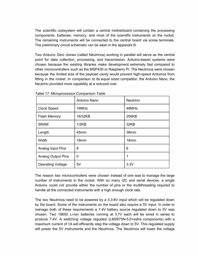
The scientific subsystem will contain a central motherboard containing the processing components, batteries, memory, and most of the scientific instruments on the rocket. The remaining instruments will be connected to the central board via screw terminals. The preliminary circuit schematic can be seen in the appendix B. Two Arduino Zero clones (called Neutrinos) working in parallel will serve as the central point for data collection, processing, and transmission. Arduinobased systems were chosen because the existing libraries make development extremely fast compared to other microcontrollers such as the MSP430 or Raspberry Pi. The Neutrinos were chosen because the limited size of the payload cavity would prevent highspeed Arduinos from fitting in the rocket. In comparison to its equal sized competitor, the Arduino Nano, the Neutrino provided more capability at a reduced cost. Table 17: Microprocessor Comparison Table
Arduino Nano Neutrino
Clock Speed 16MHz 48MHz
Flash Memory 16/32KB 256KB
SRAM 1/2KB 32KB
Length 45mm 38mm
Width 18mm 18mm
Analog Input Pins 8 6
Analog Output Pins 0 1
Operating Voltage 5V 3.3V
The reason two microcontrollers were chosen instead of one was to manage the large number of instruments in the rocket. With so many I2C and serial devices, a single Arduino could not provide either the number of pins or the multithreading required to handle all the connected instruments with a high enough clock rate. The two Neutrinos need to be powered by a 3.36V input which will be regulated down by the board. Some of the instruments on the board also require a 5V input. In order to manage both of these requirements a 7.4V battery source regulated down to 5V was chosen. Two 18650 LiIon batteries running at 3.7V each will be wired in series to produce 7.4V. A switching voltage regulator (LM2675N5.0+extra components) with a maximum current of 1A will efficiently step the voltage down to 5V. This regulated supply will power the 5V instruments and the Neutrinos. The Neutrinos will lower the voltage

down to 3.3V, which will power the remaining components with an upper current limit of 500mA each. The two Neutrinos will share a single MicroSD board for reading and writing flight data. The pins for the MicroSD board will be run through two 4053 tri 2:1 analog multiplexers for two way communication between a single Neutrino and the MicroSD. Two digital lines pulled low by 5 kOhm resistors will run directly between the two Neutrinos. The secondary Neutrino’s line will also be run to the selection pins on the multiplexers to change access between the two microcontrollers. When a Neutrino wants to use the MicroSD card, it will set its line HIGH, wait, and then check to see if its partner line is set LOW by the other Neutrino. Once it is, it will use the MicroSD card until it is finished, after which it will set its line LOW to signal the other Neutrino that it is done. The Neutrino connected to the GPS and XBee will be considered primary and will gain control of the MicroSD card in the event of a conflict. Two BMP180 I2C barometers will provide pressure data between the top and bottom of the drag flaps. Due to their communication protocol, their SDA lines will be wired to one of the spare slots on the multiplexer chip. This is because they share the same I2C address, which will cause the protocol to fail if the Neutrino attempts to access one chip, as both will respond. A 3 in 1 chip will provide the gyroscope, accelerometer, compass, pressure, and temperature readings for the scientific cavity. This chip will communicate via I2C and will not be exposed to the same problem as the two BMP180s as it will be wired to the other Neutrino. UV, Humidity, and Solar Irradiance will be measured using the analog inputs on the Neutrinos. The UV and humidity sensors will be powered directly from the 5V regulator. In order to safeguard the Neutrino chips, a voltage divider circuit will lower the maximum output voltage from the two sensors from 5 to 3.3V. Ultra low tolerance resistors were chosen in order to make the resulting data from the voltage divider as accurate as possible. Solar irradiance will be calculated by wiring a small solar cell to a resistor. By measuring the voltage drop across the resistor, the power produced by the solar cell can be calculated. That power can then be scaled to the efficiency of the solar cell to find the solar irradiance. The GPS on the rocket will be wired to the software serial ports on the primary Neutrino. Data will be saved and transmitted live across the XBee in order to locate the rocket during flight and descent. The XBee will be wired to the hardware serial on the primary Neutrino. GPS data will be sent in flight. After landing, the primary Neutrino will perform some brief processing before sending out the data logged on the microSD card.

The camera module will be mounted on a collar that will allow it to rotate freely in a horizontal plane. A weight will also be attached to the collar that will allow the camera to orient itself into the correct position upon landing to capture both the ground and sky. the photos taken during descent will be oriented correctly already. The images taken while the vehicle is landed will be digitally rotated in order to meet the requirements of having the sky toward the top of the photo and the ground toward the bottom. An acrylic ring integrated into the body will allow light to pass through to the camera. This design assumes that the rocket body will land on its side. 5.2 Payload Concept Features and Definition The RRS first entered USLI in 2011 with similar payload objectives. In 2011, the RRS used an active drag control system to manipulate the target apogee and a camera system to capture the horizon in the correct orientation. As explained in the proposal, the RRS independently developed a new active drag control system and a new atmospheric measurement system. The active drag control system is a set of four drag flaps that will slow the rocket down according to a predetermined position, acceleration, and velocity profile. This drag flap system is creative in that it originated from a rocket fairing concept. This concept centered on body flaps ejecting partially from the side of the rocket. This concept was adapted to ensure that the flaps would stay connected to the rocket body. This would allow the flaps to manipulate the drag coefficient of the rocket in a more stable configuration. The main science objective of the drag flaps is to measure the suction effect caused by the flow moving around the flaps during their opening and closing. This effect has been documented in multiple scholarly publications on the computational fluid dynamics (CFD) analysis of aircraft air brakes. The idea for measuring the suction effect of the drag flaps at its most basic level came from the suction effect created when opening doors in climate controlled rooms. The challenge in this portion of the payload design lies in: the stress analysis of the drag flap system that ensures it is a safe and durable mechanism, the use of CFD analysis to measure fluid dynamics and the suction effects around these structural protuberances, and the use of CFD analysis to determine a drag coefficient curve to correctly manipulate the rocket’s movement towards the target apogee. The atmospheric measurement system idea came from the idea of digitally manipulating images of the horizon during the rocket descent and landing using code. This idea originated in learning to manipulate images using studentdeveloped programming. This idea was then altered to only check if the image matches the target image orientation. The camera system provides mechanical challenges due to the number of degrees of motion needed for camera translation and rotation around the central axis of the rocket. The camera system provides large challenges for computer science programmers and electrical engineers in the RRS because of difficulties arising from data transmission. The atmospheric measurement system also includes several sensor arrays that provided challenges to the electrical

engineers of the RRS, including access to UV light and barometric pressure at the outside of the rocket body for measurement inside the payload section. All in all, the payload section provides numerous mechanical, electrical, aeronautical, and computer science challenges that must be surmounted by the RRS. The previous RRS club and member experience in these arenas, as well as support from the Rensselaer community will provide a strong guide for success in Project Red Gemini. 5.3 Science Value
There are a number of objectives that were established for this project. Many of these objectives are related to data collection. Data will be collected during this launch from a camera, mounted within the rocket, aerodynamic sensors, located beneath the drag flaps, sensors for measuring humidity, temperature, barometric pressure, solar irradiance, UV light levels, a GPS module, a wireless transmitter capable of sending data to the ground team, and an accelerometer to determine payload orientation during flight and recovery. The camera is going to be mounted and oriented in such a fashion that it is able to include the horizon and the ground within the context of the same photo. This camera will be able to store its data within an SD card that is also mounted on the rocket for extraction after recovery. The aerodynamic sensors will be able to analyze the turbulent flow behind the drag flaps to determine the feasibility of our design for accurate adjustment of the apogee of a rocket midflight. It will also be used to collect data so that an onboard microprocessor can determine the drag coefficient of the protuberances. The other sensors will be set up to simultaneously record data on the SD card while transmitting the data to the ground team. The GPS module will be used to determine the height of the rocket. This, in turn, will be used to determine the control of the drag flaps to adjust the apogee. It will also send data to the ground team via the transmitter. The payload success criteria for our payload is that the payload can successfully transmit at least two images during the descent of the rocket, and at least 3 images after landing (where the images have the horizon in frame with the sky at the top of the frame and the ground in the bottom of the frame), that the payload can successfully gather the required sensor data (pressure, temperature, relative humidity, solar irradiance, and UV radiation) every 60 seconds after landing and transmit/store the data for up to 10 minutes after landing, and finally, that the effects of the structural protuberances (the drag flap system) can be accurately measured and transmitted back to the ground station. For most of the scientific payload, sensors will just be passively collecting and transmitting data, so the logic, approach, and method of investigation are fairly straightforward. The drag flap system however, involves actively measuring pressure in front of and underneath the flaps in order to analyze the suction effect. According to several early CFD models that have been tested, there should be an increase in pressure underneath the flaps that increased as the flaps are deployed. In order to investigate this, barometers can be placed beneath the flaps to measure the increase in pressure and barometers placed in front of the drag flaps. A comparison can be made between the readings from both data

sets in order to see if there is truly a suction effect being created by the drag flaps. In this test, the angle in which the drag flaps are deployed at is one of the largest variables, since according to the early CFD tests, the larger the angle they are deployed at, the greater the suction force. For a control, the barometer in front of the drag flaps will be used, since it should not be affected by the structural protuberances. Since a suction effect will be accompanied by a change in pressure, the collecting the pressure data from beneath the drag flaps and then comparing it to pressure data taken in front of the drag flaps should show a difference in pressures, mainly that the pressure beneath the drag flaps is higher than the ambient pressure taken by the sensors in front of the drag flaps. The barometric sensors chosen have a resolution of 0.03hPa / 0.24m. This resolution allows for a fairly accurate reading of pressure in the different areas of the rocket. The temperature gathering sensor on the sensor also has a +/ 2C accuracy, which might affect the resolution of data gathered. Sources of error include the accuracy of the sensors which could lead to inaccurate readings. The preliminary process procedure is as follows. Before launch, pressure reading will be taken from both sets of barometers and logged. After motor burn out when the drag flaps begin to deploy, measurements from both sets of barometers can be collected again and a difference between the two can then be calculated and then logged with a timestamp in order to compare pressure the effects of the angle of the drag flaps and the pressure differences.
6. Project Plan 6.1 Budget Plan
Income
Income in Account $1,530.00
Membership Dues $1,600.00
School Funding $500.00
Fundraising Goal $3,000.00
Total $6,630.00
Vehicle Design Team
Item Price Quantity Total

Forged eye bolts with shoulder (w/ nuts), Stainless steel 316, 1/4"20 $21.27 2 $42.54
3/16" Birch Plywood (consider getting thicker ones~.25") Centering Rings $3.49 4 $13.96
16.75" Length Nosecone $21.95 1 $21.95
36" Lengthcut for motor length from tubing 2.15" diameter $14.99 1 $14.99
54mm Get from Aeropack, ordinarynot flanged $29.00 1 $29.00
Birch Plywood Bulkheads, 1/4" thick $4.78 6 $28.68
48" Length Section 1, Phenolic $25.99 1 $25.99
36" Length Section 2, Phenolic $20.99 1 $20.99
Rocketry Warehouse custom G10, .125" thick, 4 fins, See Open Rocket File $36.00 1 $36.00
Plexiglass tube, 8" Length 4" OD, 3.75" ID $15.99 1 $15.99
Stainless Steel 316, 6ft, 1032, McMasterCarr $12.30 1 $12.30
7" lengths of Phenolic coupler tubing for 3.9" diameter airframe $4.99 3 $14.97
Aerotech K1103X Motor $101.69 2 $203.38
Total $480.74
Recovery Design Team
Item Price Quantity Total
PerfectFlite StratoLoggerCF $54.95 1 $54.95
Raven3 Altimeter $115.00 1 $115.00
Skyangle Cert3 Drogue $27.50 1 $27.50
Skyangle Cert3 Large see FS image and weight of rocket for calculation $139.00 1 $139.00
Ejection Charge $5.00 2 $10.00
Total $346.45
Payload Design Team
Item Price Quantity Total
Nuetrino Microprocessor $20.00 2 $40.00

BMP180 Barometric Pressure/Temperature/Altitude Sensor 5V ready $9.95 2 $19.90
Adafruit 10DOF IMU Breakout L3GD20H + LSM303 + BMP180 $29.95 1 $29.95
Adafruit Ultimate GPS Breakout 66 channel w/10 Hz updates Version 3 $39.95 1 $39.95
CR1220 12mm Diameter 3V Lithium Coin Cell Battery CR1220 $0.95 1 $0.95
TTL Serial JPEG Camera with NTSC Video $39.95 1 $39.95
MicroSD card breakout board+ $14.95 1 $14.95
Kingston 8 GB microSDHC Class 4 Flash Memory Card SDC4/8GBET $3.92 1 $3.92
2 Samsung INR1865025R 18650 2500mAh 3.6v Rechargeable Flat Top Batteries (Blue/Green assorted) $10.20 1 $10.20
Nitecore i2 Intellicharge Charger for 18650 AAA AA LiIon/NiMH Battery + Case $14.09 1 $14.09
XBee Pro 900 RPSMA $54.95 1 $54.95
Analog UV Light Sensor Breakout GUVAS12SD $6.50 1 $6.50
SparkFun Humidity Sensor Breakout HIH4030 $16.95 1 $16.95
Miniature Solar Cell BPW34 $1.50 2 $3.00
Miscellaneous Electrical Components (resistors, capacitors, screw terminals, etc) $36.89 1 $36.89
Cylindrical Battery Contacts, Clips, Holders & Springs 18650 DUAL SOLDER TAIL BATTERY HOLDER $4.44 1 $4.44
Total $336.59
Travel
Item Price Quantity Total
Hotel Rooms $122.00 15 $1,830.00
Airfare $405.00 8 $3,240.00
Total $5,070.00

Small Scale Launch
Item Price Quantity Total
Liberty 4 kit $120.00 1 $120.00
Aerotech J850 motor $53.99 1 $53.99
Payload Bay $24.99 1 $24.99
Ejection Charges $5.00 2 $10.00
Total $208.98
Income $6,630.00
Spending $6,442.76
Difference $187.24
6.2 Funding Plan
For this project, our funding goal is $3,000. At this point, we have sufficient funding for the construction and testing of our rocket. The remaining funding will go towards travel and lodging at the competition. The remainder of our fundraising will be through corporate sponsorship and community outreach. The club has already reached out to our corporate contacts in order to get contact information. The community outreach will be accomplished through a program that we have on campus called weR Gold. This program sponsors studentrun projects by reaching out to alumni and friends of Rensselaer. We were successful in applying for funding last year, and we are applying for funding again this year.


6.3 Timeline


6.4 Educational Engagement Plan and Status
6.4.1 Soda Bottle Rockets and Open House The RRS will organize an educational day where the RRS will teach incoming Rensselaer freshmen students about rocketry. We will use water rockets, as explained at this link . The launch pad will be built beforehand. First, there will be a preliminary discussion to educate the students about basics of rocketry and give instruction for building a soda bottle rocket. Soda bottles, cardboard, and other materials for constructing the rockets will be provided to the students. Students will divide into teams to design and construct their own rockets. A construction period will ensue, and then the rockets will be launched. After the launches, there will be a concluding discussion session reflecting on what the students observed and learned. This discussion will be held at the RRS meeting and design room. This will also serve as an open house for the Rensselaer community. Following the soda bottle rockets discussion, attendees will be presented a short info session about general rocketry, the Rensselaer Rocket Society and the RRS’s rocket. General rocketry will include history of rocketry, types of rockets, and modern and future uses of rockets. The presentation of the RRS will introduce the members of the team and briefly discuss some individuals’ majors and interests. A presentation will be made introducing the RRS’s rocket including specifications, an overview of the objectives for the rocket, and an analysis of construction of the rocket.
6.4.2 Test Launch Rensselaer students and local high school students will be invited to see the test launch of the RRS’s rocket. They will be able to observe launch procedures and will learn about rocketry safety and its importance. After the launch RRS will hold a discussion on the science of rocketry.
6.4.3 Girl Scouts EggDrop The RRS will contact a local girl scouts troop and organize an educational day where RRS will hold a presentation on recovery systems for payloads that are released from high altitudes. The RRS will proceed to discuss different adaptations of these reallife recovery systems to an eggdrop competition. Cardboard, paper towels, plastic cups, and other materials will be provided for the girl scouts to design and build a container or parachute to protect a raw egg during a drop from a tall platform. After a construction period, the RRS will assist the girl scouts in testing their egg protection system with each individual dropping their egg from a tall walkway onto a tarp below. After the drop, the RRS will host a brief discussion with the girl scouts, their parents, and the scout troop leaders.
6.4.4 Girl Scouts Model Rocket Launch The RRS will contact a local Girl Scout troop and organize an educational event where RRS will hold a presentation on large scale and model rocketry. The Girl Scouts will be introduced to rocket structures that will be mirrored in a construction of small scale, individual rockets. Model rocket kits and additional construction materials will be

provided for each girl scout and their parent to build a rocket. From there, the group will travel to a clear, open field that will serve as a safe launch site. Each rocket will be launched on a launch pad provided in the rocket kit by the RRS. After the launch, a discussion will be held on rocket design and how the girl scouts might improve their rockets in a future launch.

Appendix

Appendix A: Example Milestone Review Flysheet
Milestone Review Flysheet
Institutio
n Rensselaer Polytechnic Institute
Milestone
Vehicle Properties Motor Properties
Total Length (in) Motor Manufacturer
Diameter (in) Motor Designation
Gross Lift Off Weigh
(lb) Max/Average Thrust (lb)
Airframe Material Total Impulse (lbf-s)
Fin Material Mass Before/After Burn
Drag Liftoff Thrust (lb)
Stability Analysis Ascent Analysis
Center of Pressure (in from nose) Maximum Veloxity (ft/s)
Center of Gravity (in from nose) Maximum Mach Number
Static Stability Margin Maximum Acceleration (ft/s^2)
Static Stability Margin (off launch
rail) Target Apogee (From Simulations)
Thrust-to-Weight Ratio Stable Velocity (ft/s)
Rail Size and Length (in) Distance to Stable Velocity (ft)
Rail Exit Velocity
Recovery System Properties Recovery System Properties
Dogue Parachute Main Parachute
Manufacturer/Model Manufacturer/Model
Size Size
Altitude at Deployment (ft) Altitude at Deployment (ft)
Velocity at Deployment (ft/s) Velocity at Deployment (ft/s)
Terminal Velocity (ft/s) Terminal Velocity (ft/s)
Recovery Harness Material Recovery Harness Material
Harness Size/Thickness (in) Harness Size/Thickness (in)
Recovery Harness Length (ft) Recovery Harness Length (ft)
Harness/Airframe
Interfaces
Harness/Airframe
Interfaces
Kinetic
Enerfy of
Each
Section 1 Section 2 Section 3 Section
4
Kinetic
Enerfy of
Each
Section 1 Section 2 Section 3 Section 4

Section
(Ft-lbs)
Section
(Ft-lbs)
Recovery Electonics Recovery Electonics
Altimeter(s)/Timer(s)
(Make/Model)
Rocket Locators
(Make/Model)
Redundancy Plan
Transmitting Frequencies ***Required by CDR***
Black Powder Mass Drogue
Chute (grams)
Pad Stay Time
(Launch
Configuration)
Black Powder Mass Main
Chute (grams)
Milestone Review Flysheet
Institutio
n
Milestone
Autonomous Ground Support Equipment (MAV Teams Only)
Capture
Mechanis
m
Overview
Container
Mechanis
m
Overview
Launch Rail
Mechanis
m
Overview
***Include Description of rail locking mechanism***
Igniter
Installation
Mechanis
m
Overview
Payload
Payload 1 Overview
Payload 2 Overview
Test Plans, Status, and Results
Ejection
Charge
Tests
Sub-scale
Test Flights
Full-scale
Test Flights

Milestone Review Flysheet
Institutio
n
Milestone
Additional Comments

Appendix B: Scientific Payload Schematics

Appendix C: Structural Design Assembly Drawings