2015-2016 Bearing Capacity Lecture - 3rd Year Civil
43
Bearing Capacity of Shallow Foundations Dr. Sayed Mohamed Elaraby Ain Shams University Faculty of Engineering Structural Engineering Dept. Geotechnical Group 3 rd Year Civil 1
Transcript of 2015-2016 Bearing Capacity Lecture - 3rd Year Civil
Bearing Capacity of Shallow Foundations
Dr. Sayed Mohamed Elaraby
Ain Shams UniversityFaculty of Engineering
Structural Engineering Dept.Geotechnical Group
3rd Year Civil
1

Table of Contents• Part 1: Review of Soil Compressibility and Shear Strength
2Textbook: Braja M. Das, "Principles of Geotechnical Engineering", 7th Ed.
• Part 2:
1. Introduction
2. Geotechnical Design Criteria for Foundations
3. Modes of Shear Failures
4. Bearing Capacity Equations
5. Effect of the Groundwater Table
6. Effect of the Load Eccentricity
7. Bearing Capacity of Multi-layers Soils
Code: Egyptian Code of Practice for Soil Mechanics and Foundations Part 3 : Shallow Foundations - 2001

3
Review of Soil Compressibility and Shear Strength
Part 1
4
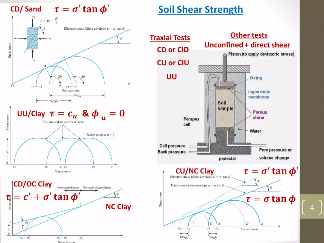
CD or CID
CU or CIU
UU
Traxial Tests Other tests Unconfined + direct shear
CD/ Sand
UU/Clay
𝝉 = 𝝈′ 𝐭𝐚𝐧𝝓′
𝝉 = 𝒄𝒖 & 𝝓 𝒖 = 𝟎
CU/NC Clay 𝝉 = 𝝈′ 𝐭𝐚𝐧𝝓′
𝝉 = 𝝈 𝐭𝐚𝐧𝝓
CD/OC Clay
NC Clay𝝉 = 𝒄′ + 𝝈′ 𝐭𝐚𝐧𝝓′
Soil Shear Strength
5
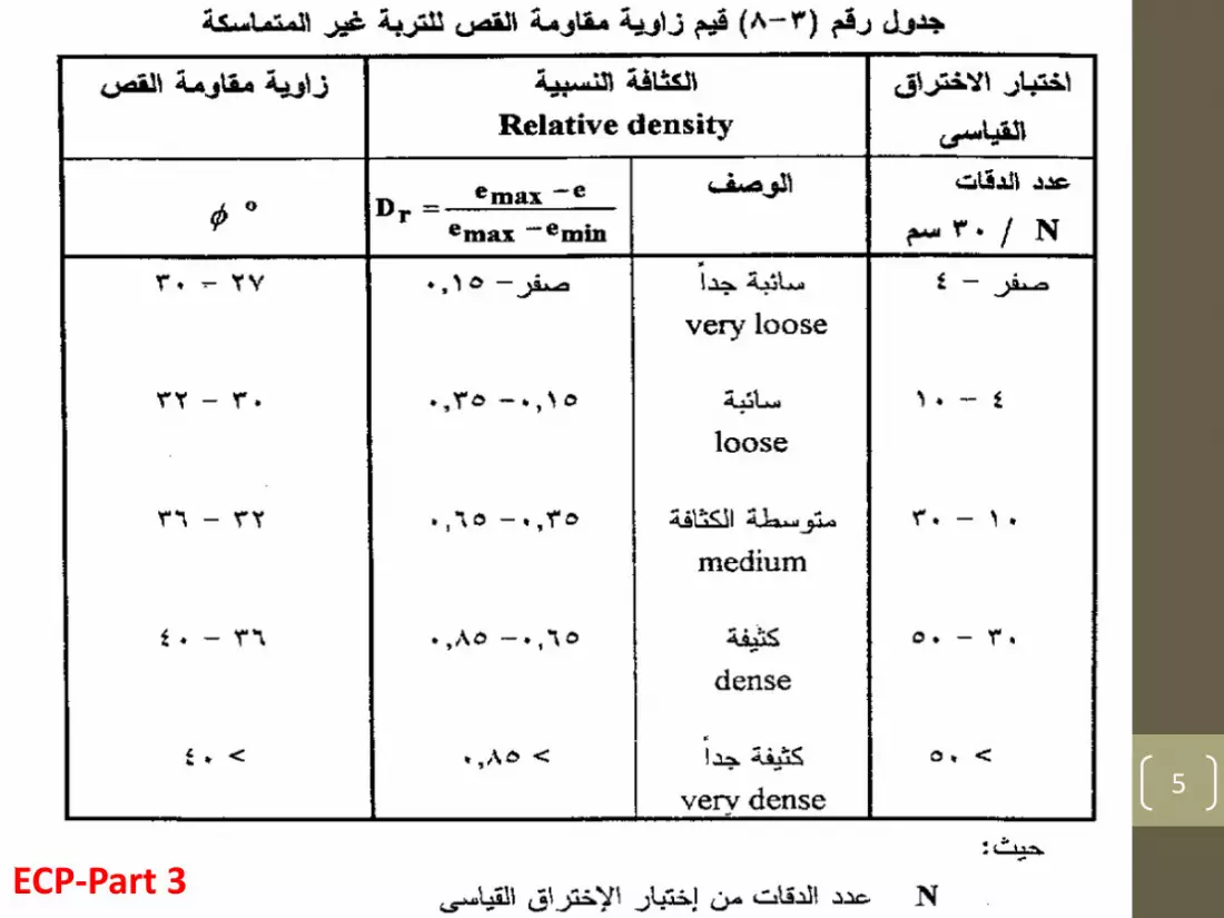
ECP-Part 3

6
ECP-Part 3

7
Di
D
𝑆 = 𝛿𝑖
𝛿𝑖 =Δ𝑝
𝐸𝑠𝐷𝑖 = 𝑚𝑣 Δ𝑝 𝐷𝑖Sand & Clay :
Clay (NL): 𝛿𝑖 =𝐶𝑐 𝐷𝑖1 + 𝑒0
log 1 +Δ𝑝
𝑝0′
Clay (OC): 𝛿𝑖 =𝐶𝑟 𝐷𝑖1 + 𝑒0
log 1 +Δ𝑝
𝑝0′
Tests: Odometer & Triaxial
Soil Compressibility

8
ECP-Part 3

9
1. Introduction
Part 2
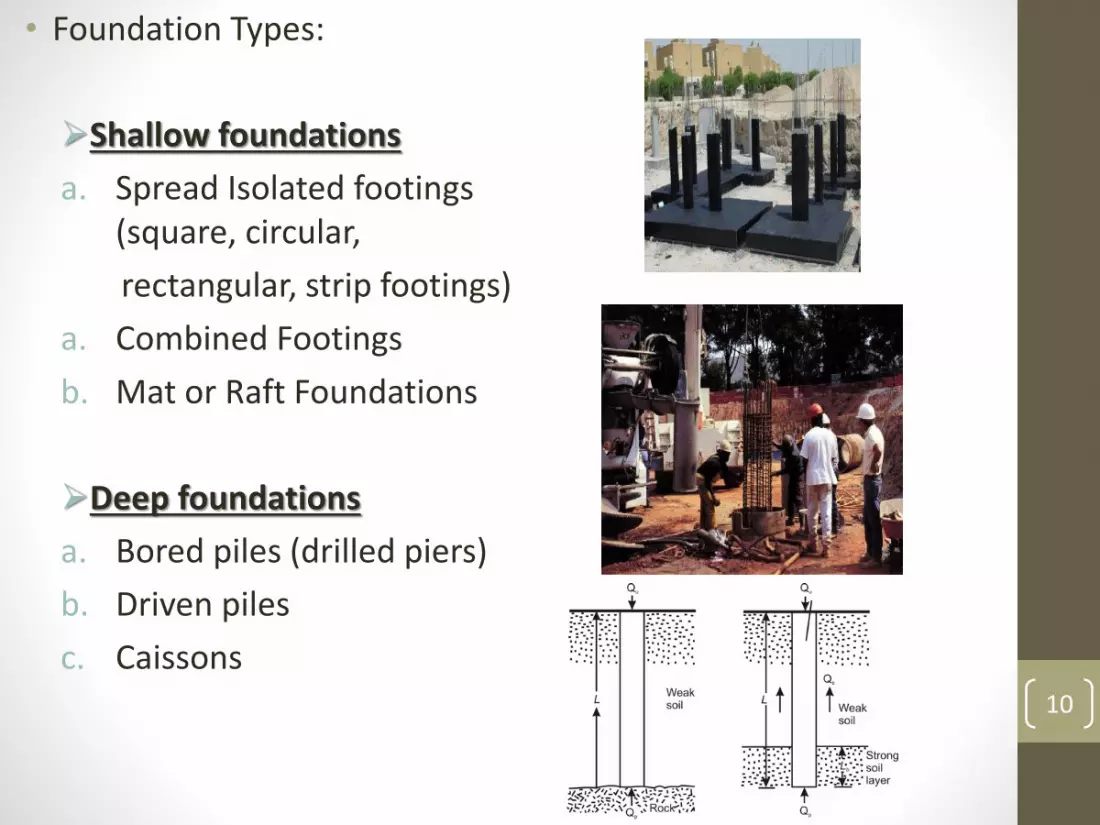
• Foundation Types:
Shallow foundations
a. Spread Isolated footings (square, circular,
rectangular, strip footings)
a. Combined Footings
b. Mat or Raft Foundations
Deep foundations
a. Bored piles (drilled piers)
b. Driven piles
c. Caissons10

11
Shallow Foundations
RaftsSpread/Isolated Footings
Combined Footings
Basics
• Depth of foundation ≤ twice the foundation width.
• Shear resistance of the soil above the foundation level is ignored.
Strip
12
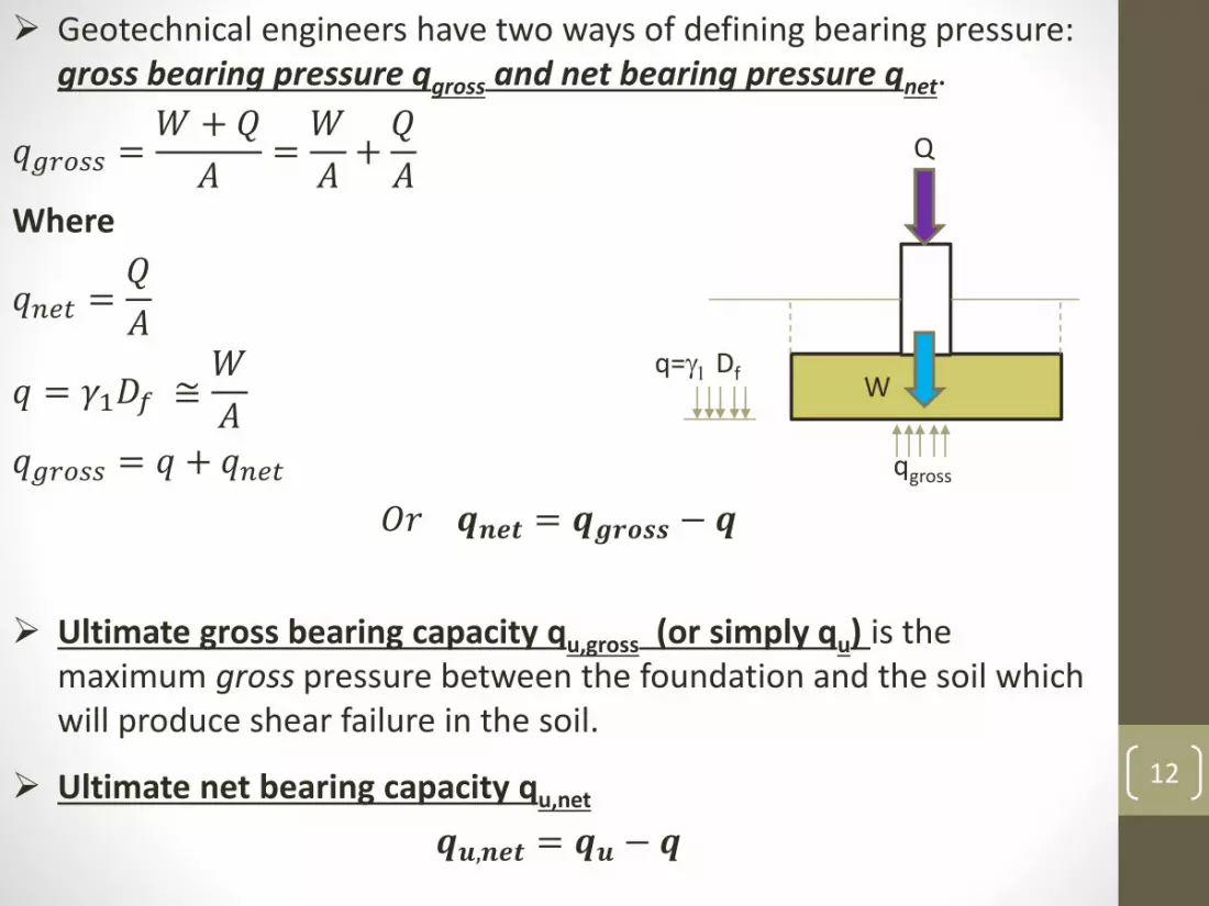
Geotechnical engineers have two ways of defining bearing pressure: gross bearing pressure qgross and net bearing pressure qnet.
𝑞𝑔𝑟𝑜𝑠𝑠 =𝑊 +𝑄
𝐴=𝑊
𝐴+𝑄
𝐴Where
𝑞𝑛𝑒𝑡 =𝑄
𝐴
𝑞 = 𝛾1𝐷𝑓 ≅𝑊
𝐴𝑞𝑔𝑟𝑜𝑠𝑠 = 𝑞 + 𝑞𝑛𝑒𝑡
𝑂𝑟 𝒒𝒏𝒆𝒕 = 𝒒𝒈𝒓𝒐𝒔𝒔 − 𝒒
Ultimate gross bearing capacity qu,gross (or simply qu) is the maximum gross pressure between the foundation and the soil which will produce shear failure in the soil.
Ultimate net bearing capacity qu,net
𝒒𝒖,𝒏𝒆𝒕 = 𝒒𝒖 − 𝒒
q=g1 Df
Q
W
qgross

13
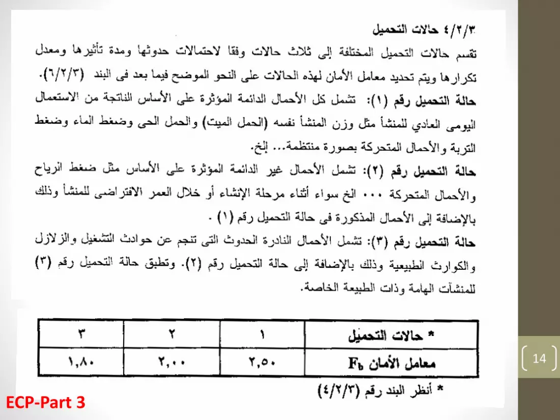
Allowable bearing capacity qall is what is used in geotechnical design, and is the ultimate bearing capacity divided by a factor of safety. It usually defined in terms of the net stress.
Factor of safety Fb. In order to determine the allowable bearing pressure qall , the ultimate bearing capacity qult is divided by a factor of safety.
𝒒𝒂𝒍𝒍 =𝒒𝒖,𝒏𝒆𝒕𝑭𝒃
=𝒒𝒖 − 𝒒
𝑭𝒃
For dense sands and stiff clays 𝑞𝑢 ≫ 𝑞
𝒒𝒂𝒍𝒍 ≈𝒒𝒖𝑭𝑺
14
ECP-Part 3

15
2. Geotechnical Design Criteria for Foundations

16
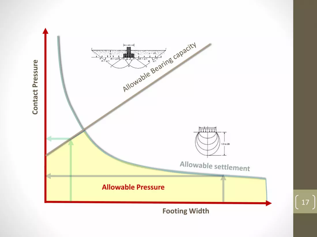
Foundation must be safe against shear failure.
Foundation must not settle excessively.
The differential settlement must not cause distress to the structure.
CostTimeOther considerations
Transcona grain elevator
failure (1913)
Pisa Tower, Italy
Silos, Winnipeg,
Canada
Farm Silo Foundation Failure (1976)
Footing Width 17
Co
nta
ct P
ress
ure
Allowable Pressure

18
ECP-Part 3

19
ECP-Part 3
20
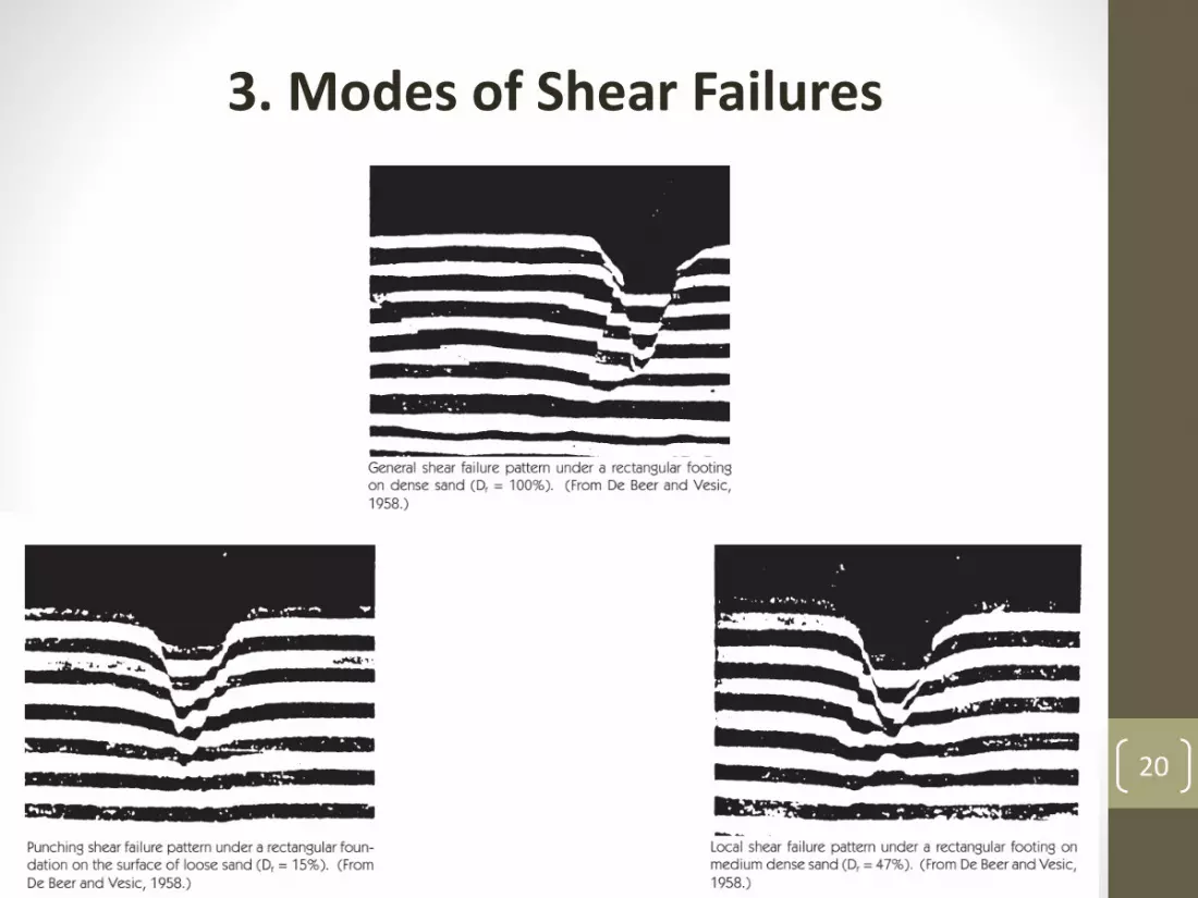
3. Modes of Shear Failures
21
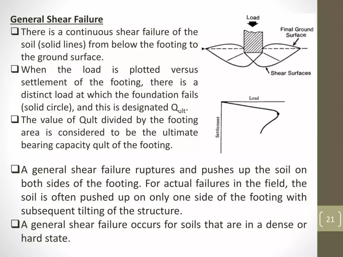
General Shear FailureThere is a continuous shear failure of the
soil (solid lines) from below the footing tothe ground surface.
When the load is plotted versussettlement of the footing, there is adistinct load at which the foundation fails(solid circle), and this is designated Qult.
The value of Qult divided by the footingarea is considered to be the ultimatebearing capacity qult of the footing.
A general shear failure ruptures and pushes up the soil onboth sides of the footing. For actual failures in the field, thesoil is often pushed up on only one side of the footing withsubsequent tilting of the structure.
A general shear failure occurs for soils that are in a dense orhard state.
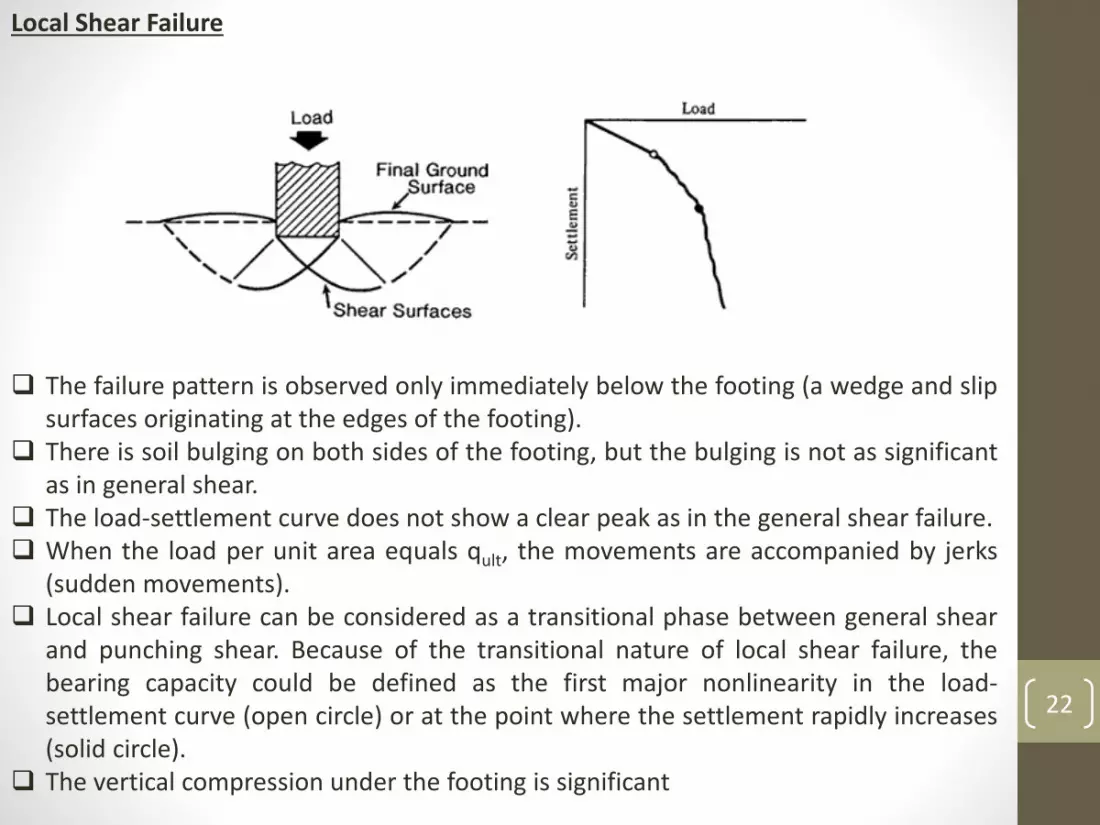
Local Shear Failure
The failure pattern is observed only immediately below the footing (a wedge and slipsurfaces originating at the edges of the footing).
There is soil bulging on both sides of the footing, but the bulging is not as significantas in general shear.
The load-settlement curve does not show a clear peak as in the general shear failure. When the load per unit area equals qult, the movements are accompanied by jerks
(sudden movements). Local shear failure can be considered as a transitional phase between general shear
and punching shear. Because of the transitional nature of local shear failure, thebearing capacity could be defined as the first major nonlinearity in the load-settlement curve (open circle) or at the point where the settlement rapidly increases(solid circle).
The vertical compression under the footing is significant
22
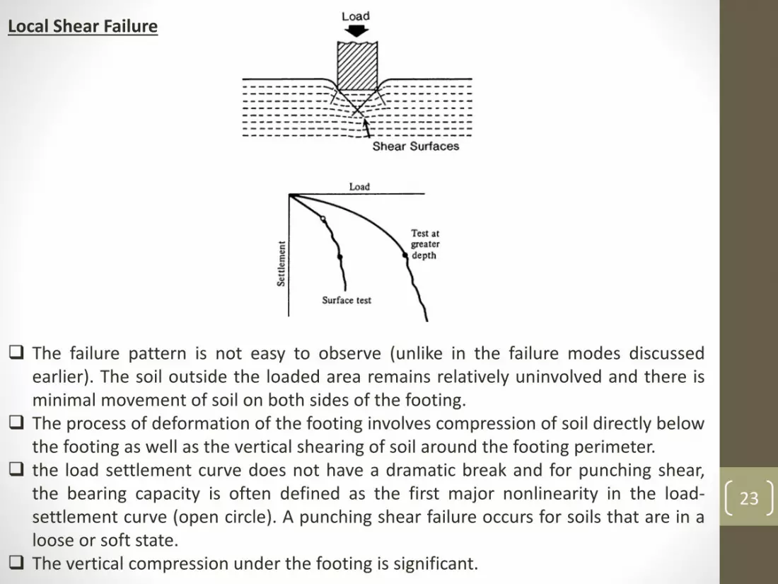
Local Shear Failure
The failure pattern is not easy to observe (unlike in the failure modes discussedearlier). The soil outside the loaded area remains relatively uninvolved and there isminimal movement of soil on both sides of the footing.
The process of deformation of the footing involves compression of soil directly belowthe footing as well as the vertical shearing of soil around the footing perimeter.
the load settlement curve does not have a dramatic break and for punching shear,the bearing capacity is often defined as the first major nonlinearity in the load-settlement curve (open circle). A punching shear failure occurs for soils that are in aloose or soft state.
The vertical compression under the footing is significant.
23

24
Shal
low
fo
un
dat
ion
s
Deep foundations
25
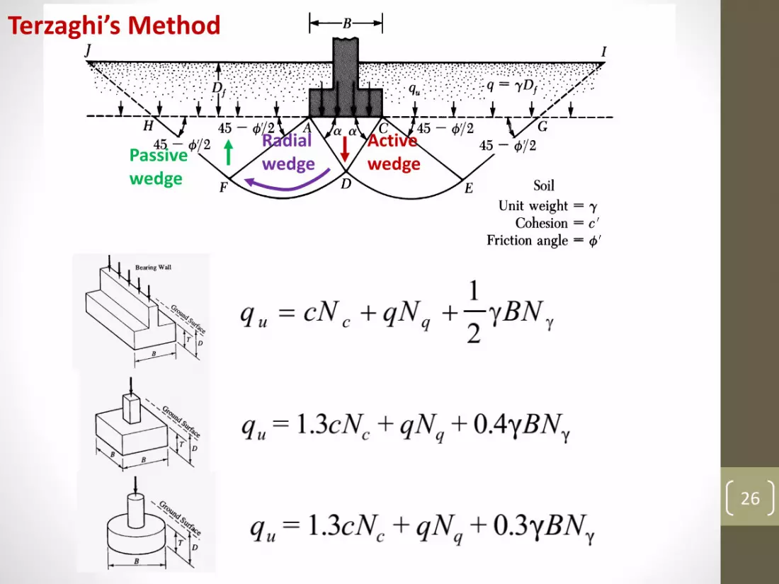
4. Bearing Capacity Equations
26
Active wedge
Radial wedgePassive
wedge
1
Terzaghi’s Method

27
Local Shear Failure
𝑐𝑙𝑜𝑐𝑎𝑙 𝑠ℎ𝑒𝑎𝑟 𝑓𝑎𝑖𝑙𝑢𝑟𝑒 = 0.67 𝑐
𝜙𝑙𝑜𝑐𝑎𝑙 𝑠ℎ𝑒𝑎𝑟 𝑓𝑎𝑖𝑙𝑢𝑟𝑒 = tan−1 0.67 tan𝜙

28
Example 1: Strip footing on cohesionless soil
Friction Angle: 36 degree Unit weight of soil: 18 kN/m3
Footing dimension: B = 2 m Depth of foundation: Df = 1m Factor of safety: Fb = 3
f
q = 1 * 18 = 18 kPa Nq = 47 Ng = 54
qu = 18 * 47 + 0.5 * 18 * 2 * 54 = 1818
qu,net = 1818-18 = 1800 kPa
qall,net = 1800/3 = 600 kPa
qall,net = 600 + 18 = 618 kPa

29
Example 2: Strip footing on cohesive soil
Undrained shear strength : 75 kPa Unit weight of soil: 18 kN/m3
Footing dimension: B = 2 m Depth of foundation: Df = 1m Factor of safety: Fb = 3
Nq = 1 Ng = 0Nq = 5.7q = 1 * 18 = 18 kPa
qu = 75 * 5.7 + 18 * 1 = 446
qu,net = 446 - 18 = 428 kPa
qall,net = 428/3 = 143 kPa ≈ the unconfined strength (2*75 = 150 kPa)
qall,gross = 143 + 18 ≈ 160 kPa

30
ECP-Part 3

31

32
Inclination Factors

33

34
35
5. Effect of the Groundwater Table
36
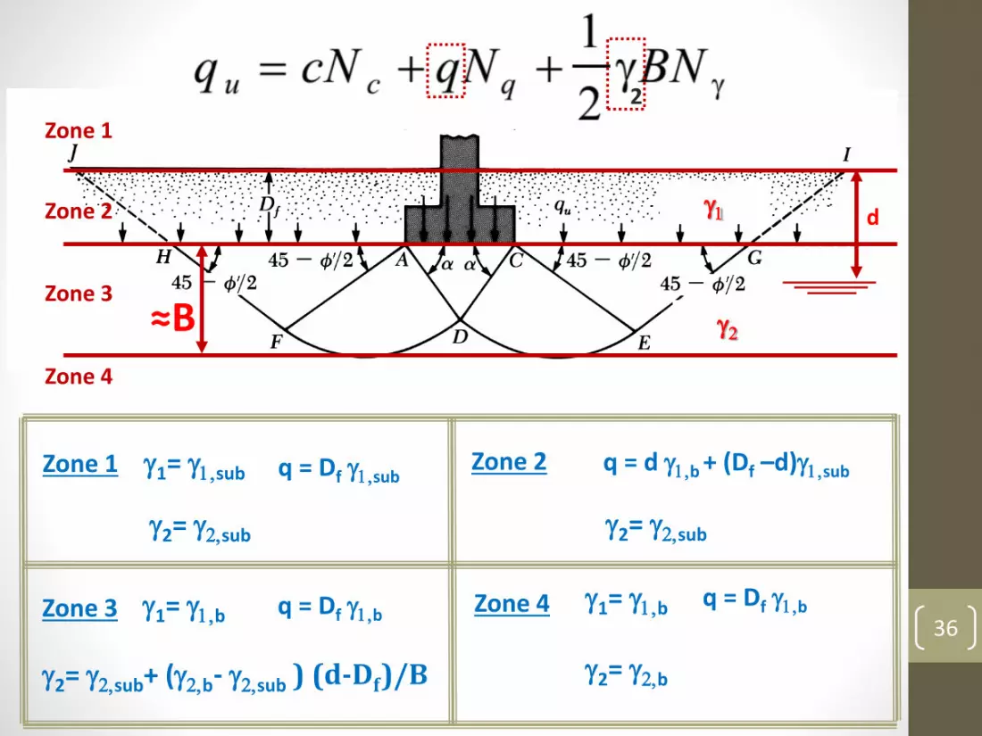
Groundwater ConsiderationZone 2
Zone 3
Zone 4
Zone 1
Zone 1 g1= g1,sub
Zone 3 g1= g1,b
g1
g2
d
≈B
2
g2= g2,sub
q = Df g1,subZone 2
g2= g2,sub
q = d g1,b + (Df –d)g1,sub
q = Df g1,b
g2= g2,sub+ (g2,b- g2,sub ) (d-Df)/B
Zone 4 g1= g1,b q = Df g1,b
g2= g2,b
37
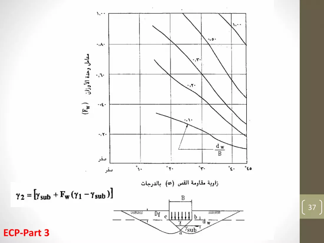
ECP-Part 3

38
6. Effect of Eccentricity

39
M1
M2
𝑒𝐵 =𝑀1𝑃
𝑒𝐿 =𝑀2𝑃
𝐵′ = 𝐵 − 2𝑒𝐵 𝐿′ = 𝐿 − 2𝑒𝐿
B B
B - eB

40
Example 3:
For the square footing shown in the figure, determine the ultimate load using the ECP and assuming a one-way eccentricity of 0.15 m and a local shear failure.
B’ = 1.5 – 2*0.15 = 1.2 mL = 1.5 m
lq = 1 + 0.3 * 1.2/1.5 = 1.24
lg = 1 - 0.3 * 1.2/1.5 = 0.76
flocal failure = tan-1 ( 0.67 * tan 30) = 21 deg.
Nq = 7 Ng = 2.5
qu = 0.7 * 18 * 7* 1.24 + 8 * 1.2 * 2.5 * 0.76 = 128 kPa
GWT
qu,net = 128 – 0.7 * 18 = 115 kPa
Qu = 115 * 1.2 * 1.5 ≈ 200 kN
41
7. Bearing Capacity of Multi-layers Soils
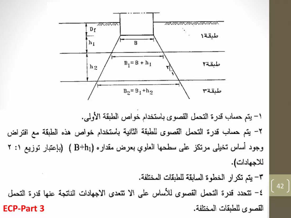
42
ECP-Part 3

43
Thank you
Questions ?