2014 PRODUCT CATALOG - Dominion Industrial
94
INDUSTRIAL 2014 PRODUCT CATALOG
-
Upload
khangminh22 -
Category
Documents
-
view
1 -
download
0
Transcript of 2014 PRODUCT CATALOG - Dominion Industrial

©2014 Setra Systems, Inc. All rights reserved. The Setra Systems name and logo are registered trademarks of Setra Systems, Inc. Phone: 800-257-3872 • Fax: 978-264-0292 • setra.com
GEN
ERAL PU
RPOSE O
EM
1
INDUSTRIAL2014 PRODUCT CATALOG

Phone: 800-257-3872 • Fax: 978-264-0292 • setra.com ©2014 Setra Systems, Inc. All rights reserved. The Setra Systems name and logo are registered trademarks of Setra Systems, Inc.
GEN
ERA
L PU
RPO
SE O
EM
2
INTRODUCTION
Setra is a leading manufacturer of a broad portfolio of pres-sure transducers, humidity transmitters, current switches and current transducers.
The company was founded in 1967 by Dr. S.Y. Lee and Dr. Y.T. Li, former Professors of Engineering at the Massachusetts In-stitute of Technology. Their philosophy, which is still carried on today and expressed in our mission statement, is that whether you require low price, ruggedness and accuracy for OEM use; or the highest possible accuracy for critical test, quality control or manufacturing applications, Setra’s products should offer you significant improvement in measurement accuracy.
Research and Innovation
Setra’s multi-disciplinary engineering department has decades of experience in designing high precision pressure, humidity, and current sensing instruments. The design group includes senior electrical, mechanical, and software engineers in an or-ganization that fosters creativity and innovation in design.
Setra’s engineers have a close working relationship with many customers. As a result, they have been able to apply Setra’s advanced technologies to solving customer application chal-lenges.
ManufacturingDedicated tools and processes eliminate product and process variation at every stage of manufacturing including:
• Design Failure Model Effect Analysis (DFMEA)• Process Failure Model Effect Analysis (PFMEA)• Process Capabilities Studies• Design Verification and Validation• Corrective and Preventative Action (CAPA)• Lean Tools
Customer SupportSetra provides customer support through its knowledg-able staff of customer service representatives and appli-cations engineers.
Our customer service representatives are available to process and assist with expediting and delivery of your order.
Our staff of application engineers are ready to discuss your system requirements, provide solutions to your ap-plications, answer technical questions, and assist with in-stallation and wiring.
A complete library of our products is maintained on our website, including product specifications, installation and operating instructions as well as our newest feature — online ordering.
Visit our Website at www.setra.com
Inside this catalog is a comprehensive selection of sen-sors and transducers designed for the HVAC/Building Au-tomation industry. If you don’t see exactly what is needed for your specific application give us a call.
Call us today — 800-257-3872 or 978-263-1400
Mission StatementTo globally serve the sensing, display and control needs of the HVAC Building Automation market and Industrial OEM Pressure sensing segments, with an emphasis on solutions that provide energy cost sav-ings and support the expansion of quality healthcare products and services
Our vision is to have a rich understanding of our served applications, local market requirements and the specific needs of our customers. We will utilize our design engineering core competency and open innovation to develop and deliver solutions that are driven by our DBS principles.

©2014 Setra Systems, Inc. All rights reserved. The Setra Systems name and logo are registered trademarks of Setra Systems, Inc. Phone: 800-257-3872 • Fax: 978-264-0292 • setra.com
GEN
ERAL PU
RPOSE O
EM
3
Capacitive TransducersSetra’s capacitive pressure transducers are expertly de-signed adaptations of a simple, durable and fundamen-tally stable device...the electrical capacitor.In a typical Setra configuration, a compact housing con-tains two closely spaced, parallel, electrically isolated metallic surfaces, one of which is essentially a diaphragm capable of slight flexing under pressure. The diaphragm is constructed of a low-hysteresis material such as 17-4 PH SS or a proprietary compound of fused glass and ceramic (Setraceram). These firmly secured surfaces (or plates) are mounted so that a slight mechanical flexing of the assembly, caused by a minute change in applied pressure, alters the gap between them (creating, in ef-fect, a variable capacitor).The resulting change in capaci-tance is detected by a sensitive linear comparator circuit (employing proprietary custom designed ASICs), which amplifies and outputs a proportional, high level signal.
.036 CU. INVOLUME
Typical capacitive pressure sensor, showing ruggedconstruction. Materials are carefully selected forcompatibility to minimize environmental effects.(Capacitance gap is accentuated for illustration.)
Gold PlatedSurface
CeramicWafer
AirDielectric
Diaphragm(conductivesurface)
SensorBody
}
NON-LINEARITYNON-LINEARITY NON-LINEARITYNON-LINEARITYRelationship of a calibration curve to a specified straight line.
Relationship of a calibration curve to a specified straight line through its end points.
Best FIt Straight Line(BFSL) Method End Point Method
Example: ±0.1% FS Example: ±0.05% FS
Used for non-linearity measurement on all Setra Pressure Transducers
except Models 270, 276, 370, and 470.
Used for non-linearity measurement on all Setra Pressure Transducers
exceptModels 270 and 276.
NON-LINEARITYNON-LINEARITYRelationship of a calibration curve to a specified straight line with end points at zero and full scale.
Terminal MethodExample: ±0.012% FS

Phone: 800-257-3872 • Fax: 978-264-0292 • setra.com ©2014 Setra Systems, Inc. All rights reserved. The Setra Systems name and logo are registered trademarks of Setra Systems, Inc.
GEN
ERA
L PU
RPO
SE O
EM
4
Absolute Pressure — Pressure measured relative to full vacu-um. Referred to as pounds per square inch absolute (PSIA).
Atmospheric Pressure — Pressure of the atmosphere at the earth’s surface NIST standard atmospheric pressure = 1.01325 bar.
BAR — Unit of pressure (or stress). 1 bar = 750.07 mm of mer-cury at 0°C, at 45°.
Barometric Pressure — Atmospheric pressure, often measured in millibars, in Hg (inches of mercury), or hectopascals.
Burst Pressure — The maximum pressure that may be applied to the positive pressure port without rupturing the sensing ele-ment.
Capacitive Sensing — Detection and measurement of pressure through the change in voltage across a capacitor, one plate of which is a diaphragm which deflects slightly with changes in applied pressure.
Compound Pressure — Pressure measured from full vacuum (-14.7 PSIV) to gauge pressure, referencing atmosphere.
Demand (active, real or true power)— The power which is actually consumed by the load. The measurement takes the power factor into account.
Differential Pressure — Pressure measured relative to a refer-ence pressure. Referred to as pounds per square inch differen-tial (PSID).
Frequency— The number of complete cycles of AC voltage which occurs during one second (Hz).
FS (Full Span or Full Scale) — The range of measured values over which a transducer is intended to measure, specified by the upper and lower limits. EX: 0 to 100 PSIG, FS is 100 PSIG/0 to 5 VDC, FS is 5 VDC, 800-100 MB FS is 300 MB.
Gauge Pressure — Pressure measured relative to ambient atmospheric pressure. Quantified in pounds per square inch gauge (PSIG).
Harmonics — Current or voltages which have frequencies that are integer multiples of the fundamental power frequency; com-mon and sometimes dangerous in nonlinear loads.
Manometer — An early instrument for measuring pressure; originally, a U-shaped tube containing liquid (water, oil, or mer-cury), one limb opening to the gas volume to be measured, the other closed or connected to a registering or recording instru-ment. Modern versions utilize diaphragms, bellows or other devices for sensing relative pressures.
Millibar (mbar) — Unit of pressure generally used in barometric measurements: 1 mbar ± 100 N/m2, or 10 = dyn/cm2.
Newton (N) — The unit of force in the International System of Units (SI); the force required to impart an acceleration of 1m/sec2 to a mass of 1 kg.
Pascal (Pa) — The standard unit of pressure (or stress) in the SI system; equal to 1 newton per square meter (1 N/m2)
Peak Demand (maximum RMS power) — The highest average load during a specified time interval (kW).
P/I — Term common to process industries meaning pressure-in/current-out. (3-15 PSIG Input to 4 to 20 mA DC Output).
Potential Transformer — An instrument transformer used to step down high voltage potentials to lower levels acceptable for the input of electrical test instruments.
Pressure Transducer — An electromechanical device for translat-ing fluid pressure values into voltages across a high-impedance (5k ohms or greater) load.
Pressure Transmitter — An electromechanical device for trans-lating fluid pressure values into currents (generally 4 to 20 mA) into a low-impedance load.
Proof Pressure — The maximum pressure that may be applied without changing performance beyond specifications (typically, 0.5% FS zero shift).
PSIA — Pounds per square inch absolute.
PSIV — Pounds per square inch vacuum.
Range — The spread between the maximum and minimum pressures between which the transducer has been designed to operate.
Ratchet Demand — Determining the billing demand based upond a pre-established peak average demand (usually at 75%, 80% or 100% of the pre-established peak.
Relative Humidity — Relative humidity is a measurement of water in the air at a given temperature.
Span — The algebraic difference between the limits of the range. Ex: 0.1 to 5.1 Volts DC; span is 5 VDC. Sometimes used to desig-nate full scale output; i.e. 5 VDC.
Vacuum — Generally refers to pressures between 0 and atmo-spheric; often measured in 0-30 in Hg Vacuum. Referred to as pounds per square inch vacuum (PSIV).

©2014 Setra Systems, Inc. All rights reserved. The Setra Systems name and logo are registered trademarks of Setra Systems, Inc. Phone: 800-257-3872 • Fax: 978-264-0292 • setra.com
GEN
ERAL PU
RPOSE O
EM
5
INTRODUCTION 2
TECHNOLOGIES 3
TERMINOLOGY & DEFINITIONS 4
PRODUCT SECTION 1.1 General Purpose OEM
Model 209 8
Model 3100/3200 12
Model 3550 16
Model 206 20
Model 256 24
Model 210 26
Model 526 28
Model 550 30
Model 280 32
Model 205 34
Model CCM (Mini Current Switch) 36
PRODUCT SECTION 2.1 Test & Measurement
Model ASM 40
Model 201 42
Model 239 44
Model ASL 46
Model 204 48
Model 204D 50
PRODUCT SECTION 3.1 Sanitary Pressure
Model 290 54
Model 296 56
PRODUCT SECTION 4.1 Accelerometer
Model 141 60
PRODUCT SECTION 5.1 Barometric Pressure
Model 276 64
Model 278 66
Model 270 68
Model 370 70
Model 470 72
PRODUCT SECTION 6.1 Very Low Differential Pressure
Model 264 76
Model 265 78
Model 267 80
PRODUCT SECTION 7.1 Power Monitoring
Power Patrol 86
Power Squad 24 88
Patrol Flex 90
Split Core Standard CT 91
Split Core Performance CT 92
ORDERING INFORMATION

Phone: 800-257-3872 • Fax: 978-264-0292 • setra.com ©2014 Setra Systems, Inc. All rights reserved. The Setra Systems name and logo are registered trademarks of Setra Systems, Inc.
GEN
ERA
L PU
RPO
SE O
EM
6

©2014 Setra Systems, Inc. All rights reserved. The Setra Systems name and logo are registered trademarks of Setra Systems, Inc. Phone: 800-257-3872 • Fax: 978-264-0292 • setra.com
GEN
ERAL PU
RPOSE O
EM
1
PRODUCT SECTION 1.1
GENERAL PURPOSEOEM
MODELS:209 206 526 3100/3200 256 550 3550 210 280205 CCM

Phone: 800-257-3872 • Fax: 978-264-0292 • setra.com ©2014 Setra Systems, Inc. All rights reserved. The Setra Systems name and logo are registered trademarks of Setra Systems, Inc.
GEN
ERA
L PU
RPO
SE O
EM
8
GAUGE, COMPOUND & VACUUM PRESSURE RANGES
Model 209 Pressure Transducers
FEATURES■ High Over Pressure Option Available on
Selected Ranges
■ Rugged Design Withstands Harsh Environments
■ Operates Over a Wide Temperature Band
■ Compatible w/ Wide Range of Gases & Liquids
■ Operates on Low Cost Unregulated DC Power
■ Suitable for High Shock & Vibration Applications■ No Seals or “O” Rings to Cause Leakage■ No Brazed Joints Susceptible to Corrosion
Problems■ 3 to 5 Day Shipment for Small Quantities, Stan-
dard Configurations■ CE & RoHS Compliant
APPLICATIONS■ Industrial OEM Equipment■ Hydraulic Systems
■ Compressor Control
■ HVAC/R Equipment
■Industrial Engines
■Industrial Refrigeration
NOTE: Setra quality standards are based on ANSI-Z540-1. The calibration of this product is NIST traceable.U.S. Patent nos. 6019002; 6014800
DESCRIPTIONThe Model 209 pressure transducer is designed for industrial applications with demanding price and performance require-ments. The 209 offers exceptional reliability in typical industrial grade environments. Standard features tailor the Model 209 for applications with more extreme environmental conditions or more stringent performance needs. The Model 209 offers un-paralleled performance in a configurable transducer designed specifically for the budget conscious OEM.
Setra’s proven center mount electrode configuration is the heart of this simple, yet industrialized design. A 17-4 Stainless steel sensor and a rigid stainless steel electrode form the vari-able capacitor.
The 209 transducer is packaged in a rugged stainless steel valox housing, which is small and lightweight for optimum compat-ibility with system designs. As a totally self-contained package, the 209 stainless steel capacitance sensing element, coupled with a high level output IC-based circuit, assures excellent ac-curacy and long term stability.
Gauge Pressure: Pressure measured rela-tive to ambient atmospheric pressure. Referred to as pounds per square inch (gauge) or psig.
Proof Pressure: The maximum pressure that may be applied without changing performance beyond specifications (± 0.5% FS zero shift).
Burst Pressure: The maximum pressure that may be applied to the positive pres-sure port without rupturing the sensing element.
STANDARD OPTIONFull Scale Range(PSI)
Proof Pressure(PSI)
Burst Pressure(PSI)
High Proof Pressure (PSI)
High Burst Pressure (PSI)
1251025501002002505001000150020003000500010,000-14.7 (Vacuum)
24
102050
100200400500
100020002500300045007500
12,50010
250250250500500750
10002000200030005000600065007500
10,00020,000
15
N/AN/AN/AN/AN/A800
100015002000250040005000
N/AN/AN/AN/AN/A
N/AN/AN/AN/AN/A
5000500050008000
10,00010,00012,000
N/AN/AN/AN/AN/A
*Also available in Bar ranges. Consult Fac-tory.

©2014 Setra Systems, Inc. All rights reserved. The Setra Systems name and logo are registered trademarks of Setra Systems, Inc. Phone: 800-257-3872 • Fax: 978-264-0292 • setra.com
GEN
ERAL PU
RPOSE O
EM
9
WIRING
Model 209 Pressure Transducers
Voltage Output The Model 209 voltage output is a 3-wire circuit. If the 209 is supplied with 2 feet of cable, the electrical connec-tion is as follows:
Model 209 Setra Transducer
(4-20 mA)
PowerSupply
Load(Monitor)
++ +_
_ _
Red Black
4-Pin Packard Connector
DTop View: 4-Pin Packard ConnectorType: Metri-Pack 150
Vent+ Excitation
+ OutputCommon
(Not Used)Top View: 4-Pin Packard ConnectorType: Metri-Pack 150
Negative
PositiveVent
Top View: Hirschmann ConnectorType: G4A1M#931807-106
Common+ Output
+ Excitation
Negative
Positive
Top View: 3-Pin Packard ConnectorType: P2S Series 150
Common+ Output
+ Excitation
Top View: 3-Pin Packard ConnectorType: P2S Series 150
Positive
Negative
Hirschmann Connectors
Voltage Current
Voltage Current
Voltage Current
Current OutputThe Model 209 True 2-wire device. If the 209 is supplied with 2 feet of cable, the electrical connection is as fol-lows:
Top View: Hirschmann Con-nectorType: G4A1M#931807-106
Voltage Current
Conduit Version
+–
– +
••
– +
– +
•• •
•
SPECIFICATIONSPerformance Data Environmental Data Electrical Data (Voltage)
Accuracy RSS1 (at constant temp) ±0.25% FS Operating3 Temperature °F (°C) -40 to + 185 (-40 to +85) Circuit 3-Wire (COM, OUT, EXC)
Non-Linearity, BFSL ±0.22% FS Storage Temperature °F (°C) -40 to + 185 (-40 to +85) Excitation 9 to 30 VDC
Hysteresis 0.10% FS Shock3 200g operating Output6 0.5 to 5.5 VDC7
Non-Repeatability 0.05% FS Acceleration 10 g Maximum5 Output Impedance 10 ohms
Thermal Effects Shock3 200g Operating Electrical Data (Current)
Compensated Range °F (°C) -4 to +176 (-20 to +80) Vibration4 20g Circuit 2-Wire
Zero Shift %FS/100°F (%FS/50°C) ±2.0 (±1.8) Environmental Protection Weather Resistant Output8 4 to 20mA9
Span Shift %FS/100°F (%FS/50°C) ±1.5 (±1.3) Physical Description External Load 0 to 800 ohms
Warm-up Shift 0.1% FS TotalCase Stainless Steel & Valox Minimum supply voltage
(VDC)
9+ 0.02 x (Resistance of receiver
plus line)
Response Time 5 millisecondsSensor 17-4 PH Stainless Steel Maximum supply voltage
(VDC)
30+ 0.004 x (Resistance of receiver
plus line).
Long Term Stability 0.5% FS/1 YR Electrical Connection 2 ft. multiconductor cable 1 RSS of Non-Linearity, Hysteresis, and Non-Repeatability.2 Note: Hydrogen not recommended for use with 17-4 PH Stainless Steel. 3 Mil-Std. 202, Method 213B, Cond. C 4 Mil-Std. 202, Method 204, Cond. C 5 See ordering information for other fittings available (minimum quantities apply).6 Calibrated into a 50K ohm load, operable into a 5000 ohm load or greater. 7 Zero output factory set to within ±50mV. Span (Full Scale) output factory set to within ±50mV. 8 Calibrated at factory with a 24 VDC loop supply voltage and a 250 ohm load. 9 Zero output factory set to within ±0.16mA. Span (Full Scale) output factory set to within ±0.16mA. Specifications subject to change without notice.
Pressure Media Pressure Fitting5 1/4” -18 NPT external, 17-4 PH Stainless Steel
Liquids and gases compatible with 17-4 PH Stainless Steel.2 Vent Through cable
Weight (approx.) 2.3 ounces (65 grams)
Red + Excitation
Black - Excitation
+Monitor or
ControlDevice
_
Green+ Out
White- Out
Shield
3-Pin Packard Connector
Phone: 800-257-3872 • Fax: 978-264-0292 • setra.com ©2014 Setra Systems, Inc. All rights reserved. The Setra Systems name and logo are registered trademarks of Setra Systems, Inc.
GEN
ERA
L PU
RPO
SE O
EM
10
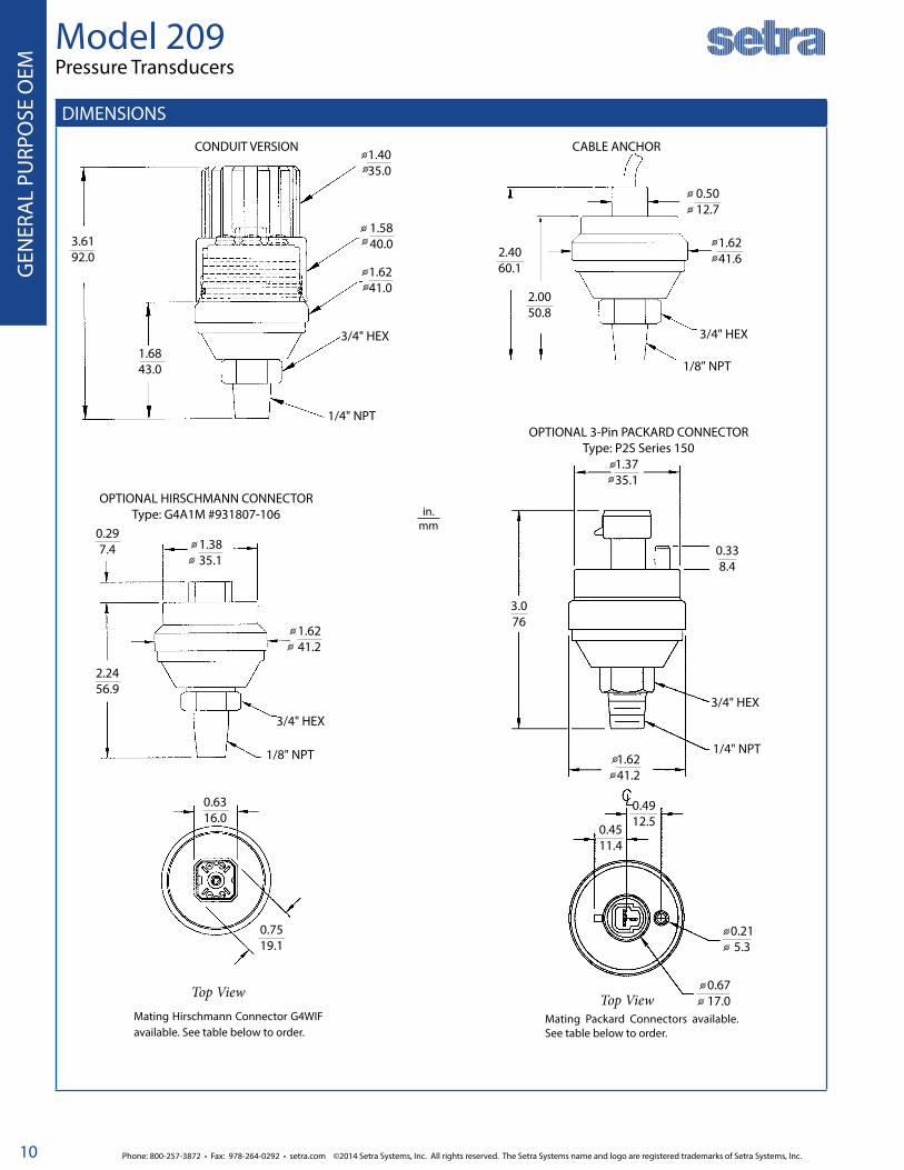
DIMENSIONS
Model 209 Pressure Transducers
in.mm
CONDUIT VERSION
1.6843.0
3.6192.0
1/4" NPT
φ1.4035.0
φ
φ 1.5840.0φ
φ
φ 1.6241.0
3/4" HEX 3/4" HEX
1/8" NPT
0.5012.7
1.6241.6
2.0050.8
2.4060.1
CABLE ANCHOR
φ
φ
φ
φ
0.7519.1
0.6316.0
Top ViewMating Hirschmann Connector G4WIF available. See table below to order.
1/8" NPT
2.2456.9
0.297.4 1.38
35.1φ
φ
3/4" HEX
OPTIONAL HIRSCHMANN CONNECTOR Type: G4A1M #931807-106
1.6241.2φ
φ
0.4912.5
0.4511.4
0.215.3
0.6717.0φ
φ
0.338.4
3.076
1.3735.1φ
φ
1.6241.2φ
φ
3/4" HEX
1/4" NPT
OPTIONAL 3-Pin PACKARD CONNECTORType: P2S Series 150
Top ViewMating Packard Connectors available. See table below to order.
φ
φ

©2014 Setra Systems, Inc. All rights reserved. The Setra Systems name and logo are registered trademarks of Setra Systems, Inc. Phone: 800-257-3872 • Fax: 978-264-0292 • setra.com
GEN
ERAL PU
RPOSE O
EM
11
ORDERING INFORMATION
Model 209Pressure Transducers
Model Range Code Pressure Type Pressure Fitting Output Elec. Termination Options
2091 = 209 See Table 1 Below G Gauge 2M 1/4” NPT Male 11 4-20 mA XX Cable length in feet1 H High Overpressure Capability (Only available on 25 PSI up to 1500 PSI Pressure Ranges)
C Compound J7 7/16” SAE Male
24 0.5 to 5.5 VDC P1 Packard (3-Pin)2
S Sealed* 1M 1/8” NPT Male 28 1 to 6 VDC P3 Packard (4-Pin)3
V Vacuum L4 1/4 Female SAE
45 0.5 to 4.5 VDC H2 Hirschmann, (“Mini”)4
G4 1/2” A Male A1 Terminal Block w/Conduit CoverP1 1/8” NPT
FemaleBulkhead (Available on Ranges > 50 PSI)
2 0 9 1
1 i.e., 2 feet = 022 Order Setra Part #577 for Mating Connector3 Order Setra Part #857 for Mating Connector4 Order Setra Part #590 for Mating Connector
NOTE: Standard configuration consists of: PSI Range, 1/4" NPT Fitting and 2 feet of cable (up to 25 feet of cable can be ordered) . (Minimum quantities apply for all other configurations. Consult a Setra Applications Engineer for assistance.
Note: Order mating connectors direct from manufacturers:
Mfr. Part #12103881-L/#12065287/#1203-4413 = Setra’s Part #577
Mfr. Part #12065298/#12066176/#12048086 = Setra Part #857
Mfr. Part #932157-106 = Setra Part #590
Table 1. Range Specification
RANGE CODE
PSI
001P 0 to 1
002P 0 to 2
005P 0 to 5
010P 0 to 10
025P 0 to 25
050P 0 to 50
100P 0 to 100
200P 0 to 200
250P 0 to 250
500P 0 to 500
10CP 0 to 1000
15CP 0 to 1500
20CP 0 to 2000
30CP 0 to 3000
50CP 0 to 5000
10KP 0 to 10000
Z01P 0 to -14.7 PSI
Ordering Example: 2091001PG2M1102 = Model 209, 0 to1 PSI Range, Gauge Pressure, 1/4” NPT Male Fitting, 4 to 20 mA Output, 2 ft. Cable.
*Sealed Version Available on 200 PSI Range and Above)

Phone: 800-257-3872 • Fax: 978-264-0292 • setra.com ©2014 Setra Systems, Inc. All rights reserved. The Setra Systems name and logo are registered trademarks of Setra Systems, Inc.
GEN
ERA
L PU
RPO
SE O
EM
12
FEATURES■ Low Cost for High Volume OEM Installations
■ Thin Film Tech. Assures Long-Term Stability
■ Wide Choice of Pressure Ranges from 50 PSI up to 32,000 PSI
■ Long-Term Stability Better Than ±0.1% FS/Yr
■ 0.25% Full Scale Accuracy
■ Dual Temperature and Pressure Output on Voltage Units
■ Small Footprint -Less than 1 inch Dia. (25 mm long)
■ Choice of mA, Voltage, or Ratiometric Outputs
■ Reverse Wiring Protected■ Accuracy Specified Over the Full Temperature
Range of -40°F to +221°F (-40°C to +105°C)■ All Welded Stainless Steel Construction■ No Oil Fill to Cause Thermal Instability or
Leakage ■ No Internal Elastomers or O-Rings, no RTV’s or
Epoxies
■ CE, RoHS Compliant & UL Approved
APPLICATIONS■Medical■ Hydraulic Pressure
■ HVAC/R Compressors
■ Variable Speed Pumps
■Refrigeration
■Industrial/OEM
■Pumps
DESCRIPTIONThe 3100/3200 Series high-pressure OEM transducers feature a sputtered thin-film sensor to provide high levels of performance and stability for large volume OEM installations. A wide choice of outputs as well as electrical and pressure connections means that the unit is suitable for most applications without modification. In addition, the compact construction of the 3100/3200 Series makes it ideal for installations where space is at a premium.
The Model 3200 features a thicker diaphragm and a restrictor (optional) to handle environments where extreme positive or negative pressure spikes are a concern. Proof pressures on the Model 3200 are 3x full scale on 50 psi up to 10,000 psi pressure ranges. PRINCIPLE OF OPERATIONSputtered Thin Film Strain Gauge Pressure SensorsUsing the well proven Wheatstone Bridge principle, molecular layers are sputtered onto a 17-4 PH stainless steel diaphragm and the circuit is etched to provide excellent resistor definition and uniformity. Sputtered thin film technology allows the design of simple, highly accurate and compact strain gauges deposited onto the back of the sensing diaphragm, which is in direct contact with the media. This method virtually eliminates drift, while offering enhanced sensitivity.
PRESSURE CAPABILITY
Pressure RangePSI (BAR)
Proof Pressure(x Full Scale)
Burst Pressure(x Full Scale)
3100 3200 3100 3200
50-300 (3.5-25) 3.00 x FS
3.00 x FS
40 x FS 40 x FS
500-1,500 (3.5-25)
2.00 x FS
20 x FS 20 x FS
2,000-6,000 (160-400) 10 x FS 10 x FS
7,500-9,000 (600)
4 x FS
10 x FS
10,000 (700)>60,000 PSI(4,000 Bar)15,000 (1,000)
2.50 x FS25,000 (1,800)
1.40 x FS1.8 x FS
30,000 (2,200) — 1.5 x FS —
Application pressure should be restricted to the rated-range of the transducer. The maximum overpressure is the pressure limit at which the transducer will not show significant offset shift. The minimum burst pressure is the test-rating for fluid containment.
The data in the tables is “times rate ranges” (xRR).
Model 3100/3200 Standard & Heavy Duty OEM Pressure Transducers

©2014 Setra Systems, Inc. All rights reserved. The Setra Systems name and logo are registered trademarks of Setra Systems, Inc. Phone: 800-257-3872 • Fax: 978-264-0292 • setra.com
GEN
ERAL PU
RPOSE O
EM
13
Model 3100/3200 Standard & Heavy Duty OEM Pressure Transducers
SPECIFICATIONSPerformance Data Physical DescriptionAccuracy1 Data Pressure Port See Ordering Instructions on page 4
Model 3100 ±0.25% FS Wetted Parts 17-4 PH Stainless Steel (Diaphragm) 304 Stainless Steel (Fittings)
Model 3200 ±0.5% FS Electrical Connections See Ordering Instructions on page 4
Thermal Effects2 Enclosure IP67 (IP65 for Electrical Code A)
Compensated Range oF (oC) -40 to +221 (-40 to +105) Vibration 40G Peak to Peak Sinusoidal to 2000 Hz (Random Vibration: 20 to 1000 Hz @ approx. 40G Peak per MIL-STD-810E
Zero/Span Shift %FS/100oF )%FS/100oC) Shock Withstands free fall to IEC 68-2-32 procedure 1
Model 3100 0.83 (1.5) Weight 35 grams
Model 3200 0.94 (2.0) for <1000 PSI (60 BAR) Electrical Data (Voltage)6
Zero/Span Tolerance Circuit 3-Wire (Exc, Out, Com)
Model 3100 ±0.5% of Span Output 1 to 6 VDC, 1 to 5 VDC, 0.5 to 4.5 VDC, 0 to 5 VDC, 0 to 10 VDC7
Model 3200 1% FS for <1000 PSI (60 BAR) Excitation 2 Volts above Full Scale to max 30 Volts @ 4.5 mA (6.5mA Dual Output Version)
Response Time 1 ms Source and Sinks 2 mA
Long Term Stability ±0.2% FS/YR Non-Cumulative Electrical Data (Ratiometric)Proof/Burst Pressure See Table on Page 1 Output 0.5 to 4.5 VDC @ 4 mA (6.5 mA on Dual Output Version)
Fatigue Life Designed for more than 100 M cycles Excitation 5 VDC ± 10%
Temperature Output Range oFo (C)3,4,5 Electrical Data (Current)7
Series 3101/2301 -40 to +221 (-40 to +105) Circuit 2-Wire
Series 3201/3202 +32 to +212 (0 to +100) Output 4 to 20 mA
Series 3103/3203 +32 to +176 (0 to +80) Excitation 8 to 30 VDC (24 VDC max. above 110oC applications)
Performance Data Max. Loop Resistance (Supply Voltage -8) x 50 ohms
Operating/Storage Temp. oFo (C) -40 to +257 (-40 to +125) Options
Approvals Miswire Protection (Option 1)
CE Conforms to European Pressure Directive Full miswire protection between all signal and power lines (any combination)Full short-circuit protection for Vout1 to 0V or Vout1 connected to supply, indefinitely.Ratiometric output not availableSupply Voltage must be 4V above the maximum Vout1 output. This also accounts for worse-case customer output leads.
EMC Radiated Immunity is 100V/m
RoHS Fully Compliant
UL E3126511RSS of Non-Linearity, Hysteresis, and Non-Repeatability .2Note: Hydrogen not recommended for use with 17-4 PH Stainless Steel.3Temperature outputs are for voltage output pressure sensors only and limited to connections that have 4 pins (Electrical Codes -D, -E, -8).4Requires additional 2 mA of power.5For use with pull-down resistors, contact factory before ordering.6Reverse Wiring Protected.7Not available for pressure ranges lower than 100 PSI (7 BAR)

Phone: 800-257-3872 • Fax: 978-264-0292 • setra.com ©2014 Setra Systems, Inc. All rights reserved. The Setra Systems name and logo are registered trademarks of Setra Systems, Inc.
GEN
ERA
L PU
RPO
SE O
EM
14
Model 3100/3200 Standard & Heavy Duty OEM Pressure Transducers
Dimensions: in. (mm)
WIRING
ELECTRICAL FITTINGSDin 9.4 mm M12 x 1P Amp Supeseal 1.5 Deutsch DT4-4P Packard Metri Pack 3-Pin Deutsch
Code B Code E Code 6 Code 8 Code 9 Code CPin #
Voltage Mode
Current Mode
Voltage Mode
Current Mode
Voltage Mode
Current Mode
Voltage Mode
Current Mode
Voltage Mode
Current Mode
Current Mode
Voltage Mode
1 Vout1(pressure)
No Connect Vsupply Vsupply
Vout1(pressure) No Connect Ground Return Vout1
(pressure)No
Connect C Vsupply Vsupply A
2 Vsupply VsupplyVout1
(pressure)No
Connect Ground Return Vsupply Vsupply Ground Return A Ground Ground B
3 Vout2(temp)
No Connect Ground Return Vsupply Vsupply
Vout2(temp) No Connect Vsupply Vsupply B No
ConnectVout1
(pressure) C
4 Ground Return Vout2(temp)
No Connect — — Vout1
(pressure) No Connect — — — — —
1.63
0.28
0.75 (19)
0.76 (19)
2
3
1
4
0.75 (19)
1.50 (38) 1.53 (39)
0.75 (19)
B
C
A
1.46 (37)
1 2 3
1.02 (26)
0.38 (10)
0.72 (18)
0.75 (19)
2
21
34
1.02
A
B
C
0.75 (19)
0.71 (18)
0.38 (9.7)
43
12
PRESSURE FITTINGSSAE
Dimensionsin Inches
Fitting Code OL = M12 x 1.5 01 = G1/4 Ext. 1G = 1/4-SAE Female 7/16 UNF w/Schraeder
1J = 7/16-20Ext.(SAE#4, J1926-2)w/O-Ring
1P = SAE6 (9/16-18UNF 2A)
Torque 28-30 NM 30-35 NM 18-20 NM 18-20 NM 18-20 NM
Fitting Code 2T = M12 x 1.5 04 = 7/16-20 Ext. (SAE #4, J514 w/37°Flare
4C = 1/4NPTF Dryseal EXT. 4D = 1/8NPTF Dryseal EXT. 05 = G 1/4 Ext. Face Seal
Torque 30-35 NM 15-16 NM 2-3 TFFT* 2-3 TFFT*
Fitting Code 02 = 1/4-18 PT Ext. OE = Female 1/4-18NPT 08 = 1/8-27 NPT Ext. OK = M14 x 1.5 Straight
Torque 2-3 TFFT* 2-3 TFFT* 2-3 TFFT* 2-3 TFFT*
©2014 Setra Systems, Inc. All rights reserved. The Setra Systems name and logo are registered trademarks of Setra Systems, Inc. Phone: 800-257-3872 • Fax: 978-264-0292 • setra.com
GEN
ERAL PU
RPOSE O
EM
15
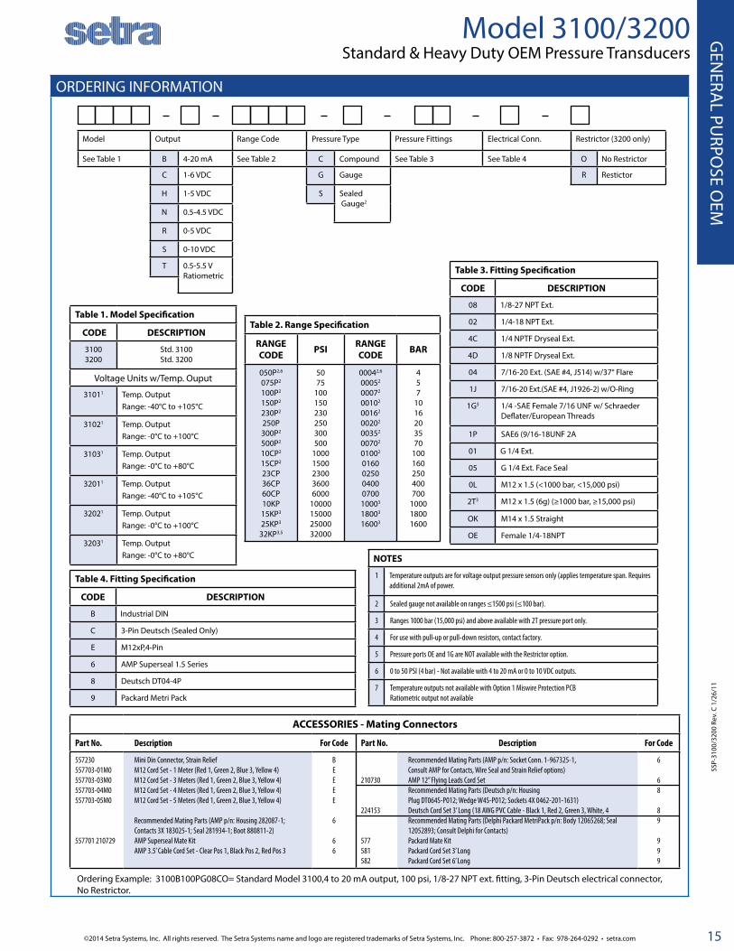
ORDERING INFORMATION
Model 3100/3200 Standard & Heavy Duty OEM Pressure Transducers
Model Output Range Code Pressure Type Pressure Fittings Electrical Conn. Restrictor (3200 only)
See Table 1 B 4-20 mA See Table 2 C Compound See Table 3 See Table 4 O No Restrictor
C 1-6 VDC G Gauge R Restictor
H 1-5 VDC S Sealed Gauge2
N 0.5-4.5 VDC
R 0-5 VDC
S 0-10 VDC
T 0.5-5.5 VRatiometric
Ordering Example: 3100B100PG08CO= Standard Model 3100,4 to 20 mA output, 100 psi, 1/8-27 NPT ext. fitting, 3-Pin Deutsch electrical connector, No Restrictor.
SSP-
3100
/320
0 Re
v. C
1/2
6/11
Table 2. Range Specification
RANGE CODE PSI RANGE
CODE BAR
050P2,6
075P2
100P2
150P2
230P2
250P300P2
500P2
10CP2
15CP2
23CP36CP60CP10KP15KP3
25KP3
32KP3,5
5075
100150230250300500
10001500230036006000
10000150002500032000
00042,6
00052
00072
00102
00162
00202
00352
00702
01002
016002500400070010003
18003
16003
457
1016203570
100160250400700
100018001600
ACCESSORIES - Mating Connectors
Part No. Description For Code Part No. Description For Code
557230 557703-01M0 557703-03M0 557703-04M0 557703-05M0
557701 210729
Mini Din Connector, Strain Relief M12 Cord Set - 1 Meter (Red 1, Green 2, Blue 3, Yellow 4) M12 Cord Set - 3 Meters (Red 1, Green 2, Blue 3, Yellow 4) M12 Cord Set - 4 Meters (Red 1, Green 2, Blue 3, Yellow 4) M12 Cord Set - 5 Meters (Red 1, Green 2, Blue 3, Yellow 4)
Recommended Mating Parts (AMP p/n: Housing 282087-1; Contacts 3X 183025-1; Seal 281934-1; Boot 880811-2) AMP Superseal Mate Kit AMP 3.5’ Cable Cord Set - Clear Pos 1, Black Pos 2, Red Pos 3
BEEEE
6
66
210730
224153
577 581 582
Recommended Mating Parts (AMP p/n: Socket Conn. 1-967325-1, Consult AMP for Contacts, Wire Seal and Strain Relief options) AMP 12” Flying Leads Cord SetRecommended Mating Parts (Deutsch p/n: Housing Plug DT064S-P012; Wedge W4S-P012; Sockets 4X 0462-201-1631) Deutsch Cord Set 3’ Long (18 AWG PVC Cable - Black 1, Red 2, Green 3, White, 4Recommended Mating Parts (Delphi Packard MetriPack p/n: Body 12065268; Seal 12052893; Consult Delphi for Contacts)Packard Mate Kit Packard Cord Set 3’ Long Packard Cord Set 6’ Long
6
68
89
999
Table 1. Model Specification
CODE DESCRIPTION
31003200
Std. 3100Std. 3200
Voltage Units w/Temp. Ouput
31011 Temp. OutputRange: -40°C to +105°C
31021 Temp. OutputRange: -0°C to +100°C
31031 Temp. OutputRange: -0°C to +80°C
32011 Temp. OutputRange: -40°C to +105°C
32021 Temp. OutputRange: -0°C to +100°C
32031 Temp. OutputRange: -0°C to +80°C
Table 3. Fitting Specification
CODE DESCRIPTION
08 1/8-27 NPT Ext.
02 1/4-18 NPT Ext.
4C 1/4 NPTF Dryseal Ext.
4D 1/8 NPTF Dryseal Ext.
04 7/16-20 Ext. (SAE #4, J514) w/37° Flare
1J 7/16-20 Ext.(SAE #4, J1926-2) w/O-Ring
1G5 1/4 -SAE Female 7/16 UNF w/ Schraeder Deflater/European Threads
1P SAE6 (9/16-18UNF 2A
01 G 1/4 Ext.
05 G 1/4 Ext. Face Seal
0L M12 x 1.5 (<1000 bar, <15,000 psi)
2T3 M12 x 1.5 (6g) (≥1000 bar, ≥15,000 psi)
OK M14 x 1.5 Straight
OE Female 1/4-18NPT
Table 4. Fitting Specification
CODE DESCRIPTION
B Industrial DIN
C 3-Pin Deutsch (Sealed Only)
E M12xP,4-Pin
6 AMP Superseal 1.5 Series
8 Deutsch DT04-4P
9 Packard Metri Pack
NOTES
1 Temperature outputs are for voltage output pressure sensors only (applies temperature span. Requires additional 2mA of power.
2 Sealed gauge not available on ranges ≤1500 psi (≤100 bar).
3 Ranges 1000 bar (15,000 psi) and above available with 2T pressure port only.
4 For use with pull-up or pull-down resistors, contact factory.
5 Pressure ports OE and 1G are NOT available with the Restrictor option.
6 0 to 50 PSI (4 bar) - Not available with 4 to 20 mA or 0 to 10 VDC outputs.
7 Temperature outputs not available with Option 1 Miswire Protection PCBRatiometric output not available

Phone: 800-257-3872 • Fax: 978-264-0292 • setra.com ©2014 Setra Systems, Inc. All rights reserved. The Setra Systems name and logo are registered trademarks of Setra Systems, Inc.
GEN
ERA
L PU
RPO
SE O
EM
16
Model 3550Compact Low Pressure OEM Pressure Transducers
FEATURES Low Cost for High Volume OEM Installations
Pressure Ranges from 0-15 PSI to 0-250 PSI
.25% Full Scale Accuracy
Small Package Size
316L Stainless Steel Wetted Parts
Absolute, Gauge, and Compound Pressure Ranges
APPLICATIONS Refrigeration Systems
Medical
Oil & Gas
Industrial OEM Emissions Monitoring
Harsh Chemical
Transformer/Smart Grid Technology
Automotive
DESCRIPTIONFor OEMs that need consistent high levels of performance, reli-ability and stability the 3550 Series units offer a small package size with all 316 stainless steel wetted parts at an unbeatable price performance ratio. A wide choice of electrical outputs as well as both electrical and pressure connections means the unit is suitable for most applications without modifications. The compact construction of the 3550 Series makes it ideal for in-stallation where space is at a premium.
SPECIFICATIONSPerformance Data Mechanical Configuration Voltage Output UnitsLong Term Drift < 0.2% FS/YR Pressure Port See under “How to Order” Output 0 V min. to 10V max. See under “How to Order”
Accuracy (BSFL) 0.25% FS Wetted Parts 316L Stainless Steel Supply Voltage (Vs) 2 Volts above full scale to 30 VDC (24 VDC max. above 230OF (110OC) applications). Source and Sinks 8mA
Thermal Error, Max. ±1% max./176OF (80OC) Electrical Conn. See under “How to Order” Current Output UnitsCompensated Temp. -4OF to +212OF (-20OC to +100OC) Enclosure IP67 (IP65 for electrical codes B & K) Output 4-20 mA
Operating Temp. -40OF to +257OF (-40OC to +125OC) Vibration BSEN 60068-2-6 (FC)BSEN 60068-2-64 (FH)
Supply Voltage (Vs) 10-30 VDC (24 VDC max. above 230OF (110OC) applications)
Zero Tolerance, Max. ±0.5% of span max. Shock BSEN 60068-2-27 (Ea) Max. Load Resistance (Supply Voltage - 10) x 50 ohms
Span Tolerance, Max. ±1% of span max. Approvals CE, PED, RoHS Ratiometric Output UnitsFatgue Life Designed for more than 100M
CyclesWeight 1.23 to 1.9 ounce (35 to 52 grams)
Configuration dependent.Output 0.5 to 4.5 VDC
Input Supply Voltage (Vs) 5 VDC ±10%
Pressure Range 0-250 psi (0-16 bar)
Proof Pressure 2x Nominal Range
Burst Pressure 3x Nominal Range
Wiring Diagram

©2014 Setra Systems, Inc. All rights reserved. The Setra Systems name and logo are registered trademarks of Setra Systems, Inc. Phone: 800-257-3872 • Fax: 978-264-0292 • setra.com
GEN
ERAL PU
RPOSE O
EM
17
ELECTRICAL CONNECTOR
PRESSURE PORTS
Model 3550Compact Low Pressure OEM Pressure Transducers
inch(mm)
DIN 9.4 mm M12 x 1P Deutsch DT04-4P Packard MetriPack
Code B Code E Code 8 Code 9
Pin#
VoltageMode
CurrentMode
VoltageMode
CurrentMode
VoltageMode
CurrentMode
PinID
VoltageMode Note
1 Vout(pressure)
NoConnect Vsupply Supply Ground Return C Vout
(pressure)MetriPack
connectors may be used with 0.5-4.5V Ratiometric Output only.
2 Vsupply Supply Vout (pressure)
NoConnect Vsupply Supply A Ground
3 No Connect
NoConnect Ground Return No
ConnectNo
Connect B Vsupply
4 Ground Return NoConnect
NoConnect
Vout (pressure)
NoConnect — —
2
3
4
1
POLARIZINGWIDE CONTACT
0.86(21.9)
1
3
42
0.4(10.1)
0.72(18.3)
KEY
4
1
3
2
1.538.1
0.071.9
AB
C
1.52(38.6)
Dimensions in MM
G1/8˝ External G1/4˝-19 External w/O-Ring
G1/4˝-19 A Integral Face Seal M12 x 1.5 w/O-Ring
Fitting Code OS 01 05 OL
Torque 22-25 NM 30-35 NM 30-35 NM 28-30 NM
* NPT Threads 2-3 turns from finger tight. Wrench tighten 2-3 turns.
General Notes:1. The diameter of all cans is 19 mm (0.748˝)2. Hex is 22 mm (0.886˝) Across Flats (A/F) for deep socket mounting
G1/4˝ External
01
11.0
13.1
G1/8˝ External
OS
11.0
13.1
G1/4"A Integral Face Seal
05
12.5 11.0
13.1
OL
ISO 6149-2:M12 x 1.5
11.0
13.1
Dimensions in Inches
1/8˝-27 NPT 1/4˝-18 NPT 7/16˝-20 UNF with 37° Flare
Fitting Code 08 02 04
Torque 2-3 TFFT* 2-3 TFFT* 15-16 NM
1/8"-27 NPT
08
0.52
0.39
1/4"-18 NPT
02
0.57
0.52
SAE
BSP & Metric
0.28 (7)
0.55 (14)

Phone: 800-257-3872 • Fax: 978-264-0292 • setra.com ©2014 Setra Systems, Inc. All rights reserved. The Setra Systems name and logo are registered trademarks of Setra Systems, Inc.
GEN
ERA
L PU
RPO
SE O
EM
18
ORDERING INFORMATION3 5 5 0
Model Output Pressure Range Pressure Datum Pressure Port Electrical Conn. Optional RestrictorModel 3550 B 4-20 Ma 0000 0 bar1 G Gauge 01 G1/4” External B Industrial DIN 9.4mm R Restrictor
N 0.5-4.5 V 0001 1 bar A Absolute 02 1/4”-18 NPT External E M12 x 1 0 No Restrictor
S 0-10 V 01B6 1.6 bar C Compound2 04 7/16-20 UNF w/ 37o Flare 8 Deutsch DT04-4P
C 1-6 V 02B5 2.5 bar 05 G1/4” A Integral Face Seal 9 Packard MetriPack3
P 1-10 V 0004 4 bar 08 1/8”-27 NPT External
T 0.5-4.5 V Ratiometric 0006 6 bar OL M12 x 1.5 - 6g
H 1-5 V 0010 10 bar OS G1/8”-27 External
R 0-5 V 0016 16 bar
000P 0 psi1
015P 15 psi
030P 30 psi
050P 50 psi
100P 100 psi
150P 150 psi
200P 200 psi
250P 250 psi
Model 3550Compact Low Pressure OEM Pressure Transducers
1. Compound vacuum gauge only (eq. -15 to 0 PSIG or -1 to 0 barG2. Compound versions extend the pressure range on the low end to -15 PSIG or -1 barG respectively. Compound versions measure Gauge pressure only. (eg. -15 to 100 PSIG)3. Compatible with Ratiometric Output Only; Code T.
Mating Electrical ConnectorsPart Number Description For Use
on Elect. Code #
557230 MINI DIN Connector, Strain Relief (with drive screw & gasket) B
557703-01M0 M12 Cord Set - 1 Meter (Red 1, Green 2, Blue 3, Yellow 4) E
557703-03M0 M12 Cord Set - 3 Meters (Red 1, Green 2, Blue 3, Yellow 4) E
557703-04M0 M12 Cord Set - 4 Meters (Red 1, Green 2, Blue 3, Yellow 4) E
557703-05M0 M12 Cord Set - 5 Meters (Red 1, Green 2, Blue 3, Yellow 4) E
Recommended Mating Parts (Deutsch p/n: Housing Plug DT064S-PO12; Wedge W4S-PO12; SOckets 4X 0462-201-1631 8
224153 Deutsch Cord Set 3’ Long (18 AWG PVC Cable -Black 1, Red 2, Green 3, White 4) 8
Recommended Mating Parts (Delphi Packard MetriPack p/n: Body 12065286; Seal 12052893; Consult Delphi for Contacts) 9
557 Packard Mate Kit 9
581 Packard Cord Set 3’ Long (24 AWG PVC Cable - White 1, Black 2, Red 3) 9
582 Packard Cord Set 63’ Long (24 AWG PVC Cable - White 1, Black 2, Red 3) 9
Ordering Example: 3550B015PA02ER00 = Model 3550, 4-20mA Output, 0-15 psia, 1/4 NPT Fitting, M12 x 1 Electrical Connector with Restrictor Installed in Pressure Port
EMC SpecificationsEmissions Tests: EN61326-1:2006 and EN61326-2-3:2006
Test Standard Test
EN55011:2009 + A1 Radiated Emissions
Immunity Tests: EN61326-1:2006 and EN61326-2-3:2006
Test Standard Test
EN6100-4-2:2009 Electrostatic Discharge
EN6100-4-3:2006 + A2 Radiated Immunity
EN6100-4-4:2012 Fast Burst Trasients
EN6100-4-6:2009 Conducted RF Immunity
SS35
50 R
ev. A
3/1
7/14
0 0

©2014 Setra Systems, Inc. All rights reserved. The Setra Systems name and logo are registered trademarks of Setra Systems, Inc. Phone: 800-257-3872 • Fax: 978-264-0292 • setra.com
GEN
ERAL PU
RPOSE O
EM
19

Phone: 800-257-3872 • Fax: 978-264-0292 • setra.com ©2014 Setra Systems, Inc. All rights reserved. The Setra Systems name and logo are registered trademarks of Setra Systems, Inc.
GEN
ERA
L PU
RPO
SE O
EM
20
PRESSURE RANGES
Model 206 Pressure Transducers
FEATURES■ Solid Stability for Confident Installations
■ Exceptional EMI/RFI Performance Prevents False System Shutdown
■ NEMA-4/IP-65 Certified (206) for Use in Harsh Environments (Cable Version Only)
■ Reverse Wiring Protection
■ Rugged Design Withstands High Shock/ Vibration Applications
■ Versatile Package Design Provides JIT Delivery
■ User Accessible Zero and Span Adjustment
■ Meets CE Conformance Standards
APPLICATIONS■ Industrial OEM Equipment■Off-Road Equipment■ Hydraulic Systems
■ Compressor Control
■ HVAC/R Equipment
■ Industrial Engines
■Industrial Refrigeration
NOTE: Setra quality standards are based on ANSI-Z540-1. The calibration of this product is NIST traceable.
U.S. Patent nos. 6019002; 6014800
DESCRIPTIONSetra’s Model 206 gauge pressure transducers are the most rugged and most reliable sensors available. Time afer time, these transducers prove to be superior to competitive brands and technologies in the most critical test of all—the field application test!
Setra’s robust capacitive design is resistant to environmental effects such as shock, vibration, temperature and EMI/RFI. In addition, the 206 meets NEMA4 and IP65 environmental pro-tection ratings.
Packaged in a welded stainless steel housing, the Model 206 accommodates a variety of pressure fittings and electrical con-nector options.
PSIG Ranges
Gauge Pressure
Proof Pressure
Burst Pressure
0-250-500-1000-2500-5000-10000-30000-50000-10,000
100150300500100020004500750012,500
5007501000200030005000750010,00020,000
Bar Ranges
Gauge Pressure
Proof Pressure
Burst Pressure
1.64.06.01016254060100160250400700
6101830325080120200250380600800
325060801301702403004005005508001350
Gauge Pressure: Pressure measured relative to ambient atmospheric pressure. Referred to as pounds per square inch (gauge) or psig.Proof Pressure: The maximum pressure that may be applied without changing performance beyond specifications (± 0.5% FS zero shift).Burst Pressure: The maximum pressure that may be applied to the positive pressure port without rupturing the sensing element.
©2014 Setra Systems, Inc. All rights reserved. The Setra Systems name and logo are registered trademarks of Setra Systems, Inc. Phone: 800-257-3872 • Fax: 978-264-0292 • setra.com
GEN
ERAL PU
RPOSE O
EM
21
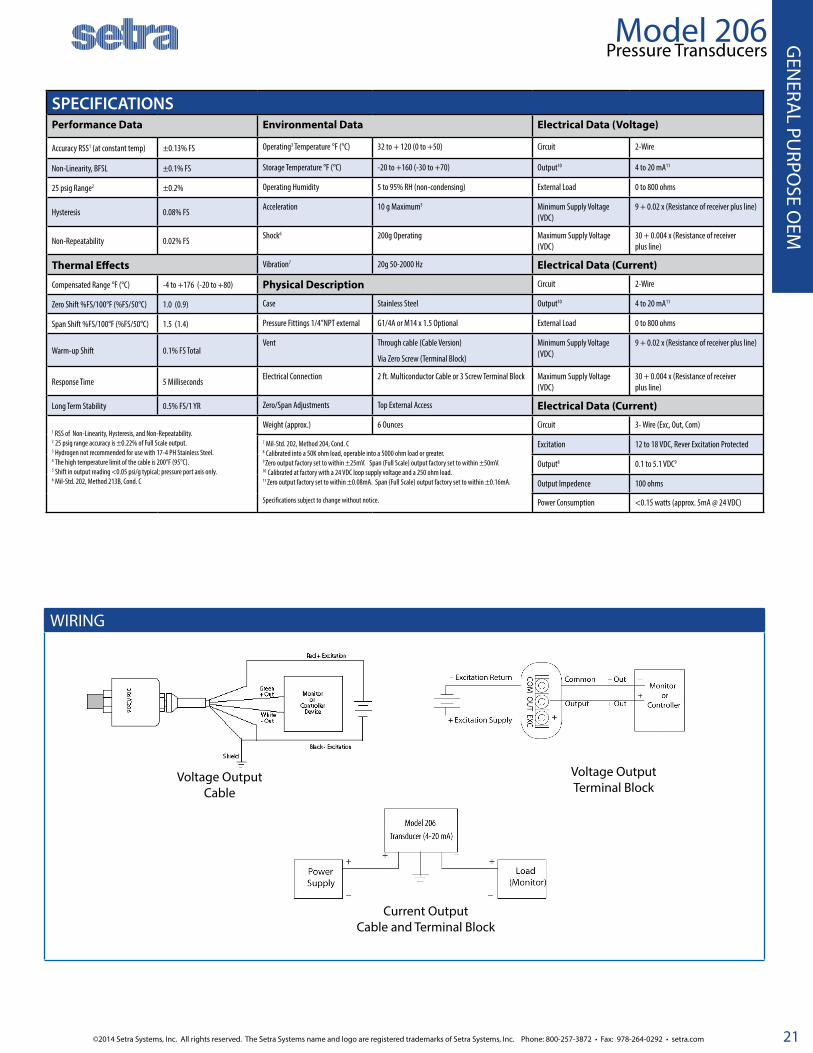
WIRING
Model 206 Pressure Transducers
Voltage OutputCable
Voltage OutputTerminal Block
Current OutputCable and Terminal Block
SPECIFICATIONSPerformance Data Environmental Data Electrical Data (Voltage)
Accuracy RSS1 (at constant temp) ±0.13% FS Operating3 Temperature °F (°C) 32 to + 120 (0 to +50) Circuit 2-Wire
Non-Linearity, BFSL ±0.1% FS Storage Temperature °F (°C) -20 to +160 (-30 to +70) Output10 4 to 20 mA11
25 psig Range2 ±0.2% Operating Humidity 5 to 95% RH (non-condensing) External Load 0 to 800 ohms
Hysteresis 0.08% FSAcceleration 10 g Maximum5 Minimum Supply Voltage
(VDC)9 + 0.02 x (Resistance of receiver plus line)
Non-Repeatability 0.02% FSShock6 200g Operating Maximum Supply Voltage
(VDC)30 + 0.004 x (Resistance of receiver plus line)
Thermal Effects Vibration7 20g 50-2000 Hz Electrical Data (Current)
Compensated Range °F (°C) -4 to +176 (-20 to +80) Physical Description Circuit 2-Wire
Zero Shift %FS/100°F (%FS/50°C) 1.0 (0.9) Case Stainless Steel Output10 4 to 20 mA11
Span Shift %FS/100°F (%FS/50°C) 1.5 (1.4) Pressure Fittings 1/4”NPT external G1/4A or M14 x 1.5 Optional External Load 0 to 800 ohms
Warm-up Shift 0.1% FS TotalVent Through cable (Cable Version)
Via Zero Screw (Terminal Block)
Minimum Supply Voltage (VDC)
9 + 0.02 x (Resistance of receiver plus line)
Response Time 5 MillisecondsElectrical Connection 2 ft. Multiconductor Cable or 3 Screw Terminal Block Maximum Supply Voltage
(VDC)30 + 0.004 x (Resistance of receiver plus line)
Long Term Stability 0.5% FS/1 YR Zero/Span Adjustments Top External Access Electrical Data (Current)
1 RSS of Non-Linearity, Hysteresis, and Non-Repeatability.2 25 psig range accuracy is ±0.22% of Full Scale output. 3 Hydrogen not recommended for use with 17-4 PH Stainless Steel. 4 The high temperature limit of the cable is 200°F (95°C). 5 Shift in output reading <0.05 psi/g typical; pressure port axis only. 6 Mil-Std. 202, Method 213B, Cond. C
Weight (approx.) 6 Ounces Circuit 3- Wire (Exc, Out, Com)
7 Mil-Std. 202, Method 204, Cond. C 8 Calibrated into a 50K ohm load, operable into a 5000 ohm load or greater. 9 Zero output factory set to within ±25mV. Span (Full Scale) output factory set to within ±50mV. 10 Calibrated at factory with a 24 VDC loop supply voltage and a 250 ohm load. 11 Zero output factory set to within ±0.08mA. Span (Full Scale) output factory set to within ±0.16mA.
Specifications subject to change without notice.
Excitation 12 to 18 VDC, Rever Excitation Protected
Output8 0.1 to 5.1 VDC9
Output Impedence 100 ohms
Power Consumption <0.15 watts (approx. 5mA @ 24 VDC)

Phone: 800-257-3872 • Fax: 978-264-0292 • setra.com ©2014 Setra Systems, Inc. All rights reserved. The Setra Systems name and logo are registered trademarks of Setra Systems, Inc.
GEN
ERA
L PU
RPO
SE O
EM
22
DIMENSIONS
Model 206Pressure Transducers
206
19/32ACROSS FLATS
3/4" HEX
1/4"-18 NPT PRESSURE PORT
SPANZERO
0.7519.1 0.50
12.7
2.0050.8
φφ
0.4411.1
φφ
2.1354.0
2.0050.8
Cable VersionZERO
206
7/16-20 SAEPRESSURE FITTING
0.369.1
0.7819.8
2.0050.8
1.1629.5 7/8" HEX
CONDUIT FIT-TING 1/2" NPT
SPAN
2.0050.8
φφ
Cable with Conduit Version
HIRSCHMANNCONNECTOR
3/4" HEX
1/4"-18NPTPRESSURE PORT
SPAN
2.0050.8
ZERO
0.5012.7
0.8220.8
2.0050.8
φφ
1.5038.1
1.5038.1 .06
1.6
206
1.0025.4
Hirschmann Connector
Terminal Version
ZERO
SPAN
1.8145.9
0.8320.6
0.7719.6
RADIUS
Current Version Shown 3/4" HEX
1/4"-18NPT PRESSURE PORT
0.5012.7
0.8020.3
2.5364.3
2.0050.8
2.00 DIA.
TERMINAL STRIP
INMM
206

©2014 Setra Systems, Inc. All rights reserved. The Setra Systems name and logo are registered trademarks of Setra Systems, Inc. Phone: 800-257-3872 • Fax: 978-264-0292 • setra.com
GEN
ERAL PU
RPOSE O
EM
23
ORDERING INFORMATION
Model Range Code Pressure Type Fitting Output Termination Accuracy Options2
2061 = 206
See Table 1 Below
G Gauge 1M 1/4” NPT Male 11 4 to 20 mA XX Cable Length1
8 ±0.13% FS NN None
C Com-pound
2M 1/8” NPT Male 22 0.1 to 5.1 VDC
H1 Hirschmann A Cleaning for Oxygen Service
A Absolute 1F 1/8” NPT Female
27 1 to 5 VDC A1 1/2” Conduit B Mating Bayonet Con-nector
2F 1/4” NPT Female
28 1 to 6 VDC T1 Terminal Block
C Cal Cert
J7 7/16” SAE 2T 0.1 to 10.1 VDC
D Mate with Datum
L Etched SS Tag
F NEMA 4 Enclosure
G Mating Hirschmann Connector
2 0 6 1
Model 206 Pressure Transducers
Table 1. Range Specification
RANGE CODE
PSI RANGE CODE
BAR
025P 0 to 25 1R6B 0 to 1.6
050P 0 to 50 004B 0 to 4
100P 0 to 100 006B 0 to 6
250P 0 to 250 010B 0 to 10
500P 0 to 500 016B 0 to 16
10CP 0 to 1000 025B 0 to 25
30CP 0 to 3000 040B 0 to 40
50CP 0 to 5000 060B 0 to 60
10KP 0 to 10000 100B 0 to 100
160B 0 to 60
250B 0 to 250
400B 0 to 400
700B 0 to 700B
Notes:1. 2 feet of cable is standard. Ordering Example: 2 feet = 02 Up to 25 feet of cable can be ordered.2. Both boxes must be filled in: If No options: N + N If 1 option: Option Code +N If 2 options: Option Code + Option Code
SSP-
206
Rev.
J 02
/02/
2013
Ordering Example: 2061025PG2M22028CN = Model 261, 0 to 25 PSI Range, Gauge Pressure, 1/4” NPT Male Fitting, 0.1 to 5.1 VDC Output, 2 ft. Cable, ±0.13 FS Accuracy, Calibration Certificate

Phone: 800-257-3872 • Fax: 978-264-0292 • setra.com ©2014 Setra Systems, Inc. All rights reserved. The Setra Systems name and logo are registered trademarks of Setra Systems, Inc.
GEN
ERA
L PU
RPO
SE O
EM
24
Model 256 Pressure Transducers
BENEFITS■ Low Cost
■ High Accuracy
■ NEMA-4/IP-65
■ Wide Operating Temperature Range
■ Compatible with a Wide Range of Gases or Liquids
■ Corrosive Resistant All Stainless Steel Wetted Parts
■Choice of Voltage or Current Output
■Operates on Low Cost Unregulated Power Sup-ply
■ Meets CE Conformance Standards
APPLICATIONS■ Process Control
■ Chemical Processing
■ Agricultural Irrigation Systems
■ Natural Gas Pipeline Monitoring
■ Grain Processing
■Industrial Pressure Monitoring
NOTE: Setra quality standards are based on ANSI-Z540-1. The calibration of this product is NIST traceable.
U.S. Patent nos. 6019002; 6014800
DESCRIPTIONThe Model 256 is one of the most rugged and reliable sensors available. Specifically designed for NEMA4/IP65 service, the 256 is packaged in a die-cast aluminum enclosure and includes Setra’s robust capacitive design, making it resistant to environmental ef-fects such as shock, vibration, temperature and EMI/RFI.
Available in a wide variety of gauge pressure ranges, the 256 fea-tures adjustable potentiometers for zero and span settings.
Only 3.6” high x 4.0” wide, the Model 256 is designed for compact installations. The removable cover provides easy access to the in-ternal terminal strip for wiring. Installation is quick and easy with 1/2 inch internal threaded conduit ports for electrical termination.
SPECIFICATIONSPerformance Data Environmental Data Electrical Data (Voltage)
Ranges Ranges Operating3 Temperature °F (°C) -40 to + 185 (-40 to +85) Circuit 3-Wire (Exc, Out, Com)
25 PSI & Higher Less than 25 PSI Storage Temperature °F (°C) -40 to + 185 (-40 to +85) Excitation 9 to 30 VDC
Accuracy RSS1 (at constant temp)2 ±0.13% FS ±0.25% FS Shock6 200g Output5 0.1 to 5.1 VDC for Ranges ≥ 25 PSI6
Non-Linearity, BFSL ±0.10% FS ±0.22% FS Vibration7 20g Output Impedance 100 ohms
Hysteresis 0.08% FS 0.10% FS Environmental Protection NEMA 4/IP65 Power Consumption <0.15 watts (approx. 5mA @ 24 VDC)
Non-Repeatability 0.02% FS 0.05% FS Physical Description Electrical Data (Current)
Thermal Effects Case Die Cast Aluminum Circuit 2-Wire
Compensated Range °F -4 to +176 -4 to 176 Electrical Connections Two 1/2” Internal Conduit Ports Output7 4 to 20mA8 for All Ranges
Compensated Range °C -20 to 80 -20 to ±80 Pressure Fittings 1/4” NPT External External Load 0 to 800 ohms
Zero Shift %FS/100°F 1.0 1.0Weight (approx.) 13.4 Ounces Minimum supply voltage
(VDC)
9 + 0.02 x (Resistance of receiver plus line).
Zero Shift %FS/100°C ±0.9 ±1.8Pressure Media Maximum supply voltage
(VDC)
30 + 0.004 x Resistance of receiver plus line).
Span Shift %FS/100°F 1.5 ±1.5 Liquids and gases compatible with 17-4 PH Stainless Steel.4 1 RSS of Non-Linearity, Hysteresis, and Non-Repeatability.2. Units calibrated at nominal 70°F. Maximum thermal error computed from this datum.3. Operating temperature limits of the electronics only. Pressure media temperature may be considerably higher or lower. 4 Note: Hydrogen not recommended for use with 17-4 PH Stainless Steel.
Specifications subject to change without notice.
5. Calibrated into a 50K ohm load, operable into a 5000 ohm load or greater.6. Zero output factory set to within ±25 mV. Span (Full Scale) output factory set to within ±50 mV.7. Calibrated at factory with a 24 VDC loop supply voltage and a 250 ohm load.8. Zero output factory set to within ±0.08 mA Span output factory set to within ±16 mA
Span Shift %FS/100°C 1.4 ±1.4 Environmental Protection Weather Resistant
Long Term Stability 0.5% FS/YR 0.5% FS/YR Physical Description
Warm-up Shift 0.1% FS Total 0.1% FS Total Case Stainless Steel & Valox

©2014 Setra Systems, Inc. All rights reserved. The Setra Systems name and logo are registered trademarks of Setra Systems, Inc. Phone: 800-257-3872 • Fax: 978-264-0292 • setra.com
GEN
ERAL PU
RPOSE O
EM
25
DIMENSIONS Wiring
Model 256 Pressure Transducers
ORDERING INFORMATION
+ EX
C
EXC
GN
D
OUT
+ OU
T
Voltage Connections
Current Connections
Screw Terminal Designations
+ EX
C
EXC
GND
Model Range Code Pressure Type Pressure Fitting Output Options
2561 = 256 See Table 1 Below G Gauge Ranges <25 PSI Ranges <25 PSI C Calibration Certificate
2M 1/4” NPT Male 11 4-20 mA
1M 1/8” NPT Male Ranges ≥25 PSI
Ranges ≥ 25 PSI 11 4-20 mA
2M 1/4” NPT Male 22 0.1 - 5.1 VDC
4M 1/2 “ NPT (Male)
2F 1.4” NPT (Female)
Table 1. Range Specification
RANGE CODE
PSI RANGE CODE
BAR
001P 0 to 1 1R6B 0 to 1.6
002P 0 to 2 004B 0 to 4
005P 0 to 5 006B 0 to 6
010P 0 to 10 010B 0 to 8
015P 0 to 15 016B 0 to 16
025P 0 to 25 025B 0 to 25
050P 0 to 50 040B 0 to 40
100P 0 to 100 060B 0 to 60
150P 0 to 150 100B 0 to 100
200P 0 to 200 160B 0 to 160
250P 0 to 250 250B 0 to 250
500P 0 to 500 400B 0 to 400
600P 0 to 600 700B 0 to 700
10CP 0 to 1000
30CP 0 to 3000
50CP 0 to 5000
10KP 0 to 10000
2 5 6 1
Ordering Example: 2561001PG2M11C = Model 256, 0 to 1PSI , Gauge Pressure, 1/4” NPT Pressure Fitting, 4 to 20 MA Output, Calibration Certificate
2.0050.8
1/4” NPT
0.389
25464.5
3.5690.4
1.4637.1
Removable Zero/Span
Access Plugs
Removable Terminal Block
Connector
2.5061
4.02102.1
in.mm
SSP-
256
Rev.
H 0
2/16
/201
0

Phone: 800-257-3872 • Fax: 978-264-0292 • setra.com ©2014 Setra Systems, Inc. All rights reserved. The Setra Systems name and logo are registered trademarks of Setra Systems, Inc.
GEN
ERA
L PU
RPO
SE O
EM
26
Model 210Circuit Board-Mountable Pressure Transducer
BENEFITS■ Fully Signal Conditioned
■ High Level Output
■ Excellent Long Term Stability
■ EMI/RFI Immunity
■ Easily Customized Package
■ Optional Excitations, Outputs and Accuracies
■ Wide Operating Temperature Range
■ High Signal to Noise Ration■ Meets CE Conformance Standards
APPLICATIONS■ Analytical Measurement and Control
■ OEM Medical Systems
DESCRIPTIONSetra Systems 210 is the ultimate in circuit board-mountable pressure transducers. In addition to the convenience of quick PCB installations, the 210 offers wide media compatibility with its stainless steel sensor construction. The calibrated high level output eliminates the need for additional circuit and calibration labor costs.
Packaged in a compact plastic enclosure (1.25” diameter footprint), the Model 210 incorporates Setra’s unique capacitance technology, known worldwide for its solid stability, accuracy, and thermal performance. With the custom ASIC circuit and capacitive sensor, the Model 210 performs with reliability and EMI/RFI immunity. The Model 210 can be customized to accommodate various package and performance re-quirements, and is designed for OEM applications.
SPECIFICATIONSPerformance Data Physical Description Electrical Data (Voltage)
Standard Optional Case Fire Retardant Glass-Filled Polyester
Circuit 3-Wire (+In, +Out, Common)
Accuracy RSS ±1.0% FS ±0.5% FS ±0.25% FS Sensor 17-7 Stainless Steel for Ranges ≥5 PSI. Other Ranges, 300 Series Stainless Steel
Excitation 24 VDC (21.6 to 32)12 VDC (10.8 to 18.4)5 VDC (4.9 to 8.1)
Non-Linearity, (BFSL) ±0.98% FS ±0.48% FS ±0.22% FS Pressure Fitting 3/16 O.D. Barbed Nylon Pressure Fitting for 1/8” I.D. Tubing
Output* 1 to 6 VDC0.5 to 4.5 VDC0.5 to 5.5 VDC
Hysteresis 0.20% FS 0.10% FS 0.10% FS Electrical Connection Solder Pins, 0.030” Roung on 0.2” Centers
Output Impedance <100 Ohms
Non-Repeatability 0.05% FS 0.05% FS 0.05% FS Weight (approx) 0.5 ounces Response Time 10 Milliseconds
Thermal Effects Environmental Data *Calibrated into a 50K ohm load or greater.Zero output factory set to within ±25 mV.Span (Full Scale) output factory set to within 50 mV.Zero Shift %FS/°F (%FS/ºC) <±2.0 (<±1.8) Temperature
Span Shift %FS/°F (%FS/ºC) <±1.5 (<±1.4) Operating °F(ºC) 4 -4 to +176 (-20 to +80)
Long Term Stability 0.5% FS/YR Storage °F(ºC) -40 to +185 (-40 to +85)
Pressure Media Humidity
Gases compatible with 304 SS, 17-7 PH Series Stainless Steel, Nylon, Polyester and Silicone.
Operating 0 to 95% RH Non-Condensing
Storage 0 to 98% RH Non-Condensing
Vibration 5g Operating
Shock <100g
PRESSURE RANGES0 PSIG
to:Proof Pressure
(PSIG)Burst Pressure
(PSIG)
1 2 250
2 4 250
5 10 500
10 20 500
15 30 500
25 50 500
50 100 500
100 200 500
NOTE: Our pressure sensor products are not necessarily designed or manufactured for use as a “critical component” in a “critical device”, as those terms are defined in the Medical Devices Subchapter contained in the Food and Drug Administration Rules, 21CFR800.NOTE: Setra adheres to strict quality standards including ISO 9001 and ANSI-Z540-1. The calibration of this product is NIST traceable. U.S. Patent Nos. 4054833, 5442962, 6205861 B1.

©2014 Setra Systems, Inc. All rights reserved. The Setra Systems name and logo are registered trademarks of Setra Systems, Inc. Phone: 800-257-3872 • Fax: 978-264-0292 • setra.com
GEN
ERAL PU
RPOSE O
EM
27
DRAWINGS & DIMENSIONS
ORDERING INFORMATION
2 1 0 1
Ordering Example: 2101001PG1B35C1C = 210 Transducer, 0 to 1 PSIG range, Barbed fitting, 12 VDC excitation, 0.5 to 4.5 VDC output with PC board mountable pins and an accuracy of ±10%.
Model 210 Circuit Board-Mountable Pressure Transducer
SSP2
10 Re
v. G
06/1
4/20
04
Model Pressure Range Pressure Type Fitting Output Elec. Termination Accuracy
2101 210 001P 1 PSI G Gauge 1B Straight Barbed 24 24 VDC/0.5-5.5 VDC C1 PC Board Mountable Pins Standard
002P 2 PSI 1D Right Angle 25 24 VDC/0.5-4.5 VDC C ±1.0% FS
005P 5 PSI 28 24 VDC.1-6 VDC Options (w Cal Cert)
010P 10 PSI 35 12 VDC/0.5-4.5 VDC H ±0.5%
015P 15 PSI 38 12 VDC/1-6 VDC F ±0.25%
025P 25 PSI 45 5 VDC/0.5-4.5 VDC
050P 50 PSI
100P 100 PSI

Phone: 800-257-3872 • Fax: 978-264-0292 • setra.com ©2014 Setra Systems, Inc. All rights reserved. The Setra Systems name and logo are registered trademarks of Setra Systems, Inc.
GEN
ERA
L PU
RPO
SE O
EM
28
Model 526 Submersible Pressure Transducer
FEATURES■ Superior Stability Avoid Down Time
■ IP30, IP65, IP68 Rated
■ ±0.25% FS Accuracy, Optional ±0.15%
■ High Shock and Vibration Resistance
■ Meets CE Conformance Standards
APPLICATIONS■ General Purpose■ Off-Highway Vehicles
■ Natural Gas Equipment
■ Power Plants
■HVAC Compressors
■ Refrigeration
■ Robotics
DESCRIPTION
Setra’s Model 526 pressure transducer is designed with a thicker diaphragm for robust industrial and submersible applications that require exceptional stability and high accuracy.
Depending upon the electrical connection selected, when coupled with the Model 526 enclosure, which is fabricated in 316 SS/17-4 PH SS, this unit is rated for IP30, IP65, IP68 operation.
The Model 526’s modular design is offered in a wide choice of millivolt, volt-age or current outputs over almost any pressure range, and a variety of pressure and electrical connections, enabling this unit to be custom con-figured for an OEM application.
SPECIFICATIONSPerformance Data Environmental Data Electrical Data (Voltage)
Accuracy RSS1 (at constant temp) ±0.25% FS, ±0.15% FS Optional Operating and Storage Temperature3 oFoC Circuit 3-Wire (Exc, Out, Com)
Thermal Effect2 for Elec. Code E1 -40 to +260 (-40 to +125) Excitation 1.5 VDC Above Span to 35 VDC @ 6mA4
Compensated Range Fo(Co) -5 to +180 (-20 to + 80)for Elec. Code N1 -5 to +180 (-20 to +80) Output5 0 to 5VDC, 0 to 10VDC, 0.5 to 5.5 VDC,
1 to 5 VDC, 1 to 6 VDC, 1 to 11 VDC
Accuracy ±0.25% FSZero/Span Shift %FS/100°F (%FS/50°C)
0.8 (1.5)for Elec. Code NA -5 to +125 (-20 to +50) Current Consumption6 Approx. 6 mA @ 7.5 VDC output
Accuracy ±0.15% FSZero/Span Shift %FS/100°F (%FS/50°C)
0.5 (1.0)Vibration 70g Peak to Peak Sinusoidal, 5 to 2000 Hz
(Random)Electrical Data (Millivolt)
Response Time 0.5 milliseconds Acceleration 100g Stead Acceleration in any direction 0.32% F Circuit 4-Wire (+Exc, -Out, +Out, -Exc)
Long Term Stability 0.2% FS/yearShock 20g, 11ms per MIL-STD-810E; Method 516.4
ProcedureExcitation 10 VDC (15 VDC Max) Regulated
Proof Pressure 2 x FS (<1.5 x FS for 400 BAR, >=5000 PSI) Physical Description Output7 100 mV (10mV/V)
Burst Pressure>35 x FS<=100 PSI (6 BAR)>20 x FS<=1000 PSI (60 BAR)>5 x FS<=6000 PSI (400 BAR)
Case 316 Stainless Steel, 17-4 Stainless Steel Bridge Resistance 2600-6000 Ohms
Ratings IP65 for Elec Codes B3, B1, E2; IP68 for Elec Code UA (Max. Depth 200 Meters H20 Electrical Data (Current)
Pressure Media Wetted Parts 17-4 PH Stainless Steel Circuit 2-Wire
Liquids or gases compatible with 17-4 PH Stainless Steel Note: Hydrogen not recommended for use with 17-4 PH Stainless Steel
Weight 3.5 Oz (100g) Output8 4 to 20 mA9
1 RSS of Non-Linearity, Non-Repeatability and Hysteresis.2 Units calibrated at nominal 70°F. Maximum thermal error is computed from this datum.3 Operating/Storage temperature limits of the connector only.4 Zero/Span output factory set to <1.0% Full Scale5 Temperatures >100oC/212oC is limited to 24 VDC.
6 Minimum Load Resistance: (FS output/2)Kohms.7 Zero/Span output factory set to 1.0% Full Scale8 Zero/Span output factory set within ±0.16 mA9 Temperatures >100oC/212oC is limited to 24 VDC.
Loop Supply Voltage 24 VDC, (7-35 VDC)
Maximum Loop Resistance (Vs-7) x 50 Ohms
Principle of Operation:
Using the well proven Wheatstone Bridge Principle, a chemical vapor is deposited in thin layers or silicon and silicon dioxide onto a stainless steel sensor to form a very sensitive and accurate polysilicon strain gauge. The elements of the strain gauge are fused together at the atomic level, assuring the strength and integrity of the bond, which exceeds the adhesives used in common bonded strain gauge pressure sensors. A custom designed ASIC performs signal amplification and temperature compensation. This technology offers the user the option of configurable output and pressure ranges, sets the zero and span tolerance, and ensures interchangeability from unit to unit.

©2014 Setra Systems, Inc. All rights reserved. The Setra Systems name and logo are registered trademarks of Setra Systems, Inc. Phone: 800-257-3872 • Fax: 978-264-0292 • setra.com
GEN
ERAL PU
RPOSE O
EM
29
ORDERING INFORMATION
Model 526Submersible Pressure Transducer
Model Range Pressure Pressure Fitting Output Elec. Term. Accuracy Options
5261 = 526 015P 15 PSI 001B 1 BAR G Gauge 1M 1/8-27 NPT Male BP 100 mV B3 10-6 Baronet Connector
F 0.25% FS A Instrinsic Safe CSA
030P 30 PSI 0R6B 1.6 BAR C Compound 1F 1/8-27 NPT Female 11 4-20 mA UA Molded Immersible
Cable (up to 2000
meters (656 ft)
S 0.15% FS,
Opt.
B Intrinsic Safe ATEX
060P 60 PSI 2R5B 2.5 BAR A Absolute 2M 1/4-18 NPT Male 28 1-6 VDC
100P 100 PSI 004B 4 BAR J7 7/16-20 UNF Male SAE#4 (J1926-2)
2R 1-11 VDC B1 8-4 Bayonet Conn.
150P 150 PSI 006B 6 BAR G2 G 1/4 Male 27 1-5 VDC A2 1/2” Conduit Conn.
w/ 1 Meter (3.28ft)
flying leads200P 200 PSI 010B 10 BAR G3 G 1/4 Female 24 0.5-5.5 VDC
300P 300 PSI 016B 16 BAR Submersible Units 2B 0-5 VDC E2 Large DIN 43650 Conn w. Mating Plug
500P 500 PSI 025B 25 BAR W1 Plastic Nose Cone 2C 0-10 VDC
600P 600 PSI 040B 40 BAR W2 Stainless Steel Sink Weight Nose Cone
29 0.2-10.2 VDC
10CP 1000 PSI 060B 60 BAR 22 0.1-5-1 VDC
15CP 1500 PSI 100B 100 BAR
15CP 1500 PSI 100B 100 BAR
20CP 2000 PSI 160B 160 BAR
30CP 3000 PSI 250B 250 BAR
40CP 4000 PSI 400B 400 BAR
50CP 5000 PSI 600B 600 BAR
60CP 6000 PSI
000P 14.7 TO 0 PSI 135P 14.7 TO 135 PSI
015P 14.7 TO 15 PSI 185P 14.7 TO 185 PSI
045P 14.7 TO 45 PSI 285P 14.7 TO 285 PSI
5 2 6 1
SSP5
26 R
ev A
4/1
6/03
OUTLINE DRAWING
Shown with Conduit Connector with Cable & 1/8-27 NPT Pressure Fitting
Shown with Molded Immersible Cable & Plastic Nose Cone
Ordering example: Part No. 5261030PG1M11E2F - For a Model 526 Pressure Transducer, 30 PSI, Gauge Pressure, 1/8-27 NPT Male Pressure Fitting, 4-20 mA Output, Large Din Plug w/ Mate, 0.25% Accuracy.

Phone: 800-257-3872 • Fax: 978-264-0292 • setra.com ©2014 Setra Systems, Inc. All rights reserved. The Setra Systems name and logo are registered trademarks of Setra Systems, Inc.
GEN
ERA
L PU
RPO
SE O
EM
30
Model 550 Low Pressure Transducer
FEATURES■ Superior Stability Avoid Down Time
■ NEMA 4/IP65 and NEMA 6/IP68 Rated
■ ±0.25% FS High Accuracy
■ 3:1 Range Turndown
■ Meets CE Conformance Standards
APPLICATIONS■ Tank Level■ Reservoir Level
■ River Level
■ Hydro-Power
■Open Channel Flow
■ Flood Warning
■ Waste Water
DESCRIPTION
Setra’s Model 550 low pressure transducer features 3:1 range turndown for field adjustment from 110% to 32% of the nominal range, making this unit well suited for applications that are subject to overpressure. Adjustment is made via the switch and potentiometer conveniently located on the top of the transducer housing.
The Model 550 is packaged in a rugged 316 stainless steel housing for use in general purpose and submersible applications. A male or female thread-ed pressure fitting is offered for general purpose applications, and an open face style with a KF25 flange is offered for submersible applications.
The Model 550 circuit is RFI/lightning protected, virtually eliminating costly field replacement.
SPECIFICATIONSPerformance Data Environmental Data Electrical Data (Voltage)
Accuracy RSS1 (at constant temp) ±0.25% F Operating and Storage Temperature3 oFoC Circuit 3-Wire
Thermal Effect2 for Elec. Codes E2 +15 to +185 (+25 to +85) Excitation 7.5 to 35 VDC (8-35 VDC, 1-6 VDC output)
Compensated Range Fo(Co) -5 to +140 (-20 to + 60)for Elec. Codes UA -5 to +120 (-20 to +50) Output4 0.5 to 5.5 VDC, 1 to 6 VDC, 0 to 5 VDC, 0.1
to 5.1 VDC, 1 to 5 VDC
Zero/Span Shift %FS/100°F (%FS/50°C) 1.0 (2.0) w/ Process Media -40 to +212 (-40 to +100) Electrical Data (Millivolt)
Zero/Span Adjustment ±10% (by Potentiometer) Physical Description Circuit 2-Wire
Response Time 0.5 millisecondsCase Rating
318 Stainless Steel IP68 (NEMA) Submersible G IP65
Excitation 9 to 35 VDC
Long Term Stability 0.2% FS/1 year Wetted Parts Inconel, Ceramic & Nitrile Output5 4 to 20 mA
Pressure Media Weight 11.6 oz. (330g) Maximum Loop Resistance (Vs-9) x 50 Ohms
Water of Viscous Fluids Compatible with 316 SS, Ceramic and Nitrile Diameter 38.1 mm w/o K2 flange, 40.0 mm w K2 flange Accessories 1 RSS of Non-Linearity, Non-Repeatability and Hysteresis.2 Units calibrated at nominal 70°F. Maximum thermal error is computed from this datum.3 Operating/Storage temperature limits of the cable or process media.4 Zero/Span output factory set to <1.0% Full Scale5 Zero/Span output factory set within ±0.16 mA.
GA9GA10GA11GA25
Large Din, 4365-A, Strain ReliefLarge Din, 4365-A, 1/2” Conduit6-Pin Dendix to 125oCPlastic Nose Cone w/ G 1/4 Port
Principle of Operation:
The capacitive sensor is constructed of an electrically isolated stainless steel electrode and ceramic diaphragm, mounted closely and in parallel to each other. The diaphragm is capable of slight flexing under applied pressure. A minute change in applied pressure alters the gap between the electrode and diaphragm. This change is detected by a custom designed ASIC, amplified and converted to high-level linear output signal that is proportional to applied pressure.
Pressure RangesPressure Range Proof
PressureBurst
Pressure
≤ 85 in. W.C. 803 in. W.C. 1219 in. W.C.
86 in W.C. to 140 in. W.C. 1607 in. W.C. 2410 in. W.C.
141 in. W.C. to 400 in. W.C. 2025 in. W.C. 4017 in. W.C.
≤ 3 psi 29 psi 44 psi
3.1 to 5 psi 58 psi 87 psi
5.1 to 15 psi 102 psi 145 psi

©2014 Setra Systems, Inc. All rights reserved. The Setra Systems name and logo are registered trademarks of Setra Systems, Inc. Phone: 800-257-3872 • Fax: 978-264-0292 • setra.com
GEN
ERAL PU
RPOSE O
EM
31
ORDERING INFORMATION
Model 550Low Pressure Transducer
Model Range Pressure Pressure Fitting Output Elec. Term. Accuracy Options
5501 = 550 001P 1 PSI 010W 10 in W.C G Gauge G3 G 1/4 Female 11 4-20 mA, 2-Wire E2 Large DIN 43650 Conn w. Mating Plug
F 0.25% FS A Instrinsic Safe CSA
002P 2 PSI 015W 15 in W.C 2M 1/4-18 NPT Male 28 1-6 VDC, 3-Wire UA 1M Molded
Immersible Cable
(up to 2000 meters
(656 ft)
S 0.15% FS,
Opt.
B Intrinsic Safe ATEX
003P 3 PSI 025W 25 in W.C 4M 1/2-14 NPT Male 2B 0-5VDC, 3-Wire
004P 4 PSI 050W 50 in W.C G2 G 1/4 Male 24 0.5-5.5 VDC, 3-Wire
005P 5 PSI 100W 100 in W.C N2 KF25 Flange 27 1-5 VDC, 3-Wire
007P 7 PSI 150W 150 in W.C 0.1-5-1 VDC, 3-Wire
010P 10 PSI 200W 200 in W.C
012P 12 PSI 250W 250 in W.C
015P 15 PSI 300W 300 in W.C
350W 350 in W.C
400W 400 in W.C
5 5 0 1
SSP5
50 R
ev. C
12/
27/2
006
Ordering example: Part No. 5501002PG211UAF - For a Model 550 Pressure Transducer, 2 PSI, G 1/4” Male Pressure Fitting, 4-20 mA Output, Molded Submersible Cable, and 0.25% Accuracy.
OUTLINE DRAWING
Shown with 1/4-14 NPT Conduit Shown with KF25 Flange and Submersible Cable Assembly

Phone: 800-257-3872 • Fax: 978-264-0292 • setra.com ©2014 Setra Systems, Inc. All rights reserved. The Setra Systems name and logo are registered trademarks of Setra Systems, Inc.
GEN
ERA
L PU
RPO
SE O
EM
32
Model 280 Gauge, Compound and Absolute Pressure Transducer
BENEFITS■ Low Cost/High Performance
■ 0.11% Full Scale Accuracy
■ High Level Output: Voltage & Current
■ One Piece Stainless Steel Sensor
■ Small Size and Light Weight
■ Temperature Compensated for Low Thermal Error
APPLICATIONS■ High Pressure
■ General Purpose
■ P/I Process Signals
■ Hydraulics and Pneumatics
DESCRIPTIONSetra Systems Model 280 pressure transducer is intended for low to high pressure measurements of gases or liquids in applications requiring rug-ged packaging, high performance and affordability. The 17-4 PH stainless steel capacitance sensing element, coupled with a custom ASIC based cir-cuit, assures excellent accuracy and long term stability.
The stable electronic circuit, combined with Setra’s variable capacitance sensor, results in the ultimate in design simplicity. The sensor features a 17-4 PH stainless steel pressure sensor and an insulated electrode, which forms a variable capacitor. As the pressure increases, the capacitance de-creases. The change in capacitance is detected and converted to a linear DC output signal.
The high level of voltage or current output signal requires no additional signal and conditioning and results in excellent stability, accuracy and fast dynamic response, making the 280 ideal for high performance applica-tions.
SPECIFICATIONSPerformance Data Physical Description Electrical Data (Voltage)
Accuracy RSS 1
(at constant temperature)±0.11% FS Case Stainless Steel with O-Ring Circuit 3-Wire (+In, +out, Com)
Non-Linearity, (BFSL)
±0.1% FS Electrical Connection 1” Edge Card with Space Lugs and Dust Boot
Excitation 15 to 32 VDC
Hysteresis 2 0.05% FS Pressure Fitting 1/4” - 18 NPT Internal Output 7 0.03 to 5.03 VDC 8
Non-Repeatability 0.02% FS Pressure Cavity Volume 0.04 in.3 Power Consumption 0.25 watts (approx. 10mA @ 24 VDC)
Thermal Effects 3 Volume Increase 5 x 10⁻⁵ in.3 Output Impedance 100 ohms
Compensated Range +32 to +150°F (0 to +65ºC) Weight 5 oz Output Noise 100 microvolts RMS (0 Hz to 10 KHz)
Zero/Span Shift %FS/100oF (%FS/50oC)
2.0 (1.8) Environmental Data Electrical Data (Current)
Warm-Up Shift 0.5% FS (0.1% FS residual shift after 5 minutes)
Temperature Circuit 2-Wire
Pressure Media Operating 5 0 to +175°F (-18 to +80ºC) Output 9 4 to 20 mA 10
Gases or liquids compatible with 17-4 PH Stainless Steel. 4 Storage -65 to +200°F (-54 to +93ºC) External Load 0 to 800 ohms
Vibration 2g from 5 Hz to 500 Hz Min. Supply Voltage (VDC) = 18 +0.02 x (Resistance of receiver plus line)
Acceleration 10g 6 Max. Supply Voltage (VDC) = 32 + 0.004 x (Resistance of receiver plus line)
Shock 50g Reverse Excitation Protected.
1 RSS of Non-Linearity, Hysteresis and Non-Repeatability.2 0.1% FS for 10,000 psi range only.3 Units calibrated at nominal 70oF. Maximum thermal error is computed from this datum.4 Hydrogen not recommended for use with 17-4 PH Stainless Steel.5 Operating temperature limits of the electronics only. Pressure media temperatures may be considerably higher or lower.6 Shift in output reading of 0.05% FS/G typical, pressure port axis only.7 Calibrated into a 50K ohm load.8 Span (Full Scale) output factory set to within ±50mV.9 Calibrated at factory with 24 VDC loop supply voltage and a 250 ohm load.10 Zero output and Span FS factory set to within ±0.16mA. Span (Full Scale) output factory set to within ±0.16mA.

©2014 Setra Systems, Inc. All rights reserved. The Setra Systems name and logo are registered trademarks of Setra Systems, Inc. Phone: 800-257-3872 • Fax: 978-264-0292 • setra.com
GEN
ERAL PU
RPOSE O
EM
33
ORDERING INFORMATION
DRAWINGS & DIMENSIONS
2 8 0 1
Ordering Example: 2801025PG2F11T1WCN - Model 280, 0 to 25 PSI, Gauge Pressure, 4-20 mA, Terminal Strip, ±0.11%, 11 Point Cal Certification
Model 280 Gauge, Compound and Absolute Pressure Transducer
SSP2
80
PRESSURE RATING (PSI)Sensor Range Proof Pressure Burst Pressure
0-15 25 75
0-25 50 150
0-50 75 200
0-100 150 500
0-250 375 1000
0-500 750 1500
0-1000 1250 3000
0-3000 3750 45000
0-5000 6000 7500
0-10000 11000 12500
-14.7 to 35 75 200
-14.7 to 50 150 500
3-15 25 75
Model Pressure Range Units Pressure Type Fitting Output Termination Accuracy Options
2801 280 015 15 P PSI G Gauge 2F 1/4” NPT Internal 11 4 to 20 mA T1 Terminal Strip W ±0.11% FS NN None
025 25 C Compound (Available 35 to 10,000 PSI Only) 2S
0.03 to 5.03 VDC (24 VDC EXC) 93 ±0.073% C
11 Point Calibration Certification
050 50 A Absolute (Available 25-5,000 PSI Only) 3S
0.03 to 5.03 VDC(12 VDC EXC) D
Mate with Datum
100 100 F NEMA 4 Enclosure
250 250 L Etched SS Tag
500 500 Y Clean for Oxygen SVC
10C 1000
30C 3000
50C 5000
10K 10000
Z02 3 to 151
035 -14.7 to 352
Both boxes must filled in alphabetical order:• If No options: N + N• If 1 option: Option Code + N• If 2 options: Option Code + Option Code
3 Not available on 10K PSI
1 Only available with Type code “C”2 Only available with output code “11”
SETRACAPACITANCE SENSING
CIRCUIT••
••
HIGH LEVELDC OUTPUT
.036 CU. INVOLUME
.036 CU. IN.VOLUME
Extremely low hysteresis and very stable operation under extreme temperature condi-tions are inherent in this sensor design.
NOTE: Setra quality standards are based on ANSI-Z540-1. The calibration of this product is NIST traceable.
1.332
INMM
1028
.9424
3079
4.4113
.6015
.7019.90221.844
PRESSURE PORT1/4” - 18 NPT INTERNAL
Voltage terminal kit - 280620Voltage terminal kit - 280621
CAUTION: Center clip must be mounted on opposite side of outside clips to avoid shorting. (voltage units)
All other compound ranges have same rating as gauge ranges.

Phone: 800-257-3872 • Fax: 978-264-0292 • setra.com ©2014 Setra Systems, Inc. All rights reserved. The Setra Systems name and logo are registered trademarks of Setra Systems, Inc.
GEN
ERA
L PU
RPO
SE O
EM
34
Model 205Gauge & Absolute Pressure Transducer
BENEFITS Low Price 0.11% Full Scale Accuracy 5 VDC Output High Cycle Life Fast Response, 1 Millisecond Solid One-Piece Stainless Steel Sensor Fast Warm-Up
APPLICATIONS High Accuracy General Purpose R&D Test & Measurement Vacuum Systems Dynamometers Engine Test Calls
DESCRIPTIONSetra Systems 205 pressure transducer is designed for accurate pres-sure measurement of gases or liquids compatible with stainless steel. The high level output signal requires no additional signal conditioning and results in excellent stability, accuracy, and fast dynamic response, making the 205 ideal for high performance applications. The stable electronic circuit, combined with Setra’s patented variable capaci-tance sensor, results in the ultimate in design simplicity. The sensor features a one-piece 17-4 PH stainless steel pressure sensor and an insulated electrode, which forms a variable capacitor. As the pressure increases, the capacitance decreases. This change in capacitance is detected and converted to a linear DC electric signal.
SPECIFICATIONSPerformance Data Physical Description Electrical Data (Voltage)
Accuracy RSS 1
(at constant temperature)±0.11% FS Case Stainless Steel Circuit 4-Wire (+Exc, -Exc, +Out, -Out)
Non-Linearity, (BFSL) ±0.10% FS Electrical Connection 2ft. Multiconductor Cable (Std) Excitation 18 to 30 VDC
Hysteresis 0.05% FS Pressure Fitting 1/4” - 18 NPT Internal Output 5 0 to 5 VDC 6
Non-Repeatability 0.02% FS Weight 4 ounces Output Impedance 400 ohms
Thermal Effects 2 Environmental Data Output Noise 100 Microvolts RMS (0 Hz to 10 KHz)
Compensated Range °F(ºC) +32 to +150 (0 to +65) Temperature 1 RSS of Non-Linearity, Hysteresis and Non-Repeatability.2 Units calibrated at nominal 70oF. Maximum thermal error is computed from this datum.3 Hydrogen not recommended for use with 17-4 PH Stainless Steel.4 Operating temperature limits of the electronics only. Pressure media temperatures may be considerably higher or lower.5 Calibrated into a 50K ohm load.6 Zero output factory set to within ±50mV. Span (Full Scale) output factory set to within ±50mV.NOTE: Both output leads are nominally 1.6 VDC above the negative excitation lead at zero pressure. Either negative excitation or negative output should be connected to case (ground). But both leads cannot be connected to case (ground). Unit is calibrated at the factory with the negative excitation connected to case (ground).
Zero Shift %FS/°F (%FS/ºC) ±0.02 (±0.036) Operating °F(ºC) 4 0 to +175 (-18 to +79)
Span Shift %FS/°F (%FS/ºC) ±0.015 (±0.027) Storage °F(ºC) -65 to +250 (-54 to +121)
Warm-Up Shift 0.5% FS (0.1% FS residual shift after 5 minutes)
Vibration 2g from 5 Hz to 500 Hz
Response Time 1 Millisecond Shock 50g
Static Acceleration Effect 0.05 psi/g Accceleration 10g Maximum
Pressure Media
Gases or liquids compatible with 17-4 PH Stainless Steel. 3

©2014 Setra Systems, Inc. All rights reserved. The Setra Systems name and logo are registered trademarks of Setra Systems, Inc. Phone: 800-257-3872 • Fax: 978-264-0292 • setra.com
GEN
ERAL PU
RPOSE O
EM
35
DRAWINGS & DIMENSIONS
2.4262
2.0051
0.875 22
φφ
2051100PG2F2B02WFN10307250-100 PSIG18-30 VDC0-5 VDC
ORDERING INFORMATION
2 0 5 1
Ordering Example: 2051100PG2F2B02WFN - Model 205, 0 to 100 PSIG, Gauge Pressure, 1/4” NPT Internal Fitting, 2’ Cable ±0.11% FS, NEMA 4 Option
Model 205 Gauge & Absolute Pressure Transducer
SSP2
05 Re
v G
PSIG RANGESStandard Pressure
Ranges (psi)Proof Pressure
(psi)Burst Pressure
Rating (psi)Approx. Natural
Frequency
0-25 50 150 2.0
0-50 75 200 2.5
0-100 150 500 3.5
0-250 375 1000 5.0
0-500 750 1500 8.0
0-1000 1250 3000 11.0
0-3000 3750 4500 15.0
0-5000 6000 7500 25.0
Model Pressure Range Units Pressure Type Fitting Output Termination Accuracy Options
2051 205 25 025 P PSI G Gauge 2F 1/4” NPT Internal 2B 0 to 5 VDC 02 2’ Cable W ±0.11% FS NN None
50 050 A Absolute 27 1 to 5 VDC 10 10’ Cable 9 ±0.073% C 11 PT Cal. Certificate
100 100 25 25’ Cable D Mate with Datum
250 250 XX Consult facotry for other lengths
F Nema 4 Enclosure
500 500 L Etched SS Tag
10C 1000 Y Clean for Oxygen SVC
30C 3000 3 -65 to 250 oF Compensated Range
50C 5000
Both boxes must be filled in alphanumeric order:• If No options: N + N• If 1 option: Option Code + N• If 2 options: Option Code + Option Code
SETRACAPACITANCE SENSING
CIRCUIT••
••
HIGH LEVELDC OUTPUT
.036 CU. INVOLUME
.036 CU. IN.VOLUME
Extremely low hysteresis and very stable operation under extreme temperature condi-tions are inherent in this sensor design.
NOTE: Setra quality standards are based on ANSI-Z540-1. The calibration of this product is NIST traceable.
INMM
PRESSURE PORT1/4” - 18 NPT INTERNAL
BOTTOM VIEW
1.75 44
φφ

Phone: 800-257-3872 • Fax: 978-264-0292 • setra.com ©2014 Setra Systems, Inc. All rights reserved. The Setra Systems name and logo are registered trademarks of Setra Systems, Inc.
GEN
ERA
L PU
RPO
SE O
EM
36
DIMENSIONS
Model CCMMini Current Switch
FEATURES Small Footprint Clamped/Split Core Design
Under Current Sensing
Integrated Mounting Flange with DIN-Rail Capability
BENEFITS Low Cost Solution
Save Valuable Space in the Electrical Panel
Simple Installation
Accurate Fixed Set Point, No Guessing at Switchover Current
APPLICATIONS HVAC Refrigeration Pumps Small Industrial Motors Fans Lighting
DESCRIPTIONThe Mini Current Switch (Model CCM) is the industry’s smallest split core current switch. It features an integrated mounting flange with DIN-rail capability and offers in-creased installation convenience at no additional cost to the end user. The Model CCM is a cost effective solution to monitoring light to medium current loads.
An increase or decrease in operating current may result in motor belt loss, slippage or mechanical failure, which could jeopardize the user’s process. Designed to de-tect these changes in operating current, the Model CCM (Split Core Current Switch) can be easily clamped onto new or existing power cables or wires.
The Model CCM current switch has a fixed set point of 0.15 Amps.
inches(mm)
0.76(19.3)
1.19(30.23)
0.18(4.57)
1.72(43.7)
1.69(42.9)
0.83(21.1 )
1.55(39.4)

©2014 Setra Systems, Inc. All rights reserved. The Setra Systems name and logo are registered trademarks of Setra Systems, Inc. Phone: 800-257-3872 • Fax: 978-264-0292 • setra.com
GEN
ERAL PU
RPOSE O
EM
37
Model CCMMini Current Switch
SPECIFICATIONSMODEL CCMF015Amperage Range 0.15 to 60 A
Continuous Operating Current 60A, 300V AC
Current Set Point Fixed
Switch LED Indication No
Relay LED Indication No
Trip Point Set Value 0.15A
Current Switching Mode Under Current Sensing
Dimensions1.57 H X 1.66 L X 1.52 W in.
(39.9) x 42.2 L x 38.6 W mm)
Aperture Size 0.3 in. (7.6 mm) 6 AWG
Sensor Power SourceInduced from measured conductor
No external source needed
Status Output N.O.
Switch Load Capacity 1A @ 30V AC/DC
Isolation Voltage 300V AC rms.
Temperature Range 5 to 140°F (-15 to 60°C)
Frequency Range 50/60 Hz
Humidity Range 0 to 95% non-condensing
Agency Approvals/Compliance UL/c-UL Listed: 508, IND. Cont. EQ: E317719/CE Compliant/RoHS Compliant
ORDERING INFORMATION
Model No. DescriptionCCMF015 Mini Current Switch, Trip Point Set Value 0.15 A
C C M 0 1 5
SSP-
CCM
Rev
A 0
6/20
13
F

Phone: 800-257-3872 • Fax: 978-264-0292 • setra.com ©2014 Setra Systems, Inc. All rights reserved. The Setra Systems name and logo are registered trademarks of Setra Systems, Inc.
GEN
ERA
L PU
RPO
SE O
EM
38

©2014 Setra Systems, Inc. All rights reserved. The Setra Systems name and logo are registered trademarks of Setra Systems, Inc. Phone: 800-257-3872 • Fax: 978-264-0292 • setra.com
GEN
ERAL PU
RPOSE O
EM
39
PRODUCT SECTION 2.1
TEST &MEASUREMENT
MODELS:ASM 239 204201 ASL 204D

Phone: 800-257-3872 • Fax: 978-264-0292 • setra.com ©2014 Setra Systems, Inc. All rights reserved. The Setra Systems name and logo are registered trademarks of Setra Systems, Inc.
GEN
ERA
L PU
RPO
SE O
EM
40
TEST
& M
EASU
REM
ENT
AccuSense™ Model ASMHigh Accuracy Pressure Transducer
FEATURES High Accuracy: ±0.05% FS (End-Point) Low Thermal Error Over Wide Temperature Compact Design (1.3” Diameter) Optional Overpressure Protection up to 10x
Proof Pressure Low Thermal Error Secure & Simple Field Calibration Rugged Stainless Steel Construction Multiple Configurations Available CE Mark & EU RoHS Compliant
APPLICATIONS Engine Test Stands Particle Test & Analysis Industrial (High Accuracy) Dynamometers Research & Development Refrigeration Testing
DESCRIPTIONThe AccuSense™ Model ASM is a high performance pressure transducer designed for industrial applications requiring high accuracy. The all stainless steel construction, groove design, and hydrophobic porous plug protect the recessed air vent from contaminents in industrial environments. The patented resonant variable capacitance sensor is laser welded, providing high accuracy and stability.
The electronics platform enables outstanding performance over environmental temperature ranges.
As part of the AccuSense™ product family, Model ASM’s zero and span settings are securely set through use of SecureCal™ accessory making for secure and stable calibration settings. Excellent stability, and secure calibration makes it ideal for high performance industrial, laboratory, and test cell applications.
SPECIFICATIONSPerformance Data Physical Description Electrical DataZero Offset Position Effect <0.05%/G (Ranges ≥100 psi)
<0.1%/G (Ranges ≤50 psi)Electrical Terminations 6-Conductor Cable, Pigtail
6-Pin Bayonet ConnectorExcitation Range 9 to 30VDC (5VDC & 4-20 mA output)
15 to 30VDC (10VDC output)
Long-term Stability <0.10% FS/Year, Typical Dimensions See reverse side Current Consumption <23 mA
Response Time to Pressure Input(From 100% to 10% of pressure range)
<10 ms for Voltage Output<80 ms for Current Output
Moisture/Splash Resistance
NEMA 4X (IP65) Warm-up, Environmental
Within ±0.02% FS after 15 min warm-up time
Unit factory calibrated in vertical position (pressure port downward) Weight 9 oz. (254 g) Miswiring Reverse Excitation Protection
Environmental Data Pressure Fittings See Ordering Information Signal Output Ranges 0 to 5 VDC, 0 to 10VDC (4-wire), 4-20mA (2-wire)
Temperature Calibrated ºF (ºC) -4 to +140 (-20 to +60) Case Materials Stainless Steel Regulatory Data CE Compliant & RoHS Compliant
Operating -40 to +185 (-40 to +85) Sensor Description Pressure Media Storage -40 to +185 (-40 to +85) Wetted Materials 17-4 PH Stainless Steel Clean, dry gases compatible with17-4 pH stainless steel.
Note: Hydrogen not recommended for use with 17-4 PH stainless steel.Vibration 10g from 1 kHz to 2kHz Life Cycle Rating >10^6 Pressure Cycles
Higher or lower limits available (consult factory).
US Patents # 6,532,834; 6,718,827 Specifications subject to change without notice
AccuSense™ Model ASM withSecureCal™ Accessory

©2014 Setra Systems, Inc. All rights reserved. The Setra Systems name and logo are registered trademarks of Setra Systems, Inc. Phone: 800-257-3872 • Fax: 978-264-0292 • setra.com
GEN
ERAL PU
RPOSE O
EM
41
TEST & M
EASU
REMEN
T
ORDERING INFORMATION
DIMENSIONS
A S M 1
Model Pressure Ranges Type Pressure Port Output Elec. Termination Accuracy Option
ASM1 ASM PSI BAR G Gauge 1F 1/8” NPT Female 2B 0 to 5 VDC 03 3 ft, 1m Std CableA
<±0.05% FS RSS<0.25% TEB
00 None, Standard
Z01P 0 to -14.7 PSI Z01B -1 BAR C Compound 1M 1/8” NPT Male 2C 0 to 10 VDCB3
Std 6-Pin Male Bayonet Connector, Std Wiring
01High Overpressure (See Table)015P 0 to 15 PSI 001B 1 BAR A Absolute 2F 1/4” NPT Female 11 4 to 20 mA
B<±0.10% Reading<0.25% TEB025P 0 to 25 PSI 002B 2 BAR V Vacuum* 2M 1/4” NPT Male B4
B5B6B7
6-Pin Male Bayonet Con-nector, Optional Wiring(See Wiring Code Table)
050P 0 to 50 PSI 005B 5 BAR *Z01 Range Only J7 7/16-20 SAE MaleC
<±0.1% FS RSS<0.5% TEB100P 0 to 100 PSI 010B 10 BAR
150P 0 to 150 PSI 020B 20 BARD
<±0.1% FS RSS<1.5% TEB250P 0 to 250 PSI 040B 40 BAR
300P 0 to 300 PSI 050B 50 BAR
500P 0 to 500 PSI 070B 70 BAR
750P 0 to 750 PSI
10CP 0 to 1000 PSI
AccuSense™ Model ASMHigh Accuracy Pressure Transducer
SSPA
SM Re
vD 5/
2013
ACCURACY DATAAccuracy Code
A B C D
Accuracy RSS*: End-Point Typ. (BFSL) <±0.05% FS (<±0.04% FS) <±0.1% Reading** <±0.1% FS (<±0.07% FS)
Non-Linearity: End-Point Typ. (BFSL) <±0.025% FS (±0.015% FS) <±0.05% FS (<±0.03% FS)
Hysteresis <0.03% FS Typ. <±0.03% FS Typ.
Non-Repeatability <±0.02% FS Typ. <±0.02% FS Typ.
Span Setting Tol. <±0.05% FS <±0.01% FS
Zero Offset Tol. <±0.05% FS Typ. <±0.01% FS
Thermal Total Error Band (-20°C to 60°C) <±0.25% FS Typ. <±0.5% FS <±1.5% FS
*RSS: Root Sum Square of endpoint linearity, Hysteresis and Non-repeatability at constant temperature.** % of Reading accuracy achieved down to 20% of pressure range when zero offset is removed. Below 20% of pressure range uncertainty is ±0.03% FS.
Example: Part No. ASM1015PG1F2B03A00= ASM Transducer, 0 to 15 PSI pressure range, Gauge, 1/8” NPT Female Pressure Port, 0 to 5 VDC Output, 3ft Cable, ±0.05% FS accuracy, No options
WIRING CODESCode B3*
(Standard)Code B4Option
Code B5Option
Code B6Option
Code B7Option
Electrical ConnectionWire Color
Bayonet Connector
Pinout
Bayonet Connector
Pinout
Bayonet Connector
Pinout
Bayonet Connector
Pinout
Bayonet Connector
PinoutCurrent Voltage
+ EXC + EXC Red A A A C A
- EXC - EXC Black D B B D C
NA + Sig Out Green B C D A F
NA - Sig Out White C D C B E
Reserved for communication with SecureCalTM calibration module
SecureCal™ Blue E E E E B
SecureCal™ Brown F F F F C
6-Pin Bayonet Connector Assembly w/Strain ReliefOrder Separately:Part No: 600751
PRESSURE RANGESFull Scale Range
(PSI)Burst Pressure*
(PSI)Std Proof Pressure*
Option Code “00”High Proof Pressure
Option Code “01”
0 to 15 3,000 30 (2x) 150 (10x)
0 to 25 3,000 50 (2x) 250 (10x)
0 to 50 8,000 100 (2x) 500 (10x)
0 to 100 10,000 200 (2x) 1,000 (10x)
0 to 150 10,000 300 (2x) 1,200 (8x)
0 to 200 10,000 400 (2x) 1,200 (6x)
0 to 300 10,000 600 (2x) 1,500 (5x)
0 to 500 10,000 800 (1.5x) 2,000 (4x)
0 to 750 10,000 1,200 (1.5x) 2,250 (3x)
0 to 1000 10,000 1,500 (1.5x) 3,000 (3x)
* Burst Pressure: The maximum pressure that may be applied to the positive pressure port without rupturing the sensing element.** Proof Pressure: The maximum recoverable pressure that may be applied without changing performance beyond specification:±0.5% Zero Shift, Typical
Cable Strain Relief
6-Pin Bayonet Connector
1.3/32.9
3/4” Hex
1.0/25.4
3.29/
83.4
0.45/11.4
0.8/20
VentPorous Teflon, Recessed
Shown w/Bayonet Connector Shown w/Cable Connector
in./mm
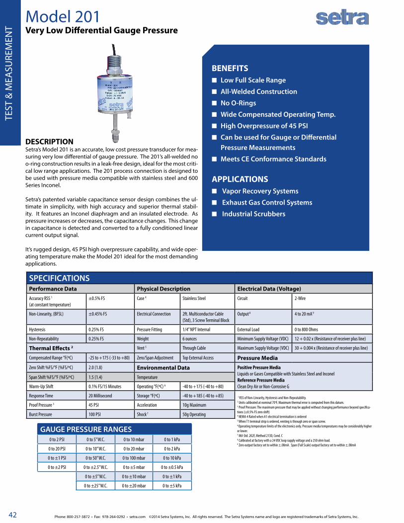
Phone: 800-257-3872 • Fax: 978-264-0292 • setra.com ©2014 Setra Systems, Inc. All rights reserved. The Setra Systems name and logo are registered trademarks of Setra Systems, Inc.
GEN
ERA
L PU
RPO
SE O
EM
42
TEST
& M
EASU
REM
ENT
Model 201Very Low Differential Gauge Pressure
BENEFITS■ Low Full Scale Range
■ All-Welded Construction
■ No O-Rings
■ Wide Compensated Operating Temp.
■ High Overpressure of 45 PSI
■ Can be used for Gauge or Differential Pressure Measurements
■ Meets CE Conformance Standards APPLICATIONS■ Vapor Recovery Systems
■ Exhaust Gas Control Systems
■ Industrial Scrubbers
DESCRIPTIONSetra’s Model 201 is an accurate, low cost pressure transducer for mea-suring very low differential of gauge pressure. The 201’s all-welded no o-ring construction results in a leak-free design, ideal for the most criti-cal low range applications. The 201 process connection is designed to be used with pressure media compatible with stainless steel and 600 Series Inconel.
Setra’s patented variable capacitance sensor design combines the ul-timate in simplicity, with high accuracy and superior thermal stabil-ity. It features an Inconel diaphragm and an insulated electrode. As pressure increases or decreases, the capacitance changes. This change in capacitance is detected and converted to a fully conditioned linear current output signal.
It’s rugged design, 45 PSI high overpressure capability, and wide oper-ating temperature make the Model 201 ideal for the most demanding applications.
SPECIFICATIONSPerformance Data Physical Description Electrical Data (Voltage)
Accuracy RSS 1
(at constant temperature)±0.5% FS Case 4 Stainless Steel Circuit 2-Wire
Non-Linearity, (BFSL) ±0.45% FS Electrical Connection 2ft. Multiconductor Cable (Std), 3 Screw Terminal Block
Output 8 4 to 20 mA 9
Hysteresis 0.25% FS Pressure Fitting 1/4” NPT Internal External Load 0 to 800 Ohms
Non-Repeatability 0.25% FS Weight 6 ounces Minimum Supply Voltage (VDC) 12 + 0.02 x (Resistance of receiver plus line)
Thermal Effects 2 Vent 5 Through Cable Maximum Supply Voltage (VDC) 30 + 0.004 x (Resistance of receiver plus line)
Compensated Range °F(ºC) -25 to +175 (-33 to +80) Zero/Span Adjustment Top External Access Pressure Media
Zero Shift %FS/°F (%FS/ºC) 2.0 (1.8) Environmental Data Positive Pressure MediaLiquids or Gases Compatible with Stainless Steel and InconelReference Pressure MediaClean Dry Air or Non-Corrosive G
Span Shift %FS/°F (%FS/ºC) 1.5 (1.4) Temperature
Warm-Up Shift 0.1% FS/15 Minutes Operating °F(ºC) 6 -40 to +175 (-40 to +80)
Response Time 20 Millisecond Storage °F(ºC) -40 to +185 (-40 to +85)
Proof Pressure 3 45 PSI Acceleration 10g Maximum
Burst Pressure 100 PSI Shock 7 50g Operating
GAUGE PRESSURE RANGES0 to 2 PSI 0 to 5” W.C. 0 to 10 mbar 0 to 1 kPa
0 to 20 PSI 0 to 10” W.C. 0 to 20 mbar 0 to 2 kPa
0 to ±1 PSI 0 to 50” W.C. 0 to 100 mbar 0 to 10 kPa
0 to ±2 PSI 0 to ±2.5” W.C. 0 to ±5 mbar 0 to ±0.5 kPa
0 to ±5” W.C. 0 to ±10 mbar 0 to ±1 kPa
0 to ±25” W.C. 0 to ±20 mbar 0 to ±5 kPa
1 RSS of Non-Linearity, Hysteresis and Non-Repeatability.2 Units calibrated at nominal 70oF. Maximum thermal error is computed from this datum.3 Proof Pressure: The maximum pressure that may be applied without changing performance beyond specifica-tions (±0.5% FS zero shift)4 NEMA 4 Rated when A1 electrical termination is ordered5 When T1 terminal strip is ordered, venting is through zero or span screw.6 Operating temperature limits of the electronics only. Pressure media temperatures may be considerably higher or lower.7 Mil-Std. 202F, Method 213D, Cond. C8 Calibrated at factory with a 24 VDC loop supply voltage and a 250 ohm load. 9 Zero output factory set to within ±.08mA. Span (Full Scale) output factory set to within ±.08mA
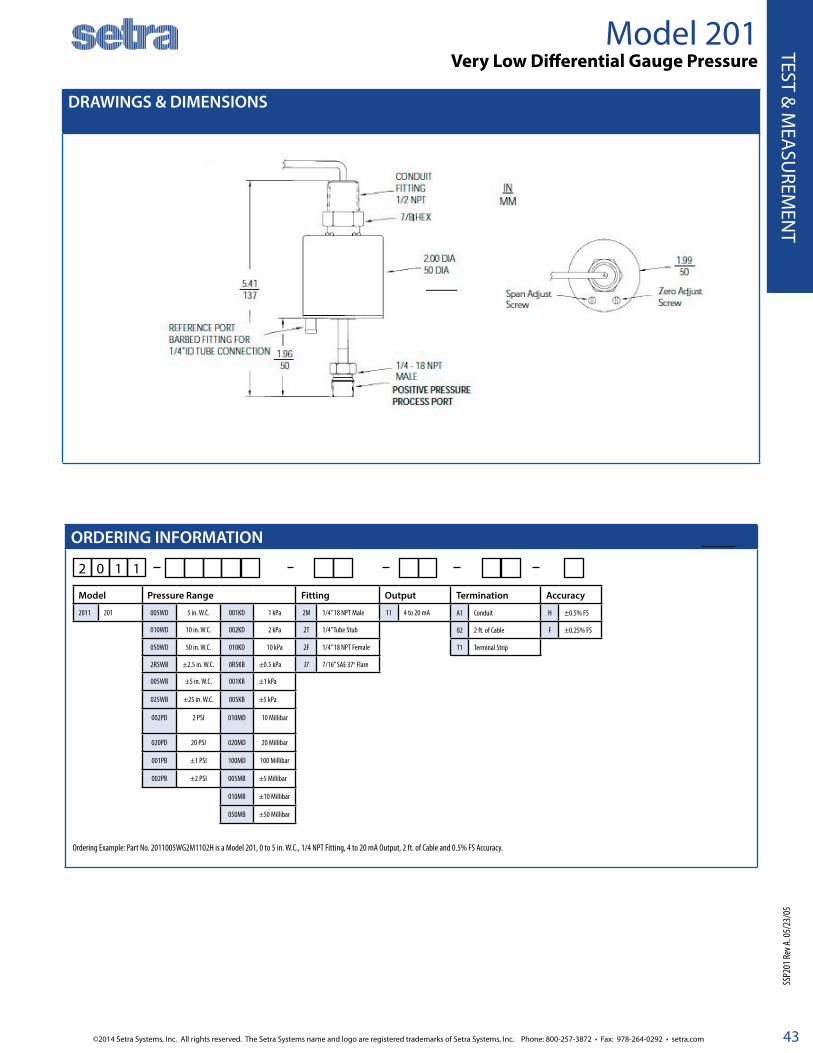
©2014 Setra Systems, Inc. All rights reserved. The Setra Systems name and logo are registered trademarks of Setra Systems, Inc. Phone: 800-257-3872 • Fax: 978-264-0292 • setra.com
GEN
ERAL PU
RPOSE O
EM
43
TEST & M
EASU
REMEN
T
DRAWINGS & DIMENSIONS
ORDERING INFORMATION
2 0 1 1
Ordering Example: Part No. 2011005WG2M1102H is a Model 201, 0 to 5 in. W.C., 1/4 NPT Fitting, 4 to 20 mA Output, 2 ft. of Cable and 0.5% FS Accuracy.
Model 201 Very Low Differential Gauge Pressure
SSP2
01 Re
v A. 0
5/23
/05
Model Pressure Range Fitting Output Termination Accuracy
2011 201 005WD 5 in. W.C. 001KD 1 kPa 2M 1/4” 18 NPT Male 11 4 to 20 mA A1 Conduit H ±0.5% FS
010WD 10 in. W.C. 002KD 2 kPa 2T 1/4” Tube Stub 02 2 ft. of Cable F ±0.25% FS
050WD 50 in. W.C. 010KD 10 kPa 2F 1/4” 18 NPT Female T1 Terminal Strip
2R5WB ±2.5 in. W.C. 0R5KB ±0.5 kPa J7 7/16” SAE 37o Flare
005WB ±5 in. W.C. 001KB ±1 kPa
025WB ±25 in. W.C. 005KB ±5 kPa
002PD 2 PSI 010MD 10 Millibar
020PD 20 PSI 020MD 20 Millibar
001PB ±1 PSI 100MD 100 Millibar
002PB ±2 PSI 005MB ±5 Millibar
010MB ±10 Millibar
050MB ±50 Millibar

Phone: 800-257-3872 • Fax: 978-264-0292 • setra.com ©2014 Setra Systems, Inc. All rights reserved. The Setra Systems name and logo are registered trademarks of Setra Systems, Inc.
GEN
ERA
L PU
RPO
SE O
EM
44
TEST
& M
EASU
REM
ENT
Model 239High Accuracy, Low-Differential Pressure Transducer
FEATURES ±0.14% FS Accuracy Fast Warm-Up Low Thermal Effects Fast Response Time (<10ms) Withstands High Overpressure RoHS Compliant Meets CE Conformance Standards
APPLICATIONS HVAC Control Leak Detection Environmental Testing Medical Instrumentation Energy Management Clean Rooms
DESCRIPTIONThe Model 239 Series pressure transducers are designed for very low pressure applications that require high accuracy.
The variable capacitance sensor is design to be simple and re-liable. The stainless steel diaphragm and insulated electrode form a variable capacitor. As pressure increases or decreases, the capacitance changes. This change is detected and con-verted to a linear DC electric signal by Setra’s unique electronic circuit.
The Model 239 series is available in a voltage or current output. High positive overpressure protection is achieved by the sen-sor electrode acting as a stop for the diaphragm. The high level output signals, excellent long term stability, and fast dynamic response make these transducers ideal for a wide range of in-dustrial, laboratory and aerospace applications.
SPECIFICATIONSPerformance Data Physical Description Electrical Data (Voltage)Accuracy RSS at constant temp* ±0.14% FS Pressure Fittings 1/8”- 27NPT internal Circuit 4-Wire (+Exc, -Exc, +Out, -Out)
Non-Linearity, BFSL ±0.10% FS Electrical Connection 2’ Multiconductor Cable Excitation* 22 to 30 VDC (reverse excitation protected)
Hysteresis 0.10% FS Weight (approx) 8 oz Output Impedance <10 ohms
Non-Repeatability 0.02% FS Vibration 2g from 5 Hz to 500 Hz Output Noise <200 microvolts RMS (in band, 0Hz to 10kHz)
Warm-Up Shift <±0.1% FS residual shift after 5 minutes
Internal Volumes Positive port 0.03 in3
Reference port 0.1 in3
Output** See Ordering Information (for unidirectional ranges) ±2.5 VDC (for bidirectional ranges)
Settling Time <100 ms Max Volume Change at FS 0.001 in3 *Internal regulation minimizes effect of excitation variation, with <±0.005% FS output change. Will operate on 28VDC aircraft power per MIL-STD-704A & not be damaged by emergency power conditions.**Calibrated into 50K ohm load. Operable into 5000 ohms or greater. ***Zero output factory set to within ±20mV
Acceleration Response <0.0002 psi/g Acceleration 10g Max
Natural Frequency 2000 Hz nominal Shock 50g Operating
Operable Line Pressure Vacuum to Max 250 PSIG Environmental Data Electrical Data (Current)Line Pressure Effect 2%/100 PSI Temperature Circuit 2-Wire
Thermal Effects** Operating ºF (ºC) 0 to +175 (-18 to +80) Output* 4 to 20 mA**
Compensated Range ºF (ºC) +30 to +150 (-1 to +65) Storage ºF (ºC) -65 to +250 (-55 to +120) External Load 0 to 1000 ohms
Zero Shift %FS/100ºF(50ºC) <+1 (<±0.9) Pressure Media Min. Supply Voltage (VDC) 17 + 0.02 x (resistance of receiver plus line)
Span Shift %FS/100ºF(50ºC) <+1 (<±0.9) Positive Pressure Media: Gases compatible with stainless steel, hard anodized 6061 aluminum (Buna-N O-ring)
Max. Supply Voltage (VDC) 42 + 0.004 x (resistance of receiver plus line)
*RSS of Non-Linearity, Non-Repeatability and Hysteresis**Units calibrated at nominal 70ºF. Maximum thermal error computed from this datum. x 2 for 0.5 and ±0.25 in. W.C. ranges.
Effect of Power Supply
Reference Pressure Media: Clean dry air or other gases (non-corrosive, non-condensable)
Variations <0.003 mA/Volt
Output Noise <10 microamperes RMS (0Hz to 10kHz)
Specifications subject to change without notice *Calibrated at factory with a 24 VDC loop supply voltage and a 250 ohm load.** Zero output factory set to within ±0.07 mA. Span (FS) output factory set to within ±0.07 mA.

©2014 Setra Systems, Inc. All rights reserved. The Setra Systems name and logo are registered trademarks of Setra Systems, Inc. Phone: 800-257-3872 • Fax: 978-264-0292 • setra.com
GEN
ERAL PU
RPOSE O
EM
45
TEST & M
EASU
REMEN
T
ORDERING INFORMATION
DIMENSIONS
2 3 9 1
Model Pressure Ranges Pressure Fitting Output Termination Accuracy Options4
2391 239 Unidirectional Bidirectional 1F 1/8” NPT Female 11 4 to 20 mA 02 2’ Cable 22 GA W ±0.14% FS N None
0R5WD 0 to 0.5 in. W.C. R25WB ±0.25 in. W.C. 2S ±2.5 VDC1 10 10’ Cable 22 GA 9 ±0.073% FS 1 303SS Housing Positive Port
001WD 0 to 1 in. W.C. 0R5WB ±0.5 in. W.C. 2B 0 to 5 VDC2 25 25’ Cable 22 GA 3 Compensated Temp. Range (-65 to 250ºF)6
2R5WD 0 to 2.5 in. W.C. 001WB ±1 in. W.C. 27 1 to 5 VDC Y1 2’ 30 GA 9-Conductor 3 4 Viton O-Ring
005WD 0 to 5 in. W.C. 2R5WB ±2.5 in. W.C. 28 1 to 6 VDC Y3 5’ 30 GA 9-Conductor 3 D Mate with Datum
015WD 0 to 15 in. W.C. 005WB ±5 in. W.C. 2C 0 to 10 VDC Y4 10’ 30 GA 9-Conductor 3 E Special Excitation Voltage ±24 VDC
030WD 0 to 30 in. W.C. 7R5WB ±7.5 in. W.C. 2T 0 TO 5 VDC1 Y6 25’ 30 GA 9-Conductor 3 G Special Excitation Voltage ±15VDC
005PD 0 to 5 PSID 015WB ±15 in. W.C. L Etched SS Tags
010PD 0 to 10 PSID 2R5PB ±2.5 PSID M Remote Full Scale Sensitivity5
250LD 0 to 250 Pa 005PB ±5 PSID R Remote Calibration (Adjustable)5
500LD 0 to 500 Pa 125LB ±125 Pa S Remote Calibration Adjustment (Fixed)5
10CLD 0 to 1000 Pa 250LB ±250 Pa Y Clean for Oxygen
20CLD 0 to 2000 Pa 500LB ±500 Pa
50CLD 0 to 5000 Pa 10CLB ±1000 Pa
10KLD 0 to 10 kPa 25CLB ±2500 Pa
15KLD 0 to 15 KPa 50CLB ±5000 Pa
35KLD 0 to 35 KPa 75CLB ±7500 Pa
70KLD 0 to 70 KPa 35KLB ±35 KPa
1 F
Model 239High Accuracy, Low-Differential Pressure Transducer
SSP2
39/C
239 R
evK 0
6/20
13
PRESSURE RANGE PROOF PRESSURE PRESSURE RANGE PROOF PRESSUREUnidirectional Bidirectional Positive Negative Unidirectional Bidirectional Positive Negative
0 to 0.5 in. W.C. ±0.25 in. W.C. 5 PSI 2.5 in. W.C. 0 to 250 Pa ±125 Pa 0.5 BAR 1250 Pa
0 to 1 in. W.C. ±0.5 in. W.C. 7 PSI 5 in. W.C. 0 to 500 Pa ±250 Pa 0.7 BAR 3000 Pa
0 to 2.5 in. W.C. ±1 in. W.C. 10 PSI 12.5 in. W.C. 0 to 1000 Pa ±500 Pa 1.25 BAR 6250 Pa
0 to 5 in. W.C. ±2.5 in. W.C. 20 PSI 25 in. W.C. 0 to 2000 Pa ±1000 Pa 3.5 BAR 18500 Pa
0 to 15 in. W.C. ±5 in. W.C. 50 PSI 75 in. W.C. 0 to 5000 Pa ±2500 Pa 3.5 BAR 37000 Pa
0 to 30 in. W.C. 0 to ±15 in. W.C. 50 PSI 150 in. W.C. 0 to 15 kPa ±7500 Pa 3.5 BAR 37000 Pa
0 to 5 PSID 0 to ±2.5 PSID 75 PSI 25 PSI 0 to 35 kPa 5 BAR 1.75 BAR
0 to 10 PSID 0 to ±5 PSID 100 PSI 50 PSI 0 to 70 kPa ±35 kPa 7 BAR 3.5 BAR
Example: Part No. 2391001WD1F1102WLN = Model 239, 0 to 1 in. W.C. pressure range, 1/8” NPT female fitting, 4 to 20 mA Output, 2’ Cable Length, ±0.14% FS Accuracy, Etched SS Tags Option
Proof Pressure: The maximum recoverable pressure that may be applied without changing performance beyond specifications ±0.5% Zero/Span shift.
3.076.20
Dia. 2.70Dia. 68.28
0.87522.23
1.4436.42 1.94
49.38
4 MOUNTING HOLES FOR NO. 6 SCREWS(Dia. 0.156)(Dia. 3.96)
0.62515.88
1.0526.80
3.1078.40
1.7042.65 0.812
20.62
INMM
0.95024.133.266
82.55
4 HOLES DRILLED & TAPPED 6-32 X .220 DEEP
POSITIVE PRESSURE PORT 1/8-27 NPT INTERNAL
REFERENCEPRESSURE PORT 1/8-27 NPT INTERNAL
4 Both boxes must filled in alphanumeric order:• If No options: N + N• If 1 option: Option Code + N• If 2 options: Option Code + Option Code
5 Options M, R & S are for voltage units and Y1-Y6 Termination Codes6 2x Thermal Effects Specification
1 2S and 2T are for Bi-Directional Pressure Ranges Only2 2B is for Uni-Directional Pressure Ranges Only
3 Y1-Y6 = Red Jacket Cable(previously the standard for voltage outputs.)

Phone: 800-257-3872 • Fax: 978-264-0292 • setra.com ©2014 Setra Systems, Inc. All rights reserved. The Setra Systems name and logo are registered trademarks of Setra Systems, Inc.
GEN
ERA
L PU
RPO
SE O
EM
46
TEST
& M
EASU
REM
ENT
AccuSense™ Model ASLHigh Accuracy Differential Pressure Transducer
FEATURES High Accuracy: ±0.07% FS Low Differential Pressure Ranges Unidirectional & Bidirectional Types High Over-Pressure Capability Low Thermal Error Excellent Stability Secure & Simple Field Calibration High Line Pressure Capability Rugged Stainless Steel Construction Multiple Configurations Available CE Mark & EU RoHS Compliant
APPLICATIONS Test Stands Wind Tunnels Leak Detection Systems Pharmaceutical Medical Instrumentation Energy Management Clean Rooms Industrial, High Accuracy Environmental Testing General R&D
DESCRIPTIONThe AccuSense™ Model ASL is a high performance pressure transducer designed for low differential pressure measure-ments of air or other clean gases. Setra’s variable capacitance technology is industry tested and preferred in applications that demand reliability, repeatability and accuracy.
Model ASL’s exceptional linearity and thermal compensation is achieved through computerized factory calibration and curve fitting algorithm. The sensor’s rugged construction and factory conditioning enable high overpressure capability and stability to ensure a highly robust and reliable measurement.
As part of AccuSense™ product family, Model ASL’s zero and span settings are securely set through use of SecureCal acces-sory making for secure and stable calibration settings. Excel-lent stability, and secure calibration makes it ideal for high per-formance industrial, laboratory, and test cell applications.
SPECIFICATIONSPerformance Data Physical Description Electrical DataInternal Volumes Positive Port 0.03 cu. in.
Reference Port 0.75 cu. in.Electrical Terminations 6-Conductor Cable, Pigtail
6-Pin Bayonet ConnectorExcitation Range 9 to 30VDC (5VDC & 4-20 mA output)
15 to 30VDC (10VDC output)
Operable Line Pressure Vacuum to 250 psi max Dimensions See reverse side Current Consumption <23 mA (5VDC & 10VDC Versions)
Maximum Volume Change at FS 0.002 cu. in. Weight 13 oz. (360 g) Miswiring Reverse Excitation Protection
Long-term Stability <0.15% FS/Year, Typical Moisture/Splash Resistance
NEMA 4X (IP65) Warm-up, Environmental
Within ±0.02% FS after 15 min warm-up time
Response Time to Pressure Input(From 100% to 10% of pressure range)
<10 ms for Voltage Output<100 ms for Current Output
Pressure Fittings See Ordering Information Signal Output Ranges 0 to 5 VDC, 0 to 10VDC (4-wire), 4-20mA (2-wire)
Case Materials Stainless Steel Regulatory Data CE Compliant & RoHS Compliant
Line Pressure Effect 2% FS/100 psig Environmental Data Pressure MediaZero Offset Position Effect <0.1%/G Temperature Calibrated -4 to +140ºF (-20 to +60ºC) Clean, dry gases compatible with 300 series stainless steel and 17-4 pH
stainless steelUnit factory calibrated in vertical position (pressure port downward) Operating -40 to +185°F (-40 to +85ºC)
Storage -40 to +185°F (-40 to +85ºC)
US Patent # 6,789,429 Higher or lower limits available (consult factory) Specifications subject to change without notice
AccuSense™ Model ASL withSecureCal™ Calibration Key

©2014 Setra Systems, Inc. All rights reserved. The Setra Systems name and logo are registered trademarks of Setra Systems, Inc. Phone: 800-257-3872 • Fax: 978-264-0292 • setra.com
GEN
ERAL PU
RPOSE O
EM
47
TEST & M
EASU
REMEN
T
ORDERING INFORMATION
DIMENSIONS
A S L 1
Model Pressure Ranges* Process/Reference Port Output Elec. Termination Accuracy Option
ASL1 ASL Differential Bidirectional/Differential 1F 1/8” NPT Female / Barb 2B 0 to 5 VDC 03 3 ft, 1m Std Cable A <±0.07% FS RSS 00 None, Standard
002WD 0 to 2” W.C. 001WB ±1” W.C. FF 1/8” NPT Female / 1/8” NPT Female 2C 0 to 10 VDCB3
Std 6-Pin Male Bayonet Connector, Std Wiring
01High Overpressure (See Table Below)2R5WD 0 to 2.5” W.C. 002WB ±2” W.C. 1M 1/8” NPT Male / Barb 11 4 to 20 mA
005WD 0 to 5” W.C. 005WB ±5” W.C. J7 7/16-20 SAE Male / Barb
010WD 0 to 10” W.C. 015WB ±15” W.C.
030WD 0 to 30” W.C. 001PB ±1 PSID
040WD 0 to 40” W.C. 005MB ±5 mBar
001PD 0 to 1 PSID 010MB ±10 mBar
005MD 0 to 5 mBar 025MB ±25 mBar
010MD 0 to 10 mBar 050MB ±50 mBar
025MD 0 to 25 mBar
050MD 0 to 50 mBar
100MD 0 to 100 mBar
Model Input Connection to ASLConnection to Power Supply Options
SEC1 SEC V Voltage (0-5VDC & 0-10VDC) TBR Removable Terminal Block, Rear 03R 3 ft (1m) Cable 00 None, Standard
C Current (4-20mA) B3B Std 6-Pin Bayonet, Female, B3 Wiring
AccuSense™ Model ASLHigh Accuracy Differential Pressure Transducer
SSPA
SL Re
vA 07
/201
3
ACCURACY DATAAccuracy Code
A
Accuracy <±0.07% FS RSS*
Non-Linearity, End-Point <±0.03% FS Typical
Hysteresis <0.03% FS Typical
Non-Repeatability <±0.02% FS Typical
Span Setting Tol. <±0.1% FS
Zero Offset Tol. <±0.1% FS Typical
Thermal Total Error Band
<±0.25% FS Typ. <±0.5% max (-20°C to 60°C)
*RSS: Root Sum Square of endpoint linearity, Hysteresis and Non-repeatability at constant temperature.
ACCESSORIES
Example: Part No. ASL1001WB1F2B03A00 = ASL Transducer, ±1” W.C. Pressure Range, 1/8" NPT Female Reference Port, 0 to 5 VDC Output, 3 Foot Cable, <±0.07% FS RSS Accuracy, No Options
*Other ranges and engineering units are available (ex: Pa, kPa)
Pressure Ranges Burst PressureStandard Proof Pressure
Option Code “00”High Proof Pressure
Option Code “01”
0 to 2.5 in. WC, 5 mBar 200 psi, 15 Bar ±10 psi, ±700 mBar ±75 psi, ±5 Bar
0 to 5 in. WC, 10 mBar 300 psi, 20 Bar ±20 psi, ±1 Bar ±100 psi, ±7 Bar
0 to 10 in WC, 25 mBar 300 psi, 20 Bar ±30 psi, ±2 Bar ±150 psi, ±10 Bar
0 to 30 in. WC, 1 psi, 100 mbar 300 psi, 20 Bar ±50 psi, ±4 Bar ±150 psi, ±10 Bar
* Burst Pressure: The maximum pressure that may be applied to the positive pressure port without rupturing the diaphragm or reference pressure containment.
** Proof Pressure: The maximum recoverable pressure that may be applied without changing performance beyond specification: ±0.5% Zero Shift, Typical
WIRING CODESCode B3*
(Standard)
Electrical Connection
Wire Color
Bayonet Connector
Pinout
+ EXC Red A
- EXC Black D
+ Sig Out Green B
- Sig Out White C
Reserved for communication with SecureCalTM calibration module
SecureCal™ Blue E
SecureCal™ Brown F
*Other wiring options availableinches (mm)
0.875(22.2)
0.58 (14.7)
0.45 (11.4)
3.00 (76.2)
3.25 (82.6)
2.39 (60.7)
1.375 (34.9)
0.75(19)
2.00(50.8)
2.00(50.8)
REFERENCEPORT
PROCESSPORT
2.39 (60.7)
0.58 (14.7) 0.35 (8.9)
BARBED TUBEFITTING
FITTING CODE "1F"WITH CABLE TERMINATION
FITTING CODE "FF"WITH BAYONET CONNECTOR "B3"
FITTING CODE "FF"WITH BAYONET CONNECTOR "B3"
SecureCalTM Calibration Key
in.mm
S E C 1 0 00 3 R
6-Pin Bayonet Connector Assembly w/Strain ReliefOrder Separately:Part No: 600751
1.5038.10
1.6040.69
1.6541.91
2.6467.08

Phone: 800-257-3872 • Fax: 978-264-0292 • setra.com ©2014 Setra Systems, Inc. All rights reserved. The Setra Systems name and logo are registered trademarks of Setra Systems, Inc.
GEN
ERA
L PU
RPO
SE O
EM
48
TEST
& M
EASU
REM
ENT
Model 204High Accuracy Gauge & Absolute Pressure Transducers
FEATURES 0.11% FS Accuracy
0-5 VDC or 4-20mA Output
Fast Response, Less than 1 MS
Fast Warm-Up
Excellent Thermal Effects
Low Output Noise
Solid One-Piece Stainless Steel Sensor
Meets CE Conformance Standards
APPLICATIONS High Accuracy General Purpose
R&D Test and Measurement
Vacuum Systems
Dynamometers
Engine Test Cells
DESCRIPTIONSetra’s Model 204 pressure transducers are intended for accu-rate pressure measurements of gas or liquid media compatible with 17-4 PH stainless steel. The high level output signal and excellent stability, combined with fast dynamic response, make this unit ideal for industrial, laboratory and aerospace applica-tions.
The exceptional accuracy is achieved by combining Setra’s unique electronic circuitry with its field proven variable capaci-tance sensor. This unit is compensated for both zero and sensi-tivity shifts due to environmental temperature variations. The Model 204, with a high-level voltage outputor current output, require no additional signal conditioning. The sensor features a one-piece 17-4 PH stainless steel pressure sensor and an insu-lated electrode, which form a variable capacitor. As the pressure increases, the capacitance decreases. This change in capaci-tance is detected and converted to a linear DC electric signal. On absolute pressure units, the reference side of the diaphragm is sealed by electron beam welding under high vacuum.
SPECIFICATIONSPerformance Data Physical Description Electrical Data (Voltage Output)Accuracy RSS1 (at constant temperature)
±0.11% FS±0.14% for 10,000 PSIG
Pressure Fitting 1/4” - 18 NPT Internal Circuit 4-Wire (+Exc, - Exc, + Out, - Out)
Non-Linearity (BFSL) ±0.07% FS Electrical Connection 2 ft. Multiconductor Cable Excitation 22 to 30 VDC, 24 VDC (Normal) Reverse Excitation Protected
Hysteresis 0.08% FS0.1% for 10,000 PSIG
Weight 10 Ounces Output4 0 to 5 VDC5
STD, see ordering information for more options
Non-Repeatability 0.02% FS Environmental Data Power Consumption 10 mA (0.25 Watts)
Thermal Effects2 Operating Temperature °F(°C) 0 to +175 (-18 to +80) Output Impedance <10 Ohms
Compensated Range °F(°C) +30 to +150 (-1 to +65) Storage Temperature °F(°C) -65 to +250 (-55 to +120) Output Noise <100 Microvolts RMS (0 Hz to 10 KHz)
Zero Shift3 %FS/100°F (%FS/50°C) <±0.4 (<±0.36) Vibration 2g from 5 Hz to 500 Hz Electrical Data (Current Output)Span Shift %FS/100°F (%FS/50°C) <±0.3(<±0.27) Shock 50g Circuit 2-Wire
Static Acceleration Effect <0.05 PSI/G (Typ.)(Pressure Port Axis)
Acceleration 10g Maximum Output6 4 to 20 mA7
Volume Increase Due to FS Pressure 5 x 10⁻⁵ cu. in. External Load 0 to 1000 Ohms
Warm-Up Shift ±0.5% Total(±0.1% Residual Shift after 5 Minutes)
Ordering Information Minimum Supply Voltage (VDC) 17 + 0.02 x (Resistance of receiver plus line)
1RSS of Non-Linearity, Hysteresis and Non-Repeatability2Units calibrated at nominal 70°F 3Approximately 50% higher for 0-14.7 psiv range4Calibrated into 50K ohm load. Operable into 5000 ohms or greater.5Zero output factory set to within ±10mV. Span (Full Span) output factory set to within ±10mV. Note: Both output leads are normally 1.6 VDC above the negative excitation lead at zero pressure. Either negative excitation or negative output should be connected to case (ground). But both leads cannot be connected to case (ground). Unit is calibrated at the factory with the negative excitation connected to case (ground.)
6Calibrated at factory with a 24 VDC loop supply voltage and a 250 ohm load.7Zero output factory set within ±0.03mA. Span (Full Span) output factory set to within ±0.03mA.
Specifications subject to change without notice.
Maximum Supply Voltage (VDC) 42 + 0.004 x (Resistance of receiver plus line)
Effect of Power Supply
VariationsOutput Noise
<0.003mA/Volt<10 Microamperes RMS (0 HZ to 10 KHz)

©2014 Setra Systems, Inc. All rights reserved. The Setra Systems name and logo are registered trademarks of Setra Systems, Inc. Phone: 800-257-3872 • Fax: 978-264-0292 • setra.com
GEN
ERAL PU
RPOSE O
EM
49
TEST & M
EASU
REMEN
T
ORDERING INFORMATION
DIMENSIONS
2 0 4 1
Model Pressure Ranges Pressure Fitting Output Electrical Termination Accuracy* OptionsModel 204 Gauge Pressure 2F 1/4” NPT Female 11 4-20 mA 02 2’ Cable 22 AWG W ± 0.11% FS 3** Compensated Temperature Range (-65 to 250°F )
025PG 0-25 PSIG 2B 0-5 VDC 10 10’ Cable 22 AWG 9 ± 0.073% FS 7 Clean for Oxygen
050PG 0-50 PSIG 2Y 0-2.5 VDC 25 25’ Cable 22 AWG D Mate with Datum
100PG 0-100 PSIG 27 1-5 VDC Y1 2’ Red Cable 9-Conductor 30 AWG E Special Excitation Voltage ± -24 VDC
250PG 0-250 PSIG 28 1-6 VDC F NEMA 4 Enclosure
500PG 0-500 PSIG 2C 0-10 VDC G Special Excitation Voltage ± -15 VDC
10CPG 0-1000 PSIG 2U 1-10 VDC L Etched SS Tags
30CPG 0-3000 PSIG M* Remote Full Scale Sensitivity
50CPG 0-5000 PSIG N None
10KPG 0-10000 PSIG R* Remote Calibration (Adjustable)
Z01PV 0-14.7 PSI (VACUUM) S* Remote Calibration Adjustment (Fixed)
Absolute Pressure
025PA 0-25 PSIA
050PA 0-50 PSIA
100PA 0-100 PSIA
250PA 0-250 PSIA
500PA 0-500 PSIA
10CPA 0-1000 PSIA
30CPA 0-3000 PSIA
50CPA 0-5000 PSIA
Model 204High Accuracy Gauge & Absolute Pressure Transducers
SSP2
04/C
204 R
EV G
2 F
Note: Setra adheres to strict quality standards includingISO 9001 and ANSI-Z540-1. The calibration of this product is NIST traceable.
* Options M, R and S will have Y1 Cable as STD.** 2x Thermal Effects Specificaltion
Note: For Differential Ranges please refer to Model 204D Datasheet
Both boxes must be filled in alphanumeric order:-If No options: N + N-If 1 option: Option Code + N-If 2 options: Option Code + Option Code
Pressure Ranges 0 psia or 0 psig to:
Proof Pressure(psi)
Burst Pressure Rating (psi)
Approx. Natural Frequency (KHz)
25 50 150 2.0
50 75 200 2.5
100 150 500 3.5
250 375 1000 5.0
500 750 1500 8.0
1000 1250 3000 11.0
3000 3750 4500 15.0
5000 6000 7500 25.0
10,000 psig only 11,000 12,500 30.0
0-14.7 psi vac 50 150 2.0
*Units with pressure range > 5,000 psi have accuracy of±0.14% FS only.
NOTE: Setra quality standards are based on ANSI-Z540-1. The calibration of this product is NIST traceable.
Example: Part No. 2041025PG2F110297N: o to 25 PSIG, 1/4” NPT Internal Fitting, 4 to 20 mA Output, 2’ Cable (22 AWG), ±0.073% FS Accuracy, Clean for Oxygen Service

Phone: 800-257-3872 • Fax: 978-264-0292 • setra.com ©2014 Setra Systems, Inc. All rights reserved. The Setra Systems name and logo are registered trademarks of Setra Systems, Inc.
GEN
ERA
L PU
RPO
SE O
EM
50
TEST
& M
EASU
REM
ENT
Model 204DHigh Accuracy Differential Pressure
FEATURES Instant Warm-Up
High Output: 0-5 VDC
± 0.11% FS Accuracy
Low Thermal Effect
Low Output Noise
Fast Response, Less than 1 MS
Stainless Steel Sensor
Very Low Line Pressure Effect
Meets CE Conformance Standards
APPLICATIONS High Accuracy General Purpose
R&D Test and Measurement
Vacuum Systems
Dynamometers
Engine Test Cells
DESCRIPTIONSetra’s Model 204 pressure transducer is intended for accurate differential pressure measurement of gas or liquid media com-patible with 17-4 PH stainless steel. The high level output signal and excellent stability, combined with fast dynamic response, make this unit ideal for industrial, laboratory, and aerospace ap-plications requiring the highest accuracy. The differential 204D is thermally compensated for both zero and span shifts due to environmental temperature variations. Setra’s unique high out-put electric circuitry requires no additional signal conditioning.
Setra’s variable capacitance sensor approaches the ultimate in design simplicity. It features a one-piece 17-4 PH stainless steel pressure sensor and an insulated electrode, which form a vari-able capacitor. As pressure increases, the capacitance decreas-es. The change in capacitance is detected and converted to a linear DC signal by Setra’s electronic circuit.
SPECIFICATIONSPerformance Data Physical Description Electrical Data
Uni & Bi Directional±10, ±25, ±50 PSID
10,000 PSID Range
Electrical Connection 2 Foot Multiconductor Cable Circuit 4-Wire (+Exc, -Exc, +Out, -Out)
Positive Pressure Fitting 1/4” - 18 NPT Internal Excitation4 22 to 30 VDC
Reference Pressure Fitting 1/8” - 27 NPT Internal Output5 0 to 5 VDC6
Accuracy RSS1
(at constant temp)±0.11% FS ±0.14% FS Weight 10 Ounces Zero Adjustment Accessible Inside of Case, or External Remote Adjust-
ment (using customer supplied 10K ohms potentiom-eter to the remote zero lead of the transducer cable.
Non Linearity, BFSL ±0.07% FS ±0.10% FS Pressure Media Span Adjustment Accessible Inside of Case, or External Remote Adjust-ment (Options)
Hysteresis 0.08% FS 0.10% FS Positive Pressure Media Gas or liquid compatible with 17-4 PH stainless steel3
Output Impedance 10 ohms
Non-Repeatability 0.02% FS 0.02% FS Reference Pressure Media Clean dry air or non-corrosive gas (1000 psig maximum)
Output Noise <100 microvolts RMS (0 to 10K Hz)
Thermal Effects2 Environmental Data Current Consumption 10 mA (0.25 Watts)
Compensated Range °F(°C) +30 to +150 (-1 to +65) Operating Temperature °F(°C) 0 to +175 (-18 to +79) 1RSS of Non-Linearity, Hysteresis and Non-Repeatability.2Units calibrated at normal 70°F Maximum thermal error is computed from this datum.3Operating temperature limits of the electronics only. Pressure media temperatures may be
considerably higher or lower.4Will operate at 28 VDC aircraft power per MIL-STD-704A and not be damaged by emergency
power conditions. Nominal excitation is 24 VDC. Excitation variation effect is less than 0.2%
FS output change.5Calibrated into a 50K ohm load, operable into 5000 ohms or greater.6Zero output factory set to within ±10mV.7Span (Full Scale) output factory is set to within ±10mV. NOTE: Both output leads are nominally 4.7 VDC above the negative excitation lead at zero pressure. Either negative excitation or negative output should be connected to case (ground). But both leads cannot be connected to case (ground). Unit is calibrated at the factory with the negative excitation connected to case (ground.)
Zero/Span Shift (%FS/50°C) 1.0 (.09) Storage Temperature °F(°C) -65 to +250 (-55 to +121)
Acceleration Response <0.05 psi/g, pressure port axis only
Vibration 2g from 5Hz to 500 Hz
Volume Increase Due to FS Pressure
5 x 10⁻⁵ cu. in. Acceleration 10g
Warm-Up Shift 0.5% Total; 0.1% Residual shift after 5 minutes at constant temperature
Shock 50g
Line Pressure Effect Zero Shift ±0.1% FS/100 psig of Reference Pressure

©2014 Setra Systems, Inc. All rights reserved. The Setra Systems name and logo are registered trademarks of Setra Systems, Inc. Phone: 800-257-3872 • Fax: 978-264-0292 • setra.com
GEN
ERAL PU
RPOSE O
EM
51
TEST & M
EASU
REMEN
T
ORDERING INFORMATION
DIMENSIONS
Model 204DHigh Accuracy Differential Pressure
SSP2
04D
REV J
10/
31/1
3
2 0 4 1
Model Pressure Ranges Pressure Fitting Ouptut Electrical Termination Accuracy* OptionsModel 204 Uni-Directional 2F 1/4” NPT Female 2B* 0-5 VDC 02 2’ Grey Cable 22 AWG W ± 0.11% FS 3 Compensated Temperature Range (-65 to 250°F )
Differential Pressure 2Y 0-2.5 VDC 10 10’ Grey Cable 22 AWG 9 ± 0.073% FS D Mate with Datum
025PD 0-25 PSID 27 1-5 VDC 25 25’ Grey Cable 22 AWG E Special Excitation Voltage ± -24 VDC
050PD 0-50 PSID 28 1-6 VDC Y1 2’ Red Cable 30 AWG 9-Conductor G Special Excitation Voltage ± -15 VDC
100PD 0-100 PSID 2C 0-10 VDC L Etched SS Tags
250PD 0-250 PSID 2U 1-10 VDC M* Remote Full Scale Sensitivity
500PD 0-500 PSID N None
10CPD 0-1000 PSID R* Remote Calibration (Adjustable)
30CPD 0-3000 PSID S* Remote Calibration Adjustment (Fixed)
50CPD 0-5000 PSID 7 Clean for Oxygen
2 F
*Options M, R and S will have Y1 Cable as STD.
Both boxes must be filled in alphanumeric order:- If No options: N + N- If 1 options: Option Code + N- If 2 options: Option Code + Option Code
*For Bi-Directional units please consult the factory
NOTE: Setra quality standards are based on ANSI-Z540-1. The calibration of this product is NIST traceable.
Note: For Gauge and Absolute Ranges please refer to Model 204 Datasheet
*Units with pressure range > 5,000 psi have accuracy of±0.14% FS only.
Pressure Range PSID Proof Pressure* PSID Burst Pressure*
0 to 25 ±50 ± 150 psid
0 to 50 ±75 ± 200 psid
0 to 100 ±150 ± 500 psid
0 to 250 ±375 ±1000 psid
0 to 500 ±750 positive port +1500 psid
0 to 1000 +1250 positive port +3000 psid
-1000 reference port 1000 psig
0 to 3000 +3750 positive port +4500 psid
-1000 reference port 1000 psig
0 to 5000 +6000 positive port +7500 psid
-1000 reference port 1000 psig
*Maximum pressure on reference port must not exceed 1000 psig.
Example: Part No. 2041050PD2F2B02WLN: 0 to 50 PSID, 1/4” NPT Internal Fitting, 4 to 20 mA Output, 2’ Cable (AWG), ±0.11% FS Accuracy, Etched SS Tags

Phone: 800-257-3872 • Fax: 978-264-0292 • setra.com ©2014 Setra Systems, Inc. All rights reserved. The Setra Systems name and logo are registered trademarks of Setra Systems, Inc.
GEN
ERA
L PU
RPO
SE O
EM
52

©2014 Setra Systems, Inc. All rights reserved. The Setra Systems name and logo are registered trademarks of Setra Systems, Inc. Phone: 800-257-3872 • Fax: 978-264-0292 • setra.com
GEN
ERAL PU
RPOSE O
EM
53
PRODUCT SECTION 3.1
SANITARYPRESSURE
MODELS:
290296

Phone: 800-257-3872 • Fax: 978-264-0292 • setra.com ©2014 Setra Systems, Inc. All rights reserved. The Setra Systems name and logo are registered trademarks of Setra Systems, Inc.
GEN
ERA
L PU
RPO
SE O
EM
54
WIRING
Model 290 Sanitary Pressure Transmitter
FEATURES■ Robust Non-Liquid Filled Capacitive Sensor
Negligible Clamping Effect for Easy Installation
■ Designed for Clean-In-Place (CIP) and Sterilize-In-Place (SIP) Installations
■ Meets 3A Sanitary Standards
■ 0.20% Full Scale Accuracy Improves System Performance
High Overpressure Protection
■ Insensitive to Thermal Shock
■ Industrial Design and 316 Stainless Steel Permits Use in Harsh Environments
■ Higher Accuracy Option Available■ Meets CE Conformance Standards
APPLICATIONS■ Food Processing■ Dairy and Beverage Processing
■ Pharmaceutical Processing
■ Liquid Level Control
■Sanitary Pipelines
DESCRIPTION
The 290 design meets 3-A sanitary design standards and is fully sealed to withstand external high pressure washdown and CIP/SIP cycles. As a totally self-contained electronic package, the 290’s capacitance sensing element, coupled with a signal conditioned IC-based circuit, assures excellent accu-racy and long term stability.
The 290 pressure transmitter is intended for low to high pressure mea-surements of gases or liquids in sanitary applications. The 290 pressure transmitter, packaged in a rugged welded stainless steel housing, is ex-ceptionally insensitive to vibration, shock and environmental extremes. Its small size, light weight, and tri-clover sanitary pressure fitting allows direct mounting in most CIP and SIP installations.
Unlike fluid-filled sensors, the 290 utilizes a rugged, non-filled capacitive sensor which enables low hysteresis and excellent performance during thermal transients.
1 1/2” Tri-Clover Sanitary FittingDiaphragm Material: 316SS
2” Tri-Clover Sanitary FittingDiaphragm Material: 316LSS
■
■
Accesory
Model 299 Dri- SenseTermination Enclosure
Features:
• Visible Desiccant Status Indicator• Easily Replaceable Desiccating Cov-ers• Replaceable Terminal Interface Circuit Board• Surge Suppression• NEMA 4X Industrial Housing
SAN
ITA
RY P
RESS
URE

©2014 Setra Systems, Inc. All rights reserved. The Setra Systems name and logo are registered trademarks of Setra Systems, Inc. Phone: 800-257-3872 • Fax: 978-264-0292 • setra.com
GEN
ERAL PU
RPOSE O
EM
55
ORDERING INFORMATION
Model 290 Sanitary Pressure Transmitter
SPECIFICATIONSPerformance Data 2” Tri-Clover Sanitary Fitting
Performance Data 1.5” Tri-Clover Sanitary Fitting
Electrical Data
Accuracy RSS1 (at constant temp) ±0.20% FS Accuracy RSS1 (at constant temp) ±0.20% FS Circuit 2-Wire
Non-Linearity (BFSL) ±0.17% FS Non-Linearity (BFSL) ±015% FS Output3 4 to 20 mA4
Hysteresis 0.10% FS Hysteresis 0.12% FS Zero/Span, Adjustment ± 0.5 mA
Non-Repeatability 0.025% FS Non-Repeatability 0.10% FS External Load 0 to 800 ohms
Thermal Effect2 Thermal Effect2 Min. Supply Voltage (VDC) 12 + 0.02 x resistance of receiver plus line
Compensated Range Fo(Co) +20 to +180 (-7 to +82) Compensated Range Fo(Co) +20 to +180 (-7 to +82) Max. Supply Voltage (VDC) 30 + .004 x resistance of receiver plus line
Zero/Span Shift %FS/100°F (%FS/50°C) 2.0 (1.8) Zero/Span Shift %FS/100°F (%FS/50°C) 2.0 (1.8) Environmental Data
Response Time 10 milliseconds Response Time 10 milliseconds Operating Temperature°F (°C)5 -40 to +260 (-40 to +125)
EMI/RFI Effect< 1.0% output shift; 10V/M, 10-300 MHz
EMI/RFI Effect < 1.0% output shift; 10V/M, 10-300 MHz
Storage Temperature°F (°C) -65 to +260 (-55 to +125)
Clamping Effect, Zero/Span Shift ±0.15% FS Clamping Effect, Zero/Span Shift ±0.25% FS Vibration 10g, 50-1000Hz
Maximum Vacuum (without affecting specifications)
Half on ranges ≤15 PSIMaximum Vacuum (without affecting specifications)
Full on ranges ≥ 30 PSI Acceleration6 10g maximum
Physical Description 1 RSS of Non-Linearity, Non-Repeatability and Hysteresis.2 Units calibrated at nominal 70°F. Maximum thermal error is computed from this datum.Variations in the power supply voltage cause less than 0.005 mA change in the transmitter’s current output, per volt change in the power supply. Reverse excita-tion will not damage circuit.3 Calibrated at factory with a 24 VDC loop supply voltage and a 250 ohm load.4 Zero output factory set to within ±0.08mA.4 Span (Full Scale) output factory set to within ±0.16mA.5 Operating temperature limits of the electronics only. Pressure media temperatures may be considerably higher or lower.6 shift in output reading at <0.05% FS/g; pressure port axis only.
Shock 50g operating
Zero/Span Adjustments Top Access Through Seal Screws Thermal Shock°F (°C) 0 to +257 (0 to +125) negligible shift
Case Stainless SteelAccessoriesModel 299 Dri-Sense Pressure TransducerTermination Enclosure P/N: 2991G211Electrical Connection
1/2 NPT” Conduit Fitting & Strain Relief w/ 15’ Shielded Cable
Pressure Fitting2” or 1 1/2” Tri-Clover Sanitary Fitting
SanitaryMeets 3-A Sanitary Standard (74-02)
Note: Setra quality standards are based on ANSI-Z540-1. The calibration of this product is NIST traceable.
Vent Through Cable
Weight (Approx.) 8 Ounces
Model Range Units Pressure Type Fitting Output Termination Accuracy Options2
2901 = 290 2” Tri-Clover (PSI) 1 1/2” Tri-Clover(PSI) P PSI G Gauge T6 1 1/2” Tri-Clover 11 4-20 mA 15 15’ Cable 3 ± 0.2% FS N None
001 0-1 030 0-30 M mBAR C** Compound T8 2” Tri-Clover 25 25’ Cable T ± 0.1% FS L Etched SS Tags
002 0-2 045* 0-45 30 30’ Cable R 20 Ra Sensor Finish
005 0-5 060 0-60
010 0-10 100 0-100
015 0-15 150 0-150
030 0-30 300 0-300
060 0-60 500 0-500
100 0-100 10C 0-1000
150 0-150
2 9 0 1 1 1
Pressure Ranges 2” Tri-Clover
psig Range mb
in. H20 Proof psig
Burst psig
1 100 27.7 50 100
2 160 55.4 75 150
5 400 138.4 150 200
10 600 276.8 150 200
15 1000 415.2 150 200
30 830.4 150 300
60 1660.8 180 400
100 2768 200 400
150 4152 225 400
-14.7 to 15 -407 to 415 150 300
Pressure Ranges 1 1/2” Tri-Clover
Ramge psig Proof psig
Burst psig
30 1000 1200
60 1000 1200
100 1000 1200
150 1000 1200
300 1000 1200
500 1000 1500
1000 1250 2400
-14.7 to 15 1000 1200
-14.7 to 45 1000 1200
Proof Pressure: The maximum pressure that may be applied without changing performance beyond specifications (<±0.5% FS zero shift).Burst Pressure: The maximum pressure that may be applied to the positive pressure port without rupturing the sensing element.
** -14.7 to X psi, -1000 to XmBAR
SSPC
290
Rev
G 2
/20/
2014
2 Both boxes must be filled in alphabetical order:- If No options: N + N- If 1 option: Option Code + N- If 2 options: Option Code + Option Code
SAN
ITARY PRESSU
RE
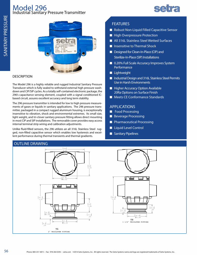
Phone: 800-257-3872 • Fax: 978-264-0292 • setra.com ©2014 Setra Systems, Inc. All rights reserved. The Setra Systems name and logo are registered trademarks of Setra Systems, Inc.
GEN
ERA
L PU
RPO
SE O
EM
56
SAN
ITA
RY P
RESS
URE
OUTLINE DRAWING
Model 296 Industrial Sanitary Pressure Transmitter
FEATURES■ Robust Non-Liquid Filled Capacitive Sensor
■ High Overpressure Protection
■ All 316L Stainless Steel Wetted Surfaces
■ Insensitive to Thermal Shock
■ Designed for Clean-In-Place (CIP) and
Sterilize-In-Place (SIP) Installations
■ 0.20% Full Scale Accuracy Improves System Performance
■ Lightweight
■ Industrial Design and 316L Stainless Steel Permits Use in Harsh Environments
■ Higher Accuracy Option Available 20Ra Options on Surface Finish■ Meets CE Conformance Standards
APPLICATIONS■ Food Processing■ Beverage Processing
■ Pharmaceutical Processing
■ Liquid Level Control
■Sanitary Pipelines
DESCRIPTION
The Model 296 is a highly reliable and rugged Industrial Sanitary Pressure Transducer which is fully sealed to withstand external high pressure wash-down and CIP/SIP cycles. As a totally self-contained electronic package, the 296’s capacitance sensing element, coupled with a signal conditioned IC-based circuit, assures excellent accuracy and long term stability.
The 296 pressure transmitter is intended for low to high pressure measure-ments of gases or liquids in sanitary applications. The 296 pressure trans-mitter, packaged in a compact rugged aluminum housing, is exceptionally insensitive to vibration, shock and environmental extremes. Its small size, light weight, and tri-clover sanitary pressure fitting allows direct mounting in most CIP and SIP installations. The removable cover provides easy access internal terminal strip wiring and calibration adjustments.
Unlike fluid-filled sensors, the 296 utilizes an all 316L Stainless Steel rug-ged, non-filled capacitive sensor which enables low hysteresis and excel-lent performance during thermal transients and thermal gradients.
63.92.52 6.2
.24
91.73.61
50.82.00 17.6
.69
371.46
1024.02
63.92.52
642.52
50.391.98
11.2.44
96.63.81
22.6.89
T6
T81 1/2" TRICLOVER FITTING
2" TRICLOVER FITTING

©2014 Setra Systems, Inc. All rights reserved. The Setra Systems name and logo are registered trademarks of Setra Systems, Inc. Phone: 800-257-3872 • Fax: 978-264-0292 • setra.com
GEN
ERAL PU
RPOSE O
EM
57
ORDERING INFORMATION
SAN
ITARY PRESSU
RE
Example: Part No. , 2961005PGT8113RN: 0 to 5 PSIG, 2” Tri-Clover Fitting, 4 to 20 mA Output, ±0.2% FS Accuracy, 20 Ra Sensor Finish
Model 296 Industrial Sanitary Pressure Transmitter
SPECIFICATIONSPerformance Data 2” Tri-Clover Sanitary Fitting
Performance Data 1.5” Tri-Clover Sanitary Fitting
Electrical Data
Accuracy RSS1 (at constant temp) ±0.20% FS Accuracy RSS1 (at constant temp) ±0.20% FS Circuit 2-Wire
Non-Linearity (BFSL) ±0.17% FS Non-Linearity (BFSL) ±015% FS Output3 4 to 20 mA4
Hysteresis 0.10% FS Hysteresis 0.12% FS Zero/Span, Adjustment ± 0.5 mA
Non-Repeatability 0.025% FS Non-Repeatability 0.10% FS External Load 0 to 800 ohms
Thermal Effect2 Thermal Effect2 Min. Supply Voltage (VDC) 12 + 0.02 x resistance of receiver plus line
Compensated Range Fo(Co) +20 to +180 (-7 to +82) Compensated Range Fo(Co) +20 to +180 (-7 to +82) Max. Supply Voltage (VDC) 30 + .004 x resistance of receiver plus line
Zero/Span Shift %FS/100°F (%FS/50°C) 2.0 (1.8) Zero/Span Shift %FS/100°F (%FS/50°C) 2.0 (1.8) Environmental Data
Response Time 10 milliseconds Response Time 10 milliseconds Operating Temperature°F (°C)5 -40 to +260 (-40 to +125)
EMI/RFI Effect< 1.0% output shift; 10V/M, 10-300 MHz
EMI/RFI Effect < 1.0% output shift; 10V/M, 10-300 MHz
Storage Temperature°F (°C) -65 to +260 (-55 to +125)
Clamping Effect, Zero/Span Shift ±0.15% FS Clamping Effect, Zero/Span Shift ±0.25% FS Vibration 10g, 50-1000Hz
Maximum Vacuum (without affecting specifications)
Half on ranges ≤15 PSIMaximum Vacuum (without affecting specifications)
Full on ranges ≥ 30 PSI Acceleration6 10g maximum
Physical Description 1 RSS of Non-Linearity, Non-Repeatability and Hysteresis.2 Units calibrated at nominal 70°F. Maximum thermal error is computed from this datum.Variations in the power supply voltage cause less than 0.005 mA change in the transmitter’s current output, per volt change in the power supply. Reverse excita-tion will not damage circuit.3 Calibrated at factory with a 24 VDC loop supply voltage and a 250 ohm load.4 Zero output factory set to within ±0.08mA.4 Span (Full Scale) output factory set to within ±0.16mA.5 Operating temperature limits of the electronics only. Pressure media temperatures may be considerably higher or lower.6 shift in output reading at <0.05% FS/g; pressure port axis only.
Shock 50g operating
Zero/Span Adjustments Access Through Internal to Housing Thermal Shock°F (°C) 0 to +257 (0 to +125) negligible shift
Housing Die Cut Aluminum and Stainless Steel Note: Setra quality standards are based on ANSI-Z540-1. The calibration of this product is NIST traceable.
Electrical Connection1/2 NPT” Conduit with Removable Internal Terminal Connector
Pressure Fitting 2” or 1 1/2” Tri-Clover Sanitary Fitting
Vent Through Hydrophobic Teflon Plug
Weight (Approx.) 18 Ounces
Model Range Units Pressure Type Fitting Output Termination Accuracy Options2
2901 = 290 2” Tri-Clover (PSI) 1 1/2” Tri-Clover(PSI) P PSI G Gauge T6 1 1/2” Tri-Clover 11 4-20 mA T1 Terminal Block 3 ± 0.2% FS N None
001 0-1 030 0-30 M mBAR C** Compound T8 2” Tri-Clover T ± 0.1% FS R 20 Ra Sensor Finish
002 0-2 045* 0-45
005 0-5 060 0-60
010 0-10 100 0-100
015 0-15 150 0-150
030 0-30 300 0-300
060 0-60 500 0-500
100 0-100 10C 0-1000
150 0-150
2 9 6 1 1 1
Pressure Ranges 2” Tri-Clover
psig Range mb
in. H20 Proof psig
Burst psig
1 100 27.7 50 100
2 160 55.4 75 150
5 400 138.4 150 200
10 600 276.8 150 200
15 1000 415.2 150 200
30 830.4 150 300
60 1660.8 180 400
100 2768 200 400
150 4152 225 400
-14.7 to 15 -407 to 415 150 300
Pressure Ranges 1 1/2” Tri-Clover
Range psig Proof psig
Burst psig
30 1000 1200
60 1000 1200
100 1000 1200
150 1000 1200
300 1000 1200
500 1000 1500
1000 1250 2400
-14.7 to 15 1000 1200
-14.7 to 45 1000 1200
Proof Pressure: The maximum pressure that may be applied without changing performance beyond specifications (<±0.5% FS zero shift).Burst Pressure: The maximum pressure that may be applied to the positive pressure port without rupturing the sensing element.
** -14.7 to X psi, -1000 to XmBAR
SSP2
96 R
ev. 1
2 Both boxes must be filled in alphabetical order:- If No options: N + N- If 1 option: Option Code + N- If 2 options: Option Code + Option Code

Phone: 800-257-3872 • Fax: 978-264-0292 • setra.com ©2014 Setra Systems, Inc. All rights reserved. The Setra Systems name and logo are registered trademarks of Setra Systems, Inc.
GEN
ERA
L PU
RPO
SE O
EM
58

©2014 Setra Systems, Inc. All rights reserved. The Setra Systems name and logo are registered trademarks of Setra Systems, Inc. Phone: 800-257-3872 • Fax: 978-264-0292 • setra.com
GEN
ERAL PU
RPOSE O
EM
59
PRODUCT SECTION 4.1
ACCELEROMETER
MODEL:
141

Phone: 800-257-3872 • Fax: 978-264-0292 • setra.com ©2014 Setra Systems, Inc. All rights reserved. The Setra Systems name and logo are registered trademarks of Setra Systems, Inc.
GEN
ERA
L PU
RPO
SE O
EM
60
Model 141 High Output Linear Accelerometer
BENEFITS Excellent Static and Dynamic Response Temperature-Insensitive Gas Damping (0.7
Critical) High Output Signal High Overload Capability, 2000g static Low Transverse Sensitivity (0.012 g/g) Wide-Range Rcal Type Calibration Easy-to-Replace Cable Attachment Compact and Lightweight Optional EMI Filter Upgrade
DESCRIPTIONThe Model 141 is a linear accelerometer that produces high level in-stantaneous DC output signal proportional to sensed accelerations (ranging from static acceleration up to 3000 Hz as indicated below). Setra accelerometers are unique in their ability to withstand exceed-ingly high g overload without damage. The Model 141 incorporates the super-rugged Setra capacitance-type sensor and a miniaturized electronic circuit.Its excellent dynamic response is maintained by air damping, which varies with temperature approximately one-tenth as much as the best fluid damping. The electrical characteristics are compatible with con-ventional strain-gauge type signal conditioning, including the use of shunt Rcal over any selected range up to 100% full scale. The stainless steel case is O-Ring sealed, has a well-defined base plane and is quite insensitive to mounting strain.Cross axis interface is exceedingly low. The external easy-to-replace cable attachment facilitates installation and service.
SPECIFICATIONSPerformance Data Thermal Effects Electrical DataNon-Linearity(Best Fit Straight Line)
±1.0% FS Operating Temperature °F(ºC)
-10 to +150 (-23 to +65) Electrical Circuit1 3-Wire (Com, -Exc, -Out)
Hysteresis 0.10% Zero Shift <±0.02% Nominal Range/°F(<±0.36%/°C)
Isolation 100 M ohms
Non-Repeatability 0.05% Sensitivity Shift <±0.02% Nominal Range/°F (<±0.36%/°C) Slightly higher thermal effects when 141A is operated at excitation voltage below 10 VDC
Internal Frequency 20 MHz approx.
Transverse Accelera-tion Response
<±.012 g/g Zero G Output <±25 mV (factory calibrated at 10 VDC or 24 VDC excitation)
Calibration Signal (Rcal) Available up to 100% Nominal Range by shunting external calibration resistor from calibration lead to -signal lead.
Damping Approx. second order system with 0.7 critical damping (Gas Squeeze-Film 0.7 ±0.2 of critical at 77oF [25°C]). Damping ratio increases approx. 0.15%/°F.
FS G Output <±25% of Nominal Output Excitation/Output2 Code BT 2S
Excitation Range 5-15 VDC 10-28 VDC3
Frequency Band Flat from static to approx. 60% of natural frequency (all ranges)
Noise Level <±0.01% Nominal Range (RMS, in-band) Calibrated Excitation Voltage 10 VDC 24 VDC
Excitation Current 5 mA 10 mA
Resolution Infinite, limited only by output noise level Physical Description Nominal Output (open circuit) ±500 mV @ 10 VDC ±1000 mV @ 24 VDC
Calibration Data Each unit is supplied with a computer generated plot
of output vs. acceleration (centrifuge) at the specified
excitation voltage.
Electrical Connection 2 foot multiconductor cable 1 Circuit is capacitively isolated from case. Power applied to output, or shorted output, will not damage unit. No reverse excitation protection.2 Typical performance for nominal g range: Output is proportional to excitation voltage. Output impedance 9k ohms (nominal).3 Operable on 28 VDC aircracft power. (Recommend high voltage transient protection to prevent damage by emergency power conditions as defined in MIL-STD-704A, and voltage regulation to attain highest accuracy.)
Sensitivity Reported at Nominal Range Weight 30 grams (not including cable)
Excitation Voltage Model 141 calibrated at 10 VDC 0r 24 VDC Case Stainless Steel, O-Ring
ACCE
LERO
MET
ER

©2014 Setra Systems, Inc. All rights reserved. The Setra Systems name and logo are registered trademarks of Setra Systems, Inc. Phone: 800-257-3872 • Fax: 978-264-0292 • setra.com
GEN
ERAL PU
RPOSE O
EM
61
DRAWINGS & DIMENSIONS
ORDERING INFORMATION
1 4 1 1
Model 141High Output Linear Accelerometer
SSP1
41 Re
v. D
FULL SCALE RANGESFor each of the available g ranges, the linearity is characterized by this range chart: (Non-linearity is % full range, best fit straight line)
Nominal Range Natural Frequency (Nominal)
Flat Response(±3 db) 0 Hz to:
±2g 300Hz 200Hz
±4g 440Hz 260Hz
±8g 570Hz 300Hz
±15g 840Hz 400Hz
±30g 1200Hz 700Hz
±60g 1560Hz 1000Hz
±150g 2600Hz 1600Hz
±600g 5000Hz 3000Hz
Model Range Units Type Output Termination Accuracy Options
141 1411 002 ±2g A G Force B Bi-Direction BT ±500 mV (10VDC EXC) 02 2’ Cable G ± 1.0% FS NN None
004 ±4g 2S ±1000 mV (24VDC EXC) 10 10’ Cable 6 Calibration Special EXC
007 ±8g 25 25’ Cable 7 EMI/RFI Filter
015 ±15g XX Consult facotry for other lengths 3 Wide Oper. Temp. -65 to 220oF
030 ±30g
060 ±60g
150 ±150g
600 ±600g
Both boxes must be filled in alphanumeric order:• If No options: N + N• If 1 option: Option Code + N• If 2 options: Option Code + Option Code
NOTE: Setra adheres to strict quality standards including ISO 9001 and ANSI-Z540. The calibration of this product is NIST traceable.
ACCELEROM
ETER
Example: Part No. , 1411002ABB10GNN: ±2g, ±500mV Output, 10’ Cable, 1% Accuracy

Phone: 800-257-3872 • Fax: 978-264-0292 • setra.com ©2014 Setra Systems, Inc. All rights reserved. The Setra Systems name and logo are registered trademarks of Setra Systems, Inc.
GEN
ERA
L PU
RPO
SE O
EM
62

©2014 Setra Systems, Inc. All rights reserved. The Setra Systems name and logo are registered trademarks of Setra Systems, Inc. Phone: 800-257-3872 • Fax: 978-264-0292 • setra.com
GEN
ERAL PU
RPOSE O
EM
63
PRODUCT SECTION 5.1
BAROMETRICPRESSURE
MODELS:
276 370278 470270

Phone: 800-257-3872 • Fax: 978-264-0292 • setra.com ©2014 Setra Systems, Inc. All rights reserved. The Setra Systems name and logo are registered trademarks of Setra Systems, Inc.
GEN
ERA
L PU
RPO
SE O
EM
64
BARO
MET
RIC
PRES
SURE
DRAWINGS & DIMENSIONS
Model 276 Low Cost Barometric Pressure Transducer
BENEFITS Proven SETRACERAMTM Sensor ±0.25% FS Accuracy Environmentally Rugged < ±0.25% FS, 6 Month Stability Compact Size (2” dia. x 1”) Excellent Long-Term Stability Low Power Consumption Fast Response Meets CE Conformance Standards APPLICATIONS Environmental Monitoring Systems Weather Measurement Systems Weather & Environmental Data Logging Barometric Pressure Compensation for
Internal Combustion Engine Performance Cleanroom Barometric Pressure Compensation Automotive Emissions Test Equipment
DESCRIPTIONSetra Systems has been a technology leader in Environmental Pressure Measurement for over three decades. The Model 276 is an extremely accurate and stable transducer based on the proven SETRACERAMTM sensing element. The glass fused ceramic capacitive sensing capsule is the heart of Setra’s environmental pressure transducers because of its inherent thermal stability, low hysteresis and fundamentally simple design.Another major feature of the 276 is Setra’s custom Application Specific Integrated Circuit (ASIC). The ASIC works hand-in-hand with the SE-TRACERAMTM sensor to achieve long-term stability and high accuracy, unmatched by other manufacturers, even at a much higher cost. The ASIC circuit allows the 276 to operate with an excitation as low as 5 VDC for remote battery or solar powered applications.The 276 is designed specifically to give maximum flexibility to system integrators and OEM’s. The standard unit has a convenient mounting bracket and simple 1/8” tube fitting for quick installations. It’s low cost, small in size and configurable to your applications.
Type of Pressure
Pressure Range
Maximum Pressure
Barometric 600 to 1100 mb/hPa800 to 1100 mb/hPa
20 PSIA20 PSIA
Absolute 0-20 PSIA 30 PSIA

©2014 Setra Systems, Inc. All rights reserved. The Setra Systems name and logo are registered trademarks of Setra Systems, Inc. Phone: 800-257-3872 • Fax: 978-264-0292 • setra.com
GEN
ERAL PU
RPOSE O
EM
65
BARO
METRIC PRESSU
RE
ORDERING INFORMATION
2 7 6 1
Model 276 Low Cost Barometric Pressure Transducer
SPECIFICATIONSPerformance Data Environmental Data
Accuracy RSS 1 (at constant temp) ±0.25% FS 2 Temperature
Non-Linearity (BSFL) ±0.22% FS Operating 4 °F(ºC) 0 to +175 (-18 to +79)
Hysteresis .05% FS Storage °F(ºC) -65 to +250 (-55 to +121)
Non-Repeatability .05% FS Vibration 2g from 5Hz to 500 Hz
Resolution Infinite, limited only by output noise level (0.005% FS)
Acceleration 10g
Thermal Effects 3 Shock 50g Operating, 1/2 since 10ms
Compensated Range °F(ºC) +30 to +130 (0 to +55) Electrical Data (Voltage)
Zero/Span Shift %FS/°F (%FS/ºC) 1% FS Circuit 3-Wire 5 (Exc, Out, Com)
Resolution Infinite, limited only by output noise level (0.0005% FS)
Power Consumption 0.2 Watts (24 VDC)
Time Constant 10 milliseconds to reach 90% final out-put with step function pressure input
Output Impedance
Long Term Stability 0.25% FS/6 months Output Noise <200 microvolts RMS (0 Hz to 100 Hz)
Pressure Media
Non-condensing air or gas compatible with stainles steel, alumina ceram-ics, gold and elastomer.
Physical Description
Case Stainless Steel
Electrical Connection 2 ft. Multiconductor Cable
Pressure Fitting 1/8” Tube Fitting
SSP2
76 Re
v D
Model Pressure Range Units Pressure Type Fitting Output Termination Accuracy Options
276 2761 600 600-1100 M mb/hPa A Absolute 1B 1/8” Push Tube Fitting 22 0.1 to 5.1 VDC (24 VDC EXC) 02 2’ Cable F ±0.25% FS NN None
800 800-1100 M mb/hPa 1M 1/8” NPT External 32 0.1 to 5.1 VDC (12 VDC EXC) 10 10’ Cable T ±0.1% C 11 PT Cal. Certificate
020 20 P PSI 45 0.5 to 4.5 VDC (5 VDC EXC) 25 25’ Cable D Mate with Datum
XX Consult facotry for other cable lengths
L Etched SS Tag
Both boxes must be filled in alphanumeric order:• If No options: N + N• If 1 option: Option Code + N• If 2 options: Option Code + Option Code
1 RSS of Non-Linearity, Hysteresis and Non-Repeatability. Higher accuracy units available on special order.2 FS = 300mb for 800-1100 range; 500 for 600-1100 mb range; and 20 PSI for 0 to 20 PSIA.3 Units calibrated at a nominal 70o F. Maximum thermal error computed from this datum.4 Operating temperature limits of the electronics only. Pressure media temperatures may be considerable higher or lower.5 The separate leads for +EXC, -EXC, +Out, -Out are commoned internally. The shield is connected to the case. For best performance, either the -Exc or -Out should be connected to the case. Unit is calibrated at the factory with -Exc connected to the case. The insulation resistance between all signal leads are tied together and case ground is 100 ohms minimum at 25 VDC.6 Zero and Full Scale Outputs are factory set to within ±0.25% Full Scale.
Example: Part No. , 2761800MA1B2202FCN: 800 to 1100 mb, 1/8” Push Tube Fitting, 0.1 to 5.1 VDC Output (24 VDC EXC), 2’ Cable, ±0.25% FS Accuracy, 11 Point Cal Cert
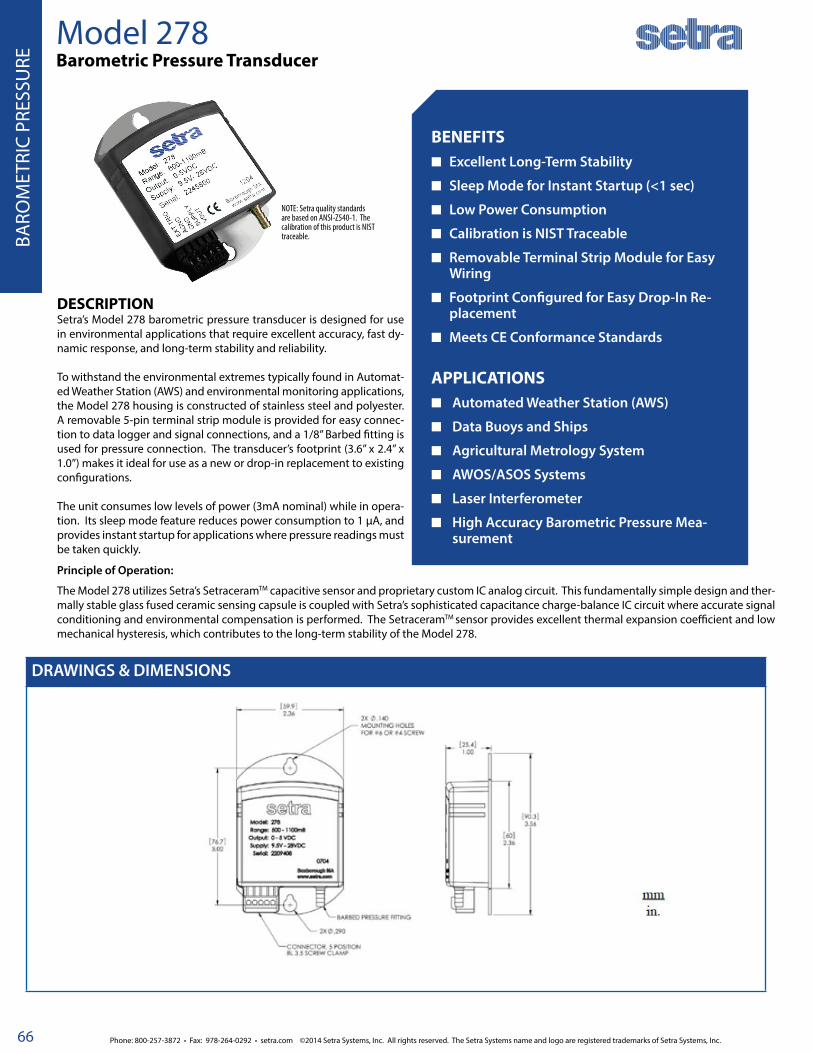
Phone: 800-257-3872 • Fax: 978-264-0292 • setra.com ©2014 Setra Systems, Inc. All rights reserved. The Setra Systems name and logo are registered trademarks of Setra Systems, Inc.
GEN
ERA
L PU
RPO
SE O
EM
66
DRAWINGS & DIMENSIONS
Model 278 Barometric Pressure Transducer
BENEFITS■ Excellent Long-Term Stability
■ Sleep Mode for Instant Startup (<1 sec)
■ Low Power Consumption
■ Calibration is NIST Traceable
■ Removable Terminal Strip Module for Easy Wiring
■ Footprint Configured for Easy Drop-In Re-placement
■ Meets CE Conformance Standards APPLICATIONS■ Automated Weather Station (AWS)
■ Data Buoys and Ships
■ Agricultural Metrology System
■ AWOS/ASOS Systems
■ Laser Interferometer
■ High Accuracy Barometric Pressure Mea-surement
DESCRIPTIONSetra’s Model 278 barometric pressure transducer is designed for use in environmental applications that require excellent accuracy, fast dy-namic response, and long-term stability and reliability.
To withstand the environmental extremes typically found in Automat-ed Weather Station (AWS) and environmental monitoring applications, the Model 278 housing is constructed of stainless steel and polyester. A removable 5-pin terminal strip module is provided for easy connec-tion to data logger and signal connections, and a 1/8” Barbed fitting is used for pressure connection. The transducer’s footprint (3.6” x 2.4” x 1.0”) makes it ideal for use as a new or drop-in replacement to existing configurations.
The unit consumes low levels of power (3mA nominal) while in opera-tion. Its sleep mode feature reduces power consumption to 1 μA, and provides instant startup for applications where pressure readings must be taken quickly.
Principle of Operation:
The Model 278 utilizes Setra’s SetraceramTM capacitive sensor and proprietary custom IC analog circuit. This fundamentally simple design and ther-mally stable glass fused ceramic sensing capsule is coupled with Setra’s sophisticated capacitance charge-balance IC circuit where accurate signal conditioning and environmental compensation is performed. The SetraceramTM sensor provides excellent thermal expansion coefficient and low mechanical hysteresis, which contributes to the long-term stability of the Model 278.
NOTE: Setra quality standards are based on ANSI-Z540-1. The calibration of this product is NIST traceable. BA
ROM
ETRI
C PR
ESSU
RE

©2014 Setra Systems, Inc. All rights reserved. The Setra Systems name and logo are registered trademarks of Setra Systems, Inc. Phone: 800-257-3872 • Fax: 978-264-0292 • setra.com
GEN
ERAL PU
RPOSE O
EM
67
ORDERING INFORMATION
2 7 8 1 1 B T 1A
Example: Part No. 2781600MA1B2BT1 for a 278 Pressure Transducer 600 to 1100 hPa, mb, Absolute Pressure, 1/8” Barbed Fitting, 0 to 5 VDC Output, 5-Pin Terminal Block.
Model 278 Barometric Pressure Transducer
SPECIFICATIONSPerformance Data Environmental Data
Pressure Range hPa/mb 500 600 800 Temperature
Temperature at: Accuracy (hpa/mb) 1 Operating 4 °C(ºF) -40 to +60 (-40 to +140)
20oC (+68oF) ±0.6 ±0.5 ±0.3 Storage °C(ºF) -60 to +120 (-76 to +248)
0 to 40oC (+23o to +104oF) ±1.2 ±1.0 ±0.6 Physical Description
20 to 50oC (-4o to +122oF) ±2.0 ±1.5 ±1 Case Stainless Steel and Polyester
-40 to 60oC (-40o to +140oF) ±2.5 ±2.0 ±1.5 Pressure Fitting 1/8” (ID dia.) Bardbed Fitting
Non-Linearity ±0.5 ±0.4 ±0.25 Electrical Connection 5-Pin Terminal Block
Hysteresis ±0.06 ±0.05 ±0.03 Dimensions 3.6” x 2.4” x 1.0”
Non-Repeatability ±0.04 ±0.03 ±0.02 Weight 4.8 ox (135g)
Resolution 0.01 mB Electrical Data
Long Term Stability 0.1 mb/yr Circuit 3 or 4-Wire
Warm-UpDownshift
<1 Sec. from Shut-Mode (Warm-Up <0.1 mb Max.
Output 2 0.2.5 VDC0.5 VDC
Response Time <100 mSec Excitation 3 9.5 to 28 VDC
Proof Pressure 1500 hPa Output Impedance <10 Ohms
Burst Pressure 2000 hPa Output Noise <50 Microvolts
Pressure MediaNon Condensing Air or Gas.
Current Consumption 3mA Nominal (Operating Mode) 1uA (Sleep Mode)
SSP2
78 Re
v B 03
/11/
11
Model Pressure Range Pressure Type Pressure Conn. Output/Exc. Electrical Conn.
278 2781 500M 500 to 1100 hPa/mb A Absolute 1B 1/8” Push Tube Fitting 2Y 0 to 2.5VDC/9.5 to 28 T1 5-Pin Terminal Block
600M 600 to 1100 hPa/mb 2B 0 to 5 VDC/9.5 to 28 VDC
800M 800 to 1100 hPa/mb
1 The root sum squared (RSS) of end point non-linearity, hysteresis, non-repeatability, and calibration uncertainty.2 Internal regulation minimizes effect of excitation variation, with <0.02 mb out-put change of 9.5 VDC to 28 VDC range.3 Zero output saturates at about 20 mV.
BARO
METRIC PRESSU
RE

Phone: 800-257-3872 • Fax: 978-264-0292 • setra.com ©2014 Setra Systems, Inc. All rights reserved. The Setra Systems name and logo are registered trademarks of Setra Systems, Inc.
GEN
ERA
L PU
RPO
SE O
EM
68
BARO
MET
RIC
PRES
SURE
DRAWINGS & DIMENSIONS
Model 270 SETRACERAMTM for Barometric, Gauge or Absolute Pressure
BENEFITS SETRACERAMTM Sensor High Accuracy ±0.05% FS (end point method)
±0.03% FS Optional Accuracy High Cycle Life Repeatability Within 0.01% FS Excellent Long-Term Stability Low Power Consumption Instant Warm-Up Fast Response APPLICATIONS High Accuracy Barometric Pressure Measurement Weather & Environmental Data Data Buoys & Remote Weather Stations Engine Test Cells High Accuracy Transfer Standard for Calibration Meets CE Conformance Standards
DESCRIPTIONFor many years, high accuracy environmental and test and measure-ment applications around the world have relied on the consistent performance of the Setra Model 270 pressure transducer. Applica-tions range from remote weather monitoring and avionics systems, endorsed by government agencies, to crucial compensation for baro-metric pressure variations in laser interferometers. Long-term reli-ability and stability in such demanding application environments are achieved in the 270 with the combination of the SETRACERAMTM ca-pacitive sensor and Setra’s proprietary custom IC analog circuit.
The fundamentally simple design and thermally stable glass fused ce-ramic sensing capsule is coupled with the sophisticated capacitance charge-balance IC circuit where accurate signal conditioning and en-vironmental compensation is performed. Standard accuracy is 0.05% Full Scale, end point method. Higher accuracy and thermal specifica-tions are also available.
Type of Pressure
Pressure Range
Maximum Pressure
Barometric 600 to 1100 hPa/mb800 to 1100 hPa/mb
20 psia
Absolute 0 to 10, 20, 50, 100 psia 1.5 x rated
Gauge 0 to 5, 10, 20, 50, 100 psig 1.5 x rated

©2014 Setra Systems, Inc. All rights reserved. The Setra Systems name and logo are registered trademarks of Setra Systems, Inc. Phone: 800-257-3872 • Fax: 978-264-0292 • setra.com
GEN
ERAL PU
RPOSE O
EM
69
BARO
METRIC PRESSU
RE
ORDERING INFORMATION
2 7 0 1
Model 270 SETRACERAMTM for Barometric, Gauge or Absolute Pressure
SPECIFICATIONSPerformance Data Environmental Data Electrical Data
Accuracy RSS 1 (at constant temp) ±0.05% FS Temperature Electrical Circuit 3 4-Wire (+Exc, -Exc, _Out, -Out)
Non-Linearity Operating °F(ºC) 0 to +175 (-18 to +80) Excitation 4 24 VDC (22-32 VDC)12VDC (11-15 VDC) Reverse Wiring Protection
End Point ±0.05% FS Storage °F(ºC) -65 to +250 (-54 to +120) Output 5 0 to 5 VDC 6
Best Fit Straight Line ±0.03% FS Vibration 2g from 5Hz to 500 Hz Isolation The insulation resistance between all signals leads tied together and case ground is 100 ohms minimum at 25 VDC
Hysteresis <0.01% FS (TYP.) Acceleration 10g Output Impedance <5 ohms
Resolution Infinite, limited only by output noise level (0.005% FS)
Shock 50g Operating, 1/2 sine 10ms Output Noise <200 microvolts RMS (0 Hz to 100 Hz)
Thermal Effects 2 Pressure Fitting 1/8”-27 NPT Internal Current Consumption 8 mA (0.2 Watts)
Compensated Range °F(ºC) +30 to +120 (-1 to +49) Electrical Connection 2’ Multiconductor Cable
Thermal Zero Shift %FS/°F (%FS/ºC) Weight (approx.) 9 ounces (0.25 Kgm)
Barometric ±0.2 (±0.18) Pressure Media:
Other Ranges ±0.1 (±0.09) Non-condensing air or gas compatible with hard anodized aluminum, alumina ceramics, gold, fluorocarbon elastomer sealant & Buna-N O-Ring.
Thermal Coefficient Sensitivity ±0.1 (±0.09)
Long Term Stability < ±0.1% FS/YR
Warm-Up < ±0.04% FS shift after 20 minutes at constant temp.
Time Constant <10 milliseconds to reach 90% final output with step function pressure input
SSP2
870 R
ev D
Model Pressure Range Units Pressure Type Fitting Output Termination Accuracy Options
2701 270 600 600-1100 M mb/hPa A Absolute 1F 1/8” NPT Internal 2B 0 to 5 VDC (24 VDC EXC) 02 2’ Cable N ±0.05% FS NN None
800 800-1100 M mb/hPa G Gauge (PSI units only) 3B 0 to 5 VDC (12 VDC EXC) 10 10’ Cable Y ±0.03% ** C 11 PT Cal. Certificate
*005 0-5 P PSI 25 25’ Cable D Mate with Datum
010 0-10 P PSI XX Consult facotry for other cable lengths
F Nema 4 Enclosure
020 0-20 P PSI L Etched SS Tag
050 0-50 P PSI 2 -13 to -150o F Compensated Range **
100 0-100 P PSI
Both boxes must be filled in alphanumeric order:• If No options: N + N• If 1 option: Option Code + N• If 2 options: Option Code + Option Code
1 RSS of Non-Linearity, Hysteresis and Non-Repeatability. Higher accuracy units available on special order.2 Units calibrated at nominal 70oF. Maximum thermal error is computed from this datum.3 For best performance, either negative excitation or negative output should be connected to case (ground). Both leads cannot be connected to case (ground). Units calibrated at the factory with negative excitation connected to case.4 Internal regulation minimizes effect of excitation variation, with <±0.005% FS output change. Will operate at 28 VDC aircraft power per MIL-STD-704A and not be damaged by emergency power conditions.5 Calibrated into a 50K ohm load, operable into a 5000 ohm load or greater.6 Zero output factory set to within ±5mV. Span (Full Scale) output factory set to within ±5mV.
** Accuracy “Y” and Option “2” cannot be combined.
*Available in Gauge Pressure Type Only
Example: Part No. , 2701600MA1F2B02NCN: 600 to 1100 mb, 1/8” NPT Internal Fitting, 0 to 5 VDC Output (24 VDC EXC), 2’ Cable, ±0.05% FS Accuracy, 11 Point Cal Cert

Phone: 800-257-3872 • Fax: 978-264-0292 • setra.com ©2014 Setra Systems, Inc. All rights reserved. The Setra Systems name and logo are registered trademarks of Setra Systems, Inc.
GEN
ERA
L PU
RPO
SE O
EM
70
BARO
MET
RIC
PRES
SURE
Model 370 Digital Pressure Gauge
BENEFITS ±0.02% Full Scale Accuracy High Resolution 6 Digit LCD Display for Pressure or Altitude Monitoring Bidirectional RS-232 Digital Communications I/O Port Engineering Unit Conversions for Pressure
and Altitude Digital Altimeter Setting Indicator (DASI)
and Corrected Altimeter Mode Programmable Non-Linear Functions APPLICATIONS Automatic Weather Reporting Systems Pressure Transfer Standard Altimeter Calibration Recertification Lab or Production Process Monitoring Altitude Chambers
DESCRIPTIONSetra Systems Model 370 offers extremely high accuracy and un-matched stability in a digital output configuration. Environmental monitoring and test & measurement systems around the world rely on Setra’s experience in barometric pressure measurement instrumenta-tion, as well as high accuracy measurements of higher pressures. The 370 utilizes Setra’s unique SETRACERAMTM sensor, which is combined with advanced microprocessor based circuitry and sophisticated firm-ware to provide system accuracy to better than ±0.02% FS.
The Model 370 Digital Pressure Gauge is an extremely versatile instru-ment. Pressure and altitude data is displayed on a 6 digit LCD and is also accessible through a bidirectional RS-232 port. A numeric keypad is provided for easy access to engineering unit conversions, min/max tracking, entry of Hi/Lo alarm setpoints and calibration procedures. The 370 is also available with an optional rechargeable battery pack to bring lab accuracy to the field.
SPECIFICATIONSPerformance Data Physical DescriptionAccuracy1 ±0.02% FS2 at 70o F(21oC) Pressure Fitting 1/8” - 27 NPT Internal Display 6 digit Liquid Crystal Display (LCD) with annunciators for pressure/
altitude engineering units (PSI, mbar, hPa, mmHg, in.Hg, mmH2O, in.H2O, ft, m, units), HI/LO ALARM, pressure signal stability (O.K.) and barometric pressure corrected to sea level (SEA LEVEL).
Non-Linearity ±0.012% FS (End Point) Power Cord 5 Ft. Length, 3-Prong
Hysteresis 0.010% FS Weight 12 lbs. (with Battery Pack)
Non-Repeatability 0.010% FS Thermal Effects 3 Digital Output Bidirectional RS-232 interface. All display data can be transmitted on the interface and all keyboard functions and commands can be duplicated using a remote terminal or keyboard.Pressure Media Compensated Range °F(ºC) +32 to +110 (0 to +45)
Clean dry air or other gases (non-condensable) Zero Shift %FS/°F (%FS/ºC) 0.002 (0.004)
Span Shift %FS/°F (%FS/ºC) 0.001 (0.002) Operating Power 110/220 VAC (-10% to +20%), 50/60 Hz., optional 12 VDC internal rechargeable battery pack (approx. 8 hours between charges). Approximately 4 watts power consumption.
1 RSS of Non-Linearity, Non-Repeatability and Hysteresis2 FS = 300 hPa/mb for 800-1100 hPa/mb range; 500 hPa/mb for 600-1100 hPa/mb range3 Unit calibrated at 70oF. Maximum thermal error is computed from this datum.
Altitude Resolution 1 ft. (4 ft. for 100 psia range)
Stability 0.005% FS, 24 hours0.02% FS, 30 days0.05% FS, 1 year
Digital Interface Bidirectional RS-232 interface. Access data, functions and com-mands via an RS-232 compatible remote terminal, data acquisition system or data storage device. 300, 600, 1200, 2400, 4800, 9600 Baud Rate, adjustable. Typical data printouts below:
PRESSURE RANGESType of Pressure Pressure Range Readout or
ReportAltitude Range1
Barometric 600 to 1100 mb/hPa800 to 1100 mb/hPa
600.00 to 1100.00800.00 to 1100.00
-1000 to 13,800 ft.-1000 to 6,400 ft.
Absolute 0 to 10 psia0 to 20 psia0 to 50 psia
0 to 100 psia
10.000020.000050.0000100.000
10,300 to 100,000 ft.-1000 to 100,000 ft.-1000 to 100,000 ft.-1000 to 100,000 ft.
1 Altitude is calculated using a pol Smithsonian Meteorological Tables, Vol. 114” Ranges greater than 20 psia not recommended for altimeter recertification.Proof Pressure: 150% of full scale pressure range.

©2014 Setra Systems, Inc. All rights reserved. The Setra Systems name and logo are registered trademarks of Setra Systems, Inc. Phone: 800-257-3872 • Fax: 978-264-0292 • setra.com
GEN
ERAL PU
RPOSE O
EM
71
BARO
METRIC PRESSU
RE
DRAWINGS & DIMENSIONS
ORDERING INFORMATION
3 7 0 1
Model 370Digital Pressure Gauge
SSP3
70 Re
v. G
Model Pressure Range Units Pressure Type Fitting Output Accuracy Options
3701 370 600 600-1100 M mb/hPa A Absolute 1F 1/8” NPT Internal VT RS-232/6 Digit LCD/120 VAC Y ±0.02% FS NN None
800 800-1100 M mb/hPa L Etched SS Tag
010 0-10 P PSI 5 Installed Battery Pack
020 0-20 P PSI
050 0-50 P PSI
100 0-100 P PSI
Both boxes must be filled in alphanumeric order:• If No options: N + N• If 1 option: Option Code + N• If 2 options: Option Code + Option Code
Example: Part No. , 3701020PA1FVTY5N: 0 to 20 PSIA, 1/8” NPT Internal Fitting, RS232/6 Digit LCD Output, Installed Battery Pack

Phone: 800-257-3872 • Fax: 978-264-0292 • setra.com ©2014 Setra Systems, Inc. All rights reserved. The Setra Systems name and logo are registered trademarks of Setra Systems, Inc.
GEN
ERA
L PU
RPO
SE O
EM
72
BARO
MET
RIC
PRES
SURE
Model 470 Digital Pressure Transducer
BENEFITS ±0.02% Full Scale Accuracy Bidirectional RS-232 Digital Communications I/O Port Engineering Unit Conversions for Pressure
and Altitude Digital Altimeter Setting Indicator (DASI)
and Corrected Altimeter Mode ProgramMable Non-Linear Functions APPLICATIONS Automatic Weather Reporting Systems Pressure Transfer Standard Altimeter Calibration Recertification Lab or Production Process Monitoring Altitude Chambers
DESCRIPTIONSetra Systems Model 470 offers extremely high accuracy and un-matched stability in a digital output configuration. Environmental monitoring and test & measurement systems around the world rely on Setra’s experience in barometric pressure measurement instrumenta-tion, as well as high accuracy measurements of higher pressures. The 470 utilizes Setra’s unique SETRACERAMTM sensor, which is combined with advanced microprocessor based circuitry and sophisticated firm-ware to provide system accuracy to better than ±0.02% FS.
The Model 470 is intended for applications which do not require local display of pressure or key pad access to commands. The 470’s solid stability, reliability and versatility make it the first choice for weather observation systems worldwide. It is programmable for continuous, interval or on-demand printing at an adjustable (300-9600) Baud rate.
SPECIFICATIONSPerformance Data Physical DescriptionAccuracy1 ±0.02% FS2 at 70o F(21oC) Pressure Fitting Barbed Fitting for 1/8” I.D. Tubing Digital Output Pressure data is accessible through the Bidirectional RS-232 I/O port,
which is user programmable for continuous, interval or on-demand printing at an adjustable (300-9600) baud rate. The data is reported in a simple string of ASCII characters in response to a command consisting of an ASCII character, for example, P (for PRINT) instructs the device to report a pressure reading.
Non-Linearity ±0.012% FS (End Point) Pressure Connection 10-32 Internal Thread
Hysteresis 0.010% FS Excitation DB-9S, (9 Pin D-Sub Female)Pin: 3 GRD, 9 + 5 VDC
Non-Repeatability 0.010% FS Communications DB-9S, (9 Pin D-Sub Male)Pin: 2 TXD, 3 RXD, 5GRD
Operating Power 5 VDC ±1%, 70 mA max.
Pressure Media Weight Apprx. 2.4 lbs. Digital Interface Bidirectional RS-232 interface. Access data, functions and commands via an RS-232 compatible remote terminal, data acquisition system or data storage device. 300, 600, 1200, 2400, 4800, 9600 Baud Rate, adjustable. Typical data printouts below:
Clean dry air or other gases (non-condensable) Thermal Effects 3
1 RSS of Non-Linearity, Non-Repeatability and Hysteresis2 FS = 300 hPa/mb for 800-1100 hPa/mb range; 500 hPa/mb for 600-1100 hPa/mb range3 Unit calibrated at 70oF. Maximum thermal error is computed from this datum.
Compensated Range °F(ºC) +32 to +110 (0 to +45)
Zero Shift %FS/°F (%FS/ºC) 0.002 (0.004)
Span Shift %FS/°F (%FS/ºC) 0.001 (0.002)
Altitude Resolution 1 ft. (4 ft. for 100 psia range)
Stability 0.005% FS, 24 hours0.02% FS, 30 days0.05% FS, 1 year
PRESSURE RANGESType of Pressure Pressure Range Readout or
ReportAltitude Range1
Barometric 600 to 1100mb/ hPa800 to 1100 mn/hPa
600.00 to 1100.00800.00 to 1100.00
-1000 to 13,800 ft.-1000 to 6,400 ft.
Absolute 0 to 10 psia0 to 20 psia0 to 50 psia
0 to 100 psia
10.000020.000050.0000100.000
10,300 to 100,000 ft.-1000 to 100,000 ft.-1000 to 100,000 ft.-1000 to 100,000 ft.
1 Altitude is calculated using a pol Smithsonian Meteorological Tables, Vol. 114” Ranges greater than 20 psia not recommended for altimeter recertification.Proof Pressure: 150% of full scale pressure range.

©2014 Setra Systems, Inc. All rights reserved. The Setra Systems name and logo are registered trademarks of Setra Systems, Inc. Phone: 800-257-3872 • Fax: 978-264-0292 • setra.com
GEN
ERAL PU
RPOSE O
EM
73
BARO
METRIC PRESSU
RE
DRAWINGS & DIMENSIONS
ORDERING INFORMATION
4 7 0 1
Model 470Digital Pressure Transducer
SSP4
70 Re
v. G
Model Pressure Range Units Pressure Type Fitting Output Accuracy Options
4701 470 600 600-1100 M mb/hPa A Absolute 1B 1/8” Barb 4T RS-232/5 VDC Y ±0.02% FS NN None
800 800-1100 M mb/hPa L Etched SS Tag
010 0-10 P PSI
020 0-20 P PSI
050 0-50 P PSI
100 0-100 P PSI
Both boxes must be filled in alphanumeric order:• If No options: N + N• If 1 option: Option Code + N• If 2 options: Option Code + Option Code
Example: Part No. , 4701020PA1B4SD9: 0 to 20 PSIA, 1/8” Barbed Fitting, RS232 Output, 9-Pin D-Sub Electrical Connector

Phone: 800-257-3872 • Fax: 978-264-0292 • setra.com ©2014 Setra Systems, Inc. All rights reserved. The Setra Systems name and logo are registered trademarks of Setra Systems, Inc.
GEN
ERA
L PU
RPO
SE O
EM
74
©2014 Setra Systems, Inc. All rights reserved. The Setra Systems name and logo are registered trademarks of Setra Systems, Inc. Phone: 800-257-3872 • Fax: 978-264-0292 • setra.com
GEN
ERAL PU
RPOSE O
EM
75
PRODUCT SECTION 6.1
LOW DIFFERENTIALPRESSURE
MODELS:
264265267

Phone: 800-257-3872 • Fax: 978-264-0292 • setra.com ©2014 Setra Systems, Inc. All rights reserved. The Setra Systems name and logo are registered trademarks of Setra Systems, Inc.
GEN
ERA
L PU
RPO
SE O
EM
76
Model 264 Very Low Differential Pressure Transducer
FEATURES■ Up to 10 PSI Overpressure (Range Dependent)
■ Installation Time Minimized with Snap Track Mounting and Easy-To-Access Pressure Ports and Electrical Connections
■ 0 to 5 VDC or 2-wire 4 to 20 mA Analog Outputs Are Compatible with Energy Man-agement Systems
■ Reverse Wiring Protection
■ Internal Regulation Permits Use with Unregu-lated DC Power Supplies
■ Fire Retardant Case (UL 94 V-0 Approved)
■ Meets CE Conformance Standards
APPLICATIONS ■ Heating, Ventilating and Air Conditioning
(HVAC)■ Energy Management Systems■ Variable Air Volume and Fan Control (VAV)
■ Environmental Pollution Control
■ Lab and Fume Hood Control
■Oven Pressurization and Furnace Draft Controls
NOTE: Setra quality standards are based on ANSI-Z540-1. The calibration of this product is NIST traceable.
U.S. Patent nos. 6019002; 6014800
DESCRIPTIONUsed in Building Energy Management Systems, the Model 264 measures pressures and flows with the accuracy necessary for proper management of building pressurization and air flow control.
The 264 is available in air pressure ranges as low as 0.1 in. W.C. full scale to 100 in. W.C. full scale. Static standard accuracy is ±1.0% full scale in normal ambient temperature environments. The units are temperature compensated to 0.033% FS/°F ther-mal error over the temperature range of 0°F to +150°F
Model 264 w/ Conduit Cover Option
SPECIFICATIONSPerformance Data Environmental Data Electrical Data (Voltage)
Standard Optional Operating Temperature3 °F (°C) 0 to +175 (-18 to +79) Circuit 3-Wire (Com, Out, Exc)
Accuracy RSS1
(at constant temp)±1.0% FS ±0.4% FS ±0.25% FS
Storage Temperature °F (°C) -65 to +250 (-54 to +121) Excitation/ Output4 9 to 30 VDC / 0 to 5 VDC5 ,6
Non-Linearity, BFSL ±0.96% FS ±0.38% FS ±0.22% FS Physical Description Output Impedance 100 ohms
Hysteresis 0.10% FS 0.10% FS 0.10% FSCase Fire-Retardant Glass Filled Polyester
(UL 94 V-O Approved)Bidirectional output at zero pressure 2.5 VDC5 ,6
Physical Description Electrical Connection Screw Terminal Strip Electrical Data (Current)
Compensated Range ºF (ºC) 0 to +150 (-18 to +65) Mounting 4 screw holes on removable zinc plated steel base (designed for 2.75” snap track)
Circuit 2-Wire
Zero/ Span Shift %FS/100ºF(50ºC)
±0.033 (±0.06)Pressure Fittings
3/16” O.D. barbed brass for 1/4” pushon tubing
Output2 4 to 20 mA8,9
Maximum Line Pressure 10 PSI Zero and Span Adjustments Accessible on top of case External Load 0 to 800 ohms
Overpressure Up to 10 PSI (Range Development) Weight (approx.) 10 Ounces Minimum Supply Voltage (VDC) 9 + 0.02 x (resistance of receiver plus line)
Long Term Stability 0.5% FS/1 YR Pressure Media Maximum Supply Voltage (VDC) 30 + 0.004 x (resistance of receiver plus line)
Typically air or similar non-conducting gases. Bidirectional output at zero pressure 12 mA8,9
Position Effect Range %FS/G 1 RSS of Non-Linearity, Hysteresis, and Non-Repeatability.2 Units calibrated at nominal 70˚F. Maximum thermal error computed from this datum. 3 Operating temperature limits of the electronics only. Pressure media temperatures may be considerably higher. 4 Calibrated into a 50K ohm load, operable into a 5000 ohm load or greater. 5 Zero output factory set to within ±50mV (±25 mV for optional accuracies).6 Span (Full Scale) output factory set to within ±50mV. (±25 mV for optional accuracies). 7 Calibrated at factory with a 24 VDC loop supply voltage and a 250 ohm load. 8 Zero output factory set to within ±0.16mA (±0.08 mA for optional accuracies). 9 Span (Full Scale) output factory set to within ±0.16mA (±0.08 mA for optional accuracies). Specifications subject to change without notice.
Unit is factory calibrated at 0g effect in the vertical position
0.1 in. WC 2.3
0.25in. WC 1
0.5 in. WC 0.5
1.0 in. WC 0.3
2.5 in. WC 0.2
10 in. WC 0.15
DIF
FERE
NTI
AL
PRES
SURE

©2014 Setra Systems, Inc. All rights reserved. The Setra Systems name and logo are registered trademarks of Setra Systems, Inc. Phone: 800-257-3872 • Fax: 978-264-0292 • setra.com
GEN
ERAL PU
RPOSE O
EM
77
WIRING
DIMENSIONSCode T1 Electrical Termination Dimensions
2.75069.85
1.66242.21
1.18730.15 4.562
115.87 5.062128.57
0.0781.98
0.3127.92
0.3859.78
#6 SCREW WIRE CLAMP 3 PLACES
PRESSURE PORTS
0.59415.08
1.81145.99
1.62441.25
INMM
Model 264 Very Low Differential Pressure Transducer
Readoutor
DASMODEL
264PowerSupply
OUT
EXC
COM
4-20 mA Output
MODEL264
+
–CurrentMonitoring
Device
9 to 30 VDC
0-5 VDC Output
Ordering Example: 26412R5WD11T1C= Model 265, 0 to 2.5 in. W.C. Range, 4 to 20 mA Output, Terminal Strip Electrical Connection, and ±1% Accuracy
SSP2
64 R
ev.J
11/8
/12
INMM
1.1930.15 1.19
30.15
3.0076.20
4.56115.87
5.51139.83
1.6642.21
0.4912.55
1.9148.51
1.5038.10
0.9925.17
PRESSURE PORTSOptional 1/2” Conduit Electrical Enclosure Dimensions
ORDERING INFORMATION
Table 1. Range SpecificationRANGE CODE
DIFFERENTIAL RANGE CODE
BIDIRECTIONAL
in. W.C. in. W.C.
0R1WDR25WD0R5WD001WD1R5WD2R5WD003WD005WD010WD015WD025WD050WD100WD
0 to 0.10 to 0.250 to 0.50 to 1
0 to 1.50 to 2.50 to 30 to 5
0 to 100 to 150 to 250 to 50
0 to 100
R05WB0R1WBR25WB0R5WB001WB1R5WB2R5WB005WB7R5WB010WB025WB050WB
±0.05±0.1
±0.25±0.5±1
±1.5±2.5±5
±7.5±10±25±50
Model Range Code Output Elec. Termination Accuracy1
2641 = 264 See Table 1 Below 11 4-20 mA Std. T1 Terminal Strip Std. C ±1% FS
2D 0-5 VDC Opt. A1 1/2 in. Conduit Enc. Opt. E ±0.4% FS
Opt. F ±0.25% FS
Opt. G ±1% FS
2 6 4 1
1. Optional Accuracies include Calibration Certificate
DIFFEREN
TIAL PRESSU
RE

Phone: 800-257-3872 • Fax: 978-264-0292 • setra.com ©2014 Setra Systems, Inc. All rights reserved. The Setra Systems name and logo are registered trademarks of Setra Systems, Inc.
GEN
ERA
L PU
RPO
SE O
EM
78
DIF
FERE
NTI
AL
PRES
SURE
Model 265Very Low Differential Pressure Transducer
FEATURES Up to 10 PSI Overpressure 24 VDC or 24 VAC Excitation Voltage or Analog Outputs Reverse Wiring Protection 1.0% Accuracy (optional 0.25% FS) Internal Regulation Fire Retardent Case (UL 94 V-0 Approved) Meets CE Conformance Standards
APPLICATIONS Heating, Ventilation & Air Conditioning Energy Management Systems Variable Air Volume & Fan Control (VAV) Environmental Pollution Control Static Dust & Clean Room Pressures Oven Pressurization & Furnace Draft
Controls
DESCRIPTIONThe Model 265 is designed to reduce installation costs while in-creasing overall operating efficiency. At ±1% full scale accuracy (optional ±0.4% and ±0.25%) , the Model 265 provides superior positive and negative pressure sensing required for high effi-ciency air control systems.
Its small footprint (189”W x 2.74”L x 1.64”H) is an ideal fit for the tightest matrix. Installation is easy with an integral mounting bracket, 1/4” O.D. tube pressure connections conveniently lo-cated the on the face of the unit, and a screw terminal strip for electrical termination.
SPECIFICATIONSPerformance Data Physical Description Electrical Data (Voltage)
Standard Optional Pressure Fittings 1/4” Fitting Circuit 3-Wire (Com, Out, Exc)
Accuracy RSS1
(at constant temp)±1.0% FS ±0.4% FS ±0.22% FS
Case Fire Retardent Glass Filled Polyester(UL 94-V Approved)
Excitation/Output4 9 to 30 VDC / 0 to 5 VDC5
9 to 30 VAC / 0 to 5 VDC12 to 30 VAC / 0 to 10 VDC5
Non-Linearity, BFSL ±0.98% FS ±0.38% FS ±0.22% FS Weight 3 oz Output Impedance <100 ohms
Hysteresis 0.10% FS 0.10% FS 0.10% FS Elec. Connection Screw Terminal Strip Bidirectional output at zero pressure 2.5 VDC (±50 mV)
Non-Repeatability 0.05% FS 0.05% FS 0.05% FS4 Calibrated into 50K ohm load. Operable into 5000 ohms or greater. 5 Zero & Span (FS) output factory set to within ±50mV (±25 mV for optional accuracies).
Thermal Effects2 Position Effect3 Electrical Data (Current)Compensated Range ºF (ºC) 0 to +150 (-18 to +65) Range Zero Offset (%FS/G) Circuit 2-Wire
Zero Shift %FS/100ºF(50ºC) ±0.033 (±0.06) To 0.5 in. W.C. 0.60 Output6 4 to 20 mA7
Span Shift %FS/100ºF(50ºC) ±0.033 (±0.06) To 1.0 in. W.C. 0.50 External Load 0 to 800 ohms
Max. Line Pressure 10 PSI To 2.5 in. W.C. 0.22 Min. Loop Supply Voltage (VDC) 9 + 0.02 x (resistance of receiver plus line)
Overpressure Up to 10 PSI (range depedent) To 5.0 in. W.C. 0.14 Max. Loop Supply Voltage (VDC) 30 + 0.004 x (resistance of receiver plus line)
Long Term Stability 0.5% FS/YR 3 Unit is factory calibrated at 0g effect of vertical position.
Bidirectional output at zero pressure 12 mA
Warm-Up Shift ±0.1% FS Total 6 Calibrated at factory with a 24 VDC loop supply voltage and a 250 ohm load.7 Zero & Span (FS) output factory set to within ±0.16 mA (±0.08 mA for optional accuracies.).
1 RSS of Non-Linearity, Non-Repeatability and Hysteresis2 Units calibrated at nominal 70ºF. Maximum thermal error computed from this datum.
Pressure Media Environmental DataTypically air or similar non-conducting gases.
Temperature
NOTE: Setra quality standards are based on ANSI-Z540-1. The calibration of this product is NIST traceable.
Operating ºF (ºC)8 0 to +150 (-18 to +65)
U.S. Patent Nos. 5442962, 6019002, 6014800 and other Patents Pending.
Storage ºF (ºC) -40 to +185 (-40 to +85)
Specifications subject to change without notice 8 Operating temperature of the electronics only. Pressure media temperatures may be considerably higher or lower.
Model 265 with Conduit Cover Option

©2014 Setra Systems, Inc. All rights reserved. The Setra Systems name and logo are registered trademarks of Setra Systems, Inc. Phone: 800-257-3872 • Fax: 978-264-0292 • setra.com
GEN
ERAL PU
RPOSE O
EM
79
DIFFEREN
TIAL PRESSU
RE
ORDERING INFORMATION
DIMENSIONS
WIRING
Model 265Very Low Differential Pressure Transducer
SSP2
65 Re
vE 04
/24/
2013
Table 1. Range Specification
RANGE CODE
DIFFERENTIAL RANGE CODE
BIDIRECTIONAL
“W.C. “W.C.R25WD0R5WD001WD2R5WD005WD010WD025WD050WD100WD
0 to 0.250 to 0.50 to 1
0 to 2.50 to 5
0 to 100 to 250 to 50
0 to 100
0R1WBR25WB0R5WB001WB2R5WB005WB010WB025WB050WB
±0.1 in. WC±0.25 in. WC±0.5 in. WC±1 in. WC
±2.5 in. WC±5 in. WC
±10 in. WC±25 in. WC±50 in. WC
Model Range Code Excitation/Output Elec. Termination Accuracy
2651 = 265 See Table 1 Below 11 24VDC/ 4-20 mA Std. T1 Terminal Strip Std. C ±1% FS
2B 24VDC/ 0-5 VDC Opt. A1 1/2” Conduit Enc. Opt. E ±0.4% FS
AB 24VAC/ 0-5 VDC Opt. F ±0.25% FS
AC 24VAC/ 0-10 VDC Opt. G ±1% FS
Readoutor
DASMODEL
265PowerSupply
OUT
EXC
COM
4-20 mA Output
MODEL265
+
–CurrentMonitoring
Device
9 to 30 VDC
0-5 VDC Output
2 6 5 1
MOUNTING HOLES 2 PLACES
6-32 SCREWW/TERMINAL WASHERS 3 PLACES
Ø 0.156 Ø 4
Ø 0.875(FOR 1/2” CONDUIT
FITTING)
4.33110
0.6116
3.3485
1.4136
1.0025
1.6742
1.6442
1.89483.16
80
0.38510
2.7470
2.1956
1.1028
1.9449.3
1.5640
0.8020
INMM
Code T1 Electrical Termination Dimensions Optional A1 Conduit Electrical Enclosure Dimensions
Please contact factory for versions not shown.
Ordering Example: 26512R5WD11T1C =265 Transducer0 to 25 in. WC Range4 to 20 mA OutputTerminal Strip Electrical Connection±1% Acuracy

Phone: 800-257-3872 • Fax: 978-264-0292 • setra.com ©2014 Setra Systems, Inc. All rights reserved. The Setra Systems name and logo are registered trademarks of Setra Systems, Inc.
GEN
ERA
L PU
RPO
SE O
EM
80
DIF
FERE
NTI
AL
PRES
SURE
DIMENSIONS
Model 267/267MR Very Low Differential Pressure Transducer
FEATURES■ Model 267MR Offers Multi-Range Capability, 6
Field Selectable Ranges via Dip Switches, and Field Selectable 0-5 or 0-10 VDC Output
■ Model 267 Offers an Optional 3 1/2 Digit LCD Display with a 0.5% FS Standard Accuracy
■ NEMA 4/IP65 Rated Housing
■ Optional Accuracies as High as 0.25% FS
■ 24 VAC or 24 VDC Excitation
■ PG-9, PG13.5 or Conduit Electrical Termination■ Integral Static Pressure Probe
■ Ranges as low as 0.1 in. W.C. (25 Pa)■ Meets CE Conformance Standards
APPLICATIONS■ Heating, Ventilating and Air Conditioning
(HVAC)■ Energy Management Systems■ Static Duct Pressure
■ Clean Room Pressure
■ Oven Pressurization and Furnace Draft Controls
NOTE: Setra quality standards are based on ANSI-Z540-1. The calibration of this product is NIST traceable.
U.S. Patent nos. 6019002; 6014800
DESCRIPTIONSetra’s Model 267 and 267MR pressure transducers sense gauge (static) or differential pressure in air pressure ranges as low as 0.1”WC Full Scale up to 100”WC.
The Model 267 gauge pressure transducer is offered in a high level voltage or 4 to 20 mA output and is available with a static pres-sure probe for installation directly onto the duct. The 0.25” diam-eter pressure probe is made of sturdy extruded aluminum and is designed with baffles to prevent velocity pressure errors. This unit is also available with an LCD display.
The 267MR multi-range transducer offers 6 field selectable pres-sure ranges (bidirectional and unidirectional), and field configu-rable outputs of 0 to 5 VDC, 0 to 10 VDC, and 4 to 20 mA. With the flip of a switch the user can field calibrate the unit and be assured of optimum performance.
2.6868
1.3434 0.50
13
3/16” O.D. PRESSURE FITTING FOR 1/4” PUSH-ON TUBING
LCD available as an Option on Model 267 only.
1.2933
1.1830
0.8020
1.7344
7/8”22
φφ PG and Conduit Opening
Electrical Termination
0.9324
2.3660
6.20158 5.60
142
1.7444
φ0.184.5
φ
0.7820
Static Duct Probe
9.45240
8.002.03
9 pin D-sub ConnectorElectrical Termination
5.60142
0.615
1/4” NPT Brass Fitting
1.1830
1.2933
0.8020
Model 267MR - Multi-Range
Model 267 w/ Display Option

©2014 Setra Systems, Inc. All rights reserved. The Setra Systems name and logo are registered trademarks of Setra Systems, Inc. Phone: 800-257-3872 • Fax: 978-264-0292 • setra.com
GEN
ERAL PU
RPOSE O
EM
81
DIFFEREN
TIAL PRESSU
REModel 267/267MR
Very Low Differential Pressure Transducer
WIRING
Voltage Output
+EXC
GND Model 267 / 267MR
Power Supply
Readoutor
DAS+SIG
Models267 / 267MR9 to 30 VDC
+
_
Current Monitor Device
Current Output
SPECIFICATIONSPerformance Data Environmental Data Electrical Data (Voltage)
Standard OptionalOperating7 Temperature °F (°C) 0 to +150 (-18 to +65) Circuit 3-Wire (Exc, Gnd, Sig), Protected from
Miswiring
Accuracy RSS1
(at constant temp)±1.0% FS ±0.4% FS ±0.25% FS
Storage Temperature °F (°C) -65 to +180 (-54 to +82) Excitation (for 0-5 VDC Output) 9 to 30 VAC /12 to 40 VDC
Non-Linearity, BFSL ±0.98% FS ±0.38% FS ±0.22% FS Physical Description Excitation (for 0-10 VDC Output) 11 to 30 VAC /13 to 40 VDC
Hysteresis ±0.10% FS ±0.10% FS ±0.10% FSCase IP65/NEMA 4 Plastic Glass-Filled
Polycarbonate UL94V-O CaseModel 267
Non-Repeatability ±0.5% FS ±0.5% FS ±0.5% FS Electrical Connection Screw Terminal Strip Inside of Case Output3 0 to 5 VDC4 / 0 to 10 VDC4
Position Effect Electirical Terminations PG-9/PG13.5 Strain Relief, 1/2” Conduit Opening, or 9 Pin D-Sub Connector*
Model 267MR
Unit if factory calibrated at 0g effect in the vertical position
Range Zero Offset (%FS/G) *9 Pin D-Sub Connector is not suitable for NEMA4/IP-65 Environments Output (Field Selectable) 0 to 10 VDC4
0.1 in. WC 2.3 Zero and Span Adjustments Accessible Inside of Case Bidirectional Output at Zero Mid-Range of Specified
0.25 in. WC 1Display (Optional on 267 only) Accessible Inside of Case
Display (1/74”W x 0.78”H)Output Impedance Ohms
0.5 in. WC 0.5Pressure Fittings 3/16” O.D. Barbed Brass for 1/4”
Push-On Tubing (Standard)Static Pressure Probe (Optional1/4” NPTF Brass (Optional)
Re-Ranging (267MR Only) 5 Position Dip Switches (Located Inside Case)
1.0 in. WC 0.3 Electrical Data (Current)
2.5 in. WC 0.2 Circuit 2-Wire, Protected from Miswiring
10 in. WC 0.15 Mounting 2 Mounting Tabs with 0.18” HolesPressure Probe Assembly is Supplied with a 6061 Aluminum Alloy Probe and a Gasket Against the Duct 7.8” to Seal
Output5 4 to 20 mA6
Pressure Media Bidirectional Output at Zero 12 mA
Typically air or similar non-conducting gases. Min. Loop Supply Voltage (VDC) 9 + 0.02 x (Resistance of Receiver plus line)
Weight (approx.) 9.0 Ounces (255 grams)9.5 Ounces (Duct Probe Assembly)
Max. Loop Supply Voltage (VDC) 30 + 0.004 x (Resistance of Receiver plus line)
Thermal Effects2,3 Re-Ranging (267MR only) 4 Position Dip Switches (located inside case)
Compensated Range °F (°C) +40 to +150 (+5 to +65) 1 RSS of Non-Linearity, Hysteresis, and Non-Repeatability.2 Units calibrated at nominal 70˚F. Maximum thermal error computed from this datum. 3 Calibrated into a 50K ohm load, operable into a 5000 ohm load or greater.4 Zero output factory set to within ±50mV (±25 mV for optional accuracies). Span (Full Scale) output factory set to within ±50mV (±25 mV for optional accuracies5 Calibrated at factory with a 24 VDC loop supply voltage and a 250 ohm load. 6 Zero output factory set to within ±0.16 mA (±0.08 mA for optional accuracies). Span (Full Scale) output factoy set to within ±0.16 mA (±0.08mA for optional Accuracies.)7 Operating temperature limits of the electronics only. Pressure media temperatures may be considerably higher.
Zero/Span Shift %FS/°F (°C) ±0.033 (±0.06)
Maximum Line Pressure 10 psi
Overpressure Up to 10 psi (Range Dependant)
Long Term Stability 0.1% FS Total

Phone: 800-257-3872 • Fax: 978-264-0292 • setra.com ©2014 Setra Systems, Inc. All rights reserved. The Setra Systems name and logo are registered trademarks of Setra Systems, Inc.
GEN
ERA
L PU
RPO
SE O
EM
82
D-SUB ELECTRICAL TERMINATION
ORDERING INFORMATION (Model 267)
Model 267/267MR Very Low Differential Pressure Transducer
Table 1. Range SpecificationRANGE CODE
UNIDIRECTIONAL RANGE CODE
BIDIRECTIONAL RANGE CODE
UNIDIRECTIONAL RANGE CODE
BIDIRECTIONAL
“W.C. “W.C. PASCALS PASCALS
0R1WDR25WD0R5WD001WD1RSWD2R5WD005WD010WD025WD050WD100WD
0 to 0.1 0 to 0.25 0 to 0.5 0 to 1 0 to 1.5 0 to 2.5 0 to 5 0 to 10 0 to 25 0 to 50
0 to 100
0R1WBR25WB0R5WB001WB1RSWB2R5WB005WB010WB025WB050WB100WB
±0.1±0.25±0.5±1
±1.5±2.5±5
±10±25±50
025LD050LD100LD250LD500LD10CLD25CLD40CLD70CLD
0 to 25 0 to 50 0 to 100 0 to 250 0 to 500 0 to 1000 0 to 2500 0 to 4000 0 to 7000
025LB050LB100LB250LB500LB10CLB25CLB40CLB70CLB
±25±50
±100±250±500
±1000±2500
Model Range Code Output Pressure Fitting/Elec. Termination Accuracy (Full Scale) Display
2671 = 267 See Table 1 Below 11 4-20 mA 3/16” Barbed Brass Fitting Std. C ±1%3 D LCD4
2D 0-5 VDC Std. G1 PG-13.5 Strain Relief Opt.1 E ±0.4% N None
2E 0-10 VDC Std. G2 PG9 Strain Relief Opt. 1 F ±0.25%
Std. D9 9 pin D-Sub Conn. Opt. 1 G ±1%
Std. A1 1/2” Conduit Opening Opt.1,2 H ±0.5%
1/4”NPTF Brass Fitting 1. Optional accuracies include Calibration Certificate
Opt. 1K PG-9 Strain Relief
Opt. 2K PG-13.5 Strain Relief
Opt. 9K 9 Pin D-Sub Conn.
Opt. AK 1/2” Conduit Opening
Static Duct Probe
Opt. 1P PG-9 Strain Relief
Opt. 2P PG-13.5 Strain Relief
Opt. 9P 9 Pin D-Sub Conn..
Opt. Ap 1/2” Conduit Opening
2 6 7 1
PIN 4
PIN 9- EXC
+ EXC
CONNECTION 9 PIN D-SUB CONNECTOR
+ Excitation 4
- Excitation 9
PINS 8, 9*Common
PIN 4+ EXC
PIN 1+ Output CONNECTION 9 PIN D-SUB
CONNECTOR+ Excitation 4
+ Output 1
Common 8, 9
Excitation9 to 30 VAC/ 11.5 to
42 VDC12 to 30 VAC/ 13 to
42 VDC
Output0 to 5 VDC
0 to 10 VDC
Voltage Output Current Output
2. ±0.5% FS (Code H) accuracy is standard when ordered with the LCD Display (Code D).
3. Not available with LCD Display (Code D)
4. ±0.5% FS (Code H) Accuracy is standard when ordered with LCD Display (Code D)
Ordering Example: Part No. 2671R25WD11G2CD for a 0 to .25 in. WC Unidirectional Range, 4-20 mA Output, 3/16” Barbed Brass Fitting, PG-9 Electrical Termination, 1% Accuracy with LCD Display

©2014 Setra Systems, Inc. All rights reserved. The Setra Systems name and logo are registered trademarks of Setra Systems, Inc. Phone: 800-257-3872 • Fax: 978-264-0292 • setra.com
GEN
ERAL PU
RPOSE O
EM
83
Model 267/267MR Very Low Differential Pressure Transducer
ORDERING INFORMATION (Model 267MR)
Table 1. Range SpecificationRANGE CODE
DIFFERENTIAL RANGE CODE DIFFERENTIAL
“W.C. PASCALS
MR1WD 0 to 0.1 ±0.05 MR5LD 0 to 25 ±12.5
MR2WD 0 to 0.25 ±0.1250 to 0.5 ±0.250 to 1 ±0.5
MR6LD 0 to 50 ±250 to 100 ±500 to 200 ±100
MR3WD 0 to 1.25 ±0.6250 to 2.5 ±1.250 to 5.0 ±2.5
MR7LD 0 to 250 ±1250 to 500 ±2500 to 1000 ±500
MR4WD 0 to 7.5 ±3.750 to 15 ±7.50 to 30 ±15
MR8LD 0 to 625 ±3120 to 1250 ±6250 to 2500 ±1250
MR9LD 0 to 1875 ±9370 to 3750 ±18750 to 7000 ±3750
Model Range Code Output Pressure Fitting/Elec. Termination Accuracy (Full Scale) Display
2671 = 267 See Table 1 Below 11 4-20 mA 3/16” Barbed Brass Fitting Std. C ±1% N None
2D 0-5 VDC Std. G1 PG-13.5 Strain Relief Opt.1 G ±1%
2E 0-10 VDC Std. G2 PG9 Strain Relief
Std. D9 9 pin D-Sub Conn.
Std. A1 1/2” Conduit Opening
1/4”NPTF Brass Fitting
Opt. 1K PG-9 Strain Relief
Opt. 2K PG-13.5 Strain Relief
Opt. 9K 9 Pin D-Sub Conn.
Opt. AK 1/2” Conduit Opening
Static Duct Probe
Opt. 1P PG-9 Strain Relief
Opt. 2P PG-13.5 Strain Relief
Opt. 9P 9 Pin D-Sub Conn..
Opt. Ap 1/2” Conduit Opening
2 6 7 1
1. Order Opt G for ±1% Acc. to include Calibration Certificate
Note: Opional higher accuracies are not avaialble on the 267MR.
Ranges are factory set for the highest range
SSP2
67/2
67M
R Re
v.J1
1/8/
12
Ordering Example: Part No. 2671MR1WD11G1CN = 267MR Transducer, 0.01, ±0.05 in. WC, Differential, 4-20 mA Output, 3/16” Barbed Brass Fitting, PG-13.5 Strain Relief Electrical Termination, 1% Accuracy with No Display

Phone: 800-257-3872 • Fax: 978-264-0292 • setra.com ©2014 Setra Systems, Inc. All rights reserved. The Setra Systems name and logo are registered trademarks of Setra Systems, Inc.
GEN
ERA
L PU
RPO
SE O
EM
84

©2014 Setra Systems, Inc. All rights reserved. The Setra Systems name and logo are registered trademarks of Setra Systems, Inc. Phone: 800-257-3872 • Fax: 978-264-0292 • setra.com
GEN
ERAL PU
RPOSE O
EM
85
PRODUCT SECTION 7.1
POWERMONITORING
MODELS:Power Patrol Patrol Flex CT Split Core Standard CT Split Core Performance CTPower Squad 24

Phone: 800-257-3872 • Fax: 978-264-0292 • setra.com ©2014 Setra Systems, Inc. All rights reserved. The Setra Systems name and logo are registered trademarks of Setra Systems, Inc.
GEN
ERA
L PU
RPO
SE O
EM
86
Power Patrol Features:
• Configure & Power Through USB• Rogowski Coil and Split Core CT Compatible• Field Selectable BACnet/Modbus (4-in-1)• Broadband Power Supply (80-600V)• Optional Display for Setup and Monitoring• ANSI C12.20-2010 Class 0.2• Bi-Directional• DIN- Mount
Applications:
• Measurement & Verification• Demand Response• Energy Cost Allocation• Equipment Efficiency Tracking• Preventive Maintenance• Tenant Sub-Metering• Net Metering
The Setra Power Patrol is every electrical contractor’s dream. The networked 3-phase power meter works with Rogowski Coils and has a small enough form factor to be mounted inside or outside of the panel using either mount-ing tabs or the DINrail clip making it the easiest installation in the industry.
Rogowski and CT Compatible The Power Patrol works with either Rogowski Coil “flex” CTs or conventional split-core CTs. The ability to have in-terchangeable CTs gives added flexibility for last minute changes at the job site. The Power Patrol is embedded with the necessary amplifier/integrator circuitry for Rogowski coil CTs—eliminating the need to provide external power.
Easy USB ConfigurationUsing the Power Patrol HeadStart software, power and con-figure the meter through your computer’s USB port. While other meter’s require configuration in a live enclosure, the Power Patrol can be easily configured outside of the panel, eliminating the risk of arc flash. HeadStart can save me-ter settings, allowing the installer to clone meter profiles quickly and easily.
Line Powered from 80-600V The Power Patrol series instruments are line-powered and do not require external power. Its power supply can accom-modate service voltages ranging from 80-600V (phase-to-phase). The Power Patrol has 3 LED indicators (Red/Green) which confirm proper CT-to-phase installation.
Field Selectable Communications (4-in-1)Each Power Patrol comes with a field selectable Modbus or BACnet communication. Communications interface to the Power Patrol is through either an RS-485 serial connec-tion (BACnet MS/TP / Modbus) or over Ethernet (BACnet IP / Modbus TCP).
5 Year Warranty
Power PatrolAdvanced Power Meter
POW
ER M
ON
ITO
RIN
G
©2014 Setra Systems, Inc. All rights reserved. The Setra Systems name and logo are registered trademarks of Setra Systems, Inc. Phone: 800-257-3872 • Fax: 978-264-0292 • setra.com
GEN
ERAL PU
RPOSE O
EM
87
SPECIFICATIONSTechnical CommunicationsService Type Single Phase, Three Phase-Four Wire (WYE), Three Phase-Three Wire (Delta) Direct BACnet IP, BACnet MS/TP, Modbus TCP, Modbus RTU
Power From L1 Phase to L2 Phase. 80-600VAC CAT III 50/60Hz, 70 mA Max. Non-user replaceable .5 Amp internal fuse protection
Max Distance 1200 meters with data rate of 100K bits.second of less
Voltage Channels 80-346 Volts AC Line-to-Neutral, 600V Phase-to-Phase, CAT III Baud Rate 9600 (Modbus default), 19200, 38400, 57600, 76800 (BACnet default), 11200
Current Channels 3 Channels, 0.67 VAC max, 333 mV CTs, 0-4,700 Amps depending on CT Data Bits 8
Maximum Current Input
200% of current transducer rating (mV CTs)Measure up to 5000A Patrol Flex
Parity None, Even, Odd
Measurement Type
True RMS using high-speed digital signal processing (DSP) Stop Bit 2,1
Line Frequency 50/60 Data Formats Modbus or BACnet
Waveform Sampling
12 kHz Mechanical
Parameter Update Rate
.5 seconds Operating Temperature -7o to 60o C (-20o to 140o F)
Measurements Volts, Amps, kW, kWh, kVAR, kVARh, kVA, aPF, dPF (Partial List) Humidity 5% to 95% non-condensing
Accuracy 0.2% (<0.1% typical) ANSI C12.20-2010 Class 0.2 Enclosure ABS Plastic, 94-V0 flammability rating
Resolution 0.01 Amp, 0.1 Volt, 0.01 watt, 0.01 VAR, 0.01 VA, 0.01 Power Factor depending on scalar setting
Weight 340 g (12 ounces, exclusive of CTs
LED Indicators Bi-color LEDs (red and green): 1 LED to indicate communication, 2 LEDs for correct CT-to-phase installation (per meter element), 1 LED for pulse
Dimensions 23.0 x 9.0 x 4.0 cm, (9.0” x 3.5” x 1.5”)
Pulse Output Open Collector, 5mA max current, 30V max open voltage Safety
Power Patrol Serial and Ethernet
UL Listed and CE Mark, Conforms to UL Std 61010-1 Certified to CSA Std C22.2 No. 61010-1
Modbus Register/BACnet Object Descriptions (Partial List)System True Energy (kWh) Individual Phase to Phase Voltages
Instantaneous Total True Power (kW) Line Frequency (Hz)
Peak Demand (Adjustable Window) (kW) Individual Phases True Energy (kWh)
Maximum Instantaneous Power (kW) Individual Phases True Power (kW)
System Reactive Energy (kVARh) Individual Phases Reactive Energy (kVARh)
System Apparent Energy (kVAh) Individual Phases Reactive Power (kVAR)
System Apparent Power (kVA) Individual Phases Apparent Energy (kVAh)
System Displacement Power Factor (dPF) Individual Phases Apparent Power (kVA)
System Apparent Power Factor (aPF) Individual Phases Apparent Power Factor (aPF)
Average Current (Amps) Individual Phases Displacement Power Factor (dPF)
Average Line to Line Voltage (Volts) Individual Phases Current (Amps)
Average Line to Neutral Voltage (Volts) Individual Phases Line to Neutral Voltages (Volts)
Multiple Meters External Data Synchronization Individual Phases Line to Line Voltages (Volts)
S P POrdering Information for Setra Power Patrol SPP - Setra Power Patrol Communication Port
E - Ethernet & SerialS - Serial Only (RS-485)
DisplayD - Display
N - No Display
Power PatrolAdvanced Power Meter
Setra P/N Description
900900-G USB Communication Cable, Type A to B, Power Patrol
900901-G USB Flash Drive, HeadStart Software, Power Patrol
Communication Accessories
POW
ER MO
NITO
RING

Phone: 800-257-3872 • Fax: 978-264-0292 • setra.com ©2014 Setra Systems, Inc. All rights reserved. The Setra Systems name and logo are registered trademarks of Setra Systems, Inc.
GEN
ERA
L PU
RPO
SE O
EM
88
Power Squad 24 Features:
• Rogowski Coil and Split Core CT Compatible• Broadband Power Supply (80-600V)• Field Selectable BACnet/Modbus (4-in-1)• Data Updates Occur Every 1 Second• Bi-Directional
Applications:
• Measurement & Verification• Energy Cost Allocation• Equipment Efficiency Tracking• Preventive Maintenance• Data Center Monitoring
The Power Squad 24 is a versatile, multi-channel (CT) instrument. The modular design allows it to be configured for monitoring multiple electrical circuits (sharing a common voltage source) or for current-only monitoring of branch circuits. It can be supplied with virtually any combination of Setra’s internally-shunted split-core or Power Flex CTs and is capable of monitor-ing up to 8 three-phase or 24 single-phase electrical devices.
Versatility The Power Squad 24 works with either Rogowski Coil “flex” CTs or conventional split-core CTs. The ability to have interchangeable CTs gives added flexibility for last minute changes at the job site. All Setra CTs are internally shunted and carry either UL or ETL certifi-cation as well as the CE Mark. Every Power Squad 24 is embedded with the necessary amplifier/integrator circuitry for Rogowski coil CTs—eliminating the need to provide external power to these flexible CTs.
Easy Installation The Power Squad 24 series instruments are line-pow-ered and do not require external power. Its power supply can accommodate service voltages ranging from 80-600V (phase-to-phase). The Power Squad 24’s flexibility, and ease-of-use make it the ideal solution for commercial, industrial, government, and retail ap-plications.
Field Selectable CommunicationsEach Power Squad 24 comes with a field selectable Modbus or BACnet communication. Communications interface to the Power Squad 24 is through either an RS-485 serial connection (BACnet MS/TP / Modbus) or over Ethernet (BACnet IP / Modbus TCP).
POWER SQUAD 24
5 Year Warranty
Power Squad 24Multi-Circuit Power Meter
POW
ER M
ON
ITO
RIN
G

©2014 Setra Systems, Inc. All rights reserved. The Setra Systems name and logo are registered trademarks of Setra Systems, Inc. Phone: 800-257-3872 • Fax: 978-264-0292 • setra.com
GEN
ERAL PU
RPOSE O
EM
89
SPECIFICATIONSTechnical CommunicationsService Type Single Phase, Three Phase-Four Wire (WYE), Three Phase-Three
Wire (Delta)Direct BACnet IP, BACnet MS/TP, Modbus TCP, Modbus RTU
Power From L1 Phase to L2 Phase. 80-600VAC CAT III 50/60Hz, 70 mA Max. Non-user replaceable .5 Amp internal fuse protection
Max Distance 1200 meters with data rate of 100K bits.second of less
Power Out Unregulated 5VDC output, 500 mA Max Baud Rate 9600 (Modbus default), 19200, 38400, 57600, 76800 (BACnet default), 11200
Voltage Channels 80-346 Volts AC Line-to-Neutral, 600V Phase-to-Phase, CAT III Data Bits 8
Current Channels 3 or 24 Channels, 0.67 VAC max, 333 mV CTs, 0-5,000 Amps depending on CT
Parity None, Even, Odd
Maximum Current Input 200% of current transducer rating (mV CTs)Measure up to 5000A with Patrol Flex
Stop Bit 2, 1
Measurement Type True RMS using high-speed digital signal processing (DSP) Data Formats Modbus or BACnet
Line Frequency 50/60 or 400Hz MechanicalWaveform Sampling 12 kHz Operating Temperature -7o to 60o C (-20o to 140o F)
Parameter Update Rate 1 second Humidity 5% to 95% non-condensing
Measurements Volts, Amps, kW, kWh, kVAR, kVARh, kVA, aPF, dPF. Enclosure (optional) PC UL 94 5V
Accuracy 1% (<0.5% typical) for V, A, kW, kVAR, kVA, PF. Weight without enclosure: 369g (13oz)with enclosure: 610g (21.5oz)
Resolution 0.01 Amp, 0.1 Volt, 0.01 watt, 0.01 VAR, 0.01 VA, 0.01 Power Factor depending on scalar setting
Dimensions without enclosure: 25.5 x 16.5 x 3.2 cm (10.0” x 6.5” x 1.3”)with enclosure: 27.8 x 18.8 x 13.0 cm (10.9” x 7.4 “ x 5.1”)
LED Indicators Bi-color LEDs (red and green): 1 LED to indicate communication, 3 LEDs for correct CT-to-phase installation (per meter element)
Safety
Pulse Output Open Collector, 75mA max current, 40V max open voltage Power Patrol Serial and Ethernet
UL Listed and CE Mark, Conforms to UL Std 61010-1, Certified to CSA Std C22.2 No. 61010-1
Modbus Register/BACnet Object Descriptions (Partial List)System True Energy (kWh) Individual Phase to Phase Voltages
Instantaneous Total True Power (kW) Line Frequency (Hz)
Peak Demand (Adjustable Window) (kW) Individual Phases True Energy (kWh)
Maximum Instantaneous Power (kW) Individual Phases True Power (kW)
System Reactive Energy (kVARh) Individual Phases Reactive Energy (kVARh)
System Apparent Energy (kVAh) Individual Phases Reactive Power (kVAR)
System Apparent Power (kVA) Individual Phases Apparent Energy (kVAh)
System Displacement Power Factor (dPF) Individual Phases Apparent Power (kVA)
System Apparent Power Factor (aPF) Individual Phases Apparent Power Factor (aPF)
Average Current (Amps) Individual Phases Displacement Power Factor (dPF)
Average Line to Line Voltage (Volts) Individual Phases Current (Amps)
Average Line to Neutral Voltage (Volts) Individual Phases Line to Neutral Voltages (Volts)
Multiple Meters External Data Synchronization Individual Phases Line to Line Voltages (Volts)
Ordering Information for Setra Power Patrol SPS24 - Setra Power Squad 24 Enclosure
E - EnclosureN - No Enclosure
S P S 2 4Communication Port
E - EthernetS - Serial
Power Squad 24Multi-Circuit Power Meter
POW
ER MO
NITO
RING

Phone: 800-257-3872 • Fax: 978-264-0292 • setra.com ©2014 Setra Systems, Inc. All rights reserved. The Setra Systems name and logo are registered trademarks of Setra Systems, Inc.
GEN
ERA
L PU
RPO
SE O
EM
90
Patrol Flex Rogowski Coil
DESCRIPTIONThe Setra Patrol Flex is an AC current probe utilizing the Rogowski prin-ciple. The flexible and lightweight measuring head allows quick and easy installation in hard to reach areas, without batteries or an external power source.
Setra Patrol Flex is available as a 3-pack, perfect for use with 3-phase power applications. The Flex clamp fits around bus bars and large or hard-to-reach conductors.
SPECIFICATIONSGeneral Specifications Specifications Safety Specifications
Probe and Cable Material
TPE rubber, reinforced insulation UL94 V-0, Colour: RED Munsell 7.5 R 1/14
Current Range 12” - 0-1500A24” - 0-3000A36” - 0-6000A
Safety Standards
-BS EN 61010-1 2001- BS EN 61010-2-032 2002 -BS EN 61010-031 2002, 1000 VRMS, Category III, Pollution Degree 2 -Use of the probe on uninsulated conductors is limited to 1000 V ACRMS or DC and frequencies below 1 kHz.- Please note that this probe is designed to work with Fluke 435, if used with other products safety rat-ing for the output to earth is limited to 600V ACRMS or DC.
Couplings Material Polypropylene, UL94 V-0 Voltage Output (@1000 ARMS, 50 Hz)
85 mV
Probe Cable Length 610 mm Accuracy ± 1% of reading(@ 25°C, 50 Hz)
Probe Cable Diameter 12.4 mm Linearity (10% to 100% of range)
± 0.2% of reading
Probe Cable Bend Radius
40 mm Noise (10 Hz - 7 Hz) 1.0 mV ACRMS
Output Cable Length 2.5 meters RG58 Output Impedance 82 Ω min
Output Connector Unterminated Load Impedance 50 kΩ
Operating Range -20° to +90° C Internal Resistance per 100 mm probe length
10.5Ω ± 5%
Storage Temperature -40° to +105° C Bandwidth (-3dB) 10 Hz to 7 kHz
Operating Humidity 15% to 85% (non condensing) Phase Error (45-65 Hz) ±1°
Degree of Protection (Probe)
IP41 Position Sensitivity ± 2% of reading max.
Temperature Coef-ficient
± 0.08% max of reading per °C
Working Voltage (see Safety Standards section)
1000 V AC RMS or DC (head) 30 V max. (output)
ORDERING INFORMATIONC T P F
Name Probe Length
PF Patrol Flex 12 12”
24 24”
36 36”
POW
ER M
ON
ITO
RIN
G

©2014 Setra Systems, Inc. All rights reserved. The Setra Systems name and logo are registered trademarks of Setra Systems, Inc. Phone: 800-257-3872 • Fax: 978-264-0292 • setra.com
GEN
ERAL PU
RPOSE O
EM
91
*IEEE C57.13 Certification available upon request
Split Core Standard CTCurrent Transformers
DESCRIPTION Split Core Standard CTs provide linear output voltage that is directly proportional to the input current. These current transformers are safely and easily installed over existing electrical power lines without disconnecting the lines or interrupting service.
Setra’s energy monitoring components are used for a variety of applications including building automation, tenant submetering, performance verification, energy management, and new technology assessment.
SPECIFICATIONS
100A 200A 400A 600A
Window Size 1.25” (3.20 cm)
Current Range 5-130A AC 4-260A AC 8-520A AC 12-780A AC
Output 333 mV @ rated current
Ratio Error* <1% at rated current (typical)
Phase Error <2o at rated current (typical)
Electrical
Wire Polarity White = Hi, positive (+) Black + Low, negative (-)
Frequency Range 50 to 400 Hz
Mechanical
Case Material Epoxy Encapsulated Housing
Leads 2.7 M (8’), twisted pair, 20 AWG
Operating Temp. Maximum 105o C (220o F)
Safety
Working Voltage 600 VAC, Category III
Dielectric Strength 5000 VAC around case, 600V rated leads
Certifications UL STD 61010-1, EN 60044-1:1999Certified to: CAN/CSA STD 22.2 NO. 61010-1
Dimensions
A B C D E
8.26 cm(3.25”)
8.51 cm(3.35”)
2.54 cm(1.00”)
3.18 cm(1.25”)
3.18 cm(1.25”)
ORDERING INFORMATION
C T
Name AmpsSCS Split Core Standard 100 100 Amps
200 200 Amps
400 400 Amps
600 600 Amps
S C S
POW
ER MO
NITO
RING

Phone: 800-257-3872 • Fax: 978-264-0292 • setra.com ©2014 Setra Systems, Inc. All rights reserved. The Setra Systems name and logo are registered trademarks of Setra Systems, Inc.
GEN
ERA
L PU
RPO
SE O
EM
92
Split Core Performance CTCurrent Transformers
DESCRIPTION The hinged Split Core Performance CTs are small, low cost current transformers with high accuracy over a wide dynamic range with excellent phase shift. These CTs are ideal where space is limited such as when metering multiple loads within a panel board. Use for current measurement, energy metering, load surveys, de-mand metering, energy research, and submetering.
SPECIFICATIONS
20A 50A 100A 200A
Window Size 0.4” (10mm) 0.4” (10mm) 1.0” 25mm 1.0” 25mm
Current Range 0.25-40A AC 0.25-80A AC 1-200A AC 1-300A AC
Output 333 mV @ 20A AC, 16.65 mV/A AC
333 mV @ 50A AC, 6.66 mV/A AC
333 mV @ 100A AC, 3.33 mV/A AC
333 mV @ 200A AC, 1.67 mV/A AC
Ratio Error* <0.5% from 0.25 to 40A AC (typical)
<0.5% from 0.25 to 80A AC (typical)
<0.3% from 1.0A to 200A AC (typical)
<1.0% from 1.0A to 300A AC (typical)
Phase Error <1.5o from 1A to 80A AC<2o from 0.25 to 1A AC
<1.5o from 1A to 40A AC<2o from 0.25 to 1A AC
<0.5o from 1.0A to 200A AC <0.5o from 1.0A to 300A AC
Electrical
Wire Polarity White = Hi, positive (+) Black + Low, negative (-)
Phasing Arrow on Case Points
Oreintation Toward Load
Frequency Range 50 to 400 Hz
Mechanical
Case Material White Nylon, UL 94 V-0
Leads 2.4 M (8’), 600V, 20 gage 2.4 M (8’), 600V, 22 gage
Operating Temp. -15 to 60oC (5 to 140oF)
Storage Temp. -20 to 85oC (-4 to 185oF)
Safety
Working Voltage 600 VAC, Category III
Dielectric Strength 3525 VAC for 1 Minute 5200 VAC for 1 Minute
Certifications UL STD 61010-1 Certified to: CAN/CSA STD 22.2 NO. 61010-1
ORDERING INFORMATION
C T
Name AmpsSCP Split Core Performance 020 20 Amps
050 50 Amps
100 100 Amps
200 200 Amps
S C P
POW
ER M
ON
ITO
RIN
G

©2014 Setra Systems, Inc. All rights reserved. The Setra Systems name and logo are registered trademarks of Setra Systems, Inc. Phone: 800-257-3872 • Fax: 978-264-0292 • setra.com
GEN
ERAL PU
RPOSE O
EM
93
POW
ER MO
NITO
RING
ORDER USING SETRA’S CONFIGURABLE PART NUMBER
Our products feature configurable part numbers. Configu-rable part numbers are designed to simplify and expedite the ordering process as well as provide you with a conve-nient reference number for inventory control. Individual part numbers identify the product and its unique specifica-tions. The following is an example of how to order using Setra’s configurable part numbers:
Example: Order a Model 264 (2641), with a range of 0.25 in.WC (R25WD), 0-5 VDC output (2D), Housing w/1/2” con-duit opening (A1), 0.4% Accuracy (E).
Part NO: 2641 R25WD 2D A1 E = 2641R25WD2DA1E
TERMSNet 30 days upon credit approval, otherwise payment must be received in advance of shipment.Remit payment to:
Bank of America Lockbox Services 12003 Collections Center Drive Chicago, IL 60693
F.I.D. #: 042432269
We also accept:
PRICESAll prices are U.S. funds, F.O.B. Prices do not include federal, state or local sales, use, excise or similar taxes that may be in effect, or shipping charges. All prices are subject to change without notice. Quantity discounts in the following table apply to identical items with the same range:
Discount Schedule Quantity % Discount 10-24 23% 25-49 5% 50-99 8% 100+ 10%
MAIL, FAX, TELEPHONE, OR EMAIL ORDER INQUIRIES TO:Customer ServiceSetra Systems, Inc.
159 Swanson Road. M/S P417Boxborough, Massachusetts 01719
Fax: (978) 264-0292Telephone: 1 (800) 257-3872
Email: [email protected]
RETURNED PRODUCT POLICYAuthorization must be obtained from Setra prior to returning any product.* Products must be returned, freight prepaid, within 12 months of purchase date. *Note: Returned products may be subject to a restocking charge.
LIMITED WARRANTY AND ,LIMITATIONS OF LIABILITY
SETRA warrants its products to be free from defects in materials and workmanship, subject to the following terms and conditions. Without charge, SETRA will repair or replace products found to be defective in materials or workmanship within the warranty period; provided that:
a.) the product has not been subjected to abuse, neglect, accident, incorrect wiring not our own, improper installation or servicing, or use in violation of instructions furnished by SETRA;
b.) the product has not been repaired or altered by anyone except SETRA or its authorized service agencies;
c.) the serial number or date code has not been removed, defaced, or otherwise changed; and
d.) examination discloses, in the judgment of SETRA, the defect in materials or workmanship which developed under normal installation, use and service;
e.) SETRA is notified in advance of and the product is returned to SETRA transpor-tation prepaid.
Unless otherwise specified in a manual or warranty card, or agreed to in writing signed by a SETRA officer, SETRA pressure and acceleration products shall be warranted for one year from date of sale.The foregoing warranty is in lieu of all warranties, express, implied or statutory, including but not limited to, any implied warranty of merchantability, for a particular purpose.Setra’s liability for breach of warranty is limited to repair or replacement, or if the goods cannot be repaired or replaced, to a refund of the purchase price. Setra’s liability for all other breaches is limited to a refund of the purchase price. In no instance shall SETRA be liable for incidental or consequential damages arising from a breach of warranty or from the use or installation of the products. No representative or person is authorized to give any warranty other than as set out above or to assume for SETRA any other liability in connection with the sale of its products.
ORDERING INFORMATION

Phone: 800-257-3872 • Fax: 978-264-0292 • setra.com ©2014 Setra Systems, Inc. All rights reserved. The Setra Systems name and logo are registered trademarks of Setra Systems, Inc.
GEN
ERA
L PU
RPO
SE O
EM
94