2010 Chevrolet Impala Owner Manual M - Dealer E Process
420
2010 Chevrolet Impala Owner Manual M In Brief ............................................ 1-1 Instrument Panel ................................. 1-2 Initial Drive Information ........................... 1-4 Vehicle Features ................................ 1-15 Performance and Maintenance .................. 1-19 Seats and Restraint System ...................... 2-1 Head Restraints .................................. 2-2 Front Seats ....................................... 2-4 Rear Seats ...................................... 2-10 Safety Belts ..................................... 2-13 Child Restraints ................................. 2-34 Airbag System .................................. 2-58 Restraint System Check ......................... 2-75 Features and Controls ............................ 3-1 Keys ............................................. 3-3 Doors and Locks ................................. 3-9 Windows ........................................ 3-14 Theft-Deterrent Systems ........................ 3-16 Starting and Operating Your Vehicle ............. 3-19 Mirrors .......................................... 3-31 Universal Home Remote System ................ 3-33 Storage Areas ................................... 3-39 Sunroof ......................................... 3-40 Instrument Panel ................................. 4-1 Instrument Panel Overview ....................... 4-3 Climate Controls ................................ 4-16 Warning Lights, Gauges, and Indicators ......... 4-21 Driver Information Center (DIC) ................. 4-37 Audio System(s) ................................ 4-57 Driving Your Vehicle .............................. 5-1 Your Driving, the Road, and the Vehicle .......... 5-2 Towing .......................................... 5-24
-
Upload
khangminh22 -
Category
Documents
-
view
2 -
download
0
Transcript of 2010 Chevrolet Impala Owner Manual M - Dealer E Process

2010 Chevrolet Impala Owner Manual M
In Brief . . . . . . . . . . . . . . . . . . . . . . . . . . . . . . . . . . . . . . . . . . . . 1-1Instrument Panel . . . . . . . . . . . . . . . . . . . . . . . . . . . . . . . . . 1-2Initial Drive Information . . . . . . . . . . . . . . . . . . . . . . . . . . . 1-4Vehicle Features . . . . . . . . . . . . . . . . . . . . . . . . . . . . . . . . 1-15Performance and Maintenance . . . . . . . . . . . . . . . . . . 1-19
Seats and Restraint System . . . . . . . . . . . . . . . . . . . . . . 2-1Head Restraints . . . . . . . . . . . . . . . . . . . . . . . . . . . . . . . . . . 2-2Front Seats . . . . . . . . . . . . . . . . . . . . . . . . . . . . . . . . . . . . . . . 2-4Rear Seats . . . . . . . . . . . . . . . . . . . . . . . . . . . . . . . . . . . . . . 2-10Safety Belts . . . . . . . . . . . . . . . . . . . . . . . . . . . . . . . . . . . . . 2-13Child Restraints . . . . . . . . . . . . . . . . . . . . . . . . . . . . . . . . . 2-34Airbag System . . . . . . . . . . . . . . . . . . . . . . . . . . . . . . . . . . 2-58Restraint System Check . . . . . . . . . . . . . . . . . . . . . . . . . 2-75
Features and Controls . . . . . . . . . . . . . . . . . . . . . . . . . . . . 3-1Keys . . . . . . . . . . . . . . . . . . . . . . . . . . . . . . . . . . . . . . . . . . . . . 3-3Doors and Locks . . . . . . . . . . . . . . . . . . . . . . . . . . . . . . . . . 3-9
Windows . . . . . . . . . . . . . . . . . . . . . . . . . . . . . . . . . . . . . . . . 3-14Theft-Deterrent Systems . . . . . . . . . . . . . . . . . . . . . . . . 3-16Starting and Operating Your Vehicle . . . . . . . . . . . . . 3-19Mirrors . . . . . . . . . . . . . . . . . . . . . . . . . . . . . . . . . . . . . . . . . . 3-31Universal Home Remote System . . . . . . . . . . . . . . . . 3-33Storage Areas . . . . . . . . . . . . . . . . . . . . . . . . . . . . . . . . . . . 3-39Sunroof . . . . . . . . . . . . . . . . . . . . . . . . . . . . . . . . . . . . . . . . . 3-40
Instrument Panel . . . . . . . . . . . . . . . . . . . . . . . . . . . . . . . . . 4-1Instrument Panel Overview . . . . . . . . . . . . . . . . . . . . . . . 4-3Climate Controls . . . . . . . . . . . . . . . . . . . . . . . . . . . . . . . . 4-16Warning Lights, Gauges, and Indicators . . . . . . . . . 4-21Driver Information Center (DIC) . . . . . . . . . . . . . . . . . 4-37Audio System(s) . . . . . . . . . . . . . . . . . . . . . . . . . . . . . . . . 4-57
Driving Your Vehicle . . . . . . . . . . . . . . . . . . . . . . . . . . . . . . 5-1Your Driving, the Road, and the Vehicle . . . . . . . . . . 5-2Towing . . . . . . . . . . . . . . . . . . . . . . . . . . . . . . . . . . . . . . . . . . 5-24
Information Provided by:

2010 Chevrolet Impala Owner Manual M
Service and Appearance Care . . . . . . . . . . . . . . . . . . . 6-1Service . . . . . . . . . . . . . . . . . . . . . . . . . . . . . . . . . . . . . . . . . . . 6-3Fuel . . . . . . . . . . . . . . . . . . . . . . . . . . . . . . . . . . . . . . . . . . . . . . 6-5Checking Things Under the Hood . . . . . . . . . . . . . . . 6-12Headlamp Aiming . . . . . . . . . . . . . . . . . . . . . . . . . . . . . . . 6-43Bulb Replacement . . . . . . . . . . . . . . . . . . . . . . . . . . . . . . 6-43Windshield Wiper Blade Replacement . . . . . . . . . . . 6-50Tires . . . . . . . . . . . . . . . . . . . . . . . . . . . . . . . . . . . . . . . . . . . . 6-52Appearance Care . . . . . . . . . . . . . . . . . . . . . . . . . . . . . . . 6-86Vehicle Identification . . . . . . . . . . . . . . . . . . . . . . . . . . . . 6-93Electrical System . . . . . . . . . . . . . . . . . . . . . . . . . . . . . . . . 6-94Capacities and Specifications . . . . . . . . . . . . . . . . . . . 6-99
Maintenance Schedule . . . . . . . . . . . . . . . . . . . . . . . . . . . 7-1Maintenance Schedule . . . . . . . . . . . . . . . . . . . . . . . . . . . 7-2
Customer Assistance Information . . . . . . . . . . . . . . . 8-1Customer Assistance and Information . . . . . . . . . . . . 8-2Reporting Safety Defects . . . . . . . . . . . . . . . . . . . . . . . . 8-15Vehicle Data Recording and Privacy . . . . . . . . . . . . . 8-17
Index . . . . . . . . . . . . . . . . . . . . . . . . . . . . . . . . . . . . i-1
Information Provided by:

GENERAL MOTORS, GM, the GM Emblem,CHEVROLET, the CHEVROLET Emblem,the IMPALA Emblem, and the name IMPALAare registered trademarks of General Motors.
This manual describes features that may or maynot be on your specific vehicle either because theyare options that you did not purchase or due to changessubsequent to the printing of this owner manual. Pleaserefer to the purchase documentation relating to yourspecific vehicle to confirm each of the features foundon your vehicle. For vehicles first sold in Canada,substitute the name "General Motors of CanadaLimited" for Chevrolet Motor Division wherever itappears in this manual.
Keep this manual in the vehicle for quick reference.
Canadian Owners
Propriétaires CanadiensA French language copy of this manual can be obtainedfrom your dealer or from:
On peut obtenir un exemplaire de ce guide en françaisauprès du concessionnaire ou à l'adresse suivante:
Helm, IncorporatedP.O. Box 07130Detroit, MI 48207
1-800-551-4123
Numéro de poste 6438 de langue française
www.helminc.com
IndexTo quickly locate information about the vehicle, use theindex in the back of the manual. It is an alphabetical listof what is in the manual and the page number where itcan be found.
iii
Litho in U.S.A.Part No. 25896384 B Second Printing ©2009 General Motors. All Rights Reserved.
Information Provided by:

Safety Warnings and SymbolsWarning messages found on vehicle labels and in thismanual describe hazards and what to do to avoid orreduce them.
Danger indicates a hazard with a high level of riskwhich will result in serious injury or death.
Warning or Caution indicates a hazard that could resultin injury or death.
{ WARNING:
These mean there is something that could hurtyou or other people.
Notice: This means there is something that couldresult in property or vehicle damage. This would notbe covered by the vehicle's warranty.
A circle with a slashthrough it is a safetysymbol which means“Do Not,” “Do not dothis,” or “Do not let thishappen.”
Vehicle SymbolsThe vehicle has components and labels that usesymbols instead of text. Symbols are shown along withthe text describing the operation or information relatingto a specific component, control, message, gauge,or indicator.
M : This symbol is shown when you need to see yourowner manual for additional instructions or information.
* : This symbol is shown when you need to see aservice manual for additional instructions or information.
iv Information Provided by:

Vehicle Symbol ChartHere are some additional symbols that may be found onthe vehicle and what they mean. For more informationon the symbol, refer to the index.
9 : Airbag Readiness Light
# : Air Conditioning
! : Antilock Brake System (ABS)
g : Audio Steering Wheel Controls or OnStar®
$ : Brake System Warning Light
" : Charging System
I : Cruise Control
B : Engine Coolant Temperature
O : Exterior Lamps
# : Fog Lamps
. : Fuel Gauge
+ : Fuses
i : Headlamp High/Low-Beam Changer
j : LATCH System Child Restraints
* : Malfunction Indicator Lamp
: : Oil Pressure
} : Power
/ : Remote Vehicle Start
> : Safety Belt Reminders
7 : Tire Pressure Monitor
F : Traction Control
M : Windshield Washer Fluid
vInformation Provided by:

2 NOTES
vi Information Provided by:

Section 1 In Brief
Instrument Panel . . . . . . . . . . . . . . . . . . . . . . . . . . . . . . . . . . . 1-2
Initial Drive Information . . . . . . . . . . . . . . . . . . . . . . . . . . . 1-4Remote Keyless Entry (RKE) System . . . . . . . . . . . 1-4Remote Vehicle Start . . . . . . . . . . . . . . . . . . . . . . . . . . . 1-5Door Locks . . . . . . . . . . . . . . . . . . . . . . . . . . . . . . . . . . . . . 1-5Trunk Release . . . . . . . . . . . . . . . . . . . . . . . . . . . . . . . . . . 1-5Windows . . . . . . . . . . . . . . . . . . . . . . . . . . . . . . . . . . . . . . . . 1-6Seat Adjustment . . . . . . . . . . . . . . . . . . . . . . . . . . . . . . . . 1-6Second Row Seats . . . . . . . . . . . . . . . . . . . . . . . . . . . . . 1-8Head Restraint Adjustment . . . . . . . . . . . . . . . . . . . . . . 1-8Safety Belt . . . . . . . . . . . . . . . . . . . . . . . . . . . . . . . . . . . . . . 1-9Sensing System for Passenger Airbag . . . . . . . . . . 1-9Mirror Adjustment . . . . . . . . . . . . . . . . . . . . . . . . . . . . . . 1-10Steering Wheel Adjustment . . . . . . . . . . . . . . . . . . . . 1-11Interior Lighting . . . . . . . . . . . . . . . . . . . . . . . . . . . . . . . . 1-11Exterior Lighting . . . . . . . . . . . . . . . . . . . . . . . . . . . . . . . 1-12Windshield Wiper/Washer . . . . . . . . . . . . . . . . . . . . . . 1-13Climate Controls . . . . . . . . . . . . . . . . . . . . . . . . . . . . . . . 1-14
Vehicle Features . . . . . . . . . . . . . . . . . . . . . . . . . . . . . . . . . . 1-15Radio(s) . . . . . . . . . . . . . . . . . . . . . . . . . . . . . . . . . . . . . . . 1-15Satellite Radio . . . . . . . . . . . . . . . . . . . . . . . . . . . . . . . . . 1-16Portable Audio Devices . . . . . . . . . . . . . . . . . . . . . . . . 1-16Steering Wheel Controls . . . . . . . . . . . . . . . . . . . . . . . 1-17Bluetooth® . . . . . . . . . . . . . . . . . . . . . . . . . . . . . . . . . . . . . 1-17Cruise Control . . . . . . . . . . . . . . . . . . . . . . . . . . . . . . . . . 1-18Power Outlets . . . . . . . . . . . . . . . . . . . . . . . . . . . . . . . . . 1-18
Performance and Maintenance . . . . . . . . . . . . . . . . . . 1-19Traction Control System (TCS) . . . . . . . . . . . . . . . . 1-19Electronic Stability Control (ESC) . . . . . . . . . . . . . . 1-19Tire Pressure Monitor . . . . . . . . . . . . . . . . . . . . . . . . . . 1-20Engine Oil Life System . . . . . . . . . . . . . . . . . . . . . . . . 1-20Fuel E85 (85% Ethanol) . . . . . . . . . . . . . . . . . . . . . . . 1-21Driving for Better Fuel Economy . . . . . . . . . . . . . . . 1-21Roadside Assistance Program . . . . . . . . . . . . . . . . . 1-21OnStar® . . . . . . . . . . . . . . . . . . . . . . . . . . . . . . . . . . . . . . . 1-22
1-1Information Provided by:

Instrument Panel
1-2 Information Provided by:

A. Outlet Adjustment on page 4‑20.
B. Remote Trunk Release Button. See Trunk onpage 3‑12.
C. Turn Signal/Multifunction Lever on page 4‑4.
D. Instrument Panel Cluster on page 4‑22.
E. Hazard Warning Flashers on page 4‑3.
F. Driver Information Center (DIC) on page 4‑37.
G. Passenger Airbag Status Indicator on page 4‑25.
H. Audio System(s) on page 4‑57.
I. Exterior Lamps on page 4‑9.
J. Instrument Panel Brightness on page 4‑11.
K. Traction Control System (TCS) on page 5‑7(If Equipped).
L. Tilt Wheel on page 4‑3.
M. Cruise Control on page 4‑6.
N. Hood Release on page 6‑13.
O. Horn on page 4‑3.
P. Audio Steering Wheel Controls on page 4‑86(If Equipped).
Q. Ignition Positions on page 3‑20.
R. Climate Control System on page 4‑16.
S. Accessory Power Outlet(s) on page 4‑15.
T. Center Console Shift Lever (If Equipped).See Shifting Into Park on page 3‑26.
U. Glove Box on page 3‑39.
1-3Information Provided by:

Initial Drive InformationThis section provides a brief overview about some ofthe important features that may or may not be on yourspecific vehicle.
For more detailed information, refer to each of thefeatures which can be found later in this owner manual.
Remote Keyless Entry (RKE) SystemThe RKE transmitter is used to remotely lock andunlock the doors from up to 60 m (195 feet) awayfrom the vehicle.
Press K to unlock thedriver door. Press againwithin five seconds tounlock all remainingdoors.
Press Q to lock all doors.
Lock and unlock feedback can be personalized.
Press and holdV for approximately one second toopen the trunk.
PressL and release to locate the vehicle.
PressL and hold for more than two seconds to soundthe panic alarm.
PressL again to cancel the panic alarm.
See Keys on page 3‑3 and Remote KeylessEntry (RKE) System Operation on page 3‑4.
1-4 Information Provided by:

Remote Vehicle StartWith this feature the engine can be started from outsideof the vehicle.
Starting the Vehicle1. Aim the RKE transmitter at the vehicle.
2. Press Q.3. Immediately after completing Step 2, press and
hold/ until the turn signal lamps flash.
When the vehicle starts, the parking lamps will turnon and remain on as long as the engine is running.The doors will be locked and the climate control systemmay come on.
The engine will continue to run for 10 minutes. Repeatthe steps for a 10-minute time extension. Remote startcan be extended only once.
Canceling a Remote StartTo cancel a remote start:. Aim the RKE transmitter at the vehicle and press
and hold/ until the parking lamps turn off.. Turn on the hazard warning flashers.. Turn the ignition on and then back off.
See Remote Vehicle Start on page 3‑7.
Door Locks
Manual LocksFrom outside the vehicle, use the key in the door or theRemote Keyless Entry (RKE) transmitter to lock orunlock the vehicle. From the inside, pull up or pushdown on the manual door lock knobs.
See Door Locks on page 3‑9.
Power Door LocksPower door lock switches are located on the front doorsnear the handle.
Q : Press the bottom of the switch to lock all doors.
K : Press the top of the switch to unlock all doors.
For more information, see:. Power Door Locks on page 3‑10.. Delayed Locking on page 3‑10.
Trunk ReleaseIn addition to the trunk release button on the RKEtransmitter, there is a remote releaseV buttonlocated on the left side of the instrument panel.
For more information see Trunk on page 3‑12.
1-5Information Provided by:

Windows
On vehicles with power windows, the switches are onthe driver door armrest. Each passenger door has aswitch that controls only that window.
Press the front of the switch to the first position to openthe window. Pull the switch up to close it.
For more information, see Power Windows onpage 3‑15.
Seat Adjustment
Manual Seats
1. Lift the bar under the seat to unlock the seat.
2. Slide the seat to the desired position and releasethe bar.
Try to move the seat to be sure it is locked in place.
See Manual Seats on page 2‑4.
1-6 Information Provided by:

Power Seats
Move the seat forward or rearward by moving thecontrol forward or rearward.
Raise or lower the front or rear of the seat cushion bymoving the front or rear of the control up or down.
See Power Seats on page 2‑5.
Power Reclining Seatback
To raise or recline the seatback, tilt the top of thecontrol forward or rearward.
See Reclining Seatbacks on page 2‑7.
1-7Information Provided by:

Manual Lumbar
Increase or decrease the lumbar support by repeatedlypushing down or pulling up on the lever.
See Manual Lumbar on page 2‑6.
Second Row SeatsOn vehicles with the Flip and Fold feature, the bottomseat cushions can be flipped forward and the seatbackfolded down to create an extended cargo area.
The vehicle also has an under seat storage area.
See Split Folding Rear Seat on page 2‑10 for moreinformation.
Head Restraint AdjustmentDo not drive until the head restraints for all occupantsare installed and adjusted properly.
For more information see Head Restraints onpage 2‑2 .
1-8 Information Provided by:

Safety Belt
Refer to the following sections for important informationon how to use safety belts properly.. Safety Belts: They Are for Everyone on page 2‑13.. How to Wear Safety Belts Properly on page 2‑18.. Lap-Shoulder Belt on page 2‑27.. Lap Belt on page 2‑32.. Lower Anchors and Tethers for Children (LATCH)
on page 2‑45.
Sensing System for PassengerAirbagThe passenger sensing system will turn off the rightfront passenger frontal airbag under certain conditions.The driver airbags, seat‐side impact airbags, androof‐rail airbags are not affected by this.
The passenger airbag status indicator will be visible onthe instrument panel when the vehicle is started.
United States Canada
See Passenger Sensing System on page 2‑68 forimportant information.
1-9Information Provided by:

Mirror Adjustment
Exterior MirrorsControls for the outsidepower mirrors are locatedon the driver doorarmrest.
Press the left or right side of the selector locatedbeneath the control pad to adjust the driver orpassenger mirror. Then press the control padto move the mirror to the desired direction.
Interior MirrorVehicles with a manual rearview mirror can be adjustedby holding the mirror in the center to move it for aclearer view behind the vehicle. Adjust the mirror toavoid glare from the headlamps behind. Pull the lever,located at the bottom of the mirror for nighttime use.Return the lever to its original position for the dayposition.
Vehicles with an automatic dimming rearview mirror willautomatically adjust to reduce the glare of lights frombehind the vehicle. See Automatic Dimming RearviewMirror on page 3‑31.
1-10 Information Provided by:

Steering Wheel Adjustment
The tilt wheel lever is located on the left side of thesteering column.
To adjust the steering wheel:
1. Hold the wheel and pull the lever towards you.
2. Move the steering wheel up or down into acomfortable position.
3. Release the lever to lock the steering wheel inplace.
See Tilt Wheel on page 4‑3.
Interior Lighting
Dome LampThe center mounted dome lamp overhead comes onwhen a door is opened. This lamp can also be turnedon by turning the instrument panel brightness controlclockwise.
Reading LampsThe vehicle has reading lamps that also act as thedome lamp. Press the button near each lamp to turnthem on and off.
Map LampsThe vehicle has map lamps on the rearview mirror.Push the button near each lamp to turn the map lampson and off.
For more information on interior lighting, see:. Instrument Panel Brightness on page 4‑11.. Courtesy Lamps on page 4‑12.. Delayed Entry Lighting on page 4‑12.. Delayed Exit Lighting on page 4‑13.. Parade Dimming on page 4‑13.
1-11Information Provided by:

Exterior Lighting
The exterior lamps control is located on the instrumentpanel to the left of the steering wheel.
P : Briefly turn to this position to manually turnthe automatic lamp control and Daytime RunningLamps (DRL) off or on. For vehicles first sold inCanada, the off position only works when thevehicle is shifted into the P (Park) position.
AUTO: Automatic operation of the headlamps and otherexterior lamps at normal brightness.
; : Turns on the the parking lamps and taillamps.
2 : Turns on the headlamps and other exterior lamps.
# (If Equipped): Turns on the fog lamps.
For more information, see:. Exterior Lamps on page 4‑9.. Fog Lamps on page 4‑11.. Daytime Running Lamps (DRL)/Automatic
Headlamp System on page 4‑11.
1-12 Information Provided by:

Windshield Wiper/Washer
The lever is located on the left side of the steeringcolumn.
8 : Use for a single wiping cycle.
9 : Turns the windshield wipers off.
6 : Turn the band up for more frequent wipes or downfor less frequent wipes.
6 : Slow wipes.
? : Fast wipes.
Windshield WasherAt the top of the multifunction lever, there is a paddlewithL on it. Push the paddle to spray washer fluid onthe windshield.
See Windshield Wipers on page 4‑5 and WindshieldWasher on page 4‑6.
1-13Information Provided by:

Climate ControlsThis vehicle may have a dual or single climate controlsystem. The heating, cooling, defrost, defog andventilation can be controlled with either of thesesystems.
Dual Zone with Optional Heated Seat Controls
A. Fan Control
B. Outside Air
C. Recirculation
D. Air DeliveryMode Control
E. Air Conditioning
F. Driver and PassengerHeated Seats
G. Driver and PassengerTemperature Controls
H. Rear Window Defogger
Single Zone
A. Fan Control
B. Outside Air
C. Temperature Control
D. Recirculation
E. Air Delivery Mode Control
F. Air Conditioning
G. Rear Window Defogger
See Climate Control System on page 4‑16.
1-14 Information Provided by:

Vehicle Features
Radio(s)
Radio with CD (MP3)
O : Press to turn the system on and off. Turn toincrease or decrease the volume.
BAND: Press to choose between FM, AM, or XM™,if equipped.
f : Select radio stations.
©¨ : Seek or scan stations.
4 : Press to display additional text information related tothe current FM-RDS or XM station; or CD, MP3 or WMAsong. If information is available during XM, CD, MP3 orWMA playback, the song title information displays onthe top line of the display and artist information displayson the bottom line. When information is not available,“No Info” displays.
For more information about these and other radiofeatures, see Audio System(s) on page 4‑57.
Storing a Favorite StationDepending on which radio the vehicle has, radiostations are stored as either favorites or presets.
For radios with a FAV button, a maximum of 36 stationscan be stored as favorites using the six softkeys locatedbelow the radio station frequency tabs and by usingthe radio FAV button. Press FAV to go through up tosix pages of favorites, each having six favorite stationsavailable per page. Each page of favorites can containany combination of AM, FM, or XM stations.
For radios without a FAV button, up to 18 stations(six FM1, six FM2, and six AM), can be programmedon the six numbered buttons.
See Radio(s) on page 4‑60.
1-15Information Provided by:
Setting the ClockTo set the time and date for the Radio with CD (MP3):
1. Turn the radio on.
2. Press H and the HR, MIN, MM, DD, YYYY(hour, minute, month, day, and year) displays.
3. Press the pushbutton located below any one of thetabs that you want to change.
4. Increase or decrease the time or date byturning f clockwise or counterclockwise.
For detailed instructions on setting the clock for yourspecific audio system, see Setting the Clock onpage 4‑58.
Satellite RadioXM is a satellite radio service that is based in the48 contiguous United States and 10 Canadianprovinces. XM satellite radio has a wide varietyof programming and commercial-free music,coast-to-coast, and in digital-quality sound.
A fee is required to receive the XM service.
For more information, refer to:. www.xmradio.com or call 1-800-929-2100 (U.S.). www.xmradio.ca or call 1-877-438-9677 (Canada)
See “XM Satellite Radio Service” under Radio(s) onpage 4‑60.
Portable Audio DevicesThis vehicle may have an auxiliary input jack, locatedon the audio faceplate. External devices such as iPod®,MP3 players, etc. can be connected to the auxiliaryinput jack using a 3.5 mm (1/8 in) input jack cable.
See “Using the Auxiliary Input Jack” under Radio(s) onpage 4‑60.
1-16 Information Provided by:

Steering Wheel ControlsIf equipped, thesecontrols are located onthe right side of thesteering wheel.
w : Press to go to the next radio station stored as afavorite, or the next track if a CD is playing.
b g : Press to silence the vehicle speakers only. Pressagain to turn the sound on. Press and hold longer thantwo seconds to interact with the OnStar® or Bluetoothsystems, if equipped.
cx : Press to go to the previous radio station storedas a favorite, the next track if a CD is playing, to rejectan incoming call, or end a current call.
SRCE : Press to choose between the radio, CD, andauxiliary input jack.
+ e − e : Increases or decreases volume.
¨ : Press to go to the next radio station while in AM,FM, or XM™. Press to go to the next track or chapterwhile sourced to the CD.
For more information, see Audio Steering WheelControls on page 4‑86.
Bluetooth®
For vehicles with an in-vehicle Bluetooth system, itallows users with a Bluetooth enabled cell phone tomake and receive hands-free calls using the vehicle’saudio system and controls.
The Bluetooth enabled cell phone must be paired withthe in-vehicle Bluetooth system before it can be usedin the vehicle. Not all phones will support all functions.For more information visit www.gm.com/bluetooth.
For more information, see Bluetooth® on page 4‑75.
1-17Information Provided by:

Cruise ControlThe cruise control buttonsare located on the leftside of the steering wheel.
J: On/Off.
RES+ : Press to resume or accelerate speed.
SET− : Press to set or decrease speed.
[ : Press to cancel cruise control.
For more information, see Cruise Control on page 4‑6.
Power OutletsThe vehicle has three 12‐volt outlets to use withelectrical equipment, such as a cellular telephone.
On vehicles with a center console, one outlet is locatedinside the center floor console and two outlets arelocated at the front of the console bin under theinstrument panel. Lift the cover to access the outlet.
On vehicles without a center console, two are locatedunder the climate controls and another outlet for therear seat passengers is at the rear of the center frontseat. Remove the cover to access the outlets.
See Accessory Power Outlet(s) on page 4‑15.
1-18 Information Provided by:

Performance and Maintenance
Traction Control System (TCS)The vehicle may have a traction control system limitswheel spin. The system turns on automatically everytime the vehicle is started.. For vehicles with traction control, press and
release i on the instrument panel to turn off
traction control. F illuminates and the appropriateDIC message displays. See DIC Warnings andMessages on page 4‑44.
. For vehicles with traction control and electronicstability control, press and release 5 on the
instrument panel to turn off traction control. Filluminates and the appropriate DIC messagedisplays. See DIC Warnings and Messages onpage 4‑44.
. Press and release the button again to turn ontraction control.
For more information, see Traction ControlSystem (TCS) on page 5‑7.
Electronic Stability Control (ESC)The Electronic Stability Control system assists withdirectional control of the vehicle in difficult drivingconditions. The system turns on automatically everytime the vehicle is started.. To turn off both traction control and Electronic
Stability Control, press and hold 5 on the
instrument panel until F illuminates and theappropriate DIC message displays. See DICWarnings and Messages on page 4‑44.
. Press and release the button again to turn on bothsystems.
For more information, see Electronic StabilityControl (ESC) on page 5‑5.
1-19Information Provided by:

Tire Pressure MonitorThis vehicle may have a Tire Pressure MonitorSystem (TPMS).
The Tire PressureMonitor alerts you whena significant reduction inpressure occurs in one ormore of the vehicle’s tiresby illuminating the low tirepressure warning light onthe instrument cluster.
If the warning light comes on, stop as soon as possibleand inflate the tires to the recommended pressureshown on the tire loading information label located onthe driver side center pillar (B pillar). See Loading theVehicle on page 5‑19. The warning light will remainon until the tire pressure is corrected.
You may notice during cooler conditions that the low tirepressure warning light will appear when the vehicle isfirst started and then turn off as you drive. This may bean early indicator that your tire pressures are gettinglow and the tires need to be inflated to the properpressure.
The Tire Pressure Monitor can alert you about low tirepressure, but it does not replace normal monthly tiremaintenance. It is the driver’s responsibility to maintaincorrect tire pressures.
See Tire Pressure Monitor System on page 6‑60 andTire Pressure Monitor Operation on page 6‑62.
Engine Oil Life SystemThe engine oil life system calculates engine oil lifebased on vehicle use and displays a DIC messagewhen it is necessary to change the engine oil andfilter. The oil life system should be reset to 100%only following an oil change.
Resetting the Oil Life System1. Display the OIL LIFE REMAINING on the DIC.
2. Press and hold the SET/RESET button on the DICfor more than five seconds. The oil life will changeto 100%.
See Engine Oil Life System on page 6‑18.
1-20 Information Provided by:

Fuel E85 (85% Ethanol)Vehicles that have the 3.5L V6 engine (VIN Code K) orthe 3.9L V6 engine (VIN Code M) have a yellow fuelcap and can use either unleaded gasoline or ethanolfuel containing up to 85% ethanol (E85). See Fuel E85(85% Ethanol) on page 6‑8 . In all other engines, useonly the unleaded gasoline described under GasolineOctane on page 6‑6.
Driving for Better Fuel EconomyDriving habits can affect fuel mileage. Here are somedriving tips to get the best fuel economy possible.. Avoid fast starts and accelerate smoothly.. Brake gradually and avoid abrupt stops.. Avoid idling the engine for long periods of time.. When road and weather conditions are
appropriate, use cruise control, if equipped.. Always follow posted speed limits or drive more
slowly when conditions require.. Keep vehicle tires properly inflated.. Combine several trips into a single trip.. Replace the vehicle's tires with the same TPC
Spec number molded into the tire's sidewall nearthe size.
. Follow recommended scheduled maintenance.
Roadside Assistance ProgramU.S.: 1-800-CHEV-USA (1-800-243-8872)
TTY Users: 1-888-889-2438
Canada: 1-800-268-6800
As the owner of a new Chevrolet, you are automaticallyenrolled in the Roadside Assistance program.This program provides technically trained advisorswho are available 24 hours a day, 365 days a year,minor repair information or towing arrangements.
Roadside Assistance and OnStarIf you have a current OnStar subscription, press theOnStar button and the current GPS location will be sentto an OnStar Advisor who will assess your problem,contact Roadside Assistance, and relay exact locationto get you the help you need.
Online Owner CenterThe Online Owner Center is a complimentary servicethat includes online service reminders, vehiclemaintenance tips, online owner manual, specialprivileges and more.
Sign up today at: www.gmownercenter.com/chevrolet(U.S.) or www.gm.ca (Canada).
1-21Information Provided by:

OnStar®
OnStar® uses several innovative technologies and liveadvisors to provide a wide range of safety, security,navigation, diagnostics, and calling services.
Automatic Crash ResponseIn a crash, built in sensors can automatically alert anOnStar advisor who is immediately connected to thevehicle to see if you need help.
How OnStar Service WorksQ : This blue button connects you to a speciallytrained OnStar advisor to verify your accountinformation and to answer questions.
] : Push this red emergency button to get priority helpfrom specially trained OnStar emergency advisors.
X : Push this button for hands‐free, voice‐activatedcalling and to give voice commands for turn‐by‐turnnavigation.
Crisis Assist, Stolen Vehicle Assistance, VehicleDiagnostics, Remote Door Unlock, RoadsideAssistance, Turn‐by‐Turn Navigation and Hands‐FreeCalling are available on most vehicles. Not all OnStarservices are available on all vehicles. For moreinformation see the OnStar Owner's Guide or visitwww.onstar.com (U.S.) or www.onstar.ca (Canada),contact OnStar at 1-888-4-ONSTAR (1‐888‐466‐7827)or TTY 1‐877‐248‐2080, or pressQ to speak withan OnStar advisor 24 hours a day, 7 days a week.
For a full description of OnStar services and systemlimitations, see the OnStar Owner's Guide in theglove box.
OnStar service is subject to the OnStar terms andconditions included in the OnStar SubscriberInformation.
OnStar service cannot work unless the vehicle is in aplace where OnStar has an agreement with a wirelessservice provider for service in that area. OnStar servicealso cannot work unless the vehicle is in a place wherethe wireless service provider OnStar has hired for thatarea has coverage, network capacity and receptionwhen the service is needed, and technology that iscompatible with the OnStar service. Not all servicesare available everywhere, particularly in remote orenclosed areas, or at all times.
1-22 Information Provided by:

The OnStar system can record and transmit vehicleinformation. This information is automatically sent to anOnStar call center whenQ is pressed,] is pressed,or if the airbags or ACR system deploy. This informationusually includes the vehicle's GPS location and, in theevent of a crash, additional information regarding thecrash that the vehicle was involved in (e.g. the directionfrom which the vehicle was hit). When the virtualadvisor feature of OnStar hands-free calling is used, thevehicle also sends OnStar the vehicle's GPS locationso they can provide services where it is located.
Location information about the vehicle is only availableif the GPS satellite signals are unobstructed andavailable.
The vehicle must have a working electrical system,including adequate battery power, for the OnStarequipment to operate. There are other problems OnStarcannot control that may prevent OnStar from providingOnStar service at any particular time or place. Someexamples are damage to important parts of the vehiclein a crash, hills, tall buildings, tunnels, weather orwireless phone network congestion.
OnStar Steering Wheel ControlsThis vehicle may have a Talk/Mute button that canbe used to interact with OnStar hands-free calling.See Audio Steering Wheel Controls on page 4‑86for more information.
On some vehicles, the mute button can be used todial numbers into voice mail systems, or to dial phoneextensions. See the OnStar Owner's Guide for moreinformation.
Your ResponsibilityIncrease the volume of the radio if the OnStar advisorcannot be heard.
If the light next to the OnStar buttons is red, the systemmay not be functioning properly. PressQ and request avehicle diagnostic. If the light appears clear (no light isappearing), your OnStar subscription has expired andall services have been deactivated. PressQ to confirmthat the OnStar equipment is active.
1-23Information Provided by:

2 NOTES
1-24 Information Provided by:

Section 2 Seats and Restraint System
Head Restraints . . . . . . . . . . . . . . . . . . . . . . . . . . . . . . . . . . . . 2-2
Front Seats . . . . . . . . . . . . . . . . . . . . . . . . . . . . . . . . . . . . . . . . . 2-4Manual Seats . . . . . . . . . . . . . . . . . . . . . . . . . . . . . . . . . . . 2-4Power Seats . . . . . . . . . . . . . . . . . . . . . . . . . . . . . . . . . . . . 2-5Manual Lumbar . . . . . . . . . . . . . . . . . . . . . . . . . . . . . . . . . 2-6Heated Seats . . . . . . . . . . . . . . . . . . . . . . . . . . . . . . . . . . . 2-6Reclining Seatbacks . . . . . . . . . . . . . . . . . . . . . . . . . . . . 2-7Center Seat . . . . . . . . . . . . . . . . . . . . . . . . . . . . . . . . . . . . 2-10
Rear Seats . . . . . . . . . . . . . . . . . . . . . . . . . . . . . . . . . . . . . . . . 2-10Split Folding Rear Seat . . . . . . . . . . . . . . . . . . . . . . . . 2-10
Safety Belts . . . . . . . . . . . . . . . . . . . . . . . . . . . . . . . . . . . . . . . 2-13Safety Belts: They Are for Everyone . . . . . . . . . . . 2-13How to Wear Safety Belts Properly . . . . . . . . . . . . 2-18Lap-Shoulder Belt . . . . . . . . . . . . . . . . . . . . . . . . . . . . . 2-27Safety Belt Use During Pregnancy . . . . . . . . . . . . . 2-32Lap Belt . . . . . . . . . . . . . . . . . . . . . . . . . . . . . . . . . . . . . . . 2-32Safety Belt Extender . . . . . . . . . . . . . . . . . . . . . . . . . . . 2-33
Child Restraints . . . . . . . . . . . . . . . . . . . . . . . . . . . . . . . . . . 2-34Older Children . . . . . . . . . . . . . . . . . . . . . . . . . . . . . . . . . 2-34Infants and Young Children . . . . . . . . . . . . . . . . . . . . 2-37Child Restraint Systems . . . . . . . . . . . . . . . . . . . . . . . 2-41Where to Put the Restraint . . . . . . . . . . . . . . . . . . . . . 2-43
Lower Anchors and Tethers for Children(LATCH) . . . . . . . . . . . . . . . . . . . . . . . . . . . . . . . . . . . . . 2-45
Securing a Child Restraint in a Rear SeatPosition . . . . . . . . . . . . . . . . . . . . . . . . . . . . . . . . . . . . . . 2-51
Securing a Child Restraint in the Center FrontSeat Position . . . . . . . . . . . . . . . . . . . . . . . . . . . . . . . . 2-53
Securing a Child Restraint in the Right FrontSeat Position . . . . . . . . . . . . . . . . . . . . . . . . . . . . . . . . 2-54
Airbag System . . . . . . . . . . . . . . . . . . . . . . . . . . . . . . . . . . . . 2-58Where Are the Airbags? . . . . . . . . . . . . . . . . . . . . . . . 2-61When Should an Airbag Inflate? . . . . . . . . . . . . . . . 2-63What Makes an Airbag Inflate? . . . . . . . . . . . . . . . . 2-65How Does an Airbag Restrain? . . . . . . . . . . . . . . . . 2-65What Will You See After an Airbag Inflates? . . . 2-66Passenger Sensing System . . . . . . . . . . . . . . . . . . . 2-68Servicing Your Airbag-Equipped Vehicle . . . . . . . 2-73Adding Equipment to Your Airbag-EquippedVehicle . . . . . . . . . . . . . . . . . . . . . . . . . . . . . . . . . . . . . . 2-74
Restraint System Check . . . . . . . . . . . . . . . . . . . . . . . . . 2-75Checking the Restraint Systems . . . . . . . . . . . . . . . 2-75Replacing Restraint System Parts After aCrash . . . . . . . . . . . . . . . . . . . . . . . . . . . . . . . . . . . . . . . . 2-76
2-1Information Provided by:

Head RestraintsThe front seats have adjustable head restraints in theoutboard seating positions.
{ WARNING:
With head restraints that are not installed andadjusted properly, there is a greater chance thatoccupants will suffer a neck/spinal injury in acrash. Do not drive until the head restraints for alloccupants are installed and adjusted properly.
Adjust the head restraint so that the top of the restraintis at the same height as the top of the occupant's head.This position reduces the chance of a neck injury in acrash.
2-2 Information Provided by:

Pull the head restraint up to raise it. To lower the headrestraint, press the button, located on the top of theseatback, and push the restraint down.
Push down on the head restraint after the button isreleased to make sure that it is locked in place.
The head restraints are not designed to be removed.
2-3Information Provided by:

Front Seats
Manual Seats
{ WARNING:
You can lose control of the vehicle if you try toadjust a manual driver's seat while the vehicle ismoving. The sudden movement could startle andconfuse you, or make you push a pedal when youdo not want to. Adjust the driver's seat only whenthe vehicle is not moving.
If the vehicle has a manual seat, it can be movedforward or rearward.
1. Lift the bar to unlockthe seat.
2. Slide the seat to thedesired position andrelease the bar.
Try to move the seat with your body to be sure the seatis locked in place.
2-4 Information Provided by:

Power Seats
Driver Seat with Manual Lumbar, Power Seat Control,and Power Recline shown
On vehicles with power seats, the controls used tooperate them are located on the outboard side of theseats. To adjust the seat:. Move the seat forward or rearward by sliding the
control forward or rearward.. Raise or lower the front part of the seat cushion by
moving the front of the control up or down.. Raise or lower the rear part of the seat cushion by
moving the rear of the control up or down.
The driver seat may have power reclining seatbacks.See “Power Reclining Seatbacks” under RecliningSeatbacks on page 2‑7 for more information.
2-5Information Provided by:

Manual Lumbar
Driver Seat with Manual Lumbar shown
On vehicles with manual lumbar, the lever is locatedon the outboard side of the driver seat near the frontof the seat cushion. Lift up or push down on the leverrepeatedly to increase or decrease lumbar support.
Heated SeatsOn vehicles with thisfeature, the buttons thatcontrol the driver andfront passenger heatedseats are located on theclimate control panel.See Climate ControlSystem on page 4‑16.
Press the button to turn on the seat at the high setting.Both lights below the heated seat symbol are lit. Pressthe button a second time to turn the seat to the lowsetting. Only the bottom light is lit. Press the button athird time to turn the heated seat off.
The heated seat feature must be turned on again eachtime the ignition is turned off and back on.
2-6 Information Provided by:

Reclining Seatbacks
Manual Reclining Seatbacks
{ WARNING:
You can lose control of the vehicle if you try toadjust a manual driver's seat while the vehicle ismoving. The sudden movement could startle andconfuse you, or make you push a pedal when youdo not want to. Adjust the driver's seat only whenthe vehicle is not moving.
{ WARNING:
If either seatback is not locked, it could moveforward in a sudden stop or crash. That couldcause injury to the person sitting there. Alwayspush and pull on the seatbacks to be sure theyare locked.
Passenger Seat with Manual Recline and Power SeatControl shown
To operate a manual reclining seatback:
1. Lift the recline lever.
2. Move the seatback to the desired position, thenrelease the lever to lock the seatback in place.
3. Push and pull on the seatback to make sure it islocked.
2-7Information Provided by:

To return the seatback to an upright position:
1. Lift the lever fully without applying pressure to theseatback and the seatback will return to the uprightposition.
2. Push and pull on the seatback to make sure it islocked.
Power Reclining Seatback
Driver Seat with Manual Lumbar, Power Seat Control,and Power Recline shown
The driver seat may have a power reclining seatback.The control used to operate it is located on the outboardside of the seat cushion rear of the horizontal powerseat control.. Press the control rearward to recline the seatback.. Press the control forward to raise the seatback.
2-8 Information Provided by:

{ WARNING:
Sitting in a reclined position when the vehicle is inmotion can be dangerous. Even when buckled up,the safety belts cannot do their job when reclinedlike this.
The shoulder belt cannot do its job because it willnot be against your body. Instead, it will be in frontof you. In a crash, you could go into it, receivingneck or other injuries.
The lap belt cannot do its job either. In a crash,the belt could go up over your abdomen. The beltforces would be there, not at your pelvic bones.This could cause serious internal injuries.
For proper protection when the vehicle is inmotion, have the seatback upright. Then sit wellback in the seat and wear the safety belt properly.
Do not have a seatback reclined if the vehicle ismoving.
2-9Information Provided by:

Center Seat
The vehicle may have a front center seat. There arecupholders on the underside of the seat cushion. To usethem, flip the seat cushion forward. The seat can alsobe used as a storage area by lowering the seatback.See Center Console Storage on page 3‑39.
The seatback doubles as an armrest for the driver orfront passenger when the center seat is unoccupied.
Rear Seats
Split Folding Rear Seat
Flip and Fold FeatureOn vehicles with this feature, you can flip the bottomseat cushion(s) forward and fold the seatback(s) downto create an extended flat cargo area.
To use this feature:
1. Make sure the front seats are not reclined.If they are, the seat cushion will not flip forwardcompletely.
2-10 Information Provided by:

2. Flip the bottom seat cushion forward by pulling upon the tab located in the center of the seat cushionwhere the seatback meets the seat cushion.
3. Lower the seatback(s)by pulling forward onthe tab located on theoutboard side of theseatback(s).
2-11Information Provided by:

To return the seats to the normal position:
{ WARNING:
If either seatback is not locked, it could moveforward in a sudden stop or crash. That couldcause injury to the person sitting there. Alwayspush and pull on the seatbacks to be sure theyare locked.
1. Raise the seatback up and make sure it latches.
{ WARNING:
A safety belt that is improperly routed, notproperly attached, or twisted will not provide theprotection needed in a crash. The person wearingthe belt could be seriously injured. After raisingthe rear seatback, always check to be sure thatthe safety belts are properly routed and attached,and are not twisted.
2. Ensure that the safety belts are properly stowedover the seatback in all three positions.
3. Flip the bottom seat cushion back into place.Push firmly on the seat cushion to make sureit is secure.
When the seat is not in use, the seatback should beplaced in an upright, locked position, and the seatcushion should be in the down position.
Under Seat StorageThe vehicle also has an under seat storage area.
To access the storage area, lift up on the tab located inthe center of the bottom seat cushion where the seatcushion meets the seatback. See Rear Storage Area onpage 3‑39 for more information.
2-12 Information Provided by:

Safety Belts
Safety Belts: They Are for EveryoneThis section of the manual describes how to use safetybelts properly. It also describes some things not to dowith safety belts.
{ WARNING:
Do not let anyone ride where a safety belt cannotbe worn properly. In a crash, if you or yourpassenger(s) are not wearing safety belts, theinjuries can be much worse. You can hit thingsinside the vehicle harder or be ejected from thevehicle. You and your passenger(s) can beseriously injured or killed. In the same crash, youmight not be, if you are buckled up. Always fastenyour safety belt, and check that your passenger(s)are restrained properly too.
{ WARNING:
It is extremely dangerous to ride in a cargo area,inside or outside of a vehicle. In a collision,people riding in these areas are more likely to beseriously injured or killed. Do not allow peopleto ride in any area of your vehicle that is notequipped with seats and safety belts. Be sureeveryone in your vehicle is in a seat and using asafety belt properly.
This vehicle has indicators as a reminder to buckle thesafety belts. See Safety Belt Reminders on page 4‑23for additional information.
2-13Information Provided by:

In most states and in all Canadian provinces, the lawrequires wearing safety belts. Here is why:
You never know if you will be in a crash. If you do havea crash, you do not know if it will be a serious one.
A few crashes are mild, and some crashes can beso serious that even buckled up, a person would notsurvive. But most crashes are in between. In many ofthem, people who buckle up can survive and sometimeswalk away. Without safety belts, they could have beenbadly hurt or killed.
After more than 40 years of safety belts in vehicles,the facts are clear. In most crashes buckling up doesmatter ... a lot!
Why Safety Belts WorkWhen you ride in or on anything, you go as fast asit goes.
Take the simplest vehicle. Suppose it is just a seat onwheels.
2-14 Information Provided by:

Put someone on it. Get it up to speed. Then stop the vehicle. The riderdoes not stop.
2-15Information Provided by:

The person keeps going until stopped by something.In a real vehicle, it could be the windshield...
or the instrument panel...
2-16 Information Provided by:

or the safety belts!
With safety belts, you slow down as the vehicle does.You get more time to stop. You stop over more distance,and your strongest bones take the forces. That is whysafety belts make such good sense.
Questions and Answers About SafetyBelts
Q: Will I be trapped in the vehicle after a crash if Iam wearing a safety belt?
A: You could be — whether you are wearing a safetybelt or not. But your chance of being consciousduring and after an accident, so you can unbuckleand get out, is much greater if you are belted. Andyou can unbuckle a safety belt, even if you areupside down.
Q: If my vehicle has airbags, why should I have towear safety belts?
A: Airbags are supplemental systems only; so theywork with safety belts — not instead of them.Whether or not an airbag is provided, all occupantsstill have to buckle up to get the most protection.That is true not only in frontal collisions, butespecially in side and other collisions.
2-17Information Provided by:

Q: If I am a good driver, and I never drive far fromhome, why should I wear safety belts?
A: You may be an excellent driver, but if you are in acrash — even one that is not your fault — you andyour passenger(s) can be hurt. Being a good driverdoes not protect you from things beyond yourcontrol, such as bad drivers.
Most accidents occur within 25 miles (40 km) ofhome. And the greatest number of serious injuriesand deaths occur at speeds of less than 40 mph(65 km/h).
Safety belts are for everyone.
How to Wear Safety Belts ProperlyThis section is only for people of adult size.
Be aware that there are special things to know aboutsafety belts and children. And there are different rulesfor smaller children and infants. If a child will be riding inthe vehicle, see Older Children on page 2‑34 or Infantsand Young Children on page 2‑37. Follow those rulesfor everyone's protection.
It is very important for all occupants to buckle up.Statistics show that unbelted people are hurt more oftenin crashes than those who are wearing safety belts.
Occupants who are not buckled up can be thrown out ofthe vehicle in a crash. And they can strike others in thevehicle who are wearing safety belts.
First, before you or your passenger(s) wear a safetybelt, there is important information you should know.
2-18 Information Provided by:

Sit up straight and always keep your feet on the floorin front of you. The lap part of the belt should be wornlow and snug on the hips, just touching the thighs.
In a crash, this applies force to the strong pelvic bonesand you would be less likely to slide under the lap belt.If you slid under it, the belt would apply force on yourabdomen. This could cause serious or even fatalinjuries. The shoulder belt should go over the shoulderand across the chest. These parts of the body are bestable to take belt restraining forces.
The shoulder belt locks if there is a sudden stop orcrash.
2-19Information Provided by:
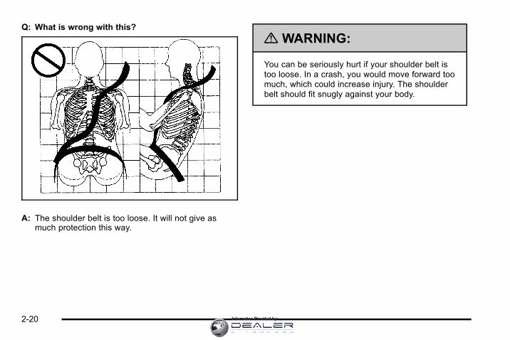
Q: What is wrong with this?
A: The shoulder belt is too loose. It will not give asmuch protection this way.
{ WARNING:
You can be seriously hurt if your shoulder belt istoo loose. In a crash, you would move forward toomuch, which could increase injury. The shoulderbelt should fit snugly against your body.
2-20 Information Provided by:

Q: What is wrong with this?
A: The lap belt is too loose. It will not give nearly asmuch protection this way.
{ WARNING:
You can be seriously hurt if your lap belt is tooloose. In a crash, you could slide under the lapbelt and apply force on your abdomen. This couldcause serious or even fatal injuries. The lap beltshould be worn low and snug on the hips, justtouching the thighs.
2-21Information Provided by:
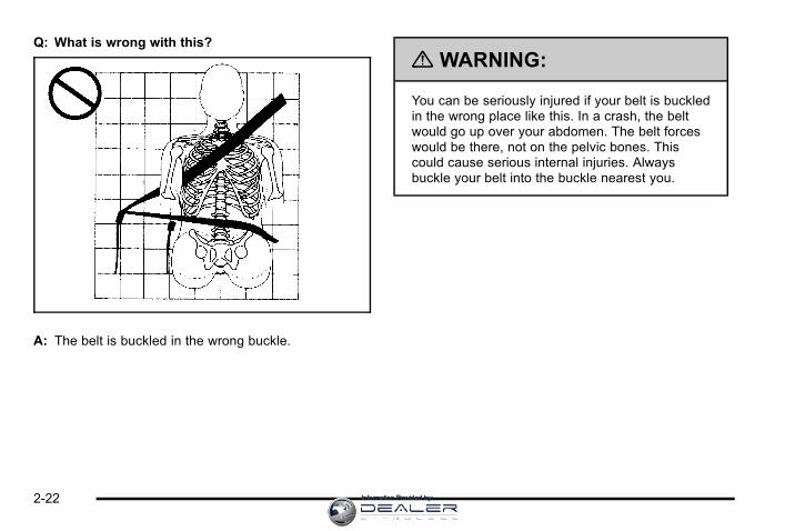
Q: What is wrong with this?
A: The belt is buckled in the wrong buckle.
{ WARNING:
You can be seriously injured if your belt is buckledin the wrong place like this. In a crash, the beltwould go up over your abdomen. The belt forceswould be there, not on the pelvic bones. Thiscould cause serious internal injuries. Alwaysbuckle your belt into the buckle nearest you.
2-22 Information Provided by:

Q: What is wrong with this?
A: The belt is over an armrest.
{ WARNING:
You can be seriously injured if your belt goes overan armrest like this. The belt would be much toohigh. In a crash, you can slide under the belt.The belt force would then be applied on theabdomen, not on the pelvic bones, and that couldcause serious or fatal injuries. Be sure the beltgoes under the armrests.
2-23Information Provided by:

Q: What is wrong with this?
A: The shoulder belt is worn under the arm. It shouldbe worn over the shoulder at all times.
{ WARNING:
You can be seriously injured if you wear theshoulder belt under your arm. In a crash, yourbody would move too far forward, which wouldincrease the chance of head and neck injury.Also, the belt would apply too much force to theribs, which are not as strong as shoulder bones.You could also severely injure internal organs likeyour liver or spleen. The shoulder belt should goover the shoulder and across the chest.
2-24 Information Provided by:

Q: What is wrong with this?
A: The belt is behind the body.
{ WARNING:
You can be seriously injured by not wearing thelap-shoulder belt properly. In a crash, you wouldnot be restrained by the shoulder belt. Your bodycould move too far forward increasing the chanceof head and neck injury. You might also slideunder the lap belt. The belt force would then beapplied right on the abdomen. That could causeserious or fatal injuries. The shoulder belt shouldgo over the shoulder and across the chest.
2-25Information Provided by:

Q: What is wrong with this?
A: The belt is twisted across the body.
{ WARNING:
You can be seriously injured by a twisted belt. In acrash, you would not have the full width of the beltto spread impact forces. If a belt is twisted, makeit straight so it can work properly, or ask yourdealer to fix it.
2-26 Information Provided by:
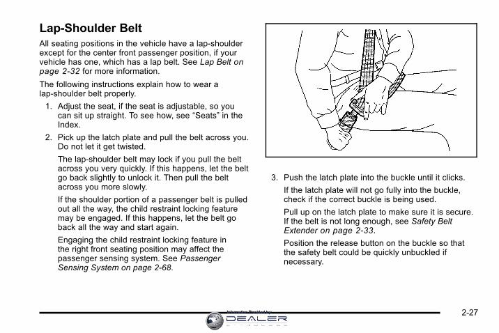
Lap-Shoulder BeltAll seating positions in the vehicle have a lap-shoulderexcept for the center front passenger position, if yourvehicle has one, which has a lap belt. See Lap Belt onpage 2‑32 for more information.
The following instructions explain how to wear alap-shoulder belt properly.
1. Adjust the seat, if the seat is adjustable, so youcan sit up straight. To see how, see “Seats” in theIndex.
2. Pick up the latch plate and pull the belt across you.Do not let it get twisted.
The lap-shoulder belt may lock if you pull the beltacross you very quickly. If this happens, let the beltgo back slightly to unlock it. Then pull the beltacross you more slowly.
If the shoulder portion of a passenger belt is pulledout all the way, the child restraint locking featuremay be engaged. If this happens, let the belt goback all the way and start again.
Engaging the child restraint locking feature inthe right front seating position may affect thepassenger sensing system. See PassengerSensing System on page 2‑68.
3. Push the latch plate into the buckle until it clicks.
If the latch plate will not go fully into the buckle,check if the correct buckle is being used.
Pull up on the latch plate to make sure it is secure.If the belt is not long enough, see Safety BeltExtender on page 2‑33.
Position the release button on the buckle so thatthe safety belt could be quickly unbuckled ifnecessary.
2-27Information Provided by:

4. If equipped with a shoulder belt height adjuster,move it to the height that is right for you.See “Shoulder Belt Height Adjustment” laterin this section for instructions on use and importantsafety information.
5. To make the lap part tight, pull up on theshoulder belt.
It may be necessary to pull stitching on the safetybelt through the latch plate to fully tighten the lapbelt on smaller occupants.
To unlatch the belt, push the button on the buckle.The belt should return to its stowed position.
Before a door is closed, be sure the belt is out of theway. If a door is slammed against a safety belt, damagecan occur to both the safety belt and the vehicle.
2-28 Information Provided by:

Shoulder Belt Height AdjusterThe vehicle has shoulder belt height adjusters for thedriver and right front passenger positions.
Adjust the height so that the shoulder portion of the beltis centered on the shoulder. The belt should be awayfrom the face and neck, but not falling off the shoulder.Improper shoulder belt height adjustment could reducethe effectiveness of the safety belt in a crash.
Squeeze the buttons (A)on the sides of the heightadjuster and move theheight adjuster to thedesired position.
You can move the adjuster up just by pushing up on theshoulder belt guide.
After the adjuster is set to the desired position, try tomove it down without squeezing the buttons to makesure it has locked into position.
Safety Belt PretensionersThis vehicle has safety belt pretensioners for frontoutboard occupants. Although the safety beltpretensioners cannot be seen, they are part of thesafety belt assembly. They can help tighten the safetybelts during the early stages of a moderate to severefrontal and near frontal crash if the threshold conditionsfor pretensioner activation are met. And, if the vehiclehas side impact airbags, safety belt pretensioners canhelp tighten the safety belts in a side crash.
Pretensioners work only once. If the pretensionersactivate in a crash, they will need to be replaced, andprobably other new parts for the vehicle's safety beltsystem. See Replacing Restraint System Parts After aCrash on page 2‑76.
Rear Safety Belt Comfort GuidesThis vehicle may have rear shoulder belt comfortguides for each outboard passenger position in therear seat. If not, they are available through your dealer.The guides may provide added safety belt comfort forolder children who have outgrown booster seats and forsome adults. When installed and properly adjusted, thecomfort guide positions the belt away from the neckand head.
2-29Information Provided by:

Here is how to install a comfort guide to the safety belt:
1. Pull the guide out from the pocket on the edge ofthe seatback.
2. Place the guide over the belt, and insert the twoedges of the belt into the slots of the guide.
3. Be sure that the belt is not twisted and it lies flat.The elastic cord must be under the belt and theguide on top.
2-30 Information Provided by:

{ WARNING:
A safety belt that is not properly worn maynot provide the protection needed in a crash.The person wearing the belt could be seriouslyinjured. The shoulder belt should go over theshoulder and across the chest. These parts of thebody are best able to take belt restraining forces.
4. Buckle, position, and release the safety belt asdescribed previously in this section. Make sure thatthe shoulder belt crosses the shoulder.
To remove and store the comfort guide, squeeze thebelt edges together so that the safety belt can beremoved from the guide. Slide the guide into thestorage pocket on the edge of the seatback.
2-31Information Provided by:

Safety Belt Use During PregnancySafety belts work for everyone, including pregnantwomen. Like all occupants, they are more likely to beseriously injured if they do not wear safety belts.
A pregnant woman should wear a lap-shoulder belt,and the lap portion should be worn as low as possible,below the rounding, throughout the pregnancy.
The best way to protect the fetus is to protect themother. When a safety belt is worn properly, it ismore likely that the fetus will not be hurt in a crash.For pregnant women, as for anyone, the key to makingsafety belts effective is wearing them properly.
Lap BeltThis section is only for the lap belt. To learn how towear a lap-shoulder belt, see Lap-Shoulder Belt onpage 2‑27.
The vehicle may have a center seating position. Whenyou sit in the center front seating position, you have alap safety belt, which has no retractor.
To make the belt longer, tilt the latch plate and pull italong the belt.
Buckle, position, and release it the same way as the lappart of a lap-shoulder belt.
2-32 Information Provided by:

To make the belt shorter, pull its free end as shown untilthe belt is snug.
If the belt is not long enough, see Safety Belt Extenderon page 2‑33.
Make sure the release button on the buckle ispositioned so you would be able to unbuckle thesafety belt quickly if necessary.
Safety Belt ExtenderIf the vehicle's safety belt will fasten around you, youshould use it.
But if a safety belt is not long enough, your dealer willorder you an extender. When you go in to order it, takethe heaviest coat you will wear, so the extender will belong enough for you. To help avoid personal injury, donot let someone else use it, and use it only for the seatit is made to fit. The extender has been designed foradults. Never use it for securing child seats. To wear it,attach it to the regular safety belt. For more information,see the instruction sheet that comes with the extender.
2-33Information Provided by:

Child Restraints
Older Children
Older children who have outgrown booster seats shouldwear the vehicle's safety belts.
The manufacturer's instructions that come with thebooster seat, state the weight and height limitations forthat booster. Use a booster seat with a lap-shoulder beltuntil the child passes the below fit test:. Sit all the way back on the seat. Do the knees
bend at the seat edge? If yes, continue. If no,return to the booster seat.
. Buckle the lap-shoulder belt. Does the shoulderbelt rest on the shoulder? If yes, continue. If no, tryusing the rear safety belt comfort guide. See “RearSafety Belt Comfort Guides” under Lap-ShoulderBelt on page 2‑27 for more information. If theshoulder belt still does not rest on the shoulder,then return to the booster seat.
. Does the lap belt fit low and snug on the hips,touching the thighs? If yes, continue. If no, returnto the booster seat.
. Can proper safety belt fit be maintained forlength of trip? If yes, continue. If no, return tothe booster seat.
If you have the choice, a child should sit in a positionwith a lap-shoulder belt and get the additional restrainta shoulder belt can provide.
2-34 Information Provided by:

Q: What is the proper way to wear safety belts?
A: An older child should wear a lap-shoulder belt andget the additional restraint a shoulder belt canprovide. The shoulder belt should not cross the faceor neck. The lap belt should fit snugly below thehips, just touching the top of the thighs. This appliesbelt force to the child's pelvic bones in a crash.It should never be worn over the abdomen, whichcould cause severe or even fatal internal injuries ina crash.
Also see “Rear Safety Belt Comfort Guides” underLap-Shoulder Belt on page 2‑27.
According to accident statistics, children and infantsare safer when properly restrained in the rear seatingpositions than in the front seating positions.
In a crash, children who are not buckled up can strikeother people who are buckled up, or can be thrown outof the vehicle. Older children need to use safety beltsproperly.
{ WARNING:
Never do this.
Never allow two children to wear the same safetybelt. The safety belt can not properly spread theimpact forces. In a crash, the two children can becrushed together and seriously injured. A safetybelt must be used by only one person at a time.
2-35Information Provided by:

{ WARNING:
Never do this.
Never allow a child to wear the safety belt with theshoulder belt behind their back. A child can beseriously injured by not wearing the lap-shoulderbelt properly. In a crash, the child would not berestrained by the shoulder belt. The child couldmove too far forward increasing the chance ofhead and neck injury. The child might also slideunder the lap belt. The belt force would then beapplied right on the abdomen. That could causeserious or fatal injuries. The shoulder belt shouldgo over the shoulder and across the chest.
2-36 Information Provided by:

Infants and Young ChildrenEveryone in a vehicle needs protection! This includesinfants and all other children. Neither the distancetraveled nor the age and size of the traveler changesthe need, for everyone, to use safety restraints. In fact,the law in every state in the United States and in everyCanadian province says children up to some age mustbe restrained while in a vehicle.
{ WARNING:
Children can be seriously injured or strangled if ashoulder belt is wrapped around their neck andthe safety belt continues to tighten. Never leavechildren unattended in a vehicle and never allowchildren to play with the safety belts.
Airbags plus lap‐shoulder belts offer protection foradults and older children, but not for young children andinfants. Neither the vehicle's safety belt system nor itsairbag system is designed for them. Every time infantsand young children ride in vehicles, they should havethe protection provided by appropriate child restraints.
Children who are not restrained properly can strikeother people, or can be thrown out of the vehicle.
2-37Information Provided by:

{ WARNING:
Never do this.
Never hold an infant or a child while riding in avehicle. Due to crash forces, an infant or a childwill become so heavy it is not possible to hold itduring a crash. For example, in a crash at only40 km/h (25 mph), a 5.5 kg (12 lb) infant willsuddenly become a 110 kg (240 lb) force on aperson's arms. An infant should be secured inan appropriate restraint.
2-38 Information Provided by:

{ WARNING:
Never do this.
Children who are up against, or very close to,any airbag when it inflates can be seriouslyinjured or killed. Never put a rear-facing childrestraint in the right front seat. Secure arear-facing child restraint in a rear seat. It is alsobetter to secure a forward-facing child restraint ina rear seat. If you must secure a forward-facingchild restraint in the right front seat, always movethe front passenger seat as far back as it will go.
2-39Information Provided by:

Q: What are the different types of add-on childrestraints?
A: Add-on child restraints, which are purchased by thevehicle's owner, are available in four basic types.Selection of a particular restraint should take intoconsideration not only the child's weight, height,and age but also whether or not the restraint willbe compatible with the motor vehicle in which it willbe used.
For most basic types of child restraints, there aremany different models available. When purchasing achild restraint, be sure it is designed to be used in amotor vehicle. If it is, the restraint will have a labelsaying that it meets federal motor vehicle safetystandards.
The restraint manufacturer's instructions thatcome with the restraint state the weight and heightlimitations for a particular child restraint. In addition,there are many kinds of restraints available forchildren with special needs.
{ WARNING:
To reduce the risk of neck and head injury duringa crash, infants need complete support. This isbecause an infant's neck is not fully developedand its head weighs so much compared withthe rest of its body. In a crash, an infant in arear-facing child restraint settles into the restraint,so the crash forces can be distributed across thestrongest part of an infant's body, the back andshoulders. Infants should always be secured inrear-facing child restraints.
2-40 Information Provided by:

{ WARNING:
A young child's hip bones are still so small thatthe vehicle's regular safety belt may not remainlow on the hip bones, as it should. Instead, it maysettle up around the child's abdomen. In a crash,the belt would apply force on a body area that isunprotected by any bony structure. This alonecould cause serious or fatal injuries. To reducethe risk of serious or fatal injuries during a crash,young children should always be secured inappropriate child restraints.
Child Restraint SystemsA rear-facing infantseat (A) provides restraintwith the seating surfaceagainst the back of theinfant.
The harness system holds the infant in place and, in acrash, acts to keep the infant positioned in the restraint.
A forward-facing childseat (B) provides restraintfor the child's body withthe harness.
2-41Information Provided by:

A booster seat (C-D) is a child restraint designed toimprove the fit of the vehicle's safety belt system.A booster seat can also help a child to see out thewindow.
Securing an Add-On Child Restraint inthe Vehicle
{ WARNING:
A child can be seriously injured or killed in a crashif the child restraint is not properly secured in thevehicle. Secure the child restraint properly in thevehicle using the vehicle's safety belt or LATCHsystem, following the instructions that came withthat child restraint and the instructions in thismanual.
To help reduce the chance of injury, the child restraintmust be secured in the vehicle. Child restraint systemsmust be secured in vehicle seats by lap belts or the lapbelt portion of a lap-shoulder belt, or by the LATCHsystem. See Lower Anchors and Tethers for Children(LATCH) on page 2‑45 for more information. A childcan be endangered in a crash if the child restraint is notproperly secured in the vehicle.
2-42 Information Provided by:

When securing an add-on child restraint, refer to theinstructions that come with the restraint which may beon the restraint itself or in a booklet, or both, and to thismanual. The child restraint instructions are important,so if they are not available, obtain a replacement copyfrom the manufacturer.
Keep in mind that an unsecured child restraint canmove around in a collision or sudden stop and injurepeople in the vehicle. Be sure to properly secure anychild restraint in the vehicle — even when no child isin it.
Securing the Child Within the ChildRestraint
{ WARNING:
A child can be seriously injured or killed in a crashif the child is not properly secured in the childrestraint. Secure the child properly following theinstructions that came with that child restraint.
Where to Put the RestraintAccording to accident statistics, children and infantsare safer when properly restrained in a child restraintsystem or infant restraint system secured in a rearseating position.
We recommend that children and child restraints besecured in a rear seat, including: an infant or a childriding in a rear-facing child restraint; a child riding ina forward-facing child seat; an older child riding in abooster seat; and children, who are large enough,using safety belts.
2-43Information Provided by:

A label on your sun visor says, “Never put a rear-facingchild seat in the front.” This is because the risk to therear-facing child is so great, if the airbag deploys.
{ WARNING:
A child in a rear-facing child restraint can beseriously injured or killed if the right frontpassenger airbag inflates. This is because theback of the rear-facing child restraint would bevery close to the inflating airbag. A child in aforward-facing child restraint can be seriouslyinjured or killed if the right front passenger airbaginflates and the passenger seat is in a forwardposition.
Even if the passenger sensing system has turnedoff the right front passenger frontal airbag, nosystem is fail-safe. No one can guarantee thatan airbag will not deploy under some unusualcircumstance, even though it is turned off.
(Continued)
WARNING: (Continued)
Secure rear-facing child restraints in a rearseat, even if the airbag is off. If you secure aforward-facing child restraint in the right frontseat, always move the front passenger seat as farback as it will go. It is better to secure the childrestraint in a rear seat.
See Passenger Sensing System on page 2‑68for additional information.
{ WARNING:
A child in a child restraint in the center front seatcan be badly injured or killed by the frontalairbags if they inflate. Never secure a childrestraint in the center front seat. It is alwaysbetter to secure a child restraint in a rear seat.
2-44 Information Provided by:

Do not use child restraints in the center front seatposition.
When securing a child restraint in a rear seatingposition, study the instructions that came with your childrestraint to make sure it is compatible with this vehicle.
Wherever a child restraint is installed, be sure to securethe child restraint properly.
Keep in mind that an unsecured child restraint canmove around in a collision or sudden stop and injurepeople in the vehicle. Be sure to properly secure anychild restraint in your vehicle — even when no child isin it.
Lower Anchors and Tethers forChildren (LATCH)The LATCH system holds a child restraint duringdriving or in a crash. This system is designed tomake installation of a child restraint easier. The LATCHsystem uses anchors in the vehicle and attachments onthe child restraint that are made for use with the LATCHsystem.
Make sure that a LATCH-compatible child restraintis properly installed using the anchors, or use thevehicle's safety belts to secure the restraint, followingthe instructions that came with that restraint, and alsothe instructions in this manual. When installing a childrestraint with a top tether, you must also use either thelower anchors or the safety belts to properly secure thechild restraint. A child restraint must never be installedusing only the top tether and anchor.
In order to use the LATCH system in your vehicle,you need a child restraint that has LATCH attachments.The child restraint manufacturer will provide you withinstructions on how to use the child restraint and itsattachments. The following explains how to attach achild restraint with these attachments in your vehicle.
Not all vehicle seating positions or child restraints havelower anchors and attachments or top tether anchorsand attachments.
2-45Information Provided by:

Lower Anchors
Lower anchors (A) are metal bars built into the vehicle.There are two lower anchors for each LATCH seatingposition that will accommodate a child restraint withlower attachments (B).
Top Tether Anchor
A top tether (A, C) anchors the top of the child restraintto the vehicle. A top tether anchor is built into thevehicle. The top tether attachment (B) on the childrestraint connects to the top tether anchor in the vehiclein order to reduce the forward movement and rotation ofthe child restraint during driving or in a crash.
Your child restraint may have a single tether (A) or adual tether (C). Either will have a single attachment (B)to secure the top tether to the anchor.
2-46 Information Provided by:

Some child restraints that have a top tether aredesigned for use with or without the top tetherbeing attached. Others require the top tether alwaysto be attached. In Canada, the law requires thatforward-facing child restraints have a top tether, andthat the tether be attached. Be sure to read and followthe instructions for your child restraint.
If the child restraint does not have a top tether, onecan be obtained, in kit form, for many child restraints.Ask the child restraint manufacturer whether or not a kitis available.
Lower Anchor and Top Tether AnchorLocations
Rear Seat
i (Top Tether Anchor):Seating positions with toptether anchors.
j (Lower Anchor):Seating positions with twolower anchors.
To assist you in locatingthe lower anchors, eachseating position with loweranchors has two labels,near the crease betweenthe seatback and the seatcushion.
To assist you in locatingthe top tether anchors, thetop tether anchor symbolis located on the cover.
2-47Information Provided by:
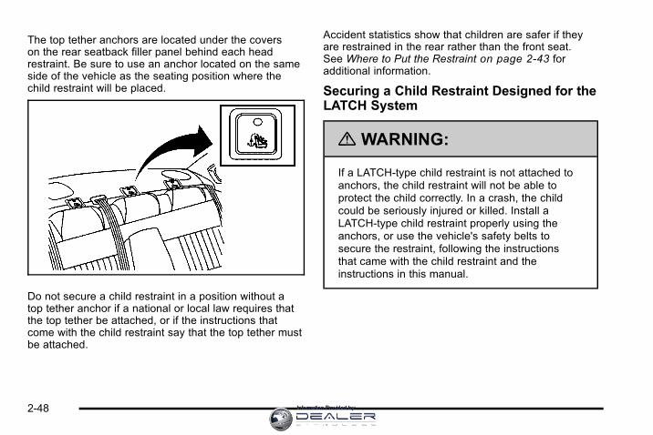
The top tether anchors are located under the coverson the rear seatback filler panel behind each headrestraint. Be sure to use an anchor located on the sameside of the vehicle as the seating position where thechild restraint will be placed.
Do not secure a child restraint in a position without atop tether anchor if a national or local law requires thatthe top tether be attached, or if the instructions thatcome with the child restraint say that the top tether mustbe attached.
Accident statistics show that children are safer if theyare restrained in the rear rather than the front seat.See Where to Put the Restraint on page 2‑43 foradditional information.
Securing a Child Restraint Designed for theLATCH System
{ WARNING:
If a LATCH-type child restraint is not attached toanchors, the child restraint will not be able toprotect the child correctly. In a crash, the childcould be seriously injured or killed. Install aLATCH-type child restraint properly using theanchors, or use the vehicle's safety belts tosecure the restraint, following the instructionsthat came with the child restraint and theinstructions in this manual.
2-48 Information Provided by:

{ WARNING:
Do not attach more than one child restraint to asingle anchor. Attaching more than one childrestraint to a single anchor could cause theanchor or attachment to come loose or evenbreak during a crash. A child or others could beinjured. To reduce the risk of serious or fatalinjuries during a crash, attach only one childrestraint per anchor.
{ WARNING:
Children can be seriously injured or strangled if ashoulder belt is wrapped around their neck andthe safety belt continues to tighten. Buckle anyunused safety belts behind the child restraint sochildren cannot reach them. Pull the shoulder beltall the way out of the retractor to set the lock,if your vehicle has one, after the child restrainthas been installed.
Notice: Do not let the LATCH attachments rubagainst the vehicle’s safety belts. This may damagethese parts. If necessary, move buckled safety beltsto avoid rubbing the LATCH attachments.
Do not fold the empty rear seat with a safety beltbuckled. This could damage the safety belt or theseat. Unbuckle and return the safety belt to itsstowed position, before folding the seat.
1. Attach and tighten the lower attachments to thelower anchors. If the child restraint does not havelower attachments or the desired seating positiondoes not have lower anchors, secure the childrestraint with the top tether and the safety belts.Refer to your child restraint manufacturerinstructions and the instructions in this manual.
1.1. Find the lower anchors for the desiredseating position.
1.2. Put the child restraint on the seat.
1.3. Attach and tighten the lower attachments onthe child restraint to the lower anchors.
2-49Information Provided by:

2. If the child restraint manufacturer recommends thatthe top tether be attached, attach and tighten thetop tether to the top tether anchor, if equipped.Refer to the child restraint instructions and thefollowing steps:
2.1. Find the top tether anchor.
2.2. Push on the depression at the rear of thecover and swing the lid open to expose thetop tether anchor.
2.3. Route, attach, and tighten the top tetheraccording to your child restraint instructionsand the following instructions:
If the position you areusing has a fixedheadrest and you areusing a single tether,route the tether overthe head restraint.
If the position youare using has a fixedheadrest and you areusing a dual tether, routethe tether around thehead restraint.
3. Push and pull the child restraint in differentdirections to be sure it is secure.
2-50 Information Provided by:

Securing a Child Restraint in a RearSeat PositionWhen securing a child restraint in a rear seatingposition, study the instructions that came with the childrestraint to make sure it is compatible with this vehicle.
If the child restraint has the LATCH system, seeLower Anchors and Tethers for Children (LATCH) onpage 2‑45 for how and where to install the childrestraint using LATCH. If a child restraint is secured inthe vehicle using a safety belt and it uses a top tether,see Lower Anchors and Tethers for Children (LATCH)on page 2‑45 for top tether anchor locations.
Do not secure a child seat in a position without a toptether anchor if a national or local law requires that thetop tether be anchored, or if the instructions that comewith the child restraint say that the top strap must beanchored.
In Canada, the law requires that forward-facing childrestraints have a top tether, and that the tether beattached.
If the child restraint does not have the LATCHsystem, you will be using the safety belt to securethe child restraint in this position. Be sure to followthe instructions that came with the child restraint.Secure the child in the child restraint when andas the instructions say.
If more than one child restraint needs to be installedin the rear seat, be sure to read Where to Put theRestraint on page 2‑43.
1. Put the child restraint on the seat.
2. Pick up the latch plate, and run the lap andshoulder portions of the vehicle's safety beltthrough or around the restraint. The child restraintinstructions will show you how.
2-51Information Provided by:

3. Push the latch plate into the buckle until it clicks.
Position the release button on the buckle so thatthe safety belt could be quickly unbuckled ifnecessary.
4. Pull the rest of the shoulder belt all the way out ofthe retractor to set the lock.
2-52 Information Provided by:

5. To tighten the belt, push down on the childrestraint, pull the shoulder portion of the beltto tighten the lap portion of the belt and feedthe shoulder belt back into the retractor. Wheninstalling a forward-facing child restraint, it may behelpful to use your knee to push down on the childrestraint as you tighten the belt.
6. If the child restraint has a top tether, follow thechild restraint manufacturer's instructions regardingthe use of the top tether. See Lower Anchors andTethers for Children (LATCH) on page 2‑45 formore information.
7. Push and pull the child restraint in differentdirections to be sure it is secure.
To remove the child restraint, unbuckle the vehiclesafety belt and let it return to the stowed position.If the top tether is attached to a top tether anchor,disconnect it.
Securing a Child Restraint in theCenter Front Seat Position
{ WARNING:
A child in a child restraint in the center frontseat can be badly injured or killed by the frontalairbags if they inflate. Never secure a childrestraint in the center front seat. It is alwaysbetter to secure a child restraint in a rear seat.
Do not use child restraints in the center front seatposition.
2-53Information Provided by:

Securing a Child Restraint in theRight Front Seat PositionThis vehicle has airbags. A rear seat is a safer place tosecure a forward-facing child restraint. See Where toPut the Restraint on page 2‑43.
In addition, the vehicle has a passenger sensing systemwhich is designed to turn off the right front passengerfrontal airbag under certain conditions. See PassengerSensing System on page 2‑68 and Passenger AirbagStatus Indicator on page 4‑25 for more information,including important safety information.
A label on the sun visor says, “Never put a rear-facingchild seat in the front.” This is because the risk to therear-facing child is so great, if the airbag deploys.
{ WARNING:
A child in a rear-facing child restraint can beseriously injured or killed if the right frontpassenger airbag inflates. This is because theback of the rear-facing child restraint would bevery close to the inflating airbag. A child in aforward-facing child restraint can be seriously
(Continued)
WARNING: (Continued)
injured or killed if the right front passenger airbaginflates and the passenger seat is in a forwardposition.
Even if the passenger sensing system has turnedoff the right front passenger frontal airbag, nosystem is fail-safe. No one can guarantee thatan airbag will not deploy under some unusualcircumstance, even though it is turned off.
Secure rear-facing child restraints in a rearseat, even if the airbag is off. If you secure aforward-facing child restraint in the right front seat,always move the front passenger seat as far backas it will go. It is better to secure the child restraintin a rear seat.
See Passenger Sensing System on page 2‑68for additional information.
2-54 Information Provided by:

If the child restraint has the LATCH system, seeLower Anchors and Tethers for Children (LATCH) onpage 2‑45 for how and where to install the childrestraint using LATCH. If a child restraint is securedusing a safety belt and it uses a top tether, see LowerAnchors and Tethers for Children (LATCH) onpage 2‑45 for top tether anchor locations.
Do not secure a child seat in a position without a toptether anchor if a national or local law requires that thetop tether be anchored, or if the instructions that comewith the child restraint say that the top strap must beanchored.
In Canada, the law requires that forward-facing childrestraints have a top tether, and that the tether beattached.
You will be using the lap-shoulder belt to secure thechild restraint in this position. Follow the instructionsthat came with the child restraint.
1. Move the seat as far back as it will go beforesecuring the forward-facing child restraint.
When the passenger sensing system has turnedoff the right front passenger frontal airbag, the offindicator on the passenger airbag status indicatorshould light and stay lit when the vehicle is started.See Passenger Airbag Status Indicator onpage 4‑25.
2. Put the child restraint on the seat.
3. Pick up the latch plate, and run the lap andshoulder portions of the vehicle's safety beltthrough or around the restraint. The child restraintinstructions will show you how.
2-55Information Provided by:

4. Push the latch plate into the buckle until it clicks.
Position the release button on the buckle so thatthe safety belt could be quickly unbuckled ifnecessary.
5. Pull the rest of the shoulder belt all the way out ofthe retractor to set the lock.
2-56 Information Provided by:

6. To tighten the belt, push down on the childrestraint, pull the shoulder portion of the beltto tighten the lap portion of the belt and feedthe shoulder belt back into the retractor. Wheninstalling a forward-facing child restraint, it maybe helpful to use your knee to push down on thechild restraint as you tighten the belt.
7. Push and pull the child restraint in differentdirections to be sure it is secure.
If the airbag is off, the off indicator in the passengerairbag status indicator will come on and stay on whenthe vehicle is started.
If a child restraint has been installed and the onindicator is lit, see “If the On Indicator is Lit for aChild Restraint” under Passenger Sensing System onpage 2‑68 for more information.
To remove the child restraint, unbuckle the vehiclesafety belt and let it return to the stowed position.
2-57Information Provided by:

Airbag SystemThe vehicle has the following airbags:. A frontal airbag for the driver.. A frontal airbag for the right front passenger.. A seat-mounted side impact airbag for the driver.. A seat-mounted side impact airbag for the right
front passenger.. A roof-rail airbag for the driver and passenger
seated directly behind the driver.. A roof-rail airbag for the right front passenger and
passenger seated directly behind the right frontpassenger.
All of the airbags in the vehicle will have the wordAIRBAG embossed in the trim or on an attached labelnear the deployment opening.
For frontal airbags, the word AIRBAG will appear on themiddle part of the steering wheel for the driver and onthe instrument panel for the right front passenger.
With seat-mounted side impact airbags, the wordAIRBAG will appear on the side of the seatbackclosest to the door.
With roof-rail airbags, the word AIRBAG will appearalong the headliner or trim.
Airbags are designed to supplement the protectionprovided by safety belts. Even though today's airbagsare also designed to help reduce the risk of injury fromthe force of an inflating bag, all airbags must inflate veryquickly to do their job.
2-58 Information Provided by:

Here are the most important things to know about theairbag system:
{ WARNING:
You can be severely injured or killed in a crashif you are not wearing your safety belt— even ifyou have airbags. Airbags are designed to workwith safety belts, but do not replace them. Also,airbags are not designed to deploy in every crash.In some crashes safety belts are your onlyrestraint. See When Should an Airbag Inflate? onpage 2‑63.
Wearing your safety belt during a crash helpsreduce your chance of hitting things inside thevehicle or being ejected from it. Airbags are“supplemental restraints” to the safety belts.Everyone in your vehicle should wear a safetybelt properly—whether or not there is an airbagfor that person.
{ WARNING:
Airbags inflate with great force, faster than theblink of an eye. Anyone who is up against, orvery close to, any airbag when it inflates can beseriously injured or killed. Do not sit unnecessarilyclose to the airbag, as you would be if you weresitting on the edge of your seat or leaning forward.Safety belts help keep you in position before andduring a crash. Always wear your safety belt,even with airbags. The driver should sit as farback as possible while still maintaining controlof the vehicle.
Occupants should not lean on or sleep against thedoor or side windows in seating positions withseat-mounted side impact airbags and/or roof-railairbags.
2-59Information Provided by:

{ WARNING:
Children who are up against, or very close to,any airbag when it inflates can be seriouslyinjured or killed. Airbags plus lap-shoulder beltsoffer protection for adults and older children, butnot for young children and infants. Neither thevehicle's safety belt system nor its airbag systemis designed for them. Young children and infantsneed the protection that a child restraint systemcan provide. Always secure children properly inyour vehicle. To read how, see Older Children onpage 2‑34 or Infants and Young Children onpage 2‑37.
There is an airbag readiness light on the instrumentpanel cluster, which shows the airbag symbol.
The system checks the airbag electrical system formalfunctions. The light tells you if there is an electricalproblem. See Airbag Readiness Light on page 4‑24 formore information.
2-60 Information Provided by:
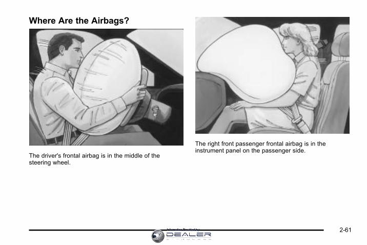
Where Are the Airbags?
The driver's frontal airbag is in the middle of thesteering wheel.
The right front passenger frontal airbag is in theinstrument panel on the passenger side.
2-61Information Provided by:

Driver Side shown, Passenger Side similar
The seat-mounted side impact airbags for the driver andright front passenger are in the side of the seatbacksclosest to the door.
Driver Side shown, Passenger Side similar
The roof-rail airbags for the driver, right front passenger,and second row outboard passengers are in the ceilingabove the side windows.
2-62 Information Provided by:

{ WARNING:
If something is between an occupant and anairbag, the airbag might not inflate properly or itmight force the object into that person causingsevere injury or even death. The path of aninflating airbag must be kept clear. Do not putanything between an occupant and an airbag,and do not attach or put anything on the steeringwheel hub or on or near any other airbagcovering.
Do not use seat accessories that block theinflation path of a seat-mounted side impactairbag.
Never secure anything to the roof of a vehiclewith roof-rail airbags by routing a rope or tie downthrough any door or window opening. If you do,the path of an inflating roof-rail airbag will beblocked.
When Should an Airbag Inflate?Frontal airbags are designed to inflate in moderate tosevere frontal or near-frontal crashes to help reducethe potential for severe injuries mainly to the driver's orright front passenger's head and chest. However, theyare only designed to inflate if the impact exceeds apredetermined deployment threshold. Deploymentthresholds are used to predict how severe a crash islikely to be in time for the airbags to inflate and helprestrain the occupants.
Whether the frontal airbags will or should deploy is notbased on how fast your vehicle is traveling. It dependslargely on what you hit, the direction of the impact, andhow quickly your vehicle slows down.
2-63Information Provided by:

Frontal airbags may inflate at different crash speeds.For example:. If the vehicle hits a stationary object, the airbags
could inflate at a different crash speed than if thevehicle hits a moving object.
. If the vehicle hits an object that deforms, theairbags could inflate at a different crash speedthan if the vehicle hits an object that does notdeform.
. If the vehicle hits a narrow object (like a pole), theairbags could inflate at a different crash speedthan if the vehicle hits a wide object (like a wall).
. If the vehicle goes into an object at an angle, theairbags could inflate at a different crash speedthan if the vehicle goes straight into the object.
Thresholds can also vary with specific vehicle design.
Frontal airbags are not intended to inflate during vehiclerollovers, rear impacts, or in many side impacts.
In addition, the vehicle has dual-stage frontal airbags.Dual-stage airbags adjust the restraint according tocrash severity. The vehicle has electronic frontalsensors, which help the sensing system distinguishbetween a moderate frontal impact and a more severefrontal impact. For moderate frontal impacts, dual-stageairbags inflate at a level less than full deployment.For more severe frontal impacts, full deploymentoccurs.
The vehicle has seat-mounted side impact androof-rail airbags. See Airbag System on page 2‑58.Seat-mounted side impact and roof-rail airbags areintended to inflate in moderate to severe side crashes.Seat-mounted side impact and roof-rail airbags willinflate if the crash severity is above the system'sdesigned threshold level. The threshold level canvary with specific vehicle design.
Roof-rail airbags are not intended to inflate in rolloversor rear impacts. A seat-mounted side impact airbag isintended to deploy on the side of the vehicle that isstruck. Both roof-rail airbags will deploy when eitherside of the vehicle is struck.
In any particular crash, no one can say whether anairbag should have inflated simply because of thedamage to a vehicle or because of what the repaircosts were. For frontal airbags, inflation is determinedby what the vehicle hits, the angle of the impact, andhow quickly the vehicle slows down. For seat-mountedside impact and roof-rail airbags, deployment isdetermined by the location and severity of the sideimpact.
2-64 Information Provided by:

What Makes an Airbag Inflate?In a deployment event, the sensing system sends anelectrical signal triggering a release of gas from theinflator. Gas from the inflator fills the airbag causing thebag to break out of the cover and deploy. The inflator,the airbag, and related hardware are all part of theairbag module.
Frontal airbag modules are located inside thesteering wheel and instrument panel. For vehicleswith seat-mounted side impact airbags, there are airbagmodules in the side of the front seatbacks closest tothe door. For vehicles with roof-rail airbags, there areairbag modules in the ceiling of the vehicle, near theside windows that have occupant seating positions.
How Does an Airbag Restrain?In moderate to severe frontal or near frontal collisions,even belted occupants can contact the steering wheelor the instrument panel. In moderate to severe sidecollisions, even belted occupants can contact the insideof the vehicle.
Airbags supplement the protection provided by safetybelts. Frontal airbags distribute the force of the impactmore evenly over the occupant's upper body, stoppingthe occupant more gradually. Seat-mounted side impactand roof-rail airbags distribute the force of the impactmore evenly over the occupant's upper body.
But airbags would not help in many types of collisions,primarily because the occupant's motion is not towardthose airbags. See When Should an Airbag Inflate? onpage 2‑63 for more information.
Airbags should never be regarded as anything morethan a supplement to safety belts.
2-65Information Provided by:

What Will You See After an AirbagInflates?After the frontal airbags and seat-mounted side impactairbags inflate, they quickly deflate, so quickly thatsome people may not even realize an airbag inflated.Roof-rail airbags may still be at least partially inflatedfor some time after they deploy. Some componentsof the airbag module may be hot for several minutes.For location of the airbag modules, see What Makes anAirbag Inflate? on page 2‑65.
The parts of the airbag that come into contact with youmay be warm, but not too hot to touch. There may besome smoke and dust coming from the vents in thedeflated airbags. Airbag inflation does not prevent thedriver from seeing out of the windshield or being ableto steer the vehicle, nor does it prevent people fromleaving the vehicle.
{ WARNING:
When an airbag inflates, there may be dust in theair. This dust could cause breathing problems forpeople with a history of asthma or other breathingtrouble. To avoid this, everyone in the vehicleshould get out as soon as it is safe to do so.If you have breathing problems but cannot get outof the vehicle after an airbag inflates, then getfresh air by opening a window or a door. If youexperience breathing problems following an airbagdeployment, you should seek medical attention.
The vehicle has a feature that may automatically unlockthe doors, turn on the interior lamps and hazard warningflashers, and shut off the fuel system after the airbagsinflate. You can lock the doors, turn off the interiorlamps and hazard warning flashers by using thecontrols for those features.
2-66 Information Provided by:

{ WARNING:
A crash severe enough to inflate the airbags mayhave also damaged important functions in thevehicle, such as the fuel system, brake andsteering systems, etc. Even if the vehicle appearsto be drivable after a moderate crash, there maybe concealed damage that could make it difficultto safely operate the vehicle.
Use caution if you should attempt to restart theengine after a crash has occurred.
In many crashes severe enough to inflate the airbag,windshields are broken by vehicle deformation.Additional windshield breakage may also occurfrom the right front passenger airbag.. Airbags are designed to inflate only once. After an
airbag inflates, you will need some new parts forthe airbag system. If you do not get them, theairbag system will not be there to help protectyou in another crash. A new system will includeairbag modules and possibly other parts.The service manual for your vehicle coversthe need to replace other parts.
. The vehicle has a crash sensing and diagnosticmodule which records information after a crash.See Vehicle Data Recording and Privacy onpage 8‑17 and Event Data Recorders onpage 8‑18.
. Let only qualified technicians work on the airbagsystems. Improper service can mean that anairbag system will not work properly. See yourdealer for service.
2-67Information Provided by:

Passenger Sensing SystemThe vehicle has a passenger sensing system for theright front passenger position. The passenger airbagstatus indicator will be visible on the instrument panelwhen the vehicle is started.
United States Canada
The words ON and OFF, or the symbol for on and off,will be visible during the system check. If you areusing remote start to start the vehicle from a distance,if equipped, you may not see the system check. Whenthe system check is complete, either the word ON orthe word OFF, or the symbol for on or off, will be visible.See Passenger Airbag Status Indicator on page 4‑25.
The passenger sensing system will turn off the rightfront passenger frontal airbag under certain conditions.The driver airbag, seat‐mounted side impact airbags,and roof‐rail airbags are not affected by the passengersensing system.
The passenger sensing system works with sensorsthat are part of the right front passenger seat.The sensors are designed to detect the presenceof a properly-seated occupant and determine if theright front passenger frontal airbag should be enabled(may inflate) or not.
According to accident statistics, children are safer whenproperly secured in a rear seat in the correct childrestraint for their weight and size.
We recommend that children be secured in a rear seat,including: an infant or a child riding in a rear-facing childrestraint; a child riding in a forward-facing child seat;an older child riding in a booster seat; and children,who are large enough, using safety belts.
A label on the sun visor says, “Never put a rear-facingchild seat in the front.” This is because the risk to therear-facing child is so great, if the airbag deploys.
2-68 Information Provided by:
{ WARNING:
A child in a rear-facing child restraint can beseriously injured or killed if the right frontpassenger airbag inflates. This is because theback of the rear-facing child restraint would bevery close to the inflating airbag. A child in aforward-facing child restraint can be seriouslyinjured or killed if the right front passenger airbaginflates and the passenger seat is in a forwardposition.
Even if the passenger sensing system has turnedoff the right front passenger frontal airbag, nosystem is fail-safe. No one can guarantee thatan airbag will not deploy under some unusualcircumstance, even though the airbag isturned off.
Secure rear-facing child restraints in a rearseat, even if the airbag is off. If you secure aforward-facing child restraint in the right front seat,always move the front passenger seat as far backas it will go. It is better to secure the child restraintin a rear seat.
The passenger sensing system is designed to turn offthe right front passenger frontal airbag if:. The right front passenger seat is unoccupied.. The system determines that an infant is present in
a child restraint.. A right front passenger takes his/her weight off of
the seat for a period of time.. Or, if there is a critical problem with the airbag
system or the passenger sensing system.
When the passenger sensing system has turned off theright front passenger frontal airbag, the off indicator willlight and stay lit to remind you that the airbag is off.See Passenger Airbag Status Indicator on page 4‑25.
The passenger sensing system is designed to turn on(may inflate) the right front passenger frontal airbaganytime the system senses that a person of adult size issitting properly in the right front passenger seat. Whenthe passenger sensing system has allowed the airbagto be enabled, the on indicator will light and stay lit toremind you that the airbag is active.
2-69Information Provided by:

For some children, including children in child restraints,and for very small adults, the passenger sensingsystem may or may not turn off the right front passengerfrontal airbag, depending upon the person's seatingposture and body build. Everyone in the vehicle whohas outgrown child restraints should wear a safety beltproperly — whether or not there is an airbag for thatperson.
{ WARNING:
If the airbag readiness light ever comes on andstays on, it means that something may be wrongwith the airbag system. To help avoid injury toyourself or others, have the vehicle serviced rightaway. See Airbag Readiness Light on page 4‑24for more information, including important safetyinformation.
If the On Indicator is Lit for a ChildRestraintIf a child restraint has been installed and the onindicator is lit:
1. Turn the vehicle off.
2. Remove the child restraint from the vehicle.
3. Remove any additional items from the seat suchas blankets, cushions, seat covers, seat heaters,or seat massagers.
4. Reinstall the child restraint following the directionsprovided by the child restraint manufacturer andrefer to Securing a Child Restraint in the RightFront Seat Position on page 2‑54.
2-70 Information Provided by:

5. If, after reinstalling the child restraint andrestarting the vehicle, the on indicator is still lit,turn the vehicle off. Then slightly recline the vehicleseatback and adjust the seat cushion, if adjustable,to make sure that the vehicle seatback is notpushing the child restraint into the seat cushion.
Also make sure the child restraint is not trappedunder the vehicle head restraint. If this happens,adjust the head restraint. See Head Restraints onpage 2‑2 .
6. Restart the vehicle.
The passenger sensing system may or may not turn offthe airbag for a child in a child restraint depending uponthe child's seating posture and body build. It is better tosecure the child restraint in a rear seat.
If the Off Indicator is Lit for anAdult-Size Occupant
If a person of adult-size is sitting in the right frontpassenger seat, but the off indicator is lit, it could bebecause that person is not sitting properly in the seat.
2-71Information Provided by:

If this happens, use the following steps to allow thesystem to detect that person and enable the right frontpassenger frontal airbag:
1. Turn the vehicle off.
2. Remove any additional material from the seat,such as blankets, cushions, seat covers, seatheaters, or seat massagers.
3. Place the seatback in the fully upright position.
4. Have the person sit upright in the seat, centeredon the seat cushion, with legs comfortablyextended.
5. Restart the vehicle and have the person remain inthis position for two to three minutes after the onindicator is lit.
Additional Factors Affecting SystemOperationSafety belts help keep the passenger in position on theseat during vehicle maneuvers and braking, which helpsthe passenger sensing system maintain the passengerairbag status. See “Safety Belts” and “Child Restraints”in the Index for additional information about theimportance of proper restraint use.
A thick layer of additional material, such as a blanketor cushion, or aftermarket equipment such as seatcovers, seat heaters, and seat massagers can affecthow well the passenger sensing system operates.We recommend that you not use seat covers or otheraftermarket equipment except when approved by GMfor your specific vehicle. See Adding Equipment toYour Airbag-Equipped Vehicle on page 2‑74 for moreinformation about modifications that can affect how thesystem operates.
A wet seat can affect the performance of the passengersensing system. Here is how:. The passenger sensing system may turn off the
passenger airbag when liquid is soaked into theseat. If this happens, the off indicator will be lit,and the airbag readiness light on the instrumentpanel will also be lit.
. Liquid pooled on the seat that has not soakedin may make it more likely that the passengersensing system will enable (turn on) the passengerairbag while a child restraint or child occupant is onthe seat. If the passenger airbag is turned on, theon indicator will be lit.
2-72 Information Provided by:

If the passenger seat gets wet, dry the seatimmediately. If the airbag readiness light is lit, do notinstall a child restraint or allow anyone to occupy theseat. See Airbag Readiness Light on page 4‑24 forimportant safety information.
The on indicator may be lit if an object, such as abriefcase, handbag, grocery bag, laptop or otherelectronic device, is put on an unoccupied seat.If this is not desired, remove the object from the seat.
{ WARNING:
Stowing of articles under the passenger seator between the passenger seat cushion andseatback may interfere with the proper operationof the passenger sensing system.
Servicing Your Airbag-EquippedVehicleAirbags affect how the vehicle should be serviced.There are parts of the airbag system in several placesaround the vehicle. Your dealer and the service manualhave information about servicing the vehicle and theairbag system. To purchase a service manual, seeService Publications Ordering Information onpage 8‑16.
{ WARNING:
For up to 10 seconds after the ignition is turned offand the battery is disconnected, an airbag can stillinflate during improper service. You can be injuredif you are close to an airbag when it inflates. Avoidyellow connectors. They are probably part of theairbag system. Be sure to follow proper serviceprocedures, and make sure the person performingwork for you is qualified to do so.
2-73Information Provided by:

Adding Equipment to YourAirbag-Equipped Vehicle
Q: Is there anything I might add to or change aboutthe vehicle that could keep the airbags fromworking properly?
A: Yes. If you add things that change the vehicle'sframe, bumper system, height, front end or sidesheet metal, they may keep the airbag system fromworking properly. Changing or moving any parts ofthe front seats, safety belts, the airbag sensing anddiagnostic module, steering wheel, instrument panel,roof-rail airbag modules, ceiling headliner or pillargarnish trim, front sensors, side impact sensors,or airbag wiring can affect the operation of theairbag system.
In addition, the vehicle has a passenger sensingsystem for the right front passenger position, whichincludes sensors that are part of the passenger'sseat. The passenger sensing system may notoperate properly if the original seat trim is replacedwith non-GM covers, upholstery or trim, or with GMcovers, upholstery or trim designed for a differentvehicle. Any object, such as an aftermarket seatheater or a comfort enhancing pad or device,
installed under or on top of the seat fabric, couldalso interfere with the operation of the passengersensing system. This could either prevent properdeployment of the passenger airbag(s) or preventthe passenger sensing system from properly turningoff the passenger airbag(s). See Passenger SensingSystem on page 2‑68.
If you have any questions, call CustomerAssistance. The phone numbers and addressesfor Customer Assistance are in Step Two of theCustomer Satisfaction Procedure in this manual.See Customer Satisfaction Procedure on page 8‑2.
Q: Because I have a disability, I have to get myvehicle modified. How can I find out whether thiswill affect my airbag system?
A: If you have questions, call Customer Assistance.The phone numbers and addresses for CustomerAssistance are in Step Two of the CustomerSatisfaction Procedure in this manual. SeeCustomer Satisfaction Procedure on page 8‑2.
In addition, your dealer and the service manual haveinformation about the location of the airbag sensors,sensing and diagnostic module and airbag wiring.
2-74 Information Provided by:
Restraint System Check
Checking the Restraint Systems
Safety BeltsNow and then, check that the safety belt reminder light,safety belts, buckles, latch plates, retractors, andanchorages are all working properly.
Look for any other loose or damaged safety belt systemparts that might keep a safety belt system from doing itsjob. See your dealer to have it repaired. Torn or frayedsafety belts may not protect you in a crash. They canrip apart under impact forces. If a belt is torn or frayed,get a new one right away.
Make sure the safety belt reminder light is working.See Safety Belt Reminders on page 4‑23 for moreinformation.
Keep safety belts clean and dry. See Care of SafetyBelts on page 6‑89.
AirbagsThe airbag system does not need regularly scheduledmaintenance or replacement. Make sure the airbagreadiness light is working. See Airbag Readiness Lighton page 4‑24 for more information.
Notice: If an airbag covering is damaged, opened,or broken, the airbag may not work properly. Do notopen or break the airbag coverings. If there are anyopened or broken airbag covers, have the airbagcovering and/or airbag module replaced. For thelocation of the airbag modules, see What Makes anAirbag Inflate? on page 2‑65. See your dealer forservice.
2-75Information Provided by:

Replacing Restraint System PartsAfter a Crash
{ WARNING:
A crash can damage the restraint systems in yourvehicle. A damaged restraint system may notproperly protect the person using it, resulting inserious injury or even death in a crash. To helpmake sure your restraint systems are workingproperly after a crash, have them inspected andany necessary replacements made as soon aspossible.
If the vehicle has been in a crash, do you need newsafety belts or LATCH system (if equipped) parts?
After a very minor crash, nothing may be necessary.But the safety belt assemblies that were used duringany crash may have been stressed or damaged.See your dealer to have the safety belt assembliesinspected or replaced.
If the vehicle has the LATCH system and it was beingused during a crash, you may need new LATCH systemparts.
New parts and repairs may be necessary even if thesafety belt or LATCH system (if equipped), was notbeing used at the time of the crash.
If an airbag inflates, you will need to replace airbagsystem parts. See the part on the airbag system earlierin this section.
Have the safety belt pretensioners checked if thevehicle has been in a crash, if the airbag readiness lightstays on after the vehicle is started, or while you aredriving. See Airbag Readiness Light on page 4‑24.
2-76 Information Provided by:

Section 3 Features and Controls
Keys . . . . . . . . . . . . . . . . . . . . . . . . . . . . . . . . . . . . . . . . . . . . . . . . 3-3Remote Keyless Entry (RKE) System . . . . . . . . . . . 3-4Remote Keyless Entry (RKE) SystemOperation . . . . . . . . . . . . . . . . . . . . . . . . . . . . . . . . . . . . . 3-4
Remote Vehicle Start . . . . . . . . . . . . . . . . . . . . . . . . . . . 3-7
Doors and Locks . . . . . . . . . . . . . . . . . . . . . . . . . . . . . . . . . . 3-9Door Locks . . . . . . . . . . . . . . . . . . . . . . . . . . . . . . . . . . . . . 3-9Power Door Locks . . . . . . . . . . . . . . . . . . . . . . . . . . . . . 3-10Delayed Locking . . . . . . . . . . . . . . . . . . . . . . . . . . . . . . . 3-10Automatic Door Lock . . . . . . . . . . . . . . . . . . . . . . . . . . . 3-11Programmable Automatic Door Unlock . . . . . . . . . 3-11Rear Door Security Locks . . . . . . . . . . . . . . . . . . . . . . 3-11Lockout Protection . . . . . . . . . . . . . . . . . . . . . . . . . . . . . 3-12Trunk . . . . . . . . . . . . . . . . . . . . . . . . . . . . . . . . . . . . . . . . . . 3-12
Windows . . . . . . . . . . . . . . . . . . . . . . . . . . . . . . . . . . . . . . . . . . 3-14Power Windows . . . . . . . . . . . . . . . . . . . . . . . . . . . . . . . 3-15Sun Visors . . . . . . . . . . . . . . . . . . . . . . . . . . . . . . . . . . . . . 3-16
Theft-Deterrent Systems . . . . . . . . . . . . . . . . . . . . . . . . . 3-16Content Theft-Deterrent . . . . . . . . . . . . . . . . . . . . . . . . 3-17PASS-Key® III+ Electronic Immobilizer . . . . . . . . . 3-18PASS-Key® III+ Electronic ImmobilizerOperation . . . . . . . . . . . . . . . . . . . . . . . . . . . . . . . . . . . . 3-18
Starting and Operating Your Vehicle . . . . . . . . . . . . 3-19New Vehicle Break-In . . . . . . . . . . . . . . . . . . . . . . . . . . 3-19Ignition Positions . . . . . . . . . . . . . . . . . . . . . . . . . . . . . . 3-20Retained Accessory Power (RAP) . . . . . . . . . . . . . 3-21Starting the Engine . . . . . . . . . . . . . . . . . . . . . . . . . . . . 3-21Engine Coolant Heater . . . . . . . . . . . . . . . . . . . . . . . . . 3-22Automatic Transmission Operation . . . . . . . . . . . . . 3-23Parking Brake . . . . . . . . . . . . . . . . . . . . . . . . . . . . . . . . . 3-26Shifting Into Park . . . . . . . . . . . . . . . . . . . . . . . . . . . . . . 3-26Shifting Out of Park . . . . . . . . . . . . . . . . . . . . . . . . . . . . 3-28Parking Over Things That Burn . . . . . . . . . . . . . . . . 3-29Engine Exhaust . . . . . . . . . . . . . . . . . . . . . . . . . . . . . . . . 3-29Running the Vehicle While Parked . . . . . . . . . . . . . 3-30
3-1Information Provided by:

Section 3 Features and Controls
Mirrors . . . . . . . . . . . . . . . . . . . . . . . . . . . . . . . . . . . . . . . . . . . . 3-31Manual Rearview Mirror . . . . . . . . . . . . . . . . . . . . . . . . 3-31Automatic Dimming Rearview Mirror . . . . . . . . . . . 3-31Outside Power Mirrors . . . . . . . . . . . . . . . . . . . . . . . . . 3-32Outside Convex Mirror . . . . . . . . . . . . . . . . . . . . . . . . . 3-32Outside Heated Mirrors . . . . . . . . . . . . . . . . . . . . . . . . 3-32
Universal Home Remote System . . . . . . . . . . . . . . . . 3-33Universal Home Remote System Operation(With Three Round LED) . . . . . . . . . . . . . . . . . . . . 3-33
Storage Areas . . . . . . . . . . . . . . . . . . . . . . . . . . . . . . . . . . . . 3-39Glove Box . . . . . . . . . . . . . . . . . . . . . . . . . . . . . . . . . . . . . 3-39Cupholders . . . . . . . . . . . . . . . . . . . . . . . . . . . . . . . . . . . . 3-39Sunglasses Storage Compartment . . . . . . . . . . . . . 3-39Center Console Storage . . . . . . . . . . . . . . . . . . . . . . 3-39Rear Storage Area . . . . . . . . . . . . . . . . . . . . . . . . . . . . . 3-39Rear Seat Armrest . . . . . . . . . . . . . . . . . . . . . . . . . . . . . 3-40Convenience Net . . . . . . . . . . . . . . . . . . . . . . . . . . . . . . 3-40
Sunroof . . . . . . . . . . . . . . . . . . . . . . . . . . . . . . . . . . . . . . . . . . . 3-40
3-2 Information Provided by:

Keys
{ WARNING:
Leaving children in a vehicle with the ignition keyis dangerous for many reasons, children or otherscould be badly injured or even killed. They couldoperate the power windows or other controls oreven make the vehicle move. The windows willfunction with the keys in the ignition and childrencould be seriously injured or killed if caught in thepath of a closing window. Do not leave the keys ina vehicle with children.
The key can be used for the ignition and thedriver's door.
See your dealer if a replacement key or additional keyis needed.
Notice: If you ever lock your keys in the vehicle,you may have to damage the vehicle to get in.Be sure you have spare keys.
If you are locked out of your vehicle, contact RoadsideAssistance. See Roadside Assistance Program onpage 8‑7 for more information.
3-3Information Provided by:

Remote Keyless Entry (RKE) SystemSee Radio Frequency Statement on page 8‑19for information regarding Part 15 of the FederalCommunications Commission (FCC) Rules andRSS-210/211 of Industry Canada.
Changes or modifications to this system by other thanan authorized service facility could void authorization touse this equipment.
If there is a decrease in the RKE operating range,try this:. Check the distance. The transmitter may be too
far from the vehicle. Stand closer during rainy orsnowy weather.
. Check the location. Other vehicles or objects maybe blocking the signal. Take a few steps to the leftor right, hold the transmitter higher, and try again.
. Check the transmitter's battery. See “BatteryReplacement” later in this section.
. If the transmitter is still not working correctly, seeyour dealer or a qualified technician for service.
Remote Keyless Entry (RKE) SystemOperationThe Remote Keyless Entry (RKE) transmitter functionswork up to 195 feet (60 m) away from the vehicle.
There are other conditions which can affect theperformance of the transmitter. See Remote KeylessEntry (RKE) System on page 3‑4.
With Remote Start Shown,Without Remote Start
Similar
/ (Remote Vehicle Start): For vehicles with thisfeature, press to start the engine from outside thevehicle using the RKE transmitter. See Remote VehicleStart on page 3‑7 for additional information.
3-4 Information Provided by:

Q (Lock): Press to lock all the doors. If enabledthrough the Driver Information Center (DIC), the parkinglamps flash once to indicate locking has occurred.If enabled through the DIC, the horn chirps when Q ispressed again within five seconds. See DIC VehicleCustomization on page 4‑51 for additional information.
Pressing Q may arm the content theft‐deterrent system.See Content Theft-Deterrent on page 3‑17.
" (Unlock): Press once to unlock the driver door. If " ispressed again within five seconds, all remaining doorsunlock. The interior lamps come on and stay on for20 seconds or until the ignition is turned on. If enabledthrough the DIC, the parking lamps flash twice toindicate unlocking has occurred. See DIC VehicleCustomization on page 4‑51.
Pressing " on the RKE transmitter disarms the contenttheft‐deterrent system. See Content Theft-Deterrent onpage 3‑17.
V (Remote Trunk Release): Press and hold for aboutone second to unlock the trunk. The transmission mustbe in P (Park).
L (Vehicle Locator/Panic Alarm): Press and releaseto locate the vehicle. The turn signal lamps flash andthe horn sounds three times. Press and hold L formore than two seconds to activate the panic alarm.The turn signal lamps flash and the horn soundsrepeatedly for 30 seconds. The alarm turns off whenthe ignition is turned to ON/RUN or L is pressed again.The ignition must be in LOCK/OFF for the panic alarmto work.
3-5Information Provided by:

Programming Transmitters to theVehicleOnly RKE transmitters programmed to the vehicle willwork. If a transmitter is lost or stolen, a replacement canbe purchased and programmed through your dealer.When the replacement transmitter is programmedto the vehicle, all remaining transmitters must also beprogrammed. Any lost or stolen transmitters no longerwork once the new transmitter is programmed. Eachvehicle can have up to eight transmitters programmedto it. See “Remote Key” under DIC Operation andDisplays on page 4‑37.
Battery ReplacementReplace the battery if the REPLACE BATTERY INREMOTE KEY message displays in the DIC. See“REPLACE BATTERY IN REMOTE KEY” under DICWarnings and Messages on page 4‑44 for additionalinformation.
Notice: When replacing the battery, do not touchany of the circuitry on the transmitter. Static fromyour body could damage the transmitter.
To replace the battery:
1. Separate the transmitter with a flat, thin object,such as a flat head screwdriver.. Carefully insert the tool into the notch located
along the parting line of the transmitter.Do not insert the tool too far. Stop as soonas resistance is felt.
. Twist the tool until the transmitter is separated.
2. Remove the old battery. Do not use a metal object.
3. Insert the new battery, positive side facing down.Replace with a CR2032 or equivalent battery.
4. Snap the transmitter back together.
3-6 Information Provided by:

Remote Vehicle StartYour vehicle may have a remote starting feature thatallows you to start the engine from outside the vehicle.It may also start the vehicle's heating or air conditioningsystems and rear window defogger. When the remotestart system is active and the vehicle has an automaticclimate control system, it will automatically regulate theinside temperature. Normal operation of these systemswill return after the ignition key is turned to ON/RUN.
Laws in some communities may restrict the use ofremote starters. For example, some laws may requirea person using remote start to have the vehicle inview when doing so. Check local regulations for anyrequirements on remote starting of vehicles.
Do not use the remote start feature if your vehicle is lowon fuel. Your vehicle may run out of fuel.
If your vehicle has the remote start feature, the RKEtransmitter functions will have an increased range ofoperation. However, the range may be less while thevehicle is running.
There are other conditions which can affect theperformance of the transmitter, see Remote KeylessEntry (RKE) System on page 3‑4
/ (Remote Start): This button will be on the RKEtransmitter if you have remote start.
To start the vehicle using the remote start feature:
1. Aim the transmitter at the vehicle.
2. Press and release Q, then immediately press
and hold/ for two to four seconds or until thevehicle's turn signal lamps flash. The doorswill lock.
When the vehicle starts, the parking lamps turn onand remain on while the engine is running.
The remote start feature provides two separate startsper ignition cycle, each with 10 minutes of enginerunning time, or one start with a time extension.The first start must expire or be canceled to gettwo separate 10 minute starts.
3-7Information Provided by:

If it is the first remote start since the vehicle has beendriven, repeat the previous steps, while the engine isstill running, to extend the engine running time by10 minutes from the time you repeat the steps forremote starting. The remote start running time can beextended one time and only after the first remote start.
After entering the vehicle during a remote start, insertand turn the key to ON/RUN to drive the vehicle.
The engine will shut off automatically after 10 minutes,unless a time extension has been done or the vehicle'skey is inserted into the ignition switch and turned toON/RUN.
To manually shut off a remote start, do any of thefollowing.. Aim the RKE transmitter at the vehicle and press
and release the remote start button.. Turn on the hazard warning flashers.. Turn the ignition switch out of LOCK/OFF position
and then back to LOCK/OFF.
After the engine has been started two times, or onetime with a time extension, the vehicle's ignition mustbe turned to ON/RUN using the key before the remote
start procedure can be used again. See IgnitionPositions on page 3‑20 for information regardingthe ignition positions on your vehicle.
The remote vehicle start feature will not operate if anyof the follow occur:. The remote start system is disabled through
the DIC.. The vehicle's key is in the ignition.. The vehicle's hood is open.. The hazard warning flashers are on.. The check engine light is on. See Malfunction
Indicator Lamp on page 4‑31.. The engine coolant temperature is too high.. The oil pressure is low.. The content theft-deterrent alarm has been
activated.. Two remote vehicle starts, or one start with a time
extension, have already been provided for thatignition cycle.
3-8 Information Provided by:

Doors and Locks
Door Locks
{ WARNING:
Unlocked doors can be dangerous.. Passengers, especially children, can easily
open the doors and fall out of a movingvehicle. When a door is locked, the handlewill not open it. The chance of being thrownout of the vehicle in a crash is increased ifthe doors are not locked. So, all passengersshould wear safety belts properly and thedoors should be locked whenever the vehicleis driven.
. Young children who get into unlocked vehiclesmay be unable to get out. A child can beovercome by extreme heat and can sufferpermanent injuries or even death from heatstroke. Always lock the vehicle wheneverleaving it.
(Continued)
WARNING: (Continued)
. Outsiders can easily enter through anunlocked door when you slow down or stopyour vehicle. Locking your doors can helpprevent this from happening.
From the outside, use the key in the driver door or usethe Remote Keyless Entry (RKE) transmitter to lock andunlock the vehicle. From the inside, use the manual orpower door locks.
To lock or unlock the driver side door from the outsidewith the key, insert the key and turn it clockwise orcounterclockwise.
To lock or unlock the door from the inside, push or pullthe manual lock knob.
3-9Information Provided by:

Power Door LocksA power door lock switchis located on both frontdoors next to the doorhandle.
Press the top of the switch to unlock all doors or pressthe bottom of the switch to lock all doors.
If the vehicle has the optional content theft-deterrentsystem and it is armed, the power door lock switcheswill be disabled. You must use the RKE transmitter orthe key to unlock the doors when the system is armed.See Content Theft-Deterrent on page 3‑17.
Delayed LockingThis feature allows the driver to delay the actual lockingof the doors. When the driver power door lock switchis pressed with the key removed from the ignition, andthe driver door open, a chime will sound three timesto signal that the delayed locking system is active.When all doors have been closed, the doors will lockautomatically after several seconds. If any door isopened before this, the timer will reset itself onceall the doors have been closed again.
Pressing the driver or passenger power door lock switchagain or the RKE transmitter button will override thisfeature.
Personal Choice ProgrammingThe delayed locking feature can be turned on or off,using the Driver Information Center (DIC) to programthis feature. See “DELAY DOOR LOCK” under DICVehicle Customization on page 4‑51.
3-10 Information Provided by:

Automatic Door LockThe doors will automatically lock when the shift lever ismoved out of P (Park). The automatic door lockingfeature cannot be disabled.
Programmable Automatic DoorUnlockThe vehicle is programmed so that when the shift leveris moved into P (Park) all doors will unlock.
With the vehicle stopped and the engine running,door unlocking can be programmed through promptsdisplayed on the Driver Information Center (DIC).These prompts allow the driver to choose variousunlock settings. For programming information,see DIC Vehicle Customization on page 4‑51.
Rear Door Security LocksRear door security locks prevent passengers fromopening the rear doors from the inside.
The rear door security locks are located on the insideedge of each rear door. The rear doors must be openedto access them.
To assist in finding the lock, the vehicle has thefollowing:
To use the lock:
1. Insert the key into the security lock slot and turn itso the slot is in the horizontal position.
2. Close the door.
3. Do the same for the other rear door.
3-11Information Provided by:

To open a rear door when the security lock is on, do thefollowing:
1. Unlock the door using the Remote KeylessEntry (RKE) transmitter, if the vehicle has one,the power door lock switch, or by lifting the reardoor manual lock.
2. Open the door from the outside.
To cancel the rear door security lock:
1. Unlock the door and open it from the outside.
2. Insert the key into the security lock slot and turn itso the slot is in the vertical position.
3. Do the same for the other rear door.
Lockout ProtectionThis feature helps prevent you from locking the doorswhile the key is in the ignition. Always remember to takeyour key with you when exiting the vehicle.
If the lock switch is pressed on the door that is openand the key is in the ignition, all of the doors will lockand then the open door will unlock. A chime soundscontinuously until the driver door is closed.
Trunk
{ WARNING:
Exhaust gases can enter the vehicle if it is drivenwith the liftgate, trunk/hatch open, or with anyobjects that pass through the seal between thebody and the trunk/hatch or liftgate. Engineexhaust contains Carbon Monoxide (CO) whichcannot be seen or smelled. It can causeunconsciousness and even death.
If the vehicle must be driven with the liftgate,or trunk/hatch open:
. Close all of the windows.
. Fully open the air outlets on or under theinstrument panel.
. Adjust the Climate Control system to a settingthat brings in only outside air and set the fanspeed to the highest setting. See ClimateControl System in the Index.
. If the vehicle is equipped with a power liftgate,disable the power liftgate function.
For more information about carbon monoxide, seeEngine Exhaust on page 3‑29.
3-12 Information Provided by:

Trunk ReleaseTo open the trunk from the outside, press the trunkrelease button on the RKE transmitter, if equipped.
Remote Trunk ReleaseG (Remote Trunk Release): Press the buttonlocated next to the exterior lamps control on the left sideof the instrument panel to open the trunk. The shift levermust be in P (Park).
The trunk can also be opened by lowering the rearseat and pulling the emergency trunk release handlelocated inside the trunk. See Split Folding Rear Seat onpage 2‑10 and “Emergency Trunk Release Handle”following.
Emergency Trunk Release HandleNotice: Do not use the emergency trunk releasehandle as a tie-down or anchor point when securingitems in the trunk as it could damage the handle.The emergency trunk release handle is onlyintended to aid a person trapped in a latched trunk,enabling them to open the trunk from the inside.
There is a glow-in-the-dark trunk release handle locatedon the latch inside the trunk . This handle will glowfollowing exposure to light. Pull the release handle toopen the trunk from the inside.
3-13Information Provided by:

Windows
{ WARNING:
Leaving children, helpless adults, or pets in avehicle with the windows closed is dangerous.They can be overcome by the extreme heat andsuffer permanent injuries or even death from heatstroke. Never leave a child, a helpless adult, or apet alone in a vehicle, especially with the windowsclosed in warm or hot weather.
3-14 Information Provided by:

Power Windows
{ WARNING:
Leaving children in a vehicle with the keys isdangerous for many reasons, children or otherscould be badly injured or even killed. They couldoperate the power windows or other controls oreven make the vehicle move. The windows willfunction and they could be seriously injured orkilled if caught in the path of a closing window.Do not leave keys in a vehicle with children.
When there are children in the rear seat use thewindow lockout button to prevent unintentionaloperation of the windows.
The switches on the driver door armrest are used tocontrol each of the windows. Each passenger door hasits own window switch.
The power window switches work while the ignitionis in ON/RUN, ACC/ACCESSORY, or while RetainedAccessory Power (RAP) is active. See RetainedAccessory Power (RAP) on page 3‑21.
To lower the window, press and hold the front of theswitch to the first position until the window is at thedesired level. To raise the window, pull up and hold thefront of the switch.
3-15Information Provided by:

Express-Down WindowThe driver window switch has an express-downfeature labeled AUTO. This lets you lower the windowcompletely without holding the switch. Press the frontof the switch to the second position and release.
To stop the window while it is lowering, briefly pull up onthe switch.
Window Lockouto (Window Lockout): The driver window switchesalso include a lockout switch. Press the right side of theswitch to prevent the rear passengers from using theirwindow switches. The driver can still control all thewindows and the front passenger can control their ownwindow with the lockout on. Press the left side of theswitch to return to normal window operation. A red baron the right side of the switch indicates that the lockoutis off.
Sun VisorsTo block out glare, swing down the sun visors. They canbe detached from the center retainer and slid along therod to cover different areas of the front window andturned to cover the side windows.
Visor Vanity MirrorOn vehicles with this feature, swing down the sunvisors and lift the cover to expose the vanity mirror.Do not drive with the cover lifted due to possible glareimpeding other drivers behind or to the side of thevehicle.
Theft-Deterrent SystemsVehicle theft is big business, especially in some cities.This vehicle has theft-deterrent features, however, theydo not make it impossible to steal.
3-16 Information Provided by:

Content Theft-DeterrentYour vehicle may have the optional contenttheft-deterrent alarm system.
To activate the theft-deterrent system:
1. Open the door.
2. Lock the door with the power door lock switch orthe Remote Keyless Entry (RKE) transmitter. If youare using the RKE transmitter, the door does notneed to be open.
3. Close all doors.
Once armed, the alarm will go off if someone tries toenter the vehicle without using the RKE transmitteror a key or turns the ignition on with an incorrect key.The horn will sound and the turn signal lamps will flashfor about 30 seconds.
When the alarm is armed, the trunk may be opened withthe RKE transmitter. The power door lock switches aredisabled and the doors remain locked. You must useyour RKE transmitter or your key to unlock the doorswhen the system is armed.
Arming with the Power Lock SwitchThe alarm system will arm when you use either powerlock switch to lock the doors while any door is open andthe key is removed from the ignition. The alarm systemwill not arm if the truck is open when you use eitherpower lock switch to lock the doors.
Arming with the RKE TransmitterThe alarm system will arm when you use your RKEtransmitter to lock the doors, if the key is not in theignition.
Disarming with the RKE TransmitterThe alarm system will disarm when you use your RKEtransmitter to unlock the doors.
The first time a remote unlock command is received,three flashes will be seen and three horn chirps heardto indicate an alarm condition has occurred since lastarming.
Disarming with Your KeyThe alarm system will disarm when you use your key tounlock the doors or insert your key in the ignition andturn it from the LOCK/OFF position.
3-17Information Provided by:

PASS-Key® III+ ElectronicImmobilizerSee Radio Frequency Statement on page 8‑19for information regarding Part 15 of the FederalCommunications Commission (FCC) Rules andRSS-210/211 of Industry Canada.
PASS-Key® III+ ElectronicImmobilizer OperationYour vehicle has PASS-Key® III+ (PersonalizedAutomotive Security System) theft-deterrent system.PASS-Key® III+ is a passive theft-deterrent system.
The system is automatically armed when the key isremoved from the ignition.
The system is automatically disarmed when the key isturned to ON/RUN, ACC/ACCESSORY or START fromthe LOCK/OFF position.
You do not have to manually arm or disarm the system.
The security light will come on if there is a problem witharming or disarming the theft-deterrent system.
When the PASS-Key® III+ system senses that someoneis using the wrong key, it prevents the vehicle fromstarting. Anyone using a trial-and-error method to startthe vehicle will be discouraged because of the highnumber of electrical key codes.
If the engine does not start and the security light onthe instrument panel cluster comes on when trying tostart the vehicle, there may be a problem with yourtheft-deterrent system. Turn the ignition off and tryagain.
If the engine still does not start, and the key appears tobe undamaged, try another ignition key. At this time,you may also want to check the fuse, see Fuses andCircuit Breakers on page 6‑94. If the engine still doesnot start with the other key, your vehicle needs service.If your vehicle does start, the first key may be faulty.See your dealer who can service the PASS-Key® III+to have a new key made. In an emergency, contactRoadside Assistance.
It is possible for the PASS-Key® III+ decoder to learnthe transponder value of a new or replacement key.Up to 10 keys may be programmed for the vehicle.The following procedure is for programming additionalkeys only. If all the currently programmed keys arelost or do not operate, you must see your dealer ora locksmith who can service PASS-Key® III+ to havekeys made and programmed to the system.
See your dealer or a locksmith who can servicePASS-Key® III+ to get a new key blank that is cutexactly as the ignition key that operates the system.
3-18 Information Provided by:

To program the new additional key:
1. Verify that the new key has a 1 stamped on it.
2. Insert the original, already programmed, key in theignition and start the engine. If the engine will notstart, see your dealer for service.
3. After the engine has started, turn the key toLOCK/OFF, and remove the key.
4. Insert the new key to be programmed and turn it tothe ON/RUN position within five seconds of turningthe ignition to the LOCK/OFF position in Step 3.
The security light will turn off once the key hasbeen programmed.
5. Repeat Steps 1 through 4 if additional keys are tobe programmed.
If you lose or damage your PASS-Key® III+ key,see your dealer or a locksmith who can servicePASS-Key® III+ to have a new key made.
Do not leave the key or device that disarms ordeactivates the theft deterrent system in the vehicle.
Starting and Operating YourVehicle
New Vehicle Break-InNotice: The vehicle does not need an elaboratebreak-in. But it will perform better in the long run ifyou follow these guidelines:
. Do not drive at any one constant speed,fast or slow, for the first 500miles (805 km).Do not make full-throttle starts. Avoiddownshifting to brake or slow the vehicle.
. Avoid making hard stops for the first200miles (322 km) or so. During this timethe new brake linings are not yet broken in.Hard stops with new linings can meanpremature wear and earlier replacement.Follow this breaking-in guideline every timeyou get new brake linings.
. Do not tow a trailer during break-in.See Towing a Trailer on page 5‑27 for thetrailer towing capabilities of your vehicleand more information.
Following break‐in, engine speed and load can begradually increased.
3-19Information Provided by:

Ignition PositionsThe ignition switch hasfour different positions.
To shift out of P (Park), the ignition must be in ON/RUNand the brake pedal must be applied.
Notice: Using a tool to force the key to turn in theignition could cause damage to the switch or breakthe key. Use the correct key, make sure it is all theway in, and turn it only with your hand. If the keycannot be turned by hand, see your dealer.
A (LOCK/OFF): This position locks the ignition. It alsolocks the transmission. This is the only position in whichthe ignition key can be inserted or removed.
The steering can bind with the wheels turned off center.If this happens, move the steering wheel from left toright while turning the key to ACC/ACCESSORY. If thisdoesn't work, then the vehicle needs service.
B (ACC/ACCESSORY): This is the position in whichyou can operate the radio and windshield wipers whilethe engine is off. To use ACC/ACCESSORY, turn thekey clockwise.
C (ON/RUN): This position can be used to operate theelectrical accessories and to display some instrumentpanel cluster warning and indicator lights. The switchstays in this position when the engine is running.
If you leave the key in the ACC/ACCESSORY orON/RUN position with the engine off, the battery couldbe drained. You may not be able to start the vehicle ifthe battery is allowed to drain for an extended periodof time.
D (START): This is the position that starts the engine.When the engine starts, release the key. The ignitionswitch returns to ON/RUN for driving.
A warning chime will sound and the Driver InformationCenter (DIC) will display DRIVER'S DOOR AJARwhen the driver door is opened, the ignition is inACC/ACCESSORY or LOCK/OFF and the key isin the ignition. See DIC Warnings and Messages onpage 4‑44 for more information.
3-20 Information Provided by:

Retained Accessory Power (RAP)These vehicle accessories can be used for up to10 minutes after the engine turned off:. Audio System. Power Windows
The radio will work when the key is in ON/RUN orACC/ACCESSORY. Once the key is turned fromON/RUN to LOCK/OFF the radio will continue towork 10 minutes or until the driver's door is opened.The power windows will continue to work for up to10 minutes or until any door is opened.
Starting the EngineMove the shift lever to P (Park) or N (Neutral).The engine will not start in any other position.To restart the engine when the vehicle is alreadymoving, use N (Neutral) only.
Notice: Do not try to shift to P (Park) if thevehicle is moving. If you do, you could damagethe transmission. Shift to P (Park) only when thevehicle is stopped.
Starting Procedure1. With your foot off the accelerator pedal, turn the
ignition to START. When the engine starts, let goof the key. The idle speed will slow down asthe engine warms. Do not race the engineimmediately after starting it. Operate the engineand transmission gently to allow the oil to warmup and lubricate all moving parts.
The vehicle has a Computer-Controlled CrankingSystem. This feature assists in starting the engineand protects components. If the ignition key isturned to the START position, and then releasedwhen the engine begins cranking, the engine willcontinue cranking for a few seconds or until thevehicle starts. If the engine does not start andthe key is held in START, cranking will be stoppedafter 15 seconds to prevent cranking motordamage. To prevent gear damage, this system alsoprevents cranking if the engine is already running.Engine cranking can be stopped by turning theignition switch to the ACC/ACCESSORY orLOCK/OFF position.
Notice: Cranking the engine for long periods oftime, by returning the key to the START positionimmediately after cranking has ended, can overheatand damage the cranking motor, and drain thebattery. Wait at least 15 seconds between each try,to let the cranking motor cool down.
3-21Information Provided by:

2. If the engine does not start after 5‐10 seconds,especially in very cold weather (below 0°F or−18°C), it could be flooded with too much gasoline.Try pushing the accelerator pedal all the way tothe floor and holding it there as you hold the keyin START for up to a maximum of 15 seconds.Wait at least 15 seconds between each try, to allowthe cranking motor to cool down. When the enginestarts, let go of the key and accelerator. If thevehicle starts briefly but then stops again, repeatthese steps. This clears the extra gasoline from theengine. Do not race the engine immediately afterstarting it. Operate the engine and transmissiongently until the oil warms up and lubricates allmoving parts.
Notice: The engine is designed to work with theelectronics in the vehicle. If you add electricalparts or accessories, you could change the waythe engine operates. Before adding electricalequipment, check with your dealer. If you do not,the engine might not perform properly. Anyresulting damage would not be covered by thevehicle warranty.
Engine Coolant HeaterThe engine coolant heater can provide easier startingand better fuel economy during engine warm‐up in coldweather conditions at or below 0°F (−18°C). Vehicleswith an engine coolant heater should be plugged in atleast four hours before starting.
To Use the Engine Coolant Heater1. Turn off the engine.
2. Open the hood and unwrap the electrical cord.The cord is attached to the underside of thediagonal brace, which is located above the engineair cleaner/filter assembly.
3. Plug it into a normal, grounded 110-volt AC outlet.
3-22 Information Provided by:

{ WARNING:
Plugging the cord into an ungrounded outlet couldcause an electrical shock. Also, the wrong kind ofextension cord could overheat and cause a fire.You could be seriously injured. Plug the cord intoa properly grounded three-prong 110-volt ACoutlet. If the cord will not reach, use a heavy-dutythree-prong extension cord rated for at least15 amps.
4. Before starting the engine, be sure to unplug andstore the cord as it was before to keep it away frommoving engine parts, and prevent damage.
The length of time the heater should remain plugged independs on several factors. Ask a dealer in the areawhere you will be parking the vehicle for the best adviceon this.
Automatic Transmission OperationThe automatic transmission has a shift lever on thesteering column or on the console between the seats.
There is a display, located on the instrument panelcluster that will indicate the gear the vehicle is in.
Maximum engine speed is limited on automatictransmission vehicles while in P (Park) or N (Neutral) toprotect driveline components from improper operation.
3-23Information Provided by:

There are several different positions for the shift lever.
P (Park): This position locks the front wheels. It is thebest position to use when the engine is started becausethe vehicle cannot move easily.
{ WARNING:
It can be dangerous to get out of the vehicle if theshift lever is not fully in P (Park) with the parkingbrake firmly set. The vehicle can roll. If you haveleft the engine running, the vehicle can movesuddenly. You or others could be injured. To besure the vehicle will not move, even when you areon fairly level ground, use the steps that follow.If you are pulling a trailer, see Towing a Trailer onpage 5‑27.
Make sure the shift lever is fully in P (Park) beforestarting the engine. The vehicle has an automatictransmission shift lock control system. You must fullyapply the brakes first, then press the shift lever buttonbefore you can shift from P (Park) while the ignitionis in ON/RUN. If you cannot shift out of P (Park), easepressure on the shift lever and push the shift lever allthe way into P (Park) as you maintain brake application.
Then press the shift lever button and move the shiftlever into another gear. See Shifting Out of Park onpage 3‑28.
R (Reverse): Use this gear to back up.
Notice: Shifting to R (Reverse) while the vehicle ismoving forward could damage the transmission.The repairs would not be covered by the vehiclewarranty. Shift to R (Reverse) only after the vehicleis stopped.
To rock the vehicle back and forth to get out of snow,ice, or sand without damaging the transmission, see IfYour Vehicle is Stuck in Sand, Mud, Ice, or Snow onpage 5‑18.
N (Neutral): In this position, the engine does notconnect with the wheels. To restart the engine whenthe vehicle is already moving, use N (Neutral) only.Also, use N (Neutral) when the vehicle is being towed.
{ WARNING:
Shifting into a drive gear while the engine isrunning at high speed is dangerous. Unless yourfoot is firmly on the brake pedal, the vehicle couldmove very rapidly. You could lose control and hitpeople or objects. Do not shift into a drive gearwhile the engine is running at high speed.
3-24 Information Provided by:
Notice: Shifting out of P (Park) or N (Neutral) withthe engine running at high speed may damage thetransmission. The repairs would not be covered bythe vehicle warranty. Be sure the engine is notrunning at high speed when shifting the vehicle.
D (Drive) : This position is for normal driving.It provides the best fuel economy. If you need morepower for passing, and you are:. Going less than 35 mph (55 km/h), push the
accelerator pedal about halfway down.. Going about 35 mph (55 km/h) or more, push the
accelerator pedal all the way down.
The transmission will shift down to the next gearand the vehicle will have more power.
Downshifting the transmission in slippery roadconditions could result in skidding, see “Skidding”under Loss of Control on page 5‑11.
Notice: Driving the vehicle if you notice that it ismoving slowly or not shifting gears as you increasespeed may damage the transmission. Have thevehicle serviced right away. You can drive in2 (Second) when you are driving less than 35mph(55 km/h) and D (Drive) for higher speeds until then.
3 (Third): This position is also used for normal driving.However, it reduces vehicle speed more than D (Drive)without using the brakes. You might choose 3 (Third)
instead of D (Drive) when driving on hilly, winding roads,when towing a trailer, so there is less shifting betweengears and when going down a steep hill.
2 (Second): This position reduces vehicle speedeven more than 3 (Third) without using the brakes.You can use 2 (Second) on hills. It can help controlvehicle speed as you go down steep mountain roads.You would also want to use the brakes off and on.
Notice: Driving in 2 (Second) for more than 25miles(40 km) or at speeds over 55mph (90 km/h) maydamage the transmission. Also, shifting into2 (Second) at speeds above 65mph (105 km/h)can cause damage. Drive in 3 (Third) or D (Drive)instead of 2 (Second).
1 (First): This position reduces vehicle speedeven more than 2 (Second) without using the brakes.You can use it on very steep hills, or in deep snow ormud. If the shift lever is in 1 (First) while the vehicle ismoving forward, the transmission will not shift into firstgear until the vehicle is going slowly enough.
Notice: Spinning the tires or holding the vehicle inone place on a hill using only the accelerator pedalmay damage the transmission. The repair will not becovered by the vehicle warranty. If you are stuck, donot spin the tires. When stopping on a hill, use thebrakes to hold the vehicle in place.
3-25Information Provided by:

Parking Brake
The parking brake is located to the left of the brakepedal, near the driver door.
To set the parking brake, hold the brake pedal down,then push down the parking brake pedal.
To release the parking brake, hold the brake pedaldown and push the parking brake pedal. When you liftyour foot off the parking brake pedal, the pedal willfollow it to the released position.
A warning chime will sound and a brake warning lightlocated on the instrument panel cluster will come on,if the parking brake is set, the ignition is on and thevehicle speed is greater than 8 km/h (5 mph).
Notice: Driving with the parking brake on canoverheat the brake system and cause prematurewear or damage to brake system parts. Make surethat the parking brake is fully released and thebrake warning light is off before driving.
If you are towing a trailer and parking on any hill, seeTowing a Trailer on page 5‑27.
Shifting Into Park
{ WARNING:
It can be dangerous to get out of the vehicle if theshift lever is not fully in P (Park) with the parkingbrake firmly set. The vehicle can roll. If you haveleft the engine running, the vehicle can movesuddenly. You or others could be injured. To besure the vehicle will not move, even when you areon fairly level ground, use the steps that follow.If you are pulling a trailer, see Towing a Trailer onpage 5‑27.
3-26 Information Provided by:
Steering Column Shift LeverIf the vehicle has a steering column shift lever, use thisprocedure to shift the vehicle into P (Park):
1. Hold the brake pedal down.
2. Move the shift lever into P (Park) by pulling theshift lever toward you and moving it up as far as itwill go.
3. With your foot still holding the brake pedal down,set the parking brake. See Parking Brake onpage 3‑26 for more information.
4. Turn the ignition key to LOCK/OFF.
5. Remove the key and take it with you. If you canleave the vehicle with the ignition key in your hand,the vehicle is in P (Park).
Console Shift LeverIf the vehicle is equipped with a console shift lever, usethis procedure to shift the vehicle into P (Park):
1. Hold the brake pedal down.
2. Move the shift lever into P (Park) by pushing thelever all the way toward the front of the vehicle.
3. While keeping the brake pedal applied, set theparking brake. See Parking Brake on page 3‑26for more information.
4. Turn the ignition key to LOCK/OFF.
5. Remove the key and take it with you. If you canleave the vehicle with the ignition key in your hand,the vehicle is in P (Park).
Leaving the Vehicle With the EngineRunning
{ WARNING:
It can be dangerous to leave the vehicle with theengine running. The vehicle could move suddenlyif the shift lever is not fully in P (Park) with theparking brake firmly set. And, if you leave thevehicle with the engine running, it could overheatand even catch fire. You or others could beinjured. Do not leave the vehicle with the enginerunning.
If you have to leave the vehicle with the engine running,be sure your vehicle is in P (Park) and the parkingbrake is firmly set before you leave it. See ParkingBrake on page 3‑26 for more information.
3-27Information Provided by:

Torque LockTorque lock is when the weight of the vehicle puts toomuch force on the parking pawl in the transmission.This happens when parking on a hill and shifting thetransmission into P (Park) is not done properly and thenit is difficult to shift out of P (Park). To prevent torquelock, set the parking brake and then shift into P (Park).To find out how, see “Shifting Into Park” in this section.
If torque lock does occur, your vehicle may need to bepushed uphill by another vehicle to relieve the parkingpawl pressure, so you can shift out of P (Park).
Shifting Out of Park
Automatic Transmission Shift LockThe vehicle has an electronic shift lock release system.The shift lock release is designed to:. Prevent ignition key removal unless the shift lever
is in P (Park). Prevent movement of the shift lever out of P (Park),
unless the ignition is in ON/RUN and the regularbrake pedal is applied.
The shift lock is always functional except in the case ofa an uncharged or low voltage (less than 9 volt) battery.
If the vehicle has an uncharged battery or a battery withlow voltage, try charging or jump starting the battery.See Jump Starting on page 6‑39.
Console ShiftIf the console shift lever cannot be moved out ofP (Park):
1. Apply and maintain the regular brakes.
2. Turn the ignition to ON/RUN position. See IgnitionPositions on page 3‑20 for more information.
3. Let up on the shift lever and make sure the shiftlever is pushed all the way into P (Park).
4. Press the shift lever button
5. Then, move the shift into the desired gear.
If you still cannot move the shift lever from P (Park),consult your dealer or a professional towing service.
Column ShiftIf the column shift lever cannot be moved out ofP (Park):
1. Apply and maintain the regular brakes.
2. Turn the ignition key to the ON/RUN position.See Ignition Positions on page 3‑20 for moreinformation.
3. Shift out of the P (Park) position to the N (Neutral)position.
4. Move the vehicle to a safe location.
If you still cannot move the shift lever from P (Park),consult your dealer or a professional towing service.
3-28 Information Provided by:

Parking Over Things That Burn
{ WARNING:
Things that can burn could touch hot exhaustparts under the vehicle and ignite. Do not parkover papers, leaves, dry grass, or other things thatcan burn.
Engine Exhaust
{ WARNING:
Engine exhaust contains Carbon Monoxide (CO)which cannot be seen or smelled. Exposure to COcan cause unconsciousness and even death.
Exhaust may enter the vehicle if:
. The vehicle idles in areas with poor ventilation(parking garages, tunnels, deep snow thatmay block underbody airflow or tail pipes).
. The exhaust smells or sounds strange ordifferent.
(Continued)
WARNING: (Continued)
. The exhaust system leaks due to corrosion ordamage.
. The vehicle’s exhaust system has beenmodified, damaged or improperly repaired.
. There are holes or openings in the vehiclebody from damage or after-marketmodifications that are not completely sealed.
If unusual fumes are detected or if it is suspectedthat exhaust is coming into the vehicle:
. Drive it only with the windowscompletely down.
. Have the vehicle repaired immediately.
Never park the vehicle with the engine running inan enclosed area such as a garage or a buildingthat has no fresh air ventilation.
3-29Information Provided by:

Running the Vehicle While ParkedIt is better not to park with the engine running. But if youever have to, here are some things to know.
{ WARNING:
Idling a vehicle in an enclosed area with poorventilation is dangerous. Engine exhaust mayenter the vehicle. Engine exhaust containsCarbon Monoxide (CO) which cannot be seenor smelled. It can cause unconsciousness andeven death. Never run the engine in an enclosedarea that has no fresh air ventilation. For moreinformation, see Engine Exhaust on page 3‑29.
{ WARNING:
It can be dangerous to get out of the vehicleif the automatic transmission shift lever is notfully in P (Park) with the parking brake firmly set.The vehicle can roll. Do not leave the vehiclewhen the engine is running unless you have to.If you have left the engine running, the vehiclecan move suddenly. You or others could beinjured. To be sure the vehicle will not move,even when you are on fairly level ground, alwaysset the parking brake and move the shift leverto P (Park).
Follow the proper steps to be sure the vehicle will notmove. See Shifting Into Park on page 3‑26.
If parking on a hill and pulling a trailer, see Towing aTrailer on page 5‑27.
3-30 Information Provided by:

Mirrors
Manual Rearview MirrorHold the inside rearview mirror in the center to move itfor a clearer view behind your vehicle. Adjust the mirrorto avoid glare from the headlamps behind you. Pull thelever, located at the bottom of the mirror for nighttimeuse. Return the lever to its original position for the dayposition.
If the vehicle has map lamps, press the buttons locatedat the bottom of the mirror to turn them on or off.
Vehicles with OnStar® have three additional controlbuttons located at the bottom of the mirror. See yourdealer for more information about OnStar® and how tosubscribe to it. See the OnStar® owner's guide for moreinformation about the services OnStar® provides.
Automatic Dimming Rearview MirrorThe vehicle may have an automatic dimming rearviewmirror with the OnStar® System.
Press the button located below the mirror, on the farleft, for up to three seconds to turn the dimming featureoff and on.
There are two map lamps located on the bottom of themirror. Press the button next to each lamp to turn it onand off.
There are also OnStar® buttons located at the bottom ofthe mirror. See your dealer for more information aboutOnStar® and how to subscribe to it. See the OnStar®
owner's guide for more information about the serviceOnStar® provides.
3-31Information Provided by:

Outside Power MirrorsControls for the outsidepower mirrors are locatedon the driver doorarmrest.
1. Press the left or right side of the selector switchlocated beneath the control pad, to select thedriver or passenger mirror.
2. Press one of the four buttons located on thecontrol pad to move the mirror to the desireddirection.
3. Adjust each outside mirror so that a little of thevehicle and the area behind it can be seen.
Keep the selector switch in the center position when notadjusting either outside mirror.
Outside Convex Mirror
{ WARNING:
A convex mirror can make things, like othervehicles, look farther away than they really are.If you cut too sharply into the right lane, you couldhit a vehicle on the right. Check the inside mirroror glance over your shoulder before changinglanes.
The passenger side mirror is convex shaped. A convexmirror's surface is curved so more can be seen from thedriver seat.
Outside Heated MirrorsFor vehicles with heated mirrors:
= (Rear Window Defogger): Press to heat theoutside rearview mirrors. See “Rear Window Defogger”under Climate Control System on page 4‑16 for moreinformation.
3-32 Information Provided by:

Universal Home RemoteSystemSee Radio Frequency Statement on page 8‑19for information regarding Part 15 of the FederalCommunications Commission (FCC) Rules andRSS-210/211 of Industry Canada.
Universal Home Remote SystemOperation (With Three Round LED)
This vehicle may have the Universal Home RemoteSystem. If there are three round Light Emitting Diode(LED) indicator lights above the Universal HomeRemote buttons, follow the instructions below.
This system provides a way to replace up to threeremote control transmitters used to activate devicessuch as garage door openers, security systems, andhome automation devices.
Do not use this system with any garage door openerthat does not have the stop and reverse feature. Thisincludes any garage door opener model manufacturedbefore April 1, 1982.
Read the instructions completely before attempting toprogram the transmitter. Because of the steps involved,it may be helpful to have another person available toassist you in programming the transmitter.
Be sure to keep the original remote control transmitterfor use in other vehicles, as well as, for futureprogramming. Only the original remote controltransmitter is needed for Fixed Code programming.The programmed buttons should be erased whenthe vehicle is sold or the lease ends. See “ErasingUniversal Home Remote Buttons” later in this section.
Park the vehicle outside of the garage whenprogramming a garage door. Be sure that peopleand objects are clear of the garage door or gatethat is being programmed.
3-33Information Provided by:

Programming Universal HomeRemote — Rolling CodeFor questions or help programming the UniversalHome Remote System, call 1-866-572-2728 or goto www.learcar2u.com.
Most garage door openers sold after 1996 are RollingCode units.
Programming a garage door opener involvestime-sensitive actions, so read the entire procedurebefore starting. Otherwise, the device will time outand the procedure will have to be repeated.
To program up to three devices:
1. From inside the vehicle, press the two outsidebuttons at the same time for one to two seconds,and immediately release them.
2. Locate in the garage, the garage door openerreceiver (motor-head unit). Locate the “Learn”or “Smart” button. It can usually be found wherethe hanging antenna wire is attached to themotor-head unit and may be a colored button.Press this button. After pressing this button,complete the following steps in less than30 seconds.
3-34 Information Provided by:

3. Immediately return to the vehicle. Press and holdthe Universal Home Remote button that will beused to control the garage door until the garagedoor moves. The indicator light, above the selectedbutton, should slowly blink. This button may needto be held for up to 20 seconds.
4. Immediately, within one second, release the buttonwhen the garage door moves. The indicator lightwill blink rapidly until programming is complete.
5. Press and release the same button again.The garage door should move, confirming thatprogramming is successful and complete.
To program another Rolling Code device such asan additional garage door opener, a security device,or home automation device, repeat Steps 1-5, choosinga different function button in Step 3 than what was usedfor the garage door opener.
If these instructions do not work, the garage dooropener is probably a Fixed Code unit. Follow theProgramming instructions that follow for a Fixed Codegarage door opener.
Programming Universal HomeRemote — Fixed CodeFor questions or help programming the UniversalHome Remote System, call 1-866-572-2728 or go towww.learcar2u.com.
Most garage door openers sold before 1996 are FixedCode units.
Programming a garage door opener involvestime-sensitive actions, so read the entire procedurebefore starting. Otherwise, the device will time outand the procedure will have to be repeated.
3-35Information Provided by:

To program up to three devices:
1. To verify that the garage door opener is a FixedCode unit, remove the battery cover on the handheld transmitter supplied by the manufacturer ofthe garage door opener motor. If there are a rowof dip switches similar to the graphic above, thegarage door opener is a Fixed Code unit. If youdo not see a row of dip switches, return to theprevious section for Programming Universal HomeRemote – Rolling Code.
Your hand held transmitter can have between eightto 12 dip switches depending on the brand oftransmitter.
The garage door opener receiver (motor head unit)could also have a row of dip switches that can beused when programming the Universal HomeRemote. If the total number of switches on themotor head and hand held transmitter are different,or if the dip switch settings are different, use thedip switch settings on the motor head unit toprogram the Universal Home Remote. The motorhead dip switch settings can also be used whenthe original hand held transmitter is not available.
Example of Eight Dip Switches with Two Positions
3-36 Information Provided by:

Example of Eight Dip Switches with Three Positions
The panel of switches might not appear exactly asthey do in the examples above, but they should besimilar.
The switch positions on the hand-held transmittercould be labeled, as follows:. A switch in the up position could be labeled as
“Up,” “+,” or “On.”. A switch in the down position could be labeled
as “Down,” “−,” or “Off.”. A switch in the middle position could be labeled
as “Middle,” “0,” or “Neutral.”
2. Write down the eight to 12 switch settings from leftto right as follows:. When a switch is in the up position, write “Left.”. When a switch is in the down position, write
“Right.”. If a switch is set between the up and down
position, write “Middle.”
The switch settings written down in Step 2 willnow become the button strokes to be enteredinto the Universal Home Remote in Step 4.Be sure to enter the switch settings writtendown in Step 2, in order from left to right, intothe Universal Home Remote, when completingStep 4.
3. From inside your vehicle, first firmly press all threebuttons at the same time for about three seconds.Release the buttons to put the Universal HomeRemote into programming mode.
3-37Information Provided by:

4. The indicator lights will blink slowly. Enter eachswitch setting from Step 2 into your vehicle'sUniversal Home Remote. You will have two andone-half minutes to complete Step 4. Now pressone button on the Universal Home Remote foreach switch setting as follows:. If you wrote “Left,” press the left button in the
vehicle.. If you wrote “Right,” press the right button in
the vehicle.. If you wrote “Middle,” press the middle button in
the vehicle.
5. After entering all of the switch positions, again,firmly press and release all three buttons at thesame time. The indicator lights will turn on.
6. Press and hold the button that will be used tocontrol the garage door until the garage doormoves. The indicator light above the selectedbutton should slowly blink. This button may needto be held for up to 55 seconds.
7. Immediately release the button when the garagedoor moves. The indicator light will blink rapidlyuntil programming is complete.
8. Press and release the same button again.The garage door should move, confirming thatprogramming is successful and complete.
To program another Fixed Code device such as anadditional garage door opener, a security device,or home automation device, repeat Steps 1-8, choosinga different button in Step 6 than what was used for thegarage door opener.
Using Universal Home RemotePress and hold the appropriate button for at least halfof a second. The indicator light will come on while thesignal is being transmitted.
3-38 Information Provided by:

Reprogramming Universal HomeRemote ButtonsAny of the three buttons can be reprogrammed byrepeating the instructions.
Erasing Universal Home RemoteButtonsThe programmed buttons should be erased when thevehicle is sold or the lease ends.
To erase either Rolling Code or Fixed Code on theUniversal Home Remote device:
1. Press and hold the two outside buttons at thesame time for approximately 20 seconds, until theindicator lights, located directly above the buttons,begin to blink rapidly.
2. Once the indicator lights begin to blink, releaseboth buttons. The codes from all buttons will beerased.
For help or information on the Universal Home RemoteSystem, call the customer assistance phone numberunder Customer Assistance Offices on page 8‑6.
Storage Areas
Glove BoxLift up on the glove box lever to open it.
CupholdersCupholders may be built into the front center console,front portion of the front center seat, and rear armrest ofthe vehicle.
Sunglasses Storage CompartmentA storage compartment for sunglasses may be locatedabove the rearview mirror. Push on cover to open thecompartment.
Center Console StorageFor vehicles with a front center console storage area,open it by pulling up on the latch located in the front ofthe console cover.
Rear Storage AreaFor vehicles with a split folding rear seat, there are twostorage areas underneath. Pull the tab(s) located by thepassenger side safety belt buckle and the driver siderear seat to access the storage areas. See Split FoldingRear Seat on page 2‑10 for more information.
3-39Information Provided by:

Rear Seat ArmrestFor vehicles with a rear seat armrest, pull the tab on thearmrest forward to access it.
Convenience NetFor vehicles with a convenience net, it is located inthe rear. Use it to store small loads as far forward aspossible. The net should not be used to store heavyloads.
SunroofOn vehicles with asunroof, the sunroofswitches are located onthe overhead console.
The sunroof can only be operated when the ignitionis in ON/RUN, ACC/ACCESSORY, or when RetainedAccessory Power (RAP) is active. See RetainedAccessory Power (RAP) on page 3‑21.
Q (Vent/Express-Open): Press this switch once to ventthe sunroof when it is closed. When using the vent, thesunshade should be fully opened. The sunshade canbe opened or closed manually by sliding it rearward orforward.
From the vent position, press this switch again toactivate the express-open feature. Press the closeswitch to stop movement of the sunroof. The sunshadewill automatically open when using express‐open.
A deflector will automatically pop up when the sunroofis opened. The deflector will retract when the sunroof isclosed.
R (Close): Press and hold this switch until the sunroofmotor stops to close the sunroof, or release the switchwhen the desired position has been reached.
Dirt and debris may collect on the sunroof seal or in thetracks that could cause an issue with sunroof operation,noise or plug the water drainage system. Periodicallyopen the sunroof and remove any obstacles or loosedebris. Wipe the sunroof seal and roof sealing areausing a clean cloth, mild soap, and water. Do notremove grease from sunroof.
3-40 Information Provided by:

Section 4 Instrument Panel
Instrument Panel Overview . . . . . . . . . . . . . . . . . . . . . . . . 4-3Hazard Warning Flashers . . . . . . . . . . . . . . . . . . . . . . . 4-3Horn . . . . . . . . . . . . . . . . . . . . . . . . . . . . . . . . . . . . . . . . . . . . 4-3Tilt Wheel . . . . . . . . . . . . . . . . . . . . . . . . . . . . . . . . . . . . . . . 4-3Turn Signal/Multifunction Lever . . . . . . . . . . . . . . . . . . 4-4Turn and Lane-Change Signals . . . . . . . . . . . . . . . . . 4-4Headlamp High/Low-Beam Changer . . . . . . . . . . . . 4-5Flash-to-Pass . . . . . . . . . . . . . . . . . . . . . . . . . . . . . . . . . . . 4-5Windshield Wipers . . . . . . . . . . . . . . . . . . . . . . . . . . . . . . 4-5Windshield Washer . . . . . . . . . . . . . . . . . . . . . . . . . . . . . 4-6Cruise Control . . . . . . . . . . . . . . . . . . . . . . . . . . . . . . . . . . 4-6Exterior Lamps . . . . . . . . . . . . . . . . . . . . . . . . . . . . . . . . . . 4-9Daytime Running Lamps (DRL)/AutomaticHeadlamp System . . . . . . . . . . . . . . . . . . . . . . . . . . . 4-11
Fog Lamps . . . . . . . . . . . . . . . . . . . . . . . . . . . . . . . . . . . . . 4-11Instrument Panel Brightness . . . . . . . . . . . . . . . . . . . 4-11Courtesy Lamps . . . . . . . . . . . . . . . . . . . . . . . . . . . . . . . 4-12Dome Lamp . . . . . . . . . . . . . . . . . . . . . . . . . . . . . . . . . . . 4-12Entry Lighting . . . . . . . . . . . . . . . . . . . . . . . . . . . . . . . . . . 4-12Delayed Entry Lighting . . . . . . . . . . . . . . . . . . . . . . . . . 4-12Delayed Exit Lighting . . . . . . . . . . . . . . . . . . . . . . . . . . 4-13Parade Dimming . . . . . . . . . . . . . . . . . . . . . . . . . . . . . . . 4-13Reading Lamps . . . . . . . . . . . . . . . . . . . . . . . . . . . . . . . . 4-13Map Lamps . . . . . . . . . . . . . . . . . . . . . . . . . . . . . . . . . . . . 4-13Electric Power Management . . . . . . . . . . . . . . . . . . . 4-13
Battery Run-Down Protection . . . . . . . . . . . . . . . . . . 4-14Accessory Power Outlet(s) . . . . . . . . . . . . . . . . . . . . . 4-15Ashtray(s) and Cigarette Lighter . . . . . . . . . . . . . . . 4-16
Climate Controls . . . . . . . . . . . . . . . . . . . . . . . . . . . . . . . . . . 4-16Climate Control System . . . . . . . . . . . . . . . . . . . . . . . . 4-16Outlet Adjustment . . . . . . . . . . . . . . . . . . . . . . . . . . . . . . 4-20Passenger Compartment Air Filter . . . . . . . . . . . . . 4-20
Warning Lights, Gauges, and Indicators . . . . . . . . 4-21Instrument Panel Cluster . . . . . . . . . . . . . . . . . . . . . . . 4-22Speedometer and Odometer . . . . . . . . . . . . . . . . . . . 4-23Tachometer . . . . . . . . . . . . . . . . . . . . . . . . . . . . . . . . . . . . 4-23Safety Belt Reminders . . . . . . . . . . . . . . . . . . . . . . . . . 4-23Airbag Readiness Light . . . . . . . . . . . . . . . . . . . . . . . . 4-24Passenger Airbag Status Indicator . . . . . . . . . . . . . 4-25Charging System Light . . . . . . . . . . . . . . . . . . . . . . . . 4-26Brake System Warning Light . . . . . . . . . . . . . . . . . . . 4-27Antilock Brake System (ABS) Warning Light . . . 4-28Traction Control System (TCS) WarningLight . . . . . . . . . . . . . . . . . . . . . . . . . . . . . . . . . . . . . . . . . 4-28
Electronic Stability Control Indicator Light . . . . . . 4-29Engine Coolant Temperature Warning Light . . . . 4-30Engine Coolant Temperature Gauge . . . . . . . . . . . 4-30Tire Pressure Light . . . . . . . . . . . . . . . . . . . . . . . . . . . . 4-31Malfunction Indicator Lamp . . . . . . . . . . . . . . . . . . . . 4-31
4-1Information Provided by:

Section 4 Instrument Panel
Oil Pressure Light . . . . . . . . . . . . . . . . . . . . . . . . . . . . . 4-34Security Light . . . . . . . . . . . . . . . . . . . . . . . . . . . . . . . . . . 4-35Fog Lamp Light . . . . . . . . . . . . . . . . . . . . . . . . . . . . . . . . 4-35Cruise Control Light . . . . . . . . . . . . . . . . . . . . . . . . . . . 4-35Highbeam On Light . . . . . . . . . . . . . . . . . . . . . . . . . . . . 4-35Fuel Gauge . . . . . . . . . . . . . . . . . . . . . . . . . . . . . . . . . . . . 4-36
Driver Information Center (DIC) . . . . . . . . . . . . . . . . . . 4-37DIC Operation and Displays . . . . . . . . . . . . . . . . . . . 4-37DIC Compass . . . . . . . . . . . . . . . . . . . . . . . . . . . . . . . . . . 4-42DIC Warnings and Messages . . . . . . . . . . . . . . . . . . 4-44DIC Vehicle Customization . . . . . . . . . . . . . . . . . . . . 4-51
Audio System(s) . . . . . . . . . . . . . . . . . . . . . . . . . . . . . . . . . . 4-57Setting the Clock . . . . . . . . . . . . . . . . . . . . . . . . . . . . . . 4-58Radio(s) . . . . . . . . . . . . . . . . . . . . . . . . . . . . . . . . . . . . . . . 4-60Using an MP3 . . . . . . . . . . . . . . . . . . . . . . . . . . . . . . . . . 4-70XM Radio Messages . . . . . . . . . . . . . . . . . . . . . . . . . . . 4-74Bluetooth® . . . . . . . . . . . . . . . . . . . . . . . . . . . . . . . . . . . . . 4-75Theft-Deterrent Feature . . . . . . . . . . . . . . . . . . . . . . . . 4-86Audio Steering Wheel Controls . . . . . . . . . . . . . . . . 4-86Radio Reception . . . . . . . . . . . . . . . . . . . . . . . . . . . . . . . 4-87Backglass Antenna . . . . . . . . . . . . . . . . . . . . . . . . . . . . 4-88XM™ Satellite Radio Antenna System . . . . . . . . . 4-88
4-2 Information Provided by:

Instrument Panel Overview
Hazard Warning FlashersThe hazard warning flashers let you warn others thatyou have a problem.
The hazard warning flasher button is located on top ofthe steering column.
| : Press to make the front and rear turn signal lampsflash on and off. Press the button again to turn theflashers off.
When the hazard warning flashers are on, the turnsignals will not work.
HornPress near or on the horn symbols on the steeringwheel pad to sound the horn.
Tilt WheelA tilt wheel allows the steering wheel to be adjustedbefore driving. The steering wheel can be raised to thehighest level for more room when entering and exitingthe vehicle.
The tilt wheel lever is located on the left side of thesteering column.
To tilt the wheel, hold the wheel and pull the lever.Then move the wheel to a comfortable position andrelease the lever to lock the wheel in place.
4-3Information Provided by:

Turn Signal/Multifunction Lever
The lever on the left side of the steering columnincludes the following:
G : Turn and Lane Change Signals
2 : Headlamp High/Low-Beam Changer
N : Windshield Wipers
LQ : Windshield Washer
Flash-to-Pass.
For information on the headlamps, see Exterior Lampson page 4‑9 .
Information for these features is on the pages following.
Turn and Lane-Change SignalsAn arrow on theinstrument panel clusterwill flash in the directionof the turn or lane change.
Move the lever all the way up or down to signal a turn.
Raise or lower the lever until the arrow starts to flashto signal a lane change. Hold it there until the lanechange is completed. If the lever is briefly pressedand released, the turn signal flashes three times.
The lever returns to its starting position whenever it isreleased.
If after signaling a turn or lane change the arrow flashesrapidly or does not come on, a signal bulb might beburned out.
Have the bulbs replaced. If the bulb is not burned out,check the fuse. See Fuses and Circuit Breakers onpage 6‑94.
4-4 Information Provided by:

Turn Signal On ChimeIf either one of the turn signals are left on and thevehicle has been driven more than 3/4 mile (1.2 km),a chime will sound.
Headlamp High/Low-Beam ChangerTo change the headlamps from low beam to high beam,push the turn signal/multifunction lever away from you.
This instrument panel cluster light3 comes on if thehigh beam lamps are turned on while the ignition is inON/RUN.
To change the headlamps from high beam to low beam,pull the turn signal lever toward you.
Flash-to-PassThis feature is used to signal to the vehicle ahead thatyou want to pass.
If the headlamps are off or in the low‐beam position, pullthe turn signal lever toward you to momentarily switchto high‐beams.
Release the lever to turn the high-beam headlamps off.
Windshield WipersTurn the band with the wiper symbol to control thewindshield wipers.
8 (Mist): Single wipe, turn to8, then release.Several wipes, hold the band on8 longer.
9 (Off): Turns the windshield wipers off.
6 (Adjustable Interval Wipes): Turn the band up formore frequent wipes or down for less frequent wipes.
6 (Low Speed): Slow wipes.
? (High Speed): Fast wipes.
Clear ice and snow from the wiper blades before usingthem. If frozen to the windshield, carefully loosen orthaw them. Damaged wiper blades should be replaced.See Windshield Wiper Blade Replacement onpage 6‑50.
Heavy snow or ice can overload the wiper motor.A circuit breaker will stop the motor until it cools down.
4-5Information Provided by:

Windshield WasherAt the top of the multifunction lever, there is a paddlewithL on it. Push the paddle to spray washer fluidon the windshield. The wipers run for several sweepsand then either stop or return to the preset speed.The ignition key must be in ACC/ACCESSORY orON/RUN for this to work. See Windshield Washer Fluidon page 6‑33.
{ WARNING:
In freezing weather, do not use your washer untilthe windshield is warmed. Otherwise the washerfluid can form ice on the windshield, blocking yourvision.
When the vehicle is low on washer fluid, the WASHERFLUID LOW ADD FLUID displays in the DriverInformation Center (DIC) for 60 seconds. When theignition is turned off, this message displays again forthree seconds to remind you that the fluid level is low.
Until the fluid reservoir is refilled, every time the vehicleis started, the WASHER FLUID LOW ADD FLUIDmessage displays in the Driver Information Center (DIC)for 60 seconds. See DIC Warnings and Messages onpage 4‑44.
Cruise ControlWith cruise control, you can maintain a speed of about40 km/h (25 mph) or more without keeping your foot onthe accelerator. Cruise control does not work at speedsbelow about 40 km/h (25 mph).
{ WARNING:
Cruise control can be dangerous where youcannot drive safely at a steady speed. So, donot use the cruise control on winding roads or inheavy traffic.
Cruise control can be dangerous on slipperyroads. On such roads, fast changes in tire tractioncan cause excessive wheel slip, and you couldlose control. Do not use cruise control on slipperyroads.
If your vehicle has the Traction Control System (TCS)and the cruise control is on, TCS will begin to limitwheel spin and the cruise control automatically turns off.See Traction Control System (TCS) on page 5‑7 .When road conditions allow you to safely use it again,the cruise control can be turned back on.
4-6 Information Provided by:

The cruise control buttonsare located on left side ofthe steering wheel.
T (On/Off): Press to turn cruise control on and off.The indicator is lit when cruise control is on.
+ RES (Resume/Accelerate): Press briefly to make thevehicle resume to a previously set speed, or press andhold to accelerate.
SET– : Press to set the speed and activate cruisecontrol or make the vehicle decelerate.
[ (Cancel): Press to disengage cancel cruise controlwithout erasing the set speed from memory.
Setting Cruise ControlThe cruise control light on the instrument panel clustercomes on after the cruise control has been set to thedesired speed. See Instrument Panel Cluster onpage 4‑22.
{ WARNING:
If you leave your cruise control on when you arenot using cruise, you might hit a button and gointo cruise when you do not want to. You could bestartled and even lose control. Keep the cruisecontrol switch off until you want to use cruisecontrol.
1. Press theT button to turn the cruise system on.
2. Get up to the desired speed.
3. Press and release the SET– button located on thesteering wheel.
4. Take your foot off the accelerator.
4-7Information Provided by:

Resuming a Set SpeedIf cruise control is set at a desired speed and then thebrakes are applied, the cruise control is disengagedwithout erasing the set speed from memory.
Once the vehicle speed is 40 km/h (25 mph) orgreater, press the +RES button on the steering wheel.The vehicle returns to the previously selected speedand stays there.
Increasing Speed While Using CruiseControlIf the cruise control system is already activated,. Press and hold the +RES button on the steering
wheel until the desired speed is reached, thenrelease it.
. To increase vehicle speed in small increments,press the +RES button. Each time this is done,the vehicle goes about 1.6 km/h (1 mph) faster.
Reducing Speed While Using CruiseControlIf the cruise control system is already activated,. Press and hold the SET– button on the steering
wheel until the lower speed desired is reached,then release it.
. To slow down in small amounts, press the SET–button briefly. Each time this is done, the vehiclegoes about 1.6 km/h (1 mph) slower.
Passing Another Vehicle While UsingCruise ControlUse the accelerator pedal to increase vehicle speed.When you take your foot off the pedal, the vehicle willslow down to the cruise speed you set earlier.
4-8 Information Provided by:
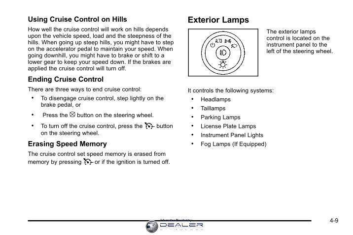
Using Cruise Control on HillsHow well the cruise control will work on hills dependsupon the vehicle speed, load and the steepness of thehills. When going up steep hills, you might have to stepon the accelerator pedal to maintain your speed. Whengoing downhill, you might have to brake or shift to alower gear to keep your speed down. If the brakes areapplied the cruise control will turn off.
Ending Cruise ControlThere are three ways to end cruise control:. To disengage cruise control, step lightly on the
brake pedal, or
. Press the [ button on the steering wheel.
. To turn off the cruise control, press theT buttonon the steering wheel.
Erasing Speed MemoryThe cruise control set speed memory is erased frommemory by pressingT or if the ignition is turned off.
Exterior LampsThe exterior lampscontrol is located on theinstrument panel to theleft of the steering wheel.
It controls the following systems:. Headlamps. Taillamps. Parking Lamps. License Plate Lamps. Instrument Panel Lights. Fog Lamps (If Equipped)
4-9Information Provided by:

The exterior lamps control has four positions:
O (Off): Turns off the automatic headlamps anddaytime running lamps (DRL). Turning the headlampcontrol to the off position again will turn the automaticheadlamps or DRL back on. For vehicles first sold inCanada, the off position only works when the vehicle isshifted into the P (Park) position.
AUTO (Automatic): Automatically turns on theheadlamps at normal brightness, together with thefollowing:. Parking Lamps. Instrument Panel Lights. Taillamps. License Plate Lamps
; (Parking Lamps): Turns on the parking lampstogether with the following:. Instrument Panel Lights. Taillamps. License Plate Lamps
2 (Headlamps): Turns on the headlamps together withthe following lamps listed below. When the headlampsare turned on while the vehicle is on, the headlamps willturn off automatically 10 minutes after the ignition isturned off. When the headlamps are turned on while thevehicle is off, the headlamps will stay on for 10 minutesbefore automatically turning off to prevent the batteryfrom being drained. Turn the headlamp control to offand then back to the headlamp on position to makethe headlamps stay on for an additional 10 minutes.. Parking Lamps. Taillamps. License Plate Lamps. Instrument Panel Lights
# (Fog Lamps) (If Equipped): Turns on the fog lamps.
See Fog Lamps on page 4‑11.
4-10 Information Provided by:

Daytime Running Lamps (DRL)/Automatic Headlamp SystemDaytime Running Lamps (DRL) can make it easier forothers to see the front of your vehicle during the day.Fully functional daytime running lamps are required onall vehicles first sold in Canada.
The DRL system makes the low-beam headlampscome on at a reduced brightness when the followingconditions are met:. The ignition is in the ON/RUN position.. The exterior lamps control is in AUTO.. The engine is running.
When the DRL are on, the regular headlamps,taillamps, sidemarker, and other lamps are not on.The instrument panel and cluster are also not on.
The headlamps automatically change from DRL to theregular headlamps depending on the darkness of thesurroundings. The other lamps that come on with theheadlamps will also come on.
When it is bright enough outside, the headlamps go offand the DRL come on.
The regular headlamp system should be turned onwhen needed.
Do not cover the light sensor on top of the instrumentpanel because it works with the DRL.
Fog Lamps# (Fog Lamps): For vehicles with fog lamps,the button is located on the exterior lamps control.The exterior lamps control is located on the instrumentpanel to the left of the steering column.
The ignition must be in the ON/RUN position for the foglamps to come on.
Press # to turn the fog lamps on or off. A light willcome on in the instrument panel cluster.
When the headlamps are changed to high-beam, thefog lamps also go off.
Some localities have laws that require the headlamps tobe on along with the fog lamps.
Instrument Panel BrightnessD (Instrument Panel Brightness): The knob with thissymbol on it is located next to the exterior lamps controlto the left of the steering wheel. Push the knob in allthe way until it extends out and then turn the knobclockwise or counterclockwise to brighten or dim thelights. Push the knob back in when finished.
4-11Information Provided by:

Courtesy LampsWhen a door is opened, the courtesy lampsautomatically come on. They make it easy foryou to enter and leave your vehicle. You can alsomanually turn these lamps on by fully turning theinstrument panel brightness control clockwise.
The reading lamps, located on the rearview mirror,can be turned on or off independent of the automaticcourtesy lamps, when the doors are closed.
Dome LampThe center mounted dome lamp overhead comes onwhen a door is opened. This lamp can also be turnedon by turning the instrument panel brightness controlclockwise.
Entry LightingFor vehicles with courtesy lamps, they come on andstay on for a set time whenever the unlock symbolis pressed on the Remote Keyless Entry (RKE)transmitter, if the vehicle has one.
If a door is opened, the lamps stay on while it is openand then turn off automatically about 20 seconds afterthe door is closed. If the unlock symbol is pressed andno door is opened, the lamps turn off after about20 seconds.
Entry lighting includes a feature called theater dimming.With theater dimming, the lamps do not turn off at theend of the delay time. Instead, they slowly dim and thengo out. The delay time is canceled if the ignition key isturned to ON/RUN or the power door lock switch ispressed. The lamps will dim right away.
When the ignition is on, illuminated entry is inactive,which means the courtesy lamps will not come onunless a door is opened.
Delayed Entry LightingDelayed entry lighting illuminates the interior for aperiod of time after all the doors have been closed.
The ignition must be off for delayed entry lighting towork. Immediately after all the doors have been closed,the delayed entry lighting feature continues to work untilone of the following occurs:. The ignition is in ON/RUN.. The doors are locked.. An illumination period of about 25 seconds has
elapsed.
If during the illumination period a door is opened, thetimed illumination period is canceled and the interiorlamps remain on.
4-12 Information Provided by:

Delayed Exit LightingThis feature illuminates the interior for a period of timeafter the key is removed from the ignition.
The ignition must be off for delayed exit lighting to work.When the key is removed, interior illumination activatesand remains on until one of the following occurs:. The ignition is in ON/RUN.. The power door locks are activated.. An illumination period of 20 seconds has elapsed.
If during the illumination period a door is opened, thetimed illumination period will be canceled and theinterior lamps will remain on because a door is open.
Parade DimmingParade mode automatically prohibits the dimming of theinstrument panel displays during the daylight while theheadlamps are on so that the displays are still able tobe seen.
Reading LampsThe vehicle has reading lamps that also act as thedome lamp. Press the button near each lamp to turnthem on and off.
Map LampsThe vehicle has map lamps on the rearview mirror.Press the button near each lamp on the mirror to turnthe map lamps on and off.
Electric Power ManagementThe vehicle has Electric Power Management (EPM) thatestimates the battery's temperature and state of charge.It then adjusts the voltage for best performance andextended life of the battery.
When the battery's state of charge is low, the voltageis raised slightly to quickly bring the charge back up.When the state of charge is high, the voltage is loweredslightly to prevent overcharging. If the vehicle has avoltmeter gauge or a voltage display on the DriverInformation Center (DIC), you may see the voltagemove up or down. This is normal. If there is a problem,an alert will be displayed.
The battery can be discharged at idle if the electricalloads are very high. This is true for all vehicles. This isbecause the generator (alternator) may not be spinningfast enough at idle to produce all the power that isneeded for very high electrical loads.
4-13Information Provided by:

A high electrical load occurs when several of thefollowing are on, such as: headlamps, high beams,fog lamps, rear window defogger, climate control fan athigh speed, heated seats, engine cooling fans, trailerloads, and loads plugged into accessory power outlets.
EPM works to prevent excessive discharge of thebattery. It does this by balancing the generator's outputand the vehicle's electrical needs. It can increaseengine idle speed to generate more power, wheneverneeded. It can temporarily reduce the power demandsof some accessories.
Normally, these actions occur in steps or levels,without being noticeable. In rare cases at the highestlevels of corrective action, this action may be noticeableto the driver. If so, a Driver Information Center (DIC)message might be displayed, such as BATTERYSAVER ACTIVE, BATTERY VOLTAGE LOW, orLOW BATTERY. If this message is displayed, it isrecommended that the driver reduce the electricalloads as much as possible. See DIC Warnings andMessages on page 4‑44.
Battery Run-Down ProtectionThis feature helps prevent the battery from beingdrained, if the interior courtesy lamps, reading/maplamps, visor vanity lamps or trunk lamp are accidentallyleft on. If any of these lamps are left on, theyautomatically turn off after 10 minutes, if the ignition isoff. The lamps will not come back on again until one ofthe following occurs:. The ignition is turned on.. The exterior lamps control is turned off, then on
again.
The headlamps will timeout after 10 minutes, if they aremanually turned on with the ignition on or off.
4-14 Information Provided by:

Accessory Power Outlet(s)The vehicle has three 12‐volt outlets which can beused to plug in electrical equipment, such as a cellulartelephone.
On vehicles with a center console, one outlet is locatedinside the center floor console and two outlets arelocated at the front of the console bin under theinstrument panel. Lift the cover to access the outlet.Close the cover when not using the outlet.
On vehicles without a center console, two are locatedunder the climate controls and another outlet for therear seat passengers is at the rear of the center frontseat. Remove the cover to access the outlets. Whennot using the outlet, make sure the cover is closed.
Notice: Leaving electrical equipment plugged in foran extended period of time while the vehicle is offwill drain the battery. Power is always supplied tothe outlets. Always unplug electrical equipmentwhen not in use and do not plug in equipment thatexceeds the maximum 20 ampere rating.
Certain accessory plugs may not be compatible tothe accessory power outlet and could result in blownvehicle and adapter fuses. If you experience a problem,see your dealer for additional information on the poweraccessory plugs.
Notice: Adding any electrical equipment to thevehicle can damage it or keep other componentsfrom working as they should. The repairs wouldnot be covered by the vehicle warranty. Do not useequipment exceeding maximum amperage rating of20 amperes. Check with your dealer before addingelectrical equipment.
When adding electrical equipment, be sure to followthe proper installation instructions included with theequipment. Check with your dealer before addingelectrical equipment, and never use anything thatexceeds the maximum amperage rating of 20 amps.
Notice: Improper use of the power outlet can causedamage not covered by the vehicle warranty. Do nothang any type of accessory or accessory bracketfrom the plug because the power outlets aredesigned for accessory power plugs only.
4-15Information Provided by:

Ashtray(s) and Cigarette LighterThe vehicle may have an ashtray and a cigarette lighter.The ashtray and cigarette lighter may be located in theconsole, if the vehicle has one, otherwise, they may belocated in the center armrest of the front seat.
Notice: If papers, pins, or other flammable items areput in the ashtray, hot cigarettes or other smokingmaterials could ignite them and possibly damagethe vehicle. Never put flammable items in theashtray.
Notice: Holding a cigarette lighter in while it isheating does not let the lighter back away fromthe heating element when it is hot. Damage fromoverheating can occur to the lighter or heatingelement, or a fuse could be blown. Do not hold acigarette lighter in while it is heating.
To use the lighter, just push it in all the way and let go.When it is ready, it will pop back out by itself.
Climate Controls
Climate Control SystemThis vehicle may have a dual or single climatecontrol system. The heating, cooling, defrost, defogand ventilation can be controlled with this system.For vehicles with heated seats, see Heated Seats onpage 2‑6 .
Dual Zone with Optional Heated Seat Controls
A. Fan Control
B. Outside Air
C. Recirculation
D. Air Delivery ModeControl
E. Air Conditioning
F. Driver and PassengerHeated Seats
G. Driver and PassengerTemperature Controls
H. Rear Window Defogger
4-16 Information Provided by:

Single Zone
A. Fan Control
B. Outside Air
C. Temperature Control
D. Recirculation
E. Air Delivery ModeControl
F. Air Conditioning
G. Rear Window Defogger
Temperature Control: For dual zone, turn thethumbwheels up or down to increase or decreasethe temperature on the driver or the passenger sideof the vehicle. For single zone, turn the knob clockwiseor counterclockwise to increase or decrease thetemperature.
9 (Fan Control): Turn clockwise or counterclockwiseto increase or decrease the fan speed. Positioning theknob between two modes, can select a combination ofthose modes.
If the airflow seems low when the fan is at the highestsetting, the passenger compartment air filter may needto be replaced. There will be some airflow noticeablefrom the various outlets when driving, even with the fanin the off position. For more information, see PassengerCompartment Air Filter on page 4‑20 and ScheduledMaintenance on page 7‑3.
Air Delivery Mode Control: Turn clockwise orcounterclockwise to change the direction of the airflowinside the vehicle.
4-17Information Provided by:

To change the current mode, select one of the following:
H (Vent): Air is directed to the instrument paneloutlets.
) (Bi-Level): Air is divided between the instrumentpanel outlets and the floor outlets.
6 (Floor): Air is directed to the floor outlets, with someof the air directed to the windshield and side windowoutlets. In this mode, the system automatically selectsoutside air.
- (Defog): This mode clears the windshield of fog ormoisture. Air is directed equally to the windshield andthe floor outlets. When defog is selected, the systemturns off recirculation and runs the air conditioningcompressor unless the outside temperature is below40°F (4°C).
0 (Defrost): This mode clears the windshield of fog orfrost more quickly. Air is directed to the windshield withsome air to the side window vents and the floor vents.When defrost is selected, the system automaticallyforces outside air into the vehicle. The air conditioningcompressor will run automatically in this setting, unlessthe outside temperature is below 40°F (4°C).
# (Air Conditioning): Press to turn the airconditioning system on or off. An indicator lightcomes on to show that it is on. The air conditioningcan be selected in any mode as long as the fan ison and the outside temperature is above freezing.A flashing indicator light indicates that the airconditioning compressor is currently not available.
On hot days, open the windows to let hot inside airescape; then close them. This helps to reduce the timeit takes for the vehicle to cool down. It also helps thesystem to operate more efficiently.
For quick cool down on hot days, do the following:
1. Select theH mode.
2. Press the# button.
3. Select the coolest temperature for both zones.
4. Select the highest9 speed.
5. When the coolest temperature is selected in theA/C mode, the system automatically goes into therecirculation mode to improve cooling.
4-18 Information Provided by:

Using these settings together for long periods of timemay cause the air inside the vehicle to become too dry.To prevent this from happening, after the air inside thevehicle has cooled, turn the recirculation mode off.
The air conditioning system removes moisture fromthe air, so a small amount of water may drip underthe vehicle while idling or after turning off the engine.This is normal.
: (Outside Air): Press to turn on outside air.An indicator light comes on to show that it is on.Outside air will circulate throughout the vehicle.
? (Recirculation): Press to turn on the recirculationmode. An indicator light comes on to show that it is on.
This mode helps to quickly heat or cool the air insidethe vehicle once the temperature inside the vehicle isequal to or better than the outside temperature. It canbe used to prevent outside air and odors from enteringthe vehicle. The recirculation mode is not available inoutside air, floor, defog or defrost modes. If the buttonis selected while in these modes, the indicator flashesthree times.
Rear Window DefoggerThe rear window defogger uses a warming grid toremove fog from the rear window.
< (Rear Window Defogger): The rear windowdefogger turns off automatically after it has beenactivated for 10 minutes. It can be turned off manually,by pressing the button again or by turning the ignitionto the LOCK/OFF position. The rear window defoggercan be turned on again for additional window clearing.The length of defogger operation will increase if thevehicle is being driven.
For vehicles with heated outside rearview mirrors, themirrors heat to help clear fog or frost from the surfaceof the mirror when the rear window defog button ispressed. See Outside Power Mirrors on page 3‑32.
Do not drive the vehicle until all the windows are clear.
Notice: Do not use anything sharp on the inside ofthe rear window. If you do, you could cut or damagethe warming grid, and the repairs would not becovered by the vehicle warranty. Do not attach atemporary vehicle license, tape, a decal or anythingsimilar to the defogger grid.
4-19Information Provided by:

Outlet AdjustmentUse the thumbwheel located below or to the side of theoutlet, to change the direction of the air flow.
Operation Tips. Clear away any ice, snow or leaves from the air
inlets at the base of the windshield that may blockthe flow of air into the vehicle.
. Use of non-GM approved hood deflectors mayadversely affect the performance of the system.
. Keep the path under the front seats clear ofobjects to help circulate the air inside the vehiclemore effectively.
. If the airflow seems low when the fan is at thehighest setting, the passenger compartment airfilter, if equipped, may need to replaced. For moreinformation, see Passenger Compartment Air Filteron page 4‑20 and Scheduled Maintenance onpage 7‑3 .
. If fogging reoccurs while in vent or bi-level modeswith mild temperature throughout the vehicle, turnon the air conditioner to reduce windshield fogging.
Passenger Compartment Air FilterThe vehicle has a passenger compartment particulateair filter. It is located in the engine compartment, belowthe air inlet grille on the passenger side.
The filter traps most of the pollen from air enteringthe climate control system. It needs to be changedperiodically to ensure system performance.For information on how often to change the passengercompartment air filter, see Scheduled Maintenance onpage 7‑3 .
To change the passenger compartment air filter:
1. Turn off the ignition when the windshield wipersare in the up position.
2. Raise the vehicle hood.
3. Pull back the hood weatherstrip from thepassengers side of the vehicle halfway to center.
4-20 Information Provided by:
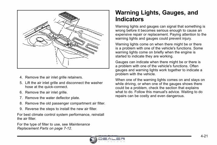
4. Remove the air inlet grille retainers.
5. Lift the air inlet grille and disconnect the washerhose at the quick-connect.
6. Remove the air inlet grille.
7. Remove the water deflector plate.
8. Remove the old passenger compartment air filter.
9. Reverse the steps to install the new air filter.
For best climate control system performance, reinstallthe air filter.
For the type of filter to use, see MaintenanceReplacement Parts on page 7‑12.
Warning Lights, Gauges, andIndicatorsWarning lights and gauges can signal that something iswrong before it becomes serious enough to cause anexpensive repair or replacement. Paying attention to thewarning lights and gauges could prevent injury.
Warning lights come on when there might be or thereis a problem with one of the vehicle's functions. Somewarning lights come on briefly when the engine isstarted to indicate they are working.
Gauges can indicate when there might be or there isa problem with one of the vehicle's functions. Oftengauges and warning lights work together to indicate aproblem with the vehicle.
When one of the warning lights comes on and stays onwhile driving, or when one of the gauges shows therecould be a problem, check the section that explainswhat to do. Follow this manual's advice. Waiting to dorepairs can be costly and even dangerous.
4-21Information Provided by:

Instrument Panel ClusterThe instrument panel cluster is designed to show how the vehicle is running. It shows how fast the vehicle is going,about how much fuel has been used and many other things needed to drive safely and economically.
United States Uplevel shown, Base and Canada similar
4-22 Information Provided by:

Speedometer and OdometerThe speedometer shows the vehicle's speed in bothmiles per hour (mph) and kilometers per hour (km/h).The odometer shows how far the vehicle has beendriven in either miles (used in the United States) orin kilometers (used in Canada).
This vehicle has a tamper-resistant odometer. If theodometer displays ERROR, it probably has beentampered with and the numbers might not be accurate.
If the vehicle needs a new odometer installed, it mustbe set to the mileage total of the old odometer. If that isnot possible, then it will be set at zero and a label mustbe put on the driver's door to show the old mileagereading of the vehicle when the new odometer wasinstalled.
TachometerThe tachometer displays the engine speed inrevolutions per minute (rpm).
Notice: If the engine is operated with thetachometer in the shaded warning area, thevehicle could be damaged, and the damageswould not be covered by the vehicle warranty.Do not operate the engine with the tachometerin the shaded warning area.
Safety Belt Reminders
Safety Belt Reminder LightWhen the engine is started, a chime sounds forseveral seconds to remind a driver to fasten the safetybelt, unless the driver safety belt is already buckled.
The safety belt lightcomes on and stays onfor several seconds, thenflashes for several more.
This chime and light are repeated if the driver remainsunbuckled and the vehicle is in motion. If the driversafety belt is already buckled, neither the chime northe light comes on.
4-23Information Provided by:

Passenger Safety Belt Reminder LightSeveral seconds after the engine is started,a chime sounds for several seconds to remindthe front passenger to buckle their safety belt.This only occurs if the passenger airbag is enabled.See Passenger Sensing System on page 2‑68 formore information. The passenger safety belt light,located on the instrument panel, comes on and stayson for several seconds and then flashes forseveral more.
This chime and light arerepeated if the passengerremains unbuckled andthe vehicle is in motion.
If the passenger safety belt is buckled, neither thechime nor the light comes on.
The front passenger safety belt warning light andchime may turn on if an object is put on the seat suchas a briefcase, handbag, grocery bag, laptop or otherelectronic device. To turn off the warning light and orchime, remove the object from the seat or buckle thesafety belt.
Airbag Readiness LightThe system checks the airbag's electrical system forpossible malfunctions. If the light stays on it indicatesthere is an electrical problem. The system checkincludes the airbag sensor, the pretensioners, theairbag modules, the wiring and the crash sensingand diagnostic module. For more information on theairbag system, see Airbag System on page 2‑58.
The airbag readiness lightflashes for a few secondswhen the engine isstarted. If the light doesnot come on then, haveit fixed immediately.
4-24 Information Provided by:

{ WARNING:
If the airbag readiness light stays on after thevehicle is started or comes on while driving, itmeans the airbag system might not be workingproperly. The airbags in the vehicle might notinflate in a crash, or they could even inflatewithout a crash. To help avoid injury, have thevehicle serviced right away.
If there is a problem with the airbag system, an airbagDriver Information Center (DIC) message can alsocome on. See DIC Warnings and Messages onpage 4‑44 for more information.
Passenger Airbag Status IndicatorThe vehicle has the passenger sensing system.See Passenger Sensing System on page 2‑68 forimportant safety information. The instrument panelhas a passenger airbag status indicator.
United States Canada
When the vehicle is started, the passenger airbagstatus indicator will light ON and OFF, or the symbolfor on and off, for several seconds as a system check.If you are using remote start to start the vehicle froma distance, if equipped, you may not see the systemcheck. Then, after several more seconds, the statusindicator will light either ON or OFF, or either the on oroff symbol to let you know the status of the right frontpassenger frontal airbag.
4-25Information Provided by:

If the word ON or the on symbol is lit on the passengerairbag status indicator, it means that the right frontpassenger frontal airbag is enabled (may inflate).
If the word OFF or the off symbol is lit on the airbagstatus indicator, it means that the passenger sensingsystem has turned off the right front passenger frontalairbag.
If, after several seconds, both status indicator lightsremain on, or if there are no lights at all, there may bea problem with the lights or the passenger sensingsystem. See your dealer for service.
{ WARNING:
If the airbag readiness light ever comes on andstays on, it means that something may be wrongwith the airbag system. To help avoid injury toyourself or others, have the vehicle serviced rightaway. See Airbag Readiness Light on page 4‑24for more information, including important safetyinformation.
Charging System LightThis light comes on brieflywhen the ignition key isturned to START, but theengine is not running, asa check to show it isworking.
If it does not, have the vehicle serviced by your dealer.
The light should go out once the engine starts. If it stayson, or comes on while driving, there could be a problemwith the charging system. A charging system messagein the Driver Information Center (DIC) can also appear.See DIC Warnings and Messages on page 4‑44 formore information. This light could indicate that there areproblems with a generator drive belt, or that there is anelectrical problem. Have it checked right away. If thevehicle must be driven a short distance with the lighton, turn off accessories, such as the radio and airconditioner.
4-26 Information Provided by:

Brake System Warning LightThe vehicle's hydraulic brake system is divided into twoparts. If one part is not working, the other part can stillwork and stop the vehicle. For good braking both partsneed to be working well.
If the warning light comes on, there is a brake problem.Have the brake system inspected right away.
United States Canada
This light should come on briefly when the engine isstarted. If it does not come on then, have it fixed so itwill be ready to warn if there is a problem.
When the ignition is on, the brake system warning lightalso comes on when the parking brake is set. The lightstays on if the parking brake does not fully release.If it stays on after the parking brake is fully released,it means the vehicle has a brake problem.
If the light comes on while driving, pull off the road andstop carefully. The pedal might be harder to push, or thepedal can go closer to the floor. It may take longer tostop. If the light is still on, have the vehicle towed forservice. See Towing Your Vehicle on page 5‑24.
{ WARNING:
The brake system might not be working properly ifthe brake system warning light is on. Driving withthe brake system warning light on can lead to acrash. If the light is still on after the vehicle hasbeen pulled off the road and carefully stopped,have the vehicle towed for service.
4-27Information Provided by:

Antilock Brake System (ABS)Warning Light
The Antilock BrakeSystem (ABS) lightcomes on briefly whenthe engine is started.
If it does not, have the vehicle serviced by your dealer.If the system is working normally the indicator light thengoes off.
If the ABS light stays on, turn the ignition off. If the lightcomes on while driving, stop as soon as it is safelypossible and turn the ignition off. Then start the engineagain to reset the system. If the ABS light stays on,or comes on again while driving, the vehicle needsservice. If the regular brake system warning light is noton, the vehicle still has brakes, but not antilock brakes.If the regular brake system warning light is also on, thevehicle does not have antilock brakes and there is aproblem with the regular brakes. See Brake SystemWarning Light on page 4‑27.
For vehicles with a Driver Information Center (DIC),see DIC Warnings and Messages on page 4‑44 for allbrake related DIC messages.
Traction Control System (TCS)Warning Light
For vehicles with aTraction Control System(TCS) and StabiliTrak®
warning light, this lightcomes on briefly whenthe engine is started.
If it does not, have the vehicle serviced by your dealer.If the system is working normally the indicator light thengoes off.
When the system is active, the light flashes while thesystem is limiting wheel spin or assisting with controllingthe vehicle.
If it stays on or comes on while driving a SERVICETRACTION CONTROL message appears in the DriverInformation Center (DIC). This indicates that there couldbe a problem with the traction control system and thevehicle may need service. When this warning light is onand the SERVICE TRACTION CONTROL messageappears on the DIC, the system does not limitwheel spin.
4-28 Information Provided by:

If the traction control system is manually turned off, thislight comes on and the TRACTION CONTROL OFFmessage appears on the DIC.
See Traction Control System (TCS) on page 5‑7 andDIC Warnings and Messages on page 4‑44 for moreinformation.
Electronic Stability Control IndicatorLight
This light comes onbriefly while the engineis started. If it does not,have the vehicle servicedby your dealer. If thesystem is workingnormally the indicatorlight will then go off.
This light can come on after the vehicle is first drivenand the STABILITRAK NOT READY message appearsin the Driver Information Center (DIC). See ElectronicStability Control (ESC) on page 5‑5 for moreinformation.
If the light stays on, or comes on while driving aSERVICE STABILITRAK message appears in theDIC. This indicates that there may be a problem withthe Electronic Stability Control (ESC) system and thevehicle may need service. When this warning light is onand the SERVICE STABILITRAK message appears onthe DIC, the ESC system does not assist in controllingthe vehicle.
When the system is active, the light flashes while thesystem is assisting in controlling the vehicle.
See Electronic Stability Control (ESC) on page 5‑5and DIC Warnings and Messages on page 4‑44 formore information.
4-29Information Provided by:

Engine Coolant TemperatureWarning Light
This light comes on brieflywhile starting the vehicle.
If it does not, have the vehicle serviced by the dealer.If the system is working normally the indicator lightgoes off.
Notice: Driving with the engine coolant temperaturewarning light on could cause the vehicle tooverheat. See Engine Overheating on page 6‑29.The vehicle's engine could be damaged, and itmight not be covered by the vehicle warranty. Neverdrive with the engine coolant temperature warninglight on.
The engine coolant temperature warning light comes onwhen the engine has overheated.
If this happens pull over and turn off the engine as soonas possible. See Engine Overheating on page 6‑29 formore information.
Engine Coolant Temperature Gauge
United States Canada
This gauge shows the engine coolant temperature.If the gauge pointer moves toward the “H”(United States) or torward the shaded thermostat(Canada), it means that the engine coolant hasoverheated. If the vehicle has been operating undernormal driving conditions, pull off the road, stop thevehicle and turn off the engine as soon as possible.
See Engine Overheating on page 6‑29 for moreinformation.
4-30 Information Provided by:

Tire Pressure LightFor vehicles with a tirepressure monitoringsystem, this light comeson briefly when the engineis started. It providesinformation about tirepressures and the TirePressure MonitoringSystem.
When the Light is On SteadyThis indicates that one or more of the tires issignificantly underinflated.
A tire pressure message in the Driver InformationCenter (DIC), can accompany the light. See DriverInformation Center (DIC) on page 4‑37 for moreinformation. Stop and check the tires as soon as it issafe to do so. If underinflated, inflate to the properpressure. See Inflation - Tire Pressure on page 6‑59for more information.
When the Light Flashes First and Then isOn SteadyThis indicates that there may be a problem with theTire Pressure Monitor System. The light flashes forabout a minute and stays on steady for the remainderof the ignition cycle. This sequence repeats with everyignition cycle. See Tire Pressure Monitor Operation onpage 6‑62 for more information.
Malfunction Indicator Lamp
Check Engine LightA computer system called OBD II (On-BoardDiagnostics-Second Generation) monitors operationof the fuel, ignition, and emission control systems.It ensures that emissions are at acceptable levels forthe life of the vehicle, helping to produce a cleanerenvironment.
This light should come onwhen the ignition is on,but the engine is notrunning, as a check toshow it is working. If itdoes not, have the vehicleserviced by your dealer.
4-31Information Provided by:

If the check engine light comes on and stays on, whilethe engine is running, this indicates that there is anOBD II problem and service is required.
Malfunctions often are indicated by the system beforeany problem is apparent. Being aware of the lightcan prevent more serious damage to the vehicle.This system assists the service technician in correctlydiagnosing any malfunction.
Notice: If the vehicle is continually driven with thislight on, after a while, the emission controls mightnot work as well, the vehicle's fuel economy mightnot be as good, and the engine might not run assmoothly. This could lead to costly repairs thatmight not be covered by the vehicle warranty.
Notice: Modifications made to the engine,transmission, exhaust, intake, or fuel systemof the vehicle or the replacement of the original tireswith other than those of the same Tire PerformanceCriteria (TPC) can affect the vehicle's emissioncontrols and can cause this light to come on.Modifications to these systems could lead tocostly repairs not covered by the vehicle warranty.This could also result in a failure to pass arequired Emission Inspection/Maintenance test.See Accessories and Modifications on page 6‑3.
This light comes on during a malfunction in one oftwo ways:
Light Flashing: A misfire condition has been detected.A misfire increases vehicle emissions and coulddamage the emission control system on the vehicle.Diagnosis and service might be required.
To prevent more serious damage to the vehicle:. Reduce vehicle speed.. Avoid hard accelerations.. Avoid steep uphill grades.. If towing a trailer, reduce the amount of cargo
being hauled as soon as it is possible.
If the light continues to flash, when it is safe to do so,stop the vehicle. Find a safe place to park the vehicle.Turn the key off, wait at least 10 seconds, and restartthe engine. If the light is still flashing, follow theprevious steps and see your dealer for service assoon as possible.
4-32 Information Provided by:

Light On Steady: An emission control systemmalfunction has been detected on the vehicle.Diagnosis and service might be required.
An emission system malfunction might be corrected bydoing the following:. Make sure the fuel cap is fully installed. See Filling
the Tank on page 6‑10. The diagnostic systemcan determine if the fuel cap has been left off orimproperly installed. A loose or missing fuel capallows fuel to evaporate into the atmosphere.A few driving trips with the cap properly installedshould turn the light off.
. If the vehicle has been driven through a deeppuddle of water, the vehicle's electrical systemmight be wet. The condition is usually correctedwhen the electrical system dries out. A few drivingtrips should turn the light off.
. Make sure to fuel the vehicle with quality fuel.Poor fuel quality causes the engine not to run asefficiently as designed and can cause: stallingafter start-up, stalling when the vehicle is changedinto gear, misfiring, hesitation on acceleration,or stumbling on acceleration. These conditionsmight go away once the engine is warmed up.
If one or more of these conditions occurs, changethe fuel brand used. It will require at least one fulltank of the proper fuel to turn the light off.
See Gasoline Octane on page 6‑6.
If none of the above have made the light turn off,your dealer can check the vehicle. The dealer has theproper test equipment and diagnostic tools to fix anymechanical or electrical problems that might havedeveloped.
4-33Information Provided by:

Emissions Inspection and MaintenanceProgramsSome state/provincial and local governments haveor might begin programs to inspect the emissioncontrol equipment on the vehicle. Failure to pass thisinspection could prevent getting a vehicle registration.
Here are some things to know to help the vehicle passan inspection:. The vehicle will not pass this inspection if the
check engine light is on with the engine running,or if the key is in ON/RUN and the light is not on.
. The vehicle will not pass this inspection if theOBD II (on-board diagnostic) system determinesthat critical emission control systems have notbeen completely diagnosed by the system.The vehicle would be considered not ready forinspection. This can happen if the battery hasrecently been replaced or if the battery has rundown. The diagnostic system is designed toevaluate critical emission control systems duringnormal driving. This can take several days ofroutine driving. If this has been done and thevehicle still does not pass the inspection for lackof OBD II system readiness, your dealer canprepare the vehicle for inspection.
Oil Pressure Light
{ WARNING:
Do not keep driving if the oil pressure is low.The engine can become so hot that it catches fire.Someone could be burned. Check the oil as soonas possible and have the vehicle serviced.
Notice: Lack of proper engine oil maintenancecan damage the engine. The repairs would not becovered by the vehicle warranty. Always follow themaintenance schedule in this manual for changingengine oil.
This light comes on briefly while starting the engine.If it does not, have the vehicle serviced by your dealer.If the system is working normally the indicator light thengoes off.
4-34 Information Provided by:

If the light comes on and stays on, it means that oil isnot flowing through the engine properly. The vehiclecould be low on oil and it might have some othersystem problem.
Security LightFor information regardingthis light and the vehicle'ssecurity system, seeContent Theft-Deterrenton page 3‑17.
Fog Lamp LightThe fog lamp light comeson when the fog lampsare in use.
The light goes out when the fog lamps are turned off.See Fog Lamps on page 4‑11 for more information.
Cruise Control LightThe cruise control lightcomes on whenever thecruise control is set.
The light goes out when the cruise control is turned off.See Cruise Control on page 4‑6 for more information.
Highbeam On LightThis light comes on whenthe high-beam headlampsare in use.
See Headlamp High/Low-Beam Changer on page 4‑5for more information.
4-35Information Provided by:

Fuel Gauge
United States Canada
When the ignition is on, the fuel gauge indicates abouthow much fuel is left in the fuel tank.
An arrow on the fuel gauge indicates the side of thevehicle the fuel door is on.
Here are four things that some owners ask about.None of these show a problem with the fuel gauge:. At the gas station, the gas pump shuts off before
the gauge reads full.. It takes a little more or less fuel to fill up than the
gauge indicated. For example, the gauge mayhave indicated the tank was half full, but it actuallytook a little more or less than half the fuel tank'scapacity to fill the tank.
. The gauge moves a little when while turning acorner or speeding up.
. The gauge does not go back to empty when theignition is turned off.
4-36 Information Provided by:
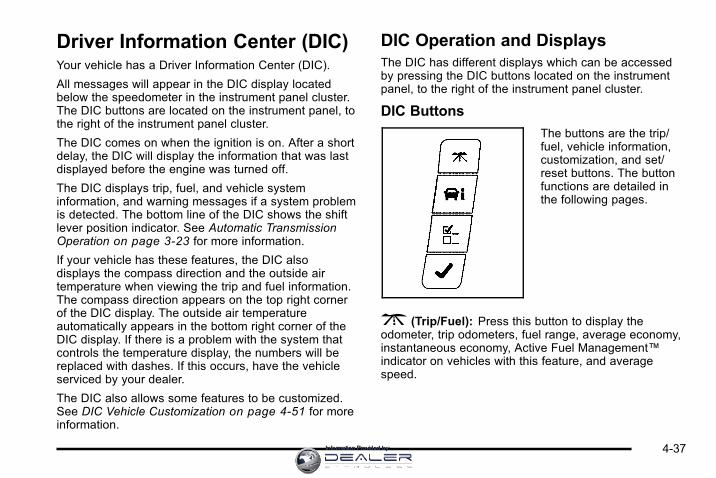
Driver Information Center (DIC)Your vehicle has a Driver Information Center (DIC).
All messages will appear in the DIC display locatedbelow the speedometer in the instrument panel cluster.The DIC buttons are located on the instrument panel, tothe right of the instrument panel cluster.
The DIC comes on when the ignition is on. After a shortdelay, the DIC will display the information that was lastdisplayed before the engine was turned off.
The DIC displays trip, fuel, and vehicle systeminformation, and warning messages if a system problemis detected. The bottom line of the DIC shows the shiftlever position indicator. See Automatic TransmissionOperation on page 3‑23 for more information.
If your vehicle has these features, the DIC alsodisplays the compass direction and the outside airtemperature when viewing the trip and fuel information.The compass direction appears on the top right cornerof the DIC display. The outside air temperatureautomatically appears in the bottom right corner of theDIC display. If there is a problem with the system thatcontrols the temperature display, the numbers will bereplaced with dashes. If this occurs, have the vehicleserviced by your dealer.
The DIC also allows some features to be customized.See DIC Vehicle Customization on page 4‑51 for moreinformation.
DIC Operation and DisplaysThe DIC has different displays which can be accessedby pressing the DIC buttons located on the instrumentpanel, to the right of the instrument panel cluster.
DIC Buttons
The buttons are the trip/fuel, vehicle information,customization, and set/reset buttons. The buttonfunctions are detailed inthe following pages.
3 (Trip/Fuel): Press this button to display theodometer, trip odometers, fuel range, average economy,instantaneous economy, Active Fuel Management™indicator on vehicles with this feature, and averagespeed.
4-37Information Provided by:

T (Vehicle Information): Press this button to displaythe oil life, units, tire pressure readings, compass zoneand compass calibration on vehicles with this feature,and Remote Keyless Entry (RKE) transmitterprogramming.
U (Customization): Press this button to customizethe feature settings on your vehicle. See DIC VehicleCustomization on page 4‑51 for more information.
V (Set/Reset): Press this button to set or reset certainfunctions and to turn off or acknowledge messages onthe DIC.
Trip/Fuel Menu Items3 (Trip/Fuel): Press this button to scroll through thefollowing menu items:
OdometerPress the trip/fuel button until ODOMETER displays.This display shows the distance the vehicle has beendriven in either miles (mi) or kilometers (km).
Trip A and Trip BPress the trip/fuel button until TRIPA or TRIP Bdisplays. This display shows the current distancetraveled in either miles (mi) or kilometers (km) since thelast reset for each trip odometer. Both trip odometerscan be used at the same time.
Each trip odometer can be reset to zero separately bypressing the set/reset button while the desired tripodometer is displayed.
The trip odometer has a feature called the retro-activereset. This can be used to set the trip odometer to thenumber of miles (kilometers) driven since the ignitionwas last turned on. This can be used if the tripodometer is not reset at the beginning of the trip.
To use the retro-active reset feature, press and holdthe set/reset button for at least four seconds. The tripodometer will display the number of miles (mi) orkilometers (km) driven since the ignition was last turnedon and the vehicle was moving. Once the vehiclebegins moving, the trip odometer will accumulatemileage. For example, if the vehicle was driven5 miles (8 km) before it is started again, and then theretro-active reset feature is activated, the display willshow 5miles (8 km). As the vehicle begins moving, thedisplay will then increase to 5.1 miles (8.2 km), 5.2 miles(8.4 km), etc.
4-38 Information Provided by:

If the retro-active reset feature is activated afterthe vehicle is started, but before it begins moving,the display will show the number of miles (mi) orkilometers (km) that were driven during the last ignitioncycle.
Fuel RangePress the trip/fuel button until FUEL RANGE displays.This display shows the approximate number ofremaining miles (mi) or kilometers (km) the vehiclecan be driven without refueling.
The fuel range estimate is based on an average ofthe vehicle's fuel economy over recent driving historyand the amount of fuel remaining in the fuel tank.This estimate will change if driving conditions change.For example, if driving in traffic and making frequentstops, this display may read one number, but if thevehicle is driven on a freeway, the number may changeeven though the same amount of fuel is in the fuel tank.This is because different driving conditions producedifferent fuel economies. Generally, freeway drivingproduces better fuel economy than city driving.
If your vehicle is low on fuel, the FUEL LEVEL LOWmessage displays. See “FUEL LEVEL LOW” under DICWarnings and Messages on page 4‑44 for moreinformation.
Average EconomyPress the trip/fuel button until AVG ECONOMYdisplays. This display shows the approximate averagemiles per gallon (mpg) or liters per 100 kilometers(L/100 km). This number is calculated based on thenumber of mpg (L/100 km) recorded since the last timethis menu item was reset. To reset this display to zero,press and hold the set/reset button.
Instantaneous EconomyPress the trip/fuel button until INST ECONOMYdisplays. This display shows the current fuel economyat a particular moment and will change frequently asdriving conditions change. This display shows theinstantaneous fuel economy in miles per gallon (mpg)or liters per 100 kilometers (L/100 km). Unlike averageeconomy, this screen cannot be reset.
Average SpeedPress the trip/fuel button until AVERAGE SPEEDdisplays. This display shows the average speed of thevehicle in miles per hour (mph) or kilometers per hour(km/h). This average is calculated based on the variousvehicle speeds recorded since the last reset of thisvalue. To reset the value, press and hold the set/resetbutton. The display will return to zero.
Blank DisplayThis display shows no information.
4-39Information Provided by:

Vehicle Information Menu ItemsT (Vehicle Information): Press this button to scrollthrough the following menu items:
Oil LifePress the vehicle information button until OIL LIFEREMAINING displays. This display shows anestimate of the oil's remaining useful life. If you see99%OIL LIFE REMAINING on the display, that means99% of the current oil life remains. The engine oil lifesystem will alert you to change the oil on a scheduleconsistent with your driving conditions.
When the remaining oil life is low, the CHANGEENGINE OIL SOON message will appear on thedisplay. See “CHANGE ENGINE OIL SOON” underDIC Warnings and Messages on page 4‑44.You should change the oil as soon as possible.See Engine Oil on page 6‑15. In addition to theengine oil life system monitoring the oil life, additionalmaintenance is recommended in the MaintenanceSchedule in this manual. See Scheduled Maintenanceon page 7‑3 for more information.
Remember, you must reset the OIL LIFE yourself aftereach oil change. It will not reset itself. Also, be carefulnot to reset the OIL LIFE accidentally at any time otherthan when the oil has just been changed. It cannot bereset accurately until the next oil change. To reset theengine oil life system, see Engine Oil Life System onpage 6‑18.
UnitsPress the vehicle information button until UNITSdisplays. This display allows you to select betweenEnglish or Metric units of measurement. Once in thisdisplay, press the set/reset button to select betweenENGLISH or METRIC units.
4-40 Information Provided by:

Tire PressureOn vehicles with the Tire Pressure MonitorSystem (TPMS), the pressure for each tire can beviewed in the DIC. The tire pressure will be shown ineither pounds per square inch (psi) or kilopascals (kPa).Press the vehicle information button until the DICdisplays FRONT TIRES PSI (kPa) LEFT ## RIGHT ##.Press the vehicle information button again until the DICdisplays REAR TIRES PSI (kPa) LEFT ## RIGHT ##.
If a low tire pressure condition is detected by thesystem while driving, a message advising you toadd air to a specific tire will appear in the display.See Inflation - Tire Pressure on page 6‑59 and DICWarnings and Messages on page 4‑44 for moreinformation.
If the tire pressure display shows dashes instead of avalue, there may be a problem with your vehicle. If thisconsistently occurs, see your dealer for service.
Change Compass ZoneYour vehicle may have this feature. To change thecompass zone through the DIC, see DIC Compass onpage 4‑42.
Calibrate CompassYour vehicle may have this feature. The compass canbe manually calibrated. To calibrate the compassthrough the DIC, see DIC Compass on page 4‑42.
Relearn Remote KeyTo access this display, the vehicle must be in P (Park).This display allows you to match the Remote KeylessEntry (RKE) transmitter to your vehicle. This procedurewill erase all previously learned transmitters. Therefore,they must be relearned as additional transmitters.
To match an RKE transmitter to your vehicle:
1. Press the vehicle information button untilPRESS V TO RELEARN REMOTE KEY displays.
2. Press the set/reset button until REMOTE KEYLEARNING ACTIVE is displayed.
3. Press and hold the lock and unlock buttons onthe first transmitter at the same time for about15 seconds.
A chime will sound indicating that the transmitter ismatched.
4. To match additional transmitters at this time, repeatStep 3.
Each vehicle can have a maximum of eighttransmitters matched to it.
5. To exit the programming mode, you must cycle thekey to LOCK/OFF.
Blank DisplayThis display shows no information.
4-41Information Provided by:

DIC CompassYour vehicle may have a compass in the DriverInformation Center (DIC).
Compass ZoneYour dealer will set the correct zone for your location.
Under certain circumstances, such as during a longdistance cross-country trip or moving to a new stateor province, it will be necessary to compensate forcompass variance by resetting the zone through theDIC if the zone is not set correctly.
Compass variance is the difference between the earth'smagnetic north and true geographic north. If thecompass is not set to the zone where you live, thecompass may give false readings. The compass mustbe set to the variance zone in which the vehicle istraveling.
To adjust for compass variance, use the followingprocedure:
Compass Variance (Zone) Procedure1. Do not set the compass zone when the vehicle is
moving. Only set it when the vehicle is in P (Park).
Press the vehicle information button untilPRESS V TO CHANGE COMPASS ZONEdisplays.
2. Find the vehicle's current location and variancezone number on the map.
Zones 1 through 15 are available.
3. Press the set/reset button to scroll through andselect the appropriate variance zone.
4. Press the trip/fuel button until the vehicle heading,for example, N for North, is displayed in the DIC.
5. If calibration is necessary, calibrate the compass.See “Compass Calibration Procedure” following.
4-42 Information Provided by:

Compass CalibrationThe compass can be manually calibrated. Only calibratethe compass in a magnetically clean and safe location,such as an open parking lot, where driving the vehiclein circles is not a danger. It is suggested to calibrateaway from tall buildings, utility wires, manhole covers,or other industrial structures, if possible.
If CAL should ever appear in the DIC display, thecompass should be calibrated.
If the DIC display does not show a heading, forexample, N for North, or the heading does not changeafter making turns, there may be a strong magnetic fieldinterfering with the compass. Such interference may becaused by a magnetic CB or cell phone antenna mount,a magnetic emergency light, magnetic note pad holder,or any other magnetic item. Turn off the vehicle, movethe magnetic item, then turn on the vehicle and calibratethe compass.
To calibrate the compass, use the following procedure:
Compass Calibration Procedure1. Before calibrating the compass, make sure the
compass zone is set to the variance zone in whichthe vehicle is located. See “Compass Variance(Zone) Procedure” earlier in this section.
Do not operate any switches such as window,sunroof, climate controls, seats, etc. during thecalibration procedure.
2. Press the vehicle information button untilPRESS V TO CALIBRATE COMPASS displays.
3. Press the set/reset button to start the compasscalibration.
4. The DIC will display CALIBRATING: DRIVE INCIRCLES. Drive the vehicle in tight circles at lessthan 5 mph (8 km/h) to complete the calibration.The DIC will display CALIBRATION COMPLETEfor a few seconds when the calibration is complete.The DIC display will then return to PRESS V TOCALIBRATE COMPASS.
4-43Information Provided by:

DIC Warnings and MessagesMessages are displayed on the DIC to notify the driverthat the status of the vehicle has changed and thatsome action may be needed by the driver to correct thecondition. Multiple messages may appear one afteranother. Some messages may not require immediateaction, but you can press the set/reset button toacknowledge that you received the message andclear it from the DIC display. Pressing any of the DICbuttons also acknowledges and clears any messages.Some messages cannot be cleared from the DICdisplay because they are more urgent. Thesemessages require action before they can be cleared.You should take any messages that appear on thedisplay seriously and remember that clearing themessages will only make the messages disappear,not correct the problem. The following are the possiblemessages that can be displayed and some informationabout them.
AUTOMATIC LIGHT CONTROL OFFThis message displays when the automatic headlampsare turned off. See Exterior Lamps on page 4‑9 formore information.
AUTOMATIC LIGHT CONTROL ONThis message displays when the automatic headlampsare turned on. See Exterior Lamps on page 4‑9 formore information.
BATTERY SAVER ACTIVEThis message displays when the system detects thatthe battery voltage is dropping beyond a reasonablelevel. The battery saver system starts reducing certainfeatures of the vehicle that you may be able to notice.At the point that the features are disabled, this messageis displayed. It means that the vehicle is trying to savethe charge in the battery.
Turn off all unnecessary accessories to allow thebattery to recharge.
The normal battery voltage range is 11.5 to 15.5 volts.
CHANGE ENGINE OIL SOONThis message displays when service is required for thevehicle. See your dealer. See Engine Oil on page 6‑15and Scheduled Maintenance on page 7‑3 for moreinformation.
Acknowledging the CHANGE ENGINE OIL SOONmessage will not reset the OIL LIFE REMAINING.That must be done at the OIL LIFE screen under thevehicle information menu. See “Oil Life” under DICOperation and Displays on page 4‑37 and Engine OilLife System on page 6‑18.
4-44 Information Provided by:

DRIVER DOOR OPENThis message displays when the driver door is notclosed properly. Make sure that the door is closedcompletely.
ENGINE HOT A/C(Air Conditioning) OFFThis message displays when the engine coolantbecomes hotter than the normal operating temperature.To avoid added strain on a hot engine, the airconditioning compressor is automatically turned off.When the coolant temperature returns to normal,the A/C operation automatically resumes. You cancontinue to drive your vehicle. If this message continuesto appear, have the system repaired by your dealeras soon as possible to avoid compressor damage.
ENGINE OVERHEATED IDLE ENGINENotice: If you drive your vehicle while the engine isoverheating, severe engine damage may occur. If anoverheat warning appears on the instrument panelcluster and/or DIC, stop the vehicle as soon aspossible. Do not increase the engine speed abovenormal idling speed. See Engine Overheating onpage 6‑29 for more information.
This message displays when the engine coolanttemperature is too hot. Stop and allow the vehicle toidle until it cools down.
ENGINE OVERHEATED STOP ENGINENotice: If you drive your vehicle while the engine isoverheating, severe engine damage may occur. If anoverheat warning appears on the instrument panelcluster and/or DIC, stop the vehicle as soon aspossible. See Engine Overheating on page 6‑29for more information.
This message displays along with a continuous chimewhen the engine has overheated. Stop and turn theengine off immediately to avoid severe engine damage.See Engine Overheating on page 6‑29.
ENGINE POWER IS REDUCEDThis message displays when the vehicle's enginepower is reduced. Reduced engine power can affectthe vehicle's ability to accelerate. If this message is on,but there is no reduction in performance, proceed toyour destination. The performance may be reducedthe next time the vehicle is driven. The vehicle may bedriven at a reduced speed while this message is on,but acceleration and speed may be reduced. Anytimethis message stays on, the vehicle should be taken toyour dealer for service as soon as possible.
ERRORThis message displays while viewing the odometer ortrip odometers if there is a problem with the instrumentpanel cluster. See your dealer for service.
4-45Information Provided by:
FUEL LEVEL LOWThis message displays when your vehicle is low on fuel.Refill the fuel tank as soon as possible. See FuelGauge on page 4‑36 and Filling the Tank onpage 6‑10 for more information.
HOOD OPENIf your vehicle has the remote start feature, thismessage displays when the hood is not closedproperly. Make sure that the hood is closed completely.See Hood Release on page 6‑13.
ICE POSSIBLE DRIVE WITH CAREThis message displays when the outside airtemperature is cold enough to create icy roadconditions. Adjust your driving accordingly.
LEFT REAR DOOR OPENThis message displays when the driver side rear door isnot closed properly. Make sure that the door is closedcompletely.
OIL PRESSURE LOW STOP ENGINENotice: If you drive your vehicle while the engine oilpressure is low, severe engine damage may occur.If a low oil pressure warning appears on the DriverInformation Center (DIC), stop the vehicle as soonas possible. Do not drive the vehicle until the causeof the low oil pressure is corrected. See Engine Oilon page 6‑15 for more information.
This message displays when the vehicle's engine oilpressure is low. The oil pressure light also appears onthe instrument panel cluster. See Oil Pressure Light onpage 4‑34.
Stop the vehicle immediately, as engine damage canresult from driving a vehicle with low oil pressure. Havethe vehicle serviced by your dealer as soon as possiblewhen this message is displayed.
PASSENGER DOOR OPENThis message displays when the front passenger dooris not closed properly. Make sure that the door is closedcompletely.
4-46 Information Provided by:

REMOTE KEY LEARNING ACTIVEThis message displays while you are matching aRemote Keyless Entry (RKE) transmitter to yourvehicle. See “Matching Transmitter(s) to Your Vehicle”under Remote Keyless Entry (RKE) System Operationon page 3‑4 and DIC Operation and Displays onpage 4‑37 for more information.
REPLACE BATTERY IN REMOTE KEYThis message displays when the battery in the RemoteKeyless Entry (RKE) transmitter needs to be replaced.To replace the battery, see “Battery Replacement” underRemote Keyless Entry (RKE) System Operation onpage 3‑4 .
RIGHT REAR DOOR OPENThis message displays when the passenger side reardoor is not closed properly. Make sure that the door isclosed completely.
SERVICE A/C (Air Conditioning)SYSTEMThis message displays when the electronic sensors thatcontrol the air conditioning and heating systems areno longer working. Have the climate control systemserviced by your dealer if you notice a drop in heatingand air conditioning efficiency.
SERVICE AIR BAGThis message displays when there is a problem withthe airbag system. Have your vehicle serviced by yourdealer immediately. See Airbag Readiness Light onpage 4‑24 for more information.
SERVICE BATTERY CHARGINGSYSTEMThis message displays when there is a problem withthe generator and battery charging systems. Drivingwith this problem could drain the battery. Turn off allunnecessary accessories. Stop and turn off the vehicleas soon as it is safe to do so. Have the electricalsystem checked by your dealer immediately.
SERVICE BRAKE SYSTEMThis message displays when service is required on thebrake system. Have the brake system serviced by yourdealer as soon as possible. The brake system warninglight also appears on the instrument panel cluster whenthis message appears on the DIC. See Brake SystemWarning Light on page 4‑27.
4-47Information Provided by:

SERVICE POWER STEERINGThis message displays when a problem is detectedwith the power steering system. When this messageis displayed, you may notice that the effort required tosteer the vehicle increases or feels heavier, but you willstill be able to steer the vehicle. Have your vehicleserviced by your dealer immediately.
SERVICE STABILITRAKIf your vehicle has Electronic Stability Control (ESC),this message displays if there has been a problemdetected with ESC. The ESC/TCS light also appears onthe instrument panel cluster. See Electronic StabilityControl (ESC) on page 5‑5 for more information.
If this message turns on while you are driving, pulloff the road as soon as possible and stop carefully.Try resetting the system by turning the ignition off andthen back on. If this message still stays on or turnsback on again while you are driving, your vehicle needsservice. Have the system inspected by your dealer assoon as possible.
SERVICE THEFT SYSTEMThis message displays when there is a problem with thetheft-deterrent system programmed in the key. A faulthas been detected in the system which means that thesystem is disabled and it is not protecting the vehicle.The vehicle usually restarts; however, you may want totake the vehicle to your dealer before turning off theengine. See PASS-Key® III+ Electronic ImmobilizerOperation on page 3‑18 for more information.
SERVICE TIRE MONITOR SYSTEMOn vehicles with the Tire Pressure Monitor System(TPMS), this message displays if a part on the TPMSis not working properly. The tire pressure light alsoflashes and then remains on during the same ignitioncycle. See Tire Pressure Light on page 4‑31. Severalconditions may cause this message to appear. See TirePressure Monitor Operation on page 6‑62 for moreinformation. If the warning comes on and stays on,there may be a problem with the TPMS. See yourdealer.
4-48 Information Provided by:

SERVICE TRACTION CONTROLIf your vehicle has the Traction Control System (TCS),this message displays when the system is notfunctioning properly. A warning light also appearson the instrument panel cluster. See Traction ControlSystem (TCS) Warning Light on page 4‑28. SeeTraction Control System (TCS) on page 5‑7 for moreinformation. Have the TCS serviced by your dealer assoon as possible.
SERVICE TRANSMISSIONThis message displays when there is a problem with thetransmission. See your dealer for service.
SERVICE VEHICLE SOONThis message displays when a non-emissions relatedmalfunction occurs. Have the vehicle serviced by yourdealer as soon as possible.
STABILITRAK NOT READYIf your vehicle has Electronic Stability Control (ESC),this message may display and the ESC/TCS light onthe instrument panel cluster may be on after first drivingthe vehicle and exceeding 19 mph (30 km/h) for30 seconds. The ESC system is not functional until thelight has turned off. See Electronic Stability Control(ESC) on page 5‑5 for more information.
STARTING DISABLED SERVICETHROTTLEThis message displays if the starting of the engine isdisabled due to the electronic throttle control system.Have your vehicle serviced by your dealer immediately.
This message only appears while the ignition is inON/RUN, and will not disappear until the problem isresolved.
This message cannot be acknowledged.
THEFT ATTEMPTEDThis message displays if the content theft-deterrentsystem has detected a break-in attempt while you wereaway from your vehicle. See Content Theft-Deterrent onpage 3‑17 for more information.
TIGHTEN GAS CAPThis message may be displayed if the gas cap is noton, or is not fully tightened. Check the gas cap toensure that it is on properly. See Filling the Tank onpage 6‑10 for more information.
4-49Information Provided by:

TIRE LEARNING ACTIVEOn vehicles with the Tire Pressure MonitorSystem (TPMS), this message displays whenthe TPMS is re-learning the tire positions on yourvehicle. The tire positions must be re-learned afterrotating the tires or after replacing a tire or sensor.See Tire Inspection and Rotation on page 6‑65,Tire Pressure Monitor System on page 6‑60, andInflation - Tire Pressure on page 6‑59 for moreinformation.
TIRE LOW ADD AIR TO TIREOn vehicles with the Tire Pressure Monitor System(TPMS), this message displays when the pressure inone or more of the vehicle's tires is low. This messagealso displays LEFT FRT (left front), RIGHT FRT (rightfront), LEFT RR (left rear), or RIGHT RR (right rear)to indicate the location of the low tire. The low tirepressure warning light will also come on. See TirePressure Light on page 4‑31. You can receive morethan one tire pressure message at a time. To read theother messages that may have been sent at the sametime, press the set/reset button. If a tire pressuremessage appears on the DIC, stop as soon as you can.Have the tire pressures checked and set to thoseshown on the Tire Loading Information label. See Tireson page 6‑52, Loading the Vehicle on page 5‑19, and
Inflation - Tire Pressure on page 4‑37. The DIC alsoshows the tire pressure values. See DIC Operation andDisplays on page 4‑37.
TRACTION CONTROL OFFIf your vehicle has the Traction Control System (TCS),this message displays when the TCS turns off.See Traction Control System (TCS) on page 5‑7for more information.
This message may display when the ignition is inON/RUN and disappears after 10 seconds, unlessit is acknowledged or an urgent warning appears.
Any of the following conditions may cause the TCS toturn off:. The TCS is turned off by pressing the traction
control button. See Traction Control System (TCS)on page 5‑7 for more information.
. The battery is low.
. There is a TCS failure. See your dealer for service.
TRACTION CONTROL ONIf your vehicle has the Traction Control System (TCS),this message displays when the TCS is turned on.See Traction Control System (TCS) on page 5‑7 formore information.
4-50 Information Provided by:

TRANSMISSION HOT IDLE ENGINEThis message displays when the transmission fluidin your vehicle is too hot. Stop the vehicle and allowit to idle until it cools down. If the warning messagecontinues to display, have the vehicle serviced by yourdealer as soon as possible.
TRUNK OPENThis message displays when the trunk is not closedcompletely. Make sure that the trunk is closedcompletely. See Trunk on page 3‑12.
TURN SIGNAL ONThis message displays as a reminder to turn off the turnsignal if you drive your vehicle for more than about0.75 mile (1.2 km) with a turn signal on. See TurnSignal/Multifunction Lever on page 4‑4.
This message displays and a chime sounds onlywhen the ignition is in ON/RUN. The message will notdisappear until the turn signal is manually turned off,or a turn is completed.
WASHER FLUID LOW ADD FLUIDThis message displays when the windshield washerfluid is low. Fill the windshield washer reservoir as soonas possible. See Engine Compartment Overview onpage 6‑14 for the location of the windshield washerreservoir. Also, see Windshield Washer Fluid onpage 6‑33 for more information.
DIC Vehicle CustomizationYour vehicle has customization capabilities that allowyou to program certain features to one preferred setting.Customization features can only be programmed to onesetting on the vehicle and cannot be programmed to apreferred setting for two different drivers.
All of the customization options may not be availableon your vehicle. Only the options available will bedisplayed on the DIC.
The default settings for the customization features wereset when your vehicle left the factory, but may havebeen changed from their default state since then.
The customization preferences are automaticallyrecalled.
4-51Information Provided by:

To change customization preferences, use the followingprocedure.
Entering the Feature Settings Menu1. Turn the ignition on and place the vehicle in
P (Park).
To avoid excessive drain on the battery, it isrecommended that the headlamps are turned off.
2. Press the customization button to enter the featuresettings menu.
If the menu is not available, FEATURE SETTINGSAVAILABLE IN PARK will display. Before enteringthe menu, make sure the vehicle is in P (Park).
Feature Settings Menu ItemsThe following are customization features that allow youto program settings to the vehicle:
DISPLAY IN ENGLISHThis feature will only display if a language other thanEnglish has been set. This feature allows you to changethe language in which the DIC messages appear toEnglish.
Press the customization button until the PRESS V TODISPLAY IN ENGLISH screen appears on the DICdisplay. Press the set/reset button once to display allDIC messages in English.
DISPLAY LANGUAGEThis feature allows you to select the language in whichthe DIC messages will appear.
Press the customization button until the DISPLAYLANGUAGE screen appears on the DIC display. Pressthe set/reset button once to access the settings for thisfeature. Then press the customization button to scrollthrough the following settings:
ENGLISH (default): All messages will appear inEnglish.
FRANCAIS: All messages will appear in French.
ESPANOL: All messages will appear in Spanish.
NO CHANGE: No change will be made to this feature.The current setting will remain.
To select a setting, press the set/reset button while thedesired setting is displayed on the DIC.
4-52 Information Provided by:

AUTO DOOR UNLOCKThis feature allows you to select whether or not to turnoff the automatic door unlocking feature. It also allowsyou to select which doors and when the doors willautomatically unlock. See Programmable AutomaticDoor Unlock on page 3‑11 for more information.
Press the customization button until AUTO DOORUNLOCK appears on the DIC display. Press theset/reset button once to access the settings for thisfeature. Then press the customization button to scrollthrough the following settings:
OFF: None of the doors will automatically unlock.
DRIVER AT KEY OUT: Only the driver's door willunlock when the key is taken out of the ignition.
DRIVER IN PARK: Only the driver's door will unlockwhen the vehicle is shifted into P (Park) .
ALL AT KEY OUT: All of the doors will unlock when thekey is taken out of the ignition.
ALL IN PARK (default): All of the doors will unlockwhen the vehicle is shifted into P (Park).
NO CHANGE: No change will be made to this feature.The current setting will remain.
To select a setting, press the set/reset button while thedesired setting is displayed on the DIC.
REMOTE DOOR LOCKThis feature allows you to select the type of feedbackyou will receive when locking the vehicle with theRemote Keyless Entry (RKE) transmitter. You will notreceive feedback when locking the vehicle with the RKEtransmitter if any of the doors are open. See RemoteKeyless Entry (RKE) System Operation on page 3‑4for more information.
Press the customization button until REMOTE DOORLOCK appears on the DIC display. Press the set/resetbutton once to access the settings for this feature.Then press the customization button to scroll throughthe following settings:
HORN & LIGHTS OFF: There will be no feedbackwhen you press the lock button on the RKE transmitter.
LIGHTS ONLY: The exterior lamps will flash when youpress the lock button on the RKE transmitter.
HORN ONLY: The horn will sound on the second pressof the lock button on the RKE transmitter.
HORN & LIGHTS ON (default): The exterior lampswill flash when you press the lock button on the RKEtransmitter, and the horn will sound when the lockbutton is pressed again within five seconds of theprevious command.
NO CHANGE: No change will be made to this feature.The current setting will remain.
4-53Information Provided by:

To select a setting, press the set/reset button while thedesired setting is displayed on the DIC.
REMOTE DOOR UNLOCKThis feature allows you to select the type of feedbackyou will receive when unlocking the vehicle with theRemote Keyless Entry (RKE) transmitter. You will notreceive feedback when unlocking the vehicle with theRKE transmitter if the doors are open. See RemoteKeyless Entry (RKE) System Operation on page 3‑4for more information.
Press the customization button until REMOTE DOORUNLOCK appears on the DIC display. Press theset/reset button once to access the settings for thisfeature. Then press the customization button to scrollthrough the following settings:
LIGHTS OFF: The exterior lamps will not flash whenyou press the unlock button on the RKE transmitter.
LIGHTS ON (default): The exterior lamps will flashwhen you press the unlock button on the RKEtransmitter.
NO CHANGE: No change will be made to this feature.The current setting will remain.
To select a setting, press the set/reset button while thedesired setting is displayed on the DIC.
EXIT LIGHTINGThis feature allows you to select the amount of time youwant the exterior lamps to remain on when it is darkenough outside. This happens after the key is turnedfrom ON/RUN to LOCK/OFF.
Press the customization button until EXIT LIGHTINGappears on the DIC display. Press the set/reset buttononce to access the settings for this feature. Then pressthe customization button to scroll through the followingsettings:
OFF: The exterior lamps will not turn on.
30 SECONDS (default): The exterior lamps will stay onfor 30 seconds.
1MINUTE: The exterior lamps will stay on forone minute.
2MINUTES: The exterior lamps will stay on fortwo minutes.
NO CHANGE: No change will be made to this feature.The current setting will remain.
To select a setting, press the set/reset button while thedesired setting is displayed on the DIC.
4-54 Information Provided by:

APPROACH LIGHTINGThis feature allows you to select whether or not to havethe exterior lights turn on briefly during low light periodsafter unlocking the vehicle using the Remote KeylessEntry (RKE) transmitter.
Press the customization button until APPROACHLIGHTING appears on the DIC display. Press theset/reset button once to access the settings for thisfeature. Then press the customization button to scrollthrough the following settings:
OFF: The exterior lights will not turn on when youunlock the vehicle with the RKE transmitter.
ON (default): If it is dark enough outside, the exteriorlights will turn on briefly when you unlock the vehiclewith the RKE transmitter.
The lights will remain on for 20 seconds or until the lockbutton on the RKE transmitter is pressed, or the vehicleis no longer off. See Remote Keyless Entry (RKE)System Operation on page 3‑4 for more information.
NO CHANGE : No change will be made to this feature.The current setting will remain.
To select a setting, press the set/reset button while thedesired setting is displayed on the DIC.
CHIME VOLUMEThis feature allows you to select the volume level of thechime.
Press the customization button until CHIME VOLUMEappears on the DIC display. Press the set/reset buttononce to access the settings for this feature. Then pressthe customization button to scroll through the followingsettings:
NORMAL: The chime volume will be set to a normallevel.
LOUD: The chime volume will be set to a loud level.
NO CHANGE: No change will be made to this feature.The current setting will remain.
There is no default for chime volume. The volume willstay at the last known setting.
To select a setting, press the set/reset button while thedesired setting is displayed on the DIC.
4-55Information Provided by:

REMOTE STARTIf your vehicle has this feature, it allows you to turnthe remote start off or on. The remote start featureallows you to start the engine from outside of thevehicle using the Remote Keyless Entry (RKE)transmitter. See Remote Vehicle Start on page 3‑7for more information.
Press the customization button until REMOTE STARTappears on the DIC display. Press the set/reset buttononce to access the settings for this feature. Then pressthe customization button to scroll through the followingsettings:
OFF: The remote start feature will be disabled.
ON (default): The remote start feature will be enabled.
NO CHANGE: No change will be made to this feature.The current setting will remain.
To select a setting, press the set/reset button while thedesired setting is displayed on the DIC.
FACTORY SETTINGSThis feature allows you to set all of the customizationfeatures back to their factory default settings.
Press the customization button until FACTORYSETTINGS appears on the DIC display. Press theset/reset button once to access the settings for thisfeature. Then press the customization button to scrollthrough the following settings:
RESTORE ALL (default): The customization featureswill be set to their factory default settings.
DO NOT RESTORE: The customization features willnot be set to their factory default settings.
To select a setting, press the set/reset button while thedesired setting is displayed on the DIC.
EXIT FEATURE SETTINGSThis feature allows you to exit the FEATURESETTINGS menu.
Press the customization button until FEATURESETTINGS PRESS V TO EXIT appears in the DICdisplay. Press the set/reset button once to exitthe menu.
If you do not exit, pressing the customization buttonagain will return you to the beginning of the FEATURESETTINGS menu.
4-56 Information Provided by:

Exiting the Feature Settings MenuThe feature settings menu will be exited when any ofthe following occurs:. The vehicle is shifted out of P (Park).. The vehicle is no longer in ON/RUN.. The trip/fuel or vehicle information DIC buttons are
pressed.. The end of the feature settings menu is reached
and exited.. A 40 second time period has elapsed with no
selection made.
Audio System(s)Determine which radio the vehicle has and read thefollowing pages to become familiar with its features.
{ WARNING:
Taking your eyes off the road for extended periodscould cause a crash resulting in injury or death toyou or others. Do not give extended attention toentertainment tasks while driving.
This system provides access to many audio and nonaudio listings.
To minimize taking your eyes off the road while driving,do the following while the vehicle is parked:. Become familiar with the operation and controls of
the audio system.. Set up the tone, speaker adjustments, and preset
radio stations.
For more information, see Defensive Driving onpage 5‑2 .
Notice: Contact your dealer before adding anyequipment.
Adding audio or communication equipment couldinterfere with the operation of the vehicle's engine,radio, or other systems, and could damage them.Follow federal rules covering mobile radio andtelephone equipment.
The vehicle has Retained Accessory Power (RAP).With RAP, the audio system can be played even afterthe ignition is turned off. See Retained AccessoryPower (RAP) on page 3‑21 for more information.
4-57Information Provided by:

Setting the Clock
Without Date Display
AM/FM Base Radio with a Single CD Player
This radio has a H button for setting the time.
To set the time:
1. Press the H button until the hour begins flashing
on display. Press H a second time and theminutes begin flashing on display.
2. To increase or decrease the time, do one of thefollowing while the hours or minutes are flashing:
. Turn the f knob.
. Press¨ SEEK or© SEEK.
. Press\ FWD ors REV.
3. Press the H button again until the clock displaystops flashing to set the currently displayed time,or wait five seconds until the flashing stops and thecurrent time displayed is automatically set.
To change the time default setting from 12 hour to24 hour, press the H button until 12H or 24H isdisplayed. Once 12H or 24H is displayed, turnthe f knob to the desired option to select the setting.
Press the H button again to apply the setting, or let thescreen time out.
With Date Display
Single CD (MP3) Player
This radio has a H button for setting the time.
To set the time and date:
1. Turn the radio on.
2. Press the H button and the HR, MIN, MM, DD,YYYY (hour, minute, month, day, and year)displays.
3. Press the pushbutton located under any one of thetabs to be changed.
4-58 Information Provided by:

4. To increase the time or date, do one of thefollowing:. Press the pushbutton below the selected tab.
. Turn the f knob clockwise.
. Press¨ SEEK.
. Press\ FWD.
5. To decrease the time or date, do one of thefollowing:
. Turn the f knob counter‐clockwise.
. Press© SEEK.
. Presss REV.
The date does not automatically display. To see thedate press the H button while the radio is on. The datewith display times out after a few seconds and goesback to the normal radio and time display.
To change the time default setting from 12 hour to24 hour or to change the date default setting frommonth/day/year to day/month/year:
1. Press the H button and then the pushbuttonlocated under the forward arrow tab. Once the time12H and 24H, and the date MM/DD/YYYY (month,day, and year) and DD/MM/YYYY (day, month, andyear) displays.
2. Press the pushbutton located under the desiredoption.
3. Press the H or MENU button again to apply theselected default, or let the screen time out.
4-59Information Provided by:

Radio(s)
Radio with CD
Radio with CD (MP3)
The vehicle has one of these radios as its audiosystem.
4-60 Information Provided by:

Radio Data System (RDS)The radio may have the Radio Data System (RDS)feature. RDS is available for use only on FM stationsthat broadcast RDS information. This system reliesupon receiving specific information from these stationsand only works when the information is available.While the radio is tuned to an FM-RDS station, thestation name or call letters display. In rare cases, aradio station can broadcast incorrect information thatcauses the radio features to work improperly. If thishappens, contact the radio station.
Playing the RadioO (Power/Volume): Press to turn the system onand off.
Turn clockwise or counterclockwise to increase ordecrease the volume.
The radio goes to the previous volume setting when theradio is turned on. The volume can still be adjusted byusing the volume knob.
Speed Compensated Volume (SCV): The Radio withCD (MP3) has SCV. SCV automatically adjusts the radiovolume to compensate for road and wind noise as thevehicle increases or decreases speed while driving.The volume level should sound about the same whiledriving. To activate SCV:
1. Set the radio volume to the desired level.
2. Press the MENU button to display the radiosetup menu.
3. Press the softkey under the AUTO VOLUM(automatic volume) tab on the radio display.
4. Press the softkey under the desired SpeedCompensated Volume setting (OFF, Low, Med,or High) to select the level of radio volumecompensation. The display times out afterapproximately 10 seconds. Each higher settingallows for more radio volume compensation atfaster vehicle speeds.
4-61Information Provided by:

Finding a StationBAND: Press to switch between FM1, FM2, AM on theRadio with CD. The selection displays.
Press to switch between FM, AM, and XM™ on theRadio with CD (MP3).
f (Tune): Turn to select radio stations.
© SEEK¨ : Press to go to the previous or the nextstation and stay there.
To scan stations, press and hold either arrow for a fewseconds until the radio beeps once. The radio goes to astation, plays for a few seconds, then goes to the nextstation. Press either arrow again to stop scanning.
The radio seeks and scans stations only with a strongsignal that are in the selected band.
4 (Information) (Radio with CD (Base)): Press toswitch the display between the radio station frequencyand the time. While the ignition is off, press to displaythe time.
4 (Information) (With XM™ Satellite Radio Service,MP3, and RDS Features): Press to display additionaltext information related to the current FM-RDS or XMstation; or CD, MP3 or WMA song. If information isavailable during XM, CD, MP3 or WMA playback, thesong title information displays on the top line of thedisplay and artist information displays on the bottomline. When information is not available, No Info displays.
Setting Preset Stations (Radio with CD)If the radio does not have XM, up to 18 stations(six FM1, six FM2, and six AM), can be programmed onthe six numbered pushbuttons. To program presets:
1. Turn the radio on.
2. Press BAND to select FM1, FM2, or AM.
3. Tune in the desired station.
4. Press and hold one of the six numberedpushbuttons for three seconds until a beep sounds.When that pushbutton is pressed and released, thestation that was set, returns.
5. Repeat the Steps 2 through 4 for each pushbutton.
Storing a Radio Station as a Favorite(Radio with CD (MP3))Drivers are encouraged to set up their radio stationfavorites while the vehicle is in P (Park). Tune tofavorite stations using the presets, favorites button, andsteering wheel controls if the vehicle has this feature.See Defensive Driving on page 5‑2.
If the vehicle has XM and has a FAV button, amaximum of 36 stations can be programmed asfavorites using the six softkeys below the radio stationfrequency tabs and by using the radio favorites pagebutton (FAV button).
4-62 Information Provided by:

FAV (Favorites): Press to go through up to six pagesof favorites, each having six favorite stations availableper page. Each page of favorites can contain anycombination of AM, FM, or XM stations. To store astation as a favorite:
1. Tune to the desired radio station.
2. Press the FAV button to display the page whereyou want the station stored.
3. Press and hold one of the six softkeys until abeep sounds. When that softkey is pressed andreleased, the station that was set, returns.
4. Repeat the steps for each radio station you wantstored as a favorite.
The number of favorites pages can be setup using theMENU button. To setup the number of favorites pages:
1. Press the MENU button to display the radiosetup menu.
2. Press the softkey below the FAV 1-6 tab.
3. Select the desired number of favorites pages bypressing the softkey below the displayed pagenumbers.
4. Press the FAV button, or let the menu time out, toreturn to the original main radio screen showingthe radio station frequency tabs and to begin theprocess of programming favorites for the chosenamount of numbered pages.
Setting the Tone (Bass/Midrange/Treble)BASS/MID/TREB (Bass, Midrange, or Treble): Theradio may display some or all tones, such as BASS,MID, and TREB. To adjust the tone settings, pressthe f knob until the tone control tabs display. Press
the softkey under the desired tab, then turn the f knobclockwise or counterclockwise to adjust the highlightedsetting. The highlighted setting can also be adjustedby pressing either SEEK arrow,\ FWD, ors REVbutton until the desired levels are obtained. If a station'sfrequency is weak, or has static, decrease the treble.
The radio may be capable of adjusting bass, midrange,or treble to the middle position by pressing the softkeyunder the BASS, MID (midrange), or TREB (treble) tabfor more than two seconds. The radio beeps once andthe level adjusts to the middle position.
The radio may also be capable of adjusting all toneand speaker controls to the middle position by pressingthe f knob for more than two seconds until the radiobeeps once.
EQ (Equalization): Press to select preset equalizationsettings.
To return to the manual mode, press until Manualdisplays or start to manually adjust the bass anddepending on the radio, midrange, or treble by pressingthe f knob.
4-63Information Provided by:

Adjusting the Speakers (Balance/Fade)` BAL/FADE (Balance/Fade): To adjust balanceor fade, press the` if the radio has this symbol,
or the f knob until the speaker control tabs display.
Continue pressing the f knob to highlight the desiredtab, or press the softkey under the desired tab. Turnthe f knob clockwise or counterclockwise to adjust thesetting. The setting can also be adjusted by pressingeither SEEK arrow,\ FWD, ors REV until thedesired levels are obtained.
The radio may be capable of adjusting balance or fadeto the middle position by pressing the softkey under theBAL or FADE tab for more than two seconds. The radiobeeps once and the level adjusts to the middle position.
The radio may also be capable of adjusting all speakerand tone controls to the middle position by pressingthe f knob for more than two seconds until the radiobeeps once.
Finding a Category (CAT) Station(XM™ Satellite Radio Service Only)CAT (Category): The radio may have the CAT buttonfeature. To select and find a desired category:
1. Press the BAND button until the XM frequencydisplays. Press the CAT button to display thecategory tabs on the radio display. Continuepressing the CAT button until the desired categoryname displays.
2. Press either of the two buttons below the desiredcategory tab to immediately tune to the first XMstation associated with that category.
3. Turn the f knob, press the buttons below the rightor left arrows displayed, or press the SEEK arrowsto go to the previous or to the next XM stationwithin the selected category.
4. To exit the category search mode, press the FAVbutton or BAND button to display favorites again.
4-64 Information Provided by:

Undesired XM categories can be removed through thesetup menu. To remove an undesired category:
1. Press the MENU button to display the radiosetup menu.
2. Press the softkey below the XM CAT tab.
3. Turn the f knob to display the category to beremoved.
4. Press the softkey located under the Remove tabuntil the category name along with the wordRemoved displays.
5. Repeat the steps to remove more categories.
Removed categories can be restored by pressing thesoftkey under the Add tab when a removed categorydisplays or by pressing the softkey under the RestoreAll tab.
Categories cannot be removed or added while thevehicle is moving faster than 5 mph (8 km/h).
Radio MessagesCalibration Error: The audio system has beencalibrated for the vehicle from the factory. If CalibrationError displays, it means that the radio has not beenconfigured properly for the vehicle and it must bereturned to your dealer for service.
Loc or Locked: If Loc or Locked displays, it means theTHEFTLOCK® system has locked up. Take the vehicleto your dealer for service.
If any error occurs repeatedly or if an error cannot becorrected, contact your dealer.
XM™ Satellite Radio ServiceXM is a satellite radio service that is based in the48 contiguous United States and 10 Canadianprovinces. XM Satellite Radio has a wide varietyof programming and commercial-free music,coast-to-coast, and in digital-quality sound. A servicefee is required to receive the XM service. For moreinformation, contact XM at www.xmradio.com or call1-800-929-2100 in the U.S. and www.xmradio.ca orcall 1-877-438-9677 in Canada.
Radio Messages for XM™ OnlySee XM Radio Messages on page 4‑74 later in thissection for further detail.
4-65Information Provided by:

Playing a CDInsert a CD partway into the slot, label side up.The player pulls it in and the CD should begin playing.
If the ignition or radio is turned off while a CD in theplayer it stays in the player. When the ignition or radio isturned on, the CD starts to play where it stopped, if itwas the last selected audio source.
When the CD is inserted, the CD symbol displays. Aseach new track starts to play, the track number displays.
The CD player can play the smaller 3 inch (8 cm) singleCDs with an adapter ring. Full-size CDs and the smallerCDs are loaded in the same manner.
If the ignition or radio is turned off, while a CD is in theplayer, it stays in the player. When the ignition or radiois turned on, the CD starts playing where it stopped, if itwas the last selected audio source.
Z EJECT: Press to eject the CD. If the CD is notremoved, after several seconds, the CD automaticallypulls back into the player.
f (Tune): Turn to select tracks on the CD currentlyplaying.
© SEEK¨ : Press the left arrow to go to the start ofthe current track, if more than ten seconds have played.Press the right arrow to go to the next track. If eitherarrow is held, or pressed multiple times, the playercontinues moving backward or forward through thetracks on the CD.
s REV (Fast Reverse): Press and hold to reverseplayback quickly within a track. Sound is heard at areduced volume. Release to resume playing the track.The elapsed time of the track displays.
\ FWD (Fast Forward): Press and hold to advanceplayback quickly within a track. Sound is heard at areduced volume. Release to resume playing the track.The elapsed time of the track displays.
RDM (Random): Tracks can be listened to in random,rather than sequential order.
To use random on the Radio with CD, press the RDMbutton to play tracks from a CD in random order. Therandom icon displays. Press again to turn off randomplay. The random icon disappears from the display.
To use random on the Radio with CD (MP3):
1. Press the CD/AUX button, insert a disc partwayinto the slot of the CD player. A RDM tab displays.
2. To play the tracks in random order, press thesoftkey under the RDM tab until Random CurrentDisc displays. Press the softkey again to turn offrandom play.
4-66 Information Provided by:

RPT (Repeat): With repeat, one track or an entire CDcan be repeated.
To use repeat on the Radio with CD:. Press and release the RPT button to repeat the
current track. An arrow symbol displays. Pressagain to turn off repeat play.
. Press and hold the RPT button for a few secondsto repeat the CD. An arrow symbol displays. Pressagain to turn off repeat play. When repeat is off,the symbol no longer displays.
BAND: Press to listen to the radio while a CD isplaying. The CD remains inside the radio for futurelistening.
CD/AUX (CD/Auxiliary): Press to play a CD whilelistening to the radio. The CD icon and a messageshowing disc and/or track number displays when a CDis in the player. Press this button again and the systemautomatically searches for an auxiliary input device,such as a portable audio player. If a portable audioplayer is not connected, No Aux Input Device Foundmay display.
Care of CDsIf playing a CD-R, the sound quality can be reduceddue to CD-R quality, the method of recording, thequality of the music that has been recorded, andthe way the CD-R has been handled. Handle themcarefully. Store CD-R(s) in their original cases or otherprotective cases and away from direct sunlight anddust. The CD player scans the bottom surface of thedisc. If the surface of a CD is damaged, such ascracked, broken, or scratched, the CD does not playproperly or not at all. Do not touch the bottom side ofa CD while handling it; this could damage the surface.Pick up CDs by grasping the outer edges or the edgeof the hole and the outer edge.
If the surface of a CD is soiled, take a soft, lint freecloth or dampen a clean, soft cloth in a mild, neutraldetergent solution mixed with water, and clean it.Make sure the wiping process starts from the centerto the edge.
4-67Information Provided by:

Care of the CD PlayerDo not add any label to a CD, it could get caught in theCD player. If a CD is recorded on a personal computerand a description label is needed, try labeling the top ofthe recorded CD with a marking pen.
The use of CD lens cleaners for CDs is not advised,due to the risk of contaminating the lens of the CDoptics with lubricants internal to the CD playermechanism.
Notice: If a label is added to a CD, or more than oneCD is inserted into the slot at a time, or an attemptis made to play scratched or damaged CDs, the CDplayer could be damaged. While using the CDplayer, use only CDs in good condition without anylabel, load one CD at a time, and keep the CD playerand the loading slot free of foreign materials,liquids, and debris.
If an error displays, see “CD Messages” later in thissection.
Playing an MP3 CD-R or CD-RW DiscThe radio may have MP3 CD-R or CD-RW disccapability. For more information, see Using an MP3 onpage 4‑70 later in this section.
CD MessagesCHECK DISC: If an error message displays and/or theCD comes out, it could be for one of the followingreasons:. It is very hot. When the temperature returns to
normal, the CD should play.. The road is very rough. When the road becomes
smoother, the CD should play.. The CD is dirty, scratched, wet, or upside down.. The air is very humid. If so, wait about an hour and
try again.. There could have been a problem while burning
the CD.. The label could be caught in the CD player.
If there is no apparent damage, try a known good CD.
If any error occurs repeatedly or if an error cannot becorrected, contact your dealer. If the radio displays anerror message, write it down and provide it to yourdealer while reporting the problem.
4-68 Information Provided by:
Using the Auxiliary Input JackThe radio system has an auxiliary input jack located onthe lower right side of the faceplate. This is not an audiooutput; do not plug the headphone set into the frontauxiliary input jack. However, an external audio devicesuch as an iPod, laptop computer, MP3 player, CDchanger, or cassette tape player, etc. can be connectedto the auxiliary input jack for use as another source foraudio listening.
Drivers are encouraged to set up any auxiliary devicewhile the vehicle is in P (Park). See Defensive Drivingon page 5‑2 for more information on driver distraction.
To use a portable audio player, connect a 3.5 mm(1/8 in) cable to the radio's front auxiliary input jack.While a device is connected, press the radio CD/AUXbutton to begin playing audio from the device over thevehicle speakers.
O (Power/Volume): Turn to increase or decreasethe volume of the portable player. Additional volumeadjustments might need to be made from the portabledevice.
BAND: Press to listen to the radio while a portableaudio device is playing. The portable audio devicecontinues playing until it is stopped or turned off.
CD/AUX (CD/Auxiliary): Press to play a CD whilea portable audio device is playing. Press again andthe system begins playing audio from the connectedportable audio player. If a portable audio player is notconnected, No Aux Input Device Found may display.
4-69Information Provided by:

Using an MP3
MP3 CD-R or CD-RW DiscThe radio may have MP3 capability. With this feature,the radio plays MP3 files that were recorded on a CD-Ror CD-RW disc. Song title, artist name, and albumcan display when files are recorded using ID3 tagsversion 1 and 2.
Compressed AudioThe radio also plays discs that contain bothuncompressed CD audio (.CDA files) and MP3 files.By default the radio reads only the uncompressed audioand ignore the MP3 files. Pressing the CAT buttontoggles between compressed and uncompressed audioformat.
MP3 FormatIf you burn your own MP3 disc on a personal computer:. Make sure the MP3 files are recorded on a CD-R
or CD-RW disc.. Do not mix standard audio and MP3 files on
one disc.. The CD player is able to read and play a maximum
of 50 folders, 50 playlists, and 255 files.
. Create a folder structure that makes it easy to findsongs while driving. Organize songs by albumsusing one folder for each album. Each folder oralbum should contain 18 songs or less.
. Avoid subfolders. The system can support up to8 subfolders deep, however, keep the total numberof folders to a minimum in order to reduce thecomplexity and confusion in trying to locate aparticular folder during playback.
. Make sure playlists have a .m3u or .wpl extension(other file extensions might not work).
. Minimize the length of the file, folder or playlistnames. Long file, folder, or playlist names, or acombination of a large number of files and folders,or playlists can cause the player to be unable toplay up to the maximum number of files, folders,playlists, or sessions. If you wish to play a largenumber of files, folders, playlists, or sessions,minimize the length of the file, folder, or playlistname. Long names also take up more space onthe display, potentially getting cut off.
. Finalize the audio disc before burning it. Trying toadd music to an existing disc can cause the discnot to function in the player.
4-70 Information Provided by:

Playlists can be changed by using the previous andnext folder buttons, the f knob, or the seek buttons.An MP3 CD-R or CD-RW that was recorded usingno file folders can also be played. If a CD containsmore than the maximum of 50 folders, 50 playlists, and255 files, the player lets you access and navigate up tothe maximum, but all items over the maximum cannotbe accessed.
Root DirectoryThe root directory of the CD is treated as a folder. If theroot directory has compressed audio files, the directorydisplays as F1 ROOT. All files contained directly underthe root directory are accessed prior to any rootdirectory folders. However, playlists (Px) are alwaysaccessed before root folders or files.
Empty Directory or FolderIf a root directory or a folder exists somewhere in thefile structure that contains only folders/subfolders andno compressed files directly beneath them, the playeradvances to the next folder in the file structure thatcontains compressed audio files. The empty folderdoes not display.
No FolderWhen the CD contains only compressed files, the filesare located under the root folder. The next and previousfolder functions do not function on a CD that wasrecorded without folders or playlists. When displayingthe name of the folder the radio displays ROOT.
When the CD contains only playlists and compressedaudio files, but no folders, all files are located under theroot folder. The folder down and the folder up buttonssearches playlists (Px) first and then goes to the rootfolder. When the radio displays the name of the folderthe radio displays ROOT.
Order of PlayTracks recorded to the CD-R or CD-RW are played inthe following order:. Play begins from the first track in the first playlist
and continues sequentially through all tracks ineach playlist. When the last track of the last playlisthas played, play continues from the first track ofthe first playlist.
. Play begins from the first track in the first folderand continues sequentially through all tracks ineach folder. When the last track of the last folderhas played, play continues from the first track ofthe first folder.
4-71Information Provided by:

When play enters a new folder, the display does notautomatically show the new folder name unless thefolder mode has been chosen as the default display.The new track name displays.
File System and NamingThe song name that displays is the song name thatis contained in the ID3 tag. If the song name is notpresent in the ID3 tag, then the radio displays the filename without the extension (such as .mp3) as thetrack name.
Track names longer than 32 characters or four pagesare shortened. The display does not show parts ofwords on the last page of text and the extension ofthe filename is not displayed.
Preprogrammed PlaylistsPreprogrammed playlists that were created usingWinAmp™, MusicMatch™, or Real Jukebox™ softwarecan be accessed, however, you do not have playlistediting capability using the radio. These playlists aretreated as special folders containing compressed audiosong files.
Playing an MP3f (Tune): Turn this knob to select MP3 files on the CDcurrently playing.
© SEEK¨ : Press the left SEEK arrow to go to thestart of the current MP3 file, if more than ten secondshave played. Press the right SEEK arrow to go to thenext MP3 file. If either SEEK arrow is held or pressedmultiple times, the player continues moving backwardor forward through MP3 files on the CD.
Sc (Previous Folder): Press the softkey under theFolder tab to go to the first track in the previous folder.
c T (Next Folder): Press the softkey under theFolder tab to go to the first track in the next folder.
s REV (Reverse): Press and hold to reverseplayback quickly within an MP3 file. Sound is heardat a reduced volume. Release this button to resumeplaying the file. The elapsed time of the file displays.
\ FWD (Fast Forward): Press and hold to advanceplayback quickly within an MP3 file. Sound is heard at areduced volume. Release this button to resume playingthe file. The elapsed time of the file displays.
4-72 Information Provided by:

RDM (Random): MP3 files can be listened to on a CDin random, rather than sequential order. To use random:
1. To play MP3 files in random order from the CDthat is currently playing, press the softkey underthe RDM tab until Random Current Disc displays.Press the same softkey again to turn offrandom play.
h (Music Navigator): If the radio has the MP3feature, it has the music navigator feature to play MP3files on the CD-R or CD-RW in order by artist or album.Press the softkey below the music navigator tab.The player scans the disc to sort the files by artist andalbum ID3 tag information. It can take several minutesto scan the disc depending on the number of MP3 filesrecorded to the CD-R or CD-RW. The radio might beginplaying while it is scanning the disc in the background.When the scan is finished, the CD begins playing again.
Once the disc has scanned, the player defaults toplaying MP3 files in order by artist. The current artistplaying is shown on the second line of the display
between the arrows. Once all songs by that artistare played, the player moves to the next artist inalphabetical order on the CD and begins playing MP3files by that artist. If you want to listen to MP3 files byanother artist, press the softkey below either arrowbutton. The CD goes to the next or previous artist inalphabetical order. Continue pressing either buttonuntil the desired artist displays.
To change from playback by artist to playback byalbum, press the softkey below the Sort By tab. Fromthe sort screen, push one of the softkeys below thealbum button. Press the softkey below the back tab toreturn to the main music navigator screen. Now thealbum name displays on the second line between thearrows and songs from the current album begins toplay. Once all songs from that album have played, theplayer moves to the next album in alphabetical order onthe CD and begins playing MP3 files from that album.
To exit music navigator mode, press the softkey belowthe Back tab to return to normal MP3 playback.
4-73Information Provided by:

XM Radio MessagesXL (Explicit Language Channels): These channels,or any others, can be blocked at a customer's request,by calling 1-800-852-XMXM (9696).
XM Updating: The encryption code in the receiver isbeing updated, and no action is required. This processshould take no longer than 30 seconds.
No XM Signal: The system is functioning correctly, butthe vehicle is in a location that is blocking the XM™signal. When the vehicle is moved into an open area,the signal should return.
Loading XM: The audio system is acquiring andprocessing audio and text data. No action is needed.This message should disappear shortly.
Channel Off Air: This channel is not currently inservice. Tune in to another channel.
Channel Unauth : This channel is blocked or cannotbe received with your XM Subscription package.
Channel Unavail: This previously assigned channelis no longer assigned. Tune to another station. If thisstation was one of the presets, choose another stationfor that preset button.
No Artist Info: No artist information is available at thistime on this channel. The system is working properly.
No Title Info: No song title information is availableat this time on this channel. The system is workingproperly.
No CAT Info: No category information is available atthis time on this channel. The system is workingproperly.
No Information: No text or informational messages areavailable at this time on this channel. The system isworking properly.
CAT Not Found: There are no channels available forthe selected category. The system is working properly.
XM Theftlocked: The XM receiver in the vehicle couldhave previously been in another vehicle. For securitypurposes, XM receivers cannot be swapped betweenvehicles. If this message is received after having thevehicle serviced, check with your dealer.
XM Radio ID: If tuned to channel 0, this messagealternates with the XM™ Radio 8 digit radio ID label.This label is needed to activate the service.
4-74 Information Provided by:

Unknown: If this message is received when tuned tochannel 0, there could be a receiver fault. Consult withyour dealer.
Check Antenna: If this message does not clear withina short period of time, the receiver or antenna couldhave a fault. Consult with your dealer.
Check XM Receivr: If this message does not clearwithin a short period of time, the receiver could have afault. Consult with your dealer.
XM Not Available: If this message does not clearwithin a short period of time, the receiver could have afault. Consult with your dealer.
Bluetooth®
Vehicles with a Bluetooth system can use a Bluetoothcapable cell phone with a Hands Free Profile to makeand receive phone calls. The system can be used whilethe key is in ON/RUN or ACC/ACCESSORY position.The range of the Bluetooth system can be up to 9.1 m(30 ft). Not all phones support all functions, and not allphones are guaranteed to work with the in-vehicleBluetooth system. See www.gm.com/bluetooth for moreinformation on compatible phones.
Voice RecognitionThe Bluetooth system uses voice recognition tointerpret voice commands to dial phone numbersand name tags.
Noise: Keep interior noise levels to a minimum.The system may not recognize voice commands ifthere is too much background noise.
When to Speak: A short tone sounds after the systemresponds indicating when it is waiting for a voicecommand. Wait until the tone and then speak.
How to Speak: Speak clearly in a calm and naturalvoice.
Audio SystemWhen using the in‐vehicle Bluetooth system, soundcomes through the vehicle's front audio systemspeakers and overrides the audio system. Use theaudio system volume knob, during a call, to changethe volume level. The adjusted volume level remainsin memory for later calls. To prevent missed calls, aminimum volume level is used if the volume is turneddown too low.
4-75Information Provided by:

Bluetooth ControlsUse the buttons located on the steering wheel tooperate the in‐vehicle Bluetooth system. See AudioSteering Wheel Controls on page 4‑86 for moreinformation.
b g (Push To Talk): Press to answer incoming calls, toconfirm system information, and to start speechrecognition.
cx (Phone On Hook): Press to end a call, reject acall, or to cancel an operation.
PairingA Bluetooth enabled cell phone must be paired to thein‐vehicle Bluetooth system first and then connected tothe vehicle before it can be used. See the cell phonemanufacturers user guide for Bluetooth functionsbefore pairing the cell phone. If a Bluetooth phoneis not connected, calls will be made using OnStar®
Hands‐Free Calling, if available. Refer to the OnStarowner's guide for more information.
Pairing Information:. Up to five cell phones can be paired to the
in‐vehicle Bluetooth system.. The pairing process is disabled when the vehicle is
moving.. The in‐vehicle Bluetooth system automatically links
with the first available paired cell phone in theorder the phone was paired.
. Only one paired cell phone can be connected tothe in‐vehicle Bluetooth system at a time.
. Pairing should only need to be completed once,unless changes to the pairing information havebeen made or the phone is deleted.
To link to a different paired phone, see Linking to aDifferent Phone later in this section.
4-76 Information Provided by:

Pairing a Phone
1. Press and hold b g for two seconds. The systemresponds with “Ready” followed by a tone.
2. Say “Bluetooth”. The system responds with“Bluetooth ready” followed by a tone.
3. Say “Pair”. The system responds with instructionsand a four digit PIN number. The PIN number willbe used in Step 4.
4. Start the Pairing process on the cell phone that willbe paired to the vehicle. Reference the cell phonemanufacturers user guide for information on thisprocess.
Locate the device named “General Motors” in thelist on the cellular phone and follow the instructionson the cell phone to enter the four digit PINnumber that was provided in Step 3.
5. The system prompts for a name for the phone. Usea name that best describes the phone. This namewill be used to indicate which phone is connected.The system then confirms the name provided.
6. The system responds with “<Phone name> hasbeen successfully paired” after the pairing processis complete.
7. Repeat Steps 1 through 7 for additional phones tobe paired.
Listing All Paired and Connected Phones
1. Press and hold b g for two seconds. The systemresponds with “Ready” followed by a tone.
2. Say “Bluetooth”. The system responds with“Bluetooth ready” followed by a tone.
3. Say “List”. The system lists all the paired Bluetoothdevices. If a phone is connected to the vehicle, thesystem will say “Is connected” after the connectedphone.
Deleting a Paired Phone
1. Press and hold b g for two seconds. The systemresponds with “Ready” followed by a tone.
2. Say “Bluetooth”. The system responds with“Bluetooth ready” followed by a tone.
3. Say “Delete”. The system asks which phone todelete followed by a tone.
4. Say the name of the phone to be deleted. If thephone name is unknown, use the “List” commandfor a list of all paired phones. The system respondswith “Would you like to delete <phone name>? Yesor No” followed by a tone.
5. Say “Yes” to delete the phone. The systemresponds with “OK, deleting <phone name>”.
4-77Information Provided by:

Linking to a Different Phone
1. Press and hold b g for two seconds. The systemresponds with “Ready” followed by a tone.
2. Say “Bluetooth”. The system responds with“Bluetooth ready” followed by a tone.
3. Say “Change phone”. The system responds with“Please wait while I search for other phones”.. If another phone is found, the response will be
“<Phone name> is now connected”.. If another phone is not found, the original
phone remains connected.
Storing Name TagsThe system can store up to thirty phone numbers asname tags that are shared between the Bluetooth andOnStar systems.
The system uses the following commands to store andretrieve phone numbers:. Store. Digit Store. Directory
Using the Store CommandThe store command allows a phone number to bestored without entering the digits individually.
1. Press and hold b g for two seconds. The systemresponds with “Ready” followed by a tone.
2. Say “Store”. The system responds with“Store, number please” followed by a tone.
3. Say the complete phone number to be stored atonce with no pauses.. If the system recognizes the number it
responds with “OK, Storing” and repeats thephone number.
. If the system is unsure it recognizes the phonenumber, it responds with “Store” and repeatsthe number followed by “Please say yes or no”.If the number is correct, say “Yes”. If thenumber is not correct, say “No”. The systemwill ask for the number to be re‐entered.
4-78 Information Provided by:

4. After the system stores the phone number, itresponds with “Please say the name tag” followedby a tone.
5. Say a name tag for the phone number. The nametag is recorded and the system responds with“About to store <name tag>. Does thatsound OK?”.. If the name tag does not sound correct, say
“No” and repeat Step 5.. If the name tag sounds correct, say “Yes” and
the name tag is stored. After the number isstored the system returns to the main menu.
Using the Digit Store CommandThe digit store command allows a phone number to bestored by entering the digits individually.
1. Press and hold b g for two seconds. The systemresponds with “Ready” followed by a tone.
2. Say “Digit Store”. The system responds with“Please say the first digit to store” followed bya tone.
3. Say the first digit to be stored. The system willrepeat back the digit it heard followed by a tone.Continue entering digits until the number to bestored is complete.. If an unwanted number is recognized by the
system, say “Clear” at any time to clear the lastnumber.
. To hear all of the numbers recognized by thesystem, say “Verify” at any time and the systemwill repeat them.
4. After the complete number has been entered, say“Store”. The system responds with “Please say thename tag” followed by a tone.
5. Say a name tag for the phone number. The nametag is recorded and the system responds with“About to store <name tag>. Does thatsound OK?”.. If the name tag does not sound correct, say
“No” and repeat Step 5.. If the name tag sounds correct, say “Yes” and
the name tag is stored. After the number isstored the system returns to the main menu.
4-79Information Provided by:

Using the Directory CommandThe directory command lists all of the name tags storedby the system. To use the directory command:
1. Press and hold b g for two seconds. The systemresponds with “Ready” followed by a tone.
2. Say “Directory”. The system responds with“Directory” and then plays back all of the storedname tags. When the list is complete, the systemreturns to the main menu.
Deleting Name TagsThe system uses the following commands to deletename tags:. Delete. Delete all name tags
Using the Delete CommandThe delete command allows specific name tags to bedeleted.
To use the delete command:
1. Press and hold b g for two seconds. The systemresponds with “Ready” followed by a tone.
2. Say “Delete”. The system responds with “Delete,please say the name tag” followed by a tone.
3. Say the name tag to be deleted. The systemresponds with “Would you like to delete,<name tag>? Please say yes or no”.. If the name tag is correct, say “Yes” to delete
the name tag. The system responds with“OK, deleting <name tag>, returning to themain menu.”
. If the name tag is incorrect, say “No”.The system responds with “No. OK, let's tryagain, please say the name tag.”
Using the Delete All Name Tags CommandThe delete all name tags command deletes all storedphone book name tags and route name tags for OnStar(if present).
To use the delete all name tags command:
1. Press and hold b g for two seconds. The systemresponds with “Ready” followed by a tone.
2. Say “Delete all name tags”. The system respondswith “You are about to delete all name tags storedin your phone directory and your route destinationdirectory. Are you sure you want to do this? Pleasesay yes or no.”. Say “Yes” to delete all name tags.. Say “No” to cancel the function and return to
the main menu.
4-80 Information Provided by:

Making a CallCalls can be made using the following commands:. Dial. Digit Dial. Call. Re‐dial
Using the Dial Command
1. Press and hold b g for two seconds. The systemresponds with “Ready” followed by a tone.
2. Say “Dial”. The system responds with “Dial using<phone name>”. “Number please” followed bya tone.
3. Say the entire number without pausing.. If the system recognizes the number, it
responds with “OK, Dialing” and dials thenumber.
. If the system does not recognize the number,it confirms the numbers followed by a tone.If the number is correct, say “Yes”. The systemresponds with “OK, Dialing” and dials thenumber. If the number is not correct, say “No”.The system will ask for the number to bere‐entered.
Using the Digit Dial Command
1. Press and hold b g for two seconds. The systemresponds with “Ready” followed by a tone.
2. Say “Digit Dial”. The system responds with“Digit dial using <phone name>, please say thefirst digit to dial” followed by a tone.
3. Say the digit to be dialed one at a time. Followingeach digit, the system will repeat back the digit itheard followed by a tone.
4. Continue entering digits until the number to bedialed is complete. After the whole number hasbeen entered, say “Dial”. The system respondswith “OK, Dialing” and dials the number.. If an unwanted number is recognized by the
system, say “Clear” at any time to clear the lastnumber.
. To hear all of the numbers recognized by thesystem, say “Verify” at any time and the systemwill repeat them.
4-81Information Provided by:

Using the Call Command
1. Press and hold b g for two seconds. The systemresponds with “Ready” followed by a tone.
2. Say “Call”. The system responds with “Call using<phone name>. Please say the name tag” followedby a tone.
3. Say the name tag of the person to call.. If the system clearly recognizes the name tag it
responds with “OK, calling, <name tag>” anddials the number.
. If the system is unsure it recognizes the rightname tag, it confirms the name tag followed bya tone. If the name tag is correct, say “Yes”.The system responds with “OK, calling,<name tag>” and dials the number. If the nametag is not correct, say “No”. The system will askfor the name tag to be re‐entered.
Once connected, the person called will be heardthrough the audio speakers.
Using the Re‐dial Command
1. Press and hold b g for two seconds. The systemresponds with “Ready” followed by a tone.
2. After the tone, say “Re‐dial”. The system respondswith “Re‐dial using <phone name>” and dials thelast number called from the connected Bluetoothphone.
Once connected, the person called will be heardthrough the audio speakers.
Receiving a CallWhen an incoming call is received, the audio systemmutes and a ring tone is heard in the vehicle.
. Press b g and begin speaking to answer the call.
. Presscx to ignore a call.
4-82 Information Provided by:

Call WaitingCall waiting must be supported on the Bluetooth phoneand enabled by the wireless service carrier to work.
. Press b g to answer an incoming call whenanother call is active. The original call is placedon hold.
. Press b g again to return to the original call.
. To ignore the incoming call, continue with theoriginal call with no action.
. Presscx to disconnect the current call andswitch to the call on hold.
Three‐Way CallingThree‐Way Calling must be supported on the Bluetoothphone and enabled by the wireless service carrierto work.
1. While on a call press b g. The system respondswith “Ready” followed by a tone.
2. Say “Three‐way call”. The system responds with“Three‐way call, please say dial or call”.
3. Use the dial or call command to dial the number ofthe third party to be called.
4. Once the call is connected, press b g to link allthe callers together.
Ending a Call
Presscx to end a call.
Muting a CallDuring a call, all sounds from inside the vehicle can bemuted so that the person on the other end of the callcannot hear them.
To Mute a call
1. Press b g. The system responds with “Ready”followed by a tone.
2. Say “Mute Call”. The system responds with“Call muted”.
To Cancel Mute
1. Press b g. The system responds with “Ready”followed by a tone.
2. After the tone, say “Mute Call”. The systemresponds with “Resuming call”.
Transferring a CallAudio can be transferred between the in‐vehicleBluetooth system and the cell phone.
4-83Information Provided by:

To Transfer Audio to the Cell PhoneDuring a call with the audio in the vehicle:
1. Press b g. The system responds with “Ready”followed by a tone.
2. Say “Transfer Call.” The system responds with“Transferring call” and the audio will switch fromthe vehicle to the cell phone.
To Transfer Audio to the In-VehicleBluetooth SystemThe cellular phone must be paired and connected withthe Bluetooth system before a call can be transferred.The connection process can take up to two minutesafter the key is turned to the ON/RUN orACC/ACCESSORY position.
During a call with the audio on the cell phone,press b g for more than two seconds. The audioswitches from the cell phone to the vehicle.
Voice Pass-ThruVoice Pass‐Thru allows access to the voice recognitioncommands on the cell phone. See the cell phonemanufacturers user guide to see if the cell phonesupports this feature. This feature can be used toverbally access contacts stored in the cell phone.
1. Press and hold b g for two seconds. The systemresponds with “Ready” followed by a tone.
2. Say “Bluetooth”. The system responds with“Bluetooth ready” followed by a tone.
3. Say “Voice”. The system responds with“OK, accessing <phone name>”.. The cell phone's normal prompt messages will
go through its cycle according to the phone'soperating instructions.
Dual Tone Multi-Frequency (DTMF)TonesThe in‐vehicle Bluetooth system can send numbers andnumbers stored as name tags during a call. This is usedwhen calling a menu driven phone system. Accountnumbers can be programmed into the phonebook forretrieval during menu driven calls.
4-84 Information Provided by:

Sending a Number During a Call
1. Press b g. The system responds with “Ready”followed by a tone.
2. Say “Dial”. The system responds with“Say a number to send tones” followed bya tone.
3. Say the number to send.. If the system clearly recognizes the number it
responds with “OK, Sending Number” and thedial tones are sent and the call continues.
. If the system is not sure it recognized thenumber properly, it responds “Dial Number,Please say yes or no?” followed by a tone.If the number is correct, say “Yes”. The systemresponds with “OK, Sending Number” and thedial tones are sent and the call continues.
Sending a Stored Name Tag During a Call
1. Press b g. The system responds with “Ready”followed by a tone.
2. Say “Send name tag.” The system responds with“Say a name tag to send tones” followed by a tone.
3. Say the name tag to send.. If the system clearly recognizes the name tag it
responds with “OK, Sending <name tag>” andthe dial tones are sent and the call continues.
. If the system is not sure it recognized the nametag properly, it responds “Dial <name tag>,Please say yes or no?” followed by a tone.If the name tag is correct, say “Yes”. Thesystem responds with “OK, Sending <nametag>” and the dial tones are sent and the callcontinues.
4-85Information Provided by:

Clearing the SystemUnless information is deleted out of the in‐vehicleBluetooth system, it will be retained indefinitely. Thisincludes all saved name tags in the phonebook andphone pairing information. For information on how todelete this information, see the above sections onDeleting a Paired Phone and Deleting Name Tags.
Other InformationThe Bluetooth® word mark and logos are owned by theBluetooth® SIG, Inc. and any use of such marks byGeneral Motors is under license. Other trademarks andtrade names are those of their respective owners.
See Radio Frequency Statement on page 8‑19 for FCCinformation.
Theft-Deterrent FeatureTHEFTLOCK® is designed to discourage theft of thevehicle's radio by learning a portion of the VehicleIdentification Number (VIN). The radio does not operateif it is stolen or moved to a different vehicle.
Audio Steering Wheel ControlsVehicles with audiosteering wheel controlscould differ dependingon the vehicle's options.Some audio controlscan be adjusted at thesteering wheel.
w (Next): Press to go to the next radio station storedas a favorite, or the next track if a CD is playing.
cx (Previous/End): Press to go to the previousradio station stored as a favorite, the next track if a CDis playing, to reject an incoming call, or end acurrent call.
b g (Mute/Push to Talk): Press to silence thevehicle speakers only. Press again to turn the sound on.For vehicles with OnStar® or Bluetooth® systems, pressand hold b g for longer than two seconds to interactwith those systems. See the OnStar Owner's Guide andBluetooth® on page 4‑75 for more information.
4-86 Information Provided by:

SRCE (Source): Press to choose between the radio(AM, FM, XM), CD, and auxiliary input jack.
+ e − e (Volume): Press to increase or to decreasethe radio volume.
¨ (Seek): Press to go to the next radio station while inAM, FM, or XM™. Press¨ to go to the next track orchapter while sourced to the CD.
Radio ReceptionFrequency interference and static can occur duringnormal radio reception if items such as cell phonechargers, vehicle convenience accessories, andexternal electronic devices are plugged into theaccessory power outlet. If there is interference orstatic, unplug the item from the accessory power outlet.
AMThe range for most AM stations is greater than for FM,especially at night. The longer range can cause stationfrequencies to interfere with each other. For better radioreception, most AM radio stations boost the powerlevels during the day, and then reduce these levelsduring the night. Static can also occur when things likestorms and power lines interfere with radio reception.When this happens, try reducing the treble on the radio.
FM StereoFM signals only reach about 10 to 40 miles(16 to 65 km). Although the radio has a built-in electroniccircuit that automatically works to reduce interference,some static can occur, especially around tall buildingsor hills, causing the sound to fade in and out.
XM™ Satellite Radio ServiceXM Satellite Radio Service gives digital radio receptionfrom coast-to-coast in the 48 contiguous United States,and in Canada. Just as with FM, tall buildings or hillscan interfere with satellite radio signals, causing thesound to fade in and out. In addition, traveling orstanding under heavy foliage, bridges, garages,or tunnels may cause loss of the XM signal for aperiod of time.
Cellular Phone UsageCellular phone usage may cause interference withthe vehicle's radio. This interference may occurwhen making or receiving phone calls, chargingthe phone's battery, or simply having the phone on.This interference causes an increased level of staticwhile listening to the radio. If static is received whilelistening to the radio, unplug the cellular phone andturn it off.
4-87Information Provided by:

Backglass AntennaThe AM-FM antenna is integrated with the rear windowdefogger, located in the rear window. Make sure thatthe inside surface of the rear window is not scratchedand that the lines on the glass are not damaged. If theinside surface is damaged, it could interfere with radioreception. For proper radio reception, the antennaconnector needs to be properly attached to the poston the glass.
If a cellular telephone antenna needs to be attached tothe glass, make sure that the grid lines for the AM-FMantenna are not damaged. There is enough spacebetween the grid lines to attach a cellular telephoneantenna without interfering with radio reception.
Notice: Using a razor blade or sharp object to clearthe inside rear window can damage the rear windowantenna and/or the rear window defogger. Repairswould not be covered by the vehicle warranty. Donot clear the inside rear window with sharp objects.
Notice: Do not apply aftermarket glass tintingwith metallic film. The metallic film in some tintingmaterials will interfere with or distort the incomingradio reception. Any damage caused to yourbackglass antenna due to metallic tinting materialswill not be covered by the vehicle warranty.
XM™ Satellite Radio AntennaSystemThe XM Satellite Radio antenna is located on the roof ofthe vehicle. Keep the antenna clear of obstructions forclear radio reception.
If the vehicle has a sunroof, the performance of the XMsystem may be affected if the sunroof is open.
4-88 Information Provided by:

Section 5 Driving Your Vehicle
Your Driving, the Road, and the Vehicle . . . . . . . . . . 5-2Defensive Driving . . . . . . . . . . . . . . . . . . . . . . . . . . . . . . . 5-2Drunk Driving . . . . . . . . . . . . . . . . . . . . . . . . . . . . . . . . . . . 5-2Control of a Vehicle . . . . . . . . . . . . . . . . . . . . . . . . . . . . . 5-3Braking . . . . . . . . . . . . . . . . . . . . . . . . . . . . . . . . . . . . . . . . . 5-3Antilock Brake System (ABS) . . . . . . . . . . . . . . . . . . . 5-4Braking in Emergencies . . . . . . . . . . . . . . . . . . . . . . . . . 5-5Electronic Stability Control (ESC) . . . . . . . . . . . . . . . 5-5Traction Control System (TCS) . . . . . . . . . . . . . . . . . . 5-7Steering . . . . . . . . . . . . . . . . . . . . . . . . . . . . . . . . . . . . . . . . . 5-9Off-Road Recovery . . . . . . . . . . . . . . . . . . . . . . . . . . . . 5-10Passing . . . . . . . . . . . . . . . . . . . . . . . . . . . . . . . . . . . . . . . . 5-11Loss of Control . . . . . . . . . . . . . . . . . . . . . . . . . . . . . . . . 5-11Driving at Night . . . . . . . . . . . . . . . . . . . . . . . . . . . . . . . . 5-12
Driving in Rain and on Wet Roads . . . . . . . . . . . . . 5-13Before Leaving on a Long Trip . . . . . . . . . . . . . . . . . 5-14Highway Hypnosis . . . . . . . . . . . . . . . . . . . . . . . . . . . . . 5-14Hill and Mountain Roads . . . . . . . . . . . . . . . . . . . . . . . 5-14Winter Driving . . . . . . . . . . . . . . . . . . . . . . . . . . . . . . . . . 5-16If Your Vehicle is Stuck in Sand, Mud, Ice,or Snow . . . . . . . . . . . . . . . . . . . . . . . . . . . . . . . . . . . . . 5-18
Rocking Your Vehicle to Get It Out . . . . . . . . . . . . . 5-19Loading the Vehicle . . . . . . . . . . . . . . . . . . . . . . . . . . . . 5-19
Towing . . . . . . . . . . . . . . . . . . . . . . . . . . . . . . . . . . . . . . . . . . . . 5-24Towing Your Vehicle . . . . . . . . . . . . . . . . . . . . . . . . . . . 5-24Recreational Vehicle Towing . . . . . . . . . . . . . . . . . . . 5-25Towing a Trailer . . . . . . . . . . . . . . . . . . . . . . . . . . . . . . . . 5-27
5-1Information Provided by:

Your Driving, the Road, and theVehicle
Defensive DrivingDefensive driving means “always expect theunexpected.” The first step in driving defensively is towear your safety belt — See Safety Belts: They Are forEveryone on page 2‑13.
{ WARNING:
Assume that other road users (pedestrians,bicyclists, and other drivers) are going to becareless and make mistakes. Anticipate whatthey might do and be ready. In addition:. Allow enough following distance between you
and the driver in front of you.. Focus on the task of driving.
Driver distraction can cause collisions resulting ininjury or possible death. These simple defensivedriving techniques could save your life.
Drunk Driving
{ WARNING:
Drinking and then driving is very dangerous.Your reflexes, perceptions, attentiveness, andjudgment can be affected by even a small amountof alcohol. You can have a serious — or evenfatal — collision if you drive after drinking. Do notdrink and drive or ride with a driver who has beendrinking. Ride home in a cab; or if you are with agroup, designate a driver who will not drink.
Death and injury associated with drinking and driving isa global tragedy.
Alcohol affects four things that anyone needs to drive avehicle: judgment, muscular coordination, vision, andattentiveness.
Police records show that almost 40 percent of all motorvehicle-related deaths involve alcohol. In most cases,these deaths are the result of someone who wasdrinking and driving. In recent years, more than17,000 annual motor vehicle-related deaths havebeen associated with the use of alcohol, with about250,000 people injured.
5-2 Information Provided by:

For persons under 21, it is against the law in everyU.S. state to drink alcohol. There are good medical,psychological, and developmental reasons forthese laws.
The obvious way to eliminate the leading highwaysafety problem is for people never to drink alcoholand then drive.
Medical research shows that alcohol in a person'ssystem can make crash injuries worse, especiallyinjuries to the brain, spinal cord, or heart. This meansthat when anyone who has been drinking — driver orpassenger — is in a crash, that person's chance ofbeing killed or permanently disabled is higher than ifthe person had not been drinking.
Control of a VehicleThe following three systems help to control the vehiclewhile driving — brakes, steering, and accelerator.At times, as when driving on snow or ice, it is easy toask more of those control systems than the tires androad can provide. Meaning, you can lose control ofthe vehicle. See Traction Control System (TCS) onpage 5‑7 .
Adding non‐dealer/non‐retailer accessories canaffect vehicle performance. See Accessories andModifications on page 6‑3.
BrakingSee Brake System Warning Light on page 4‑27.
Braking action involves perception time and reactiontime. Deciding to push the brake pedal is perceptiontime. Actually doing it is reaction time.
Average reaction time is about three‐fourths of asecond. But that is only an average. It might be lesswith one driver and as long as two or three seconds ormore with another. Age, physical condition, alertness,coordination, and eyesight all play a part. So do alcohol,drugs, and frustration. But even in three‐fourths of asecond, a vehicle moving at 100 km/h (60 mph) travels20 m (66 feet). That could be a lot of distance in anemergency, so keeping enough space between thevehicle and others is important.
And, of course, actual stopping distances vary greatlywith the surface of the road, whether it is pavement orgravel; the condition of the road, whether it is wet, dry,or icy; tire tread; the condition of the brakes; the weightof the vehicle; and the amount of brake force applied.
Avoid needless heavy braking. Some people drive inspurts, heavy acceleration followed by heavy braking,rather than keeping pace with traffic. This is a mistake.
5-3Information Provided by:

The brakes might not have time to cool between hardstops. The brakes will wear out much faster with a lotof heavy braking. Keeping pace with the traffic andallowing realistic following distances eliminates a lot ofunnecessary braking. That means better braking andlonger brake life.
If the engine ever stops while the vehicle is beingdriven, brake normally but do not pump the brakes.If the brakes are pumped, the pedal could get harder topush down. If the engine stops, there will still be somepower brake assist but it will be used when the brake isapplied. Once the power assist is used up, it can takelonger to stop and the brake pedal will be harderto push.
Adding non‐dealer/non‐retailer accessories canaffect vehicle performance. See Accessories andModifications on page 6‑3.
Antilock Brake System (ABS)The vehicle might have the Antilock Brake System(ABS), an advanced electronic braking system thathelps prevent a braking skid.
If the vehicle has ABS,this warning light on theinstrument panel clustercomes on briefly when thevehicle is started.
When the engine is started, or when the vehicle beginsto drive away, ABS checks itself. A momentary motor orclicking noise might be heard while this test is going on,and it might even be noticed that the brake pedalmoves or pulses a little. This is normal.
5-4 Information Provided by:

Let us say the road is wet and you are driving safely.Suddenly, an animal jumps out in front of you. You slamon the brakes and continue braking. Here is whathappens with ABS:
A computer senses that the wheels are slowingdown. If one of the wheels is about to stop rolling,the computer will separately work the brakes at eachfront wheel and at both rear wheels.
ABS can change the brake pressure to each wheel, asrequired, faster than any driver could. This can help thedriver steer around the obstacle while braking hard.
As the brakes are applied, the computer keepsreceiving updates on wheel speed and controlsbraking pressure accordingly.
Remember: ABS does not change the time needed toget a foot up to the brake pedal or always decreasestopping distance. If you get too close to the vehicle infront of you, there will not be enough time to apply thebrakes if that vehicle suddenly slows or stops. Alwaysleave enough room up ahead to stop, even with ABS.
Using ABSDo not pump the brakes. Just hold the brake pedaldown firmly and let antilock work. A slight brake pedalpulsation might be felt or some noise might be heard,but this is normal.
Braking in EmergenciesABS allows the driver to steer and brake at the sametime. In many emergencies, steering can help morethan even the very best braking.
Electronic Stability Control (ESC)Your vehicle may have an Electronic Stability Control(ESC) system which combines antilock brake, tractionand stability control systems and helps the drivermaintain directional control of the vehicle in mostdriving conditions.
When you first start your vehicle and begin to driveaway, the system performs several diagnostic checksto ensure there are no problems. You may hear or feelthe system working. This is normal and does not meanthere is a problem with your vehicle. The system shouldinitialize before the vehicle reaches 20 mph (32 km/h).
If the system fails to turn on or activate, the ESC/TCSlight will be on solid, and the SERVICE STABILITRAKmessage will be displayed.
For more information, see Driver InformationCenter (DIC) on page 4‑37.
5-5Information Provided by:

This light will flash on theinstrument panel clusterwhen the ESC system isboth on and activated.
You may also feel or hear the system working; this isnormal.
When the light is on solid and the SERVICESTABILITRAK message is displayed, the systemwill not assist the driver in maintaining directionalcontrol of the vehicle. Adjust your driving accordingly.See DIC Warnings and Messages on page 4‑44.
The Electronic Stability Control (ESC) system isautomatically enabled whenever you start your vehicle.To assist the driver with vehicle directional control,especially in slippery road conditions, you shouldalways leave the system on. But, you can turnESC off if you ever need to.
If the vehicle is in cruise control when the systembegins to assist the driver maintain directional controlof the vehicle, the ESC/TCS light will flash and thecruise control will automatically disengage. When roadconditions allow you to use cruise again, you mayre-engage the cruise control. See Cruise Control onpage 4‑6 .
The ESC/TCS button islocated on the instrumentpanel.
The traction control system can be turned off or backon by pressing the ESC/TCS button. To disable bothtraction control and ESC, press and hold the buttonbriefly.
When the ESC system is turned off, the TRACTIONCONTROL OFF message will appear, and theESC/TCS light will be on solid to warn the driverthat both traction control and ESC are disabled.
It is recommended to leave the system on for normaldriving conditions, but it may be necessary to turn thesystem off if your vehicle is stuck in sand, mud, ice orsnow, and you want to “rock” your vehicle to attempt tofree it. It may also be necessary to turn off the systemwhen driving in extreme off-road conditions where highwheel spin is required. See If Your Vehicle is Stuck inSand, Mud, Ice, or Snow on page 5‑18.
5-6 Information Provided by:

ESC may also turn off automatically if it determinesthat a problem exists with the system. The SERVICESTABILITRAK message and the ESC/TCS light will beon solid to warn the driver that ESC is disabled andrequires service. If the problem does not clear afterrestarting the vehicle, you should see your dealerfor service. See DIC Warnings and Messages onpage 4‑44 for more information.
Adding non‐dealer/non‐retailer accessories can affectyour vehicle's performance. See Accessories andModifications on page 6‑3 for more information.
Traction Control System (TCS)The vehicle may have a Traction Control System (TCS)that limits wheel spin. This is especially useful inslippery road conditions. The system operates onlyif it senses that one or both of the front wheels arespinning or beginning to lose traction. When thishappens, the system reduces engine power andmay also upshift the transmission and apply thefront brakes to limit wheel spin.
This light will flash whenthe TCS is limitingwheel spin.
The system may be heard or felt while it is working, butthis is normal.
If cruise control is being used when TCS begins tolimit wheel spin, the cruise control will automaticallydisengage. Cruise control may be reengaged whenroad conditions allow. See Cruise Control on page 4‑6.
The TCS operates in all transmission shift leverpositions. But the system can upshift the transmissiononly as high as the shift lever position chosen, so usethe lower gears only when necessary. See AutomaticTransmission Operation on page 3‑23.
5-7Information Provided by:

When the system is on,this warning light comeson and stays on if there isa problem.
A SERVICE TRACTION CONTROL message alsoappears on the DIC. When this warning light is on, thesystem will not limit wheel spin. Adjust your drivingaccordingly. See DIC Warnings and Messages onpage 4‑44 for more information.
To limit wheel spin, especially in slippery roadconditions, TCS should always be left on. But thesystem can be turned off if needed. Turn the systemoff if the vehicle gets stuck in sand, mud or snow androcking the vehicle is required. See Rocking YourVehicle to Get It Out on page 5‑19 and If Your Vehicleis Stuck in Sand, Mud, Ice, or Snow on page 5‑18 formore information.
To turn the system onor off, press the TractionControl button located onthe instrument panel.
When the system is turned off, the traction controlwarning light comes on and TRACTION CONTROLOFF appears on the DIC. If the traction control systemis limiting wheel spin when the button is pressed to turnthe system off, the warning light comes on and thesystem will turn off right away.
Press the Traction Control button again to turn thesystem back on. The Traction Control warning lightshould go off.
Adding non‐dealer/non‐retailer accessories can affectthe vehicle's performance. See Accessories andModifications on page 6‑3 for more information.
5-8 Information Provided by:

Steering
Power SteeringIf power steering assist is lost because the engine stopsor the system is not functioning, the vehicle can besteered but it will take more effort.
Steering TipsIt is important to take curves at a reasonable speed.
Traction in a curve depends on the condition of the tiresand the road surface, the angle at which the curve isbanked, and vehicle speed. While in a curve, speed isthe one factor that can be controlled.
If there is a need to reduce speed, do it before enteringthe curve, while the front wheels are straight.
Try to adjust the speed so you can drive through thecurve. Maintain a reasonable, steady speed. Wait toaccelerate until out of the curve, and then accelerategently into the straightaway.
Steering in EmergenciesThere are times when steering can be more effectivethan braking. For example, you come over a hill andfind a truck stopped in your lane, or a car suddenlypulls out from nowhere, or a child darts out frombetween parked cars and stops right in front of you.These problems can be avoided by braking— if youcan stop in time. But sometimes you cannot stop intime because there is no room. That is the time forevasive action— steering around the problem.
The vehicle can perform very well in emergencies likethese. First apply the brakes— but, unless the vehiclehas antilock brakes, not enough to lock the wheels.See Braking on page 5‑3 . It is better to remove asmuch speed as possible from a collision. Then steeraround the problem, to the left or right depending onthe space available.
5-9Information Provided by:

An emergency like this requires close attention and aquick decision. If holding the steering wheel at therecommended 9 and 3 o'clock positions, it can beturned a full 180 degrees very quickly without removingeither hand. But you have to act fast, steer quickly,and just as quickly straighten the wheel once youhave avoided the object.
The fact that such emergency situations are alwayspossible is a good reason to practice defensive drivingat all times and wear safety belts properly.
Off-Road RecoveryThe vehicle's right wheels can drop off the edge of aroad onto the shoulder while driving.
If the level of the shoulder is only slightly below thepavement, recovery should be fairly easy. Ease off theaccelerator and then, if there is nothing in the way, steerso that the vehicle straddles the edge of the pavement.Turn the steering wheel 8 to 13 cm (3 to 5 inches),about one-eighth turn, until the right front tire contactsthe pavement edge. Then turn the steering wheel to gostraight down the roadway.
5-10 Information Provided by:

PassingPassing another vehicle on a two-lane road can bedangerous. To reduce the risk of danger while passing:. Look down the road, to the sides, and to
crossroads for situations that might affect asuccessful pass. If in doubt, wait.
. Watch for traffic signs, pavement markings, andlines that could indicate a turn or an intersection.Never cross a solid or double‐solid line on yourside of the lane.
. Do not get too close to the vehicle you want topass. Doing so can reduce your visibility.
. Wait your turn to pass a slow vehicle.
. When you are being passed, ease to the right.
Loss of ControlLet us review what driving experts say about whathappens when the three control systems— brakes,steering, and acceleration— do not have enoughfriction where the tires meet the road to do what thedriver has asked.
In any emergency, do not give up. Keep trying to steerand constantly seek an escape route or area of lessdanger.
SkiddingIn a skid, a driver can lose control of the vehicle.Defensive drivers avoid most skids by takingreasonable care suited to existing conditions, andby not overdriving those conditions. But skids arealways possible.
The three types of skids correspond to the vehicle'sthree control systems. In the braking skid, the wheelsare not rolling. In the steering or cornering skid, toomuch speed or steering in a curve causes tires to slipand lose cornering force. And in the acceleration skid,too much throttle causes the driving wheels to spin.
If the vehicle starts to slide, ease your foot off theaccelerator pedal and quickly steer the way you wantthe vehicle to go. If you start steering quickly enough,the vehicle may straighten out. Always be ready for asecond skid if it occurs.
Of course, traction is reduced when water, snow, ice,gravel, or other material is on the road. For safety, slowdown and adjust your driving to these conditions. It isimportant to slow down on slippery surfaces becausestopping distance will be longer and vehicle controlmore limited.
5-11Information Provided by:

While driving on a surface with reduced traction, tryyour best to avoid sudden steering, acceleration,or braking, including reducing vehicle speed by shiftingto a lower gear. Any sudden changes could cause thetires to slide. You may not realize the surface is slipperyuntil the vehicle is skidding. Learn to recognize warningclues— such as enough water, ice, or packed snow onthe road to make a mirrored surface— and slow downwhen you have any doubt.
If the vehicle has the Antilock Brake System (ABS),remember: It helps avoid only the braking skid. If thevehicle does not have ABS, then in a braking skid,where the wheels are no longer rolling, release enoughpressure on the brakes to get the wheels rolling again.This restores steering control. Push the brake pedaldown steadily when you have to stop suddenly. As longas the wheels are rolling, you will have steering control.
Driving at NightNight driving is more dangerous than day drivingbecause some drivers are likely to be impaired — byalcohol or drugs, with night vision problems, or byfatigue.
Night driving tips include:. Drive defensively.. Do not drink and drive.. Reduce headlamp glare by adjusting the inside
rearview mirror.. Slow down and keep more space between you and
other vehicles because headlamps can only lightup so much road ahead.
. Watch for animals.
. When tired, pull off the road.
. Do not wear sunglasses.
. Avoid staring directly into approaching headlamps.
. Keep the windshield and all glass on your vehicleclean — inside and out.
. Keep your eyes moving, especially during turns orcurves.
No one can see as well at night as in the daytime.But, as we get older, these differences increase.A 50-year-old driver might need at least twice as muchlight to see the same thing at night as a 20-year-old.
5-12 Information Provided by:

Driving in Rain and on Wet RoadsRain and wet roads can reduce vehicle traction andaffect your ability to stop and accelerate. Always driveslower in these types of driving conditions and avoiddriving through large puddles and deep‐standing orflowing water.
{ WARNING:
Wet brakes can cause crashes. They might notwork as well in a quick stop and could causepulling to one side. You could lose control of thevehicle.
After driving through a large puddle of water or acar/vehicle wash, lightly apply the brake pedaluntil the brakes work normally.
Flowing or rushing water creates strong forces.Driving through flowing water could cause yourvehicle to be carried away. If this happens, youand other vehicle occupants could drown. Do notignore police warnings and be very cautious abouttrying to drive through flowing water.
HydroplaningHydroplaning is dangerous. Water can build up underyour vehicle's tires so they actually ride on the water.This can happen if the road is wet enough and you aregoing fast enough. When your vehicle is hydroplaning, ithas little or no contact with the road.
There is no hard and fast rule about hydroplaning.The best advice is to slow down when the road is wet.
Other Rainy Weather TipsBesides slowing down, other wet weather driving tipsinclude:. Allow extra following distance.. Pass with caution.. Keep windshield wiping equipment in good shape.. Keep the windshield washer fluid reservoir filled.. Have good tires with proper tread depth.
See Tires on page 6‑52.. Turn off cruise control.
5-13Information Provided by:

Before Leaving on a Long TripTo prepare your vehicle for a long trip, consider havingit serviced by your dealer before departing.
Things to check on your own include:. Windshield Washer Fluid: Reservoir full? Windows
clean — inside and outside?. Wiper Blades: In good shape?. Fuel, Engine Oil, Other Fluids: All levels checked?. Lamps: Do they all work and are lenses clean?. Tires: Are treads good? Are tires inflated to
recommended pressure?. Weather and Maps: Safe to travel? Have
up-to-date maps?
Highway HypnosisAlways be alert and pay attention to your surroundingswhile driving. If you become tired or sleepy, find a safeplace to park your vehicle and rest.
Other driving tips include:. Keep the vehicle well ventilated.. Keep interior temperature cool.. Keep your eyes moving — scan the road ahead
and to the sides.. Check the rearview mirror and vehicle instruments
often.
Hill and Mountain RoadsDriving on steep hills or through mountains is differentthan driving on flat or rolling terrain. Tips for driving inthese conditions include:. Keep the vehicle serviced and in good shape.. Check all fluid levels and brakes, tires, cooling
system, and transmission.. Going down steep or long hills, shift to a
lower gear.
5-14 Information Provided by:

{ WARNING:
If you do not shift down, the brakes could get sohot that they would not work well. You would thenhave poor braking or even none going down a hill.You could crash. Shift down to let the engineassist the brakes on a steep downhill slope.
{ WARNING:
Coasting downhill in N (Neutral) or with theignition off is dangerous. The brakes will haveto do all the work of slowing down and theycould get so hot that they would not work well.
(Continued)
WARNING: (Continued)
You would then have poor braking or even nonegoing down a hill. You could crash. Always havethe engine running and the vehicle in gear whengoing downhill.
. Stay in your own lane. Do not swing wide or cutacross the center of the road. Drive at speeds thatlet you stay in your own lane.
. Top of hills: Be alert — something could be in yourlane (stalled car, accident).
. Pay attention to special road signs (falling rocksarea, winding roads, long grades, passing orno-passing zones) and take appropriate action.
5-15Information Provided by:

Winter Driving
Driving on Snow or IceDrive carefully when there is snow or ice betweenthe tires and the road, creating less traction or grip.Wet ice can occur at about 0°C (32°F) when freezingrain begins to fall, resulting in even less traction. Avoiddriving on wet ice or in freezing rain until roads can betreated with salt or sand.
Drive with caution, whatever the condition. Accelerategently so traction is not lost. Accelerating too quicklycauses the wheels to spin and makes the surface underthe tires slick, so there is even less traction.
Try not to break the fragile traction. If you accelerate toofast, the drive wheels will spin and polish the surfaceunder the tires even more.
If the vehicle has the Traction Control System (TCS) onpage 5‑7 , it improves the ability to accelerate onslippery roads, but slow down and adjust your driving tothe road conditions. When driving through deep snow,turn off the traction control system to help maintainvehicle motion at lower speeds.
The Antilock Brake System (ABS) on page 5‑4improves vehicle stability during hard stops on aslippery roads, but apply the brakes sooner thanwhen on dry pavement.
Allow greater following distance on any slippery roadand watch for slippery spots. Icy patches can occuron otherwise clear roads in shaded areas. The surfaceof a curve or an overpass can remain icy when thesurrounding roads are clear. Avoid sudden steeringmaneuvers and braking while on ice.
Turn off cruise control, if equipped, on slippery surfaces.
5-16 Information Provided by:

Blizzard ConditionsBeing stuck in snow can be in a serious situation. Staywith the vehicle unless there is help nearby. If possible,use the Roadside Assistance Program on page 8‑7 .To get help and keep everyone in the vehicle safe:. Turn on the Hazard Warning Flashers on
page 4‑3 .. Tie a red cloth to an outside mirror.
{ WARNING:
Snow can trap engine exhaust under the vehicle.This may cause exhaust gases to get inside.Engine exhaust contains carbon monoxide (CO)which cannot be seen or smelled. It can causeunconsciousness and even death.
If the vehicle is stuck in the snow:. Clear away snow from around the base of
your vehicle, especially any that is blockingthe exhaust pipe.
. Check again from time to time to be suresnow does not collect there.
(Continued)
WARNING: (Continued)
. Open a window about 5 cm (two inches) onthe side of the vehicle that is away from thewind to bring in fresh air.
. Fully open the air outlets on or under theinstrument panel.
. Adjust the Climate Control system to a settingthat circulates the air inside the vehicle andset the fan speed to the highest setting.See Climate Control System in the Index.
For more information about carbon monoxide, seeEngine Exhaust on page 3‑29.
Snow can trap exhaust gases under your vehicle.This can cause deadly CO (carbon monoxide) gasto get inside. CO could overcome you and kill you.You cannot see it or smell it, so you might notknow it is in your vehicle. Clear away snow fromaround the base of your vehicle, especially anythat is blocking the exhaust.
Run the engine for short periods only as needed tokeep warm, but be careful.
5-17Information Provided by:

To save fuel, run the engine for only short periods asneeded to warm the vehicle and then shut the engineoff and close the window most of the way to save heat.Repeat this until help arrives but only when you feelreally uncomfortable from the cold. Moving about tokeep warm also helps.
If it takes some time for help to arrive, now and thenwhen you run the engine, push the accelerator pedalslightly so the engine runs faster than the idle speed.This keeps the battery charged to restart the vehicleand to signal for help with the headlamps. Do this aslittle as possible to save fuel.
If Your Vehicle is Stuck in Sand,Mud, Ice, or SnowSlowly and cautiously spin the wheels to free thevehicle when stuck in sand, mud, ice, or snow.See Rocking Your Vehicle to Get It Out on page 5‑19.
If the vehicle has a traction system, it can often helpto free a stuck vehicle. Refer to the vehicle's tractionsystem in the Index. If stuck too severely for the tractionsystem to free the vehicle, turn the traction system offand use the rocking method.
{ WARNING:
If the vehicle's tires spin at high speed, theycan explode, and you or others could be injured.The vehicle can overheat, causing an enginecompartment fire or other damage. Spin thewheels as little as possible and avoid going above55 km/h (35 mph) as shown on the speedometer.
For information about using tire chains on the vehicle,see Tire Chains on page 6‑73.
5-18 Information Provided by:

Rocking Your Vehicle to Get It OutTurn the steering wheel left and right to clear the areaaround the front wheels. Turn off any traction system.Shift back and forth between R (Reverse) and aforward gear, spinning the wheels as little as possible.To prevent transmission wear, wait until the wheels stopspinning before shifting gears. Release the acceleratorpedal while shifting, and press lightly on the acceleratorpedal when the transmission is in gear. Slowly spinningthe wheels in the forward and reverse directions causesa rocking motion that could free the vehicle. If that doesnot get the vehicle out after a few tries, it might need tobe towed out. If the vehicle does need to be towed out,see Towing Your Vehicle on page 5‑24.
Loading the VehicleIt is very important to know how much weightyour vehicle can carry. Two labels on your vehicleshow how much weight it may properly carry, theTire and Loading Information label and the VehicleCertification label.
{ WARNING:
Do not load the vehicle any heavier thanthe Gross Vehicle Weight Rating (GVWR),or either the maximum front or rear GrossAxle Weight Rating (GAWR). If you do, partson the vehicle can break, and it can changethe way the vehicle handles. These couldcause you to lose control and crash. Also,overloading can shorten the life of thevehicle.
5-19Information Provided by:

Tire and Loading Information Label
Label Example
A vehicle specific Tire and Loading Informationlabel is attached to the vehicle's centerpillar (B-pillar). With the driver door open,you will find the label attached below thedoor lock post (striker). The Tire and LoadingInformation label lists the number of occupantseating positions (A), and the maximum vehiclecapacity weight (B) in kilograms and pounds.The vehicle capacity weight includes the weight ofall occupants, cargo, and all nonfactory‐installedoptions.
The Tire and Loading Information label also liststhe tire size of the original equipment tires (C) andthe recommended cold tire inflation pressures (D).For more information on tires and inflation, seeTires on page 6‑52 and Inflation - Tire Pressure onpage 6‑59.
There is also important loading information on theCertification label. It tells you the Gross VehicleWeight Rating (GVWR) and the Gross AxleWeight Rating (GAWR) for the front and rear axle,see “Certification Label” later in this section.
Steps for Determining Correct Load Limit1. Locate the statement “The combined weight
of occupants and cargo should never exceedXXX kg or XXX lbs” on your vehicle's placard.
2. Determine the combined weight of the driverand passengers that will be riding in yourvehicle.
3. Subtract the combined weight of the driverand passengers from XXX kg or XXX lbs.
5-20 Information Provided by:

4. The resulting figure equals the availableamount of cargo and luggage load capacity.For example, if the “XXX” amount equals1400 lbs and there will be five 150 lbpassengers in your vehicle, the amount ofavailable cargo and luggage load capacity is650 lbs (1400 − 750 (5 x 150) = 650 lbs).
5. Determine the combined weight of luggageand cargo being loaded on the vehicle.That weight may not safely exceed theavailable cargo and luggage load capacitycalculated in Step 4.
6. If your vehicle will be towing a trailer, the loadfrom your trailer will be transferred to yourvehicle. Consult this manual to determinehow this reduces the available cargo andluggage load capacity for your vehicle.
If your vehicle can tow a trailer, see Towing aTrailer on page 5‑27 for important informationon towing a trailer, towing safety rules, andtrailering tips.
Example 1
Item Description Total
AMaximum VehicleCapacity Weight forExample 1 =
1,000 lbs(453 kg)
BSubtract OccupantWeight @ 150 lbs(68 kg) × 2 =
300 lbs (136 kg)
CAvailable Occupantand Cargo Weight = 700 lbs (317 kg)
5-21Information Provided by:

Example 2
Item Description Total
AMaximum VehicleCapacity Weight forExample 2 =
1,000 lbs(453 kg)
BSubtract OccupantWeight @ 150 lbs(68 kg) × 5 =
750 lbs (340 kg)
CAvailable CargoWeight = 250 lbs (113 kg)
Example 3
Item Description Total
AMaximum VehicleCapacity Weight forExample 3 =
1,000 lbs(453 kg)
BSubtract OccupantWeight @ 200 lbs(91 kg) × 5 =
1,000 lbs(453 kg)
CAvailable CargoWeight = 0 lbs (0 kg)
5-22 Information Provided by:
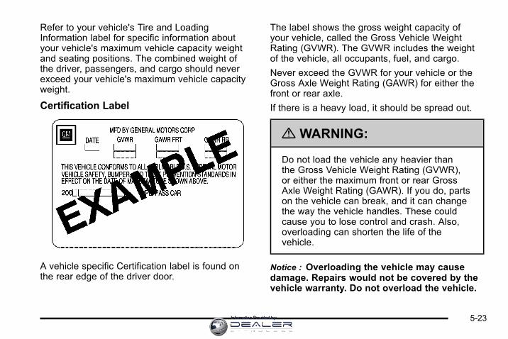
Refer to your vehicle's Tire and LoadingInformation label for specific information aboutyour vehicle's maximum vehicle capacity weightand seating positions. The combined weight ofthe driver, passengers, and cargo should neverexceed your vehicle's maximum vehicle capacityweight.
Certification Label
A vehicle specific Certification label is found onthe rear edge of the driver door.
The label shows the gross weight capacity ofyour vehicle, called the Gross Vehicle WeightRating (GVWR). The GVWR includes the weightof the vehicle, all occupants, fuel, and cargo.
Never exceed the GVWR for your vehicle or theGross Axle Weight Rating (GAWR) for either thefront or rear axle.
If there is a heavy load, it should be spread out.
{ WARNING:
Do not load the vehicle any heavier thanthe Gross Vehicle Weight Rating (GVWR),or either the maximum front or rear GrossAxle Weight Rating (GAWR). If you do, partson the vehicle can break, and it can changethe way the vehicle handles. These couldcause you to lose control and crash. Also,overloading can shorten the life of thevehicle.
Notice : Overloading the vehicle may causedamage. Repairs would not be covered by thevehicle warranty. Do not overload the vehicle.
5-23Information Provided by:

If things like suitcases, tools, packages,or anything else are put inside the vehicle,they will go as fast as the vehicle goes. If youhave to stop or turn quickly, or if there is a crash,they will keep going.
{ WARNING:
Things you put inside the vehicle can strikeand injure people in a sudden stop or turn,or in a crash.. Put things in the cargo area of the
vehicle. In the cargo area, put themas far forward as you can. Try to spreadthe weight evenly.
. Never stack heavier things, likesuitcases, inside the vehicle so that someof them are above the tops of the seats.
(Continued)
WARNING: (Continued)
. Do not leave an unsecured child restraintin the vehicle.
. When you carry something inside thevehicle, secure it whenever you can.
. Do not leave a seat folded down unlessyou need to.
Towing
Towing Your VehicleTo avoid damage, the disabled vehicle should be towedwith all four wheels off the ground. Consult your dealeror a professional towing service if the disabled vehiclemust be towed. See Roadside Assistance Program onpage 8‑7 .
To tow the vehicle behind another vehicle forrecreational purposes, such as behind a motorhome,see “Recreational Vehicle Towing” following.
5-24 Information Provided by:

Recreational Vehicle TowingRecreational vehicle towing means towing the vehiclebehind another vehicle – such as behind a motorhome.The two most common types of recreational vehicletowing are known as dinghy towing and dolly towing.Dinghy towing is towing the vehicle with all four wheelson the ground. Dolly towing is towing the vehicle withtwo wheels on the ground and two wheels up on adevice known as a dolly.
Here are some important things to consider beforerecreational vehicle towing:. What is the towing capacity of the towing vehicle?
Be sure to read the tow vehicle manufacturer'srecommendations.
. What is the distance that will be travelled? Somevehicles have restrictions on how far and how longthey can tow.
. Is the proper towing equipment going to beused? See your dealer or trailering professionalfor additional advice and equipmentrecommendations.
. Is the vehicle ready to be towed? Just as preparingthe vehicle for a long trip, make sure the vehicle isprepared to be towed. See Before Leaving on aLong Trip on page 5‑14.
Dinghy Towing
Notice: If the vehicle is towed with all four wheelson the ground, the drivetrain components could bedamaged. The repairs would not be covered by thevehicle warranty. Do not tow the vehicle with all fourwheels on the ground.
The vehicle was not designed to be towed with all fourwheels on the ground. If the vehicle must be towed, adolly should be used. See “Dolly Towing” that follows formore information.
5-25Information Provided by:

Dolly Towing
Use the following procedure to dolly tow the vehiclefrom the front:
1. Attach the dolly to the tow vehicle following thedolly manufacturer's instructions.
2. Drive the front wheels onto the dolly.
3. Shift the transmission to P (Park).
4. Firmly set the parking brake.
5. Use an adequate clamping device designed fortowing to ensure that the front wheels are lockedinto the straight position.
6. Secure the vehicle to the dolly following themanufacturer's instructions.
7. Release the parking brake only after the vehiclebeing towed is firmly attached to the towingvehicle.
8. Turn the ignition to LOCK/OFF and removethe key.
5-26 Information Provided by:

Towing a Trailer
{ WARNING:
The driver can lose control when pulling a trailer ifthe correct equipment is not used or the vehicle isnot driven properly. For example, if the trailer istoo heavy, the brakes may not work well— oreven at all. The driver and passengers couldbe seriously injured. The vehicle may also bedamaged; the resulting repairs would not becovered by the vehicle warranty. Pull a trailer onlyif all the steps in this section have been followed.Ask your dealer for advice and information abouttowing a trailer with the vehicle.
Notice: Pulling a trailer improperly can damage thevehicle and result in costly repairs not covered bythe vehicle warranty. To pull a trailer correctly,follow the advice in this section and see your dealerfor important information about towing a trailer withthe vehicle.
The vehicle can tow a trailer if it is equipped withthe proper trailer towing equipment. To identify thetrailering capacity of the vehicle, read the informationin “Weight of the Trailer” that appears later in thissection. Trailering is different than just driving thevehicle by itself. Trailering means changes in handling,acceleration, braking, durability and fuel economy.Successful, safe trailering takes correct equipment,and it has to be used properly.
The following information has many time-tested,important trailering tips and safety rules. Many ofthese are important for the safety of the driver andthe passengers. So please read this section carefullybefore pulling a trailer.
Load-pulling components such as the engine,transmission, axles, wheel assemblies and tires areforced to work harder against the drag of the addedweight. The engine is required to operate at relativelyhigher speeds and under greater loads, generatingextra heat. The trailer also adds considerably to windresistance, increasing the pulling requirements.
5-27Information Provided by:

Pulling A TrailerHere are some important points:. There are many different laws, including speed
limit restrictions, having to do with trailering.Make sure the rig will be legal, not only whereyou live but also where you will be driving.A good source for this information can bestate or provincial police.
. Do not tow a trailer at all during the first1,000 miles (1600 km) the new vehicle is driven.The engine, transmission or other parts could bedamaged. The repairs would not be covered bythe vehicle's warranty.
. Then, during the first 500 miles (800 km) that atrailer is towed, do not drive over 50 mph (80 km/h)and do not make starts at full throttle. This helpsthe engine and other parts of the vehicle wear inat the heavier loads.
. Obey speed limit restrictions when towing a trailer.Do not drive faster than the maximum postedspeed for trailers, or no more than 55 mph(90 km/h), to save wear on the vehicle's parts.
. Do not tow a trailer when the outside temperatureis above 100°F (38°C).
Three important considerations have to do with weight:. the weight of the trailer,. the weight of the trailer tongue. and the total weight on the vehicle's tires.
Weight of the TrailerHow heavy can a trailer safely be?
It should never weigh more than 1,000 lbs (454 kg).But even that can be too heavy.
It depends on how the rig is used. For example,speed, altitude, road grades, outside temperature andhow much the vehicle is used to pull a trailer are allimportant. It can depend on any special equipmenton the vehicle, and the amount of tongue weight thevehicle can carry. See “Weight of the Trailer Tongue”later in this section for more information.
Maximum trailer weight is calculated assuming only thedriver is in the tow vehicle and it has all the requiredtrailering equipment. The weight of additional optionalequipment, passengers and cargo in the tow vehiclemust be subtracted from the maximum trailer weight.
Ask your dealer for trailering information or advice,or write us at our Customer Assistance Offices.See Customer Assistance Offices on page 8‑6for more information.
5-28 Information Provided by:

Weight of the Trailer TongueThe tongue load (A) of any trailer is an important weightto measure because it affects the total gross weight ofthe vehicle. The Gross Vehicle Weight (GVW) includesthe curb weight of the vehicle, any cargo carried in it,and the people who will be riding in the vehicle. If thereare a lot of options, equipment, passengers or cargo inthe vehicle, it will reduce the tongue weight the vehiclecan carry, which will also reduce the trailer weight thevehicle can tow. If towing a trailer, the tongue load mustbe added to the GVW because the vehicle will becarrying that weight, too. See Loading the Vehicle onpage 5‑19 for more information about the vehicle'smaximum load capacity.
Using a weight-carrying hitch, the trailer tongue (A)should weigh 10 to 15 percent of the total loaded trailerweight (B).
After loading the trailer, weigh the trailer and then thetongue, separately, to see if the weights are proper.If they are not, adjustments might be made by movingsome items around in the trailer.
5-29Information Provided by:

Total Weight on the Vehicle's TiresBe sure the vehicle's tires are inflated to the upper limitfor cold tires. These numbers can be found on theCertification/Tire label. See Loading the Vehicle onpage 5‑19. Make sure not to go over the GVW limit forthe vehicle, including the weight of the trailer tongue.
HitchesIt is important to have the correct hitch equipment.Crosswinds, large trucks going by and rough roads area few reasons why the right hitch is needed. Here aresome rules to follow:. The rear bumper on the vehicle is not intended
for hitches. Do not attach rental hitches orother bumper-type hitches to it. Use only aframe-mounted hitch that does not attach tothe bumper.
. Will any holes be made in the body of the vehiclewhen the trailer hitch is installed? If there are, thenbe sure to seal the holes later when the hitch isremoved. If the holes are not sealed, dirt, water,and deadly carbon monoxide (CO) from theexhaust can get into the vehicle. See EngineExhaust on page 3‑29 in the Index for moreinformation.
Safety ChainsAlways attach chains between the vehicle and thetrailer. Cross the safety chains under the tongue of thetrailer to help prevent the tongue from contacting theroad if it becomes separated from the hitch. Instructionsabout safety chains may be provided by the hitchmanufacturer or by the trailer manufacturer. Follow themanufacturer's recommendation for attaching safetychains and do not attach them to the bumper. Alwaysleave just enough slack so the rig can turn. Never allowsafety chains to drag on the ground.
Trailer BrakesBecause the vehicle has antilock brakes, do not try totap into the vehicle's hydraulic brake system. If you do,both brake systems will not work well, or at all.
Does your trailer have its own brakes? Be sure to readand follow the instructions for the trailer brakes so youwill be able to install, adjust and maintain them properly.
5-30 Information Provided by:

Driving with a TrailerTowing a trailer requires a certain amount ofexperience. Get to know the rig before setting outfor the open road. Get acquainted with the feel ofhandling and braking with the added weight of thetrailer. And always keep in mind that the vehicle youare driving is now longer and not as responsive asthe vehicle is by itself.
Before starting, check all trailer hitch parts andattachments, safety chains, electrical connectors,lamps, tires and mirror adjustments. If the trailer haselectric brakes, start the vehicle and trailer movingand then apply the trailer brake controller by hand to besure the brakes are working. This checks the electricalconnection at the same time.
During the trip, check occasionally to be sure that theload is secure, and that the lamps and any trailerbrakes are still working.
Following DistanceStay at least twice as far behind the vehicle ahead asyou would when driving the vehicle without a trailer.This can help to avoid situations that require heavybraking and sudden turns.
PassingMore passing distance is needed when towing a trailer.Because the rig is longer, it is necessary to go muchfarther beyond the passed vehicle before returning tothe lane.
Backing UpHold the bottom of the steering wheel with one hand.Then, to move the trailer to the left, move that hand tothe left. To move the trailer to the right, move your handto the right. Always back up slowly and, if possible,have someone guide you.
Making TurnsNotice: Making very sharp turns while traileringcould cause the trailer to come in contact with thevehicle. The vehicle could be damaged. Avoidmaking very sharp turns while trailering.
When turning with a trailer, make wider turns thannormal. Do this so the trailer will not strike softshoulders, curbs, road signs, trees or other objects.Avoid jerky or sudden maneuvers. Signal well inadvance.
5-31Information Provided by:
Turn Signals When Towing a TrailerThe arrows on the instrument panel flash wheneversignaling a turn or lane change. Properly hooked up,the trailer lamps also flash, telling other drivers thevehicle is turning, changing lanes or stopping.
When towing a trailer, the arrows on the instrumentpanel flash for turns even if the bulbs on the trailer areburned out. For this reason you may think other driversare seeing the signal when they are not. It is importantto check occasionally to be sure the trailer bulbs are stillworking.
Driving on GradesNotice: Do not tow on steep continuous gradesexceeding 6 miles (9.6 km). Extended, higher thannormal engine and transmission temperatures mayresult and damage the vehicle. Frequent stops arevery important to allow the engine and transmissionto cool.
Reduce speed and shift to a lower gear before startingdown a long or steep downgrade. If the transmission isnot shifted down, the brakes might have to be used somuch that they would get hot and no longer work well.
On a long uphill grade, shift down and reduce thevehicle's speed to around 45 mph (70 km/h) to reducethe possibility of the engine and the transmissionoverheating. If the engine does overheat, see EngineOverheating on page 6‑29.
Parking on Hills
{ WARNING:
Parking the vehicle on a hill with the trailerattached can be dangerous. If something goeswrong, the rig could start to move. People can beinjured, and both the vehicle and the trailer can bedamaged. When possible, always park the rig ona flat surface.
If parking the rig on a hill:
1. Press the brake pedal, but do not shift into P (Park)yet. Turn the wheels into the curb if facing downhillor into traffic if facing uphill.
2. Have someone place chocks under the trailerwheels.
3. When the wheel chocks are in place, release thebrake pedal until the chocks absorb the load.
4. Reapply the brake pedal. Then apply the parkingbrake and shift the transmission into P (Park).
5. Release the brake pedal.
5-32 Information Provided by:

Leaving After Parking on a Hill1. Apply and hold the brake pedal while you:
. start the engine,
. shift into a gear, and
. release the parking brake.
2. Let up on the brake pedal.
3. Drive slowly until the trailer is clear of the chocks.
4. Stop and have someone pick up and store thechocks.
Maintenance When Trailer TowingThe vehicle needs service more often when pulling atrailer. See Scheduled Maintenance on page 7‑3 formore information. Things that are especially importantin trailer operation are automatic transmission fluid,engine oil, belts, cooling system and brake system. It isa good idea to inspect these before and during the trip.
Check periodically to see that all hitch nuts and boltsare tight.
Engine Cooling When Trailer TowingThe cooling system may temporarily overheat duringsevere operating conditions. See Engine Overheatingon page 6‑29.
Changing a Tire When Trailer TowingIf the vehicle gets a flat tire while towing a trailer, besure to secure the trailer and disconnect it from thevehicle before changing the tire.
5-33Information Provided by:

2 NOTES
5-34 Information Provided by:

Section 6 Service and Appearance Care
Service . . . . . . . . . . . . . . . . . . . . . . . . . . . . . . . . . . . . . . . . . . . . . 6-3Accessories and Modifications . . . . . . . . . . . . . . . . . . 6-3California Proposition 65 Warning . . . . . . . . . . . . . . . 6-4California Perchlorate MaterialsRequirements . . . . . . . . . . . . . . . . . . . . . . . . . . . . . . . . . 6-4
Doing Your Own Service Work . . . . . . . . . . . . . . . . . . 6-4Adding Equipment to the Outside of theVehicle . . . . . . . . . . . . . . . . . . . . . . . . . . . . . . . . . . . . . . . . 6-5
Fuel . . . . . . . . . . . . . . . . . . . . . . . . . . . . . . . . . . . . . . . . . . . . . . . . . 6-5Gasoline Octane . . . . . . . . . . . . . . . . . . . . . . . . . . . . . . . . 6-6Gasoline Specifications . . . . . . . . . . . . . . . . . . . . . . . . . 6-6California Fuel . . . . . . . . . . . . . . . . . . . . . . . . . . . . . . . . . . 6-6Additives . . . . . . . . . . . . . . . . . . . . . . . . . . . . . . . . . . . . . . . . 6-6Fuel E85 (85% Ethanol) . . . . . . . . . . . . . . . . . . . . . . . . . 6-8Fuels in Foreign Countries . . . . . . . . . . . . . . . . . . . . . . 6-9Filling the Tank . . . . . . . . . . . . . . . . . . . . . . . . . . . . . . . . 6-10Filling a Portable Fuel Container . . . . . . . . . . . . . . . 6-12
Checking Things Under the Hood . . . . . . . . . . . . . . . 6-12Hood Release . . . . . . . . . . . . . . . . . . . . . . . . . . . . . . . . . 6-13Engine Compartment Overview . . . . . . . . . . . . . . . . 6-14Engine Oil . . . . . . . . . . . . . . . . . . . . . . . . . . . . . . . . . . . . . 6-15Engine Oil Life System . . . . . . . . . . . . . . . . . . . . . . . . 6-18Engine Air Cleaner/Filter . . . . . . . . . . . . . . . . . . . . . . . 6-19Automatic Transmission Fluid . . . . . . . . . . . . . . . . . . 6-21Cooling System . . . . . . . . . . . . . . . . . . . . . . . . . . . . . . . . 6-24Engine Coolant . . . . . . . . . . . . . . . . . . . . . . . . . . . . . . . . 6-25
Engine Overheating . . . . . . . . . . . . . . . . . . . . . . . . . . . 6-29Overheated Engine ProtectionOperating Mode . . . . . . . . . . . . . . . . . . . . . . . . . . . . . 6-32
Power Steering Fluid . . . . . . . . . . . . . . . . . . . . . . . . . . 6-32Windshield Washer Fluid . . . . . . . . . . . . . . . . . . . . . . 6-33Brakes . . . . . . . . . . . . . . . . . . . . . . . . . . . . . . . . . . . . . . . . . 6-35Battery . . . . . . . . . . . . . . . . . . . . . . . . . . . . . . . . . . . . . . . . . 6-38Jump Starting . . . . . . . . . . . . . . . . . . . . . . . . . . . . . . . . . . 6-39
Headlamp Aiming . . . . . . . . . . . . . . . . . . . . . . . . . . . . . . . . 6-43
Bulb Replacement . . . . . . . . . . . . . . . . . . . . . . . . . . . . . . . . 6-43Halogen Bulbs . . . . . . . . . . . . . . . . . . . . . . . . . . . . . . . . . 6-43Headlamps, Front Turn Signal, Sidemarker, andParking Lamps . . . . . . . . . . . . . . . . . . . . . . . . . . . . . . 6-44
Taillamps, Turn Signal, Sidemarker, Stoplampsand Back-up Lamps . . . . . . . . . . . . . . . . . . . . . . . . . 6-47
License Plate Lamp . . . . . . . . . . . . . . . . . . . . . . . . . . . . 6-49Replacement Bulbs . . . . . . . . . . . . . . . . . . . . . . . . . . . . 6-50
Windshield Wiper Blade Replacement . . . . . . . . . . . 6-50
Tires . . . . . . . . . . . . . . . . . . . . . . . . . . . . . . . . . . . . . . . . . . . . . . . 6-52Tire Sidewall Labeling . . . . . . . . . . . . . . . . . . . . . . . . . 6-52Tire Terminology and Definitions . . . . . . . . . . . . . . . 6-56Inflation - Tire Pressure . . . . . . . . . . . . . . . . . . . . . . . . 6-59Tire Pressure Monitor System . . . . . . . . . . . . . . . . . 6-60Tire Pressure Monitor Operation . . . . . . . . . . . . . . . 6-62Tire Inspection and Rotation . . . . . . . . . . . . . . . . . . . 6-65
6-1Information Provided by:

Section 6 Service and Appearance Care
When It Is Time for New Tires . . . . . . . . . . . . . . . . . 6-66Buying New Tires . . . . . . . . . . . . . . . . . . . . . . . . . . . . . . 6-67Different Size Tires and Wheels . . . . . . . . . . . . . . . 6-69Uniform Tire Quality Grading . . . . . . . . . . . . . . . . . . . 6-70Wheel Alignment and Tire Balance . . . . . . . . . . . . 6-71Wheel Replacement . . . . . . . . . . . . . . . . . . . . . . . . . . . 6-72Tire Chains . . . . . . . . . . . . . . . . . . . . . . . . . . . . . . . . . . . . 6-73If a Tire Goes Flat . . . . . . . . . . . . . . . . . . . . . . . . . . . . . 6-74Changing a Flat Tire . . . . . . . . . . . . . . . . . . . . . . . . . . . 6-75Removing the Spare Tire and Tools . . . . . . . . . . . . 6-76Removing the Flat Tire and Installing theSpare Tire . . . . . . . . . . . . . . . . . . . . . . . . . . . . . . . . . . . 6-77
Storing a Flat or Spare Tire and Tools . . . . . . . . . 6-83Compact Spare Tire . . . . . . . . . . . . . . . . . . . . . . . . . . . 6-85
Appearance Care . . . . . . . . . . . . . . . . . . . . . . . . . . . . . . . . . 6-86Interior Cleaning . . . . . . . . . . . . . . . . . . . . . . . . . . . . . . 6-86Fabric/Carpet . . . . . . . . . . . . . . . . . . . . . . . . . . . . . . . . . . 6-87Leather . . . . . . . . . . . . . . . . . . . . . . . . . . . . . . . . . . . . . . . . 6-88Instrument Panel, Vinyl, and Other PlasticSurfaces . . . . . . . . . . . . . . . . . . . . . . . . . . . . . . . . . . . . . 6-88
Care of Safety Belts . . . . . . . . . . . . . . . . . . . . . . . . . . . 6-89Weatherstrips . . . . . . . . . . . . . . . . . . . . . . . . . . . . . . . . . . 6-89Washing Your Vehicle . . . . . . . . . . . . . . . . . . . . . . . . . 6-89
Cleaning Exterior Lamps/Lenses . . . . . . . . . . . . . . 6-90Finish Care . . . . . . . . . . . . . . . . . . . . . . . . . . . . . . . . . . . . 6-90Windshield and Wiper Blades . . . . . . . . . . . . . . . . . . 6-91Aluminum Wheels . . . . . . . . . . . . . . . . . . . . . . . . . . . . . 6-91Tires . . . . . . . . . . . . . . . . . . . . . . . . . . . . . . . . . . . . . . . . . . . 6-92Sheet Metal Damage . . . . . . . . . . . . . . . . . . . . . . . . . . 6-92Finish Damage . . . . . . . . . . . . . . . . . . . . . . . . . . . . . . . . 6-92Underbody Maintenance . . . . . . . . . . . . . . . . . . . . . . . 6-92Chemical Paint Spotting . . . . . . . . . . . . . . . . . . . . . . . 6-92
Vehicle Identification . . . . . . . . . . . . . . . . . . . . . . . . . . . . . 6-93Vehicle Identification Number (VIN) . . . . . . . . . . . . 6-93Service Parts Identification Label . . . . . . . . . . . . . . 6-93
Electrical System . . . . . . . . . . . . . . . . . . . . . . . . . . . . . . . . . 6-94Add-On Electrical Equipment . . . . . . . . . . . . . . . . . . 6-94Headlamp Wiring . . . . . . . . . . . . . . . . . . . . . . . . . . . . . . 6-94Windshield Wiper Fuses . . . . . . . . . . . . . . . . . . . . . . . 6-94Power Windows and Other Power Options . . . . . 6-94Fuses and Circuit Breakers . . . . . . . . . . . . . . . . . . . . 6-94Instrument Panel Fuse Block . . . . . . . . . . . . . . . . . . 6-95Underhood Fuse Block . . . . . . . . . . . . . . . . . . . . . . . . 6-96
Capacities and Specifications . . . . . . . . . . . . . . . . . . . 6-99
6-2 Information Provided by:

ServiceFor service and parts needs, visit your dealer.You will receive genuine GM parts and GM-trainedand supported service people.
Genuine GM parts have one of these marks:
Accessories and ModificationsWhen non‐dealer/non‐retailer accessories are addedto the vehicle, they can affect vehicle performanceand safety, including such things as airbags, braking,stability, ride and handling, emissions systems,aerodynamics, durability, and electronic systemslike antilock brakes, traction control, and stabilitycontrol. Some of these accessories could evencause malfunction or damage not covered by thevehicle warranty.
Damage to vehicle components resulting from theinstallation or use of non‐GM certified parts, includingcontrol module modifications, is not covered under theterms of the vehicle warranty and may affect remainingwarranty coverage for affected parts.
GM Accessories are designed to complement andfunction with other systems on the vehicle. Your GMdealer can accessorize the vehicle using genuine GMAccessories. When you go to your GM dealer and askfor GM Accessories, you will know that GM-trained andsupported service technicians will perform the workusing genuine GM Accessories.
Also, see Adding Equipment to Your Airbag-EquippedVehicle on page 2‑74.
6-3Information Provided by:

California Proposition 65 WarningMost motor vehicles, including this one, contain and/oremit chemicals known to the State of California tocause cancer and birth defects or other reproductiveharm. Engine exhaust, many parts and systems, manyfluids, and some component wear by-products containand/or emit these chemicals.
California Perchlorate MaterialsRequirementsCertain types of automotive applications, such asairbag initiators, seat belt pretensioners, and lithiumbatteries contained in remote keyless transmitters,may contain perchlorate materials. Special handlingmay be necessary. For additional information, seewww.dtsc.ca.gov/hazardouswaste/perchlorate.
Doing Your Own Service Work
{ WARNING:
You can be injured and the vehicle could bedamaged if you try to do service work on a vehiclewithout knowing enough about it.
. Be sure you have sufficient knowledge,experience, the proper replacement parts,and tools before attempting any vehiclemaintenance task.
. Be sure to use the proper nuts, bolts, andother fasteners. English and metric fastenerscan be easily confused. If the wrong fastenersare used, parts can later break or fall off.You could be hurt.
If doing some of your own service work, use the properservice manual. It tells you much more about how toservice the vehicle than this manual can. To orderthe proper service manual, see Service PublicationsOrdering Information on page 8‑16.
6-4 Information Provided by:

This vehicle has an airbag system. Before attemptingto do your own service work, see Servicing YourAirbag-Equipped Vehicle on page 2‑73.
Keep a record with all parts receipts and list themileage and the date of any service work performed.See Maintenance Record on page 7‑14.
Adding Equipment to the Outside ofthe VehicleThings added to the outside of the vehicle can affectthe airflow around it. This can cause wind noise andcan affect fuel economy and windshield washerperformance. Check with your dealer before addingequipment to the outside of the vehicle.
FuelUse of the recommended fuel is an important partof the proper maintenance of this vehicle. To helpkeep the engine clean and maintain optimum vehicleperformance, we recommend the use of gasolineadvertised as TOP TIER Detergent Gasoline.
Look for the TOP TIER label on the fuel pump toensure gasoline meets enhanced detergency standardsdeveloped by auto companies. A list of marketersproviding TOP TIER Detergent Gasoline can befound at www.toptiergas.com.
The 8th digit of the Vehicle Identification Number (VIN)shows the code letter or number that identifies thevehicle's engine. The VIN is at the top left of theinstrument panel. See Vehicle IdentificationNumber (VIN) on page 6‑93.
6-5Information Provided by:

If the vehicle has the 3.5LV6 engine (VIN Code K) orthe 3.9LV6 engine (VIN Code M), you can use eitherunleaded gasoline or ethanol fuel containing up to85% ethanol (E85). See Fuel E85 (85% Ethanol) onpage 6‑8 . In all other engines, use only the unleadedgasoline described under Gasoline Octane onpage 6‑6 .
Gasoline OctaneUse regular unleaded gasoline with a posted octanerating of 87 or higher. If the octane rating is less than87, an audible knocking noise, commonly referred toas spark knock, might be heard when driving. If thisoccurs, use a gasoline rated at 87 octane or higheras soon as possible. If heavy knocking is heard whenusing gasoline rated at 87 octane or higher, the engineneeds service.
Gasoline SpecificationsAt a minimum, gasoline should meet ASTMspecification D 4814 in the United States orCAN/CGSB‐3.5 or 3.511 in Canada. Some gasolinescontain an octane-enhancing additive calledmethylcyclopentadienyl manganese tricarbonyl (MMT).We recommend against the use of gasolines containingMMT. See Additives on page 6‑6 for additionalinformation.
California FuelIf the vehicle is certified to meet California EmissionsStandards, it is designed to operate on fuels that meetCalifornia specifications. See the underhood emissioncontrol label. If this fuel is not available in statesadopting California emissions standards, the vehiclewill operate satisfactorily on fuels meeting federalspecifications, but emission control system performancemight be affected. The malfunction indicator lamp couldturn on and the vehicle might fail a smog‐check test.See Malfunction Indicator Lamp on page 4‑31. If thisoccurs, return to your authorized dealer for diagnosis.If it is determined that the condition is caused by thetype of fuel used, repairs might not be covered by thevehicle warranty.
AdditivesTo provide cleaner air, all gasolines in the United Statesare now required to contain additives that help preventengine and fuel system deposits from forming, allowingthe emission control system to work properly. In mostcases, nothing should have to be added to the fuel.However, some gasolines contain only the minimumamount of additive required to meet U.S. EnvironmentalProtection Agency regulations. To help keep fuelinjectors and intake valves clean, or if the vehicle
6-6 Information Provided by:

experiences problems due to dirty injectors or valves,look for gasoline that is advertised as TOP TIERDetergent Gasoline.
For customers who do not use TOP TIER DetergentGasoline regularly, one bottle of GM Fuel SystemTreatment PLUS, added to the fuel tank at everyengine oil change, can help clean deposits from fuelinjectors and intake valves. GM Fuel System TreatmentPLUS is the only gasoline additive recommended byGeneral Motors.
Also, your dealer has additives that will help correct andprevent most deposit‐related problems.
Gasolines containing oxygenates, such as ethers andethanol, and reformulated gasolines might be availablein your area. We recommend that you use thesegasolines, if they comply with the specificationsdescribed earlier. However, E85 (85% ethanol) andother fuels containing more than 10% ethanol mustnot be used in vehicles that were not designed forthose fuels.
Notice: This vehicle was not designed for fuel thatcontains methanol. Do not use fuel containingmethanol. It can corrode metal parts in the fuelsystem and also damage plastic and rubber parts.That damage would not be covered under thevehicle warranty.
Some gasolines that are not reformulated for lowemissions can contain an octane-enhancing additivecalled methylcyclopentadienyl manganese tricarbonyl(MMT); ask the attendant where you buy gasolinewhether the fuel contains MMT. We recommend againstthe use of such gasolines. Fuels containing MMT canreduce the life of spark plugs and the performanceof the emission control system could be affected.The malfunction indicator lamp might turn on. If thisoccurs, return to your dealer for service.
6-7Information Provided by:

Fuel E85 (85% Ethanol)The 8th digit of the Vehicle Identification Number (VIN)shows the code letter or number that identifies thevehicle's engine. The VIN is at the top left of theinstrument panel. See Vehicle IdentificationNumber (VIN) on page 6‑93.
If the vehicle has the 3.5L V6 engine (VIN Code K)or the 3.9LV6 engine (VIN Code M), you can useeither unleaded gasoline or ethanol fuel containingup to 85% ethanol (E85). See Fuel on page 6‑5 .In all other engines, use only the unleaded gasolinedescribed under Gasoline Octane on page 6‑6.
Only vehicles that have the 3.5L V6 engine(VIN Code K) or the 3.9LV6 engine (VIN Code M) canuse 85% ethanol fuel (E85). We encourage the use ofE85 in vehicles that are designed to use it. The ethanolin E85 is a “renewable” fuel, meaning it is made fromrenewable sources such as corn and other crops.
Many service stations will not have an 85% ethanol fuel(E85) pump available. The U.S. Department of Energyhas an alternative fuels website (www.eere.energy.gov/afdc/infrastructure/locator.html) that can help you findE85 fuel. Those stations that do have E85 should havea label indicating ethanol content. Do not use the fuel ifthe ethanol content is greater than 85%.
At a minimum, E85 should meet ASTM SpecificationD 5798. By definition, this means that fuel labeled E85will have an ethanol content between 70% and 85%.Filling the fuel tank with fuel mixtures that do not meetASTM specifications can affect driveability and couldcause the malfunction indicator lamp to come on.
To ensure quick starts in the wintertime, the E85 fuelmust be formulated properly for your climate accordingto ASTM specification D 5798. If you have troublestarting on E85, it could be because the E85 fuel is notproperly formulated for your climate. If this happens,switching to gasoline or adding gasoline to the fuel tankcan improve starting. For good starting and heaterefficiency below 0°C (32°F), the fuel mix in the fuel tankshould contain no more than 70% ethanol. It is best notto alternate repeatedly between gasoline and E85.
6-8 Information Provided by:

If you do switch fuels, it is recommended that youadd as much fuel as possible — do not add less than11 L (three gallons) when refueling. You should drivethe vehicle immediately after refueling for at least11 km (seven miles) to allow the vehicle to adaptto the change in ethanol concentration.
E85 has less energy per gallon than gasoline, so youwill need to refill the fuel tank more often when usingE85 than when you are using gasoline. See Filling theTank on page 6‑10.
Notice: Some additives are not compatible with E85fuel and can harm the vehicle's fuel system. Do notadd anything to E85. Damage caused by additiveswould not be covered by the vehicle warranty.
Notice: This vehicle was not designed for fuel thatcontains methanol. Do not use fuel containingmethanol. It can corrode metal parts in the fuelsystem and also damage plastic and rubber parts.That damage would not be covered under thevehicle warranty.
Fuels in Foreign CountriesIf you plan on driving in another country outside theUnited States or Canada, the proper fuel might be hardto find. Never use leaded gasoline or any other fuelnot recommended in the previous text on fuel. Costlyrepairs caused by use of improper fuel would not becovered by the vehicle warranty.
To check the fuel availability, ask an auto club,or contact a major oil company that does business inthe country where you will be driving.
6-9Information Provided by:

Filling the Tank
{ WARNING:
Fuel vapor burns violently and a fuel fire cancause bad injuries. To help avoid injuries to youand others, read and follow all the instructions onthe fuel pump island. Turn off the engine whenrefueling. Do not smoke near fuel or whenrefueling the vehicle. Do not use cellular phones.Keep sparks, flames, and smoking materials awayfrom fuel. Do not leave the fuel pump unattendedwhen refueling the vehicle. This is against the lawin some places. Do not re-enter the vehicle whilepumping fuel. Keep children away from the fuelpump; never let children pump fuel.
The tethered fuel cap is located behind a hinged fueldoor on the driver side of the vehicle. If the vehiclehas E85 fuel capability, the fuel cap will be yellow andstate that E85 or gasoline can be used. See Fuel E85(85% Ethanol) on page 6‑8.
To remove the fuel cap, turn it slowly counterclockwise.
While refueling, hang the tethered fuel cap on the hookon the inside of the fuel door.
6-10 Information Provided by:

{ WARNING:
Fuel can spray out on you if you open the fuel captoo quickly. If you spill fuel and then somethingignites it, you could be badly burned. This spraycan happen if the tank is nearly full, and is morelikely in hot weather. Open the fuel cap slowly andwait for any hiss noise to stop. Then unscrew thecap all the way.
Be careful not to spill fuel. Do not top off or overfill thetank and wait a few seconds after you have finishedpumping before removing the nozzle. Clean fuel frompainted surfaces as soon as possible. See WashingYour Vehicle on page 6‑89.
When replacing the fuel cap, turn it clockwiseuntil it clicks. Make sure the cap is fully installed.The diagnostic system can determine if the fuel caphas been left off or improperly installed. This wouldallow fuel to evaporate into the atmosphere.See Malfunction Indicator Lamp on page 4‑31.
The TIGHTEN GAS CAP message displays on theDriver Information Center (DIC) if the fuel cap is notproperly installed. See DIC Warnings and Messages onpage 4‑44 for more information.
{ WARNING:
If a fire starts while you are refueling, do notremove the nozzle. Shut off the flow of fuel byshutting off the pump or by notifying the stationattendant. Leave the area immediately.
Notice: If you need a new fuel cap, be sure to getthe right type. Your dealer can get one for you.If you get the wrong type, it may not fit properly.This may cause the malfunction indicator lamp tolight and may damage the fuel tank and emissionssystem. See Malfunction Indicator Lamp onpage 4‑31.
6-11Information Provided by:

Filling a Portable Fuel Container
{ WARNING:
Never fill a portable fuel container while it is inthe vehicle. Static electricity discharge from thecontainer can ignite the fuel vapor. You can bebadly burned and the vehicle damaged if thisoccurs. To help avoid injury to you and others:
. Dispense fuel only into approved containers.
. Do not fill a container while it is inside avehicle, in a vehicle's trunk, pickup bed,or on any surface other than the ground.
. Bring the fill nozzle in contact with the insideof the fill opening before operating the nozzle.Contact should be maintained until the filling iscomplete.
. Do not smoke while pumping fuel.
. Do not use a cellular phone whilepumping fuel.
Checking Things Underthe Hood
{ WARNING:
An electric fan under the hood can start up andinjure you even when the engine is not running.Keep hands, clothing, and tools away from anyunderhood electric fan.
{ WARNING:
Things that burn can get on hot engine parts andstart a fire. These include liquids like fuel, oil,coolant, brake fluid, windshield washer and otherfluids, and plastic or rubber. You or others couldbe burned. Be careful not to drop or spill thingsthat will burn onto a hot engine.
6-12 Information Provided by:

Hood ReleaseTo open the hood, do the following:
1. Pull the interior hoodrelease handle withthis symbol on it. It islocated to the left of theparking brake pedal.
2. Then go to the front of the vehicle and release thesecondary hood latch, located near the center ofthe hood front, by pushing the latch to the right.
3. Lift the hood.
Before closing the hood, be sure all the filler caps areon properly. Then pull the hood down and close it firmly.
6-13Information Provided by:

Engine Compartment OverviewWhen you open the hood on the 3.5LV6 engine (3.9LV6 similar), here is what you will see:
6-14 Information Provided by:

A. Windshield Washer Fluid Reservoir. See “AddingWasher Fluid” under Windshield Washer Fluid onpage 6‑33.
B. Battery. See Battery on page 6‑38.
C. Underhood Fuse Block. See Underhood FuseBlock on page 6‑96.
D. Remote Positive (+) Terminal. See Jump Startingon page 6‑39.
E. Coolant Recovery Tank. See “Checking Coolant”under Cooling System on page 6‑24.
F. Pressure Cap. See Cooling System on page 6‑24.
G. Power Steering Fluid Cap. See Power SteeringFluid on page 6‑32.
H. Engine Oil Fill Cap. See “When to Add Engine Oil”under Engine Oil on page 6‑15.
I. Engine Oil Dipstick. See “Checking Engine Oil”under Engine Oil on page 6‑15.
J. Automatic Transmission Fluid Dipstick (Out ofView). See “Checking the Fluid Level” underAutomatic Transmission Fluid on page 6‑21.
K. Brake Master Cylinder Reservoir. See “BrakeFluid” under Brakes on page 6‑35.
L. Engine Air Cleaner/Filter. See Engine AirCleaner/Filter on page 6‑19.
Engine Oil
Checking Engine OilIt is a good idea to check the engine oil level at eachfuel fill. In order to get an accurate reading, the oil mustbe warm and the vehicle must be on level ground.
The engine oil dipstick handle is a yellow loop.See Engine Compartment Overview on page 6‑14for the location of the engine oil dipstick.
1. Turn off the engine and give the oil several minutesto drain back into the oil pan. If this is not done, theoil dipstick might not show the actual level.
2. Pull out the dipstick and clean it with a paper towelor cloth, then push it back in all the way. Remove itagain, keeping the tip down, and check the level.
6-15Information Provided by:

When to Add Engine Oil
V6 Engine
V8 Engine
If the oil is below the cross-hatched area at the tipof the dipstick, add at least one quart/liter of therecommended oil. This section explains what kindof oil to use. For engine oil crankcase capacity, seeCapacities and Specifications on page 6‑99.
Notice: Do not add too much oil. If the enginehas so much oil that the oil level gets above thecross-hatched area that shows the proper operatingrange, the engine could be damaged.
See Engine CompartmentOverview on page 6‑14for the location of theengine oil fill cap.
Add enough oil to put the level somewhere in the properoperating range in the cross-hatched area. Push thedipstick all the way back in when through.
6-16 Information Provided by:

What Kind of Engine Oil to UseLook for three things:. GM6094M
Use only an oil that meets GM StandardGM6094M.
. SAE 5W-30
SAE 5W-30 is best for the vehicle. These numberson an oil container show its viscosity, or thickness.Do not use other viscosity oils such asSAE 20W-50.
. American Petroleum Institute (API) starburstsymbol
Oils meeting theserequirements should havethe starburst symbol onthe container. This symbolindicates that the oil hasbeen certified by theAmerican PetroleumInstitute (API).
Notice: Use only engine oil identified as meetingGM Standard GM6094M and showing the AmericanPetroleum Institute Certified For Gasoline Enginesstarburst symbol. Failure to use the recommendedoil can result in engine damage not covered by thevehicle warranty.
Cold Temperature OperationIf in an area of extreme cold, where the temperaturefalls below −20°F (−29°C), use either an SAE 5W-30synthetic oil or an SAE 0W-30 engine oil. Both provideeasier cold starting for the engine at extremely lowtemperatures. Always use an oil that meets the requiredspecification, GM6094M. See “What Kind of Engine Oilto Use” for more information.
Engine Oil Additives / Engine OilFlushesDo not add anything to the oil. The recommendedoils with the starburst symbol that meet GM StandardGM6094M are all that is needed for good performanceand engine protection.
Engine oil system flushes are not recommended andcould cause engine damage not covered by the vehiclewarranty.
6-17Information Provided by:

Engine Oil Life System
When to Change Engine OilThis vehicle has a computer system that indicates whento change the engine oil and filter. This is based onengine revolutions and engine temperature, and not onmileage. Based on driving conditions, the mileage atwhich an oil change is indicated can vary considerably.For the oil life system to work properly, the system mustbe reset every time the oil is changed.
When the system has calculated that oil life has beendiminished, it indicates that an oil change is necessary.A CHANGE ENGINE OIL SOON message comes on.See DIC Warnings and Messages on page 4‑44.Change the oil as soon as possible within the next600 miles (1 000 km). It is possible that, if drivingunder the best conditions, the oil life system might notindicate that an oil change is necessary for over a year.However, the engine oil and filter must be changed atleast once a year and at this time the system must bereset. Your dealer has trained service people who willperform this work using genuine parts and reset thesystem. It is also important to check the oil regularlyand keep it at the proper level.
If the system is ever reset accidentally, the oil mustbe changed at 3,000 miles (5 000 km) since the lastoil change. Remember to reset the oil life systemwhenever the oil is changed.
How to Reset the Engine Oil LifeSystemThe Engine Oil Life System calculates when tochange the engine oil and filter based on vehicle use.Whenever the oil is changed, reset the system so itcan calculate when the next oil change is required.If a situation occurs where the oil is changed prior to aCHANGE ENGINE OIL SOON message being turnedon, reset the system.
Always reset the engine oil life to 100% after every oilchange. It will not reset itself. To reset the Engine OilLife System:
1. Display the OIL LIFE REMAINING on the DIC.
2. Press and hold the SET/RESET button on the DICfor more than five seconds. The oil life will changeto 100%.
If the CHANGE ENGINE OIL SOON message comesback on when the vehicle is started, the Engine Oil LifeSystem has not reset. Repeat the procedure.
6-18 Information Provided by:

What to Do with Used OilUsed engine oil contains certain elements that can beunhealthy for your skin and could even cause cancer.Do not let used oil stay on your skin for very long. Cleanyour skin and nails with soap and water, or a good handcleaner. Wash or properly dispose of clothing or ragscontaining used engine oil. See the manufacturer'swarnings about the use and disposal of oil products.
Used oil can be a threat to the environment. If youchange your own oil, be sure to drain all the oil from thefilter before disposal. Never dispose of oil by putting it inthe trash, pouring it on the ground, into sewers, or intostreams or bodies of water. Recycle it by taking it to aplace that collects used oil.
Engine Air Cleaner/FilterThe engine air cleaner/filter is located in the enginecompartment on the driver's side of the vehicle.See Engine Compartment Overview on page 6‑14for more information on location.
When to Inspect the Engine AirCleaner/FilterInspect the air cleaner/filter at the Maintenance IIintervals and replace it at the first oil change aftereach 50,000 mile (80 000 km) interval. See ScheduledMaintenance on page 7‑3 for more information. If youare driving in dusty/dirty conditions, inspect the filter ateach engine oil change.
How to Inspect the Engine AirCleaner/FilterTo inspect the air cleaner/filter, remove the filter fromthe vehicle and lightly shake the filter to release loosedust and dirt. If the filter remains caked with dirt, a newfilter is required.
6-19Information Provided by:

To inspect or replace the engine air cleaner/filter do thefollowing:
1. Lift the filter cover tabs on top of the engine aircleaner/filter housing.
2. Push the filter cover housing toward the engine.
3. Pull out the filter.
6-20 Information Provided by:

4. Inspect or replace the engine air cleaner/filter.
5. To reinstall the cover, position the tabs through thehinges on the housing.
6. Push the cover tabs on top of the housing to lockthe cover in place.
{ WARNING:
Operating the engine with the air cleaner/filter offcan cause you or others to be burned. The aircleaner not only cleans the air; it helps to stopflames if the engine backfires. Use caution whenworking on the engine and do not drive with theair cleaner/filter off.
Notice: If the air cleaner/filter is off, dirt can easilyget into the engine, which could damage it. Alwayshave the air cleaner/filter in place when you aredriving.
Automatic Transmission Fluid
When to Check and Change AutomaticTransmission FluidA good time to check your automatic transmission fluidlevel is when the engine oil is changed.
Change the fluid and filter at the intervals listed inScheduled Maintenance on page 7‑3 , and be sureto use the transmission fluid listed in RecommendedFluids and Lubricants on page 7‑11.
6-21Information Provided by:

How to Check Automatic TransmissionFluidBecause this operation can be a little difficult, youmay choose to have this done at the dealer servicedepartment.
If you do it yourself, be sure to follow all the instructionshere, or you could get a false reading on the dipstick.
Notice: Too much or too little fluid can damage thetransmission. Too much can mean that some of thefluid could come out and fall on hot engine partsor exhaust system parts, starting a fire. Too littlefluid could cause the transmission to overheat.Be sure to get an accurate reading if checking thetransmission fluid.
Wait at least 30 minutes before checking thetransmission fluid level if you have been driving:. When outside temperatures are above
32°C (90°F).. At high speed for quite a while.. In heavy traffic— especially in hot weather.. While pulling a trailer.
To get the right reading, the fluid should be atnormal operating temperature, which is 82°C to 93°C(180°F to 200°F).
Get the vehicle warmed up by driving about 24 km(15 miles) when outside temperatures are above10°C (50°F). If it is colder than 10°C (50°F), you mayhave to drive longer.
Checking the Fluid LevelPrepare your vehicle as follows:
1. Park your vehicle on a level place. Keep theengine running.
2. With the parking brake applied, place the shiftlever in P (Park).
3. With your foot on the brake pedal, move the shiftlever through each gear range, pausing for aboutthree seconds in each range. Then, position theshift lever in P (Park).
4. Let the engine run at idle for three to five minutes.
6-22 Information Provided by:

Then, without shutting off the engine, follow thesesteps:
1. Pull out the dipstick and wipe it with a clean rag orpaper towel.
The transmission fluiddipstick handle is theblack loop with thissymbol on it. It is locatednear the rear of theengine compartment.
See Engine Compartment Overview on page 6‑14for more information on location.
2. Push it back in all the way, wait three seconds andthen pull it back out again.
V6 Engines
Check both sides of the dipstick, and readthe lower level. The fluid level must be in thecross-hatched area.
4. If the fluid level is in the acceptable range, pushthe dipstick back in all the way.
6-23Information Provided by:

How to Add FluidRefer to the Maintenance Schedule to determine whatkind of transmission fluid to use. See RecommendedFluids and Lubricants on page 7‑11.
If the fluid level is low, add only enough of the properfluid to bring the level into the cross-hatched area onthe dipstick.
1. Pull out the dipstick.
2. Using a long-neck funnel, add enough fluid at thedipstick hole to bring it to the proper level.
It does not take much fluid, generally less thanone pint (0.5 L). Do not overfill.
Notice: Use of the incorrect automatic transmissionfluid may damage the vehicle, and the damages maynot be covered by the vehicle's warranty. Alwaysuse the automatic transmission fluid listed inRecommended Fluids and Lubricants on page 7‑11.
3. After adding fluid, recheck the fluid level asdescribed under “How to Check AutomaticTransmission Fluid,” earlier in this section.
4. When the correct fluid level is obtained, push thedipstick back in all the way.
Cooling SystemThe Cooling System allows the engine to maintain thecorrect working temperature.
3.5L V6 Engine shown, 3.9L Engine similar
A. Coolant Recovery Tank
B. Pressure Cap
C. Electric Engine Cooling Fans
6-24 Information Provided by:

{ WARNING:
An electric engine cooling fan under the hood canstart up even when the engine is not running andcan cause injury. Keep hands, clothing, and toolsaway from any underhood electric fan.
{ WARNING:
Heater and radiator hoses, and other engineparts, can be very hot. Do not touch them. If youdo, you can be burned.
Do not run the engine if there is a leak. If you runthe engine, it could lose all coolant. That couldcause an engine fire, and you could be burned.Get any leak fixed before you drive the vehicle.
Notice: Using coolant other than DEX-COOL® cancause premature engine, heater core, or radiatorcorrosion. In addition, the engine coolant couldrequire changing sooner, at 50 000 km (30,000miles)or 24months, whichever occurs first. Any repairswould not be covered by the vehicle warranty.Always use DEX-COOL® (silicate-free) coolantin the vehicle.
Engine CoolantThe cooling system in the vehicle is filled withDEX-COOL® engine coolant. This coolant is designedto remain in the vehicle for five years or 150,000 miles(240 000 km), whichever occurs first.
The following explains the cooling system and howto check and add coolant when it is low. If there isa problem with engine overheating, see EngineOverheating on page 6‑29.
6-25Information Provided by:

What to Use
{ WARNING:
Adding only plain water to the cooling system canbe dangerous. Plain water, or some other liquidsuch as alcohol, can boil before the propercoolant mixture will. The vehicle's coolant warningsystem is set for the proper coolant mixture. Withplain water or the wrong mixture, the engine couldget too hot but you would not get the overheatwarning. The engine could catch fire and you orothers could be burned. Use a 50/50 mixture ofclean, drinkable water and DEX-COOL® coolant.
Use a 50/50 mixture of clean, drinkable water andDEX-COOL® coolant. If using this mixture, nothing elseneeds to be added. This mixture:. Gives freezing protection down to −34°F (−37°C),
outside temperature.. Gives boiling protection up to 265°F (129°C),
engine temperature.. Protects against rust and corrosion.. Will not damage aluminum parts.. Helps keep the proper engine temperature.
Notice: If an improper coolant mixture is used,the engine could overheat and be badly damaged.The repair cost would not be covered by the vehiclewarranty. Too much water in the mixture can freezeand crack the engine, radiator, heater core, andother parts.
Notice: If extra inhibitors and/or additives are usedin the vehicle's cooling system, the vehicle could bedamaged. Use only the proper mixture of the enginecoolant listed in this manual for the cooling system.See Recommended Fluids and Lubricants onpage 7‑11 for more information.
6-26 Information Provided by:

Checking CoolantThe vehicle must be on a level surface when checkingthe coolant level.
Check to see if coolant is visible in the coolant recoverytank. If the coolant inside the coolant recovery tank isboiling, do not do anything else until it cools down.If coolant is visible but the coolant level is not at orabove the COLD FILL line, add a 50/50 mixture ofclean, drinkable water and DEX-COOL® coolant at thecoolant recovery tank, but be sure the cooling systemis cool before this is done. See Engine Coolant EngineCoolant for more information.
If your vehicle has one of the V6 engines, the coolantrecovery tank is located in the rear of the enginecompartment on the passenger's side of the vehicle.If your vehicle has the 5.3L V8 engine, the coolantrecovery tank is located in the rear of the enginecompartment on the driver's side of the vehicle.See Engine Compartment Overview on page 6‑14.
When the engine is cold, the coolant level should be ator above the COLD FILL line on the coolant recoverytank. To check the coolant level, look for the COLD FILLline on the side of the coolant recovery tank that facesthe engine. If the level is not correct, there may be aleak in the cooling system.
How to Add Coolant to theRecovery Tank
{ WARNING:
You can be burned if you spill coolant on hotengine parts. Coolant contains ethylene glycoland it will burn if the engine parts are hot enough.Do not spill coolant on a hot engine.
Notice: This vehicle has a specific coolant fillprocedure. Failure to follow this procedure couldcause the engine to overheat and be severelydamaged.
If coolant is needed, add the proper DEX-COOL®
coolant mixture at the coolant recovery tank.
When the coolant level in the coolant recovery tank is atthe COLD FILL line, start the vehicle.
If the overheat warning continues, there is one morething you can try. You can add the proper coolantmixture directly to the cooling system through thecoolant fill neck on the engine, but be sure the systemis cool before you do it.
6-27Information Provided by:

How to Add Coolant to the Radiator
{ WARNING:
An electric engine cooling fan under the hood canstart up even when the engine is not running andcan cause injury. Keep hands, clothing, and toolsaway from any underhood electric fan.
{ WARNING:
Steam and scalding liquids from a hot coolingsystem can blow out and burn you badly. They areunder pressure, and if you turn the surge tankpressure cap— even a little— they can comeout at high speed. Never turn the cap when thecooling system, including the surge tank pressurecap, is hot. Wait for the cooling system and surgetank pressure cap to cool if you ever have to turnthe pressure cap.
If coolant is needed, add the proper mixture directlyto the radiator, but be sure the cooling system is coolbefore this is done.
1. You can remove thepressure cap whenthe cooling system,including the pressurecap and upper radiatorhose is no longerhot. Turn thepressure cap slowlycounterclockwise.
If you hear a hiss, waitfor that to stop. A hissmeans that there is stillsome pressure left.
2. Keep turning the pressure cap and remove it.
3. Fill the cooling system with the properDEX-COOL® coolant mixture, up to the base ofthe filler neck. See Engine Coolant on page 6‑25Engine Coolant for more information about theproper coolant mixture. Rinse or wipe any spilledcoolant from the engine and the compartment.
6-28 Information Provided by:
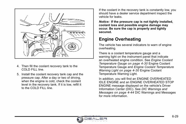
4. Then fill the coolant recovery tank to theCOLD FILL line.
5. Install the coolant recovery tank cap and thepressure cap. After a day or two of driving,when the engine is cold, check the coolantlevel in the recovery tank. If it is low, refill itto the COLD FILL line.
If the coolant in the recovery tank is constantly low, youshould have a dealer service department inspect thevehicle for leaks.
Notice: If the pressure cap is not tightly installed,coolant loss and possible engine damage mayoccur. Be sure the cap is properly and tightlysecured.
Engine OverheatingThe vehicle has several indicators to warn of engineoverheating.
There is a coolant temperature gauge and awarning light on the instrument panel that indicatean overheated engine condition. See Engine CoolantTemperature Gauge on page 4‑30 Engine CoolantTemperature Gauge and Engine Coolant TemperatureWarning Light on page 4‑30 Engine CoolantTemperature Warning Light.
In addition, you will find an ENGINE OVERHEATEDIDLE ENGINE and an ENGINE OVERHEATED STOPENGINE message displayed on the vehicle's DriverInformation Center (DIC). See DIC Warnings andMessages on page 4‑44 DIC Warnings and Messagesfor more information.
6-29Information Provided by:
You may decide not to lift the hood when this warningappears, but instead get service help right away.See Roadside Assistance Program on page 8‑7.
If you do decide to lift the hood, make sure the vehicleis parked on a level surface.
Then check to see if the engine cooling fans arerunning. If the engine is overheating, both fans shouldbe running. If they are not, do not continue to run theengine and have the vehicle serviced.
Notice: Engine damage from running the enginewithout coolant is not covered by the warranty.
Notice: If the engine catches fire while drivingwith no coolant, the vehicle can be badly damaged.The costly repairs would not be covered by thevehicle warranty. See Overheated Engine ProtectionOperating Mode on page 6‑32 for information ondriving to a safe place in an emergency.
If Steam Is Coming From The EngineCompartment
{ WARNING:
Steam from an overheated engine can burn youbadly, even if you just open the hood. Stay awayfrom the engine if you see or hear steam comingfrom it. Turn it off and get everyone away fromthe vehicle until it cools down. Wait until thereis no sign of steam or coolant before you openthe hood.
If you keep driving when the vehicles engine isoverheated, the liquids in it can catch fire. You orothers could be badly burned. Stop the engine ifit overheats, and get out of the vehicle until theengine is cool.
See Overheated Engine Protection OperatingMode on page 6‑32 for information on driving toa safe place in an emergency.
6-30 Information Provided by:

If No Steam Is Coming From TheEngine CompartmentIf an engine overheat warning is displayed but no steamcan be seen or heard, the problem may not be tooserious. Sometimes the engine can get a little toohot when the vehicle:. Climbs a long hill on a hot day.. Stops after high-speed driving.. Idles for long periods in traffic.. Tows a trailer.
If the overheat warning is displayed with no sign ofsteam:
1. Turn the air off.
2. Turn the heater on to the highest temperature andto the highest fan speed. Open the windows asnecessary.
3. In heavy traffic, let the engine idle in N (Neutral)while stopped. If it is safe to do so, pull off theroad, shift to P (Park) or N (Neutral) and let theengine idle.
If the temperature overheat gauge is no longer inthe overheat zone or an overheat warning no longerdisplays, the vehicle can be driven. Continue to drivethe vehicle slow for about 10 minutes. Keep a safevehicle distance from the car in front of you. If thewarning does not come back on, continue to drivenormally.
If the warning continues, pull over, stop, and park thevehicle right away.
If there is no sign of steam, idle the engine forthree minutes while parked. If the warning is stilldisplayed, turn off the engine until it cools down.Also, see "Overheated Engine Protection OperatingMode" later in this section.
6-31Information Provided by:

Overheated Engine ProtectionOperating ModeThis emergency operating mode allows your vehicle tobe driven to a safe place in an emergency situation.If an overheated engine condition exists, an overheatprotection mode which alternates firing groups ofcylinders helps prevent engine damage. In this mode,you will notice a significant loss in power and engineperformance. The coolant temperature gauge willindicate an overheat condition exists. Driving extendedmiles (km) and/or towing a trailer in the overheatprotection mode should be avoided.
Notice: After driving in the overheated engineprotection operating mode, to avoid engine damage,allow the engine to cool before attempting anyrepair. The engine oil will be severely degraded.Repair the cause of coolant loss, change the oiland reset the oil life system. See Engine Oil onpage 6‑15.
Power Steering FluidThe power steering fluidreservoir is located towardthe rear of the enginecompartment on thepassenger's side of thevehicle. See EngineCompartment Overviewon page 6‑14 forreservoir location.
When to Check Power Steering FluidIt is not necessary to regularly check power steeringfluid unless you suspect there is a leak in the system oryou hear an unusual noise. A fluid loss in this systemcould indicate a problem. Have the system inspectedand repaired.
6-32 Information Provided by:

How to Check Power Steering FluidTo check the power steering fluid, do the following:
1. Turn the key off and let the engine compartmentcool down.
2. Wipe the cap and the top of the reservoir clean.
3. Unscrew the cap and wipe the dipstick with aclean rag.
4. Replace the cap and completely tighten it.
5. Remove the cap again and look at the fluid levelon the dipstick.
The fluid level should be somewhere within thecross‐hatched area on the dipstick. If the fluid isat the ADD mark, you should add fluid.
What to UseTo determine what kind of fluid to use, seeRecommended Fluids and Lubricants on page 7‑11.Always use the proper fluid.
Notice: Use of the incorrect fluid may damage thevehicle and the damages may not be covered bythe vehicle's warranty. Always use the correct fluidlisted in Recommended Fluids and Lubricants onpage 7‑11.
Windshield Washer Fluid
What to UseWhen you need windshield washer fluid, be sureto read the manufacturer's instructions before use.If you will be operating your vehicle in an area wherethe temperature may fall below freezing, use a fluidthat has sufficient protection against freezing.
6-33Information Provided by:

Adding Washer FluidA WASHER FLUID LOW ADD FLUID message will bedisplayed on the Driver Information Center (DIC) whenyou need to add windshield washer fluid to your vehicle.See DIC Warnings and Messages on page 4‑44 formore information.
Open the cap with thewasher symbol on it. Addwasher fluid until the tankis full.
See Engine Compartment Overview on page 6‑14 formore information on location.
Notice:. When using concentrated washer fluid,
follow the manufacturer's instructions foradding water.
. Do not mix water with ready-to-use washerfluid. Water can cause the solution to freezeand damage the washer fluid tank and otherparts of the washer system. Also, water doesnot clean as well as washer fluid.
. Fill the washer fluid tank only three-quartersfull when it is very cold. This allows for fluidexpansion if freezing occurs, which coulddamage the tank if it is completely full.
. Do not use engine coolant (antifreeze) inthe windshield washer. It can damage thevehicle's windshield washer system andpaint.
6-34 Information Provided by:

Brakes
Brake FluidThe brake master cylinderreservoir is filled withDOT 3 brake fluid. SeeEngine CompartmentOverview on page 6‑14for the location of thereservoir.
There are only two reasons why the brake fluid level inthe reservoir might go down:. The brake fluid level goes down because of
normal brake lining wear. When new linings areinstalled, the fluid level goes back up.
. A fluid leak in the brake hydraulic system can alsocause a low fluid level. Have the brake hydraulicsystem fixed, since a leak means that sooner orlater the brakes will not work well.
Do not top off the brake fluid. Adding fluid does notcorrect a leak. If fluid is added when the linings areworn, there will be too much fluid when new brakelinings are installed. Add or remove brake fluid, asnecessary, only when work is done on the brakehydraulic system.
{ WARNING:
If too much brake fluid is added, it can spill onthe engine and burn, if the engine is hot enough.You or others could be burned, and the vehiclecould be damaged. Add brake fluid only whenwork is done on the brake hydraulic system.
When the brake fluid falls to a low level, the brakewarning light comes on. See Brake System WarningLight on page 4‑27.
6-35Information Provided by:

What to AddUse only new DOT 3 brake fluid from a sealedcontainer. See Recommended Fluids and Lubricants onpage 7‑11.
Always clean the brake fluid reservoir cap and the areaaround the cap before removing it. This helps keep dirtfrom entering the reservoir.
{ WARNING:
With the wrong kind of fluid in the brake hydraulicsystem, the brakes might not work well. This couldcause a crash. Always use the proper brake fluid.
Notice:. Using the wrong fluid can badly damage
brake hydraulic system parts. For example,just a few drops of mineral-based oil, suchas engine oil, in the brake hydraulic systemcan damage brake hydraulic system partsso badly that they will have to be replaced.Do not let someone put in the wrong kindof fluid.
. If brake fluid is spilled on the vehicle'spainted surfaces, the paint finish can bedamaged. Be careful not to spill brakefluid on the vehicle. If you do, wash it offimmediately. See Washing Your Vehicle onpage 6‑89.
Brake WearThis vehicle has disc brakes. Disc brake pads havebuilt-in wear indicators that make a high-pitchedwarning sound when the brake pads are worn and newpads are needed. The sound can come and go or beheard all the time the vehicle is moving, except whenapplying the brake pedal firmly.
{ WARNING:
The brake wear warning sound means that soonthe brakes will not work well. That could lead toan accident. When the brake wear warning soundis heard, have the vehicle serviced.
Notice: Continuing to drive with worn-out brakepads could result in costly brake repair.
6-36 Information Provided by:
Some driving conditions or climates can cause a brakesqueal when the brakes are first applied or lightlyapplied. This does not mean something is wrong withthe brakes.
Properly torqued wheel nuts are necessary to helpprevent brake pulsation. When tires are rotated, inspectbrake pads for wear and evenly tighten wheel nutsin the proper sequence to torque specifications inCapacities and Specifications on page 6‑99.
Brake linings should always be replaced as completeaxle sets.
Brake Pedal TravelSee your dealer if the brake pedal does not return tonormal height, or if there is a rapid increase in pedaltravel. This could be a sign that brake service mightbe required.
Brake AdjustmentEvery time the brakes are applied, with or without thevehicle moving, the brakes adjust for wear.
Replacing Brake System PartsThe braking system on a vehicle is complex. Its manyparts have to be of top quality and work well together ifthe vehicle is to have really good braking. The vehiclewas designed and tested with top-quality brake parts.When parts of the braking system are replaced — forexample, when the brake linings wear down and newones are installed — be sure to get new approvedreplacement parts. If this is not done, the brakes mightnot work properly. For example, if someone puts inbrake linings that are wrong for the vehicle, the balancebetween the front and rear brakes can change — for theworse. The braking performance expected can changein many other ways if the wrong replacement brakeparts are installed.
6-37Information Provided by:

BatteryRefer to the replacement number on the original batterylabel when a new battery is needed. See EngineCompartment Overview on page 6‑14 for batterylocation.
{ DANGER:
Battery posts, terminals, and related accessoriescontain lead and lead compounds, chemicalsknown to the State of California to cause cancerand reproductive harm. Wash hands afterhandling.
Vehicle Storage
{ WARNING:
Batteries have acid that can burn you and gasthat can explode. You can be badly hurt if you arenot careful. See Jump Starting on page 6‑39 fortips on working around a battery withoutgetting hurt.
Infrequent Usage: Remove the black, negative (−) cablefrom the battery to keep the battery from running down.
Extended Storage: Remove the black, negative (−)cable from the battery or use a battery trickle charger.
6-38 Information Provided by:

Jump StartingIf your vehicle's battery has run down, you may want touse another vehicle and some jumper cables to startyour vehicle. Be sure to use the following steps to do itsafely.
{ WARNING:
Batteries can hurt you. They can be dangerousbecause:. They contain acid that can burn you.
. They contain gas that can explode or ignite.
. They contain enough electricity to burn you.
If you do not follow these steps exactly, some orall of these things can hurt you.
Notice: Ignoring these steps could result in costlydamage to the vehicle that would not be covered bythe warranty.
Trying to start the vehicle by pushing or pulling itwill not work, and it could damage the vehicle.
1. Check the other vehicle. It must have a 12‐voltbattery with a negative ground system.
Notice: If the other vehicle's system is not a 12-voltsystem with a negative ground, both vehicles canbe damaged. Only use vehicles with 12-volt systemswith negative grounds to jump start your vehicle.
2. Get the vehicles close enough so the jumpercables can reach, but be sure the vehicles are nottouching each other. If they are, it could cause aground connection you do not want. You wouldnot be able to start your vehicle, and the badgrounding could damage the electrical systems.
To avoid the possibility of the vehicles rolling, setthe parking brake firmly on both vehicles involvedin the jump start procedure. Put an automatictransmission in P (Park) or a manual transmissionin N (Neutral) before setting the parking brake.
Notice: If you leave the radio or other accessorieson during the jump starting procedure, they couldbe damaged. The repairs would not be covered bythe warranty. Always turn off the radio and otheraccessories when jump starting the vehicle.
3. Turn off the ignition on both vehicles. Unplugunnecessary accessories plugged into thecigarette lighter or the accessory power outlets.Turn off the radio and all lamps that are notneeded. This will avoid sparks and help saveboth batteries. And it could save the radio!
6-39Information Provided by:

4. Open the hoods and locate the batteries. Find thepositive (+) and negative (−) terminal locations oneach vehicle.
You will not need to access your battery for jumpstarting. Your vehicle has a remote positive (+)jump starting terminal for that purpose. The remotepositive (+) terminal is located in the enginecompartment on the passenger's side of thevehicle, on the underhood fuse block. See EngineCompartment Overview on page 6‑14 for moreinformation on location.
To uncover the remotepositive (+) terminal,remove the fuse blockcover. You shouldalways use the remotepositive (+) terminalinstead of the positive (+)terminal on the battery.
{ WARNING:
An electric fan can start up even when the engineis not running and can injure you. Keep hands,clothing and tools away from any underhoodelectric fan.
{ WARNING:
Using an open flame near a battery can causebattery gas to explode. People have been hurtdoing this, and some have been blinded. Use aflashlight if you need more light.
Be sure the battery has enough water. You do notneed to add water to the battery installed in yournew vehicle. But if a battery has filler caps, besure the right amount of fluid is there. If it is low,add water to take care of that first. If you do not,explosive gas could be present.
Battery fluid contains acid that can burn you.Do not get it on you. If you accidentally get it inyour eyes or on your skin, flush the place withwater and get medical help immediately.
6-40 Information Provided by:

{ WARNING:
Fans or other moving engine parts can injure youbadly. Keep your hands away from moving partsonce the engine is running.
5. Check that the jumper cables do not have looseor missing insulation. If they do, you could get ashock. The vehicles could be damaged too.
Before you connect the cables, here are somebasic things you should know. Positive (+) will goto positive (+) or to a remote positive (+) terminalif the vehicle has one. Negative (−) will go to aheavy, unpainted metal engine part or to a remotenegative (−) terminal if the vehicle has one.
Do not connect positive (+) to negative (−), or youwill get a short that would damage the battery andmaybe other parts too. And do not connect thenegative (−) cable to the negative (−) terminal onthe dead battery because this can cause sparks.
6. Connect the red positive (+) cable to thepositive (+) terminal location of the vehicle with thedead battery. Use a remote positive (+) terminal ifthe vehicle has one.
7. Do not let the other end touch metal. Connect it tothe positive (+) terminal location of the vehicle withthe good battery. Use a remote positive (+) terminalif the vehicle has one.
8. Now connect the black negative (−) cable to thenegative (−) terminal location of the vehicle with thegood battery. Use a remote negative (−) terminal ifthe vehicle has one.
Do not let the other end touch anything until thenext step. The other end of the negative (−) cabledoes not go to the dead battery. It goes to aheavy, unpainted metal engine part or to a remotenegative (−) terminal on the vehicle with the deadbattery.
9. Connect the other end of the negative (−) cableat least 18 inches (45 cm) away from the deadbattery, but not near engine parts that move.The electrical connection is just as good there,and the chance of sparks getting back to thebattery is much less.
10. Now start the vehicle with the good battery and runthe engine for a while.
11. Try to start the vehicle that had the dead battery.If it will not start after a few tries, it probably needsservice.
6-41Information Provided by:

Notice: If the jumper cables are connected orremoved in the wrong order, electrical shorting mayoccur and damage the vehicle. The repairs wouldnot be covered by the vehicle warranty. Alwaysconnect and remove the jumper cables in thecorrect order, making sure that the cables do nottouch each other or other metal.
Jumper Cable Removal
A. Heavy, Unpainted Metal Engine Part or RemoteNegative (−) Terminal
B. Good Battery or Remote Positive (+) Terminal andRemote Negative (−) Terminals
C. Dead Battery or Remote Positive (+) Terminal
To disconnect the jumper cables from both vehicles,do the following:
1. Disconnect the black negative (−) cable from thevehicle that had the dead battery.
2. Disconnect the black negative (−) cable from thevehicle with the good battery.
3. Disconnect the red positive (+) cable from thevehicle with the good battery.
4. Disconnect the red positive (+) cable from the othervehicle.
5. Return the fuse block cover to its original position.
6-42 Information Provided by:

Headlamp AimingHeadlamp aim has been preset at the factory andshould need no further adjustment.
However, if your vehicle is damaged in a crash, theheadlamp aim may be affected. Aim adjustment to thelow-beam headlamps may be necessary if oncomingdrivers flash their high-beam headlamps at you (forvertical aim).
If the headlamps need to be re-aimed, it isrecommended that you take the vehicle to your dealerfor service.
Bulb ReplacementFor the proper type of replacement bulbs, seeReplacement Bulbs on page 6‑50.
For any bulb changing procedure not listed in thissection, contact your dealer.
Halogen Bulbs
{ WARNING:
Halogen bulbs have pressurized gas inside andcan burst if you drop or scratch the bulb. You orothers could be injured. Be sure to read andfollow the instructions on the bulb package.
6-43Information Provided by:

Headlamps, Front Turn Signal,Sidemarker, and Parking Lamps
A. Sidemarker
B. Low-Beam Headlamp
C. High-BeamHeadlamp
D. Parking/TurnSignal Lamp
To replace one of these bulbs:
1. Open the hood. See Hood Release on page 6‑13.
2. Remove the screw from the headlamp assembly.
6-44 Information Provided by:

3. Pull up on the plastic headlamp retainer andremove it.
4. Pull the headlamp assembly away from the vehicleand remove the electrical connector.
5. Remove the round dust caps to gain access to thebulbs.
6. Turn the old bulb counterclockwise and remove itfrom the retaining ring by pulling it away from theheadlamp.
7. Remove the electrical connector from the bulb byraising the lock tab and pulling the connector awayfrom the bulb's base.
8. Install the electrical connector to the bulb.
9. Install the new bulb by inserting the smallest tabon the bulb base into the matching notch in theretaining ring. Turn the bulb a quarter-turnclockwise until it stops.
10. Reinstall the dust caps.
11. Push the headlamp assembly toward the vehicle.
6-45Information Provided by:

12. Push down on the plastic headlamp retainer toreinstall it.
13. Reinstall the screw from the headlamp assembly.
6-46 Information Provided by:

Taillamps, Turn Signal, Sidemarker,Stoplamps and Back-up Lamps
A. Rear Sidemarker Lamp
B. Back-up Lamp
C. Stoplamp/Taillamp/Turn Signal
To replace one of these bulbs:
1. Open the trunk. See Trunk on page 3‑12.
2. Remove the convenience net. Unhook the net fromthe upper wing nut.
3. Turn the upper wing nut counterclockwise andremove it.
4. Pull the carpet away from the rear of the vehicle.
6-47Information Provided by:

5. Turn the two hex nuts counterclockwise toremove them.
6. Pull out the taillamp assembly and disconnect thewiring harness.
7. Turn the bulb socket counterclockwise toremove it.
8. Pull the old bulb straight out to remove it.
9. Push the new bulb straight in until it clicks toinstall it.
10. Turn the bulb socket clockwise to reinstall it.
11. Push the taillamp assembly back into place.
When reinstalling the taillamp assembly, makesure that you line up the four posts on theassembly with the slots in the vehicle.
12. Turn the two hex nuts clockwise to reinstall them.
13. Put the carpet back in place at the rear of thevehicle.
6-48 Information Provided by:

14. Turn the upper wing nut clockwise to reinstall.
15. Put the convenience net back into place byhooking it to the upper wing nut.
License Plate LampTo replace one of these bulbs:
1. Turn the lamp assembly counterclockwise and pullthe lamp assembly out of the connector.
2. Pull the old bulb from the lamp assembly, keepingthe bulb straight as you pull it out.
3. Install the new bulb.
4. Reverse Steps 1 through 3 to reinstall the licenseplate lamp.
6-49Information Provided by:

Replacement BulbsExterior Lamp Bulb Number
Back-Up 921
Front Parking/Turn Signal 3157NAK
License Plate Lamp 194
Headlamps
High-Beam H9
Low-Beam H11
Sidemarker 194
Stoplamp, Taillamp, and TurnSignal
3057
For replacement bulbs not listed here, contact yourdealer.
Windshield Wiper BladeReplacementWindshield wiper blades should be inspected for wearor cracking. See Scheduled Maintenance on page 7‑3for more information on wiper blade inspection.
Replacement blades come in different types and areremoved in different ways. Here's how to remove thewiper blade:
1. Pull the windshield wiper arm connector away fromthe windshield.
2. While holding the wiper arm, pull the clip up fromthe blade connecting point, and pull the bladeassembly down toward the windshield to remove itfrom the wiper arm.
3. Install the new wiper blade onto the wiper arm andsnap the clip down into place.
6-50 Information Provided by:

To remove and replace the wiper blade element do thefollowing:
1. The wiper blade element has two notches at oneend which are engaged by the bottom claw set ofthe wiper blade. At the notched end of the wiperblade, pull the wiper blade element from the wiperblade assembly.
2. To replace the element, start at the heel end ofthe wiper blade, which is the end nearest to thebase of the wiper arm, and slide the wiper bladeelement, notched end last, into the wiper bladeclaw sets.
3. To engage the last claw into the notched end of thewiper blade element, squeeze the wiper bladeelement at the notched area, and push the wiperblade element so the claw fits into the notch.
4. Be sure the two wiper blade element notches areengaged by the last claw set, and that all the otherclaws are properly engaged in the slots of thewiper blade element on both sides.
A. Correct Installation
B. Incorrect Installation
For the proper type and size windshield wiper blades,see Maintenance Replacement Parts on page 7‑12.
6-51Information Provided by:
TiresYour new vehicle comes with high-quality tiresmade by a leading tire manufacturer. If you everhave questions about your tire warranty andwhere to obtain service, see your vehicleWarranty booklet for details. For additionalinformation refer to the tire manufacturer.
{ WARNING:
Poorly maintained and improperly used tiresare dangerous.. Overloading your vehicle's tires can
cause overheating as a result of toomuch flexing. You could have an air-outand a serious accident. See Loading theVehicle on page 5‑19.
. Underinflated tires pose the samedanger as overloaded tires. The resultingaccident could cause serious injury.Check all tires frequently to maintain therecommended pressure. Tire pressure
(Continued)
WARNING: (Continued)
should be checked when your vehicle'stires are cold. See Inflation - TirePressure on page 6‑59.
. Overinflated tires are more likely to becut, punctured, or broken by a suddenimpact— such as when you hit a pothole.Keep tires at the recommended pressure.
. Worn, old tires can cause accidents.If the tire's tread is badly worn, or if yourvehicle's tires have been damaged,replace them.
Tire Sidewall LabelingUseful information about a tire is molded into itssidewall. The examples below show a typicalpassenger vehicle tire and a compact spare tiresidewall.
6-52 Information Provided by:

Passenger (P‐Metric) Tire Example
(A) Tire Size: The tire size is a combination ofletters and numbers used to define a particulartire's width, height, aspect ratio, construction type,and service description. See the “Tire Size”illustration later in this section for more detail.
(B) TPC Spec (Tire Performance CriteriaSpecification): Original equipment tires designedto GM's specific tire performance criteria have aTPC specification code molded onto the sidewall.GM's TPC specifications meet or exceed allfederal safety guidelines.
(C) DOT (Department of Transportation):The Department of Transportation (DOT) codeindicates that the tire is in compliance with theU.S. Department of Transportation Motor VehicleSafety Standards.
(D) Tire Identification Number (TIN): The lettersand numbers following DOT (Department ofTransportation) code is the Tire IdentificationNumber (TIN). The TIN shows the manufacturerand plant code, tire size, and date the tire wasmanufactured. The TIN is molded onto both sidesof the tire, although only one side may have thedate of manufacture.
6-53Information Provided by:

(E) Tire Ply Material: The type of cord andnumber of plies in the sidewall and under thetread.
(F) Uniform Tire Quality Grading (UTQG): Tiremanufacturers are required to grade tires basedon three performance factors: treadwear, traction,and temperature resistance. For more informationsee Uniform Tire Quality Grading on page 6‑70.
(G) Maximum Cold Inflation Load Limit:Maximum load that can be carried and themaximum pressure needed to support that load.
Compact Spare Tire Example
(A) Temporary Use Only: The compact sparetire or temporary use tire has a tread life ofapproximately 3,000 miles (5 000 km) and shouldnot be driven at speeds over 65 mph (105 km/h).The compact spare tire is for emergency usewhen a regular road tire has lost air and gone flat.If your vehicle has a compact spare tire, seeCompact Spare Tire on page 6‑85 and If a TireGoes Flat on page 6‑74.
6-54 Information Provided by:

(B) Tire Ply Material: The type of cord andnumber of plies in the sidewall and under thetread.
(C) Tire Identification Number (TIN): The lettersand numbers following the DOT (Department ofTransportation) code is the Tire IdentificationNumber (TIN). The TIN shows the manufacturerand plant code, tire size, and date the tire wasmanufactured. The TIN is molded onto both sidesof the tire, although only one side may have thedate of manufacture.
(D) Maximum Cold Inflation Load Limit:Maximum load that can be carried and themaximum pressure needed to support that load.
(E) Tire Inflation: The temporary use tire orcompact spare tire should be inflated to 60 psi(420 kPa). For more information on tire pressureand inflation see Inflation - Tire Pressure onpage 6‑59.
(F) Tire Size : A combination of letters andnumbers define a tire's width, height, aspectratio, construction type, and service description.The letter T as the first character in the tire sizemeans the tire is for temporary use only.
(G) TPC Spec (Tire Performance CriteriaSpecification): Original equipment tires designedto GM's specific tire performance criteria have aTPC specification code molded onto the sidewall.GM's TPC specifications meet or exceed allfederal safety guidelines.
Tire SizeThe following illustration shows an example of atypical passenger vehicle tire size.
(A) Passenger (P‐Metric) Tire: The United Statesversion of a metric tire sizing system. The letter Pas the first character in the tire size means apassenger vehicle tire engineered to standardsset by the U.S. Tire and Rim Association.
(B) Tire Width: The three‐digit number indicatesthe tire section width in millimeters from sidewallto sidewall.
6-55Information Provided by:

(C) Aspect Ratio: A two‐digit number thatindicates the tire height‐to‐width measurements.For example, if the tire size aspect ratio is 60, asshown in item C of the illustration, it would meanthat the tire's sidewall is 60 percent as high as itis wide.
(D) Construction Code: A letter code is used toindicate the type of ply construction in the tire.The letter R means radial ply construction; theletter D means diagonal or bias ply construction;and the letter B means belted‐bias plyconstruction.
(E) Rim Diameter: Diameter of the wheel ininches.
(F) Service Description: These charactersrepresent the load index and speed rating of thetire. The load index represents the load carrycapacity a tire is certified to carry. The speedrating is the maximum speed a tire is certifiedto carry a load.
Tire Terminology and DefinitionsAir Pressure: The amount of air inside the tirepressing outward on each square inch of the tire.Air pressure is expressed in pounds per squareinch (psi) or kilopascal (kPa).
Accessory Weight: This means the combinedweight of optional accessories. Some examples ofoptional accessories are, automatic transmission,power steering, power brakes, power windows,power seats, and air conditioning.
Aspect Ratio: The relationship of a tire's height toits width.
Belt: A rubber coated layer of cords that islocated between the plies and the tread. Cordsmay be made from steel or other reinforcingmaterials.
Bead: The tire bead contains steel wires wrappedby steel cords that hold the tire onto the rim.
Bias Ply Tire: A pneumatic tire in which the pliesare laid at alternate angles less than 90 degreesto the centerline of the tread.
6-56 Information Provided by:

Cold Tire Pressure: The amount of air pressurein a tire, measured in pounds per square inch (psi)or kilopascals (kPa) before a tire has built up heatfrom driving. See Inflation - Tire Pressure onpage 6‑59.
Curb Weight: The weight of a motor vehicle withstandard and optional equipment including themaximum capacity of fuel, oil, and coolant, butwithout passengers and cargo.
DOT Markings: A code molded into the sidewallof a tire signifying that the tire is in compliancewith the U.S. Department of Transportation (DOT)motor vehicle safety standards. The DOT codeincludes the Tire Identification Number (TIN), analphanumeric designator which can also identifythe tire manufacturer, production plant, brand,and date of production.
GVWR: Gross Vehicle Weight Rating.See Loading the Vehicle on page 5‑19.
GAWR FRT: Gross Axle Weight Rating for thefront axle. See Loading the Vehicle on page 5‑19.
GAWR RR: Gross Axle Weight Rating for the rearaxle. See Loading the Vehicle on page 5‑19.
Intended Outboard Sidewall: The side of anasymmetrical tire, that must always face outwardwhen mounted on a vehicle.
Kilopascal (kPa): The metric unit for air pressure.
Light Truck (LT‐Metric) Tire: A tire used on lightduty trucks and some multipurpose passengervehicles.
Load Index: An assigned number ranging from1 to 279 that corresponds to the load carryingcapacity of a tire.
Maximum Inflation Pressure: The maximumair pressure to which a cold tire can be inflated.The maximum air pressure is molded onto thesidewall.
Maximum Load Rating: The load rating for a tireat the maximum permissible inflation pressure forthat tire.
Maximum Loaded Vehicle Weight: The sum ofcurb weight, accessory weight, vehicle capacityweight, and production options weight.
Normal Occupant Weight: The number ofoccupants a vehicle is designed to seat multipliedby 150 lbs (68 kg). See Loading the Vehicle onpage 5‑19.
6-57Information Provided by:

Occupant Distribution: Designated seatingpositions.
Outward Facing Sidewall: The side of anasymmetrical tire that has a particular sidethat faces outward when mounted on a vehicle.The side of the tire that contains a whitewall,bears white lettering, or bears manufacturer,brand, and/or model name molding that is higheror deeper than the same moldings on the othersidewall of the tire.
Passenger (P-Metric) Tire: A tire used onpassenger cars and some light duty trucksand multipurpose vehicles.
Recommended Inflation Pressure: Vehiclemanufacturer's recommended tire inflationpressure as shown on the tire placard.See Inflation - Tire Pressure on page 6‑59and Loading the Vehicle on page 5‑19.
Radial Ply Tire: A pneumatic tire in which theply cords that extend to the beads are laid at90 degrees to the centerline of the tread.
Rim: A metal support for a tire and upon whichthe tire beads are seated.
Sidewall: The portion of a tire between the treadand the bead.
Speed Rating: An alphanumeric code assignedto a tire indicating the maximum speed at which atire can operate.
Traction: The friction between the tire and theroad surface. The amount of grip provided.
Tread: The portion of a tire that comes intocontact with the road.
Treadwear Indicators: Narrow bands, sometimescalled wear bars, that show across the tread ofa tire when only 1/16 inch (1.6 mm) of treadremains. See When It Is Time for New Tires onpage 6‑66.
UTQGS (Uniform Tire Quality GradingStandards): A tire information system thatprovides consumers with ratings for a tire'straction, temperature, and treadwear. Ratingsare determined by tire manufacturers usinggovernment testing procedures. The ratings aremolded into the sidewall of the tire. See UniformTire Quality Grading on page 6‑70.
Vehicle Capacity Weight: The number ofdesignated seating positions multiplied by 150 lbs(68 kg) plus the rated cargo load. See Loading theVehicle on page 5‑19.
6-58 Information Provided by:

Vehicle Maximum Load on the Tire: Load on anindividual tire due to curb weight, accessoryweight, occupant weight, and cargo weight.
Vehicle Placard: A label permanently attachedto a vehicle showing the vehicle's capacityweight and the original equipment tire size andrecommended inflation pressure. See “Tire andLoading Information Label” under Loading theVehicle on page 5‑19.
Inflation - Tire PressureTires need the correct amount of air pressure tooperate effectively.
Notice: Do not let anyone tell you thatunder‐inflation or over‐inflation is all right.It is not. If your tires do not have enough air(under‐inflation), you can get the following:
. Too much flexing
. Too much heat
. Tire overloading
. Premature or irregular wear
. Poor handling
. Reduced fuel economy
If your tires have too much air (over‐inflation),you can get the following:
. Unusual wear
. Poor handling
. Rough ride
. Needless damage from road hazards
A vehicle specific Tire and Loading Informationlabel is attached to your vehicle. This label showsyour vehicle's original equipment tires and thecorrect inflation pressures for your tires when theyare cold. The recommended cold tire inflationpressure, shown on the label, is the minimumamount of air pressure needed to support yourvehicle's maximum load carrying capacity.
For additional information regarding how muchweight your vehicle can carry, and an exampleof the Tire and Loading Information label, seeLoading the Vehicle on page 5‑19. How you loadyour vehicle affects vehicle handling and ridecomfort. Never load your vehicle with more weightthan it was designed to carry.
6-59Information Provided by:

When to CheckCheck your tires once a month or more. Do notforget to check the compact spare tire, it shouldbe at 60 psi (420 kPa). For additional informationregarding the compact spare tire, see CompactSpare Tire on page 6‑85.
How to CheckUse a good quality pocket-type gauge to checktire pressure. You cannot tell if your tires areproperly inflated simply by looking at them.Radial tires may look properly inflated evenwhen they are under‐inflated. Check the tire'sinflation pressure when the tires are cold.Cold means your vehicle has been sitting forat least three hours or driven no more than1 mile (1.6 km).
Remove the valve cap from the tire valve stem.Press the tire gauge firmly onto the valve to geta pressure measurement. If the cold tire inflationpressure matches the recommended pressure onthe Tire and Loading Information label, no furtheradjustment is necessary. If the inflation pressureis low, add air until you reach the recommendedamount.
If you overfill the tire, release air by pushing onthe metal stem in the center of the tire valve.Re‐check the tire pressure with the tire gauge.
Be sure to put the valve caps back on the valvestems. They help prevent leaks by keeping out dirtand moisture.
Tire Pressure Monitor SystemThe Tire Pressure Monitor System (TPMS) uses radioand sensor technology to check tire pressure levels.The TPMS sensors monitor the air pressure in yourvehicle's tires and transmit tire pressure readings toa receiver located in the vehicle.
Each tire, including the spare (if provided), should bechecked monthly when cold and inflated to the inflationpressure recommended by the vehicle manufactureron the vehicle placard or tire inflation pressure label.(If your vehicle has tires of a different size than the sizeindicated on the vehicle placard or tire inflation pressurelabel, you should determine the proper tire inflationpressure for those tires.)
As an added safety feature, your vehicle has beenequipped with a tire pressure monitoring system(TPMS) that illuminates a low tire pressure telltale whenone or more of your tires is significantly under‐inflated.
6-60 Information Provided by:

Accordingly, when the low tire pressure telltaleilluminates, you should stop and check your tiresas soon as possible, and inflate them to the properpressure. Driving on a significantly under‐inflated tirecauses the tire to overheat and can lead to tire failure.Under‐inflation also reduces fuel efficiency and tiretread life, and may affect the vehicle's handling andstopping ability.
Please note that the TPMS is not a substitute for propertire maintenance, and it is the driver's responsibility tomaintain correct tire pressure, even if under‐inflationhas not reached the level to trigger illumination of theTPMS low tire pressure telltale.
Your vehicle has also been equipped with a TPMSmalfunction indicator to indicate when the system isnot operating properly. The TPMS malfunction indicatoris combined with the low tire pressure telltale. Whenthe system detects a malfunction, the telltale willflash for approximately one minute and then remaincontinuously illuminated. This sequence will continueupon subsequent vehicle start‐ups as long as themalfunction exists.
When the malfunction indicator is illuminated, thesystem may not be able to detect or signal low tirepressure as intended. TPMS malfunctions may occurfor a variety of reasons, including the installation ofreplacement or alternate tires or wheels on the vehiclethat prevent the TPMS from functioning properly.Always check the TPMS malfunction telltale afterreplacing one or more tires or wheels on your vehicleto ensure that the replacement or alternate tires andwheels allow the TPMS to continue to function properly.
See Tire Pressure Monitor Operation on page 6‑62 foradditional information.
Federal Communications Commission(FCC) and Industry CanadaSee Radio Frequency Statement on page 8‑19for information regarding Part 15 of the FederalCommunications Commission (FCC) Rules andRSS-210/211 of Industry Canada.
6-61Information Provided by:

Tire Pressure Monitor OperationThis vehicle may have a Tire Pressure Monitor System(TPMS). The TPMS is designed to warn the driver whena low tire pressure condition exists. TPMS sensors aremounted onto each tire and wheel assembly, excludingthe spare tire and wheel assembly. The TPMS sensorsmonitor the air pressure in the vehicle's tires andtransmits the tire pressure readings to a receiverlocated in the vehicle.
When a low tire pressurecondition is detected, theTPMS illuminates the lowtire pressure warning lightlocated on the instrumentpanel cluster.
At the same time a message to check the pressure in aspecific tire appears on the Driver Information Center(DIC) display. The low tire pressure warning light andthe DIC warning message come on at each ignitioncycle until the tires are inflated to the correct inflationpressure. Using the DIC, tire pressure levels can beviewed by the driver. For additional information anddetails about the DIC operation and displays see DICOperation and Displays on page 4‑37 and DICWarnings and Messages on page 4‑44.
The low tire pressure warning light may come on in coolweather when the vehicle is first started, and then turnoff as you start to drive. This could be an early indicatorthat the air pressure in the tire(s) are getting low andneed to be inflated to the proper pressure.
A Tire and Loading Information label, attached toyour vehicle, shows the size of your vehicle's originalequipment tires and the correct inflation pressure foryour vehicle's tires when they are cold. See Loading theVehicle on page 5‑19, for an example of the Tire andLoading Information label and its location on yourvehicle. Also see Inflation - Tire Pressure on page 6‑59.
Your vehicle's TPMS can warn you about a low tirepressure condition but it does not replace normal tiremaintenance. See Tire Inspection and Rotation onpage 6‑65 and Tires on page 6‑52.
Notice: Liquid tire sealants could damage theTire Pressure Monitor System (TPMS) sensors.Sensor damage caused by using a tire sealant isnot covered by your warranty. Do not use liquid tiresealants.
6-62 Information Provided by:

TPMS Malfunction Light and MessageThe TPMS will not function properly if one or more ofthe TPMS sensors are missing or inoperable. When thesystem detects a malfunction, the low tire warning lightflashes for about one minute and then stays on for theremainder of the ignition cycle. A DIC warning messageis also displayed. The low tire warning light and DICwarning message come on at each ignition cycle untilthe problem is corrected. Some of the conditions thatcan cause the malfunction light and DIC message tocome on are:. One of the road tires has been replaced with the
spare tire. The spare tire does not have a TPMSsensor. The TPMS malfunction light and DICmessage should go off once you re‐install theroad tire containing the TPMS sensor.
. The TPMS sensor matching process was startedbut not completed or not completed successfullyafter rotating the vehicle's tires. The DIC messageand TPMS malfunction light should go off oncethe TPMS sensor matching process is performedsuccessfully. See “TPMS Sensor MatchingProcess” later in this section.
. One or more TPMS sensors are missing ordamaged. The DIC message and the TPMSmalfunction light should go off when the TPMSsensors are installed and the sensor matchingprocess is performed successfully. See yourdealer for service.
. Replacement tires or wheels do not match yourvehicle's original equipment tires or wheels.Tires and wheels other than those recommendedfor your vehicle could prevent the TPMS fromfunctioning properly. See Buying New Tires onpage 6‑67.
. Operating electronic devices or being near facilitiesusing radio wave frequencies similar to the TPMScould cause the TPMS sensors to malfunction.
If the TPMS is not functioning it cannot detect or signala low tire condition. See your dealer for service if theTPMS malfunction light and DIC message comes onand stays on.
6-63Information Provided by:

TPMS Sensor Matching ProcessEach TPMS sensor has a unique identification code.Any time you rotate your vehicle's tires or replace oneor more of the TPMS sensors, the identification codeswill need to be matched to the new tire/wheel position.The sensors are matched to the tire/wheel positions inthe following order: driver side front tire, passenger sidefront tire, passenger side rear tire, and driver side reartire using a TPMS diagnostic tool. See your dealer forservice.
The TPMS sensors can also be matched to eachtire/wheel position by increasing or decreasing the tire'sair pressure. If increasing the tire's air pressure, do notexceed the maximum inflation pressure indicated on thetire's sidewall.
To decrease air-pressure out of a tire you can use thepointed end of the valve cap, a pencil-style air pressuregauge, or a key.
You have two minutes to match the first tire/wheelposition, and five minutes overall to match all fourtire/wheel positions. If it takes longer than two minutes,to match the first tire and wheel, or more thanfive minutes to match all four tire and wheel positionsthe matching process stops and you need to start over.
The TPMS sensor matching process is outlined below:
1. Set the parking brake.
2. Turn the ignition switch to ON/RUN with theengine off.
3. Press the Remote Keyless Entry (RKE)transmitter's lock and unlock buttons at thesame time for approximately five seconds.The horn sounds twice to signal the receiver isin relearn mode and TIRE LEARNING ACTIVEmessage displays on the DIC screen.
4. Start with the driver side front tire.
5. Remove the valve cap from the valve cap stem.Activate the TPMS sensor by increasing ordecreasing the tire's air pressure for five seconds,or until a horn chirp sounds. The horn chirp, whichmay take up to 30 seconds to sound, confirms thatthe sensor identification code has been matched tothis tire and wheel position.
6. Proceed to the passenger side front tire, andrepeat the procedure in Step 5.
6-64 Information Provided by:

7. Proceed to the passenger side rear tire, and repeatthe procedure in Step 5.
8. Proceed to the driver side rear tire, and repeat theprocedure in Step 5. The horn sounds two timesto indicate the sensor identification code hasbeen matched to the driver side rear tire, andthe TPMS sensor matching process is no longeractive. The TIRE LEARNING ACTIVE messageon the DIC display screen goes off.
9. Turn the ignition switch to LOCK/OFF.
10. Set all four tires to the recommended air pressurelevel as indicated on the Tire and LoadingInformation label.
11. Put the valve caps back on the valve stems.
Tire Inspection and RotationWe recommend that you regularly inspect yourvehicle's tires, including the spare tire, for signs ofwear or damage. See When It Is Time for NewTires on page 6‑66 for more information.
Tires should be rotated every 5,000 to 8,000 miles(8 000 to 13 000 km). See Scheduled Maintenanceon page 7‑3.
The purpose of a regular tire rotation is to achievea uniform wear for all tires on the vehicle. This willensure that your vehicle continues to performmost like it did when the tires were new.
Any time you notice unusual wear, rotate the tiresas soon as possible and check wheel alignment.Also check for damaged tires or wheels. SeeWhen It Is Time for New Tires on page 6‑66 andWheel Replacement on page 6‑72.
When rotating the vehicle's tires, always use thecorrect rotation pattern shown here.
Do not include the compact spare tire in the tirerotation.
6-65Information Provided by:

After the tires have been rotated, adjust the frontand rear inflation pressures as shown on the Tireand Loading Information label. See Inflation - TirePressure on page 6‑59 and Loading the Vehicle onpage 5‑19.
Reset the Tire Pressure Monitor System. See TirePressure Monitor Operation on page 6‑62.
Make certain that all wheel nuts are properlytightened. See “Wheel Nut Torque” underCapacities and Specifications on page 6‑99.
{ WARNING:
Rust or dirt on a wheel, or on the parts towhich it is fastened, can make wheel nutsbecome loose after time. The wheel couldcome off and cause an accident. When youchange a wheel, remove any rust or dirt fromplaces where the wheel attaches to thevehicle. In an emergency, you can use acloth or a paper towel to do this; but besure to use a scraper or wire brush later,if needed, to get all the rust or dirt off.See Changing a Flat Tire on page 6‑75.
When It Is Time for New TiresVarious factors, such as maintenance, temperatures,driving speeds, vehicle loading, and road conditionsinfluence when you need new tires.
One way to tell when itis time for new tires isto check the treadwearindicators, which willappear when your tireshave only 1/16 inch(1.6 mm) or less oftread remaining.
6-66 Information Provided by:

You need new tires if any of the following statementsare true:. You can see the indicators at three or more places
around the tire.. You can see cord or fabric showing through the
tire's rubber.. The tread or sidewall is cracked, cut, or snagged
deep enough to show cord or fabric.. The tire has a bump, bulge, or split.. The tire has a puncture, cut, or other damage that
cannot be repaired well because of the size orlocation of the damage.
The rubber in tires degrades over time, even if theyare not being used. This is also true for the spare tire,if your vehicle has one. Multiple conditions affect howfast this aging takes place, including temperatures,loading conditions, and inflation pressure maintenance.With proper care and maintenance tires will typicallywear out before they degrade due to age. If you areunsure about the need to replace your tires as they getolder, consult the tire manufacturer for more information.
Buying New TiresGM has developed and matched specific tires foryour vehicle. The original equipment tires installedon your vehicle, when it was new, were designedto meet General Motors Tire Performance CriteriaSpecification (TPC Spec) system rating. If youneed replacement tires, GM strongly recommendsthat you get tires with the same TPC Spec rating.This way, your vehicle will continue to have tiresthat are designed to give the same performanceand vehicle safety, during normal use, as theoriginal tires.
GM's exclusive TPC Spec system considers overa dozen critical specifications that impact theoverall performance of your vehicle, includingbrake system performance, ride and handling,traction control, and tire pressure monitoringperformance. GM's TPC Spec number is moldedonto the tire's sidewall near the tire size. If thetires have an all‐season tread design, the TPCSpec number will be followed by an MS formud and snow. See Tire Sidewall Labeling onpage 6‑52 for additional information.
6-67Information Provided by:

GM recommends replacing tires in sets of four.This is because uniform tread depth on all tireswill help keep your vehicle performing most likeit did when the tires were new. Replacing lessthan a full set of tires can affect the brakingand handling performance of your vehicle.See Tire Inspection and Rotation on page 6‑65for information on proper tire rotation.
{ WARNING:
Mixing tires could cause you to losecontrol while driving. If you mix tires ofdifferent sizes, brands, or types (radialand bias-belted tires), the vehicle may nothandle properly, and you could have a crash.Using tires of different sizes, brands, or typesmay also cause damage to your vehicle.Be sure to use the correct size, brand, andtype of tires on all wheels. It is all right todrive with your compact spare temporarily,as it was developed for use on your vehicle.See Compact Spare Tire on page 6‑85.
{ WARNING:
If you use bias-ply tires on the vehicle, thewheel rim flanges could develop cracks aftermany miles of driving. A tire and/or wheelcould fail suddenly, causing a crash. Useonly radial-ply tires with the wheels on thevehicle.
If you must replace your vehicle's tires with thosethat do not have a TPC Spec number, make surethey are the same size, load range, speed rating,and construction type (radial and bias‐belted tires)as your vehicle's original tires.
Vehicles that have a tire pressure monitoringsystem could give an inaccurate low‐pressurewarning if non‐TPC Spec rated tires are installedon your vehicle. Non‐TPC Spec rated tires maygive a low‐pressure warning that is higher or lowerthan the proper warning level you would get withTPC Spec rated tires. See Tire Pressure MonitorSystem on page 6‑60.
6-68 Information Provided by:

Your vehicle's original equipment tires are listedon the Tire and Loading Information Label.See Loading the Vehicle on page 5‑19, formore information about the Tire and LoadingInformation Label and its location on your vehicle.
Different Size Tires and WheelsIf you add wheels or tires that are a different size thanyour original equipment wheels and tires, this mayaffect the way your vehicle performs, including itsbraking, ride and handling characteristics, stability,and resistance to rollover. Additionally, if your vehiclehas electronic systems such as, antilock brakes,traction control, and electronic stability control, theperformance of these systems can be affected.
{ WARNING:
If you add different sized wheels, your vehiclemay not provide an acceptable level ofperformance and safety if tires not recommendedfor those wheels are selected. You may increasethe chance that you will crash and suffer seriousinjury. Only use GM specific wheel and tiresystems developed for your vehicle, and havethem properly installed by a GM certifiedtechnician.
See Buying New Tires on page 6‑67 and Accessoriesand Modifications on page 6‑3 for additionalinformation.
6-69Information Provided by:

Uniform Tire Quality GradingQuality grades can be found where applicableon the tire sidewall between tread shoulder andmaximum section width. For example:
Treadwear 200 Traction AATemperature AThe following information relates to the systemdeveloped by the United States NationalHighway Traffic Safety Administration (NHTSA),which grades tires by treadwear, traction, andtemperature performance. This applies only tovehicles sold in the United States. The grades aremolded on the sidewalls of most passenger cartires. The Uniform Tire Quality Grading (UTQG)system does not apply to deep tread, winter-typesnow tires, space-saver, or temporary usespare tires, tires with nominal rim diametersof 10 to 12 inches (25 to 30 cm), or to somelimited-production tires.
While the tires available on General Motorspassenger cars and light trucks may vary withrespect to these grades, they must also conformto federal safety requirements and additionalGeneral Motors Tire Performance Criteria (TPC)standards.
All Passenger Car Tires Must Conform to FederalSafety Requirements In Addition To TheseGrades.
TreadwearThe treadwear grade is a comparative ratingbased on the wear rate of the tire when testedunder controlled conditions on a specifiedgovernment test course. For example, a tiregraded 150 would wear one and a half (1½) timesas well on the government course as a tiregraded 100. The relative performance of tiresdepends upon the actual conditions of their use,however, and may depart significantly from thenorm due to variations in driving habits, servicepractices and differences in road characteristicsand climate.
6-70 Information Provided by:

Traction – AA, A, B, CThe traction grades, from highest to lowest,are AA, A, B, and C. Those grades representthe tire's ability to stop on wet pavement asmeasured under controlled conditions onspecified government test surfaces of asphaltand concrete. A tire marked C may have poortraction performance. Warning: The traction gradeassigned to this tire is based on straight-aheadbraking traction tests, and does not includeacceleration, cornering, hydroplaning, or peaktraction characteristics.
Temperature – A, B, CThe temperature grades are A (the highest), B,and C, representing the tire's resistance to thegeneration of heat and its ability to dissipate heatwhen tested under controlled conditions on aspecified indoor laboratory test wheel. Sustainedhigh temperature can cause the material ofthe tire to degenerate and reduce tire life, andexcessive temperature can lead to sudden tirefailure. The grade C corresponds to a level of
performance which all passenger car tires mustmeet under the Federal Motor Safety StandardNo. 109. Grades B and A represent higher levelsof performance on the laboratory test wheel thanthe minimum required by law. Warning: Thetemperature grade for this tire is established for atire that is properly inflated and not overloaded.Excessive speed, underinflation, or excessiveloading, either separately or in combination, cancause heat buildup and possible tire failure.
Wheel Alignment and Tire BalanceThe tires and wheels on your vehicle were aligned andbalanced carefully at the factory to give you the longesttire life and best overall performance. Adjustmentsto wheel alignment and tire balancing will not benecessary on a regular basis. However, if you noticeunusual tire wear or your vehicle pulling to one side orthe other, the alignment might need to be checked.If you notice your vehicle vibrating when driving on asmooth road, the tires and wheels might need to berebalanced. See your dealer for proper diagnosis.
6-71Information Provided by:

Wheel ReplacementReplace any wheel that is bent, cracked, or badlyrusted or corroded. If wheel nuts keep coming loose,the wheel, wheel bolts, and wheel nuts should bereplaced. If the wheel leaks air, replace it (except somealuminum wheels, which can sometimes be repaired).See your dealer if any of these conditions exist.
Your dealer will know the kind of wheel you need.
Each new wheel should have the same load-carryingcapacity, diameter, width, offset, and be mounted thesame way as the one it replaces.
If you need to replace any of your wheels, wheel bolts,wheel nuts, or Tire Pressure Monitor System (TPMS)sensors, replace them only with new GM originalequipment parts. This way, you will be sure to have theright wheel, wheel bolts, wheel nuts, and TPMS sensorsfor your vehicle.
{ WARNING:
Using the wrong replacement wheels, wheel bolts,or wheel nuts on your vehicle can be dangerous.It could affect the braking and handling of yourvehicle, make your tires lose air and make youlose control. You could have a collision in whichyou or others could be injured. Always use thecorrect wheel, wheel bolts, and wheel nuts forreplacement.
Notice: The wrong wheel can also cause problemswith bearing life, brake cooling, speedometer orodometer calibration, headlamp aim, bumper height,vehicle ground clearance, and tire or tire chainclearance to the body and chassis.
See Changing a Flat Tire on page 6‑75 for moreinformation.
6-72 Information Provided by:

Used Replacement Wheels
{ WARNING:
Putting a used wheel on the vehicle is dangerous.You cannot know how it has been used or howfar it has been driven. It could fail suddenly andcause a crash. If you have to replace a wheel, usea new GM original equipment wheel.
Tire Chains
{ WARNING:
If your vehicle has P225/55R17 or P235/50R18size tires, do not use tire chains, there is notenough clearance.
Tire chains used on a vehicle without the properamount of clearance can cause damage to thebrakes, suspension, or other vehicle parts.The area damaged by the tire chains could causeyou to lose control of your vehicle and you orothers may be injured in a crash.
(Continued)
WARNING: (Continued)
Use another type of traction device only if itsmanufacturer recommends it for use on yourvehicle and tire size combination and roadconditions. Follow that manufacturer'sinstructions. To help avoid damage to yourvehicle, drive slowly, readjust, or remove thedevice if it is contacting your vehicle, and donot spin your wheels.
If you do find traction devices that will fit, installthem on the front tires.
Notice: If your vehicle has a tire size other thanP225/55R17 or P235/50R18 size tires, use tire chainsonly where legal and only when you must. Use onlySAE Class S‐type chains that are the proper size foryour tires. Install them on the front tires and tightenthem as tightly as possible with the ends securelyfastened. Drive slowly and follow the chainmanufacturer's instructions. If you can hear thechains contacting your vehicle, stop and retightenthem. If the contact continues, slow down until itstops. Driving too fast or spinning the wheels withchains on will damage your vehicle.
6-73Information Provided by:

If a Tire Goes FlatIt is unusual for a tire to blowout while you are driving,especially if you maintain your vehicle's tires properly.If air goes out of a tire, it is much more likely to leak outslowly. But if you should ever have a blowout, here area few tips about what to expect and what to do:
If a front tire fails, the flat tire creates a drag that pullsthe vehicle toward that side. Take your foot off theaccelerator pedal and grip the steering wheel firmly.Steer to maintain lane position, and then gently braketo a stop well out of the traffic lane.
A rear blowout, particularly on a curve, acts much like askid and may require the same correction you woulduse in a skid. In any rear blowout remove your foot fromthe accelerator pedal. Get the vehicle under control bysteering the way you want the vehicle to go. It may bevery bumpy and noisy, but you can still steer. Gentlybrake to a stop, well off the road if possible.
{ WARNING:
Lifting a vehicle and getting under it to domaintenance or repairs is dangerous withoutthe appropriate safety equipment and training.If a jack is provided with the vehicle, it is designedonly for changing a flat tire. If it is used foranything else, you or others could be badlyinjured or killed if the vehicle slips off the jack.If a jack is provided with the vehicle, only use itfor changing a flat tire.
If a tire goes flat, the next part shows how to use thejacking equipment to change a flat tire safely.
6-74 Information Provided by:

Changing a Flat TireIf a tire goes flat, avoid further tire and wheel damageby driving slowly to a level place. Turn on the hazardwarning flashers. See Hazard Warning Flashers onpage 4‑3 .
{ WARNING:
Changing a tire can be dangerous. The vehiclecan slip off the jack and roll over or fall on you orother people. You and they could be badly injuredor even killed. Find a level place to change yourtire. To help prevent the vehicle from moving:
1. Set the parking brake firmly.
2. Put the shift lever in P (Park).
3. Turn off the engine and do not restart whilethe vehicle is raised.
4. Do not allow passengers to remain in thevehicle.
To be even more certain the vehicle will not move,you should put blocks at the front and rear of thetire farthest away from the one being changed.That would be the tire, on the other side, at theopposite end of the vehicle.
When the vehicle has a flat tire (B), use the followingexample as a guide to assist you in the placement ofwheel blocks (A).
A. Wheel Block
B. Flat Tire
The following information explains how to use the jackand change a tire.
6-75Information Provided by:

Removing the Spare Tire and ToolsThe equipment you will need is located in the trunk.
1. Open the trunk. See Trunk on page 3‑12.
2. Remove the convenience net if the vehiclehas one.
3. Remove the spare tire cover.
4. Turn the wing nut counterclockwise and remove it.
5. Remove the compact spare tire.
6. Turn the nut holding the jack counterclockwise andremove it. Then remove the jack and wrench.
6-76 Information Provided by:

The tools you will need to change a tire include thejack (A), extension and protection guide (B), and wheelwrench (C).
Removing the Flat Tire and Installingthe Spare TireThis vehicle may have aluminum wheels with exposedwheel nuts. Use the wheel wrench to loosen all thewheel nuts. Do not remove them yet.
Or, this vehicle may have steel wheels with plasticcovers.
To remove the plastic covers and wheel nut caps,loosen the plastic nut caps with the wheel wrench in acounterclockwise direction. If needed, finish looseningthem with your fingers. The plastic nut caps will notcome off.
6-77Information Provided by:

If needed, use the flat end of the wheel wrench and pryalong the edge of the cover until it comes off. The edgeof the wheel cover could be sharp, so do not try toremove it with your bare hands. Do not drop the coveror lay it face down, as it could become scratched ordamaged. Store the wheel cover in the trunk until theflat tire is repaired or replaced.
Once you have removed the wheel cover, use thefollowing procedure to remove the flat tire and installthe spare tire.
1. Do a safety check before proceeding.See Changing a Flat Tire on page 6‑75.
Turn the wheel wrench counterclockwise once oneach wheel nut to loosen them. Do not removethem yet.
3. For all wheel types, find the jacking location usingthe diagram above and the corresponding jackingnotches located on the bottom side of the plasticmolding. The notches in the plastic molding aremarked with a triangle shape to help you find them.
The front location is about 7.0 inches (17.7 cm)from the rear edge of the front wheel well. The rearlocation is about 4.5 inches (11.4 cm) from the frontedge of the rear wheel well.
4. Put the compact spare tire near you.
6-78 Information Provided by:
{ WARNING:
Getting under a vehicle when it is jacked up isdangerous. If the vehicle slips off the jack youcould be badly injured or killed. Never get undera vehicle when it is supported only by a jack.
{ WARNING:
Raising your vehicle with the jack improperlypositioned can damage the vehicle and evenmake the vehicle fall. To help avoid personalinjury and vehicle damage, be sure to fit the jacklift head into the proper location before raising thevehicle.
{ WARNING:
Lifting a vehicle and getting under it to domaintenance or repairs is dangerous withoutthe appropriate safety equipment and training.If a jack is provided with the vehicle, it is designedonly for changing a flat tire. If it is used foranything else, you or others could be badlyinjured or killed if the vehicle slips off the jack.If a jack is provided with the vehicle, only use itfor changing a flat tire.
6-79Information Provided by:

5. Raise the vehicle by turning the jack handleclockwise. Raise the vehicle far enough off theground to install the compact spare tire.
6. Remove all wheel nuts and the flat tire.
{ WARNING:
Rust or dirt on a wheel, or on the parts to which itis fastened, can make wheel nuts become looseafter time. The wheel could come off and cause
(Continued)
WARNING: (Continued)
an accident. When changing a wheel, remove anyrust or dirt from places where the wheel attachesto the vehicle. In an emergency, use a cloth ora paper towel to do this; but be sure to use ascraper or wire brush later, if needed, to get allthe rust or dirt off. See Changing a Flat Tire onpage 6‑75.
7. Remove any rust or dirtfrom the wheel bolts,mounting surfaces, andspare wheel.
8. Install the compact spare tire.
6-80 Information Provided by:

{ WARNING:
Never use oil or grease on bolts or nuts becausethe nuts might come loose. The vehicle's wheelcould fall off, causing a crash.
9. Reinstall the wheelnuts with the roundedend of the nuts towardthe wheel. Tighteneach nut clockwise byhand until the wheel isheld against the hub.
10. Lower the vehicle by turning the jack handlecounterclockwise. Lower the jack completely.
6-81Information Provided by:

{ WARNING:
Wheel nuts that are improperly or incorrectlytightened can cause the wheels to becomeloose or come off. The wheel nuts should betightened with a torque wrench to the propertorque specification after replacing. Follow thetorque specification supplied by the aftermarketmanufacturer when using accessory locking wheelnuts. See Capacities and Specifications onpage 6‑99 for original equipment wheel nuttorque specifications.
Notice: Improperly tightened wheel nuts can leadto brake pulsation and rotor damage. To avoidexpensive brake repairs, evenly tighten the wheelnuts in the proper sequence and to the propertorque specification. See Capacities andSpecifications on page 6‑99 for the wheel nuttorque specification.
11. Tighten the wheel nutsfirmly in a crisscrosssequence as shown.
Notice: Wheel covers will not fit on your vehicle'scompact spare. If you try to put a wheel cover onthe compact spare, the cover or the spare could bedamaged.
6-82 Information Provided by:

Storing a Flat or Spare Tire andTools
{ WARNING:
Storing a jack, a tire, or other equipment in thepassenger compartment of the vehicle couldcause injury. In a sudden stop or collision, looseequipment could strike someone. Store all thesein the proper place.
After the compact spare tire has been installed on thevehicle, store the flat tire in the trunk.
When storing a full-size tire, use the extension with theextension protector, located in the foam holder, to helpavoid wheel surface damage.
To store a full-size tire:
1. Install the tools in their original location in the trunkarea and secure.
2. Place the tire valve stem facing down and theprotector/guide placed through a wheel bolt holeand threaded onto the bolt screw.
3. Remove the protector and attach the retainersecurely
4. Store the cover as far forward as possible.
When storing a compact spare tire in the trunk, put theprotector back in the foam holder.
The compact spare is for temporary use only. Replacethe compact spare tire with a full-size tire as soon asyou can. See Compact Spare Tire on page 6‑85.Use this as a guide for storing the compact spare tireand tools.
6-83Information Provided by:

Compact Spare Tire
A. Cover
B. Retainer
C. Compact Spare Tire
D. Wing Nut
E. Jack
F. Wheel Wrench
G. Extension Protector
H. Foam Holder
I. Bolt Screw
Full-Size Flat Tire
A. Retainer
B. Full-Size Flat Tire
C. Protective Guide
D. Extension Bolt Screw
E. Wing Nut
F. Jack
G. Wheel Wrench
H. Foam Holder
I. Bolt Screw
6-84 Information Provided by:
Compact Spare Tire
{ WARNING:
Driving with more than one compact spare tire ata time could result in loss of braking and handling.This could lead to a crash and you or others couldbe injured. Use only one compact spare tire ata time.
Although the compact spare tire was fully inflatedwhen the vehicle was new, it can lose air after a time.Check the inflation pressure regularly. It should be60 psi (420 kPa).
After installing the compact spare on the vehicle, youshould stop as soon as possible and make sure thespare tire is correctly inflated. The compact spareis made to perform well at speeds up to 65 mph(105 km/h) for distances up to 3,000 miles (5 000 km),so you can finish your trip and have the full-size tire
repaired or replaced where you want. You mustcalibrate the tire inflation monitor system after installingor removing the compact spare. See Tire PressureMonitor System on page 6‑60. The system may notwork correctly when the compact spare is installed onthe vehicle. Of course, it's best to replace the spare witha full-size tire as soon as you can. The spare will lastlonger and be in good shape in case you need it again.
Notice: When the compact spare is installed, do nottake the vehicle through an automatic car wash withguide rails. The compact spare can get caught onthe rails which can damage the tire, wheel and otherparts of the vehicle.
Do not use the compact spare on other vehicles.
And do not mix the compact spare tire or wheel withother wheels or tires. They will not fit. Keep the sparetire and its wheel together.
Notice: Tire chains will not fit the compact spare.Using them can damage the vehicle and candamage the chains too. Do not use tire chainson the compact spare.
6-85Information Provided by:

Appearance Care
Interior CleaningThe vehicle's interior will continue to look its bestif it is cleaned often. Although not always visible,dust and dirt can accumulate on the upholstery.Dirt can damage carpet, fabric, leather, and plasticsurfaces. Regular vacuuming is recommended toremove particles from the upholstery. It is importantto keep the upholstery from becoming and remainingheavily soiled. Soils should be removed as quicklyas possible. The vehicle's interior may experienceextremes of heat that could cause stains to set rapidly.
Lighter colored interiors may require more frequentcleaning. Use care because newspapers and garmentsthat transfer color to home furnishings may also transfercolor to the vehicle's interior.
When cleaning the vehicle's interior, only use cleanersspecifically designed for the surfaces being cleaned.Permanent damage may result from using cleaners on
surfaces for which they were not intended. Use glasscleaner only on glass. Remove any accidentalover-spray from other surfaces immediately. To preventover-spray, apply cleaner directly to the cleaning cloth.
Notice: Using abrasive cleaners when cleaningglass surfaces on the vehicle, could scratch theglass and/or cause damage to the rear windowdefogger. When cleaning the glass on the vehicle,use only a soft cloth and glass cleaner.
Many cleaners contain solvents that may becomeconcentrated in the vehicle's breathing space.Before using cleaners, read and adhere to all safetyinstructions on the label. While cleaning the vehicle'sinterior, maintain adequate ventilation by opening thevehicle's doors and windows.
Dust may be removed from small buttons and knobsusing a small brush with soft bristles.
Products that remove odors from the vehicle'supholstery and clean the vehicle's glass can beobtained from your dealer.
6-86 Information Provided by:

Do not clean the vehicle using:. A knife or any other sharp object to remove a soil
from any interior surface.. A stiff brush. It can cause damage to the vehicle's
interior surfaces.. Heavy pressure or aggressive rubbing with a
cleaning cloth. Use of heavy pressure can damagethe interior and does not improve the effectivenessof soil removal.
. Laundry detergents or dishwashing soaps withdegreasers can leave residue that streaks andattracts dirt. For liquid cleaners, about 20 drops pergallon (3.78 L) of water is a good guide. Use onlymild, neutral-pH soaps.
. Too much cleaner that saturates the upholstery.
. Organic solvents such as naptha, alcohol, etc. thatcan damage the vehicle's interior.
Fabric/CarpetUse a vacuum cleaner with a soft brush attachmentfrequently to remove dust and loose dirt. A canistervacuum with a beater bar in the nozzle may only beused on floor carpet and carpeted floor mats. For anysoil, always try to remove it first with plain water or clubsoda. Before cleaning, gently remove as much of thesoil as possible using one of the following techniques:. For liquids: gently blot the remaining soil with a
paper towel. Allow the soil to absorb into the papertowel until no more can be removed.
. For solid dry soils: remove as much as possibleand then vacuum.
To clean:
1. Saturate a lint-free, clean white cloth with water orclub soda.
2. Wring the cloth to remove excess moisture.
3. Start on the outside edge of the soil and gently rubtoward the center. Continue cleaning, using a cleanarea of the cloth each time it becomes soiled.
4. Continue to gently rub the soiled area until thecleaning cloth remains clean.
5. If the soil is not completely removed, use a mildsoap solution and repeat the cleaning process thatwas used with plain water.
6-87Information Provided by:

If any of the soil remains, a commercial fabric cleaneror spot lifter may be necessary. When a commercialupholstery cleaner or spot lifter is to be used, test asmall hidden area for colorfastness first. If the locallycleaned area gives any impression that a ring formationmay result, clean the entire surface.
After the cleaning process has been completed, a papertowel can be used to blot excess moisture from thefabric or carpet.
LeatherA soft cloth dampened with water can be used toremove dust. If a more thorough cleaning is necessary,a soft cloth dampened with a mild soap solution canbe used. Allow the leather to dry naturally. Do not useheat to dry. Never use steam to clean leather. Neveruse spot lifters or spot removers on leather. Manycommercial leather cleaners and coatings that aresold to preserve and protect leather may permanentlychange the appearance and feel of the leather and arenot recommended. Do not use silicone or wax-basedproducts, or those containing organic solvents toclean the vehicle's interior because they can alter theappearance by increasing the gloss in a non-uniformmanner. Never use shoe polish on leather.
Instrument Panel, Vinyl, and OtherPlastic SurfacesA soft cloth dampened with water may be used toremove dust. If a more thorough cleaning is necessary,a clean soft cloth dampened with a mild soap solutioncan be used to gently remove dust and dirt. Neveruse spot lifters or removers on plastic surfaces.Many commercial cleaners and coatings that aresold to preserve and protect soft plastic surfaces maypermanently change the appearance and feel of theinterior and are not recommended. Do not use siliconeor wax-based products, or those containing organicsolvents to clean the vehicle's interior because theycan alter the appearance by increasing the gloss ina non-uniform manner.
Some commercial products may increase gloss on theinstrument panel. The increase in gloss may causeannoying reflections in the windshield and even makeit difficult to see through the windshield under certainconditions.
6-88 Information Provided by:

Care of Safety BeltsKeep belts clean and dry.
{ WARNING:
Do not bleach or dye safety belts. It may severelyweaken them. In a crash, they might not be ableto provide adequate protection. Clean safety beltsonly with mild soap and lukewarm water.
WeatherstripsIf dirt and/or contaminants build up in the glassseals, use a cloth and water to clean the glass seals.Silicone grease on weatherstrips will make them lastlonger, seal better, and not stick or squeak. Applysilicone grease with a clean cloth. During very cold,damp weather, frequent application may be required.See Recommended Fluids and Lubricants onpage 7‑11.
Washing Your VehicleThe best way to preserve the vehicle's finish is to keepit clean by washing it often.
Notice: Certain cleaners contain chemicals that candamage the emblems or nameplates on the vehicle.Check the cleaning product label. If it states that itshould not be used on plastic parts, do not use it onthe vehicle or damage may occur and it would notbe covered by the warranty.
Do not wash the vehicle in direct sunlight. Use a carwashing soap. Do not use cleaning agents that arepetroleum based or that contain acid or abrasives, asthey can damage the paint, metal or plastic on thevehicle. Approved cleaning products can be obtainedfrom your dealer. Follow all manufacturers' directionsregarding correct product usage, necessary safetyprecautions and appropriate disposal of any vehiclecare product.
Rinse the vehicle well, before washing and after toremove all cleaning agents completely. If they areallowed to dry on the surface, they could stain.
Dry the finish with a soft, clean chamois or an all-cottontowel to avoid surface scratches and water spotting.
6-89Information Provided by:

High pressure car washes may cause water to enter thevehicle. Avoid using high pressure washes closer than12 inches (30 cm) to the surface of the vehicle. Use ofpower washers exceeding 1,200 psi (8 274 kPa) canresult in damage or removal of paint and decals.
Cleaning Exterior Lamps/LensesUse only lukewarm or cold water, a soft cloth and acar washing soap to clean exterior lamps and lenses.Follow instructions under Washing Your Vehicle onpage 6‑89.
Finish CareOccasional waxing or mild polishing of the vehicle byhand may be necessary to remove residue from thepaint finish. Approved cleaning products can beobtained from your dealer.
If the vehicle has a basecoat/clearcoat paint finish, theclearcoat gives more depth and gloss to the coloredbasecoat. Always use waxes and polishes that arenon-abrasive and made for a basecoat/clearcoat paintfinish.
Notice: Machine compounding or aggressivepolishing on a basecoat/clearcoat paint finishmay damage it. Use only non-abrasive waxes andpolishes that are made for a basecoat/clearcoatpaint finish on the vehicle.
Foreign materials such as calcium chloride and othersalts, ice melting agents, road oil and tar, tree sap, birddroppings, chemicals from industrial chimneys, etc., candamage the vehicle's finish if they remain on paintedsurfaces. Wash the vehicle as soon as possible.If necessary, use non-abrasive cleaners that aremarked safe for painted surfaces to remove foreignmatter.
Exterior painted surfaces are subject to aging, weatherand chemical fallout that can take their toll over a periodof years. To help keep the paint finish looking new, keepthe vehicle garaged or covered whenever possible.
Protecting Exterior Bright Metal PartsBright metal parts should be cleaned regularly to keeptheir luster. Washing with water is all that is usuallyneeded. However, chrome polish may be used onchrome or stainless steel trim, if necessary.
Use special care with aluminum trim. To avoiddamaging protective trim, never use auto or chromepolish, steam or caustic soap to clean aluminum.A coating of wax, rubbed to high polish, isrecommended for all bright metal parts.
6-90 Information Provided by:

Windshield and Wiper BladesClean the outside of the windshield with glass cleaner.
Clean the rubber blades using a lint free cloth or papertowel soaked with windshield washer fluid or a milddetergent. Wash the windshield thoroughly whencleaning the blades. Bugs, road grime, sap, and abuildup of vehicle wash/wax treatments may causewiper streaking. Replace the wiper blades if they areworn or damaged.
Wipers can be damaged by:. Extreme dusty conditions. Sand and salt. Heat and sun. Snow and ice, without proper removal
Aluminum WheelsNotice: Using strong soaps, chemicals, abrasivepolishes, cleaners, brushes, or cleaners that containacid on aluminum or chrome-plated wheels, coulddamage the surface of the wheel(s). The repairswould not be covered by the vehicle warranty.Use only approved cleaners on aluminum orchrome-plated wheels.
Keep the wheels clean using a soft clean cloth with mildsoap and water. Rinse with clean water. After rinsingthoroughly, dry with a soft clean towel. A wax may thenbe applied.
Notice: Using chrome polish on aluminum wheelscould damage the wheels. The repairs would not becovered by the vehicle warranty. Use chrome polishon chrome wheels only.
The surface of these wheels is similar to the paintedsurface of the vehicle. Do not use strong soaps,chemicals, abrasive polishes, abrasive cleaners,cleaners with acid, or abrasive cleaning brusheson them because the surface could be damaged.Do not use chrome polish on aluminum wheels.
Notice: Driving the vehicle through an automaticcar wash that has silicone carbide tire cleaningbrushes, could damage the aluminum orchrome-plated wheels. The repairs would not becovered by the vehicle warranty. Never drive avehicle that has aluminum or chrome-plated wheelsthrough an automatic car wash that uses siliconecarbide tire cleaning brushes.
6-91Information Provided by:

TiresTo clean the tires, use a stiff brush with tire cleaner.
Notice: Using petroleum-based tire dressingproducts on the vehicle may damage the paint finishand/or tires. When applying a tire dressing, alwayswipe off any overspray from all painted surfaces onthe vehicle.
Sheet Metal DamageIf the vehicle is damaged and requires sheet metalrepair or replacement, make sure the body repair shopapplies anti-corrosion material to parts repaired orreplaced to restore corrosion protection.
Original manufacturer replacement parts will providethe corrosion protection while maintaining the vehiclewarranty.
Finish DamageAny stone chips, fractures or deep scratches in thefinish should be repaired right away. Bare metal willcorrode quickly and may develop into major repairexpense.
Minor chips and scratches can be repaired withtouch-up materials available from your dealer.Larger areas of finish damage can be correctedin your dealer's/retailer's body and paint shop.
Underbody MaintenanceChemicals used for ice and snow removal and dustcontrol can collect on the underbody. If these are notremoved, corrosion and rust can develop on theunderbody parts such as fuel lines, frame, floor pan,and exhaust system even though they have corrosionprotection.
At least every spring, flush these materials from theunderbody with plain water. Clean any areas wheremud and debris can collect. Dirt packed in close areasof the frame should be loosened before being flushed.Your dealer or an underbody car washing system cando this.
Chemical Paint SpottingSome weather and atmospheric conditions can create achemical fallout. Airborne pollutants can fall upon andattack painted surfaces on the vehicle. This damagecan take two forms: blotchy, ring-shaped discolorations,and small, irregular dark spots etched into the paintsurface.
Although no defect in the paint job causes this, we willrepair, at no charge to the owner, the surfaces of newvehicles damaged by this fallout condition within12 months or 12,000 miles (20 000 km) of purchase,whichever occurs first.
6-92 Information Provided by:

Vehicle Identification
Vehicle Identification Number (VIN)
This legal identifier is in the front corner of theinstrument panel, on the driver side. It can be seenthrough the windshield from outside. The VIN alsoappears on the Vehicle Certification and Service Partslabels and certificates of title and registration.
Engine IdentificationThe eighth character in the VIN is the engine code. Thiscode identifies the vehicle's engine, specifications, andreplacement parts. See “Engine Specifications” underCapacities and Specifications on page 6‑99 for thevehicle's engine code.
Service Parts Identification LabelThis label, in the trunk, has the following information:. Vehicle Identification Number (VIN). Model designation. Paint information. Production options and special equipment
Do not remove this label from the vehicle.
6-93Information Provided by:

Electrical System
Add-On Electrical EquipmentNotice: Do not add anything electrical to the vehicleunless you check with your dealer first. Someelectrical equipment can damage the vehicle andthe damage would not be covered by the vehicle'swarranty. Some add-on electrical equipment cankeep other components from working as theyshould.
Add-on equipment can drain the vehicle battery, even ifthe vehicle is not operating.
The vehicle has an airbag system. Before attempting toadd anything electrical to the vehicle, see ServicingYour Airbag-Equipped Vehicle on page 2‑73 andAdding Equipment to Your Airbag-Equipped Vehicle onpage 2‑74.
Headlamp WiringThe headlamp wiring is protected by fuses in the fuseblock. An electrical overload will cause the lamps to turnoff. If this happens, have the headlamp wiring checkedright away.
Windshield Wiper FusesThe windshield wiper motor is protected by a fuse. If themotor overheats due to heavy snow, etc., the wiper willstop until the motor cools. If the overload is caused bysome electrical problem, have it fixed.
Power Windows and Other PowerOptionsCircuit breakers in the instrument panel fusepanel protect the power windows and other poweraccessories. When the current load is too heavy, thecircuit breaker opens and closes, protecting the circuituntil the problem is fixed.
Fuses and Circuit BreakersThe wiring circuits in the vehicle are protected fromshort circuits by a combination of fuses and circuitbreakers. This greatly reduces the chance of firescaused by electrical problems.
Look at the silver-colored band inside the fuse. If theband is broken or melted, replace the fuse. Be sure youreplace a bad fuse with a new one of the identical sizeand rating.
6-94 Information Provided by:
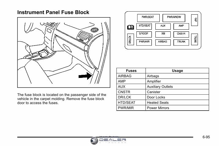
Instrument Panel Fuse Block
The fuse block is located on the passenger side of thevehicle in the carpet molding. Remove the fuse blockdoor to access the fuses.
Fuses Usage
AIRBAG Airbags
AMP Amplifier
AUX Auxiliary Outlets
CNSTR Canister
DR/LCK Door Locks
HTD/SEAT Heated Seats
PWR/MIR Power Mirrors
6-95Information Provided by:

Fuses Usage
PWR/SEAT Power Seats
PWR/WNDW Power Window
RAP Retained Accessory Power
S/ROOF Sunroof
TRUNK Trunk
TRUNK Trunk Relay
XM XM™ Radio
Underhood Fuse BlockThe underhood fuse block is located in the enginecompartment. See Engine Compartment Overview onpage 6‑14 for more information on location.
Notice: Spilling liquid on any electrical componentson the vehicle may damage it. Always keep thecovers on any electrical component.
6-96 Information Provided by:

Fuses Usage
A/C CMPRSR Air Conditioning Compressor
ABS MTR 1 Antilock Brake System (ABS) Motor 1
ABS MTR 2 ABS Motor 2
AIR PUMP Air Pump
AIR SOL Air Injection Reactor Solenoid
AIRBAG/DISPLAY
Airbag, Display
AUX PWR Auxiliary Power
BATT 1 Battery 1
BATT 2 Battery 2
BATT 3 Battery 3
BATT 4 Battery 4
BCM Body Control Module (BCM)
CHMSL/BCK‐UP
Center High‐Mounted Stoplamp,Back‐up Lamp
DISPLAY Display
DRL 1 Daytime Running Lamps 1
DRL 2 Daytime Running Lamps 2
ECM IGN Engine Control Module (ECM), Ignition
ECM/TCMECM, Transmission ControlModule (TCM)
EMISSIONS 1 Emissions 1
Fuses Usage
EMISSIONS 2 Emissions 2
ETC/ECM Electronic Throttle Control, ECM
FAN 1 Cooling Fan 1
FAN 2 Cooling Fan 2
FOG LAMPS Fog Lamps (If Equipped)
FUEL/PUMP Fuel Pump
HDLP MDL Headlamp Module
HORN Horn
HTD MIR Heated Mirror
INJ 1 Injector 1
INJ 2 Injector 2
INT LIGHTS Interior Lamps
INT LTS/PNL DIM
Interior Lamps, Instrument PanelDimmer
LT HI BEAM Driver Side High‐Beam Headlamp
LT LO BEAM Driver Side Low‐Beam Headlamp
LT PARK Driver Side Parking Lamp
LT SPOT Left Spot
LT T/SIG Driver Side Turn Signal Lamp
ONSTAR OnStar®
PWR DROP/CRANK
Power Drop, Crank
6-97Information Provided by:

Fuses Usage
RADIO Audio System
RT HI BEAMPassenger Side High‐BeamHeadlamp
RT LO BEAM Passenger Side Low‐Beam Headlamp
RT PARK Passenger Side Parking Lamp
RT SPOT Right Spot
RT T/SIG Passenger Side Turn Signal Lamp
RVC SEN Regulated Voltage Control Sensor
STRG WHL Steering Wheel
STRTR Starter
TRANS Transmission
WPR Wiper
WSW Windshield Wiper
Relay Usage
A/C CMPRSR Air Conditioning Compressor
FAN 1 Cooling Fan 1
FAN 2 Cooling Fan 2
FAN 3 Cooling Fan 3
FUEL/PUMP Fuel Pump
PWR/TRN Powertrain
REAR DEFOG Rear Defogger
STRTR Starter
6-98 Information Provided by:

Capacities and SpecificationsThe following approximate capacities are given in Metric and English conversions. See Recommended Fluids andLubricants on page 7‑11 for more information.
ApplicationCapacities
Metric English
Air Conditioning Refrigerant R134aFor the air conditioning system refrigerant chargeamount, see the refrigerant caution label located
under the hood. See your dealer for more information.
Automatic Transmission (Bottom Pan Removal) 7.0 L 7.4 qt
Cooling System Including Reservoir
3.5L V6, 3.5L and 3.9L V6 Flexible Fuel Engines 9.6 L 10.1 qt
Engine Oil with Filter
3.5L V6, 3.5L and 3.9L V6 Flexible Fuel Engines 3.8 L 4.0 qt
Fuel Tank
3.5L V6 Engine (with NU6 emissions) 64.4 L 17.0 gal
3.5L V6 Engine (without NU6 emissions) 66.2 L 17.5 gal
3.9L V6 Engine 66.2 L 17.5 gal
Wheel Nut Torque 140Y 100 lb ft
All capacities are approximate. When adding, be sure to fill to the approximate level, as recommended in this manual.Recheck fluid level after filling.
6-99Information Provided by:

Engine SpecificationsEngine VIN Code Transmission Spark Plug Gap
3.5L V6 N Automatic 1.01 mm (0.040 in)
3.5L Flexible Fuel V6 K Automatic 1.01 mm (0.040 in )
3.9L Flexible Fuel V6 M Automatic 1.01 mm (0.040 in )
6-100 Information Provided by:

Section 7 Maintenance Schedule
Maintenance Schedule . . . . . . . . . . . . . . . . . . . . . . . . . . . . 7-2Introduction . . . . . . . . . . . . . . . . . . . . . . . . . . . . . . . . . . . . . 7-2Scheduled Maintenance . . . . . . . . . . . . . . . . . . . . . . . . 7-3Owner Checks and Services . . . . . . . . . . . . . . . . . . . . 7-9
Recommended Fluids and Lubricants . . . . . . . . . . 7-11Maintenance Replacement Parts . . . . . . . . . . . . . . 7-12Engine Drive Belt Routing . . . . . . . . . . . . . . . . . . . . . 7-13Maintenance Record . . . . . . . . . . . . . . . . . . . . . . . . . . . 7-14
7-1Information Provided by:

Maintenance Schedule
IntroductionNotice: Maintenance intervals, checks, inspections,recommended fluids, and lubricants are necessaryto keep this vehicle in good working condition.Damage caused by failure to follow scheduledmaintenance might not be covered by the vehiclewarranty.
As the vehicle owner, you are responsible for thescheduled maintenance in this section. We recommendhaving your dealer perform these services. Propervehicle maintenance helps to keep the vehicle in goodworking condition, improves fuel economy, and reducesvehicle emissions for better air quality.
Because of all the different ways people use vehicles,maintenance needs vary. The vehicle might needmore frequent checks and services. Please read theinformation under Scheduled Maintenance. To keepthe vehicle in good condition, see your dealer.
The maintenance schedule is for vehicles that:. carry passengers and cargo within recommended
limits on the Tire and Loading Information label.See Loading the Vehicle on page 5‑19.
. are driven on reasonable road surfaces within legaldriving limits.
. use the recommended fuel. See Gasoline Octaneon page 6‑6 .
{ WARNING:
Performing maintenance work on a vehicle canbe dangerous. In trying to do some jobs, you canbe seriously injured. Do your own maintenancework only if you have the required know-howand the proper tools and equipment for the job.If you have any doubt, see your dealer to have aqualified technician do the work. See Doing YourOwn Service Work on page 6‑4.
7-2 Information Provided by:

At your dealer, you can be certain that you will receivethe highest level of service available. Your dealer hasspecially trained service technicians, uses genuinereplacement parts, as well as, up to date tools andequipment to ensure fast and accurate diagnostics.
The proper replacement parts, fluids, and lubricants touse are listed in Recommended Fluids and Lubricantson page 7‑11 and Maintenance Replacement Parts onpage 7‑12. We recommend the use of genuine partsfrom your dealer.
Rotation of New TiresTo maintain ride, handling, and performance of thevehicle, it is important that the first rotation servicefor new tires be performed when they have 8 000 to13 000 km (5,000 to 8,000 miles). See Tire Inspectionand Rotation on page 6‑65.
Scheduled Maintenance
When the Change Engine Oil SoonMessage DisplaysChange engine oil and filter. See Engine Oil onpage 6‑15. An Emission Control Service.
When the Change Engine Oil Soon message displays,service is required for the vehicle as soon as possible,within the next 1 000 km/600 miles. If driving under thebest conditions, the engine oil life system might notindicate the need for vehicle service for more thana year. The engine oil and filter must be changed atleast once a year and the oil life system must be reset.Your dealer has trained service technicians who willperform this work and reset the system. If the engineoil life system is reset accidentally, service the vehiclewithin 5 000 km/3,000 miles since the last service.Reset the oil life system whenever the oil is changed.See Engine Oil Life System on page 6‑18.
7-3Information Provided by:
When the Change Engine Oil Soon messagedisplays, certain services, checks, and inspections arerequired. The services described for Maintenance Ishould be performed at every engine oil change.The services described for Maintenance II shouldbe performed when:. Maintenance I was performed the last time the
engine oil was changed.. It has been 10 months or more since the Change
Engine Oil Soon message has displayed or sincethe last service.
Maintenance I. Change engine oil and filter. See Engine Oil on
page 6‑15. An Emission Control Service.. Engine coolant level check. See Engine Coolant
on page 6‑25.. Windshield washer fluid level check.
See Windshield Washer Fluid on page 6‑33.
. Tire inflation check. See Inflation - Tire Pressureon page 6‑59.
. Tire wear inspection. See Tire Inspection andRotation on page 6‑65.
. Rotate tires. See Tire Inspection and Rotation onpage 6‑65.
. Fluids visual leak check (or every 12 months,whichever occurs first). A leak in any system mustbe repaired and the fluid level checked.
. Engine air cleaner filter inspection (vehicles drivenin dusty conditions only). See Engine Air Cleaner/Filter on page 6‑19.
. Brake system inspection (or every 12 months,whichever occurs first).
7-4 Information Provided by:

Maintenance II. Perform all services described in Maintenance I.. Steering and suspension inspection. Visual
inspection for damaged, loose, or missing partsor signs of wear.
. Engine cooling system inspection. Visualinspection of hoses, pipes, fittings, and clampsand replacement, if needed.
. Windshield wiper blade inspection for wear,cracking, or contamination and windshieldand wiper blade cleaning, if contaminated.See Windshield and Wiper Blades on page 6‑91.Worn or damaged wiper blade replacement.See Windshield Wiper Blade Replacement onpage 6‑50.
. Body hinges and latches, key lock cylinders,folding seat hardware, and rear compartmenthinges lubrication. See Recommended Fluidsand Lubricants on page 7‑11. More frequentlubrication may be required when vehicle isexposed to a corrosive environment. Applyingsilicone grease on weatherstrips with a cleancloth makes them last longer, seal better, andnot stick or squeak.
. Restraint system component check. See Checkingthe Restraint Systems on page 2‑75.
. Automatic transmission fluid level check andadding fluid, if needed. See AutomaticTransmission Fluid on page 6‑21.
. Engine air cleaner filter inspection. See Engine AirCleaner/Filter on page 6‑19.
. Passenger compartment air filter replacement(or every 12 months, whichever occurs first). Morefrequent replacement may be required if vehicle isdriven regularly under dusty conditions.
7-5Information Provided by:

Additional Required Services
At Each Fuel Stop. Engine oil level check. See Engine Oil on
page 6‑15.. Engine coolant level check. See Engine Coolant
on page 6‑25.. Windshield washer fluid level check.
See Windshield Washer Fluid on page 6‑33.
Once a Month. Tire inflation check. See Inflation - Tire Pressure
on page 6‑59.. Tire wear inspection. See Tire Inspection and
Rotation on page 6‑65.
Once a Year. Starter switch check. See Owner Checks and
Services on page 7‑9.. Parking brake and automatic transmission P (Park)
mechanism check. See Owner Checks andServices on page 7‑9.
. Automatic transmission shiftlock control systemcheck. See Owner Checks and Services onpage 7‑9 .
. Ignition transmission lock check. See OwnerChecks and Services on page 7‑9.
. Engine cooling system and pressure cap pressurecheck. Radiator and air conditioning condenseroutside cleaning. See Cooling System onpage 6‑24.
. Exhaust system and nearby heat shieldsinspection for loose or damaged components.
. Throttle system inspection for interference, bindingor for damaged or missing parts. Replace partsas needed. Replace any components that havehigh effort or excessive wear. Do not lubricateaccelerator or cruise control cables.
7-6 Information Provided by:

First Engine Oil Change After Every40 000 km/25,000Miles. Fuel system inspection for damage or leaks.
First Engine Oil Change After Every80 000 km/50,000Miles. Engine air cleaner filter replacement. See Engine
Air Cleaner/Filter on page 6‑19.. Automatic transmission fluid change (severe
service) for vehicles mainly driven in heavy citytraffic in hot weather, in hilly or mountainousterrain, when frequently towing a trailer, or usedfor taxi, police, or delivery service. See AutomaticTransmission Fluid on page 6‑21.
First Engine Oil Change After Every160 000 km/100,000Miles. Automatic transmission fluid change (normal
service). See Automatic Transmission Fluid onpage 6‑21.
. Spark plug replacement and spark plug wiresinspection. An Emission Control Service.
First Engine Oil Change After Every240 000 km/150,000Miles. Engine cooling system drain, flush, and refill,
cooling system and cap pressure check, andcleaning of outside of radiator and air conditioningcondenser (or every 5 years, whichever occursfirst). See Engine Coolant on page 6‑25.An Emission Control Service.
. Engine accessory drive belt inspection for fraying,excessive cracks, or obvious damage andreplacement, if needed. An Emission ControlService.
7-7Information Provided by:

Scheduled MaintenanceService Maintenance I Maintenance II
Change engine oil and filter. Reset oil life system. • •
Engine coolant level check. • •
Windshield washer fluid level check. • •
Tire inflation pressures check. • •
Tire wear inspection. • •
Rotate tires. • •
Fluids visual leak check. • •
Engine air cleaner filter inspection (vehicles driven in dusty conditions only). • •
Brake system inspection. • •
Steering and suspension inspection. •
Engine cooling system inspection. •
Windshield wiper blades inspection. •
Body components lubrication. •
Restraint system components check. •
Automatic transmission fluid level check. •
Passenger compartment air filter replacement. •
Engine air cleaner filter inspection (vehicles not driven in dusty conditions). •
7-8 Information Provided by:

Owner Checks and Services
Starter Switch Check
{ WARNING:
When you are doing this inspection, the vehiclecould move suddenly. If the vehicle moves, you orothers could be injured.
1. Before starting this check, be sure there is enoughroom around the vehicle.
2. Firmly apply both the parking brake and the regularbrake. See Parking Brake on page 3‑26.
Do not use the accelerator pedal, and be ready toturn off the engine immediately if it starts.
3. Try to start the engine in each gear. The vehicleshould start only in P (Park) or N (Neutral). If thevehicle starts in any other position, contact yourdealer for service.
Automatic Transmission Shift LockControl System Check
{ WARNING:
When you are doing this inspection, the vehiclecould move suddenly. If the vehicle moves, you orothers could be injured.
1. Before starting this check, be sure there is enoughroom around the vehicle. It should be parked on alevel surface.
2. Firmly apply the parking brake. See Parking Brakeon page 3‑26.
Be ready to apply the regular brake immediately ifthe vehicle begins to move.
3. With the engine off, turn the ignition to ON/RUN,but do not start the engine. Without applying theregular brake, try to move the shift lever out ofP (Park) with normal effort. If the shift lever movesout of P (Park), contact your dealer for service.
7-9Information Provided by:

Ignition Transmission Lock CheckWhile parked, and with the parking brake set, try to turnthe ignition to LOCK/OFF in each shift lever position.. The ignition should turn to LOCK/OFF only when
the shift lever is in P (Park).. The ignition key should come out only in
LOCK/OFF.
Contact your dealer if service is required.
Parking Brake and AutomaticTransmission P (Park) MechanismCheck
{ WARNING:
When you are doing this check, the vehicle couldbegin to move. You or others could be injured andproperty could be damaged. Make sure there isroom in front of the vehicle in case it begins toroll. Be ready to apply the regular brake at onceshould the vehicle begin to move.
Park on a fairly steep hill, with the vehicle facingdownhill. Keeping your foot on the regular brake,set the parking brake.. To check the parking brake's holding ability:
With the engine running and the transmission inN (Neutral), slowly remove foot pressure from theregular brake pedal. Do this until the vehicle is heldby the parking brake only.
. To check the P (Park) mechanism's holdingability: With the engine running, shift to P (Park).Then release the parking brake followed by theregular brake.
Contact your dealer if service is required.
7-10 Information Provided by:
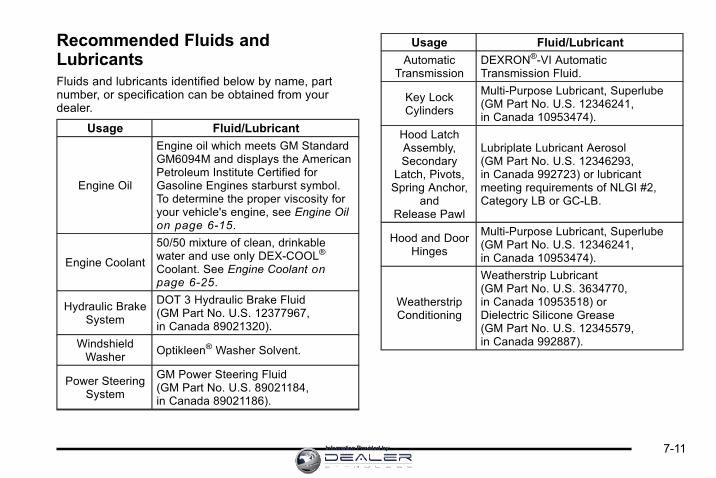
Recommended Fluids andLubricantsFluids and lubricants identified below by name, partnumber, or specification can be obtained from yourdealer.
Usage Fluid/Lubricant
Engine Oil
Engine oil which meets GM StandardGM6094M and displays the AmericanPetroleum Institute Certified forGasoline Engines starburst symbol.To determine the proper viscosity foryour vehicle's engine, see Engine Oilon page 6‑15.
Engine Coolant
50/50 mixture of clean, drinkablewater and use only DEX-COOL®
Coolant. See Engine Coolant onpage 6‑25.
Hydraulic BrakeSystem
DOT 3 Hydraulic Brake Fluid(GM Part No. U.S. 12377967,in Canada 89021320).
WindshieldWasher
Optikleen® Washer Solvent.
Power SteeringSystem
GM Power Steering Fluid(GM Part No. U.S. 89021184,in Canada 89021186).
Usage Fluid/Lubricant
AutomaticTransmission
DEXRON®-VI AutomaticTransmission Fluid.
Key LockCylinders
Multi-Purpose Lubricant, Superlube(GM Part No. U.S. 12346241,in Canada 10953474).
Hood LatchAssembly,Secondary
Latch, Pivots,Spring Anchor,
andRelease Pawl
Lubriplate Lubricant Aerosol(GM Part No. U.S. 12346293,in Canada 992723) or lubricantmeeting requirements of NLGI #2,Category LB or GC-LB.
Hood and DoorHinges
Multi-Purpose Lubricant, Superlube(GM Part No. U.S. 12346241,in Canada 10953474).
WeatherstripConditioning
Weatherstrip Lubricant(GM Part No. U.S. 3634770,in Canada 10953518) orDielectric Silicone Grease(GM Part No. U.S. 12345579,in Canada 992887).
7-11Information Provided by:

Maintenance Replacement PartsReplacement parts identified below by name, part number, or specification can be obtained from your dealer.
Maintenance Replacement PartsPart GM Part Number ACDelco Part Number
Engine Air Cleaner/Filter 10350737 A2962C
Engine Oil Filter
3.5L V6, 3.5L and 3.9L V6 Flexible Fuel Engines 19210285 PF61
Passenger Compartment Air Filter 15284938 CF132
Spark Plugs
3.5L V6, 3.5L and 3.9L V6 Flexible Fuel Engines 12591131 41-100
Wiper Blades
Driver ‐ 21.7 in (55.0 cm) 15941731 —
Passenger ‐ 21.7 in (55.0 cm) 15941732 —
7-12 Information Provided by:

Engine Drive Belt Routing
3.5L V6 and 3.9 V6 Engines
7-13Information Provided by:

Maintenance RecordAfter the scheduled services are performed, record the date, odometer reading, who performed the service, and thetype of services performed in the boxes provided. Retain all maintenance receipts.
Maintenance Record
DateOdometerReading
Serviced By Services Performed
7-14 Information Provided by:

Maintenance Record (cont'd)
Date OdometerReading
Serviced By Services Performed
7-15Information Provided by:

Maintenance Record (cont'd)
Date OdometerReading
Serviced By Services Performed
7-16 Information Provided by:

Section 8 Customer Assistance Information
Customer Assistance and Information . . . . . . . . . . . 8-2Customer Satisfaction Procedure . . . . . . . . . . . . . . . 8-2Online Owner Center . . . . . . . . . . . . . . . . . . . . . . . . . . . . 8-5Customer Assistance for Text Telephone (TTY)Users . . . . . . . . . . . . . . . . . . . . . . . . . . . . . . . . . . . . . . . . . 8-6
Customer Assistance Offices . . . . . . . . . . . . . . . . . . . 8-6GM Mobility Reimbursement Program . . . . . . . . . . . 8-7Roadside Assistance Program . . . . . . . . . . . . . . . . . . 8-7Scheduling Service Appointments . . . . . . . . . . . . . 8-10Courtesy Transportation Program . . . . . . . . . . . . . . 8-10Collision Damage Repair . . . . . . . . . . . . . . . . . . . . . . 8-12
Reporting Safety Defects . . . . . . . . . . . . . . . . . . . . . . . . 8-15Reporting Safety Defects to the United StatesGovernment . . . . . . . . . . . . . . . . . . . . . . . . . . . . . . . . . 8-15
Reporting Safety Defects to the CanadianGovernment . . . . . . . . . . . . . . . . . . . . . . . . . . . . . . . . . 8-15
Reporting Safety Defects to General Motors . . . 8-16Service Publications Ordering Information . . . . . 8-16
Vehicle Data Recording and Privacy . . . . . . . . . . . . . 8-17Event Data Recorders . . . . . . . . . . . . . . . . . . . . . . . . . 8-18Navigation System . . . . . . . . . . . . . . . . . . . . . . . . . . . . . 8-19Radio Frequency Identification (RFID) . . . . . . . . . 8-19Radio Frequency Statement . . . . . . . . . . . . . . . . . . . 8-19
8-1Information Provided by:

Customer Assistance andInformation
Customer Satisfaction ProcedureYour satisfaction and goodwill are important to yourdealer and to Chevrolet. Normally, any concerns withthe sales transaction or the operation of the vehiclewill be resolved by the dealer's sales or servicedepartments. Sometimes, however, despite the bestintentions of all concerned, misunderstandings canoccur. If your concern has not been resolved to yoursatisfaction, the following steps should be taken:
STEP ONE: Discuss your concern with a memberof dealership management. Normally, concerns canbe quickly resolved at that level. If the matter hasalready been reviewed with the sales, service, orparts manager, contact the owner of the dealershipor the general manager.
STEP TWO: If after contacting a member of dealershipmanagement, it appears your concern cannot beresolved by the dealership without further help, in theU.S., call the Chevrolet Customer Assistance Centerat 1-800-222-1020. In Canada, call General Motorsof Canada Customer Communication Centre at1-800-263-3777 (English), or 1-800-263-7854 (French).
We encourage you to call the toll-free number in orderto give your inquiry prompt attention. Have the followinginformation available to give the Customer AssistanceRepresentative:. Vehicle Identification Number (VIN). This is
available from the vehicle registration or title,or the plate at the top left of the instrumentpanel and visible through the windshield.
. Dealership name and location.
. Vehicle delivery date and present mileage.
When contacting Chevrolet, remember that yourconcern will likely be resolved at a dealer's facility.That is why we suggest following Step One first.
8-2 Information Provided by:

STEP THREE — U.S. Owners: Both General Motorsand your dealer are committed to making sure you arecompletely satisfied with your new vehicle. However,if you continue to remain unsatisfied after followingthe procedure outlined in Steps One and Two, you canfile with the Better Business Bureau (BBB) Auto LineProgram to enforce your rights.
The BBB Auto Line Program is an out of court programadministered by the Council of Better Business Bureausto settle automotive disputes regarding vehicle repairsor the interpretation of the New Vehicle LimitedWarranty. Although you may be required to resort tothis informal dispute resolution program prior to filing acourt action, use of the program is free of charge andyour case will generally be heard within 40 days. If youdo not agree with the decision given in your case, youmay reject it and proceed with any other venue for reliefavailable to you.
You may contact the BBB Auto Line Program using thetoll-free telephone number or write them at the followingaddress:
BBB Auto Line ProgramCouncil of Better Business Bureaus, Inc.4200 Wilson BoulevardSuite 800Arlington, VA 22203-1838
Telephone: 1-800-955-5100dr.bbb.org/goauto
This program is available in all 50 states and theDistrict of Columbia. Eligibility is limited by vehicle age,mileage, and other factors. General Motors reserves theright to change eligibility limitations and/or discontinueits participation in this program.
8-3Information Provided by:

STEP THREE — Canadian Owners: In the event thatyou do not feel your concerns have been addressedafter following the procedure outlined in Steps 1 and 2,General Motors of Canada Limited wants you tobe aware of its participation in a no-charge Mediation/Arbitration Program. General Motors of CanadaLimited has committed to binding arbitration of ownerdisputes involving factory-related vehicle serviceclaims. The program provides for the review of thefacts involved by an impartial third party arbiter, andmay include an informal hearing before the arbiter.The program is designed so that the entire disputesettlement process, from the time you file yourcomplaint to the final decision, should be completedin about 70 days. We believe our impartial programoffers advantages over courts in most jurisdictionsbecause it is informal, quick, and free of charge.
For further information concerning eligibility in theCanadian Motor Vehicle Arbitration Plan (CAMVAP), calltoll-free 1-800-207-0685, or call the General MotorsCustomer Communication Centre, 1-800-263-3777(English), 1-800-263-7854 (French), or write to:
The Mediation/Arbitration Programc/o Customer Communication CentreGeneral Motors of Canada LimitedMail Code: CA1-163-0051908 Colonel Sam DriveOshawa, Ontario L1H 8P7
Your inquiry should be accompanied by the VehicleIdentification Number (VIN).
8-4 Information Provided by:

Online Owner Center
Online Owner Center (U.S.) —www.gmownercenter.com/chevroletInformation and services customized for your specificvehicle — all in one convenient place.. Digital owner manual, warranty information,
and more. Online service and maintenance records. Find Chevrolet dealers for service nationwide. Exclusive privileges and offers. Recall notices for your specific vehicle. OnStar® and GM Cardmember Services Earnings
summaries
Other Helpful Links:Chevrolet — www.chevrolet.com
Chevrolet Merchandise — www.chevymall.com
Help Center — www.chevrolet.com/helpcenter. FAQ. Contact Us
My GM Canada (Canada) — www.gm.caMy GM Canada is a password-protected section ofwww.gm.ca where you can save information on GMvehicles, get personalized offers, and use handy toolsand forms with greater ease.
Here are a few of the valuable tools and services youwill have access to:. My Showroom: Find and save information on
vehicles and current offers in your area.. My Dealers/Retailers: Save details such as
address and phone number for each of yourpreferred GM dealers/retailers.
. My Driveway: Access quick links to partsand service estimates, check trade-in values,or schedule a service appointment by addingthe vehicles you own to your driveway profile.
. My Preferences: Manage your profile and use toolsand forms with greater ease.
To sign up, visit the My GM Canada section withinwww.gm.ca.
8-5Information Provided by:

Customer Assistance for TextTelephone (TTY) UsersTo assist customers who are deaf, hard of hearing,or speech-impaired and who use Text Telephones(TTYs), Chevrolet has TTY equipment available atits Customer Assistance Center. Any TTY user inthe U.S. can communicate with Chevrolet by dialing:1-800-833-CHEV (2438). (TTY users in Canada candial 1-800-263-3830.)
Customer Assistance OfficesChevrolet encourages customers to call the toll-freenumber for assistance. However, if a customer wishesto write or e-mail Chevrolet, the letter should beaddressed to:
United States — Customer AssistanceChevrolet Motor DivisionChevrolet Customer Assistance CenterP.O. Box 33170Detroit, MI 48232-5170Chevrolet.com
1-800-222-10201-800-833-2438 (For Text Telephonedevices (TTYs))Roadside Assistance: 1-800-CHEV-USA (243-8872)
From Puerto Rico:
1-800-496-9992 (English)1-800-496-9993 (Spanish)
From U.S. Virgin Islands:
1-800-496-9994
Canada — Customer AssistanceGeneral Motors of Canada LimitedCustomer Communication Centre, CA1-163-0051908 Colonel Sam DriveOshawa, Ontario L1H 8P7gmcanada.com
1-800-263-3777 (English)1-800-263-7854 (French)1-800-263-3830 (For Text Telephonedevices (TTYs))Roadside Assistance: 1-800-268-6800
Overseas — Customer AssistancePlease contact the local General Motors Business Unit.
8-6 Information Provided by:
Mexico, Central America and CaribbeanIslands/Countries (Except Puerto Ricoand U.S. Virgin Islands) — CustomerAssistance
General Motors de Mexico, S. de R.L. de C.V.Customer Assistance CenterPaseo de la Reforma # 2740Col. Lomas de BezaresC.P. 11910, Mexico, D.F.
01-800-508-0000Long Distance: 011-52-53 29 0 800
GM Mobility ReimbursementProgram
This program, available to qualified applicants, canreimburse you up to $1,000 of the cost of eligibleaftermarket adaptive equipment required for yourvehicle, such as hand controls or a wheelchair/scooter lift.
The offer is available for a very limited period of timefrom the date of vehicle purchase/lease. For moredetails, or to determine your vehicle's eligibility, visitgmmobility.com or call the GM Mobility AssistanceCenter at 1-800-323-9935. Text telephone (TTY) users,call 1-800-833-9935.
General Motors of Canada also has a Mobility Program.Call 1-800-GM-DRIVE (463-7483) for details. TTY userscall 1-800-263-3830.
Roadside Assistance ProgramFor U.S. purchased vehicles, call 1‐800‐CHEV‐USA(1‐800‐243‐8872); (Text telephone (TTY):1‐888‐889‐2438).
For Canadian purchased vehicles, call 1-800-268-6800.
Service is available 24 hours a day, 365 days a year.
8-7Information Provided by:

Calling for AssistanceWhen calling Roadside Assistance, have the followinginformation ready:. Your name, home address, and home telephone
number. Telephone number of your location. Location of the vehicle. Model, year, color, and license plate number of the
vehicle. Odometer reading, Vehicle Identification
Number (VIN), and delivery date of the vehicle. Description of the problem
CoverageServices are provided up to 5 years/100,000 miles (160 000 km), whichever comes first.
In the U.S., anyone driving the vehicle is covered.In Canada, a person driving the vehicle withoutpermission from the owner is not covered.
Roadside Assistance is not a part of the New VehicleLimited Warranty. Chevrolet and General Motors ofCanada Limited reserve the right to make any changesor discontinue the Roadside Assistance program at anytime without notification.
Chevrolet and General Motors of Canada Limitedreserve the right to limit services or payment to anowner or driver if they decide the claims are made toooften, or the same type of claim is made many times.
Services Provided. Emergency Fuel Delivery: Delivery of enough
fuel for the vehicle to get to the nearest servicestation.
. Lock‐Out Service: Service is provided to unlockthe vehicle if you are locked out. A remote unlockmay be available if you have OnStar®. For securityreasons, the driver must present identificationbefore this service is given.
. Emergency Tow From a Public Road orHighway: Tow to the nearest Chevrolet dealerfor warranty service, or if the vehicle was in acrash and cannot be driven. Assistance is alsogiven when the vehicle is stuck in the sand, mud,or snow.
. Flat Tire Change: Service is provided to changea flat tire with the spare tire. The spare tire,if equipped, must be in good condition andproperly inflated. It is the owner's responsibilityfor the repair or replacement of the tire if it isnot covered by the warranty.
. Battery Jump Start: Service is provided to jumpstart a dead battery.
8-8 Information Provided by:

Services Not Included in RoadsideAssistance. Impound towing caused by violation of any laws.. Legal fines.. Mounting, dismounting or changing of snow tires,
chains, or other traction devices.. Towing or services for vehicles driven on a
non-public road or highway.
Services Specific to CanadianPurchased Vehicles. Fuel delivery: Reimbursement is approximately
$5 Canadian. Diesel fuel delivery may berestricted. Propane and other fuels are notprovided through this service.
. Lock-Out Service: Vehicle registration isrequired.
. Trip Routing Service: Detailed maps of NorthAmerica are provided when requested either withthe most direct route or the most scenic route.There is a limit of six requests per year. Additionaltravel information is also available. Allowthree weeks for delivery.
. Trip Interruption Benefits and Assistance: Mustbe over 250 km from where your trip was started toqualify. General Motors of Canada Limited requirespre-authorization, original detailed receipts, and acopy of the repair orders. Once authorization hasbeen received, the Roadside Assistance advisorwill help you make arrangements and explain howto receive payment.
. Alternative Service: If assistance cannot beprovided right away, the Roadside Assistanceadvisor may give you permission to get localemergency road service. You will receive payment,up to $100, after sending the original receipt toRoadside Assistance. Mechanical failures may becovered, however any cost for parts and labor forrepairs not covered by the warranty are the ownerresponsibility.
8-9Information Provided by:
Scheduling Service AppointmentsWhen your vehicle requires warranty service, contactyour dealer and request an appointment. By schedulinga service appointment and advising your serviceconsultant of your transportation needs, your dealercan help minimize your inconvenience.
If your vehicle cannot be scheduled into the servicedepartment immediately, keep driving it until it can bescheduled for service, unless, of course, the problemis safety-related. If it is, please call your dealership/retailer, let them know this, and ask for instructions.
If the dealer requests you to bring the vehicle forservice, you are urged to do so as early in the workday as possible to allow for the same day repair.
Courtesy Transportation ProgramTo enhance your ownership experience, we and ourparticipating dealers are proud to offer CourtesyTransportation, a customer support program for vehicleswith the New Vehicle Limited Warranty (Base WarrantyCoverage period in Canada) and extended powertrain,and hybrid specific warranty in both the U.S. andCanada.
Several courtesy transportation options are available toassist in reducing your inconvenience when warrantyrepairs are required.
Courtesy Transportation is not a part of the New VehicleLimited Warranty. A separate booklet entitled “Warrantyand Owner Assistance Information” furnished with eachnew vehicle provides detailed warranty coverageinformation.
Transportation OptionsWarranty service can generally be completedwhile you wait. However, if you are unable to wait,GM helps to minimize your inconvenience by providingseveral transportation options. Depending on thecircumstances, your dealer can offer you one ofthe following:
Shuttle ServiceShuttle service is the preferred means of offeringCourtesy Transportation. Dealers may provide youwith shuttle service to get you to your destinationwith minimal interruption of your daily schedule.This includes one‐way or round trip shuttle servicewithin reasonable time and distance parameters ofthe dealer's area.
8-10 Information Provided by:

Public Transportation or FuelReimbursementIf your vehicle requires overnight warranty repairs, andpublic transportation is used instead of the dealer'sshuttle service, the expense must be supported byoriginal receipts and can only be up to the maximumamount allowed by GM for shuttle service. In addition,for U.S. customers, should you arrange transportationthrough a friend or relative, limited reimbursement forreasonable fuel expenses may be available. Claimamounts should reflect actual costs and be supportedby original receipts. See your dealer for informationregarding the allowance amounts for reimbursementof fuel or other transportation costs.
Courtesy Rental VehicleYour dealer may arrange to provide you with acourtesy rental vehicle or reimburse you for a rentalvehicle that you obtain if your vehicle is kept for anovernight warranty repair. Rental reimbursement willbe limited and must be supported by original receipts.
This requires that you sign and complete a rentalagreement and meet state/provincial, local, and rentalvehicle provider requirements. Requirements vary andmay include minimum age requirements, insurancecoverage, credit card, etc. You are responsible for fuelusage charges and may also be responsible for taxes,levies, usage fees, excessive mileage, or rental usagebeyond the completion of the repair.
It may not be possible to provide a like-vehicle as acourtesy rental.
Additional Program InformationAll program options, such as shuttle service, may not beavailable at every dealer. Please contact your dealerfor specific information about availability. All CourtesyTransportation arrangements will be administered byappropriate dealer personnel.
General Motors reserves the right to unilaterally modify,change or discontinue Courtesy Transportation at anytime and to resolve all questions of claim eligibilitypursuant to the terms and conditions described hereinat its sole discretion.
8-11Information Provided by:

Collision Damage RepairIf your vehicle is involved in a collision and it isdamaged, have the damage repaired by a qualifiedtechnician using the proper equipment and qualityreplacement parts. Poorly performed collision repairsdiminish your vehicle's resale value, and safetyperformance can be compromised in subsequentcollisions.
Collision PartsGenuine GM Collision parts are new parts madewith the same materials and construction methods asthe parts with which your vehicle was originally built.Genuine GM Collision parts are your best choice toensure that your vehicle's designed appearance,durability, and safety are preserved. The use ofGenuine GM parts can help maintain your GMNew Vehicle Warranty.
Recycled original equipment parts may also be used forrepair. These parts are typically removed from vehiclesthat were total losses in prior crashes. In most cases,the parts being recycled are from undamaged sectionsof the vehicle. A recycled original equipment GM part,may be an acceptable choice to maintain your vehicle's
originally designed appearance and safety performance,however, the history of these parts is not known. Suchparts are not covered by your GM New Vehicle LimitedWarranty, and any related failures are not covered bythat warranty.
Aftermarket collision parts are also available. These aremade by companies other than GM and may not havebeen tested for your vehicle. As a result, these partsmay fit poorly, exhibit premature durability/corrosionproblems, and may not perform properly in subsequentcollisions. Aftermarket parts are not covered by yourGM New Vehicle Limited Warranty, and any vehiclefailure related to such parts are not covered by thatwarranty.
Repair FacilityWe recommend that you choose a collision repairfacility that meets your needs before you ever needcollision repairs. Your dealer may have a collision repaircenter with GM-trained technicians and state of the artequipment, or be able to recommend a collision repaircenter that has GM-trained technicians and comparableequipment.
8-12 Information Provided by:

Insuring Your VehicleProtect your investment in your GM vehicle withcomprehensive and collision insurance coverage.There are significant differences in the quality ofcoverage afforded by various insurance policy terms.Many insurance policies provide reduced protection toyour GM vehicle by limiting compensation for damagerepairs by using aftermarket collision parts. Someinsurance companies will not specify aftermarketcollision parts. When purchasing insurance, werecommend that you assure your vehicle will berepaired with GM original equipment collision parts.If such insurance coverage is not available from yourcurrent insurance carrier, consider switching to anotherinsurance carrier.
If your vehicle is leased, the leasing company mayrequire you to have insurance that assures repairs withGenuine GM Original Equipment Manufacturer (OEM)parts or Genuine Manufacturer replacement parts. Readyour lease carefully, as you may be charged at the endof your lease for poor quality repairs.
If a Crash OccursHere is what to do if you are involved in a crash.. Check to make sure that you are all right. If you
are uninjured, make sure that no one else in yourvehicle, or the other vehicle, is injured.
. If there has been an injury, call emergencyservices for help. Do not leave the scene of acrash until all matters have been taken care of.Move your vehicle only if its position puts you indanger or you are instructed to move it by a policeofficer.
. Give only the necessary and requested informationto police and other parties involved in the crash.Do not discuss your personal condition, mentalframe of mind, or anything unrelated to the crash.This will help guard against post-crash legal action.
. If you need roadside assistance, call GM RoadsideAssistance. See Roadside Assistance Program onpage 8‑7 for more information.
. If your vehicle cannot be driven, know where thetowing service will be taking it. Get a card from thetow truck operator or write down the driver's name,the service's name, and the phone number.
. Remove any valuables from your vehicle beforeit is towed away. Make sure this includes yourinsurance information and registration if you keepthese items in your vehicle.
8-13Information Provided by:

. Gather the important information you will need fromthe other driver. Things like name, address, phonenumber, driver's license number, vehicle licenseplate, vehicle make, model and model year,Vehicle Identification Number (VIN), insurancecompany and policy number, and a generaldescription of the damage to the other vehicle.
. If possible, call your insurance company from thescene of the crash. They will walk you through theinformation they will need. If they ask for a policereport, phone or go to the police departmentheadquarters the next day and you can get a copyof the report for a nominal fee. In some states/provinces with “no fault” insurance laws, a reportmay not be necessary. This is especially trueif there are no injuries and both vehicles aredriveable.
. Choose a reputable collision repair facility for yourvehicle. Whether you select a dealer or a privatecollision repair facility to fix the damage, make sureyou are comfortable with them. Remember, youwill have to feel comfortable with their work for along time.
. Once you have an estimate, read it carefully andmake sure you understand what work will beperformed on your vehicle. If you have a question,ask for an explanation. Reputable shops welcomethis opportunity.
Managing the Vehicle Damage RepairProcessIn the event that your vehicle requires damage repairs,GM recommends that you take an active role in itsrepair. If you have a pre-determined repair facility ofchoice, take your vehicle there, or have it towed there.Specify to the facility that any required replacementcollision parts be original equipment parts, eithernew Genuine GM parts or recycled original GM parts.Remember, recycled parts will not be covered by yourGM vehicle warranty.
Insurance pays the bill for the repair, but you mustlive with the repair. Depending on your policy limits,your insurance company may initially value the repairusing aftermarket parts. Discuss this with your repairprofessional, and insist on Genuine GM parts.Remember if your vehicle is leased you may beobligated to have the vehicle repaired with GenuineGM parts, even if your insurance coverage does notpay the full cost.
If another party's insurance company is paying forthe repairs, you are not obligated to accept a repairvaluation based on that insurance company's collisionpolicy repair limits, as you have no contractual limitswith that company. In such cases, you can have controlof the repair and parts choices as long as cost stayswithin reasonable limits.
8-14 Information Provided by:

Reporting Safety Defects
Reporting Safety Defects to theUnited States GovernmentIf you believe that your vehicle has a defect whichcould cause a crash or could cause injury ordeath, you should immediately inform the NationalHighway Traffic Safety Administration (NHTSA) inaddition to notifying General Motors.
If NHTSA receives similar complaints, it may openan investigation, and if it finds that a safety defectexists in a group of vehicles, it may order a recalland remedy campaign. However, NHTSA cannotbecome involved in individual problems betweenyou, your dealer, or General Motors.
To contact NHTSA, you may call theVehicle Safety Hotline toll-free at1-888-327-4236 (TTY: 1-800-424-9153);go to http://www.safercar.gov; or write to:
Administrator, NHTSA1200 New Jersey Avenue, S.E.Washington, D.C. 20590
You can also obtain other information about motorvehicle safety from http://www.safercar.gov.
Reporting Safety Defects to theCanadian GovernmentIf you live in Canada, and you believe that yourvehicle has a safety defect, notify Transport Canadaimmediately, in addition to notifying General Motorsof Canada Limited. Call them at 1-800-333-0510 orwrite to:
Transport CanadaRoad Safety Branch2780 Sheffield RoadOttawa, Ontario K1B 3V9
8-15Information Provided by:

Reporting Safety Defects toGeneral MotorsIn addition to notifying NHTSA (or Transport Canada) ina situation like this, please notify General Motors.
Call 1-800-222-1020, or write:
Chevrolet Motor DivisionChevrolet Customer Assistance CenterP.O. Box 33170Detroit, MI 48232-5170
In Canada, call 1-800-263-3777 (English) or1-800-263-7854 (French), or write:
General Motors of Canada LimitedCustomer Communication Centre, CA1-163-0051908 Colonel Sam DriveOshawa, Ontario L1H 8P7
Service Publications OrderingInformation
Service ManualsService Manuals have the diagnosis and repairinformation on engines, transmission, axle suspension,brakes, electrical, steering, body, etc.
Service BulletinsService Bulletins give additional technical serviceinformation needed to knowledgeably serviceGeneral Motors cars and trucks. Each bulletin containsinstructions to assist in the diagnosis and service ofyour vehicle.
Owner InformationOwner publications are written specifically for ownersand intended to provide basic operational informationabout the vehicle. The owner manual includes theMaintenance Schedule for all models.
In-Portfolio: Includes a Portfolio, Owner Manual, andWarranty Booklet.
RETAIL SELL PRICE: $35.00 (U.S.) plus processing fee
Without Portfolio: Owner Manual only.
RETAIL SELL PRICE: $25.00 (U.S.) plus processing fee
Current and Past Model Order FormsTechnical Service Bulletins and Manuals are availablefor current and past model GM vehicles. To request anorder form, specify year and model name of the vehicle.
8-16 Information Provided by:

ORDER TOLL FREE: 1-800-551-4123Monday-Friday 8:00 AM - 6:00 PMEastern TimeFor Credit Card Orders Only(VISA-MasterCard-Discover), visit Helm, Inc.on the World Wide Web at: helminc.com
Or you can write to:
Helm, IncorporatedP.O. Box 07130Detroit, MI 48207
Prices are subject to change without notice and withoutincurring obligation. Allow ample time for delivery.
Note to Canadian Customers: All listed prices arequoted in U.S. funds. Canadian residents are to makechecks payable in U.S. funds.
Vehicle Data Recording andPrivacyYour GM vehicle has a number of sophisticatedcomputers that record information about the vehicle’sperformance and how it is driven. For example, yourvehicle uses computer modules to monitor and controlengine and transmission performance, to monitor theconditions for airbag deployment and deploy airbags ina crash and, if so equipped, to provide antilock brakingto help the driver control the vehicle. These modulesmay store data to help your dealer technician serviceyour vehicle. Some modules may also store data abouthow you operate the vehicle, such as rate of fuelconsumption or average speed. These modules mayalso retain the owner’s personal preferences, such asradio pre-sets, seat positions, and temperature settings.
8-17Information Provided by:

Event Data RecordersThis vehicle has an Event Data Recorder (EDR).The main purpose of an EDR is to record, in certaincrash or near crash-like situations, such as an airbagdeployment or hitting a road obstacle, data that willassist in understanding how a vehicle's systemsperformed. The EDR is designed to record data relatedto vehicle dynamics and safety systems for a shortperiod of time, typically 30 seconds or less. The EDRin this vehicle is designed to record such data as:. How various systems in your vehicle were
operating. Whether or not the driver and passenger safety
belts were buckled/fastened. How far, if at all, the driver was pressing the
accelerator and/or brake pedal. How fast the vehicle was traveling
This data can help provide a better understanding of thecircumstances in which crashes and injuries occur.
Important: EDR data is recorded by your vehicle only ifa non-trivial crash situation occurs; no data is recordedby the EDR under normal driving conditions and nopersonal data (e.g., name, gender, age, and crashlocation) is recorded. However, other parties, such aslaw enforcement, could combine the EDR data with thetype of personally identifying data routinely acquiredduring a crash investigation.
To read data recorded by an EDR, special equipmentis required, and access to the vehicle or the EDR isneeded. In addition to the vehicle manufacturer, otherparties, such as law enforcement, that have the specialequipment, can read the information if they have accessto the vehicle or the EDR.
GM will not access this data or share it with othersexcept: with the consent of the vehicle owner or,if the vehicle is leased, with the consent of the lessee;in response to an official request of police or similargovernment office; as part of GM's defense of litigationthrough the discovery process; or, as required by law.Data that GM collects or receives may also be used forGM research needs or may be made available to othersfor research purposes, where a need is shown and thedata is not tied to a specific vehicle or vehicle owner.
8-18 Information Provided by:

Navigation SystemIf your vehicle has a navigation system, use of thesystem may result in the storage of destinations,addresses, telephone numbers, and other tripinformation. Refer to the navigation system operatingmanual for information on stored data and for deletioninstructions.
Radio FrequencyIdentification (RFID)RFID technology is used in some vehicles for functionssuch as tire pressure monitoring and ignition systemsecurity, as well as in connection with conveniencessuch as key fobs for remote door locking/unlockingand starting, and in-vehicle transmitters for garage dooropeners. RFID technology in GM vehicles does not useor record personal information or link with any other GMsystem containing personal information.
Radio Frequency StatementThis vehicle has systems that operate on a radiofrequency that comply with Part 15 of the FederalCommunications Commission (FCC) Rules and withRSS-210/211 of Industry Canada.
Operation is subject to the following two conditions:
1. The device may not cause interference.
2. The device must accept any interference received,including interference that may cause undesiredoperation of the device.
Changes or modifications to any of these systems byother than an authorized service facility could voidauthorization to use this equipment.
8-19Information Provided by:

2 NOTES
8-20 Information Provided by:

AAccessories and Modifications . . . . . . . . . . . . . . . . . . . . . . .6-3Accessory Power . . . . . . . . . . . . . . . . . . . . . . . . . . . . . . . . . . 3-21Accessory Power Outlets . . . . . . . . . . . . . . . . . . . . . . . . . . 4-15Add-On Electrical Equipment . . . . . . . . . . . . . . . . . . . . . . 6-94Additives, Fuel . . . . . . . . . . . . . . . . . . . . . . . . . . . . . . . . . . . . . . .6-6Air Cleaner/Filter, Engine . . . . . . . . . . . . . . . . . . . . . . . . . . 6-19Air Conditioning . . . . . . . . . . . . . . . . . . . . . . . . . . . . . . . . . . . 4-16Air Filter, Passenger Compartment . . . . . . . . . . . . . . . . 4-20AirbagAdding Equipment to Your Airbag-EquippedVehicle . . . . . . . . . . . . . . . . . . . . . . . . . . . . . . . . . . . . . . . . . . 2-74
Airbag SystemHow Does an Airbag Restrain? . . . . . . . . . . . . . . . . . . . 2-65Passenger Sensing System . . . . . . . . . . . . . . . . . . . . . . 2-68Servicing Your Airbag-Equipped Vehicle . . . . . . . . . . 2-73What Makes an Airbag Inflate? . . . . . . . . . . . . . . . . . . . 2-65What Will You See After an Airbag Inflates? . . . . . . 2-66When Should an Airbag Inflate? . . . . . . . . . . . . . . . . . . 2-63Where Are the Airbags? . . . . . . . . . . . . . . . . . . . . . . . . . . 2-61
AirbagsPassenger Status Indicator . . . . . . . . . . . . . . . . . . . . . . . 4-25Readiness Light . . . . . . . . . . . . . . . . . . . . . . . . . . . . . . . . . . 4-24System Check . . . . . . . . . . . . . . . . . . . . . . . . . . . . . . . . . . . . 2-58
AntennaBackglass . . . . . . . . . . . . . . . . . . . . . . . . . . . . . . . . . . . . . . . . 4-88
Antenna, XM™ Satellite Radio Antenna System . . . 4-88Antilock Brake System (ABS) . . . . . . . . . . . . . . . . . . . . . . . .5-4Warning Light . . . . . . . . . . . . . . . . . . . . . . . . . . . . . . . . . . . . . 4-28
Appearance CareAluminum Wheels . . . . . . . . . . . . . . . . . . . . . . . . . . . . . . . . 6-91Care of Safety Belts . . . . . . . . . . . . . . . . . . . . . . . . . . . . . . 6-89Chemical Paint Spotting . . . . . . . . . . . . . . . . . . . . . . . . . . 6-92Cleaning Exterior Lamps/Lenses . . . . . . . . . . . . . . . . . 6-90Fabric/Carpet . . . . . . . . . . . . . . . . . . . . . . . . . . . . . . . . . . . . . 6-87Finish Care . . . . . . . . . . . . . . . . . . . . . . . . . . . . . . . . . . . . . . . 6-90Finish Damage . . . . . . . . . . . . . . . . . . . . . . . . . . . . . . . . . . . 6-92Instrument Panel, Vinyl, and Other PlasticSurfaces . . . . . . . . . . . . . . . . . . . . . . . . . . . . . . . . . . . . . . . . 6-88
Interior Cleaning . . . . . . . . . . . . . . . . . . . . . . . . . . . . . . . . . . 6-86
i - 1Information Provided by:

Appearance Care (cont.)Leather . . . . . . . . . . . . . . . . . . . . . . . . . . . . . . . . . . . . . . . . . . . 6-88Sheet Metal Damage . . . . . . . . . . . . . . . . . . . . . . . . . . . . . 6-92Tires . . . . . . . . . . . . . . . . . . . . . . . . . . . . . . . . . . . . . . . . . . . . . . 6-92Underbody Maintenance . . . . . . . . . . . . . . . . . . . . . . . . . . 6-92Washing Your Vehicle . . . . . . . . . . . . . . . . . . . . . . . . . . . . 6-89Weatherstrips . . . . . . . . . . . . . . . . . . . . . . . . . . . . . . . . . . . . . 6-89Windshield and Wiper Blades . . . . . . . . . . . . . . . . . . . . . 6-91
Ashtray . . . . . . . . . . . . . . . . . . . . . . . . . . . . . . . . . . . . . . . . . . . . 4-16Assistance Program, Roadside . . . . . . . . . . . . . . . . . . . . . .8-7Audio System . . . . . . . . . . . . . . . . . . . . . . . . . . . . . . . . . . . . . . 4-57Audio Steering Wheel Controls . . . . . . . . . . . . . . . . . . . 4-86Radio Reception . . . . . . . . . . . . . . . . . . . . . . . . . . . . . . . . . . 4-87Setting the Clock . . . . . . . . . . . . . . . . . . . . . . . . . . . . . . . . . 4-58Theft-Deterrent Feature . . . . . . . . . . . . . . . . . . . . . . . . . . . 4-86XM™ Satellite Radio Antenna System . . . . . . . . . . . . 4-88
Audio System(s) . . . . . . . . . . . . . . . . . . . . . . . . . . . . . . . . . . . 4-60Automatic Door Lock . . . . . . . . . . . . . . . . . . . . . . . . . . . . . . 3-11Automatic TransmissionFluid . . . . . . . . . . . . . . . . . . . . . . . . . . . . . . . . . . . . . . . . . . . . . . 6-21Operation . . . . . . . . . . . . . . . . . . . . . . . . . . . . . . . . . . . . . . . . . 3-23
BBackglass Antenna . . . . . . . . . . . . . . . . . . . . . . . . . . . . . . . . 4-88Battery . . . . . . . . . . . . . . . . . . . . . . . . . . . . . . . . . . . . . . . . . . . . 6-38Electric Power Management . . . . . . . . . . . . . . . . . . . . . . 4-13Run-Down Protection . . . . . . . . . . . . . . . . . . . . . . . . . . . . . 4-14
Belt Routing, Engine . . . . . . . . . . . . . . . . . . . . . . . . . . . . . . . 7-13Bluetooth® . . . . . . . . . . . . . . . . . . . . . . . . . . . . . . . . . . . . . . . . . 4-75BrakeEmergencies . . . . . . . . . . . . . . . . . . . . . . . . . . . . . . . . . . . . . . 5-5
Brakes . . . . . . . . . . . . . . . . . . . . . . . . . . . . . . . . . . . . . . . . . . . . . 6-35Antilock . . . . . . . . . . . . . . . . . . . . . . . . . . . . . . . . . . . . . . . . . . . . 5-4Parking . . . . . . . . . . . . . . . . . . . . . . . . . . . . . . . . . . . . . . . . . . . 3-26System Warning Light . . . . . . . . . . . . . . . . . . . . . . . . . . . . 4-27
Braking . . . . . . . . . . . . . . . . . . . . . . . . . . . . . . . . . . . . . . . . . . . . . .5-3Braking in Emergencies . . . . . . . . . . . . . . . . . . . . . . . . . . . . .5-5Break-In, New Vehicle . . . . . . . . . . . . . . . . . . . . . . . . . . . . . 3-19
i - 2 Information Provided by:

Bulb Replacement . . . . . . . . . . . . . . . . . . . . . . . . . . . . . . . . . 6-50Fog Lamps . . . . . . . . . . . . . . . . . . . . . . . . . . . . . . . . . . . . . . . 4-11Halogen Bulbs . . . . . . . . . . . . . . . . . . . . . . . . . . . . . . . . . . . . 6-43Headlamp Aiming . . . . . . . . . . . . . . . . . . . . . . . . . . . . . . . . . 6-43Headlamps . . . . . . . . . . . . . . . . . . . . . . . . . . . . . . . . . . . . . . . 6-43Headlamps, Front Turn Signal, Sidemarker,and Parking Lamps . . . . . . . . . . . . . . . . . . . . . . . . . . . . . 6-44
License Plate Lamps . . . . . . . . . . . . . . . . . . . . . . . . . . . . . 6-49Taillamps, Turn Signal, Sidemarker,Stoplamps, and Back-Up Lamps . . . . . . . . . . . . . . . . 6-47
Buying New Tires . . . . . . . . . . . . . . . . . . . . . . . . . . . . . . . . . . 6-67
CCalibration . . . . . . . . . . . . . . . . . . . . . . . . . . . . . . . . . . . . . . . . . 4-42CaliforniaPerchlorate Materials Requirements . . . . . . . . . . . . . . . 6-4Warning . . . . . . . . . . . . . . . . . . . . . . . . . . . . . . . . . . . . . . . . . . . 6-4
California Fuel . . . . . . . . . . . . . . . . . . . . . . . . . . . . . . . . . . . . . . .6-6Canadian Owners . . . . . . . . . . . . . . . . . . . . . . . . . . . . . . . . . . . . iiiCapacities and Specifications . . . . . . . . . . . . . . . . . . . . . . 6-99Carbon MonoxideEngine Exhaust . . . . . . . . . . . . . . . . . . . . . . . . . . . . . . . . . . . 3-29Trunk . . . . . . . . . . . . . . . . . . . . . . . . . . . . . . . . . . . . . . . . . . . . . 3-12Winter Driving . . . . . . . . . . . . . . . . . . . . . . . . . . . . . . . . . . . . 5-16
Care ofSafety Belts . . . . . . . . . . . . . . . . . . . . . . . . . . . . . . . . . . . . . . 6-89
CD, MP3 . . . . . . . . . . . . . . . . . . . . . . . . . . . . . . . . . . . . . . . . . . 4-70
Center Console Storage . . . . . . . . . . . . . . . . . . . . . . . . . . . 3-39Center Seat . . . . . . . . . . . . . . . . . . . . . . . . . . . . . . . . . . . . . . . 2-10Chains, Tire . . . . . . . . . . . . . . . . . . . . . . . . . . . . . . . . . . . . . . . 6-73Charging System Light . . . . . . . . . . . . . . . . . . . . . . . . . . . . 4-26CheckEngine Lamp . . . . . . . . . . . . . . . . . . . . . . . . . . . . . . . . . . . . . 4-31
Checking Things Under the Hood . . . . . . . . . . . . . . . . . . 6-12Chemical Paint Spotting . . . . . . . . . . . . . . . . . . . . . . . . . . . 6-92Child RestraintsInfants and Young Children . . . . . . . . . . . . . . . . . . . . . . . 2-37Lower Anchors and Tethers for Children . . . . . . . . . . 2-45Older Children . . . . . . . . . . . . . . . . . . . . . . . . . . . . . . . . . . . . 2-34Securing a Child Restraint in a Rear SeatPosition . . . . . . . . . . . . . . . . . . . . . . . . . . . . . . . . . . . . . . . . . 2-51
Securing a Child Restraint in the Center FrontSeat Position . . . . . . . . . . . . . . . . . . . . . . . . . . . . . . . . . . . . 2-53
Securing a Child Restraint in the Right FrontSeat Position . . . . . . . . . . . . . . . . . . . . . . . . . . . . . . . . . . . . 2-54
Systems . . . . . . . . . . . . . . . . . . . . . . . . . . . . . . . . . . . . . . . . . . 2-41Where to Put the Restraint . . . . . . . . . . . . . . . . . . . . . . . 2-43
Cigarette Lighter . . . . . . . . . . . . . . . . . . . . . . . . . . . . . . . . . . . 4-16Circuit Breakers . . . . . . . . . . . . . . . . . . . . . . . . . . . . . . . . . . . 6-94CleaningAluminum Wheels . . . . . . . . . . . . . . . . . . . . . . . . . . . . . . . . 6-91Exterior Lamps/Lenses . . . . . . . . . . . . . . . . . . . . . . . . . . . 6-90Fabric/Carpet . . . . . . . . . . . . . . . . . . . . . . . . . . . . . . . . . . . . . 6-87Finish Care . . . . . . . . . . . . . . . . . . . . . . . . . . . . . . . . . . . . . . . 6-90
i - 3Information Provided by:

Cleaning (cont.)Instrument Panel, Vinyl, and Other PlasticSurfaces . . . . . . . . . . . . . . . . . . . . . . . . . . . . . . . . . . . . . . . . 6-88
Interior . . . . . . . . . . . . . . . . . . . . . . . . . . . . . . . . . . . . . . . . . . . . 6-86Leather . . . . . . . . . . . . . . . . . . . . . . . . . . . . . . . . . . . . . . . . . . . 6-88Tires . . . . . . . . . . . . . . . . . . . . . . . . . . . . . . . . . . . . . . . . . . . . . . 6-92Underbody Maintenance . . . . . . . . . . . . . . . . . . . . . . . . . . 6-92Washing Your Vehicle . . . . . . . . . . . . . . . . . . . . . . . . . . . . 6-89Weatherstrips . . . . . . . . . . . . . . . . . . . . . . . . . . . . . . . . . . . . . 6-89Windshield and Wiper Blades . . . . . . . . . . . . . . . . . . . . . 6-91
Climate Control System . . . . . . . . . . . . . . . . . . . . . . . . . . . . 4-16Outlet Adjustment . . . . . . . . . . . . . . . . . . . . . . . . . . . . . . . . 4-20
Climate Controls . . . . . . . . . . . . . . . . . . . . . . . . . . . . . . . . . . . 1-14Clock, Setting . . . . . . . . . . . . . . . . . . . . . . . . . . . . . . . . . . . . . 4-58Collision Damage Repair . . . . . . . . . . . . . . . . . . . . . . . . . . 8-12Compact Spare Tire . . . . . . . . . . . . . . . . . . . . . . . . . . . . . . . 6-85Compass . . . . . . . . . . . . . . . . . . . . . . . . . . . . . . . . . . . . . . . . . . 4-42Content Theft-Deterrent . . . . . . . . . . . . . . . . . . . . . . . . . . . 3-17
Control of a Vehicle . . . . . . . . . . . . . . . . . . . . . . . . . . . . . . . . . .5-3Convenience Net . . . . . . . . . . . . . . . . . . . . . . . . . . . . . . . . . . 3-40CoolantEngine . . . . . . . . . . . . . . . . . . . . . . . . . . . . . . . . . . . . . . . . . . . . 6-25Engine Temperature Gauge . . . . . . . . . . . . . . . . . . . . . . 4-30Engine Temperature Warning Light . . . . . . . . . . . . . . . 4-30
Cooling System . . . . . . . . . . . . . . . . . . . . . . . . . . . . . . . . . . . . 6-24Courtesy Lamps . . . . . . . . . . . . . . . . . . . . . . . . . . . . . . . . . . . 4-12Courtesy Transportation Program . . . . . . . . . . . . . . . . . . 8-10Cruise Control . . . . . . . . . . . . . . . . . . . . . . . . . . . . . . . . . . . . . . .4-6Light . . . . . . . . . . . . . . . . . . . . . . . . . . . . . . . . . . . . . . . . . . . . . . 4-35
Cupholders . . . . . . . . . . . . . . . . . . . . . . . . . . . . . . . . . . . . . . . . 3-39Customer Assistance . . . . . . . . . . . . . . . . . . . . . . . . . . . . . . . .8-6Offices . . . . . . . . . . . . . . . . . . . . . . . . . . . . . . . . . . . . . . . . . . . . . 8-6Text Telephone (TTY) Users . . . . . . . . . . . . . . . . . . . . . . . 8-6
Customer InformationService Publications Ordering Information . . . . . . . . 8-16
Customer Satisfaction Procedure . . . . . . . . . . . . . . . . . . . .8-2
i - 4 Information Provided by:

DDamage Repair, Collision . . . . . . . . . . . . . . . . . . . . . . . . . . 8-12Data Recorders, Event . . . . . . . . . . . . . . . . . . . . . . . . . . . . 8-18Daytime Running Lamps/Automatic HeadlampSystem . . . . . . . . . . . . . . . . . . . . . . . . . . . . . . . . . . . . . . . . . . . 4-11
Defensive Driving . . . . . . . . . . . . . . . . . . . . . . . . . . . . . . . . . . . .5-2Delayed Entry Lighting . . . . . . . . . . . . . . . . . . . . . . . . . . . . 4-12Delayed Exit Lighting . . . . . . . . . . . . . . . . . . . . . . . . . . . . . . 4-13Delayed Locking . . . . . . . . . . . . . . . . . . . . . . . . . . . . . . . . . . . 3-10DIC Compass . . . . . . . . . . . . . . . . . . . . . . . . . . . . . . . . . . . . . 4-42Disc, MP3 . . . . . . . . . . . . . . . . . . . . . . . . . . . . . . . . . . . . . . . . . 4-70Doing Your Own Service Work . . . . . . . . . . . . . . . . . . . . . . .6-4Dome Lamp . . . . . . . . . . . . . . . . . . . . . . . . . . . . . . . . . . . . . . . 4-12DoorAutomatic Door Lock . . . . . . . . . . . . . . . . . . . . . . . . . . . . . 3-11Delayed Locking . . . . . . . . . . . . . . . . . . . . . . . . . . . . . . . . . . 3-10Locks . . . . . . . . . . . . . . . . . . . . . . . . . . . . . . . . . . . . . . . . . . . . . . 3-9Power Locks . . . . . . . . . . . . . . . . . . . . . . . . . . . . . . . . . . . . . . 3-10Programmable Automatic Door Unlock . . . . . . . . . . . 3-11Rear Door Security Locks . . . . . . . . . . . . . . . . . . . . . . . . 3-11
Driver Information Center (DIC) . . . . . . . . . . . . . . . . . . . . 4-37DIC Operation and Displays . . . . . . . . . . . . . . . . . . . . . . 4-37DIC Vehicle Customization . . . . . . . . . . . . . . . . . . . . . . . 4-51DIC Warnings and Messages . . . . . . . . . . . . . . . . . . . . . 4-44
DrivingAt Night . . . . . . . . . . . . . . . . . . . . . . . . . . . . . . . . . . . . . . . . . . . 5-12Before a Long Trip . . . . . . . . . . . . . . . . . . . . . . . . . . . . . . . . 5-14Defensive . . . . . . . . . . . . . . . . . . . . . . . . . . . . . . . . . . . . . . . . . . 5-2Drunk . . . . . . . . . . . . . . . . . . . . . . . . . . . . . . . . . . . . . . . . . . . . . . 5-2Highway Hypnosis . . . . . . . . . . . . . . . . . . . . . . . . . . . . . . . . 5-14Hill and Mountain Roads . . . . . . . . . . . . . . . . . . . . . . . . . . 5-14In Rain and on Wet Roads . . . . . . . . . . . . . . . . . . . . . . . . 5-13Loss of Control . . . . . . . . . . . . . . . . . . . . . . . . . . . . . . . . . . . 5-11Off-Road Recovery . . . . . . . . . . . . . . . . . . . . . . . . . . . . . . . 5-10Rocking Your Vehicle to Get it Out . . . . . . . . . . . . . . . . 5-19Winter . . . . . . . . . . . . . . . . . . . . . . . . . . . . . . . . . . . . . . . . . . . . 5-16
Driving for Better Fuel Economy . . . . . . . . . . . . . . . . . . . 1-21
i - 5Information Provided by:

EE85 Fuel . . . . . . . . . . . . . . . . . . . . . . . . . . . . . . . . . . . . . . . . . . . . .6-8EDR . . . . . . . . . . . . . . . . . . . . . . . . . . . . . . . . . . . . . . . . . . . . . . . 8-17Electrical Equipment, Add-On . . . . . . . . . . . . . . . . . . . . . 6-94Electrical SystemFuses and Circuit Breakers . . . . . . . . . . . . . . . . . . . . . . . 6-94Headlamp Wiring . . . . . . . . . . . . . . . . . . . . . . . . . . . . . . . . . 6-94Instrument Panel Fuse Block . . . . . . . . . . . . . . . . . . . . . 6-95Power Windows and Other Power Options . . . . . . . 6-94Underhood Fuse Block . . . . . . . . . . . . . . . . . . . . . . . . . . . 6-96Windshield Wiper Fuses . . . . . . . . . . . . . . . . . . . . . . . . . . 6-94
Electronic ImmobilizerPASS-Key® III+ . . . . . . . . . . . . . . . . . . . . . . . . . . . . . . . . . . . 3-18
Electronic Immobilizer OperationPASS-Key® III+ . . . . . . . . . . . . . . . . . . . . . . . . . . . . . . . . . . . 3-18
Electronic Stability Control . . . . . . . . . . . . . . . . . . . . . . . . . . .5-5EngineAir Cleaner/Filter . . . . . . . . . . . . . . . . . . . . . . . . . . . . . . . . . 6-19Check and Service Engine Soon Lamp . . . . . . . . . . . 4-31Compartment Overview . . . . . . . . . . . . . . . . . . . . . . . . . . . 6-14
Engine (cont.)Coolant . . . . . . . . . . . . . . . . . . . . . . . . . . . . . . . . . . . . . . . . . . . 6-25Coolant Heater . . . . . . . . . . . . . . . . . . . . . . . . . . . . . . . . . . . 3-22Coolant Temperature Gauge . . . . . . . . . . . . . . . . . . . . . . 4-30Coolant Temperature Warning Light . . . . . . . . . . . . . . 4-30Cooling System . . . . . . . . . . . . . . . . . . . . . . . . . . . . . . . . . . . 6-24Drive Belt Routing . . . . . . . . . . . . . . . . . . . . . . . . . . . . . . . . 7-13Exhaust . . . . . . . . . . . . . . . . . . . . . . . . . . . . . . . . . . . . . . . . . . 3-29Oil . . . . . . . . . . . . . . . . . . . . . . . . . . . . . . . . . . . . . . . . . . . . . . . . 6-15Overheated Protection Operating Mode . . . . . . . . . . 6-32Overheating . . . . . . . . . . . . . . . . . . . . . . . . . . . . . . . . . . . . . . 6-29Starting . . . . . . . . . . . . . . . . . . . . . . . . . . . . . . . . . . . . . . . . . . . 3-21
Engine OilLife System . . . . . . . . . . . . . . . . . . . . . . . . . . . . . . . . . . . . . . . 6-18
Entry Lighting . . . . . . . . . . . . . . . . . . . . . . . . . . . . . . . . . . . . . . 4-12Event Data Recorders . . . . . . . . . . . . . . . . . . . . . . . . . . . . . 8-18Extender, Safety Belt . . . . . . . . . . . . . . . . . . . . . . . . . . . . . . 2-33Exterior Lamps . . . . . . . . . . . . . . . . . . . . . . . . . . . . . . . . . . . . . .4-9
i - 6 Information Provided by:

FFilterEngine Air Cleaner . . . . . . . . . . . . . . . . . . . . . . . . . . . . . . . 6-19
Finish Damage . . . . . . . . . . . . . . . . . . . . . . . . . . . . . . . . . . . . 6-92Flash-to-Pass . . . . . . . . . . . . . . . . . . . . . . . . . . . . . . . . . . . . . . . .4-5Flashers, Hazard Warning . . . . . . . . . . . . . . . . . . . . . . . . . . .4-3Flat Tire . . . . . . . . . . . . . . . . . . . . . . . . . . . . . . . . . . . . . . . . . . . 6-74Flat Tire, Changing . . . . . . . . . . . . . . . . . . . . . . . . . . . . . . . . 6-75Flat Tire, Storing . . . . . . . . . . . . . . . . . . . . . . . . . . . . . . . . . . . 6-83FluidAutomatic Transmission . . . . . . . . . . . . . . . . . . . . . . . . . . 6-21Power Steering . . . . . . . . . . . . . . . . . . . . . . . . . . . . . . . . . . . 6-32Windshield Washer . . . . . . . . . . . . . . . . . . . . . . . . . . . . . . . 6-33
Fog LampsBulb Replacement . . . . . . . . . . . . . . . . . . . . . . . . . . . . . . . . 4-11Light . . . . . . . . . . . . . . . . . . . . . . . . . . . . . . . . . . . . . . . . . . . . . . 4-35
Folding Rear Seat . . . . . . . . . . . . . . . . . . . . . . . . . . . . . . . . . 2-10Fuel . . . . . . . . . . . . . . . . . . . . . . . . . . . . . . . . . . . . . . . . . . . . . . . . .6-5Additives . . . . . . . . . . . . . . . . . . . . . . . . . . . . . . . . . . . . . . . . . . 6-6California Fuel . . . . . . . . . . . . . . . . . . . . . . . . . . . . . . . . . . . . . 6-6E85 (85% Ethanol) . . . . . . . . . . . . . . . . . . . . . . . . . . . . . . . . 6-8Filling a Portable Fuel Container . . . . . . . . . . . . . . . . . . 6-12Filling the Tank . . . . . . . . . . . . . . . . . . . . . . . . . . . . . . . . . . . 6-10Fuels in Foreign Countries . . . . . . . . . . . . . . . . . . . . . . . . . 6-9
Fuel (cont.)Gasoline Octane . . . . . . . . . . . . . . . . . . . . . . . . . . . . . . . . . . . 6-6Gasoline Specifications . . . . . . . . . . . . . . . . . . . . . . . . . . . . 6-6Gauge . . . . . . . . . . . . . . . . . . . . . . . . . . . . . . . . . . . . . . . . . . . . 4-36
Fuel EconomyDriving for Better . . . . . . . . . . . . . . . . . . . . . . . . . . . . . . . . . 1-21
FusesFuses and Circuit Breakers . . . . . . . . . . . . . . . . . . . . . . . 6-94Instrument Panel Fuse Block . . . . . . . . . . . . . . . . . . . . . 6-95Underhood Fuse Block . . . . . . . . . . . . . . . . . . . . . . . . . . . 6-96Windshield Wiper . . . . . . . . . . . . . . . . . . . . . . . . . . . . . . . . . 6-94
GGarage Door Opener . . . . . . . . . . . . . . . . . . . . . . . . . . . . . . 3-33GasolineOctane . . . . . . . . . . . . . . . . . . . . . . . . . . . . . . . . . . . . . . . . . . . . 6-6Specifications . . . . . . . . . . . . . . . . . . . . . . . . . . . . . . . . . . . . . . 6-6
GaugesEngine Coolant Temperature . . . . . . . . . . . . . . . . . . . . . 4-30Fuel . . . . . . . . . . . . . . . . . . . . . . . . . . . . . . . . . . . . . . . . . . . . . . 4-36Speedometer . . . . . . . . . . . . . . . . . . . . . . . . . . . . . . . . . . . . . 4-23Tachometer . . . . . . . . . . . . . . . . . . . . . . . . . . . . . . . . . . . . . . . 4-23
Glove Box . . . . . . . . . . . . . . . . . . . . . . . . . . . . . . . . . . . . . . . . . 3-39GM Mobility Reimbursement Program . . . . . . . . . . . . . . .8-7
i - 7Information Provided by:

HHalogen Bulbs . . . . . . . . . . . . . . . . . . . . . . . . . . . . . . . . . . . . . 6-43Hazard Warning Flashers . . . . . . . . . . . . . . . . . . . . . . . . . . . .4-3Head Restraints . . . . . . . . . . . . . . . . . . . . . . . . . . . . . . . . . . . . .2-2Headlamp Wiring . . . . . . . . . . . . . . . . . . . . . . . . . . . . . . . . . . 6-94HeadlampsAiming . . . . . . . . . . . . . . . . . . . . . . . . . . . . . . . . . . . . . . . . . . . . 6-43Bulb Replacement . . . . . . . . . . . . . . . . . . . . . . . . . . . . . . . . 6-43Daytime Running Lamps/Automatic HeadlampSystem . . . . . . . . . . . . . . . . . . . . . . . . . . . . . . . . . . . . . . . . . . 4-11
Exterior Lamps . . . . . . . . . . . . . . . . . . . . . . . . . . . . . . . . . . . . 4-9Flash-to-Pass . . . . . . . . . . . . . . . . . . . . . . . . . . . . . . . . . . . . . . 4-5Headlamps, Front Turn Signal, Sidemarker,and Parking Lamps . . . . . . . . . . . . . . . . . . . . . . . . . . . . . 6-44
High/Low Beam Changer . . . . . . . . . . . . . . . . . . . . . . . . . . 4-5Heated Seats . . . . . . . . . . . . . . . . . . . . . . . . . . . . . . . . . . . . . . . .2-6Heater . . . . . . . . . . . . . . . . . . . . . . . . . . . . . . . . . . . . . . . . . . . . . 4-16Engine Coolant . . . . . . . . . . . . . . . . . . . . . . . . . . . . . . . . . . . 3-22
Highbeam On Light . . . . . . . . . . . . . . . . . . . . . . . . . . . . . . . . 4-35Highway Hypnosis . . . . . . . . . . . . . . . . . . . . . . . . . . . . . . . . . 5-14Hill and Mountain Roads . . . . . . . . . . . . . . . . . . . . . . . . . . . 5-14
HoodChecking Things Under . . . . . . . . . . . . . . . . . . . . . . . . . . . 6-12Release . . . . . . . . . . . . . . . . . . . . . . . . . . . . . . . . . . . . . . . . . . 6-13
Horn . . . . . . . . . . . . . . . . . . . . . . . . . . . . . . . . . . . . . . . . . . . . . . . . .4-3How to Wear Safety Belts Properly . . . . . . . . . . . . . . . . 2-18
IIgnition Positions . . . . . . . . . . . . . . . . . . . . . . . . . . . . . . . . . . 3-20Infants and Young Children, Restraints . . . . . . . . . . . . 2-37Inflation - Tire Pressure . . . . . . . . . . . . . . . . . . . . . . . . . . . . 6-59Instrument PanelBrightness . . . . . . . . . . . . . . . . . . . . . . . . . . . . . . . . . . . . . . . . 4-11
Instrument Panel Cluster . . . . . . . . . . . . . . . . . . . . . . . . . . 4-22Integrated Trailer Brake Control System (ITBC) . . . . 5-27Introduction . . . . . . . . . . . . . . . . . . . . . . . . . . . . . . . . . . . . . . . . . .7-2
JJump Starting . . . . . . . . . . . . . . . . . . . . . . . . . . . . . . . . . . . . . . 6-39
i - 8 Information Provided by:

KKeyless EntryRemote (RKE) System . . . . . . . . . . . . . . . . . . . . . . . . . . . . 3-4
Keyless Entry System . . . . . . . . . . . . . . . . . . . . . . . . . . . . . . .3-4Keys . . . . . . . . . . . . . . . . . . . . . . . . . . . . . . . . . . . . . . . . . . . . . . . . .3-3
LLabeling, Tire Sidewall . . . . . . . . . . . . . . . . . . . . . . . . . . . . . 6-52LampsCourtesy . . . . . . . . . . . . . . . . . . . . . . . . . . . . . . . . . . . . . . . . . . 4-12Dome . . . . . . . . . . . . . . . . . . . . . . . . . . . . . . . . . . . . . . . . . . . . . 4-12License Plate . . . . . . . . . . . . . . . . . . . . . . . . . . . . . . . . . . . . . 6-49Malfunction Indicator . . . . . . . . . . . . . . . . . . . . . . . . . . . . . 4-31Map . . . . . . . . . . . . . . . . . . . . . . . . . . . . . . . . . . . . . . . . . . . . . . 4-13Reading . . . . . . . . . . . . . . . . . . . . . . . . . . . . . . . . . . . . . . . . . . 4-13
Lap Belt . . . . . . . . . . . . . . . . . . . . . . . . . . . . . . . . . . . . . . . . . . . 2-32Lap-Shoulder Belt . . . . . . . . . . . . . . . . . . . . . . . . . . . . . . . . . 2-27LATCH System for Child Restraints . . . . . . . . . . . . . . . . 2-45LightingDelayed Entry . . . . . . . . . . . . . . . . . . . . . . . . . . . . . . . . . . . . 4-12Delayed Exit . . . . . . . . . . . . . . . . . . . . . . . . . . . . . . . . . . . . . . 4-13Entry . . . . . . . . . . . . . . . . . . . . . . . . . . . . . . . . . . . . . . . . . . . . . 4-12Parade Dimming . . . . . . . . . . . . . . . . . . . . . . . . . . . . . . . . . . 4-13
LightsAirbag Readiness . . . . . . . . . . . . . . . . . . . . . . . . . . . . . . . . . 4-24Antilock Brake System (ABS) Warning . . . . . . . . . . . . 4-28Brake System Warning . . . . . . . . . . . . . . . . . . . . . . . . . . . 4-27Charging System . . . . . . . . . . . . . . . . . . . . . . . . . . . . . . . . . 4-26Cruise Control . . . . . . . . . . . . . . . . . . . . . . . . . . . . . . . . . . . . 4-35Electronic StabiliTrak Control Indicator . . . . . . . . . . . 4-29Engine Coolant Temperature Warning . . . . . . . . . . . . 4-30Exterior Lamps . . . . . . . . . . . . . . . . . . . . . . . . . . . . . . . . . . . . 4-9Flash-to-Pass . . . . . . . . . . . . . . . . . . . . . . . . . . . . . . . . . . . . . . 4-5Fog Lamps . . . . . . . . . . . . . . . . . . . . . . . . . . . . . . . . . . . . . . . 4-35High/Low Beam Changer . . . . . . . . . . . . . . . . . . . . . . . . . . 4-5Highbeam On . . . . . . . . . . . . . . . . . . . . . . . . . . . . . . . . . . . . . 4-35Oil Pressure . . . . . . . . . . . . . . . . . . . . . . . . . . . . . . . . . . . . . . 4-34Passenger Airbag Status Indicator . . . . . . . . . . . . . . . . 4-25Safety Belt Reminders . . . . . . . . . . . . . . . . . . . . . . . . . . . . 4-23Security . . . . . . . . . . . . . . . . . . . . . . . . . . . . . . . . . . . . . . . . . . 4-35Tire Pressure . . . . . . . . . . . . . . . . . . . . . . . . . . . . . . . . . . . . . 4-31Traction Control System (TCS) Warning . . . . . . . . . . 4-28
Loading Your Vehicle . . . . . . . . . . . . . . . . . . . . . . . . . . . . . . 5-19
i - 9Information Provided by:

LocksAutomatic Door Lock . . . . . . . . . . . . . . . . . . . . . . . . . . . . . 3-11Delayed Locking . . . . . . . . . . . . . . . . . . . . . . . . . . . . . . . . . . 3-10Door . . . . . . . . . . . . . . . . . . . . . . . . . . . . . . . . . . . . . . . . . . . . . . . 3-9Lockout Protection . . . . . . . . . . . . . . . . . . . . . . . . . . . . . . . . 3-12Power Door . . . . . . . . . . . . . . . . . . . . . . . . . . . . . . . . . . . . . . . 3-10Programmable Automatic Door Unlock . . . . . . . . . . . 3-11Rear Door Security Locks . . . . . . . . . . . . . . . . . . . . . . . . 3-11
Loss of Control . . . . . . . . . . . . . . . . . . . . . . . . . . . . . . . . . . . . 5-11Lower Anchors and Tethers for Children . . . . . . . . . . . 2-45LumbarManual Controls . . . . . . . . . . . . . . . . . . . . . . . . . . . . . . . . . . . 2-6
MMaintenance ScheduleMaintenance Record . . . . . . . . . . . . . . . . . . . . . . . . . . . . . 7-14Maintenance Replacement Parts . . . . . . . . . . . . . . . . . 7-12Owner Checks and Services . . . . . . . . . . . . . . . . . . . . . . . 7-9Recommended Fluids and Lubricants . . . . . . . . . . . . 7-11Scheduled Maintenance . . . . . . . . . . . . . . . . . . . . . . . . . . . 7-3
Malfunction Indicator Lamp . . . . . . . . . . . . . . . . . . . . . . . . 4-31Manual Lumbar Controls . . . . . . . . . . . . . . . . . . . . . . . . . . . . .2-6Manual Seats . . . . . . . . . . . . . . . . . . . . . . . . . . . . . . . . . . . . . . . .2-4Map Lamps . . . . . . . . . . . . . . . . . . . . . . . . . . . . . . . . . . . . . . . . 4-13MessageDIC Warnings and Messages . . . . . . . . . . . . . . . . . . . . . 4-44
MirrorsAutomatic Dimming Rearview . . . . . . . . . . . . . . . . . . . . . 3-31Manual Rearview . . . . . . . . . . . . . . . . . . . . . . . . . . . . . . . . . 3-31Outside Convex Mirror . . . . . . . . . . . . . . . . . . . . . . . . . . . . 3-32Outside Heated Mirrors . . . . . . . . . . . . . . . . . . . . . . . . . . . 3-32Outside Power Mirrors . . . . . . . . . . . . . . . . . . . . . . . . . . . . 3-32
MP3 . . . . . . . . . . . . . . . . . . . . . . . . . . . . . . . . . . . . . . . . . . . . . . . 4-70
NNavigation System, Privacy . . . . . . . . . . . . . . . . . . . . . . . . 8-19Net, Convenience . . . . . . . . . . . . . . . . . . . . . . . . . . . . . . . . . 3-40New Vehicle Break-In . . . . . . . . . . . . . . . . . . . . . . . . . . . . . . 3-19
OOdometer . . . . . . . . . . . . . . . . . . . . . . . . . . . . . . . . . . . . . . . . . . 4-23Off-RoadRecovery . . . . . . . . . . . . . . . . . . . . . . . . . . . . . . . . . . . . . . . . . 5-10
OilEngine . . . . . . . . . . . . . . . . . . . . . . . . . . . . . . . . . . . . . . . . . . . . 6-15Engine Oil Life System . . . . . . . . . . . . . . . . . . . . . . . . . . . 6-18Pressure Light . . . . . . . . . . . . . . . . . . . . . . . . . . . . . . . . . . . . 4-34
Older Children, Restraints . . . . . . . . . . . . . . . . . . . . . . . . . 2-34Online Owner Center . . . . . . . . . . . . . . . . . . . . . . . . . . . . . . . .8-5OnStar® System . . . . . . . . . . . . . . . . . . . . . . . . . . . . . . . . . . . 1-22Operation, Universal Home Remote System . . . . . . . 3-33Outlet Adjustment . . . . . . . . . . . . . . . . . . . . . . . . . . . . . . . . . 4-20
i - 10 Information Provided by:

OutletsAccessory Power . . . . . . . . . . . . . . . . . . . . . . . . . . . . . . . . . 4-15
OutsideConvex Mirror . . . . . . . . . . . . . . . . . . . . . . . . . . . . . . . . . . . . 3-32Heated Mirrors . . . . . . . . . . . . . . . . . . . . . . . . . . . . . . . . . . . . 3-32Power Mirrors . . . . . . . . . . . . . . . . . . . . . . . . . . . . . . . . . . . . 3-32
Overheated Engine Protection Operating Mode . . . . 6-32Owner Checks and Services . . . . . . . . . . . . . . . . . . . . . . . . .7-9Owners, Canadian . . . . . . . . . . . . . . . . . . . . . . . . . . . . . . . . . . . . iii
PPaint, Damage . . . . . . . . . . . . . . . . . . . . . . . . . . . . . . . . . . . . . 6-92Parade Dimming . . . . . . . . . . . . . . . . . . . . . . . . . . . . . . . . . . . 4-13ParkShifting Into . . . . . . . . . . . . . . . . . . . . . . . . . . . . . . . . . . . . . . . 3-26Shifting Out of . . . . . . . . . . . . . . . . . . . . . . . . . . . . . . . . . . . . 3-28
ParkingBrake . . . . . . . . . . . . . . . . . . . . . . . . . . . . . . . . . . . . . . . . . . . . . 3-26Over Things That Burn . . . . . . . . . . . . . . . . . . . . . . . . . . . 3-29
PASS-Key® III+ Electronic Immobilizer . . . . . . . . . . . . . 3-18PASS-Key® III+ Electronic ImmobilizerOperation . . . . . . . . . . . . . . . . . . . . . . . . . . . . . . . . . . . . . . . . 3-18
Passenger Airbag Status Indicator . . . . . . . . . . . . . . . . . 4-25
Passenger Compartment Air Filter . . . . . . . . . . . . . . . . . 4-20Passenger Sensing System . . . . . . . . . . . . . . . . . . . . . . . 2-68Passing . . . . . . . . . . . . . . . . . . . . . . . . . . . . . . . . . . . . . . . . . . . . 5-11Perchlorate Materials Requirements, California . . . . . .6-4PhoneBluetooth® . . . . . . . . . . . . . . . . . . . . . . . . . . . . . . . . . . . . . . . . 4-75
PowerDoor Locks . . . . . . . . . . . . . . . . . . . . . . . . . . . . . . . . . . . . . . . 3-10Electrical System . . . . . . . . . . . . . . . . . . . . . . . . . . . . . . . . . 6-94Retained Accessory (RAP) . . . . . . . . . . . . . . . . . . . . . . . 3-21Seat . . . . . . . . . . . . . . . . . . . . . . . . . . . . . . . . . . . . . . . . . . . . . . . 2-5Steering Fluid . . . . . . . . . . . . . . . . . . . . . . . . . . . . . . . . . . . . . 6-32Windows . . . . . . . . . . . . . . . . . . . . . . . . . . . . . . . . . . . . . . . . . 3-15
Pregnancy, Using Safety Belts . . . . . . . . . . . . . . . . . . . . . 2-32Privacy . . . . . . . . . . . . . . . . . . . . . . . . . . . . . . . . . . . . . . . . . . . . 8-17Navigation System . . . . . . . . . . . . . . . . . . . . . . . . . . . . . . . . 8-19Radio Frequency Identification (RFID) . . . . . . . . . . . . 8-19
ProgramCourtesy Transportation . . . . . . . . . . . . . . . . . . . . . . . . . . 8-10
Programmable Automatic Door Unlock . . . . . . . . . . . . 3-11Proposition 65 Warning, California . . . . . . . . . . . . . . . . . . .6-4
i - 11Information Provided by:

RRadio FrequencyIdentification (RFID) . . . . . . . . . . . . . . . . . . . . . . . . . . . . . . 8-19Statement . . . . . . . . . . . . . . . . . . . . . . . . . . . . . . . . . . . . . . . . 8-19
Radio(s) . . . . . . . . . . . . . . . . . . . . . . . . . . . . . . . . . . . . . . . . . . . 4-60RadiosReception . . . . . . . . . . . . . . . . . . . . . . . . . . . . . . . . . . . . . . . . 4-87Setting the Clock . . . . . . . . . . . . . . . . . . . . . . . . . . . . . . . . . 4-58Theft-Deterrent . . . . . . . . . . . . . . . . . . . . . . . . . . . . . . . . . . . 4-86
Reading Lamps . . . . . . . . . . . . . . . . . . . . . . . . . . . . . . . . . . . . 4-13Rear Door Security Locks . . . . . . . . . . . . . . . . . . . . . . . . . 3-11Rear Seat Armrest . . . . . . . . . . . . . . . . . . . . . . . . . . . . . . . . . 3-40Rear Storage . . . . . . . . . . . . . . . . . . . . . . . . . . . . . . . . . . . . . . 3-39Rearview Mirrors . . . . . . . . . . . . . . . . . . . . . . . . . . . . . . . . . . 3-31Automatic Dimming . . . . . . . . . . . . . . . . . . . . . . . . . . . . . . . 3-31
Reclining Seatbacks . . . . . . . . . . . . . . . . . . . . . . . . . . . . . . . . .2-7Recommended Fluids and Lubricants . . . . . . . . . . . . . 7-11Recreational Vehicle Towing . . . . . . . . . . . . . . . . . . . . . . . 5-25Reimbursement Program, GM Mobility . . . . . . . . . . . . . . .8-7Remote Keyless Entry (RKE) System . . . . . . . . . . . . . . . .3-4Remote Vehicle Start . . . . . . . . . . . . . . . . . . . . . . . . . . . . . . . .3-7Removing the Flat Tire and Installing theSpare Tire . . . . . . . . . . . . . . . . . . . . . . . . . . . . . . . . . . . . . . . . 6-77
Removing the Spare Tire and Tools . . . . . . . . . . . . . . . . 6-76Replacement Bulbs . . . . . . . . . . . . . . . . . . . . . . . . . . . . . . . . 6-50Replacement PartsMaintenance . . . . . . . . . . . . . . . . . . . . . . . . . . . . . . . . . . . . . . 7-12
Reporting Safety DefectsCanadian Government . . . . . . . . . . . . . . . . . . . . . . . . . . . . 8-15General Motors . . . . . . . . . . . . . . . . . . . . . . . . . . . . . . . . . . . 8-16U.S. Government . . . . . . . . . . . . . . . . . . . . . . . . . . . . . . . . . 8-15
Restraint System CheckChecking the Restraint Systems . . . . . . . . . . . . . . . . . . 2-75Replacing Restraint System Parts After aCrash . . . . . . . . . . . . . . . . . . . . . . . . . . . . . . . . . . . . . . . . . . . 2-76
Retained Accessory Power (RAP) . . . . . . . . . . . . . . . . . 3-21Ride Control Systems . . . . . . . . . . . . . . . . . . . . . . . . . . . . . . .5-5Electronic Stability (ESC) . . . . . . . . . . . . . . . . . . . . . . . . . . 5-5
Roadside Assistance Program . . . . . . . . . . . . . . . . . . . . . . .8-7Rocking Your Vehicle to Get it Out . . . . . . . . . . . . . . . . . 5-19RoofSunroof . . . . . . . . . . . . . . . . . . . . . . . . . . . . . . . . . . . . . . . . . . . 3-40
Running the Vehicle While Parked . . . . . . . . . . . . . . . . . 3-30
i - 12 Information Provided by:

SSafety BeltsCare of . . . . . . . . . . . . . . . . . . . . . . . . . . . . . . . . . . . . . . . . . . . 6-89Extender . . . . . . . . . . . . . . . . . . . . . . . . . . . . . . . . . . . . . . . . . . 2-33How to Wear Safety Belts Properly . . . . . . . . . . . . . . . 2-18Lap Belt . . . . . . . . . . . . . . . . . . . . . . . . . . . . . . . . . . . . . . . . . . 2-32Lap-Shoulder Belt . . . . . . . . . . . . . . . . . . . . . . . . . . . . . . . . 2-27Reminders . . . . . . . . . . . . . . . . . . . . . . . . . . . . . . . . . . . . . . . . 4-23Safety Belts Are for Everyone . . . . . . . . . . . . . . . . . . . . 2-13Use During Pregnancy . . . . . . . . . . . . . . . . . . . . . . . . . . . . 2-32
Safety Defects ReportingCanadian Government . . . . . . . . . . . . . . . . . . . . . . . . . . . . 8-15General Motors . . . . . . . . . . . . . . . . . . . . . . . . . . . . . . . . . . . 8-16U.S. Government . . . . . . . . . . . . . . . . . . . . . . . . . . . . . . . . . 8-15
Safety Warnings and Symbols . . . . . . . . . . . . . . . . . . . . . . . . ivScheduled Maintenance . . . . . . . . . . . . . . . . . . . . . . . . . . . . .7-3Scheduling Appointments . . . . . . . . . . . . . . . . . . . . . . . . . . 8-10SeatsCenter Seat . . . . . . . . . . . . . . . . . . . . . . . . . . . . . . . . . . . . . . 2-10Head Restraints . . . . . . . . . . . . . . . . . . . . . . . . . . . . . . . . . . . 2-2Heated Seats . . . . . . . . . . . . . . . . . . . . . . . . . . . . . . . . . . . . . . 2-6Manual Lumbar . . . . . . . . . . . . . . . . . . . . . . . . . . . . . . . . . . . . 2-6Power Seats . . . . . . . . . . . . . . . . . . . . . . . . . . . . . . . . . . . . . . . 2-5Reclining Seatbacks . . . . . . . . . . . . . . . . . . . . . . . . . . . . . . . 2-7Split Folding Rear Seat . . . . . . . . . . . . . . . . . . . . . . . . . . . 2-10
Securing a Child RestraintCenter Front Seat Position . . . . . . . . . . . . . . . . . . . . . . . 2-53Rear Seat Position . . . . . . . . . . . . . . . . . . . . . . . . . . . . . . . 2-51Right Front Seat Position . . . . . . . . . . . . . . . . . . . . . . . . . 2-54
SecurityLight . . . . . . . . . . . . . . . . . . . . . . . . . . . . . . . . . . . . . . . . . . . . . . 4-35
Service . . . . . . . . . . . . . . . . . . . . . . . . . . . . . . . . . . . . . . . . . . . . . .6-3Accessories and Modifications . . . . . . . . . . . . . . . . . . . . . 6-3Adding Equipment to the Outside of the Vehicle . . . 6-5Doing Your Own Work . . . . . . . . . . . . . . . . . . . . . . . . . . . . . 6-4Engine Soon Lamp . . . . . . . . . . . . . . . . . . . . . . . . . . . . . . . 4-31Parts Identification Label . . . . . . . . . . . . . . . . . . . . . . . . . 6-93Publications Ordering Information . . . . . . . . . . . . . . . . . 8-16Scheduling Appointments . . . . . . . . . . . . . . . . . . . . . . . . . 8-10
Servicing Your Airbag-Equipped Vehicle . . . . . . . . . . . 2-73Setting the Clock . . . . . . . . . . . . . . . . . . . . . . . . . . . . . . . . . . 4-58Sheet Metal Damage . . . . . . . . . . . . . . . . . . . . . . . . . . . . . . 6-92ShiftingOut of Park . . . . . . . . . . . . . . . . . . . . . . . . . . . . . . . . . . . . . . . 3-28
Shifting Into Park . . . . . . . . . . . . . . . . . . . . . . . . . . . . . . . . . . 3-26Signals, Turn and Lane-Change . . . . . . . . . . . . . . . . . . . . .4-4Spare TireCompact . . . . . . . . . . . . . . . . . . . . . . . . . . . . . . . . . . . . . . . . . . 6-85Installing . . . . . . . . . . . . . . . . . . . . . . . . . . . . . . . . . . . . . . . . . . 6-77Removing . . . . . . . . . . . . . . . . . . . . . . . . . . . . . . . . . . . . . . . . 6-76Storing . . . . . . . . . . . . . . . . . . . . . . . . . . . . . . . . . . . . . . . . . . . 6-83
i - 13Information Provided by:

Specifications and Capacities . . . . . . . . . . . . . . . . . . . . . . 6-99Speedometer . . . . . . . . . . . . . . . . . . . . . . . . . . . . . . . . . . . . . . 4-23Split Folding Rear Seat . . . . . . . . . . . . . . . . . . . . . . . . . . . . 2-10StabiliTrak Control Indicator Light, Electronic . . . . . . 4-29Start Vehicle, Remote . . . . . . . . . . . . . . . . . . . . . . . . . . . . . . .3-7Starting the Engine . . . . . . . . . . . . . . . . . . . . . . . . . . . . . . . . 3-21Steering . . . . . . . . . . . . . . . . . . . . . . . . . . . . . . . . . . . . . . . . . . . . .5-9Steering Wheel Controls, Audio . . . . . . . . . . . . . . . . . . . 4-86Steering Wheel, Tilt Wheel . . . . . . . . . . . . . . . . . . . . . . . . . .4-3Storage AreasCenter Console . . . . . . . . . . . . . . . . . . . . . . . . . . . . . . . . . . . 3-39Convenience Net . . . . . . . . . . . . . . . . . . . . . . . . . . . . . . . . . 3-40Cupholders . . . . . . . . . . . . . . . . . . . . . . . . . . . . . . . . . . . . . . . 3-39Glove Box . . . . . . . . . . . . . . . . . . . . . . . . . . . . . . . . . . . . . . . . 3-39Rear . . . . . . . . . . . . . . . . . . . . . . . . . . . . . . . . . . . . . . . . . . . . . . 3-39Rear Seat Armrest . . . . . . . . . . . . . . . . . . . . . . . . . . . . . . . . 3-40Sunglasses Storage Compartment . . . . . . . . . . . . . . . . 3-39
Stuck in Sand, Mud, Ice, or Snow . . . . . . . . . . . . . . . . . 5-18Sun Visors . . . . . . . . . . . . . . . . . . . . . . . . . . . . . . . . . . . . . . . . . 3-16Sunroof . . . . . . . . . . . . . . . . . . . . . . . . . . . . . . . . . . . . . . . . . . . . 3-40
TTachometer . . . . . . . . . . . . . . . . . . . . . . . . . . . . . . . . . . . . . . . . 4-23TaillampsTurn Signal, Sidemarker, Stoplamps, andBack-Up Lamps . . . . . . . . . . . . . . . . . . . . . . . . . . . . . . . . . 6-47
Text Telephone (TTY) Users . . . . . . . . . . . . . . . . . . . . . . . . .8-6Theft-Deterrent Feature . . . . . . . . . . . . . . . . . . . . . . . . . . . . 4-86Theft-Deterrent Systems . . . . . . . . . . . . . . . . . . . . . . . . . . . 3-16Content Theft-Deterrent . . . . . . . . . . . . . . . . . . . . . . . . . . 3-17PASS-Key® III+ Electronic Immobilizer . . . . . . . . . . . . 3-18PASS-Key® III+ Electronic ImmobilizerOperation . . . . . . . . . . . . . . . . . . . . . . . . . . . . . . . . . . . . . . . 3-18
Tilt Wheel . . . . . . . . . . . . . . . . . . . . . . . . . . . . . . . . . . . . . . . . . . . .4-3Time, Setting . . . . . . . . . . . . . . . . . . . . . . . . . . . . . . . . . . . . . . 4-58Tires . . . . . . . . . . . . . . . . . . . . . . . . . . . . . . . . . . . . . . . . . . . . . . . 6-52Aluminum Wheels, Cleaning . . . . . . . . . . . . . . . . . . . . . . 6-91Buying New Tires . . . . . . . . . . . . . . . . . . . . . . . . . . . . . . . . . 6-67Chains . . . . . . . . . . . . . . . . . . . . . . . . . . . . . . . . . . . . . . . . . . . . 6-73Changing a Flat Tire . . . . . . . . . . . . . . . . . . . . . . . . . . . . . . 6-75Cleaning . . . . . . . . . . . . . . . . . . . . . . . . . . . . . . . . . . . . . . . . . . 6-92Compact Spare . . . . . . . . . . . . . . . . . . . . . . . . . . . . . . . . . . . 6-85Different Size . . . . . . . . . . . . . . . . . . . . . . . . . . . . . . . . . . . . . 6-69If a Tire Goes Flat . . . . . . . . . . . . . . . . . . . . . . . . . . . . . . . . 6-74Inflation - Tire Pressure . . . . . . . . . . . . . . . . . . . . . . . . . . . 6-59
i - 14 Information Provided by:

Tires (cont.)Inspection and Rotation . . . . . . . . . . . . . . . . . . . . . . . . . . 6-65Installing the Spare Tire . . . . . . . . . . . . . . . . . . . . . . . . . . 6-77Pressure Light . . . . . . . . . . . . . . . . . . . . . . . . . . . . . . . . . . . . 4-31Pressure Monitor Operation . . . . . . . . . . . . . . . . . . . . . . 6-62Pressure Monitor System . . . . . . . . . . . . . . . . . . . . . . . . . 6-60Removing the Flat Tire . . . . . . . . . . . . . . . . . . . . . . . . . . . 6-77Removing the Spare Tire and Tools . . . . . . . . . . . . . . . 6-76Sidewall Labeling . . . . . . . . . . . . . . . . . . . . . . . . . . . . . . . . . 6-52Storing a Flat or Spare Tire and Tools . . . . . . . . . . . . 6-83Terminology and Definitions . . . . . . . . . . . . . . . . . . . . . . 6-56Uniform Tire Quality Grading . . . . . . . . . . . . . . . . . . . . . 6-70Wheel Alignment and Tire Balance . . . . . . . . . . . . . . . 6-71Wheel Replacement . . . . . . . . . . . . . . . . . . . . . . . . . . . . . . 6-72When It Is Time for New Tires . . . . . . . . . . . . . . . . . . . . 6-66
TowingRecreational Vehicle . . . . . . . . . . . . . . . . . . . . . . . . . . . . . . 5-25Towing a Trailer . . . . . . . . . . . . . . . . . . . . . . . . . . . . . . . . . . 5-27Your Vehicle . . . . . . . . . . . . . . . . . . . . . . . . . . . . . . . . . . . . . . 5-24
TractionControl System (TCS) . . . . . . . . . . . . . . . . . . . . . . . . . . . . . 5-7Control System Warning Light . . . . . . . . . . . . . . . . . . . . 4-28
TransmissionFluid, Automatic . . . . . . . . . . . . . . . . . . . . . . . . . . . . . . . . . . 6-21
Transmission Operation, Automatic . . . . . . . . . . . . . . . . 3-23
Transportation Program, Courtesy . . . . . . . . . . . . . . . . . 8-10Trunk . . . . . . . . . . . . . . . . . . . . . . . . . . . . . . . . . . . . . . . . . . . . . . 3-12Turn and Lane-Change Signals . . . . . . . . . . . . . . . . . . . . . .4-4Turn Signal/Multifunction Lever . . . . . . . . . . . . . . . . . . . . . .4-4
UUniform Tire Quality Grading . . . . . . . . . . . . . . . . . . . . . . 6-70Universal Home Remote System . . . . . . . . . . . . . . . . . . 3-33Operation . . . . . . . . . . . . . . . . . . . . . . . . . . . . . . . . . . . . . . . . . 3-33
VVehicleControl . . . . . . . . . . . . . . . . . . . . . . . . . . . . . . . . . . . . . . . . . . . . 5-3Loading . . . . . . . . . . . . . . . . . . . . . . . . . . . . . . . . . . . . . . . . . . . 5-19Remote Start . . . . . . . . . . . . . . . . . . . . . . . . . . . . . . . . . . . . . . 3-7Running While Parked . . . . . . . . . . . . . . . . . . . . . . . . . . . . 3-30Symbols . . . . . . . . . . . . . . . . . . . . . . . . . . . . . . . . . . . . . . . . . . . . . iv
Vehicle Customization, DIC . . . . . . . . . . . . . . . . . . . . . . . . 4-51Vehicle Data Recording and Privacy . . . . . . . . . . . . . . . 8-17Vehicle IdentificationNumber (VIN) . . . . . . . . . . . . . . . . . . . . . . . . . . . . . . . . . . . . . 6-93Service Parts Identification Label . . . . . . . . . . . . . . . . . 6-93
Ventilation Adjustment . . . . . . . . . . . . . . . . . . . . . . . . . . . . . 4-20Visors . . . . . . . . . . . . . . . . . . . . . . . . . . . . . . . . . . . . . . . . . . . . . 3-16
i - 15Information Provided by:

WWarning Lights, Gauges, and Indicators . . . . . . . . . . . 4-21WarningsDIC Warnings and Messages . . . . . . . . . . . . . . . . . . . . . 4-44Hazard Flashers . . . . . . . . . . . . . . . . . . . . . . . . . . . . . . . . . . . 4-3Safety and Symbols . . . . . . . . . . . . . . . . . . . . . . . . . . . . . . . . . iv
WheelsAlignment and Tire Balance . . . . . . . . . . . . . . . . . . . . . . 6-71Different Size . . . . . . . . . . . . . . . . . . . . . . . . . . . . . . . . . . . . . 6-69Replacement . . . . . . . . . . . . . . . . . . . . . . . . . . . . . . . . . . . . . 6-72
When It Is Time for New Tires . . . . . . . . . . . . . . . . . . . . . 6-66Where to Put the Child Restraint . . . . . . . . . . . . . . . . . . . 2-43Windows . . . . . . . . . . . . . . . . . . . . . . . . . . . . . . . . . . . . . . . . . . 3-14Power . . . . . . . . . . . . . . . . . . . . . . . . . . . . . . . . . . . . . . . . . . . . 3-15
WindshieldWasher . . . . . . . . . . . . . . . . . . . . . . . . . . . . . . . . . . . . . . . . . . . . 4-6Washer Fluid . . . . . . . . . . . . . . . . . . . . . . . . . . . . . . . . . . . . . 6-33Wiper Blade Replacement . . . . . . . . . . . . . . . . . . . . . . . . 6-50Wiper Blades, Cleaning . . . . . . . . . . . . . . . . . . . . . . . . . . . 6-91Wiper Fuses . . . . . . . . . . . . . . . . . . . . . . . . . . . . . . . . . . . . . . 6-94Wipers . . . . . . . . . . . . . . . . . . . . . . . . . . . . . . . . . . . . . . . . . . . . . 4-5
Winter Driving . . . . . . . . . . . . . . . . . . . . . . . . . . . . . . . . . . . . . 5-16
XXM Radio Messages . . . . . . . . . . . . . . . . . . . . . . . . . . . . . . 4-74XM™ Satellite RadioAntenna . . . . . . . . . . . . . . . . . . . . . . . . . . . . . . . . . . . . . . . . . . 4-88
i - 16 Information Provided by: