2006 buell firebolt models - service manual - BuellMods
622
2006 BUELL FIREBOLT MODELS SERVICE MANUAL Part Number 99493-06Y Section 1: Maintenance Section 2: Chassis Section 3: Engine Section 4: Fuel System Section 5: Starter Section 6: Drive/Transmission Section 7: Electrical Appendices
-
Upload
khangminh22 -
Category
Documents
-
view
3 -
download
0
Transcript of 2006 buell firebolt models - service manual - BuellMods
2
S
PS
S
S
S
S
S
S
A
006 BUELL FIREBOLT MODELS
ERVICE MANUAL
art Number 99493-06Yection 1: Maintenance
ection 2: Chassis
ection 3: Engine
ection 4: Fuel System
ection 5: Starter
ection 6: Drive/Transmission
ection 7: Electrical
ppendices

1-2 Edit Me: Printed September 13, 2005 11:46 am
HOME
A
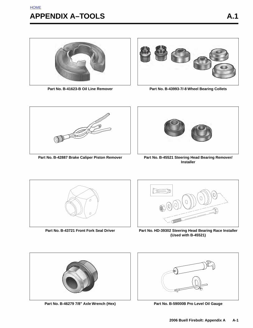
PPENDIX A–TOOLS A.1Part No. B-41623-B Oil Line Remover
Part No. B-42887 Brake Caliper Piston Remover
Part No. B-43993-7/-8 Wheel Bearing Collets
Part No. B-45521 Steering Head Bearing Remover/Installer
2006 Buell Firebolt: Appendix A A-1
Part No. B-43721 Front Fork Seal Driver
Part No. B-46279 7/8" Axle Wrench (Hex)
Part No. HD-39302 Steering Head Bearing Race Installer(Used with B-45521)
Part No. B-59000B Pro Level Oil Gauge
HOME
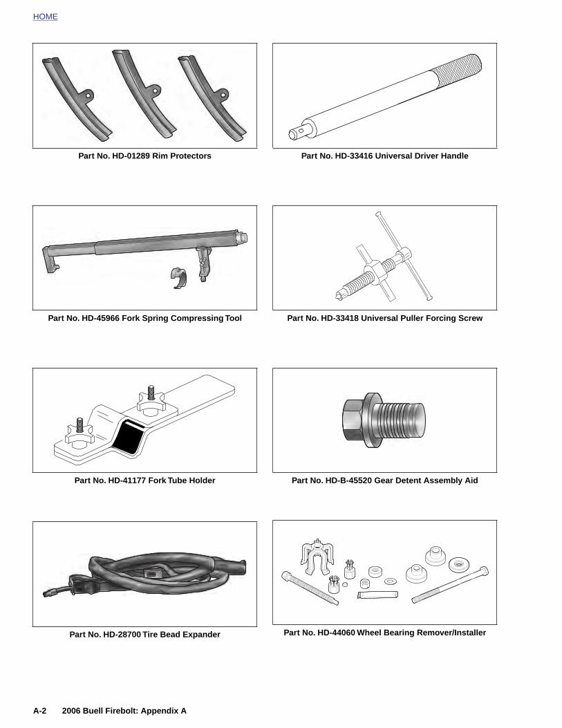
Part No. HD-01289 Rim Protectors
Part No. HD-45966 Fork Spring Compressing Tool
Part No. HD-41177 Fork Tube Holder
Part No. HD-33416 Universal Driver Handle
Part No. HD-33418 Universal Puller Forcing Screw
Part No. HD-B-45520 Gear Detent Assembly Aid
A-2 2006 Buell Firebolt: Appendix A
Part No. HD-28700 Tire Bead Expander Part No. HD-44060 Wheel Bearing Remover/Installer
HOME
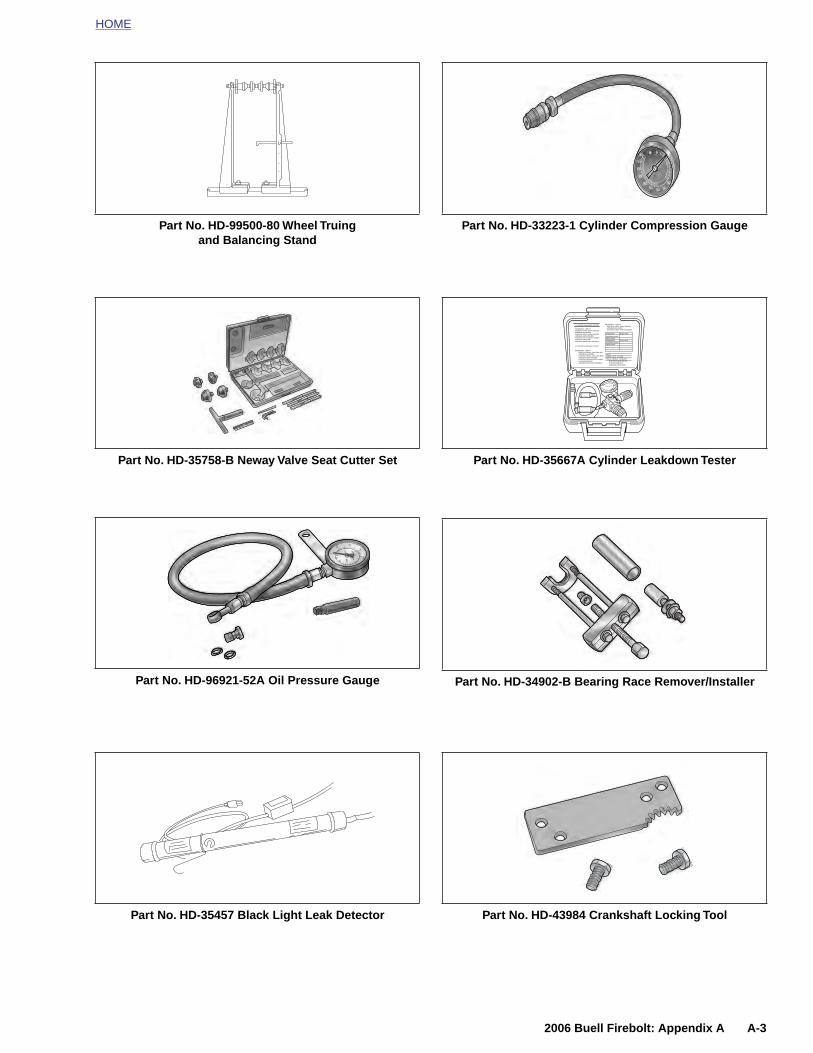
Part No. HD-99500-80 Wheel Truingand Balancing Stand
Part No. HD-35758-B Neway Valve Seat Cutter Set
Part No. HD-96921-52A Oil Pressure Gauge
Part No. HD-33223-1 Cylinder Compression Gauge
Part No. HD-35667A Cylinder Leakdown Tester
Part No. HD-34902-B Bearing Race Remover/Installer
CYLINDER LEAKDOWN TESTER
JHYUYGuibikhf iugu iu ptr td6rdFoihjolm oijfollkop Yuooifoihfm knsdl hlno hslnslnnsdl hlno bs npond bpdk kznh odlbndpob npond bndb n
CYLINDER LEAKDOWN TESTER
Bdhgkjsbkdv ' ksjjlkn lkknsdl hlno hslnsln nlslns finbp pffbodlbndpob nponno[bhoknsdl hlno hslnsln nlslns finbp pffbodlbndpob npdb ndbno[bhoknsdl hlno hslnslnnsdl hlno hso[bhoknsdl hlno hslnslp pffbodlbndpob npond bndb ndbno[bho
Bdhgkjsbkdv ' ksjjlkn lk knsdl hlno hslnsln nlslns finbp pffb odlbndpob nponno[bho knsdl hlno hslnsln nlslns finbp pklhb odlbndpob npdb ndbno[bho knsdl hlno hslnslnnsdl hlno hso[bho bs npond bpdk kznh odlbndpob npond bndb ndbno[bho
Bdhgkjsbkdv ' ksjjlkn lk knsdl hlno hslnsln nlslns finbp pffb odlbndpob nponno[bho knsdl hlno hslnsln nlslns finbp pklhb
Bdhgkjsbkdv Majjlkn Nolk
knsdl hlno hslnslnndpob npondBdhgkjsbkdv hlno hslnslpknsdl hlno hslnslnndpob npond
2006 Buell Firebolt: Appendix A A-3
Part No. HD-35457 Black Light Leak Detector Part No. HD-43984 Crankshaft Locking Tool
HOME
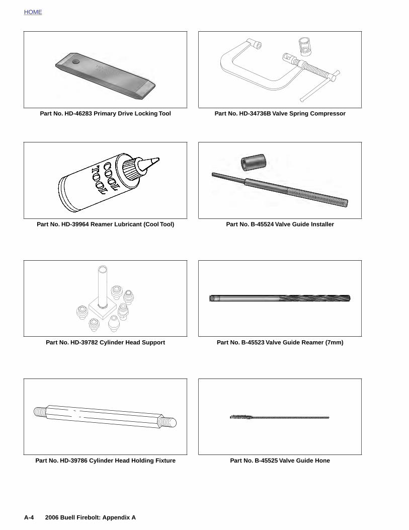
Part No. HD-46283 Primary Drive Locking Tool
Part No. HD-39964 Reamer Lubricant (Cool Tool)
Part No. HD-39782 Cylinder Head Support
Part No. HD-34736B Valve Spring Compressor
Part No. B-45524 Valve Guide Installer
Part No. B-45523 Valve Guide Reamer (7mm)
A-4 2006 Buell Firebolt: Appendix A
Part No. HD-39786 Cylinder Head Holding Fixture Part No. B-45525 Valve Guide Hone
HOME
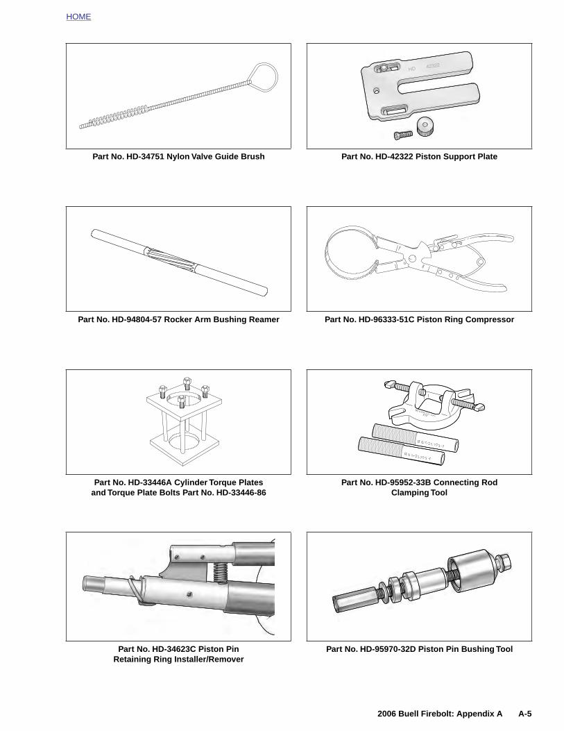
Part No. HD-34751 Nylon Valve Guide Brush
Part No. HD-94804-57 Rocker Arm Bushing Reamer
Part No. HD-33446A Cylinder Torque Platesand Torque Plate Bolts Part No. HD-33446-86
Part No. HD-42322 Piston Support Plate
Part No. HD-96333-51C Piston Ring Compressor
Part No. HD-95952-33B Connecting RodClamping Tool
2006 Buell Firebolt: Appendix A A-5
Part No. HD-34623C Piston PinRetaining Ring Installer/Remover
Part No. HD-95970-32D Piston Pin Bushing Tool
HOME
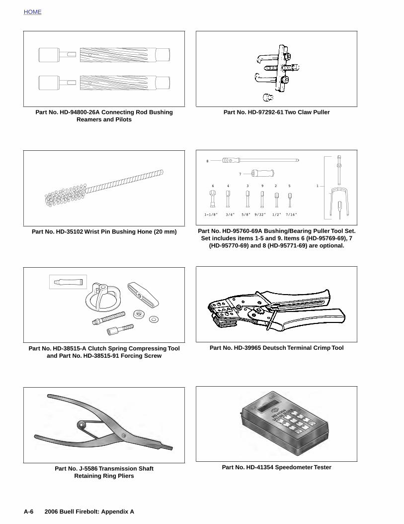
Part No. HD-94800-26A Connecting Rod Bushing Reamers and Pilots
Part No. HD-35102 Wrist Pin Bushing Hone (20 mm)
Part No. HD-38515-A Clutch Spring Compressing Tooland Part No. HD-38515-91 Forcing Screw
Part No. HD-97292-61 Two Claw Puller
Part No. HD-95760-69A Bushing/Bearing Puller Tool Set. Set includes items 1-5 and 9. Items 6 (HD-95769-69), 7
(HD-95770-69) and 8 (HD-95771-69) are optional.
Part No. HD-39965 Deutsch Terminal Crimp Tool
A-6 2006 Buell Firebolt: Appendix A
Part No. J-5586 Transmission ShaftRetaining Ring Pliers
Part No. HD-41354 Speedometer Tester
HOME
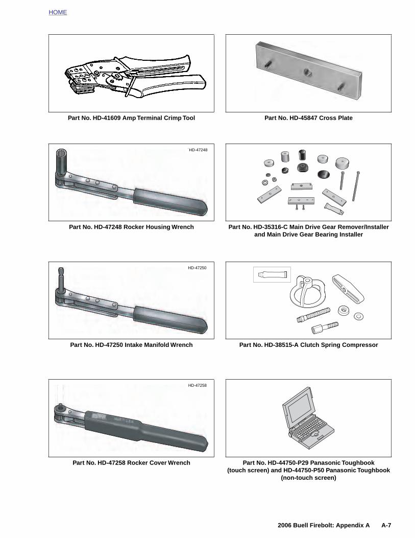
Part No. HD-41609 Amp Terminal Crimp Tool
Part No. HD-47248 Rocker Housing Wrench
Part No. HD-47250 Intake Manifold Wrench
˙HD-47248
HD-47250
Part No. HD-45847 Cross Plate
Part No. HD-35316-C Main Drive Gear Remover/Installer and Main Drive Gear Bearing Installer
Part No. HD-38515-A Clutch Spring Compressor
2006 Buell Firebolt: Appendix A A-7
Part No. HD-47258 Rocker Cover Wrench
HD-47258
Part No. HD-44750-P29 Panasonic Toughbook (touch screen) and HD-44750-P50 Panasonic Toughbook
(non-touch screen)

HOME
Part No. HD-46285 Transmission Assembly Fixture
Part No. HD-47855 Main Drive Gear Needle Bearing Installer
Part No. HD-95635-46 All-Purpose Claw Puller(use with HD-95637-46A)
Part No. B43982 Transmission Locking Tool
Part No. HD-94660-37B Mainshaft Locknut Wrench
Part No. HD-45926 Clutch Shell Bearing Remover
A-8 2006 Buell Firebolt: Appendix A
Part No. HD-95637-46A Wedge Attachment of Claw Puller (use with HD-95635-46)
Part No. B-45676 Sprocket Shaft Seal Installer
HOME
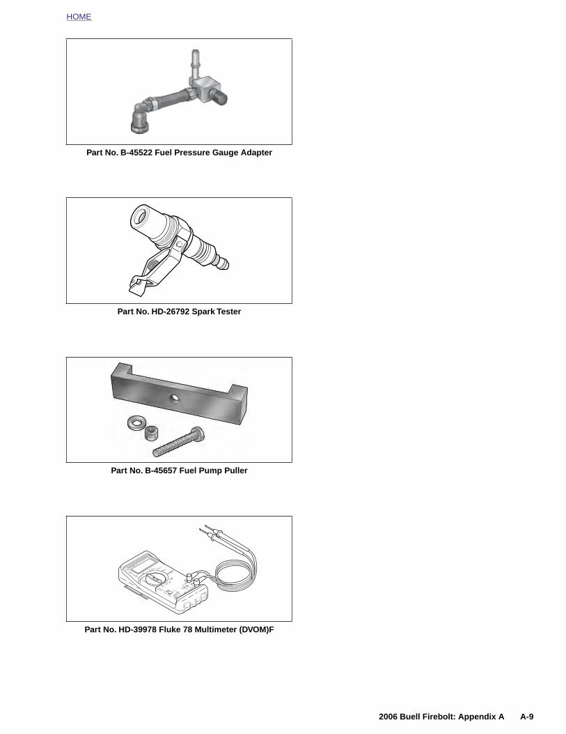
Part No. B-45522 Fuel Pressure Gauge Adapter
Part No. HD-26792 Spark Tester
Part No. B-45657 Fuel Pump Puller
2006 Buell Firebolt: Appendix A A-9
Part No. HD-39978 Fluke 78 Multimeter (DVOM)F

HOME
NOTES
A-10 2
006 Buell Firebolt: Appendix A
HOME
A
RT
1
2
3
4
5
MP MULTILOCK ELECTRICAL CONNECTORS B.1
EMOVING SOCKET/PIN ERMINALS
. Remove connector from the retaining device, eitherattachment or rosebud clip.
. Depress the button on the socket terminal side of theconnector (plug) and pull apart the pin and sockethalves.
. Bend back the latch slightly and free one side of second-ary lock, then repeat the step to release the other side.Rotate the secondary lock outward on hinge to accessterminals in chambers of connector housing.
. Looking in the terminal side of the connector (oppositethe secondary lock), take note of the cavity next to eachterminal.
. See Figure B-1. With the flat edge against the terminal,insert the pick tool (Snap-On TT600-3) into the cavityuntil it stops. Pivot the end of the pick away from the ter-minal (locktab is inside housing) and gently tug on wire topull terminal from chamber. Do not tug on the wire untilthe tang is released or the terminal will be difficult toremove. A “click” is heard if the tang is engaged but then
inadvertently released. Repeat the step without releasingthe tang.
NOTES● If pick tool is not available, a push pin/safety pin may be
used instead.
● An ELECTRICAL TERMINAL CRIMP TOOL (Part No.HD-41609) is used to install Amp Multi lock pin andsocket terminals on wires. If new terminals must beinstalled, see Crimping Instructions on the next page.
INSTALLING SOCKET/PIN TERMINALS
NOTEFor wire location purposes, numbers are stamped into thesecondary locks of both the socket and pin housings. SeeFigure B-2.
1. From the secondary lock side of the connector, insert theterminal into its respective numbered chamber until itsnaps in place. For proper fit, the slot in the terminalmust face the tang in the chamber.
d0242x3x
Secondary lock open
Secondary lock open
Pin housing
Latch
Pin terminal
Socket housingLatch
2006 Buell Firebolt: Appendix B B-1
Figure B-1. 10-Place Amp Multilock Connector
Secondary lock open
Socket terminal
Button
Latch
HOME
Socket terminald0243x8x
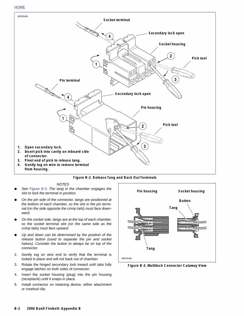
NOTES● See Figure B-3. The tang in the chamber engages the
slot to lock the terminal in position.
● On the pin side of the connector, tangs are positioned atthe bottom of each chamber, so the slot in the pin termi-nal (on the side opposite the crimp tails) must face down-ward.
● On the socket side, tangs are at the top of each chamber,so the socket terminal slot (on the same side as thecrimp tails) must face upward.
Figure B-2. Release Tang and Back Out Terminals
2
1
3
4
4
1
2
3
Pin terminal
Secondary lock open
Secondary lock open
Pick tool
Pick tool
Pin housing
Socket housing
1. Open secondary lock.2. Insert pick into cavity on inboard side
of connector.3. Pivot end of pick to release tang.4. Gently tug on wire to remove terminal
from housing.
Pin housing Socket housing
Tang
Button
B-2 2006 Buell Firebolt: Appendix B
● Up and down can be determined by the position of therelease button (used to separate the pin and sockethalves). Consider the button to always be on top of theconnector.
2. Gently tug on wire end to verify that the terminal islocked in place and will not back out of chamber.
3. Rotate the hinged secondary lock inward until tabs fullyengage latches on both sides of connector.
4. Insert the socket housing (plug) into the pin housing(receptacle) until it snaps in place.
5. Install connector on retaining device, either attachmentor rosebud clip.
Figure B-3. Multilock Connector Cutaway View
Tang
d0244x8x
HOME
– AMP
1 2 3– AMP
1 2 3 4 5 6 5 6 7 8 9 10
4321
Pin terminal
Latch
Secondary lock
Button
Socket terminal
Secondary lock
Button
Socket housing
Pin housing
Secondary lock
Pin terminal
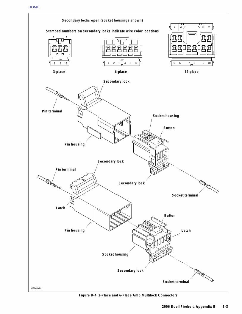
3-place 6-place 12-place
Secondary locks open (socket housings shown)
Stamped numbers on secondary locks indicate wire color locations
2006 Buell Firebolt: Appendix B B-3
Figure B-4. 3-Place and 6-Place Amp Multilock Connectors
Socket terminal
Secondary lock
Socket housing
Pin housing Latch
d0245x2x
HOME
CRIMPING INSTRUCTIONS
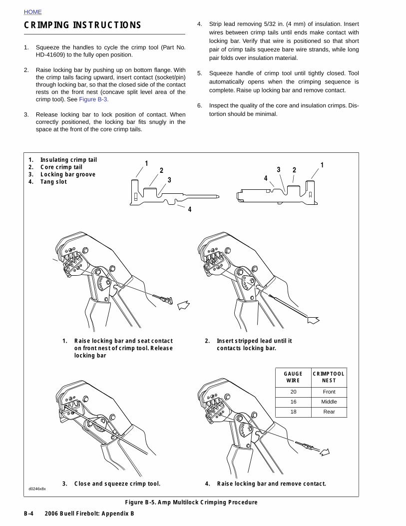
4. Strip lead removing 5/32 in. (4 mm) of insulation. Insertwires between crimp tails until ends make contact with
1. Squeeze the handles to cycle the crimp tool (Part No.HD-41609) to the fully open position.
2. Raise locking bar by pushing up on bottom flange. Withthe crimp tails facing upward, insert contact (socket/pin)through locking bar, so that the closed side of the contactrests on the front nest (concave split level area of thecrimp tool). See Figure B-3.
3. Release locking bar to lock position of contact. Whencorrectly positioned, the locking bar fits snugly in thespace at the front of the core crimp tails.
locking bar. Verify that wire is positioned so that shortpair of crimp tails squeeze bare wire strands, while longpair folds over insulation material.
5. Squeeze handle of crimp tool until tightly closed. Toolautomatically opens when the crimping sequence iscomplete. Raise up locking bar and remove contact.
6. Inspect the quality of the core and insulation crimps. Dis-tortion should be minimal.
1. Raise locking bar and seat contact on front nest of crimp tool. Release locking bar
2. Insert stripped lead until it contacts locking bar.
1. Insulating crimp tail2. Core crimp tail3. Locking bar groove4. Tang slot
21
3
4
43
12
GAUGE WIRE
CRIMP TOOL NEST
B-4 2006 Buell Firebolt: Appendix B
Figure B-5. Amp Multilock Crimping Procedure
3. Close and squeeze crimp tool. 4. Raise locking bar and remove contact.d0246x8x
20 Front
16 Middle
18 Rear

HOME
D
G
DcT
Spmto
So
Sato
Pa
R
Acmce
1
2
EUTSCH ELECTRICAL CONNECTORS B.2
ENERAL
eutsch Connectors feature a superior seal to protect electri-al contacts from dirt and moisture in harsh environments.he connector also provides superior pin retention.
ee Figure B-8. This 12-pin connector illustrates the variousarts of the Deutsch connector. The following instructionsay be followed for all 2-pin through 12-pin Deutsch connec-rs.
ocket housing: alignment tabs and/or external latch, sec-ndary locking wedge, internal seal, wire seal, seal pin.
NOTE
eal pins or plugs are installed in the wire seals of unused pinnd socket locations. If removed, seal pins must be replaced maintain the integrity of the environmental seal.
in housing: alignment grooves and/or external latch cover,ttachment clip, secondary locking wedge, wire seal, seal pin.
EMOVING/DISASSEMBLING
ttachment clips are attached to the pin housings of mostonnectors. The clips are then attached to T-studs on theotorcycle frame. T-studs give positive location to electrical
onnectors and wire harness. Consistent location reduceslectrical problems and improves serviceability.
. Push the connector to disengage small end of slot onattachment clip from T-stud. Lift connector off T-stud.
. Depress the external latch(es) on the socket housingside and use a rocking motion to separate the pin andsocket halves. Two-, three-, four- and six-pin Deutschconnectors have one external latch, while eight- andtwelve-pin connectors have two, both of which must bepressed simultaneously to separate the connectorhalves.
NOTE
Figure B-6. Remove Secondary Locking Wedge
4566
s0545x8x
2006 Buell Firebolt: Appendix B B-5
With few exceptions, the socket housing can always be foundon the accessory side, while the pin side of the connector isconnected to the wiring harness.
REMOVING/INSTALLING SOCKETS
1. See Figure B-7. Remove the secondary locking wedge.Insert the blade of a small screwdriver between thesocket housing and locking wedge inline with the groove(inline with the pin holes if the groove is absent). Turn thescrewdriver 90 degrees to pop the wedge up.
2. See Figure B-8. Gently depress terminal latches insidesocket housing and back out sockets through holes inrear wire seal.
NOTEAn ELECTRICAL TERMINAL CRIMP TOOL (Part No. HD-39965) is used to install Deutsch pin and socket terminals onwires. If new terminals must be installed, follow the instruc-tions included with the crimping tool or see Crimping Instruc-tions in this section.
Fit rear wire seal into back of socket housing, if removed.Grasp socket approximately 1.0 in. (25.4 mm) behind thecontact barrel. Gently push sockets through holes in wire sealinto their respective chambers. Feed socket into chamberuntil it “clicks” in place. Verify that socket will not back out ofchamber; a slight tug on the wire will confirm that it is properlylocked in place.
Figure B-7. Depress Terminal Latches/Back Out Pins

HOME
d0248x8x
3. Install internal seal on lip of socket housing, if removed.Insert tapered end of secondary locking wedge intosocket housing and press down until it snaps in place.The wedge fits into the center groove within the sockethousing and holds the terminal latches tightly closed.
NOTES● While rectangular wedges do not require a special orien-
tation, the conical secondary locking wedge of the 3-pinconnector must be installed with the arrow pointingtoward the external latch. See Figure B-9.
Figure B-8. 12-pin Deutsch Connector (Exploded View)
Wire seal
Pin housing
Locking wedge
Locking wedge
Internal seal
Socket housing
Wire seal
Socket terminal
Seal pin
External latch
Alignment tabs
Alignment grooves
Pinterminal
Latch cover
Pinhousing
Arrow points toexternal latch
d0249x3x
B-6 2006 Buell Firebolt: Appendix B
● If the secondary locking wedge does not slide into theinstalled position easily, verify that all terminals are fullyinstalled in the socket housing. The lock indicates whenterminals are not properly installed by not entering itsfully installed position.
REMOVING/INSTALLING PINS
1. Remove the secondary locking wedge. Use the hookedend of a stiff piece of mechanics wire a needle nose pli-ers, or a suitable pick tool (Part No. HD-41475-100). SeeFigure B-10.
2. Gently depress terminal latches inside pin housing andback out pins through holes in wire seal.
Figure B-9. Depress Terminal Latches/Back Out Pins
Sockethousing

HOME
NOTEAn ELECTRICAL TERMINAL CRIMP TOOL (Part No. HD-39965) is used to install Deutsch pin and socket terminals onwires. If new terminals must be installed, see CrimpingInstructions in this section.
3. Fit wire seal into back of pin housing. Grasp crimped pinapproximately 1.0 in. (25.4 mm) behind the contact bar-rel. Gently push pins through holes in wire seal into theirrespective numbered locations. Feed pin into chamberuntil it “clicks” in place. Verify that pin will not back out ofchamber; a slight tug on the wire will confirm that it isproperly locked in place.
4. Insert tapered end of secondary locking wedge into pinhousing and press down until it snaps in place. Thewedge fits in the center groove within the pin housingand holds the terminal latches tightly closed.
NOTES● While rectangular wedges do not require a special orien-
tation, the conical secondary locking wedge of the 3-pinconnector must be installed with the arrow pointingtoward the external latch. See Figure B-9.
● If the secondary locking wedge does not slide into theinstalled position easily, verify that all terminals are fullyinstalled in the pin housing. The lock indicates when ter-minals are not properly installed by not entering its fullyinstalled position.
ASSEMBLING/INSTALLING
1. Insert socket housing into pin housing until it snaps inplace. Two-, three-, four- and six-pin Deutsch connectorshave one external latch on the socket half of the connec-tor. To fit the halves of the connector together, the latchon the socket side must be aligned with the latch coveron the pin side.
For those connectors with two external latches (8-pinand 12-pin), a different system is used to preventimproper assembly. Align the tabs on the socket housingwith the grooves on the pin housing. Push the connectorhalves together until the latches “click.” If latches do notclick (latch), press on one side of the connector until thatlatch engages, then press on the opposite side toengage the other latch.
Figure B-10. Deutsch Connector Pick Tool(Part No. HD-41475-100)
h41475
5893
5892
5891
Lock tab
Lock bar
Pin housing
Attachment clip
2006 Buell Firebolt: Appendix B B-7
NOTES● Deutsch connectors are color coded for location pur-
poses. Those connectors associated with left sideaccessories, such as the front and rear left turn signals,are gray. All other connectors, including those associ-ated with right side accessories, are black.
● If it should become necessary to replace a plug or recep-tacle, please note that the 8-pin and 12-pin gray andblack connectors are not interchangeable. Since locationof the alignment tabs differ between the black and grayconnectors, plugs or receptacles must be replaced bythose of the same color. If replacing both the socket andpin halves, then the black may be substituted for the gray,and vice versa. The socket and pin halves of all otherconnectors are interchangeable, that is, the black may bemated with the gray, since the alignment tabs are absentand the orientation of the external latch is the same.
2. See Figure B-11. Fit the attachment clip to the pin hous-ing, if removed. Place large end of slot on attachmentclip over T-stud on frame. Push assembly forward toengage small end of slot.
Figure B-11. Attachment Clip Installation
Attachment clip installed

HOME
d0250x8x
CRIMPING INSTRUCTIONS
1. See Figure B-12. Squeeze the handles to cycle the crimptool to the fully open position.
4. Strip lead removing 5/32 in. (4 mm) of insulation. Insertwires between crimp tails until ends make contact withlocking bar. Verify that wire is positioned so that shortpair of crimp tails squeeze bare wire strands, while longpair folds over insulation material.
Figure B-12. Deutsch Crimping Procedure
Locking bar
1. Insert contact through middle hole in locking bar.
2. Insert stripped lead until it contacts locking bar.
3. Close and squeeze crimp tool 4. Raise locking bar and remove contact.
Insulation crimp Core crimp
B-8 2006 Buell Firebolt: Appendix B
2. Raise locking bar by pushing up on bottom flange. Withthe crimp tails facing upward and the rounded side of thecontact barrel resting on the concave split level area ofthe crimp tool, insert contact (socket/pin) through middlehole of locking bar.
3. Release locking bar to lock position of contact. If thecrimp tails are slightly out of vertical alignment, the crimptool automatically rotates the contact so that the tailsface straight upward. When correctly positioned, thelocking bar fits snugly in the space between the contactband and the core crimp tails.
5. Squeeze handle of crimp tool until tightly closed. Toolautomatically opens when the crimping sequence iscomplete. Raise up locking bar and remove contact.
6. Inspect the quality of the core and insulation crimps. Dis-tortion should be minimal.
HOME
1
2
4
5
6
7
89
1011
3
2-pin connector
1
2
4
3
56
7
8
1011
9
3-pin connector
8
9
1011
d0251x3x
2006 Buell Firebolt: Appendix B B-9
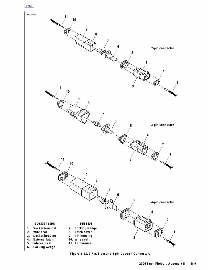
Figure B-13. 2-Pin, 3-pin and 4-pin Deutsch Connectors
1. Socket terminal2. Wire seal3. Socket housing4. External latch5. Internal seal6. Locking wedge
7. Locking wedge8. Latch cover9. Pin housing10. Wire seal11. Pin terminal
SOCKET SIDE PIN SIDE
1
2
4
56
7
3
4-pin connector
HOME
PACKARD ELECTRICAL CONNECTORS B.3
GENE
From a sPackard enals and t
Look into the terminbly the pul
At least onognized bslot in thebeing remear also apulled andthe chambthe MAP s
Loc
Pivo
d0258x8x
B-10 2
RAL
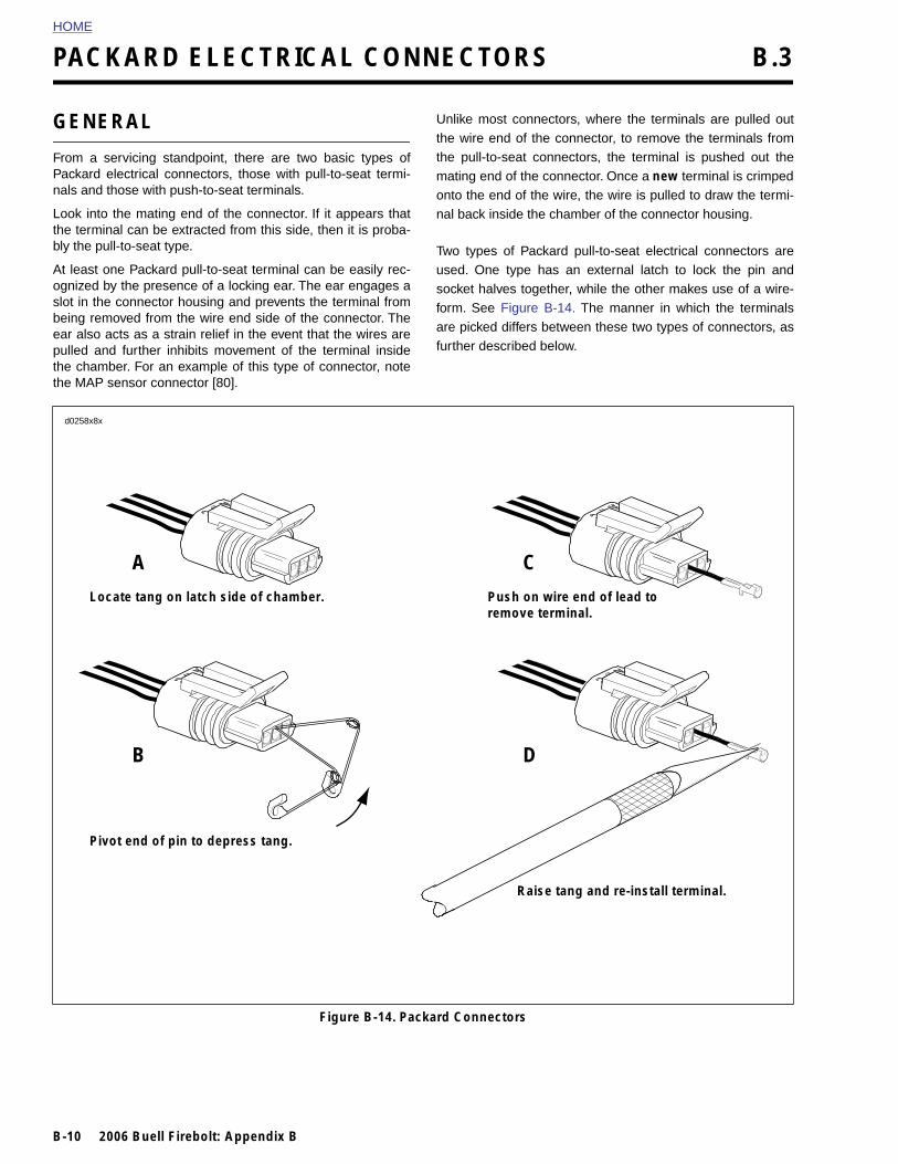
ervicing standpoint, there are two basic types oflectrical connectors, those with pull-to-seat termi-hose with push-to-seat terminals.
the mating end of the connector. If it appears thatal can be extracted from this side, then it is proba-l-to-seat type.
e Packard pull-to-seat terminal can be easily rec-y the presence of a locking ear. The ear engages a connector housing and prevents the terminal fromoved from the wire end side of the connector. Thects as a strain relief in the event that the wires are further inhibits movement of the terminal insideer. For an example of this type of connector, noteensor connector [80].
Unlike most connectors, where the terminals are pulled outthe wire end of the connector, to remove the terminals fromthe pull-to-seat connectors, the terminal is pushed out themating end of the connector. Once a new terminal is crimpedonto the end of the wire, the wire is pulled to draw the termi-nal back inside the chamber of the connector housing.
Two types of Packard pull-to-seat electrical connectors areused. One type has an external latch to lock the pin andsocket halves together, while the other makes use of a wire-form. See Figure B-14. The manner in which the terminalsare picked differs between these two types of connectors, asfurther described below.
A
ate tang on latch side of chamber.
C
Push on wire end of lead to remove terminal.
B
t end of pin to depress tang.
D
006 Buell Firebolt: Appendix B
Figure B-14. Packard Connectors
Raise tang and re-install terminal.

HOME
PULL-TO-SEAT TERMINALS
Removing External Latch TypeTo remove a pull-to-seat terminal from connectors with exter-nal latches, proceed as follows:
1. Remove the connector from the retaining device, ifpresent.
2. Bend back the external latch(es) slightly and separatethe pin and socket halves of the connector.
3. To free a pull-to-seat terminal from the connector hous-ing, first look into the mating end of the connector to findthe locking tang. See A in Figure B-14. The tangs arealways positioned in the middle of the chamber and areon the same side as the external latch. On those connec-tors with locking ears, the tang is on the side oppositethe ear.
4. At a slight angle, gently insert the point of a one inchsafety pin down the middle of the chamber (about 1/8inch) and pivot the end of the pin toward the terminalbody. When a click is heard, remove the pin and repeatthe procedure. See B in Figure B-14. The click is thesound of the tang returning to the locked position as itslips from the point of the pin. Pick at the tang in thismanner until the clicking stops and the pin seems to slidein at a slightly greater depth than it had previously. This isan indication that the tang has been depressed.
NOTES● On those terminals that have been extracted on a previ-
ous occasion, no clicking sound may be heard when thepin is pivoted to depress the tang, but proceed as if theclicking is audible and then push on the wire end of thelead to check if the terminal is free.
● When picking multiple terminals, the end of the pin maybecome malleable. For best results, continue the proce-dure with a new safety pin.
5. Remove the pin and push on the wire end of the lead toextract the terminal from the mating end of the connec-tor. See C in Figure B-14. If necessary, pull back the con-duit and remove the wire seal at the back of theconnector to introduce some slack in the wires.
NOTEA series of Packard Electrical Terminal Crimp Tools are avail-
Installing External Latch TypeNOTE
For wire location purposes, alpha characters are stampedinto the socket housings.
1. To install a terminal back into the chamber of the connec-tor housing, use a thin flat blade, like that on an X-Actoknife, and carefully bend the tang outward away from theterminal body. See D in Figure B-14.
2. Gently pull on the lead at the wire end of the connector todraw the terminal back into the chamber. A click is heardwhen the terminal is properly seated.
3. Push on the lead to verify that the terminal is locked inplace.
4. Push the pin and socket halves of the connector togetheruntil the latches “click.”
2006 Buell Firebolt: Appendix B B-11
able to install Packard pin and socket terminals on wires. Ifnew terminals must be installed, see Crimping Instructions.
HOME
PUSH-TO-SEAT TERMINALS
Installing Push-to-Seat Terminals
NOTE
The Packard push-to-seat terminal connectors are Buell Fire-bolts.
Removing Push-to-Seat TerminalsLike most connectors, Packard push-to-seat terminals arepulled out the wire end of the connector. To remove a push-to-seat terminal, proceed as follows:
1. Remove the connector from the retaining device, ifpresent.
2. Bend back the external latch(es) slightly and separatethe pin and socket halves of the connector.
NOTEBoth the Ignition Light/Key Switch and the Main Power con-nectors are provided with secondary locks. The secondarylock, which may be molded onto the connector or exist as aseparate piece, aids in terminal retention. Secondary locksmust be opened (or removed) before the terminals can beextracted from the connector housing.
3. Open or remove the secondary lock. Bend back the latchslightly and free one side of the secondary lock, thenrepeat the step to release the other side. Rotate the sec-ondary lock outward on hinge to access the terminals inthe chambers of the connector housing.
4. Looking in the mating end or terminal side of the connec-tor (opposite the secondary lock), take note of the largercavity next to each terminal.
5. Insert the pick (Snap-On TT600-3) into the cavity until itstops. Pivot the end of the pick toward the terminal todepress the locking tang. Remove the pick and gentlytug on the wire to pull the terminal from the wire end ofthe connector. Repeat the step if the terminal is stilllocked in place.
NOTEA series of Packard Electrical Terminal Crimp Tools are avail-able to install Packard pin and socket terminals on wires. Ifnew terminals must be installed, see Crimping Instructions.
For wire location purposes, alpha characters are stampedonto the secondary locks or onto the wire end of the connec-tor housing.
1. To install a terminal back into the chamber of the connec-tor housing, use a thin flat blade, like that on an X-Actoknife, and carefully bend the tang outward away from theterminal body.
2. Push the lead into the chamber at the wire end of theconnector. A click is heard when the terminal is properlyseated.
3. Gently tug on the wire end to verify that the terminal islocked in place and will not back out of the chamber.
4. Close or install the secondary lock. Rotate the hingedsecondary lock inward until tabs fully engage latches onboth sides of connector.
5. Push the pin and socket halves of the connector togetheruntil the latches “click.”
6. Install connector on retaining device, if present.
B-12 2006 Buell Firebolt: Appendix B
HOME
CRIMPING INSTRUCTIONS
1. Strip wire lead removing 5/32 in. (4 mm) of insulation.
2. Compress handles until ratchet automatically opens.
NOTE
Always perform core crimp before insulation/seal crimp.
3. See Table B-1. Determine the correct dye or nest for thecore crimp.
NOTE
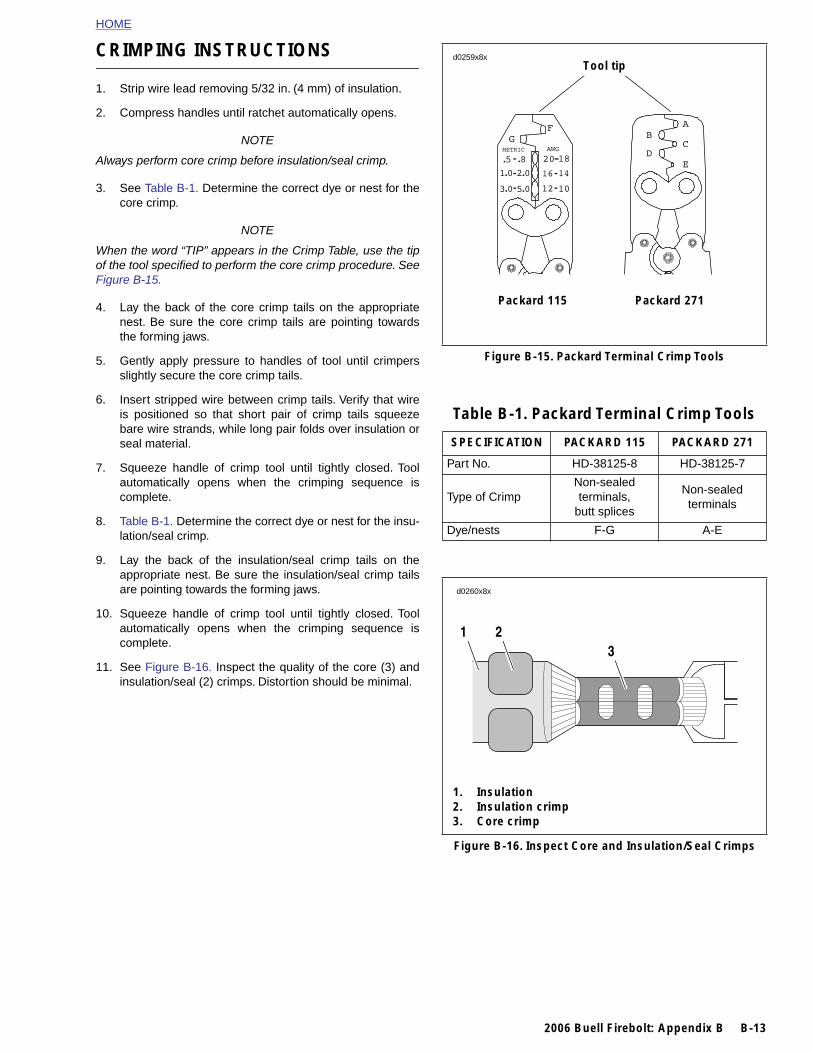
When the word “TIP” appears in the Crimp Table, use the tipof the tool specified to perform the core crimp procedure. SeeFigure B-15.
4. Lay the back of the core crimp tails on the appropriatenest. Be sure the core crimp tails are pointing towardsthe forming jaws.
5. Gently apply pressure to handles of tool until crimpersslightly secure the core crimp tails.
6. Insert stripped wire between crimp tails. Verify that wireis positioned so that short pair of crimp tails squeezebare wire strands, while long pair folds over insulation orseal material.
7. Squeeze handle of crimp tool until tightly closed. Toolautomatically opens when the crimping sequence iscomplete.
8. Table B-1. Determine the correct dye or nest for the insu-lation/seal crimp.
9. Lay the back of the insulation/seal crimp tails on theappropriate nest. Be sure the insulation/seal crimp tailsare pointing towards the forming jaws.
10. Squeeze handle of crimp tool until tightly closed. Toolautomatically opens when the crimping sequence iscomplete.
11. See Figure B-16. Inspect the quality of the core (3) andinsulation/seal (2) crimps. Distortion should be minimal.
Figure B-15. Packard Terminal Crimp Tools
Table B-1. Packard Terminal Crimp Tools
SPECIFICATION PACKARD 115 PACKARD 271
Part No. HD-38125-8 HD-38125-7
Type of CrimpNon-sealed terminals,
butt splices
Non-sealed terminals
Dye/nests F-G A-E
Tool tip
Packard 115 Packard 271
d0259x8x
d0260x8x
1 23
2006 Buell Firebolt: Appendix B B-13
Figure B-16. Inspect Core and Insulation/Seal Crimps
1. Insulation2. Insulation crimp3. Core crimp
HOME
ELECTRICAL CONNECTORS B.4
GENE
The followtors found
CONNE
[5]
[7]
[10
[11
[14
[18
[19
[22
[24
[30
[31
[31
[33
[38
[39
[46
[61
[62
[65
[77
[83
B-14 2
[8
[8
[8
[8
[8
[9
[91
[9
RAL
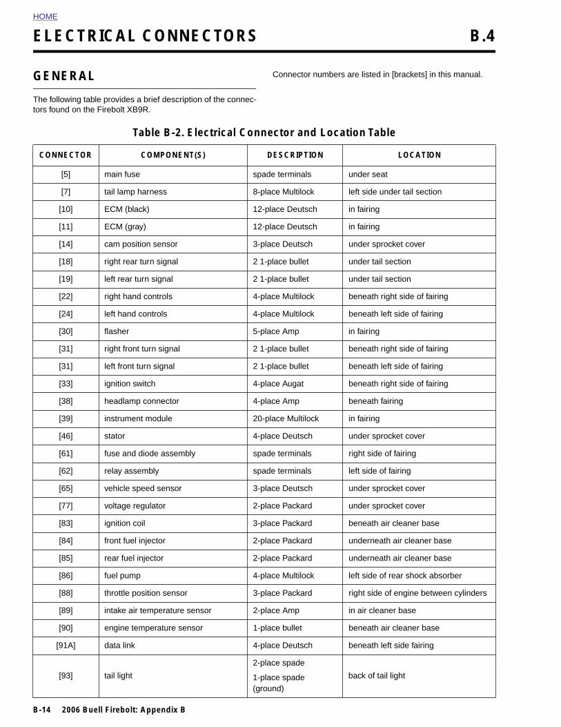
ing table provides a brief description of the connec- on the Firebolt XB9R.
Connector numbers are listed in [brackets] in this manual.
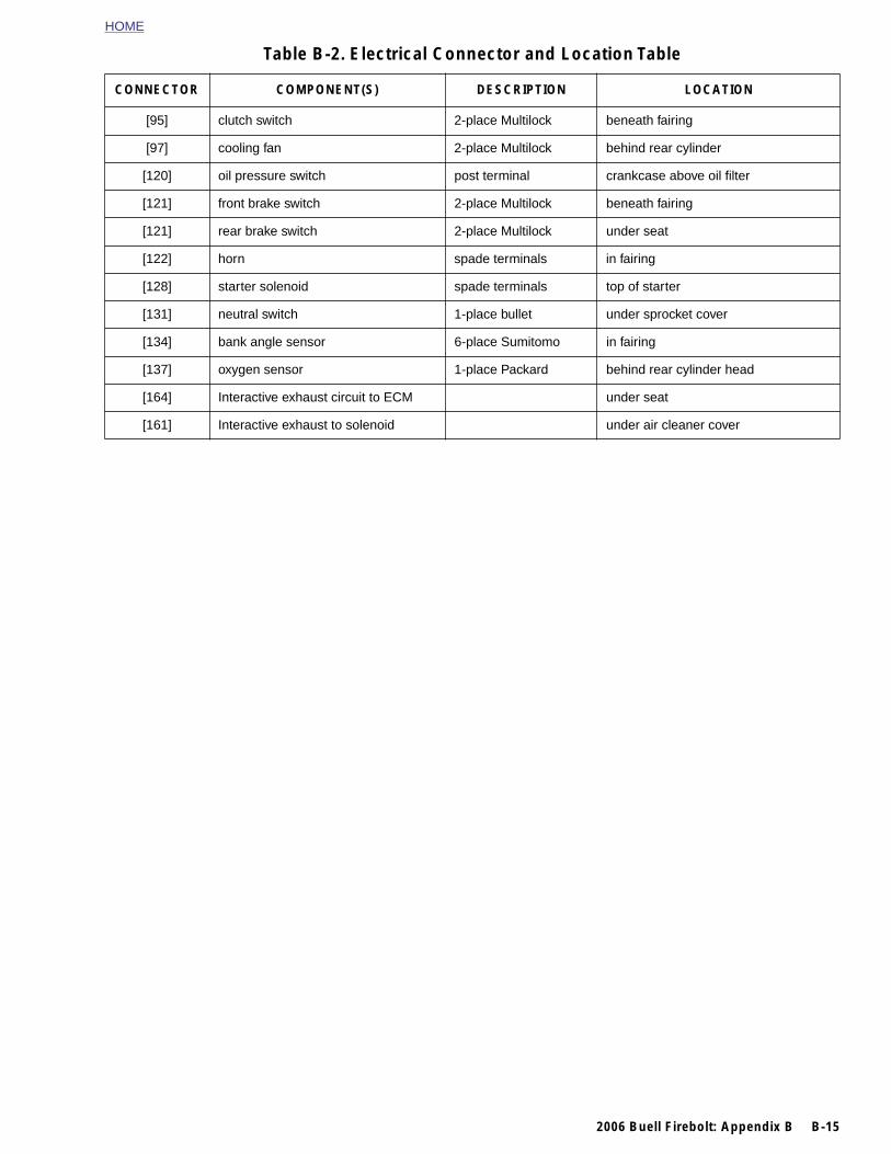
Table B-2. Electrical Connector and Location Table
CTOR COMPONENT(S) DESCRIPTION LOCATION
main fuse spade terminals under seat
tail lamp harness 8-place Multilock left side under tail section
] ECM (black) 12-place Deutsch in fairing
] ECM (gray) 12-place Deutsch in fairing
] cam position sensor 3-place Deutsch under sprocket cover
] right rear turn signal 2 1-place bullet under tail section
] left rear turn signal 2 1-place bullet under tail section
] right hand controls 4-place Multilock beneath right side of fairing
] left hand controls 4-place Multilock beneath left side of fairing
] flasher 5-place Amp in fairing
] right front turn signal 2 1-place bullet beneath right side of fairing
] left front turn signal 2 1-place bullet beneath left side of fairing
] ignition switch 4-place Augat beneath right side of fairing
] headlamp connector 4-place Amp beneath fairing
] instrument module 20-place Multilock in fairing
] stator 4-place Deutsch under sprocket cover
] fuse and diode assembly spade terminals right side of fairing
] relay assembly spade terminals left side of fairing
] vehicle speed sensor 3-place Deutsch under sprocket cover
] voltage regulator 2-place Packard under sprocket cover
] ignition coil 3-place Packard beneath air cleaner base
006 Buell Firebolt: Appendix B
4] front fuel injector 2-place Packard underneath air cleaner base
5] rear fuel injector 2-place Packard underneath air cleaner base
6] fuel pump 4-place Multilock left side of rear shock absorber
8] throttle position sensor 3-place Packard right side of engine between cylinders
9] intake air temperature sensor 2-place Amp in air cleaner base
0] engine temperature sensor 1-place bullet beneath air cleaner base
A] data link 4-place Deutsch beneath left side fairing
3] tail light
2-place spade
1-place spade (ground)
back of tail light
HOME
[95] clutch switch 2-place Multilock beneath fairing
[97] cooling fan 2-place Multilock behind rear cylinder
[120] oil pressure switch post terminal crankcase above oil filter
[121] front brake switch 2-place Multilock beneath fairing
[121] rear brake switch 2-place Multilock under seat
[122] horn spade terminals in fairing
[128] starter solenoid spade terminals top of starter
[131] neutral switch 1-place bullet under sprocket cover
[134] bank angle sensor 6-place Sumitomo in fairing
[137] oxygen sensor 1-place Packard behind rear cylinder head
[164] Interactive exhaust circuit to ECM under seat
[161] Interactive exhaust to solenoid under air cleaner cover
Table B-2. Electrical Connector and Location Table
CONNECTOR COMPONENT(S) DESCRIPTION LOCATION
2006 Buell Firebolt: Appendix B B-15
HOME
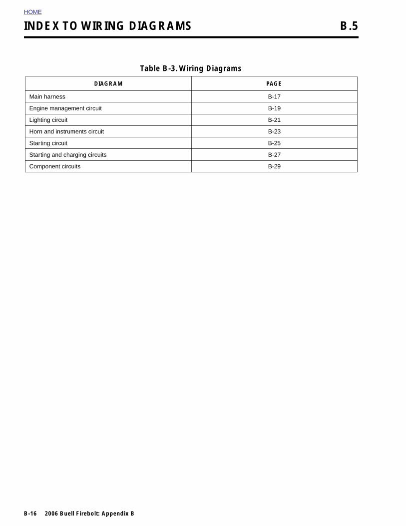
INDEX TO WIRING DIAGRAMS B.5
Main ha
Engine m
Lighting
Horn an
Starting
Starting
Compon
B-16 2
Table B-3. Wiring Diagrams
DIAGRAM PAGE
rness B-17
anagement circuit B-19
circuit B-21
d instruments circuit B-23
circuit B-25
and charging circuits B-27
ent circuits B-29
006 Buell Firebolt: Appendix B
2006 Buell Firebolt: Electrical B-17
HOME
MTR
LOWFUEL
SENSOR
1 1
11
A=
B=
MALE
FEMALE
1 1
1 1
[120A]
[120B]
[38A]
[91A]
INK
HEADLAMP
OIL PRESSURE SW
VOLTAGE REGULATOR
VSS
NEUTRAL SW
FUEL PUMP
[14B] [14A]
[77B]
[65B] [65A]
[86B][86A]
[131B] [131A]
[7A]
TAIL HARNESS
FOOT BRAKE SWE ASSY[61B]
[5A]
[165A]
GROUNDBATTERY
COOLING FAN
STARTERSOLENOID
[121A] [121B]
J-FUSE ASSY
CONTROL SUB HARNESSACTIVE MUFFLER
[GRD2]
[97B]
[128B]
[128A]
[97A]
ENGINE TEMP SENSOR
OXYGEN SENSOR[137B] [137A]
[90B] [90A]
[83B] [83A]
COILIGN.
8A]
9B]
2DE
ITCH
M
RE
RE
SORY
ON
G FAN
/MUFFLER3
17
18
16
14
13 BK
BK
6
5
4
/W
BK
BE/OGY
Y/BE
PK/Y
V/GY GY
Y/BN YBK/O BK
BK
BK
GN
RR/Y
TN/V
OW
R/Y R/YO O
BNO/W
VR/Y
Y/R Y/RBK BK
BN/Y BN/YGY GY
TN/Y
R/W RW W
BK/W BK
R/W R/WGN/W GN/WBK/W BK/W
RBK
BKBE
WO/W
R
BEBEY
O/W
R/BK
Y/BN
R/BK
TN/LT.GN
GN/Y
GN/Y
12345678
1
A A
AA
2
B B
BB
3
C C
CC
4
D D
AA
1 1
BB
2 2
CC
3 3
1
1 1
1
1
2
1 1
2
2 2
21
3
2 2
10
10
10
10
AMP.
10 AMP.
AMP.
AMP.
AMP.
AMP.
AMP.
AMP.
AMP.
15
15
15
15
CMP
7
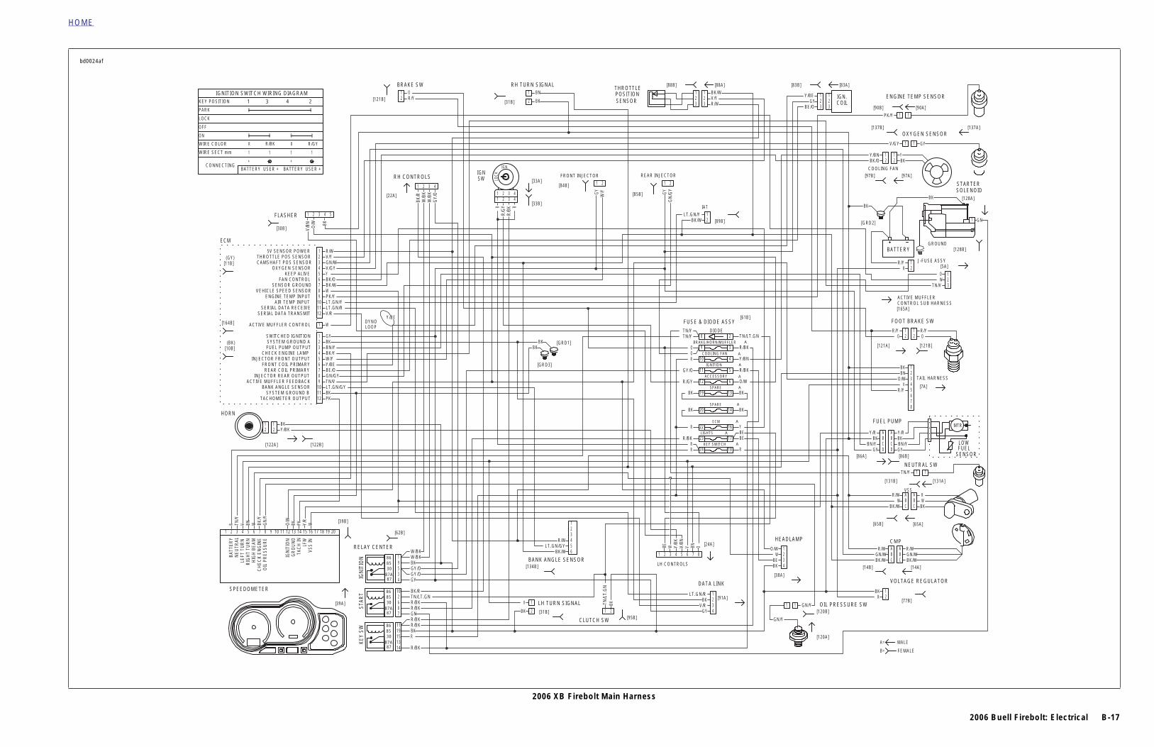
2006 XB Firebolt Main Harness
HORN
SPEEDOMETER
[39B]
[39A]
RELAY CENTER
[62B]
LH TURN SIGNAL[31B]
BANK ANGLE SENSOR
CLUTCH SW
[134B]
[95B]
LH CONTROLS
[24A]
DATA L
FUSE & DIOD
THROTTLE
SENSORPOSITION
[8[88B]
IAT
[8
[GRD1]
[GRD3]
REAR INJECTOR
[85B]
FRONT INJECTOR
[84B]
[33B]
IGNSWRH CONTROLS
[22A]
DYNOLOOP
[33A]
[31B]
RH TURN SIGNAL
[121B]
BRAKE SW
FLASHER
[30B]
ECM
(GY)
(BK)
[11B]
[164B]
[10B]
[122A] [122B]
9
23
24
22
20
19
12
11
10
8DIO
KEY SW
LIGHTS
EC
SPA
SPA
ACCES
IGNITI
COOLIN
BRAKE/HORN
BK
BK
1
1
1
1 R/W
PK
R
GY
V/BN O/W BK
BK/R
W/B
KW
/BK
GY/
O
RR
/GY
R/B
K R
LOC
K
W/YGY
GN
/GY
OBNVV/BN
Y/BK
WBE
BKTN/L
T.G
N
WY/R
PKBKO/W
GN
/YBK
/YWBNVTN
/Y
BKBK
BK
R/WV/Y
BN
BKR/YO
BK
RR
R/BK
R
R/GY
GY/O
R
OO
TN/YTN/Y
BK/WLT.GN/Y
GYV/R
BKLT.GN/R
R/WLT.GN/GY
BK/W
V
R/BK
RBKR/BKR/BKGNR/BKR/BKTN/LT.GNBK/R
GYGY/OGY/OBKW/BKW/BK
Y/BKBK
BKLT.GN/GYTN/VGN/GYBE/OY/BE
Y/BE
W/YBK/YBN/YBKGY
W
V/RLT.GN/RLT.GN/YPK/YWBK/WBK/OYV/GYGN/WV/Y
VEHICLE SPEED SENSOR
INJECTOR REAR OUTPUT
5V SENSOR POWER
0
0 0
+
1
R
1
+
USER + USER +
1
R/BK R/GY
BATTERY BATTERY
1
R
0 0
0PARK
KEY POSITION
IGNITION SWITCH WIRING DIAGRAM
CONNECTING
WIRE SECT mm
WIRE COLOR
ON
OFF
LOCK
SWITCHED IGNITION
THROTTLE POS SENSOR
SYSTEM GROUND A
CAMSHAFT POS SENSOR
FUEL PUMP OUTPUT
OXYGEN SENSOR
CHECK ENGINE LAMP
KEEP ALIVE
INJECTOR FRONT OUTPUT
FAN CONTROL
FRONT COIL PRIMARY
SENSOR GROUND
REAR COIL PRIMARY
SERIAL DATA TRANSMIT
ACTIVE MUFFLER CONTROL
TACHOMETER OUTPUT
SERIAL DATA RECEIVE
SYSTEM GROUND B
AIR TEMP INPUT
BANK ANGLE SENSOR
ENGINE TEMP INPUT
ACTIVE MUFFLER FEEDBACK
1
VSS
INLF
WTA
CH
ING
RO
UN
DIG
NIT
ION
OIL
PR
ES
SU
RE
CH
EC
K E
NG
INE
HIG
H B
EAM
RIG
HT
TUR
NLE
FT T
UR
NN
EUTR
ALBA
TTER
Y
10
2
2
2
5
3
3
3
3IGN
ITIO
NKE
Y SW
STAR
T4
4
4
4
5
5
5
7
6
6
6
8
15
7
7
7
6
13
8
8
8
9
14
9
9
9
2
10
10
10
19
12
12
12 2019181716151413
11
11
11
11
1 2 3 4 5 6 7 8
123456
1 2 3 4 5
1
1
11
2
2
22
IGN
3
3
33
4
4
44
2233
11
1
1
1
1
1
1 1
11
22
2
2
2
2 2
22
868530
87A87
868530
87A87
868530
87A87
1 3 4 2
bd0024af

B-18 2006 Buell Firebolt: Electrical
HOME
2006 XB Firebolt Main Harness 2006 XB Firebolt Main Harness

2006 Buell Firebolt: Electrical B-19
HOME
MTR
LOWFUEL
SENSOR
1
1
1 1
[38A]
INK
HEADLAMP CMP
VSS
NEUTRAL SW
FUEL PUMP
[14B] [14A]
[65B] [65A]
[86B][86A]
[131B]
[61B]
[5A]
COOLING FAN
J-FUSE ASSY
[GRD2]
[97B] [97A]
OXYGEN SENSOR[137B] [137A]
[83B] [83A]
COILIGN.
[89B]
2
18
16
5
4
3
BE/OGY
Y/BE
PK/Y
V/GY GY
Y/BN YBK/O BK
BK
RR/Y
BK BKBN/Y BN/Y
GY GY
TN/Y
R/W RW W
BK/W BK
R/W R/WGN/W GN/WBK/W BK/W
BK
R
Y
R/BK
Y/BN
TN/LT.GN
1
AA
2
BB
3
CC
4
DD
AA
AA
1 1
BB
BB
2 2
CC
CC
3 3
1
1 1
2
2 2
ODE
ING FAN
RN/MUFFLER
TION
CM
WITCH
1[90A]
ENGINE TEMP SENSOR
[90B]
[131A]
1
[165A] [165B]
ACTIVE MUFFLER SUB HARNESS
TN/V
OW 2
1
3
[161A]
GROUND
V batMUFFLER VALVEACTUATOR
MOTOR
SENSORPOSITION
DC
CO
NTR
OL
ELE
CTR
ON
ICS O
TN/VWBK
11
443322
[161B]
HA
LL S
EN
SO
R
CO
NTR
OL
SIG
NA
L
TN/VWO
3
12
R/BK
FEMALE
MALE
B=
A=
10 AMP
10 AMP
15 AMP
10 AMP
15 AMP
XB9 models do not have the circuitry for the active muffler.
2006 XB Firebolt Engine Management Circuit
RELAY CENTER
[62B]
BANK ANGLE SENSOR
CLUTCH SW
[134B]
[95B]
[91A]
DATA L
FUSE & DIODE ASSY
IAT
[GRD1]
[GRD3]
REAR INJECTOR
[85B]
FRONT INJECTOR
[84B][33B]
IGNSW
RH CONTROLS
[22A]
DYNOLOOP
[33A]
24
22
11
10
9
8
1
1
1 R/W
R
GY
W/B
KW
/BK
GY/
O
R
R/B
K R
LOC
K
W/YGY
GN
/GY
BKTN/L
T.G
N
WBKTN/Y
BK/Y
BKBK
RR
R
GY/O
R
TN/YTN/Y
BK/WLT.GN/Y
GYV/R
BKLT.GN/R
R/WLT.GN/GY
BK/W
R/BK
RBK
R/BK
GYGY/OGY/OBKW/BKW/BK
BKLT.GN/GY
GN/GYBE/OY/BE
Y/BE
W/YBK/YBN/YBKGY
V/RLT.GN/RLT.GN/YPK/YWBK/WBK/OYV/GYGN/WV/Y
2
2
5
8787A308586
3
3
3
IGN
ITIO
NKE
Y SW
4
4
4
5
5
6
6
15
7
7
13
8
8
9
14
9
9
10
10
19
12
12
11
11
11
123456
1
1
11
2
2
22
IGN
3
3
33
4
4
44
1
1
1
1
2
2
2
2
DI
COOL
BRAKE/HO
IGNI
E
KEY S
1 W
TN/V
O
ECM
SENSORPOSITION
THROTTLE[88B] [88A]
321 1
23 R/W
V/YBK/W
R/BK
0
2431
0 0
+
1
R
1
+
USER + USER +
1
R/BK R/GY
BATTERY BATTERY
1
R
0 0
0PARK
KEY POSITION
IGNITION SWITCH WIRING DIAGRAM
CONNECTING
WIRE SECT mm
WIRE COLOR
ON
OFF
LOCK
TACHOMETER OUTPUTSYSTEM GROUND B
BANK ANGLE SENSORACTIVE MUFFLER FEEDBACK
INJECTOR REAR OUTPUTREAR COIL PRIMARY
FRONT COIL PRIMARYINJECTOR FRONT OUTPUT
CHECK ENGINE LAMPFUEL PUMP OUTPUTSYSTEM GROUND A
SWITCHED IGNITION
ACTIVE MUFFLER CONTROL
SERIAL DATA TRANSMITSERIAL DATA RECEIVE
AIR TEMP INPUTENGINE TEMP INPUT
VEHICLE SPEED SENSORSENSOR GROUND
FAN CONTROLKEEP ALIVE
OXYGEN SENSORCAMSHAFT POS SENSORTHROTTLE POS SENSOR
5V SENSOR POWER
[11B](GY)
[164B]
(BK)[10B]
SPEEDOMETER
[39A]
1
VSS
INLF
WTA
CH
ING
RO
UN
DIG
NIT
ION
OIL
PR
ES
SU
RE
CH
EC
K E
NG
INE
HIG
H B
EAM
RIG
HT
TUR
NLE
FT T
UR
NN
EUTR
ALBA
TTER
Y
2 3 4 5 6 7 8 9 10 12 201918171615141311
[39B]
8787A308586
bd0022af
B-20 2006 Buell Firebolt: Electrical
HOME
2006 XB Firebolt Engine Management Circuit 2006 XB Firebolt Engine Management Circuit
2006 Buell Firebolt: Electrical B-21
HOME
[38A]
[24A]HEADLAMP
[7A]
TAIL HARNESS
FOOT BRAKE SW& DIODE ASSY
[61B]
[5A]
[121A] [121B]
J-FUSE ASSY
[GRD2]
3
17
18
6
BK
BK
RR/Y
R/Y R/YO O
BNO/W
VR/Y
BKBE
WO/W
R
BEBE
O/W
R/BK
12345678
1234
1 1
1
2 2
2
/HORN/MUFFLER
CESSORY
LIGHTS
EY SWITCH
10 AMP
10 AMP
15 AMP
15 AMP
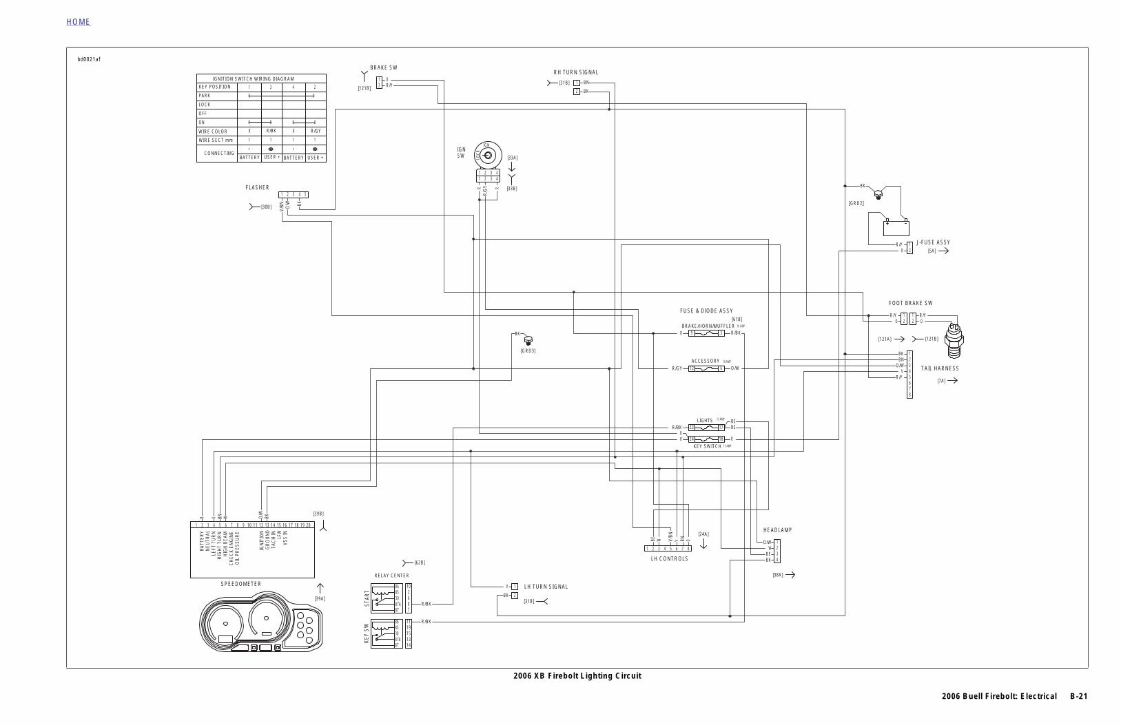
2006 XB Firebolt Lighting Circuit
RELAY CENTER
[62B]
LH TURN SIGNAL
[31B]
LH CONTROLS
FUSE
[GRD3]
[33B]
IGNSW [33A]
[31B]
RH TURN SIGNAL
[121B]
BRAKE SW
FLASHER
[30B]
9
23
24
12
R
V/BN O/W BK
RR
/GY R
LOC
K
OBNVV/BN
WBE
BKO/W
WBNV
BK
BN
BKR/YO
BK
RR
R/BK
R/GY
O
V
R/BK
R/BK
10
8787A308586
KEY
SWST
ART
78
15
6
1314
2
1911
1 2 3 4 5 6 7 8
1 2 3 4 5
11
22
IGN
33
44
1
1 1
2
22
BRAKE
AC
K
0
2431
0 0
+
1
R
1
+
USER + USER +
1
R/BK R/GY
BATTERY BATTERY
1
R
0 0
0PARK
KEY POSITION
IGNITION SWITCH WIRING DIAGRAM
CONNECTING
WIRE SECT mm
WIRE COLOR
ON
OFF
LOCK
SPEEDOMETER
[39A]
1
VSS
INLF
WTA
CH
ING
RO
UN
DIG
NIT
ION
OIL
PR
ES
SU
RE
CH
EC
K E
NG
INE
HIG
H B
EAM
RIG
HT
TUR
NLE
FT T
UR
NN
EUTR
ALBA
TTER
Y
2 3 4 5 6 7 8 9 10 12 201918171615141311
[39B]
8787A308586
bd0021af

B-22 2006 Buell Firebolt: Electrical
HOME
2006 XB Firebolt Lighting Circuit 2006 XB Firebolt Lighting Circuit
2006 Buell Firebolt: Electrical B-23
HOME
MTR
LOWFUEL
SENSOR
1
11
[120A]
[120B]
[24A]
OIL PRESSURE SW
VSS
NEUTRAL SW
FUEL PUMP
[65B] [65A]
[86B][86A]
[131B]
& DIODE ASSY [61B]
[5A]
J-FUSE ASSY
[GRD2]
2
18
6
3 R/BK
BK
RR/Y
Y/R Y/RBK BK
GY GY
TN/Y
R/W RW W
BK/W BK
R
O/W
TN/LT.GN
GN/Y
GN/Y
AABBCCDD
AABBCC
12
DIODE
E/HORN/MUFFLER
ACCESSORY
KEY SWITCH
[131A]
1
FEMALE
MALE
B=
A=
10AMP
10AMP
15AMP
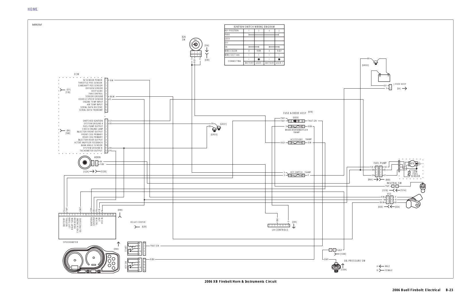
2006 XB Firebolt Horn & Instruments Circuit
HORN
LH CONTROLS
FUSE
[GRD1]
[GRD3]
[33B]
IGNSW
[33A]
ECM
[122A] [122B]
24
12
9
81
1
PK
R
RR
/GY R
LOC
K
OY/BK
WY/R
PKBKO/W
GN
/Y
TN/Y
BKBK
RR
R/GY
TN/Y
O
TN/Y
Y/BKBK
BK
BKGY
WBK/W
R/W
2
2
3
3
4
4
5
5
6
6
7
7
8
8
9
9
10
10
12
12
11
11
1 2 3 4 5 6 7 8
11
22
IGN
33
44
1122
STAR
T
86853087A87 7
862
10
KEY
SW
15
1119
1314
TN/LT.GN
R/BK
[62B]
RELAY CENTER
BRAK
0
2431
0 0
+
1
R
1
+
USER + USER +
1
R/BK R/GY
BATTERY BATTERY
1
R
0 0
0PARK
KEY POSITION
IGNITION SWITCH WIRING DIAGRAM
CONNECTING
WIRE SECT mm
WIRE COLOR
ON
OFF
LOCK
TACHOMETER OUTPUTSYSTEM GROUND B
BANK ANGLE SENSORACTIVE MUFFLER FEEDBACK
INJECTOR REAR OUTPUTREAR COIL PRIMARY
FRONT COIL PRIMARYINJECTOR FRONT OUTPUT
CHECK ENGINE LAMPFUEL PUMP OUTPUTSYSTEM GROUND A
SWITCHED IGNITION
SERIAL DATA TRANSMITSERIAL DATA RECEIVE
AIR TEMP INPUTENGINE TEMP INPUT
VEHICLE SPEED SENSORSENSOR GROUND
FAN CONTROLKEEP ALIVE
OXYGEN SENSORCAMSHAFT POS SENSORTHROTTLE POS SENSOR
5V SENSOR POWER
[11B](GY)
(BK)[10B]
SPEEDOMETER
[39A]
1
VSS
INLF
WTA
CH
ING
RO
UN
DIG
NIT
ION
OIL
PR
ES
SU
RE
CH
EC
K E
NG
INE
HIG
H B
EAM
RIG
HT
TUR
NLE
FT T
UR
NN
EUTR
ALBA
TTER
Y
2 3 4 5 6 7 8 9 10 12 201918171615141311
[39B]
86853087A87
bd0020af

B-24 2006 Buell Firebolt: Electrical
HOME
2006 XB Firebolt Horn & Instruments Circuit 2006 XB Firebolt Horn & Instruments Circuit

2006 Buell Firebolt: Electrical B-25
HOME
1
A=
B=
NEUTRAL SW
[131B]
[5A]
GROUND
STARTERSOLENOID
J-FUSE ASSY
[GRD2]
[128B]
[128A]BK
BK
GN
RR/Y
TN/Y
1
1
2
[131A]
1
MALE
FEMALE
2006 XB Firebolt Starting Circuit
RELAY CENTER
[62B]
CLUTCH SW
[95B]
FUSE & DIODE ASSY [61B]
[33B]
IGNSW
RH CONTROLS
[22A]
[33A]
2
24
11
8
18
5
1
BK/R
W/B
KW
/BK
GY/
O
R
R/B
K R
LOC
K
BKTN/L
T.G
N
R
GY/O
TN/Y
R/BK
RBK
R/BKGN
R/BKTN/LT.GNBK/R
GY/OGY/OBKW/BK
R
R/BK
TN/LT.GN
W/BK
10
5
8787A308586
3IGN
ITIO
NKE
Y SW
STAR
T
4
78
15
6
13
9
14
2
1911
1
11
2
22
IGN
3
33
4
44
1 2
DIODE
IGNITION
KEY SWITCH
0
2431
0 0
+
1
R
1
+
USER + USER +
1
R/BK R/GY
BATTERY BATTERY
1
R
0 0
0PARK
KEY POSITION
IGNITION SWITCH WIRING DIAGRAM
CONNECTING
WIRE SECT mm
WIRE COLOR
ON
OFF
LOCK
15AMP
15AMP
8787A308586
8787A308586
bd0023af

B-26 2006 Buell Firebolt: Electrical
HOME
2006 XB Firebolt Starting Circuit 2006 XB Firebolt Starting Circuit
2006 Buell Firebolt: Electrical B-27
HOME
[128A]
BKBK
er Motor
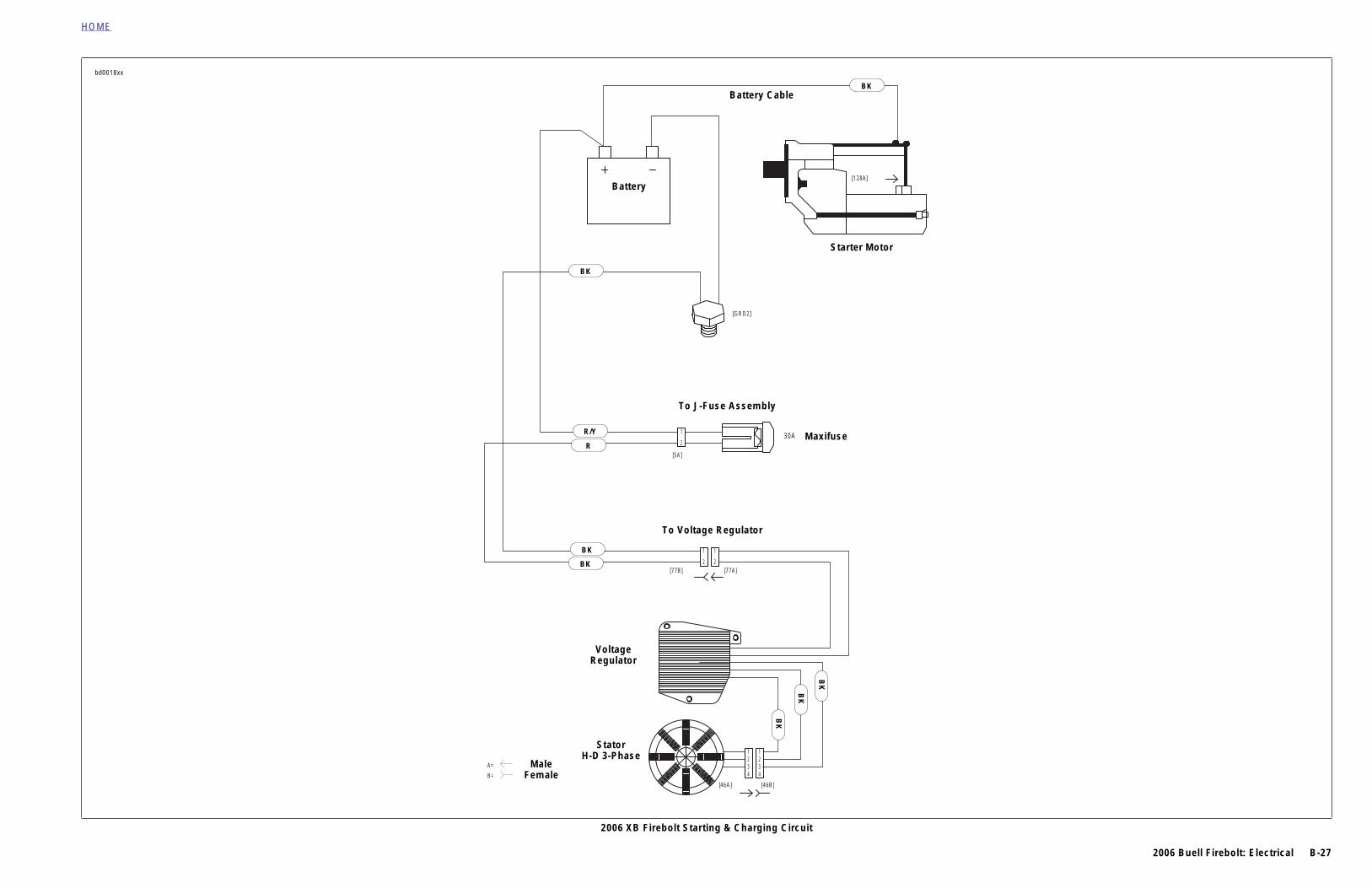
2006 XB Firebolt Starting & Charging Circuit
bd0018xx
A=
B=[46B][46A]
[77A][77B]
30A
[5A]
[GRD2]
2
11
443322
2
11
R
BK
2
1
R
R/Y
BK
R
R/Y
BK
BK
BK
BK
BK
Battery Cable
Start
Battery
To J-Fuse Assembly
To Voltage Regulator
VoltageRegulator
MaleFemale
StatorH-D 3-Phase
Maxifuse
BK

B-28 2006 Buell Firebolt: Electrical
HOME
2006 XB Firebolt Starting & Charging Circuit 2006 XB Firebolt Starting & Charging Circuit

2006 Buell Firebolt: Electrical B-29
HOME
MTR
LOWFUEL
SENSOR
O BK
TN/VW
O
TN/VW
R/Y
R/Y
BK
BKBK
BK
BKBK
BN
BNBN
O/W
O/W
V
VV
BK
4321
Y/R
GYBN/YBK
1 432
321
22
11
11
2211
22
11
1 432
1
8765432
DCBA
A
BKWR
BC
[86B]
MUFFLER ACTUATORSUB-HARNESS
Y0206.1AA
TO MAIN HARNESS
POSITIONSENSOR MTR
CONTROL ELECTRONICS
MUFFLER VALVE ACTUATOR
TAIL LAMP/REAR TURNING LIGHTS
RH TURN SIGNAL
TAIL LIGHT
[93A] [93B]
[19A] [19B]
[7B]
[18A] [18B]
LH TURN SIGNAL
TO MAIN HARNESS
YH350.02A8
[128A]
ERY CABLE
SOLENOIDSTARTER
MOTORSTARTER
D2]
30A MAXIFUSE
7A]
[165B]
[46B]
[161B]
[161A]
GULATOR
FUEL PUMP
VEHICLE SPEED SENSOR
[65A]
FEMALE
MALE
B=
A=
2006 XB Firebolt Component Circuits
MAIN HARNESS
MAIN HARNESS
TO MAIN HARNESS
SUB-HARNESS(ES)
[38LA]
[38HA]
[29B][29A]
HEADLIGHT
FRONT TURN SIGNALS
GYBKO
/WV/
BN
GN
/GYGY
W/Y
BK
21R/Y
R
RBK 1
2 21
1234
GN/Y
PK/Y
LT.G
N/Y
LT.GN/GYR/W
BK/W
BK/W
GN/Y
GY
Y/BK
OBNV
BE/W
BK
4
4 4
8 8
1
1
1
11
1
1
BEAMSHI AND LOH3-55W
1
1
1
1
1
1 2
1
1
111
1
54321
42
222
66554433
11 1
1
3
2
1
2
1
21
5 5
2
2
2
22
2
2
2
2
222 2
2
4
1
2
1
2
6 6
3
3 3
7 7
W/BK
WY/BK
Y/BK
W/BK
BE
W
BK
BK
BK
O/W
(HDI ONLY)LAMPS
POSITION O/W
BKW
BKY
BN
BK
BE
BK
BK/R
Y
O/W
Y
BK
V
BK
BE
REAR INJECTOR
OIL PRESSURE SWITCH
STATOR
REGULATORVOLTAGE
BATT
BATTERY
[GR
[5A]
TO J-FUSE ASSY
[7
[46A]
[77B]
TO VOLTAGE RE
(HD 3-PHASE)
ENGINE TEMP SENSOR
INTAKE AIR TEMPBANK ANGLE SENSOR
UP
FRONT INJECTOR
FLASHER
[84A]
[30A]
[85A]
[120A]
[90A]
[89A]
[134A]
[84B]
[30B]
[85B]
[120B]
[90B]
[89B]
[134B]
RH CONTROLS
BRAKE SW.
CLUTCH SW.
LH CONTROLS
HORN
[22B]
[24B]
[31B]
[31B]
RH TURN SIGNALS
LH TURN SIGNALS
[122B]
[24A]
[31A]
[31A]
[121A]
[95A]
bd0019af
HOME
2006 XB Firebolt Component Circuits 2006 XB Firebolt Component Circuits
B-30 2006 Buell Firebolt: Electrical
HOME
A
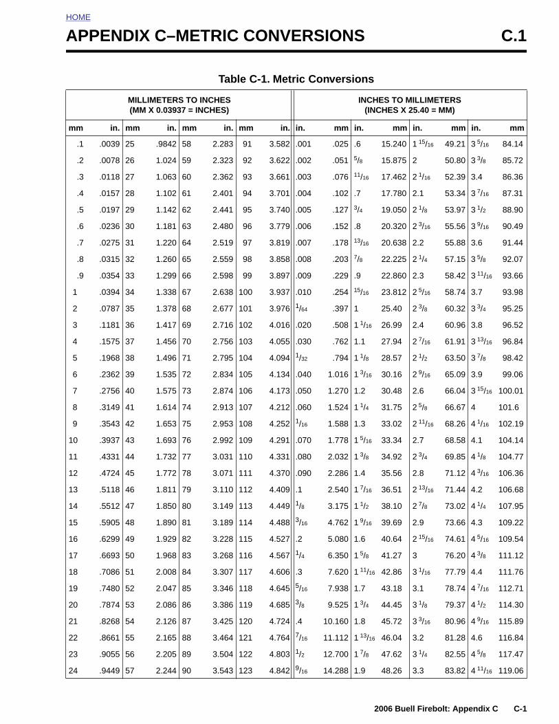
PPENDIX C–METRIC CONVERSIONS C.1Table C-1. Metric Conversions
MILLIMETERS TO INCHES(MM X 0.03937 = INCHES)
INCHES TO MILLIMETERS(INCHES X 25.40 = MM)
mm in. mm in. mm in. mm in. in. mm in. mm in. mm in. mm
.1
.2
.3
.4
.5
.6
.7
.8
.9
1
2
3
4
5
6
7
8
9
10
11
12
13
.0039
.0078
.0118
.0157
.0197
.0236
.0275
.0315
.0354
.0394
.0787
.1181
.1575
.1968
.2362
.2756
.3149
.3543
.3937
.4331
.4724
.5118
25
26
27
28
29
30
31
32
33
34
35
36
37
38
39
40
41
42
43
44
45
46
.9842
1.024
1.063
1.102
1.142
1.181
1.220
1.260
1.299
1.338
1.378
1.417
1.456
1.496
1.535
1.575
1.614
1.653
1.693
1.732
1.772
1.811
58
59
60
61
62
63
64
65
66
67
68
69
70
71
72
73
74
75
76
77
78
79
2.283
2.323
2.362
2.401
2.441
2.480
2.519
2.559
2.598
2.638
2.677
2.716
2.756
2.795
2.834
2.874
2.913
2.953
2.992
3.031
3.071
3.110
91
92
93
94
95
96
97
98
99
100
101
102
103
104
105
106
107
108
109
110
111
112
3.582
3.622
3.661
3.701
3.740
3.779
3.819
3.858
3.897
3.937
3.976
4.016
4.055
4.094
4.134
4.173
4.212
4.252
4.291
4.331
4.370
4.409
.001
.002
.003
.004
.005
.006
.007
.008
.009
.010
1/64
.020
.030
1/32
.040
.050
.060
1/16
.070
.080
.090
.1
.025
.051
.076
.102
.127
.152
.178
.203
.229
.254
.397
.508
.762
.794
1.016
1.270
1.524
1.588
1.778
2.032
2.286
2.540
.6
5/8
11/16
.7
3/4
.8
13/16
7/8
.9
15/16
1
1 1/16
1.1
1 1/8
1 3/16
1.2
1 1/4
1.3
1 5/16
1 3/8
1.4
1 7/16
15.240
15.875
17.462
17.780
19.050
20.320
20.638
22.225
22.860
23.812
25.40
26.99
27.94
28.57
30.16
30.48
31.75
33.02
33.34
34.92
35.56
36.51
1 15/16
2
2 1/16
2.1
2 1/8
2 3/16
2.2
2 1/4
2.3
2 5/16
2 3/8
2.4
2 7/16
2 1/2
2 9/16
2.6
2 5/8
2 11/16
2.7
2 3/4
2.8
2 13/16
49.21
50.80
52.39
53.34
53.97
55.56
55.88
57.15
58.42
58.74
60.32
60.96
61.91
63.50
65.09
66.04
66.67
68.26
68.58
69.85
71.12
71.44
3 5/16
3 3/8
3.4
3 7/16
3 1/2
3 9/16
3.6
3 5/8
3 11/16
3.7
3 3/4
3.8
3 13/16
3 7/8
3.9
3 15/16
4
4 1/16
4.1
4 1/8
4 3/16
4.2
84.14
85.72
86.36
87.31
88.90
90.49
91.44
92.07
93.66
93.98
95.25
96.52
96.84
98.42
99.06
100.01
101.6
102.19
104.14
104.77
106.36
106.68
2006 Buell Firebolt: Appendix C C-1
14
15
16
17
18
19
20
21
22
23
24
.5512
.5905
.6299
.6693
.7086
.7480
.7874
.8268
.8661
.9055
.9449
47
48
49
50
51
52
53
54
55
56
57
1.850
1.890
1.929
1.968
2.008
2.047
2.086
2.126
2.165
2.205
2.244
80
81
82
83
84
85
86
87
88
89
90
3.149
3.189
3.228
3.268
3.307
3.346
3.386
3.425
3.464
3.504
3.543
113
114
115
116
117
118
119
120
121
122
123
4.449
4.488
4.527
4.567
4.606
4.645
4.685
4.724
4.764
4.803
4.842
1/8
3/16
.2
1/4
.3
5/16
3/8
.4
7/16
1/2
9/16
3.175
4.762
5.080
6.350
7.620
7.938
9.525
10.160
11.112
12.700
14.288
1 1/2
1 9/16
1.6
1 5/8
1 11/16
1.7
1 3/4
1.8
1 13/16
1 7/8
1.9
38.10
39.69
40.64
41.27
42.86
43.18
44.45
45.72
46.04
47.62
48.26
2 7/8
2.9
2 15/16
3
3 1/16
3.1
3 1/8
3 3/16
3.2
3 1/4
3.3
73.02
73.66
74.61
76.20
77.79
78.74
79.37
80.96
81.28
82.55
83.82
4 1/4
4.3
4 5/16
4 3/8
4.4
4 7/16
4 1/2
4 9/16
4.6
4 5/8
4 11/16
107.95
109.22
109.54
111.12
111.76
112.71
114.30
115.89
116.84
117.47
119.06
HOME
UNITED STATES SYSTEM
BRITISH IMPERIAL SYSTEM
Unless otherwise specified, all fluid volume measurementsin this Service Manual are expressed in United States(U.S.) units-of-measure. See below:
● 1 pint (U.S.) = 16 fluid ounces (U.S.)● 1 quart (U.S.) = 2 pints (U.S.) = 32 fl. oz. (U.S.)● 1 gallon (U.S.) = 4 quarts (U.S.) = 128 fl. oz. (U.S.)
METRIC SYSTEM
Fluid volume measurements in this Service Manual includethe metric system equivalents. In the metric system, 1 liter (L)= 1,000 milliliters (mL). Should you need to convert from U.S.units-of-measure to metric units-of-measure (or vice versa),refer to the following:
● fluid ounces (U.S.) x 29.574 = milliliters● pints (U.S.) x 0.473 = liters● quarts (U.S.) x 0.946 = liters● gallons (U.S.) x 3.785 = liters● milliliters x 0.0338 = fluid ounces (U.S.)● liters x 2.113 = pints (U.S.)● liters x 1.057 = quarts (U.S.)● liters x 0.264 = gallons (U.S.)
Fluid volume measurements in this Service Manual do notinclude the British Imperial (Imp.) system equivalents. The fol-lowing conversions exist in the British Imperial system:
● 1 pint (Imp.) = 20 fluid ounces (Imp.)● 1 quart (Imp.) = 2 pints (Imp.)● 1 gallon (Imp.) = 4 quarts (Imp.)
Although the same unit-of-measure terminology as the U.S.system is used in the British Imperial (Imp.) system, theactual volume of each British Imperial unit-of-measure differsfrom its U.S. counterpart. The U.S. fluid ounce is larger thanthe British Imperial fluid ounce. However, the U.S. pint, quart,and gallon are smaller than the British Imperial pint, quart,and gallon, respectively. Should you need to convert fromU.S. units to British Imperial units (or vice versa), refer to thefollowing:
● fluid ounces (U.S.) x 1.042 = fluid ounces (Imp.)● pints (U.S.) x 0.833 = pints (Imp.)● quarts (U.S.) x 0.833 = quarts (Imp.)● gallons (U.S.) x 0.833 = gallons (Imp.)● fluid ounces (Imp.) x 0.960 = fluid ounces (U.S.)● pints (Imp.) x 1.201 = pints (U.S.)● quarts (Imp.) x 1.201 = quarts (U.S.)● gallons (Imp.) x 1.201 = gallons (U.S.)
C-2 2006 Buell Firebolt: Appendix C
2006 Bu
ell Fireb
olt: A
pp
end
ix DD
-1
HOME
HOS D.1
b1114xa
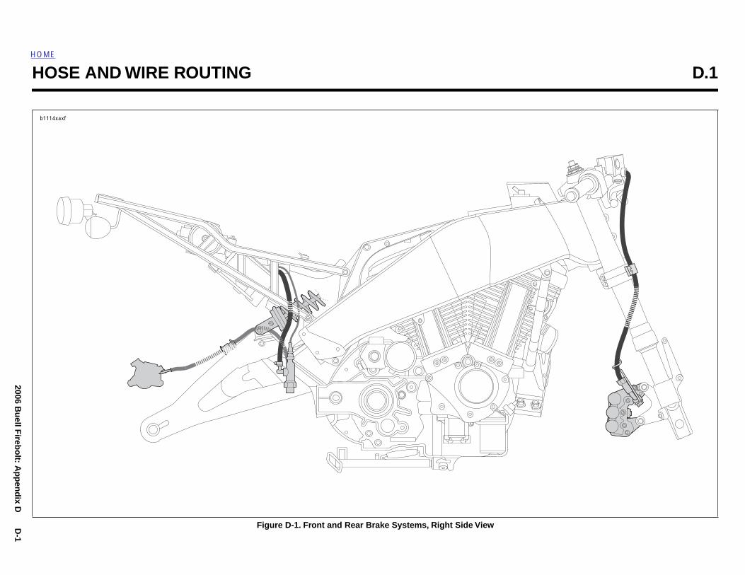
E AND WIRE ROUTING
Figure D-1. Front and Rear Brake Systems, Right Side View
xf
D-2
2006 Bu
ell Fireb
olt: A
pp
end
ix D
HOME
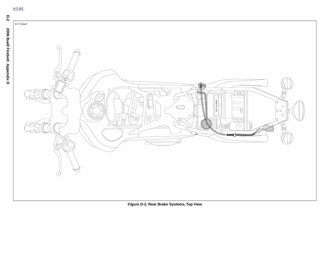
Figure D-2. Rear Brake Systems, Top View
b1115abxf
2006 Bu
ell Fireb
olt: A
pp
end
ix DD
-3
HOME
b1116acxf
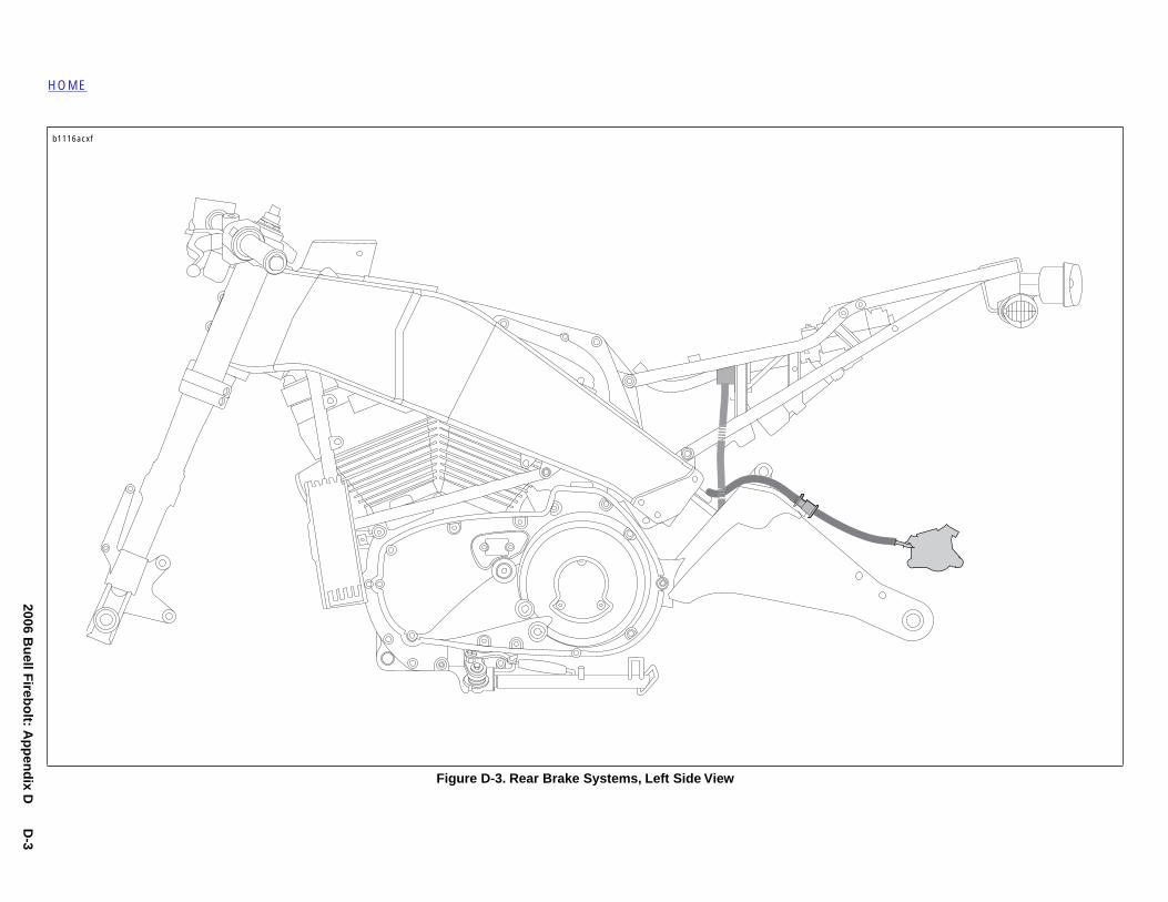
Figure D-3. Rear Brake Systems, Left Side View
D-4
2006 Bu
ell Fireb
olt: A
pp
end
ix D
Carbon canister
HOME
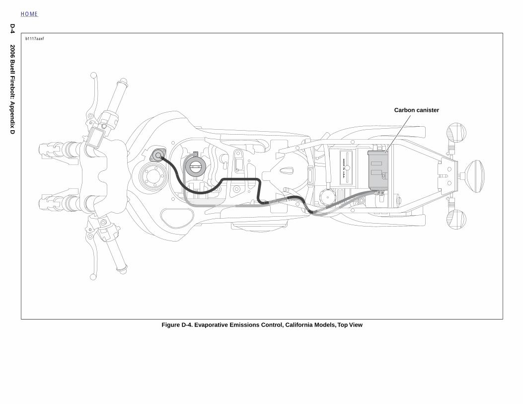
Figure D-4. Evaporative Emissions Control, California Models, Top View
b1117aaxf
2006 Bu
ell Fireb
olt: A
pp
end
ix DD
-5
HOME
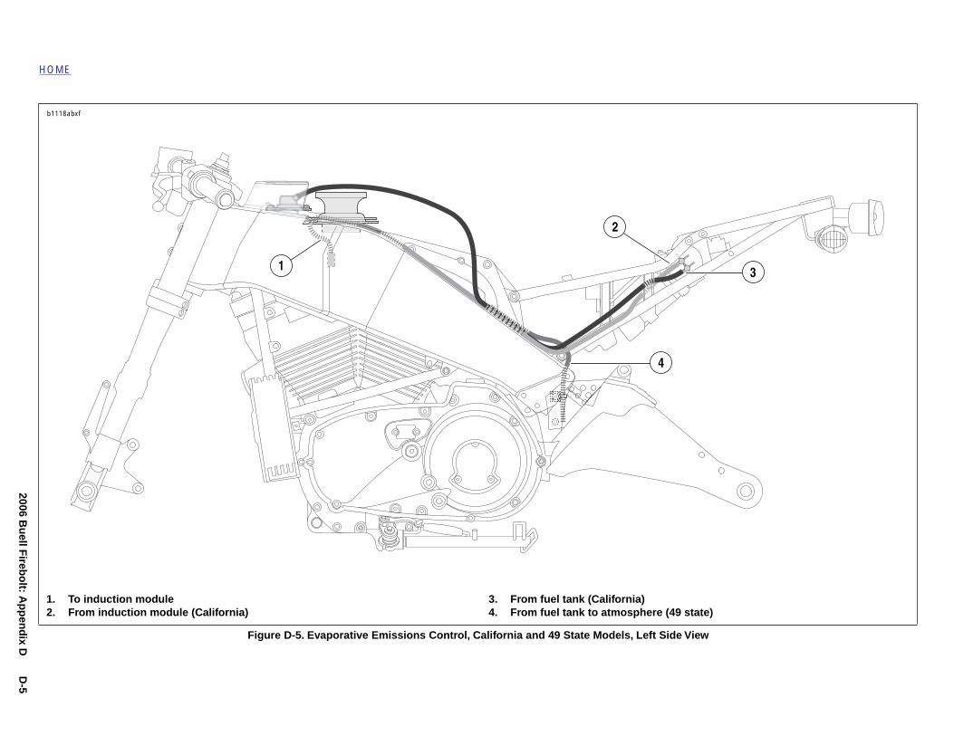
1. To2. Fr )
3
b1118abx
Figure D-5. Evaporative Emissions Control, California and 49 State Models, Left Side View
induction moduleom induction module (California)
3. From fuel tank (California)4. From fuel tank to atmosphere (49 state
2
1
4
f

D-6
2006 Bu
ell Fireb
olt: A
pp
end
ix D
HOME
Figure D-6. Wiring Harness, Left Side View
1. Active intake solenoid (Japan only)2. Intake air temperature sensor (IAT)
3. Fuel pump
3
2
b1119xcxf
To ECM
1
2006 Bu
ell Fireb
olt: A
pp
end
ix DD
-7
HOME
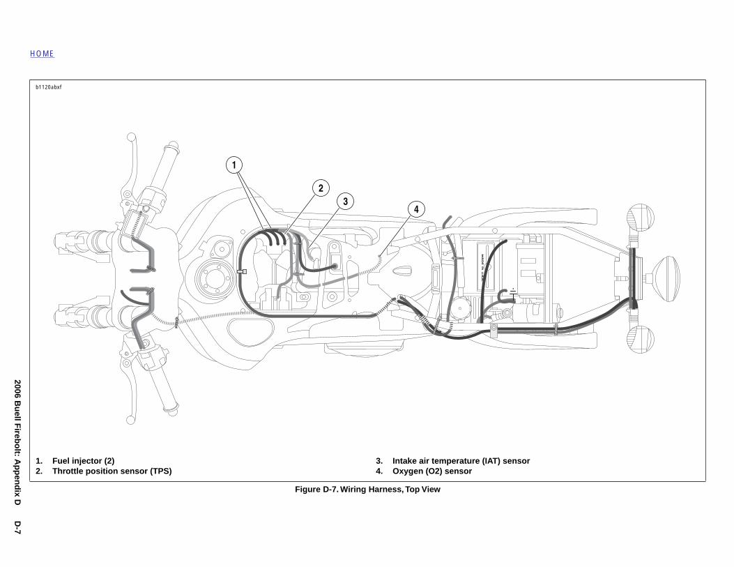
1. Fu2. Th
b1120abx
Figure D-7. Wiring Harness, Top View
el injector (2)rottle position sensor (TPS)
3. Intake air temperature (IAT) sensor4. Oxygen (O2) sensor
23
4
f
1
D-8
2006 Bu
ell Fireb
olt: A
pp
end
ix D
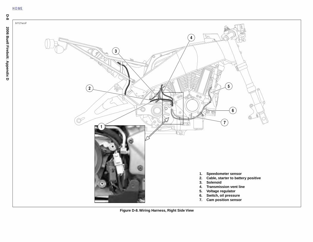
ometer sensorstarter to battery positiveidission vent line regulator
, oil pressureosition sensor
5
6
7
HOME
Figure D-8. Wiring Harness, Right Side View
1. Speed2. Cable, 3. Soleno4. Transm5. Voltage6. Switch7. Cam p
2
3
b1121acxf
4
1
2006 Bu
ell Fireb
olt: A
pp
end
ix DD
-9
HOME
45
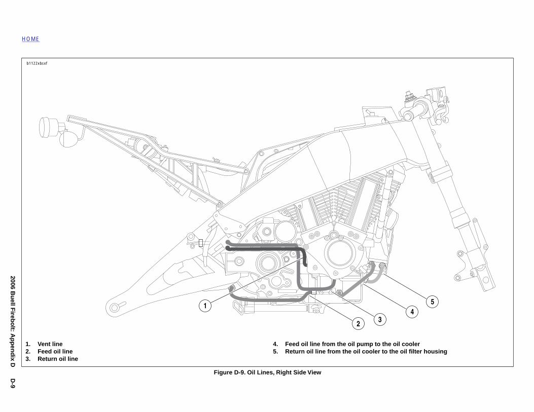
1. Ve2. Fe3. Re
il coolere oil filter housing
b1122xbs
Figure D-9. Oil Lines, Right Side View
2 3
nt lineed oil lineturn oil line
4. Feed oil line from the oil pump to the o5. Return oil line from the oil cooler to th
xf
1
D-10
2006 Bu
ell Fireb
olt: A
pp
end
ix D
eturn oil line
3
HOME
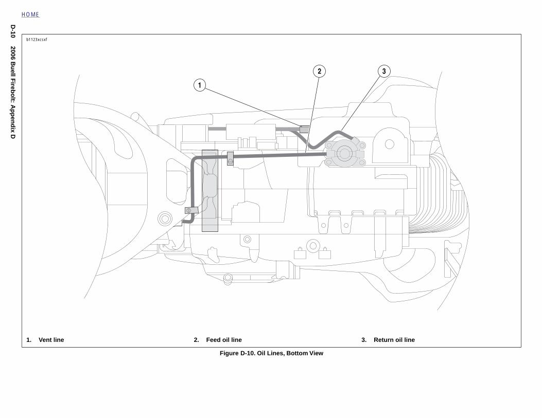
Figure D-10. Oil Lines, Bottom View
1. Vent line 2. Feed oil line 3. R
b1123xcsxf
1
2
2006 Bu
ell Fireb
olt: A
pp
end
ix DD
-11
HOME
iew
b1124xbx
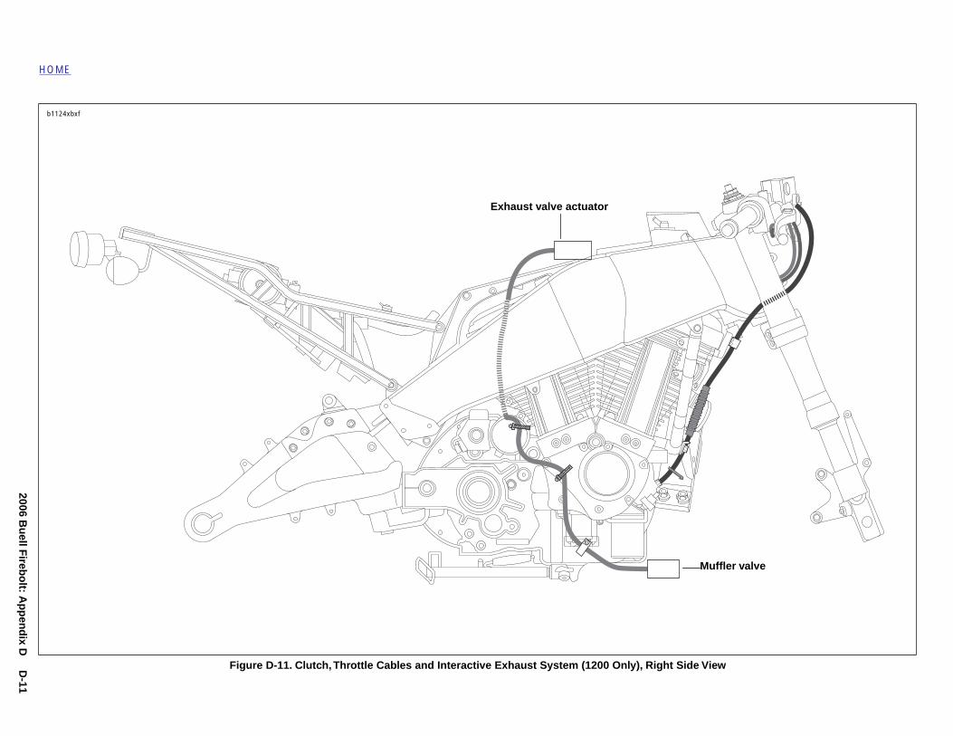
uffler valve
Figure D-11. Clutch, Throttle Cables and Interactive Exhaust System (1200 Only), Right Side V
f
Exhaust valve actuator
M
D-12
2006 Bu
ell Fireb
olt: A
pp
end
ix D
ly), Left Side View
Cable, seat lock
HOME
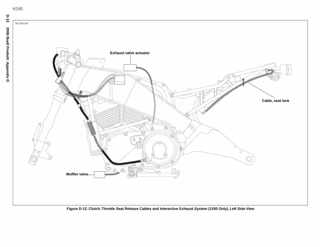
Figure D-12. Clutch, Throttle Seat Release Cables and Interactive Exhaust System (1200 On
b1125xcxaf
Muffler valve
Exhaust valve actuator
2006 Bu
ell Fireb
olt: A
pp
end
ix DD
-13
HOME
00 Only), Top View
b1126xdx
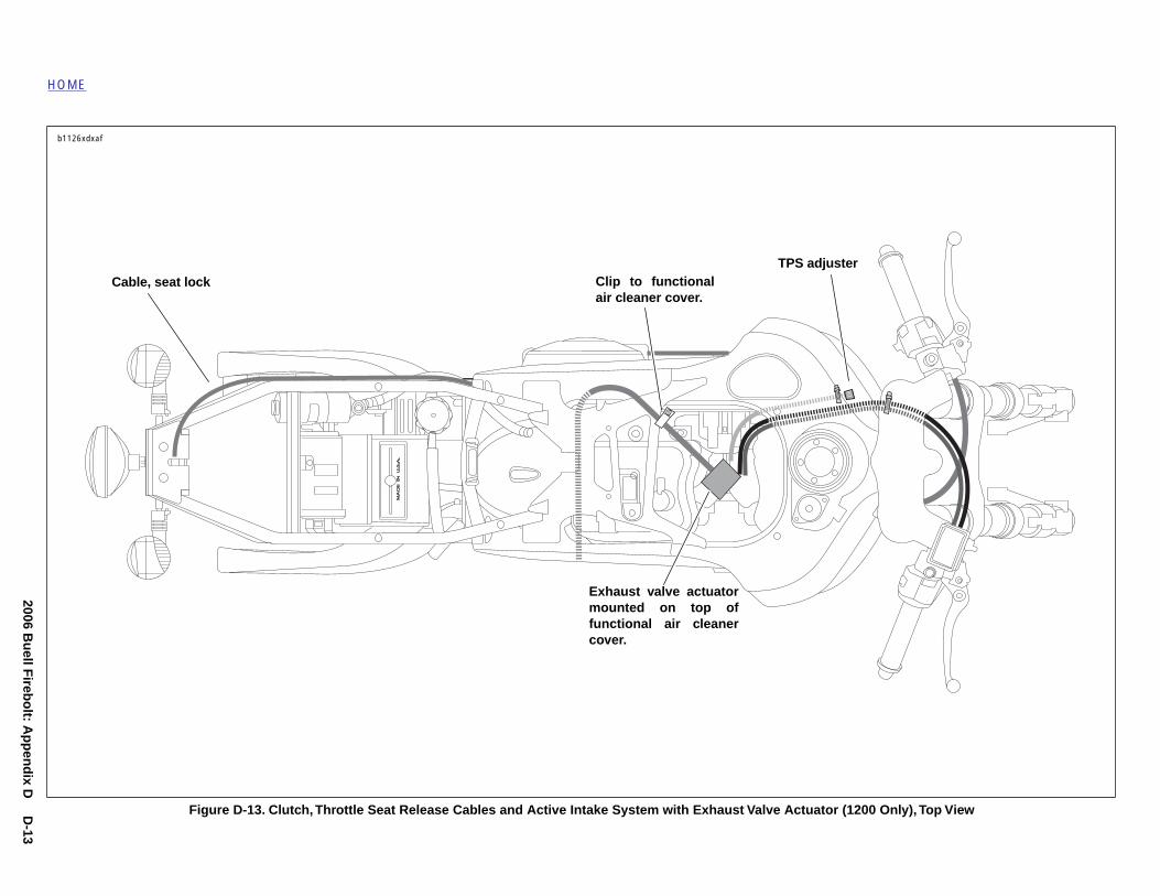
Figure D-13. Clutch, Throttle Seat Release Cables and Active Intake System with Exhaust Valve Actuator (12
Cable, seat lockTPS adjuster
af
Clip to functionalair cleaner cover.
Exhaust valve actuatormounted on top offunctional air cleanercover.

HOME
N
OTES2006 Buell Firebolt: Appendix D D-14
HOME
G
A(Twtlc
Aac
L
●
●
●
●
DTb
UB
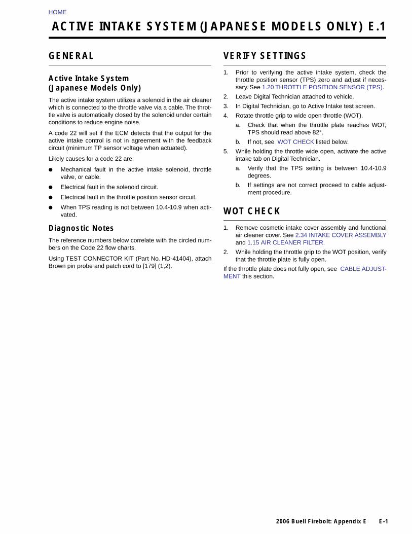
ACTIVE INTAKE SYSTEM (JAPANESE MODELS ONLY) E.1
ENERAL
ctive Intake SystemJapanese Models Only)he active intake system utilizes a solenoid in the air cleanerhich is connected to the throttle valve via a cable. The throt-e valve is automatically closed by the solenoid under certainonditions to reduce engine noise.
code 22 will set if the ECM detects that the output for thective intake control is not in agreement with the feedbackircuit (minimum TP sensor voltage when actuated).
ikely causes for a code 22 are:
Mechanical fault in the active intake solenoid, throttlevalve, or cable.
Electrical fault in the solenoid circuit.
Electrical fault in the throttle position sensor circuit.
When TPS reading is not between 10.4-10.9 when acti-vated.
iagnostic Noteshe reference numbers below correlate with the circled num-ers on the Code 22 flow charts.
sing TEST CONNECTOR KIT (Part No. HD-41404), attachrown pin probe and patch cord to [179] (1,2).
VERIFY SETTINGS
1. Prior to verifying the active intake system, check thethrottle position sensor (TPS) zero and adjust if neces-sary. See 1.20 THROTTLE POSITION SENSOR (TPS).
2. Leave Digital Technician attached to vehicle.
3. In Digital Technician, go to Active Intake test screen.
4. Rotate throttle grip to wide open throttle (WOT).
a. Check that when the throttle plate reaches WOT,TPS should read above 82°.
b. If not, see WOT CHECK listed below.
5. While holding the throttle wide open, activate the activeintake tab on Digital Technician.
a. Verify that the TPS setting is between 10.4-10.9degrees.
b. If settings are not correct proceed to cable adjust-ment procedure.
WOT CHECK
1. Remove cosmetic intake cover assembly and functionalair cleaner cover. See 2.34 INTAKE COVER ASSEMBLYand 1.15 AIR CLEANER FILTER.
2. While holding the throttle grip to the WOT position, verifythat the throttle plate is fully open.
If the throttle plate does not fully open, see CABLE ADJUST-MENT this section.
2006 Buell Firebolt: Appendix E E-1
HOME
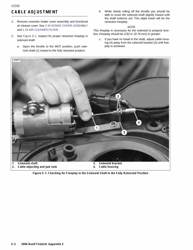
CABLE ADJUSTMENT
b. While slowly rolling off the throttle you should beable to move the solenoid shaft slightly inward untilthe shaft bottoms out. This slight travel will be the
1. Remove cosmetic intake cover assembly and functionalair cleaner cover. See 2.34 INTAKE COVER ASSEMBLYand 1.15 AIR CLEANER FILTER.
2. See Figure E-1. Inspect for proper retraction freeplay insolenoid shaft:
a. Open the throttle to the WOT position, push sole-noid shaft (1) inward to the fully retracted position.
retraction freeplay.
NOTEThis freeplay is necessary for the solenoid to properly func-tion. Freeplay should be 1/32 in. (0.79 mm) or greater.
c. If you have no travel in the shaft, adjust cable hous-ing (4) away from the solenoid bracket (3) until free-play is achieved.
Figure E-1. Checking for Freeplay in the Solenoid Shaft in the Fully Retracted Position
1. Solenoid shaft2. Cable adjusting and jam nuts
3. Solenoid bracket4. Cable housing
10957f
1
2
3
4
E-2 2006 Buell Firebolt: Appendix E
HOME
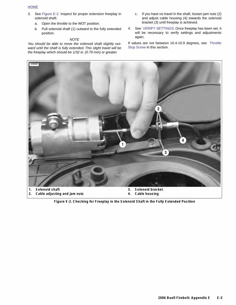
3. See Figure E-2. Inspect for proper extension freeplay insolenoid shaft:
a. Open the throttle to the WOT position.
b. Pull solenoid shaft (1) outward to the fully extendedposition.
NOTEYou should be able to move the solenoid shaft slightly out-ward until the shaft is fully extended. This slight travel will bethe freeplay which should be 1/32 in. (0.79 mm) or greater.
c. If you have no travel in the shaft, loosen jam nuts (2)and adjust cable housing (4) towards the solenoidbracket (3) until freeplay is achieved.
4. See VERIFY SETTINGS. Once freeplay has been set, itwill be necessary to verify settings and adjustmentsagain.
If values are not between 10.4-10.9 degrees, see ThrottleStop Screw in this section.
Figure E-2. Checking for Freeplay in the Solenoid Shaft in the Fully Extended Position
1. Solenoid shaft2. Cable adjusting and jam nuts
3. Solenoid bracket4. Cable housing
10956f
1
2
3
4
2006 Buell Firebolt: Appendix E E-3
HOME
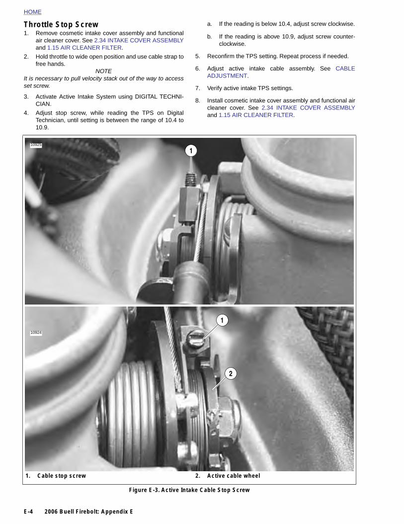
Throttle Stop Screw
1. Remove cosmetic intake cover assembly and functionalair cleaner cover. See 2.34 INTAKE COVER ASSEMBLY
a. If the reading is below 10.4, adjust screw clockwise.
b. If the reading is above 10.9, adjust screw counter-
and 1.15 AIR CLEANER FILTER.
2. Hold throttle to wide open position and use cable strap tofree hands.
NOTEIt is necessary to pull velocity stack out of the way to accessset screw.
3. Activate Active Intake System using DIGITAL TECHNI-CIAN.
4. Adjust stop screw, while reading the TPS on DigitalTechnician, until setting is between the range of 10.4 to10.9.
clockwise.
5. Reconfirm the TPS setting. Repeat process if needed.
6. Adjust active intake cable assembly. See CABLEADJUSTMENT.
7. Verify active intake TPS settings.
8. Install cosmetic intake cover assembly and functional aircleaner cover. See 2.34 INTAKE COVER ASSEMBLYand 1.15 AIR CLEANER FILTER.
1
1
2
10925
10924
E-4 2006 Buell Firebolt: Appendix E
Figure E-3. Active Intake Cable Stop Screw
1. Cable stop screw 2. Active cable wheel

HOME
]
[178A] [178B]
GY
/O
W/G
Y
1 122
Active Intake Solenoid
Co
ntr
ol S
ign
al
b1171xex
2006 Buell Firebolt: Appendix E E-5
Figure E-4. Active Intake System
11
22
J1 J3 J4 J2
[11A
]
[164
A]
[179
B
[179
A]
[10A
]
EC
M
HOME
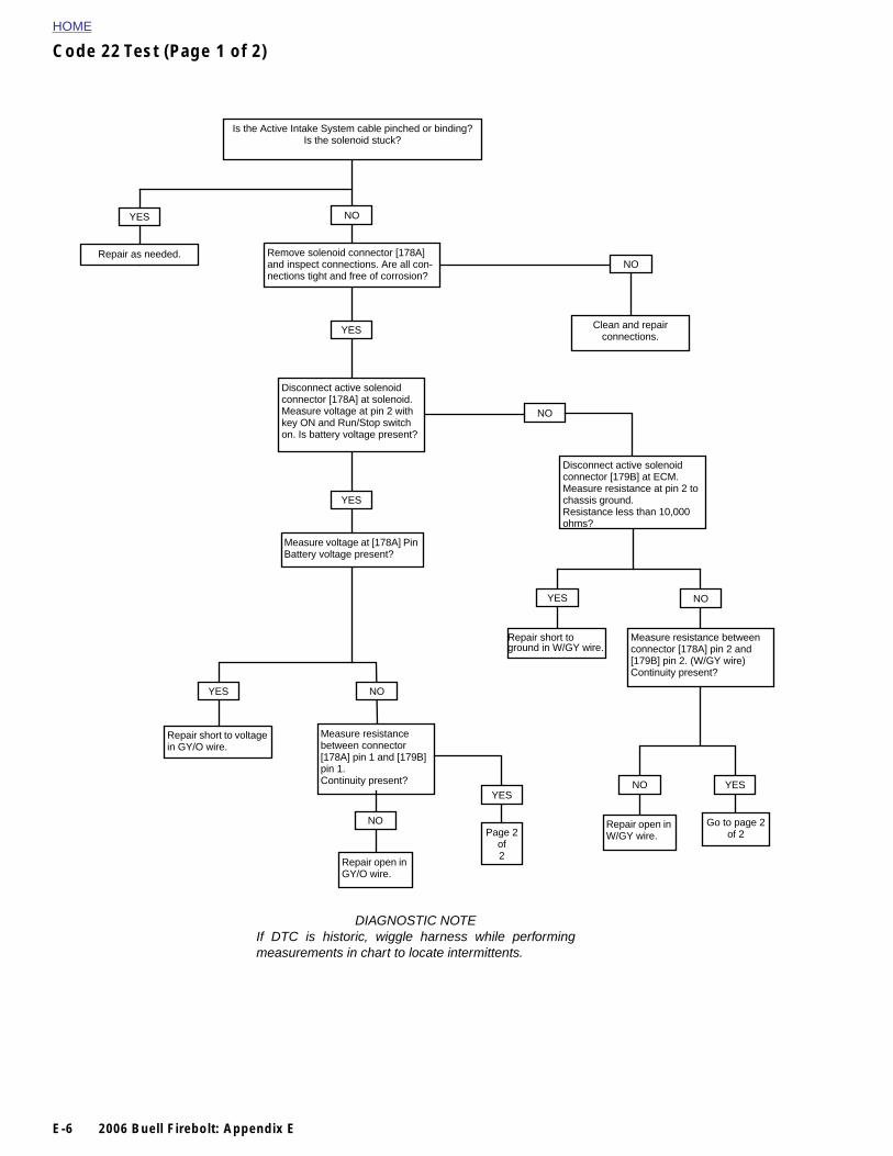
Code 22 Test (Page 1 of 2)
Is the Active Intake System cable pinched or binding?Is the solenoid stuck?
Remove solenoid connector [178A] and inspect connections. Are all con-nections tight and free of corrosion?
NOYES
Repair as needed.
YES
Disconnect active solenoid connector [178A] at solenoid. Measure voltage at pin 2 with key ON and Run/Stop switch on. Is battery voltage present?
YES
Measure voltage at [178A] Pin Battery voltage present?
NO
Measure resistance between connector [178A] pin 1 and [179B] pin 1.Continuity present?
NO
NO
Clean and repairconnections.
Disconnect active solenoid connector [179B] at ECM. Measure resistance at pin 2 to chassis ground.Resistance less than 10,000 ohms?
Repair short to voltage in GY/O wire.
YES
NO
YES NO
Repair short to ground in W/GY wire.
Measure resistance between connector [178A] pin 2 and [179B] pin 2. (W/GY wire)Continuity present?
Repair open in W/GY wire.
YESNO
Page 2of
YES
Go to page 2of 2
E-6 2006 Buell Firebolt: Appendix E
Repair open in GY/O wire.
2
DIAGNOSTIC NOTEIf DTC is historic, wiggle harness while performingmeasurements in chart to locate intermittents.

HOME
Code 22 Test (Page 2 of 2)
Measure resistance from active intake solenoid pin 1 to pin 2 [178B] (use HD 41404 brown pins).Continuity should be present, approximately less than 4 ohms, nominal 2.4 ohms.
Replace solenoid.
NOYES
Connect battery voltage to [178B] pin 2 of active intake solenoid. (Use HD 41404 brown pin and patch cable). Hold throttle wide open. Observe throttle plate and connect solenoid pin 1 to ground.Does solenoid attempt to pull throttle almost closed?
NO
Hold throttle wide open. Energize active intake solenoid. Does throttle close to an angle less than 11 degrees?
YES
YES NO
Replace ECM See CABLE ADJUSTMENT in this section.
Replace solenoid
2006 Buell Firebolt: Appendix E E-7
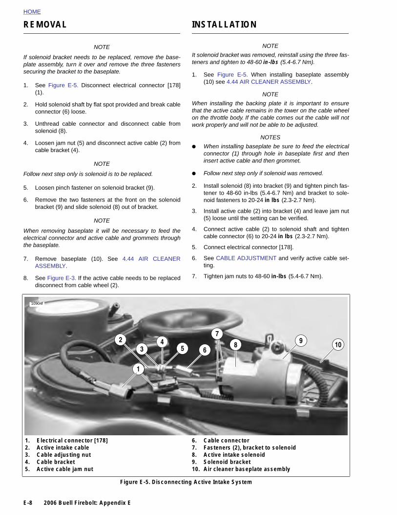
HOME
REMOVAL
INSTALLATION
NOTE
If solenoid bracket needs to be replaced, remove the base-plate assembly, turn it over and remove the three fastenerssecuring the bracket to the baseplate.
1. See Figure E-5. Disconnect electrical connector [178](1).
2. Hold solenoid shaft by flat spot provided and break cableconnector (6) loose.
3. Unthread cable connector and disconnect cable fromsolenoid (8).
4. Loosen jam nut (5) and disconnect active cable (2) fromcable bracket (4).
NOTE
Follow next step only is solenoid is to be replaced.
5. Loosen pinch fastener on solenoid bracket (9).
6. Remove the two fasteners at the front on the solenoidbracket (9) and slide solenoid (8) out of bracket.
NOTE
When removing baseplate it will be necessary to feed theelectrical connector and active cable and grommets throughthe baseplate.
7. Remove baseplate (10). See 4.44 AIR CLEANERASSEMBLY.
8. See Figure E-3. If the active cable needs to be replaceddisconnect from cable wheel (2).
NOTE
It solenoid bracket was removed, reinstall using the three fas-teners and tighten to 48-60 in-lbs (5.4-6.7 Nm).
1. See Figure E-5. When installing baseplate assembly(10) see 4.44 AIR CLEANER ASSEMBLY.
NOTE
When installing the backing plate it is important to ensurethat the active cable remains in the tower on the cable wheelon the throttle body. If the cable comes out the cable will notwork properly and will not be able to be adjusted.
NOTES
● When installing baseplate be sure to feed the electricalconnector (1) through hole in baseplate first and theninsert active cable and then grommet.
● Follow next step only if solenoid was removed.
2. Install solenoid (8) into bracket (9) and tighten pinch fas-tener to 48-60 in-lbs (5.4-6.7 Nm) and bracket to sole-noid fasteners to 20-24 in lbs (2.3-2.7 Nm).
3. Install active cable (2) into bracket (4) and leave jam nut(5) loose until the setting can be verified.
4. Connect active cable (2) to solenoid shaft and tightencable connector (6) to 20-24 in lbs (2.3-2.7 Nm).
5. Connect electrical connector [178].
6. See CABLE ADJUSTMENT and verify active cable set-ting.
7. Tighten jam nuts to 48-60 in-lbs (5.4-6.7 Nm).
98
1
10
10904f
32
5 64
7
E-8 2006 Buell Firebolt: Appendix E
Figure E-5. Disconnecting Active Intake System
1. Electrical connector [178]2. Active intake cable3. Cable adjusting nut4. Cable bracket5. Active cable jam nut
6. Cable connector7. Fasteners (2), bracket to solenoid8. Active intake solenoid9. Solenoid bracket10. Air cleaner baseplate assembly

SUBJECT PAGE NO.
1.1 General . . . . . . . . . . . . . . . . . . . . . . . . . . . . . . . . . . . . . . . . . . . . . . . . . . . . . . 1-11.2 Fuel and Oil . . . . . . . . . . . . . . . . . . . . . . . . . . . . . . . . . . . . . . . . . . . . . . . . . . . 1-51.3 Maintenan1.4 Windshield1.5 Battery Ma1.6 Engine Lub1.7 Brake Sys1.8 Tires and W1.9 Clutch . . 1.10 Drive Bel1.11 Primary C1.12 Suspensi1.13 Steering 1.14 Spark Plu1.15 Air Clean1.16 Throttle C1.17 Interactiv1.18 Ignition T1.19 Headlight1.20 Throttle P1.21 Storage 1.22 Troublesh
MAINTENANCE 1
Table Of Contents
ce Schedule . . . . . . . . . . . . . . . . . . . . . . . . . . . . . . . . . . . . . . . . . . 1-6 Maintenance . . . . . . . . . . . . . . . . . . . . . . . . . . . . . . . . . . . . . . . . . 1-9intenance . . . . . . . . . . . . . . . . . . . . . . . . . . . . . . . . . . . . . . . . . . . . 1-10rication System . . . . . . . . . . . . . . . . . . . . . . . . . . . . . . . . . . . . . . . 1-13
tem Maintenance . . . . . . . . . . . . . . . . . . . . . . . . . . . . . . . . . . . . . . . 1-16heels . . . . . . . . . . . . . . . . . . . . . . . . . . . . . . . . . . . . . . . . . . . . . . . 1-24
. . . . . . . . . . . . . . . . . . . . . . . . . . . . . . . . . . . . . . . . . . . . . . . . . . . . . 1-25t System . . . . . . . . . . . . . . . . . . . . . . . . . . . . . . . . . . . . . . . . . . . . . 1-28hain . . . . . . . . . . . . . . . . . . . . . . . . . . . . . . . . . . . . . . . . . . . . . . . . 1-31
on Damping Adjustments . . . . . . . . . . . . . . . . . . . . . . . . . . . . . . . . 1-33Head Bearings . . . . . . . . . . . . . . . . . . . . . . . . . . . . . . . . . . . . . . . . 1-38gs . . . . . . . . . . . . . . . . . . . . . . . . . . . . . . . . . . . . . . . . . . . . . . . . . . 1-39er Filter . . . . . . . . . . . . . . . . . . . . . . . . . . . . . . . . . . . . . . . . . . . . . . 1-41able and Idle Speed Adjustment . . . . . . . . . . . . . . . . . . . . . . . . . . 1-43
e Exhaust Cable (XB12 Models only) . . . . . . . . . . . . . . . . . . . . . . . 1-44iming . . . . . . . . . . . . . . . . . . . . . . . . . . . . . . . . . . . . . . . . . . . . . . . . 1-46s . . . . . . . . . . . . . . . . . . . . . . . . . . . . . . . . . . . . . . . . . . . . . . . . . . . 1-48osition Sensor (TPS) . . . . . . . . . . . . . . . . . . . . . . . . . . . . . . . . . . . 1-50. . . . . . . . . . . . . . . . . . . . . . . . . . . . . . . . . . . . . . . . . . . . . . . . . . . . . 1-51ooting . . . . . . . . . . . . . . . . . . . . . . . . . . . . . . . . . . . . . . . . . . . . . . . 1-52


HOME
G
S
Pcmti
SaA
Tttd
S
●
●
Aov
ENERAL 1.1
ERVICING A NEW MOTORCYCLE
1WARNING1WARNING
erform the service and maintenance operations as indi-ated in the regular service interval table. Lack of regularaintenance at the recommended intervals can affect
he safe operation of your motorcycle, which could resultn death or serious injury. (00010a)
ervice operations to be performed before customer deliveryre specified in the applicable model year PREDELIVERYND SETUP MANUAL.
he performance of new motorcycle initial service is requiredo keep warranty in force and to ensure proper emissions sys-ems operation. See 1.3 MAINTENANCE SCHEDULE foretails.
AFE OPERATING MAINTENANCE
NOTES
Do not attempt to retighten engine head bolts. Retighten-ing can cause engine damage.
During the initial break-in period, use only Harley-David-son 20W50 engine oil. Failure to use the recommendedoil will result in improper break-in of the engine cylindersand piston rings.
careful check of certain equipment is necessary after peri-ds of storage, and frequently between regular service inter-als, to determine if additional maintenance is required.
SHOP PRACTICES
Repair NotesNOTE
● General maintenance practices are given in this section.
● Repair = Disassembly/Assembly.
● Replace = Removal/Installation.
All special tools and torque values are noted at the point ofuse.
All required parts or materials can be found in the appropriatePARTS CATALOG.
SafetySafety is always the most important consideration when per-forming any job. Be sure you have a complete understandingof the task to be performed. Use common sense. Use theproper tools. Protect yourself and bystanders with approvedeye protection. Don’t just do the job – do the job safely.
Removing PartsAlways consider the weight of a part when lifting. Use a hoistwhenever necessary. Do not lift heavy parts by hand. A hoistand adjustable lifting beam or sling are needed to removesome parts. The lengths of chains or cables from the hoist tothe part should be equal and parallel and should be posi-tioned directly over the center of the part. Be sure that noobstructions will interfere with the lifting operation. Neverleave a part suspended in mid-air.
1WARNING1WARNING
Always check the capacity rating and condition of hoists,slings, chains or cables before use. Failure to do so canlead to an accident which could result in death or seriousinjury.
Always use blocking or proper stands to support the part thathas been hoisted. If a part cannot be removed, verify that allbolts and attaching hardware have been removed. Check to
2006 Buell Firebolt: Maintenance 1-1
Check:
1. Tires for abrasions, cuts and correct pressure.
2. Secondary drive belt for proper tension and condition.
3. Brakes, steering and throttle for responsiveness.
4. Brake fluid level and condition. Hydraulic lines and fit-tings for leaks. Also, check brake pads and rotors forwear.
5. Cables for fraying, crimping and free operation.
6. Engine oil and transmission fluid levels.
7. Headlamp, passing lamp, tail lamp, brake lamp and turnsignal operation.
see if any parts are in the way of the part being removed.
When removing hoses, wiring or tubes, always tag each partto ensure proper installation.
CleaningIf you intend to reuse parts, follow good shop practice andthoroughly clean the parts before assembly. Keep all dirt outof parts; the unit will perform better and last longer. Seals, fil-ters and covers are used in this vehicle to keep out environ-mental dirt and dust. These items must be kept in goodcondition to ensure satisfactory operation.
Clean and inspect all parts as they are removed. Be sure wallholes and passages are clean and open. After cleaning,cover all parts with clean lint-free cloth, paper or other mate-rial. Be sure the part is clean when it is installed.
Always clean around lines or covers before they are removed.Plug, tape or cap holes and openings to keep out dirt, dustand debris.

HOME
Disassembly and Assembly
Always assemble or disassemble one part at a time. Do not
Bushings
Do not remove a bushing unless damaged, excessively worn
work on two assemblies simultaneously. Be sure to make allnecessary adjustments. Recheck your work when finished.Be sure that everything is done.
Operate the vehicle to perform any final check or adjust-ments. If all is correct, the vehicle is ready to go back to thecustomer.
REPAIR AND REPLACEMENT PROCEDURES
Hardware and Threaded Parts
Install helical thread inserts when inside threads in castingsare stripped, damaged or not capable of withstanding speci-fied torque.
Replace bolts, nuts, studs, washers, spacers and small com-mon hardware if missing or in any way damaged. Clean up orrepair minor thread damage with a suitable thread chaser.
Replace all damaged or missing lubrication fittings.
Use Teflon pipe sealant on pipe fitting threads.
Wiring, Hoses and Lines
Replace hoses, clamps, electrical wiring, electrical switchesor fuel lines if they do not meet specifications.
Instruments and Gauges
Replace broken or defective instruments and gauges.
Bearings
Anti-friction bearings must be handled in a special way. Tokeep out dirt and abrasives, cover the bearings as soon asthey are removed from the package.
Wash bearings in a non-flammable cleaning solution. Knockout packed lubricant inside by tapping the bearing against awooden block. Wash bearings again. Cover bearings with
or loose in its bore. Press out bushings that must be replaced.
When pressing or driving bushings, be sure to apply pressurein line with the bushing bore. Use a bearing/bushing driver ora bar with a smooth, flat end. Never use a hammer to drivebushings.
Inspect the bushing and the mated part for oil holes. Be sureall oil holes are properly aligned.
Gaskets
Always discard gaskets after removal. Replace with new gas-kets. Never use the same gasket twice. Be sure that gasketholes match up with holes in the mating part.
Lip Type Seals
Lip seals are used to seal oil or grease and are usuallyinstalled with the sealing lip facing the contained lubricant.Seal orientation, however, may vary under different applica-tions.
Seals should not be removed unless necessary. Only removeseals if required to gain access to other parts or if seal dam-age or wear dictates replacement.
Leaking oil or grease usually means that a seal is damaged.Replace leaking seals to prevent overheated bearings.
Always discard seals after removal. Do not use the same sealtwice.
O-Rings (Preformed Packings)
Always discard o-rings after removal. Replace with new o-rings. To prevent leaks, lubricate the o-rings before installa-tion. Apply the same type of lubricant as that being sealed.Be sure that all gasket, o-ring and seal mating surfaces arethoroughly clean before installation.
Gears
Always check gears for damaged or worn teeth.
Lubricate mating surfaces before pressing gears on shafts.
1-2 2006 Buell Firebolt: Maintenance
clean material after setting them down to dry. Never use com-pressed air to dry bearings.
Coat bearings with clean oil. Wrap bearings in clean paper.
Be sure that the chamfered side of the bearing always facesthe shoulder (when bearings installed against shoulders).Lubricate bearings and all metal contact surfaces beforepressing into place. Only apply pressure on the part of thebearing that makes direct contact with the mating part. Installbearings with numbered side facing out.
Always use the proper tools and fixtures for removing andinstalling bearings.
Bearings do not usually need to be removed. Only removebearings if necessary.
Shafts
If a shaft does not come out easily, check that all nuts, boltsor retaining rings have been removed. Check to see if otherparts are in the way before using force.
Shafts fitted to tapered splines should be very tight. If shaftsare not tight, disassemble and inspect tapered splines. Dis-card parts that are worn. Be sure tapered splines are clean,dry and free of burrs before putting them in place. Press mat-ing parts together tightly.
Clean all rust from the machined surfaces of new parts.
Part Replacement
Always replace worn or damaged parts with new parts.
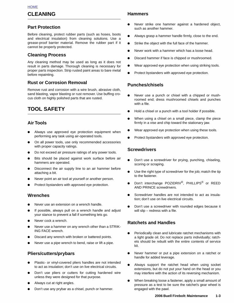
HOME
CLEANING
Part ProtectionBefore cleaning, protect rubber parts (such as hoses, bootsand electrical insulation) from cleaning solutions. Use agrease-proof barrier material. Remove the rubber part if itcannot be properly protected.
Cleaning ProcessAny cleaning method may be used as long as it does notresult in parts damage. Thorough cleaning is necessary forproper parts inspection. Strip rusted paint areas to bare metalbefore repainting.
Rust or Corrosion RemovalRemove rust and corrosion with a wire brush, abrasive cloth,sand blasting, vapor blasting or rust remover. Use buffing cro-cus cloth on highly polished parts that are rusted.
TOOL SAFETY
Air Tools
● Always use approved eye protection equipment whenperforming any task using air-operated tools.
● On all power tools, use only recommended accessorieswith proper capacity ratings.
● Do not exceed air pressure ratings of any power tools.
● Bits should be placed against work surface before airhammers are operated.
● Disconnect the air supply line to an air hammer beforeattaching a bit.
● Never point an air tool at yourself or another person.
● Protect bystanders with approved eye protection.
Wrenches
● Never use an extension on a wrench handle.
Hammers
● Never strike one hammer against a hardened object,such as another hammer.
● Always grasp a hammer handle firmly, close to the end.
● Strike the object with the full face of the hammer.
● Never work with a hammer which has a loose head.
● Discard hammer if face is chipped or mushroomed.
● Wear approved eye protection when using striking tools.
● Protect bystanders with approved eye protection.
Punches/chisels
● Never use a punch or chisel with a chipped or mush-roomed end; dress mushroomed chisels and puncheswith a file.
● Hold a chisel or a punch with a tool holder if possible.
● When using a chisel on a small piece, clamp the piecefirmly in a vise and chip toward the stationary jaw.
● Wear approved eye protection when using these tools.
● Protect bystanders with approved eye protection.
Screwdrivers
● Don’t use a screwdriver for prying, punching, chiseling,scoring or scraping.
● Use the right type of screwdriver for the job; match the tipto the fastener.
● Don’t interchange POZIDRIV®, PHILLIPS® or REEDAND PRINCE screwdrivers.
● Screwdriver handles are not intended to act as insula-tion; don’t use on live electrical circuits.
● Don’t use a screwdriver with rounded edges because it
2006 Buell Firebolt: Maintenance 1-3
● If possible, always pull on a wrench handle and adjustyour stance to prevent a fall if something lets go.
● Never cock a wrench.
● Never use a hammer on any wrench other than a STRIK-ING FACE wrench.
● Discard any wrench with broken or battered points.
● Never use a pipe wrench to bend, raise or lift a pipe.
Pliers/cutters/prybars
● Plastic- or vinyl-covered pliers handles are not intendedto act as insulation; don’t use on live electrical circuits.
● Don’t use pliers or cutters for cutting hardened wireunless they were designed for that purpose.
● Always cut at right angles.
● Don’t use any prybar as a chisel, punch or hammer.
will slip – redress with a file.
Ratchets and Handles
● Periodically clean and lubricate ratchet mechanisms witha light grade oil. Do not replace parts individually; ratch-ets should be rebuilt with the entire contents of servicekit.
● Never hammer or put a pipe extension on a ratchet orhandle for added leverage.
● Always support the ratchet head when using socketextensions, but do not put your hand on the head or youmay interfere with the action of its reversing mechanism.
● When breaking loose a fastener, apply a small amount ofpressure as a test to be sure the ratchet’s gear wheel isengaged with the pawl.
HOME
Sockets
●
Never use hand sockets on power or impact wrenches.
● Select the right size socket for the job.
● Never cock any wrench or socket.
● Select only impact sockets for use with air or electricimpact wrenches.
● Replace sockets showing cracks or wear.
● Keep sockets clean.
● Always use approved eye protection when using poweror impact sockets.
Storage Units
● Don’t open more than one loaded drawer at a time.Close each drawer before opening up another.
● Close lids and lock drawers and doors before movingstorage units.
● Don’t pull on a tool cabinet; push it in front of you.
● Set the brakes on the locking casters after the cabinethas been rolled to your work.
1-4 2006 Buell Firebolt: Maintenance
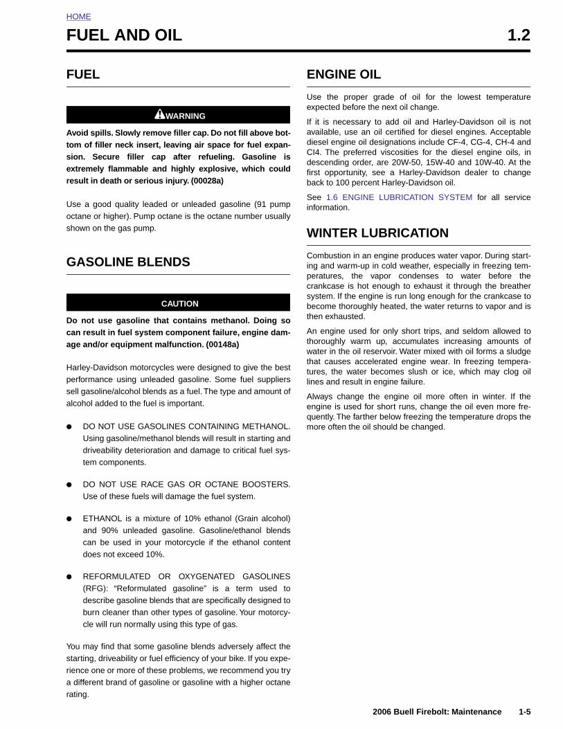
HOME
F
F
Atser
Uos
G
Dca
Hpsa
●
●
UEL AND OIL 1.2
UEL
1WARNING1WARNING
void spills. Slowly remove filler cap. Do not fill above bot-om of filler neck insert, leaving air space for fuel expan-ion. Secure filler cap after refueling. Gasoline isxtremely flammable and highly explosive, which couldesult in death or serious injury. (00028a)
se a good quality leaded or unleaded gasoline (91 pumpctane or higher). Pump octane is the octane number usuallyhown on the gas pump.
ASOLINE BLENDS
CAUTION
o not use gasoline that contains methanol. Doing soan result in fuel system component failure, engine dam-ge and/or equipment malfunction. (00148a)
arley-Davidson motorcycles were designed to give the besterformance using unleaded gasoline. Some fuel suppliersell gasoline/alcohol blends as a fuel. The type and amount oflcohol added to the fuel is important.
DO NOT USE GASOLINES CONTAINING METHANOL.Using gasoline/methanol blends will result in starting anddriveability deterioration and damage to critical fuel sys-tem components.
DO NOT USE RACE GAS OR OCTANE BOOSTERS.Use of these fuels will damage the fuel system.
ENGINE OIL
Use the proper grade of oil for the lowest temperatureexpected before the next oil change.
If it is necessary to add oil and Harley-Davidson oil is notavailable, use an oil certified for diesel engines. Acceptablediesel engine oil designations include CF-4, CG-4, CH-4 andCI4. The preferred viscosities for the diesel engine oils, indescending order, are 20W-50, 15W-40 and 10W-40. At thefirst opportunity, see a Harley-Davidson dealer to changeback to 100 percent Harley-Davidson oil.
See 1.6 ENGINE LUBRICATION SYSTEM for all serviceinformation.
WINTER LUBRICATION
Combustion in an engine produces water vapor. During start-ing and warm-up in cold weather, especially in freezing tem-peratures, the vapor condenses to water before thecrankcase is hot enough to exhaust it through the breathersystem. If the engine is run long enough for the crankcase tobecome thoroughly heated, the water returns to vapor and isthen exhausted.
An engine used for only short trips, and seldom allowed tothoroughly warm up, accumulates increasing amounts ofwater in the oil reservoir. Water mixed with oil forms a sludgethat causes accelerated engine wear. In freezing tempera-tures, the water becomes slush or ice, which may clog oillines and result in engine failure.
Always change the engine oil more often in winter. If theengine is used for short runs, change the oil even more fre-quently. The farther below freezing the temperature drops themore often the oil should be changed.
2006 Buell Firebolt: Maintenance 1-5
● ETHANOL is a mixture of 10% ethanol (Grain alcohol)and 90% unleaded gasoline. Gasoline/ethanol blendscan be used in your motorcycle if the ethanol contentdoes not exceed 10%.
● REFORMULATED OR OXYGENATED GASOLINES(RFG): “Reformulated gasoline” is a term used todescribe gasoline blends that are specifically designed toburn cleaner than other types of gasoline. Your motorcy-cle will run normally using this type of gas.
You may find that some gasoline blends adversely affect thestarting, driveability or fuel efficiency of your bike. If you expe-rience one or more of these problems, we recommend you trya different brand of gasoline or gasoline with a higher octanerating.
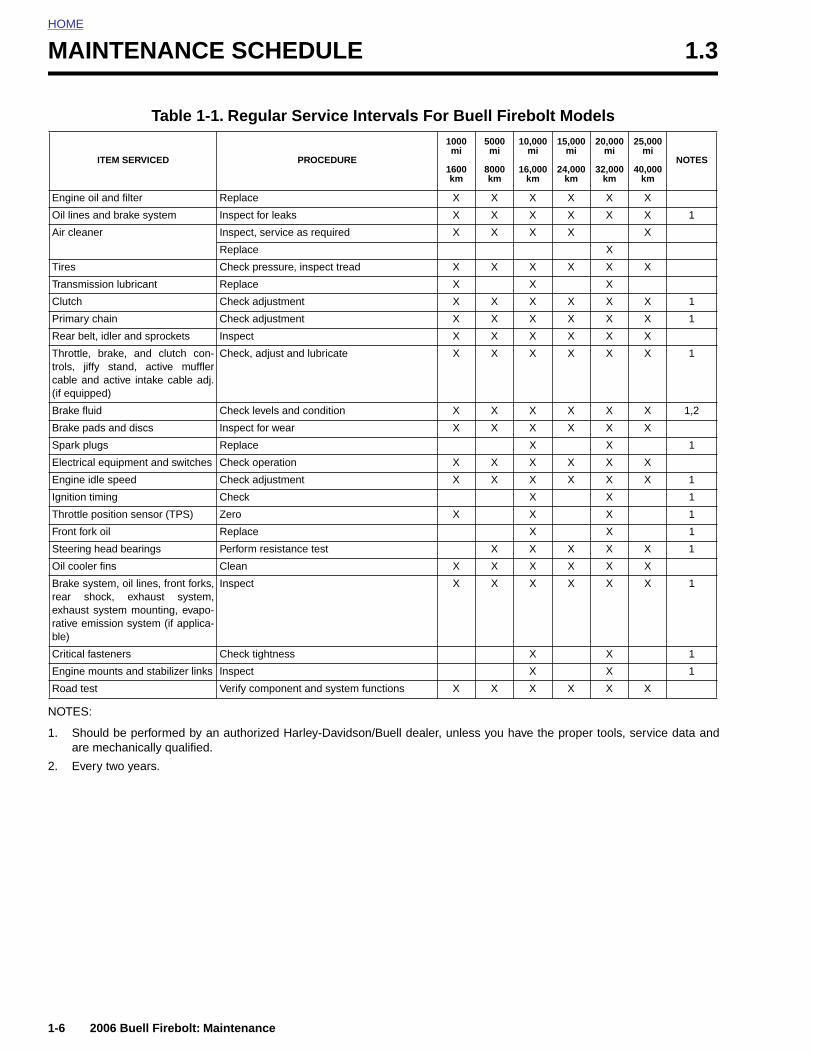
HOME
MAINTENANCE SCHEDULE 1.3
NOTES:
1. Shouare m
2. Every
I
Engine oil
Oil lines a
Air cleane
Tires
Transmiss
Clutch
Primary ch
Rear belt,
Throttle, btrols, jiffycable and(if equippe
Brake fluid
Brake pad
Spark plug
Electrical e
Engine idl
Ignition tim
Throttle po
Front fork
Steering h
Oil cooler
Brake sysrear shoexhaust srative emible)
Critical fas
Engine mo
Road test
1-6
ld be performed by an authorized Harley-Davidson/Buell dealer, unless you have the proper tools, service data andechanically qualified.
two years.
Table 1-1. Regular Service Intervals For Buell Firebolt Models
TEM SERVICED PROCEDURE
1000mi
1600km
5000mi
8000km
10,000 mi
16,000 km
15,000 mi
24,000 km
20,000 mi
32,000 km
25,000 mi
40,000 km
NOTES
and filter Replace X X X X X X
nd brake system Inspect for leaks X X X X X X 1
r Inspect, service as required X X X X X
Replace X
Check pressure, inspect tread X X X X X X
ion lubricant Replace X X X
Check adjustment X X X X X X 1
ain Check adjustment X X X X X X 1
idler and sprockets Inspect X X X X X X
rake, and clutch con- stand, active muffler active intake cable adj.d)
Check, adjust and lubricate X X X X X X 1
Check levels and condition X X X X X X 1,2
s and discs Inspect for wear X X X X X X
s Replace X X 1
quipment and switches Check operation X X X X X X
e speed Check adjustment X X X X X X 1
ing Check X X 1
sition sensor (TPS) Zero X X X 1
oil Replace X X 1
ead bearings Perform resistance test X X X X X 1
fins Clean X X X X X X
tem, oil lines, front forks,ck, exhaust system,ystem mounting, evapo-ssion system (if applica-
Inspect X X X X X X 1
teners Check tightness X X 1
unts and stabilizer links Inspect X X 1
Verify component and system functions X X X X X X
2006 Buell Firebolt: Maintenance
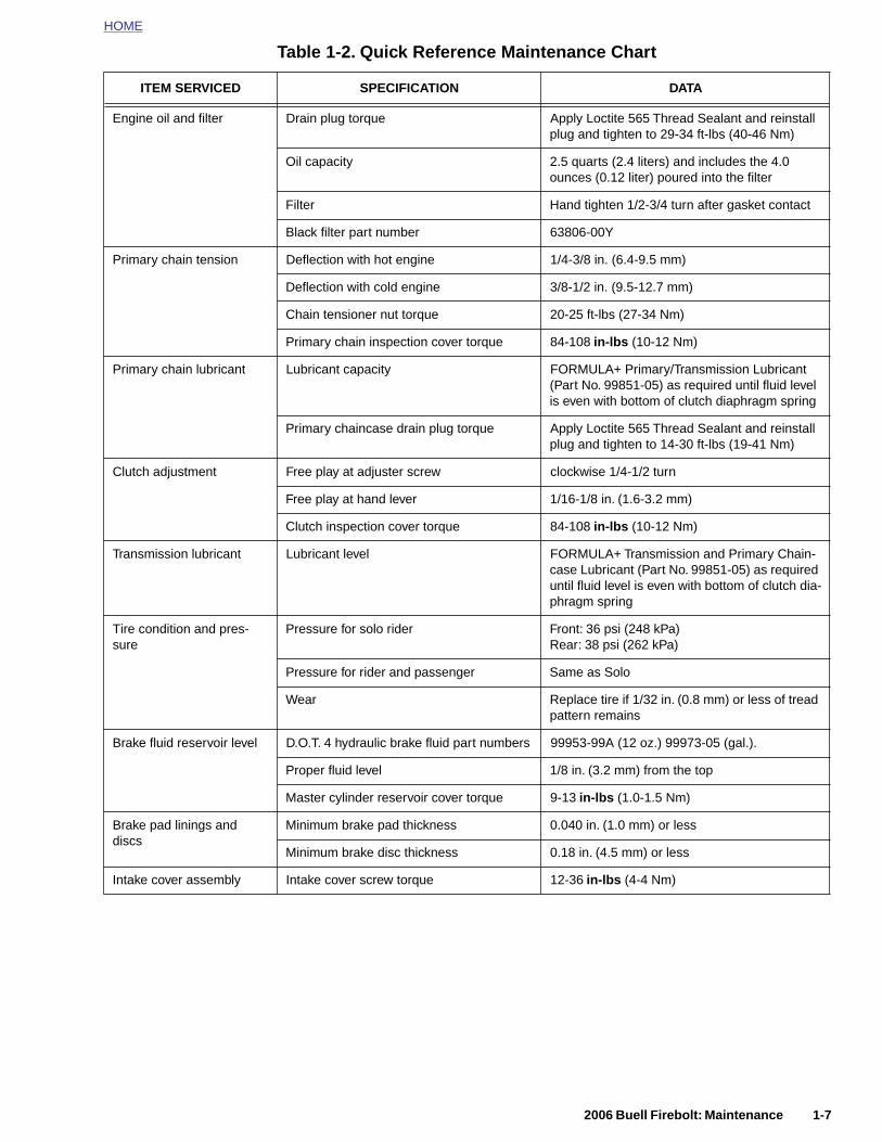
HOME
Table 1-2. Quick Reference Maintenance Chart
ITEM SERVICED SPECIFICATION DATA
Engine oil and filter Drain plug torque Apply Loctite 565 Thread Sealant and reinstall plug and tighten to 29-34 ft-lbs (40-46 Nm)
Oil capacity 2.5 quarts (2.4 liters) and includes the 4.0 ounces (0.12 liter) poured into the filter
Filter Hand tighten 1/2-3/4 turn after gasket contact
Black filter part number 63806-00Y
Primary chain tension Deflection with hot engine 1/4-3/8 in. (6.4-9.5 mm)
Deflection with cold engine 3/8-1/2 in. (9.5-12.7 mm)
Chain tensioner nut torque 20-25 ft-lbs (27-34 Nm)
Primary chain inspection cover torque 84-108 in-lbs (10-12 Nm)
Primary chain lubricant Lubricant capacity FORMULA+ Primary/Transmission Lubricant (Part No. 99851-05) as required until fluid level is even with bottom of clutch diaphragm spring
Primary chaincase drain plug torque Apply Loctite 565 Thread Sealant and reinstall plug and tighten to 14-30 ft-lbs (19-41 Nm)
Clutch adjustment Free play at adjuster screw clockwise 1/4-1/2 turn
Free play at hand lever 1/16-1/8 in. (1.6-3.2 mm)
Clutch inspection cover torque 84-108 in-lbs (10-12 Nm)
Transmission lubricant Lubricant level FORMULA+ Transmission and Primary Chain-case Lubricant (Part No. 99851-05) as required until fluid level is even with bottom of clutch dia-phragm spring
Tire condition and pres-sure
Pressure for solo rider Front: 36 psi (248 kPa)Rear: 38 psi (262 kPa)
Pressure for rider and passenger Same as Solo
Wear Replace tire if 1/32 in. (0.8 mm) or less of tread pattern remains
Brake fluid reservoir level D.O.T. 4 hydraulic brake fluid part numbers 99953-99A (12 oz.) 99973-05 (gal.).
Proper fluid level 1/8 in. (3.2 mm) from the top
2006 Buell Firebolt: Maintenance 1-7
Master cylinder reservoir cover torque 9-13 in-lbs (1.0-1.5 Nm)
Brake pad linings and discs
Minimum brake pad thickness 0.040 in. (1.0 mm) or less
Minimum brake disc thickness 0.18 in. (4.5 mm) or less
Intake cover assembly Intake cover screw torque 12-36 in-lbs (4-4 Nm)
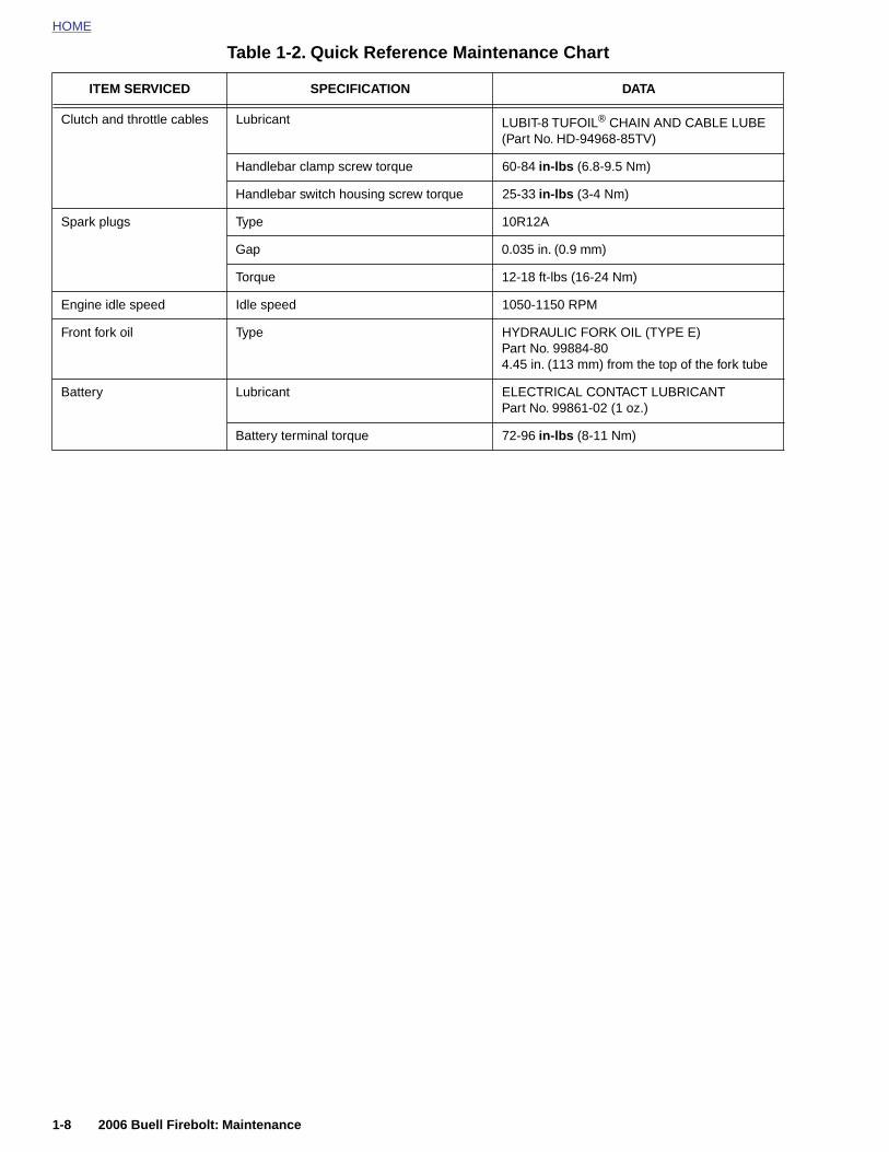
HOME
Table 1-2. Quick Reference Maintenance Chart
Clutch and throttle cables Lubricant LUBIT-8 TUFOIL® CHAIN AND CABLE LUBE (Part No. HD-94968-85TV)
Handlebar clamp screw torque 60-84 in-lbs (6.8-9.5 Nm)
Handlebar switch housing screw torque 25-33 in-lbs (3-4 Nm)
Spark plugs Type 10R12A
Gap 0.035 in. (0.9 mm)
Torque 12-18 ft-lbs (16-24 Nm)
Engine idle speed Idle speed 1050-1150 RPM
Front fork oil Type HYDRAULIC FORK OIL (TYPE E)Part No. 99884-804.45 in. (113 mm) from the top of the fork tube
Battery Lubricant ELECTRICAL CONTACT LUBRICANTPart No. 99861-02 (1 oz.)
Battery terminal torque 72-96 in-lbs (8-11 Nm)
ITEM SERVICED SPECIFICATION DATA
1-8 2006 Buell Firebolt: Maintenance
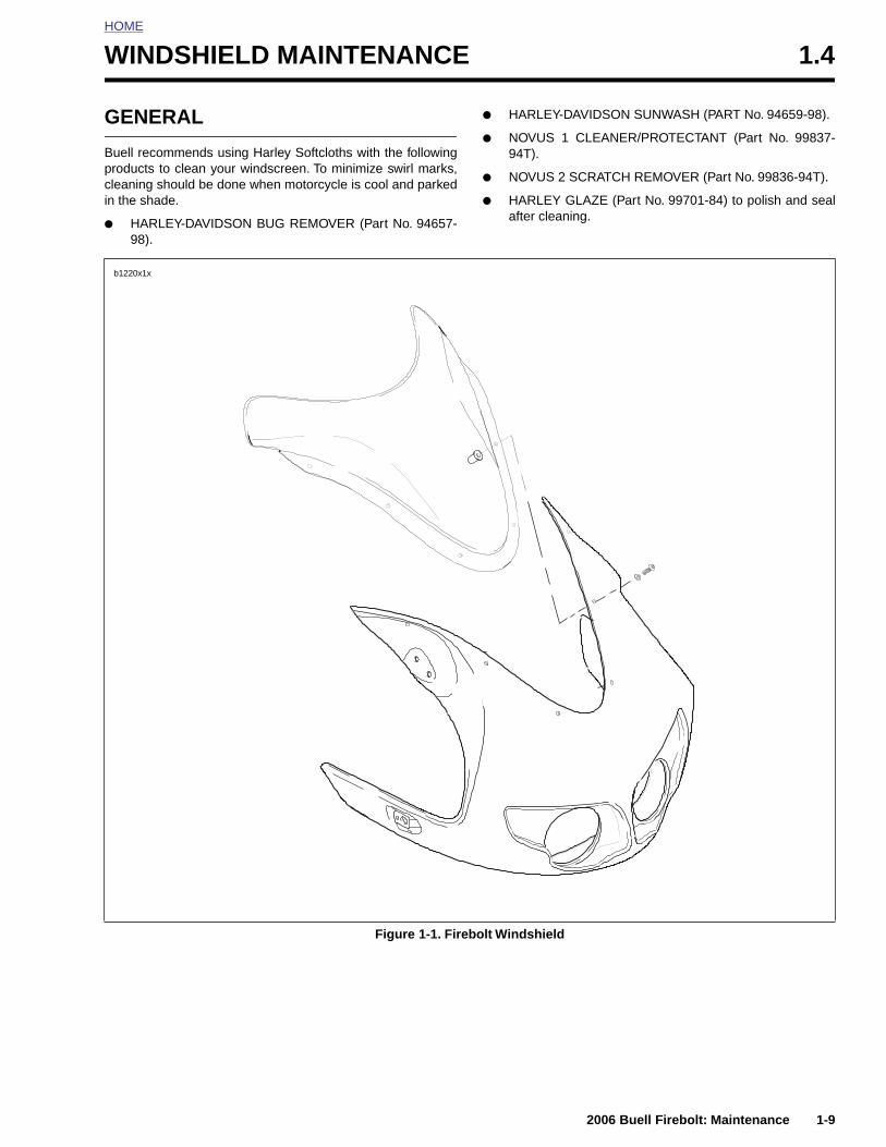
HOME
W
G
Bpcin
●
INDSHIELD MAINTENANCE 1.4
ENERAL
uell recommends using Harley Softcloths with the followingroducts to clean your windscreen. To minimize swirl marks,leaning should be done when motorcycle is cool and parked the shade.
HARLEY-DAVIDSON BUG REMOVER (Part No. 94657-98).
● HARLEY-DAVIDSON SUNWASH (PART No. 94659-98).
● NOVUS 1 CLEANER/PROTECTANT (Part No. 99837-94T).
● NOVUS 2 SCRATCH REMOVER (Part No. 99836-94T).
● HARLEY GLAZE (Part No. 99701-84) to polish and sealafter cleaning.
b1220x1x
2006 Buell Firebolt: Maintenance 1-9
Figure 1-1. Firebolt Windshield

HOME
BATTERY MAINTENANCE 1.5
GENE
Buell motnance-frebatteries. be put intoany reaso
Inspect thcorroded
● At the
● At ev
Batteriesburns to rubberizewith battDREN. (0
A warninFigure 1-2battery. Fcontainedinjury. (00
Battery plead and of Califorreproduc
Table
CON
Exte
1-10
In
E
RAL
orcycle batteries are permanently sealed, mainte-e, valve-regulated, lead/calcium and sulfuric acidThe batteries are shipped pre-charged and ready to service. Do not attempt to open these batteries for
n.
e battery for damage or leaks and for clean, non-connections:
1000 mile (1600 km) service interval.
ery scheduled service interval thereafter.
1WARNING1WARNING
contain sulfuric acid, which could cause severeeyes and skin. Wear a protective face shield,d gloves and protective clothing when workingeries. KEEP BATTERIES AWAY FROM CHIL-0063a)
1WARNING1WARNING
g label is attached to the top of the battery. See. Never remove warning label attached to top ofailure to read and understand all precautions in warning, could result in death or serious064a)
1WARNING1WARNING
osts, terminals and related accessories containlead components, chemicals known to the Statenia to cause cancer and birth defects or othertive harm. Wash hands after handling. (00019a)
BATTERY TESTING
Voltmeter Test
See Table 1-4. The voltmeter test provides a general indicatorof battery condition. Check the voltage of the battery to verifythat it is in a 100% fully charged condition. If the open circuit(disconnected) voltage reading is below 12.6V, charge thebattery and then recheck the voltage after the battery has setfor one to two hours. If the voltage reading is 12.8V or above,perform the load test described under 7.11 BATTERY.
1-3. Battery Electrolyte Antidotes
TACT SOLUTION
rnal Flush with water.
Drink large quantities of milk or water,followed by milk of magnesia, vegeta-
Figure 1-2. Battery Warning Label
Table 1-4. Voltmeter Test
BATTERY CHARGE CONDITIONS
b1142x7x
2006 Buell Firebolt: Maintenance
ternalble oil or beaten eggs. Call doctorimmediately.
yesFlush with water, get immediate medi-cal attention.
12.7 100%
12.6 75%
12.3 50%
12.0 25%
11.8 0%
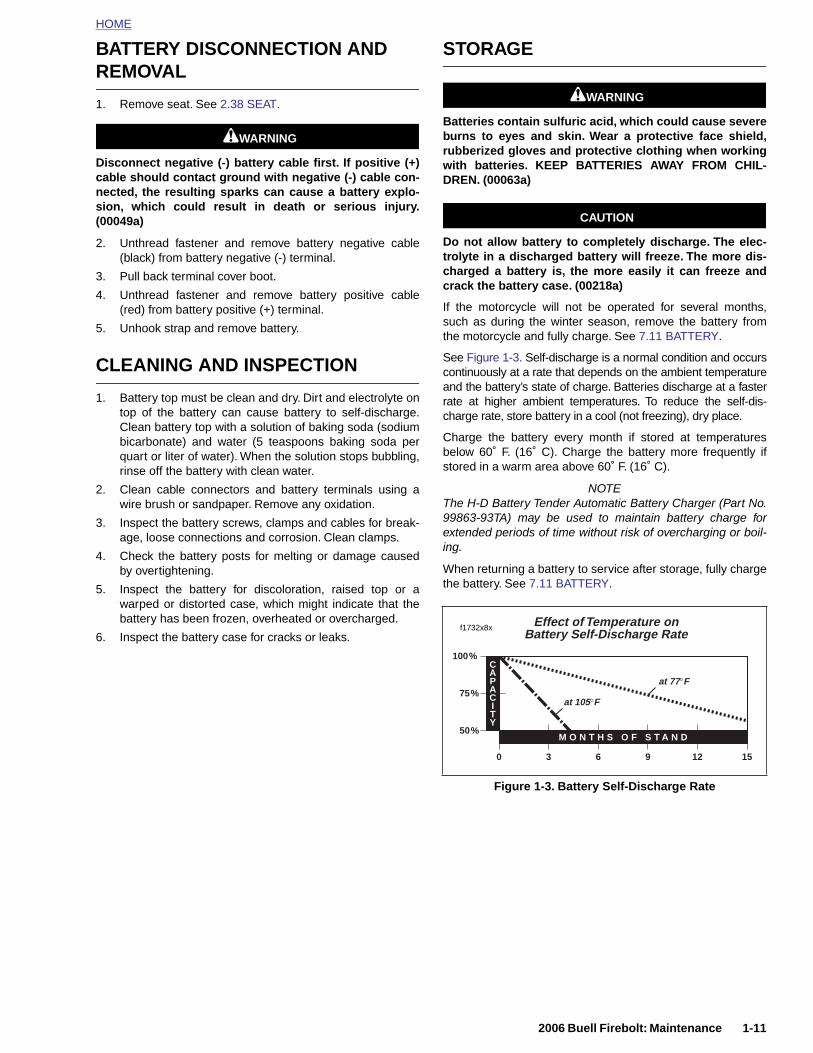
HOME
BATTERY DISCONNECTION AND REMOVAL
1. Remove seat. See 2.38 SEAT.
1WARNING1WARNING
Disconnect negative (-) battery cable first. If positive (+)cable should contact ground with negative (-) cable con-nected, the resulting sparks can cause a battery explo-sion, which could result in death or serious injury.(00049a)
2. Unthread fastener and remove battery negative cable(black) from battery negative (-) terminal.
3. Pull back terminal cover boot.
4. Unthread fastener and remove battery positive cable(red) from battery positive (+) terminal.
5. Unhook strap and remove battery.
CLEANING AND INSPECTION
1. Battery top must be clean and dry. Dirt and electrolyte ontop of the battery can cause battery to self-discharge.Clean battery top with a solution of baking soda (sodiumbicarbonate) and water (5 teaspoons baking soda perquart or liter of water). When the solution stops bubbling,rinse off the battery with clean water.
2. Clean cable connectors and battery terminals using awire brush or sandpaper. Remove any oxidation.
3. Inspect the battery screws, clamps and cables for break-age, loose connections and corrosion. Clean clamps.
4. Check the battery posts for melting or damage causedby overtightening.
5. Inspect the battery for discoloration, raised top or awarped or distorted case, which might indicate that thebattery has been frozen, overheated or overcharged.
6. Inspect the battery case for cracks or leaks.
STORAGE
1WARNING1WARNING
Batteries contain sulfuric acid, which could cause severeburns to eyes and skin. Wear a protective face shield,rubberized gloves and protective clothing when workingwith batteries. KEEP BATTERIES AWAY FROM CHIL-DREN. (00063a)
CAUTION
Do not allow battery to completely discharge. The elec-trolyte in a discharged battery will freeze. The more dis-charged a battery is, the more easily it can freeze andcrack the battery case. (00218a)
If the motorcycle will not be operated for several months,such as during the winter season, remove the battery fromthe motorcycle and fully charge. See 7.11 BATTERY.
See Figure 1-3. Self-discharge is a normal condition and occurscontinuously at a rate that depends on the ambient temperatureand the battery’s state of charge. Batteries discharge at a fasterrate at higher ambient temperatures. To reduce the self-dis-charge rate, store battery in a cool (not freezing), dry place.
Charge the battery every month if stored at temperaturesbelow 60˚ F. (16˚ C). Charge the battery more frequently ifstored in a warm area above 60˚ F. (16˚ C).
NOTEThe H-D Battery Tender Automatic Battery Charger (Part No.99863-93TA) may be used to maintain battery charge forextended periods of time without risk of overcharging or boil-ing.
When returning a battery to service after storage, fully chargethe battery. See 7.11 BATTERY.
75%
100%CAPACITY
at 105°F
at 77°F
Effect of Temperature onBattery Self-Discharge Rate
f1732x8x
2006 Buell Firebolt: Maintenance 1-11
Figure 1-3. Battery Self-Discharge Rate
3 6 9 12 15
50%M O N T H S O F S T A N D
0
HOME
BATTERY INSTALLATION AND
CONNECTION
3. Insert fastener through battery positive cable (red) intothreaded hole of battery positive (+) terminal and tightenfastener to 72-96
in-lbs
(8-11 Nm).
1. Place the fully charged battery in the mounting position,terminal side to the rear of motorcycle.
2. Hook rubber strap around body of battery.
CAUTION
Connect the cables to the correct battery terminals. Fail-ure to do so could result in damage to the motorcycleelectrical system. (00215a)
1WARNING1WARNING
Connect positive (+) battery cable first. If positive (+)cable should contact ground with negative (-) cable con-nected, the resulting sparks can cause a battery explo-sion, which could result in death or serious injury.(00068a)
CAUTION
Do not over-tighten bolts on battery terminals. Use rec-ommended torque values. Over-tightening battery termi-nal bolts could result in damage to battery terminals.(00216a)
4. Install terminal cover boot.
5. Insert fastener through battery negative cable (black) intothreaded hole of battery negative (-) terminal and tightenfastener to 72-96 in-lbs (8-11 Nm).
6. Apply a light coat of petroleum jelly or corrosion retardantmaterial to both battery terminals.
1WARNING1WARNING
After installing seat, pull upward on front of seat to besure it is in locked position. While riding, a loose seat canshift causing loss of control, which could result in deathor serious injury. (00070a)
7. Install seat. See 2.38 SEAT.
1-12 2006 Buell Firebolt: Maintenance
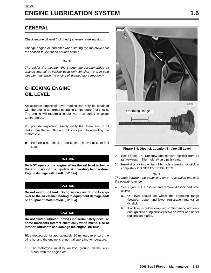
HOME
E
G
C
Ct
Tcw
CO
AwTt
Flem
●
DtE
NGINE LUBRICATION SYSTEM 1.6
ENERAL
heck engine oil level (hot check) at every refueling stop.
hange engine oil and filter when storing the motorcycle forhe season for extended periods of time.
NOTE
he colder the weather, the shorter the recommended oilhange interval. A vehicle used only for short runs in coldeather must have the engine oil drained more frequently.
HECKING ENGINE IL LEVEL
n accurate engine oil level reading can only be obtainedith the engine at normal operating temperature (hot check).he engine will require a longer warm up period in colder
emperatures.
or pre-ride inspection, simply verify that there are no oilaks from the oil filter and oil lines prior to operating theotorcycle.
Perform a hot check of the engine oil level at each fuelstop.
CAUTION
o NOT operate the engine when the oil level is belowhe add mark on the dipstick at operating temperature.ngine damage will result. (00187a)
CAUTION
2. See Figure 1-4. Unscrew and remove dipstick from oiltank/swingarm filler hole. Wipe dipstick clean.
3. Insert dipstick into oil tank filler hole, screwing dipstick incompletely. DO NOT OVER TIGHTEN.
NOTEThe area between the upper and lower registration marks isthe operating range.
4. See Figure 1-4. Unscrew and remove dipstick and note
Figure 1-4. Dipstick Location/Engine Oil Level
11500
Operating Range
11135
2006 Buell Firebolt: Maintenance 1-13
Do not overfill oil tank. Doing so can result in oil carry-over to the air cleaner leading to equipment damage and/or equipment malfunction. (00190a)
CAUTION
Do not switch lubricant brands indiscriminately becausesome lubricants interact chemically when mixed. Use ofinferior lubricants can damage the engine. (00184a)
Ride motorcycle for approximately 10 minutes to ensure theoil is hot and the engine is at normal operating temperature.
1. The motorcycle must be on level ground, on the side-stand, with the engine off.
oil level.
a. Oil level should be within the operating range(between upper and lower registration marks) ondipstick.
b. If oil level is below lower registration mark, add onlyenough oil to bring oil level between lower and upperregistration marks.
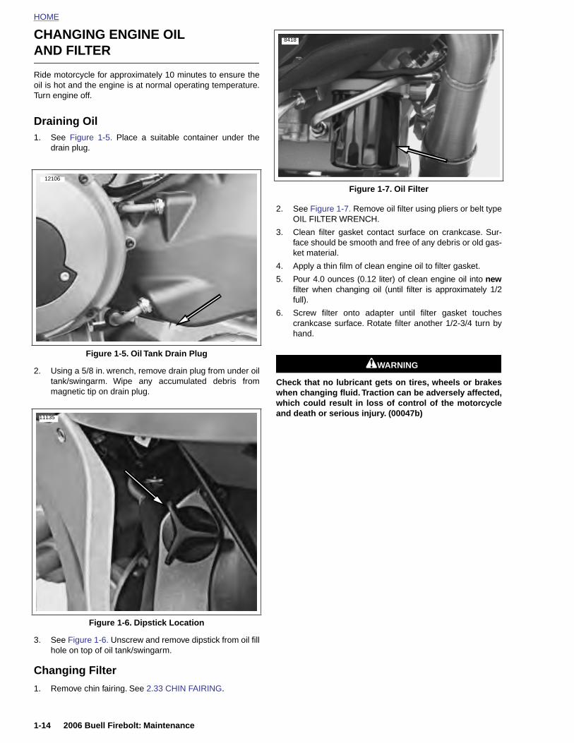
HOME
CHANGING ENGINE OIL
AND FILTER 8418
Ride motorcycle for approximately 10 minutes to ensure theoil is hot and the engine is at normal operating temperature.Turn engine off.
Draining Oil1. See Figure 1-5. Place a suitable container under the
drain plug.
2. Using a 5/8 in. wrench, remove drain plug from under oiltank/swingarm. Wipe any accumulated debris frommagnetic tip on drain plug.
2. See Figure 1-7. Remove oil filter using pliers or belt typeOIL FILTER WRENCH.
3. Clean filter gasket contact surface on crankcase. Sur-face should be smooth and free of any debris or old gas-ket material.
4. Apply a thin film of clean engine oil to filter gasket.
5. Pour 4.0 ounces (0.12 liter) of clean engine oil into newfilter when changing oil (until filter is approximately 1/2full).
6. Screw filter onto adapter until filter gasket touchescrankcase surface. Rotate filter another 1/2-3/4 turn byhand.
1WARNING1WARNING
Check that no lubricant gets on tires, wheels or brakeswhen changing fluid. Traction can be adversely affected,which could result in loss of control of the motorcycleand death or serious injury. (00047b)
Figure 1-5. Oil Tank Drain Plug
12106
11135
Figure 1-7. Oil Filter
1-14 2006 Buell Firebolt: Maintenance
3. See Figure 1-6. Unscrew and remove dipstick from oil fillhole on top of oil tank/swingarm.
Changing Filter
1. Remove chin fairing. See 2.33 CHIN FAIRING.
Figure 1-6. Dipstick Location
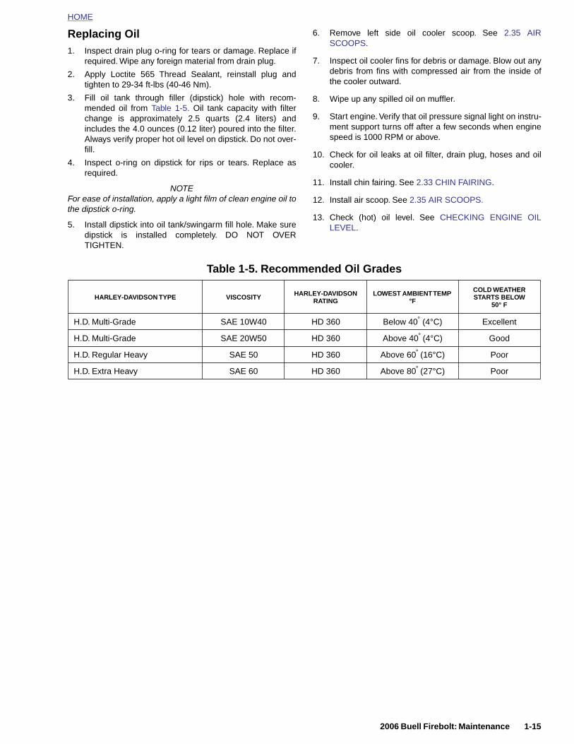
HOME
Replacing Oil1. Inspect drain plug o-ring for tears or damage. Replace if
required. Wipe any foreign material from drain plug.
2. Apply Loctite 565 Thread Sealant, reinstall plug andtighten to 29-34 ft-lbs (40-46 Nm).
3. Fill oil tank through filler (dipstick) hole with recom-mended oil from Table 1-5. Oil tank capacity with filterchange is approximately 2.5 quarts (2.4 liters) andincludes the 4.0 ounces (0.12 liter) poured into the filter.Always verify proper hot oil level on dipstick. Do not over-fill.
4. Inspect o-ring on dipstick for rips or tears. Replace asrequired.
NOTEFor ease of installation, apply a light film of clean engine oil tothe dipstick o-ring.
5. Install dipstick into oil tank/swingarm fill hole. Make suredipstick is installed completely. DO NOT OVERTIGHTEN.
6. Remove left side oil cooler scoop. See 2.35 AIRSCOOPS.
7. Inspect oil cooler fins for debris or damage. Blow out anydebris from fins with compressed air from the inside ofthe cooler outward.
8. Wipe up any spilled oil on muffler.
9. Start engine. Verify that oil pressure signal light on instru-ment support turns off after a few seconds when enginespeed is 1000 RPM or above.
10. Check for oil leaks at oil filter, drain plug, hoses and oilcooler.
11. Install chin fairing. See 2.33 CHIN FAIRING.
12. Install air scoop. See 2.35 AIR SCOOPS.
13. Check (hot) oil level. See CHECKING ENGINE OILLEVEL.
Table 1-5. Recommended Oil Grades
HARLEY-DAVIDSON TYPE VISCOSITY HARLEY-DAVIDSON RATING
LOWEST AMBIENT TEMP °F
COLD WEATHER STARTS BELOW
50° F
H.D. Multi-Grade SAE 10W40 HD 360 Below 40° (4°C) Excellent
H.D. Multi-Grade SAE 20W50 HD 360 Above 40° (4°C) Good
H.D. Regular Heavy SAE 50 HD 360 Above 60° (16°C) Poor
H.D. Extra Heavy SAE 60 HD 360 Above 80° (27°C) Poor
2006 Buell Firebolt: Maintenance 1-15
HOME
BRAKE SYSTEM MAINTENANCE 1.7
GENE
Check bra
● When
Replace D
● Every
Front brakfirm feel wdescribed
Inspect fro
● Every
Inspect crequired:
● Every
If determinto Table 1
BLEED
Direct coirritation.with largSwallowincause digattentionREACH O
Never mix5). Use onify D.O.T.types of lead to b
1-16
ous inju
RAL
ke fluid level and condition:
storing or removing the motorcycle for the season.
.O.T. 4 BRAKE FLUID:
2 years.
e hand lever and rear brake foot pedal must have ahen brakes are applied. If not, bleed system as
.
nt and rear brake lines and replace as required:
4 years.
aliper and master cylinder seals and replace as
2 years.
ing probable causes of poor brake operation, refer-6.
ING BRAKES
1WARNING1WARNING
ntact of D.O.T. 4 brake fluid with eyes can cause Avoid eye contact. In case of eye contact flushe amounts of water and get medical attention.
g large amounts of D.O.T. 4 brake fluid canestive discomfort. If swallowed, obtain medical
. Use in well ventilated area. KEEP OUT OFF CHILDREN. (00240a)
1WARNING1WARNING
D.O.T. 4 with other brake fluids (such as D.O.T.ly D.O.T. 4 brake fluid in motorcycles that spec-
4 fluid on the reservoir cap. Mixing differentfluid may adversely affect braking ability andrake failure which could result in death or seri-
1WARNING1WARNING
Use only fresh, uncontaminated D.O.T. 4 fluid. Cans offluid that have been opened may have been contami-nated by moisture in the air or dirt. Use of contaminatedbrake fluid may adversely affect braking ability and leadto brake failure which could result in death or seriousinjury
1WARNING1WARNING
Use only new copper crush banjo washers (See PartsCatalog for Part No.) with D.O.T. 4 brake fluid. Earlier sil-ver banjo washers are not compatible with D.O.T. 4 fluidand will not seal properly over time. Failure to complymay adversely affect braking ability and lead to brakefailure which could result in death or serious injury.
1WARNING1WARNING
Use denatured alcohol to clean brake system compo-nents. Do not use mineral-based solvents (such as gaso-line or paint thinner), which will deteriorate rubber partseven after assembly. Deterioration of these componentscan cause brake failure, which could result in death orserious injury. (00291a)
1WARNING1WARNING
After repairing the brake system, test brakes at lowspeed. If brakes are not operating properly, testing athigh speeds can cause loss of control, which couldresult in death or serious injury. (00289a)
CAUTION
D.O.T. 4 brake fluid will damage painted and body panelsurfaces it comes in contact with. Always use cautionand protect surfaces from spills whenever brake work isperformed. Failure to comply can result in cosmetic dam-age. (00239a)
2006 Buell Firebolt: Maintenance
ry.
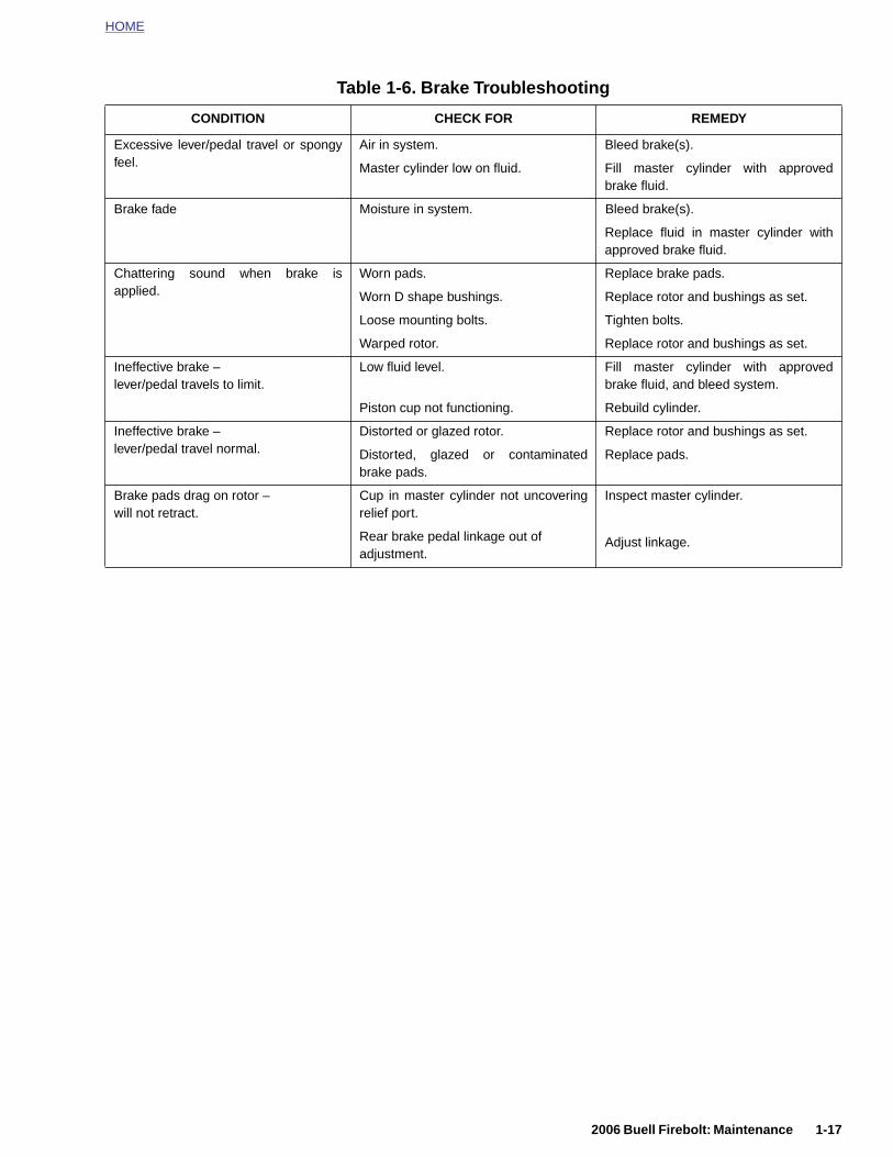
HOME
Table 1-6. Brake Troubleshooting
CONDITION CHECK FOR REMEDY
Excessive lever/pedal travel or spongyfeel.
Air in system.
Master cylinder low on fluid.
Bleed brake(s).
Fill master cylinder with approvedbrake fluid.
Brake fade Moisture in system. Bleed brake(s).
Replace fluid in master cylinder withapproved brake fluid.
Chattering sound when brake isapplied.
Worn pads.
Worn D shape bushings.
Loose mounting bolts.
Warped rotor.
Replace brake pads.
Replace rotor and bushings as set.
Tighten bolts.
Replace rotor and bushings as set.
Ineffective brake –lever/pedal travels to limit.
Low fluid level.
Piston cup not functioning.
Fill master cylinder with approvedbrake fluid, and bleed system.
Rebuild cylinder.
Ineffective brake –lever/pedal travel normal.
Distorted or glazed rotor.
Distorted, glazed or contaminatedbrake pads.
Replace rotor and bushings as set.
Replace pads.
Brake pads drag on rotor –will not retract.
Cup in master cylinder not uncoveringrelief port.
Rear brake pedal linkage out of adjustment.
Inspect master cylinder.
Adjust linkage.
2006 Buell Firebolt: Maintenance 1-17
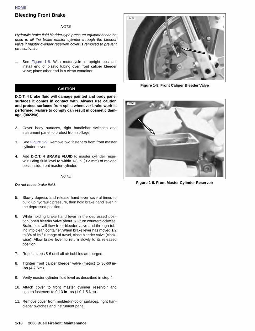
HOME
Bleeding Front Brake8346
NOTE
Hydraulic brake fluid bladder-type pressure equipment can beused to fill the brake master cylinder through the bleedervalve if master cylinder reservoir cover is removed to preventpressurization.
1. See Figure 1-8. With motorcycle in upright position,install end of plastic tubing over front caliper bleedervalve; place other end in a clean container.
CAUTION
D.O.T. 4 brake fluid will damage painted and body panelsurfaces it comes in contact with. Always use cautionand protect surfaces from spills whenever brake work isperformed. Failure to comply can result in cosmetic dam-age. (00239a)
2. Cover body surfaces, right handlebar switches andinstrument panel to protect from spillage.
3. See Figure 1-9. Remove two fasteners from front mastercylinder cover.
4. Add D.O.T. 4 BRAKE FLUID to master cylinder reser-voir. Bring fluid level to within 1/8 in. (3.2 mm) of moldedboss inside front master cylinder.
NOTE
Do not reuse brake fluid.
5. Slowly depress and release hand lever several times tobuild up hydraulic pressure, then hold brake hand lever inthe depressed position.
6. While holding brake hand lever in the depressed posi-tion, open bleeder valve about 1/2-turn counterclockwise.Brake fluid will flow from bleeder valve and through tub-ing into clean container. When brake lever has moved 1/2to 3/4 of its full range of travel, close bleeder valve (clock-wise). Allow brake lever to return slowly to its released
Figure 1-8. Front Caliper Bleeder Valve
Figure 1-9. Front Master Cylinder Reservoir
8359
1-18 2006 Buell Firebolt: Maintenance
position.
7. Repeat steps 5-6 until all air bubbles are purged.
8. Tighten front caliper bleeder valve (metric) to 36-60 in-lbs (4-7 Nm).
9. Verify master cylinder fluid level as described in step 4.
10. Attach cover to front master cylinder reservoir andtighten fasteners to 9-13 in-lbs (1.0-1.5 Nm).
11. Remove cover from molded-in-color surfaces, right han-dlebar switches and instrument panel.
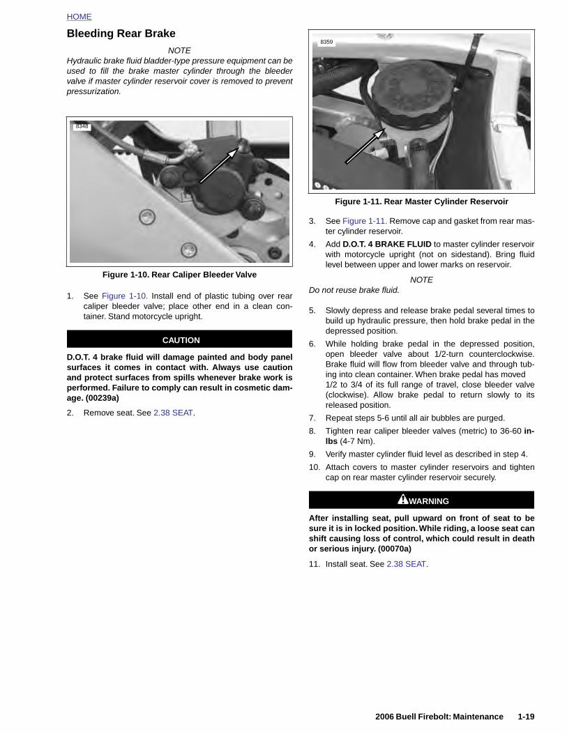
HOME
Bleeding Rear BrakeNOTE
Hydraulic brake fluid bladder-type pressure equipment can beused to fill the brake master cylinder through the bleedervalve if master cylinder reservoir cover is removed to preventpressurization.
1. See Figure 1-10. Install end of plastic tubing over rearcaliper bleeder valve; place other end in a clean con-tainer. Stand motorcycle upright.
CAUTION
D.O.T. 4 brake fluid will damage painted and body panelsurfaces it comes in contact with. Always use cautionand protect surfaces from spills whenever brake work isperformed. Failure to comply can result in cosmetic dam-age. (00239a)
2. Remove seat. See 2.38 SEAT.
3. See Figure 1-11. Remove cap and gasket from rear mas-ter cylinder reservoir.
4. Add D.O.T. 4 BRAKE FLUID to master cylinder reservoirwith motorcycle upright (not on sidestand). Bring fluidlevel between upper and lower marks on reservoir.
NOTEDo not reuse brake fluid.
5. Slowly depress and release brake pedal several times tobuild up hydraulic pressure, then hold brake pedal in thedepressed position.
6. While holding brake pedal in the depressed position,open bleeder valve about 1/2-turn counterclockwise.Brake fluid will flow from bleeder valve and through tub-ing into clean container. When brake pedal has moved 1/2 to 3/4 of its full range of travel, close bleeder valve(clockwise). Allow brake pedal to return slowly to itsreleased position.
7. Repeat steps 5-6 until all air bubbles are purged.
8. Tighten rear caliper bleeder valves (metric) to 36-60 in-lbs (4-7 Nm).
9. Verify master cylinder fluid level as described in step 4.
10. Attach covers to master cylinder reservoirs and tightencap on rear master cylinder reservoir securely.
1WARNING1WARNING
Figure 1-10. Rear Caliper Bleeder Valve
8348
Figure 1-11. Rear Master Cylinder Reservoir
8359
2006 Buell Firebolt: Maintenance 1-19
After installing seat, pull upward on front of seat to besure it is in locked position. While riding, a loose seat canshift causing loss of control, which could result in deathor serious injury. (00070a)
11. Install seat. See 2.38 SEAT.
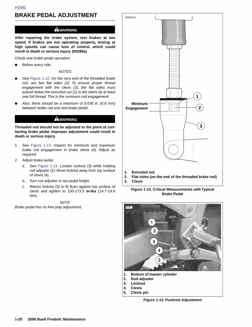
HOME
BRAKE PEDAL ADJUSTMENT b0615x1x
1WARNING1WARNING
After repairing the brake system, test brakes at lowspeed. If brakes are not operating properly, testing athigh speeds can cause loss of control, which couldresult in death or serious injury. (00289a)
Check rear brake pedal operation:
● Before every ride.
NOTES
● See Figure 1-12. On the very end of the threaded brakerod, are two flat sides (2). To ensure proper threadengagement with the clevis (3), the flat sides mustextend below the extruded nut (1) in the clevis by at leastone full thread. This is the minimum rod engagement.
● Also, there should be a minimum of 0.030 in. (0.8 mm)between brake rod end and brake pedal.
1WARNING1WARNING
Threaded rod should not be adjusted to the point of con-tacting brake pedal. Improper adjustment could result indeath or serious injury.
1. See Figure 1-13. Inspect for minimum and maximumbrake rod engagement in brake clevis (4). Adjust asrequired.
2. Adjust brake pedal.
a. See Figure 1-13. Loosen locknut (3) while holdingrod adjuster (2). Move locknut away from top surfaceof clevis (4).
b. Turn rod adjuster to set pedal height.
c. Return locknut (3) to fit flush against top surface ofclevis and tighten to 130-173.5 in-lbs (14.7-19.6Nm).
NOTEBrake pedal has no free play adjustment.
Figure 1-12. Critical Measurements with Typical Brake Pedal
MinimumEngagement
1. Extruded nut2. Flat sides (on the end of the threaded brake rod)3. Clevis
3
2
1
8349
2
1
1-20 2006 Buell Firebolt: Maintenance
Figure 1-13. Pushrod Adjustment
1. Bottom of master cylinder2. Rod adjuster3. Locknut4. Clevis5. Clevis pin
3
4
5
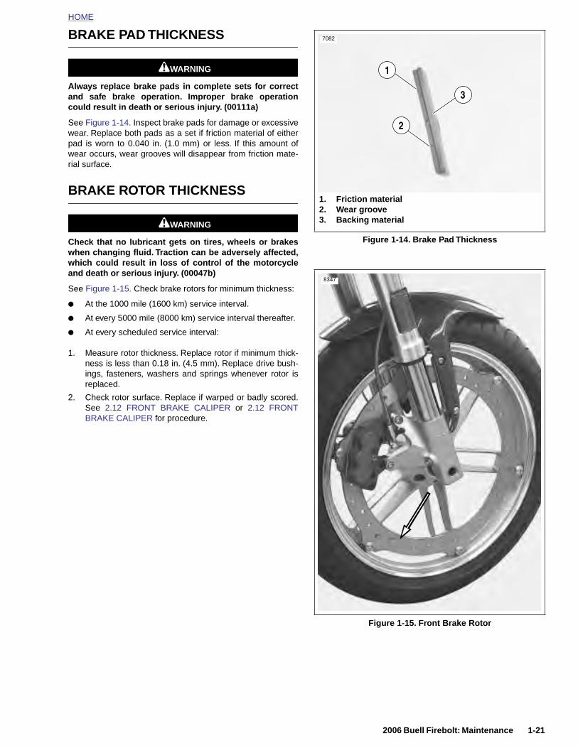
HOME
BRAKE PAD THICKNESS
1WARNING1WARNING
Always replace brake pads in complete sets for correctand safe brake operation. Improper brake operationcould result in death or serious injury. (00111a)
See Figure 1-14. Inspect brake pads for damage or excessivewear. Replace both pads as a set if friction material of eitherpad is worn to 0.040 in. (1.0 mm) or less. If this amount ofwear occurs, wear grooves will disappear from friction mate-rial surface.
BRAKE ROTOR THICKNESS
1WARNING1WARNING
Check that no lubricant gets on tires, wheels or brakeswhen changing fluid. Traction can be adversely affected,which could result in loss of control of the motorcycleand death or serious injury. (00047b)
See Figure 1-15. Check brake rotors for minimum thickness:
● At the 1000 mile (1600 km) service interval.
● At every 5000 mile (8000 km) service interval thereafter.
● At every scheduled service interval:
1. Measure rotor thickness. Replace rotor if minimum thick-ness is less than 0.18 in. (4.5 mm). Replace drive bush-ings, fasteners, washers and springs whenever rotor isreplaced.
2. Check rotor surface. Replace if warped or badly scored.See 2.12 FRONT BRAKE CALIPER or 2.12 FRONTBRAKE CALIPER for procedure.
Figure 1-14. Brake Pad Thickness
7082
1. Friction material2. Wear groove3. Backing material
1
2
3
83478347
2006 Buell Firebolt: Maintenance 1-21
Figure 1-15. Front Brake Rotor
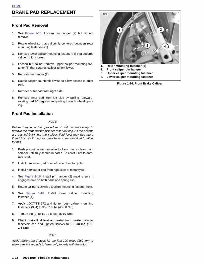
HOME
BRAKE PAD REPLACEMENT 8346
Front Pad Removal
1. See Figure 1-16. Loosen pin hanger (2) but do notremove.
2. Rotate wheel so that caliper is centered between rotormounting fasteners (1).
3. Remove lower caliper mounting fastener (4) that securescaliper to fork lower.
4. Loosen but do not remove upper caliper mounting fas-tener (3) that secures caliper to fork lower.
5. Remove pin hanger (2).
6. Rotate caliper counterclockwise to allow access to outerpad.
7. Remove outer pad from right side.
8. Remove inner pad from left side by pulling rearward,rotating pad 90 degrees and pulling through wheel open-ing.
Front Pad Installation
NOTE
Before beginning this procedure it will be necessary toremove the front master cylinder reservoir cap. As the pistonsare pushed back into the caliper, fluid level may rise morethan 1/8 in. (3.2 mm) You may have to remove fluid to allowfor this.
1. Push pistons in with suitable tool such as a clean paintscraper until fully seated in bores. Be careful not to dam-age rotor.
2. Install new inner pad from left side of motorcycle.
3. Install new outer pad from right side of motorcycle.
4. See Figure 1-16. Install pin hanger (2) making sure itengages hole on both pads and spring clip.
5. Rotate caliper clockwise to align mounting fastener hole.
6. See Figure 1-16. Install lower caliper mounting
Figure 1-16. Front Brake Caliper
1. Rotor mounting fastener (6)2. Front caliper pin hanger3. Upper caliper mounting fastener4. Lower caliper mounting fastener
2
1
4
3
1-22 2006 Buell Firebolt: Maintenance
fastener (4).
7. Apply LOCTITE 272 and tighten both caliper mountingfasteners (3, 4) to 35-37 ft-lbs (48-50 Nm).
8. Tighten pin (2) to 11-14 ft-lbs (15-19 Nm).
9. Check brake fluid level and install front master cylinderreservoir cap and tighten screws to 9-13 in-lbs (1.0-1.5 Nm).
NOTE
Avoid making hard stops for the first 100 miles (160 km) toallow new brake pads to “wear in” properly with the rotor.
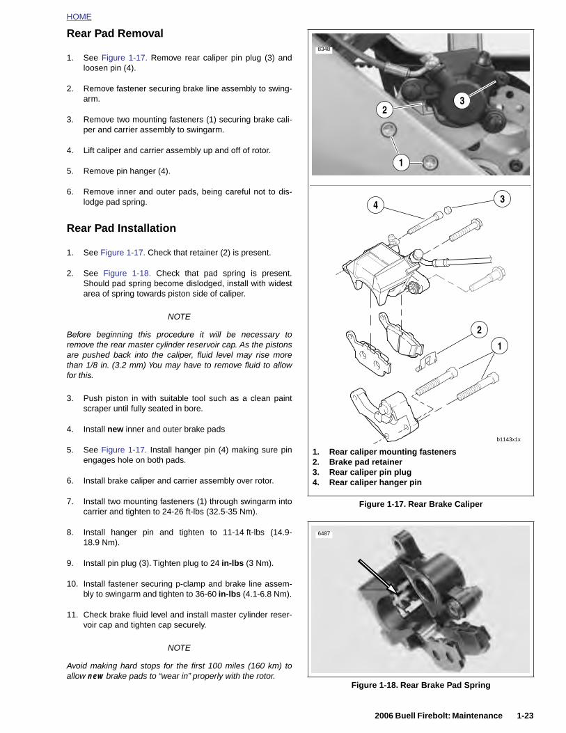
HOME
Rear Pad Removal
1. See Figure 1-17. Remove rear caliper pin plug (3) andloosen pin (4).
2. Remove fastener securing brake line assembly to swing-arm.
3. Remove two mounting fasteners (1) securing brake cali-per and carrier assembly to swingarm.
4. Lift caliper and carrier assembly up and off of rotor.
5. Remove pin hanger (4).
6. Remove inner and outer pads, being careful not to dis-lodge pad spring.
Rear Pad Installation
1. See Figure 1-17. Check that retainer (2) is present.
2. See Figure 1-18. Check that pad spring is present.Should pad spring become dislodged, install with widestarea of spring towards piston side of caliper.
NOTE
Before beginning this procedure it will be necessary toremove the rear master cylinder reservoir cap. As the pistonsare pushed back into the caliper, fluid level may rise morethan 1/8 in. (3.2 mm) You may have to remove fluid to allowfor this.
3. Push piston in with suitable tool such as a clean paintscraper until fully seated in bore.
4. Install new inner and outer brake pads
5. See Figure 1-17. Install hanger pin (4) making sure pinengages hole on both pads.
6. Install brake caliper and carrier assembly over rotor.
7. Install two mounting fasteners (1) through swingarm into Figure 1-17. Rear Brake Caliper
8348
1. Rear caliper mounting fasteners2. Brake pad retainer3. Rear caliper pin plug4. Rear caliper hanger pin
3
3
1
2
1
2
b1143x1x
4
2006 Buell Firebolt: Maintenance 1-23
carrier and tighten to 24-26 ft-lbs (32.5-35 Nm).
8. Install hanger pin and tighten to 11-14 ft-lbs (14.9-18.9 Nm).
9. Install pin plug (3). Tighten plug to 24 in-lbs (3 Nm).
10. Install fastener securing p-clamp and brake line assem-bly to swingarm and tighten to 36-60 in-lbs (4.1-6.8 Nm).
11. Check brake fluid level and install master cylinder reser-voir cap and tighten cap securely.
NOTE
Avoid making hard stops for the first 100 miles (160 km) toallow new brake pads to “wear in” properly with the rotor.
Figure 1-18. Rear Brake Pad Spring
6487
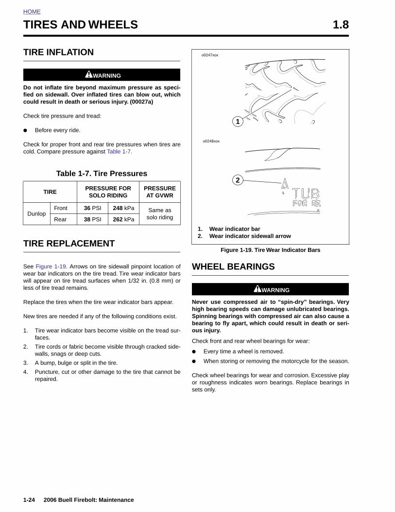
HOME
TIRES AND WHEELS 1.8
TIRE I
Do not infied on scould res
Check tire
● Befor
Check forcold. Com
TIRE R
See Figurwear bar will appealess of tire
Replace t
New tires
1. Tire wfaces
2. Tire cwalls,
3. A bum
4. Punc
TI
Dunlop
1-24
repa
NFLATION
1WARNING1WARNING
flate tire beyond maximum pressure as speci-idewall. Over inflated tires can blow out, whichult in death or serious injury. (00027a)
pressure and tread:
e every ride.
proper front and rear tire pressures when tires arepare pressure against Table 1-7.
EPLACEMENT
e 1-19. Arrows on tire sidewall pinpoint location ofindicators on the tire tread. Tire wear indicator barsr on tire tread surfaces when 1/32 in. (0.8 mm) or tread remains.
he tires when the tire wear indicator bars appear.
are needed if any of the following conditions exist.
ear indicator bars become visible on the tread sur-.
ords or fabric become visible through cracked side- snags or deep cuts.
p, bulge or split in the tire.
ture, cut or other damage to the tire that cannot be
WHEEL BEARINGS
1WARNING1WARNING
Never use compressed air to “spin-dry” bearings. Veryhigh bearing speeds can damage unlubricated bearings.Spinning bearings with compressed air can also cause abearing to fly apart, which could result in death or seri-ous injury.
Check front and rear wheel bearings for wear:
● Every time a wheel is removed.
● When storing or removing the motorcycle for the season.
Check wheel bearings for wear and corrosion. Excessive play
Table 1-7. Tire Pressures
RE PRESSURE FOR
SOLO RIDING PRESSURE AT GVWR
Front 36 PSI 248 kPa Same as solo ridingRear 38 PSI 262 kPa
Figure 1-19. Tire Wear Indicator Bars
o0247xox
1
o0248xox
2
1. Wear indicator bar2. Wear indicator sidewall arrow
2006 Buell Firebolt: Maintenance
ired.or roughness indicates worn bearings. Replace bearings insets only.
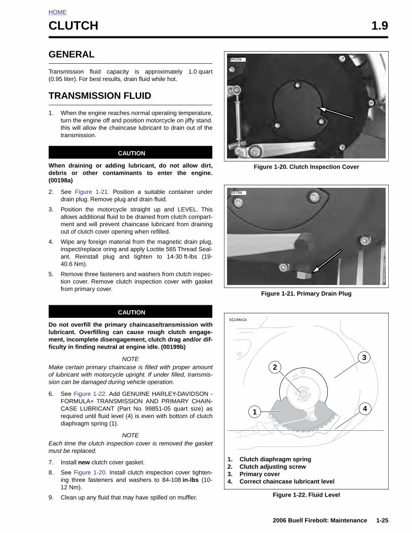
HOME
C
G
T(
T
1
Wd(
2
3
4
5
Dlmfi
M
LUTCH 1.9
ENERAL
ransmission fluid capacity is approximately 1.0 quart0.95 liter). For best results, drain fluid while hot.
RANSMISSION FLUID
. When the engine reaches normal operating temperature,turn the engine off and position motorcycle on jiffy stand.this will allow the chaincase lubricant to drain out of thetransmission.
CAUTION
hen draining or adding lubricant, do not allow dirt,ebris or other contaminants to enter the engine.00198a)
. See Figure 1-21. Position a suitable container underdrain plug. Remove plug and drain fluid.
. Position the motorcycle straight up and LEVEL. Thisallows additional fluid to be drained from clutch compart-ment and will prevent chaincase lubricant from drainingout of clutch cover opening when refilled.
. Wipe any foreign material from the magnetic drain plug,inspect/replace oring and apply Loctite 565 Thread Seal-ant. Reinstall plug and tighten to 14-30 ft-lbs (19-40.6 Nm).
. Remove three fasteners and washers from clutch inspec-tion cover. Remove clutch inspection cover with gasketfrom primary cover.
CAUTION
o not overfill the primary chaincase/transmission withubricant. Overfilling can cause rough clutch engage-
ent, incomplete disengagement, clutch drag and/or dif-culty in finding neutral at engine idle. (00199b)
NOTEake certain primary chaincase is filled with proper amount
Figure 1-20. Clutch Inspection Cover
Figure 1-21. Primary Drain Plug
8410a
8376a
b1144x1x
3
2006 Buell Firebolt: Maintenance 1-25
of lubricant with motorcycle upright. If under filled, transmis-sion can be damaged during vehicle operation.
6. See Figure 1-22. Add GENUINE HARLEY-DAVIDSON -FORMULA+ TRANSMISSION AND PRIMARY CHAIN-CASE LUBRICANT (Part No. 99851-05 quart size) asrequired until fluid level (4) is even with bottom of clutchdiaphragm spring (1).
NOTEEach time the clutch inspection cover is removed the gasketmust be replaced.
7. Install new clutch cover gasket.
8. See Figure 1-20. Install clutch inspection cover tighten-ing three fasteners and washers to 84-108 in-lbs (10-12 Nm).
9. Clean up any fluid that may have spilled on muffler. Figure 1-22. Fluid Level
1. Clutch diaphragm spring2. Clutch adjusting screw3. Primary cover4. Correct chaincase lubricant level
1
2
4

HOME
ADJUSTMENT8411
If clutch slips under load or drags when released, first checkcontrol cable adjustment. If cable adjustment is within specifi-cations, adjust clutch mechanism as described below.
When necessary, lubricate cable with LUBIT-8 TUFOIL®
CHAIN AND CABLE LUBE (Part No. HD-94968-85TV).
1. Position the vehicle upright and level. This will preventlubricate from draining out when clutch inspection coveris removed.
2. See Figure 1-23. Slide rubber boot (1) upward to exposeadjuster mechanism. Loosen jam nut (3) from adjuster(4). Turn adjuster to shorten cable housing until there is alarge amount of free play at clutch hand lever.
3. See Figure 1-20. Remove three fasteners and washersfrom clutch inspection cover. Remove clutch inspectioncover and gasket from primary cover.
4. See Figure 1-24. Remove spring (1) and lockplate (2).Using a flat tip screwdriver, turn adjusting screw (3)counterclockwise until it lightly bottoms.
5. Turn adjusting screw clockwise 1/4-1/2 turn. Install lock-plate and spring on adjusting screw flats. If hex on lock-plate does not align with recess in outer ramp, rotateadjusting screw clockwise until it aligns.
NOTESpring installs on outboard side of hex lockplate.
Figure 1-23. Clutch Cable Adjuster Mechanism
1. Rubber boot2. Cable end3. Jam nut4. Adjuster
1
2
4
3
8405
1
2 3
1-26 2006 Buell Firebolt: Maintenance
Figure 1-24. Clutch Adjustment
1. Diaphragm spring2. Lockplate3. Adjusting screw
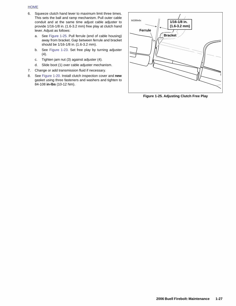
HOME
6. Squeeze clutch hand lever to maximum limit three times.This sets the ball and ramp mechanism. Pull outer cableconduit and at the same time adjust cable adjuster toprovide 1/16-1/8 in. (1.6-3.2 mm) free play at clutch handlever. Adjust as follows:
a. See Figure 1-25. Pull ferrule (end of cable housing)away from bracket. Gap between ferrule and bracketshould be 1/16-1/8 in. (1.6-3.2 mm).
b. See Figure 1-23. Set free play by turning adjuster(4).
c. Tighten jam nut (3) against adjuster (4).
d. Slide boot (1) over cable adjuster mechanism.
7. Change or add transmission fluid if necessary.
8. See Figure 1-20. Install clutch inspection cover and newgasket using three fasteners and washers and tighten to84-108 in-lbs (10-12 Nm).
Figure 1-25. Adjusting Clutch Free Play
b0289x6x
BracketFerrule
1/16-1/8 in.(1.6-3.2 mm)
2006 Buell Firebolt: Maintenance 1-27
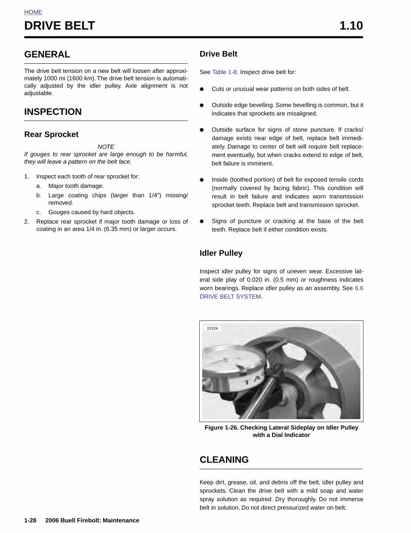
HOME
DRIVE BELT 1.10
GENE
The drive mately 10cally adjuadjustable
INSPE
Rear S
If gougesthey will le
1. Inspe
a. M
b. Lr
c. G
2. Replacoatin
1-28
RAL
belt tension on a new belt will loosen after approxi-00 mi (1600 km). The drive belt tension is automati-sted by the idler pulley. Axle alignment is not.
CTION
procketNOTE
to rear sprocket are large enough to be harmful,ave a pattern on the belt face.
ct each tooth of rear sprocket for:
ajor tooth damage.
arge coating chips (larger than 1/4") missing/emoved.
ouges caused by hard objects.
ce rear sprocket if major tooth damage or loss ofg in an area 1/4 in. (6.35 mm) or larger occurs.
Drive Belt
See Table 1-8. Inspect drive belt for:
● Cuts or unusual wear patterns on both sides of belt.
● Outside edge bevelling. Some bevelling is common, but itindicates that sprockets are misaligned.
● Outside surface for signs of stone puncture. If cracks/damage exists near edge of belt, replace belt immedi-ately. Damage to center of belt will require belt replace-ment eventually, but when cracks extend to edge of belt,belt failure is imminent.
● Inside (toothed portion) of belt for exposed tensile cords(normally covered by facing fabric). This condition willresult in belt failure and indicates worn transmissionsprocket teeth. Replace belt and transmission sprocket.
● Signs of puncture or cracking at the base of the beltteeth. Replace belt if either condition exists.
Idler Pulley
Inspect idler pulley for signs of uneven wear. Excessive lat-eral side play of 0.020 in. (0.5 mm) or roughness indicatesworn bearings. Replace idler pulley as an assembly. See 6.6DRIVE BELT SYSTEM.
10124
2006 Buell Firebolt: Maintenance
CLEANING
Keep dirt, grease, oil, and debris off the belt, idler pulley andsprockets. Clean the drive belt with a mild soap and waterspray solution as required. Dry thoroughly. Do not immersebelt in solution. Do not direct pressurized water on belt.
Figure 1-26. Checking Lateral Sideplay on Idler Pulley with a Dial Indicator

HOME
Table 1-8. Potential Limits to Belt Drive Service Life
CONDITION ROOT CAUSE REQUIRED ACTION
Excessive Edge Wear(mistracking)
Misalignment or bent drive structure Check structure (bad bearing, bent members, etc.)
Bent or rough flange Repair flange/replace sprocket
Damage due to handling (pry on, etc.) Follow proper handling/installation procedure
Debris damage to edge of beltInspect/replace belt
Inspect for damaged or missing guards
Belt hitting obstruction
Check structure (bad bearing, bent members, etc.)
Inspect for loose/missing fasteners
Inspect for damaged or missing guards
Bent or loose idler bracketReplace idler assembly
Inspect for loose/missing fasteners
Broken or loose guards
Check structure (bad bearing, bent members, etc.)
Inspect for loose/missing fasteners
Inspect for damaged or missing guards
Excessive tooth wear
Rough or damaged sprocket Inspect/replace sprocket
Worn sprocket Inspect/replace sprocket
Debris in sprocketClean and protect drive
Inspect for damaged or missing guards
Abrasive environmentEliminate or control exposure
Inspect for damaged or missing guards
Apparent belt stretch
NOTEThe drive belt tensionon a new belt willloosen after approxi-mately 1000 mi (1600km)
Worn sprocket Inspect/replace sprocket
Debris in sprocketClean and protect drive
Inspect for damaged or missing guards
Idler bearing failure Replace idler assembly
Aggressive riding/hard use Riding practice/operator choice
Exposure to oils, solvents, harsh chemicalsEliminate or control exposure
Clean and protect drive
Idler/bearing binding Replace idler assembly
2006 Buell Firebolt: Maintenance 1-29
Cracks in back of belt
Exposure to oils, solvents, harsh chemicalsEliminate or control exposure
Clean and protect drive
Cut by sharp debris (not at belt edge)Inspect/replace sprocket
Continue to run but monitor condition frequently
Cut by sharp debris at belt edgeInspect/replace sprocket
Inspect/replace belt
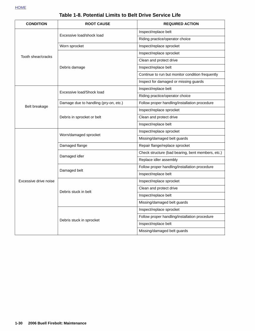
HOME
Table 1-8. Potential Limits to Belt Drive Service Life
CONDITION ROOT CAUSE REQUIRED ACTION
Tooth shear/cracks
Excessive load/shock loadInspect/replace belt
Riding practice/operator choice
Worn sprocket Inspect/replace sprocket
Debris damage
Inspect/replace sprocket
Clean and protect drive
Inspect/replace belt
Continue to run but monitor condition frequently
Inspect for damaged or missing guards
Belt breakage
Excessive load/Shock loadInspect/replace belt
Riding practice/operator choice
Damage due to handling (pry-on, etc.) Follow proper handling/installation procedure
Debris in sprocket or belt
Inspect/replace sprocket
Clean and protect drive
Inspect/replace belt
Excessive drive noise
Worn/damaged sprocketInspect/replace sprocket
Missing/damaged belt guards
Damaged flange Repair flange/replace sprocket
Damaged idlerCheck structure (bad bearing, bent members, etc.)
Replace idler assembly
Damaged beltFollow proper handling/installation procedure
Inspect/replace belt
Debris stuck in belt
Inspect/replace sprocket
Clean and protect drive
Inspect/replace belt
Missing/damaged belt guards
Debris stuck in sprocket
Inspect/replace sprocket
Follow proper handling/installation procedure
Inspect/replace belt
Missing/damaged belt guards
1-30 2006 Buell Firebolt: Maintenance
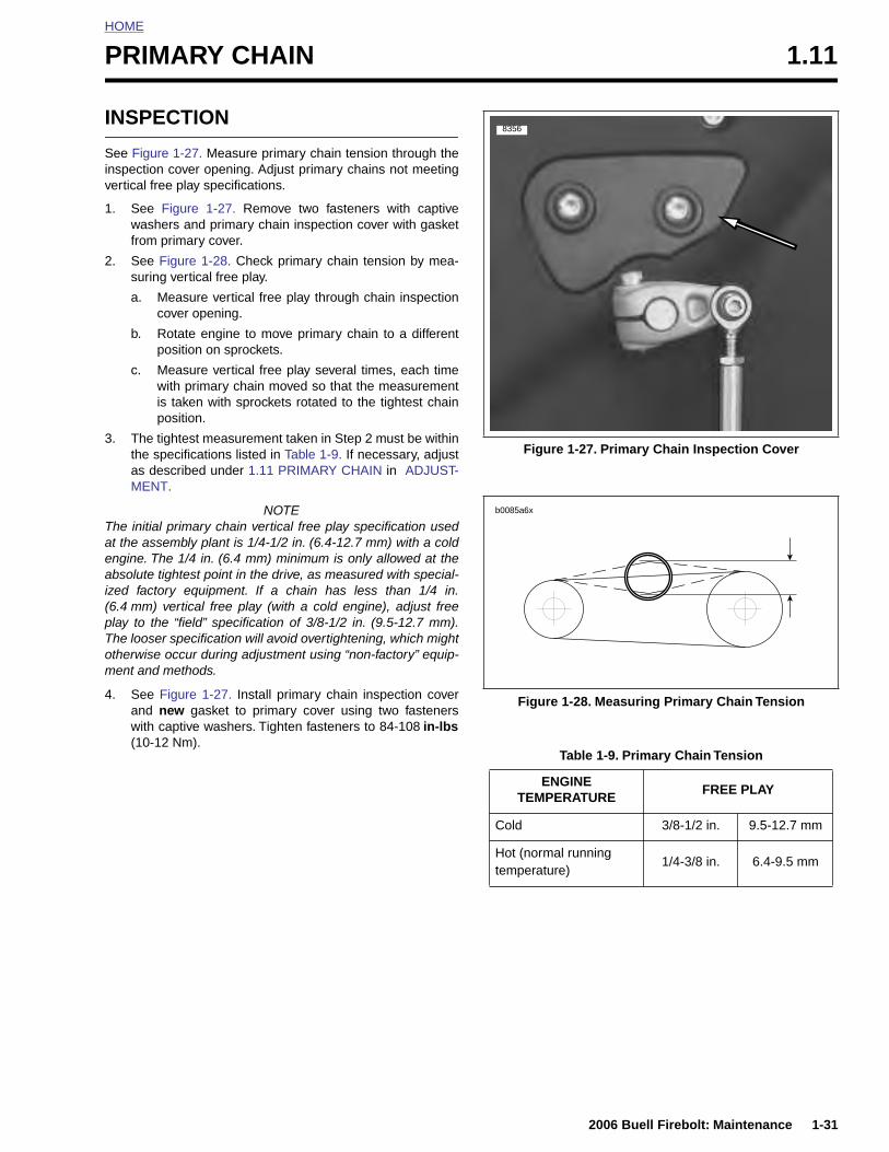
HOME
P
I
Siv
1
2
3
Taeai(pTom
4
RIMARY CHAIN 1.11
NSPECTION
ee Figure 1-27. Measure primary chain tension through thenspection cover opening. Adjust primary chains not meetingertical free play specifications.
. See Figure 1-27. Remove two fasteners with captivewashers and primary chain inspection cover with gasketfrom primary cover.
. See Figure 1-28. Check primary chain tension by mea-suring vertical free play.
a. Measure vertical free play through chain inspectioncover opening.
b. Rotate engine to move primary chain to a differentposition on sprockets.
c. Measure vertical free play several times, each timewith primary chain moved so that the measurementis taken with sprockets rotated to the tightest chainposition.
. The tightest measurement taken in Step 2 must be withinthe specifications listed in Table 1-9. If necessary, adjustas described under 1.11 PRIMARY CHAIN in ADJUST-MENT.
NOTEhe initial primary chain vertical free play specification usedt the assembly plant is 1/4-1/2 in. (6.4-12.7 mm) with a coldngine. The 1/4 in. (6.4 mm) minimum is only allowed at thebsolute tightest point in the drive, as measured with special-
zed factory equipment. If a chain has less than 1/4 in.6.4 mm) vertical free play (with a cold engine), adjust freelay to the “field” specification of 3/8-1/2 in. (9.5-12.7 mm).he looser specification will avoid overtightening, which mighttherwise occur during adjustment using “non-factory” equip-ent and methods.
. See Figure 1-27. Install primary chain inspection coverand new gasket to primary cover using two fastenerswith captive washers. Tighten fasteners to 84-108 in-lbs(10-12 Nm).
Figure 1-27. Primary Chain Inspection Cover
Figure 1-28. Measuring Primary Chain Tension
Table 1-9. Primary Chain Tension
ENGINEFREE PLAY
8356
b0085a6x
2006 Buell Firebolt: Maintenance 1-31
TEMPERATURE
Cold 3/8-1/2 in. 9.5-12.7 mm
Hot (normal runningtemperature)
1/4-3/8 in. 6.4-9.5 mm
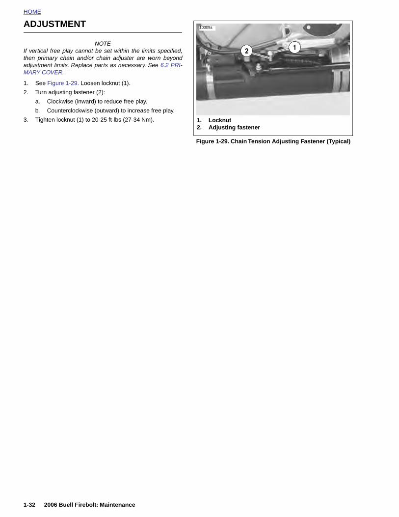
HOME
ADJUSTMENT
10309a
NOTEIf vertical free play cannot be set within the limits specified,then primary chain and/or chain adjuster are worn beyondadjustment limits. Replace parts as necessary. See 6.2 PRI-MARY COVER.
1. See Figure 1-29. Loosen locknut (1).
2. Turn adjusting fastener (2):
a. Clockwise (inward) to reduce free play.
b. Counterclockwise (outward) to increase free play.
3. Tighten locknut (1) to 20-25 ft-lbs (27-34 Nm).
Figure 1-29. Chain Tension Adjusting Fastener (Typical)
1. Locknut2. Adjusting fastener
12
1-32 2006 Buell Firebolt: Maintenance
HOME
S
G
BcitRiw
Mmcat
Irmec
Edma
FB
Tbpa
●
USPENSION DAMPING ADJUSTMENTS 1.12
ENERAL
1WARNING1WARNING
efore evaluating and adjusting suspension settings,heck the motorcycle’s tires. Be sure tires are properlynflated, balanced and have adequate tread. Inspect yourires regularly and see a Buell dealer for replacements.iding with excessively worn, unbalanced or under-
nflated tires can adversely affect stability and handling,hich could result in death or serious injury. (00114a)
ake all suspension adjustments in one or two click incre-ents. Adjusting more than one or two clicks at a time may
ause you to skip the best adjustment. Test ride after eachdjustment. When an adjustment makes no difference, returno the previous adjustment and try a different approach.
f both preload adjustments are correct, and you have theebound and compression damping set at the factory recom-ended points, the motorcycle should handle and ride prop-rly. If you wish to fine tune these settings they can behanged according to the following procedures.
NOTEvaluating and changing the rebound and compressionamping is a very subjective process. Many variables affectotorcycle handling under different circumstances. Approachll changes carefully and consult Table 1-10.
INE TUNING SUSPENSION:UELL MODELS
he settings are the best balance of handling, ride, and sta-ility. Suspension can be changed to accommodate riderreferences for ride quality and handling for road conditionsnd load changes.
NOTESDo not continue to repeat the steps involved with the fol-
1WARNING1WARNING
Do not exceed the motorcycle Gross Vehicle Weight Rat-ing (GVWR). Exceeding the GVWR can affect stabilityand handling, which could result in death or seriousinjury. (00016a)
● GVWR is the sum of the weight of the motorcycle, acces-sories, and the maximum weight of the rider, passengerand cargo that can be safely carried.
● The GVWR is shown on the information plate, located onthe frame steering head.
Ride Quality Enhancement
The stock settings are designed to offer sufficient chassiscontrol, but some may choose to enhance ride comfort overrougher road conditions or for long rides. Adjusting the com-pression setting will reduce both high and low speed damp-ing.
1. Adjust suspension for rider weight. Refer to Table 1-10.
2. Increase ride quality by reducing front and rear compres-sion damping by turning adjuster counterclockwise 1/4-1turn.
3. If additional ride quality is desired, reduce front preloadby turning adjuster counterclockwise until an additionalline is visible and also reduce rear preload 1 position.
4. If maximum ride quality is desired, decrease front andrear rebound damping by turning adjusters counterclock-wise by 1/4-1/2 turn.
Enhanced Steering Quickness
The response to steering input (quickness) may be enhancedby adjusting the vehicles front/rear ride height. This adjust-
2006 Buell Firebolt: Maintenance 1-33
lowing settings beyond those which are listed.
● Adjust suspension to the recommendation if possible, butnever force adjusters beyond the mechanical stops.
1WARNING1WARNING
Do not operate motorcycle with loose, worn or damagedsteering or suspension systems. Contact a Buell dealerfor repairs. Loose, worn or damaged steering or suspen-sion components can adversely affect stability and han-dling, which could result in death or serious injury.(00113a)
Changes in Load
Changes in the load carried requires changes in the preloadsetting(s). Carrying less weight than was used for setting upthe suspension requires decreasing the amount of preload.Increasing the load carried requires adding more preload.
ment effectively decreases the vehicles rake angle. This isachieved by adjusting the preload to increase front sag andreduce rear sag.
1. Adjust suspension for rider weight. Refer to Table 1-10.
2. Reduce steering effort by increasing the rear preloadone position.
3. If more enhanced steering and cornering control isdesired, reduce front preload by turning adjuster counter-clockwise until an additional line is visible.
4. If additional enhanced steering and cornering control isdesired, increase rear compression damping by turningadjuster clockwise by 1/4-1/2 turn.
5. If maximum enhanced steering and cornering control isdesired, increase front rebound damping by turningadjuster clockwise 1/4 turn.
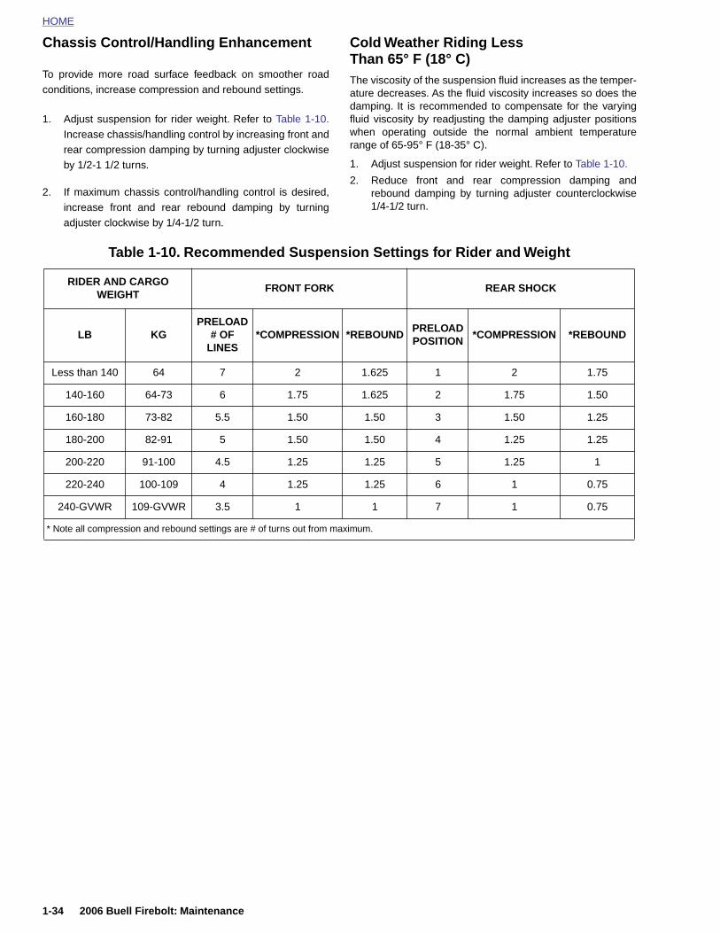
HOME
Chassis Control/Handling Enhancement
Cold Weather Riding LessThan 65° F (18° C)
To provide more road surface feedback on smoother roadconditions, increase compression and rebound settings.
1. Adjust suspension for rider weight. Refer to Table 1-10.Increase chassis/handling control by increasing front andrear compression damping by turning adjuster clockwiseby 1/2-1 1/2 turns.
2. If maximum chassis control/handling control is desired,increase front and rear rebound damping by turningadjuster clockwise by 1/4-1/2 turn.
The viscosity of the suspension fluid increases as the temper-ature decreases. As the fluid viscosity increases so does thedamping. It is recommended to compensate for the varyingfluid viscosity by readjusting the damping adjuster positionswhen operating outside the normal ambient temperaturerange of 65-95° F (18-35° C).
1. Adjust suspension for rider weight. Refer to Table 1-10.
2. Reduce front and rear compression damping andrebound damping by turning adjuster counterclockwise1/4-1/2 turn.
Table 1-10. Recommended Suspension Settings for Rider and Weight
RIDER AND CARGO WEIGHT
FRONT FORK REAR SHOCK
LB KGPRELOAD
# OF LINES
*COMPRESSION *REBOUNDPRELOAD POSITION
*COMPRESSION *REBOUND
Less than 140 64 7 2 1.625 1 2 1.75
140-160 64-73 6 1.75 1.625 2 1.75 1.50
160-180 73-82 5.5 1.50 1.50 3 1.50 1.25
180-200 82-91 5 1.50 1.50 4 1.25 1.25
200-220 91-100 4.5 1.25 1.25 5 1.25 1
220-240 100-109 4 1.25 1.25 6 1 0.75
240-GVWR 109-GVWR 3.5 1 1 7 1 0.75
* Note all compression and rebound settings are # of turns out from maximum.
1-34 2006 Buell Firebolt: Maintenance
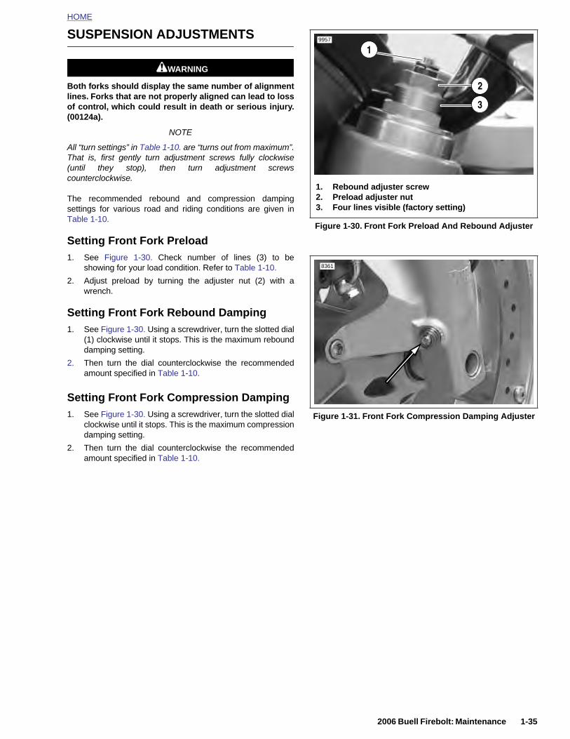
HOME
SUSPENSION ADJUSTMENTS
1WARNING1WARNING
Both forks should display the same number of alignmentlines. Forks that are not properly aligned can lead to lossof control, which could result in death or serious injury.(00124a).
NOTE
All “turn settings” in Table 1-10. are “turns out from maximum”.That is, first gently turn adjustment screws fully clockwise(until they stop), then turn adjustment screwscounterclockwise.
The recommended rebound and compression dampingsettings for various road and riding conditions are given inTable 1-10.
Setting Front Fork Preload1. See Figure 1-30. Check number of lines (3) to be
showing for your load condition. Refer to Table 1-10.
2. Adjust preload by turning the adjuster nut (2) with awrench.
Setting Front Fork Rebound Damping1. See Figure 1-30. Using a screwdriver, turn the slotted dial
(1) clockwise until it stops. This is the maximum rebounddamping setting.
2. Then turn the dial counterclockwise the recommendedamount specified in Table 1-10.
Setting Front Fork Compression Damping1. See Figure 1-30. Using a screwdriver, turn the slotted dial
clockwise until it stops. This is the maximum compressiondamping setting.
2. Then turn the dial counterclockwise the recommendedamount specified in Table 1-10.
Figure 1-30. Front Fork Preload And Rebound Adjuster
Figure 1-31. Front Fork Compression Damping Adjuster
1. Rebound adjuster screw2. Preload adjuster nut3. Four lines visible (factory setting)
1
2
3
9957
8361
2006 Buell Firebolt: Maintenance 1-35
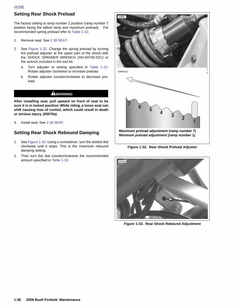
HOME
Setting Rear Shock Preload
The factory setting is ramp number 2 position (ramp number 7
8388
position being the tallest ramp and maximum preload). Forrecommended spring preload refer to Table 1-10.
1. Remove seat. See 2.38 SEAT.
2. See Figure 1-32. Change the spring preload by turningthe preload adjuster at the upper part of the shock withthe SHOCK SPANNER WRENCH (HD-94700-52C) orthe wrench included in the tool kit.
a. Turn adjuster to setting specified in Table 1-10.Rotate adjuster clockwise to increase preload.
b. Rotate adjuster counterclockwise to decrease pre-load.
1WARNING1WARNING
After installing seat, pull upward on front of seat to besure it is in locked position. While riding, a loose seat canshift causing loss of control, which could result in deathor serious injury. (00070a)
3. Install seat. See 2.38 SEAT.
Setting Rear Shock Rebound Damping
1. See Figure 1-33. Using a screwdriver, turn the slotted dialclockwise until it stops. This is the maximum rebounddamping setting.
2. Then turn the dial counterclockwise the recommendedamount specified in Table 1-10.
Figure 1-32. Rear Shock Preload Adjuster
Figure 1-33. Rear Shock Rebound Adjustment
Maximum preload adjustment (ramp number 7)Minimum preload adjustment (ramp number 1)
b0954x1x
8416a
1-36 2006 Buell Firebolt: Maintenance
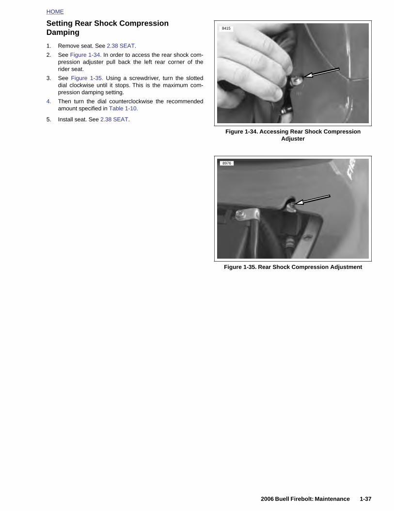
HOME
Setting Rear Shock Compression Damping
1. Remove seat. See 2.38 SEAT.
2. See Figure 1-34. In order to access the rear shock com-pression adjuster pull back the left rear corner of therider seat.
3. See Figure 1-35. Using a screwdriver, turn the slotteddial clockwise until it stops. This is the maximum com-pression damping setting.
4. Then turn the dial counterclockwise the recommendedamount specified in Table 1-10.
5. Install seat. See 2.38 SEAT.
Figure 1-34. Accessing Rear Shock Compression Adjuster
Figure 1-35. Rear Shock Compression Adjustment
8415
8976
2006 Buell Firebolt: Maintenance 1-37
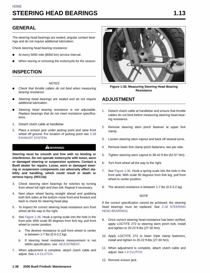
HOME
STEERING HEAD BEARINGS 1.13
GENE
The steerings and d
Check ste
● At ev
● When
INSPE
● Checbeari
● Steeradditi
● SteerReplations.
1. Detac
2. PlacewheeEXHA
Steering interferenor damagBuell deaing or subility andserious in
3. Checfront
4. Next both f
1-38
bac
5. To iwhe
6. Seefronwhe
a.
b.
7. Whadju
RAL
ing head bearings are sealed, angular contact bear-o not require additional lubrication.
ering head bearing resistance:
ery 5000 mile (8000 km) service interval.
storing or removing the motorcycle for the season.
CTION
NOTES
k that throttle cables do not bind when measuringng resistance.
ing head bearings are sealed and do not requireonal lubrication.
ing head bearing resistance is not adjustable.ce bearings that do not meet resistance specifica-
h clutch cable at handlebar.
a scissor jack under jacking point and raise frontl off ground. For location of jacking point see 2.28UST SYSTEM.
1WARNING1WARNING
must be smooth and free with no binding orce. Do not operate motorcycle with loose, worned steering or suspension systems. Contact aler for repairs. Loose, worn or damaged steer-spension components can adversely affect sta- handling, which could result in death orjury. (00113a)
k steering stem bearings for notches by turningwheel full right and then left. Repeat if necessary.
place wheel facing straight ahead and grabbingork sides at the bottom move front-end forward and
ADJUSTMENT
1. Detach clutch cable at handlebar and ensure that throttlecables do not bind before measuring steering head bear-ing resistance.
2. Remove steering stem pinch fastener at upper forkclamp.
3. Loosen steering stem capnut and back off several turns.
4. Remove lower fork clamp pinch fasteners, two per side.
5. Tighten steering stem capnut to 38-42 ft-lbs (52-57 Nm).
6. Turn front wheel all the way to the right.
7. See Figure 1-36. Hook a spring scale into the hole in thefront axle. With scale 90 degrees from fork leg, pull frontwheel to center position.
8. The desired resistance is between 1-7 lbs (0.5-3.2 kg).
NOTE
Figure 1-36. Measuring Steering Head Bearing Resistance
8421
2006 Buell Firebolt: Maintenance
k to check for steering head play.
nspect for correct steering head resistance turn frontel all the way to the right.
Figure 1-36. Hook a spring scale into the hole in thet axle. With scale 90 degrees from fork leg, pull frontel to center position.
The desired resistance to pull front wheel to centeris between 1-7 lbs (0.5-3.2 kg).
If steering head resistance measurement is notwithin specification, see ADJUSTMENT.
en adjustment is complete, attach clutch cable andst. See 1.9 CLUTCH.
If the correct specification cannot be achieved, the steeringhead bearings must be replaced. See 2.18 STEERINGHEAD BEARINGS.
9. Once correct steering head resistance has been verified,apply LOCTITE 272 to steering stem pinch bolt, installand tighten to 20-22 ft-lbs (27-30 Nm).
10. Apply LOCTITE 272 to lower triple clamp fasteners,install and tighten to 20-22 ft-lbs (27-30 Nm).
11. When adjustment is complete, attach clutch cable andadjust. See 1.9 CLUTCH.
12. Remove scissor jack.
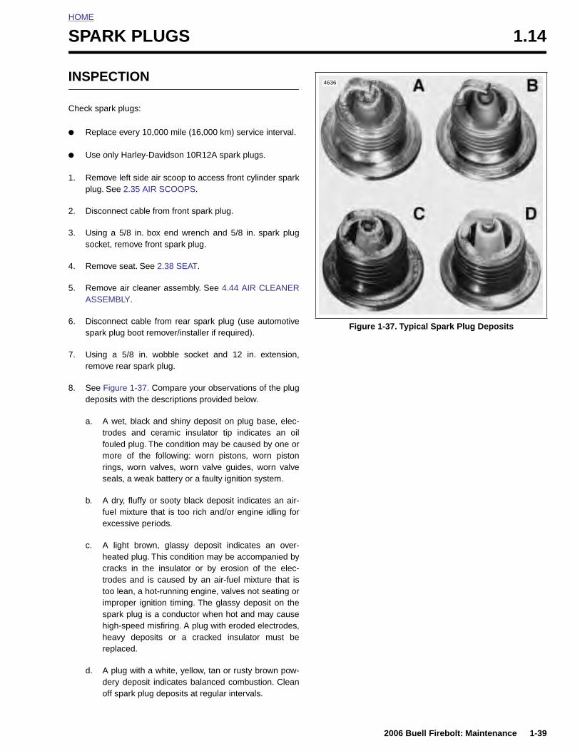
HOME
S
I
C
●
●
1
2
3
4
5
6
7
8
PARK PLUGS 1.14
NSPECTION
heck spark plugs:
Replace every 10,000 mile (16,000 km) service interval.
Use only Harley-Davidson 10R12A spark plugs.
. Remove left side air scoop to access front cylinder sparkplug. See 2.35 AIR SCOOPS.
. Disconnect cable from front spark plug.
. Using a 5/8 in. box end wrench and 5/8 in. spark plugsocket, remove front spark plug.
. Remove seat. See 2.38 SEAT.
. Remove air cleaner assembly. See 4.44 AIR CLEANERASSEMBLY.
. Disconnect cable from rear spark plug (use automotivespark plug boot remover/installer if required).
. Using a 5/8 in. wobble socket and 12 in. extension,remove rear spark plug.
. See Figure 1-37. Compare your observations of the plugdeposits with the descriptions provided below.
a. A wet, black and shiny deposit on plug base, elec-trodes and ceramic insulator tip indicates an oilfouled plug. The condition may be caused by one ormore of the following: worn pistons, worn pistonrings, worn valves, worn valve guides, worn valveseals, a weak battery or a faulty ignition system.
b. A dry, fluffy or sooty black deposit indicates an air-fuel mixture that is too rich and/or engine idling for
Figure 1-37. Typical Spark Plug Deposits
4636
2006 Buell Firebolt: Maintenance 1-39
excessive periods.
c. A light brown, glassy deposit indicates an over-heated plug. This condition may be accompanied bycracks in the insulator or by erosion of the elec-trodes and is caused by an air-fuel mixture that istoo lean, a hot-running engine, valves not seating orimproper ignition timing. The glassy deposit on thespark plug is a conductor when hot and may causehigh-speed misfiring. A plug with eroded electrodes,heavy deposits or a cracked insulator must bereplaced.
d. A plug with a white, yellow, tan or rusty brown pow-dery deposit indicates balanced combustion. Cleanoff spark plug deposits at regular intervals.
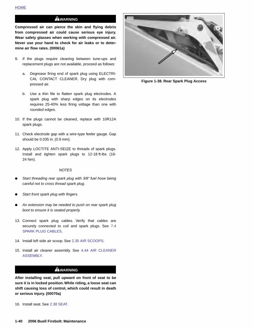
HOME
1WARNING1WARNING
8389
Compressed air can pierce the skin and flying debrisfrom compressed air could cause serious eye injury.Wear safety glasses when working with compressed air.Never use your hand to check for air leaks or to deter-mine air flow rates. (00061a)
9. If the plugs require cleaning between tune-ups andreplacement plugs are not available, proceed as follows:
a. Degrease firing end of spark plug using ELECTRI-CAL CONTACT CLEANER. Dry plug with com-pressed air.
b. Use a thin file to flatten spark plug electrodes. Aspark plug with sharp edges on its electrodesrequires 25-40% less firing voltage than one withrounded edges.
10. If the plugs cannot be cleaned, replace with 10R12Aspark plugs.
11. Check electrode gap with a wire-type feeler gauge. Gapshould be 0.035 in. (0.9 mm).
12. Apply LOCTITE ANTI-SEIZE to threads of spark plugs.Install and tighten spark plugs to 12-18 ft-lbs (16-24 Nm).
NOTES
● Start threading rear spark plug with 3/8” fuel hose beingcareful not to cross thread spark plug.
● Start front spark plug with fingers.
● An extension may be needed to push on rear spark plugboot to ensure it is seated properly.
13. Connect spark plug cables. Verify that cables aresecurely connected to coil and spark plugs. See 7.4SPARK PLUG CABLES.
14. Install left side air scoop. See 2.35 AIR SCOOPS.
Figure 1-38. Rear Spark Plug Access
1-40 2006 Buell Firebolt: Maintenance
15. Install air cleaner assembly. See 4.44 AIR CLEANERASSEMBLY.
1WARNING1WARNING
After installing seat, pull upward on front of seat to besure it is in locked position. While riding, a loose seat canshift causing loss of control, which could result in deathor serious injury. (00070a)
16. Install seat. See 2.38 SEAT.

HOME
A
R
Ice
C
●
●
●
●
1
2
IR CLEANER FILTER 1.15
EMOVAL
CAUTION
nstall air filter before running engine. Failure to do soan draw debris into the engine and could result inngine damage. (00207a)
heck air cleaner filter element:
Inspect at the 1000 mile (1600 km) service interval andat every 5000 mile (8000 km) service interval thereafter.
Replace at every 20,000 mile (32,000 km) service interval.
NOTESDo not cover or restrict the air intake screen. Certaintank bags or accessories may cover or restrict the airintake screen. This may reduce power and performance.
Inspect and replace air cleaner filter element more oftenif the motorcycle is run in a dusty environment.
. Remove seat. See 2.38 SEAT.
. Remove four fasteners, nylon washers and intake coverassembly. See 2.34 INTAKE COVER ASSEMBLY.
3. See Figure 1-40. Remove fuel vent tube (3) from vaporvalve at front of air cleaner cover and groove on top of aircleaner cover (1).
Figure 1-39. Air Intake For Functional Air Cleaner Cover
12107
Figure 1-40. Air Cleaner Cover, Fuel Vent Tube and Fuel Vapor Valve (XB12R)
12049
2
1. Air cleaner cover 2. Actuator (interactive exhaust)3. Fuel vent tube4. Cable (interactive exhaust)5. Harness (interactive exhaust)6. Air cleaner cover latch tabs7. Fuel vent valve
31 45
67
12037
2006 Buell Firebolt: Maintenance 1-41
4. See Figure 1-41. Unlatch six latching tabs and removeair cleaner cover from base plate.
Figure 1-41. Air Cleaner Cover (XB9R)
1. Air cleaner cover2. Air cleaner cover latch tabs
12
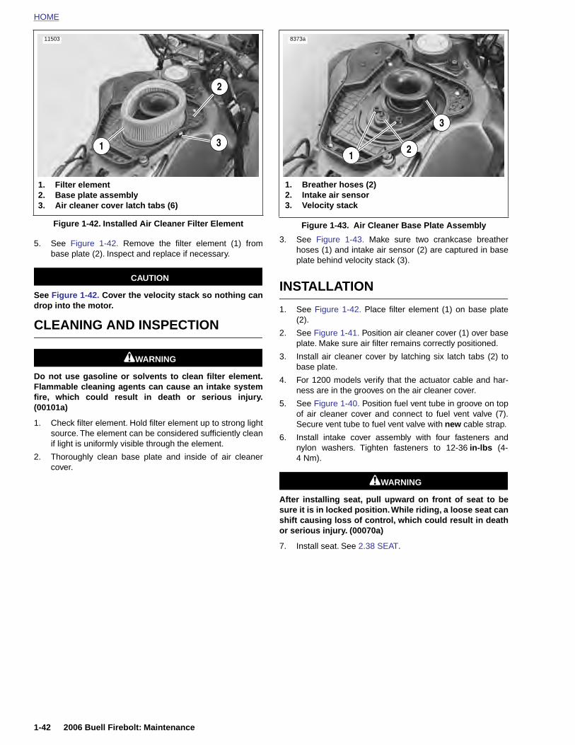
HOME
11503
8373a
5. See Figure 1-42. Remove the filter element (1) frombase plate (2). Inspect and replace if necessary.
CAUTION
See Figure 1-42. Cover the velocity stack so nothing candrop into the motor.
CLEANING AND INSPECTION
1WARNING1WARNING
Do not use gasoline or solvents to clean filter element.Flammable cleaning agents can cause an intake systemfire, which could result in death or serious injury.(00101a)
1. Check filter element. Hold filter element up to strong lightsource. The element can be considered sufficiently cleanif light is uniformly visible through the element.
2. Thoroughly clean base plate and inside of air cleanercover.
3. See Figure 1-43. Make sure two crankcase breatherhoses (1) and intake air sensor (2) are captured in baseplate behind velocity stack (3).
INSTALLATION
1. See Figure 1-42. Place filter element (1) on base plate(2).
2. See Figure 1-41. Position air cleaner cover (1) over baseplate. Make sure air filter remains correctly positioned.
3. Install air cleaner cover by latching six latch tabs (2) tobase plate.
4. For 1200 models verify that the actuator cable and har-ness are in the grooves on the air cleaner cover.
5. See Figure 1-40. Position fuel vent tube in groove on topof air cleaner cover and connect to fuel vent valve (7).Secure vent tube to fuel vent valve with new cable strap.
6. Install intake cover assembly with four fasteners andnylon washers. Tighten fasteners to 12-36 in-lbs (4-4 Nm).
1WARNING1WARNING
After installing seat, pull upward on front of seat to besure it is in locked position. While riding, a loose seat canshift causing loss of control, which could result in deathor serious injury. (00070a)
7. Install seat. See 2.38 SEAT.
Figure 1-42. Installed Air Cleaner Filter Element
1. Filter element2. Base plate assembly3. Air cleaner cover latch tabs (6)
1 3
2
Figure 1-43. Air Cleaner Base Plate Assembly
1. Breather hoses (2)2. Intake air sensor3. Velocity stack
3
21
1-42 2006 Buell Firebolt: Maintenance
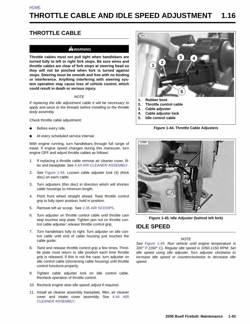
HOME
T
T
Ttttsotc
Iab
C
●
●
Wte
1
2
3
4
5
6
HROTTLE CABLE AND IDLE SPEED ADJUSTMENT 1.16
HROTTLE CABLE
1WARNING1WARNING
hrottle cables must not pull tight when handlebars areurned fully to left or right fork stops. Be sure wires andhrottle cables are clear of fork stops at steering head sohey will not be pinched when fork is turned againsttops. Steering must be smooth and free with no bindingr interference. Anything interfering with steering sys-em operation may cause loss of vehicle control, whichould result in death or serious injury.
NOTE
f replacing the idle adjustment cable it will be necessary topply anti-seize to the threads before installing to the throttleody assembly.
heck throttle cable adjustment:
Before every ride.
At every scheduled service interval.
ith engine running, turn handlebars through full range ofravel. If engine speed changes during this maneuver, turnngine OFF and adjust throttle cables as follows:
. If replacing a throttle cable remove air cleaner cover, fil-ter and baseplate. See 4.44 AIR CLEANER ASSEMBLY.
. See Figure 1-44. Loosen cable adjuster lock (4) (thickdisc) on each cable.
. Turn adjusters (thin disc) in direction which will shortencable housings to minimum length.
. Point front wheel straight ahead. Twist throttle controlgrip to fully open position; hold in position.
. Remove left air scoop. See 2.35 AIR SCOOPS.
. Turn adjuster on throttle control cable until throttle camstop touches stop plate. Tighten jam nut on throttle con-
Figure 1-44. Throttle Cable Adjusters
Figure 1-45. Idle Adjuster (behind left fork)
8401
1. Rubber boot2. Throttle control cable3. Cable adjuster4. Cable adjuster lock5. Idle control cable
1
5
432
11988
2006 Buell Firebolt: Maintenance 1-43
trol cable adjuster; release throttle control grip.
7. Turn handlebars fully to right. Turn adjuster on idle con-trol cable until end of cable housing just touches thecable guide.
8. Twist and release throttle control grip a few times. Throt-tle plate must return to idle position each time throttlegrip is released. If this is not the case, turn adjuster onidle control cable (shortening cable housing) until throttlecontrol functions properly.
9. Tighten cable adjuster lock on idle control cable.Recheck operation of throttle control.
10. Recheck engine slow idle speed; adjust if required.
11. Install air cleaner assembly baseplate, filter, air cleanercover and intake cover assembly. See 4.44 AIRCLEANER ASSEMBLY.
IDLE SPEED
NOTESee Figure 1-45. Run vehicle until engine temperature is320° F (160° C). Regular idle speed is 1050-1150 RPM. Setidle speed using idle adjuster. Turn adjuster clockwise toincrease idle speed or counterclockwise to decrease idlespeed.
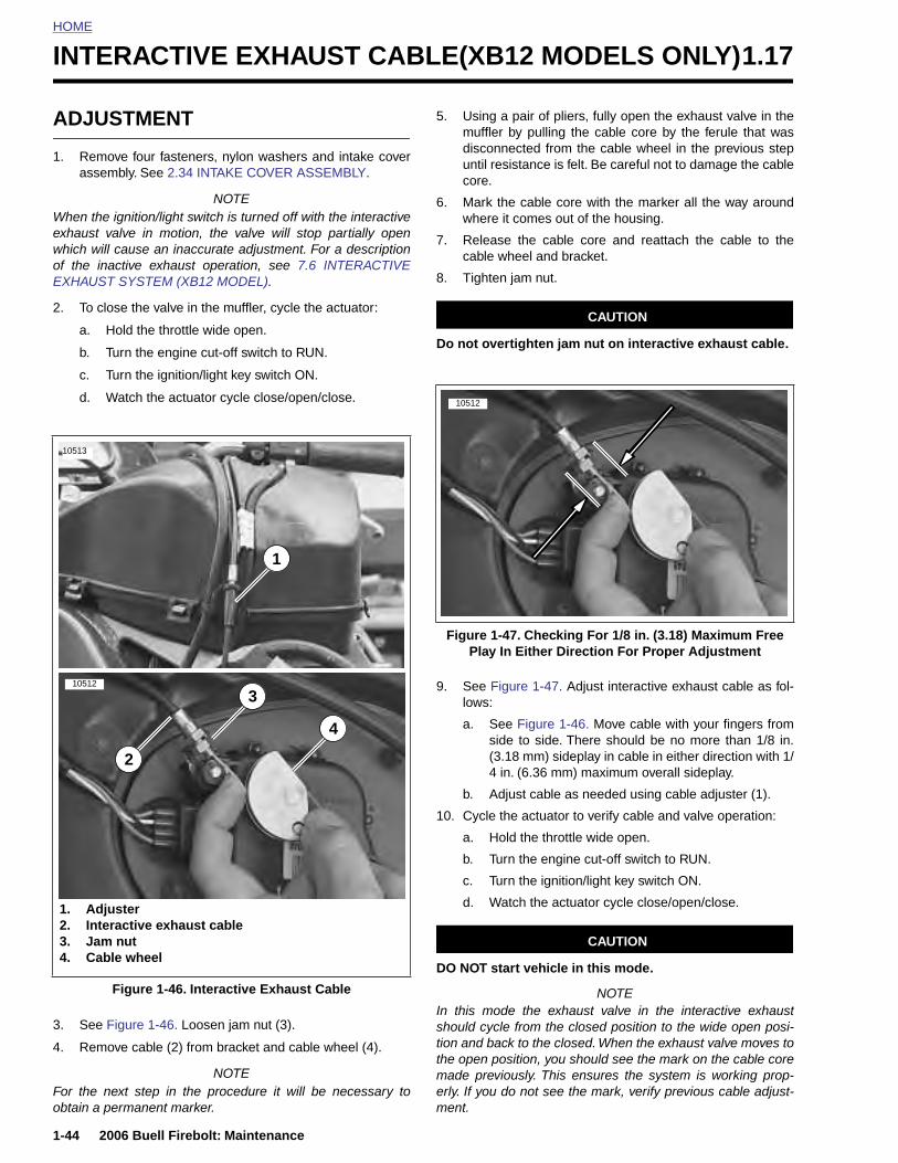
HOME
INTERACTIVE EXHAUST CABLE(XB12 MODELS ONLY)1.17
ADJU
1. Remoassem
When theexhaust vwhich willof the inaEXHAUST
2. To clo
a. H
b. T
c. T
d. W
10513
10512
1-44
3. See
4. Rem
For the obtain a
1. Ad2. Int3. Ja4. Ca
STMENT
ve four fasteners, nylon washers and intake coverbly. See 2.34 INTAKE COVER ASSEMBLY.
NOTE ignition/light switch is turned off with the interactivealve in motion, the valve will stop partially open cause an inaccurate adjustment. For a descriptionctive exhaust operation, see 7.6 INTERACTIVE SYSTEM (XB12 MODEL).
se the valve in the muffler, cycle the actuator:
old the throttle wide open.
urn the engine cut-off switch to RUN.
urn the ignition/light key switch ON.
atch the actuator cycle close/open/close.
5. Using a pair of pliers, fully open the exhaust valve in themuffler by pulling the cable core by the ferule that wasdisconnected from the cable wheel in the previous stepuntil resistance is felt. Be careful not to damage the cablecore.
6. Mark the cable core with the marker all the way aroundwhere it comes out of the housing.
7. Release the cable core and reattach the cable to thecable wheel and bracket.
8. Tighten jam nut.
CAUTION
Do not overtighten jam nut on interactive exhaust cable.
9. See Figure 1-47. Adjust interactive exhaust cable as fol-lows:
a. See Figure 1-46. Move cable with your fingers fromside to side. There should be no more than 1/8 in.(3.18 mm) sideplay in cable in either direction with 1/4 in. (6.36 mm) maximum overall sideplay.
b. Adjust cable as needed using cable adjuster (1).
10. Cycle the actuator to verify cable and valve operation:
a. Hold the throttle wide open.
4
3
1
2
Figure 1-47. Checking For 1/8 in. (3.18) Maximum Free Play In Either Direction For Proper Adjustment
10512
2006 Buell Firebolt: Maintenance
Figure 1-46. Loosen jam nut (3).
ove cable (2) from bracket and cable wheel (4).
NOTEnext step in the procedure it will be necessary to permanent marker.
b. Turn the engine cut-off switch to RUN.
c. Turn the ignition/light key switch ON.
d. Watch the actuator cycle close/open/close.
CAUTION
DO NOT start vehicle in this mode.
NOTEIn this mode the exhaust valve in the interactive exhaustshould cycle from the closed position to the wide open posi-tion and back to the closed. When the exhaust valve moves tothe open position, you should see the mark on the cable coremade previously. This ensures the system is working prop-erly. If you do not see the mark, verify previous cable adjust-ment.
Figure 1-46. Interactive Exhaust Cable
justereractive exhaust cablem nutble wheel
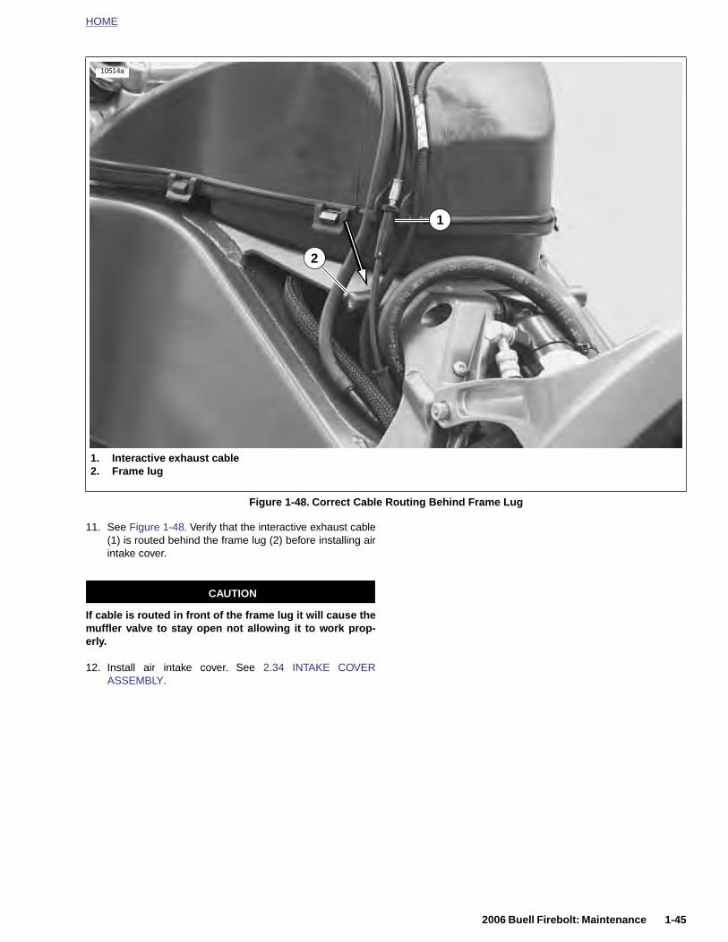
HOME
11. See Figure 1-48. Verify that the interactive exhaust cable(1) is routed behind the frame lug (2) before installing airintake cover.
CAUTION
If cable is routed in front of the frame lug it will cause themuffler valve to stay open not allowing it to work prop-erly.
Figure 1-48. Correct Cable Routing Behind Frame Lug
10514a
1. Interactive exhaust cable2. Frame lug
2
1
2006 Buell Firebolt: Maintenance 1-45
12. Install air intake cover. See 2.34 INTAKE COVERASSEMBLY.
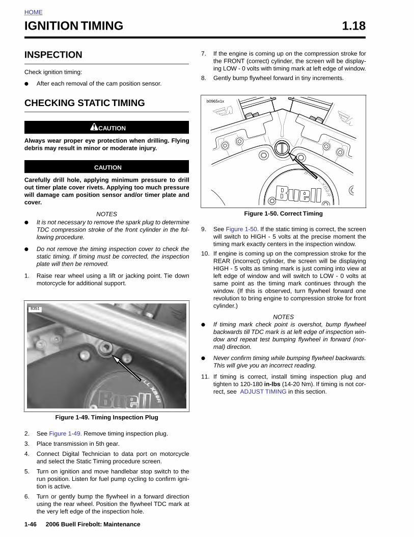
HOME
IGNITION TIMING 1.18
INSPE
Check ign
● After
CHEC
Always wdebris ma
Carefullyout timerwill damacover.
● It is nTDC lowin
● Do nostaticplate
1. Raisemoto
8351
1-46
2. See
3. Pla
4. Conand
5. Turnruntion
6. Turnusinthe
CTION
ition timing:
each removal of the cam position sensor.
KING STATIC TIMING
1CAUTION
ear proper eye protection when drilling. Flyingy result in minor or moderate injury.
CAUTION
drill hole, applying minimum pressure to drill plate cover rivets. Applying too much pressurege cam position sensor and/or timer plate and
NOTESot necessary to remove the spark plug to determinecompression stroke of the front cylinder in the fol-g procedure.
t remove the timing inspection cover to check the timing. If timing must be corrected, the inspectionwill then be removed.
rear wheel using a lift or jacking point. Tie downrcycle for additional support.
7. If the engine is coming up on the compression stroke forthe FRONT (correct) cylinder, the screen will be display-ing LOW - 0 volts with timing mark at left edge of window.
8. Gently bump flywheel forward in tiny increments.
9. See Figure 1-50. If the static timing is correct, the screenwill switch to HIGH - 5 volts at the precise moment thetiming mark exactly centers in the inspection window.
10. If engine is coming up on the compression stroke for theREAR (incorrect) cylinder, the screen will be displayingHIGH - 5 volts as timing mark is just coming into view atleft edge of window and will switch to LOW - 0 volts atsame point as the timing mark continues through thewindow. (If this is observed, turn flywheel forward onerevolution to bring engine to compression stroke for frontcylinder.)
NOTES● If timing mark check point is overshot, bump flywheel
backwards till TDC mark is at left edge of inspection win-dow and repeat test bumping flywheel in forward (nor-mal) direction.
● Never confirm timing while bumping flywheel backwards.This will give you an incorrect reading.
11. If timing is correct, install timing inspection plug andtighten to 120-180 in-lbs (14-20 Nm). If timing is not cor-rect, see ADJUST TIMING in this section.
Figure 1-50. Correct Timing
b0965x1x
2006 Buell Firebolt: Maintenance
Figure 1-49. Remove timing inspection plug.
ce transmission in 5th gear.
nect Digital Technician to data port on motorcycle select the Static Timing procedure screen.
on ignition and move handlebar stop switch to the position. Listen for fuel pump cycling to confirm igni- is active.
or gently bump the flywheel in a forward directiong the rear wheel. Position the flywheel TDC mark atvery left edge of the inspection hole.
Figure 1-49. Timing Inspection Plug
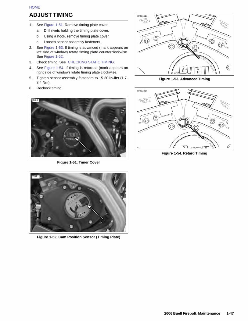
HOME
ADJUST TIMING
1. See Figure 1-51. Remove timing plate cover.
a. Drill rivets holding the timing plate cover.
b. Using a hook, remove timing plate cover.
c. Loosen sensor assembly fasteners.
2. See Figure 1-53. If timing is advanced (mark appears onleft side of window) rotate timing plate counterclockwise.See Figure 1-52.
3. Check timing. See CHECKING STATIC TIMING.
4. See Figure 1-54. If timing is retarded (mark appears onright side of window) rotate timing plate clockwise.
5. Tighten sensor assembly fasteners to 15-30 in-lbs (1.7-3.4 Nm).
6. Recheck timing.
Figure 1-51. Timer Cover
8363
8391
Figure 1-53. Advanced Timing
Figure 1-54. Retard Timing
b0964x1x
b0963x1x
2006 Buell Firebolt: Maintenance 1-47
Figure 1-52. Cam Position Sensor (Timing Plate)

HOME
HEADLIGHTS 1.19
INSPE
Do not mthe automimportanhave hearesulting
Check hea
● When
● When
1. In a screefloor.
2. See Ffrom front
3. VerifyAND
4. LoadWeig
5. Standforwa
6. Chec
a. Sh
b. T
c. Crli
d. Aw
1-48
7. Che
a.
Low bea
b.
c.
CTION
1WARNING1WARNING
odify ignition/light switch wiring to circumventatic-on headlight feature. High visibility is an
t consideration for motorcycle riders. Failure todlight on at all times could cause an accident, in death or serious injury.
dlights for proper alignment:
the new owner takes delivery of the motorcycle.
there is a change in load (adding luggage, etc.).
location with low light, draw a horizontal line on an or wall that measures 34-36 in. (86-91 cm) above
igure 1-55. Position motorcycle 25 ft (7.6 m) awaya screen or wall by measure the distance from theaxle to the screen/wall.
correct front and rear tire pressure. See 1.8 TIRESWHEELS.
vehicle with rider/passenger/cargo/accessories.ht will compress vehicle suspension slightly.
motorcycle upright with front fairing aimed straightrd.
k LOW beam (right lens) for alignment.
ee Figure 1-56. Turn ignition switch to IGN. Setandlebar headlamp switch to LOW beam position.
urn engine stop switch to the run position.
heck that the correct pattern of light is a doubleectangular pattern and is aligned with the horizontalne as shown in Figure 1-55.
djust headlight alignment. See ADJUSTMENThich follows.
Figure 1-55. Checking Headlight Alignment
Position Motorcycle25 ft (7.6 m)
b0949x1x
Horizontal Line34-36 in.
(86-91 cm)
High Beam
Low Beam
Horizontal Line34-36 in.
(86-91 cm)
Position Motorcycle25 ft (7.6 m)
8370
1
2006 Buell Firebolt: Maintenance
ck HIGH beam (left lens) for alignment.
See Figure 1-56. Set handlebar headlamp switch toHIGH beam position.
NOTE
m lamp will stay illuminated.
Check that the correct pattern of light is a circularpattern and is centered on the horizontal line asshown in Figure 1-55.
Adjust headlamp alignment. See ADJUSTMENTsection.
Figure 1-56. Headlamp Switch
2
1. High beam2. Low beam
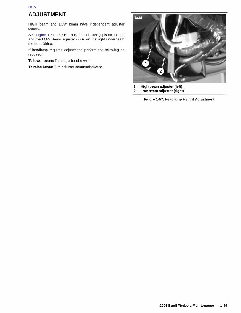
HOME
ADJUSTMENT
HIGH beam and LOW beam have independent adjusterscrews.
See Figure 1-57. The HIGH Beam adjuster (1) is on the leftand the LOW Beam adjuster (2) is on the right underneaththe front fairing.
If headlamp requires adjustment, perform the following asrequired:
To lower beam: Turn adjuster clockwise.
To raise beam: Turn adjuster counterclockwise.
Figure 1-57. Headlamp Height Adjustment
8392
1
2
1. High beam adjuster (left)2. Low beam adjuster (right)
2006 Buell Firebolt: Maintenance 1-49
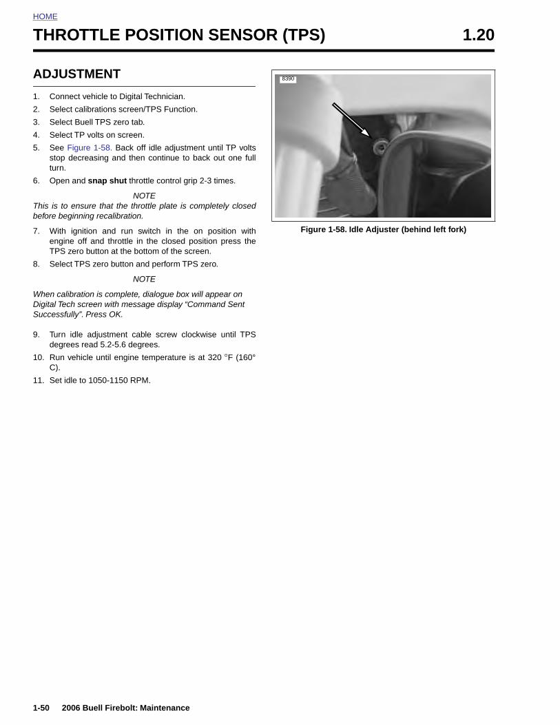
HOME
THROTTLE POSITION SENSOR (TPS) 1.20
ADJU
1. Conn
2. Selec
3. Selec
4. Selec
5. See Fstop turn.
6. Open
This is to before beg
7. With enginTPS
8. Selec
When caliDigital TecSuccessfu
9. Turn degre
10. Run vC).
11. Set id
1-50
STMENT
ect vehicle to Digital Technician.
t calibrations screen/TPS Function.
t Buell TPS zero tab.
t TP volts on screen.
igure 1-58. Back off idle adjustment until TP voltsdecreasing and then continue to back out one full
and snap shut throttle control grip 2-3 times.
NOTEensure that the throttle plate is completely closedinning recalibration.
ignition and run switch in the on position withe off and throttle in the closed position press thezero button at the bottom of the screen.
t TPS zero button and perform TPS zero.
NOTE
bration is complete, dialogue box will appear on h screen with message display “Command Sent lly”. Press OK.
idle adjustment cable screw clockwise until TPSes read 5.2-5.6 degrees.
ehicle until engine temperature is at 320 °F (160°
le to 1050-1150 RPM.
Figure 1-58. Idle Adjuster (behind left fork)
8390
2006 Buell Firebolt: Maintenance
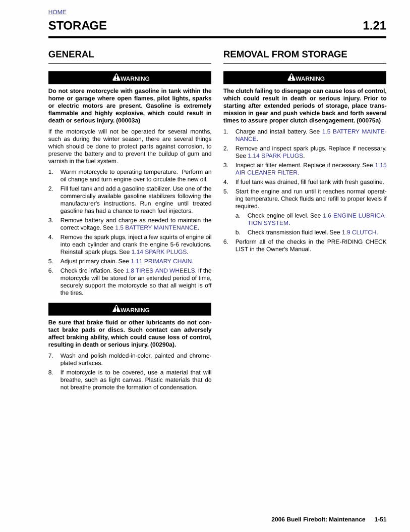
HOME
S
G
Dhofld
Iswpv
1
2
3
4
5
6
Btar
7
TORAGE 1.21
ENERAL
1WARNING1WARNING
o not store motorcycle with gasoline in tank within theome or garage where open flames, pilot lights, sparksr electric motors are present. Gasoline is extremelyammable and highly explosive, which could result ineath or serious injury. (00003a)
f the motorcycle will not be operated for several months,uch as during the winter season, there are several thingshich should be done to protect parts against corrosion, toreserve the battery and to prevent the buildup of gum andarnish in the fuel system.
. Warm motorcycle to operating temperature. Perform anoil change and turn engine over to circulate the new oil.
. Fill fuel tank and add a gasoline stabilizer. Use one of thecommercially available gasoline stabilizers following themanufacturer’s instructions. Run engine until treatedgasoline has had a chance to reach fuel injectors.
. Remove battery and charge as needed to maintain thecorrect voltage. See 1.5 BATTERY MAINTENANCE.
. Remove the spark plugs, inject a few squirts of engine oilinto each cylinder and crank the engine 5-6 revolutions.Reinstall spark plugs. See 1.14 SPARK PLUGS.
. Adjust primary chain. See 1.11 PRIMARY CHAIN.
. Check tire inflation. See 1.8 TIRES AND WHEELS. If themotorcycle will be stored for an extended period of time,securely support the motorcycle so that all weight is offthe tires.
1WARNING1WARNING
e sure that brake fluid or other lubricants do not con-act brake pads or discs. Such contact can adverselyffect braking ability, which could cause loss of control,esulting in death or serious injury. (00290a).
. Wash and polish molded-in-color, painted and chrome-plated surfaces.
REMOVAL FROM STORAGE
1WARNING1WARNING
The clutch failing to disengage can cause loss of control,which could result in death or serious injury. Prior tostarting after extended periods of storage, place trans-mission in gear and push vehicle back and forth severaltimes to assure proper clutch disengagement. (00075a)
1. Charge and install battery. See 1.5 BATTERY MAINTE-NANCE.
2. Remove and inspect spark plugs. Replace if necessary.See 1.14 SPARK PLUGS.
3. Inspect air filter element. Replace if necessary. See 1.15AIR CLEANER FILTER.
4. If fuel tank was drained, fill fuel tank with fresh gasoline.
5. Start the engine and run until it reaches normal operat-ing temperature. Check fluids and refill to proper levels ifrequired.
a. Check engine oil level. See 1.6 ENGINE LUBRICA-TION SYSTEM.
b. Check transmission fluid level. See 1.9 CLUTCH.
6. Perform all of the checks in the PRE-RIDING CHECKLIST in the Owner’s Manual.
2006 Buell Firebolt: Maintenance 1-51
8. If motorcycle is to be covered, use a material that willbreathe, such as light canvas. Plastic materials that donot breathe promote the formation of condensation.
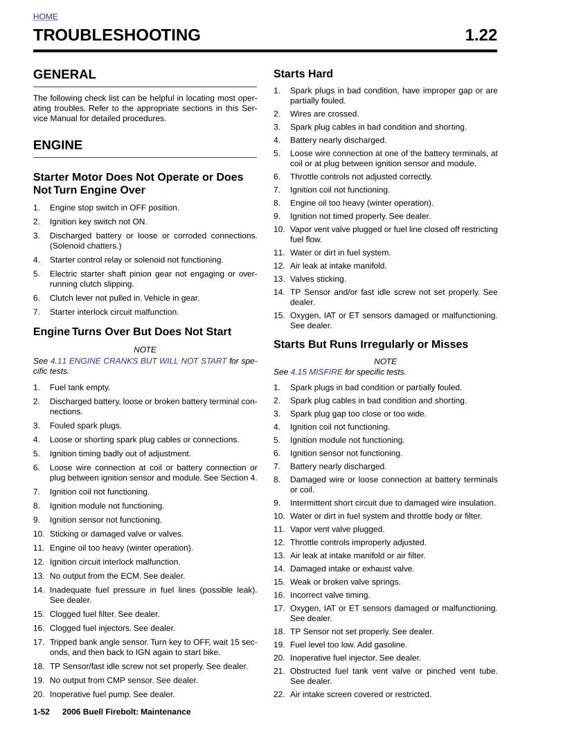
HOME
TROUBLESHOOTING 1.22
GENE
The followating trouvice Manu
ENGIN
StarterNot Tur
1. Engin
2. Ignitio
3. Disch(Sole
4. Starte
5. Electrunni
6. Clutc
7. Starte
Engine
See 4.11 cific tests.
1. Fuel
2. Dischnectio
3. Foule
4. Loose
5. Ignitio
6. Looseplug b
7. Ignitio
8. Ignitio
9. Ignitio
10. Sticki
1-52
11. Eng
12. Igni
13. No
14. InadSee
15. Clo
16. Clo
17. Tripond
18. TP
19. No
20. Inop
RAL
ing check list can be helpful in locating most oper-bles. Refer to the appropriate sections in this Ser-al for detailed procedures.
E
Motor Does Not Operate or Does n Engine Over
e stop switch in OFF position.
n key switch not ON.
arged battery or loose or corroded connections.noid chatters.)
r control relay or solenoid not functioning.
ric starter shaft pinion gear not engaging or over-ng clutch slipping.
h lever not pulled in. Vehicle in gear.
r interlock circuit malfunction.
Turns Over But Does Not Start
NOTEENGINE CRANKS BUT WILL NOT START for spe-
tank empty.
arged battery, loose or broken battery terminal con-ns.
d spark plugs.
or shorting spark plug cables or connections.
n timing badly out of adjustment.
wire connection at coil or battery connection oretween ignition sensor and module. See Section 4.
n coil not functioning.
n module not functioning.
n sensor not functioning.
ng or damaged valve or valves.
Starts Hard1. Spark plugs in bad condition, have improper gap or are
partially fouled.
2. Wires are crossed.
3. Spark plug cables in bad condition and shorting.
4. Battery nearly discharged.
5. Loose wire connection at one of the battery terminals, atcoil or at plug between ignition sensor and module.
6. Throttle controls not adjusted correctly.
7. Ignition coil not functioning.
8. Engine oil too heavy (winter operation).
9. Ignition not timed properly. See dealer.
10. Vapor vent valve plugged or fuel line closed off restrictingfuel flow.
11. Water or dirt in fuel system.
12. Air leak at intake manifold.
13. Valves sticking.
14. TP Sensor and/or fast idle screw not set properly. Seedealer.
15. Oxygen, IAT or ET sensors damaged or malfunctioning.See dealer.
Starts But Runs Irregularly or MissesNOTE
See 4.15 MISFIRE for specific tests.
1. Spark plugs in bad condition or partially fouled.
2. Spark plug cables in bad condition and shorting.
3. Spark plug gap too close or too wide.
4. Ignition coil not functioning.
5. Ignition module not functioning.
6. Ignition sensor not functioning.
7. Battery nearly discharged.
8. Damaged wire or loose connection at battery terminalsor coil.
9. Intermittent short circuit due to damaged wire insulation.
10. Water or dirt in fuel system and throttle body or filter.
11. Vapor vent valve plugged.
2006 Buell Firebolt: Maintenance
ine oil too heavy (winter operation).
tion circuit interlock malfunction.
output from the ECM. See dealer.
equate fuel pressure in fuel lines (possible leak). dealer.
gged fuel filter. See dealer.
gged fuel injectors. See dealer.
ped bank angle sensor. Turn key to OFF, wait 15 sec-s, and then back to IGN again to start bike.
Sensor/fast idle screw not set properly. See dealer.
output from CMP sensor. See dealer.
erative fuel pump. See dealer.
12. Throttle controls improperly adjusted.
13. Air leak at intake manifold or air filter.
14. Damaged intake or exhaust valve.
15. Weak or broken valve springs.
16. Incorrect valve timing.
17. Oxygen, IAT or ET sensors damaged or malfunctioning.See dealer.
18. TP Sensor not set properly. See dealer.
19. Fuel level too low. Add gasoline.
20. Inoperative fuel injector. See dealer.
21. Obstructed fuel tank vent valve or pinched vent tube.See dealer.
22. Air intake screen covered or restricted.
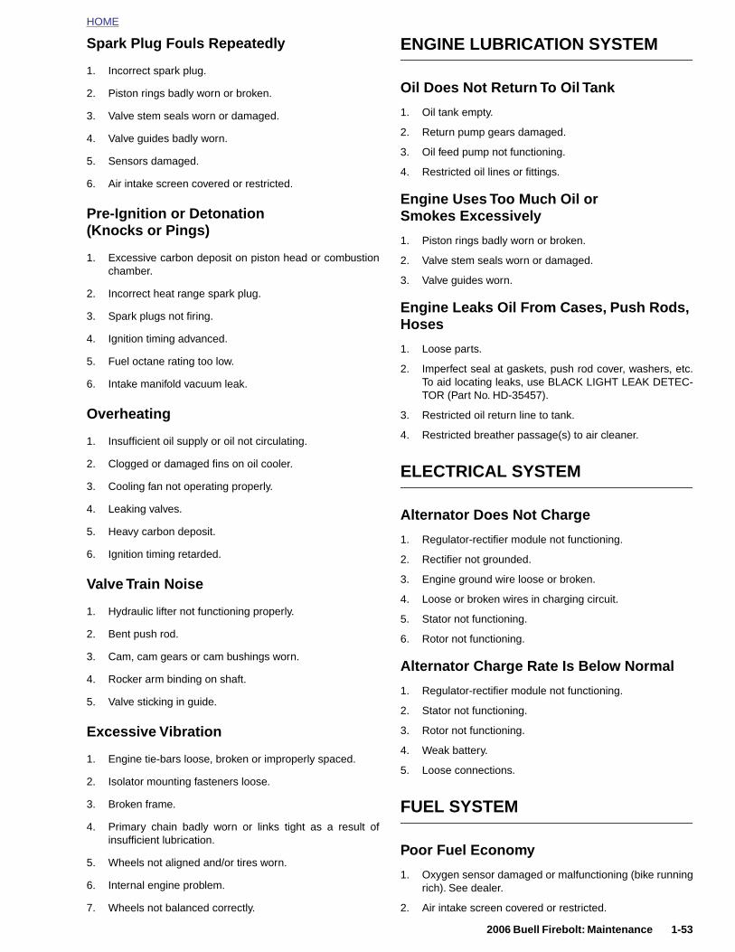
HOME
Spark Plug Fouls Repeatedly
1. Incorrect spark plug.
2. Piston rings badly worn or broken.
3. Valve stem seals worn or damaged.
4. Valve guides badly worn.
5. Sensors damaged.
6. Air intake screen covered or restricted.
Pre-Ignition or Detonation(Knocks or Pings)
1. Excessive carbon deposit on piston head or combustionchamber.
2. Incorrect heat range spark plug.
3. Spark plugs not firing.
4. Ignition timing advanced.
5. Fuel octane rating too low.
6. Intake manifold vacuum leak.
Overheating
1. Insufficient oil supply or oil not circulating.
2. Clogged or damaged fins on oil cooler.
3. Cooling fan not operating properly.
4. Leaking valves.
5. Heavy carbon deposit.
6. Ignition timing retarded.
Valve Train Noise
1. Hydraulic lifter not functioning properly.
2. Bent push rod.
ENGINE LUBRICATION SYSTEM
Oil Does Not Return To Oil Tank
1. Oil tank empty.
2. Return pump gears damaged.
3. Oil feed pump not functioning.
4. Restricted oil lines or fittings.
Engine Uses Too Much Oil or Smokes Excessively
1. Piston rings badly worn or broken.
2. Valve stem seals worn or damaged.
3. Valve guides worn.
Engine Leaks Oil From Cases, Push Rods, Hoses
1. Loose parts.
2. Imperfect seal at gaskets, push rod cover, washers, etc.To aid locating leaks, use BLACK LIGHT LEAK DETEC-TOR (Part No. HD-35457).
3. Restricted oil return line to tank.
4. Restricted breather passage(s) to air cleaner.
ELECTRICAL SYSTEM
Alternator Does Not Charge
1. Regulator-rectifier module not functioning.
2. Rectifier not grounded.
3. Engine ground wire loose or broken.
4. Loose or broken wires in charging circuit.
5. Stator not functioning.
6. Rotor not functioning.
2006 Buell Firebolt: Maintenance 1-53
3. Cam, cam gears or cam bushings worn.
4. Rocker arm binding on shaft.
5. Valve sticking in guide.
Excessive Vibration
1. Engine tie-bars loose, broken or improperly spaced.
2. Isolator mounting fasteners loose.
3. Broken frame.
4. Primary chain badly worn or links tight as a result ofinsufficient lubrication.
5. Wheels not aligned and/or tires worn.
6. Internal engine problem.
7. Wheels not balanced correctly.
Alternator Charge Rate Is Below Normal
1. Regulator-rectifier module not functioning.
2. Stator not functioning.
3. Rotor not functioning.
4. Weak battery.
5. Loose connections.
FUEL SYSTEM
Poor Fuel Economy
1. Oxygen sensor damaged or malfunctioning (bike runningrich). See dealer.
2. Air intake screen covered or restricted.
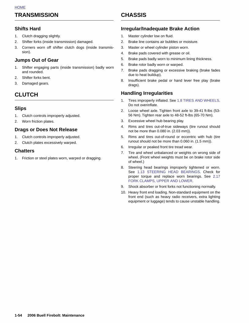
HOME
TRANSMISSION CHASSIS
Shifts Hard1. Clutch dragging slightly.
2. Shifter forks (inside transmission) damaged.
3. Corners worn off shifter clutch dogs (inside transmis-sion).
Jumps Out of Gear1. Shifter engaging parts (inside transmission) badly worn
and rounded.
2. Shifter forks bent.
3. Damaged gears.
CLUTCH
Slips1. Clutch controls improperly adjusted.
2. Worn friction plates.
Drags or Does Not Release1. Clutch controls improperly adjusted.
2. Clutch plates excessively warped.
Chatters1. Friction or steel plates worn, warped or dragging.
Irregular/Inadequate Brake Action1. Master cylinder low on fluid.
2. Brake line contains air bubbles or moisture.
3. Master or wheel cylinder piston worn.
4. Brake pads covered with grease or oil.
5. Brake pads badly worn to minimum lining thickness.
6. Brake rotor badly worn or warped.
7. Brake pads dragging or excessive braking (brake fadesdue to heat buildup).
8. Insufficient brake pedal or hand lever free play (brakedrags).
Handling Irregularities1. Tires improperly inflated. See 1.8 TIRES AND WHEELS.
Do not overinflate.
2. Loose wheel axle. Tighten front axle to 39-41 ft-lbs (53-56 Nm). Tighten rear axle to 48-52 ft-lbs (65-70 Nm).
3. Excessive wheel hub bearing play.
4. Rims and tires out-of-true sideways (tire runout shouldnot be more than 0.080 in. (2.03 mm)).
5. Rims and tires out-of-round or eccentric with hub (tirerunout should not be more than 0.060 in. (1.5 mm)).
6. Irregular or peaked front tire tread wear.
7. Tire and wheel unbalanced or weights on wrong side ofwheel. (Front wheel weights must be on brake rotor sideof wheel.)
8. Steering head bearings improperly tightened or worn.See 1.13 STEERING HEAD BEARINGS. Check forproper torque and replace worn bearings. See 2.17FORK CLAMPS, UPPER AND LOWER.
9. Shock absorber or front forks not functioning normally.
10. Heavy front end loading. Non-standard equipment on thefront end (such as heavy radio receivers, extra lightingequipment or luggage) tends to cause unstable handling.
1-54 2006 Buell Firebolt: Maintenance
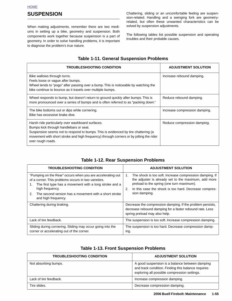
HOME
SUSPENSION
When making adjustments, remember there are two medi-ums in setting up a bike, geometry and suspension. Bothcomponents work together because suspension is a part ofgeometry. In order to solve handling problems, it is importantto diagnose the problem’s true nature.
Chattering, sliding or an uncomfortable feeling are suspen-sion-related. Handling and a swinging fork are geometry-related, but often these unwanted characteristics can besolved by suspension adjustments.
The following tables list possible suspension and operatingtroubles and their probable causes.
Table 1-11. General Suspension Problems
TROUBLESHOOTING CONDITION ADJUSTMENT SOLUTION
Bike wallows through turns.Feels loose or vague after bumps.Wheel tends to “pogo” after passing over a bump. This is noticeable by watching the bike continue to bounce as it travels over multiple bumps.
Increase rebound damping.
Wheel responds to bump, but doesn’t return to ground quickly after bumps. This is more pronounced over a series of bumps and is often referred to as “packing down.”
Reduce rebound damping.
The bike bottoms out or dips while cornering.Bike has excessive brake dive.
Increase compression damping.
Harsh ride particularly over washboard surfaces.Bumps kick through handlebars or seat.Suspension seems not to respond to bumps. This is evidenced by tire chattering (a movement with short stroke and high frequency) through corners or by jolting the rider over rough roads.
Reduce compression damping.
Table 1-12. Rear Suspension Problems
TROUBLESHOOTING CONDITION ADJUSTMENT SOLUTION
“Pumping on the Rear” occurs when you are accelerating out of a corner. This problems occurs in two varieties.1. The first type has a movement with a long stroke and a
high frequency.
2. The second version has a movement with a short strokeand high frequency.
1. The shock is too soft. Increase compression damping. Ifthe adjuster is already set to the maximum, add morepreload to the spring (one turn maximum).
2. In this case the shock is too hard. Decrease compres-sion damping.
Chattering during braking. Decrease the compression damping. If the problem persists,
2006 Buell Firebolt: Maintenance 1-55
decrease rebound damping for a faster rebound rate. Less spring preload may also help.
Lack of tire feedback. The suspension is too soft. Increase compression damping.
Sliding during cornering. Sliding may occur going into the corner or accelerating out of the corner.
The suspension is too hard. Decrease compression damp-ing.
Table 1-13. Front Suspension Problems
TROUBLESHOOTING CONDITION ADJUSTMENT SOLUTION
Not absorbing bumps. A good suspension is a balance between damping and track condition. Finding this balance requires exploring all possible compression settings.
Lack of tire feedback. Increase compression damping.
Tire slides. Decrease compression damping.
HOME
NOTES
1-56
2006 Buell Firebolt: Maintenance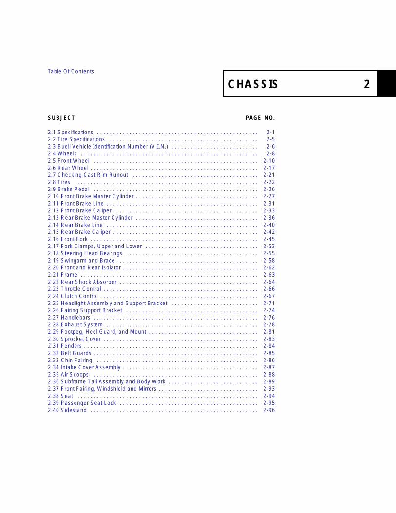
SUBJECT
2.1 Specifications . . . . .2.2 Tire Specifications .2.3 Buell Vehicle Identifi2.4 Wheels . . . . . . . . . .2.5 Front Wheel . . . . . .2.6 Rear Wheel . . . . . . .2.7 Checking Cast Rim R2.8 Tires . . . . . . . . . . . .2.9 Brake Pedal . . . . . .2.10 Front Brake Master2.11 Front Brake Line . .2.12 Front Brake Caliper2.13 Rear Brake Master 2.14 Rear Brake Line . .2.15 Rear Brake Caliper2.16 Front Fork . . . . . . .2.17 Fork Clamps, Uppe2.18 Steering Head Bea2.19 Swingarm and Brac2.20 Front and Rear Isol2.21 Frame . . . . . . . . . .2.22 Rear Shock Absorb2.23 Throttle Control . . .2.24 Clutch Control . . . .2.25 Headlight Assembly2.26 Fairing Support Bra2.27 Handlebars . . . . . .2.28 Exhaust System . .2.29 Footpeg, Heel Gua2.30 Sprocket Cover . . .2.31 Fenders . . . . . . . . .2.32 Belt Guards . . . . . .2.33 Chin Fairing . . . . .2.34 Intake Cover Assem2.35 Air Scoops . . . . . .2.36 Subframe Tail Asse2.37 Front Fairing, Wind2.38 Seat . . . . . . . . . . .2.39 Passenger Seat Lo2.40 Sidestand . . . . . . .
CHASSIS 2
Table Of Contents
PAGE NO.
. . . . . . . . . . . . . . . . . . . . . . . . . . . . . . . . . . . . . . . . . . . . . 2-1 . . . . . . . . . . . . . . . . . . . . . . . . . . . . . . . . . . . . . . . . . . . . . 2-5cation Number (V.I.N.) . . . . . . . . . . . . . . . . . . . . . . . . . . . 2-6 . . . . . . . . . . . . . . . . . . . . . . . . . . . . . . . . . . . . . . . . . . . . . 2-8 . . . . . . . . . . . . . . . . . . . . . . . . . . . . . . . . . . . . . . . . . . . . . 2-10 . . . . . . . . . . . . . . . . . . . . . . . . . . . . . . . . . . . . . . . . . . . . . 2-17unout . . . . . . . . . . . . . . . . . . . . . . . . . . . . . . . . . . . . . . . 2-21
. . . . . . . . . . . . . . . . . . . . . . . . . . . . . . . . . . . . . . . . . . . . . 2-22 . . . . . . . . . . . . . . . . . . . . . . . . . . . . . . . . . . . . . . . . . . . . . 2-26 Cylinder . . . . . . . . . . . . . . . . . . . . . . . . . . . . . . . . . . . . . . 2-27 . . . . . . . . . . . . . . . . . . . . . . . . . . . . . . . . . . . . . . . . . . . . . 2-31 . . . . . . . . . . . . . . . . . . . . . . . . . . . . . . . . . . . . . . . . . . . . . 2-33Cylinder . . . . . . . . . . . . . . . . . . . . . . . . . . . . . . . . . . . . . . 2-36 . . . . . . . . . . . . . . . . . . . . . . . . . . . . . . . . . . . . . . . . . . . . . 2-40 . . . . . . . . . . . . . . . . . . . . . . . . . . . . . . . . . . . . . . . . . . . . . 2-42 . . . . . . . . . . . . . . . . . . . . . . . . . . . . . . . . . . . . . . . . . . . . . 2-45r and Lower . . . . . . . . . . . . . . . . . . . . . . . . . . . . . . . . . . . 2-53rings . . . . . . . . . . . . . . . . . . . . . . . . . . . . . . . . . . . . . . . . . 2-55e . . . . . . . . . . . . . . . . . . . . . . . . . . . . . . . . . . . . . . . . . . . 2-58ator . . . . . . . . . . . . . . . . . . . . . . . . . . . . . . . . . . . . . . . . . . 2-62 . . . . . . . . . . . . . . . . . . . . . . . . . . . . . . . . . . . . . . . . . . . . . 2-63er . . . . . . . . . . . . . . . . . . . . . . . . . . . . . . . . . . . . . . . . . . . 2-64 . . . . . . . . . . . . . . . . . . . . . . . . . . . . . . . . . . . . . . . . . . . . . 2-66 . . . . . . . . . . . . . . . . . . . . . . . . . . . . . . . . . . . . . . . . . . . . . 2-67 and Support Bracket . . . . . . . . . . . . . . . . . . . . . . . . . . . 2-71cket . . . . . . . . . . . . . . . . . . . . . . . . . . . . . . . . . . . . . . . . . 2-74 . . . . . . . . . . . . . . . . . . . . . . . . . . . . . . . . . . . . . . . . . . . . . 2-76 . . . . . . . . . . . . . . . . . . . . . . . . . . . . . . . . . . . . . . . . . . . . . 2-78rd, and Mount . . . . . . . . . . . . . . . . . . . . . . . . . . . . . . . . . . 2-81 . . . . . . . . . . . . . . . . . . . . . . . . . . . . . . . . . . . . . . . . . . . . . 2-83 . . . . . . . . . . . . . . . . . . . . . . . . . . . . . . . . . . . . . . . . . . . . . 2-84
. . . . . . . . . . . . . . . . . . . . . . . . . . . . . . . . . . . . . . . . . . . . . 2-85 . . . . . . . . . . . . . . . . . . . . . . . . . . . . . . . . . . . . . . . . . . . . . 2-86bly . . . . . . . . . . . . . . . . . . . . . . . . . . . . . . . . . . . . . . . . . . 2-87. . . . . . . . . . . . . . . . . . . . . . . . . . . . . . . . . . . . . . . . . . . . . 2-88mbly and Body Work . . . . . . . . . . . . . . . . . . . . . . . . . . . . 2-89shield and Mirrors . . . . . . . . . . . . . . . . . . . . . . . . . . . . . . . 2-93 . . . . . . . . . . . . . . . . . . . . . . . . . . . . . . . . . . . . . . . . . . . . . 2-94ck . . . . . . . . . . . . . . . . . . . . . . . . . . . . . . . . . . . . . . . . . . . 2-95 . . . . . . . . . . . . . . . . . . . . . . . . . . . . . . . . . . . . . . . . . . . . . 2-96


HOME
S
GloRo
PECIFICATIONS 2.1
NOTEross Vehicle Weight Rating (GVWR) (maximum allowableaded vehicle weight) and corresponding Gross Axle Weightatings (GAWR) are given on an information decal locatedn the steering head.
Table 2-1. Dimensions
XB9R XB12R
DIMENSIONS IN. MM IN. MM
Wheel base 52.0 1320 52.0 1320
Seat height (XB9R/XB12R) 30.5 775 30.5 775
Ground clearance 4.35 110 4.35 110
Trail 3.3 83 3.3 83
Rake 21 Degrees 21 Degrees
Table 2-2. Weight Specifications
XB9R XB12R
WEIGHT-U.S. MODELS LBS. KG LBS. KG
Wet weight 452 205 462 210
GVWR 850 386 850 386
GAWR - front 325 147 325 147
GAWR - rear 525 238 525 238
Load capacity 398 181 388 176
Table 2-3. Capacities
CAPACITIES U.S. LITERS
Fuel tank (inc. reserve) 3.82 gal-lons
14.5
Table 2-5. Tire and Positions
TIRE AND POSITION SOLO
RIDINGGVWR
FrontDunlop Sportmax Radial II 120/70 ZR 17 D208FW
36 PSI(248 kPa)
Same as SoloRear
Dunlop Sportmax Radial II 38 PSI(262 kPa)
2006 Buell Firebolt: Chassis 2-1
11WARNING1WARNING
Do not inflate tire beyond maximum pressure as speci-fied on sidewall. Over inflated tires can blow out, whichcould result in death or serious injury. (00027a)
Reserve/Low fuel light atilluminates at
0.75 gal-lons
2.80
Oil tank 2.5 quarts 2.4
Fork oil - approximately 16 ounces 0.47
Transmission 1.0 quart 0.9
Table 2-4. Brake Rotor Runout
RUNOUT IN. MM
Front radial 0.0177 0.45
Front lateral 0.0248 0.63
Rear radial 0.0177 0.45
Rear lateral 0.0154 0.39
180/55 ZR 17 D208M

HOME
TORQUE VALUES
ITEM TORQUE NOTES
Air cleaner cover fasteners 12-36 in-lbs 1-4 Nm page 2-87
Axle, front 39-41 ft-lbs 53-56 Nm ANTI-SIEZE, Left handed thread, page 2-16
Axle (rear)48-52 ft-lbs 65.1-70.5 ANTI-SEIZE, Tighten to 23-27 ft-lbs (31.2-36.6
Nm) then back off 2 turns and final tighten, page2-19
Axle pinch fastener, rear 40-45 ft-lbs 54-61 Nm page 2-19
Axle pinch fasteners, front 20-22 ft-lbs 27-30 Nm page 2-16
Bank angel sensor fasteners 12-36 in-lbs 1.3-4 Nm page 2-73
Bank angle sensor 12-36 in-lbs 1-4 Nm page 2-72
Brake hand lever housing fasteners 80-90 in-lbs 9-10 Nm page 2-30
Brake lamp switch fastener, front 7-10 in-lbs 0.8-1.0 Nm page 2-30
Brake line p-clamp fastener, front 36-60 in-lbs 4-7 Nm page 2-32
Brake line p-clamp fastener, rear 36-60 in-lbs 4-7 Nm page 2-41
Brake pedal fastener 22-24 ft-lbs 30-33 Nm LOCTITE 272, page 2-26
Brake pin hanger set, front 11-14 ft-lbs 15-19 Nm page 2-34
Brake pin hanger set, rear 11-14 ft-lbs 15-20 Nm page 2-43
Brake pin plug, rear 24 in-lbs 3 Nm page 2-43
Brake reservoir fastener, rear 48-72 in-lbs 5.4-8.1 Nm page 2-91
Caliper banjo bolt, front 16-20 ft-lbs 22-27 Nm metric, page 2-32
Caliper banjo bolt, rear 16-20 ft-lbs 22-27 Nm page 2-41
Caliper bleeder valves 36-60 in-lbs 4-7 Nm metric, page 2-27
Caliper carrier, rear 24-26 ft-lbs 32-35 Nm page 2-20
Caliper fasteners, front 15-19 ft-lbs 20-26 Nm LOCTITE 272, page 2-34
Caliper mounting fasteners, front 35-37 ft-lbs 47-50 Nm page 2-34
Caliper mounting large fastener, rear 18-21 ft-lbs 24-28 Nm page 2-44
Caliper mounting small fastener, rear 14-18 ft-lbs 19-24 Nm page 2-44
Chin fairing fasteners 36-48 in-lbs 4-5 Nm LOCTITE 272, page 2-86
Clutch cable fitting at primary 36-108 in-lbs 4-12 Nm page 2-69
Clutch cable wireform 84-92 in-lbs 9.59-10.3 Nm page 2-62
Clutch inspection cover fasteners 84-108 in-lbs 9.5-12.2 Nm Tighten in a crosswise pattern, page 2-70
Electronic control module fasteners 72-96 in-lbs 8-11 Nm page 2-73
Engine shroud air scoop 12-36 in-lbs 1-4 Nm page 2-88
Exhaust header mounting nut 72-96 in-lbs 8-11 Nm page 2-80
2-2 2006 Buell Firebolt: Chassis
Fairing support bracket fastener 16-18 ft-lbs 22-26 Nm page 2-74
Flasher fastener, right 30-40 in-lbs 3.4-4.5 Nm page 2-73
Footpeg mount fasteners, rider 108-132 in-lbs 12.2-14.9 Nm page 2-81
Footpeg mount, passenger 25-28 ft-lbs 34-38 Nm LOCTITE 272, page 2-82
Fork cap to fork tube 25 ft-lbs 34 Nm page 2-51
Fork cap to damping rod 38-42 ft-lbs 51-57 Nm page 2-51
Fork center bolt 22-30 ft-lbs 30-40 Nm page 2-50
Fork clamp, lower 20-22 ft-lbs 27-30 Nm LOCTITE 272, page 2-52
Fork clamp, upper 23-25 ft-lbs 31-34 Nm page 2-52
Fork clamp, upper 23-25 ft-lbs 31-34 Nm LOCTITE 272, page 2-54
Fork damper locknut 22-30 ft-lbs 30-40 Nm page 2-50
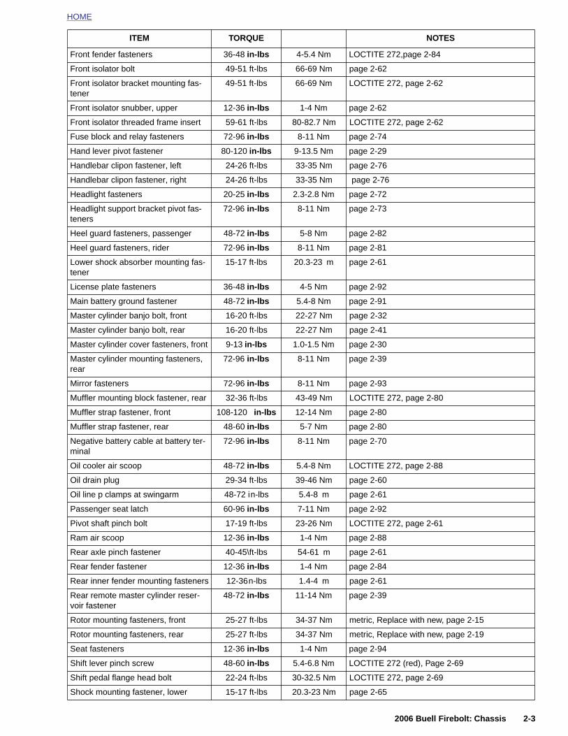
HOME
Front fender fasteners 36-48 in-lbs 4-5.4 Nm LOCTITE 272,page 2-84
Front isolator bolt 49-51 ft-lbs 66-69 Nm page 2-62
Front isolator bracket mounting fas-tener
49-51 ft-lbs 66-69 Nm LOCTITE 272, page 2-62
Front isolator snubber, upper 12-36 in-lbs 1-4 Nm page 2-62
Front isolator threaded frame insert 59-61 ft-lbs 80-82.7 Nm LOCTITE 272, page 2-62
Fuse block and relay fasteners 72-96 in-lbs 8-11 Nm page 2-74
Hand lever pivot fastener 80-120 in-lbs 9-13.5 Nm page 2-29
Handlebar clipon fastener, left 24-26 ft-lbs 33-35 Nm page 2-76
Handlebar clipon fastener, right 24-26 ft-lbs 33-35 Nm page 2-76
Headlight fasteners 20-25 in-lbs 2.3-2.8 Nm page 2-72
Headlight support bracket pivot fas-teners
72-96 in-lbs 8-11 Nm page 2-73
Heel guard fasteners, passenger 48-72 in-lbs 5-8 Nm page 2-82
Heel guard fasteners, rider 72-96 in-lbs 8-11 Nm page 2-81
Lower shock absorber mounting fas-tener
15-17 ft-lbs 20.3-23 m page 2-61
License plate fasteners 36-48 in-lbs 4-5 Nm page 2-92
Main battery ground fastener 48-72 in-lbs 5.4-8 Nm page 2-91
Master cylinder banjo bolt, front 16-20 ft-lbs 22-27 Nm page 2-32
Master cylinder banjo bolt, rear 16-20 ft-lbs 22-27 Nm page 2-41
Master cylinder cover fasteners, front 9-13 in-lbs 1.0-1.5 Nm page 2-30
Master cylinder mounting fasteners, rear
72-96 in-lbs 8-11 Nm page 2-39
Mirror fasteners 72-96 in-lbs 8-11 Nm page 2-93
Muffler mounting block fastener, rear 32-36 ft-lbs 43-49 Nm LOCTITE 272, page 2-80
Muffler strap fastener, front 108-120 in-lbs 12-14 Nm page 2-80
Muffler strap fastener, rear 48-60 in-lbs 5-7 Nm page 2-80
Negative battery cable at battery ter-minal
72-96 in-lbs 8-11 Nm page 2-70
Oil cooler air scoop 48-72 in-lbs 5.4-8 Nm LOCTITE 272, page 2-88
Oil drain plug 29-34 ft-lbs 39-46 Nm page 2-60
Oil line p clamps at swingarm 48-72 in-lbs 5.4-8 m page 2-61
ITEM TORQUE NOTES
2006 Buell Firebolt: Chassis 2-3
Passenger seat latch 60-96 in-lbs 7-11 Nm page 2-92
Pivot shaft pinch bolt 17-19 ft-lbs 23-26 Nm LOCTITE 272, page 2-61
Ram air scoop 12-36 in-lbs 1-4 Nm page 2-88
Rear axle pinch fastener 40-45\ft-lbs 54-61 m page 2-61
Rear fender fastener 12-36 in-lbs 1-4 Nm page 2-84
Rear inner fender mounting fasteners 12-36n-lbs 1.4-4 m page 2-61
Rear remote master cylinder reser-voir fastener
48-72 in-lbs 11-14 Nm page 2-39
Rotor mounting fasteners, front 25-27 ft-lbs 34-37 Nm metric, Replace with new, page 2-15
Rotor mounting fasteners, rear 25-27 ft-lbs 34-37 Nm metric, Replace with new, page 2-19
Seat fasteners 12-36 in-lbs 1-4 Nm page 2-94
Shift lever pinch screw 48-60 in-lbs 5.4-6.8 Nm LOCTITE 272 (red), Page 2-69
Shift pedal flange head bolt 22-24 ft-lbs 30-32.5 Nm LOCTITE 272, page 2-69
Shock mounting fastener, lower 15-17 ft-lbs 20.3-23 Nm page 2-65
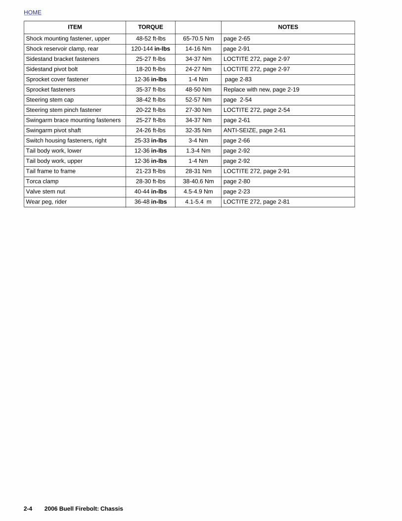
HOME
Shock mounting fastener, upper 48-52 ft-lbs 65-70.5 Nm page 2-65
ITEM TORQUE NOTES
Shock reservoir clamp, rear 120-144 in-lbs 14-16 Nm page 2-91
Sidestand bracket fasteners 25-27 ft-lbs 34-37 Nm LOCTITE 272, page 2-97
Sidestand pivot bolt 18-20 ft-lbs 24-27 Nm LOCTITE 272, page 2-97
Sprocket cover fastener 12-36 in-lbs 1-4 Nm page 2-83
Sprocket fasteners 35-37 ft-lbs 48-50 Nm Replace with new, page 2-19
Steering stem cap 38-42 ft-lbs 52-57 Nm page 2-54
Steering stem pinch fastener 20-22 ft-lbs 27-30 Nm LOCTITE 272, page 2-54
Swingarm brace mounting fasteners 25-27 ft-lbs 34-37 Nm page 2-61
Swingarm pivot shaft 24-26 ft-lbs 32-35 Nm ANTI-SEIZE, page 2-61
Switch housing fasteners, right 25-33 in-lbs 3-4 Nm page 2-66
Tail body work, lower 12-36 in-lbs 1.3-4 Nm page 2-92
Tail body work, upper 12-36 in-lbs 1-4 Nm page 2-92
Tail frame to frame 21-23 ft-lbs 28-31 Nm LOCTITE 272, page 2-91
Torca clamp 28-30 ft-lbs 38-40.6 Nm page 2-80
Valve stem nut 40-44 in-lbs 4.5-4.9 Nm page 2-23
Wear peg, rider 36-48 in-lbs 4.1-5.4 m LOCTITE 272, page 2-81
2-4 2006 Buell Firebolt: Chassis
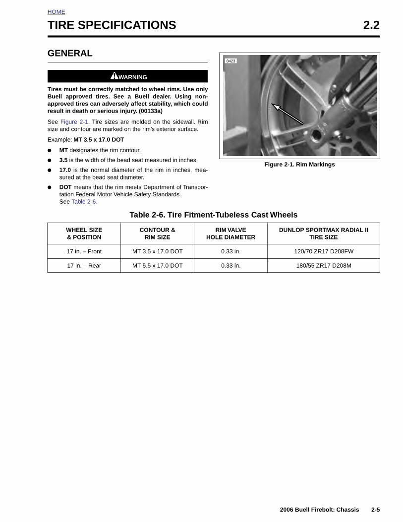
HOME
T
G
TBar
Ss
E
●
●
●
●
IRE SPECIFICATIONS 2.2
ENERAL
11WARNING1WARNING
ires must be correctly matched to wheel rims. Use onlyuell approved tires. See a Buell dealer. Using non-pproved tires can adversely affect stability, which couldesult in death or serious injury. (00133a)
ee Figure 2-1. Tire sizes are molded on the sidewall. Rimize and contour are marked on the rim’s exterior surface.
xample: MT 3.5 x 17.0 DOT
MT designates the rim contour.
3.5 is the width of the bead seat measured in inches.
17.0 is the normal diameter of the rim in inches, mea-sured at the bead seat diameter.
DOT means that the rim meets Department of Transpor-tation Federal Motor Vehicle Safety Standards.See Table 2-6.
Figure 2-1. Rim Markings
8423
Table 2-6. Tire Fitment-Tubeless Cast Wheels
WHEEL SIZE & POSITION
CONTOUR &RIM SIZE
RIM VALVE HOLE DIAMETER
DUNLOP SPORTMAX RADIAL IITIRE SIZE
17 in. – Front MT 3.5 x 17.0 DOT 0.33 in. 120/70 ZR17 D208FW
17 in. – Rear MT 5.5 x 17.0 DOT 0.33 in. 180/55 ZR17 D208M
2006 Buell Firebolt: Chassis 2-5
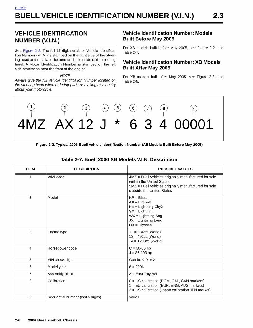
HOME
BUELL VEHICLE IDENTIFICATION NUMBER (V.I.N.) 2.3
VEHICNUMB
See Figurtion Numbing head ahead. A Mside crank
Always githe steerinabout you
4M
1
ITE
1
2
3
2-6
LE IDENTIFICATION ER (V.I.N.)
e 2-2. The full 17 digit serial, or Vehicle Identifica-er (V.I.N.) is stamped on the right side of the steer-nd on a label located on the left side of the steeringotor Identification Number is stamped on the leftcase near the front of the engine.
NOTEve the full Vehicle Identification Number located ong head when ordering parts or making any inquiry
r motorcycle.
Vehicle Identification Number: Models Built Before May 2005
For XB models built before May 2005, see Figure 2-2. andTable 2-7.
Vehicle Identification Number: XB Models Built After May 2005
For XB models built after May 2005, see Figure 2-3. andTable 2-8.
Figure 2-2. Typical 2006 Buell Vehicle Identification Number (All Models Built Before May 2005)
Z AX 12 J * 6 3 4 0000198765432
Table 2-7. Buell 2006 XB Models V.I.N. Description
M DESCRIPTION POSSIBLE VALUES
WMI code 4MZ = Buell vehicles originally manufactured for sale within the United States5MZ = Buell vehicles originally manufactured for sale outside the United States
Model KP = BlastAX = FireboltKX = Lightning CityXSX = LightningWX = Lightning ScgJX = Lightning LongDX = Ulysses
Engine type 12 = 984cc (World)13 = 492cc (World)
2006 Buell Firebolt: Chassis
14 = 1203cc (World)
4 Horsepower code C = 30-35 hpJ = 86-103 hp
5 VIN check digit Can be 0-9 or X
6 Model year 6 = 2006
7 Assembly plant 3 = East Troy, WI
8 Calibration 0 = US calibration (DOM, CAL, CAN markets)1 = EU calibration (EUR, ENG, AUS markets)2 = US calibration (Japan calibration JPN market)
9 Sequential number (last 5 digits) varies

HOME
Figure 2-3. Typical 2006 Buell Vehicle Identification Number (All Models Built After May 2005)
Table 2-8. Buell 2006 XB Models V.I.N. Description
ITEM DESCRIPTION POSSIBLE VALUES
1 WMI Code 4MZ = Buell vehicles originally manufactured for sale within the United States5MZ = Buell vehicles originally manufactured for sale outside the United States
2 Model KP = BlastAX = FireboltKX = Lightning CityXSX = LightningWX = Lightning ScgJX = Lightning LongDX = Ulysses
3 Engine type 01 = 984cc (World)02 = 492cc (World)03 = 1203cc (World)
4 Market configuration A = AustraliaL = CaliforniaN = CanadaD = DomesticE = EnglandR = Europe (formerly HDI)J = Japan
5 VIN check digit Can be 0-9 or X
6 Model year 6 = 2006
7 Assembly plant 3 = East Troy, WI
8 Model(Manufactured after May 1, 2005)
0 = Blast (06)1 = XB9R (06)2 = XB9SX (06)
4MZ DX 03 D * 6 3 7 000011 98765432
2006 Buell Firebolt: Chassis 2-7
3 = XB12R (06)4 = XB12S (06)5 = XB12Scg (06)6 = XB12Ss (06)7 = XB12X (06)
9 Sequential number (last 5 digits) varies
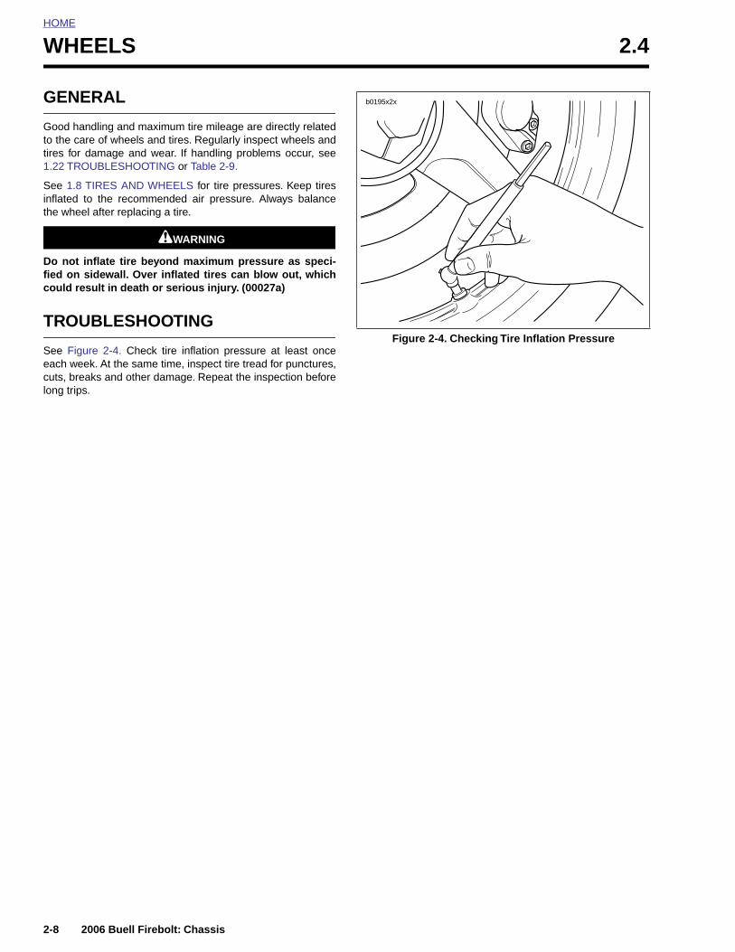
HOME
WHEELS 2.4
GENE
Good hanto the caretires for d1.22 TRO
See 1.8 Tinflated tothe wheel
Do not infied on scould res
TROU
See Figureach weecuts, brealong trips.
2-8
RAL
dling and maximum tire mileage are directly related of wheels and tires. Regularly inspect wheels and
amage and wear. If handling problems occur, seeUBLESHOOTING or Table 2-9.
IRES AND WHEELS for tire pressures. Keep tires the recommended air pressure. Always balance after replacing a tire.
11WARNING1WARNING
flate tire beyond maximum pressure as speci-idewall. Over inflated tires can blow out, whichult in death or serious injury. (00027a)
BLESHOOTING
e 2-4. Check tire inflation pressure at least oncek. At the same time, inspect tire tread for punctures,ks and other damage. Repeat the inspection before
Figure 2-4. Checking Tire Inflation Pressure
b0195x2x
2006 Buell Firebolt: Chassis
HOME
11WARNING1WARNING
To prevent death or serious injury, use the followingguidelines when installing a new tire or repairing a flat:
1. Always locate and eliminate the cause of the originaltire failure.
2. Do not patch or vulcanize a tire casing. These proce-dures weaken the casing and increase the risk of ablowout.
11WARNING1WARNING
Buell tires are equipped with wear bars that run horizon-tally across the tread. When wear bars become visibleand only 1/32 in. (0.8 mm) tread depth remains, replacetire immediately. Using a worn tire can adversely affectstability and handling, which could result in death orserious injury. Use only Dunlop Harley-Davidson replace-ment tires. (00090a)
At regular intervals of 5000 miles (8000 km) or whenever
Table 2-9. Wheel Service
CHECK FOR REMEDY
Loose axles. Tighten front axle. See 2.5 FRONT WHEEL.Tighten rear axle. See 2.6 REAR WHEEL.
Excessive side-play or radial (up-and-down)play in wheel hubs.
Replace wheel bearings.
Rims and tires out-of-true sideways; shouldnot be more than 0.080 in. (2.03 mm).
Replace rims. See 2.8 TIRES and 2.7 CHECKING CAST RIM RUNOUT.
Rims and tires out-of-round or eccentricwith hub; should not be more than 0.090 in.(2.29 mm).
Replace rims. See 2.8 TIRES and 2.7 CHECKING CAST RIM RUNOUT.
Irregular or peaked front tire wear. Replace as described under 2.5 FRONT WHEEL, 2.6 REAR WHEEL and 2.8 TIRES.
Correct tire inflation. Inflate tires to correct pressure. See 1.8 TIRES AND WHEELS.
Correct tire and wheel balance. Static balance may be satisfactory if dynamic balancing facilities are not available. However, dynamic balancing is strongly recommended.
Steering head bearings. Check for proper torque and replace worn or damaged bearings. See 1.13 STEERING HEAD BEARINGS.
Damper tubes. Check for leaks. See 2.16 FRONT FORK.
Shock absorbers. Check damping action and mounts. See 1.12 SUSPENSION DAMPING ADJUSTMENTS.
Swingarm bearings. Check for proper torque and replace worn or damaged bearings. See 2.19 SWINGARM AND BRACE.
2006 Buell Firebolt: Chassis 2-9
3. The use of tires other than those specified canadversely affect handling which could result in deathor serious injury.
4. Tires and wheels are critical items. Since the servic-ing of these components requires special tools andskills, Buell recommends that you see your dealerfor these services.
11WARNING1WARNING
Replace punctured or damaged tires. In some cases,small punctures in the tread area may be repaired fromwithin the demounted tire by a Buell dealer. Speedshould NOT exceed 50 mph (80 km/h) for the first 24hours after repair, and the repaired tire should NEVER beused over 80 mph (130 km/h). Failure to follow this warn-ing could result in death or serious injury. (00118a)
handling irregularities are noted, perform the recommendedservice checks. See Table 2-9.
If tires must be replaced, same as original equipment tiresmust be used. Other tires may not fit correctly and may behazardous to use.
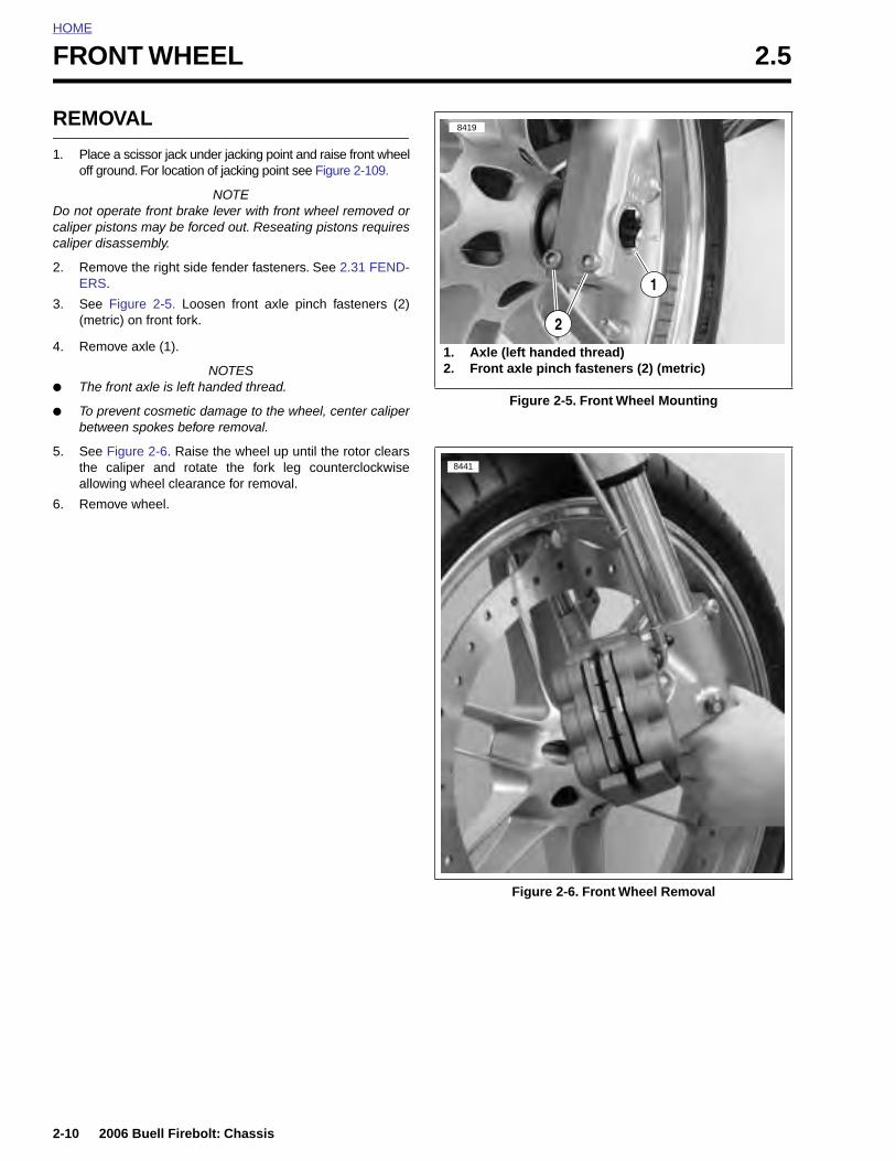
HOME
FRONT WHEEL 2.5
REMO
1. Placeoff gro
Do not opcaliper piscaliper dis
2. RemoERS.
3. See (metr
4. Remo
● The f
● To prbetwe
5. See Fthe callow
6. Remo
2-10
VAL
a scissor jack under jacking point and raise front wheelund. For location of jacking point see Figure 2-109.
NOTEerate front brake lever with front wheel removed ortons may be forced out. Reseating pistons requiresassembly.
ve the right side fender fasteners. See 2.31 FEND-
Figure 2-5. Loosen front axle pinch fasteners (2)ic) on front fork.
ve axle (1).
NOTESront axle is left handed thread.
event cosmetic damage to the wheel, center caliperen spokes before removal.
igure 2-6. Raise the wheel up until the rotor clearsaliper and rotate the fork leg counterclockwiseing wheel clearance for removal.
ve wheel.
Figure 2-5. Front Wheel Mounting
1. Axle (left handed thread)2. Front axle pinch fasteners (2) (metric)
8419
1
2
8441
2006 Buell Firebolt: Chassis
Figure 2-6. Front Wheel Removal
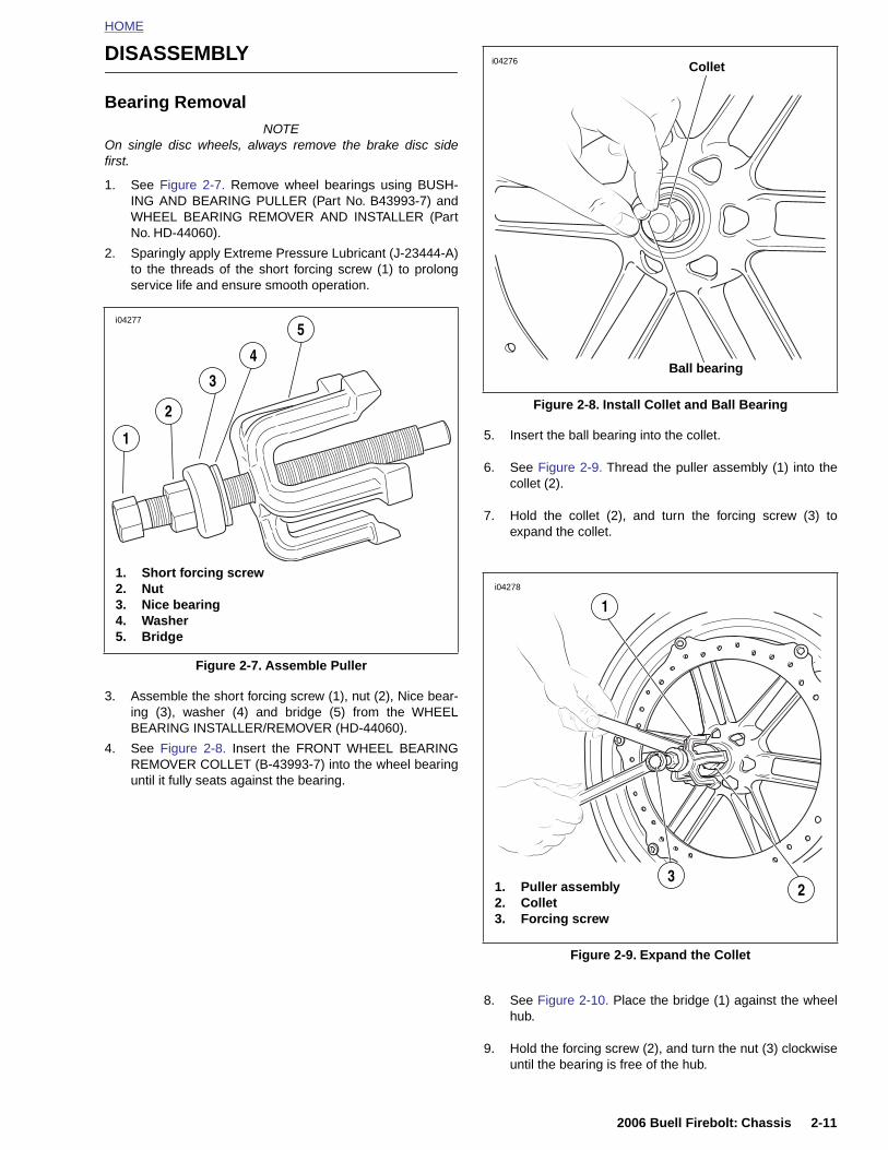
HOME
DISASSEMBLY
Bearing RemovalNOTE
On single disc wheels, always remove the brake disc sidefirst.
1. See Figure 2-7. Remove wheel bearings using BUSH-ING AND BEARING PULLER (Part No. B43993-7) andWHEEL BEARING REMOVER AND INSTALLER (PartNo. HD-44060).
2. Sparingly apply Extreme Pressure Lubricant (J-23444-A)to the threads of the short forcing screw (1) to prolongservice life and ensure smooth operation.
3. Assemble the short forcing screw (1), nut (2), Nice bear-ing (3), washer (4) and bridge (5) from the WHEELBEARING INSTALLER/REMOVER (HD-44060).
4. See Figure 2-8. Insert the FRONT WHEEL BEARINGREMOVER COLLET (B-43993-7) into the wheel bearinguntil it fully seats against the bearing.
5. Insert the ball bearing into the collet.
6. See Figure 2-9. Thread the puller assembly (1) into thecollet (2).
7. Hold the collet (2), and turn the forcing screw (3) toexpand the collet.
Figure 2-7. Assemble Puller
i04277
1. Short forcing screw2. Nut3. Nice bearing4. Washer5. Bridge
3
1
2
4
5
Figure 2-8. Install Collet and Ball Bearing
i04276
Ball bearing
Collet
i04278
1
2006 Buell Firebolt: Chassis 2-11
8. See Figure 2-10. Place the bridge (1) against the wheelhub.
9. Hold the forcing screw (2), and turn the nut (3) clockwiseuntil the bearing is free of the hub.
Figure 2-9. Expand the Collet
21. Puller assembly2. Collet3. Forcing screw
3
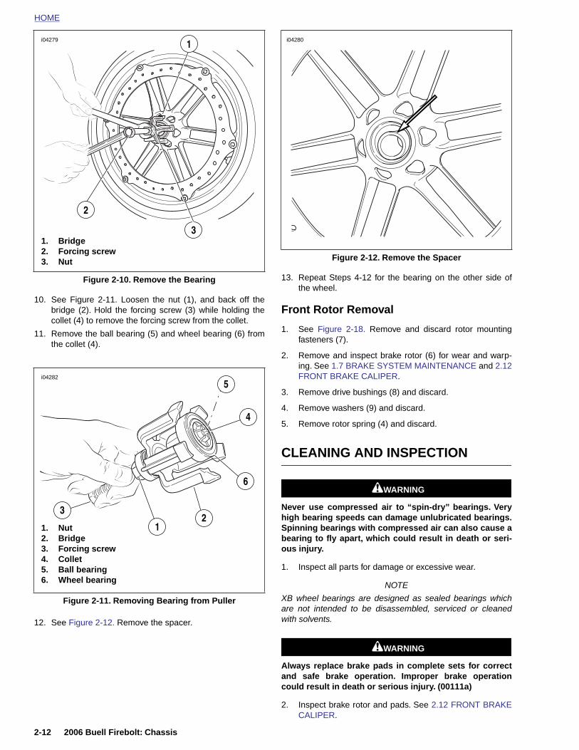
HOME
i04279 1
i04280
10. See Figure 2-11. Loosen the nut (1), and back off thebridge (2). Hold the forcing screw (3) while holding thecollet (4) to remove the forcing screw from the collet.
11. Remove the ball bearing (5) and wheel bearing (6) fromthe collet (4).
13. Repeat Steps 4-12 for the bearing on the other side ofthe wheel.
Front Rotor Removal
1. See Figure 2-18. Remove and discard rotor mountingfasteners (7).
2. Remove and inspect brake rotor (6) for wear and warp-ing. See 1.7 BRAKE SYSTEM MAINTENANCE and 2.12FRONT BRAKE CALIPER.
3. Remove drive bushings (8) and discard.
4. Remove washers (9) and discard.
5. Remove rotor spring (4) and discard.
CLEANING AND INSPECTION
11WARNING1WARNING
Never use compressed air to “spin-dry” bearings. Veryhigh bearing speeds can damage unlubricated bearings.Spinning bearings with compressed air can also cause abearing to fly apart, which could result in death or seri-ous injury.
Figure 2-10. Remove the Bearing
3
2
1. Bridge2. Forcing screw3. Nut
i04282
1. Nut2. Bridge3. Forcing screw
3
12
6
4
5
Figure 2-12. Remove the Spacer
2-12 2006 Buell Firebolt: Chassis
12. See Figure 2-12. Remove the spacer.
1. Inspect all parts for damage or excessive wear.
NOTE
XB wheel bearings are designed as sealed bearings whichare not intended to be disassembled, serviced or cleanedwith solvents.
11WARNING1WARNING
Always replace brake pads in complete sets for correctand safe brake operation. Improper brake operationcould result in death or serious injury. (00111a)
2. Inspect brake rotor and pads. See 2.12 FRONT BRAKECALIPER.
Figure 2-11. Removing Bearing from Puller
4. Collet5. Ball bearing6. Wheel bearing
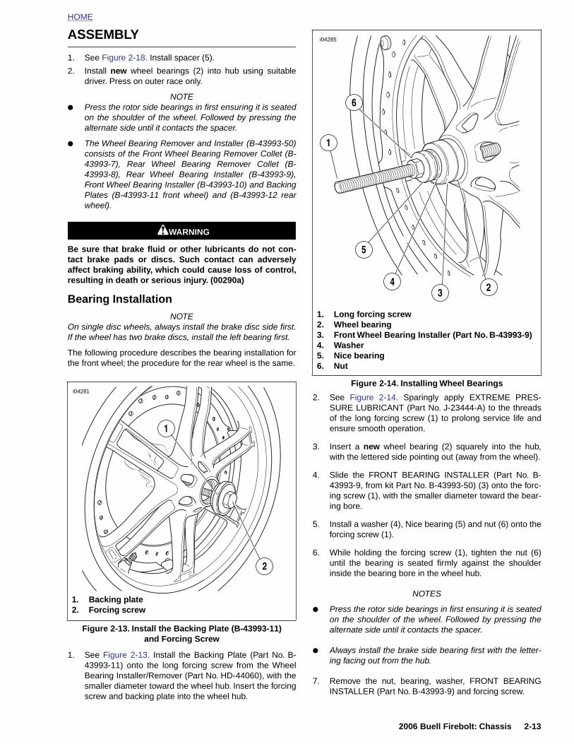
HOME
ASSEMBLY
1. See Figure 2-18. Install spacer (5).
2. Install new wheel bearings (2) into hub using suitabledriver. Press on outer race only.
NOTE● Press the rotor side bearings in first ensuring it is seated
on the shoulder of the wheel. Followed by pressing thealternate side until it contacts the spacer.
● The Wheel Bearing Remover and Installer (B-43993-50)consists of the Front Wheel Bearing Remover Collet (B-43993-7), Rear Wheel Bearing Remover Collet (B-43993-8), Rear Wheel Bearing Installer (B-43993-9),Front Wheel Bearing Installer (B-43993-10) and BackingPlates (B-43993-11 front wheel) and (B-43993-12 rearwheel).
11WARNING1WARNING
Be sure that brake fluid or other lubricants do not con-tact brake pads or discs. Such contact can adverselyaffect braking ability, which could cause loss of control,resulting in death or serious injury. (00290a)
Bearing InstallationNOTE
On single disc wheels, always install the brake disc side first.If the wheel has two brake discs, install the left bearing first.
The following procedure describes the bearing installation forthe front wheel; the procedure for the rear wheel is the same.
2. See Figure 2-14. Sparingly apply EXTREME PRES-SURE LUBRICANT (Part No. J-23444-A) to the threadsof the long forcing screw (1) to prolong service life andensure smooth operation.
3. Insert a new wheel bearing (2) squarely into the hub,with the lettered side pointing out (away from the wheel).
4. Slide the FRONT BEARING INSTALLER (Part No. B-43993-9, from kit Part No. B-43993-50) (3) onto the forc-ing screw (1), with the smaller diameter toward the bear-ing bore.
i04281
1
Figure 2-14. Installing Wheel Bearings
i04285
1. Long forcing screw2. Wheel bearing3. Front Wheel Bearing Installer (Part No. B-43993-9)4. Washer5. Nice bearing6. Nut
5
1
6
34 2
2006 Buell Firebolt: Chassis 2-13
1. See Figure 2-13. Install the Backing Plate (Part No. B-43993-11) onto the long forcing screw from the WheelBearing Installer/Remover (Part No. HD-44060), with thesmaller diameter toward the wheel hub. Insert the forcingscrew and backing plate into the wheel hub.
5. Install a washer (4), Nice bearing (5) and nut (6) onto theforcing screw (1).
6. While holding the forcing screw (1), tighten the nut (6)until the bearing is seated firmly against the shoulderinside the bearing bore in the wheel hub.
NOTES
● Press the rotor side bearings in first ensuring it is seatedon the shoulder of the wheel. Followed by pressing thealternate side until it contacts the spacer.
● Always install the brake side bearing first with the letter-ing facing out from the hub.
7. Remove the nut, bearing, washer, FRONT BEARINGINSTALLER (Part No. B-43993-9) and forcing screw.
Figure 2-13. Install the Backing Plate (B-43993-11)and Forcing Screw
1. Backing plate2. Forcing screw
2
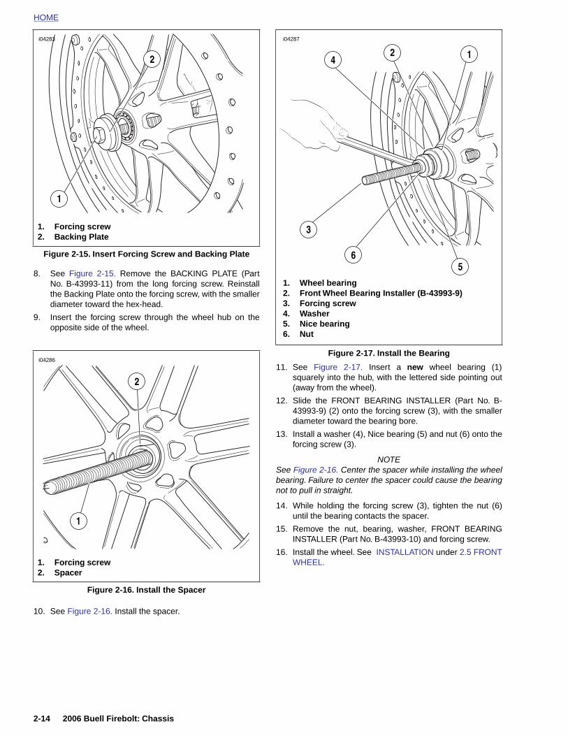
HOME
i04283
i04287
12
8. See Figure 2-15. Remove the BACKING PLATE (PartNo. B-43993-11) from the long forcing screw. Reinstallthe Backing Plate onto the forcing screw, with the smallerdiameter toward the hex-head.
9. Insert the forcing screw through the wheel hub on theopposite side of the wheel.
11. See Figure 2-17. Insert a new wheel bearing (1)squarely into the hub, with the lettered side pointing out(away from the wheel).
12. Slide the FRONT BEARING INSTALLER (Part No. B-43993-9) (2) onto the forcing screw (3), with the smallerdiameter toward the bearing bore.
13. Install a washer (4), Nice bearing (5) and nut (6) onto theforcing screw (3).
NOTESee Figure 2-16. Center the spacer while installing the wheelbearing. Failure to center the spacer could cause the bearingnot to pull in straight.
14. While holding the forcing screw (3), tighten the nut (6)until the bearing contacts the spacer.
15. Remove the nut, bearing, washer, FRONT BEARINGINSTALLER (Part No. B-43993-10) and forcing screw.
Figure 2-15. Insert Forcing Screw and Backing Plate
1. Forcing screw2. Backing Plate
1
2
i04286
2
1
Figure 2-17. Install the Bearing
1. Wheel bearing2. Front Wheel Bearing Installer (B-43993-9)3. Forcing screw4. Washer5. Nice bearing6. Nut
56
3
4
2-14 2006 Buell Firebolt: Chassis
10. See Figure 2-16. Install the spacer.
16. Install the wheel. See INSTALLATION under 2.5 FRONTWHEEL.
Figure 2-16. Install the Spacer
1. Forcing screw2. Spacer
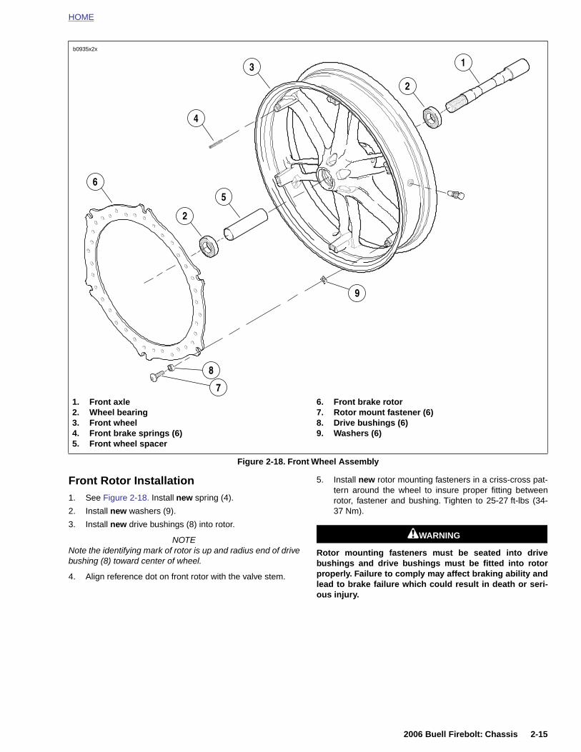
HOME
Front Rotor Installation1. See Figure 2-18. Install new spring (4).
2. Install new washers (9).
5. Install new rotor mounting fasteners in a criss-cross pat-tern around the wheel to insure proper fitting betweenrotor, fastener and bushing. Tighten to 25-27 ft-lbs (34-37 Nm).
Figure 2-18. Front Wheel Assembly
1. Front axle2. Wheel bearing3. Front wheel4. Front brake springs (6)5. Front wheel spacer
6. Front brake rotor7. Rotor mount fastener (6)8. Drive bushings (6)9. Washers (6)
b0935x2x
7
8
1
2
3
4
5
2
6
9
2006 Buell Firebolt: Chassis 2-15
3. Install new drive bushings (8) into rotor.
NOTENote the identifying mark of rotor is up and radius end of drivebushing (8) toward center of wheel.
4. Align reference dot on front rotor with the valve stem.
11WARNING1WARNING
Rotor mounting fasteners must be seated into drivebushings and drive bushings must be fitted into rotorproperly. Failure to comply may affect braking ability andlead to brake failure which could result in death or seri-ous injury.
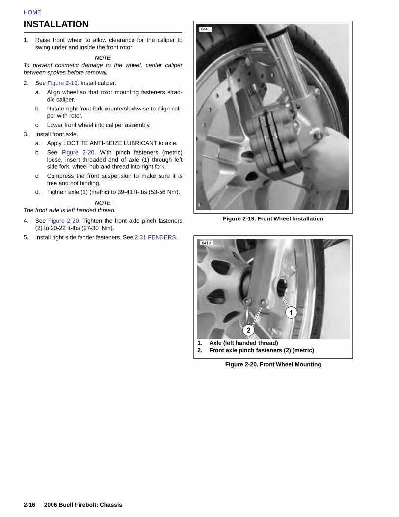
HOME
INSTALLATION
8441
1. Raise front wheel to allow clearance for the caliper toswing under and inside the front rotor.
NOTETo prevent cosmetic damage to the wheel, center caliperbetween spokes before removal.
2. See Figure 2-19. Install caliper.
a. Align wheel so that rotor mounting fasteners strad-dle caliper.
b. Rotate right front fork counterclockwise to align cali-per with rotor.
c. Lower front wheel into caliper assembly.
3. Install front axle.
a. Apply LOCTITE ANTI-SEIZE LUBRICANT to axle.
b. See Figure 2-20. With pinch fasteners (metric)loose, insert threaded end of axle (1) through leftside fork, wheel hub and thread into right fork.
c. Compress the front suspension to make sure it isfree and not binding.
d. Tighten axle (1) (metric) to 39-41 ft-lbs (53-56 Nm).
NOTEThe front axle is left handed thread.
4. See Figure 2-20. Tighten the front axle pinch fasteners(2) to 20-22 ft-lbs (27-30 Nm).
5. Install right side fender fasteners. See 2.31 FENDERS.
Figure 2-19. Front Wheel Installation
Figure 2-20. Front Wheel Mounting
1. Axle (left handed thread)2. Front axle pinch fasteners (2) (metric)
8419
1
2
2-16 2006 Buell Firebolt: Chassis
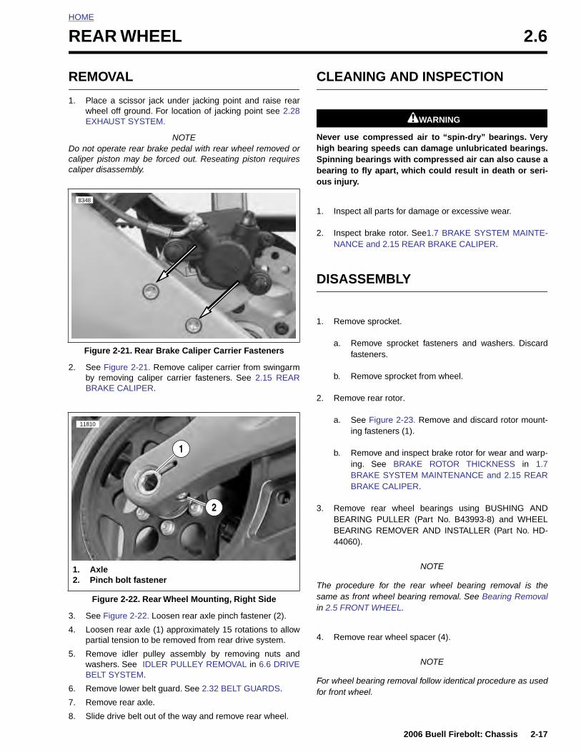
HOME
R
R
1
Dcc
2
EAR WHEEL 2.6
EMOVAL
. Place a scissor jack under jacking point and raise rearwheel off ground. For location of jacking point see 2.28EXHAUST SYSTEM.
NOTEo not operate rear brake pedal with rear wheel removed oraliper piston may be forced out. Reseating piston requiresaliper disassembly.
. See Figure 2-21. Remove caliper carrier from swingarmby removing caliper carrier fasteners. See 2.15 REARBRAKE CALIPER.
CLEANING AND INSPECTION
11WARNING1WARNING
Never use compressed air to “spin-dry” bearings. Veryhigh bearing speeds can damage unlubricated bearings.Spinning bearings with compressed air can also cause abearing to fly apart, which could result in death or seri-ous injury.
1. Inspect all parts for damage or excessive wear.
2. Inspect brake rotor. See1.7 BRAKE SYSTEM MAINTE-NANCE and 2.15 REAR BRAKE CALIPER.
DISASSEMBLY
1. Remove sprocket.
a. Remove sprocket fasteners and washers. Discardfasteners.
b. Remove sprocket from wheel.
2. Remove rear rotor.
a. See Figure 2-23. Remove and discard rotor mount-ing fasteners (1).
b. Remove and inspect brake rotor for wear and warp-ing. See BRAKE ROTOR THICKNESS in 1.7BRAKE SYSTEM MAINTENANCE and 2.15 REARBRAKE CALIPER.
3. Remove rear wheel bearings using BUSHING AND
Figure 2-21. Rear Brake Caliper Carrier Fasteners
8348
11810
2
1
2006 Buell Firebolt: Chassis 2-17
3. See Figure 2-22. Loosen rear axle pinch fastener (2).
4. Loosen rear axle (1) approximately 15 rotations to allowpartial tension to be removed from rear drive system.
5. Remove idler pulley assembly by removing nuts andwashers. See IDLER PULLEY REMOVAL in 6.6 DRIVEBELT SYSTEM.
6. Remove lower belt guard. See 2.32 BELT GUARDS.
7. Remove rear axle.
8. Slide drive belt out of the way and remove rear wheel.
BEARING PULLER (Part No. B43993-8) and WHEELBEARING REMOVER AND INSTALLER (Part No. HD-44060).
NOTE
The procedure for the rear wheel bearing removal is thesame as front wheel bearing removal. See Bearing Removalin 2.5 FRONT WHEEL.
4. Remove rear wheel spacer (4).
NOTE
For wheel bearing removal follow identical procedure as usedfor front wheel.
Figure 2-22. Rear Wheel Mounting, Right Side
1. Axle2. Pinch bolt fastener
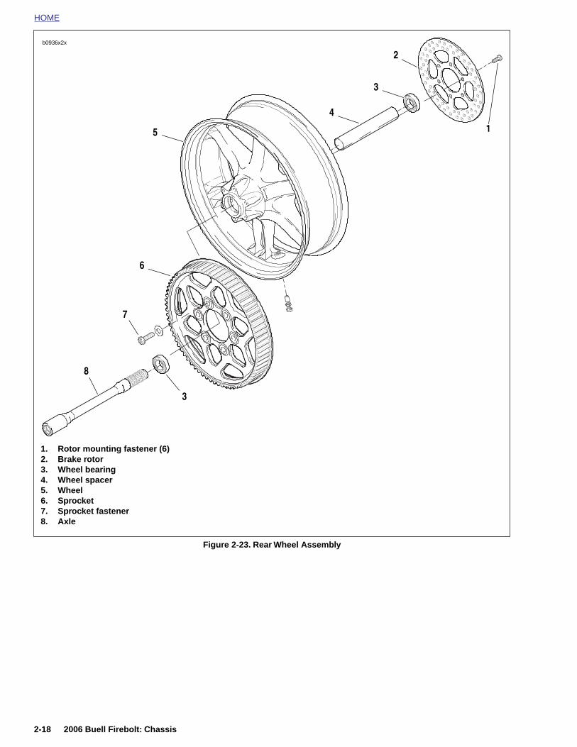
HOME
b0936x2x
2
Figure 2-23. Rear Wheel Assembly
1. Rotor mounting fastener (6)2. Brake rotor3. Wheel bearing4. Wheel spacer5. Wheel6. Sprocket7. Sprocket fastener8. Axle
1
3
5
4
3
6
7
8
2-18 2006 Buell Firebolt: Chassis
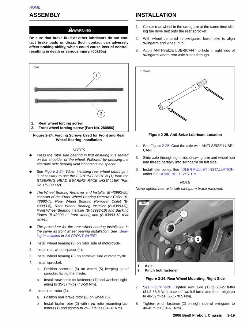
HOME
ASSEMBLY
11WARNING1WARNING
Be sure that brake fluid or other lubricants do not con-tact brake pads or discs. Such contact can adverselyaffect braking ability, which could cause loss of control,resulting in death or serious injury. (00290a)
NOTES● Press the rotor side bearing in first ensuring it is seated
on the shoulder of the wheel. Followed by pressing thealternate side bearing until it contacts the spacer.
● See Figure 2-24. When installing rear wheel bearings itis necessary to use the FORCING SCREW (1) from theSTEERING HEAD BEARING RACE INSTALLER (PartNo. HD-39302).
● The Wheel Bearing Remover and Installer (B-43993-50)consists of the Front Wheel Bearing Remover Collet (B-43993-7), Rear Wheel Bearing Remover Collet (B-43993-8), Rear Wheel Bearing Installer (B-43993-9),Front Wheel Bearing Installer (B-43993-10) and BackingPlates (B-43993-11 front wheel) and (B-43993-12 rearwheel).
INSTALLATION
1. Center rear wheel in the swingarm at the same time slid-ing the drive belt onto the rear sprocket.
2. With wheel centered in swingarm, lower bike to alignswingarm and wheel hub.
3. Apply ANTI-SEIZE LUBRICANT to hole in right side ofswingarm where rear axle slides through.
4. See Figure 2-25. Coat the axle with ANTI-SEIZE LUBRI-CANT.
5. Slide axle through right side of swing arm and wheel huband thread partially into swingarm on left side.
6. Install idler pulley. See IDLER PULLEY INSTALLATION-under 6.6 DRIVE BELT SYSTEM.
NOTE
Never tighten rear axle with swingarm brace removed.
Figure 2-24. Forcing Screws Used for Front and Rear Wheel Bearing Installation
10096
1. Rear wheel forcing screw2. Front wheel forcing screw (Part No. 280856)
1
2
Figure 2-25. Anti-Seize Lubricant Location
b1036x2x
11810
1
2006 Buell Firebolt: Chassis 2-19
● The procedure for the rear wheel bearing installation isthe same as front wheel bearing installation. See Bear-ing Installation in 2.5 FRONT WHEEL.
1. Install wheel bearing (3) on rotor side of motorcycle.
2. Install rear wheel spacer (4).
3. Install wheel bearing (3) on sprocket side of motorcycle.
4. Install sprocket.
a. Position sprocket (6) on wheel (5) keeping lip ofsprocket facing the inside.
b. Install new sprocket fasteners (7) and washers tight-ening to 35-37 ft-lbs (48-50 Nm).
5. Install rear rotor (2).
a. Position rear brake rotor (2) on wheel (5).
b. Install brake rotor (2) with new rotor mounting fas-teners (1) and tighten to 25-27 ft-lbs (34-37 Nm).
7. See Figure 2-26. Tighten rear axle (1) to 23-27 ft-lbs(31.2-36.6 Nm), back off two full turns and then retightento 48-52 ft-lbs (65.1-70.5 Nm).
8. Tighten pinch fastener (2) on right side of swingarm to40-45 ft-lbs (54-61 Nm).
Figure 2-26. Rear Wheel Mounting, Right Side
2
1. Axle2. Pinch bolt fastener
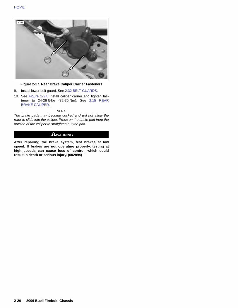
HOME
8348
9. Install lower belt guard. See 2.32 BELT GUARDS.
10. See Figure 2-27. Install caliper carrier and tighten fas-tener to 24-26 ft-lbs (32-35 Nm). See 2.15 REARBRAKE CALIPER.
NOTEThe brake pads may become cocked and will not allow therotor to slide into the caliper. Press on the brake pad from theoutside of the caliper to straighten out the pad.
11WARNING1WARNING
After repairing the brake system, test brakes at lowspeed. If brakes are not operating properly, testing athigh speeds can cause loss of control, which couldresult in death or serious injury. (00289a)
Figure 2-27. Rear Brake Caliper Carrier Fasteners
2-20 2006 Buell Firebolt: Chassis

HOME
C
G
Cn
R1
2
3
R1
2
3
HECKING CAST RIM RUNOUT 2.7
ENERAL
heck wheels for lateral and radial runout before installing aew tire.
im Lateral Runout. See Figure 2-28. Install truing arbor in wheel hub and
place wheel in WHEEL TRUING AND BALANCINGSTAND (Part No. HD-99500-80).
. Tighten arbor nuts so hub will turn on its bearings.
. Check rim lateral runout by placing a gauge rod or dialindicator near the rim bead. Replace wheel if lateralrunout exceeds specification shown in Table 2-10.
im Radial Runout. See Figure 2-29. Install truing arbor in wheel hub and
place wheel in WHEEL TRUING AND BALANCINGSTAND (Part No. HD-99500-80).
. Tighten arbor nuts so hub will turn on its bearings.
. Check radial runout as shown. Replace wheel if runoutexceeds specification shown in Table 2-10.
Table 2-10. Wheel Rim Runout
RUNOUT IN MM
Maximum lateral 0.040 1.02
Maximum radial 0.030 0.76
Figure 2-28. Checking Cast Rim Lateral Runout Using Wheel Truing and Balancing Stand (HD-99500-80)
b0757x2x
Gauge rod
b0758x2x
2006 Buell Firebolt: Chassis 2-21
Figure 2-29. Checking Cast Rim Radial Runout Using Wheel Truing and Balancing Stand (HD-99500-80)
Gauge rod
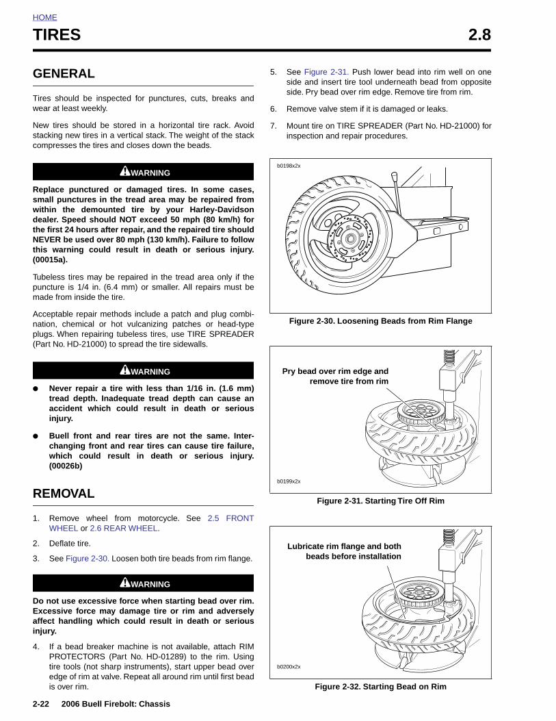
HOME
TIRES 2.8
GENE
Tires showear at le
New tiresstacking ncompress
Replace small punwithin thdealer. Spthe first 2NEVER bthis warn(00015a).
Tubeless puncture made from
Acceptablnation, chplugs. Wh(Part No. H
● Nevetreadaccidinjury
● Buellchanwhich(0002
REMO
1. RemoWHE
2-22
2. Defl
3. See
Do not Excessaffect hinjury.
4. If aPROtire edgis o
RAL
uld be inspected for punctures, cuts, breaks andast weekly.
should be stored in a horizontal tire rack. Avoidew tires in a vertical stack. The weight of the stackes the tires and closes down the beads.
11WARNING1WARNING
punctured or damaged tires. In some cases,ctures in the tread area may be repaired frome demounted tire by your Harley-Davidsoneed should NOT exceed 50 mph (80 km/h) for
4 hours after repair, and the repaired tire shoulde used over 80 mph (130 km/h). Failure to following could result in death or serious injury.
tires may be repaired in the tread area only if theis 1/4 in. (6.4 mm) or smaller. All repairs must be inside the tire.
e repair methods include a patch and plug combi-emical or hot vulcanizing patches or head-typeen repairing tubeless tires, use TIRE SPREADERD-21000) to spread the tire sidewalls.
11WARNING1WARNING
r repair a tire with less than 1/16 in. (1.6 mm) depth. Inadequate tread depth can cause anent which could result in death or serious.
front and rear tires are not the same. Inter-ging front and rear tires can cause tire failure, could result in death or serious injury.6b)
VAL
ve wheel from motorcycle. See 2.5 FRONTEL or 2.6 REAR WHEEL.
5. See Figure 2-31. Push lower bead into rim well on oneside and insert tire tool underneath bead from oppositeside. Pry bead over rim edge. Remove tire from rim.
6. Remove valve stem if it is damaged or leaks.
7. Mount tire on TIRE SPREADER (Part No. HD-21000) forinspection and repair procedures.
Figure 2-30. Loosening Beads from Rim Flange
Figure 2-31. Starting Tire Off Rim
b0198x2x
Pry bead over rim edge andremove tire from rim
b0199x2x
2006 Buell Firebolt: Chassis
ate tire.
Figure 2-30. Loosen both tire beads from rim flange.
11WARNING1WARNING
use excessive force when starting bead over rim.ive force may damage tire or rim and adverselyandling which could result in death or serious
bead breaker machine is not available, attach RIMTECTORS (Part No. HD-01289) to the rim. Using
tools (not sharp instruments), start upper bead overe of rim at valve. Repeat all around rim until first beadver rim. Figure 2-32. Starting Bead on Rim
Lubricate rim flange and bothbeads before installation
b0200x2x
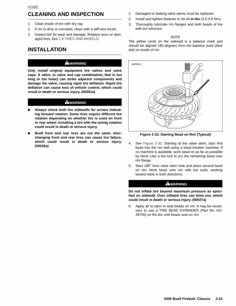
HOME
CLEANING AND INSPECTION
1. Clean inside of tire with dry rag.
2. If rim is dirty or corroded, clean with a stiff wire brush.
3. Inspect tire for wear and damage. Replace worn or dam-aged tires. See 1.8 TIRES AND WHEELS.
INSTALLATION
11WARNING1WARNING
Only install original equipment tire valves and valvecaps. A valve, or valve and cap combination, that is toolong or too heavy can strike adjacent components anddamage the valve, causing rapid tire deflation. Rapid tiredeflation can cause loss of vehicle control, which couldresult in death or serious injury. (00281a)
11WARNING1WARNING
● Always check both tire sidewalls for arrows indicat-ing forward rotation. Some tires require different tirerotation depending on whether tire is used on frontor rear wheel. Installing a tire with the wrong rotationcould result in death or serious injury.
● Buell front and rear tires are not the same. Inter-changing front and rear tires can cause tire failure,which could result in death or serious injury.(00026a)
1. Damaged or leaking valve stems must be replaced.
2. Install and tighten fastener to 40-44 in-lbs (4.5-4.9 Nm).
3. Thoroughly lubricate rim flanges and both beads of tirewith tire lubricant.
NOTEThe yellow circle on the sidewall is a balance mark andshould be aligned 180 degrees from the balance mark (bluedot) on inside of rim.
4. See Figure 2-33. Starting at the valve stem, start firstbead into the rim well using a bead breaker machine. Ifno machine is available, work bead on as far as possibleby hand. Use a tire tool to pry the remaining bead overrim flange.
5. Start 180° from valve stem hole and place second beadon rim. Work bead onto rim with tire tools, workingtoward valve in both directions.
11WARNING1WARNING
Do not inflate tire beyond maximum pressure as speci-fied on sidewall. Over inflated tires can blow out, whichcould result in death or serious injury. (00027a)
6. Apply air to stem to seat beads on rim. It may be neces-sary to use a TIRE BEAD EXPANDER (Part No. HD-
Figure 2-33. Starting Bead on Rim (Typical)
a0209x2x
2006 Buell Firebolt: Chassis 2-23
28700) on the tire until beads seal on rim.
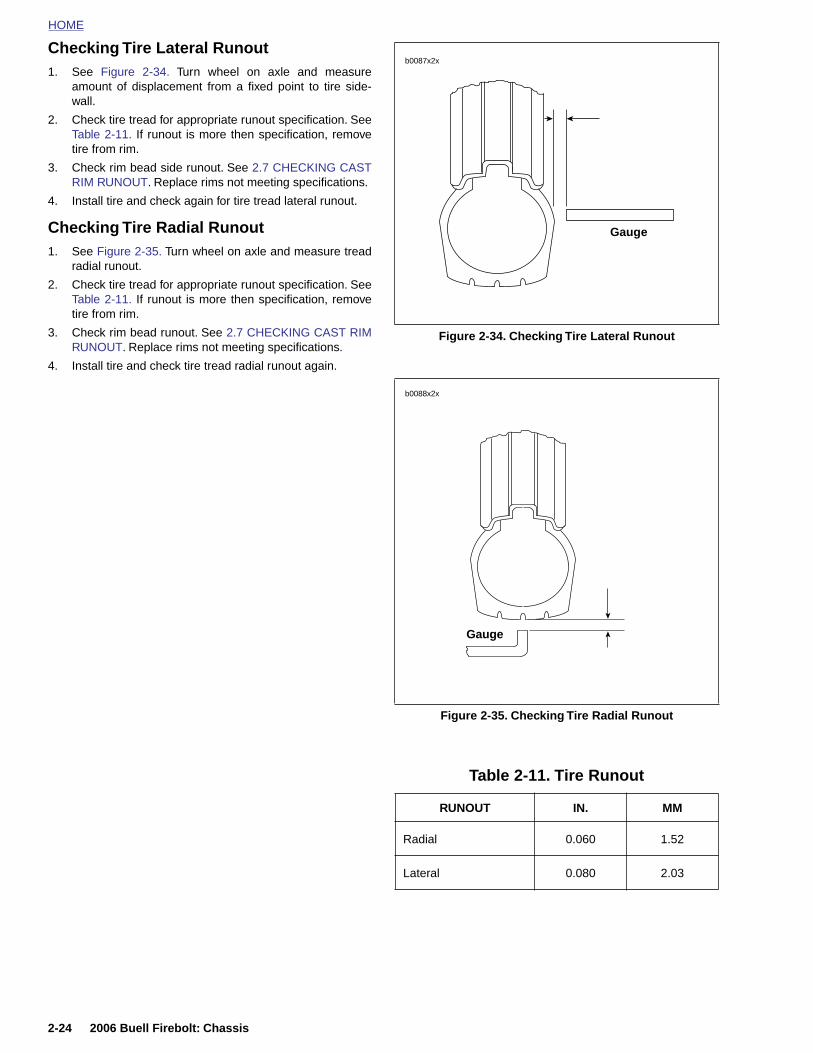
HOME
Checking Tire Lateral Runout1. See Figure 2-34. Turn wheel on axle and measure
b0087x2x
amount of displacement from a fixed point to tire side-wall.
2. Check tire tread for appropriate runout specification. SeeTable 2-11. If runout is more then specification, removetire from rim.
3. Check rim bead side runout. See 2.7 CHECKING CASTRIM RUNOUT. Replace rims not meeting specifications.
4. Install tire and check again for tire tread lateral runout.
Checking Tire Radial Runout1. See Figure 2-35. Turn wheel on axle and measure tread
radial runout.
2. Check tire tread for appropriate runout specification. SeeTable 2-11. If runout is more then specification, removetire from rim.
3. Check rim bead runout. See 2.7 CHECKING CAST RIMRUNOUT. Replace rims not meeting specifications.
4. Install tire and check tire tread radial runout again.
Figure 2-34. Checking Tire Lateral Runout
Figure 2-35. Checking Tire Radial Runout
Gauge
b0088x2x
Gauge
2-24 2006 Buell Firebolt: Chassis
Table 2-11. Tire Runout
RUNOUT IN. MM
Radial 0.060 1.52
Lateral 0.080 2.03
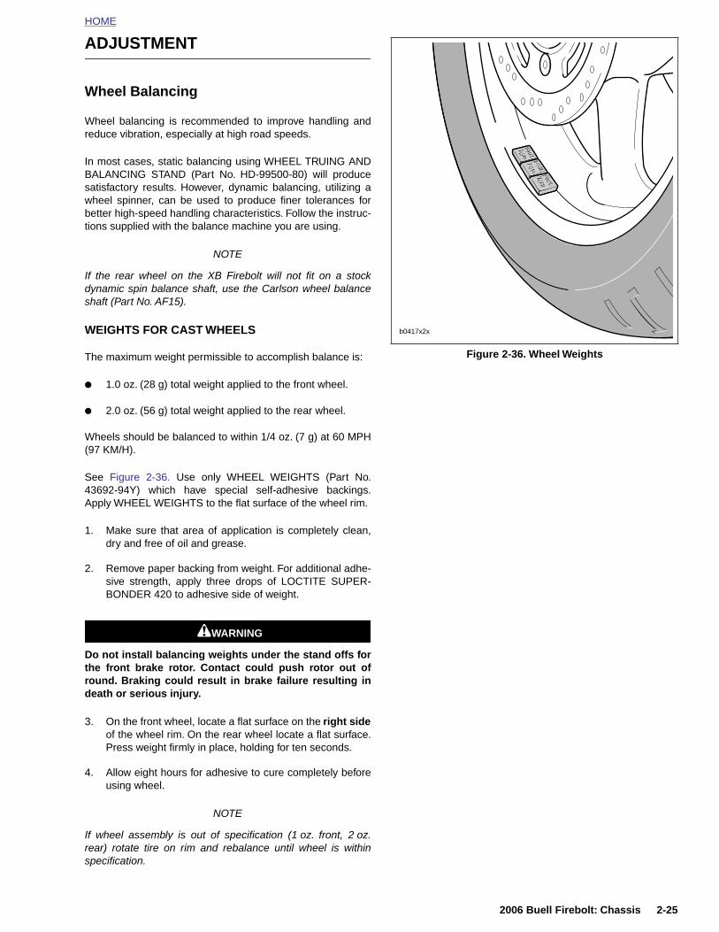
HOME
ADJUSTMENT
Wheel Balancing
Wheel balancing is recommended to improve handling andreduce vibration, especially at high road speeds.
In most cases, static balancing using WHEEL TRUING ANDBALANCING STAND (Part No. HD-99500-80) will producesatisfactory results. However, dynamic balancing, utilizing awheel spinner, can be used to produce finer tolerances forbetter high-speed handling characteristics. Follow the instruc-tions supplied with the balance machine you are using.
NOTE
If the rear wheel on the XB Firebolt will not fit on a stockdynamic spin balance shaft, use the Carlson wheel balanceshaft (Part No. AF15).
WEIGHTS FOR CAST WHEELS
The maximum weight permissible to accomplish balance is:
● 1.0 oz. (28 g) total weight applied to the front wheel.
● 2.0 oz. (56 g) total weight applied to the rear wheel.
Wheels should be balanced to within 1/4 oz. (7 g) at 60 MPH(97 KM/H).
See Figure 2-36. Use only WHEEL WEIGHTS (Part No.43692-94Y) which have special self-adhesive backings.Apply WHEEL WEIGHTS to the flat surface of the wheel rim.
1. Make sure that area of application is completely clean,dry and free of oil and grease.
2. Remove paper backing from weight. For additional adhe-sive strength, apply three drops of LOCTITE SUPER-BONDER 420 to adhesive side of weight.
11WARNING1WARNING
Figure 2-36. Wheel Weights
b0417x2x
2006 Buell Firebolt: Chassis 2-25
Do not install balancing weights under the stand offs forthe front brake rotor. Contact could push rotor out ofround. Braking could result in brake failure resulting indeath or serious injury.
3. On the front wheel, locate a flat surface on the right sideof the wheel rim. On the rear wheel locate a flat surface.Press weight firmly in place, holding for ten seconds.
4. Allow eight hours for adhesive to cure completely beforeusing wheel.
NOTE
If wheel assembly is out of specification (1 oz. front, 2 oz.rear) rotate tire on rim and rebalance until wheel is withinspecification.
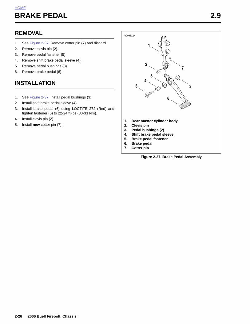
HOME
BRAKE PEDAL 2.9
REMO
1. See F
2. Remo
3. Remo
4. Remo
5. Remo
6. Remo
INSTA
1. See F
2. Instal
3. Instaltighte
4. Instal
5. Instal
2-26
VAL
igure 2-37. Remove cotter pin (7) and discard.
ve clevis pin (2).
ve pedal fastener (5).
ve shift brake pedal sleeve (4).
ve pedal bushings (3).
ve brake pedal (6).
LLATION
igure 2-37. Install pedal bushings (3).
l shift brake pedal sleeve (4).
l brake pedal (6) using LOCTITE 272 (Red) andn fastener (5) to 22-24 ft-lbs (30-33 Nm).
l clevis pin (2).
l new cotter pin (7).
Figure 2-37. Brake Pedal Assembly
1. Rear master cylinder body2. Clevis pin3. Pedal bushings (2)4. Shift brake pedal sleeve5. Brake pedal fastener6. Brake pedal7. Cotter pin
b0938x2x
1
2
45
3
7
6
3
2006 Buell Firebolt: Chassis
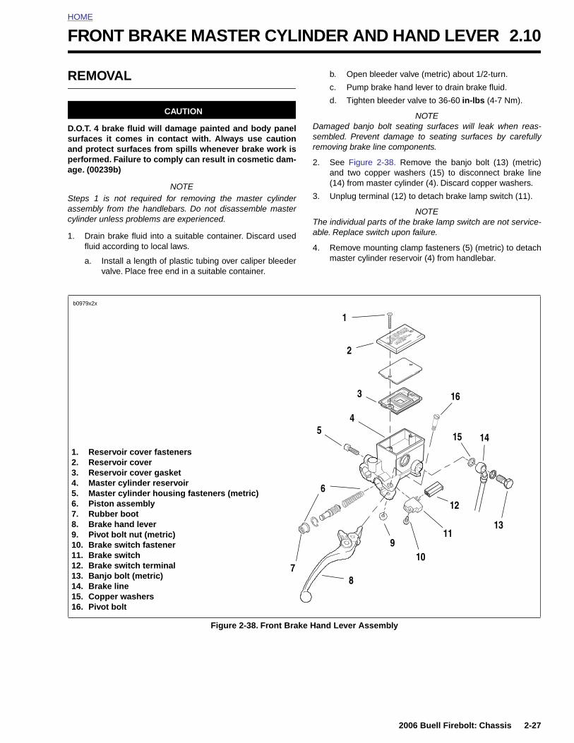
HOME
F
R
Dsapa
Sac
1
RONT BRAKE MASTER CYLINDER AND HAND LEVER 2.10
EMOVAL
CAUTION
.O.T. 4 brake fluid will damage painted and body panelurfaces it comes in contact with. Always use cautionnd protect surfaces from spills whenever brake work iserformed. Failure to comply can result in cosmetic dam-ge. (00239b)
NOTEteps 1 is not required for removing the master cylinderssembly from the handlebars. Do not disassemble masterylinder unless problems are experienced.
. Drain brake fluid into a suitable container. Discard usedfluid according to local laws.
a. Install a length of plastic tubing over caliper bleedervalve. Place free end in a suitable container.
b. Open bleeder valve (metric) about 1/2-turn.
c. Pump brake hand lever to drain brake fluid.
d. Tighten bleeder valve to 36-60 in-lbs (4-7 Nm).
NOTEDamaged banjo bolt seating surfaces will leak when reas-sembled. Prevent damage to seating surfaces by carefullyremoving brake line components.
2. See Figure 2-38. Remove the banjo bolt (13) (metric)and two copper washers (15) to disconnect brake line(14) from master cylinder (4). Discard copper washers.
3. Unplug terminal (12) to detach brake lamp switch (11).
NOTEThe individual parts of the brake lamp switch are not service-able. Replace switch upon failure.
4. Remove mounting clamp fasteners (5) (metric) to detachmaster cylinder reservoir (4) from handlebar.
1. Reservoir cover fasteners2. Reservoir cover3. Reservoir cover gasket4. Master cylinder reservoir5. Master cylinder housing fasteners (metric)6. Piston assembly
b0979x2x
1
2
3
6
12
15
16
14
45
2006 Buell Firebolt: Chassis 2-27
Figure 2-38. Front Brake Hand Lever Assembly
7. Rubber boot8. Brake hand lever9. Pivot bolt nut (metric)10. Brake switch fastener11. Brake switch12. Brake switch terminal13. Banjo bolt (metric)14. Brake line15. Copper washers16. Pivot bolt
8
10
1113
9
7
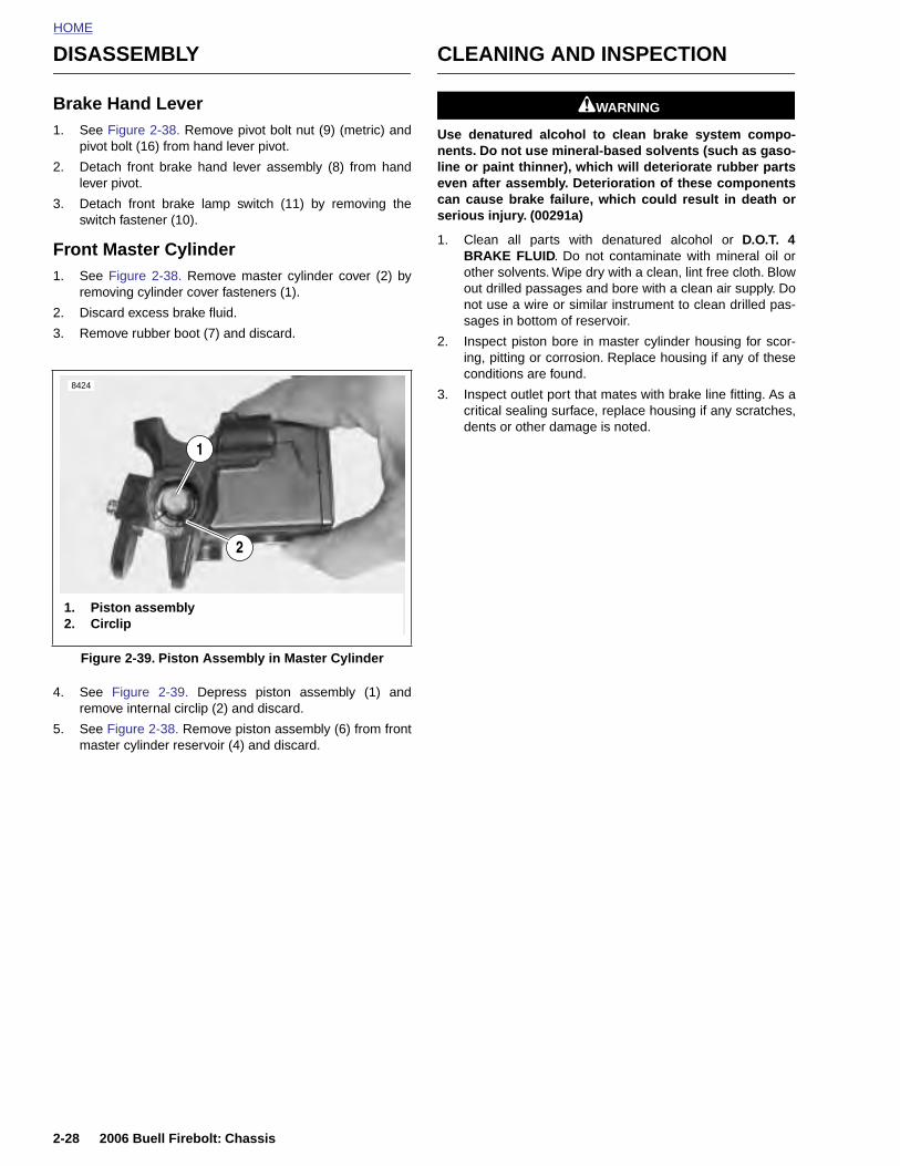
HOME
DISASSEMBLY CLEANING AND INSPECTION
Brake Hand Lever1. See Figure 2-38. Remove pivot bolt nut (9) (metric) and
pivot bolt (16) from hand lever pivot.
2. Detach front brake hand lever assembly (8) from handlever pivot.
3. Detach front brake lamp switch (11) by removing theswitch fastener (10).
Front Master Cylinder1. See Figure 2-38. Remove master cylinder cover (2) by
removing cylinder cover fasteners (1).
2. Discard excess brake fluid.
3. Remove rubber boot (7) and discard.
4. See Figure 2-39. Depress piston assembly (1) andremove internal circlip (2) and discard.
5. See Figure 2-38. Remove piston assembly (6) from frontmaster cylinder reservoir (4) and discard.
11WARNING1WARNING
Use denatured alcohol to clean brake system compo-nents. Do not use mineral-based solvents (such as gaso-line or paint thinner), which will deteriorate rubber partseven after assembly. Deterioration of these componentscan cause brake failure, which could result in death orserious injury. (00291a)
1. Clean all parts with denatured alcohol or D.O.T. 4BRAKE FLUID. Do not contaminate with mineral oil orother solvents. Wipe dry with a clean, lint free cloth. Blowout drilled passages and bore with a clean air supply. Donot use a wire or similar instrument to clean drilled pas-sages in bottom of reservoir.
2. Inspect piston bore in master cylinder housing for scor-ing, pitting or corrosion. Replace housing if any of theseconditions are found.
3. Inspect outlet port that mates with brake line fitting. As acritical sealing surface, replace housing if any scratches,dents or other damage is noted.
Figure 2-39. Piston Assembly in Master Cylinder
8424
2
1. Piston assembly2. Circlip
1
2-28 2006 Buell Firebolt: Chassis

HOME
ASSEMBLY
Front Master Cylinder1. Obtain PISTON ASSEMBLY KIT.
2. See Figure 2-40. Assemble new piston componentsplacing small end of spring (5) behind primary seal ofpiston (4).
3. Lubricate master cylinder body and piston seals withspecial lubricant found in the service parts kit.
11WARNING1WARNING
When installing circlip to secure master cylinder, be surethe circlip snaps into place. Failure to do so can result inimproper brake operation which could result in death orserious injury.
4. See Figure 2-38. Insert piston assembly (6), spring first,into master cylinder reservoir (4).
5. See Figure 2-39. Secure piston assembly (1) with a newcirclip (2).
6. See Figure 2-40. Install ridge on boot (1) into groove onpiston (3).
Brake Hand Lever1. See Figure 2-38. Lubricate pivot bolt (16) with LOCTITE
ANTI-SEIZE.
2. Align hole in hand lever (8) with hole in hand lever pivotand install pivot bolt (16) through top of hand lever pivotand tighten nut to 80-120 in-lbs (9-13.5 Nm).
Figure 2-40. Front Master Cylinder Piston Assembly
b0977x2x
1. Ridge on rubber boot2. Circlip3. Groove on piston4. Primary seal of piston5. Spring
12
5
4
3
2006 Buell Firebolt: Chassis 2-29
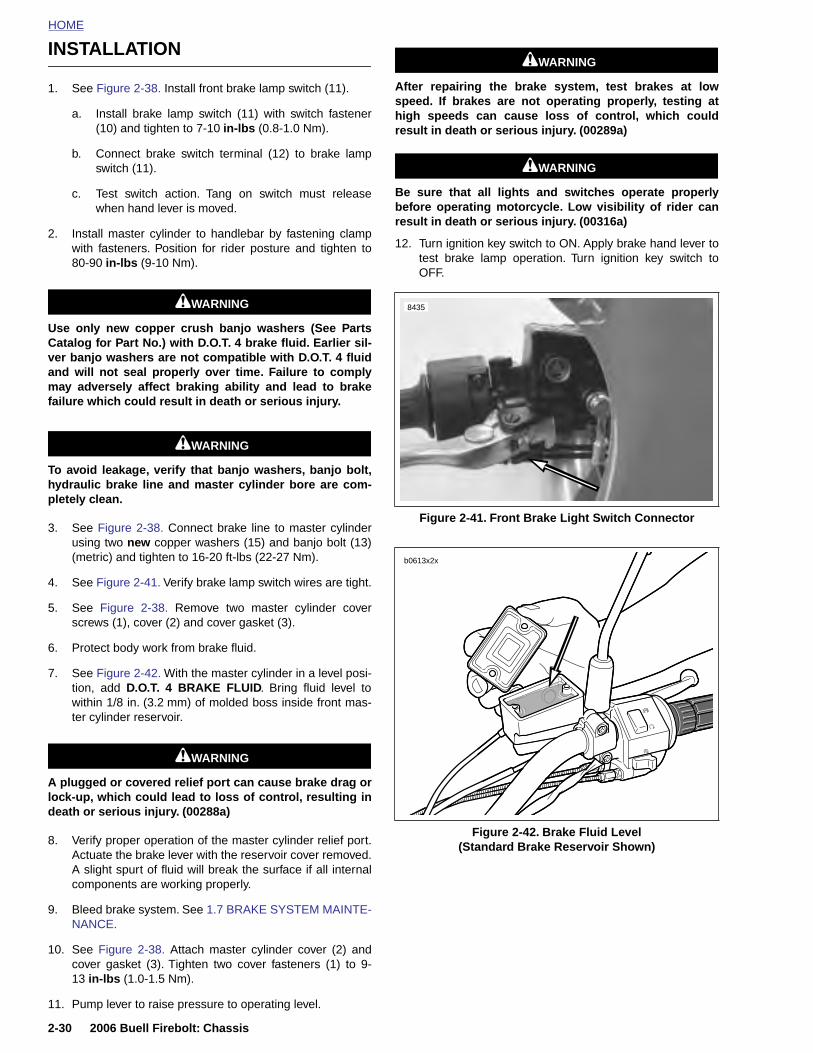
HOME
INSTALLATION 11WARNING1WARNING
1. See Figure 2-38. Install front brake lamp switch (11).
a. Install brake lamp switch (11) with switch fastener(10) and tighten to 7-10 in-lbs (0.8-1.0 Nm).
b. Connect brake switch terminal (12) to brake lampswitch (11).
c. Test switch action. Tang on switch must releasewhen hand lever is moved.
2. Install master cylinder to handlebar by fastening clampwith fasteners. Position for rider posture and tighten to80-90 in-lbs (9-10 Nm).
11WARNING1WARNING
Use only new copper crush banjo washers (See PartsCatalog for Part No.) with D.O.T. 4 brake fluid. Earlier sil-ver banjo washers are not compatible with D.O.T. 4 fluidand will not seal properly over time. Failure to complymay adversely affect braking ability and lead to brakefailure which could result in death or serious injury.
11WARNING1WARNING
To avoid leakage, verify that banjo washers, banjo bolt,hydraulic brake line and master cylinder bore are com-pletely clean.
3. See Figure 2-38. Connect brake line to master cylinderusing two new copper washers (15) and banjo bolt (13)(metric) and tighten to 16-20 ft-lbs (22-27 Nm).
4. See Figure 2-41. Verify brake lamp switch wires are tight.
5. See Figure 2-38. Remove two master cylinder coverscrews (1), cover (2) and cover gasket (3).
6. Protect body work from brake fluid.
7. See Figure 2-42. With the master cylinder in a level posi-tion, add D.O.T. 4 BRAKE FLUID. Bring fluid level towithin 1/8 in. (3.2 mm) of molded boss inside front mas-ter cylinder reservoir.
11WARNING1WARNING
After repairing the brake system, test brakes at lowspeed. If brakes are not operating properly, testing athigh speeds can cause loss of control, which couldresult in death or serious injury. (00289a)
11WARNING1WARNING
Be sure that all lights and switches operate properlybefore operating motorcycle. Low visibility of rider canresult in death or serious injury. (00316a)
12. Turn ignition key switch to ON. Apply brake hand lever totest brake lamp operation. Turn ignition key switch toOFF.
Figure 2-41. Front Brake Light Switch Connector
8435
b0613x2x
2-30 2006 Buell Firebolt: Chassis
A plugged or covered relief port can cause brake drag orlock-up, which could lead to loss of control, resulting indeath or serious injury. (00288a)
8. Verify proper operation of the master cylinder relief port.Actuate the brake lever with the reservoir cover removed.A slight spurt of fluid will break the surface if all internalcomponents are working properly.
9. Bleed brake system. See 1.7 BRAKE SYSTEM MAINTE-NANCE.
10. See Figure 2-38. Attach master cylinder cover (2) andcover gasket (3). Tighten two cover fasteners (1) to 9-13 in-lbs (1.0-1.5 Nm).
11. Pump lever to raise pressure to operating level.
Figure 2-42. Brake Fluid Level (Standard Brake Reservoir Shown)

HOME
F
R
1
2
Dsr
3
4
5
RONT BRAKE LINE 2.11
EMOVAL
. Drain brake fluid into a suitable container. Discard ofused fluid according to local laws.
a. Install a length of plastic tubing over caliper bleedervalve. Place free end in a suitable container.
b. Open bleeder valve (metric) about 1/2-turn.
c. Pump brake hand lever to drain brake fluid.
d. Tighten bleeder valve to 36-60 in-lbs (4-7 Nm).
. See Figure 2-43. Remove p-clamp (1) detaching brakeline from right side of lower fork clamp.
NOTEamaged banjo bolt seating surfaces will leak when reas-embled. Prevent damage to seating surfaces by carefullyemoving brake line components.
. See Figure 2-38. Remove master cylinder banjo bolt (13)(metric) and two copper washers (15) to disconnectbrake line from master cylinder (4). Discard copperwashers.
. See Figure 2-43. Remove caliper banjo bolt (5) (metric),two copper washers and wire form (3) to disconnectbrake line (2) from caliper. Discard copper washers.
. Carefully inspect the brake line for dents, cuts, chaffingor other defects. Replace the brake line if any damage isnoted.
Figure 2-43. Front Brake Line
8429
1. P-clamp2. Brake line3. Wire form4. Bleeder valve5. Banjo bolt
1
2
3
4
5
2006 Buell Firebolt: Chassis 2-31

HOME
INSTALLATION 7. Install bleeder valve if removed. Refill master cylinderand bleed brakes. See 1.7 BRAKE SYSTEM MAINTE-NANCE.
NOTE
To avoid leakage, verify that gaskets, banjo bolt, hydraulicbrake line and master cylinder bore are completely clean.
1. See Figure 2-38. Connect brake line (14) to master cylin-der (4) using two new copper washers (15) and a banjobolt (13) (metric). Loosely install bolt into master cylinder.
2. Route the brake line from the master cylinder to the cali-per. See D.1 HOSE AND WIRE ROUTING for front brakeline routing.
11WARNING1WARNING
Use only new copper crush banjo washers (See PartsCatalog for Part No.) with D.O.T. 4 brake fluid. Earlier sil-ver banjo washers are not compatible with D.O.T. 4 fluidand will not seal properly over time. Failure to complymay adversely affect braking ability and lead to brakefailure which could result in death or serious injury.
NOTE
To avoid leakage, verify that gaskets, banjo bolt, hydraulicbrake line and master cylinder bore are completely clean.
3. Install brake line to caliper.
a. See Figure 2-43. Install new copper washer, brakeline (2), new copper washer and wire form (3) ontobanjo bolt (5).
b. Finger tighten banjo bolt (5) onto front caliper beingcareful not to pinch wire form (3) while tightening,wire form should rotate around banjo bolt freely.
c. Twist brake line (2) into wire form (3) spiral and clockwire form against bleeder valve (4).
4. Tighten p-clamp with fastener (1) on lower triple clamp to
11WARNING1WARNING
Be sure that all lights and switches operate properlybefore operating motorcycle. Low visibility of rider canresult in death or serious injury. (00316a)
8. Turn ignition key switch to ON. Apply brake hand lever totest brake lamp operation. Turn ignition key switch toLOCK.
8429
1. P-clamp2. Brake line3. Wire form
1
2
3
4
5
2-32 2006 Buell Firebolt: Chassis
36-60 in-lbs (4-7 Nm).
5. See Figure 2-38. Tighten master cylinder banjo bolt (12)(metric) to 16-20 ft-lbs (22-27 Nm).
6. See Figure 2-43. Tighten brake caliper banjo bolt (5)(metric) to 16-20 ft-lbs (22-27 Nm).
11WARNING1WARNING
After repairing the brake system, test brakes at lowspeed. If brakes are not operating properly, testing athigh speeds can cause loss of control, which couldresult in death or serious injury. (00289a)
Figure 2-44. Front Brake Line
4. Bleeder valve5. Banjo bolt
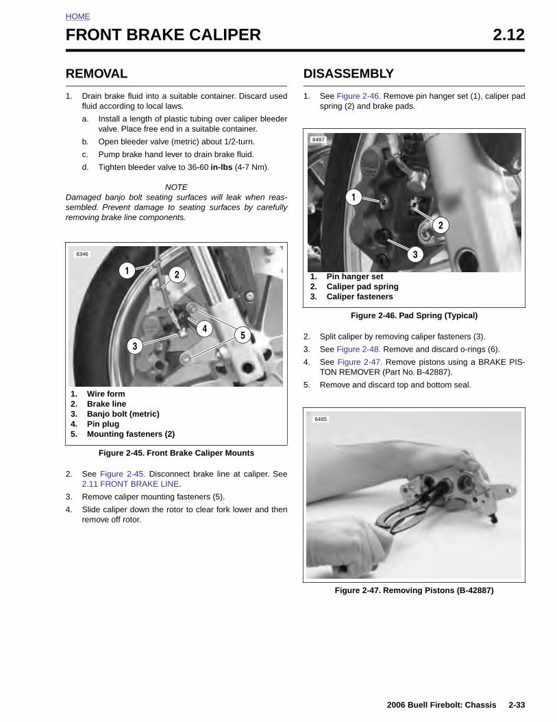
HOME
F
R
1
Dsr
2
3
RONT BRAKE CALIPER 2.12
EMOVAL
. Drain brake fluid into a suitable container. Discard usedfluid according to local laws.
a. Install a length of plastic tubing over caliper bleedervalve. Place free end in a suitable container.
b. Open bleeder valve (metric) about 1/2-turn.
c. Pump brake hand lever to drain brake fluid.
d. Tighten bleeder valve to 36-60 in-lbs (4-7 Nm).
NOTEamaged banjo bolt seating surfaces will leak when reas-embled. Prevent damage to seating surfaces by carefullyemoving brake line components.
. See Figure 2-45. Disconnect brake line at caliper. See2.11 FRONT BRAKE LINE.
. Remove caliper mounting fasteners (5).
DISASSEMBLY
1. See Figure 2-46. Remove pin hanger set (1), caliper padspring (2) and brake pads.
2. Split caliper by removing caliper fasteners (3).
3. See Figure 2-48. Remove and discard o-rings (6).
4. See Figure 2-47. Remove pistons using a BRAKE PIS-TON REMOVER (Part No. B-42887).
5. Remove and discard top and bottom seal.
Figure 2-45. Front Brake Caliper Mounts
8346
21
4
1. Wire form2. Brake line3. Banjo bolt (metric)4. Pin plug5. Mounting fasteners (2)
53
Figure 2-46. Pad Spring (Typical)
1. Pin hanger set2. Caliper pad spring3. Caliper fasteners
8487
1
2
3
6495
2006 Buell Firebolt: Chassis 2-33
4. Slide caliper down the rotor to clear fork lower and thenremove off rotor.
Figure 2-47. Removing Pistons (B-42887)
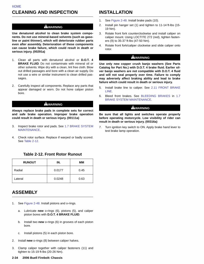
HOME
CLEANING AND INSPECTION INSTALLATION
11WARNING1WARNING
Use denatured alcohol to clean brake system compo-nents. Do not use mineral-based solvents (such as gaso-line or paint thinner), which will deteriorate rubber partseven after assembly. Deterioration of these componentscan cause brake failure, which could result in death orserious injury. (00291a)
1. Clean all parts with denatured alcohol or D.O.T. 4BRAKE FLUID. Do not contaminate with mineral oil orother solvents. Wipe dry with a clean, lint free cloth. Blowout drilled passages and bore with a clean air supply. Donot use a wire or similar instrument to clean drilled pas-sages.
2. Carefully inspect all components. Replace any parts thatappear damaged or worn. Do not hone caliper pistonbore.
11WARNING1WARNING
Always replace brake pads in complete sets for correctand safe brake operation. Improper brake operationcould result in death or serious injury. (00111a)
3. Inspect brake rotor and pads. See 1.7 BRAKE SYSTEMMAINTENANCE.
4. Check rotor surface. Replace if warped or badly scored.See Table 2-12.
ASSEMBLY
1. See Figure 2-48. Install brake pads (10).
2. Install pin hanger set (1) and tighten to 11-14 ft-lbs (15-19 Nm).
3. Rotate front fork counterclockwise and install caliper oncaliper mount. Using LOCTITE 272 (red), tighten fasten-ers (9) to 35-37 ft-lbs (47-50 Nm).
4. Rotate front fork/caliper clockwise and slide caliper ontorotor.
11WARNING1WARNING
Use only new copper crush banjo washers (See PartsCatalog for Part No.) with D.O.T. 4 brake fluid. Earlier sil-ver banjo washers are not compatible with D.O.T. 4 fluidand will not seal properly over time. Failure to complymay adversely affect braking ability and lead to brakefailure which could result in death or serious injury.
5. Install brake line to caliper. See 2.11 FRONT BRAKELINE.
6. Bleed front brakes. See BLEEDING BRAKES in 1.7BRAKE SYSTEM MAINTENANCE.
11WARNING1WARNING
Be sure that all lights and switches operate properlybefore operating motorcycle. Low visibility of rider canresult in death or serious injury. (00316a)
7. Turn ignition key switch to ON. Apply brake hand lever totest brake lamp operation.
Table 2-12. Front Rotor Runout
RUNOUT IN. MM
Radial 0.0177 0.45
Lateral 0.0248 0.63
2-34 2006 Buell Firebolt: Chassis
1. See Figure 2-48. Install pistons and o-rings.
a. Lubricate new o-rings (6), pistons (5), and caliperpiston bores with D.O.T. 4 BRAKE FLUID.
b. Install two new o-rings (6) in grooves of each pistonbore.
c. Install pistons (5) in each piston bore.
2. Install new o-rings (8) between caliper halves.
3. Clamp caliper together with caliper fasteners (11) andtighten to 15-19 ft-lbs (20-26 Nm).
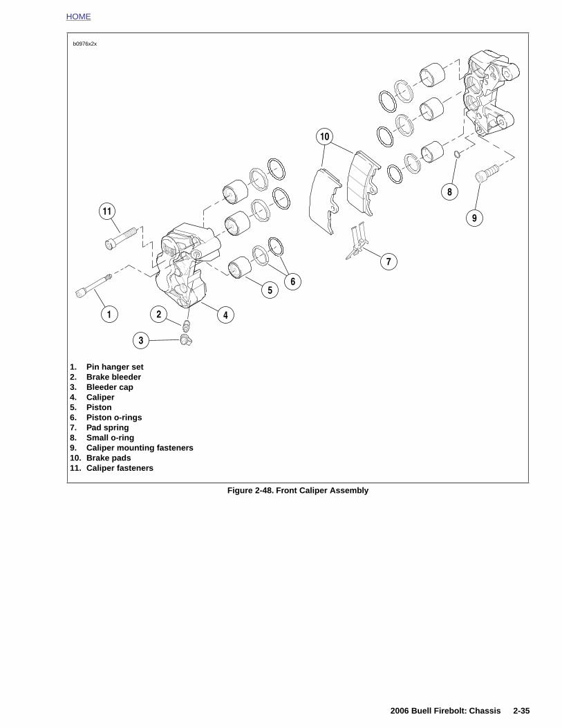
HOME
Figure 2-48. Front Caliper Assembly
b0976x2x
1. Pin hanger set2. Brake bleeder3. Bleeder cap4. Caliper5. Piston6. Piston o-rings7. Pad spring8. Small o-ring9. Caliper mounting fasteners10. Brake pads11. Caliper fasteners
5
3
21
11
4
6
7
8
9
10
2006 Buell Firebolt: Chassis 2-35
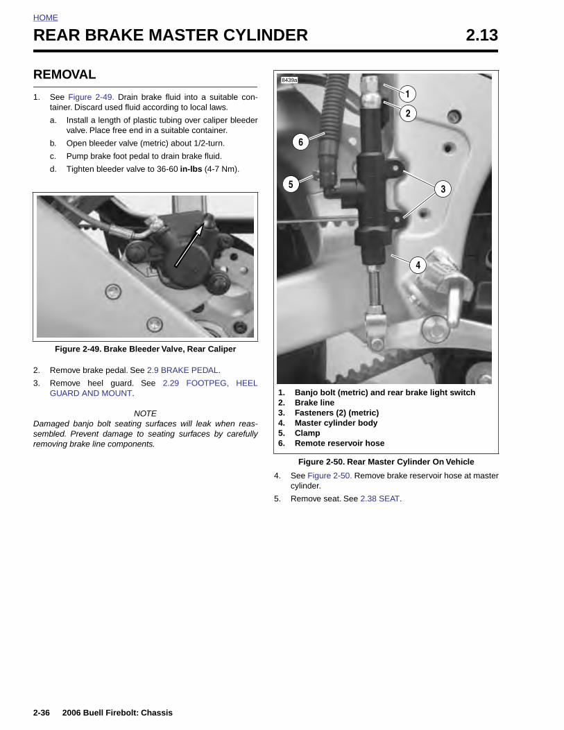
HOME
REAR BRAKE MASTER CYLINDER 2.13
REMO
1. See Ftainer
a. Iv
b. O
c. P
d. T
2. Remo
3. RemoGUAR
Damagedsembled. removing
Figu
2-36
VAL
igure 2-49. Drain brake fluid into a suitable con-. Discard used fluid according to local laws.
nstall a length of plastic tubing over caliper bleederalve. Place free end in a suitable container.
pen bleeder valve (metric) about 1/2-turn.
ump brake foot pedal to drain brake fluid.
ighten bleeder valve to 36-60 in-lbs (4-7 Nm).
ve brake pedal. See 2.9 BRAKE PEDAL.
ve heel guard. See 2.29 FOOTPEG, HEELD AND MOUNT.
NOTE banjo bolt seating surfaces will leak when reas-Prevent damage to seating surfaces by carefullybrake line components.
4. See Figure 2-50. Remove brake reservoir hose at mastercylinder.
5. Remove seat. See 2.38 SEAT.
re 2-49. Brake Bleeder Valve, Rear Caliper
Figure 2-50. Rear Master Cylinder On Vehicle
8439a
1. Banjo bolt (metric) and rear brake light switch2. Brake line3. Fasteners (2) (metric)4. Master cylinder body5. Clamp6. Remote reservoir hose
4
6
2
1
35
2006 Buell Firebolt: Chassis
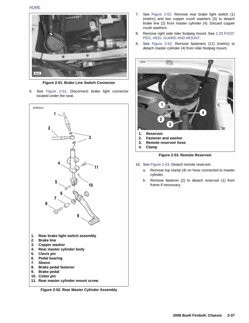
HOME
6. See Figure 2-51. Disconnect brake light connectorlocated under the seat.
7. See Figure 2-52. Remove rear brake light switch (1)(metric) and two copper crush washers (3) to detachbrake line (2) from master cylinder (4). Discard coppercrush washers.
8. Remove right side rider footpeg mount. See 2.29 FOOT-PEG, HEEL GUARD AND MOUNT.
9. See Figure 2-52. Remove fasteners (11) (metric) todetach master cylinder (4) from rider footpeg mount.
10. See Figure 2-53. Detach remote reservoir.
a. Remove top clamp (4) on hose connected to mastercylinder.
b. Remove fastener (2) to detach reservoir (1) fromframe if necessary.
Figure 2-51. Brake Line Switch Connector
8442
b0983a2x
4
5
78
6
10
9
2
1
3
11
Figure 2-53. Remote Reservoir
8359
1. Reservoir2. Fastener and washer3. Remote reservoir hose4. Clamp
3
42
1
2006 Buell Firebolt: Chassis 2-37
Figure 2-52. Rear Master Cylinder Assembly
1. Rear brake light switch assembly2. Brake line3. Copper washer4. Rear master cylinder body5. Clevis pin6. Pedal bearing7. Sleeve8. Brake pedal fastener9. Brake pedal10. Cotter pin11. Rear master cylinder mount screw
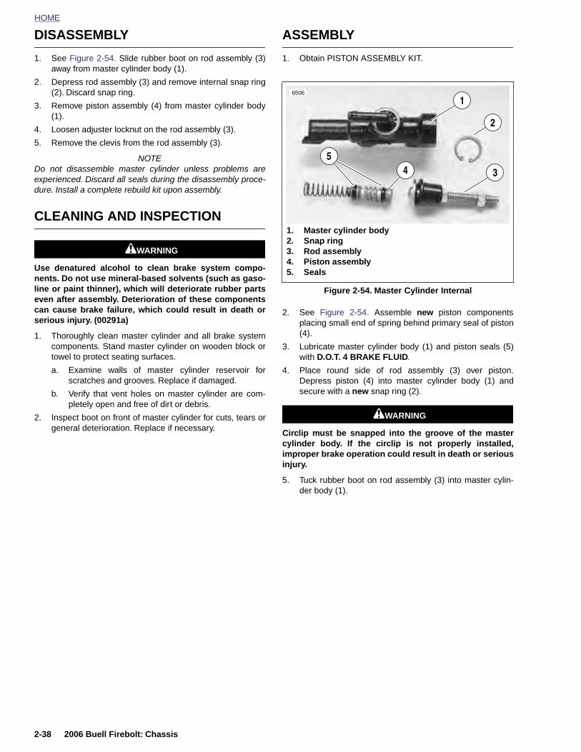
HOME
DISASSEMBLY ASSEMBLY
1. See Figure 2-54. Slide rubber boot on rod assembly (3)away from master cylinder body (1).
2. Depress rod assembly (3) and remove internal snap ring(2). Discard snap ring.
3. Remove piston assembly (4) from master cylinder body(1).
4. Loosen adjuster locknut on the rod assembly (3).
5. Remove the clevis from the rod assembly (3).
NOTEDo not disassemble master cylinder unless problems areexperienced. Discard all seals during the disassembly proce-dure. Install a complete rebuild kit upon assembly.
CLEANING AND INSPECTION
11WARNING1WARNING
Use denatured alcohol to clean brake system compo-nents. Do not use mineral-based solvents (such as gaso-line or paint thinner), which will deteriorate rubber partseven after assembly. Deterioration of these componentscan cause brake failure, which could result in death orserious injury. (00291a)
1. Thoroughly clean master cylinder and all brake systemcomponents. Stand master cylinder on wooden block ortowel to protect seating surfaces.
a. Examine walls of master cylinder reservoir forscratches and grooves. Replace if damaged.
b. Verify that vent holes on master cylinder are com-pletely open and free of dirt or debris.
2. Inspect boot on front of master cylinder for cuts, tears orgeneral deterioration. Replace if necessary.
1. Obtain PISTON ASSEMBLY KIT.
2. See Figure 2-54. Assemble new piston componentsplacing small end of spring behind primary seal of piston(4).
3. Lubricate master cylinder body (1) and piston seals (5)with D.O.T. 4 BRAKE FLUID.
4. Place round side of rod assembly (3) over piston.Depress piston (4) into master cylinder body (1) andsecure with a new snap ring (2).
11WARNING1WARNING
Circlip must be snapped into the groove of the mastercylinder body. If the circlip is not properly installed,improper brake operation could result in death or seriousinjury.
5. Tuck rubber boot on rod assembly (3) into master cylin-der body (1).
Figure 2-54. Master Cylinder Internal
6506
1. Master cylinder body2. Snap ring3. Rod assembly4. Piston assembly5. Seals
1
2
345
2-38 2006 Buell Firebolt: Chassis
HOME
INSTALLATION
1. See Figure 2-52. Install master cylinder (4) onto footpegmount with fasteners (11). Tighten to 72-96 in-lbs (8-11 Nm).
2. Install rear brake switch (1) and banjo bolt (2) and newcopper crush washers (3). Tighten to 16-20 ft-lbs (22-27 Nm).
3. Install footpeg mount to frame. See 2.29 FOOTPEG,HEEL GUARD AND MOUNT.
11WARNING1WARNING
Use only new copper crush banjo washers (See PartsCatalog for Part No.) with D.O.T. 4 brake fluid. Earlier sil-ver banjo washers are not compatible with D.O.T. 4 fluidand will not seal properly over time. Failure to complymay adversely affect braking ability and lead to brakefailure which could result in death or serious injury.
NOTETo avoid leakage, verify that gaskets, banjo bolt, hydraulicbrake line and master cylinder bore are completely clean.
4. See Figure 2-53. Connect remote reservoir.
a. If removed, attach remote reservoir (1) to frameusing clamp fastener (2). Tighten to 48-72 in-lbs(5.4-8.1 Nm).
b. Attach hose (3) to rear brake reservoir using clamp.
5. See Figure 2-51. Connect brake line switch connectorunder seat.
6. Install heel guard. See 2.29 FOOTPEG, HEEL GUARDAND MOUNT.
7. Install rear brake pedal. See 2.9 BRAKE PEDAL.
8. Adjust rear brake pedal. See BRAKE PEDAL ADJUST-MENT in 1.7 BRAKE SYSTEM MAINTENANCE.
11WARNING1WARNING
After repairing the brake system, test brakes at lowspeed. If brakes are not operating properly, testing athigh speeds can cause loss of control, which couldresult in death or serious injury. (00289a)
9. Add brake fluid and bleed brake system. See 1.7 BRAKESYSTEM MAINTENANCE.
11WARNING1WARNING
Be sure that all lights and switches operate properlybefore operating motorcycle. Low visibility of rider canresult in death or serious injury. (00316a)
11WARNING1WARNING
After installing seat, pull upward on front of seat to besure it is in locked position. While riding, a loose seat canshift causing loss of control, which could result in deathor serious injury. (00070a)
10. Install seat. See 2.38 SEAT.
2006 Buell Firebolt: Chassis 2-39
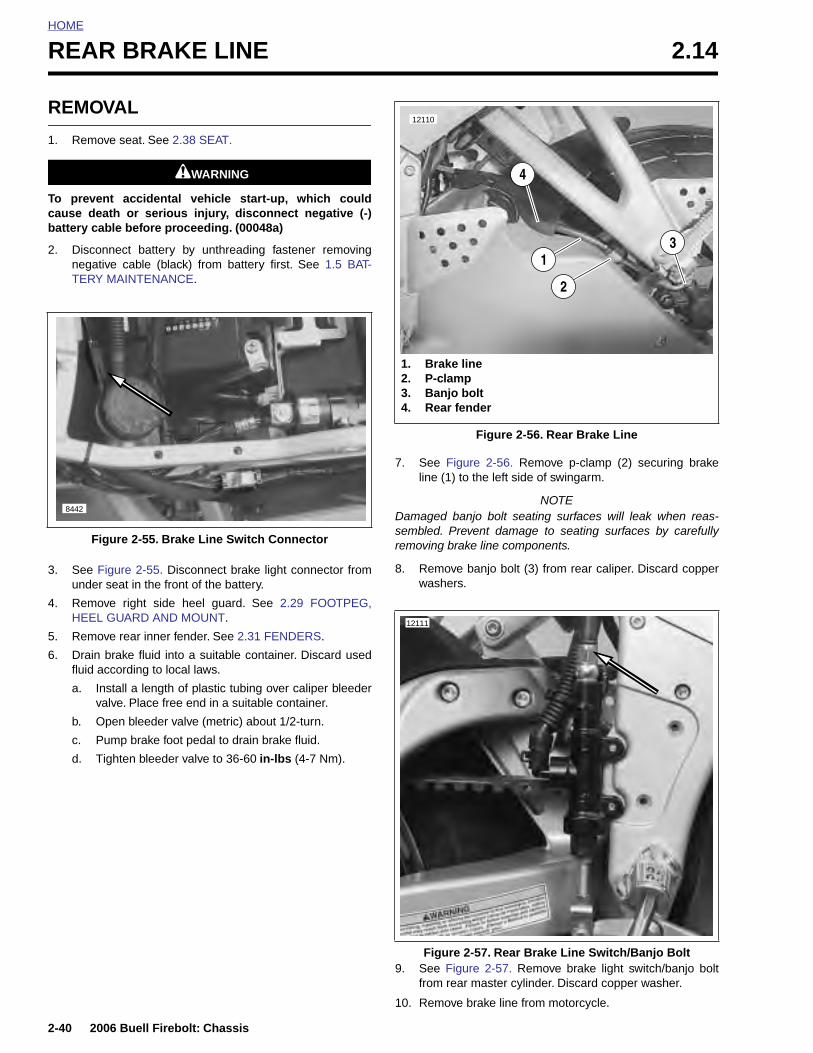
HOME
REAR BRAKE LINE 2.14
REMO
1. Remo
To prevecause debattery ca
2. DisconegaTERY
3. See Funde
4. RemoHEEL
5. Remo
6. Drainfluid a
a. Iv
b. O
c. P
d. T
F
8442
2-40
VAL
ve seat. See 2.38 SEAT.
11WARNING1WARNING
nt accidental vehicle start-up, which couldath or serious injury, disconnect negative (-)ble before proceeding. (00048a)
nnect battery by unthreading fastener removingtive cable (black) from battery first. See 1.5 BAT- MAINTENANCE.
igure 2-55. Disconnect brake light connector fromr seat in the front of the battery.
ve right side heel guard. See 2.29 FOOTPEG, GUARD AND MOUNT.
ve rear inner fender. See 2.31 FENDERS.
brake fluid into a suitable container. Discard usedccording to local laws.
nstall a length of plastic tubing over caliper bleederalve. Place free end in a suitable container.
pen bleeder valve (metric) about 1/2-turn.
ump brake foot pedal to drain brake fluid.
ighten bleeder valve to 36-60 in-lbs (4-7 Nm).
7. See Figure 2-56. Remove p-clamp (2) securing brakeline (1) to the left side of swingarm.
NOTEDamaged banjo bolt seating surfaces will leak when reas-sembled. Prevent damage to seating surfaces by carefullyremoving brake line components.
8. Remove banjo bolt (3) from rear caliper. Discard copperwashers.
igure 2-55. Brake Line Switch Connector
Figure 2-56. Rear Brake Line
12110
1
2
3
1. Brake line2. P-clamp3. Banjo bolt4. Rear fender
4
12111
2006 Buell Firebolt: Chassis
9. See Figure 2-57. Remove brake light switch/banjo boltfrom rear master cylinder. Discard copper washer.
10. Remove brake line from motorcycle.
Figure 2-57. Rear Brake Line Switch/Banjo Bolt
HOME
INSTALLATION
1. See Figure 2-57. Install brake light switch/banjo bolt withnew copper washers to the master cylinder. Tighten to16-20 ft-lbs (22-27 Nm).
NOTETighten the right side banjo bolt with FLARE NUT SOCKETtool (SNAP-ON Part No. FRXM14) or a crowsfoot.
11WARNING1WARNING
Use only new copper crush banjo washers (See PartsCatalog for Part No.) with D.O.T. 4 brake fluid. Earlier sil-ver banjo washers are not compatible with D.O.T. 4 fluidand will not seal properly over time. Failure to complymay adversely affect braking ability and lead to brakefailure which could result in death or serious injury.
2. Install brake line, banjo bolt and new copper washers torear caliper. Tighten to 16-20 ft-lbs (22-27 Nm).
3. See Figure 2-56. Secure brake line (1) to left side ofswingarm with p-clamp (2), and tighten to 36-60 in-lbs(4-7 Nm). See D.1 HOSE AND WIRE ROUTING forbrake line routing.
4. See Figure 2-58. Connect brake light switch connectorunderneath seat. See D.1 HOSE AND WIRE ROUTINGfor brake line routing.
5. Install rear inner fender. Ensure that brake line is cor-rectly captured by rear fender. See 2.31 FENDERS.
6. Install right heel guard. See 2.29 FOOTPEG, HEELGUARD AND MOUNT.
7. Bleed brakes. See BLEEDING BRAKES in 1.7 BRAKESYSTEM MAINTENANCE.
11WARNING1WARNING
Connect positive (+) battery cable first. If positive (+)cable should contact ground with negative (-) cable con-nected, the resulting sparks can cause a battery explo-sion, which could result in death or serious injury.(00068a)
8. Install negative battery cable and tighten to 72-96 in-lbs
11WARNING1WARNING
After repairing the brake system, test brakes at lowspeed. If brakes are not operating properly, testing athigh speeds can cause loss of control, which couldresult in death or serious injury. (00289a)
11. Test ride motorcycle and check for proper brake opera-tion.
2006 Buell Firebolt: Chassis 2-41
(8-11 Nm). See 1.5 BATTERY MAINTENANCE.
11WARNING1WARNING
After installing seat, pull upward on front of seat to besure it is in locked position. While riding, a loose seat canshift causing loss of control, which could result in deathor serious injury. (00070a)
9. Install seat. See 2.38 SEAT.
11WARNING1WARNING
Be sure that all lights and switches operate properlybefore operating motorcycle. Low visibility of rider canresult in death or serious injury. (00316a)
10. Turn ignition key ON, depress rear brake pedal andcheck for proper brake light operation.

HOME
REAR BRAKE CALIPER 2.15
REMO
● Stepsrotor.
● Damareasscaref
1. Drainfluid a
a. Iv
b. O
c. P
d. T
2. RemoSee 2
8348
1. Brak2. Ban3. Cop4. Blee5. Pin 6. Sma7. Larg8. Cali
1
2-42
3. Seeand
VAL
NOTES 1 and 2 are not required for detaching caliper from
Drain fluid only when disassembling caliper.
ged banjo bolt seating surfaces will leak whenembled. Prevent damage to seating surfaces byully removing brake line components.
brake fluid into a suitable container. Discard usedccording to local laws.
nstall a length of plastic tubing over caliper bleederalve. Place free end in a suitable container.
pen bleeder valve (metric) about 1/2-turn.
ump brake foot pedal to drain brake fluid.
ighten bleeder valve to 36-60 in-lbs (4-7 Nm).
ve banjo bolt connecting brake line to rear caliper..14 REAR BRAKE LINE.
DISASSEMBLY
1. See Figure 2-58. Remove pin plug (5) and pad hanger(metric) to free brake pads.
2. See Figure 2-59. Remove spring clip (1).
Figure 2-58. Rear Brake Caliper
e linejo bolt (metric)per washers (2)der valve (metric)plugll caliper fastenerer caliper fastener
per mounting fasteners
2 3
4
8
5
7
6
Figure 2-59. Brake Pads
6487
3
1
2
1. Clip2. Pin plug and pad hanger (metric)3. Brake pads (2)
6496
1
2
3
2006 Buell Firebolt: Chassis
Figure 2-58. Remove caliper mounting fasteners (6 7).
3. See Figure 2-60. Remove piston (3) using BRAKE CALI-PER PISTON REMOVER (1) (Part No. B-42887) withadaptor (2).
4. Remove two o-rings from groove in caliper bore and dis-card.
Figure 2-60. Removing Rear Brake Caliper Piston
1. Brake caliper piston remover2. Adaptor3. Piston
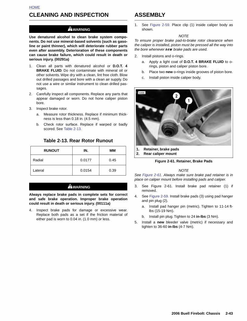
HOME
CLEANING AND INSPECTION
11WARNING1WARNING
Use denatured alcohol to clean brake system compo-nents. Do not use mineral-based solvents (such as gaso-line or paint thinner), which will deteriorate rubber partseven after assembly. Deterioration of these componentscan cause brake failure, which could result in death orserious injury. (00291a)
1. Clean all parts with denatured alcohol or D.O.T. 4BRAKE FLUID. Do not contaminate with mineral oil orother solvents. Wipe dry with a clean, lint free cloth. Blowout drilled passages and bore with a clean air supply. Donot use a wire or similar instrument to clean drilled pas-sages.
2. Carefully inspect all components. Replace any parts thatappear damaged or worn. Do not hone caliper pistonbore.
3. Inspect brake rotor.
a. Measure rotor thickness. Replace if minimum thick-ness is less than 0.18 in. (4.5 mm).
b. Check rotor surface. Replace if warped or badlyscored. See Table 2-13.
11WARNING1WARNING
Always replace brake pads in complete sets for correctand safe brake operation. Improper brake operationcould result in death or serious injury. (00111a)
4. Inspect brake pads for damage or excessive wear.Replace both pads as a set if the friction material ofeither pad is worn to 0.04 in. (1.0 mm) or less.
ASSEMBLY
1. See Figure 2-59. Place clip (1) inside caliper body asshown.
NOTETo ensure proper brake pad-to-brake rotor clearance whenthe caliper is installed, piston must be pressed all the way intothe bore whenever new brake pads are used.
2. Install pistons and o-rings.
a. Apply a light coat of D.O.T. 4 BRAKE FLUID to o-rings, piston and caliper piston bore.
b. Place two new o-rings inside grooves of piston bore.
c. Install piston inside caliper body.
NOTESee Figure 2-61. Always make sure brake pad retainer is inplace on caliper mount before installing pads and caliper.
3. See Figure 2-61. Install brake pad retainer (1) ifremoved.
4. See Figure 2-59. Install brake pads (3) using pad hangerand pin plug (2).
a. Install pad hanger pin (metric). Tighten to 11-14 ft-lbs (15-19 Nm).
b. Install pin plug. Tighten to 24 in-lbs (3 Nm).
Table 2-13. Rear Rotor Runout
RUNOUT IN. MM
Radial 0.0177 0.45
Lateral 0.0154 0.39
Figure 2-61. Retainer, Brake Pads
6486
12
1. Retainer, brake pads2. Rear caliper mount
2006 Buell Firebolt: Chassis 2-43
5. Install a new bleeder valve (metric) if necessary andtighten to 36-60 in-lbs (4-7 Nm).
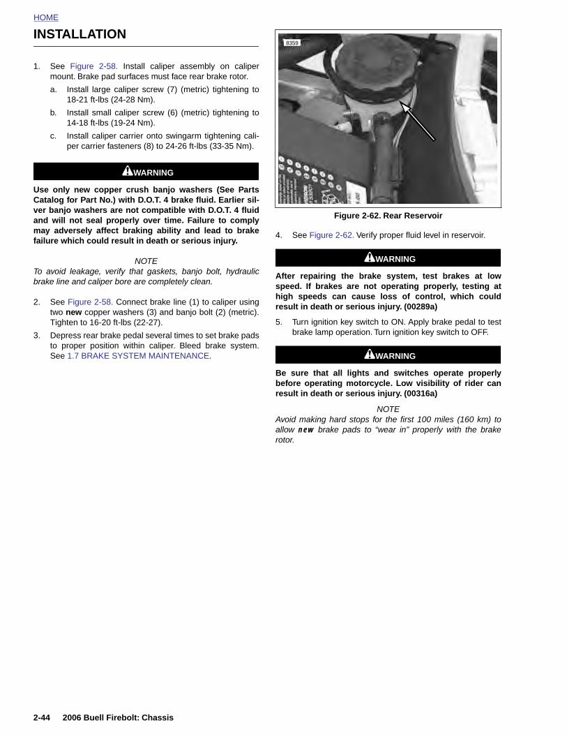
HOME
INSTALLATION8359
1. See Figure 2-58. Install caliper assembly on calipermount. Brake pad surfaces must face rear brake rotor.
a. Install large caliper screw (7) (metric) tightening to18-21 ft-lbs (24-28 Nm).
b. Install small caliper screw (6) (metric) tightening to14-18 ft-lbs (19-24 Nm).
c. Install caliper carrier onto swingarm tightening cali-per carrier fasteners (8) to 24-26 ft-lbs (33-35 Nm).
11WARNING1WARNING
Use only new copper crush banjo washers (See PartsCatalog for Part No.) with D.O.T. 4 brake fluid. Earlier sil-ver banjo washers are not compatible with D.O.T. 4 fluidand will not seal properly over time. Failure to complymay adversely affect braking ability and lead to brakefailure which could result in death or serious injury.
NOTETo avoid leakage, verify that gaskets, banjo bolt, hydraulicbrake line and caliper bore are completely clean.
2. See Figure 2-58. Connect brake line (1) to caliper usingtwo new copper washers (3) and banjo bolt (2) (metric).Tighten to 16-20 ft-lbs (22-27).
3. Depress rear brake pedal several times to set brake padsto proper position within caliper. Bleed brake system.See 1.7 BRAKE SYSTEM MAINTENANCE.
4. See Figure 2-62. Verify proper fluid level in reservoir.
11WARNING1WARNING
After repairing the brake system, test brakes at lowspeed. If brakes are not operating properly, testing athigh speeds can cause loss of control, which couldresult in death or serious injury. (00289a)
5. Turn ignition key switch to ON. Apply brake pedal to testbrake lamp operation. Turn ignition key switch to OFF.
11WARNING1WARNING
Be sure that all lights and switches operate properlybefore operating motorcycle. Low visibility of rider canresult in death or serious injury. (00316a)
NOTEAvoid making hard stops for the first 100 miles (160 km) toallow new brake pads to “wear in” properly with the brakerotor.
Figure 2-62. Rear Reservoir
2-44 2006 Buell Firebolt: Chassis
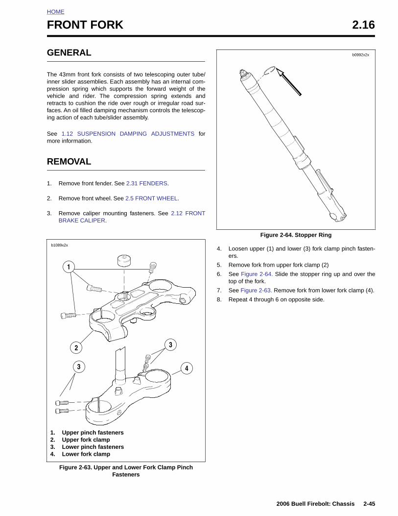
HOME
F
G
Tinpvrfin
Sm
R
1
2
3
RONT FORK 2.16
ENERAL
he 43mm front fork consists of two telescoping outer tube/ner slider assemblies. Each assembly has an internal com-ression spring which supports the forward weight of theehicle and rider. The compression spring extends andetracts to cushion the ride over rough or irregular road sur-aces. An oil filled damping mechanism controls the telescop-g action of each tube/slider assembly.
ee 1.12 SUSPENSION DAMPING ADJUSTMENTS forore information.
EMOVAL
. Remove front fender. See 2.31 FENDERS.
. Remove front wheel. See 2.5 FRONT WHEEL.
. Remove caliper mounting fasteners. See 2.12 FRONTBRAKE CALIPER.
4. Loosen upper (1) and lower (3) fork clamp pinch fasten-ers.
5. Remove fork from upper fork clamp (2)
6. See Figure 2-64. Slide the stopper ring up and over thetop of the fork.
7. See Figure 2-63. Remove fork from lower fork clamp (4).
8. Repeat 4 through 6 on opposite side.
b1089x2x
1
2 3
Figure 2-64. Stopper Ring
b0992x2x
2006 Buell Firebolt: Chassis 2-45
Figure 2-63. Upper and Lower Fork Clamp Pinch Fasteners
3
1. Upper pinch fasteners2. Upper fork clamp3. Lower pinch fasteners4. Lower fork clamp
4
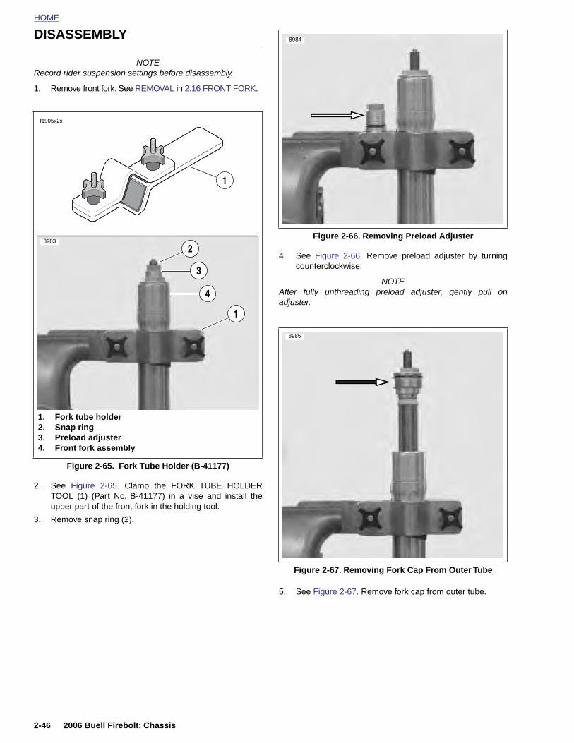
HOME
DISASSEMBLY 8984
NOTERecord rider suspension settings before disassembly.
1. Remove front fork. See REMOVAL in 2.16 FRONT FORK.
2. See Figure 2-65. Clamp the FORK TUBE HOLDERTOOL (1) (Part No. B-41177) in a vise and install theupper part of the front fork in the holding tool.
3. Remove snap ring (2).
4. See Figure 2-66. Remove preload adjuster by turningcounterclockwise.
NOTEAfter fully unthreading preload adjuster, gently pull onadjuster.
Figure 2-65. Fork Tube Holder (B-41177)
f1905x2x
1. Fork tube holder2. Snap ring3. Preload adjuster4. Front fork assembly
1
1
2
3
4
8983Figure 2-66. Removing Preload Adjuster
8985
2-46 2006 Buell Firebolt: Chassis
5. See Figure 2-67. Remove fork cap from outer tube.
Figure 2-67. Removing Fork Cap From Outer Tube
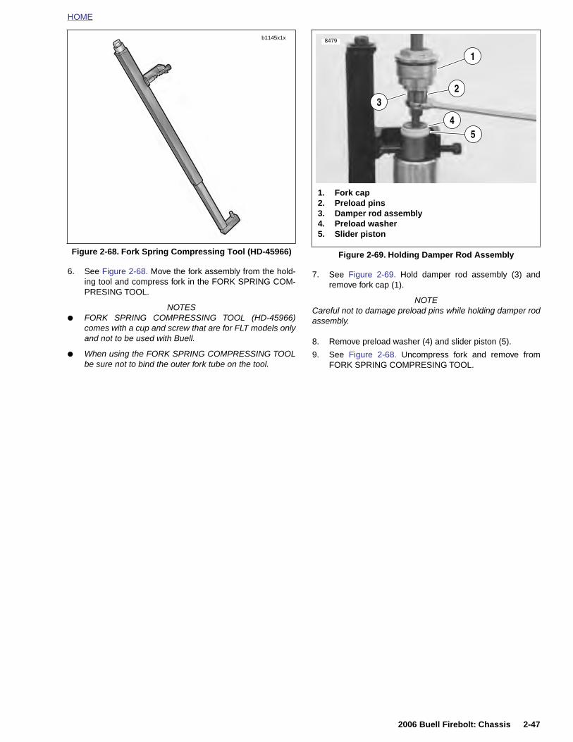
HOME
6. See Figure 2-68. Move the fork assembly from the hold-ing tool and compress fork in the FORK SPRING COM-PRESING TOOL.
NOTES● FORK SPRING COMPRESSING TOOL (HD-45966)
comes with a cup and screw that are for FLT models onlyand not to be used with Buell.
● When using the FORK SPRING COMPRESSING TOOLbe sure not to bind the outer fork tube on the tool.
7. See Figure 2-69. Hold damper rod assembly (3) andremove fork cap (1).
NOTECareful not to damage preload pins while holding damper rodassembly.
8. Remove preload washer (4) and slider piston (5).
9. See Figure 2-68. Uncompress fork and remove fromFORK SPRING COMPRESING TOOL.
Figure 2-68. Fork Spring Compressing Tool (HD-45966)
b1145x1x
Figure 2-69. Holding Damper Rod Assembly
8479
1. Fork cap2. Preload pins3. Damper rod assembly4. Preload washer5. Slider piston
32
1
45
2006 Buell Firebolt: Chassis 2-47
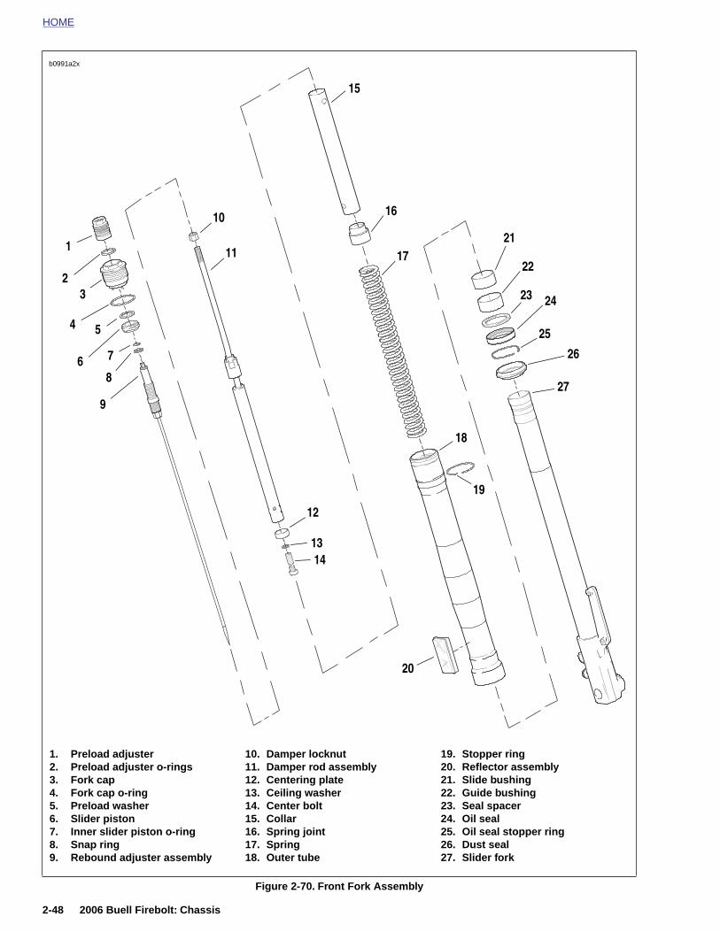
HOME
b0991a2x
1
23
4 5
6 7
8
9
10
11
12
1314
20
15
17
18
21
22
23 24
25
26
27
16
19
2-48 2006 Buell Firebolt: Chassis
Figure 2-70. Front Fork Assembly
1. Preload adjuster2. Preload adjuster o-rings3. Fork cap4. Fork cap o-ring5. Preload washer6. Slider piston7. Inner slider piston o-ring8. Snap ring9. Rebound adjuster assembly
10. Damper locknut11. Damper rod assembly12. Centering plate13. Ceiling washer14. Center bolt15. Collar16. Spring joint17. Spring18. Outer tube
19. Stopper ring20. Reflector assembly21. Slide bushing22. Guide bushing23. Seal spacer24. Oil seal25. Oil seal stopper ring26. Dust seal27. Slider fork
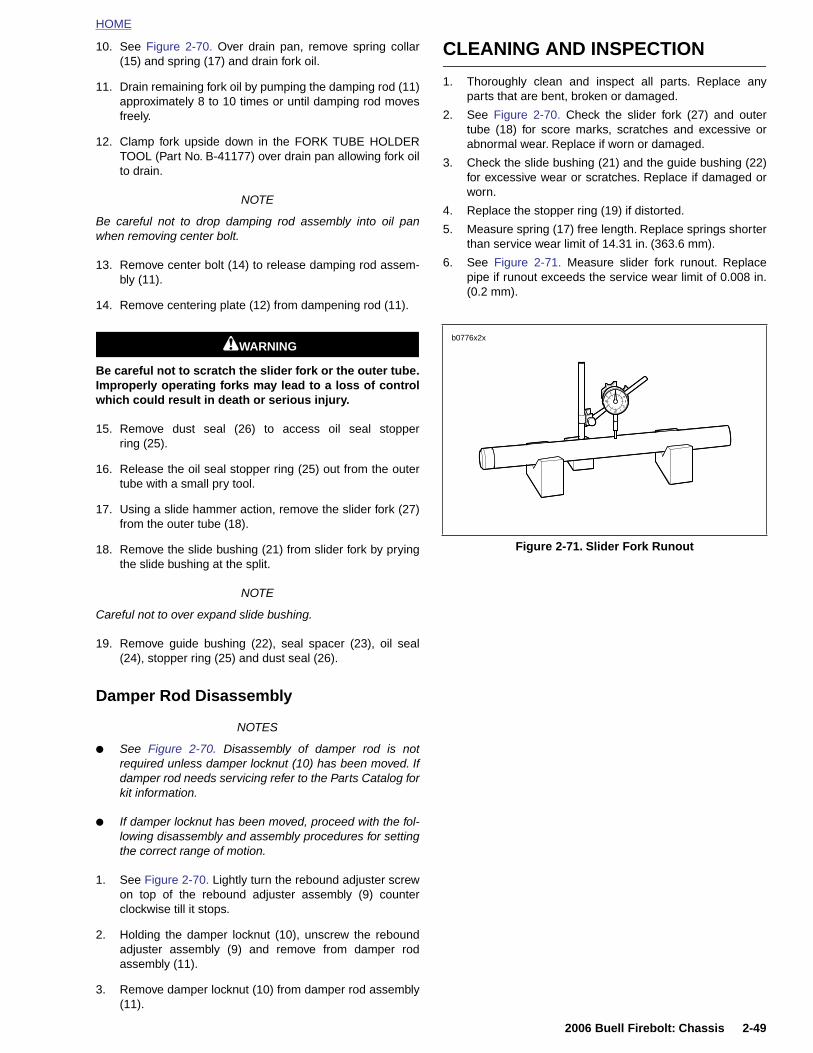
HOME
10. See Figure 2-70. Over drain pan, remove spring collar(15) and spring (17) and drain fork oil.
11. Drain remaining fork oil by pumping the damping rod (11)approximately 8 to 10 times or until damping rod movesfreely.
12. Clamp fork upside down in the FORK TUBE HOLDERTOOL (Part No. B-41177) over drain pan allowing fork oilto drain.
NOTE
Be careful not to drop damping rod assembly into oil panwhen removing center bolt.
13. Remove center bolt (14) to release damping rod assem-bly (11).
14. Remove centering plate (12) from dampening rod (11).
11WARNING1WARNING
Be careful not to scratch the slider fork or the outer tube.Improperly operating forks may lead to a loss of controlwhich could result in death or serious injury.
15. Remove dust seal (26) to access oil seal stopperring (25).
16. Release the oil seal stopper ring (25) out from the outertube with a small pry tool.
17. Using a slide hammer action, remove the slider fork (27)from the outer tube (18).
18. Remove the slide bushing (21) from slider fork by pryingthe slide bushing at the split.
NOTE
Careful not to over expand slide bushing.
19. Remove guide bushing (22), seal spacer (23), oil seal(24), stopper ring (25) and dust seal (26).
Damper Rod Disassembly
CLEANING AND INSPECTION
1. Thoroughly clean and inspect all parts. Replace anyparts that are bent, broken or damaged.
2. See Figure 2-70. Check the slider fork (27) and outertube (18) for score marks, scratches and excessive orabnormal wear. Replace if worn or damaged.
3. Check the slide bushing (21) and the guide bushing (22)for excessive wear or scratches. Replace if damaged orworn.
4. Replace the stopper ring (19) if distorted.
5. Measure spring (17) free length. Replace springs shorterthan service wear limit of 14.31 in. (363.6 mm).
6. See Figure 2-71. Measure slider fork runout. Replacepipe if runout exceeds the service wear limit of 0.008 in.(0.2 mm).
Figure 2-71. Slider Fork Runout
b0776x2x
2006 Buell Firebolt: Chassis 2-49
NOTES
● See Figure 2-70. Disassembly of damper rod is notrequired unless damper locknut (10) has been moved. Ifdamper rod needs servicing refer to the Parts Catalog forkit information.
● If damper locknut has been moved, proceed with the fol-lowing disassembly and assembly procedures for settingthe correct range of motion.
1. See Figure 2-70. Lightly turn the rebound adjuster screwon top of the rebound adjuster assembly (9) counterclockwise till it stops.
2. Holding the damper locknut (10), unscrew the reboundadjuster assembly (9) and remove from damper rodassembly (11).
3. Remove damper locknut (10) from damper rod assembly(11).
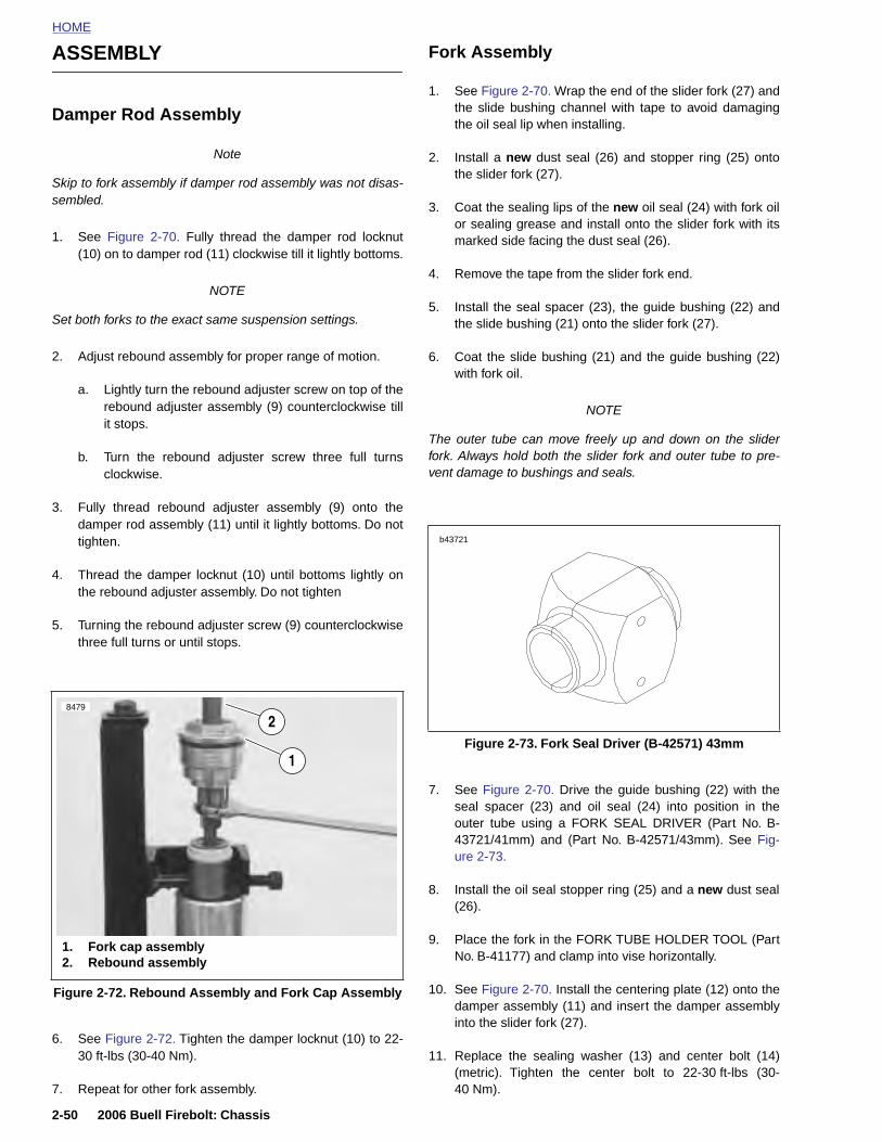
HOME
ASSEMBLY Fork Assembly
Damper Rod Assembly
Note
Skip to fork assembly if damper rod assembly was not disas-sembled.
1. See Figure 2-70. Fully thread the damper rod locknut(10) on to damper rod (11) clockwise till it lightly bottoms.
NOTE
Set both forks to the exact same suspension settings.
2. Adjust rebound assembly for proper range of motion.
a. Lightly turn the rebound adjuster screw on top of therebound adjuster assembly (9) counterclockwise tillit stops.
b. Turn the rebound adjuster screw three full turnsclockwise.
3. Fully thread rebound adjuster assembly (9) onto thedamper rod assembly (11) until it lightly bottoms. Do nottighten.
4. Thread the damper locknut (10) until bottoms lightly onthe rebound adjuster assembly. Do not tighten
5. Turning the rebound adjuster screw (9) counterclockwisethree full turns or until stops.
1. See Figure 2-70. Wrap the end of the slider fork (27) andthe slide bushing channel with tape to avoid damagingthe oil seal lip when installing.
2. Install a new dust seal (26) and stopper ring (25) ontothe slider fork (27).
3. Coat the sealing lips of the new oil seal (24) with fork oilor sealing grease and install onto the slider fork with itsmarked side facing the dust seal (26).
4. Remove the tape from the slider fork end.
5. Install the seal spacer (23), the guide bushing (22) andthe slide bushing (21) onto the slider fork (27).
6. Coat the slide bushing (21) and the guide bushing (22)with fork oil.
NOTE
The outer tube can move freely up and down on the sliderfork. Always hold both the slider fork and outer tube to pre-vent damage to bushings and seals.
7. See Figure 2-70. Drive the guide bushing (22) with theseal spacer (23) and oil seal (24) into position in theouter tube using a FORK SEAL DRIVER (Part No. B-
8479
1
2Figure 2-73. Fork Seal Driver (B-42571) 43mm
b43721
2-50 2006 Buell Firebolt: Chassis
6. See Figure 2-72. Tighten the damper locknut (10) to 22-30 ft-lbs (30-40 Nm).
7. Repeat for other fork assembly.
43721/41mm) and (Part No. B-42571/43mm). See Fig-ure 2-73.
8. Install the oil seal stopper ring (25) and a new dust seal(26).
9. Place the fork in the FORK TUBE HOLDER TOOL (PartNo. B-41177) and clamp into vise horizontally.
10. See Figure 2-70. Install the centering plate (12) onto thedamper assembly (11) and insert the damper assemblyinto the slider fork (27).
11. Replace the sealing washer (13) and center bolt (14)(metric). Tighten the center bolt to 22-30 ft-lbs (30-40 Nm).
Figure 2-72. Rebound Assembly and Fork Cap Assembly
1. Fork cap assembly2. Rebound assembly
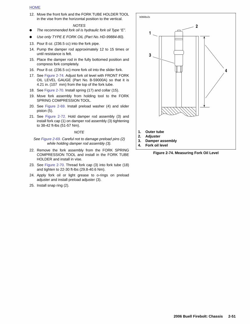
HOME
12. Move the front fork and the FORK TUBE HOLDER TOOLin the vise from the horizontal position to the vertical.
NOTES● The recommended fork oil is hydraulic fork oil Type “E”.
● Use only TYPE E FORK OIL (Part No. HD-99884-80).
13. Pour 8 oz. (236.5 cc) into the fork pipe.
14. Pump the damper rod approximately 12 to 15 times oruntil resistance is felt.
15. Place the damper rod in the fully bottomed position andcompress fork completely.
16. Pour 8 oz. (236.5 cc) more fork oil into the slider fork.
17. See Figure 2-74. Adjust fork oil level with FRONT FORKOIL LEVEL GAUGE (Part No. B-59000A) so that it is4.21 in. (107 mm) from the top of the fork tube.
18. See Figure 2-70. Install spring (17) and collar (15).
19. Move fork assembly from holding tool to the FORKSPRING COMPRESSION TOOL.
20. See Figure 2-69. Install preload washer (4) and sliderpiston (5).
21. See Figure 2-72. Hold damper rod assembly (3) andinstall fork cap (1) on damper rod assembly (3) tighteningto 38-42 ft-lbs (51-57 Nm).
NOTE
See Figure 2-69. Careful not to damage preload pins (2) while holding damper rod assembly (3).
22. Remove the fork assembly from the FORK SPRINGCOMPRESSION TOOL and install in the FORK TUBEHOLDER and install in vise.
23. See Figure 2-70. Thread fork cap (3) into fork tube (18)and tighten to 22-30 ft-lbs (29.8-40.6 Nm).
24. Apply fork oil or light grease to o-rings on preloadadjuster and install preload adjuster (3).
25. Install snap ring (2).
Figure 2-74. Measuring Fork Oil Level
b0666x2x
3
2
1. Outer tube2. Adjuster3. Damper assembly4. Fork oil level
1
4
2006 Buell Firebolt: Chassis 2-51
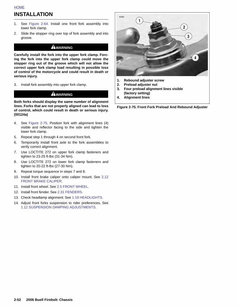
HOME
INSTALLATION1
8360
1. See Figure 2-64. Install one front fork assembly intolower fork clamp.
2. Slide the stopper ring over top of fork assembly and intogroove.
11WARNING1WARNING
Carefully install the fork into the upper fork clamp. Forc-ing the fork into the upper fork clamp could move thestopper ring out of the groove which will not allow thecorrect upper fork clamp load resulting in possible lossof control of the motorcycle and could result in death orserious injury.
3. Install fork assembly into upper fork clamp.
11WARNING1WARNING
Both forks should display the same number of alignmentlines. Forks that are not properly aligned can lead to lossof control, which could result in death or serious injury.(00124a)
4. See Figure 2-75. Position fork with alignment lines (4)visible and reflector facing to the side and tighten thelower fork clamp.
5. Repeat step 1 through 4 on second front fork.
6. Temporarily install front axle to the fork assemblies toverify correct alignment.
7. Use LOCTITE 272 on upper fork clamp fasteners andtighten to 23-25 ft-lbs (31-34 Nm).
8. Use LOCTITE 272 on lower fork clamp fasteners andtighten to 20-22 ft-lbs (27-30 Nm).
9. Repeat torque sequence in steps 7 and 8.
10. Install front brake caliper onto caliper mount. See 2.12FRONT BRAKE CALIPER.
11. Install front wheel. See 2.5 FRONT WHEEL.
12. Install front fender. See 2.31 FENDERS.
13. Check headlamp alignment. See 1.19 HEADLIGHTS.
14. Adjust front forks suspension to rider preferences. See1.12 SUSPENSION DAMPING ADJUSTMENTS.
Figure 2-75. Front Fork Preload And Rebound Adjuster
1. Rebound adjuster screw2. Preload adjuster nut3. Four preload alignment lines visible
(factory setting)4. Alignment lines
2
3
4
2-52 2006 Buell Firebolt: Chassis
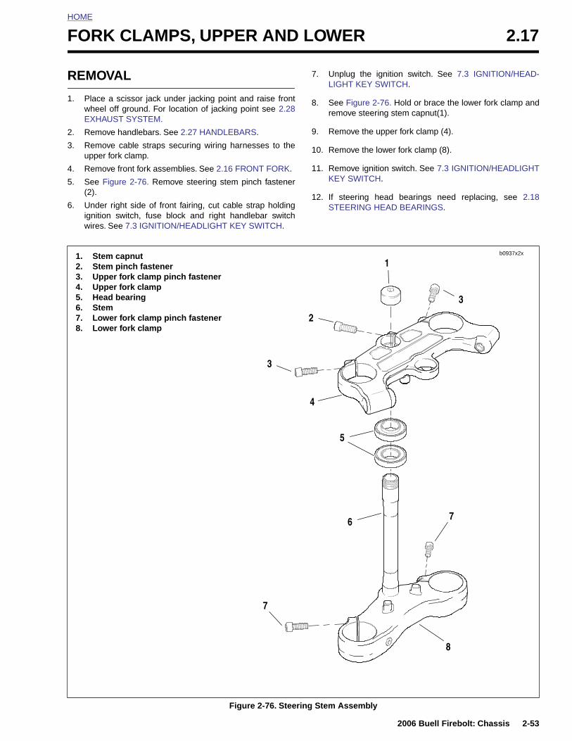
HOME
F
R
1
2
3
4
5
6
ORK CLAMPS, UPPER AND LOWER 2.17
EMOVAL
. Place a scissor jack under jacking point and raise frontwheel off ground. For location of jacking point see 2.28EXHAUST SYSTEM.
. Remove handlebars. See 2.27 HANDLEBARS.
. Remove cable straps securing wiring harnesses to theupper fork clamp.
. Remove front fork assemblies. See 2.16 FRONT FORK.
. See Figure 2-76. Remove steering stem pinch fastener(2).
. Under right side of front fairing, cut cable strap holdingignition switch, fuse block and right handlebar switchwires. See 7.3 IGNITION/HEADLIGHT KEY SWITCH.
7. Unplug the ignition switch. See 7.3 IGNITION/HEAD-LIGHT KEY SWITCH.
8. See Figure 2-76. Hold or brace the lower fork clamp andremove steering stem capnut(1).
9. Remove the upper fork clamp (4).
10. Remove the lower fork clamp (8).
11. Remove ignition switch. See 7.3 IGNITION/HEADLIGHTKEY SWITCH.
12. If steering head bearings need replacing, see 2.18STEERING HEAD BEARINGS.
b0937x2x1. Stem capnut2. Stem pinch fastener3. Upper fork clamp pinch fastener4. Upper fork clamp5. Head bearing6. Stem7. Lower fork clamp pinch fastener8. Lower fork clamp
1
4
2
3
3
5
2006 Buell Firebolt: Chassis 2-53
Figure 2-76. Steering Stem Assembly
6
7
8
7
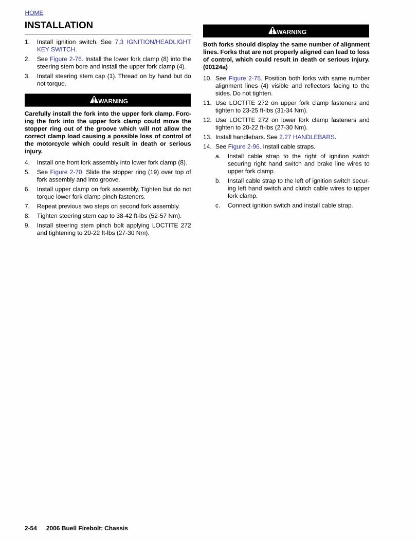
HOME
INSTALLATION
11WARNING1WARNING
1. Install ignition switch. See 7.3 IGNITION/HEADLIGHTKEY SWITCH.
2. See Figure 2-76. Install the lower fork clamp (8) into thesteering stem bore and install the upper fork clamp (4).
3. Install steering stem cap (1). Thread on by hand but donot torque.
11WARNING1WARNING
Carefully install the fork into the upper fork clamp. Forc-ing the fork into the upper fork clamp could move thestopper ring out of the groove which will not allow thecorrect clamp load causing a possible loss of control ofthe motorcycle which could result in death or seriousinjury.
4. Install one front fork assembly into lower fork clamp (8).
5. See Figure 2-70. Slide the stopper ring (19) over top offork assembly and into groove.
6. Install upper clamp on fork assembly. Tighten but do nottorque lower fork clamp pinch fasteners.
7. Repeat previous two steps on second fork assembly.
8. Tighten steering stem cap to 38-42 ft-lbs (52-57 Nm).
9. Install steering stem pinch bolt applying LOCTITE 272and tightening to 20-22 ft-lbs (27-30 Nm).
Both forks should display the same number of alignmentlines. Forks that are not properly aligned can lead to lossof control, which could result in death or serious injury.(00124a)
10. See Figure 2-75. Position both forks with same numberalignment lines (4) visible and reflectors facing to thesides. Do not tighten.
11. Use LOCTITE 272 on upper fork clamp fasteners andtighten to 23-25 ft-lbs (31-34 Nm).
12. Use LOCTITE 272 on lower fork clamp fasteners andtighten to 20-22 ft-lbs (27-30 Nm).
13. Install handlebars. See 2.27 HANDLEBARS.
14. See Figure 2-96. Install cable straps.
a. Install cable strap to the right of ignition switchsecuring right hand switch and brake line wires toupper fork clamp.
b. Install cable strap to the left of ignition switch secur-ing left hand switch and clutch cable wires to upperfork clamp.
c. Connect ignition switch and install cable strap.
2-54 2006 Buell Firebolt: Chassis
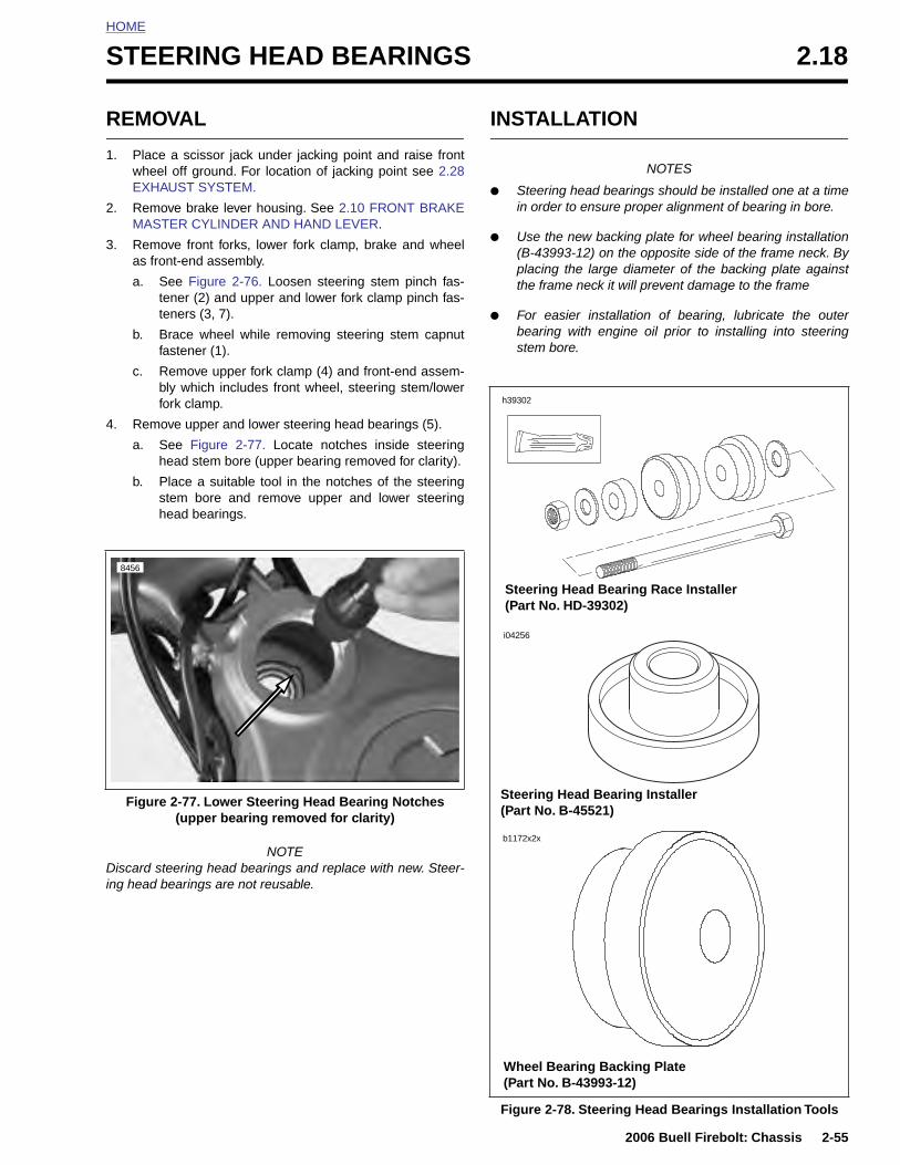
HOME
S
R
1
2
3
4
TEERING HEAD BEARINGS 2.18
EMOVAL
. Place a scissor jack under jacking point and raise frontwheel off ground. For location of jacking point see 2.28EXHAUST SYSTEM.
. Remove brake lever housing. See 2.10 FRONT BRAKEMASTER CYLINDER AND HAND LEVER.
. Remove front forks, lower fork clamp, brake and wheelas front-end assembly.
a. See Figure 2-76. Loosen steering stem pinch fas-tener (2) and upper and lower fork clamp pinch fas-teners (3, 7).
b. Brace wheel while removing steering stem capnutfastener (1).
c. Remove upper fork clamp (4) and front-end assem-bly which includes front wheel, steering stem/lowerfork clamp.
. Remove upper and lower steering head bearings (5).
a. See Figure 2-77. Locate notches inside steeringhead stem bore (upper bearing removed for clarity).
b. Place a suitable tool in the notches of the steeringstem bore and remove upper and lower steeringhead bearings.
INSTALLATION
NOTES
● Steering head bearings should be installed one at a timein order to ensure proper alignment of bearing in bore.
● Use the new backing plate for wheel bearing installation(B-43993-12) on the opposite side of the frame neck. Byplacing the large diameter of the backing plate againstthe frame neck it will prevent damage to the frame
● For easier installation of bearing, lubricate the outerbearing with engine oil prior to installing into steeringstem bore.
Figure 2-77. Lower Steering Head Bearing Notches
8456
h39302
i04256
Steering Head Bearing Race Installer (Part No. HD-39302)
Steering Head Bearing Installer
2006 Buell Firebolt: Chassis 2-55
NOTEDiscard steering head bearings and replace with new. Steer-ing head bearings are not reusable.
(upper bearing removed for clarity)
Figure 2-78. Steering Head Bearings Installation Tools
(Part No. B-45521)
Wheel Bearing Backing Plate(Part No. B-43993-12)
b1172x2x
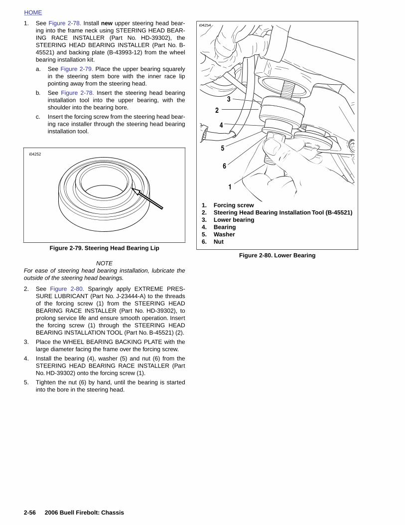
HOME
1. See Figure 2-78. Install
new
upper steering head bear-ing into the frame neck using STEERING HEAD BEAR-ING RACE INSTALLER (Part No. HD-39302), the
i04254
STEERING HEAD BEARING INSTALLER (Part No. B-45521) and backing plate (B-43993-12) from the wheelbearing installation kit.
a. See Figure 2-79. Place the upper bearing squarelyin the steering stem bore with the inner race lippointing away from the steering head.
b. See Figure 2-78. Insert the steering head bearinginstallation tool into the upper bearing, with theshoulder into the bearing bore.
c. Insert the forcing screw from the steering head bear-ing race installer through the steering head bearinginstallation tool.
NOTEFor ease of steering head bearing installation, lubricate theoutside of the steering head bearings.
2. See Figure 2-80. Sparingly apply EXTREME PRES-SURE LUBRICANT (Part No. J-23444-A) to the threadsof the forcing screw (1) from the STEERING HEADBEARING RACE INSTALLER (Part No. HD-39302), toprolong service life and ensure smooth operation. Insertthe forcing screw (1) through the STEERING HEADBEARING INSTALLATION TOOL (Part No. B-45521) (2).
3. Place the WHEEL BEARING BACKING PLATE with thelarge diameter facing the frame over the forcing screw.
4. Install the bearing (4), washer (5) and nut (6) from theSTEERING HEAD BEARING RACE INSTALLER (PartNo. HD-39302) onto the forcing screw (1).
5. Tighten the nut (6) by hand, until the bearing is started
Figure 2-79. Steering Head Bearing Lip
i04252
Figure 2-80. Lower Bearing
1. Forcing screw2. Steering Head Bearing Installation Tool (B-45521)3. Lower bearing4. Bearing5. Washer6. Nut
6
5
4
3
2
1
2-56 2006 Buell Firebolt: Chassis
into the bore in the steering head.
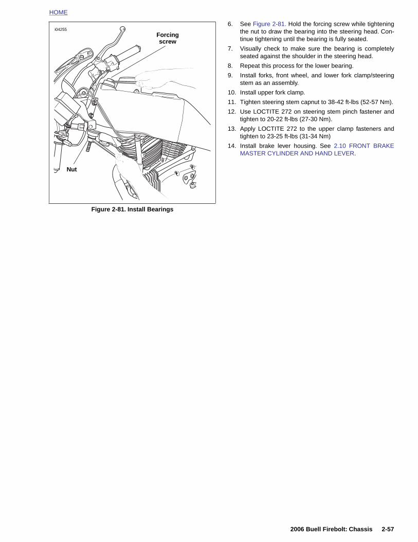
HOME
6. See Figure 2-81. Hold the forcing screw while tighteningthe nut to draw the bearing into the steering head. Con-tinue tightening until the bearing is fully seated.
7. Visually check to make sure the bearing is completelyseated against the shoulder in the steering head.
8. Repeat this process for the lower bearing.
9. Install forks, front wheel, and lower fork clamp/steeringstem as an assembly.
10. Install upper fork clamp.
11. Tighten steering stem capnut to 38-42 ft-lbs (52-57 Nm).
12. Use LOCTITE 272 on steering stem pinch fastener andtighten to 20-22 ft-lbs (27-30 Nm).
13. Apply LOCTITE 272 to the upper clamp fasteners andtighten to 23-25 ft-lbs (31-34 Nm)
14. Install brake lever housing. See 2.10 FRONT BRAKEMASTER CYLINDER AND HAND LEVER.
Figure 2-81. Install Bearings
i04255
Forcing screw
Nut
2006 Buell Firebolt: Chassis 2-57
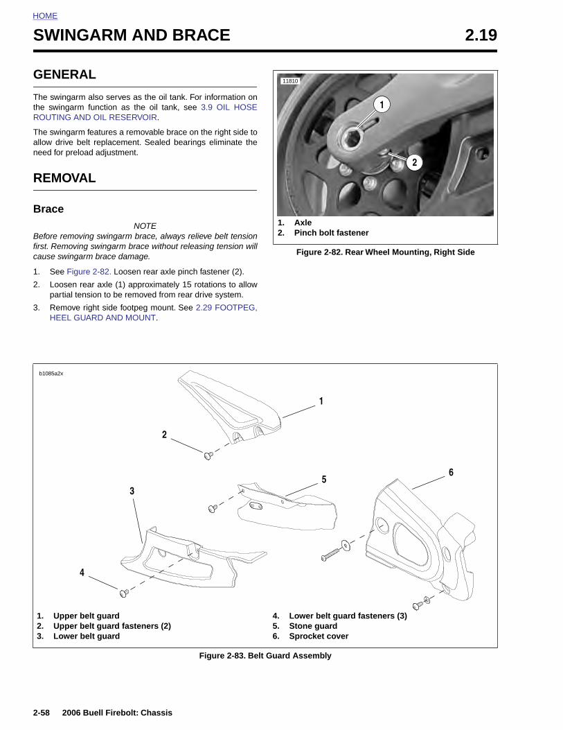
HOME
SWINGARM AND BRACE 2.19
GENE
The swingthe swingROUTING
The swingallow drivneed for p
REMO
Brace
Before remfirst. Remcause swi
1. See F
2. Loosepartia
3. RemoHEEL
b1085a2x
2-58
1. Up2. Up3. Lo
RAL
arm also serves as the oil tank. For information onarm function as the oil tank, see 3.9 OIL HOSE AND OIL RESERVOIR.
arm features a removable brace on the right side toe belt replacement. Sealed bearings eliminate thereload adjustment.
VAL
NOTEoving swingarm brace, always relieve belt tension
oving swingarm brace without releasing tension willngarm brace damage.
igure 2-82. Loosen rear axle pinch fastener (2).
n rear axle (1) approximately 15 rotations to allowl tension to be removed from rear drive system.
ve right side footpeg mount. See 2.29 FOOTPEG, GUARD AND MOUNT.
Figure 2-82. Rear Wheel Mounting, Right Side
11810
2
1. Axle2. Pinch bolt fastener
1
1
2
35
6
2006 Buell Firebolt: Chassis
Figure 2-83. Belt Guard Assembly
per belt guardper belt guard fasteners (2)wer belt guard
4. Lower belt guard fasteners (3)5. Stone guard6. Sprocket cover
4
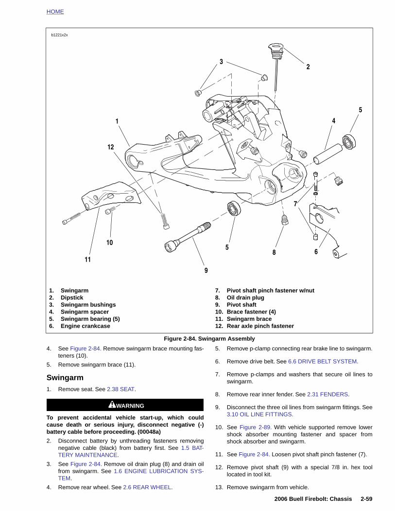
HOME
4. See Figure 2-84. Remove swingarm brace mounting fas- 5. Remove p-clamp connecting rear brake line to swingarm.
Figure 2-84. Swingarm Assembly
b1221x2x
1. Swingarm2. Dipstick3. Swingarm bushings4. Swingarm spacer5. Swingarm bearing (5)6. Engine crankcase
7. Pivot shaft pinch fastener w/nut8. Oil drain plug9. Pivot shaft10. Brace fastener (4)11. Swingarm brace12. Rear axle pinch fastener
1
2
4
5
7
10
12
11
5
3
68
9
2006 Buell Firebolt: Chassis 2-59
teners (10).
5. Remove swingarm brace (11).
Swingarm1. Remove seat. See 2.38 SEAT.
11WARNING1WARNING
To prevent accidental vehicle start-up, which couldcause death or serious injury, disconnect negative (-)battery cable before proceeding. (00048a)
2. Disconnect battery by unthreading fasteners removingnegative cable (black) from battery first. See 1.5 BAT-TERY MAINTENANCE.
3. See Figure 2-84. Remove oil drain plug (8) and drain oilfrom swingarm. See 1.6 ENGINE LUBRICATION SYS-TEM.
4. Remove rear wheel. See 2.6 REAR WHEEL.
6. Remove drive belt. See 6.6 DRIVE BELT SYSTEM.
7. Remove p-clamps and washers that secure oil lines toswingarm.
8. Remove rear inner fender. See 2.31 FENDERS.
9. Disconnect the three oil lines from swingarm fittings. See3.10 OIL LINE FITTINGS.
10. See Figure 2-89. With vehicle supported remove lowershock absorber mounting fastener and spacer fromshock absorber and swingarm.
11. See Figure 2-84. Loosen pivot shaft pinch fastener (7).
12. Remove pivot shaft (9) with a special 7/8 in. hex toollocated in tool kit.
13. Remove swingarm from vehicle.
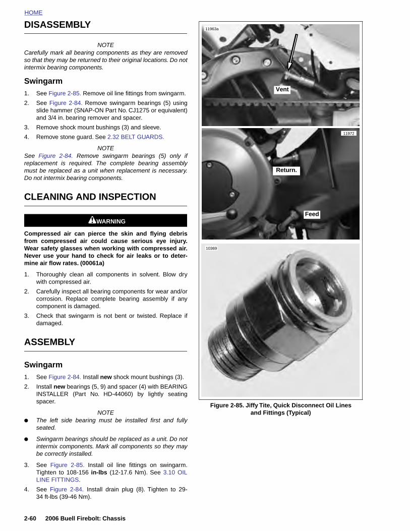
HOME
DISASSEMBLY
11963a
NOTECarefully mark all bearing components as they are removedso that they may be returned to their original locations. Do notintermix bearing components.
Swingarm1. See Figure 2-85. Remove oil line fittings from swingarm.
2. See Figure 2-84. Remove swingarm bearings (5) usingslide hammer (SNAP-ON Part No. CJ1275 or equivalent)and 3/4 in. bearing remover and spacer.
3. Remove shock mount bushings (3) and sleeve.
4. Remove stone guard. See 2.32 BELT GUARDS.
NOTESee Figure 2-84. Remove swingarm bearings (5) only ifreplacement is required. The complete bearing assemblymust be replaced as a unit when replacement is necessary.Do not intermix bearing components.
CLEANING AND INSPECTION
11WARNING1WARNING
Compressed air can pierce the skin and flying debrisfrom compressed air could cause serious eye injury.Wear safety glasses when working with compressed air.Never use your hand to check for air leaks or to deter-mine air flow rates. (00061a)
1. Thoroughly clean all components in solvent. Blow drywith compressed air.
2. Carefully inspect all bearing components for wear and/orcorrosion. Replace complete bearing assembly if anycomponent is damaged.
3. Check that swingarm is not bent or twisted. Replace ifdamaged.
ASSEMBLY
Swingarm1. See Figure 2-84. Install new shock mount bushings (3).
2. Install new bearings (5, 9) and spacer (4) with BEARING
10369
Vent
Feed
Return.
11972
2-60 2006 Buell Firebolt: Chassis
INSTALLER (Part No. HD-44060) by lightly seatingspacer.
NOTE ● The left side bearing must be installed first and fully
seated.
● Swingarm bearings should be replaced as a unit. Do notintermix components. Mark all components so they maybe correctly installed.
3. See Figure 2-85. Install oil line fittings on swingarm.Tighten to 108-156 in-lbs (12-17.6 Nm). See 3.10 OILLINE FITTINGS.
4. See Figure 2-84. Install drain plug (8). Tighten to 29-34 ft-lbs (39-46 Nm).
Figure 2-85. Jiffy Tite, Quick Disconnect Oil Linesand Fittings (Typical)

HOME
INSTALLATION
Swingarm1. See Figure 2-84. Align swingarm (1) in pivot of engine
crankcase (6).
2. Install pivot shaft (9) with a special 7/8 in. hex toollocated in tool kit, ANTI-SEIZE and tighten to 24-26 ft-lbs(32-35 Nm).
3. Apply LOCKTITE 272 and tighten pivot shaft pinch fas-tener (7) to 17-19 ft-lbs (23-26 Nm).
4. See Figure 2-89. Install lower shock absorber mountingfastener (7) and spacer from shock absorber and swing-arm and tighten to 15-17 ft-lbs (20.3-23 Nm).
5. Install p-clamp and washer that secures rear brake lineto swingarm and tighten to 36-60 in-lbs (4-7 Nm).
NOTEBe careful to align the rear brake line with the rear innerfender. The rear inner fender captures the rear brake line tohelp maintain proper location.
6. Install rear inner fender. See 2.31 FENDERS.
7. Install rear inner fender and tighten fasteners to 12-36 in-lbs (1.4-4Nm).
8. Connect three oil lines to swingarm fittings and installand tighten p clamps to 48-72 in-lbs (5.4-8 Nm). See3.10 OIL LINE FITTINGS.
9. Install rear wheel. See 2.6 REAR WHEEL.
10. Install stone guard. See 2.32 BELT GUARDS.
NOTEInstalling the rear wheel will include installation of the beltdrive system. See 6.6 DRIVE BELT SYSTEM.
11. Fill motorcycle with recommended oil. See 1.6 ENGINELUBRICATION SYSTEM.
Brace1. Install the belt drive. See 6.6 DRIVE BELT SYSTEM.
2. See Figure 2-84. Install swingarm brace (12) with swing-arm brace mounting fasteners (11) loosely. Do nottighten.
3. Tighten swingarm brace fasteners (11) to 25-27 ft-lbs(34-37 Nm).
4. Tighten rear axle. See DRIVE BELT INSTALLATION.
5. Tighten rear axle pinch fastener (13) to 40-45 ft-lbs (54-61 Nm).
6. Install right side rider footpeg mount. Tighten fasteners to108-132 in-lbs (12-15 Nm). See 2.29 FOOTPEG, HEELGUARD AND MOUNT.
7. Remove rear wheel support stand.
11WARNING1WARNING
Connect positive (+) battery cable first. If positive (+)cable should contact ground with negative (-) cable con-nected, the resulting sparks can cause a battery explo-sion, which could result in death or serious injury.(00068a)
8. Install battery by threading positive cable (red) intothreaded hole first tightening to 72-96 in-lbs (8-11 Nm).See 1.5 BATTERY MAINTENANCE.
11WARNING1WARNING
After servicing brakes and before moving motorcycle,pump brakes to build brake system pressure. Insufficientpressure can adversely affect brake performance, whichcould result in death or serious injury. (00279a)
11WARNING1WARNING
After installing seat, pull upward on front of seat to besure it is in locked position. While riding, a loose seat canshift causing loss of control, which could result in deathor serious injury. (00070a)
9. Install seat. See 2.38 SEAT.
Final Swingarm Inspection
2006 Buell Firebolt: Chassis 2-61
1. Check oil level after starting motorcycle and allowing it toreach operating temperature.
2. Check rear brake operation.
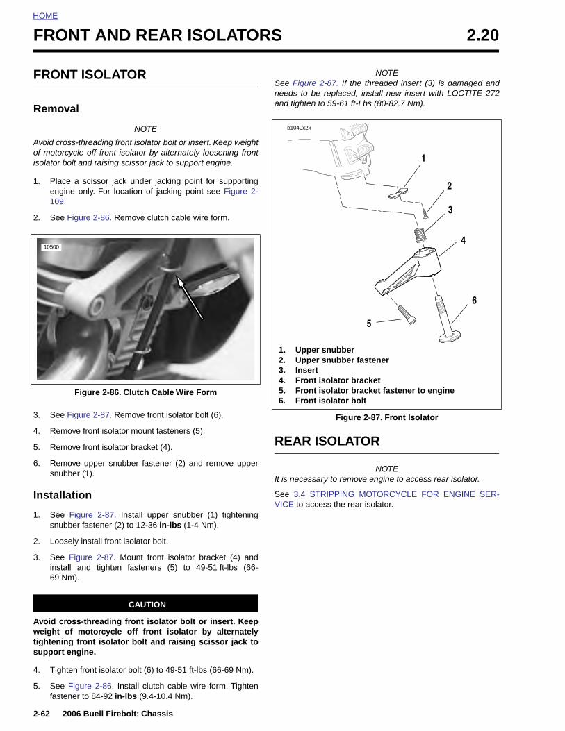
HOME
FRONT AND REAR ISOLATORS 2.20
FRON
Remov
Avoid crosof motorcisolator bo
1. Placeengin109.
2. See F
3. See F
4. Remo
5. Remo
6. Remosnubb
Installa
1. See snubb
10500
2-62
2. Loo
3. Seeinst69 N
Avoid cweight tightenisupport
4. Tigh
5. Seefast
T ISOLATOR
al
NOTE
s-threading front isolator bolt or insert. Keep weightycle off front isolator by alternately loosening frontlt and raising scissor jack to support engine.
a scissor jack under jacking point for supportinge only. For location of jacking point see Figure 2-
igure 2-86. Remove clutch cable wire form.
igure 2-87. Remove front isolator bolt (6).
ve front isolator mount fasteners (5).
ve front isolator bracket (4).
ve upper snubber fastener (2) and remove upperer (1).
tion
Figure 2-87. Install upper snubber (1) tighteninger fastener (2) to 12-36 in-lbs (1-4 Nm).
NOTESee Figure 2-87. If the threaded insert (3) is damaged andneeds to be replaced, install new insert with LOCTITE 272and tighten to 59-61 ft-Lbs (80-82.7 Nm).
REAR ISOLATOR
NOTEIt is necessary to remove engine to access rear isolator.
See 3.4 STRIPPING MOTORCYCLE FOR ENGINE SER-VICE to access the rear isolator.
Figure 2-86. Clutch Cable Wire Form
Figure 2-87. Front Isolator
b1040x2x
1. Upper snubber2. Upper snubber fastener3. Insert4. Front isolator bracket5. Front isolator bracket fastener to engine6. Front isolator bolt
1
2
3
4
6
5
2006 Buell Firebolt: Chassis
sely install front isolator bolt.
Figure 2-87. Mount front isolator bracket (4) andall and tighten fasteners (5) to 49-51 ft-lbs (66-m).
CAUTION
ross-threading front isolator bolt or insert. Keepof motorcycle off front isolator by alternatelyng front isolator bolt and raising scissor jack to engine.
ten front isolator bolt (6) to 49-51 ft-lbs (66-69 Nm).
Figure 2-86. Install clutch cable wire form. Tightenener to 84-92 in-lbs (9.4-10.4 Nm).
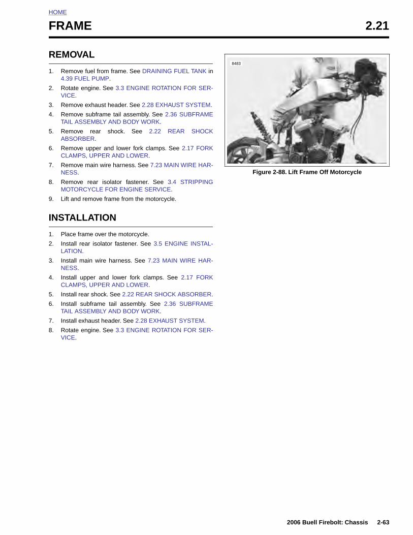
HOME
F
R
1
2
3
4
5
6
7
8
9
I
1
2
3
4
5
6
7
8
RAME 2.21
EMOVAL
. Remove fuel from frame. See DRAINING FUEL TANK in4.39 FUEL PUMP.
. Rotate engine. See 3.3 ENGINE ROTATION FOR SER-VICE.
. Remove exhaust header. See 2.28 EXHAUST SYSTEM.
. Remove subframe tail assembly. See 2.36 SUBFRAMETAIL ASSEMBLY AND BODY WORK.
. Remove rear shock. See 2.22 REAR SHOCKABSORBER.
. Remove upper and lower fork clamps. See 2.17 FORKCLAMPS, UPPER AND LOWER.
. Remove main wire harness. See 7.23 MAIN WIRE HAR-NESS.
. Remove rear isolator fastener. See 3.4 STRIPPINGMOTORCYCLE FOR ENGINE SERVICE.
. Lift and remove frame from the motorcycle.
NSTALLATION
. Place frame over the motorcycle.
. Install rear isolator fastener. See 3.5 ENGINE INSTAL-LATION.
. Install main wire harness. See 7.23 MAIN WIRE HAR-NESS.
. Install upper and lower fork clamps. See 2.17 FORKCLAMPS, UPPER AND LOWER.
. Install rear shock. See 2.22 REAR SHOCK ABSORBER.
. Install subframe tail assembly. See 2.36 SUBFRAMETAIL ASSEMBLY AND BODY WORK.
. Install exhaust header. See 2.28 EXHAUST SYSTEM.
. Rotate engine. See 3.3 ENGINE ROTATION FOR SER-VICE.
Figure 2-88. Lift Frame Off Motorcycle
8483
2006 Buell Firebolt: Chassis 2-63

HOME
REAR SHOCK ABSORBER 2.22
GENE
The rear sshock allodamping a
b0940x2x
2-64
1. S2. S3. S4. S5. U6. L
RAL
uspension is controlled by the shock absorber. Thews adjustment of rear compression and reboundnd spring preload.
The most important rear shock adjustment is the preload set-ting. Before making any damping adjustments, set the properpreload. See 1.12 SUSPENSION DAMPING ADJUST-MENTS.
1
2
3
11
8
6
94
10 5
710
12
12
2006 Buell Firebolt: Chassis
Figure 2-89. Rear Shock Absorber Assembly
hock remote reservoir clamp fastenerhock remote reservoir clamphock remote reservoirhock reservoir bodypper shock mount fastenerower shock mount nut and washer
7. Lower shock mount8. Lower shock mount sleeve9. Lower shock mount fastener and washer10. Shock spring retainer kit11. Rear shock spring12. Washers
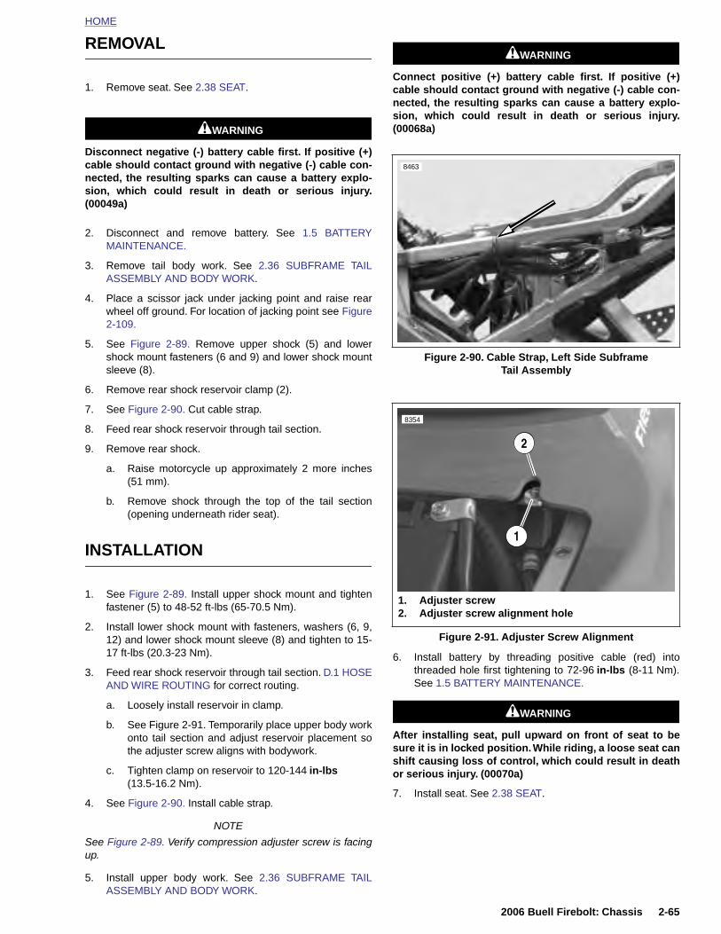
HOME
REMOVAL
1. Remove seat. See 2.38 SEAT.
11WARNING1WARNING
Disconnect negative (-) battery cable first. If positive (+)cable should contact ground with negative (-) cable con-nected, the resulting sparks can cause a battery explo-sion, which could result in death or serious injury.(00049a)
2. Disconnect and remove battery. See 1.5 BATTERYMAINTENANCE.
3. Remove tail body work. See 2.36 SUBFRAME TAILASSEMBLY AND BODY WORK.
4. Place a scissor jack under jacking point and raise rearwheel off ground. For location of jacking point see Figure2-109.
5. See Figure 2-89. Remove upper shock (5) and lowershock mount fasteners (6 and 9) and lower shock mountsleeve (8).
6. Remove rear shock reservoir clamp (2).
7. See Figure 2-90. Cut cable strap.
8. Feed rear shock reservoir through tail section.
9. Remove rear shock.
a. Raise motorcycle up approximately 2 more inches(51 mm).
b. Remove shock through the top of the tail section(opening underneath rider seat).
INSTALLATION
1. See Figure 2-89. Install upper shock mount and tightenfastener (5) to 48-52 ft-lbs (65-70.5 Nm).
2. Install lower shock mount with fasteners, washers (6, 9,12) and lower shock mount sleeve (8) and tighten to 15-
11WARNING1WARNING
Connect positive (+) battery cable first. If positive (+)cable should contact ground with negative (-) cable con-nected, the resulting sparks can cause a battery explo-sion, which could result in death or serious injury.(00068a)
Figure 2-90. Cable Strap, Left Side Subframe Tail Assembly
Figure 2-91. Adjuster Screw Alignment
8463
1. Adjuster screw2. Adjuster screw alignment hole
1
8354
2
2006 Buell Firebolt: Chassis 2-65
17 ft-lbs (20.3-23 Nm).
3. Feed rear shock reservoir through tail section. D.1 HOSEAND WIRE ROUTING for correct routing.
a. Loosely install reservoir in clamp.
b. See Figure 2-91. Temporarily place upper body workonto tail section and adjust reservoir placement sothe adjuster screw aligns with bodywork.
c. Tighten clamp on reservoir to 120-144 in-lbs (13.5-16.2 Nm).
4. See Figure 2-90. Install cable strap.
NOTE
See Figure 2-89. Verify compression adjuster screw is facingup.
5. Install upper body work. See 2.36 SUBFRAME TAILASSEMBLY AND BODY WORK.
6. Install battery by threading positive cable (red) intothreaded hole first tightening to 72-96 in-lbs (8-11 Nm).See 1.5 BATTERY MAINTENANCE.
11WARNING1WARNING
After installing seat, pull upward on front of seat to besure it is in locked position. While riding, a loose seat canshift causing loss of control, which could result in deathor serious injury. (00070a)
7. Install seat. See 2.38 SEAT.
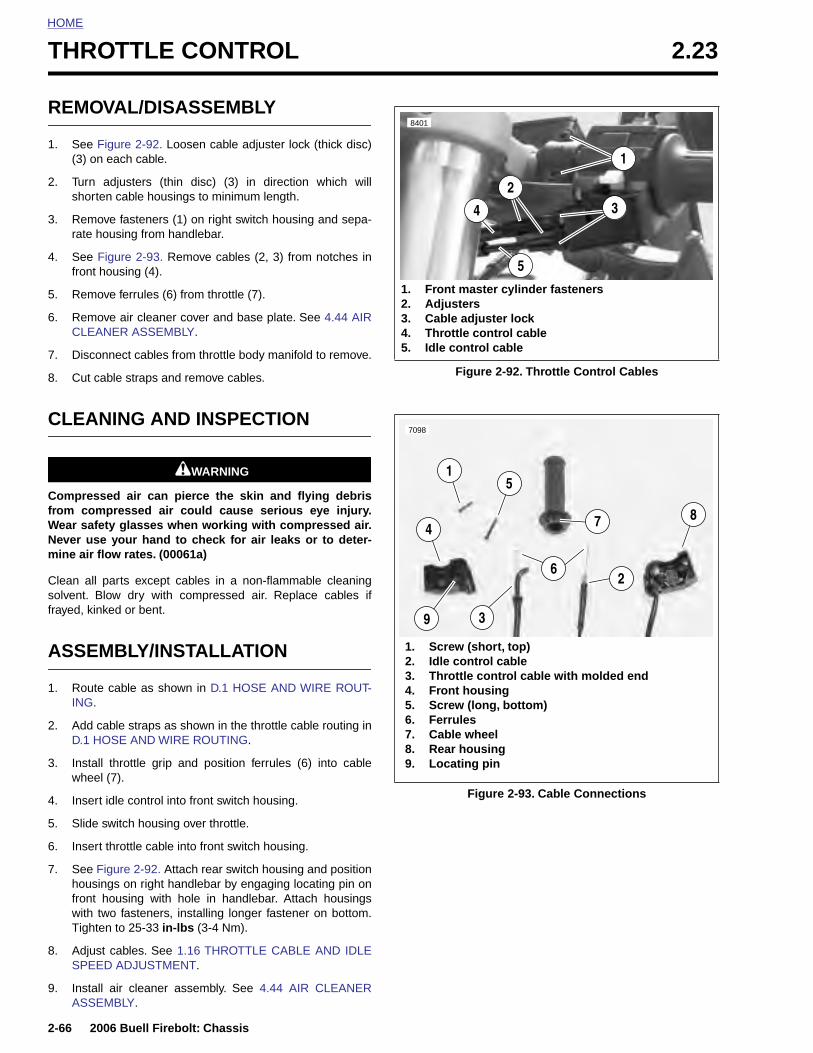
HOME
THROTTLE CONTROL 2.23
REMO
1. See F(3) on
2. Turn short
3. Remorate h
4. See Ffront
5. Remo
6. RemoCLEA
7. Disco
8. Cut c
CLEA
Compresfrom comWear safeNever usmine air fl
Clean all solvent. Bfrayed, kin
ASSE
1. RouteING.
2. Add cD.1 H
3. Instal
2-66
whe
4. Inse
5. Slid
6. Inse
7. SeehoufronwithTigh
8. AdjSPE
9. InstASS
VAL/DISASSEMBLY
igure 2-92. Loosen cable adjuster lock (thick disc) each cable.
adjusters (thin disc) (3) in direction which willen cable housings to minimum length.
ve fasteners (1) on right switch housing and sepa-ousing from handlebar.
igure 2-93. Remove cables (2, 3) from notches inhousing (4).
ve ferrules (6) from throttle (7).
ve air cleaner cover and base plate. See 4.44 AIRNER ASSEMBLY.
nnect cables from throttle body manifold to remove.
able straps and remove cables.
NING AND INSPECTION
11WARNING1WARNING
sed air can pierce the skin and flying debrispressed air could cause serious eye injury.ty glasses when working with compressed air.
e your hand to check for air leaks or to deter-ow rates. (00061a)
parts except cables in a non-flammable cleaninglow dry with compressed air. Replace cables ifked or bent.
MBLY/INSTALLATION
cable as shown in D.1 HOSE AND WIRE ROUT-
able straps as shown in the throttle cable routing inOSE AND WIRE ROUTING.
l throttle grip and position ferrules (6) into cable
Figure 2-92. Throttle Control Cables
1. Front master cylinder fasteners2. Adjusters3. Cable adjuster lock4. Throttle control cable5. Idle control cable
8401
1
4
5
32
1. Screw (short, top)2. Idle control cable3. Throttle control cable with molded end4. Front housing5. Screw (long, bottom)6. Ferrules7. Cable wheel8. Rear housing9. Locating pin
1
7098
487
5
3
26
9
2006 Buell Firebolt: Chassis
el (7).
rt idle control into front switch housing.
e switch housing over throttle.
rt throttle cable into front switch housing.
Figure 2-92. Attach rear switch housing and positionsings on right handlebar by engaging locating pin ont housing with hole in handlebar. Attach housings two fasteners, installing longer fastener on bottom.ten to 25-33 in-lbs (3-4 Nm).
ust cables. See 1.16 THROTTLE CABLE AND IDLEED ADJUSTMENT.
all air cleaner assembly. See 4.44 AIR CLEANEREMBLY.
Figure 2-93. Cable Connections
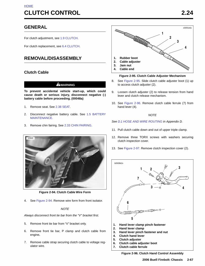
HOME
C
G
F
F
R
C
Tcb
1
2
3
LUTCH CONTROL 2.24
ENERAL
or clutch adjustment, see 1.9 CLUTCH.
or clutch replacement, see 6.4 CLUTCH.
EMOVAL/DISASSEMBLY
lutch Cable
11WARNING1WARNING
o prevent accidental vehicle start-up, which couldause death or serious injury, disconnect negative (-)attery cable before proceeding. (00048a)
. Remove seat. See 2.38 SEAT.
. Disconnect negative battery cable. See 1.5 BATTERYMAINTENANCE.
. Remove chin fairing. See 2.33 CHIN FAIRING.
8. See Figure 2-95. Slide clutch cable adjuster boot (1) upto access clutch adjuster (2).
9. Loosen clutch adjuster (2) to release tension from handlever and clutch release mechanism.
10. See Figure 2-96. Remove clutch cable ferrule (7) fromhand lever (4).
NOTE
See D.1 HOSE AND WIRE ROUTING in Appendix D.
11. Pull clutch cable down and out of upper triple clamp.
12. Remove three TORX screws with washers securingclutch inspection cover.
13. See Figure 2-97. Remove clutch inspection cover (2).
10500
Figure 2-95. Clutch Cable Adjuster Mechanism
x0055x6x
1. Rubber boot2. Cable adjuster3. Jam nut4. Cable end
12
3
4
b0939b2x
31
7
2
2006 Buell Firebolt: Chassis 2-67
4. See Figure 2-94. Remove wire form from front isolator.
NOTE
Always disconnect front tie bar from the "V" bracket first.
5. Remove front tie bar from “V” bracket only.
6. Remove front tie bar, P clamp and clutch cable fromengine.
7. Remove cable strap securing clutch cable to voltage reg-ulator wire.
Figure 2-94. Clutch Cable Wire Form
Figure 2-96. Clutch Hand Control Assembly
1. Hand lever clamp pinch fastener2. Hand lever clamp3. Hand lever pinch fastener and nut4. Clutch hand lever5. Clutch adjuster6. Clutch cable adjuster boot7. Clutch cable ferrule
43
5
6
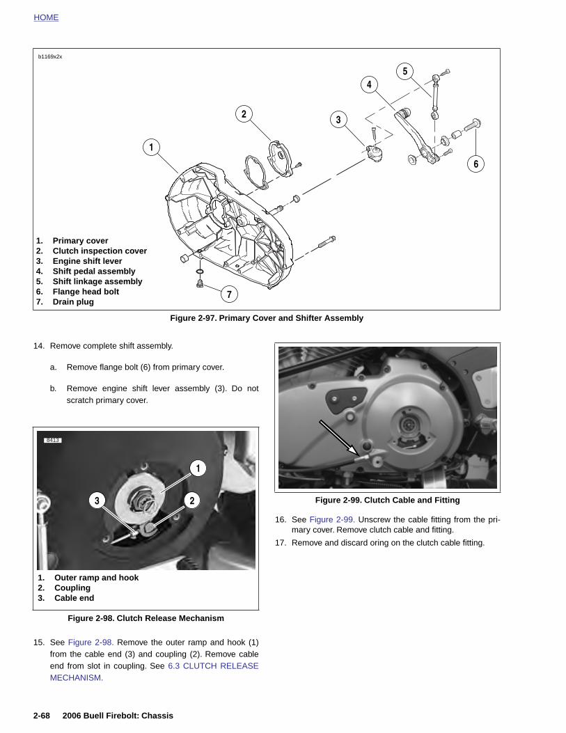
HOME
14. Remove complete shift assembly.
a. Remove flange bolt (6) from primary cover.
b. Remove engine shift lever assembly (3). Do notscratch primary cover.
16. See Figure 2-99. Unscrew the cable fitting from the pri-mary cover. Remove clutch cable and fitting.
Figure 2-97. Primary Cover and Shifter Assembly
1. Primary cover2. Clutch inspection cover3. Engine shift lever4. Shift pedal assembly5. Shift linkage assembly6. Flange head bolt7. Drain plug
3
1
45
6
2
7
b1169x2x
1
23
8413
Figure 2-99. Clutch Cable and Fitting
2-68 2006 Buell Firebolt: Chassis
15. See Figure 2-98. Remove the outer ramp and hook (1)from the cable end (3) and coupling (2). Remove cableend from slot in coupling. See 6.3 CLUTCH RELEASEMECHANISM.
17. Remove and discard oring on the clutch cable fitting.
Figure 2-98. Clutch Release Mechanism
1. Outer ramp and hook2. Coupling3. Cable end
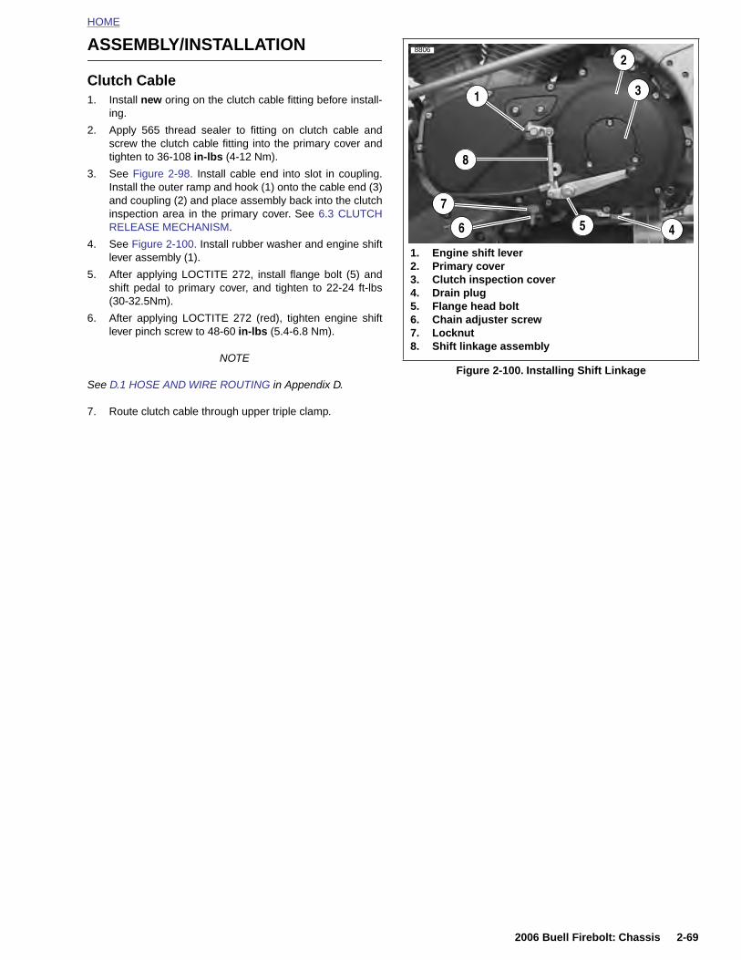
HOME
ASSEMBLY/INSTALLATION
Clutch Cable1. Install new oring on the clutch cable fitting before install-
ing.
2. Apply 565 thread sealer to fitting on clutch cable andscrew the clutch cable fitting into the primary cover andtighten to 36-108 in-lbs (4-12 Nm).
3. See Figure 2-98. Install cable end into slot in coupling.Install the outer ramp and hook (1) onto the cable end (3)and coupling (2) and place assembly back into the clutchinspection area in the primary cover. See 6.3 CLUTCHRELEASE MECHANISM.
4. See Figure 2-100. Install rubber washer and engine shiftlever assembly (1).
5. After applying LOCTITE 272, install flange bolt (5) andshift pedal to primary cover, and tighten to 22-24 ft-lbs(30-32.5Nm).
6. After applying LOCTITE 272 (red), tighten engine shiftlever pinch screw to 48-60 in-lbs (5.4-6.8 Nm).
NOTE
See D.1 HOSE AND WIRE ROUTING in Appendix D.
7. Route clutch cable through upper triple clamp.
Figure 2-100. Installing Shift Linkage
1. Engine shift lever2. Primary cover3. Clutch inspection cover4. Drain plug5. Flange head bolt6. Chain adjuster screw7. Locknut8. Shift linkage assembly
3
2
4
7
6
1
8806
5
8
2006 Buell Firebolt: Chassis 2-69
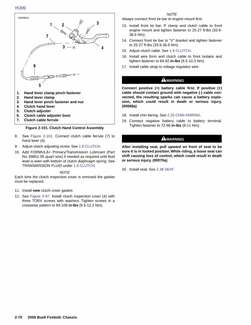
HOME
NOTEAlways connect front tie bar to engine mount first.
b0939b2x
3
8. See Figure 2-101. Connect clutch cable ferrule (7) tohand lever (4).
9. Adjust clutch adjusting screw. See 1.9 CLUTCH.
10. Add FORMULA+ Primary/Transmission Lubricant (PartNo. 99851-05 quart size) if needed as required until fluidlevel is even with bottom of clutch diaphragm spring. SeeTRANSMISSION FLUID under 1.9 CLUTCH.
NOTEEach time the clutch inspection cover is removed the gasketmust be replaced.
11. Install new clutch cover gasket.
12. See Figure 2-97. Install clutch inspection cover (4) withthree TORX screws with washers. Tighten screws in acrosswise pattern to 84-108 in-lbs (9.5-12.2 Nm).
13. Install front tie bar, P clamp and clutch cable to frontengine mount and tighten fastener to 25-27 ft-lbs (33.9-36.6 Nm).
14. Connect front tie bar to "V" bracket and tighten fastenerto 25-27 ft-lbs (33.9-36.6 Nm).
15. Adjust clutch cable. See 1.9 CLUTCH.
16. Install wire form and clutch cable to front isolator andtighten fastener to 84-92 in-lbs (9.5-10.3 Nm).
17. Install cable strap to voltage regulator wire.
11WARNING1WARNING
Connect positive (+) battery cable first. If positive (+)cable should contact ground with negative (-) cable con-nected, the resulting sparks can cause a battery explo-sion, which could result in death or serious injury.(00068a)
18. Install chin fairing. See 2.33 CHIN FAIRING.
19. Connect negative battery cable to battery terminal.Tighten fastener to 72-96 in-lbs (8-11 Nm).
11WARNING1WARNING
After installing seat, pull upward on front of seat to besure it is in locked position. While riding, a loose seat canshift causing loss of control, which could result in deathor serious injury. (00070a)
20. Install seat. See 2.38 SEAT.
Figure 2-101. Clutch Hand Control Assembly
1. Hand lever clamp pinch fastener2. Hand lever clamp3. Hand lever pinch fastener and nut4. Clutch hand lever5. Clutch adjuster6. Clutch cable adjuster boot7. Clutch cable ferrule
1
7
43
5
2
6
2-70 2006 Buell Firebolt: Chassis
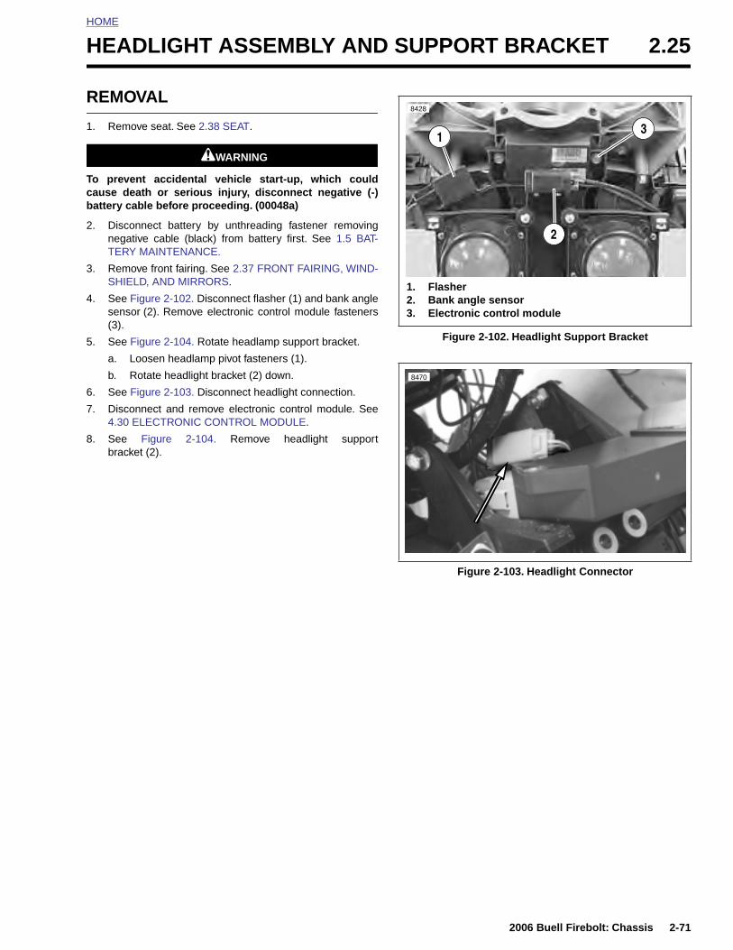
HOME
H
R
1
Tcb
2
3
4
5
6
7
8
EADLIGHT ASSEMBLY AND SUPPORT BRACKET 2.25
EMOVAL
. Remove seat. See 2.38 SEAT.
11WARNING1WARNING
o prevent accidental vehicle start-up, which couldause death or serious injury, disconnect negative (-)attery cable before proceeding. (00048a)
. Disconnect battery by unthreading fastener removingnegative cable (black) from battery first. See 1.5 BAT-TERY MAINTENANCE.
. Remove front fairing. See 2.37 FRONT FAIRING, WIND-SHIELD, AND MIRRORS.
. See Figure 2-102. Disconnect flasher (1) and bank anglesensor (2). Remove electronic control module fasteners(3).
. See Figure 2-104. Rotate headlamp support bracket.
a. Loosen headlamp pivot fasteners (1).
b. Rotate headlight bracket (2) down.
. See Figure 2-103. Disconnect headlight connection.
. Disconnect and remove electronic control module. See4.30 ELECTRONIC CONTROL MODULE.
. See Figure 2-104. Remove headlight supportbracket (2).
Figure 2-102. Headlight Support Bracket
Figure 2-103. Headlight Connector
6775
1. Flasher2. Bank angle sensor3. Electronic control module
1
8428
2
3
8470
2006 Buell Firebolt: Chassis 2-71
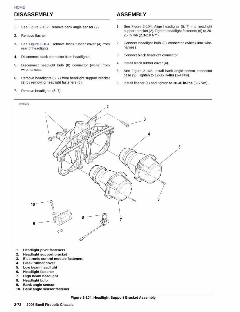
HOME
DISASSEMBLY ASSEMBLY
1. See Figure 2-102. Remove bank angle sensor (2).
2. Remove flasher.
3. See Figure 2-104. Remove black rubber cover (4) fromrear of headlights.
4. Disconnect black connector from headlights.
5. Disconnect headlight bulb (8) connector (white) fromwire harness.
6. Remove headlights (5, 7) from headlight support bracket(2) by removing headlight fasteners (6).
7. Remove headlights (5, 7).
1. See Figure 2-104. Align headlights (5, 7) into headlightsupport bracket (2). Tighten headlight fasteners (6) to 20-25 in lbs (2.3-2.8 Nm).
2. Connect headlight bulb (8) connector (white) into wire-harness.
3. Connect black headlight connector.
4. Install black rubber cover (4).
5. See Figure 2-102. Install bank angle sensor connectorcase (2). Tighten to 12-36 in-lbs (1-4 Nm).
6. Install flasher (1) and tighten to 30-40 in-lbs (3-5 Nm).
b0989x2x2
5
7
31
8
4
9
106
2-72 2006 Buell Firebolt: Chassis
Figure 2-104. Headlight Support Bracket Assembly
1. Headlight pivot fasteners2. Headlight support bracket3. Electronic control module fasteners4. Black rubber cover5. Low beam headlight6. Headlight fastener7. High beam headlight8. Headlight bulb9. Bank angle sensor10. Bank angle sensor fastener
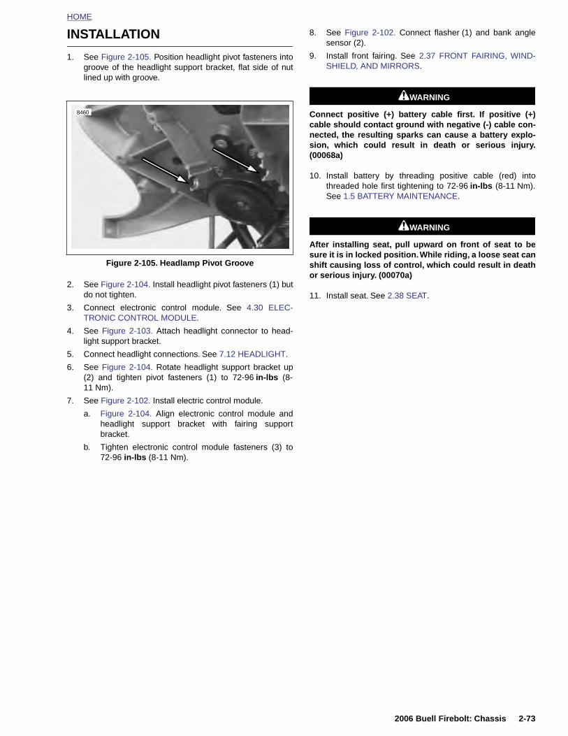
HOME
INSTALLATION
1. See Figure 2-105. Position headlight pivot fasteners intogroove of the headlight support bracket, flat side of nutlined up with groove.
2. See Figure 2-104. Install headlight pivot fasteners (1) butdo not tighten.
3. Connect electronic control module. See 4.30 ELEC-TRONIC CONTROL MODULE.
4. See Figure 2-103. Attach headlight connector to head-light support bracket.
5. Connect headlight connections. See 7.12 HEADLIGHT.
6. See Figure 2-104. Rotate headlight support bracket up(2) and tighten pivot fasteners (1) to 72-96 in-lbs (8-11 Nm).
7. See Figure 2-102. Install electric control module.
a. Figure 2-104. Align electronic control module andheadlight support bracket with fairing supportbracket.
b. Tighten electronic control module fasteners (3) to72-96 in-lbs (8-11 Nm).
8. See Figure 2-102. Connect flasher (1) and bank anglesensor (2).
9. Install front fairing. See 2.37 FRONT FAIRING, WIND-SHIELD, AND MIRRORS.
11WARNING1WARNING
Connect positive (+) battery cable first. If positive (+)cable should contact ground with negative (-) cable con-nected, the resulting sparks can cause a battery explo-sion, which could result in death or serious injury.(00068a)
10. Install battery by threading positive cable (red) intothreaded hole first tightening to 72-96 in-lbs (8-11 Nm).See 1.5 BATTERY MAINTENANCE.
11WARNING1WARNING
After installing seat, pull upward on front of seat to besure it is in locked position. While riding, a loose seat canshift causing loss of control, which could result in deathor serious injury. (00070a)
11. Install seat. See 2.38 SEAT.
Figure 2-105. Headlamp Pivot Groove
8460
2006 Buell Firebolt: Chassis 2-73

HOME
FAIRING SUPPORT BRACKET 2.26
REMO
1. Remo
To prevecause debattery ca
2. DisconegaTERY
3. RemoSHIE
4. RemoLIGH
5. Remo7.22
6. Disco
7. Disco7.18
8. See Ftenersuppo
2-74
VAL
ve seat. See 2.38 SEAT.
11WARNING1WARNING
nt accidental vehicle start-up, which couldath or serious injury, disconnect negative (-)ble before proceeding. (00048a)
nnect battery by unthreading fastener removingtive cable (black) from battery first. See 1.5 BAT- MAINTENANCE.
ve front fairing. See 2.37 FRONT FAIRING, WIND-LD, AND MIRRORS.
ve headlight support bracket. See 2.25 HEAD-T ASSEMBLY AND SUPPORT BRACKET.
ve fuse block and relay block and p-clamp. SeeMAIN FUSE AND FUSES.
nnect and remove horn (5). See 7.20 HORN.
nnect and remove instrument cluster (2, 3). SeeINSTRUMENT MODULE.
igure 2-106. Remove fairing support bracket fas-s and washers (4), p-clamp (7) to remove fairingrt bracket (5).
INSTALLATION
1. Route the wire harness. See D.1 HOSE AND WIREROUTING for wire harness routing.
2. See Figure 2-106. Install fairing support bracket with fas-teners, p-clamp (7) and washers (4). Tightening to 16-18 ft-lbs (22-26 Nm).
3. Connect instrument cluster connector and install instru-ment cluster. Tightening to 12-36 in-lbs (1.3-4 Nm). See7.18 INSTRUMENT MODULE.
4. Install horn and tighten fasteners to 72-96 in-lbs (8-10 Nm). See 7.20 HORN.
5. Install fuse block, relay and p-clamp tightening fastenersto 72-96 in-lbs (8-11 Nm). See 7.22 MAIN FUSE ANDFUSES.
6. Install lower headlight support bracket. See 2.25 HEAD-LIGHT ASSEMBLY AND SUPPORT BRACKET.
7. Install front fairing. See 2.37 FRONT FAIRING, WIND-SHIELD, AND MIRRORS.
11WARNING1WARNING
Connect positive (+) battery cable first. If positive (+)cable should contact ground with negative (-) cable con-nected, the resulting sparks can cause a battery explo-sion, which could result in death or serious injury.(00068a)
8. Install battery by threading positive cable (red) intothreaded hole first tightening to 72-96 in-lbs (8-11 Nm).See 1.5 BATTERY MAINTENANCE.
11WARNING1WARNING
After installing seat, pull upward on front of seat to besure it is in locked position. While riding, a loose seat canshift causing loss of control, which could result in deathor serious injury. (00070a)
9. Install seat. See 2.38 SEAT.
2006 Buell Firebolt: Chassis
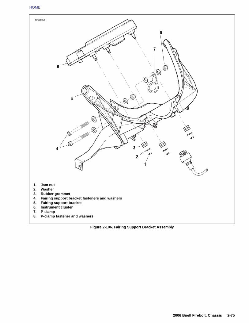
HOME
1. Jam nut2. Washer3. Rubber grommet4. Fairing support bracket fasteners and washers5. Fairing support bracket6. Instrument cluster7. P-clamp8. P-clamp fastener and washers
b0958x2x
1
2
3
6
5
4
7
8
2006 Buell Firebolt: Chassis 2-75
Figure 2-106. Fairing Support Bracket Assembly
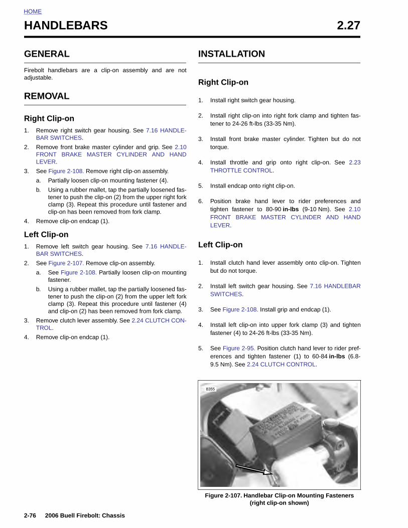
HOME
HANDLEBARS 2.27
GENE
Firebolt hadjustable
REMO
Right C1. Remo
BAR
2. RemoFRONLEVE
3. See F
a. P
b. Utcc
4. Remo
Left Cli1. Remo
BAR
2. See F
a. Sf
b. Utca
3. RemoTROL
4. Remo
2-76
RAL
andlebars are a clip-on assembly and are not.
VAL
lip-onve right switch gear housing. See 7.16 HANDLE-
SWITCHES.
ve front brake master cylinder and grip. See 2.10T BRAKE MASTER CYLINDER AND HANDR.
igure 2-108. Remove right clip-on assembly.
artially loosen clip-on mounting fastener (4).
sing a rubber mallet, tap the partially loosened fas-ener to push the clip-on (2) from the upper right forklamp (3). Repeat this procedure until fastener andlip-on has been removed from fork clamp.
ve clip-on endcap (1).
p-onve left switch gear housing. See 7.16 HANDLE-
SWITCHES.
igure 2-107. Remove clip-on assembly.
ee Figure 2-108. Partially loosen clip-on mountingastener.
sing a rubber mallet, tap the partially loosened fas-ener to push the clip-on (2) from the upper left forklamp (3). Repeat this procedure until fastener (4)nd clip-on (2) has been removed from fork clamp.
ve clutch lever assembly. See 2.24 CLUTCH CON-.
ve clip-on endcap (1).
INSTALLATION
Right Clip-on
1. Install right switch gear housing.
2. Install right clip-on into right fork clamp and tighten fas-tener to 24-26 ft-lbs (33-35 Nm).
3. Install front brake master cylinder. Tighten but do nottorque.
4. Install throttle and grip onto right clip-on. See 2.23THROTTLE CONTROL.
5. Install endcap onto right clip-on.
6. Position brake hand lever to rider preferences andtighten fastener to 80-90 in-lbs (9-10 Nm). See 2.10FRONT BRAKE MASTER CYLINDER AND HANDLEVER.
Left Clip-on
1. Install clutch hand lever assembly onto clip-on. Tightenbut do not torque.
2. Install left switch gear housing. See 7.16 HANDLEBARSWITCHES.
3. See Figure 2-108. Install grip and endcap (1).
4. Install left clip-on into upper fork clamp (3) and tightenfastener (4) to 24-26 ft-lbs (33-35 Nm).
5. See Figure 2-95. Position clutch hand lever to rider pref-erences and tighten fastener (1) to 60-84 in-lbs (6.8-9.5 Nm). See 2.24 CLUTCH CONTROL.
2006 Buell Firebolt: Chassis
Figure 2-107. Handlebar Clip-on Mounting Fasteners (right clip-on shown)
8355

HOME
Figure 2-108. Handlebar Clip-on Assembly (left clip-on shown)
b0945x2x
1. Endcap2. Clip-on3. Upper fork clamp4. Clip-on fastener
3
1
2
3
4
2006 Buell Firebolt: Chassis 2-77
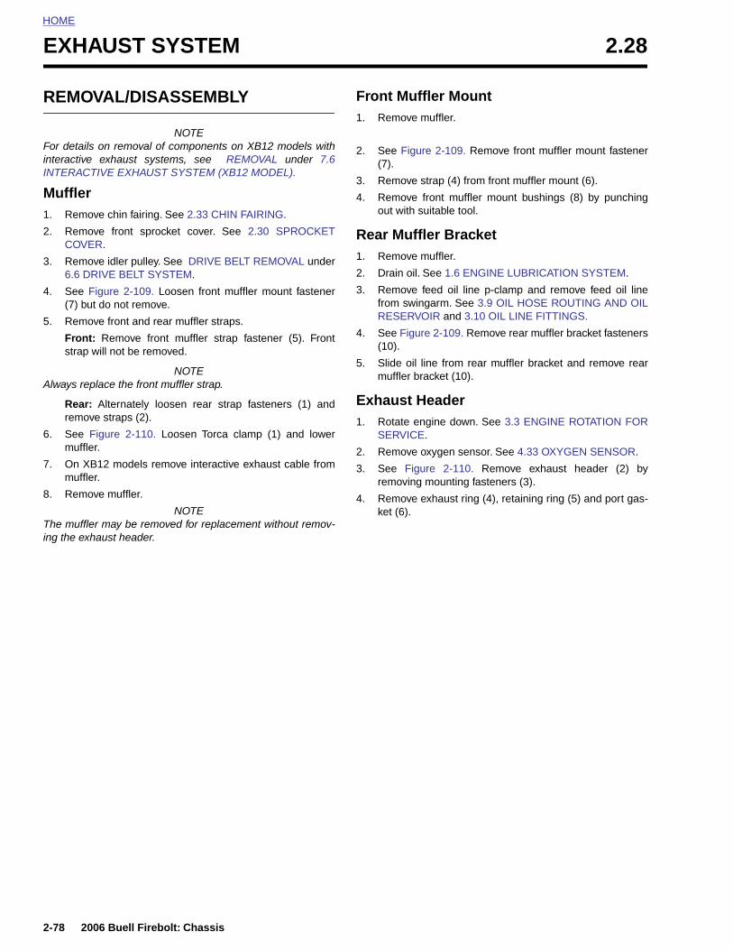
HOME
EXHAUST SYSTEM 2.28
REMO
For detailsinteractiveINTERAC
Muffler1. Remo
2. RemoCOVE
3. Remo6.6 D
4. See F(7) bu
5. Remo
Frontstrap
Always re
Rear:remo
6. See muffle
7. On Xmuffle
8. Remo
The muffleing the ex
2-78
VAL/DISASSEMBLY
NOTE on removal of components on XB12 models with exhaust systems, see REMOVAL under 7.6TIVE EXHAUST SYSTEM (XB12 MODEL).
ve chin fairing. See 2.33 CHIN FAIRING.
ve front sprocket cover. See 2.30 SPROCKETR.
ve idler pulley. See DRIVE BELT REMOVAL underRIVE BELT SYSTEM.
igure 2-109. Loosen front muffler mount fastenert do not remove.
ve front and rear muffler straps.
: Remove front muffler strap fastener (5). Frontwill not be removed.
NOTEplace the front muffler strap.
Alternately loosen rear strap fasteners (1) andve straps (2).
Figure 2-110. Loosen Torca clamp (1) and lowerr.
B12 models remove interactive exhaust cable fromr.
ve muffler.
NOTEr may be removed for replacement without remov-
haust header.
Front Muffler Mount1. Remove muffler.
2. See Figure 2-109. Remove front muffler mount fastener(7).
3. Remove strap (4) from front muffler mount (6).
4. Remove front muffler mount bushings (8) by punchingout with suitable tool.
Rear Muffler Bracket1. Remove muffler.
2. Drain oil. See 1.6 ENGINE LUBRICATION SYSTEM.
3. Remove feed oil line p-clamp and remove feed oil linefrom swingarm. See 3.9 OIL HOSE ROUTING AND OILRESERVOIR and 3.10 OIL LINE FITTINGS.
4. See Figure 2-109. Remove rear muffler bracket fasteners(10).
5. Slide oil line from rear muffler bracket and remove rearmuffler bracket (10).
Exhaust Header1. Rotate engine down. See 3.3 ENGINE ROTATION FOR
SERVICE.
2. Remove oxygen sensor. See 4.33 OXYGEN SENSOR.
3. See Figure 2-110. Remove exhaust header (2) byremoving mounting fasteners (3).
4. Remove exhaust ring (4), retaining ring (5) and port gas-ket (6).
2006 Buell Firebolt: Chassis
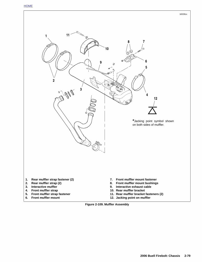
HOME
b0039cx
1. Rear muffler strap fastener (2) 7. Front muffler mount fastener
*Jacking point symbol shownon both sides of muffler.
2
1
3
4
5
6
78
9
10
11
12
2006 Buell Firebolt: Chassis 2-79
Figure 2-109. Muffler Assembly
2. Rear muffler strap (2)3. Interactive muffler4. Front muffler strap5. Front muffler strap fastener6. Front muffler mount
8. Front muffler mount bushings9. Interactive exhaust cable10. Rear muffler bracket11. Rear muffler bracket fasteners (2)12. Jacking point on muffler

HOME
ASSEMBLY/INSTALLATION ● When rear muffler straps have been installed, it is impor-tant that strap fasteners do not contact idler pulleybracket.
Exhaust Header1. See Figure 2-110. Install exhaust ring (4), retaining ring
(5) and new port gasket (6).
2. Install exhaust header (2). Tighten mounting fasteners(3) to 72-96 in-lbs (8-11 Nm).
NOTETighten header nuts gradually, alternating between studs toinsure that exhaust rings are flush with engine.
3. Install oxygen sensor. See 4.33 OXYGEN SENSOR.
4. Rotate engine up. See 3.3 ENGINE ROTATION FORSERVICE.
Rear Muffler Bracket1. See Figure 2-109. Slide rear muffler bracket (10) over oil
line.
2. Apply LOCTITE 272 and install rear muffler bracket fas-teners (11) and tighten to 32-36 ft-lbs (43-49 Nm).
3. Install oil line to swingarm. See 3.9 OIL HOSE ROUTINGAND OIL RESERVOIR/3.10 OIL LINE FITTINGS.
4. Fill swingarm/oil tank with 2.5 quarts (3.3 liters) oil. See1.6 ENGINE LUBRICATION SYSTEM.
5. Install muffler.
NOTEFor details on removal of components on XB12R with interac-tive exhaust systems, see REMOVAL under 7.6 INTERAC-TIVE EXHAUST SYSTEM (XB12 MODEL).
Front Muffler Mount1. See Figure 2-109. Install front muffler mount bushings
(8).
2. Install new strap on front muffler mount (6).
3. Install front muffler mount fastener (7) loosely. Do nottighten.
4. Install muffler.
Muffler and StrapsNOTE
Torca muffler clamps have eliminated the need for silicone orgraphite tape during assembly. To ensure sealing integrity ofmuffler clamps and prevent the possibility of leakage, Buell
NOTE
On the front muffler mount fastener, torque is applied to thehead and not to the nut.
3. Tighten front strap fastener and alternately tighten rearmuffler strap fasteners evenly till fasteners are tightenedto:
a. Front: Tighten around the muffler until snug.
b. Rear: 48-60 in-lbs (5-7 Nm).
c. Front: 108-120 in-lbs (12-14 Nm). Back off fastenertwo full turns and then retighten to 108-120 in-lbs(12-14 Nm).
4. See Figure 2-110. Tighten the Torca clamp (1) to 28-30 ft-lbs (38-40.6Nm).
5. Front muffler mount: 16-18 ft-lbs (21.7-24.4 Nm).
6. Install idler pulley. See 6.6 DRIVE BELT SYSTEM.
7. Install front sprocket cover. See 2.30 SPROCKETCOVER.
8. Install chin fairing. See 2.33 CHIN FAIRING.
b0973a2x
4
56
3
2-80 2006 Buell Firebolt: Chassis
recommends that muffler clamp assemblies be discarded andreplaced each time they are removed.
1. Install muffler and new Torca clamp onto header.
NOTEIf necessary, use a fiber hammer to fit muffler on header.
2. See Figure 2-109. Loosely install new front and rearmuffler straps (2, 4).
NOTES● It is important that the front muffler mount is tightened
last in order to ensure proper alignment of the exhaustsystem.
● Never re-use front muffler strap. Always replace frontmuffler strap with a new strap when removed from sys-tem. Figure 2-110. Exhaust Header
1
1. Torca clamp2. Header3. Header mount fastener4. Exhaust ring5. Exhaust retaining ring6. Exhaust port gasket
2
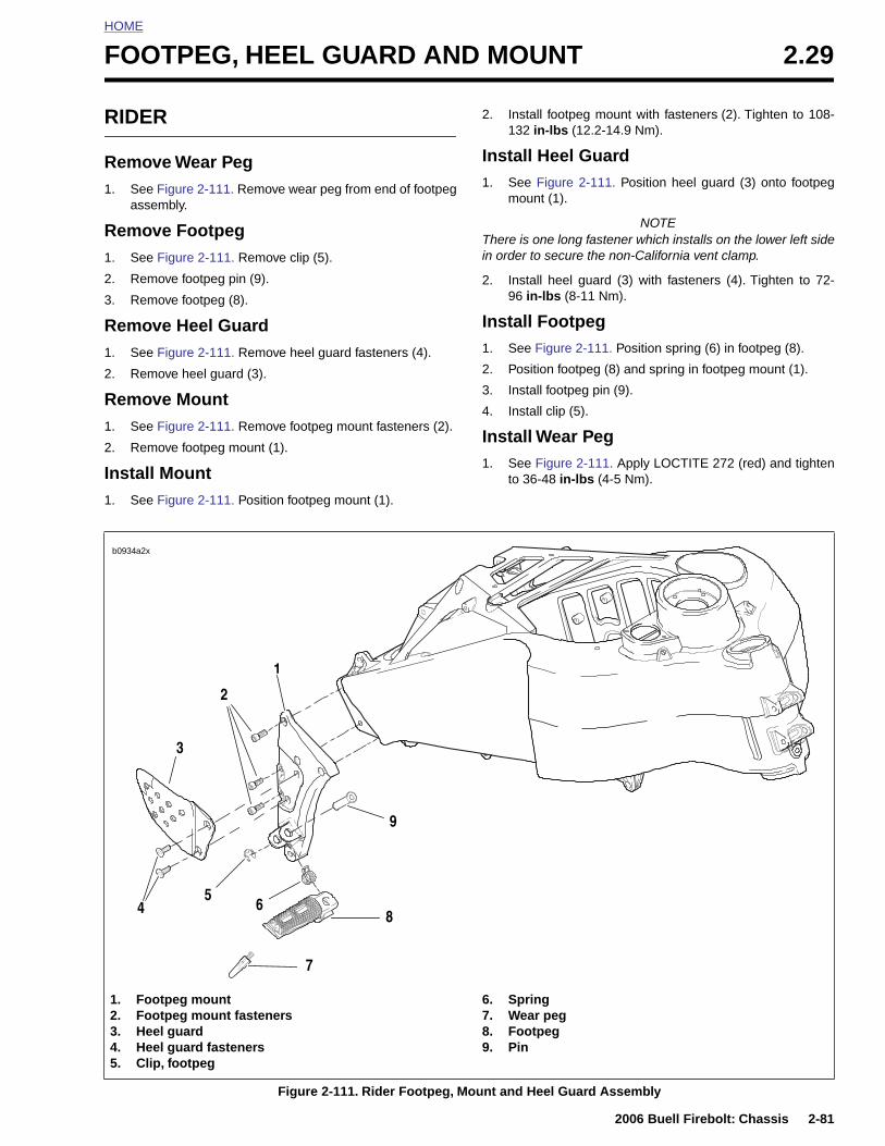
HOME
F
R
R1
R1
2
3
R1
2
R1
2
I1
OOTPEG, HEEL GUARD AND MOUNT 2.29
IDER
emove Wear Peg. See Figure 2-111. Remove wear peg from end of footpeg
assembly.
emove Footpeg. See Figure 2-111. Remove clip (5).
. Remove footpeg pin (9).
. Remove footpeg (8).
emove Heel Guard. See Figure 2-111. Remove heel guard fasteners (4).
. Remove heel guard (3).
emove Mount. See Figure 2-111. Remove footpeg mount fasteners (2).
. Remove footpeg mount (1).
nstall Mount. See Figure 2-111. Position footpeg mount (1).
2. Install footpeg mount with fasteners (2). Tighten to 108-132 in-lbs (12.2-14.9 Nm).
Install Heel Guard1. See Figure 2-111. Position heel guard (3) onto footpeg
mount (1).
NOTEThere is one long fastener which installs on the lower left sidein order to secure the non-California vent clamp.
2. Install heel guard (3) with fasteners (4). Tighten to 72-96 in-lbs (8-11 Nm).
Install Footpeg1. See Figure 2-111. Position spring (6) in footpeg (8).
2. Position footpeg (8) and spring in footpeg mount (1).
3. Install footpeg pin (9).
4. Install clip (5).
Install Wear Peg1. See Figure 2-111. Apply LOCTITE 272 (red) and tighten
to 36-48 in-lbs (4-5 Nm).
b0934a2x
1
3
2
2006 Buell Firebolt: Chassis 2-81
Figure 2-111. Rider Footpeg, Mount and Heel Guard Assembly
1. Footpeg mount2. Footpeg mount fasteners3. Heel guard4. Heel guard fasteners5. Clip, footpeg
6. Spring7. Wear peg8. Footpeg9. Pin
9
56
7
4 8
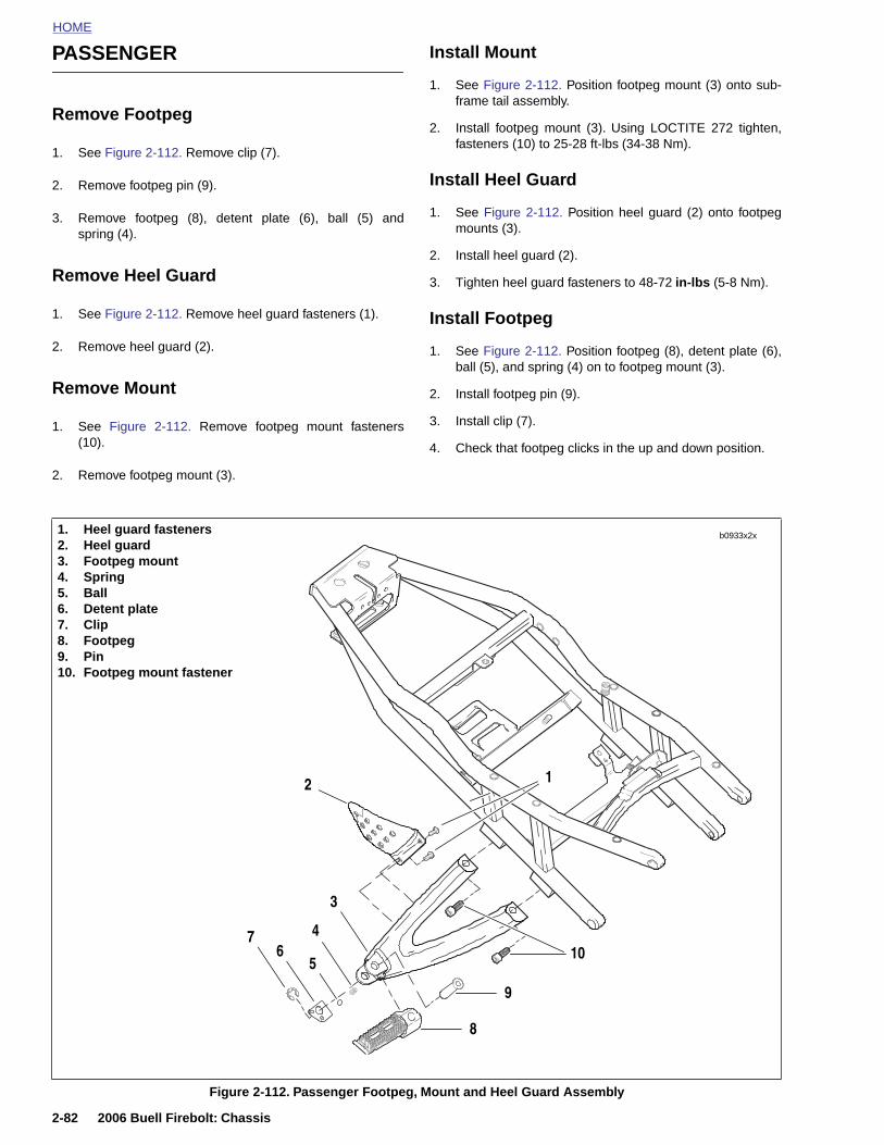
HOME
PASSENGER Install Mount
1. See Figure 2-112. Position footpeg mount (3) onto sub-
Remove Footpeg
1. See Figure 2-112. Remove clip (7).
2. Remove footpeg pin (9).
3. Remove footpeg (8), detent plate (6), ball (5) andspring (4).
Remove Heel Guard
1. See Figure 2-112. Remove heel guard fasteners (1).
2. Remove heel guard (2).
Remove Mount
1. See Figure 2-112. Remove footpeg mount fasteners(10).
2. Remove footpeg mount (3).
frame tail assembly.
2. Install footpeg mount (3). Using LOCTITE 272 tighten,fasteners (10) to 25-28 ft-lbs (34-38 Nm).
Install Heel Guard
1. See Figure 2-112. Position heel guard (2) onto footpegmounts (3).
2. Install heel guard (2).
3. Tighten heel guard fasteners to 48-72 in-lbs (5-8 Nm).
Install Footpeg
1. See Figure 2-112. Position footpeg (8), detent plate (6),ball (5), and spring (4) on to footpeg mount (3).
2. Install footpeg pin (9).
3. Install clip (7).
4. Check that footpeg clicks in the up and down position.
1. Heel guard fasteners2. Heel guard3. Footpeg mount4. Spring5. Ball6. Detent plate7. Clip8. Footpeg9. Pin10. Footpeg mount fastener
2 1
b0933x2x
2-82 2006 Buell Firebolt: Chassis
Figure 2-112. Passenger Footpeg, Mount and Heel Guard Assembly
3
10
9
8
65
47
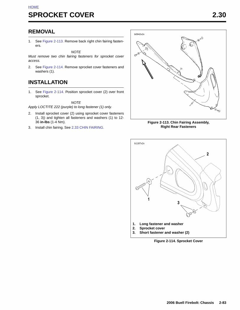
HOME
S
R
1
Ma
2
I
1
A
2
3
PROCKET COVER 2.30
EMOVAL
. See Figure 2-113. Remove back right chin fairing fasten-ers.
NOTEust remove two chin fairing fasteners for sprocket coverccess.
. See Figure 2-114. Remove sprocket cover fasteners andwashers (1).
NSTALLATION
. See Figure 2-114. Position sprocket cover (2) over frontsprocket.
NOTEpply LOCTITE 222 (purple) to long fastener (1) only.
. Install sprocket cover (2) using sprocket cover fasteners(1, 3)) and tighten all fasteners and washers (1) to 12-36 in-lbs (1-4 Nm).
. Install chin fairing. See 2.33 CHIN FAIRING.
Figure 2-113. Chin Fairing Assembly, Right Rear Fasteners
b0942x2x
b1187x2x
2
13
2006 Buell Firebolt: Chassis 2-83
Figure 2-114. Sprocket Cover
1. Long fastener and washer2. Sprocket cover3. Short fastener and washer (2)
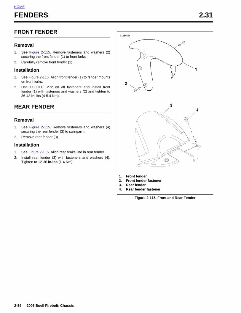
HOME
FENDERS 2.31
FRON
Remov1. See
secur
2. Caref
Installa1. See F
on fro
2. Use fende36-48
REAR
Remov1. See
secur
2. Remo
Installa1. See F
2. InstalTight
2-84
T FENDER
alFigure 2-115. Remove fasteners and washers (2)ing the front fender (1) to front forks.
ully remove front fender (1).
tionigure 2-115. Align front fender (1) to fender mountsnt forks.
LOCTITE 272 on all fasteners and install frontr (1) with fasteners and washers (2) and tighten to in-lbs (4-5.4 Nm).
FENDER
alFigure 2-115. Remove fasteners and washers (4)ing the rear fender (3) to swingarm.
ve rear fender (3).
tionigure 2-115. Align rear brake line in rear fender.
l rear fender (3) with fasteners and washers (4),en to 12-36 in-lbs (1-4 Nm).
Figure 2-115. Front and Rear Fender
1. Front fender2. Front fender fastener3. Rear fender4. Rear fender fastener
b1186x2x
1
2
34
2006 Buell Firebolt: Chassis

HOME
B
R
1
2
3
4
5
6
7
ELT GUARDS 2.32
EMOVAL
. Place a scissor jack under jacking point and raise rearwheel off ground. For location of jacking point see 2.28EXHAUST SYSTEM.
. Remove right side rider footrest support bracket.
. Loosen rear axle pinch fastener.
. Loosen rear axle approximately 15 rotations to allow par-tial tension to be removed from rear drive system.
. Remove lower belt guard by removing the two fastenerslocated on the outside of the lower belt guard.
. Once the lower belt guard has been removed, removethe metal stone guard.
. Remove upper belt guard (1) by removing fasteners fromswingarm.
INSTALLATION
1. Install upper belt guard (1) tightening fasteners to 12-36 in-lbs (1-4 Nm).
2. Install stone guard and tighten fasteners to 12-36 in-lbs(1-4 Nm).
3. Install lower belt guard (3) and tighten fasteners (4) to12-36 in-lbs (1-4 Nm).
4. Tighten rear axle to 48-52 ft-lbs (65-70 Nm).
5. Tighten rear axle pinch fastener to 40-45 ft-lbs (54-61 Nm).
6. Install right side rider footrest mount and tighten fasten-ers to 108-132 in-lbs (12.2-14.9 Nm).
7. Remove scissor jack from motorcycle.
b1185a2x
2
7
1
35
2006 Buell Firebolt: Chassis 2-85
Figure 2-116. Belt Guard Assembly
8
4
6
1. Upper belt guard2. Upper belt guard and stone guard fasteners (2)3. Lower belt guard4. Lower belt guard fasteners (2)
5. Fasteners, stone guard6. Stone guard7. Sprocket cover8. Sprocket cover fasteners (2 short, 1 long)
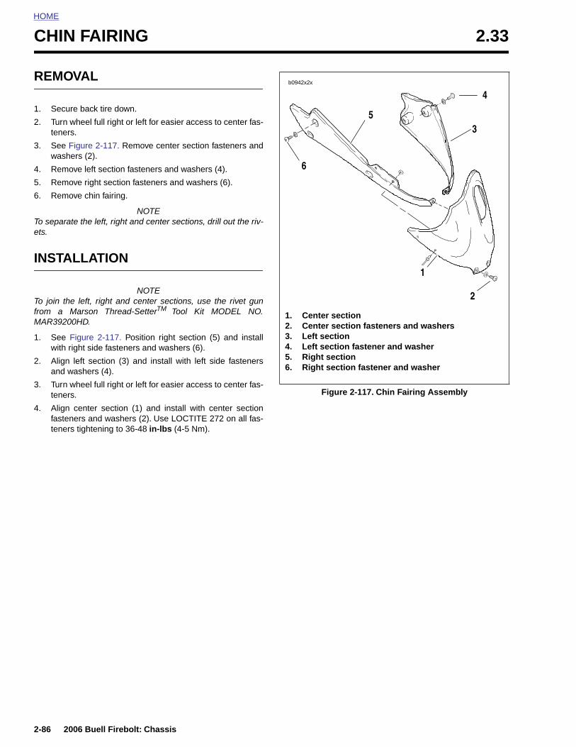
HOME
CHIN FAIRING 2.33
REMO
1. Secu
2. Turn wtener
3. See Fwash
4. Remo
5. Remo
6. Remo
To separaets.
INSTA
To join thfrom a MMAR3920
1. See Fwith r
2. Alignand w
3. Turn wtener
4. Alignfastentener
2-86
VAL
re back tire down.
heel full right or left for easier access to center fas-s.
igure 2-117. Remove center section fasteners anders (2).
ve left section fasteners and washers (4).
ve right section fasteners and washers (6).
ve chin fairing.
NOTEte the left, right and center sections, drill out the riv-
LLATION
NOTEe left, right and center sections, use the rivet gun
arson Thread-SetterTM Tool Kit MODEL NO.0HD.
igure 2-117. Position right section (5) and installight side fasteners and washers (6).
left section (3) and install with left side fastenersashers (4).
heel full right or left for easier access to center fas-s.
center section (1) and install with center sectioners and washers (2). Use LOCTITE 272 on all fas-
s tightening to 36-48 in-lbs (4-5 Nm).
Figure 2-117. Chin Fairing Assembly
b0942x2x
1. Center section 2. Center section fasteners and washers3. Left section 4. Left section fastener and washer5. Right section 6. Right section fastener and washer
1
2
6
53
4
2006 Buell Firebolt: Chassis
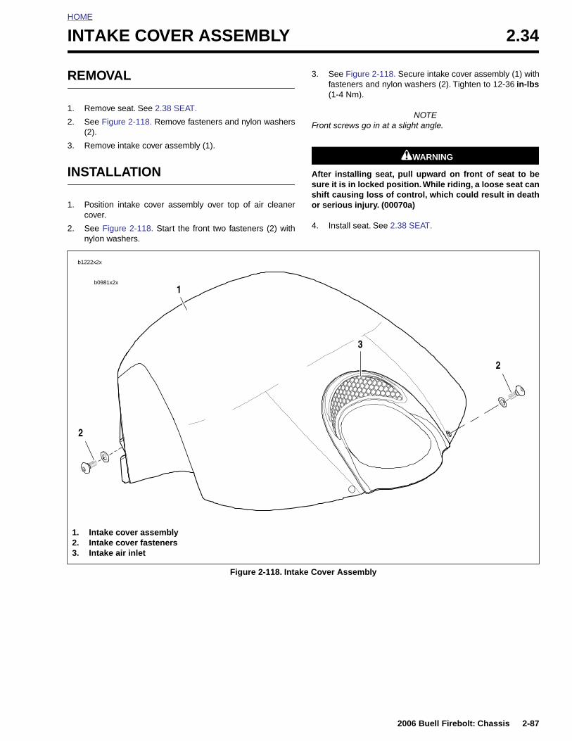
HOME
I
R
1
2
3
I
1
2
NTAKE COVER ASSEMBLY 2.34
EMOVAL
. Remove seat. See 2.38 SEAT.
. See Figure 2-118. Remove fasteners and nylon washers(2).
. Remove intake cover assembly (1).
NSTALLATION
. Position intake cover assembly over top of air cleanercover.
. See Figure 2-118. Start the front two fasteners (2) withnylon washers.
3. See Figure 2-118. Secure intake cover assembly (1) withfasteners and nylon washers (2). Tighten to 12-36 in-lbs(1-4 Nm).
NOTEFront screws go in at a slight angle.
11WARNING1WARNING
After installing seat, pull upward on front of seat to besure it is in locked position. While riding, a loose seat canshift causing loss of control, which could result in deathor serious injury. (00070a)
4. Install seat. See 2.38 SEAT.
b0981x2x
1
2
2
3
b1222x2x
2006 Buell Firebolt: Chassis 2-87
Figure 2-118. Intake Cover Assembly
1. Intake cover assembly2. Intake cover fasteners3. Intake air inlet
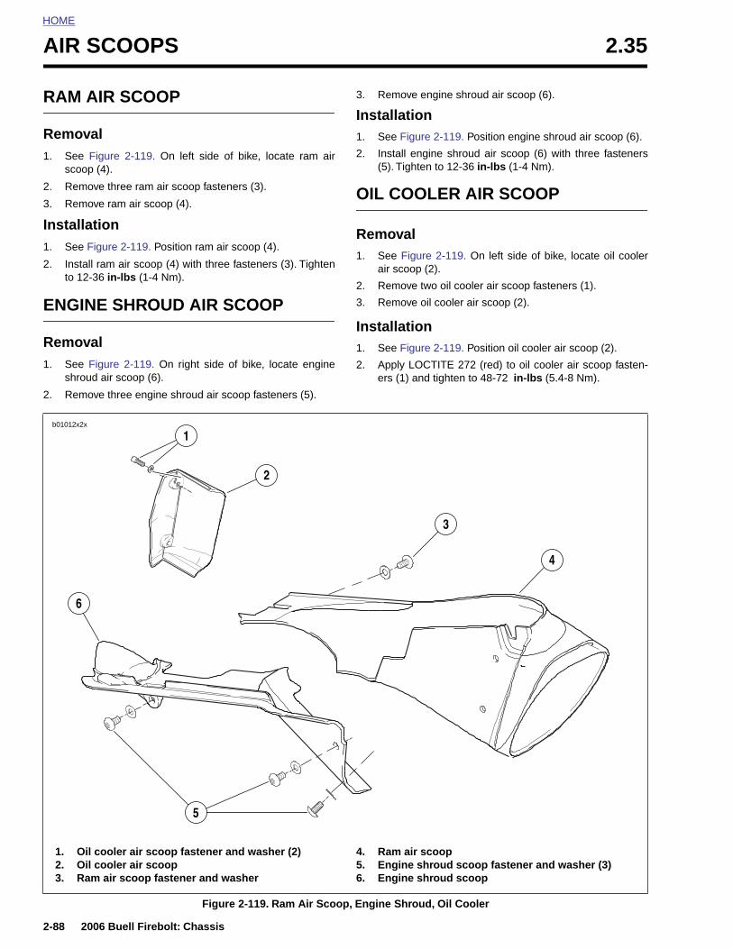
HOME
AIR SCOOPS 2.35
RAM A
Remov1. See
scoop
2. Remo
3. Remo
Installa1. See F
2. Instalto 12
ENGIN
Remov1. See F
shrou
2. Remo
b01012x2x
6
2-88
1. O2. O3. R
IR SCOOP
alFigure 2-119. On left side of bike, locate ram air (4).
ve three ram air scoop fasteners (3).
ve ram air scoop (4).
tionigure 2-119. Position ram air scoop (4).
l ram air scoop (4) with three fasteners (3). Tighten-36 in-lbs (1-4 Nm).
E SHROUD AIR SCOOP
aligure 2-119. On right side of bike, locate engine
d air scoop (6).
ve three engine shroud air scoop fasteners (5).
3. Remove engine shroud air scoop (6).
Installation1. See Figure 2-119. Position engine shroud air scoop (6).
2. Install engine shroud air scoop (6) with three fasteners(5). Tighten to 12-36 in-lbs (1-4 Nm).
OIL COOLER AIR SCOOP
Removal1. See Figure 2-119. On left side of bike, locate oil cooler
air scoop (2).
2. Remove two oil cooler air scoop fasteners (1).
3. Remove oil cooler air scoop (2).
Installation1. See Figure 2-119. Position oil cooler air scoop (2).
2. Apply LOCTITE 272 (red) to oil cooler air scoop fasten-ers (1) and tighten to 48-72 in-lbs (5.4-8 Nm).
4
3
1
2
2006 Buell Firebolt: Chassis
Figure 2-119. Ram Air Scoop, Engine Shroud, Oil Cooler
il cooler air scoop fastener and washer (2)il cooler air scoopam air scoop fastener and washer
4. Ram air scoop5. Engine shroud scoop fastener and washer (3)6. Engine shroud scoop
5
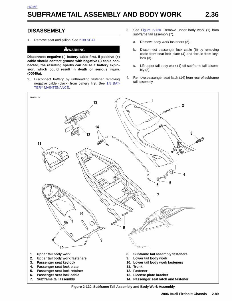
HOME
S
D
1
Dcns(
2
UBFRAME TAIL ASSEMBLY AND BODY WORK 2.36
ISASSEMBLY
. Remove seat and pillion. See 2.38 SEAT.
11WARNING1WARNING
isconnect negative (-) battery cable first. If positive (+)able should contact ground with negative (-) cable con-ected, the resulting sparks can cause a battery explo-ion, which could result in death or serious injury.00049a).
. Disconnect battery by unthreading fastener removingnegative cable (black) from battery first. See 1.5 BAT-TERY MAINTENANCE.
3. See Figure 2-120. Remove upper body work (1) fromsubframe tail assembly (7).
a. Remove body work fasteners (2).
b. Disconnect passenger lock cable (6) by removingcable from seat lock plate (4) and ferrule from key-lock (3).
c. Lift upper tail body work (1) off subframe tail assem-bly (8).
4. Remove passenger seat latch (14) from rear of subframetail assembly.
b0956x2x
11
6
213 1
14
12 3
4
5
7
2006 Buell Firebolt: Chassis 2-89
Figure 2-120. Subframe Tail Assembly and Body Work Assembly
1. Upper tail body work2. Upper tail body work fasteners3. Passenger seat keylock4. Passenger seat lock plate5. Passenger seat lock retainer6. Passenger seat lock cable7. Subframe tail assembly
8. Subframe tail assembly fasteners9. Lower tail body work10. Lower tail body work fasteners11. Trunk12. Fastener13. License plate bracket14. Passenger seat latch and fastener
9
10
8
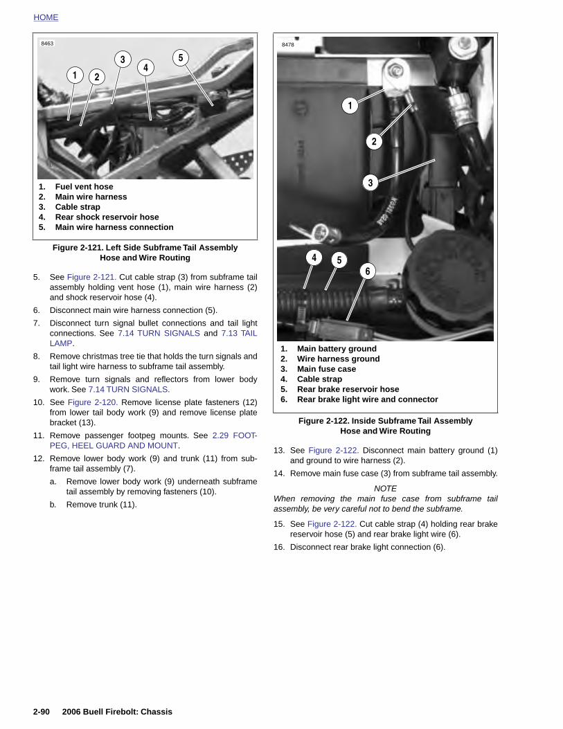
HOME
8463 8478
5. See Figure 2-121. Cut cable strap (3) from subframe tailassembly holding vent hose (1), main wire harness (2)and shock reservoir hose (4).
6. Disconnect main wire harness connection (5).
7. Disconnect turn signal bullet connections and tail lightconnections. See 7.14 TURN SIGNALS and 7.13 TAILLAMP.
8. Remove christmas tree tie that holds the turn signals andtail light wire harness to subframe tail assembly.
9. Remove turn signals and reflectors from lower bodywork. See 7.14 TURN SIGNALS.
10. See Figure 2-120. Remove license plate fasteners (12)from lower tail body work (9) and remove license platebracket (13).
11. Remove passenger footpeg mounts. See 2.29 FOOT-PEG, HEEL GUARD AND MOUNT.
12. Remove lower body work (9) and trunk (11) from sub-frame tail assembly (7).
a. Remove lower body work (9) underneath subframetail assembly by removing fasteners (10).
b. Remove trunk (11).
13. See Figure 2-122. Disconnect main battery ground (1)and ground to wire harness (2).
14. Remove main fuse case (3) from subframe tail assembly.
NOTEWhen removing the main fuse case from subframe tailassembly, be very careful not to bend the subframe.
15. See Figure 2-122. Cut cable strap (4) holding rear brakereservoir hose (5) and rear brake light wire (6).
Figure 2-121. Left Side Subframe Tail Assembly Hose and Wire Routing
1. Fuel vent hose2. Main wire harness3. Cable strap4. Rear shock reservoir hose5. Main wire harness connection
1 2
3 54
Figure 2-122. Inside Subframe Tail Assembly Hose and Wire Routing
1. Main battery ground2. Wire harness ground3. Main fuse case4. Cable strap5. Rear brake reservoir hose6. Rear brake light wire and connector
1
2
3
64 5
2-90 2006 Buell Firebolt: Chassis
16. Disconnect rear brake light connection (6).
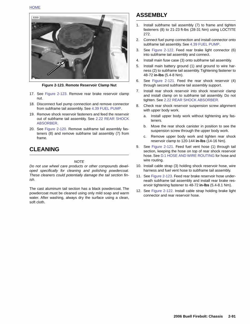
HOME
17. See Figure 2-123. Remove rear brake reservoir clampnut.
18. Disconnect fuel pump connection and remove connectorfrom subframe tail assembly. See 4.39 FUEL PUMP.
19. Remove shock reservoir fasteners and feed the reservoirout of subframe tail assembly. See 2.22 REAR SHOCKABSORBER.
20. See Figure 2-120. Remove subframe tail assembly fas-teners (8) and remove subframe tail assembly (7) fromframe.
CLEANING
NOTEDo not use wheel care products or other compounds devel-oped specifically for cleaning and polishing powdercoat.These cleaners could potentially damage the tail section fin-ish.
The cast aluminum tail section has a black powdercoat. Thepowdercoat must be cleaned using only mild soap and warmwater. After washing, always dry the surface using a clean,soft cloth.
ASSEMBLY
1. Install subframe tail assembly (7) to frame and tightenfasteners (8) to 21-23 ft-lbs (28-31 Nm) using LOCTITE272.
2. Connect fuel pump connection and install connector ontosubframe tail assembly. See 4.39 FUEL PUMP.
3. See Figure 2-122. Feed rear brake light connector (6)into subframe tail assembly and connect.
4. Install main fuse case (3) onto subframe tail assembly.
5. Install main battery ground (1) and ground to wire har-ness (2) to subframe tail assembly. Tightening fastener to48-72 in-lbs (5.4-8 Nm).
6. See Figure 2-121. Feed the rear shock reservoir (4)through second subframe tail assembly support.
7. Install rear shock reservoir into shock reservoir clampand install clamp on to subframe tail assembly. Do nottighten. See 2.22 REAR SHOCK ABSORBER.
8. Check rear shock reservoir suspension screw alignmentwith upper body work.
a. Install upper body work without tightening any fas-teners.
b. Move the rear shock canister in position to see thesuspension screw through the upper body work.
c. Remove upper body work and tighten rear shockreservoir clamp to 120-144 in-lbs (14-16 Nm).
9. See Figure 2-121. Feed fuel vent hose (1) through tailsection, keeping the hose on top of rear shock reservoirhose. See D.1 HOSE AND WIRE ROUTING for hose andwire routing.
10. Install cable strap (3) holding shock reservoir hose, wireharness and fuel vent hose to subframe tail assembly.
11. See Figure 2-123. Feed rear brake reservoir hose under-neath subframe tail assembly and install rear brake res-ervoir tightening fastener to 48-72 in-lbs (5.4-8.1 Nm).
12. See Figure 2-122. Install cable strap holding brake lightconnector and rear reservoir hose.
Figure 2-123. Remote Reservoir Clamp Nut
8359
2006 Buell Firebolt: Chassis 2-91
HOME
13. See Figure 2-120. Install lower body work (9) and trunk(11) onto subframe tail assembly (7).
21. See Figure 2-120. Install upper body work onto subframetail assembly.
a. Connect passenger lock cable (6) by installing fer-
a. Install trunk (11).b. Install lower body work (9) underneath subframe tailassembly by tightening fasteners (10) to 12-36 in-lbs (1.3-4 Nm).
14. Install passenger footpeg mounts. Tightening footpegmount fasteners to 25-28 ft-lbs (34-38 Nm). See 2.29FOOTPEG, HEEL GUARD AND MOUNT.
15. See Figure 2-121. Connect rear power harness to taillight harness (5).
16. Install christmas tree tie down that holds the turn signalsand tail light wire harness to subframe tail assembly. See7.14 TURN SIGNALS.
11WARNING1WARNING
Be sure that all lights and switches operate properlybefore operating motorcycle. Low visibility of rider canresult in death or serious injury. (00316a)
17. See Figure 2-120. Install license plate bracket (13) tolower tail body work (9) and tighten fasteners (12) to 36-48 in-lbs (4-5 Nm).
18. Install turn signals and reflectors onto lower body workand tighten to 25-28 in-lbs (2-3 Nm). See 7.14 TURNSIGNALS.
19. Connect turn signal bullet connections and tail light con-nections. See 7.14 TURN SIGNALS and 7.13 TAILLAMP.
20. Install passenger seat latch (14) from rear of subframetail assembly and tighten to 60-96 in-lbs (7-11 Nm).
rule into lock lever.
b. Starting on the left side of the subframe tail assem-bly cover the lock cable and wire harness and alignupper body work (1) on subframe tail assembly (7).
c. Install tail body work starting with the fastener in thecenter of upper body work and between the passen-ger and rider seat. Tighten all fasteners to 12-36 in-lbs (1-4 Nm).
11WARNING1WARNING
Connect positive (+) battery cable first. If positive (+)cable should contact ground with negative (-) cable con-nected, the resulting sparks can cause a battery explo-sion, which could result in death or serious injury.(00068a)
22. Install battery by threading positive cable (red) intothreaded hole first tightening to 72-96 in-lbs (8-11 Nm).See 1.5 BATTERY MAINTENANCE.
11WARNING1WARNING
After installing seat, pull upward on front of seat to besure it is in locked position. While riding, a loose seat canshift causing loss of control, which could result in deathor serious injury. (00070a)
23. Install seat and pillion. See 2.38 SEAT.
2-92 2006 Buell Firebolt: Chassis
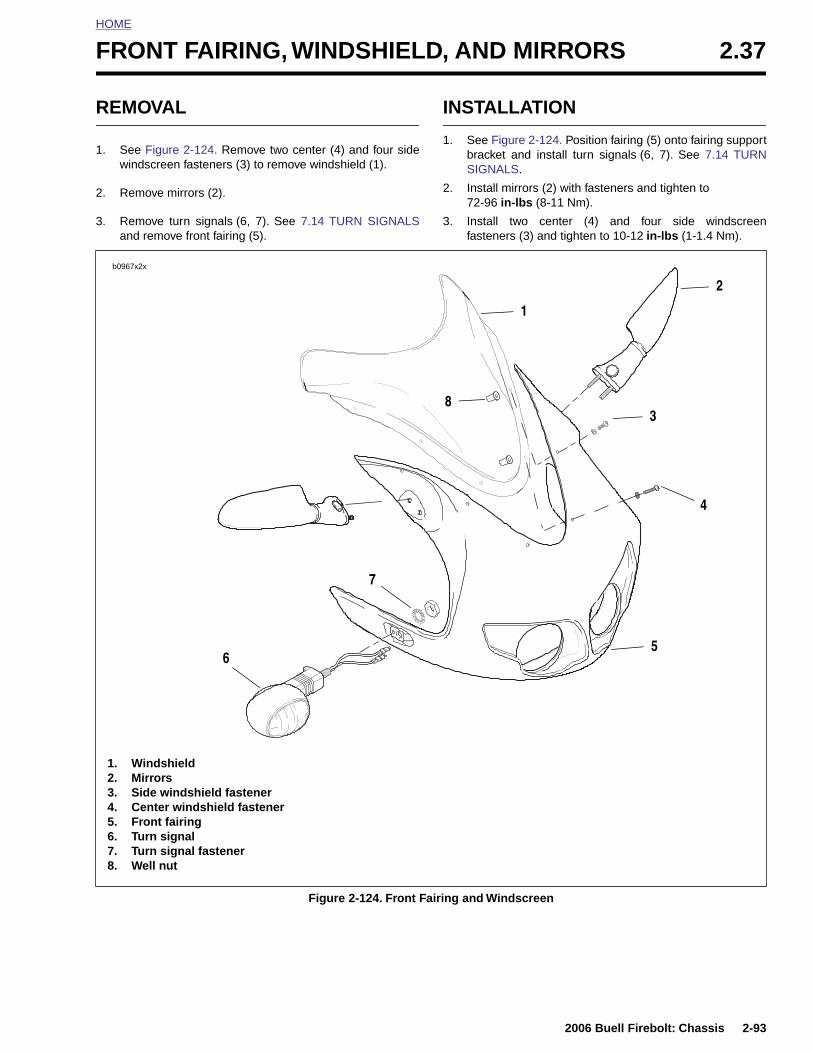
HOME
F
R
1
2
3
RONT FAIRING, WINDSHIELD, AND MIRRORS 2.37
EMOVAL
. See Figure 2-124. Remove two center (4) and four sidewindscreen fasteners (3) to remove windshield (1).
. Remove mirrors (2).
. Remove turn signals (6, 7). See 7.14 TURN SIGNALSand remove front fairing (5).
INSTALLATION
1. See Figure 2-124. Position fairing (5) onto fairing supportbracket and install turn signals (6, 7). See 7.14 TURNSIGNALS.
2. Install mirrors (2) with fasteners and tighten to 72-96 in-lbs (8-11 Nm).
3. Install two center (4) and four side windscreenfasteners (3) and tighten to 10-12 in-lbs (1-1.4 Nm).
b0967x2x
2
1
3
4
56
8
7
2006 Buell Firebolt: Chassis 2-93
Figure 2-124. Front Fairing and Windscreen
1. Windshield2. Mirrors3. Side windshield fastener4. Center windshield fastener5. Front fairing6. Turn signal7. Turn signal fastener8. Well nut
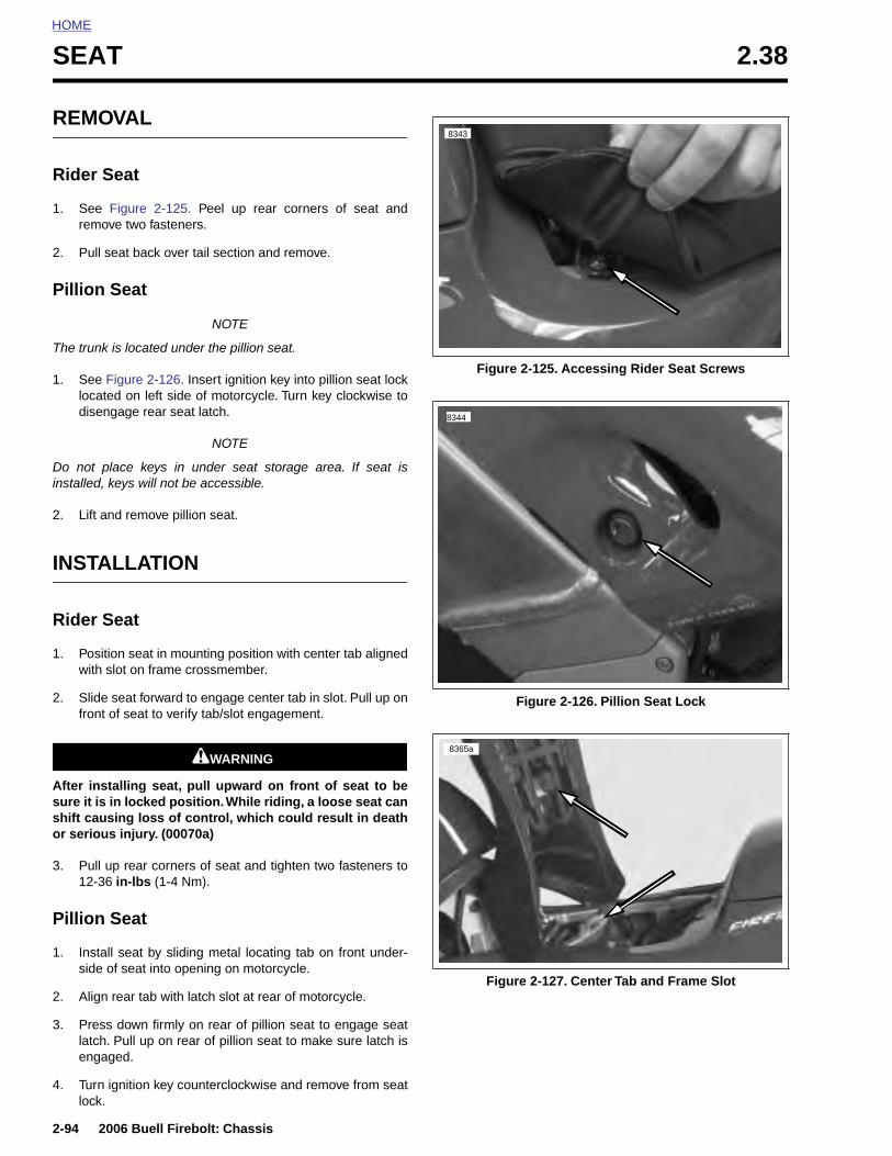
HOME
SEAT 2.38
REMO
Rider S
1. See remo
2. Pull s
Pillion
The trunk
1. See Flocatedisen
Do not pinstalled,
2. Lift an
INSTA
Rider S
1. Positiwith s
2. Slidefront
After instsure it is shift causor seriou
2-94
3. Pul12-
Pillion
1. Instside
2. Alig
3. Prelatceng
4. Turnlock
VAL
eat
Figure 2-125. Peel up rear corners of seat andve two fasteners.
eat back over tail section and remove.
Seat
NOTE
is located under the pillion seat.
igure 2-126. Insert ignition key into pillion seat lockd on left side of motorcycle. Turn key clockwise to
gage rear seat latch.
NOTE
lace keys in under seat storage area. If seat iskeys will not be accessible.
d remove pillion seat.
LLATION
eat
on seat in mounting position with center tab alignedlot on frame crossmember.
seat forward to engage center tab in slot. Pull up onof seat to verify tab/slot engagement.
11WARNING1WARNING
alling seat, pull upward on front of seat to bein locked position. While riding, a loose seat caning loss of control, which could result in death
s injury. (00070a)
Figure 2-125. Accessing Rider Seat Screws
Figure 2-126. Pillion Seat Lock
8343
8344
8365a
2006 Buell Firebolt: Chassis
l up rear corners of seat and tighten two fasteners to36 in-lbs (1-4 Nm).
Seat
all seat by sliding metal locating tab on front under- of seat into opening on motorcycle.
n rear tab with latch slot at rear of motorcycle.
ss down firmly on rear of pillion seat to engage seath. Pull up on rear of pillion seat to make sure latch isaged.
ignition key counterclockwise and remove from seat.
Figure 2-127. Center Tab and Frame Slot
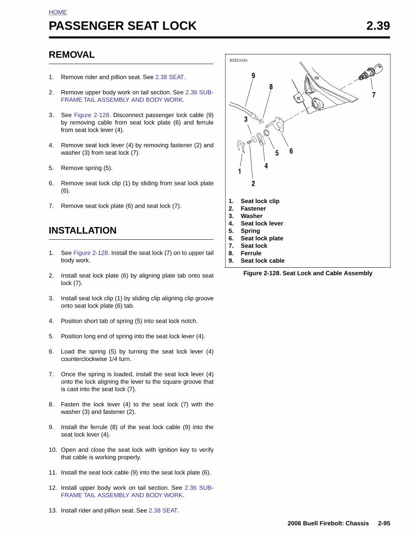
HOME
P
R
1
2
3
4
5
6
7
I
1
2
3
4
5
6
ASSENGER SEAT LOCK 2.39
EMOVAL
. Remove rider and pillion seat. See 2.38 SEAT.
. Remove upper body work on tail section. See 2.36 SUB-FRAME TAIL ASSEMBLY AND BODY WORK.
. See Figure 2-128. Disconnect passenger lock cable (9)by removing cable from seat lock plate (6) and ferrulefrom seat lock lever (4).
. Remove seat lock lever (4) by removing fastener (2) andwasher (3) from seat lock (7).
. Remove spring (5).
. Remove seat lock clip (1) by sliding from seat lock plate(6).
. Remove seat lock plate (6) and seat lock (7).
NSTALLATION
. See Figure 2-128. Install the seat lock (7) on to upper tailbody work.
. Install seat lock plate (6) by aligning plate tab onto seatlock (7).
. Install seat lock clip (1) by sliding clip aligning clip grooveonto seat lock plate (6) tab.
. Position short tab of spring (5) into seat lock notch.
. Position long end of spring into the seat lock lever (4).
. Load the spring (5) by turning the seat lock lever (4)counterclockwise 1/4 turn.
Figure 2-128. Seat Lock and Cable Assembly
1. Seat lock clip2. Fastener3. Washer4. Seat lock lever5. Spring6. Seat lock plate7. Seat lock8. Ferrule9. Seat lock cable
b1011x2x
1
2
4
5 6
7
3
9
8
2006 Buell Firebolt: Chassis 2-95
7. Once the spring is loaded, install the seat lock lever (4)onto the lock aligning the lever to the square groove thatis cast into the seat lock (7).
8. Fasten the lock lever (4) to the seat lock (7) with thewasher (3) and fastener (2).
9. Install the ferrule (8) of the seat lock cable (9) into theseat lock lever (4).
10. Open and close the seat lock with ignition key to verifythat cable is working properly.
11. Install the seat lock cable (9) into the seat lock plate (6).
12. Install upper body work on tail section. See 2.36 SUB-FRAME TAIL ASSEMBLY AND BODY WORK.
13. Install rider and pillion seat. See 2.38 SEAT.
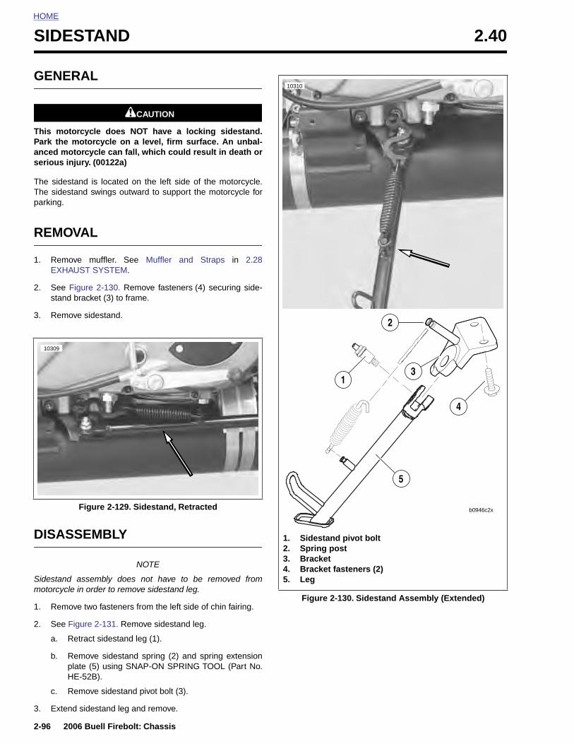
HOME
SIDESTAND 2.40
GENE
This motPark the anced moserious in
The sidesThe sidesparking.
REMO
1. RemoEXHA
2. See Fstand
3. Remo
DISAS
10309
2-96
Sidestanmotorcy
1. Rem
2. See
a.
b.
c.
3. Ext
RAL
1CAUTION
orcycle does NOT have a locking sidestand.motorcycle on a level, firm surface. An unbal-torcycle can fall, which could result in death orjury. (00122a)
tand is located on the left side of the motorcycle.tand swings outward to support the motorcycle for
VAL
ve muffler. See Muffler and Straps in 2.28UST SYSTEM.
igure 2-130. Remove fasteners (4) securing side- bracket (3) to frame.
ve sidestand.
SEMBLY
Figure 2-129. Sidestand, Retracted
10310
1. Sidestand pivot bolt
5
b0946c2x
4
1
2
3
2006 Buell Firebolt: Chassis
NOTE
d assembly does not have to be removed fromcle in order to remove sidestand leg.
ove two fasteners from the left side of chin fairing.
Figure 2-131. Remove sidestand leg.
Retract sidestand leg (1).
Remove sidestand spring (2) and spring extensionplate (5) using SNAP-ON SPRING TOOL (Part No.HE-52B).
Remove sidestand pivot bolt (3).
end sidestand leg and remove.
Figure 2-130. Sidestand Assembly (Extended)
2. Spring post3. Bracket4. Bracket fasteners (2)5. Leg

HOME
ASSEMBLY
1. See Figure 2-131. Install sidestand leg (1).a. See Figure 2-132. Lubricate sidestand pivot bolt (3)
and mating portions on sidestand bracket (5) withWHEEL BEARING GREASE (Part No. 99855-89) asshown in Figure 2-132.
b. See Figure 2-133. Apply LOCTITE 272 (red) tothreaded area (clevis) of sidestand leg.
NOTEApplying LOCTITE to threaded area of clevis on sidestandleg, instead of threads on the pivot bolt, will eliminate build-upbetween clevis and sidestand bracket which can interfere withthe applied lubricant.
c. See Figure 2-131. Install sidestand leg (1) and applyLOCTITE 272 (red) to sidestand pivot bolt (3) tight-ening to 18-20 ft-lbs (24-27 Nm).
d. Retract sidestand leg.
e. Install spring extension plate (4) and sidestandspring (2) using SNAP-ON SPRING TOOL (Part No.HE-52B).
NOTEExtension plate should curve away from primary chain adjust-ment screw to allow for clearance around adjustment screw.
INSTALLATION
1. Apply LOCTITE 272 to fasteners and install sidestand toframe tightening the sidestand bracket fasteners to 25-27 ft-lbs (34-37 Nm).
2. Install muffler. See Muffler and Straps in 2.28 EXHAUSTSYSTEM.
3. Inspect sidestand.
Figure 2-131. Sidestand Assembly
1. Leg2. Spring3. Pivot fastener4. Extension plate5. Bracket6. Bracket fastener
b0946x2x
3
b0946d2x
2
1
4
5 6
b1128x3x
2006 Buell Firebolt: Chassis 2-97
Figure 2-132. Lubricating Points (Shaded Areas)
Figure 2-133. Threaded Area for Loctite Application
b1127x2x

HOME
NOTES
2-98
2006 Buell Firebolt: Chassis
ENGINE 3
SUBJECT PAGE NO.
3.1 Specifications . . . . . . . . . . . . . . . . . . . . . . . . . . . . . . . . . . . . . . . . . . . . . . . . . 3-13.2 Engine . . . . . . . . . . . . . . . . . . . . . . . . . . . . . . . . . . . . . . . . . . . . . . . . . . . . . . . 3-63.3 Engine Rotation for Service . . . . . . . . . . . . . . . . . . . . . . . . . . . . . . . . . . . . . . . 3-83.4 Stripping Motorcycle for Engine Service . . . . . . . . . . . . . . . . . . . . . . . . . . . . . 3-193.5 Engine Installation . . . . . . . . . . . . . . . . . . . . . . . . . . . . . . . . . . . . . . . . . . . . . . 3-303.6 Cylinder Head . . . . . . . . . . . . . . . . . . . . . . . . . . . . . . . . . . . . . . . . . . . . . . . . . 3-443.7 Cylinder and Piston . . . . . . . . . . . . . . . . . . . . . . . . . . . . . . . . . . . . . . . . . . . . . 3-623.8 Lubrication System . . . . . . . . . . . . . . . . . . . . . . . . . . . . . . . . . . . . . . . . . . . . . 3-713.9 Oil Hose Routing and Oil Reservoir . . . . . . . . . . . . . . . . . . . . . . . . . . . . . . . . . 3-723.10 Oil Line Fittings . . . . . . . . . . . . . . . . . . . . . . . . . . . . . . . . . . . . . . . . . . . . . . . 3-733.11 Oil Cooler . . . . . . . . . . . . . . . . . . . . . . . . . . . . . . . . . . . . . . . . . . . . . . . . . . . . 3-753.12 Oil Pressure Indicator Switch . . . . . . . . . . . . . . . . . . . . . . . . . . . . . . . . . . . . 3-773.13 Crankcase Breathing System . . . . . . . . . . . . . . . . . . . . . . . . . . . . . . . . . . . . 3-783.14 Oiling System . . . . . . . . . . . . . . . . . . . . . . . . . . . . . . . . . . . . . . . . . . . . . . . . 3-803.15 Oil Pump . . . . . . . . . . . . . . . . . . . . . . . . . . . . . . . . . . . . . . . . . . . . . . . . . . . . 3-813.16 Oil Filter Mount . . . . . . . . . . . . . . . . . . . . . . . . . . . . . . . . . . . . . . . . . . . . . . . 3-843.17 Hydraulic Lifters . . . . . . . . . . . . . . . . . . . . . . . . . . . . . . . . . . . . . . . . . . . . . . . 3-853.18 Gearcase Cover And Cam Gears . . . . . . . . . . . . . . . . . . . . . . . . . . . . . . . . . 3-873.19 Crankcase . . . . . . . . . . . . . . . . . . . . . . . . . . . . . . . . . . . . . . . . . . . . . . . . . . . 3-92
Table Of Contents

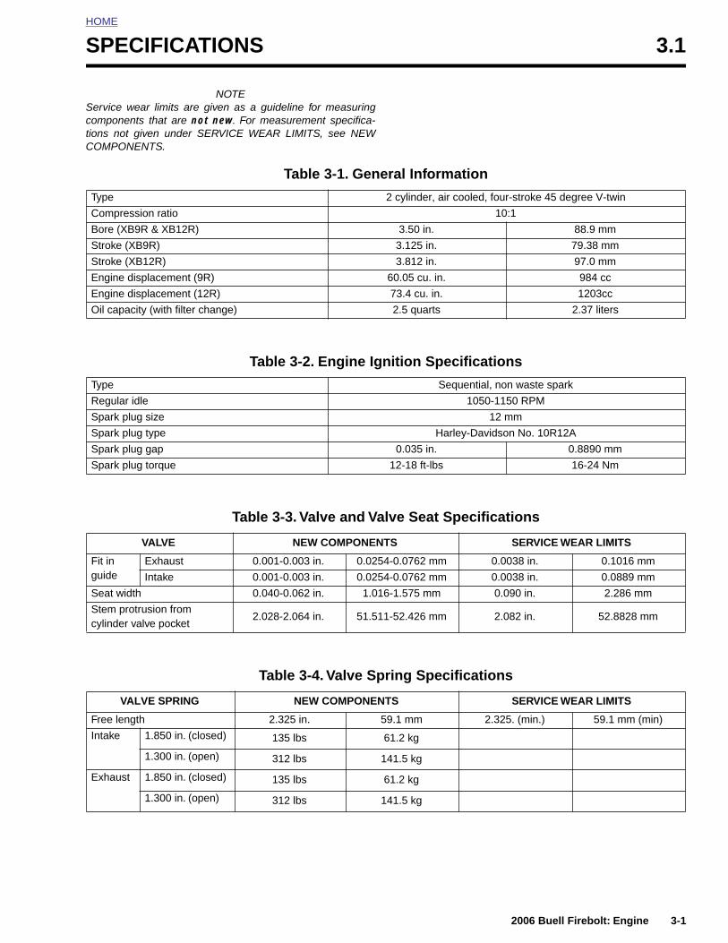
HOME
S
SctC
PECIFICATIONS 3.1
NOTEervice wear limits are given as a guideline for measuringomponents that are not new. For measurement specifica-ions not given under SERVICE WEAR LIMITS, see NEWOMPONENTS.
Table 3-1. General Information
Type 2 cylinder, air cooled, four-stroke 45 degree V-twin
Compression ratio 10:1
Bore (XB9R & XB12R) 3.50 in. 88.9 mm
Stroke (XB9R) 3.125 in. 79.38 mm
Stroke (XB12R) 3.812 in. 97.0 mm
Engine displacement (9R) 60.05 cu. in. 984 cc
Engine displacement (12R) 73.4 cu. in. 1203cc
Oil capacity (with filter change) 2.5 quarts 2.37 liters
Table 3-2. Engine Ignition Specifications
Type Sequential, non waste spark
Regular idle 1050-1150 RPM
Spark plug size 12 mm
Spark plug type Harley-Davidson No. 10R12A
Spark plug gap 0.035 in. 0.8890 mm
Spark plug torque 12-18 ft-lbs 16-24 Nm
Table 3-3. Valve and Valve Seat Specifications
VALVE NEW COMPONENTS SERVICE WEAR LIMITS
Fit in guide
Exhaust 0.001-0.003 in. 0.0254-0.0762 mm 0.0038 in. 0.1016 mm
Intake 0.001-0.003 in. 0.0254-0.0762 mm 0.0038 in. 0.0889 mm
Seat width 0.040-0.062 in. 1.016-1.575 mm 0.090 in. 2.286 mm
Stem protrusion fromcylinder valve pocket
2.028-2.064 in. 51.511-52.426 mm 2.082 in. 52.8828 mm
2006 Buell Firebolt: Engine 3-1
Table 3-4. Valve Spring Specifications
VALVE SPRING NEW COMPONENTS SERVICE WEAR LIMITS
Free length 2.325 in. 59.1 mm 2.325. (min.) 59.1 mm (min)
Intake 1.850 in. (closed) 135 lbs 61.2 kg
1.300 in. (open) 312 lbs 141.5 kg
Exhaust 1.850 in. (closed) 135 lbs 61.2 kg
1.300 in. (open) 312 lbs 141.5 kg
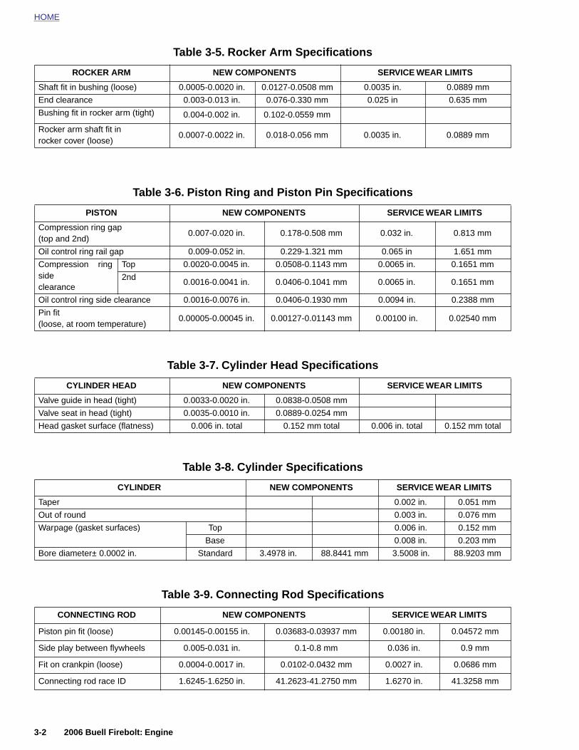
HOME
Table 3-5. Rocker Arm Specifications
ROCKER ARM NEW COMPONENTS SERVICE WEAR LIMITS
Shaft fit in bushing (loose) 0.0005-0.0020 in. 0.0127-0.0508 mm 0.0035 in. 0.0889 mm
End clearance 0.003-0.013 in. 0.076-0.330 mm 0.025 in 0.635 mm
Bushing fit in rocker arm (tight) 0.004-0.002 in. 0.102-0.0559 mm
Rocker arm shaft fit in rocker cover (loose)
0.0007-0.0022 in. 0.018-0.056 mm 0.0035 in. 0.0889 mm
Table 3-6. Piston Ring and Piston Pin Specifications
PISTON NEW COMPONENTS SERVICE WEAR LIMITS
Compression ring gap (top and 2nd)
0.007-0.020 in. 0.178-0.508 mm 0.032 in. 0.813 mm
Oil control ring rail gap 0.009-0.052 in. 0.229-1.321 mm 0.065 in 1.651 mm
Compression ringsideclearance
Top 0.0020-0.0045 in. 0.0508-0.1143 mm 0.0065 in. 0.1651 mm
2nd0.0016-0.0041 in. 0.0406-0.1041 mm 0.0065 in. 0.1651 mm
Oil control ring side clearance 0.0016-0.0076 in. 0.0406-0.1930 mm 0.0094 in. 0.2388 mm
Pin fit (loose, at room temperature)
0.00005-0.00045 in. 0.00127-0.01143 mm 0.00100 in. 0.02540 mm
Table 3-7. Cylinder Head Specifications
CYLINDER HEAD NEW COMPONENTS SERVICE WEAR LIMITS
Valve guide in head (tight) 0.0033-0.0020 in. 0.0838-0.0508 mm
Valve seat in head (tight) 0.0035-0.0010 in. 0.0889-0.0254 mm
Head gasket surface (flatness) 0.006 in. total 0.152 mm total 0.006 in. total 0.152 mm total
Table 3-8. Cylinder Specifications
CYLINDER NEW COMPONENTS SERVICE WEAR LIMITS
Taper 0.002 in. 0.051 mm
Out of round 0.003 in. 0.076 mm
Warpage (gasket surfaces) Top 0.006 in. 0.152 mm
Base 0.008 in. 0.203 mm
3-2 2006 Buell Firebolt: Engine
Bore diameter± 0.0002 in. Standard 3.4978 in. 88.8441 mm 3.5008 in. 88.9203 mm
Table 3-9. Connecting Rod Specifications
CONNECTING ROD NEW COMPONENTS SERVICE WEAR LIMITS
Piston pin fit (loose) 0.00145-0.00155 in. 0.03683-0.03937 mm 0.00180 in. 0.04572 mm
Side play between flywheels 0.005-0.031 in. 0.1-0.8 mm 0.036 in. 0.9 mm
Fit on crankpin (loose) 0.0004-0.0017 in. 0.0102-0.0432 mm 0.0027 in. 0.0686 mm
Connecting rod race ID 1.6245-1.6250 in. 41.2623-41.2750 mm 1.6270 in. 41.3258 mm
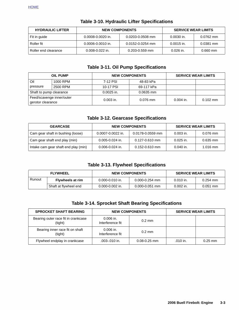
HOME
Table 3-10. Hydraulic Lifter Specifications
HYDRAULIC LIFTER NEW COMPONENTS SERVICE WEAR LIMITS
Fit in guide 0.0008-0.0020 in. 0.0203-0.0508 mm 0.0030 in. 0.0762 mm
Roller fit 0.0006-0.0010 in. 0.0152-0.0254 mm 0.0015 in. 0.0381 mm
Roller end clearance 0.008-0.022 in. 0.203-0.559 mm 0.026 in. 0.660 mm
Table 3-11. Oil Pump Specifications
OIL PUMP NEW COMPONENTS SERVICE WEAR LIMITS
Oilpressure
1000 RPM 7-12 PSI 48-83 kPa
2500 RPM 10-17 PSI 69-117 kPa
Shaft to pump clearance 0.0025 in. 0.0635 mm
Feed/scavenge inner/outergerotor clearance
0.003 in. 0.076 mm 0.004 in. 0.102 mm
Table 3-12. Gearcase Specifications
GEARCASE NEW COMPONENTS SERVICE WEAR LIMITS
Cam gear shaft in bushing (loose) 0.0007-0.0022 in. 0.0178-0.0559 mm 0.003 in. 0.076 mm
Cam gear shaft end play (min) 0.005-0.024 in. 0.127-0.610 mm 0.025 in. 0.635 mm
Intake cam gear shaft end play (min) 0.006-0.024 in. 0.152-0.610 mm 0.040 in. 1.016 mm
Table 3-13. Flywheel Specifications
FLYWHEEL NEW COMPONENTS SERVICE WEAR LIMITS
Runout Flywheels at rim 0.000-0.010 in. 0.000-0.254 mm 0.010 in. 0.254 mm
Shaft at flywheel end 0.000-0.002 in. 0.000-0.051 mm 0.002 in. 0.051 mm
Table 3-14. Sprocket Shaft Bearing Specifications
SPROCKET SHAFT BEARING NEW COMPONENTS SERVICE WEAR LIMITS
2006 Buell Firebolt: Engine 3-3
Bearing outer race fit in crankcase (tight)
0.006 in.Interference fit
0.2 mm
Bearing inner race fit on shaft(tight)
0.006 in.Interference fit
0.2 mm
Flywheel endplay in crankcase .003-.010 in. 0.08-0.25 mm .010 in. 0.25 mm

HOME
Table 3-15. Pinion Shaft Bearing Specifications
TORQUE VALUES
PINION SHAFT BEARINGS NEW COMPONENTS SERVICE WEAR LIMITS
Pinion shaft journal diameter1.2496-1.2500 in.
31.7398-31.7500 mm
1.2496 in. (min) 31.7398 mm (min)
Outer race diameter in right crankcase
1.5646-1.5652 in.39.7408-39.7561
mm1.5672 in. (max) 39.8069 mm (max)
Bearing running clearance 0.00012-0.00088 in.0.00305-0.02235
mm
Fit in cover bushing (loose) 0.0023-0.0043 in. 0.0584-0.1092 mm 0.0050 in. 0.1270 mm
Air scoop fastener at oil cooler 48-72 in-lbs 5.4-8 Nm page 3-76
All tie bars 25-27 ft-lbs 33.9-36.6 Nm page 3-14
Anti-rotation screws (lifter) 55-65 in-lbs 6-7 Nm page 3-86
Center tie bar mount to enginefasteners
30-33 ft-lbs 40.6-44.7 Nm page 3-30
Clutch cable wire form fas-tener
84-92 in-lbs 9.5-10.4 Nm page 3-40
Clutch cable wire form retainer 84-92 in-lbs 9.5-10.4 Nm page 3-15
Crankcase 5/16 in. screws 15-19 ft-lbs20-26 Nm, LOC-
TITE 272page 3-104
Cylinder head screwsSpecial procedure and special pattern to tighten,page 3-59
Cylinder studs 10-20 ft-lbs 14-27 Nm Special method to tighten, page 3-105
Exhaust header nuts 72-96 in-lbs 8.1-10.8 Nm page 3-14
Feed oil line at rear of oilpump
27-29 ft-lbs 36.6-39.3 Nm page 3-36
Front isolator bolt 49-51 ft-lbs 66-69 Nm page 3-14
Front isolator bracket mount-ing fastener
49-51 ft-lbs 66-69 Nm page 3-14, 3-33
Gearcase cover screws 80-110 in-lbs 9-12 Nm Special pattern to tighten, page 3-91
3-4 2006 Buell Firebolt: Engine
Oil cooler feed oil line at oilcooler
19-21 ft-lbs 26-28 Nm page 3-38, 3-76
Oil cooler feed oil line at oilpump
19-21 ft-lbs 26-28 Nm page 3-38
Oil cooler line clamp 12-36 ft-lbs 1-4 Nm page 3-38
Oil cooler return oil line atcrankcase
15-17 ft-lbs 20.3-23 Nm page 3-38
Oil cooler return oil line at oilcooler
19-21 ft-lbs 25.8-28.5 Nm page 3-38, 3-76
Oil filter adapter 96-144 in-lbs 11-16 Nm LOCTITE 243 (blue), page 3-84
Oil line clamp at starter motor 40-50 in-lbs 5-5.5 Nm page 3-36
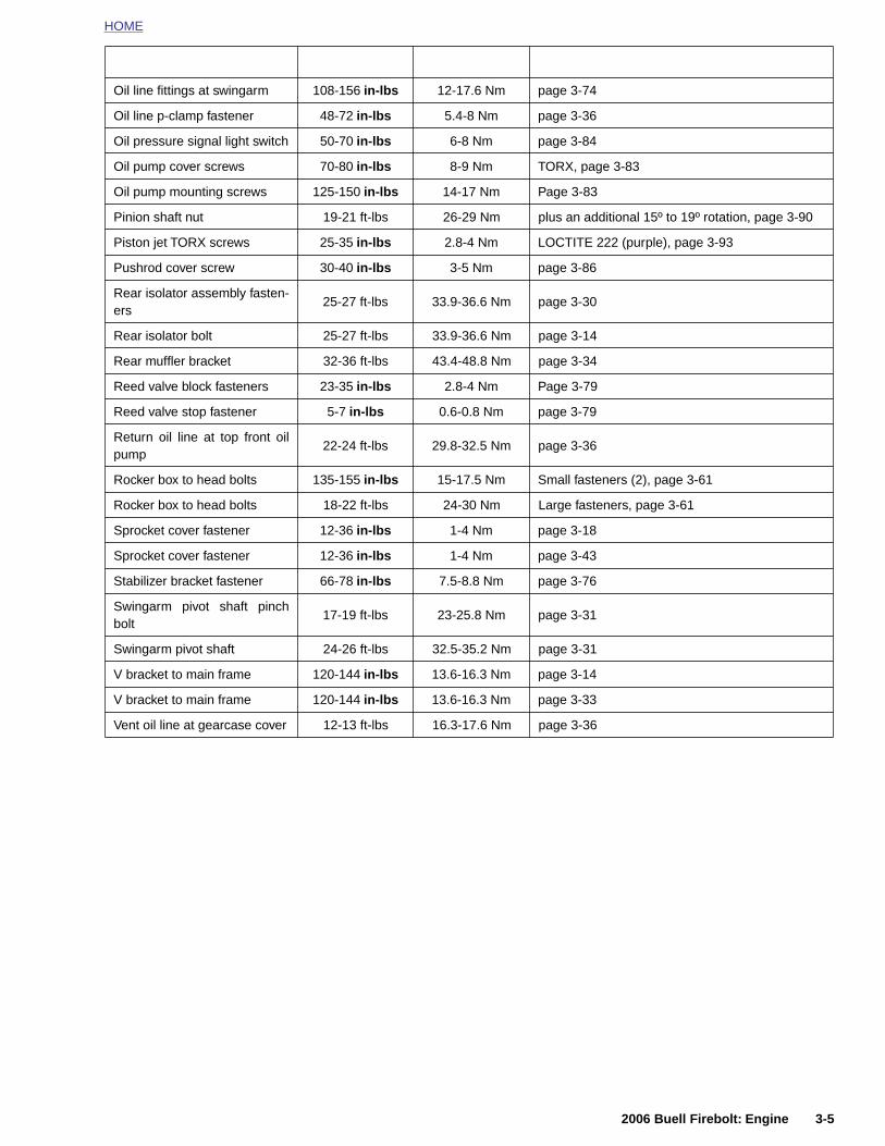
HOME
Oil line fittings at swingarm 108-156 in-lbs 12-17.6 Nm page 3-74
Oil line p-clamp fastener 48-72 in-lbs 5.4-8 Nm page 3-36
Oil pressure signal light switch 50-70 in-lbs 6-8 Nm page 3-84
Oil pump cover screws 70-80 in-lbs 8-9 Nm TORX, page 3-83
Oil pump mounting screws 125-150 in-lbs 14-17 Nm Page 3-83
Pinion shaft nut 19-21 ft-lbs 26-29 Nm plus an additional 15º to 19º rotation, page 3-90
Piston jet TORX screws 25-35 in-lbs 2.8-4 Nm LOCTITE 222 (purple), page 3-93
Pushrod cover screw 30-40 in-lbs 3-5 Nm page 3-86
Rear isolator assembly fasten-ers
25-27 ft-lbs 33.9-36.6 Nm page 3-30
Rear isolator bolt 25-27 ft-lbs 33.9-36.6 Nm page 3-14
Rear muffler bracket 32-36 ft-lbs 43.4-48.8 Nm page 3-34
Reed valve block fasteners 23-35 in-lbs 2.8-4 Nm Page 3-79
Reed valve stop fastener 5-7 in-lbs 0.6-0.8 Nm page 3-79
Return oil line at top front oilpump
22-24 ft-lbs 29.8-32.5 Nm page 3-36
Rocker box to head bolts 135-155 in-lbs 15-17.5 Nm Small fasteners (2), page 3-61
Rocker box to head bolts 18-22 ft-lbs 24-30 Nm Large fasteners, page 3-61
Sprocket cover fastener 12-36 in-lbs 1-4 Nm page 3-18
Sprocket cover fastener 12-36 in-lbs 1-4 Nm page 3-43
Stabilizer bracket fastener 66-78 in-lbs 7.5-8.8 Nm page 3-76
Swingarm pivot shaft pinchbolt
17-19 ft-lbs 23-25.8 Nm page 3-31
Swingarm pivot shaft 24-26 ft-lbs 32.5-35.2 Nm page 3-31
V bracket to main frame 120-144 in-lbs 13.6-16.3 Nm page 3-14
V bracket to main frame 120-144 in-lbs 13.6-16.3 Nm page 3-33
Vent oil line at gearcase cover 12-13 ft-lbs 16.3-17.6 Nm page 3-36
2006 Buell Firebolt: Engine 3-5
HOME
ENGINE 3.2
LUBR
The enginincorporatwith one forces oillower constems, vapiston, pisare lubriccrankshafan internaguide. Oilway of thethe pumpLUBRICAT
3-6
ICATION
e has a force-feed (pressure) type oiling system,ing oil feed and return pumps in one pump body,check valve on the oil feed side. The feed pump through the oil cooler to the engine, lubricatingnecting rod bearings, rocker arm bushings, valvelve springs, push rods and tappets. Cylinder wall,ton pin, timing gears, bushings and main bearingsated by oil spray thrown off connecting rods andt, and by oil draining from each rocker box throughl drain passage in each cylinder and each tappet
is transferred to the teeth of all the cam gears by gear meshing action. The oil-scavenging section of returns oil to the tank from the engine. See 3.8ION SYSTEM for more information.
ADJUSTMENT/TESTING
GeneralWhen an engine needs repair, it is not always possible todetermine definitely beforehand whether repair is possiblewith only cylinder head, cylinder and piston disassembled orwhether complete engine disassembly is required for crank-case repair.
Most commonly, only cylinder head and cylinder repair isneeded (valves, rings, piston, etc.) and it is recommendedprocedure to service these units first, allowing engine crank-case to remain in frame.
See 3.4 STRIPPING MOTORCYCLE FOR ENGINE SER-VICE to strip motorcycle for removal of cylinder head, cylin-der, and piston.
After disassembling “upper end” only, it may be found thatcrankcase repair is necessary. In this situation, remove theengine crankcase from the chassis.
NOTEIf engine is removed from chassis, do not lay engine on pri-mary side. Placing engine on primary side will damage clutchcable end fitting. If fitting is damaged, clutch cable must bereplaced.
See 1.22 TROUBLESHOOTING section. Symptoms indicat-ing a need for engine repair are often misleading, but gener-ally, if more than one symptom is present, possible causescan be narrowed down to make at least a partial diagnosis.An above-normal consumption of oil, for example, could becaused by several mechanical faults. However, when accom-panied by blue-gray exhaust smoke and low engine compres-sion, it indicates the piston rings need replacing. Lowcompression by itself, however, may indicate improperlyseated valves, in addition to or in lieu of worn piston rings.
Most frequently, valves, rings, pins, bushings, and bearingsneed attention at about the same time. If the possible causescan be narrowed down through the process of elimination toindicate any one of the above components is worn, it is bestto give attention to all of the cylinder head and cylinder parts.
2006 Buell Firebolt: Engine
HOME
COMPRESSION TEST PROCEDURE
Combustion chamber leakage can result in unsatisfactoryengine performance. A compression test can help determinethe source of cylinder leakage. Use CYLINDER COMPRES-SION GAUGE (Part No. HD-33223-1).
A proper compression test should be performed with theengine at normal operating temperature when possible. Pro-ceed as follows:
NOTEAfter completing the compression test(s), make sure that thethrottle plate is in the closed position before starting engine.Engine will start at an extremely high RPM if throttle plate isleft open.
1. Disconnect spark plug wire. Clean around plug base andremove plug.
2. Connect compression tester to cylinder.
3. With induction module throttle plate in wide open posi-tion, crank engine continuously through 5-7 full compres-sion strokes.
4. Note gauge readings at the end of the first and last com-pression strokes. Record test results.
5. Compression is normal if final readings are 120 psi(827 kPa) or more.
6. Inject approximately 1/2 oz. (15 ml) of SAE 30 oil into cyl-inder and repeat the compression test. Readings that areconsiderably higher during the second test indicate wornpiston rings.
2. Stop engine. Clean dirt from around spark plug andremove spark plug.
3. Remove air cleaner and set induction module throttleplate in wide open position.
4. Remove timing inspection plug from crankcase.
5. The piston, in cylinder being tested, must be at top deadcenter of compression stroke during test.
6. To keep engine from turning over when air pressure isapplied to cylinder, engage transmission in fifth gear andlock the rear brake.
7. Following the manufacturer’s instructions, perform a cyl-inder leakage test on the front cylinder. Make a note ofthe percent leakdown. Any cylinder with 12% leakdown,or more, requires further attention.
8. See Table 3-17. Listen for air leaks at induction intake,exhaust, head gasket and timing inspection hole.
NOTE
If air is escaping through valves, check push rod length.
9. Repeat procedure on rear cylinder.
NOTE
After completing the compression test(s), make sure that thethrottle plate is in the closed position before starting engine.Engine will start at an extremely high RPM if throttle plate isleft open.
Table 3-16. Compression Test Results
DIAGNOSIS TEST RESULTS
Ring trouble Compression low on first stroke; tends to build up on the following strokes but does not reach normal; improves considerably when oil is added to cylinder.
Valve trouble Compression low on first stroke; does not build up much on follow-ing strokes; does not improve con-
Table 3-17. Air Leakage Test
AIR LEAK LOCATION POSSIBLE CAUSES
Induction module intake Intake valve leaking.
Exhaust pipe Exhaust valve leaking.
Timing inspection hole Piston rings leaking.
2006 Buell Firebolt: Engine 3-7
Cylinder Leakage TestThe cylinder leakage test pinpoints engine problems includ-ing leaking valves, worn, broken or stuck piston rings andblown head gaskets. The cylinder leakage tester applies com-pressed air to the cylinder at a controlled pressure and vol-ume, and measures the percent of leakage from the cylinder.
Use a CYLINDER LEAKDOWN TESTER (Part No. HD-35667A) and follow the specific instructions supplied with thetester.
The following are some general instructions that apply toBuell motorcycle engines:
1. Run engine until it reaches normal operating tempera-ture.
Diagnosing Smoking Engine or High Oil Consumption
Perform COMPRESSION TEST PROCEDURE or CylinderLeakage Test as described previously. If further testing isneeded, remove suspect head(s) and inspect the following:
● Valve guide seals.
● Valve guide-to-valve stem clearance.
● Gasket surface of both head and cylinder.
siderably with the addition of oil.
Head gasket leak Same reaction as valve trouble.
Worn or broken piston.Worn cylinder.
Head gasket Leaking gasket.
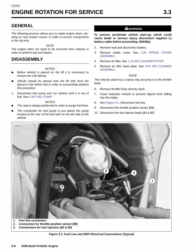
HOME
ENGINE ROTATION FOR SERVICE 3.3
GENE
The followoting on rin the top
The enginorder to p
DISAS
● Beforremo
● Vehicplacethis p
1. Discofuel. S
● This s
● The clocatevehic
10646a
3-8
1. Fu2. Co3. Co
RAL
ing process allows you to rotate engine down, piv-ear isolator mount, in order to service componentsend.
NOTEe does not need to be removed from chassis in
erform top end repairs.
SEMBLY
NOTESe vehicle is placed on the lift it is necessary tove the chin fairing.
le should be placed onto the lift with front tired in the wheel vise in order to successfully performrocedure.
nnect fuel pump and run vehicle until it is out ofee 4.39 FUEL PUMP.
NOTEStep is always performed in order to purge fuel lines.
onnection for fuel pump is just above the pumpd at the rear of the fuel tank on the left side of the
le.
11WARNING1WARNING
To prevent accidental vehicle start-up, which couldcause death or serious injury, disconnect negative (-)battery cable before proceeding. (00048a)
2. Remove seat and disconnect battery.
3. Remove intake cover. See 2.34 INTAKE COVERASSEMBLY.
4. Remove air filter. See 1.15 AIR CLEANER FILTER.
5. Remove air filter base plate. See 4.44 AIR CLEANERASSEMBLY.
NOTEThe velocity stack has a clamp ring securing it to the throttlebody.
6. Remove throttle body velocity stack.
7. Cover induction module to prevent objects from fallinginto the intake.
8. See Figure 3-1. Disconnect fuel line.
9. Disconnect the throttle position sensor [88].
10. Disconnect the fuel injector leads [84 & 85].
2
1
3
2006 Buell Firebolt: Engine
Figure 3-1. Fuel Line and DDFI Electrical Connections (Typical)
el line connectionnnection for throttle position sensor [88]nnections for fuel injectors [84 & 85]
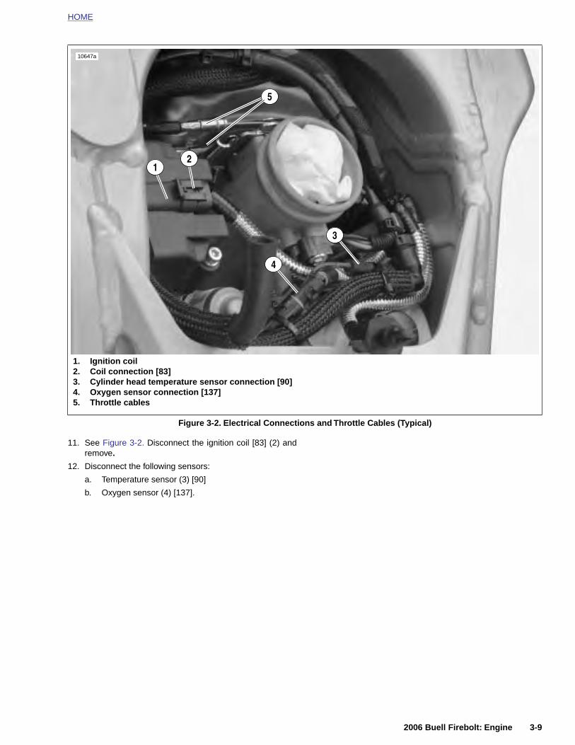
HOME
11. See Figure 3-2. Disconnect the ignition coil [83] (2) andremove.
12. Disconnect the following sensors:
a. Temperature sensor (3) [90]
b. Oxygen sensor (4) [137].
Figure 3-2. Electrical Connections and Throttle Cables (Typical)
1. Ignition coil2. Coil connection [83]3. Cylinder head temperature sensor connection [90]4. Oxygen sensor connection [137]5. Throttle cables
5
3
21
10647a
4
2006 Buell Firebolt: Engine 3-9
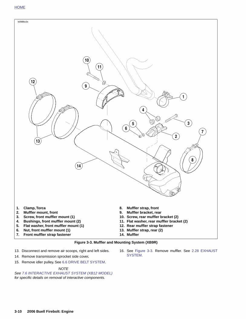
HOME
b0986x3x
1. Clamp, Torca2. Muffler mount, front3. Screw, front muffler mount (1)4. Bushings, front muffler mount (2)5. Flat washer, front muffler mount (1)6. Nut, front muffler mount (1)
8. Muffler strap, front9. Muffler bracket, rear10. Screw, rear muffler bracket (2)11. Flat washer, rear muffler bracket (2)12. Rear muffler strap fastener13. Muffler strap, rear (2)
11
9
148
2
1
13
3
10
12
7
4
56
3-10 2006 Buell Firebolt: Engine
13. Disconnect and remove air scoops, right and left sides.
14. Remove transmission sprocket side cover.
15. Remove idler pulley. See 6.6 DRIVE BELT SYSTEM.
NOTESee 7.6 INTERACTIVE EXHAUST SYSTEM (XB12 MODEL)for specific details on removal of interactive components.
16. See Figure 3-3. Remove muffler. See 2.28 EXHAUSTSYSTEM.
Figure 3-3. Muffler and Mounting System (XB9R)
7. Front muffler strap fastener 14. Muffler
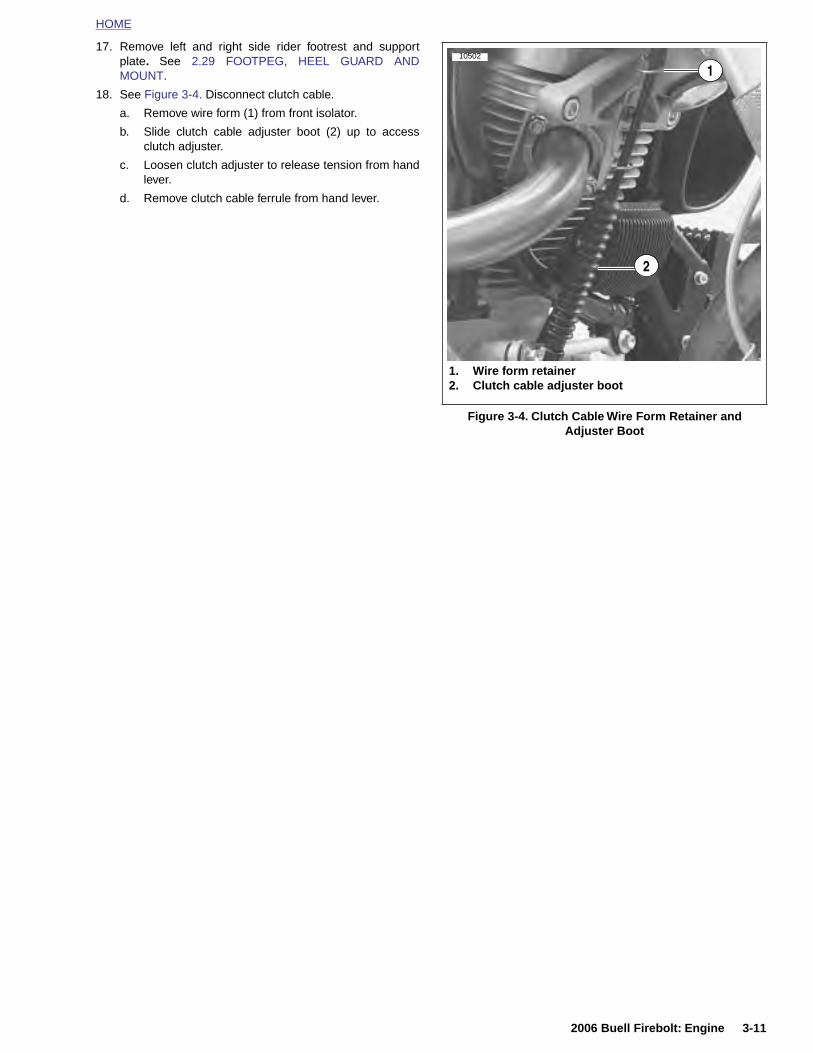
HOME
17. Remove left and right side rider footrest and supportplate. See 2.29 FOOTPEG, HEEL GUARD ANDMOUNT.
18. See Figure 3-4. Disconnect clutch cable.
a. Remove wire form (1) from front isolator.
b. Slide clutch cable adjuster boot (2) up to accessclutch adjuster.
c. Loosen clutch adjuster to release tension from handlever.
d. Remove clutch cable ferrule from hand lever.
Figure 3-4. Clutch Cable Wire Form Retainer and Adjuster Boot
1. Wire form retainer2. Clutch cable adjuster boot
1
2
10502
2006 Buell Firebolt: Engine 3-11
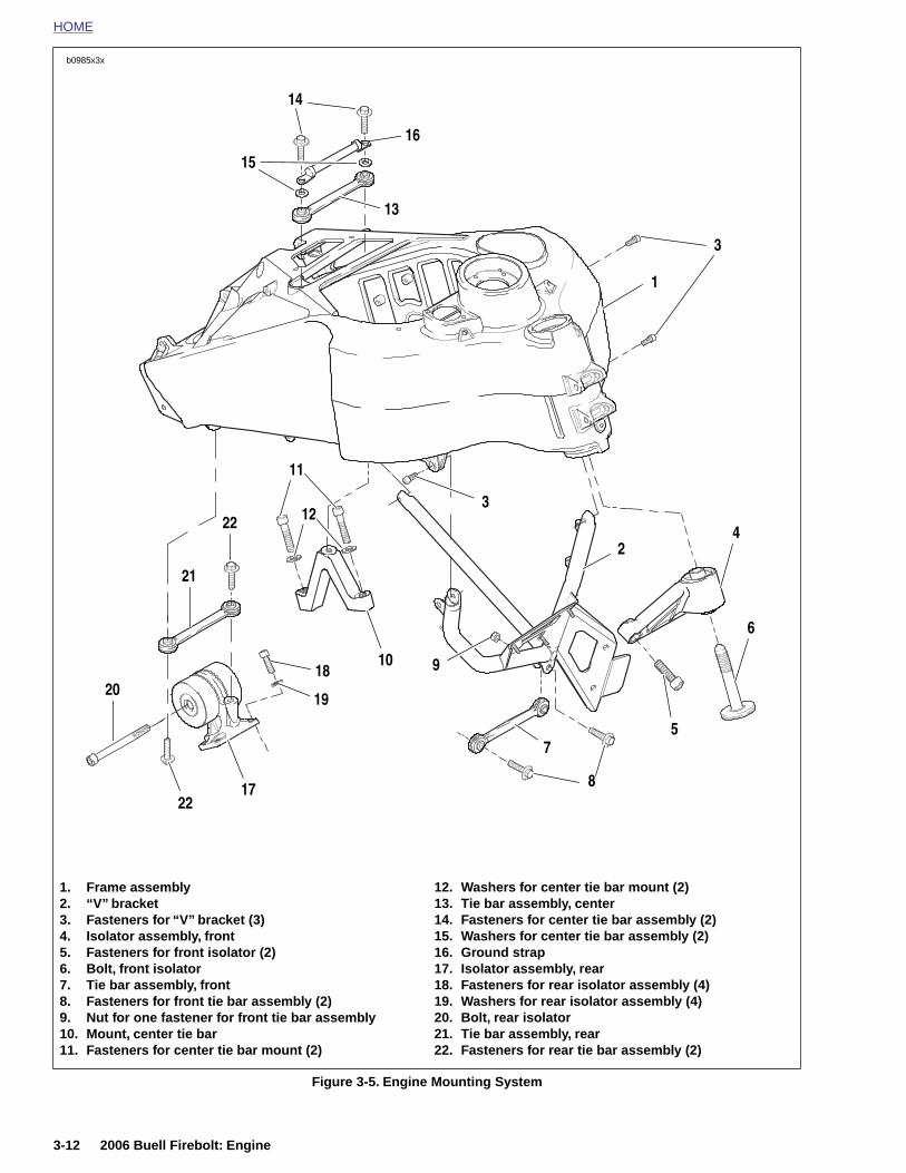
HOME
b0985x3x
22
19
18
17
22
21
20
10
11
16
3
1
4
14
13
15
12
6
2
7
8
5
3
9
3-12 2006 Buell Firebolt: Engine
Figure 3-5. Engine Mounting System
1. Frame assembly2. “V” bracket3. Fasteners for “V” bracket (3)4. Isolator assembly, front5. Fasteners for front isolator (2)6. Bolt, front isolator7. Tie bar assembly, front8. Fasteners for front tie bar assembly (2)9. Nut for one fastener for front tie bar assembly10. Mount, center tie bar11. Fasteners for center tie bar mount (2)
12. Washers for center tie bar mount (2)13. Tie bar assembly, center14. Fasteners for center tie bar assembly (2)15. Washers for center tie bar assembly (2)16. Ground strap17. Isolator assembly, rear18. Fasteners for rear isolator assembly (4)19. Washers for rear isolator assembly (4)20. Bolt, rear isolator21. Tie bar assembly, rear22. Fasteners for rear tie bar assembly (2)
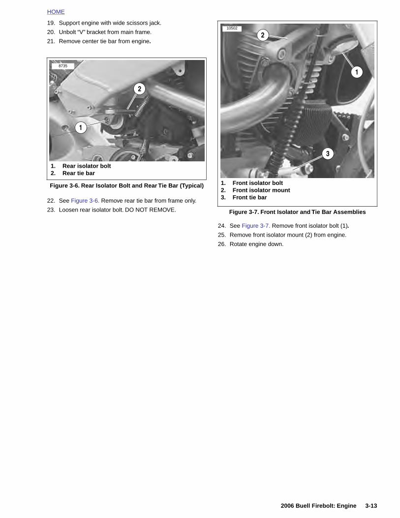
HOME
19. Support engine with wide scissors jack.
20. Unbolt “V” bracket from main frame.
21. Remove center tie bar from engine.
22. See Figure 3-6. Remove rear tie bar from frame only.
23. Loosen rear isolator bolt. DO NOT REMOVE.
24. See Figure 3-7. Remove front isolator bolt (1).
25. Remove front isolator mount (2) from engine.
26. Rotate engine down.
Figure 3-6. Rear Isolator Bolt and Rear Tie Bar (Typical)
1. Rear isolator bolt2. Rear tie bar
2
1
8735
Figure 3-7. Front Isolator and Tie Bar Assemblies
1. Front isolator bolt2. Front isolator mount3. Front tie bar
1
3
210502
2006 Buell Firebolt: Engine 3-13

HOME
ASSEMBLY
8720
2
NOTES● If exhaust header was removed during service it must betorqued with the engine rotated in the down position. It isnot possible to reach fasteners on the rear exhaust at thehead with engine rotated in the up position.
● Tighten the front head pipe first. Tighten header nutsgradually, alternating between studs to insure thatexhaust rings are flush with engine. Tighten fasteners to72-96 in-lbs (8.1-10.8 Nm).
1. When repairs have been completed, rotate engine backup into frame.
NOTEWhen installing and tightening isolator bolt it is important tokeep load off of isolator bolt for installation purposes. Alter-nate between tightening isolator bolt and raising engine withscissors jack.
2. See Figure 3-8. Insert front isolator bolt (1) through frontisolator (2) and loosely thread into frame. Do not tightenat this point.
3. Install isolator mounting fasteners (3) and tighten to 49-51 ft-lbs (66-69 Nm).
4. Tighten front isolator bolt to 49-51 ft-lbs (66-69 Nm).
5. See Figure 3-5. Torque rear isolator bolt to 25-27 ft-lbs(33.9-36.6 Nm).
6. Install rear tie bar to frame and tighten to 25-27 ft-lbs(33.9-36.6 Nm).
7. See Figure 3-5. Install center tie bar to engine andtighten to 25-27 ft-lbs (33.9-36.6 Nm).
8. See Figure 3-5. Install “V” bracket to main frame from theleft side of the vehicle and tighten to 120-144 in-lbs(13.6-16.3 Nm).
9. Remove scissors jack.
Figure 3-8. Front Isolator and Tie Bar Assemblies
1
3
4
1. Front isolator bolt2. Front isolator mount3. Front isolator mount fasteners (2)4. Front tie bar
3-14 2006 Buell Firebolt: Engine
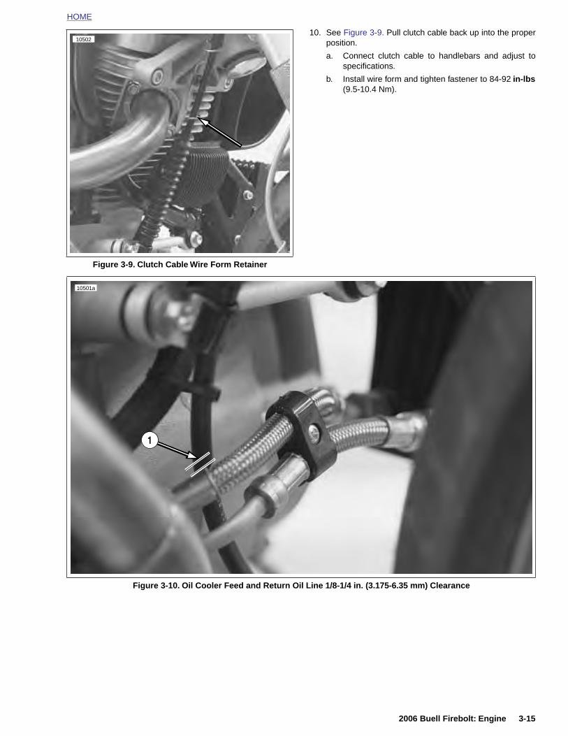
HOME
10. See Figure 3-9. Pull clutch cable back up into the properposition.
a. Connect clutch cable to handlebars and adjust tospecifications.
b. Install wire form and tighten fastener to 84-92 in-lbs(9.5-10.4 Nm).
Figure 3-9. Clutch Cable Wire Form Retainer
10502
10501a
1
2006 Buell Firebolt: Engine 3-15
Figure 3-10. Oil Cooler Feed and Return Oil Line 1/8-1/4 in. (3.175-6.35 mm) Clearance
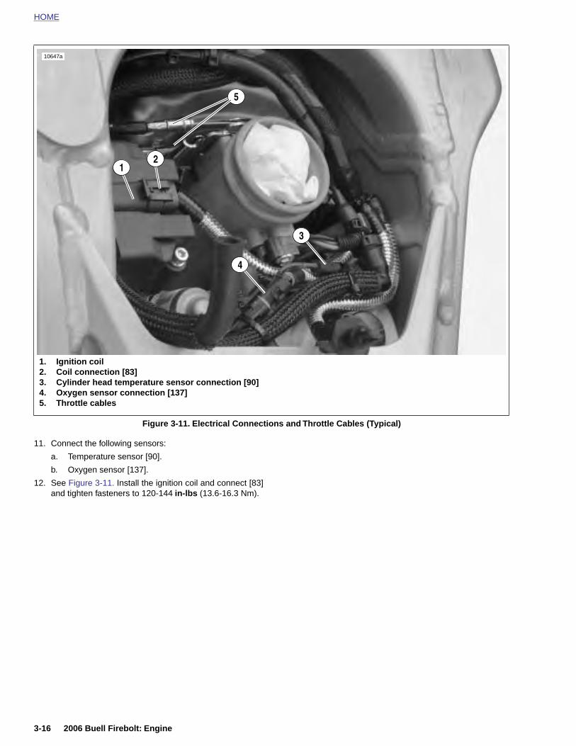
HOME
10647a
11. Connect the following sensors:
a. Temperature sensor [90].
b. Oxygen sensor [137].
12. See Figure 3-11. Install the ignition coil and connect [83]and tighten fasteners to 120-144 in-lbs (13.6-16.3 Nm).
Figure 3-11. Electrical Connections and Throttle Cables (Typical)
1. Ignition coil2. Coil connection [83]3. Cylinder head temperature sensor connection [90]4. Oxygen sensor connection [137]5. Throttle cables
5
3
21
4
3-16 2006 Buell Firebolt: Engine

HOME
NOTES● Never re-use front muffler strap. Always replace front
muffler strap with a new strap when removed from sys-tem.
● It is important that the front muffler mount is tightenedlast in order to ensure proper alignment of the exhaustsystem.
Figure 3-12. Muffler and Mounting System
b0986x3c
1. Clamp, Torca2. Front muffler mount3. Front muffler strap fastener4. Muffler strap, front
5. Rear muffler bracket6. Rear muffler strap fastener7. Muffler strap, rear (2)8. Muffler
1
8
4
3
7
6
2
5
2006 Buell Firebolt: Engine 3-17
● When rear muffler straps have been installed, it is impor-tant that strap fasteners do not contact idler pulleybracket.
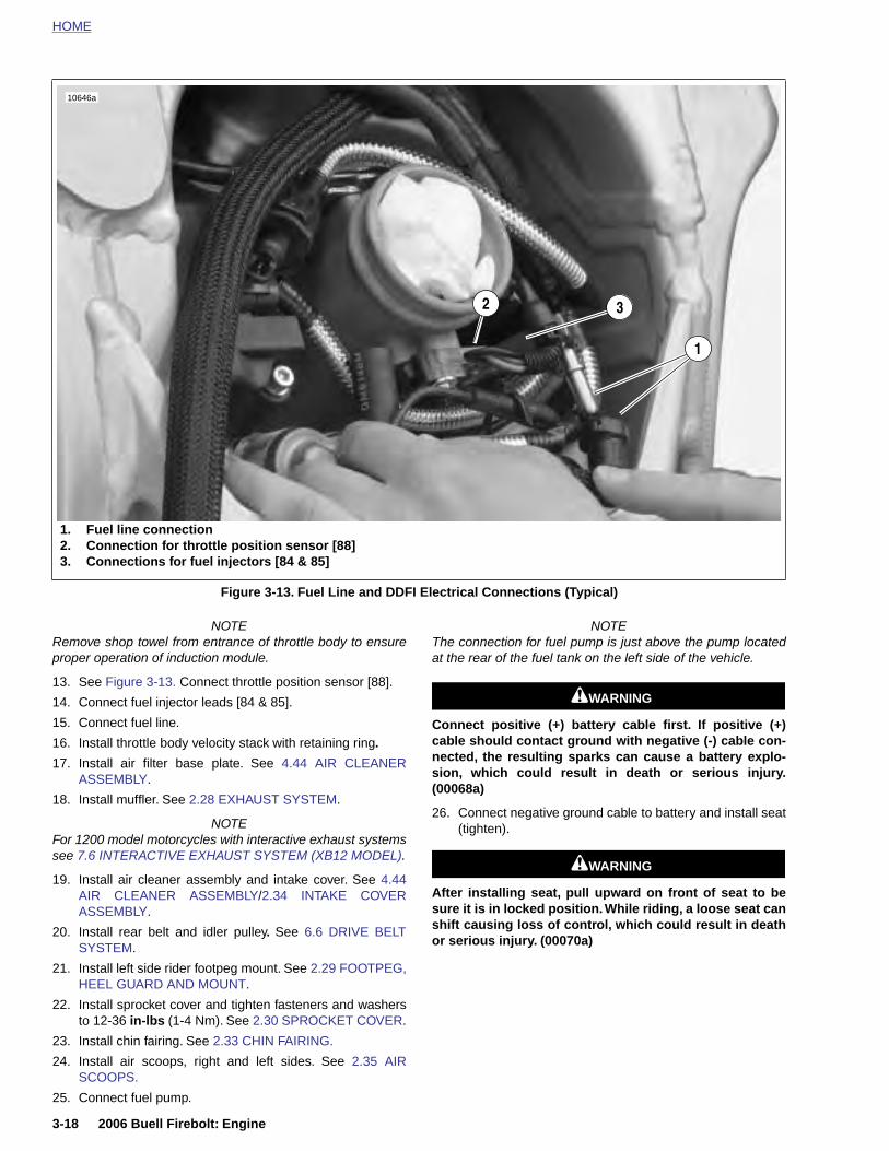
HOME
NOTERemove shop towel from entrance of throttle body to ensureproper operation of induction module.
13. See Figure 3-13. Connect throttle position sensor [88].
14. Connect fuel injector leads [84 & 85].
15. Connect fuel line.
16. Install throttle body velocity stack with retaining ring.
17. Install air filter base plate. See 4.44 AIR CLEANERASSEMBLY.
18. Install muffler. See 2.28 EXHAUST SYSTEM.
NOTEFor 1200 model motorcycles with interactive exhaust systems
NOTEThe connection for fuel pump is just above the pump locatedat the rear of the fuel tank on the left side of the vehicle.
11WARNING1WARNING
Connect positive (+) battery cable first. If positive (+)cable should contact ground with negative (-) cable con-nected, the resulting sparks can cause a battery explo-sion, which could result in death or serious injury.(00068a)
26. Connect negative ground cable to battery and install seat(tighten).
Figure 3-13. Fuel Line and DDFI Electrical Connections (Typical)
2
10646a
1. Fuel line connection2. Connection for throttle position sensor [88]3. Connections for fuel injectors [84 & 85]
1
3
3-18 2006 Buell Firebolt: Engine
see 7.6 INTERACTIVE EXHAUST SYSTEM (XB12 MODEL).
19. Install air cleaner assembly and intake cover. See 4.44AIR CLEANER ASSEMBLY/2.34 INTAKE COVERASSEMBLY.
20. Install rear belt and idler pulley. See 6.6 DRIVE BELTSYSTEM.
21. Install left side rider footpeg mount. See 2.29 FOOTPEG,HEEL GUARD AND MOUNT.
22. Install sprocket cover and tighten fasteners and washersto 12-36 in-lbs (1-4 Nm). See 2.30 SPROCKET COVER.
23. Install chin fairing. See 2.33 CHIN FAIRING.
24. Install air scoops, right and left sides. See 2.35 AIRSCOOPS.
25. Connect fuel pump.
11WARNING1WARNING
After installing seat, pull upward on front of seat to besure it is in locked position. While riding, a loose seat canshift causing loss of control, which could result in deathor serious injury. (00070a)
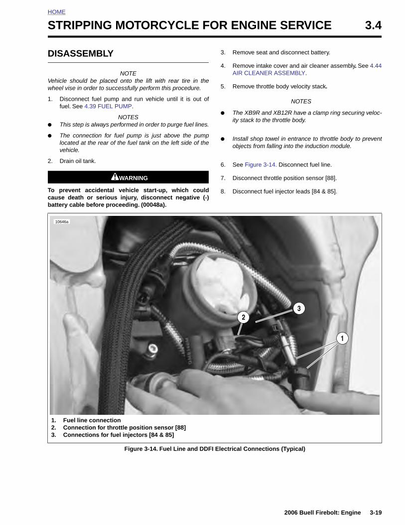
HOME
S
D
Vw
1
●
●
2
Tcb
TRIPPING MOTORCYCLE FOR ENGINE SERVICE 3.4
ISASSEMBLY
NOTEehicle should be placed onto the lift with rear tire in theheel vise in order to successfully perform this procedure.
. Disconnect fuel pump and run vehicle until it is out offuel. See 4.39 FUEL PUMP.
NOTESThis step is always performed in order to purge fuel lines.
The connection for fuel pump is just above the pumplocated at the rear of the fuel tank on the left side of thevehicle.
. Drain oil tank.
11WARNING1WARNING
o prevent accidental vehicle start-up, which couldause death or serious injury, disconnect negative (-)attery cable before proceeding. (00048a).
3. Remove seat and disconnect battery.
4. Remove intake cover and air cleaner assembly. See 4.44AIR CLEANER ASSEMBLY.
5. Remove throttle body velocity stack.
NOTES
● The XB9R and XB12R have a clamp ring securing veloc-ity stack to the throttle body.
● Install shop towel in entrance to throttle body to preventobjects from falling into the induction module.
6. See Figure 3-14. Disconnect fuel line.
7. Disconnect throttle position sensor [88].
8. Disconnect fuel injector leads [84 & 85].
23
10646a
1
2006 Buell Firebolt: Engine 3-19
Figure 3-14. Fuel Line and DDFI Electrical Connections (Typical)
1. Fuel line connection2. Connection for throttle position sensor [88]3. Connections for fuel injectors [84 & 85]
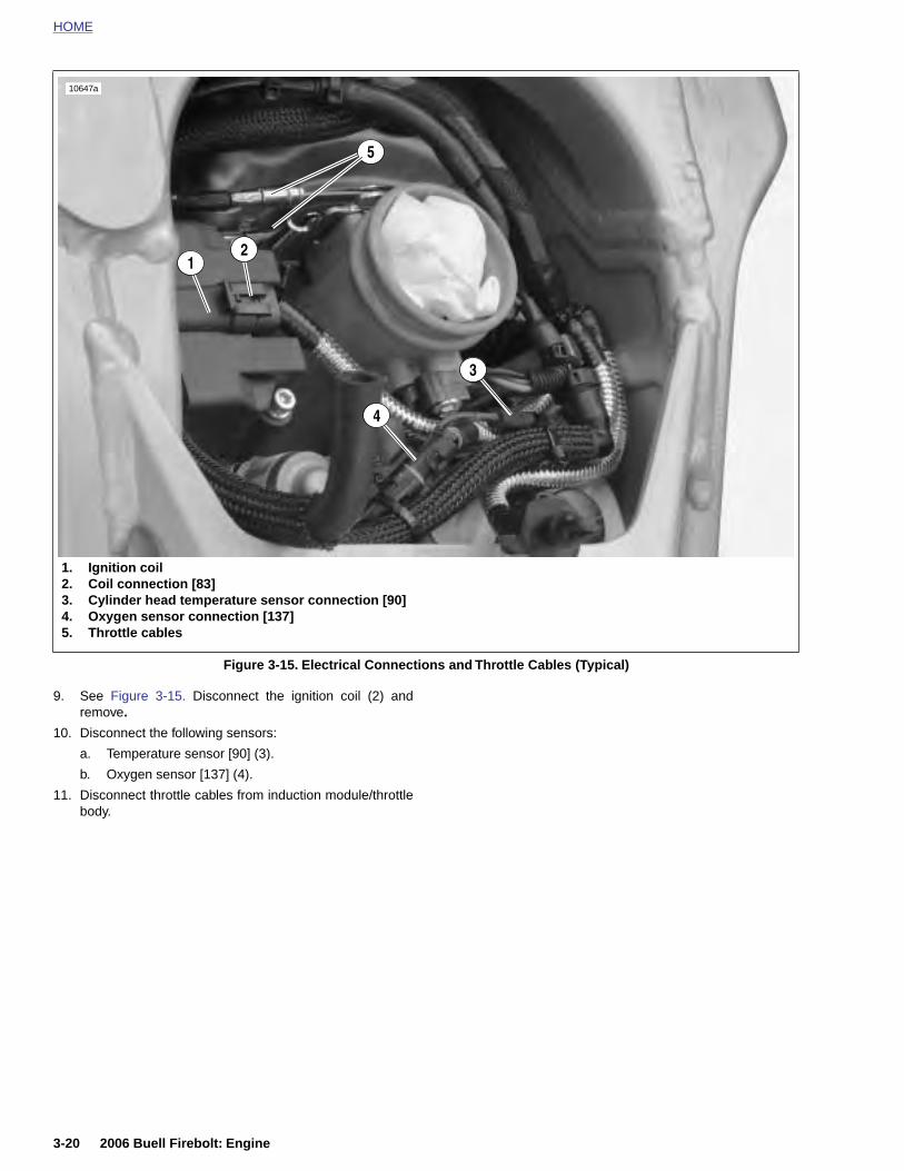
HOME
10647a
9. See Figure 3-15. Disconnect the ignition coil (2) andremove.
10. Disconnect the following sensors:
a. Temperature sensor [90] (3).
b. Oxygen sensor [137] (4).
11. Disconnect throttle cables from induction module/throttlebody.
Figure 3-15. Electrical Connections and Throttle Cables (Typical)
1. Ignition coil2. Coil connection [83]3. Cylinder head temperature sensor connection [90]4. Oxygen sensor connection [137]5. Throttle cables
5
3
21
4
3-20 2006 Buell Firebolt: Engine
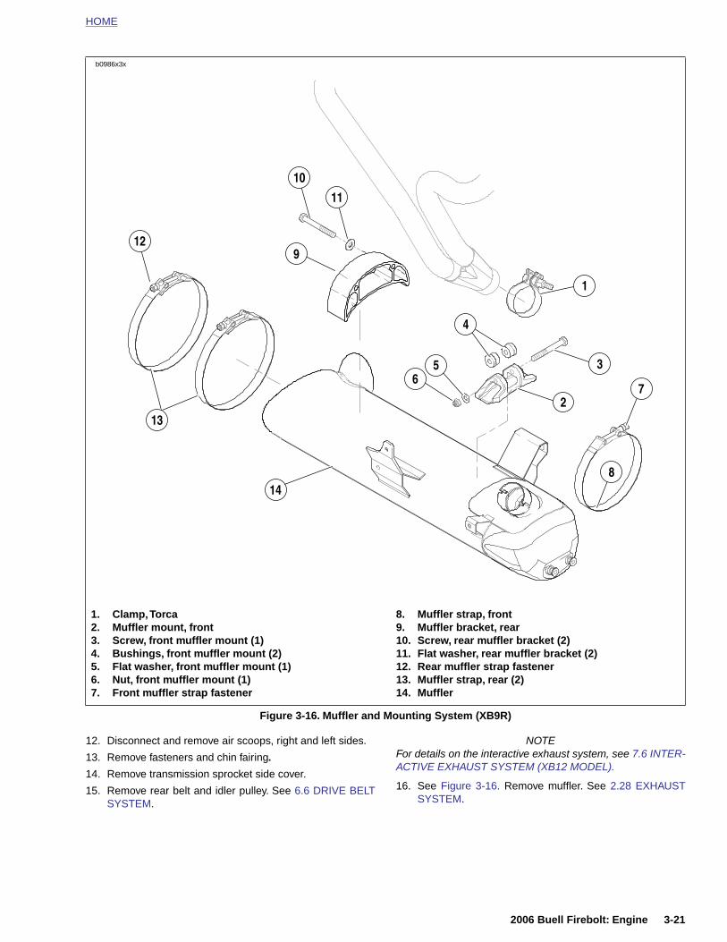
HOME
1. Clamp, Torca2. Muffler mount, front3. Screw, front muffler mount (1)
8. Muffler strap, front9. Muffler bracket, rear10. Screw, rear muffler bracket (2)
11
9
148
2
1
13
3
10
b0986x3x
12
7
4
56
2006 Buell Firebolt: Engine 3-21
12. Disconnect and remove air scoops, right and left sides.
13. Remove fasteners and chin fairing.
14. Remove transmission sprocket side cover.
15. Remove rear belt and idler pulley. See 6.6 DRIVE BELTSYSTEM.
NOTEFor details on the interactive exhaust system, see 7.6 INTER-ACTIVE EXHAUST SYSTEM (XB12 MODEL).
16. See Figure 3-16. Remove muffler. See 2.28 EXHAUSTSYSTEM.
Figure 3-16. Muffler and Mounting System (XB9R)
4. Bushings, front muffler mount (2)5. Flat washer, front muffler mount (1)6. Nut, front muffler mount (1)7. Front muffler strap fastener
11. Flat washer, rear muffler bracket (2)12. Rear muffler strap fastener13. Muffler strap, rear (2)14. Muffler
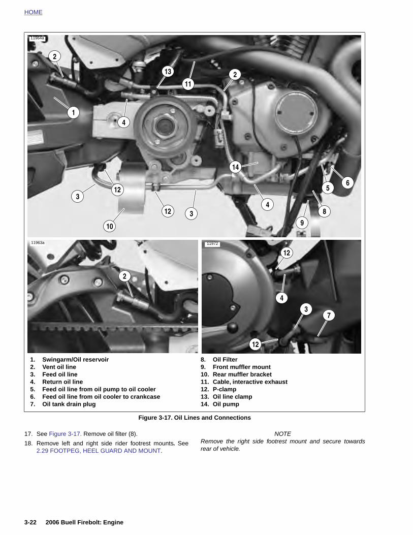
HOME
11964a
1. Swingarm/Oil reservoir2. Vent oil line3. Feed oil line4. Return oil line5. Feed oil line from oil pump to oil cooler
8. Oil Filter9. Front muffler mount10. Rear muffler bracket11. Cable, interactive exhaust12. P-clamp
2
7
5
43
4
11963a
10
1
2
3
3
8
9
6
4
11972
11
12
12
13
12
12
14
2
3-22 2006 Buell Firebolt: Engine
17. See Figure 3-17. Remove oil filter (8).
18. Remove left and right side rider footrest mounts. See2.29 FOOTPEG, HEEL GUARD AND MOUNT.
NOTERemove the right side footrest mount and secure towardsrear of vehicle.
Figure 3-17. Oil Lines and Connections
6. Feed oil line from oil cooler to crankcase7. Oil tank drain plug
13. Oil line clamp14. Oil pump
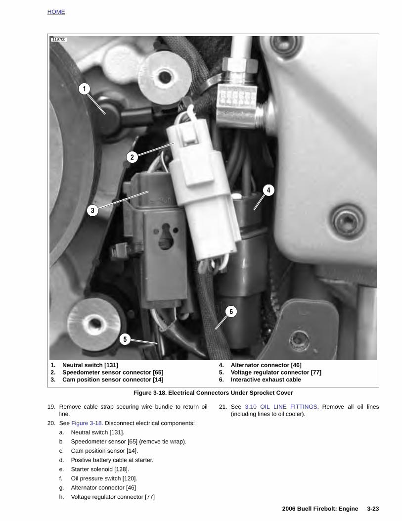
HOME
4
5
3
11970b
1
2
6
2006 Buell Firebolt: Engine 3-23
19. Remove cable strap securing wire bundle to return oilline.
20. See Figure 3-18. Disconnect electrical components:
a. Neutral switch [131].
b. Speedometer sensor [65] (remove tie wrap).
c. Cam position sensor [14].
d. Positive battery cable at starter.
e. Starter solenoid [128].
f. Oil pressure switch [120].
g. Alternator connector [46]
h. Voltage regulator connector [77]
21. See 3.10 OIL LINE FITTINGS. Remove all oil lines(including lines to oil cooler).
Figure 3-18. Electrical Connectors Under Sprocket Cover
1. Neutral switch [131]2. Speedometer sensor connector [65]3. Cam position sensor connector [14]
4. Alternator connector [46]5. Voltage regulator connector [77]6. Interactive exhaust cable
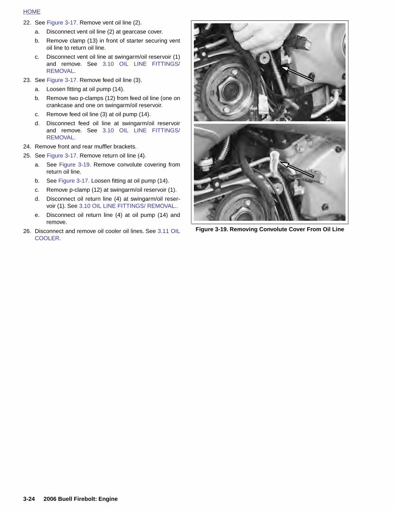
HOME
22. See Figure 3-17. Remove vent oil line (2).
a. Disconnect vent oil line (2) at gearcase cover.
b. Remove clamp (13) in front of starter securing ventoil line to return oil line.
c. Disconnect vent oil line at swingarm/oil reservoir (1)and remove. See 3.10 OIL LINE FITTINGS/REMOVAL.
23. See Figure 3-17. Remove feed oil line (3).
a. Loosen fitting at oil pump (14).
b. Remove two p-clamps (12) from feed oil line (one oncrankcase and one on swingarm/oil reservoir.
c. Remove feed oil line (3) at oil pump (14).
d. Disconnect feed oil line at swingarm/oil reservoirand remove. See 3.10 OIL LINE FITTINGS/REMOVAL.
24. Remove front and rear muffler brackets.
25. See Figure 3-17. Remove return oil line (4).
a. See Figure 3-19. Remove convolute covering fromreturn oil line.
b. See Figure 3-17. Loosen fitting at oil pump (14).
c. Remove p-clamp (12) at swingarm/oil reservoir (1).
d. Disconnect oil return line (4) at swingarm/oil reser-voir (1). See 3.10 OIL LINE FITTINGS/ REMOVAL..
e. Disconnect oil return line (4) at oil pump (14) andremove.
26. Disconnect and remove oil cooler oil lines. See 3.11 OILCOOLER.
Figure 3-19. Removing Convolute Cover From Oil Line
3-24 2006 Buell Firebolt: Engine
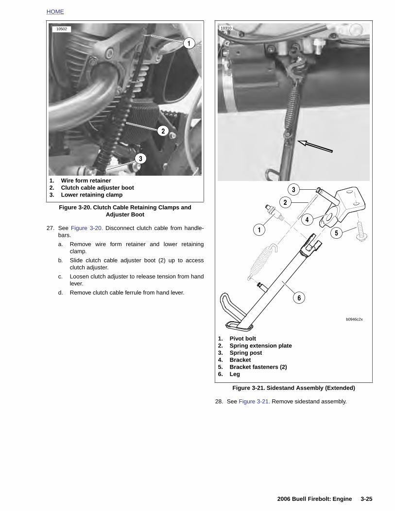
HOME
27. See Figure 3-20. Disconnect clutch cable from handle-bars.
a. Remove wire form retainer and lower retainingclamp.
b. Slide clutch cable adjuster boot (2) up to accessclutch adjuster.
c. Loosen clutch adjuster to release tension from handlever.
d. Remove clutch cable ferrule from hand lever.
Figure 3-20. Clutch Cable Retaining Clamps and Adjuster Boot
1. Wire form retainer2. Clutch cable adjuster boot3. Lower retaining clamp
1
2
3
10502 10310
1. Pivot bolt2. Spring extension plate
6
b0946c2x
1
2
3
4
5
2006 Buell Firebolt: Engine 3-25
28. See Figure 3-21. Remove sidestand assembly.
Figure 3-21. Sidestand Assembly (Extended)
3. Spring post4. Bracket5. Bracket fasteners (2)6. Leg
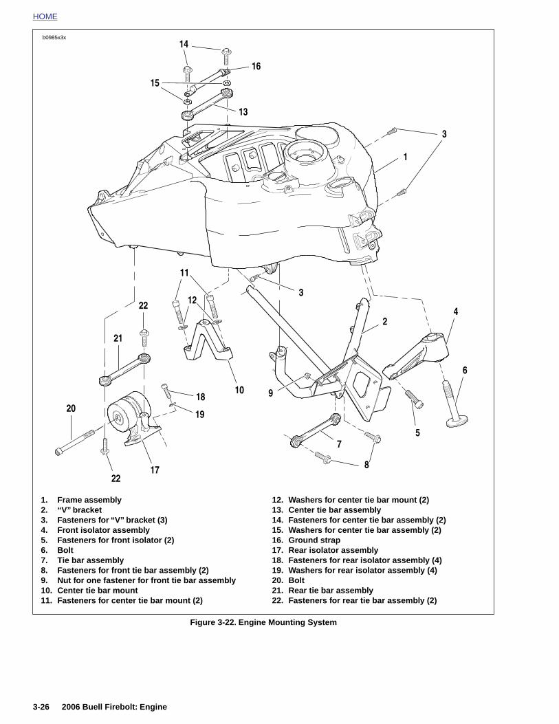
HOME
b0985x3x
14
1. Frame assembly2. “V” bracket3. Fasteners for “V” bracket (3)4. Front isolator assembly
12. Washers for center tie bar mount (2)13. Center tie bar assembly14. Fasteners for center tie bar assembly (2)15. Washers for center tie bar assembly (2)
22
19
18
17
22
21
20
10
11
16
3
1
4
13
15
12
6
2
7
8
5
3
9
3-26 2006 Buell Firebolt: Engine
Figure 3-22. Engine Mounting System
5. Fasteners for front isolator (2)6. Bolt7. Tie bar assembly8. Fasteners for front tie bar assembly (2)9. Nut for one fastener for front tie bar assembly10. Center tie bar mount11. Fasteners for center tie bar mount (2)
16. Ground strap17. Rear isolator assembly18. Fasteners for rear isolator assembly (4)19. Washers for rear isolator assembly (4)20. Bolt21. Rear tie bar assembly22. Fasteners for rear tie bar assembly (2)
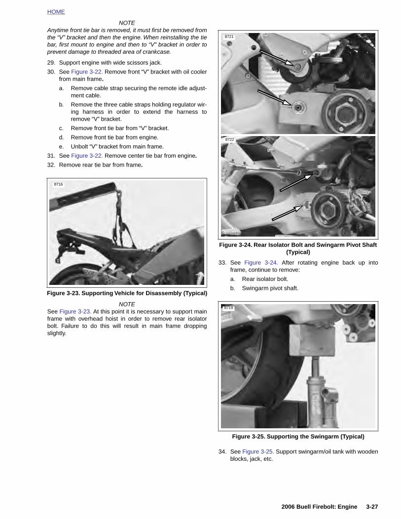
HOME
NOTEAnytime front tie bar is removed, it must first be removed fromthe “V” bracket and then the engine. When reinstalling the tiebar, first mount to engine and then to “V” bracket in order toprevent damage to threaded area of crankcase.
29. Support engine with wide scissors jack.
30. See Figure 3-22. Remove front “V” bracket with oil coolerfrom main frame.
a. Remove cable strap securing the remote idle adjust-ment cable.
b. Remove the three cable straps holding regulator wir-ing harness in order to extend the harness toremove “V” bracket.
c. Remove front tie bar from “V” bracket.
d. Remove front tie bar from engine.
e. Unbolt “V” bracket from main frame.
31. See Figure 3-22. Remove center tie bar from engine.
32. Remove rear tie bar from frame.
NOTESee Figure 3-23. At this point it is necessary to support mainframe with overhead hoist in order to remove rear isolatorbolt. Failure to do this will result in main frame droppingslightly.
33. See Figure 3-24. After rotating engine back up intoframe, continue to remove:
a. Rear isolator bolt.
b. Swingarm pivot shaft.Figure 3-23. Supporting Vehicle for Disassembly (Typical)
8716
Figure 3-24. Rear Isolator Bolt and Swingarm Pivot Shaft (Typical)
8721
8722
8719
2006 Buell Firebolt: Engine 3-27
34. See Figure 3-25. Support swingarm/oil tank with woodenblocks, jack, etc.
Figure 3-25. Supporting the Swingarm (Typical)

HOME
8730
8724
35. See Figure 3-26. Cut the two tie wraps holding transmis-sion vent line and pull vent line out of frame leaving itattached to engine.
NOTE
The transmission vent line runs up the left side of the frameand exits underneath the rear brake reservoir and hose.
36. Lower engine with scissors lift all the way down.
37. Move the engine assembly from under the main frame tothe right side of the lift.
38. Remove engine.
Figure 3-26. Transmission Vent Line
Figure 3-27. Center Tie Bar Mount
8725
Figure 3-28. Removing Threaded Insert
8729
Left Side
8718
8727
3-28 2006 Buell Firebolt: Engine
39. Once engine has been removed from vehicle finishremoving the following items as required:
a. Shifter assembly.
b. See Figure 3-27. Center tie bar mount.
c. See Figure 3-28. Swingarm pivot shaft pinch boltthreaded insert.
d. See Figure 3-29. Aluminum bushings from frontexhaust mount.
e. Timer cover.
f. See Figure 3-30. Wire guard located under thesprocket cover.
Figure 3-29. Front Exhaust Mount Bushings (2 piece)
Right Side
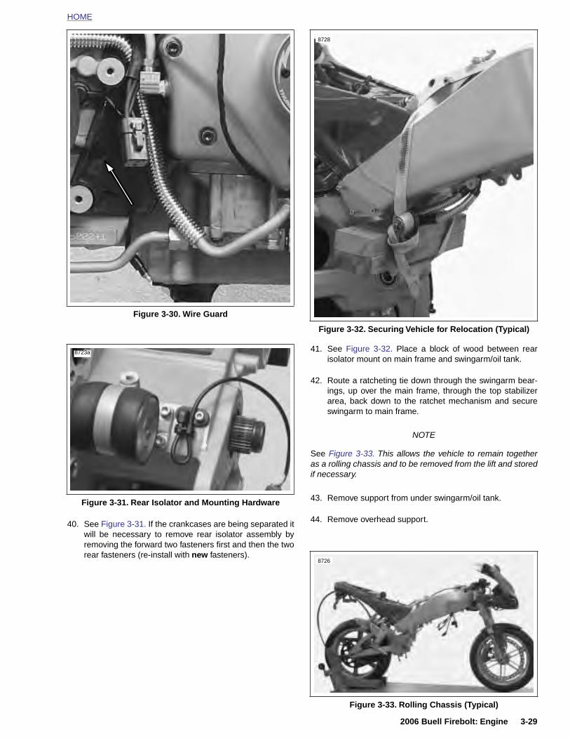
HOME
41. See Figure 3-32. Place a block of wood between rearisolator mount on main frame and swingarm/oil tank.
42. Route a ratcheting tie down through the swingarm bear-ings, up over the main frame, through the top stabilizerarea, back down to the ratchet mechanism and secureswingarm to main frame.
NOTE
See Figure 3-33. This allows the vehicle to remain togetheras a rolling chassis and to be removed from the lift and storedif necessary.
43. Remove support from under swingarm/oil tank.
Figure 3-30. Wire Guard
Figure 3-31. Rear Isolator and Mounting Hardware
8723a
Figure 3-32. Securing Vehicle for Relocation (Typical)
8728
2006 Buell Firebolt: Engine 3-29
40. See Figure 3-31. If the crankcases are being separated itwill be necessary to remove rear isolator assembly byremoving the forward two fasteners first and then the tworear fasteners (re-install with new fasteners).
44. Remove overhead support.
Figure 3-33. Rolling Chassis (Typical)
8726
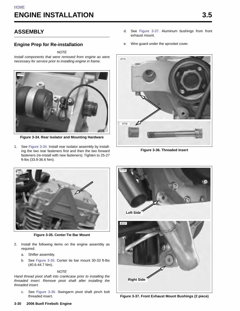
HOME
ENGINE INSTALLATION 3.5
ASSE
Engine
Install comnecessary
1. See Fing thfastenft-lbs
Figure
8723a
8725
3-30
2. Instreq
a.
b.
Hand ththreadedthreaded
c.
MBLY
Prep for Re-installation
NOTEponents that were removed from engine as were
for service prior to installing engine in frame.
igure 3-34. Install rear isolator assembly by install-e two rear fasteners first and then the two forwarders (re-install with new fasteners). Tighten to 25-27(33.9-36.6 Nm).
d. See Figure 3-37. Aluminum bushings from frontexhaust mount.
e. Wire guard under the sprocket cover.
3-34. Rear Isolator and Mounting Hardware
Figure 3-36. Threaded Insert
8770
8729
Left Side
8718
8727
2006 Buell Firebolt: Engine
all the following items on the engine assembly asuired:
Shifter assembly.
See Figure 3-35. Center tie bar mount 30-33 ft-lbs(40.6-44.7 Nm).
NOTEread pivot shaft into crankcase prior to installing the insert. Remove pivot shaft after installing the insert.
See Figure 3-36. Swingarm pivot shaft pinch boltthreaded insert.
Figure 3-35. Center Tie Bar Mount
Figure 3-37. Front Exhaust Mount Bushings (2 piece)
Right Side
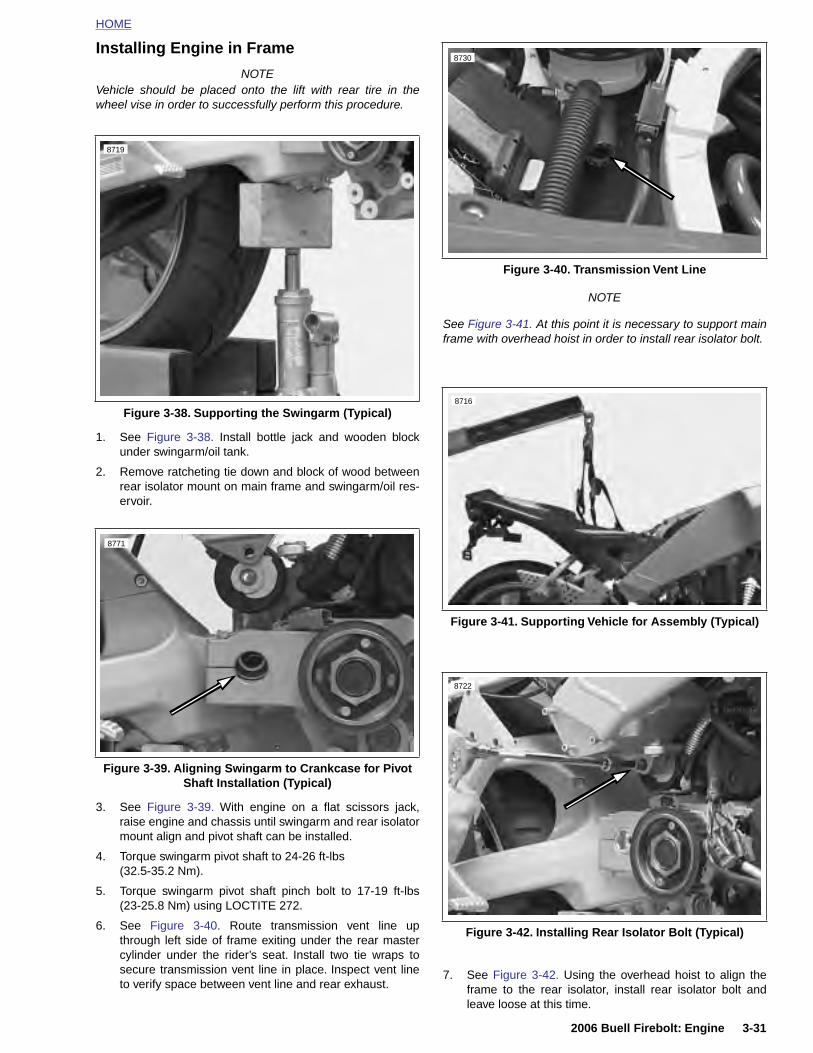
HOME
Installing Engine in Frame
NOTEVehicle should be placed onto the lift with rear tire in thewheel vise in order to successfully perform this procedure.
1. See Figure 3-38. Install bottle jack and wooden blockunder swingarm/oil tank.
2. Remove ratcheting tie down and block of wood betweenrear isolator mount on main frame and swingarm/oil res-ervoir.
NOTE
See Figure 3-41. At this point it is necessary to support mainframe with overhead hoist in order to install rear isolator bolt.
Figure 3-38. Supporting the Swingarm (Typical)
8719
8771
Figure 3-40. Transmission Vent Line
Figure 3-41. Supporting Vehicle for Assembly (Typical)
8730
8716
8722
2006 Buell Firebolt: Engine 3-31
3. See Figure 3-39. With engine on a flat scissors jack,raise engine and chassis until swingarm and rear isolatormount align and pivot shaft can be installed.
4. Torque swingarm pivot shaft to 24-26 ft-lbs(32.5-35.2 Nm).
5. Torque swingarm pivot shaft pinch bolt to 17-19 ft-lbs(23-25.8 Nm) using LOCTITE 272.
6. See Figure 3-40. Route transmission vent line upthrough left side of frame exiting under the rear mastercylinder under the rider’s seat. Install two tie wraps tosecure transmission vent line in place. Inspect vent lineto verify space between vent line and rear exhaust.
7. See Figure 3-42. Using the overhead hoist to align theframe to the rear isolator, install rear isolator bolt andleave loose at this time.
Figure 3-39. Aligning Swingarm to Crankcase for Pivot Shaft Installation (Typical)
Figure 3-42. Installing Rear Isolator Bolt (Typical)
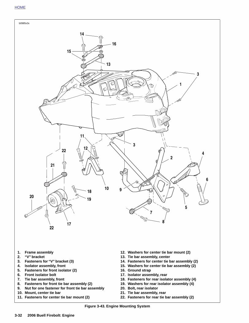
HOME
b0985x3x
22
19
18
17
22
21
20
10
11
16
3
1
4
14
13
15
12
6
2
7
8
5
3
9
3-32 2006 Buell Firebolt: Engine
Figure 3-43. Engine Mounting System
1. Frame assembly2. “V” bracket3. Fasteners for “V” bracket (3)4. Isolator assembly, front5. Fasteners for front isolator (2)6. Front isolator bolt7. Tie bar assembly, front8. Fasteners for front tie bar assembly (2)9. Nut for one fastener for front tie bar assembly10. Mount, center tie bar11. Fasteners for center tie bar mount (2)
12. Washers for center tie bar mount (2)13. Tie bar assembly, center14. Fasteners for center tie bar assembly (2)15. Washers for center tie bar assembly (2)16. Ground strap17. Isolator assembly, rear18. Fasteners for rear isolator assembly (4)19. Washers for rear isolator assembly (4)20. Bolt, rear isolator21. Tie bar assembly, rear22. Fasteners for rear tie bar assembly (2)
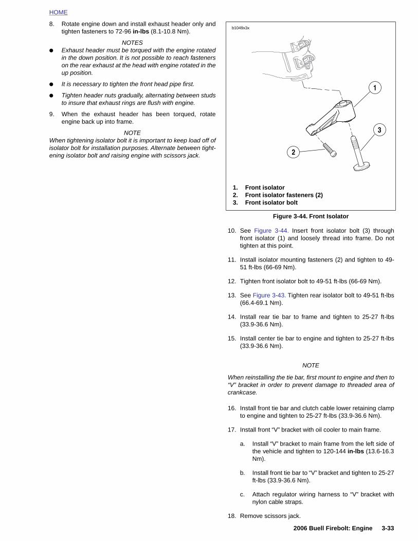
HOME
8. Rotate engine down and install exhaust header only andtighten fasteners to 72-96 in-lbs (8.1-10.8 Nm).
NOTES● Exhaust header must be torqued with the engine rotated
in the down position. It is not possible to reach fastenerson the rear exhaust at the head with engine rotated in theup position.
● It is necessary to tighten the front head pipe first.
● Tighten header nuts gradually, alternating between studsto insure that exhaust rings are flush with engine.
9. When the exhaust header has been torqued, rotateengine back up into frame.
NOTEWhen tightening isolator bolt it is important to keep load off ofisolator bolt for installation purposes. Alternate between tight-ening isolator bolt and raising engine with scissors jack.
10. See Figure 3-44. Insert front isolator bolt (3) throughfront isolator (1) and loosely thread into frame. Do nottighten at this point.
11. Install isolator mounting fasteners (2) and tighten to 49-51 ft-lbs (66-69 Nm).
12. Tighten front isolator bolt to 49-51 ft-lbs (66-69 Nm).
13. See Figure 3-43. Tighten rear isolator bolt to 49-51 ft-lbs(66.4-69.1 Nm).
14. Install rear tie bar to frame and tighten to 25-27 ft-lbs(33.9-36.6 Nm).
15. Install center tie bar to engine and tighten to 25-27 ft-lbs(33.9-36.6 Nm).
NOTE
Figure 3-44. Front Isolator
b1049x3x
1. Front isolator2. Front isolator fasteners (2)3. Front isolator bolt
1
3
2
2006 Buell Firebolt: Engine 3-33
When reinstalling the tie bar, first mount to engine and then to“V” bracket in order to prevent damage to threaded area ofcrankcase.
16. Install front tie bar and clutch cable lower retaining clampto engine and tighten to 25-27 ft-lbs (33.9-36.6 Nm).
17. Install front “V” bracket with oil cooler to main frame.
a. Install “V” bracket to main frame from the left side ofthe vehicle and tighten to 120-144 in-lbs (13.6-16.3Nm).
b. Install front tie bar to “V” bracket and tighten to 25-27ft-lbs (33.9-36.6 Nm).
c. Attach regulator wiring harness to “V” bracket withnylon cable straps.
18. Remove scissors jack.

HOME
b0986x3a
19. See Figure 3-45. Install rear muffler bracket and torqueto 32-36 ft-lbs (43.4-48.8 Nm).
20. Install front muffler mount and leave loose at this time.
NOTE● DO NOT install muffler at this time. It is necessary to
install muffler mounts first in order to properly install feedoil line.
● At this point it will be necessary to install the oil lines. It isimportant to follow this procedure to ensure correct ori-entation of oil lines in order to establish the proper clear-ances needed between the oil lines and variedcomponents on the vehicle.
Figure 3-45. Muffler Mounting System (XB9R)
Rear muffler mount
Front Muffler Mount
3-34 2006 Buell Firebolt: Engine
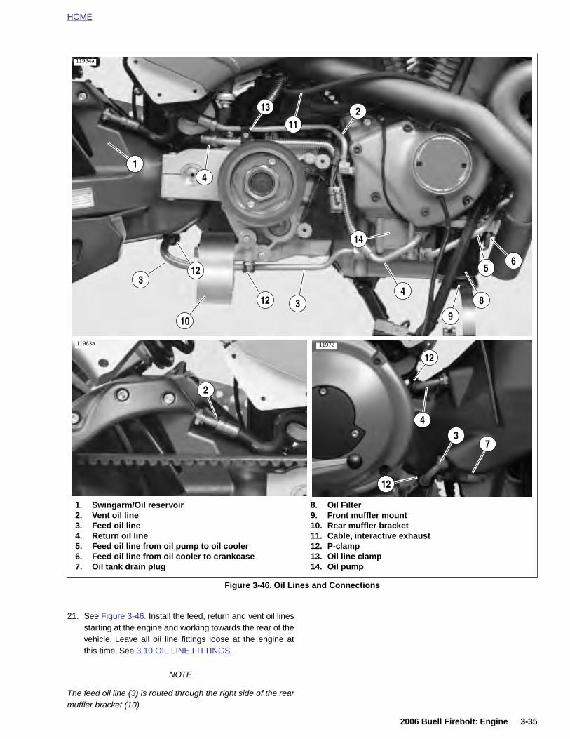
HOME
1. Swingarm/Oil reservoir 8. Oil Filter
2
7
5
43
4
11964a
11963a
10
1
2
3
3
8
9
6
4
11972
11
12
12
13
12
12
14
2006 Buell Firebolt: Engine 3-35
21. See Figure 3-46. Install the feed, return and vent oil linesstarting at the engine and working towards the rear of thevehicle. Leave all oil line fittings loose at the engine atthis time. See 3.10 OIL LINE FITTINGS.
NOTE
The feed oil line (3) is routed through the right side of the rearmuffler bracket (10).
Figure 3-46. Oil Lines and Connections
2. Vent oil line3. Feed oil line4. Return oil line5. Feed oil line from oil pump to oil cooler6. Feed oil line from oil cooler to crankcase7. Oil tank drain plug
9. Front muffler mount10. Rear muffler bracket11. Cable, interactive exhaust12. P-clamp13. Oil line clamp14. Oil pump
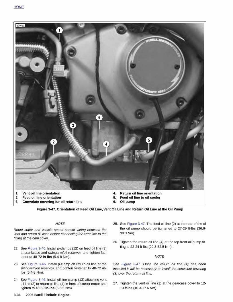
HOME
Figure 3-47. Orientation of Feed Oil Line, Vent Oil Line and Return Oil Line at the Oil Pump
11971a
1. Vent oil line orientation2. Feed oil line orientation3. Convolute covering for oil return line
4. Return oil line orientation5. Feed oil line to oil cooler6. Oil pump
1
2 45
3
6
3-36 2006 Buell Firebolt: Engine
NOTE
Route stator and vehicle speed sensor wiring between thevent and return oil lines before connecting the vent line to thefitting at the cam cover.
22. See Figure 3-46. Install p-clamps (12) on feed oil line (3)at crankcase and swingarm/oil reservoir and tighten fas-tener to 48-72 in-lbs (5.4-8 Nm).
23. See Figure 3-46. Install p-clamp on return oil line at theswingarm/oil reservoir and tighten fastener to 48-72 in-lbs (5.4-8 Nm).
24. See Figure 3-46. Install oil line clamp (13) attaching ventoil line (2) to return oil line (4) in front of starter motor andtighten to 40-50 in-lbs (5-5.5 Nm).
25. See Figure 3-47. The feed oil line (2) at the rear of the ofthe oil pump should be tightened to 27-29 ft-lbs (36.6-39.3 Nm).
26. Tighten the return oil line (4) at the top front oil pump fit-ting to 22-24 ft-lbs (29.8-32.5 Nm).
NOTE
See Figure 3-47. Once the return oil line (4) has beeninstalled it will be necessary to install the convolute covering(3) over the return oil line.
27. Tighten the vent oil line (1) at the gearcase cover to 12-13 ft-lbs (16.3-17.6 Nm).
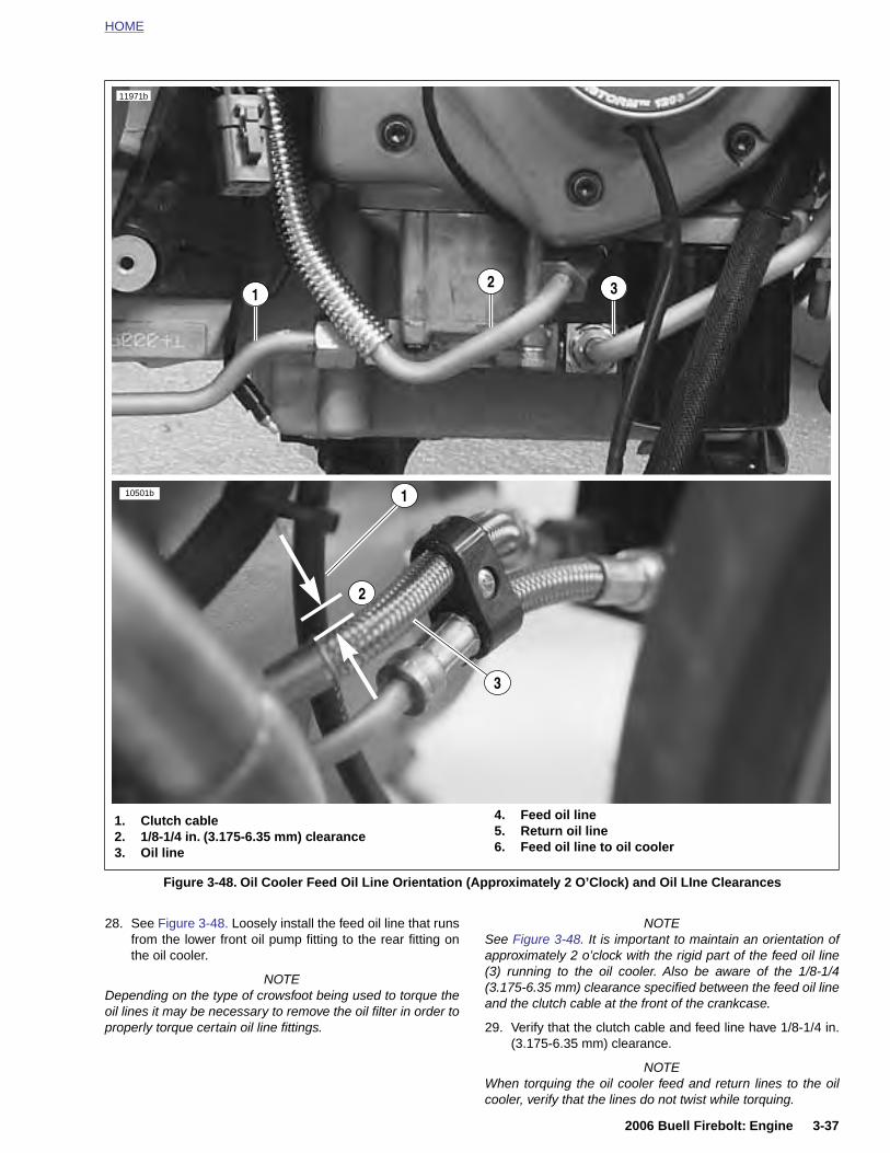
HOME
11971b
10501b 1
2
3
1 32
2006 Buell Firebolt: Engine 3-37
28. See Figure 3-48. Loosely install the feed oil line that runsfrom the lower front oil pump fitting to the rear fitting onthe oil cooler.
NOTEDepending on the type of crowsfoot being used to torque theoil lines it may be necessary to remove the oil filter in order toproperly torque certain oil line fittings.
NOTESee Figure 3-48. It is important to maintain an orientation ofapproximately 2 o’clock with the rigid part of the feed oil line(3) running to the oil cooler. Also be aware of the 1/8-1/4(3.175-6.35 mm) clearance specified between the feed oil lineand the clutch cable at the front of the crankcase.
29. Verify that the clutch cable and feed line have 1/8-1/4 in.(3.175-6.35 mm) clearance.
NOTEWhen torquing the oil cooler feed and return lines to the oilcooler, verify that the lines do not twist while torquing.
Figure 3-48. Oil Cooler Feed Oil Line Orientation (Approximately 2 O’Clock) and Oil LIne Clearances
1. Clutch cable2. 1/8-1/4 in. (3.175-6.35 mm) clearance3. Oil line
4. Feed oil line5. Return oil line6. Feed oil line to oil cooler
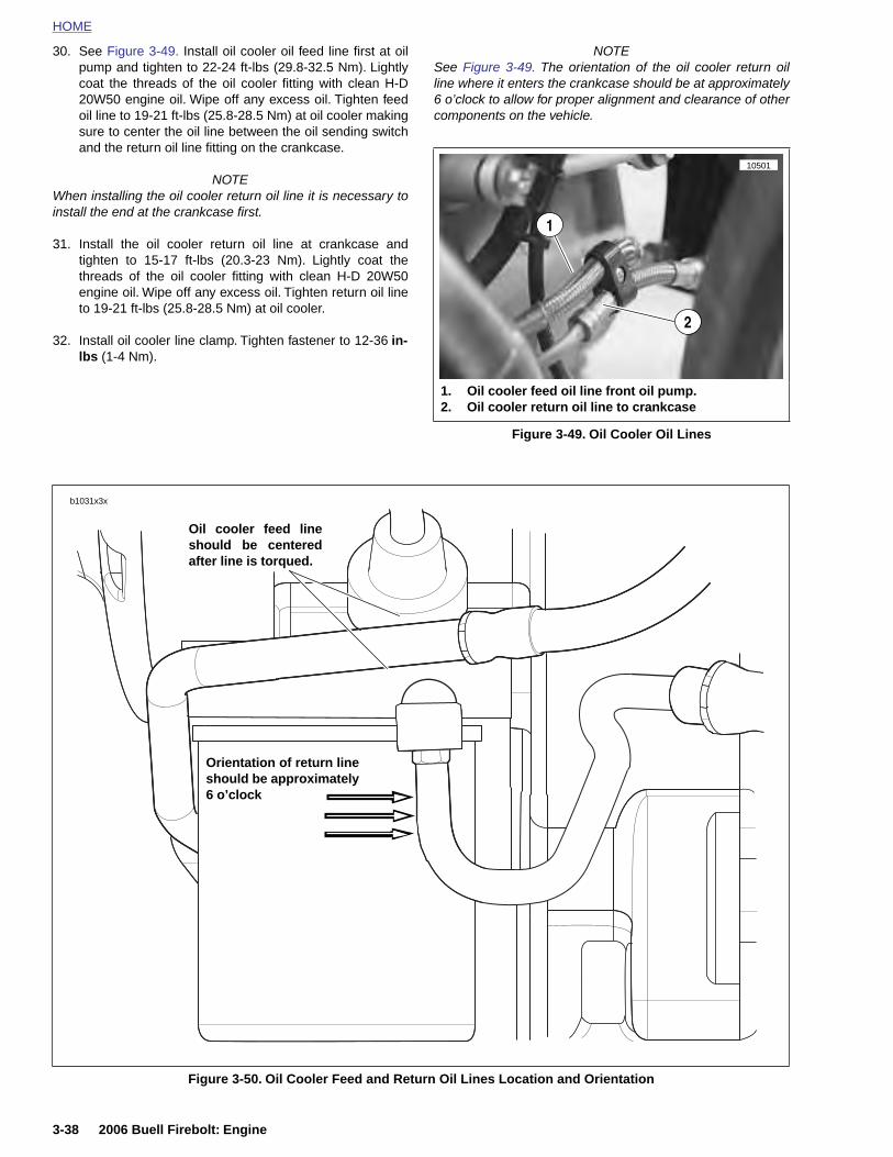
HOME
30. See Figure 3-49. Install oil cooler oil feed line first at oilpump and tighten to 22-24 ft-lbs (29.8-32.5 Nm). Lightlycoat the threads of the oil cooler fitting with clean H-D
NOTESee Figure 3-49. The orientation of the oil cooler return oilline where it enters the crankcase should be at approximately
20W50 engine oil. Wipe off any excess oil. Tighten feedoil line to 19-21 ft-lbs (25.8-28.5 Nm) at oil cooler makingsure to center the oil line between the oil sending switchand the return oil line fitting on the crankcase.
NOTEWhen installing the oil cooler return oil line it is necessary toinstall the end at the crankcase first.
31. Install the oil cooler return oil line at crankcase andtighten to 15-17 ft-lbs (20.3-23 Nm). Lightly coat thethreads of the oil cooler fitting with clean H-D 20W50engine oil. Wipe off any excess oil. Tighten return oil lineto 19-21 ft-lbs (25.8-28.5 Nm) at oil cooler.
32. Install oil cooler line clamp. Tighten fastener to 12-36 in-lbs (1-4 Nm).
6 o’clock to allow for proper alignment and clearance of othercomponents on the vehicle.
Figure 3-49. Oil Cooler Oil Lines
10501
1. Oil cooler feed oil line front oil pump.2. Oil cooler return oil line to crankcase
2
1
Oil cooler feed lineshould be centeredafter line is torqued.
Orientation of return lineshould be approximately6 o’clock
b1031x3x
3-38 2006 Buell Firebolt: Engine
Figure 3-50. Oil Cooler Feed and Return Oil Lines Location and Orientation

HOME
33. See 7.25 SPROCKET COVER WIRING before connect-ing the following electrical components:
a. Neutral switch [131].
b. Speedometer sensor [65] (install cable strap).
Figure 7-51. Sprocket Cover Wiring and Connections
1. Voltage regulator connector [77]2. Neutral switch connector [131]3. Neutral switch location4. Vehicle speed sensor connector [65]5. Main harness
6. Gear cover vent line7. Cam position sensor connector [14]8. Stator connector [46]9. Oil pressure switch wiring10. Interactive exhaust cable
11993
5
7
10
1
6
10
9
8
4
3
2
2006 Buell Firebolt: Engine 3-39
c. Cam position sensor [14].
d. Alternator [46].
e. Voltage regulator [77].
f. Positive battery cable at starter.
g. Starter solenoid [128].
h. Oil pressure switch [120].
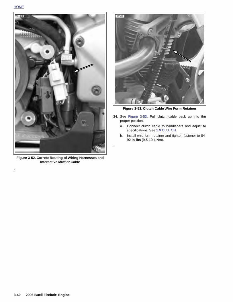
HOME
11970 10502
[
34. See Figure 3-53. Pull clutch cable back up into theproper position.
a. Connect clutch cable to handlebars and adjust tospecifications. See 1.9 CLUTCH.
b. Install wire form retainer and tighten fastener to 84-92 in-lbs (9.5-10.4 Nm).
.
Figure 3-52. Correct Routing of Wiring Harnesses and Interactive Muffler Cable
Figure 3-53. Clutch Cable Wire Form Retainer
3-40 2006 Buell Firebolt: Engine
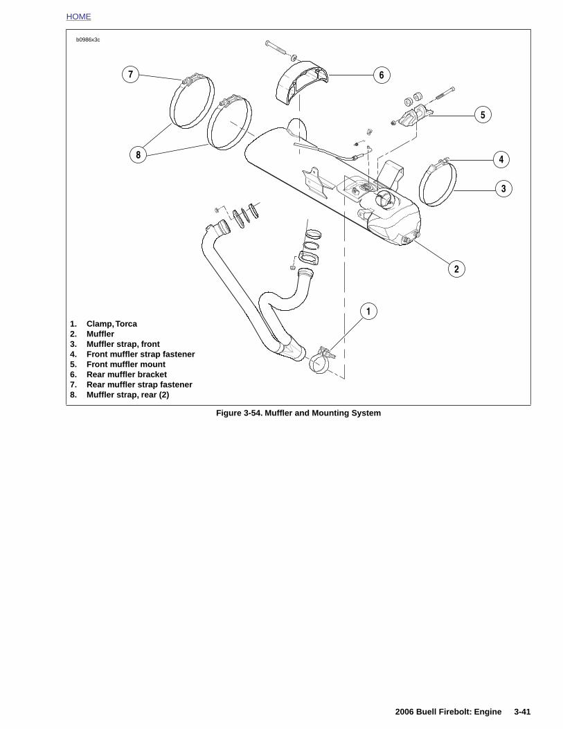
HOME
Figure 3-54. Muffler and Mounting System
b0986x3c
1. Clamp, Torca2. Muffler3. Muffler strap, front4. Front muffler strap fastener5. Front muffler mount6. Rear muffler bracket7. Rear muffler strap fastener8. Muffler strap, rear (2)
1
4
6
5
2
3
7
8
2006 Buell Firebolt: Engine 3-41
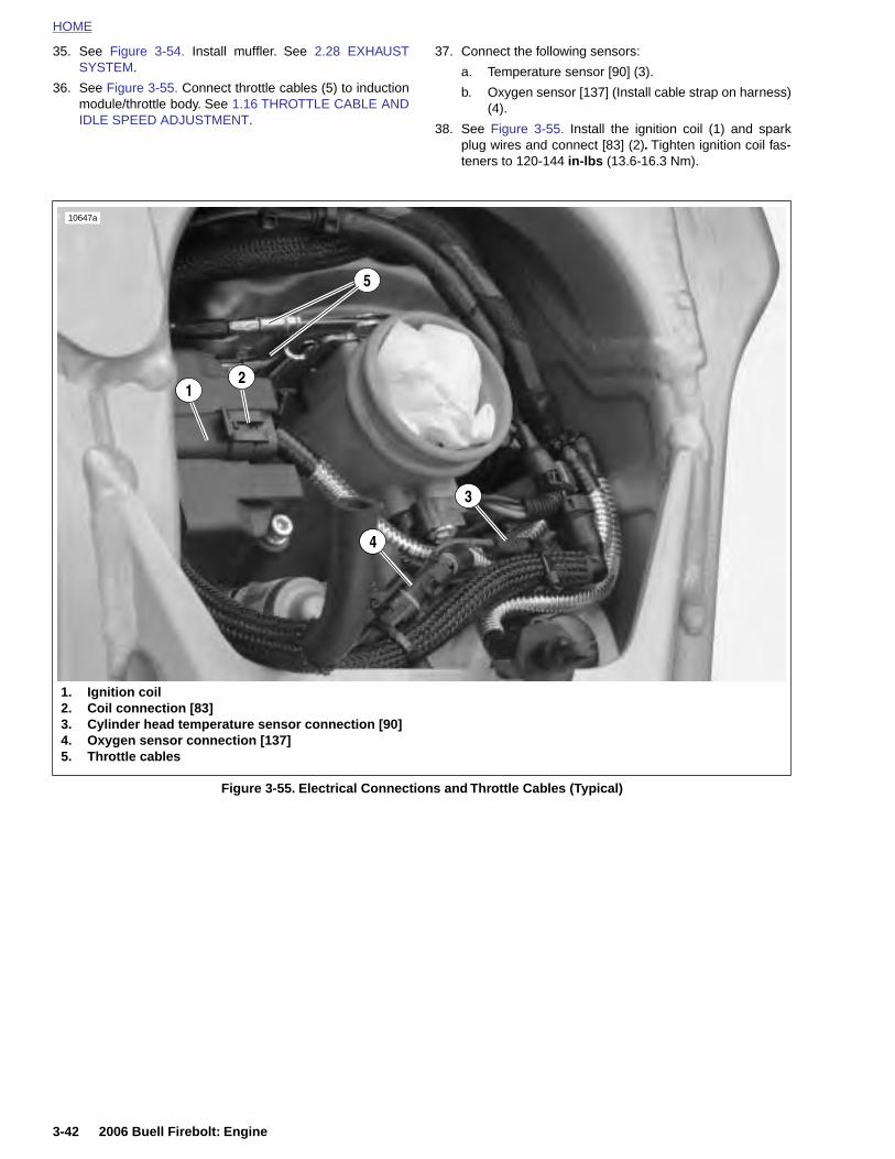
HOME
35. See Figure 3-54. Install muffler. See 2.28 EXHAUSTSYSTEM.
37. Connect the following sensors:
a. Temperature sensor [90] (3).
36. See Figure 3-55. Connect throttle cables (5) to inductionmodule/throttle body. See 1.16 THROTTLE CABLE ANDIDLE SPEED ADJUSTMENT.
b. Oxygen sensor [137] (Install cable strap on harness)(4).
38. See Figure 3-55. Install the ignition coil (1) and sparkplug wires and connect [83] (2). Tighten ignition coil fas-teners to 120-144 in-lbs (13.6-16.3 Nm).
Figure 3-55. Electrical Connections and Throttle Cables (Typical)
1. Ignition coil2. Coil connection [83]3. Cylinder head temperature sensor connection [90]4. Oxygen sensor connection [137]5. Throttle cables
5
3
21
10647a
4
3-42 2006 Buell Firebolt: Engine
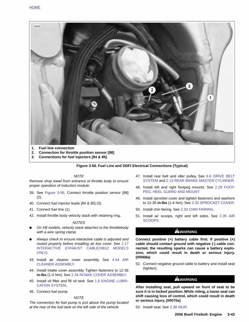
HOME
NOTERemove shop towel from entrance of throttle body to ensureproper operation of induction module.
39. See Figure 3-56. Connect throttle position sensor [88](2).
40. Connect fuel injector leads [84 & 85] (3).
41. Connect fuel line (1).
42. Install throttle body velocity stack with retaining ring.
47. Install rear belt and idler pulley. See 6.6 DRIVE BELTSYSTEM and 2.13 REAR BRAKE MASTER CYLINDER.
48. Install left and right footpeg mounts. See 2.29 FOOT-PEG, HEEL GUARD AND MOUNT
49. Install sprocket cover and tighten fasteners and washersto 12-36 in-lbs (1-4 Nm). See 2.30 SPROCKET COVER.
50. Install chin fairing. See 2.33 CHIN FAIRING.
51. Install air scoops, right and left sides. See 2.35 AIRSCOOPS.
Figure 3-56. Fuel Line and DDFI Electrical Connections (Typical)
23
10646
1. Fuel line connection2. Connection for throttle position sensor [88]3. Connections for fuel injectors [84 & 85]
1
2006 Buell Firebolt: Engine 3-43
NOTES● On XB models, velocity stack attaches to the throttlebody
with a wire spring clamp.
● Always check to ensure interactive cable is adjusted androuted properly before installing air box cover. See 1.17INTERACTIVE EXHAUST CABLE(XB12 MODELSONLY).
43. Install air cleaner cover assembly. See 4.44 AIRCLEANER ASSEMBLY.
44. Install intake cover assembly. Tighten fasteners to 12-36in-lbs (1-4 Nm). See 2.34 INTAKE COVER ASSEMBLY.
45. Install oil filter and fill oil tank. See 1.6 ENGINE LUBRI-CATION SYSTEM.
46. Connect fuel pump.
NOTEThe connection for fuel pump is just above the pump locatedat the rear of the fuel tank on the left side of the vehicle.
11WARNING1WARNING
Connect positive (+) battery cable first. If positive (+)cable should contact ground with negative (-) cable con-nected, the resulting sparks can cause a battery explo-sion, which could result in death or serious injury.(00068a)
52. Connect negative ground cable to battery and install seat(tighten).
11WARNING1WARNING
After installing seat, pull upward on front of seat to besure it is in locked position. While riding, a loose seat canshift causing loss of control, which could result in deathor serious injury. (00070a)
53. Install seat. See 2.38 SEAT.

HOME
CYLINDER HEAD 3.6
REMO
Before remto rotate TION FOcomponenheads.
1. Cr2. Gr3. Sc4. W5. Ga6. Ro7. Bo8. W9. Ga10. Ga11. Ro12. Bo13. wa14. Ro15. Ro16. Bu17. Ga18. Hy19. Sc20. Ga21. Pu22. Sc23. O-24. Pu25. W26. Bo
3-44
VAL
oving the cylinder head assembly, it is necessaryengine down as described in 3.3 ENGINE ROTA-R SERVICE. The rocker arm covers and internalts must be removed before removing cylinder
NOTE
All washers and fasteners used in the engine are hardened.Do not mix or replace hardened washers and fasteners withunhardened parts. Do not re-use fiber cover seals. Enginedamage may result.
ankcase breatherommetrew (4)
asher (4)sket (4)cker cover (top)lt (3)
asher (3)sket (inner)sket (lower)cker arm shaftslt (2)sher (2)cker cover (lower)cker arm (2)shing (rocker arm - 4)sket (lower rocker cover)draulic lifterrew, tappet anti-rotation (2)sket (push rod cover)shrod coverrew (4)ring (push rod cover - 2)sh rod
asher (4)lt (4)
1
2
3
4
5
6
7
8
11
12
13
14
15
16
17
24
23
25 9
10
26
2006 Buell Firebolt: Engine
Figure 3-57. Rocker Arm and Pushrod Cover Assemblies
22
21
20
b0960x3x
18
19
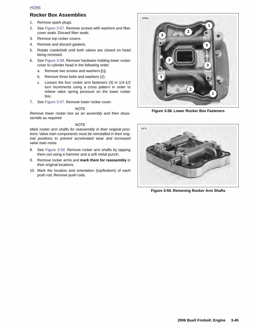
HOME
Rocker Box Assemblies1. Remove spark plugs.
2. See Figure 3-57. Remove screws with washers and fibercover seals. Discard fiber seals.
3. Remove top rocker covers.
4. Remove and discard gaskets.
5. Rotate crankshaft until both valves are closed on headbeing removed.
6. See Figure 3-58. Remove hardware holding lower rockercover to cylinder head in the following order.
a. Remove two screws and washers (1).
b. Remove three bolts and washers (2).
c. Loosen the four rocker arm fasteners (3) in 1/4-1/2turn increments using a cross pattern in order torelieve valve spring pressure on the lower rockerbox.
7. See Figure 3-57. Remove lower rocker cover.
NOTERemove lower rocker box as an assembly and then disas-semble as required.
NOTEMark rocker arm shafts for reassembly in their original posi-tions. Valve train components must be reinstalled in their orig-inal positions to prevent accelerated wear and increasedvalve train noise.
8. See Figure 3-59. Remove rocker arm shafts by tappingthem out using a hammer and a soft metal punch.
9. Remove rocker arms and mark them for reassembly intheir original locations.
10. Mark the location and orientation (top/bottom) of eachpush rod. Remove push rods.
Figure 3-58. Lower Rocker Box Fasteners
Figure 3-59. Removing Rocker Arm Shafts
1
1
2
2
23
3
3
3
4688a
8676
2006 Buell Firebolt: Engine 3-45
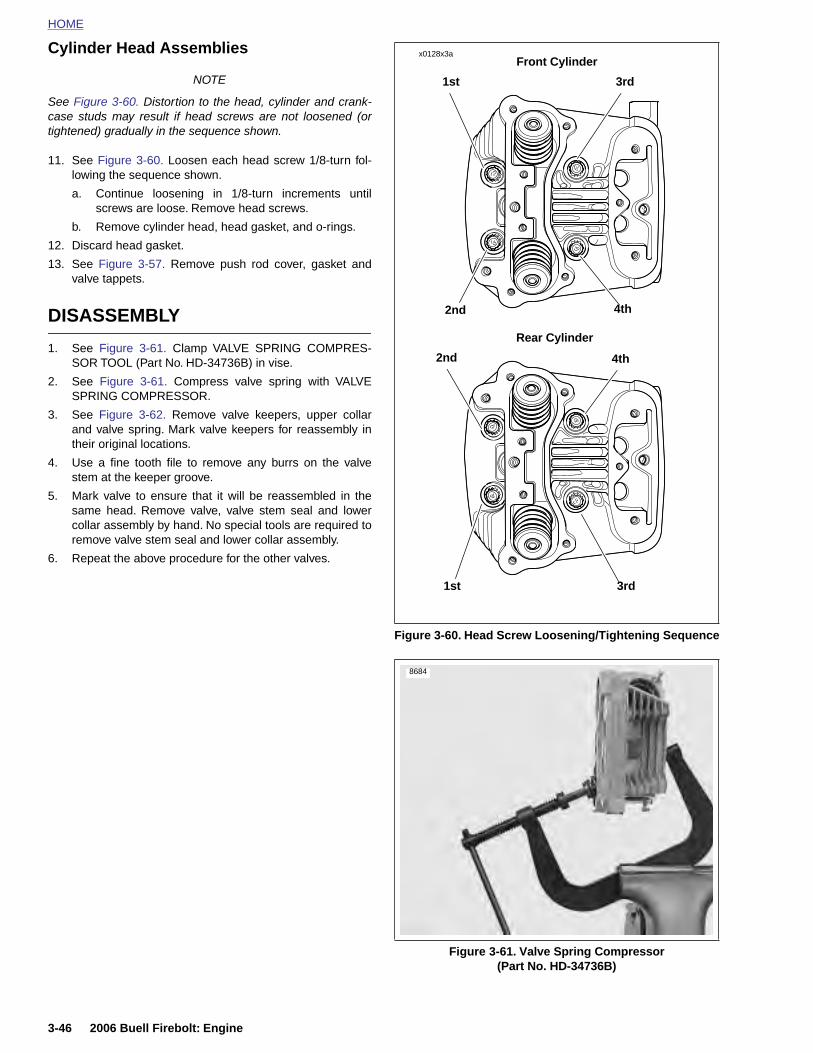
HOME
Cylinder Head AssembliesFront Cylinder
x0128x3a
NOTE
See Figure 3-60. Distortion to the head, cylinder and crank-case studs may result if head screws are not loosened (ortightened) gradually in the sequence shown.
11. See Figure 3-60. Loosen each head screw 1/8-turn fol-lowing the sequence shown.
a. Continue loosening in 1/8-turn increments untilscrews are loose. Remove head screws.
b. Remove cylinder head, head gasket, and o-rings.
12. Discard head gasket.
13. See Figure 3-57. Remove push rod cover, gasket andvalve tappets.
DISASSEMBLY
1. See Figure 3-61. Clamp VALVE SPRING COMPRES-SOR TOOL (Part No. HD-34736B) in vise.
2. See Figure 3-61. Compress valve spring with VALVESPRING COMPRESSOR.
3. See Figure 3-62. Remove valve keepers, upper collarand valve spring. Mark valve keepers for reassembly intheir original locations.
4. Use a fine tooth file to remove any burrs on the valvestem at the keeper groove.
5. Mark valve to ensure that it will be reassembled in thesame head. Remove valve, valve stem seal and lowercollar assembly by hand. No special tools are required toremove valve stem seal and lower collar assembly.
6. Repeat the above procedure for the other valves.
Figure 3-60. Head Screw Loosening/Tightening Sequence
Rear Cylinder
3rd
2nd
1st
4th
1st
2nd
3rd
4th
8684
3-46 2006 Buell Firebolt: Engine
Figure 3-61. Valve Spring Compressor (Part No. HD-34736B)

HOME
2b1024x3x
3
4
5
6
7
8
12
9
10
11
13
13
16
17
1
14
1. Screw2. Screw
2006 Buell Firebolt: Engine 3-47
Figure 3-62. Cylinder Head, Cylinder and Piston Assembly
153. Valve collar retainer4. Upper valve spring collar5. Valve spring6. Valve seal and lower valve spring
collar assembly7. Valve guide intake & exhaust (2)8. Cylinder head9. Exhaust port stud10. Cylinder head gasket11. Cylinder O-ring (4)12. Cylinder insert13. Cylinder w/piston & rings14. Cylinder base gasket15. Cylinder base stud16. Exhaust valve17. Exhaust valve seat
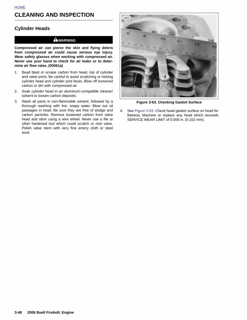
HOME
CLEANING AND INSPECTION6609
Cylinder Heads
11WARNING1WARNING
Compressed air can pierce the skin and flying debrisfrom compressed air could cause serious eye injury.Wear safety glasses when working with compressed air.Never use your hand to check for air leaks or to deter-mine air flow rates. (00061a)
1. Bead blast or scrape carbon from head, top of cylinderand valve ports. Be careful to avoid scratching or nickingcylinder head and cylinder joint faces. Blow off loosenedcarbon or dirt with compressed air.
2. Soak cylinder head in an aluminum-compatible cleaner/solvent to loosen carbon deposits.
3. Wash all parts in non-flammable solvent, followed by athorough washing with hot, soapy water. Blow out oilpassages in head. Be sure they are free of sludge andcarbon particles. Remove loosened carbon from valvehead and stem using a wire wheel. Never use a file orother hardened tool which could scratch or nick valve.Polish valve stem with very fine emery cloth or steelwool.
4. See Figure 3-63. Check head gasket surface on head forflatness. Machine or replace any head which exceedsSERVICE WEAR LIMIT of 0.006 in. (0.152 mm).
Figure 3-63. Checking Gasket Surface
3-48 2006 Buell Firebolt: Engine
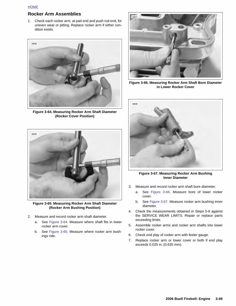
HOME
Rocker Arm Assemblies1. Check each rocker arm, at pad end and push rod end, for
uneven wear or pitting. Replace rocker arm if either con-dition exists.
3. Measure and record rocker arm shaft bore diameter.
a. See Figure 3-66. Measure bore of lower rockercover.
b. See Figure 3-67. Measure rocker arm bushing innerdiameter.
Figure 3-64. Measuring Rocker Arm Shaft Diameter(Rocker Cover Position)
Figure 3-65. Measuring Rocker Arm Shaft Diameter(Rocker Arm Bushing Position)
6606
6605
Figure 3-66. Measuring Rocker Arm Shaft Bore Diameter in Lower Rocker Cover
Figure 3-67. Measuring Rocker Arm BushingInner Diameter
6607
6608
2006 Buell Firebolt: Engine 3-49
2. Measure and record rocker arm shaft diameter.
a. See Figure 3-64. Measure where shaft fits in lowerrocker arm cover.
b. See Figure 3-65. Measure where rocker arm bush-ings ride.
4. Check the measurements obtained in Steps 5-6 againstthe SERVICE WEAR LIMITS. Repair or replace partsexceeding limits.
5. Assemble rocker arms and rocker arm shafts into lowerrocker cover.
6. Check end play of rocker arm with feeler gauge.
7. Replace rocker arm or lower cover or both if end playexceeds 0.025 in. (0.635 mm).
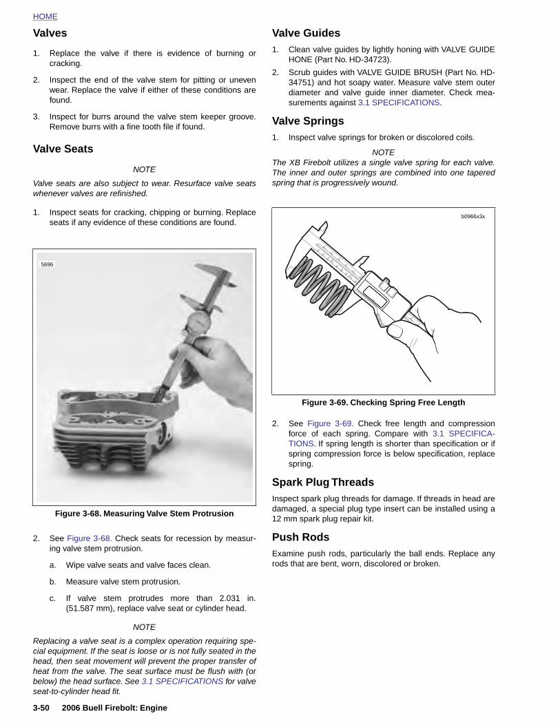
HOME
Valves
1. Replace the valve if there is evidence of burning or
Valve Guides1. Clean valve guides by lightly honing with VALVE GUIDE
cracking.
2. Inspect the end of the valve stem for pitting or unevenwear. Replace the valve if either of these conditions arefound.
3. Inspect for burrs around the valve stem keeper groove.Remove burrs with a fine tooth file if found.
Valve Seats
NOTE
Valve seats are also subject to wear. Resurface valve seatswhenever valves are refinished.
1. Inspect seats for cracking, chipping or burning. Replaceseats if any evidence of these conditions are found.
HONE (Part No. HD-34723).
2. Scrub guides with VALVE GUIDE BRUSH (Part No. HD-34751) and hot soapy water. Measure valve stem outerdiameter and valve guide inner diameter. Check mea-surements against 3.1 SPECIFICATIONS.
Valve Springs1. Inspect valve springs for broken or discolored coils.
NOTEThe XB Firebolt utilizes a single valve spring for each valve.The inner and outer springs are combined into one taperedspring that is progressively wound.
2. See Figure 3-69. Check free length and compressionforce of each spring. Compare with 3.1 SPECIFICA-TIONS. If spring length is shorter than specification or ifspring compression force is below specification, replacespring.
Spark Plug ThreadsInspect spark plug threads for damage. If threads in head aredamaged, a special plug type insert can be installed using a12 mm spark plug repair kit.
Figure 3-68. Measuring Valve Stem Protrusion
5696
Figure 3-69. Checking Spring Free Length
b0966x3x
3-50 2006 Buell Firebolt: Engine
2. See Figure 3-68. Check seats for recession by measur-ing valve stem protrusion.
a. Wipe valve seats and valve faces clean.
b. Measure valve stem protrusion.
c. If valve stem protrudes more than 2.031 in.(51.587 mm), replace valve seat or cylinder head.
NOTE
Replacing a valve seat is a complex operation requiring spe-cial equipment. If the seat is loose or is not fully seated in thehead, then seat movement will prevent the proper transfer ofheat from the valve. The seat surface must be flush with (orbelow) the head surface. See 3.1 SPECIFICATIONS for valveseat-to-cylinder head fit.
Push RodsExamine push rods, particularly the ball ends. Replace anyrods that are bent, worn, discolored or broken.
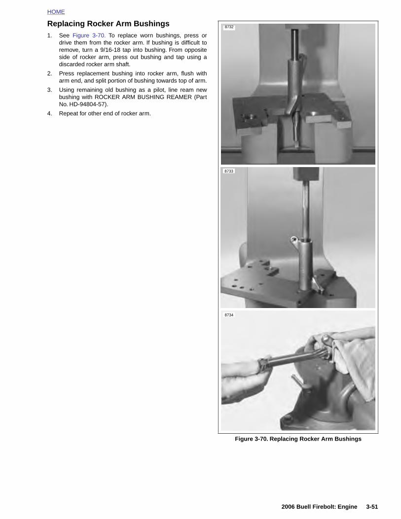
HOME
Replacing Rocker Arm Bushings1. See Figure 3-70. To replace worn bushings, press or
drive them from the rocker arm. If bushing is difficult toremove, turn a 9/16-18 tap into bushing. From oppositeside of rocker arm, press out bushing and tap using adiscarded rocker arm shaft.
2. Press replacement bushing into rocker arm, flush witharm end, and split portion of bushing towards top of arm.
3. Using remaining old bushing as a pilot, line ream newbushing with ROCKER ARM BUSHING REAMER (PartNo. HD-94804-57).
4. Repeat for other end of rocker arm.
8732
8733
8734
2006 Buell Firebolt: Engine 3-51
Figure 3-70. Replacing Rocker Arm Bushings
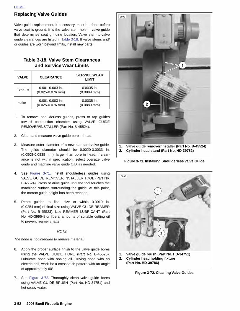
HOME
Replacing Valve Guides5692
Valve guide replacement, if necessary, must be done beforevalve seat is ground. It is the valve stem hole in valve guidethat determines seat grinding location. Valve stem-to-valveguide clearances are listed in Table 3-18. If valve stems and/or guides are worn beyond limits, install new parts.
1. To remove shoulderless guides, press or tap guidestoward combustion chamber using VALVE GUIDEREMOVER/INSTALLER (Part No. B-45524).
2. Clean and measure valve guide bore in head.
3. Measure outer diameter of a new standard valve guide.The guide diameter should be 0.0020-0.0033 in.(0.0508-0.0838 mm). larger than bore in head. If clear-ance is not within specification, select oversize valveguide and machine valve guide O.D. as needed.
4. See Figure 3-71. Install shoulderless guides usingVALVE GUIDE REMOVER/INSTALLER TOOL (Part No.B-45524). Press or drive guide until the tool touches themachined surface surrounding the guide. At this point,the correct guide height has been reached.
5. Ream guides to final size or within 0.0010 in.(0.0254 mm) of final size using VALVE GUIDE REAMER(Part No. B-45523). Use REAMER LUBRICANT (PartNo. HD-39964) or liberal amounts of suitable cutting oilto prevent reamer chatter.
Table 3-18. Valve Stem Clearancesand Service Wear Limits
VALVE CLEARANCESERVICE WEAR
LIMIT
Exhaust0.001-0.003 in.
(0.025-0.076 mm)0.0035 in.
(0.0889 mm)
Intake0.001-0.003 in.
(0.025-0.076 mm)0.0035 in.
(0.0889 mm)
Figure 3-71. Installing Shoulderless Valve Guide
1. Valve guide remover/installer (Part No. B-45524)2. Cylinder head stand (Part No. HD-39782)
2
1
5695
1
3-52 2006 Buell Firebolt: Engine
NOTE
The hone is not intended to remove material.
6. Apply the proper surface finish to the valve guide boresusing the VALVE GUIDE HONE (Part No. B-45525).Lubricate hone with honing oil. Driving hone with anelectric drill, work for a crosshatch pattern with an angleof approximately 60°.
7. See Figure 3-72. Thoroughly clean valve guide boresusing VALVE GUIDE BRUSH (Part No. HD-34751) andhot soapy water.
Figure 3-72. Cleaning Valve Guides
1. Valve guide brush (Part No. HD-34751)2. Cylinder head holding fixture
(Part No. HD-39786)
2
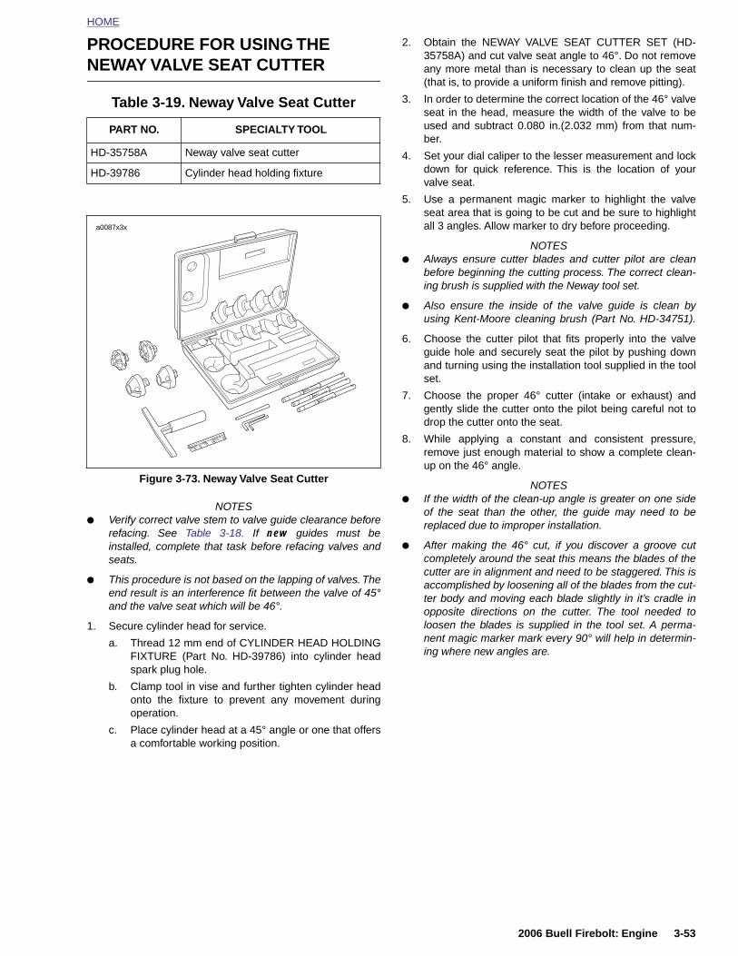
HOME
PROCEDURE FOR USING THE NEWAY VALVE SEAT CUTTER
Table 3-19. Neway Valve Seat Cutter
NOTES● Verify correct valve stem to valve guide clearance before
refacing. See Table 3-18. If new guides must beinstalled, complete that task before refacing valves andseats.
● This procedure is not based on the lapping of valves. Theend result is an interference fit between the valve of 45°and the valve seat which will be 46°.
1. Secure cylinder head for service.
a. Thread 12 mm end of CYLINDER HEAD HOLDINGFIXTURE (Part No. HD-39786) into cylinder head
2. Obtain the NEWAY VALVE SEAT CUTTER SET (HD-35758A) and cut valve seat angle to 46°. Do not removeany more metal than is necessary to clean up the seat(that is, to provide a uniform finish and remove pitting).
3. In order to determine the correct location of the 46° valveseat in the head, measure the width of the valve to beused and subtract 0.080 in.(2.032 mm) from that num-ber.
4. Set your dial caliper to the lesser measurement and lockdown for quick reference. This is the location of yourvalve seat.
5. Use a permanent magic marker to highlight the valveseat area that is going to be cut and be sure to highlightall 3 angles. Allow marker to dry before proceeding.
NOTES● Always ensure cutter blades and cutter pilot are clean
before beginning the cutting process. The correct clean-ing brush is supplied with the Neway tool set.
● Also ensure the inside of the valve guide is clean byusing Kent-Moore cleaning brush (Part No. HD-34751).
6. Choose the cutter pilot that fits properly into the valveguide hole and securely seat the pilot by pushing downand turning using the installation tool supplied in the toolset.
7. Choose the proper 46° cutter (intake or exhaust) andgently slide the cutter onto the pilot being careful not todrop the cutter onto the seat.
8. While applying a constant and consistent pressure,remove just enough material to show a complete clean-up on the 46° angle.
NOTES● If the width of the clean-up angle is greater on one side
of the seat than the other, the guide may need to bereplaced due to improper installation.
● After making the 46° cut, if you discover a groove cutcompletely around the seat this means the blades of thecutter are in alignment and need to be staggered. This isaccomplished by loosening all of the blades from the cut-ter body and moving each blade slightly in it’s cradle inopposite directions on the cutter. The tool needed toloosen the blades is supplied in the tool set. A perma-nent magic marker mark every 90° will help in determin-ing where new angles are.
PART NO. SPECIALTY TOOL
HD-35758A Neway valve seat cutter
HD-39786 Cylinder head holding fixture
Figure 3-73. Neway Valve Seat Cutter
a0087x3x
2006 Buell Firebolt: Engine 3-53
spark plug hole.
b. Clamp tool in vise and further tighten cylinder headonto the fixture to prevent any movement duringoperation.
c. Place cylinder head at a 45° angle or one that offersa comfortable working position.
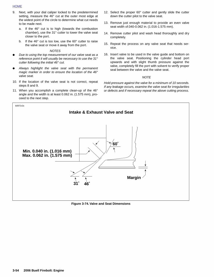
HOME
9. Next, with your dial caliper locked to the predeterminedsetting, measure the 46° cut at the outer most edge atthe widest point of the circle to determine what cut needs
12. Select the proper 60° cutter and gently slide the cutterdown the cutter pilot to the valve seat.
to be made next.
a. If the 46° cut is to high (towards the combustionchamber), use the 31° cutter to lower the valve seatcloser to the port.
b. If the 46° cut is too low, use the 60° cutter to raisethe valve seat or move it away from the port.
NOTES● Due to using the top measurement of our valve seat as a
reference point it will usually be necessary to use the 31°cutter following the initial 46° cut.
● Always highlight the valve seat with the permanentmagic marker in order to ensure the location of the 46°valve seat.
10. If the location of the valve seat is not correct, repeatsteps 8 and 9.
11. When you accomplish a complete clean-up of the 46°angle and the width is at least 0.062 in. (1.575 mm), pro-ceed to the next step.
13. Remove just enough material to provide an even valveseat width of.040-0.062 in. (1.016-1.575 mm).
14. Remove cutter pilot and wash head thoroughly and drycompletely.
15. Repeat the process on any valve seat that needs ser-vice.
16. Insert valve to be used in the valve guide and bottom onthe valve seat. Positioning the cylinder head portupwards and with slight thumb pressure against thevalve, completely fill the port with solvent to verify properseal between the valve and the valve seat.
NOTE
Hold pressure against the valve for a minimum of 10 seconds.If any leakage occurs, examine the valve seat for irregularitiesor defects and if necessary repeat the above cutting process.
Intake & Exhaust Valve and Seat
31˚ 46˚
60˚
Min. 0.040 in. (1.016 mm)Max. 0.062 in. (1.575 mm)
b0972x3x
Margin
3-54 2006 Buell Firebolt: Engine
Figure 3-74. Valve and Seat Dimensions
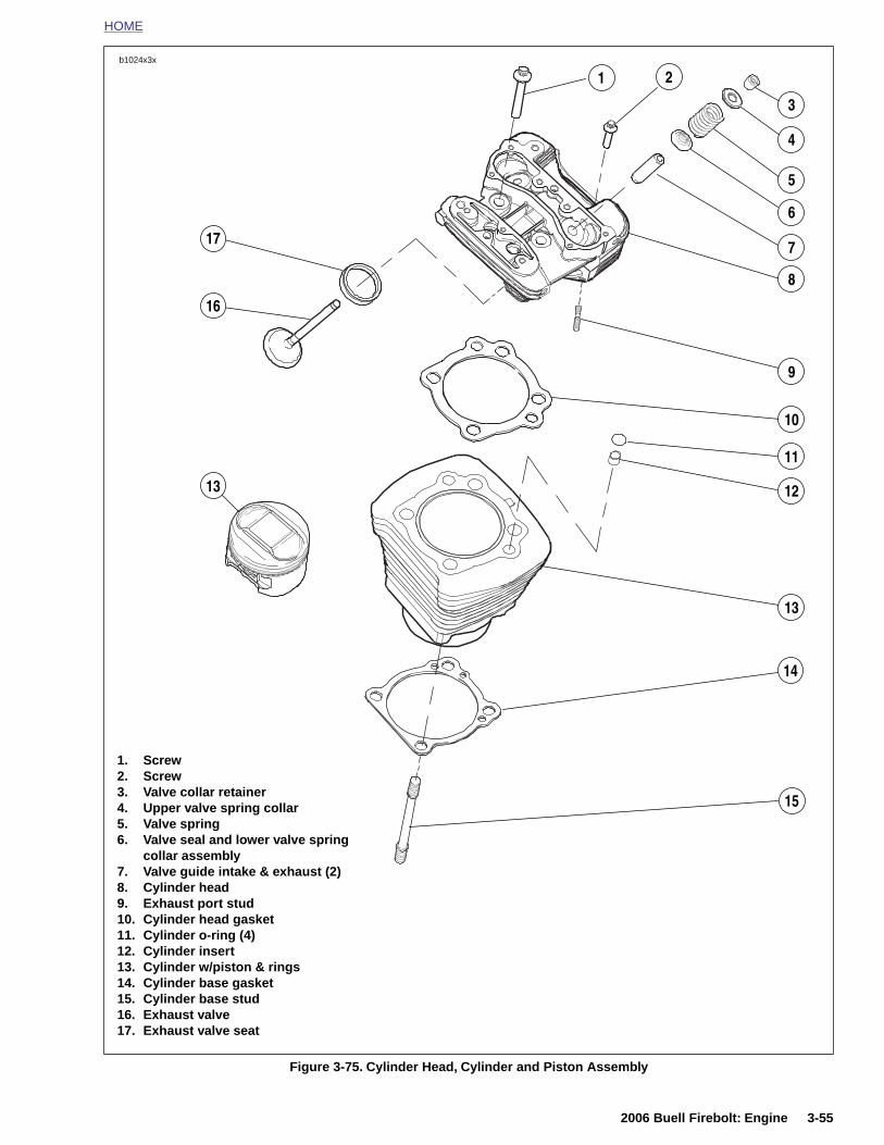
HOME
2b1024x3x
3
4
5
6
7
8
12
9
10
11
13
13
16
17
1
14
1. Screw2. Screw
2006 Buell Firebolt: Engine 3-55
Figure 3-75. Cylinder Head, Cylinder and Piston Assembly
153. Valve collar retainer4. Upper valve spring collar5. Valve spring6. Valve seal and lower valve spring
collar assembly7. Valve guide intake & exhaust (2)8. Cylinder head9. Exhaust port stud10. Cylinder head gasket11. Cylinder o-ring (4)12. Cylinder insert13. Cylinder w/piston & rings14. Cylinder base gasket15. Cylinder base stud16. Exhaust valve17. Exhaust valve seat
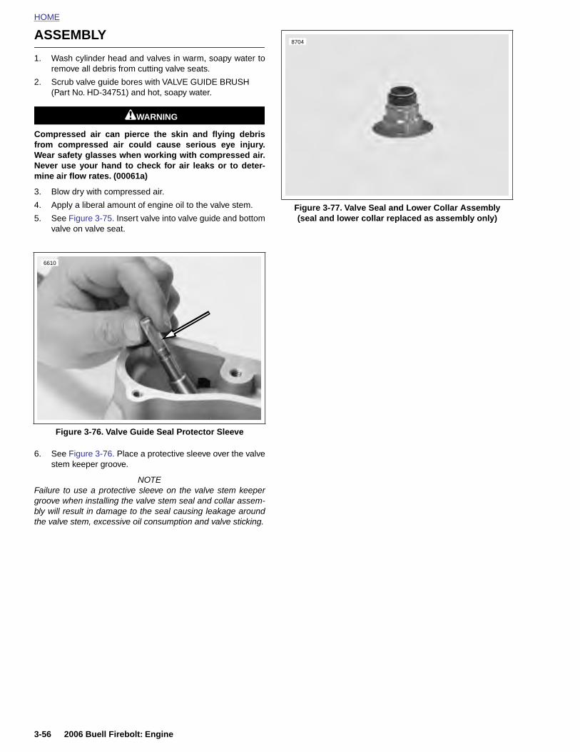
HOME
ASSEMBLY8704
1. Wash cylinder head and valves in warm, soapy water toremove all debris from cutting valve seats.
2. Scrub valve guide bores with VALVE GUIDE BRUSH(Part No. HD-34751) and hot, soapy water.
11WARNING1WARNING
Compressed air can pierce the skin and flying debrisfrom compressed air could cause serious eye injury.Wear safety glasses when working with compressed air.Never use your hand to check for air leaks or to deter-mine air flow rates. (00061a)
3. Blow dry with compressed air.
4. Apply a liberal amount of engine oil to the valve stem.
5. See Figure 3-75. Insert valve into valve guide and bottomvalve on valve seat.
6. See Figure 3-76. Place a protective sleeve over the valvestem keeper groove.
NOTEFailure to use a protective sleeve on the valve stem keepergroove when installing the valve stem seal and collar assem-bly will result in damage to the seal causing leakage aroundthe valve stem, excessive oil consumption and valve sticking.
Figure 3-76. Valve Guide Seal Protector Sleeve
6610
Figure 3-77. Valve Seal and Lower Collar Assembly(seal and lower collar replaced as assembly only)
3-56 2006 Buell Firebolt: Engine
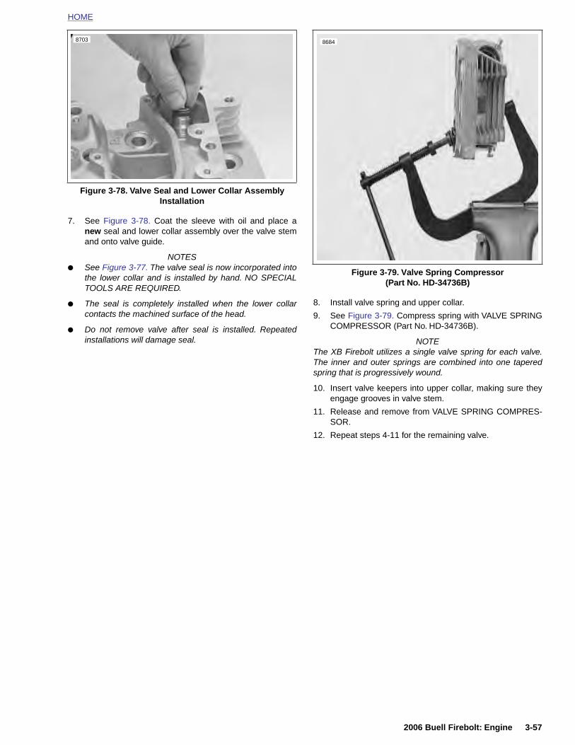
HOME
7. See Figure 3-78. Coat the sleeve with oil and place anew seal and lower collar assembly over the valve stemand onto valve guide.
NOTES● See Figure 3-77. The valve seal is now incorporated into
the lower collar and is installed by hand. NO SPECIALTOOLS ARE REQUIRED.
● The seal is completely installed when the lower collarcontacts the machined surface of the head.
● Do not remove valve after seal is installed. Repeatedinstallations will damage seal.
8. Install valve spring and upper collar.
9. See Figure 3-79. Compress spring with VALVE SPRINGCOMPRESSOR (Part No. HD-34736B).
NOTEThe XB Firebolt utilizes a single valve spring for each valve.The inner and outer springs are combined into one taperedspring that is progressively wound.
10. Insert valve keepers into upper collar, making sure theyengage grooves in valve stem.
11. Release and remove from VALVE SPRING COMPRES-SOR.
12. Repeat steps 4-11 for the remaining valve.
Figure 3-78. Valve Seal and Lower Collar AssemblyInstallation
8703
Figure 3-79. Valve Spring Compressor (Part No. HD-34736B)
8684
2006 Buell Firebolt: Engine 3-57
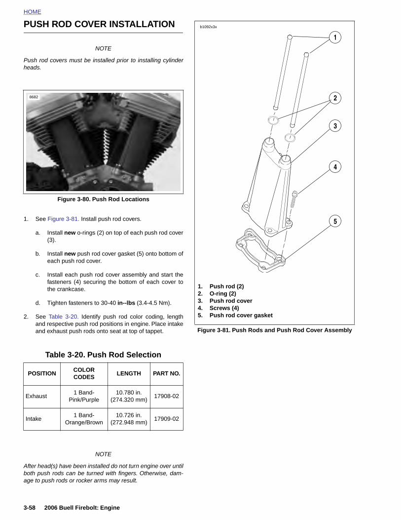
HOME
PUSH ROD COVER INSTALLATION b1092x3x
1
NOTEPush rod covers must be installed prior to installing cylinderheads.
1. See Figure 3-81. Install push rod covers.
a. Install new o-rings (2) on top of each push rod cover(3).
b. Install new push rod cover gasket (5) onto bottom ofeach push rod cover.
c. Install each push rod cover assembly and start thefasteners (4) securing the bottom of each cover tothe crankcase.
d. Tighten fasteners to 30-40 in--lbs (3.4-4.5 Nm).
2. See Table 3-20. Identify push rod color coding, lengthand respective push rod positions in engine. Place intakeand exhaust push rods onto seat at top of tappet.
Figure 3-80. Push Rod Locations
Table 3-20. Push Rod Selection
POSITIONCOLOR CODES
LENGTH PART NO.
8682
Figure 3-81. Push Rods and Push Rod Cover Assembly
2
3
4
5
1. Push rod (2)2. O-ring (2)3. Push rod cover4. Screws (4)5. Push rod cover gasket
3-58 2006 Buell Firebolt: Engine
NOTE
After head(s) have been installed do not turn engine over untilboth push rods can be turned with fingers. Otherwise, dam-age to push rods or rocker arms may result.
Exhaust1 Band-
Pink/Purple10.780 in.
(274.320 mm)17908-02
Intake1 Band-
Orange/Brown10.726 in.
(272.948 mm)17909-02
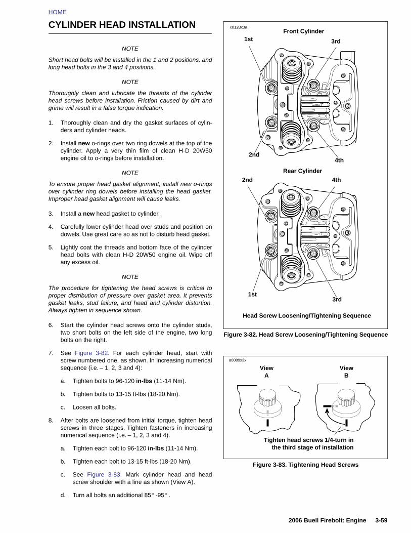
HOME
CYLINDER HEAD INSTALLATION
NOTE
Short head bolts will be installed in the 1 and 2 positions, andlong head bolts in the 3 and 4 positions.
NOTE
Thoroughly clean and lubricate the threads of the cylinderhead screws before installation. Friction caused by dirt andgrime will result in a false torque indication.
1. Thoroughly clean and dry the gasket surfaces of cylin-ders and cylinder heads.
2. Install new o-rings over two ring dowels at the top of thecylinder. Apply a very thin film of clean H-D 20W50engine oil to o-rings before installation.
NOTE
To ensure proper head gasket alignment, install new o-ringsover cylinder ring dowels before installing the head gasket.Improper head gasket alignment will cause leaks.
3. Install a new head gasket to cylinder.
4. Carefully lower cylinder head over studs and position ondowels. Use great care so as not to disturb head gasket.
5. Lightly coat the threads and bottom face of the cylinderhead bolts with clean H-D 20W50 engine oil. Wipe offany excess oil.
NOTE
The procedure for tightening the head screws is critical toproper distribution of pressure over gasket area. It preventsgasket leaks, stud failure, and head and cylinder distortion.Always tighten in sequence shown.
6. Start the cylinder head screws onto the cylinder studs,two short bolts on the left side of the engine, two longbolts on the right.
7. See Figure 3-82. For each cylinder head, start withscrew numbered one, as shown. In increasing numerical
Figure 3-82. Head Screw Loosening/Tightening Sequence
Head Screw Loosening/Tightening Sequence
Rear Cylinder
Front Cylinder
4th
1st
2nd
3rd
x0128x3a
2nd
1st
4th
3rd
a0089x3x
2006 Buell Firebolt: Engine 3-59
sequence (i.e. – 1, 2, 3 and 4):
a. Tighten bolts to 96-120 in-lbs (11-14 Nm).
b. Tighten bolts to 13-15 ft-lbs (18-20 Nm).
c. Loosen all bolts.
8. After bolts are loosened from initial torque, tighten headscrews in three stages. Tighten fasteners in increasingnumerical sequence (i.e. – 1, 2, 3 and 4).
a. Tighten each bolt to 96-120 in-lbs (11-14 Nm).
b. Tighten each bolt to 13-15 ft-lbs (18-20 Nm).
c. See Figure 3-83. Mark cylinder head and headscrew shoulder with a line as shown (View A).
d. Turn all bolts an additional 85 -95 .° °
Figure 3-83. Tightening Head Screws
ViewA
ViewB
Tighten head screws 1/4-turn inthe third stage of installation
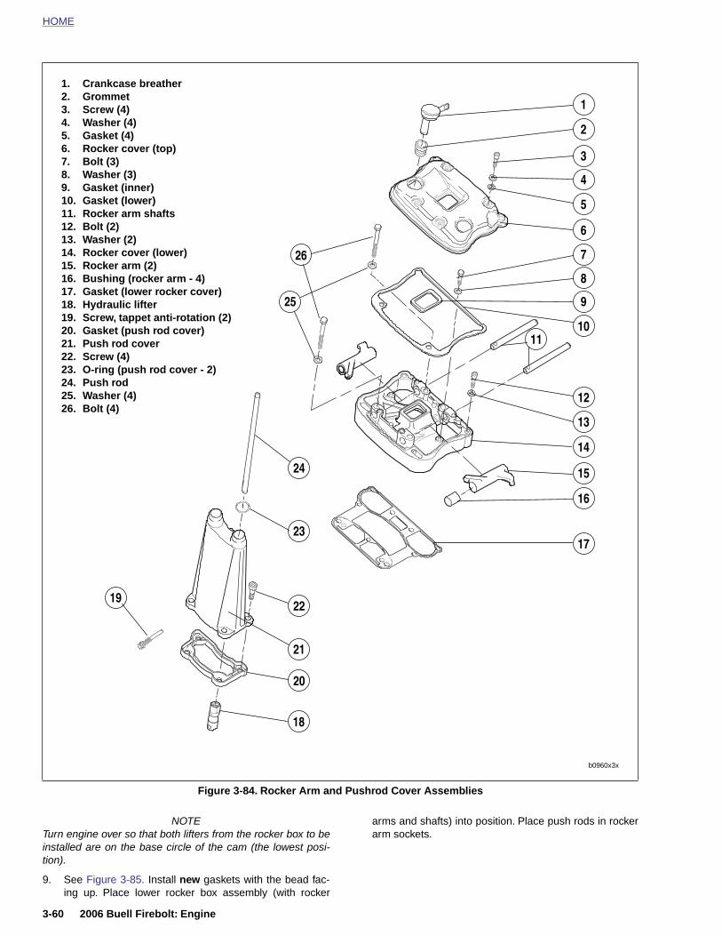
HOME
1. Crankcase breather2. Grommet3. Screw (4)4. Washer (4)5. Gasket (4)6. Rocker cover (top)7. Bolt (3) 8. Washer (3)9. Gasket (inner)10. Gasket (lower)11. Rocker arm shafts12. Bolt (2)13. Washer (2)14. Rocker cover (lower)15. Rocker arm (2)16. Bushing (rocker arm - 4)17. Gasket (lower rocker cover)18. Hydraulic lifter19. Screw, tappet anti-rotation (2)20. Gasket (push rod cover)21. Push rod cover22. Screw (4)23. O-ring (push rod cover - 2)24. Push rod25. Washer (4)26. Bolt (4)
1
2
3
4
5
6
7
8
11
12
13
14
15
16
17
26
24
22
21
20
23
25 9
10
19
3-60 2006 Buell Firebolt: Engine
NOTETurn engine over so that both lifters from the rocker box to beinstalled are on the base circle of the cam (the lowest posi-tion).
9. See Figure 3-85. Install new gaskets with the bead fac-ing up. Place lower rocker box assembly (with rocker
arms and shafts) into position. Place push rods in rockerarm sockets.
Figure 3-84. Rocker Arm and Pushrod Cover Assemblies
b0960x3x
18

HOME
10. See Figure 3-85. Install hardware attaching lower rockercover to cylinder head in the following order. After looselyinstalling all fasteners, use a cross pattern on the fourlarge bolts that fasten the lower rocker box to head totighten and then torque to specifications. This will bleedthe tappets. Finish tightening remaining fasteners. Fas-tener sequences, sizes and torque specifications arelisted in Table 3-21.
a. Tighten bolts (1) to 18-22 ft-lbs (24-30 Nm).
b. Tighten bolts (2) to 135-155 in-lbs (15-17.5 Nm).
c. Tighten bolts (3) to 135-155 in-lbs (15-17.5 Nm).
11. See Figure 3-84. Install upper rocker covers.
a. Place a new inner gaskets on lower rocker boxassemblies.
b. Place a new lower gaskets on lower rocker cover.
c. Install upper rocker cover using screws with washersand new fiber seals. Tighten screws to 120-156 in-lbs (13.6-17.6 Nm).
Figure 3-85. Lower Rocker Box Fasteners
4688a
3
3
2
2
2
1
1
1
1
4688a
Table 3-21. Lower Rocker Box Fasteners
No. ITEM SIZE TORQUE
1 Bolt w/washer5/16-18 X 2-1/2
18-22 ft-lbs (24-30 Nm)
2 Bolt w/washer1/4-20 X 1-1/4
135-155 in-lbs(15-17.5 Nm)
3 Screw w/washer1/4-20 X 1-1/2
135-155 in-lbs(15-18 Nm)
2006 Buell Firebolt: Engine 3-61
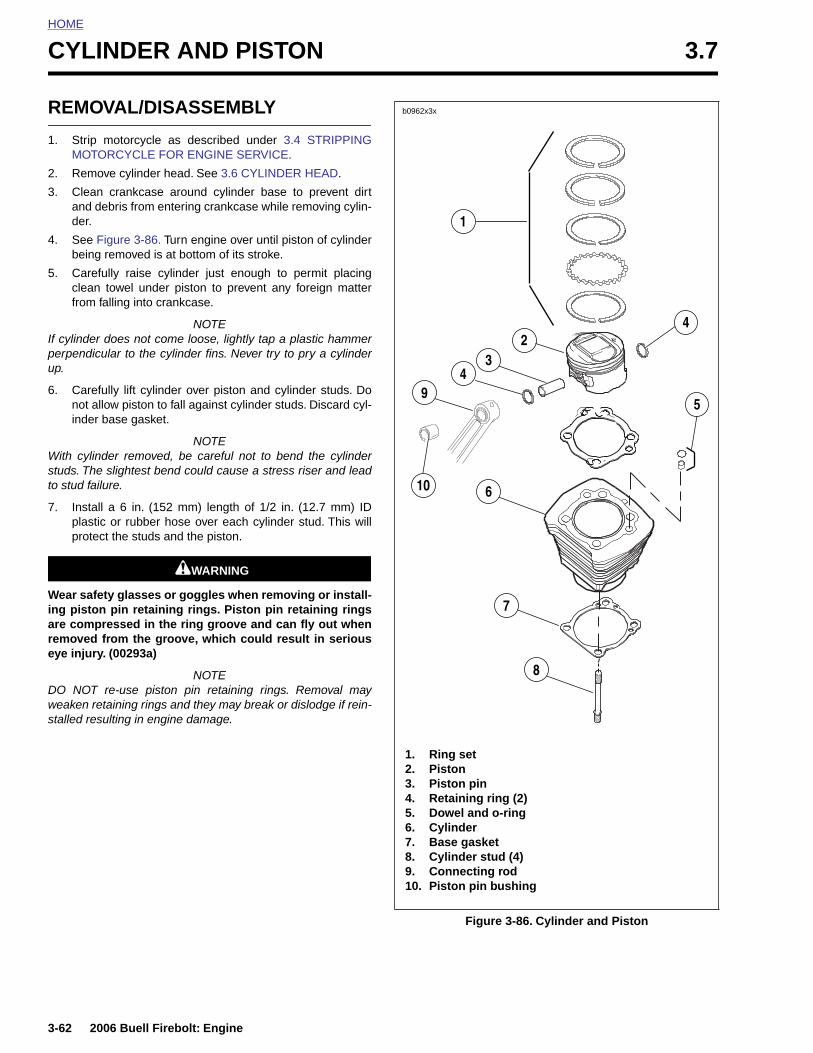
HOME
CYLINDER AND PISTON 3.7
REMO
1. Strip MOTO
2. Remo
3. Cleanand dder.
4. See Fbeing
5. Carefcleanfrom
If cylinderperpendicup.
6. Carefnot alinder
With cylinstuds. Theto stud fai
7. Instalplastiprote
Wear safeing pistoare compremoved eye injury
DO NOT weaken restalled res
3-62
VAL/DISASSEMBLY
motorcycle as described under 3.4 STRIPPINGRCYCLE FOR ENGINE SERVICE.
ve cylinder head. See 3.6 CYLINDER HEAD.
crankcase around cylinder base to prevent dirtebris from entering crankcase while removing cylin-
igure 3-86. Turn engine over until piston of cylinder removed is at bottom of its stroke.
ully raise cylinder just enough to permit placing towel under piston to prevent any foreign matterfalling into crankcase.
NOTE does not come loose, lightly tap a plastic hammerular to the cylinder fins. Never try to pry a cylinder
ully lift cylinder over piston and cylinder studs. Dolow piston to fall against cylinder studs. Discard cyl- base gasket.
NOTEder removed, be careful not to bend the cylinder slightest bend could cause a stress riser and leadlure.
l a 6 in. (152 mm) length of 1/2 in. (12.7 mm) IDc or rubber hose over each cylinder stud. This willct the studs and the piston.
11WARNING1WARNING
ty glasses or goggles when removing or install-n pin retaining rings. Piston pin retaining ringsressed in the ring groove and can fly out whenfrom the groove, which could result in serious. (00293a)
NOTEre-use piston pin retaining rings. Removal maytaining rings and they may break or dislodge if rein-ulting in engine damage.
1. Ring set2. Piston
1
42
3
10
5
49
6
7
8
b0962x3x
2006 Buell Firebolt: Engine
Figure 3-86. Cylinder and Piston
3. Piston pin4. Retaining ring (2)5. Dowel and o-ring6. Cylinder7. Base gasket8. Cylinder stud (4)9. Connecting rod10. Piston pin bushing
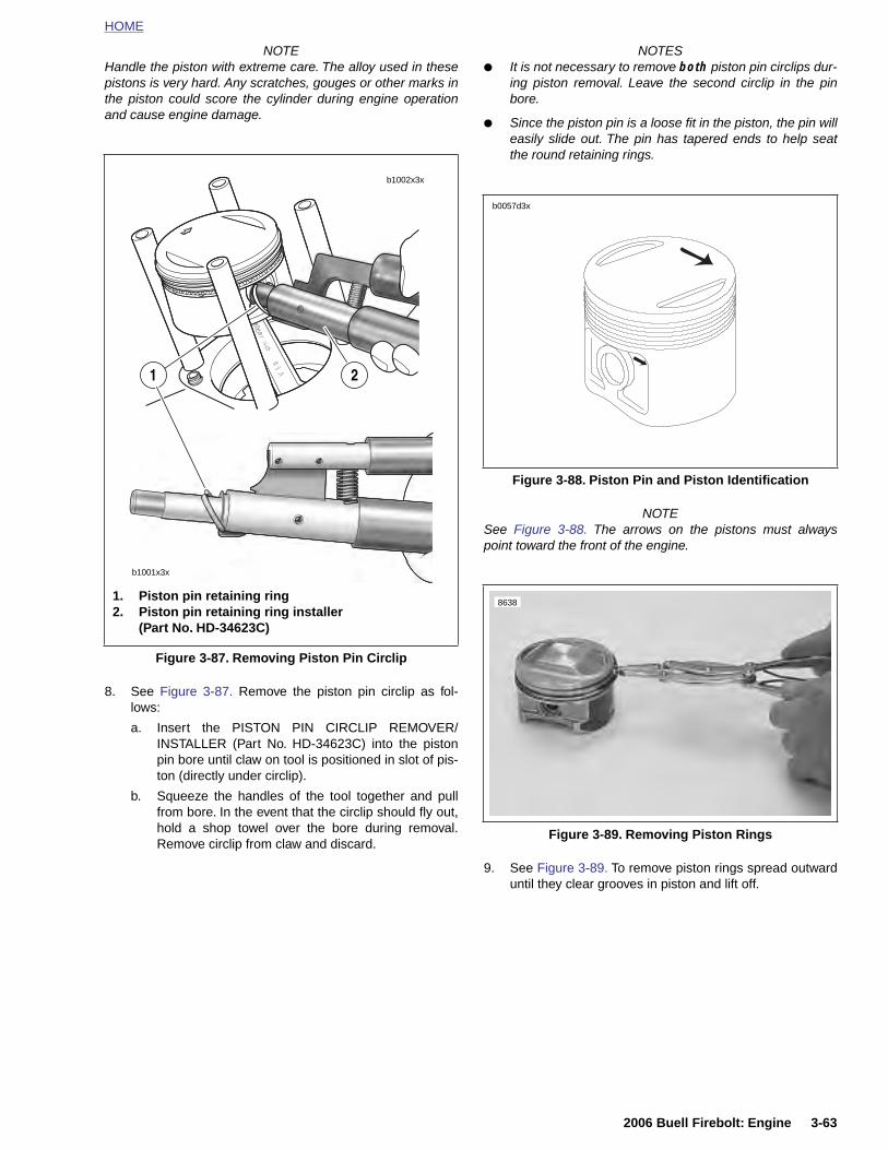
HOME
NOTEHandle the piston with extreme care. The alloy used in thesepistons is very hard. Any scratches, gouges or other marks inthe piston could score the cylinder during engine operationand cause engine damage.
8. See Figure 3-87. Remove the piston pin circlip as fol-lows:
a. Insert the PISTON PIN CIRCLIP REMOVER/INSTALLER (Part No. HD-34623C) into the pistonpin bore until claw on tool is positioned in slot of pis-ton (directly under circlip).
NOTES● It is not necessary to remove both piston pin circlips dur-
ing piston removal. Leave the second circlip in the pinbore.
● Since the piston pin is a loose fit in the piston, the pin willeasily slide out. The pin has tapered ends to help seatthe round retaining rings.
NOTESee Figure 3-88. The arrows on the pistons must alwayspoint toward the front of the engine.
Figure 3-87. Removing Piston Pin Circlip
b1002x3x
b1001x3x
1. Piston pin retaining ring2. Piston pin retaining ring installer
(Part No. HD-34623C)
1 2
Figure 3-88. Piston Pin and Piston Identification
b0057d3x
8638
2006 Buell Firebolt: Engine 3-63
b. Squeeze the handles of the tool together and pullfrom bore. In the event that the circlip should fly out,hold a shop towel over the bore during removal.Remove circlip from claw and discard.
9. See Figure 3-89. To remove piston rings spread outwarduntil they clear grooves in piston and lift off.
Figure 3-89. Removing Piston Rings
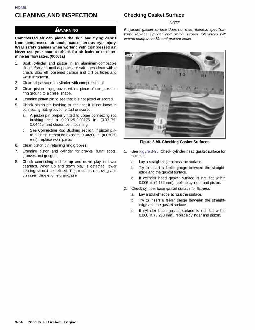
HOME
CLEANING AND INSPECTION Checking Gasket SurfaceNOTE
11WARNING1WARNING
Compressed air can pierce the skin and flying debrisfrom compressed air could cause serious eye injury.Wear safety glasses when working with compressed air.Never use your hand to check for air leaks or to deter-mine air flow rates. (00061a)
1. Soak cylinder and piston in an aluminum-compatiblecleaner/solvent until deposits are soft, then clean with abrush. Blow off loosened carbon and dirt particles andwash in solvent.
2. Clean oil passage in cylinder with compressed air.
3. Clean piston ring grooves with a piece of compressionring ground to a chisel shape.
4. Examine piston pin to see that it is not pitted or scored.
5. Check piston pin bushing to see that it is not loose inconnecting rod, grooved, pitted or scored.
a. A piston pin properly fitted to upper connecting rodbushing has a 0.00125-0.00175 in. (0.03175-0.04445 mm) clearance in bushing.
b. See Connecting Rod Bushing section. If piston pin-to-bushing clearance exceeds 0.00200 in. (0.05080mm), replace worn parts.
6. Clean piston pin retaining ring grooves.
7. Examine piston and cylinder for cracks, burnt spots,grooves and gouges.
8. Check connecting rod for up and down play in lowerbearings. When up and down play is detected, lowerbearing should be refitted. This requires removing anddisassembling engine crankcase.
If cylinder gasket surface does not meet flatness specifica-tions, replace cylinder and piston. Proper tolerances willextend component life and prevent leaks.
1. See Figure 3-90. Check cylinder head gasket surface forflatness.
a. Lay a straightedge across the surface.
b. Try to insert a feeler gauge between the straight-edge and the gasket surface.
c. If cylinder head gasket surface is not flat within0.006 in. (0.152 mm), replace cylinder and piston.
2. Check cylinder base gasket surface for flatness.
a. Lay a straightedge across the surface.
b. Try to insert a feeler gauge between the straight-edge and the gasket surface.
c. If cylinder base gasket surface is not flat within0.008 in. (0.203 mm), replace cylinder and piston.
Figure 3-90. Checking Gasket Surfaces
6611
3-64 2006 Buell Firebolt: Engine
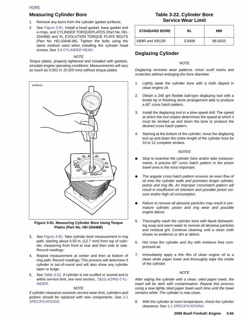
HOME
Measuring Cylinder Bore1. Remove any burrs from the cylinder gasket surfaces.
2. See Figure 3-91. Install a head gasket, base gasket ando-rings, and CYLINDER TORQUEPLATES (Part No. HD-33446B) and XL EVOLUTION TORQUE PLATE BOLTS(Part No. HD-33446-86). Tighten the bolts using thesame method used when installing the cylinder headscrews. See 3.6 CYLINDER HEAD.
NOTETorque plates, properly tightened and installed with gaskets,simulate engine operating conditions. Measurements will varyas much as 0.001 in. (0.025 mm) without torque plates.
Deglazing Cylinder
NOTE
Deglazing removes wear patterns, minor scuff marks andscratches without enlarging the bore diameter.
1. Lightly swab the cylinder bore with a cloth dipped inclean engine oil.
2. Obtain a 240 grit flexible ball-type deglazing tool with abristle tip or finishing stone arrangement able to producea 60˚ cross hatch pattern.
3. Install the deglazing tool in a slow-speed drill. The speedat which the tool rotates determines the speed at which itmust be stroked up and down the bore to produce thedesired cross hatch pattern.
4. Starting at the bottom of the cylinder, move the deglazingtool up and down the entire length of the cylinder bore for10 to 12 complete strokes.
NOTES
● Stop to examine the cylinder bore and/or take measure-ments. A precise 60˚ cross hatch pattern in the pistontravel area is the most important.
● The angular cross hatch pattern ensures an even flow ofoil onto the cylinder walls and promotes longer cylinder,piston and ring life. An Improper crosshatch pattern willresult in insufficient oil retention and possible piston sei-zure and/or high oil consumption.
● Failure to remove all abrasive particles may result in pre-mature cylinder, piston and ring wear and possibleengine failure.
5. Thoroughly wash the cylinder bore with liquid dishwash-
b0306x3x
Table 3-22. Cylinder Bore Service Wear Limit
STANDARD BORE IN. MM
XB9R and XB12R 3.5008 88.9203
2006 Buell Firebolt: Engine 3-65
3. See Figure 3-91. Take cylinder bore measurement in ringpath, starting about 0.50 in. (12.7 mm) from top of cylin-der, measuring from front to rear and then side to side.Record readings.
4. Repeat measurement at center and then at bottom ofring path. Record readings. This process will determine ifcylinder is out-of-round and will also show any cylindertaper or bulge.
5. See Table 3-22. If cylinder is not scuffed or scored and iswithin service limit, see next section, DEGLAZING CYL-INDER.
NOTEIf cylinder clearance exceeds service wear limit, cylinders andpistons should be replaced with new components. See 3.1SPECIFICATIONS.
ing soap and warm water to remove all abrasive particlesand residual grit. Continue cleaning until a clean clothshows no evidence or dirt or debris.
6. Hot rinse the cylinder and dry with moisture free com-pressed air.
7. Immediately apply a thin film of clean engine oil to aclean white paper towel and thoroughly wipe the insideof the cylinder.
NOTE
After wiping the cylinder with a clean, oiled paper towel, thetowel will be dark with contamination. Repeat this processusing a new lightly oiled paper towel each time until the towelremains white. The cylinder is now clean.
8. With the cylinder at room temperature, check the cylinderclearance. See 3.1 SPECIFICATIONS.
Figure 3-91. Measuring Cylinder Bore Using Torque Plates (Part No. HD-33446B)

HOME
Fitting Piston Rings2783b
NOTESSee Figure 3-92. Piston rings are of two types: compression(1, 2) and oil control (3). The two compression rings are posi-tioned in the two upper piston ring grooves. The dot (4) on thesecond compression ring must face upward.
1. See Figure 3-93. Insert the new ring into the cylinder,square it in the bore using the top of the piston and mea-sure the ring end gap with a feeler gauge. Do not use thering if the end gap does not fall within the following spec-ifications, See Table 3-23.
NOTES● The same piston may be used if cylinder bore was not
changed, unless it is scuffed or grooved. If re-using pis-ton, replace piston rings and hone the cylinder walls witha No. 240 grit flexible hone to facilitate ring seating.
● Piston ring sets must be properly fitted to piston and cyl-inder: Ring sets are available to fit standard and oversizepistons.
Figure 3-92. Piston Rings
1. Top compression ring – Install either side up2. Second compression ring – Install dot toward top3. Oil control rings4. Dot
2
13
6612
4
Figure 3-93. Measuring Ring End Gap
Table 3-23. Piston Ring End Gap
Ring Type inches mm
Top compression ring 0.010 - 0.020 0.25 - 0.51
2nd compression ring 0.014 - 0.024 0.36 - 0.61
Oil control ring rails 0.010 - 0.050 0.25 - 1.27
3-66 2006 Buell Firebolt: Engine

HOME
2. See Figure 3-94. Apply engine oil to piston grooves. UseTRANSMISSION SHAFT RETAINING RING PLIERS(Part No. J-5586) to slip compression rings over pistoninto their respective grooves. Be extremely careful not toover expand, twist rings or damage piston surface wheninstalling rings.
NOTEInstall second compression ring with dot towards top.
4. See Figure 3-96. Check for proper side clearance withthickness gauge, as shown. See 3.1 SPECIFICATIONS.
NOTEIf the ring grooves are clean and the side play is still not cor-rect, replace the rings, the piston or both.
Figure 3-94. Installing Piston Rings Transmission Shaft Retaining Ring Pliers (Part No. J-5586)
Figure 3-95. Ring End Gap Position
8638
x0486x3x
Piston Pin
Position ring end gaps at arrows
Front
Rear
Figure 3-96. Measuring Ring Clearance in Groove
10562
2006 Buell Firebolt: Engine 3-67
3. See Figure 3-95. Install rings so end gaps of adjacentrings are a minimum of 90° apart. Ring gaps are not tobe within 10° of the thrust face centerline.
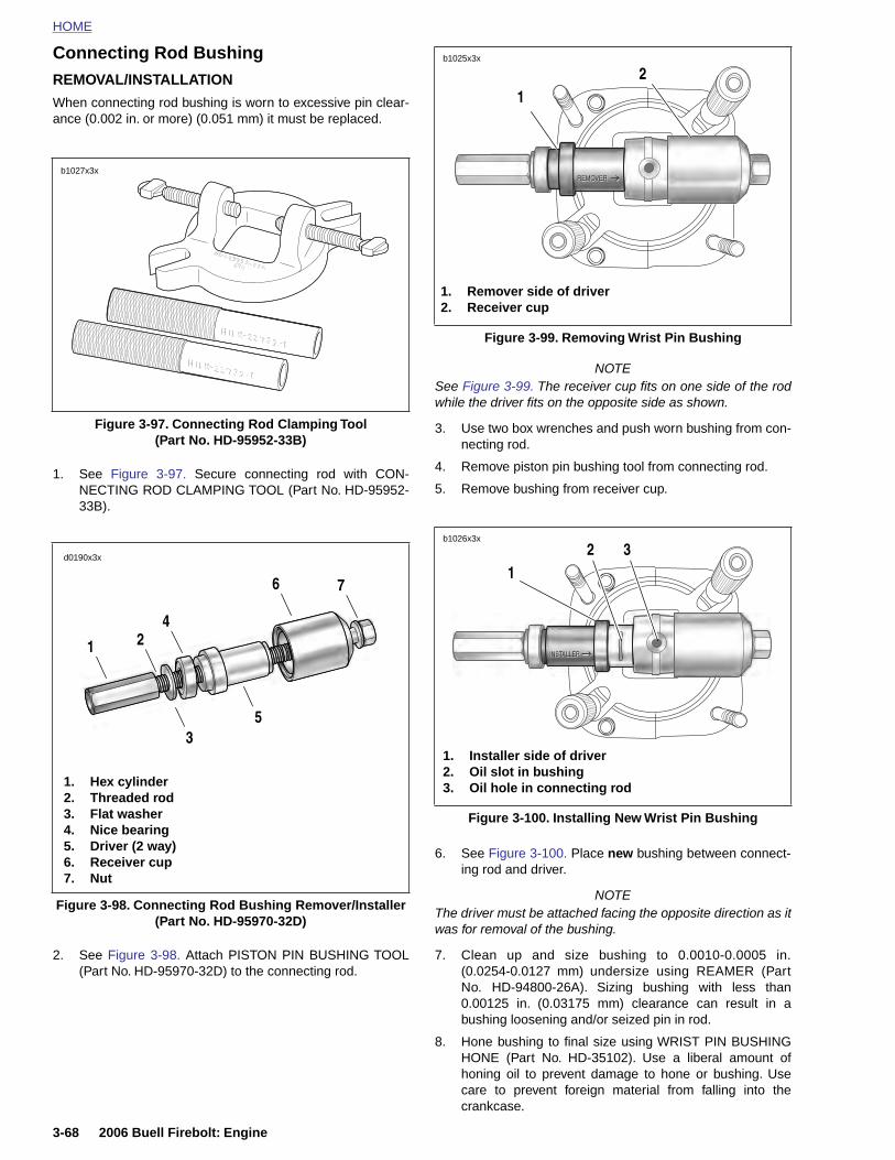
HOME
Connecting Rod BushingREMOVAL/INSTALLATION 2
b1025x3x
When connecting rod bushing is worn to excessive pin clear-ance (0.002 in. or more) (0.051 mm) it must be replaced.
1. See Figure 3-97. Secure connecting rod with CON-NECTING ROD CLAMPING TOOL (Part No. HD-95952-33B).
NOTESee Figure 3-99. The receiver cup fits on one side of the rodwhile the driver fits on the opposite side as shown.
3. Use two box wrenches and push worn bushing from con-necting rod.
4. Remove piston pin bushing tool from connecting rod.
5. Remove bushing from receiver cup.
Figure 3-97. Connecting Rod Clamping Tool(Part No. HD-95952-33B)
b1027x3x
1. Hex cylinder2. Threaded rod3. Flat washer4. Nice bearing5. Driver (2 way)
d0190x3x
1
3
4
6 7
5
2
Figure 3-99. Removing Wrist Pin Bushing
Figure 3-100. Installing New Wrist Pin Bushing
1. Remover side of driver2. Receiver cup
1
1. Installer side of driver2. Oil slot in bushing3. Oil hole in connecting rod
321
b1026x3x
3-68 2006 Buell Firebolt: Engine
2. See Figure 3-98. Attach PISTON PIN BUSHING TOOL(Part No. HD-95970-32D) to the connecting rod.
6. See Figure 3-100. Place new bushing between connect-ing rod and driver.
NOTEThe driver must be attached facing the opposite direction as itwas for removal of the bushing.
7. Clean up and size bushing to 0.0010-0.0005 in.(0.0254-0.0127 mm) undersize using REAMER (PartNo. HD-94800-26A). Sizing bushing with less than0.00125 in. (0.03175 mm) clearance can result in abushing loosening and/or seized pin in rod.
8. Hone bushing to final size using WRIST PIN BUSHINGHONE (Part No. HD-35102). Use a liberal amount ofhoning oil to prevent damage to hone or bushing. Usecare to prevent foreign material from falling into thecrankcase.
Figure 3-98. Connecting Rod Bushing Remover/Installer(Part No. HD-95970-32D)
6. Receiver cup7. Nut
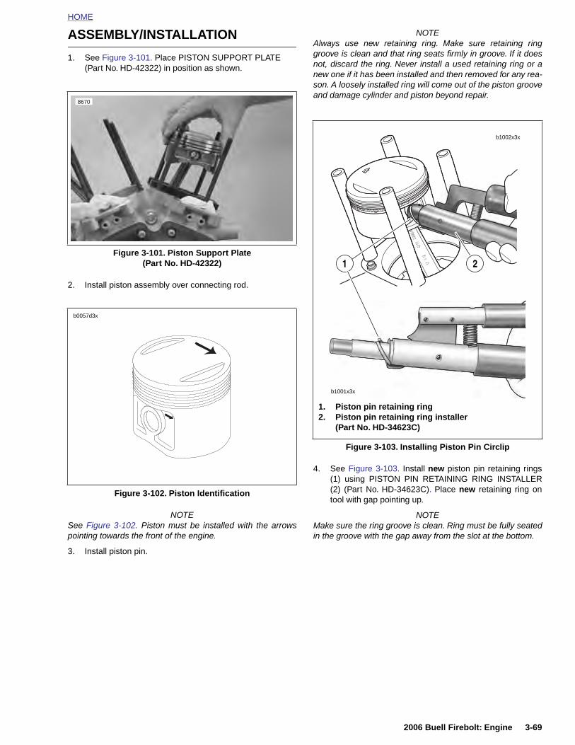
HOME
ASSEMBLY/INSTALLATION
1. See Figure 3-101. Place PISTON SUPPORT PLATE(Part No. HD-42322) in position as shown.
2. Install piston assembly over connecting rod.
NOTEAlways use new retaining ring. Make sure retaining ringgroove is clean and that ring seats firmly in groove. If it doesnot, discard the ring. Never install a used retaining ring or anew one if it has been installed and then removed for any rea-son. A loosely installed ring will come out of the piston grooveand damage cylinder and piston beyond repair.
4. See Figure 3-103. Install new piston pin retaining rings(1) using PISTON PIN RETAINING RING INSTALLER(2) (Part No. HD-34623C). Place new retaining ring ontool with gap pointing up.
Figure 3-101. Piston Support Plate(Part No. HD-42322)
Figure 3-102. Piston Identification
8670
b0057d3x
Figure 3-103. Installing Piston Pin Circlip
b1002x3x
b1001x3x
1. Piston pin retaining ring2. Piston pin retaining ring installer
(Part No. HD-34623C)
1 2
2006 Buell Firebolt: Engine 3-69
NOTESee Figure 3-102. Piston must be installed with the arrowspointing towards the front of the engine.
3. Install piston pin.
NOTEMake sure the ring groove is clean. Ring must be fully seatedin the groove with the gap away from the slot at the bottom.
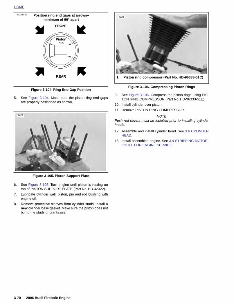
HOME
Position ring end gaps at arrows–minimum of 90° apart
a0101x3x8671
5. See Figure 3-104. Make sure the piston ring end gapsare properly positioned as shown.
6. See Figure 3-105. Turn engine until piston is resting ontop of PISTON SUPPORT PLATE (Part No. HD-42322).
7. Lubricate cylinder wall, piston, pin and rod bushing withengine oil.
8. Remove protective sleeves from cylinder studs. Install anew cylinder base gasket. Make sure the piston does notbump the studs or crankcase.
9. See Figure 3-106. Compress the piston rings using PIS-TON RING COMPRESSOR (Part No. HD-96333-51E).
10. Install cylinder over piston.
11. Remove PISTON RING COMPRESSOR.
NOTEPush rod covers must be installed prior to installing cylinderheads.
12. Assemble and install cylinder head. See 3.6 CYLINDERHEAD.
13. Install assembled engine. See 3.4 STRIPPING MOTOR-CYCLE FOR ENGINE SERVICE.
Figure 3-104. Ring End Gap Position
Figure 3-105. Piston Support Plate
FRONT
Piston pin
REAR
8672
Figure 3-106. Compressing Piston Rings
1. Piston ring compressor (Part No. HD-96333-51C)
3-70 2006 Buell Firebolt: Engine
HOME
L
C
Cmmct
C
Aaps(kswo
St
UBRICATION SYSTEM 3.8
HECKING AND ADDING OIL
heck engine oil level in oil reservoir at least once every 500iles (800 km). Check level more frequently if engine usesore oil than normal or if vehicle is operated under harsh
onditions. Check oil when engine is warmed up to operatingemperature (see Hot Check).
HANGING OIL AND FILTER
fter a new engine has run its first 1000 miles (1600 km) andt 5000 miles (8000 km) intervals or annually thereafter, com-letely drain oil reservoir of used oil. If riding habits includeevere dust conditions, operation at temperature above 80° F26.7° C), extensive idling, speeds in excess of 65 mph (105ph) and /or extensive two up riding or similar loads the oilhould be changed at 2500 mile (4000 km) intervals. Refillith fresh oil. Always change oil filter when changing engineil.
NOTE
ee 1.6 ENGINE LUBRICATION SYSTEM for more informa-ion on checking oil level and changing oil and filter.
WINTER LUBRICATION
Normal fuel combustion in a gasoline engine produces watervapor and carbon dioxide along with other gases and particu-lates. When first starting and warming an engine, some of thewater vapor that gets into the engine crankcase condenses toform liquid water. If the engine is driven long enough to thor-oughly warm the crankcase, most of this liquid water is againvaporized and exhausted through the crankcase breathersystem.
A moderately driven vehicle making short runs may not beable to vacate water vapors allowing liquid water to accumu-late in the oil reservoir. This is especially true if the vehicle isoperated in cold weather. In freezing weather, an accumula-tion of water in the engine oil may become slush or ice, whichcan block oil lines and lead to severe engine damage. Waterremaining in the engine oil for long periods of time can forman acidic sludge that is corrosive to metal engine parts andcauses accelerated wear of moving components.
In winter the oil change interval should be shorter than nor-mal. The colder the weather, the shorter the recommended oilchange interval. A vehicle used only for short runs in coldweather must have the engine oil drained frequently.
2006 Buell Firebolt: Engine 3-71

HOME
OIL HOSE ROUTING AND OIL RESERVOIR 3.9
GENE
See Figuwhich servoir, the vThe returnpump (14clamp (13
11964a
11963a
3-72
1. S2. V3. F4. R5. F6. F7. O
RAL
re 3-107. Engine oil runs through the swingarmves as the oil reservoir. From the front of the reser-ent line (2) runs to the rear of the gearcase cover. line (4) and the feed line (3) run forward to the oil). Three rubberized clamps (12) and one plastic) secure the lines in place.
The oil cooler feed line (5) exits the front of the oil pump androutes across the front of the engine to the oil cooler on theleft front side of the crankcases. The oil cooler return line (6)then exits the oil cooler and connects to the oil filter housingon the right front side of the crankcases.
The vent line (2) connects to an elbow fitting at the rear of thegearcase cover. See 3.14 OILING SYSTEM.
2
5
43
4
10
1
2
3
8
9
6
4
11972
11
12
12
13
12
14
2006 Buell Firebolt: Engine
Figure 3-107. Oil Lines and Connections (Typical)
wingarm/Oil reservoirent oil lineeed oil lineeturn oil lineeed oil line from oil pump to oil coolereed oil line from oil cooler to crankcaseil tank drain plug
8. Oil Filter9. Front muffler mount10. Rear muffler bracket11. Cable, interactive exhaust12. P-clamp13. Oil line clamp14. Oil pump
73

HOME
O
R
1
2
3
4
5
6
IL LINE FITTINGS 3.10
EMOVAL
. See Figure 3-108. Close the OIL LINE REMOVER (B-41623-B) over the oil line. Match the notches in the toolflange to the U-bends in the spring clip.
. See Figure 3-109. Rotate the tool to expand the springclip out of the groove in the oil fitting.
. Using finger and thumb to hold the OIL LINE REMOVER(B-41623-B) squarely against the fitting to keep thespring clip expanded. Use only enough pressure to holdthe tool square. Excess pressure will prevent simulta-neously pulling the line and tool from the fitting.
. Pull the oil line and the tool from the fitting.
. Repeat to remove the remaining oil lines.
. Remove oil line fittings and plug the holes until they canbe replaced.
PART NO. SPECIALTY TOOL
B-41623-B Oil line remover
Figure 3-108. Oil Line Remover (B-41623-B)
11261
10369
2006 Buell Firebolt: Engine 3-73
Figure 3-109. Oil Line Fitting with Spring Clip
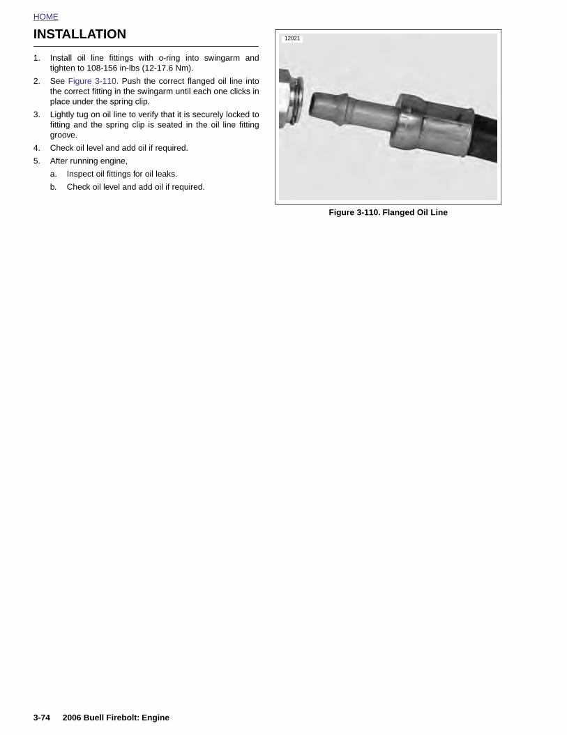
HOME
INSTALLATION
12021
1. Install oil line fittings with o-ring into swingarm andtighten to 108-156 in-lbs (12-17.6 Nm).
2. See Figure 3-110. Push the correct flanged oil line intothe correct fitting in the swingarm until each one clicks inplace under the spring clip.
3. Lightly tug on oil line to verify that it is securely locked tofitting and the spring clip is seated in the oil line fittinggroove.
4. Check oil level and add oil if required.
5. After running engine,
a. Inspect oil fittings for oil leaks.
b. Check oil level and add oil if required.
Figure 3-110. Flanged Oil Line
3-74 2006 Buell Firebolt: Engine
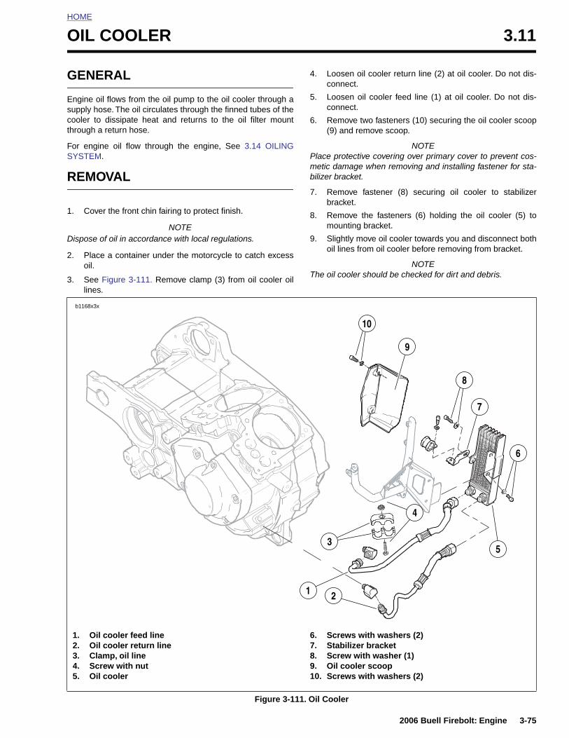
HOME
O
G
Esct
FS
R
1
D
2
3
IL COOLER 3.11
ENERAL
ngine oil flows from the oil pump to the oil cooler through aupply hose. The oil circulates through the finned tubes of theooler to dissipate heat and returns to the oil filter mounthrough a return hose.
or engine oil flow through the engine, See 3.14 OILINGYSTEM.
EMOVAL
. Cover the front chin fairing to protect finish.
NOTEispose of oil in accordance with local regulations.
. Place a container under the motorcycle to catch excessoil.
. See Figure 3-111. Remove clamp (3) from oil cooler oillines.
4. Loosen oil cooler return line (2) at oil cooler. Do not dis-connect.
5. Loosen oil cooler feed line (1) at oil cooler. Do not dis-connect.
6. Remove two fasteners (10) securing the oil cooler scoop(9) and remove scoop.
NOTEPlace protective covering over primary cover to prevent cos-metic damage when removing and installing fastener for sta-bilizer bracket.
7. Remove fastener (8) securing oil cooler to stabilizerbracket.
8. Remove the fasteners (6) holding the oil cooler (5) tomounting bracket.
9. Slightly move oil cooler towards you and disconnect bothoil lines from oil cooler before removing from bracket.
NOTEThe oil cooler should be checked for dirt and debris.
6
7
8
9
10
b1168x3x
2006 Buell Firebolt: Engine 3-75
Figure 3-111. Oil Cooler
1. Oil cooler feed line2. Oil cooler return line3. Clamp, oil line4. Screw with nut5. Oil cooler
6. Screws with washers (2)7. Stabilizer bracket8. Screw with washer (1)9. Oil cooler scoop10. Screws with washers (2)
21
3
4
5
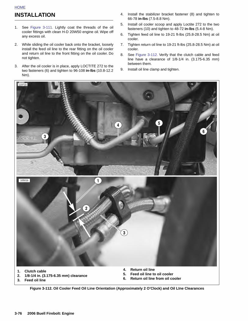
HOME
INSTALLATION
4. Install the stabilizer bracket fastener (8) and tighten to66-78
in-lbs
(7.5-8.8 Nm).
5. Install oil cooler scoop and apply Loctite 272 to the two
1. See Figure 3-111. Lightly coat the threads of the oilcooler fittings with clean H-D 20W50 engine oil. Wipe offany excess oil.
2. While sliding the oil cooler back onto the bracket, looselyinstall the feed oil line to the rear fitting on the oil coolerand return oil line to the front fitting on the oil cooler. Donot tighten.
3. After the oil cooler is in place, apply LOCTITE 272 to thetwo fasteners (6) and tighten to 96-108 in-lbs (10.8-12.2Nm).
fasteners (10) and tighten to 48-72 in-lbs (5.4-8 Nm).
6. Tighten feed oil line to 19-21 ft-lbs (25.8-28.5 Nm) at oilcooler.
7. Tighten return oil line to 19-21 ft-lbs (25.8-28.5 Nm) at oilcooler.
8. See Figure 3-112. Verify that the clutch cable and feedline have a clearance of 1/8-1/4 in. (3.175-6.35 mm)between them.
9. Install oil line clamp and tighten.
11971b
10501b 1
2
3
4
3
5
6
3-76 2006 Buell Firebolt: Engine
Figure 3-112. Oil Cooler Feed Oil Line Orientation (Approximately 2 O’Clock) and Oil LIne Clearances
1. Clutch cable2. 1/8-1/4 in. (3.175-6.35 mm) clearance3. Feed oil line
4. Return oil line5. Feed oil line to oil cooler6. Return oil line from oil cooler
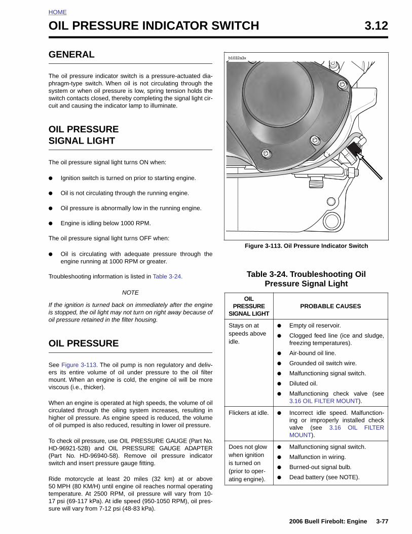
HOME
O
G
Tpssc
OS
T
●
●
●
●
T
●
T
Iio
O
S
IL PRESSURE INDICATOR SWITCH 3.12
ENERAL
he oil pressure indicator switch is a pressure-actuated dia-hragm-type switch. When oil is not circulating through theystem or when oil pressure is low, spring tension holds thewitch contacts closed, thereby completing the signal light cir-uit and causing the indicator lamp to illuminate.
IL PRESSUREIGNAL LIGHT
he oil pressure signal light turns ON when:
Ignition switch is turned on prior to starting engine.
Oil is not circulating through the running engine.
Oil pressure is abnormally low in the running engine.
Engine is idling below 1000 RPM.
he oil pressure signal light turns OFF when:
Oil is circulating with adequate pressure through theengine running at 1000 RPM or greater.
roubleshooting information is listed in Table 3-24.
NOTE
f the ignition is turned back on immediately after the engines stopped, the oil light may not turn on right away because ofil pressure retained in the filter housing.
IL PRESSURE
ee Figure 3-113. The oil pump is non regulatory and deliv-
s
Figure 3-113. Oil Pressure Indicator Switch
Table 3-24. Troubleshooting Oil Pressure Signal Light
OILPRESSURE
SIGNAL LIGHTPROBABLE CAUSES
Stays on at speeds above idle.
● Empty oil reservoir.
● Clogged feed line (ice and sludge,freezing temperatures).
● Air-bound oil line.
● Grounded oil switch wire.
b1032a3x
2006 Buell Firebolt: Engine 3-77
ers its entire volume of oil under pressure to the oil filtermount. When an engine is cold, the engine oil will be moreviscous (i.e., thicker).
When an engine is operated at high speeds, the volume of oilcirculated through the oiling system increases, resulting inhigher oil pressure. As engine speed is reduced, the volumeof oil pumped is also reduced, resulting in lower oil pressure.
To check oil pressure, use OIL PRESSURE GAUGE (Part No.HD-96921-52B) and OIL PRESSURE GAUGE ADAPTER(Part No. HD-96940-58). Remove oil pressure indicatorswitch and insert pressure gauge fitting.
Ride motorcycle at least 20 miles (32 km) at or above50 MPH (80 KM/H) until engine oil reaches normal operatingtemperature. At 2500 RPM, oil pressure will vary from 10-17 psi (69-117 kPa). At idle speed (950-1050 RPM), oil pres-sure will vary from 7-12 psi (48-83 kPa).
● Malfunctioning signal switch.
● Diluted oil.
● Malfunctioning check valve (see3.16 OIL FILTER MOUNT).
Flickers at idle. ● Incorrect idle speed. Malfunction-ing or improperly installed checkvalve (see 3.16 OIL FILTERMOUNT).
Does not glow when ignition is turned on (prior to oper-ating engine).
● Malfunctioning signal switch.
● Malfunction in wiring.
● Burned-out signal bulb.
● Dead battery (see NOTE).
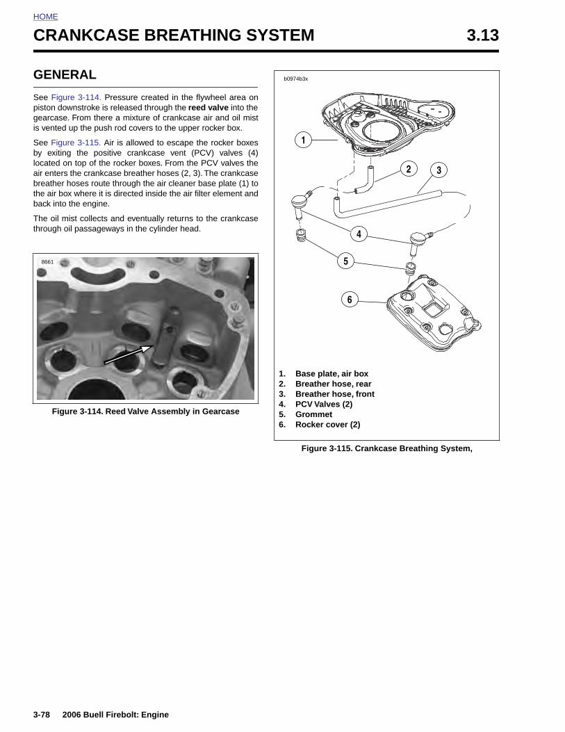
HOME
CRANKCASE BREATHING SYSTEM 3.13
GENE
See Figurpiston dowgearcase.is vented
See Figurby exitinglocated onair enters breather hthe air boxback into
The oil mthrough o
Figu
8661
3-78
RAL
e 3-114. Pressure created in the flywheel area onnstroke is released through the reed valve into the
From there a mixture of crankcase air and oil mistup the push rod covers to the upper rocker box.
e 3-115. Air is allowed to escape the rocker boxes the positive crankcase vent (PCV) valves (4) top of the rocker boxes. From the PCV valves thethe crankcase breather hoses (2, 3). The crankcaseoses route through the air cleaner base plate (1) to where it is directed inside the air filter element and
the engine.
ist collects and eventually returns to the crankcaseil passageways in the cylinder head.
re 3-114. Reed Valve Assembly in Gearcase
Figure 3-115. Crankcase Breathing System,
1. Base plate, air box2. Breather hose, rear3. Breather hose, front4. PCV Valves (2)5. Grommet6. Rocker cover (2)
32
4
5
1
6
b0974b3x
2006 Buell Firebolt: Engine
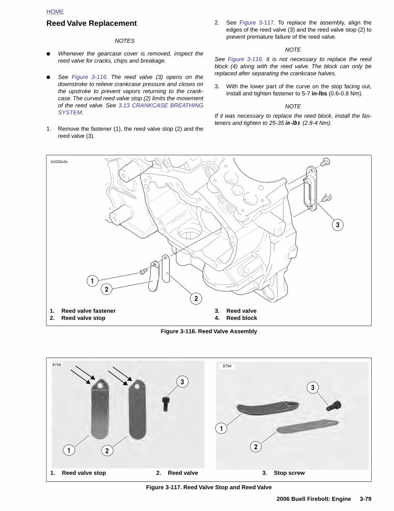
HOME
Reed Valve Replacement
NOTES
● Whenever the gearcase cover is removed, inspect thereed valve for cracks, chips and breakage.
● See Figure 3-116. The reed valve (3) opens on thedownstroke to relieve crankcase pressure and closes onthe upstroke to prevent vapors returning to the crank-case. The curved reed valve stop (2) limits the movementof the reed valve. See 3.13 CRANKCASE BREATHINGSYSTEM.
1. Remove the fastener (1), the reed valve stop (2) and thereed valve (3).
2. See Figure 3-117. To replace the assembly, align theedges of the reed valve (3) and the reed valve stop (2) toprevent premature failure of the reed valve.
NOTE
See Figure 3-116. It is not necessary to replace the reedblock (4) along with the reed valve. The block can only bereplaced after separating the crankcase halves.
3. With the lower part of the curve on the stop facing out,install and tighten fastener to 5-7 in-lbs (0.6-0.8 Nm).
NOTE
If it was necessary to replace the reed block, install the fas-teners and tighten to 25-35 in-lbs (2.8-4 Nm).
Figure 3-116. Reed Valve Assembly
1. Reed valve fastener2. Reed valve stop
3. Reed valve4. Reed block
3
2
1
b1033x3x
2
2006 Buell Firebolt: Engine 3-79
Figure 3-117. Reed Valve Stop and Reed Valve
1. Reed valve stop 2. Reed valve 3. Stop screw
3
1 2
8759
1
2
8794
3
HOME
OILING SYSTEM 3.14
GENE
1. Oil is oil puand fi
See 3.15 pump sets
2. The fthe ex
3. From
4. Throu
5. Oil ethrouoil filtconne
6. Adeqthe opress
7. Oil floThe c
8. With feed g
9. Oil enand fl
10. Oil entravelflywhpin to
3-80
RAL
gravity-fed from the oil reservoir to the gerotor-stylemp through a feed hose. Oil enters the feed sectionlls a cavity located under the feed pump.
NOTEOIL PUMP for a complete explanation of the gerotor.
eed pump transfers oil from the inlet cavity throughternal steel line to the oil cooler.
the oil cooler oil flows to the oil filter mount.
gh the filter mount cavity oil flows to the oil filter.
nters the peripheral cavity of the oil filter, passesgh the filtering medium into the central cavity of theer, and flows into the filter adapter (fitting whichcts filter to filter mount).
uate oil pressure in the filter mount cavity activatesil pressure signal light switch and shuts off the oilure signal light.
wing from the filter adapter opens the check ball.heck ball opens at 4-6 psi (28-41 kPa) oil pressure.
the check ball open, oil flows into the crankcasealley.
ters an intersecting passage in the gearcase coverow is then routed to the pinion bushing.
ters a hole in the end of the pinion gear shaft ands to the right flywheel where it is routed through theeel to the crankpin. Oil is forced through the crank- properly lubricate the rod bearing assembly.
11. Oil flow then continues through the gearcase cover to themain feed galley at the top of the gearcase cover. Drilledpassages in the crankcase intersect the main feed galleyand carry oil to all hydraulic lifters and piston jets.
12. Oil flows up passages in the push rods to the rocker armshafts and bushings.
13. The valve stems are lubricated by oil supplied throughdrilled oil holes in the rocker arms.
14. Oil collected in the push rod areas of the cylinder headsflows down the push rod cover, through drain holes in thetappet blocks and into the gearcase. After providing lubri-cation to the gearcase components oil returns to thescavenge section of the oil pump through a passagelocated in the top of the pump. Oil is then returned to theoil tank.
15. Feed oil to the rocker area is returned to the crankcasethrough a passage in the head and cylinder.
16. Oil collected in the sump is splash-fed to the pistons, cyl-inder walls and flywheel components.
17. A pair of piston oil jets cools the bottoms of the pistonswith a spray of oil.
18. Oil collected in the sump area returns to the scavengesection of the oil pump through a passage located in therear section of the sump. Oil flow to the pump is accom-plished by the scavenging effect of the pump and by thepressure created by the downward stroke of the pistons.
19. Return oil fills a cavity above the pump's return gears.The return gears pump oil back to the oil reservoir.
2006 Buell Firebolt: Engine
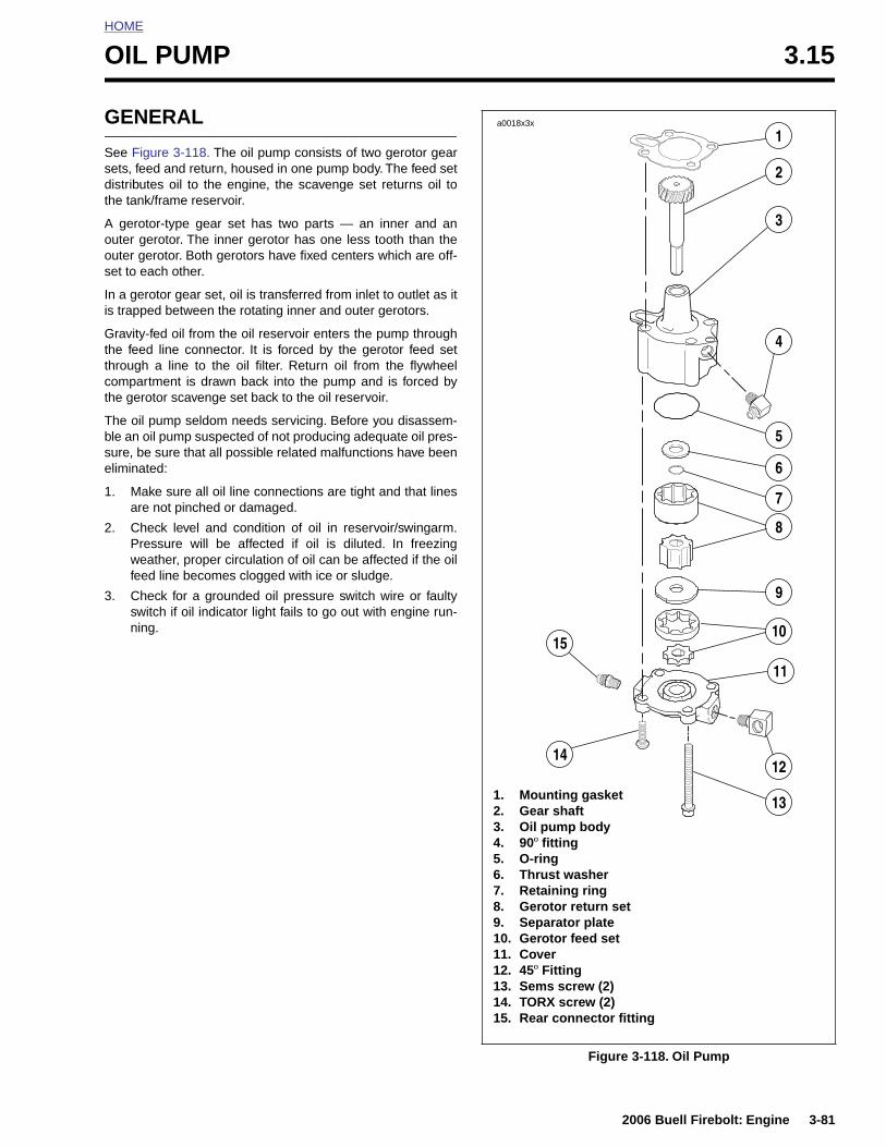
HOME
O
G
Ssdt
Aoos
Iis
Gttct
Tbse
1
2
3
IL PUMP 3.15
ENERAL
ee Figure 3-118. The oil pump consists of two gerotor gearets, feed and return, housed in one pump body. The feed setistributes oil to the engine, the scavenge set returns oil tohe tank/frame reservoir.
gerotor-type gear set has two parts — an inner and anuter gerotor. The inner gerotor has one less tooth than theuter gerotor. Both gerotors have fixed centers which are off-et to each other.
n a gerotor gear set, oil is transferred from inlet to outlet as it trapped between the rotating inner and outer gerotors.
ravity-fed oil from the oil reservoir enters the pump throughhe feed line connector. It is forced by the gerotor feed sethrough a line to the oil filter. Return oil from the flywheelompartment is drawn back into the pump and is forced byhe gerotor scavenge set back to the oil reservoir.
he oil pump seldom needs servicing. Before you disassem-le an oil pump suspected of not producing adequate oil pres-ure, be sure that all possible related malfunctions have beenliminated:
. Make sure all oil line connections are tight and that linesare not pinched or damaged.
. Check level and condition of oil in reservoir/swingarm.Pressure will be affected if oil is diluted. In freezingweather, proper circulation of oil can be affected if the oilfeed line becomes clogged with ice or sludge.
. Check for a grounded oil pressure switch wire or faultyswitch if oil indicator light fails to go out with engine run-ning.
a0018x3x
1
2
3
4
5
6
7
8
9
10
1214
15
11
2006 Buell Firebolt: Engine 3-81
Figure 3-118. Oil Pump
1. Mounting gasket2. Gear shaft3. Oil pump body4. 90º fitting5. O-ring6. Thrust washer7. Retaining ring8. Gerotor return set9. Separator plate10. Gerotor feed set11. Cover12. 45º Fitting13. Sems screw (2)14. TORX screw (2)15. Rear connector fitting
13
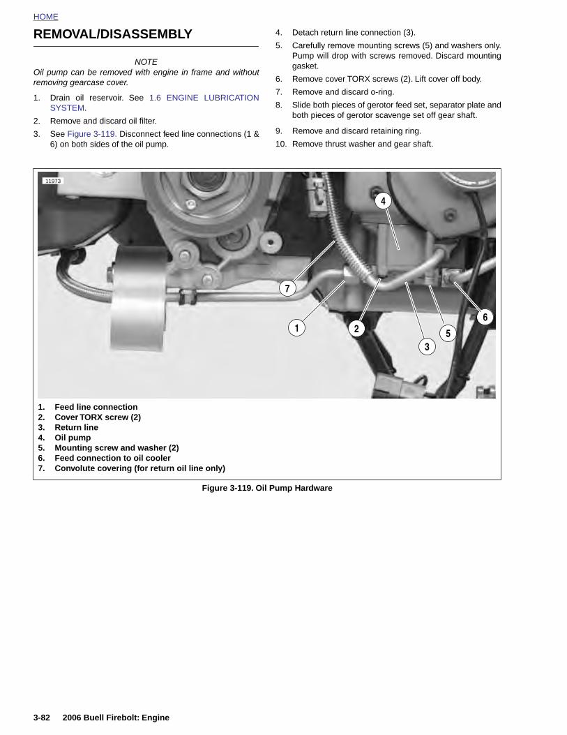
HOME
REMOVAL/DISASSEMBLY
4. Detach return line connection (3).
5. Carefully remove mounting screws (5) and washers only.Pump will drop with screws removed. Discard mounting
NOTEOil pump can be removed with engine in frame and withoutremoving gearcase cover.
1. Drain oil reservoir. See 1.6 ENGINE LUBRICATIONSYSTEM.
2. Remove and discard oil filter.
3. See Figure 3-119. Disconnect feed line connections (1 &6) on both sides of the oil pump.
gasket.
6. Remove cover TORX screws (2). Lift cover off body.
7. Remove and discard o-ring.
8. Slide both pieces of gerotor feed set, separator plate andboth pieces of gerotor scavenge set off gear shaft.
9. Remove and discard retaining ring.
10. Remove thrust washer and gear shaft.
Figure 3-119. Oil Pump Hardware
1. Feed line connection2. Cover TORX screw (2)3. Return line4. Oil pump5. Mounting screw and washer (2)6. Feed connection to oil cooler7. Convolute covering (for return oil line only)
6
5
11973
3
4
21
7
3-82 2006 Buell Firebolt: Engine
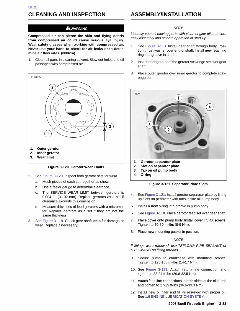
HOME
CLEANING AND INSPECTION
11WARNING1WARNING
Compressed air can pierce the skin and flying debrisfrom compressed air could cause serious eye injury.Wear safety glasses when working with compressed air.Never use your hand to check for air leaks or to deter-mine air flow rates. (00061a)
1. Clean all parts in cleaning solvent. Blow out holes and oilpassages with compressed air.
2. See Figure 3-120. Inspect both gerotor sets for wear.
a. Mesh pieces of each set together as shown.
b. Use a feeler gauge to determine clearance.
c. The SERVICE WEAR LIMIT between gerotors is0.004 in. (0.102 mm). Replace gerotors as a set ifclearance exceeds this dimension.
d. Measure thickness of feed gerotors with a microme-ter. Replace gerotors as a set if they are not the
ASSEMBLY/INSTALLATION
NOTE
Liberally coat all moving parts with clean engine oil to ensureeasy assembly and smooth operation at start-up.
1. See Figure 3-118. Install gear shaft through body. Posi-tion thrust washer over end of shaft. Install new retainingring into groove in shaft.
2. Insert inner gerotor of the gerotor scavenge set over gearshaft.
3. Place outer gerotor over inner gerotor to complete scav-enge set.
4. See Figure 3-121. Install gerotor separator plate by liningup slots on perimeter with tabs inside oil pump body.
5. Install a new o-ring into groove in pump body.
6. See Figure 3-118. Place gerotor feed set over gear shaft.
Figure 3-120. Gerotor Wear Limits
b1070x3x
1. Outer gerotor2. Inner gerotor3. Wear limit
1
2
3
Figure 3-121. Separator Plate Slots
16620
23
1. Gerotor separator plate2. Slot on separator plate 3. Tab on oil pump body4. O-ring
4
2006 Buell Firebolt: Engine 3-83
same thickness.
3. See Figure 3-118. Check gear shaft teeth for damage orwear. Replace if necessary.
7. Place cover onto pump body. Install cover TORX screws.Tighten to 70-80 in-lbs (8-9 Nm).
8. Place new mounting gasket in position.
NOTE
If fittings were removed, use TEFLON® PIPE SEALANT orHYLOMAR® on fitting threads.
9. Secure pump to crankcase with mounting screws.Tighten to 125-150 in-lbs (14-17 Nm).
10. See Figure 3-119. Attach return line connection andtighten to 22-24 ft-lbs (29.8-32.5 Nm).
11. Attach feed line connections to both sides of the oil pumpand tighten to 27-29 ft-lbs (36.6-39.3 Nm).
12. Install new oil filter and fill oil reservoir with proper oil.See 1.6 ENGINE LUBRICATION SYSTEM.
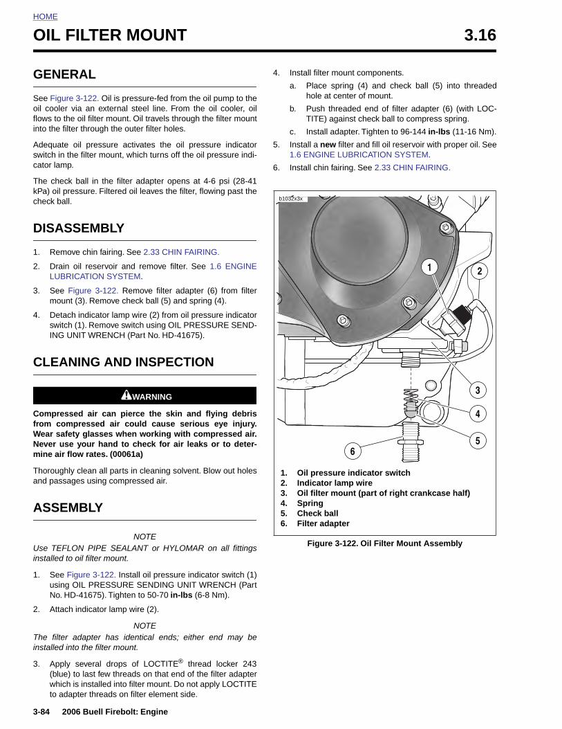
HOME
OIL FILTER MOUNT 3.16
GENE
See Figuroil cooler flows to thinto the fil
Adequateswitch in tcator lamp
The checkPa) oil prcheck ball
DISAS
1. Remo
2. DrainLUBR
3. See Fmoun
4. DetacswitchING U
CLEA
Compresfrom comWear safeNever usmine air fl
Thoroughand passa
ASSE
3-84
Use TEinstalled
1. SeeusinNo.
2. Atta
The filteinstalled
3. App(bluwhito a
RAL
e 3-122. Oil is pressure-fed from the oil pump to thevia an external steel line. From the oil cooler, oile oil filter mount. Oil travels through the filter mountter through the outer filter holes.
oil pressure activates the oil pressure indicatorhe filter mount, which turns off the oil pressure indi-.
k ball in the filter adapter opens at 4-6 psi (28-41essure. Filtered oil leaves the filter, flowing past the.
SEMBLY
ve chin fairing. See 2.33 CHIN FAIRING.
oil reservoir and remove filter. See 1.6 ENGINEICATION SYSTEM.
igure 3-122. Remove filter adapter (6) from filtert (3). Remove check ball (5) and spring (4).
h indicator lamp wire (2) from oil pressure indicator (1). Remove switch using OIL PRESSURE SEND-NIT WRENCH (Part No. HD-41675).
NING AND INSPECTION
11WARNING1WARNING
sed air can pierce the skin and flying debrispressed air could cause serious eye injury.ty glasses when working with compressed air.
e your hand to check for air leaks or to deter-ow rates. (00061a)
ly clean all parts in cleaning solvent. Blow out holesges using compressed air.
MBLY
4. Install filter mount components.
a. Place spring (4) and check ball (5) into threadedhole at center of mount.
b. Push threaded end of filter adapter (6) (with LOC-TITE) against check ball to compress spring.
c. Install adapter. Tighten to 96-144 in-lbs (11-16 Nm).
5. Install a new filter and fill oil reservoir with proper oil. See1.6 ENGINE LUBRICATION SYSTEM.
6. Install chin fairing. See 2.33 CHIN FAIRING.
1. Oil pressure indicator switch2. Indicator lamp wire3. Oil filter mount (part of right crankcase half)4. Spring5. Check ball6. Filter adapter
b1032x3x
21
6
4
3
5
2006 Buell Firebolt: Engine
NOTEFLON PIPE SEALANT or HYLOMAR on all fittings to oil filter mount.
Figure 3-122. Install oil pressure indicator switch (1)g OIL PRESSURE SENDING UNIT WRENCH (Part
HD-41675). Tighten to 50-70 in-lbs (6-8 Nm).
ch indicator lamp wire (2).
NOTEr adapter has identical ends; either end may be into the filter mount.
ly several drops of LOCTITE® thread locker 243e) to last few threads on that end of the filter adapterch is installed into filter mount. Do not apply LOCTITEdapter threads on filter element side.
Figure 3-122. Oil Filter Mount Assembly
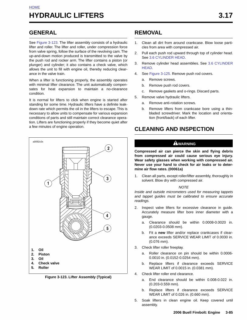
HOME
H
G
Slifutpaa
Wwsc
Isdncta
YDRAULIC LIFTERS 3.17
ENERAL
ee Figure 3-123. The lifter assembly consists of a hydraulicfter and roller. The lifter and roller, under compression forcerom valve spring, follow the surface of the revolving cam. Thep-and-down motion produced is transmitted to the valve byhe push rod and rocker arm. The lifter contains a piston (orlunger) and cylinder; it also contains a check valve, whichllows the unit to fill with engine oil, thereby reducing clear-nce in the valve train.
hen a lifter is functioning properly, the assembly operatesith minimal lifter clearance. The unit automatically compen-ates for heat expansion to maintain a no-clearanceondition.
t is normal for lifters to click when engine is started aftertanding for some time. Hydraulic lifters have a definite leak-own rate which permits the oil in the lifters to escape. This isecessary to allow units to compensate for various expansiononditions of parts and still maintain correct clearance opera-ion. Lifters are functioning properly if they become quiet after few minutes of engine operation.
REMOVAL
1. Clean all dirt from around crankcase. Blow loose parti-cles from area with compressed air.
2. Pull each push rod upward through top of cylinder head.See 3.6 CYLINDER HEAD.
3. Remove cylinder head assemblies. See 3.6 CYLINDERHEAD.
4. See Figure 3-125. Remove push rod covers.
a. Remove screws.
b. Remove push rod covers.
c. Remove gaskets and o-rings. Discard parts.
5. Remove valve hydraulic lifters.
a. Remove anti-rotation screws.
b. Remove lifters from crankcase bore using a thin-bladed screwdriver. Mark the location and orienta-tion (front/back) of each lifter.
CLEANING AND INSPECTION
11WARNING1WARNING
Compressed air can pierce the skin and flying debrisfrom compressed air could cause serious eye injury.Wear safety glasses when working with compressed air.Never use your hand to check for air leaks or to deter-mine air flow rates. (00061a)
1. Clean all parts, except roller/lifter assembly, thoroughly insolvent. Blow dry with compressed air.
NOTEInside and outside micrometers used for measuring tappetsand tappet guides must be calibrated to ensure accuratereadings.
2. Inspect valve lifters for excessive clearance in guide.Accurately measure lifter bore inner diameter with agauge.
a0092x3x
1
2
3
4
2006 Buell Firebolt: Engine 3-85
a. Clearance should be within 0.0008-0.0020 in.(0.0203-0.0508 mm).
b. Fit a new lifter and/or replace crankcases if clear-ance exceeds SERVICE WEAR LIMIT of 0.0030 in.(0.076 mm).
3. Check lifter roller freeplay.
a. Roller clearance on pin should be within 0.0006-0.0010 in. (0.0152-0.0254 mm).
b. Replace lifters if clearance exceeds SERVICEWEAR LIMIT of 0.0015 in. (0.0381 mm).
4. Check lifter roller end clearance.
a. End clearance should be within 0.008-0.022 in.(0.203-0.559 mm).
b. Replace lifters if clearance exceeds SERVICEWEAR LIMIT of 0.026 in. (0.660 mm).
5. Soak lifters in clean engine oil. Keep covered untilassembly.
Figure 3-123. Lifter Assembly (Typical)
1. Oil2. Piston3. Oil4. Check valve5. Roller
5
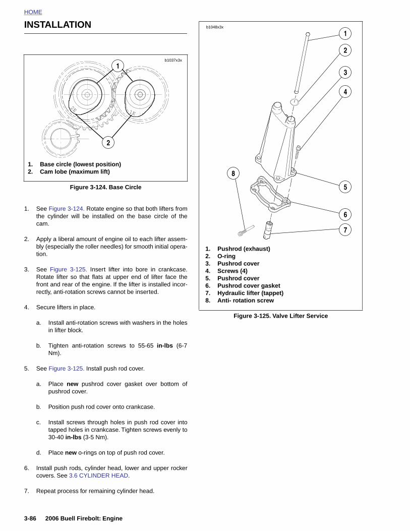
HOME
INSTALLATION
b1048x3x
1
1. See Figure 3-124. Rotate engine so that both lifters fromthe cylinder will be installed on the base circle of thecam.
2. Apply a liberal amount of engine oil to each lifter assem-bly (especially the roller needles) for smooth initial opera-tion.
3. See Figure 3-125. Insert lifter into bore in crankcase.Rotate lifter so that flats at upper end of lifter face thefront and rear of the engine. If the lifter is installed incor-rectly, anti-rotation screws cannot be inserted.
4. Secure lifters in place.
a. Install anti-rotation screws with washers in the holesin lifter block.
b. Tighten anti-rotation screws to 55-65 in-lbs (6-7Nm).
5. See Figure 3-125. Install push rod cover.
a. Place new pushrod cover gasket over bottom of
Figure 3-124. Base Circle
2E 1E
b1037x3x
1
2
1. Base circle (lowest position)2. Cam lobe (maximum lift)
Figure 3-125. Valve Lifter Service
2
3
4
5
6
7
8
1. Pushrod (exhaust)2. O-ring3. Pushrod cover4. Screws (4)5. Pushrod cover6. Pushrod cover gasket7. Hydraulic lifter (tappet)8. Anti- rotation screw
3-86 2006 Buell Firebolt: Engine
pushrod cover.
b. Position push rod cover onto crankcase.
c. Install screws through holes in push rod cover intotapped holes in crankcase. Tighten screws evenly to30-40 in-lbs (3-5 Nm).
d. Place new o-rings on top of push rod cover.
6. Install push rods, cylinder head, lower and upper rockercovers. See 3.6 CYLINDER HEAD.
7. Repeat process for remaining cylinder head.
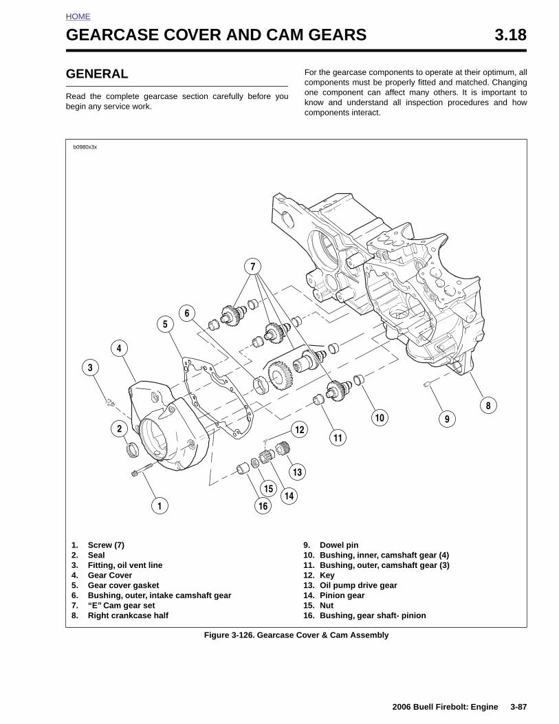
HOME
G
G
Rb
EARCASE COVER AND CAM GEARS 3.18
ENERAL
ead the complete gearcase section carefully before youegin any service work.
For the gearcase components to operate at their optimum, allcomponents must be properly fitted and matched. Changingone component can affect many others. It is important toknow and understand all inspection procedures and howcomponents interact.
b0980x3x
15
12
5
7
4
2
13
11
10
3
14
89
6
2006 Buell Firebolt: Engine 3-87
Figure 3-126. Gearcase Cover & Cam Assembly
1. Screw (7)2. Seal3. Fitting, oil vent line4. Gear Cover5. Gear cover gasket6. Bushing, outer, intake camshaft gear7. “E” Cam gear set8. Right crankcase half
9. Dowel pin10. Bushing, inner, camshaft gear (4)11. Bushing, outer, camshaft gear (3)12. Key13. Oil pump drive gear14. Pinion gear15. Nut16. Bushing, gear shaft- pinion
161

HOME
REMOVAL/DISASSEMBLY
6. Remove cam position sensor and rotor from gearcasecover. See 4.31 CAM POSITION SENSOR ANDROTOR.
11WARNING1WARNING
Compressed air can pierce the skin and flying debrisfrom compressed air could cause serious eye injury.Wear safety glasses when working with compressed air.Never use your hand to check for air leaks or to deter-mine air flow rates. (00061a)
1. See Figure 3-126. Thoroughly clean area around gear-case cover and tappets. Blow loose dirt from crankcasewith compressed air.
2. Remove any parts that will interfere with gearcase disas-sembly.
3. Remove push rods. See 3.6 CYLINDER HEAD.
4. Remove hydraulic lifters. See 3.17 HYDRAULIC LIFT-ERS.
5. Check for minimum cam gear end play. Record readings.
7. Place a pan under gearcase to collect oil. Remove coverscrews. Carefully remove gearcase cover. Discard oldgasket.
NOTEIf cover does not come loose on removal of screws, tap lightlywith a plastic hammer. Never pry cover off.
8. See Figure 3-127. Remove cam gears (1, 2, 3 & 4).
NOTENut is secured by LOCTITE 262 (red) on the nut threads.
9. Remove pinion nut (6). Slide pinion gear (5) and oil pumpdrive gear (6) off pinion shaft.
NOTESee Figure 3-127. The timing marks are located on the front intake cam assembly (2). Note the “V” marks (7).
1
23
4
5 6
8662a
7
7
3-88 2006 Buell Firebolt: Engine
Figure 3-127. Cam and Pinion Gear Location and Timing Mark Indexing
1. Front exhaust cam gear2. Front intake cam gear3. Rear intake cam gear4. Rear exhaust cam gear5. Pinion gear6. Pinion nut7. Timing V marks

HOME
CLEANING AND INSPECTION
1. Thoroughly clean gearcase compartment, gearcasecover and gears in solvent to remove oil and carbondeposits.
11WARNING1WARNING
Compressed air can pierce the skin and flying debrisfrom compressed air could cause serious eye injury.Wear safety glasses when working with compressed air.Never use your hand to check for air leaks or to deter-mine air flow rates. (00061a)
2. Blow out all cover oil passages and bushings with com-pressed air.
3. Clean old gasket material from gearcase and crankcase.
Cam and Pinion Gear Identification, Inspection and Selection
See Figure 3-128. Cam lobes are stamped with a number (1,2, 3 or 4) followed by a letter (“E”). The numbers identify thecam location/function and the letter (“E”) indicates model yearapplication. Refer to Table 3-25.
NOTE
Prior to changing any cam gears, check gear shaft fit withincorresponding bushings. Worn bushings can cause excessivebacklash.
Bushing Inspection1. Bushings are press fit in gearcase cover and crankcase.
Inspect each bushing against its corresponding camgear shaft or pinion gear shaft. See Table 3-26.
NOTEIf Service Wear Limits are exceeded, replace crankcase setand/or gearcase cover as required.
2E
b0952x1x
Table 3-26. Gear Shaft Specifications
GEAR SHAFT
CORRECT CLEARANCE
SERVICE WEAR LIMIT
Cam0.0007-0.0022 in.
(0.0178-0.0559 mm)0.003 in.
(0.076 mm)
Pinion0.0023-0.0043 in.
(0.0584-0.1092 mm)0.0050 in.
(0.1270 mm)
2006 Buell Firebolt: Engine 3-89
Figure 3-128. Cam Identification Stamp
Table 3-25. Cam Location Numbers
STAMP LOCATION
1E Front exhaust
2E Front intake
3E Rear intake
4E Rear exhaust
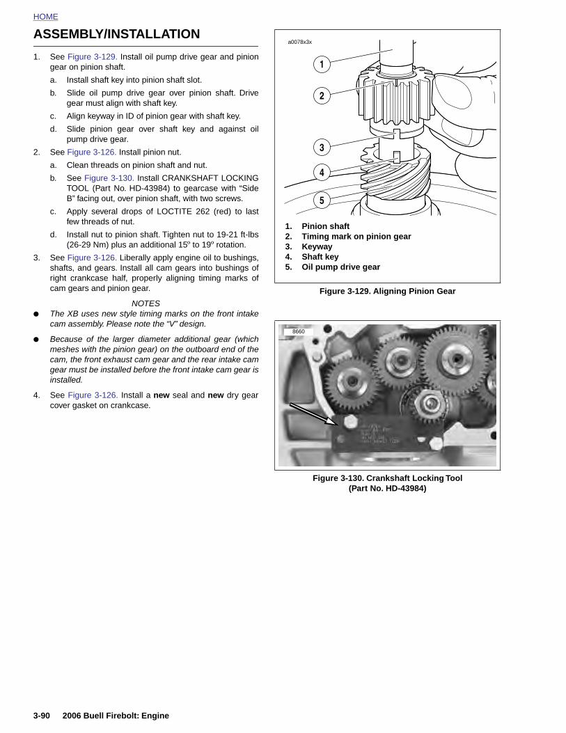
HOME
ASSEMBLY/INSTALLATION
a0078x3x
1. See Figure 3-129. Install oil pump drive gear and piniongear on pinion shaft.
a. Install shaft key into pinion shaft slot.
b. Slide oil pump drive gear over pinion shaft. Drivegear must align with shaft key.
c. Align keyway in ID of pinion gear with shaft key.
d. Slide pinion gear over shaft key and against oilpump drive gear.
2. See Figure 3-126. Install pinion nut.
a. Clean threads on pinion shaft and nut.
b. See Figure 3-130. Install CRANKSHAFT LOCKINGTOOL (Part No. HD-43984) to gearcase with “SideB” facing out, over pinion shaft, with two screws.
c. Apply several drops of LOCTITE 262 (red) to lastfew threads of nut.
d. Install nut to pinion shaft. Tighten nut to 19-21 ft-lbs(26-29 Nm) plus an additional 15º to 19º rotation.
3. See Figure 3-126. Liberally apply engine oil to bushings,shafts, and gears. Install all cam gears into bushings ofright crankcase half, properly aligning timing marks ofcam gears and pinion gear.
NOTES● The XB uses new style timing marks on the front intake
cam assembly. Please note the “V” design.
● Because of the larger diameter additional gear (whichmeshes with the pinion gear) on the outboard end of thecam, the front exhaust cam gear and the rear intake camgear must be installed before the front intake cam gear isinstalled.
4. See Figure 3-126. Install a new seal and new dry gearcover gasket on crankcase.
Figure 3-129. Aligning Pinion Gear
Figure 3-130. Crankshaft Locking Tool(Part No. HD-43984)
1. Pinion shaft2. Timing mark on pinion gear3. Keyway4. Shaft key5. Oil pump drive gear
1
2
3
4
5
8660
3-90 2006 Buell Firebolt: Engine
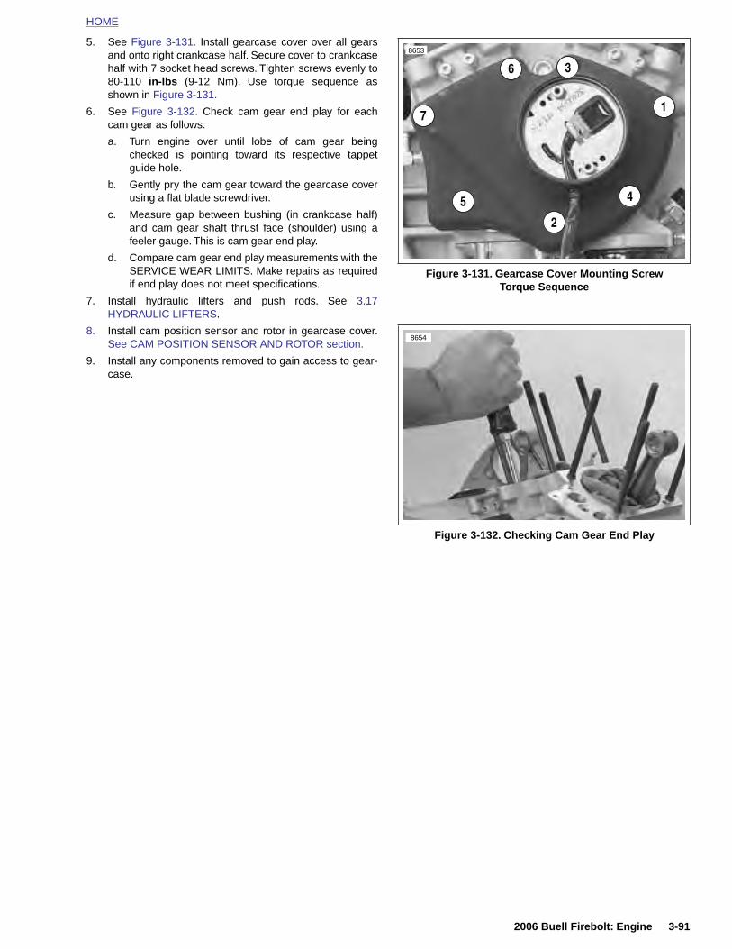
HOME
5. See Figure 3-131. Install gearcase cover over all gearsand onto right crankcase half. Secure cover to crankcasehalf with 7 socket head screws. Tighten screws evenly to80-110 in-lbs (9-12 Nm). Use torque sequence asshown in Figure 3-131.
6. See Figure 3-132. Check cam gear end play for eachcam gear as follows:
a. Turn engine over until lobe of cam gear beingchecked is pointing toward its respective tappetguide hole.
b. Gently pry the cam gear toward the gearcase coverusing a flat blade screwdriver.
c. Measure gap between bushing (in crankcase half)and cam gear shaft thrust face (shoulder) using afeeler gauge. This is cam gear end play.
d. Compare cam gear end play measurements with theSERVICE WEAR LIMITS. Make repairs as requiredif end play does not meet specifications.
7. Install hydraulic lifters and push rods. See 3.17HYDRAULIC LIFTERS.
8. Install cam position sensor and rotor in gearcase cover.See CAM POSITION SENSOR AND ROTOR section.
9. Install any components removed to gain access to gear-case.
Figure 3-131. Gearcase Cover Mounting ScrewTorque Sequence
Figure 3-132. Checking Cam Gear End Play
2
4
1
36
5
7
8653
8654
2006 Buell Firebolt: Engine 3-91
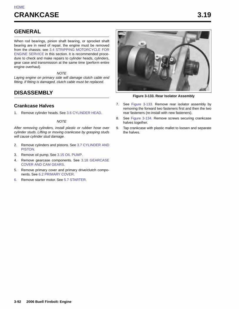
HOME
CRANKCASE 3.19
GENE
When rodbearing afrom the cENGINE Sdure to chgear caseengine ov
Laying enfitting. If fit
DISAS
Crankc1. Remo
After remcylinder swill cause
2. RemoPISTO
3. Remo
4. RemoCOVE
5. Remonents
6. Remo
3-92
RAL
bearings, pinion shaft bearing, or sprocket shaftre in need of repair, the engine must be removedhassis; see 3.4 STRIPPING MOTORCYCLE FORERVICE in this section. It is recommended proce-eck and make repairs to cylinder heads, cylinders, and transmission at the same time (perform entireerhaul).
NOTEgine on primary side will damage clutch cable endting is damaged, clutch cable must be replaced.
SEMBLY
ase Halvesve cylinder heads. See 3.6 CYLINDER HEAD.
NOTE
oving cylinders, install plastic or rubber hose overtuds. Lifting or moving crankcase by grasping studs cylinder stud damage.
ve cylinders and pistons. See 3.7 CYLINDER ANDN.
ve oil pump. See 3.15 OIL PUMP.
ve gearcase components. See 3.18 GEARCASER AND CAM GEARS.
ve primary cover and primary drive/clutch compo-. See 6.2 PRIMARY COVER.
ve starter motor. See 5.7 STARTER.
7. See Figure 3-133. Remove rear isolator assembly byremoving the forward two fasteners first and then the tworear fasteners (re-install with new fasteners).
8. See Figure 3-134. Remove screws securing crankcasehalves together.
9. Tap crankcase with plastic mallet to loosen and separatethe halves.
Figure 3-133. Rear Isolator Assembly
8723a
2006 Buell Firebolt: Engine
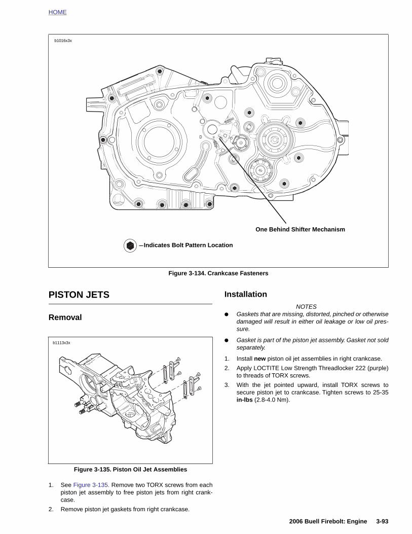
HOME
PISTON JETS
Removal
InstallationNOTES
● Gaskets that are missing, distorted, pinched or otherwisedamaged will result in either oil leakage or low oil pres-sure.
● Gasket is part of the piston jet assembly. Gasket not soldseparately.
1. Install new piston oil jet assemblies in right crankcase.
2. Apply LOCTITE Low Strength Threadlocker 222 (purple)
Figure 3-134. Crankcase Fasteners
D
b1016x3x
Indicates Bolt Pattern Location
One Behind Shifter Mechanism
b1113x3x
2006 Buell Firebolt: Engine 3-93
1. See Figure 3-135. Remove two TORX screws from eachpiston jet assembly to free piston jets from right crank-case.
2. Remove piston jet gaskets from right crankcase.
to threads of TORX screws.
3. With the jet pointed upward, install TORX screws tosecure piston jet to crankcase. Tighten screws to 25-35in-lbs (2.8-4.0 Nm).
Figure 3-135. Piston Oil Jet Assemblies
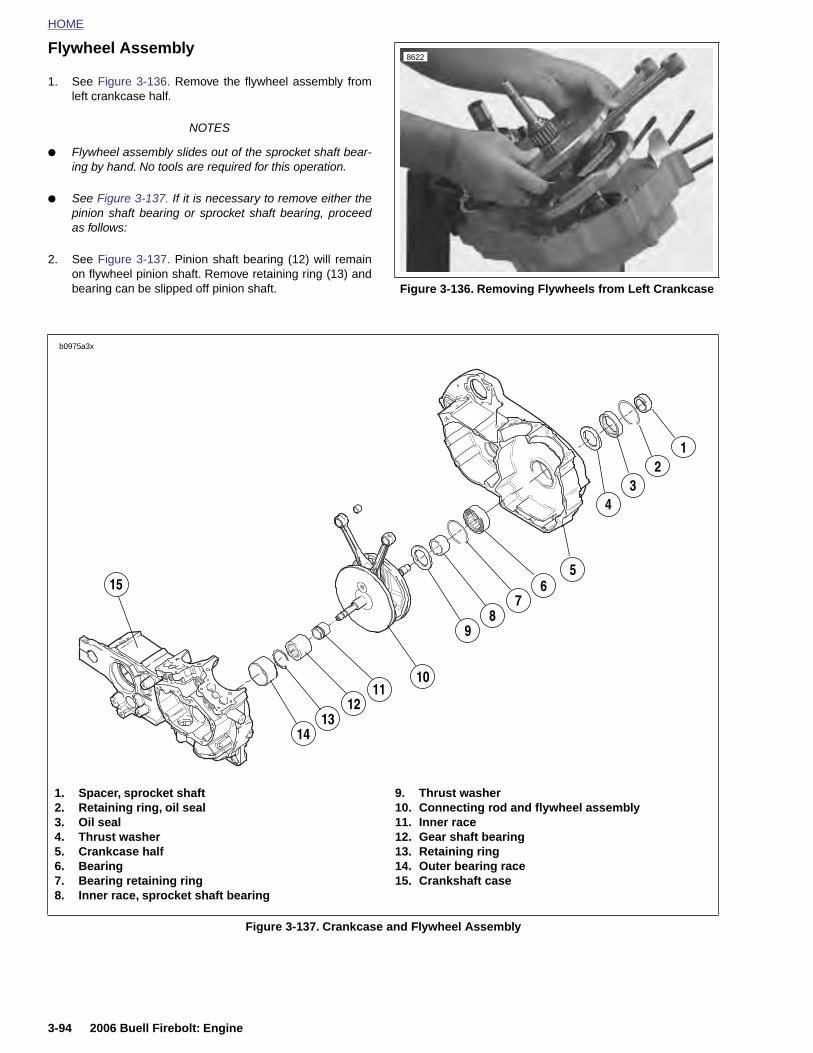
HOME
Flywheel Assembly8622
1. See Figure 3-136. Remove the flywheel assembly fromleft crankcase half.
NOTES
● Flywheel assembly slides out of the sprocket shaft bear-ing by hand. No tools are required for this operation.
● See Figure 3-137. If it is necessary to remove either thepinion shaft bearing or sprocket shaft bearing, proceedas follows:
2. See Figure 3-137. Pinion shaft bearing (12) will remainon flywheel pinion shaft. Remove retaining ring (13) andbearing can be slipped off pinion shaft. Figure 3-136. Removing Flywheels from Left Crankcase
b0975a3x
23
4
56
78
9
10
15
1112
1314
1
3-94 2006 Buell Firebolt: Engine
Figure 3-137. Crankcase and Flywheel Assembly
1. Spacer, sprocket shaft2. Retaining ring, oil seal3. Oil seal4. Thrust washer5. Crankcase half6. Bearing7. Bearing retaining ring8. Inner race, sprocket shaft bearing
9. Thrust washer10. Connecting rod and flywheel assembly11. Inner race12. Gear shaft bearing13. Retaining ring14. Outer bearing race 15. Crankshaft case

HOME
3. See Figure 3-138. Place flywheel assembly in FLY-WHEEL SUPPORT FIXTURE (Part No. HD-44385). Pullsprocket shaft bearing inner race with WEDGE ATTACH-MENT for CLAW PULLER (Part No. HD-95637-46A) withBEARING RACE REMOVER/INSTALLER (Part No. HD-34902B) and END CAP (Part No. HD-34902-7).
NOTE
Sprocket shaft bearing inner race does not need to be groundonce it is installed on the sprocket shaft.
7. See Figure 3-140. Remove sprocket shaft bearing retain-ing ring from the inside of the left crankcase half.
8. See Figure 3-141. Using CRANKCASE BEARINGREMOVER/INSTALLER with ADAPTER (Part No. B-45655, HD-42720-2 and HD-46663) press sprocket shaftbearing out of the left crankcase half.
NOTEThe bearing presses to the inside. There is a shoulder incor-porated into the left crankcase half which allows the bearing
Figure 3-138. Removing Sprocket Shaft Inner Bearing Race
8760
8861
Figure 3-140. Removing Sprocket Shaft Bearing Retaining Ring
Figure 3-141. Direction of Bearing Removal From Left Crankcase
8762
8790
2006 Buell Firebolt: Engine 3-95
4. See Figure 3-139. Remove sprocket shaft oil seal retain-ing ring.
5. See Figure 3-137. Remove sprocket shaft oil seal (3)from crankcase using Snap-On Tool (Part No. CJ 114,Body Dent Puller)
6. Remove outer thrust washer (4) next to sprocket shaftbearing (6).
to be removed in one direction only.
Figure 3-139. Sprocket Shaft Seal Retaining Ring
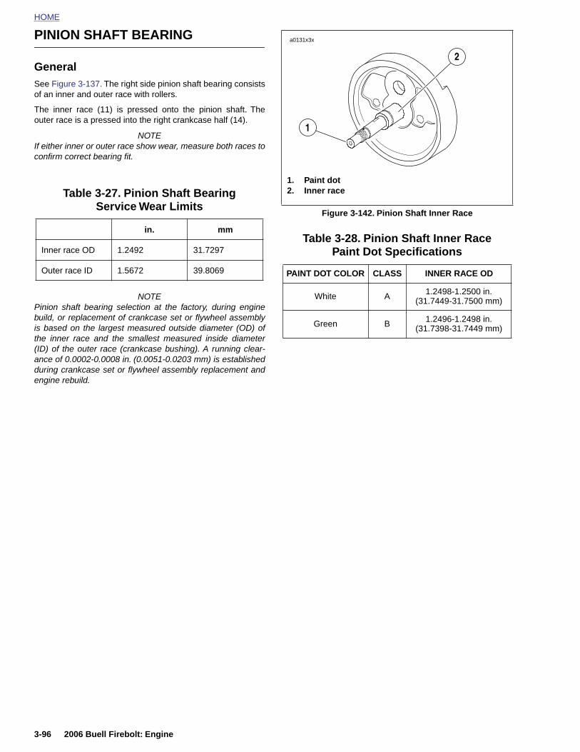
HOME
PINION SHAFT BEARING a0131x3x
GeneralSee Figure 3-137. The right side pinion shaft bearing consistsof an inner and outer race with rollers.
The inner race (11) is pressed onto the pinion shaft. Theouter race is a pressed into the right crankcase half (14).
NOTEIf either inner or outer race show wear, measure both races toconfirm correct bearing fit.
NOTEPinion shaft bearing selection at the factory, during enginebuild, or replacement of crankcase set or flywheel assemblyis based on the largest measured outside diameter (OD) ofthe inner race and the smallest measured inside diameter(ID) of the outer race (crankcase bushing). A running clear-ance of 0.0002-0.0008 in. (0.0051-0.0203 mm) is establishedduring crankcase set or flywheel assembly replacement andengine rebuild.
Table 3-28. Pinion Shaft Inner RacePaint Dot Specifications
Table 3-27. Pinion Shaft Bearing Service Wear Limits
in. mm
Inner race OD 1.2492 31.7297
Outer race ID 1.5672 39.8069
Figure 3-142. Pinion Shaft Inner Race
PAINT DOT COLOR CLASS INNER RACE OD
White A 1.2498-1.2500 in.(31.7449-31.7500 mm)
Green B 1.2496-1.2498 in.(31.7398-31.7449 mm)
1. Paint dot2. Inner race
1
2
3-96 2006 Buell Firebolt: Engine
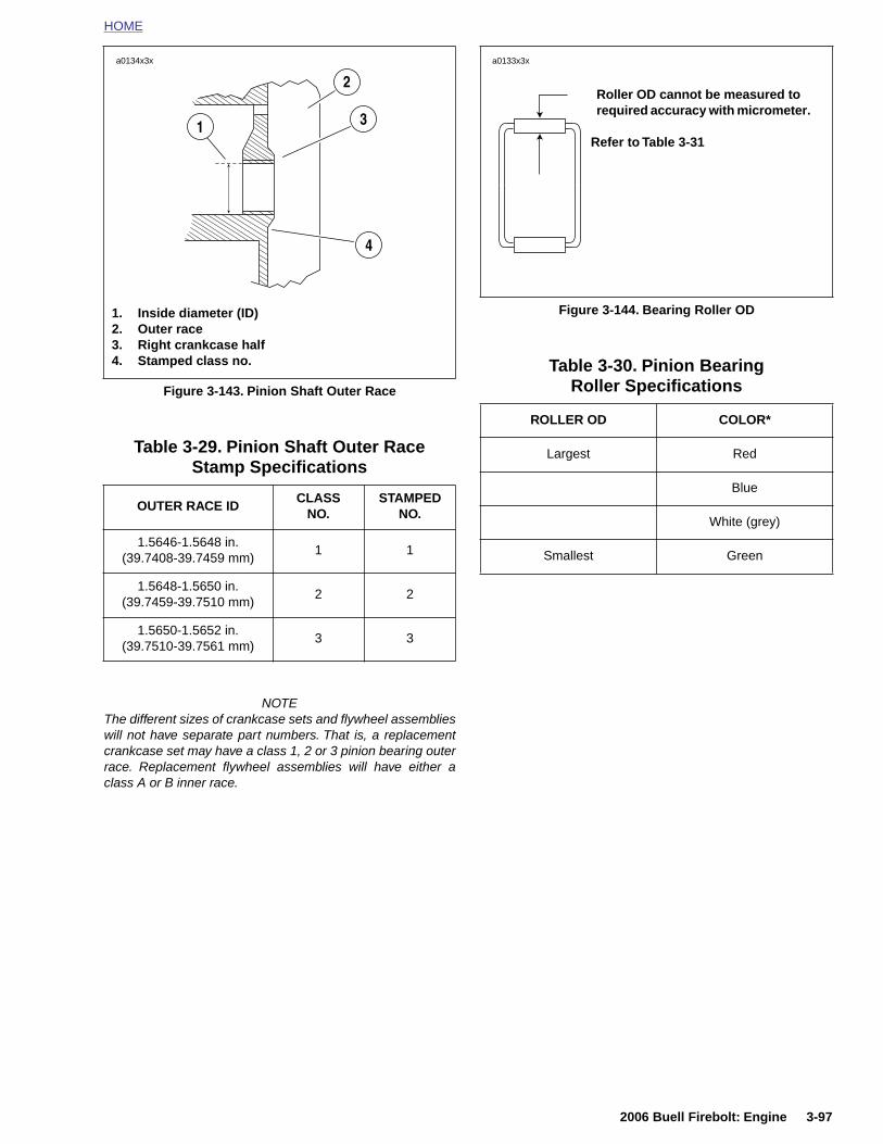
HOME
Table 3-29. Pinion Shaft Outer Race Stamp Specifications
NOTEThe different sizes of crankcase sets and flywheel assemblieswill not have separate part numbers. That is, a replacementcrankcase set may have a class 1, 2 or 3 pinion bearing outerrace. Replacement flywheel assemblies will have either aclass A or B inner race.
Table 3-30. Pinion BearingRoller SpecificationsFigure 3-143. Pinion Shaft Outer Race
OUTER RACE IDCLASS
NO.STAMPED
NO.
1.5646-1.5648 in.(39.7408-39.7459 mm)
1 1
1.5648-1.5650 in.(39.7459-39.7510 mm)
2 2
1.5650-1.5652 in.(39.7510-39.7561 mm)
3 3
a0134x3x
1. Inside diameter (ID)2. Outer race3. Right crankcase half4. Stamped class no.
1
2
3
4
Figure 3-144. Bearing Roller OD
ROLLER OD COLOR*
Largest Red
Blue
White (grey)
Smallest Green
Roller OD cannot be measured to required accuracy with micrometer.
Refer to Table 3-31
a0133x3x
2006 Buell Firebolt: Engine 3-97
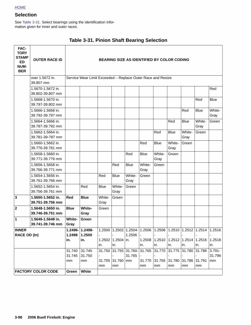
HOME
SelectionSee Table 3-31. Select bearings using the identification infor-
mation given for inner and outer races.Table 3-31. Pinion Shaft Bearing Selection
FAC-TORY
STAMPED
NUM-BER
OUTER RACE ID BEARING SIZE AS IDENTIFIED BY COLOR CODING
over 1.5672 in.39.807 mm
Service Wear Limit Exceeded – Replace Outer Race and Resize
1.5670-1.5672 in.39.802-39.807 mm
Red
1.5668-1.5670 in.39.797-39.802 mm
Red Blue
1.5666-1.5668 in.39.792-39.797 mm
Red Blue White-Gray
1.5664-1.5666 in.39.787-39.792 mm
Red Blue White-Gray
Green
1.5662-1.5664 in.39.781-39-787 mm
Red Blue White-Gray
Green
1.5660-1.5662 in.39.776-39.781 mm
Red Blue White-Gray
Green
1.5658-1.5660 in.39.771-39.776 mm
Red Blue White-Gray
Green
1.5656-1.5658 in.39.766-39.771 mm
Red Blue White-Gray
Green
1.5654-1.5656 in.39.761-39.766 mm
Red Blue White-Gray
Green
1.5652-1.5654 in.39.756-39.761 mm
Red Blue White-Gray
Green
3 1.5650-1.5652 in.39.751-39.756 mm
Red Blue White-Gray
Green
2 1.5648-1.5650 in.39.746-39.751 mm
Blue White-Gray
Green
1 1.5646-1.5648 in.39.741-39.746 mm
White-Gray
Green
INNERRACE OD (In)
1.2496-1.2498
1.2498-1.2500
1.2500-
1.2502-
1.2504-1.2506
1.2506-
1.2508-
1.2510-
1.2512-
1.2514-
1.2516-
3-98 2006 Buell Firebolt: Engine
in. in. 1.2502 in.
1.2504 in.
in. 1.2508 in.
1.2510 in.
1.2512 in.
1.2514 in.
1.2516 in.
1.2518 in.
31.74031.745 mm
31.74531.750 mm
31.750-31.755 mm
31.755-31.760 mm
31.760-31.765 mm
31.765-31.770 mm
31.770-31.755 mm
31.775-31.780 mm
31.780-31.786 mm
31.786-31.791 mm
3.791-31.796 mm
FACTORY COLOR CODE Green White
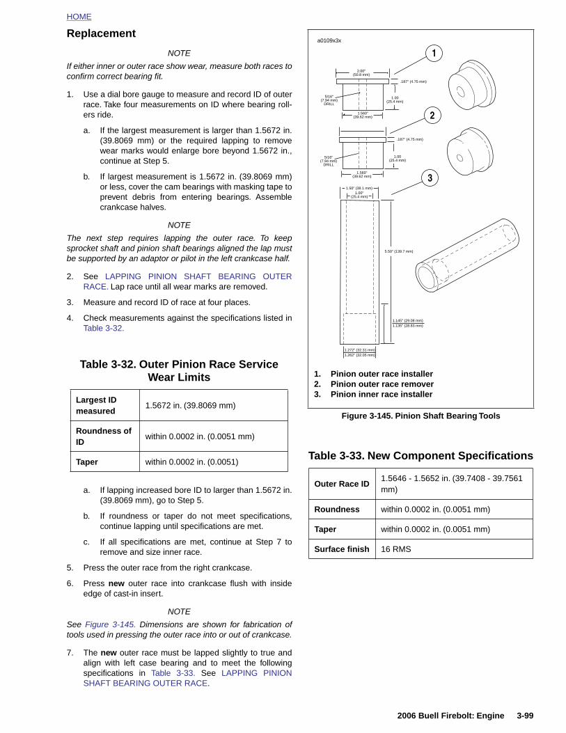
HOME
Replacement
NOTE
If either inner or outer race show wear, measure both races toconfirm correct bearing fit.
1. Use a dial bore gauge to measure and record ID of outerrace. Take four measurements on ID where bearing roll-ers ride.
a. If the largest measurement is larger than 1.5672 in.(39.8069 mm) or the required lapping to removewear marks would enlarge bore beyond 1.5672 in.,continue at Step 5.
b. If largest measurement is 1.5672 in. (39.8069 mm)or less, cover the cam bearings with masking tape toprevent debris from entering bearings. Assemblecrankcase halves.
NOTE
The next step requires lapping the outer race. To keepsprocket shaft and pinion shaft bearings aligned the lap mustbe supported by an adaptor or pilot in the left crankcase half.
2. See LAPPING PINION SHAFT BEARING OUTERRACE. Lap race until all wear marks are removed.
3. Measure and record ID of race at four places.
4. Check measurements against the specifications listed inTable 3-32.
a. If lapping increased bore ID to larger than 1.5672 in.(39.8069 mm), go to Step 5.
Table 3-32. Outer Pinion Race Service Wear Limits
Largest ID measured
1.5672 in. (39.8069 mm)
Roundness of ID
within 0.0002 in. (0.0051 mm)
Taper within 0.0002 in. (0.0051)
Figure 3-145. Pinion Shaft Bearing Tools
Table 3-33. New Component Specifications
Outer Race ID1.5646 - 1.5652 in. (39.7408 - 39.7561 mm)
.187" (4.75 mm)
2.00"(50.8 mm)
1.00(25.4 mm)
1.560"(39.62 mm)
1.560"(39.62 mm)
.187" (4.75 mm)
5/16"(7.94 mm)
DRILL
5/16"(7.94 mm)
DRILL
1.00"(25.4 mm)
1.50" (38.1 mm)
1.272" (32.31 mm)1.262" (32.05 mm)
1.145" (29.08 mm)1.135" (28.83 mm)
5.50" (139.7 mm)
a0109x3x
1.00(25.4 mm)
1. Pinion outer race installer2. Pinion outer race remover3. Pinion inner race installer
3
1
2
2006 Buell Firebolt: Engine 3-99
b. If roundness or taper do not meet specifications,continue lapping until specifications are met.
c. If all specifications are met, continue at Step 7 toremove and size inner race.
5. Press the outer race from the right crankcase.
6. Press new outer race into crankcase flush with insideedge of cast-in insert.
NOTE
See Figure 3-145. Dimensions are shown for fabrication oftools used in pressing the outer race into or out of crankcase.
7. The new outer race must be lapped slightly to true andalign with left case bearing and to meet the followingspecifications in Table 3-33. See LAPPING PINIONSHAFT BEARING OUTER RACE.
Roundness within 0.0002 in. (0.0051 mm)
Taper within 0.0002 in. (0.0051 mm)
Surface finish 16 RMS
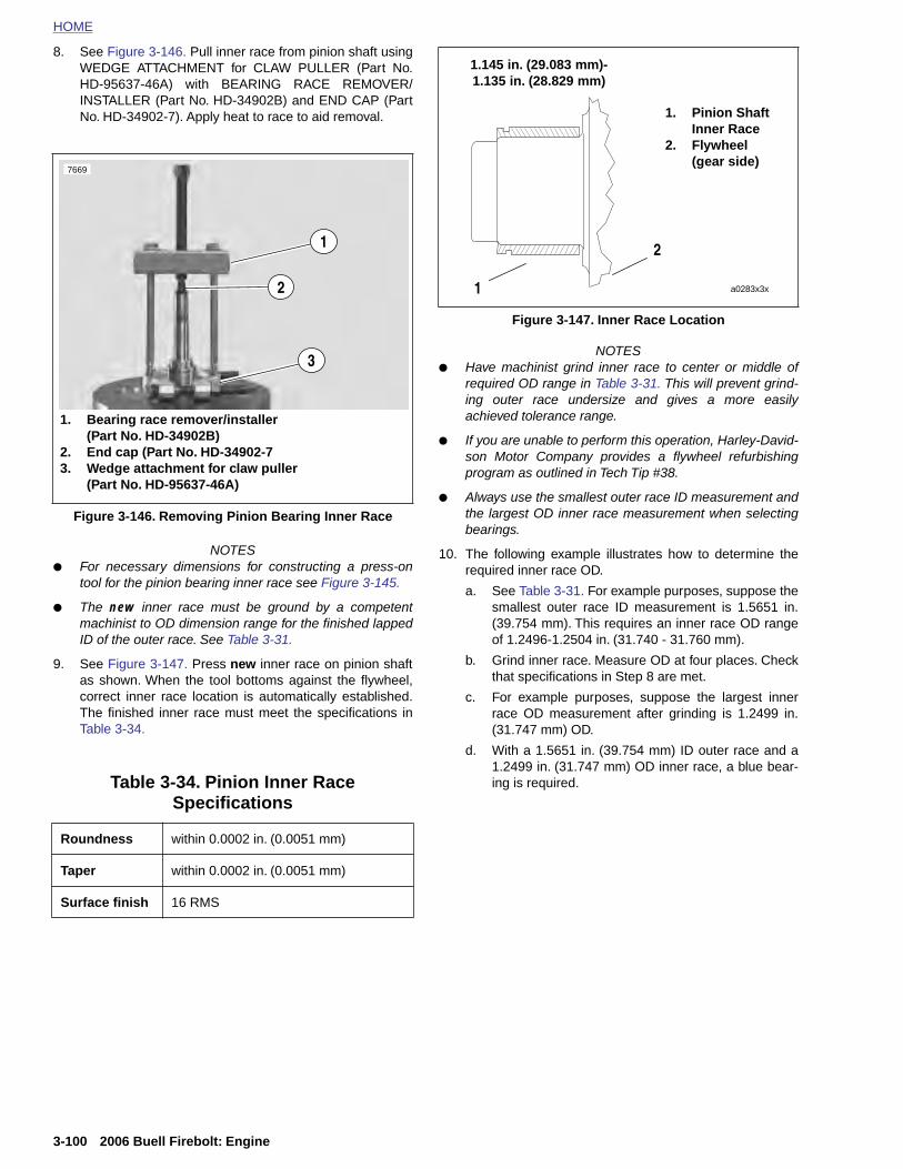
HOME
8. See Figure 3-146. Pull inner race from pinion shaft usingWEDGE ATTACHMENT for CLAW PULLER (Part No.HD-95637-46A) with BEARING RACE REMOVER/
1.145 in. (29.083 mm)-1.135 in. (28.829 mm)
INSTALLER (Part No. HD-34902B) and END CAP (PartNo. HD-34902-7). Apply heat to race to aid removal.
NOTES● For necessary dimensions for constructing a press-on
tool for the pinion bearing inner race see Figure 3-145.
● The new inner race must be ground by a competentmachinist to OD dimension range for the finished lappedID of the outer race. See Table 3-31.
9. See Figure 3-147. Press new inner race on pinion shaftas shown. When the tool bottoms against the flywheel,correct inner race location is automatically established.The finished inner race must meet the specifications inTable 3-34.
NOTES● Have machinist grind inner race to center or middle of
required OD range in Table 3-31. This will prevent grind-ing outer race undersize and gives a more easilyachieved tolerance range.
● If you are unable to perform this operation, Harley-David-son Motor Company provides a flywheel refurbishingprogram as outlined in Tech Tip #38.
● Always use the smallest outer race ID measurement andthe largest OD inner race measurement when selectingbearings.
10. The following example illustrates how to determine therequired inner race OD.
a. See Table 3-31. For example purposes, suppose thesmallest outer race ID measurement is 1.5651 in.(39.754 mm). This requires an inner race OD rangeof 1.2496-1.2504 in. (31.740 - 31.760 mm).
b. Grind inner race. Measure OD at four places. Checkthat specifications in Step 8 are met.
c. For example purposes, suppose the largest innerrace OD measurement after grinding is 1.2499 in.(31.747 mm) OD.
d. With a 1.5651 in. (39.754 mm) ID outer race and a1.2499 in. (31.747 mm) OD inner race, a blue bear-ing is required.
Figure 3-146. Removing Pinion Bearing Inner Race
Table 3-34. Pinion Inner RaceSpecifications
Roundness within 0.0002 in. (0.0051 mm)
7669
1. Bearing race remover/installer (Part No. HD-34902B)
2. End cap (Part No. HD-34902-73. Wedge attachment for claw puller
(Part No. HD-95637-46A)
1
3
2
Figure 3-147. Inner Race Location
1. Pinion Shaft Inner Race
2. Flywheel (gear side)
a0283x3x1
2
3-100 2006 Buell Firebolt: Engine
Taper within 0.0002 in. (0.0051 mm)
Surface finish 16 RMS
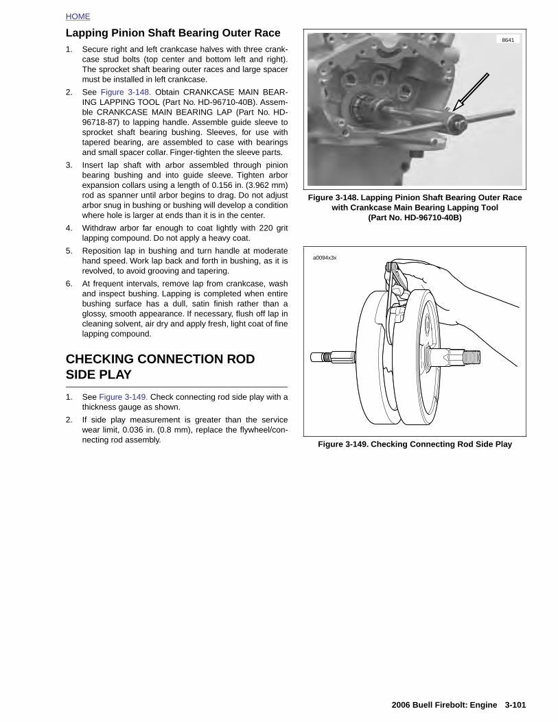
HOME
Lapping Pinion Shaft Bearing Outer Race1. Secure right and left crankcase halves with three crank-
case stud bolts (top center and bottom left and right).The sprocket shaft bearing outer races and large spacermust be installed in left crankcase.
2. See Figure 3-148. Obtain CRANKCASE MAIN BEAR-ING LAPPING TOOL (Part No. HD-96710-40B). Assem-ble CRANKCASE MAIN BEARING LAP (Part No. HD-96718-87) to lapping handle. Assemble guide sleeve tosprocket shaft bearing bushing. Sleeves, for use withtapered bearing, are assembled to case with bearingsand small spacer collar. Finger-tighten the sleeve parts.
3. Insert lap shaft with arbor assembled through pinionbearing bushing and into guide sleeve. Tighten arborexpansion collars using a length of 0.156 in. (3.962 mm)rod as spanner until arbor begins to drag. Do not adjustarbor snug in bushing or bushing will develop a conditionwhere hole is larger at ends than it is in the center.
4. Withdraw arbor far enough to coat lightly with 220 gritlapping compound. Do not apply a heavy coat.
5. Reposition lap in bushing and turn handle at moderatehand speed. Work lap back and forth in bushing, as it isrevolved, to avoid grooving and tapering.
6. At frequent intervals, remove lap from crankcase, washand inspect bushing. Lapping is completed when entirebushing surface has a dull, satin finish rather than aglossy, smooth appearance. If necessary, flush off lap incleaning solvent, air dry and apply fresh, light coat of finelapping compound.
CHECKING CONNECTION ROD SIDE PLAY
1. See Figure 3-149. Check connecting rod side play with athickness gauge as shown.
2. If side play measurement is greater than the servicewear limit, 0.036 in. (0.8 mm), replace the flywheel/con-necting rod assembly.
Figure 3-148. Lapping Pinion Shaft Bearing Outer Race with Crankcase Main Bearing Lapping Tool
(Part No. HD-96710-40B)
Figure 3-149. Checking Connecting Rod Side Play
8641
a0094x3x
2006 Buell Firebolt: Engine 3-101
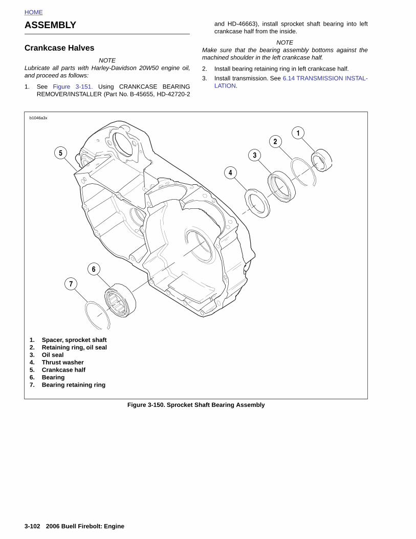
HOME
ASSEMBLY and HD-46663), install sprocket shaft bearing into leftcrankcase half from the inside.
Crankcase HalvesNOTE
Lubricate all parts with Harley-Davidson 20W50 engine oil,and proceed as follows:
1. See Figure 3-151. Using CRANKCASE BEARINGREMOVER/INSTALLER (Part No. B-45655, HD-42720-2
NOTEMake sure that the bearing assembly bottoms against themachined shoulder in the left crankcase half.
2. Install bearing retaining ring in left crankcase half.
3. Install transmission. See 6.14 TRANSMISSION INSTAL-LATION.
7
1
3
4
6
b1046a3x
5
2
1. Spacer, sprocket shaft2. Retaining ring, oil seal3. Oil seal4. Thrust washer5. Crankcase half6. Bearing7. Bearing retaining ring
3-102 2006 Buell Firebolt: Engine
Figure 3-150. Sprocket Shaft Bearing Assembly
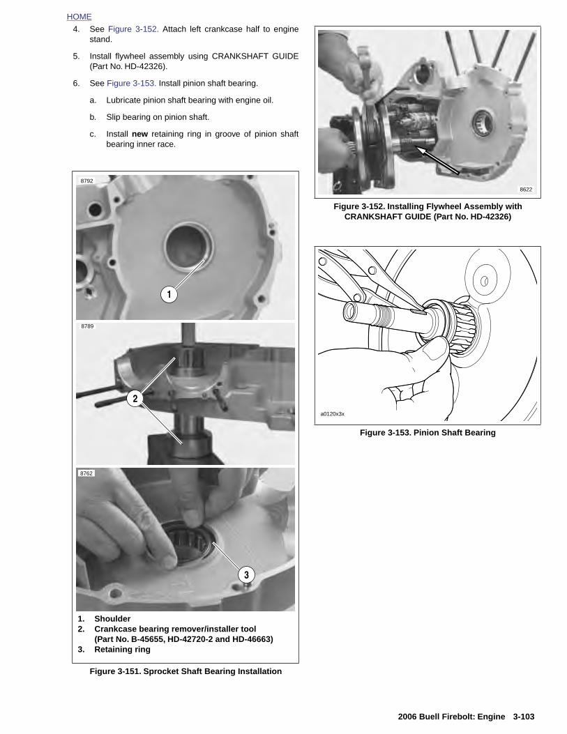
HOME
4. See Figure 3-152. Attach left crankcase half to enginestand.
5. Install flywheel assembly using CRANKSHAFT GUIDE(Part No. HD-42326).
6. See Figure 3-153. Install pinion shaft bearing.
a. Lubricate pinion shaft bearing with engine oil.
b. Slip bearing on pinion shaft.
c. Install new retaining ring in groove of pinion shaftbearing inner race.
8789
8792
8762
1
2
Figure 3-152. Installing Flywheel Assembly withCRANKSHAFT GUIDE (Part No. HD-42326)
Figure 3-153. Pinion Shaft Bearing
8622
a0120x3x
2006 Buell Firebolt: Engine 3-103
Figure 3-151. Sprocket Shaft Bearing Installation
3
1. Shoulder2. Crankcase bearing remover/installer tool
(Part No. B-45655, HD-42720-2 and HD-46663)3. Retaining ring

HOME
b1016x3x
7. See Figure 3-154. Assemble crankcase halves together.
a. Apply a thin coat of GREY HIGH-PERFORMANCESEALANT (Part No. 99650-02) to crankcase jointfaces.
b. Slide outer race in right crankcase over pinion shaftand bearing assembly.
c. Apply LOCTITE 272 to the last few threads andtighten fasteners to 15-19 ft-lbs (20-26 Nm).
NOTEAccording to manufacturing, there is no torque sequence tofollow when tightening crankcase fasteners.
Figure 3-154. Crankcase Fasteners
D
Indicates Bolt Pattern Location
One Behind Shifter Mechanism
3-104 2006 Buell Firebolt: Engine

HOME
8. See Figure 3-155. Use SPROCKET SHAFT SEALINSTALLER (Part No. B-45676) to install sprocket shaftseal.
a. Center seal/spacer driver over seal, so that thesleeve (smaller OD) seats between seal wall andgarter spring.
b. Sparingly apply graphite lubricant to threads of pilotshaft to ensure smooth operation.
c. Slide sleeve over pilot until sleeve contacts the oilseal. Install handle on top of sleeve.
d. Rotate handle clockwise until tool bottoms on crank-case lip. Remove tool from sprocket shaft.
e. Install new retaining ring in groove in left crankcasenext to oil seal.
9. Install thrust washer from the outside against thesprocket shaft bearing.
10. Install new spacer in seal ID. With the thin (lipped) sidefacing outward, center seal/spacer assembly over bear-ing bore.
NOTE
Do not remove the spacer after installation or the new sealwill have to be discarded and the procedure repeated.
11. See Figure 3-156. Install cylinder studs.
a. Pack clean towels into crankcase opening.
b. Place a steel ball into a head screw.
c. The cylinder studs have a shoulder at the lower end.Place the end of the stud without the shoulder intothe head screw.
d. Install the stud in the crankcase with the shoulderend down. Use an air gun to drive the stud until theshoulder reaches the crankcase.
e. Remove air gun. Use a torque wrench to tightenstud to 10-20 ft-lbs (14-27 Nm).
12. Install piston and cylinder. See 3.7 CYLINDER AND PIS-TON.
13. Install oil pump. See 3.15 OIL PUMP.
14. Install cam gears, gearcase cover, lifter guides and lift-ers. See 3.18 GEARCASE COVER AND CAM GEARS.
15. Install cylinder head. See 3.6 CYLINDER HEAD.
Figure 3-155. Sprocket Shaft Seal/Spacer Installer(Part No. HD-42579 and B-45676)
8761
Figure 3-156. Cylinder Studs
1
4
1. Head Screw with ball inside2. Cylinder stud3. Shoulder on cylinder stud4. Air gun
23
8799
2006 Buell Firebolt: Engine 3-105
16. Install starter. See 5.7 STARTER.
17. Install shift linkage.
18. Install all primary drive components. This includesengine sprocket, primary chain, complete clutch assem-bly, engine sprocket nut and mainshaft nut. See 6.4CLUTCH.
19. Install primary cover. See 6.2 PRIMARY COVER.
NOTE
Be sure to refill transmission to proper level with fresh lubri-cant. See 1.9 CLUTCH.
20. See 3.6 CYLINDER HEAD and perform the applicablesteps.
21. To reinstall engine in frame see 3.5 ENGINE INSTALLA-TION.

HOME
NOTES
3-106
2006 Buell Firebolt: Engine
SUBJECT
4.1 Specifications . . . . . . . . . . . . . . . . . . . . . . . . . . . . . . 4.2 Dynamic Digital Fuel Injection . . . . . . . . . . . . . . . . . . 4.3 Diagnostic Introduction . . . . . . . . . . . . . . . . . . . . . . . 4.4 Checking For Trouble Codes . . . . . . . . . . . . . . . . . . . 4.5 Check Engine Lamp Diagnostics . . . . . . . . . . . . . . . . 4.6 Breakout Box . . . . . . . . . . . . . . . . . . . . . . . . . . . . . . . 4.7 Wiggle Test . . . . . . . . . . . . . . . . . . . . . . . . . . . . . . . . 4.8 Initial Diagnostic Check . . . . . . . . . . . . . . . . . . . . . . . 4.9 Check Engine Lamp Not Illuminated at Key ON . . . . .4.10 Check Engine Lamp On Continuously . . . . . . . . . . . 4.11 Engine Cranks But Will Not Start . . . . . . . . . . . . . . . 4.12 No ECM Power . . . . . . . . . . . . . . . . . . . . . . . . . . . . 4.13 Fuel Pressure Test . . . . . . . . . . . . . . . . . . . . . . . . . 4.14 Idle Speed Control . . . . . . . . . . . . . . . . . . . . . . . . . . 4.15 Misfire . . . . . . . . . . . . . . . . . . . . . . . . . . . . . . . . . . . 4.16 Trouble Code 11 . . . . . . . . . . . . . . . . . . . . . . . . . . . 4.17 Trouble Code 13 . . . . . . . . . . . . . . . . . . . . . . . . . . . 4.18 Trouble Code 14 . . . . . . . . . . . . . . . . . . . . . . . . . . . 4.19 Trouble Code 15 . . . . . . . . . . . . . . . . . . . . . . . . . . . 4.20 Trouble Code 16 . . . . . . . . . . . . . . . . . . . . . . . . . . . 4.21 Trouble Code 21 . . . . . . . . . . . . . . . . . . . . . . . . . . . 4.22 Trouble Codes 23 and 32 . . . . . . . . . . . . . . . . . . . . 4.23 Trouble Codes 24 and 25 . . . . . . . . . . . . . . . . . . . . 4.24 Trouble Code 33 . . . . . . . . . . . . . . . . . . . . . . . . . . . 4.25 Trouble Code 35 . . . . . . . . . . . . . . . . . . . . . . . . . . . 4.26 Trouble Code 36 . . . . . . . . . . . . . . . . . . . . . . . . . . . 4.27 Trouble Code 44 . . . . . . . . . . . . . . . . . . . . . . . . . . . 4.28 Trouble Codes 52, 53, 54 and 55 . . . . . . . . . . . . . . 4.29 Trouble Code 56 . . . . . . . . . . . . . . . . . . . . . . . . . . . 4.30 Electronic Control Module . . . . . . . . . . . . . . . . . . . . 4.31 Cam Position Sensor and Rotor . . . . . . . . . . . . . . . 4.32 Ignition Coil . . . . . . . . . . . . . . . . . . . . . . . . . . . . . . . 4.33 Oxygen Sensor . . . . . . . . . . . . . . . . . . . . . . . . . . . . 4.34 Engine Temperature Sensor . . . . . . . . . . . . . . . . . . 4.35 Bank Angle Sensor . . . . . . . . . . . . . . . . . . . . . . . . . 4.36 Intake Air Temperature Sensor . . . . . . . . . . . . . . . . 4.37 Throttle Position Sensor . . . . . . . . . . . . . . . . . . . . .
Table Of Contents
PAGE NO.
. . . . . . . . . . . . . . . . . . . 4-1
. . . . . . . . . . . . . . . . . . . 4-3
. . . . . . . . . . . . . . . . . . . 4-5
. . . . . . . . . . . . . . . . . . . 4-6
. . . . . . . . . . . . . . . . . . . 4-8
. . . . . . . . . . . . . . . . . . . 4-10
. . . . . . . . . . . . . . . . . . . 4-11
. . . . . . . . . . . . . . . . . . . 4-12 . . . . . . . . . . . . . . . . . . 4-17. . . . . . . . . . . . . . . . . . . 4-20. . . . . . . . . . . . . . . . . . . 4-23. . . . . . . . . . . . . . . . . . . 4-29. . . . . . . . . . . . . . . . . . . 4-32. . . . . . . . . . . . . . . . . . . 4-37. . . . . . . . . . . . . . . . . . . 4-38. . . . . . . . . . . . . . . . . . . 4-43. . . . . . . . . . . . . . . . . . . 4-47. . . . . . . . . . . . . . . . . . . 4-52. . . . . . . . . . . . . . . . . . . 4-56. . . . . . . . . . . . . . . . . . . 4-60
FUEL SYSTEM 4
. . . . . . . . . . . . . . . . . . . 4-64
. . . . . . . . . . . . . . . . . . . 4-67
. . . . . . . . . . . . . . . . . . . 4-71
. . . . . . . . . . . . . . . . . . . 4-74
. . . . . . . . . . . . . . . . . . . 4-77
. . . . . . . . . . . . . . . . . . . 4-80
. . . . . . . . . . . . . . . . . . . 4-84
. . . . . . . . . . . . . . . . . . . 4-88
. . . . . . . . . . . . . . . . . . . 4-89
. . . . . . . . . . . . . . . . . . . 4-93
. . . . . . . . . . . . . . . . . . . 4-95
. . . . . . . . . . . . . . . . . . . 4-99
. . . . . . . . . . . . . . . . . . . 4-101
. . . . . . . . . . . . . . . . . . . 4-102
. . . . . . . . . . . . . . . . . . . 4-103
. . . . . . . . . . . . . . . . . . . 4-104
. . . . . . . . . . . . . . . . . . . 4-105
Continued on Next Page

4.38 Cooling Fan . . . . . . . . . . . . . . . . . . . . . . . . . . . . . . . . . . . . . . . . . . . . . . . . . . 4-1064.39 Fuel Pump . . . . . . . . . . . . . . . . . . . . . . . . . . . . . . . . . . . . . . . . . . . . . . . . . . . 4-1074.40 Fuel Tank Vent Valve . . . . . . . . . . . . . . . . . . . . . . . . . . . . . . . . . . . . . . . . . . 4-1154.41 Fuel Cap Retaining Ring . . . . . . . . . . . . . . . . . . . . . . . . . . . . . . . . . . . . . . . . 4-1164.42 Throttle Body . . . . . . . . . . . . . . . . . . . . . . . . . . . . . . . . . . . . . . . . . . . . . . . . . 4-1174.43 Intake Leak Test . . . . . . . . . . . . . . . . . . . . . . . . . . . . . . . . . . . . . . . . . . . . . . 4-1224.44 Air Cleaner Assembly . . . . . . . . . . . . . . . . . . . . . . . . . . . . . . . . . . . . . . . . . . 4-1244.45 Evaporative Emissions Control-California Models . . . . . . . . . . . . . . . . . . . . . 4-127

HOME
S
T
PECIFICATIONS 4.1
ORQUE VALUES
Table 4-1. Fuel System Specifications
FUEL SYSTEM TYPE
Intake (XB9R) 45 mm downdraft manifold, ram air
Intake (XB12R) 49 mm downdraft manifold, ram air
Fuel delivery DDFI fuel injection
Fuel pressure 49-51 Psi (338-352 kPa)
Recommended fuel 91 Octane
Table 4-2. Fuel Tank Specifications
FUEL TANK CAPACITY GALLONS LITERS
Total (including reserve) 3.82 14.5
Reserve/Low fuel indicator at 0.75 2.8
Table 4-3. Idle Speed Specifications
IDLE SPEED ADJUSTMENT
Normal idle speed 1050-1150 RPM
ITEM TORQUE NOTES
Airbox back plate fasteners 84-120 in-lbs 9.5-13.6 Nm page 4-125
Bank angle sensor mounting fastener
12-36 in-lbs 1.4-4.1 Nm page 4-103
Battery terminal hardware 72-96 in-lbs 8-11 Nm page 4-115
Cooling fan fasteners 12-36 in-lbs 1.4-4.1 Nm page 4-106
Engine temperature sensor 120-168 in-lbs 13.6-19 Nm page 4-102
Fuel cap retaining ring fasten-ers
62-71 in-lbs 7-8 Nm page 4-116
Fuel pump assembly ground screw
18-22 in-lbs 2.0-2.5 Nm page 4-111
Fuel pump drain plug 84-108 in-lbs 9.5-12.2 Nm page 4-107
Fuel pump screws 48-51 in-lbs 5.4-5.8 Nm page 4-114
Fuel rail fasteners 20-25 in-lbs 2.3-2.8 Nm LOCTITE 272 (red), page 4-120
Fuel supply line banjo fitting 84-108 in-lbs 9.5-12.2 Nm page 4-114
Fuel tank vent valve fasteners 39-41 in-lbs 4.4-4.6 Nm page 4-115
Ignition coil mounting screws 120-144 in-lbs 13.6-16.3 Nm page 4-100
2006 Buell Firebolt: Fuel System 4-1
Ignition rotor mounting bolt 43-53 in-lbs 5-6 Nm LOCTITE THREADLOCKER 243 (blue), page 4-98
Inner timer cover screws 12-20 in-lbs 1-2 Nm page 4-98
Intake flange screws 96-120 in-lbs 10.8-13.6 Nm page 4-121
Interactive exhaust actuator fasteners
36-40 in-lbs 4-4.5 Nm page 4-125
Low fuel level sensor retaining screw
18-22 in-lbs 2.0-2.5 Nm page 4-110
Oxygen sensor 40-45 ft-lbs 54-61 Nm LOCTITE ANTI-SEIZE, page 4-101
Rear shock absorber reservoir clamp rear
10-12 ft-lbs 13.6-16.3 Nm page 4-128
Throttle position sensor 12-15 in-lbs 1.4-1.7 Nm LOCTITE THREADLOCKER 222 (purple), page 4-105
Timer plate studs 15-30 in-lbs 2-3 Nm page 4-98
Upper tie bar 25-27 ft-lbs 33.9-36.6 Nm page 4-102

HOME
NOTES
4-2
2006 Buell Firebolt: Fuel System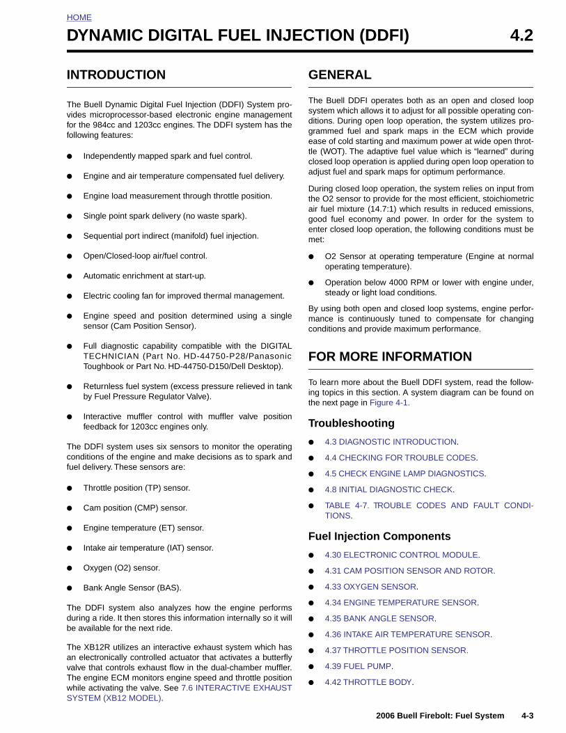
HOME
D
I
Tvff
●
●
●
●
●
●
●
●
●
●
●
●
Tcf
●
YNAMIC DIGITAL FUEL INJECTION (DDFI) 4.2
NTRODUCTION
he Buell Dynamic Digital Fuel Injection (DDFI) System pro-ides microprocessor-based electronic engine managementor the 984cc and 1203cc engines. The DDFI system has theollowing features:
Independently mapped spark and fuel control.
Engine and air temperature compensated fuel delivery.
Engine load measurement through throttle position.
Single point spark delivery (no waste spark).
Sequential port indirect (manifold) fuel injection.
Open/Closed-loop air/fuel control.
Automatic enrichment at start-up.
Electric cooling fan for improved thermal management.
Engine speed and position determined using a singlesensor (Cam Position Sensor).
Full diagnostic capability compatible with the DIGITALTECHNICIAN (Part No. HD-44750-P28/PanasonicToughbook or Part No. HD-44750-D150/Dell Desktop).
Returnless fuel system (excess pressure relieved in tankby Fuel Pressure Regulator Valve).
Interactive muffler control with muffler valve positionfeedback for 1203cc engines only.
he DDFI system uses six sensors to monitor the operatingonditions of the engine and make decisions as to spark anduel delivery. These sensors are:
Throttle position (TP) sensor.
GENERAL
The Buell DDFI operates both as an open and closed loopsystem which allows it to adjust for all possible operating con-ditions. During open loop operation, the system utilizes pro-grammed fuel and spark maps in the ECM which provideease of cold starting and maximum power at wide open throt-tle (WOT). The adaptive fuel value which is “learned” duringclosed loop operation is applied during open loop operation toadjust fuel and spark maps for optimum performance.
During closed loop operation, the system relies on input fromthe O2 sensor to provide for the most efficient, stoichiometricair fuel mixture (14.7:1) which results in reduced emissions,good fuel economy and power. In order for the system toenter closed loop operation, the following conditions must bemet:
● O2 Sensor at operating temperature (Engine at normaloperating temperature).
● Operation below 4000 RPM or lower with engine under,steady or light load conditions.
By using both open and closed loop systems, engine perfor-mance is continuously tuned to compensate for changingconditions and provide maximum performance.
FOR MORE INFORMATION
To learn more about the Buell DDFI system, read the follow-ing topics in this section. A system diagram can be found onthe next page in Figure 4-1.
Troubleshooting
● 4.3 DIAGNOSTIC INTRODUCTION.
● 4.4 CHECKING FOR TROUBLE CODES.
● 4.5 CHECK ENGINE LAMP DIAGNOSTICS.
● 4.8 INITIAL DIAGNOSTIC CHECK.
● TABLE 4-7. TROUBLE CODES AND FAULT CONDI-
2006 Buell Firebolt: Fuel System 4-3
● Cam position (CMP) sensor.
● Engine temperature (ET) sensor.
● Intake air temperature (IAT) sensor.
● Oxygen (O2) sensor.
● Bank Angle Sensor (BAS).
The DDFI system also analyzes how the engine performsduring a ride. It then stores this information internally so it willbe available for the next ride.
The XB12R utilizes an interactive exhaust system which hasan electronically controlled actuator that activates a butterflyvalve that controls exhaust flow in the dual-chamber muffler.The engine ECM monitors engine speed and throttle positionwhile activating the valve. See 7.6 INTERACTIVE EXHAUSTSYSTEM (XB12 MODEL).
TIONS.
Fuel Injection Components
● 4.30 ELECTRONIC CONTROL MODULE.
● 4.31 CAM POSITION SENSOR AND ROTOR.
● 4.33 OXYGEN SENSOR.
● 4.34 ENGINE TEMPERATURE SENSOR.
● 4.35 BANK ANGLE SENSOR.
● 4.36 INTAKE AIR TEMPERATURE SENSOR.
● 4.37 THROTTLE POSITION SENSOR.
● 4.39 FUEL PUMP.
● 4.42 THROTTLE BODY.
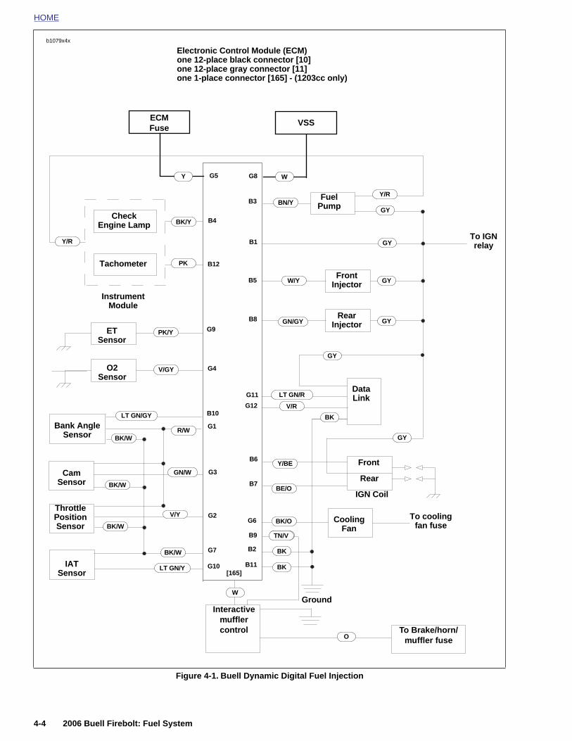
HOME
b1079x4x
Electronic Control Module (ECM)
Cam Sensor
Throttle Position Sensor
ET Sensor
O2 Sensor
FuelPump
FrontInjector
RearInjector
Check Engine Lamp
Bank Angle Sensor
IGN Coil
Front
CoolingFan
DataLink
BN/Y
PK
GN/GY
LT GN/GY
Y/BE
W/Y
LT GN/R
V/GY
PK/Y
R/W
GY
Tachometer
G2
G9
G4
G11
G12
B5
B4
B12
B10
B6
B7
B1
Instrument Module
V/R
BK/Y
BK
GN/W
one 12-place black connector [10]one 12-place gray connector [11]one 1-place connector [165] - (1203cc only)
GY
GY
GY
GY
GY
B8
Y/R
Y/R
B3
BE/O
G1
G3
G6 BK/OTo cooling
fan fuse
Rear
To IGN relay
V/Y
BK/W
BK/W
BK/W
BE/OTN/VB9
VSSECMFuse
G8G5Y W
4-4 2006 Buell Firebolt: Fuel System
Figure 4-1. Buell Dynamic Digital Fuel Injection
IATSensor
Ground
BK
BK
BK/W
LT GN/Y G10
G7 B2
B11[165]
Interactive muffler control To Brake/horn/
muffler fuse
W
O
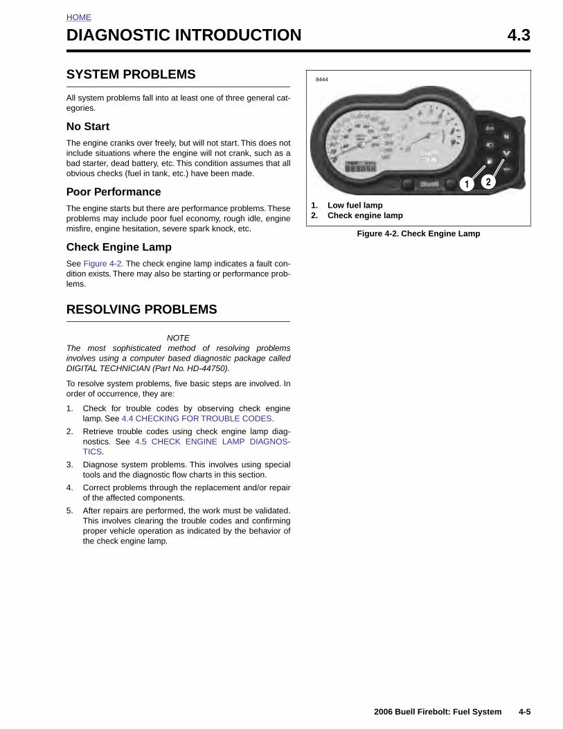
HOME
D
S
Ae
NTibo
PTpm
CSdle
R
TinD
To
1
2
3
4
IAGNOSTIC INTRODUCTION 4.3
YSTEM PROBLEMS
ll system problems fall into at least one of three general cat-gories.
o Starthe engine cranks over freely, but will not start. This does not
nclude situations where the engine will not crank, such as aad starter, dead battery, etc. This condition assumes that allbvious checks (fuel in tank, etc.) have been made.
oor Performancehe engine starts but there are performance problems. Theseroblems may include poor fuel economy, rough idle, engineisfire, engine hesitation, severe spark knock, etc.
heck Engine Lampee Figure 4-2. The check engine lamp indicates a fault con-ition exists. There may also be starting or performance prob-ms.
ESOLVING PROBLEMS
NOTEhe most sophisticated method of resolving problemsvolves using a computer based diagnostic package calledIGITAL TECHNICIAN (Part No. HD-44750).
o resolve system problems, five basic steps are involved. Inrder of occurrence, they are:
. Check for trouble codes by observing check enginelamp. See 4.4 CHECKING FOR TROUBLE CODES.
. Retrieve trouble codes using check engine lamp diag-nostics. See 4.5 CHECK ENGINE LAMP DIAGNOS-TICS.
. Diagnose system problems. This involves using specialtools and the diagnostic flow charts in this section.
. Correct problems through the replacement and/or repairof the affected components.
Figure 4-2. Check Engine Lamp
2
1. Low fuel lamp2. Check engine lamp
1
8444
2006 Buell Firebolt: Fuel System 4-5
5. After repairs are performed, the work must be validated.This involves clearing the trouble codes and confirmingproper vehicle operation as indicated by the behavior ofthe check engine lamp.
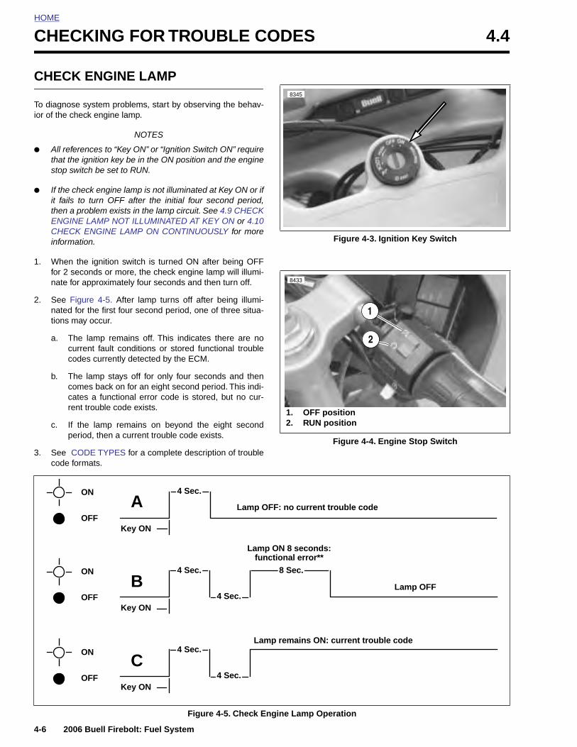
HOME
CHECKING FOR TROUBLE CODES 4.4
CHEC
To diagnoior of the c
● All rethat thstop s
● If the it failsthen aENGICHECinform
1. Whenfor 2 nate
2. See natedtions
a. Tcc
b. Tccr
c. Ip
3. See code
4-6
K ENGINE LAMP
se system problems, start by observing the behav-heck engine lamp.
NOTES
ferences to “Key ON” or “Ignition Switch ON” requiree ignition key be in the ON position and the enginewitch be set to RUN.
check engine lamp is not illuminated at Key ON or if to turn OFF after the initial four second period, problem exists in the lamp circuit. See 4.9 CHECK
NE LAMP NOT ILLUMINATED AT KEY ON or 4.10K ENGINE LAMP ON CONTINUOUSLY for moreation.
the ignition switch is turned ON after being OFFseconds or more, the check engine lamp will illumi-for approximately four seconds and then turn off.
Figure 4-5. After lamp turns off after being illumi- for the first four second period, one of three situa-may occur.
he lamp remains off. This indicates there are nourrent fault conditions or stored functional troubleodes currently detected by the ECM.
he lamp stays off for only four seconds and thenomes back on for an eight second period. This indi-ates a functional error code is stored, but no cur-ent trouble code exists.
f the lamp remains on beyond the eight seconderiod, then a current trouble code exists.
CODE TYPES for a complete description of troubleformats.
Figure 4-3. Ignition Key Switch
Figure 4-4. Engine Stop Switch
8345
1. OFF position2. RUN position
1
2
8433
ON
OFFKey ON
A Lamp OFF: no current trouble code
Lamp ON 8 seconds:
4 Sec.
2006 Buell Firebolt: Fuel System
Figure 4-5. Check Engine Lamp Operation
ON
OFF
ON
OFF
Key ON
Key ON
B
CLamp remains ON: current trouble code
Lamp OFF
functional error**
4 Sec.
4 Sec.
4 Sec.
4 Sec.
8 Sec.
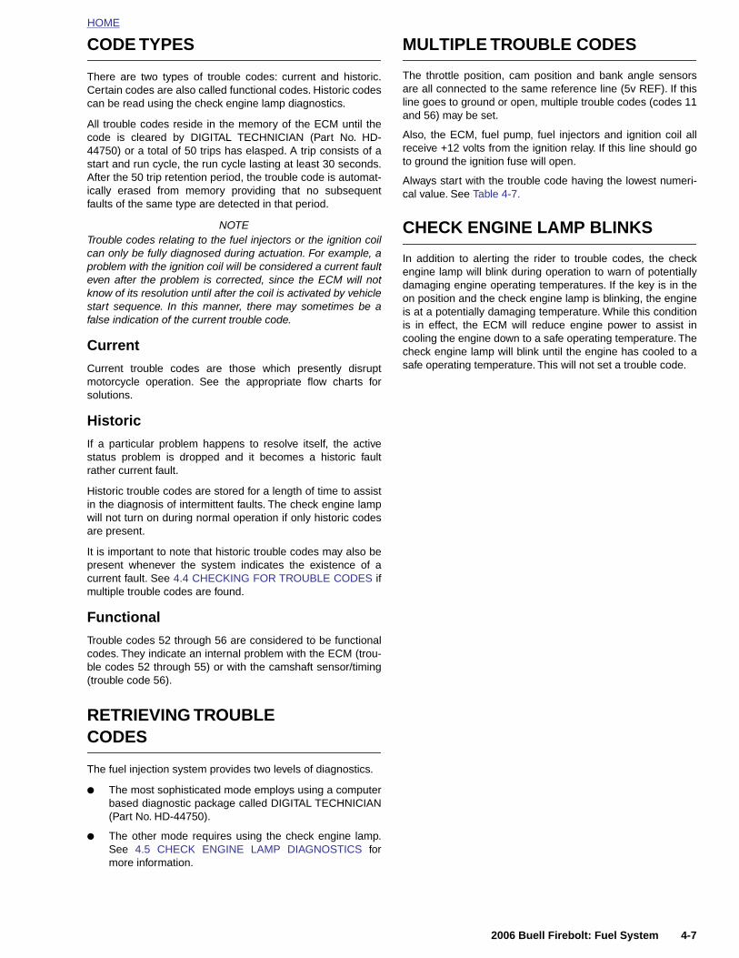
HOME
CODE TYPES
There are two types of trouble codes: current and historic.Certain codes are also called functional codes. Historic codescan be read using the check engine lamp diagnostics.
All trouble codes reside in the memory of the ECM until thecode is cleared by DIGITAL TECHNICIAN (Part No. HD-44750) or a total of 50 trips has elasped. A trip consists of astart and run cycle, the run cycle lasting at least 30 seconds.After the 50 trip retention period, the trouble code is automat-ically erased from memory providing that no subsequentfaults of the same type are detected in that period.
NOTETrouble codes relating to the fuel injectors or the ignition coilcan only be fully diagnosed during actuation. For example, aproblem with the ignition coil will be considered a current faulteven after the problem is corrected, since the ECM will notknow of its resolution until after the coil is activated by vehiclestart sequence. In this manner, there may sometimes be afalse indication of the current trouble code.
Current
Current trouble codes are those which presently disruptmotorcycle operation. See the appropriate flow charts forsolutions.
Historic
If a particular problem happens to resolve itself, the activestatus problem is dropped and it becomes a historic faultrather current fault.
Historic trouble codes are stored for a length of time to assistin the diagnosis of intermittent faults. The check engine lampwill not turn on during normal operation if only historic codesare present.
It is important to note that historic trouble codes may also bepresent whenever the system indicates the existence of acurrent fault. See 4.4 CHECKING FOR TROUBLE CODES ifmultiple trouble codes are found.
Functional
Trouble codes 52 through 56 are considered to be functionalcodes. They indicate an internal problem with the ECM (trou-
MULTIPLE TROUBLE CODES
The throttle position, cam position and bank angle sensorsare all connected to the same reference line (5v REF). If thisline goes to ground or open, multiple trouble codes (codes 11and 56) may be set.
Also, the ECM, fuel pump, fuel injectors and ignition coil allreceive +12 volts from the ignition relay. If this line should goto ground the ignition fuse will open.
Always start with the trouble code having the lowest numeri-cal value. See Table 4-7.
CHECK ENGINE LAMP BLINKS
In addition to alerting the rider to trouble codes, the checkengine lamp will blink during operation to warn of potentiallydamaging engine operating temperatures. If the key is in theon position and the check engine lamp is blinking, the engineis at a potentially damaging temperature. While this conditionis in effect, the ECM will reduce engine power to assist incooling the engine down to a safe operating temperature. Thecheck engine lamp will blink until the engine has cooled to asafe operating temperature. This will not set a trouble code.
2006 Buell Firebolt: Fuel System 4-7
ble codes 52 through 55) or with the camshaft sensor/timing(trouble code 56).
RETRIEVING TROUBLECODES
The fuel injection system provides two levels of diagnostics.
● The most sophisticated mode employs using a computerbased diagnostic package called DIGITAL TECHNICIAN(Part No. HD-44750).
● The other mode requires using the check engine lamp.See 4.5 CHECK ENGINE LAMP DIAGNOSTICS formore information.
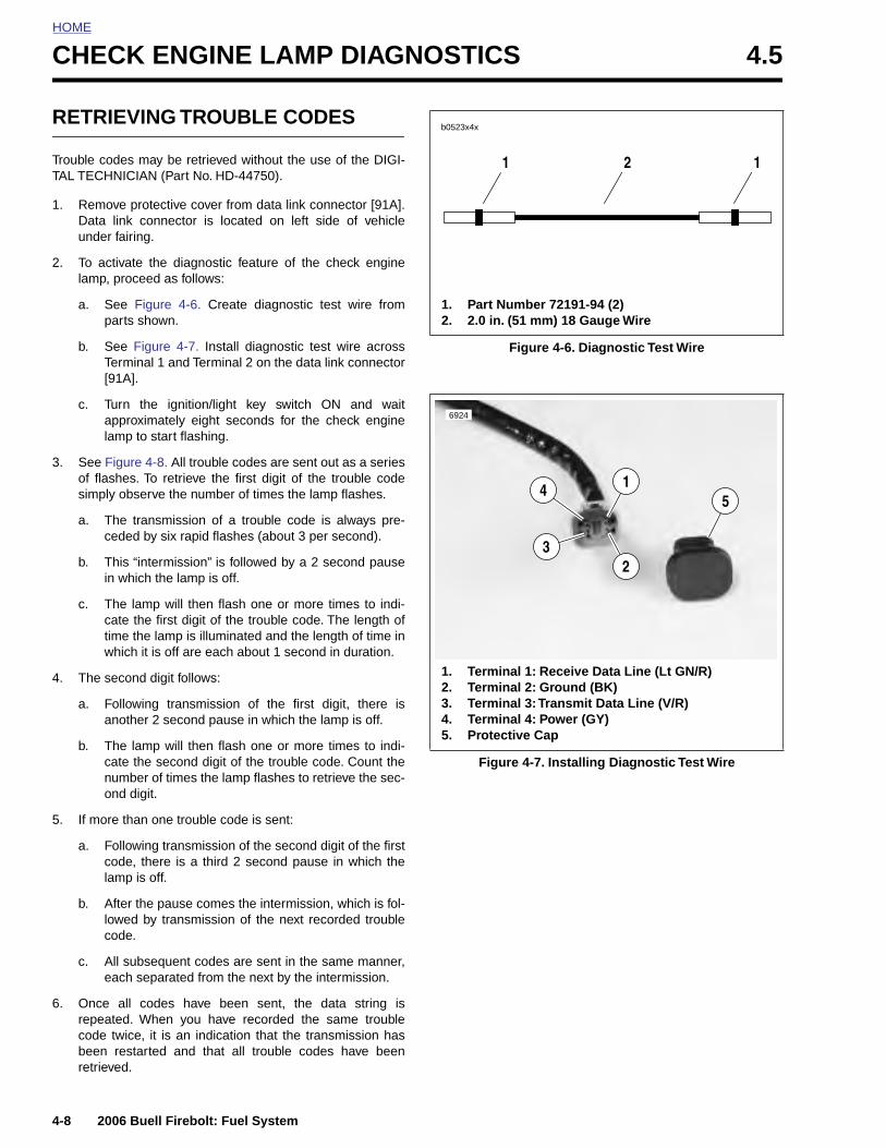
HOME
CHECK ENGINE LAMP DIAGNOSTICS 4.5
RETR
Trouble coTAL TECH
1. RemoData unde
2. To aclamp,
a. Sp
b. ST[
c. Tala
3. See Fof flasimpl
a. Tc
b. Tin
c. Tctw
4. The s
a. Fa
b. Tcno
5. If mo
4-8
a.
b.
c.
6. Oncrepecodbeeretr
IEVING TROUBLE CODES
des may be retrieved without the use of the DIGI-NICIAN (Part No. HD-44750).
ve protective cover from data link connector [91A].link connector is located on left side of vehicle
r fairing.
tivate the diagnostic feature of the check engine proceed as follows:
ee Figure 4-6. Create diagnostic test wire fromarts shown.
ee Figure 4-7. Install diagnostic test wire acrosserminal 1 and Terminal 2 on the data link connector91A].
urn the ignition/light key switch ON and waitpproximately eight seconds for the check enginemp to start flashing.
igure 4-8. All trouble codes are sent out as a seriesshes. To retrieve the first digit of the trouble codey observe the number of times the lamp flashes.
he transmission of a trouble code is always pre-eded by six rapid flashes (about 3 per second).
his “intermission” is followed by a 2 second pause which the lamp is off.
he lamp will then flash one or more times to indi-ate the first digit of the trouble code. The length ofime the lamp is illuminated and the length of time inhich it is off are each about 1 second in duration.
econd digit follows:
ollowing transmission of the first digit, there isnother 2 second pause in which the lamp is off.
he lamp will then flash one or more times to indi-ate the second digit of the trouble code. Count theumber of times the lamp flashes to retrieve the sec-nd digit.
re than one trouble code is sent:
Figure 4-6. Diagnostic Test Wire
Figure 4-7. Installing Diagnostic Test Wire
b0523x4x
1 2 1
1. Part Number 72191-94 (2)2. 2.0 in. (51 mm) 18 Gauge Wire
1. Terminal 1: Receive Data Line (Lt GN/R)2. Terminal 2: Ground (BK)3. Terminal 3: Transmit Data Line (V/R)4. Terminal 4: Power (GY)5. Protective Cap
6924
14
32
5
2006 Buell Firebolt: Fuel System
Following transmission of the second digit of the firstcode, there is a third 2 second pause in which thelamp is off.
After the pause comes the intermission, which is fol-lowed by transmission of the next recorded troublecode.
All subsequent codes are sent in the same manner,each separated from the next by the intermission.
e all codes have been sent, the data string isated. When you have recorded the same trouble
e twice, it is an indication that the transmission hasn restarted and that all trouble codes have beenieved.
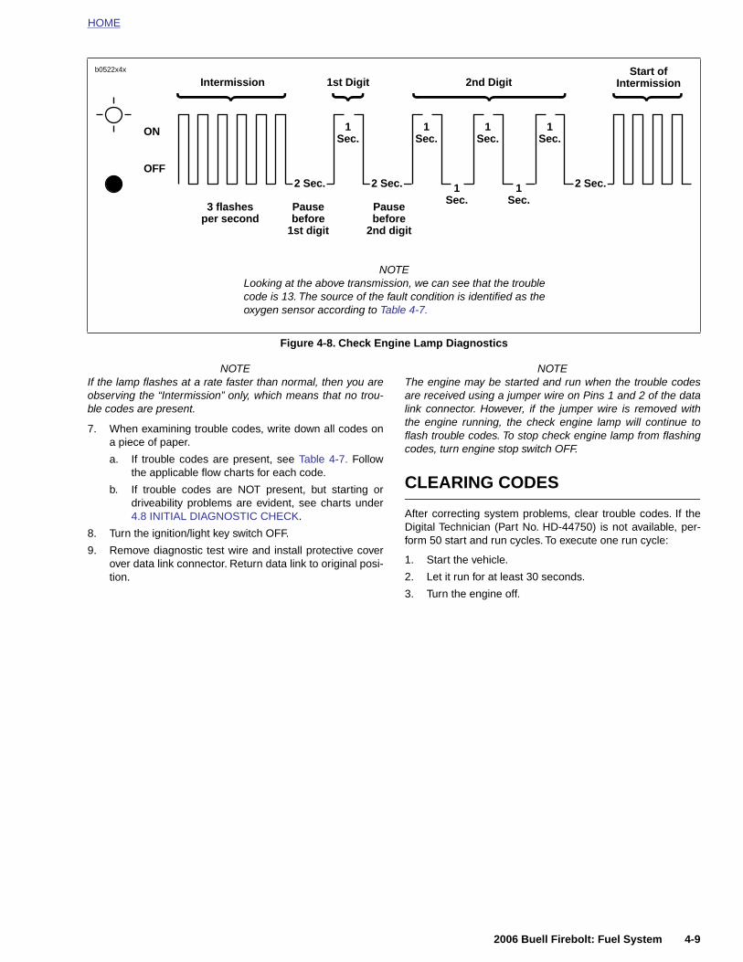
HOME
NOTEIf the lamp flashes at a rate faster than normal, then you areobserving the “Intermission” only, which means that no trou-ble codes are present.
7. When examining trouble codes, write down all codes ona piece of paper.
a. If trouble codes are present, see Table 4-7. Followthe applicable flow charts for each code.
b. If trouble codes are NOT present, but starting ordriveability problems are evident, see charts under4.8 INITIAL DIAGNOSTIC CHECK.
8. Turn the ignition/light key switch OFF.
9. Remove diagnostic test wire and install protective coverover data link connector. Return data link to original posi-tion.
NOTEThe engine may be started and run when the trouble codesare received using a jumper wire on Pins 1 and 2 of the datalink connector. However, if the jumper wire is removed withthe engine running, the check engine lamp will continue toflash trouble codes. To stop check engine lamp from flashingcodes, turn engine stop switch OFF.
CLEARING CODES
After correcting system problems, clear trouble codes. If theDigital Technician (Part No. HD-44750) is not available, per-form 50 start and run cycles. To execute one run cycle:
1. Start the vehicle.
2. Let it run for at least 30 seconds.
3. Turn the engine off.
Figure 4-8. Check Engine Lamp Diagnostics
ON
OFF
Intermission
2 Sec.
1Sec.
1st Digit 2nd Digit
3 flashes per second
Pause before
1st digit
Start of Intermission
2 Sec. 2 Sec.1Sec.
Pause before
2nd digit
NOTELooking at the above transmission, we can see that the troublecode is 13. The source of the fault condition is identified as theoxygen sensor according to Table 4-7.
1Sec.
1Sec.
1Sec.
1Sec.
b0522x4x
2006 Buell Firebolt: Fuel System 4-9
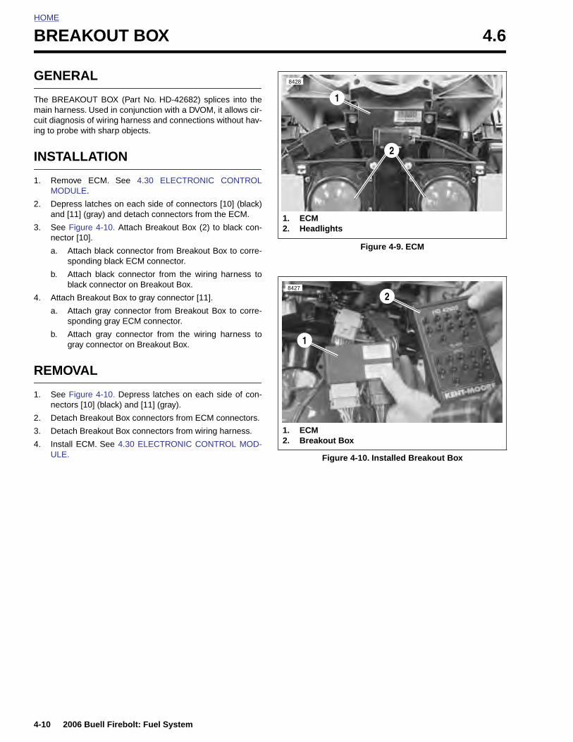
HOME
BREAKOUT BOX 4.6
GENE
The BREAmain harncuit diagning to prob
INSTA
1. RemoMOD
2. Depreand [
3. See Fnecto
a. As
b. Ab
4. Attac
a. As
b. Ag
REMO
1. See Fnecto
2. Detac
3. Detac
4. InstalULE.
4-10
RAL
KOUT BOX (Part No. HD-42682) splices into theess. Used in conjunction with a DVOM, it allows cir-osis of wiring harness and connections without hav-e with sharp objects.
LLATION
ve ECM. See 4.30 ELECTRONIC CONTROLULE.
ss latches on each side of connectors [10] (black)11] (gray) and detach connectors from the ECM.
igure 4-10. Attach Breakout Box (2) to black con-r [10].
ttach black connector from Breakout Box to corre-ponding black ECM connector.
ttach black connector from the wiring harness tolack connector on Breakout Box.
h Breakout Box to gray connector [11].
ttach gray connector from Breakout Box to corre-ponding gray ECM connector.
ttach gray connector from the wiring harness toray connector on Breakout Box.
VAL
igure 4-10. Depress latches on each side of con-rs [10] (black) and [11] (gray).
h Breakout Box connectors from ECM connectors.
h Breakout Box connectors from wiring harness.
l ECM. See 4.30 ELECTRONIC CONTROL MOD-
Figure 4-9. ECM
Figure 4-10. Installed Breakout Box
1. ECM2. Headlights
1
2
8428
1. ECM2. Breakout Box
1
28427
2006 Buell Firebolt: Fuel System
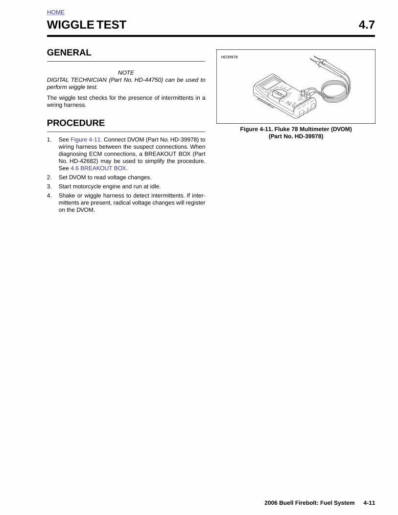
HOME
W
G
Dp
Tw
P
1
2
3
4
IGGLE TEST 4.7
ENERAL
NOTEIGITAL TECHNICIAN (Part No. HD-44750) can be used toerform wiggle test.
he wiggle test checks for the presence of intermittents in airing harness.
ROCEDURE
. See Figure 4-11. Connect DVOM (Part No. HD-39978) towiring harness between the suspect connections. Whendiagnosing ECM connections, a BREAKOUT BOX (PartNo. HD-42682) may be used to simplify the procedure.See 4.6 BREAKOUT BOX.
. Set DVOM to read voltage changes.
. Start motorcycle engine and run at idle.
. Shake or wiggle harness to detect intermittents. If inter-mittents are present, radical voltage changes will registeron the DVOM.
Figure 4-11. Fluke 78 Multimeter (DVOM) (Part No. HD-39978)
HD39978
2006 Buell Firebolt: Fuel System 4-11
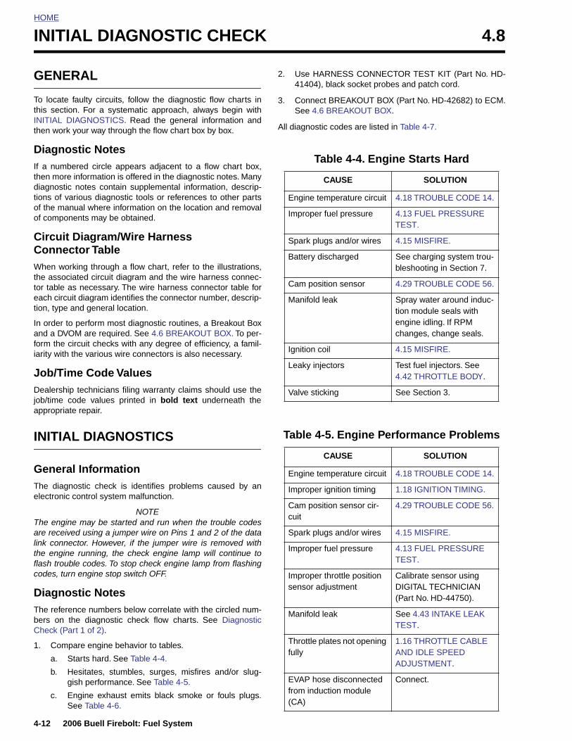
HOME
INITIAL DIAGNOSTIC CHECK 4.8
GENE
To locate this sectioINITIAL Dthen work
DiagnoIf a numbthen morediagnostictions of vaof the maof compon
Circuit ConnecWhen wothe assoctor table aeach circution, type
In order toand a DVOform the ciarity with
Job/TimDealershijob/time cappropria
INITIA
GeneraThe diagnelectronic
The enginare receivlink conne
4-12
the engflash trocodes, t
DiagnThe refebers onCheck (P
1. Com
a.
b.
c.
RAL
faulty circuits, follow the diagnostic flow charts inn. For a systematic approach, always begin withIAGNOSTICS. Read the general information and your way through the flow chart box by box.
stic Notesered circle appears adjacent to a flow chart box, information is offered in the diagnostic notes. Many notes contain supplemental information, descrip-rious diagnostic tools or references to other parts
nual where information on the location and removalents may be obtained.
Diagram/Wire Harnesstor Table
rking through a flow chart, refer to the illustrations,iated circuit diagram and the wire harness connec-s necessary. The wire harness connector table forit diagram identifies the connector number, descrip-and general location.
perform most diagnostic routines, a Breakout BoxM are required. See 4.6 BREAKOUT BOX. To per-
ircuit checks with any degree of efficiency, a famil-the various wire connectors is also necessary.
e Code Valuesp technicians filing warranty claims should use theode values printed in bold text underneath the
te repair.
L DIAGNOSTICS
l Informationostic check is identifies problems caused by an
control system malfunction.
NOTEe may be started and run when the trouble codesed using a jumper wire on Pins 1 and 2 of the datactor. However, if the jumper wire is removed with
2. Use HARNESS CONNECTOR TEST KIT (Part No. HD-41404), black socket probes and patch cord.
3. Connect BREAKOUT BOX (Part No. HD-42682) to ECM.See 4.6 BREAKOUT BOX.
All diagnostic codes are listed in Table 4-7.
Table 4-4. Engine Starts Hard
CAUSE SOLUTION
Engine temperature circuit 4.18 TROUBLE CODE 14.
Improper fuel pressure 4.13 FUEL PRESSURE TEST.
Spark plugs and/or wires 4.15 MISFIRE.
Battery discharged See charging system trou-bleshooting in Section 7.
Cam position sensor 4.29 TROUBLE CODE 56.
Manifold leak Spray water around induc-tion module seals with engine idling. If RPM changes, change seals.
Ignition coil 4.15 MISFIRE.
Leaky injectors Test fuel injectors. See 4.42 THROTTLE BODY.
Valve sticking See Section 3.
Table 4-5. Engine Performance Problems
CAUSE SOLUTION
Engine temperature circuit 4.18 TROUBLE CODE 14.
Improper ignition timing 1.18 IGNITION TIMING.
Cam position sensor cir-cuit
4.29 TROUBLE CODE 56.
Spark plugs and/or wires 4.15 MISFIRE.
2006 Buell Firebolt: Fuel System
ine running, the check engine lamp will continue touble codes. To stop check engine lamp from flashingurn engine stop switch OFF.
ostic Notesrence numbers below correlate with the circled num- the diagnostic check flow charts. See Diagnosticart 1 of 2).
pare engine behavior to tables.
Starts hard. See Table 4-4.
Hesitates, stumbles, surges, misfires and/or slug-gish performance. See Table 4-5.
Engine exhaust emits black smoke or fouls plugs.See Table 4-6.
Improper fuel pressure 4.13 FUEL PRESSURE TEST.
Improper throttle position sensor adjustment
Calibrate sensor using DIGITAL TECHNICIAN (Part No. HD-44750).
Manifold leak See 4.43 INTAKE LEAK TEST.
Throttle plates not opening fully
1.16 THROTTLE CABLE AND IDLE SPEED ADJUSTMENT.
EVAP hose disconnected from induction module (CA)
Connect.

HOME
Throttle plates not opening fully
1.16 THROTTLE CABLE AND IDLE SPEED ADJUSTMENT.
EVAP hose disconnected from induction module (CA)
Connect.
Water or dirt in fuel system Drain and refill with fresh fuel.
Cooling fan inoperative 4.26 TROUBLE CODE 36.
Interactive muffler control Inoperative
4.21 TROUBLE CODE 21
Table 4-5. Engine Performance Problems
CAUSE SOLUTIONTable 4-6. Engine Exhaust Emits
Black Smoke or Fouls Plugs
CAUSE SOLUTION
Engine temperature circuit 4.18 TROUBLE CODE 14.
Clogged air filter 1.15 AIR CLEANER FILTER.
Improper throttle positionsensor adjustment
Calibrate sensor. See 4.37 THROTTLE POSITION SENSOR.
Leaky injectors Test fuel injectors. See 4.42 THROTTLE BODY.
Improper fuel pressure 4.13 FUEL PRESSURE TEST.
Table 4-7. Trouble Codes and Fault Conditions
CODE NO. FAULT CONDITION RELEVANT TOPIC
11 Throttle position sensor 4.16 TROUBLE CODE 11
13 Oxygen sensor 4.17 TROUBLE CODE 13
14 Engine temperature sensor 4.18 TROUBLE CODE 14
15 Intake air temperature sensor 4.19 TROUBLE CODE 15
16 Battery voltage 4.20 TROUBLE CODE 16
21 Interactive muffler control (1203’s only) 4.21 TROUBLE CODE 21
23 Front fuel injector 4.22 TROUBLE CODES 23 AND 32
24 Front ignition coil 4.23 TROUBLE CODES 24 AND 25
25 Rear ignition coil 4.23 TROUBLE CODES 24 AND 25
32 Rear fuel injector 4.22 TROUBLE CODES 23 AND 32
33 Fuel pump 4.24 TROUBLE CODE 33
35 Tachometer 4.25 TROUBLE CODE 35
36 Cooling fan 4.26 TROUBLE CODE 36
2006 Buell Firebolt: Fuel System 4-13
44 Bank angle sensor 4.27 TROUBLE CODE 44
52, 53, 54, 55 ECM failure 4.28 TROUBLE CODES 52, 53, 54 AND 55
56 Cam sync failure 4.29 TROUBLE CODE 56

HOME
b1080a4x
1234
Electronic Control Module (ECM)
Connector [10] Connector [11]
LTGN/RGYBK
BK V/R
Data Link [91A]
To IGN relay
4-14 2006 Buell Firebolt: Fuel System
Figure 4-12. Diagnostic Check
Table 4-8. Wire Harness Connectors in Figure 4-12.
NO. DESCRIPTION TYPE LOCATION
[10] ECM (black) 12-place Deutsch in fairing
[11] ECM (gray) 12-place Deutsch in fairing
[91A] data link 4-place Deutsch beneath left side fairing

HOME
Diagnostic Check (Part 1 of 2)
Turn ignition/headlight key switch ON. Set engine stop switch to RUN. Do not start
engine. Does check engine lamp illuminate?
See 4.9 CHECK ENGINE LAMP NOT ILLUMINATED AT
KEY ON.
NO
Does light go off after four seconds?
YES
See 4.10 CHECK ENGINE LAMP ON CONTINUOUSLY.
NO
Does enginestart?
YES
See 4.11 ENGINE CRANKS BUT WILL NOT START.
NOYES
NO
Are any troublecodes displayed?
YES
Go to Diagnostic Check (Part 2 of 2).STOP
Does check engine lamp dis-play ignition module data? See 4.4 CHECKING FOR TROU-
BLE CODES.
2006 Buell Firebolt: Fuel System 4-15
NO
Refer to applicable trouble code flow chart. Start with lowest trouble code. All diagnostic codes are listed on page 4-13 in Table 4-7.
YES
Refer to diagnostic tips in related trouble code chart (even if
no code is set).
1

HOME
Diagnostic Check (Part 2 of 2)
Continued from Diagnostic Check (Part 1 of 2).
Remove ECM connectors [10B] (BK) and [11B] (GY). Check for continuity to ground at data link connector [91A] Terminals 1, 3 and 4. Continu-
ity to ground?
Test the four data link connector terminals against their ECM connector pins for continuity.
Continuity present in all four circumstances?
DATA LINK TERMINAL ECM TERMINAL
Pin Wire Color Pin Connector
1 Lt. GN/R 11 [11B]
2 BK 11 [10B]
3 V/R 12 [11B]
4 GY 1 [10B]
NO
Repair shortto ground.
YES
YES
Inspect terminals for damage or repair opens as necessary.
NO
2
2
Replace ECM. See 4.30 ELECTRONIC
CONTROL MODULE.
3
4-16 2006 Buell Firebolt: Fuel System
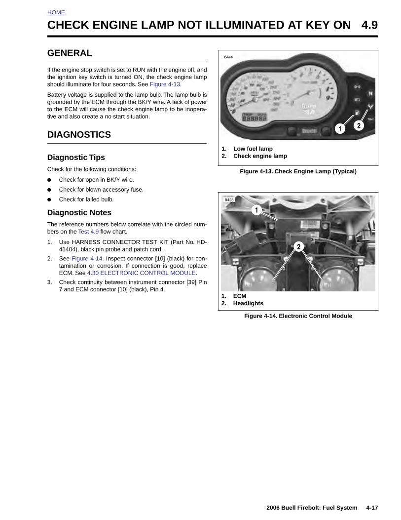
HOME
C
G
Its
Bgtt
D
DC
●
●
●
DTb
1
2
3
HECK ENGINE LAMP NOT ILLUMINATED AT KEY ON 4.9
ENERAL
f the engine stop switch is set to RUN with the engine off, andhe ignition key switch is turned ON, the check engine lamphould illuminate for four seconds. See Figure 4-13.
attery voltage is supplied to the lamp bulb. The lamp bulb isrounded by the ECM through the BK/Y wire. A lack of powero the ECM will cause the check engine lamp to be inopera-ive and also create a no start situation.
IAGNOSTICS
iagnostic Tipsheck for the following conditions:
Check for open in BK/Y wire.
Check for blown accessory fuse.
Check for failed bulb.
iagnostic Noteshe reference numbers below correlate with the circled num-ers on the Test 4.9 flow chart.
. Use HARNESS CONNECTOR TEST KIT (Part No. HD-41404), black pin probe and patch cord.
. See Figure 4-14. Inspect connector [10] (black) for con-tamination or corrosion. If connection is good, replaceECM. See 4.30 ELECTRONIC CONTROL MODULE.
. Check continuity between instrument connector [39] Pin7 and ECM connector [10] (black), Pin 4.
Figure 4-13. Check Engine Lamp (Typical)
Figure 4-14. Electronic Control Module
1. Low fuel lamp2. Check engine lamp
21
8444
8428
1. ECM2. Headlights
1
2
2006 Buell Firebolt: Fuel System 4-17
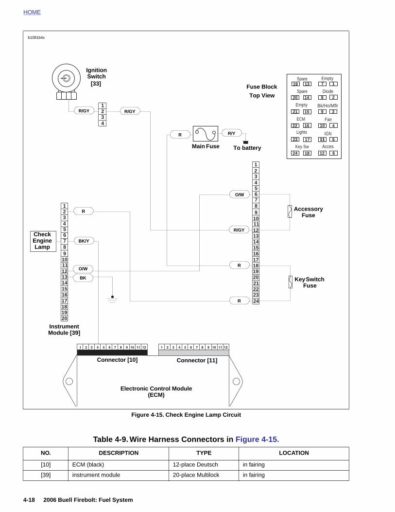
HOME
b1081b4x
1234
1
3456789
101112131415161718192021222324
2
123456789
1011121314151617181920
19
20
21
22
23
24
13
14
15
16
17
18
1
2
3
4
5
6
7
8
9
10
11
12
11
Spare
Diode
Bk/Hn/Mflr
Fan
IGN
Acces.Key Sw
Lights
ECM
Spare
Empty
Empty
BK
Ignition Switch
[33]
To battery
Connector [10] Connector [11]
Instrument Module [39]
R
BK/Y
R/Y
R/GY
O/W
R
R
R
Main Fuse
Fuse Block
Check Engine Lamp
Accessory Fuse
Key Switch Fuse
Top View
R/GY R/GY
O/W
4-18 2006 Buell Firebolt: Fuel System
Figure 4-15. Check Engine Lamp Circuit
Electronic Control Module(ECM)
Table 4-9. Wire Harness Connectors in Figure 4-15.
NO. DESCRIPTION TYPE LOCATION
[10] ECM (black) 12-place Deutsch in fairing
[39] instrument module 20-place Multilock in fairing
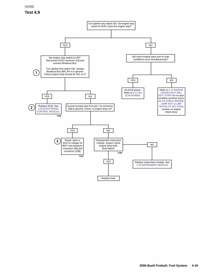
HOME
Test 4.9
Set engine stop switch to OFF. Disconnect ECM connector [10] and
connect Breakout Box.
Turn ignition key switch ON. Jumper Breakout Box (BK) Pin 4 to ground.
Check engine lamp should be ON. Is it?
Turn ignition key switch ON. Set engine stop switch to RUN. Does the engine start?
YES NO
1
Did check engine lamp and no startconditions occur simultaneously?
YES
No ECM power. Refer to 4.12 NO ECM POWER.
NO
Refer to 4.11 ENGINE CRANKS BUT WILL
NOT START for no start condition and then return to 4.9 CHECK ENGINE
LAMP NOT ILLUMI-NATED AT KEY ON to
resolve no engine check lamp.
YES NO
Connect jumper wire from pin 7 at connector [39] to ground. Check, is engine lamp on?
YES
Repair open or short to voltage on BK/Y wire between connector [39] and connector [10B].
NO
Disassemble instrument module. Inspect check
engine lamp bulb.Bulb failed?
2
3
Replace ECM. See 4.30 ELECTRONIC
CONTROL MODULE.
7130
7151
7145
NO
Replace Instrument module. See 7.18 INSTRUMENT MODULE
YES
Replace bulb.
2006 Buell Firebolt: Fuel System 4-19
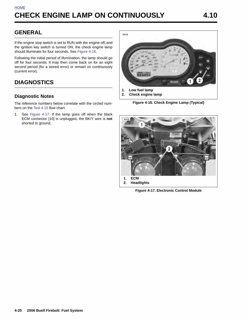
HOME
CHECK ENGINE LAMP ON CONTINUOUSLY 4.10
GENE
If the engithe ignitioshould illu
Following off for fousecond pe(current e
DIAGN
DiagnoThe referebers on th
1. See ECM short
4-20
RAL
ne stop switch is set to RUN with the engine off, andn key switch is turned ON, the check engine lampminate for four seconds. See Figure 4-16.
the initial period of illumination, the lamp should gor seconds. It may then come back on for an eightriod (for a stored error) or remain on continuously
rror).
OSTICS
stic Notesnce numbers below correlate with the circled num-e Test 4.10 flow chart.
Figure 4-17. If the lamp goes off when the blackconnector [10] is unplugged, the BK/Y wire is not
ed to ground.
Figure 4-16. Check Engine Lamp (Typical)
Figure 4-17. Electronic Control Module
1. Low fuel lamp2. Check engine lamp
21
8444
8428
1. ECM2. Headlights
2
1
2006 Buell Firebolt: Fuel System
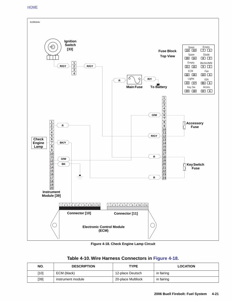
HOME
1234
1
3456789
101112131415161718192021222324
2
123456789
1011121314151617181920
19
20
21
22
23
24
13
14
15
16
17
18
1
2
3
4
5
6
7
8
9
10
11
12
11
Spare
Diode
Bk/Hn/Mflr
Fan
IGN
Acces.Key Sw
Lights
ECM
Spare
Empty
Empty
BK
Ignition Switch
[33]
To Battery
Instrument Module [39]
R
BK/Y
R/Y
R/GY
O/W
R
R
R
Main Fuse
Fuse Block
Check Engine Lamp
Accessory Fuse
Key Switch Fuse
b1081b4x
Top View
R/GY R/GY
O/W
2006 Buell Firebolt: Fuel System 4-21
Figure 4-18. Check Engine Lamp Circuit
Electronic Control Module(ECM)
Connector [10] Connector [11]
Table 4-10. Wire Harness Connectors in Figure 4-18.
NO. DESCRIPTION TYPE LOCATION
[10] ECM (black) 12-place Deutsch in fairing
[39] instrument module 20-place Multilock in fairing

HOME
Test 4.10
Turn ignition key switch OFF. Disconnect black ECM connector [10]. Turn ignition key
switch ON. Check engine lamp should be OFF. Is it?
YES NO
1
Disconnect instrument connector [39]. Remove BK/Y wire from connector [39A]. Reconnect [39]. Check engine lamp ON?
YES NO
Check engine lamp function OK. Check for trouble codes. See 4.4
CHECKING FOR TROUBLE CODES.
With ignition key switch OFF, reconnect black ECM connector [10]. With ignition key
switch ON, verify that there is NOT a 4 second lamp OFF period.
Is there a lamp OFF period?
YES NO
Repair short to ground on BK/Y wire between
connector [39] and connector [10].
Repair short to ground on BK/Y wire between
connector [39] and lamp in tachometer.
Replace ECM. See 4.30 ELECTRONIC
CONTROL MODULE.
4-22 2006 Buell Firebolt: Fuel System
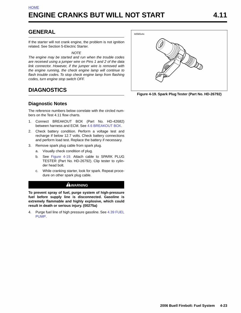
HOME
E
G
Ir
Talitflc
D
DTb
1
2
3
Tfer
4
NGINE CRANKS BUT WILL NOT START 4.11
ENERAL
f the starter will not crank engine, the problem is not ignitionelated. See Section 5-Electric Starter.
NOTEhe engine may be started and run when the trouble codesre received using a jumper wire on Pins 1 and 2 of the datank connector. However, if the jumper wire is removed withhe engine running, the check engine lamp will continue toash trouble codes. To stop check engine lamp from flashingodes, turn engine stop switch OFF.
IAGNOSTICS
iagnostic Noteshe reference numbers below correlate with the circled num-ers on the Test 4.11 flow charts.
. Connect BREAKOUT BOX (Part No. HD-42682)between harness and ECM. See 4.6 BREAKOUT BOX.
. Check battery condition. Perform a voltage test andrecharge if below 12.7 volts. Check battery connectionsand perform load test. Replace the battery if necessary.
. Remove spark plug cable from spark plug.
a. Visually check condition of plug.
b. See Figure 4-19. Attach cable to SPARK PLUGTESTER (Part No. HD-26792). Clip tester to cylin-der head bolt.
c. While cranking starter, look for spark. Repeat proce-dure on other spark plug cable.
1WARNING1WARNING
o prevent spray of fuel, purge system of high-pressureuel before supply line is disconnected. Gasoline isxtremely flammable and highly explosive, which couldesult in death or serious injury. (00275a)
. Purge fuel line of high pressure gasoline. See 4.39 FUEL
Figure 4-19. Spark Plug Tester (Part No. HD-26792)
b0565x4x
2006 Buell Firebolt: Fuel System 4-23
PUMP.
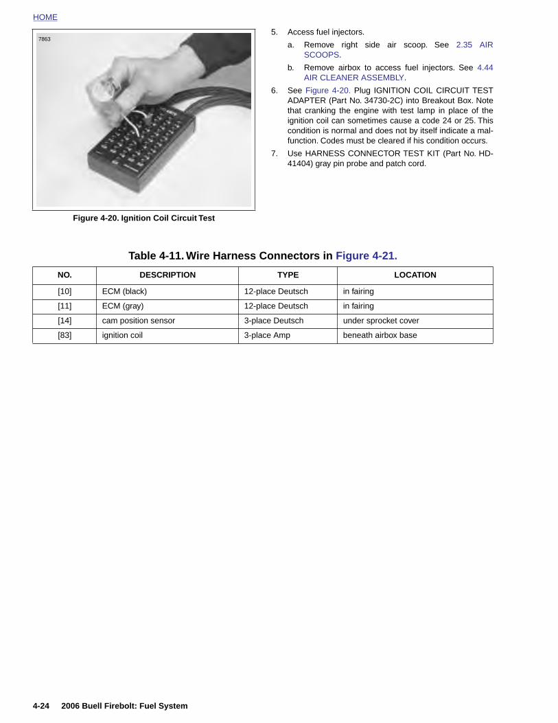
HOME
5. Access fuel injectors.
a. Remove right side air scoop. See 2.35 AIR
7863
SCOOPS.
b. Remove airbox to access fuel injectors. See 4.44AIR CLEANER ASSEMBLY.
6. See Figure 4-20. Plug IGNITION COIL CIRCUIT TESTADAPTER (Part No. 34730-2C) into Breakout Box. Notethat cranking the engine with test lamp in place of theignition coil can sometimes cause a code 24 or 25. Thiscondition is normal and does not by itself indicate a mal-function. Codes must be cleared if his condition occurs.
7. Use HARNESS CONNECTOR TEST KIT (Part No. HD-41404) gray pin probe and patch cord.
Figure 4-20. Ignition Coil Circuit Test
Table 4-11. Wire Harness Connectors in Figure 4-21.
NO. DESCRIPTION TYPE LOCATION
[10] ECM (black) 12-place Deutsch in fairing
[11] ECM (gray) 12-place Deutsch in fairing
[14] cam position sensor 3-place Deutsch under sprocket cover
[83] ignition coil 3-place Amp beneath airbox base
4-24 2006 Buell Firebolt: Fuel System
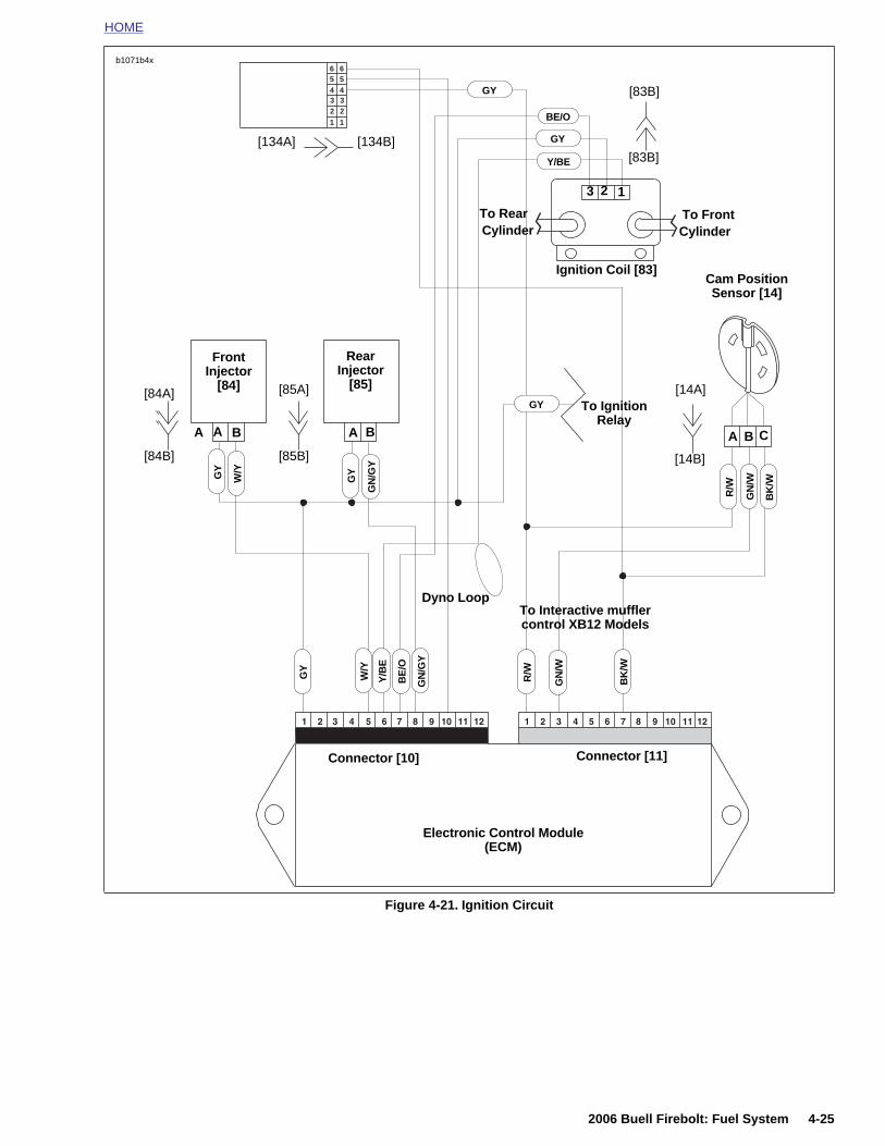
HOME
123456
123456
123456
123456
Front Injector
[84]
Ignition Coil [83]
W/Y
GN
/W
BK
/W
R/W
Connector [10] Connector [11]
GY
Cam Position Sensor [14]
A
GN
/W
Y/B
E
GY
BE
/O
BK
/W
B CAA
3 12
BA
To RearCylinder
To FrontCylinder
W/Y
GN
/GY
Rear Injector
[85]
GY To Ignition Relay
Y/BE
GY
BE/O
GY
GN
/GY
Dyno Loop
b1071b4x
GY
To Interactive muffler control XB12 Models
R/W
[83B]
[83B]
[14A]
[14B]
[134B][134A]
B
[84A]
[84B]
[85A]
[85B]
2006 Buell Firebolt: Fuel System 4-25
Figure 4-21. Ignition Circuit
Electronic Control Module (ECM)
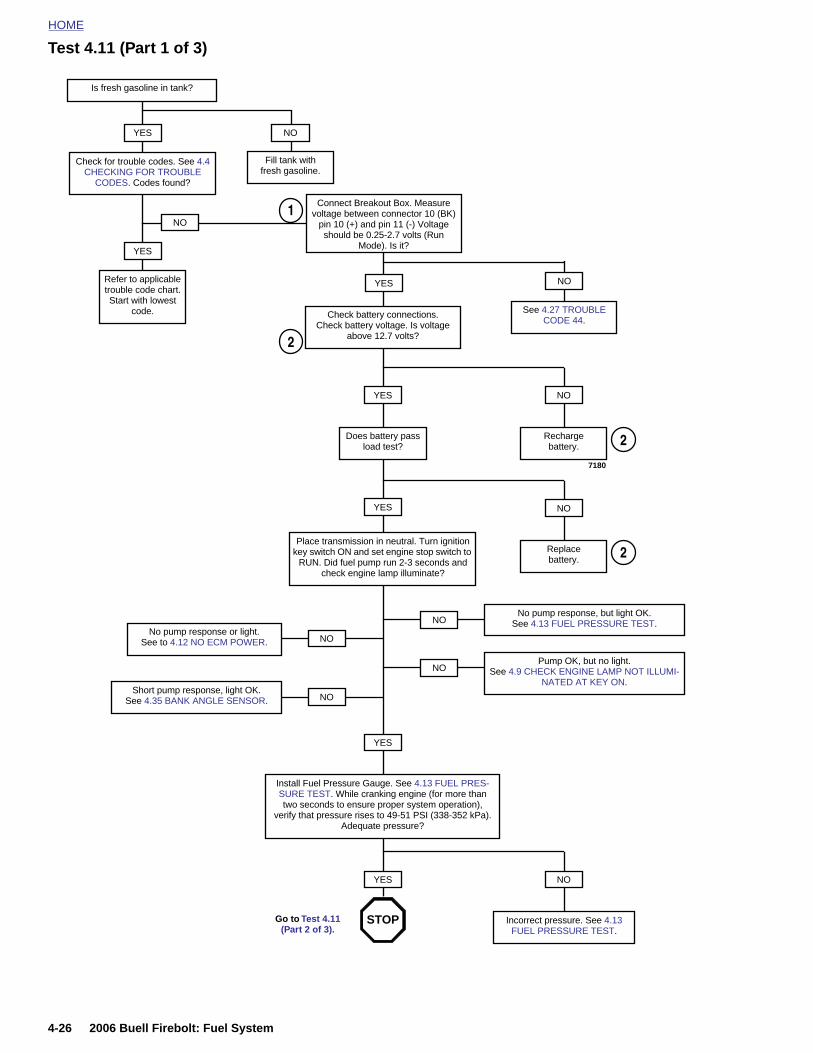
HOME
Test 4.11 (Part 1 of 3)
Is fresh gasoline in tank?
YES NO
Fill tank with fresh gasoline.
Check for trouble codes. See 4.4 CHECKING FOR TROUBLE
CODES. Codes found?
Refer to applicable trouble code chart. Start with lowest
code.
YES
Check battery connections. Check battery voltage. Is voltage
above 12.7 volts?
NO
Rechargebattery.
YES
Does battery pass load test?
NO
Replacebattery.
YES
Place transmission in neutral. Turn ignition key switch ON and set engine stop switch to
RUN. Did fuel pump run 2-3 seconds and check engine lamp illuminate?
NONo pump response, but light OK.
See 4.13 FUEL PRESSURE TEST.
NOPump OK, but no light.
See 4.9 CHECK ENGINE LAMP NOT ILLUMI-NATED AT KEY ON.
YES
2
2
2
NONo pump response or light.
See to 4.12 NO ECM POWER.
NOShort pump response, light OK.
See 4.35 BANK ANGLE SENSOR.
7180
NO
Connect Breakout Box. Measure voltage between connector 10 (BK)
pin 10 (+) and pin 11 (-) Voltage should be 0.25-2.7 volts (Run
Mode). Is it?
YES
See 4.27 TROUBLE CODE 44.
NO
1
4-26 2006 Buell Firebolt: Fuel System
Install Fuel Pressure Gauge. See 4.13 FUEL PRES-SURE TEST. While cranking engine (for more than two seconds to ensure proper system operation),
verify that pressure rises to 49-51 PSI (338-352 kPa). Adequate pressure?
NO
Incorrect pressure. See 4.13 FUEL PRESSURE TEST.
Go to Test 4.11 (Part 2 of 3).
YES
STOP
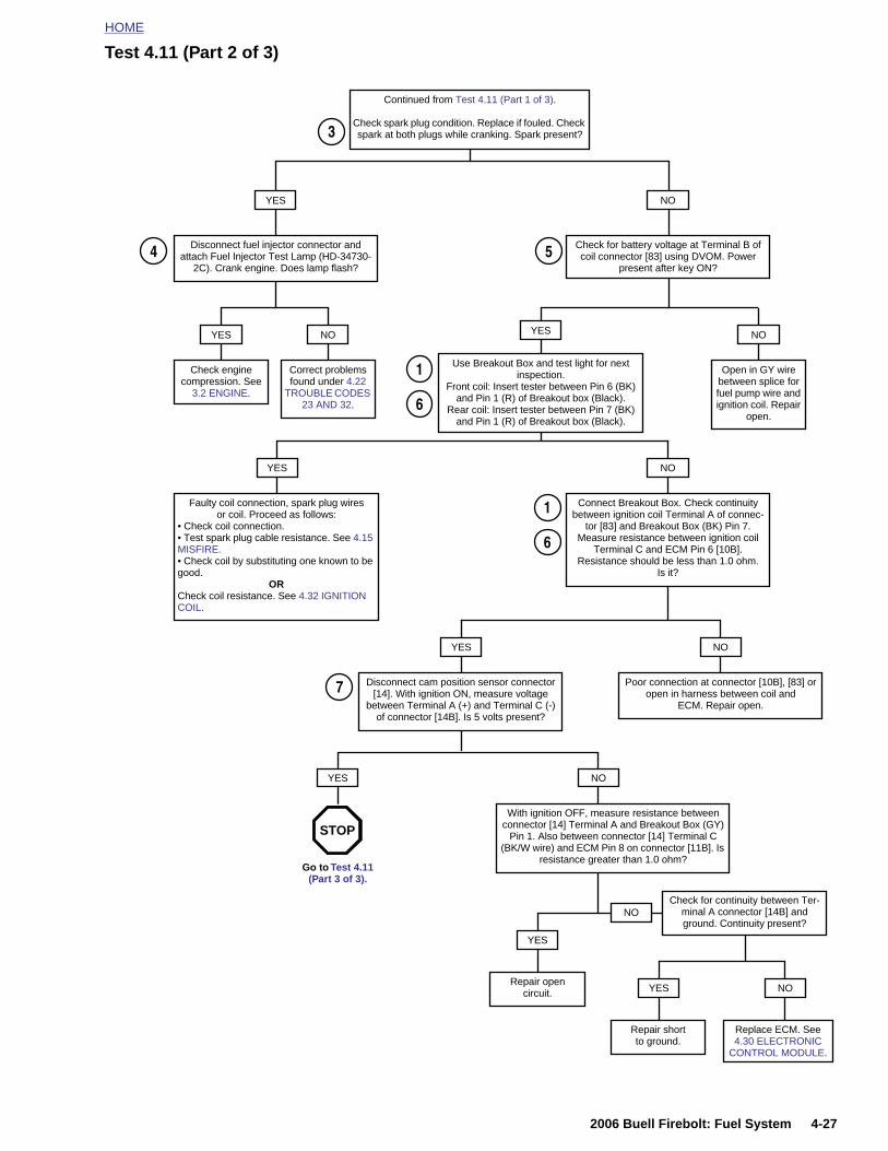
HOME
Test 4.11 (Part 2 of 3)
Continued from Test 4.11 (Part 1 of 3).
Check spark plug condition. Replace if fouled. Check spark at both plugs while cranking. Spark present?
YES NO
3
Check for battery voltage at Terminal B of coil connector [83] using DVOM. Power
present after key ON?
Disconnect fuel injector connector and attach Fuel Injector Test Lamp (HD-34730-
2C). Crank engine. Does lamp flash?
Check enginecompression. See
3.2 ENGINE.
YES
Correct problems found under 4.22
TROUBLE CODES 23 AND 32.
NO
Use Breakout Box and test light for next inspection.
Front coil: Insert tester between Pin 6 (BK) and Pin 1 (R) of Breakout box (Black).
Rear coil: Insert tester between Pin 7 (BK) and Pin 1 (R) of Breakout box (Black).
YES
Open in GY wire between splice for fuel pump wire and ignition coil. Repair
open.
NO
Faulty coil connection, spark plug wires or coil. Proceed as follows:
• Check coil connection.• Test spark plug cable resistance. See 4.15 MISFIRE.• Check coil by substituting one known to be good.
ORCheck coil resistance. See 4.32 IGNITION COIL.
YES
Connect Breakout Box. Check continuity between ignition coil Terminal A of connec-
tor [83] and Breakout Box (BK) Pin 7. Measure resistance between ignition coil
Terminal C and ECM Pin 6 [10B]. Resistance should be less than 1.0 ohm.
Is it?
NO
Disconnect cam position sensor connector [14]. With ignition ON, measure voltage
between Terminal A (+) and Terminal C (-) of connector [14B]. Is 5 volts present?
YES
Poor connection at connector [10B], [83] or open in harness between coil and
ECM. Repair open.
NO
NOYES
4 5
1
6
7
1
6
2006 Buell Firebolt: Fuel System 4-27
With ignition OFF, measure resistance between connector [14] Terminal A and Breakout Box (GY)
Pin 1. Also between connector [14] Terminal C (BK/W wire) and ECM Pin 8 on connector [11B]. Is
resistance greater than 1.0 ohm?Go to Test 4.11
(Part 3 of 3).
YES
Repair opencircuit.
NOCheck for continuity between Ter-
minal A connector [14B] and ground. Continuity present?
YES
Repair shortto ground.
NO
STOP
Replace ECM. See 4.30 ELECTRONIC
CONTROL MODULE.
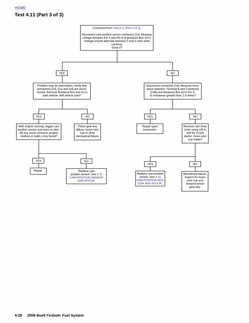
HOME
Test 4.11 (Part 3 of 3)
Continued from Test 4.11 (Part 2 of 3).
Reconnect cam position sensor connector [14]. Measure voltage between Pin 3 and Pin 8 of Breakout Box (GY). Voltage should alternate between 0 and 5 volts while
cranking.Does it?
YES
Problem may be intermittent. Verify that connectors [10], [11] and [14] are recon-nected. Remove Breakout Box and try to
start vehicle. Will vehicle start?
With engine running, wiggle cam position sensor and wires to iden-
tify any loose connects (engine misfires or stalls.) Any found?
YES
Pinion gear key failure, loose rotor
cup or other mechanical failure.
NO
Replace cam position sensor. See 4.31 CAM POSITION SENSOR
AND ROTOR.
NO
Repair.
YES
NO
Disconnect connector [14]. Measure resis-tance between Terminal B and Connector
[14B] and Breakout Box (GY) Pin 3. Is resistance greater than 1.0 ohms?
Remove cam timer cover using 1/8 in.
drill bit. Crank starter. Does rotor
cup rotate?
NO
Repair open connection.
YES
Mechanical failure. Inspect for loose
rotor cup and sheared pinion
gear key.
NOYES
Replace cam position sensor. See 4.31
CAM POSITION SEN-SOR AND ROTOR.
4-28 2006 Buell Firebolt: Fuel System
HOME
N
G
AtgtgE
O ECM POWER 4.12
ENERAL
relay controlled by the engine stop switch supplies power tohe ECM. The relay requires a ground to operate. If theround is not established, the ECM will not receive power. Ifhe ECM does not appear to be receiving power, check theround sources. A blown ignition fuse can also disable theCM.
DIAGNOSTICS
Diagnostic NotesThe reference numbers below correlate with the circled num-bers on the Test 4.12 flow chart.
1. Connect BREAKOUT BOX (Part No. HD-42682) to ECM.See 4.6 BREAKOUT BOX.
2006 Buell Firebolt: Fuel System 4-29
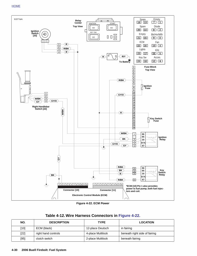
HOME
Spare Emptyb1077a4x
1
1
2
2
3
3
4
4
12
3456789
101112131415161718192021222324
9
55
4
1
8787A308586
1915
14
11
8787A308586
2
ISO
ISOISO
KEY SW.
IGNITION START 19
20
21
22
23
24
13
14
15
16
17
18
1
2
3
4
5
6
7
8
9
10
11
12
11
Diode
Bk/Hn/Mflr
Fan
IGN
Acces.Key Sw
Lights
ECM
Spare
Empty
*ECM [10] Pin 1 also provides
Right Handlebar Switch [22]
GY/O
GY
Ignition Relay
Ignition Fuse
Key Switch Fuse
Ignition Switch
[33]
Relay Center
Fuse Block
R
W/B
K
R
R
R R/Y
BK
BK
W/BKGY/O
W/BK
R/BK
GY
GY
To Battery
R/BK
R/BK
GY/O
Top View
Top View
R
BK
R/BK
KeySwitchRelay
4-30 2006 Buell Firebolt: Fuel System
Figure 4-22. ECM Power
power to fuel pump, both fuel injec-tors and coil.
Electronic Control Module (ECM)
Connector [11]Connector [10]
Table 4-12. Wire Harness Connectors in Figure 4-22.
NO. DESCRIPTION TYPE LOCATION
[10] ECM (black) 12-place Deutsch in fairing
[22] right hand controls 4-place Multilock beneath right side of fairing
[95] clutch switch 2-place Multilock beneath fairing
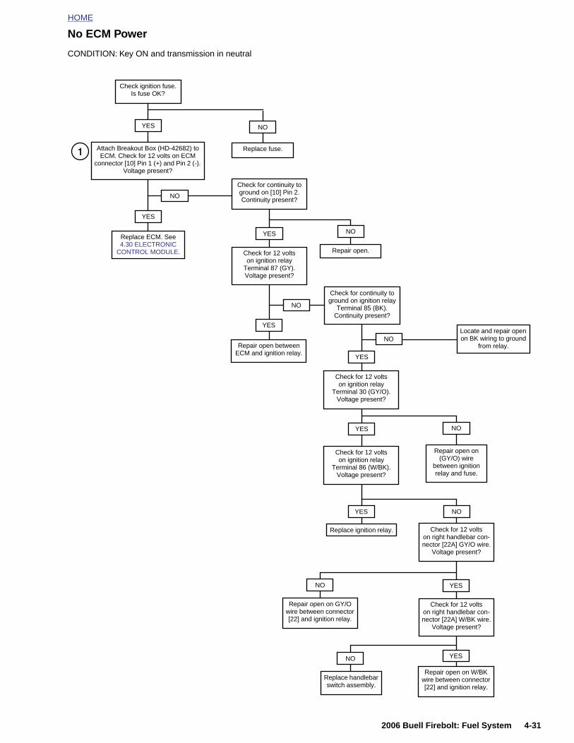
HOME
No ECM Power
CONDITION: Key ON and transmission in neutral
Check for 12 volts on ignition relay
Terminal 87 (GY).Voltage present?
YES
Repair open between ECM and ignition relay.
YES
YES
YES
Check for continuity to ground on ignition relay
Terminal 85 (BK).Continuity present?
NO
NO
Check for continuity to ground on [10] Pin 2. Continuity present?
Repair open.
Repair open on (GY/O) wire
between ignition relay and fuse.
Check for 12 volts on ignition relay
Terminal 30 (GY/O).Voltage present?
Check for 12 volts on ignition relay
Terminal 86 (W/BK).Voltage present?
Check ignition fuse. Is fuse OK?
YES
Replace ECM. See 4.30 ELECTRONIC
CONTROL MODULE.
YES
Attach Breakout Box (HD-42682) to ECM. Check for 12 volts on ECM
connector [10] Pin 1 (+) and Pin 2 (-). Voltage present?
Replace fuse.
YES
NO
NO
NO
NO
NO
1
Locate and repair open on BK wiring to ground
from relay.
2006 Buell Firebolt: Fuel System 4-31
Replace ignition relay.
Repair open on GY/O wire between connector [22] and ignition relay.
NO
Check for 12 volts on right handlebar con-nector [22A] GY/O wire.
Voltage present?
YES
Check for 12 volts on right handlebar con-nector [22A] W/BK wire.
Voltage present?
YES
Repair open on W/BK wire between connector [22] and ignition relay.
Replace handlebar switch assembly.
NO
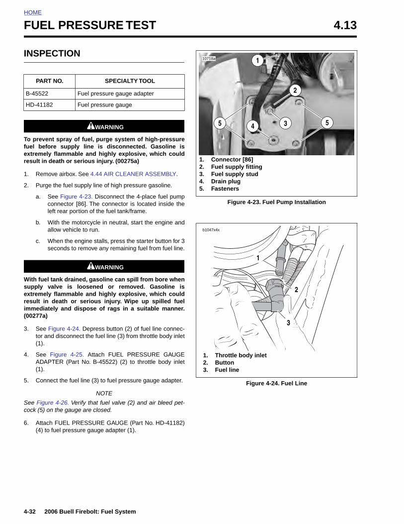
HOME
FUEL PRESSURE TEST 4.13
INSPE
To prevenfuel befoextremelyresult in d
1. Remo
2. Purge
a. Scl
b. Wa
c. Ws
With fuel supply vextremelyresult in immediat(00277a)
3. See Ftor an(1).
4. See ADAP(1).
5. Conn
PART
B-45522
HD-4118
4-32
See Figcock (5)
6. Atta(4)
CTION
1WARNING1WARNING
t spray of fuel, purge system of high-pressurere supply line is disconnected. Gasoline is flammable and highly explosive, which couldeath or serious injury. (00275a)
ve airbox. See 4.44 AIR CLEANER ASSEMBLY.
the fuel supply line of high pressure gasoline.
ee Figure 4-23. Disconnect the 4-place fuel pumponnector [86]. The connector is located inside the
eft rear portion of the fuel tank/frame.
ith the motorcycle in neutral, start the engine andllow vehicle to run.
hen the engine stalls, press the starter button for 3econds to remove any remaining fuel from fuel line.
1WARNING1WARNING
tank drained, gasoline can spill from bore whenalve is loosened or removed. Gasoline is flammable and highly explosive, which coulddeath or serious injury. Wipe up spilled fuel
ely and dispose of rags in a suitable manner.
igure 4-24. Depress button (2) of fuel line connec-d disconnect the fuel line (3) from throttle body inlet
Figure 4-25. Attach FUEL PRESSURE GAUGETER (Part No. B-45522) (2) to throttle body inlet
ect the fuel line (3) to fuel pressure gauge adapter.
NO. SPECIALTY TOOL
Fuel pressure gauge adapter
2 Fuel pressure gauge
Figure 4-23. Fuel Pump Installation
Figure 4-24. Fuel Line
10718a
55
1
4 3
1. Connector [86]2. Fuel supply fitting3. Fuel supply stud4. Drain plug5. Fasteners
2
b1047x4x
2
3
1. Throttle body inlet2. Button3. Fuel line
1
2006 Buell Firebolt: Fuel System
NOTE
ure 4-26. Verify that fuel valve (2) and air bleed pet- on the gauge are closed.
ch FUEL PRESSURE GAUGE (Part No. HD-41182)to fuel pressure gauge adapter (1).
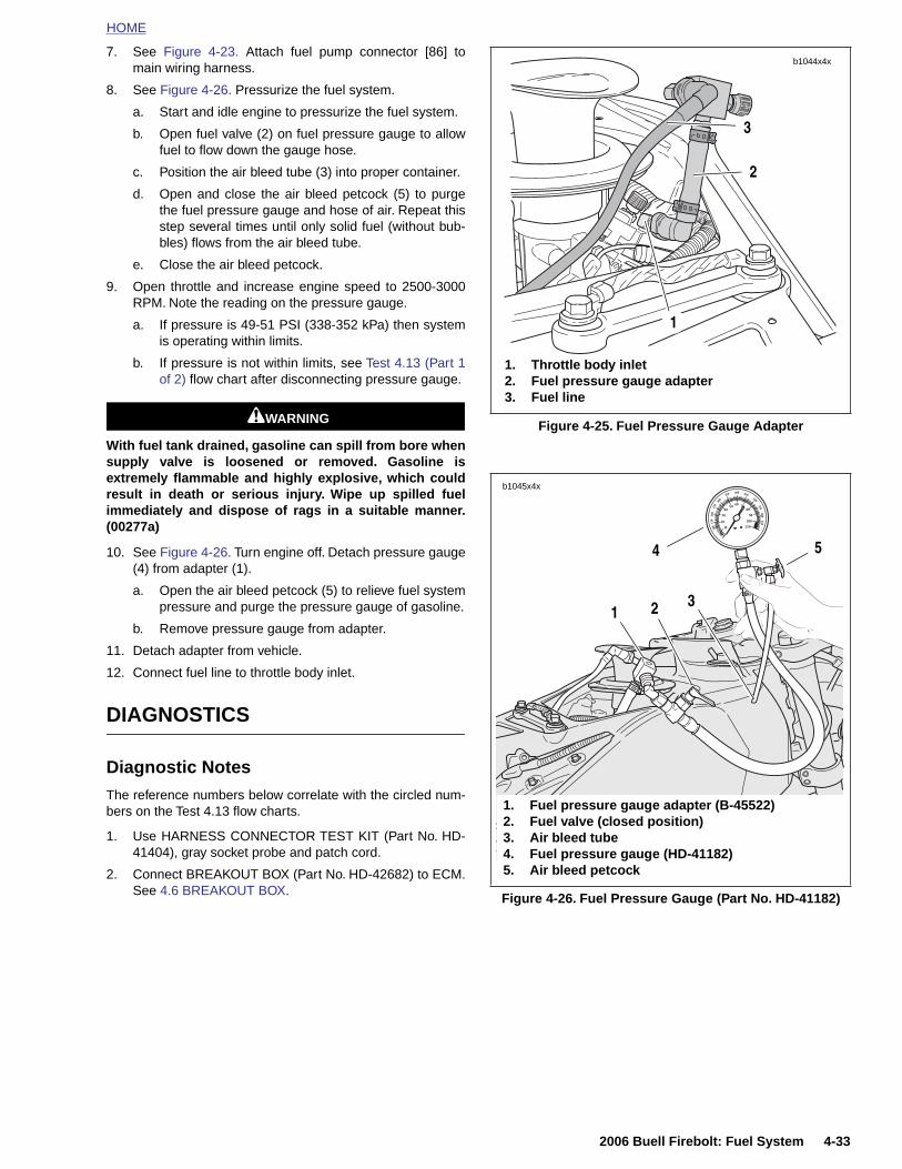
HOME
7. See Figure 4-23. Attach fuel pump connector [86] tomain wiring harness.
8. See Figure 4-26. Pressurize the fuel system.
a. Start and idle engine to pressurize the fuel system.
b. Open fuel valve (2) on fuel pressure gauge to allowfuel to flow down the gauge hose.
c. Position the air bleed tube (3) into proper container.
d. Open and close the air bleed petcock (5) to purgethe fuel pressure gauge and hose of air. Repeat thisstep several times until only solid fuel (without bub-bles) flows from the air bleed tube.
e. Close the air bleed petcock.
9. Open throttle and increase engine speed to 2500-3000RPM. Note the reading on the pressure gauge.
a. If pressure is 49-51 PSI (338-352 kPa) then systemis operating within limits.
b. If pressure is not within limits, see Test 4.13 (Part 1of 2) flow chart after disconnecting pressure gauge.
1WARNING1WARNING
With fuel tank drained, gasoline can spill from bore whensupply valve is loosened or removed. Gasoline isextremely flammable and highly explosive, which couldresult in death or serious injury. Wipe up spilled fuelimmediately and dispose of rags in a suitable manner.(00277a)
10. See Figure 4-26. Turn engine off. Detach pressure gauge(4) from adapter (1).
a. Open the air bleed petcock (5) to relieve fuel systempressure and purge the pressure gauge of gasoline.
b. Remove pressure gauge from adapter.
11. Detach adapter from vehicle.
12. Connect fuel line to throttle body inlet.
DIAGNOSTICS
Diagnostic Notes
The reference numbers below correlate with the circled num-
Figure 4-25. Fuel Pressure Gauge Adapter
1. Throttle body inlet2. Fuel pressure gauge adapter3. Fuel line
b1044x4x
1
3
2
10
30
20
5040
250
60 7080
90
100
400350
300
250
200
150
100
450500
550600
650
4
b1045x4x
1. Fuel pressure gauge adapter (B-45522)
21
5
3
2006 Buell Firebolt: Fuel System 4-33
bers on the Test 4.13 flow charts.
1. Use HARNESS CONNECTOR TEST KIT (Part No. HD-41404), gray socket probe and patch cord.
2. Connect BREAKOUT BOX (Part No. HD-42682) to ECM.See 4.6 BREAKOUT BOX.
Figure 4-26. Fuel Pressure Gauge (Part No. HD-41182)
2. Fuel valve (closed position)3. Air bleed tube4. Fuel pressure gauge (HD-41182)5. Air bleed petcock
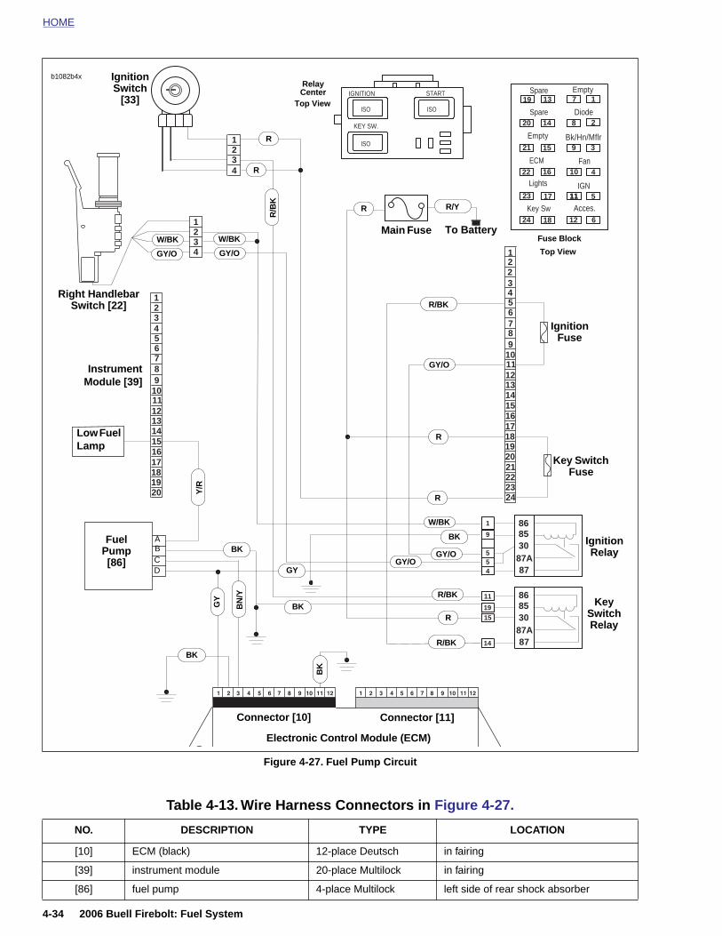
HOME
1234
123456789
1011121314151617181920
1234 1
2
3456789
101112131415161718192021222324
9
55
4
1
8787A308586
1915
14
11
8787A308586
2
ISO
ISOISO
KEY SW.
IGNITION START19
20
21
22
23
24
13
14
15
16
17
18
1
2
3
4
5
6
7
8
9
10
11
12
11
Spare
Diode
Bk/Hn/Mflr
Fan
IGN
Acces.Key Sw
Lights
ECM
Spare
Empty
Empty
Ignition Switch
[33]
Low Fuel Lamp
InstrumentModule [39]
FuelPump [86]
R/Y
R
Main Fuse To Battery
Ignition Relay
Key Switch Relay
W/BK
GY/O
W/BK
GY/O
Ignition Fuse
Key Switch Fuse
R
R
R/B
K
BK
BK
Y/R
GY/O
R/BK
BK
BN
/Y
GY
GY
Right Handlebar Switch [22]
b1082b4x
R
R
W/BK
GY/OGY/O
R/BKBK
R
R/BK
Relay Center
Fuse Block
Top View
Top View
ABCD
BK
4-34 2006 Buell Firebolt: Fuel System
Figure 4-27. Fuel Pump Circuit
Electronic Control Module (ECM)
Connector [10] Connector [11]
Table 4-13. Wire Harness Connectors in Figure 4-27.
NO. DESCRIPTION TYPE LOCATION
[10] ECM (black) 12-place Deutsch in fairing
[39] instrument module 20-place Multilock in fairing
[86] fuel pump 4-place Multilock left side of rear shock absorber
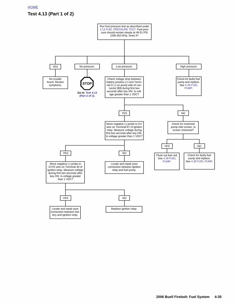
HOME
Test 4.13 (Part 1 of 2)
Run fuel pressure test as described under 4.13 FUEL PRESSURE TEST. Fuel pres-sure should remain steady at 49-51 PSI
(338-352 kPa). Does it?
Flush out fuel cell. See 4.39 FUEL
PUMP.
YES
No trouble found. Review
symptoms.
YES
Check for faulty fuel pump and replace.
See 4.39 FUEL PUMP.
NO
Check for faulty fuel pump and replace.
See 4.39 FUEL PUMP.
Low pressure. High pressure.
Check voltage drop between battery positive (+) and Termi-nal D (-) on pump side of con-
nector [89] during first two seconds after key ON. Is volt-
age greater than 1 VDC?
Check for restricted pump inlet screen. Is
screen restricted?
NO
Move negative (-) probe to GY wire on Terminal 87 of ignition relay. Measure voltage during first two seconds after key ON. Is voltage greater than 1 VDC?
YES
Locate and repair poor connection between ignition
relay and fuel pump.
NO
Move negative (-) probe to GY/O wire on Terminal 30 of
ignition relay. Measure voltage during first two seconds after
key ON. Is voltage greater than 1 VDC?
YES
Locate and repair poor
NO
Replace ignition relay.
YES
Go to Test 4.13 (Part 2 of 2).
STOP
No pressure.
2006 Buell Firebolt: Fuel System 4-35
connection between bat-tery and ignition relay.
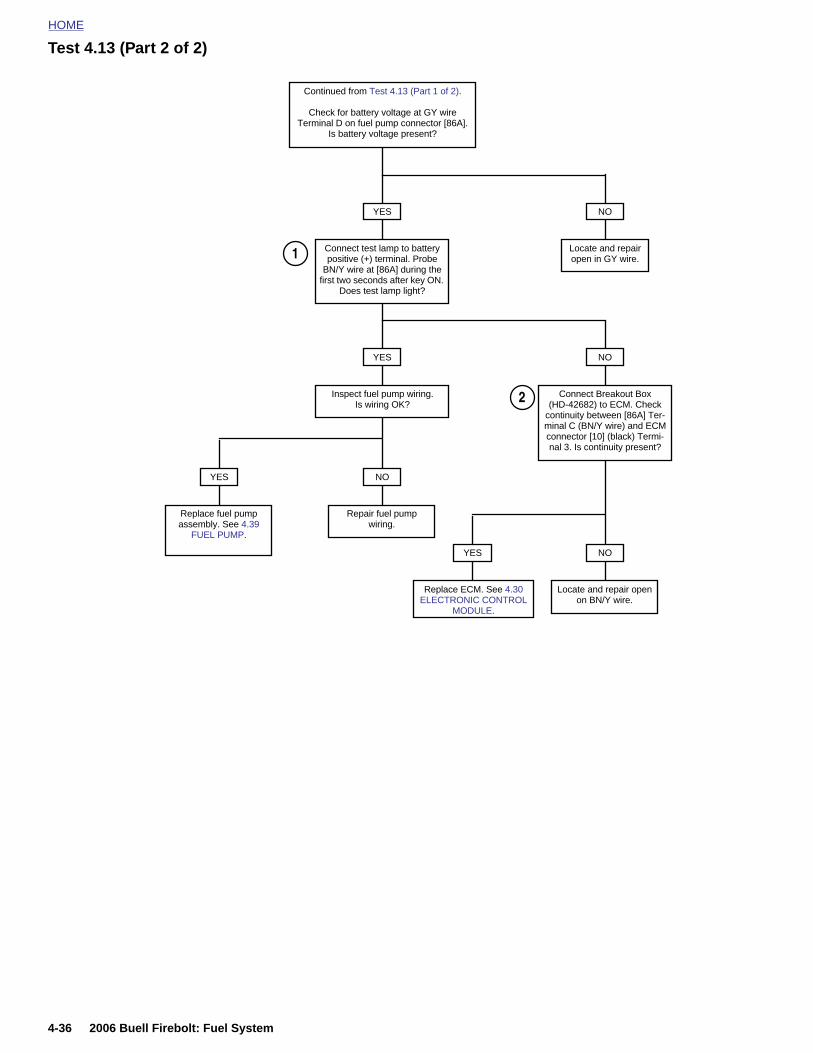
HOME
Test 4.13 (Part 2 of 2)
Continued from Test 4.13 (Part 1 of 2).
Check for battery voltage at GY wire Terminal D on fuel pump connector [86A].
Is battery voltage present?
Locate and repair open in GY wire.
Connect test lamp to battery positive (+) terminal. Probe
BN/Y wire at [86A] during the first two seconds after key ON.
Does test lamp light?
YES NO
Connect Breakout Box (HD-42682) to ECM. Check
continuity between [86A] Ter-minal C (BN/Y wire) and ECM connector [10] (black) Termi-nal 3. Is continuity present?
Inspect fuel pump wiring. Is wiring OK?
YES NO
Repair fuel pump wiring.
NO
Replace fuel pump assembly. See 4.39
FUEL PUMP.
YES
Locate and repair open on BN/Y wire.
NO
Replace ECM. See 4.30 ELECTRONIC CONTROL
MODULE.
YES
1
2
4-36 2006 Buell Firebolt: Fuel System
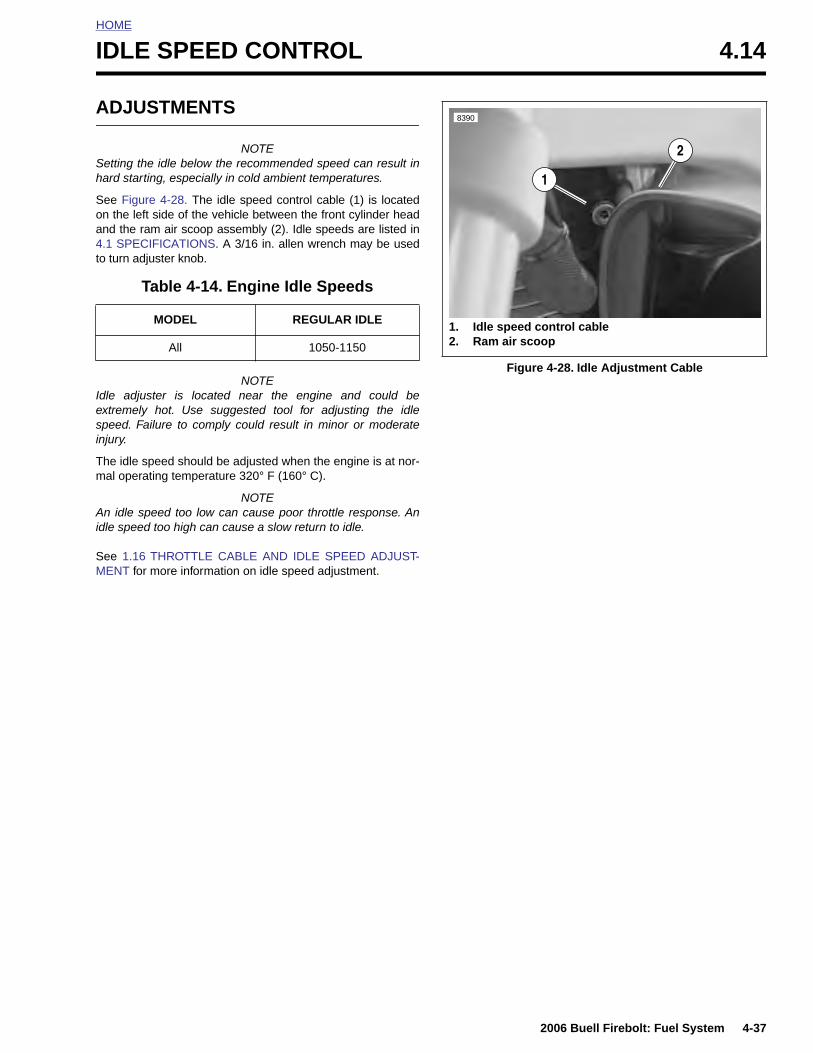
HOME
I
A
Sh
Soa4t
Iesin
Tm
Aid
SM
DLE SPEED CONTROL 4.14
DJUSTMENTS
NOTEetting the idle below the recommended speed can result inard starting, especially in cold ambient temperatures.
ee Figure 4-28. The idle speed control cable (1) is locatedn the left side of the vehicle between the front cylinder headnd the ram air scoop assembly (2). Idle speeds are listed in.1 SPECIFICATIONS. A 3/16 in. allen wrench may be used
o turn adjuster knob.
NOTEdle adjuster is located near the engine and could bextremely hot. Use suggested tool for adjusting the idlepeed. Failure to comply could result in minor or moderatejury.
he idle speed should be adjusted when the engine is at nor-al operating temperature 320° F (160° C).
NOTEn idle speed too low can cause poor throttle response. Anle speed too high can cause a slow return to idle.
ee 1.16 THROTTLE CABLE AND IDLE SPEED ADJUST-ENT for more information on idle speed adjustment.
Table 4-14. Engine Idle Speeds
MODEL REGULAR IDLE
All 1050-1150
Figure 4-28. Idle Adjustment Cable
1. Idle speed control cable2. Ram air scoop
1
2
8390
2006 Buell Firebolt: Fuel System 4-37
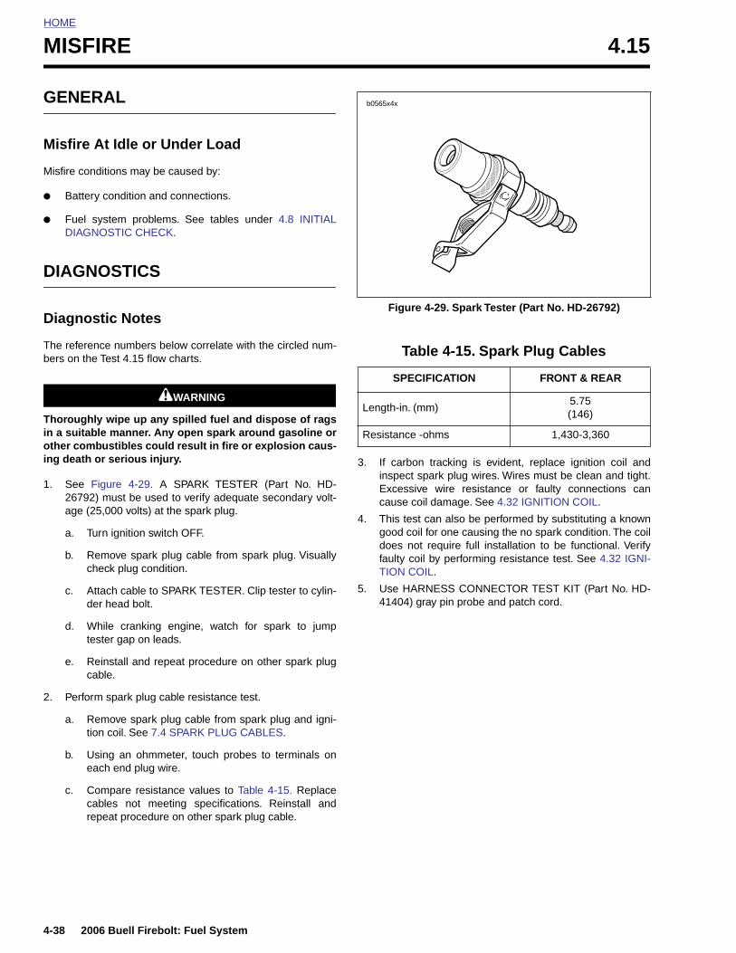
HOME
MISFIRE 4.15
GENE
Misfire
Misfire co
● Batte
● Fuel DIAG
DIAGN
Diagno
The referebers on th
Thoroughin a suitaother coming death
1. See 2679age (
a. T
b. Rc
c. Ad
d. Wt
e. Rc
2. Perfo
4-38
a.
b.
c.
RAL
At Idle or Under Load
nditions may be caused by:
ry condition and connections.
system problems. See tables under 4.8 INITIALNOSTIC CHECK.
OSTICS
stic Notes
nce numbers below correlate with the circled num-e Test 4.15 flow charts.
1WARNING1WARNING
ly wipe up any spilled fuel and dispose of ragsble manner. Any open spark around gasoline orbustibles could result in fire or explosion caus-
or serious injury.
Figure 4-29. A SPARK TESTER (Part No. HD-2) must be used to verify adequate secondary volt-25,000 volts) at the spark plug.
urn ignition switch OFF.
emove spark plug cable from spark plug. Visuallyheck plug condition.
ttach cable to SPARK TESTER. Clip tester to cylin-er head bolt.
hile cranking engine, watch for spark to jumpester gap on leads.
einstall and repeat procedure on other spark plugable.
rm spark plug cable resistance test.
3. If carbon tracking is evident, replace ignition coil andinspect spark plug wires. Wires must be clean and tight.Excessive wire resistance or faulty connections cancause coil damage. See 4.32 IGNITION COIL.
4. This test can also be performed by substituting a knowngood coil for one causing the no spark condition. The coildoes not require full installation to be functional. Verifyfaulty coil by performing resistance test. See 4.32 IGNI-TION COIL.
5. Use HARNESS CONNECTOR TEST KIT (Part No. HD-41404) gray pin probe and patch cord.
Figure 4-29. Spark Tester (Part No. HD-26792)
Table 4-15. Spark Plug Cables
SPECIFICATION FRONT & REAR
Length-in. (mm)5.75(146)
Resistance -ohms 1,430-3,360
b0565x4x
2006 Buell Firebolt: Fuel System
Remove spark plug cable from spark plug and igni-tion coil. See 7.4 SPARK PLUG CABLES.
Using an ohmmeter, touch probes to terminals oneach end plug wire.
Compare resistance values to Table 4-15. Replacecables not meeting specifications. Reinstall andrepeat procedure on other spark plug cable.
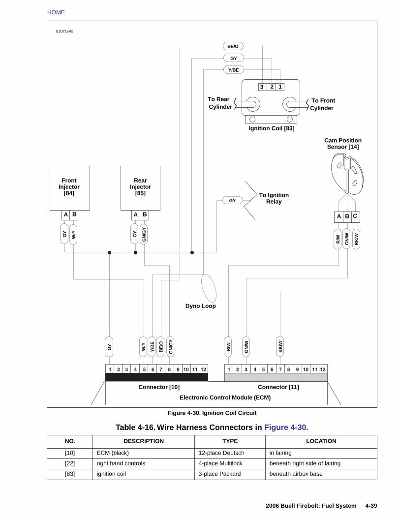
HOME
Front Injector
[84]
Ignition Coil [83]
W/Y
GN
/W
BK
/W
R/W
GY
Cam Position Sensor [14]
A
GN
/W
Y/B
E
GY
BE
/O
BK
/W
B CAA
3 12
BB
To RearCylinder
To FrontCylinder
W/Y
GN
/GY
R/W
Rear Injector
[85]GY
To Ignition Relay
Y/BE
GY
BE/O
GY
GN
/GY
Dyno Loop
b1071x4x
2006 Buell Firebolt: Fuel System 4-39
Figure 4-30. Ignition Coil Circuit
Table 4-16. Wire Harness Connectors in Figure 4-30.
NO. DESCRIPTION TYPE LOCATION
[10] ECM (black) 12-place Deutsch in fairing
[22] right hand controls 4-place Multilock beneath right side of fairing
[83] ignition coil 3-place Packard beneath airbox base
Electronic Control Module (ECM)
Connector [10] Connector [11]
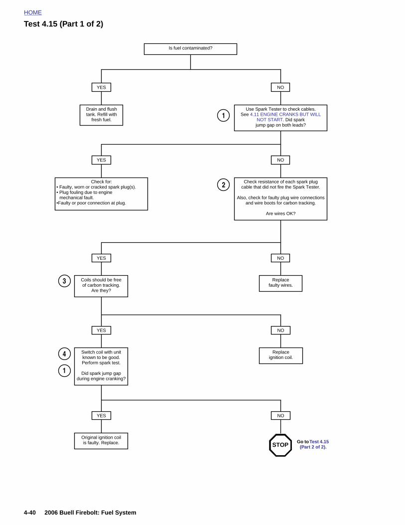
HOME
Test 4.15 (Part 1 of 2)
Is fuel contaminated?
YES
Drain and flush tank. Refill with
fresh fuel.
NO
Use Spark Tester to check cables. See 4.11 ENGINE CRANKS BUT WILL
NOT START. Did spark jump gap on both leads?
1
NO
Check resistance of each spark plug cable that did not fire the Spark Tester.
Also, check for faulty plug wire connections and wire boots for carbon tracking.
Are wires OK?
YES
Check for:• Faulty, worn or cracked spark plug(s).• Plug fouling due to engine
mechanical fault.•Faulty or poor connection at plug.
NO
Replace faulty wires.
YES
Coils should be free of carbon tracking.
Are they?
NO
Replace ignition coil.
YES
Switch coil with unit known to be good.Perform spark test.
Did spark jump gap during engine cranking?
2
3
4
1
4-40 2006 Buell Firebolt: Fuel System
NOYES
Original ignition coil is faulty. Replace. Go to Test 4.15
(Part 2 of 2).STOP
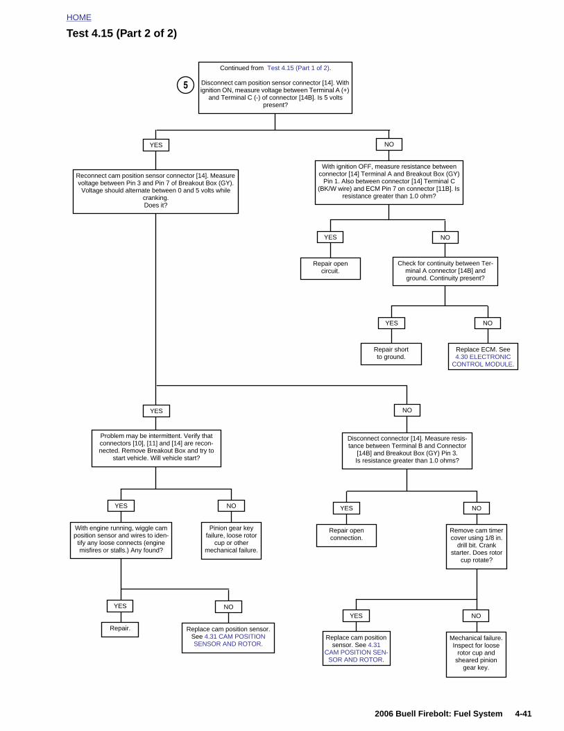
HOME
Test 4.15 (Part 2 of 2)
Continued from Test 4.15 (Part 1 of 2).
Disconnect cam position sensor connector [14]. With ignition ON, measure voltage between Terminal A (+)
and Terminal C (-) of connector [14B]. Is 5 volts present?
With ignition OFF, measure resistance between connector [14] Terminal A and Breakout Box (GY)
Pin 1. Also between connector [14] Terminal C (BK/W wire) and ECM Pin 7 on connector [11B]. Is
resistance greater than 1.0 ohm?
NOYES
YES
Repair opencircuit.
Check for continuity between Ter-minal A connector [14B] and ground. Continuity present?
YES
Repair shortto ground.
NO
5
Replace ECM. See 4.30 ELECTRONIC
CONTROL MODULE.
Reconnect cam position sensor connector [14]. Measure voltage between Pin 3 and Pin 7 of Breakout Box (GY). Voltage should alternate between 0 and 5 volts while
cranking.Does it?
YES NO
Disconnect connector [14]. Measure resis-tance between Terminal B and Connector
[14B] and Breakout Box (GY) Pin 3. Is resistance greater than 1.0 ohms?
Problem may be intermittent. Verify that connectors [10], [11] and [14] are recon-nected. Remove Breakout Box and try to
start vehicle. Will vehicle start?
NO
2006 Buell Firebolt: Fuel System 4-41
With engine running, wiggle cam position sensor and wires to iden-
tify any loose connects (engine misfires or stalls.) Any found?
YES
Pinion gear key failure, loose rotor
cup or other mechanical failure.
NO
Replace cam position sensor. See 4.31 CAM POSITION SENSOR AND ROTOR.
NO
Repair.
YES
Remove cam timer cover using 1/8 in.
drill bit. Crank starter. Does rotor
cup rotate?
NO
Repair open connection.
YES
Mechanical failure. Inspect for loose
rotor cup and sheared pinion
gear key.
NOYES
Replace cam position sensor. See 4.31
CAM POSITION SEN-SOR AND ROTOR.

HOME
NOTES
4-42
2006 Buell Firebolt: Fuel System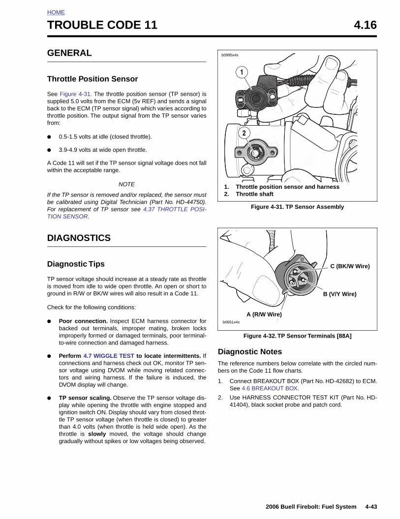
HOME
T
G
T
Ssbtf
●
●
Aw
IbFT
D
D
Tisg
C
●
●
ROUBLE CODE 11 4.16
ENERAL
hrottle Position Sensor
ee Figure 4-31. The throttle position sensor (TP sensor) isupplied 5.0 volts from the ECM (5v REF) and sends a signalack to the ECM (TP sensor signal) which varies according tohrottle position. The output signal from the TP sensor variesrom:
0.5-1.5 volts at idle (closed throttle).
3.9-4.9 volts at wide open throttle.
Code 11 will set if the TP sensor signal voltage does not fallithin the acceptable range.
NOTE
f the TP sensor is removed and/or replaced, the sensor muste calibrated using Digital Technician (Part No. HD-44750).or replacement of TP sensor see 4.37 THROTTLE POSI-ION SENSOR.
IAGNOSTICS
iagnostic Tips
P sensor voltage should increase at a steady rate as throttle moved from idle to wide open throttle. An open or short toround in R/W or BK/W wires will also result in a Code 11.
heck for the following conditions:
Poor connection. Inspect ECM harness connector forbacked out terminals, improper mating, broken locksimproperly formed or damaged terminals, poor terminal-to-wire connection and damaged harness.
Perform 4.7 WIGGLE TEST to locate intermittents. IfDiagnostic Notes
Figure 4-31. TP Sensor Assembly
Figure 4-32. TP Sensor Terminals [88A]
1. Throttle position sensor and harness2. Throttle shaft
b0995x4x
2
1
b0651x4x
A (R/W Wire)
B (V/Y Wire)
C (BK/W Wire)
2006 Buell Firebolt: Fuel System 4-43
connections and harness check out OK, monitor TP sen-sor voltage using DVOM while moving related connec-tors and wiring harness. If the failure is induced, theDVOM display will change.
● TP sensor scaling. Observe the TP sensor voltage dis-play while opening the throttle with engine stopped andignition switch ON. Display should vary from closed throt-tle TP sensor voltage (when throttle is closed) to greaterthan 4.0 volts (when throttle is held wide open). As thethrottle is slowly moved, the voltage should changegradually without spikes or low voltages being observed.
The reference numbers below correlate with the circled num-bers on the Code 11 flow charts.
1. Connect BREAKOUT BOX (Part No. HD-42682) to ECM.See 4.6 BREAKOUT BOX.
2. Use HARNESS CONNECTOR TEST KIT (Part No. HD-41404), black socket probe and patch cord.
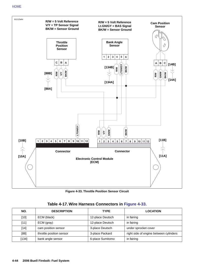
HOME
b1112a4x
Figure 4-33. Throttle Position Sensor Circuit
ABC CBA
Throttle Position Sensor
R/W V/Y
BK
/W
R/W
BK
/W
GN
/W
Cam PositionSensor
R/W = 5 Volt ReferenceV/Y = TP Sensor SignalBK/W = Sensor Ground
R/W V/Y
GN
/W
BK
/W
Electronic Control Module (ECM)
Connector Connector
LT
GN
/GY
R/W = 5 Volt ReferenceLt.GN/GY = BAS SignalBK/W = Sensor Ground
Bank Angle Sensor
BK
/W
R/W
LT
GN
/GY
[10B] [11B]
[10A] [11A]
[88B]
[88A]
[134A]
[134B]
[14A]
[14B]
4-44 2006 Buell Firebolt: Fuel System
Table 4-17. Wire Harness Connectors in Figure 4-33.
NO. DESCRIPTION TYPE LOCATION
[10] ECM (black) 12-place Deutsch in fairing
[11] ECM (gray) 12-place Deutsch in fairing
[14] cam position sensor 3-place Deutsch under sprocket cover
[88] throttle position sensor 3-place Packard right side of engine between cylinders
[134] bank angle sensor 6-place Sumitomo in fairing
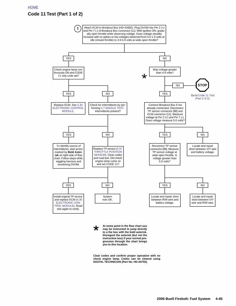
HOME
Code 11 Test (Part 1 of 2)
Attach ECM to Breakout Box (HD-42682). Plug DVOM into Pin 2 (+) and Pin 7 (-) of Breakout Box connector [11]. With ignition ON, gradu-
ally open throttle while observing voltage. Does voltage steadily increase with no spikes or low voltages observed from 0.5-1.5 volts at
idle (closed throttle) to 3.9-4.9 volts at wide open throttle?
Was voltage greater than 4.9 volts?
NOYES
Check engine lamp con-tinuously ON and CODE
11 only code set?
YES
Replace ECM. See 4.30 ELECTRONIC CONTROL
MODULE.
NO
Check for intermittents by per-forming 4.7 WIGGLE TEST.
Intermittents present?
YES
To identify source of intermittents, start at box marked by Bold Aster-isk on right side of flow
chart. Follow steps while wiggling harness and
monitoring DVOM.
NO
Replace TP sensor (4.37 THROTTLE POSITION SENSOR). Clear codes and road test. Did check
engine lamp come on and set CODE 11?
NO
System now OK.
YES
Install original TP sensor and replace ECM (4.30 ELECTRONIC CON-
TROL MODULE). Road test again to verify.
*YES
Connect Breakout Box if not already connected. Disconnect TP sensor connector [88] and ECM connector [11]. Measure
voltage at Pin 2 (+) and Pin 7 (-). Does voltage measure 5.0 volts?
NO
Go to Code 11 Test (Part 2 of 2).
STOP
YES
Reconnect TP sensor connector [88]. Measure
TP sensor voltage at wide open throttle. Is voltage greater than
5.0 volts?
YES
Locate and repair short between R/W wire and
battery voltage.
1
NO
Locate and repair short between V/Y wire
and battery voltage.
NO
Locate and repair short between V/Y wire and R/W wire.
2006 Buell Firebolt: Fuel System 4-45
Clear codes and confirm proper operation with nocheck engine lamp. Codes can be cleared usingDIGITAL TECHNICIAN (Part No. HD-44750).
At some point in the flow chart youmay be instructed to jump directlyto a the box with the bold asterisk.Disregard the asterisk (but not theinstruction box) if your normal pro-gression through the chart bringsyou to this location.
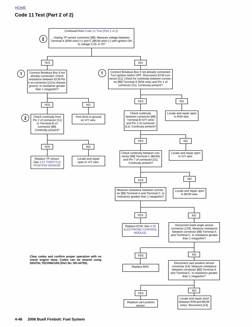
HOME
Code 11 Test (Part 2 of 2)
Connect Breakout Box if not already connected. Turn ignition switch OFF. Disconnect ECM con-
nector [11]. Check for continuity between connec-tor [88] Terminal A (R/W wire) and Pin 1 of
connector [11]. Continuity present?
NO
Continued from Code 11 Test (Part 1 of 2).
Unplug TP sensor connector [88]. Measure voltage between Terminal A (R/W wire) (+) and C (BK/W wire) (-) with ignition ON.
Is voltage 5.25- 4.75?
YES
Connect Breakout Box if not already connected. Check
resistance between ECM Pin 2 on connector [11] to chassis ground. Is resistance greater
than 1 megaohm?
Find short to groundon V/Y wire.
NO
Check continuity from Pin 2 of connector [11]
to Terminal B on connector [88].
Continuity present?
YES
Locate and repair open in V/Y wire.
NO
Replace TP sensor. See 4.37 THROTTLE POSITION SENSOR.
YES
Locate and repair open in R/W wire.
NO
Check continuity between connector [88] Terminal B (V/Y wire) and Pin 2 of connector
[11]. Continuity present?
YES
Locate and repair open in V/Y wire.
NO
Check continuity between con-nector [88] Terminal C (BK/W)
and Pin 7 of connector [11].Continuity present?
YES
Locate and repair open in BK/W wire.
NOYES
NO
Replace ECM. See 4.30 ELECTRONIC CONTROL
MODULE.
YES
2
1 1
2
Disconnect bank angle sensor connector [134]. Measure resistance between connector [88] Terminal A
and Terminal C. Is resistance greater than 1 megaohm?
Measure resistance between connec-tor [88] Terminal A and Terminal C. Is resistance greater than 1 megaohm?
4-46 2006 Buell Firebolt: Fuel System
Locate and repair short between R/W and BK/W wires. Reconnect [14].
Clear codes and confirm proper operation with nocheck engine lamp. Codes can be cleared usingDIGITAL TECHNICIAN (Part No. HD-44750).
NO
Replace BAS.
NO
Disconnect cam position sensor connector [14]. Measure resistance between connector [88] Terminal A
and Terminal C. Is resistance greater than 1 megaohm?
YES
Replace cam position sensor.
YES

HOME
T
G
OSEle
●
●
Wa
D
DTvleostarR
C
●
●
ROUBLE CODE 13 4.17
ENERAL
xygen Sensor ee Figure 4-34. The oxygen sensor provides a signal to theCM which indicates whether the engine is running rich oran.
A low voltage signal (<0.41 V) indicates the engine isrunning lean.
A high voltage signal (>0.56 V) indicates the engine isrunning rich.
hen the air/fuel mixture is ideal, approximately 14.7 partsir to 1 part fuel, the voltage will be approximately 0.48 V.
IAGNOSTICS
iagnostic Tipshe DVOM displays the signal from the oxygen sensor inolts. This voltage will have an average value tending towardsan, rich or ideal value depending on operating temperaturef the engine, engine speed and throttle position. An open/hort to voltage or short to ground in the V/GY wire will causehe engine to run rich (short to ground) or lean (short to volt-ge) until fault is detected. Once fault is detected, vehicle willun in open loop. The engine must be running below 5000PM for the ECM to detect an oxygen sensor failure.
heck for the following conditions:
Poor connection. Inspect the ECM harness connector[11], fuel injector connectors [84, 85] and oxygen sensorconnector wiring for backed out terminals, improper mat-ing, broken locks, improperly formed or damaged termi-nals, poor terminal-to-wire connection and damagedharness.
Dirty/stuck open injectors. The motorcycle may runlean (dirty/clogged injectors) or rich (stuck open injec-tors) if there is an injector problem. This could also causepoor fuel economy and performance.
Figure 4-34. Oxygen Sensor
Figure 4-35. Oxygen Sensor (shock absorber removed)
1. Oxygen sensor2. Connector [137]
1
2
b1111x7x
8467
2006 Buell Firebolt: Fuel System 4-47
● Loose oxygen sensor. See Figure 4-35. If the oxygensensor is loose engine performance may be affected.This could also show up as a slow changing oxygen sen-sor voltage.
● Loose/leaking exhaust. This can cause a poor groundconnection for sensor or allow fresh air into the exhaustsystem. If fresh air enters exhaust system, the oxygensensor will read a lean condition, causing the system togo rich.
Diagnostic Notes1. Connect BREAKOUT BOX (Part No. HD-42682) to ECM.
See 4.6 BREAKOUT BOX.
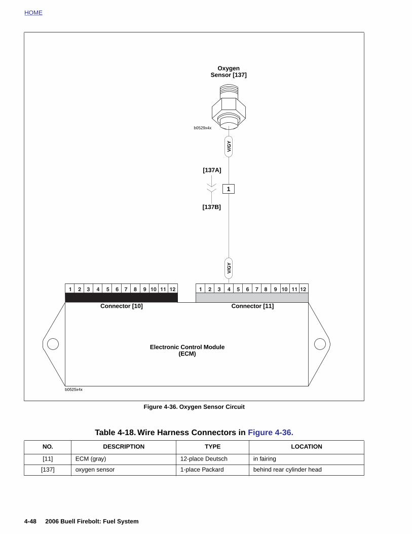
HOME
b0529x4x
OxygenSensor [137]
Electronic Control Module(ECM)
Connector [10] Connector [11]
V/G
YV
/GY
1
[137A]
[137B]
4-48 2006 Buell Firebolt: Fuel System
Figure 4-36. Oxygen Sensor Circuit
Table 4-18. Wire Harness Connectors in Figure 4-36.
NO. DESCRIPTION TYPE LOCATION
[11] ECM (gray) 12-place Deutsch in fairing
[137] oxygen sensor 1-place Packard behind rear cylinder head

HOME
Code 13 Test (Part 1 of 3)
Install Breakout Box (HD-42682) leaving harness side connector [11] disconnected from the Breakout Box. Is the oxygen volt-
age approximately 0.5 volts?
NO. 0 volts.
NO.Greater than
1 volt.
YES
YES NO
Locate and repair short to ground on
V/GY wire.
Replace ECM. See 4.30 ELECTRONIC
CONTROL MODULE.
Disconnect O2 sensor from harness. Connect DVOM to Pin 4 (+) and Pin 7 (-) of con-nector [11] (gray).
Turn ignition ON and start engine. (Engine must be on and running to read O2 sensor values). Observe O2 voltage. Is it approximately 0.5 volts?
Install Breakout Box (HD-42682) leaving harness side connector [11] disconnected from the Breakout Box. Is the oxygen volt-
age approximately 0.5 volts?
YES NO
Inspect V/GYwire for shorts to
voltage and repair.
Replace ECM. See 4.30 ELECTRONIC
CONTROL MODULE.
Go to Code 13 Test (Part 2 of 3).
STOP 11
Clear codes and confirm proper operation with nocheck engine lamp. Codes can be cleared usingDIGITAL TECHNICIAN (Part No. HD-44750).
2006 Buell Firebolt: Fuel System 4-49
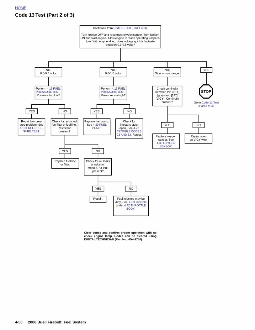
HOME
Code 13 Test (Part 2 of 3)
NO. 0.0-0.4 volts.
NO. 0.6-1.0 volts.
NO. Slow or no change.
Check continuity between Pin 4 [11]
(gray) and [137] (V/GY). Continuity
present?
Replace oxygen sensor. See
4.33 OXYGEN SENSOR.
YES
Repair open on V/GY wire.
NO
Perform 4.13 FUEL PRESSURE TEST. Pressure too high?
NO
Perform 4.13 FUEL PRESSURE TEST. Pressure too low?
YES
Check for injectors stuck open. See 4.22
TROUBLE CODES 23 AND 32. Retest.
NOYES
Check for restricted fuel filter or fuel line.
Restriction present?
NO
Check for air leaks at induction
module. Air leak present?
YES
Replace fuel lineor filter.
NO
Fuel injectors may be dirty. See Fuel Injectors under 4.42 THROTTLE
BODY.
YES
Repair.
Go to Code 13 Test (Part 3 of 3).
STOP
YES
Repair low pres-sure problem. See 4.13 FUEL PRES-
SURE TEST.
Replace fuel pump. See 4.39 FUEL
PUMP.
Clear codes and confirm proper operation with nocheck engine lamp. Codes can be cleared usingDIGITAL TECHNICIAN (Part No. HD-44750).
Continued from Code 13 Test (Part 1 of 3).
Turn ignition OFF and reconnect oxygen sensor. Turn ignition ON and start engine. Allow engine to reach operating tempera-
ture. With engine idling, does voltage quickly fluctuate between 0.1-0.8 volts?
4-50 2006 Buell Firebolt: Fuel System
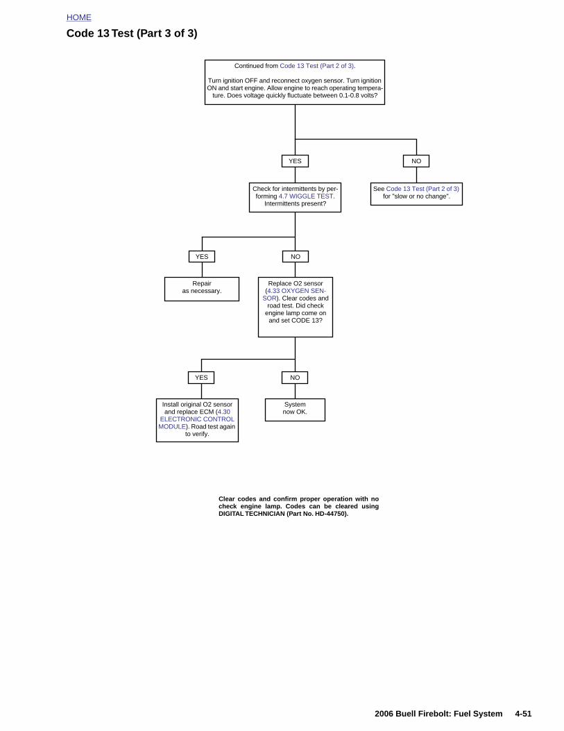
HOME
Code 13 Test (Part 3 of 3)
Check for intermittents by per-forming 4.7 WIGGLE TEST.
Intermittents present?
YES
Repair as necessary.
NO
Replace O2 sensor (4.33 OXYGEN SEN-
SOR). Clear codes and road test. Did check
engine lamp come on and set CODE 13?
NO
System now OK.
YES
Install original O2 sensor and replace ECM (4.30
ELECTRONIC CONTROL MODULE). Road test again
to verify.
YES
See Code 13 Test (Part 2 of 3) for "slow or no change".
NO
Continued from Code 13 Test (Part 2 of 3).
Turn ignition OFF and reconnect oxygen sensor. Turn ignition ON and start engine. Allow engine to reach operating tempera-
ture. Does voltage quickly fluctuate between 0.1-0.8 volts?
Clear codes and confirm proper operation with no
2006 Buell Firebolt: Fuel System 4-51
check engine lamp. Codes can be cleared usingDIGITAL TECHNICIAN (Part No. HD-44750).

HOME
TROUBLE CODE 14 4.18
GENE
Engine
Do not pstrain to s
The ECMof the engof the ET
See Tablemeans thresistancedoes the s
● At higlow. T
● At lowthe vo
The ECMoperating
DIAGN
Diagno
An intermthrough w
Check the
● Poorfor baimproto-wir
● Shiftetable perat
4-52
shifdriv
Diagn
The refebers on
1. ConSee
2. Use414
RAL
Temperature Sensor
NOTE
ull on engine temperature sensor wiring. Excessensor wiring will cause sensor damage.
supplies and monitors a 0-5 volt signal to one sideine temperature sensor (ET sensor). The other sidesensor is connected to ground through the engine.
4-19. The ET sensor is a thermistor device whichat at a specific temperature it will have a specific across its terminals. As this resistance varies, soupplied voltage.
h temperatures, the resistance of the sensor is veryhis effectively lowers the signal voltage.
temperatures, the resistance is very high, allowingltage to rise close to the supplied voltage of 5 volts.
monitors this voltage to compensate for variousconditions.
OSTICS
stic Tips
ittent may be caused by poor connection, rubbedire insulation or a wire broken inside the insulation.
following conditions:
connection. Inspect ECM harness connector [11]cked out terminals, improper mating, broken locks,perly formed or damaged terminals, poor terminal-e connection and damaged harness.
d sensor. The temperature-to-resistance valuesmay be used to test the ET sensor at various tem-ure levels in order to evaluate the possibility of a
Figure 4-37. Location of Engine Temperature Sensor in Rear Cylinder Head
Table 4-19. Engine TemperatureSensor Specifications
VOLTS RESISTANCE TEMP ° C TEMP ° F
0.00 0 300 572
0.21 145 255 491
0.42 303 210 410
0.62 463 190 374
0.81 638 170 338
1.20 1042 150 302
1.59 1539 130 266
3.01 4991 85 185
4.43 25,647 40 104
4.63 41,295 25 77
4.83 93,759 10 50
b0801x4x
2006 Buell Firebolt: Fuel System
ted (out-of-calibration) sensor which may result ineability problems.
ostic Notes
rence numbers below correlate with the circled num-the Code 14 flow charts.
nect BREAKOUT BOX (Part No. HD-42682) to ECM. 4.6 BREAKOUT BOX.
HARNESS CONNECTOR TEST KIT (Part No. HD-04), gray pin probes and patch cord.
NOTEAll voltage and resistance values are approximate (+/- 20%).Engine temperature sensor is measured between Terminal 9of connector [11] and system ground (Terminals 2 and 11 ofconnector [10]).
4.88 134,200 0 32
4.93 232,414 -10 14
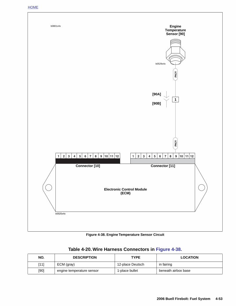
HOME
b0529x4x
EngineTemperature Sensor [90]
PK
/Y
Electronic Control Module(ECM)
Connector [10] Connector [11]
PK
/Y
1
b0801x4x
[90A]
[90B]
2006 Buell Firebolt: Fuel System 4-53
Figure 4-38. Engine Temperature Sensor Circuit
Table 4-20. Wire Harness Connectors in Figure 4-38.
NO. DESCRIPTION TYPE LOCATION
[11] ECM (gray) 12-place Deutsch in fairing
[90] engine temperature sensor 1-place bullet beneath airbox base
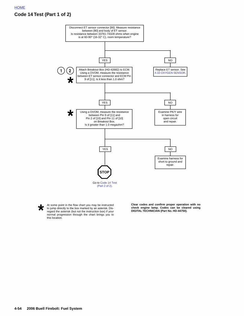
HOME
Code 14 Test (Part 1 of 2)
YES
2
Disconnect ET sensor connector [90]. Measure resistance between [90] and body of ET sensor.
Is resistance between 33761-74328 ohms when engineis at 60-90° (16-32° C), room temperature?
Attach Breakout Box (HD-42682) to ECM. Using a DVOM, measure the resistance
between ET sensor connector and ECM Pin 9 of [11]. Is it less than 1.0 ohm?
NO
Replace ET sensor. See 4.33 OXYGEN SENSOR.
YES
Using a DVOM, measure the resistance between Pin 9 of [11] and
Pin 2 of [10] and Pin 11 of [10] on Breakout Box.
Is it greater than 1.0 megaohm?
NO
Examine PK/Y wire in harness for open circuit and repair.
YES NO
Examine harness for short to ground and
repair.
At some point in the flow chart you may be instructedto jump directly to the box marked by an asterisk. Dis-regard the asterisk (but not the instruction box) if yournormal progression through the chart brings you tothis location.
Go to Code 14 Test (Part 2 of 2).
STOP
1
Clear codes and confirm proper operation with nocheck engine lamp. Codes can be cleared usingDIGITAL TECHNICIAN (Part No. HD-44750).
4-54 2006 Buell Firebolt: Fuel System
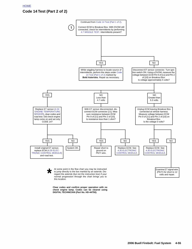
HOME
Code 14 Test (Part 2 of 2)
Continued from Code 14 Test (Part 1 of 2).
Connect ECM to Breakout Box. With DVOM still connected, check for intermittents by performing
4.7 WIGGLE TEST. Intermittents present?
YES
While wiggling harness to locate source of intermittents, perform the steps under Code
14 Test (Part 1 of 2) marked by Bold Asterisks. Repair as necessary.
Disconnect ET sensor connector. Turn igni-tion switch ON. Using a DVOM, measure the voltage between ECM Pin 9 of [11] and Pin 2
of [10] on Breakout Box. Is voltage approximately 5 volts?
YES NOLess than 4.7 volts
NOGreater than
5.3 volts.
Replace ET sensor (4.34 ENGINE TEMPERATURE SENSOR), clear codes and road test. Did check engine lamp come on and set only
CODE 14?
With ET sensor disconnected, dis-connect ECM connector [11]. Mea-
sure resistance between ECM Pin 9 of [11] and Pin 2 of [10]. Is resistance less than 1 ohm?
Unplug ECM leaving Breakout Box connected at vehicle harness.
Measure voltage between ECM Pin 9 of [11] and Pin 2 of [10] on
Breakout Box. Is the voltage 0 volts?
Install original ET sensor, replace ECM (4.30 ELEC-
TRONIC CONTROL MODULE) and road test.
YES
System OK. Repair short to ground onPK/Y wire.
YES YES
Examine ET signal wire
NO
NO NO
At some point in the flow chart you may be instructedto jump directly to the box marked by an asterisk. Dis-
Replace ECM. See 4.30 ELECTRONIC
CONTROL MODULE.
Replace ECM. See 4.30 ELECTRONIC
CONTROL MODULE.
1
NO
2006 Buell Firebolt: Fuel System 4-55
(PK/Y) for short to 12 volts and repair.regard the asterisk (but not the instruction box) if your
normal progression through the chart brings you tothis location.
Clear codes and confirm proper operation with nocheck engine lamp. Codes can be cleared usingDIGITAL TECHNICIAN (Part No. HD-44750).
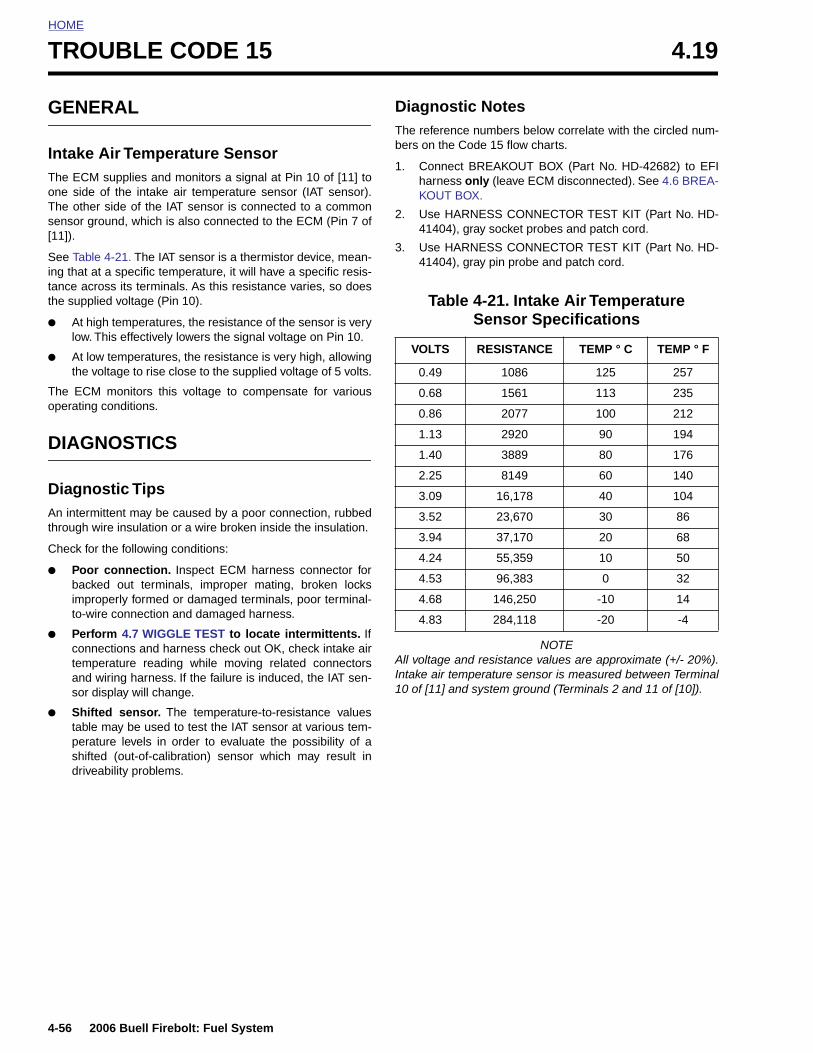
HOME
TROUBLE CODE 15 4.19
GENE
Intake The ECMone side The othersensor gro[11]).
See Tableing that attance acrothe suppli
● At higlow. T
● At lowthe vo
The ECMoperating
DIAGN
DiagnoAn intermthrough w
Check for
● Poorbackeimproto-wir
● Perfoconnetempand wsor d
● Shiftetable peratshiftedrivea
4-56
RAL
Air Temperature Sensor supplies and monitors a signal at Pin 10 of [11] toof the intake air temperature sensor (IAT sensor). side of the IAT sensor is connected to a commonund, which is also connected to the ECM (Pin 7 of
4-21. The IAT sensor is a thermistor device, mean- a specific temperature, it will have a specific resis-ss its terminals. As this resistance varies, so does
ed voltage (Pin 10).
h temperatures, the resistance of the sensor is veryhis effectively lowers the signal voltage on Pin 10.
temperatures, the resistance is very high, allowingltage to rise close to the supplied voltage of 5 volts.
monitors this voltage to compensate for variousconditions.
OSTICS
stic Tipsittent may be caused by a poor connection, rubbedire insulation or a wire broken inside the insulation.
the following conditions:
connection. Inspect ECM harness connector ford out terminals, improper mating, broken locksperly formed or damaged terminals, poor terminal-e connection and damaged harness.
rm 4.7 WIGGLE TEST to locate intermittents. Ifctions and harness check out OK, check intake air
erature reading while moving related connectorsiring harness. If the failure is induced, the IAT sen-
isplay will change.
d sensor. The temperature-to-resistance valuesmay be used to test the IAT sensor at various tem-ure levels in order to evaluate the possibility of ad (out-of-calibration) sensor which may result inbility problems.
Diagnostic NotesThe reference numbers below correlate with the circled num-bers on the Code 15 flow charts.
1. Connect BREAKOUT BOX (Part No. HD-42682) to EFIharness only (leave ECM disconnected). See 4.6 BREA-KOUT BOX.
2. Use HARNESS CONNECTOR TEST KIT (Part No. HD-41404), gray socket probes and patch cord.
3. Use HARNESS CONNECTOR TEST KIT (Part No. HD-41404), gray pin probe and patch cord.
NOTEAll voltage and resistance values are approximate (+/- 20%).Intake air temperature sensor is measured between Terminal10 of [11] and system ground (Terminals 2 and 11 of [10]).
Table 4-21. Intake Air Temperature Sensor Specifications
VOLTS RESISTANCE TEMP ° C TEMP ° F
0.49 1086 125 257
0.68 1561 113 235
0.86 2077 100 212
1.13 2920 90 194
1.40 3889 80 176
2.25 8149 60 140
3.09 16,178 40 104
3.52 23,670 30 86
3.94 37,170 20 68
4.24 55,359 10 50
4.53 96,383 0 32
4.68 146,250 -10 14
4.83 284,118 -20 -4
2006 Buell Firebolt: Fuel System
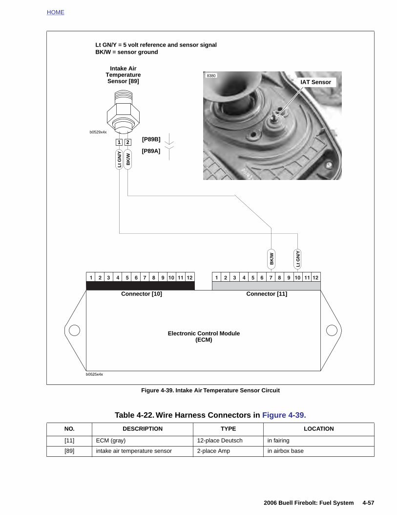
HOME
b0529x4xB
K/W
Electronic Control Module(ECM)
Connector [10] Connector [11]
Lt G
N/Y
Intake Air Temperature Sensor [89]
Lt GN/Y = 5 volt reference and sensor signalBK/W = sensor ground
1 2
BK
/W
Lt G
N/Y
IAT Sensor8380
[P89B]
[P89A]
2006 Buell Firebolt: Fuel System 4-57
Figure 4-39. Intake Air Temperature Sensor Circuit
Table 4-22. Wire Harness Connectors in Figure 4-39.
NO. DESCRIPTION TYPE LOCATION
[11] ECM (gray) 12-place Deutsch in fairing
[89] intake air temperature sensor 2-place Amp in airbox base
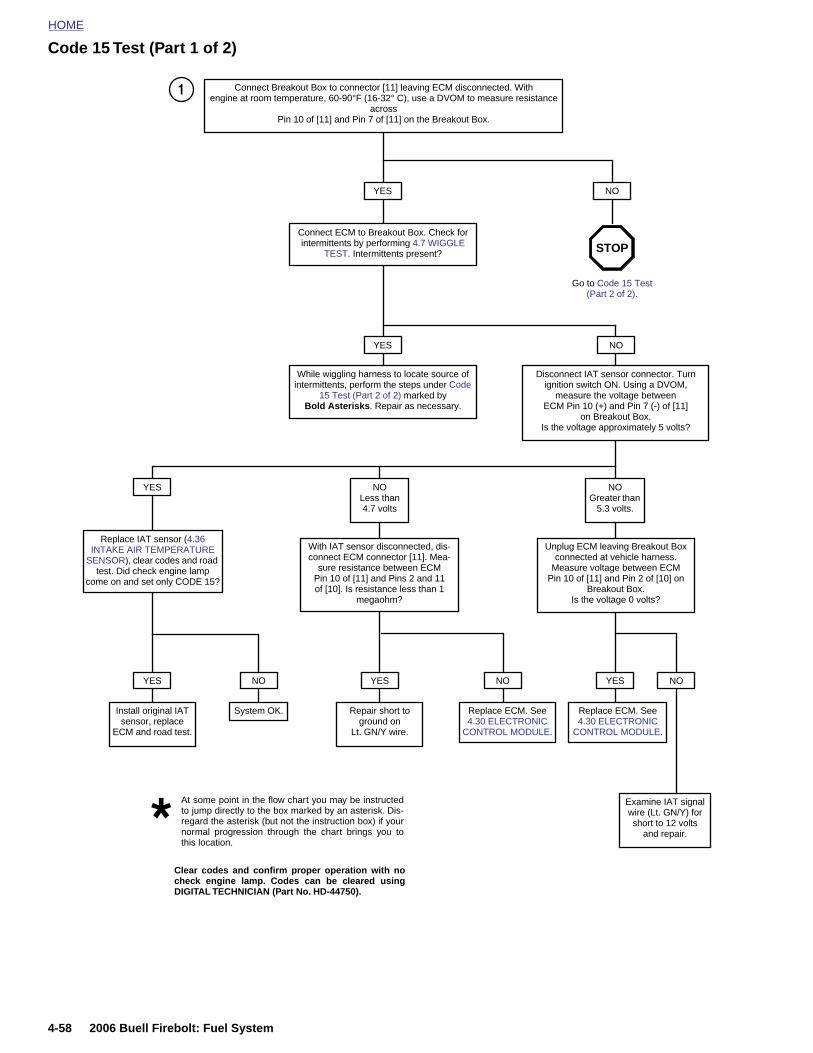
HOME
Code 15 Test (Part 1 of 2)
1
Go to Code 15 Test (Part 2 of 2).
Connect Breakout Box to connector [11] leaving ECM disconnected. With engine at room temperature, 60-90°F (16-32° C), use a DVOM to measure resistance
across Pin 10 of [11] and Pin 7 of [11] on the Breakout Box.
YES
Connect ECM to Breakout Box. Check for intermittents by performing 4.7 WIGGLE
TEST. Intermittents present?
YES
While wiggling harness to locate source of intermittents, perform the steps under Code
15 Test (Part 2 of 2) marked by Bold Asterisks. Repair as necessary.
NO
Disconnect IAT sensor connector. Turn ignition switch ON. Using a DVOM,
measure the voltage between ECM Pin 10 (+) and Pin 7 (-) of [11]
on Breakout Box. Is the voltage approximately 5 volts?
YES NOLess than 4.7 volts
NOGreater than
5.3 volts.
Replace IAT sensor (4.36 INTAKE AIR TEMPERATURE
SENSOR), clear codes and road test. Did check engine lamp
come on and set only CODE 15?
With IAT sensor disconnected, dis-connect ECM connector [11]. Mea-
sure resistance between ECM Pin 10 of [11] and Pins 2 and 11of [10]. Is resistance less than 1
megaohm?
Unplug ECM leaving Breakout Box connected at vehicle harness.
Measure voltage between ECM Pin 10 of [11] and Pin 2 of [10] on
Breakout Box. Is the voltage 0 volts?
Install original IAT sensor, replace
ECM and road test.
YES
System OK.
YESNO NO
STOP
Replace ECM. See 4.30 ELECTRONIC
CONTROL MODULE.
Replace ECM. See 4.30 ELECTRONIC
CONTROL MODULE.
Repair short to ground on
Lt. GN/Y wire.
YES
NO
NO
4-58 2006 Buell Firebolt: Fuel System
Examine IAT signal wire (Lt. GN/Y) for short to 12 volts
and repair.
At some point in the flow chart you may be instructedto jump directly to the box marked by an asterisk. Dis-regard the asterisk (but not the instruction box) if yournormal progression through the chart brings you tothis location.
Clear codes and confirm proper operation with nocheck engine lamp. Codes can be cleared usingDIGITAL TECHNICIAN (Part No. HD-44750).
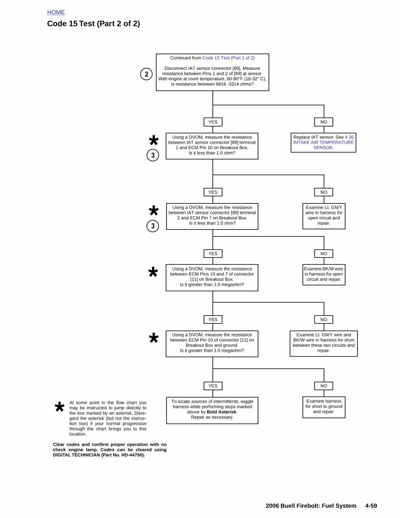
HOME
Code 15 Test (Part 2 of 2)
YES
Continued from Code 15 Test (Part 1 of 2)
Disconnect IAT sensor connector [89]. Measure resistance between Pins 1 and 2 of [89] at sensor.
With engine at room temperature, 60-90°F (16-32° C), is resistance between 6816 -3314 ohms?
Using a DVOM, measure the resistance between IAT sensor connector [89] terminal
1 and ECM Pin 10 on Breakout Box.Is it less than 1.0 ohm?
NO
Replace IAT sensor. See 4.36 INTAKE AIR TEMPERATURE
SENSOR.
YES
Using a DVOM, measure the resistance between IAT sensor connector [89] terminal
2 and ECM Pin 7 on Breakout Box.Is it less than 1.0 ohm?
NO
Examine Lt. GN/Y wire in harness for open circuit and
repair.
YES
3
Using a DVOM, measure the resistance between ECM Pins 10 and 7 of connector
[11] on Breakout Box.Is it greater than 1.0 megaohm?
NO
Examine BK/W wire in harness for open circuit and repair.
YES
Using a DVOM, measure the resistance between ECM Pin 10 of connector [11] on
Breakout Box and ground.Is it greater than 1.0 megaohm?
NO
Examine Lt. GN/Y wire and BK/W wire in harness for short between these two circuits and
repair.
3
2
2006 Buell Firebolt: Fuel System 4-59
YES NO
Examine harness for short to ground
and repair.
To locate sources of intermittents, wiggle harness while performing steps marked
above by Bold Asterisk. Repair as necessary.
At some point in the flow chart youmay be instructed to jump directly tothe box marked by an asterisk. Disre-gard the asterisk (but not the instruc-tion box) if your normal progressionthrough the chart brings you to thislocation.
Clear codes and confirm proper operation with nocheck engine lamp. Codes can be cleared usingDIGITAL TECHNICIAN (Part No. HD-44750).

HOME
TROUBLE CODE 16 4.20
GENE
BatteryA Code 16less than
● A lowof thetions.
● A higvoltag
DIAGN
DiagnoThe referebers on th
1. The E(blackHD-4
2. This ca sigbe ca
4-60
RAL
Voltage will set if the ECM detects battery positive voltage
6 volts or greater than 20 volts.
voltage condition typically occurs during activation starter or generally indicates loose wire connec-
h voltage condition is usually caused by a faultye regulator.
OSTICS
stic Notesnce numbers below correlate with the circled num-e Code 16 flow charts.
CM is monitoring voltage at ECM connector [10]) Terminal 1. Connect BREAKOUT BOX (Part No.
2682) to ECM. See 4.6 BREAKOUT BOX.
hecks for voltage drops in the ECM power circuit. Ifnificant voltage drop is not present, condition mayused by excessive starter current draw.
Figure 4-40. Electrical Relays
Figure 4-41. Fuse Block
8379
1
1. Key Switch Relay2. Ignition Relay3. Start Relay
3
2
10960
19 13 17Spare
DiodeSpare
Emptybd0016ax
2006 Buell Firebolt: Fuel System
Figure 4-42. Fuses and Diode
20
21
22
23
24
14
15
16
17
18
2
3
4
5
6
8
9
10
11
12
11
Bk/Hn/Mflr
Fan
IGN
Acces.Key Sw
Lights
ECM
Empty

HOME
1
1
2
2
3
3
4
4
1
12
3456789
101112131415161718192021222324
9
55
4
1
8787A308586
1915
14
11
8787A308586
2
ISO
ISOISO
KEY SW.
IGNITION START 19
20
21
22
23
24
13
14
15
16
17
18
1
2
3
4
5
6
7
8
9
10
11
12
11
Spare
Diode
Bk/Hn/Mflr
Fan
IGN
Acces.Key Sw
Lights
ECM
Spare
Empty
Empty
Right Handlebar Switch [22]
GY/O
GY
Ignition Relay
Key Switch Relay
Ignition Fuse
Key Switch Fuse
Ignition Switch
[33]
Main Fuse
Relay Center
Fuse Block
R
R
W/BK
R
R R/Y
R/BKBK
W/BKGY/O
W/BK
R/BK
GY
LT GN/R
To Battery
R/BK
R/BK
GY/O
b1083d4x
R
R
Top View
Top View
2006 Buell Firebolt: Fuel System 4-61
Figure 4-43. Battery Voltage Circuit
234
Electronic Control Module (ECM)
Connector [11]Connector [10]
BK
GY
BK
V/R
*ECM [10] Pin 1 also provides power to fuel pump, both fuel injec-tors and coil.
Data Link
Table 4-23. Wire Harness Connectors in Figure 4-43.
NO. DESCRIPTION TYPE LOCATION
[10] ECM (black) 12-place Deutsch in fairing
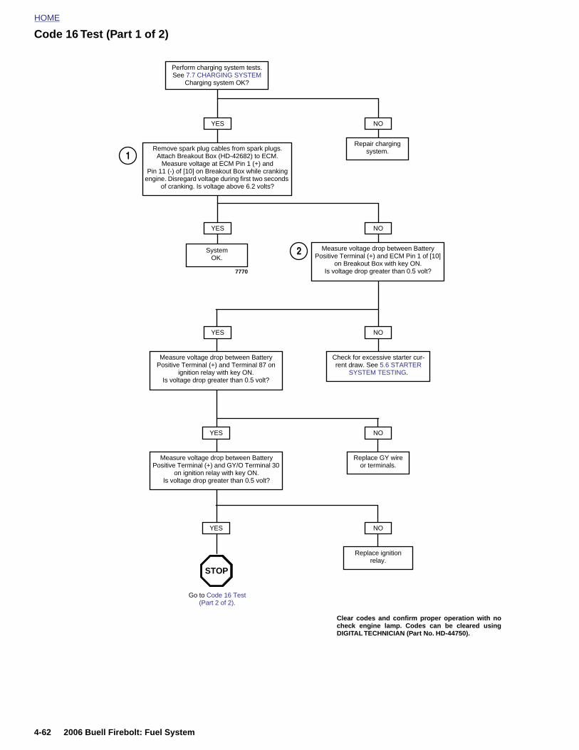
HOME
Code 16 Test (Part 1 of 2)
Perform charging system tests. See 7.7 CHARGING SYSTEM
Charging system OK?
YES NO
Repair chargingsystem.Remove spark plug cables from spark plugs.
Attach Breakout Box (HD-42682) to ECM. Measure voltage at ECM Pin 1 (+) and
Pin 11 (-) of [10] on Breakout Box while cranking engine. Disregard voltage during first two seconds
of cranking. Is voltage above 6.2 volts?
YES NO
Measure voltage drop between Battery Positive Terminal (+) and ECM Pin 1 of [10]
on Breakout Box with key ON. Is voltage drop greater than 0.5 volt?
System OK.
YES NO
Check for excessive starter cur-rent draw. See 5.6 STARTER
SYSTEM TESTING.
Measure voltage drop between Battery Positive Terminal (+) and Terminal 87 on
ignition relay with key ON. Is voltage drop greater than 0.5 volt?
NO
1
2
YES
Measure voltage drop between Battery Positive Terminal (+) and GY/O Terminal 30
on ignition relay with key ON.Is voltage drop greater than 0.5 volt?
YES
Replace GY wire or terminals.
NO
7770
4-62 2006 Buell Firebolt: Fuel System
Replace ignitionrelay.
Go to Code 16 Test (Part 2 of 2).
STOP
Clear codes and confirm proper operation with nocheck engine lamp. Codes can be cleared usingDIGITAL TECHNICIAN (Part No. HD-44750).
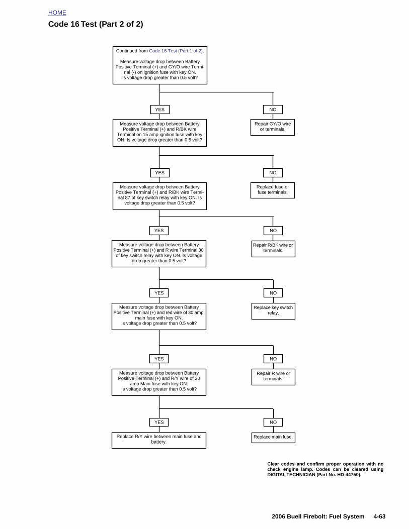
HOME
Code 16 Test (Part 2 of 2)
Continued from Code 16 Test (Part 1 of 2).
Measure voltage drop between Battery Positive Terminal (+) and GY/O wire Termi-
nal (-) on ignition fuse with key ON.Is voltage drop greater than 0.5 volt?
NO
Replace fuse or fuse terminals.
YES
Measure voltage drop between Battery Positive Terminal (+) and R wire Terminal 30 of key switch relay with key ON. Is voltage
drop greater than 0.5 volt?
YES NO
Replace key switch relay.
Measure voltage drop between Battery Positive Terminal (+) and red wire of 30 amp
main fuse with key ON. Is voltage drop greater than 0.5 volt?
YES NO
YES
Measure voltage drop between Battery Positive Terminal (+) and R/BK wire
Terminal on 15 amp ignition fuse with key ON. Is voltage drop greater than 0.5 volt?
YES
Measure voltage drop between Battery Positive Terminal (+) and R/BK wire Termi-nal 87 of key switch relay with key ON. Is
voltage drop greater than 0.5 volt?
NO
Repair GY/O wire or terminals.
NO
Repair R/BK wire or terminals.
2006 Buell Firebolt: Fuel System 4-63
Repair R wire or terminals.
Measure voltage drop between Battery Positive Terminal (+) and R/Y wire of 30
amp Main fuse with key ON. Is voltage drop greater than 0.5 volt?
YES NO
Replace main fuse. Replace R/Y wire between main fuse and battery.
Clear codes and confirm proper operation with nocheck engine lamp. Codes can be cleared usingDIGITAL TECHNICIAN (Part No. HD-44750).
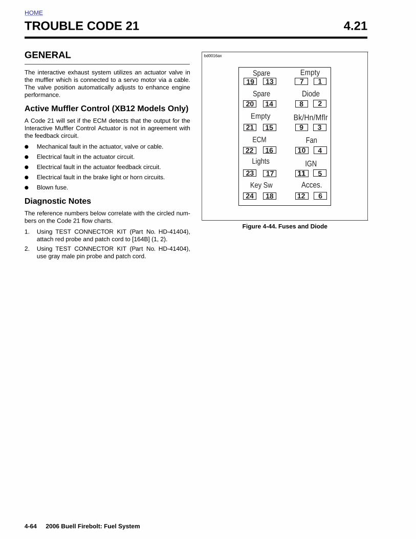
HOME
TROUBLE CODE 21 4.21
GENE
The interathe muffleThe valveperforman
Active A Code 2Interactivethe feedba
● Mech
● Elect
● Elect
● Elect
● Blown
DiagnoThe referebers on th
1. Usingattach
2. Usinguse g
4-64
RAL
ctive exhaust system utilizes an actuator valve inr which is connected to a servo motor via a cable. position automatically adjusts to enhance enginece.
Muffler Control (XB12 Models Only)1 will set if the ECM detects that the output for the Muffler Control Actuator is not in agreement withck circuit.
anical fault in the actuator, valve or cable.
rical fault in the actuator circuit.
rical fault in the actuator feedback circuit.
rical fault in the brake light or horn circuits.
fuse.
stic Notesnce numbers below correlate with the circled num-e Code 21 flow charts.
TEST CONNECTOR KIT (Part No. HD-41404), red probe and patch cord to [164B] (1, 2).
TEST CONNECTOR KIT (Part No. HD-41404),ray male pin probe and patch cord.
Figure 4-44. Fuses and Diode
19
20
21
22
23
24
13
14
15
16
17
18
1
2
3
4
5
6
7
8
9
10
11
12
11
Spare
Diode
Bk/Hn/Mflr
Fan
IGN
Acces.Key Sw
Lights
ECM
Spare
Empty
Empty
bd0016ax
2006 Buell Firebolt: Fuel System
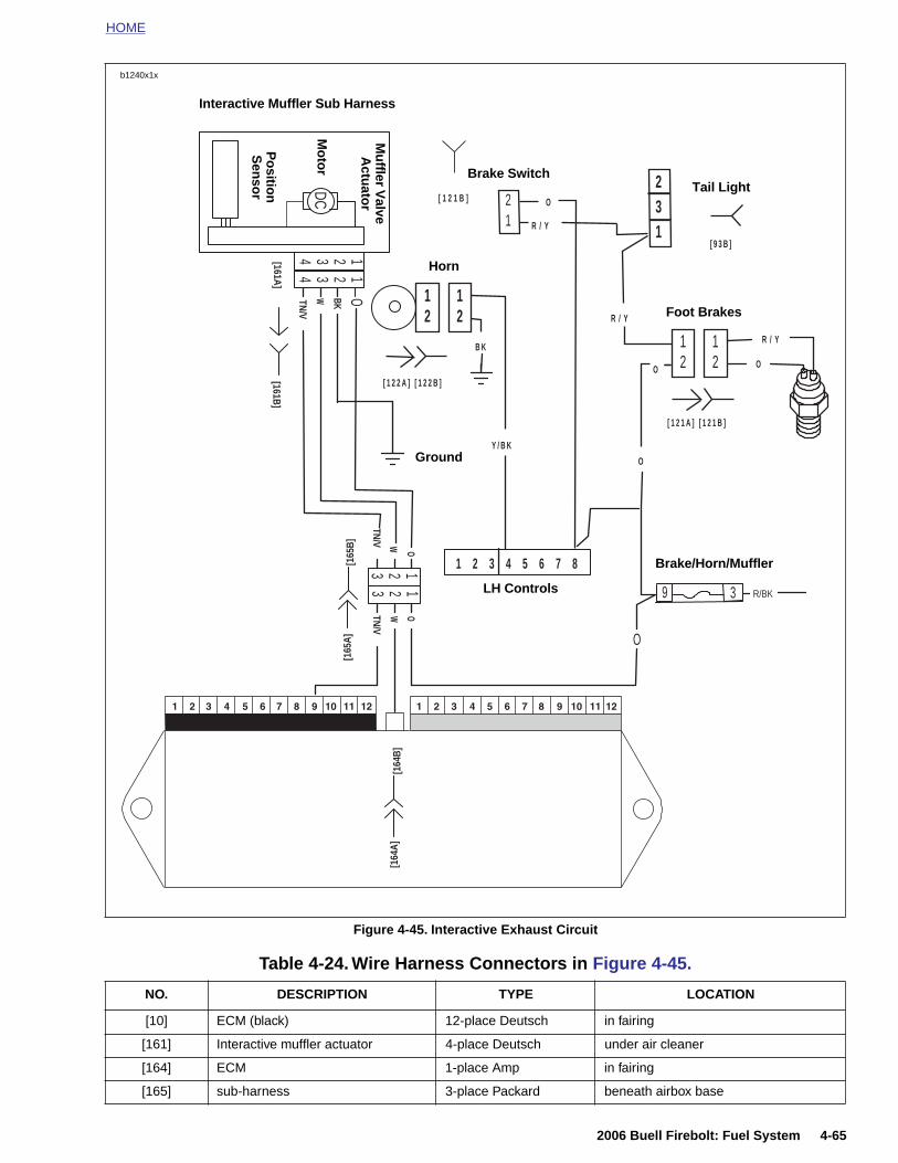
HOME
Connector [10] Connector [11]
b1240x1x
[164
B]
TN/V
OW2 13
TN/V
W O
3 12
[161A]
DC
OTN/V
W BK
11
44
33
22
[161B]
[165
A]
[165
B]
9 3 R/BK
O
1 2 3 4 5 6 7 8
12
12
[ 1 2 2 A ] [ 1 2 2 B ]
Y / B K
B K
21
[ 1 2 1 B ] O
231R / Y
12
12
R / Y
R / Y
OO
O
[ 1 2 1 A ] [ 1 2 1 B ]
[ 9 3 B ]
Brake Switch
Brake/Horn/Muffler
Foot Brakes
Tail Light
LH Controls
Ground
Horn
Interactive Muffler Sub Harness
Mu
ffler Valve
Actu
ator
Mo
tor
Po
sition
Sen
sor
2006 Buell Firebolt: Fuel System 4-65
Figure 4-45. Interactive Exhaust Circuit
Electronic Control Module (ECM)
[164
A]
Table 4-24. Wire Harness Connectors in Figure 4-45.
NO. DESCRIPTION TYPE LOCATION
[10] ECM (black) 12-place Deutsch in fairing
[161] Interactive muffler actuator 4-place Deutsch under air cleaner
[164] ECM 1-place Amp in fairing
[165] sub-harness 3-place Packard beneath airbox base
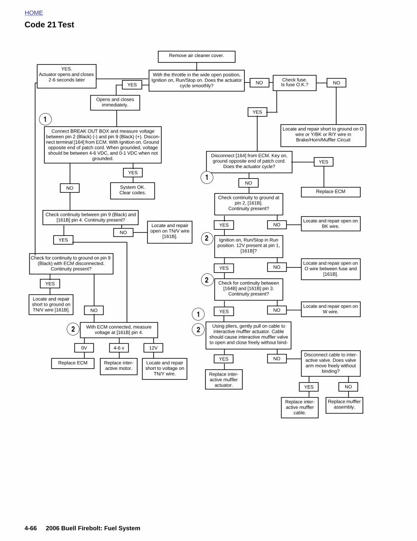
HOME
Code 21 Test
Remove air cleaner cover.
NOSystem OK.Clear codes.
Connect BREAK OUT BOX and measure voltage between pin 2 (Black) (-) and pin 9 (Black) (+). Discon-nect terminal [164] from ECM. With Ignition on, Ground opposite end of patch cord. When grounded, voltage should be between 4-6 VDC, and 0-1 VDC when not
grounded.
YES
Check continuity between pin 9 (Black) and [161B] pin 4. Continuity present?
Disconnect [164] from ECM. Key on, ground opposite end of patch cord.
Does the actuator cycle?
With the throttle in the wide open position, Ignition on, Run/Stop on. Does the actuator
cycle smoothly?
NO
Check for continuity to ground on pin 9 (Black) with ECM disconnected.
Continuity present?
1
YES
Replace ECMCheck continuity to ground at
pin 2, [161B]. Continuity present?
2
NOLocate and repair open on
BK wire.YES
Ignition on, Run/Stop in Run position. 12V present at pin 1,
[161B]?
NOLocate and repair open on O wire between fuse and
[161B].
YES
Check for continuity between [164B] and [161B] pin 3.
Continuity present?
NOLocate and repair open on
W wire.
Locate and repair open on TN/V wire
[161B].
Using pliers, gently pull on cable to interactive muffler actuator. Cable
should cause interactive muffler valve to open and close freely without bind-
NODisconnect cable to inter-active valve. Does valve arm move freely without
binding?
YES NO
YES
Replace inter-active muffler
actuator.
1
2
YES
YES
Locate and repair short to ground on TN/V wire [161B]. NO
With ECM connected, measure voltage at [161B] pin 4.
0V 4-6 v 12V
Replace ECM Replace inter-active motor.
Locate and repair short to voltage on
TN/Y wire.
1
2
2
YES
YES. Actuator opens and closes
2-6 seconds later
Opens and closesimmediately.
NO
YES
Locate and repair short to ground on O wire or Y/BK or R/Y wire inBrake/Horn/Muffler Circuit
Check fuse.Is fuse O.K.?NOYES NO
4-66 2006 Buell Firebolt: Fuel System
Replace muffler assembly.
Replace inter-active muffler
cable.
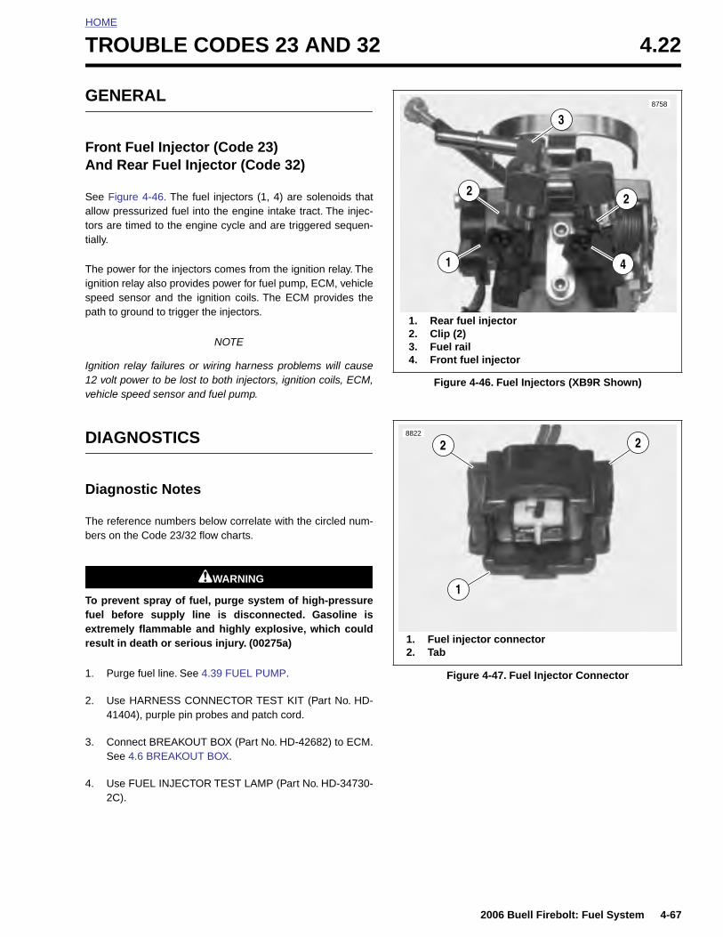
HOME
T
G
FA
Satt
Tigsp
I1v
D
D
Tb
Tfer
ROUBLE CODES 23 AND 32 4.22
ENERAL
ront Fuel Injector (Code 23)nd Rear Fuel Injector (Code 32)
ee Figure 4-46. The fuel injectors (1, 4) are solenoids thatllow pressurized fuel into the engine intake tract. The injec-ors are timed to the engine cycle and are triggered sequen-ially.
he power for the injectors comes from the ignition relay. Thenition relay also provides power for fuel pump, ECM, vehiclepeed sensor and the ignition coils. The ECM provides theath to ground to trigger the injectors.
NOTE
gnition relay failures or wiring harness problems will cause2 volt power to be lost to both injectors, ignition coils, ECM,ehicle speed sensor and fuel pump.
IAGNOSTICS
iagnostic Notes
he reference numbers below correlate with the circled num-ers on the Code 23/32 flow charts.
1WARNING1WARNING
o prevent spray of fuel, purge system of high-pressureuel before supply line is disconnected. Gasoline isxtremely flammable and highly explosive, which couldesult in death or serious injury. (00275a)
Figure 4-46. Fuel Injectors (XB9R Shown)
8758
1. Rear fuel injector2. Clip (2)3. Fuel rail4. Front fuel injector
4
2
1
2
3
8822
1. Fuel injector connector
1
2 2
2006 Buell Firebolt: Fuel System 4-67
1. Purge fuel line. See 4.39 FUEL PUMP.
2. Use HARNESS CONNECTOR TEST KIT (Part No. HD-41404), purple pin probes and patch cord.
3. Connect BREAKOUT BOX (Part No. HD-42682) to ECM.See 4.6 BREAKOUT BOX.
4. Use FUEL INJECTOR TEST LAMP (Part No. HD-34730-2C).
Figure 4-47. Fuel Injector Connector
2. Tab
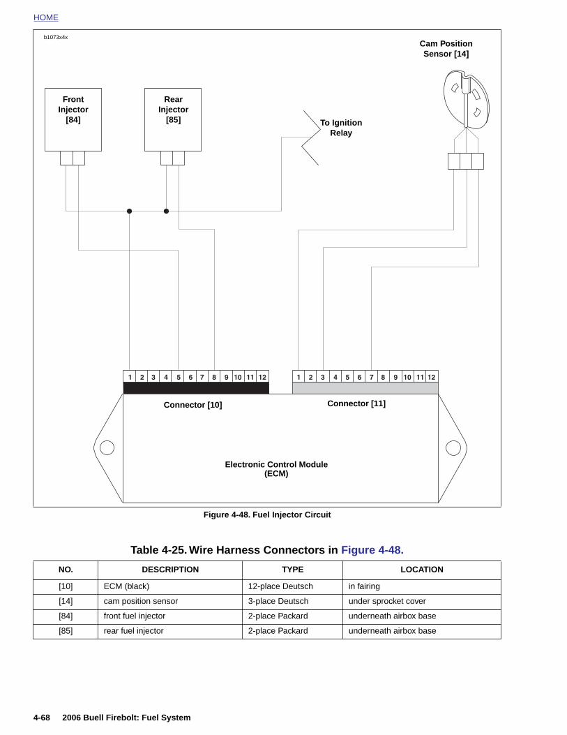
HOME
b1073x4xCam Position Sensor [14]
Figure 4-48. Fuel Injector Circuit
Connector [10] Connector [11]
Electronic Control Module (ECM)
To IgnitionRelay
FrontInjector
[84]
RearInjector
[85]
4-68 2006 Buell Firebolt: Fuel System
Table 4-25. Wire Harness Connectors in Figure 4-48.
NO. DESCRIPTION TYPE LOCATION
[10] ECM (black) 12-place Deutsch in fairing
[14] cam position sensor 3-place Deutsch under sprocket cover
[84] front fuel injector 2-place Packard underneath airbox base
[85] rear fuel injector 2-place Packard underneath airbox base
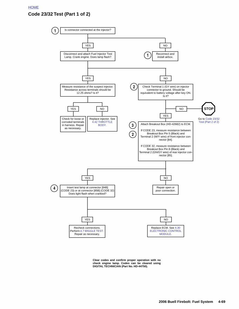
HOME
Code 23/32 Test (Part 1 of 2)
Is connector connected at the injector?
YES NO
Reconnect and install airbox.
YES
Disconnect and attach Fuel Injector Test Lamp. Crank engine. Does lamp flash?
1
Measure resistance of the suspect injector. Resistance across terminals should be
12.25 ohms? Is it?
Check Terminal 1 (GY wire) on injector connector to ground. Should be
equivalent to battery voltage after key ON. Is it?
NO
Attach Breakout Box (HD-42682) to ECM.
If CODE 23, measure resistance between Breakout Box Pin 5 (Black) and
Terminal 2 (W/Y wire) of front injector con-nector [84].
If CODE 32, measure resistance between Breakout Box Pin 8 (Black) and
Terminal 2 (GN/GY wire) of rear injector con-nector [85].
YESCheck for loose or corroded terminals in harness. Repair
as necessary.
Replace injector. See 4.42 THROTTLE
BODY.
YES NO NO
Go to Code 23/32 Test (Part 2 of 2)
YES NO
Repair open orpoor connection.
Insert test lamp at connector [84B] (CODE 23) or at connector [85B] (CODE 32)
Does light flash when cranked?
2
2
4
STOP
3
1
2006 Buell Firebolt: Fuel System 4-69
YES NO
Recheck connections. Perform 4.7 WIGGLE TEST.
Repair as necessary.
Replace ECM. See 4.30 ELECTRONIC CONTROL
MODULE.
Clear codes and confirm proper operation with nocheck engine lamp. Codes can be cleared usingDIGITAL TECHNICIAN (Part No. HD-44750).
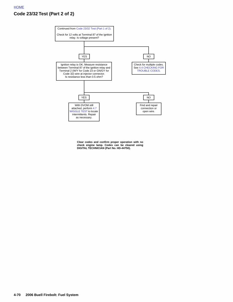
HOME
Code 23/32 Test (Part 2 of 2)
NO
Continued from Code 23/32 Test (Part 1 of 2).
Check for 12 volts at Terminal 87 of the ignition relay. Is voltage present?
YES
Ignition relay is OK. Measure resistance between Terminal 87 of the ignition relay and Terminal 2 (W/Y for Code 23 or GN/GY for
Code 32) wire at injector connector.Is resistance less than 0.5 ohm?
With DVOM still attached, perform 4.7
WIGGLE TEST to locate intermittents. Repair
as necessary.
Find and repair connection or
open wire.
YES NO
Check for multiple codes. See 4.4 CHECKING FOR
TROUBLE CODES.
Clear codes and confirm proper operation with nocheck engine lamp. Codes can be cleared usingDIGITAL TECHNICIAN (Part No. HD-44750).
4-70 2006 Buell Firebolt: Fuel System
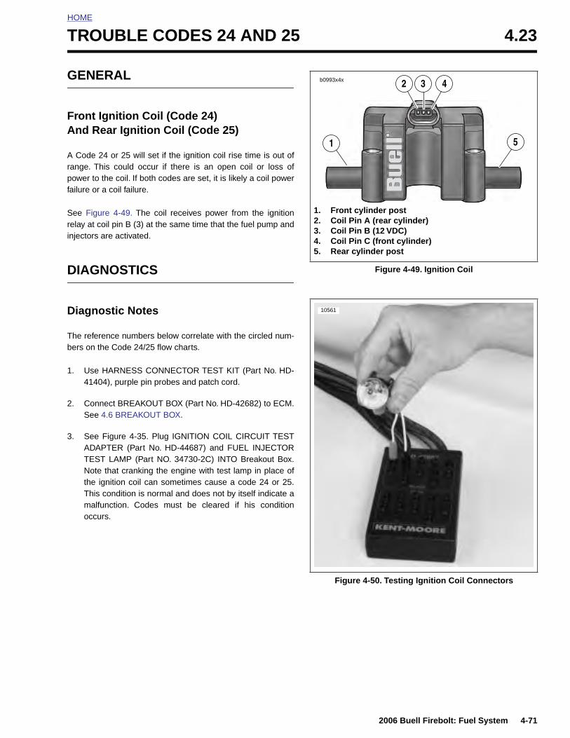
HOME
T
G
FA
Arpf
Sri
D
D
Tb
1
2
3
ROUBLE CODES 24 AND 25 4.23
ENERAL
ront Ignition Coil (Code 24)nd Rear Ignition Coil (Code 25)
Code 24 or 25 will set if the ignition coil rise time is out ofange. This could occur if there is an open coil or loss ofower to the coil. If both codes are set, it is likely a coil power
ailure or a coil failure.
ee Figure 4-49. The coil receives power from the ignitionelay at coil pin B (3) at the same time that the fuel pump andnjectors are activated.
IAGNOSTICS
iagnostic Notes
he reference numbers below correlate with the circled num-ers on the Code 24/25 flow charts.
. Use HARNESS CONNECTOR TEST KIT (Part No. HD-41404), purple pin probes and patch cord.
. Connect BREAKOUT BOX (Part No. HD-42682) to ECM.See 4.6 BREAKOUT BOX.
. See Figure 4-35. Plug IGNITION COIL CIRCUIT TESTADAPTER (Part No. HD-44687) and FUEL INJECTORTEST LAMP (Part NO. 34730-2C) INTO Breakout Box.Note that cranking the engine with test lamp in place ofthe ignition coil can sometimes cause a code 24 or 25.This condition is normal and does not by itself indicate amalfunction. Codes must be cleared if his condition
Figure 4-49. Ignition Coil
1. Front cylinder post2. Coil Pin A (rear cylinder)3. Coil Pin B (12 VDC)4. Coil Pin C (front cylinder)5. Rear cylinder post
1
2 3 4
5
b0993x4x
10561
2006 Buell Firebolt: Fuel System 4-71
occurs.
Figure 4-50. Testing Ignition Coil Connectors
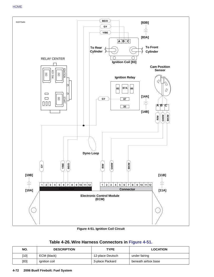
HOME
BE/O
ISO
ISOISO
KEY SW.
IGN
ITION
START
87A
Ignition Coil [83]
GN
/W
BK
/W
R/W
Electronic Control Module (ECM)
Connector Connector
Cam Position Sensor
A
GN
/W
Y/B
E
GY
BE
/O
BK
/W
B C
A CB
To RearCylinder
To FrontCylinder
R/W
GY
Ignition Relay
Y/BE
GY
Dyno Loop
b1072a4x
[10A]
[83A]
[83B]
[14A]
[14B]
[11A]
[11B][10B]
RELAY CENTER
4-72 2006 Buell Firebolt: Fuel System
Figure 4-51. Ignition Coil Circuit
Table 4-26. Wire Harness Connectors in Figure 4-51.
NO. DESCRIPTION TYPE LOCATION
[10] ECM (black) 12-place Deutsch under fairing
[83] ignition coil 3-place Packard beneath airbox base
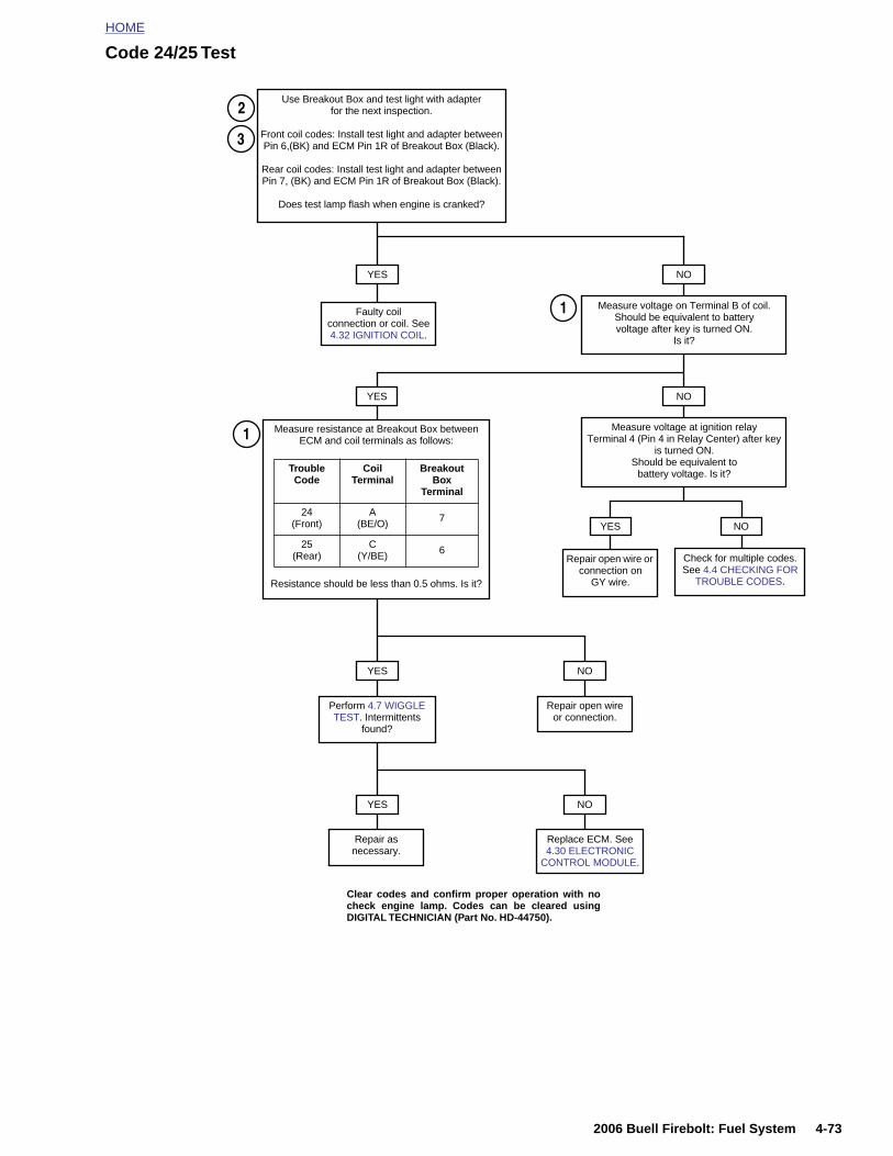
HOME
Code 24/25 Test
NO
Measure voltage on Terminal B of coil. Should be equivalent to batteryvoltage after key is turned ON.
Is it?
YES
Faulty coilconnection or coil. See 4.32 IGNITION COIL.
Use Breakout Box and test light with adapterfor the next inspection.
Front coil codes: Install test light and adapter betweenPin 6,(BK) and ECM Pin 1R of Breakout Box (Black).
Rear coil codes: Install test light and adapter betweenPin 7, (BK) and ECM Pin 1R of Breakout Box (Black).
Does test lamp flash when engine is cranked?
NOYES
Measure voltage at ignition relay Terminal 4 (Pin 4 in Relay Center) after key
is turned ON. Should be equivalent to
battery voltage. Is it?
YES
Repair open wire or connection on
GY wire.
NO
Check for multiple codes. See 4.4 CHECKING FOR
TROUBLE CODES.
Measure resistance at Breakout Box between ECM and coil terminals as follows:
Resistance should be less than 0.5 ohms. Is it?
Trouble Code
Coil Terminal
Breakout Box
Terminal
24 (Front)
A (BE/O) 7
25 (Rear)
C(Y/BE) 6
NO
Repair open wire or connection.
YES
Perform 4.7 WIGGLE TEST. Intermittents
found?
1
1
3
2
2006 Buell Firebolt: Fuel System 4-73
NOYES
Repair as necessary.
Replace ECM. See 4.30 ELECTRONIC
CONTROL MODULE.
Clear codes and confirm proper operation with nocheck engine lamp. Codes can be cleared usingDIGITAL TECHNICIAN (Part No. HD-44750).
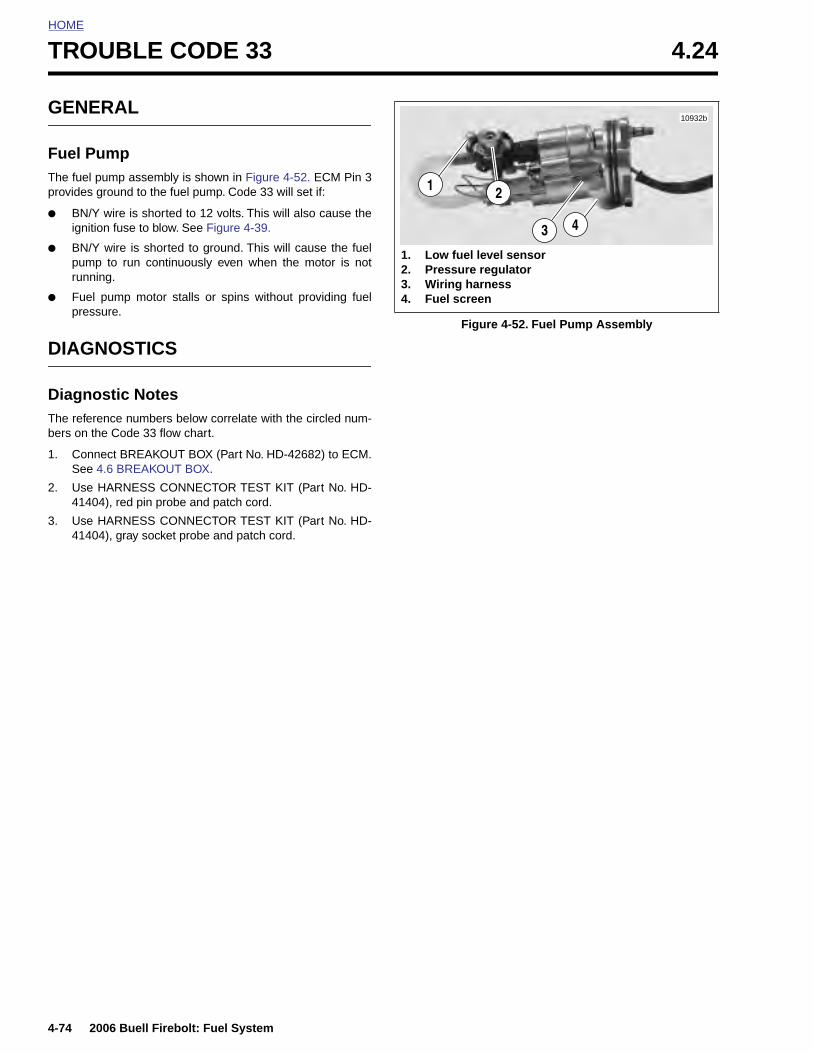
HOME
TROUBLE CODE 33 4.24
GENE
Fuel PuThe fuel pprovides g
● BN/Yignitio
● BN/Ypumprunni
● Fuel press
DIAGN
DiagnoThe referebers on th
1. ConnSee 4
2. Use H4140
3. Use H4140
4-74
RAL
mpump assembly is shown in Figure 4-52. ECM Pin 3round to the fuel pump. Code 33 will set if:
wire is shorted to 12 volts. This will also cause then fuse to blow. See Figure 4-39.
wire is shorted to ground. This will cause the fuel to run continuously even when the motor is notng.
pump motor stalls or spins without providing fuelure.
OSTICS
stic Notesnce numbers below correlate with the circled num-e Code 33 flow chart.
ect BREAKOUT BOX (Part No. HD-42682) to ECM..6 BREAKOUT BOX.
ARNESS CONNECTOR TEST KIT (Part No. HD-4), red pin probe and patch cord.
ARNESS CONNECTOR TEST KIT (Part No. HD-4), gray socket probe and patch cord.
Figure 4-52. Fuel Pump Assembly
10932b
3 4
2
1. Low fuel level sensor2. Pressure regulator3. Wiring harness4. Fuel screen
1
2006 Buell Firebolt: Fuel System
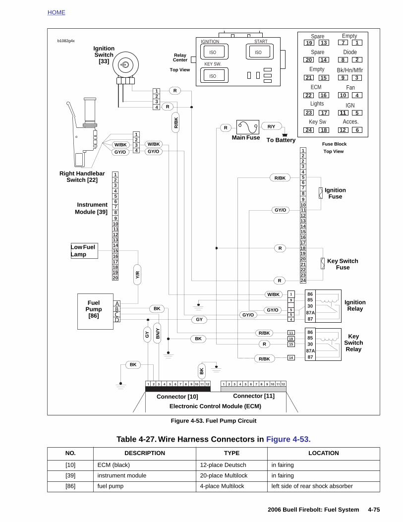
HOME
1234
123456789
1011121314151617181920
1234 1
2
3456789
101112131415161718192021222324
9
55
4
1
8787A308586
1915
14
11
8787A308586
2
ABCD
ISO
ISOISO
KEY SW.
IGNITION START 19
20
21
22
23
24
13
14
15
16
17
18
1
2
3
4
5
6
7
8
9
10
11
12
11
Spare
Diode
Bk/Hn/Mflr
Fan
IGN
Acces.Key Sw
Lights
ECM
Spare
Empty
Empty
Ignition Switch
[33]
Low Fuel Lamp
InstrumentModule [39]
FuelPump [86]
R/Y
R
Main Fuse To Battery
Ignition Relay
Key Switch Relay
W/BK
GY/O
W/BK
GY/O
Key Switch Fuse
R
R
R/B
K
Y/R
GY/O
R/BK
BK
BN
/Y
GY
GY
Right Handlebar Switch [22]
b1082g4x
R
R
W/BK
GY/OGY/O
R/BKBK
R
R/BK
Relay Center
Fuse Block
Top View
Top View
Ignition Fuse
2006 Buell Firebolt: Fuel System 4-75
Figure 4-53. Fuel Pump Circuit
BK
BK
Electronic Control Module (ECM)
Connector [10] Connector [11]
Table 4-27. Wire Harness Connectors in Figure 4-53.
NO. DESCRIPTION TYPE LOCATION
[10] ECM (black) 12-place Deutsch in fairing
[39] instrument module 20-place Multilock in fairing
[86] fuel pump 4-place Multilock left side of rear shock absorber
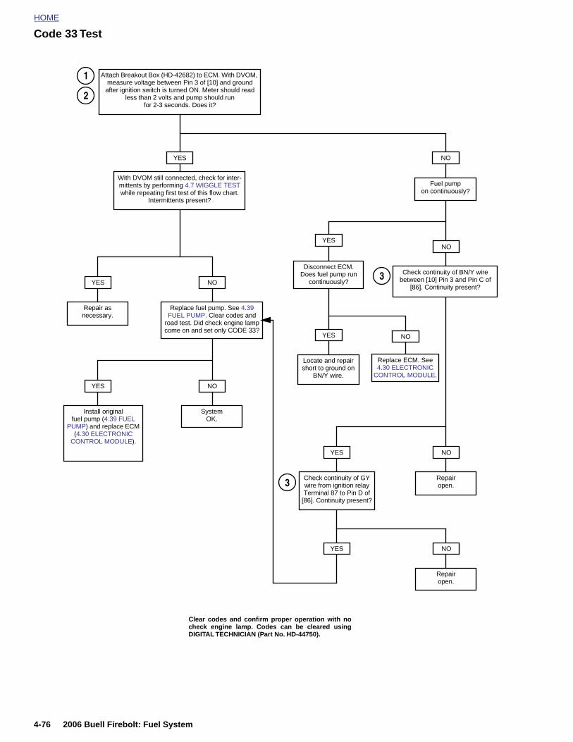
HOME
Code 33 Test
YES
With DVOM still connected, check for inter-mittents by performing 4.7 WIGGLE TEST while repeating first test of this flow chart.
Intermittents present?
Attach Breakout Box (HD-42682) to ECM. With DVOM, measure voltage between Pin 3 of [10] and ground
after ignition switch is turned ON. Meter should read less than 2 volts and pump should run
for 2-3 seconds. Does it?
YES NO
Repair as necessary.
Replace fuel pump. See 4.39 FUEL PUMP. Clear codes and
road test. Did check engine lamp come on and set only CODE 33?
YES NO
Install original fuel pump (4.39 FUEL
PUMP) and replace ECM (4.30 ELECTRONIC
CONTROL MODULE).
SystemOK.
Fuel pump on continuously?
NO
Check continuity of BN/Y wire between [10] Pin 3 and Pin C of
[86]. Continuity present?
YES
Repairopen.
NO
Check continuity of GY wire from ignition relay Terminal 87 to Pin D of
[86]. Continuity present?
NO
1
2
3
3
Disconnect ECM. Does fuel pump run
continuously?
YES NO
Locate and repair short to ground on
BN/Y wire.
Replace ECM. See 4.30 ELECTRONIC
CONTROL MODULE.
YES
4-76 2006 Buell Firebolt: Fuel System
YES
Repairopen.
NO
Clear codes and confirm proper operation with nocheck engine lamp. Codes can be cleared usingDIGITAL TECHNICIAN (Part No. HD-44750).
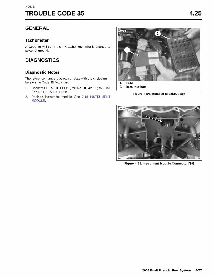
HOME
T
G
TAp
D
DTb
1
2
ROUBLE CODE 35 4.25
ENERAL
achometer Code 35 will set if the PK tachometer wire is shorted toower or ground.
IAGNOSTICS
iagnostic Noteshe reference numbers below correlate with the circled num-ers on the Code 35 flow chart.
. Connect BREAKOUT BOX (Part No. HD-42682) to ECM.See 4.6 BREAKOUT BOX.
. Replace instrument module. See 7.18 INSTRUMENTMODULE.
Figure 4-54. Installed Breakout Box
Figure 4-55. Instrument Module Connector [39]
8427
1. ECM2. Breakout box
1
2
8426
2006 Buell Firebolt: Fuel System 4-77
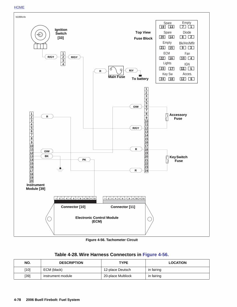
HOME
Spare Empty
b1084c4x
1234
1
3456789
101112131415161718192021222324
2
123456789
1011121314151617181920
19
20
21
22
23
24
13
14
15
16
17
18
1
2
3
4
5
6
7
8
9
10
11
12
11
Diode
Bk/Hn/Mflr
Fan
IGN
Acces.Key Sw
Lights
ECM
Spare
Empty
O/W
BK
Ignition Switch
[33]
To battery
Electronic Control Module(ECM)
Connector [10] Connector [11]
Instrument Module [39]
R
R/Y
R/GY
O/W
R
R
R
Main Fuse
Fuse Block
R/GY
Accessory Fuse
Key Switch FusePK
Top View
R/GY
4-78 2006 Buell Firebolt: Fuel System
Figure 4-56. Tachometer Circuit
Table 4-28. Wire Harness Connectors in Figure 4-56.
NO. DESCRIPTION TYPE LOCATION
[10] ECM (black) 12-place Deutsch in fairing
[39] instrument module 20-place Multilock in fairing
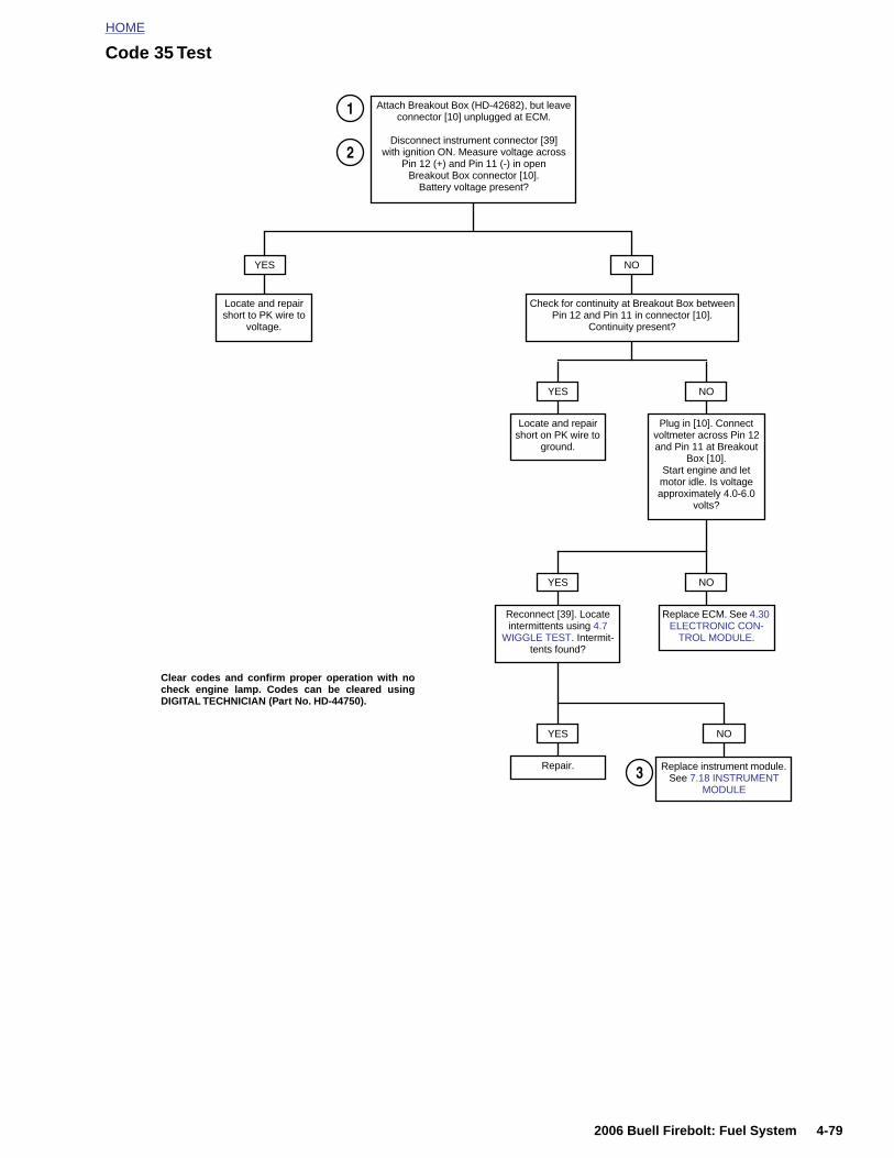
HOME
Code 35 Test
Attach Breakout Box (HD-42682), but leave connector [10] unplugged at ECM.
Disconnect instrument connector [39] with ignition ON. Measure voltage across
Pin 12 (+) and Pin 11 (-) in open Breakout Box connector [10].
Battery voltage present?
YES
Locate and repair short to PK wire to
voltage.
NO
Check for continuity at Breakout Box betweenPin 12 and Pin 11 in connector [10].
Continuity present?
Locate and repair short on PK wire to
ground.
YES
Plug in [10]. Connect voltmeter across Pin 12 and Pin 11 at Breakout
Box [10]. Start engine and let motor idle. Is voltage approximately 4.0-6.0
volts?
NO
Reconnect [39]. Locate intermittents using 4.7
WIGGLE TEST. Intermit-tents found?
YES
Replace ECM. See 4.30 ELECTRONIC CON-
TROL MODULE.
NO
Repair.
YES NO
Replace instrument module. See 7.18 INSTRUMENT
MODULE
1
2
3
Clear codes and confirm proper operation with nocheck engine lamp. Codes can be cleared usingDIGITAL TECHNICIAN (Part No. HD-44750).
2006 Buell Firebolt: Fuel System 4-79
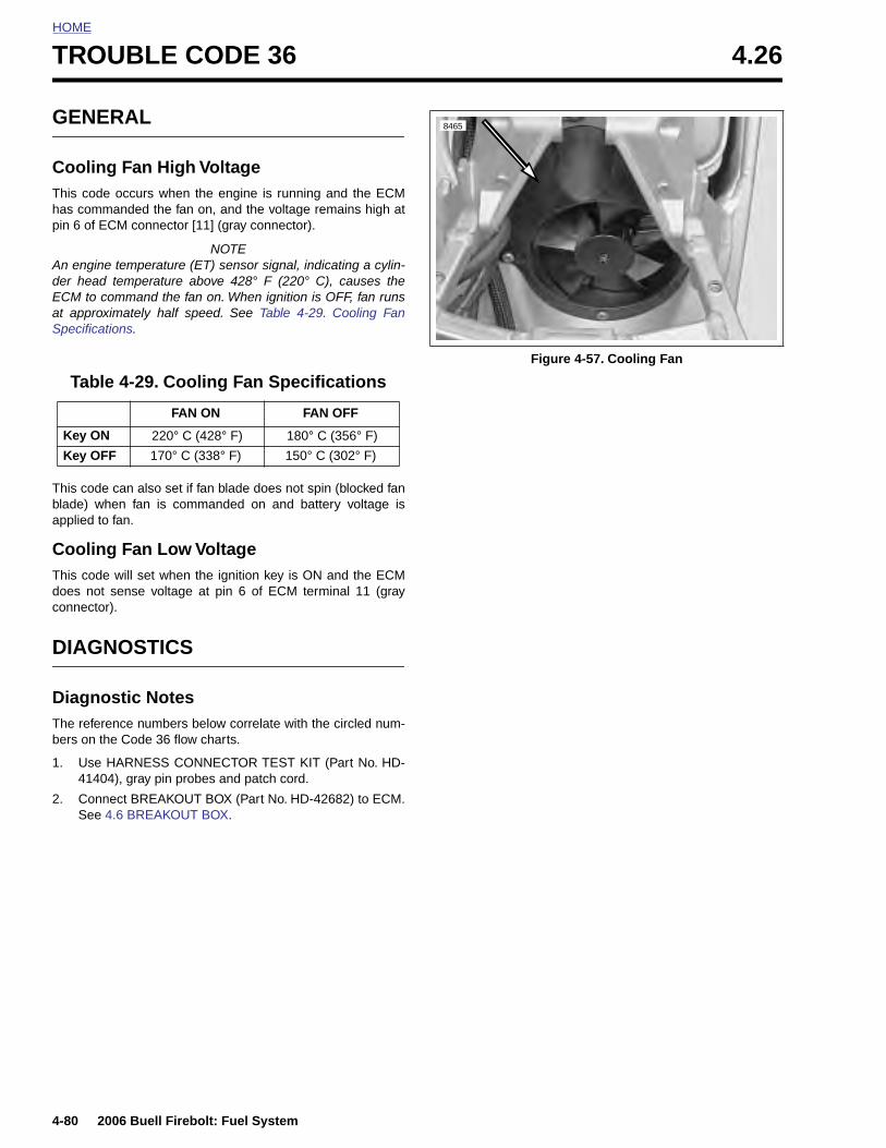
HOME
TROUBLE CODE 36 4.26
GENE
CoolingThis codehas commpin 6 of E
An engineder head ECM to coat approxSpecificat
This codeblade) whapplied to
CoolingThis codedoes not connector
DIAGN
DiagnoThe referebers on th
1. Use H4140
2. ConnSee 4
Table
Key ON
Key OF
4-80
RAL
Fan High Voltage occurs when the engine is running and the ECManded the fan on, and the voltage remains high at
CM connector [11] (gray connector).
NOTE temperature (ET) sensor signal, indicating a cylin-temperature above 428° F (220° C), causes themmand the fan on. When ignition is OFF, fan runs
imately half speed. See Table 4-29. Cooling Fanions.
can also set if fan blade does not spin (blocked fanen fan is commanded on and battery voltage is fan.
Fan Low Voltage will set when the ignition key is ON and the ECMsense voltage at pin 6 of ECM terminal 11 (gray).
OSTICS
stic Notesnce numbers below correlate with the circled num-e Code 36 flow charts.
ARNESS CONNECTOR TEST KIT (Part No. HD-4), gray pin probes and patch cord.
ect BREAKOUT BOX (Part No. HD-42682) to ECM..6 BREAKOUT BOX.
4-29. Cooling Fan Specifications
FAN ON FAN OFF
220° C (428° F) 180° C (356° F)
F 170° C (338° F) 150° C (302° F)
Figure 4-57. Cooling Fan
8465
2006 Buell Firebolt: Fuel System
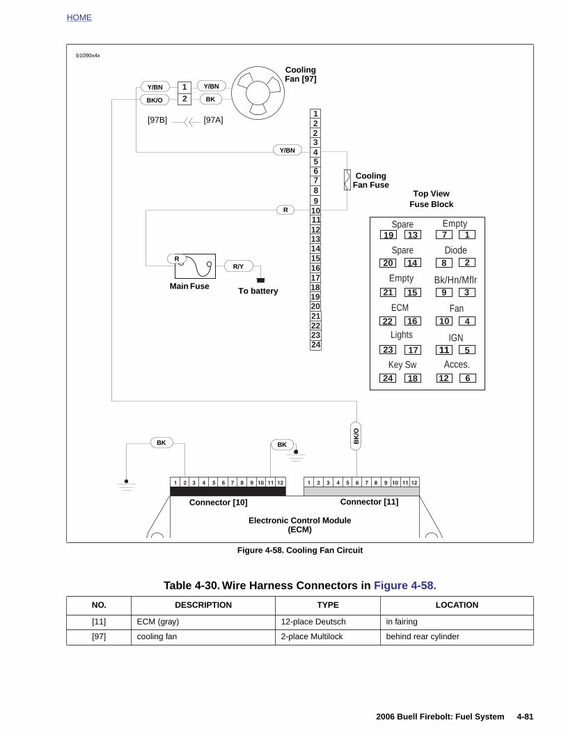
HOME
12
12
3456789
101112131415161718192021222324
2
19
20
21
22
23
24
13
14
15
16
17
18
1
2
3
4
5
6
7
8
9
10
11
12
11
Spare
Diode
Bk/Hn/Mflr
Fan
IGN
Acces.Key Sw
Lights
ECM
Spare
Empty
Empty
Connector [10] Connector [11]
BK
R/Y
Y/BN
BK/O
To battery
R
Main Fuse
Fuse Block
Cooling Fan Fuse
Top View
Y/BN
R
Cooling Fan [97]
BK
/O
BK
b1090x4x
Y/BN
BK
[97A][97B]
2006 Buell Firebolt: Fuel System 4-81
Figure 4-58. Cooling Fan Circuit
Electronic Control Module (ECM)
Table 4-30. Wire Harness Connectors in Figure 4-58.
NO. DESCRIPTION TYPE LOCATION
[11] ECM (gray) 12-place Deutsch in fairing
[97] cooling fan 2-place Multilock behind rear cylinder
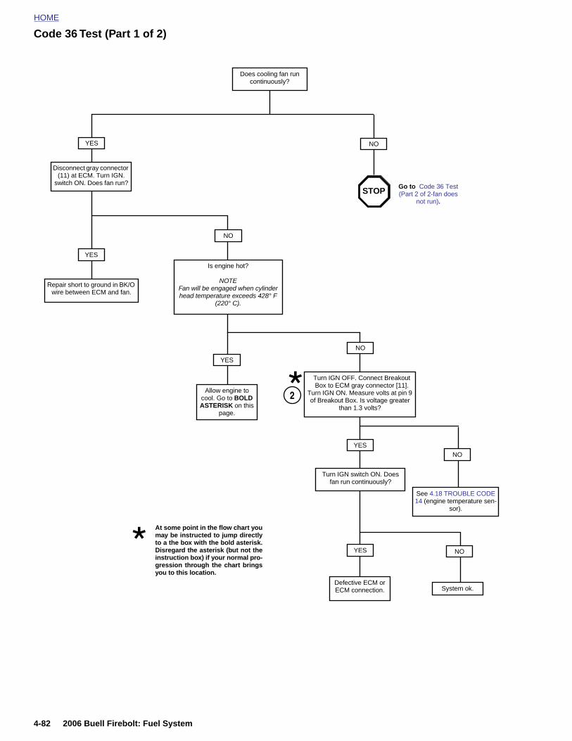
HOME
Code 36 Test (Part 1 of 2)
YES
Disconnect gray connector (11) at ECM. Turn IGN.
switch ON. Does fan run?
Repair short to ground in BK/O wire between ECM and fan.
Is engine hot?
NOTEFan will be engaged when cylinder head temperature exceeds 428° F
(220° C).
NO
YES
Allow engine to cool. Go to BOLD ASTERISK on this
page.
NO
Turn IGN OFF. Connect Breakout Box to ECM gray connector [11].
Turn IGN ON. Measure volts at pin 9 of Breakout Box. Is voltage greater
than 1.3 volts?
YES
2
Does cooling fan run continuously?
NO
YESNO
See 4.18 TROUBLE CODE 14 (engine temperature sen-
sor).
Turn IGN switch ON. Does fan run continuously?
At some point in the flow chart youmay be instructed to jump directlyto a the box with the bold asterisk.
Go to Code 36 Test (Part 2 of 2-fan does
not run).
STOP
4-82 2006 Buell Firebolt: Fuel System
YES
Defective ECM or ECM connection.
NO
System ok.
Disregard the asterisk (but not theinstruction box) if your normal pro-gression through the chart bringsyou to this location.
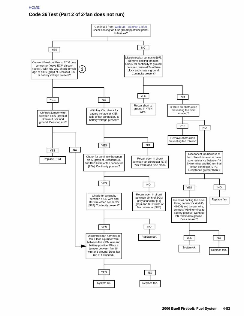
HOME
Code 36 Test (Part 2 of 2-fan does not run)
YES
YES
Connect jumper wire between pin 6 (gray) of
Breakout Box and ground. Does fan run?
NO
With key ON, check for battery voltage at Y/BN side of fan connector. Is battery voltage present?
YES
Connect Breakout Box to ECM gray connector (leave ECM discon-
nected). With key ON, check for volt-age at pin 6 (gray) of Breakout Box.
Is battery voltage present?
NO
Repair open in circuit between fan connector [97B]
Y/BR wire and fuse block.
Replace ECM.
Continued from Code 36 Test (Part 1 of 2). Check cooling fan fuse (10 amp) at fuse panel.
Is fuse ok?
NO
Disconnect fan connector [97]. Remove cooling fan fuse.
Check for continuity to ground between terminal 24 of fuse block and chassis ground.
Continuity present?
YES NO
Repair short to ground in Y/BN
wire.
Is there an obstruction preventing fan from
rotating?
YES
Remove obstruction preventing fan rotation.
NO
Disconnect fan harness at fan. Use ohmmeter to mea-sure resistance between Y/BN terminal and BK terminal
of fan connector [97A]. Resistance greater than 1
Check for continuity between pin 6 (gray) of Breakout Box
and BK/O wire of fan connector [97A]. Continuity present?
Check for continuity between Y/BN wire and BK wire of fan connector [97A] Continuity present?
YES NO
Repair open in circuit between pin 6 of ECM
gray connector [11] (gray) and BK/O wire of
fan connector [97B]
NO
Replace fan.
2
YES NO
YES
Reinstall cooling fan fuse. Using connector kit (HD-41404) and jumper wire, connect Y/BN terminal to battery positive. Connect BK terminal to ground.
2006 Buell Firebolt: Fuel System 4-83
YES NO
Replace fan.Disconnect fan harness at fan. Place a jumper wire
between fan Y/BN wire and battery positive. Place a jumper between fan BK
wire and ground. Does fan run at full speed?
System ok.
YES
Replace fan.
NO
Does fan run?
YES NO
Replace fan.System ok.
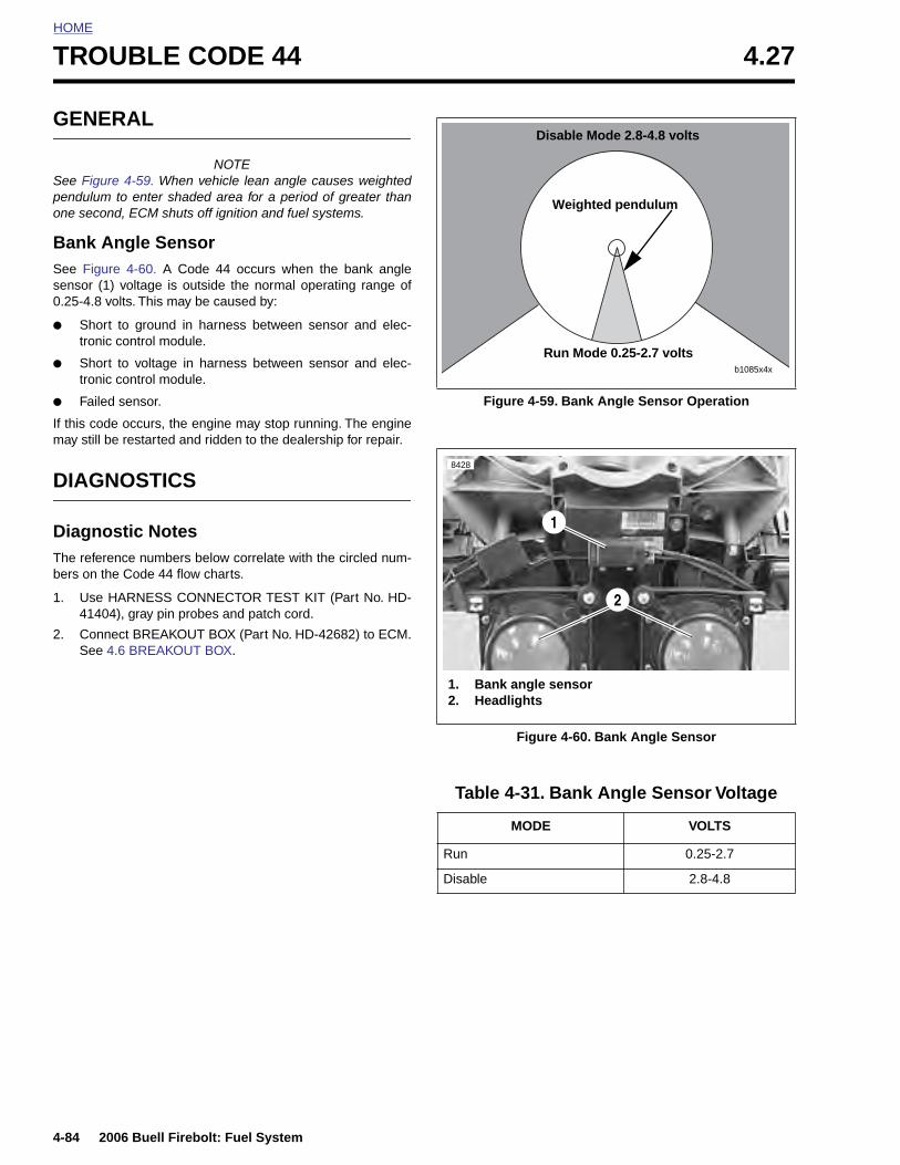
HOME
TROUBLE CODE 44 4.27
GENE
See Figurpendulumone secon
Bank ASee Figursensor (10.25-4.8 v
● Shorttronic
● Shorttronic
● Failed
If this codmay still b
DIAGN
DiagnoThe referebers on th
1. Use H4140
2. ConnSee 4
4-84
RAL
NOTEe 4-59. When vehicle lean angle causes weighted to enter shaded area for a period of greater thand, ECM shuts off ignition and fuel systems.
ngle Sensore 4-60. A Code 44 occurs when the bank angle) voltage is outside the normal operating range ofolts. This may be caused by:
to ground in harness between sensor and elec- control module.
to voltage in harness between sensor and elec- control module.
sensor.
e occurs, the engine may stop running. The enginee restarted and ridden to the dealership for repair.
OSTICS
stic Notesnce numbers below correlate with the circled num-e Code 44 flow charts.
ARNESS CONNECTOR TEST KIT (Part No. HD-4), gray pin probes and patch cord.
ect BREAKOUT BOX (Part No. HD-42682) to ECM..6 BREAKOUT BOX.
Figure 4-59. Bank Angle Sensor Operation
Figure 4-60. Bank Angle Sensor
Table 4-31. Bank Angle Sensor Voltage
MODE VOLTS
Run 0.25-2.7
b1085x4x
Run Mode 0.25-2.7 volts
Disable Mode 2.8-4.8 volts
Weighted pendulum
8428
1. Bank angle sensor2. Headlights
1
2
2006 Buell Firebolt: Fuel System
Disable 2.8-4.8

HOME
123 CBA
Throttle Position
Sensor [88]
R/W V/Y
BK
/W
R/W
BK
/W
GN
/W
Cam PositionSensor [14]
R/W = 5 Volt ReferenceV/Y = TP Sensor SignalBK/W = Sensor Ground
R/W V/Y
GN
/W
BK
/W
Electronic Control Module (ECM)
Connector [10] Connector [11]
LT
GN
/GY
R/W = 5 Volt ReferenceLt.GN/GY = BAS SignalBK/W = Sensor Ground
Bank Angle Sensor [134]
BK
/W
R/W
LT
GN
/GY
b1112x4x
2006 Buell Firebolt: Fuel System 4-85
Figure 4-61. Bank Angle Sensor Circuit
Table 4-32. Wire Harness Connectors in Figure 4-61.
NO. DESCRIPTION TYPE LOCATION
[10] ECM (black) 12-place Deutsch in fairing
[11] ECM (gray) 12-place Deutsch in fairing
[14] cam position sensor 3-place Deutsch under sprocket cover
[88] throttle position sensor 3-place Packard right side of engine between cylinders
[134] bank angle sensor 6-place Sumitomo in fairing
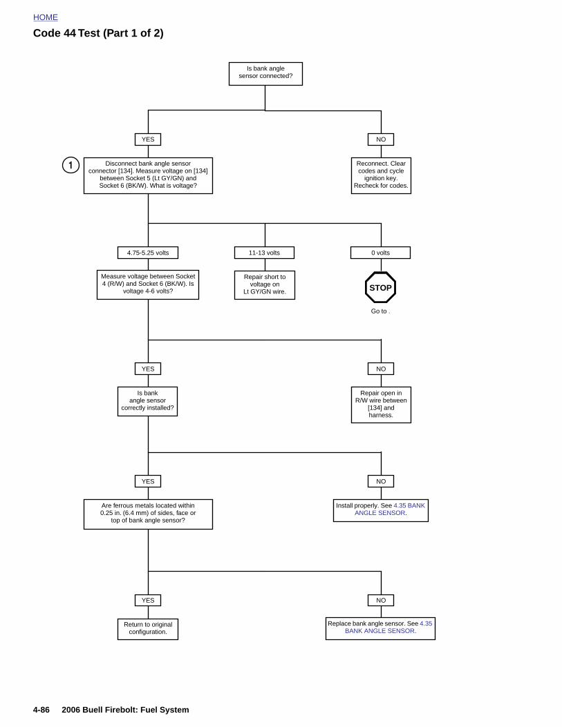
HOME
Code 44 Test (Part 1 of 2)
Is bank angle sensor connected?
YES
Disconnect bank angle sensor connector [134]. Measure voltage on [134]
between Socket 5 (Lt GY/GN) and Socket 6 (BK/W). What is voltage?
NO
Reconnect. Clear codes and cycle
ignition key. Recheck for codes.
Repair short to voltage on
Lt GY/GN wire.
4.75-5.25 volts
Measure voltage between Socket 4 (R/W) and Socket 6 (BK/W). Is
voltage 4-6 volts?
11-13 volts 0 volts
Go to .
YES
Is bank angle sensor
correctly installed?
NO
Repair open in R/W wire between
[134] andharness.
YES
Are ferrous metals located within 0.25 in. (6.4 mm) of sides, face or
top of bank angle sensor?
NO
Install properly. See 4.35 BANK ANGLE SENSOR.
STOP
1
4-86 2006 Buell Firebolt: Fuel System
YES
Return to originalconfiguration.
NO
Replace bank angle sensor. See 4.35 BANK ANGLE SENSOR.

HOME
Code 44 Test (Part 2 of 2)
Continued from Code 44 Test (Part 1 of 2).
Disconnect connectors [10] (BK) and [11] (GY) from module and plug into Breakout Box (HD-42682). Check continuity
between Socket 5 (Lt GN/GY) on connector [134] and Breakout Box (BK) Pin 10. Is continuity present?
NO
Repair open inLt GN/GY wire.
YES
Check continuity to ground for Socket 6 (BK/W) and connector [11] Pin 7.
Is continuity present?
NO
Repair open inground wire.
YES
Check continuity to ground for Socket 5 (Lt GN/GY) and connector [134].
Is continuity present?
NO
Replace ECM. See 4.30 ELECTRONIC
CONTROL MODULE.
YES
Repair short to ground on Lt GN/GY wire.
2
Clear codes and confirm proper operation with nocheck engine lamp. Codes can be cleared usingDIGITAL TECHNICIAN (Part No. HD-44750).
2006 Buell Firebolt: Fuel System 4-87
HOME
TROUBLE CODES 52, 53, 54 AND 55 4.28
GENE
ECM FaAll of thereplacemeMODULE
● Code
● Code
● Code
● Code
4-88
RAL
ilure following codes indicate a failure which requiresnt of the ECM. See 4.30 ELECTRONIC CONTROL
.
52 - RAM failure.
53 - ROM failure.
54 - EE PROM failure.
55 - Microprocessor failure.
2006 Buell Firebolt: Fuel System
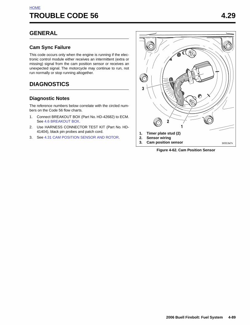
HOME
T
G
CTtmur
D
DTb
1
2
3
ROUBLE CODE 56 4.29
ENERAL
am Sync Failurehis code occurs only when the engine is running if the elec-
ronic control module either receives an intermittent (extra orissing) signal from the cam position sensor or receives annexpected signal. The motorcycle may continue to run, notun normally or stop running altogether.
IAGNOSTICS
iagnostic Noteshe reference numbers below correlate with the circled num-ers on the Code 56 flow charts.
. Connect BREAKOUT BOX (Part No. HD-42682) to ECM.See 4.6 BREAKOUT BOX.
. Use HARNESS CONNECTOR TEST KIT (Part No. HD-41404), black pin probes and patch cord.
. See 4.31 CAM POSITION SENSOR AND ROTOR.
Figure 4-62. Cam Position Sensor
11. Timer plate stud (2)2. Sensor wiring3. Cam position sensor
2
3
b0313a7x
2006 Buell Firebolt: Fuel System 4-89
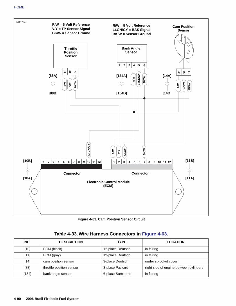
HOME
b1112a4x
Figure 4-63. Cam Position Sensor Circuit
ABC CBA
Throttle Position Sensor
R/W V/Y
BK
/W
R/W
BK
/W
GN
/W
Cam PositionSensor
R/W = 5 Volt ReferenceV/Y = TP Sensor SignalBK/W = Sensor Ground
R/W V/Y
GN
/W
BK
/W
Electronic Control Module (ECM)
Connector Connector
LT
GN
/GY
R/W = 5 Volt ReferenceLt.GN/GY = BAS SignalBK/W = Sensor Ground
Bank Angle Sensor
BK
/W
R/W
LT
GN
/GY [14A]
[11A]
[11B]
[10A]
[10B]
[14B][134B]
[134A]
[88B]
[88A]
4-90 2006 Buell Firebolt: Fuel System
Table 4-33. Wire Harness Connectors in Figure 4-63.
NO. DESCRIPTION TYPE LOCATION
[10] ECM (black) 12-place Deutsch in fairing
[11] ECM (gray) 12-place Deutsch in fairing
[14] cam position sensor 3-place Deutsch under sprocket cover
[88] throttle position sensor 3-place Packard right side of engine between cylinders
[134] bank angle sensor 6-place Sumitomo in fairing
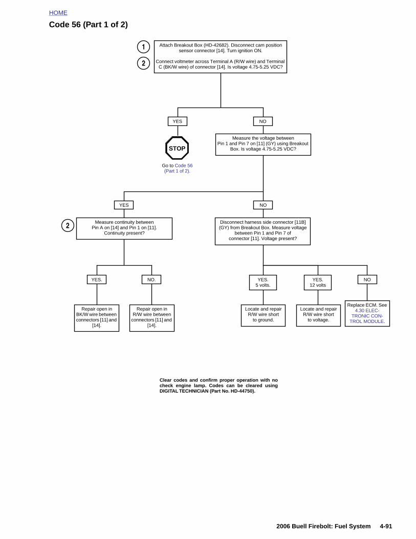
HOME
Code 56 (Part 1 of 2)
Attach Breakout Box (HD-42682). Disconnect cam position sensor connector [14]. Turn ignition ON.
Connect voltmeter across Terminal A (R/W wire) and Terminal C (BK/W wire) of connector [14]. Is voltage 4.75-5.25 VDC?
YES NO
Measure the voltage between Pin 1 and Pin 7 on [11] (GY) using Breakout
Box. Is voltage 4.75-5.25 VDC?
Go to Code 56 (Part 1 of 2).
YES NO
Measure continuity between Pin A on [14] and Pin 1 on [11].
Continuity present?
Disconnect harness side connector [11B] (GY) from Breakout Box. Measure voltage
between Pin 1 and Pin 7 of connector [11]. Voltage present?
NO.
Repair open in R/W wire between
connectors [11] and [14].
NO
Repair open inBK/W wire between connectors [11] and
[14].
YES. YES.12 volts
Locate and repairR/W wire short
to voltage.
Locate and repairR/W wire short
to ground.
YES. 5 volts.
STOP
Replace ECM. See 4.30 ELEC-
TRONIC CON-TROL MODULE.
1
2
2
2006 Buell Firebolt: Fuel System 4-91
Clear codes and confirm proper operation with nocheck engine lamp. Codes can be cleared usingDIGITAL TECHNICIAN (Part No. HD-44750).
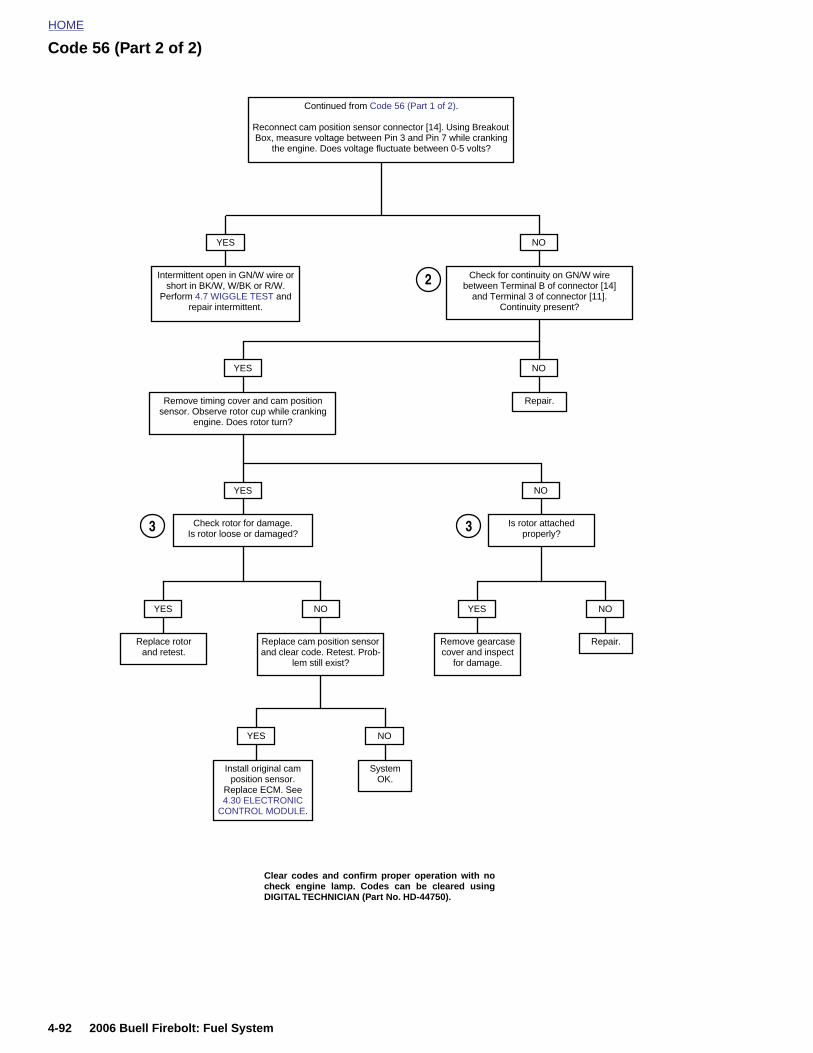
HOME
Code 56 (Part 2 of 2)
Continued from Code 56 (Part 1 of 2).
Reconnect cam position sensor connector [14]. Using Breakout Box, measure voltage between Pin 3 and Pin 7 while cranking
the engine. Does voltage fluctuate between 0-5 volts?
YES NO
Check for continuity on GN/W wire between Terminal B of connector [14]
and Terminal 3 of connector [11].Continuity present?
Intermittent open in GN/W wire or short in BK/W, W/BK or R/W.
Perform 4.7 WIGGLE TEST and repair intermittent.
YES NO
Repair.Remove timing cover and cam position sensor. Observe rotor cup while cranking
engine. Does rotor turn?
YES
Check rotor for damage. Is rotor loose or damaged?
NO
Is rotor attached properly?
YES
Remove gearcase cover and inspect
for damage.
NO
Repair.
YES
Replace rotorand retest.
NO
Replace cam position sensor and clear code. Retest. Prob-
lem still exist?
YES
Install original cam
NO
System
2
3 3
4-92 2006 Buell Firebolt: Fuel System
position sensor. Replace ECM. See 4.30 ELECTRONIC
CONTROL MODULE.
OK.
Clear codes and confirm proper operation with nocheck engine lamp. Codes can be cleared usingDIGITAL TECHNICIAN (Part No. HD-44750).

HOME
E
R
1
2
3
I
1
2
3
4
5
LECTRONIC CONTROL MODULE 4.30
EMOVAL
. Remove front fairing. See 2.37 FRONT FAIRING, WIND-SHIELD, AND MIRRORS.
. Remove Electronic Control Module (ECM). See 2.25HEADLIGHT ASSEMBLY AND SUPPORT BRACKETbut do not disconnect sensors.
. Disconnect ECM black connector [10] and gray connec-tor [11].
NSTALLATION
. Attach ECM connectors [10] and [11].
. Locate ECM between fairing and headlight bracket.
. Install headlight bracket. See 2.25 HEADLIGHT ASSEM-BLY AND SUPPORT BRACKET.
. Install front fairing. See 2.37 FRONT FAIRING, WIND-SHIELD, AND MIRRORS.
. Re calibrate throttle position sensor using DIGITALTECHNICIAN (Part No. HD-44750).
Figure 4-64. ECM
1. ECM2. Headlights
8428
2
1
2006 Buell Firebolt: Fuel System 4-93
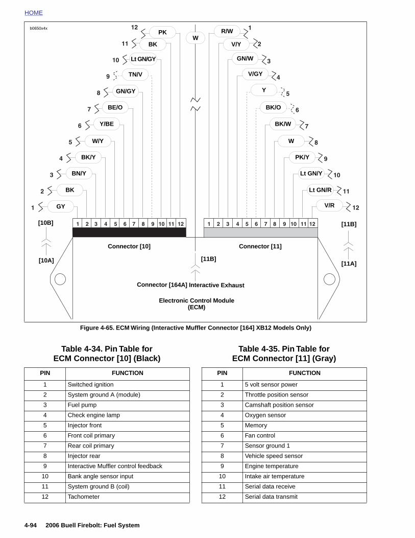
HOME
b0650x4x R/WPKW
Figure 4-65. ECM Wiring (Interactive Muffler Connector [164] XB12 Models Only)
Connector [10]
V/Y
GN/W
V/GY
Y
BK/O
BK/W
W
PK/Y
Lt GN/Y
Lt GN/R
V/R
BK
Lt GN/GY
TN/V
GN/GY
Y/BE
W/Y
BK/Y
BN/Y
BK
GY
Connector [11]
Electronic Control Module(ECM)
[10A] [11A]
[10B] [11B]
BE/O
Connector [164A] Interactive Exhaust
[11B]
Table 4-34. Pin Table for ECM Connector [10] (Black)
PIN FUNCTION
1 Switched ignition
2 System ground A (module)
Table 4-35. Pin Table for ECM Connector [11] (Gray)
PIN FUNCTION
1 5 volt sensor power
2 Throttle position sensor
4-94 2006 Buell Firebolt: Fuel System
3 Fuel pump
4 Check engine lamp
5 Injector front
6 Front coil primary
7 Rear coil primary
8 Injector rear
9 Interactive Muffler control feedback
10 Bank angle sensor input
11 System ground B (coil)
12 Tachometer
3 Camshaft position sensor
4 Oxygen sensor
5 Memory
6 Fan control
7 Sensor ground 1
8 Vehicle speed sensor
9 Engine temperature
10 Intake air temperature
11 Serial data receive
12 Serial data transmit
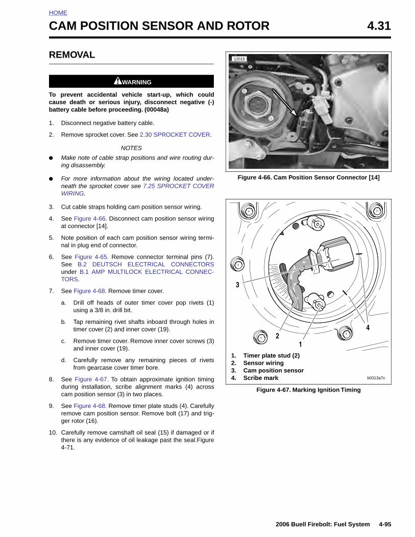
HOME
C
R
Tcb
1
2
●
●
3
4
5
6
7
AM POSITION SENSOR AND ROTOR 4.31
EMOVAL
1WARNING1WARNING
o prevent accidental vehicle start-up, which couldause death or serious injury, disconnect negative (-)attery cable before proceeding. (00048a)
. Disconnect negative battery cable.
. Remove sprocket cover. See 2.30 SPROCKET COVER.
NOTES
Make note of cable strap positions and wire routing dur-ing disassembly.
For more information about the wiring located under-neath the sprocket cover see 7.25 SPROCKET COVERWIRING.
. Cut cable straps holding cam position sensor wiring.
. See Figure 4-66. Disconnect cam position sensor wiringat connector [14].
. Note position of each cam position sensor wiring termi-nal in plug end of connector.
. See Figure 4-65. Remove connector terminal pins (7).See B.2 DEUTSCH ELECTRICAL CONNECTORSunder B.1 AMP MULTILOCK ELECTRICAL CONNEC-TORS.
. See Figure 4-68. Remove timer cover.
a. Drill off heads of outer timer cover pop rivets (1)using a 3/8 in. drill bit.
b. Tap remaining rivet shafts inboard through holes intimer cover (2) and inner cover (19).
c. Remove timer cover. Remove inner cover screws (3)and inner cover (19).
d. Carefully remove any remaining pieces of rivetsfrom gearcase cover timer bore.
Figure 4-66. Cam Position Sensor Connector [14]
12015
11. Timer plate stud (2)2. Sensor wiring
2
3
4
2006 Buell Firebolt: Fuel System 4-95
8. See Figure 4-67. To obtain approximate ignition timingduring installation, scribe alignment marks (4) acrosscam position sensor (3) in two places.
9. See Figure 4-68. Remove timer plate studs (4). Carefullyremove cam position sensor. Remove bolt (17) and trig-ger rotor (16).
10. Carefully remove camshaft oil seal (15) if damaged or ifthere is any evidence of oil leakage past the seal.Figure4-71.
Figure 4-67. Marking Ignition Timing
3. Cam position sensor4. Scribe mark b0313a7x
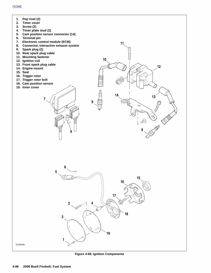
HOME
1. Pop rivet (2)
2. Timer cover3. Screw (2)4. Timer plate stud (2)5. Cam position sensor connector [14]6. Terminal pin7. Electronic control module (ECM)8. Connector, interactive exhaust system9. Spark plug (2)10. Rear spark plug cable11. Mounting fastener12. Ignition coil13. Front spark plug cable14. Engine mount15. Seal16. Trigger rotor17. Trigger rotor bolt18. Cam position sensor19. Inner cover56
7
17
16
9
10
11
12
1314
15
9
8
4-96 2006 Buell Firebolt: Fuel System
Figure 4-68. Ignition Components
b1164a4x
1
2
3 4
18
19
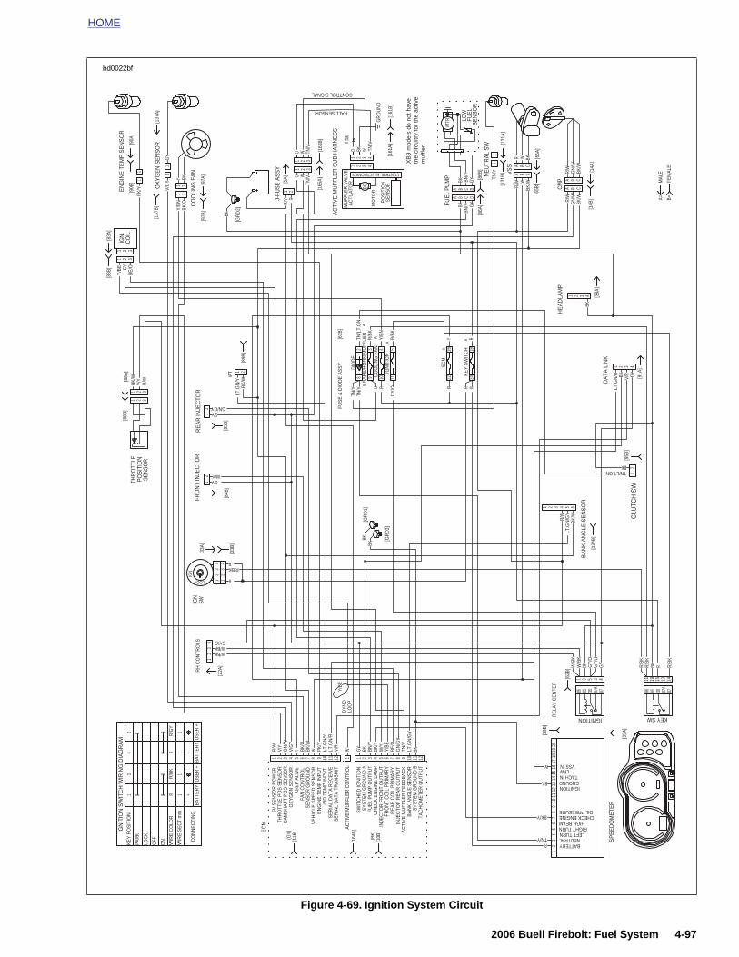
HOME
MTR LO
WFU
ELSE
NSO
R
1
1
11
BA
NK
AN
GLE
SE
NS
OR
CLU
TCH
SW
[134
B]
[95B
]
[38A
]
[91A
]
DAT
A LI
NK
HEA
DLA
MP
CM
P
VSS
NEU
TRAL
SW
FUEL
PU
MP
[14B
][1
4A]
[65B
][6
5A]
[86B
][8
6A]
[131
B]
FUS
E &
DIO
DE
AS
SY
[61B
]
[5A]
CO
OLI
NG
FA
N
J-FU
SE
AS
SY
[GR
D2]
[97B
][9
7A]
OX
YG
EN
SE
NS
OR
[137
B][1
37A]
[83B
][8
3A]
CO
ILIG
N.
IAT
[89B
]
[GR
D1]
[GR
D3]
RE
AR
INJE
CTO
R
[85B
]
FRO
NT
INJE
CTO
R
[84B
][3
3B]
IGN
SWO
NTR
OLS
[33A
]
2
2422111098
1816543
GY
W/BKW/BKGY/O
R
R/BKR
LOCK
W/YGY
GN/GY
BKTN/LT.GN
BKBK
RRR
GY/
OR
TN/Y
TN/YBK
/WLT
.GN
/Y
BE/OG
YY/
BE
PK/Y V/
GY
GY
Y/BN
YBK
/OBK
BK
RR
/Y
BKBK
BN/Y
BN/Y
GY
GY TN
/Y
R/W
RW
WBK
/WBK
R/W
R/W
GN
/WG
N/W
BK/W
BK/W
BK
GY
V/RBK
LT.G
N/R
R/W
LT.G
N/G
YBK
/W
BKBK/O/OBK
RYR/B
K
Y/BN
TN/L
T.G
N
BK
1 2 3 4 5 61
1
AA
1
11
2
2
BB
2
22IGN
3
3
CC
3
33
4
4
DD
4
44
AA
AA
11
BB
BB
22
CC
CC
33
1
111
1
1
1
2
222
2
2
2
DIO
DE
CO
OLI
NG
FA
N
BR
AK
E/H
OR
N/M
UFF
LER
IGN
ITIO
N
ECM
KEY
SWIT
CH
1[9
0A]
EN
GIN
E T
EM
P S
EN
SO
R
[90B
]
[131
A]
1
O
[165
A][1
65B]
AC
TIV
E M
UFF
LER
SU
B H
AR
NE
SS
TN/VO W
21 3
SEN
SOR
POSI
TIO
NTH
RO
TTLE
[88B
][8
8A]
3211 2 3
R/W
V/Y
BK/W
[161
A]
GR
OU
ND
Vba
tM
UFF
LER
VA
LVE
ACTU
ATO
R
MO
TOR
SEN
SOR
POSI
TIO
N
DC
CONTROL ELECTRONICS
O TN/V
WBK1
1
44
33
22
[161
B]HALL SENSOR
CONTROL SIGNAL
TN/V
WO
31 2
R/B
K
BK
FEM
ALE
MAL
E
B=A=
10 A
MP
10 A
MP
15 A
MP
10 A
MP 15
AM
P
XB
9 m
odel
s do
not
hav
e th
e ci
rcui
try
for
the
activ
e m
uffle
r.
bd0022bf
2006 Buell Firebolt: Fuel System 4-97
Figure 4-69. Ignition System Circuit
RE
LAY
CE
NTE
R
[62B
]RH
C
[22A
]
DYN
OLO
OP
1
11R
/W
R
W
BK
TN/Y
BK/Y
R/
RBKR/
GY
GY
GY
BKW/
W/
BKLT.G
N/G
Y
GN
/GY
BE/O
Y/BE
Y/BE
W/Y
BK/Y
BN/Y
BKGY
V/R
LT.G
N/R
LT.G
N/Y
PK/Y
WBK/W
BK/O
YV/G
YG
N/W
V/Y
22
5
8787A
308586
33
3
IGNITION KEY SW
44
4
55 66
15
77
13
88
9 14
99 1010
19
1212
11
1111 1W TN
/V
ECM
R/
0
24
31 0
0
+
1R
1
+
USE
R +
USE
R +
1
R/B
KR
/GY
BATT
ERY
BATT
ERY
1R
000
PAR
K
KE
Y P
OS
ITIO
N
IGN
ITIO
N S
WIT
CH
WIR
ING
DIA
GR
AM
CO
NN
ECTI
NG
WIR
E S
EC
T m
m
WIR
E C
OLO
R
ON
OFF
LOC
K
TAC
HO
ME
TER
OU
TPU
TS
YS
TEM
GR
OU
ND
BB
AN
K A
NG
LE S
EN
SO
RA
CTI
VE
MU
FFLE
R F
EE
DB
AC
KIN
JEC
TOR
RE
AR
OU
TPU
TR
EA
R C
OIL
PR
IMA
RY
FRO
NT
CO
IL P
RIM
AR
YIN
JEC
TOR
FR
ON
T O
UTP
UT
CH
EC
K E
NG
INE
LA
MP
FUE
L P
UM
P O
UTP
UT
SY
STE
M G
RO
UN
D A
SW
ITC
HE
D IG
NIT
ION
AC
TIV
E M
UFF
LER
CO
NTR
OL
SE
RIA
L D
ATA
TR
AN
SM
ITS
ER
IAL
DA
TA R
EC
EIV
EA
IR T
EM
P IN
PU
TE
NG
INE
TE
MP
INP
UT
VE
HIC
LE S
PE
ED
SE
NS
OR
SE
NS
OR
GR
OU
ND
FAN
CO
NTR
OL
KEEP
ALI
VEO
XY
GE
N S
EN
SO
RC
AM
SH
AFT
PO
S S
EN
SO
RTH
RO
TTLE
PO
S S
EN
SO
R5V
SE
NS
OR
PO
WE
R
[11B
](G
Y)
[164
B]
(BK)
[10B
]
SP
EE
DO
ME
TER
[39A
]
1
VSS INLFW
TACH INGROUNDIGNITION
OIL PRESSURECHECK ENGINE
HIGH BEAMRIGHT TURNLEFT TURN
NEUTRALBATTERY2
34
56
78
910
1220
1918
1716
1514
1311
[39B
]
8787A
308586
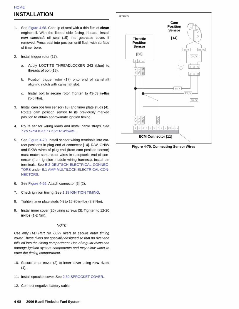
HOME
INSTALLATION
b0765x7x
Cam
1. See Figure 4-68. Coat lip of seal with a thin film of cleanengine oil. With the lipped side facing inboard, installnew camshaft oil seal (15) into gearcase cover, ifremoved. Press seal into position until flush with surfaceof timer bore.
2. Install trigger rotor (17).
a. Apply LOCTITE THREADLOCKER 243 (blue) tothreads of bolt (18).
b. Position trigger rotor (17) onto end of camshaftaligning notch with camshaft slot.
c. Install bolt to secure rotor. Tighten to 43-53 in-lbs(5-6 Nm).
3. Install cam position sensor (18) and timer plate studs (4).Rotate cam position sensor to its previously markedposition to obtain approximate ignition timing.
4. Route sensor wiring leads and install cable straps. See7.25 SPROCKET COVER WIRING.
5. See Figure 4-70. Install sensor wiring terminals into cor-rect positions in plug end of connector [14]. R/W, GN/Wand BK/W wires of plug end (from cam position sensor)must match same color wires in receptacle end of con-nector (from ignition module wiring harness). Install pinterminals. See B.2 DEUTSCH ELECTRICAL CONNEC-TORS under B.1 AMP MULTILOCK ELECTRICAL CON-NECTORS.
6. See Figure 4-65. Attach connector [3] (2).
7. Check ignition timing. See 1.18 IGNITION TIMING.
8. Tighten timer plate studs (4) to 15-30 in-lbs (2-3 Nm).
9. Install inner cover (20) using screws (3). Tighten to 12-20in-lbs (1-2 Nm).
NOTE
Figure 4-70. Connecting Sensor Wires
8765 12111094321
/WGN
/WGN
/WBK
/WBK
R/W
R/W
A B C
A B C
123
R/
W
V/
Y
BK
/W
R/
W
V/
Y
GN
/W
BK
/W
Throttle Position Sensor
[88]
Position Sensor
[14]
ECM Connector [11]
4-98 2006 Buell Firebolt: Fuel System
Use only H-D Part No. 8699 rivets to secure outer timingcover. These rivets are specially designed so that no rivet endfalls off into the timing compartment. Use of regular rivets candamage ignition system components and may allow water toenter the timing compartment.
10. Secure timer cover (2) to inner cover using new rivets(1).
11. Install sprocket cover. See 2.30 SPROCKET COVER.
12. Connect negative battery cable.
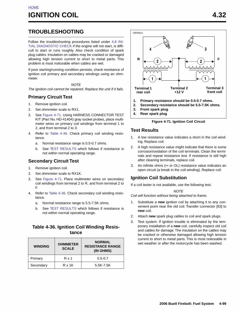
HOME
I
T
FTcpap
Iigm
T
P1
2
3
4
S1
2
3
4
GNITION COIL 4.32
ROUBLESHOOTING
ollow the troubleshooting procedures listed under 4.8 INI-IAL DIAGNOSTIC CHECK if the engine will not start, is diffi-ult to start or runs roughly. Also check condition of sparklug cables. Insulation on cables may be cracked or damagedllowing high tension current to short to metal parts. Thisroblem is most noticeable when cables are wet.
f poor starting/running condition persists, check resistance ofnition coil primary and secondary windings using an ohm-eter.
NOTEhe ignition coil cannot be repaired. Replace the unit if it fails.
rimary Circuit Test. Remove ignition coil.
. Set ohmmeter scale to RX1.
. See Figure 4-71. Using HARNESS CONNECTOR TESTKIT (Part No. HD-41404) gray socket probes, place multi-meter wires on primary coil windings from terminal 1 to2, and from terminal 2 to 3.
. Refer to Table 4-36. Check primary coil winding resis-tance.
a. Normal resistance range is 0.5-0.7 ohms.
b. See TEST RESULTS which follows if resistance isnot within normal operating range.
econdary Circuit Test. Remove ignition coil.
. Set ohmmeter scale to RX1K.
. See Figure 4-71. Place multimeter wires on secondarycoil windings from terminal 2 to R, and from terminal 2 toF.
. Refer to Table 4-36. Check secondary coil winding resis-tance.
a. Normal resistance range is 5.5-7.5K ohms.
b. See TEST RESULTS which follows if resistance isnot within normal operating range.
Test Results1. A low resistance value indicates a short in the coil wind-
ing. Replace coil.
2. A high resistance value might indicate that there is somecorrosion/oxidation of the coil terminals. Clean the termi-nals and repeat resistance test. If resistance is still highafter cleaning terminals, replace coil.
3. An infinite ohms (∞ or OL) resistance value indicates anopen circuit (a break in the coil winding). Replace coil.
Ignition Coil SubstitutionIf a coil tester is not available, use the following test.
NOTECoil will function without being attached to frame.
1. Substitute a new ignition coil by attaching it to any con-venient point near the old coil. Transfer connector [83] tonew coil.
Figure 4-71. Ignition Coil Circuit
2
1
1. Primary resistance should be 0.5-0.7 ohms.2. Secondary resistance should be 5.5-7.5K ohms.3. Front spark plug4. Rear spark plug
Terminal 1 rear coil
x0649a1x
FR2
1
Terminal 2 +12 V
Terminal 3 front coil
4 3
2006 Buell Firebolt: Fuel System 4-99
2. Attach new spark plug cables to coil and spark plugs.
3. Test system. If ignition trouble is eliminated by the tem-porary installation of a new coil, carefully inspect old coiland cables for damage. The insulation on the cables maybe cracked or otherwise damaged allowing high tensioncurrent to short to metal parts. This is most noticeable inwet weather or after the motorcycle has been washed.
Table 4-36. Ignition Coil Winding Resis-tance
WINDINGOHMMETER
SCALE
NORMAL RESISTANCE RANGE
(IN OHMS)
Primary R x 1 0.5-0.7
Secondary R x 1K 5.5K-7.5K
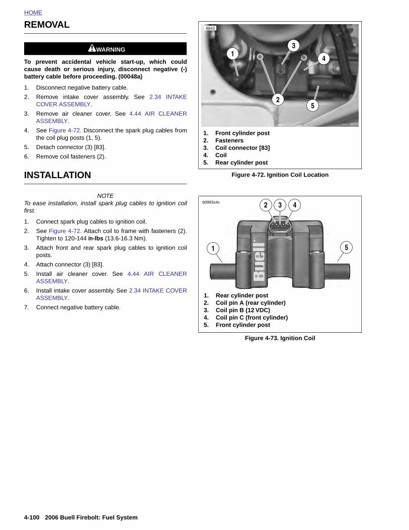
HOME
REMOVAL
8843
1WARNING1WARNING
To prevent accidental vehicle start-up, which couldcause death or serious injury, disconnect negative (-)battery cable before proceeding. (00048a)
1. Disconnect negative battery cable.
2. Remove intake cover assembly. See 2.34 INTAKECOVER ASSEMBLY.
3. Remove air cleaner cover. See 4.44 AIR CLEANERASSEMBLY.
4. See Figure 4-72. Disconnect the spark plug cables fromthe coil plug posts (1, 5).
5. Detach connector (3) [83].
6. Remove coil fasteners (2).
INSTALLATION
NOTETo ease installation, install spark plug cables to ignition coilfirst.
1. Connect spark plug cables to ignition coil.
2. See Figure 4-72. Attach coil to frame with fasteners (2).Tighten to 120-144 in-lbs (13.6-16.3 Nm).
3. Attach front and rear spark plug cables to ignition coilposts.
4. Attach connector (3) [83].
5. Install air cleaner cover. See 4.44 AIR CLEANERASSEMBLY.
6. Install intake cover assembly. See 2.34 INTAKE COVERASSEMBLY.
7. Connect negative battery cable.
Figure 4-72. Ignition Coil Location
Figure 4-73. Ignition Coil
13
2
1. Front cylinder post2. Fasteners3. Coil connector [83]4. Coil5. Rear cylinder post
5
4
1
1. Rear cylinder post2. Coil pin A (rear cylinder)3. Coil pin B (12 VDC)4. Coil pin C (front cylinder)5. Front cylinder post
2 3 4
5
b0993x4x
4-100 2006 Buell Firebolt: Fuel System
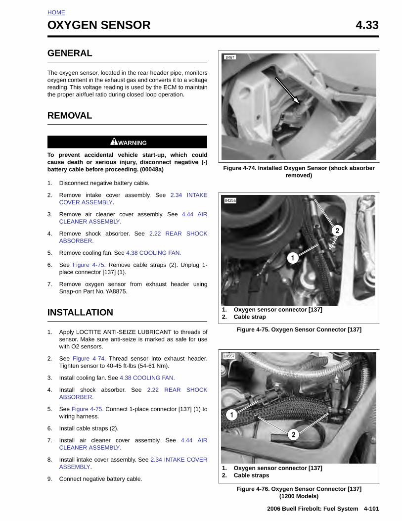
HOME
O
G
Tort
R
Tcb
1
2
3
4
5
6
7
I
1
2
XYGEN SENSOR 4.33
ENERAL
he oxygen sensor, located in the rear header pipe, monitorsxygen content in the exhaust gas and converts it to a voltageeading. This voltage reading is used by the ECM to maintainhe proper air/fuel ratio during closed loop operation.
EMOVAL
1WARNING1WARNING
o prevent accidental vehicle start-up, which couldause death or serious injury, disconnect negative (-)attery cable before proceeding. (00048a)
. Disconnect negative battery cable.
. Remove intake cover assembly. See 2.34 INTAKECOVER ASSEMBLY.
. Remove air cleaner cover assembly. See 4.44 AIRCLEANER ASSEMBLY.
. Remove shock absorber. See 2.22 REAR SHOCKABSORBER.
. Remove cooling fan. See 4.38 COOLING FAN.
. See Figure 4-75. Remove cable straps (2). Unplug 1-place connector [137] (1).
. Remove oxygen sensor from exhaust header usingSnap-on Part No. YA8875.
NSTALLATION
. Apply LOCTITE ANTI-SEIZE LUBRICANT to threads ofsensor. Make sure anti-seize is marked as safe for usewith O2 sensors.
. See Figure 4-74. Thread sensor into exhaust header.
Figure 4-74. Installed Oxygen Sensor (shock absorber removed)
Figure 4-75. Oxygen Sensor Connector [137]
8467
8425a
1. Oxygen sensor connector [137]2. Cable strap
2
1
10557
2006 Buell Firebolt: Fuel System 4-101
Tighten sensor to 40-45 ft-lbs (54-61 Nm).
3. Install cooling fan. See 4.38 COOLING FAN.
4. Install shock absorber. See 2.22 REAR SHOCKABSORBER.
5. See Figure 4-75. Connect 1-place connector [137] (1) towiring harness.
6. Install cable straps (2).
7. Install air cleaner cover assembly. See 4.44 AIRCLEANER ASSEMBLY.
8. Install intake cover assembly. See 2.34 INTAKE COVERASSEMBLY.
9. Connect negative battery cable.
Figure 4-76. Oxygen Sensor Connector [137](1200 Models)
1. Oxygen sensor connector [137]2. Cable straps
1
2
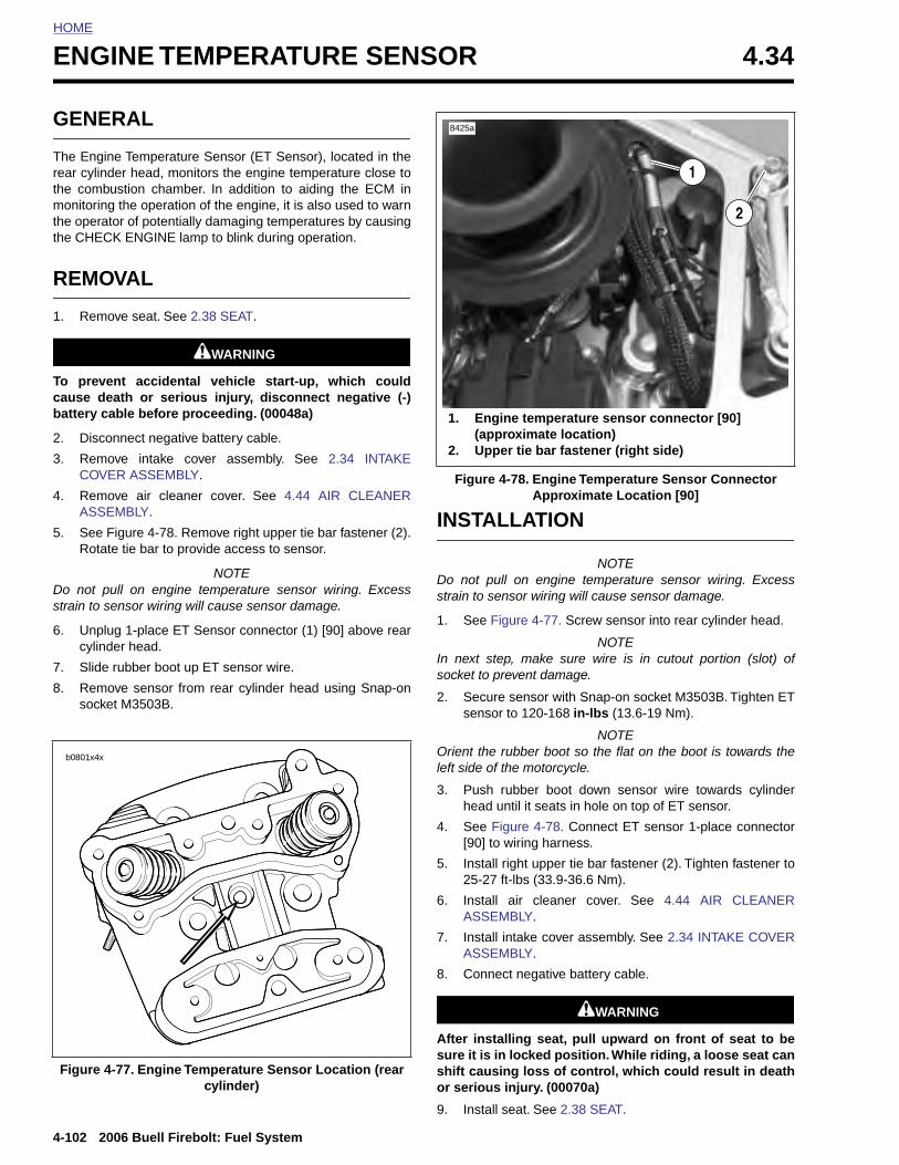
HOME
ENGINE TEMPERATURE SENSOR 4.34
GENE
The Enginrear cylindthe combmonitoringthe operatthe CHEC
REMO
1. Remo
To prevecause debattery ca
2. Disco
3. RemoCOVE
4. RemoASSE
5. See FRotat
Do not pstrain to s
6. Unplucylind
7. Slide
8. Remosocke
b0801x4x
4-102
Figure
RAL
e Temperature Sensor (ET Sensor), located in theer head, monitors the engine temperature close to
ustion chamber. In addition to aiding the ECM in the operation of the engine, it is also used to warnor of potentially damaging temperatures by causingK ENGINE lamp to blink during operation.
VAL
ve seat. See 2.38 SEAT.
1WARNING1WARNING
nt accidental vehicle start-up, which couldath or serious injury, disconnect negative (-)ble before proceeding. (00048a)
nnect negative battery cable.
ve intake cover assembly. See 2.34 INTAKER ASSEMBLY.
ve air cleaner cover. See 4.44 AIR CLEANERMBLY.
igure 4-78. Remove right upper tie bar fastener (2).e tie bar to provide access to sensor.
NOTEull on engine temperature sensor wiring. Excessensor wiring will cause sensor damage.
g 1-place ET Sensor connector (1) [90] above rearer head.
rubber boot up ET sensor wire.
ve sensor from rear cylinder head using Snap-ont M3503B.
INSTALLATION
NOTEDo not pull on engine temperature sensor wiring. Excessstrain to sensor wiring will cause sensor damage.
1. See Figure 4-77. Screw sensor into rear cylinder head.
NOTEIn next step, make sure wire is in cutout portion (slot) ofsocket to prevent damage.
2. Secure sensor with Snap-on socket M3503B. Tighten ETsensor to 120-168 in-lbs (13.6-19 Nm).
NOTEOrient the rubber boot so the flat on the boot is towards theleft side of the motorcycle.
3. Push rubber boot down sensor wire towards cylinderhead until it seats in hole on top of ET sensor.
4. See Figure 4-78. Connect ET sensor 1-place connector[90] to wiring harness.
Figure 4-78. Engine Temperature Sensor Connector Approximate Location [90]
1. Engine temperature sensor connector [90] (approximate location)
2. Upper tie bar fastener (right side)
1
2
8425a
2006 Buell Firebolt: Fuel System
5. Install right upper tie bar fastener (2). Tighten fastener to25-27 ft-lbs (33.9-36.6 Nm).
6. Install air cleaner cover. See 4.44 AIR CLEANERASSEMBLY.
7. Install intake cover assembly. See 2.34 INTAKE COVERASSEMBLY.
8. Connect negative battery cable.
1WARNING1WARNING
After installing seat, pull upward on front of seat to besure it is in locked position. While riding, a loose seat canshift causing loss of control, which could result in deathor serious injury. (00070a)
9. Install seat. See 2.38 SEAT.
4-77. Engine Temperature Sensor Location (rear cylinder)
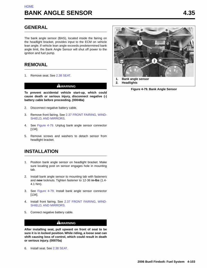
HOME
B
G
Ttlai
R
1
Tcb
2
3
4
5
I
1
2
ANK ANGLE SENSOR 4.35
ENERAL
he bank angle sensor (BAS), located inside the fairing onhe headlight bracket, provides input to the ECM on vehicleean angle. If vehicle lean angle exceeds predetermined bankngle limit, the Bank Angle Sensor will shut off power to the
gnition and fuel pump.
EMOVAL
. Remove seat. See 2.38 SEAT.
1WARNING1WARNING
o prevent accidental vehicle start-up, which couldause death or serious injury, disconnect negative (-)attery cable before proceeding. (00048a)
. Disconnect negative battery cable.
. Remove front fairing. See 2.37 FRONT FAIRING, WIND-SHIELD, AND MIRRORS.
. See Figure 4-79. Unplug bank angle sensor connector[134].
. Remove screws and washers to detach sensor fromheadlight bracket.
NSTALLATION
. Position bank angle sensor on headlight bracket. Makesure locating post on sensor engages hole in mountingtab.
. Install bank angle sensor to mounting tab with fastenersand new locknuts. Tighten fastener to 12-36 in-lbs (1.4-4.1 Nm).
Figure 4-79. Bank Angle Sensor
8428
1. Bank angle sensor2. Headlights
1
2
2006 Buell Firebolt: Fuel System 4-103
3. See Figure 4-79. Install bank angle sensor connector[134].
4. Install front fairing. See 2.37 FRONT FAIRING, WIND-SHIELD, AND MIRRORS.
5. Connect negative battery cable.
1WARNING1WARNING
After installing seat, pull upward on front of seat to besure it is in locked position. While riding, a loose seat canshift causing loss of control, which could result in deathor serious injury. (00070a)
6. Install seat. See 2.38 SEAT.

HOME
INTAKE AIR TEMPERATURE SENSOR 4.36
GENE
The intakthe air cleture allowing the ma
REMO
To prevecause debattery ca
1. Disco
2. See RemoCLEA
3. Raise
4. Discosenso
5. Insperequi
INSTA
1. Conn
2. Instalunde
3. InstalASSE
4. Instal
4-104
RAL
e air temperature sensor (IAT Sensor), located onaner cover baseplate, measures the air tempera-
ing the ECM to calculate the density of the air enter-nifold. The IAT is a thermistor type sensor.
VAL
1WARNING1WARNING
nt accidental vehicle start-up, which couldath or serious injury, disconnect negative (-)ble before proceeding. (00048a)
nnect negative battery cable.
Figure 4-80. Remove air cleaner cover, filter.ve fasteners securing base. See 4.44 AIRNER ASSEMBLY.
base and pull IAT sensor from sensor grommet.
nnect connector [89] from intake air temperaturer.
ct sensor grommet for damage and replace asred.
LLATION
ect IAT sensor connector [89] to wiring harness.
l IAT sensor into grommet on air cleaner base fromrneath.
l air cleaner cover. See 4.44 AIR CLEANERMBLY.
l negative battery cable.
Figure 4-80. Intake Air Temperature Sensor Installed
11504
2006 Buell Firebolt: Fuel System
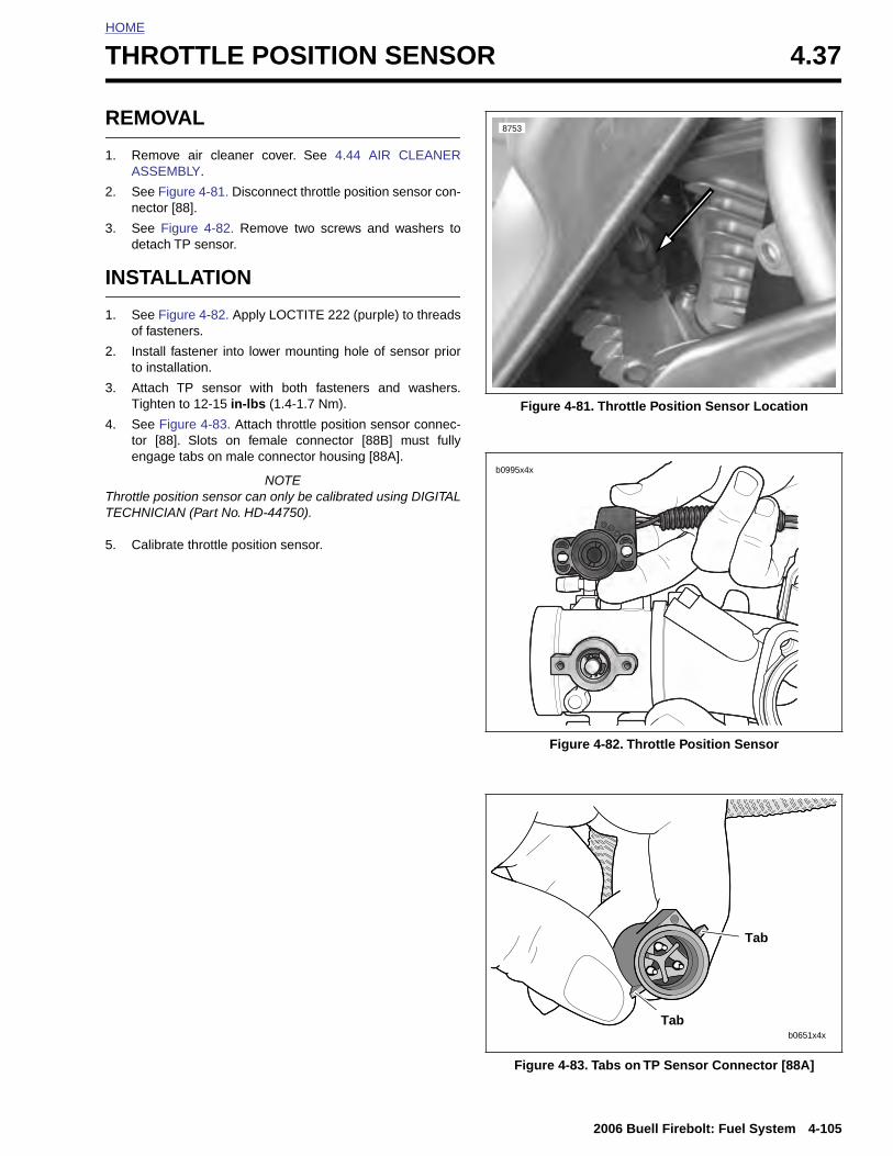
HOME
T
R
1
2
3
I
1
2
3
4
TT
5
HROTTLE POSITION SENSOR 4.37
EMOVAL
. Remove air cleaner cover. See 4.44 AIR CLEANERASSEMBLY.
. See Figure 4-81. Disconnect throttle position sensor con-nector [88].
. See Figure 4-82. Remove two screws and washers todetach TP sensor.
NSTALLATION
. See Figure 4-82. Apply LOCTITE 222 (purple) to threadsof fasteners.
. Install fastener into lower mounting hole of sensor priorto installation.
. Attach TP sensor with both fasteners and washers.Tighten to 12-15 in-lbs (1.4-1.7 Nm).
. See Figure 4-83. Attach throttle position sensor connec-tor [88]. Slots on female connector [88B] must fullyengage tabs on male connector housing [88A].
NOTEhrottle position sensor can only be calibrated using DIGITALECHNICIAN (Part No. HD-44750).
. Calibrate throttle position sensor.
Figure 4-81. Throttle Position Sensor Location
Figure 4-82. Throttle Position Sensor
8753
b0995x4x
2006 Buell Firebolt: Fuel System 4-105
Figure 4-83. Tabs on TP Sensor Connector [88A]
b0651x4x
Tab
Tab
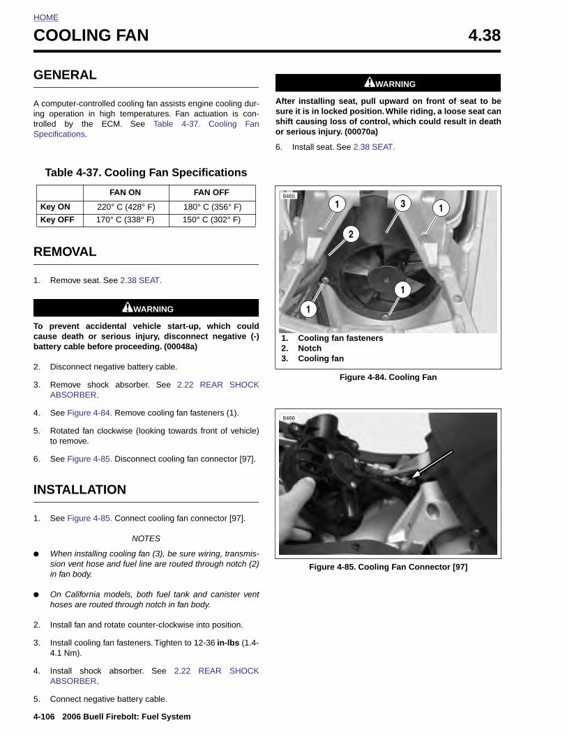
HOME
COOLING FAN 4.38
GENE
A computing operatrolled bSpecificat
REMO
1. Remo
To prevecause debattery ca
2. Disco
3. RemoABSO
4. See F
5. Rotatto rem
6. See F
INSTA
1. See F
Table
Key ON
Key OF
4-106
● Whsionin fa
● On hos
2. Inst
3. Inst4.1
4. InstABS
5. Con
RAL
er-controlled cooling fan assists engine cooling dur-tion in high temperatures. Fan actuation is con-y the ECM. See Table 4-37. Cooling Fanions.
VAL
ve seat. See 2.38 SEAT.
1WARNING1WARNING
nt accidental vehicle start-up, which couldath or serious injury, disconnect negative (-)ble before proceeding. (00048a)
nnect negative battery cable.
ve shock absorber. See 2.22 REAR SHOCKRBER.
igure 4-84. Remove cooling fan fasteners (1).
ed fan clockwise (looking towards front of vehicle)ove.
igure 4-85. Disconnect cooling fan connector [97].
LLATION
igure 4-85. Connect cooling fan connector [97].
NOTES
1WARNING1WARNING
After installing seat, pull upward on front of seat to besure it is in locked position. While riding, a loose seat canshift causing loss of control, which could result in deathor serious injury. (00070a)
6. Install seat. See 2.38 SEAT.
4-37. Cooling Fan Specifications
FAN ON FAN OFF
220° C (428° F) 180° C (356° F)
F 170° C (338° F) 150° C (302° F)
Figure 4-84. Cooling Fan
8465
1. Cooling fan fasteners2. Notch3. Cooling fan
3 1
1
1
1
2
8466
2006 Buell Firebolt: Fuel System
en installing cooling fan (3), be sure wiring, transmis- vent hose and fuel line are routed through notch (2)n body.
California models, both fuel tank and canister ventes are routed through notch in fan body.
all fan and rotate counter-clockwise into position.
all cooling fan fasteners. Tighten to 12-36 in-lbs (1.4-Nm).
all shock absorber. See 2.22 REAR SHOCKORBER.
nect negative battery cable.
Figure 4-85. Cooling Fan Connector [97]
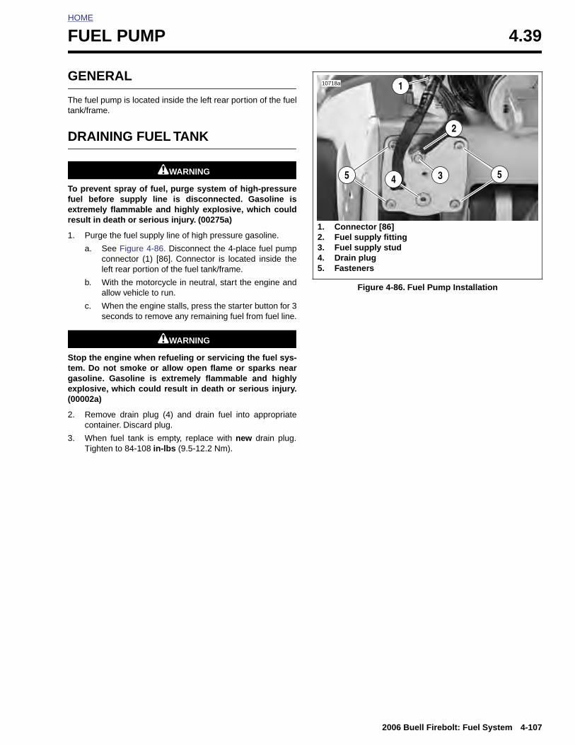
HOME
F
G
Tt
D
Tfer
1
Stge(
2
3
UEL PUMP 4.39
ENERAL
he fuel pump is located inside the left rear portion of the fuelank/frame.
RAINING FUEL TANK
1WARNING1WARNING
o prevent spray of fuel, purge system of high-pressureuel before supply line is disconnected. Gasoline isxtremely flammable and highly explosive, which couldesult in death or serious injury. (00275a)
. Purge the fuel supply line of high pressure gasoline.
a. See Figure 4-86. Disconnect the 4-place fuel pumpconnector (1) [86]. Connector is located inside theleft rear portion of the fuel tank/frame.
b. With the motorcycle in neutral, start the engine andallow vehicle to run.
c. When the engine stalls, press the starter button for 3seconds to remove any remaining fuel from fuel line.
1WARNING1WARNING
top the engine when refueling or servicing the fuel sys-em. Do not smoke or allow open flame or sparks nearasoline. Gasoline is extremely flammable and highlyxplosive, which could result in death or serious injury.00002a)
. Remove drain plug (4) and drain fuel into appropriatecontainer. Discard plug.
. When fuel tank is empty, replace with new drain plug.Tighten to 84-108 in-lbs (9.5-12.2 Nm).
Figure 4-86. Fuel Pump Installation
10718a
55
1
4 3
1. Connector [86]2. Fuel supply fitting3. Fuel supply stud4. Drain plug5. Fasteners
2
2006 Buell Firebolt: Fuel System 4-107
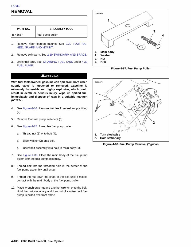
HOME
REMOVAL
b0988x4x
1. Remove rider footpeg mounts. See 2.29 FOOTPEG,HEEL GUARD AND MOUNT.
2. Remove swingarm. See 2.19 SWINGARM AND BRACE.
3. Drain fuel tank. See DRAINING FUEL TANK under 4.39FUEL PUMP.
1WARNING1WARNING
With fuel tank drained, gasoline can spill from bore whensupply valve is loosened or removed. Gasoline isextremely flammable and highly explosive, which couldresult in death or serious injury. Wipe up spilled fuelimmediately and dispose of rags in a suitable manner.(00277a)
4. See Figure 4-86. Remove fuel line from fuel supply fitting(2).
5. Remove four fuel pump fasteners (5).
6. See Figure 4-87. Assemble fuel pump puller.
a. Thread nut (3) onto bolt (4).
b. Slide washer (2) onto bolt.
c. Insert bolt assembly into hole in main body (1).
7. See Figure 4-88. Place the main body of the fuel pumppuller over the fuel pump assembly.
8. Thread bolt into the threaded hole in the center of thefuel pump assembly until snug.
9. Thread the nut down the shaft of the bolt until it makescontact with the main body of the fuel pump puller.
PART NO. SPECIALTY TOOL
B-45657 Fuel pump puller
Figure 4-87. Fuel Pump Puller
Figure 4-88. Fuel Pump Removal (Typical)
1. Main body2. Washer3. Nut4. Bolt
1
2
34
b0987x4x
1. Turn clockwise2. Hold stationary
2
1
4-108 2006 Buell Firebolt: Fuel System
10. Place wrench onto nut and another wrench onto the bolt.Hold the bolt stationary and turn nut clockwise until fuelpump is pulled free from frame.

HOME
REPAIR
Fuel Pressure Regulator Replacement1. Remove fuel pump assembly from tank. See REMOVAL
in this section.
2. See Figure 4-89. Remove the plastic retaining ring (1)securing the four plastic retainers (2) holding the fuelpressure regulator (3) in place. Spread the four clips anddetach regulator (3) from regulator housing(4).
3. Remove and discard o-rings from regulator.
4. Install new o-rings on new regulator. Press new regula-tor into place.
5. Install plastic retaining ring.
6. Install fuel pump assembly. See INSTALLATION in thissection.
Figure 4-89. Fuel Pressure Regulator
10937a
1. Plastic retaining ring2. Plastic retainers
3. Fuel pressure regulator4. Fuel pressure regulator housing
3
1
2 4
2006 Buell Firebolt: Fuel System 4-109
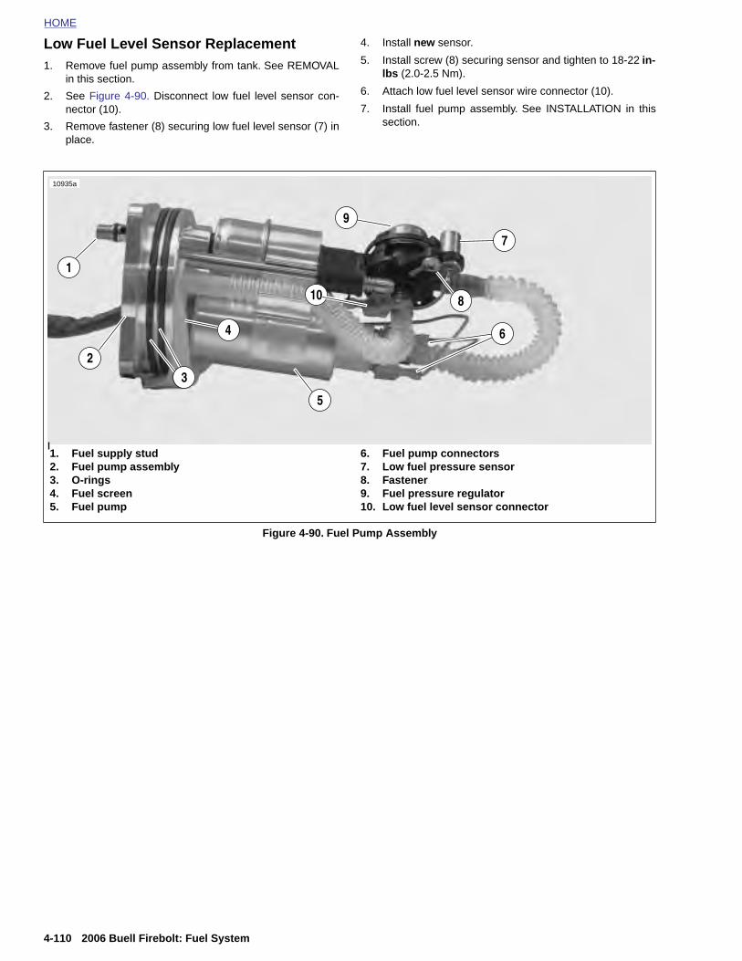
HOME
Low Fuel Level Sensor Replacement1. Remove fuel pump assembly from tank. See REMOVAL
4. Install new sensor.
5. Install screw (8) securing sensor and tighten to 18-22 in-
in this section.
2. See Figure 4-90. Disconnect low fuel level sensor con-nector (10).
3. Remove fastener (8) securing low fuel level sensor (7) inplace.
lbs (2.0-2.5 Nm).
6. Attach low fuel level sensor wire connector (10).
7. Install fuel pump assembly. See INSTALLATION in thissection.
Figure 4-90. Fuel Pump Assembly
1. Fuel supply stud2. Fuel pump assembly3. O-rings4. Fuel screen5. Fuel pump
6. Fuel pump connectors7. Low fuel pressure sensor8. Fastener9. Fuel pressure regulator10. Low fuel level sensor connector
9
10
5
3
1
2
4
7
8
6
10935a
4-110 2006 Buell Firebolt: Fuel System
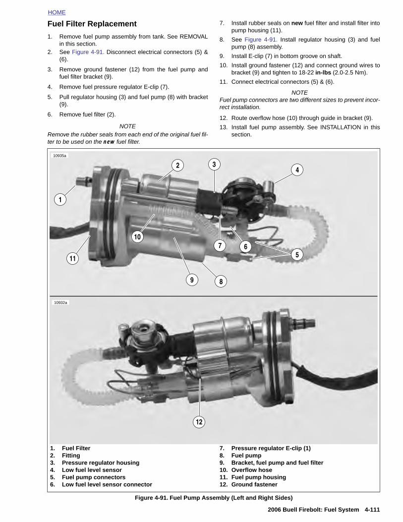
HOME
Fuel Filter Replacement
1. Remove fuel pump assembly from tank. See REMOVALin this section.
2. See Figure 4-91. Disconnect electrical connectors (5) &(6).
3. Remove ground fastener (12) from the fuel pump andfuel filter bracket (9).
4. Remove fuel pressure regulator E-clip (7).
5. Pull regulator housing (3) and fuel pump (8) with bracket(9).
6. Remove fuel filter (2).
NOTERemove the rubber seals from each end of the original fuel fil-ter to be used on the new fuel filter.
7. Install rubber seals on new fuel filter and install filter intopump housing (11).
8. See Figure 4-91. Install regulator housing (3) and fuelpump (8) assembly.
9. Install E-clip (7) in bottom groove on shaft.
10. Install ground fastener (12) and connect ground wires tobracket (9) and tighten to 18-22 in-lbs (2.0-2.5 Nm).
11. Connect electrical connectors (5) & (6).
NOTEFuel pump connectors are two different sizes to prevent incor-rect installation.
12. Route overflow hose (10) through guide in bracket (9).
13. Install fuel pump assembly. See INSTALLATION in thissection.
10935a
5
1
2 3
6
4
7
89
11
10
10932a
2006 Buell Firebolt: Fuel System 4-111
Figure 4-91. Fuel Pump Assembly (Left and Right Sides)
1. Fuel Filter2. Fitting3. Pressure regulator housing4. Low fuel level sensor5. Fuel pump connectors6. Low fuel level sensor connector
7. Pressure regulator E-clip (1)8. Fuel pump9. Bracket, fuel pump and fuel filter10. Overflow hose11. Fuel pump housing12. Ground fastener
12
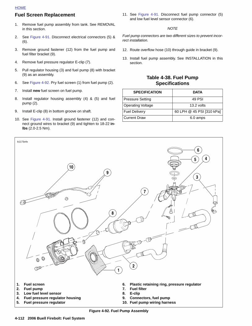
HOME
Fuel Screen Replacement
1. Remove fuel pump assembly from tank. See REMOVAL
11. See Figure 4-91. Disconnect fuel pump connector (5)and low fuel level sensor connector (6).
in this section.
2. See Figure 4-91. Disconnect electrical connectors (5) &(6).
3. Remove ground fastener (12) from the fuel pump andfuel filter bracket (9).
4. Remove fuel pressure regulator E-clip (7).
5. Pull regulator housing (3) and fuel pump (8) with bracket(9) as an assembly.
6. See Figure 4-92. Pry fuel screen (1) from fuel pump (2).
7. Install new fuel screen on fuel pump.
8. Install regulator housing assembly (4) & (5) and fuelpump (2).
9. Install E-clip (8) in bottom groove on shaft.
10. See Figure 4-91. Install ground fastener (12) and con-nect ground wires to bracket (9) and tighten to 18-22 in-lbs (2.0-2.5 Nm).
NOTE
Fuel pump connectors are two different sizes to prevent incor-rect installation.
12. Route overflow hose (10) through guide in bracket (9).
13. Install fuel pump assembly. See INSTALLATION in thissection.
Table 4-38. Fuel Pump Specifications
SPECIFICATION DATA
Pressure Setting 49 PSI
Operating Voltage 13.2 volts
Fuel Delivery 60 LPH @ 45 PSI [310 kPa]
Current Draw 6.0 amps
3
5 4
10
7
6
b1173x4x
9
8
4-112 2006 Buell Firebolt: Fuel System
Figure 4-92. Fuel Pump Assembly
1. Fuel screen2. Fuel pump3. Low fuel level sensor4. Fuel pressure regulator housing5. Fuel pressure regulator
6. Plastic retaining ring, pressure regulator7. Fuel filter8. E-clip9. Connectors, fuel pump10. Fuel pump wiring harness
12
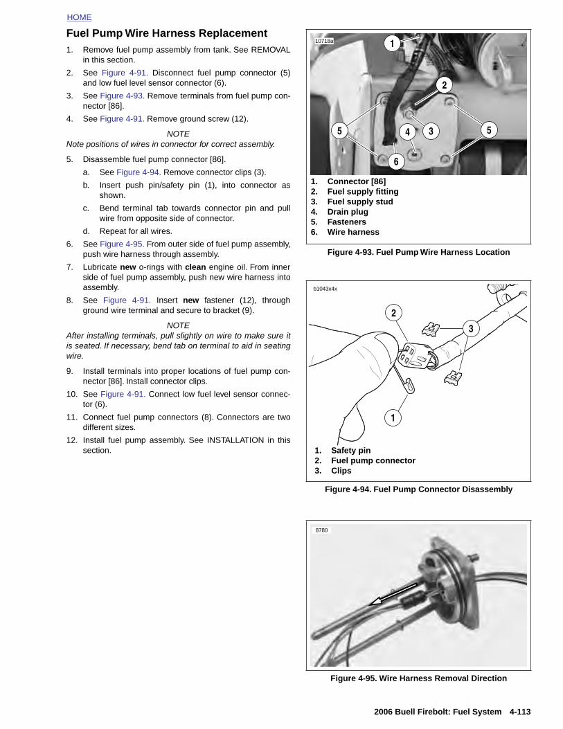
HOME
Fuel Pump Wire Harness Replacement1. Remove fuel pump assembly from tank. See REMOVAL
in this section.
2. See Figure 4-91. Disconnect fuel pump connector (5)and low fuel level sensor connector (6).
3. See Figure 4-93. Remove terminals from fuel pump con-nector [86].
4. See Figure 4-91. Remove ground screw (12).
NOTENote positions of wires in connector for correct assembly.
5. Disassemble fuel pump connector [86].
a. See Figure 4-94. Remove connector clips (3).
b. Insert push pin/safety pin (1), into connector asshown.
c. Bend terminal tab towards connector pin and pullwire from opposite side of connector.
d. Repeat for all wires.
6. See Figure 4-95. From outer side of fuel pump assembly,push wire harness through assembly.
7. Lubricate new o-rings with clean engine oil. From innerside of fuel pump assembly, push new wire harness intoassembly.
8. See Figure 4-91. Insert new fastener (12), throughground wire terminal and secure to bracket (9).
NOTEAfter installing terminals, pull slightly on wire to make sure itis seated. If necessary, bend tab on terminal to aid in seatingwire.
9. Install terminals into proper locations of fuel pump con-nector [86]. Install connector clips.
10. See Figure 4-91. Connect low fuel level sensor connec-tor (6).
11. Connect fuel pump connectors (8). Connectors are twodifferent sizes.
12. Install fuel pump assembly. See INSTALLATION in thissection.
Figure 4-93. Fuel Pump Wire Harness Location
Figure 4-94. Fuel Pump Connector Disassembly
10718a
55
1
4 3
1. Connector [86]2. Fuel supply fitting3. Fuel supply stud4. Drain plug5. Fasteners6. Wire harness
2
6
1. Safety pin2. Fuel pump connector3. Clips
3
1
2
b1043x4x
2006 Buell Firebolt: Fuel System 4-113
Figure 4-95. Wire Harness Removal Direction
8780
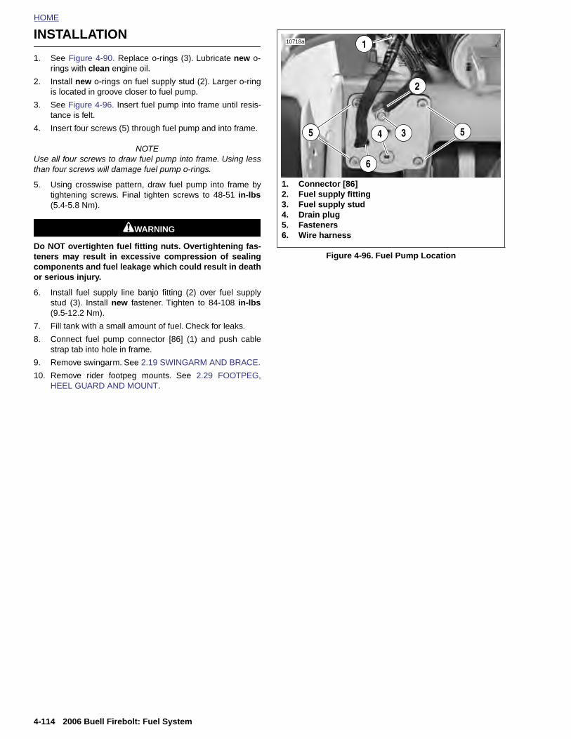
HOME
INSTALLATION10718a 1
1. See Figure 4-90. Replace o-rings (3). Lubricate new o-rings with clean engine oil.
2. Install new o-rings on fuel supply stud (2). Larger o-ringis located in groove closer to fuel pump.
3. See Figure 4-96. Insert fuel pump into frame until resis-tance is felt.
4. Insert four screws (5) through fuel pump and into frame.
NOTEUse all four screws to draw fuel pump into frame. Using lessthan four screws will damage fuel pump o-rings.
5. Using crosswise pattern, draw fuel pump into frame bytightening screws. Final tighten screws to 48-51 in-lbs(5.4-5.8 Nm).
1WARNING1WARNING
Do NOT overtighten fuel fitting nuts. Overtightening fas-teners may result in excessive compression of sealingcomponents and fuel leakage which could result in deathor serious injury.
6. Install fuel supply line banjo fitting (2) over fuel supplystud (3). Install new fastener. Tighten to 84-108 in-lbs(9.5-12.2 Nm).
7. Fill tank with a small amount of fuel. Check for leaks.
8. Connect fuel pump connector [86] (1) and push cablestrap tab into hole in frame.
9. Remove swingarm. See 2.19 SWINGARM AND BRACE.
10. Remove rider footpeg mounts. See 2.29 FOOTPEG,HEEL GUARD AND MOUNT.
Figure 4-96. Fuel Pump Location
55 4 3
1. Connector [86]2. Fuel supply fitting3. Fuel supply stud4. Drain plug5. Fasteners6. Wire harness
2
6
4-114 2006 Buell Firebolt: Fuel System
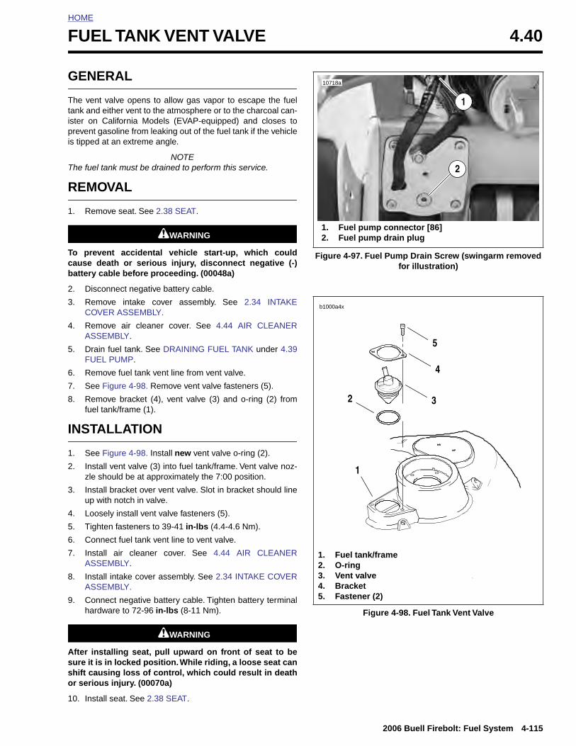
HOME
F
G
Ttispis
T
R
1
Tcb
2
3
4
5
6
7
8
I
1
2
3
4
UEL TANK VENT VALVE 4.40
ENERAL
he vent valve opens to allow gas vapor to escape the fuelank and either vent to the atmosphere or to the charcoal can-ter on California Models (EVAP-equipped) and closes torevent gasoline from leaking out of the fuel tank if the vehicle tipped at an extreme angle.
NOTEhe fuel tank must be drained to perform this service.
EMOVAL
. Remove seat. See 2.38 SEAT.
1WARNING1WARNING
o prevent accidental vehicle start-up, which couldause death or serious injury, disconnect negative (-)attery cable before proceeding. (00048a)
. Disconnect negative battery cable.
. Remove intake cover assembly. See 2.34 INTAKECOVER ASSEMBLY.
. Remove air cleaner cover. See 4.44 AIR CLEANERASSEMBLY.
. Drain fuel tank. See DRAINING FUEL TANK under 4.39FUEL PUMP.
. Remove fuel tank vent line from vent valve.
. See Figure 4-98. Remove vent valve fasteners (5).
. Remove bracket (4), vent valve (3) and o-ring (2) fromfuel tank/frame (1).
NSTALLATION
. See Figure 4-98. Install new vent valve o-ring (2).
. Install vent valve (3) into fuel tank/frame. Vent valve noz-zle should be at approximately the 7:00 position.
. Install bracket over vent valve. Slot in bracket should lineup with notch in valve.
. Loosely install vent valve fasteners (5).
Figure 4-97. Fuel Pump Drain Screw (swingarm removed for illustration)
10718a
1. Fuel pump connector [86]2. Fuel pump drain plug
2
1
b1000x4x
5
4
32
1
b1000a4x
2006 Buell Firebolt: Fuel System 4-115
5. Tighten fasteners to 39-41 in-lbs (4.4-4.6 Nm).
6. Connect fuel tank vent line to vent valve.
7. Install air cleaner cover. See 4.44 AIR CLEANERASSEMBLY.
8. Install intake cover assembly. See 2.34 INTAKE COVERASSEMBLY.
9. Connect negative battery cable. Tighten battery terminalhardware to 72-96 in-lbs (8-11 Nm).
1WARNING1WARNING
After installing seat, pull upward on front of seat to besure it is in locked position. While riding, a loose seat canshift causing loss of control, which could result in deathor serious injury. (00070a)
10. Install seat. See 2.38 SEAT.
Figure 4-98. Fuel Tank Vent Valve
1. Fuel tank/frame2. O-ring3. Vent valve4. Bracket5. Fastener (2)
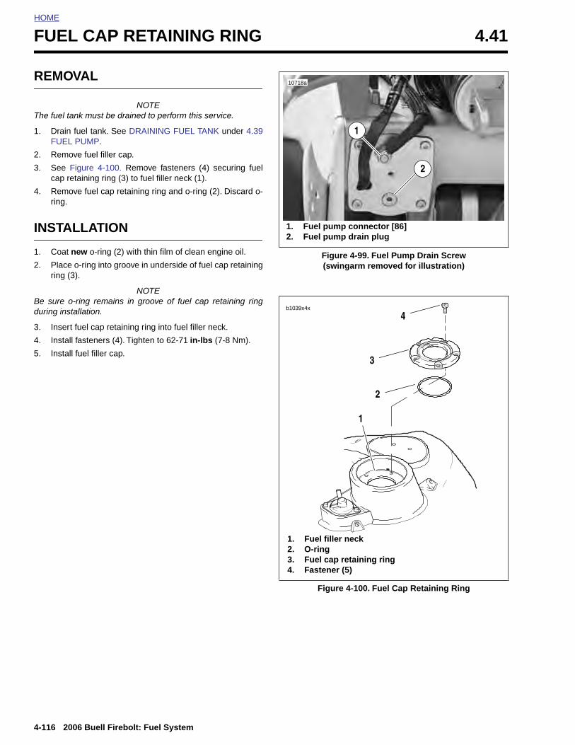
HOME
FUEL CAP RETAINING RING 4.41
REMO
The fuel ta
1. DrainFUEL
2. Remo
3. See cap r
4. Remoring.
INSTA
1. Coat
2. Placering (
Be sure oduring ins
3. Inser
4. Instal
5. Instal
4-116
VAL
NOTEnk must be drained to perform this service.
fuel tank. See DRAINING FUEL TANK under 4.39 PUMP.
ve fuel filler cap.
Figure 4-100. Remove fasteners (4) securing fueletaining ring (3) to fuel filler neck (1).
ve fuel cap retaining ring and o-ring (2). Discard o-
LLATION
new o-ring (2) with thin film of clean engine oil.
o-ring into groove in underside of fuel cap retaining3).
NOTE-ring remains in groove of fuel cap retaining ringtallation.
t fuel cap retaining ring into fuel filler neck.
l fasteners (4). Tighten to 62-71 in-lbs (7-8 Nm).
l fuel filler cap.
Figure 4-99. Fuel Pump Drain Screw(swingarm removed for illustration)
10718a
1. Fuel pump connector [86]2. Fuel pump drain plug
2
1
4
3
2
1
1. Fuel filler neck
b1039x4x
2006 Buell Firebolt: Fuel System
Figure 4-100. Fuel Cap Retaining Ring
2. O-ring3. Fuel cap retaining ring4. Fastener (5)
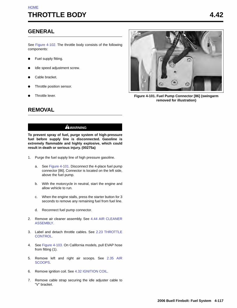
HOME
T
G
Sc
●
●
●
●
●
R
Tfer
1
HROTTLE BODY 4.42
ENERAL
ee Figure 4-102. The throttle body consists of the followingomponents:
Fuel supply fitting.
Idle speed adjustment screw.
Cable bracket.
Throttle position sensor.
Throttle lever.
EMOVAL
1WARNING1WARNING
o prevent spray of fuel, purge system of high-pressureuel before supply line is disconnected. Gasoline isxtremely flammable and highly explosive, which couldesult in death or serious injury. (00275a)
. Purge the fuel supply line of high pressure gasoline.
a. See Figure 4-101. Disconnect the 4-place fuel pumpconnector [86]. Connector is located on the left side,above the fuel pump.
b. With the motorcycle in neutral, start the engine andallow vehicle to run.
c. When the engine stalls, press the starter button for 3seconds to remove any remaining fuel from fuel line.
d. Reconnect fuel pump connector.
Figure 4-101. Fuel Pump Connector [86] (swingarm removed for illustration)
10718a
2006 Buell Firebolt: Fuel System 4-117
2. Remove air cleaner assembly. See 4.44 AIR CLEANERASSEMBLY.
3. Label and detach throttle cables. See 2.23 THROTTLECONTROL.
4. See Figure 4-103. On California models, pull EVAP hosefrom fitting (1).
5. Remove left and right air scoops. See 2.35 AIRSCOOPS.
6. Remove ignition coil. See 4.32 IGNITION COIL.
7. Remove cable strap securing the idle adjuster cable to"V" bracket.
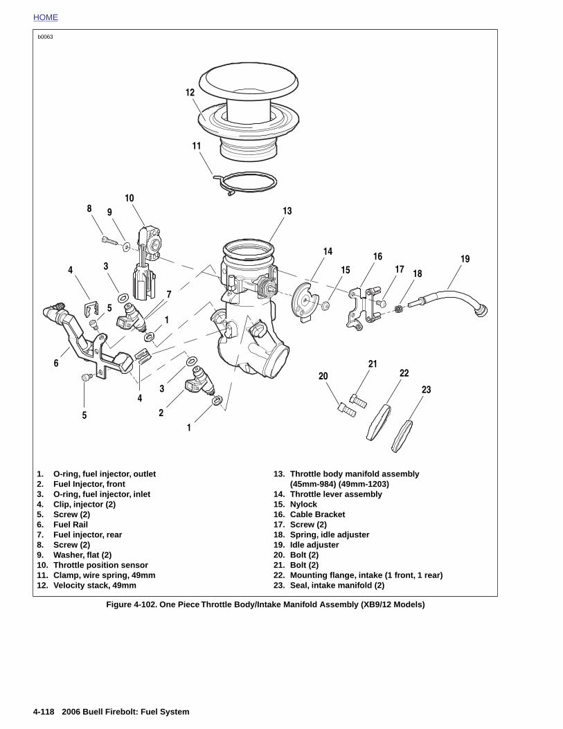
HOME
b0063
1. O-ring, fuel injector, outlet2. Fuel Injector, front3. O-ring, fuel injector, inlet4. Clip, injector (2)5. Screw (2)6. Fuel Rail7. Fuel injector, rear
13. Throttle body manifold assembly(45mm-984) (49mm-1203)
14. Throttle lever assembly15. Nylock16. Cable Bracket17. Screw (2)18. Spring, idle adjuster
8
5 2
3
1
4
51
7
4
6
9
11
12
13
1516
17 1819
2122
23
14
20
10
3
4-118 2006 Buell Firebolt: Fuel System
Figure 4-102. One Piece Throttle Body/Intake Manifold Assembly (XB9/12 Models)
8. Screw (2) 9. Washer, flat (2)10. Throttle position sensor11. Clamp, wire spring, 49mm12. Velocity stack, 49mm
19. Idle adjuster20. Bolt (2)21. Bolt (2)22. Mounting flange, intake (1 front, 1 rear)23. Seal, intake manifold (2)
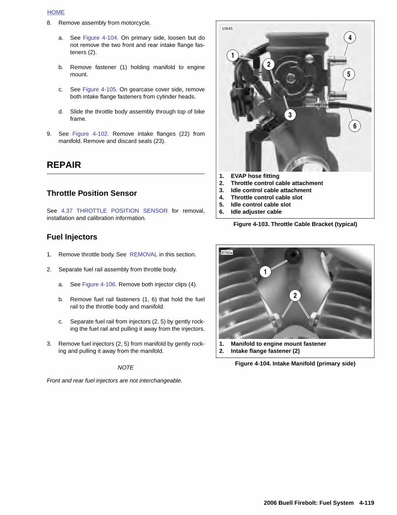
HOME
8. Remove assembly from motorcycle.
a. See Figure 4-104. On primary side, loosen but donot remove the two front and rear intake flange fas-teners (2).
b. Remove fastener (1) holding manifold to enginemount.
c. See Figure 4-105. On gearcase cover side, removeboth intake flange fasteners from cylinder heads.
d. Slide the throttle body assembly through top of bikeframe.
9. See Figure 4-102. Remove intake flanges (22) frommanifold. Remove and discard seals (23).
REPAIR
Throttle Position Sensor
See 4.37 THROTTLE POSITION SENSOR for removal,installation and calibration information.
Fuel Injectors
1. Remove throttle body. See REMOVAL in this section.
2. Separate fuel rail assembly from throttle body.
a. See Figure 4-106. Remove both injector clips (4).
b. Remove fuel rail fasteners (1, 6) that hold the fuelrail to the throttle body and manifold.
c. Separate fuel rail from injectors (2, 5) by gently rock-ing the fuel rail and pulling it away from the injectors.
3. Remove fuel injectors (2, 5) from manifold by gently rock-ing and pulling it away from the manifold.
Figure 4-103. Throttle Cable Bracket (typical)
4
5
6
12
3
1. EVAP hose fitting2. Throttle control cable attachment3. Idle control cable attachment4. Throttle control cable slot5. Idle control cable slot6. Idle adjuster cable
10645
1. Manifold to engine mount fastener2. Intake flange fastener (2)
2
1
8750a
2006 Buell Firebolt: Fuel System 4-119
NOTE
Front and rear fuel injectors are not interchangeable.
Figure 4-104. Intake Manifold (primary side)
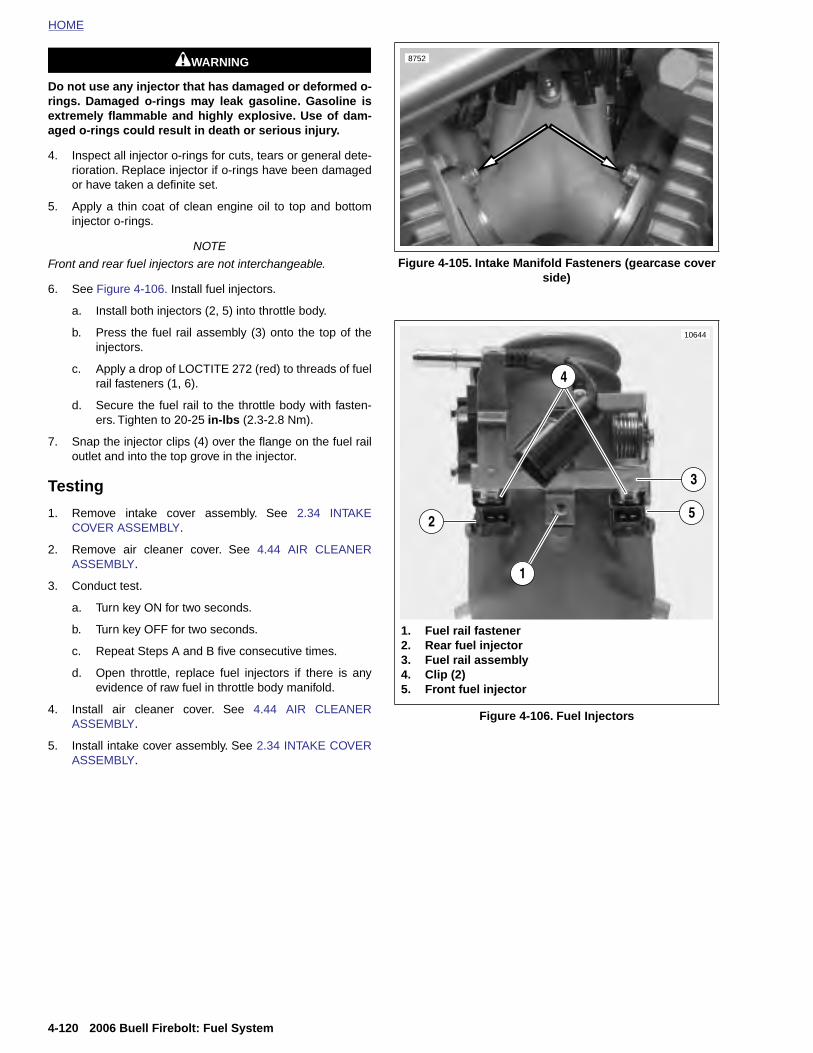
HOME
1WARNING1WARNING 8752
Do not use any injector that has damaged or deformed o-rings. Damaged o-rings may leak gasoline. Gasoline isextremely flammable and highly explosive. Use of dam-aged o-rings could result in death or serious injury.
4. Inspect all injector o-rings for cuts, tears or general dete-rioration. Replace injector if o-rings have been damagedor have taken a definite set.
5. Apply a thin coat of clean engine oil to top and bottominjector o-rings.
NOTE
Front and rear fuel injectors are not interchangeable.
6. See Figure 4-106. Install fuel injectors.
a. Install both injectors (2, 5) into throttle body.
b. Press the fuel rail assembly (3) onto the top of theinjectors.
c. Apply a drop of LOCTITE 272 (red) to threads of fuelrail fasteners (1, 6).
d. Secure the fuel rail to the throttle body with fasten-ers. Tighten to 20-25 in-lbs (2.3-2.8 Nm).
7. Snap the injector clips (4) over the flange on the fuel railoutlet and into the top grove in the injector.
Testing
1. Remove intake cover assembly. See 2.34 INTAKECOVER ASSEMBLY.
2. Remove air cleaner cover. See 4.44 AIR CLEANERASSEMBLY.
3. Conduct test.
a. Turn key ON for two seconds.
b. Turn key OFF for two seconds.
c. Repeat Steps A and B five consecutive times.
d. Open throttle, replace fuel injectors if there is anyevidence of raw fuel in throttle body manifold.
4. Install air cleaner cover. See 4.44 AIR CLEANERASSEMBLY.
5. Install intake cover assembly. See 2.34 INTAKE COVERASSEMBLY.
Figure 4-105. Intake Manifold Fasteners (gearcase cover side)
Figure 4-106. Fuel Injectors
2
1
1. Fuel rail fastener2. Rear fuel injector3. Fuel rail assembly4. Clip (2)5. Front fuel injector
10644
4
3
5
4-120 2006 Buell Firebolt: Fuel System
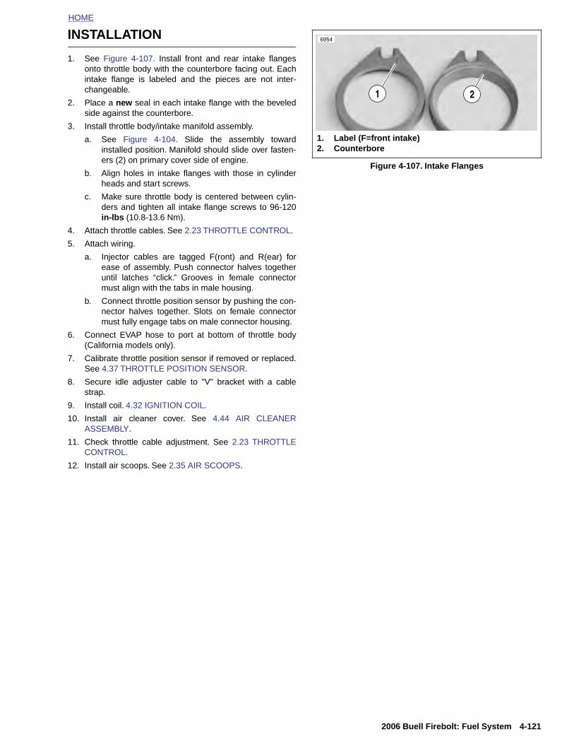
HOME
INSTALLATION
1. See Figure 4-107. Install front and rear intake flangesonto throttle body with the counterbore facing out. Eachintake flange is labeled and the pieces are not inter-changeable.
2. Place a new seal in each intake flange with the beveledside against the counterbore.
3. Install throttle body/intake manifold assembly.
a. See Figure 4-104. Slide the assembly towardinstalled position. Manifold should slide over fasten-ers (2) on primary cover side of engine.
b. Align holes in intake flanges with those in cylinderheads and start screws.
c. Make sure throttle body is centered between cylin-ders and tighten all intake flange screws to 96-120in-lbs (10.8-13.6 Nm).
4. Attach throttle cables. See 2.23 THROTTLE CONTROL.
5. Attach wiring.
a. Injector cables are tagged F(ront) and R(ear) forease of assembly. Push connector halves togetheruntil latches “click.” Grooves in female connectormust align with the tabs in male housing.
b. Connect throttle position sensor by pushing the con-nector halves together. Slots on female connectormust fully engage tabs on male connector housing.
6. Connect EVAP hose to port at bottom of throttle body(California models only).
7. Calibrate throttle position sensor if removed or replaced.See 4.37 THROTTLE POSITION SENSOR.
8. Secure idle adjuster cable to "V" bracket with a cablestrap.
9. Install coil. 4.32 IGNITION COIL.
10. Install air cleaner cover. See 4.44 AIR CLEANERASSEMBLY.
11. Check throttle cable adjustment. See 2.23 THROTTLECONTROL.
12. Install air scoops. See 2.35 AIR SCOOPS.
Figure 4-107. Intake Flanges
1 2
1. Label (F=front intake)2. Counterbore
6954
2006 Buell Firebolt: Fuel System 4-121

HOME
INTAKE LEAK TEST 4.43
GENE
Be sure using thedevice. Fcause a fi(00335a)
● AvoidExtrein dea
● Avoidnent work
● Alwayshrink
● To pinstal
● Do noresult
LEAK
Parts L● Stand
● HD-4
● 12 in.ing.
Tester 1. Cut ru
2. See Fa noz
3. Inser
4-122
RAL
1DANGER
to follow manufacturer's instructions when UltraTorch UT-100 or any other radiant heatingailure to follow manufacturer's instructions canre, which could result in death or serious injury.
directing heat toward any fuel system component.me heat can cause fuel ignition/explosion resultingth or serious injury.
directing heat toward any electrical system compo-other than the connectors on which heat shrinkis being performed.
s keep hands away from tool tip area and heat attachment.
revent false readings, keep air cleaner coverled when performing test.
t direct propane into air scoop, false readings will.
TESTER
istard 14oz. propane cylinder.
1417 Propane Enrichment Kit.
(304 mm) long-1/4 in. (6mm) diameter copper tub-
Assemblybber hose from kit to 18 in. (457 mm) in length.
igure 4-108. Flatten one end of copper tube to formzle.
t round side of copper tube into end of tubing.
Figure 4-108. Nozzle
Figure 4-109. Leak Tester
9648
9649
1. Nozzle2. Copper tube3. Hose4. Valve5. Knob6. Propane bottle
1
2
3 5
6
4
2006 Buell Firebolt: Fuel System
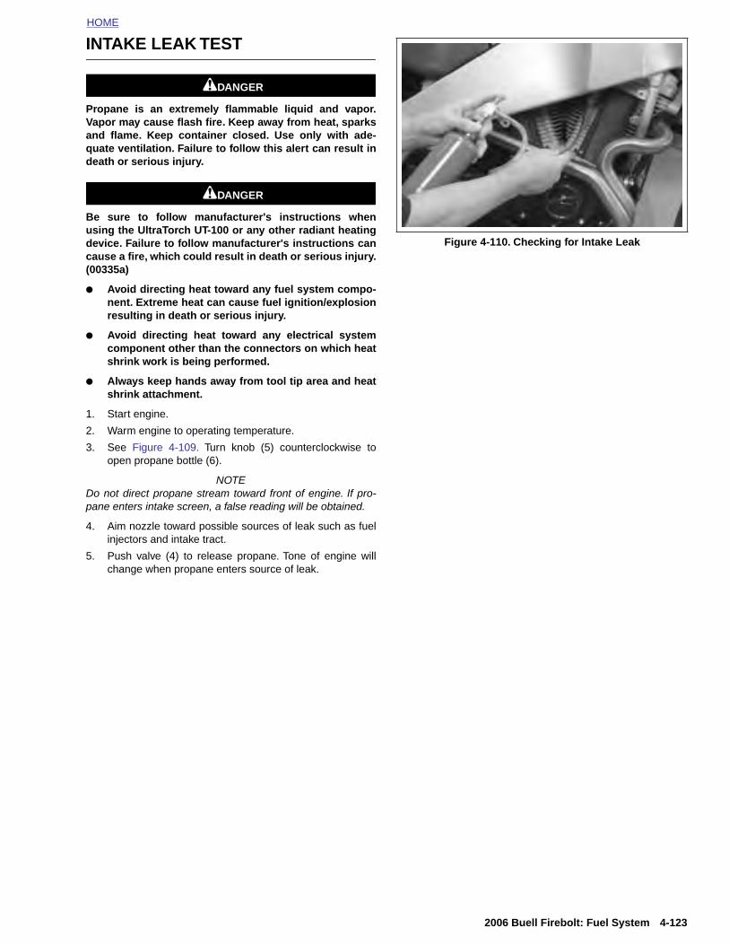
HOME
INTAKE LEAK TEST
1DANGER
Propane is an extremely flammable liquid and vapor.Vapor may cause flash fire. Keep away from heat, sparksand flame. Keep container closed. Use only with ade-quate ventilation. Failure to follow this alert can result indeath or serious injury.
1DANGER
Be sure to follow manufacturer's instructions whenusing the UltraTorch UT-100 or any other radiant heatingdevice. Failure to follow manufacturer's instructions cancause a fire, which could result in death or serious injury.(00335a)
● Avoid directing heat toward any fuel system compo-nent. Extreme heat can cause fuel ignition/explosionresulting in death or serious injury.
● Avoid directing heat toward any electrical systemcomponent other than the connectors on which heatshrink work is being performed.
● Always keep hands away from tool tip area and heatshrink attachment.
1. Start engine.
2. Warm engine to operating temperature.
3. See Figure 4-109. Turn knob (5) counterclockwise toopen propane bottle (6).
NOTEDo not direct propane stream toward front of engine. If pro-pane enters intake screen, a false reading will be obtained.
4. Aim nozzle toward possible sources of leak such as fuelinjectors and intake tract.
5. Push valve (4) to release propane. Tone of engine willchange when propane enters source of leak.
Figure 4-110. Checking for Intake Leak
2006 Buell Firebolt: Fuel System 4-123
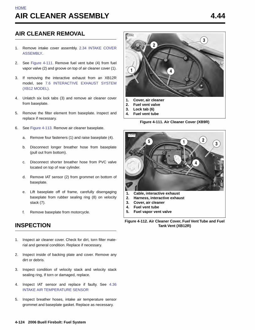
HOME
AIR CLEANER ASSEMBLY 4.44
AIR C
1. RemoASSE
2. See Fvapor
3. If remmode(XB12
4. Unlatfrom
5. Remoreplac
6. See F
a. R
b. D(
c. Dlo
d. Rb
e. Lbs
f. R
INSPE
1. Inspe
4-124
rial
2. Inspdirt
3. Inspsea
4. InspINT
5. Inspgrom
LEANER REMOVAL
ve intake cover assembly. 2.34 INTAKE COVERMBLY.
igure 4-111. Remove fuel vent tube (4) from fuel valve (2) and groove on top of air cleaner cover (1).
oving the interactive exhaust from an XB12Rl, see 7.6 INTERACTIVE EXHAUST SYSTEM MODEL).
ch six lock tabs (3) and remove air cleaner coverbaseplate.
ve the filter element from baseplate. Inspect ande if necessary.
igure 4-113. Remove air cleaner baseplate.
emove four fasteners (1) and raise baseplate (4).
isconnect longer breather hose from baseplatepull out from bottom).
isconnect shorter breather hose from PVC valvecated on top of rear cylinder.
emove IAT sensor (2) from grommet on bottom ofaseplate.
ift baseplate off of frame, carefully disengagingaseplate from rubber sealing ring (8) on velocitytack (7).
emove baseplate from motorcycle.
CTION
ct air cleaner cover. Check for dirt, torn filter mate-
Figure 4-111. Air Cleaner Cover (XB9R)
Figure 4-112. Air Cleaner Cover, Fuel Vent Tube and Fuel Tank Vent (XB12R)
12092
1. Cover, air cleaner2. Fuel vent valve3. Lock tab (6)4. Fuel vent tube
4
2
1
3
12049
1. Cable, interactive exhaust2. Harness, interactive exhaust3. Cover, air cleaner4. Fuel vent tube5. Fuel vapor vent valve
5 1 23
4
2006 Buell Firebolt: Fuel System
and general condition. Replace if necessary.
ect inside of backing plate and cover. Remove anyor debris.
ect condition of velocity stack and velocity stackling ring, If torn or damaged, replace.
ect IAT sensor and replace if faulty. See 4.36AKE AIR TEMPERATURE SENSOR
ect breather hoses, intake air temperature sensormet and baseplate gasket. Replace as necessary.

HOME
INSTALLATION
1. See Figure 4-113. Hold baseplate above mounting posi-tion.
2. Insert IAT sensor into grommet on baseplate from under-side.
NOTE
A small amount of soapy water applied to the inside diameterof grommet will make breather hose installation easier.
NOTE
In next step, be sure breather hoses do not extend pastIntake air temperature sensor tower. If hoses extend pasttower, damage to sensor may occur.
3. Insert longer breather hose into right baseplate grommetfrom underside.
4. Attach shorter breather hose onto crankcase breatherlocated on top of rear cylinder.
5. Carefully lower baseplate into mounting position. Ensurerubber sealing ring on velocity stack completely engagesbaseplate. Baseplate should be sandwiched betweenupper and lower rubber sealing rings.
6. Install baseplate to frame with four fasteners and wash-ers (5). Tighten fasteners to 84-120 in-lbs (9.5-13.6 Nm).
7. Position air cleaner filter on baseplate.
8. Install air cleaner to baseplate and latch six latches tosecure.
9. If interactive exhaust actuator (XB12R) was removed,install at this time and tighten fasteners to 36-40 in-lbs(4-4.5 Nm). See 7.6 INTERACTIVE EXHAUST SYSTEM(XB12 MODEL).
10. Route vent hose through groove on air cleaner to vent
Figure 4-113. Baseplate
11504
1. Fasteners2. Gasket3. Baseplate4. Velocity stack5. Velocity stack sealing ring6. Intake air temperature sensor (IAT)7. Breather hoses
5
1
1
1
6
7
3
2
4
2006 Buell Firebolt: Fuel System 4-125
valve.
11. Install intake cover assembly. See 2.34 INTAKE COVERASSEMBLY.
1WARNING1WARNING
After installing seat, pull upward on front of seat to besure it is in locked position. While riding, a loose seat canshift causing loss of control, which could result in deathor serious injury. (00070a)
12. Install seat. See 2.38 SEAT.
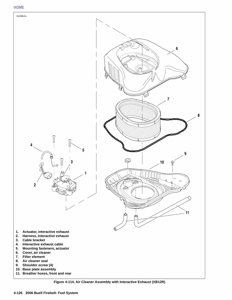
HOME
b1246x1x
1
8
10
5
2
3
4
6
7
9
11
4-126 2006 Buell Firebolt: Fuel System
Figure 4-114. Air Cleaner Assembly with Interactive Exhaust (XB12R)
1. Actuator, interactive exhaust2. Harness, interactive exhaust3. Cable bracket4. Interactive exhaust cable5. Mounting fasteners, actuator6. Cover, air cleaner7. Filter element8. Air cleaner seal9. Shoulder screw (4)10. Base plate assembly11. Breather hoses, front and rear
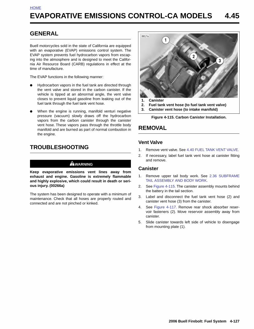
HOME
E
G
BwEinnt
T
●
●
T
Keao
Tmc
VAPORATIVE EMISSIONS CONTROL-CA MODELS 4.45
ENERAL
uell motorcycles sold in the state of California are equippedith an evaporative (EVAP) emissions control system. TheVAP system prevents fuel hydrocarbon vapors from escap-g into the atmosphere and is designed to meet the Califor-ia Air Resource Board (CARB) regulations in effect at theime of manufacture.
he EVAP functions in the following manner:
Hydrocarbon vapors in the fuel tank are directed throughthe vent valve and stored in the carbon canister. If thevehicle is tipped at an abnormal angle, the vent valvecloses to prevent liquid gasoline from leaking out of thefuel tank through the fuel tank vent hose.
When the engine is running, manifold venturi negativepressure (vacuum) slowly draws off the hydrocarbonvapors from the carbon canister through the canistervent hose. These vapors pass through the throttle bodymanifold and are burned as part of normal combustion inthe engine.
ROUBLESHOOTING
1WARNING1WARNING
eep evaporative emissions vent lines away fromxhaust and engine. Gasoline is extremely flammablend highly explosive, which could result in death or seri-us injury. (00266a)
he system has been designed to operate with a minimum ofaintenance. Check that all hoses are properly routed and
onnected and are not pinched or kinked.
REMOVAL
Vent Valve1. Remove vent valve. See 4.40 FUEL TANK VENT VALVE.
2. If necessary, label fuel tank vent hose at canister fittingand remove.
Canister1. Remove upper tail body work. See 2.36 SUBFRAME
TAIL ASSEMBLY AND BODY WORK.
2. See Figure 4-115. The canister assembly mounts behindthe battery in the tail section.
3. Label and disconnect the fuel tank vent hose (2) andcanister vent hose (3) from the canister.
4. See Figure 4-117. Remove rear shock absorber reser-voir fasteners (2). Move reservoir assembly away fromcanister.
5. Slide canister towards left side of vehicle to disengagefrom mounting plate (1).
Figure 4-115. Carbon Canister Installation.
8817a
1. Canister2. Fuel tank vent hose (to fuel tank vent valve)3. Canister vent hose (to intake manifold)
1
23
2006 Buell Firebolt: Fuel System 4-127
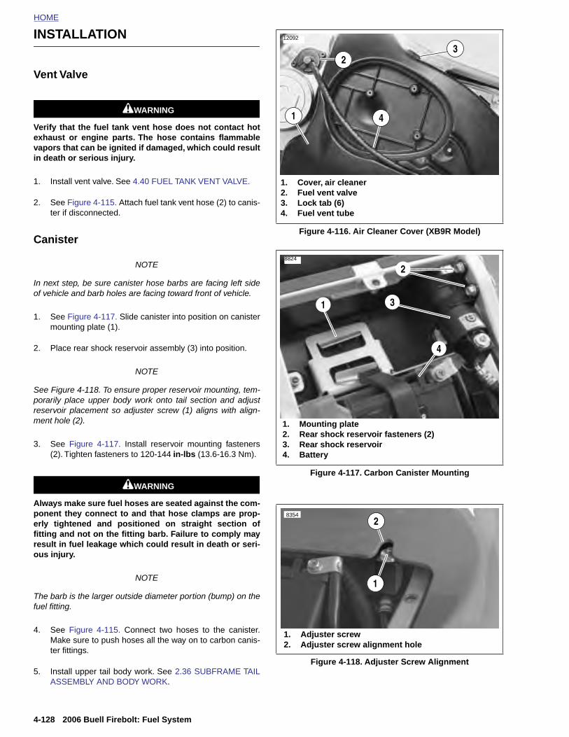
HOME
INSTALLATION 12092
3
Vent Valve
1WARNING1WARNING
Verify that the fuel tank vent hose does not contact hotexhaust or engine parts. The hose contains flammablevapors that can be ignited if damaged, which could resultin death or serious injury.
1. Install vent valve. See 4.40 FUEL TANK VENT VALVE.
2. See Figure 4-115. Attach fuel tank vent hose (2) to canis-ter if disconnected.
Canister
NOTE
In next step, be sure canister hose barbs are facing left sideof vehicle and barb holes are facing toward front of vehicle.
1. See Figure 4-117. Slide canister into position on canistermounting plate (1).
2. Place rear shock reservoir assembly (3) into position.
NOTE
See Figure 4-118. To ensure proper reservoir mounting, tem-porarily place upper body work onto tail section and adjustreservoir placement so adjuster screw (1) aligns with align-ment hole (2).
3. See Figure 4-117. Install reservoir mounting fasteners(2). Tighten fasteners to 120-144 in-lbs (13.6-16.3 Nm).
1WARNING1WARNING
Always make sure fuel hoses are seated against the com-ponent they connect to and that hose clamps are prop-erly tightened and positioned on straight section offitting and not on the fitting barb. Failure to comply may
Figure 4-116. Air Cleaner Cover (XB9R Model)
Figure 4-117. Carbon Canister Mounting
1. Cover, air cleaner2. Fuel vent valve3. Lock tab (6)4. Fuel vent tube
4
2
1
1. Mounting plate2. Rear shock reservoir fasteners (2)3. Rear shock reservoir4. Battery
1
4
8824
3
2
83542
4-128 2006 Buell Firebolt: Fuel System
result in fuel leakage which could result in death or seri-ous injury.
NOTE
The barb is the larger outside diameter portion (bump) on thefuel fitting.
4. See Figure 4-115. Connect two hoses to the canister.Make sure to push hoses all the way on to carbon canis-ter fittings.
5. Install upper tail body work. See 2.36 SUBFRAME TAILASSEMBLY AND BODY WORK.
Figure 4-118. Adjuster Screw Alignment
1. Adjuster screw2. Adjuster screw alignment hole
1
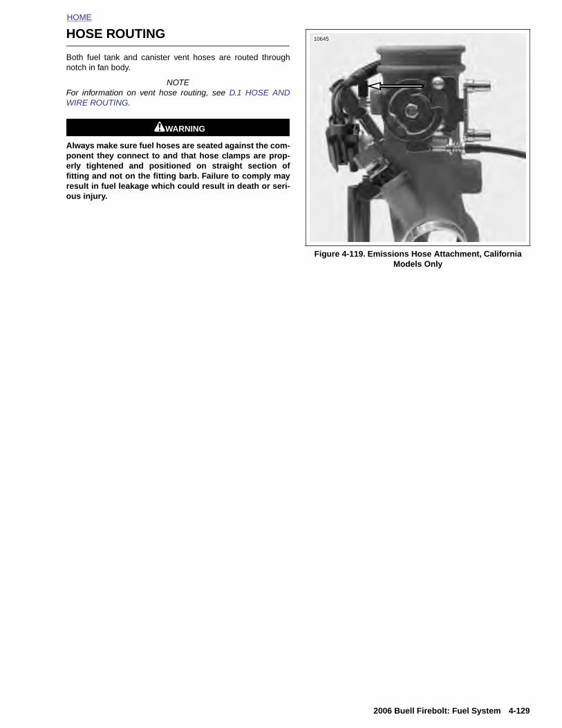
HOME
HOSE ROUTING
Both fuel tank and canister vent hoses are routed throughnotch in fan body.
NOTEFor information on vent hose routing, see D.1 HOSE ANDWIRE ROUTING.
1WARNING1WARNING
Always make sure fuel hoses are seated against the com-ponent they connect to and that hose clamps are prop-erly tightened and positioned on straight section offitting and not on the fitting barb. Failure to comply mayresult in fuel leakage which could result in death or seri-ous injury.
Figure 4-119. Emissions Hose Attachment, California Models Only
10645
2006 Buell Firebolt: Fuel System 4-129

HOME
NOTES
4-130
2006 Buell Firebolt: Fuel System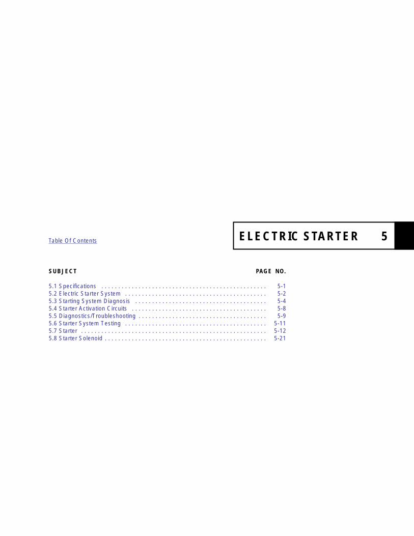
SUBJECT PAGE NO.
5.1 Specifications . . . . . . . . . . . . . . . . . . . . . . . . . . . . . . . . . . . . . . . . . . . . . . . . . 5-15.2 Electric Starter System . . . . . . . . . . . . . . . . . . . . . . . . . . . . . . . . . . . . . . . . . . 5-25.3 Starting System Diagnosis . . . . . . . . . . . . . . . . . . . . . . . . . . . . . . . . . . . . . . . 5-45.4 Starter Activation Circuits . . . . . . . . . . . . . . . . . . . . . . . . . . . . . . . . . . . . . . . . 5-85.5 Diagnostics/Troubleshooting . . . . . . . . . . . . . . . . . . . . . . . . . . . . . . . . . . . . . . 5-95.6 Starter System Testing . . . . . . . . . . . . . . . . . . . . . . . . . . . . . . . . . . . . . . . . . . 5-115.7 Starter . . . . . . . . . . . . . . . . . . . . . . . . . . . . . . . . . . . . . . . . . . . . . . . . . . . . . . . 5-125.8 Starter Solenoid . . . . . . . . . . . . . . . . . . . . . . . . . . . . . . . . . . . . . . . . . . . . . . . . 5-21
Table Of Contents
ELECTRIC STARTER 5

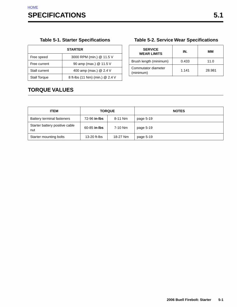
HOME
S
T
PECIFICATIONS 5.1
ORQUE VALUES
Table 5-1. Starter Specifications
STARTER
Free speed 3000 RPM (min.) @ 11.5 V
Free current 90 amp (max.) @ 11.5 V
Stall current 400 amp (max.) @ 2.4 V
Stall Torque 8 ft-lbs (11 Nm) (min.) @ 2.4 V
Table 5-2. Service Wear Specifications
SERVICE WEAR LIMITS
IN. MM
Brush length (minimum) 0.433 11.0
Commutator diameter(minimum)
1.141 28.981
ITEM TORQUE NOTES
Battery terminal fasteners 72-96 in-lbs 8-11 Nm page 5-19
Starter battery positive cable nut
60-85 in-lbs 7-10 Nm page 5-19
Starter mounting bolts 13-20 ft-lbs 18-27 Nm page 5-19
2006 Buell Firebolt: Starter 5-1

HOME
ELECTRIC STARTER SYSTEM 5.2
GENE
The startebly, soleno
The starteThe gear ture, an ididler gearthe overru
The overrthe clutchning. Thearmature
Wiring For additiocuit, see tTRICAL.
StarterThe starte
StarterSee 7.5 Sshooting i
5-2
RAL
r is made up of an armature, field winding assem-id, drive assembly, idler gear and drive housing.
r motor torque is increased through gear reduction.reduction consists of the drive pinion on the arma-ler gear and a clutch gear in the drive housing. The is supported by rollers. The clutch gear is part ofnning clutch/drive assembly.
unning clutch is the part which engages and drives ring gear. It also prevents the starter from overrun- field windings are connected in series with thethrough brushes and commutator segments.
Diagramsnal information concerning the starting system cir-he wiring diagram at the end of Section 7, ELEC-
Relayr relay is not repairable. Replace the unit if it fails.
InterlockTARTER INTERLOCK for operation and trouble-
nformation.
OPERATION
See Figure 5-1. When the starter switch is pushed, the starterrelay is activated and battery current flows into the pull-inwinding (10) and the hold-in winding (11), to ground.
The magnetic forces of the pull-in and hold-in windings in thesolenoid push the plunger (7) causing it to shift to the left.This action engages the pinion gear (1) with the clutch ringgear (13). At the same time, the main solenoid contacts (8)are closed, so battery current flows directly through the fieldwindings (3) to the armature (4) and to ground. Simulta-neously, the pull-in winding (10) is shorted.
The current continues flowing through the hold-in winding(11) keeping the main solenoid contacts (8) closed. At thispoint, the starter begins to crank the engine.
After the engine has started, the pinion gear (1) turns freelyon the pinion shaft through the action of the overrunningclutch (12). The overrunning clutch prevents the clutch ringgear (13) (which is now rotating under power from the engine)from turning the armature (4) too fast.
When the starter switch is released, the current of the hold-inwinding (11) is fed through the main solenoid contacts (8) andthe direction of the current in the pull-in winding (10) isreversed. The solenoid plunger (7) is returned to its originalposition by the return spring, which causes the pinion gear (1)to disengage from the clutch ring gear (13).
2006 Buell Firebolt: Starter
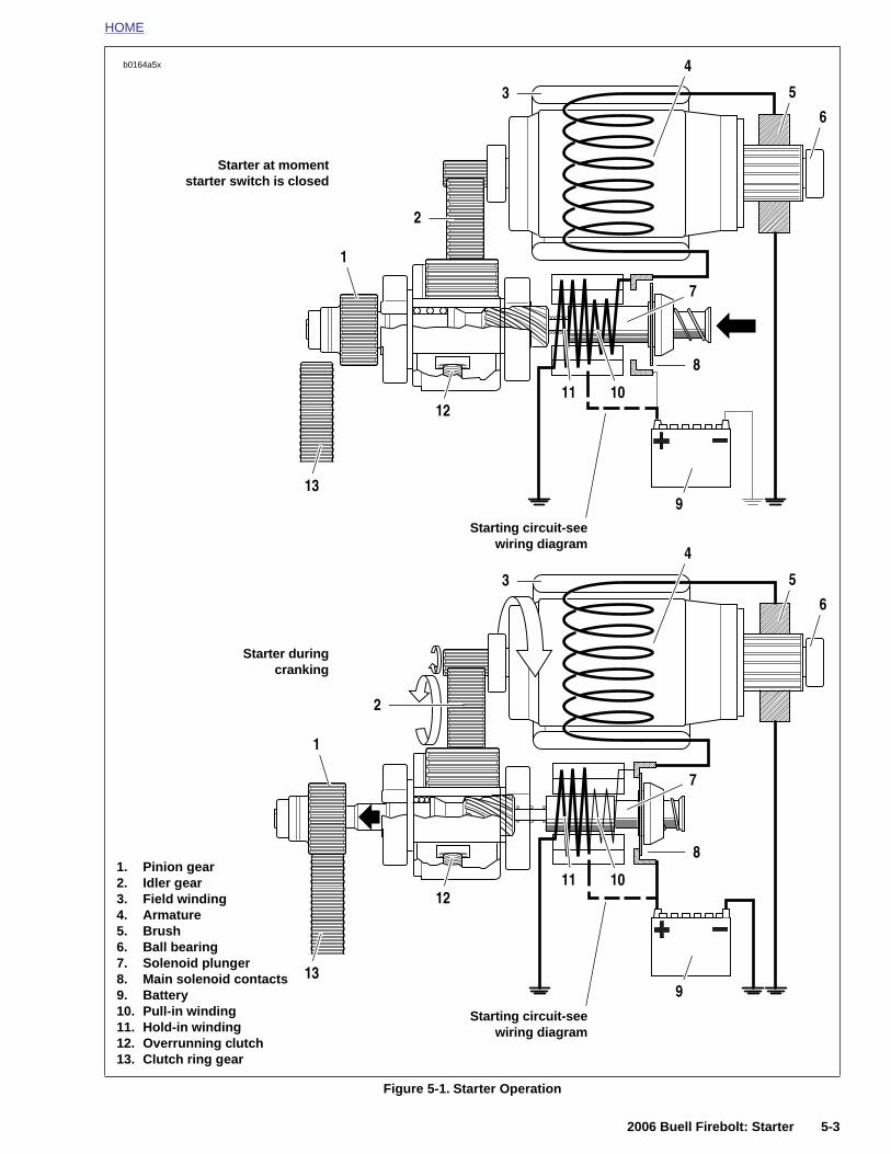
HOME
1
2
3
4
5
6
7
8
10
9
12
13
11
1
2
3
4
5
6
7
b0164a5x
Starting circuit-seewiring diagram
Starter at momentstarter switch is closed
Starter duringcranking
2006 Buell Firebolt: Starter 5-3
Figure 5-1. Starter Operation
8
10
9
12
13
11
Starting circuit-seewiring diagram
1. Pinion gear2. Idler gear3. Field winding4. Armature5. Brush6. Ball bearing7. Solenoid plunger8. Main solenoid contacts9. Battery10. Pull-in winding11. Hold-in winding12. Overrunning clutch13. Clutch ring gear
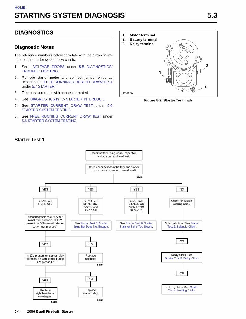
HOME
STARTING SYSTEM DIAGNOSIS 5.3
DIAGN
Diagno
The referebers on th
1. See TROU
2. Remodescrunde
3. Take
4. See
5. See STAR
6. See 5.6 S
Starter
Dism
pre
5-4
IT
OSTICS
stic Notes
nce numbers below correlate with the circled num-e starter system flow charts.
VOLTAGE DROPS under 5.5 DIAGNOSTICS/BLESHOOTING.
ve starter motor and connect jumper wires asibed in FREE RUNNING CURRENT DRAW TESTr 5.7 STARTER.
measurement with connector mated.
DIAGNOSTICS in 7.5 STARTER INTERLOCK.
STARTER CURRENT DRAW TEST under 5.6TER SYSTEM TESTING.
FREE RUNNING CURRENT DRAW TEST underTARTER SYSTEM TESTING.
Test 1
Figure 5-2. Starter Terminals
1
3
2
1. Motor terminal2. Battery terminal3. Relay terminal
d0361x5x
STARTER RUNS ON.
YES
5822
Check battery using visual inspection, voltage test and load test.
Check connections at battery and starter components. Is system operational?
STARTER SPINS, BUT DOES NOT ENGAGE.
YES
STARTER STALLS OR SPINS TOO SLOWLY.
YES
Check for audible clicking noise.
NO
Solenoid clicks. See Starter Test 2: Solenoid Clicks.
See Starter Test 5: Starter Spins But Does Not Engage.
See Starter Test 6: Starter Stalls or Spins Too Slowly.
connect solenoid relay ter-inal from solenoid. Is 12V sent on GN wire with starter
button not pressed?
2006 Buell Firebolt: Starter
Relay clicks. See Starter Test 3: Relay Clicks.
Nothing clicks. See Starter Test 4: Nothing Clicks.
OR
OR
s 12V present on starter relay erminal 86 with starter button
not pressed?
YES
Replace solenoid.
NO
Replaceright handlebar
switchgear.
YES
Replace starter relay.
NO
5845
58325818
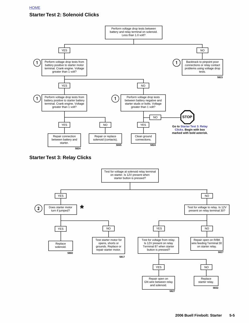
HOME
Starter Test 2: Solenoid Clicks
Starter Test 3: Relay Clicks
Perform voltage drop tests from battery positive to starter motor terminal. Crank engine. Voltage
greater than 1 volt?
YES
5823
Perform voltage drop tests between battery and relay terminal on solenoid.
Less than 1.0 volt?
Backtrack to pinpoint poor connections or relay contact problems using voltage drop
tests.
NO
Perform voltage drop tests from battery positive to starter battery terminal. Crank engine. Voltage
greater than 1 volt?
YES
Perform voltage drop tests between battery negative and starter studs or bolts. Voltage
greater than 1 volt?
NO
Repair connection between battery and
starter.
YES
Clean ground connections.
YES
Repair or replace solenoid (contacts).
NO
58245845 5824
NO
Go to Starter Test 3: Relay Clicks. Begin with box
marked with bold asterisk.
STOP
1
1
21
1
Does starter motor turn if jumped?
YES
Test for voltage at solenoid relay terminal on starter. Is 12V present when
starter button is pressed?
Test for voltage to relay. Is 12V present on relay terminal 30?
NO
2 *
2006 Buell Firebolt: Starter 5-5
YES
Test starter motor for opens, shorts or
grounds. Replace or repair starter motor.
NO
Replacesolenoid.
Test for voltage from relay. Is 12V present on relay
Terminal 87 when starter button is pressed?
YES
Repair open on R/BK wire feeding Terminal 30
on starter relay.
NO
Repair open on GN wire between relay
and solenoid.
YES
Replacestarter relay.
NO
5817
5860 5827
58275832
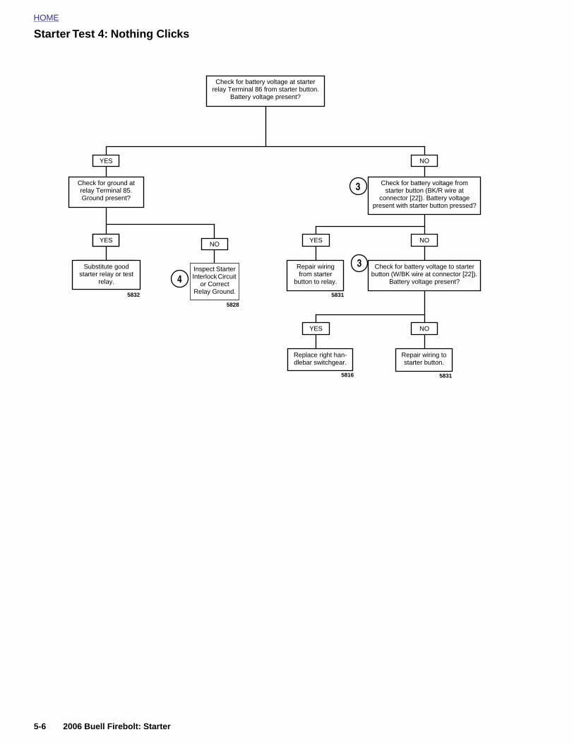
HOME
Starter Test 4: Nothing Clicks
Check for ground at relay Terminal 85. Ground present?
YES
5832
Check for battery voltage at starter relay Terminal 86 from starter button.
Battery voltage present?
Check for battery voltage from starter button (BK/R wire at
connector [22]). Battery voltage present with starter button pressed?
NO
Substitute good relay or test relay.
YESNO
Substitute good starter relay or test
relay.
YES
Check for battery voltage to starter button (W/BK wire at connector [22]).
Battery voltage present?
NO
Repair wiring from starter
button to relay.
YES
Repair wiring to starter button.
NO
Replace right han-dlebar switchgear.
YES
5831
5816 5831
Inspect Starter Interlock Circuit
or Correct Relay Ground.
5828
4
3
3
5-6 2006 Buell Firebolt: Starter

HOME
Starter Test 5: Starter Spins But Does Not Engage
Starter Test 6: Starter Stalls or Spins Too Slowly
Remove starter. Disassemble drive housing assembly. Inspect for damage to armature
gear or idler gear. Damage present?
Replace damaged idler gear and armature.
YES
Starter clutch failure. Replace starter clutch.
NO
58375825
Perform voltage drop tests between battery positive to
starter battery terminal. Crank engine.
Voltage greater than 1 volt?
YES
Perform voltage drop tests from battery positive to starter motor terminal. Crank
engine. Voltage greater than 1 volt?
NO
Repair connection between battery and
starter.
YES
Repair or replace solenoid (contacts).
NO
Perform voltage drop tests between battery negative and
starter studs or bolts. Voltage greater than 1 volt?
Clean groundconnections.
YES
Perform starter motor current draw test (on vehicle).
NO
5845 5835
1
1
4
2006 Buell Firebolt: Starter 5-7
5824Perform starter motor free draw
bench test.
Are test results within range?
Remove spark plugs while in 5th gear. Rotate rear wheel. Check for engine, primary
and/or crankshaft bind.
YES
Test starter motor for opens, shorts or grounds. Replace or repair starter
motor.
NO
5817Use appropriate code
5

HOME
STARTER ACTIVATION CIRCUITS 5.4
0.1A
0
0.1A
b0157a5x
1
5-8
1. Ba2. Ma3. Ke4. Ke5. Ru
1
150A
20A
20A
0.1A
150A
15A
0.1A
0.1A0.1A
0.1A
.1A 0.1A
150A
20A
20A
0.1A
150A
15A
0.1A
0.1A
0.1A0.1A
0.1A
0.1A 0.1A
20A
20A
0.1A
15A
0.1A
0.1A0.1A
0.1A
0.1A 0.1A
20A
20A
0.1A
15A
0.1A
0.1A
0.1A0.1A
0.1A
0.1A 0.1A
VDC
ITEM AIDEAL CLOSED CIRCUIT
GROUND CIRCUITOPEN CIRCUIT
OV
12V OV
ITEM B
ITEM C ITEM D
VDC
6
3
7
84
59
10
6
3
7
84
59
10
6
1211
3
7
84
59
10
1
2
6
1211
3
7
84
59
10
2
2006 Buell Firebolt: Starter
Figure 5-3. Typical Circuity. Refer to wiring diagrams for more information.
150A 150A 150A 150A
VDC
tteryin fuse (30 A)y switch fusey switchn/Stop switch
6. Ignition relay (used for junction purposes only)
7. Ignition fuse8. Key switch relay9. Start switch
10. Start relay11. Solenoid12. Starter
12112 1211
1
2
HOME
D
G
Fdpc
V
Ct
Ta
1
2
3
4
5
IAGNOSTICS/TROUBLESHOOTING 5.5
ENERAL
ollow the 5.3 STARTING SYSTEM DIAGNOSIS diagram toiagnose starting system problems. The VOLTAGE DROPSrocedure below will help you to locate poor connections oromponents with excessive voltage drops.
OLTAGE DROPS
heck the integrity of all wiring, switches, fuses and connec-ors between the source and destination.
he voltage drop test measures the difference in potential or thectual voltage dropped between the source and destination.
. See ITEM A in Figure 5-3. Attach your red meter lead tothe most positive part of the circuit, which in this casewould be the positive post of the battery (1).
. See ITEM B in Figure 5-3. Attach the black meter lead tothe final destination or component in the circuit (solenoidterminal from relay).
. Activate the starter and observe the meter reading. Themeter will read the voltage dropped or the difference inpotential between the source and destination.
. An ideal circuit’s voltage drop would be 0 volts or no volt-age dropped, meaning no difference in potential.
. See ITEM C in Figure 5-3. An open circuit should read12 volts, displaying all the voltage dropped, and theentire difference in potential displayed on the meter.
6. Typically, a good circuit will drop less than 1 volt.
7. If the voltage drop is greater, back track through the con-nections until the source of the potential difference isfound. The benefit of doing it this way is speed.
a. Readings aren’t as sensitive to real battery voltage.
b. Readings show the actual voltage dropped, not justthe presence of voltage.
c. This tests the system as it is actually being used. Itis more accurate and will display hard to find poorconnections.
d. This approach can be used on lighting circuits, igni-tion circuits, etc. Start from most positive and go tomost negative (the destination or component).
8. See ITEM D in Figure 5-3. The negative or ground circuitcan be checked as well.
a. Place the negative lead on the most negative part ofthe circuit (or the negative battery post). Remember,there is nothing more negative than the negativepost of the battery.
b. Place the positive lead to the ground you wish tocheck.
c. Activate the circuit. This will allow you to read thepotential difference or voltage dropped on the nega-tive or ground circuit. This technique is very effectivefor identifying poor grounds due to powdered paint.Even the slightest connection may cause an ohm-meter to give a good reading. However, when suffi-cient current is passed through, the resistancecaused by the powdered paint will cause a voltagedrop or potential difference in the ground circuit.
2006 Buell Firebolt: Starter 5-9
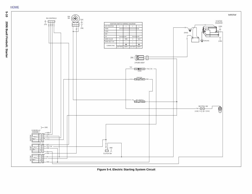
5-102006 B
uell F
irebo
lt: Starter
1
NEUTRAL SW
[131B]
GROUND
STARTERSOLENOID
[GRD2]
[128B]
[128A]
R/Y
BK
BK
GN
TN/Y
1
[131A]
1
bd0025af
HOME
Figure 5-4. Electric Starting System Circuit
ASSEMBLYFUSE/RELAY
[62B]
CLUTCH SW
[95B]
[33B]
IGNSWRH CONTROLS
[22A]
[33A]
2
24
11
8
18
5
1
BK/R
W/B
KW
/BK
GY/
O
R
R/B
K R
LOC
K
BKTN/L
T.G
N
R
GY/O
TN/Y
R/BK
RBK
R/BKGN
R/BKTN/LT.GNBK/R
GY/OGY/OBKW/BK
R
R/BK
TN/LT.GN
W/BK
10
5
87
87
87
87A
87A
87A
30
30
30
85
85
85
86
86
86
3
IGN
ITIO
NKE
Y SW
STAR
T
4
78
15
6
13
9
14
2
1911
1
11
2
22
IGN
3
33
4
44
1 2
DIODE
IGNITION
KEY SWITCH
0
2431
0 0
+
1
R
1
+
USER + USER +
1
R/BK R/GY
BATTERY BATTERY
1
R
0 0
0PARK
KEY POSITION
IGNITION SWITCH WIRING DIAGRAM
CONNECTING
WIRE SECT mm
WIRE COLOR
ON
OFF
LOCK
21[5A]
J-FUSE ASSY
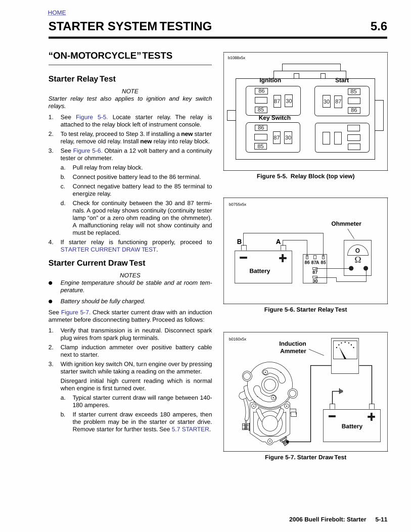
HOME
S
“
S
Sre
1
2
3
4
S
●
●
Sa
1
2
3
TARTER SYSTEM TESTING 5.6
ON-MOTORCYCLE” TESTS
tarter Relay TestNOTE
tarter relay test also applies to ignition and key switchlays.
. See Figure 5-5. Locate starter relay. The relay isattached to the relay block left of instrument console.
. To test relay, proceed to Step 3. If installing a new starterrelay, remove old relay. Install new relay into relay block.
. See Figure 5-6. Obtain a 12 volt battery and a continuitytester or ohmmeter.
a. Pull relay from relay block.
b. Connect positive battery lead to the 86 terminal.
c. Connect negative battery lead to the 85 terminal toenergize relay.
d. Check for continuity between the 30 and 87 termi-nals. A good relay shows continuity (continuity testerlamp “on” or a zero ohm reading on the ohmmeter).A malfunctioning relay will not show continuity andmust be replaced.
. If starter relay is functioning properly, proceed toSTARTER CURRENT DRAW TEST.
tarter Current Draw TestNOTES
Engine temperature should be stable and at room tem-perature.
Battery should be fully charged.
ee Figure 5-7. Check starter current draw with an inductionmmeter before disconnecting battery. Proceed as follows:
. Verify that transmission is in neutral. Disconnect sparkplug wires from spark plug terminals.
. Clamp induction ammeter over positive battery cablenext to starter.
. With ignition key switch ON, turn engine over by pressing
Figure 5-5. Relay Block (top view)
Figure 5-6. Starter Relay Test
86
86
86
87
85
85
87
873030
30
85
b1088x5x
Ignition Start
Key Switch
b0755x5x
Battery
Ohmmeter
InductionAmmeter
b0160x5x
2006 Buell Firebolt: Starter 5-11
starter switch while taking a reading on the ammeter.
Disregard initial high current reading which is normalwhen engine is first turned over.
a. Typical starter current draw will range between 140-180 amperes.
b. If starter current draw exceeds 180 amperes, thenthe problem may be in the starter or starter drive.Remove starter for further tests. See 5.7 STARTER.
Figure 5-7. Starter Draw Test
Battery
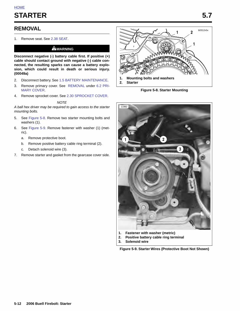
HOME
STARTER 5.7
REMO
1. Remo
Disconnecable shonected, thsion, wh(00049a)
2. Disco
3. RemoMARY
4. Remo
A ball hexmounting
5. See Fwashe
6. See Fric).
a. R
b. R
c. D
7. Remo
5-12
VAL
ve seat. See 2.38 SEAT.
1WARNING1WARNING
ct negative (-) battery cable first. If positive (+)uld contact ground with negative (-) cable con-e resulting sparks can cause a battery explo-
ich could result in death or serious injury.
nnect battery. See 1.5 BATTERY MAINTENANCE.
ve primary cover. See REMOVAL under 6.2 PRI- COVER.
ve sprocket cover. See 2.30 SPROCKET COVER.
NOTE driver may be required to gain access to the starterbolts.
igure 5-8. Remove two starter mounting bolts andrs (1).
igure 5-9. Remove fastener with washer (1) (met-
emove protective boot.
emove positive battery cable ring terminal (2).
etach solenoid wire (3).
ve starter and gasket from the gearcase cover side.
Figure 5-8. Starter Mounting
1
1
2
1. Mounting bolts and washers2. Starter
b0312x5x
8742
21
3
11992
2006 Buell Firebolt: Starter
Figure 5-9. Starter Wires (Protective Boot Not Shown)
1. Fastener with washer (metric)2. Positive battery cable ring terminal3. Solenoid wire
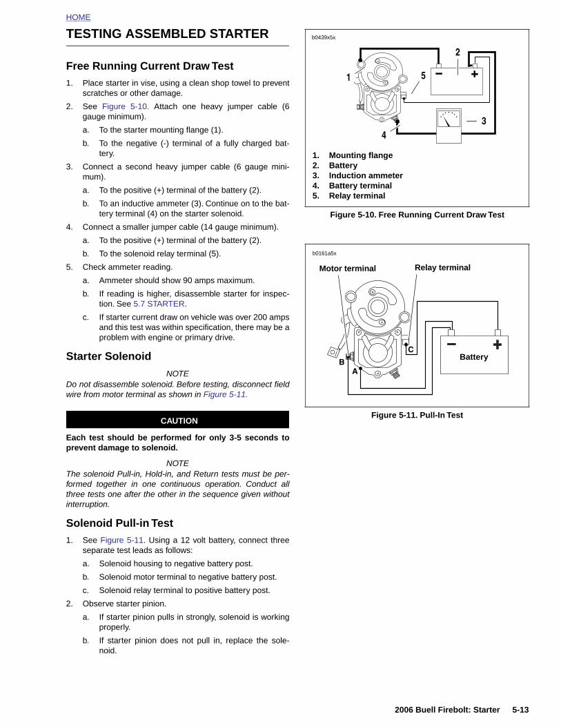
HOME
TESTING ASSEMBLED STARTER
Free Running Current Draw Test1. Place starter in vise, using a clean shop towel to prevent
scratches or other damage.
2. See Figure 5-10. Attach one heavy jumper cable (6gauge minimum).
a. To the starter mounting flange (1).
b. To the negative (-) terminal of a fully charged bat-tery.
3. Connect a second heavy jumper cable (6 gauge mini-mum).
a. To the positive (+) terminal of the battery (2).
b. To an inductive ammeter (3). Continue on to the bat-tery terminal (4) on the starter solenoid.
4. Connect a smaller jumper cable (14 gauge minimum).
a. To the positive (+) terminal of the battery (2).
b. To the solenoid relay terminal (5).
5. Check ammeter reading.
a. Ammeter should show 90 amps maximum.
b. If reading is higher, disassemble starter for inspec-tion. See 5.7 STARTER.
c. If starter current draw on vehicle was over 200 ampsand this test was within specification, there may be aproblem with engine or primary drive.
Starter Solenoid
NOTEDo not disassemble solenoid. Before testing, disconnect fieldwire from motor terminal as shown in Figure 5-11.
CAUTION
Each test should be performed for only 3-5 seconds toprevent damage to solenoid.
NOTEThe solenoid Pull-in, Hold-in, and Return tests must be per-formed together in one continuous operation. Conduct allthree tests one after the other in the sequence given without
Figure 5-10. Free Running Current Draw Test
Figure 5-11. Pull-In Test
1. Mounting flange2. Battery3. Induction ammeter4. Battery terminal5. Relay terminal
b0439x5x
1
43
5
2
Battery
b0161a5x
Motor terminal Relay terminal
2006 Buell Firebolt: Starter 5-13
interruption.
Solenoid Pull-in Test1. See Figure 5-11. Using a 12 volt battery, connect three
separate test leads as follows:
a. Solenoid housing to negative battery post.
b. Solenoid motor terminal to negative battery post.
c. Solenoid relay terminal to positive battery post.
2. Observe starter pinion.
a. If starter pinion pulls in strongly, solenoid is workingproperly.
b. If starter pinion does not pull in, replace the sole-noid.
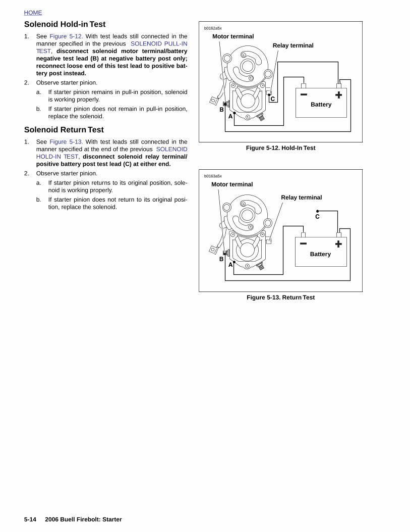
HOME
Solenoid Hold-in Test
1. See Figure 5-12. With test leads still connected in the
b0162a5x
Motor terminal
manner specified in the previous SOLENOID PULL-INTEST, disconnect solenoid motor terminal/batterynegative test lead (B) at negative battery post only;reconnect loose end of this test lead to positive bat-tery post instead.2. Observe starter pinion.
a. If starter pinion remains in pull-in position, solenoidis working properly.
b. If starter pinion does not remain in pull-in position,replace the solenoid.
Solenoid Return Test1. See Figure 5-13. With test leads still connected in the
manner specified at the end of the previous SOLENOIDHOLD-IN TEST, disconnect solenoid relay terminal/positive battery post test lead (C) at either end.
2. Observe starter pinion.
a. If starter pinion returns to its original position, sole-noid is working properly.
b. If starter pinion does not return to its original posi-tion, replace the solenoid.
Figure 5-12. Hold-In Test
Figure 5-13. Return Test
Battery
Relay terminal
Battery
b0163a5x
Motor terminal
Relay terminal
5-14 2006 Buell Firebolt: Starter

HOME
DISASSEMBLY, INSPECTION AND REPAIR
1. See Figure 5-14. Lift rubber boot (1). Remove field wirenut with washer (2) (metric) to detach field wire (3).
2. See Figure 5-15. Remove both thru-bolts (1, 3).
3. Remove both end cover screws with o-rings (2) and endcover (4).
4. See Figure 5-16. Use a wire hook to pull upward onbrush springs (3), and lift brushes out of holder (2).Remove brush holder.
5. Check brush length. Replace all four brushes if length ofany one brush is less than 0.433 in. (11.0 mm).
NOTE
Brushes not available separately. Purchase a new field frame(1) and brush holder (2) to replace brushes.
6. Remove armature (4) and field frame (1).
7. Place armature in lathe or truing stand and check com-mutator runout and diameter.
a. Commutators with more than 0.016 in. (0.406 mm)of runout should be replaced or machined on alathe.
b. Replace commutators when diameter is less than1.141 in. (28.981 mm)
c. Check armature bearings. Replace if necessary.
CAUTION
Do not use sandpaper or emery cloth to remove burrs oncommutator. Otherwise, abrasive grit may remain oncommutator segments; this could lead to excessivebrush wear. Use only the recommended crocus cloth.
NOTE
See Figure 5-17. If an undercutting machine is not available,
Figure 5-14. Field Wire
Figure 5-15. Removing the Thru-Bolts
6007 1
1. Rubber boot2. Field wire nut with washer (metric)3. Field wire
3
2
6009
1
3
2
4
1. Lower thru-bolt2. Screw with o-ring (2)3. Upper thru-bolt4. End cover
6010 1
2006 Buell Firebolt: Starter 5-15
undercutting can be done satisfactorily using a thin hacksawblade. After undercutting, lightly sand the commutator withcrocus cloth to remove any burrs.
8. Check depth of mica on commutator. If undercut is lessthan 0.008 in. (0.203 mm), use an undercutting machineto undercut the mica to 1/32 in. (0.794 mm) deep. Theslots should then be cleaned to remove any dirt or cop-per dust.
Figure 5-16. Starter Components
1. Field frame2. Brush holder3. Brush spring (4)4. Armature5. Solenoid housing
2
3
4
5
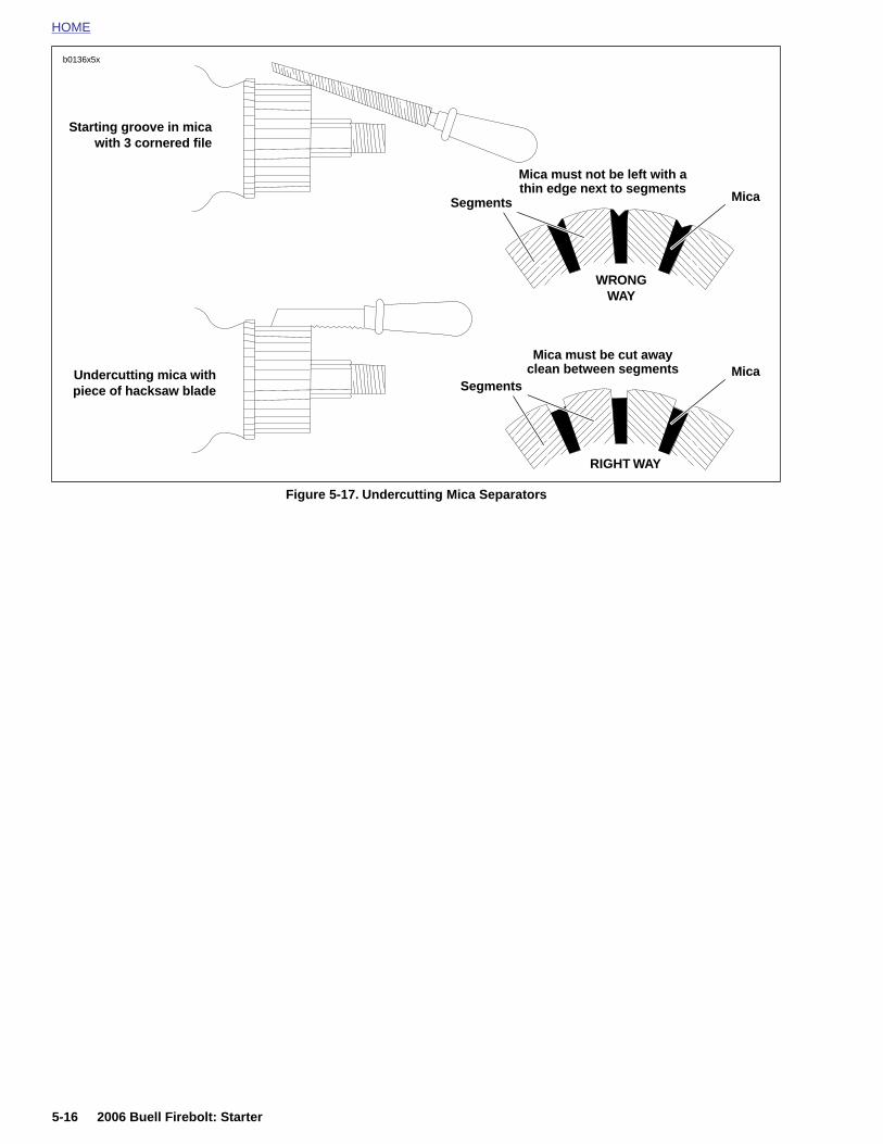
HOME
b0136x5x
Figure 5-17. Undercutting Mica Separators
Mica must not be left with a thin edge next to segments
RIGHT WAY
Mica
Undercutting mica withpiece of hacksaw blade
WRONG WAY
Starting groove in micawith 3 cornered file
Mica must be cut awayclean between segments Mica
Segments
Segments
5-16 2006 Buell Firebolt: Starter

HOME
9. See Figure 5-18. Check for SHORTED ARMATURE witha growler.
a. Place armature on growler (1).
b. Hold a thin steel strip (2) (hacksaw blade) againstarmature core and slowly turn armature.
c. A shorted armature will cause the steel strip tovibrate and be attracted to the core. Replaceshorted armatures.
10. See Figure 5-19. Check for a GROUNDED ARMATUREwith an ohmmeter or continuity tester.
a. Touch one probe to any commutator segment (1).
b. Touch the other probe to the armature core (2).
c. There should be no continuity (infinite ohms). Ifthere is continuity, then the armature is grounded.Replace grounded armatures.
11. See Figure 5-20. Check for OPEN ARMATURE with anohmmeter or continuity tester.
a. Check for continuity between all commutator seg-ments (1).
b. There should be continuity (0 ohms) at all testpoints. No continuity at any test point indicatesarmature is open and must be replaced.
Figure 5-18. Shorted Armature Test Using Growler
Figure 5-19. Grounded Armature Test
1782a
1
2
6011
12
6012a
1
2006 Buell Firebolt: Starter 5-17
Figure 5-20. Open Armature Test
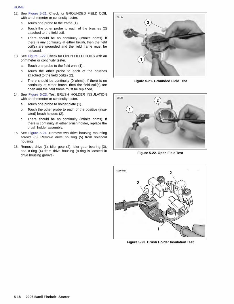
HOME
12. See Figure 5-21. Check for GROUNDED FIELD COILwith an ohmmeter or continuity tester.
6013a
2
a. Touch one probe to the frame (1).b. Touch the other probe to each of the brushes (2)attached to the field coil.
c. There should be no continuity (infinite ohms). Ifthere is any continuity at either brush, then the fieldcoil(s) are grounded and the field frame must bereplaced.
13. See Figure 5-22. Check for OPEN FIELD COILS with anohmmeter or continuity tester.
a. Touch one probe to the field wire (1).
b. Touch the other probe to each of the brushesattached to the field coil(s) (2).
c. There should be continuity (0 ohms). If there is nocontinuity at either brush, then the field coil(s) areopen and the field frame must be replaced.
14. See Figure 5-23. Test BRUSH HOLDER INSULATIONwith an ohmmeter or continuity tester.
a. Touch one probe to holder plate (1).
b. Touch the other probe to each of the positive (insu-lated) brush holders (2).
c. There should be no continuity (infinite ohms). Ifthere is continuity at either brush holder, replace thebrush holder assembly.
15. See Figure 5-24. Remove two drive housing mountingscrews (6). Remove drive housing (5) from solenoidhousing.
16. Remove drive (1), idler gear (2), idler gear bearing (3),and o-ring (4) from drive housing (o-ring is located indrive housing groove).
Figure 5-21. Grounded Field Test
Figure 5-22. Open Field Test
1
6014a
1
2
s0164x5x
2
2
5-18 2006 Buell Firebolt: Starter
Figure 5-23. Brush Holder Insulation Test
1
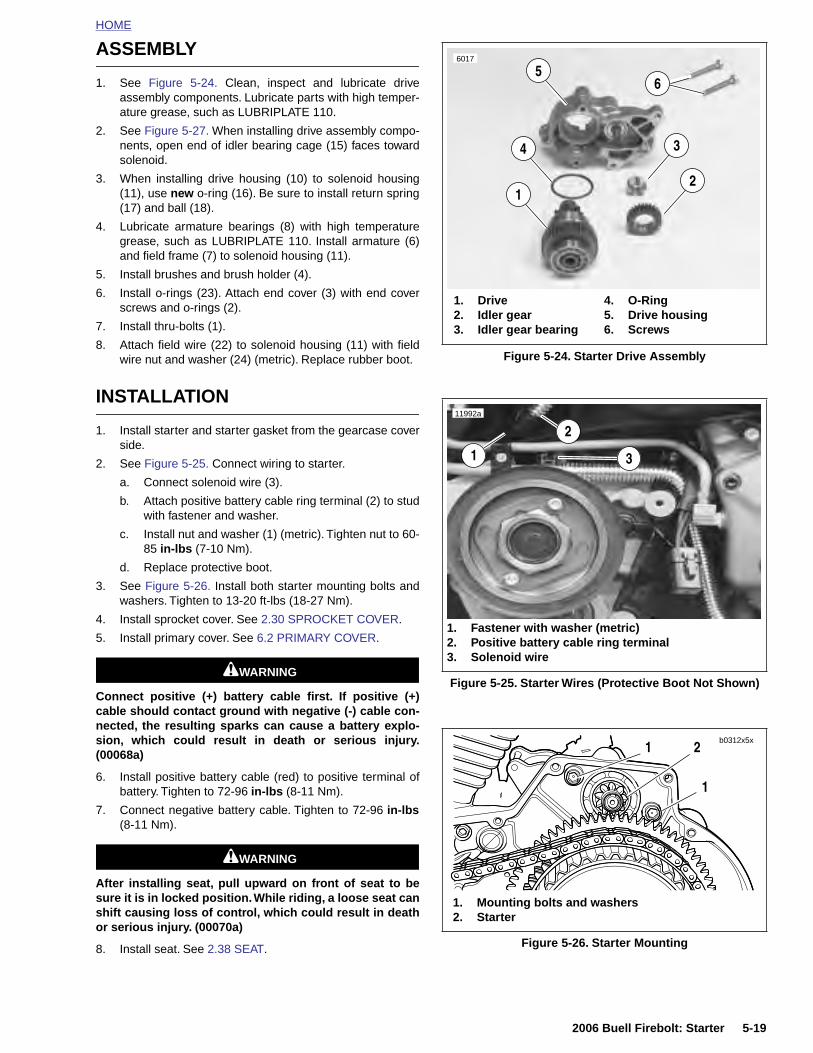
HOME
ASSEMBLY
1. See Figure 5-24. Clean, inspect and lubricate driveassembly components. Lubricate parts with high temper-ature grease, such as LUBRIPLATE 110.
2. See Figure 5-27. When installing drive assembly compo-nents, open end of idler bearing cage (15) faces towardsolenoid.
3. When installing drive housing (10) to solenoid housing(11), use new o-ring (16). Be sure to install return spring(17) and ball (18).
4. Lubricate armature bearings (8) with high temperaturegrease, such as LUBRIPLATE 110. Install armature (6)and field frame (7) to solenoid housing (11).
5. Install brushes and brush holder (4).
6. Install o-rings (23). Attach end cover (3) with end coverscrews and o-rings (2).
7. Install thru-bolts (1).
8. Attach field wire (22) to solenoid housing (11) with fieldwire nut and washer (24) (metric). Replace rubber boot.
INSTALLATION
1. Install starter and starter gasket from the gearcase coverside.
2. See Figure 5-25. Connect wiring to starter.
a. Connect solenoid wire (3).
b. Attach positive battery cable ring terminal (2) to studwith fastener and washer.
c. Install nut and washer (1) (metric). Tighten nut to 60-85 in-lbs (7-10 Nm).
d. Replace protective boot.
3. See Figure 5-26. Install both starter mounting bolts andwashers. Tighten to 13-20 ft-lbs (18-27 Nm).
4. Install sprocket cover. See 2.30 SPROCKET COVER.
5. Install primary cover. See 6.2 PRIMARY COVER.
1WARNING1WARNING
Connect positive (+) battery cable first. If positive (+)cable should contact ground with negative (-) cable con-nected, the resulting sparks can cause a battery explo-
Figure 5-24. Starter Drive Assembly
Figure 5-25. Starter Wires (Protective Boot Not Shown)
4. O-Ring5. Drive housing6. Screws
1. Drive2. Idler gear3. Idler gear bearing
12
34
56017
6
11992a
1
2
1. Fastener with washer (metric)2. Positive battery cable ring terminal3. Solenoid wire
3
sion, which could result in de(00068a)
6. Install positive battery cable (rebattery. Tighten to 72-96 in-lbs
7. Connect negative battery cable(8-11 Nm).
1WARNIN1WARNIN
After installing seat, pull upwardsure it is in locked position. Whileshift causing loss of control, whicor serious injury. (00070a)
8. Install seat. See 2.38 SEAT.
2006 Buell Firebolt: Starter 5-19
ath or serious injury.
d) to positive terminal of(8-11 Nm).
. Tighten to 72-96 in-lbs
GG
on front of seat to be riding, a loose seat canh could result in death
Figure 5-26. Starter Mounting
1
1
2
1. Mounting bolts and washers2. Starter
b0312x5x
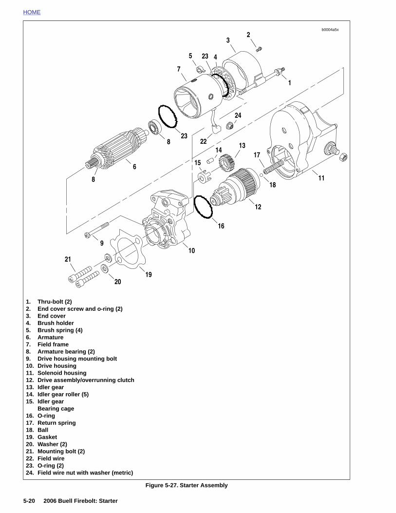
HOME
b0004a5x
2
1. Thru-bolt (2)2. End cover screw and o-ring (2)3. End cover4. Brush holder5. Brush spring (4)6. Armature7. Field frame8. Armature bearing (2)9. Drive housing mounting bolt10. Drive housing11. Solenoid housing
21
2019
10
16
12
1811
9
15
1314
17
8
6
823
1
23 4
24
22
3
5
7
5-20 2006 Buell Firebolt: Starter
Figure 5-27. Starter Assembly
12. Drive assembly/overrunning clutch13. Idler gear14. Idler gear roller (5)15. Idler gear
Bearing cage16. O-ring17. Return spring18. Ball19. Gasket20. Washer (2)21. Mounting bolt (2)22. Field wire23. O-ring (2)24. Field wire nut with washer (metric)
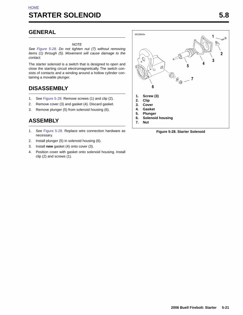
HOME
S
G
Sitc
Tcst
D
1
2
3
A
1
2
3
4
TARTER SOLENOID 5.8
ENERAL
NOTEee Figure 5-28. Do not tighten nut (7) without removingems (1) through (5). Movement will cause damage to theontact.
he starter solenoid is a switch that is designed to open andlose the starting circuit electromagnetically. The switch con-ists of contacts and a winding around a hollow cylinder con-aining a movable plunger.
ISASSEMBLY
. See Figure 5-28. Remove screws (1) and clip (2).
. Remove cover (3) and gasket (4). Discard gasket.
. Remove plunger (5) from solenoid housing (6).
SSEMBLY
. See Figure 5-28. Replace wire connection hardware asnecessary.
. Install plunger (5) in solenoid housing (6).
. Install new gasket (4) onto cover (3).
. Position cover with gasket onto solenoid housing. Installclip (2) and screws (1).
Figure 5-28. Starter Solenoid
1. Screw (3)2. Clip3. Cover4. Gasket5. Plunger6. Solenoid housing7. Nut
b0158x5x
6
5 43
2
7
1
2006 Buell Firebolt: Starter 5-21
HOME
NOTES
5-22
2006 Buell Firebolt: Starter
SUBJECT PAGE NO.
6.1 Specifications . . . . . . . . . . . . . . . . . . . . . . . . . . . . . . . . . . . . . . . . . . . . . . . . . 6-16.2 Primary Cover . . . . . . . . . . . . . . . . . . . . . . . . . . . . . . . . . . . . . . . . . . . . . . . . . 6-36.3 Clutch Release Mechanism . . . . . . . . . . . . . . . . . . . . . . . . . . . . . . . . . . . . . . . 6-76.4 Clutch . . . . . . . . . . . . . . . . . . . . . . . . . . . . . . . . . . . . . . . . . . . . . . . . . . . . . . . 6-96.5 Primary Chain . . . . . . . . . . . . . . . . . . . . . . . . . . . . . . . . . . . . . . . . . . . . . . . . . 6-166.6 Drive Belt System . . . . . . . . . . . . . . . . . . . . . . . . . . . . . . . . . . . . . . . . . . . . . . 6-216.7 Transmission . . . . . . . . . . . . . . . . . . . . . . . . . . . . . . . . . . . . . . . . . . . . . . . . . . 6-256.8 Case Disassembly for Transmission Removal . . . . . . . . . . . . . . . . . . . . . . . . 6-266.9 Transmission Disassembly . . . . . . . . . . . . . . . . . . . . . . . . . . . . . . . . . . . . . . . 6-296.10 Transmission Assembly . . . . . . . . . . . . . . . . . . . . . . . . . . . . . . . . . . . . . . . . . 6-346.11 Main Drive Gear and Bearing . . . . . . . . . . . . . . . . . . . . . . . . . . . . . . . . . . . . 6-366.12 Transmission Right Case Bearings . . . . . . . . . . . . . . . . . . . . . . . . . . . . . . . . 6-446.13 Transmission Left Case Bearings . . . . . . . . . . . . . . . . . . . . . . . . . . . . . . . . . 6-456.14 Transmission Installation . . . . . . . . . . . . . . . . . . . . . . . . . . . . . . . . . . . . . . . . 6-466.15 Shifter Shaft . . . . . . . . . . . . . . . . . . . . . . . . . . . . . . . . . . . . . . . . . . . . . . . . . . 6-506.16 Transmission Sprocket . . . . . . . . . . . . . . . . . . . . . . . . . . . . . . . . . . . . . . . . . 6-52
Table Of Contents
DRIVE/TRA
NSMISSION 6
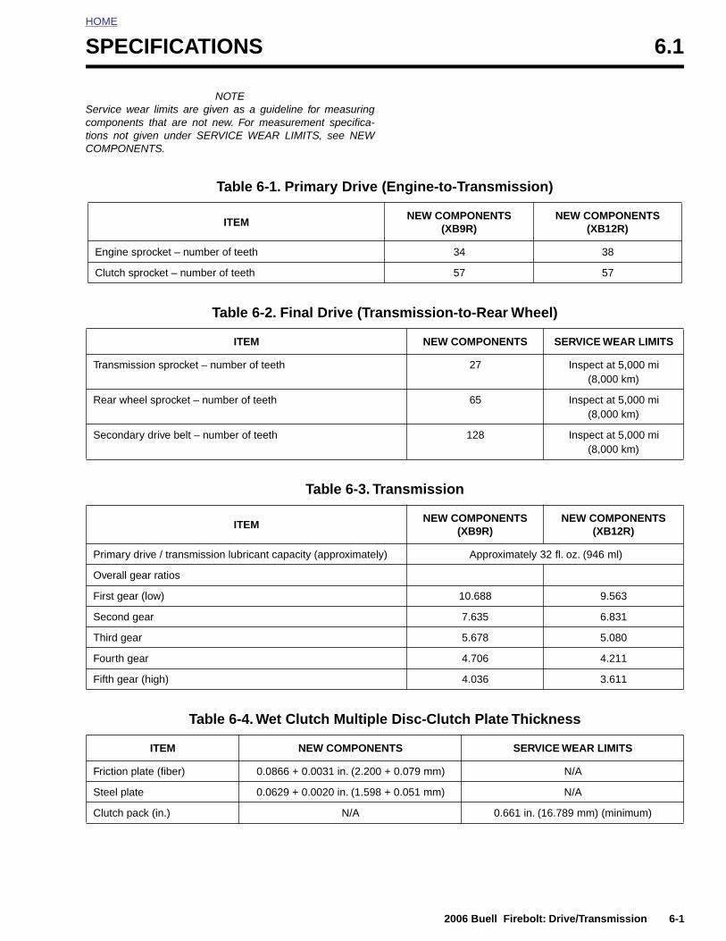
HOME
S
SctiC
PECIFICATIONS 6.1
NOTEervice wear limits are given as a guideline for measuringomponents that are not new. For measurement specifica-ons not given under SERVICE WEAR LIMITS, see NEWOMPONENTS.
Table 6-1. Primary Drive (Engine-to-Transmission)
ITEMNEW COMPONENTS
(XB9R)NEW COMPONENTS
(XB12R)
Engine sprocket – number of teeth 34 38
Clutch sprocket – number of teeth 57 57
Table 6-2. Final Drive (Transmission-to-Rear Wheel)
ITEM NEW COMPONENTS SERVICE WEAR LIMITS
Transmission sprocket – number of teeth 27 Inspect at 5,000 mi (8,000 km)
Rear wheel sprocket – number of teeth 65 Inspect at 5,000 mi (8,000 km)
Secondary drive belt – number of teeth 128 Inspect at 5,000 mi (8,000 km)
Table 6-3. Transmission
ITEMNEW COMPONENTS
(XB9R)NEW COMPONENTS
(XB12R)
Primary drive / transmission lubricant capacity (approximately) Approximately 32 fl. oz. (946 ml)
Overall gear ratios
First gear (low) 10.688 9.563
Second gear 7.635 6.831
Third gear 5.678 5.080
2006 Buell Firebolt: Drive/Transmission 6-1
Fourth gear 4.706 4.211
Fifth gear (high) 4.036 3.611
Table 6-4. Wet Clutch Multiple Disc-Clutch Plate Thickness
ITEM NEW COMPONENTS SERVICE WEAR LIMITS
Friction plate (fiber) 0.0866 + 0.0031 in. (2.200 + 0.079 mm) N/A
Steel plate 0.0629 + 0.0020 in. (1.598 + 0.051 mm) N/A
Clutch pack (in.) N/A 0.661 in. (16.789 mm) (minimum)
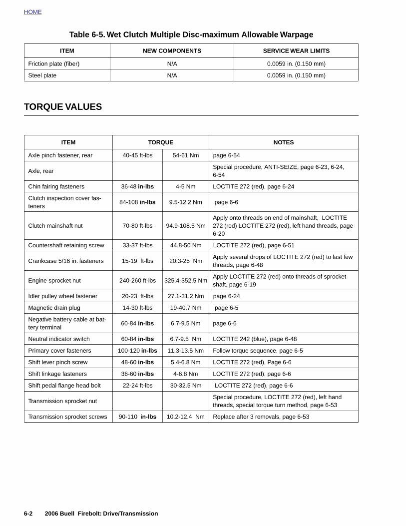
HOME
Table 6-5. Wet Clutch Multiple Disc-maximum Allowable Warpage
TORQUE VALUES
ITEM NEW COMPONENTS SERVICE WEAR LIMITS
Friction plate (fiber) N/A 0.0059 in. (0.150 mm)
Steel plate N/A 0.0059 in. (0.150 mm)
ITEM TORQUE NOTES
Axle pinch fastener, rear 40-45 ft-lbs 54-61 Nm page 6-54
Axle, rearSpecial procedure, ANTI-SEIZE, page 6-23, 6-24,6-54
Chin fairing fasteners 36-48 in-lbs 4-5 Nm LOCTITE 272 (red), page 6-24
Clutch inspection cover fas-teners
84-108 in-lbs 9.5-12.2 Nm page 6-6
Clutch mainshaft nut 70-80 ft-lbs 94.9-108.5 NmApply onto threads on end of mainshaft, LOCTITE 272 (red) LOCTITE 272 (red), left hand threads, page 6-20
Countershaft retaining screw 33-37 ft-lbs 44.8-50 Nm LOCTITE 272 (red), page 6-51
Crankcase 5/16 in. fasteners 15-19 ft-lbs 20.3-25 NmApply several drops of LOCTITE 272 (red) to last few threads, page 6-48
Engine sprocket nut 240-260 ft-lbs 325.4-352.5 NmApply LOCTITE 272 (red) onto threads of sprocket shaft, page 6-19
Idler pulley wheel fastener 20-23 ft-lbs 27.1-31.2 Nm page 6-24
Magnetic drain plug 14-30 ft-lbs 19-40.7 Nm page 6-5
Negative battery cable at bat-tery terminal
60-84 in-lbs 6.7-9.5 Nm page 6-6
Neutral indicator switch 60-84 in-lbs 6.7-9.5 Nm LOCTITE 242 (blue), page 6-48
Primary cover fasteners 100-120 in-lbs 11.3-13.5 Nm Follow torque sequence, page 6-5
Shift lever pinch screw 48-60 in-lbs 5.4-6.8 Nm LOCTITE 272 (red), Page 6-6
Shift linkage fasteners 36-60 in-lbs 4-6.8 Nm LOCTITE 272 (red), page 6-6
Shift pedal flange head bolt 22-24 ft-lbs 30-32.5 Nm LOCTITE 272 (red), page 6-6
6-2 2006 Buell Firebolt: Drive/Transmission
Transmission sprocket nutSpecial procedure, LOCTITE 272 (red), left hand threads, special torque turn method, page 6-53
Transmission sprocket screws 90-110 in-lbs 10.2-12.4 Nm Replace after 3 removals, page 6-53
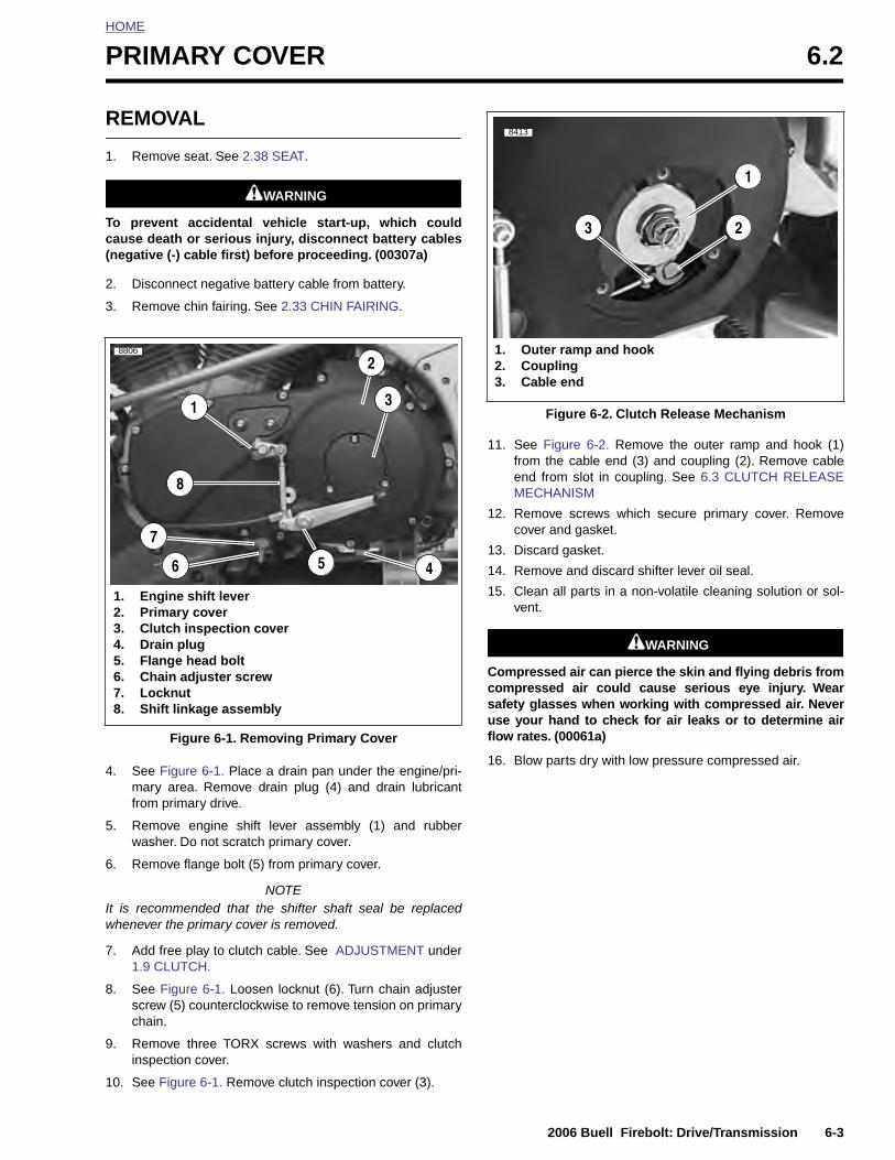
HOME
P
R
1
Tc(
2
3
4
RIMARY COVER 6.2
EMOVAL
. Remove seat. See 2.38 SEAT.
11WARNING1WARNING
o prevent accidental vehicle start-up, which couldause death or serious injury, disconnect battery cablesnegative (-) cable first) before proceeding. (00307a)
. Disconnect negative battery cable from battery.
. Remove chin fairing. See 2.33 CHIN FAIRING.
. See Figure 6-1. Place a drain pan under the engine/pri-mary area. Remove drain plug (4) and drain lubricant
11. See Figure 6-2. Remove the outer ramp and hook (1)from the cable end (3) and coupling (2). Remove cableend from slot in coupling. See 6.3 CLUTCH RELEASEMECHANISM
12. Remove screws which secure primary cover. Removecover and gasket.
13. Discard gasket.
14. Remove and discard shifter lever oil seal.
15. Clean all parts in a non-volatile cleaning solution or sol-vent.
11WARNING1WARNING
Compressed air can pierce the skin and flying debris fromcompressed air could cause serious eye injury. Wearsafety glasses when working with compressed air. Neveruse your hand to check for air leaks or to determine airflow rates. (00061a)
16. Blow parts dry with low pressure compressed air.
Figure 6-1. Removing Primary Cover
1. Engine shift lever2. Primary cover3. Clutch inspection cover4. Drain plug5. Flange head bolt6. Chain adjuster screw7. Locknut8. Shift linkage assembly
3
2
4
7
6
1
8806
5
8
Figure 6-2. Clutch Release Mechanism
1. Outer ramp and hook2. Coupling3. Cable end
1
23
8413
2006 Buell Firebolt: Drive/Transmission 6-3
from primary drive.
5. Remove engine shift lever assembly (1) and rubberwasher. Do not scratch primary cover.
6. Remove flange bolt (5) from primary cover.
NOTEIt is recommended that the shifter shaft seal be replacedwhenever the primary cover is removed.
7. Add free play to clutch cable. See ADJUSTMENT under1.9 CLUTCH.
8. See Figure 6-1. Loosen locknut (6). Turn chain adjusterscrew (5) counterclockwise to remove tension on primarychain.
9. Remove three TORX screws with washers and clutchinspection cover.
10. See Figure 6-1. Remove clutch inspection cover (3).
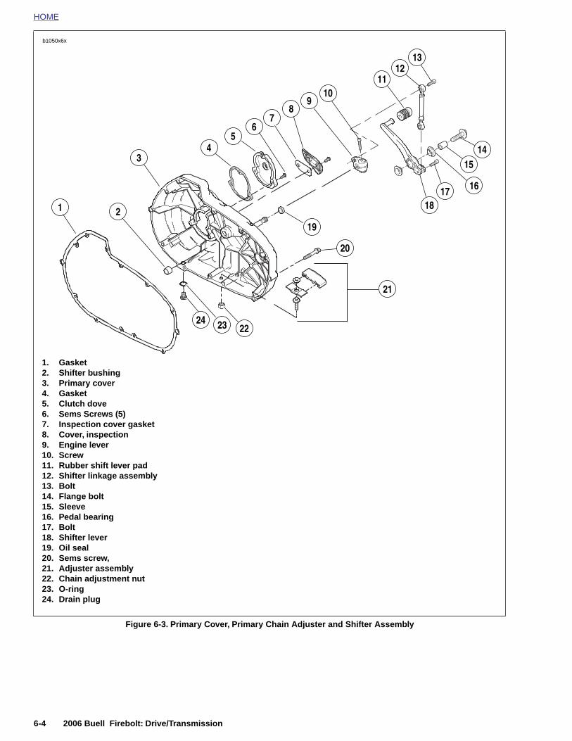
HOME
b1050x6x
1
9
14
78
2
10
24
3
22
45
6
1617
15
1213
11
18
21
19
1. Gasket2. Shifter bushing3. Primary cover4. Gasket5. Clutch dove6. Sems Screws (5)7. Inspection cover gasket8. Cover, inspection9. Engine lever10. Screw11. Rubber shift lever pad12. Shifter linkage assembly13. Bolt14. Flange bolt 15. Sleeve16. Pedal bearing17. Bolt18. Shifter lever
20
23
6-4 2006 Buell Firebolt: Drive/Transmission
Figure 6-3. Primary Cover, Primary Chain Adjuster and Shifter Assembly
19. Oil seal20. Sems screw,21. Adjuster assembly22. Chain adjustment nut23. O-ring24. Drain plug
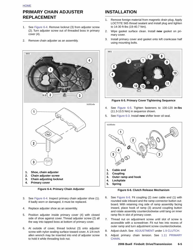
HOME
PRIMARY CHAIN ADJUSTER REPLACEMENT
1. See Figure 6-4. Remove locknut (3) from adjuster screw(2). Turn adjuster screw out of threaded boss in primarycover (4).
2. Remove chain adjuster as an assembly.
INSTALLATION
1. Remove foreign material from magnetic drain plug. ApplyLOCTITE 565 thread sealant and install plug and tightento 14-30 ft-lbs (19-40.7 Nm).
2. Wipe gasket surface clean. Install new gasket on pri-mary cover.
3. Install primary cover and gasket onto left crankcase halfusing mounting bolts.
4. See Figure 6-5. Tighten fasteners to 100-120 in-lbs(11.3-13.5 Nm) in sequence shown.
5. See Figure 6-3. Install new shifter lever oil seal.
b1051x6x
1. Shoe, chain adjuster
1
2
3
1
2
8800
3
4
Figure 6-5. Primary Cover Tightening Sequence
8801
6 17 8
9
11
10
2123 13
4
5
3
2
1
b1055x6x
1. Cable end
54
2006 Buell Firebolt: Drive/Transmission 6-5
3. See Figure 6-4. Inspect primary chain adjuster shoe (1).If badly worn or damaged, it must be replaced.
4. Replace adjuster shoe as an assembly.
5. Position adjuster inside primary cover (4) with closedside of shoe against cover. Thread adjuster screw (2) allthe way into tapped boss at bottom of primary cover.
6. At outside of cover, thread locknut (3) onto adjusterscrew with nylon sealing surface toward cover. A 1/4-inchallen wrench may be inserted into end of adjuster screwto hold it while threading lock nut.
6. See Figure 6-6. Fit coupling (2) over cable end (1) withrounded side inboard and the ramp connector button out-board. With retaining ring side of ramp assembly facinginward, place hook of ramp (3) around coupling buttonand rotate assembly counterclockwise until tang on innerramp fits in slot of primary cover.
7. Thread nut on adjustment screw until slot of screw isaccessible with a screwdriver. Fit nut hex into recess ofouter ramp and turn adjustment screw counterclockwise.
8. Adjust clutch. See ADJUSTMENT under 1.9 CLUTCH.
9. Adjust primary chain tension. See 1.11 PRIMARYCHAIN.
Figure 6-4. Primary Chain Adjuster
2. Chain adjuster screw3. Chain adjusting locknut4. Primary cover
Figure 6-6. Clutch Release Mechanism
2. Coupling3. Outer ramp and hook4. Lockplate5. Spring
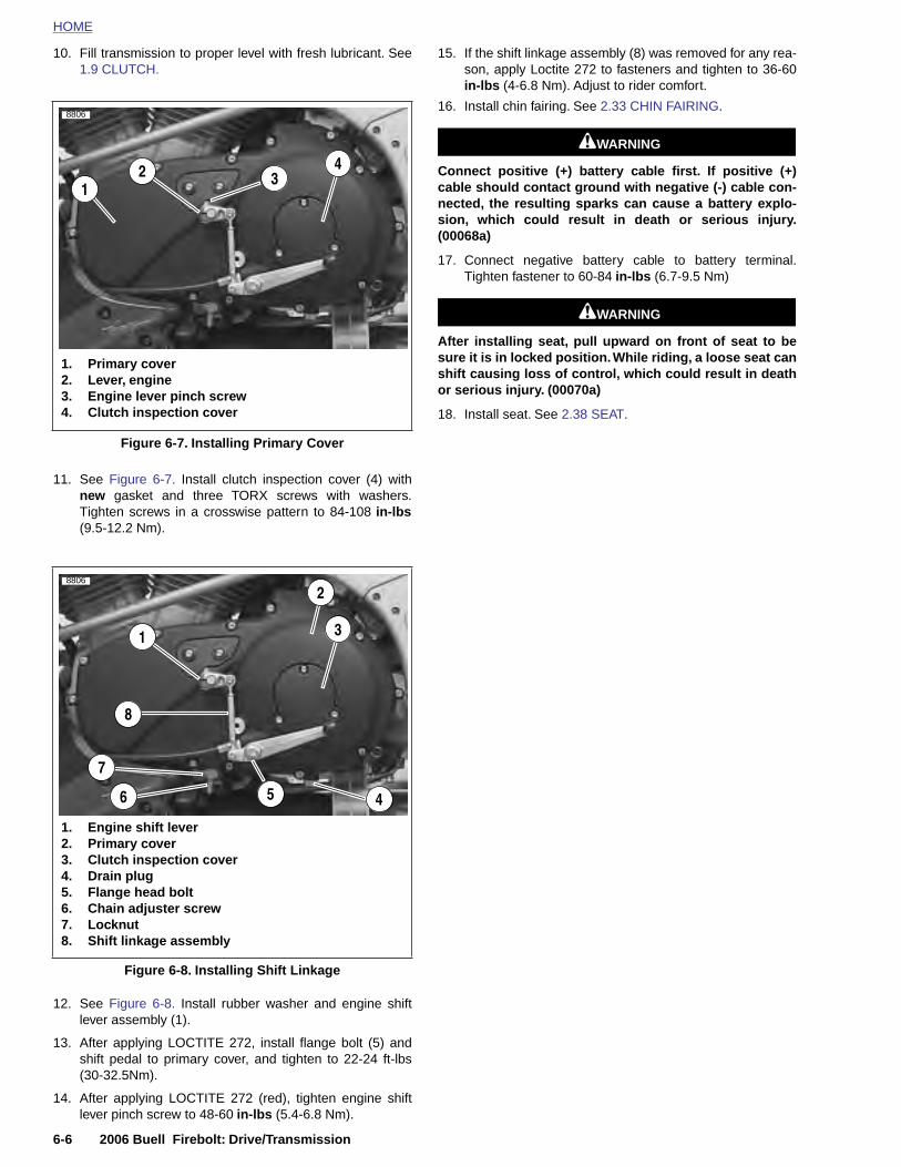
HOME
10. Fill transmission to proper level with fresh lubricant. See1.9 CLUTCH.
15. If the shift linkage assembly (8) was removed for any rea-son, apply Loctite 272 to fasteners and tighten to 36-60
in-lbs
(4-6.8 Nm). Adjust to rider comfort.
11. See Figure 6-7. Install clutch inspection cover (4) withnew gasket and three TORX screws with washers.Tighten screws in a crosswise pattern to 84-108 in-lbs(9.5-12.2 Nm).
16. Install chin fairing. See 2.33 CHIN FAIRING.
11WARNING1WARNING
Connect positive (+) battery cable first. If positive (+)cable should contact ground with negative (-) cable con-nected, the resulting sparks can cause a battery explo-sion, which could result in death or serious injury.(00068a)
17. Connect negative battery cable to battery terminal.Tighten fastener to 60-84 in-lbs (6.7-9.5 Nm)
11WARNING1WARNING
After installing seat, pull upward on front of seat to besure it is in locked position. While riding, a loose seat canshift causing loss of control, which could result in deathor serious injury. (00070a)
18. Install seat. See 2.38 SEAT.
Figure 6-7. Installing Primary Cover
1. Primary cover2. Lever, engine3. Engine lever pinch screw4. Clutch inspection cover
4
132
8806
1. Engine shift lever2. Primary cover
3
2
4
7
6
1
8806
5
8
6-6 2006 Buell Firebolt: Drive/Transmission
12. See Figure 6-8. Install rubber washer and engine shiftlever assembly (1).
13. After applying LOCTITE 272, install flange bolt (5) andshift pedal to primary cover, and tighten to 22-24 ft-lbs(30-32.5Nm).
14. After applying LOCTITE 272 (red), tighten engine shiftlever pinch screw to 48-60 in-lbs (5.4-6.8 Nm).
Figure 6-8. Installing Shift Linkage
3. Clutch inspection cover4. Drain plug5. Flange head bolt6. Chain adjuster screw7. Locknut8. Shift linkage assembly
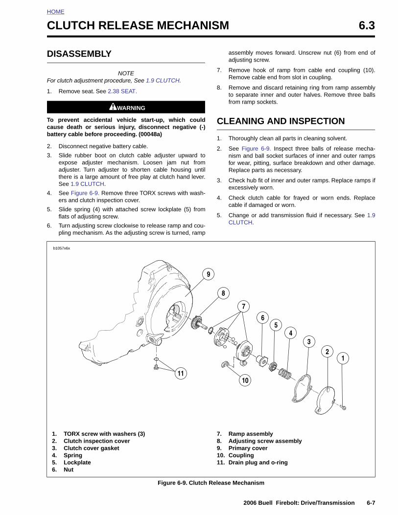
HOME
C
D
F
1
Tcb
2
3
4
5
6
LUTCH RELEASE MECHANISM 6.3
ISASSEMBLY
NOTEor clutch adjustment procedure, See 1.9 CLUTCH.
. Remove seat. See 2.38 SEAT.
11WARNING1WARNING
o prevent accidental vehicle start-up, which couldause death or serious injury, disconnect negative (-)attery cable before proceeding. (00048a)
. Disconnect negative battery cable.
. Slide rubber boot on clutch cable adjuster upward toexpose adjuster mechanism. Loosen jam nut fromadjuster. Turn adjuster to shorten cable housing untilthere is a large amount of free play at clutch hand lever.See 1.9 CLUTCH.
. See Figure 6-9. Remove three TORX screws with wash-ers and clutch inspection cover.
. Slide spring (4) with attached screw lockplate (5) fromflats of adjusting screw.
. Turn adjusting screw clockwise to release ramp and cou-pling mechanism. As the adjusting screw is turned, ramp
assembly moves forward. Unscrew nut (6) from end ofadjusting screw.
7. Remove hook of ramp from cable end coupling (10).Remove cable end from slot in coupling.
8. Remove and discard retaining ring from ramp assemblyto separate inner and outer halves. Remove three ballsfrom ramp sockets.
CLEANING AND INSPECTION
1. Thoroughly clean all parts in cleaning solvent.
2. See Figure 6-9. Inspect three balls of release mecha-nism and ball socket surfaces of inner and outer rampsfor wear, pitting, surface breakdown and other damage.Replace parts as necessary.
3. Check hub fit of inner and outer ramps. Replace ramps ifexcessively worn.
4. Check clutch cable for frayed or worn ends. Replacecable if damaged or worn.
5. Change or add transmission fluid if necessary. See 1.9CLUTCH.
b1057x6x
23
4
7
8
56
9
2006 Buell Firebolt: Drive/Transmission 6-7
Figure 6-9. Clutch Release Mechanism
1
1110
1. TORX screw with washers (3)2. Clutch inspection cover3. Clutch cover gasket4. Spring5. Lockplate6. Nut
7. Ramp assembly8. Adjusting screw assembly9. Primary cover10. Coupling11. Drain plug and o-ring
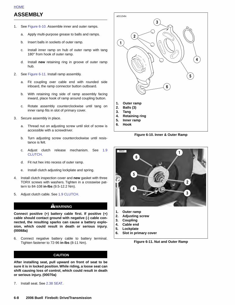
HOME
ASSEMBLY
a0112x6x
3
1. See Figure 6-10. Assemble inner and outer ramps.a. Apply multi-purpose grease to balls and ramps.
b. Insert balls in sockets of outer ramp.
c. Install inner ramp on hub of outer ramp with tang180° from hook of outer ramp.
d. Install new retaining ring in groove of outer ramphub.
2. See Figure 6-11. Install ramp assembly.
a. Fit coupling over cable end with rounded sideinboard, the ramp connector button outboard.
b. With retaining ring side of ramp assembly facinginward, place hook of ramp around coupling button.
c. Rotate assembly counterclockwise until tang oninner ramp fits in slot of primary cover.
3. Secure assembly in place.
a. Thread nut on adjusting screw until slot of screw isaccessible with a screwdriver.
b. Turn adjusting screw counterclockwise until resis-tance is felt.
c. Adjust clutch release mechanism. See 1.9CLUTCH.
d. Fit nut hex into recess of outer ramp.
e. Install clutch adjusting lockplate and spring.
4. Install clutch inspection cover and new gasket with threeTORX screws with washers. Tighten in a crosswise pat-tern to 84-108 in-lbs (9.5-12.2 Nm).
5. Adjust clutch cable. See 1.9 CLUTCH.
11WARNING1WARNING
Connect positive (+) battery cable first. If positive (+)cable should contact ground with negative (-) cable con-nected, the resulting sparks can cause a battery explo-
Figure 6-10. Inner & Outer Ramp
1. Outer ramp2. Balls (3)3. Tang4. Retaining ring5. Inner ramp6. Hook
6
5
4
1
2
1. Outer ramp2. Adjusting screw3. Coupling
8413 1
2
5
4
6
3
6-8 2006 Buell Firebolt: Drive/Transmission
sion, which could result in death or serious injury.(00068a)
6. Connect negative battery cable to battery terminal.Tighten fastener to 72-96 in-lbs (8-11 Nm).
CAUTION
After installing seat, pull upward on front of seat to besure it is in locked position. While riding, a loose seat canshift causing loss of control, which could result in deathor serious injury. (00070a)
7. Install seat. See 2.38 SEAT.
Figure 6-11. Nut and Outer Ramp
4. Cable end5. Lockplate6. Slot in primary cover
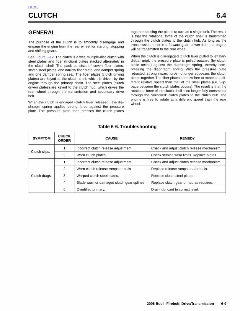
HOME
C
G
Tea
Ssthsapedrb
Wpp
LUTCH 6.4
ENERAL
he purpose of the clutch is to smoothly disengage andngage the engine from the rear wheel for starting, stoppingnd shifting gears.
ee Figure 6-12. The clutch is a wet, multiple-disc clutch withteel plates and fiber (friction) plates stacked alternately ine clutch shell. The pack consists of seven fiber plates,
even steel plates, one narrow fiber plate, one damper springnd one damper spring seat. The fiber plates (clutch drivinglates) are keyed to the clutch shell, which is driven by thengine through the primary chain. The steel plates (clutchriven plates) are keyed to the clutch hub, which drives theear wheel through the transmission and secondary driveelt.
hen the clutch is engaged (clutch lever released), the dia-hragm spring applies strong force against the pressurelate. The pressure plate then presses the clutch plates
together causing the plates to turn as a single unit. The resultis that the rotational force of the clutch shell is transmittedthrough the clutch plates to the clutch hub. As long as thetransmission is set in a forward gear, power from the enginewill be transmitted to the rear wheel.
When the clutch is disengaged (clutch lever pulled to left han-dlebar grip), the pressure plate is pulled outward (by clutchcable action) against the diaphragm spring, thereby com-pressing the diaphragm spring. With the pressure plateretracted, strong inward force no longer squeezes the clutchplates together. The fiber plates are now free to rotate at a dif-ferent relative speed than that of the steel plates (i.e. Slip-page between the clutch plates occurs). The result is that therotational force of the clutch shell is no longer fully transmittedthrough the “unlocked” clutch plates to the clutch hub. Theengine is free to rotate at a different speed than the rearwheel.
Table 6-6. Troubleshooting
SYMPTOMCHECKORDER
CAUSE REMEDY
Clutch slips.1 Incorrect clutch release adjustment. Check and adjust clutch release mechanism.
2 Worn clutch plates. Check service wear limits. Replace plates.
Clutch drags.
1 Incorrect clutch release adjustment. Check and adjust clutch release mechanism.
2 Worn clutch release ramps or balls Replace release ramps and/or balls.
3 Warped clutch steel plates. Replace clutch steel plates.
4 Blade worn or damaged clutch gear splines. Replace clutch gear or hub as required.
5 Overfilled primary. Drain lubricant to correct level.
2006 Buell Firebolt: Drive/Transmission 6-9
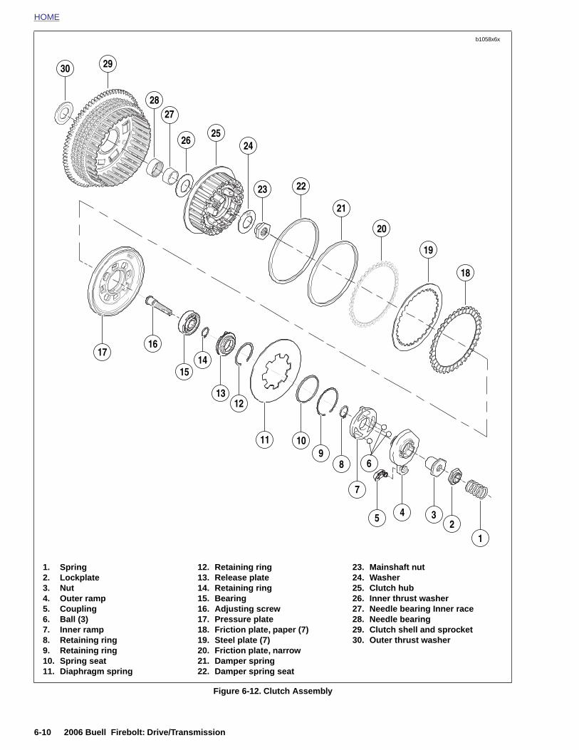
HOME
b1058x6x
30
18
19
20
21
2223
2526
27
29
28
1617
24
15
1312
11 109
7
5 4 32
1
14
8 6
6-10 2006 Buell Firebolt: Drive/Transmission
Figure 6-12. Clutch Assembly
1. Spring2. Lockplate3. Nut4. Outer ramp5. Coupling6. Ball (3)7. Inner ramp8. Retaining ring9. Retaining ring10. Spring seat11. Diaphragm spring
12. Retaining ring13. Release plate14. Retaining ring15. Bearing16. Adjusting screw17. Pressure plate18. Friction plate, paper (7)19. Steel plate (7)20. Friction plate, narrow21. Damper spring22. Damper spring seat
23. Mainshaft nut 24. Washer25. Clutch hub26. Inner thrust washer27. Needle bearing Inner race28. Needle bearing29. Clutch shell and sprocket30. Outer thrust washer
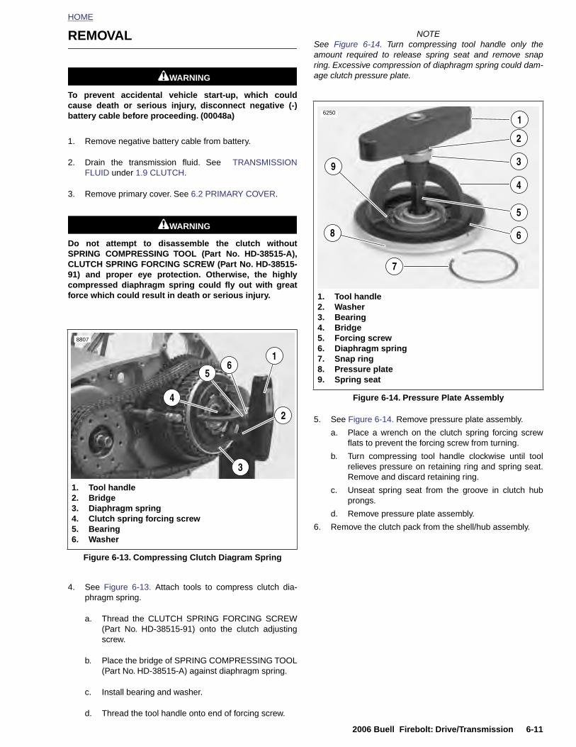
HOME
REMOVAL
11WARNING1WARNING
To prevent accidental vehicle start-up, which couldcause death or serious injury, disconnect negative (-)battery cable before proceeding. (00048a)
1. Remove negative battery cable from battery.
2. Drain the transmission fluid. See TRANSMISSIONFLUID under 1.9 CLUTCH.
3. Remove primary cover. See 6.2 PRIMARY COVER.
11WARNING1WARNING
Do not attempt to disassemble the clutch withoutSPRING COMPRESSING TOOL (Part No. HD-38515-A),CLUTCH SPRING FORCING SCREW (Part No. HD-38515-91) and proper eye protection. Otherwise, the highlycompressed diaphragm spring could fly out with greatforce which could result in death or serious injury.
NOTESee Figure 6-14. Turn compressing tool handle only theamount required to release spring seat and remove snapring. Excessive compression of diaphragm spring could dam-age clutch pressure plate.
5. See Figure 6-14. Remove pressure plate assembly.
a. Place a wrench on the clutch spring forcing screwflats to prevent the forcing screw from turning.
b. Turn compressing tool handle clockwise until toolrelieves pressure on retaining ring and spring seat.Remove and discard retaining ring.
c. Unseat spring seat from the groove in clutch hubprongs.
d. Remove pressure plate assembly.
8807
1. Tool handle2. Bridge3. Diaphragm spring
16
5
2
4
3
Figure 6-14. Pressure Plate Assembly
6250
1. Tool handle2. Washer3. Bearing4. Bridge5. Forcing screw6. Diaphragm spring7. Snap ring8. Pressure plate9. Spring seat
1
3
2
9
8
7
4
6
5
2006 Buell Firebolt: Drive/Transmission 6-11
4. See Figure 6-13. Attach tools to compress clutch dia-phragm spring.
a. Thread the CLUTCH SPRING FORCING SCREW(Part No. HD-38515-91) onto the clutch adjustingscrew.
b. Place the bridge of SPRING COMPRESSING TOOL(Part No. HD-38515-A) against diaphragm spring.
c. Install bearing and washer.
d. Thread the tool handle onto end of forcing screw.
6. Remove the clutch pack from the shell/hub assembly.
Figure 6-13. Compressing Clutch Diagram Spring
4. Clutch spring forcing screw5. Bearing6. Washer
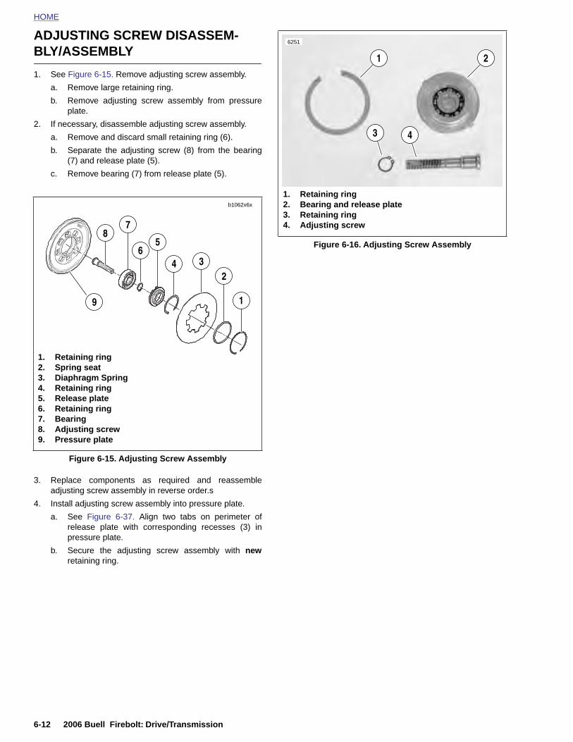
HOME
ADJUSTING SCREW DISASSEM-
BLY/ASSEMBLY
6251
1. See Figure 6-15. Remove adjusting screw assembly.
a. Remove large retaining ring.
b. Remove adjusting screw assembly from pressureplate.
2. If necessary, disassemble adjusting screw assembly.
a. Remove and discard small retaining ring (6).
b. Separate the adjusting screw (8) from the bearing(7) and release plate (5).
c. Remove bearing (7) from release plate (5).
3. Replace components as required and reassembleadjusting screw assembly in reverse order.s
4. Install adjusting screw assembly into pressure plate.
a. See Figure 6-37. Align two tabs on perimeter ofrelease plate with corresponding recesses (3) inpressure plate.
Figure 6-15. Adjusting Screw Assembly
1
234
56
78
9
1. Retaining ring2. Spring seat3. Diaphragm Spring4. Retaining ring5. Release plate6. Retaining ring7. Bearing8. Adjusting screw9. Pressure plate
b1062x6x
Figure 6-16. Adjusting Screw Assembly
1
1. Retaining ring2. Bearing and release plate3. Retaining ring4. Adjusting screw
2
3 4
6-12 2006 Buell Firebolt: Drive/Transmission
b. Secure the adjusting screw assembly with newretaining ring.
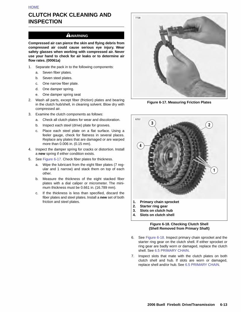
HOME
CLUTCH PACK CLEANING AND INSPECTION
11WARNING1WARNING
Compressed air can pierce the skin and flying debris fromcompressed air could cause serious eye injury. Wearsafety glasses when working with compressed air. Neveruse your hand to check for air leaks or to determine airflow rates. (00061a)
1. Separate the pack in to the following components:
a. Seven fiber plates.
b. Seven steel plates.
c. One narrow fiber plate.
d. One damper spring.
e. One damper spring seat
2. Wash all parts, except fiber (friction) plates and bearingin the clutch hub/shell, in cleaning solvent. Blow dry withcompressed air.
3. Examine the clutch components as follows:
a. Check all clutch plates for wear and discoloration.
b. Inspect each steel (drive) plate for grooves.
c. Place each steel plate on a flat surface. Using afeeler gauge, check for flatness in several places.Replace any plates that are damaged or are warpedmore than 0.006 in. (0.15 mm).
4. Inspect the damper spring for cracks or distortion. Installa new spring if either condition exists.
5. See Figure 6-17. Check fiber plates for thickness.
a. Wipe the lubricant from the eight fiber plates (7 reg-ular and 1 narrow) and stack them on top of eachother.
b. Measure the thickness of the eight stacked fiberplates with a dial caliper or micrometer. The mini-mum thickness must be 0.661 in. (16.789 mm).
c. If the thickness is less than specified, discard thefiber plates and steel plates. Install a new set of bothfriction and steel plates.
Figure 6-17. Measuring Friction Plates
7738
6252
2
1
3
4
1. Primary chain sprocket 2. Starter ring gear 3. Slots on clutch hub4. Slots on clutch shell
2006 Buell Firebolt: Drive/Transmission 6-13
6. See Figure 6-18. Inspect primary chain sprocket and thestarter ring gear on the clutch shell. If either sprocket orring gear are badly worn or damaged, replace the clutchshell. See 6.5 PRIMARY CHAIN.
7. Inspect slots that mate with the clutch plates on bothclutch shell and hub. If slots are worn or damaged,replace shell and/or hub. See 6.5 PRIMARY CHAIN.
Figure 6-18. Checking Clutch Shell(Shell Removed from Primary Shaft)
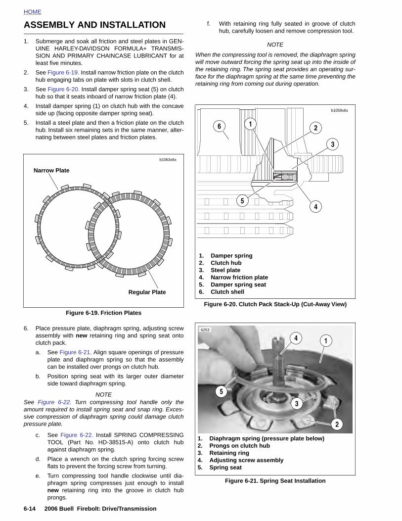
HOME
ASSEMBLY AND INSTALLATION
f. With retaining ring fully seated in groove of clutchhub, carefully loosen and remove compression tool.
1. Submerge and soak all friction and steel plates in GEN-UINE HARLEY-DAVIDSON FORMULA+ TRANSMIS-SION AND PRIMARY CHAINCASE LUBRICANT for atleast five minutes.
2. See Figure 6-19. Install narrow friction plate on the clutchhub engaging tabs on plate with slots in clutch shell.
3. See Figure 6-20. Install damper spring seat (5) on clutchhub so that it seats inboard of narrow friction plate (4).
4. Install damper spring (1) on clutch hub with the concaveside up (facing opposite damper spring seat).
5. Install a steel plate and then a friction plate on the clutchhub. Install six remaining sets in the same manner, alter-nating between steel plates and friction plates.
6. Place pressure plate, diaphragm spring, adjusting screwassembly with new retaining ring and spring seat ontoclutch pack.
a. See Figure 6-21. Align square openings of pressureplate and diaphragm spring so that the assemblycan be installed over prongs on clutch hub.
b. Position spring seat with its larger outer diameter
NOTE
When the compressing tool is removed, the diaphragm springwill move outward forcing the spring seat up into the inside ofthe retaining ring. The spring seat provides an operating sur-face for the diaphragm spring at the same time preventing theretaining ring from coming out during operation.
Figure 6-19. Friction Plates
Narrow Plate
Regular Plate
b1063x6x
Figure 6-20. Clutch Pack Stack-Up (Cut-Away View)
b1059x6x
1. Damper spring2. Clutch hub3. Steel plate4. Narrow friction plate5. Damper spring seat6. Clutch shell
4
2
5
16
3
6253
14
6-14 2006 Buell Firebolt: Drive/Transmission
side toward diaphragm spring.
NOTESee Figure 6-22. Turn compressing tool handle only theamount required to install spring seat and snap ring. Exces-sive compression of diaphragm spring could damage clutchpressure plate.
c. See Figure 6-22. Install SPRING COMPRESSINGTOOL (Part No. HD-38515-A) onto clutch hubagainst diaphragm spring.
d. Place a wrench on the clutch spring forcing screwflats to prevent the forcing screw from turning.
e. Turn compressing tool handle clockwise until dia-phragm spring compresses just enough to installnew retaining ring into the groove in clutch hubprongs.
Figure 6-21. Spring Seat Installation
5
2
1. Diaphragm spring (pressure plate below)2. Prongs on clutch hub3. Retaining ring4. Adjusting screw assembly5. Spring seat
3
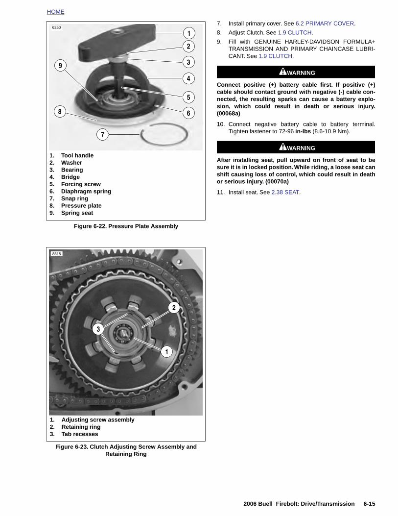
HOME
7. Install primary cover. See 6.2 PRIMARY COVER.
8. Adjust Clutch. See 1.9 CLUTCH.
9. Fill with GENUINE HARLEY-DAVIDSON FORMULA+TRANSMISSION AND PRIMARY CHAINCASE LUBRI-CANT. See 1.9 CLUTCH.
11WARNING1WARNING
Connect positive (+) battery cable first. If positive (+)cable should contact ground with negative (-) cable con-nected, the resulting sparks can cause a battery explo-sion, which could result in death or serious injury.(00068a)
10. Connect negative battery cable to battery terminal.Tighten fastener to 72-96 in-lbs (8.6-10.9 Nm).
11WARNING1WARNING
After installing seat, pull upward on front of seat to besure it is in locked position. While riding, a loose seat canshift causing loss of control, which could result in deathor serious injury. (00070a)
11. Install seat. See 2.38 SEAT.
Figure 6-22. Pressure Plate Assembly
6250
1. Tool handle2. Washer3. Bearing4. Bridge5. Forcing screw6. Diaphragm spring7. Snap ring8. Pressure plate9. Spring seat
1
3
2
9
8
7
4
6
5
8815
2
1
3
2006 Buell Firebolt: Drive/Transmission 6-15
Figure 6-23. Clutch Adjusting Screw Assembly and Retaining Ring
1. Adjusting screw assembly2. Retaining ring3. Tab recesses
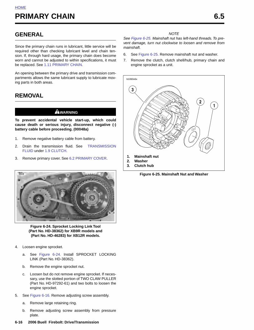
HOME
PRIMARY CHAIN 6.5
GENE
Since the required osion. If, thworn and be replace
An openinpartmentsing parts i
REMO
To prevecause debattery ca
1. Remo
2. DrainFLUID
3. Remo
F(P
(
8808
6-16 2
4. Loo
a.
b.
c.
5. See
a.
b.
RAL
primary chain runs in lubricant, little service will bether than checking lubricant level and chain ten-
rough hard usage, the primary chain does becomecannot be adjusted to within specifications, it mustd. See 1.11 PRIMARY CHAIN.
g between the primary drive and transmission com- allows the same lubricant supply to lubricate mov-n both areas.
VAL
11WARNING1WARNING
nt accidental vehicle start-up, which couldath or serious injury, disconnect negative (-)ble before proceeding. (00048a)
ve negative battery cable from battery.
the transmission fluid. See TRANSMISSION under 1.9 CLUTCH.
ve primary cover. See 6.2 PRIMARY COVER.
NOTESee Figure 6-25. Mainshaft nut has left-hand threads. To pre-vent damage, turn nut clockwise to loosen and remove frommainshaft.
6. See Figure 6-25. Remove mainshaft nut and washer.
7. Remove the clutch, clutch shell/hub, primary chain andengine sprocket as a unit.
igure 6-24. Sprocket Locking Link Toolart No. HD-38362) for XB9R models and Part No. HD-46283) for XB12R models.
Figure 6-25. Mainshaft Nut and Washer
1. Mainshaft nut2. Washer3. Clutch hub
b1060x6x
3
21
006 Buell Firebolt: Drive/Transmission
sen engine sprocket.
See Figure 6-24. Install SPROCKET LOCKINGLINK (Part No. HD-38362).
Remove the engine sprocket nut.
Loosen but do not remove engine sprocket. If neces-sary, use the slotted portion of TWO CLAW PULLER(Part No. HD-97292-61) and two bolts to loosen theengine sprocket.
Figure 6-16. Remove adjusting screw assembly.
Remove large retaining ring.
Remove adjusting screw assembly from pressureplate.
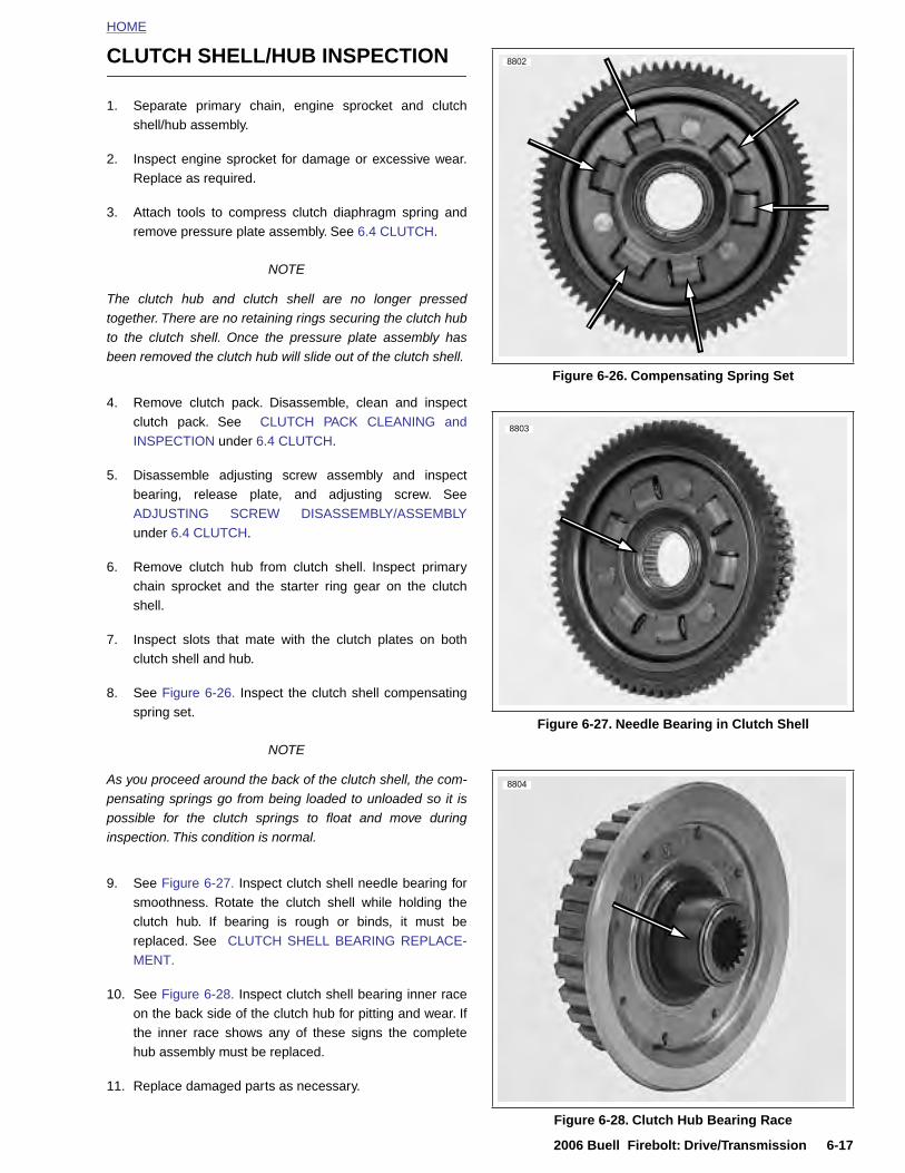
HOME
CLUTCH SHELL/HUB INSPECTION
1. Separate primary chain, engine sprocket and clutchshell/hub assembly.
2. Inspect engine sprocket for damage or excessive wear.Replace as required.
3. Attach tools to compress clutch diaphragm spring andremove pressure plate assembly. See 6.4 CLUTCH.
NOTE
The clutch hub and clutch shell are no longer pressedtogether. There are no retaining rings securing the clutch hubto the clutch shell. Once the pressure plate assembly hasbeen removed the clutch hub will slide out of the clutch shell.
4. Remove clutch pack. Disassemble, clean and inspectclutch pack. See CLUTCH PACK CLEANING andINSPECTION under 6.4 CLUTCH.
5. Disassemble adjusting screw assembly and inspectbearing, release plate, and adjusting screw. SeeADJUSTING SCREW DISASSEMBLY/ASSEMBLYunder 6.4 CLUTCH.
6. Remove clutch hub from clutch shell. Inspect primarychain sprocket and the starter ring gear on the clutchshell.
7. Inspect slots that mate with the clutch plates on bothclutch shell and hub.
8. See Figure 6-26. Inspect the clutch shell compensatingspring set.
NOTE
As you proceed around the back of the clutch shell, the com-pensating springs go from being loaded to unloaded so it is
Figure 6-26. Compensating Spring Set
Figure 6-27. Needle Bearing in Clutch Shell
8802
8803
8804
2006 Buell Firebolt: Drive/Transmission 6-17
possible for the clutch springs to float and move duringinspection. This condition is normal.
9. See Figure 6-27. Inspect clutch shell needle bearing forsmoothness. Rotate the clutch shell while holding theclutch hub. If bearing is rough or binds, it must bereplaced. See CLUTCH SHELL BEARING REPLACE-MENT.
10. See Figure 6-28. Inspect clutch shell bearing inner raceon the back side of the clutch hub for pitting and wear. Ifthe inner race shows any of these signs the completehub assembly must be replaced.
11. Replace damaged parts as necessary.
Figure 6-28. Clutch Hub Bearing Race
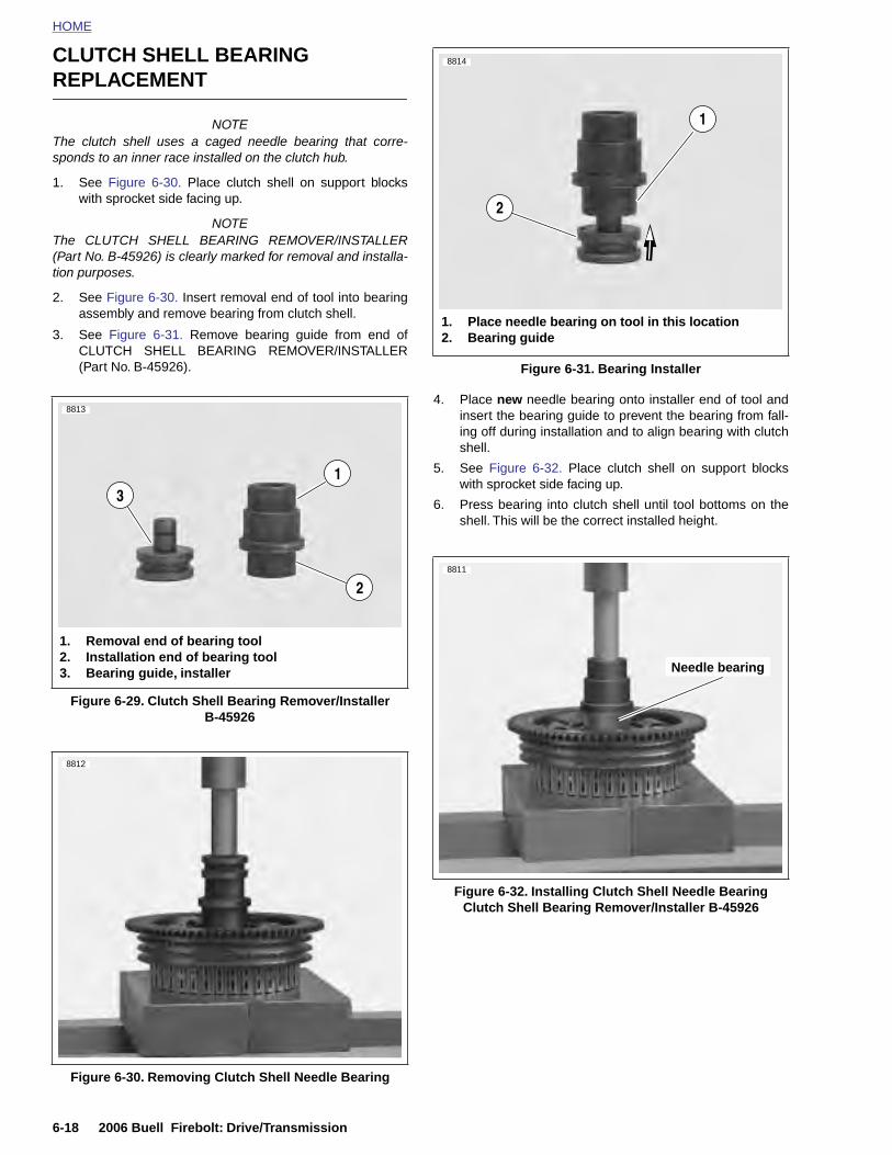
HOME
CLUTCH SHELL BEARING
REPLACEMENT
8814
NOTEThe clutch shell uses a caged needle bearing that corre-sponds to an inner race installed on the clutch hub.
1. See Figure 6-30. Place clutch shell on support blockswith sprocket side facing up.
NOTEThe CLUTCH SHELL BEARING REMOVER/INSTALLER(Part No. B-45926) is clearly marked for removal and installa-tion purposes.
2. See Figure 6-30. Insert removal end of tool into bearingassembly and remove bearing from clutch shell.
3. See Figure 6-31. Remove bearing guide from end ofCLUTCH SHELL BEARING REMOVER/INSTALLER(Part No. B-45926).
4. Place new needle bearing onto installer end of tool andinsert the bearing guide to prevent the bearing from fall-ing off during installation and to align bearing with clutchshell.
5. See Figure 6-32. Place clutch shell on support blockswith sprocket side facing up.
6. Press bearing into clutch shell until tool bottoms on theshell. This will be the correct installed height.
Figure 6-29. Clutch Shell Bearing Remover/InstallerB-45926
1. Removal end of bearing tool2. Installation end of bearing tool3. Bearing guide, installer
1
2
3
8813
8812
Figure 6-31. Bearing Installer
1. Place needle bearing on tool in this location2. Bearing guide
1
2
Needle bearing
8811
6-18 2006 Buell Firebolt: Drive/Transmission
Figure 6-30. Removing Clutch Shell Needle Bearing
Figure 6-32. Installing Clutch Shell Needle BearingClutch Shell Bearing Remover/Installer B-45926
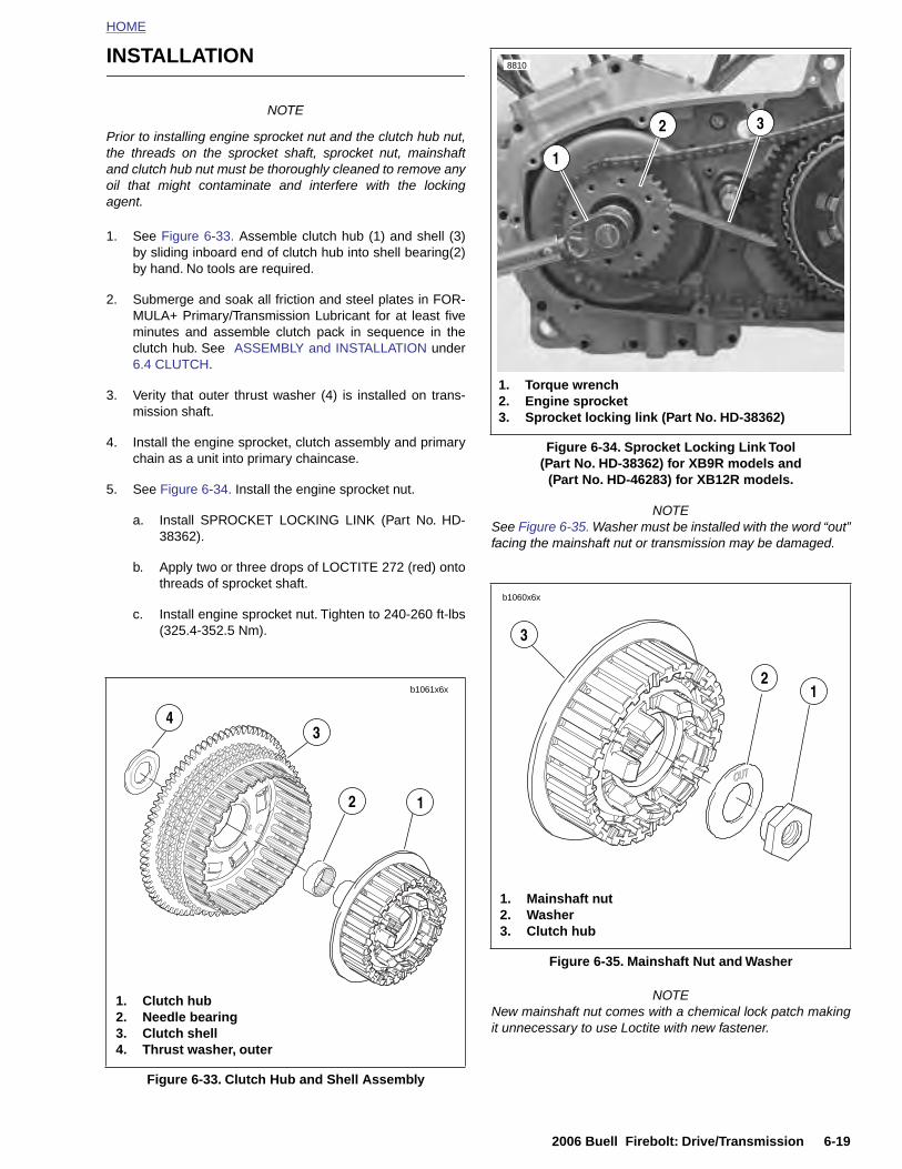
HOME
INSTALLATION
NOTE
Prior to installing engine sprocket nut and the clutch hub nut,the threads on the sprocket shaft, sprocket nut, mainshaftand clutch hub nut must be thoroughly cleaned to remove anyoil that might contaminate and interfere with the lockingagent.
1. See Figure 6-33. Assemble clutch hub (1) and shell (3)by sliding inboard end of clutch hub into shell bearing(2)by hand. No tools are required.
2. Submerge and soak all friction and steel plates in FOR-MULA+ Primary/Transmission Lubricant for at least fiveminutes and assemble clutch pack in sequence in theclutch hub. See ASSEMBLY and INSTALLATION under6.4 CLUTCH.
3. Verity that outer thrust washer (4) is installed on trans-mission shaft.
4. Install the engine sprocket, clutch assembly and primarychain as a unit into primary chaincase.
5. See Figure 6-34. Install the engine sprocket nut.
a. Install SPROCKET LOCKING LINK (Part No. HD-38362).
b. Apply two or three drops of LOCTITE 272 (red) ontothreads of sprocket shaft.
c. Install engine sprocket nut. Tighten to 240-260 ft-lbs(325.4-352.5 Nm).
NOTESee Figure 6-35. Washer must be installed with the word “out”facing the mainshaft nut or transmission may be damaged.
b1061x6x
1
34
2
Figure 6-34. Sprocket Locking Link Tool(Part No. HD-38362) for XB9R models and
(Part No. HD-46283) for XB12R models.
8810
1. Torque wrench2. Engine sprocket3. Sprocket locking link (Part No. HD-38362)
2 3
1
b1060x6x
3
21
2006 Buell Firebolt: Drive/Transmission 6-19
NOTENew mainshaft nut comes with a chemical lock patch makingit unnecessary to use Loctite with new fastener.
Figure 6-33. Clutch Hub and Shell Assembly
1. Clutch hub2. Needle bearing3. Clutch shell4. Thrust washer, outer
Figure 6-35. Mainshaft Nut and Washer
1. Mainshaft nut2. Washer3. Clutch hub

HOME
6. See Figure 6-35. Install mainshaft washer (2) and nut(1).
8816
a. If using original mainshaft nut apply two or threedrops of LOCTITE 272 (red) onto threads on end ofmainshaft.
b. Place washer (2) on mainshaft with the word “out”facing away from clutch hub.
c. Install nut (left-hand threads) (1). Tighten to 70-80 ft-lbs (94.9-108.5 Nm).
7. Remove SPROCKET LOCKING LINK.
8. Install the pressure plate assembly. See 6.4 CLUTCH.
9. Install adjusting screw assembly into pressure plate.
a. See Figure 6-37. Align two tabs on perimeter ofrelease plate with corresponding recesses (3) inpressure plate.
b. Secure the adjusting screw assembly with newretaining ring.
10. Install primary cover. See 6.2 PRIMARY COVER.
11. Adjust Clutch. See 1.9 CLUTCH.
12. Add GENUINE HARLEY-DAVIDSON FORMULA+TRANSMISSION AND PRIMARY CHAINCASE LUBRI-CANT. See TRANSMISSION FLUID under 1.9CLUTCH.
11WARNING1WARNING
Connect positive (+) battery cable first. If positive (+)cable should contact ground with negative (-) cable con-nected, the resulting sparks can cause a battery explo-sion, which could result in death or serious injury.(00068a)
13. Connect negative battery cable to battery terminal.Tighten fastener to 72-96 in-lbs (8.1-10.9 Nm).
11WARNING1WARNING
After installing seat, pull upward on front of seat to besure it is in locked position. While riding, a loose seat canshift causing loss of control, which could result in deathor serious injury. (00070a)
14. Install seat. See 2.38 SEAT.
Figure 6-36. Adjusting Screw Assembly Aligning Tabs
8815
1. Adjusting screw assembly2. Retaining ring3. Tab recesses
2
1
3
6-20 2006 Buell Firebolt: Drive/Transmission
Figure 6-37. Clutch Adjusting Screw Assembly and Retaining Ring
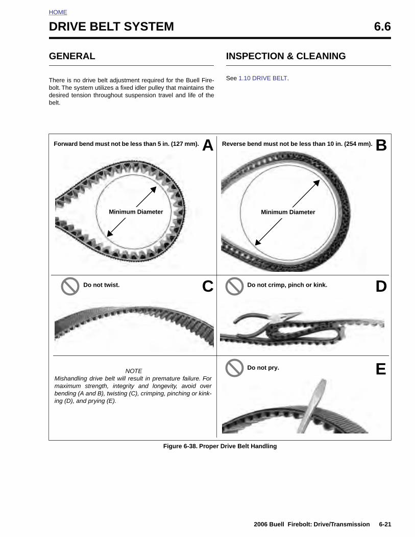
HOME
D
G
Tbdb
RIVE BELT SYSTEM 6.6
ENERAL
here is no drive belt adjustment required for the Buell Fire-olt. The system utilizes a fixed idler pulley that maintains theesired tension throughout suspension travel and life of theelt.
INSPECTION & CLEANING
See 1.10 DRIVE BELT.
A B
C D
Forward bend must not be less than 5 in. (127 mm). Reverse bend must not be less than 10 in. (254 mm).
Do not twist. Do not crimp, pinch or kink.
Do not pry.
Minimum Diameter Minimum Diameter
2006 Buell Firebolt: Drive/Transmission 6-21
Figure 6-38. Proper Drive Belt Handling
NOTEMishandling drive belt will result in premature failure. Formaximum strength, integrity and longevity, avoid overbending (A and B), twisting (C), crimping, pinching or kink-ing (D), and prying (E).
E
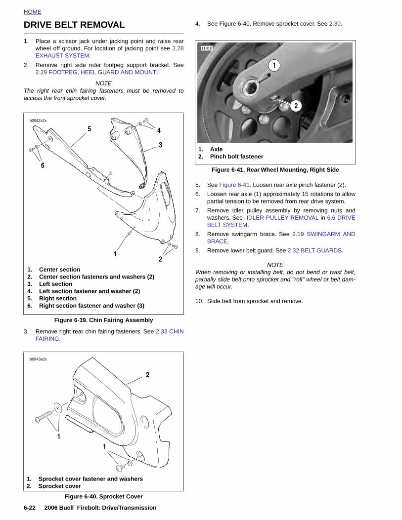
HOME
DRIVE BELT REMOVAL 4. See Figure 6-40. Remove sprocket cover. See 2.30.
1. Place a scissor jack under jacking point and raise rearwheel off ground. For location of jacking point see 2.28EXHAUST SYSTEM.
2. Remove right side rider footpeg support bracket. See2.29 FOOTPEG, HEEL GUARD AND MOUNT.
NOTEThe right rear chin fairing fasteners must be removed toaccess the front sprocket cover.
3. Remove right rear chin fairing fasteners. See 2.33 CHINFAIRING.
5. See Figure 6-41. Loosen rear axle pinch fastener (2).
6. Loosen rear axle (1) approximately 15 rotations to allowpartial tension to be removed from rear drive system.
7. Remove idler pulley assembly by removing nuts andwashers. See IDLER PULLEY REMOVAL in 6.6 DRIVEBELT SYSTEM.
8. Remove swingarm brace. See 2.19 SWINGARM ANDBRACE.
9. Remove lower belt guard. See 2.32 BELT GUARDS.
NOTEWhen removing or installing belt, do not bend or twist belt,partially slide belt onto sprocket and "roll" wheel or belt dam-age will occur.
10. Slide belt from sprocket and remove.
Figure 6-39. Chin Fairing Assembly
b0942x2x
1. Center section 2. Center section fasteners and washers (2)3. Left section 4. Left section fastener and washer (2)5. Right section 6. Right section fastener and washer (3)
6
5 4
3
21
b0943a2x
2
Figure 6-41. Rear Wheel Mounting, Right Side
11810
2
1. Axle2. Pinch bolt fastener
1
6-22 2006 Buell Firebolt: Drive/Transmission
Figure 6-40. Sprocket Cover
1. Sprocket cover fastener and washers 2. Sprocket cover
11

HOME
DRIVE BELT INSTALLATION
NOTEWhen removing or installing belt, do not bend or twist belt,partially slide belt onto sprocket and "roll" wheel or belt dam-age will occur.
1. Slide belt onto sprocket.
2. Install swingarm brace and tighten fasteners to 25-27 ft-lbs (34-37 Nm). See 2.19 SWINGARM AND BRACE.
NOTESee Figure 6-42. Occasionally the drive belt is not fullyseated in rear sprocket making it difficult to install the idlerpulley. It will be necessary to follow the outlined procedure inorder to easily install idler pulley.
3. See Figure 6-42. Grasp top and bottom of drive belt andsqueeze together until belt teeth are fully seated in rearsprocket.
4. While keeping tension on lower belt, install idler pulleyassembly tightening washers and nuts to 33-35 ft-lbs(45-47 Nm).
5. See Figure 6-41. Tighten rear axle (1) to 23-27 ft-lbs(31.2-36.6 Nm), back off two full turns and then retightento 48-52 ft-lbs (65.1-70.5 Nm).
6. Tighten rear axle pinch fastener (2) to 40-45 ft-lbs (54-61 Nm).
7. See Figure 6-40. Install front sprocket cover. See 2.30SPROCKET COVER.
8. Install chin fairing. See 2.33 CHIN FAIRING.
9. Install right side rider footpeg mount. See 2.29 FOOT-PEG, HEEL GUARD AND MOUNT.
10. Install lower belt guard. See 2.32 BELT GUARDS.
11. Remove scissor jack from motorcycle.
1
3
2
10536
10537
10538
2006 Buell Firebolt: Drive/Transmission 6-23
Figure 6-42. Seating Drive Belt Into Pulley Teeth
1. Drive belt not fully seated in rear sprocket2. Squeezing drive belt in order to seat in pulleys3. Drive belt fully seated in rear sprocket
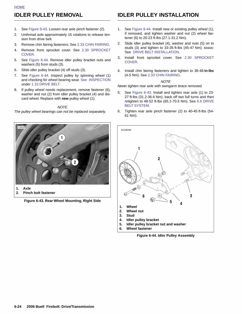
HOME
IDLER PULLEY REMOVAL IDLER PULLEY INSTALLATION
1. See Figure 6-43. Loosen rear axle pinch fastener (2).
2. Unthread axle approximately 15 rotations to release ten-sion from drive belt.
3. Remove chin fairing fasteners. See 2.33 CHIN FAIRING.
4. Remove front sprocket cover. See 2.30 SPROCKETCOVER.
5. See Figure 6-44. Remove idler pulley bracket nuts andwashers (5) from studs (3).
6. Slide idler pulley bracket (4) off studs (3).
7. See Figure 6-44. Inspect pulley by spinning wheel (1)and checking for wheel bearing wear. See INSPECTIONunder 1.10 DRIVE BELT.
8. If pulley wheel needs replacement, remove fastener (6),washer and nut (2) from idler pulley bracket (4) and dis-card wheel. Replace with new pulley wheel (1).
NOTEThe pulley wheel bearings can not be replaced separately.
1. See Figure 6-44. Install new or existing pulley wheel (1),if removed, and tighten washer and nut (2) wheel fas-tener (6) to 20-23 ft-lbs (27.1-31.2 Nm).
2. Slide idler pulley bracket (4), washer and nuts (5) on tostuds (3) and tighten to 33-35 ft-lbs (45-47 Nm). sssss-See DRIVE BELT INSTALLATION.
3. Install front sprocket cover. See 2.30 SPROCKETCOVER.
4. Install chin fairing fasteners and tighten to 36-48 in-lbs(4-5 Nm). See 2.33 CHIN FAIRING.
NOTENever tighten rear axle with swingarm brace removed.
5. See Figure 6-43. Install and tighten rear axle (1) to 23-27 ft-lbs (31.2-36.6 Nm), back off two full turns and thenretighten to 48-52 ft-lbs (65.1-70.5 Nm). See 6.6 DRIVEBELT SYSTEM.
6. Tighten rear axle pinch fastener (2) to 40-45 ft-lbs (54-61 Nm).
Figure 6-43. Rear Wheel Mounting, Right Side
11810
2
1. Axle2. Pinch bolt fastener
1
b1106x6x
1
4
2
36
1. Wheel2. Wheel nut3. Stud4. Idler pulley bracket5. Idler pulley bracket nut and washer6. Wheel fastener
5
6-24 2006 Buell Firebolt: Drive/Transmission
Figure 6-44. Idler Pulley Assembly

HOME
T
G
Smtrsin
RANSMISSION 6.7
ENERAL
ee Figure 6-45. The transmission is a five-speed constant-esh type housed in an extension of the crankcase. Theansmission permits the rider to vary the ratio of enginepeed-to-rear driving wheel speed in order to meet the vary-g conditions of operation.
The transmission is foot-operated by the gear shifter lever,which transmits the force through a gear shifter shaft. Theshifter shaft actuates a pawl and a shifter fork drum. Theshifter fork drum moves shifter forks, which slide a series ofshifter dogs on the mainshaft and countershaft, into and outof mesh with the other gears.
2 3 4 1 5
Neutral 1st Gear
2nd Gear 3rd Gear
Mainshaft
Countershaft2 3 4 1 5
2 3 4 1 5 2 3 4 1 5
Mainshaft
Countershaft
Mainshaft
Countershaft
Mainshaft
Countershaft
Mainshaft Mainshaft
x0259c6x
2006 Buell Firebolt: Drive/Transmission 6-25
Figure 6-45. Transmission Power Flow
4th Gear 5th Gear
- SLIDING MEMBER
- POWER FLOW
- IN
- OUT
2 3 4 1 52 3 4 1 5Countershaft Countershaft
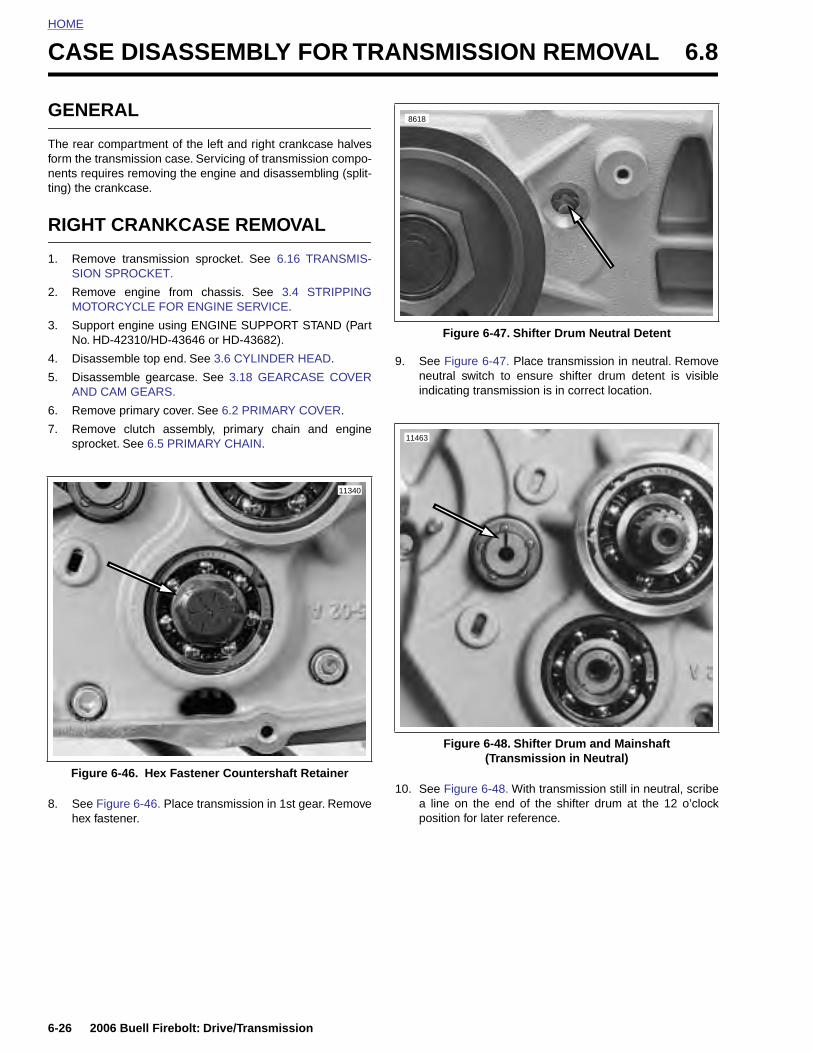
HOME
CASE DISASSEMBLY FOR TRANSMISSION REMOVAL 6.8
GENE
The rear cform the trnents requting) the c
RIGHT
1. RemoSION
2. RemoMOTO
3. SuppNo. H
4. Disas
5. DisasAND
6. Remo
7. Remosproc
Figur
6-26 2
8. Seehex
RAL
ompartment of the left and right crankcase halvesansmission case. Servicing of transmission compo-ires removing the engine and disassembling (split-
rankcase.
CRANKCASE REMOVAL
ve transmission sprocket. See 6.16 TRANSMIS- SPROCKET.
ve engine from chassis. See 3.4 STRIPPINGRCYCLE FOR ENGINE SERVICE.
ort engine using ENGINE SUPPORT STAND (PartD-42310/HD-43646 or HD-43682).
semble top end. See 3.6 CYLINDER HEAD.
semble gearcase. See 3.18 GEARCASE COVERCAM GEARS.
ve primary cover. See 6.2 PRIMARY COVER.
ve clutch assembly, primary chain and engineket. See 6.5 PRIMARY CHAIN.
9. See Figure 6-47. Place transmission in neutral. Removeneutral switch to ensure shifter drum detent is visibleindicating transmission is in correct location.
e 6-46. Hex Fastener Countershaft Retainer
11340
Figure 6-47. Shifter Drum Neutral Detent
Figure 6-48. Shifter Drum and Mainshaft(Transmission in Neutral)
8618
11463
006 Buell Firebolt: Drive/Transmission
Figure 6-46. Place transmission in 1st gear. Removefastener.
10. See Figure 6-48. With transmission still in neutral, scribea line on the end of the shifter drum at the 12 o’clockposition for later reference.

HOME
11. See Figure 6-49. Remove shifter shaft assembly.
12. See Figure 6-50. Depress ratchet arms (3) in order toclear the shifter drum and remove shifter shaft assemblyfrom left crankcase half.
13. Remove starter. See 5.7 STARTER.
14. See Figure 6-51. Remove rear isolator assembly by
Figure 6-49. Removing Shifter Shaft Assembly
11403
Figure 6-50. Shifter Shaft Assembly
Figure 6-51. Rear Isolator Assembly
1. Shifter shaft2. Return spring3. Ratchet arms
1
11462
3
2
8723a
2006 Buell Firebolt: Drive/Transmission 6-27
removing the forward two fasteners first and then the tworear fasteners (re-install with new fasteners).
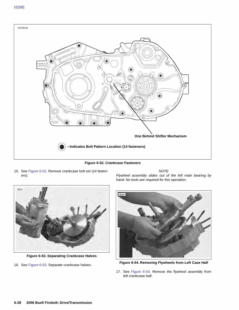
HOME
15. See Figure 6-52. Remove crankcase bolt set (14 fasten-ers).
NOTEFlywheel assembly slides out of the left main bearing byhand. No tools are required for this operation.
Figure 6-52. Crankcase Fasteners
D
b1016x3x
Indicates Bolt Pattern Location (14 fasteners)
One Behind Shifter Mechanism
8621
8636
6-28 2006 Buell Firebolt: Drive/Transmission
16. See Figure 6-53. Separate crankcase halves.
17. See Figure 6-54. Remove the flywheel assembly fromleft crankcase half.
Figure 6-53. Separating Crankcase Halves
Figure 6-54. Removing Flywheels from Left Case Half
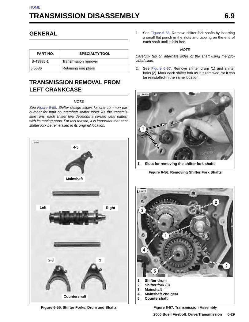
HOME
T
G
TL
Snsws
J
RANSMISSION DISASSEMBLY 6.9
ENERAL
RANSMISSION REMOVAL FROM EFT CRANKCASE
NOTE
ee Figure 6-55. Shifter design allows for one common partumber for both countershaft shifter forks. As the transmis-ion runs, each shifter fork develops a certain wear patternith its mating parts. For this reason, it is important that eachhifter fork be reinstalled in its original location.
1. See Figure 6-56. Remove shifter fork shafts by insertinga small flat punch in the slots and tapping on the end ofeach shaft until it falls free.
NOTE
Carefully tap on alternate sides of the shaft using the pro-vided slots.
2. See Figure 6-57. Remove shifter drum (1) and shifterforks (2). Mark each shifter fork as it is removed, so it canbe reinstalled in the same location.
PART NO. SPECIALTY TOOL
B-43985-1 Transmission remover
-5586 Retaining ring pliers
11495
Mainshaft
Left
4-5
Right
Figure 6-56. Removing Shifter Fork Shafts
1. Slots for removing the shifter fork shafts
11465a
1
11349
2
3
2006 Buell Firebolt: Drive/Transmission 6-29
Figure 6-55. Shifter Forks, Drum and Shafts
Countershaft
12-3
Figure 6-57. Transmission Assembly
1. Shifter drum2. Shifter fork (3)3. Mainshaft4. Mainshaft 2nd gear5. Countershaft
1
2
4
5
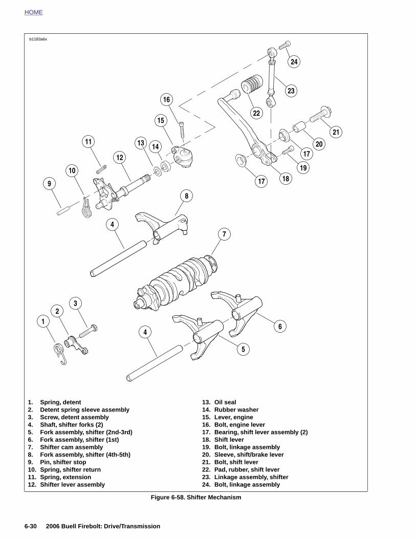
HOME
b1183a6x
17
32
14
47
12
11
10
9
16
15
21
19
20
5
6
8
13 14
18
23
17
22
24
6-30 2006 Buell Firebolt: Drive/Transmission
Figure 6-58. Shifter Mechanism
1. Spring, detent2. Detent spring sleeve assembly3. Screw, detent assembly4. Shaft, shifter forks (2)5. Fork assembly, shifter (2nd-3rd)6. Fork assembly, shifter (1st)7. Shifter cam assembly8. Fork assembly, shifter (4th-5th)9. Pin, shifter stop10. Spring, shifter return11. Spring, extension12. Shifter lever assembly
13. Oil seal14. Rubber washer15. Lever, engine16. Bolt, engine lever17. Bearing, shift lever assembly (2)18. Shift lever19. Bolt, linkage assembly20. Sleeve, shift/brake lever21. Bolt, shift lever22. Pad, rubber, shift lever23. Linkage assembly, shifter24. Bolt, linkage assembly
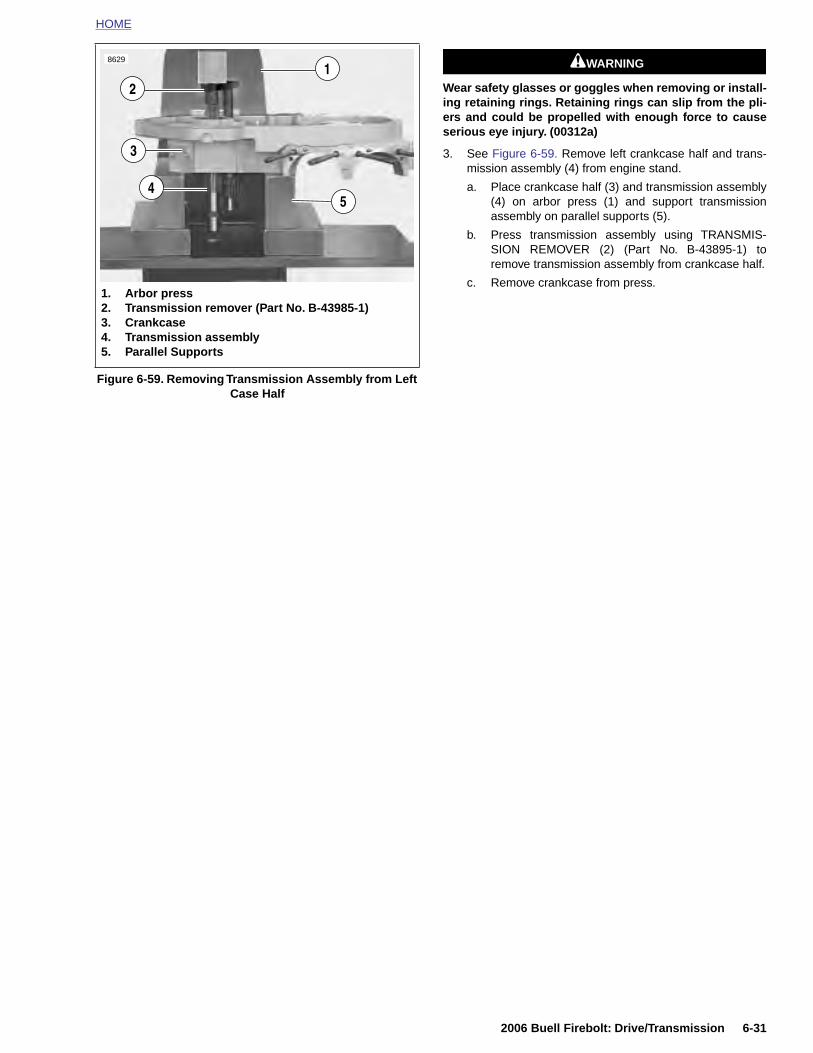
HOME
11WARNING1WARNING
Wear safety glasses or goggles when removing or install-ing retaining rings. Retaining rings can slip from the pli-ers and could be propelled with enough force to causeserious eye injury. (00312a)
3. See Figure 6-59. Remove left crankcase half and trans-mission assembly (4) from engine stand.
a. Place crankcase half (3) and transmission assembly(4) on arbor press (1) and support transmissionassembly on parallel supports (5).
b. Press transmission assembly using TRANSMIS-SION REMOVER (2) (Part No. B-43895-1) toremove transmission assembly from crankcase half.
c. Remove crankcase from press.
Figure 6-59. Removing Transmission Assembly from Left Case Half
1. Arbor press2. Transmission remover (Part No. B-43985-1)3. Crankcase4. Transmission assembly5. Parallel Supports
8629
1
5
3
4
2
2006 Buell Firebolt: Drive/Transmission 6-31
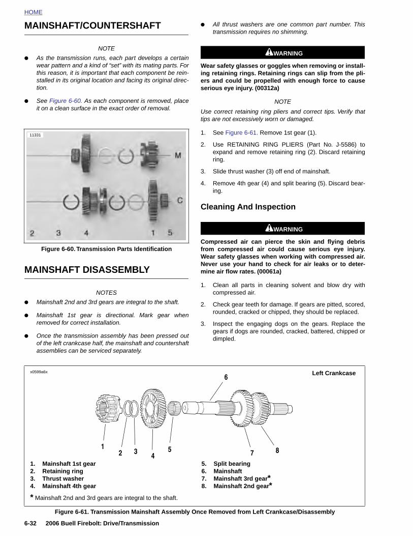
HOME
MAINSHAFT/COUNTERSHAFT
●
All thrust washers are one common part number. Thistransmission requires no shimming.
NOTE
● As the transmission runs, each part develops a certainwear pattern and a kind of “set” with its mating parts. Forthis reason, it is important that each component be rein-stalled in its original location and facing its original direc-tion.
● See Figure 6-60. As each component is removed, placeit on a clean surface in the exact order of removal.
MAINSHAFT DISASSEMBLY
NOTES
● Mainshaft 2nd and 3rd gears are integral to the shaft.
● Mainshaft 1st gear is directional. Mark gear whenremoved for correct installation.
● Once the transmission assembly has been pressed outof the left crankcase half, the mainshaft and countershaftassemblies can be serviced separately.
11WARNING1WARNING
Wear safety glasses or goggles when removing or install-ing retaining rings. Retaining rings can slip from the pli-ers and could be propelled with enough force to causeserious eye injury. (00312a)
NOTE
Use correct retaining ring pliers and correct tips. Verify thattips are not excessively worn or damaged.
1. See Figure 6-61. Remove 1st gear (1).
2. Use RETAINING RING PLIERS (Part No. J-5586) toexpand and remove retaining ring (2). Discard retainingring.
3. Slide thrust washer (3) off end of mainshaft.
4. Remove 4th gear (4) and split bearing (5). Discard bear-ing.
Cleaning And Inspection
11WARNING1WARNING
Compressed air can pierce the skin and flying debrisfrom compressed air could cause serious eye injury.Wear safety glasses when working with compressed air.Never use your hand to check for air leaks or to deter-mine air flow rates. (00061a)
1. Clean all parts in cleaning solvent and blow dry withcompressed air.
2. Check gear teeth for damage. If gears are pitted, scored,rounded, cracked or chipped, they should be replaced.
3. Inspect the engaging dogs on the gears. Replace thegears if dogs are rounded, cracked, battered, chipped ordimpled.
Figure 6-60. Transmission Parts Identification
11331
x0599a6x Left Crankcase6
6-32 2006 Buell Firebolt: Drive/Transmission
Figure 6-61. Transmission Mainshaft Assembly Once Removed from Left Crankcase/Disassembly
1. Mainshaft 1st gear2. Retaining ring3. Thrust washer4. Mainshaft 4th gear
5. Split bearing6. Mainshaft7. Mainshaft 3rd gear*8. Mainshaft 2nd gear*
5 8743
12
* Mainshaft 2nd and 3rd gears are integral to the shaft.
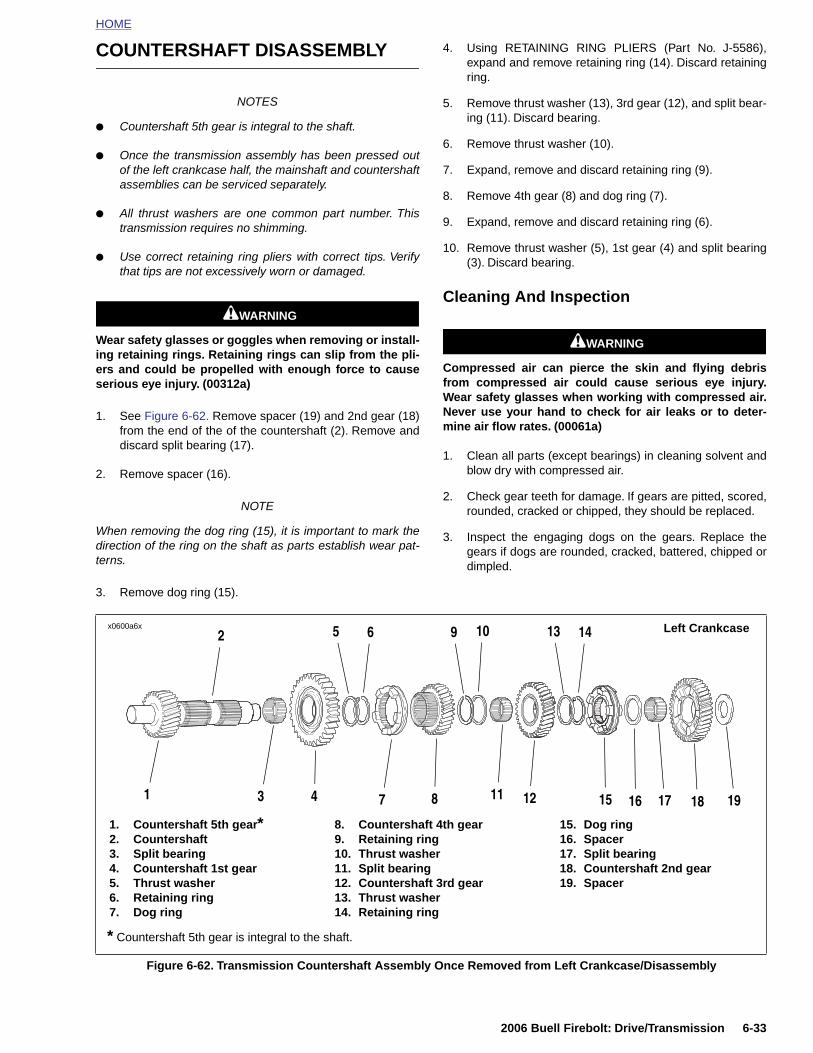
HOME
COUNTERSHAFT DISASSEMBLY
NOTES
● Countershaft 5th gear is integral to the shaft.
● Once the transmission assembly has been pressed outof the left crankcase half, the mainshaft and countershaftassemblies can be serviced separately.
● All thrust washers are one common part number. Thistransmission requires no shimming.
● Use correct retaining ring pliers with correct tips. Verifythat tips are not excessively worn or damaged.
11WARNING1WARNING
Wear safety glasses or goggles when removing or install-ing retaining rings. Retaining rings can slip from the pli-ers and could be propelled with enough force to causeserious eye injury. (00312a)
1. See Figure 6-62. Remove spacer (19) and 2nd gear (18)from the end of the of the countershaft (2). Remove anddiscard split bearing (17).
2. Remove spacer (16).
NOTE
When removing the dog ring (15), it is important to mark thedirection of the ring on the shaft as parts establish wear pat-terns.
3. Remove dog ring (15).
4. Using RETAINING RING PLIERS (Part No. J-5586),expand and remove retaining ring (14). Discard retainingring.
5. Remove thrust washer (13), 3rd gear (12), and split bear-ing (11). Discard bearing.
6. Remove thrust washer (10).
7. Expand, remove and discard retaining ring (9).
8. Remove 4th gear (8) and dog ring (7).
9. Expand, remove and discard retaining ring (6).
10. Remove thrust washer (5), 1st gear (4) and split bearing(3). Discard bearing.
Cleaning And Inspection
11WARNING1WARNING
Compressed air can pierce the skin and flying debrisfrom compressed air could cause serious eye injury.Wear safety glasses when working with compressed air.Never use your hand to check for air leaks or to deter-mine air flow rates. (00061a)
1. Clean all parts (except bearings) in cleaning solvent andblow dry with compressed air.
2. Check gear teeth for damage. If gears are pitted, scored,rounded, cracked or chipped, they should be replaced.
3. Inspect the engaging dogs on the gears. Replace thegears if dogs are rounded, cracked, battered, chipped ordimpled.
x0600a6x Left Crankcase652 9 10 1413
2006 Buell Firebolt: Drive/Transmission 6-33
Figure 6-62. Transmission Countershaft Assembly Once Removed from Left Crankcase/Disassembly
1. Countershaft 5th gear*2. Countershaft3. Split bearing4. Countershaft 1st gear5. Thrust washer6. Retaining ring7. Dog ring
8. Countershaft 4th gear9. Retaining ring10. Thrust washer11. Split bearing12. Countershaft 3rd gear13. Thrust washer14. Retaining ring
15. Dog ring16. Spacer17. Split bearing18. Countershaft 2nd gear19. Spacer
3 8741 15 16 18 191211 17
* Countershaft 5th gear is integral to the shaft.

HOME
TRANSMISSION ASSEMBLY 6.10
GENE
MAINS
Wear safeing retainers and cserious e
PART
J-5586
x0599a6x
1. Mai2. Ret3. Thr4. Mai
* Mainsh
6-34 2
RAL
HAFT ASSEMBLY
11WARNING1WARNING
ty glasses or goggles when removing or install-ing rings. Retaining rings can slip from the pli-ould be propelled with enough force to causeye injury. (00312a)
NOTES● Use correct retaining ring pliers and correct tips. Verify
that tips are not excessively worn or damaged.
● During assembly, the split bearings and the internalbores of the gears must be lubricated with Harley-David-son FORMULA+ TRANSMISSION AND PRIMARYCHAINCASE LUBRICANT. prior to assembly. Leavingthese parts dry could accelerate wear at start-up.
1. See Figure 6-63. Install new split bearing (5) in 4th gearposition on mainshaft.
2. Install 4th gear (4) and thrust washer (3).
3. Using RETAINING RING PLIERS (Part No. J-5586),expand and install new retaining ring (2).
4. Install 1st gear (1).
NO. SPECIALTY TOOL
Retaining ring pliers
Figure 6-63. Transmission Mainshaft Assembly/Reassembly
Left Crankcase
nshaft 1st gearaining ringust washernshaft 4th gear
5. Split bearing6. Mainshaft7. Mainshaft 3rd gear*8. Mainshaft 2nd gear*
5 8743
1
6
2
aft 2nd and 3rd gears are integral to the shaft.
006 Buell Firebolt: Drive/Transmission
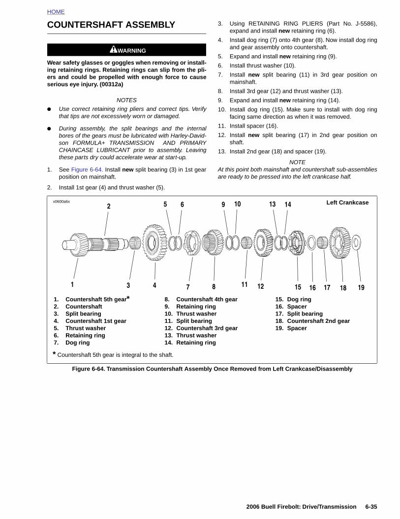
HOME
COUNTERSHAFT ASSEMBLY
11WARNING1WARNING
Wear safety glasses or goggles when removing or install-ing retaining rings. Retaining rings can slip from the pli-ers and could be propelled with enough force to causeserious eye injury. (00312a)
NOTES
● Use correct retaining ring pliers and correct tips. Verifythat tips are not excessively worn or damaged.
● During assembly, the split bearings and the internalbores of the gears must be lubricated with Harley-David-son FORMULA+ TRANSMISSION AND PRIMARYCHAINCASE LUBRICANT prior to assembly. Leavingthese parts dry could accelerate wear at start-up.
1. See Figure 6-64. Install new split bearing (3) in 1st gearposition on mainshaft.
2. Install 1st gear (4) and thrust washer (5).
3. Using RETAINING RING PLIERS (Part No. J-5586),expand and install new retaining ring (6).
4. Install dog ring (7) onto 4th gear (8). Now install dog ringand gear assembly onto countershaft.
5. Expand and install new retaining ring (9).
6. Install thrust washer (10).
7. Install new split bearing (11) in 3rd gear position onmainshaft.
8. Install 3rd gear (12) and thrust washer (13).
9. Expand and install new retaining ring (14).
10. Install dog ring (15). Make sure to install with dog ringfacing same direction as when it was removed.
11. Install spacer (16).
12. Install new split bearing (17) in 2nd gear position onshaft.
13. Install 2nd gear (18) and spacer (19).
NOTEAt this point both mainshaft and countershaft sub-assembliesare ready to be pressed into the left crankcase half.
1. Countershaft 5th gear*2. Countershaft3. Split bearing4. Countershaft 1st gear5. Thrust washer6. Retaining ring7. Dog ring
8. Countershaft 4th gear9. Retaining ring10. Thrust washer11. Split bearing12. Countershaft 3rd gear13. Thrust washer14. Retaining ring
15. Dog ring16. Spacer17. Split bearing18. Countershaft 2nd gear19. Spacer
x0600a6x Left Crankcase
3 87
6
4
52
1 15 16 18 1912
9 10
11
1413
17
* Countershaft 5th gear is integral to the shaft.
2006 Buell Firebolt: Drive/Transmission 6-35
Figure 6-64. Transmission Countershaft Assembly Once Removed from Left Crankcase/Disassembly

HOME
MAIN DRIVE GEAR AND BEARING 6.11
GENE
PART
HD-3531
B-45847
HD-4785
HD-9563
HD-4785
1. Reta2. Bea3. Fifth4. Bea5. O-ri6. Oil s
b1013x6x
12
11
6-36 2
RAL NOTEWhen removing the main drive gear, the gear is pressed outagainst the resistance of the ball bearing inner race. Withoutany support at the inner race, the bearing is destroyed.Whenever the main drive gear is removed the main drive gearbearing must also be replaced.
NO. SPECIALTY TOOL
6-C Main drive gear remover and installer
Cross plate
5 Inner/outer main drive gear needle bearing installation tool
7-46A Bearing race puller
6 Seal driver
ining ringring (Inner) gear mainshaft
ring (Outer)ngeal
7. Right crankcase half8. Ball bearing with spacer9. Retaining ring10. Oil seal11. Bearing, (closed end) countershaft12. Bushing, shifter drum
10
8
4
21
3
5
7
9
6
006 Buell Firebolt: Drive/Transmission
Figure 6-65. Transmission Assembly-Right Crankcase Half
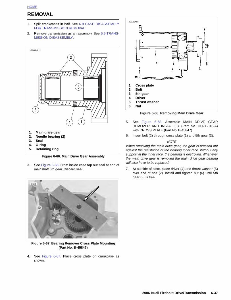
HOME
REMOVAL
1. Split crankcases in half. See 6.8 CASE DISASSEMBLYFOR TRANSMISSION REMOVAL.
2. Remove transmission as an assembly. See 6.9 TRANS-MISSION DISASSEMBLY.
3. See Figure 6-66. From inside case tap out seal at end ofmainshaft 5th gear. Discard seal.
5. See Figure 6-68. Assemble MAIN DRIVE GEARREMOVER AND INSTALLER (Part No. HD-35316-A)with CROSS PLATE (Part No. B-45847).
6. Insert bolt (2) through cross plate (1) and 5th gear (3).
NOTEWhen removing the main drive gear, the gear is pressed outagainst the resistance of the bearing inner race. Without anysupport at the inner race, the bearing is destroyed. Wheneverthe main drive gear is removed the main drive gear bearingwill also have to be replaced.
7. At outside of case, place driver (4) and thrust washer (5)over end of bolt (2). Install and tighten nut (6) until 5thgear (3) is free.
Figure 6-66. Main Drive Gear Assembly
1. Main drive gear2. Needle bearing (2)3. Seal4. O-ring5. Retaining ring
b1069a6x
2
3
14
5
8681
Figure 6-68. Removing Main Drive Gear
1. Cross plate2. Bolt3. 5th gear4. Driver5. Thrust washer6. Nut
a0121x6x
2006 Buell Firebolt: Drive/Transmission 6-37
4. See Figure 6-67. Place cross plate on crankcase asshown.
Figure 6-67. Bearing Remover Cross Plate Mounting(Part No. B-45847)

HOME
Main Drive Gear Bearing
DISASSEMBLY
11WARNING1WARNING
Wear safety glasses or goggles when removing or install-ing retaining rings. Retaining rings can slip from the pli-ers and could be propelled with enough force to causeserious eye injury. (00312a)
NOTEUse correct retaining ring pliers and correct tips. Verify thattips are not excessively worn or damaged.
1. See Figure 6-65. At outside of case remove and discardoil seal (10). Remove and discard main drive gear bear-ing retaining ring (9).
2. See Figure 6-67. From inside crankcase, position BEAR-ING DRIVER (Part No. HD-035316-9) (2) over main drivegear bearing.
3. Insert 8 IN. BOLT (Part No. HD-35316-4A) (1) throughbearing driver and bearing.
4. See Figure 6-69. At outside of case, slide RECEIVERCUP (Part No. HD-35316-11) (3) onto bolt and overbearing. Install NICE BEARING (4), FLAT WASHER (5)and NUT (6) over end of bolt.
NOTESupport bearing remover assembly as you remove bearing inthe following step. Entire assembly will fall out of crankcasewhen bearing comes free.
5. Tighten nut until main drive gear bearing is free.
6. Discard main drive gear bearing.
1. See Figure 6-66. Remove and discard retaining ring (5).
2. Drive out needle bearings (2) from inside bore of maindrive gear (1) using appropriate bearing and bushingpuller. Discard bearings. Do not reuse bearings afterremoval.
3. Remove o-ring (4) from outside of main drive gear anddiscard. Do not reuse o-ring after removal.
NOTE
When the main drive gear is removed, a portion of the bear-ing inner race remains attached to the main drive gear. Thisinner race must be removed before the main drive gear canbe re-installed.
4. See Figure 6-70. Attach BEARING RACE PULLER (PartNo. 95637-46A) (3) to inner race (2) on main drive gear(1).
5. Place main drive gear with bearing race puller assemblyonto press bed as shown in the photo.
NOTE
Provide a soft surface to catch the main drive gear when itfalls free in the next step.
6. Press main drive gear out of inner bearing race. Discardinner bearing race.
1
11507
2
3 5
4 611508
1. 8 in. Bolt (Part No. HD-35316-4A)2. Bearing driver (Part No. HD-35316-9)3. Receiver cup (Part No. HD-35316-11)4. Nice bearing5. Flat washer6. Nut
11516
24
6-38 2006 Buell Firebolt: Drive/Transmission
Figure 6-69. Removing Main Drive Gear Bearing (Typical)
Figure 6-70. Removing Inner Bearing Race From Main Drive Gear
1. Main drive gear2. Inner bearing race (not visible in this photo)3. Bearing race puller (Part no. HD-95637-46A)4. Press ram
3
1

HOME
ASSEMBLY
1. Use INNER/OUTER MAIN DRIVE GEAR NEEDLEBEARING INSTALLATION TOOL (Part No. HD-47855)for assembly. Assemble parts. The installation tool willautomatically bottom on the gear when the correct depthis reached.
2. See Figure 6-71. Place main drive gear (4) on press bedwith gear end facing up.
3. Place needle bearing (3) squarely into end of drive gear.Insert installation tool (2) with end stamped “INNER” fac-ing needle bearing.
4. Press in the inner bearing until the installation tool bot-toms on the main drive gear. The surface of the needlebearing will be at a depth of 0.175-0.200 in. (4.4-5 mm)from the face of the shifter dogs on the main drive gear.
5. Install new retaining ring.
6. See Figure 6-72. Place main drive gear (4) on press bedwith gear end facing down.
7. Place needle bearing (3) squarely into end of drive gear.Insert installation tool (2) with end stamped “OUTER”facing needle bearing.
8. Press in the outer bearing until the installation tool bot-toms on the main drive gear. The surface of the needlebearing will be at a depth of 0.315 in. (8.001 mm) fromthe end of the main drive gear.
Figure 6-71. Pressing Inner Needle Bearing Assembly into Main Drive Gear
11477
1. Press ram2. Needle bearing installation tool
(Part No. HD-47855)3. Needle bearing4. Main drive gear
1
3
2
4
11477
1
1. Press ram
3
2
4
2006 Buell Firebolt: Drive/Transmission 6-39
Figure 6-72. Pressing Outer Needle Bearing Assembly into Main Drive Gear
2. Needle bearing installation tool (Part No. HD-47855)
3. Needle bearing4. Main drive gear
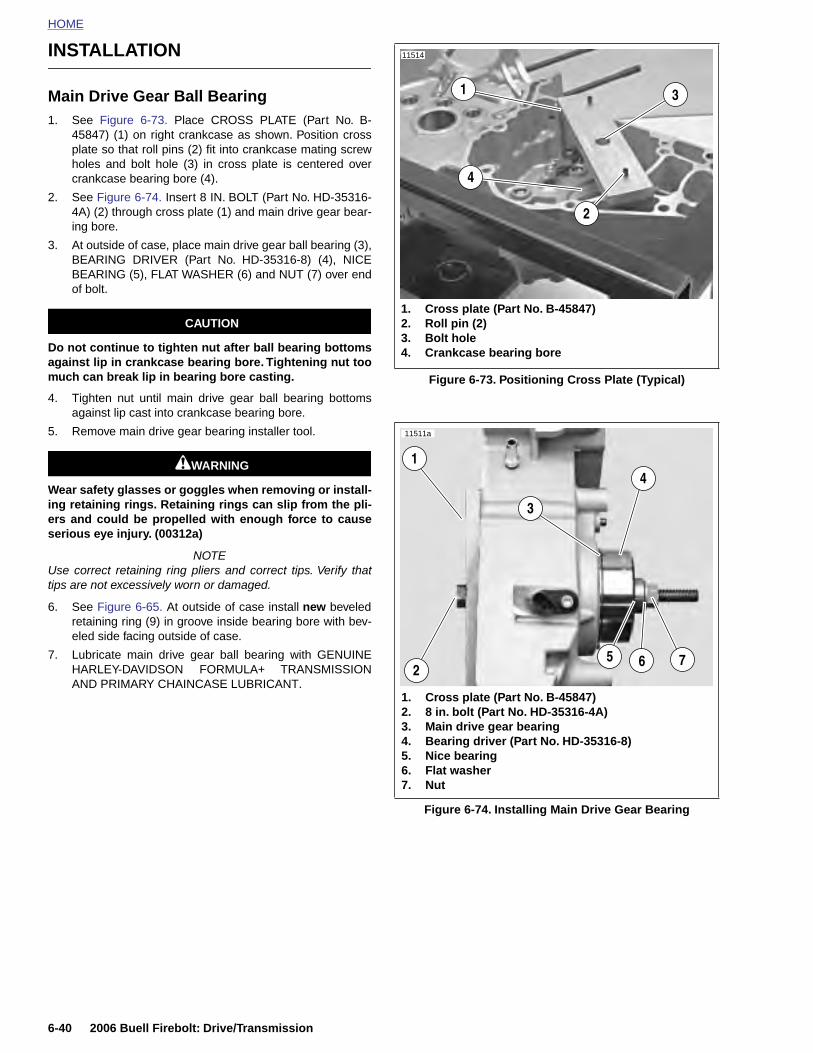
HOME
INSTALLATION
11514
Main Drive Gear Ball Bearing1. See Figure 6-73. Place CROSS PLATE (Part No. B-
45847) (1) on right crankcase as shown. Position crossplate so that roll pins (2) fit into crankcase mating screwholes and bolt hole (3) in cross plate is centered overcrankcase bearing bore (4).
2. See Figure 6-74. Insert 8 IN. BOLT (Part No. HD-35316-4A) (2) through cross plate (1) and main drive gear bear-ing bore.
3. At outside of case, place main drive gear ball bearing (3),BEARING DRIVER (Part No. HD-35316-8) (4), NICEBEARING (5), FLAT WASHER (6) and NUT (7) over endof bolt.
CAUTION
Do not continue to tighten nut after ball bearing bottomsagainst lip in crankcase bearing bore. Tightening nut toomuch can break lip in bearing bore casting.
4. Tighten nut until main drive gear ball bearing bottomsagainst lip cast into crankcase bearing bore.
5. Remove main drive gear bearing installer tool.
11WARNING1WARNING
Wear safety glasses or goggles when removing or install-ing retaining rings. Retaining rings can slip from the pli-ers and could be propelled with enough force to causeserious eye injury. (00312a)
NOTEUse correct retaining ring pliers and correct tips. Verify thattips are not excessively worn or damaged.
6. See Figure 6-65. At outside of case install new beveledretaining ring (9) in groove inside bearing bore with bev-eled side facing outside of case.
7. Lubricate main drive gear ball bearing with GENUINEHARLEY-DAVIDSON FORMULA+ TRANSMISSIONAND PRIMARY CHAINCASE LUBRICANT.
Figure 6-73. Positioning Cross Plate (Typical)
3
2
1
1. Cross plate (Part No. B-45847)2. Roll pin (2)3. Bolt hole4. Crankcase bearing bore
4
1
11511a
1. Cross plate (Part No. B-45847)2. 8 in. bolt (Part No. HD-35316-4A)3. Main drive gear bearing4. Bearing driver (Part No. HD-35316-8)5. Nice bearing6. Flat washer
2
4
65 7
3
6-40 2006 Buell Firebolt: Drive/Transmission
Figure 6-74. Installing Main Drive Gear Bearing
7. Nut
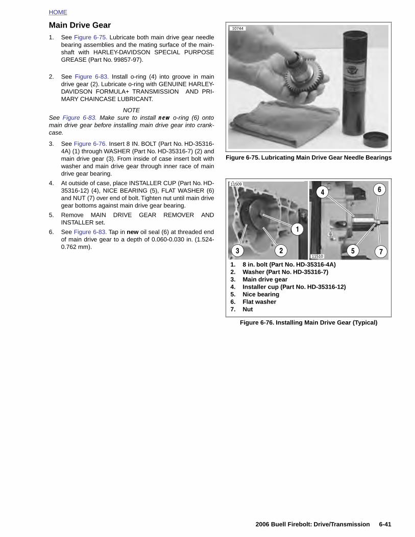
HOME
Main Drive Gear1. See Figure 6-75. Lubricate both main drive gear needle
bearing assemblies and the mating surface of the main-shaft with HARLEY-DAVIDSON SPECIAL PURPOSEGREASE (Part No. 99857-97).
2. See Figure 6-83. Install o-ring (4) into groove in maindrive gear (2). Lubricate o-ring with GENUINE HARLEY-DAVIDSON FORMULA+ TRANSMISSION AND PRI-MARY CHAINCASE LUBRICANT.
NOTESee Figure 6-83. Make sure to install new o-ring (6) ontomain drive gear before installing main drive gear into crank-case.
3. See Figure 6-76. Insert 8 IN. BOLT (Part No. HD-35316-4A) (1) through WASHER (Part No. HD-35316-7) (2) andmain drive gear (3). From inside of case insert bolt withwasher and main drive gear through inner race of maindrive gear bearing.
4. At outside of case, place INSTALLER CUP (Part No. HD-35316-12) (4), NICE BEARING (5), FLAT WASHER (6)and NUT (7) over end of bolt. Tighten nut until main drivegear bottoms against main drive gear bearing.
5. Remove MAIN DRIVE GEAR REMOVER ANDINSTALLER set.
6. See Figure 6-83. Tap in new oil seal (6) at threaded endof main drive gear to a depth of 0.060-0.030 in. (1.524-0.762 mm).
Figure 6-75. Lubricating Main Drive Gear Needle Bearings
Figure 6-76. Installing Main Drive Gear (Typical)
10744
6
1
4
523
11509
1. 8 in. bolt (Part No. HD-35316-4A)2. Washer (Part No. HD-35316-7)3. Main drive gear4. Installer cup (Part No. HD-35316-12)5. Nice bearing6. Flat washer7. Nut
711510
2006 Buell Firebolt: Drive/Transmission 6-41
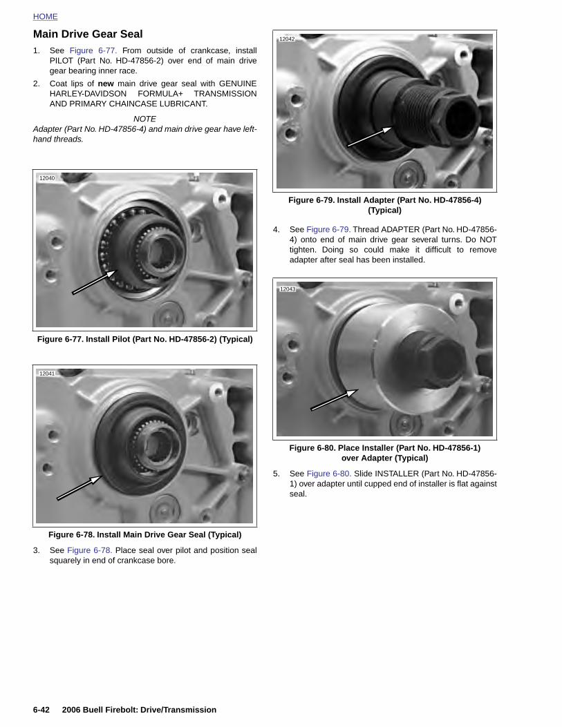
HOME
Main Drive Gear Seal
1. See Figure 6-77. From outside of crankcase, install
12042
PILOT (Part No. HD-47856-2) over end of main drivegear bearing inner race.
2. Coat lips of new main drive gear seal with GENUINEHARLEY-DAVIDSON FORMULA+ TRANSMISSIONAND PRIMARY CHAINCASE LUBRICANT.
NOTEAdapter (Part No. HD-47856-4) and main drive gear have left-hand threads.
4. See Figure 6-79. Thread ADAPTER (Part No. HD-47856-4) onto end of main drive gear several turns. Do NOTtighten. Doing so could make it difficult to removeadapter after seal has been installed.
5. See Figure 6-80. Slide INSTALLER (Part No. HD-47856-1) over adapter until cupped end of installer is flat againstseal.
Figure 6-77. Install Pilot (Part No. HD-47856-2) (Typical)
12040
12041
Figure 6-79. Install Adapter (Part No. HD-47856-4)(Typical)
Figure 6-80. Place Installer (Part No. HD-47856-1)over Adapter (Typical)
12043
6-42 2006 Buell Firebolt: Drive/Transmission
3. See Figure 6-78. Place seal over pilot and position sealsquarely in end of crankcase bore.
Figure 6-78. Install Main Drive Gear Seal (Typical)
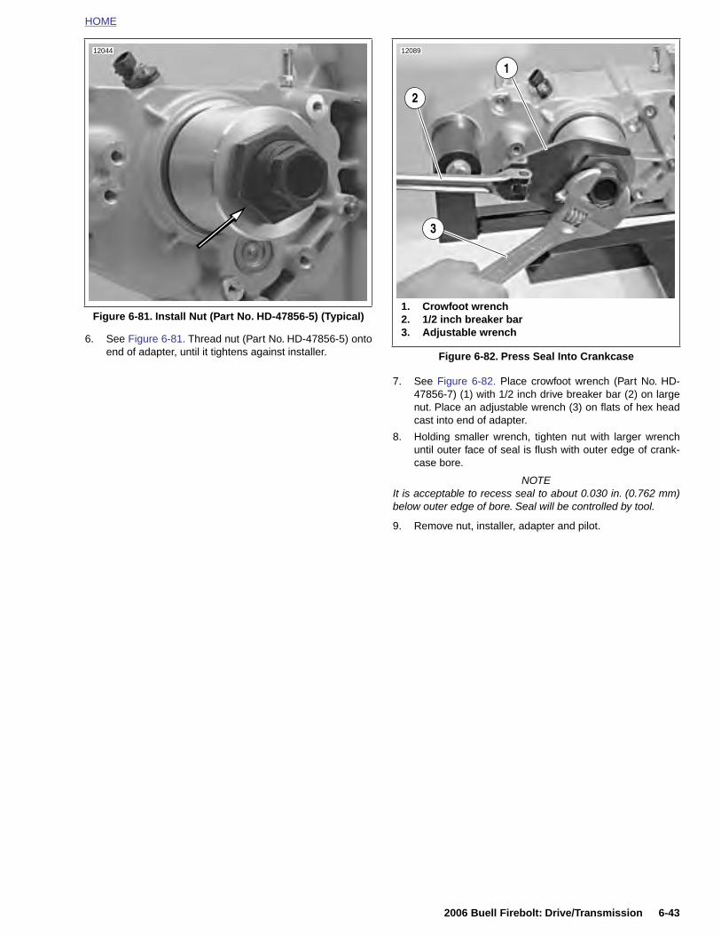
HOME
6. See Figure 6-81. Thread nut (Part No. HD-47856-5) ontoend of adapter, until it tightens against installer.
7. See Figure 6-82. Place crowfoot wrench (Part No. HD-47856-7) (1) with 1/2 inch drive breaker bar (2) on largenut. Place an adjustable wrench (3) on flats of hex headcast into end of adapter.
8. Holding smaller wrench, tighten nut with larger wrenchuntil outer face of seal is flush with outer edge of crank-case bore.
NOTEIt is acceptable to recess seal to about 0.030 in. (0.762 mm)below outer edge of bore. Seal will be controlled by tool.
9. Remove nut, installer, adapter and pilot.
Figure 6-81. Install Nut (Part No. HD-47856-5) (Typical)
12044
Figure 6-82. Press Seal Into Crankcase
12089
1
3
2
1. Crowfoot wrench2. 1/2 inch breaker bar3. Adjustable wrench
2006 Buell Firebolt: Drive/Transmission 6-43
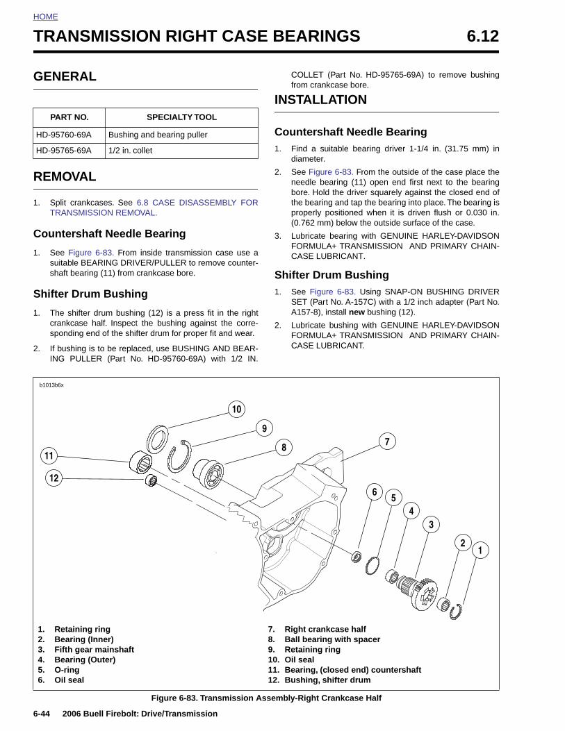
HOME
TRANSMISSION RIGHT CASE BEARINGS 6.12
GENE
REMO
1. Split TRAN
Counte
1. See Fsuitabshaft
Shifter
1. The scrankspond
2. If busING
PART
HD-9576
HD-9576
b1013b6x
12
11
6-44 2
1. Re2. Be3. Fif4. Be5. O-6. Oil
RAL
VAL
crankcases. See 6.8 CASE DISASSEMBLY FORSMISSION REMOVAL.
rshaft Needle Bearing
igure 6-83. From inside transmission case use ale BEARING DRIVER/PULLER to remove counter-bearing (11) from crankcase bore.
Drum Bushing
hifter drum bushing (12) is a press fit in the rightcase half. Inspect the bushing against the corre-ing end of the shifter drum for proper fit and wear.
hing is to be replaced, use BUSHING AND BEAR-PULLER (Part No. HD-95760-69A) with 1/2 IN.
COLLET (Part No. HD-95765-69A) to remove bushingfrom crankcase bore.
INSTALLATION
Countershaft Needle Bearing1. Find a suitable bearing driver 1-1/4 in. (31.75 mm) in
diameter.
2. See Figure 6-83. From the outside of the case place theneedle bearing (11) open end first next to the bearingbore. Hold the driver squarely against the closed end ofthe bearing and tap the bearing into place. The bearing isproperly positioned when it is driven flush or 0.030 in.(0.762 mm) below the outside surface of the case.
3. Lubricate bearing with GENUINE HARLEY-DAVIDSONFORMULA+ TRANSMISSION AND PRIMARY CHAIN-CASE LUBRICANT.
Shifter Drum Bushing1. See Figure 6-83. Using SNAP-ON BUSHING DRIVER
SET (Part No. A-157C) with a 1/2 inch adapter (Part No.A157-8), install new bushing (12).
2. Lubricate bushing with GENUINE HARLEY-DAVIDSONFORMULA+ TRANSMISSION AND PRIMARY CHAIN-CASE LUBRICANT.
NO. SPECIALTY TOOL
0-69A Bushing and bearing puller
5-69A 1/2 in. collet
10
8
5
34
6
79
006 Buell Firebolt: Drive/Transmission
Figure 6-83. Transmission Assembly-Right Crankcase Half
taining ringaring (Inner)th gear mainshaft aring (Outer)ring seal
7. Right crankcase half8. Ball bearing with spacer9. Retaining ring10. Oil seal11. Bearing, (closed end) countershaft12. Bushing, shifter drum
21
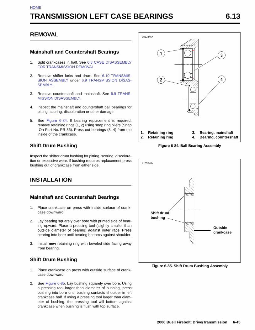
HOME
T
R
M
1
2
3
4
5
S
Intib
I
M
1
2
RANSMISSION LEFT CASE BEARINGS 6.13
EMOVAL
ainshaft and Countershaft Bearings
. Split crankcases in half. See 6.8 CASE DISASSEMBLYFOR TRANSMISSION REMOVAL.
. Remove shifter forks and drum. See 6.10 TRANSMIS-SION ASSEMBLY under 6.9 TRANSMISSION DISAS-SEMBLY.
. Remove countershaft and mainshaft. See 6.9 TRANS-MISSION DISASSEMBLY.
. Inspect the mainshaft and countershaft ball bearings forpitting, scoring, discoloration or other damage.
. See Figure 6-84. If bearing replacement is required,remove retaining rings (1, 2) using snap ring pliers (Snap-On Part No. PR-36). Press out bearings (3, 4) from theinside of the crankcase.
hift Drum Bushing
spect the shifter drum bushing for pitting, scoring, discolora-on or excessive wear. If bushing requires replacement pressushing out of crankcase from either side.
NSTALLATION
ainshaft and Countershaft Bearings
. Place crankcase on press with inside surface of crank-case downward.
. Lay bearing squarely over bore with printed side of bear-ing upward. Place a pressing tool (slightly smaller than
Figure 6-84. Ball Bearing Assembly
1. Retaining ring2. Retaining ring
3. Bearing, mainshaft4. Bearing, countershaft
a0123xSx
31
2 4
Shift drum bushing
b1035a6x
2006 Buell Firebolt: Drive/Transmission 6-45
outside diameter of bearing) against outer race. Pressbearing into bore until bearing bottoms against shoulder.
3. Install new retaining ring with beveled side facing awayfrom bearing.
Shift Drum Bushing
1. Place crankcase on press with outside surface of crank-case downward.
2. See Figure 6-85. Lay bushing squarely over bore. Usinga pressing tool larger than diameter of bushing, pressbushing into bore until bushing contacts shoulder in leftcrankcase half. If using a pressing tool larger than diam-eter of bushing, the pressing tool will bottom againstcrankcase when bushing is flush with top surface.
Figure 6-85. Shift Drum Bushing Assembly
Outsidecrankcase
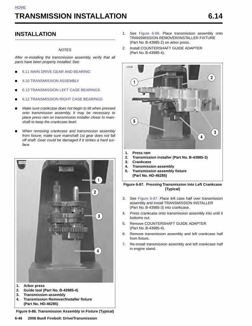
HOME
TRANSMISSION INSTALLATION 6.14
INSTA
After re-inparts have
● 6.11 M
● 6.10 T
● 6.13 T
● 6.12 T
● Makeonto placeshaft
● Whenfrom off shface.
11534
6-46 2
Figure
1. Arb2. Gu3. Tra4. Tra
(Pa
LLATION
NOTES
stalling the transmission assembly, verify that all been properly installed. See:
AIN DRIVE GEAR AND BEARING
RANSMISSION ASSEMBLY
RANSMISSION LEFT CASE BEARINGS
RANSMISSION RIGHT CASE BEARINGS
sure crankcase does not begin to tilt when pressedtransmission assembly. It may be necessary to press ram on transmission installer closer to main-to keep the crankcase level.
removing crankcase and transmission assemblyfixture, make sure mainshaft 1st gear does not fallaft. Gear could be damaged if it strikes a hard sur-
1. See Figure 6-86. Place transmission assembly ontoTRANSMISSION REMOVER/INSTALLER FIXTURE(Part No. B-43985-2) on arbor press.
2. Install COUNTERSHAFT GUIDE ADAPTER(Part No. B-43985-4).
3. See Figure 6-87. Place left case half over transmissionassembly and install TRANSMISSION INSTALLER(Part No. B-43985-3) into crankcase.
4. Press crankcase onto transmission assembly into until itbottoms out.
5. Remove COUNTERSHAFT GUIDE ADAPTER(Part No. B-43985-4).
6. Remove transmission assembly and left crankcase halffrom fixture.
3
1
2
Figure 6-87. Pressing Transmission Into Left Crankcase (Typical)
1
3
2
1. Press ram2. Transmission installer (Part No. B-43985-3)3. Crankcase4. Transmission assembly5. Transmission assembly fixture
(Part No. HD-46285)
4
5
11535
006 Buell Firebolt: Drive/Transmission
7. Re-install transmission assembly and left crankcase halfin engine stand.
6-86. Transmission Assembly in Fixture (Typical)
or presside tool (Part No. B-43985-4)nsmission assemblynsmission Remover/Installer fixturert No. HD-46285)
4
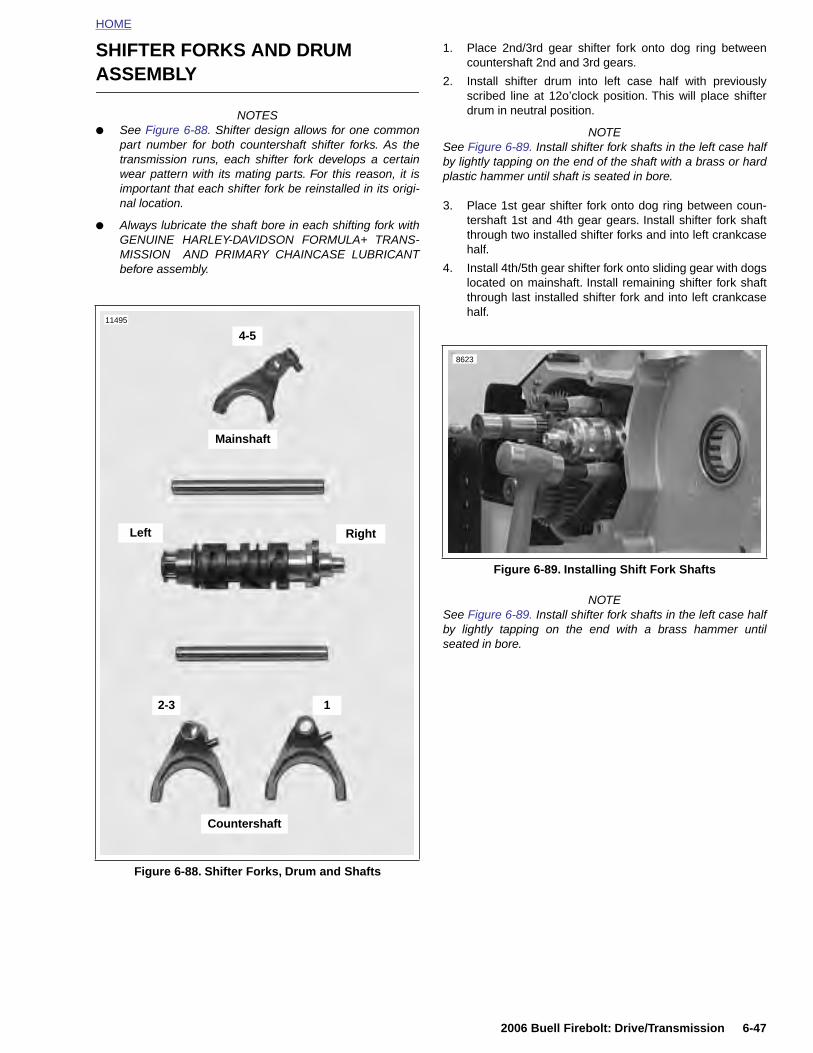
HOME
SHIFTER FORKS AND DRUM ASSEMBLY
NOTES● See Figure 6-88. Shifter design allows for one common
part number for both countershaft shifter forks. As thetransmission runs, each shifter fork develops a certainwear pattern with its mating parts. For this reason, it isimportant that each shifter fork be reinstalled in its origi-nal location.
● Always lubricate the shaft bore in each shifting fork withGENUINE HARLEY-DAVIDSON FORMULA+ TRANS-MISSION AND PRIMARY CHAINCASE LUBRICANTbefore assembly.
1. Place 2nd/3rd gear shifter fork onto dog ring betweencountershaft 2nd and 3rd gears.
2. Install shifter drum into left case half with previouslyscribed line at 12o’clock position. This will place shifterdrum in neutral position.
NOTESee Figure 6-89. Install shifter fork shafts in the left case halfby lightly tapping on the end of the shaft with a brass or hardplastic hammer until shaft is seated in bore.
3. Place 1st gear shifter fork onto dog ring between coun-tershaft 1st and 4th gear gears. Install shifter fork shaftthrough two installed shifter forks and into left crankcasehalf.
4. Install 4th/5th gear shifter fork onto sliding gear with dogslocated on mainshaft. Install remaining shifter fork shaftthrough last installed shifter fork and into left crankcasehalf.
NOTESee Figure 6-89. Install shifter fork shafts in the left case halfby lightly tapping on the end with a brass hammer untilseated in bore.
11495
Mainshaft
Left
12-3
4-5
Right
Figure 6-89. Installing Shift Fork Shafts
8623
2006 Buell Firebolt: Drive/Transmission 6-47
Figure 6-88. Shifter Forks, Drum and Shafts
Countershaft
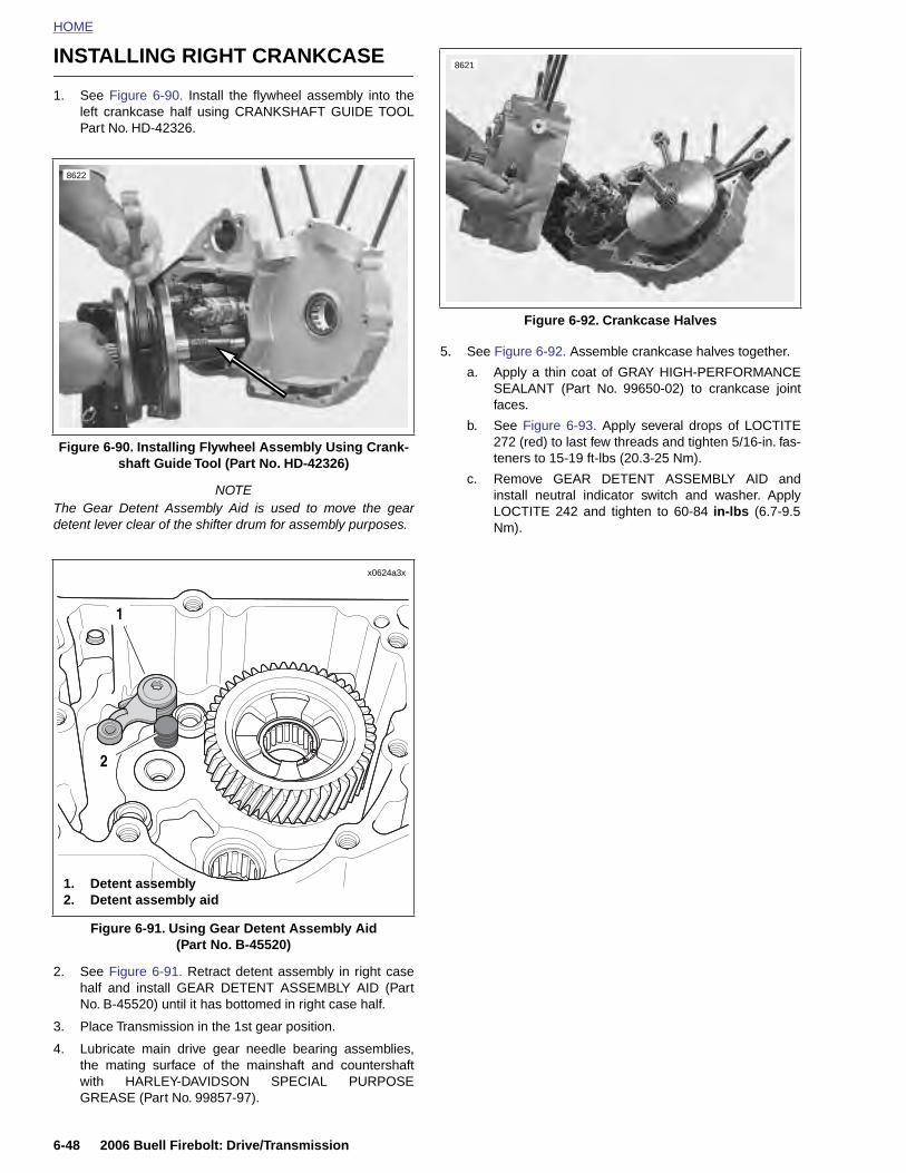
HOME
INSTALLING RIGHT CRANKCASE8621
1. See Figure 6-90. Install the flywheel assembly into theleft crankcase half using CRANKSHAFT GUIDE TOOLPart No. HD-42326.
NOTEThe Gear Detent Assembly Aid is used to move the geardetent lever clear of the shifter drum for assembly purposes.
5. See Figure 6-92. Assemble crankcase halves together.
a. Apply a thin coat of GRAY HIGH-PERFORMANCESEALANT (Part No. 99650-02) to crankcase jointfaces.
b. See Figure 6-93. Apply several drops of LOCTITE272 (red) to last few threads and tighten 5/16-in. fas-teners to 15-19 ft-lbs (20.3-25 Nm).
c. Remove GEAR DETENT ASSEMBLY AID andinstall neutral indicator switch and washer. ApplyLOCTITE 242 and tighten to 60-84 in-lbs (6.7-9.5Nm).
Figure 6-90. Installing Flywheel Assembly Using Crank-shaft Guide Tool (Part No. HD-42326)
8622
x0624a3x
1
2
Figure 6-92. Crankcase Halves
6-48 2006 Buell Firebolt: Drive/Transmission
2. See Figure 6-91. Retract detent assembly in right casehalf and install GEAR DETENT ASSEMBLY AID (PartNo. B-45520) until it has bottomed in right case half.
3. Place Transmission in the 1st gear position.
4. Lubricate main drive gear needle bearing assemblies,the mating surface of the mainshaft and countershaftwith HARLEY-DAVIDSON SPECIAL PURPOSEGREASE (Part No. 99857-97).
Figure 6-91. Using Gear Detent Assembly Aid(Part No. B-45520)
1. Detent assembly2. Detent assembly aid
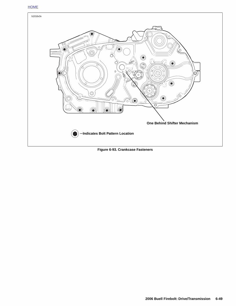
HOME
Figure 6-93. Crankcase Fasteners
D
b1016x3x
Indicates Bolt Pattern Location
One Behind Shifter Mechanism
2006 Buell Firebolt: Drive/Transmission 6-49
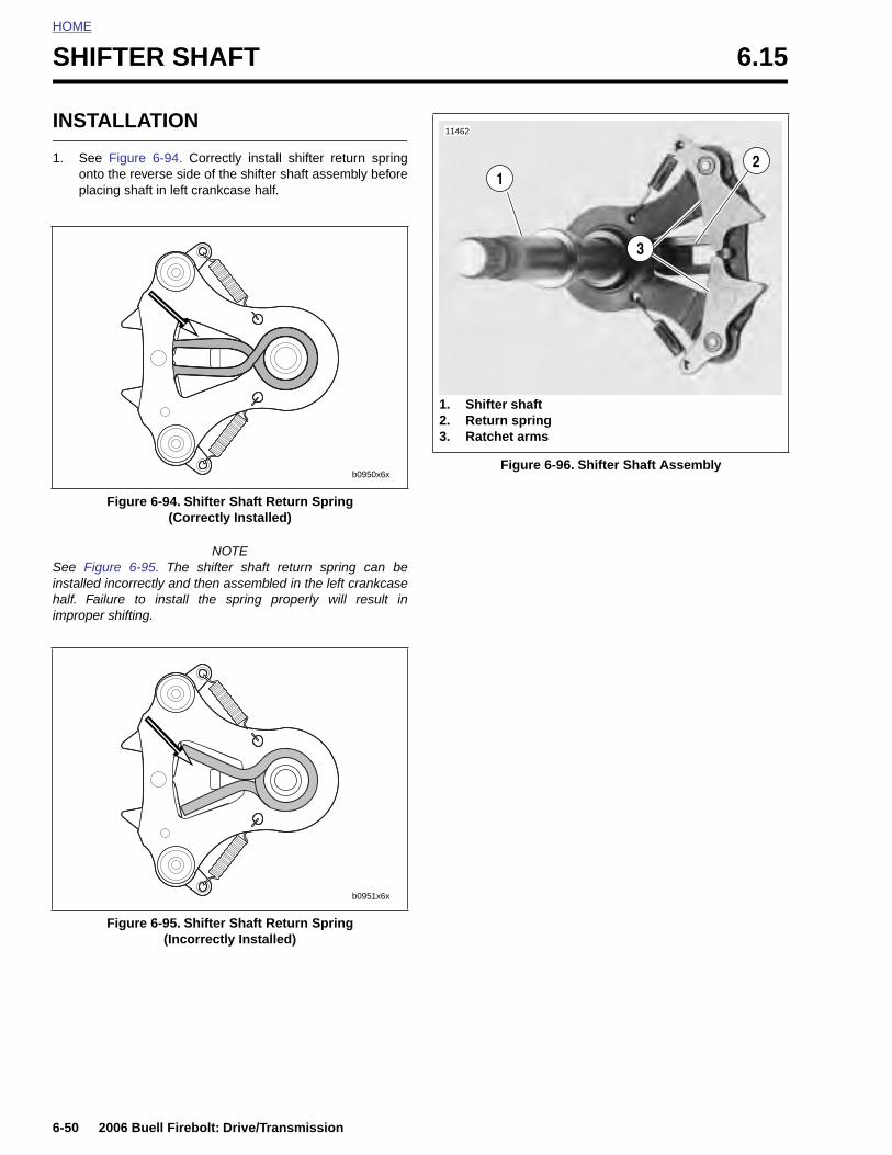
HOME
SHIFTER SHAFT 6.15
INSTA
1. See Fonto tplacin
See Figuinstalled inhalf. Failuimproper s
F
6-50 2
LLATION
igure 6-94. Correctly install shifter return springhe reverse side of the shifter shaft assembly beforeg shaft in left crankcase half.
NOTEre 6-95. The shifter shaft return spring can becorrectly and then assembled in the left crankcasere to install the spring properly will result inhifting.
igure 6-94. Shifter Shaft Return Spring(Correctly Installed)
b0950x6xFigure 6-96. Shifter Shaft Assembly
1. Shifter shaft2. Return spring3. Ratchet arms
1
11462
3
2
006 Buell Firebolt: Drive/Transmission
Figure 6-95. Shifter Shaft Return Spring(Incorrectly Installed)
b0951x6x

HOME
2. See Figure 6-97. Depress ratchet arms and insert shaftassembly into the bushing in the left case half andrelease. Ratchet arms should now be inside the endplate of the shifter drum contacting the shifter drum pins.
3. See Figure 6-98. Apply several drops of LOCTITE 262(red) to last few threads of countershaft retaining screw.Thread screw into end of shaft.
4. Place transmission in gear and tighten screw to 33-37 ft-lbs (44.8-50 Nm).
5. Install transmission sprocket. See 6.16 TRANSMISSIONSPROCKET.
6. Continue assembling engine. See appropriate sectionsof 3.19 CRANKCASE/ ASSEMBLY and 3.6 CYLINDERHEAD/3.7 CYLINDER AND PISTON/ ASSEMBLY/INSTALLATION.
7. Install primary chain and engine sprocket, clutch assem-bly and primary cover. See 6.5 PRIMARY CHAIN.
8. Install engine in chassis. See 3.5 ENGINE INSTALLA-TION.
Figure 6-97. Installing Shifter Shaft Assembly
11403
Figure 6-98. Hex Fastener Countershaft Retainer
11340
2006 Buell Firebolt: Drive/Transmission 6-51
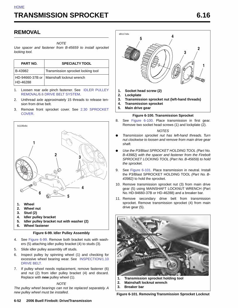
HOME
TRANSMISSION SPROCKET 6.16
REMO
Use spaclocking too
1. LooseREMO
2. Unthrsion f
3. RemoCOVE
PART
B-43982
HD-9466HD-4628
b1106x6x
1. Wh2. Wh3. Stu4. Idle5. Idle6. Wh
6-52 2
4. Seeers
5. Slid
6. InspexceDRI
7. If puandRep
The pullenew pulle
VAL
NOTEer and fastener from B-45659 to install sprocketl.
n rear axle pinch fastener. See IDLER PULLEYVAL/6.6 DRIVE BELT SYSTEM.
ead axle approximately 15 threads to release ten-rom drive belt.
ve front sprocket cover. See 2.30 SPROCKETR.
8. See Figure 6-100. Place transmission in first gear.Remove two socket head screws (1) and lockplate (2).
NOTES● Transmission sprocket nut has left-hand threads. Turn
nut clockwise to loosen and remove from main drive gearshaft.
● Use the P3/Blast SPROCKET HOLDING TOOL (Part No.B-43982) with the spacer and fastener from the FireboltSPROCKET LOCKING TOOL (Part No. B-45659) to holdthe sprocket.
9. See Figure 6-101. Place transmission in neutral. Installthe P3/Blast SPROCKET HOLDING TOOL (Part No. B-43982) to hold the sprocket.
10. Remove transmission sprocket nut (3) from main drivegear (5) using MAINSHAFT LOCKNUT WRENCH (PartNo. HD-94660-37B or HD-46288) and a breaker bar.
11. Remove secondary drive belt from transmissionsprocket. Remove transmission sprocket (4) from maindrive gear (5).
NO. SPECIALTY TOOL
Transmission sprocket locking tool
0-37B or 8
Mainshaft locknut wrench
2 3
4
56
eeleel nutd (2)r pulley bracketr pulley bracket nut with washer (2)eel fastener
1
Figure 6-100. Transmission Sprocket
1. Socket head screw (2)2. Lockplate3. Transmission sprocket nut (left-hand threads)4. Transmission sprocket5. Main drive gear
1
23
45d0117x6x
11978
006 Buell Firebolt: Drive/Transmission
Figure 6-99. Remove both bracket nuts with wash-(5) attaching idler pulley bracket (4) to studs (3).
e idler pulley assembly off studs.
ect pulley by spinning wheel (1) and checking forssive wheel bearing wear. See INSPECTION/1.10
VE BELT.
lley wheel needs replacement, remove fastener (6) nut (2) from idler pulley bracket (4) and discard.lace with new pulley wheel (1).
NOTEy wheel bearings can not be replaced separately. Ay wheel must be installed.
Figure 6-99. Idler Pulley Assembly
Figure 6-101. Removing Transmission Sprocket Locknut
1. Transmission sprocket holding tool2. Mainshaft locknut wrench3. Breaker bar
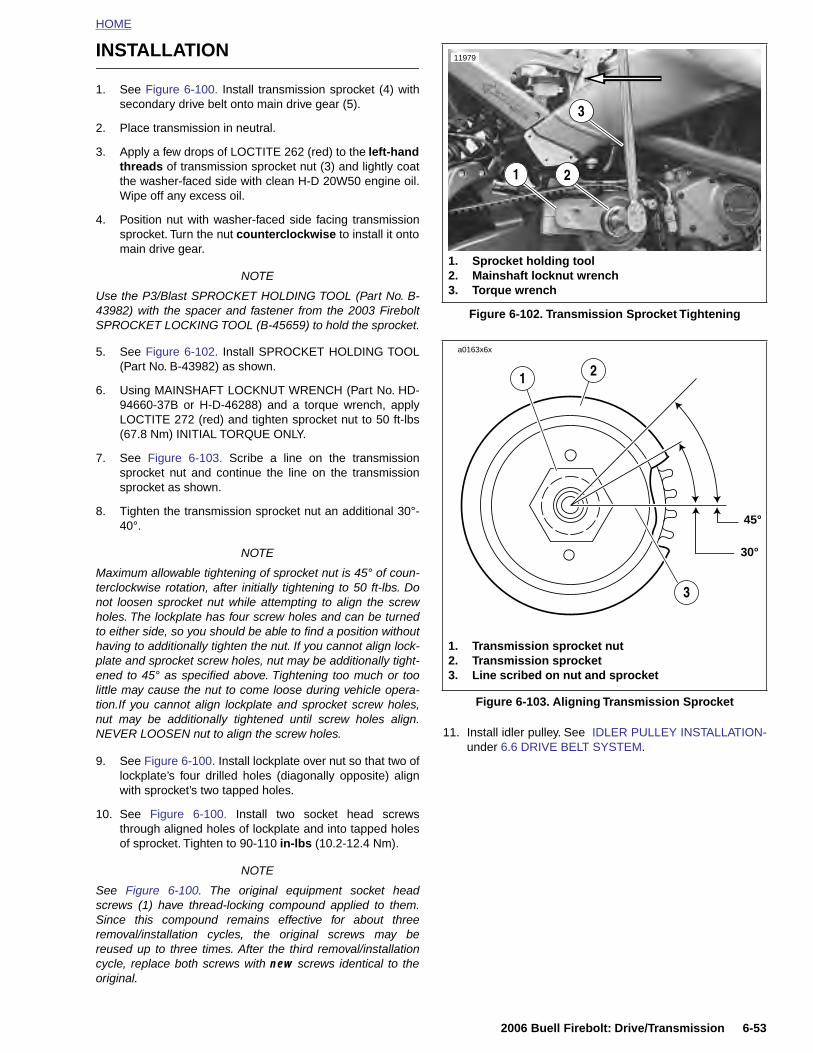
HOME
INSTALLATION
1. See Figure 6-100. Install transmission sprocket (4) withsecondary drive belt onto main drive gear (5).
2. Place transmission in neutral.
3. Apply a few drops of LOCTITE 262 (red) to the left-handthreads of transmission sprocket nut (3) and lightly coatthe washer-faced side with clean H-D 20W50 engine oil.Wipe off any excess oil.
4. Position nut with washer-faced side facing transmissionsprocket. Turn the nut counterclockwise to install it ontomain drive gear.
NOTE
Use the P3/Blast SPROCKET HOLDING TOOL (Part No. B-43982) with the spacer and fastener from the 2003 FireboltSPROCKET LOCKING TOOL (B-45659) to hold the sprocket.
5. See Figure 6-102. Install SPROCKET HOLDING TOOL(Part No. B-43982) as shown.
6. Using MAINSHAFT LOCKNUT WRENCH (Part No. HD-94660-37B or H-D-46288) and a torque wrench, applyLOCTITE 272 (red) and tighten sprocket nut to 50 ft-lbs(67.8 Nm) INITIAL TORQUE ONLY.
7. See Figure 6-103. Scribe a line on the transmissionsprocket nut and continue the line on the transmissionsprocket as shown.
8. Tighten the transmission sprocket nut an additional 30°-40°.
NOTE
Maximum allowable tightening of sprocket nut is 45° of coun-terclockwise rotation, after initially tightening to 50 ft-lbs. Donot loosen sprocket nut while attempting to align the screwholes. The lockplate has four screw holes and can be turnedto either side, so you should be able to find a position withouthaving to additionally tighten the nut. If you cannot align lock-plate and sprocket screw holes, nut may be additionally tight-ened to 45° as specified above. Tightening too much or toolittle may cause the nut to come loose during vehicle opera-tion.If you cannot align lockplate and sprocket screw holes,nut may be additionally tightened until screw holes align.
Figure 6-102. Transmission Sprocket Tightening
Figure 6-103. Aligning Transmission Sprocket
1. Sprocket holding tool2. Mainshaft locknut wrench3. Torque wrench
11979
21
3
45°
30°
a0163x6x
1. Transmission sprocket nut2. Transmission sprocket3. Line scribed on nut and sprocket
3
21
2006 Buell Firebolt: Drive/Transmission 6-53
NEVER LOOSEN nut to align the screw holes.
9. See Figure 6-100. Install lockplate over nut so that two oflockplate’s four drilled holes (diagonally opposite) alignwith sprocket’s two tapped holes.
10. See Figure 6-100. Install two socket head screwsthrough aligned holes of lockplate and into tapped holesof sprocket. Tighten to 90-110 in-lbs (10.2-12.4 Nm).
NOTE
See Figure 6-100. The original equipment socket headscrews (1) have thread-locking compound applied to them.Since this compound remains effective for about threeremoval/installation cycles, the original screws may bereused up to three times. After the third removal/installationcycle, replace both screws with new screws identical to theoriginal.
11. Install idler pulley. See IDLER PULLEY INSTALLATION-under 6.6 DRIVE BELT SYSTEM.
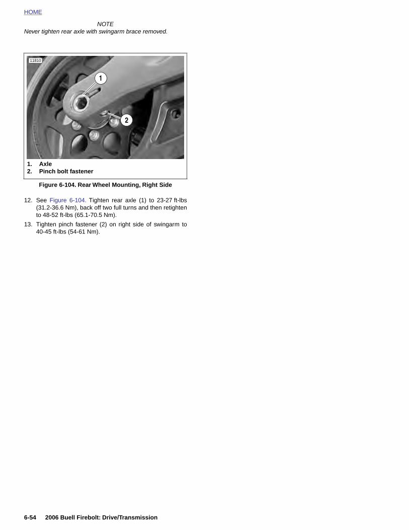
HOME
NOTENever tighten rear axle with swingarm brace removed.
12. See Figure 6-104. Tighten rear axle (1) to 23-27 ft-lbs(31.2-36.6 Nm), back off two full turns and then retightento 48-52 ft-lbs (65.1-70.5 Nm).
13. Tighten pinch fastener (2) on right side of swingarm to40-45 ft-lbs (54-61 Nm).
Figure 6-104. Rear Wheel Mounting, Right Side
11810
2
1. Axle2. Pinch bolt fastener
1
6-54 2006 Buell Firebolt: Drive/Transmission
SUBJECT PAGE NO.
7.1 Specifications . . . . . . . . . . . . . . . . . . . . . . . . . . . . . . . . . . . . . . . . . . . . . . . . . 7-17.2 Ignition System . . . . . . . . . . . . . . . . . . . . . . . . . . . . . . . . . . . . . . . . . . . . . . . . 7-37.3 Ignition/Headlight Key Switch . . . . . . . . . . . . . . . . . . . . . . . . . . . . . . . . . . . . . 7-57.4 Spar7.5 Start7.6 Intera7.7 Char7.8 Altern7.9 Volta7.10 Batt7.11 Batt7.12 Hea7.13 Tail7.14 Turn7.15 Turn7.16 Han7.17 Spe7.18 Inst7.19 Spe7.20 Hor7.21 Neu7.22 Mai7.23 Mai7.24 Inte7.25 Spr
Table Of Contents
L 7
k Plug Cables . . . . . . . . . . . . . . . . . . . . . . . . . . . . . . . . . . . . . . . . . . . . . . 7-9er Interlock . . . . . . . . . . . . . . . . . . . . . . . . . . . . . . . . . . . . . . . . . . . . . . . . 7-11ctive Exhaust System (XB12 Model) . . . . . . . . . . . . . . . . . . . . . . . . . . . 7-18
ging System . . . . . . . . . . . . . . . . . . . . . . . . . . . . . . . . . . . . . . . . . . . . . . . 7-23ator . . . . . . . . . . . . . . . . . . . . . . . . . . . . . . . . . . . . . . . . . . . . . . . . . . . . . 7-30
ge Regulator . . . . . . . . . . . . . . . . . . . . . . . . . . . . . . . . . . . . . . . . . . . . . . 7-32ery Cables . . . . . . . . . . . . . . . . . . . . . . . . . . . . . . . . . . . . . . . . . . . . . . . . 7-33ery . . . . . . . . . . . . . . . . . . . . . . . . . . . . . . . . . . . . . . . . . . . . . . . . . . . . . . 7-35dlight . . . . . . . . . . . . . . . . . . . . . . . . . . . . . . . . . . . . . . . . . . . . . . . . . . . . 7-42 Lamp . . . . . . . . . . . . . . . . . . . . . . . . . . . . . . . . . . . . . . . . . . . . . . . . . . . . 7-44 Signals . . . . . . . . . . . . . . . . . . . . . . . . . . . . . . . . . . . . . . . . . . . . . . . . . 7-45 Signal Flasher . . . . . . . . . . . . . . . . . . . . . . . . . . . . . . . . . . . . . . . . . . . . 7-48dlebar Switches . . . . . . . . . . . . . . . . . . . . . . . . . . . . . . . . . . . . . . . . . . . . 7-49edometer Sensor . . . . . . . . . . . . . . . . . . . . . . . . . . . . . . . . . . . . . . . . . . . 7-51rument Module . . . . . . . . . . . . . . . . . . . . . . . . . . . . . . . . . . . . . . . . . . . . . 7-52edometer Performance Check . . . . . . . . . . . . . . . . . . . . . . . . . . . . . . . . 7-54n . . . . . . . . . . . . . . . . . . . . . . . . . . . . . . . . . . . . . . . . . . . . . . . . . . . . . . . . 7-59tral Indicator Switch . . . . . . . . . . . . . . . . . . . . . . . . . . . . . . . . . . . . . . . . . 7-61n Fuse and Fuses . . . . . . . . . . . . . . . . . . . . . . . . . . . . . . . . . . . . . . . . . . 7-62n Wire Harness . . . . . . . . . . . . . . . . . . . . . . . . . . . . . . . . . . . . . . . . . . . . 7-63ractive Exhaust Harness (XB12 Models) . . . . . . . . . . . . . . . . . . . . . . . . . 7-68ocket Cover Wiring . . . . . . . . . . . . . . . . . . . . . . . . . . . . . . . . . . . . . . . . . . 7-70
ELECTRICA

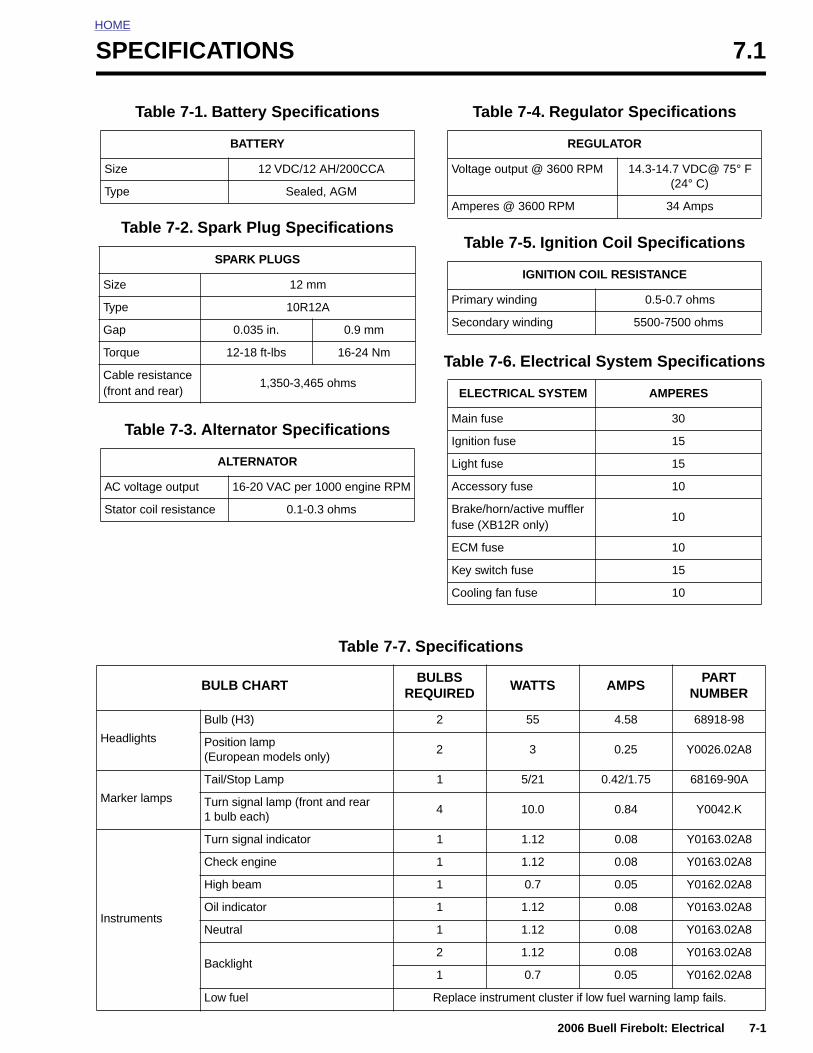
HOME
S
PECIFICATIONS 7.1Table 7-1. Battery Specifications
BATTERY
Size 12 VDC/12 AH/200CCA
Type Sealed, AGM
Table 7-2. Spark Plug Specifications
SPARK PLUGS
Size 12 mm
Type 10R12A
Gap 0.035 in. 0.9 mm
Torque 12-18 ft-lbs 16-24 Nm
Cable resistance (front and rear)
1,350-3,465 ohms
Table 7-3. Alternator Specifications
ALTERNATOR
AC voltage output 16-20 VAC per 1000 engine RPM
Stator coil resistance 0.1-0.3 ohms
Table 7-4. Regulator Specifications
REGULATOR
Voltage output @ 3600 RPM 14.3-14.7 VDC@ 75° F (24° C)
Amperes @ 3600 RPM 34 Amps
Table 7-5. Ignition Coil Specifications
IGNITION COIL RESISTANCE
Primary winding 0.5-0.7 ohms
Secondary winding 5500-7500 ohms
Table 7-6. Electrical System Specifications
ELECTRICAL SYSTEM AMPERES
Main fuse 30
Ignition fuse 15
Light fuse 15
Accessory fuse 10
Brake/horn/active muffler fuse (XB12R only)
10
ECM fuse 10
Key switch fuse 15
Cooling fan fuse 10
Table 7-7. Specifications
BULB CHARTBULBS
REQUIREDWATTS AMPS
PART NUMBER
Bulb (H3) 2 55 4.58 68918-98
2006 Buell Firebolt: Electrical 7-1
Headlights Position lamp (European models only)
2 3 0.25 Y0026.02A8
Marker lamps
Tail/Stop Lamp 1 5/21 0.42/1.75 68169-90A
Turn signal lamp (front and rear1 bulb each)
4 10.0 0.84 Y0042.K
Instruments
Turn signal indicator 1 1.12 0.08 Y0163.02A8
Check engine 1 1.12 0.08 Y0163.02A8
High beam 1 0.7 0.05 Y0162.02A8
Oil indicator 1 1.12 0.08 Y0163.02A8
Neutral 1 1.12 0.08 Y0163.02A8
Backlight2 1.12 0.08 Y0163.02A8
1 0.7 0.05 Y0162.02A8
Low fuel Replace instrument cluster if low fuel warning lamp fails.
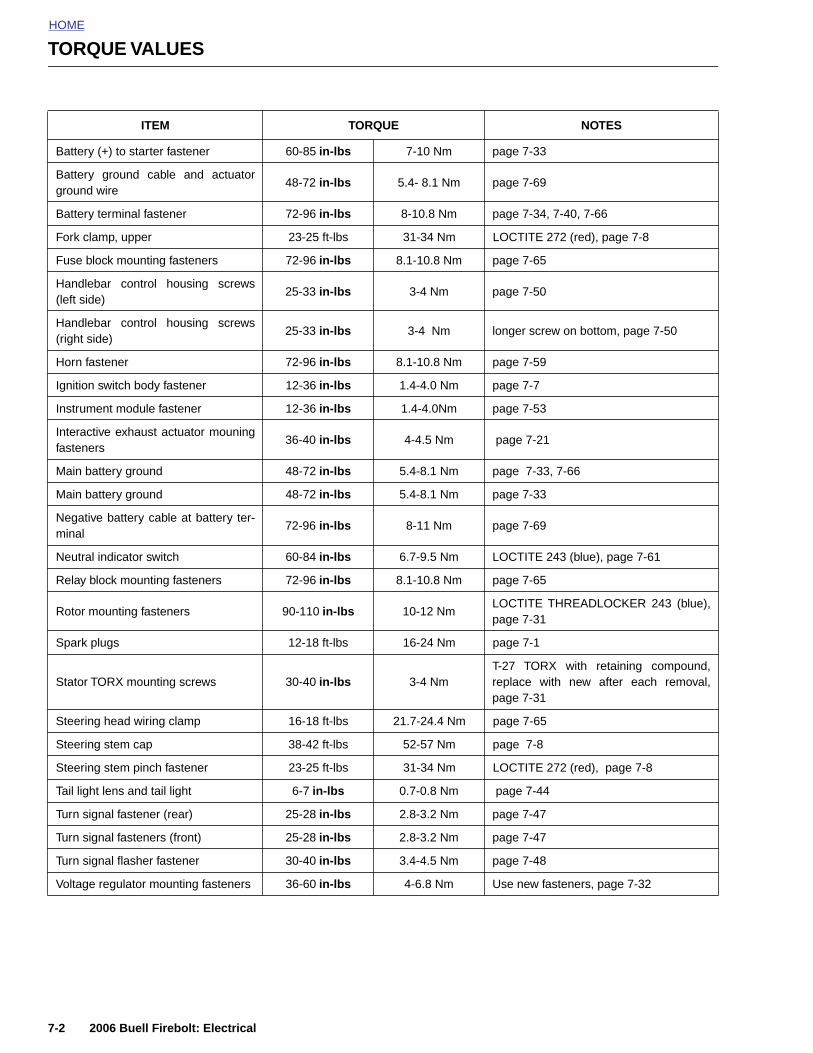
HOME
TORQUE VALUES
ITEM TORQUE NOTES
Battery (+) to starter fastener 60-85 in-lbs 7-10 Nm page 7-33
Battery ground cable and actuatorground wire
48-72 in-lbs 5.4- 8.1 Nm page 7-69
Battery terminal fastener 72-96 in-lbs 8-10.8 Nm page 7-34, 7-40, 7-66
Fork clamp, upper 23-25 ft-lbs 31-34 Nm LOCTITE 272 (red), page 7-8
Fuse block mounting fasteners 72-96 in-lbs 8.1-10.8 Nm page 7-65
Handlebar control housing screws(left side)
25-33 in-lbs 3-4 Nm page 7-50
Handlebar control housing screws(right side)
25-33 in-lbs 3-4 Nm longer screw on bottom, page 7-50
Horn fastener 72-96 in-lbs 8.1-10.8 Nm page 7-59
Ignition switch body fastener 12-36 in-lbs 1.4-4.0 Nm page 7-7
Instrument module fastener 12-36 in-lbs 1.4-4.0Nm page 7-53
Interactive exhaust actuator mouningfasteners
36-40 in-lbs 4-4.5 Nm page 7-21
Main battery ground 48-72 in-lbs 5.4-8.1 Nm page 7-33, 7-66
Main battery ground 48-72 in-lbs 5.4-8.1 Nm page 7-33
Negative battery cable at battery ter-minal
72-96 in-lbs 8-11 Nm page 7-69
Neutral indicator switch 60-84 in-lbs 6.7-9.5 Nm LOCTITE 243 (blue), page 7-61
Relay block mounting fasteners 72-96 in-lbs 8.1-10.8 Nm page 7-65
Rotor mounting fasteners 90-110 in-lbs 10-12 NmLOCTITE THREADLOCKER 243 (blue),page 7-31
Spark plugs 12-18 ft-lbs 16-24 Nm page 7-1
Stator TORX mounting screws 30-40 in-lbs 3-4 NmT-27 TORX with retaining compound,replace with new after each removal,page 7-31
Steering head wiring clamp 16-18 ft-lbs 21.7-24.4 Nm page 7-65
Steering stem cap 38-42 ft-lbs 52-57 Nm page 7-8
Steering stem pinch fastener 23-25 ft-lbs 31-34 Nm LOCTITE 272 (red), page 7-8
7-2 2006 Buell Firebolt: Electrical
Tail light lens and tail light 6-7 in-lbs 0.7-0.8 Nm page 7-44
Turn signal fastener (rear) 25-28 in-lbs 2.8-3.2 Nm page 7-47
Turn signal fasteners (front) 25-28 in-lbs 2.8-3.2 Nm page 7-47
Turn signal flasher fastener 30-40 in-lbs 3.4-4.5 Nm page 7-48
Voltage regulator mounting fasteners 36-60 in-lbs 4-6.8 Nm Use new fasteners, page 7-32
HOME
I
G
TscittF
Dim
TTtioiTf
TctadaarTwi
Td
GNITION SYSTEM 7.2
ENERAL
he vehicle uses a breakerless inductive-discharge ignitionystem. The system has both a primary and secondary cir-uit. The primary circuit consists of the battery, main fuse,
gnition switch, primary coil windings, computerized ignitionimer and associated wiring. The secondary circuit consists ofhe secondary coil, spark plugs and associated wiring. Seeigure 7-1.
IGITAL TECHNICIAN (Part No. HD-44750) can access thenformation received by and stored in the electronic control
odule.
he electronic control module (ECM) is located in the fairing.he module has three primary functions. First, it computes
he spark advance for proper ignition timing based on sensornput. Second, it controls the independent, primary windingsf the spark coil and is thus able to provide sequential and
ndependent firing of the spark plugs (non waste spark).hird, it calculates the correct air/fuel ratio based on input
rom the sensors.
he electronic control module contains all the solid-stateomponents used in the ignition system. The dwell time forhe ignition coil is also calculated by the ECM microprocessornd is dependent upon battery voltage. The programmedwell is an added feature to keep battery drain to a minimumnd to adequately charge the coil at all speeds. The ECM hasdded protection against transient voltages, continuouseverse voltage protection and damage due to jump starts.he ECM is fully enclosed to protect it from vibration, dust,ater and oil. The module is not repairable. Replace the unit if
t fails.
he ECM uses six or seven different sensors to monitor rideremands and engine conditions. These sensors are:
● Throttle Position (TP) Sensor ● Cam Position (CMP) Sensor● Intake Air Temperature (IAT) Sensor● Engine Temperature (ET) Sensor● Oxygen (O2) Sensor● Bank Angle Sensor (BAS)● Interactive Muffler Valve Position Sensor (XB12R)
On the XB12R, an interactive exhaust system utilizes anactuator valve in the muffler which is connected to a servomotor via a cable. The valve position automatically adjusts toenhance engine performance.
Cooling fan actuation is controlled by the ECM. With key ON,fan turns on when engine cylinder head temperature reaches220° C (428° F) and shuts off when temperature reaches180° C (356° F). With key OFF, fan turns on when enginetemperature reaches 170° C (338° F) and shuts off whentemperature reaches 150° C (302° F).
The information provided by the O2 sensor allows the ECM toensure a proper air/fuel mixture by monitoring the final com-bustion efficiency in the exhaust system. This ensures opti-mum engine performance at any altitude or barometricpressure. The O2 sensor input to the ECM is required toensure a stoichiometric (14.7:1) air/fuel ratio during closedloop operation.
The Bank Angle Sensor (BAS) provides input to the ECM onwhether the vehicle lean is greater than predetermined bankangle limit. As long as lean angle does not exceed limit, fuelsupply and ignition operation are unaffected. If the vehicleexceeds the predetermined bank angle limit, the BAS willinterrupt the operation of the ignition system and fuel supply.To reset system, return vehicle to the upright position andswitch key OFF.
The ECM-controlled ignition coil fires each spark plug inde-pendently on the compression stroke of each cylinder (nowaste spark). The spark plug in the front cylinder fires at theend of that cylinder’s compression stroke, thereby igniting theair/fuel mixture. The same sequence occurs at the end of therear cylinder’s compression stroke (thereby igniting the air/fuel mixture in the rear cylinder).
The rotor and cam position sensor are located in the gear-case cover on the right side of the motorcycle. The Cam posi-tion sensor consists of a Hall-effect device, magnet and plate.The plate is mounted over a rotating cup (“rotor cup”). Therotor cup is mounted on the camshaft and operates at one-half crankshaft speed. As the rotor cup turns inside the gear-case, six asymmetrical teeth on the rotor cup sequentiallybreak the magnetic field between the magnet and the Hall-
2006 Buell Firebolt: Electrical 7-3
(Built-in to the actuator)
The ECM uses the information provided by the throttle posi-tion and cam position sensors to calculate how much air isentering the engine.The throttle position sensor monitors theamount of air entering the engine by how far the throttle isopen, whether it is opening or closing and how fast it is open-ing or closing. The IAT sensor measures the temperature ofthe air entering the engine, providing the rest of the informa-tion necessary to determine the density of the air entering theengine. The ECM also monitors the cam position sensor todetermine the exact position of both cylinders in the combus-tion cycle and the engine speed.
The ET sensor provides the ECM the current engine temper-ature. Proper fuel and spark delivery are dependent on thetemperature of the engine. The ECM will provide a richer fuelmixture on start up and a higher degree of spark advance. Asthe vehicle warms up to operating temperature the fuel mix-ture will lean and the spark advance will decrease.
effect device. The edges of these teeth are cut to correspondto specific positions of the camshaft during the engine cyclesuch as TDC for the front cylinder. The output of the camposition sensor is used by the ECM to not only determineengine position, but also to calculate engine speed. Thismethod of measuring camshaft position provides accurateinformation on engine position down to zero engine speed.
For more information on the sensors used in conjunction withthe ECM see Section 4 Fuel System.
See the wiring diagrams in the Appendix for additional infor-mation on ignition system circuits.
TROUBLESHOOTING
See Section 4 Fuel System for troubleshooting information.
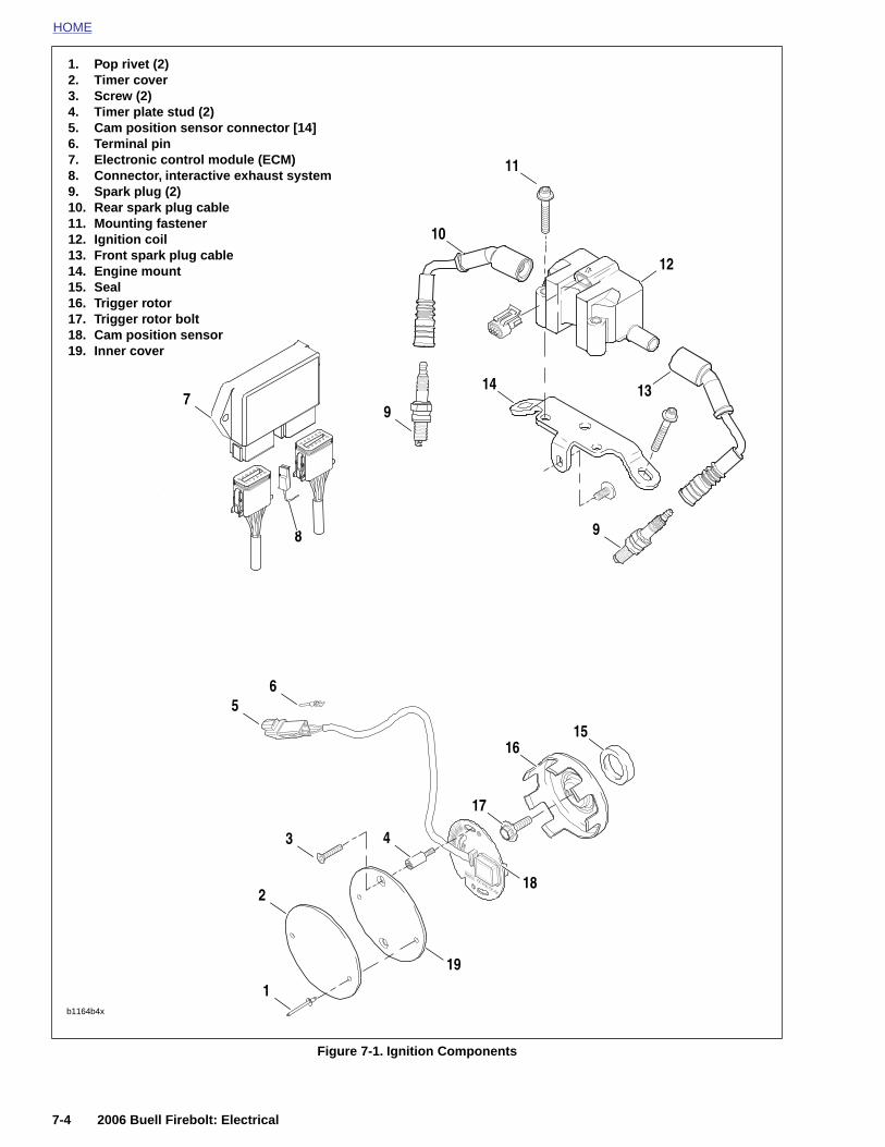
HOME
1. Pop rivet (2)2. Timer cover
3. Screw (2)4. Timer plate stud (2)5. Cam position sensor connector [14]6. Terminal pin7. Electronic control module (ECM)8. Connector, interactive exhaust system9. Spark plug (2)10. Rear spark plug cable11. Mounting fastener12. Ignition coil13. Front spark plug cable14. Engine mount15. Seal16. Trigger rotor17. Trigger rotor bolt18. Cam position sensor19. Inner cover3
56
7
4
17
16
9
10
11
12
1314
15
9
8
7-4 2006 Buell Firebolt: Electrical
Figure 7-1. Ignition Components
b1164b4x
1
218
19

HOME
I
G
Dcipo
S
Tttr
Ttcrpb
GNITION/HEADLIGHT KEY SWITCH 7.3
ENERAL
1WARNING1WARNING
O NOT modify the ignition/headlight switch wiring toircumvent the automatic-on headlight feature. Visibilitys a major concern for motorcyclists. Failure to haveroper headlight operation could result in death or seri-us injury.
witch positions are explained in Table 7-8.
CAUTION
urn the ignition switch to the OFF position and removehe key before locking the motorcycle. Leaving the key inhe P position will keep the instrument lights on andesult in a discharged battery. (00155a)
NOTE
he key locks the ignition system and is removable in bothhe LOCK and P positions. The P position is located counter-lockwise from the LOCK position and allows the rider toemove the key while leaving the lights on. When the key islaced in the P position, several indicator markers are or cane activated. See Table 7-9.
8345
123
4
Table 7-8. Ignition Key Switch Positions
LABEL IGN. LAMPSREMOVE
KEY
OFF off off yes
P off See note & Table 7-9.
yes
ON on no
LOCK off off yes
Table 7-9. Indicator Markers
ITEM P ON
Headlight position marker lamps(European models only)
on on
Headlight high beamoff
can be activated
Headlight low beam off on
Instrument module illuminationlamps
on on
Stop lamp can beactivated
Front and rear turn signals can be activated
Horn cannot be activated
can be activated
2006 Buell Firebolt: Electrical 7-5
Figure 7-2. Ignition/Headlight Key Switch
1. ON position2. OFF position3. PUSH DETENT4. LOCK position5. PARKING LIGHT position6. Upper triple clamp
56
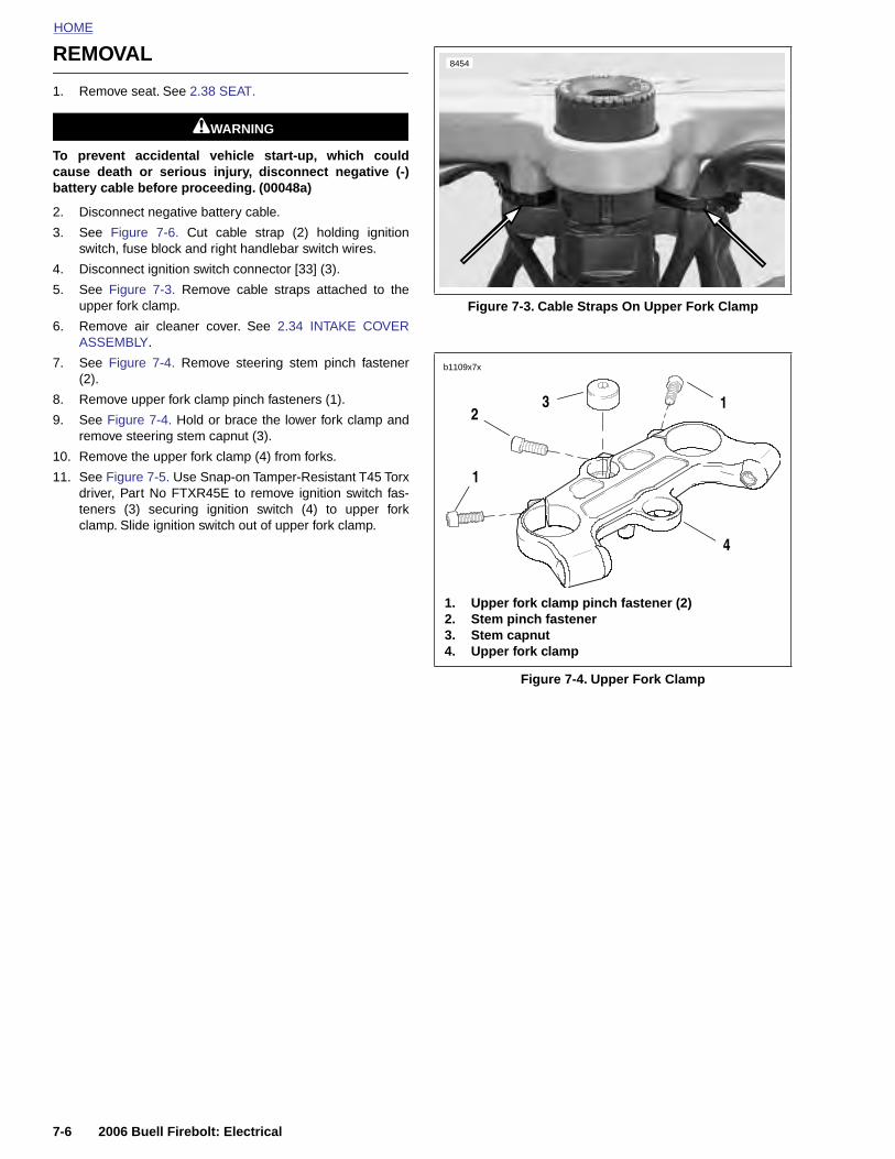
HOME
REMOVAL
8454
1. Remove seat. See 2.38 SEAT.
1WARNING1WARNING
To prevent accidental vehicle start-up, which couldcause death or serious injury, disconnect negative (-)battery cable before proceeding. (00048a)
2. Disconnect negative battery cable.
3. See Figure 7-6. Cut cable strap (2) holding ignitionswitch, fuse block and right handlebar switch wires.
4. Disconnect ignition switch connector [33] (3).
5. See Figure 7-3. Remove cable straps attached to theupper fork clamp.
6. Remove air cleaner cover. See 2.34 INTAKE COVERASSEMBLY.
7. See Figure 7-4. Remove steering stem pinch fastener(2).
8. Remove upper fork clamp pinch fasteners (1).
9. See Figure 7-4. Hold or brace the lower fork clamp andremove steering stem capnut (3).
10. Remove the upper fork clamp (4) from forks.
11. See Figure 7-5. Use Snap-on Tamper-Resistant T45 Torxdriver, Part No FTXR45E to remove ignition switch fas-teners (3) securing ignition switch (4) to upper forkclamp. Slide ignition switch out of upper fork clamp.
Figure 7-3. Cable Straps On Upper Fork Clamp
Figure 7-4. Upper Fork Clamp
1. Upper fork clamp pinch fastener (2)2. Stem pinch fastener3. Stem capnut4. Upper fork clamp
1
12
3
4
b1109x7x
7-6 2006 Buell Firebolt: Electrical
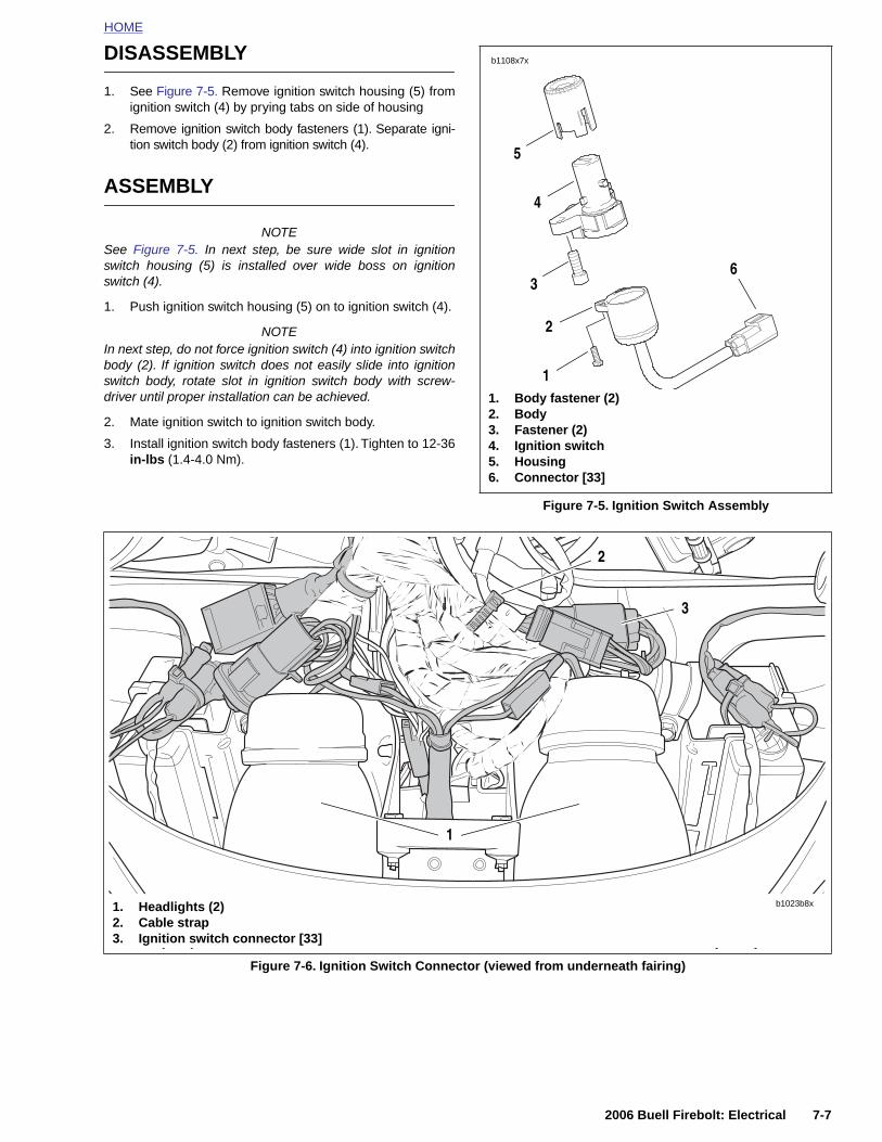
HOME
DISASSEMBLY
1. See Figure 7-5. Remove ignition switch housing (5) fromignition switch (4) by prying tabs on side of housing
2. Remove ignition switch body fasteners (1). Separate igni-tion switch body (2) from ignition switch (4).
ASSEMBLY
NOTESee Figure 7-5. In next step, be sure wide slot in ignitionswitch housing (5) is installed over wide boss on ignitionswitch (4).
1. Push ignition switch housing (5) on to ignition switch (4).
NOTEIn next step, do not force ignition switch (4) into ignition switchbody (2). If ignition switch does not easily slide into ignitionswitch body, rotate slot in ignition switch body with screw-driver until proper installation can be achieved.
2. Mate ignition switch to ignition switch body.
3. Install ignition switch body fasteners (1). Tighten to 12-36in-lbs (1.4-4.0 Nm).
Figure 7-5. Ignition Switch Assembly
b1108x7x
1. Body fastener (2)2. Body3. Fastener (2)4. Ignition switch5. Housing6. Connector [33]
5
4
3
1
6
2
2
3
2006 Buell Firebolt: Electrical 7-7
Figure 7-6. Ignition Switch Connector (viewed from underneath fairing)
1. Headlights (2)2. Cable strap3. Ignition switch connector [33]
b1023b8x
1
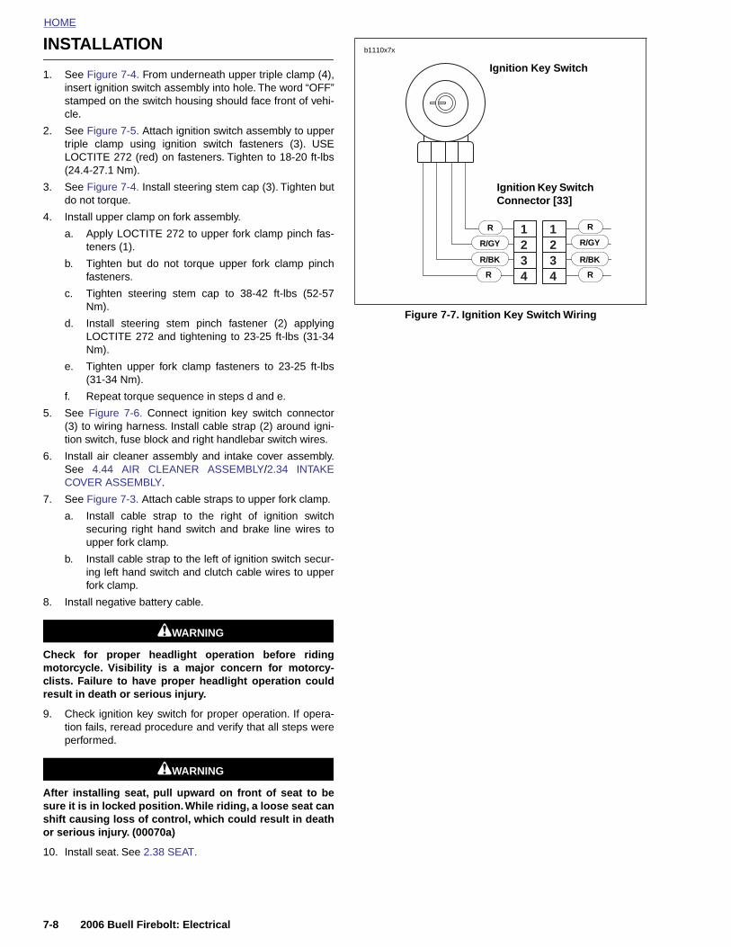
HOME
INSTALLATION
Ignition Key Switch
b1110x7x
1. See Figure 7-4. From underneath upper triple clamp (4),insert ignition switch assembly into hole. The word “OFF”stamped on the switch housing should face front of vehi-cle.
2. See Figure 7-5. Attach ignition switch assembly to uppertriple clamp using ignition switch fasteners (3). USELOCTITE 272 (red) on fasteners. Tighten to 18-20 ft-lbs(24.4-27.1 Nm).
3. See Figure 7-4. Install steering stem cap (3). Tighten butdo not torque.
4. Install upper clamp on fork assembly.
a. Apply LOCTITE 272 to upper fork clamp pinch fas-teners (1).
b. Tighten but do not torque upper fork clamp pinchfasteners.
c. Tighten steering stem cap to 38-42 ft-lbs (52-57Nm).
d. Install steering stem pinch fastener (2) applyingLOCTITE 272 and tightening to 23-25 ft-lbs (31-34Nm).
e. Tighten upper fork clamp fasteners to 23-25 ft-lbs(31-34 Nm).
f. Repeat torque sequence in steps d and e.
5. See Figure 7-6. Connect ignition key switch connector(3) to wiring harness. Install cable strap (2) around igni-tion switch, fuse block and right handlebar switch wires.
6. Install air cleaner assembly and intake cover assembly.See 4.44 AIR CLEANER ASSEMBLY/2.34 INTAKECOVER ASSEMBLY.
7. See Figure 7-3. Attach cable straps to upper fork clamp.
a. Install cable strap to the right of ignition switchsecuring right hand switch and brake line wires toupper fork clamp.
b. Install cable strap to the left of ignition switch secur-ing left hand switch and clutch cable wires to upperfork clamp.
8. Install negative battery cable.
1WARNING1WARNING
Check for proper headlight operation before ridingmotorcycle. Visibility is a major concern for motorcy-clists. Failure to have proper headlight operation couldresult in death or serious injury.
Figure 7-7. Ignition Key Switch Wiring
44332211
Ignition Key Switch Connector [33]
R/GY
R
R
R
R
R/GY
R/BK R/BK
7-8 2006 Buell Firebolt: Electrical
9. Check ignition key switch for proper operation. If opera-tion fails, reread procedure and verify that all steps wereperformed.
1WARNING1WARNING
After installing seat, pull upward on front of seat to besure it is in locked position. While riding, a loose seat canshift causing loss of control, which could result in deathor serious injury. (00070a)
10. Install seat. See 2.38 SEAT.
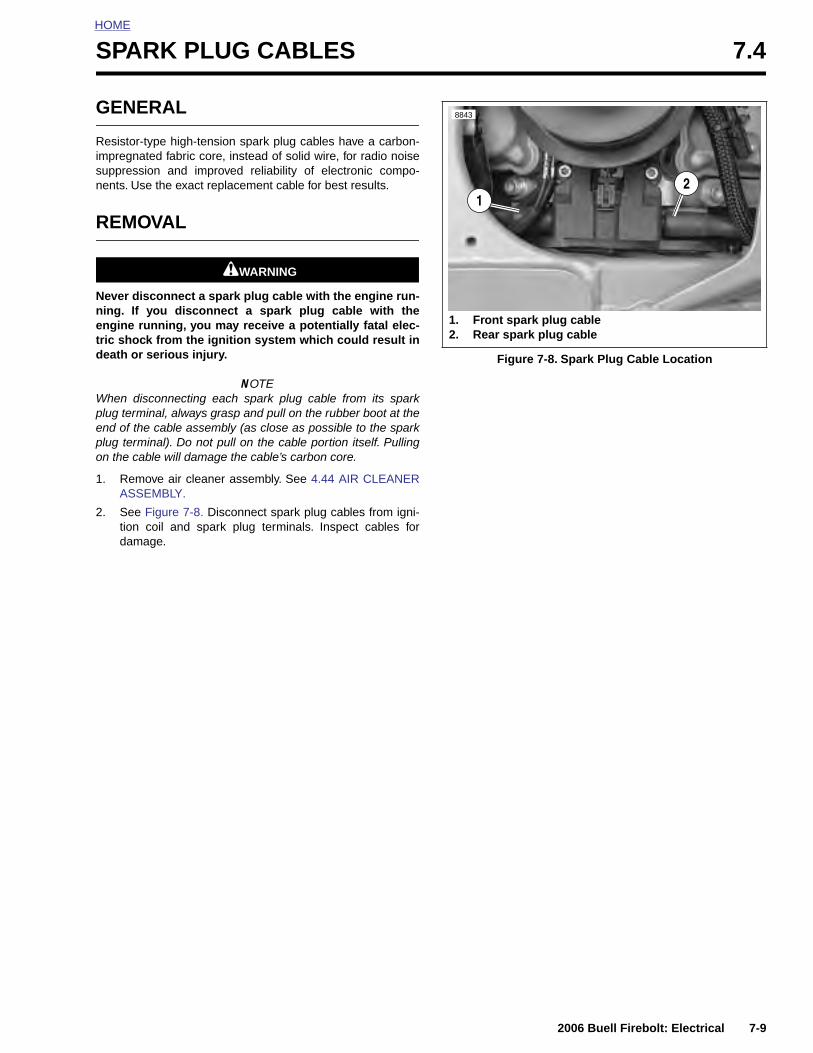
HOME
S
G
Rimsn
R
Nnetd
Wpepo
1
2
PARK PLUG CABLES 7.4
ENERAL
esistor-type high-tension spark plug cables have a carbon-pregnated fabric core, instead of solid wire, for radio noise
uppression and improved reliability of electronic compo-ents. Use the exact replacement cable for best results.
EMOVAL
1WARNING1WARNING
ever disconnect a spark plug cable with the engine run-ing. If you disconnect a spark plug cable with thengine running, you may receive a potentially fatal elec-ric shock from the ignition system which could result ineath or serious injury.
NOTEhen disconnecting each spark plug cable from its spark
lug terminal, always grasp and pull on the rubber boot at thend of the cable assembly (as close as possible to the sparklug terminal). Do not pull on the cable portion itself. Pullingn the cable will damage the cable’s carbon core.
. Remove air cleaner assembly. See 4.44 AIR CLEANERASSEMBLY.
. See Figure 7-8. Disconnect spark plug cables from igni-tion coil and spark plug terminals. Inspect cables fordamage.
Figure 7-8. Spark Plug Cable Location
1. Front spark plug cable2. Rear spark plug cable
12
8843
2006 Buell Firebolt: Electrical 7-9
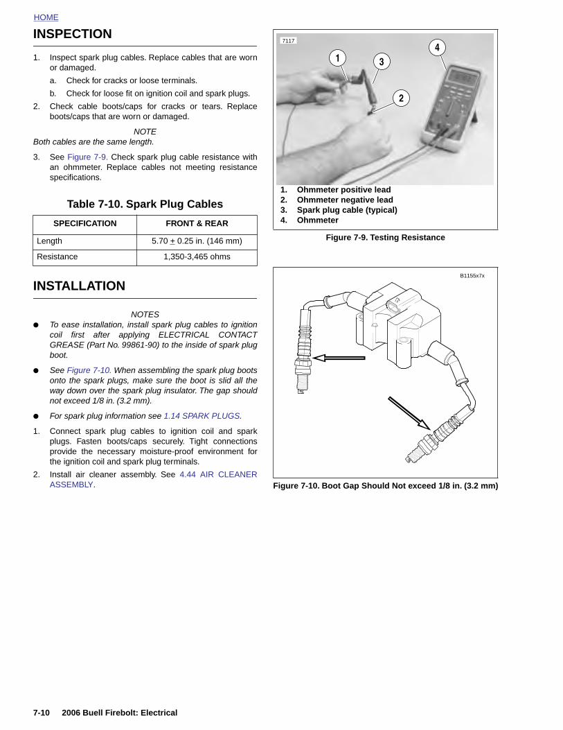
HOME
INSPECTION
7117
4
1. Inspect spark plug cables. Replace cables that are wornor damaged.
a. Check for cracks or loose terminals.
b. Check for loose fit on ignition coil and spark plugs.
2. Check cable boots/caps for cracks or tears. Replaceboots/caps that are worn or damaged.
NOTEBoth cables are the same length.
3. See Figure 7-9. Check spark plug cable resistance withan ohmmeter. Replace cables not meeting resistancespecifications.
INSTALLATION
NOTES● To ease installation, install spark plug cables to ignition
coil first after applying ELECTRICAL CONTACTGREASE (Part No. 99861-90) to the inside of spark plugboot.
● See Figure 7-10. When assembling the spark plug bootsonto the spark plugs, make sure the boot is slid all theway down over the spark plug insulator. The gap shouldnot exceed 1/8 in. (3.2 mm).
● For spark plug information see 1.14 SPARK PLUGS.
1. Connect spark plug cables to ignition coil and sparkplugs. Fasten boots/caps securely. Tight connectionsprovide the necessary moisture-proof environment forthe ignition coil and spark plug terminals.
2. Install air cleaner assembly. See 4.44 AIR CLEANERASSEMBLY.
Table 7-10. Spark Plug Cables
SPECIFICATION FRONT & REAR
Length 5.70 + 0.25 in. (146 mm)
Resistance 1,350-3,465 ohms
Figure 7-9. Testing Resistance
Figure 7-10. Boot Gap Should Not exceed 1/8 in. (3.2 mm)
1. Ohmmeter positive lead2. Ohmmeter negative lead3. Spark plug cable (typical)4. Ohmmeter
31
2
B1155x7x
7-10 2006 Buell Firebolt: Electrical
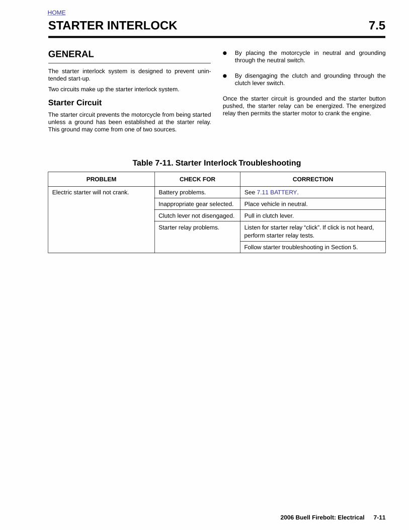
HOME
S
G
Tt
T
STuT
TARTER INTERLOCK 7.5
ENERAL
he starter interlock system is designed to prevent unin-ended start-up.
wo circuits make up the starter interlock system.
tarter Circuithe starter circuit prevents the motorcycle from being startednless a ground has been established at the starter relay.his ground may come from one of two sources.
● By placing the motorcycle in neutral and groundingthrough the neutral switch.
● By disengaging the clutch and grounding through theclutch lever switch.
Once the starter circuit is grounded and the starter buttonpushed, the starter relay can be energized. The energizedrelay then permits the starter motor to crank the engine.
Table 7-11. Starter Interlock Troubleshooting
PROBLEM CHECK FOR CORRECTION
Electric starter will not crank. Battery problems. See 7.11 BATTERY.
Inappropriate gear selected. Place vehicle in neutral.
Clutch lever not disengaged. Pull in clutch lever.
Starter relay problems. Listen for starter relay “click”. If click is not heard, perform starter relay tests.
Follow starter troubleshooting in Section 5.
2006 Buell Firebolt: Electrical 7-11
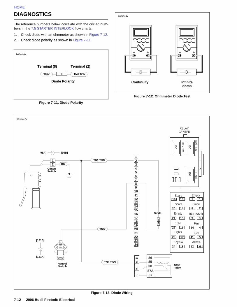
HOME
DIAGNOSTICS
b0643x4x
The reference numbers below correlate with the circled num-bers in the 7.5 STARTER INTERLOCK flow charts.
1. Check diode with an ohmmeter as shown in Figure 7-12.
2. Check diode polarity as shown in Figure 7-11.
Figure 7-11. Diode Polarity
b0644x4x
TN/Y
Diode Polarity
TN/LTGN
Terminal (8) Terminal (2)
Figure 7-12. Ohmmeter Diode Test
Continuity Infinite ohms
12
1 2
4 5 67 8 910111213141516171819
3
RELAYCENTER
ISO
ISOISO
KEY SW.
IGN
ITION
START
19
20
21
13
14
15
1
2
3
7
8
9
Spare
Diode
Bk/Hn/Mflr
FanECM
Spare
Empty
Empty
TN/LTGN
Diode
BK
b1107e7x
Clutch Switch
[95B][95A]
7-12 2006 Buell Firebolt: Electrical
Figure 7-13. Diode Wiring
2021222324
2
6
7
10
8787A308586
22
23
24
16
17
18
4
5
6
10
11
12
11IGN
Acces.Key Sw
Lights
Neutral Switch Start
Relay
TN/Y
[131A]
[131B]
TN/LTGN
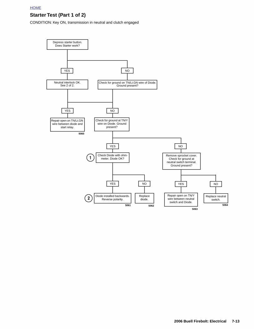
HOME
Starter Test (Part 1 of 2)CONDITION: Key ON, transmission in neutral and clutch engaged
YES
Repair open on TN/Lt.GN wire between diode and
start relay.
YES
Check Diode with ohm-meter. Diode OK?
Remove sprocket cover. Check for ground at
neutral switch terminal. Ground present?
Check for ground at TN/Y wire on Diode. Ground
present?
YES
Diode installed backwards. Reverse polarity.
Replace diode.
YES
Repair open on TN/Y wire between neutral
switch and Diode.
Replace neutral switch.
NO
NO
NO
NO
5060
5061 50625063
5064
1
2
Depress starter button.Does Starter work?
Check for ground on TN/Lt.GN wire of Diode.Ground present?
NO
Neutral interlock OK.See 2 of 2.
YES
2006 Buell Firebolt: Electrical 7-13
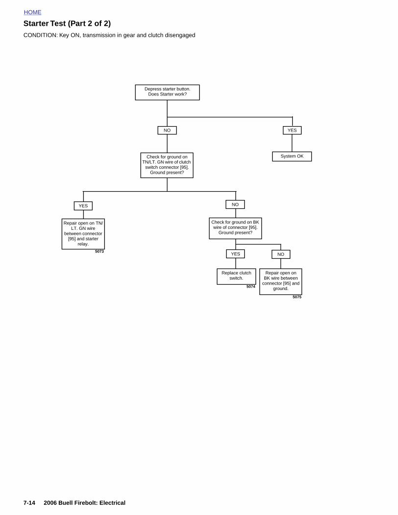
HOME
Starter Test (Part 2 of 2)
CONDITION: Key ON, transmission in gear and clutch disengaged
YES
Check for ground on TN/LT. GN wire of clutch
switch connector [95].Ground present?
YES
Repair open on TN/LT. GN wire
between connector [95] and starter
relay.
NO
Replace clutch switch.
Check for ground on BK wire of connector [95].
Ground present?
NO
Repair open on BK wire between
connector [95] and ground.
5073
5074
5075
YES
Depress starter button.Does Starter work?
NO
System OK
7-14 2006 Buell Firebolt: Electrical
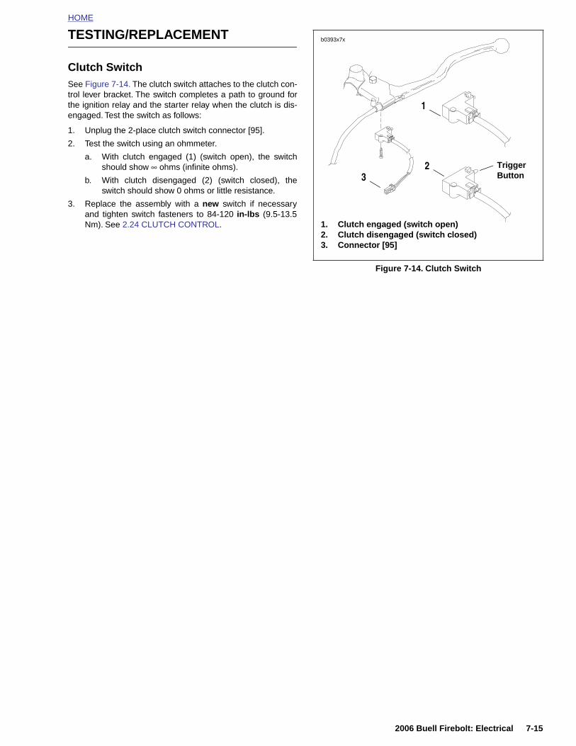
HOME
TESTING/REPLACEMENT
Clutch SwitchSee Figure 7-14. The clutch switch attaches to the clutch con-trol lever bracket. The switch completes a path to ground forthe ignition relay and the starter relay when the clutch is dis-engaged. Test the switch as follows:
1. Unplug the 2-place clutch switch connector [95].
2. Test the switch using an ohmmeter.
a. With clutch engaged (1) (switch open), the switchshould show ∞ ohms (infinite ohms).
b. With clutch disengaged (2) (switch closed), theswitch should show 0 ohms or little resistance.
3. Replace the assembly with a new switch if necessaryand tighten switch fasteners to 84-120 in-lbs (9.5-13.5Nm). See 2.24 CLUTCH CONTROL.
Figure 7-14. Clutch Switch
b0393x7x
1. Clutch engaged (switch open)2. Clutch disengaged (switch closed)3. Connector [95]
Trigger Button3
1
2
2006 Buell Firebolt: Electrical 7-15
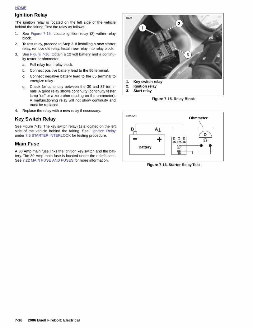
HOME
Ignition Relay
The ignition relay is located on the left side of the vehicle
8379
2
behind the fairing. Test the relay as follows:1. See Figure 7-15. Locate ignition relay (2) within relayblock.
2. To test relay, proceed to Step 3. If installing a new starterrelay, remove old relay. Install new relay into relay block.
3. See Figure 7-16. Obtain a 12 volt battery and a continu-ity tester or ohmmeter.
a. Pull relay from relay block.
b. Connect positive battery lead to the 86 terminal.
c. Connect negative battery lead to the 85 terminal toenergize relay.
d. Check for continuity between the 30 and 87 termi-nals. A good relay shows continuity (continuity testerlamp “on” or a zero ohm reading on the ohmmeter).A malfunctioning relay will not show continuity andmust be replaced.
4. Replace the relay with a new relay if necessary.
Key Switch RelaySee Figure 7-15. The key switch relay (1) is located on the leftside of the vehicle behind the fairing. See Ignition Relayunder 7.5 STARTER INTERLOCK for testing procedure.
Main FuseA 30 Amp main fuse links the ignition key switch and the bat-tery. The 30 Amp main fuse is located under the rider’s seat.See 7.22 MAIN FUSE AND FUSES for more information.
Figure 7-15. Relay Block
Figure 7-16. Starter Relay Test
1
1. Key switch relay2. Ignition relay3. Start relay
3
b0755x5x
Battery
Ohmmeter
7-16 2006 Buell Firebolt: Electrical
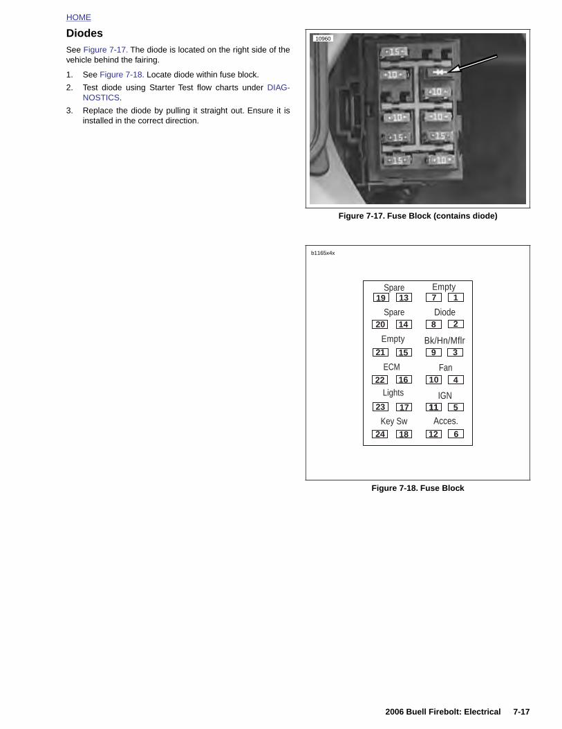
HOME
DiodesSee Figure 7-17. The diode is located on the right side of thevehicle behind the fairing.
1. See Figure 7-18. Locate diode within fuse block.
2. Test diode using Starter Test flow charts under DIAG-NOSTICS.
3. Replace the diode by pulling it straight out. Ensure it isinstalled in the correct direction.
Figure 7-17. Fuse Block (contains diode)
Figure 7-18. Fuse Block
10960
19
20
21
22
23
24
13
14
15
16
17
18
1
2
3
4
5
6
7
8
9
10
11
12
11
Spare
Diode
Bk/Hn/Mflr
Fan
IGN
Acces.Key Sw
Lights
ECM
Spare
Empty
Empty
b1165x4x
2006 Buell Firebolt: Electrical 7-17
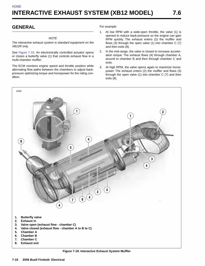
HOME
INTERACTIVE EXHAUST SYSTEM (XB12 MODEL) 7.6
GENE
The interaXB12R on
See Figuror closes multi-cham
The ECMalternatingpressure odition.
8
10568
7-18
1. B2. E3. V4. V5. C6. C7. C8. E
RAL
NOTEctive exhaust system is standard equipment on thely.
e 7-19. An electronically controlled actuator opensa butterfly valve (1) that controls exhaust flow in aber muffler.
monitors engine speed and throttle position while flow paths between the chambers to adjust back-ptimizing torque and horsepower for the riding con-
For example:
1. At low RPM with a wide-open throttle, the valve (1) isopened to reduce back-pressure so the engine can gainRPM quickly. The exhaust enters (2) the muffler andflows (3) through the open valve (1) into chamber C (7)and then exits (8).
2. In the mid-range, the valve is closed to increase acceler-ation torque. The exhaust flows (4) through chamber A,around to chamber B and then through chamber C andexits.
3. At high RPM, the valve opens again to maximize horse-power. The exhaust enters (2) the muffler and flows (3)through the open valve (1) into chamber C (7) and thenexits (8).
12
3
4
4
3
5
1
4
2006 Buell Firebolt: Electrical
Figure 7-19. Interactive Exhaust System Muffler
746
4
utterfly valvexhaust inalve open (exhaust flow - chamber C)alve closed (exhaust flow - chamber A to B to C)hamber Ahamber Bhamber Cxhaust exit
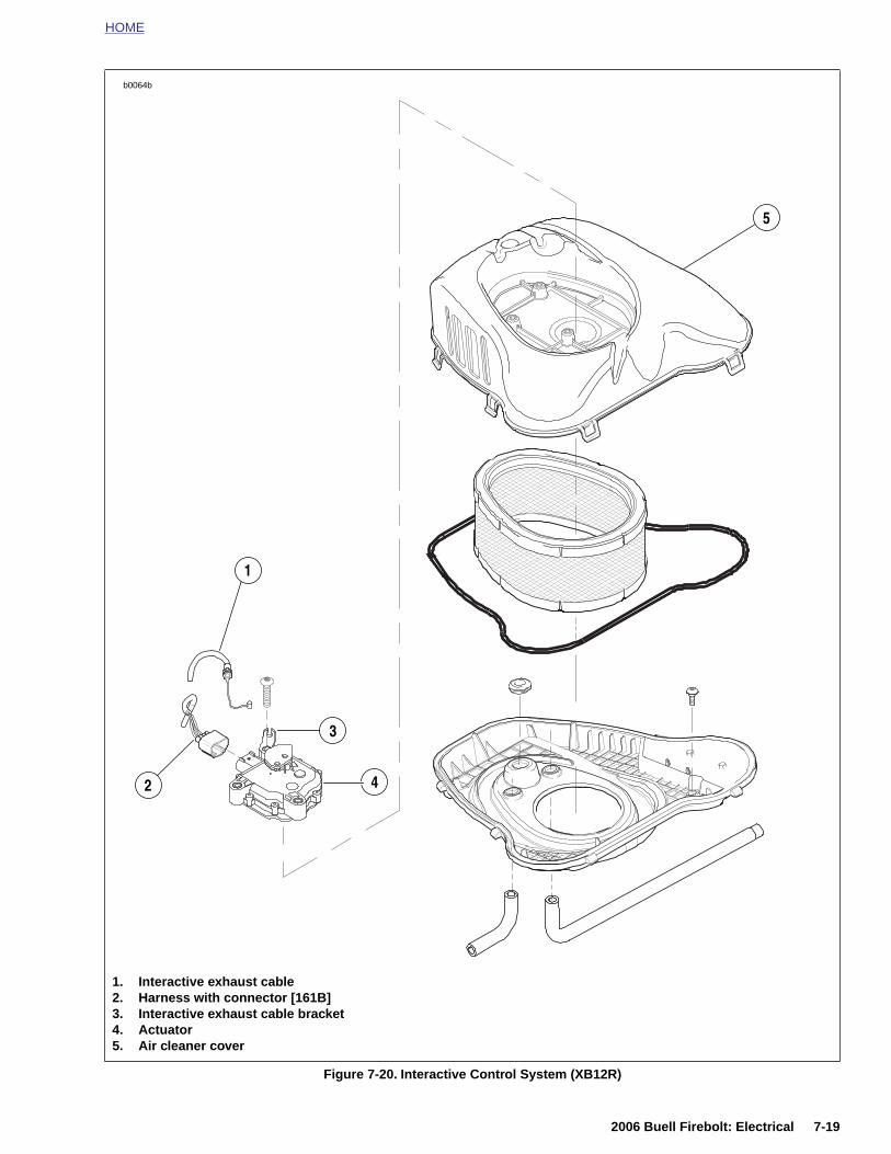
HOME
4
b0064b
1
2
3
5
2006 Buell Firebolt: Electrical 7-19
Figure 7-20. Interactive Control System (XB12R)
1. Interactive exhaust cable2. Harness with connector [161B]3. Interactive exhaust cable bracket4. Actuator5. Air cleaner cover
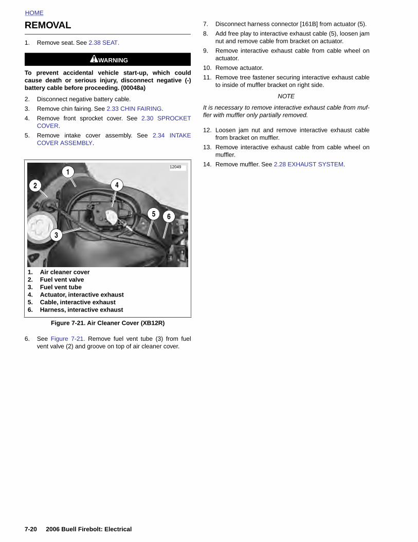
HOME
REMOVAL
7. Disconnect harness connector [161B] from actuator (5).
8. Add free play to interactive exhaust cable (5), loosen jam
1. Remove seat. See 2.38 SEAT.
1WARNING1WARNING
To prevent accidental vehicle start-up, which couldcause death or serious injury, disconnect negative (-)battery cable before proceeding. (00048a)
2. Disconnect negative battery cable.
3. Remove chin fairing. See 2.33 CHIN FAIRING.
4. Remove front sprocket cover. See 2.30 SPROCKETCOVER.
5. Remove intake cover assembly. See 2.34 INTAKECOVER ASSEMBLY.
6. See Figure 7-21. Remove fuel vent tube (3) from fuelvent valve (2) and groove on top of air cleaner cover.
nut and remove cable from bracket on actuator.
9. Remove interactive exhaust cable from cable wheel onactuator.
10. Remove actuator.
11. Remove tree fastener securing interactive exhaust cableto inside of muffler bracket on right side.
NOTE
It is necessary to remove interactive exhaust cable from muf-fler with muffler only partially removed.
12. Loosen jam nut and remove interactive exhaust cablefrom bracket on muffler.
13. Remove interactive exhaust cable from cable wheel onmuffler.
14. Remove muffler. See 2.28 EXHAUST SYSTEM.
Figure 7-21. Air Cleaner Cover (XB12R)
12049
1. Air cleaner cover2. Fuel vent valve3. Fuel vent tube4. Actuator, interactive exhaust5. Cable, interactive exhaust6. Harness, interactive exhaust
3
5 6
1
2 4
7-20 2006 Buell Firebolt: Electrical
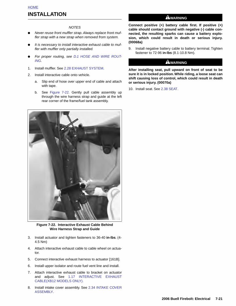
HOME
INSTALLATION
NOTES
● Never reuse front muffler strap. Always replace front muf-fler strap with a new strap when removed from system.
● It is necessary to install interactive exhaust cable to muf-fler with muffler only partially installed.
● For proper routing, see D.1 HOSE AND WIRE ROUT-ING.
1. Install muffler. See 2.28 EXHAUST SYSTEM.
2. Install interactive cable onto vehicle.
a. Slip end of hose over upper end of cable and attachwith tape.
b. See Figure 7-22. Gently pull cable assembly upthrough the wire harness strap and guide at the leftrear corner of the frame/fuel tank assembly.
1WARNING1WARNING
Connect positive (+) battery cable first. If positive (+)cable should contact ground with negative (-) cable con-nected, the resulting sparks can cause a battery explo-sion, which could result in death or serious injury.(00068a)
9. Install negative battery cable to battery terminal. Tightenfastener to 72-96 in-lbs (8.1-10.8 Nm).
1WARNING1WARNING
After installing seat, pull upward on front of seat to besure it is in locked position. While riding, a loose seat canshift causing loss of control, which could result in deathor serious injury. (00070a)
10. Install seat. See 2.38 SEAT.
2006 Buell Firebolt: Electrical 7-21
3. Install actuator and tighten fasteners to 36-40 in-lbs. (4-4.5 Nm)
4. Attach interactive exhaust cable to cable wheel on actua-tor.
5. Connect interactive exhaust harness to actuator [161B].
6. Install upper isolator and route fuel vent line and install.
7. Attach interactive exhaust cable to bracket on actuatorand adjust. See 1.17 INTERACTIVE EXHAUSTCABLE(XB12 MODELS ONLY).
8. Install intake cover assembly. See 2.34 INTAKE COVERASSEMBLY.
Figure 7-22. Interactive Exhaust Cable Behind Wire Harness Strap and Guide

HOME
NOTES
7-22 2006 Buell Firebolt: Electrical
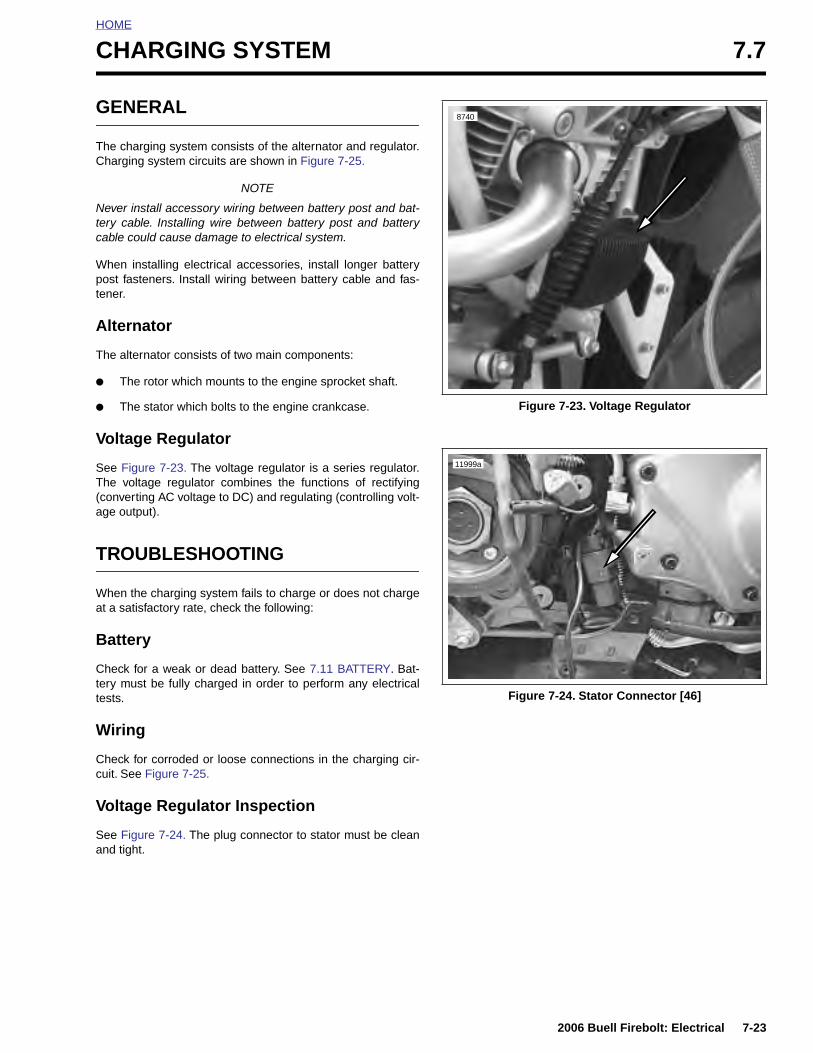
HOME
CHARGING SYSTEM 7.7
GENERAL
The charging system consists of the alternator and regulator.Charging system circuits are shown in Figure 7-25.
NOTE
Never install accessory wiring between battery post and bat-tery cable. Installing wire between battery post and batterycable could cause damage to electrical system.
When installing electrical accessories, install longer batterypost fasteners. Install wiring between battery cable and fas-tener.
Alternator
The alternator consists of two main components:
● The rotor which mounts to the engine sprocket shaft.
● The stator which bolts to the engine crankcase.
Voltage Regulator
See Figure 7-23. The voltage regulator is a series regulator.The voltage regulator combines the functions of rectifying(converting AC voltage to DC) and regulating (controlling volt-age output).
TROUBLESHOOTING
When the charging system fails to charge or does not chargeat a satisfactory rate, check the following:
Battery
Check for a weak or dead battery. See 7.11 BATTERY. Bat-tery must be fully charged in order to perform any electricaltests.
Wiring
Check for corroded or loose connections in the charging cir-cuit. See Figure 7-25.
Voltage Regulator Inspection
See Figure 7-24. The plug connector to stator must be cleanand tight.
Figure 7-23. Voltage Regulator
Figure 7-24. Stator Connector [46]
8740
11999a
2006 Buell Firebolt: Electrical 7-23
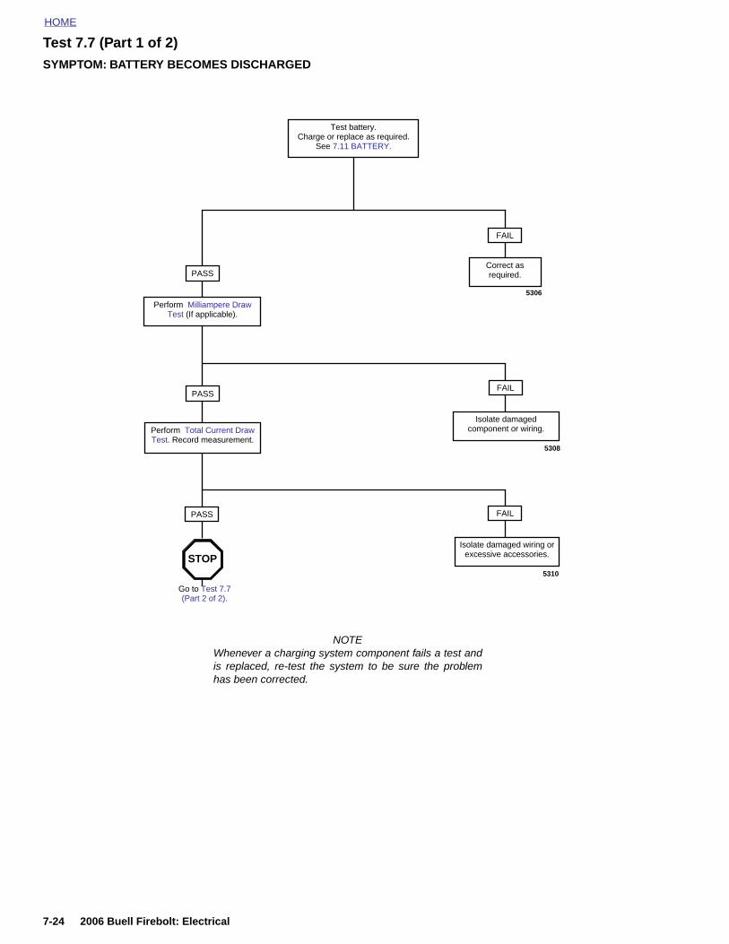
HOME
Test 7.7 (Part 1 of 2)SYMPTOM: BATTERY BECOMES DISCHARGED
Test battery. Charge or replace as required.
See 7.11 BATTERY.
Go to Test 7.7 (Part 2 of 2).
STOP
PASS
FAILPASS
5308
Isolate damaged component or wiring.
FAILPASS
5310
Isolate damaged wiring or excessive accessories.
Perform Milliampere Draw Test (If applicable).
Perform Total Current Draw Test. Record measurement.
NOTEWhenever a charging system component fails a test andis replaced, re-test the system to be sure the problemhas been corrected.
FAIL
Correct as required.
5306
7-24 2006 Buell Firebolt: Electrical
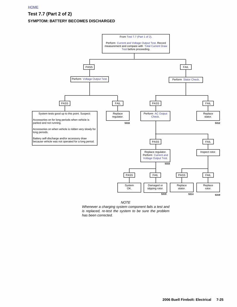
HOME
Test 7.7 (Part 2 of 2)SYMPTOM: BATTERY BECOMES DISCHARGED
FAILPASS
Perform Voltage Output Test. Perform Stator Check.
FAILPASS
System tests good up to this point. Suspect:
Accessories on for long periods when vehicle is parked and not running.
Accessories on when vehicle is ridden very slowly for long periods.
Battery self-discharge and/or accessory draw because vehicle was not operated for a long period.
5316
Replace regulator.
From Test 7.7 (Part 1 of 2).
Perform Current and Voltage Output Test. Record measurement and compare with Total Current Draw
Test before proceeding.
FAILPASS
Perform AC Output Check.
5312
Replace stator.
FAILPASS
Replace regulator. Perform Current and Voltage Output Test.
Inspect rotor.
FAIL
Replace rotor.
PASS
Replace stator.
FAIL
Damaged or slipping rotor.
PASS
SystemOK.
53195314
NOTEWhenever a charging system component fails a test andis replaced, re-test the system to be sure the problemhas been corrected.
5315
5319
2006 Buell Firebolt: Electrical 7-25
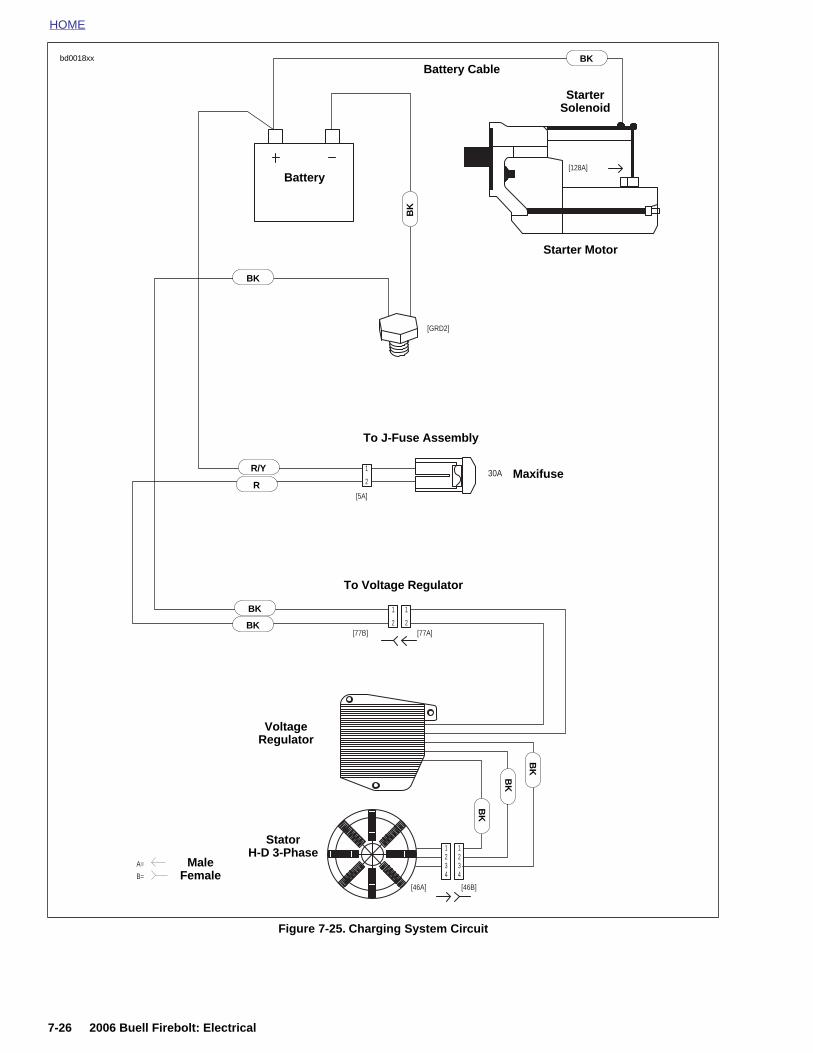
HOME
Figure 7-25. Charging System Circuit
[128A]
A=
B=[46B][46A]
[77A][77B]
30A
[5A]
[GRD2]
BK
2
11
443322
2
11
R
BK
2
1
R
R/Y
BK
bd0018xx BK
R
R/Y
BK
BK
BK
BK
BK
BK
Battery Cable
Starter Solenoid
Starter Motor
Battery
To J-Fuse Assembly
To Voltage Regulator
VoltageRegulator
MaleFemale
StatorH-D 3-Phase
Maxifuse
BK
7-26 2006 Buell Firebolt: Electrical
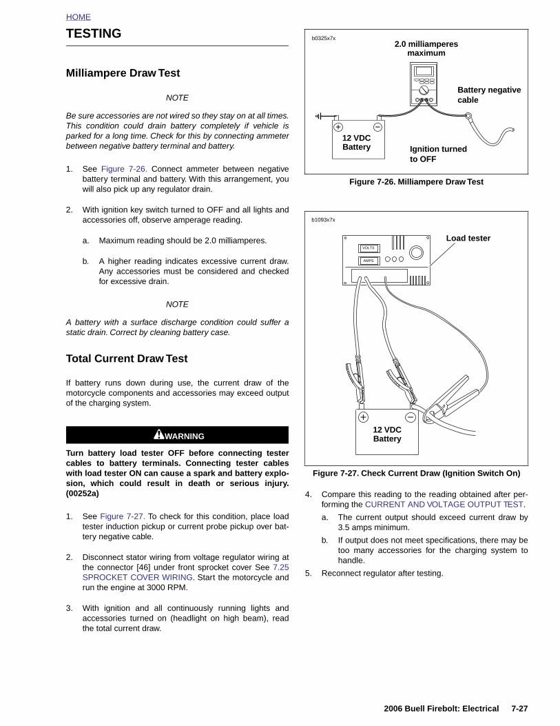
HOME
TESTING
Milliampere Draw Test
NOTE
Be sure accessories are not wired so they stay on at all times.This condition could drain battery completely if vehicle isparked for a long time. Check for this by connecting ammeterbetween negative battery terminal and battery.
1. See Figure 7-26. Connect ammeter between negativebattery terminal and battery. With this arrangement, youwill also pick up any regulator drain.
2. With ignition key switch turned to OFF and all lights andaccessories off, observe amperage reading.
a. Maximum reading should be 2.0 milliamperes.
b. A higher reading indicates excessive current draw.Any accessories must be considered and checkedfor excessive drain.
NOTE
A battery with a surface discharge condition could suffer astatic drain. Correct by cleaning battery case.
Total Current Draw Test
If battery runs down during use, the current draw of themotorcycle components and accessories may exceed outputof the charging system.
1WARNING1WARNING
Turn battery load tester OFF before connecting testercables to battery terminals. Connecting tester cableswith load tester ON can cause a spark and battery explo-sion, which could result in death or serious injury.(00252a)
1. See Figure 7-27. To check for this condition, place loadtester induction pickup or current probe pickup over bat-tery negative cable.
2. Disconnect stator wiring from voltage regulator wiring atthe connector [46] under front sprocket cover See 7.25SPROCKET COVER WIRING. Start the motorcycle andrun the engine at 3000 RPM.
3. With ignition and all continuously running lights andaccessories turned on (headlight on high beam), readthe total current draw.
4. Compare this reading to the reading obtained after per-forming the CURRENT AND VOLTAGE OUTPUT TEST.
a. The current output should exceed current draw by3.5 amps minimum.
b. If output does not meet specifications, there may betoo many accessories for the charging system tohandle.
5. Reconnect regulator after testing.
Figure 7-26. Milliampere Draw Test
Figure 7-27. Check Current Draw (Ignition Switch On)
b0325x7x
12 VDC Battery Ignition turned
to OFF
Battery negative cable
2.0 milliamperes maximum
b1093x7x
Load tester
12 VDC Battery
VOLTS
AMPS
2006 Buell Firebolt: Electrical 7-27

HOME
Current and Voltage Output Test
1. Connect load tester.
a. Connect negative and positive leads to battery ter-minals.
b. See Figure 7-28. Place load tester induction pickupover positive regulator cable.
NOTE
Do not leave any load switch turned on for more than 20 sec-onds or overheating and tester damage are possible.
2. Run the engine at 3000 RPM. Increase the load asrequired to obtain a constant 13.0 VDC.
3. The current output should be 34-38 amps. Make note ofmeasurement for use in TOTAL CURRENT DRAW TEST.
NOTE
Rider’s habits may require output test at lower RPM.
Voltage Output Test
1. See Figure 7-28. After removing the load, read the loadtester voltage meter.
a. If voltage to the battery is not more than 15 VDC,voltage output is within specifications. Investigateother possible problems. See TROUBLESHOOT-ING in this section.
b. If voltage is higher, regulator is not functioning prop-erly.
Stator Check
1. Turn ignition key switch to OFF.
2. See Figure 7-29. Connect an ohmmeter.
a. Locate voltage regulator connector [46] undersprocket cover. See 7.24 INTERACTIVE EXHAUSTHARNESS(XB12 MODELS). Disconnect from alter-nator stator wiring.
b. Insert one ohmmeter lead into a stator socket.
c. Attach the other lead to a suitable ground.
3. Test for continuity with ohmmeter set on the RX1 scale.
a. A good stator will show no continuity (∞ ohms)across all stator sockets and ground.
b. Any other reading indicates a grounded stator whichmust be replaced.
4. See Figure 7-30. Remove ground lead. Check resistanceacross stator sockets 1-2, 2-3 and 3-1.
5. Test for resistance with ohmmeter set on the RX1 scale.
a. Resistance across the stator sockets should be 0.1-0.3 ohms.
b. If the resistance is lower, the stator is damaged andmust be replaced.
NOTE
a. Verify that meter reads 0 ohms when probes areshorted together. If not, subtract lowest value toresistance value of stator.
Figure 7-28. Positive Regulator Cable (red wire)
Figure 7-29. Test for Grounded Stator
11993
b0996x7x
7-28 2006 Buell Firebolt: Electrical
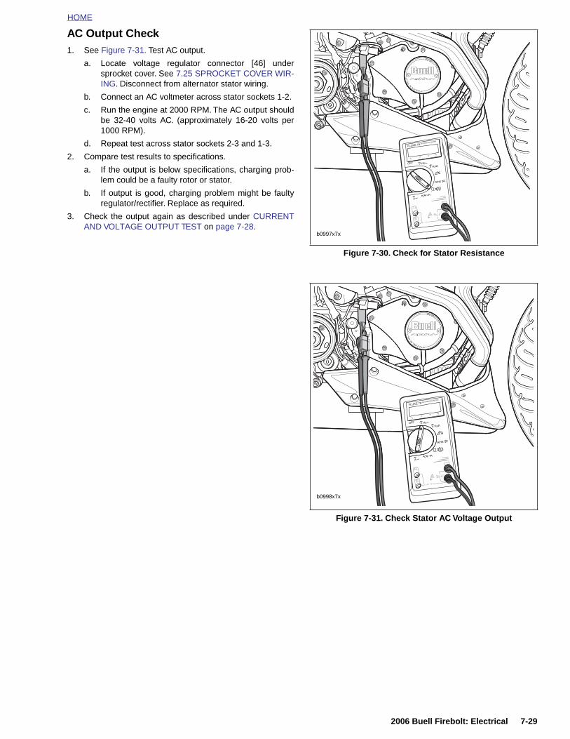
HOME
AC Output Check1. See Figure 7-31. Test AC output.
a. Locate voltage regulator connector [46] undersprocket cover. See 7.25 SPROCKET COVER WIR-ING. Disconnect from alternator stator wiring.
b. Connect an AC voltmeter across stator sockets 1-2.
c. Run the engine at 2000 RPM. The AC output shouldbe 32-40 volts AC. (approximately 16-20 volts per1000 RPM).
d. Repeat test across stator sockets 2-3 and 1-3.
2. Compare test results to specifications.
a. If the output is below specifications, charging prob-lem could be a faulty rotor or stator.
b. If output is good, charging problem might be faultyregulator/rectifier. Replace as required.
3. Check the output again as described under CURRENTAND VOLTAGE OUTPUT TEST on page 7-28.
Figure 7-30. Check for Stator Resistance
Figure 7-31. Check Stator AC Voltage Output
b0997x7x
b0998x7x
2006 Buell Firebolt: Electrical 7-29
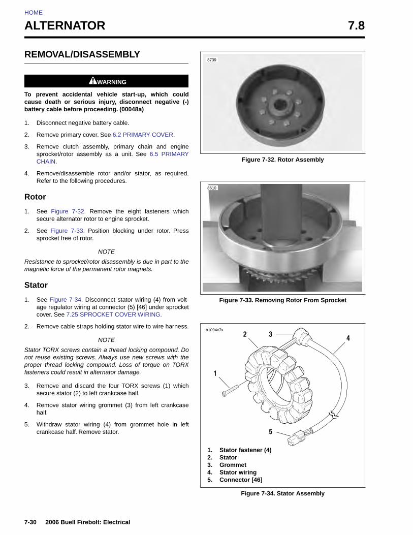
HOME
ALTERNATOR 7.8
REMOVAL/DISASSEMBLY
1WARNING1WARNING
To prevent accidental vehicle start-up, which couldcause death or serious injury, disconnect negative (-)battery cable before proceeding. (00048a)
1. Disconnect negative battery cable.
2. Remove primary cover. See 6.2 PRIMARY COVER.
3. Remove clutch assembly, primary chain and enginesprocket/rotor assembly as a unit. See 6.5 PRIMARYCHAIN.
4. Remove/disassemble rotor and/or stator, as required.Refer to the following procedures.
Rotor
1. See Figure 7-32. Remove the eight fasteners whichsecure alternator rotor to engine sprocket.
2. See Figure 7-33. Position blocking under rotor. Presssprocket free of rotor.
NOTE
Resistance to sprocket/rotor disassembly is due in part to themagnetic force of the permanent rotor magnets.
Stator
1. See Figure 7-34. Disconnect stator wiring (4) from volt-age regulator wiring at connector (5) [46] under sprocketcover. See 7.25 SPROCKET COVER WIRING.
2. Remove cable straps holding stator wire to wire harness.
NOTE
Stator TORX screws contain a thread locking compound. Donot reuse existing screws. Always use new screws with theproper thread locking compound. Loss of torque on TORXfasteners could result in alternator damage.
3. Remove and discard the four TORX screws (1) whichsecure stator (2) to left crankcase half.
4. Remove stator wiring grommet (3) from left crankcasehalf.
5. Withdraw stator wiring (4) from grommet hole in leftcrankcase half. Remove stator.
Figure 7-32. Rotor Assembly
Figure 7-33. Removing Rotor From Sprocket
Figure 7-34. Stator Assembly
8739
8610
1. Stator fastener (4)2. Stator3. Grommet4. Stator wiring5. Connector [46]
b1094x7x2 4
1
23
5
7-30 2006 Buell Firebolt: Electrical
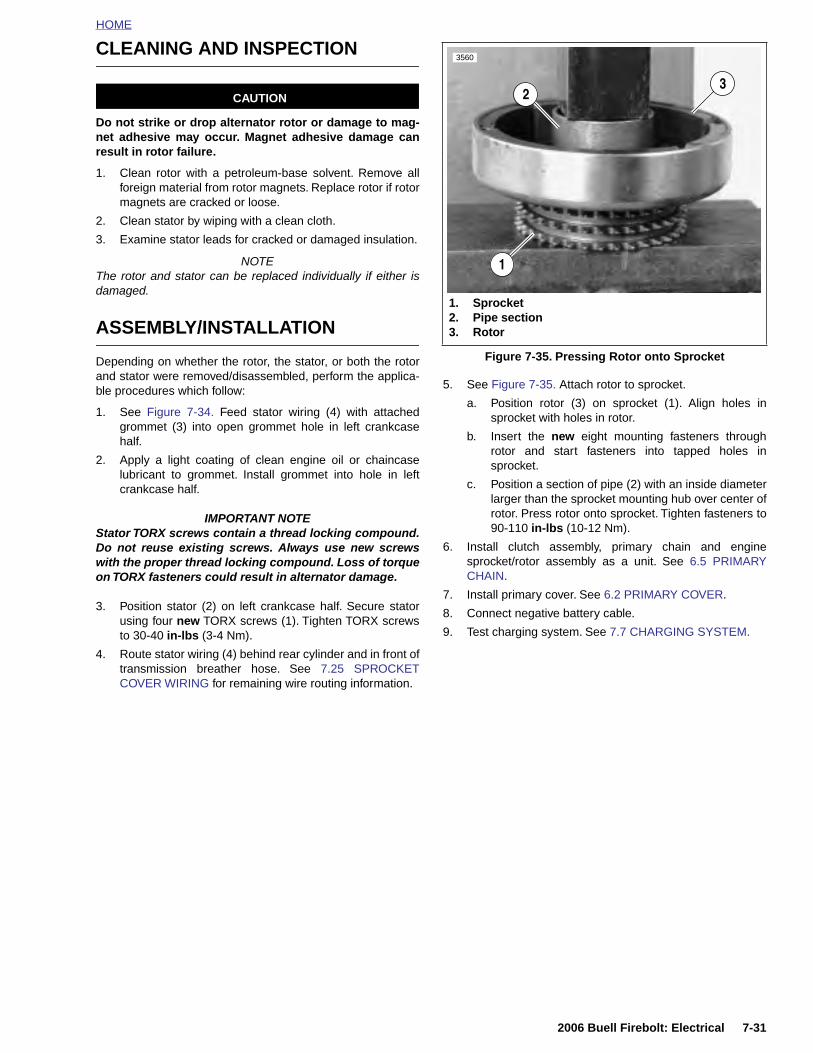
HOME
CLEANING AND INSPECTION
CAUTION
Do not strike or drop alternator rotor or damage to mag-net adhesive may occur. Magnet adhesive damage canresult in rotor failure.
1. Clean rotor with a petroleum-base solvent. Remove allforeign material from rotor magnets. Replace rotor if rotormagnets are cracked or loose.
2. Clean stator by wiping with a clean cloth.
3. Examine stator leads for cracked or damaged insulation.
NOTEThe rotor and stator can be replaced individually if either isdamaged.
ASSEMBLY/INSTALLATION
Depending on whether the rotor, the stator, or both the rotorand stator were removed/disassembled, perform the applica-ble procedures which follow:
1. See Figure 7-34. Feed stator wiring (4) with attachedgrommet (3) into open grommet hole in left crankcasehalf.
2. Apply a light coating of clean engine oil or chaincaselubricant to grommet. Install grommet into hole in leftcrankcase half.
IMPORTANT NOTEStator TORX screws contain a thread locking compound.Do not reuse existing screws. Always use new screwswith the proper thread locking compound. Loss of torqueon TORX fasteners could result in alternator damage.
3. Position stator (2) on left crankcase half. Secure statorusing four new TORX screws (1). Tighten TORX screwsto 30-40 in-lbs (3-4 Nm).
4. Route stator wiring (4) behind rear cylinder and in front oftransmission breather hose. See 7.25 SPROCKETCOVER WIRING for remaining wire routing information.
5. See Figure 7-35. Attach rotor to sprocket.
a. Position rotor (3) on sprocket (1). Align holes insprocket with holes in rotor.
b. Insert the new eight mounting fasteners throughrotor and start fasteners into tapped holes insprocket.
c. Position a section of pipe (2) with an inside diameterlarger than the sprocket mounting hub over center ofrotor. Press rotor onto sprocket. Tighten fasteners to90-110 in-lbs (10-12 Nm).
6. Install clutch assembly, primary chain and enginesprocket/rotor assembly as a unit. See 6.5 PRIMARYCHAIN.
7. Install primary cover. See 6.2 PRIMARY COVER.
8. Connect negative battery cable.
9. Test charging system. See 7.7 CHARGING SYSTEM.
Figure 7-35. Pressing Rotor onto Sprocket
3560
1. Sprocket2. Pipe section3. Rotor
1
32
2006 Buell Firebolt: Electrical 7-31
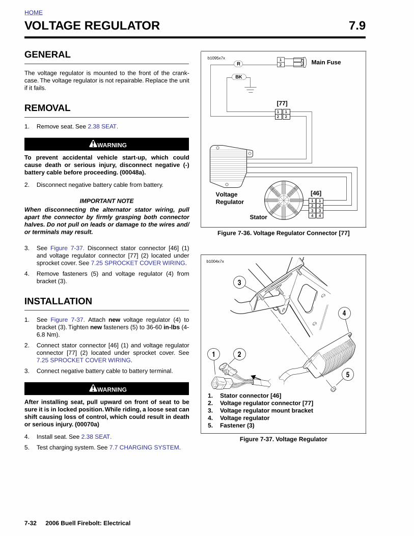
HOME
VOLTAGE REGULATOR 7.9
GENERAL
The voltage regulator is mounted to the front of the crank-case. The voltage regulator is not repairable. Replace the unitif it fails.
REMOVAL
1. Remove seat. See 2.38 SEAT.
1WARNING1WARNING
To prevent accidental vehicle start-up, which couldcause death or serious injury, disconnect negative (-)battery cable before proceeding. (00048a).
2. Disconnect negative battery cable from battery.
IMPORTANT NOTEWhen disconnecting the alternator stator wiring, pullapart the connector by firmly grasping both connectorhalves. Do not pull on leads or damage to the wires and/or terminals may result.
3. See Figure 7-37. Disconnect stator connector [46] (1)and voltage regulator connector [77] (2) located undersprocket cover. See 7.25 SPROCKET COVER WIRING.
4. Remove fasteners (5) and voltage regulator (4) frombracket (3).
INSTALLATION
1. See Figure 7-37. Attach new voltage regulator (4) tobracket (3). Tighten new fasteners (5) to 36-60 in-lbs (4-6.8 Nm).
2. Connect stator connector [46] (1) and voltage regulatorconnector [77] (2) located under sprocket cover. See7.25 SPROCKET COVER WIRING.
3. Connect negative battery cable to battery terminal.
1WARNING1WARNING
After installing seat, pull upward on front of seat to besure it is in locked position. While riding, a loose seat canshift causing loss of control, which could result in deathor serious injury. (00070a)
4. Install seat. See 2.38 SEAT.
5. Test charging system. See 7.7 CHARGING SYSTEM.
Figure 7-36. Voltage Regulator Connector [77]
Figure 7-37. Voltage Regulator
2 234
34
1 1
2 21 1
21b1095x7x
Main Fuse
Voltage Regulator
Stator
[46]
[77]
R
BK
b1004x7x
1. Stator connector [46]2. Voltage regulator connector [77]3. Voltage regulator mount bracket4. Voltage regulator 5. Fastener (3)
3
5
4
1 2
7-32 2006 Buell Firebolt: Electrical
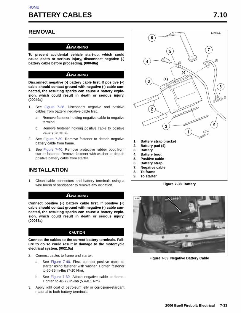
HOME
BATTERY CABLES 7.10
REMOVAL
1WARNING1WARNING
To prevent accidental vehicle start-up, which couldcause death or serious injury, disconnect negative (-)battery cable before proceeding. (00048a)
1WARNING1WARNING
Disconnect negative (-) battery cable first. If positive (+)cable should contact ground with negative (-) cable con-nected, the resulting sparks can cause a battery explo-sion, which could result in death or serious injury.(00049a)
1. See Figure 7-38. Disconnect negative and positivecables from battery, negative cable first.
a. Remove fastener holding negative cable to negativeterminal.
b. Remove fastener holding positive cable to positivebattery terminal.
2. See Figure 7-39. Remove fastener to detach negativebattery cable from frame.
3. See Figure 7-40. Remove protective rubber boot fromstarter fastener. Remove fastener with washer to detachpositive battery cable from starter.
INSTALLATION
1. Clean cable connectors and battery terminals using awire brush or sandpaper to remove any oxidation.
1WARNING1WARNING
Connect positive (+) battery cable first. If positive (+)cable should contact ground with negative (-) cable con-nected, the resulting sparks can cause a battery explo-sion, which could result in death or serious injury.(00068a)
CAUTION
Connect the cables to the correct battery terminals. Fail-ure to do so could result in damage to the motorcycleelectrical system. (00215a)
2. Connect cables to frame and starter.
a. See Figure 7-40. First, connect positive cable tostarter using fastener with washer. Tighten fastenerto 60-85 in-lbs (7-10 Nm).
b. See Figure 7-39. Attach negative cable to frame.Tighten to 48-72 in-lbs (5.4-8.1 Nm).
3. Apply light coat of petroleum jelly or corrosion-retardantmaterial to both battery terminals.
Figure 7-38. Battery
Figure 7-39. Negative Battery Cable
b1005x7x
(+)
(-)
1. Battery strap bracket2. Battery pad (4)3. Battery4. Battery boot5. Positive cable6. Battery strap7. Negative cable8. To frame9. To starter
2
2
6
3
5
4
8
9
1
7
8442
2006 Buell Firebolt: Electrical 7-33
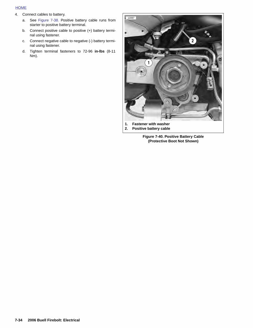
HOME
4. Connect cables to battery.
a. See Figure 7-38. Positive battery cable runs fromstarter to positive battery terminal.
b. Connect positive cable to positive (+) battery termi-nal using fastener.
c. Connect negative cable to negative (-) battery termi-nal using fastener.
d. Tighten terminal fasteners to 72-96 in-lbs (8-11Nm).
Figure 7-40. Positive Battery Cable (Protective Boot Not Shown)
12097
1. Fastener with washer 2. Positive battery cable
1
2
7-34 2006 Buell Firebolt: Electrical
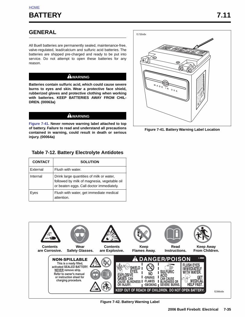
HOME
BATTERY 7.11
GENERAL
All Buell batteries are permanently sealed, maintenance-free,valve-regulated, lead/calcium and sulfuric acid batteries. Thebatteries are shipped pre-charged and ready to be put intoservice. Do not attempt to open these batteries for anyreason.
1WARNING1WARNING
Batteries contain sulfuric acid, which could cause severeburns to eyes and skin. Wear a protective face shield,rubberized gloves and protective clothing when workingwith batteries. KEEP BATTERIES AWAY FROM CHIL-DREN. (00063a)
1WARNING1WARNING
Figure 7-41. Never remove warning label attached to topof battery. Failure to read and understand all precautionscontained in warning, could result in death or seriousinjury. (00064a)
Table 7-12. Battery Electrolyte Antidotes
CONTACT SOLUTION
External Flush with water.
Internal Drink large quantities of milk or water, followed by milk of magnesia, vegetable oil or beaten eggs. Call doctor immediately.
Eyes Flush with water, get immediate medical attention.
Figure 7-41. Battery Warning Label Location
M A D E I N U S AHA
RLEY-DA
VIDSO
N
MILWAU
KEE,
WI 5
3201
MADE I
N U.S.
A.
WARRAN
TY AN
D ADJUSTM
ENT POLIC
Y
This ba
ttery w
ill be re
placed
without c
harge
if found
to be
defect
ive in m
aterial
s or
workmans
hip 12
months
from da
te of
vehicle
purch
ase or
6 mont
hs from
date
of over
-the-co
unter p
urchas
e. After
6
months,
but w
ithin th
e 12 m
onths
of the
over-th
e-coun
ter pur
chase,
the ba
ttery w
ill
be rep
laced a
nd the
purch
aser ch
arged
only fo
r the p
eriod o
f owner
ship b
ased o
n
the reg
ular pr
ice at t
he tim
e of re
turn
prorate
d ver t
he num
ber of
months
of
warrant
y. This
warrant
y is no
t transf
erable
and is
voided
by the
use o
f rejuv
enators
,
improper
electro
lyte, ne
glect o
r abuse
.
PART
NO.
1
2
3
4
5
6
7
8
9
0
JA
FE
MA
AP
MY
JU
JY
AU
SE
OC
NO
DE
f1730x8x
Figure 7-42. Battery Warning Label
f2396x8x
Contentsare Corrosive.
WearSafety Glasses.
Contentsare Explosive.
KeepFlames Away.
ReadInstructions.
Keep AwayFrom Children.
2006 Buell Firebolt: Electrical 7-35
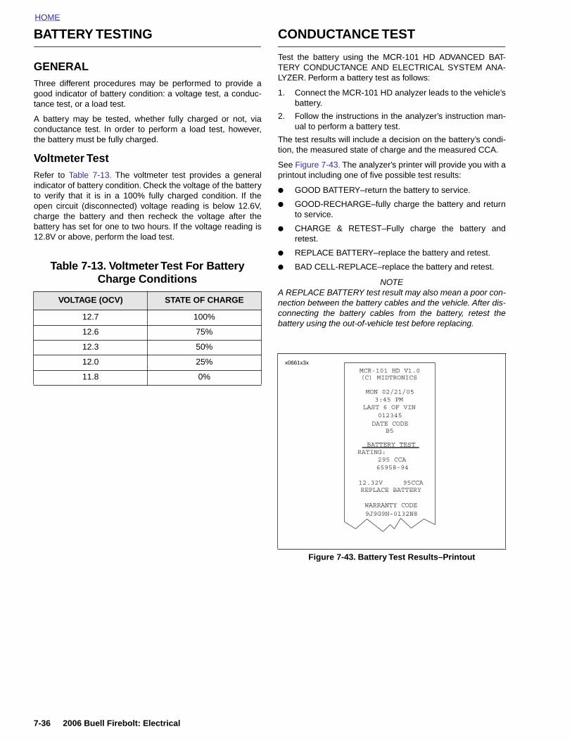
HOME
BATTERY TESTING
GENERALThree different procedures may be performed to provide agood indicator of battery condition: a voltage test, a conduc-tance test, or a load test.
A battery may be tested, whether fully charged or not, viaconductance test. In order to perform a load test, however,the battery must be fully charged.
Voltmeter TestRefer to Table 7-13. The voltmeter test provides a generalindicator of battery condition. Check the voltage of the batteryto verify that it is in a 100% fully charged condition. If theopen circuit (disconnected) voltage reading is below 12.6V,charge the battery and then recheck the voltage after thebattery has set for one to two hours. If the voltage reading is12.8V or above, perform the load test.
CONDUCTANCE TEST
Test the battery using the MCR-101 HD ADVANCED BAT-TERY CONDUCTANCE AND ELECTRICAL SYSTEM ANA-LYZER. Perform a battery test as follows:
1. Connect the MCR-101 HD analyzer leads to the vehicle’sbattery.
2. Follow the instructions in the analyzer’s instruction man-ual to perform a battery test.
The test results will include a decision on the battery’s condi-tion, the measured state of charge and the measured CCA.
See Figure 7-43. The analyzer’s printer will provide you with aprintout including one of five possible test results:
● GOOD BATTERY–return the battery to service.
● GOOD-RECHARGE–fully charge the battery and returnto service.
● CHARGE & RETEST–Fully charge the battery andretest.
● REPLACE BATTERY–replace the battery and retest.
● BAD CELL-REPLACE–replace the battery and retest.
NOTEA REPLACE BATTERY test result may also mean a poor con-nection between the battery cables and the vehicle. After dis-connecting the battery cables from the battery, retest thebattery using the out-of-vehicle test before replacing.
Table 7-13. Voltmeter Test For Battery Charge Conditions
VOLTAGE (OCV) STATE OF CHARGE
12.7 100%
12.6 75%
12.3 50%
12.0 25%
11.8 0%
Figure 7-43. Battery Test Results–Printout
x0661x3x
7-36 2006 Buell Firebolt: Electrical
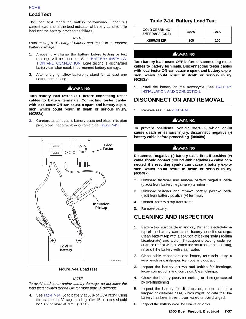
HOME
Load Test
The load test measures battery performance under fullcurrent load and is the best indicator of battery condition. Toload test the battery, proceed as follows:
NOTELoad testing a discharged battery can result in permanentbattery damage.
1. Always fully charge the battery before testing or testreadings will be incorrect. See BATTERY INSTALLA-TION AND CONNECTION. Load testing a dischargedbattery can also result in permanent battery damage.
2. After charging, allow battery to stand for at least onehour before testing.
1WARNING1WARNING
Turn battery load tester OFF before connecting testercables to battery terminals. Connecting tester cableswith load tester ON can cause a spark and battery explo-sion, which could result in death or serious injury.(00252a)
3. Connect tester leads to battery posts and place inductionpickup over negative (black) cable. See Figure 7-45.
NOTETo avoid load tester and/or battery damage, do not leave theload tester switch turned ON for more than 20 seconds.
4. See Table 7-14. Load battery at 50% of CCA rating usingthe load tester. Voltage reading after 15 seconds shouldbe 9.6V or more at 70° F. (21° C).
1WARNING1WARNING
Turn battery load tester OFF before disconnecting testercables to battery terminals. Disconnecting tester cableswith load tester ON can cause a spark and battery explo-sion, which could result in death or serious injury.(00253a)
5. Install the battery on the motorcycle. See BATTERYINSTALLATION AND CONNECTION.
DISCONNECTION AND REMOVAL
1. Remove seat. See 2.38 SEAT.
1WARNING1WARNING
To prevent accidental vehicle start-up, which couldcause death or serious injury, disconnect negative (-)battery cable before proceeding. (00048a)
1WARNING1WARNING
Disconnect negative (-) battery cable first. If positive (+)cable should contact ground with negative (-) cable con-nected, the resulting sparks can cause a battery explo-sion, which could result in death or serious injury.(00049a)
2. Unthread fastener and remove battery negative cable(black) from battery negative (-) terminal.
3. Unthread fastener and remove battery positive cable(red) from battery positive (+) terminal.
4. Unhook battery strap from frame.
5. Remove battery.
CLEANING AND INSPECTION
1. Battery top must be clean and dry. Dirt and electrolyte ontop of the battery can cause battery to self-discharge.Clean battery top with a solution of baking soda (sodiumbicarbonate) and water (5 teaspoons baking soda perquart or liter of water). When the solution stops bubbling,rinse off the battery with clean water.
2. Clean cable connectors and battery terminals using awire brush or sandpaper. Remove any oxidation.
3. Inspect the battery screws and cables for breakage,loose connections and corrosion. Clean clamps.
4. Check the battery posts for melting or damage causedby overtightening.
5. Inspect the battery for discoloration, raised top or awarped or distorted case, which might indicate that thebattery has been frozen, overheated or overcharged.
6. Inspect the battery case for cracks or leaks.
Figure 7-44. Load Test
LoadTester
InductionPickup
b1098x7x
12 VDC Battery
VOLTS
AMPS
Table 7-14. Battery Load Test
COLD CRANKING AMPERAGE (CCA)
100% 50%
XB9R/XB12R 200 100
2006 Buell Firebolt: Electrical 7-37
HOME
BATTERY CHARGING
Safety Precautions
Never charge a battery without first reviewing the in-structions for the charger being used. In addition to themanufacturer’s instructions, follow these general safetyprecautions:
● Always wear proper eye, face and hand protection.
● Always charge batteries in a well-ventilated area.
● Turn the charger “OFF” before connecting the leadsto the battery to avoid dangerous sparks.
● Never try to charge a visibly damaged or frozen bat-tery.
● Connect the charger leads to the battery; red posi-tive (+) lead to the positive (+) terminal and blacknegative (–) lead to the negative (–) terminal. If thebattery is still in the vehicle, connect the negativelead to the chassis ground. Be sure that the ignitionand all electrical accessories are turned off.
● Make sure that the charger leads to the battery arenot broken, frayed or loose.
● If the battery becomes hot, or if violent gassing orspewing of electrolyte occurs, reduce the chargingrate or turn off the charger temporarily.
● Always turn the charger “OFF” before removingcharger leads from the battery to avoid dangeroussparks.
Charging Battery
Charge the battery if any of the following conditions exist:
● Vehicle lights appear dim.
● Electric starter sounds weak.
● Battery has not been used for an extended period oftime.
1WARNING1WARNING
Explosive hydrogen gas, which escapes during charg-ing, could cause death or serious injury. Charge batteryin a well-ventilated area. Keep open flames, electricalsparks and smoking materials away from battery at alltimes. KEEP BATTERIES AWAY FROM CHILDREN.(00065a)
NOTE
If the battery releases an excessive amount of gas duringcharging, decrease the charging rate. If the battery gets hot-ter than 110˚F. (43˚C) during charging, discontinue chargingand allow the battery to cool. Overheating may result in platedistortion, internal shorting, dryout or other damage.
1. Perform a voltmeter test to determine the state of charge.See BATTERY TESTING. If battery needs to be charged,proceed to step 2.
CAUTION
Remove battery from motorcycle before charging. Elec-trolyte leakage will damage motorcycle parts. (00213a)
2. Remove the battery from the motorcycle. See DISCON-NECTION AND REMOVAL. Place the battery on a levelsurface.
1WARNING1WARNING
Unplug or turn OFF battery charger before connectingcharger cables to battery. Connecting cables withcharger ON can cause a spark and battery explosion,which could result in death or serious injury. (00066a)
1WARNING1WARNING
Do not reverse the charger connections described in thefollowing steps or the charging system of the motorcyclecould be damaged. (00214a)
3. Connect the red battery charger lead to the positive (+)terminal of the battery.
4. Connect the black battery charger lead to negative (-)terminal of the battery.
NOTE
If the battery is still in the vehicle, connect the negative leadto the chassis ground. Be sure that the ignition and all electri-cal accessories are turned off.
5. Step away from the battery and turn on the charger. Seethe charging instructions in Table 7-15.
1WARNING1WARNING
Unplug or turn OFF battery charger before disconnectingcharger cables from battery. Disconnecting clamps withcharger ON can cause a spark and battery explosion,which could result in death or serious injury. (00067a)
6. After the battery is fully charged, disconnect the blackbattery charger lead to the negative (–) terminal of thebattery.
7. Disconnect the red battery charger lead to the positive(+) terminal of the battery.
8. Mark the charging date on the battery.
9. Perform a load test to determine the condition of the bat-tery. See BATTERY TESTING.
7-38 2006 Buell Firebolt: Electrical
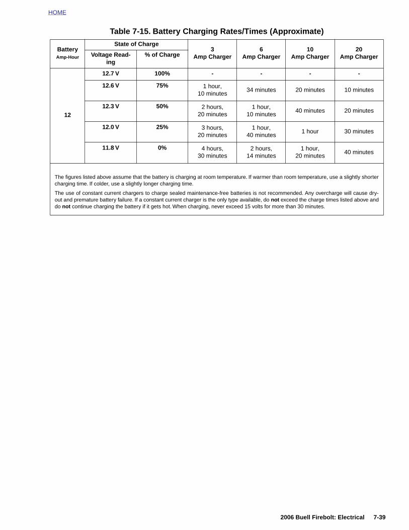
HOME
Table 7-15. Battery Charging Rates/Times (Approximate)
Battery Amp-Hour
State of Charge3
Amp Charger6
Amp Charger10
Amp Charger20
Amp ChargerVoltage Read-ing
% of Charge
12
12.7 V 100% - - - -
12.6 V 75% 1 hour,10 minutes
34 minutes 20 minutes 10 minutes
12.3 V 50% 2 hours,20 minutes
1 hour,10 minutes
40 minutes 20 minutes
12.0 V 25% 3 hours,20 minutes
1 hour,40 minutes
1 hour 30 minutes
11.8 V 0% 4 hours, 30 minutes
2 hours,14 minutes
1 hour,20 minutes
40 minutes
The figures listed above assume that the battery is charging at room temperature. If warmer than room temperature, use a slightly shortercharging time. If colder, use a slightly longer charging time.
The use of constant current chargers to charge sealed maintenance-free batteries is not recommended. Any overcharge will cause dry-out and premature battery failure. If a constant current charger is the only type available, do not exceed the charge times listed above anddo not continue charging the battery if it gets hot. When charging, never exceed 15 volts for more than 30 minutes.
2006 Buell Firebolt: Electrical 7-39
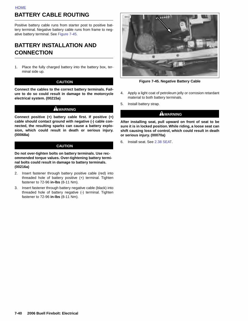
HOME
BATTERY CABLE ROUTING
Positive battery cable runs from starter post to positive bat-tery terminal. Negative battery cable runs from frame to neg-ative battery terminal. See Figure 7-45.
BATTERY INSTALLATION AND CONNECTION
1. Place the fully charged battery into the battery box, ter-minal side up.
CAUTION
Connect the cables to the correct battery terminals. Fail-ure to do so could result in damage to the motorcycleelectrical system. (00215a)
1WARNING1WARNING
Connect positive (+) battery cable first. If positive (+)cable should contact ground with negative (-) cable con-nected, the resulting sparks can cause a battery explo-sion, which could result in death or serious injury.(00068a)
CAUTION
Do not over-tighten bolts on battery terminals. Use rec-ommended torque values. Over-tightening battery termi-nal bolts could result in damage to battery terminals. (00216a)
2. Insert fastener through battery positive cable (red) intothreaded hole of battery positive (+) terminal. Tightenfastener to 72-96 in-lbs (8-11 Nm).
3. Insert fastener through battery negative cable (black) intothreaded hole of battery negative (-) terminal. Tightenfastener to 72-96 in-lbs (8-11 Nm).
4. Apply a light coat of petroleum jelly or corrosion retardantmaterial to both battery terminals.
5. Install battery strap.
1WARNING1WARNING
After installing seat, pull upward on front of seat to besure it is in locked position. While riding, a loose seat canshift causing loss of control, which could result in deathor serious injury. (00070a)
6. Install seat. See 2.38 SEAT.
Figure 7-45. Negative Battery Cable
8442
7-40 2006 Buell Firebolt: Electrical
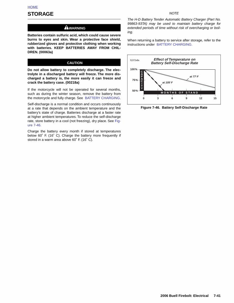
HOME
STORAGE
1WARNING1WARNING
Batteries contain sulfuric acid, which could cause severeburns to eyes and skin. Wear a protective face shield,rubberized gloves and protective clothing when workingwith batteries. KEEP BATTERIES AWAY FROM CHIL-DREN. (00063a)
CAUTION
Do not allow battery to completely discharge. The elec-trolyte in a discharged battery will freeze. The more dis-charged a battery is, the more easily it can freeze andcrack the battery case. (00218a)
If the motorcycle will not be operated for several months,such as during the winter season, remove the battery fromthe motorcycle and fully charge. See BATTERY CHARGING.
Self-discharge is a normal condition and occurs continuouslyat a rate that depends on the ambient temperature and thebattery’s state of charge. Batteries discharge at a faster rateat higher ambient temperatures. To reduce the self-dischargerate, store battery in a cool (not freezing), dry place. See Fig-ure 7-46.
Charge the battery every month if stored at temperaturesbelow 60˚ F. (16˚ C). Charge the battery more frequently ifstored in a warm area above 60˚ F. (16˚ C).
NOTE
The H-D Battery Tender Automatic Battery Charger (Part No.99863-93TA) may be used to maintain battery charge forextended periods of time without risk of overcharging or boil-ing.
When returning a battery to service after storage, refer to theinstructions under BATTERY CHARGING.
Figure 7-46. Battery Self-Discharge Rate
3 6 9 12 15
50%
75%
100%
M O N T H S O F S T A N D
CAPACITY
0
at 105°F
at 77°F
Effect of Temperature onBattery Self-Discharge Rate
f1372x8x
2006 Buell Firebolt: Electrical 7-41

HOME
HEADLIGHT 7.12
GENERAL
Dual headlights are equipped with replaceable bulbs. Highbeam headlight is located on the left side of vehicle.
● High beam headlight turns on and off with headlightswitch.
● Low beam headlight is located on the right side of vehi-cle.
● Adjustment of individual headlight projection is accom-plished by adjusting two screws located in the headlightsupport.
For information on headlight housing and bracket disassem-bly/assembly see 2.25 HEADLIGHT ASSEMBLY AND SUP-PORT BRACKET.
HEADLIGHT BULBS
Removal
1WARNING1WARNING
To prevent accidental vehicle start-up, which couldcause death or serious injury, disconnect negative (-)battery cable before proceeding. (00048a)
1. Disconnect negative battery cable.
1CAUTION
Handle bulb carefully and wear eye protection. Bulb con-tains Halogen gas under pressure, which, if not handledcarefully, could cause serious eye injury. (00062a)
CAUTION
Never touch the quartz bulb. Fingerprints will etch theglass and decrease bulb life. Grab the bulb with paper ora clean, dry cloth. Failure to do so could result in bulbdamage. (00210a)
2. See Figure 7-47. Disconnect headlight connection (1).
3. Release wire retaining latch (5) from headlight housingclips.
4. Pull bulb housing from headlight housing.
Figure 7-47. Headlight Bulb
1
8743
3
2
1. Headlight connection2. Ground connection3. Headlight bulb4. Headlight 5. Wire retaining latch
5
4
7-42 2006 Buell Firebolt: Electrical
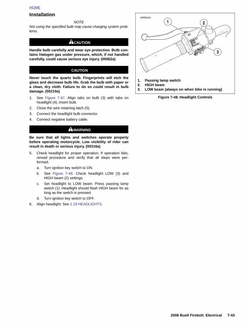
HOME
InstallationNOTE
Not using the specified bulb may cause charging system prob-lems.
1CAUTION
Handle bulb carefully and wear eye protection. Bulb con-tains Halogen gas under pressure, which, if not handledcarefully, could cause serious eye injury. (00062a)
CAUTION
Never touch the quartz bulb. Fingerprints will etch theglass and decrease bulb life. Grab the bulb with paper ora clean, dry cloth. Failure to do so could result in bulbdamage. (00210a)
1. See Figure 7-47. Align tabs on bulb (3) with tabs onheadlight (4). Insert bulb.
2. Close the wire retaining latch (5).
3. Connect the headlight bulb connector.
4. Connect negative battery cable.
1WARNING1WARNING
Be sure that all lights and switches operate properlybefore operating motorcycle. Low visibility of rider canresult in death or serious injury. (00316a)
5. Check headlight for proper operation. If operation fails,reread procedure and verify that all steps were per-formed.
a. Turn ignition key switch to ON.
b. See Figure 7-48. Check headlight LOW (3) andHIGH beam (2) settings.
c. Set headlight to LOW beam. Press passing lampswitch (1). Headlight should flash HIGH beam for aslong as the switch is pressed.
d. Turn ignition key switch to OFF.
6. Align headlight. See 1.19 HEADLIGHTS.
Figure 7-48. Headlight Controls
1. Passing lamp switch2. HIGH beam3. LOW beam (always on when bike is running)
b0586x0x
1
3
2
2006 Buell Firebolt: Electrical 7-43
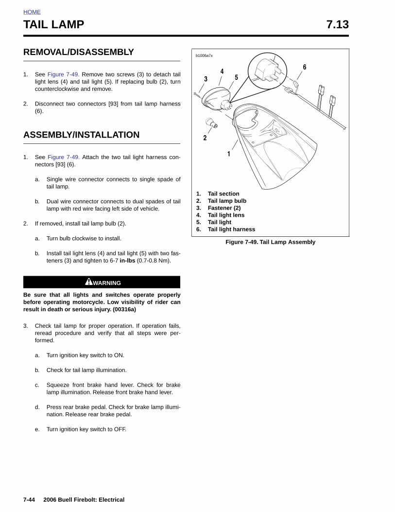
HOME
TAIL LAMP 7.13
REMOVAL/DISASSEMBLY
1. See Figure 7-49. Remove two screws (3) to detach taillight lens (4) and tail light (5). If replacing bulb (2), turncounterclockwise and remove.
2. Disconnect two connectors [93] from tail lamp harness(6).
ASSEMBLY/INSTALLATION
1. See Figure 7-49. Attach the two tail light harness con-nectors [93] (6).
a. Single wire connector connects to single spade oftail lamp.
b. Dual wire connector connects to dual spades of taillamp with red wire facing left side of vehicle.
2. If removed, install tail lamp bulb (2).
a. Turn bulb clockwise to install.
b. Install tail light lens (4) and tail light (5) with two fas-teners (3) and tighten to 6-7 in-lbs (0.7-0.8 Nm).
1WARNING1WARNING
Be sure that all lights and switches operate properlybefore operating motorcycle. Low visibility of rider canresult in death or serious injury. (00316a)
3. Check tail lamp for proper operation. If operation fails,reread procedure and verify that all steps were per-formed.
a. Turn ignition key switch to ON.
b. Check for tail lamp illumination.
c. Squeeze front brake hand lever. Check for brakelamp illumination. Release front brake hand lever.
d. Press rear brake pedal. Check for brake lamp illumi-nation. Release rear brake pedal.
e. Turn ignition key switch to OFF.
Figure 7-49. Tail Lamp Assembly
b1006a7x
1. Tail section2. Tail lamp bulb3. Fastener (2)4. Tail light lens5. Tail light6. Tail light harness
3
2
1
65
4
7-44 2006 Buell Firebolt: Electrical
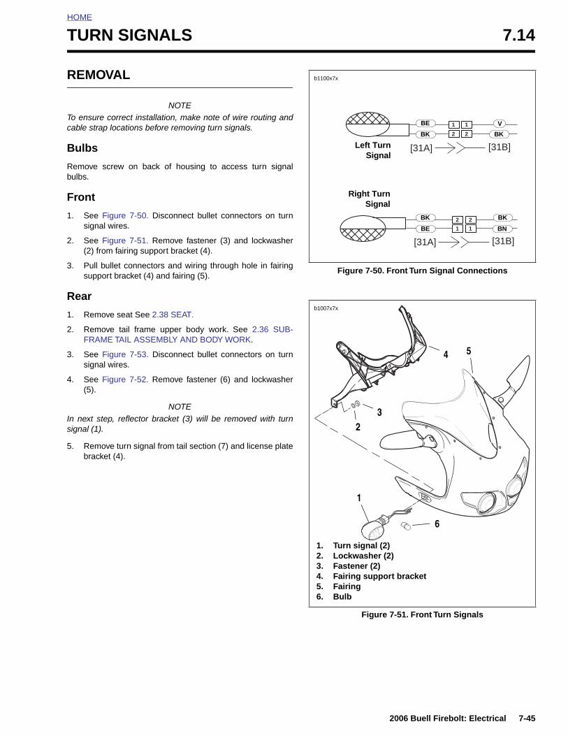
HOME
TURN SIGNALS 7.14
REMOVAL
NOTETo ensure correct installation, make note of wire routing andcable strap locations before removing turn signals.
Bulbs
Remove screw on back of housing to access turn signalbulbs.
Front
1. See Figure 7-50. Disconnect bullet connectors on turnsignal wires.
2. See Figure 7-51. Remove fastener (3) and lockwasher(2) from fairing support bracket (4).
3. Pull bullet connectors and wiring through hole in fairingsupport bracket (4) and fairing (5).
Rear
1. Remove seat See 2.38 SEAT.
2. Remove tail frame upper body work. See 2.36 SUB-FRAME TAIL ASSEMBLY AND BODY WORK.
3. See Figure 7-53. Disconnect bullet connectors on turnsignal wires.
4. See Figure 7-52. Remove fastener (6) and lockwasher(5).
NOTEIn next step, reflector bracket (3) will be removed with turnsignal (1).
5. Remove turn signal from tail section (7) and license platebracket (4).
Figure 7-50. Front Turn Signal Connections
Figure 7-51. Front Turn Signals
22
11
1 1
2 2
[31B][31A]
[31B][31A]
b1100x7x
Right TurnSignal
Left TurnSignal
BK
VBE
BK
BK
BE
BK
BN
b1007x7x
1. Turn signal (2)2. Lockwasher (2)3. Fastener (2)4. Fairing support bracket5. Fairing6. Bulb
1
23
4 5
6
2006 Buell Firebolt: Electrical 7-45
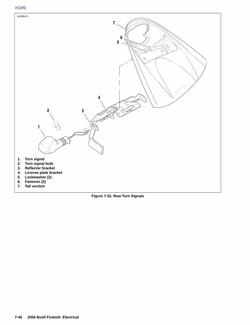
HOME
Figure 7-52. Rear Turn Signals
1. Turn signal2. Turn signal bulb3. Reflector bracket4. License plate bracket5. Lockwasher (2)6. Fastener (2)7. Tail section
1
2
4
7
56
b1008a7x
3
7-46 2006 Buell Firebolt: Electrical
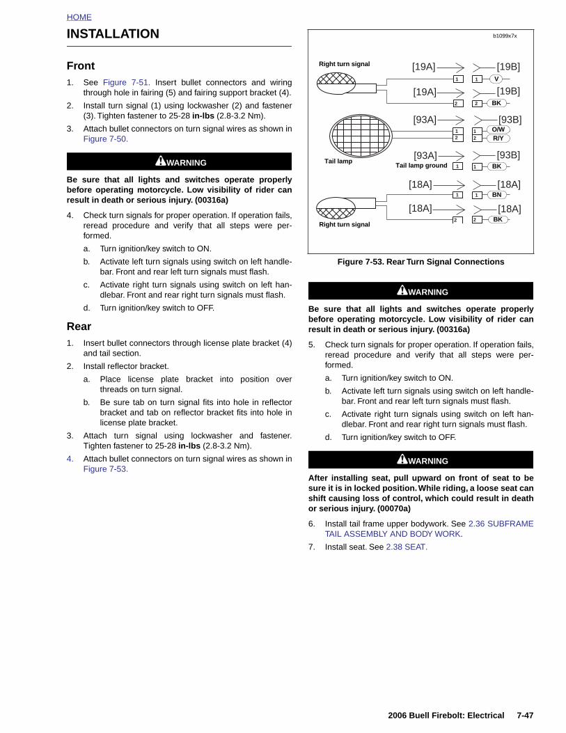
HOME
INSTALLATION
Front1. See Figure 7-51. Insert bullet connectors and wiring
through hole in fairing (5) and fairing support bracket (4).
2. Install turn signal (1) using lockwasher (2) and fastener(3). Tighten fastener to 25-28 in-lbs (2.8-3.2 Nm).
3. Attach bullet connectors on turn signal wires as shown inFigure 7-50.
1WARNING1WARNING
Be sure that all lights and switches operate properlybefore operating motorcycle. Low visibility of rider canresult in death or serious injury. (00316a)
4. Check turn signals for proper operation. If operation fails,reread procedure and verify that all steps were per-formed.
a. Turn ignition/key switch to ON.
b. Activate left turn signals using switch on left handle-bar. Front and rear left turn signals must flash.
c. Activate right turn signals using switch on left han-dlebar. Front and rear right turn signals must flash.
d. Turn ignition/key switch to OFF.
Rear1. Insert bullet connectors through license plate bracket (4)
and tail section.
2. Install reflector bracket.
a. Place license plate bracket into position overthreads on turn signal.
b. Be sure tab on turn signal fits into hole in reflectorbracket and tab on reflector bracket fits into hole inlicense plate bracket.
3. Attach turn signal using lockwasher and fastener.Tighten fastener to 25-28 in-lbs (2.8-3.2 Nm).
4. Attach bullet connectors on turn signal wires as shown inFigure 7-53.
1WARNING1WARNING
Be sure that all lights and switches operate properlybefore operating motorcycle. Low visibility of rider canresult in death or serious injury. (00316a)
5. Check turn signals for proper operation. If operation fails,reread procedure and verify that all steps were per-formed.
a. Turn ignition/key switch to ON.
b. Activate left turn signals using switch on left handle-bar. Front and rear left turn signals must flash.
c. Activate right turn signals using switch on left han-dlebar. Front and rear right turn signals must flash.
d. Turn ignition/key switch to OFF.
1WARNING1WARNING
After installing seat, pull upward on front of seat to besure it is in locked position. While riding, a loose seat canshift causing loss of control, which could result in deathor serious injury. (00070a)
6. Install tail frame upper bodywork. See 2.36 SUBFRAMETAIL ASSEMBLY AND BODY WORK.
7. Install seat. See 2.38 SEAT.
Figure 7-53. Rear Turn Signal Connections
11
22
22
11
12
1
21
1
[19A]
[93A] [93B]
[93B][93A]
[18A] [18A]
[18A][18A]
[19A]
[19B]
[19B]
Right turn signal
Tail lamp
b1099x7x
Right turn signal
V
BK
BK
BN
Tail lamp ground BK
O/WR/Y
2006 Buell Firebolt: Electrical 7-47

HOME
TURN SIGNAL FLASHER 7.15
REMOVAL
NOTEThe turn signal flasher is not repairable. Replace flasher uponfailure.
1. Remove front fairing. See 2.37 FRONT FAIRING, WIND-SHIELD, AND MIRRORS.
2. Remove fastener securing turn signal flasher to head-light support bracket.
3. Detach 3-place connector [30] from flasher body.
INSTALLATION
1. See Figure 7-54. Attach 3-place connector [30] toflasher.
2. Install turn signal to headlight support bracket. Tightenfastener to 30-40 in-lbs (3.4-4.5 Nm).
3. Install front fairing. See 2.37 FRONT FAIRING, WIND-SHIELD, AND MIRRORS.
1WARNING1WARNING
Be sure that all lights and switches operate properlybefore operating motorcycle. Low visibility of rider canresult in death or serious injury. (00316a)
4. Check turn signals for proper operation. If operation fails,reread procedure and verify that all steps were per-formed.
a. Turn ignition key switch to IGN.
b. See Figure 7-55. Activate left turn signals usingswitch on left handlebar. Front and rear left turn sig-nals must flash.
c. Activate right turn signals using switch on left han-dlebar. Front and rear right turn signals must flash.
d. Turn ignition key switch to OFF.
Figure 7-54. Turn Signal Flasher
Figure 7-55. Turn Signal Controls
8428
8370
2
1. Left turn signal2. Right turn signal
1
7-48 2006 Buell Firebolt: Electrical
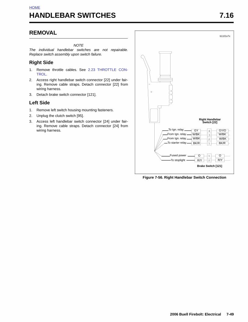
HOME
HANDLEBAR SWITCHES 7.16
REMOVAL
NOTEThe individual handlebar switches are not repairable.Replace switch assembly upon switch failure.
Right Side1. Remove throttle cables. See 2.23 THROTTLE CON-
TROL.
2. Access right handlebar switch connector [22] under fair-ing. Remove cable straps. Detach connector [22] fromwiring harness.
3. Detach brake switch connector [121].
Left Side1. Remove left switch housing mounting fasteners.
2. Unplug the clutch switch [95].
3. Access left handlebar switch connector [24] under fair-ing. Remove cable straps. Detach connector [24] fromwiring harness.
Figure 7-56. Right Handlebar Switch Connection
1
2
1
3
2
4
b1101x7x
Right Handlebar Switch [22]
Brake Switch [121]
To starter relay
GY GY/OW/BKW/BK
W/BKW/BK
BK/RBK/R
OO
R/YR/YTo stoplight
From Ign. relay
To Ign. relay
From Ign. relay
Fused power
2006 Buell Firebolt: Electrical 7-49
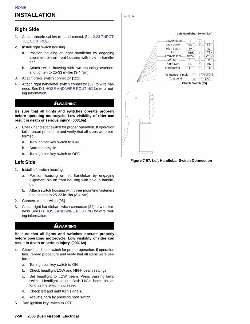
HOME
INSTALLATION
Right Side1. Attach throttle cables to hand control. See 2.23 THROT-
TLE CONTROL.
2. Install right switch housing.
a. Position housing on right handlebar by engagingalignment pin on front housing with hole in handle-bar.
b. Attach switch housing with two mounting fastenersand tighten to 25-33 in-lbs (3-4 Nm).
3. Attach brake switch connector [121].
4. Attach right handlebar switch connector [22] to wire har-ness. See D.1 HOSE AND WIRE ROUTING for wire rout-ing information.
1WARNING1WARNING
Be sure that all lights and switches operate properlybefore operating motorcycle. Low visibility of rider canresult in death or serious injury. (00316a)
5. Check handlebar switch for proper operation. If operationfails, reread procedure and verify that all steps were per-formed.
a. Turn ignition key switch to IGN.
b. Start motorcycle.
c. Turn ignition key switch to OFF.
Left Side1. Install left switch housing.
a. Position housing on left handlebar by engagingalignment pin on front housing with hole in handle-bar.
b. Attach switch housing with three mounting fastenersand tighten to 25-33 in-lbs (3-4 Nm).
2. Connect clutch switch [95].
3. Attach right handlebar switch connector [24] to wire har-ness. See D.1 HOSE AND WIRE ROUTING for wire rout-ing information.
1WARNING1WARNING
Be sure that all lights and switches operate properlybefore operating motorcycle. Low visibility of rider canresult in death or serious injury. (00316a)
4. Check handlebar switch for proper operation. If operationfails, reread procedure and verify that all steps were per-formed.
a. Turn ignition key switch to ON.
b. Check headlight LOW and HIGH beam settings.
c. Set headlight to LOW beam. Press passing lampswitch. Headlight should flash HIGH beam for aslong as the switch is pressed.
d. Check left and right turn signals.
e. Activate horn by pressing horn switch.
5. Turn ignition key switch to OFF.
Figure 7-57. Left Handlebar Switch Connection
2
8
7
65
4
3
1
21
b1103x7x
Clutch Switch [95]
Left Handlebar Switch [24]
Y/BK
Low/Unused
BE/WY/BKV/BN
Light power
High beamHorn
From flasherLeft turn
Right turnHorn power
To interlock circuitTo ground
Y
W W
—
V
O
V
OBN BN
BE BE
BKTN/LTGN
7-50 2006 Buell Firebolt: Electrical
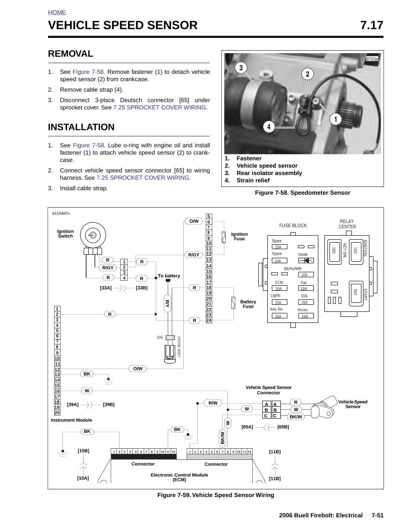
HOME
VEHICLE SPEED SENSOR 7.17
REMOVAL
1. See Figure 7-58. Remove fastener (1) to detach vehiclespeed sensor (2) from crankcase.
2. Remove cable strap (4).
3. Disconnect 3-place Deutsch connector [65] undersprocket cover. See 7.25 SPROCKET COVER WIRING.
INSTALLATION
1. See Figure 7-58. Lube o-ring with engine oil and installfastener (1) to attach vehicle speed sensor (2) to crank-case.
2. Connect vehicle speed sensor connector [65] to wiringharness. See 7.25 SPROCKET COVER WIRING.
3. Install cable strap.Figure 7-58. Speedometer Sensor
1
8723a
23
1. Fastener 2. Vehicle speed sensor3. Rear isolator assembly4. Strain relief
4
Figure 7-59. Vehicle Speed Sensor Wiring
1234
21[5A]
123456789
1011121314151617181920
5 6
8 9101112131415161718192021222324
7RELAY
CENTER
ISO
ISOISO
KEY SW.
IGN
ITION
START
Spare
Diode
Bk/Hn/Mflr
Fan
IGN
15A
15A
10A
10A
10A
10A
15A
15A
10A
Acces.Key Sw
Lights
ECM
Spare
FUSE BLOCKJ-FU
SE
AS
SY
b1104d7x
Vehicle Speed Sensor
Vehicle Speed SensorConnector
Electronic Control Module(ECM)
Connector Connector
Ignition Fuse
Battery Fuse
To battery
Ignition Switch
R/GY
Instrument Module
R
R
RR
R
R
R/Y
O/W
R
O/WBK
W
W
BKBK
BK
/W
W W
R
BK/W
R/W
R/GY
A ABB
C C
[39A] [39B]
[10B]
[10A]
[65B][65A]
[11B]
[11B]
[33B][33A]
2006 Buell Firebolt: Electrical 7-51
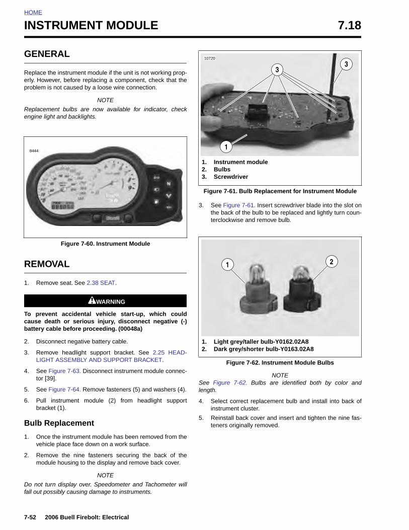
HOME
INSTRUMENT MODULE 7.18
GENERAL
Replace the instrument module if the unit is not working prop-erly. However, before replacing a component, check that theproblem is not caused by a loose wire connection.
NOTE
Replacement bulbs are now available for indicator, checkengine light and backlights.
REMOVAL
1. Remove seat. See 2.38 SEAT.
1WARNING1WARNING
To prevent accidental vehicle start-up, which couldcause death or serious injury, disconnect negative (-)battery cable before proceeding. (00048a)
2. Disconnect negative battery cable.
3. Remove headlight support bracket. See 2.25 HEAD-LIGHT ASSEMBLY AND SUPPORT BRACKET.
4. See Figure 7-63. Disconnect instrument module connec-tor [39].
5. See Figure 7-64. Remove fasteners (5) and washers (4).
6. Pull instrument module (2) from headlight supportbracket (1).
Bulb Replacement
1. Once the instrument module has been removed from thevehicle place face down on a work surface.
2. Remove the nine fasteners securing the back of themodule housing to the display and remove back cover.
NOTE
Do not turn display over. Speedometer and Tachometer willfall out possibly causing damage to instruments.
3. See Figure 7-61. Insert screwdriver blade into the slot onthe back of the bulb to be replaced and lightly turn coun-terclockwise and remove bulb.
NOTESee Figure 7-62. Bulbs are identified both by color andlength.
4. Select correct replacement bulb and install into back ofinstrument cluster.
5. Reinstall back cover and insert and tighten the nine fas-teners originally removed.
Figure 7-60. Instrument Module
8444
Figure 7-61. Bulb Replacement for Instrument Module
Figure 7-62. Instrument Module Bulbs
1. Instrument module2. Bulbs3. Screwdriver
33
1
10720
1. Light grey/taller bulb-Y0162.02A82. Dark grey/shorter bulb-Y0163.02A8
21
7-52 2006 Buell Firebolt: Electrical
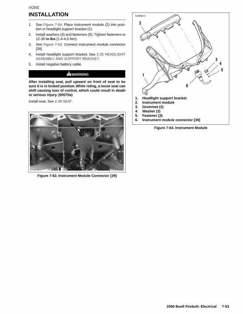
HOME
INSTALLATION
1. See Figure 7-64. Place instrument module (2) into posi-tion in headlight support bracket (1).
2. Install washers (4) and fasteners (5). Tighten fasteners to12-36 in-lbs (1.4-4.0 Nm).
3. See Figure 7-63. Connect instrument module connector[39].
4. Install headlight support bracket. See 2.25 HEADLIGHTASSEMBLY AND SUPPORT BRACKET.
5. Install negative battery cable.
1WARNING1WARNING
After installing seat, pull upward on front of seat to besure it is in locked position. While riding, a loose seat canshift causing loss of control, which could result in deathor serious injury. (00070a)
Install seat. See 2.38 SEAT.
Figure 7-63. Instrument Module Connector [39]
8426
Figure 7-64. Instrument Module
b1009x7x
2
1
6
345
1. Headlight support bracket2. Instrument module3. Grommet (3)4. Washer (3)5. Fastener (3)6. Instrument module connector [39]
2006 Buell Firebolt: Electrical 7-53
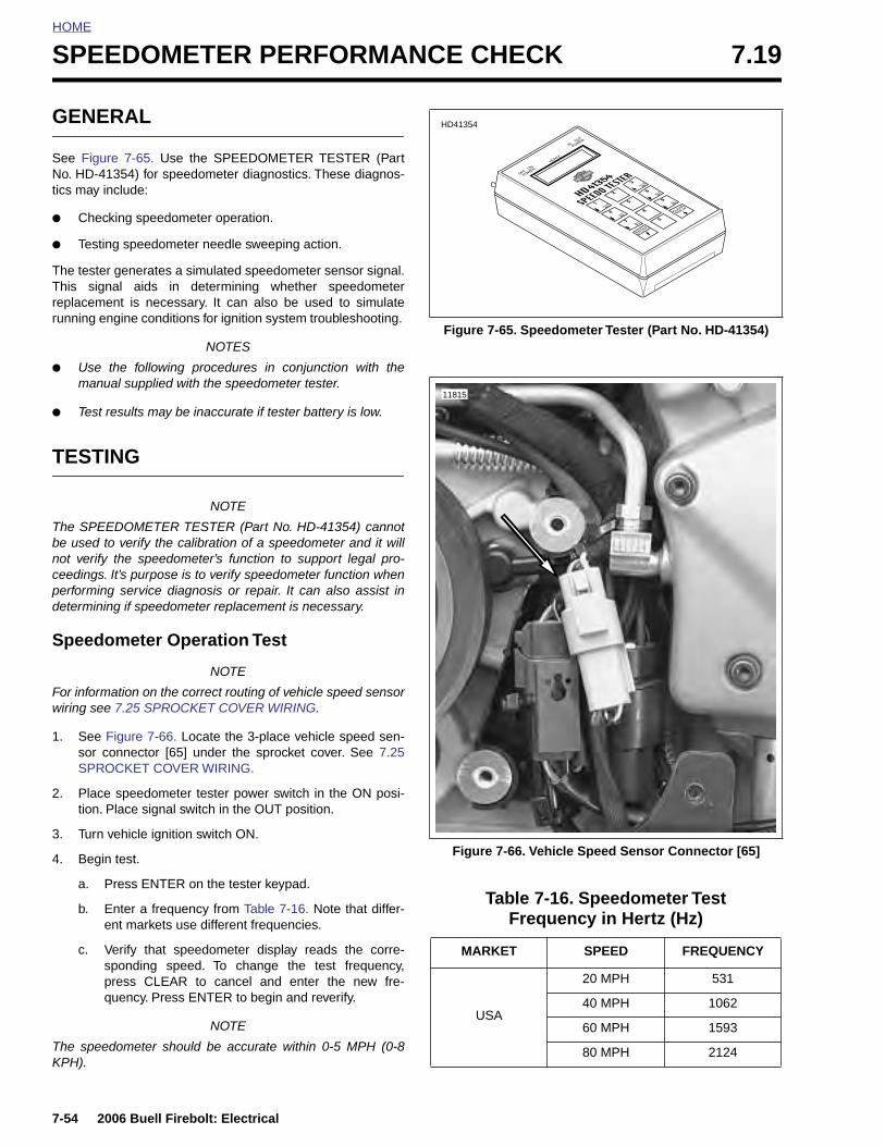
HOME
SPEEDOMETER PERFORMANCE CHECK 7.19
GENERAL
See Figure 7-65. Use the SPEEDOMETER TESTER (PartNo. HD-41354) for speedometer diagnostics. These diagnos-tics may include:
● Checking speedometer operation.
● Testing speedometer needle sweeping action.
The tester generates a simulated speedometer sensor signal.This signal aids in determining whether speedometerreplacement is necessary. It can also be used to simulaterunning engine conditions for ignition system troubleshooting.
NOTES
● Use the following procedures in conjunction with themanual supplied with the speedometer tester.
● Test results may be inaccurate if tester battery is low.
TESTING
NOTE
The SPEEDOMETER TESTER (Part No. HD-41354) cannotbe used to verify the calibration of a speedometer and it willnot verify the speedometer’s function to support legal pro-ceedings. It’s purpose is to verify speedometer function whenperforming service diagnosis or repair. It can also assist indetermining if speedometer replacement is necessary.
Speedometer Operation Test
NOTE
For information on the correct routing of vehicle speed sensorwiring see 7.25 SPROCKET COVER WIRING.
1. See Figure 7-66. Locate the 3-place vehicle speed sen-sor connector [65] under the sprocket cover. See 7.25SPROCKET COVER WIRING.
2. Place speedometer tester power switch in the ON posi-tion. Place signal switch in the OUT position.
3. Turn vehicle ignition switch ON.
4. Begin test.
a. Press ENTER on the tester keypad.
b. Enter a frequency from Table 7-16. Note that differ-ent markets use different frequencies.
c. Verify that speedometer display reads the corre-sponding speed. To change the test frequency,press CLEAR to cancel and enter the new fre-quency. Press ENTER to begin and reverify.
NOTE
The speedometer should be accurate within 0-5 MPH (0-8KPH).
Figure 7-65. Speedometer Tester (Part No. HD-41354)
Figure 7-66. Vehicle Speed Sensor Connector [65]
Table 7-16. Speedometer Test Frequency in Hertz (Hz)
MARKET SPEED FREQUENCY
USA
20 MPH 531
40 MPH 1062
60 MPH 1593
80 MPH 2124
HD41354
11815
7-54 2006 Buell Firebolt: Electrical

HOME
Speedometer Needle Sweep TestNOTE
Speedometer needle sweep test works on the speedometeronly. Use the diagnostics available with DIGITAL TECHNI-CIAN (Part No. HD-44750) to test a tachometer.
The tester’s sweep function moves the speedometer needlethrough the full range of movement. This allows for testing thesmoothness of operation and checking for hesitancy or astuck needle.
1. See Figure 7-66. Disconnect vehicle speed sensor con-nector [65]. Attach speedometer tester connector to vehi-cle speed sensor connector.
2. Place speedometer tester power switch in the ON posi-tion. Place signal switch in the OUT position.
3. Turn vehicle ignition switch ON.
4. Begin test by pressing 0 on the tester keypad, thenpressing ENTER. The tester will scan for two seconds,then the tester will put out a 1 Hz signal.
5. Select a test range.
a. Press 2 to select LO range (1-20 Hz).
b. Press 5 to select CEN range (21-999 Hz).
c. Press 8 to select HI range (1000-20,000 Hz).
6. After selecting a range, use the corresponding arrowkeys to accelerate through the range. As you movethrough the speed range, check for smooth needlemovement.
a. If testing LO range, press 1 or 3.
b. If testing CEN range, press 4 or 6.
c. If testing HI range, press 7 or 9.
Speedometer Sensor Test
If the speedometer is inoperative, but backlighting and odom-eter work, the speedometer sensor may not be working.
See Figure 7-67. Fabricate a test harness using the followingparts. This harness can also be used to test the tachometer.
● Two Deutsch 3-place socket housings (Part No. 72113-94BK) and six socket terminals (Part No. 72191-94).
● Deutsch 3-place pin housing (Part No. 72103-94BK) andthree pin terminals (Part No. 72080-99Y).
● Six lengths of 18 gauge wire, each 6.0 in. (15 cm) long.
● Test for voltage to sensor by checking for 4-6 VDC onred/white wire in connector [65].
● Then check for continuity to ground on black wire in con-nector [65].
1. Install the test harness between the vehicle speed sen-sor connector halves [65].
2. Raise rear wheel off floor using REAR WHEEL SUP-PORT STAND (Part No. B-41174).
3. Place speedometer tester power switch in the ON posi-tion. Place signal switch in the IN position.
4. Plug the speedometer tester into the test harness. Turnvehicle ignition switch ON.
5. Press ENTER on the tester keypad.
6. Rotate the motorcycle’s rear wheel.
a. If reading on speedometer tester changes as wheelis rotated, speedometer sensor is OK.
b. If reading does not change, vehicle speed sensor issuspect. Install a known, good vehicle speed sensorand test again.
ENG, AUS, EUR, CAN, JPN
40 KPH 660
60 KPH 990
80 KPH 1320
100 KPH 1650
Table 7-16. Speedometer Test Frequency in Hertz (Hz)
MARKET SPEED FREQUENCY
Figure 7-67. Test Harness
1. Deutsch socket housing (2)2. Deutsch pin housing
1
2
b0779x7x
1
2006 Buell Firebolt: Electrical 7-55
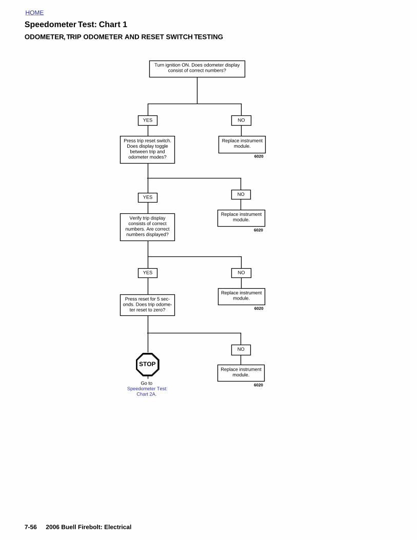
HOME
Speedometer Test: Chart 1ODOMETER, TRIP ODOMETER AND RESET SWITCH TESTING
NO
Replace instrument module.
YES
Press trip reset switch. Does display toggle
between trip and odometer modes?
Turn ignition ON. Does odometer display consist of correct numbers?
YES
Verify trip display consists of correct
numbers. Are correct numbers displayed?
NOYES
Go to Speedometer Test:
Chart 2A.
6020
6020
STOP
NO
6020
Press reset for 5 sec-onds. Does trip odome-
ter reset to zero?
NO
6020
Replace instrument module.
Replace instrument module.
Replace instrument module.
7-56 2006 Buell Firebolt: Electrical
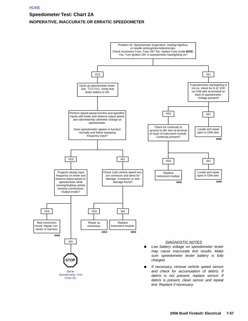
HOME
Speedometer Test: Chart 2AINOPERATIVE, INACCURATE OR ERRATIC SPEEDOMETER
YES
Hook up speedometer tester. See TESTING. Verify that
tester battery is OK.
NO
NO
If speedometer backlighting is not on, check for 9-12 VDC on O/W wire at terminal on
back of speedometer. Voltage present?
Perform speed sweep function and specified inputs with tester and observe output speed
and odometer/trip odometer change on speedometer.
Does speedometer appear to function normally and follow sweeping
frequency input?
NO
Check 3-pin vehicle speed sen-sor connector and wires for damage. Connector or wire
damage found?
YES
Program steady input frequency on tester and observe output speed on
speedometer while moving/shaking vehicle harness connections.
Output erratic?
YES
Repair asnecessary.
NO
Replaceinstrument module.
NO
Bad connection found. Repair con-nector or harness.
DIAGNOSTIC NOTES● Low battery voltage on speedometer tester
may cause inaccurate test results. Makesure speedometer tester battery is fullycharged.
● If necessary, remove vehicle speed sensorand check for accumulation of debris. Ifdebris is not present, replace sensor. Ifdebris is present, clean sensor and repeattest. Replace if necessary.
YES
Locate and repair open in O/W wire.
Check for continuity to ground on BK wire at terminal on back of instrument module.
Continuity present?
NOYES
Locate and repair open in O/W wire.
YES
Go to Speedometer Test:
Chart 2B.
STOP
6008
6008
600660046008
Problem #2: Speedometer inoperative, reading high/low, or needle sticking/intermittent/erratic.
Check Accessory Fuse. Fuse OK? No, replace Fuse (code 6032).Yes, Turn ignition ON. Is speedometer backlighting on?
Replaceinstrument module.
6006
2006 Buell Firebolt: Electrical 7-57

HOME
Speedometer Test: Chart 2BINOPERATIVE, INACCURATE OR ERRATIC SPEEDOMETER
Continued from Speedometer Test: Chart 2A.
Check for 4-5 VDC on R/W wire in vehicle speed sensor con-nector [65B]. Voltage present?
YES
Check for continuity to ground on BK wire in connector [65B].
Continuity present?
NO
Check for open/grounded wires.
Wires OK?
YES
Replace instrument module.
NO
Repairwires.
YES
Check for voltage on W wire in connector [65B]. While
connected, meter should read 4-6 VDC when gear tooth
absent and 0-1 VDC when gear tooth present. Does it?
NO
Check for open wires. Wires OK?
YES
Replace instrument module.
NO
Repairwires.
YES
Check instrument module power(O/W wire) and ground terminal (BK wire) voltage at back of instrument module. Test voltage while shaking harness. Does voltage fluctuate?
NO
4-6 VDC is not present.
Replace instrument module
NO
4-6 VDC is present, but no flunctuation
to 0-1 VDC.
Replace vehicle speed sensor.
YES
Repair as necessary.
NO
Check speedometer speed sensor. Clean or replace sen-
sor as required. Retest. Problem solved?
YES
System OK.
6022 6013
6022 6013
60226010
6008
60296024
NO
Replace instrument module.
7-58 2006 Buell Firebolt: Electrical
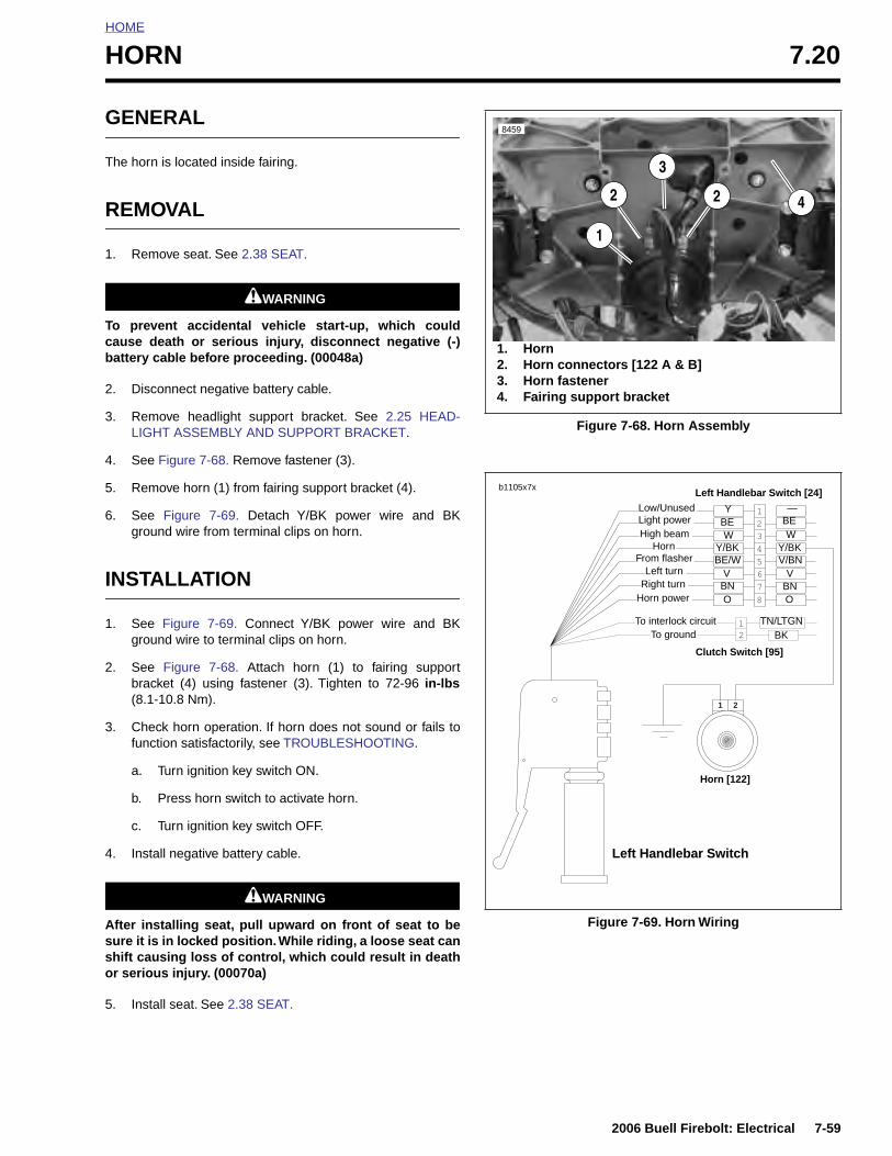
HOME
HORN 7.20
GENERAL
The horn is located inside fairing.
REMOVAL
1. Remove seat. See 2.38 SEAT.
1WARNING1WARNING
To prevent accidental vehicle start-up, which couldcause death or serious injury, disconnect negative (-)battery cable before proceeding. (00048a)
2. Disconnect negative battery cable.
3. Remove headlight support bracket. See 2.25 HEAD-LIGHT ASSEMBLY AND SUPPORT BRACKET.
4. See Figure 7-68. Remove fastener (3).
5. Remove horn (1) from fairing support bracket (4).
6. See Figure 7-69. Detach Y/BK power wire and BKground wire from terminal clips on horn.
INSTALLATION
1. See Figure 7-69. Connect Y/BK power wire and BKground wire to terminal clips on horn.
2. See Figure 7-68. Attach horn (1) to fairing supportbracket (4) using fastener (3). Tighten to 72-96 in-lbs(8.1-10.8 Nm).
3. Check horn operation. If horn does not sound or fails tofunction satisfactorily, see TROUBLESHOOTING.
a. Turn ignition key switch ON.
b. Press horn switch to activate horn.
c. Turn ignition key switch OFF.
4. Install negative battery cable.
1WARNING1WARNING
After installing seat, pull upward on front of seat to besure it is in locked position. While riding, a loose seat canshift causing loss of control, which could result in deathor serious injury. (00070a)
5. Install seat. See 2.38 SEAT.
Figure 7-68. Horn Assembly
Figure 7-69. Horn Wiring
1. Horn2. Horn connectors [122 A & B]3. Horn fastener4. Fairing support bracket
8459
1
2 2
3
4
2
8
7
65
4
3
1
21
21
b1105x7x
Left Handlebar Switch
Horn [122]
Clutch Switch [95]
Left Handlebar Switch [24]
Y/BK
Low/Unused
BE/WY/BKV/BN
Light powerHigh beam
HornFrom flasher
Left turnRight turn
Horn power
To interlock circuitTo ground
Y
W
—
V
O
V
OBN BN
BE BE
BKTN/LTGN
W
2006 Buell Firebolt: Electrical 7-59
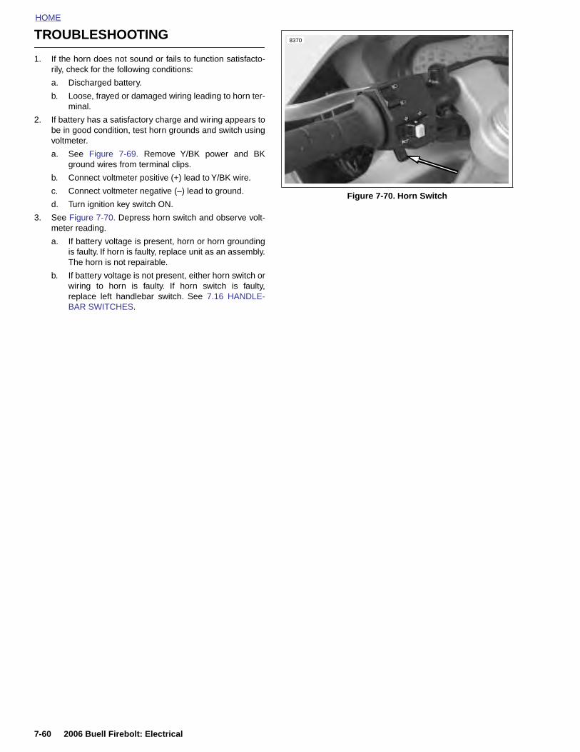
HOME
TROUBLESHOOTING
1. If the horn does not sound or fails to function satisfacto-rily, check for the following conditions:
a. Discharged battery.
b. Loose, frayed or damaged wiring leading to horn ter-minal.
2. If battery has a satisfactory charge and wiring appears tobe in good condition, test horn grounds and switch usingvoltmeter.
a. See Figure 7-69. Remove Y/BK power and BKground wires from terminal clips.
b. Connect voltmeter positive (+) lead to Y/BK wire.
c. Connect voltmeter negative (–) lead to ground.
d. Turn ignition key switch ON.
3. See Figure 7-70. Depress horn switch and observe volt-meter reading.
a. If battery voltage is present, horn or horn groundingis faulty. If horn is faulty, replace unit as an assembly.The horn is not repairable.
b. If battery voltage is not present, either horn switch orwiring to horn is faulty. If horn switch is faulty,replace left handlebar switch. See 7.16 HANDLE-BAR SWITCHES.
Figure 7-70. Horn Switch
8370
7-60 2006 Buell Firebolt: Electrical

HOME
NEUTRAL INDICATOR SWITCH 7.21
GENERAL
See Figure 7-71. The neutral indicator switch (2) is threadedinto the transmission portion of the right crankcase half. It isimmediately forward of the transmission sprocket (1). Thesprocket cover must be removed to test the switch.
A pin on the shifter drum contacts the neutral indicator switchplunger, completing the neutral indicator circuit. The switch isnot repairable. Replace the switch if it malfunctions.
TESTING
1. Remove sprocket cover. See 2.30 SPROCKET COVER.
2. See Figure 7-71. Disconnect wire lead from neutral indi-cator switch (2).
3. Turn ignition key switch to ON. Touch the neutral indica-tor wire lead to a suitable ground.
a. If indicator lamp lights, then problem is at indicatorswitch. Replace switch.
b. If indicator lamp does not light, then problem is else-where in circuit. Check for loose connections,burned out indicator lamps or faulty wiring.
c. After testing and repair, connect wire lead to indica-tor switch.
4. Install sprocket cover. See 2.30 SPROCKET COVER.
REMOVAL/INSTALLATION
1. Verify that the ignition key switch is turned to OFF.
2. Remove sprocket cover. See 2.30 SPROCKET COVER.
NOTE
If replacing neutral indicator switch wiring, see 7.24 INTER-ACTIVE EXHAUST HARNESS(XB12 MODELS) for correctwire routing.
3. See Figure 7-72. Remove wire lead (1) from neutral indi-cator switch (2).
4. Remove neutral indicator switch and washer (3).
5. Install new neutral indicator switch.
a. Apply a light coating of LOCTITE THREADLOCKER243 (blue) to new neutral indicator switch (1)threads.
b. Install washer (3) over neutral indicator switch (2)threads.
c. Install switch in crankcase. Tighten switch to 60-84in-lbs (6.7-9.5 Nm).
d. Connect wire lead (1) to switch.
6. Install sprocket cover. See 2.30 SPROCKET COVER.
Figure 7-71. Neutral Indicator Switch Location
Figure 7-72. Neutral Indicator Switch
11815
1. Transmission sprocket2. Neutral indicator switch
2
1
1. Neutral indicator switch wire lead2. Neutral indicator switch3. Washer
12
3
b1029x8x
2006 Buell Firebolt: Electrical 7-61
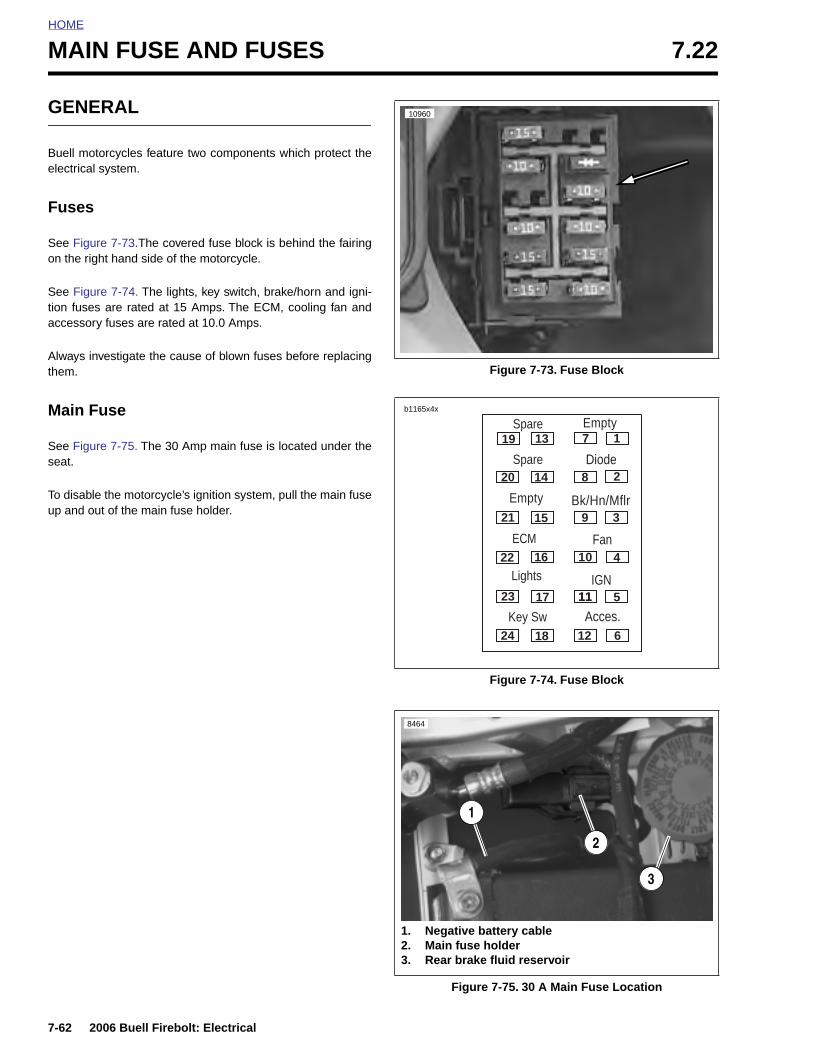
HOME
MAIN FUSE AND FUSES 7.22
GENERAL
Buell motorcycles feature two components which protect theelectrical system.
Fuses
See Figure 7-73.The covered fuse block is behind the fairingon the right hand side of the motorcycle.
See Figure 7-74. The lights, key switch, brake/horn and igni-tion fuses are rated at 15 Amps. The ECM, cooling fan andaccessory fuses are rated at 10.0 Amps.
Always investigate the cause of blown fuses before replacingthem.
Main Fuse
See Figure 7-75. The 30 Amp main fuse is located under theseat.
To disable the motorcycle’s ignition system, pull the main fuseup and out of the main fuse holder.
Figure 7-73. Fuse Block
Figure 7-74. Fuse Block
Figure 7-75. 30 A Main Fuse Location
10960
19
20
21
22
23
24
13
14
15
16
17
18
1
2
3
4
5
6
7
8
9
10
11
12
11
Spare
Diode
Bk/Hn/Mflr
Fan
IGN
Acces.Key Sw
Lights
ECM
Spare
Empty
Empty
b1165x4x
8464
1. Negative battery cable2. Main fuse holder3. Rear brake fluid reservoir
1
2
3
7-62 2006 Buell Firebolt: Electrical
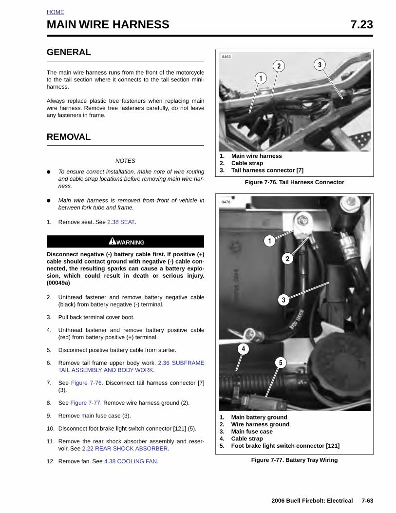
HOME
MAIN WIRE HARNESS 7.23
GENERAL
The main wire harness runs from the front of the motorcycleto the tail section where it connects to the tail section mini-harness.
Always replace plastic tree fasteners when replacing mainwire harness. Remove tree fasteners carefully, do not leaveany fasteners in frame.
REMOVAL
NOTES
● To ensure correct installation, make note of wire routingand cable strap locations before removing main wire har-ness.
● Main wire harness is removed from front of vehicle inbetween fork tube and frame.
1. Remove seat. See 2.38 SEAT.
1WARNING1WARNING
Disconnect negative (-) battery cable first. If positive (+)cable should contact ground with negative (-) cable con-nected, the resulting sparks can cause a battery explo-sion, which could result in death or serious injury.(00049a)
2. Unthread fastener and remove battery negative cable(black) from battery negative (-) terminal.
3. Pull back terminal cover boot.
4. Unthread fastener and remove battery positive cable(red) from battery positive (+) terminal.
5. Disconnect positive battery cable from starter.
6. Remove tail frame upper body work. 2.36 SUBFRAMETAIL ASSEMBLY AND BODY WORK.
7. See Figure 7-76. Disconnect tail harness connector [7](3).
8. See Figure 7-77. Remove wire harness ground (2).
9. Remove main fuse case (3).
10. Disconnect foot brake light switch connector [121] (5).
11. Remove the rear shock absorber assembly and reser-voir. See 2.22 REAR SHOCK ABSORBER.
12. Remove fan. See 4.38 COOLING FAN.
Figure 7-76. Tail Harness Connector
Figure 7-77. Battery Tray Wiring
1
2 38463
1. Main wire harness2. Cable strap3. Tail harness connector [7]
1. Main battery ground2. Wire harness ground3. Main fuse case4. Cable strap5. Foot brake light switch connector [121]
1
2
3
5
4
8478
2006 Buell Firebolt: Electrical 7-63
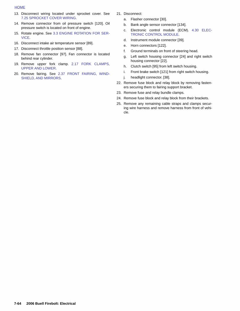
HOME
13. Disconnect wiring located under sprocket cover. See7.25 SPROCKET COVER WIRING.
14. Remove connector from oil pressure switch [120]. Oilpressure switch is located on front of engine.
15. Rotate engine. See 3.3 ENGINE ROTATION FOR SER-VICE.
16. Disconnect intake air temperature sensor [89].
17. Disconnect throttle position sensor [88].
18. Remove fan connector [97]. Fan connector is locatedbehind rear cylinder.
19. Remove upper fork clamp. 2.17 FORK CLAMPS,UPPER AND LOWER.
20. Remove fairing. See 2.37 FRONT FAIRING, WIND-SHIELD, AND MIRRORS.
21. Disconnect:
a. Flasher connector [30].
b. Bank angle sensor connector [134].
c. Electronic control module (ECM). 4.30 ELEC-TRONIC CONTROL MODULE.
d. Instrument module connector [39].
e. Horn connectors [122].
f. Ground terminals on front of steering head.
g. Left switch housing connector [24] and right switchhousing connector [22].
h. Clutch switch [95] from left switch housing.
i. Front brake switch [121] from right switch housing.
j. headlight connector. [38].
22. Remove fuse block and relay block by removing fasten-ers securing them to fairing support bracket.
23. Remove fuse and relay bundle clamps.
24. Remove fuse block and relay block from their brackets.
25. Remove any remaining cable straps and clamps secur-ing wire harness and remove harness from front of vehi-cle.
7-64 2006 Buell Firebolt: Electrical
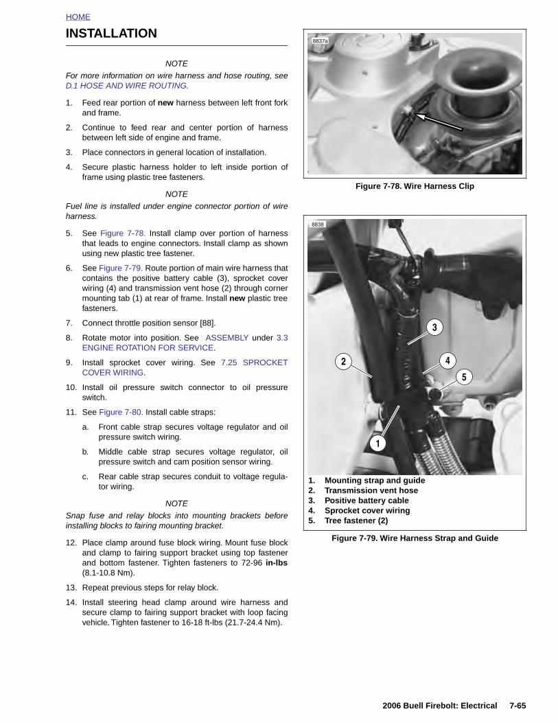
HOME
INSTALLATION
NOTE
For more information on wire harness and hose routing, seeD.1 HOSE AND WIRE ROUTING.
1. Feed rear portion of new harness between left front forkand frame.
2. Continue to feed rear and center portion of harnessbetween left side of engine and frame.
3. Place connectors in general location of installation.
4. Secure plastic harness holder to left inside portion offrame using plastic tree fasteners.
NOTE
Fuel line is installed under engine connector portion of wireharness.
5. See Figure 7-78. Install clamp over portion of harnessthat leads to engine connectors. Install clamp as shownusing new plastic tree fastener.
6. See Figure 7-79. Route portion of main wire harness thatcontains the positive battery cable (3), sprocket coverwiring (4) and transmission vent hose (2) through cornermounting tab (1) at rear of frame. Install new plastic treefasteners.
7. Connect throttle position sensor [88].
8. Rotate motor into position. See ASSEMBLY under 3.3ENGINE ROTATION FOR SERVICE.
9. Install sprocket cover wiring. See 7.25 SPROCKETCOVER WIRING.
10. Install oil pressure switch connector to oil pressureswitch.
11. See Figure 7-80. Install cable straps:
a. Front cable strap secures voltage regulator and oilpressure switch wiring.
b. Middle cable strap secures voltage regulator, oilpressure switch and cam position sensor wiring.
c. Rear cable strap secures conduit to voltage regula-tor wiring.
NOTE
Snap fuse and relay blocks into mounting brackets beforeinstalling blocks to fairing mounting bracket.
12. Place clamp around fuse block wiring. Mount fuse blockand clamp to fairing support bracket using top fastenerand bottom fastener. Tighten fasteners to 72-96 in-lbs(8.1-10.8 Nm).
13. Repeat previous steps for relay block.
14. Install steering head clamp around wire harness andsecure clamp to fairing support bracket with loop facingvehicle. Tighten fastener to 16-18 ft-lbs (21.7-24.4 Nm).
Figure 7-78. Wire Harness Clip
Figure 7-79. Wire Harness Strap and Guide
8837a
8838
42
1
3
1. Mounting strap and guide2. Transmission vent hose3. Positive battery cable4. Sprocket cover wiring5. Tree fastener (2)
5
2006 Buell Firebolt: Electrical 7-65
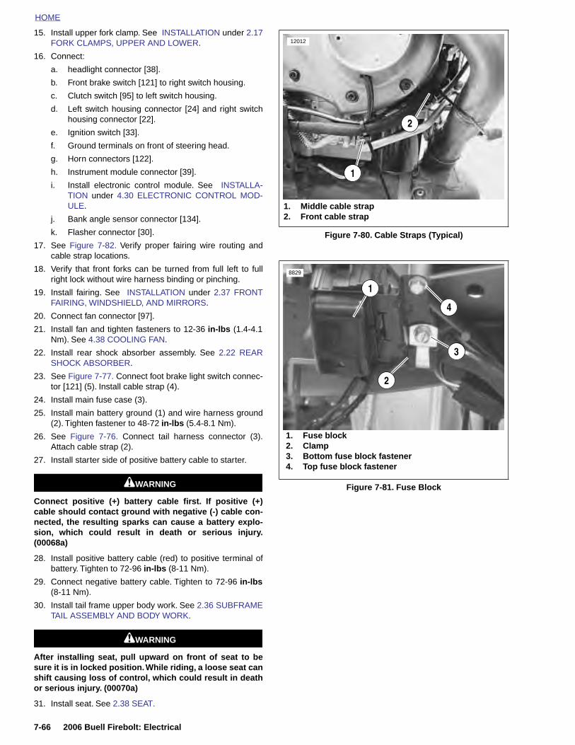
HOME
15. Install upper fork clamp. See INSTALLATION under 2.17FORK CLAMPS, UPPER AND LOWER.
16. Connect:
a. headlight connector [38].
b. Front brake switch [121] to right switch housing.
c. Clutch switch [95] to left switch housing.
d. Left switch housing connector [24] and right switchhousing connector [22].
e. Ignition switch [33].
f. Ground terminals on front of steering head.
g. Horn connectors [122].
h. Instrument module connector [39].
i. Install electronic control module. See INSTALLA-TION under 4.30 ELECTRONIC CONTROL MOD-ULE.
j. Bank angle sensor connector [134].
k. Flasher connector [30].
17. See Figure 7-82. Verify proper fairing wire routing andcable strap locations.
18. Verify that front forks can be turned from full left to fullright lock without wire harness binding or pinching.
19. Install fairing. See INSTALLATION under 2.37 FRONTFAIRING, WINDSHIELD, AND MIRRORS.
20. Connect fan connector [97].
21. Install fan and tighten fasteners to 12-36 in-lbs (1.4-4.1Nm). See 4.38 COOLING FAN.
22. Install rear shock absorber assembly. See 2.22 REARSHOCK ABSORBER.
23. See Figure 7-77. Connect foot brake light switch connec-tor [121] (5). Install cable strap (4).
24. Install main fuse case (3).
25. Install main battery ground (1) and wire harness ground(2). Tighten fastener to 48-72 in-lbs (5.4-8.1 Nm).
26. See Figure 7-76. Connect tail harness connector (3).Attach cable strap (2).
27. Install starter side of positive battery cable to starter.
1WARNING1WARNING
Connect positive (+) battery cable first. If positive (+)cable should contact ground with negative (-) cable con-nected, the resulting sparks can cause a battery explo-sion, which could result in death or serious injury.(00068a)
28. Install positive battery cable (red) to positive terminal ofbattery. Tighten to 72-96 in-lbs (8-11 Nm).
29. Connect negative battery cable. Tighten to 72-96 in-lbs(8-11 Nm).
30. Install tail frame upper body work. See 2.36 SUBFRAMETAIL ASSEMBLY AND BODY WORK.
1WARNING1WARNING
After installing seat, pull upward on front of seat to besure it is in locked position. While riding, a loose seat canshift causing loss of control, which could result in deathor serious injury. (00070a)
31. Install seat. See 2.38 SEAT.
Figure 7-80. Cable Straps (Typical)
Figure 7-81. Fuse Block
1. Middle cable strap2. Front cable strap
12012
2
1
1
2
3
4
1. Fuse block2. Clamp3. Bottom fuse block fastener4. Top fuse block fastener
8829
7-66 2006 Buell Firebolt: Electrical
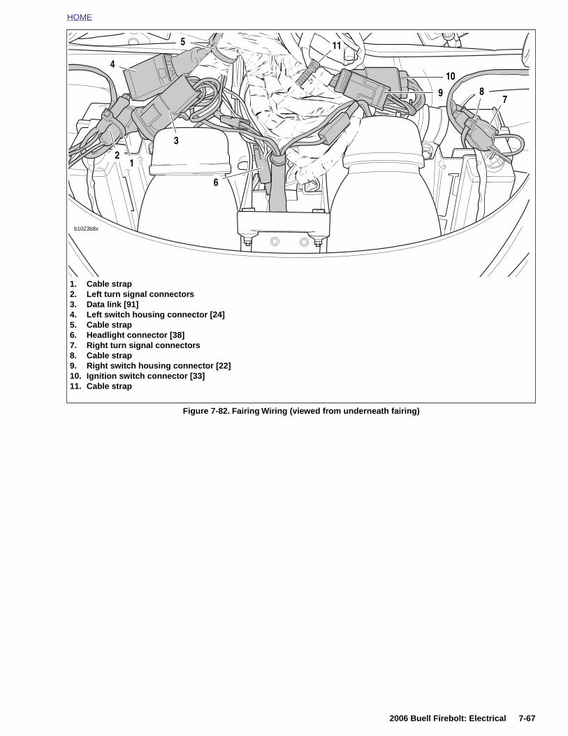
HOME
Figure 7-82. Fairing Wiring (viewed from underneath fairing)
b1023b8x
11
10
3
4
5
9
12
87
6
1. Cable strap2. Left turn signal connectors3. Data link [91]4. Left switch housing connector [24]5. Cable strap6. Headlight connector [38]7. Right turn signal connectors8. Cable strap9. Right switch housing connector [22]10. Ignition switch connector [33]11. Cable strap
2006 Buell Firebolt: Electrical 7-67

HOME
INTERACTIVE EXHAUST HARNESS(XB12 MODELS) 7.24
REMOVAL
1. Remove seat and pillion. See 2.38 SEAT.
2. Remove four fasteners, nylon washers and intake coverassembly. See 2.34 INTAKE COVER ASSEMBLY.
3. Remove negative battery cable from battery.
4. Remove main battery ground and the exhaust actuatorground.
5. Remove the subframe tail body work. See 2.36 SUB-FRAME TAIL ASSEMBLY AND BODY WORK.
6. See Figure 7-83. Separate exhaust actuator harnessconnector [165] (2) at main harness.
7. Note location of cable strap and cut as required.
8. Pull actuator harness through frame.
9. Disconnect connector [161B] from actuator.
10. If removing actuator:
a. Add free play to interactive exhaust cable, loosenjam nut and remove cable from bracket. See 7.6INTERACTIVE EXHAUST SYSTEM (XB12MODEL).
b. Remove interactive exhaust cable from cable wheel.
c. Remove actuator.
Figure 7-83. Left Side Subframe Hose and Wire Routing
Figure 2-84. Battery and Harness Ground (battery removed for clarity)
8463
1. Fuel vent hose2. Main wire harness3. Cable strap4. Rear shock reservoir hose5. Main wire harness connection [165]
1 2
3 54
8478
1. Main battery ground2. Wire harness ground3. Main fuse case
1
2
3
7-68 2006 Buell Firebolt: Electrical
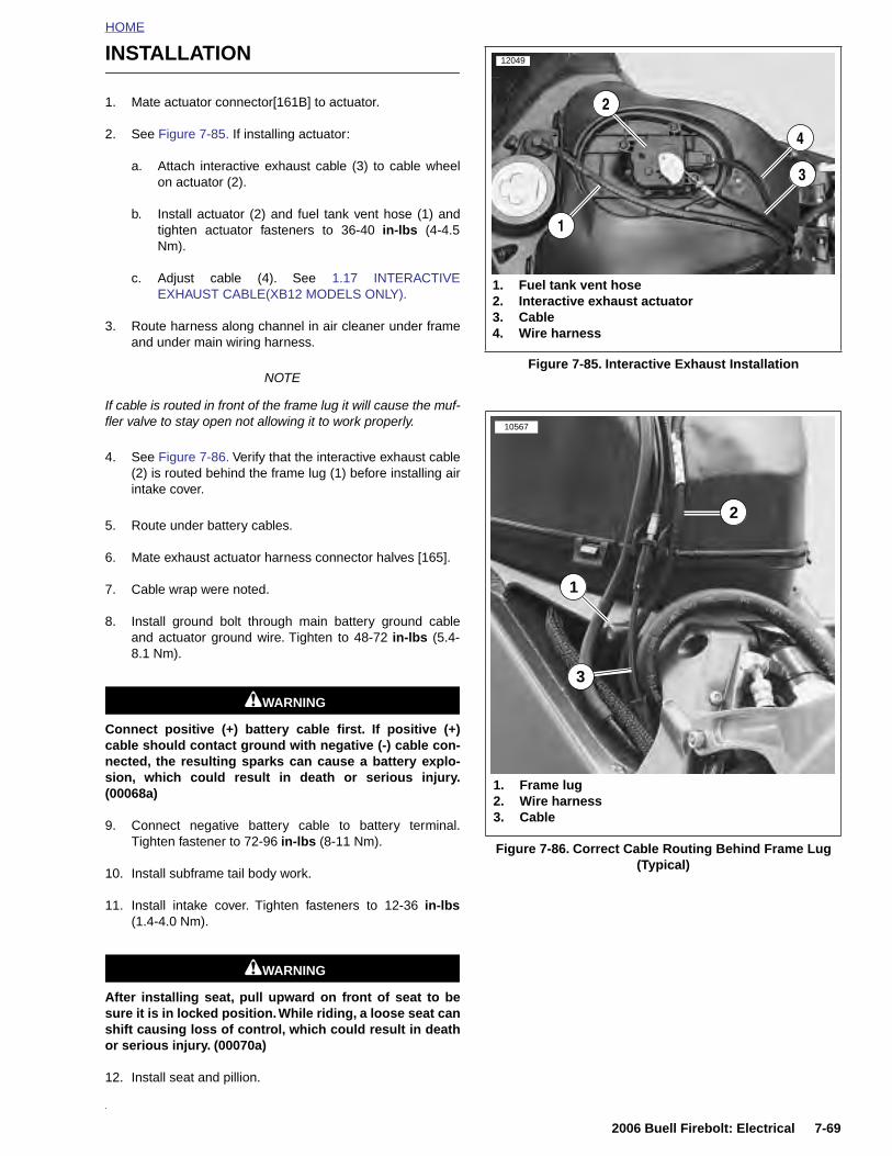
HOME
INSTALLATION
1. Mate actuator connector[161B] to actuator.
2. See Figure 7-85. If installing actuator:
a. Attach interactive exhaust cable (3) to cable wheelon actuator (2).
b. Install actuator (2) and fuel tank vent hose (1) andtighten actuator fasteners to 36-40 in-lbs (4-4.5Nm).
c. Adjust cable (4). See 1.17 INTERACTIVEEXHAUST CABLE(XB12 MODELS ONLY).
3. Route harness along channel in air cleaner under frameand under main wiring harness.
NOTE
If cable is routed in front of the frame lug it will cause the muf-fler valve to stay open not allowing it to work properly.
4. See Figure 7-86. Verify that the interactive exhaust cable(2) is routed behind the frame lug (1) before installing airintake cover.
5. Route under battery cables.
6. Mate exhaust actuator harness connector halves [165].
7. Cable wrap were noted.
8. Install ground bolt through main battery ground cableand actuator ground wire. Tighten to 48-72 in-lbs (5.4-8.1 Nm).
1WARNING1WARNING
Connect positive (+) battery cable first. If positive (+)cable should contact ground with negative (-) cable con-nected, the resulting sparks can cause a battery explo-sion, which could result in death or serious injury.(00068a)
9. Connect negative battery cable to battery terminal.Tighten fastener to 72-96 in-lbs (8-11 Nm).
10. Install subframe tail body work.
11. Install intake cover. Tighten fasteners to 12-36 in-lbs(1.4-4.0 Nm).
1WARNING1WARNING
After installing seat, pull upward on front of seat to besure it is in locked position. While riding, a loose seat canshift causing loss of control, which could result in deathor serious injury. (00070a)
12. Install seat and pillion.
.
Figure 7-85. Interactive Exhaust Installation
Figure 7-86. Correct Cable Routing Behind Frame Lug(Typical)
12049
1. Fuel tank vent hose2. Interactive exhaust actuator3. Cable4. Wire harness
1
2
3
4
10567
1. Frame lug2. Wire harness3. Cable
1
3
2
2006 Buell Firebolt: Electrical 7-69
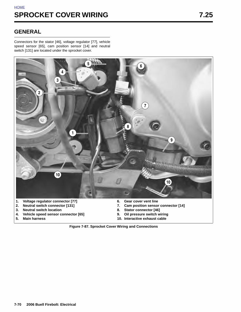
HOME
SPROCKET COVER WIRING 7.25
GENERAL
Connectors for the stator [46], voltage regulator [77], vehiclespeed sensor [65], cam position sensor [14] and neutralswitch [131] are located under the sprocket cover.
Figure 7-87. Sprocket Cover Wiring and Connections
1. Voltage regulator connector [77]2. Neutral switch connector [131]3. Neutral switch location4. Vehicle speed sensor connector [65]5. Main harness
6. Gear cover vent line7. Cam position sensor connector [14]8. Stator connector [46]9. Oil pressure switch wiring10. Interactive exhaust cable
411993
5
7
10
1
2
3
6
10
9
8
7-70 2006 Buell Firebolt: Electrical
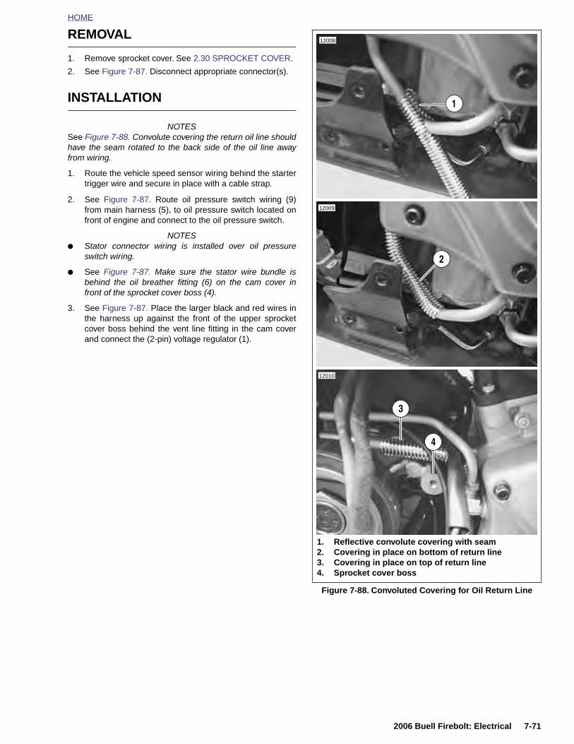
HOME
REMOVAL
1. Remove sprocket cover. See 2.30 SPROCKET COVER.
2. See Figure 7-87. Disconnect appropriate connector(s).
INSTALLATION
NOTESSee Figure 7-88. Convolute covering the return oil line shouldhave the seam rotated to the back side of the oil line awayfrom wiring.
1. Route the vehicle speed sensor wiring behind the startertrigger wire and secure in place with a cable strap.
2. See Figure 7-87. Route oil pressure switch wiring (9)from main harness (5), to oil pressure switch located onfront of engine and connect to the oil pressure switch.
NOTES● Stator connector wiring is installed over oil pressure
switch wiring.
● See Figure 7-87. Make sure the stator wire bundle isbehind the oil breather fitting (6) on the cam cover infront of the sprocket cover boss (4).
3. See Figure 7-87. Place the larger black and red wires inthe harness up against the front of the upper sprocketcover boss behind the vent line fitting in the cam coverand connect the (2-pin) voltage regulator (1).
Figure 7-88. Convoluted Covering for Oil Return Line
12008
12009
12010
1. Reflective convolute covering with seam2. Covering in place on bottom of return line3. Covering in place on top of return line4. Sprocket cover boss
3
1
2
4
2006 Buell Firebolt: Electrical 7-71
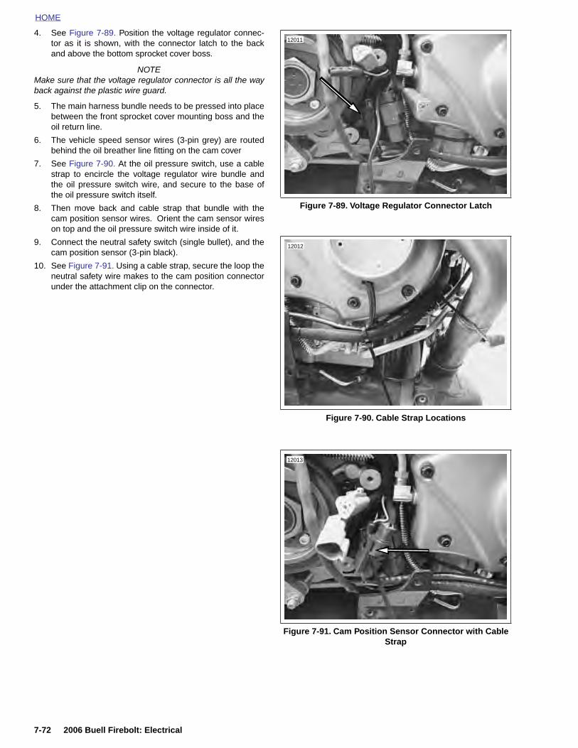
HOME
4. See Figure 7-89. Position the voltage regulator connec-tor as it is shown, with the connector latch to the backand above the bottom sprocket cover boss.
NOTEMake sure that the voltage regulator connector is all the wayback against the plastic wire guard.
5. The main harness bundle needs to be pressed into placebetween the front sprocket cover mounting boss and theoil return line.
6. The vehicle speed sensor wires (3-pin grey) are routedbehind the oil breather line fitting on the cam cover
7. See Figure 7-90. At the oil pressure switch, use a cablestrap to encircle the voltage regulator wire bundle andthe oil pressure switch wire, and secure to the base ofthe oil pressure switch itself.
8. Then move back and cable strap that bundle with thecam position sensor wires. Orient the cam sensor wireson top and the oil pressure switch wire inside of it.
9. Connect the neutral safety switch (single bullet), and thecam position sensor (3-pin black).
10. See Figure 7-91. Using a cable strap, secure the loop theneutral safety wire makes to the cam position connectorunder the attachment clip on the connector.
Figure 7-89. Voltage Regulator Connector Latch
Figure 7-90. Cable Strap Locations
Figure 7-91. Cam Position Sensor Connector with Cable Strap
12011
12012
12013
7-72 2006 Buell Firebolt: Electrical

HOME
11. See Figure 7-92. Position the cam position sensor wirebundle and the voltage regulator wire bundle inboard,then push the wire bundle up against the return oil lineand cable strap them to the return oil line.
12. See Figure 7-93. Capture the main wire harness bundle,the vehicle speed sensor lead, the stator bundle, and themuffler actuator cable (if applicable) to the oil return linewith a cable strap.
13. See Figure 7-94. Connect the vehicle speed sensor last.
NOTES
● The vehicle speed sensor is positioned high in the bun-dle in order for the front sprocket cover to conform to theadditional components.
● Make sure main harness is routed around sprocket coverboss.
14. Install sprocket cover. See 2.30 SPROCKET COVER.
Figure 7-92. Cable Strap Wire Bundle to Return Oil Line
Figure 7-93. Cable Strap Wire Bundle to Return Oil Line, Upper Part of Sprocket Cover
12007
12014
Figure 7-94. Vehicle Speed Sensor
Figure 7-95. Correct Location for Sprocket Cover Wiring
12015
1. Sprocket cover boss2. Main harness3. Cable strap securing main harness wiring
3
1
11970a
2
2006 Buell Firebolt: Electrical 7-73
HOME
NOTES
7-74 2006 Buell Firebolt: Electrical
SUBJECT PAGE NO.
A.1 Tools . . . . . . . . . . . . . . . . . . . . . . . . . . . . . . . . . . . . . . . . . . . . . . . . . . . . . . . . A-1B.1 Amp MultiB.2 Deutsch EB.3 Packard EB.4 Electrical CB.5 Index to WC.1 Metric ConD.1 Hose and E.1 Active Inta
Table Of Contents
lock Electrical Connectors . . . . . . . . . . . . . . . . . . . . . . . . . . . . . . . . B-1lectrical Connectors . . . . . . . . . . . . . . . . . . . . . . . . . . . . . . . . . . . . B-5lectrical Connectors . . . . . . . . . . . . . . . . . . . . . . . . . . . . . . . . . . . . B-10onnectors . . . . . . . . . . . . . . . . . . . . . . . . . . . . . . . . . . . . . . . . . . . B-14iring Diagrams . . . . . . . . . . . . . . . . . . . . . . . . . . . . . . . . . . . . . . . . B-16versions . . . . . . . . . . . . . . . . . . . . . . . . . . . . . . . . . . . . . . . . . . . . . C-1Wire Routing . . . . . . . . . . . . . . . . . . . . . . . . . . . . . . . . . . . . . . . . . . D-1ke System (Japanese models only) . . . . . . . . . . . . . . . . . . . . . . . E-1
APPENDICES