
2005 deep snow service manual
308
PN 9919302 2005 DEEP SNOW SERVICE MANUAL TRAIL RMK 600 RMK 700 RMK 800 RMK 900 RMK 600 SWITCHBACK ™ 800 SWITCHBACK ™
-
Upload
khangminh22 -
Category
Documents
-
view
1 -
download
0
Transcript of 2005 deep snow service manual

9919302PART #
PN 99193029919302
2005 DEEP SNOWSERVICE MANUAL
TRAIL RMK600 RMK700 RMK800 RMK900 RMK
600 SWITCHBACK™
800 SWITCHBACK™
2005 DEEP SNO
W SERVICE M
ANUAL
CVR_9919302 9/23/04 9:17 AM Page 1
creo
UNDERSTANDING SAFETY LABELS AND INSTRUCTIONSThroughout these instructions, important information is brought to your attention by the following symbols:
NOTE: S A NOTE provides key information to clarify instructions.
CAUTION: A CAUTION indicates special precautions that must be taken to avoid personal injury,
or snowmobile or property damage.
DANGERFailure to follow DANGER instructions will result in severe injury or death to the operator,
bystander or person inspecting or servicing the snowmobile.
WARNING
Failure to follow WARNING instructions could result in severe injury or death to the operator, bystander or person inspectingor servicing the snowmobile.
CAUTION:
A CAUTION indicates special precautions that must be taken to avoid personal injury, or snowmobile or property damage.
NOTE:
A NOTE provides key information to clarify instructions.
Trademarks
Polaris acknowledges the following products mentioned in this manual:
FLEXLOC, Registered Trademark of SPS Technologies
Loctite, Registered Trademark of the Loctite Corporation
STA-BIL, Registered Trademark of Gold Eagle
FOX, Registered Trademark of Fox Shox
Nyogel, Trademark of Wm. F. Nye Co.
Fluke, Registered Trademark of John Fluke Mfg. Co.
Mity Vac, Registered Trademark of Neward Enterprises, Inc.
Ammco, Registered Trademark of Ammco Tools, Inc.
Torx, Registered Trademark of Textron
Hilliard, Trademark of the Hilliard Corporation
Willwood, Trademark of the Willwood Corporation

i
2005 DEEP SNOWMANUAL
SPECIFICATIONS 1
GENERAL 2
MAINTENANCE 3
FUEL DELIVERY 4
ENGINE 5
CLUTCHING 6
FINAL DRIVE 7
BRAKE SYSTEM 8
STEERING 9
FRONT SUSPENSION 10
REAR SUSPENSION 11
CHASSIS / HOOD 12
ELECTRICAL SYSTEM 13
WIRING DIAGRAMS 14
ForewordThis manual is designed primarily for use by certifiedPolaris snowmobile service technicians in a properlyequipped shop. Persons using this manual should havea sound knowledge of mechanical theory, tool use, andshop procedures in order to perform the work safely andcorrectly. The technician should read the text and be fa-miliar with service procedures before starting the work.Certain procedures require the use of special tools. Useonly the proper tools, as specified. Cleanliness of partsand tools as well as the work area is of primary impor-tance.
All references to left and right side of the vehicle arefrom the operator’s perspective when seated in a normalriding position.
This manual includes 2005 Model Year information,along with service specifications. A table of contents isplaced at the beginning of each chapter, and analphabetic index is provided at the end of the manual forlocation of specific page numbers and serviceinformation. Keep this manual available for referencein the shop area.
At the time of publication all information contained inthis manual was technically correct. However, allmaterials and specifications are subject to changewithout notice.
Comments or suggestions about this manual may bedirected to:
Polaris Sales Inc.Snow Engineering Publications Department2100 Hwy 55 Medina, Minnesota 55340.
2005 DEEP SNOW MANUAL
(PN9919302)Copyright 2004 Polaris Sales Inc. Printed in U.S.A.

INTRODUCTION
ii
NOTES

TRAIL RMK 1.2 -- 1.3. . . . . . . . . . . . . . . . . . . . . . . . . . . . . . . . . . . . . . . . .
600 RMK 1.4 -- 1.5. . . . . . . . . . . . . . . . . . . . . . . . . . . . . . . . . . . . . . . . . . . .700 RMK 1.6 -- 1.7. . . . . . . . . . . . . . . . . . . . . . . . . . . . . . . . . . . . . . . . . . . .
800 RMK 1.8 -- 1.9. . . . . . . . . . . . . . . . . . . . . . . . . . . . . . . . . . . . . . . . . . . .
900 RMK 1.10 -- 1.11. . . . . . . . . . . . . . . . . . . . . . . . . . . . . . . . . . . . . . . . . . . .
600 SWITCHBACK 1.12 -- 1.13. . . . . . . . . . . . . . . . . . . . . . . . . . . . . . . . . . .
800 SWITCHBACK 1.14 -- 1.15. . . . . . . . . . . . . . . . . . . . . . . . . . . . . . . . . . .

SPECIFICATIONS
1.1
NOTES

SPECIFICATIONS
1.2
MODEL: TRAIL RMK. . . . . . . . . . . . . .MODEL NUMBER: S05NJ5BS(A). . . .ENGINE MODEL: EC55PM071. . . . .
ENGINE CARBURETION
Engine Type Libertyt Type MikuniVM34SS w/ACCS
Engine Displacement cc’s 544 Main Jet 260 PTO / 250 MAG
Bore in / mm 2.87” / 73mm Pilot Jet 35
Stroke in / mm 2.56” / 65mm Jet Needle 6DEH11 / 3
Cylinders 2 Needle Jet Q--0 (480)
Piston / Cylinder Clearancein / mm
.0045 -- .0053”
.114 -- .135mmThrottle Gap UnderCutaway
in / mm.250”
6.35mm
Piston Ring End Gap in / mm .015 -- .022”.4 -- .55mm
Cutaway 3.0
Piston Marking 5MD Valve Seat 1.5 Viton
Piston Ring Marking N Starter Jet 1.5
Operating RPM ±200 7000 Fuel Screw N/A
Idle RPM ±200 1600 Pilot Air Jet N/A
Air Screw 1.0 Turns
Engagement RPM ±300 3800Fuel Octane (R+M/2) 87 Oct. NonOxy /
89 Oct. Oxy
AMBIENT TEMPERATURE
Altitude Below -30°F -30_ to --10_F --10_to +10_F +10_to +30_F +30_to +50_F Above +50_FAltitude Below -30 FBelow -34°C
-30_ to --10_F-34_to -23_C
--10_to +10_F-23_ to --12_C
+10_to +30_F-12_to --1_C
+30_to +50_F-1_to +10_C
Above +50_FAbove +10_C
0--600(0--2000)
290/280#3
280/270#3
270/260#3
260/250#3
250/240#3
240/230#3
600--1200(2000--4000)
290/280#3
280/270#3
270/260#3
260/250#3
250/240#3
240/230#3
1200--1800 290/280 280/270 270/260 260/250 250/240 240/2301200--1800(4000--6000)
290/280#3
280/270#3
270/260#3
260/250#3
250/240#3
240/230#3
Meters(Feet)
1800--2400(6000 8000)
290/280 280/270 270/260 260/250 250/240 240/230(Feet) (6000--8000)290/280
#3280/270
#3270/260
#3260/250
#3250/240
#3240/230
#3
2400--3000(8000 10000)
290/280 280/270 270/260 260/250 250/240 240/230(8000--10000)
290/280#3
280/270#3
270/260#3
260/250#3
250/240#3
240/230#3
3000--3700(10000 12000)
290/280 280/270 270/260 260/250 250/240 240/230(10000--12000)
290/280#3
280/270#3
270/260#3
260/250#3
250/240#3
240/230#3
DRIVE CLUTCH DRIVEN CLUTCH
Altitude Shift Clutch Clutch Driven ChaincaseAltitude ShiftWeight
ClutchSpring
ClutchSpring
DrivenHelix
ChaincaseGearing
0-900 10 64 Bushed Dark Blue / Red / Blue 40° 19 43 74P0-900(0-3000)
10--64 Bushed Dark Blue /White
Red / Blue 40Team Reverse
19--43 74P
M t900-1800 10 62 Bushed Dark Blue / Red / Blue 40° 19 43 74PMeters
(Feet)
900-1800(3000-6000)
10--62 Bushed Dark Blue /White
Red / Blue 40Team Reverse
19--43 74P(Feet)
1800-2700 10 60 Bushed Dark Blue / Red / Blue 40° 19 43 74P1800-2700(6000-9000)
10--60 Bushed Dark Blue /White
Red / Blue 40Team Reverse
19--43 74P
2700-3700 10 58 Bushed Dark Blue / Red / Blue 40° 19 43 74P2700-3700(9000-12000)
10--58 Bushed Dark Blue /White
Red / Blue 40Team Reverse
19--43 74P

SPECIFICATIONS
1.3
DRIVE CLUTCH CHAINCASE
Type P--85 Center DIstance 7.92” / 20.12cm.
Shift Weights 10--60 Bushed Gearing : Chain 19--43 :74P
Drive Spring Red/Blue Reverse Electronic Reverse
DRIVEN CLUTCH Brake Pads Type 81
Type Team Roller ReverseBrake Type Air Cooled
Spring Dark Blue/WhiteBrake Type Air Cooled
Helix Angle 40_Team Reverse
CAPACITIES
BELT Fuel Tank 11.8 Gal. / 45 Liters
Belt Part Number 3211078 Oil Tank 3.25 Qts / 3 Liters
Belt Width (Projected) 1.438” / 3.65cm. Coolant N/A
Side Angle (Overall) 28_ Chain Case Oil 9 fl. oz. / 266 ml
Outside Diameter 46.625” / 118.4cm. SLED DIMENSION
Center Distance 11.5” / 29.2cm. Unit Length / Height /Width in / cm.
121” / 48” / 48”308 / 122 / 122 cm.
FRONT SUSPENSION REAR SUSPENSION
Type EDGE RMK (V/ESC) Type EDGE RMK
Standard IFS Shocks 7042197 Nitrex Standard FTS 7042085 Nitrex
Standard IFS Spring Rate 80#/in. Standard FTS Spring Rate 170#
Standard Spring Pre--Load .75”/1.9cm Standard Spring Pre--Load N/A
Premium IFS Shocks 7042059 Arvin IFP Premium FTS 7042084 Arvin IFP
Premium Spring Rate 75#/In. Premium Spring Rate 170#
Premium Spring Pre--Load 9.75”/24.8cm Installedlength
Premium Spring Pre--Load2.98” (7.57cm) from bottomof shock body to bottom of
spring retainer
Front Vertical Travel 7 6” / 19 3cmStandard RTS Select / PN 7042058
Front Vertical Travel 7.6” / 19.3cm.Premium RTS Arvin IFP C/A 7042176
TRACK Torsion Spring .347” (Sq) x 77_
Width / Length / Lug Height 15”/136”/1.25” (38 cm./345cm./3.18 cm.) See page 11.7 for optional springs
Track Tension See page 3.10See page 11.7 for optional springs
ELECTRICAL
Flywheel I.D. FP9312 Spark Plug / Gap NGK BR9ES.028” / .70mm
CDI Marking CU7236 Voltage RegulatorLR7
Alternator Output 240 watts Magneto Pulses 6
Ignition Timing (see conver- 27_@3000 RPM±1.5_ Electric StartStandard AccessoryIgnition Timing (see conver
sion chart page 13.4)27 @3000 RPM±1.514_@6500 RPM±1.5_
Electric Starty
Premuim Optional

SPECIFICATIONS
1.4
MODEL: 600 RMK 144”. . . . . . . . . . . . . .MODEL NUMBER: S05NK6ES(A). . . .ENGINE MODEL: S2712--6044--PI6E. . . . .
ENGINE CARBURETION
Engine Type Libertyt Type MikuniTM 38
Engine Displacement cc’s 599 Main Jet 310
Bore in / mm 3.04” / 77.25mm Pilot Jet 45
Stroke in / mm 2.52” / 64mm Jet Needle 9DGI01--60 / 2
Cylinders 2 Needle Jet P--8
Piston / Cylinder Clearancein / mm
.0045 -- .0059”
.115 -- .149mmThrottle Gap UnderCutaway
in / mm.11”
2.7mm
Piston Ring End Gap in / mm .014 -- .020”.14 -- .20mm
Cutaway 1.5 (N)
Piston PN 3021308 Valve Seat 1.5
Piston Ring Marking N/A Starter Jet 140
Operating RPM ±200 8000 Fuel Screw 1.0 Turns
Idle RPM ±200 1500 Pilot Air Jet N/A
Engagement RPM ±300 3900 Air Screw .75
Exhaust Valve Spring Green/White Fuel Octane (R+M/2) 87 Oct. NonOxy /89 Oct. Oxy
AMBIENT TEMPERATURE
Altitude Below -30°F -30_ to --10_F --10_to +10_F +10_to +30_F +30_to +50_F Above +50_FAltitude Below -30 FBelow -34°C
-30_ to --10_F-34_to -23_C
--10_to +10_F-23_ to --12_C
+10_to +30_F-12_to --1_C
+30_to +50_F-1_to +10_C
Above +50_FAbove +10_C
0--600(0--2000)
450#4
430#4
420#3
400#3
380#3
370#3
600--1200(2000--4000)
410#4
390#3
380#3
360#3
340#3
330#2
1200--1800 380 360 350 330 320 3001200--1800(4000--6000)
380#3
360#3
350#3
330#3
320#2
300#2
Meters(Feet)
1800--2400(6000 8000)
360 340 320 310 290 280(Feet) (6000--8000)360#3
340#3
320#3
310#2
290#2
280#2
2400--3000(8000 10000)
340 320 300 290 270 260(8000--10000)
340#3
320#3
300#2
290#2
270#2
260#2
3000--3700(10000 12000)
330 310 290 280 260 240(10000--12000)
330#3
310#2
290#2
280#2
260#2
240#2
DRIVE CLUTCH DRIVEN CLUTCH
Altitude Shift Clutch Clutch Driven ChaincaseAltitude ShiftWeight
ClutchSpring
ClutchSpring
DrivenHelix
ChaincaseGearing
0--900 10 60 Bushed0--900(0-3000)
10-60 Bushed
900-1500 10 58 Bushed900-1500(3000-5000)
10-58 Bushed
1500-2100 10 56 BushedMeters
1500-2100(5000-7000)
10-56 Bushed56 / 42 -- 36Meters
(Feet) 2100-2700 10 54 BushedBlack/Green 7043063 56 / 42 -- .36
ER19--39 : 72P(Feet) 2100-2700
(7000-9000)10-54 Bushed ER
2700-3350(9000-11000)
10AL Bushed
3350-4000(11000-13000)
10 Bushed

SPECIFICATIONS
1.5
DRIVE CLUTCH CHAINCASE
Type P--85 Center Distance 7.92” / 20.12cm.
Shift Weights 10--54 Bushed Gearing : Chain 19--39 : 72 P
Drive Spring Black/Green Reverse Electronic Reverse
DRIVEN CLUTCH Brake Pads Type 81
Type Team Roller ReverseBrake Type Liquid Cooled
Spring 7043063Brake Type Liquid Cooled
Helix Angle 54 / 42 -- .36 Reverse CAPACITIES
BELT Fuel Tank 11.8 Gal. / 45 Liters
Belt Part Number 3211080 Oil Tank 3.25 Qts / 3 Liters
Belt Width (Projected) 1.438” / 3.65cm. Coolant 5 Qts / 4.7 Liters
Side Angle (Overall) 28_ Chain Case Oil 9 fl. oz. / 299ml
Outside Diameter 46.625” / 118.4cm. SLED DIMENSION
Center Distance 11.5” / 29.2cm. Unit Length / Height /Width in / cm.
124” / 48” / 45.5”315 / 122 / 116cm.
FRONT SUSPENSION REAR SUSPENSION
Type EDGE RMK (V/ESC) Type EDGE RMK
Standard IFS Shocks 7042197 Nitrex Standard FTS 7042058 Nitrex
Standard IFS Spring Rate 100# Standard FTS Spring Rate 170#
Standard Spring Pre--Load 9.75”/24.7cm Installed Standard Spring Pre--Load 7.375”/18.7 Installed
Premium IFS Shocks 7042059 Arvin IFP Premium FTS 7042084 Arvin IFP
Premium Spring Rate 100# Premium Spring Rate 170#
Premium Spring Pre--Load 4.25”/10.8cm Premium Spring Pre--Load 2.98”/7.6cm
Front Vertical Travel 7 6”/19 3cmStandard RTS 7042085 Select
Front Vertical Travel 7.6”/19.3cmPremium RTS 7042176 Arvin IFP C/A
TRACK Torsion Spring .359/47_
Width / Length / Lug Height 15”/144”/2” (38 cm./366cm./5 cm.) See page 11.7 for optional springs
Track Tension See page 3.10See page 11.7 for optional springs
ELECTRICAL
Flywheel I.D. 4010677 Spark Plug / Gap Champion RN57YCC /.028” / .70mm
CDI Marking 4010834 Voltage Regulator T1
Alternator Output 280 watts Magneto Pulses 6
Ignition Timing (see conver- 24_@3500 RPM±1.5_ Electric StartStandard AccessoryIgnition Timing (see conver
sion chart on page 13.4)24 @3500 RPM±1.5w/TPS Disconnected
Electric Starty
Premium Optional
SPECIFICATIONS
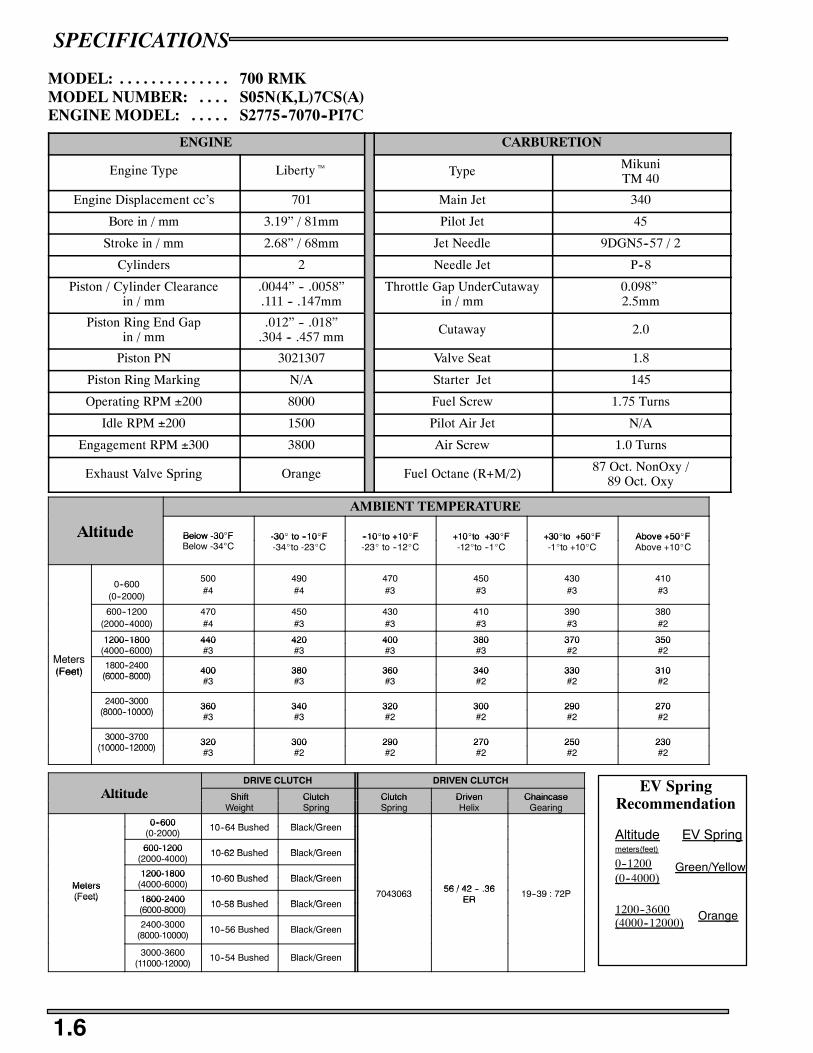
1.6
MODEL: 700 RMK. . . . . . . . . . . . . .MODEL NUMBER: S05N(K,L)7CS(A). . . .ENGINE MODEL: S2775--7070--PI7C. . . . .
ENGINE CARBURETION
Engine Type Libertyt Type MikuniTM 40
Engine Displacement cc’s 701 Main Jet 340
Bore in / mm 3.19” / 81mm Pilot Jet 45
Stroke in / mm 2.68” / 68mm Jet Needle 9DGN5--57 / 2
Cylinders 2 Needle Jet P--8
Piston / Cylinder Clearancein / mm
.0044” -- .0058”.111 -- .147mm
Throttle Gap UnderCutawayin / mm
0.098”2.5mm
Piston Ring End Gapin / mm
.012” -- .018”.304 -- .457 mm
Cutaway 2.0
Piston PN 3021307 Valve Seat 1.8
Piston Ring Marking N/A Starter Jet 145
Operating RPM ±200 8000 Fuel Screw 1.75 Turns
Idle RPM ±200 1500 Pilot Air Jet N/A
Engagement RPM ±300 3800 Air Screw 1.0 Turns
Exhaust Valve Spring Orange Fuel Octane (R+M/2) 87 Oct. NonOxy /89 Oct. Oxy
AMBIENT TEMPERATURE
Altitude Below -30°F -30_ to --10_F --10_to +10_F +10_to +30_F +30_to +50_F Above +50_FAltitude Below -30 FBelow -34°C
-30_ to --10_F-34_to -23_C
--10_to +10_F-23_ to --12_C
+10_to +30_F-12_to --1_C
+30_to +50_F-1_to +10_C
Above +50_FAbove +10_C
0--600(0--2000)
500#4
490#4
470#3
450#3
430#3
410#3
600--1200(2000--4000)
470#4
450#3
430#3
410#3
390#3
380#2
1200--1800 440 420 400 380 370 350
M t
1200--1800(4000--6000)
440#3
420#3
400#3
380#3
370#2
350#2
Meters(Feet)
1800--2400(6000 8000)
400 380 360 340 330 310(Feet) (6000--8000)400#3
380#3
360#3
340#2
330#2
310#2
2400--3000(8000 10000)
360 340 320 300 290 270(8000--10000)
360#3
340#3
320#2
300#2
290#2
270#2
3000--3700(10000 12000)
320 300 290 270 250 230(10000--12000)
320#3
300#2
290#2
270#2
250#2
230#2
DRIVE CLUTCH DRIVEN CLUTCH
Altitude Shift Clutch Clutch Driven ChaincaseAltitude ShiftWeight
ClutchSpring
ClutchSpring
DrivenHelix
ChaincaseGearing
0--600 10 64 Bushed Black/Green0--600(0-2000)
10--64 Bushed Black/Green
600-1200 10 62 Bushed Black/Green600-1200(2000-4000)
10-62 Bushed Black/Green
1200-1800 10 60 Bushed Black/GreenMeters
1200-1800(4000-6000)
10-60 Bushed Black/Green56 / 42 -- 36Meters
(Feet) 1800-2400 10 58 Bushed Black/Green7043063 56 / 42 -- .36
ER19--39 : 72P(Feet) 1800-2400
(6000-8000)10-58 Bushed Black/Green ER
2400-3000(8000-10000)
10--56 Bushed Black/Green
3000-3600(11000-12000)
10--54 Bushed Black/Green
EV SpringRecommendation
Altitude EV Spring
0--1200(0--4000)
Green/Yellow
1200--3600(4000--12000)
Orange
meters(feet)
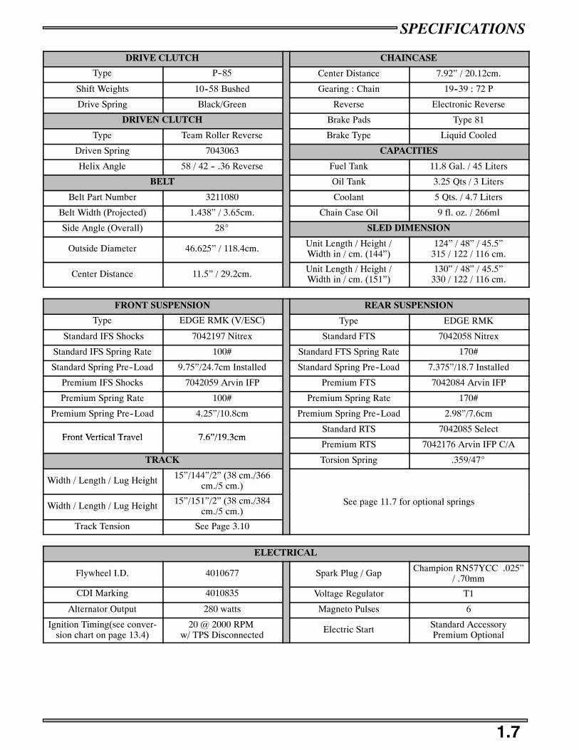
SPECIFICATIONS
1.7
DRIVE CLUTCH CHAINCASE
Type P--85 Center Distance 7.92” / 20.12cm.
Shift Weights 10--58 Bushed Gearing : Chain 19--39 : 72 P
Drive Spring Black/Green Reverse Electronic Reverse
DRIVEN CLUTCH Brake Pads Type 81
Type Team Roller Reverse Brake Type Liquid Cooled
Driven Spring 7043063 CAPACITIES
Helix Angle 58 / 42 -- .36 Reverse Fuel Tank 11.8 Gal. / 45 Liters
BELT Oil Tank 3.25 Qts / 3 Liters
Belt Part Number 3211080 Coolant 5 Qts. / 4.7 Liters
Belt Width (Projected) 1.438” / 3.65cm. Chain Case Oil 9 fl. oz. / 266ml
Side Angle (Overall) 28_ SLED DIMENSION
Outside Diameter 46.625” / 118.4cm. Unit Length / Height /Width in / cm. (144”)
124” / 48” / 45.5”315 / 122 / 116 cm.
Center Distance 11.5” / 29.2cm. Unit Length / Height /Width in / cm. (151”)
130” / 48” / 45.5”330 / 122 / 116 cm.
FRONT SUSPENSION REAR SUSPENSION
Type EDGE RMK (V/ESC) Type EDGE RMK
Standard IFS Shocks 7042197 Nitrex Standard FTS 7042058 Nitrex
Standard IFS Spring Rate 100# Standard FTS Spring Rate 170#
Standard Spring Pre--Load 9.75”/24.7cm Installed Standard Spring Pre--Load 7.375”/18.7 Installed
Premium IFS Shocks 7042059 Arvin IFP Premium FTS 7042084 Arvin IFP
Premium Spring Rate 100# Premium Spring Rate 170#
Premium Spring Pre--Load 4.25”/10.8cm Premium Spring Pre--Load 2.98”/7.6cm
Front Vertical Travel 7 6”/19 3cmStandard RTS 7042085 Select
Front Vertical Travel 7.6”/19.3cmPremium RTS 7042176 Arvin IFP C/A
TRACK Torsion Spring .359/47_
Width / Length / Lug Height 15”/144”/2” (38 cm./366cm./5 cm.)
Width / Length / Lug Height 15”/151”/2” (38 cm./384cm./5 cm.)
See page 11.7 for optional springs
Track Tension See Page 3.10
ELECTRICAL
Flywheel I.D. 4010677 Spark Plug / Gap Champion RN57YCC .025”/ .70mm
CDI Marking 4010835 Voltage Regulator T1
Alternator Output 280 watts Magneto Pulses 6
Ignition Timing(see conver-sion chart on page 13.4)
20 @ 2000 RPMw/ TPS Disconnected
Electric Start Standard AccessoryPremium Optional

SPECIFICATIONS
1.8
MODEL: 800 RMK. . . . . . . . . . . . . .MODEL NUMBER: S05N(M,K,L)8CS(A,B). . . .ENGINE MODEL: S2776--8070--PI8C. . . . .
ENGINE CARBURETION
Engine Type Libertyt Type MikuniTM40
Engine Displacement cc’s 794 Main Jet 350
Bore in / mm 3.35” / 85mm Pilot Jet 45
Stroke in / mm 2.76” / 70mm Jet Needle 9DGN6--57 / 2
Cylinders 2 Needle Jet P--8
Piston / Cylinder Clearancein / mm
.006 -- .0074”.152 --.188mm
Throttle Gap UnderCutawayin / mm
0.102”2.6mm
Piston Ring End Gapin / mm
.016 -- .022”.40 -- .559mm
Cutaway 2.0
Piston PN 3021315 Valve Seat 1.8
Piston Ring Marking N/A Starter Jet 145
Operating RPM ±200 8000 Fuel Screw 1.5 Turns
Idle RPM ±200 1500 Pilot Air Jet N/A
Engagement RPM ±300 3800 Air Screw .75 Turns
Exhaust Valve Spring Pink Fuel Octane (R+M/2) 87 Oct. NonOxy /89 Oct. Oxy
AMBIENT TEMPERATURE
Altitude Below -30°F -30_ to --10_F --10_to +10_F +10_to +30_F +30_to +50_F Above +50_FAltitude Below -30 FBelow -34°C
-30_ to --10_F-34_to -23_C
--10_to +10_F-23_ to --12_C
+10_to +30_F-12_to --1_C
+30_to +50_F-1_to +10_C
Above +50_FAbove +10_C
0--600(0--2000)
510N#5
490#3
470#4
450#4
430#3
410#3
600--1200(2000--4000)
480#4
470#4
450#4
430#3
410#3
390#2
1200--1800 450 430 410 390 370 350
M t
1200--1800(4000--6000)
450#4
430#4
410#3
390#3
370#2
350#2
Meters(Feet)
1800--2400(6000 8000)
410 390 370 350 330 310(Feet) (6000--8000)410#4
390#3
370#3
350#2
330#2
310#2
2400--3000(8000 10000)
370 350 330 310 290 270(8000--10000)
370#3
350#3
330#2
310#2
290#2
270#2
3000--3700(10000 12000)
340 320 300 280 260 240(10000--12000)
340#3
320#2
300#2
280#2
260#2
240#1
DRIVE CLUTCH DRIVEN CLUTCH
Altitude Shift Clutch Clutch Driven ChaincaseAltitude ShiftWeight
ClutchSpring
ClutchSpring
DrivenHelix
ChaincaseGearing
0--900 10 66 Bushed0--900(0-3000)
10-66 Bushed
900-1500 10 64 Bushed900-1500(3000-5000)
10-64 Bushed
1500-2100 10 62 BushedMeters
1500-2100(5000-7000)
10-62 Bushed58 / 42 -- 36Meters
(Feet) 2100-2700 10 60 BushedBlack/Green 7043063 58 / 42 -- .36
Rev.19--39 : 72P(Feet) 2100-2700
(7000-9000)10-60 Bushed Rev.
2700-3350(9000-11000)
10--58 Bushed
3350-4000(11000-13000)
10--56 Bushed
EV SpringRecommendation
Altitude EV Spring
0--1200(0--4000)
Pink/Yellow
1200--3600(4000--12000)
Pink
meters(feet)

SPECIFICATIONS
1.9
DRIVE CLUTCH CHAINCASE
Type P--85 Center DIstance 7.92” / 20.12cm.
Shift Weights 10--60 Bushed Gearing : Chain 19--39 : 72 P
Drive Spring Black/Green Reverse Electronic Reverse
DRIVEN CLUTCH Brake Pads Type 81
Type Team Roller Reverse Brake Type Liquid Cooled
Driven Spring 7043063 CAPACITIES
Helix Angle 58 / 42 -- .36 Reverse Fuel Tank 11.8 Gal. / 45 Liters
BELT Oil Tank 3.25 Qts / 3 Liters
Belt Part Number 3211080 Coolant 5 Qts / 4.7 Liters
Belt Width (Projected) 1.438” / 3.65cm. Chain Case Oil 9 fl. oz. / 266 ml
Side Angle (Overall) 28_ SLED DIMENSION
Outside Diameter 46.625” / 118.4cm.Unit Length / Height /
124” / 48” / 45.5”315 / 122 / 116 cm.
Center Distance 11.5” / 29.2cm.
Unit Length / Height /Width in / cm. 130” / 48” / 45.5”
330 / 122 / 116 cm.
FRONT SUSPENSION REAR SUSPENSION
Type EDGE RMK (V/ESC) Type EDGE RMK
Standard IFS Shocks 7042197 Nitrex Standard FTS 7042058 Nitrex
Standard IFS Spring Rate 100# Standard FTS Spring Rate 170#
Standard Spring Pre--Load 9.75”/24.7cm Installed Standard Spring Pre--Load 7.375”/18.7 Installed
Premium IFS Shocks 7042059 Arvin IFP Premium FTS 7042084 Arvin IFP
Premium Spring Rate 100# Premium Spring Rate 170#
Premium Spring Pre--Load 4.25”/10.8cm Premium Spring Pre--Load 2.98”/7.6cm
Front Vertical Travel 7 6”/19 3cmStandard RTS 7042085 Select
Front Vertical Travel 7.6”/19.3cmPremium RTS 7042176 Arvin IFP C/A
TRACK TORSION SPRINGS
Width / Length / Lug Height 15”/144”/2” (38 cm./366cm./5 cm.)
Torsion Spring .359/47_
Width / Length / Lug Height 15”/151”/2” (38 cm./384cm./5 cm.) See page 11.7 for optional springs
Track Tension See Page 3 10See page 11.7 for optional springs
Track Tension See Page 3.10
ELECTRICAL
Flywheel PN 4010677 Spark Plug / Gap Champion RN57YCC/ .025”/ .64mm
CDI PN 4010842 Voltage Regulator T1
Alternator Output 280 watts Magneto Pulses 6
Ignition Timing(see conver- 29_@3250 RPM±1.5_ Electric StartStandard AccessoryIgnition Timing(see conver
sion chart on page 13.4)29 @3250 RPM±1.5w/ TPS disconnected
Electric Starty
Premium Optional

SPECIFICATIONS
1.10
MODEL: 900 RMK. . . . . . . . . . . . . .MODEL NUMBER: S05P(L,M)8DS(A,B,C,D). . . .ENGINE MODEL: S2884--8686--PI8D. . . . .
ENGINE FUEL SYSTEM
Engine Type Liberty Type Clean Fire Injection
Engine Displacement cc 866 Regulator Pressure 4 Bar (58psi)
Bore in / mm 3.46”/ 83mm THROTTLE BODY
Stroke in / mm 3.15” / 80mm Throttle Body Bore Size in/cm 2” / 51mm
Cylinders 2 TPS voltage @ idle .92 -- .94
Piston / Cylinder Clearancein / mm
.0045” -- .0098”.114 -- .249
Throttle Body Manufacture Mikuni
Piston Ring End Gap in / mm .016” -- .022”.406--.56
DRIVE CLUTCH
Piston Marking 3021327 Type P--85
Piston Ring Marking N/A Center Distance in/cm 11.5” / 29.2
Operating RPM ±200 7400 Spring Black / Green
*Idle RPM ±200 1400 Shift Weight 10--70
Engagement RPM ±300 3700 DRIVEN CLUTCH
Exhaust Valve Spring Purple Type TEAM
CHAINCASE Spring 7043058
Center Distance in/cm 11.35” / 28.83cm Helix 62/46--36 ER
Gearing 19 : 39 -- 90P BELT
Reverse Electronic Width in/cm 1.438” / 3.652cm
Brake Pads 2202727 Length in/cm 46.625” / 118.4275cm
Brake Type Type 94 (DOT 4) Part Number 3211080
CAPACITIES DIMENSIONS
Fuel Tank gal./l 10.8 / 40.9 Length in/cm 128 / 325134 / 340
Oil Tank qts./l 3 / 2.8 Height in/cm 46.5 / 118
Coolant qts. / l 6.7 -- 6.9 / 6.3 -- 6.4Width in/cm 46 33 / 118
Chain Case Oil oz. / ml 11 / 325.3Width in/cm 46.33 / 118
DRIVE CLUTCH DRIVEN CLUTCH
Altitude Shift Clutch Clutch Driven ChaincaseAltitude ShiftWeight
ClutchSpring
ClutchSpring
DrivenHelix
ChaincaseGearing
0-900 10 740-900(0-3000)
10--74
900-1500 10 74900-1500(3000-5000)
10--74
1500-2100 10 72Meters
1500-2100(5000-7000)
10--72Bl k/G 7043058 62/46 36 ER 19 39 90PMeters
(Feet) 2210-2700 10 70Black/Green 7043058 62/46--36 ER 19 : 39 -- 90P
(Feet) 2210-2700(7000-9000)
10--70
2700--3350(9000--11000)
10--68
3350--4000(11000--13000)
10--66
Idle RPM is factory set and is adjusted automatically through the barometric sensor inside the ECU. DO NOT attempt to adjustidle on the throttle body or engine performance may be affected.

SPECIFICATIONS
1.11
FRONT SUSPENSION REAR SUSPENSION
Type IQ Type IQ
Standard IFS Shocks 7043049 AFX Standard FTS 7043048 FX
Stock IFS Spring Rate 110# Standard FTS Spring Rate 170#
Stock Spring Pre--Load 11.38” / 29cm Installed Standard Spring Pre--Load Fixed
Premium IFS Shocks 7043090 Arvin IFP Premium FTS 7042335 Arvin IFP
Premium Spring Rate 100# Premium FTS Spring Rate 170#
Premium Spring Pre--Load 10” / 25.4cm Installed Premium FTS Spring Pre--Load
7.25” / 18.4 cm Installed
Front Vertical Travel 8.84 in / 22.4cm Standard RTS 7043047 AFX
TRACK Premium RTS 7043046 Arvin IFP/Res CA
Width in/cm 15/38.1 TORSION SPRINGS
Length in/cm151/384159/404166/422
Stock Torsion Spring .359/77_
Lug Height in/cm(151) 2 or 2.4/5 or 6.1(159) 2 or 2.4/5 or 6.1
(166) 2.4/6.1Light Torsion Spring .347/77_
Track Tension See page 3.10 Heavy Torsion Spring .375/77_
ELECTRICAL
Flywheel I.D. 4011119 Spark Plug / Gap Champion RN57YCC /.025mm(.003”)
Base ECU 4011081 Voltage Regulator 4010866
Alternator Output 400watts Stator 4010727
Ignition Timing(see conver- 14_ @ 3000RPM Electric Start TBDIgnition Timing(see conversion chart on page 13.4)
14_ @ 3000RPM Electric Start TBD

SPECIFICATIONS
1.12
MODEL: 600 SWITCHBACKt. . . . . . . . . . . . . .MODEL NUMBER: S05NS6ES(A). . . .ENGINE MODEL: S2709--6044--PI6E. . . . .
ENGINE CARBURETION
Engine Type Libertyt Type MikuniTM 38
Engine Displacement cc’s 599 Main Jet 420
Bore in / mm 3.04” / 77.25mm Pilot Jet 50
Stroke in / mm 2.52” / 64mm Jet Needle 9DGI01--60 / 4
Cylinders 2 Needle Jet P--6
Piston / Cylinder Clearancein / mm
.0045”--.0059”.115 -- .149mm.
Throttle Gap UnderCutawayin / mm
0.079”2.0mm
Piston Ring End Gapin / mm
.014--.020”.356 -- .508mm
Cutaway 1.5
Piston PN 3021308 Valve Seat 1.5
Piston Ring Marking N/A Starter Jet 140
Operating RPM ±200 8000 Fuel Screw 1.5 Turns
Idle RPM ±200 1500 Pilot Air Jet N/A
Engagement RPM ±300 3800 Air Screw 0.5 Turns
Exhaust Valve Spring Green/White Fuel Octane (R+M/2) 87 Oct. NonOxy /89 Oct. Oxy
AMBIENT TEMPERATURE
Altitude Below -30°F -30_ to --10_F --10_to +10_F +10_to +30_F +30_to +50_F Above +50_FAltitude Below -30 FBelow -34°C
-30_ to --10_F-34_to -23_C
--10_to +10_F-23_ to --12_C
+10_to +30_F-12_to --1_C
+30_to +50_F-1_to +10_C
Above +50_FAbove +10_C
0--600(0--2000)
450#5
430#5
420#4
400#4
380#4
370#4
600--1200(2000--4000)
410#5
390#4
380#4
360#4
340#4
330#3
1200--1800 380 360 350 330 320 300
M t
1200--1800(4000--6000)
380#4
360#4
350#4
330#4
320#3
300#3
Meters(Feet)
1800--2400(6000 8000)
360 340 320 310 290 280(Feet) (6000--8000)360#4
340#4
320#4
310#3
290#3
280#3
2400--3000(8000 10000)
340 320 300 290 270 260(8000--10000)
340#4
320#4
300#3
290#3
270#3
260#3
3000--3700(10000 12000)
330 310 290 280 260 240(10000--12000)
330#4
310#3
290#3
280#3
260#3
240#3
DRIVE CLUTCH DRIVEN CLUTCH
Altitude Shift Clutch Clutch Driven ChaincaseAltitude ShiftWeight
ClutchSpring
ClutchSpring
DrivenHelix
ChaincaseGearing
0--900 10 60 Bushed 22 40:74P0--900(0-3000)
10-60 Bushed 22--40:74P
900-1500 10 58 Bushed 22 40:74P900-1500(3000-5000)
10-58 Bushed 22--40:74P
1500-2100 10 56 Bushed 22 40:74PMeters
1500-2100(5000-7000)
10-56 Bushed56 / 42 -- 36
22--40:74PMeters(Feet) 2100-2700 10 54 Bushed
Black/Green 7043063 56 / 42 -- .36ER 19 39:72P
(Feet) 2100-2700(7000-9000)
10-54 Bushed ER 19--39:72P
2700-3350(9000-11000)
10AL Bushed 19--39:72P
3350-4000(11000-13000)
10 Bushed 19--39:72P

SPECIFICATIONS
1.13
DRIVE CLUTCH CHAINCASE
Type P--85 Center Distance 7.92” / 20.12cm.
Shift Weights 10--60 Bushed Gearing : Chain 22--40 : 74 P
Drive Spring Black / Green Reverse Electronic Reverse
DRIVEN CLUTCH Brake Pads Type 81
Type Team Roller ReverseBrake Type Liquid Cooled
Driven Spring 7043063Brake Type Liquid Cooled
Helix Angle 56 / 42 -- .36 Reverse CAPACITIES
BELT Fuel Tank 11.8 Gal. / 45 Liters
Belt Part Number 3211080 Oil Tank 3.25 Qts / 3 Liters
Belt Width (Projected) 1.438” / 3.65cm. Coolant 5 Qts / 4.7 Liters
Side Angle (Overall) 28_ Chain Case Oil 9 fl. oz. / 266 ml
Outside Diameter 46.625” / 118.4cm. SLED DIMENSION
Center Distance 11.5” / 29.2cm. Unit Length / Height /Width in / cm.
124” / 48” / 47”315 / 122 / 119 cm.
FRONT SUSPENSION REAR SUSPENSION
Type EDGE RMK Type EDGE RMK
IFS Shocks 7043083 Alum IFP FTS 7042084 Arvin IFP
IFS Spring Rate 100#/in FTS Spring Rate 170#/inIFS Spring Rate 100#/in. FTS Spring Rate 170#/in.
IFS Spring Pre--Load 10.5” / 26.7cm InstalledFTS Pre Load 2 98” / 7 6 cm
Front Vertical Travel 7.1--7.4 / 18 -- 18.8cm.FTS Pre--Load 2.98” / 7.6 cm.
TRACKRTS 7042176 Arvin IFP C/A
Width 15” / 38 cm.RTS 7042176 Arvin IFP C/A
Length 144” / 366 cm. Torsion Spring .359” (Sq) x 47_
Lug Height 1.25” / 3.175 cm.
Track Tension See page 3 10Optional springs see page 11.7
Track Tension See page 3.10p p g p g
ELECTRICAL
Flywheel I.D. 4010677 Spark Plug / Gap Champion RN57YCC .028”/ .70mm
CDI Marking 4010830 Voltage Regulator T1
Alternator Output 280 watts Magneto Pulses 6
Ignition Timing(see conver- 24_@3000 RPM±1.5_ Electric Start AccessoryIgnition Timing(see conversion chart on page 13.4)
24 @3000 RPM±1.5w/TPS Disconnected
Electric Start Accessory
SPECIFICATIONS
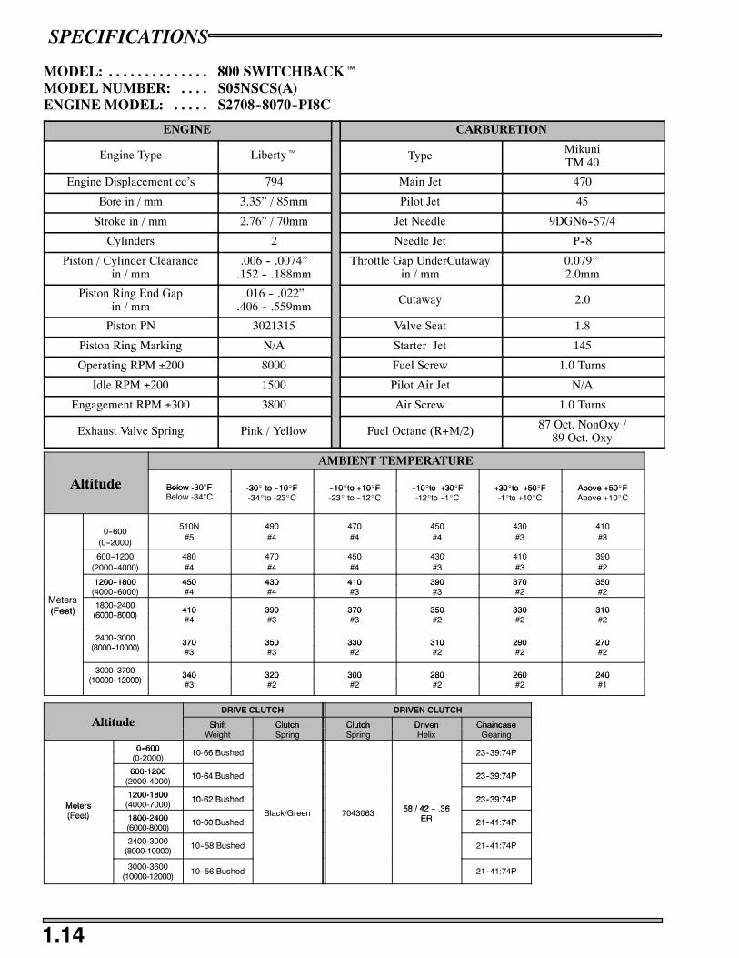
1.14
MODEL: 800 SWITCHBACKt. . . . . . . . . . . . . .MODEL NUMBER: S05NSCS(A). . . .ENGINE MODEL: S2708--8070--PI8C. . . . .
ENGINE CARBURETION
Engine Type Libertyt Type MikuniTM 40
Engine Displacement cc’s 794 Main Jet 470
Bore in / mm 3.35” / 85mm Pilot Jet 45
Stroke in / mm 2.76” / 70mm Jet Needle 9DGN6--57/4
Cylinders 2 Needle Jet P--8
Piston / Cylinder Clearancein / mm
.006 -- .0074”.152 -- .188mm
Throttle Gap UnderCutawayin / mm
0.079”2.0mm
Piston Ring End Gapin / mm
.016 -- .022”.406 -- .559mm
Cutaway 2.0
Piston PN 3021315 Valve Seat 1.8
Piston Ring Marking N/A Starter Jet 145
Operating RPM ±200 8000 Fuel Screw 1.0 Turns
Idle RPM ±200 1500 Pilot Air Jet N/A
Engagement RPM ±300 3800 Air Screw 1.0 Turns
Exhaust Valve Spring Pink / Yellow Fuel Octane (R+M/2) 87 Oct. NonOxy /89 Oct. Oxy
AMBIENT TEMPERATURE
Altitude Below -30°F -30_ to --10_F --10_to +10_F +10_to +30_F +30_to +50_F Above +50_FAltitude Below -30 FBelow -34°C
-30_ to --10_F-34_to -23_C
--10_to +10_F-23_ to --12_C
+10_to +30_F-12_to --1_C
+30_to +50_F-1_to +10_C
Above +50_FAbove +10_C
0--600(0--2000)
510N#5
490#4
470#4
450#4
430#3
410#3
600--1200(2000--4000)
480#4
470#4
450#4
430#3
410#3
390#2
1200--1800 450 430 410 390 370 350
M t
1200--1800(4000--6000)
450#4
430#4
410#3
390#3
370#2
350#2
Meters(Feet)
1800--2400(6000 8000)
410 390 370 350 330 310(Feet) (6000--8000)410#4
390#3
370#3
350#2
330#2
310#2
2400--3000(8000 10000)
370 350 330 310 290 270(8000--10000)
370#3
350#3
330#2
310#2
290#2
270#2
3000--3700(10000 12000)
340 320 300 280 260 240(10000--12000)
340#3
320#2
300#2
280#2
260#2
240#1
DRIVE CLUTCH DRIVEN CLUTCH
Altitude Shift Clutch Clutch Driven ChaincaseAltitude ShiftWeight
ClutchSpring
ClutchSpring
DrivenHelix
ChaincaseGearing
0--600 10 66 Bushed 23 39:74P0--600(0-2000)
10-66 Bushed 23--39:74P
600-1200 10 64 Bushed 23 39:74P600-1200(2000-4000)
10-64 Bushed 23--39:74P
1200-1800 10 62 Bushed 23 39:74PMeters
1200-1800(4000-7000)
10-62 Bushed58 / 42 -- 36
23--39:74PMeters(Feet) 1800-2400 10 60 Bushed
Black/Green 7043063 58 / 42 -- .36ER 21 41:74P
(Feet) 1800-2400(6000-8000)
10-60 Bushed ER 21--41:74P
2400-3000(8000-10000)
10--58 Bushed 21--41:74P
3000-3600(10000-12000)
10--56 Bushed 21--41:74P

SPECIFICATIONS
1.15
DRIVE CLUTCH CHAINCASE
Type P--85 Center Distance 7.92” / 20.12cm.
Shift Weights 10--66 Bushed Gearing : Chain 23--39 : 74 P
Drive Spring Black / Green Reverse Electronic Reverse
DRIVEN CLUTCH Brake Pads Type 81
Type Team Roller ReverseBrake Type Liquid Cooled
Driven Spring 7043063Brake Type Liquid Cooled
Driven Helix Angle 58/42--.36 ER CAPACITIES
BELT Fuel Tank 11.8 Gal. / 45 Liters
Belt Part Number 3211080 Oil Tank 3.25 Qts / 3 Liters
Belt Width (Projected) 1.438” / 3.65cm. Coolant 5 Qts/ 4.7 Liters
Side Angle (Overall) 28_ Chain Case Oil 9 fl. oz. / 266 ml
Outside Diameter 46.625” / 118.4cm. SLED DIMENSION
Center Distance 11.5” / 29.2cm. Unit Length / Height /Width in / cm.
124” / 48” / 47”315 / 122 / 119 cm.
FRONT SUSPENSION REAR SUSPENSION
Type EDGE RMK Type EDGE RMK
IFS Shocks 7043083 Alum IFP FTS 7042084 Arvin IFP
IFS Spring Rate 100#/in FTS Spring Rate 170#/inIFS Spring Rate 100#/in. FTS Spring Rate 170#/in.
IFS Spring Pre--Load 10.5” / 26.7cm InstalledFTS Pre Load 2 98” / 7 6 cm
Front Vertical Travel 7.1--7.4 / 18 -- 18.8cm.FTS Pre--Load 2.98” / 7.6 cm.
TRACKRTS 7042176 Arvin IFP C/A
Width 15” / 38 cm.RTS 7042176 Arvin IFP C/A
Length 144” / 366 cm. Torsion Spring .359” (Sq) x 47_
Lug Height 1.25” / 3.175 cm.
Track Tension See page 3 10Optional springs see page 11.7
Track Tension See page 3.10p p g p g
ELECTRICAL
Flywheel PN 4010677 Spark Plug / Gap Champion RN57YCC /.025” / .70mm
CDI PN 4010841 Voltage Regulator T1
Alternator Output 280 watts Magneto Pulses 6
Ignition Timing(see conver- 29_@3250 RPM±1.5_ Electric Start AccessoryIgnition Timing(see conversion chart on page 13.4)
29 @3250 RPM±1.5w/TPS Disconnected
Electric Start Accessory

SPECIFICATIONS
1.16
NOTES
2005 Model Number Designation 2.1. . . . . . . . . . . . . . . . . . . . . . . . .Tunnel Decal 2.1. . . . . . . . . . . . . . . . . . . . . . . . . . . . . . . . . . . . . . . . .Vehicle Identification Number 2.2. . . . . . . . . . . . . . . . . . . . . . . . . . . .2005 Publication Part Numbers 2.3. . . . . . . . . . . . . . . . . . . . . . . . . . .General Service Precautions 2.4. . . . . . . . . . . . . . . . . . . . . . . . . . . . .Standard Torque Specifications 2.5. . . . . . . . . . . . . . . . . . . . . . . . . . .Decimal Equivalents 2.6. . . . . . . . . . . . . . . . . . . . . . . . . . . . . . . . . . .Tap Drill Sizes 2.7. . . . . . . . . . . . . . . . . . . . . . . . . . . . . . . . . . . . . . . .Conversion Chart 2.8. . . . . . . . . . . . . . . . . . . . . . . . . . . . . . . . . . . . . .Piston Wash and Spark Plug Color 2.9. . . . . . . . . . . . . . . . . . . . . . . .Cylinder Inspections 2.10. . . . . . . . . . . . . . . . . . . . . . . . . . . . . . . . . . .Piston Measurements 2.11. . . . . . . . . . . . . . . . . . . . . . . . . . . . . . . . . . .Cylinder Honing 2.12. . . . . . . . . . . . . . . . . . . . . . . . . . . . . . . . . . . . . .Port Chamfering 2.13. . . . . . . . . . . . . . . . . . . . . . . . . . . . . . . . . . . . . . .Connecting Rod Bearing Inspection 2.14. . . . . . . . . . . . . . . . . . . . . . .Crankshaft Indexing 2.15 -- 2.17. . . . . . . . . . . . . . . . . . . . . . . . . . . . . . . . . . . .Oil Pump Operation and Troubleshooting 2.18. . . . . . . . . . . . . . . . . . .Oil Pump Bleeding 2.19. . . . . . . . . . . . . . . . . . . . . . . . . . . . . . . . . . . . .Oil Pump Adjustment 2.20. . . . . . . . . . . . . . . . . . . . . . . . . . . . . . . . . .Cooling System Overview 2.21. . . . . . . . . . . . . . . . . . . . . . . . . . . . . . .900 Fusion Cooling System 2.22. . . . . . . . . . . . . . . . . . . . . . . . . . . . . .

GENERAL INFORMATION
2.1
2005 MODEL NUMBER DESIGNATION
EXAMPLE: S05NB4BS
S 05 N B 4 B S #
Identifier(1st Digit)
ModelYear(2nd/3rd Dig-
it)
Model Line(4th Digit)
Model Type(5th Digit)
Engine Size(cc)
(6th Digit)
Engine modifier(6th/7th Digit)
VINIdentifier(8th Digit)
OptionIdentifier
(9thDigit)
S=Snow 05=2005 M=Fusion A=50th Anniv Spe-cial
0=0--99cc 1A=121 F/C OHV 4 cycle Fuji E=Europe unit
N=Edge B=Basic or Stan-dard
1=100--199 3A=340 F/C Piston Port S=StandardProduction
Unit
P=IQ RMK D=Classic 2=200--299cc 4B=488 L/C Piston Port
S=Gen II E=M--10 Perfor-mance
3=300--399cc 4C=440 EV L/C Case Reed (Dom)
W=Mini Indy J=136 RMK 4=400--499cc 5B=544 F/C Cylinder Reed
K=144 RMK 5=500--599cc 5C=500 EFV L/C Case Reed 2 Cyl(Dom)
L=151 RMK 6=600--600cc 6E=600 EV L/C Case Reed 2 Cyl(Dom)
M=159 RMK 7=700--799cc 7C=700 EV L/C Case Reed 2 Cyl(Dom)
N=166 RMK 8=800--899cc 7D=780 4--stroke EFI 2 Cyl (Dom)
P=Performance 9=900+cc 8C=800 EV L/C Case Reed 2 Cyl(Dom)
S=Switchback 8D=866 EV SDI Case Reed
T=Touring
U=Utility
X=Racer/Pro X
MODEL NO.
V.I.N. NO.
MFD. DATE:
THIS VEHICLE CONFORMS TO ALL APPLICABLEU.S. FEDERAL AND STATE REQUIREMENTS ANDCANADA MOTOR VEHICLE SAFETY STANDARDSIN EFFECT ON THE DATE OF MANUFACTURE.
MADE IN U.S.A.
7072133
Mfd. by Polaris Industries Inc.. in Roseau, MN under one ormore of the following patents:
U.S. Patents3,605,511 3,613,810 5,050,5593,580,647 3,867,991 5,048,5033,483,766 4,793,950 5,056,4823,533,662 5,038,881 5,099,8133,545,821 5,172,675 5,074,2713,605,510 5,090,386 5,191,5313,525,412 5,050,564 3,613,811
PATENT NOTICE
Patented Canada882,491/71883,694/71864,394/71
Canadian Rd.34,573/7134,572/71
1,227,823/87
TUNNEL DECAL
These numbers should be referred to in any correspondence regarding warranty, service or replacement parts.The machine model and serial number identification decal is located on the right front side of the tunnel. The serial number ispermanently stamped into the tunnel. The model number is embossed on the decal.
Whenever corresponding about an engine it is important that the engine model and serial numbers be called out. Laser engravedmodel and serial numbers are located on the crankcase (intake side).

GENERAL INFORMATION
2.2
VEHICLE IDENTIFICATION NUMBER
Current snowmobiles have a 17 digit Vehicle Identification Number (VIN). The VIN is organized as follows: Digits 1-3: WorldManufacturer Identifier. For Polaris, this is SN1. Digits 4-9: Vehicle Descriptor Section. Digits 10-17: Vehicle Indicator Section.Digits 4-8 of the VIN identify the body style, type, engine type, and series. The VIN and the model number must be used withany correspondence regarding service or repair.
1 2 3 4 5 6 7 8 9 10 11 12 13 14 15 16 17S N 1 S B 5 B S 0 2 2 0 0 0 0 0 0
Vehicle Descriptor Vehicle Identifier
Type
EngineSize Engine
Modifier
ModelYear
Manufacturing.Location Code
Individual Serial No.Body Style Series
World Mfg. ID
Example ofCurrent
VIN NumberCheckDigit
Vehicle Identification Number / Model Number Key
Body Style Type Engine Size Engine Modifier Series
L=Lite B=Base Model 1=100-199 cc’s A=Fan S=Domestic
N=Edge D=Deluxe 2=200-299 cc’s B=Liquid Twin U=Europe
S=Gen II P=Performance 3=300-399 cc’s C=Case Reed Twin
W=Mini R=RMK 4=400-499 cc’s D=Liquid Triple
S=SKS 5=500-599 cc’s E=Case Reed Triple
T=Touring 6=600-699 cc’s
U=Utility 7=700-799 cc’s
X=Racer 8=800-899 cc’s

GENERAL INFORMATION
2.3
PUBLICATION PART NUMBERS
Model Model No. Owner’s Manual Owners ManualSupplement
PartsManual
Microfiche
Trail RMK S05NJ5BS(A) 9919706 9919097 9919276 9919277
600 RMK S05NK6ES(A) 9919706 9919098 9919278 9919279
700 RMK S05N(K,L)7CS(A) 9919706 9919381 9919278 9919279
800 RMK S05N(M,K,L)8CS(A,B) 9919706
9919383 (144)
9919384 (151)
9919385 (159)
9919278 9919279
900 RMK S05P(L,M)8DS(A,B,C,D) 9919077
9919104 (151)
9919105 (159)
9919106 (166)
9919292 9919293
600 Switchback S05NS6ES(A) 9919076 9919095 9919280 9919281
800 Switchback S05NSCS(A) 9919076 9919095 9919280 9919281
SERVICE MANUALS
Service Manuals 20042000--2005120 XC SP / PRO X
9919307
Trail Sport500 Indy, Supersport
9919300
Touring340 Edge Touring, Trail Touring (Deluxe), Widetrak LX, 600 Edge Touring (50th), 800 Edge Touring
9919304
FrontierFrontier Touring
9919305
Classic340 Classic, 500 Classic, 550 Classic, 600 Classic, 800 Classic
9919301
Deep SnowTrail RMK, 600/700/800 RMK, 600/800 Switchbackt, 900 RMK
9919302
Performance500/600/700/800 XC SP, 900 Fusion
9919303
2005 Specification Handbook 9919311
2005 Snowmobile Wallcharts 9919309
Track Poster 9918459
Flat Rate Manual 9919308
Snowmobile Care and Adjusting for the Perfect Ride (DVD) (2004) 9918923
Snowmobile Care and Adjusting for the Perfect Ride (VHS) (2004) 9918908
2005 Snowmobile Quick Start Guide (DVD) (2005) 9919129

GENERAL INFORMATION
2.4
GENERAL SERVICE PRECAUTIONS
In order to perform service work efficiently and to prevent costly errors, the technician should read the text in this manual,thoroughly familiarizing him/herself with procedures before beginning. Photographs and illustrations have been included with thetext as an aid. Notes, cautions and warnings have also been included for clarification of text and safety concerns. However, aknowledge of mechanical theory, tool use and shop procedures is necessary to perform the service work safely and satisfactorily.Use only genuine Polaris service parts.
Cleanliness of parts and tools as well as the work area is of primary importance. Dirt and foreign matter will act as an abrasiveand cause damage to precision parts. Clean the snowmobile before beginning service. Clean new parts before installing.
Watch for sharp edges which can cause personal injury, particularly in the area of the tunnel. Protect hands with gloves whenworking with sharp components.
If difficulty is encountered in removing or installing a component, look to see if a cause for the difficulty can be found. If it isnecessary to tap the part into place, use a soft face hammer and tap lightly.
Some of the fasteners in the snowmobile were installed with locking agents. Use of impact drivers or wrenches will help avoiddamage to fasteners.
Always follow torque specifications as outlined throughout this manual. Incorrect torquing may lead to serious machinedamage or, as in the case of steering components, can result in injury or death for the rider(s).
If a torquing sequence is indicated for nuts, bolts or screws, start all fasteners in their holes and hand tighten. Then, followingthe method and sequence indicated in this manual, tighten evenly to the specified torque value. When removing nuts, bolts orscrews from a part with several fasteners, loosen them all about 1/4 turn before removing them.
If the condition of any gasket or O-Ring is in question, replace it with a new one. Be sure the mating surfaces around the gasketare clean and smooth in order to avoid leaks.
Some procedures will require removal of retaining rings or clips. Because removal weakens and deforms these parts, theyshould always be replaced with new parts. When installing new retaining rings and clips use care not to expand or compress thembeyond what is required for installation.
Because removal damages seals, replace any oil or grease seals removed with new parts.
Polaris recommends the use of Polaris lubricants and greases, which have been specially formulated for the top performanceand best protection of our machines. In some applications, such as the engine, warranty coverage may become void if other brandsare substituted.
Grease should be cleaned from parts and fresh grease applied before reassembly of components. Deteriorating grease loseslubricity and may contain abrasive foreign matter.
Whenever removing or reinstalling batteries, care should be taken to avoid the possibility of explosion resulting in seriousburns. Always disconnect the negative (black) cable first and reconnect it last. Battery electrolyte contains sulphuric acid and ispoisonous! Serious burns can result from contact with the skin, eyes or clothing. ANTIDOTE: External - Flush with water.Internal - Drink large quantities or water or milk. Follow with milk of magnesia, beaten egg, or vegetable oil. Call physicianimmediately. Eyes - Flush with water for 15 minutes and get prompt medical attention.

GENERAL INFORMATION
2.5
DECIMAL EQUIVALENTS1/64 .0156. . . . . . . . . . . . . . . . . .
1/32 .0312 1 mm = .0394″. . . . . . . . . . . . . . . . . . . . .3/64 .0469. . . . . . . . . . . . . . . . . .
1/16 .0625. . . . . . . . . . . .5/64 .0781 2 mm = .0787″. . . . . . . . . . . . . . . . . . . . . . . . . .
3/32 .0938. . . . . . . . . . . . .7/64 .1094 3 mm = .1181″. . . . . . . . . . . . . . . . . . . . . . . .
1/8 . .125. . . .9/64 .1406. . . . . . . . . . . . . . . . . .
5/32 .1563 4 mm = .1575″. . . . . . . . . . . . . . . . . . . .11/64 .1719. . . . . . . . . . . . . . . . .
3/16 .1875 5 mm = .1969″. . . . . . . . . . . . . . . . . . . .13/64 .2031. . . . . . . . . . . . . . . . .
7/32 .2188. . . . . . . . . . . .15/64 .2344 6 mm = .2362″. . . . . . . . . . . . . . . . . . . . . . . . .
1/4 .250. . . .17/64 .2656 7 mm = .2756″. . . . . . . . . . . . . . . . . . . . . . . . .
9/32 .2813. . . . . . . . . . . .19/64 .2969. . . . . . . . . . . . . . . . .
5/16 .3125 8 mm = .3150″. . . . . . . . . . . . . . . . . . . .21/64 .3281. . . . . . . . . . . . . . . . .
11/32 .3438 9 mm = .3543″. . . . . . . . . . . . . . . . . . .23/64 .3594. . . . . . . . . . . . . . . . .
3/8 .375. . . .25/64 .3906 10 mm = .3937″. . . . . . . . . . . . . . . . . . . .
13/32 .4063. . . . . . . . . . .27/64 .4219 11 mm = .4331″. . . . . . . . . . . . . . . . . . . . . . . . .
7/16 .4375. . . . . . . . . . . .29/64 .4531. . . . . . . . . . . . . . . . .
15/32 .4688 12 mm = .4724″. . . . . . . . . . . . . . . . . . .31/64 .4844. . . . . . . . . . . . . . . . .
1/2 .5 00 13 mm = .5118″. . . . . . . . . . . . . . . . . . . . .33/64 .5156. . . . . . . . . . . . . . . . .
17/32 .5313. . . . . . . . . . .35/64 .5469 14 mm = .5512″. . . . . . . . . . . . . . . . . . . . . . . . .
9/16 .5625. . . . . . . . . . . .37/64 .5781 15 mm = .5906″. . . . . . . . . . . . . . . . . . . . . . . . .
19/32 .5938. . . . . . . . . . .39/64 .6094. . . . . . . . . . . . . . . . .
5/8 .625 16 mm = .6299″. . . . . . . . . . . . . . . . . . . . .41/64 .6406. . . . . . . . . . . . . . . . .
21/32 .6563 17 mm = .6693″. . . . . . . . . . . . . . . . . . .43/64 .6719. . . . . . . . . . . . . . . .
11/16 .6875. . . . . . . . . . .45/64 .7031 18 mm = .7087″. . . . . . . . . . . . . . . . . . . . . . . . .
23/32 .7188. . . . . . . . . . .47/64 .7344 19 mm = .7480″. . . . . . . . . . . . . . . . . . . . . . . . .
3/4 .750. . . .49/64 .7656. . . . . . . . . . . . . . . . .
25/32 .7813 20 mm = .7874″. . . . . . . . . . . . . . . . . . .51/64 .7969. . . . . . . . . . . . . . . . .
13/16 .8125 21 mm = .8268″. . . . . . . . . . . . . . . . . . .53/64 .8281. . . . . . . . . . . . . . . . .
27/32 .8438. . . . . . . . . . .55/64 .8594 22 mm = .8661″. . . . . . . . . . . . . . . . . . . . . . . . .
7/8 .875. . . .57/64 .8906 23 mm = .9055″. . . . . . . . . . . . . . . . . . . . . . . . .
29/32 .9063. . . . . . . . . . .59/64 .9219. . . . . . . . . . . . . . . .
15/16 .9375 24 mm = .9449″. . . . . . . . . . . . . . . . . . .61/64 .9531. . . . . . . . . . . . . . . . .
31/32 .9688 25 mm = .9843″. . . . . . . . . . . . . . . . . . .63/64 .9844. . . . . . . . . . . . . . . . .
1 1.000. . . . . .

GENERAL INFORMATION
2.6
STANDARD TORQUE SPECIFICATIONS
The following torque specifications are to be used as a general guideline when torque value is not specified. There are exceptionsin the steering, suspension, and engine areas. Always consult the torque chart and the specific manual section for torque values offasteners.
Bolt Size Threads/In Grade 2 Grade 5 Grade 8(MM/Thread)
Torque in. lbs. (Nm)#10 - 24 27 (3.1) 43 (5) 60 (6.9). . . . . . . . . . . . . . . . . . . . . . . . . . . . . . . . . . . . . .#10 - 32 31 (3.6) 49 (5.6) 68 (7.8). . . . . . . . . . . . . . . . . . . . . . . . . . . . . . . . . . . .
Torque ft. lbs. (Nm)*1/4 - 20 5 (7) 8 (11) 12 (16). . . . . . . . . . . . . . . . . . . . . . . . . . . . . . . . . . . . . . . .1/4 - 28 6 (8) 10 (14) 14 (19). . . . . . . . . . . . . . . . . . . . . . . . . . . . . . . . . . . . . . .5/16 - 18 11 (15) 17 (23) 25 (35). . . . . . . . . . . . . . . . . . . . . . . . . . . . . . . . . . . . .5/16 - 24 12 (16) 19 (26) 29 (40). . . . . . . . . . . . . . . . . . . . . . . . . . . . . . . . . . . . .3/8 - 16 20 (27) 30 (40) 45 (62). . . . . . . . . . . . . . . . . . . . . . . . . . . . . . . . . . . . .3/8 - 24 23 (32) 35 (48) 50 (69). . . . . . . . . . . . . . . . . . . . . . . . . . . . . . . . . . . . .7/16 - 14 30 (40) 50 (69) 70 (97). . . . . . . . . . . . . . . . . . . . . . . . . . . . . . . . . . . . .7/16 - 20 35 (48) 55 (76) 80 (110). . . . . . . . . . . . . . . . . . . . . . . . . . . . . . . . . . . . .1/2 - 13 50 (69) 75 (104) 110 (152). . . . . . . . . . . . . . . . . . . . . . . . . . . . . . . . . . . .1/2 - 20 55 (76) 90 (124) 120 (166). . . . . . . . . . . . . . . . . . . . . . . . . . . . . . . . . . . .
*To convert ft. lbs. to Nm multiply foot pounds by 1.356.*To convert Nm to ft. lbs. multiply Nm by .7376.
GENERAL INFORMATION
2.7
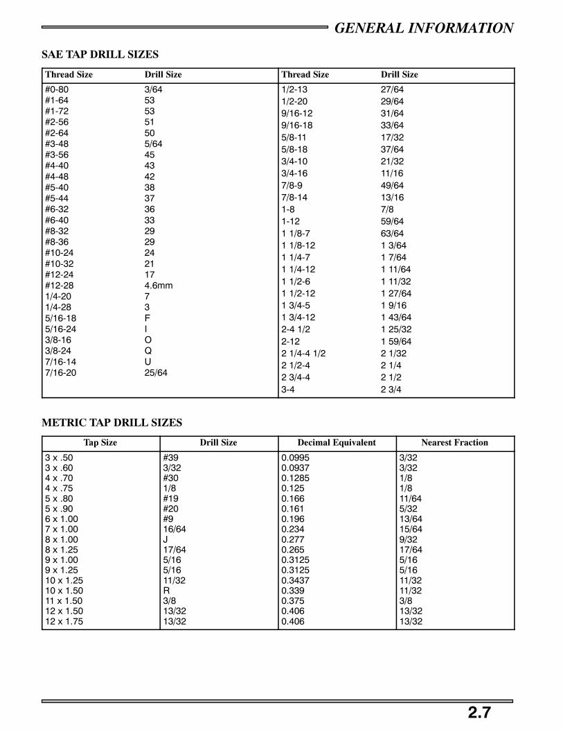
SAE TAP DRILL SIZES
Thread Size Drill Size Thread Size Drill Size
#0-80 3/64#1-64 53#1-72 53#2-56 51#2-64 50#3-48 5/64#3-56 45#4-40 43#4-48 42#5-40 38#5-44 37#6-32 36#6-40 33#8-32 29#8-36 29#10-24 24#10-32 21#12-24 17#12-28 4.6mm1/4-20 71/4-28 35/16-18 F5/16-24 I3/8-16 O3/8-24 Q7/16-14 U7/16-20 25/64
1/2-13 27/641/2-20 29/649/16-12 31/649/16-18 33/645/8-11 17/325/8-18 37/643/4-10 21/323/4-16 11/167/8-9 49/647/8-14 13/161-8 7/81-12 59/641 1/8-7 63/641 1/8-12 1 3/641 1/4-7 1 7/641 1/4-12 1 11/641 1/2-6 1 11/321 1/2-12 1 27/641 3/4-5 1 9/161 3/4-12 1 43/642-4 1/2 1 25/322-12 1 59/642 1/4-4 1/2 2 1/322 1/2-4 2 1/42 3/4-4 2 1/23-4 2 3/4
METRIC TAP DRILL SIZES
Tap Size Drill Size Decimal Equivalent Nearest Fraction
3 x .503 x .604 x .704 x .755 x .805 x .906 x 1.007 x 1.008 x 1.008 x 1.259 x 1.009 x 1.2510 x 1.2510 x 1.5011 x 1.5012 x 1.5012 x 1.75
#393/32#301/8#19#20#916/64J17/645/165/1611/32R3/813/3213/32
0.09950.09370.12850.1250.1660.1610.1960.2340.2770.2650.31250.31250.34370.3390.3750.4060.406
3/323/321/81/811/645/3213/6415/649/3217/645/165/1611/3211/323/813/3213/32

GENERAL INFORMATION
2.8
CONVERSION CHART
Unit of Measure Multiplied by Converts toft. lbs. x 12 = in. lbs.
in. lbs. x .0833 = ft. lbs.
ft. lbs. x 1.356 = Nm
in. lbs. x .0115 = kg-m
Nm x .7376 = ft. lbs.
kg-m x 7.233 = ft. lbs.
kg-m x 86.796 = in. lbs.
kg-m x 10 = Nm
in. x 25.4 = mm
mm x .03937 = in.
in. x 2.54 = cm
mile (mi.) x 1.6 = km
km x .6214 = mile (mi.)
Ounces (oz) x 28.35 = Grams (g)
Grams (g) x 0.035 = Ounces (oz)
cc’s x .03381 = Fluid Ounces (oz)
lb. x .454 = kg
kg x 2.2046 = lb.
Cubic inches (cu in) x 16.387 = Cubic centimeters (cc’s)
Cubic centimeters (cc’s) x 0.061 = Cubic inches (cu in)
Imperial pints (Imp pt) x 0.568 = Liters (l)
Liters (l) x 1.76 = Imperial pints (Imp pt)
Imperial quarts (Imp qt) x 1.137 = Liters (l)
Liters (l) x 0.88 = Imperial quarts (Imp qt)
Imperial quarts (Imp qt) x 1.201 = US quarts (US qt)
US quarts (US qt) x 0.833 = Imperial quarts (Imp qt)
US quarts (US qt) x 0.946 = Liters (l)
Liters (l) x 1.057 = US quarts (US qt)
US gallons (US gal) x 3.785 = Liters (l)
Liters (l) x 0.264 = US gallons (US gal)
Pounds - force per square inch (psi) x 6.895 = Kilopascals (kPa)
Kilopascals (kPa) x 0.145 = Pounds - force per square inch (psi)
Kilopascals (kPa) x 0.01 = Kilograms - force per square cm
Kilograms - force per square cm x 98.1 = Kilopascals (kPa)
°C to °F: 9 (°C + 40) ÷ 5 -- 40 = °F°F to °C: 5 (°F + 40) ÷ 9 -- 40 = °C
GENERAL INFORMATION
2.9
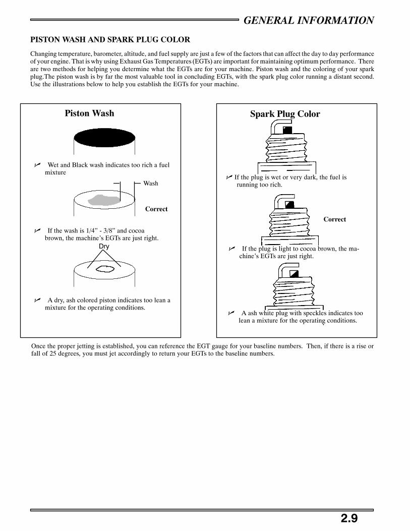
PISTON WASH AND SPARK PLUG COLOR
Changing temperature, barometer, altitude, and fuel supply are just a few of the factors that can affect the day to day performanceof your engine. That is why using Exhaust Gas Temperatures (EGTs) are important for maintaining optimum performance. Thereare two methods for helping you determine what the EGTs are for your machine. Piston wash and the coloring of your sparkplug.The piston wash is by far the most valuable tool in concluding EGTs, with the spark plug color running a distant second.Use the illustrations below to help you establish the EGTs for your machine.
n If the wash is 1/4” - 3/8” and cocoabrown, the machine’s EGTs are just right.
n Wet and Black wash indicates too rich a fuelmixture
n A dry, ash colored piston indicates too lean amixture for the operating conditions.
n If the plug is light to cocoa brown, the ma-chine’s EGTs are just right.
n If the plug is wet or very dark, the fuel isrunning too rich.
n A ash white plug with speckles indicates toolean a mixture for the operating conditions.
Piston Wash Spark Plug Color
Once the proper jetting is established, you can reference the EGT gauge for your baseline numbers. Then, if there is a rise orfall of 25 degrees, you must jet accordingly to return your EGTs to the baseline numbers.
Correct
Correct
Wash
Dry

GENERAL INFORMATION
2.10
CYLINDER INSPECTIONS
CYLINDER HEAD INSPECTION
Inspect each piston dome area of the cylinder head for warping by plac-ing a straight edge across the dome area.
With a feeler gauge measure any gap under the straight edge.
Replace cylinder head if measurement exceeds the service limit of.003” (.08mm).
NOTE:Cylinder Head Warp
Service Limit .003” (.08mm)
CYLINDER MEASUREMENT
Inspect each cylinder for wear, scratches, or damage. If no damage is evident, measure the cylinder for taper and out of roundwith a telescoping gauge or a dial bore gauge. Measure the bore 1/2, from the top of the cylinder; in line with the piston pin and90_ to the pin to determine if the bore is out of round. Repeat the measurements at the middle of the cylinder and the bottomof the cylinder to determine taper or out of round at the bottom. Use the chart below and record all measurements.
TOP
Tx Ty
MIDDLE
Mx My
BOTTOM
Bx By
Out of round =Tx--Ty and By--Bx
Taper Limit=Ty--By and Tx--Bx
Limit .003” (.08mm)
Top
Middle
Bottom
Tx
Mx
Bx
Ty
My
By
S Cylinder Taper Limit: .002” MAX
S Cylinder Out of Round Limit: .002”

GENERAL INFORMATION
2.11
PISTON INSPECTION / MEASUREMENT
90° to pin
DOMESTIC ENGINES - Measure 3/8″ (10.0mm)up from bottom of skirt
Piston Ring
Feeler Gauge
1/2″ (1.3cm.)
Straight Edge
Keystone Piston Ring Cutaway
Up
FUJI ENGINES - Measure 1/2″ (12.7mm) upfrom bottom of skirt
1/2″ (1.3cm.)Cylinder
Piston RingA B C
D
Check piston for scoring or cracks in piston crown or pin area. Excessive carbon buildup below the ring lands is an indicationof piston, ring or cylinder wear.
For Libertyt engines, measure piston outside diameter at a point 3/8” (10mm) up from the bottom of the skirt at a 90_ angleto the direction of the piston pin (diagram A).
For Fuji engines, measure piston outside diameter at a point that is 1/2” (12.7mm) up form the bottom of the skirt at a 90_ angleto the direction of the piston pin (diagram A).
NOTE: The piston must be measured at this point to provide accurate piston to cylinder measurements.
Subtract this measurement from the minimum cylinder measurement recorded previously when you recorded the cylinder mea-surements. If clearance exceeds the service limit, the cylinder should be re-bored and new pistons and rings installed. Refer topiston to cylinder clearance limits in the General Information section listed per model.
PISTON RING INSTALLED GAP
Position the ring 1/2“ (1.3 cm) from the top of the cylinder using the piston to push it squarely into place. Measure installed gapwith a feeler gauge at both the top and bottom of the cylinder (diagram B).
NOTE:A difference in end gap indicates cylinder taper. The cylinder should be measured for excessive
taper and out of round. Replace rings if the installed end gap exceeds the service limit.
NOTE: Always check piston ring installed gap after re-boring a cylinder or when installing new rings.
NOTE: Piston rings are installed with marking or beveled side up see diagram D.
GENERAL INFORMATION
2.12
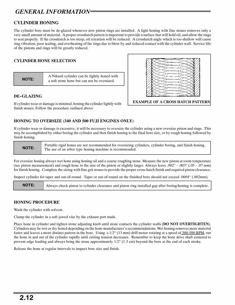
CYLINDER HONING
The cylinder bore must be de-glazed whenever new piston rings are installed. A light honing with fine stones removes only avery small amount of material. A proper crosshatch pattern is important to provide a surface that will hold oil, and allow the ringsto seat properly. If the crosshatch is too steep, oil retention will be reduced. A crosshatch angle which is too shallow will causering vibration, poor sealing, and overheating of the rings due to blow-by and reduced contact with the cylinder wall. Service lifeof the pistons and rings will be greatly reduced.
CYLINDER HONE SELECTION
A Nikasil cylinder can be lightly honed witha soft stone hone but can not be oversized.NOTE:
DE--GLAZING
If cylinder wear or damage is minimal, honing the cylinder lightly withfinish stones. Follow the procedure outlined above
HONING TO OVERSIZE (340 AND 500 FUJI ENGINES ONLY)
If cylinder wear or damage is excessive, it will be necessary to oversize the cylinder using a new oversize piston and rings. Thismay be accomplished by either boring the cylinder and then finish honing to the final bore size, or by rough honing followed byfinish honing.
Portable rigid hones are not recommended for oversizing cylinders, cylinder boring, and finish honing.The use of an arbor type honing machine is recommended.NOTE:
For oversize honing always wet hone using honing oil and a coarse roughing stone. Measure the new piston at room temperature(see piston measurement) and rough hone to the size of the piston or slightly larger. Always leave .002” - .003“ (.05 - .07 mm)for finish honing. Complete the sizing with fine grit stones to provide the proper cross-hatch finish and required piston clearance.
Inspect cylinder for taper and out-of-round. Taper or out-of-round on the finished bore should not exceed .0004“ (.002mm).
NOTE: Always check piston to cylinder clearance and piston ring installed gap after boring/honing is complete.
HONING PROCEDURE
Wash the cylinder with solvent.
Clamp the cylinder in a soft jawed vise by the exhaust port studs.
Place hone in cylinder and tighten stone adjusting knob until stone contacts the cylinder walls (DO NOT OVERTIGHTEN).Cylinders may be wet or dry honed depending on the hone manufacturer’s recommendations. Wet honing removes more materialfaster and leaves a more distinct pattern in the bore. Using a 1/2“ (13 mm) drill motor rotating at a speed of 300-500 RPM, runthe hone in and out of the cylinder rapidly until cutting tension decreases. Remember to keep the hone drive shaft centered toprevent edge loading and always bring the stone approximately 1/2“ (1.3 cm) beyond the bore at the end of each stroke.
Release the hone at regular intervals to inspect bore size and finish.
EXAMPLE OF A CROSS HATCH PATTERN

GENERAL INFORMATION
2.13
PORT CHAMFERINGRemove the sharp edges at the bottom and top of each port whenever boring or honing is performed. Make sure there are no sharpedges.
IMPORTANT:
It is very important that the cylinder be thoroughly cleaned after honing to remove all grit material.Wash the cylinder in a solvent, then in hot soapy water. Pay close attention to areas where the cylindersleeve meets the aluminum casting (transfer port area). Use electrical contact cleaner if necessary toclean these areas. Rinse thoroughly, dry with compressed air, and oil the bore immediately with PolarisPremium 2 Cycle Lubricant.
CLEANING THE CYLINDER AFTER HONINGIt is very important that the cylinder be thoroughly cleaned after honing to remove all grit material. Wash the cylinder in a solvent,then in hot soapy water. Pay close attention to areas where the cylinder sleeve meets the aluminum casting (transfer port area).Use electrical contact cleaner if necessary to clean these areas. Rinse thoroughly, dry with compressed air, and oil the bore im-mediately with Polaris Premium 2 Cycle Lubricant.
Always check piston to cylinder clearance and piston ring installed gap after boring/honing iscomplete!
NOTE:
CRANKCASE INSPECTION / BEARING FIT
Any time crankshaft bearing failure occurs and the case is to be reused,Polaris recommends checking the bearing fit into the case halves usingthe following procedure.
With case halves cleaned, press a replacement bearing into each of themain bearing journals to determine a basic amount of press fit.
NOTE: Crankcase Bearing Interference Fit:.001” -- .002” (.026 -- .051mm)
Do a comparison check of all journals by manually forcing the bearing into the bearing seats noting ifany are noticeably loose or tight. Normal hand installation will be an indication of the recommendedinterference fit. If the bearing falls out of the case when the case is inverted, or if the crankcase bear-ing surface is severely galled or damaged, the case should be replaced
NOTE:
CRANKSHAFT MAIN BEARING INSPECTIONClean crankshaft thoroughly and oil main and connecting rod bearings with Polaris engine oil. Carefully check each main bearingon the shaft.
Due to extremely close tolerances, the bearings must be inspected visually, and by feel. Look for signsof discoloration, scoring or galling. Turn the outer race of each bearing. The bearings should turnsmoothly and quietly. The inner race of each bearing should fit tightly on the crankshaft. The outerrace should be firm with minimal side to side movement and no detectable up and down movement.Replace any loose or rough bearings.
NOTE:
GENERAL INFORMATION
2.14
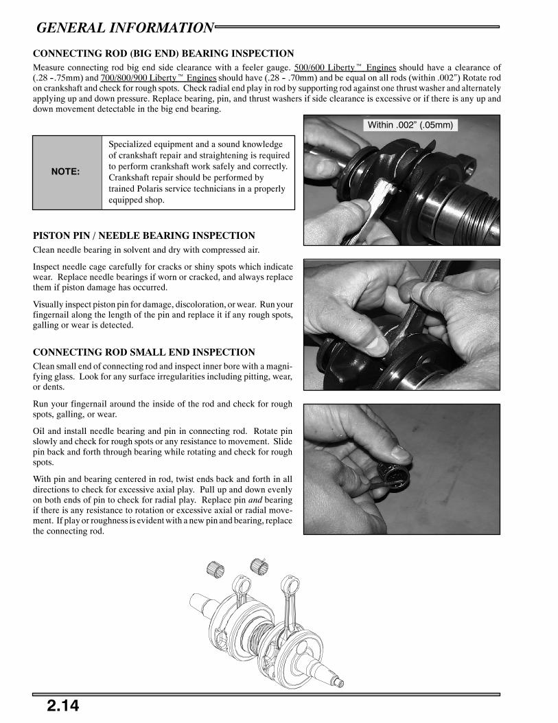
CONNECTING ROD (BIG END) BEARING INSPECTIONMeasure connecting rod big end side clearance with a feeler gauge. 500/600 Libertyt Engines should have a clearance of(.28 --.75mm) and 700/800/900 Libertyt Engines should have (.28 -- .70mm) and be equal on all rods (within .002″) Rotate rodon crankshaft and check for rough spots. Check radial end play in rod by supporting rod against one thrust washer and alternatelyapplying up and down pressure. Replace bearing, pin, and thrust washers if side clearance is excessive or if there is any up anddown movement detectable in the big end bearing.
Specialized equipment and a sound knowledgeof crankshaft repair and straightening is requiredto perform crankshaft work safely and correctly.Crankshaft repair should be performed bytrained Polaris service technicians in a properlyequipped shop.
NOTE:
PISTON PIN / NEEDLE BEARING INSPECTIONClean needle bearing in solvent and dry with compressed air.
Inspect needle cage carefully for cracks or shiny spots which indicatewear. Replace needle bearings if worn or cracked, and always replacethem if piston damage has occurred.
Visually inspect piston pin for damage, discoloration, or wear. Run yourfingernail along the length of the pin and replace it if any rough spots,galling or wear is detected.
CONNECTING ROD SMALL END INSPECTIONClean small end of connecting rod and inspect inner bore with a magni-fying glass. Look for any surface irregularities including pitting, wear,or dents.
Run your fingernail around the inside of the rod and check for roughspots, galling, or wear.
Oil and install needle bearing and pin in connecting rod. Rotate pinslowly and check for rough spots or any resistance to movement. Slidepin back and forth through bearing while rotating and check for roughspots.
With pin and bearing centered in rod, twist ends back and forth in alldirections to check for excessive axial play. Pull up and down evenlyon both ends of pin to check for radial play. Replace pin and bearingif there is any resistance to rotation or excessive axial or radial move-ment. If play or roughness is evident with a new pin and bearing, replacethe connecting rod.
Within .002” (.05mm)
GENERAL INFORMATION
2.15
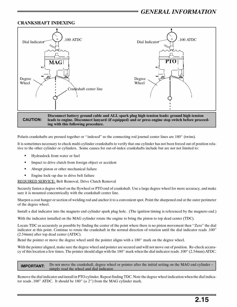
CRANKSHAFT INDEXING
Dial Indicator
DegreeWheel
.100 ATDC
Crankshaft center line
Dial Indicator
DegreeWheel
.100 ATDC
MAG PTO
CAUTION:Disconnect battery ground cable and ALL spark plug high tension leads: ground high tensionleads to engine. Disconnect lanyard (if equipped) and or press engine stop switch before proceed-ing with this following procedure.
Polaris crankshafts are pressed together or ‘‘indexed” so the connecting rod journal center lines are 180_ (twins).
It is sometimes necessary to check multi-cylinder crankshafts to verify that one cylinder has not been forced out of position rela-tive to the other cylinder or cylinders. Some causes for out-of-index crankshafts include but are not not limited to:
S Hydraulock from water or fuel
S Impact to drive clutch from foreign object or accident
S Abrupt piston or other mechanical failure
S Engine lock--up due to drive belt failure
REQUIRED SERVICE: Belt Removal, Drive Clutch Removal
Securely fasten a degree wheel on the flywheel or PTO end of crankshaft. Use a large degree wheel for more accuracy, and makesure it is mounted concentrically with the crankshaft center line.
Sharpen a coat hanger or section of welding rod and anchor it to a convenient spot. Point the sharpened end at the outer perimeterof the degree wheel.
Install a dial indicator into the magneto end cylinder spark plug hole. (The ignition timing is referenced by the magneto end.)
With the indicator installed on the MAG cylinder rotate the engine to bring the piston to top dead center (TDC).
Locate TDC as accurately as possible by finding the center of the point where there is no piston movement then ‘‘Zero” the dialindicator at this point. Continue to rotate the crankshaft in the normal direction of rotation until the dial indicator reads .100”(2.54mm) after top dead center (ATDC).
Bend the pointer or move the degree wheel until the pointer aligns with a 180_ mark on the degree wheel.
With the pointer aligned, make sure the degree wheel and pointer are secured and will not move out of position. Re-check accura-cy of this location a few times. The pointer should align with the 180_mark when the dial indicator reads .100“ (2.54mm) ATDC.
IMPORTANT: Do not move the crankshaft, degree wheel or pointer after the initial setting on the MAG end cylinder --simply read the wheel and dial indicator.
Remove the dial indicator and install in PTO cylinder. Repeat finding TDC. Note the degree wheel indication when the dial indica-tor reads .100” ATDC. It should be 180_ (± 2_) from the MAG cylinder mark.

GENERAL INFORMATION
2.16
Symptoms of an out of index crankshaft can include:
S Difficulty calibrating carburetor (repetitive plug fouling on one cylinder with no other cause)S Unexplained piston failure on one cylinder (i.e. severe detonation, broken ring lands, piston holing)
S Excessive vibration of engine, backfiring, etc.S Rough idle, poor top speed.
CRANKSHAFT TRUING
Lubricate the bearings and clamp the crankshaft securely in the holding fixture. If truing the crankshaft requires striking with ahammer, always be sure to re-check previously straightened areas to verify truing. Refer to the illustrations below. Use Crank-shaft alignment kit PN 2870569.
NOTE:The Rod Pin position in relation to the dial indicator tells you what action is required to straighten
the shaft.
To correct a situation like the one shown in illustration 1, strike theshaft at point A with a brass hammer.
To correct a situation like the one shown in illustration 2, squeeze thecrankshaft at point A. you will use the tool from the alignment kit PN2870569.
If the crank rod pin location is 180_ from the dial indicator (oppositethat shown in illustrating 2), it will be necessary to spread the crank-shaft at the A position as shown in illustration 3. When rebuilding andstraightening a crankshaft, straightness is of utmost importance. Run-out must be as close to zero as possible.
A
B
HIGH .004 (.1mm)HIGH .004 (.1mm)
SUPPORT CRANKSHAFTAT THESE TWO BEARINGS
1
A A
HIGH .002 (.05mm)HIGH .005 (.13mm)
2
A
HIGH .002 (.05mm)
HIGH .005(.13mm)A
3
GENERAL INFORMATION
2.17
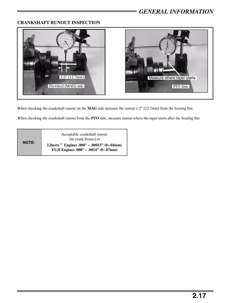
CRANKSHAFT RUNOUT INSPECTION
1/2” (12.7mm)
Flywheel (MAG) side
Measure where taper starts
PTO Side
When checking the crankshaft runout on the MAG side measure the runout 1/2” (12.7mm) from the bearing flat.
When checking the crankshaft runout from the PTO side, measure runout where the taper starts after the bearing flat.
Acceptable crankshaft runout(in crank fixture) is
Libertyt Engines .000” -- .00015” (0--.04mm)FUJI Engines .000” -- .0024” (0--.07mm)
NOTE:

GENERAL INFORMATION
2.18
OIL PUMP OPERATION AND TROUBLESHOOTING
BANJO TYPE
PRESS IN TYPE
Any time the engine is disassembled or repaired, it is important that the oil supply from the pump tothe engine be checked.
Banjo type or pressed in valves should open with 2 to 7 lbs. of pressure. Perform this test with 40:1premix in the fuel tank.
Install new sealing washers upon installation on either side of the banjo check valve.
NOTE:
With engine in chassis, oil reservoir full, and pump bled, remove two oil feed line banjo bolts (A) from their location on themanifold or carburetors.
Loosely thread the banjo bolts back into the manifold or carburetors.
Place oil feed lines with their check valves away from the clutch area.
Start the engine and let it idle at normal idle RPM.
Drops of oil should be visible from the banjo check valves after the engine is idled one to two minutes, with a drop occurringapproximately every few seconds
If oil does not flow from one of the check valves, remove oil line from check valve and again idle engine. If oil then flows, thecheck valve is defective and must be replaced.
If oil does not flow with check valves removed from their feed lines, the malfunction is one of the following:
S Inline filter blocked.
S Air not bled from oil pump.
S Feed lines leaking.
S Oil tank vent restricted or kinked.
S Defective pump.
GENERAL INFORMATION
2.19
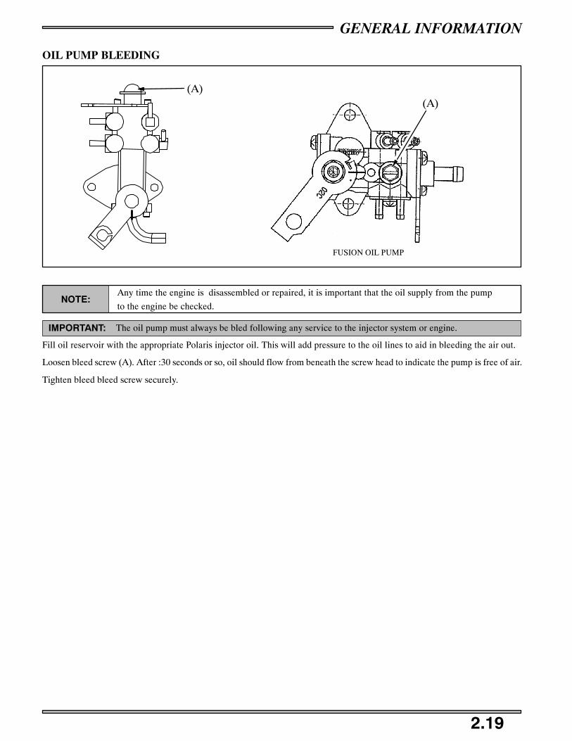
OIL PUMP BLEEDING
(A)(A)
FUSION OIL PUMP
NOTE:Any time the engine is disassembled or repaired, it is important that the oil supply from the pump
to the engine be checked.
IMPORTANT: The oil pump must always be bled following any service to the injector system or engine.
Fill oil reservoir with the appropriate Polaris injector oil. This will add pressure to the oil lines to aid in bleeding the air out.
Loosen bleed screw (A). After :30 seconds or so, oil should flow from beneath the screw head to indicate the pump is free of air.
Tighten bleed bleed screw securely.

GENERAL INFORMATION
2.20
OIL PUMP ADJUSTMENT PROCEDURE
.010-.030, (.25-.8 mm)Throttle Freeplay
Figure 2 Figure 3
Figure 4
REQUIRED SERVICE: Carburetor synchronization.
VM TYPE: Verify that carburetor slides leave their respective resting positions upon opening within .01, to .03, of throttle cablemovement, not throttle lever movement. See figure 2.
TM TYPE: Verify that carburetor slides are within .0625” of each other when passing the top of the carburetor throat. You mayhave to move slides with the starter lever.
Adjust throttle cable freeplay to .010, - .030, (.25 - .8mm).
Set idle to specified idle speed listed in the specifications chapter.
Verify that the oil pump alignment lines are aligned at the point where the carburetor slides begin to raise from their resting posi-tions. Note: Marks may not line up without throttle engagement. See figure 3.
Make adjustments so that the lines are at the position shown in figure 4.
Torque cable locknuts to 10 - 20 in.lbs.
NOTE: Use a mirror when aligning the oil pump marks whenever the oil pump is difficult to view.
THROTTLE BODY TYPE (900)
All you need to do for the 900 oil pump is to verify that the oil pump marks line up (figure 4) when the throttle is in the idle position.
You may need a mirror to see the marks straight on. If the line does not line up (figure 3) you will need to adjust the oil cableat the throttle bell housing.
To adjust this loosen the lock nut and thread the barrel nut in or out depending on the direction you need the line to move.
Moving the barrel nut in will adjust the line more to the top.
DO NOT adjust the idle. This is all set at the factory and should not be tapered with.
GENERAL INFORMATION
2.21
COOLING SYSTEM OVERVIEW
DANGER
Never remove the pressure cap when the engine is warm or hot. If the pressure cap is to be removed,
the engine must be cool. Severe personal injury could result from steam or hot liquid.
Use of a non-standard pressure cap will not allow the recovery system to function properly.
If the cap should need replacement, install the correct Polaris cap with the same pressure rating.
Refer to the appropriate parts manual.
COOLANT LEVEL
Coolant level in the coolant bottle must be maintained between the MINIMUM and MAXIMUM levels to prevent overheatingand serious engine damage.
RECOMMENDED COOLANT
Use a 60/40 mixture of antifreeze and distilled water depending on the freeze protection required for your area.
Do not use tap water in the system or reduced cooling or filter contamination may result.
Replace coolant every 2 years or if contaminated.
BLEEDING THE COOLING SYSTEM
Allow the system to cool completely.
Loosen the bleed screw and full the reservoir to the indicated Full Cold mark.
Once Full, tighten the bleed screw.
Apply parking brake and run the engine at specified idle RPM until the thermostat opens (approximately 5 to 8 minutes).
NOTE:
It is important that the thermostat stays open! When the thermostat opens it will draw in cold coolantfrom the heat exchangers and the cold coolant may close the thermostat again. Make sure the thermo-stat opens and stays open! Once the thermostat is open tip the snowmobile slightly on its right side.Cycle the RPM from idle to enough RPM (4000) to get coolant to flow but not enough RPM to engagethe clutch. This allows air to bleed from the rear crossover tube. Then tilt the machine slightly on itsleft side so that the coolant bottle is the highest point in the cooling system. Cycle the RPM from idle toenough RPM (4000) to get coolant to flow but not enough RPM to engage the clutch. It is important toget enough coolant flow to purge the air from the front close-off cooler and observe this air reaching thebottle.
Place the snowmobile in its normal riding position and loosen the bleed screw at the top of the water outlet manifold until trapped airhas been purged.
Tighten the bleed screw. Turn off the machine and release parking brake. Allow the system to cool completely. Re-check the cool-ant level after the cap has been removed and add coolant to fill line if necessary. After the machine has cooled down, 3 ouncesor more of coolant may have to be added.
This procedure should take approximately 15 minutes.
NOTE: It is important to get enough coolant flow to purge the air from the crossover hose or rear
cooler and observe this air reaching the bottle.
DANGER
When performing the following checks and adjustments, stay clear of all moving parts to avoid
serious personal injury.
Never remove the pressure cap when the engine is warm or hot. If the pressure cap is to be
removed, the engine must be cool. Severe personal injury could result from stream or hot liquid.

GENERAL INFORMATION
2.22
900 FUSION* COOLING SYSTEM
E 2004 Polaris Sales Inc.
1.
3.
5.
7.
11.
13.
17.18.
19.
21.
26.
2.
4.
6.
12.
14.
16.
9.
9.
9.
15.
15.
15.
8.8.
8.
4.
2.
22.
22.
10.
9.
9.
9.
9.20.
23.
24.
9.
9.
25.
27.
1. Mount, Radiator, Rubber 2. Exchanger, Gripper/Cooler, LHExchanger, Gripper/Cooler, RH
3. Asm., Radiator 4. Hose, Gripper/Rear Cooler, LHHose, Gripper/Rear Cooler, RH
5. Mount, Radiator, Foam 6. Asm., Rear Cooler, Long7. Hose, Tee/Radiator Inlet 8. Clamp, Springband, Brown9. Clamp, Springband, Black 10. Rivet
11. Hose, Radiator/Bottle 12. Hose, Tube/Gripper, LH13. Fitting, Tee 14. Cooler, Center15. Clamp, Springband, Black 16. Hose, Tee/Center Cooler17. Hose, Coolant Bottle/Engine18. Hose, Engine Out/Tee19. Cap, Pressure20. Line, Fuel21. Bottle, Coolant22. Clamp, Hose
Clamp, Narrow23. Nut24. Clamp, Rubber Coated, .7525. Tube, Coolant, Front, RH26. Hose, Bottle/Tube27. Hose, Gripper, Front, RH
*For other cooling diagrams please refer to the models parts book.

Maintenance Program Chart 3.1 -- 3.3. . . . . . . . . . . . . . . . . . . . . . . . . . . . . .Air Filter 3.4. . . . . . . . . . . . . . . . . . . . . . . . . . . . . . . . . . . . . . . . . . . . .Water Sediment Trap 3.4. . . . . . . . . . . . . . . . . . . . . . . . . . . . . . . . . . . .
Oil Filter 3.5. . . . . . . . . . . . . . . . . . . . . . . . . . . . . . . . . . . . . . . . . . . . . .Fuel Filter 3.5. . . . . . . . . . . . . . . . . . . . . . . . . . . . . . . . . . . . . . . . . . . . .
Lubrication Points 3.6. . . . . . . . . . . . . . . . . . . . . . . . . . . . . . . . . . . . . .
Suspension Lubrication 3.7. . . . . . . . . . . . . . . . . . . . . . . . . . . . . . . . . .
Chaincase 3.8. . . . . . . . . . . . . . . . . . . . . . . . . . . . . . . . . . . . . . . . . . . . .
Track 3.9. . . . . . . . . . . . . . . . . . . . . . . . . . . . . . . . . . . . . . . . . . . . . . . .Track Tension 3.10. . . . . . . . . . . . . . . . . . . . . . . . . . . . . . . . . . . . . . . . . .
Spark Plug Reading 3.11. . . . . . . . . . . . . . . . . . . . . . . . . . . . . . . . . . . . .
Drive Clutch Removal 3.12 -- 3.13. . . . . . . . . . . . . . . . . . . . . . . . . . . . . . . . . . .
Headlight 3.14. . . . . . . . . . . . . . . . . . . . . . . . . . . . . . . . . . . . . . . . . . . . .
Bulb Replacement 3.15. . . . . . . . . . . . . . . . . . . . . . . . . . . . . . . . . . . . . .Handlebar Adjustment 3.16. . . . . . . . . . . . . . . . . . . . . . . . . . . . . . . . . . .
Brake System 3.17 -- 3.18. . . . . . . . . . . . . . . . . . . . . . . . . . . . . . . . . . . . . . . . . .
Throttle Lever Free Play 3.19. . . . . . . . . . . . . . . . . . . . . . . . . . . . . . . . .
General Care 3.20. . . . . . . . . . . . . . . . . . . . . . . . . . . . . . . . . . . . . . . . . .
Exhaust System 3.21. . . . . . . . . . . . . . . . . . . . . . . . . . . . . . . . . . . . . . . .IQ Air Intake System 3.22. . . . . . . . . . . . . . . . . . . . . . . . . . . . . . . . . . . .
Edge Exhaust Valve Maintenance 3.23. . . . . . . . . . . . . . . . . . . . . . . . . .
IQ Exhaust Valve Maintenance 3.24. . . . . . . . . . . . . . . . . . . . . . . . . . . .
Thermostat / Temperature Sensor 3.25. . . . . . . . . . . . . . . . . . . . . . . . . .900 Liberty Coolant 3.26. . . . . . . . . . . . . . . . . . . . . . . . . . . . . . . . . . . . .
900 Liberty Oil Pump/Line Bleeding 3.27. . . . . . . . . . . . . . . . . . . . . . .
Typical Recoil Service 3.28 -- 3.29. . . . . . . . . . . . . . . . . . . . . . . . . . . . . . . . . . .
700/800 Liberty Water Pump Service 3.30. . . . . . . . . . . . . . . . . . . . . . .
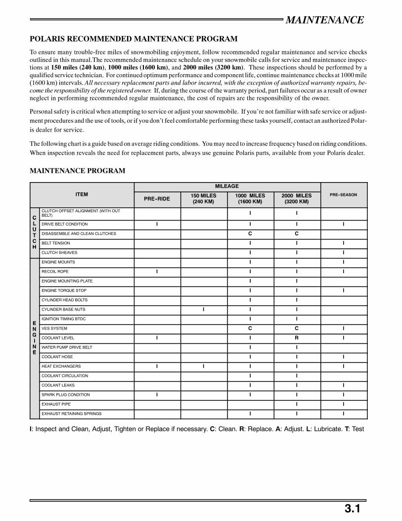
MAINTENANCE
3.1
POLARIS RECOMMENDED MAINTENANCE PROGRAM
To ensure many trouble-free miles of snowmobiling enjoyment, follow recommended regular maintenance and service checksoutlined in this manual.The recommended maintenance schedule on your snowmobile calls for service and maintenance inspec-tions at 150 miles (240 km), 1000 miles (1600 km), and 2000 miles (3200 km). These inspections should be performed by aqualified service technician. For continued optimum performance and component life, continue maintenance checks at 1000 mile(1600 km) intervals. All necessary replacement parts and labor incurred, with the exception of authorized warranty repairs, be-come the responsibility of the registered owner. If, during the course of the warranty period, part failures occur as a result of ownerneglect in performing recommended regular maintenance, the cost of repairs are the responsibility of the owner.
Personal safety is critical when attempting to service or adjust your snowmobile. If you’re not familiar with safe service or adjust-ment procedures and the use of tools, or if you don’t feel comfortable performing these tasks yourself, contact an authorized Polar-is dealer for service.
The following chart is a guide based on average riding conditions. You may need to increase frequency based on riding conditions.When inspection reveals the need for replacement parts, always use genuine Polaris parts, available from your Polaris dealer.
MAINTENANCE PROGRAM
MILEAGE
ITEMPRE--RIDE
150 MILES(240 KM)
1000 MILES(1600 KM)
2000 MILES(3200 KM)
PRE--SEASON
CCLUTCH OFFSET ALIGNMENT (WITH OUTBELT) I I
CLU
DRIVE BELT CONDITION I I I IUT DISASSEMBLE AND CLEAN CLUTCHES C CTCH
BELT TENSION I I IH
CLUTCH SHEAVES I I I
ENGINE MOUNTS I I I
RECOIL ROPE I I I I
ENGINE MOUNTING PLATE I I
ENGINE TORQUE STOP I I I
CYLINDER HEAD BOLTS I I
CYLINDER BASE NUTS I I I
EIGNITION TIMING BTDC I I
ENG
VES SYSTEM C C IGI
COOLANT LEVEL I I R IINE
WATER PUMP DRIVE BELT I IE
COOLANT HOSE I I I
HEAT EXCHANGERS I I I I I
COOLANT CIRCULATION I I
COOLANT LEAKS I I I
SPARK PLUG CONDITION I I I I
EXHAUST PIPE I I
EXHAUST RETAINING SPRINGS I I I
I: Inspect and Clean, Adjust, Tighten or Replace if necessary. C: Clean. R: Replace. A: Adjust. L: Lubricate. T: Test

MAINTENANCE
3.2
MILEAGE
ITEMPRE--RIDE
150 MILES(240 KM)
1000 MILES(1600 KM)
2000 MILES(3200 KM)
PRE--SEASON
HOSE ROUTING I I I
HOSE CONDITION I I I
FLUID LEAKS I I I
BRAKE PADS I I I
BR
BRAKE DISC I I IRA IGNITION SWITCH I I I IAKE
TAIL LIGHT T IES BRAKE LIGHT I I
HEAD LIGHT OPERATION I I
PARKING BRAKES T I I I
BRAKE SYSTEM I I
BRAKE FLUID R
FU
PILOT AIR SCREWS I IUEL CARBURETOR SYNCHRONIZATION I I
MIDLE RPM I I
MANA
THROTTLE LEVER FREE PLAY I I
AGE
SYNCHRONIZE OIL PUMP LEVER I IEME
THROTTLE CABLE LUBRICATION L L LENT OIL CABLE LUBRICATION L L L
FCHOKE CABLE LUBRICATION L L
FUE
VENT LINES I I IEL THROTTLE POSITION SENSOR I IL
CHOKE I I
MA
FUEL FILTER I IAN
FUEL LINES I INAG
OIL FILTER I IGE OIL LINES I IEME
CHANGE OIL R R IENT
AIR BOX I I I IT
CHECK DRAIN AND WATER TRAPS I I
I: Inspect and Clean, Adjust, Tighten or Replace if necessary. C: Clean. R: Replace. A: Adjust. L: Lubricate. T: Test

MAINTENANCE
3.3
ITEMMILEAGE
PRE SEASONITEMPRE--RIDE 150 1000 2000
PRE--SEASON
SKI TOE ALIGNMENT I I
SUSPENSION MOUNTING BOLTS I I I I
STEERING FASTENERS I I C
REAR SUSPENSION FASTENERS I I I
SUSPENSION SHOCK OIL I I I
COOLING FINS AND SHROUD I I I
DRIVE SHAFT BEARINGS L L I
JACKSHAFT BEARINGS L L I
SKI WEAR BARS I I
SKI SADDLE AND SPINDLE BOLTS I
SKI PIVOTS L L L I
SKI SPINDLE L L L I
STEERING ARM(S) L L L I
UPPER / LOWER STEERING POST SUPPORTBRACKET L L L I
DRIVE CHAIN TENSION I
CH
AUXILIARY SHUT--OFF SWITCH THA THROTTLE SAFETY SWITCH TASS
AUXILIARY SHUT--OFF SWITCHSIS
HOOD STRAPS IS
THROTTLE LEVER T
BATTERY FLUID LEVEL I
REAR WHEEL IDLER BOLTS I
IDLER ADJUSTING BOLT JAM NUT I
REAR SUSPENSION PIVOT SHAFTS L L
CAMBER ALIGNMENT I I
RADIUS ROD BUSHINGS I
HANDLE BAR CENTERING I
TORQUE TIE ROD END NUTS I
TETHER SWITCH AND STRAP T
TRACK ALIGNMENT I
TRACK TENSION I
FRONT LIMITER STRAP I
HYFAX CONDITION I I
CHAINCASE OIL I R I
GEARCASE OIL I R I
I: Inspect and Clean, Adjust, Tighten or Replace if necessary. C: Clean. R: Replace. A: Adjust. L: Lubricate. T: Test
Items in this chart require some mechanical knowledge. Items marked * and ** may require more technical informationand tools and should be performed by your authorized Polaris dealer.
RECOMMENDED MAINTENANCE PRODUCTS
Remember to use Pure Polaris parts and Lubricants to keep your sled running and looking like new. Pure Polaris products arespecifically engineered to rigid specifications that apply to the parts that wear and tear.

MAINTENANCE
3.4
AIR FILTER
A
BA
A
NOTE:Do not operate a machine with the intake filters removed. This may cause carburetor icingresulting poor fuel economy of carburetor malfunction.
The intake foam filter (A) limits snow ingestion into the intake system. When operating in loose powder, check the top of thefoam filter periodically to remove any accumulation of snow.
WATER / SEDIMENT TRAP
DANGERWhen draining the traps, fuel spillage will occur. be sure to work in a well ventilated area awayfrom anything which may cause the fuel to ignite such as an open flame, heaters, trouble lights orcigarettes, certifying
Most Polaris snowmobiles incorporate a patented carburetor bowl water / sediment traps which are located at the bottom of eachcarburetor. The trap consists of a hose with a plug which should be inspected for contamination every 1000 miles (1600 km).
CLEANING PROCEDURE
Turn the fuel tank supply valve to the “OFF” position.
Position a container or shop towels under the work area to help catchsome of the contaminated gasoline.
Slide the clamp (A) away from the drain plug (B) and remove the drainplug from the sediment tube and let the water/gasoline drain from thebowl. Repeat for other carburetor(s).
Wipe off residue from plug and reinstall with clamps.
A
B

MAINTENANCE
3.5
OIL FILTER / FUEL FILTER
IN LINE OIL FILTER
IN TANK SENDER/FILTER
Filter
IN--TANK FUEL FILTERS
IN--LINE FUEL FILTER
OIL FILTERS
The in tank fuel filter and fuel lines should be inspected regularly. Special attention should be givento the systems fuel line condition after periods of storage. Normal deterioration from weather andfuel can occur. Do not damage fuel lines when removing them. If a fuel line has been damaged orkinked, replace it.
CAUTION:
NOTE:The direction of the arrow indicates the direction of the flow through the filter.
After changing the oil filter, the oil injection system must be bled of all trapped air. See page3.27 for instructions on bleeding procedure.
Most models use an oil and fuel filters which are of a special design and must not be substituted. These filters should be changedand the oil and fuel lines should be inspected annually or every 100 miles (1600 km).
EDGE models utilize a special oil filter that is built into the oil sending unit located in the bottom of the oil tank. It should bereplaced every two years or 2400 miles (3862 km).
FUSION/RMK in--line fuel filters should be replaced every 2 years.
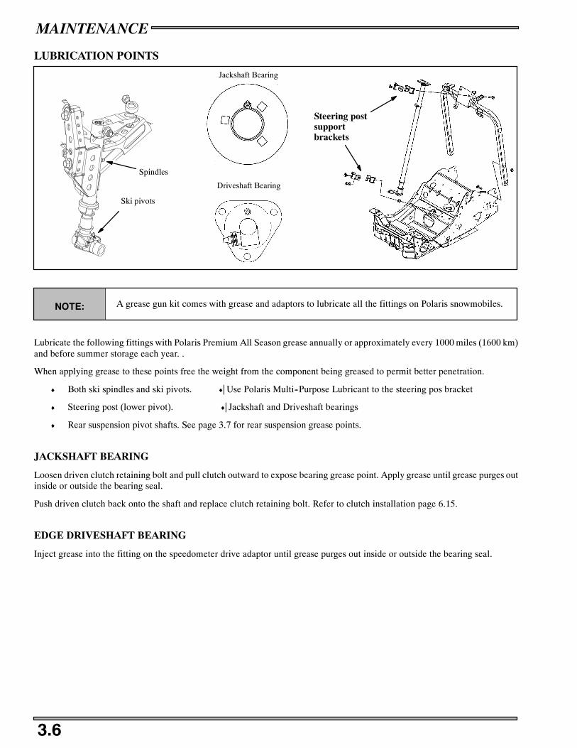
MAINTENANCE
3.6
LUBRICATION POINTS
Spindles
Jackshaft Bearing
Driveshaft Bearing
Steering postsupportbrackets
Ski pivots
NOTE: A grease gun kit comes with grease and adaptors to lubricate all the fittings on Polaris snowmobiles.
Lubricate the following fittings with Polaris Premium All Season grease annually or approximately every 1000 miles (1600 km)and before summer storage each year. .
When applying grease to these points free the weight from the component being greased to permit better penetration.
♦ Both ski spindles and ski pivots. ♦⎜Use Polaris Multi--Purpose Lubricant to the steering pos bracket
♦ Steering post (lower pivot). ♦⎜Jackshaft and Driveshaft bearings
♦ Rear suspension pivot shafts. See page 3.7 for rear suspension grease points.
JACKSHAFT BEARING
Loosen driven clutch retaining bolt and pull clutch outward to expose bearing grease point. Apply grease until grease purges outinside or outside the bearing seal.
Push driven clutch back onto the shaft and replace clutch retaining bolt. Refer to clutch installation page 6.15.
EDGE DRIVESHAFT BEARING
Inject grease into the fitting on the speedometer drive adaptor until grease purges out inside or outside the bearing seal.
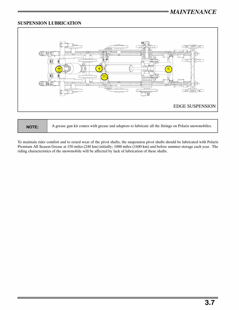
MAINTENANCE
3.7
SUSPENSION LUBRICATION
EDGE SUSPENSION
NOTE: A grease gun kit comes with grease and adaptors to lubricate all the fittings on Polaris snowmobiles.
To maintain rider comfort and to retard wear of the pivot shafts, the suspension pivot shafts should be lubricated with PolarisPremium All Season Grease at 150 miles (240 km) initially; 1000 miles (1600 km) and before summer storage each year. Theriding characteristics of the snowmobile will be affected by lack of lubrication of these shafts.

MAINTENANCE
3.8
CHAINCASE
Do not mix or use improper types of lubricants in chaincase. Excessive wear to chain, sprocketsand bearings may result.CAUTION:
The drive chain is continuously immersed in the chaincase oil.
Proper oil level is determined by checking the level on the dipstick with machine placed on a level surface. The oil level shouldbe between the “safe” marks on the dipstick.
NOTE:Clean the magnetic plug (E) every 500 miles (800 km) and whenever checking or changinglubricant. Metal shavings on magnetic plug are signs of normal wear.
The dipstick has a magnet on the end of it. When you check your chaincase oil level for the first time do not be alarmed if yousee small metal shavings. These shavings are common for chaincase break in and the magnet is there to keep the shavings fromfloating around.
Add oil through dipstick opening to maintain proper level. Use Polaris chaincase oil. Do not overfill.
DRIVE CHAIN TENSION
1. Elevate rear of machine so track is off floor.
2. Rotate driven clutch counterclockwise to move all chain slack to the tensioner side. Lock the brake lever.
3. Loosen adjuster bolt jam nut (C).
4. Finger tighten adjuster bolt (D) until it can no longer be adjusted by hand.
5. Back off adjuster bolt 1/4 turn.
6. Tighten jam nut while holding adjuster bolt.
7. The chain is now tensioned. Release brake lever lock.

MAINTENANCE
3.9
TRACK
A
Idler shaft bolt torque:
35--40 ft. lbs
(48--55Nm)B
C
D
E
DANGERWhen preforming the following checks and adjustments, stay clear of all moving parts to avoidserious personal injury.
Never make this maintenance check with the engine running, as serious personal injury can result.
Safely lift and support the rear of the snowmobile off the ground. Rotate the track by hand to check for any possible damage.
To inspect track rods (A), carefully examine the track along the entire length of each rod, bending the track and inspecting forbreakage. The three most common places where breakage occurs are shown in the illustration by the number designation.
If any rod damage is found, the track should be replaced.
DANGERBroken track rods are a serious hazard, since they can cause a rotating track to come off the ma-chine. Never operate or rotate a torn or damaged track under power. Serious personal injury ordeath may occur.
TRACK ALIGNMENT
Track alignment affects track tension. Misalignment will cause excessive wear to the track, hifax, and the slide rails.
A periodic check should be made to see that the track is centered and running evenly on the slide rails.
NOTE: If excessive hi--fax wear occurs due to poor snow conditions, additional wheels are available.
1. Safely support the rear of the machine with the track off the ground.
2. Start the engine and apply a small amount of throttle until the track turns slowly at least five complete revolutions. Stop theengine.
3. Inspect track alignment by carefully looking through the track window (B) to make sure the rails (C) are evenly spaced oneach side. If the track runs to the left, SHUT MACHINE OFF and loosen left locknut and tighten the left adjusting bolt (D). Ifthe track runs to the right, SHUT MACHINE OFF and loosen right locknut and tighten the right adjusting bolt.
4. After adjustments are complete, be sure to torque idler shaft bolts and tighten locknuts (E). Torque to specification.

MAINTENANCE
3.10
TRACK TENSION
AB C
DANGER When performing the following checks and adjustments, stay clear of all moving parts to avoid
serious personal injury.
TRACK TENSION
Track tension is critical for maintaining correct suspension operation.
If the track tension is too loose it may cause the track to slip or “ratchet” on the drive shaft drivers and cause track and rearsuspension durability problems.
If the track is too tight the track will wear down hyfax, reduce top speeds, cause rear suspension vibration and cause track andrear suspension durability problems.
Suspension Weight Measurement Location Measurement
EDGE / EDGE RMKSwitchbackt / IQ RMK
3/8 - 1/2″ (1 - 1.3 cm)
IQ Fusion 10 lbs (4.54 kg) 16″ ahead of rear idler shaft 1 1/4” -- 1 1/2″(3.17--3.81 cm)
M--10 / M--10 ACE 7/8” -- 1 1/8”(2.2--2.9 cm)
TRACK TENSION ADJUSTMENT
1. Turn the machine off.2. Lift the rear of the machine and safely support it off the ground.3. Place a 10 lb. (4.5 kg) weight on the track at a point approximately 16“ (40.6cm) ahead of the center of the rear idler wheel (A).4. Check for proper slack between the track clip wear surface and the hi-fax, and at the point where the weight is hanging (A).5. Loosen rear idler shaft bolts (B) on both sides of the machine.6. Loosen track adjusting bolt locknuts (C).7. Tighten or loosen the track adjusting bolts (B) evenly as necessary to obtain the specified track tension.
8. Tighten idler shaft bolts and adjuster bolt locknuts.
NOTE:Track alignment affects track tension. Misalignment will cause excessive wear to the track and
slide rail. Excessive hyfax wear will appear on units with the track tension set too tight.
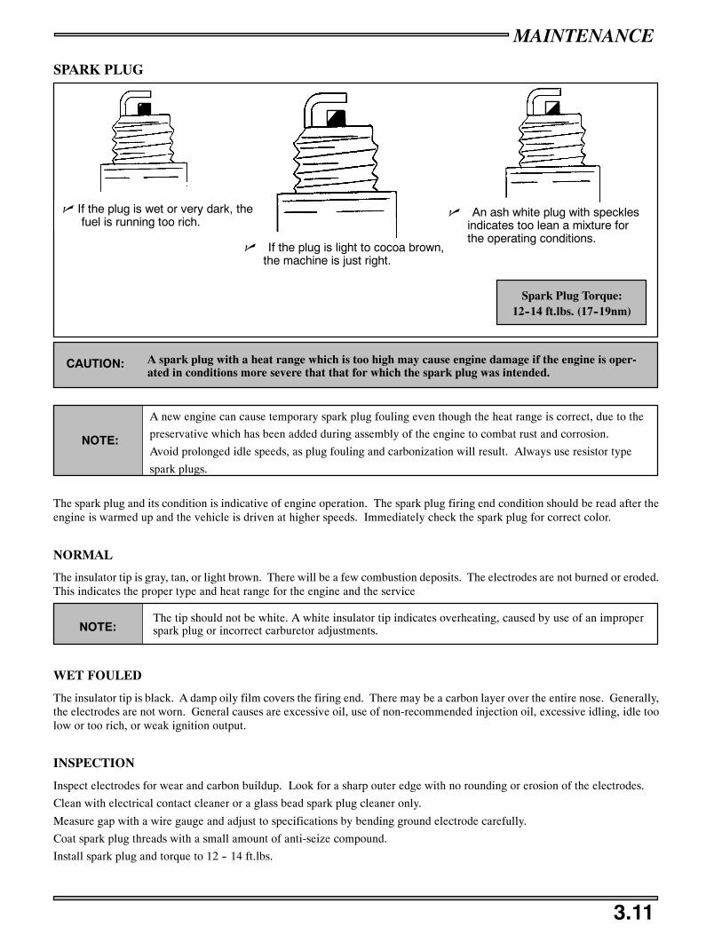
MAINTENANCE
3.11
SPARK PLUG
n An ash white plug with specklesindicates too lean a mixture forthe operating conditions.
n If the plug is light to cocoa brown,the machine is just right.
n If the plug is wet or very dark, thefuel is running too rich.
Spark Plug Torque:12--14 ft.lbs. (17--19nm)
A spark plug with a heat range which is too high may cause engine damage if the engine is oper-ated in conditions more severe that that for which the spark plug was intended.
CAUTION:
NOTE:
A new engine can cause temporary spark plug fouling even though the heat range is correct, due to the
preservative which has been added during assembly of the engine to combat rust and corrosion.
Avoid prolonged idle speeds, as plug fouling and carbonization will result. Always use resistor type
spark plugs.
The spark plug and its condition is indicative of engine operation. The spark plug firing end condition should be read after theengine is warmed up and the vehicle is driven at higher speeds. Immediately check the spark plug for correct color.
NORMAL
The insulator tip is gray, tan, or light brown. There will be a few combustion deposits. The electrodes are not burned or eroded.This indicates the proper type and heat range for the engine and the service
NOTE:The tip should not be white. A white insulator tip indicates overheating, caused by use of an improperspark plug or incorrect carburetor adjustments.
WET FOULED
The insulator tip is black. A damp oily film covers the firing end. There may be a carbon layer over the entire nose. Generally,the electrodes are not worn. General causes are excessive oil, use of non-recommended injection oil, excessive idling, idle toolow or too rich, or weak ignition output.
INSPECTION
Inspect electrodes for wear and carbon buildup. Look for a sharp outer edge with no rounding or erosion of the electrodes.
Clean with electrical contact cleaner or a glass bead spark plug cleaner only.
Measure gap with a wire gauge and adjust to specifications by bending ground electrode carefully.
Coat spark plug threads with a small amount of anti-seize compound.
Install spark plug and torque to 12 -- 14 ft.lbs.

MAINTENANCE
3.12
POLARIS DRIVE CLUTCH BELT REMOVAL / INSTALLATION
A
BC
DANGERInspect the condition of the drive belt and clutch sheaves for damage wear, or belt residue during
pre--ride inspections. Clean with a non--oil base cleaner such as isopropyl alcohol.
To ensure belt life, install belts so they operate in the same direction of rotation. Position the identification numbers so that youcan read them standing on left side of machine. This will keep the belt rotating in the same direction. If belt has been operatedwith numbers readable from right side of machine, re-install belt in this direction.
POLARIS DRIVEN BELT REMOVAL
1. Be sure key switch is off and engine has come to a complete stop. Remove the clutch cover retaining pin and open the clutchguard.
2. Apply brake (or lock parking brake if so equipped).
3. Grasp belt firmly midway between clutches and pull upward and rearward to open the driven clutch sheaves (A). Remove thebelt from the driven clutch and then from the drive clutch (B).
POLARIS DRIVEN BELT INSTALLATION
1. Drop the drive belt over the drive clutch and pull back the slack (C).
2. Turn the driven clutch moveable sheave clockwise while at the same time pushing inward and forcing the belt down betweenthe sheaves.
3. Hold the belt down between the sheaves and roll the bottom portion over the outer clutch sheave. Once installed, be sure towork the belt to the outer edge of the sheave. Be sure to release parking brake if applied.
4. Close the clutch guard and reinstall the retaining pin.
POLARIS DRIVEN CLUTCH ADJUSTMENTS
The driven clutch has a provision for varying the torque required to change its ratio. It can be readjusted by relocating the springin the helix which in turn increases or decreases the amount of load required to change the ratio.
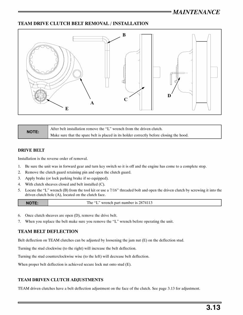
MAINTENANCE
3.13
TEAM DRIVE CLUTCH BELT REMOVAL / INSTALLATION
EA
B
CD
NOTE:After belt installation remove the “L” wrench from the driven clutch.
Make sure that the spare belt is placed in its holder correctly before closing the hood.
DRIVE BELT
Installation is the reverse order of removal.
1. Be sure the unit was in forward gear and turn key switch so it is off and the engine has come to a complete stop.
2. Remove the clutch guard retaining pin and open the clutch guard.
3. Apply brake (or lock parking brake if so equipped).
4. With clutch sheaves closed and belt installed (C).
5. Locate the “L” wrench (B) from the tool kit or use a 7/16” threaded bolt and open the driven clutch by screwing it into thedriven clutch hole (A), located on the clutch face.
NOTE: The “L” wrench part number is 2874113
6. Once clutch sheaves are open (D), remove the drive belt.
7. When you replace the belt make sure you remove the “L” wrench before operating the unit.
TEAM BELT DEFLECTION
Belt deflection on TEAM clutches can be adjusted by loosening the jam nut (E) on the deflection stud.
Turning the stud clockwise (to the right) will increase the belt deflection.
Turning the stud counterclockwise wise (to the left) will decrease belt deflection.
When proper belt deflection is achieved secure lock nut onto stud (E).
TEAM DRIVEN CLUTCH ADJUSTMENTS
TEAM driven clutches have a belt deflection adjustment on the face of the clutch. See page 3.13 for adjustment.
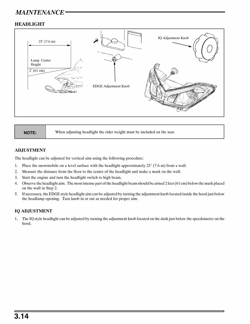
MAINTENANCE
3.14
HEADLIGHT
EDGE Adjustment Knob
25’ (7.6 m)
Lamp CenterHeight
2’ (61 cm)
IQ Adjustment Knob
NOTE: When adjusting headlight the rider weight must be included on the seat.
ADJUSTMENT
The headlight can be adjusted for vertical aim using the following procedure:
1. Place the snowmobile on a level surface with the headlight approximately 25’ (7.6 m) from a wall.
2. Measure the distance from the floor to the center of the headlight and make a mark on the wall.
3. Start the engine and turn the headlight switch to high beam.
4. Observe the headlight aim. The most intense part of the headlight beam should be aimed 2 feet (61 cm) below the mark placedon the wall in Step 2.
5. If necessary, the EDGE style headlight aim can be adjusted by turning the adjustment knob located inside the hood just belowthe headlamp opening. Turn knob in or out as needed for proper aim.
IQ ADJUSTMENT
1. The IQ style headlight can be adjusted by turning the adjustment knob located on the dash just below the speedometer on thehood.

MAINTENANCE
3.15
BULB REPLACEMENT
A
B
CD
E
F
HEADLIGHT
SNOW BEAMG
HEADLIGHT BULB REPLACEMENT
NOTE:Do not touch a halogen bulb with bare fingers. Oil from skin leaves a residue on the bulb anddecreases the life of the bulb.
1. Unplug headlight harness from bulb (A).
2. Remove rubber boot (B) from housing.
3. Pinch ends of spring (C) together and lift until it releases from spring retainer.
4. Lift spring carefully around wire harness and flip to outside of the housing.
5. Grasp bulb (D) by metal base and carefully separate bulb from harness.
6. Install new bulb by the base, do not touch the bulb it self.
SNOW BEAM BULB REPLACEMENT
1. Twist the light base (E) counter clockwise and pull out from the housing.
2. Remove the rubber boot (F).
3. Remove the bulb (G) by pulling it straight out from the housing
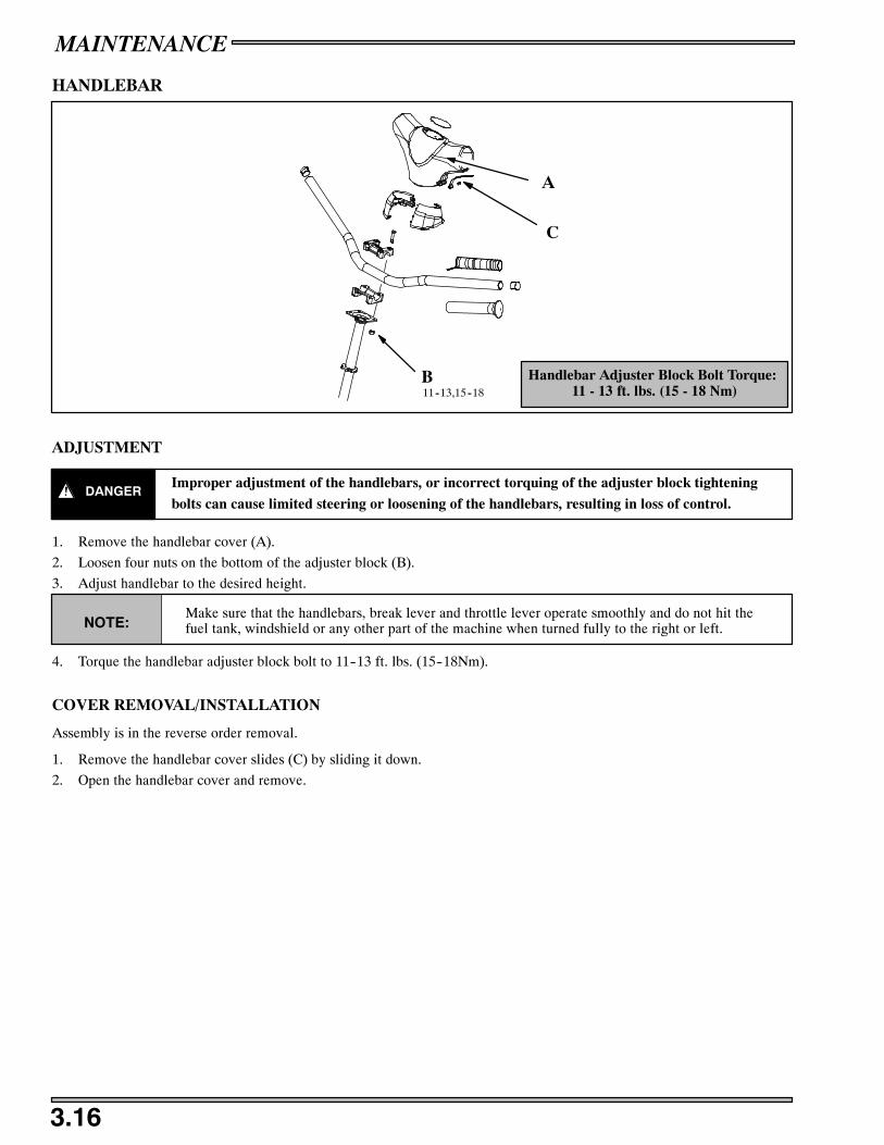
MAINTENANCE
3.16
HANDLEBAR
Handlebar Adjuster Block Bolt Torque:11 - 13 ft. lbs. (15 - 18 Nm)
A
B
C
11--13,15--18
ADJUSTMENT
DANGERImproper adjustment of the handlebars, or incorrect torquing of the adjuster block tightening
bolts can cause limited steering or loosening of the handlebars, resulting in loss of control.
1. Remove the handlebar cover (A).
2. Loosen four nuts on the bottom of the adjuster block (B).
3. Adjust handlebar to the desired height.
NOTE:Make sure that the handlebars, break lever and throttle lever operate smoothly and do not hit thefuel tank, windshield or any other part of the machine when turned fully to the right or left.
4. Torque the handlebar adjuster block bolt to 11--13 ft. lbs. (15--18Nm).
COVER REMOVAL/INSTALLATION
Assembly is in the reverse order removal.
1. Remove the handlebar cover slides (C) by sliding it down.
2. Open the handlebar cover and remove.
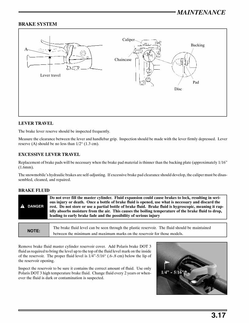
MAINTENANCE
3.17
BRAKE SYSTEM
A
Lever travel
Disc
Pad
BackingCaliper
Chaincase
LEVER TRAVEL
The brake lever reserve should be inspected frequently.
Measure the clearance between the lever and handlebar grip. Inspection should be made with the lever firmly depressed. Leverreserve (A) should be no less than 1/2“ (1.3 cm).
EXCESSIVE LEVER TRAVEL
Replacement of brake pads will be necessary when the brake pad material is thinner than the backing plate (approximately 1/16”(1.6mm).
The snowmobile’s hydraulic brakes are self-adjusting. If excessive brake pad clearance should develop, the caliper must be disas-sembled, cleaned, and repaired.
BRAKE FLUID
DANGER
Do not over fill the master cylinder. Fluid expansion could cause brakes to lock, resulting in seri-ous injury or death. Once a bottle of brake fluid is opened, use what is necessary and discard therest. Do not store or use a partial bottle of brake fluid. Brake fluid is hygroscopic, meaning it rap-idly absorbs moisture from the air. This causes the boiling temperature of the brake fluid to drop,leading to early brake fade and the possibility of serious injury
NOTE:The brake fluid level can be seen through the plastic reservoir. The fluid should be maintained
between the minimum and maximum marks on the reservoir for those models.
Remove brake fluid master cylinder reservoir cover. Add Polaris brake DOT 3fluid as required to bring the level up to the top of the fluid level mark on the insideof the reservoir. The proper fluid level is 1/4”-5/16“ (.6-.8 cm) below the lip ofthe reservoir opening.
Inspect the reservoir to be sure it contains the correct amount of fluid. Use onlyPolaris DOT 3 high temperature brake fluid. Change fluid every 2 years or when-ever the fluid is dark or contamination is suspected.
1/4” -- 5/16”

MAINTENANCE
3.18
HYDRAULIC BRAKE SYSTEM
A
BC
DANGER
Do not over fill the master cylinder. Fluid expansion could cause brakes to lock, resulting inserious injury or death. Once a bottle of brake fluid is opened, use what is necessary and discardthe rest. Do not store or use a partial bottle of brake fluid. Brake fluid is hygroscopic, meaningit rapidly absorbs moisture from the air. This causes the boiling temperature of the brake fluid todrop, leading to early brake fade and the possibility of serious injury
Brake fluid is a hazardous material. Contact with decals, paint, and many plastics will causedamage. Use proper precautions when handling brake fluid.CAUTION:
BLEEDING THE BRAKE SYSTEM
Air in the hydraulic brake system will cause a springy or spongy brake lever action. Bleeding is necessary to remove air fromthe system.
1. Remove brake fluid master cylinder reservoir cover and gasket (A).
2. Fill the master cylinder reservoir and keep the fluid level 1/4”-5/16“ (.6-.8 cm) below lip of reservoir opening during thisoperation.
3. Slip a rubber tube (B) over the end of the bleeder valve (C) and direct the flow of fluid into a waste container.
4. Slowly squeeze brake lever a full stroke and hold it. Then unscrew the bleeder valve 3/4 of a turn to release air.
5. Close bleeder valve and release brake lever, and then slowly squeeze brake lever and hold again.
Repeat steps 4 and 5 until fluid flows from bleeder valve in a solid stream and free of air bubbles. Do not allow the reservoirto run dry or air will be drawn into system.
6. Add Polaris brake DOT 3 fluid as required to bring the level up to the top of the fluid level mark on the inside of the reservoir.The proper fluid level is 1/4”-5/16“ (.6-.8 cm) below the lip of the reservoir opening
7. Replace the gasket and cover, then torque cover screws (D) to 18 in.lbs. (2Nm).
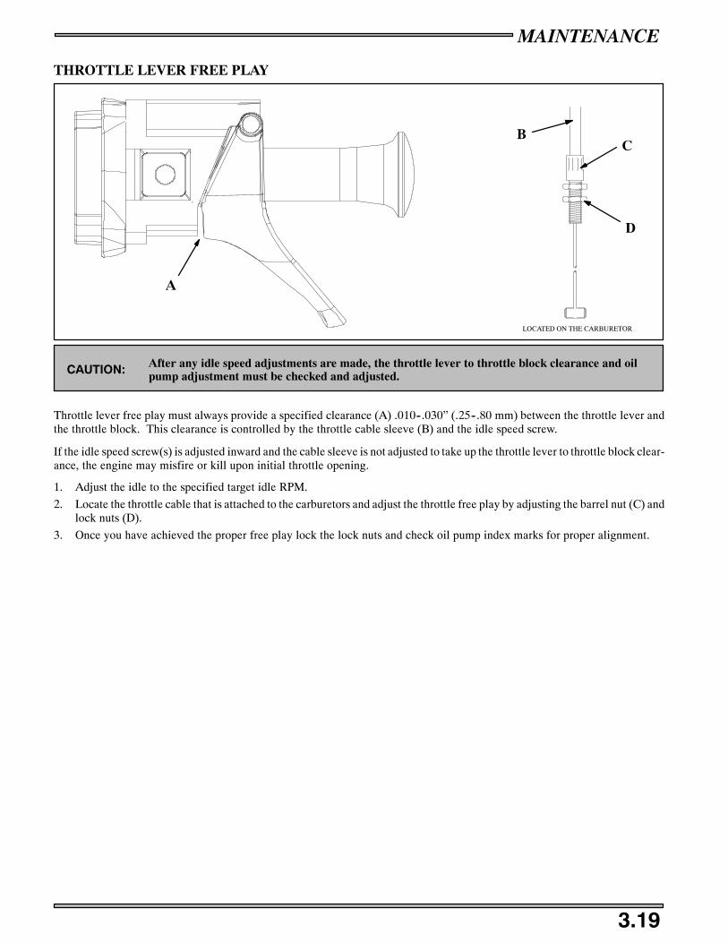
MAINTENANCE
3.19
THROTTLE LEVER FREE PLAY
A
BC
D
LOCATED ON THE CARBURETOR
After any idle speed adjustments are made, the throttle lever to throttle block clearance and oilpump adjustment must be checked and adjusted.CAUTION:
Throttle lever free play must always provide a specified clearance (A) .010--.030” (.25--.80 mm) between the throttle lever andthe throttle block. This clearance is controlled by the throttle cable sleeve (B) and the idle speed screw.
If the idle speed screw(s) is adjusted inward and the cable sleeve is not adjusted to take up the throttle lever to throttle block clear-ance, the engine may misfire or kill upon initial throttle opening.
1. Adjust the idle to the specified target idle RPM.
2. Locate the throttle cable that is attached to the carburetors and adjust the throttle free play by adjusting the barrel nut (C) andlock nuts (D).
3. Once you have achieved the proper free play lock the lock nuts and check oil pump index marks for proper alignment.

MAINTENANCE
3.20
CARE
CHASSIS AND HOOD
Proper storage starts by cleaning, washing and waxing the hood, chassis, upholstery and plastic parts. Clean and touch up withpaint any rusted or bare metal surfaces. Ensure that all corrosive salt and acids are removed from surfaces before beginning pres-ervation with waxes and rust inhibitors (grease, oil, or paint).
If the machine is equipped with a battery, disconnect the battery cables and clean the cables and battery posts. Fill battery to properlevel with distilled water and charge to full capacity. Remove and store the battery in a cool dry place.
The machine should be stored in a dry garage or shed out of the sunlight and covered with a fabric snowmobile cover. Do notuse plastic to cover the machine; moisture will be trapped inside causing rust and corrosion problems.
CLUTCH AND DRIVE SYSTEM
Remove drive belt and store in a cool dry location. Lubricate sheave faces and ramps of drive and driven clutches with light oilor rust inhibitor. All lubrication applied as a rust preventative measure must be cleaned off before installing belt for service andoperating machine.
CONTROLS AND LINKAGE
All bushings, spindle shafts and tie rod ends should be coated with a light coat of oil or grease. Throttle controls and cables shouldbe lubricated. Force a small amount of lubricant down cables.
ELECTRICAL CONNECTIONS
Separate electrical connector blocks and clean corrosive build-up from connectors. Lubricate or pack connector blocks withNyogelt grease and reconnect. Replace worn or frayed electrical wire and connectors.
CARBURETOR
Fog engine with Polaris Fogging Oil (aerosol type) according to directions on can.
FUEL SYSTEM
Treat the fuel system with Polaris Carbon Clean. If Polaris Carbon Clean is not used, fuel tank, fuel lines, and carburetor shouldbe completely drained of gasoline.
CORROSION
To prevent corrosion, always grease jackshaft and drive shaft (clutch side) bearings with Polaris Premium all season grease.Loosen driven clutch retaining bolt and pull clutch outward to expose bearing. Use a point type grease gun fitting to inject greasethrough hole in flangette into bearing until grease purges out inside or outside bearing seal. Push clutch back on shaft and replaceclutch retaining bolt. Inject grease into fitting on speedometer drive adaptor until grease purges out inside or outside the bearingseal. Lubricate both front ski pivots at bushings and spindles.
SHOCKS
Use T-9 Metal Protectant (or equivalent) on shock absorber shafts to help prevent corrosion.
BATTERY
Disconnect and remove battery. Fill with distilled water. Clean terminals and cables. Apply dielectric grease. Charge until spe-cific gravity is at least 1.270 (each cell). If machine is to be stored for one month or longer, fill and charge battery monthly usingPolaris Battery Tender, or a 1 amp trickle charger to maintain at 1.270 specific gravity.

MAINTENANCE
3.21
900 EXHAUST SYSTEM
A
B
C
D
E
F
GH
I
J
DG18,24
F
DANGER
Exhaust system temperatures can exceed 900_ F (500_ C). Serious burns may occur if this inspection
is performed without allowing adequate time for the exhaust system to cool.
Never perform this procedure with the engine running.
At approximately 2000 miles, or in preparation of off season storage, it is a good idea to check the exhaust system for wear ordamage. To inspect, allow the engine and exhaust system to cool completely. Open the hood and inspect the muffler and pipesfor cracks or damage. Check for weak or missing retaining springs or damper/support grommets.
REMOVAL
1. Disconnect the exhaust temperature sensor (A).
2. Remove all springs (B) from exhaust system.
3. Remove the exhaust pipe (C) and exhaust seals (D).
4. Take out the resonator (E) by removing the nuts (F) on the rubber isolators.
5. Remove the exhaust manifold (G) by removing the manifold bolts.
ASSEMBLY
1. Install exhaust manifold and torque the bolts (H) to 18 ft.lbs. (24Nm).
2. Install the resonator (E) by lining up the two tabs into the support grommet (I). Push the resonator down so that the exhaustoutlet is through the outlet boot (J).
3. Install the nuts (F) on to the rubber isolators.
4. Install the exhaust pipe (C) with seals (J), on the manifold and the resonator.
5. Install all exhaust springs.

MAINTENANCE
3.22
AIR INTAKE SYSTEM
A
B
C
D
E
F
G
REMOVAL/INSTALLATION
1. Pull the front of the plenum (A) with force to remove the plenum from the machine.
2. Disconnect the air intake sensor (B) form the airbox (C).
3. Remove the hose clamps (D) from the air intake boots (E) and slide the air box out.
4. Replace in reverse order. Make sure you line up the tabs on the plenum when pressing it back on to the airbox.
INSTALLATION
1. Place hose clamps back onto the throttle body boots.
2. Slide the air box (C) back into place.
3. Secure the hose clamps with the air box ends into the throttle body boots.
4. Install the air intake sensor (B) to the airbox.
5. Lift up the rubber seal (G) and line up the tabs on the rear (F) of the plenum and the airbox tabs (A) to the airbox (C) and pressdown.
6. Roll the rubber seal over the airbox so that the seal is on both the plenum and airbox. This will seal any air leakage that mayoccur.
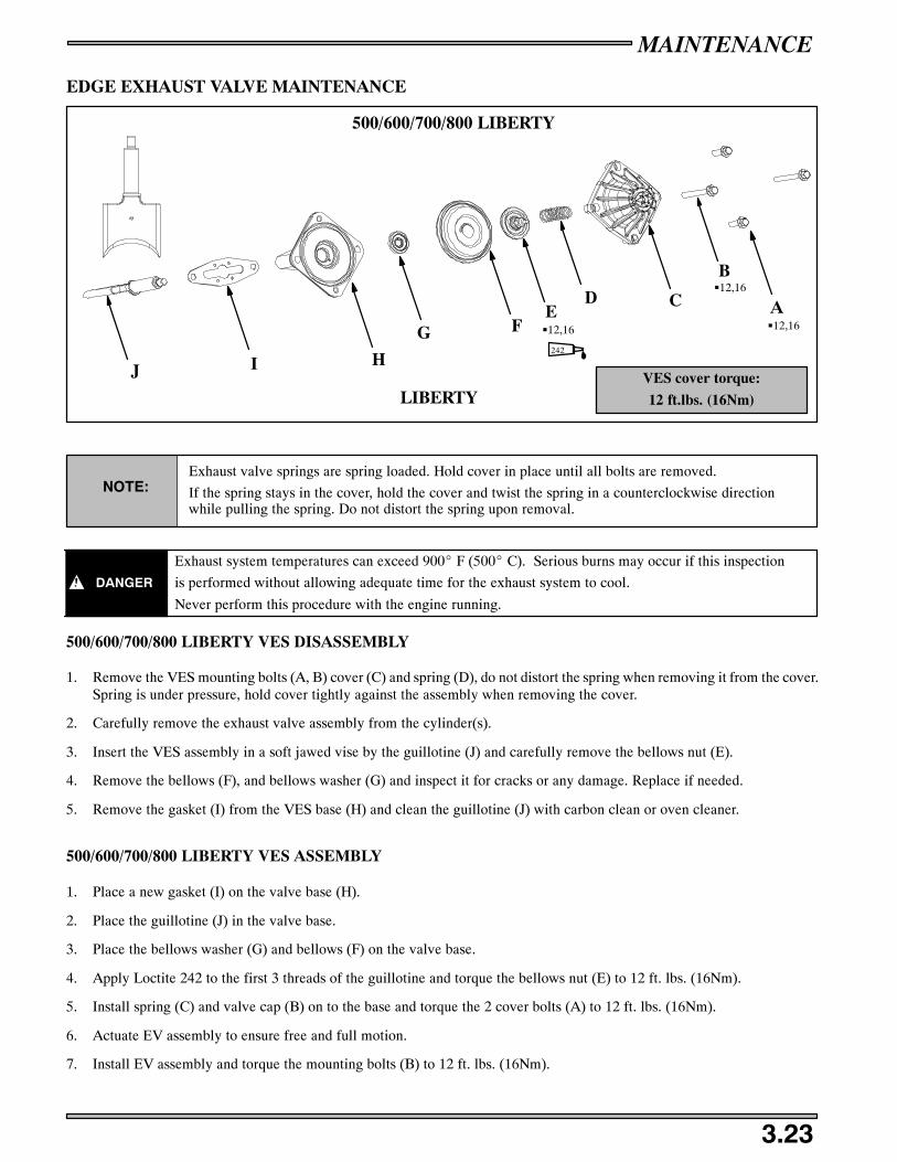
MAINTENANCE
3.23
EDGE EXHAUST VALVE MAINTENANCE
VES cover torque:
12 ft.lbs. (16Nm)
A
B
CDE
G
HJ
LIBERTY
F
I
G12,16
G12,16
500/600/700/800 LIBERTY
242
G12,16
NOTE:Exhaust valve springs are spring loaded. Hold cover in place until all bolts are removed.
If the spring stays in the cover, hold the cover and twist the spring in a counterclockwise directionwhile pulling the spring. Do not distort the spring upon removal.
DANGER
Exhaust system temperatures can exceed 900_ F (500_ C). Serious burns may occur if this inspection
is performed without allowing adequate time for the exhaust system to cool.
Never perform this procedure with the engine running.
500/600/700/800 LIBERTY VES DISASSEMBLY
1. Remove the VES mounting bolts (A, B) cover (C) and spring (D), do not distort the spring when removing it from the cover.Spring is under pressure, hold cover tightly against the assembly when removing the cover.
2. Carefully remove the exhaust valve assembly from the cylinder(s).
3. Insert the VES assembly in a soft jawed vise by the guillotine (J) and carefully remove the bellows nut (E).
4. Remove the bellows (F), and bellows washer (G) and inspect it for cracks or any damage. Replace if needed.
5. Remove the gasket (I) from the VES base (H) and clean the guillotine (J) with carbon clean or oven cleaner.
500/600/700/800 LIBERTY VES ASSEMBLY
1. Place a new gasket (I) on the valve base (H).
2. Place the guillotine (J) in the valve base.
3. Place the bellows washer (G) and bellows (F) on the valve base.
4. Apply Loctite 242 to the first 3 threads of the guillotine and torque the bellows nut (E) to 12 ft. lbs. (16Nm).
5. Install spring (C) and valve cap (B) on to the base and torque the 2 cover bolts (A) to 12 ft. lbs. (16Nm).
6. Actuate EV assembly to ensure free and full motion.
7. Install EV assembly and torque the mounting bolts (B) to 12 ft. lbs. (16Nm).

MAINTENANCE
3.24
900 LIBERTY EXHAUST VALVE MAINTENANCE
VES cover torque:
9 ft.lbs. (12 Nm)
F
J
H
G
E
E C BA
K
900 LIBERTY
G12,16
G12,16
G9,12
242
NOTE:Exhaust valve springs are spring loaded. Hold cover in place until all bolts are removed.
If the spring stays in the cover, hold the cover and twist the spring in a counterclockwise directionwhile pulling the spring. Do not distort the spring upon removal.
DANGER
Exhaust system temperatures can exceed 900_ F (500_ C). Serious burns may occur if this inspection
is performed without allowing adequate time for the exhaust system to cool.
Never perform this procedure with the engine running.
900 LIBERTY VES DISASSEMBLY
1. Carefully remove the VES cover bolts (A) cover (B) and spring (C), do not distort the spring when removing it from the cover.Spring is under pressure, hold cover tightly against the assembly when removing the cover.
2. Remove the bellows nut (E), bellows (E) and bellows washer (F).
3. Remove the base bolts (K) and remove the base assembly (G) and guillotine (J) from the cylinder.
4. Remove the gasket (H) from the VES base (G) and clean the guillotine (J) with carbon clean or oven cleaner.
900 LIBERTY VES ASSEMBLY
1. Place a new gasket (H) on the valve base (G).
2. Place the guillotine (J) in the valve base.
3. Insert the base bolts (K) and torque to 12 ft. lbs. (16 Nm).
4. Place the bellows washer (F) and the bellows (E) on the valve base.
5. Apply Loctite 242 to the bellows nut (D) and torque to 12 ft. lbs. (16 Nm).
6. Install spring (C) and valve cap (B) on to the base and torque the cover bolts (A) to 9 ft.lbs. (12 Nm).
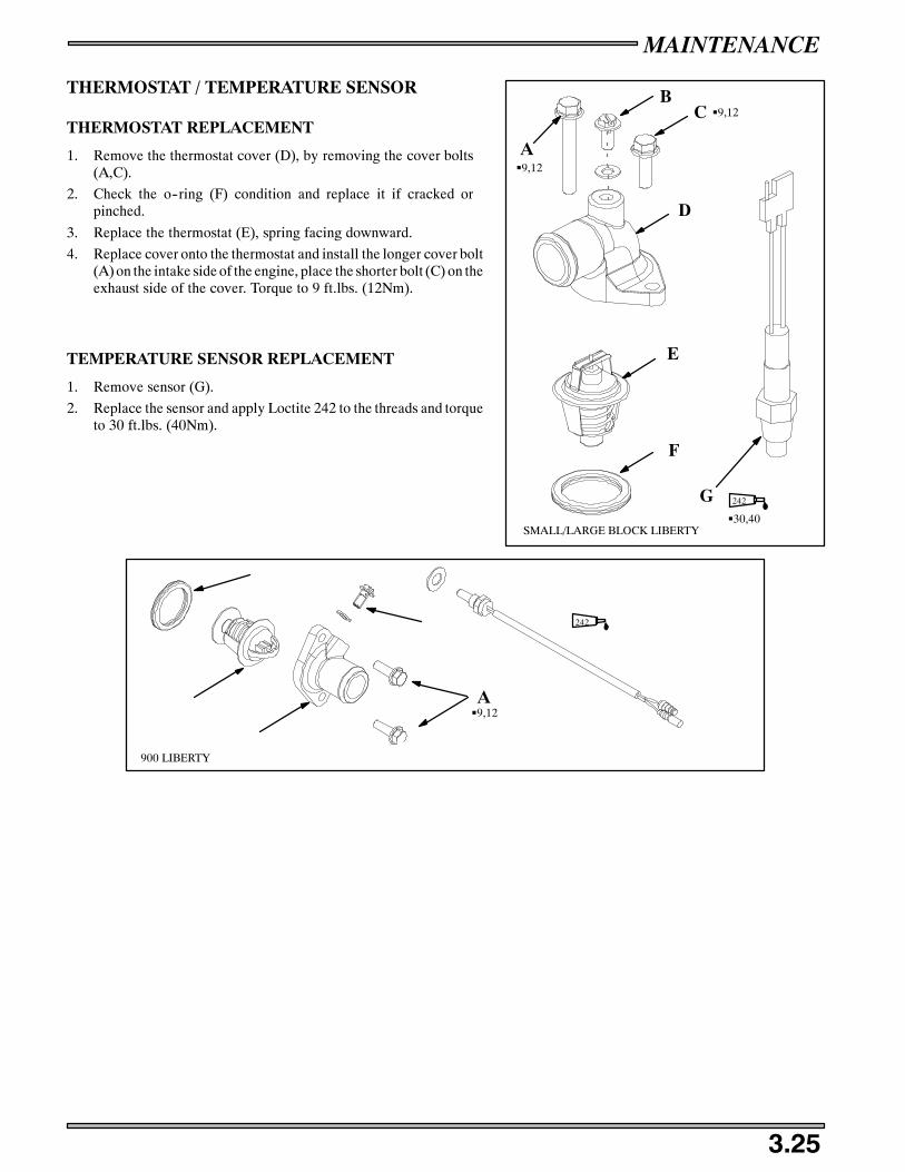
MAINTENANCE
3.25
THERMOSTAT / TEMPERATURE SENSOR
THERMOSTAT REPLACEMENT
1. Remove the thermostat cover (D), by removing the cover bolts(A,C).
2. Check the o--ring (F) condition and replace it if cracked orpinched.
3. Replace the thermostat (E), spring facing downward.
4. Replace cover onto the thermostat and install the longer cover bolt(A) on the intake side of the engine, place the shorter bolt (C) on theexhaust side of the cover. Torque to 9 ft.lbs. (12Nm).
TEMPERATURE SENSOR REPLACEMENT
1. Remove sensor (G).
2. Replace the sensor and apply Loctite 242 to the threads and torqueto 30 ft.lbs. (40Nm).
G30,40
242
A
BC
D
E
F
G
G9,12
G9,12
SMALL/LARGE BLOCK LIBERTY
242
AG9,12
900 LIBERTY
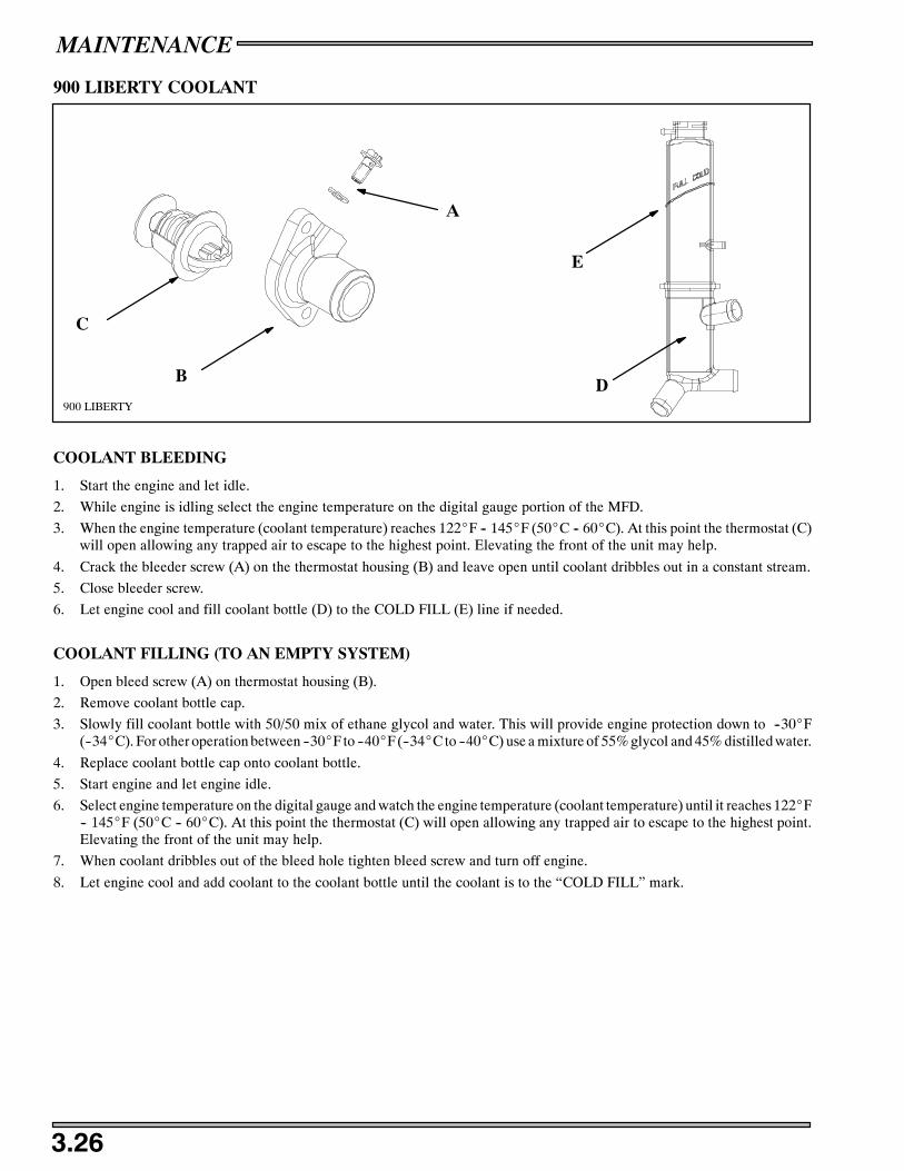
MAINTENANCE
3.26
900 LIBERTY COOLANT
A
900 LIBERTY
B
C
D
E
COOLANT BLEEDING
1. Start the engine and let idle.
2. While engine is idling select the engine temperature on the digital gauge portion of the MFD.
3. When the engine temperature (coolant temperature) reaches 122_F -- 145_F (50_C -- 60_C). At this point the thermostat (C)will open allowing any trapped air to escape to the highest point. Elevating the front of the unit may help.
4. Crack the bleeder screw (A) on the thermostat housing (B) and leave open until coolant dribbles out in a constant stream.
5. Close bleeder screw.
6. Let engine cool and fill coolant bottle (D) to the COLD FILL (E) line if needed.
COOLANT FILLING (TO AN EMPTY SYSTEM)
1. Open bleed screw (A) on thermostat housing (B).
2. Remove coolant bottle cap.
3. Slowly fill coolant bottle with 50/50 mix of ethane glycol and water. This will provide engine protection down to --30_F(--34_C). For other operation between --30_F to --40_F (--34_C to --40_C) use a mixture of 55% glycol and 45% distilled water.
4. Replace coolant bottle cap onto coolant bottle.
5. Start engine and let engine idle.
6. Select engine temperature on the digital gauge and watch the engine temperature (coolant temperature) until it reaches 122_F-- 145_F (50_C -- 60_C). At this point the thermostat (C) will open allowing any trapped air to escape to the highest point.Elevating the front of the unit may help.
7. When coolant dribbles out of the bleed hole tighten bleed screw and turn off engine.
8. Let engine cool and add coolant to the coolant bottle until the coolant is to the “COLD FILL” mark.
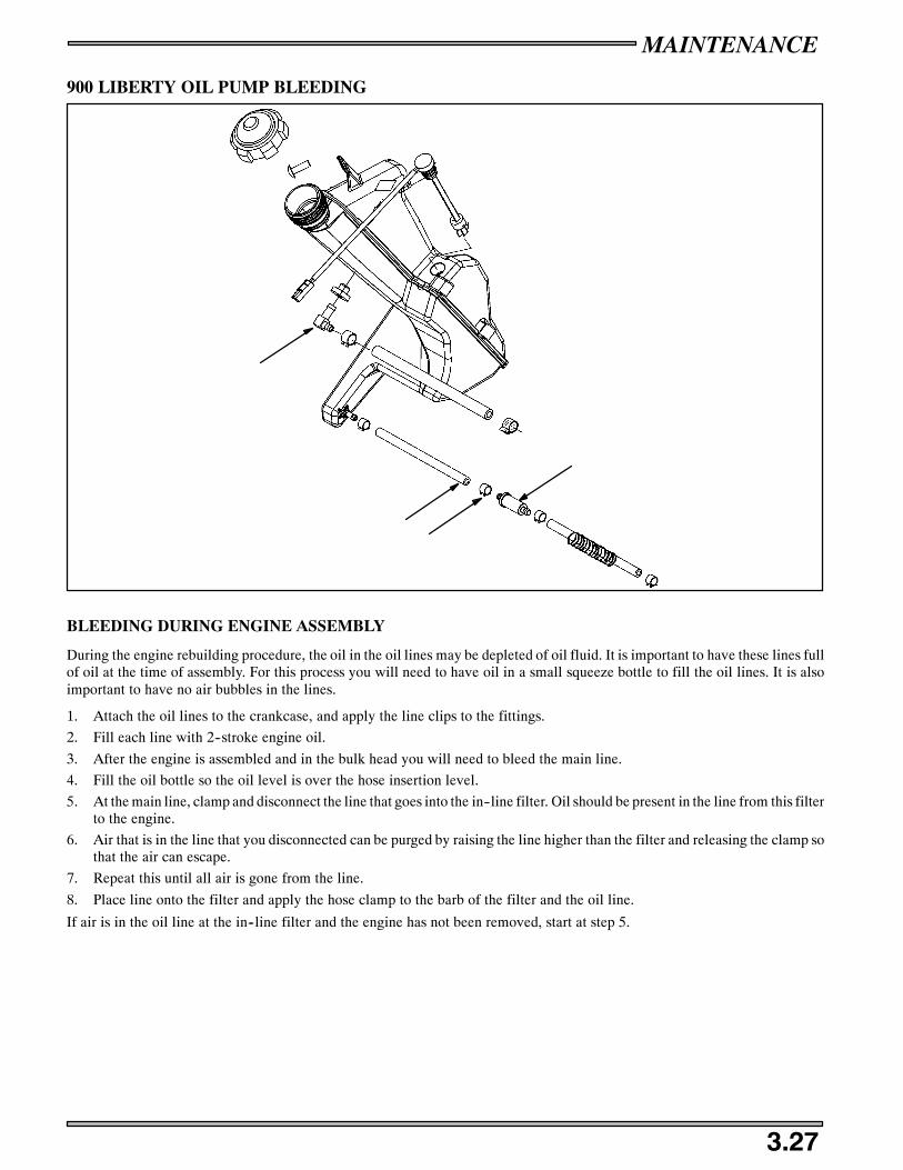
MAINTENANCE
3.27
900 LIBERTY OIL PUMP BLEEDING
BLEEDING DURING ENGINE ASSEMBLY
During the engine rebuilding procedure, the oil in the oil lines may be depleted of oil fluid. It is important to have these lines fullof oil at the time of assembly. For this process you will need to have oil in a small squeeze bottle to fill the oil lines. It is alsoimportant to have no air bubbles in the lines.
1. Attach the oil lines to the crankcase, and apply the line clips to the fittings.
2. Fill each line with 2--stroke engine oil.
3. After the engine is assembled and in the bulk head you will need to bleed the main line.
4. Fill the oil bottle so the oil level is over the hose insertion level.
5. At the main line, clamp and disconnect the line that goes into the in--line filter. Oil should be present in the line from this filterto the engine.
6. Air that is in the line that you disconnected can be purged by raising the line higher than the filter and releasing the clamp sothat the air can escape.
7. Repeat this until all air is gone from the line.
8. Place line onto the filter and apply the hose clamp to the barb of the filter and the oil line.
If air is in the oil line at the in--line filter and the engine has not been removed, start at step 5.
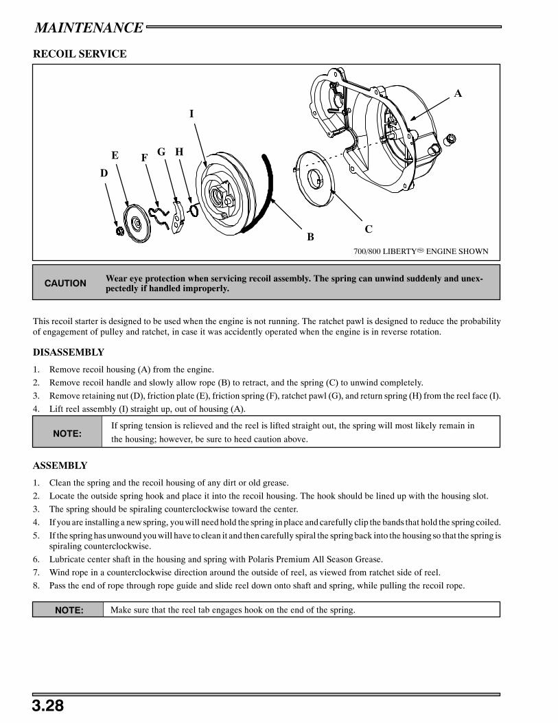
MAINTENANCE
3.28
RECOIL SERVICE
700/800 LIBERTYT ENGINE SHOWN
A
BC
D
E F G H
I
Wear eye protection when servicing recoil assembly. The spring can unwind suddenly and unex-pectedly if handled improperly.CAUTION
This recoil starter is designed to be used when the engine is not running. The ratchet pawl is designed to reduce the probabilityof engagement of pulley and ratchet, in case it was accidently operated when the engine is in reverse rotation.
DISASSEMBLY
1. Remove recoil housing (A) from the engine.
2. Remove recoil handle and slowly allow rope (B) to retract, and the spring (C) to unwind completely.
3. Remove retaining nut (D), friction plate (E), friction spring (F), ratchet pawl (G), and return spring (H) from the reel face (I).
4. Lift reel assembly (I) straight up, out of housing (A).
NOTE:If spring tension is relieved and the reel is lifted straight out, the spring will most likely remain in
the housing; however, be sure to heed caution above.
ASSEMBLY
1. Clean the spring and the recoil housing of any dirt or old grease.
2. Locate the outside spring hook and place it into the recoil housing. The hook should be lined up with the housing slot.
3. The spring should be spiraling counterclockwise toward the center.
4. If you are installing a new spring, you will need hold the spring in place and carefully clip the bands that hold the spring coiled.
5. If the spring has unwound you will have to clean it and then carefully spiral the spring back into the housing so that the spring isspiraling counterclockwise.
6. Lubricate center shaft in the housing and spring with Polaris Premium All Season Grease.
7. Wind rope in a counterclockwise direction around the outside of reel, as viewed from ratchet side of reel.
8. Pass the end of rope through rope guide and slide reel down onto shaft and spring, while pulling the recoil rope.
NOTE: Make sure that the reel tab engages hook on the end of the spring.

MAINTENANCE
3.29
Reinstall ratchet pawl onto the reel face.
NOTE: Ratchet spring must hold the ratchet in retracted position. The long leg of the spring is on the reel face side.
Reinstall friction plate with one end of the return spring in hole on end of ratchet pawl.
Apply Loctite 242 and reinstall flange nut and torque to 49 in. lbs. (5.6 Nm).
Pull recoil rope to full extension and align notch on outside edge of reel with housing rope guide hole.
Apply Polaris Premium Starter Grease on the face of the reel assembly and the pawl.
Using a needle nose pliers or hooked wire, pull a loop of rope through the notch into center of housing.
Holding side of rope loop attached to reel, wind reel counterclockwise until coil bind is felt. Then unwind reel between one andtwo turns.
Pull loop to outside of housing by pulling on rope handle.
Allow rope to fully retract and check for normal recoil and ratchet operation.

MAINTENANCE
3.30
700/800 LIBERTY WATER PUMP BELT
Replace if width is less than.25″ (6.35mm). Nominalnew width is .345″(8.75mm).
WideEnoughto SpanBelt
.062″ to .090″Wire Sug-gested
Weight should equal 2 lbs.
Weight Construction
Hang Weight Here
The water pump belt on Liberty domestic big block twin snowmobile engines should be inspected every 1500 miles. Belts shouldbe inspected by measuring the width at several locations around the belt. Belt width at any location should not be thinner than.250” (6.35mm). Replace the belt if you notice any loose cords, broken cracked or missing cogs, and variations in width. If thewater pump belt fails, serious engine damage could result. Nominal thickness of a new belt should be approximately .345“(8.75mm).
Check belt tension by rotating crankshaft 1/8 turn at a time. The tension should be equal at all points of rotation.
1. A weight is needed to test belt deflection. Construct a weight out of wire and weights such as thick washers. Use theillustration to assist you . The finished weight should weigh 2 lbs.
2. Measure the belt deflection using the following procedure:
a. Hang weight midway between pulleys. Weight must hang free and not rest on any part of machine.
b. Lay a straight edge or straight piece of stiff material (steel is suggested) across the top of both pulleys. The straight edgeshould measure approximately 1/8“ x 8“ x 1“.
c. Measure the gap between the belt and the straight edge at the point where the weight is hanging.
d. Measured distance must be between .1” and .25”. If the measured distance is more than the specification, try anotherwaterpump belt.
NOTE: Do not use tools to assemble belt on pulleys. Damage can occur which could shorten belt life. Before installing newbelt, check pulley teeth, remove all foreign material, dirt, and oil. Never install a used belt on a different engine. Install belt sowriting on the belt can be read from the right side of the machine.
Fuel Warnings 4.1. . . . . . . . . . . . . . . . . . . . . . . . . . . . . . . . . . . . . . . .Mikuni Component Part Numbers 4.1 -- 4.2. . . . . . . . . . . . . . . . . . . . . . . . .Mikuni TM Jet Needle Overview 4.3. . . . . . . . . . . . . . . . . . . . . . . . .Mikuni TM 38/40 Component Explanation 4.4. . . . . . . . . . . . . . . . .Mikuni TM 38/40 Exploded View 4.5. . . . . . . . . . . . . . . . . . . . . . . . .Gasoline Volatility 4.6. . . . . . . . . . . . . . . . . . . . . . . . . . . . . . . . . . . . .Two Stroke Pre--Mix Ratio Chart 4.6. . . . . . . . . . . . . . . . . . . . . . . . .Fuel Delivery System 4.7. . . . . . . . . . . . . . . . . . . . . . . . . . . . . . . . . . .Carburetor Component Functions
Float System 4.8. . . . . . . . . . . . . . . . . . . . . . . . . . . . .Fuel Metering 4.8. . . . . . . . . . . . . . . . . . . . . . . . . . . . .Carburetor Components 4.9. . . . . . . . . . . . . . . . . . . . .Fuel Delivery 4.10. . . . . . . . . . . . . . . . . . . . . . . . . . . . .Pilot Jet 4.10. . . . . . . . . . . . . . . . . . . . . . . . . . . . . . . . .Pilot Air Screw 4.10. . . . . . . . . . . . . . . . . . . . . . . . . . .Main Jet 4.10. . . . . . . . . . . . . . . . . . . . . . . . . . . . . . . . .Jetting Guidelines 4.10. . . . . . . . . . . . . . . . . . . . . . . . . .Throttle Valve 4.11. . . . . . . . . . . . . . . . . . . . . . . . . . . .Jet Needle/Needle Jet 4.11. . . . . . . . . . . . . . . . . . . . . . .
Throttle Opening vs Fuel Flow 4.12. . . . . . . . . . . . . . . . . . . . . . . . . . .Mikuni TM Carburetor Service
Disassembly/Assembly 4.13 -- 4.15. . . . . . . . . . . . . . . . . . . . .Throttle Synchronization 4.16. . . . . . . . . . . . . . . . . . . .
Choke Adjustments 4.17. . . . . . . . . . . . . . . . . . . . . . . . . . . . . . . . . . . .ACCS 4.18. . . . . . . . . . . . . . . . . . . . . . . . . . . . . . . . . . . . . . . . . . . . . . .Fuel Pump Maintenance 4.19. . . . . . . . . . . . . . . . . . . . . . . . . . . . . . . .Carburetor Troubleshooting 4.20 -- 4.21. . . . . . . . . . . . . . . . . . . . . . . . . . . . . .900 Liberty
Fuel Rail Bleeding Removal/Installation 4.22. . . . . . . .Fuel Pump 4.23. . . . . . . . . . . . . . . . . . . . . . . . . . . . . . .
TPS Setting 4.24. . . . . . . . . . . . . . . . . . . . . . . . . . . . . .
Throttle Body 4.25. . . . . . . . . . . . . . . . . . . . . . . . . . . . .
TPS Setting 4.26. . . . . . . . . . . . . . . . . . . . . . . . . . . . . .
Injectors 4.27. . . . . . . . . . . . . . . . . . . . . . . . . . . . . . . . .

FUEL DELIVERY
4.1
Whenever servicing the carburetor or fuel system, it is important to heed the following warnings.
WARNING Gasoline is extremely flammable and explosive under certain conditions.
Always stop the engine and refuel outdoors or in a well ventilated area.
Do not smoke or allow open flames or sparks in or near the area where refueling is performed or where gasoline is storedor used.
Do not overfill the tank. Do not fill the tank neck.
If you get gasoline in your eyes or if you swallow gasoline, see your doctor immediately.
If you spill gasoline on your skin or clothing, immediately wash it off with soap and water and change clothing.
Never start the engine or let it run in an enclosed area. Gasoline powered engine exhaust fumes are poisonous and cancause loss of consciousness and death in a short time.
MIKUNI JET PART NUMBERSThe following chart lists main and pilot jets and the part number of each that are presently available.
PILOT JET NUMBER PART NUMBER
25 3130064
30 3130065
35 3130066
40 3130067
45 3130068
50 3130629
55 3130070
60 3130071
MIKUNI HEX HEAD MAIN JET PART NUMBERS
MAIN JETNUMBER
PARTNUMBER
MAIN JETNUMBER
PARTNUMBER
MAIN JETNUMBER
PARTNUMBER
MAIN JETNUMBER
PARTNUMBER
MAIN JETNUMBER
PARTNUMBER
80 3130099 150 3130113 240 3130127 380 3130140 530 N 3131402
85 3130100 155 3130114 250 3130128 390 3130480 540 N 3131408
90 3130101 160 3130115 260 3130129 400 3130141 550 N 1311409
95 3130102 165 3130116 270 3130130 410 3130599 560 3130151
100 3130103 170 3130117 280 3130131 420 3130142 560 N 3131410
105 3130104 175 3130118 290 3130132 430 3130143 590 3130152
110 3130105 180 3130119 300 3130133 450 3130144 620 3130153
115 3130106 185 3130120 310 3130134 460 3130146
120 3130107 190 3130121 320 3130135 470 3130147
125 3130108 195 3130122 330 3130136 490 3130148
130 3130109 200 3130123 340 3130137 500 3130149
135 1310110 210 3130124 350 3130138 510 N 3131400
140 3130111 220 3130125 360 3130139 520 N 3131401
145 3130112 230 3130126 370 3130290 530 3130150

FUEL DELIVERY
4.2
MIKUNI TM JET PART NUMBERS
JET NEEDLES PART NUMBER PILOT AIR JETS (LONG) PART NUMBER
Jet Needle J8-9FH04-57 3130794 Pilot Air Jet 1.0 3131257
Jet Needle J8-9EH01-57 3130795 Pilot Air Jet 1.1 3131258
Jet Needle J8-9DH01-54 3130796 Pilot Air Jet 1.2 3131259
Jet Needle J8-9CJB01-50 3130797 Pilot Air Jet 1.3 3131260
Jet Needle J8--8BEY01 3131250 Pilot Air Jet 1.4 3131261
Jet Needle J8--9DFH06--57 3131253 Pilot Air Jet 1.5 3131262
Jet Needle J8--9DFH07--60 3131268 Pilot Air Jet 1.6 3131263
Jet Needle J8--9DFH10--57 3131313 Pilot Air Jet 1.7 3131264
Jet Needle J8--9DGI01--60 3131377 Pilot Air Jet 1.8 3131265
Jet Needle J8--9DGJ02--57 3131378 Pilot Air Jet 1.9 3131266
Jet Needle J8--EFH01--60 3131207 Pilot Air Jet 2.0 3131267
Jet Needle J8--9EFY02--61 3131202 PISTON VALVES PART NUMBER
PILOT AIR JETS (SHORT) PART NUMBER Piston Valve 1.5 3130940
Pilot Air Jet 0.5 3130773 Piston Valve 2.0 3130789
Pilot Air Jet 0.6 3130774 Piston Valve 2.5 3130790
Pilot Air Jet 0.7 3130775 Piston Valve 3.0 3130791
Pilot Air Jet 0.8 3130776 Piston Valve 3.5 3130792
Pilot Air Jet 0.9 3130777 Piston Valve 4.0 3130793
Pilot Air Jet 1.0 3130778
Pilot Air Jet 1.1 3130779 Notched PISTON VALVES PART NUMBER
Pilot Air Jet 1.2 3130780 Piston Valve 1.5 3131215
Pilot Air Jet 1.3 3130781 Piston Valve 2.0 3131252
Pilot Air Jet 1.4 3130782 Piston Valve 2.5 3131217
Pilot Air Jet 1.5 3130783 Piston Valve 3.0 3131218
Pilot Air Jet 1.6 3130784 Piston Valve 3.5 3131219
Pilot Air Jet 1.7 3130785 Piston Valve 4.0 3131220
Pilot Air Jet 1.8 3130786
Pilot Air Jet 1.9 3130787 STARTER JETS PART NUMBER
Pilot Air Jet 2.0 3130788 Starter Jet 130 3130805
PILOT AIR JETS (LONG) PART NUMBER Starter Jet 135 3130767
Pilot Air Jet 0.5 3131255 Starter Jet 140 3130768
Pilot Air Jet 0.6 3131249 Starter Jet 145 3130769
Pilot Air Jet 0.7 3131256 Starter Jet 150 3130770
Pilot Air Jet 0.8 3131254 Starter Jet 155 3130771
Pilot Air Jet 0.9 3131203 Starter Jet 160 3130772
The part numbers for main jets and pilot jets are the same as Mikuni VM round slide carburetors.
“Notched“ Piston Valves have a small notch in the bypass radius.

FUEL DELIVERY
4.3
MIKUNI TM JET NEEDLE OVERVIEW
Leaner
Richer
1
2
3
45
O.D.Straight Portion
E -- Taper
J -- Taper
This needle (example) is a 9DH01--57. The first number is the approximate overalllength in 10mm increments of the jet needle. The 9 indicates the needle is approxi-mately 90mm but less that 100mm in length.
The letters on the jet needle indicate the angle of both tapers. The first letter desig-nates the taper angle of the top section (closest to the grooves) and the second letterdesignates the angle of the bottom taper. The taper angles are graduated in 15’ (15minute) increments. The jet needle marked 9DH01--57 would have a top taper of1_0’ and a bottom taper of 2_0’.
The number following the letters on the jet needle is the serial number and it varieswith individual jet needles.
The last number, 57 indicates that the outside diameter is 2.57mm. The smaller theO.D., the richer the mixture.
9
D
H
01
--57
Overall Length in 10mm Increments
Taper of top section of needle
Taper of bottom section of needle
Serial Number
Outside Diameter

FUEL DELIVERY
4.4
MIKUNI TM 38/40
Mixing Body
Funnel
Float/Needle& SeatAsm(H)
Float Body
Starter Jet(B)MainJet(F)
Pilot Jet(F)
Fuel Screw(G)
Check Valve
Pilot Air Jet(A)
Jet Needle(C)
PistonValve(E)
Plunger
Lever
Top CapGasket(I)
(K)
(J)
Ill. 1
Needle Jet (D)
The part numbers for main jets and pilot jets are the same as Mikuni VM round slide carburetors.
The advantages of the TM flatslide system include improved throttle response and a significant reduction in throttle effort dueto rack style carbs and the use of cable cam. The following are the main components of TM carburetors and the functions of each.
Pilot Air Jet (A): The pilot air jet controls the amount of air entering the engine in the idle circuit. The pilot air jet size is imprintedon it. Bigger pilot air jets allow more air to enter, leaning the idle mixture. If engine loads up at idle, first try turning fuel screwin. If not correct, try larger pilot air jet.
Starter Jet (B): The starter jet’s function is to meter fuel entering the engine when choked. Larger numbered starter jets passmore fuel, therefore more fuel will enter the system when jetting to a larger size. Like the pilot air jet, the jet size is imprinted.
Jet Needle (C): The jet needle performs the same functions as on Mikuni VM carburetors. However, the needles in the TM-38carburetors are longer and are not interchangeable with VM needles. To raise or lower the needle, remove the top cap (D) andloosen the 2.5mm Allen screw holding the needle in place. Reach inside with a long nose pliers and pull the needle out. TheC-clip can then be adjusted for the desired effect.
Needle Jet (D): The needle jet is press fit into carbs and is not replaceable.
Piston Valve(E): The piston valve operates in the same manner as Mikuni VM carburetor round slide valves.
Main Jet and Pilot Jet(F): The main jets (hex) and pilot jets (air bleed type) are identical in style and function as the MikuniVM carbs. There is washer on main jet that is staked and should not come out.
Fuel Screw(G): The fuel screw controls the low speed air/fuel mixture at idle. Turning the fuel screw out makes the mixturericher and can be adjusted up to five turns out.
Float/Needle & Seat Assembly(H): The float/needle & seat are sold as an assembly and cannot be replaced as individual compo-nents. The float level is pre-set in the molding and cannot be adjusted. WARNING: DO NOT pressurize the fuel system byforcing compressed air through the fuel tank. Forcing air through the needle and seat will cause damage and the float/needle &seat assembly will have to be replaced.
Carburetor Synchronization: Remove the top caps on all carburetors. In the body of the carburetors, there is a Phillips headset screw(I) that connects the slide lever to the throttle lever shaft. The carburetor with the fixed set screw is the base carburetor(middle carburetor on triples, PTO carburetor on twins) and the remaining carbs are synchronized to it. Carburetor synchroniza-tion is measured at wide open throttle. Open the throttle to wide open. The bottom of the slide should be flush with the top ofthe throttle bore (see Ill. 2). If it is not flush, locate the wide open throttle stop screw(J) and turn it until the base carburetor isset flush. Loosen the Phillips head set screw in the remaining carburetor(s). Turn the adjusting nut(K) that surrounds the set screwuntil the throttle slide is set the same as the base carburetor. Tighten all set screws and replace the top caps making sure gasketsare properly positioned.
Slide Flush With Top of Bore
Ill. 2

FUEL DELIVERY
4.5
MIKUNI TM 38/40
Top Cap
Gasket
Cap
GuideHolder
Spring
Plunger
Piston Valve
Jet Needle
Plate
Lever
Ring
Adjustment Screw
O-ringFunnel
Pilot Air Jet
Pin
Main Jet
Drain Plug
Float Bowl
Float/Needle &Seat Asm.
Starter Jet
Pilot JetSpring
Adjuster
Cap
Check Valve
Plate
Spring
Packing
E-Ring
Ring

Warm Weather
Cold Weather
Low Vaporization Rate
High Vaporization Rate
FUEL DELIVERY
4.6
EXPLANATION OF GASOLINE VOLATILITY
One of the misunderstood properties of gasoline is its volatility, or ability to vaporize at different ambient temperatures and alti-tudes during the year.
When gasoline is blended, it is given a Reid Vapor Pressure (RVP) number which reflects its ability to vaporize or mix with airat a given temperature range. Gasoline vapor pressure is measured by putting a sample of fuel inside a closed container and apply-ing a specified amount of heat to the container for a certain amount of time. RVP will vary from about 7.0 PSI during the summerto approximately 13.5 PSI during the colder months. Service stations selling a large volume of fuel will normally have the correctblend to work well at all times throughout the year in their local area.
When the weather is very cold, gasoline must be able to vaporize very quickly in order for an engine to start and warm up properly.If summer blend fuel is being used in the winter, little or no vaporization will occur. Droplets will form causing flooding andvery hard starting.
If winter blend fuel is being used during the summer months, it may cause vapor lock (boiling fuel) inside the fuel lines, fuel pump,or carburetor. This will cause warm engine driveability problems and hard starting when warm. Some states are limiting the ReidVapor number to 9.0 PSI year around to help meet evaporative emissions standards.
Maximum Reid Vapor Ambient Air Temp. Range
Class Pressure Low High
A 7.0 PSI 60° F 110° F +
B 9.0 PSI 50° F 110° F
C 10.5 PSI 40° F 97° F
D 12.0 PSI 30° F 85° F
E 13.5 PSI 20° F 69° F
Add 2.45 F for each 1000 feet above seal level.
TWO--CYCLE ENGINE FUEL / OIL RATIO CHART (PRE--MIX)
To figure out the correct fuel to oil ratio per gallon, you will need to use the formula below:
Example of a Fuel/Oil Ratio of 20:1
128 (ounces of fuel in a gallon) ÷ 20 (for the ratio)= 6.4oz. of oil needed for 1 gallon of fuel.
The correct way to mix the oil and fuel together is to have a fuel container 1/2 full of the amount of fuel that you are wantingto mix. Measure the oil in a plastic cup to the desired weight ratio, and empty it into the fuel container and mix. Add some fuelfrom the mixture in the mixing cup and rinse out excess oil and pour back into mixture.
Two--Cycle Engine Fuel / Oil Ratio Chart
Gallons ofE i F l
20:1 32:1Engine Fuel oz. of oil oz. of oil
1 6 4
2 13 8
3 19 12
4 26 16
5 32 20
6 38 24
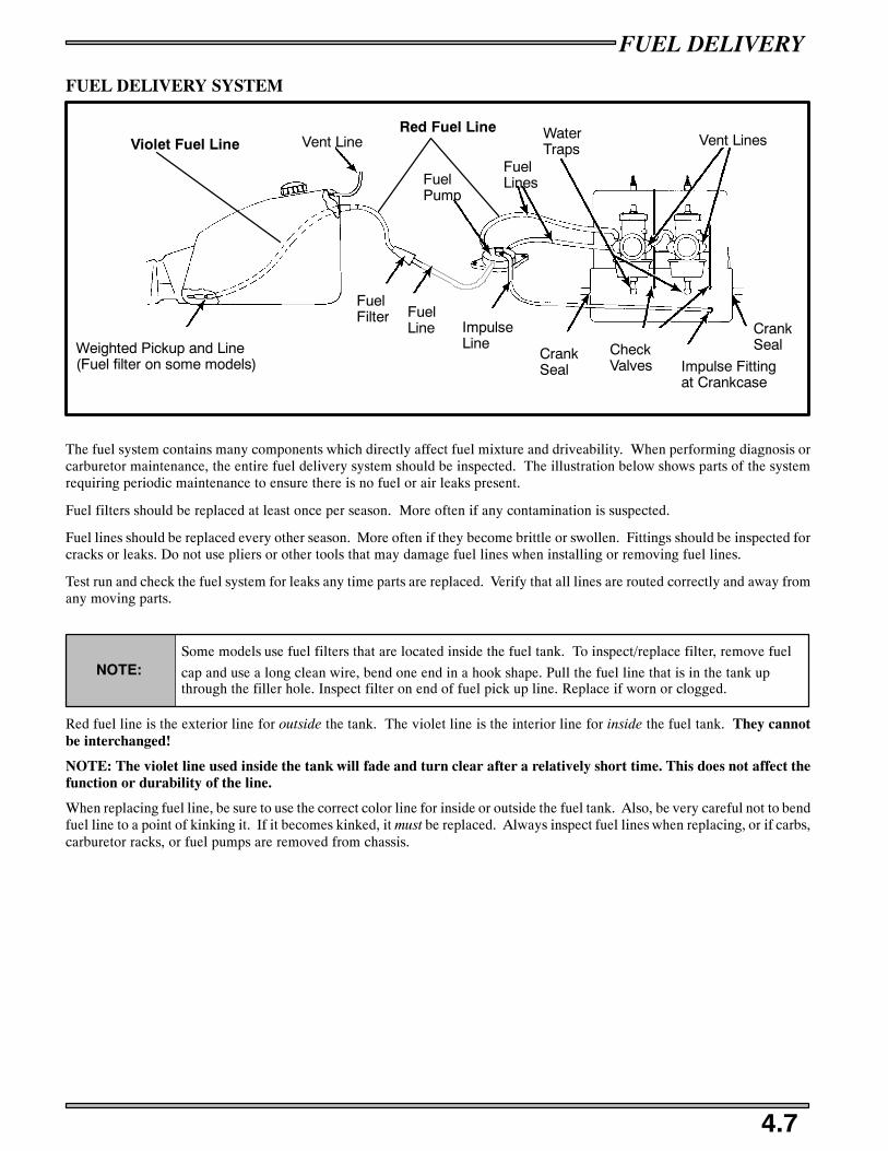
FUEL DELIVERY
4.7
FUEL DELIVERY SYSTEM
Weighted Pickup and Line(Fuel filter on some models)
Vent Line
FuelFilter Fuel
Line ImpulseLine
CrankSeal
CheckValves Impulse Fitting
at Crankcase
CrankSeal
Vent LinesWaterTraps
FuelLinesFuel
Pump
Violet Fuel LineRed Fuel Line
The fuel system contains many components which directly affect fuel mixture and driveability. When performing diagnosis orcarburetor maintenance, the entire fuel delivery system should be inspected. The illustration below shows parts of the systemrequiring periodic maintenance to ensure there is no fuel or air leaks present.
Fuel filters should be replaced at least once per season. More often if any contamination is suspected.
Fuel lines should be replaced every other season. More often if they become brittle or swollen. Fittings should be inspected forcracks or leaks. Do not use pliers or other tools that may damage fuel lines when installing or removing fuel lines.
Test run and check the fuel system for leaks any time parts are replaced. Verify that all lines are routed correctly and away fromany moving parts.
NOTE:Some models use fuel filters that are located inside the fuel tank. To inspect/replace filter, remove fuel
cap and use a long clean wire, bend one end in a hook shape. Pull the fuel line that is in the tank upthrough the filler hole. Inspect filter on end of fuel pick up line. Replace if worn or clogged.
Red fuel line is the exterior line for outside the tank. The violet line is the interior line for inside the fuel tank. They cannotbe interchanged!
NOTE: The violet line used inside the tank will fade and turn clear after a relatively short time. This does not affect thefunction or durability of the line.
When replacing fuel line, be sure to use the correct color line for inside or outside the fuel tank. Also, be very careful not to bendfuel line to a point of kinking it. If it becomes kinked, it must be replaced. Always inspect fuel lines when replacing, or if carbs,carburetor racks, or fuel pumps are removed from chassis.
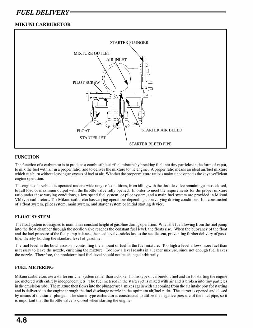
FUEL DELIVERY
4.8
MIKUNI CARBURETOR
PILOT SCREW
MIXTURE OUTLET
STARTER PLUNGER
AIR INLET
STARTER AIR BLEED
STARTER BLEED PIPE
STARTER JET
FLOAT
FUNCTION
The function of a carburetor is to produce a combustible air/fuel mixture by breaking fuel into tiny particles in the form of vapor,to mix the fuel with air in a proper ratio, and to deliver the mixture to the engine. A proper ratio means an ideal air/fuel mixturewhich can burn without leaving an excess of fuel or air. Whether the proper mixture ratio is maintained or not is the key to efficientengine operation.
The engine of a vehicle is operated under a wide range of conditions, from idling with the throttle valve remaining almost closed,to full load or maximum output with the throttle valve fully opened. In order to meet the requirements for the proper mixtureratio under these varying conditions, a low speed fuel system, or pilot system, and a main fuel system are provided in MikuniVM type carburetors. The Mikuni carburetor has varying operations depending upon varying driving conditions. It is constructedof a float system, pilot system, main system, and starter system or initial starting device.
FLOAT SYSTEM
The float system is designed to maintain a constant height of gasoline during operation. When the fuel flowing from the fuel pumpinto the float chamber through the needle valve reaches the constant fuel level, the floats rise. When the buoyancy of the floatand the fuel pressure of the fuel pump balance, the needle valve sticks fast to the needle seat, preventing further delivery of gaso-line, thereby holding the standard level of gasoline.
The fuel level in the bowl assists in controlling the amount of fuel in the fuel mixture. Too high a level allows more fuel thannecessary to leave the nozzle, enriching the mixture. Too low a level results in a leaner mixture, since not enough fuel leavesthe nozzle. Therefore, the predetermined fuel level should not be changed arbitrarily.
FUEL METERING
Mikuni carburetors use a starter enricher system rather than a choke. In this type of carburetor, fuel and air for starting the engineare metered with entirely independent jets. The fuel metered in the starter jet is mixed with air and is broken into tiny particlesin the emulsion tube. The mixture then flows into the plunger area, mixes again with air coming from the air intake port for startingand is delivered to the engine through the fuel discharge nozzle in the optimum air/fuel ratio. The starter is opened and closedby means of the starter plunger. The starter type carburetor is constructed to utilize the negative pressure of the inlet pipe, so itis important that the throttle valve is closed when starting the engine.

FUEL DELIVERY
4.9
MIKUNI CARBURETOR
THROTTLE VALVE
JET NEEDLE
BY--PASS HOLE
NEEDLE JET
PILOT JET
MAIN JET
VALVE SEAT
NEEDLE VALVE
PILOT AIR JET
MAIN JET
FUEL DELIVERY
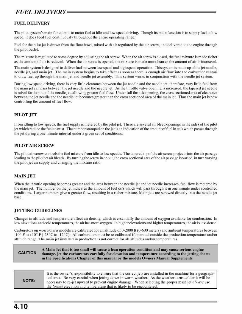
FUEL DELIVERY
4.10
FUEL DELIVERY
The pilot system’s main function is to meter fuel at idle and low speed driving. Though its main function is to supply fuel at lowspeed, it does feed fuel continuously throughout the entire operating range.
Fuel for the pilot jet is drawn from the float bowl, mixed with air regulated by the air screw, and delivered to the engine throughthe pilot outlet.
The mixture is regulated to some degree by adjusting the air screw. When the air screw is closed, the fuel mixture is made richeras the amount of air is reduced. When the air screw is opened, the mixture is made more lean as the amount of air is increased.
The main system is designed to deliver fuel between low speed and high speed operation. This system is made up of the jet needle,needle jet, and main jet. The main system begins to take effect as soon as there is enough air flow into the carburetor venturito draw fuel up through the main jet and needle jet assembly. This system works in conjunction with the needle jet system.
During low speed driving, there is very little clearance between the jet needle and the needle jet; therefore, very little fuel fromthe main jet can pass between the jet needle and the needle jet. As the throttle valve opening is increased, the tapered jet needleis raised farther out of the needle jet, allowing greater fuel flow. Under full throttle opening, the cross sectioned area of clearancebetween the jet needle and the needle jet becomes greater than the cross sectioned area of the main jet. Thus the main jet is nowcontrolling the amount of fuel flow.
PILOT JET
From idling to low speeds, the fuel supply is metered by the pilot jet. There are several air bleed openings in the sides of the pilotjet which reduce the fuel to mist. The number stamped on the jet is an indication of the amount of fuel in cc’s which passes throughthe jet during a one minute interval under a given set of conditions.
PILOT AIR SCREW
The pilot air screw controls the fuel mixture from idle to low speeds. The tapered tip of the air screw projects into the air passageleading to the pilot jet air bleeds. By turning the screw in or out, the cross sectional area of the air passage is varied, in turn varyingthe pilot jet air supply and changing the mixture ratio.
MAIN JET
When the throttle opening becomes greater and the area between the needle jet and jet needle increases, fuel flow is metered bythe main jet. The number on the jet indicates the amount of fuel cc’s which will pass through it in one minute under controlledconditions. Larger numbers give a greater flow, resulting in a richer mixture. Main jets are screwed directly into the needle jetbase.
JETTING GUIDELINES
Changes in altitude and temperature affect air density, which is essentially the amount of oxygen available for combustion. Inlow elevations and cold temperatures, the air has more oxygen. In higher elevations and higher temperatures, the air is less dense.
Carburetors on most Polaris models are calibrated for an altitude of 0-2000 ft (0-600 meters) and ambient temperatures between-10_ F to +10_ F (-23_C to -12_C). All carburetors must be re-calibrated if operated outside the production temperature and/oraltitude range. The main jet installed in production is not correct for all altitudes and/or temperatures.
A Main Jet that is too small will cause a lean operation condition and may cause serious enginedamage. jet the carburetors carefully for elevation and temperature according to the jetting chartsin the Specifications Chapter of this manual or the models Owners Manual Supplements
CAUTION
NOTE:
It is the owner’s responsibility to ensure that the correct jets are installed in the machine for a geograph-ical area. Be very careful when jetting down in warm weather. As the weather turns colder it will benecessary to re-jet upward to prevent engine damage. When selecting the proper main jet always usethe lowest elevation and temperature that is likely to be encountered.
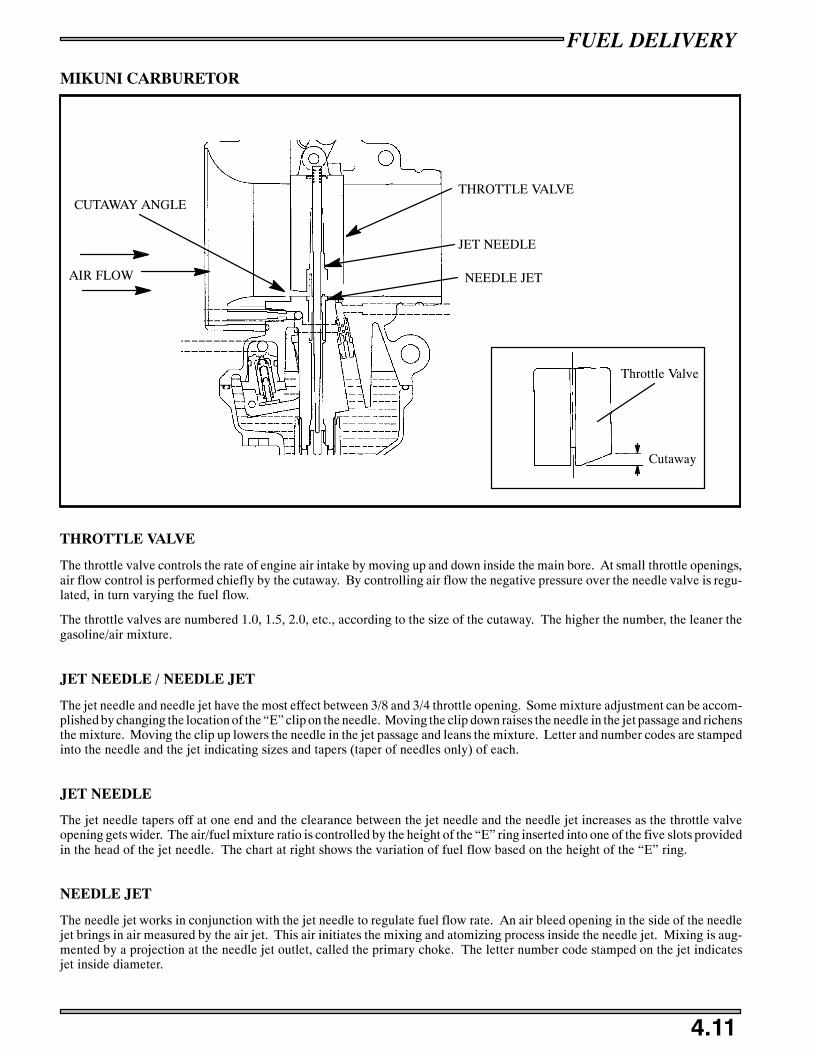
FUEL DELIVERY
4.11
MIKUNI CARBURETOR
CUTAWAY ANGLETHROTTLE VALVE
JET NEEDLE
AIR FLOW
Cutaway
Throttle Valve
NEEDLE JET
THROTTLE VALVE
The throttle valve controls the rate of engine air intake by moving up and down inside the main bore. At small throttle openings,air flow control is performed chiefly by the cutaway. By controlling air flow the negative pressure over the needle valve is regu-lated, in turn varying the fuel flow.
The throttle valves are numbered 1.0, 1.5, 2.0, etc., according to the size of the cutaway. The higher the number, the leaner thegasoline/air mixture.
JET NEEDLE / NEEDLE JET
The jet needle and needle jet have the most effect between 3/8 and 3/4 throttle opening. Some mixture adjustment can be accom-plished by changing the location of the “E” clip on the needle. Moving the clip down raises the needle in the jet passage and richensthe mixture. Moving the clip up lowers the needle in the jet passage and leans the mixture. Letter and number codes are stampedinto the needle and the jet indicating sizes and tapers (taper of needles only) of each.
JET NEEDLE
The jet needle tapers off at one end and the clearance between the jet needle and the needle jet increases as the throttle valveopening gets wider. The air/fuel mixture ratio is controlled by the height of the “E” ring inserted into one of the five slots providedin the head of the jet needle. The chart at right shows the variation of fuel flow based on the height of the “E” ring.
NEEDLE JET
The needle jet works in conjunction with the jet needle to regulate fuel flow rate. An air bleed opening in the side of the needlejet brings in air measured by the air jet. This air initiates the mixing and atomizing process inside the needle jet. Mixing is aug-mented by a projection at the needle jet outlet, called the primary choke. The letter number code stamped on the jet indicatesjet inside diameter.

FUEL DELIVERY
4.12
THROTTLE OPENING VS. FUEL FLOW
234
4
3
2
15 50 75 100%Throttle Valve Opening
SmallClearance
MediumClearance
LargeClearance
ClosedThrottle
One-halfThrottle
FullThrottle
INC
RE
AS
ING
DE
CR
EA
SIN
G
THROTTLE OPENING - TYPICAL MIKUNI VM
Throttle Valve Cut-AwayJet Needle/Needle Jet
In a full throttle condition the cross sectioned area between the jet needle and the needle jet is larger than the cross sectioned areaof the main jet. The main jet therefore has greater control over fuel flow.

FUEL DELIVERY
4.13
MIKUNI TM CARBURETOR SERVICE
Wear eye protection when using compressed air or cleaning solvents. Review all fuel system warn-ings found on page 4.1 before proceeding.CAUTION
DISASSEMBLY
1. Remove the carburetor from the engine before disassembling.Clean the outside of the carburetor thoroughly with solvent. Donot use compressed air to dry at this time. The float chambercould become pressurized resulting in damage to the floats orinlet needle and seat.
2. Remove the top caps.
3. Rotate the needle keeper far enough to remove the needle andc--clip assembly from the slide.
4. Remove the four screws on the funnel face.
5. Turn throttle shaft so slide opens all the way. You may have toturn out slide stop screw for the slide to move farther up thebody.
6. With slide fully open, pull funnel out from the bottom first.
7. Check for wear on the face of the slides, and also check theneedle for wear.

Trap/Drain Plug
Float BowlScrew
FUEL DELIVERY
4.14
8. Remove and inspect E-rings, packing, plate, spring, and ringsconnecting slide to lever if needed.
9. Remove water trap/drain plug (17 mm) and single screw onbottom of carburetor.
10. Remove the float bowl.
NOTE:Float body will not come off unless the watertrap/drain plug, is not removed.
11. Remove the two screws holding the float/needle and seatassembly in position and then remove this assembly.
12. Inspect the contents for wear and debris.
13. Remove the main jet and starter jet and clean out. Look for anydebris.
14. Clean out all passages in carburetor body with carburetorcleaner. Dry all passages and jets with compressed air.
15. Replace gaskets and any parts that show wear or damage.
Top Cap
Gasket
Cap
GuideHolder
Spring
Plunger
Piston ValveJet Needle
PlateLever
Ring
AdjustmentScrew
Plate
Spring
PackingE-Ring
Ring
Starter Jet
Main Jet

FUEL DELIVERY
4.15
MIKUNI TM CARBURETOR SERVICE
ASSEMBLY
1. Install the pilot jet, main jet and starter jets.
2. Install float/needle & seat assembly.
3. Place carburetor in an inverted position.
4. Connect pressure tester PN 2870975 to fuel inlet fitting. Apply5 psi pressure and observe for one minute. The needle and seatshould hold pressure indefinitely. If the pressure drops,carefully inspect the needle and the needle seat. The needle canbe replaced (needle comes with float and seat).
5. Carefully inspect float bowl gasket and replace if necessary.Install float bowl on carburetor.
6. Install float body.
7. Install air adjusting screw.
8. Install throttle slide.
9. Install jet needle.
10. Install funnel.
11. Install carburetors in snowmobile.
12. Synchronize the carburetors as outlined on page 4.16.
13. Replace top caps.

FUEL DELIVERY
4.16
MIKUNI TM CARBURETOR THROTTLE SYNCHRONIZATION
Mikuni TM style carburetors are synchronized at wide open throttle without the engine running. The MAG side carburetor isthe adjusting carburetor, the PTO side carburetor have a non-adjustable set screw on the throttle shaft. This carburetor is whatthe other carburetor is synchronized to and is considered the base carburetor.
1. Remove the air box.
2. Remove the tops on both carburetors.
3. On the base carburetor hold the throttle at wide open throttle andview the position of the carburetor slides. The slides should beflush with the top of the carburetor intake area.
4. If they are not flush with the top, hold the base carburetorthrottle wide open and turn the slide stop screw until slide isflush with the top.
5. On the other carburetor, loosen the Phillips head screw insidethe offset nut.
6. When screw is loose, hold throttle to wide open. Turn offset nutclockwise to raise or counterclockwise to lower,until throttleslide is in same position as base carburetor.
7. Tighten phillips head screw.
8. Replace top caps.
Flush

FUEL DELIVERY
4.17
CHOKE ADJUSTMENTS
Off
Half On
Full On
Choke Toggle Positions 1/8-1/4, (.3-.6 cm)Freeplay
A
B
With the dash mounted choke control toggle flipped to the off position, the choke plunger must be seated on the fuel passage wayin the carburetor. If the plunger is not seated on the passage way, the engine will flood or run too rich, causing plug fouling andvery poor engine performance.
If cable slack is too great there will be excessive toggle free play resulting in hard starting. Also, the half on position used forintermittent applications will not function.
If the choke lever assembly becomes damaged, a lever kit is available. This allows replacement of the lever assembly rather thanthe entire cable assembly. Installation instructions are included with the kit.
ADJUSTMENT PROCEDURE
1. Flip choke toggle to the full off position.
2. Loosen adjustment locknut (A) on carburetor(s).
3. Turn cable sleeve adjusting nut (B) clockwise on carburetor(s) until 1/4, (.6 cm) or more choke toggle free play is evident.
4. Turn cable sleeve adjusting nut counterclockwise on one carburetor until toggle has zero free play, then rotate it clockwiseuntil 1/8,-1/4, (.3-.6 cm) toggle free play is evident.
5. Tighten adjustment locknut (A).
6. For VM carburetors, repeat steps 4 and 5 for remaining carburetor(s).

FUEL DELIVERY
4.18
Altitude Compensating Carburetor System (ACCS)
The Altitude Compensating Carburetor System (ACCS) is designed to automatically compensate for changes in alti-tude. This allows the snowmobile to operate in changing elevations without having to change jets, although extremetemperatures may require re-jetting for optimum performance. Refer to the jetting compensation chart in the specifica-tions sections.
A vacuum line is connected to the float bowl. TheACCS valve is connected to this line via the 4-waymanifold. At low altitude the ACCS valve suppliesatmospheric pressure to the vacuum line and thefloat bowl (see Ill. 1).
At high altitudes the bellows expand, moving theplunger to the left and closing off some of the pas-sageways through the ACCS valve (see Ill. 2). Thisprevents atmospheric pressure from reaching thefloat bowl, allowing the vacuum line to reduce thepressure in the float bowl. This reduces the amountof fuel supplied through the carburetor, preventingthe mixture from becoming too rich.
NOTE: The ACCS valve is calibrated specifically forthe model it was intended. There are no adjust-ments for the valve, and it should not be tamperedwith in any way.
Vacuum fromVenturi
To Float Bowls
SealedBellows
High Altitude / LowAtmospheric Pressure
Thisendfixed
Plunger
Low Atmospheric Pressure-D Bellows expandD Fuel flow decreases
Vacuum fromVenturi To Float Bowls
Thisendfixed
Plunger SealedBellows
Low Altitude / HighAtmospheric Pressure
High Atmospheric Pressure-D Bellows compressD Fuel flow increases
Ill. 1
Ill. 2
ACCS System
ACCS System

FUEL DELIVERY
4.19
FUEL PUMP
The fuel pumps (340/550 style shown). The differences are in the size and location of thepumps. Pumps may be mounted to the engine, air/oil box or to the chassis.
In the two cycle engine, the pressure in the crankcase changes with the up and down stroke ofthe piston. The amplitudes of pressure vary according to the RPM and degree of throttle open-ing. Whether idling or at full throttle, the pressure built up in the crankcase has enough ampli-tude to operate the pump.
When the piston is on the upstroke, crankcase pressure in that cylinder becomes less positive.The diaphragm in the fuel pump moves toward the engine, causing a negative pressure or suc-tion in the pump chamber. This causes the inlet valve from the fuel supply to open and permitsfuel to enter the chamber. This same suction causes the outlet valve (to the carburetor) to closeso that fuel cannot return form the carburetor.
When the piston begins its downward stroke, the pressure from the crankcase becomes positive,causing the fuel pump diaphragm to move in the opposite direction and reversing the pressurein the fuel pump chamber. This causes the inlet valve in the pump to close and the outlet valveto open, filling the float bowl in the carburetor. When the float level in the carburetor reachesits standard level, the needle valve will close, preventing more fuel from entering the carbure-tor, even though the fuel pump continues to try to provide the carburetor with fuel.
MAINTENANCE
The impulse operated diaphragm fuel pump does not require any specific scheduled mainte-nance. However, the following procedures should be observed.
OPERATION
S The pump may be checked for operation by removing the fuel supply line from thecarburetor and placing it into a container. With the engine idling at approximately2000 RPM, a steady flow of fuel should be visible.
CLEANING
S The pump and impulse line must be disassembled and cleaned of foreign materialin the event of piston or other internal engine part failures which produce fragments.
INSPECTION
S Disconnect impulse line from pump. Connect Mity Vac to impulse fitting (or line)and apply 4-6 PSI pressure. Diaphragm should hold pressure indefinitely.
S The diaphragms and check valves must be carefully examined for cracks, holes, or other
damage. If in doubt as to the condition of any internal parts, replace all diaphragms, checkvalves, and gaskets.
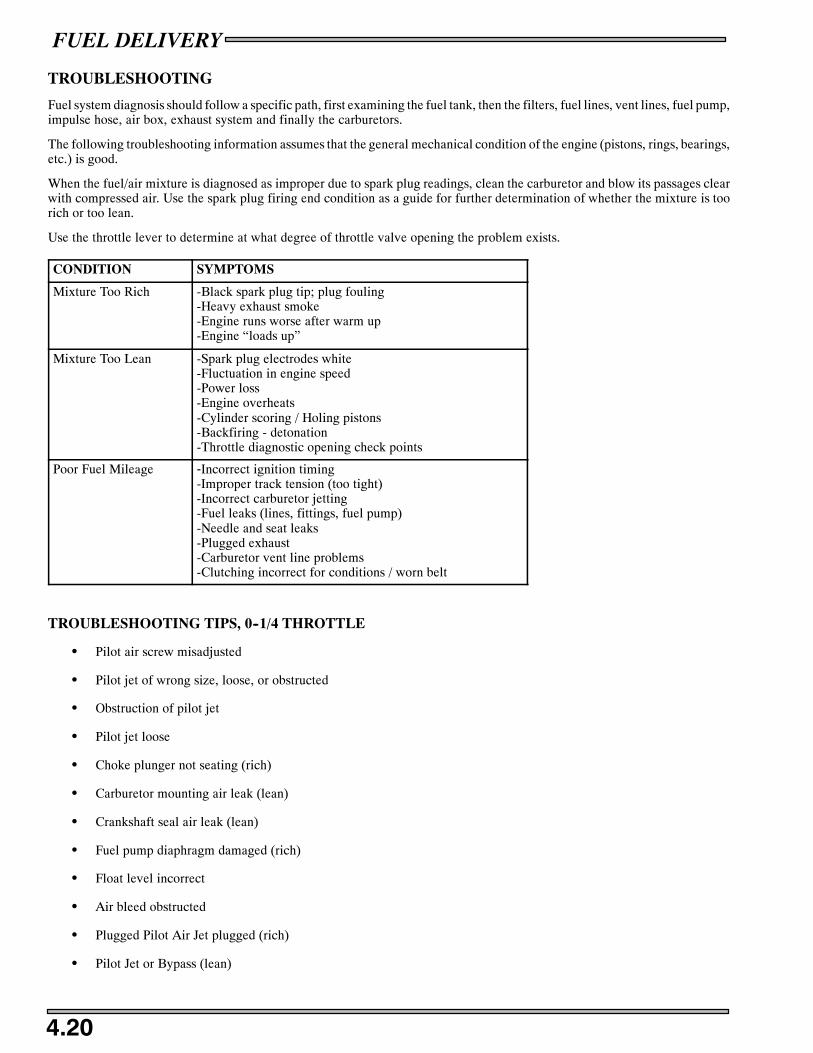
FUEL DELIVERY
4.20
TROUBLESHOOTING
Fuel system diagnosis should follow a specific path, first examining the fuel tank, then the filters, fuel lines, vent lines, fuel pump,impulse hose, air box, exhaust system and finally the carburetors.
The following troubleshooting information assumes that the general mechanical condition of the engine (pistons, rings, bearings,etc.) is good.
When the fuel/air mixture is diagnosed as improper due to spark plug readings, clean the carburetor and blow its passages clearwith compressed air. Use the spark plug firing end condition as a guide for further determination of whether the mixture is toorich or too lean.
Use the throttle lever to determine at what degree of throttle valve opening the problem exists.
CONDITION SYMPTOMS
Mixture Too Rich -Black spark plug tip; plug fouling-Heavy exhaust smoke-Engine runs worse after warm up-Engine “loads up”
Mixture Too Lean -Spark plug electrodes white-Fluctuation in engine speed-Power loss-Engine overheats-Cylinder scoring / Holing pistons-Backfiring - detonation-Throttle diagnostic opening check points
Poor Fuel Mileage -Incorrect ignition timing-Improper track tension (too tight)-Incorrect carburetor jetting-Fuel leaks (lines, fittings, fuel pump)-Needle and seat leaks-Plugged exhaust-Carburetor vent line problems-Clutching incorrect for conditions / worn belt
TROUBLESHOOTING TIPS, 0--1/4 THROTTLE
S Pilot air screw misadjusted
S Pilot jet of wrong size, loose, or obstructed
S Obstruction of pilot jet
S Pilot jet loose
S Choke plunger not seating (rich)
S Carburetor mounting air leak (lean)
S Crankshaft seal air leak (lean)
S Fuel pump diaphragm damaged (rich)
S Float level incorrect
S Air bleed obstructed
S Plugged Pilot Air Jet plugged (rich)
S Pilot Jet or Bypass (lean)

FUEL DELIVERY
4.21
TROUBLESHOOTING TIPS, 1/4-3/8 THROTTLE:
S Obstruction in main jet or needle jet
S Jet needle worn or out of adjustment
S Pilot system malfunction
S Incorrect throttle valve cutaway
TROUBLESHOOTING TIPS, 3/8-3/4 THROTTLE:
S Main jet incorrect size or clogged (lean)
S Needle jet damaged or loose
S Needle jet/jet needle worn (rich)
S E-clip position incorrect for altitude and temperature
TROUBLESHOOTING TIPS, FULL THROTTLE:
S Main jet size (rich or lean)
S Fuel filter blocked (lean)
S Fuel vent lines or check valves plugged
S Exhaust system plugged
S Air box restricted
S Fuel pump weak
S Exhaust leaking into engine compartment (rich)
S Water in float bowl (lean)

FUEL DELIVERY
4.22
900 LIBERTY FUEL RAIL BLEEDING
A
B
C
D
DANGERGasoline is extremely flammable and is explosive under certain conditions.
Work in a well ventilated area. Open flames, sparks and cigarettes must be kept away fromgasoline.
FUEL RAIL BLEEDING
The fuel pressure gauge (PN PV--43506--A) is used to check the pressure in the fuel rail lines or to bleed the fuel rail pressurefrom the fuel rail. You will need to bleed off the fuel pressure if any service is needed to the fuel system or if engine is to be re-moved.
Attach the gauge to the Schrader valve (C), between the line that comes from the tank (A) and the line that goes to the fuel injectors(B). Once the gauge is onto the Schrader valve the pressure gauge will indicate the pressure in the fuel rail. To bleed the pressure
form the fuel rail you can turn the bleeder valve on the gauge and bleed the system. Now the fuel rail is ready for service.
FUEL RAIL REMOVAL
Remove engine, see page 5.25
1. Remove the four fuel rail screws (D).
2. Carefully remove the fuel rail, replace injectors.
FUEL RAIL INSTALLATION
1. Carefully place the fuel rail with injectors on to the engine.
2. Torque the four fuel rail screws (D) to 91--125 in.lbs.

FUEL DELIVERY
4.23
900 FUEL PUMP
Regulator
Pump
Fuel PickupsFloat
CONNECTOR
FUEL PUMP: Located inside tank. Provides system with fuel at 4bar (58psi) pressure. If the fuel pump is suspect to be defectiveapply 12 VDC to the fuel pump prime (see page 13.44) and check for audible fuel pump operation as well as fuel rail pressure.The fuel pump should sound when pumping and the pressure should show 4 bar.
This fuel pump is non--serviceable and can not be replaced. If fuel pump fails you will need to replace the whole fuel tank assem-bly.
The #1 wire is the red wire that provides power from the regulator.
The #2 wire is the Violet/White wire that provides the fuel level signal to the gauge.
The #3 wire is the Brown wire that provides a ground to the chassis for the fuel pump.
The #4 wire is a Brown wire that provides a ground for the fuel level signal.

FUEL DELIVERY
4.24
TPS CHECKING PROCEDURE
If you are replacing or setting the baseline for the TPS these steps will need to be followed in order to ensure proper operation.
ELECTRICAL CHECK
1. Disconnect the TPS sensor.
2. Install the TPS tester kit PN 2201519.
3. Verify that the wires are connected correctly or faulty readings will result.
4. Verify that the 9 Volt battery is good by inserting the BLACK volt meter probe into the terminal above the black wire on theTPS tool. Place the RED probe from your meter into the terminal above the pink wire on the TPS tool. Turn the meter to theVDC scale. the voltage should read 4.99 -- 5.01 VDC. If not try a known good 9 volt battery.
5. Set your multi--meter to VDC.
6. Hook the TPS tool to the TPS.
7. Measure and record the voltage reading at idle.
8. The indicated voltage should read .920 -- .940 VDC. If it is, the TPS sensor is set correctly and should not need to be adjusted.Continue to step 18.
9. Remove the throttle cable from the throttle body.
10. Loosen the lock nut on the idle set screw and back off the idle set screw until it separates from the lever tab.
11. The voltage reading should be .709 -- .711 VDC. If your voltage reading at this point is not .709 -- .711 VDC, loosen up the TPSsensor screws and rotate the TPS sensor until you get a .709 -- .712 VDC reading.
12. When you tighten the TPS screws your voltage reading may change. The TPS voltage reading will have to be correct when thescrews are at the torqued setting.
13. If you can not obtain any of these voltage measurements go to page 4.26 and reset the throttle body base line.
14. Thread in the idle set screw clockwise until you get a voltage reading of .920 -- .940 VDC. Now lock the lock nut.
15. When you tighten the lock your voltage reading may change. The TPS voltage reading will have to be correct when the locknut is at the torqued setting.
16. The TPS is now set.
17. Remove the TPS tool and replace the TPS connector to the TPS sensor.
18. Test run the engine. If engine issues persist go to step 10.
19. If you test the engine after setting both voltage readings and issues still are present, re--set the throttle body base line on page4.26
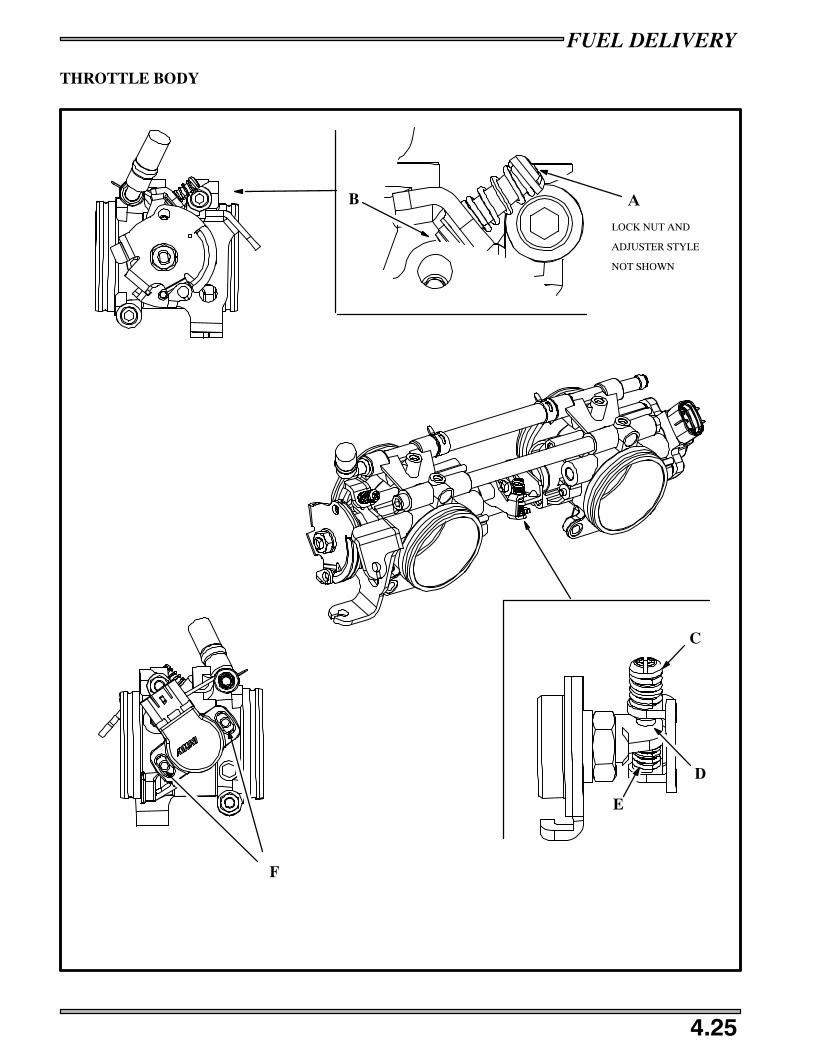
FUEL DELIVERY
4.25
THROTTLE BODY
AB
C
D
E
F
LOCK NUT AND
ADJUSTER STYLE
NOT SHOWN

FUEL DELIVERY
4.26
TPS BASELINE RE--SETTING PROCEDURE
The TPS comes set from the factory and should not need any adjustments. If replacing a TPS or resetting the TPS, Polaris hasdeveloped a TPS test kit for aid in setting the Throttle Position Sensor to specification.
1. Assemble your TPS sensor tool (PN 2201519) as per the instructions that came with the tool.2. Make sure your 9 volt battery is in good condition by inserting the black volt meter probe from your Fluketmeter in the black
terminal and the red probe into the pink terminal. Voltage should read 4.99 to 5.01 volts. If not, try a new 9 volt battery.3. Insert the red voltmeter lead into the terminal above the pink wire, and the black meter lead to the terminal above the black
wire. Slowly open throttle and check for smooth voltage change.
NOTE: The Fluke meter will change scales and show O.L. momentarily when throttle is opening.
4. Remove the throttle cable in order to take the slack out of the cable.
5. Back off the idle lock nut counterclockwise and then back out the idle adjuster (A) counterclockwise until the screw tip (B)separates from the adjusted lever tab.
6. Turn the synchronization screw (C) counterclockwise until the synchronization lever is touching the synchronization screwhole (D) tab.
7. Remove the connector from the TPS on the throttle body and install TPS sensor tool on to the TPS.8. Place a shop towel under the throttle body incase you loose grip on the spring or thread a small wire around it if it should fall.9. Remove the synchronization lever tab spring (E) and gently open and then close the throttle plates with the throttle, allowing
the plate to close gently. Note the voltage at this point.10. Insert the synchronization lever tab spring and screw.11. Turn the synchronization screw clockwise until the volt meter reads the voltage level that you noted in step #8.12. Loosen screws on the TPS sensor (F).13. Adjust the TPS sensor until the voltage on the volt meter reads .705 -- .715 volts.14. Tighten the TPS retaining screws, making sure that the voltage continues to read .705 -- .715 volts.15. Turn the idle set screw clockwise until the voltage reads .930 volts.16. Voltage at the yellow terminal should be .920 -- .940 volts at idle. Once the TPS voltage is verified and set, remove the sensor
tool and re--install the TPS harness.
IQ FUSION/RMK THROTTLE POSITION SENSOR (TPS)
0.92 -- 0.94 VDC @ Idle
R/W (from ECU)
Lite Blue
BLK/BL
NOTE: The 900 Libertyt engine TPS is set at .92 -- .94 volts at idle.
When the sensor is inoperative or disconnected the system will switch to a “LIMP HOME” mode. Limp Home mode reducesperformance to a default value and monitors other sensors.

FUEL DELIVERY
4.27
INJECTORS
MAG FULL LOAD INJECTOR: Provide calibrated amount of fuel to the MAG side of the crankcase.
PTO FULL LOAD INJECTOR: Provide calibrated amount of fuel to the PTO side of the crankcase.
MAG INJECTOR
Red / Blue Injector Power 14 VDC through ECU
Yellow ECU Injector Ground Circuit Switched to Ground
PTO INJECTOR
Red / Blue Injector Power 14 VDC through ECU
Green ECU Injector Ground Circuit Switched to Ground
Injectors are color coded and matched to the ECU. If replacement is necessary the injector color that is in the unit will have tobe replaced with the same color.
REPLACEMENT
Handle the injector with extreme care when handling injector(s). The injector(s) should be visually inspected before installation.If a injector is damaged it should not be used.
If injector replacement is verified through Digital Wrench, you will need to find what color injector is needed by looking at thetop of the ECU.
The top of the ECU will have a color coded decal that indicates what color injectors are used.
Order the same color part number injector and replace injector.
IMPORTANT: If replacing an injector do not drop the injector or damage to the injector tip may occur. Damage to the injectortip will cause a lean condition on the cylinder that the damaged injector is installed on. This will cause poor running quality andpossible engine damage.

FUEL DELIVERY
4.28
NOTES
Engine Torque Specifications 5.1. . . . . . . . . . . . . . . . . . . . . . . . . . . . .
550 Torque Patterns 5.2. . . . . . . . . . . . . . . . . . . . . . . . . . . . . . . . . . . . .500/600 Torque Patterns 5.3. . . . . . . . . . . . . . . . . . . . . . . . . . . . . . . . .
700/800 Torque Patterns 5.4. . . . . . . . . . . . . . . . . . . . . . . . . . . . . . . . .
900 Liberty Torque Patterns 5.5. . . . . . . . . . . . . . . . . . . . . . . . . . . . . .
Typical Engine Removal 5.6. . . . . . . . . . . . . . . . . . . . . . . . . . . . . . . . .
550 Engine Disassembly/Assembly 5.8 -- 5.10. . . . . . . . . . . . . . . . . . . . . . . . .500/600 Recoil/Stator Removal / Installation 5.12 -- 5.13. . . . . . . . . . . . . . . . .
500/600 Engine Disassembly / Assembly 5.14 -- 5.16. . . . . . . . . . . . . . . . . . . .
500/600 Oil Pump / Water Pump Disassembly / Assembly 5.18 -- 5.19. . . . . .
700/800 Recoil/Stator Removal / Installation 5.20 -- 5.21. . . . . . . . . . . . . . . . .
700/800 Engine Disassembly / Assembly 5.22 -- 5.23. . . . . . . . . . . . . . . . . . . .900 Engine Removal 5.24 -- 5.25. . . . . . . . . . . . . . . . . . . . . . . . . . . . . . . . . . . .
900 Recoil/Stator Removal / Installation 5.26. . . . . . . . . . . . . . . . . . . . .
900 Engine Disassembly / Assembly 5.28 -- 5.29. . . . . . . . . . . . . . . . . . . . . . . .
900 Oil Pump / Water Pump Disassembly / Assembly 5.30. . . . . . . . . .
Reed Valves 5.31. . . . . . . . . . . . . . . . . . . . . . . . . . . . . . . . . . . . . . . . . . .
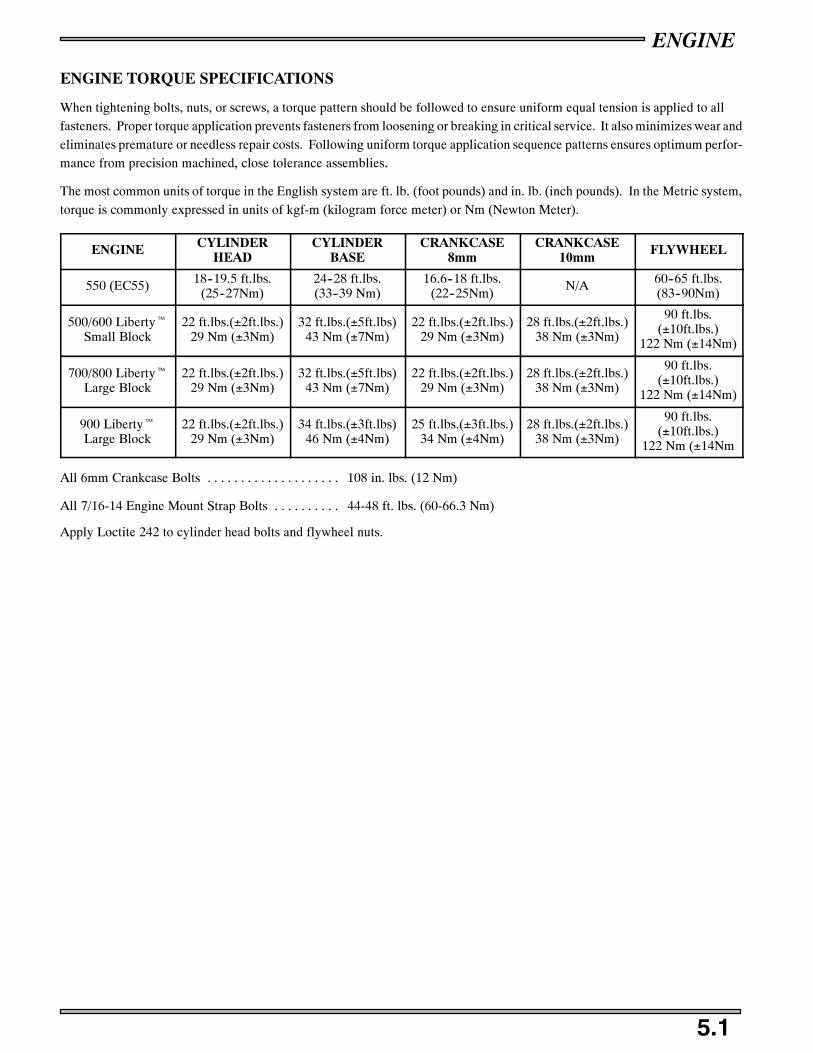
ENGINE
5.1
ENGINE TORQUE SPECIFICATIONS
When tightening bolts, nuts, or screws, a torque pattern should be followed to ensure uniform equal tension is applied to allfasteners. Proper torque application prevents fasteners from loosening or breaking in critical service. It also minimizes wear andeliminates premature or needless repair costs. Following uniform torque application sequence patterns ensures optimum perfor-mance from precision machined, close tolerance assemblies.
The most common units of torque in the English system are ft. lb. (foot pounds) and in. lb. (inch pounds). In the Metric system,torque is commonly expressed in units of kgf-m (kilogram force meter) or Nm (Newton Meter).
ENGINE CYLINDERHEAD
CYLINDERBASE
CRANKCASE8mm
CRANKCASE10mm FLYWHEEL
550 (EC55) 18--19.5 ft.lbs.(25--27Nm)
24--28 ft.lbs.(33--39 Nm)
16.6--18 ft.lbs.(22--25Nm)
N/A 60--65 ft.lbs.(83--90Nm)
500/600 LibertytSmall Block
22 ft.lbs.(±2ft.lbs.)29 Nm (±3Nm)
32 ft.lbs.(±5ft.lbs)43 Nm (±7Nm)
22 ft.lbs.(±2ft.lbs.)29 Nm (±3Nm)
28 ft.lbs.(±2ft.lbs.)38 Nm (±3Nm)
90 ft.lbs.(±10ft.lbs.)
122 Nm (±14Nm)
700/800 LibertytLarge Block
22 ft.lbs.(±2ft.lbs.)29 Nm (±3Nm)
32 ft.lbs.(±5ft.lbs)43 Nm (±7Nm)
22 ft.lbs.(±2ft.lbs.)29 Nm (±3Nm)
28 ft.lbs.(±2ft.lbs.)38 Nm (±3Nm)
90 ft.lbs.(±10ft.lbs.)
122 Nm (±14Nm)
900 LibertytLarge Block
22 ft.lbs.(±2ft.lbs.)29 Nm (±3Nm)
34 ft.lbs.(±3ft.lbs)46 Nm (±4Nm)
25 ft.lbs.(±3ft.lbs.)34 Nm (±4Nm)
28 ft.lbs.(±2ft.lbs.)38 Nm (±3Nm)
90 ft.lbs.(±10ft.lbs.)
122 Nm (±14Nm
All 6mm Crankcase Bolts 108 in. lbs. (12 Nm). . . . . . . . . . . . . . . . . . . .
All 7/16-14 Engine Mount Strap Bolts 44-48 ft. lbs. (60-66.3 Nm). . . . . . . . . .
Apply Loctite 242 to cylinder head bolts and flywheel nuts.

ENGINE
5.2
FUJI TORQUE PATTERNS
3
1
6
4
2
5
CYLINDER HEAD -6 STUD
CYLINDERHEAD - 4 STUD
3 2
41
9
5
1 3
7
11
10
6
24
8
12
CRANKCASE - TWIN CYLINDER - Fuji
3 2
41
CYLINDERBASE
MAGSIDE
PTOSIDE
EC 55

ENGINE
5.3
500/600 LIBERTYT TORQUE PATTERNS

ENGINE
5.4
700/800 LIBERTYT TORQUE PATTERNS

ENGINE
5.5
900 LIBERTYT TORQUE PATTERNS
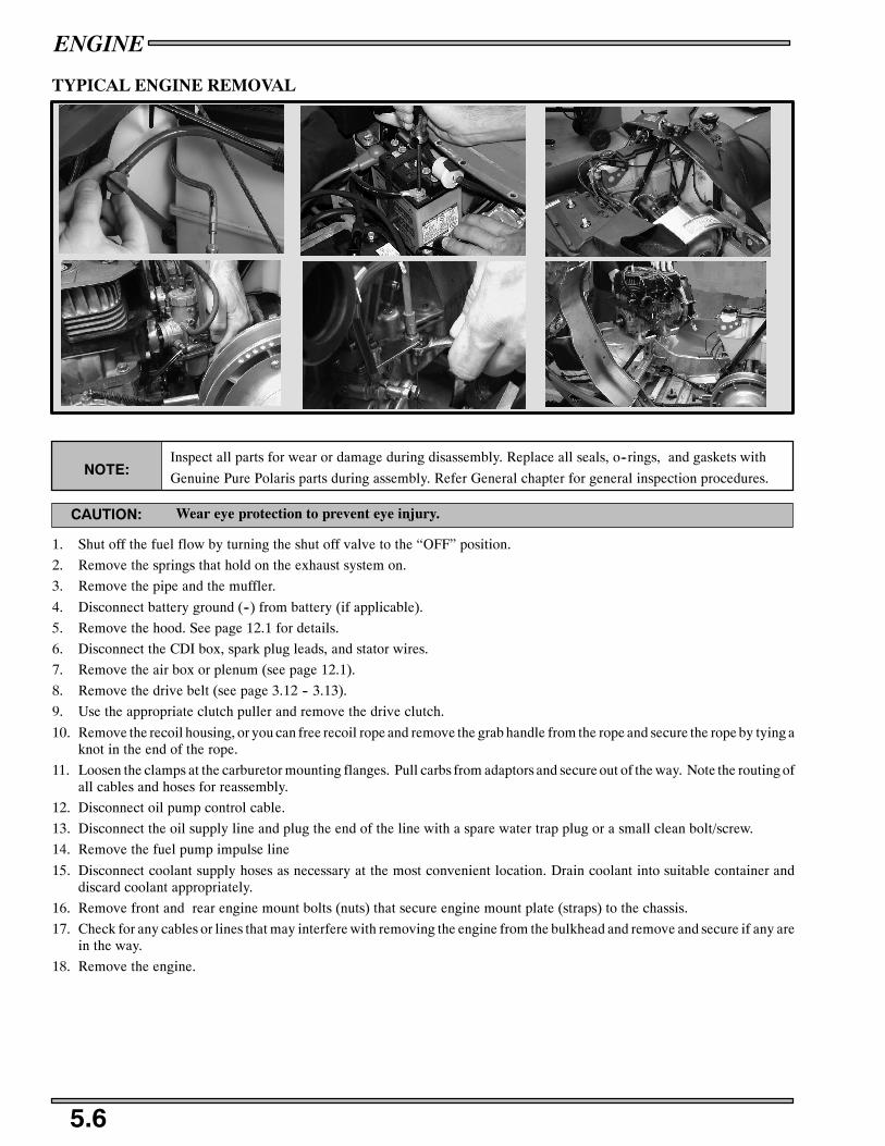
ENGINE
5.6
TYPICAL ENGINE REMOVAL
NOTE:Inspect all parts for wear or damage during disassembly. Replace all seals, o--rings, and gaskets with
Genuine Pure Polaris parts during assembly. Refer General chapter for general inspection procedures.
Wear eye protection to prevent eye injury.CAUTION:
1. Shut off the fuel flow by turning the shut off valve to the “OFF” position.
2. Remove the springs that hold on the exhaust system on.
3. Remove the pipe and the muffler.
4. Disconnect battery ground (--) from battery (if applicable).
5. Remove the hood. See page 12.1 for details.
6. Disconnect the CDI box, spark plug leads, and stator wires.
7. Remove the air box or plenum (see page 12.1).
8. Remove the drive belt (see page 3.12 -- 3.13).
9. Use the appropriate clutch puller and remove the drive clutch.
10. Remove the recoil housing, or you can free recoil rope and remove the grab handle from the rope and secure the rope by tying aknot in the end of the rope.
11. Loosen the clamps at the carburetor mounting flanges. Pull carbs from adaptors and secure out of the way. Note the routing ofall cables and hoses for reassembly.
12. Disconnect oil pump control cable.
13. Disconnect the oil supply line and plug the end of the line with a spare water trap plug or a small clean bolt/screw.
14. Remove the fuel pump impulse line
15. Disconnect coolant supply hoses as necessary at the most convenient location. Drain coolant into suitable container anddiscard coolant appropriately.
16. Remove front and rear engine mount bolts (nuts) that secure engine mount plate (straps) to the chassis.
17. Check for any cables or lines that may interfere with removing the engine from the bulkhead and remove and secure if any arein the way.
18. Remove the engine.

ENGINE
5.7
NOTES

ENGINE
5.8
EC 34 / 55 ENGINE
J
K
L
M
D
C
G
F
E
H
I
P
S
O
NA
B
R
T
P
8mm
G(340)17,22
G(550)24,33
G(340)17,22
G(550)24,33
10mm
G(340)23,32
G 18,25

ENGINE
5.9
EC 55 ENGINE DISASSEMBLY
NOTE:Inspect all parts for wear or damage surring disassembly. Replace all seals, o--rings, and gaskets with
Genuine Pure Polaris parts during assembly. Refer to the General chapter for general inspection pro-ceedures.
Wear eye protection to prevent eye injury.CAUTION:
1. Disconnect the coil pack from the recoil cover and the wiring harness.
2. Loosen carburetor clamps (A) and remove the carburetors from the mounting boots (B).
3. Remove the oil lines from the carburetors. For assembly pourpouses note where the lines are routed.
4. Remove the carburetor mounting boots (B) from the cylinders.
5. Remove both the cylinder head and the exhaust side fan shrouds (C) from the engine assembly.
6. After removing the fan shrouds, take note of the vibration dampener, (D) located between the cylinders on the intake side.
7. Remove the CDI from the flywheel shroud.
8. Remove the flywheel cover (E).
9. Recoil the recoil basket (F).
10. Hold the flywheel with the flywheel holding wrench PN 8700229 and remove the flywheel nut and washer.
11. Using a flywheel puller (PN 2871043), remove the flywheel from the engine. Do not install puller bolts more than 5/16,(7mm) into flywheel threads or stator damage may result.
12. Remove the flywheel and woodruff key.
13. Remove the stator plate (G). You should be able to carefully remove the stator plate with out removing the stator itself. Keeptrack of the locating dowels and where they match up with the crankcase.
14. Remove the oil pump. Note the o--ring (H) and shims (I) placement.
15. Remove the cylinder head bolts (J) and remove the cylinder head (K).
16. Remove the head gasket (L). During removal, note that the head gasket is stamped with “EX” and “UP”.
17. Remove the cylinder base nuts (M) and carefuly remove each cylinder.
18. Remove the reed valve assemblys from the crankcase (N).
19. Using a piston pin puller (PN 2870386), and remove the pistons.
20. Turn the crankcase over and remove the crankcase bolts (O). Turn back over and seperate the case halves.
21. Remove the crankcase seals (P).
22. Remove the oil pump bushing (R), spacer (S), and cross shaft (T), and inspect for any damage.
23. Refer to the General chapter for general engine component inspections and measurement procedures.

ENGINE
5.10
EC 55 ENGINE ASSEMBLY
1. Insert oil pump cross shaft (T), spacer (S), and bushing (R).
2. Install a new o--ring (H) on the oil pump.
3. Place oil pump aside for later installation.
4. Set the crankshaft into the lower case half.
NOTE:Make sure that the crankshaft rotates smoothly and does not bind. Rotate the bearings so that the anti--rotation pins are testing in their appropriate galleries.
5. Apply 3--Bondt (PN 2871557) sealer to the top half of the crankcase.
6. Apply Polaris 2--stroke engine oil to the oil pump cross shaft in the lower half of the crankcase.
7. Install new crankcase oil seals (P).
8. Match the top half of the crankcase to the lower and hold the case halfs together and turn upside down.
9. Install the crankcase bolts (O) to 17--18 ft.lbs (22--25Nm) in the pattern on page 5.2.
10. Turn the case over and install the pistons with the arrow on the piston crown facing the flywheel (MAG) side. This willorentate the piston so that the piston ring locating pins will be on the intake side of the engine.
11. Apply Polaris 2--stroke engine oil to the wrist pin and small end bearings and install them onto the crankshaft with the pistoninstallation tool (PN 2830386).
12. Lubricate rings and piston with Polaris 2--stroke engine oil and install rings with the letter, mark or beveled side facingupward.
13. Install the c--clips into the piston so that the opening of the “C” is positioned straight up or down.
14. Install the reed valves (N) in the crankcase, and then install new base gaskets.
15. Carefully compress the rings and install each cylinder onto the crankcase.
16. Torque the cylinder base nuts (M) to 24--28 ft.lbs. (33--39Nm) in the pattern on page 5.2.
17. Install a new head gasket with the “EX” on the exhaust side and the “UP” on the intake side of the engine.
18. Insert the head bolts (J) and torque to 18--19 ft.lbs. (25--27Nm) in the pattern on page 5.2.
19. Insert the locating dowels on the stator housing that match up with the crankcase, route the stator wire harness.
20. Install the flywheel, lockwasher, Woodruff key, and flywheel nut onto the shaft. With the flywheel holding wrench hold theflywheel and torque the flywheel nut to 60--65 ft.lbs. (83--90Nm).
21. Install the recoil basket (F).
22. Install the recoil cover (E) onto the stator housing.
23. Install the CDI box on the flywheel cover.
24. Insert the vibration dampener (D) into the cooling fins between the cylinders on the intake side of the engine.
25. Install the two fan shrouds (C) making sure that they interlock before tightening down.
26. Install the oil pump onto the lower case half. Apply blue Loctite 243 to the oil pump mounting screw threads and torque to48--72 in. lbs. (5.5--8.3Nm). Make sure you install all oil pump shims (I) in the same order as removal.
27. Install intake boots (B), carburetor clamps (C) and carburetors.
28. Route each oil line on the oil pump to the correct position.
29. Install engine into chassis, bleed the oil pump and premix the first tank of gas at a ratio of 32:1 see page 4.6 for pre--mixinstructions.

ENGINE
5.11
NOTES

ENGINE
5.12
500/600 LIBERTYT STATOR DISASSEMBLY/ASSEMBLY
G9,12
242
A
BC
D
E
F G
H
G9,12
G90,122
G5,7
242
I

ENGINE
5.13
500/600 LIBERTY ENGINE STATOR
RECOIL / STATOR DISASSEMBLY
NOTE:Inspect all parts for wear or damage during disassembly. Replace all seals, o--rings, and gaskets with
Genuine Pure Polaris parts during assembly. Refer General chapter for general inspection procedures.
1. Remove the recoil cover (B).
2. Remove the recoil basket bolts (A) and the recoil basket (D).
3. Using a strap wrench PN PU--45419 hold the flywheel while taking the flywheel nut (E) and washer (F) off.
4. Using the Flywheel Puller PN 2871043, thread the puller bolts into the flywheel. Do not install puller bolts more than 5/16,(7mm) into flywheel threads or stator damage may result.
5. Tighten the center bolt and remove the flywheel.
6. Note the ignition timing marks that match up with the stator to the crankcase or scribe additional marks for reference forassembly.
7. Remove the stator bolts (H), and remove the stator (I). Be careful when removing the wires of the stator.
RECOIL / STATOR ASSEMBLY
1. Install the stator (G) and align the timing marks that was noted earlier.
2. Apply Loctite 242 to the first few threads of the stator bolts (H) and torque to 5 ft.lbs. (7Nm).
3. Install the flywheel (G) so that it matches up with the index of the woodruff key.
4. Apply Loctite 242 to the threads of the flywheel nut (E) and place the washer (F) and nut onto the end of the crankshaft.
5. holding the flywheel with the strap wrench, torque the flywheel nut to 90 ft.lbs. (122Nm).
6. Install the recoil basket (D) and the recoil basket bolts (C) on the flywheel and torque the bolts to 9 ft.lbs. (12Nm).
7. Install recoil assembly (B) and torque the recoil assembly bolts (A) to 9 ft.lbs (12Nm).

ENGINE
5.14
500/600 LIBERTYT ENGINE DISASSEMBLY/ASSEMBLY
See page 3.25
A
B
C
D
E
F
G
H
IJ
K
L
M
N
O
P
Q
R
T
S
U
QR
ENGINE
5.15
500/600 BLOCK LIBERTY ENGINE
NOTE:Inspect all parts for wear or damage during disassembly. Replace all seals, o--rings, and gaskets with
Genuine Pure Polaris parts during assembly. Refer General chapter for general inspection procedures.
SMALL BLOCK ENGINE DISASSEMBLY
1. Remove reed valve assembly see page 5.31 for procedure and inspection guidelines.
2. Remove the head bolts (A).
3. Remove the head cover (B) and the rubber head seals (C).
4. Remove the head (D) and cylinder o--rings (E).
5. Remove the VES assembly, see page 3.23 for procedures and inspection guidelines.
6. Remove the cylinder nuts (F) and carefully remove the cylinders (G) with a slight rocking motion.
7. Remove the c--clips (K) that hold the wrist pin (J) into the piston.
8. Using the piston pin puller PN 2870386 remove the piston pins (J), and the piston (I) from the crankshaft (P).
9. Remove the water/oil pump assembly, see page 5.19 for procedures and inspection guidelines.
10. If removing the engine mounting straps (these straps are mounted to the engine and bulkhead) note the direction andplacement of each engine strap.
11. Remove the cylinder base gaskets (L) and replace if damaged.
12. Turn over the crankcase and remove the bottom crankcase bolts (T,U).
13. Turn the crankcase assembly back over and remove the top of the crankcase (N).
14. Remove the crankshaft, and refer to the General chapter for general engine component inspections and measurementprocedures.
ENGINE
5.16
500/600 ENGINE ASSEMBLY
1. Assemble the oil/water pump cross shaft as outlined on page 5.19.
2. Set the crankshaft (P) with bearings (R) and seals (Q) into the lower crankcase (S).
3. If replacing the crankcase see the NOTE below.
4. Fill the cross shaft section with cross shaft break in lube PN 2872435.
5. Place the top crankcase (N) on top of the lower crankcase and crankshaft assembly.
6. Apply Loctite 242 to the threads of the crankcase bolts (T,U).
7. Assemble the crankcase bolts into the crankcases. Torque the 8mm bolts to 22 ft.lbs (30Nm) and the 10mm bolts to 28 ft. lbs.(38 Nm).
NOTE:
If you are replacing the small block crankcase, the new case will come with the studs loose, you willneed to assemble the cylinder studs to a determined length. You will need to thread in the Dri--Loktreated portion of the stud into the case. After stud assembly remove the Dri--Lok residue from the caseassembly before assembly. The long studs are installed to a height of 3.66” (93mm). The small studsare installed to a height of 2.16” (55mm).
8. Lubricate the small end bearings and the piston pins with Polaris 2 stroke oil and install the piston onto the crankshaft with thepiston pin removal/installation tool PN 2870386.
9. Install new c--clips (K) in the piston grooves with the gap facing straight up (12:00 position) or straight down (6:00 position).Make sure that the c--clip is fully seated in the piston groove. Use c--clip installation tool PN 2872622.
10. Install the piston rings (H) onto the piston with the bevel side up and the gap facing the piston ring locating pin.
11. Install the base gaskets (L) on the upper crankcase.
12. Lubricate the cylinders and pistons with Polaris 2--stroke oil and carefully install the cylinder onto the pistons by squeezingthe piston rings onto the locating pins and rocking the cylinder gently from the intake and exhaust sides.
13. Install the cylinder base nuts (F) and torque to the sequence and specification outlined on pages 5.1--5.5.
14. Install new o--rings (E) if needed.
15. Install head (D) on cylinders.
16. Install head cover (B) with o--rings (C) on head.
17. Apply Loctite 242 on head bolt threads (A) and torque to 22ft.lbs.(29Nm).
18. See page 3.25 for thermostat installation.
19. Install VES as outlined on page 3.23.

ENGINE
5.17
NOTES
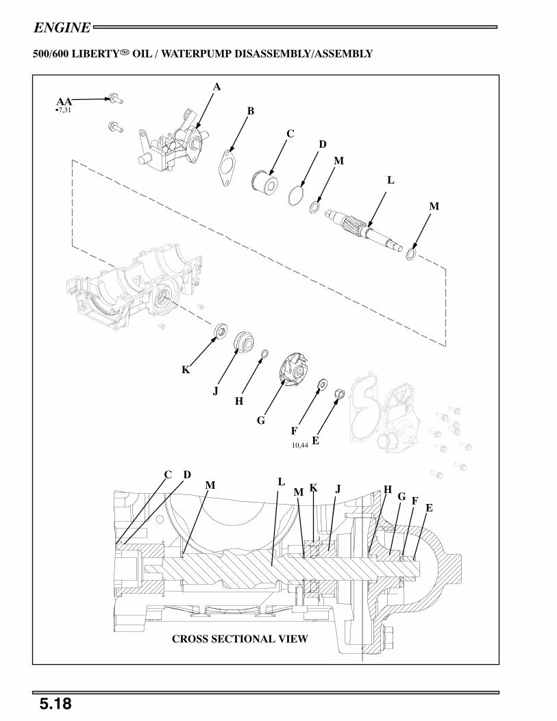
ENGINE
5.18
500/600 LIBERTYT OIL / WATERPUMP DISASSEMBLY/ASSEMBLY
CROSS SECTIONAL VIEW
A
B
CD
EF
G
HJ
K
L
C D
EFG
HJKL
M
M
MM
G7,31
10,44
AA

ENGINE
5.19
NOTE:Inspect all parts for wear or damage during disassembly. Replace all seals, o--rings, and gaskets with
Genuine Pure Polaris parts during assembly. Refer General chapter for general inspection procedures.
OIL PUMP CROSS SHAFT REMOVAL
1. Remove the oil pump (A) and gasket (B).
2. Carefully pull out the brass bushing (C) and o--ring (D).
3. With the crankshaft installed, remove the impeller nut (E) and washer (F).
4. Remove the impeller (G) and flat washer (H).
5. Remove the cross shaft (L) by hitting the shaft from the waterpump side with a rubber hammer.
6. Press out the water pump shaft (L) out toward the oil pump side.
7. Remove the mechanical water pump seal (J).
8. Pry out the seal (K) that is behind the mechanical seal.
9. Remove the thrust washers from the shaft (M).
OIL PUMP CROSS SHAFT ASSEMBLY
1. Install the seal (K) into the case.
2. Insert the cross shaft (L) with the thrust washers (M) into the case from the intake side.
3. Install the flanged pump bearing (C) with the o--ring (D) on to the cross shaft.
4. Install the water pump seal (J). Use water pump seal installation tool PN 2872010 and press it into the case. Make sure that thesealant on the seal is facing toward the crankcase.
5. Install oil pump (A) with the gasket (B) onto the crankcase and torque the bolts (AA) to 7 ft.lbs.(31Nm).
6. Place the flat washer (H), impeller (G), washer (F) and impeller nut (E) onto the other side of the cross shaft.
7. Torque the impeller nut to 10 ft.lbs.(44Nm).
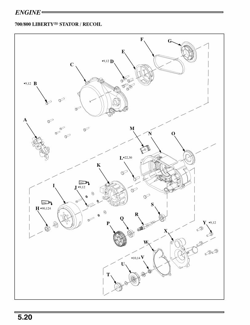
ENGINE
5.20
700/800 LIBERTYT STATOR / RECOIL
A
B
CD
E
F G
H
I J
KL
MN O
PQ
R
S
T
UV
W
X
G90,124
G9,12
G9,12
G9,12
G22,30
G9,12
G10,14
Y
242
242

ENGINE
5.21
700/800 LIBERTY ENGINE DISASSEMBLY
STATOR / WATER / OIL PUMP DISASSEMBLY
NOTE:Inspect all parts for wear or damage during disassembly. Replace all seals, o--rings, and gaskets with
Genuine Pure Polaris parts during assembly. Refer General chapter for general inspection procedures.
1. Remove the oil pump (A).
2. Remove the recoil cover (C), and the recoil basket (E).
3. Remove the water pump belt (F) and inspect for any cracks or broken drive cogs. See page 3.30 for inspection guidelines.
4. Remove the drive gear (G).
5. Hold the flywheel with the flywheel holding tool PN 9800229 and remove the flywheel nut (H) and lock washer.
6. Install the flywheel puller PN 2871043 and remove the flywheel (I) and Woodruff key.
7. Locate the pointer mark on the stator plate and make an alignment mark on the stator housing and the stator.
8. When removing the stator plate (K), carefully remove the grommet (M) and route the wires through the stator housing andremove the stator.
9. Remove the stator housing from the engine.
10. At the bottom of the stator housing check the weep hole on the oil pump side for and signs of leakage or blockage.
11. If crankshaft seal (O) needs to be replaced, drive the seal out from the stator side.
12. Remove the waterpump cover (W) and then remove the impeller (T), nut (U) and washer.
13. Remove the water/oil pump shaft (R) from the stator side and push it out from the impeller side (toward the stator side). If thebearing (Q) is being replaced you will need to press off the drive gear (P).
14. Inspect the mechanical seal (T) and replace if damaged.
STATOR / WATER / OIL PUMP ASSEMBLY
1. Reassemble the water/oil pump by installing the main seal (O) from the backside until it bottoms out on housing. The springon the seal must face toward the crankshaft.
2. If bearing (Q) was replaced. press on the water pump driven gear (P) onto the water/oil pump shaft if it was removed.
3. Assemble the water/oil pump shaft (R) and bearing (S) and then place into the stator housing from the stator side.
4. If replacing the mechanical seal (S) use the installation tool PN 2872389. Install the seal so that the spring is facing toward theimpeller (crankshaft) side.
5. Install water impeller (T), washer and torque the impeller nut (U) to 10 ft.lbs. (14Nm). Install cover gasket (V) and cover (W)and torque bolts (X) to 9ft.lbs.(12Nm).
6. Apply 3 Bond to the pump housing mating surface and carefully install onto the crankcase. Torque the stator housing housingbolts (L) to 22 ft. lbs. (30Nm).
7. Carefully route the stator wires through the stator housing. Place grommet in cover.
8. Apply Loctite 242 to the threads of the stator bolts (J) and align the timing marks on the stator and the stator housing and torquethe stator bolts to 9 ft.lbs.(12Nm).
9. Install the flywheel and apply Loctite 242 to the threads of the crankshaft. Insert the washer and flywheel nut onto thecrankshaft and hold the flywheel with flywheel holder tool PN 9800229 and torque to 90 ft.lbs. (124Nm). Torque the hoseclamp that mates with the water pump housing to 24 in.lbs.(3Nm).
10. With the belt on the water pump drive gear (G), match the waterpump pulley and the recoil basket and install onto theflywheel. Torque the recoil basket bolts (D) to 9 ft.lbs. (12Nm). See page 3.30 for installation guidelines.
11. Install recoil cover and torque the cover bolts (B) to 9 ft.lbs.(12Nm). Install oil pump and torque the screws to 7 ft.lbs.(9Nm).
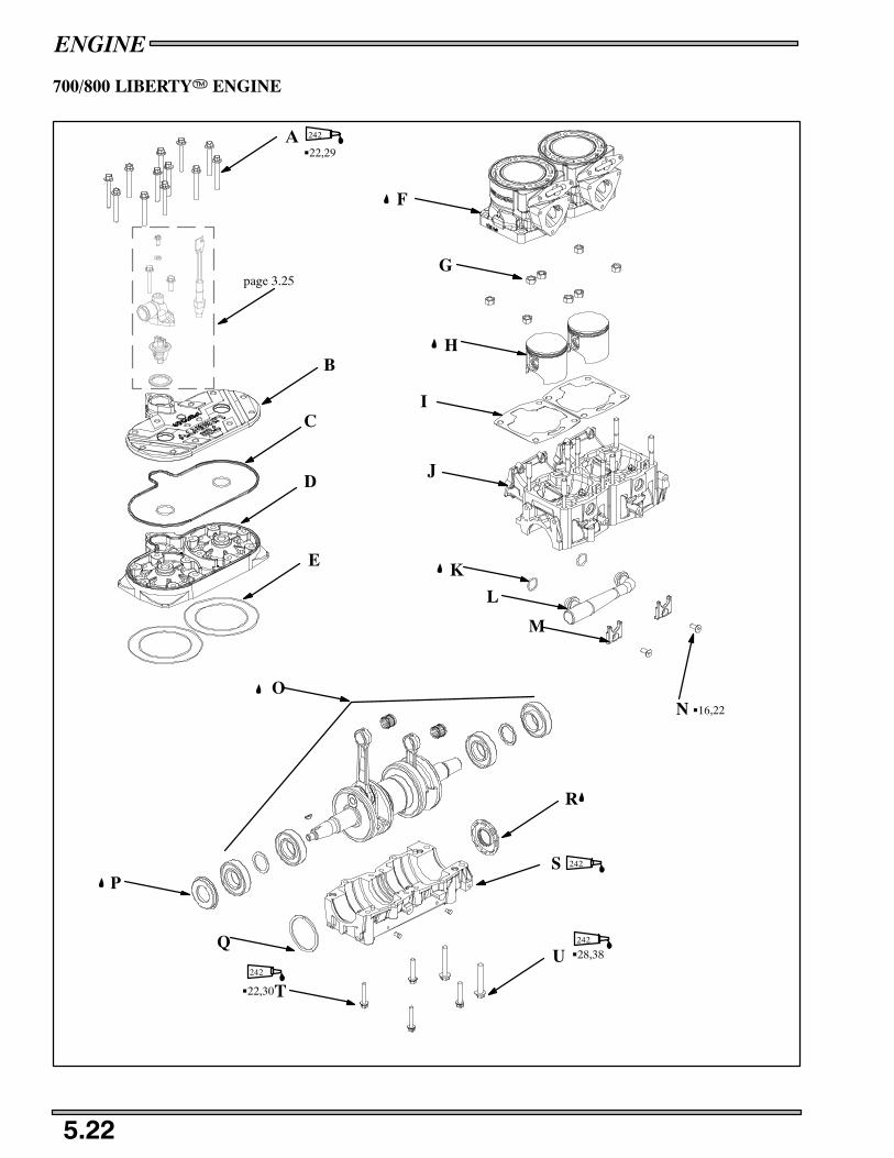
ENGINE
5.22
700/800 LIBERTYT ENGINE
F
G
H
I
J
K
L
M
NO
P
Q
T
U
S
R
G28,38
G22,30
242
242
242
page 3.25
A
B
C
D
E
G22,29
242
G16,22

ENGINE
5.23
700/800 LIBERTY ENGINE
NOTE:Inspect all parts for wear or damage during disassembly. Replace all seals, o--rings, and gaskets with
Genuine Pure Polaris parts during assembly. Refer General chapter for general inspection procedures.
ENGINE DISASSEMBLY
1. Remove the reed valve assembly, see page 5.31 for procedure.
2. Remove the cylinder head bolts (A) and remove the head cover (B), o--rings (C), and head (D). Note the condition of each ofthe o--rings used.
3. Remove the cylinder base nuts (G), and remove the cylinders (F) by a gentle rocking motion.
4. Carefully remove the c--clips holding the piston pins in place.
5. Remove the pistons (H) and piston pins by using the piston pin puller PN 2870386 and adapter PN 5130971.
6. Remove the base gasket (I) and discard the old gasket if it is damaged.
7. If needed, remove the water manifold (L), and o--rings (K) by removing both screws (N) on the retainer brackets (M).
8. Flip the crankcase over and remove the 8mm bottom crankcase bolts (T) and the 10mm bolts (U).
9. Separate the crankcase halves (S, J).
10. Remove the retaining ring (Q), crankshaft assembly (O), remove and inspect the seals (R,P) and refer to the General chapterfor general engine component inspections and measurement procedures.
ENGINE ASSEMBLY
1. Lubricate the seals (K,P) with Polaris All Season Grease. Make sure that the seals are positioned properly with the lip andspring facing inward toward the center of the crankshaft.
2. Install the crankshaft assembly (O), with seals (P,R) and the retaining ring (Q) so that the retaining rings gap is facing straightupward.
3. Set the crankshaft assembly in the lower crankcase.
4. Apply 3 Bond 1215 sealant PN 2871557 the lower (S) crankcase half.
5. Assemble crankcase halves together (S,J) and torque the crankcase bolts (T,U) in the pattern and specification found on pages5.1--5.5.
6. If water manifold was removed, grease the o--rings (K) and install them on the water manifold (L).
7. Assemble the water manifold onto the case with the retainer brackets (M) and torque the screws (N) to 16 ft.lbs.(22Nm).
8. Lubricate the small end bearings and the piston pins with Polaris 2 stroke oil and install the piston onto the crankshaft with thepiston pin removal/installation tool PN 2870386.
9. Install new c--clips in the piston grooves with the gap facing straight up (12:00 position) or straight down (6:00 position).Make sure that the c--clip is fully seated in the piston groove. Use c--clip installation tool PN 2872622.
10. Install the piston rings onto the piston with the bevel side up and the gap facing the piston ring locating pin.
11. If base gaskets are damaged, install new base gaskets (D) on the upper crankcase.
12. Lubricate the cylinders and pistons with Polaris 2--stroke oil and carefully install the cylinder onto the pistons by squeezingthe piston rings onto the locating pins and rocking the cylinder gently from the intake and exhaust sides.
13. Install the cylinder base nuts (G) and torque to the sequence and specification outlined on pages 5.1--5.5.
14. Install new o--rings (C) if needed.
15. Install head (D) on cylinders.
16. Install head cover (B).
17. Apply Loctite 242 on head bolt (A) threads and torque to 22ft.lbs.(29Nm).

ENGINE
5.24
900 LIBERTY ENGINE REMOVAL
A
B
C
CD

ENGINE
5.25
900 LIBERTY ENGINE REMOVAL
NOTE: Note the placement of all wire ties (zip ties) and the orientation of all hose clamps.
Wear eye protection to prevent eye injury.CAUTION:
1. Remove the hood. See page 12.3.
2. Use the fuel depressurization tool PN PV--43506--A, and depressurize the fuel rail. See page 4.22.
3. Drain the oil and fuel.
4. Unplug the air intake sensor from the air intake, located on the airbox.
5. Remove the air intake (plenum) see page 3.22.
6. Remove the exhaust springs and remove the exhaust pipe and muffler. See page 3.21.
7. Remove the air box.
8. Remove the pressure lines from the exhaust valves. This supply line goes to the EV solinoid.
9. Remove the drive belt. See page 3.13.
10. Remove the drive clutch. See page 6.8.
11. Remove the driven clutch. See page 6.15.
12. Remove the recoil handle and carefully route the rope through the chassis and tie a knot in the end to prevent it from beingpulled through the recoil housing.
13. Remove the console see page 12.6.
14. Drain the coolant.
15. Remove the coolant line from the throttle body (leave line hooked up to the coolant bottle and secure line away from engine).
16. Remove the oil supply line form the oil bottle.
17. Remove the seat and fuel tank. See page 12.4.
18. Disconnect the throttle cable.
19. Disconnect the sensors that are connected to the engine. (Injectors, Water temp sensor, Stator connections)
20. Remove the right (A) and left (B) bulk head side plates.
21. Remove the rear motor mount bolts (C) and front motor mount bolts.
22. With a helper or lift remove the straight out from the bulkhead.
23. The front motor mount (D) will come out with the engine.
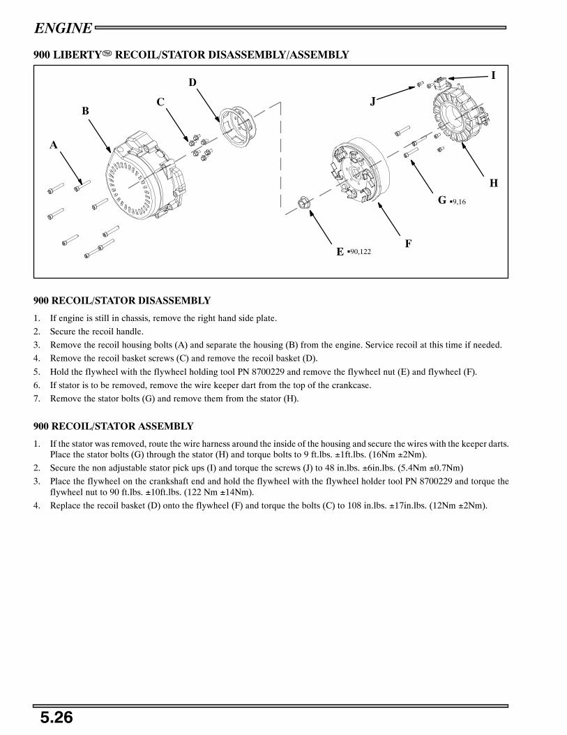
ENGINE
5.26
900 LIBERTYT RECOIL/STATOR DISASSEMBLY/ASSEMBLY
A
BC
D
EF
G
H
I
J
G9,16
G90,122
900 RECOIL/STATOR DISASSEMBLY
1. If engine is still in chassis, remove the right hand side plate.
2. Secure the recoil handle.
3. Remove the recoil housing bolts (A) and separate the housing (B) from the engine. Service recoil at this time if needed.
4. Remove the recoil basket screws (C) and remove the recoil basket (D).
5. Hold the flywheel with the flywheel holding tool PN 8700229 and remove the flywheel nut (E) and flywheel (F).
6. If stator is to be removed, remove the wire keeper dart from the top of the crankcase.
7. Remove the stator bolts (G) and remove them from the stator (H).
900 RECOIL/STATOR ASSEMBLY
1. If the stator was removed, route the wire harness around the inside of the housing and secure the wires with the keeper darts.Place the stator bolts (G) through the stator (H) and torque bolts to 9 ft.lbs. ±1ft.lbs. (16Nm ±2Nm).
2. Secure the non adjustable stator pick ups (I) and torque the screws (J) to 48 in.lbs. ±6in.lbs. (5.4Nm ±0.7Nm)
3. Place the flywheel on the crankshaft end and hold the flywheel with the flywheel holder tool PN 8700229 and torque theflywheel nut to 90 ft.lbs. ±10ft.lbs. (122 Nm ±14Nm).
4. Replace the recoil basket (D) onto the flywheel (F) and torque the bolts (C) to 108 in.lbs. ±17in.lbs. (12Nm ±2Nm).

ENGINE
5.27
NOTES

ENGINE
5.28
900 LIBERTYT ENGINE
G25,34
I
A
B
C
D
E
F
G
H
J
M
L
L
M
K
N
O
P G28,38
G34,46
G22,29

ENGINE
5.29
900 LIBERTYT ENGINE
NOTE:Inspect all parts for wear or damage during disassembly. Replace all seals, o--rings, and gaskets with
Genuine Pure Polaris parts during assembly. Refer General chapter for general inspection procedures.
DISASSEMBLY
See page 5.31 for reed removal procedure.
See page 5.26 for recoil/stator removal.
See page 4.22 for fuel rail removal.
1. Remove the head bolts (A).
2. Remove the head (B) and o--rings (C).
3. Remove the cylinder bolts (D) from the cylinders (E) and remove the cylinders.
4. Carefully remove the c--clips holding the piston pins in place.
5. Remove the pistons (F) and piston pins and roller bearings (J) by using the piston pin puller PN 2870386 and adapter PN5130971.
6. Remove the base gaskets (G).
7. Account for all cylinder centering pins (H).
8. Remove the lower case bolts (O, P, Q).
9. Remove crankshaft (K), bearings (L) and seals (M) form the lower case (N). Refer to the General chapter for general enginecomponent inspections and measurement procedures.
ASSEMBLY
1. Lubricate all the crankshaft seals (M) with Polaris All Season Grease. Make sure that the seals are positioned properly with thelip and spring facing inward toward the center of the crankshaft.
2. Install the crankshaft assembly (K), with seals (L,M) in the lower crankcase (N).
3. Fill the cross shaft area with cross shaft break in lube PN 2872435.
4. Apply 3 Bond 1215 sealant PN 2871557 the lower (N) crankcase half.
5. Assemble crankcase halves together (I,N) and torque the crankcase bolts (P,Q,R) in the pattern and specification found onpages 5.1--5.5.
6. Lubricate the small end bearings and the piston pins with Polaris 2 stroke oil and install the piston onto the crankshaft with thepiston pin removal/installation tool PN 2870386.
7. Install new c--clips in the piston grooves with the gap facing straight up (12:00 position) or straight down (6:00 position).Make sure that the c--clip is fully seated in the piston groove. Use c--clip installation tool PN 2872622.
8. Install the piston rings onto the piston with the bevel side up and the gap facing the piston ring locating pin.
9. If old base gaskets are damaged, install new base gaskets (D) on the upper crankcase.
10. Lubricate the cylinders and pistons with Polaris 2--stroke oil and carefully install the cylinder onto the pistons by squeezingthe piston rings onto the locating pins and rocking the cylinder gently from the intake and exhaust sides.
11. Install the cylinder base bolts (D) and torque to 34 ft.lbs (46Nm) in the sequence and specification outlined on pages5.1--5.5.
12. Install new head o--rings (C) if old ones are damaged.
13. Install head (B) on cylinders.
14. Apply Loctite 242 on head bolt (A) threads and torque to 22ft.lbs(29Nm).

ENGINE
5.30
900 LIBERTYT WATER/OIL PUMP CROSS SHAFT
A
B
C D
E FG
HI
J
J
KL
DISASSEMBLY
1. Remove the water pump cover bolts (A) and remove the cover (B) and cover o--ring (C).
2. Remove the impeller nut and washer (D,E), and remove the impeller (F).
3. With a scribe or flat head screwdriver carefully pry the water pump seal (G) out of the case.
4. Remove the oil seal (H) and the retaining ring (I).
5. At this point you should be able to slide the cross shaft (K) and bearings (J). Note that the gears on the shaft are closer to theintake side of the crankcase.
ASSEMBLY
1. Assemble the cross shaft (K) and bearings (J) into the crankcase with the gears on the shaft toward the intake side of the case.
2. Install the retaining ring (I) and press in the oil seal (H). Make sure that the oil seal is installed with the lip toward the case.
3. Press the water pump seal (G) into the case. Make sure that the seal has the blue sealant installed toward the case.
4. Install the impeller, washer and nut then torque the nut to 120 in.lbs. ±18in.lbs (14Nm ±2Nm).
5. Install the cover o--ring (C), cover (B) and torque the cover bolts (A) to 108 in.lbs ±17in.lbs (12Nm ±2Nm).

ENGINE
5.31
REED VALVES
G9,12
Max Reed PedalClearance .015“(.38 mm).
Exaggeratedfor illustrationA
B
C
D
REED VALVE DISASSEMBLY
1. Remove the carburetor adapter bolts (A), carburetor adaptors (B), reed stuffers (C), and reed assembly (D). Measure the airgap between the fiber reed and the reed block. The air gap should not exceed .015”(.38mm). If clearance is excessive DO NOTattempt to reverse the reeds to reduce the air gap. Always replace them if damaged or worn. Check each fiber reed for whitestress marks or missing material.
REED VALVE ASSEMBLY
2. Place the reeds (D), stuffers (C), carburetor adapters (B) into the case and torque the reed assy bolts (A) to 9 ft.lbs.(12Nm).

ENGINE
5.32
NOTES
Clutch Tools 6.1. . . . . . . . . . . . . . . . . . . . . . . . . . . . . . . . . . . . . . . . . . .
Clutch Operation Explanation 6.2 -- 6.3. . . . . . . . . . . . . . . . . . . . . . . . . . . . .Drive Clutch Springs 6.4. . . . . . . . . . . . . . . . . . . . . . . . . . . . . . . . . . . .Drive Clutch Weights 6.5 -- 6.6. . . . . . . . . . . . . . . . . . . . . . . . . . . . . . . . . . . .Drive Clutch Identification 6.7. . . . . . . . . . . . . . . . . . . . . . . . . . . . . . .Polaris P--85 Clutch Exploded View 6.7. . . . . . . . . . . . . . . . . . . . . . . .Drive Clutch Removal 6.8. . . . . . . . . . . . . . . . . . . . . . . . . . . . . . . . . . .Drive Clutch Installation 6.9. . . . . . . . . . . . . . . . . . . . . . . . . . . . . . . . .Drive Clutch
Disassembly/Inspection 6.10 -- 6.11. . . . . . . . . . . . . . . . . . . . . .Spider Removal / Installation 6.12 -- 6.13. . . . . . . . . . . . . . . . .Assembly 6.13. . . . . . . . . . . . . . . . . . . . . . . . . . . . . . . . .
Driven Clutch Types 6.14. . . . . . . . . . . . . . . . . . . . . . . . . . . . . . . . . . . .TEAM Driven Clutch
Removal / Installation 6.15. . . . . . . . . . . . . . . . . . . . . . .Disassembly 6.16. . . . . . . . . . . . . . . . . . . . . . . . . . . . . . .Assembly 6.16. . . . . . . . . . . . . . . . . . . . . . . . . . . . . . . . .Helix Angles and Effects 6.17. . . . . . . . . . . . . . . . . . . . .Spring Data 6.18. . . . . . . . . . . . . . . . . . . . . . . . . . . . . . .
Drive Belt Data 6.19. . . . . . . . . . . . . . . . . . . . . . . . . . . . . . . . . . . . . . . .Belt Inspection 6.20. . . . . . . . . . . . . . . . . . . . . . . . . . . . . . . . . . . . . . . . .Belt Diagnosis 6.20. . . . . . . . . . . . . . . . . . . . . . . . . . . . . . . . . . . . . . . . .Belt Deflection / Adjustment 6.21. . . . . . . . . . . . . . . . . . . . . . . . . . . . . .Clutch Offset / Alignment 6.22. . . . . . . . . . . . . . . . . . . . . . . . . . . . . . . .Torque Stop 6.23. . . . . . . . . . . . . . . . . . . . . . . . . . . . . . . . . . . . . . . . . . .

CLUTCHING
6.1
CLUTCH TOOLS
All drive clutch maintenance, disassembly and assembly must be performed only by an authorized Polaris dealer who has attendedcurrent model Dealer Service Seminars, has received a certificate of completion, and displays the Polaris Servicing Dealer decal.
Because of the critical nature and precision balance incorporated into the drive clutch, it is absolutely essential that no attemptat clutch disassembly and/or repair be made without factory authorized tools and service procedures.
Refer to the Service Tool Catalog (PN PU03--141) for photos and descriptions of all tools. A tool catalog update may be availablethrough the SPX parts department (Phone Number 1--800--328--6657).
TOOLS
Offset Alignment Tool♦ PS--46998
550 Fuji Drive Clutch Puller♦ 2872084
00 -- Current Domestic Engine Clutch Puller♦ 2872085
Drive Clutch Puller Replacement Handle♦ 5020326
Drive Clutch Holding Wrench♦ 9314177--A
Strap Wrench 2870336
Replacement Strap 2870389
Drive Clutch Spider Nut Socket 2870338
Drive Clutch Spider Removal and Spider Installation Tool 2870341
Pin Centering Tool 2870401
Clutch Pin Installation Tool 2870402
Clutch Pin Punch 2870507
Tapered Reamer for Drive Clutch Bore♦ 2870576
Roller Pin Tool♦ 2870910--A
Drive Clutch Button Removal Tool♦ 2870985
Clutch Bushing Replacement Tool Kit♦ 2871025
Primary Clutch Compression Tool♦ 2871173
Clutch Holding Fixture♦ 2871358--A
Replacement Base 335T51
Replacement Clap Set 5130518
Clutch Compression Tool♦ 8700220
Spider Assembly Tool♦ 8700221
Clutch Compression Tool Extensions for TEAM driven♦ PS--45909
Clutch Pilot Tool (P--85 Driven Clutch only)♦ PU--45779
♦Required Dealer Tool

CLUTCHING
6.2
CLUTCH OPERATION EXPLANATION
The Polaris drive system is a centrifugally actuated variable speed belt drive unit. The drive clutch, driven clutch, and belt makeup the torque converter system. Each clutch comes from the factory with the proper internal components installed for its specificengine model. Therefore, modifications or variations of components at random are never recommended. Proper converter setup
and adjustments of existing components must be the primary objective in converter operation diagnosis.
CAUTION:
All clutch maintenance repairs must be performed only by an authorized Polaris service techni-cian who has attended a Polaris sponsored service training seminar and understands the properprocedures as outlined in this manual. Because of the critical nature and precision balance incor-porated into the drive clutch, it is absolutely essential that no attempt at clutch disassembly and/orrepair be made without factory authorized special tools and service procedures. Any unautho-rized modifications to clutches, such as adding or removing weights, will void the warranty.
RELATIONSHIP BETWEEN DRIVE CLUTCH WEIGHTS AND SPRING FOR MAINTAININGOPERATING RPM.
The drive clutch is an RPM and torque sensing unit designed to transfer the maximum amount of horsepower from the engine
to the ground. This is accomplished by weights and a spring inside the unit which react to the centrifugal force from the engineRPM.
The spring and weights work in combination. In a properly set up clutch, the maximum desired operating RPM will be reachedimmediately after clutch engagement, under full throttle conditions. To gain optimum power this RPM should be maintained.As centrifugal force pushes the weights against the rollers, the moveable sheave will force the belt to climb up the drive clutchsheave and increase vehicle speed.
NOTE: If the weights are too light, or the spring rate too high, the maximum RPM will be too great and thedrive belt will not move into high gear at the top of the clutch.
9000
8000
7000
6000
5000
4000
3000
ENGINE OPERATINGRANGE +250 RPMENGAGEMENT
RP
M

CLUTCHING
6.3
NOTE:If the weights are too heavy, or spring rate too low, the engine RPM will be low and the drive clutchwill upshift too fast, keeping the engine out of its power band.
NOTE:If the weights and spring are matched properly, the engine RPM will go to the desired range and re-main there on both upshift and backshift.
The driven clutch operates in conjunction with the drive clutch. Its function is to maintain drive belt tension preventing slippage,and sense variations in load requirements necessary to maintain optimum engine torque output and load requirements from thetrack. Output torque is transmitted through the chaincase jackshaft and chaincase to the front drive shaft and track.
When the load on the driven clutch is increased and becomes greater than the torque delivered from the engine, the driven clutchbecomes dominant and overrides the drive clutch. The driven clutch downshifts into a ratio which will match the increased load.
Because the driven clutch can sense and shift into the proper ratio, engine RPM will remain within the specified range.
9000
8000
7000
6000
5000
4000
3000
ENGINE OPERATINGRANGE +250 RPM
ENGAGEMENT
RP
M
9000
8000
7000
6000
5000
4000
3000ENGINE OPERATINGRANGE +250 RPM
ENGAGEMENT
RP
M
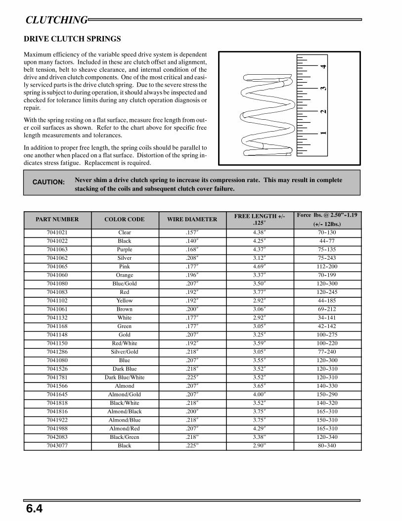
CLUTCHING
6.4
DRIVE CLUTCH SPRINGS
Maximum efficiency of the variable speed drive system is dependentupon many factors. Included in these are clutch offset and alignment,belt tension, belt to sheave clearance, and internal condition of thedrive and driven clutch components. One of the most critical and easi-ly serviced parts is the drive clutch spring. Due to the severe stress thespring is subject to during operation, it should always be inspected andchecked for tolerance limits during any clutch operation diagnosis orrepair.
With the spring resting on a flat surface, measure free length from out-er coil surfaces as shown. Refer to the chart above for specific freelength measurements and tolerances.
In addition to proper free length, the spring coils should be parallel toone another when placed on a flat surface. Distortion of the spring in-dicates stress fatigue. Replacement is required.
CAUTION: Never shim a drive clutch spring to increase its compression rate. This may result in completestacking of the coils and subsequent clutch cover failure.
PART NUMBER COLOR CODE WIRE DIAMETER FREE LENGTH +/-.125″
Force lbs. @ 2.50”--1.19
(+/-- 12lbs.)7041021 Clear .157″ 4.38″ 70--130
7041022 Black .140″ 4.25″ 44--77
7041063 Purple .168″ 4.37″ 75--135
7041062 Silver .208″ 3.12″ 75--243
7041065 Pink .177″ 4.69″ 112--200
7041060 Orange .196″ 3.37″ 70--199
7041080 Blue/Gold .207″ 3.50″ 120--300
7041083 Red .192″ 3.77″ 120--245
7041102 Yellow .192″ 2.92″ 44--185
7041061 Brown .200″ 3.06″ 69--212
7041132 White .177″ 2.92″ 34--141
7041168 Green .177″ 3.05″ 42--142
7041148 Gold .207″ 3.25″ 100--275
7041150 Red/White .192″ 3.59″ 100--220
7041286 Silver/Gold .218″ 3.05″ 77--240
7041080 Blue .207″ 3.55″ 120--300
7041526 Dark Blue .218″ 3.52″ 120--310
7041781 Dark Blue/White .225″ 3.52″ 120--310
7041566 Almond .207″ 3.65″ 140--330
7041645 Almond/Gold .207″ 4.00″ 150--290
7041818 Black/White .218″ 3.52″ 140--320
7041816 Almond/Black .200″ 3.75″ 165--310
7041922 Almond/Blue .218″ 3.75″ 150--310
7041988 Almond/Red .207″ 4.29″ 165--310
7042083 Black/Green .218” 3.38” 120--340
7043077 Black .225” 2.90” 80--340
12
34

CLUTCHING
6.5
DRIVE CLUTCH WEIGHTS
FULL TAIL WEIGHTS
Weight Gram Weight Part Number
S43H 43 grams 1321849
S45H 45 grams 1321850
S47H 47 grams 1321851
S49H 49 grams 1321730
S51H 51 grams 1321731
S53H 53 grams 1321759
S55H 53 grams 1322004
STEPPED WEIGHT AND MOD TAIL
Weight Gram Weight Part Number
10--54 Bushed 54±1 grams 1321685
10--56 Bushed 56±1 grams 1321684
10--58 Bushed 58±1 grams 1321588
10--60 Bushed 60±1 grams 1321587
10--62 Bushed 62±1 grams 1321586
10--64 Bushed 64±1 grams 1321585
10--66 Bushed 66±1 grams 1321584
10--68 Bushed 68±1 grams 5134428
10--70 Bushed 70±1 grams 5134429
10--72 Bushed 72±1 grams 5134430
10--74 Bushed 74±1 grams 5134431
10 SERIES WEIGHTS
Weight Gram Weight Part Number
10M--R Bushed 44 grams 1321530
10M--W Bushed 46 grams 1321527
10M Blue Bushed 47.5 grams 1321529
10M Bushed 49.5 grams 1321528
10 Bushed 51 grams 1321531
10A--L Bushed 53 grams 1321589
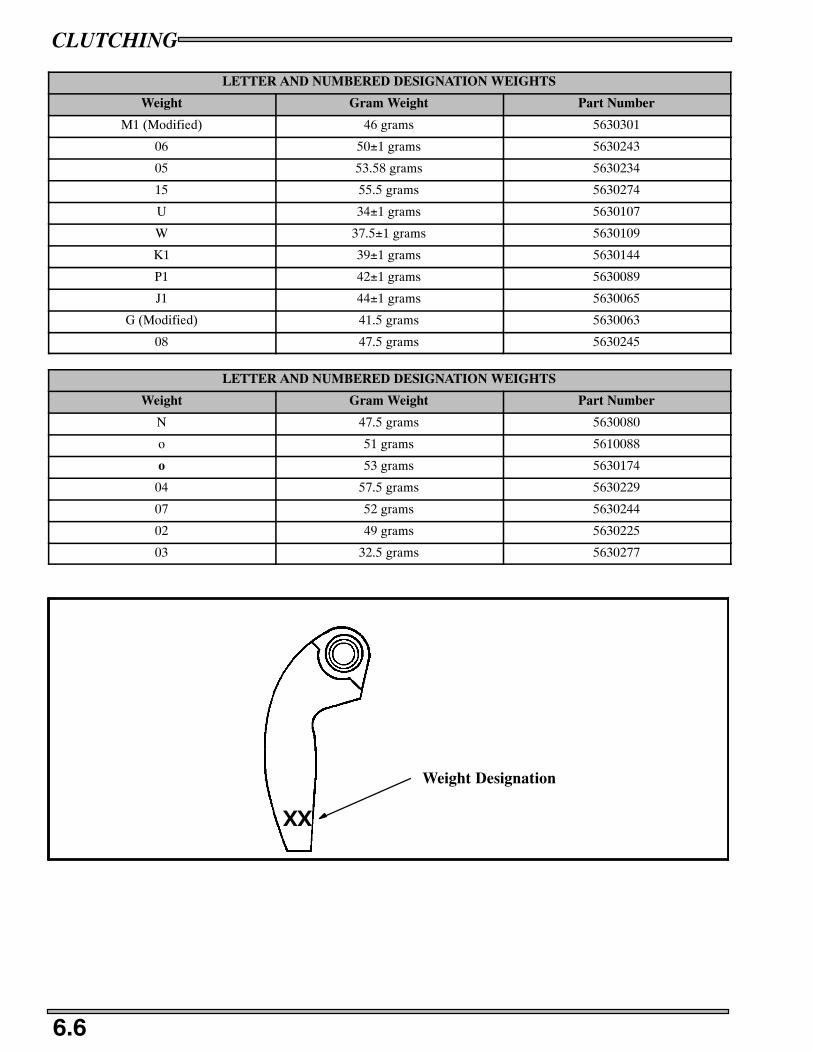
CLUTCHING
6.6
LETTER AND NUMBERED DESIGNATION WEIGHTS
Weight Gram Weight Part Number
M1 (Modified) 46 grams 5630301
06 50±1 grams 5630243
05 53.58 grams 5630234
15 55.5 grams 5630274
U 34±1 grams 5630107
W 37.5±1 grams 5630109
K1 39±1 grams 5630144
P1 42±1 grams 5630089
J1 44±1 grams 5630065
G (Modified) 41.5 grams 5630063
08 47.5 grams 5630245
LETTER AND NUMBERED DESIGNATION WEIGHTS
Weight Gram Weight Part Number
N 47.5 grams 5630080
o 51 grams 5610088
o 53 grams 5630174
04 57.5 grams 5630229
07 52 grams 5630244
02 49 grams 5630225
03 32.5 grams 5630277
XX
Weight Designation

CLUTCHING
6.7
DRIVE CLUTCH IDENTIFICATION
xxx
8/30/00
A
B
C
CC
E
Every clutch will have the last three digits of the clutch part number, date code and production code stamped here (A) on the clutchcover (B).
The “X” (C) is an index mark where the cover, moveable sheave (E) and stationary sheave should match up when the clutch isassembled.
P--85 DRIVE CLUTCH
NOTE:Replacement clutches come complete and balanced without clutch weights and clutch spring. Theclutch cover, spider, and sheaves cannot be purchased separately as replacement parts.
Drive Clutch Removal can be found on page 6.8.
Clutch Assembly(comes less weights and spring)
CoverCover Bushing
Retaining Ring
SpringJam Nut
Guide Button
Shim
WasherRoller
Spacer
Weight w/BushingWeight Pin
Sleeve Bushing
Moveable Insert
Fixed Sheave
Moveable Sheave
Spider
Roller Pin
Do not lubricate drive clutch components

CLUTCHING
6.8
DRIVE CLUTCH REMOVAL
(A)(B)
NOTE:Keep track of the washers on the clutch retaining bolt.
Clutch puller part numbers can be found on page 6.1.
DRIVE CLUTCH REMOVAL
1. Remove the belt, see page 3.13.
2. With clutch holding tool (PN 931477--A) in place remove the clutch retaining bolt. Note the location and the orientation of thewashers (B) are placed on the clutch bolt.
3. Insert the correct clutch puller and tighten puller into clutch.
DO NOT USE AN IMPACT WRENCH OR DAMAGE TO THE CLUTCH OR CRANKSHAFTMAY OCCUR.
CAUTION
4. Strike the clutch puller with a dead blow hammer, if the clutch does not come off, tighten up the clutch puller some more andstrike it again, repeat until the clutch “pops” off.

CLUTCHING
6.9
DRIVE CLUTCH INSTALLATION
A B C
D
Domestic Engines
FujiE F
NOTE: Always clean the clutch taper before re--installing clutch on engine.
1. Slight galling or scoring of the bore taper can usually be corrected by using a tapered reamer (PN 2870576). Place the reamerin a vise and lubricate the cutting edges with cutting oil (A). Clean the clutch taper by manually rotating the clutch clockwiseon the reamer one or two revolutions. Do not push down on the clutch while turning, just use the weight of the clutch.
2. Check crankshaft taper for galling or scoring. If necessary clean the taper evenly with 200 grit emery cloth (B).
3. Both the clutch taper and crankshaft taper should be clean and dry. Do not use harsh cleaners which may cause clutch taper tocorrode, or damage to the crank seal. This may cause difficulty when removing clutch in the future. Clean clutch taper withlacquer thinner or isopropyl alcohol (C).
4. Slide clutch fully on crankshaft taper (D).
5. Install retaining bolt with any spacers washers or o--rings (E).6. Torque retaining bolt to specification. Hold the clutch with the holding wrench (F) PN 931417--A. Re--check torque after first
operation or test ride.
NOTE:Drive Clutch Bolt Torque (Large ID Shaft .75”/19mm) 40--45 ft.lbs. (55--62Nm)
Drive Clutch Bolt Torque (Small ID Shaft .55”/14mm) 50 ft.lbs. (69Nm)

CLUTCHING
6.10
DRIVE CLUTCH DISASSEMBLY / INSPECTION
B
C
D
E
F
G
J
K
I
LM
N
P
Q
A
A
A
H
R
S
T
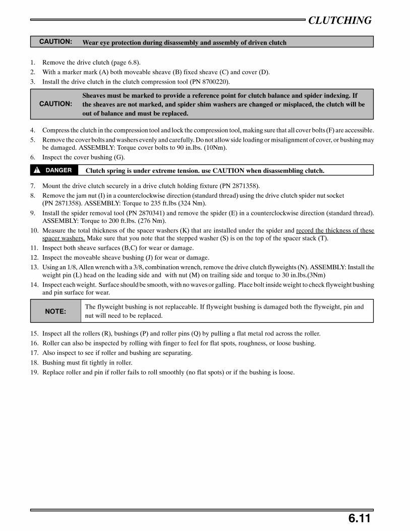
CLUTCHING
6.11
CAUTION: Wear eye protection during disassembly and assembly of driven clutch
1. Remove the drive clutch (page 6.8).
2. With a marker mark (A) both moveable sheave (B) fixed sheave (C) and cover (D).
3. Install the drive clutch in the clutch compression tool (PN 8700220).
CAUTION:Sheaves must be marked to provide a reference point for clutch balance and spider indexing. Ifthe sheaves are not marked, and spider shim washers are changed or misplaced, the clutch will beout of balance and must be replaced.
4. Compress the clutch in the compression tool and lock the compression tool, making sure that all cover bolts (F) are accessible.
5. Remove the cover bolts and washers evenly and carefully. Do not allow side loading or misalignment of cover, or bushing maybe damaged. ASSEMBLY: Torque cover bolts to 90 in.lbs. (10Nm).
6. Inspect the cover bushing (G).
DANGER Clutch spring is under extreme tension. use CAUTION when disassembling clutch.
7. Mount the drive clutch securely in a drive clutch holding fixture (PN 2871358).
8. Remove the jam nut (I) in a counterclockwise direction (standard thread) using the drive clutch spider nut socket(PN 2871358). ASSEMBLY: Torque to 235 ft.lbs (324 Nm).
9. Install the spider removal tool (PN 2870341) and remove the spider (E) in a counterclockwise direction (standard thread).ASSEMBLY: Torque to 200 ft.lbs. (276 Nm).
10. Measure the total thickness of the spacer washers (K) that are installed under the spider and record the thickness of thesespacer washers. Make sure that you note that the stepped washer (S) is on the top of the spacer stack (T).
11. Inspect both sheave surfaces (B,C) for wear or damage.
12. Inspect the moveable sheave bushing (J) for wear or damage.
13. Using an 1/8, Allen wrench with a 3/8, combination wrench, remove the drive clutch flyweights (N). ASSEMBLY: Install theweight pin (L) head on the leading side and with nut (M) on trailing side and torque to 30 in.lbs.(3Nm)
14. Inspect each weight. Surface should be smooth, with no waves or galling. Place bolt inside weight to check flyweight bushingand pin surface for wear.
NOTE:The flyweight bushing is not replaceable. If flyweight bushing is damaged both the flyweight, pin andnut will need to be replaced.
15. Inspect all the rollers (R), bushings (P) and roller pins (Q) by pulling a flat metal rod across the roller.
16. Roller can also be inspected by rolling with finger to feel for flat spots, roughness, or loose bushing.
17. Also inspect to see if roller and bushing are separating.
18. Bushing must fit tightly in roller.
19. Replace roller and pin if roller fails to roll smoothly (no flat spots) or if the bushing is loose.
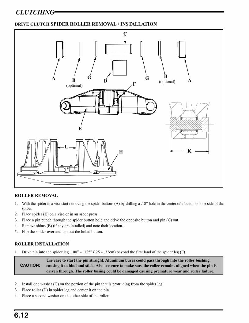
CLUTCHING
6.12
DRIVE CLUTCH SPIDER ROLLER REMOVAL / INSTALLATION
ROLLER REMOVAL
1. With the spider in a vise start removing the spider buttons (A) by drilling a .18” hole in the center of a button on one side of thespider.
2. Place spider (E) on a vise or in an arbor press.
3. Place a pin punch through the spider button hole and drive the opposite button and pin (C) out.
4. Remove shims (B) (if any are installed) and note their location.
5. Flip the spider over and tap out the holed button.
ROLLER INSTALLATION
1. Drive pin into the spider leg .100” -- .125” (.25 -- .32cm) beyond the first land of the spider leg (F).
CAUTION:Use care to start the pin straight. Aluminum burrs could pass through into the roller bushingcausing it to bind and stick. Also use care to make sure the roller remains aligned when the pin isdriven through. The roller busing could be damaged causing premature wear and roller failure.
2. Install one washer (G) on the portion of the pin that is protruding from the spider leg.
3. Place roller (D) in spider leg and center it on the pin.
4. Place a second washer on the other side of the roller.
A B
C
DB
A
E
FG G
H
(optional)(optional)
KL

CLUTCHING
6.13
5. Place the spider on a vise.6. Install pin centering tool (PN 2870401).7. Drive the roller pin through the second land of the spider.8. Install new buttons into the spider.9. Repeat this for each roller.10. Measure the width of the spider leg with the buttons installed (K) and record the measurement. Specification for the width of
the spider with buttons installed is 1.496” (37.99mm).11. Measure the width of the moveable sheave towers (L) and record the measurement. Specification for the width of the opening
of the moveable sheave towers are 1.50” (38.1mm).12. Subtract the spider measurement form the tower measurement. The clearance between the spider buttons and the moveable
sheave towers is .002” -- .004” (.05--.10mm).
DRIVE CLUTCH ASSEMBLYSPIDER INDEXING
NOTE:Spider indexing affects clutch balance and belt to sheave clearance.
Read procedures carefully before proceeding.
1. Remove and Disassemble clutch as outlined on page 6.8 -- 6.11.2. Add or remove spider washers as required to achieve desired belt to
sheave clearance. Make sure that the stepped washer (A) is on the top ofthe spacer stack (B).
S For example: If belt to sheave clearance is .020“ too large, re-moving one .020“ shim will position the movable sheave closerto the fixed sheave reducing belt to sheave clearance by .020”.
3. Place the correct number of space washers (B) beneath the spider.
The following washers are available for fine tuning:
PN 5210754 .050” (1.3mm)PN 5210753 .032” (.8mm)PN 5210752 .020” (.5mm)
4. Install spider washer(s) and spider aligning “ X ” s. Notice as thespider seat location is changed, the sheave marks made beforedisassembly no longer align (C). There are two ways to bring thesheave marks into alignment.
S Vary the amount and thickness of spacer washers (washer thick-ness may vary slightly).
S Re-index marked spider leg to another tower. This can be donebecause spider has little effect on overall clutch balance.
Re--indexing the spider 1/3 turn clockwise, or 1 leg, will allow therealignment of the moveable and stationary sheaves as previouslymarked (D). For EXAMPLE:
S .020” or .032” (.5--.8mm) washer removed -- re--index spider
clockwise 1/3 turn.
NOTE: Alignment marks on the sheaves should be with in 1” (.25mm) after final assembly and torquing.
A
B
(C)
(D)

CLUTCHING
6.14
DRIVEN CLUTCH
TEAM Roller Clutch
Driven Clutch (Typical P-85)
NOTE:
Replacement clutches come with out a spring or the driven ramp.
To service TEAM clutches, use the Clutch Compression Tool Extensions (PS--45909) with the ClutchCompression tool (PN 87000220).
Driven Clutch Removal can be found on page 6.15.

CLUTCHING
6.15
DRIVEN CLUTCH
REMOVAL
1. Remove the belt as outlined on page 3.12 -- 3.13
2. Apply the parking brake.
3. After the belt is removed, remove the driven clutch retaining bolt.
4. Slide the driven clutch off the jackshaft.
NOTE:Notice the number of shim washers and their thickness of shim washers between driven clutch
and jackshaft bearing.
5. Inspect the jackshaft keyway for wear or damage.
INSTALLATION
1. With proper off set alignment achieved as out lined on page 6.22. The driven clutch must float on the jack shaft .020 -- .1”(.5--2.5mm). Grease flange if needed.
2. Torque driven clutch retaining bolt to 12 ft.lbs.(17Nm).
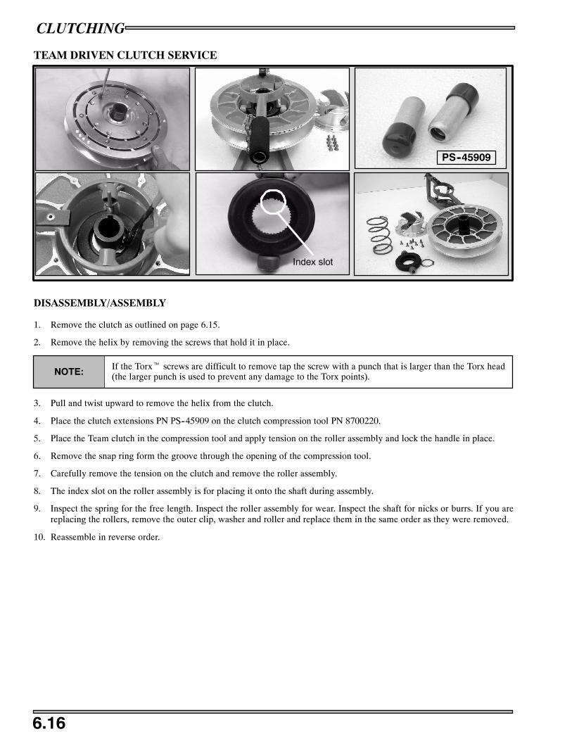
CLUTCHING
6.16
TEAM DRIVEN CLUTCH SERVICE
PS--45909
Index slot
DISASSEMBLY/ASSEMBLY
1. Remove the clutch as outlined on page 6.15.
2. Remove the helix by removing the screws that hold it in place.
NOTE:If the Torxt screws are difficult to remove tap the screw with a punch that is larger than the Torx head(the larger punch is used to prevent any damage to the Torx points).
3. Pull and twist upward to remove the helix from the clutch.
4. Place the clutch extensions PN PS--45909 on the clutch compression tool PN 8700220.
5. Place the Team clutch in the compression tool and apply tension on the roller assembly and lock the handle in place.
6. Remove the snap ring form the groove through the opening of the compression tool.
7. Carefully remove the tension on the clutch and remove the roller assembly.
8. The index slot on the roller assembly is for placing it onto the shaft during assembly.
9. Inspect the spring for the free length. Inspect the roller assembly for wear. Inspect the shaft for nicks or burrs. If you arereplacing the rollers, remove the outer clip, washer and roller and replace them in the same order as they were removed.
10. Reassemble in reverse order.
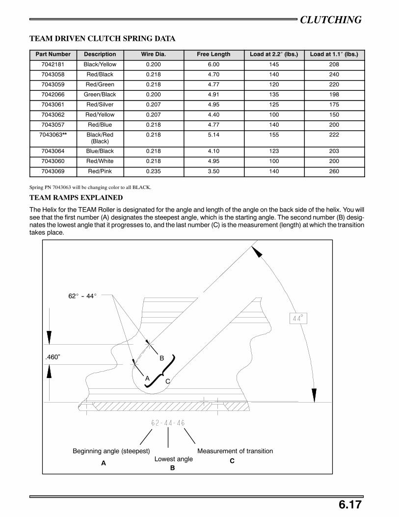
CLUTCHING
6.17
TEAM DRIVEN CLUTCH SPRING DATA
Part Number Description Wire Dia. Free Length Load at 2.2″ (lbs.) Load at 1.1″ (lbs.)
7042181 Black/Yellow 0.200 6.00 145 208
7043058 Red/Black 0.218 4.70 140 240
7043059 Red/Green 0.218 4.77 120 220
7042066 Green/Black 0.200 4.91 135 198
7043061 Red/Silver 0.207 4.95 125 175
7043062 Red/Yellow 0.207 4.40 100 150
7043057 Red/Blue 0.218 4.77 140 200
7043063** Black/Red(Black)
0.218 5.14 155 222
7043064 Blue/Black 0.218 4.10 123 203
7043060 Red/White 0.218 4.95 100 200
7043069 Red/Pink 0.235 3.50 140 260
Spring PN 7043063 will be changing color to all BLACK.
TEAM RAMPS EXPLAINED
The Helix for the TEAM Roller is designated for the angle and length of the angle on the back side of the helix. You willsee that the first number (A) designates the steepest angle, which is the starting angle. The second number (B) desig-nates the lowest angle that it progresses to, and the last number (C) is the measurement (length) at which the transitiontakes place.
.460”
62_ -- 44_
A
B
C
Beginning angle (steepest)Lowest angle
Measurement of transition
AB
C
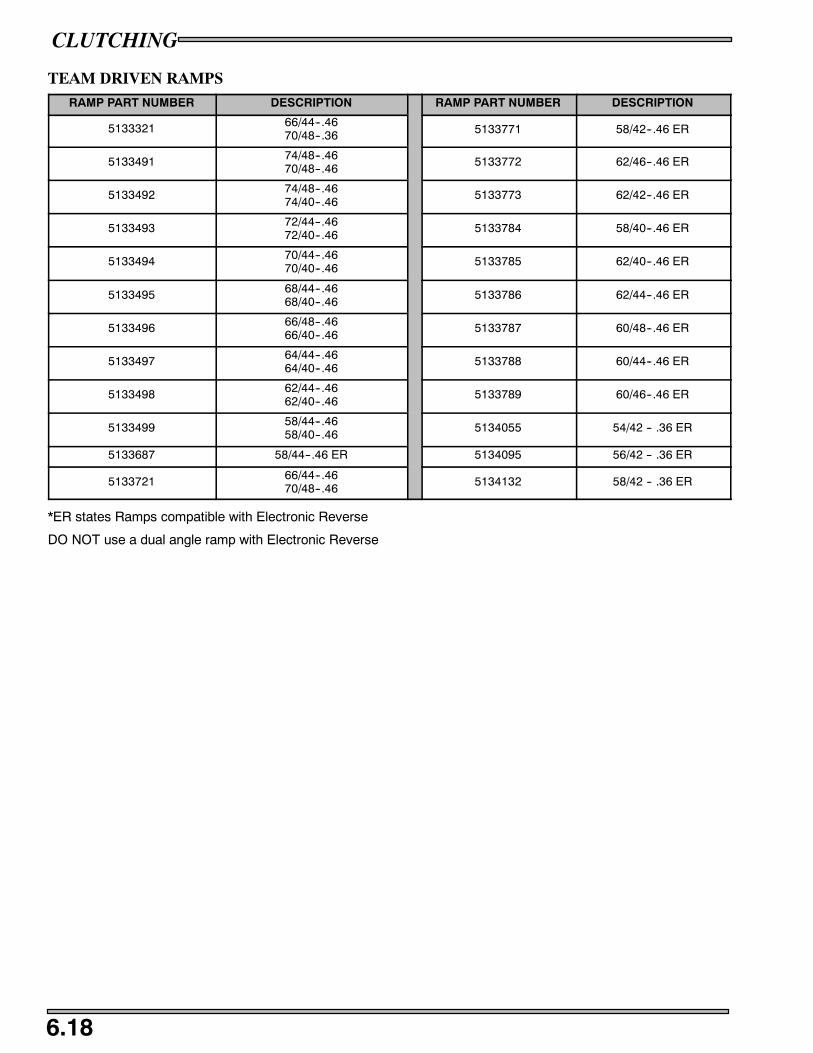
CLUTCHING
6.18
TEAM DRIVEN RAMPSRAMP PART NUMBER DESCRIPTION RAMP PART NUMBER DESCRIPTION
5133321 66/44--.4670/48--.36 5133771 58/42--.46 ER
5133491 74/48--.4670/48--.46
5133772 62/46--.46 ER
5133492 74/48--.4674/40--.46
5133773 62/42--.46 ER
5133493 72/44--.4672/40--.46
5133784 58/40--.46 ER
5133494 70/44--.4670/40--.46
5133785 62/40--.46 ER
5133495 68/44--.4668/40--.46
5133786 62/44--.46 ER
5133496 66/48--.4666/40--.46
5133787 60/48--.46 ER
5133497 64/44--.4664/40--.46
5133788 60/44--.46 ER
5133498 62/44--.4662/40--.46
5133789 60/46--.46 ER
5133499 58/44--.4658/40--.46
5134055 54/42 -- .36 ER
5133687 58/44--.46 ER 5134095 56/42 -- .36 ER
5133721 66/44--.4670/48--.46
5134132 58/42 -- .36 ER
*ER states Ramps compatible with Electronic Reverse
DO NOT use a dual angle ramp with Electronic Reverse
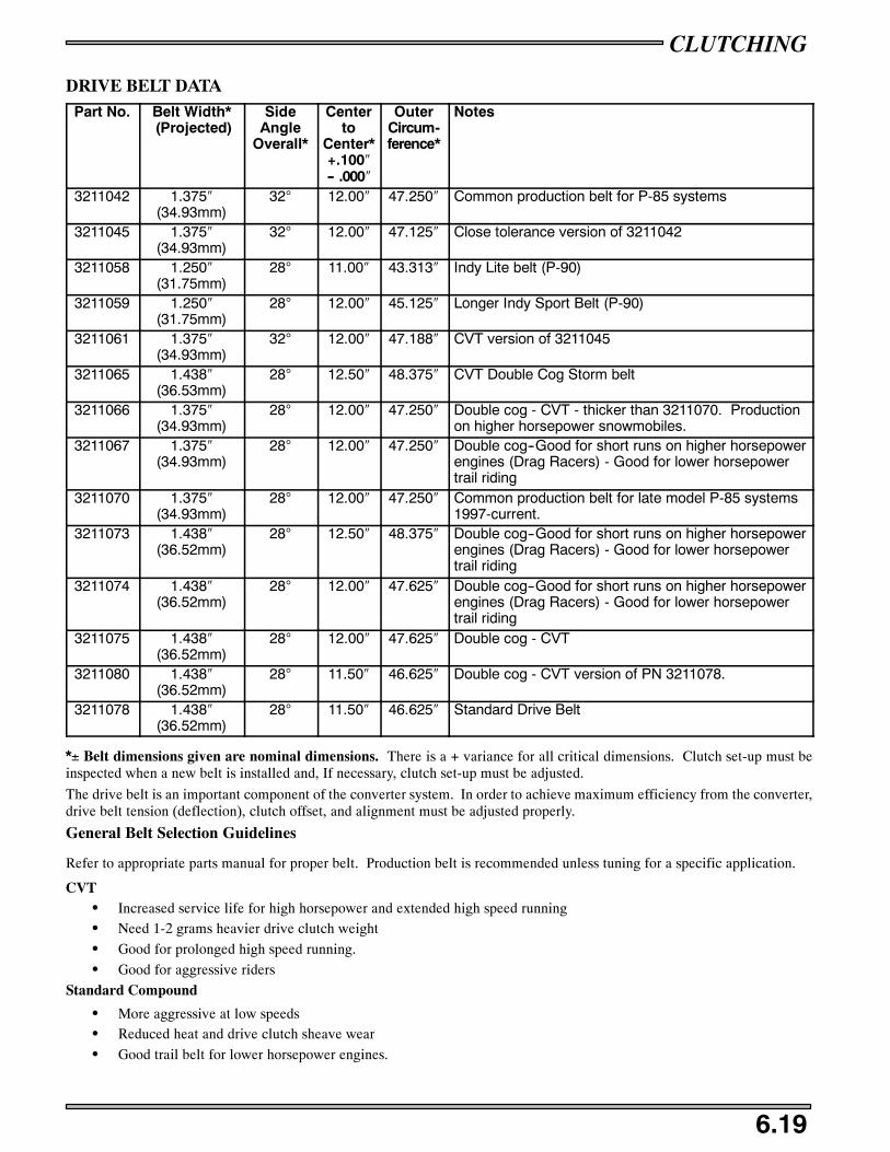
CLUTCHING
6.19
DRIVE BELT DATAPart No. Belt Width*
(Projected)Side
AngleOverall*
Centerto
Center*+.100″-- .000″
OuterCircum-ference*
Notes
3211042 1.375″(34.93mm)
32° 12.00″ 47.250″ Common production belt for P-85 systems
3211045 1.375″(34.93mm)
32° 12.00″ 47.125″ Close tolerance version of 3211042
3211058 1.250″(31.75mm)
28° 11.00″ 43.313″ Indy Lite belt (P-90)
3211059 1.250″(31.75mm)
28° 12.00″ 45.125″ Longer Indy Sport Belt (P-90)
3211061 1.375″(34.93mm)
32° 12.00″ 47.188″ CVT version of 3211045
3211065 1.438″(36.53mm)
28° 12.50″ 48.375″ CVT Double Cog Storm belt
3211066 1.375″(34.93mm)
28° 12.00″ 47.250″ Double cog - CVT - thicker than 3211070. Productionon higher horsepower snowmobiles.
3211067 1.375″(34.93mm)
28° 12.00″ 47.250″ Double cog--Good for short runs on higher horsepowerengines (Drag Racers) - Good for lower horsepowertrail riding
3211070 1.375″(34.93mm)
28° 12.00″ 47.250″ Common production belt for late model P-85 systems1997-current.
3211073 1.438″(36.52mm)
28° 12.50″ 48.375″ Double cog--Good for short runs on higher horsepowerengines (Drag Racers) - Good for lower horsepowertrail riding
3211074 1.438″(36.52mm)
28° 12.00″ 47.625″ Double cog--Good for short runs on higher horsepowerengines (Drag Racers) - Good for lower horsepowertrail riding
3211075 1.438″(36.52mm)
28° 12.00″ 47.625″ Double cog - CVT
3211080 1.438″(36.52mm)
28° 11.50″ 46.625″ Double cog - CVT version of PN 3211078.
3211078 1.438″(36.52mm)
28° 11.50″ 46.625″ Standard Drive Belt
*± Belt dimensions given are nominal dimensions. There is a + variance for all critical dimensions. Clutch set-up must beinspected when a new belt is installed and, If necessary, clutch set-up must be adjusted.
The drive belt is an important component of the converter system. In order to achieve maximum efficiency from the converter,drive belt tension (deflection), clutch offset, and alignment must be adjusted properly.
General Belt Selection Guidelines
Refer to appropriate parts manual for proper belt. Production belt is recommended unless tuning for a specific application.
CVTS Increased service life for high horsepower and extended high speed runningS Need 1-2 grams heavier drive clutch weight
S Good for prolonged high speed running.
S Good for aggressive riders
Standard Compound
S More aggressive at low speedsS Reduced heat and drive clutch sheave wear
S Good trail belt for lower horsepower engines.
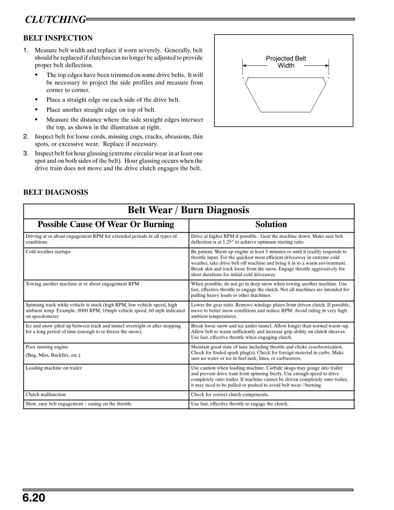
CLUTCHING
6.20
BELT INSPECTION
1. Measure belt width and replace if worn severely. Generally, beltshould be replaced if clutches can no longer be adjusted to provideproper belt deflection.
S The top edges have been trimmed on some drive belts. It willbe necessary to project the side profiles and measure fromcorner to corner.
S Place a straight edge on each side of the drive belt.
S Place another straight edge on top of belt.
S Measure the distance where the side straight edges intersectthe top, as shown in the illustration at right.
2. Inspect belt for loose cords, missing cogs, cracks, abrasions, thinspots, or excessive wear. Replace if necessary.
3. Inspect belt for hour glassing (extreme circular wear in at least onespot and on both sides of the belt). Hour glassing occurs when thedrive train does not move and the drive clutch engages the belt.
BELT DIAGNOSIS
Belt Wear / Burn DiagnosisPossible Cause Of Wear Or Burning Solution
Driving at or about engagement RPM for extended periods in all types ofconditions
Drive at higher RPM if possible. Gear the machine down. Make sure beltdeflection is at 1.25″ to achieve optimum starting ratio
Cold weather startups Be patient. Warm up engine at least 5 minutes or until it readily responds tothrottle input. For the quickest most efficient driveaway in extreme coldweather, take drive belt off machine and bring it in to a warm environment.Break skis and track loose from the snow. Engage throttle aggressively forshort durations for initial cold driveaway
Towing another machine at or about engagement RPM When possible, do not go in deep snow when towing another machine. Usefast, effective throttle to engage the clutch. Not all machines are intended forpulling heavy loads or other machines.
Spinning track while vehicle is stuck (high RPM, low vehicle speed, highambient temp. Example: 8000 RPM, 10mph vehicle speed, 60 mph indicatedon speedometer.
Lower the gear ratio. Remove windage plates from driven clutch. If possible,move to better snow conditions and reduce RPM. Avoid riding in very highambient temperatures.
Ice and snow piled up between track and tunnel overnight or after stoppingfor a long period of time (enough to re-freeze the snow).
Break loose snow and ice under tunnel. Allow longer than normal warm--up.Allow belt to warm sufficiently and increase grip ability on clutch sheaves.Use fast, effective throttle when engaging clutch.
Poor running engine
(Bog, Miss, Backfire, etc.)
Maintain good state of tune including throttle and choke synchronization.Check for fouled spark plug(s). Check for foreign material in carbs. Makesure no water or ice in fuel tank, lines, or carburetors.
Loading machine on trailer Use caution when loading machine. Carbide skags may gouge into trailerand prevent drive train from spinning freely. Use enough speed to drivecompletely onto trailer. If machine cannot be driven completely onto trailer,it may need to be pulled or pushed to avoid belt wear / burning.
Clutch malfunction Check for correct clutch components.
Slow, easy belt engagement -- easing on the throttle Use fast, effective throttle to engage the clutch.
Projected BeltWidth

CLUTCHING
6.21
BELT DEFLECTION
Belt too high on initial engagement Belt too tight
1 1/4″ (3.2 cm..)Straight Edge
A B
C
Too much belt deflection - If the belt is too long or the center distance too short, the initial starting ratio will be too high, resultingin performance loss. This is due to the belt rising too high in the drive clutch sheaves upon engagement (A).
Not enough belt deflection (belt too tight) - If the drive belt is too short or the center distance too long, the ratio will againbe incorrect. In addition, the machine may creep when the engine idles, causing damage to the internal face of the drive belt(B).
MEASURING BELT DEFLECTION
Do not apply excessive pressure to force belt into driven sheaves. This will result in an improper measurement. If belt deflectioncannot be adjusted within specification using methods below, inspect center distance.
1. Measure belt deflection with both clutches at rest and in their fullneutral position (C).
2. Place a straight edge on the belt and apply downward pressurewhile measuring at the point shown.
DRIVEN CLUTCH DEFLECTION ADJUSTMENT
TEAM BELT DEFLECTION ADJUSTMENT
1. To adjust the sheaves, loosen the 7/16” jam nut (A) on the belt widthadjuster.
2. Using a 1/8” Allen wrench, adjust the threaded set screw (B) asneeded. Turn the set screw in (clockwise) to increase the distancebetween the sheaves and out (counter clockwise) to decrease thedistance.
3. Tighten the jam nut after the belt adjustment has been made.
(A)
(B)
TEAM

MAX .060”
0.00”--0.025
CLUTCHING
6.22
CLUTCH OFFSET INSPECTION
Proper offset aligns the fixed sheaves of both clutch assemblies. Thisallows the clutches to be aligned throughout the shift range.
1. Remove drive belt. Belt deflection adjustments affect offset. Setbelt deflection first.
2. Install alignment tool PN PS--46998.
3. Front and rear of the driven clutch moveable sheave should justcontact tool when clutch is pushed inward on jackshaft. Any gapover 0.025” (.63mm) at the front of the driven clutch is notacceptable.
4. Ideal set up is the rear of driven clutch should have no gap. If agap is present it should not exceed .060” (3mm).
CLUTCH OFFSET ADJUSTMENT
1. Determine direction driven clutch needs to be adjusted. (Refer toClutch Offset Inspection procedure above).
2. Remove driven clutch retaining bolt, and remove driven clutch.
3. Add or take out washers on jackshaft between the driven clutchand jackshaft bearing to achieve proper offset.
4. Most models require the driven clutch to float on the jackshaft.After adjusting offset, add or remove shim washers from theretaining bolt to provide a +/-- .030, (.75mm) of float on thejackshaft. This will prevent side loads on the jackshaft bearing.
CLUTCH ALIGNMENT ADJUSTMENT
1. Loosen all 4 engine mounting bolts.
2. Adjust engine torque stop until clutches are in proper alignment.
3. Tighten engine mounts securely.
4. Recheck both clutch offset and alignment.
5. Verify proper torque stop adjustment.
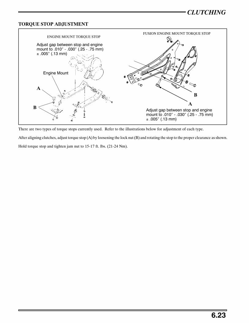
CLUTCHING
6.23
TORQUE STOP ADJUSTMENT
Adjust gap between stop and enginemount to .010″ - .030″ (.25 - .75 mm)± .005″ (.13 mm)
ENGINE MOUNT TORQUE STOP
Engine Mount
A
BA
B
FUSION ENGINE MOUNT TORQUE STOP
Adjust gap between stop and enginemount to .010″ - .030″ (.25 - .75 mm)± .005″ (.13 mm)
There are two types of torque stops currently used. Refer to the illustrations below for adjustment of each type.
After aligning clutches, adjust torque stop (A) by loosening the lock nut (B) and rotating the stop to the proper clearance as shown.
Hold torque stop and tighten jam nut to 15-17 ft. lbs. (21-24 Nm).

CLUTCHING
6.24
NOTES

Gearing Charts 7.1 -- 7.2. . . . . . . . . . . . . . . . . . . . . . . . . . . . . . . . . . . . . . . . .
Sprockets and Chains 7.3. . . . . . . . . . . . . . . . . . . . . . . . . . . . . . . . . . . .Chaincase
Exploded View 7.4. . . . . . . . . . . . . . . . . . . . . . . . . . . . .
Removal 7.5. . . . . . . . . . . . . . . . . . . . . . . . . . . . . . . . . .
Bearing Removal/Assembly 7.5. . . . . . . . . . . . . . . . . .
Jackshaft Removal/Installation 7.5. . . . . . . . . . . . . . . . . . . . . . . . . . . .Drive Shaft Removal/Installation 7.6. . . . . . . . . . . . . . . . . . . . . . . . . .

FINAL DRIVE
7.1
GEARING CHARTS
Pit
chTe
eth
Clu
tch
Rat
io
2.52
91
:1fn
:bw
gerc
ht.w
k4
Top
Gea
r---->
2525
2525
2525
2524
2424
2424
2424
2323
2323
2323
2322
2222
2222
2222
2121
2121
2121
Bot
tom
Gea
r-->
3738
3940
4142
4337
3839
4041
4243
3738
3940
4142
4337
3839
4041
4243
3738
3940
4142
7.92
Cha
inca
seC
hain
7474
NR
7676
NR
NR
7474
74N
R76
76N
RN
R74
74N
RN
R76
7672
NR
7474
NR
NR
7672
NR
NR
7474
NR
Gea
rR
atio
---->
1.48
1.52
1.56
1.60
1.64
1.68
1.72
1.54
1.58
1.63
1.67
1.71
1.75
1.79
1.61
1.65
1.70
1.74
1.78
1.83
1.87
1.68
1.73
1.77
1.82
1.86
1.91
1.95
1.76
1.81
1.86
1.90
1.95
2.00
Jack
shaf
tRP
MM
ILE
SP
ER
HO
UR
MIL
ES
PE
RH
OU
R
6000
87.1
84.8
82.6
80.6
78.6
76.7
74.9
83.6
81.4
79.3
77.3
75.4
73.6
71.9
80.1
78.0
76.0
74.1
72.3
70.6
68.9
76.6
74.6
72.7
70.9
69.2
67.5
65.9
73.1
71.2
69.4
67.7
66.0
64.4
6250
90.7
88.3
86.1
83.9
81.9
79.9
78.1
87.1
84.8
82.6
80.6
78.6
76.7
74.9
83.5
81.3
79.2
77.2
75.3
73.5
71.8
79.8
77.7
75.7
73.8
72.0
70.3
68.7
76.2
74.2
72.3
70.5
68.8
67.1
6500
94.3
91.9
89.5
87.3
85.1
83.1
81.2
90.6
88.2
85.9
83.8
81.7
79.8
77.9
86.8
84.5
82.3
80.3
78.3
76.5
74.7
83.0
80.8
78.8
76.8
74.9
73.1
71.4
79.2
77.2
75.2
73.3
71.5
69.8
6750
98.0
95.4
92.9
90.6
88.4
86.3
84.3
94.0
91.6
89.2
87.0
84.9
82.9
80.9
90.1
87.8
85.5
83.4
81.3
79.4
77.6
86.2
83.9
81.8
79.7
77.8
75.9
74.2
82.3
80.1
78.1
76.1
74.3
72.5
7000
101.
698
.996
.494
.091
.789
.587
.497
.595
.092
.590
.288
.085
.983
.993
.591
.088
.786
.584
.382
.380
.489
.487
.184
.882
.780
.778
.876
.985
.383
.181
.078
.977
.075
.2
7250
105.
210
2.5
99.8
97.3
95.0
92.7
90.5
101.
098
.495
.893
.491
.289
.086
.996
.894
.391
.889
.587
.485
.383
.392
.690
.287
.885
.783
.681
.679
.788
.486
.183
.981
.879
.877
.9
7500
108.
910
6.0
103.
310
0.7
98.2
95.9
93.7
104.
510
1.7
99.1
96.7
94.3
92.1
89.9
100.
197
.595
.092
.690
.488
.286
.295
.893
.390
.988
.686
.484
.482
.491
.489
.086
.784
.682
.580
.6
7750
112.
510
9.5
106.
710
4.0
101.
599
.196
.810
8.0
105.
110
2.4
99.9
97.4
95.1
92.9
103.
510
0.8
98.2
95.7
93.4
91.2
89.0
99.0
96.4
93.9
91.6
89.3
87.2
85.2
94.5
92.
089
.687
.485
.383
.2
8000
116.
111
3.1
110.
210
7.4
104.
810
2.3
99.9
111.
510
8.5
105.
710
3.1
100.
698
.295
.910
6.8
104.
010
1.3
98.8
96.4
94.1
91.9
102.
299
.596
.994
.592
.290
.087
.997
.595
.092
.590
.288
.085
.9
8250
119.
711
6.6
113.
611
0.8
108.
110
5.5
103.
011
4.9
111.
910
9.1
106.
310
3.7
101.
398
.911
0.2
107.
310
4.5
101.
999
.497
.094
.810
5.4
102.
610
0.0
97.5
95.1
92.8
90.7
100.
697
.995
.493
.090
.888
.6
8500
123.
412
0.1
117.
011
4.1
111.
310
8.7
106.
211
8.4
115.
311
2.4
109.
510
6.9
104.
310
1.9
113.
511
0.5
107.
710
5.0
102.
410
0.0
97.7
108.
610
5.7
103.
010
0.4
98.0
95.6
93.4
103.
610
0.9
98.3
95.9
93.5
91.3
8750
127.
012
3.7
120.
511
7.5
114.
611
1.9
109.
312
1.9
118.
711
5.7
112.
811
0.0
107.
410
4.9
116.
811
3.8
110.
810
8.1
105.
410
2.9
100.
511
1.8
108.
810
6.0
103.
410
0.9
98.5
96.2
106.
710
3.9
101.
298
.796
.394
.0
9000
130.
612
7.2
123.
912
0.8
117.
911
5.1
112.
412
5.4
122.
111
9.0
116.
011
3.2
110.
510
7.9
120.
211
7.0
114.
011
1.2
108.
410
5.9
103.
411
4.9
111.
910
9.1
106.
310
3.7
101.
398
.910
9.7
106.
810
4.1
101.
599
.096
.7
9250
134.
313
0.7
127.
412
4.2
121.
211
8.3
115.
512
8.9
125.
512
2.3
119.
211
6.3
113.
511
0.9
123.
512
0.3
117.
211
4.2
111.
510
8.8
106.
311
8.1
115.
011
2.1
109.
310
6.6
104.
110
1.7
112.
810
9.8
107.
010
4.3
101.
899
.3
9500
137.
913
4.3
130.
812
7.5
124.
412
1.5
118.
613
2.4
128.
912
5.6
122.
411
9.4
116.
611
3.9
126.
812
3.5
120.
311
7.3
114.
511
1.7
109.
112
1.3
118.
111
5.1
112.
210
9.5
106.
910
4.4
115.
811
2.8
109.
910
7.1
104.
510
2.0
9750
141.
513
7.8
134.
313
0.9
127.
712
4.7
121.
813
5.8
132.
312
8.9
125.
712
2.6
119.
711
6.9
130.
212
6.8
123.
512
0.4
117.
511
4.7
112.
012
4.5
121.
211
8.1
115.
211
2.4
109.
710
7.2
118.
911
5.7
112.
811
0.0
107.
310
4.7
1000
014
5.1
141.
313
7.7
134.
313
1.0
127.
912
4.9
139.
313
5.7
132.
212
8.9
125.
712
2.7
119.
913
3.5
130.
012
6.7
123.
512
0.5
117.
611
4.9
127.
712
4.4
121.
211
8.1
115.
311
2.5
109.
912
1.9
118.
711
5.7
112.
811
0.0
107.
4
NR
--N
otR
ecom
men
ded,
chai
nw
illno
tfit

FINAL DRIVE
7.2
GEARING CHARTS
Top
Gea
r---->
Bot
tom
Gea
r-->
7.92
Cha
inca
seC
hain
Gea
rR
atio
---->
Jack
shaf
tRP
M
6000
6250
6500
6750
7000
7250
7500
7750
8000
8250
8500
8750
9000
9250
9500
9750
1000
0
NR
--N
otR
ecom
men
ded
2120
2020
2020
2020
1919
1919
1919
1918
1818
1818
1818
1717
1717
1717
17
4337
3839
4041
4243
3738
3940
4142
4337
3839
4041
4243
3738
3940
4142
43
7672
72N
RN
R74
74N
RN
R72
72N
R74
7474
NR
NR
7272
NR
7474
70N
R72
7272
NR
74
2.05
1.85
1.90
1.95
2.00
2.05
2.10
2.15
1.95
2.00
2.05
2.11
2.16
2.21
2.26
2.06
2.11
2.17
2.22
2.28
2.33
2.39
2.18
2.24
2.29
2.35
2.41
2.47
2.53
MIL
ES
PE
RH
OU
RM
ILE
SP
ER
HO
UR
62.9
69.7
67.8
66.1
64.4
62.9
61.4
59.9
66.2
64.4
62.8
61.2
59.7
58.3
56.9
62.7
61.0
59.5
58.0
56.6
55.2
53.9
59.2
57.7
56.2
54.8
53.4
52.2
51.0
65.6
72.6
70.7
68.8
67.1
65.5
63.9
62.4
68.9
67.1
65.4
63.8
62.2
60.7
59.3
65.3
63.6
62.0
60.4
58.9
57.5
56.2
61.7
60.1
58.5
57.1
55.7
54.3
53.1
68.2
75.5
73.5
71.6
69.8
68.1
66.5
64.9
71.7
69.8
68.0
66.3
64.7
63.2
61.7
67.9
66.1
64.4
62.8
61.3
59.8
58.4
64.1
62.5
60.9
59.3
57.9
56.5
55.2
70.8
78.4
76.3
74.4
72.5
70.7
69.0
67.4
74.5
72.5
70.6
68.9
67.2
65.6
64.1
70.5
68.7
66.9
65.2
63.7
62.1
60.7
66.6
64.9
63.2
61.6
60.1
58.7
57.3
73.4
81.3
79.1
77.1
75.2
73.3
71.6
69.9
77.2
75.2
73.3
71.4
69.7
68.0
66.4
73.1
71.2
69.4
67.7
66.0
64.4
62.9
69.1
67.3
65.5
63.9
62.3
60.9
59.4
76.1
84.2
82.0
79.9
77.9
76.0
74.2
72.4
80.0
77.9
75.9
74.0
72.2
70.4
68.8
75.8
73.8
71.9
70.1
68.4
66.7
65.2
71.6
69.7
67.9
66.2
64.6
63.0
61.6
78.7
87.1
84.8
82.6
80.6
78.6
76.7
74.9
82.7
80.6
78.5
76.5
74.7
72.9
71.2
78.4
76.3
74.4
72.5
70.7
69.0
67.4
74.0
72.1
70.2
68.5
66.8
65.2
63.7
81.3
90.0
87.6
85.4
83.2
81.2
79.3
77.4
85.5
83.2
81.1
79.1
77.1
75.3
73.6
81.0
78.9
76.8
74.9
73.1
71.3
69.7
76.5
74.5
72.6
70.7
69.0
67.4
65.8
83.9
92.9
90.4
88.1
85.9
83.8
81.8
79.9
88.2
85.9
83.7
81.6
79.6
77.7
75.9
83.6
81.4
79.3
77.3
75.4
73.6
71.9
79.0
76.9
74.9
73.0
71.3
69.6
67.9
86.5
95.8
93.3
90.9
88.6
86.4
84.4
82.4
91.0
88.6
86.3
84.2
82.1
80.2
78.3
86.2
83.9
81.8
79.7
77.8
75.9
74.2
81.4
79.3
77.2
75.3
73.5
71.7
70.1
89.2
98.7
96.1
93.6
91.3
89.1
86.9
84.9
93.8
91.3
88.9
86.7
84.6
82.6
80.7
88.8
86.5
84.3
82.2
80.2
78.2
76.4
83.9
81.7
79.6
77.6
75.7
73.9
72.2
91.8
101.
698
.996
.494
.091
.789
.587
.496
.594
.091
.689
.387
.185
.083
.091
.489
.086
.784
.682
.580
.678
.786
.484
.181
.979
.977
.976
.174
.3
94.4
104.
510
1.7
99.1
96.7
94.3
92.1
89.9
99.3
96.7
94.2
91.8
89.6
87.5
85.4
94.0
91.6
89.2
87.0
84.9
82.9
80.9
88.8
86.5
84.3
82.2
80.2
78.2
76.4
97.0
107.
410
4.6
101.
999
.396
.994
.692
.410
2.0
99.3
96.8
94.4
92.1
89.9
87.8
96.7
94.1
91.7
89.4
87.2
85.2
83.2
91.3
88.9
86.6
84.4
82.4
80.4
78.6
99.7
110.
310
7.4
104.
610
2.0
99.5
97.2
94.9
104.
810
2.0
99.4
96.9
94.6
92.3
90.2
99.3
96.7
94.2
91.8
89.6
87.5
85.4
93.8
91.3
88.9
86.7
84.6
82.6
80.7
102.
311
3.2
110.
210
7.4
104.
710
2.2
99.7
97.4
107.
510
4.7
102.
099
.597
.194
.792
.510
1.9
99.2
96.7
94.2
91.9
89.8
87.7
96.2
93.7
91.3
89.0
86.8
84.8
82.8
104.
911
6.1
113.
111
0.2
107.
410
4.8
102.
399
.911
0.3
107.
410
4.6
102.
099
.597
.294
.910
4.5
101.
799
.196
.794
.392
.189
.998
.796
.193
.691
.389
.186
.984
.9
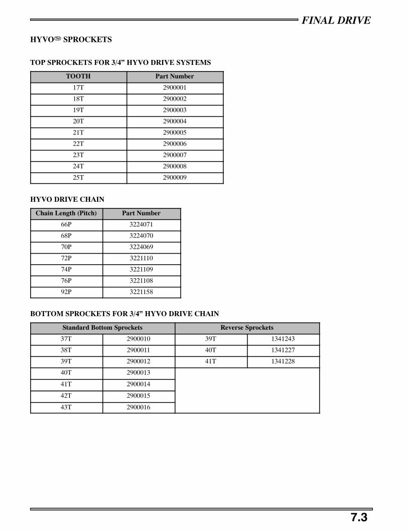
FINAL DRIVE
7.3
HYVOT SPROCKETS
TOP SPROCKETS FOR 3/4” HYVO DRIVE SYSTEMS
TOOTH Part Number
17T 2900001
18T 2900002
19T 2900003
20T 2900004
21T 2900005
22T 2900006
23T 2900007
24T 2900008
25T 2900009
HYVO DRIVE CHAIN
Chain Length (Pitch) Part Number
66P 3224071
68P 3224070
70P 3224069
72P 3221110
74P 3221109
76P 3221108
92P 3221158
BOTTOM SPROCKETS FOR 3/4” HYVO DRIVE CHAIN
Standard Bottom Sprockets Reverse Sprockets
37T 2900010 39T 1341243
38T 2900011 40T 1341227
39T 2900012 41T 1341228
40T 2900013
41T 2900014
42T 2900015
43T 2900016
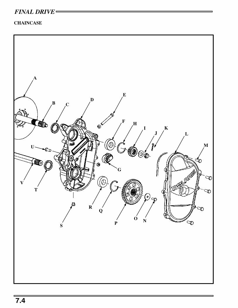
FINAL DRIVE
7.4
CHAINCASE
U
V
T
S
RQ
PO N
M
LK
JI
HF
ED
CB
A
G

FINAL DRIVE
7.5
CHAINCASE
REMOVAL
1. Remove the drain plug (S) and drain chaincase fluid.
2. Remove the chaincase cover attaching bolts (M).
3. Lock parking brake and remove cotter pin (K) washer and nut (J) from the top sprocket (I) on the jackshaft (B).
4. Loosen the chain adjustment bolt (E) and remove chain tensioner assembly (G).
5. Remove bottom sprocket attaching bolt (N) and washer (O), and carefully remove the chain and sprockets (P,I) as an assemblyby rocking both top and bottom sprockets off the shafts.
6. Remove two bolts securing caliper carrier bracket to chaincase.
7. Remove the chaincase mounting bolts (U) that hold the chaincase onto the chassis.
8. Remove brake disc (A) by tapping on jackshaft (B) end with a soft face hammer.
9. Remove the chaincase (D) from the chassis.
BEARING REMOVAL
1. Remove bearing retaining snap rings (H,Q).
2. Pry out the old seals (C,T) from the chaincase.
3. Press out the old bearings (F,R) from the back side. If the bearing pushes out hard, use heat to expand the chaincase bore. Whenremoving always push out the bearing towards the snap ring side of the chaincase.
BEARING ASSEMBLY
1. Apply Loctite 680 to the outer race of the new bearing and press it into the chaincase from the snap ring side. Press on the outerrace only, or damage may occur to bearing.
2. Replace the snap ring (H).
3. Press in new seals (C,T) in the back of the chaincase until the outer edge it flush with the chaincase shoulder.
JACKSHAFT REMOVAL
1. Remove the driven clutch.
2. Lock parking brake and remove cotter pin (K) nut and washer (J) from the top sprocket (I) on the jackshaft (B).
3. Remove the bearing flange on the driven clutch side and remove the jackshaft from the brake disc and chassis by tapping onjackshaft (B) end with a soft face hammer..
4. Inspect drive shaft and jackshaft in bearing contact area. If diameter is .001” (.025 mm) less than non-contact area, shaftsshould be replaced.
JACKSHAFT INSTALLATION
1. Grease and install all new seals and o--rings.
2. Install jackshaft installation tool PN 2871296 on the threads of the jackshaft.
3. Line up bushing, o--ring brake disc and bearing on splined shaft.
4. Install jackshaft alignment tool and secure with castle nut and flat washer. Tighten jackshaft nut securely to ensure positivebearing and jackshaft seating to chaincase.
5. If shaft is not centered, tap shaft with a soft faced hammer until centered. This will align the upper chaincase bearing in thechaincase bore.
6. Once correct jackshaft alignment has been achieved, install lock nuts on chaincase mounting bolts and torque to specification.Remove alignment tool from chaincase.
7. Install jackshaft flangette gasket and bolts. Align grease hole in bearing with hole or fitting in flangette to ensure greasability.Torque nuts to 15--17 ft.lbs. (21--24Nm)

FINAL DRIVE
7.6
DRIVE SHAFT
REMOVAL/INSTALLATION
1. Support the rear of the machine.
2. Remove the suspension. See page 11.1
3. Remove the driven clutch. See page 6.15.
4. Remove the speedo from the driveshaft bearing that is located under the drive clutch.
5. Drain the chaincase, and remove the upper and lower sprockets.
6. Remove the driveshaft by pushing it through the bearing on the chaincase through the bearing hole on the other side of thebulkhead.
7. Install in reverse order. During installation note the assembly of the o--ring on the drive shaft. See illustration below.
Install seal and O-ring with recessfacing chaincase

Hydraulic Brake System Overview 8.1. . . . . . . . . . . . . . . . . . . . . . . .
Brake Bleeding / Fluid Change 8.2. . . . . . . . . . . . . . . . . . . . . . . . . . .Hayes Master Cylinder 8.3. . . . . . . . . . . . . . . . . . . . . . . . . . . . . . . . .
Master Cylinder
Removal 8.3 -- 8.4. . . . . . . . . . . . . . . . . . . . . . . . . . . . . . . . .
Inspection 8.4. . . . . . . . . . . . . . . . . . . . . . . . . . . . . . . .
Replacing Cartridge Subassembly 8.4 -- 8.5. . . . . . . . . . . . .Assembly 8.6 -- 8.10. . . . . . . . . . . . . . . . . . . . . . . . . . . . . . . .
Brake Pad Replacement 8.11. . . . . . . . . . . . . . . . . . . . . . . . . . . . . . . . .

BRAKES
8.1
HYDRAULIC BRAKE SYSTEM OVERVIEW
A B
C
D
E
F
EndView
The Polaris snowmobile hydraulic brake system consists of the following components or assemblies: brake lever, master cylinder,hydraulic hose, brake caliper (slave cylinder), brake pads, and a brake disc which is secured to the drive line.
When the hand activated brake lever (A) is applied, it contacts a piston (B) within the master cylinder. As the master cylinderpiston moves inward it closes a small opening called a compensating port (C) within the cylinder and starts to build pressure withinthe brake system. As the pressure within the system is increased, the pistons (D) located in the brake caliper move toward the discand applies pressure to the moveable brake pads. As the lever pressure is increased, the braking effect is increased.
The friction applied to the brake pads will cause the pads to wear. As the pads wear, the piston within the caliper self-adjusts andmoves further outward.
Brake fluid level is critical to proper system operation. A low fluid level allows air to enter the system causing the brakes to feelspongy.
COMPENSATING PORTLocated within the master cylinder is a small compensating port (C) which is opened and closed by the master cylinder pistonassembly. The port is open when the brake lever is released and the piston is outward. As the temperature within the hydraulicsystem changes, this port compensates for fluid expansion caused by heat, or contraction caused by cooling. During systemservice, be sure this port is open. Due to the high temperatures created within the system during heavy braking, it is very importantthat the master cylinder reservoir have adequate space to allow for the brake fluid to expand. Master cylinder reservoirs should befilled to the top of the fluid level mark on the inside of the reservoir, 1/4, - 5/16, (.6 - .8 cm) below lip of reservoir opening.
WARNINGNever overfill the reservoir. This could alter brake function, resulting in system component
damage or sever personal injury or death.
This system also incorporates a diaphragm (E) as part of the cover gasket and a vent port (F) located between the gasket and thecover. The combination diaphragm and vent allow for the air above the fluid to equalize pressure as the fluid expands or contracts.Be sure the vent is open and allowed to function. If the reservoir is overfilled or the diaphragm vent is plugged, the expanding fluidmay build pressure in the brake system and lead to brake failure.

BRAKES
8.2
BRAKE BLEEDING - FLUID CHANGE
This procedure should be used to change fluid or bleed brakes duringregular maintenance, or after complete brake service. Brake fluid maydamage painted or plastic surfaces. Take care not to spill, and wipe upany spills immediately. Cover parts to avoid damage.
1. Clean reservoir cover thoroughly.
2. Remove screws, cover, and diaphragm from reservoir.
3. Inspect vent slots (A) in cover and remove any debris or blockage.
4. If changing fluid, remove fluid from reservoir with a Mity Vact(PN2870975) pump or similar tool.
Do not remove brake lever when reservoir fluid level is low.
5. Add Polaris DOT 3 brake fluid to within 1/4-5/16, (.6-.8 cm) ofreservoir top.
6. Install a wrench on caliper bleeder screw fitting. Attach a clean,clear hose to fitting and place the other end in a clean container.Be sure the hose fits tightly on fitting.
Fluid may be forced from compensation port (B) when brake lever ispumped. Place diaphragm (C) in reservoir to prevent spills. Do notinstall cover.
7. Slowly pump lever (D) until pressure builds and holds.
8. While maintaining lever pressure, open bleeder screw. Closebleeder screw and release brake lever. Do not release lever beforebleeder screw is tight or air may be drawn into caliper.
9. Repeat procedure until clean fluid appears in bleeder hose and allair has been purged. Add fluid as necessary to maintain level inreservoir.
CAUTION: Maintain at least 1/2” (1.27sm) of brake fluidsin the reservoir to prevent air from entering the master cylin-der.
10. Tighten bleeder screw securely and remove bleeder hose.
11. Add brake fluid to the proper level.
12. Install diaphragm, cover, and screws. Tighten screws tospecification.
13. Field test machine before putting into service. Check for properbraking action and lever reserve. With lever firmly applied, leverreserve should be no less than 1/2, (1.3 cm) from handlebar.
14. Check brake system for fluid leaks.
BA
D
C
No Closer Than1/2″ (1.3 cm) Lever Travel

BRAKES
8.3
HAYEST MASTER CYLINDER1. Cover Screw Kit2. Cover Asm. Kit (Incl. 1,3)3. Cover Gasket4. Parking Lever Spring5. Master Cylinder Assembly6. Screw7. Lever and Pivot Pin Kit8. Screw9. Body/Reservoir Clamp Kit10. Brakelight Switch11. Cartridge Kit12. LH Control Asm13. Pivot Pin Kit14. Parking Lever and Spring Kit
MASTER CYLINDER REMOVAL
1. Position clean shop cloths to catch spilled fluid.
CAUTION: Brake fluid will damage finished surfaces. Donot allow the brake fluid to come into contact with finishedsurfaces. Fusion units use DOT 4 fluid.
2. Remove the handlebar protector pad from the outlet end of thehandlebar master cylinder to access the brake fluid line connector.
SRemove handlebar cover stripsSRemove two screwsSRemove holding clip in front of coverSRemove handlebar pad
3. Loosen the connector approximately 1/4 to 1/2 turn.
4. Loosen and remove the four switch pack and handlebar mastercylinder mounting screws. Put screws aside for later installation.
5. Remove master cylinder from switch pack and handlebar.
CAUTION: Remove switch pack wires from the maser cylin-der housing with extreme care and note where they arerouted for later installation.
CAUTION: Fusion units use DOT 4 fluid.
12
3
4
5
6
7
8 910 11
1213
14

BRAKES
8.4
6. Remove master cylinder cover screws and cover. Pour out thefluid in the reservoir into a container. Unscrew the brake fluid linefrom the master cylinder outlet using a shop cloth to catch theremaining fluid. Drain the fluid from the brake line into theaforementioned container and discard the fluid.
INSPECTION
Due to the critical nature of these parts and procedures, be sure youhave thoroughly read and understand Hydraulic Brake Operation.
1. Thoroughly clean all brake parts with isopropyl alcohol and eitherwipe dry with a clean lint free cloth or lightly blow dry with an airhose. Examine all parts carefully for signs of excessive wear,damage, or corrosion. Replace any parts found to be damaged.Check park lever spring for breakage.
REPLACING CARTRIDGE SUBASSEMBLY
1. Remove master cylinder assembly as described previously.
2. To remove the lever from the housing, squeeze the lever handleand actuate the parking brake lever enough distance for the head ofthe pivot pin to clear the park brake lever.
3. Remove the snap ring and push the pivot pin up through the hole.Remove the pivot pin and the lever.
4. Lift the housing tab on the outlet end of the housing to release thecartridge assembly, allowing the cartridge to be pushed out theback of the housing.
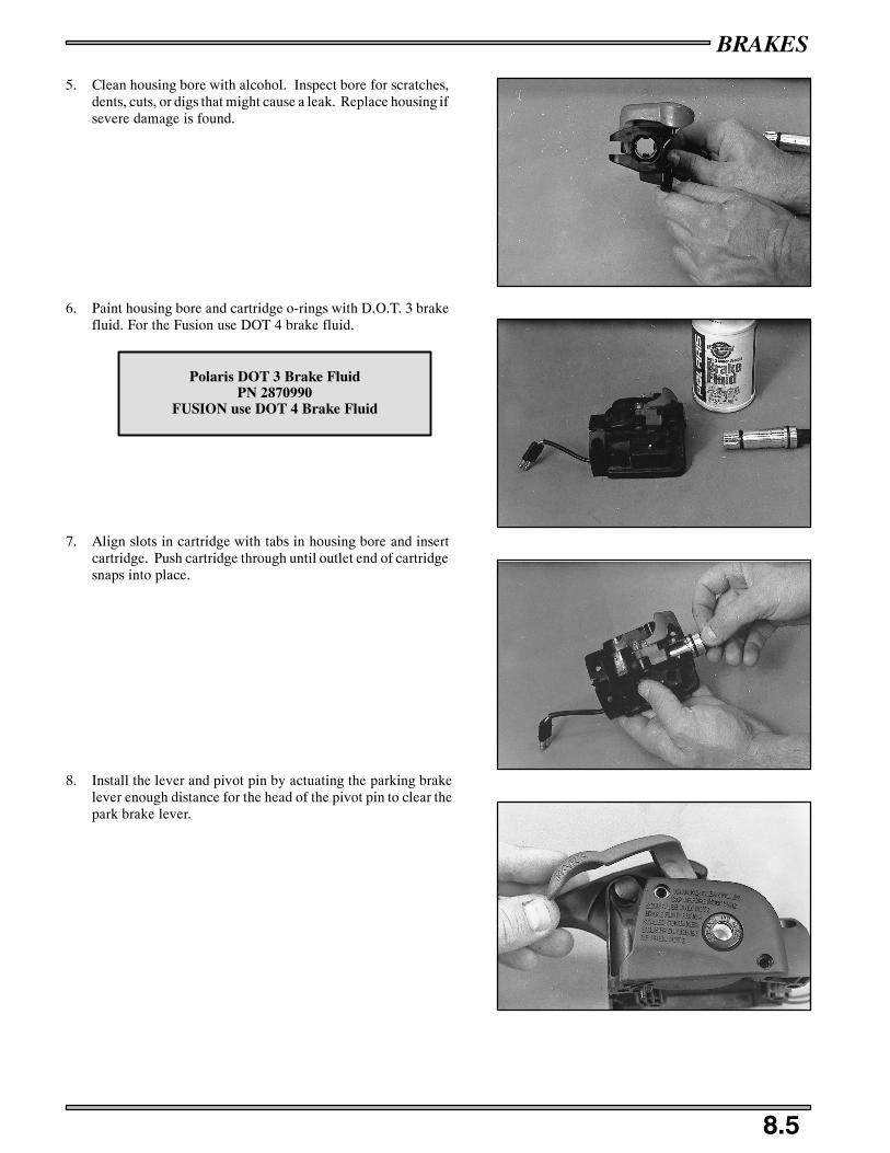
BRAKES
8.5
5. Clean housing bore with alcohol. Inspect bore for scratches,dents, cuts, or digs that might cause a leak. Replace housing ifsevere damage is found.
6. Paint housing bore and cartridge o-rings with D.O.T. 3 brakefluid. For the Fusion use DOT 4 brake fluid.
7. Align slots in cartridge with tabs in housing bore and insertcartridge. Push cartridge through until outlet end of cartridgesnaps into place.
8. Install the lever and pivot pin by actuating the parking brakelever enough distance for the head of the pivot pin to clear thepark brake lever.
Polaris DOT 3 Brake FluidPN 2870990
FUSION use DOT 4 Brake Fluid
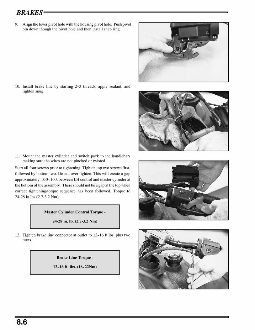
BRAKES
8.6
9. Align the lever pivot hole with the housing pivot hole. Push pivotpin down though the pivot hole and then install snap ring.
10. Install brake line by starting 2--3 threads, apply sealant, andtighten snug.
11. Mount the master cylinder and switch pack to the handlebarsmaking sure the wires are not pinched or twisted.
Start all four screws prior to tightening. Tighten top two screws first,followed by bottom two. Do not over tighten. This will create a gapapproximately .050-.100, between LH control and master cylinder atthe bottom of the assembly. There should not be a gap at the top whencorrect tightening/torque sequence has been followed. Torque to24-28 in.lbs.(2.7-3.2 Nm).
12. Tighten brake line connector at outlet to 12--16 ft.lbs. plus twoturns.
Master Cylinder Control Torque -
24-28 in. lb. (2.7-3.2 Nm)
Brake Line Torque -
12--16 ft. lbs. (16--22Nm)
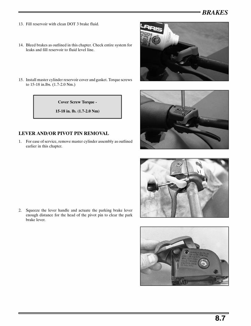
BRAKES
8.7
13. Fill reservoir with clean DOT 3 brake fluid.
14. Bleed brakes as outlined in this chapter. Check entire system forleaks and fill reservoir to fluid level line.
15. Install master cylinder reservoir cover and gasket. Torque screwsto 15-18 in.lbs. (1.7-2.0 Nm.)
LEVER AND/OR PIVOT PIN REMOVAL
1. For ease of service, remove master cylinder assembly as outlinedearlier in this chapter.
2. Squeeze the lever handle and actuate the parking brake leverenough distance for the head of the pivot pin to clear the parkbrake lever.
Cover Screw Torque -
15-18 in. lb. (1.7-2.0 Nm)
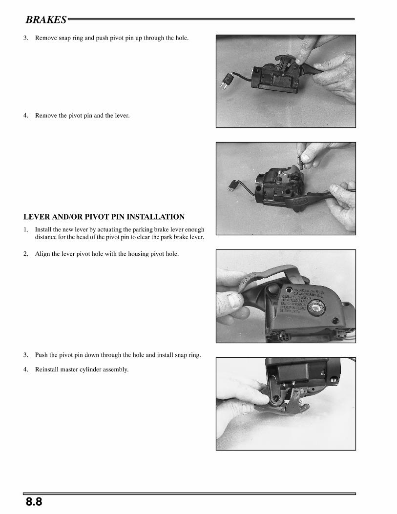
BRAKES
8.8
3. Remove snap ring and push pivot pin up through the hole.
4. Remove the pivot pin and the lever.
LEVER AND/OR PIVOT PIN INSTALLATION
1. Install the new lever by actuating the parking brake lever enoughdistance for the head of the pivot pin to clear the park brake lever.
2. Align the lever pivot hole with the housing pivot hole.
3. Push the pivot pin down through the hole and install snap ring.
4. Reinstall master cylinder assembly.

BRAKES
8.9
PARK BRAKE LEVER AND/OR SPRING REMOVAL
1. Remove master cylinder cover screws and cover.
CAUTION: Brake fluid will damage finished surfaces. Donot allow the brake fluid to come into contact with finishedsurfaces.
2. Using a small screwdriver, lift long spring arm out of its notch inthe housing.
3. While pulling in an upward direction with the brake lever slightlyactivated, gently wiggle the park brake lever and spring from itspivot hole.
PARK BRAKE LEVER AND/OR SPRINGINSTALLATION
1. Place the spring on the upper pivot post of the park lever with theformed spring arm fit into its position on the outer part of the parklever. The straight spring arm will be pointing towards the back.

BRAKES
8.10
2. Rotate the straight spring arm counterclockwise while tilting thepark lever down and inserting the pivot post into the pivot hole.
3. Release the straight arm of the spring and push the park lever pivotpost down into position.
4. With a small screwdriver, push the straight spring arm down untilit snaps into the notch in the housing.
5. Fill reservoir. Replace the master cylinder cover and screws.Torque screws to 15-18 in.lbs. (1.7-2.0 Nm).
Pivot Hole
Rotate
Cover Screw Torque -
15-18 in. lb. (1.7-2.0 Nm)
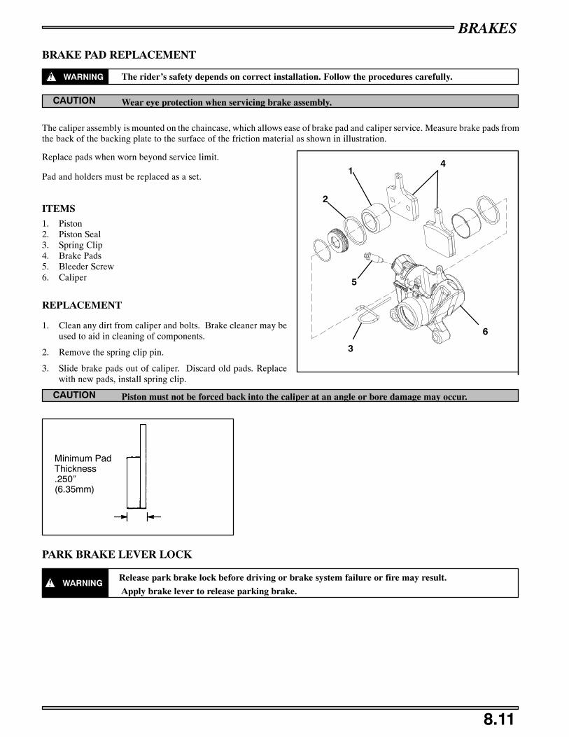
BRAKES
8.11
BRAKE PAD REPLACEMENT
WARNING The rider’s safety depends on correct installation. Follow the procedures carefully.
Wear eye protection when servicing brake assembly.CAUTION
The caliper assembly is mounted on the chaincase, which allows ease of brake pad and caliper service. Measure brake pads fromthe back of the backing plate to the surface of the friction material as shown in illustration.
Replace pads when worn beyond service limit.
Pad and holders must be replaced as a set.
ITEMS1. Piston2. Piston Seal3. Spring Clip4. Brake Pads5. Bleeder Screw6. Caliper
REPLACEMENT
1. Clean any dirt from caliper and bolts. Brake cleaner may beused to aid in cleaning of components.
2. Remove the spring clip pin.
3. Slide brake pads out of caliper. Discard old pads. Replacewith new pads, install spring clip.
Piston must not be forced back into the caliper at an angle or bore damage may occur.CAUTION
PARK BRAKE LEVER LOCK
WARNINGRelease park brake lock before driving or brake system failure or fire may result.
Apply brake lever to release parking brake.
1
2
3
5
4
6
Minimum PadThickness.250″(6.35mm)

BRAKES
8.12
NOTES

Trail/600/700/800 RMK Front Suspension 9.1. . . . . . . . . . . . . . . . . .
600/800 Switchback Front Suspension 9.2. . . . . . . . . . . . . . . . . . . . .900 RMK Front Suspension 9.3. . . . . . . . . . . . . . . . . . . . . . . . . . . . .
Steering Inspection 9.4. . . . . . . . . . . . . . . . . . . . . . . . . . . . . . . . . . . .
Camber Definition 9.5. . . . . . . . . . . . . . . . . . . . . . . . . . . . . . . . . . . . .
Radius Rod and Tie Rod End Procedure 9.5. . . . . . . . . . . . . . . . . . . .
Rod End Engagement Guidelines 9.5. . . . . . . . . . . . . . . . . . . . . . . . .IFS Steering Alignment Specifications 9.6. . . . . . . . . . . . . . . . . . . . .
Spindle Centering / Set Up Width / Camber Adjustment 9.7. . . . . . .
Camber Adjustment 9.8 -- 9.9. . . . . . . . . . . . . . . . . . . . . . . . . . . . . . . . . . . .
Handlebar Centering 9.10. . . . . . . . . . . . . . . . . . . . . . . . . . . . . . . . . . .
Toe Adjustment 9.10. . . . . . . . . . . . . . . . . . . . . . . . . . . . . . . . . . . . . . .Ski Spindle Bushing Removal/Installation 9.11 -- 9.12. . . . . . . . . . . . . . . . . .
Steering Arm Orientation 9.12. . . . . . . . . . . . . . . . . . . . . . . . . . . . . . .
Ski Installation 9.13 -- 9.14. . . . . . . . . . . . . . . . . . . . . . . . . . . . . . . . . . . . . . . .
Torsion Bar Removal/Installation 9.14. . . . . . . . . . . . . . . . . . . . . . . . .
IQ Sway Bar Replacement 9.15. . . . . . . . . . . . . . . . . . . . . . . . . . . . . . .Handlebar Torque and Sequence 9.16. . . . . . . . . . . . . . . . . . . . . . . . . .
Carbide to Ski Placement 9.16. . . . . . . . . . . . . . . . . . . . . . . . . . . . . . . .
IQ Spindle Assembly 9.17. . . . . . . . . . . . . . . . . . . . . . . . . . . . . . . . . . .
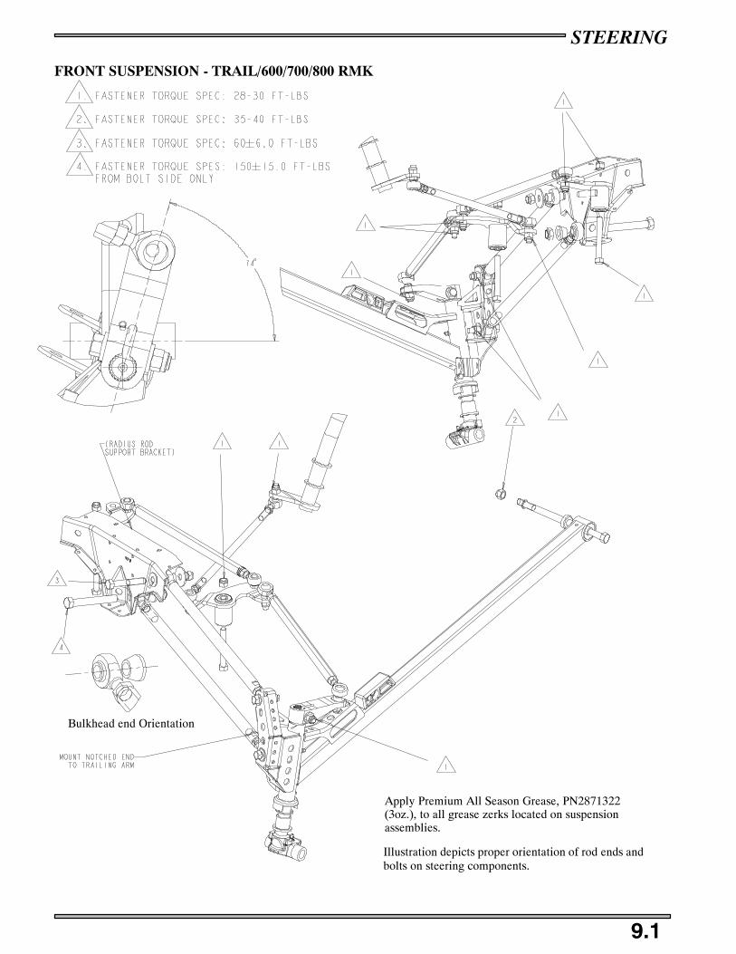
STEERING
9.1
FRONT SUSPENSION - TRAIL/600/700/800 RMK
Illustration depicts proper orientation of rod ends andbolts on steering components.
Bulkhead end Orientation
Apply Premium All Season Grease, PN2871322(3oz.), to all grease zerks located on suspensionassemblies.

STEERING
9.2
FRONT SUSPENSION - 600/800 SWITCHBACK
Illustration depicts proper orientation of rod ends andbolts on steering components.
Bulkhead end Orientation
Apply Premium All Season Grease, PN2871322(3oz.), to all grease zerks located on suspensionassemblies.

STEERING
9.3
IQ FRONT SUSPENSION
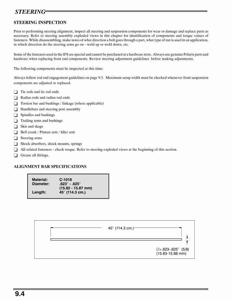
STEERING
9.4
STEERING INSPECTION
Prior to performing steering alignment, inspect all steering and suspension components for wear or damage and replace parts asnecessary. Refer to steering assembly exploded views in this chapter for identification of components and torque values offasteners. While disassembling, make notes of what direction a bolt goes through a part, what type of nut is used in an application,in which direction do the steering arms go on - weld up or weld down, etc.
Some of the fasteners used in the IFS are special and cannot be purchased at a hardware store. Always use genuine Polaris parts andhardware when replacing front end components. Review steering adjustment guidelines before making adjustments.
The following components must be inspected at this time:
Always follow rod end engagement guidelines on page 9.5. Maximum setup width must be checked whenever front suspensioncomponents are adjusted or replaced.
- Tie rods and tie rod ends
- Radius rods and radius rod ends
- Torsion bar and bushings / linkage (where applicable)
- Handlebars and steering post assembly
- Spindles and bushings
- Trailing arms and bushings
- Skis and skags
- Bell crank / Pitman arm / Idler arm
- Steering arms
- Shock absorbers, shock mounts, springs
- All related fasteners - check torque. Refer to steering exploded views at the beginning of this section.
- Grease all fittings.
ALIGNMENT BAR SPECIFICATIONS
45″ (114.3 cm.)
∅=.623-.625″ (5/8)(15.83-15.88 mm)
Material: C-1018Diameter: .623″ - .625″
(15.82 - 15.87 mm)Length: 45″ (114.3 cm.)

STEERING
9.5
CAMBER DEFINITION
The following definitions of camber use automotive terminology todescribe positive and negative positions. Refer to the illustration atright.
S 0 (Neutral) Camber - Spindle is 90_ (perpendicular) to ground
S + (Positive) Camber - Spindle bottom is canted inward towardchassis
S -- (Negative) Camber - Spindle bottom is canted outward fromchassis
RADIUS ROD AND TIE ROD END PROCEDURE
Radius rod and tie rod ends must be parallel to their respective mount-ing surface after tightening jam nut as shown at right. Hold tie rod orradius rod and tighten jam nut. If possible, support the edge of the rodend as shown to keep it from rotating out of position until jam nut istight. When tie rod ends are properly tightened, the tie rod should ro-tate freely approximately 1/8 turn.
ROD END ENGAGEMENT GUIDELINES
Tie Rod OrRadius Rod
Thread Engagement
Tie Rod Or Radius Rod End
Tie Rod Or Radius Rod End MustEngage Rod A Minimum Of 2x ThreadDiameter When Adjustment Is Complete
EXAMPLE7/16″ Rod End x 2 = 7/8″Minimum Thread Engagement =7/8″
11mm x 2 = 22mmMinimum Thread Engagement =22mm
Jam Nut
Diameter Of RodEnd x 2 = MinimumThread Engagement
Positive, Negative, and Neutral (0°) Camber
Front View
Incorrect Correct
Tie Rod End
MountingSurface
SupportEdge

STEERING
9.6
IFS STEERING ALIGNMENT SPECIFICATIONS
The following information is to be used for 2005 Polaris Snowmobile front suspension setup. The data in the following table isbased on the 2005 Polaris factory settings. Maximum Width and Camber measurements are to be taken with the front endelevated and shocks at full extension. Toe alignment is measured at ride height.
Suspension Type Maximum Setup Width± 1/4″ (6mm)
Camber Toe Out(At Ride Height)
42.5” EDGE 42.31” .82”ALL MODELS
42.5 EDGE600, 800 Switchback
42.31(107.4 cm.)
.82(2.08 cm.)
41” EDGE RMK/VERTICAL ES-CAPE
Trail RMK, 600, 700, 800 RMK40.90”
(104cm.).735
(1.87cm.)
1/8” -- 3/8”
TOE OUT
IQ RMK900 RMK 39.50”
(100cm.)2.46”
(6.2cm.) At Normal RideHeight
WIDTH NOTE: Width is measured in inches from the center of the spindles near the grease fitting for the ski mount bolt locatedat the base of the spindle. The tolerance on this measurement is ± 1/4”.
TOE ADJUSTMENT NOTE: Toe is measured in inches with the machine on the ground and resting at normal ride height -not full rebound. Measure at a point 10” (2.54cm.) forward of the ski mount bolt and 10” behind the ski mount bolt, preferablyon the center line of carbide skags. Note: Measurements to points on the skis may be inaccurate.
Camber measurement is taken in inches from top of alignment bar to the top of ski mount hole in the spindle (bushing removed).
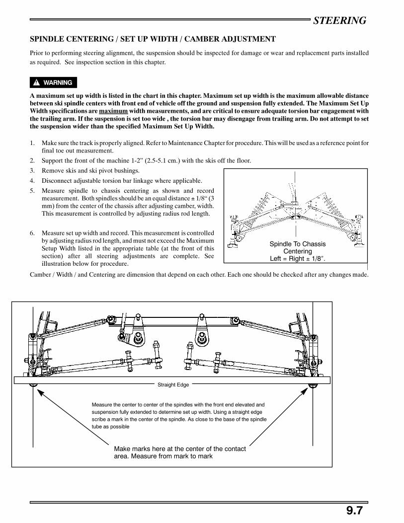
STEERING
9.7
SPINDLE CENTERING / SET UP WIDTH / CAMBER ADJUSTMENT
Prior to performing steering alignment, the suspension should be inspected for damage or wear and replacement parts installedas required. See inspection section in this chapter.
WARNING
A maximum set up width is listed in the chart in this chapter. Maximum set up width is the maximum allowable distancebetween ski spindle centers with front end of vehicle off the ground and suspension fully extended. The Maximum Set UpWidth specifications are maximum width measurements, and are critical to ensure adequate torsion bar engagement withthe trailing arm. If the suspension is set too wide , the torsion bar may disengage from trailing arm. Do not attempt to setthe suspension wider than the specified Maximum Set Up Width.
1. Make sure the track is properly aligned. Refer to Maintenance Chapter for procedure. This will be used as a reference point forfinal toe out measurement.
2. Support the front of the machine 1-2” (2.5-5.1 cm.) with the skis off the floor.
3. Remove skis and ski pivot bushings.
4. Disconnect adjustable torsion bar linkage where applicable.
5. Measure spindle to chassis centering as shown and recordmeasurement. Both spindles should be an equal distance± 1/8“ (3mm) from the center of the chassis after adjusting camber, width.This measurement is controlled by adjusting radius rod length.
6. Measure set up width and record. This measurement is controlledby adjusting radius rod length, and must not exceed the MaximumSetup Width listed in the appropriate table (at the front of thissection) after all steering adjustments are complete. Seeillustration below for procedure.
Camber / Width / and Centering are dimension that depend on each other. Each one should be checked after any changes made.
Make marks here at the center of the contactarea. Measure from mark to mark
Measure the center to center of the spindles with the front end elevated andsuspension fully extended to determine set up width. Using a straight edgescribe a mark in the center of the spindle. As close to the base of the spindletube as possible
Straight Edge
Spindle To ChassisCentering
Left = Right ± 1/8″.
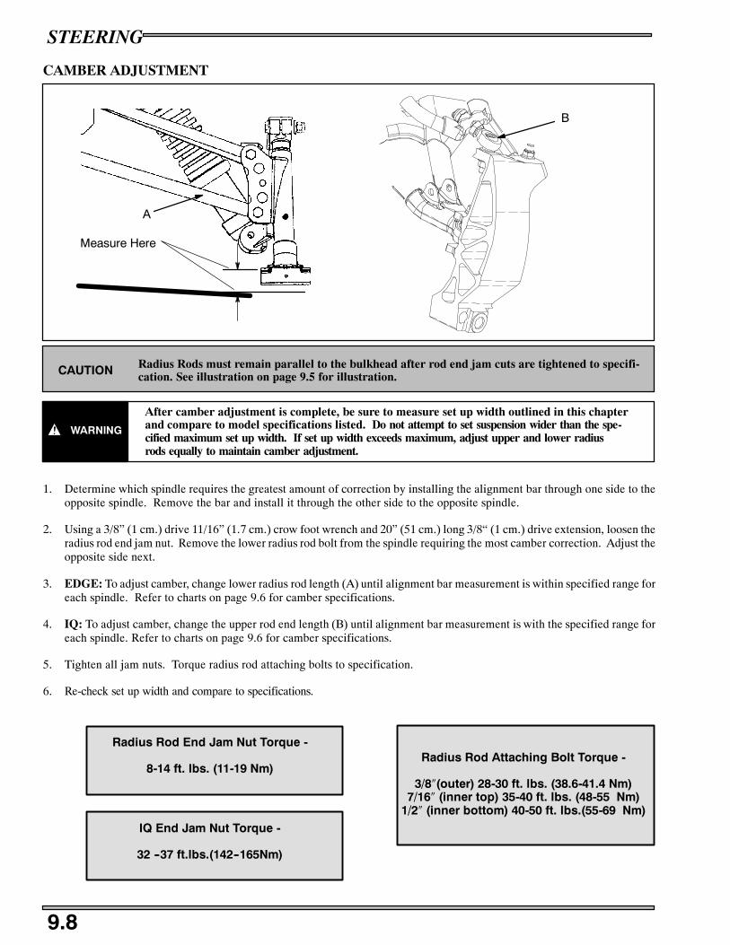
STEERING
9.8
CAMBER ADJUSTMENT
Measure Here
A
B
Radius Rods must remain parallel to the bulkhead after rod end jam cuts are tightened to specifi-cation. See illustration on page 9.5 for illustration.CAUTION
WARNING
After camber adjustment is complete, be sure to measure set up width outlined in this chapterand compare to model specifications listed. Do not attempt to set suspension wider than the spe-cified maximum set up width. If set up width exceeds maximum, adjust upper and lower radiusrods equally to maintain camber adjustment.
1. Determine which spindle requires the greatest amount of correction by installing the alignment bar through one side to theopposite spindle. Remove the bar and install it through the other side to the opposite spindle.
2. Using a 3/8” (1 cm.) drive 11/16” (1.7 cm.) crow foot wrench and 20” (51 cm.) long 3/8“ (1 cm.) drive extension, loosen theradius rod end jam nut. Remove the lower radius rod bolt from the spindle requiring the most camber correction. Adjust theopposite side next.
3. EDGE: To adjust camber, change lower radius rod length (A) until alignment bar measurement is within specified range foreach spindle. Refer to charts on page 9.6 for camber specifications.
4. IQ: To adjust camber, change the upper rod end length (B) until alignment bar measurement is with the specified range foreach spindle. Refer to charts on page 9.6 for camber specifications.
5. Tighten all jam nuts. Torque radius rod attaching bolts to specification.
6. Re-check set up width and compare to specifications.
IQ End Jam Nut Torque -
32 --37 ft.lbs.(142--165Nm)
Radius Rod Attaching Bolt Torque -
3/8″(outer) 28-30 ft. lbs. (38.6-41.4 Nm)7/16″ (inner top) 35-40 ft. lbs. (48-55 Nm)
1/2″ (inner bottom) 40-50 ft. lbs.(55-69 Nm)
Radius Rod End Jam Nut Torque -
8-14 ft. lbs. (11-19 Nm)

STEERING
9.9
- To adjust, lengthen or shorten appropriate lower radius rod until top of bar is within specified camberdistance. Measurement should be taken from top of alignment bar to top of ski pivot bushing hole inspindle (bushing removed). Radius rod must be re-attached to trailing arm before measuring.
CAMBER INSPECTION EXAMPLEAll Models - Elevate Front End - Shocks Installed
Refer to specifications for:SIFS typeSSpecified amount of camber
Attaching Bolts
Radius Rod EndJam Nuts
Suspension Free Hanging WithIFS Shocks Installed
Lower radius rod
Measure Here
Upper radius rod
Typical CRC Shown - Style varies by model
EXAMPLE:Specified Camber = 3/4″ (19mm)Specified Tolerance = ± 5/16″ (8mm)Acceptable Range = 7/16″ - 1 1/16″ (11-27mm)
Specified Camber
CAMBER - ACCEPTABLE RANGE
Refer to specification chart
Range

STEERING
9.10
HANDLEBAR CENTERING
1. With alignment bar in spindles and tie rod ends disconnected,center the steering rack by pointing the pitman arm and idler armstraight forward.
2. Center the handlebars by adjusting drag link length. Tighten jamnuts to specification listed in exploded views.
3. The steering arms should be parallel to the ski centerline orslightly inward.
4. Re-attach steering tie rod ends (C) to steering arms. It may benecessary to loosen the tie rod adjustment jam nuts (B) and adjusttie rod length (A) as required until rod end studs can be installed insteering arm. Torque tie rod end attaching nuts to specificationlisted in exploded views. If tie rod adjustment was necessary, donot tighten them until toe adjustment is complete.
5. Perform toe adjustment.
TOE ADJUSTMENT (EDGE SHOWN)
6. Remove alignment bar from spindles.
7. Toe alignment is set with shocks installed on Edge.
8. Install skis.
9. With the front of the machine still securely supported off theground, install a block or spacer between the rear of the skiframe and the bottom of the trailing arm.
10. Adjust toe so skis / carbides are parallel - zero toe out or toe inwith toe alignment travel bar installed. Measure from equalpoint on skag centerline to straightedge to determine theamount of adjustment required per ski. Measuring from pointson skis may vary and should not be used.
11. To adjust toe, hold tie rod flats or support edge of tie rod endwith a wrench or flat stock to keep it from rotating. Loosen jamnuts on each end of both tie rods. Turn tie rod as required toadjust toe.
12. Hold tie rod and tighten jam nuts. Be sure to position inner andouter tie rod ends parallel to their respective mounting surface asshown. When tie rod ends are properly tightened, the tie rodshould rotate freely approximately 1/8 turn. See page 9.5.
Pitman Arm andIdler Arm PointStraight Forward
Handlebar Centering
Adjust Drag LinkTo Center Bars
A
B
C
A
B
10″
10″
NOTE: Measurements A&B should beequal and taken 10″ (2.54 cm.) fore andaft of spindle center as shown with toealignment travel bars installed.
StraightedgeAgainst Track
10″ 10″Toe Measurement

STEERING
9.11
SKI SPINDLE BUSHING REMOVAL1. Remove steering arm.
2. Slide spindle and ski assembly out bottom of trailing arm andInspect spindle for wear or damage.
3. Remove old bushings and washer from bottom of spindle tubewith a drift punch. Inspect condition of washer and replace ifworn. Install new bushings, tapered end first.
SKI SPINDLE BUSHING INSTALLATION
4. Grease spindle shaft and new bushings with Polaris All SeasonGrease.
Washer
Bushings
All Season Grease
PN 2871322 (3 oz.)PN 2871423 (14 oz.)

STEERING
9.12
5. Install spindle into trailing arm with grease fitting facingrearward.
6. With ski facing straight forward, attach steering arm.
7. Install steering arm bolt and torque to specification.
STEERING ARM ORIENTATION
WARNING
Steering arm orientation is important to ensure proper steering tie rod end thread engagement and steering performance.Always mark steering arms and spindles before removal for reference upon reassembly. When installing new parts or aftersteering arm installation, refer to the illustrations and text below. Always verify proper steering operation after complet-ing adjustments or repairs.
1. The steering arms on each spindle should be parallel to slightlyinward in relation to each ski. When correctly installed thecenterline of the ski and centerline of the ski bolt hole in thespindle will form (approximately) a 90_ angle or slightly greater.
2. If the steering arm is installed incorrectly the threads of thesteering tie rod end will not engage the tie rod sufficiently, and theangle formed between ski and ski bolt centerlines is considerablyless than 90° as shown at right.
3. Reinstall torsion bar linkage (where applicable). Torque attachingbolts to specification.
Spindle Bolt Torque
28-30 ft. lbs. (38.6-41.4 Nm)
Forward
Steering ArmBolt Torque30 ft. lbs.(41.5 Nm)
As Close To90° As Possible
Threads engagetie rod at least3/4″ (19mm).
≥90°
Correct

STEERING
9.13
SKI INSTALLATION
SKI INSTALLATION - COMPOSITE- Install ski stop with largeportion toward rear of ski.**Optional position. Normal instal-lation consists of large end for-ward.
- Install cotter pinand bend both legs.
- Install ski to spindle. From outside of ski, install bolt,washers, and castle nut. Torque to 36 ft.lbs. (5 Nm)
- Carefully lower machine.
- Install ski over spindle, slight-ly in front of ski saddle with skipointing outside.
SKI INSTALLATION - STEEL SKIS
- Slide ski forward until spindleis just behind ski saddle and turnto the forward position.- Slide ski forward so spindle isbehind ski saddle.
- Apply soapy water solution tothe rear portion of the rubber skistop. Install ski stop on top of skisaddle with large portion forward.
- Push ski back to slide spindleinto place. From outside of ski,install bolt and castle nut. Torqueto 36 ft. lbs. Install cotter pin andbend both legs
Forward
RubberSkiStop
Frontof ski
Ski Spindle
Ski Saddle

STEERING
9.14
SKI INSTALLATION
EDGE TORSION BAR REMOVAL
1. Remove trailing arm assembly if applicable.
2. Using a small pin punch, tap out the rivet mandrels in the center ofthe torsion bar support rivets.
3. Using a 1/4“ bit, drill out the center portion of the rivets.
4. Punch out the rivet body.
5. Remove support and torsion bar.
6. Repeat procedure for second torsion bar.
EDGE TORSION BAR INSTALLATION
1. Rivet support in place using Polaris PN 7621449 rivets.
These high strength “Q” rivets are the only replacement rivets recom-
mended for this application.
2. Reinstall torsion bar.
3. Reinstall trailing arm assembly.
4. Check camber and toe adjustments.
ACCUTRAC SKI INSTALLATION
- Install Ski to spindle. From outsideof ski, install bolt, washers and nyloknut. Torque to 36 ft. lbs. (4.97 kg-m).
- Carefully lower machine
- Install ski stop with tall portiontoward front of saddle-less ski.
NOTE: These washers areslightly concave. The insidecurve should go toward the ski.
Ski
Washer
- Saddle-less skis will not requirethe use of the metal support.
- When installing a saddle-less skiwith this type of ski stop, the 90_ flat por-tion of stop should face toward the frontof the ski.
Torsion Bar Support Rivets
PN 7621449

STEERING
9.15
IQ SWAY BAR REPLACEMENT
A
B
C
D
E
SWAYBAR REMOVAL/INSTALLATION
1. Remove the lower control arm.
2. Remove the torx head screws (A) on the sway bar bushing retainer (B).
3. Remove the rivets (C) that hold the bushing (D) in place and remove the bushing.
4. Remove the sway bar (E).
5. Install in reverse order of removal.
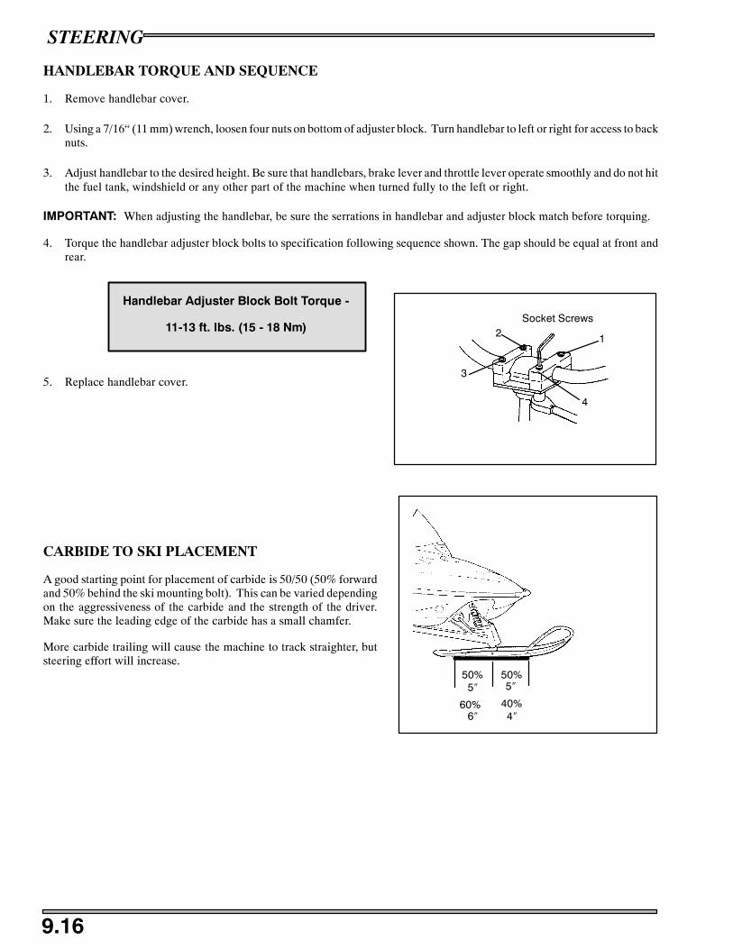
STEERING
9.16
HANDLEBAR TORQUE AND SEQUENCE
1. Remove handlebar cover.
2. Using a 7/16“ (11 mm) wrench, loosen four nuts on bottom of adjuster block. Turn handlebar to left or right for access to backnuts.
3. Adjust handlebar to the desired height. Be sure that handlebars, brake lever and throttle lever operate smoothly and do not hitthe fuel tank, windshield or any other part of the machine when turned fully to the left or right.
IMPORTANT: When adjusting the handlebar, be sure the serrations in handlebar and adjuster block match before torquing.
4. Torque the handlebar adjuster block bolts to specification following sequence shown. The gap should be equal at front andrear.
5. Replace handlebar cover.
CARBIDE TO SKI PLACEMENT
A good starting point for placement of carbide is 50/50 (50% forwardand 50% behind the ski mounting bolt). This can be varied dependingon the aggressiveness of the carbide and the strength of the driver.Make sure the leading edge of the carbide has a small chamfer.
More carbide trailing will cause the machine to track straighter, butsteering effort will increase.
Handlebar Adjuster Block Bolt Torque -
11-13 ft. lbs. (15 - 18 Nm)12
3
4
Socket Screws
50% 50%5″ 5″
60% 40%6″ 4″

STEERING
9.17
IQ STEERING SPINDLE ASSEMBLY
RMK FUSION
IF THE RMK SPINDLE IS ASSEMBLED INCORRECTLYDAMAGE TO THE SPINDLE MAY OCCUR.

Front Suspension Set up and Adjustments 10.1. . . . . . . . . . . . . . . . . . .
IFS Shock Springs 10.2. . . . . . . . . . . . . . . . . . . . . . . . . . . . . . . . . . . . . .IFS Spring Explanation 10.3. . . . . . . . . . . . . . . . . . . . . . . . . . . . . . . . . .
Compression Damping Adjustable Shocks 10.4. . . . . . . . . . . . . . . . . . .
IFS Shock Information 10.5. . . . . . . . . . . . . . . . . . . . . . . . . . . . . . . . . .
IFS Shock Valving Specifications 10.5. . . . . . . . . . . . . . . . . . . . . . . . . .
IQ Spindle/ Control Arm Replacement 10.6. . . . . . . . . . . . . . . . . . . . .
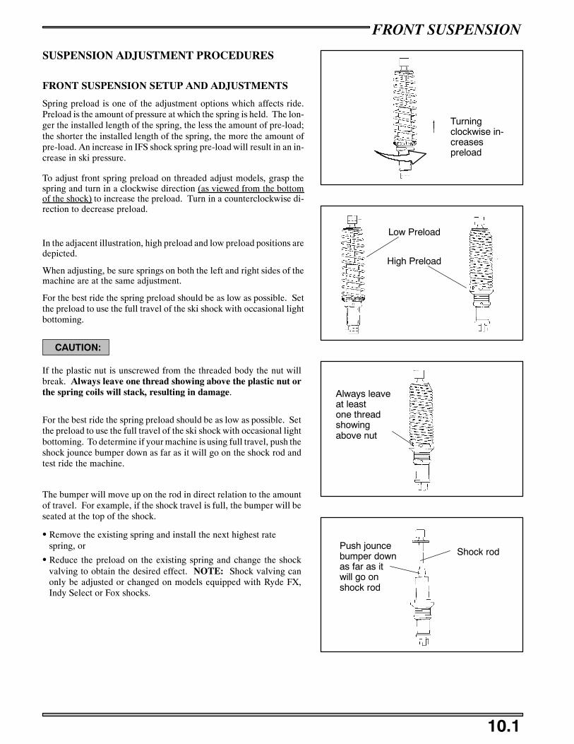
FRONT SUSPENSION
10.1
SUSPENSION ADJUSTMENT PROCEDURES
FRONT SUSPENSION SETUP AND ADJUSTMENTS
Spring preload is one of the adjustment options which affects ride.Preload is the amount of pressure at which the spring is held. The lon-ger the installed length of the spring, the less the amount of pre-load;the shorter the installed length of the spring, the more the amount ofpre-load. An increase in IFS shock spring pre-load will result in an in-crease in ski pressure.
To adjust front spring preload on threaded adjust models, grasp thespring and turn in a clockwise direction (as viewed from the bottomof the shock) to increase the preload. Turn in a counterclockwise di-rection to decrease preload.
In the adjacent illustration, high preload and low preload positions aredepicted.
When adjusting, be sure springs on both the left and right sides of themachine are at the same adjustment.
For the best ride the spring preload should be as low as possible. Setthe preload to use the full travel of the ski shock with occasional lightbottoming.
CAUTION:
If the plastic nut is unscrewed from the threaded body the nut willbreak. Always leave one thread showing above the plastic nut orthe spring coils will stack, resulting in damage.
For the best ride the spring preload should be as low as possible. Setthe preload to use the full travel of the ski shock with occasional lightbottoming. To determine if your machine is using full travel, push theshock jounce bumper down as far as it will go on the shock rod andtest ride the machine.
The bumper will move up on the rod in direct relation to the amountof travel. For example, if the shock travel is full, the bumper will beseated at the top of the shock.
S Remove the existing spring and install the next highest ratespring, or
S Reduce the preload on the existing spring and change the shockvalving to obtain the desired effect. NOTE: Shock valving canonly be adjusted or changed on models equipped with Ryde FX,Indy Select or Fox shocks.
Turningclockwise in-creasespreload
Low Preload
High Preload
Always leaveat leastone threadshowingabove nut
Push jouncebumper downas far as itwill go onshock rod
Shock rod

FRONT SUSPENSION
10.2
IFS SHOCK SPRINGS
PartNumber
Total # ofCoils
Active# of
Coils
Rate(#/in)
FreeLength
WireDia.
End Dia#1
End Dia#2 O.D.” Tabbed Application
7041396-067 13.35 11.35 50.00 11.88” .283” 1.89” 2.25” 2.82 Yes Ryde FX
7041398-067 12.72 10.72 75.00 11.88” .312” 1.89” 2.25” 2.88 Yes Ryde FX
7041405-067 13.40 11.40 65.00 11.88” .306” 1.89” 2.25” 2.82 Yes Ryde FX
7041489-067 14.70 74/120 11.30” .312” 1.89” 1.89” 2.75 Yes Fox
7041491-067 13.00 11.00 185.00 13.50” .438” 1.90” 2.48” 3.60 Yes
7041520-067 10.60 8.60 90.00 10.50” .283” 1.89” 1.89” 2.57 No
7041528-067 17.57 74/160 var 11.30” .306” 1.89” 1.89” 2.53 Yes
7041529-067 19.39 50/140 var 11.30” .283” 1.89” 1.89” 2.50 Yes
7041530-067 14.42 70/105 var 10.50” .283” 1.89” 1.89” 2.50 Yes
7041549-067 9.17 140.00 10.75” .331” 1.89” 2.25” 2.75 Yes Ryde FX
7041550-067 8.29 120.00 10.80” .306” 1.89” 2.25” 2.75 Yes Ryde FX
7041551-067 9.55 100.00 10.75” .306” 1.89” 2.25” 2.75 Yes Ryde FX
7041552-067 9.09 80.00 10.75” .283” 1.89” 2.25” 2.75 Yes Ryde FX
7041553-067 11.46 60.00 11.33” .283” 1.89” 2.25” 2.75 Yes Ryde FX
7041554-067 9.09 80.00 10.75” .283” 1.89” 1.89” 2.75 Yes Fox
7041571-067 10.40 8.40 70.00 10.50” .263” 1.89” 1.89” 2.53 No
7041573-067 9.28 160.00 10.00” .331” 1.89” 1.89” 2.91 Yes Fox
7041574-067 10.32 140.00 10.25” .331” 1.89” 1.89” 2.91 Yes Fox
7041575-067 10.36 120.00 11.42” .331” 1.89” 1.89” 2.87 Yes Fox
7041576-067 9.55 100.00 10.80” .306” 1.89” 1.89” 2.86 Yes Fox
7041591-067 12.79 80.00 12.25” .306” 1.89” 1.89” 2.75 Yes
7041598-067 9.71 105.00 9.33” .312” 1.89” 2.25” 2.894 Yes
7041613-067 14.01 75.00 11.88” .295” 1.89” 1.89” 2.62 Yes Fox
7041668-067 6.94 70.00 4.00” .219” 1.89” 1.89” 2.34 No
7041669-067 6.27 80.00 4.00” .218” 1.89” 1.89” 2.33 No
7041670-067 6.28 90.00 4.00” .225” 1.89” 1.89” 2.35 No
7041671-067 11.71 160.00 9.00” .331” 1.89” 1.89” 2.56 No Fox
7041672-067 10.63 180.00 9.00” .331” 1.89” 1.89” 2.56 No Fox
7041673-067 12.72 200.00 9.00” .362” 1.89” 1.89” 2.62 No Fox
7041674-067 12.72 220.00 9.00” .362” 1.89” 1.89” 2.62 No Fox
7041677-067 10.43 140.00 9.00” .306” 1.89” 1.89” 2.52 No Fox
7041678-067 8.65 100.00 7.00” .262” 1.89” 1.89” 2.43 No
7041683-067 12.12 80.00 11.88” .312” 1.89” 1.89” 2.87 Yes Ryde FX
7041698-067 5.84 100.00 4.00” .225” 1.89” 1.89” 2.35 No Fox
7041699-067 5.75 120.00 4.00” .235” 1.89” 1.89” 2.37 No Fox
7041701-067 10.57 120.00 9.00” .295” 1.89” 1.89” 2.49 No Fox
7041820-067 5.98 140.00 4.00” .250” 1.89” 1.89” 2.43 No Fox
7041821-067 5.91 160.00 4.00” .262” 1.89” 1.89” 2.49 No Fox
7041826-067 9.19 160.00 7.00” .306” 1.89” 1.89” 2.54 No Fox
7041826-067 8.85 180.00 7.00” .312” 1.89” 1.89” 2.54 No Fox
7041828-067 9.61 200.00 7.00” .331” 1.89” 1.89” 2.59 No Fox
7041829-067 8.92 220.00 7.00” .331” 1.89” 1.89” 2.59 No Fox

FRONT SUSPENSION
10.3
SPRINGS
Two types of springs are employed in Polaris suspensions, coil springsand torsion springs. Following is some of the terminology used whenreferring to coil springs.
S Free length - the length of a coil spring with no load applied tothe spring
S Installed length - the length of the spring between the spring re-tainers. If the installed length of the spring is less than the freelength, it will be pre-loaded.
S Spring rate - the amount of force required to compress a coilspring one inch. For example, if 150 pounds of force are requiredto compress a spring 1 inch, the spring rate would be 150 #/in.
S Straight rate spring - the spring requires the same amount of force to compress the last one inch of travel as the first one inchof travel. For example, if a 150 #/in. spring requires 150 pounds of force to compress it one inch, 300 pounds of force wouldcompress it two inches, 450 pounds of force would compress it three inches, etc.
S Progressively wound spring - the rate of the spring increases as it is compressed. For example, a 100/200 #/in. rate springrequires 100 pounds of force to compress the first one inch, but requires 200 additional pounds to compress the last one inch.
When a bump is encountered by the suspension, the force of the bump compresses the spring. If the force were 450 pounds, a100 #/in. spring would compress 4.5 inches. A 150 #/in. spring would only compress 3 inches. If the suspension had 4 inchesof spring travel the 100 #/in. spring would bottom out, while the 150 #/in. spring would have one inch of travel remaining.
Coil SpringLength
InstalledLength

FRONT SUSPENSION
10.4
COMPRESSION DAMPING ADJUSTABLE SHOCKSSnowmobiles equipped with the Indy Select or Ryde FX shocks allow the driver to make adjustments to the compression valvingby turning the screw located near the base of the shock.
ADJUSTMENT
Locate the adjustment screw near the base of the shock. NOTE: This adjustment is easiest to make with the machine tippedon its side.
WARNING
Be sure to shut off the fuel supply before tipping the machine to prevent fuel spillage and flooding of the carburetors.
By turning the screw clockwise (a small screwdriver or dime work well), the compression valving is increased, stiffening the ride.To soften the ride, reduce the compression by turning the screw counter-clockwise. A great deal of ride performance is accom-plished with a mere 1/2 to 1 turns. There are approximately 3 full turns of adjustment available.
How to Adjust IFSIf the suspension is “bottoming,” tighten the compression screw clockwise in 1/2 turn increments until the bottoming stops.Backing off 1/4 turn counter-clockwise at this point should give you the best possible ride ensuring use of the full travel of thesuspension. The opposite procedure should be used if the suspension is too stiff upon initial set-up.
If bottoming continues after the screw is turned in full clockwise, the compression spring should be adjusted with the threadedadjustment collar. Back the screw out to the original starting position after the compression spring has been adjusted.
Riding conditions are ever changing. Keep in mind the compression damping adjustable screw can be adjusted at any time toachieve the best possible ride in any condition.
NOTE: Whenever shocks are replaced or reinstalled for any reason, the adjustment screw should be located toward the insideof the suspension. Access to the adjuster is not possible if reversed. Fox Shocks should be installed with the charge fitting up.
AdjustmentScrew
Threaded AdjustmentCollar

FRONT SUSPENSION
10.5
SHOCK INFORMATION
IFS SHOCKS
IFS Shocks
Shock PN ExtendedLength(in)
CollapsedLength (in) Stroke(in) Shock
Rod (in) IFP Depth (in) Shaft Part # PSI
7042197 17.28 13.78 5.26 .49 N/A N/A N/A
7042059* 17.25 12.0 5.25 .49 7.46 1700025 200
7043049 17.02 11.27 5.75 .49 N/A N/A N/A
7043090* 17.00 11.20 5.80 .49 6.54 1700072 200
7043083* 17.69 12.56 5.13 .49 7.77 1700194 200
IFS SHOCK VALVING SPECIFICATIONS
C7042059 7043090
C7043083
CO .700X.012 C
O.700X.015
CO .700X.012
MP
.900X.010OM .800X.006 M
P.900X.010
PR 1.00X.008
MPR
.900X.006PR 1.00X.008R
ES
1.10X.012 RE
1.00X.006RES
1.10X.012S-S
1.25X.015ES- 1.10X.008 S-
S1.25X.015
SI .900X.008
SSI
1.25X.006SI .900X.008I
ON
1.00X.006 IO
.800X.008ION
1.00X.006N 1.30X.006
ON 1.10X.006 N 1.30X.006
1.30X.008
PISTON ORIFICE .086 PISTON ORIFICE .081 PISTON ORIFICE .086
R1.25X.008
RE
1.25X.010RE- 1.10X.008 R
E1.25X.010
E-B
1.10X.010EBO
1.00X.008 E-B
1.10X.010BOU
1.00X.008OU .900X.008
BOU
1.00X.008UN
.900X.008UND
.800X.008 UN
.900X.008ND .800X.008
D.700X.008
ND .800X.008

FRONT SUSPENSION
10.6
IQ SPINDLE REPLACEMENT
A
B
C
DE
F
H
G
I
J
K
SPINDLE REMOVAL
1. Remove the flanged nut (A) on the lower spherical bearing (B).
2. Remove the retaining ring (C) on the lower portion of the spherical bearing.
3. Remove the camber bolt (D) from the top of the spindle.
4. Remove the steering arm from the spindle.
5. Replace the spindle.
SPINDLE REPLACEMENT
1. Replace the steering arm and torque the bolt to 29 ft.lbs.
2. Replace the camber bolt (D) and torque the jam nut (F) to 35 ft.lbs.
3. Replace the retainer ring (C) on to the lower portion of the spherical bearing.
4. Replace the flanged nut (A) on the lower spherical bearing bolt (E) and torque to 29 ft.lbs.
UPPER AND LOWER CONTROL ARM REMOVAL
1. Remove the spindle and shock.
2. Remove the lower control arm bulk head blots (G).
3. Remove the lower control arm (B) and remove bushings (H).
4. Remove the upper control arm bolts (I).
5. Remove the upper control arm (J) and remove the bushings (K).
6. Install in reverse order and follow the torque specifications found on page 9.3

Rear Suspension Removal/Installation 11.1. . . . . . . . . . . . . . . . . . . . . .
Rear Suspension Operation 11.2. . . . . . . . . . . . . . . . . . . . . . . . . . . . . . .Rear Suspension Adjustment 11.3. . . . . . . . . . . . . . . . . . . . . . . . . . . . . .
Front Torque Arm Limiter Strap Adjustment 11.4. . . . . . . . . . . . . . . . .
Suspension Adjustment Procedures 11.4. . . . . . . . . . . . . . . . . . . . . . . . .
Rear Torsion Spring Tension 11.5. . . . . . . . . . . . . . . . . . . . . . . . . . . . . .
Torsion Spring Types 11.6. . . . . . . . . . . . . . . . . . . . . . . . . . . . . . . . . . . .Optional Torsion Springs 11.7 -- 11.8. . . . . . . . . . . . . . . . . . . . . . . . . . . . . . . . .
Hi--fax Replacement 11.9. . . . . . . . . . . . . . . . . . . . . . . . . . . . . . . . . . . . .
Track Clip Removal 11.9. . . . . . . . . . . . . . . . . . . . . . . . . . . . . . . . . . . . .
Suspension Points / Torque Specifications 11.10. . . . . . . . . . . . . . . . . . .
Suspension Components 11.10. . . . . . . . . . . . . . . . . . . . . . . . . . . . . . . . .Switchback/RMK 136’ Suspension Set Up 11.11. . . . . . . . . . . . . . . . . . .
RMK 144”/151”/159”/166” Suspension Set Up 11.12. . . . . . . . . . . . . . .
Front Torque Arm Limiter Strap Adjustment 11.13. . . . . . . . . . . . . . . . .
Rear Shock Information 11.14. . . . . . . . . . . . . . . . . . . . . . . . . . . . . . . . . .
Rear Shock Valving 11.15. . . . . . . . . . . . . . . . . . . . . . . . . . . . . . . . . . . . .Valving Part Numbers 11.16. . . . . . . . . . . . . . . . . . . . . . . . . . . . . . . . . . .
Shock Rebuilding Tools 11.17. . . . . . . . . . . . . . . . . . . . . . . . . . . . . . . . . .
Shock Valving Arrangement 11.18. . . . . . . . . . . . . . . . . . . . . . . . . . . . . .
Gas Shock Maintenance 11.19. . . . . . . . . . . . . . . . . . . . . . . . . . . . . . . . . .
Ryde FX Shock Rebuilding 11.20 -- 11.24. . . . . . . . . . . . . . . . . . . . . . . . . . . . . . .Troubleshooting 11.25. . . . . . . . . . . . . . . . . . . . . . . . . . . . . . . . . . . . . . . .

REAR SUSPENSION
11.1
REAR SUSPENSION
A B C
REMOVAL
This system consists of a right side mounted chaincase with right side mounted brake assembly.
1. Turn OFF fuel valve (if applicable).
2. Drain all the fuel from the fuel tank into an approved container to avoid spillage.
3. Support the rear of the machine (A).
4. Place drip pan under chaincase and remove drain plug. Dispose of used chaincase oil properly.
5. Remove drive belt and driven clutch.
6. Remove three bolts, nuts, and washers securing angle drive and bearing flannelettes (B).
7. Loosen the track tension.
8. Remove four suspension mounting bolts.
9. Place a protective mat on floor and tip machine onto left side.
10. Unhook the rear torsion springs to relieve pressure on the torque arm for ease of removal. Loosen rear shaft bolts and adjusterbolts, slide rear shaft forward for ease of removal.
11. Remove rear suspension by pulling rear of track outward and sliding suspension forward. Lift out rear of suspension first (C).
INSTALLATION
1. With the machine on its side, insert the front of the suspension assembly into the chassis first.
2. Carefully turn the machine upright and support it like you did when removed the suspension.
3. Align the suspension rails with the track clips.
4. Lower the machine so that you can align the suspension bolts, through the chassis and into the suspension mounts.
5. Adjust the track tension to the correct specification found on page 3.10.
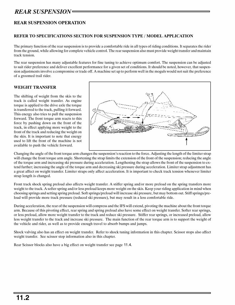
REAR SUSPENSION
11.2
REAR SUSPENSION OPERATION
REFER TO SPECIFICATIONS SECTION FOR SUSPENSION TYPE / MODEL APPLICATION
The primary function of the rear suspension is to provide a comfortable ride in all types of riding conditions. It separates the riderfrom the ground, while allowing for complete vehicle control. The rear suspension also must provide weight transfer and maintaintrack tension.
The rear suspension has many adjustable features for fine tuning to achieve optimum comfort. The suspension can be adjustedto suit rider preference and deliver excellent performance for a given set of conditions. It should be noted, however, that suspen-sion adjustments involve a compromise or trade off. A machine set up to perform well in the moguls would not suit the preferenceof a groomed trail rider.
WEIGHT TRANSFER
The shifting of weight from the skis to thetrack is called weight transfer. As enginetorque is applied to the drive axle the torqueis transferred to the track, pulling it forward.This energy also tries to pull the suspensionforward. The front torque arm reacts to thisforce by pushing down on the front of thetrack, in effect applying more weight to thefront of the track and reducing the weight onthe skis. It is important to note that energyused to lift the front of the machine is notavailable to push the vehicle forward.
Changing the angle of the front torque arm changes the suspension’s reaction to the force. Adjusting the length of the limiter strapwill change the front torque arm angle. Shortening the strap limits the extension of the front of the suspension; reducing the angleof the torque arm and increasing ski pressure during acceleration. Lengthening the strap allows the front of the suspension to ex-tend further; increasing the angle of the torque arm and decreasing ski pressure during acceleration. Limiter strap adjustment hasa great affect on weight transfer. Limiter straps only affect acceleration. It is important to check track tension whenever limiterstrap length is changed.
Front track shock spring preload also affects weight transfer. A stiffer spring and/or more preload on the spring transfers moreweight to the track. A softer spring and/or less preload keeps more weight on the skis. Keep your riding application in mind whenchoosing springs and setting spring preload. Soft springs/preload will increase ski pressure, but may bottom out. Stiff springs/pre-load will provide more track pressure (reduced ski pressure), but may result in a less comfortable ride.
During acceleration, the rear of the suspension will compress and the IFS will extend, pivoting the machine about the front torquearm. Because of this pivoting effect, rear spring and spring preload also have some effect on weight transfer. Softer rear springs,or less preload, allow more weight transfer to the track and reduce ski pressure. Stiffer rear springs, or increased preload, allowless weight transfer to the track and increase ski pressure. The main function of the rear torque arm is to support the weight ofthe vehicle and rider, as well as to provide enough travel to absorb bumps and jumps.
Shock valving also has an effect on weight transfer. Refer to shock tuning information in this chapter. Scissor stops also affectweight transfer. See scissor stop information also in this chapter.
Rear Scissor blocks also have a big effect on weight transfer see page 11.4.

REAR SUSPENSION
11.3
SUSPENSION ADJUSTMENT PROCEDURES
It is a good idea to have customers break the suspension in for approximately 150 miles (240 km) before fine tuning adjustmentsare made.
All settings will vary from rider to rider, depending on rider weight, vehicle speed, riding style, and trail conditions. We recom-mend starting with factory settings and then customizing each adjustment individually to suit rider preference. The machineshould be methodically tested under the same conditions after each adjustment (trail and snow conditions, vehicle speed,ridingposition, etc.) until a satisfactory ride is achieved. Adjustments should be made to one area at a time, in order to properly evaluatethe change.
The purpose of the front rear scissor stop (FRSS) is to control the bump attitude of the rear suspension. As the front torque arm(FTA) hits the bump, it forces the rear scissor to collapse a predetermined amount, depending on the FRSS block position.
This accomplishes two important things, it allows a lighter spring rate on the FTA because it can borrow spring rate from the reartorsion springs; and it prepares the rear portion of the suspension for the bump, reducing secondary kick back.
The FRSS is made of a resilient material allowing smooth action and preventing any suspension component damage.
This unique feature is applied to the EDGE rear suspensions.
Rear Scissor
Front TorqueArm (FTA)
FRSS with short (low) leg to rear. Note the front torque arm must collapse further to collapse reartorque arm.
Rear Scissor
Front TorqueArm (FTA)
FRSS with long (high) leg to rear. Note this forces rear scissor to collapse with less front torque armmovement than when in short position. This keeps the rails more parallel to the chassis.
FRSS RRSS
FRSS RRSS

REAR SUSPENSION
11.4
FRONT TORQUE ARM LIMITER STRAP ADJUSTMENT
One method of changing ski-to-snow pressure is to change the length of thefront torque arm limiter straps. The limiter strap is normally mounted in thefully extended position.
S Lengthening the straps decreases ski pressure under acceleration.
S Shortening the straps increases ski pressure under acceleration.
Both limiter straps must be adjusted evenly and remain equal in length toavoid improper Hi-Fax and track wear.
SUSPENSION ADJUSTMENT PROCEDURES
The RRSS controls weight transfer from the rear suspension to the skis.It also influences the stiffness of the ride by controlling the amount ofcoupling action between the front and rear torque arms. To increasethe stiffness of the suspension, the RRSS should be set in the high posi-tion.
On EDGE and Fusion models only, the RRSS can be totally removedfor maximum weight transfer. However, unless the torsion springs andrear shock valving are changed, the ride will be compromised. Alwaysmaintain equal adjustment on both sides.
Be sure rear scissor stop face is square with the face of the scissor armto ensure complete contact.
FRSS - low position shown
RRSS - lowposition shown
FRSS - medium position shown
RRSS - highposition shown
Scissor Stop Block Position
Medium
High
LowLow

REAR SUSPENSION
11.5
REAR TORSION SPRING TENSION
Rear spring tension adjustments are made by rotating the eccentric spring block (A) as shown with the engine spark plug tool.The block provides three spring tension positions. This adjustment is easier if the long spring leg is lifted over the roller and re-placed after the block is properly positioned. Always maintain equal adjustment on both sides.
Torsion springs are much like coil springs, although shaped differently. The rate of the torsion spring is controlled by the wirediameter of the spring, and the number of coils. Pre--load is controlled by the free opening angle.
Soft Tension Long End to Front Medium Tension (Short End Up) Firm Tension (Long End Up)
A
AA
Torsion Spring
Load reducesopening angle
Load
WireDia.

REAR SUSPENSION
11.6
ROUND SPRINGS VS SQUARE SPRINGS
Many snowmobiles now utilize a square profile rear torsion spring. Square springs are lighter in weight (1.5 lbs.), and smallerin packaging. The square coils take up less room, therefore allowing the carrier wheels to be positioned more inward in the tunnel.Another benefit of the square profile spring is the ability to maintain the same characteristics of the round spring, but have fewercoils of wire.
The square profile springs will not retrofit to previous models. The length of the coil stack is shorter on the square springs andthe inside diameter of the coil stack is also smaller.
The spring rates between the round wire springs and the square wire springs are identical. For example: 7041465-067 has samespring rate as 7041631-067 even though the wire diameter is different. The chart below shows equal spring rates between round
wire and square wire torsion springs.
Square wire torsion springs will not fit in machines that come with round wire springs standard.
Round Spring Square Spring
Last 3 digits of part numberLast 3 digits of part number
Larger inside diameter Smaller inside diameter
4.5” 3.5”
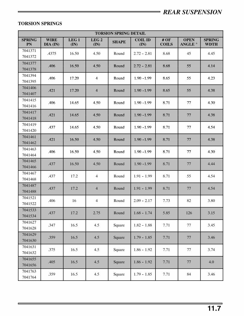
REAR SUSPENSION
11.7
TORSION SPRINGS
TORSION SPRING DETAIL
SPRINGPN
WIREDIA (IN)
LEG 1(IN)
LEG 2(IN) SHAPE COIL ID
(IN)# OF
COILSOPEN
ANGLE _SPRINGWDTH
7041371
7041372.4375 16.50 4.50 Round 2.72 -- 2.81 8.68 45 4.45
7041377406 16 50 4 50 Round 2 72 2 81 8 68 55 4 14
7041378.406 16.50 4.50 Round 2.72 -- 2.81 8.68 55 4.14
7041394406 17 20 4 Round 1 90 1 99 8 65 55 4 23
7041395.406 17.20 4 Round 1.90 --1.99 8.65 55 4.23
7041406421 17 20 4 Round 1 90 1 99 8 65 55 4 38
7041407.421 17.20 4 Round 1.90 --1.99 8.65 55 4.38
7041415406 14 65 4 50 Round 1 90 1 99 8 71 77 4 30
7041416.406 14.65 4.50 Round 1.90 --1.99 8.71 77 4.30
7041417421 14 65 4 50 Round 1 90 1 99 8 71 77 4 38
7041418.421 14.65 4.50 Round 1.90 --1.99 8.71 77 4.38
7041419437 14 65 4 50 Round 1 90 1 99 8 71 77 4 54
7041420.437 14.65 4.50 Round 1.90 --1.99 8.71 77 4.54
7041461421 16 50 4 50 Round 1 90 1 99 8 71 77 4 38
7041462.421 16.50 4.50 Round 1.90 --1.99 8.71 77 4.38
7041463406 16 50 4 50 Round 1 90 1 99 8 71 77 4 30
7041464.406 16.50 4.50 Round 1.90 --1.99 8.71 77 4.30
7041465
7041466.437 16.50 4.50 Round 1.90 --1.99 8.71 77 4.44
7041467
7041468.437 17.2 4 Round 1.91 -- 1.99 8.71 55 4.54
7041487
7041488.437 17.2 4 Round 1.91 -- 1.99 8.71 77 4.54
7041521
7041522.406 16 4 Round 2.09 -- 2.17 7.73 82 3.80
7041533
7041534.437 17.2 2.75 Round 1.68 -- 1.74 5.85 126 3.15
7041627
7041628.347 16.5 4.5 Square 1.82 -- 1.88 7.71 77 3.45
7041629
7041630.359 16.5 4.5 Square 1.79 -- 1.85 7.71 77 3.46
7041631
7041632.375 16.5 4.5 Square 1.86 -- 1.92 7.71 77 3.74
7041655
7041656.405 16.5 4.5 Square 1.86 -- 1.92 7.71 77 4.0
7041763
7041764.359 16.5 4.5 Square 1.79 -- 1.85 7.71 84 3.46

REAR SUSPENSION
11.8
TORSION SPRINGS
TORSION SPRING DETAIL
SPRINGPN
WIREDIA (IN)
LEG 1(IN)
LEG 2(IN) SHAPE COIL ID
(IN)# OF
COILSOPEN
ANGLE _SPRINGWDTH
7041856
7041857.359 16.5 4.5 Square 1.79 -- 1.85 7.71 85 3.46
7041895
7041896.375 16.5 4.5 Square 2.225 6.71 90 3.52
7041897
7041898.405 16.5 4.5 Square 2.225 6.75 90 3.55
7041902
7041903.359 16.5 4.5 Square 1.79 -- 1.85 7.75 90 3.5
7041911
7041912.347 16.5 4.5 Square 1.82 -- 1.88 7.75 90 3.49
7041940
7041941.405 16.5 4.5 Square 2.232 6.71 77 3.55
7041942
7041943.375 16.5 4.5 Square 2.225 6.71 77 3.52
7042064
7042065.359 16.5 4.5 Square 1.95 -- 2.01 7.64 50 3.45
7042068
7042069.359 16.5 4.5 Square 1.95 -- 2.01 8.64 47 3.75
7042079
7042080.375 16.5 4.5 Square 1.98 8.64 47 3.94
7042101
7042102.347 15.625 3.75 Square 1.69 -- 1.71 6.71 77 3.45
7042139
7042140.375 17.7 4 Square 2.35 6.71 77 3.1
7042157
7042158.359 15.625 3.75 Square 1.82 -- 1.84 6.71 77 3.46
7042159
7042160.347 15.625 3.75 Square 1.89 -- 1.91 6.71 77 3.45
7042240
7042241.405 17.7 4 Square 2.35 6.71 77 3.25

REAR SUSPENSION
11.9
HI-FAX REPLACEMENT - ALL MODELS
Hi-Fax replacement on all Polaris models is similar. When any area ofthe Hi-Fax is worn to 1/8“ (3 mm.), it should be replaced. This willsave wear on other vital components.
The slide rail is designed to operate in conditions with adequate snowcover to provide sufficient lubrication. Excessive wear may be due toimproper alignment, improper track adjustment or machine operationon surfaces without snow.
Replace Hi-Fax when worn to 7/16”.
New Hi-Fax are best used in deep snow conditions. Marginal snow orhard-pack conditions are better suited to worn Hi-Fax, or Hi-Faxwhich have been cured or broken in.
HI-FAX REMOVAL
1. Remove suspension from machine.
Some models may allow Hi Fax to be removed by sliding it throughtrack windows with the suspension mounted in the machine.
2. Remove front Hi-Fax retaining bolt. Located at the rail tip.3. Use a block of wood or a drift punch and hammer to drive the
Hi-Fax rearward off the slide rail.
4. With Hi-Fax material at room temperature, install new Hi-Fax byreversing steps 1 - 3.
Lightly coat Hi-Fax track clip area with a lubricant such as LPS2 orWD-40 to ease installation.
Wide Hi-Fax should be narrowed on the leading sides to allow it to fitthrough narrow windows.
TRACK CLIP REMOVAL
1. Position removal tool jaws on edge of clip.
2. Squeeze handles together to spread clip.
3. Remove clip.
TRACK CLIP REPLACEMENT
1. Place new clip in position on track.
2. Connect clip installation tool on top of clip.
3. Squeeze handles together to crimp new clip.
EDGE Hi Fax Wear Limit
7/16″ (1.1 cm)
EDGE
Suggested Hi Fax Wear Limit:
EDGE/ FUSION / M--10 7/16“ (1.1 cm.)
Track Clip Installation Tool (Camoplast)PN 2871041
Track Clip Removal Tool (Camoplast)PN 2871337
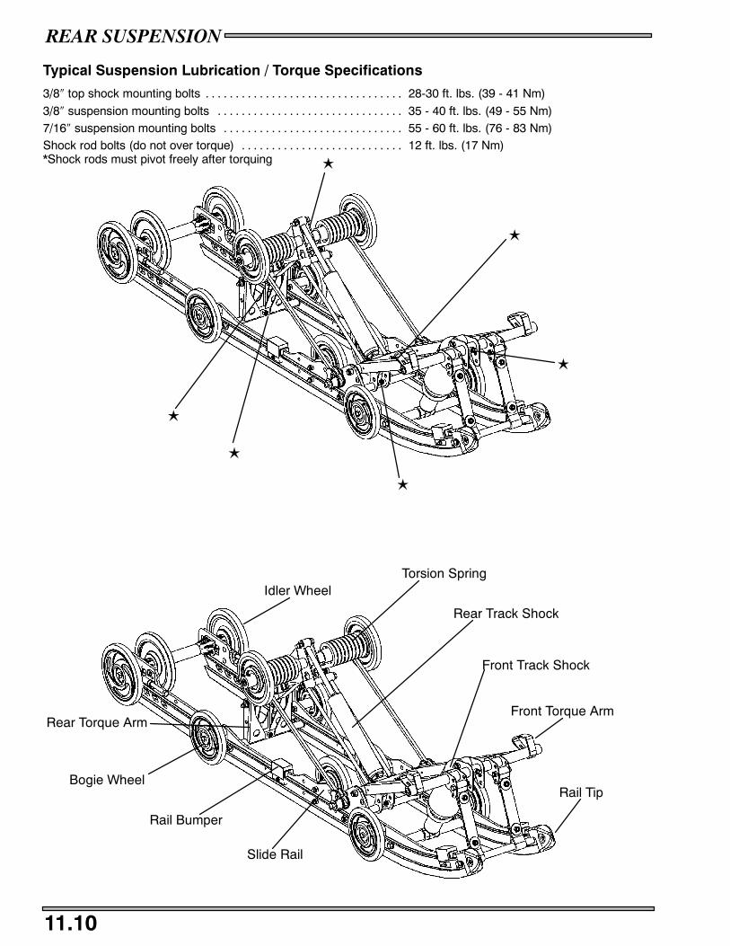
REAR SUSPENSION
11.10
Typical Suspension Lubrication / Torque Specifications
3/8″ top shock mounting bolts 28-30 ft. lbs. (39 - 41 Nm). . . . . . . . . . . . . . . . . . . . . . . . . . . . . . . . .
3/8″ suspension mounting bolts 35 - 40 ft. lbs. (49 - 55 Nm). . . . . . . . . . . . . . . . . . . . . . . . . . . . . . .7/16″ suspension mounting bolts 55 - 60 ft. lbs. (76 - 83 Nm). . . . . . . . . . . . . . . . . . . . . . . . . . . . . .Shock rod bolts (do not over torque) 12 ft. lbs. (17 Nm). . . . . . . . . . . . . . . . . . . . . . . . . . .*Shock rods must pivot freely after torquing L
L
L
L
L
L
Torsion Spring
Bogie Wheel
Slide Rail
Rail Bumper
Rail Tip
Front Track Shock
Rear Track Shock
Idler Wheel
Front Torque ArmRear Torque Arm
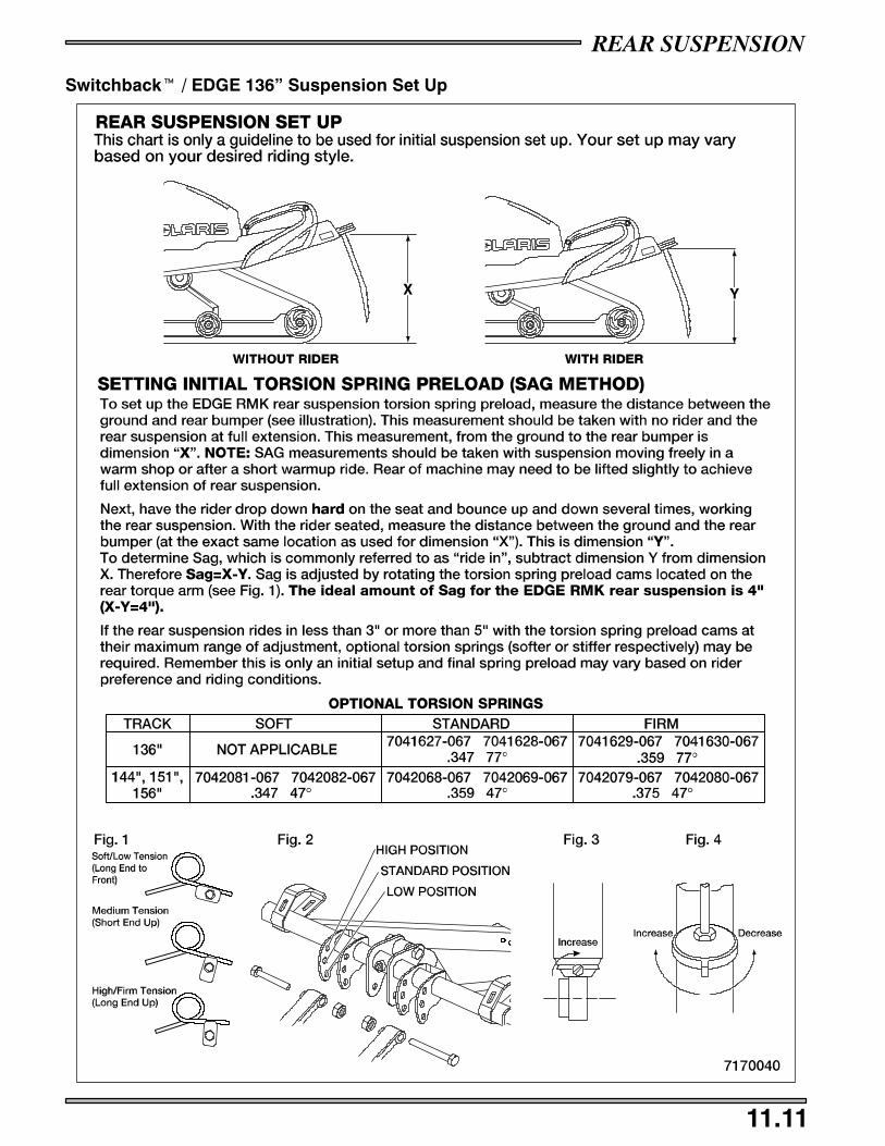
REAR SUSPENSION
11.11
Switchbackt / EDGE 136” Suspension Set Up

900 RMK = 5”
REAR SUSPENSION
11.12
Edge RMK 144” / 151” / 159” / 166”

REAR SUSPENSION
11.13
Front Torque Arm Limiter Strap Adjustment
One method of changing ski-to-snow pressure is to change the length of the front torque arm limiter straps. The limiterstrap is normally mounted in the fully extended position.Below is and example of what the hang tag
High StandardLow
Set Up Recommendations for Optimum Performance*
Deep Powder Snow Powder - Hardpack Hardpack
n Front Torque Arm -low position for maximumlift and floatation.
n Front Torque Arm -standard position foroverall handling and speedover snow
n Front Torque Arm -High position forincreased control and lesstransfer.
* More detailed instructions and options are found on troubleshooting and set-up decals under the hood.
This unit is equipped with a deep lug track. High speed use on hardpack surfacesis not recommended. Track lug damage may occur. High speed use should bekept to a minimum with frequent slow-speed intervals for track cooling.
CAUTION
9918423

REAR SUSPENSION
11.14
SHOCK INFORMATION
FRONT TRACK SHOCKS
Front Track Shocks
Shock PN ExtendedLength(in)
CollapsedLength (in) Stroke(in) Shock
Rod (in) IFP Depth (in) Shaft Part # PSI
7042085 12.49 8.92 3.58 .43 N/A N/A N/A
*7042084 12.51 8.92 3.59 .49 4.77 1700182 200
7043048 12.49 8.92 3.58 .43 N/A N/A N/A
*7042335 12.51 8.92 3.59 .49 4.77 1700182 200
REAR TRACK SHOCKS
Rear Track Shocks
Shock PN ExtendedLength(in)
CollapsedLength (in) Stroke(in) Shock
Rod (in) IFP Depth (in) Shaft Part # PSI
7042058 16.71 10.96 5.75 .49 N/A N/A N/A
*7042176 16.61 10.97 5.64 .49 1.80 1700024 200
7043047 16.71 10.96 5.75 .49 N/A N/A N/A
*7043046 16.61 10.97 5.64 .49 1.80 1700220 200
*Notes a Rebuildable shock
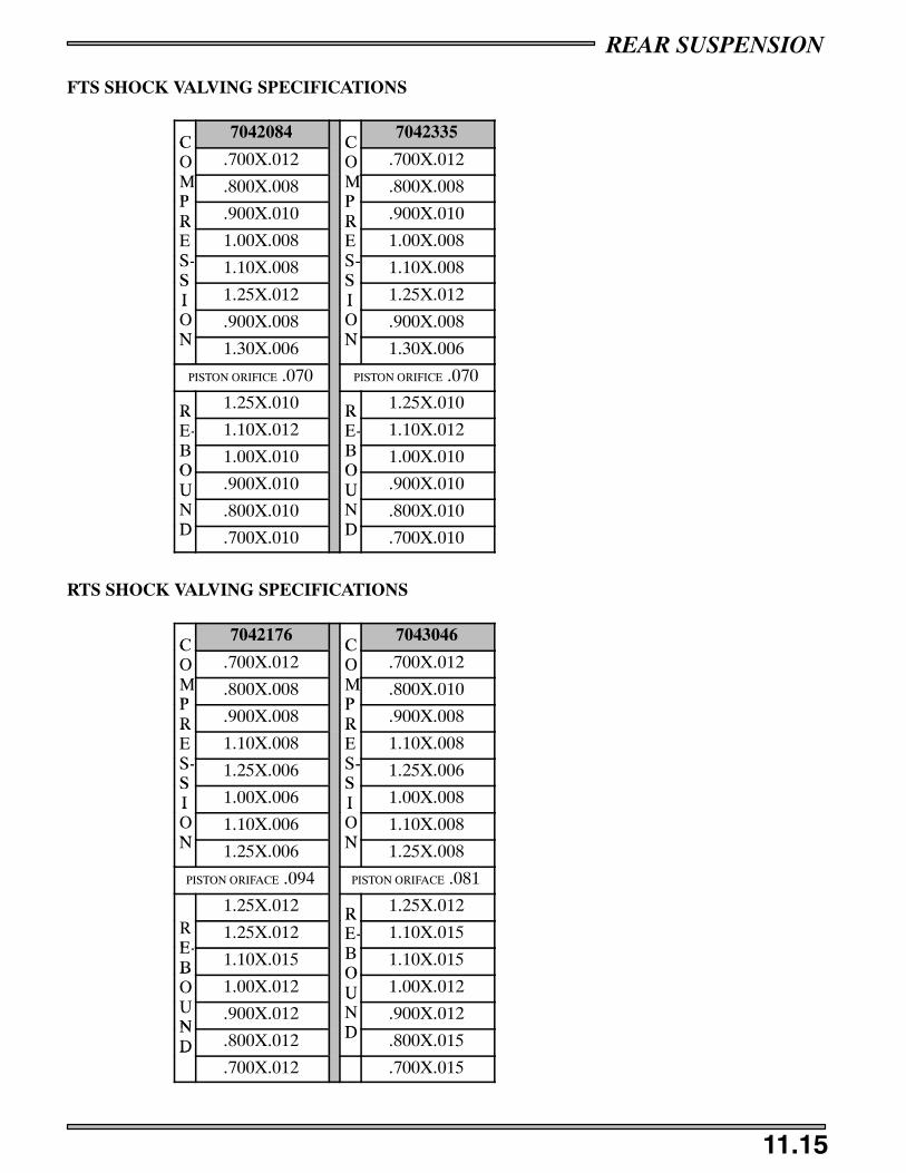
REAR SUSPENSION
11.15
FTS SHOCK VALVING SPECIFICATIONS
C7042084
C7042335
CO .700X.012
CO .700X.012
MP
.800X.008 MP
.800X.008PR .900X.010
PR .900X.010R
ES
1.00X.008RES
1.00X.008S-S
1.10X.008 S-S
1.10X.008SI 1.25X.012
SI 1.25X.012I
ON
.900X.008ION
.900X.008N 1.30X.006 N 1.30X.006
PISTON ORIFICE .070 PISTON ORIFICE .070
R 1.25X.010 R 1.25X.010RE- 1.10X.012
RE- 1.10X.012
BO
1.00X.010 BO
1.00X.010OU .900X.010
OU .900X.010U
ND
.800X.010UND
.800X.010D .700X.010 D .700X.010
RTS SHOCK VALVING SPECIFICATIONS
C7042176
C7043046
CO .700X.012
CO .700X.012
MP
.800X.008 MP
.800X.010PR .900X.008
PR .900X.008R
ES
1.10X.008RES
1.10X.008S-S
1.25X.006 S-S
1.25X.006SI 1.00X.006
SI 1.00X.008I
ON
1.10X.006ION
1.10X.008N 1.25X.006 N 1.25X.008
PISTON ORIFACE .094 PISTON ORIFACE .081
1.25X.012 R 1.25X.012RE
1.25X.012RE- 1.10X.015
E-B 1.10X.015 B
O1.10X.015B
OU
1.00X.012OU 1.00X.012
UN
.900X.012UND
.900X.012ND .800X.012 D .800X.015D
.700X.012 .700X.015
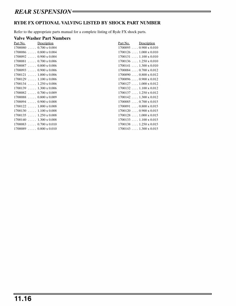
REAR SUSPENSION
11.16
RYDE FX OPTIONAL VALVING LISTED BY SHOCK PART NUMBER
Refer to the appropriate parts manual for a complete listing of Ryde FX shock parts.
Valve Washer Part NumbersPart No. Description Part No. Description1700080 0.700 x 0.004 1700095 0.900 x 0.010. . . . . . . . .1700086 0.800 x 0.004 1700126 1.000 x 0.010. . . . . . . . .1700092 0.900 x 0.004 1700131 1.100 x 0.010. . . . . . . . .1700081 0.700 x 0.006 1700136 1.250 x 0.010. . . . . . . . .1700087 0.800 x 0.006 1700141 1.300 x 0.010. . . . . . . . .1700093 0.900 x 0.006 1700084 0.700 x 0.012. . . . . . . . .1700121 1.000 x 0.006 1700090 0.800 x 0.012. . . . . . . . .1700129 1.100 x 0.006 1700096 0.900 x 0.012. . . . . . . . .1700134 1.250 x 0.006 1700127 1.000 x 0.012. . . . . . . . .1700139 1.300 x 0.006 1700132 1.100 x 0.012. . . . . . . . .1700082 0.700 x 0.009 1700137 1.250 x 0.012. . . . . . . . .1700088 0.800 x 0.009 1700142 1.300 x 0.012. . . . . . . . .1700094 0.900 x 0.008 1700085 0.700 x 0.015. . . . . . . . .1700122 1.000 x 0.008 1700091 0.800 x 0.015. . . . . . . . .1700130 1.100 x 0.008 1700120 0.900 x 0.015. . . . . . . . .1700135 1.250 x 0.008 1700128 1.000 x 0.015. . . . . . . . .1700140 1.300 x 0.008 1700133 1.100 x 0.015. . . . . . . . .1700083 0.700 x 0.010 1700138 1.250 x 0.015. . . . . . . . .1700089 0.800 x 0.010 1700143 1.300 x 0.015. . . . . . . . .

REAR SUSPENSION
11.17
SHOCK REBUILDING TOOLS
SPECIAL TOOLS PART NUMBERSPart No. Description2200421 Gas Shock Recharging Kit2201639 Shock Shaft Seal Protector 1/2”diameter2201640 Shock Shaft Seal Protector 5/8”diameter2870623 Shock Absorber Spring Compression Tool2870803 Shock Spring Pre--Load Adjustment ToolPS--45259 Gas Fill Tool
FOXT SPECIAL TOOLS PART NUMBERSPart No. Description2871021 Shock body Holding Tool2871352 Shock Rod Holding Tool 1/2” rod2872429 Shock Rod Holding Tool 5/8” rod2871232 Fox Shock Spanner2871351 Fox Shock IFP Depth ToolPS--44925 Fox Inner Tube Puller PS 2
RYDE FX TPART NUMBERSPart No. DescriptionPS--45259 Gas Fill Tool and Gauge (Incl. 5 needles)PS--45259--1 Gas Fill Needles replacement packPS--45259--2 Gas Fill Gauge (replacement)PS--45260 Lower Retainer WrenchPS--45261 IFP Positioning / Extraction toolPS--45262 Cylinder Head WrenchPS--45263 Wear Band ToolPS--45629 Arvin Shock Body HolderPS--45280 Shock Collar ToolPS--45821 Shock Reservoir Holder
SUSPENSION REBUILDING VIDEOS ARE ALSO AVAILABLE
PN 9917736 Mono Tube Shocks
PN 9917737 Remote Reservoir Shocks

Shaft End
Nut End
1.300 x .012
1.300 x .010
1.100 x .010
1.00 x .010
.700 x .010
.800 x .010
1.250 x .010
.900 x .010
Standard Valving
1.000 x .010
.800 x .010
.900 x .010
1.100 x .010
Orifice
Rebound Stack
Compression Stack
1-R
2-R
3-R
4-R
5-R
6-R
4-C
3-C
2-C
1-C
5-C
6-C
Typical Valve Stack
Piston OrientationSide with greater # ofslots must face nut end
Piston*
(Toward nut & IFP)Toward Shaft(Fewer slots) Slots
Orifice must be drilled to required size onreplacement valve pistons.
REAR SUSPENSION
11.18
TYPICAL SHOCK VALVING ARRANGEMENT
Shown below is an example of how valving stacks are arranged. The Production Shock Information contain production valvingspecifications and piston orifice sizes.
Parts in the box below are an example of standard valving.
* Note direction of valve piston before disassembly. The side with the greater number of slots should face the IFP (nut endof the shaft).
Changing oil Shocks is recommended annually and should be included when performing end of season storage preparation. Forcompetition use, shocks should be disassembled, inspected and serviced more frequently.
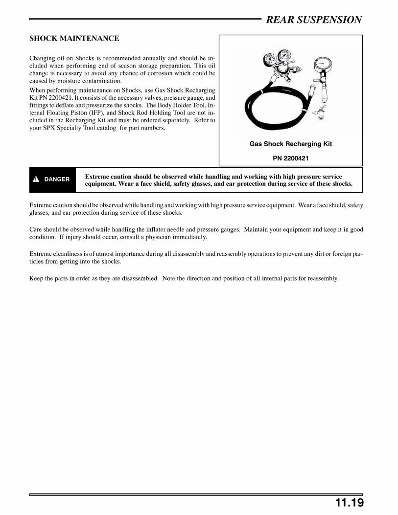
REAR SUSPENSION
11.19
SHOCK MAINTENANCE
Changing oil on Shocks is recommended annually and should be in-cluded when performing end of season storage preparation. This oilchange is necessary to avoid any chance of corrosion which could becaused by moisture contamination.
When performing maintenance on Shocks, use Gas Shock RechargingKit PN 2200421. It consists of the necessary valves, pressure gauge, andfittings to deflate and pressurize the shocks. The Body Holder Tool, In-ternal Floating Piston (IFP), and Shock Rod Holding Tool are not in-cluded in the Recharging Kit and must be ordered separately. Refer toyour SPX Specialty Tool catalog for part numbers.
DANGER Extreme caution should be observed while handling and working with high pressure serviceequipment. Wear a face shield, safety glasses, and ear protection during service of these shocks.
Extreme caution should be observed while handling and working with high pressure service equipment. Wear a face shield, safetyglasses, and ear protection during service of these shocks.
Care should be observed while handling the inflater needle and pressure gauges. Maintain your equipment and keep it in goodcondition. If injury should occur, consult a physician immediately.
Extreme cleanliness is of utmost importance during all disassembly and reassembly operations to prevent any dirt or foreign par-ticles from getting into the shocks.
Keep the parts in order as they are disassembled. Note the direction and position of all internal parts for reassembly.
Gas Shock Recharging Kit
PN 2200421

REAR SUSPENSION
11.20
RYDE FXT SHOCK MAINTENANCEProcedures for the proper disassembly and assembly of RydeFX gas charged IFP and emulsion mono--tube shock absorbers.
DANGER
Before servicing a gas shock it is important that all the gas pressure be discharged from the unit.Refer to the instructions listed below for the proper procedure of discharging the gas pressurefrom a shock. Protective eyewear should be worn to avoid risk of injury while servicing RydeFXgas charged mono--tube shocks.
Remove the shock from the vehicle.
S If shock incorporates spring; remove springand collateral retainers.
Before unscrewing pre--load springs, measure the compressedlength of the installed spring and mark position for reinstallation.(PICTURE 1)
When removing the spring from a shock thatutilizes a fixed lower retainer; the use of a proper springcompressor should be used to avoid risk of bodily injury.
CAUTION:
Wash the shock body in parts cleaner; then dry with compressedair to remove sand and dirt.
WARNING: When using compressed air to dry components, pro-tective eyewear should be worn to avoid risk of injury.
Remove bearing, sleeve and/or bushings from lower shock mounteyelet. Secure the lower mount of the shock in a vise. The use ofsoft jaws is recommend to prevent damage or marks to the shock.(PICTURE 2)
It is important that the gas shock be retained inthe vise by the lower mount. Any other method of securingthe chock body during these procedures may deform theshock body cylinder.
CAUTION:
Remove the small button head screw from the pressure valve as-sembly. (PICTURE 3)
DEPRESSURIZING SHOCK:A) Internal Floating Piston Shocks, using a slotted screwdriver,loosen the pressure valve assembly counter--clockwise two fullrevolutions allowing the gas pressure to fully escape past the pres-sure valve assembly O--ring.
1
2
3
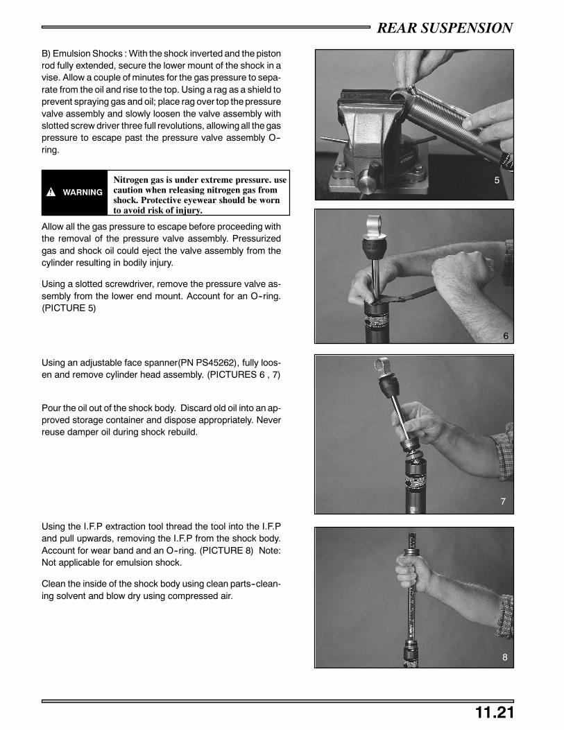
REAR SUSPENSION
11.21
B) Emulsion Shocks : With the shock inverted and the pistonrod fully extended, secure the lower mount of the shock in avise. Allow a couple of minutes for the gas pressure to sepa-rate from the oil and rise to the top. Using a rag as a shield toprevent spraying gas and oil; place rag over top the pressurevalve assembly and slowly loosen the valve assembly withslotted screw driver three full revolutions, allowing all the gaspressure to escape past the pressure valve assembly O--ring.
WARNING
Nitrogen gas is under extreme pressure. usecaution when releasing nitrogen gas fromshock. Protective eyewear should be wornto avoid risk of injury.
Allow all the gas pressure to escape before proceeding withthe removal of the pressure valve assembly. Pressurizedgas and shock oil could eject the valve assembly from thecylinder resulting in bodily injury.
Using a slotted screwdriver, remove the pressure valve as-sembly from the lower end mount. Account for an O--ring.(PICTURE 5)
Using an adjustable face spanner(PN PS45262), fully loos-en and remove cylinder head assembly. (PICTURES 6 , 7)
Pour the oil out of the shock body. Discard old oil into an ap-proved storage container and dispose appropriately. Neverreuse damper oil during shock rebuild.
Using the I.F.P extraction tool thread the tool into the I.F.Pand pull upwards, removing the I.F.P from the shock body.Account for wear band and an O--ring. (PICTURE 8) Note:Not applicable for emulsion shock.
Clean the inside of the shock body using clean parts--clean-ing solvent and blow dry using compressed air.
5
6
7
8
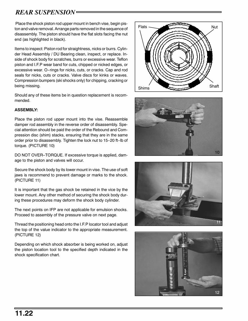
REAR SUSPENSION
11.22
Place the shock piston rod upper mount in bench vise, begin pis-ton and valve removal. Arrange parts removed in the sequenceofdisassembly. The piston should have the flat slots facing the nutend (as highlighted in black).
Items to inspect: Piston rod for straightness, nicks or burrs. Cylin-der Head Assembly / DU Bearing clean, inspect, or replace. In-side of shock body for scratches, burrs or excessive wear. Teflonpiston and I.F.P wear band for cuts, chipped or nicked edges, orexcessive wear. O--rings for nicks, cuts, or cracks. Cap and rodseals for nicks, cuts or cracks. Valve discs for kinks or waves.Compression bumpers (ski shocks only) for chipping, cracking orbeing missing.
Should any of these items be in question replacement is recom-mended.
ASSEMBLY:
Place the piston rod upper mount into the vise. Reassembledamper rod assembly in the reverse order of disassembly. Spe-cial attention should be paid the order of the Rebound and Com-pression disc (shim) stacks, ensuring that they are in the sameorder prior to disassembly. Tighten the lock nut to 15--20 ft--lb oftorque. (PICTURE 10)
DO NOT OVER--TORQUE. If excessive torque is applied, dam-age to the piston and valves will occur.
Secure the shock body by its lower mount in vise. The use of softjaws is recommend to prevent damage or marks to the shock.(PICTURE 11)
It is important that the gas shock be retained in the vice by thelower mount. Any other method of securing the shock body dur-ing these procedures may deform the shock body cylinder.
The next points on IFP are not applicable for emulsion shocks.Proceed to assembly of the pressure valve on next page.
Thread the positioning head onto the I.F.P locator tool and adjustthe top of the value indicator to the appropriate measurement.(PICTURE 12)
Depending on which shock absorber is being worked on, adjustthe piston location tool to the specified depth indicated in theshock specification chart.
Flats
Shims
Nut
Shaft
10
11
12

REAR SUSPENSION
11.23
Apply a thin film of oil onto the floating wear band and O--ring andinstall the floating piston into the top of the shock body, position-ing it below the counterbore. (PICTURE 13)
Using the tool as a handle, push the floating piston down into theshock body, being careful not to damage I.F.P wear band and O--ring, until the value indicator knob comes in contact with theshock body. The piston should now be located correctly. (PIC-TURE 14)
Apply of light film of grease to the pressure valve port counterbore through 360 Degrees, where the pressure valve assemblyO--ring meets.
Screw the pressure valve assembly into the valve port by handwith a slotted head screwdriver; and tighten to 100--110 in.lb oftorque. (PICTURE 15)
Fill the shock body with shock oil:
A) Internal Floating Piston Shocks: Fill the shock body with shockoil to the bottom of the thread within the cylinder.
B) Emulsion Shocks: Fill shock body with 110cc’s of oil. This willallow for the required air space to properly gas charge the shockwith nitrogen gas.
NOTE: -- After filling the shock body with oil, allow a couple ofminutes for all air bubbles to rise to the top.
13
14
15

REAR SUSPENSION
11.24
With the cylinder head assembly pushed down against the pis-ton, carefully, insert the piston rod and assembly into the cylinder;Slightly oscillating the piston rod to allow piston to enter shockbody bore. A light coating of oil on the piston wear band will easeinstallation. (PICTURE 17)
Slowly push the piston rod and assembly into shock body until thecylinder head assembly bottoms on the cylinder counterbore.Slight up and down movement may be required to allow all air topass through piston assembly.
During installation, some shock oil will overflow. Wrap a shopcloth around shock body to catch possible oil overflow. Fastinstallation of the piston rod and assembly may displace the float-ing piston from its original position. This must not occur if thedamper is expected to perform as designed
Using an open face spanner wrench tighten cylinder head se-curely into the shock cylinder. (PICTURE 18)
Pressurize the shock, through the pressure valve, with nitrogengas to the specified pressure. (PICTURE 19)
If using RydeFX inflation tool Refer to Procedures for use of re-placeable inflation needle instruction manual found in the Ry-deFX inflation tool case.
After being compressed, the piston rod should fully extend fromthe shock body once the shock has been pressurized.
Install the small button head screw in the pressure valve assem-bly and tighten securely. (PICTURE 20)
Reinstall sleeve and bushings in lower shock mount.
17
18
19
20
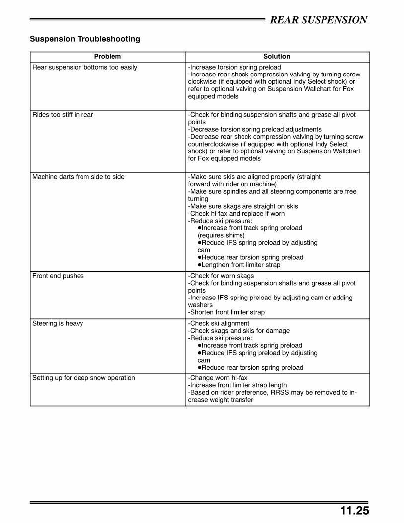
REAR SUSPENSION
11.25
Suspension Troubleshooting
Problem Solution
Rear suspension bottoms too easily -Increase torsion spring preload-Increase rear shock compression valving by turning screwclockwise (if equipped with optional Indy Select shock) orrefer to optional valving on Suspension Wallchart for Foxequipped models
Rides too stiff in rear -Check for binding suspension shafts and grease all pivotpoints-Decrease torsion spring preload adjustments-Decrease rear shock compression valving by turning screwcounterclockwise (if equipped with optional Indy Selectshock) or refer to optional valving on Suspension Wallchartfor Fox equipped models
Machine darts from side to side -Make sure skis are aligned properly (straightforward with rider on machine)-Make sure spindles and all steering components are freeturning-Make sure skags are straight on skis-Check hi-fax and replace if worn-Reduce ski pressure:DIncrease front track spring preload(requires shims)DReduce IFS spring preload by adjustingcamDReduce rear torsion spring preloadDLengthen front limiter strap
Front end pushes -Check for worn skags-Check for binding suspension shafts and grease all pivotpoints-Increase IFS spring preload by adjusting cam or addingwashers-Shorten front limiter strap
Steering is heavy -Check ski alignment-Check skags and skis for damage-Reduce ski pressure:DIncrease front track spring preloadDReduce IFS spring preload by adjustingcamDReduce rear torsion spring preload
Setting up for deep snow operation -Change worn hi-fax-Increase front limiter strap length-Based on rider preference, RRSS may be removed to in-crease weight transfer

REAR SUSPENSION
11.26
NOTES

Edge Hood Removal/Installation 12.1. . . . . . . . . . . . . . . . . . . . . . . . . .Edge Headlight Removal/Installation 12.1. . . . . . . . . . . . . . . . . . . . . .Edge Instrument Removal/Installation 12.1. . . . . . . . . . . . . . . . . . . . .900 RMK Hood ExplodedView 12.2. . . . . . . . . . . . . . . . . . . . . . . . . . .900 RMK Hood Removal/Installation 12.3. . . . . . . . . . . . . . . . . . . . . .900 RMK Front Bumper Removal/Installation 12.3. . . . . . . . . . . . . . .900 RMK Headlight Removal/Installation 12.3. . . . . . . . . . . . . . . . . .900 RMK MFD Removal/Installation 12.3. . . . . . . . . . . . . . . . . . . . . .900 RMK Seat / Fuel Tank Exploded Veiw 12.4. . . . . . . . . . . . . . . . . .900 RMK Fuel Tank Removal 12.5. . . . . . . . . . . . . . . . . . . . . . . . . . . .900 RMK Console 12.6. . . . . . . . . . . . . . . . . . . . . . . . . . . . . . . . . . . . .Seat Cover Removal/Installation 12.7. . . . . . . . . . . . . . . . . . . . . . . . . .Hood Repair 12.8. . . . . . . . . . . . . . . . . . . . . . . . . . . . . . . . . . . . . . . . . .Tool Flap Repair 12.8. . . . . . . . . . . . . . . . . . . . . . . . . . . . . . . . . . . . . .Tail Light Assembly Replacement 12.8. . . . . . . . . . . . . . . . . . . . . . . . .Nosepan Replacement 12.9 -- 12.10. . . . . . . . . . . . . . . . . . . . . . . . . . . . . . . . . .Decal Removal/Installation 12.11 -- 12.13. . . . . . . . . . . . . . . . . . . . . . . . . . . . . .
CHASSIS
12.1
EDGE HOOD REMOVAL
DANGER
Exhaust system temperatures can exceed 900_ F (500_ C). Serious burns may occur if this inspection
is performed without allowing adequate time for the exhaust system to cool.
Never perform this procedure with the engine running.
1. On Edge models disconnect the speedo cable from the speedo.
2. Unplug the hood wiring harness connections.
3. Remove the hood retention cable from hood.
4. Remove the hinge bolts.
5. Remove the hood.
Installation is the reverse order if removal
EDGE HEADLIGHT REMOVAL
1. Remove the plenum from the bottom of the hood.
2. Disconnect the head light connections.
3. Remove the 4 screws holding the headlight in place.
Installation is the reverse order if removal
INSTRUMENT REMOVAL/INSTALLATION
1. Open the hood.
2. Remove the plenum from the underside of the hood.
3. Keep track of the plenum filters.
4. Remove the instrument holder from the back of the gauge.
5. Pull the gauge out from the front.
Installation is the reverse order if removal.

CHASSIS
12.2
900 RMK HOOD
B
C
D
E
A

CHASSIS
12.3
900 RMK HOOD
DANGER
Exhaust system temperatures can exceed 900_ F (500_ C). Serious burns may occur if this inspection
is performed without allowing adequate time for the exhaust system to cool.
Never perform this procedure with the engine running.
1. Unplug the hood wiring harness connections.
2. Remove the hood retention cables (A) from hood.
3. Remove the two hinge bolts (B).
4. Remove the hood.
FUSION FRONT BUMPER REMOVAL/INSTALLATION
1. Open front Nosepan flap and remove the four (4) bumper screws.
2. Remove the center bumper nylock nut and bolt.
3. Remove bumper.
Installation is the reverse order
FUSION HEADLIGHT REMOVAL/INSTALLATION
1. Disconnect all the headlight connections.
2. Remove the headlight adjuster guide.
3. Remove the headlight screws that hold the headlight assembly on.
4. Remove the headlight.
Installation is the reverse order
FUSION MFD REMOVAL/INSTALLATION
1. Remove the intake from the under side of the hood (C).
2. Disconnect the MFD harness from the gauge.
3. Remove the MFD screws (D).
4. Remove the MFD (E).
Installation is the reverse order of removal.

CHASSIS
12.4
SEAT / FUEL TANK
Use Special ToolPS--47152
A
B
E
F
G
H
A
CD

CHASSIS
12.5
SEAT / FUEL TANK REMOVAL
1. Drain fuel from the fuel tank.
2. Using the fuel pressure bleeding tool release the pressure in the fuel rail. See page 4.22.
3. Remove the RMK seat (B).
4. Remove the two bolts (A) that hold the seat base on the tunnel.
5. Remove the two 7/16” nylock nuts (C) that hold the fuel tank (D) in place.
6. Remove the fuel tank filler cap (E) and collar (F).
7. Remove the console see page 12.6.
8. Carefully lift the rear of the fuel tank and slide the fuel tank back so that you can reach the fuel lines from the fuel sender withthe fuel line disconnection tool PN PS--47152.
9. Remove the fuel line clips.
10. Apply the diosconnection tool to the fuel line so that the shoulders of the tool are inserted into the connection.
11. Press the tool into the fuel line connections and pull the connections away from the fuel sender.
12. Disconnect the fuel sender power supply connection (G).
13. Disconnect the fuel tank vent line (H) from the top of the tank.
14. Remove the fuel tank.
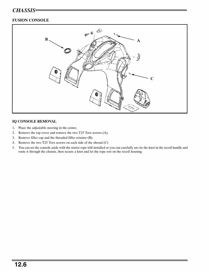
CHASSIS
12.6
FUSION CONSOLE
AB
C
IQ CONSOLE REMOVAL
1. Place the adjustable steering in the center.
2. Remove the top cover and remove the two T25 Torx screws (A).
3. Remove filler cap and the threaded filler retainer (B).
4. Remove the two T25 Torx screws on each side of the shroud (C)
5. You can set the console aside with the starter rope still installed or you can carefully un--tie the knot in the recoil handle androute it through the chassis, then secure a knot and let the rope rest on the recoil housing.
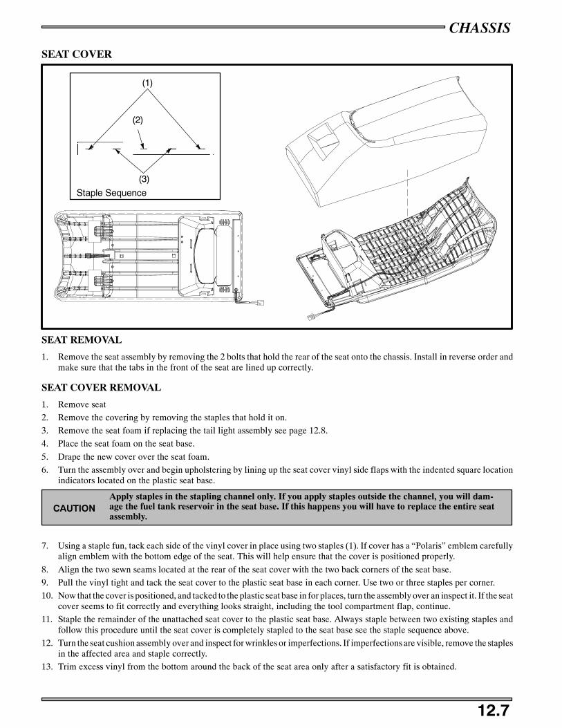
CHASSIS
12.7
SEAT COVER
Staple Sequence
(1)
(2)
(3)
SEAT REMOVAL
1. Remove the seat assembly by removing the 2 bolts that hold the rear of the seat onto the chassis. Install in reverse order andmake sure that the tabs in the front of the seat are lined up correctly.
SEAT COVER REMOVAL
1. Remove seat
2. Remove the covering by removing the staples that hold it on.
3. Remove the seat foam if replacing the tail light assembly see page 12.8.
4. Place the seat foam on the seat base.
5. Drape the new cover over the seat foam.
6. Turn the assembly over and begin upholstering by lining up the seat cover vinyl side flaps with the indented square locationindicators located on the plastic seat base.
Apply staples in the stapling channel only. If you apply staples outside the channel, you will dam-age the fuel tank reservoir in the seat base. If this happens you will have to replace the entire seatassembly.
CAUTION
7. Using a staple fun, tack each side of the vinyl cover in place using two staples (1). If cover has a “Polaris” emblem carefullyalign emblem with the bottom edge of the seat. This will help ensure that the cover is positioned properly.
8. Align the two sewn seams located at the rear of the seat cover with the two back corners of the seat base.
9. Pull the vinyl tight and tack the seat cover to the plastic seat base in each corner. Use two or three staples per corner.
10. Now that the cover is positioned, and tacked to the plastic seat base in for places, turn the assembly over an inspect it. If the seatcover seems to fit correctly and everything looks straight, including the tool compartment flap, continue.
11. Staple the remainder of the unattached seat cover to the plastic seat base. Always staple between two existing staples andfollow this procedure until the seat cover is completely stapled to the seat base see the staple sequence above.
12. Turn the seat cushion assembly over and inspect for wrinkles or imperfections. If imperfections are visible, remove the staplesin the affected area and staple correctly.
13. Trim excess vinyl from the bottom around the back of the seat area only after a satisfactory fit is obtained.

CHASSIS
12.8
HOOD REPAIR
CrackDrill Holes Here
Crack
Drill holes here
Currently there is no procedures or materials recommended by Polaris for repairing hoods. Hoods are made of Thermoplastic
Olefin (TPO) and cannot be repaired. If a hood is broken it must be replaced. For small cracks you may drill a small hole onboth ends of the crack to limit spreading. This procedure is called “stop drilling”.
MODELS WITH GROMMETS IN TOOL FLAP
1. Close tool flap cover, making sure it is aligned properly, and markgrommet holes.
2. Align twist lock with mark from step 13. Verify alignment withgrommet in tool flap.
3. Using twist lock as a template, drill two .160, to .164, holesthrough vinyl and seat base.
4. Rivet twist lock to seat base using rivets provided.
5. Trim excess vinyl from the bottom around the back of the seat areaonly after a satisfactory fit is obtained.
6. Reinstall seat by reversing disassembly steps as they apply to yourparticular model.
TAILLIGHT ASSEMBLY REPLACEMENT
1. After removal of seat cover, drill out three rivets from top of taillight.
2. Remove taillight assembly and wire harness.
3. Install new taillight assembly and rivet into place.
4. Connect taillight wire harness. Taillight harness wires must be routed away from any possible contact with seat cover staplesto prevent electrical shorts.
5. Pull seat cover tightly and evenly into position and re-staple to seat pan.
6. Inspect cover for a wrinkle-free finish before reinstalling on the snowmobile.
Grommets
Tool FlapCover
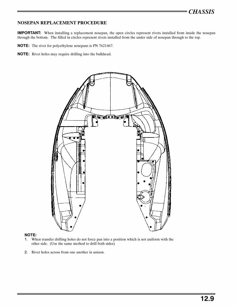
CHASSIS
12.9
NOSEPAN REPLACEMENT PROCEDURE
IMPORTANT: When installing a replacement nosepan, the open circles represent rivets installed from inside the nosepanthrough the bottom. The filled in circles represent rivets installed from the under side of nosepan through to the top.
NOTE: The rivet for polyethylene nosepans is PN 7621467.
NOTE: Rivet holes may require drilling into the bulkhead.
NOTE:1. When transfer drilling holes do not force pan into a position which is not uniform with the
other side. (Use the same method to drill both sides)
2. Rivet holes across from one another in unison.

CHASSIS
12.10
IQ NOSEPAN REPLACEMENT PROCEDURE
IMPORTANT: When installing a replacement nosepan, the open circles represent rivets installed from inside the nosepanthrough the bottom. The filled in circles represent rivets installed from the under side of nosepan through to the top.
NOTE: The rivet for polyethylene nosepans is PN 7621467.
NOTE: Rivet holes may require drilling into the bulkhead.
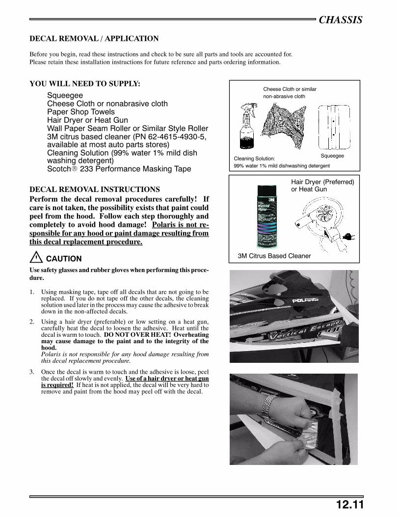
CHASSIS
12.11
DECAL REMOVAL / APPLICATION
Before you begin, read these instructions and check to be sure all parts and tools are accounted for.Please retain these installation instructions for future reference and parts ordering information.
YOU WILL NEED TO SUPPLY:
SqueegeeCheese Cloth or nonabrasive clothPaper Shop TowelsHair Dryer or Heat GunWall Paper Seam Roller or Similar Style Roller3M citrus based cleaner (PN 62-4615-4930-5,available at most auto parts stores)Cleaning Solution (99% water 1% mild dishwashing detergent)ScotchR 233 Performance Masking Tape
DECAL REMOVAL INSTRUCTIONSPerform the decal removal procedures carefully! Ifcare is not taken, the possibility exists that paint couldpeel from the hood. Follow each step thoroughly andcompletely to avoid hood damage! Polaris is not re-sponsible for any hood or paint damage resulting fromthis decal replacement procedure.
CAUTIONUse safety glasses and rubber gloves when performing this proce-dure.
1. Using masking tape, tape off all decals that are not going to bereplaced. If you do not tape off the other decals, the cleaningsolution used later in the process may cause the adhesive to breakdown in the non-affected decals.
2. Using a hair dryer (preferable) or low setting on a heat gun,carefully heat the decal to loosen the adhesive. Heat until thedecal is warm to touch. DO NOT OVER HEAT! Overheatingmay cause damage to the paint and to the integrity of thehood.Polaris is not responsible for any hood damage resulting fromthis decal replacement procedure.
3. Once the decal is warm to touch and the adhesive is loose, peelthe decal off slowly and evenly. Use of a hair dryer or heat gunis required! If heat is not applied, the decal will be very hard toremove and paint from the hood may peel off with the decal.
Cleaning Solution:99% water 1% mild dishwashing detergent
Cheese Cloth or similarnon-abrasive cloth
Squeegee
Hair Dryer (Preferred)or Heat Gun
3M Citrus Based Cleaner
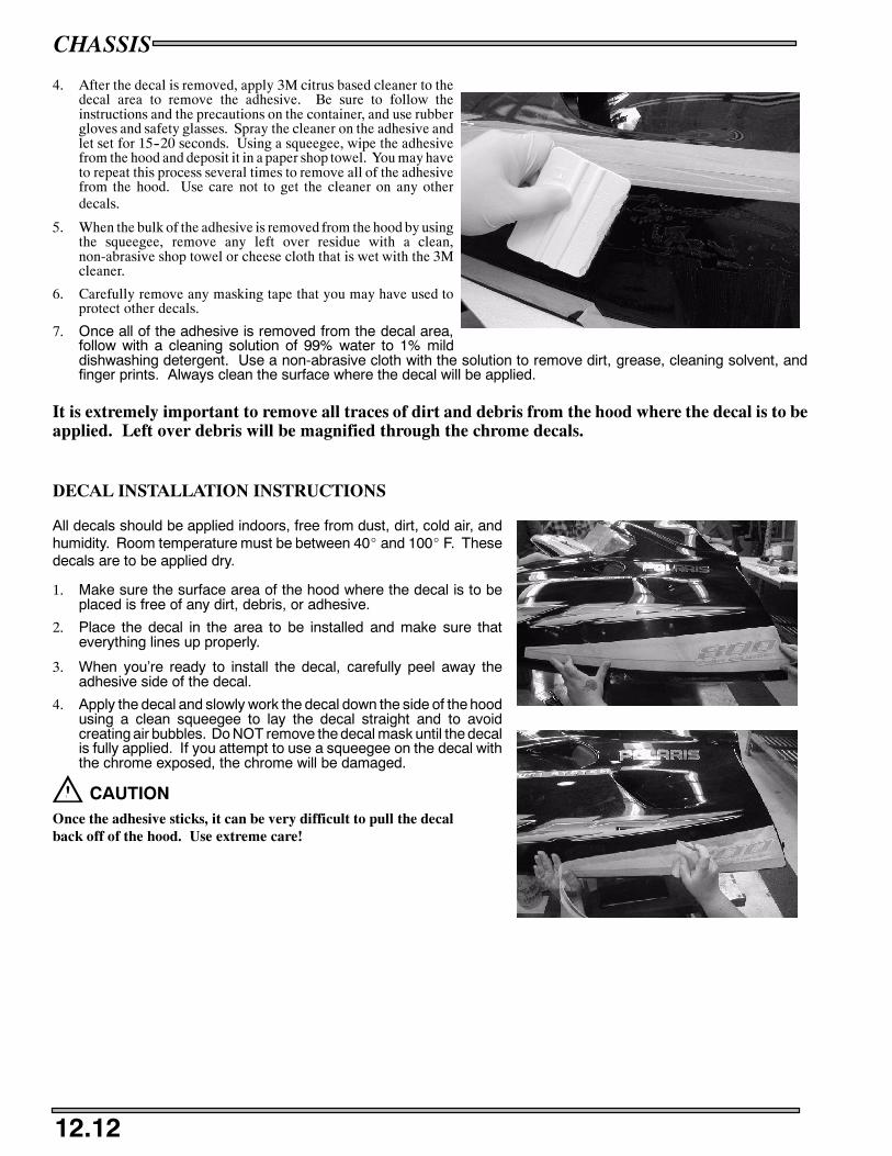
CHASSIS
12.12
4. After the decal is removed, apply 3M citrus based cleaner to thedecal area to remove the adhesive. Be sure to follow theinstructions and the precautions on the container, and use rubbergloves and safety glasses. Spray the cleaner on the adhesive andlet set for 15--20 seconds. Using a squeegee, wipe the adhesivefrom the hood and deposit it in a paper shop towel. You may haveto repeat this process several times to remove all of the adhesivefrom the hood. Use care not to get the cleaner on any otherdecals.
5. When the bulk of the adhesive is removed from the hood by usingthe squeegee, remove any left over residue with a clean,non-abrasive shop towel or cheese cloth that is wet with the 3Mcleaner.
6. Carefully remove any masking tape that you may have used toprotect other decals.
7. Once all of the adhesive is removed from the decal area,follow with a cleaning solution of 99% water to 1% milddishwashing detergent. Use a non-abrasive cloth with the solution to remove dirt, grease, cleaning solvent, andfinger prints. Always clean the surface where the decal will be applied.
It is extremely important to remove all traces of dirt and debris from the hood where the decal is to beapplied. Left over debris will be magnified through the chrome decals.
DECAL INSTALLATION INSTRUCTIONS
All decals should be applied indoors, free from dust, dirt, cold air, andhumidity. Room temperature must be between 40_ and 100_ F. Thesedecals are to be applied dry.
1. Make sure the surface area of the hood where the decal is to beplaced is free of any dirt, debris, or adhesive.
2. Place the decal in the area to be installed and make sure thateverything lines up properly.
3. When you’re ready to install the decal, carefully peel away theadhesive side of the decal.
4. Apply the decal and slowly work the decal down the side of the hoodusing a clean squeegee to lay the decal straight and to avoidcreating air bubbles. Do NOT remove the decal mask until the decalis fully applied. If you attempt to use a squeegee on the decal withthe chrome exposed, the chrome will be damaged.
CAUTIONOnce the adhesive sticks, it can be very difficult to pull the decalback off of the hood. Use extreme care!
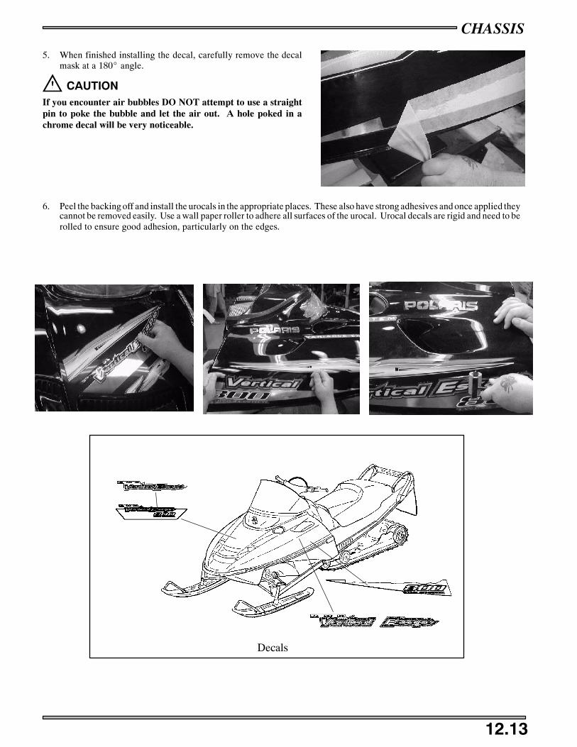
CHASSIS
12.13
5. When finished installing the decal, carefully remove the decalmask at a 180_ angle.
CAUTIONIf you encounter air bubbles DO NOT attempt to use a straightpin to poke the bubble and let the air out. A hole poked in achrome decal will be very noticeable.
6. Peel the backing off and install the urocals in the appropriate places. These also have strong adhesives and once applied theycannot be removed easily. Use a wall paper roller to adhere all surfaces of the urocal. Urocal decals are rigid and need to berolled to ensure good adhesion, particularly on the edges.
Decals

CHASSIS
12.14
NOTES

Typical Multimeter Usage 13.1 -- 13.2. . . . . . . . . . . . . . . . . . . . . . . . . . . . . . . . . . . . . . . . . .
Ignition Timing Explanation 13.3. . . . . . . . . . . . . . . . . . . . . . . . . . . . . . . . . . . . . . . .
Ignition Timing Specification Chart 13.4. . . . . . . . . . . . . . . . . . . . . . . . . . . . . . . . . .
Timing Procedure 13.5. . . . . . . . . . . . . . . . . . . . . . . . . . . . . . . . . . . . . . . . . . . . . . . . .
Preparing a New Battery 13.6. . . . . . . . . . . . . . . . . . . . . . . . . . . . . . . . . . . . . . . . . . .
Load Test 13.7. . . . . . . . . . . . . . . . . . . . . . . . . . . . . . . . . . . . . . . . . . . . . . . . . . . . . . .
Charging Procedure 13.7. . . . . . . . . . . . . . . . . . . . . . . . . . . . . . . . . . . . . . . . . . . . . . .
Testing Electric Start 13.8. . . . . . . . . . . . . . . . . . . . . . . . . . . . . . . . . . . . . . . . . . . . . .
Starter Motor Testing 13.9. . . . . . . . . . . . . . . . . . . . . . . . . . . . . . . . . . . . . . . . . . . . . .
Starter Housing and Coil Inspection 13.9. . . . . . . . . . . . . . . . . . . . . . . . . . . . . . . . . .
Starter Assembly 13.10. . . . . . . . . . . . . . . . . . . . . . . . . . . . . . . . . . . . . . . . . . . . . . . . . .
Starter Solenoid Test 13.11. . . . . . . . . . . . . . . . . . . . . . . . . . . . . . . . . . . . . . . . . . . . . . .
Starter Installation 13.11. . . . . . . . . . . . . . . . . . . . . . . . . . . . . . . . . . . . . . . . . . . . . . . .
Unregulated Voltage 13.11. . . . . . . . . . . . . . . . . . . . . . . . . . . . . . . . . . . . . . . . . . . . . . .
Sort Circuit Current 13.12. . . . . . . . . . . . . . . . . . . . . . . . . . . . . . . . . . . . . . . . . . . . . . .
Regulated Voltage 13.12. . . . . . . . . . . . . . . . . . . . . . . . . . . . . . . . . . . . . . . . . . . . . . . . .
Headlight Bulb Test 13.13. . . . . . . . . . . . . . . . . . . . . . . . . . . . . . . . . . . . . . . . . . . . . . .
HI/LO Beam Switch Testing 13.13. . . . . . . . . . . . . . . . . . . . . . . . . . . . . . . . . . . . . . . .
Seat Harness Troubleshooting 13.13. . . . . . . . . . . . . . . . . . . . . . . . . . . . . . . . . . . . . . .
Switch Testing 13.14. . . . . . . . . . . . . . . . . . . . . . . . . . . . . . . . . . . . . . . . . . . . . . . . . . .
Troubleshooting 13.17. . . . . . . . . . . . . . . . . . . . . . . . . . . . . . . . . . . . . . . . . . . . . . . . . .
500/600/700/800 Liberty TPS setting 13.18 -- 13.22. . . . . . . . . . . . . . . . . . . . . . . . . . . . . . . . .
900 Liberty TPS setting 13.22 -- 13.23. . . . . . . . . . . . . . . . . . . . . . . . . . . . . . . . . . . . . . . . . . . .
900 Liberty Temperature Light 13.24. . . . . . . . . . . . . . . . . . . . . . . . . . . . . . . . . . . . . .
900 Liberty DET 13.25. . . . . . . . . . . . . . . . . . . . . . . . . . . . . . . . . . . . . . . . . . . . . . . . . .
IQ Coolant Temperature 13.26. . . . . . . . . . . . . . . . . . . . . . . . . . . . . . . . . . . . . . . . . . . .
IQ Exhaust Temperature Sensor 13.27. . . . . . . . . . . . . . . . . . . . . . . . . . . . . . . . . . . . . .
IQ Crank Position Sensor 13.28. . . . . . . . . . . . . . . . . . . . . . . . . . . . . . . . . . . . . . . . . . .
IQ Speed Sensor 13.29. . . . . . . . . . . . . . . . . . . . . . . . . . . . . . . . . . . . . . . . . . . . . . . . . .
Oil Level Sender 13.30. . . . . . . . . . . . . . . . . . . . . . . . . . . . . . . . . . . . . . . . . . . . . . . . . .
IQ Engine Chassis Connection Location 13.31. . . . . . . . . . . . . . . . . . . . . . . . . . . . . . .
ECU Plug #1 13.32 -- 13.33. . . . . . . . . . . . . . . . . . . . . . . . . . . . . . . . . . . . . . . . . . . . . . . . . . . . .
ECU Plug #2 13.34 -- 13.35. . . . . . . . . . . . . . . . . . . . . . . . . . . . . . . . . . . . . . . . . . . . . . . . . . . . .
IQ Stator 13.36. . . . . . . . . . . . . . . . . . . . . . . . . . . . . . . . . . . . . . . . . . . . . . . . . . . . . . . .
IQ Coil / EV Solenoid 13.37 -- 13.38. . . . . . . . . . . . . . . . . . . . . . . . . . . . . . . . . . . . . . . . . . . . .
IQ Regulator Rectifier 13.39. . . . . . . . . . . . . . . . . . . . . . . . . . . . . . . . . . . . . . . . . . . . .
IQ Capacitor 13.40. . . . . . . . . . . . . . . . . . . . . . . . . . . . . . . . . . . . . . . . . . . . . . . . . . . . .
IQ Chassis Relay 13.41. . . . . . . . . . . . . . . . . . . . . . . . . . . . . . . . . . . . . . . . . . . . . . . . .
Chassis Hood Connections 13.42 -- 13.43. . . . . . . . . . . . . . . . . . . . . . . . . . . . . . . . . . . . . . . . . .
Diagnostic Ports 13.44. . . . . . . . . . . . . . . . . . . . . . . . . . . . . . . . . . . . . . . . . . . . . . . . . .
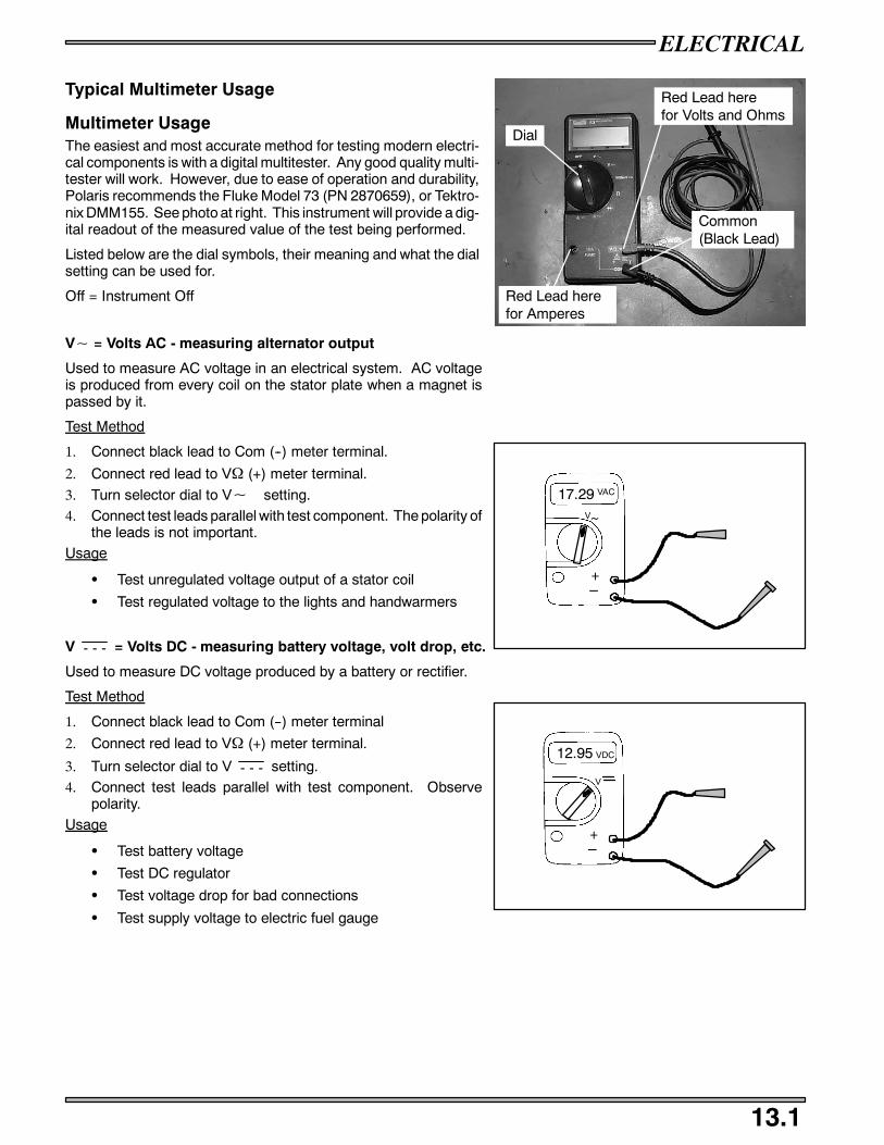
ELECTRICAL
13.1
Typical Multimeter Usage
Multimeter UsageThe easiest and most accurate method for testing modern electri-cal components is with a digital multitester. Any good quality multi-tester will work. However, due to ease of operation and durability,Polaris recommends the Fluke Model 73 (PN 2870659), or Tektro-nix DMM155. See photo at right. This instrument will provide a dig-ital readout of the measured value of the test being performed.
Listed below are the dial symbols, their meaning and what the dialsetting can be used for.
Off = Instrument Off
V~ = Volts AC - measuring alternator output
Used to measure AC voltage in an electrical system. AC voltageis produced from every coil on the stator plate when a magnet ispassed by it.
Test Method
1. Connect black lead to Com (--) meter terminal.
2. Connect red lead to VΩ (+) meter terminal.
3. Turn selector dial to V~ setting.4. Connect test leads parallel with test component. The polarity of
the leads is not important.Usage
S Test unregulated voltage output of a stator coil
S Test regulated voltage to the lights and handwarmers
V - - - = Volts DC - measuring battery voltage, volt drop, etc.
Used to measure DC voltage produced by a battery or rectifier.
Test Method
1. Connect black lead to Com (--) meter terminal
2. Connect red lead to VΩ (+) meter terminal.
3. Turn selector dial to V - - - setting.4. Connect test leads parallel with test component. Observe
polarity.Usage
S Test battery voltage
S Test DC regulator
S Test voltage drop for bad connections
S Test supply voltage to electric fuel gauge
Dial
Red Lead herefor Volts and Ohms
Common(Black Lead)
Red Lead herefor Amperes
+_
17.29V~
VAC
+_
12.95
V
VDC

ELECTRICAL
13.2
Ω = Ohms, resistance - measuring component resistance values - testing coils, wiring, etc.
Used to test resistance to the flow of electricity in a circuit or compo-nent. A reading of OL means an open circuit or infinite resistance.Sometimes the leads themselves will have some resistance. Touchthe leads together and subtract this resistance from the componentreading to achieve the actual reading.
Test Method
1. Connect black lead to Com (--) meter terminal
2. Connect red lead to VΩ (+) meter terminal.
3. Turn selector dial to Ω setting.4. Isolate test component from the rest of the electrical circuit by
disconnecting wires from harness.
5. Connect test leads to the circuit to be tested.Usage
S Testing coil resistance
S Testing switch operation
S Testing wire continuity
A~= Amps AC - used to test lighting coil output
Used to test the power of an alternator coil.
Test Method
1. Connect black lead to Com (--) meter terminal2. Connect red lead to 10A (+) meter terminal.3. Disconnect engine harness from system.
4. Connect across the specified coil wires.5. Start engine and let it idle.6. Readings should be above 5 Amps at any RPM. NOTE: It is
not necessary to increase RPM. The reading can be obtainedat idle.
Usage
S Testing stator coil power output.
A - - - = Amps DC - used to check battery charge rate, system draws, etc.
Used to check the current flow to and from the battery.
Test Method
1. Make sure red lead is in the 10A terminal of the meter and the black lead is in the Com (--) terminal of the meter.2. Disconnect battery ground wire(s) from battery (--) terminal.
3. Connect red meter lead to battery (--) terminal.4. Connect black meter lead to harness ground wires and cable.
CAUTION:
Do not operate electric starter (if equipped) or meter damage may occur.NOTE: When using the DC Amp settings, thered test lead must be moved to the 10A socket on the front of the instrument.
Usage
S Testing key off current draw and Testing charging system break even RPM
S Testing key on current draw and Testing DC current flow (direction), is battery charging?
+_
00.2 Ω
Ω
+_
14.00
A~
AC

ELECTRICAL
13.3
IGNITION TIMING
05
1015202530
1000 2000 3000 4000RPM
TIMING
DE-
GREES
EXAMPLE: 10_ @ 2500 RPM
NOTE:Always verify timing of engine at room temperature (68_ F / 20_ C) only, and at the proper RPM.
If applicable make sure the key switch is in the PREMIUM mode and the TPS is unplugged.
To obtain the best ignition timing accuracy and reduce the chance of error, the ignition timing specification is given at a “flat”portion of the advance curve. This flat portion on the curve is where the base ignition timing is specified. Refer to the specificationchapter for model specific timing specification. Ignition timing must be checked at the specified RPM, or an inaccurate timingwill result.
If engine damage has occurred due to a suspected ignition related problem, verify the ignition timing is correct at the specifiedoperating RPM.
TIMING PROCEDURE
Refer to the model timing specifications for correct timing.
Remove the MAG side spark plug.
Install the dial indicator into the spark plug hole. You may need to use a different adaptor depending the size of the spark plughole.
Find out the measurement for degrees that is specified for the model that you are checking by taking you base timing degree andcross referencing it to the appropriate engine listed on the chart on page 13.4 and write it down.
Rotate the crankshaft by hand while observing the dial indicator. As the piston touches the indicator plunger, the dial will beginto rotate. Find the point where the pointer stops rotating and reverses direction. This will be Top Dead Center (TDC).
While holding the crankshaft with the piston at TDC, zero the dial indicator by rotating the bezel until the “0” until it is alignedwith the pointer.
Rotate the crankshaft in the opposite direction of rotation .250” Before Top Dead Center (BTDC). This will be 2 1/2 pointer revo-lutions.
At this point you will rotate the crankshaft the specified measurement that you wrote down earlier.
While holding the crankshaft at this correct timing position, mark the flywheel with a white marker or white paint directly in--linewith the stationary pointer in the timing window on the recoil side.
Once the flywheel is marked, remove the dial indicator and replace the spark plug and cap.
Connect a good quality timing light to the engine (follow the timing light manufactures instructions).
Disconnect the TPS if applicable.
Place sled on track stand and start the engine and increase engine RPM to the point specified in the timing specification. Holdthe throttle to maintain specified timing RPM.
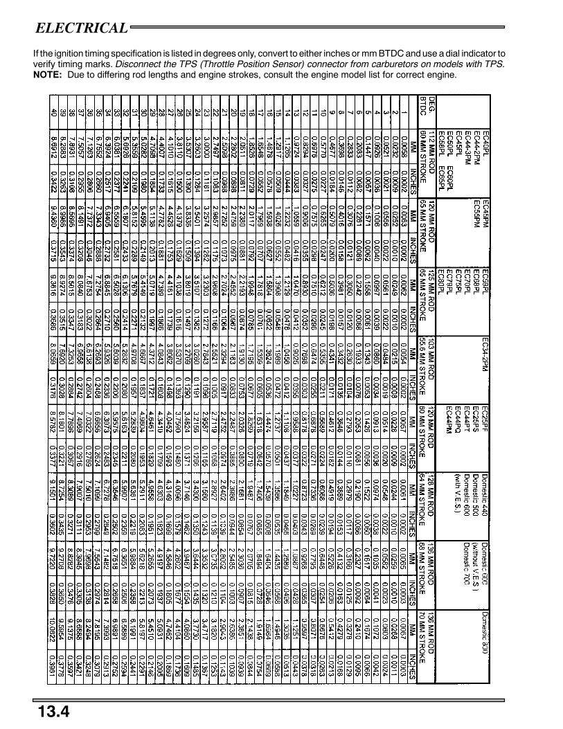
ELECTRICAL
13.4
If the ignition timing specification is listed in degrees only, convert to either inches or mm BTDC and use a dial indicator toverify timing marks. Disconnect the TPS (Throttle Position Sensor) connector from carburetors on models with TPS.NOTE: Due to differing rod lengths and engine strokes, consult the engine model list for correct engine.
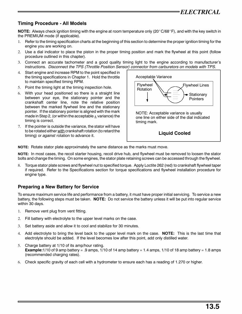
ELECTRICAL
13.5
Timing Procedure - All Models
NOTE: Always check ignition timing with the engine at room temperature only (20_C/68_F), and with the key switch inthe PREMIUM mode (if applicable).1. Refer to the timing specification charts at the beginning of this section to determine the proper ignition timing for the
engine you are working on.2. Use a dial indicator to place the piston in the proper timing position and mark the flywheel at this point (follow
procedure outlined in this chapter).3. Connect an accurate tachometer and a good quality timing light to the engine according to manufacturer’s
instructions. Disconnect the TPS (Throttle Position Sensor) connector from carburetors on models with TPS.4. Start engine and increase RPM to the point specified in
the timing specifications in Chapter 1. Hold the throttleto maintain specified timing RPM.
5. Point the timing light at the timing inspection hole.
6. With your head positioned so there is a straight linebetween your eye, the stationary pointer and thecrankshaft center line, note the relative positionbetween the marked flywheel line and the stationarypointer. If the stationary pointer is aligned with the markmade in Step 2, (or within the acceptable + variance) thetiming is correct.
7. If the pointer is outside the variance, the stator will haveto be rotated either with crankshaft rotation (to retard thetiming) or against rotation to advance it.
NOTE: Rotate stator plate approximately the same distance as the marks must move.
NOTE: In most cases, the recoil starter housing, recoil drive hub, and flywheel must be removed to loosen the statorbolts and change the timing. On some engines, the stator plate retaining screws can be accessed through the flywheel.
8. Torque stator plate screws and flywheel nut to specified torque. Apply Loctite 262 (red) to crankshaft flywheel taperif required. Refer to the Specifications section for torque specifications and flywheel installation procedure forengine type.
Preparing a New Battery for Service
To ensure maximum service life and performance from a battery, it must have proper initial servicing. To service a newbattery, the following steps must be taken. NOTE: Do not service the battery unless it will be put into regular servicewithin 30 days.
1. Remove vent plug from vent fitting.
2. Fill battery with electrolyte to the upper level marks on the case.
3. Set battery aside and allow it to cool and stabilize for 30 minutes.
4. Add electrolyte to bring the level back to the upper level mark on the case. NOTE: This is the last time thatelectrolyte should be added. If the level becomes low after this point, add only distilled water.
5. Charge battery at 1/10 of its amp/hour rating.Example:1/10 of 9 amp battery = .9 amps, 1/10 of 14 amp battery = 1.4 amps, 1/10 of 18 amp battery = 1.8 amps(recommended charging rates).
6. Check specific gravity of each cell with a hydrometer to ensure each has a reading of 1.270 or higher.
FlywheelRotation
Acceptable Variance
Flywheel Lines
StationaryPointers
NOTE: Acceptable variance is usuallyone line on either side of the dial indicatedtiming mark.
Liquid Cooled
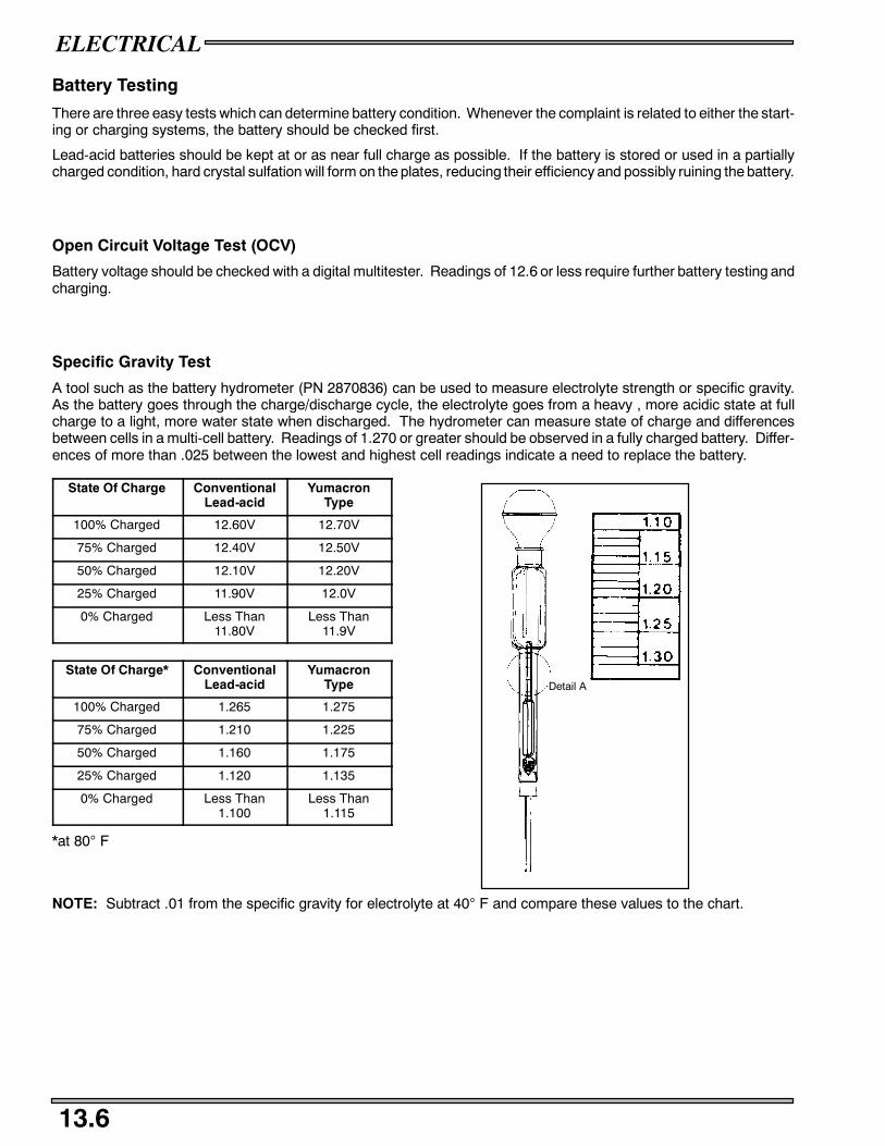
ELECTRICAL
13.6
Battery Testing
There are three easy tests which can determine battery condition. Whenever the complaint is related to either the start-ing or charging systems, the battery should be checked first.
Lead-acid batteries should be kept at or as near full charge as possible. If the battery is stored or used in a partiallycharged condition, hard crystal sulfation will form on the plates, reducing their efficiency and possibly ruining the battery.
Open Circuit Voltage Test (OCV)
Battery voltage should be checked with a digital multitester. Readings of 12.6 or less require further battery testing andcharging.
Specific Gravity Test
A tool such as the battery hydrometer (PN 2870836) can be used to measure electrolyte strength or specific gravity.As the battery goes through the charge/discharge cycle, the electrolyte goes from a heavy , more acidic state at fullcharge to a light, more water state when discharged. The hydrometer can measure state of charge and differencesbetween cells in a multi-cell battery. Readings of 1.270 or greater should be observed in a fully charged battery. Differ-ences of more than .025 between the lowest and highest cell readings indicate a need to replace the battery.
State Of Charge ConventionalLead-acid
YumacronType
100% Charged 12.60V 12.70V
75% Charged 12.40V 12.50V
50% Charged 12.10V 12.20V
25% Charged 11.90V 12.0V
0% Charged Less Than11.80V
Less Than11.9V
State Of Charge* ConventionalLead-acid
YumacronType
100% Charged 1.265 1.275
75% Charged 1.210 1.225
50% Charged 1.160 1.175
25% Charged 1.120 1.135
0% Charged Less Than1.100
Less Than1.115
*at 80° F
NOTE: Subtract .01 from the specific gravity for electrolyte at 40° F and compare these values to the chart.
Detail A

ELECTRICAL
13.7
Load TestNOTE: This test can only be performed on machines equipped with electric start. This test cannot be performed if theengine or starting system is not working properly.
A battery may indicate a fully charge condition on the OCV test and the specific gravity test, but still not have the storagecapacity necessary to properly function in the electrical system. For this reason, a battery capacity or load test shouldbe conducted whenever poor battery performance is encountered.
To perform the test, hook a multitester to the battery in the same manner as in the OCV test. The reading should be12.6 volts or greater. Engage the electric starter and view the registered battery voltage while cranking the engine.Continue the test for 15 seconds. During this cranking period, the observed voltage should not drop below 9.5 volts.If the beginning voltage is 12.6 or higher and the cranking voltage drops below 9.5 volts during the test, replace thebattery.
Refilling a Low BatteryThe normal charge/discharge cycle of a battery causes the cells to give off gases. These gases, hydrogen and oxygen,are the components of water. Because of the loss of these gases and the lowering of the electrolyte level, it will benecessary to add pure, clean distilled water to bring the fluid to the proper level. After filling, charge the battery to raisethe specific gravity to1.270 or greater.
Off Season StorageTo prevent battery damage during extended periods of non-use, the following basic maintenance items must be per-formed.
1. Remove battery from machine and wash the case and battery tray with a mild solution of baking soda and water.Rinse with lots of fresh water after cleaning. CAUTION: Do not allow any of the baking soda solution to enter thebattery or the acid will be neutralized.
2. Using a wire brush or knife, remove any corrosion from the cables and terminals.
3. Make sure the electrolyte is at the proper level. Add distilled water if necessary.
4. Charge at a rate no greater than 1/10 of the battery’s amp/hr capacity until the electrolyte’s specific gravity reaches1.270 or greater.
5. The battery may be stored either in the machine with the cables disconnected, or on a piece of wood in a cool place.NOTE: Stored batteries lose their charge at the rate of 1% per day. They should be fully recharged every 30 to 60days during a non-use period. If stored during winter months, the electrolyte will freeze at higher temperatures asthe battery discharges. The chart indicates freezing points by specific gravity.
Specific Gravity of Electrolyte Freezing Point
1.265 -75° F
1.225 -35° F
1.200 -17° F
1.150 +5° F
1.100 +18° F
1.050 +27° F
Charging Procedure
Charge battery with a charger no larger than 1/10 of the bat-tery’s amp/hr rating for as many hours as needed to raise thespecific gravity to 1.270 or greater.
WARNING
The gases given off by a battery are explosive. Any sparkor open flame near a battery can cause an explosion whichwill spray battery acid on anyone close to it. If battery acidgets on anyone, wash the affected area with large quantitiesof cool water and seek immediate medical attention.
Battery electrolyte is poisonous. It contains acid!Serious burns can result from contact with the skin,eyes, or clothing.ANTIDOTE:
EXTERNAL: Flush with water.INTERNAL: Drink large quantities of water or milk.Follow with milk of magnesia, beaten egg, or vegeta-ble oil. Call physician immediately.EYES: Flush with water for 15 minutes and get promptmedical attention.Batteries produce explosive gases. Keep sparks,flame, cigarettes, etc. away. Ventilate when chargingor using in closed space. Always shield eyes whenworking near batteries.KEEP OUT OF REACH OF CHILDREN.
WARNING
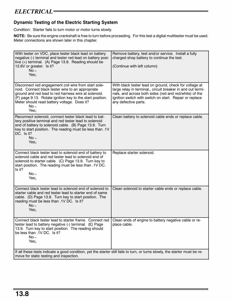
ELECTRICAL
13.8
Dynamic Testing of the Electric Starting System
Condition: Starter fails to turn motor or motor turns slowly.
NOTE: Be sure the engine crankshaft is free to turn before proceeding. For this test a digital multitester must be used.Meter connections are shown later in this chapter.
With tester on VDC, place tester black lead on batterynegative (-) terminal and tester red lead on battery posi-tive (+) terminal. (A) Page 13.9. Reading should be12.6V or greater. Is it?
No!Yes#
Remove battery, test and/or service. Install a fullycharged shop battery to continue the test.
(Continue with left column)
Disconnect red engagement coil wire from start sole-noid. Connect black tester wire to an appropriateground and red lead to red harness wire at solenoid.(F) page 9.13. Rotate ignition key to the start position.Meter should read battery voltage. Does it?
No!Yes#
With black tester lead on ground, check for voltage atlarge relay in terminal,, circuit breaker in and out termi-nals, and across both sides (red and red/white) of theignition switch with switch on start. Repair or replaceany defective parts.
Reconnect solenoid, connect tester black lead to bat-tery positive terminal and red tester lead to solenoidend of battery to solenoid cable. (B) Page 13.9. Turnkey to start position. The reading must be less than .1VDC. Is it?
No!Yes#
Clean battery to solenoid cable ends or replace cable.
Connect black tester lead to solenoid end of battery tosolenoid cable and red tester lead to solenoid end ofsolenoid to starter cable. (C) Page 13.9. Turn key tostart position. The reading must be less than .1V DC.Is it?
No!Yes#
Replace starter solenoid.
Connect black tester lead to solenoid end of solenoid tostarter cable and red tester lead to starter end of samecable. (D) Page 13.9. Turn key to start position. Thereading must be less than .1V DC. Is it?
No!Yes#
Clean solenoid to starter cable ends or replace cable.
Connect black tester lead to starter frame. Connect redtester lead to battery negative (-) terminal. (E) Page13.9. Turn key to start position. The reading shouldbe less than .1V DC. Is it?
No!Yes#
Clean ends of engine to battery negative cable or re-place cable.
If all these tests indicate a good condition, yet the starter still fails to turn, or turns slowly, the starter must be re-move for static testing and inspection.

ELECTRICAL
13.9
Starter Motor Static Testing
+ -
(F) (Disconnect R/W Wire)
1. Remove starter motor and disassemble. (See page 9.14 for exploded view) Mark end covers and housing for properreassembly.
2. Remove pinion retaining snap ring, spring and pinion gear.
3. Remove brush end bushing dust cover.
4. Remove housing through bolts.
5. Slide brush end frame off end of starter. NOTE: The electrical input post must stay with the field coil housing.
6. Slide positive brush springs to the side, pull brushes out of their guides and remove brush plate.
7. Clean and inspect starter components. NOTE: Some cleaning solvents may damage the insulation in the starter.Care should be exercised when selecting an appropriate solvent. The brushes must slide freely in their holders. Ifthe commutator needs cleaning, use only an electrical contact cleaner and/or a non-metallic grit sandpaper.Replace brush assembly when worn to 5/16″ (.8 cm) or less.
Starter Housing and Field Coil Inspection
1. Using a digital multitester, measure resistance between starter input terminal and insulated brushes. The readingshould be .3 ohms or less.
2. Measure resistance between insulated brushes and field coil housing. The reading should be infinite.
3. Inspect insulated brush wire and field coil insulation for damage. Repair or replace components as required.
Armature Testing
1. Using a digital multitester, measure resistance between each of the segments of the commutator. The readingshould indicate .3 ohms or less.
2. Measure resistance between commutator and armature shaft. Reading should be infinity.
3. Place armature in a growler. With the growler on, position a hacksaw blade lengthwise 1/8″ (.03 cm) above armaturecoil laminates. Rotate armature 360°. If hacksaw blade is drawn to the armature on any pole, the armature isshorted and must be replaced.

ELECTRICAL
13.10
Starter Assembly
Ring Gear
Armature
Brush andSpring
1. Slide armature into field coil housing.
2. Lightly grease drive end bushing and install drive end frame on armature.
3. Mount starter vertically in a vice with brush end up.
4. While holding negative brushes out against their springs, slide brush plate down onto the commutator.
5. While holding positive brush springs to the side, slide positive brushes into their holders and correctly position thesprings on top of the brushes.
6. Using a non-petroleum grease, lubricate brush end bushing and slide it onto end of armature.
7. Align threaded holes in brush plate and install dust cover and screws.
8. Reinstall through bolts and properly tighten all screws.
9. Lightly grease pinion shaft and install pinion, spring stopper and snap ring.
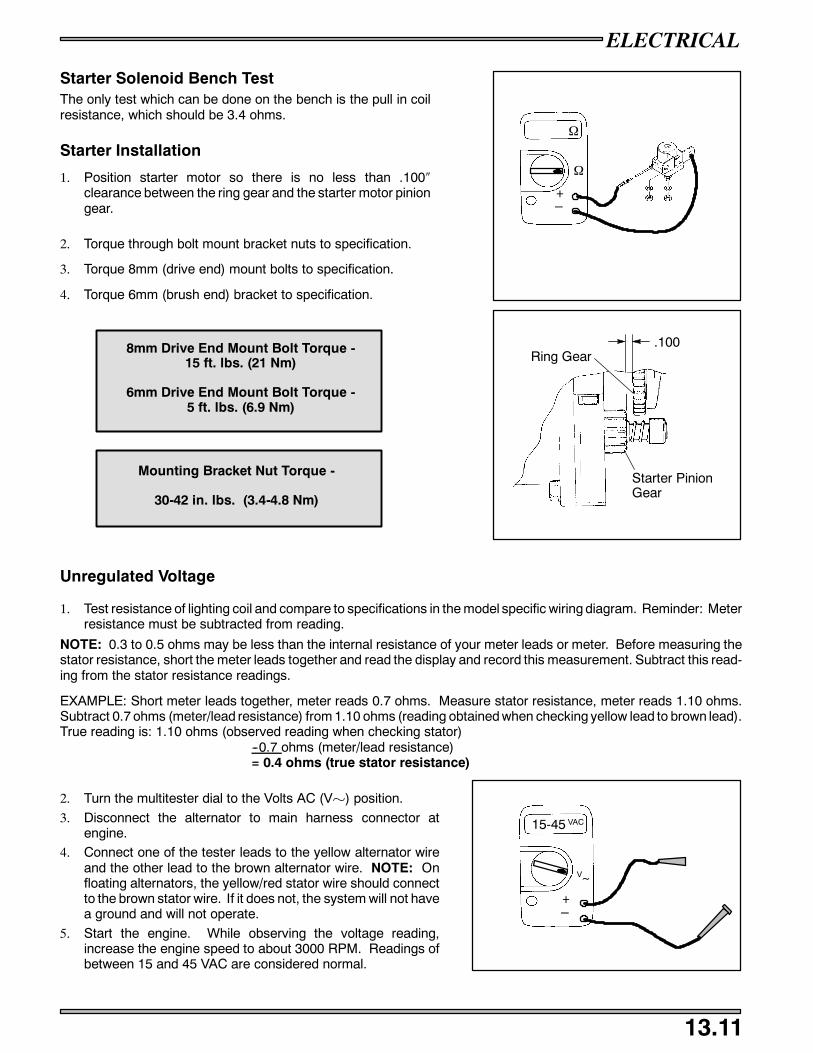
ELECTRICAL
13.11
Starter Solenoid Bench TestThe only test which can be done on the bench is the pull in coilresistance, which should be 3.4 ohms.
Starter Installation
1. Position starter motor so there is no less than .100″clearance between the ring gear and the starter motor piniongear.
2. Torque through bolt mount bracket nuts to specification.
3. Torque 8mm (drive end) mount bolts to specification.
4. Torque 6mm (brush end) bracket to specification.
Unregulated Voltage
1. Test resistance of lighting coil and compare to specifications in the model specific wiring diagram. Reminder: Meterresistance must be subtracted from reading.
NOTE: 0.3 to 0.5 ohms may be less than the internal resistance of your meter leads or meter. Before measuring thestator resistance, short the meter leads together and read the display and record this measurement. Subtract this read-ing from the stator resistance readings.
EXAMPLE: Short meter leads together, meter reads 0.7 ohms. Measure stator resistance, meter reads 1.10 ohms.Subtract 0.7 ohms (meter/lead resistance) from 1.10 ohms (reading obtained when checking yellow lead to brown lead).True reading is: 1.10 ohms (observed reading when checking stator)
--0.7 ohms (meter/lead resistance)= 0.4 ohms (true stator resistance)
2. Turn the multitester dial to the Volts AC (Vµ) position.
3. Disconnect the alternator to main harness connector atengine.
4. Connect one of the tester leads to the yellow alternator wireand the other lead to the brown alternator wire. NOTE: Onfloating alternators, the yellow/red stator wire should connectto the brown stator wire. If it does not, the system will not havea ground and will not operate.
5. Start the engine. While observing the voltage reading,increase the engine speed to about 3000 RPM. Readings ofbetween 15 and 45 VAC are considered normal.
8mm Drive End Mount Bolt Torque -15 ft. lbs. (21 Nm)
6mm Drive End Mount Bolt Torque -5 ft. lbs. (6.9 Nm)
Mounting Bracket Nut Torque -
30-42 in. lbs. (3.4-4.8 Nm)
+_
Ω
Ω
Ring Gear
Starter PinionGear
.100
+_
15-45
V~
VAC
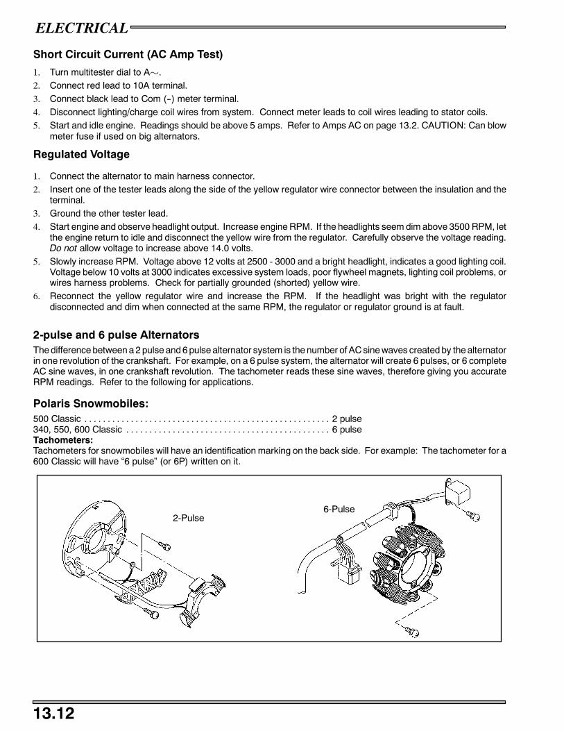
ELECTRICAL
13.12
Short Circuit Current (AC Amp Test)
1. Turn multitester dial to Aµ.2. Connect red lead to 10A terminal.3. Connect black lead to Com (--) meter terminal.4. Disconnect lighting/charge coil wires from system. Connect meter leads to coil wires leading to stator coils.5. Start and idle engine. Readings should be above 5 amps. Refer to Amps AC on page 13.2. CAUTION: Can blow
meter fuse if used on big alternators.
Regulated Voltage
1. Connect the alternator to main harness connector.2. Insert one of the tester leads along the side of the yellow regulator wire connector between the insulation and the
terminal.3. Ground the other tester lead.4. Start engine and observe headlight output. Increase engine RPM. If the headlights seem dim above 3500 RPM, let
the engine return to idle and disconnect the yellow wire from the regulator. Carefully observe the voltage reading.Do not allow voltage to increase above 14.0 volts.
5. Slowly increase RPM. Voltage above 12 volts at 2500 - 3000 and a bright headlight, indicates a good lighting coil.Voltage below 10 volts at 3000 indicates excessive system loads, poor flywheel magnets, lighting coil problems, orwires harness problems. Check for partially grounded (shorted) yellow wire.
6. Reconnect the yellow regulator wire and increase the RPM. If the headlight was bright with the regulatordisconnected and dim when connected at the same RPM, the regulator or regulator ground is at fault.
2-pulse and 6 pulse AlternatorsThe difference between a 2 pulse and 6 pulse alternator system is the number of AC sine waves created by the alternatorin one revolution of the crankshaft. For example, on a 6 pulse system, the alternator will create 6 pulses, or 6 completeAC sine waves, in one crankshaft revolution. The tachometer reads these sine waves, therefore giving you accurateRPM readings. Refer to the following for applications.
Polaris Snowmobiles:500 Classic 2 pulse. . . . . . . . . . . . . . . . . . . . . . . . . . . . . . . . . . . . . . . . . . . . . . . . . . . . .340, 550, 600 Classic 6 pulse. . . . . . . . . . . . . . . . . . . . . . . . . . . . . . . . . . . . . . . . . . . .Tachometers:Tachometers for snowmobiles will have an identification marking on the back side. For example: The tachometer for a600 Classic will have “6 pulse” (or 6P) written on it.
6-Pulse2-Pulse

ELECTRICAL
13.13
Headlight Bulb Filament Continuity Test
1. Turn the Multitester dial to the ohms (Ω) position.2. Disconnect the wire harness from the headlight bulb.3. Viewing the back of the bulb with the terminal blades at the 9, 12 and 3 o’clock position, connect the black multitester
lead to the 9 o’clock blade.4. Touch the red tester lead to the 12 o’clock terminal and then to the 3 o’clock terminal, noting the resistance value of
each. A reading of between 2 and 5 ohms is good. An open reading indicates a bad element.
Hi/Lo Beam Switch Testing
1. Set the multitester dial to the ohms (Ω) position.2. If the Hi/Lo switch has not been removed from the machine,
disconnect the switch to harness plug-in connector.3. With the Hi/Lo switch in the Lo beam position, check the
resistance between the yellow and the green switch wires.The reading should be less than .4 ohms.
4. Turn the Hi/Lo switch to the Hi beam position and themultitester should indicate an open circuit (OL) reading.
5. Move one of the tester leads from the green to the red switchwire. The multitester should now read less than .4 ohms.
6. Turn the Hi/Lo Switch back to the Lo beam position and themeter should again read an open circuit (OL).
Seat Harness Troubleshooting
1. Remove the taillight lens.2. Remove the two taillight bulbs and the brakelight bulb.3. Separate the seat harness from the main harness by unplugging the connector at the right rear of the tank.4. With the multitester dial set on ohms (Ω) connect either meter test lead to the brown seat harness wire.5. Touch the other tester lead to first the yellow wire and then the orange wire. Observe the readings. Readings other
than an open circuit (O.L.) indicate a shorted harness or bulb socket.NOTE: The bulb socket tangs sometimes short to ground with the bulb removed.
6. Check between the yellow and orange wires in the same manner to check for a short between the brake and runninglights. If damaged wiring is found, remove the seat.
7. Tip the seat over and remove the right side seat cover staples. Locate and repair the harness problem.8. Reinstall the staples and re-check the seat harness.
Ignition Switch Testing (Non-Electric Start)
1. Set the multitester dial to the ohms (Ω) position. Connect oneof the tester leads to either of the switch terminals and theothertester lead to the other switch terminal.
2. With the switch off, the reading should be less than .4 ohms.With the switch on, the reading must be an open circuit (OL).
3. Check the resistance between each of the switch terminalsand the switch body. With the switch still in the on position,there must be an open circuit (OL) reading. Readings otherthan those listed indicate a defective switch.
Low High
Grn
Yel
Yel/Rd
High/Low Switch
D
D D
D
Blk
Brn
Off On
Ignition Switch
D
D

ELECTRICAL
13.14
Ignition Switch Testing (Electric Start Models)
NOTE: Refer to the appropriate model and year wiring diagram forignition switch wire colors and connections.
1. Disconnect wires. Set the multitester dial to the ohms (Ω)position.
2. With the key in the off position, check the resistance betweenthe G (Ground, brown) terminal and the M (Mag, black)terminal. This reading must be less than .4 ohms.
3. Turn the key to the on position. The multitester should nowread an open circuit (OL).
4. Move the tester lead from the G terminal to the switch housingand re-check the reading. It should also be an open circuit(OL).
5. Place one of the tester leads on the B (Battery, red) terminaland the other tester lead on the S (Starter, blue) terminal. Withthe key in the on position, there must be an open circuit (OL) reading.
6. Turn the key to the start position. The reading should be less than .4 ohms. Readings other than the ones listedindicate a defective switch.
500/600/700/800 Temp Light
Models with TPS are fitted with a thermistor sensor. This sensor outputs a variable resistance with temperature. This allows morecapability for control when the over heat indicator light illuminates. Higher throttle positions require lower temperature for thelight to come on, possibly leading the operator to believe it to be a blinking light.
For example, the TEMP light will come on at idle (under 2000 RPM, 0% throttle) if coolant temperature reaches 230_F (110_C).Timing retard initiates at 176_F if the TPS input is over 80--100%. For more severe conditions, the engine fail--safe is turned onat high TPS input and high temperatures
At room temperature 68_ F (20_ C) the thermistor should read 2189 to 2675 Ω.
See chart below for other temperature resistances.
CAUTION:
If attempting to heat the sensor, heat only in a water bath. Never subject the sensor to an open flame to attempt to close the contactsas sensor damage may result.
TEMP _F (_C) Ω RESISTANCE RANGE
68 (20) 2189 -- 2675
149 (65) 455 -- 556
203 (95) 197 -- 240
239 (115) 120 -- 147
275 (135) 77 -- 94
Brn
Blk
R
R/W
Off On Start
D
D
D
D
Ignition Switch - Electric Start

ELECTRICAL
13.15
AB
Off Idle Switch
Idle Switch
PlungersOutward
Throttle ControlCutaway
Engine Ground
Ignition Primary
Auxiliary KillSwitch Contacts
Insulator
Conductor
The speed control assurance consists of two series connected switches. If one or both switch plungers are positionedinward, the circuit is open and the engine will run.
At idle, with the throttle lever properly adjusted, the bottom switch circuit is open and the plunger is inward. The topswitch circuit is closed, and the plunger is outward. The speed control circuit is open, allowing the engine to run.
As the throttle lever is actuated to an off idle position, the top switch circuit is opened (plunger in) and the bottom switchcircuit is closed (plunger out). The speed control circuit is still open, allowing the engine to run.
In the event the carburetor or controls malfunction and allow the throttle cable to become slack, the circuit will close(both switch plungers out), grounding the ignition system and causing the engine to stop.
Speed Control Assurance AdjustmentThrottle lever free play must always provide a specified clearancebetween throttle lever and throttle block. This clearance is con-trolled by the throttle cable sleeve(s) and the idle speed screw(s).
If the idle speed screw(s) is adjusted inward and the cablesleeve(s) is not adjusted to take up the throttle lever to throttleblock clearance, the engine may misfire or kill upon initial throttleopening.
CAUTION:
After any idle speed adjustments are made, the throttle lever to throttle block clearance and oil pump adjustment mustbe checked and adjusted.
NOTE: When adjustments are made on models which have more than one carburetor, refer to Section 6, Carburetion,for proper carburetor synchronization adjustments.
Throttle Lever Freeplay -
.010 - .030″ (.25 - .8 mm)
.010-.030″ (.25-.8 mm)

ELECTRICAL
13.16
Speed Control Assurance ReplacementAuxiliary shut-off and speed control assurance switches are connected and replaced as a unit from the back side ofthe throttle block.
1. Remove the handlebar pad and/or throttle block backing plate.
2. Slide out the auxiliary shut-off portion of the switch.
3. Remove the two screws securing the two speed control assurance switches.
4. Remove the switches noting their placement in the throttle block.
5. Replace the assembly and check its operation.
Auxiliary Shut--Off Switch Testing1. Set the multitester in the ohms (Ω) position.
2. Disconnect the switch harness from the main wire harness.
3. Connect the two multitester leads to the two switch wires.
Test 1 - Open Circuit - RunWith the auxiliary shut-off switch in the ON position, the multitester should read an open circuit (OL). As the throttlelever is moved from idle to off idle, the tester should continue to read an open circuit. If the tester fluctuates and thethrottle lever to throttle block clearance is adjusted properly, the switch assembly must be replaced.
Test 2 - Closed Circuit - KillThe two speed control switches must make a complete circuit to kill the engine. To check the switches, pull the throttlelever out away from the throttle block. With the switch plungers outward and the auxiliary shut-off switch in the ONposition, the multitester must read less than .4 ohms resistance. Inspect wires and repair if damaged, or replace switchassembly.
Test 3 - Auxiliary Shut-OffThe multitester should read less than .4 ohms in the OFF position and an open circuit in the the ON position. Inspectwires and repair if damaged, or replace switch assembly.
EDGE Fuel Sender Testing
Use the multitester ohmmeter to test the resistance of the fuelsender.
Position Ohms Range
Empty 95 Ω 90 - 97.5 Ω
Full 7 Ω 4.5 - 13 Ω
The supply voltage to the gauge should be 13.5 VAC.
+_
Ω
Ω
Fuel Gauge
Diode
Fuse(0.2A)
Pur/Wh Brn Yel

ELECTRICAL
13.17
Condition: No Spark
Disconnect the single black (black/white) wire from the CDI Module to theignition kill circuit. Does it have a spark?
Yes!No#
Check the ignition switch, wire harness, throttle safety switchesand kill switch for proper adjustment or short to ground. Repairor replace as necessary.
Disconnect the stator to CDI module wires. Test the resistance values of thestator coils as per the wiring diagrams. Are the resistance values withinspecs?
Yes!No#
All except 3 cylinders: If the parts of the ignition system underthe flywheel check OK, the only remaining component is thecoil/CDI module assembly. Replace the module with anotherwith the same number. (See ignition data)All 3 cylinders: Disconnect and check the secondary ignition coilresistances. Refer to the resistance values listed in wiringdiagrams. If the coil resistance values are within specs, replacethe CDI module.
Isolate which component’s resistance is not within specs. Remove the flywheel and stator. Recheck the resistances; look for pinched or bareharness wires; or replace the coil.
Condition: Incorrect Timing Advance/Retard
Follow the engine timing procedure for checking running timing atrecommended RPM. Is the timing within limits?
No!Yes #
Adjust the ignition timing by rotating the stator plate to correct thetiming. After adjusting the recommended RPM timing, continuewith operating RPM timing if poor performance exists. (Continueon with left column.)
Remove the ignition kill circuit by disconnecting the single black wire betweenthe CDI module and the machine harness. Is the timing now correct?
Yes!No#
Check the ignition switch, throttle safety switches, kill switch andharness for damage which can cause intermittent shortingproblems. Correct the problem.
Verify the correct CDI module by comparing the CU code on the box to theinformation listed in the ignition data charts at the beginning of this section. Isit the right module?
No!Yes#
Replace the module with the correct part and readjust the ignitiontiming.
Check the resistance of the coils under the flywheel. Compare these tovalues on wiring diagram. Are they within limits?
No!Yes#
Check the wiring connecting the coils and/or replace the coils asnecessary.

ELECTRICAL
13.18
500/600/700/800 TPS SETTING PROCEDURE
The TPS comes set from the factory and should not need adjustment. However, upon removal of the TPS, you mustmark the TPS position on the carburetor and replace it in the exact same position as removal. Polaris has developeda TPS test kit for aid in setting the Throttle Position Sensor to specification.
TPS Testing
1. Illustration at right shows the TPS sensor kit PN2201519.
2. Make sure your 9 volt battery is in good condition byinserting the black volt meter probe from your Fluketmeter in the black terminal and the red probe into thepink terminal. Voltage should read 4.99 to 5.01 volts. Ifnot, try a new 9 volt battery.
3. Remove the connector from the TPS.
Red Black
Pink
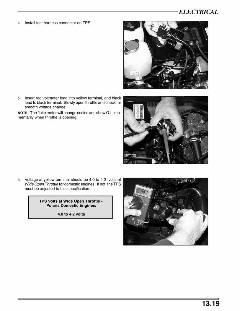
ELECTRICAL
13.19
4. Install test harness connector on TPS.
5. Insert red voltmeter lead into yellow terminal, and blacklead to black terminal. Slowly open throttle and check forsmooth voltage change.
NOTE: The fluke meter will change scales and show O.L. mo-mentarily when throttle is opening.
6. Voltage at yellow terminal should be 4.0 to 4.2 volts atWide Open Throttle for domestic engines. If not, the TPSmust be adjusted to this specification.
TPS Volts at Wide Open Throttle -Polaris Domestic Engines:
4.0 to 4.2 volts

ELECTRICAL
13.20
TPS Adjustment
1. Loosen the two screws that hold the TPS on thecarburetors.
2. Turn the TPS clockwise to decrease voltage, orcounterclockwise to increase voltage.
3. When the TPS is set to the desired voltage, tighten theholding screws and verify voltage is 4.0 to 4.2 volts atWide Open Throttle.
Decrease Increase

ELECTRICAL
13.21
4. When the TPS is set and voltage is verified, remove thetester and re-install the snowmobile TPS harness.
5. When storing the TPS tester, remove the red terminal ofthe tester and insert it in the blank terminal of the harness.
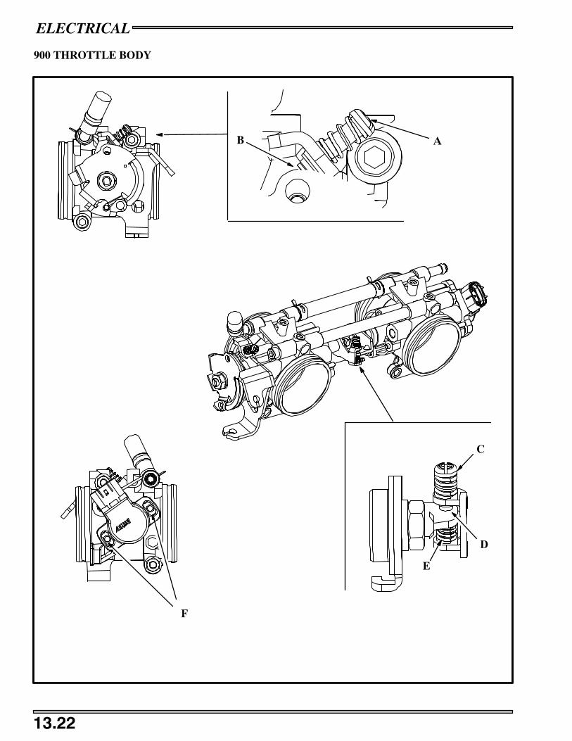
ELECTRICAL
13.22
900 THROTTLE BODY
AB
C
D
E
F

ELECTRICAL
13.23
TPS SETTING PROCEDURE
The TPS comes set from the factory and should not need any adjustments. If replacing a TPS or resetting the TPS, Polaris hasdeveloped a TPS test kit for aid in setting the Throttle Position Sensor to specification.
1. Assemble your TPS sensor tool (PN 2201519) as per the instructions that came with the tool.2. Make sure your 9 volt battery is in good condition by inserting the black volt meter probe from your Fluketmeter in the black
terminal and the red probe into the pink terminal. Voltage should read 4.99 to 5.01 volts. If not, try a new 9 volt battery.
3. Insert the red voltmeter lead into the yellow terminal, and black lead to the black terminal. Slowly open throttle and check forsmooth voltage change.
NOTE: The Fluke meter will change scales and show O.L. momentarily when throttle is opening.
4. Turn the idle set screw (A) counter clockwise until the screw tip (B) separates from the adjusted lever tab.5. Turn the synchronization screw (C) counter clockwise until the synchronization lever is touching the synchronization screw
hole (D) tab.6. Remove the connector from the TPS on the throttle body and install TPS sensor tool on to the TPS.7. Place a shop towel under the throttle body incase you loose grip on the spring.8. Remove the synchronization lever tab spring (E) and gently open and then close the throttle plates with the throttle, allowing
the plate to close gently. Note the voltage at this point.9. Insert the synchronization lever tab spring and screw.10. Turn the synchronization screw clockwise until the volt meter reads the voltage level that you noted in step #8.11. Loosen screws on the TPS sensor (F).12. Adjust the TPS sensor until the voltage on the volt meter reads .705 -- .715 volts.13. Tighten the TPS retaining screws, making sure that the voltage continues to read .705 -- .715 volts.14. Turn the idle set screw clockwise until the voltage reads .930 volts.15. Voltage at the yellow terminal should be .93 volts +.02v at idle. Once the TPS voltage is verified and set, remove the sensor
tool and re--install the TPS harness.
IQ FUSION/RMK THROTTLE POSITION SENSOR (TPS)
0.93 volts (±.02v) @ Idle
R/W (from ECU)
Lite Blue
BLK/BL
NOTE: The 900 Libertyt engine TPS is set at .93volts ±.02v at idle.
When the sensor is inoperative or disconnected the system will switch to a “LIMP HOME” mode. Limp Home mode reducesperformance to a default value and monitors other sensors.
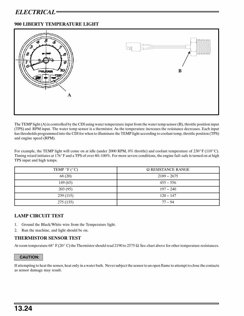
ELECTRICAL
13.24
900 LIBERTY TEMPERATURE LIGHT
A
B
The TEMP light (A) is controlled by the CDI using water temperature input from the water temp sensor (B), throttle position input(TPS) and RPM input. The water temp sensor is a thermistor. As the temperature increases the resistance decreases. Each inputhas thresholds programmed into the CDI for when to illuminate the TEMP light according to coolant temp, throttle position (TPS)and engine speed (RPM).
For example, the TEMP light will come on at idle (under 2000 RPM, 0% throttle) and coolant temperature of 230_F (110_C).Timing retard initiates at 176_F and a TPS of over 80--100%. For more severe conditions, the engine fail--safe is turned on at highTPS input and high temps.
TEMP _F (_C) Ω RESISTANCE RANGE
68 (20) 2189 -- 2675
149 (65) 455 -- 556
203 (95) 197 -- 240
239 (115) 120 -- 147
275 (135) 77 -- 94
LAMP CIRCUIT TEST
1. Ground the Black/White wire from the Temperature light.
2. Run the machine, and light should be on.
THERMISTOR SENSOR TEST
At room temperature 68_ F (20_C) the Thermistor should read 2190 to 2575Ω. See chart above for other temperature resistances.
CAUTION:
If attempting to heat the sensor, heat only in a water bath. Never subject the sensor to an open flame to attempt to close the contactsas sensor damage may result.
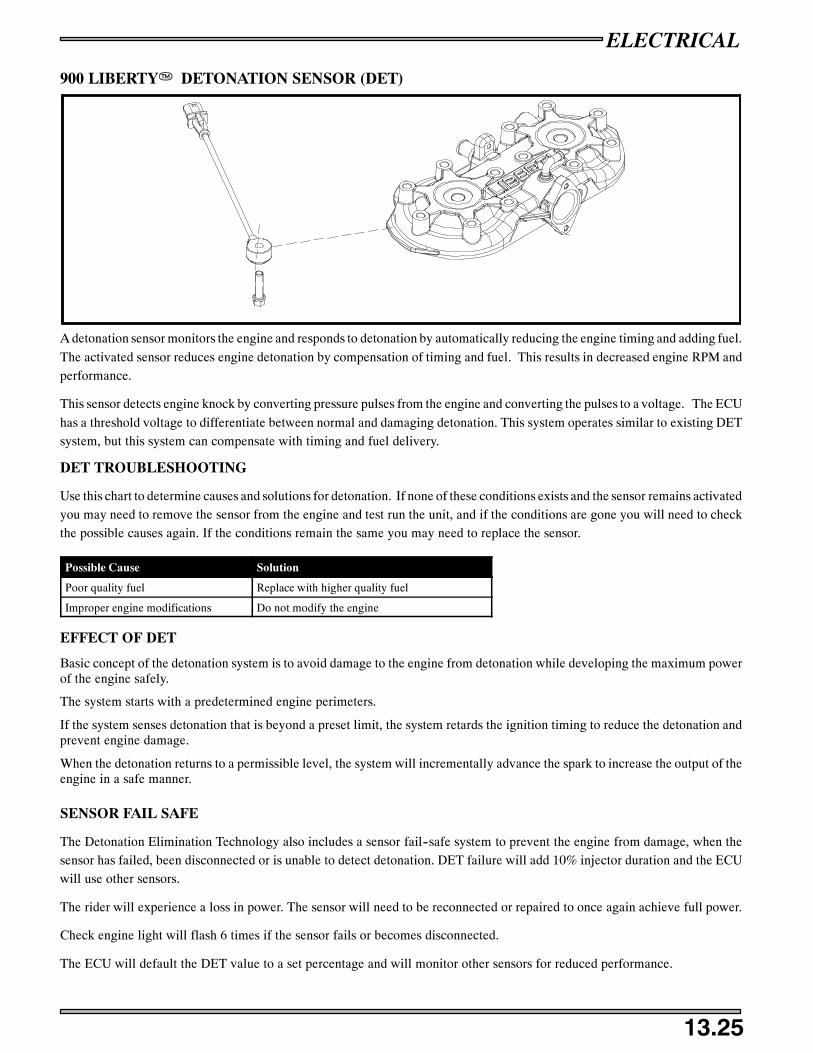
ELECTRICAL
13.25
900 LIBERTYT DETONATION SENSOR (DET)
A detonation sensor monitors the engine and responds to detonation by automatically reducing the engine timing and adding fuel.
The activated sensor reduces engine detonation by compensation of timing and fuel. This results in decreased engine RPM andperformance.
This sensor detects engine knock by converting pressure pulses from the engine and converting the pulses to a voltage. The ECU
has a threshold voltage to differentiate between normal and damaging detonation. This system operates similar to existing DETsystem, but this system can compensate with timing and fuel delivery.
DET TROUBLESHOOTING
Use this chart to determine causes and solutions for detonation. If none of these conditions exists and the sensor remains activatedyou may need to remove the sensor from the engine and test run the unit, and if the conditions are gone you will need to checkthe possible causes again. If the conditions remain the same you may need to replace the sensor.
Possible Cause Solution
Poor quality fuel Replace with higher quality fuel
Improper engine modifications Do not modify the engine
EFFECT OF DET
Basic concept of the detonation system is to avoid damage to the engine from detonation while developing the maximum powerof the engine safely.
The system starts with a predetermined engine perimeters.
If the system senses detonation that is beyond a preset limit, the system retards the ignition timing to reduce the detonation andprevent engine damage.
When the detonation returns to a permissible level, the system will incrementally advance the spark to increase the output of theengine in a safe manner.
SENSOR FAIL SAFE
The Detonation Elimination Technology also includes a sensor fail--safe system to prevent the engine from damage, when thesensor has failed, been disconnected or is unable to detect detonation. DET failure will add 10% injector duration and the ECUwill use other sensors.
The rider will experience a loss in power. The sensor will need to be reconnected or repaired to once again achieve full power.
Check engine light will flash 6 times if the sensor fails or becomes disconnected.
The ECU will default the DET value to a set percentage and will monitor other sensors for reduced performance.

ELECTRICAL
13.26
IQ FUSION/RMK COOLANT TEMPERATURE SENSOR
COOLANT TEMP SENSOR
Resistive sensor which the resistive characteristics change due to temperature. The ECU uses engine coolant temperature, throttleopening and engine RPM information to adjust fuel and ignition maps to warm up or cool down the engine. Disconnected or De-fault temperature is 77.5_F (25_C).
Operating Temperature Range --22 _F -- +248 _F (--30_C -- 120_C)
Resistance 2.4 -- 2.6KΩ @ 68_F (20_C)
Installation Torque 29 ft.lbs. (39.2Nm)

ELECTRICAL
13.27
EXHAUST TEMPERATURE SENSOR
CONNECTIONCHANGE04152004
K--Type resistive sensor with resistive characteristics that change due to temperature. The ECU senses this change in resistanceand uses this information to correct fuel and/or timing. This sensor is difficult to measure if temperature is below 392_F (200_C).Disconnected or Default temperature is 1100_F (593 _C)
Resistance Values 2.3MΩ @ 392_F (200_C) -- 76Ω @ 1652_F (900_C)
INTAKE AIR TEMPERATURE SENSOR
Resistive sensor with resistive characteristics that change due totemperature. The intake air temperature sensor is located in the lower airintake. The ECU senses this change in resistance and uses this informa-tion to correct fuel and/or timing based on intake air temperature. In caseof circuit failure ECU goes to calibrated default air temperature. Defaulttemperature is --20_F (--28_C).
OperatingTemp Range
--22 _F -- +248 _F (--30_C -- 120_C)
Resistance 77_F(25_C) 9.7 -- 10.3 KΩ
BAROMETRIC PRESSURE SENSOR
Internal ECU sensor that provides ECU with Altitude information toadjust fuel and ignition. This sensor is located in side the ECU and is notserviceable. Default setting is 28.74 inches of mercury.

ELECTRICAL
13.28
CRANK POSITION SENSOR
AB
CD
FLYWHEEL SIDE VIEW
STATOR
A&B
E
C
C
C
D
D
FLYWHEEL
E
CC
When the sensor is inoperative or disconnected thesystem will switch to a “LIMP HOME” mode. LimpHome mode reduces performance to a default valueand monitors other sensors.
The 5 tooth crank position sensor (A) picks up all 5 flywheel teeth (C).
The 2 tooth crank position sensor (B) picks up 2 off set flywheel teeth (D).
Both crank position sensors will have a gap (E) to the flywheel pick up of .035” (.90mm).
These sensors must be in the correct position or the engine will not run as expected. A sheared flywheel key will cause the engineto not start or kill if running.
The 2 tooth pick up detects the crank angle and obtains minimal information of the crank angle when control enters into limphome mode.
5 tooth pickup is to obtain the following information in combination with the 2 tooth pickup.
S Judge direction of rotation (forward and backward)S Ignition advance angle controlS Injector drive angle controlS Excess advance ignition control at reverse
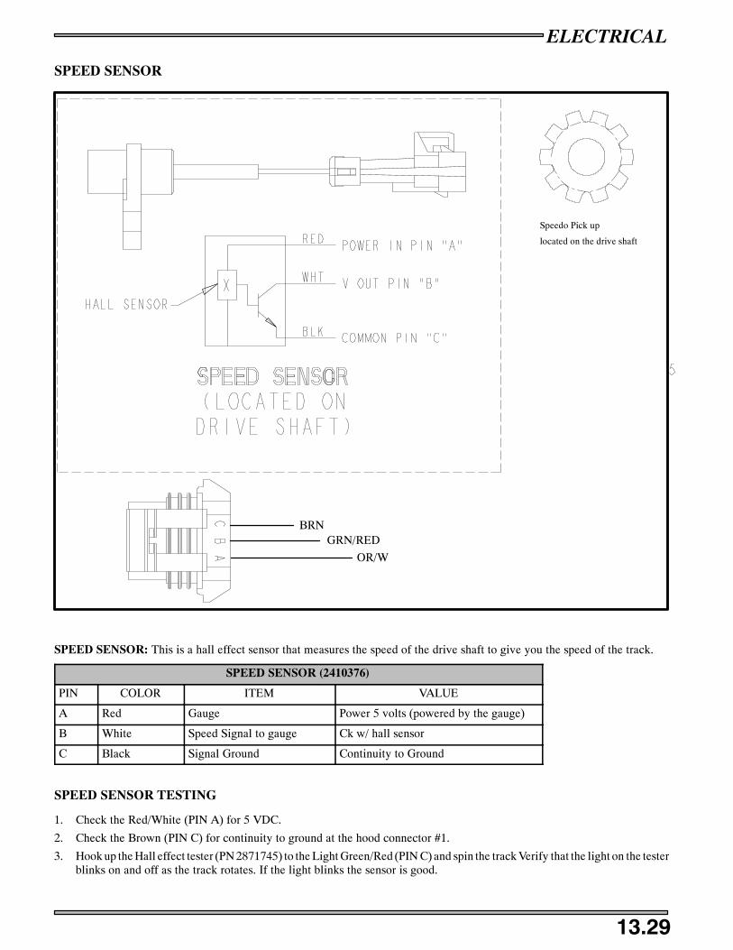
ELECTRICAL
13.29
SPEED SENSOR
Speedo Pick up
located on the drive shaft
BRNGRN/RED
OR/W
SPEED SENSOR: This is a hall effect sensor that measures the speed of the drive shaft to give you the speed of the track.
SPEED SENSOR (2410376)
PIN COLOR ITEM VALUE
A Red Gauge Power 5 volts (powered by the gauge)
B White Speed Signal to gauge Ck w/ hall sensor
C Black Signal Ground Continuity to Ground
SPEED SENSOR TESTING
1. Check the Red/White (PIN A) for 5 VDC.
2. Check the Brown (PIN C) for continuity to ground at the hood connector #1.
3. Hook up the Hall effect tester (PN 2871745) to the Light Green/Red (PIN C) and spin the track Verify that the light on the testerblinks on and off as the track rotates. If the light blinks the sensor is good.

ELECTRICAL
13.30
OIL LEVEL SENDER
GroundOil Level
A
B
The float (A) moves up and down the sender shaft (B) and ECU sends a signal to the MFD when the level get to the point whereyou need to add more oil. The oil level signal is measured in resistance, FULL is open and <10Ω at lower level.
This sensor is pressed in and has a snug fit to the tank by the grommet.
OIL LEVEL SENSOR
COLOR ITEM VALUE
Violet Oil Level Sensed by gauge when at the lowest point.
Brown Ground Ground

ELECTRICAL
13.31
ENGINE / CHASSIS CONNECTION LOCATION

CONNECTION TO CHASSIS
MAG INJECTOR
PTO
INJECTORTO REGULATOR
RECTIFIER
ELECTRICAL
13.32
ECU PLUG CONNECTION #1

ELECTRICAL
13.33
ECU PLUG #1
PIN# COLOR ITEM PIN
# COLOR ITEM
1 Orange Regulator Rectifier 18 Orange Regulator Rectifier
2 -- -- 19 Red/Black Battery Voltage (+)
3 White/Green Speed Limit Signal 20 Black/Blue Sensor Ground
4 Yellow/Red Tachometer Signal 21 Black Aux Kill Switch
5 Blue/Red Water Temp Signal 22 Black/Red Soft Stop
6 Green PTO Injector 23 Blue Air Temp Sensor
7 -- -- 24 White/Black Exhaust Temp Sensor
8 Yellow MAG Injector 25 Green/Blue Solenoid Ground
9 -- -- 26 Red Voltage Regulator (out) power
10 Orange Regulator Rectifier 27 -- --
11 White/Blue Chassis Relay Coil 28 Brown Ground
12 -- -- 29 Black/White Diagnostic
13 Grey Reverse Switch 30 Green/Blue Hot/DET Lamp
14 Red/Blue Injector Power PTO 31 White Reverse Lamp
15 -- -- 32 Light Green/Red Ground Speed Signal
16 Red/Blue Injector Power MAG 33 Orange/Green Battery Relay Coil
17 -- -- 34 Brown/WHite Fuel Pump Switch

To Magneto (coil)
To Magneto
Crank Position Sensor
To ECU
EV Solenoid
External PowerDigital Wrench
TPSCoolant Temp Sensor
PTO Ign Coil(blue cover)
#1 MAG Coil(white cover)
DET Sensor
ELECTRICAL
13.34
ECU PLUG CONNECTION #2

ELECTRICAL
13.35
ECU PLUG #2
PIN# COLOR ITEM PIN
# COLOR ITEM
1 White CPS (2 tooth) 18 -- --
2 White/Red CPS (2 tooth) 19 Purple Detonation Sensor
3 Green CPS (5 tooth) 20 Black/Blue Detonation Sensor Ground
4 White/Green CPS (5 tooth) 21 Black/Blue Coolant Temperature SensorGround / TPS Ground
5 -- -- 22 Black/Blue External Power Ground
6 -- -- 23 Brown MAG Ignition Coil Ground
7 Pink Digital Wrench 24 Brown PTO Ignition Coil Ground
8 Orange External Power (+) 25 Brown Exciter Coil Ground
9 Black/Yellow MAG Ignition Coil 26 Red Voltage Regulator Out
10 -- -- 27 White/Yellow EV Solenoid
11 Yellow Coolant Temp Sensor 28 -- --
12 Aqua TPS Signal 29 -- --
13 -- -- 30 Red/White Power Supply (5 Volts)
14 Red/Blue Digital Wrench 31 Blue/Yellow Injector Coil
15 Gray Digital Wrench 32 Blue/Yellow Injector Coil
16 Black/White Diagnostic Lamp 33 Green/Red Exciter Coil (+)
17 Black/Red PTO Ignition Coil 34 Green/Yellow Exciter Coil (Center)
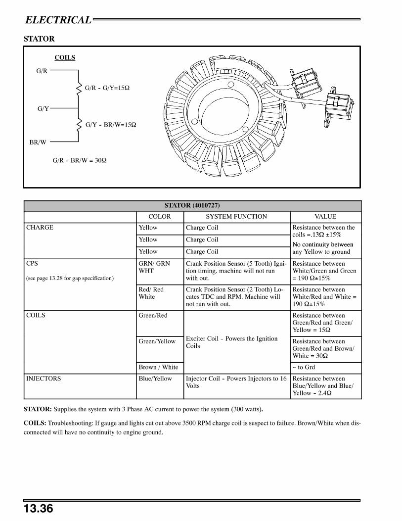
ELECTRICAL
13.36
STATOR
G/R
G/Y
BR/W
COILS
G/R -- G/Y=15Ω
G/Y -- BR/W=15Ω
G/R -- BR/W = 30Ω
STATOR (4010727)
COLOR SYSTEM FUNCTION VALUE
CHARGE Yellow Charge Coil Resistance between thecoils = 13Ω ±15%
Yellow Charge Coilcoils =.13Ω ±15%
No continuity betweenYellow Charge Coil
No continuity betweenany Yellow to ground
CPS
(see page 13.28 for gap specification)
GRN/ GRNWHT
Crank Position Sensor (5 Tooth) Igni-tion timing. machine will not runwith out.
Resistance betweenWhite/Green and Green= 190 Ω±15%
Red/ RedWhite
Crank Position Sensor (2 Tooth) Lo-cates TDC and RPM. Machine willnot run with out.
Resistance betweenWhite/Red and White =190 Ω±15%
COILS Green/Red Resistance betweenGreen/Red and Green/Yellow = 15Ω
Green/Yellow Exciter Coil -- Powers the IgnitionCoils
Resistance betweenGreen/Red and Brown/White = 30Ω
Brown / White ~ to Grd
INJECTORS Blue/Yellow Injector Coil -- Powers Injectors to 16Volts
Resistance betweenBlue/Yellow and Blue/Yellow -- 2.4Ω
STATOR: Supplies the system with 3 Phase AC current to power the system (300 watts).
COILS: Troubleshooting: If gauge and lights cut out above 3500 RPM charge coil is suspect to failure. Brown/White when dis-connected will have no continuity to engine ground.

ELECTRICAL
13.37
COIL / EV SOLENOID
PTO IGNITION COILMAG IGNITION COIL
Located under the steering column
Exhaust Valve Solenoid
IGNITION COILS: Provides ignition spark for each cylinder
PRIMARY COIL #1 (MAG SIDE) PRIMARY COIL #2 (PTO SIDE)
COLOR ITEM VALUE COLOR ITEM VALUE
BLK/RED ECU .45Ω ±15% BLK/Y ECU .45Ω ±15%
BRN Ground .45Ω ±15% BRN Ground .45Ω ±15%
SECONDARY COIL #1 (MAG SIDE) SECONDARY COIL #2 (PTO SIDE)
WHT/BLK 18KΩ±20% WHT/BLK 18KΩ±20%
EXHAUST VALVE SOLENOID: This solenoid will open and close the exhaust port vacuum at a calibrated TPS and RPM. Helpsprovide maximum power across the power band. 15Ω from W/Y to RED on the solenoid. Fail safe mode will keep the valves
closed and the unit will have no top end.
EXHAUST VALVE SOLENOID
COLOR ITEM VALUE
W/Y ECU switches to ground
Red BATT + Batt Voltage

ELECTRICAL
13.38
EV SOLENOID
ECU
SolenoidOpen
Wire
Hose
Spring
Bellows
Outlet Hole
Inlet Holefrom Cylinder
ExhaustValve
Inlet Holefrom Cylinder Spring
Bellows
ECU
SolenoidClosed
W/Y
Spring
Bellows
Inlet Holefrom Cylinder
ExhaustValve
Spring
Bellows
Outlet Hole
Inlet Holefrom Cylinder
Below 6800 RPM Above 6800 RPM Exhaust Valves Fully OpenExhaust Valves Closed
ExhaustValve
ExhaustValve
T-Fitting
SolenoidOpen
Wire
Hose
T-Fitting
R
Hose
T-Fitting
Hose
T-Fitting
RW/Y
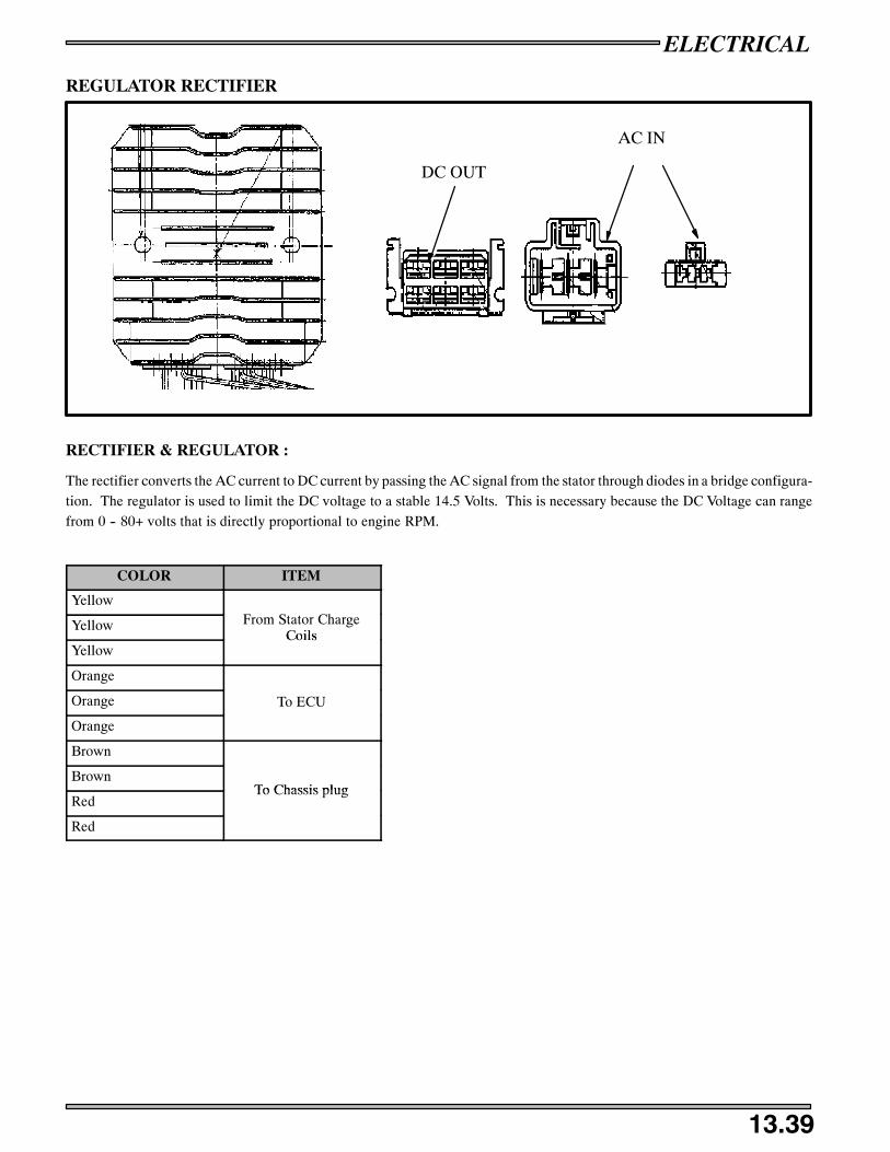
ELECTRICAL
13.39
REGULATOR RECTIFIER
DC OUT
AC IN
RECTIFIER & REGULATOR :
The rectifier converts the AC current to DC current by passing the AC signal from the stator through diodes in a bridge configura-tion. The regulator is used to limit the DC voltage to a stable 14.5 Volts. This is necessary because the DC Voltage can rangefrom 0 -- 80+ volts that is directly proportional to engine RPM.
COLOR ITEM
Yellow
Yellow From Stator ChargeCoils
YellowCoils
Orange
Orange To ECU
Orange
Brown
BrownTo Chassis plug
RedTo Chassis plug
Red

ELECTRICAL
13.40
CAPACITOR
CAPACITOR: The function of the capacitor is to act like a battery in a non--battery system. The capacitor makes the chassisside power signal stable. WIth out the capacitor in the system the unit will not run correctly at idle.
CAPACITOR
COLOR ITEM VALUE
RED/WHT Chassis Power 28000uF
BRN Chassis Ground 28000uF
Can check for sort circuit failure (O.L.).
TESTING CAPACITOR
1. Use a 12 volt battery and hook up the positive (+) to the Red/White wire and the negative (--) to the brown wire. Let thecapacitor take a charge for 10 seconds.
2. Using a multimeter check the power that is in the capacitor. The power may slowly go down.
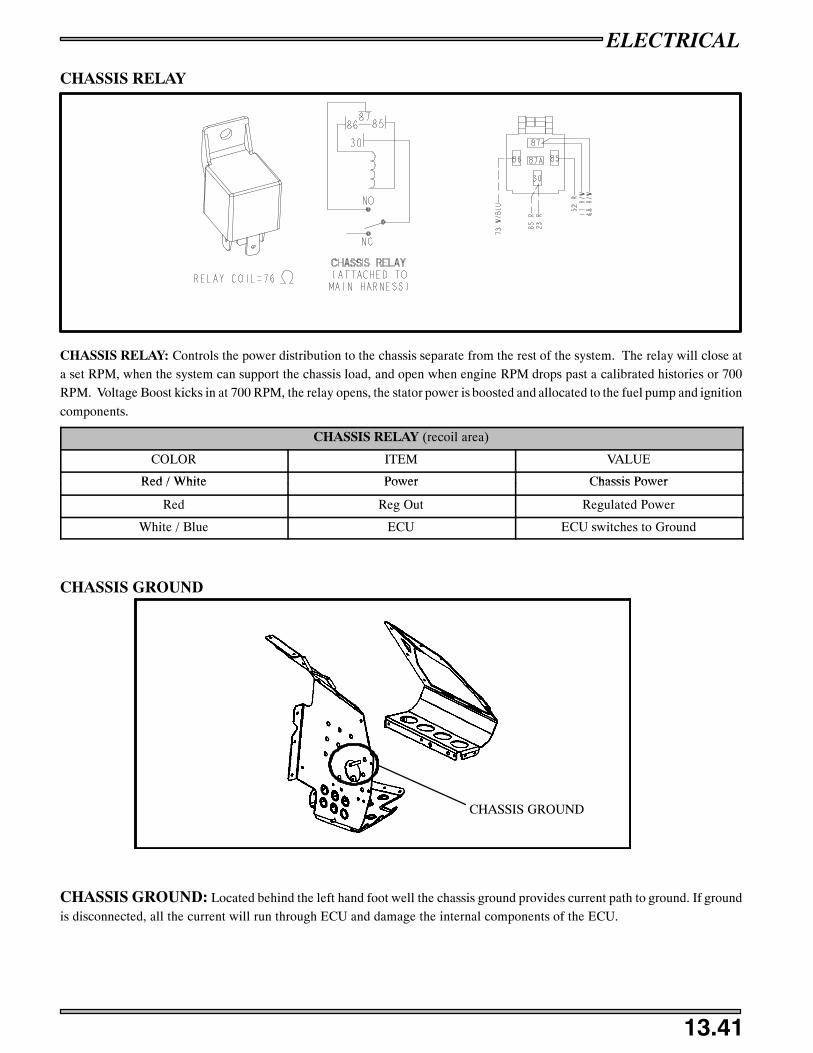
ELECTRICAL
13.41
CHASSIS RELAY
CHASSIS RELAY: Controls the power distribution to the chassis separate from the rest of the system. The relay will close ata set RPM, when the system can support the chassis load, and open when engine RPM drops past a calibrated histories or 700RPM. Voltage Boost kicks in at 700 RPM, the relay opens, the stator power is boosted and allocated to the fuel pump and ignition
components.
CHASSIS RELAY (recoil area)
COLOR ITEM VALUE
Red / White Power Chassis PowerRed / White Power Chassis Power
Red Reg Out Regulated Power
White / Blue ECU ECU switches to Ground
CHASSIS GROUND
CHASSIS GROUND: Located behind the left hand foot well the chassis ground provides current path to ground. If groundis disconnected, all the current will run through ECU and damage the internal components of the ECU.
CHASSIS GROUND

ELECTRICAL
13.42
CHASSIS HOOD CONNECTOR #1
CHASSIS HOOD CONNECTOR #1
PIN COLOR ITEM VALUE
A Brown Lamp Ground
B Yellow / Red Tachometer
C Red /White Battery (+) 14 VDC
D Light Green / Red Speed Signal
E Brown Ground
F Yellow High Beam
G Violet Oil Level OpenΩ Full< 10 Ω Empty
H Orange Brake Lamp
J Black / White Diagnostic Lamp
K Blue / White Hot/DET lamp
L White Reverse Lamp
M Green Low Beam
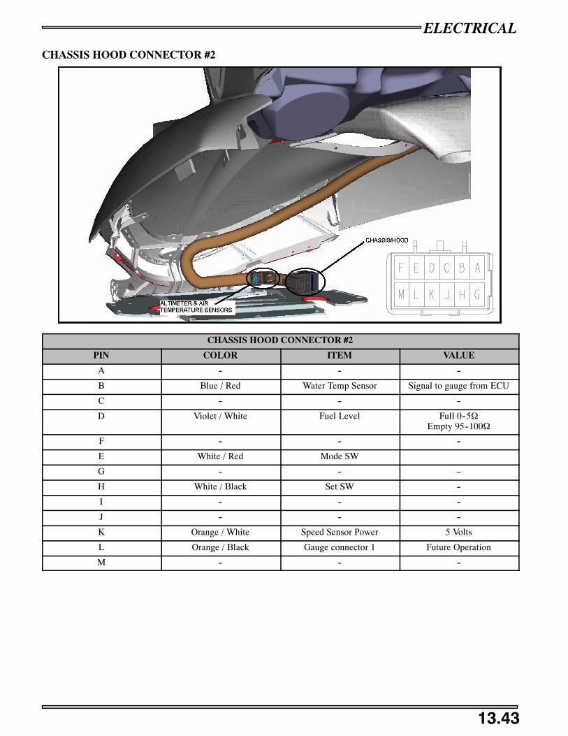
ELECTRICAL
13.43
CHASSIS HOOD CONNECTOR #2
CHASSIS HOOD CONNECTOR #2
PIN COLOR ITEM VALUE
A -- -- --
B Blue / Red Water Temp Sensor Signal to gauge from ECU
C -- -- --
D Violet / White Fuel Level Full 0--5ΩEmpty 95--100Ω
F -- -- --
E White / Red Mode SW
G -- -- --
H White / Black Set SW --
I -- -- --
J -- -- --
K Orange / White Speed Sensor Power 5 Volts
L Orange / Black Gauge connector 1 Future Operation
M -- -- --

ELECTRICAL
13.44
DIGITAL WRENCH POWER PLUG
DIGITAL WRENCH DIAGNOSTIC PORT ECU POWER UP FOR DIGITAL WRENCH
BLK/BLUOR
BROWNR/W
LIGHTS DIAGNOSTICPUMP PRIME
DIAGNOSTIC PORT
The diagnostic port is used with the Digital Wrench diagnostic program. The communication cable hooks to this port to communi-cate to the ECU when powered up with the power up port.
ECU POWER UP PORT
The power up port is used to give the ECU power so that the Digital Wrench can communicate with the ECU. To power up theECU use the M--10 ACE power cable (PN PV--46355).
DIAGNOSTIC PLUG FOR LIGHTS
Apply 12 VDC to this plug by using the M--10 ACE tool (PN PV--46355) and it will power up all the light circuits. This is helpfulfor checking any grounds for lights.
PUMP PRIME
Applying 12 VDC to this by using the M--10 ACE pig tail tool (PN PA--46355--2). This will cycle the fuel pump and pressurizethe fuel rail. Apply positive (+) power to the RED wire and the negative (--) to the BROWN wire. This will be used when primingthe fuel pump after engine rebuild.
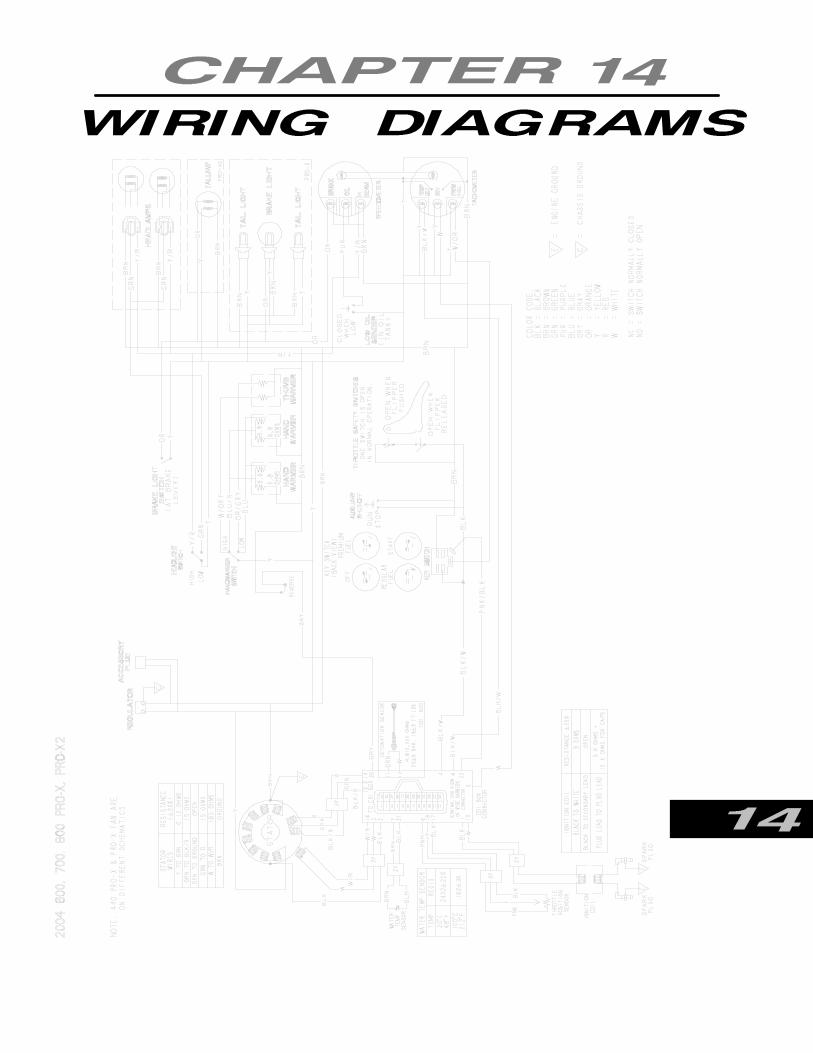
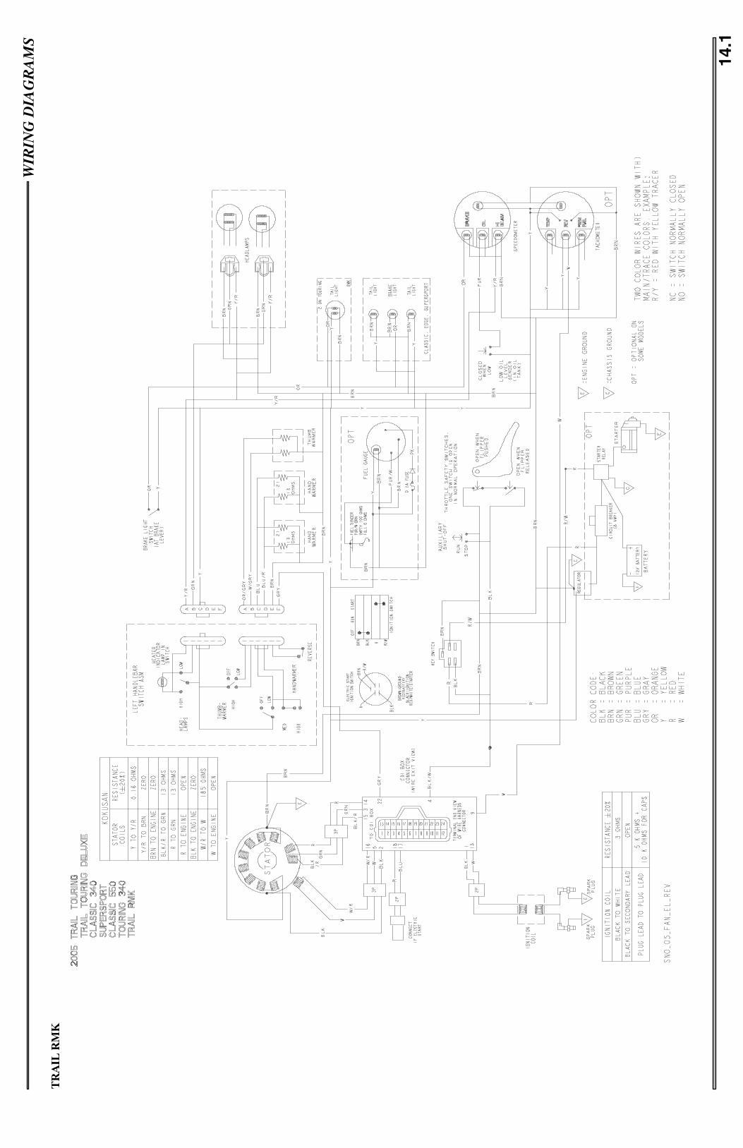
WIR
ING
DIA
GR
AM
S
14.1
TR
AIL
RM
K

WIR
ING
DIA
GR
AM
S
14.2
600/
700/
800
RM
K,6
00/8
00SW
ITC
HB
AC
K

WIR
ING
DIA
GR
AM
S
14.3
900
RM
KH
OO
D1
OF
2
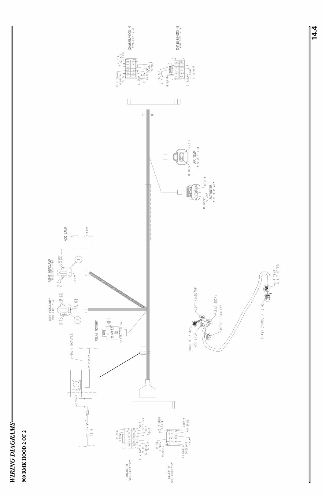
WIR
ING
DIA
GR
AM
S
14.4
900
RM
KH
OO
D2
OF
2

WIR
ING
DIA
GR
AM
S
14.5
900
RM
KC
HA
SSIS
1O
F3

WIR
ING
DIA
GR
AM
S
14.6
900
RM
KC
HA
SSIS
2O
F3

WIR
ING
DIA
GR
AM
S
14.7
900
RM
KC
HA
SSIS
3O
F3

Numbers2 --- pulse a nd 6 p ulse Alt e rna t ors, 13. 12
550 Engine Assembly, 5.10
550 Engine Disassembly, 5.9
700/800 Waterpump Belt, 3.30
900 FUSION Specifications, 1.10–1.12
AAir Filter, 3.4
Auxiliary Shut---Off Switch Testing, 13.16
BBarometric Pressure Sensor, 900 Liberty, 13.27
BatteryBattery Charging, 13.7Battery Filling, 13.7Battery Storage, 13.7Battery Testing, 13.6Load Test, 13.7
Brake Pad Replacement, 8.11
Brake SystemBleeding, 3.18Bleeding/Fluid Change, 8.2Compensating Port, 8.1Maintenance, 3.17Service, 8.3–8.11Subassembly, 8.4
Brake System Overview, 8.1
Bulb Replacement, IQ, 3.15
CCamberAdjustment, 9.8Definition, 9.5Inspection, 9.9Range, 9.9
Capacitor, 900 Liberty, 13.40
Carbide to Ski Placement, 9.16
Carburetor, Troubleshooting, 4.19
Care, 3.20
Chaincase, 3.8
ChaincaseBearing Assembly, 7.5Bearing Removal, 7.5Removal, 7.5
Chaincase Exploded View, 7.4
Chassis Ground, 900 Liberty, 13.41
Chassis Hood Connector #1, 900 Liberty, 13.42
Chassis Relay, 900 Liberty, 13.41
Choke Adjustments, 4.17
Clutch Alignmnt Adjustment, 6.22
Clutch Offset Adjustment, 6.22
Clutch Offset Inspection, 6.22
Clutch Operation, 6.2–6.4
Clutch Tools, 6.1
Coil, 900 Liberty, 13.37
Compression Damping Adjustable Shocks, 10.4
Connecting Rod Bearing Inspection, 2.14
Console Removal, 900 Fusion, 12.6
Conversion CartsFraction to Decimal, 2.5Units of Measure, 2.8
Coolant Sensor, 900 Liberty, 13.26
Cooling System900 Fusion, 2.22Coolant Level, 2.21Overview, 2.21
CrankcaseBearing Fit, 2.13Inspection, 2.13
CrankshaftConnecting Rod Small End Inspection, 2.14Indexing, 2.15–2.17Main Bearing Inspection, 2.13Needle Bearing Inspection, 2.14Piston Pin, 2.14Runout Inspection, 2.17Truing, 2.16
Crankshaft Position Sensor, 900 Liberty, 13.28
CylinderHoningCleaning, 2.13De---Glazing, 2.12Oversize, 2.12Procedure, 2.12Selection, 2.12Head Inspection, 2.10Measurements, 2.10

Port Chamfering, 2.13
DDecal Removal/Installation, 12.11–12.14
DET Sensor, 900 Liberty, 13.25
Digital WrenchDiagnostic Port, 13.44Power Plug, 13.44
Dive Chain Tension, 3.8
Drive BeltData, 6.19Deflection, 6.21Diagnosis, 6.20Inspection, 6.20
Drive Belt RemovalPolaris Drive Clutch, 3.12TEAM Clutch, 3.13
Drive Chain Part Numbers, 7.3
Drive ClutchAssembly, 6.13Disassembly, 6.10–6.12Exploded View, 6.7, 6.14Identification, 6.7Installation, 6.9Removal, 6.8Spider, Removal/Installation, 6.12Springs, 6.4Weights, 6.5–6.7
Driven ClutchInstallation, 6.15Removal, 6.15Types, 6.14
Drive Shaft, Removal/Installation, 7.6
Driven Clutch Deflection Adjustment, 6.21
EECU Plug #1, 900 Liberty, 13.32–13.34
ECU Plug #2, 900 Liberty, 13.34–13.36
ECU Powerup Port, 13.44
Edge Driveshaft Bearing, 3.6
Edge Hood Removal, 12.1
Engine/Chassis Connection Location, 900 Fusion,13.31
EV Solenoid, 900 Liberty, 13.37–13.39
Exhaust Temperature Sensor, 900 Liberty, 13.27
Exhaust Valve MaintenanceEdge, 3.23IQ, 3.24
FFront Bumper, 900 Fusion, 12.3
Front Suspension Adjustment Procedures, 10.1
Front Suspension Components600/800 Switchback, 9.2Trail/600/700/800 RMK, 9.1
Front Suspension Torque Values600/800 Switchback, 9.2Trail/600/700/800 RMK, 9.1
Front Torque Arm Limiter Strap Adjustment, 11.13
Front Track Shock Information, 11.14
Fuel Delivery Overview, 4.7
Fuel Filter, 3.5
Fuel PumpCleaning, 4.18Diaphram Style, 4.18Inspection, 4.18Maintenance, 4.18Operation, 4.18
Fuel RailInstallation, 4.21Removal, 4.21
Fuel Sender Testing, EDGE, 13.16
Fuel Tank Removal, 900 Fusion, 12.4–12.6
Fuji Engine Exploded View, 5.8
Fuji Torque Patterns, 5.2
GGasoline Volatility, 4.6
Gearing Charts, 7.1–7.3
General Service Precautions, 2.4
HHandle Bar Centering, 9.10
Handlebar Torque Sequence, 9.16
HandlebarAdjustment, 3.16

Cover Removal, 3.16
Head Light, Edge, 12.1
Head Light Adjustment, 3.14
Head Light Removal, 900 Fusion, 12.3
Headlight Bulb Filament Continuity Test, 13.13
Hi/Lo Beam Switch Testing, 13.13
Hood, 900 RMK, 12.2
Chassis Hood Connector #2, 900 Liberty, 13.43
Hood Removal, 900 RMK, 12.3
Hood Repair, 12.8
IIFS Shock Information, 10.5
IFS Shock Springs, 10.2
Front Track Shock Valving Specification, 11.15
IFS Shock Valving Specification, 10.6
Rear Track Shock Valving Specification, 11.15
IFS Specifications, 9.6
Ignition Switch Testing, 13.13–13.15
Insterment Removal/Installation, Edge, 12.1
Intake Air Tempurature Sensor, 900 Liberty, 13.27
IQAir Intake, 3.22900 Exhaust System, 3.21900 Fusion Oil Pump Bleeding, 3.27Cooling System Maintenance, 3.26Fuel Rail Bleeding, 4.21
IQ Spindle Assembly, 9.17
JJackshaft Bearing, 3.6
Jackshaft Installation, 7.5
Jackshaft Removal, 7.5
LLamp Diagnostic Connector, 13.44
Lubrication Points, 3.6
MMaintenance Program, 3.1–3.4
Master Cylinder Exploded View, 8.3
Master Cylinder Inspection, 8.4
Master Cylinder Removal, 8.3
MFD Removal, 900 Liberty, 12.3
MikuniComponent Operation, 4.8–4.13Float, 4.8Fuel Delivery, 4.10Fuel Metering, 4.8Jet Needle, 4.11Main Jet, 4.10Needle jet, 4.11Pilot Air Screw, 4.10Pilot Jet, 4.10Throttle Opening vs. Fuel Flow, 4.12Throttle Valve, 4.11Exploded View, 4.5jet Needle Overview, 4.3Jetting Guidelines, 4.10TM 38/40 Components, 4.4
Mikuni Part NumbersJets, 4.1Main Jet, 4.1Pilor Air Jets, Short,4 .2Pilot Air Jets, Long, 4.2Piston Valves, 4.2Notched, 4.2Starter Jets, 4.2TM Jet Needles, 4.2
Mikuni TM CarburetorAssembly, 4.15Disassembly, 4.13–4.15Throttle Synchronization, 4.16
Model Number Designation, 2.1
NNosepan Replacement, 12.9800 RMK, 12.10
OOil Filter, 3.5
Oil Level Sensor, 900 Liberty, 13.30
Oil PumpAdjustment, 2.20
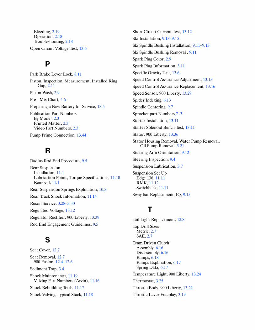
Bleeding, 2.19Operation, 2.18Troubleshooting, 2.18
Open Circuit Voltage Test, 13.6
PPark Brake Lever Lock, 8.11
Piston, Inspection, Measurement, Installed RingGap, 2.11
Piston Wash, 2.9
Pre---Mix Chart, 4.6
Preparing a New Battery for Service, 13.5
Publication Part NumbersBy Model, 2.3Printed Matter, 2.3Video Part Numbers, 2.3
Pump Prime Connection, 13.44
RRadius Rod End Procedure, 9.5
Rear SuspensionInstallation, 11.1Lubrication Points, Torque Specifications, 11.10Removal, 11.1
Rear Suspension Springs Explination, 10.3
Rear Track Shock Information, 11.14
Recoil Service, 3.28–3.30
Regulated Voltage, 13.12
Regulator Rectifier, 900 Liberty, 13.39
Rod End Engagement Guidelines, 9.5
SSeat Cover, 12.7
Seat Removal, 12.7900 Fusion, 12.4–12.6
Sediment Trap, 3.4
Shock Maintenance, 11.19Valving Part Numbers (Arvin), 11.16
Shock Rebuilding Tools, 11.17
Shock Valving, Typical Stack, 11.18
Short Circuit Current Test, 13.12
Ski Installation, 9.13–9.15
Ski Spindle Bushing Installation, 9.11–9.13
Ski Spindle Bushing Removal , 9.11
Spark Plug Color, 2.9
Spark Plug Information, 3.11
Specific Gravity Test, 13.6
Speed Control Assurance Adjustment, 13.15
Speed Control Assurance Replacement, 13.16
Speed Sensor, 900 Liberty, 13.29
Spider Indexing, 6.13
Spindle Centering, 9.7
Sprocket part Numbers,7 .3
Starter Installation, 13.11
Starter Solenoid Bench Test, 13.11
Stator, 900 Liberty, 13.36
Stator Housing Removal, Water Pump Removal,Oil Pump Removal, 5.21
Steering Arm Orientation, 9.12
Steering Inspection, 9.4
Suspension Lubrication, 3.7
Suspension Set UpEdge 136, 11.11RMK, 11.12Switchback, 11.11
Sway bar Replacement, IQ, 9.15
TTail Light Replacement, 12.8
Tap Drill SizesMetric, 2.7SAE, 2.7
Team Driven ClutchAssembly, 6.16Disassembly, 6.16Ramps, 6.18Ramps Explination, 6.17Spring Data, 6.17
Temperature Light, 900 Liberty, 13.24
Thermostat, 3.25
Throttle Body, 900 Liberty, 13.22
Throttle Lever Freeplay, 3.19

Tie Rod End Procedure, 9.5
Timing Procedure --- All Models, 13.5
Toe Ajustment, 9.10
Torque Specifications, Bolt Size, 2.6
Torque Stop Adjustment, 6.23
Torsion Bar Removal/Installation, EDGE, 9.14
TPS Adjustment, 13.20
TPS Setting, 900 Liberty, 13.23
TPS Testing, Carbureted Models, 13.18
Track Adjustment, 3.9
Track Maintenance, 3.9
Track Tension, 3.10
Track Tension Adjustment, 3.10
Troubleshooting, Rear Suspension, 11.25
Troubleshooting, Seat Harness, 13.13
Tunnel Decal, 2.1
Typical Multimeter Useage, 13.1
UUnregulated Voltage, 13.11
VVehicle Identification Number (VIN), 2.2Model Number Key, 2.2
WWarnings, Fuel, 4.1
Water Trap, 3.4
Wiring Diagram600/800/700 RMK, 14.2Trail RMK, 14.1
Wiring Diagrams, 900 RMK, 14.3–14.8

9919302PART #
PN 99193029919302
2005 DEEP SNOWSERVICE MANUAL
TRAIL RMK600 RMK700 RMK800 RMK900 RMK
600 SWITCHBACK™
800 SWITCHBACK™
2005 DEEP SNO
W SERVICE M
ANUALCVR_9919302 9/23/04 9:17 AM Page 1
creo