2004 LEGACY SERVICE MANUAL QUICK REFERENCE ...
756
FUJI HEAVY INDUSTRIES LTD. G2320GE7 2004 LEGACY SERVICE MANUAL QUICK REFERENCE INDEX BODY SECTION This service manual has been prepared to provide SUBARU service personnel with the necessary information and data for the correct maintenance and repair of SUBARU vehicles. This manual includes the procedures for maintenance, disassembling, reas- sembling, inspection and adjustment of components and diagnostics for guid- ance of experienced mechanics. Please peruse and utilize this manual fully to ensure complete repair work for satisfying our customers by keeping their vehicle in optimum condition. When replacement of parts during repair work is needed, be sure to use SUBARU genuine parts. All information, illustration and specifi- cations contained in this manual are based on the latest product information available at the time of publication approval. HVAC SYSTEM (HEATER, VENTILATOR AND A/C) AC HVAC SYSTEM (AUTO A/C) (DIAGNOSTICS) AC(diag) AIRBAG SYSTEM AB AIRBAG SYSTEM (DIAGNOSTICS) AB(diag) SEAT BELT SYSTEM SB LIGHTING SYSTEM LI WIPER AND WASHER SYSTEMS WW ENTERTAINMENT ET COMMUNICATION SYSTEM COM GLASS/WINDOWS/MIRRORS GW BODY STRUCTURE BS INSTRUMENTATION/DRIVER INFO IDI SEATS SE SECURITY AND LOCKS SL SUNROOF/T-TOP/CONVERTIBLE TOP (SUNROOF) SR EXTERIOR/INTERIOR TRIM EI EXTERIOR BODY PANELS EB
-
Upload
khangminh22 -
Category
Documents
-
view
0 -
download
0
Transcript of 2004 LEGACY SERVICE MANUAL QUICK REFERENCE ...

2004 LEGACY SERVICE MANUAL QUICK REFERENCE INDEX
BODY SECTION
This service manual has been preparedto provide SUBARU service personnelwith the necessary information and datafor the correct maintenance and repairof SUBARU vehicles.This manual includes the proceduresfor maintenance, disassembling, reas-sembling, inspection and adjustment ofcomponents and diagnostics for guid-ance of experienced mechanics.Please peruse and utilize this manualfully to ensure complete repair work forsatisfying our customers by keepingtheir vehicle in optimum condition.When replacement of parts duringrepair work is needed, be sure to useSUBARU genuine parts.
All information, illustration and specifi-cations contained in this manual arebased on the latest product informationavailable at the time of publicationapproval.
FUJI HEAVY INDUSTRIES LTD.
HVAC SYSTEM (HEATER, VENTILATOR AND A/C)
AC
HVAC SYSTEM (AUTO A/C) (DIAGNOSTICS)
AC(diag)
AIRBAG SYSTEM AB
AIRBAG SYSTEM (DIAGNOSTICS) AB(diag)
SEAT BELT SYSTEM SB
LIGHTING SYSTEM LI
WIPER AND WASHER SYSTEMS WW
ENTERTAINMENT ET
COMMUNICATION SYSTEM COM
GLASS/WINDOWS/MIRRORS GW
BODY STRUCTURE BS
INSTRUMENTATION/DRIVER INFO IDI
SEATS SE
SECURITY AND LOCKS SL
SUNROOF/T-TOP/CONVERTIBLE TOP (SUNROOF)
SR
EXTERIOR/INTERIOR TRIM EI
EXTERIOR BODY PANELS EB
G2320GE7
2004 LEGACY SERVICE MANUAL QUICK REFERENCE INDEX
BODY SECTION
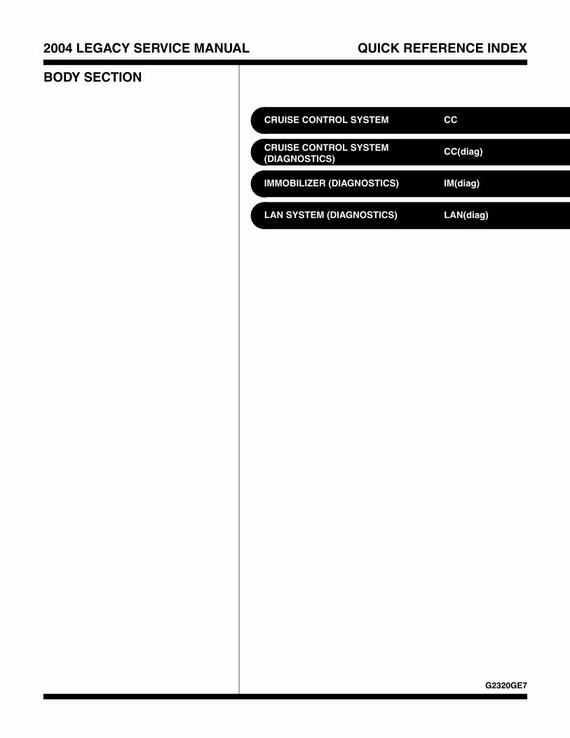
CRUISE CONTROL SYSTEM CC
CRUISE CONTROL SYSTEM (DIAGNOSTICS)
CC(diag)
IMMOBILIZER (DIAGNOSTICS) IM(diag)
LAN SYSTEM (DIAGNOSTICS) LAN(diag)
G2320GE7

HVAC SYSTEM(HEATER, VENTILATOR AND A/C)
AC
Page1. General Description ....................................................................................22. Refrigerant Pressure with Manifold Gauge Set.........................................193. Refrigerant Recovery Procedure...............................................................204. Refrigerant Charging Procedure ...............................................................215. Refrigerant Leak Check ............................................................................246. Compressor Oil .........................................................................................257. Blower Motor Unit Assembly .....................................................................268. Blower Motor .............................................................................................279. Power Transistor (Auto A/C Model) ..........................................................28
10. Blower Resistor (Manual A/C Model) ........................................................2911. Heater Core...............................................................................................3012. Control Unit (Manual A/C Model) ..............................................................3113. Control Unit (Auto A/C Model)...................................................................3214. Compressor...............................................................................................3315. Condenser.................................................................................................3516. Heater and Cooling Unit............................................................................3617. Evaporator.................................................................................................3718. Hose and Tube..........................................................................................3819. Relay and Fuse .........................................................................................3920. Pressure Switch (Triple Pressure Switch).................................................4021. Ambient Sensor (Auto A/C Model) ............................................................4122. Sunload Sensor (Auto A/C Model) ............................................................4223. In-Vehicle Sensor (Auto A/C Model) .........................................................4324. Air Vent Grille ............................................................................................4425. Heater Duct ...............................................................................................4526. Heater Vent Duct.......................................................................................4627. Heater Cock Solenoid Valve .....................................................................4728. General Diagnostic Table..........................................................................48
HVAC SYSTEM (HEATER, VENTILATOR AND A/C)General Description
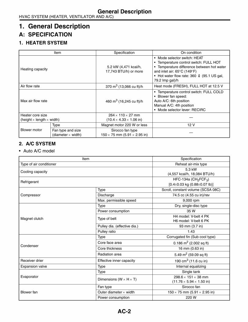
1. General DescriptionA: SPECIFICATION1. HEATER SYSTEM
2. A/C SYSTEM• Auto A/C model
Item Specification On condition
Heating capacity5.2 kW (4,471 kcal/h,
17,743 BTU/h) or more
• Mode selector switch: HEAT• Temperature control switch: FULL HOT• Temperature difference between hot water and inlet air: 65°C (149°F) • Hot water flow rate: 360 2 (95.1 US gal, 79.2 Imp gal)/h
Air flow rate 370 m3 (13,066 cu ft)/h Heat mode (FRESH), FULL HOT at 12.5 V
Max air flow rate 460 m3 (16,245 cu ft)/h
• Temperature control switch: FULL COLD• Blower fan speed:Auto A/C: 6th positionManual A/C: 4th position• Mode selector lever: RECIRC
Heater core size(height × length × width)
264 × 110 × 27 mm(10.4 × 4.33 × 1.06 in)
—
Blower motorType Magnet motor 220 W or less 12 V
Fan type and size(diameter × width)
Sirocco fan type150 × 75 mm (5.91 × 2.95 in)
—
Item Specification
Type of air conditioner Reheat air-mix type
Cooling capacity5.3 kW
(4,557 kcal/h, 18,084 BTU/h)
RefrigerantHFC-134a (CH2FCF3)
[0.4±0.03 kg (0.88±0.07 lb)]
Compressor
Type Scroll, constant volume (SCSA 08C)
Discharge 74.5 cc (4.55 cu in)/rev
Max. permissible speed 9,000 rpm
Magnet clutch
Type Dry, single-disc type
Power consumption 35 W
Type of beltH4 model: V-belt 4 PKH6 model: V-belt 6 PK
Pulley dia. (effective dia.) 93 mm (3.7 in)
Pulley ratio 1.43
Condenser
Type Corrugated fin (Sub cool type)
Core face area 0.186 m2 (2.002 sq ft)
Core thickness 16 mm (0.63 in)
Radiation area 5.49 m2 (59.09 sq ft)
Receiver drier Effective inner capacity 190 cm3 (11.6 cu in)
Expansion valve Type Internal equalizing
EvaporatorType Single tank
Dimensions (W × H × T)298.6 × 151 × 38 mm
(11.76 × 5.94 × 1.50 in)
Blower fan
Fan type Sirocco fan
Outer diameter × width 150 × 75 mm (5.91 × 2.95 in)
Power consumption 220 W
AC-2

HVAC SYSTEM (HEATER, VENTILATOR AND A/C)General Description
• Manual A/C model
Condenser fan (Sub fan)
Motor type Magnet
Power consumptionH4 model: 90 WH6 model: 160 W
Fan outer diameterH4 model: 300 mm (11.8 in)H6 model: 320 mm (12.6 in)
Radiator fan (Main fan)
Motor type Magnet
Power consumptionH4 model: 90 WH6 model: 160 W
Fan outer diameterH4 model: 300 mm (11.8 in)H6 model: 320 mm (12.6 in)
Idling speed (A/C ON) MPFI model 800±100 rpm
Triple switch(Pressure switch)
Low-pressure switch operating pressure
ON → OFF196±20 kPa
(2.00±0.20 kg/cm2, 28.4±2.9 psi)
OFF → ON225+25
−29 kPa
(2.29+0.25−0.30 kg/cm2, 32.6+3.6
−4.2 psi)
High-pressure switch operating pressure
ON → OFF3,140+50
−200 kPa
(32.02+0.51−2.04 kg/cm2, 455.4+7.25
−29.0 psi)
OFF → ON2,550±200 kPa
(26.00±2.04 kg/cm2, 369.8±29.0 psi)
Middle-pressure switch operating pressure
ON → OFF1,370±120 kPa
(13.97±1.22 kg/cm2, 198.65±17.35 psi)
OFF → ON1,770±100 kPa
(18.05±1.02 kg/cm2, 256.81±14.50 psi)
Thermo-control amplifier working temperature(Evaporator outlet air)
(1) ON(2) OFF(3) 1±0.5°C (33.8±0.9°F)
(4) 4+1.50°C (39.2+2.7
0°F)
Item Specification
Type of air conditioner Reheat air-mix type
Cooling capacity 5.3 kW (4,557 kcal/h, 18,084 BTU/h)
RefrigerantHFC-134a (CH2FCF3)
[0.4±0.03 kg (0.88±0.07 lb)]
Compressor
Type Scroll, constant volume (SCSA 08C)
Discharge 74.5 cc (4.55 cu in)/rev
Max. permissible speed 9,000 rpm
Magnet clutch
Type Dry, single-disc type
Power consumption 35 W
Type of belt V-belt 4 PK
Pulley dia. (effective dia.) 93 mm (3.7 in)
Pulley ratio 1.43
AC-00601
(1)
(2)
(3)
(4)
AC-3

HVAC SYSTEM (HEATER, VENTILATOR AND A/C)General Description
Condenser
Type Corrugated fin (Sub cool type)
Core face area 0.186 m2 (2.002 sq ft)
Core thickness 16 mm (0.63 in)
Radiation area 5.49 m2 (59.09 sq ft)
Receiver drier Effective inner capacity 250 cm3 (15.26 cu in)
Expansion valve Type Externally equalizing
EvaporatorType Single tank
Dimensions (W × H × T)298.6 × 151 × 38 mm (11.7 × 5.94 × 1.50 in)
Blower fan
Fan type Sirocco fan
Outer diameter × width 150 × 75 mm (5.91 × 2.95 in)
Power consumption 220 W
Condenser fan (Sub fan)
Motor type Magnet
Power consumption 90 W
Fan outer diameter 300 mm (11.8 in)
Radiator fan (Main fan)
Motor type Magnet
Power consumption 90 W
Fan outer diameter 300 mm (11.8 in)
Idling speed (A/C ON) MPFI model 800±100 rpm
Triple switch(Pressure switch)
Low-pressure switch operating pressure
ON → OFF196±20 kPa
(2.00±0.20 kg/cm2, 28.4±2.9 psi)
OFF → ON225+25
−29 kPa
(2.29+0.25−0.30 kg/cm2, 32.6+3.6
−4.2 psi)
High-pressure switch operating pressure
ON → OFF3,140+50
−200 kPa
(32.02+0.51−2.04 kg/cm2, 455.4+7.25
−29.0 psi)
OFF → ON2,550±200 kPa
(26.00±2.04 kg/cm2, 369.8±29.0 psi)
Middle-pressure switch operating pressure
ON → OFF1,370±120 kPa
(13.97±1.22 kg/cm2, 198.65±17.35 psi)
OFF → ON1,770±100 kPa
(18.05±1.02 kg/cm2, 256.81±14.50 psi)
Thermo control amplifier working temperature(Evaporator outlet air)
(1) ON(2) OFF(3) 1±0.5°C (33.8±0.9°F)
(4) 4+1.50°C (39.2+2.7
0°F)
AC-00601
(1)
(2)
(3)
(4)
AC-4

HVAC SYSTEM (HEATER, VENTILATOR AND A/C)General Description
B: COMPONENT1. HEATER COOLING UNIT• Auto A/C model
(1) Foot duct (RH) (8) Mix actuator (15) Foot duct (LH)
(2) Evaporator center (9) Mode actuator (16) Unit ASSY
(3) Pipe cover (10) Heater pipe clamp (17) Drain hose
(4) Evaporator cover (11) Heater core
(5) Expansion valve (12) Heater core cover Tightening torque: N⋅m (kgf-m, ft-lb)(6) Packing (13) Aspirator T: 7.5 (0.76, 5.5)(7) Evaporator (14) Aspirator hose
AC-00906
T
(16)
(13)T
(17)
(15)
(10)
(9)
(11)
(12)
(14)
(8)
(7)
(4)
(5)
(3)
(2)
(1)
(6)
AC-5

HVAC SYSTEM (HEATER, VENTILATOR AND A/C)General Description
• Manual A/C model
(1) Foot duct (RH) (8) Clip (15) Unit ASSY
(2) Thermo amplifier (9) Air mix door linkage (16) Drain hose
(3) Pipe cover (10) Mode actuator
(4) Evaporator cover (11) Heater pipe clamp Tightening torque: N⋅m (kgf-m, ft-lb)(5) Expansion valve (12) Heater core T: 7.5 (0.76, 5.5)(6) Packing (13) Heater core cover
(7) Evaporator (14) Foot duct (LH)
AC-00907
(4)
(5)
(6)
(11)
(12)
(13)
T
(16)
T
(15)
(10)
(9)
(14)
(8)
(7)
(3)
(2)
(1)
AC-6

HVAC SYSTEM (HEATER, VENTILATOR AND A/C)General Description
2. BLOWER MOTOR UNIT
(1) Upper case (6) Control unit (Auto A/C model) Tightening torque: N⋅m (kgf-m, ft-lb)(2) Intake door actuator (7) Power transistor (Auto A/C model) T: 7.5 (0.76, 5.5)(3) Filter (Auto A/C model) Blower resistor (Manual A/C
model)(4) Filter cover
(5) Blower motor ASSY
T
T
(1)
(2)
(7)
(5)
(3)
(4)
(6)
AC-00908
AC-7
HVAC SYSTEM (HEATER, VENTILATOR AND A/C)General Description
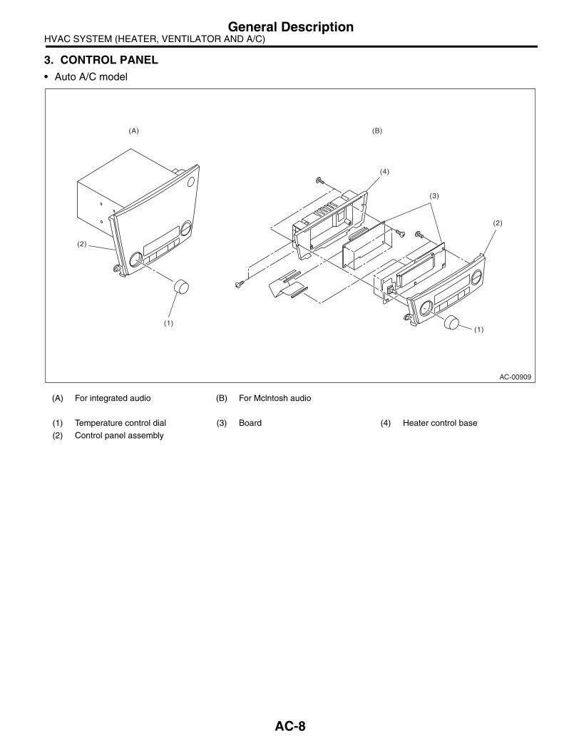
3. CONTROL PANEL• Auto A/C model
(A) For integrated audio (B) For Mclntosh audio
(1) Temperature control dial (3) Board (4) Heater control base
(2) Control panel assembly
AC-00909
(1)
(2)
(1)
(2)
(3)
(4)
(A) (B)
AC-8

HVAC SYSTEM (HEATER, VENTILATOR AND A/C)General Description
• Manual A/C model
(1) Dial (5) Heater control panel (8) Valve
(2) A/C switch (6) Heater control base (9) Fan switch ASSY
(3) FRESH/RECIRC switch (7) Temperature control cable (10) Switch base
(4) Rear window defogger switch
AC-00910
(2)
(1)
(1)
(3)
(4)
(6)
(5)
(8)
(7)
(9)
(10)(1)
AC-9

HVAC SYSTEM (HEATER, VENTILATOR AND A/C)General Description
4. AIR CONDITIONING UNIT
(1) Condenser (5) Compressor Tightening torque: N⋅m (kgf-m, ft-lb)(2) Hose (High-pressure) (6) O-ring T1: 7.5 (0.76, 5.5)(3) Hose (Low-pressure) (7) Clamp T2: 10 (1.0, 7.4)(4) Bracket (8) Tube T3: 5 (0.5, 3.7)
AC-00911
T2
(7)
(8)
(5)
(6)
(2)
T2
T3
T3
T1
(6)
(6)
(6)
(6)
(1)T1
(4)
(6)
(3)
T1
AC-10

HVAC SYSTEM (HEATER, VENTILATOR AND A/C)General Description
5. COMPRESSOR• H4 model
(1) Idler pulley bracket (5) Compressor Tightening torque: N⋅m (kgf-m, ft-lb)(2) Idler pulley adjuster (6) Compressor lower bracket T1: 23.0 (2.35, 17.0)(3) Idler pulley (7) V-Belt T2: 28.9 (2.95, 21.3)(4) Compressor upper bracket T3: 36 (3.7, 26.6)
AC-00760
(4)
(1)
(2)(3)
(7)
(6)
(5)
T2
T3
T3
T1
T1
T3
AC-11

HVAC SYSTEM (HEATER, VENTILATOR AND A/C)General Description
• H6 model
(1) Compressor upper bracket Tightening torque: N⋅m (kgf-m, ft-lb)(2) Compressor T1: 28.9 (2.95, 21.3)(3) Compressor lower bracket T2: 36 (3.7, 26.6)
AC-00912
(1)
(2)
(3)
T1
T2
T2
T2
AC-12

HVAC SYSTEM (HEATER, VENTILATOR AND A/C)General Description
6. HEATER DUCT
(1) Front defroster nozzle (3) Side ventilation duct (RH) (5) Rear heater duct (LH)
(2) Side ventilation duct (LH) (4) Center ventilation duct (6) Rear heater duct (RH)
AC-00913
(4)
(5)
(6)
(2)
(3)
(1)
AC-13
HVAC SYSTEM (HEATER, VENTILATOR AND A/C)General Description
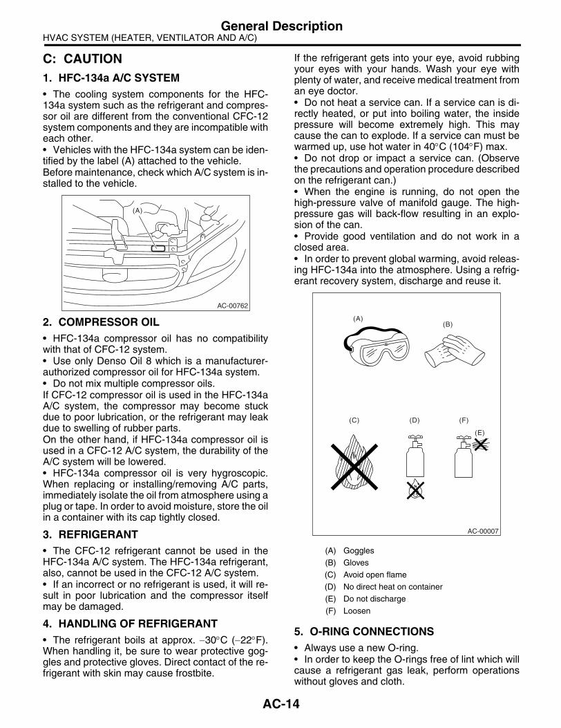
C: CAUTION1. HFC-134a A/C SYSTEM• The cooling system components for the HFC-134a system such as the refrigerant and compres-sor oil are different from the conventional CFC-12system components and they are incompatible witheach other.• Vehicles with the HFC-134a system can be iden-tified by the label (A) attached to the vehicle.Before maintenance, check which A/C system is in-stalled to the vehicle.
2. COMPRESSOR OIL• HFC-134a compressor oil has no compatibilitywith that of CFC-12 system.• Use only Denso Oil 8 which is a manufacturer-authorized compressor oil for HFC-134a system.• Do not mix multiple compressor oils.If CFC-12 compressor oil is used in the HFC-134aA/C system, the compressor may become stuckdue to poor lubrication, or the refrigerant may leakdue to swelling of rubber parts.On the other hand, if HFC-134a compressor oil isused in a CFC-12 A/C system, the durability of theA/C system will be lowered.• HFC-134a compressor oil is very hygroscopic.When replacing or installing/removing A/C parts,immediately isolate the oil from atmosphere using aplug or tape. In order to avoid moisture, store the oilin a container with its cap tightly closed.
3. REFRIGERANT• The CFC-12 refrigerant cannot be used in theHFC-134a A/C system. The HFC-134a refrigerant,also, cannot be used in the CFC-12 A/C system.• If an incorrect or no refrigerant is used, it will re-sult in poor lubrication and the compressor itselfmay be damaged.
4. HANDLING OF REFRIGERANT• The refrigerant boils at approx. −30°C (−22°F).When handling it, be sure to wear protective gog-gles and protective gloves. Direct contact of the re-frigerant with skin may cause frostbite.
If the refrigerant gets into your eye, avoid rubbingyour eyes with your hands. Wash your eye withplenty of water, and receive medical treatment froman eye doctor.• Do not heat a service can. If a service can is di-rectly heated, or put into boiling water, the insidepressure will become extremely high. This maycause the can to explode. If a service can must bewarmed up, use hot water in 40°C (104°F) max.• Do not drop or impact a service can. (Observethe precautions and operation procedure describedon the refrigerant can.)• When the engine is running, do not open thehigh-pressure valve of manifold gauge. The high-pressure gas will back-flow resulting in an explo-sion of the can.• Provide good ventilation and do not work in aclosed area.• In order to prevent global warming, avoid releas-ing HFC-134a into the atmosphere. Using a refrig-erant recovery system, discharge and reuse it.
5. O-RING CONNECTIONS• Always use a new O-ring.• In order to keep the O-rings free of lint which willcause a refrigerant gas leak, perform operationswithout gloves and cloth.
AC-00762
(A)
(A) Goggles
(B) Gloves
(C) Avoid open flame
(D) No direct heat on container
(E) Do not discharge
(F) Loosen
(A)(B)
(C) (D)
(E)
(F)
AC-00007
AC-14

HVAC SYSTEM (HEATER, VENTILATOR AND A/C)General Description
• Apply compressor oil to O-rings to avoid sticking,before installation.• Use a torque wrench to tighten the O-ring fittings.Over-tightening will result in damage of O-ring andtube end distortion.• If the operation is interrupted before completing apipe connection; recap the tubes, components andfittings with a plug or tape to prevent foreign matterfrom entering.
• Visually check the surfaces and mating surfacesof O-rings, threads and connecting points. If a fail-ure is found, replace the applicable parts.• Install the O-rings at right angle to tube beads.
• Use compressor oil specified in the service man-ual to lubricate the O-rings.Apply oil to the top and sides of O-rings before in-stallation.
Apply compressor oil to the bead of tube.
• After tightening, use a clean cloth to remove ex-cess compressor oil from the connections and anyoil which may have run on the vehicle body or otherparts.• If any leakage is suspected after tightening, donot further tighten the connections, but disconnectthe connections, remove the O-rings, and checkthe O-rings, threads, and connections.
(A) Seal
(A) O-ring
(B) OK
(C) NG
(D) Bead
(A)
AC-00008
AC-00009
(D)
(B)
(C)
(C)
(A)
AC-00010
AC-15

HVAC SYSTEM (HEATER, VENTILATOR AND A/C)General Description
D: PREPARATION TOOLCAUTION:When working on vehicles with HFC-134a system, only use HFC-134a specified tools and parts. Do not mix with those of CFC-12. If HFC-134a and CFC-12 refrigerant or compressor oil is mixed, it will result in poor lubrication and the compressor itself may be destroyed.In order to prevent the mixture of HFC-134a and CFC-12 parts and liquid, the tool and screw type andthe type of service valves used are different. The gas leak detectors for the HFC-134a and CFC-12systems must also not be interchanged.
HFC-134a CFC-12
Tool & screw type Millimeter size Inch size
Valve type Quick joint type Screw-in type
ILLUSTRATION Tools and Equipment
Wrench
Various WRENCHES will be required to service any A/C system. 7 to 40 N⋅m (0.7 to 4.1 kgf-m, 5 to 30 ft-lb) torque wrench and various crow-foot wrenches will be needed. Open end or flare nut wrenches will be needed to hold the tube and hose fittings.
Applicator bottle
A small APPLICATOR BOTTLE is recommended to apply compressor oil to the various parts. It can be available at a hardware or drug store.
Manifold gauge set
A MANIFOLD GAUGE SET (with hoses) can be available at either a refrigerant supplier or an automotive equipment supplier.
AC-00213
AC-00012
AC-00013
AC-16
HVAC SYSTEM (HEATER, VENTILATOR AND A/C)General Description
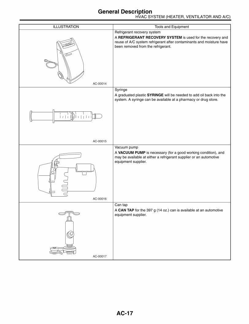
Refrigerant recovery system
A REFRIGERANT RECOVERY SYSTEM is used for the recovery and reuse of A/C system refrigerant after contaminants and moisture have been removed from the refrigerant.
Syringe
A graduated plastic SYRINGE will be needed to add oil back into the system. A syringe can be available at a pharmacy or drug store.
Vacuum pump
A VACUUM PUMP is necessary (for a good working condition), and may be available at either a refrigerant supplier or an automotive equipment supplier.
Can tap
A CAN TAP for the 397 g (14 oz.) can is available at an automotive equipment supplier.
ILLUSTRATION Tools and Equipment
AC-00014
AC-00015
AC-00016
AC-00017
AC-17

HVAC SYSTEM (HEATER, VENTILATOR AND A/C)General Description
Temperature gauge
A Pocket THERMOMETER is available at either a industrial hardware store or a refrigerant suppliers.
Electronic leak detector
An ELECTRONIC LEAK DETECTOR can be available at either a spe-cialty tool supplier or an A/C equipment supplier.
Weight scale
A WEIGHT SCALE such as an electronic charging scale or a bath-room scale with digital display will be needed, if a 13.6 kg (30 lb) refrig-erant container is used.
ILLUSTRATION Tools and Equipment
AC-00018
AC-00019
AC-00020
AC-18

HVAC SYSTEM (HEATER, VENTILATOR AND A/C)Refrigerant Pressure with Manifold Gauge Set
2. Refrigerant Pressure with Manifold Gauge SetA: PROCEDURE1) Place the vehicle in the shade and windless condition.2) Connect the manifold gauge set.3) Open the front windows and close all doors.4) Open the front hood.5) Increase the engine to 1,500 rpm.6) Turn on the A/C switch.7) Turn the temperature control switch to MAX COOL.8) Put in RECIRC position.9) Turn the blower control switch to HI.10) Read the gauge.
Standard:Low pressure: 127 — 196 kPa (1.3 — 2.0 kg/cm2, 18 — 28 psi)High pressure: 1,471 — 1,667 kPa (15 — 17 kg/cm2, 213 — 242 psi)Ambient temperature: 30 — 35°C (86 — 95°F)
B: INSPECTIONSymptom Probable cause Repair order
High-pressure side is unusually high.
• Defective condenser fan motor• Clogged condenser fin• Too much refrigerant• Air inside the system• Defective receiver dryer
• Replace the fan motor.• Clean the condenser fin.• Discharge refrigerant.• Replace the receiver dryer.• After evacuating again, charge an appropriate amount of refrigerant.
High-pressure side is unusually low.
• Defective compressor• Not enough refrigerant• Clogged expansion valve• Expansion valve frozen temporarily by moisture.
• Replace the compressor.• Check for leaks.• Replace the expansion valve.• Fully evacuate the expansion valve.
Low-pressure side is unusually high.• Defective compressor• Defective expansion valve• Too much refrigerant
• Replace the compressor.• Replace the expansion valve.• Discharge refrigerant.
Low-pressure side is unusually low.
• Not enough refrigerant• Clogged expansion valve• Expansion valve frozen temporarily by moisture.• Saturated receiver dryer
• Check for leaks.• Replace the expansion valve.• Replace the receiver dryer.
AC-19

HVAC SYSTEM (HEATER, VENTILATOR AND A/C)Refrigerant Recovery Procedure
3. Refrigerant Recovery Proce-dure
A: PROCEDURECAUTION:• During operation, be sure to wear protectivegoggles and protective gloves.• Connect the refrigerant recovery system withthe manifold gauge set to discharge the refrig-erant from the A/C system and reuse it.• When reusing the discharged refrigerant,keep service cans on hand. Because the dis-charge rate with the recovery system is approx.90%, service cans are necessary to charge therefrigerant.• Follow the detailed operation procedure de-scribed in the operation manual attached to therefrigerant recovery system.1) Perform the compressor oil return operation.<Ref. to AC-25, PROCEDURE, Compressor Oil.>2) Stop the engine.3) Make sure the valves on low-/high-pressuresides of manifold gauge set are fully closed.
4) Install the low-/high-pressure hoses to the ser-vice ports on the low-/high-pressure sides of thevehicle respectively.
5) Connect the center hose to the refrigerant recov-ery system.6) Follow the operation manual to activate the re-frigerant recovery system.
(A) Low-pressure gauge (Compound pressure gauge)
(B) High-pressure gauge
(C) Close
AC-00021
(A) (B)
(C)(C)
(A) Low-pressure gauge (Compound pressure gauge)
(B) High-pressure gauge
(C) Close
(D) Low-pressure side service port
(E) High-pressure side service port
AC-00022
(A) (B)
(C)(C)
(E)(D)
AC-20

HVAC SYSTEM (HEATER, VENTILATOR AND A/C)Refrigerant Charging Procedure
4. Refrigerant Charging Proce-dure
A: PROCEDURECAUTION:• During operation, be sure to wear protectivegoggles and protective gloves.• Before charging the refrigerant, evacuate thesystem to remove small amounts of moistureremaining in the system.The moisture in the system can be completelyevacuated only under the minimum vacuumlevel. The minimum vacuum level affects thetemperature in the system.• The list below shows the vacuum values nec-essary to boil water in various temperature. Inaddition, the vacuum levels indicated on thegauge are approx. 3.3 kPa (25 mmHg, 0.98 inHg)lower than those measured at 304.8 m (1,000 ft)above sea level.
1) Close the valves on low-/high-pressure sides ofthe manifold gauge.
2) Install the low-/high-pressure hoses to the corre-sponding service ports on the vehicle respectively.3) Connect the center hose of the manifold gaugeset with the vacuum pump.
4) Carefully open the valves on the low-/high-pres-sure sides to activate the vacuum pump.
5) After the low-pressure gauge reaches 100.0 kPa(750 mmHg, 29.5 inHg) or higher, evacuate thesystem for approx. 15 minutes. (Continue evacua-tion).
6) After 15 minutes of evacuation, if the readingshows 100.0 kPa (750 mmHg, 29.5 inHg) or higher,close the valves on the both sides to stop the vac-uum pump.
Vacuum level required to boil water (at sea level)
Temperature Vacuum
1.7°C (35°F) 100.9 kPa (757 mmHg, 29.8 inHg)
7.2°C (45°F) 100.5 kPa (754 mmHg, 29.7 inHg)
12.8°C (55°F) 99.8 kPa (749 mmHg, 29.5 inHg)
18.3°C (65°F) 99.2 kPa (744 mmHg, 29.3 inHg)
23.9°C (75°F) 98.5 kPa (739 mmHg, 29.1 inHg)
29.4°C (85°F) 97.2 kPa (729 mmHg, 28.7 inHg)
35°C (95°F) 95.8 kPa (719 mmHg, 28.3 inHg)
(A) Low-pressure gauge (Compound pressure gauge)
(B) High-pressure gauge
(C) Close
AC-00023
(A) (B)
(C)(C)
(A) Low-pressure gauge (Compound pressure gauge)
(B) High-pressure gauge
(C) Slowly open
(D) Vacuum pump turn on
(A) Low-pressure gauge (Compound pressure gauge)
(B) High-pressure gauge
(C) Close
(D) Vacuum pump turn off
AC-00024
(A) (B)
(D)
(C)(C)
AC-00025
AC-00026
(A) (B)
(D)
(C)(C)
AC-21

HVAC SYSTEM (HEATER, VENTILATOR AND A/C)Refrigerant Charging Procedure
7) Note the low-pressure gauge reading.
8) Leave it at least 5 minutes, and then check thelow-pressure gauge reading for any changes.When a gauge indicator shows near to zero point, itis a sign of leakage. Check pipe connector points,repair them, make sure there is no leakage by airbleeding. 9) Following the can tap operation manual instruc-tions, install it to the refrigerant can.
10) Disconnect the center manifold hose from thevacuum pump, and connect the hose to the tapvalve.11) When a 13.6 kg (30 lb) refrigerant container isused, measure the refrigerant amount in use usinga weight scale.
12) Confirm that all the 3 hoses are tightly connect-ed to the manifold gauge set.
13) Open the valve on the HFC-134a source.14) Loosen the center hose connection on themanifold gauge set (if applicable, press a purgevalve on the manifold gauge set) only for a coupleof seconds to allow the air in the center hose to es-cape by the refrigerant.15) Carefully open the high-pressure valve with theengine stopping.
CAUTION:Do not open the low-pressure valve.
CAUTION:Never run the engine during charging from the high-pressure side.16) Close the high-pressure valve when the low-pressure gauge reaches 98 kPa (1 kg/cm2, 14 psi).Using a leak tester, check the system for leaks.If any leakage is found after the refrigerant recov-ery is completed, repair the applicable area.
(A) Tap valve
(B) Center manifold hose
(A) Refrigerant container (HFC-134a)
(B) Weight scale
AC-00027
AC-00028
(A)
(B)
AC-00029
(A)
(B)
(A) Low-pressure gauge (Compound pressure gauge)
(B) High-pressure gauge
(C) Close
(A) Low-pressure gauge (Compound pressure gauge)
(B) High-pressure gauge
(C) Close
(D) Ignition switch OFF
(E) Slowly open
AC-00030
(A) (B)
(C)(C)
AC-00031
(A) (B)
(E)
(D)
(C)
AC-22

HVAC SYSTEM (HEATER, VENTILATOR AND A/C)Refrigerant Charging Procedure
17) After confirming that there are no leaks with theleak test, charge the required amount of refrigerant.
CAUTION:Never run the engine during charging from the high-pressure side.18) Close the high-pressure valve when;• the readings of low- / high-pressure gauges be-come almost equal, after the charging speed is re-duced,• the HFC-134a source becomes empty, or thesystem is filled with the gas.
19) If the HFC-134a source is empty, close thehigh-pressure valve, close the valve on the can tap,and replace the HFC-134a source with a new oneto restart the operation.
20) Confirm that both the low-/high-pressurevalves can be closed. Start the engine with the A/Cswitch OFF.21) Quickly repeat ON-OFF cycles a few times toprevent initial compressor damage.22) Set up the vehicle to the following status:• A/C switch ON• Engine running at 1,500 rpm• Blower speed setting to “HI”• Temperature setting to “MAX COOL”• Air inlet setting to “RECIRC”• Window open
23) While reading the low-pressure gauge, careful-ly open the low-pressure valve with the refrigerantsource connected and the service hose purged.
CAUTION:Never open the high-pressure valve with the en-gine running. The high-pressure gas will back-flow resulting in an explosion of the can.
24) Adjust the refrigerant flow to maintain the pres-sure on the low-pressure side at 276 kPa (2.81 kg/cm2, 40 psi) max.25) After the system is fully charged, close the low-pressure valve.26) Close the valve on the refrigerant source.
27) Disconnect the hose from the service port, andinstall the service port cap.
(A) Low-pressure gauge (Compound pressure gauge)
(B) High-pressure gauge
(C) Close
AC-00032
AC-00033
(A) (B)
(C)(C)
Refrigerant amount
Refrigerant Minimum Maximum
HFC-134a 370 g (0.82 lb) 430 g (0.95 lb)
AC-00034
AC-23
HVAC SYSTEM (HEATER, VENTILATOR AND A/C)Refrigerant Leak Check
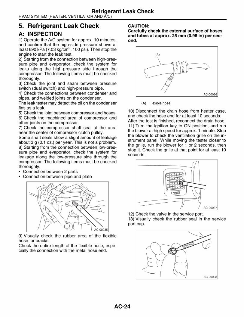
5. Refrigerant Leak CheckA: INSPECTION1) Operate the A/C system for approx. 10 minutes,and confirm that the high-side pressure shows atleast 690 kPa (7.03 kg/cm2, 100 psi). Then stop theengine to start the leak test.2) Starting from the connection between high-pres-sure pipe and evaporator, check the system forleaks along the high-pressure side through thecompressor. The following items must be checkedthoroughly.3) Check the joint and seam between pressureswitch (dual switch) and high-pressure pipe.4) Check the connections between condenser andpipes, and welded joints on the condenser.The leak tester may detect the oil on the condenserfins as a leak.5) Check the joint between compressor and hoses.6) Check the machined area of compressor andother joints on the compressor.7) Check the compressor shaft seal at the areanear the center of compressor clutch pulley.Some shaft seals show a slight amount of leakageabout 3 g (0.1 oz.) per year. This is not a problem.8) Starting from the connection between low-pres-sure pipe and evaporator, check the system forleakage along the low-pressure side through thecompressor. The following items must be checkedthoroughly.• Connection between 2 parts• Connection between pipe and plate
9) Visually check the rubber area of the flexiblehose for cracks.Check the entire length of the flexible hose, espe-cially the connection with the metal hose end.
CAUTION:Carefully check the external surface of hoses and tubes at approx. 25 mm (0.98 in) per sec-ond.
10) Disconnect the drain hose from heater case,and check the hose end for at least 10 seconds.After the test is finished, reconnect the drain hose.11) Turn the ignition key to ON position, and runthe blower at high speed for approx. 1 minute. Stopthe blower to check the ventilation grille on the in-strument panel. While moving the tester closer tothe grille, run the blower for 1 or 2 seconds, thenstop it. Check the grille at that point for at least 10seconds.
12) Check the valve in the service port.13) Visually check the rubber seal in the serviceport cap.
AC-00035
(A) Flexible hose
AC-00036
(A)
AC-00037
AC-00038
AC-24

HVAC SYSTEM (HEATER, VENTILATOR AND A/C)Compressor Oil
6. Compressor OilA: PROCEDURENOTE:Before making repairs, perform the oil return oper-ation to return the compressor oil in circulation withthe refrigerant to the compressor.1) Increase the engine to 1,500 rpm.2) Turn ON the A/C switch.3) Turn the temperature control switch to MAXCOOL.4) Put in RECIRC position.5) Turn the blower control switch to HI.6) Leave in this condition for 10 minutes.
B: REPLACEMENTNOTE:• If a component has been replaced, add an ap-propriate amount of compressor oil (same as theamount of remaining oil in removed component).• When replacing the compressor, the new com-pressor will already have the specified amount ofoil in it. Install the new compressor after removingthe same amount of oil that is remaining in the com-pressor removed.
AC-25

HVAC SYSTEM (HEATER, VENTILATOR AND A/C)Blower Motor Unit Assembly
7. Blower Motor Unit AssemblyA: REMOVAL1) Disconnect the ground cable from battery.2) Remove the glove box. <Ref. to EI-51, REMOV-AL, Glove Box.>3) Disconnect the connectors of A/C control mod-ule, intake door actuator, blower motor, power tran-sistor and blower resistor. 4) Loosen the bolt and nut to remove blower motorunit assembly.
B: INSTALLATIONInstall in the reverse order of removal.
Tightening torque:Refer to “COMPONENT” of “General Descrip-tion”. <Ref. to AC-5, HEATER COOLING UNIT, COMPONENT, General Description.> <Ref. to AC-7, BLOWER MOTOR UNIT, COM-PONENT, General Description.>
AC-00914
AC-26

HVAC SYSTEM (HEATER, VENTILATOR AND A/C)Blower Motor
8. Blower MotorA: REMOVAL1) Disconnect the ground cable from battery.2) Remove the glove box lower cover. <Ref. to EI-51, REMOVAL, Glove Box.>3) Disconnect the connector of blower motor.4) Loosen the screw to remove blower motor.
B: INSTALLATIONInstall in the reverse order of removal.
C: INSPECTIONConnect the battery positive (+) terminal to terminalNo. 2 of blower motor, and negative (−) terminal toterminal No. 1. Check the blower motor for smoothrotation.
AC-00957
AC-00915
12
AC-27

HVAC SYSTEM (HEATER, VENTILATOR AND A/C)Power Transistor (Auto A/C Model)
9. Power Transistor (Auto A/C Model)
A: REMOVAL1) Remove the glove box lower cover on passen-ger side. <Ref. to EI-51, REMOVAL, Glove Box.>2) Disconnect the power transistor connector.3) Remove two screws, and then remove the pow-er transistor.
B: INSTALLATIONInstall in the reverse order of removal.
AC-00916
AC-28

HVAC SYSTEM (HEATER, VENTILATOR AND A/C)Blower Resistor (Manual A/C Model)
10.Blower Resistor (Manual A/C Model)
A: REMOVAL1) Remove the glove box lower cover on passen-ger side. <Ref. to EI-51, REMOVAL, Glove Box.>2) Disconnect the blower resistor connector.3) Remove two screws, and then remove the blow-er resistor.
B: INSTALLATIONInstall in the reverse order of removal.
C: INSPECTION
Measure the blower resistor resistance.
If NG, replace the blower resistor.
Terminal No. Standard
4 and 2 Approx. 0.44 Ω4 and 3 Approx. 1.12 Ω4 and 1 Approx. 2.92 Ω
AC-00916
AC-00766
(2)
(4) (3)
(1)
AC-29

HVAC SYSTEM (HEATER, VENTILATOR AND A/C)Heater Core
11.Heater CoreA: REMOVAL1) Remove the heater and cooling unit. <Ref. toAC-36, REMOVAL, Heater and Cooling Unit.>2) Remove the screws and remove the heater corecover and pipe clamp.
3) Remove the heater core.
B: INSTALLATIONInstall in the reverse order of removal.
AC-00917
AC-30

HVAC SYSTEM (HEATER, VENTILATOR AND A/C)Control Unit (Manual A/C Model)
12.Control Unit (Manual A/C Model)
A: REMOVAL1) Disconnect the ground cable from battery.2) Remove the glove box. <Ref. to EI-51, REMOV-AL, Glove Box.>3) Remove the control wires.
4) Remove the integrated panel. <Ref. to ET-5,REMOVAL, Audio.>5) Loosen the screw to remove the control unit frombracket.
B: INSTALLATIONInstall in the reverse order of removal.
AC-00918
AC-31
HVAC SYSTEM (HEATER, VENTILATOR AND A/C)Control Unit (Auto A/C Model)
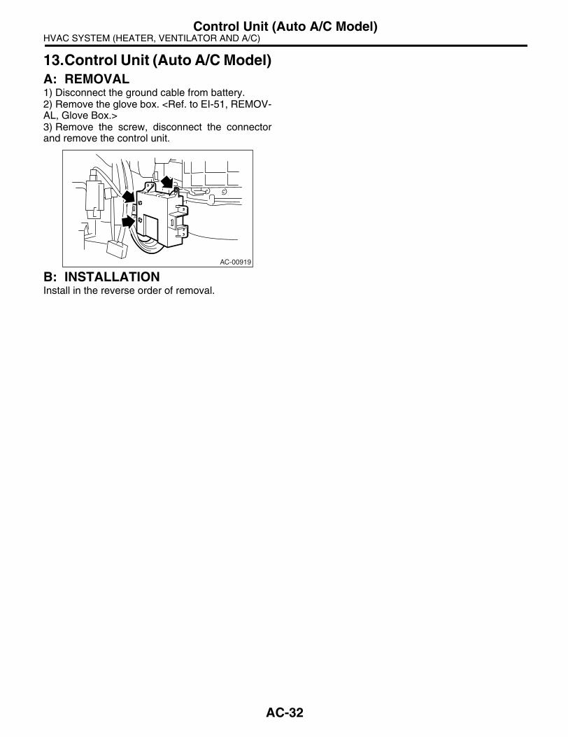
13.Control Unit (Auto A/C Model)A: REMOVAL1) Disconnect the ground cable from battery.2) Remove the glove box. <Ref. to EI-51, REMOV-AL, Glove Box.>3) Remove the screw, disconnect the connectorand remove the control unit.
B: INSTALLATIONInstall in the reverse order of removal.
AC-00919
AC-32

HVAC SYSTEM (HEATER, VENTILATOR AND A/C)Compressor
14.CompressorA: INSPECTION1. MAGNETIC CLUTCH CLEARANCECheck the clearance of entire circumferencearound the drive plate and pulley.
Standard:0.45±0.15 mm (0.0177±0.0059 in)
2. MAGNETIC CLUTCH OPERATION1) Disconnect the compressor connector.2) Connect the battery positive (+) terminal to ter-minal No. 1 of compressor connector, and negative(−) terminal to terminal No. 2.
3) Check the magnet clutch engagement.If NG, replace the compressor.
B: REMOVAL1) Perform the compressor oil return operation.<Ref. to AC-25, PROCEDURE, Compressor Oil.>2) Turn the A/C switch to OFF and stop the engine.3) Using the refrigerant recovery system, dis-charge refrigerant. <Ref. to AC-20, PROCEDURE,Refrigerant Recovery Procedure.>4) Disconnect the ground cable from battery.5) Remove the V-belts. <Ref. to ME(H4SO 2.0)-38,REMOVAL, V-belt.> <Ref. to ME(H4DOTC)-39,REMOVAL, V-belt.> <Ref. to ME(H6DO)-33, RE-MOVAL, V-belt.>6) Remove the generator. <Ref. to SC(H4SO 2.0)-14, REMOVAL, Generator.> <Ref. to SC(H6DO)-14, REMOVAL, Generator.>
7) Remove the bolt and remove the low-pressurehose and high-pressure hose.
8) Disconnect the compressor harness from bodyharness.9) Remove the bolts and remove compressorbracket.• H4 model
• H6 model
10) Remove the bolts, and then remove the bracketfrom compressor.
AC-00771
AC-00772
AC-00773
AC-00920
AC-00774
AC-33

HVAC SYSTEM (HEATER, VENTILATOR AND A/C)Compressor
C: INSTALLATION1) Install in the reverse order of removal.2) Replace the O-rings on low-/high-pressure hos-es with new ones, then apply compressor oil.3) When replacing the compressor, adjust amountof compressor oil. <Ref. to AC-25, PROCEDURE,Compressor Oil.>4) Charge refrigerant. <Ref. to AC-21, PROCE-DURE, Refrigerant Charging Procedure.>
Tightening torque:Refer to “COMPONENT” of “General Descrip-tion”. <Ref. to AC-10, AIR CONDITIONING UNIT, COMPONENT, General Description.> <Ref. to AC-11, COMPRESSOR, COMPO-NENT, General Description.>
AC-34

HVAC SYSTEM (HEATER, VENTILATOR AND A/C)Condenser
15.CondenserA: REMOVAL1) Using the refrigerant recovery system, dis-charge refrigerant. <Ref. to AC-20, PROCEDURE,Refrigerant Recovery Procedure.>2) Disconnect the ground cable from battery.3) Disconnect the pressure hose and pipe fromcondenser.
4) Remove the radiator bracket (A) and hood stay(B).
5) Remove the front grille. <Ref. to EI-24, REMOV-AL, Front Grille.>6) Remove two bolts. While lifting condenser, pull itout through the space between radiator and radia-tor panel.
CAUTION:• Be careful not to damage the condenser fins.If a damaged fin is found, repair it using a thinscrewdriver.
• If the condenser is replaced, add an appropri-ate amount of compressor oil to the compres-sor. <Ref. to AC-25, REPLACEMENT,Compressor Oil.>
B: INSTALLATION1) Install in the reverse order of removal.
CAUTION:Replace the O-rings on hoses or pipes with new ones, and then apply compressor oil. Confirm that lower guide of condenser (A) has been fit-ted into holes on radiator panel.
2) Charge refrigerant. <Ref. to AC-21, PROCE-DURE, Refrigerant Charging Procedure.>
Tightening torque:Refer to “COMPONENT” of “General Descrip-tion”. <Ref. to AC-10, AIR CONDITIONING UNIT, COMPONENT, General Description.> <Ref. to CO(H4SO 2.0)-5, RADIATOR AND RADIATOR FAN, COMPONENT, General De-scription.>
C: INSPECTION1) Check no dust or insects are found on the con-denser fins. Air-blow or flush fins with water asneeded.2) Inspect for oil leakage from condenser. If a fail-ure is found, replace the condenser with a new one.
AC-00775
AC-00776
(A) (A)(B)
AC-00777
AC-00631
(A)
AC-35

HVAC SYSTEM (HEATER, VENTILATOR AND A/C)Heater and Cooling Unit
16.Heater and Cooling UnitA: REMOVAL1) Disconnect the ground cable from battery.2) Using the refrigerant recovery system, dis-charge refrigerant. <Ref. to AC-20, PROCEDURE,Refrigerant Recovery Procedure.>3) Drain coolant from the radiator.4) Remove the bolts securing expansion valve andpipe in engine compartment. Release the heaterhose clamps in engine compartment to remove thehoses.
5) Remove the instrument panel. <Ref. to EI-56,REMOVAL, Instrument Panel Assembly.>6) Remove the support beam.7) Remove the blower motor unit assembly. <Ref.to AC-26, REMOVAL, Blower Motor Unit Assem-bly.>8) Disconnect the actuator connector.9) Remove the bolt and nuts to remove the heaterand cooling unit.
B: INSTALLATION1) Install in the reverse order of removal.2) Charge refrigerant. <Ref. to AC-21, PROCE-DURE, Refrigerant Charging Procedure.>
Tightening torque:Refer to “COMPONENT” of “General Descrip-tion”. <Ref. to AC-5, HEATER COOLING UNIT, COMPONENT, General Description.>
AC-00921
AC-00922
AC-36

HVAC SYSTEM (HEATER, VENTILATOR AND A/C)Evaporator
17.EvaporatorA: REMOVAL1) Remove the blower motor unit assembly. <Ref.to AC-26, REMOVAL, Blower Motor Unit Assem-bly.>2) Disconnect the connector, remove the screwand then remove the air-mix door actuator andmode door actuator.
3) Disconnect the connector, remove the screwand remove the pipe cover and evaporator sensor.
4) Remove the bolts securing expansion valve andpipe in engine compartment.
5) Remove the bolt which holds the pipe to evapo-rator.
6) Remove the screws and clip to remove the evap-orator cover.
7) Pull out the evaporator (A) in the direction of ar-row.
CAUTION:If the evaporator is replaced, add an appropri-ate amount of compressor oil to evaporator. <Ref. to AC-25, REPLACEMENT, Compressor Oil.>
B: INSTALLATIONInstall in the reverse order of removal.
AC-00923
AC-00924
AC-00925
AC-00926
AC-00927
AC-00928
(A)
AC-37

HVAC SYSTEM (HEATER, VENTILATOR AND A/C)Hose and Tube
18.Hose and TubeA: REMOVALCAUTION:• When disconnecting/connecting hoses, donot apply an excessive force to them. Confirmthat no torsion and excessive tension ischarged after installing.• Seal the disconnected hose with a plug or vi-nyl tape to prevent foreign matter from enter-ing.1) Disconnect the ground cable from battery.2) Using the refrigerant recovery system, dis-charge refrigerant. <Ref. to AC-20, PROCEDURE,Refrigerant Recovery Procedure.>3) Remove the evaporator unit mounting bolt (A)and low-pressure hose bracket bolt (B).4) Remove the low-pressure hose attaching bolts(C).5) Disconnect the low-pressure hose from evapo-rator unit.6) Disconnect the low-pressure hose from com-pressor.7) Remove the low-pressure hose from vehicle.8) Remove the high-pressure hose attaching bolt(D).9) Disconnect the high-pressure hose from com-pressor.10) Disconnect the high-pressure hose from con-denser.11) Remove the high-pressure hose from vehicle.12) Remove the high-pressure attaching bolt (E).13) Remove the high-pressure tube from vehicle.
B: INSTALLATIONCAUTION:• When disconnecting or connecting the hos-es, do not apply excessive force to them. Con-firm that no torsion and excessive tension ischarged after installing.• Seal the disconnected hose with a plug or vi-nyl tape to prevent foreign matter from enter-ing.1) Install in the reverse order of removal.2) Charge refrigerant. <Ref. to AC-21, PROCE-DURE, Refrigerant Charging Procedure.>
Tightening torque:Refer to “COMPONENT” of “General Descrip-tion”. <Ref. to AC-10, AIR CONDITIONING UNIT, COMPONENT, General Description.>
C: INSPECTIONCheck the hoses for cracks, damage and expan-sion. If any fault is found, replace them with newones.
(A)
(B)
AC-00929
(C) (D)
(D)
(E)
AC-38

HVAC SYSTEM (HEATER, VENTILATOR AND A/C)Relay and Fuse
19.Relay and FuseA: LOCATION
B: INSPECTION
While applying battery voltage to the terminal be-tween (3) and (4), check continuity between (1) and(2).If no continuity exists, replace the relay with a newone.
(1) Joint box
(2) Main fuse box
Main Fan Relay 1 (A)
Main Fan Relay 2 (B)
Sub Fan Relay (C)
A/C Relay (D)
A/C Fuse (E)
AC-00787
(E)(1)
(2)
(A)
(B) (D)
(C)
(3) — (4): Continuity exists
(1) — (2): Continuity does not exist
AC-00641
1
1
2
2
3
3
4
4
AC-39

HVAC SYSTEM (HEATER, VENTILATOR AND A/C)Pressure Switch (Triple Pressure Switch)
20.Pressure Switch (Triple Pressure Switch)A: INSPECTION1) Connect the manifold gauge to the service valve on the high-pressure side.2) Remove the pressure switch harness connector. Using a circuit tester, inspect the ON-OFF operation ofpressure switch.
AC-00788
124 3
Terminal No.
OperationStandard
kPa (kg/cm2, psi)
High and low pressure switch 1 and 2
Turns OFF.Increasing to 3,140+50
−200 (32.02+0.51−2.04, 455.4+7.25
−29.0)
Decreasing to 196±20 (2.00±0.20, 28.4±2.9)
Turns ON.Increasing to 225+25
−29 (2.29+0.25−0.30, 32.6+3.6
−4.2)
Decreasing to 2,550±200 (26.00±2.04, 369.8±29.0)
Middle pressure switch 3 and 4Turns OFF. Decreasing to 1,370±120 (14±1, 199±14)
Turns ON. Increasing to 1,770±100 (18±1, 256±14)
AC-40

HVAC SYSTEM (HEATER, VENTILATOR AND A/C)Ambient Sensor (Auto A/C Model)
21.Ambient Sensor (Auto A/C Model)
A: REMOVAL1) Open the front hood.2) Disconnect the ground cable from battery.3) Disconnect the ambient sensor connector.4) Remove the ambient sensor from the radiatorlower panel.
B: INSTALLATIONInstall in the reverse order of removal.
C: INSPECTION<Ref. to AC(diag)-30, AMBIENT SENSOR, Diag-nostic Procedure for Sensors.>
AC-00125
AC-41

HVAC SYSTEM (HEATER, VENTILATOR AND A/C)Sunload Sensor (Auto A/C Model)
22.Sunload Sensor (Auto A/C Model)
A: REMOVAL1) Disconnect the ground cable from battery.2) Disconnect the connector and remove the sun-load sensor.
CAUTION:Be careful not to damage the interior trims when removing the sensor.
B: INSTALLATIONInstall in the reverse order of removal.
C: INSPECTION<Ref. to AC(diag)-36, SUNLOAD SENSOR, Diag-nostic Procedure for Sensors.>
AC-00930
AC-42

HVAC SYSTEM (HEATER, VENTILATOR AND A/C)In-Vehicle Sensor (Auto A/C Model)
23.In-Vehicle Sensor (Auto A/C Model)
A: REMOVAL1) Disconnect the ground cable from battery.2) Remove the instrument panel lower cover. <Ref.to EI-50, REMOVAL, Instrument Panel Lower Cov-er.>3) Disconnect the connector and aspirator hose,remove the pawl and remove the in-vehicle sensor(A) from instrument lower cover.
CAUTION:Be careful not to damage the sensors and inte-rior trims when removing.
B: INSTALLATIONInstall in the reverse order of removal.
C: INSPECTION<Ref. to AC(diag)-32, IN-VEHICLE SENSOR, Di-agnostic Procedure for Sensors.>
AC-00790
(A)
AC-43

HVAC SYSTEM (HEATER, VENTILATOR AND A/C)Air Vent Grille
24.Air Vent GrilleA: REMOVAL1. CENTER GRILLE1) Disconnect the ground cable from battery.2) Remove the three pawls and connector to re-move center air vent grill.
2. SIDE GRILLERemove the two pawls to remove side air vent grill.
B: INSTALLATIONInstall in the reverse order of removal.
C: INSPECTION1) Check the direction and amount of air can be ad-justed smoothly.2) Check the adjustment can be kept in each posi-tion.
AC-00931
AC-00932
AC-44

HVAC SYSTEM (HEATER, VENTILATOR AND A/C)Heater Duct
25.Heater DuctA: REMOVAL1. FRONT HEATER DUCT1) Remove the instrument panel lower cover. <Ref.to EI-50, REMOVAL, Instrument Panel Lower Cov-er.>2) Remove the screws and detach the front heaterduct (A).
2. REAR HEATER DUCT1) Remove the heater cooling unit. <Ref. to AC-36,REMOVAL, Heater and Cooling Unit.>2) Remove the front seats. <Ref. to SE-7, REMOV-AL, Front Seat.>3) Remove the front side sill cover.4) Pull off the floor mat to remove the rear centerheater duct (A) and rear heater duct LH, RH (B).
B: INSTALLATIONInstall in the reverse order of removal.
AC-00933
(A)
AC-00934
(A)
(B)
AC-45

HVAC SYSTEM (HEATER, VENTILATOR AND A/C)Heater Vent Duct
26.Heater Vent DuctA: REMOVAL1) Remove the instrument panel. <Ref. to EI-50,REMOVAL, Instrument Panel Lower Cover.>2) Remove the screws and detach the center ventduct (A).3) Remove the screws and detach the center ventduct (B).4) Remove the insulator, remove the screws anddetach the defroster duct.
B: INSTALLATIONInstall in the reverse order of removal.
AC-00935
(A) (B)
(B)
AC-46

HVAC SYSTEM (HEATER, VENTILATOR AND A/C)Heater Cock Solenoid Valve
27.Heater Cock Solenoid ValveA: REMOVAL1) Drain the engine coolant. <Ref. to CO(H4SO2.0)-13, DRAINING OF ENGINE COOLANT, RE-PLACEMENT, Engine Coolant.>2) Disconnect the harness connector (A) of theheater cock solenoid valve.3) Remove the two bolts to remove the heater cocksolenoid from the bracket.
4) Pull out the heater cock solenoid. Loosen thehose clamp and disconnect the two heater hoses.
B: INSTALLATIONInstall in the reverse order of removal.
C: INSPECTION1) Remove the heater cock solenoid valve. <Ref. toAC-47, REMOVAL, Heater Cock Solenoid Valve.>2) Connect the positive terminal of battery to No. 1terminal of heater cock solenoid valve, and theground terminal to No. 2 terminal. Check that theheater cock solenoid valve opens and closes nor-mally.
If any failure is found, replace the heater cock sole-noid valve.
AC-00936
(A)
12
AC-00888
AC-47

HVAC SYSTEM (HEATER, VENTILATOR AND A/C)General Diagnostic Table
28.General Diagnostic TableA: INSPECTION
Symptom Repair order
Blower motorDoesn’t operate.
Fuse
Blower motor relay
Blower motor
Blower motor resistor
Blower switch
Wire harness
Noise Blower motor
Compressor
Doesn’t operate.
Refrigerant
Fuse
Air conditioning relay
Magnet clutch
Compressor
Pressure switch
A/C switch
Blower switch
Wire harness
Noise
V-Belt
Magnet clutch
Compressor
Cold air not emitted.
Refrigerant
V-Belt
Magnet clutch
Compressor
Pressure switch
A/C switch
Blower switch
Wire harness
Heater duct
Heater vent duct
Warm air not emitted.
Engine coolant
Blower switch
Heater core
Heater cock solenoid valve
Temperature of air from vents does not change.
Engine coolant
Air mix actuator (Auto A/C)
Wire harness (Auto A/C)
Temperature control cable (Manual A/C)
Unable to switch blow vents.
Mode actuator (Auto A/C)
Air flow switch (Auto A/C)
Wire harness (Auto A/C)
Mode cable (Manual A/C)
Unable to switch suction vents.
Air inlet select switch (Auto A/C)
FRESH/RECIRC actuator (Auto A/C)
Wire harness (Auto A/C)
Intake cable (Manual A/C)
AC-48

HVAC SYSTEM (AUTO A/C) (DIAGNOSTICS)
AC(diag)
Page1. Basic Diagnostic Procedure ........................................................................22. General Description ....................................................................................33. Electrical Component Location ...................................................................54. Auto A/C Control Module I/O Signal............................................................85. Diagnostic Chart for Self-Diagnosis ..........................................................106. Diagnostics for A/C System Malfunction ...................................................157. Diagnostic Procedure for Actuators ..........................................................248. Diagnostic Procedure for Sensors ............................................................309. Diagnostics with Phenomenon..................................................................38

HVAC SYSTEM (AUTO A/C) (DIAGNOSTICS)Basic Diagnostic Procedure
1. Basic Diagnostic ProcedureA: PROCEDURE
Step Check Yes No1 START INSPECTIONS.
1) Perform the pre-inspection. <Ref. to AC(diag)-3, INSPECTION, General Descrip-tion.>2) Perform the self-diagnosis. <Ref. to AC(diag)-10, OPERATION, Diagnostic Chart for Self-Diagnosis.>
Does the self-diagnosis oper-ate?
Go to step 2. <Ref. to AC(diag)-15, A/C OR SELF-DIAGNOSIS SYS-TEMS DO NOT OPERATE, Diag-nostics for A/C System Malfunc-tion.>
2 IDENTIFY MALFUNCTION PART.Identify the malfunction part with self-diagno-sis.
Can the malfunction part be identified?
Repair the mal-function part in accordance with each diagnostic chart.
Go to step 3.
3 CHECK COMPARTMENT TEMPERATURE.1) Turn ON the A/C switch.2) Turn the temperature control dial at maxi-mum cool position.3) Check the compartment temperature change.
Does the compartment tem-perature change?
Go to step 4. <Ref. to AC(diag)-20, COMPART-MENT TEMPERA-TURE DOES NOT CHANGE, OR A/C SYSTEM DOES NOT RESPOND PROMPTLY., Diagnostics for A/C System Mal-function.>
4 CHECK A/C SYSTEM RESPONSE.Change the temperature setting, and check the response of A/C system.
Does the A/C system respond quickly?
A/C system is nor-mal.
<Ref. to AC(diag)-20, COMPART-MENT TEMPERA-TURE DOES NOT CHANGE, OR A/C SYSTEM DOES NOT RESPOND PROMPTLY., Diagnostics for A/C System Mal-function.>
AC(diag)-2

HVAC SYSTEM (AUTO A/C) (DIAGNOSTICS)General Description
2. General Description A: CAUTION 1) Never connect the battery in reverse polarity.• Auto A/C control module may be destroyed in-stantly.2) Do not disconnect the battery terminals while theengine is running.• A large counter electromotive force will be gener-ated in the generator, and this voltage may damageelectronic parts such as auto A/C control module,etc.3) Before disconnecting the connectors of eachsensor and the auto A/C control module, be sure toturn off the ignition switch.• Auto A/C control module may be damaged.4) Every A/C-related part is a precision part. Do notdrop them.5) Airbag system wiring harness is routed near theA/C control panel and junction box.
CAUTION:• For airbag system, yellow-colored wiring har-ness and connectors are all used. Do not usethe electrical test equipment on these circuits.• Be careful not to damage the airbag systemwiring harness when servicing the A/C controlpanel and junction box.
B: INSPECTIONBefore performing the diagnosis, check the follow-ing items which might affect A/C system problems.
1. BATTERY1) Measure the battery voltage and specific gravityof electrolyte.
Standard voltage: 12 V
Specific gravity: More than 1.2602) Check the condition of the fuses for A/C systempower supply and other fuses.3) Check the condition of harness and harnessconnector connections.
2. ASPIRATOR HOSE1) Turn the ignition switch to ON, and press the A/C switch.2) Turn the temperature control dial at maximumhot position.3) Turn the air flow control dial to “DEF” position.4) Turn the fan speed control dial to 4th position.5) Approach a strip of paper in front of the in-vehi-cle sensor suction port (A) located in the instrumentlower cover, and check that air is being sucked intothe port by seeing the paper moving towards theport.
NOTE:Be careful not to let the paper get sucked into theport.
6) If the paper does not move at all, remove the in-strument panel lower cover <Ref. to EI-50, RE-MOVAL, Instrument Panel Lower Cover.> andcheck for improper connection of the aspirator hose(A), in-vehicle sensor and heater unit, and repairthem if necessary.
3. A/C LINECheck the connection for A/C line (A) and lowerside high-pressure pipe.
4. CONTROL LINKAGE1) Check the state of mode door linkage.2) Check the state of air mix door linkage.3) Check the state of intake door linkage.
(A)
AC-00894
AC-00810
(A)
(A)
AC-00895
AC(diag)-3

HVAC SYSTEM (AUTO A/C) (DIAGNOSTICS)General Description
5. CONTROL SWITCHESStart and warm-up the engine completely.1) Inspection using switches
2) Compressor operation inspection
3) Inspection of illumination control
No. Point to check Switch operation Judgment standard
1 OFF switch Press the OFF switch.
Setting temperature display goes out.• Blower fan: OFF• Inlet opening: External air• Compressor: OFF
2 AUTO switch
1) Press the AUTO switch.2) Turn the temperature control dial to the left fully, and set to 18°C (maximum cool position).
AUTO display illuminates.• Outlet air temperature: COOL• Blower fan: HI (AUTO)• Outlet opening: FACE• Inlet opening: AUTO• Compressor: AUTO
3) Turn the temperature control dial to the right slowly, and change the setting from 18°C (maxi-mum cool position) to 32°C.
• Outlet air temperature: COOL → HOT• Blower fan: AUTO• Outlet opening: FACE → B/L → FOOT• Inlet opening: AUTO• Compressor: AUTO
4) Turn the temperature control dial to the right fully, and set to 32°C (maximum hot position).
• Outlet air temperature: HOT• Blower fan: HI (AUTO)• Outlet opening: FOOT• Inlet opening: Ambient (AUTO)• Compressor: AUTO
3 Defroster switch Press the defroster switch.
Defroster switch indicator illuminates.• Outlet air temperature: AUTO• Blower fan: AUTO• Outlet opening: DEF• Inlet opening: External air• Compressor: ON
4FRESH/RECIRC switch
Press the FRESH/RECIRC switch.Inlet opening switches RECIRC → FRESH or FRESH → RECIRC each time pressing the switch.
5 MODE switch Press the MODE switch.Outlet opening switches FACE → B/L → FOOT → F/D each time pressing the switch
6 FAN switch Press the FAN (+) switch.Inlet opening switches LO → M1 → M2 → M3 → M4 → HI each time pressing the switch
No. Point to check Switch operation Judgment standard
1 Compressor1) Turn the A/C switch to ON.2) Set the FAN switch between LO and HI.
Compressor: ON
No. Point to check Switch operation Judgment standard
1 Illumination Turn the lighting switch to ON. Illumination comes on.
AC(diag)-4

HVAC SYSTEM (AUTO A/C) (DIAGNOSTICS)Electrical Component Location
3. Electrical Component LocationA: LOCATION1. ENGINE COMPARTMENT
(1) A/C compressor (3) Pressure switch (4) Ambient sensor
(2) A/C relay
AC-00896
(2)
(4)
(1) (3)
AC(diag)-5

HVAC SYSTEM (AUTO A/C) (DIAGNOSTICS)Electrical Component Location
2. PASSENGER COMPARTMENT
(1) Evaporator sensor (4) Blower motor (7) Mode door actuator
(2) Air mix door actuator (5) Sunload sensor (8) In-vehicle sensor
(3) Auto A/C control module (6) Intake door actuator
AC-00813
(1)
AC-00815
(2)
AC-00814
(3)
AC-00816
(4)
(7) (6)
(4)(3)
(2)
(1)(8)
(5)
AC-00897
AC(diag)-6

HVAC SYSTEM (AUTO A/C) (DIAGNOSTICS)Electrical Component Location
AC-00898(1)
(2)
(7)
(3)(4)
(6)
AC-00900
AC-00899
(5)
AC(diag)-7

HVAC SYSTEM (AUTO A/C) (DIAGNOSTICS)Auto A/C Control Module I/O Signal
4. Auto A/C Control Module I/O SignalA: ELECTRICAL SPECIFICATION
AC-00735
10
20 19 18 17 16 15 14 13 12 11
9 8 7 6 5 4 3 2 1
1016 15 14 13 12 11 9
8 7 6 5 4 3 2 1
To B: B283 To A: B282
AC(diag)-8

HVAC SYSTEM (AUTO A/C) (DIAGNOSTICS)Auto A/C Control Module I/O Signal
*1: Unable to measure the voltage for digital signal.
B: WIRING DIAGRAM1. AIR CONDITIONER AUTO A/C MODEL<Ref. to WI-59, WIRING DIAGRAM, Air Conditioning System.>
Terminal No. Remarks Measuring conditions Standard value
A1 Battery power supply Ignition switch: OFF Battery voltage
A2 ACC power supply Ignition switch: ACC Battery voltage
A3Mode door actuator position sig-nal
Mode door: FACE position 4 V
Mode door: DEF position 1 V
A4Air mix door actuator position sig-nal
Air mix door: Maximum cool position 4 V
Air mix door: Maximum hot position 1 V
A5 In-vehicle sensor Ignition switch: ON Less than 5 V
A6 Sunload sensor Ignition switch: ON, With sunload (No sunload: 0 V) 3 V
A8 Sensor power supply Ignition switch: ON 5 V
A9 Ignition power supply Ignition switch: ON Battery voltage
A10 A/C cut signalIgnition switch: ON Battery voltage
When operating pressure SW 0 V
A13 Evaporator center Ignition switch: ON Less than 5 V
A14, A16 Ground Continuity to chassis ground 0 ΩA15 Sensor ground Continuity to chassis ground 0 Ω
B1, B11Ambient sensor, engine coolant temperature sensor
— *1
B2 Blower motor control Ignition switch : ON, Blower switch : ON 0.45 V
B3 Blower motor control Ignition switch : ON, Blower switch : ON 9.05 V
B4 RAM monitor — *1
B5 RAM monitor — *1
B6 A/C ON signal A/C ON (A/C OFF: 0 V) 7 — 14 V
B7Mode door actuator power supply
When switching mode door from DEF → FACE Battery voltage
B17 When switching mode door from FACE → DEF Battery voltage
B8 Air mix door actuator power sup-ply
When switching air mix door from HOT → COOL Battery voltage
B18 When switching air mix door from COOL → HOT Battery voltage
B10Intake door actuator
FRESH (RECIRC: Battery voltage) 0 V
B20 RECIRC (FRESH: Battery voltage) 0 V
B13 Blower fan ON signalWhen blower fan is rotating (Not rotating: Battery volt-age)
0 V
B14 RAM monitor — *1
B15, B16 Control panel — *1
AC(diag)-9

HVAC SYSTEM (AUTO A/C) (DIAGNOSTICS)Diagnostic Chart for Self-Diagnosis
5. Diagnostic Chart for Self-Diagnosis A: OPERATION
NOTE:For A/C system self-diagnosis, there is one that checks the control panel, and the other that checks the wholecontrol system (sensor, actuator, blower motor, etc.). Perform the self-diagnosis for control panel first, andthen perform the self-diagnosis for control system.
(A) LHD model (B) RHD model
(1) Defroster switch (4) A/C switch (7) OFF switch
(2) Rear window defogger switch (5) Fan switch (8) Temperature control dial (AUTO switch)(3) Air flow control switch (6) FRESH/RECIRC switch
AC-00901
(8)
(7)(6)(5)(4)(3)
(2)
A/C
A/C OFFMODE
AUTO
PUSH AUTO/TEMP(1)
(3)(4)(5)(6)(7)
A/C
(2)
(1)
(8)
PUSH AUTO/TEMP
A/C MODEOFF
AUTO
(A)
(B)
AC(diag)-10
HVAC SYSTEM (AUTO A/C) (DIAGNOSTICS)Diagnostic Chart for Self-Diagnosis
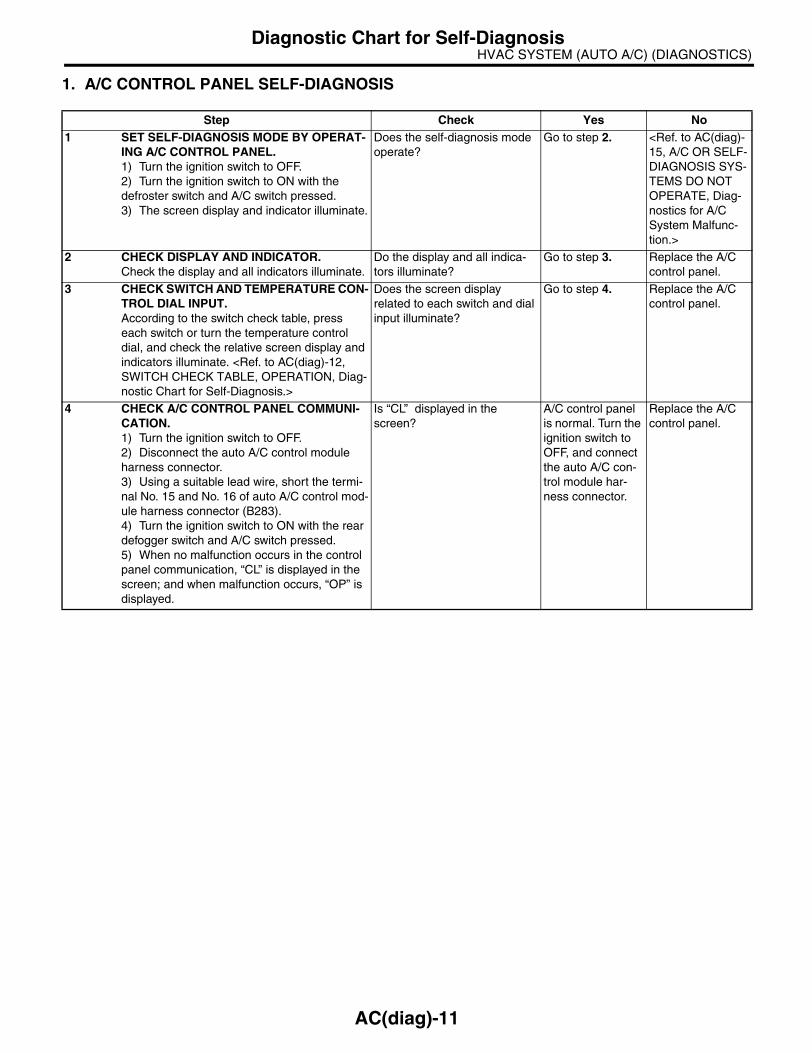
1. A/C CONTROL PANEL SELF-DIAGNOSIS
Step Check Yes No1 SET SELF-DIAGNOSIS MODE BY OPERAT-
ING A/C CONTROL PANEL.1) Turn the ignition switch to OFF.2) Turn the ignition switch to ON with the defroster switch and A/C switch pressed.3) The screen display and indicator illuminate.
Does the self-diagnosis mode operate?
Go to step 2. <Ref. to AC(diag)-15, A/C OR SELF-DIAGNOSIS SYS-TEMS DO NOT OPERATE, Diag-nostics for A/C System Malfunc-tion.>
2 CHECK DISPLAY AND INDICATOR.Check the display and all indicators illuminate.
Do the display and all indica-tors illuminate?
Go to step 3. Replace the A/C control panel.
3 CHECK SWITCH AND TEMPERATURE CON-TROL DIAL INPUT.According to the switch check table, press each switch or turn the temperature control dial, and check the relative screen display and indicators illuminate. <Ref. to AC(diag)-12, SWITCH CHECK TABLE, OPERATION, Diag-nostic Chart for Self-Diagnosis.>
Does the screen display related to each switch and dial input illuminate?
Go to step 4. Replace the A/C control panel.
4 CHECK A/C CONTROL PANEL COMMUNI-CATION.1) Turn the ignition switch to OFF.2) Disconnect the auto A/C control module harness connector.3) Using a suitable lead wire, short the termi-nal No. 15 and No. 16 of auto A/C control mod-ule harness connector (B283).4) Turn the ignition switch to ON with the rear defogger switch and A/C switch pressed.5) When no malfunction occurs in the control panel communication, “CL” is displayed in the screen; and when malfunction occurs, “OP” is displayed.
Is “CL” displayed in the screen?
A/C control panel is normal. Turn the ignition switch to OFF, and connect the auto A/C con-trol module har-ness connector.
Replace the A/C control panel.
AC(diag)-11

HVAC SYSTEM (AUTO A/C) (DIAGNOSTICS)Diagnostic Chart for Self-Diagnosis
2. SWITCH CHECK TABLE
(A) LHD model (B) RHD model
Switch Display screen Switch Display screen
A/C switch (9) FAN switch (+) (6)
AUTO switch (7) FAN switch (−) (5)
Air flow control switch (10)Temperature control dial (Right
turn)(3)
FRESH/RECIRC (8)Temperature control dial (Left
turn)(11)
Defroster switch (1) (2) OFF switch (4)
Rear defogger switch (12)
AC-00902
A/C OFFMODE
PUSH AUTO/TEMP
PUSH AUTO/TEMP
A/C MODEOFF
(A)
(B)
(8)(10)(11) (9)
(2) (3) (4) (5) (6) (7)
A/C
AUTO
(4) (5) (6)
(8)
(7)
AUTO
(9)
A/C
(10)(11)
(2) (3) (1)
(12)
(1)
(12)
AC(diag)-12
HVAC SYSTEM (AUTO A/C) (DIAGNOSTICS)Diagnostic Chart for Self-Diagnosis
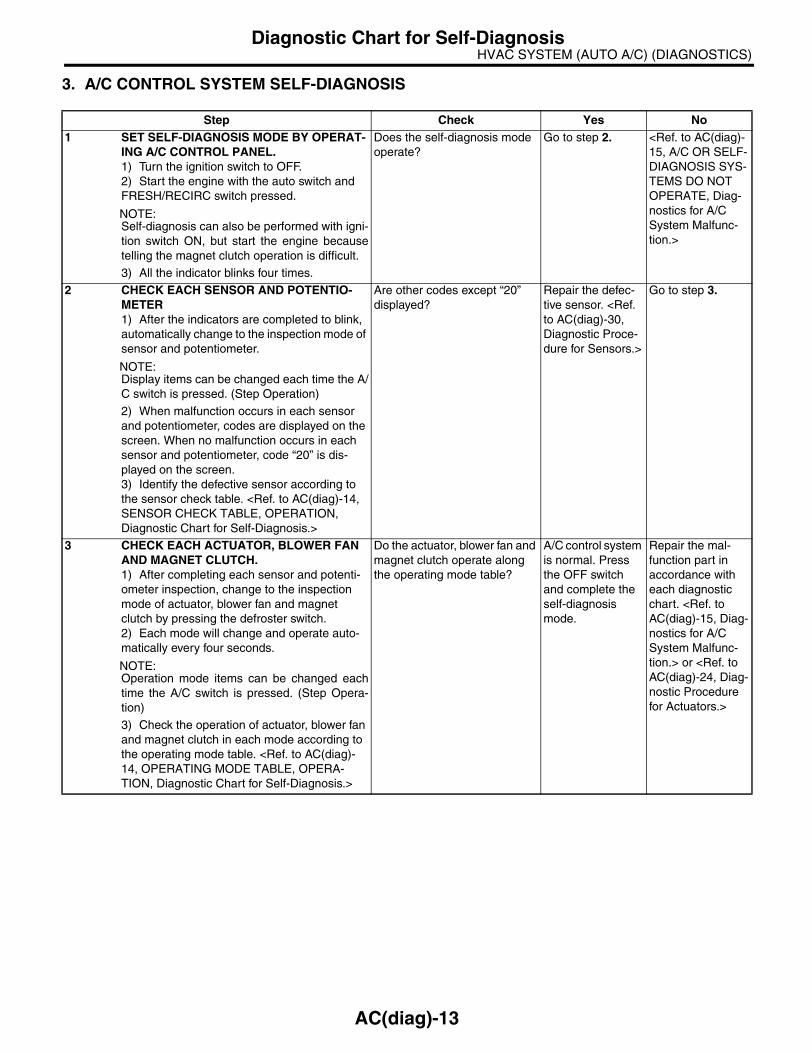
3. A/C CONTROL SYSTEM SELF-DIAGNOSIS
Step Check Yes No1 SET SELF-DIAGNOSIS MODE BY OPERAT-
ING A/C CONTROL PANEL.1) Turn the ignition switch to OFF.2) Start the engine with the auto switch and FRESH/RECIRC switch pressed.
NOTE:Self-diagnosis can also be performed with igni-tion switch ON, but start the engine becausetelling the magnet clutch operation is difficult.3) All the indicator blinks four times.
Does the self-diagnosis mode operate?
Go to step 2. <Ref. to AC(diag)-15, A/C OR SELF-DIAGNOSIS SYS-TEMS DO NOT OPERATE, Diag-nostics for A/C System Malfunc-tion.>
2 CHECK EACH SENSOR AND POTENTIO-METER1) After the indicators are completed to blink, automatically change to the inspection mode of sensor and potentiometer.
NOTE:Display items can be changed each time the A/C switch is pressed. (Step Operation)2) When malfunction occurs in each sensor and potentiometer, codes are displayed on the screen. When no malfunction occurs in each sensor and potentiometer, code “20” is dis-played on the screen.3) Identify the defective sensor according to the sensor check table. <Ref. to AC(diag)-14, SENSOR CHECK TABLE, OPERATION, Diagnostic Chart for Self-Diagnosis.>
Are other codes except “20” displayed?
Repair the defec-tive sensor. <Ref. to AC(diag)-30, Diagnostic Proce-dure for Sensors.>
Go to step 3.
3 CHECK EACH ACTUATOR, BLOWER FAN AND MAGNET CLUTCH.1) After completing each sensor and potenti-ometer inspection, change to the inspection mode of actuator, blower fan and magnet clutch by pressing the defroster switch.2) Each mode will change and operate auto-matically every four seconds.
NOTE:Operation mode items can be changed eachtime the A/C switch is pressed. (Step Opera-tion)
3) Check the operation of actuator, blower fan and magnet clutch in each mode according to the operating mode table. <Ref. to AC(diag)-14, OPERATING MODE TABLE, OPERA-TION, Diagnostic Chart for Self-Diagnosis.>
Do the actuator, blower fan and magnet clutch operate along the operating mode table?
A/C control system is normal. Press the OFF switch and complete the self-diagnosis mode.
Repair the mal-function part in accordance with each diagnostic chart. <Ref. to AC(diag)-15, Diag-nostics for A/C System Malfunc-tion.> or <Ref. to AC(diag)-24, Diag-nostic Procedure for Actuators.>
AC(diag)-13

HVAC SYSTEM (AUTO A/C) (DIAGNOSTICS)Diagnostic Chart for Self-Diagnosis
4. SENSOR CHECK TABLE
NOTE:When the sunload sensor check is conducted indoors or in the shade, open circuit might be indicated. Alwayscheck the sunload sensor at the place where the sun shines directly on it.
*1: “AUTO” display does not blink when past malfunction occurred. Past malfunction means that abnormal signal had input for acertain time continuously in the past.*2: Present malfunction only is displayed for sunload sensor open circuit.
5. OPERATING MODE TABLE
Display screen (Malfunction at present) *1
SENSOR Trouble contents
21/AUTO BlinkIn-vehicle sensor
Broken
−21/AUTO Blink Short
22/AUTO Blink Ambient sensor Sensor trouble or communication malfunction
23/AUTO BlinkEvaporator sensor
Broken
−23/AUTO Blink Short
24/AUTO Blink Engine coolant temperature sensor Sensor trouble or communication malfunction
25 BlinkSunload sensor
Open *2
−25/AUTO Blink Short
26/AUTO BlinkAir mix door actuator potentiometer
COOL
27/AUTO Blink HOT
28/AUTO BlinkMode door actuator potentiometer
FACE
29/AUTO Blink DEF
20 Blink When all conditions are normal
Display screenFRESH/RECIRC
doorMode door Air mix door Blower fan
A/C compressor (Mag-net clutch)
31 FRESH FACE Maximum cool LO OFF
32 RECIRC FACE Maximum cool LO ON
33 RECIRC FACE Maximum cool M1 ON
34 FRESH B/L 50% M1 ON
35 FRESH FOOT 50% M1 ON
36 FRESH FOOT Maximum hot M3 ON
37 FRESH F/D Maximum hot M3 ON
38 FRESH DEF Maximum hot HI ON
AC(diag)-14

HVAC SYSTEM (AUTO A/C) (DIAGNOSTICS)Diagnostics for A/C System Malfunction
6. Diagnostics for A/C System MalfunctionA: A/C OR SELF-DIAGNOSIS SYSTEMS DO NOT OPERATETROUBLE SYMPTOM:• “Set” temperature is not indicated on the display, switch LEDs are faulty and switches do not operate.• Self-diagnosis system does not operate.WIRING DIAGRAM:
A1
A9
A2
A1
6
B282A: B283B: AUTO A/C CONTROL MODULE
BATTERY
M/B NO. 8
F/B NO. 22
F/B NO. 31
SBF-1SBF-7
B282
1 2 3 4 5 6 7 89 10 11 12 13 14 15 16
B283
1 2 3 4 5 6 7 8 9 1011 12 13 14 15 16 17 18 19 20
A: B:
IGNITIONSWITCH
AC-00903
E
ACC
i88
1 25
B1
6
B1
5
3 7
A1
4
10 1
1*
i97
i3
B38
JOINTCONNECTOR
A/C CONTROL PANEL
1 2 3 4 5 6 7 8 910 11 12 13 14 15 16 17 18 19 20
B38
1 2 3 4 5 67 8 9 10 11 12
i97
1 2 3 45 6 7 8
i88
* : LHD MODEL : 4 RHD MODEL : 6
AC(diag)-15

HVAC SYSTEM (AUTO A/C) (DIAGNOSTICS)Diagnostics for A/C System Malfunction
Step Check Yes No1 CHECK FUSE.
1) Turn the ignition switch to OFF.2) Remove the fuse No. 8 from main fuse box.3) Check the condition of fuse.
Is the fuse blown-out? Replace the fuse. Go to step 2.
2 CHECK FUSE.1) Turn the ignition switch to OFF.2) Remove the fuse No. 22 and 31 from fuse & relay box.3) Check the condition of fuse.
Is the fuse blown-out? Replace the fuse. Go to step 3.
3 CHECK A/C CONTROL PANEL POWER CIR-CUIT.1) Replace the A/C control panel.2) Disconnect the A/C control panel harness connector.3) Measure the voltage between A/C control panel harness connector terminal and chassis ground after turning the ignition switch to ACC position.
Connector & terminal(i88) No. 2 (+) — Chassis ground (−):
Is the voltage more than 10 V? Go to step 4. Check the harness for open or short circuit between A/C control panel and fuse.
4 CHECK A/C CONTROL PANEL POWER CIR-CUIT.Measure the voltage between A/C control panel harness connector terminal and chassis ground after turning the ignition switch to ON position.
Connector & terminal(i88) No. 1 (+) — Chassis ground (−):
Is the voltage more than 10 V? Go to step 5. Check the harness for open or short circuit between A/C control panel and fuse.
5 CHECK A/C CONTROL PANEL GROUND POWER CIRCUIT.Measure the resistance in harness between A/C control panel and chassis ground after turning the ignition switch to OFF position.
Connector & terminal(i88) No. 5 — Chassis ground:
Is the resistance less than 10 Ω?
Go to step 6. Repair the har-ness for ground line.
6 CHECK AUTO A/C CONTROL MODULE POWER CIRCUIT.Measure the voltage between auto A/C control module connector terminal and chassis ground after turning the ignition switch to OFF posi-tion.
Connector & terminal(B282) No. 1 (+) — Chassis ground (−):
Is the voltage more than 10 V? Go to step 7. Check the harness for open or short circuit between auto A/C control module and fuse.
7 CHECK AUTO A/C CONTROL MODULE POWER CIRCUIT.Measure the voltage between auto A/C control module connector terminal and chassis ground after turning the ignition switch to ACC posi-tion.
Connector & terminal(B282) No. 2 (+) — Chassis ground (−):
Is the voltage more than 10 V? Go to step 8. Check the harness for open or short circuit between auto A/C control module and fuse.
8 CHECK AUTO A/C CONTROL MODULE POWER CIRCUIT.Measure the voltage between auto A/C control module connector terminal and chassis ground after turning the ignition switch to ON position.
Connector & terminal(B282) No. 9 (+) — Chassis ground (−):
Is the voltage more than 10 V? Go to step 9. Check the harness for open or short circuit between auto A/C control module and fuse.
AC(diag)-16

HVAC SYSTEM (AUTO A/C) (DIAGNOSTICS)Diagnostics for A/C System Malfunction
9 CHECK AUTO A/C CONTROL MODULE GROUND CIRCUIT.Measure the resistance in harness between auto A/C control module and chassis ground.
Connector & terminal(B282) No. 14, No. 16 — Chassis ground:
Is the resistance less than 5 Ω?
Go to step 10. Repair the har-ness for ground line.
10 CHECK COMMUNICATION CIRCUIT.Measure the resistance in harness between A/C control panel and auto A/C control module.
Connector & terminal(i88) No. 3 — (B283) No. 16:(i88) No. 7 — (B283) No. 15:
Is the resistance less than1 Ω? Go to step 11. Repair the har-ness.
11 CHECK POOR CONTACT.Check poor contact in auto A/C control module connector.
Is there poor contact in con-nector?
Repair the con-nector.
Replace the auto A/C control mod-ule.
Step Check Yes No
AC(diag)-17

HVAC SYSTEM (AUTO A/C) (DIAGNOSTICS)Diagnostics for A/C System Malfunction
B: BLOWER FAN DOES NOT ROTATE.TROUBLE SYMPTOM:• Blower motor does not rotate.• Blower motor does not rotate in “HI”.WIRING DIAGRAM:
B2
B3
B1
3
B225
B87
B86
BATTERY
F/B NO. 27
F/B NO. 28
F/B NO. 22
SBF-4 SBF-1
SBF-7
B283
1 2 3 4 5 6 7 8 9 1011 12 13 14 15 16 17 18 19 20
B:
241
22242321
21
BLOWER MOTOR
BLOWER MOTORRELAY
IGNITIONSWITCH
B87 B86
3 41 2
B283B: AUTO A/C CONTROL MODULE
AC-00824
E
M
3
1 2 910
1 2
3 4
5 6
7 8
11 1214
15 16
1318
19 20
1722
23 24
21
3839 40
3734
35 36
3330
31 32
2926
27 28
25
B225
POWERTRANSISTOR
AC(diag)-18

HVAC SYSTEM (AUTO A/C) (DIAGNOSTICS)Diagnostics for A/C System Malfunction
Step Check Yes No1 CHECK FUSE.
1) Remove the fuse No. 22, 27 and 28 from fuse & relay box.2) Check the condition of fuse.
Is any fuse blown-out? Replace the fuse. Go to step 2.
2 CHECK POWER SUPPLY FOR BLOWER MOTOR.1) Turn the ignition switch to ON.2) Turn the blower switch to ON.3) Measure the voltage between blower motor and chassis ground.
Connector & terminal(B87) No. 2 (+) — Chassis ground (−):
Is the voltage more than 10 V? Go to step 3. Repair the open circuit of blower motor power sup-ply line harness.
3 CHECK BLOWER MOTOR RELAY.1) Turn the ignition switch to OFF.2) Remove the blower motor relay.3) Connect the battery positive (+) terminal to terminal No. 24 of blower motor relay, and neg-ative (−) terminal to terminal No. 23.4) Measure the resistance between terminals No. 21 and 22.
TerminalsNo. 21 — No. 22:
Is the resistance less than 1 Ω?
Go to step 4. Replace the blower motor relay.
4 CHECK BLOWER MOTOR.1) Disconnect the connector from blower motor.2) Connect the battery positive (+) terminal to terminal No. 2 of blower motor connector, and negative (−) terminal to terminal No. 1.3) Make sure the blower motor runs.
Does the blower motor run? Go to step 5. Replace the blower motor.
5 CHECK POOR CONTACT.Check poor contact in auto A/C control module connector.
Is there poor contact in con-nector?
Repair the con-nector.
Replace the auto A/C control mod-ule.
AC(diag)-19

HVAC SYSTEM (AUTO A/C) (DIAGNOSTICS)Diagnostics for A/C System Malfunction
C: COMPARTMENT TEMPERATURE DOES NOT CHANGE, OR A/C SYSTEM DOES NOT RESPOND PROMPTLY.
WIRING DIAGRAM:
AC-00905
SBF-1SBF-7F/B No.22
B360
F109
B143B:
F37A:
F35C:
19
ND
HU
F24
12
B361
F108
B135
B136
B137
B:
C:
D:
ECM
B283B:
B282A:
B282
B10
F24A:
B283B:
B137D:
B143
B360 F109F108
B:F37A: F35 F27C:
B143B:
F37A:
F35C:
F27
B10
14
9
28
30
29
31
EE
C3
C7
A4
B1
3
2 4
1 3
HUB20C8
B33 B35
NDD17C30
A1
0
B6
E
A1
3B
20
C1
2
1 2 3 4 5 6 7 89 10 11 12 13 14 15 16
1 21 2 3 4 5 6 7 8 910 11 12 13 14 15 16 17 18 19 20
1 2 3 4 56 7 8 9 10 11 12
23
14
2 3 4 5 6 7 8 911 12 13 14 17 18 19 20
110 15 16
B361
1 2 3 4 5 67 8 9 10 11 12 13 14
1 2 3 89 10
411 12 13 14 15 16
5 6 717 18
1 2 38 9 10
411 12 13 14 15 16
5 6 7
123 6
7
4 5
131415
11
3031
16 178 9 1012
2627
18 1929 28
2223
20 21
2425
3 41 2 8 9 10 1112 13 14 15 16 17 18 19 20 21 22 23 24
5 6 7 1 2 3 4 5 6 7 8 9 1011 12 13 14 15 16 17 18 19 20
1 2 78 9
5 63 410 11 12
19 20 2129 30 31
13 14 15 16 17
27 2818 22 23 24 2526
B135B:
1 2 78 9
5 63 410 11 12 19
20 2129 30 31
13 14 15 16 1727
28
1822 23 24 25 26
32 33 34 35
B136C:
1 28 9
5 63 410 11 12
19 20 2129 30 31
13 14 15 1617 2728
18 22 23 24 25 267
32 33 34 35
AUTO A/C CONTROL MODULE
: 2.0 L TURBO MODEL, 3.0 L MODEL AND 2.5 L EC, K4, EK MODEL
: 2.0 L NA MODEL AND 2.5 L KS, KA MODELA/C RELAY
BATTERYIGNITION SWITCH
THROUGH JOINTCONNECTOR
THROUGH JOINTCONNECTOR
PRESSURESWITCH
MAIN FUSE BOX
MAIN FUSE BOX
MAGNETCLUTCH
AC(diag)-20

HVAC SYSTEM (AUTO A/C) (DIAGNOSTICS)Diagnostics for A/C System Malfunction
Step Check Yes No1 CHECK FUSE.
1) Turn the ignition switch to OFF.2) Remove the fuse No. 22 from fuse & relay box.3) Check the condition of fuse.
Is the fuse blown-out? Replace the fuse. Go to step 2.
2 CHECK SIGNAL TO A/C RELAY AND A/C CONTROL MODULE.1) Disconnect the A/C relay and auto A/C con-trol module harness connector.2) Turn the ignition switch to ON.3) Measure the voltage between A/C relay connector terminal and chassis ground.4) Measure the voltage between auto A/C control module harness connector terminal and chassis ground.
Connector & terminal(F27) No. 31 (+) — Chassis ground (−):(B282) No. 10 (+) — Chassis ground (−):
Is the voltage more than 10 V? Go to step 5. Go to step 3.
3 CHECK POWER SUPPLY FOR PRESSURE SWITCH.1) Turn the ignition switch to OFF.2) Disconnect the pressure switch harness connector.3) Turn the ignition switch to ON.4) Measure the voltage between pressure switch harness connector terminal and chassis ground.
Connector & terminal(B10) No. 2 (+) — Chassis ground (−):
Is the voltage more than 10 V? Go to step 4. Check the harness for open or short circuit between fuse and pressure switch.
4 CHECK HARNESS BETWEEN PRESSURE SWITCH AND A/C RELAY, AUTO A/C CON-TROL MODULE.1) Turn the ignition switch to OFF.2) Measure the resistance in harness between pressure switch connector and A/C relay connector.3) Measure the resistance in harness between pressure switch connector and auto A/C control module connector.
Connector & terminal(B10) No. 1 — (F27) No. 31:(B10) No. 1 — (B282) No. 10:
Is the resistance less than 1 Ω?
Check the pres-sure switch. <Ref. to AC-40, INSPECTION, Pressure Switch (Triple Pressure Switch).>
Repair the har-ness.
5 CHECK POWER SUPPLY FOR A/C RELAY.Measure the voltage between A/C relay con-nector terminal and chassis ground.
Connector & terminal(F27) No. 28 (+) — Chassis ground (−):
Is the voltage more than 10 V? Go to step 6. Check the harness for open or short circuit between fuse and A/C relay.
6 CHECK A/C RELAY.Check the A/C relay. <Ref. to AC-39, INSPEC-TION, Relay and Fuse.>
Is malfunction found in A/C relay?
Go to step 7. Replace the A/C relay.
AC(diag)-21

HVAC SYSTEM (AUTO A/C) (DIAGNOSTICS)Diagnostics for A/C System Malfunction
7 CHECK A/C ON SIGNAL.1) Turn the ignition switch to OFF.2) Connect the A/C relay and all disconnected connectors.3) Start the engine and turn the A/C switch to ON.4) Turn the temperature control dial at maxi-mum cool position.5) Measure the voltage between auto A/C control module harness connector terminal and chassis ground.
Connector & terminal(B283) No. 6 (+) — Chassis ground (−):
Is the voltage more than 5.5 V? Go to step 9. Go to step 8.
8 CHECK HARNESS BETWEEN AUTO A/C CONTROL MODULE AND ECM.1) Turn the ignition switch to OFF.2) Disconnect the harness connector of auto A/C control module and ECM.3) Measure the resistance in harness between auto A/C control module connector and ECM connector.
Connector & terminal2.0 L turbo model, 3.0 L model and 2.5 L EC, K4, EK model
(B283) No. 6 — (B137) No. 17:2.0 L non-turbo model and 2.5 L KS, KA model
(B283) No. 6 — (B135) No. 20:
Is the resistance less than 1 Ω?
Replace the auto A/C control mod-ule.
Repair the har-ness.
9 CHECK MAGNET CLUTCH ON SIGNAL.1) Stop the engine and turn the A/C switch to OFF.2) Turn the ignition switch to ON.3) Measure the voltage between ECM con-nector terminal and chassis ground.
Connector & terminal2.0 L turbo model, 3.0 L model and 2.5 L EC, K4, EK model
(B135) No. 33 (+) — Chassis ground (−):2.0 L non-turbo model and 2.5 L KS, KA model
(B135) No. 35 (+) — Chassis ground (−):
Is the voltage more than 10 V? Go to step 10. Check the harness for open or short circuit between A/C relay and ECM.
10 CHECK MAGNET CLUTCH ON SIGNAL.1) Start the engine and turn the A/C switch to ON.2) Turn the temperature control dial at maxi-mum cool position.3) Measure the voltage between ECM con-nector terminal and chassis ground.
Connector & terminal2.0 L turbo model, 3.0 L model and 2.5 L EC, K4, EK model
(B135) No. 33 (+) — Chassis ground (−):2.0 L non-turbo model and 2.5 L KS, KA model
(B135) No. 35 (+) — Chassis ground (−):
Is the voltage 0 V? Go to step 11. Replace the ECM.
Step Check Yes No
AC(diag)-22

HVAC SYSTEM (AUTO A/C) (DIAGNOSTICS)Diagnostics for A/C System Malfunction
11 CHECK POWER SUPPLY FOR MAGNET CLUTCH.1) Stop the engine and turn the A/C switch to OFF.2) Disconnect the harness connector of mag-net clutch.3) Start the engine and turn the A/C switch to ON.4) Turn the temperature control dial at maxi-mum cool position.5) Measure the voltage between magnet clutch harness connector terminal and chassis ground.
Connector & terminal(F24) No. 1 (+) — Chassis ground (−):
Is the voltage more than 10 V? Go to step 12. Check the harness for open or short circuit between A/C relay and mag-net clutch.
12 CHECK HARNESS BETWEEN AUTO A/C CONTROL MODULE AND ECM.1) Stop the engine and turn the A/C switch to OFF.2) Measure the resistance between magnet clutch harness connector terminal and chassis ground.
Connector & terminal(F24) No. 2 — Chassis ground:
Is the resistance less than 1 Ω?
Check the com-pressor. <Ref. to AC-33, INSPEC-TION, Compres-sor.>
Repair the har-ness.
Step Check Yes No
AC(diag)-23

HVAC SYSTEM (AUTO A/C) (DIAGNOSTICS)Diagnostic Procedure for Actuators
7. Diagnostic Procedure for ActuatorsA: INTAKE DOOR ACTUATORTROUBLE SYMPTOM:FRESH/RECIRC mode is not changed.WIRING DIAGRAM:
AC-00826
B91
SBF-1SBF-7F/B No.22
7
3 1
B283
B2
0
B1
0
B:
B283 B91B:
1 2 3 4 5 6 7 8 9 1011 12 13 14 15 16 17 18 19 20
1 2 3 4 5 6 7
AUTO A/CCONTROL MODULE
INTAKE DOORACTUATOR
IGNITIONSWITCH BATTERY
AC(diag)-24

HVAC SYSTEM (AUTO A/C) (DIAGNOSTICS)Diagnostic Procedure for Actuators
Step Check Yes No1 CHECK POWER SUPPLY FOR INTAKE
DOOR ACTUATOR.1) Turn the ignition switch to OFF.2) Disconnect the intake door actuator con-nector.3) Turn the ignition switch to ON.4) Measure the voltage between intake door actuator connector and chassis ground.
Connector & terminal(B91) No. 7 (+) — Chassis ground (−):
Is the voltage 7 V (at normal temperature)?
Go to step 2. Check the harness for open or short circuit between intake door actua-tor and fuse.
2 CHECK HARNESS BETWEEN AUTO A/C CONTROL MODULE AND INTAKE DOOR ACTUATOR.1) Turn the ignition switch to OFF.2) Disconnect the auto A/C control module connector.3) Measure the resistance between intake door actuator connector and auto A/C control module connector.
Connector & terminal(B283) No. 10 — (B91) No. 3:(B283) No. 20 — (B91) No. 1:
Is the resistance less than 1 Ω?
Go to step 3. Repair the har-ness between auto A/C control mod-ule and intake door actuator.
3 CHECK OPERATION OF INTAKE DOOR AC-TUATOR.1) Connect the intake door actuator connec-tor.2) Ground the auto A/C control module con-nector with a suitable wire.3) Turn the ignition switch to ON, and check the operation of intake door actuator.
Connector & terminal(B283) No. 10 — Chassis ground:
Does the actuator move to the FRESH side?
Go to step 4. Replace the intake door actuator.
4 CHECK OPERATION OF INTAKE DOOR AC-TUATOR.1) Turn the ignition switch to OFF.2) Ground the auto A/C control module con-nector with a suitable wire.3) Turn the ignition switch to ON, and check the operation of intake door actuator.
Connector & terminal:(B283) No. 20 — Chassis ground:
Does the actuator move to the RECIRC side?
Replace the auto A/C control mod-ule.
Replace the intake door actuator.
AC(diag)-25

HVAC SYSTEM (AUTO A/C) (DIAGNOSTICS)Diagnostic Procedure for Actuators
B: MODE DOOR ACTUATORTROUBLE SYMPTOM:Air flow outlet is not changed.WIRING DIAGRAM:
AC-00827
3 41 2 8 9 1011 12 13 14 15 16 17 18 19 20
5 6 7
B77 B283B:
3 41 2 89 10 11 12 13 14 15 16
5 6 7
B282A:
B283B282
B77
B1
7
AUTO A/CCONTROL MODULE
MODE DOOR ACTUATOR
154
A1
5
B7
B:A:
32A
8
A3
1 2 3 4 5
AC(diag)-26

HVAC SYSTEM (AUTO A/C) (DIAGNOSTICS)Diagnostic Procedure for Actuators
Step Check Yes No1 CHECK POWER SUPPLY FOR MODE DOOR
ACTUATOR POSITION SENSOR.1) Turn the ignition switch to OFF.2) Disconnect the mode door actuator con-nector.3) Turn the ignition switch and AUTO switch to ON.4) Measure the voltage between auto A/C control module connector terminals.
Connector & terminal(B282) No. 8 (+) — (B282) No. 15 (−):
Is the voltage approx. 5 V? Go to step 2. Replace the auto A/C control mod-ule.
2 CHECK POWER SUPPLY FOR MODE DOOR ACTUATOR.Measure the voltage between auto A/C control module connector and chassis ground after turning the air flow control switch to FACE posi-tion.
Connector & terminal(B283) No. 7 (+) — Chassis ground (−):
Is the voltage 7 V (at normal temperature)?
Go to step 3. Replace the auto A/C control mod-ule.
3 CHECK POWER SUPPLY FOR MODE DOOR ACTUATOR.Measure the voltage between auto A/C control module connector and chassis ground after turning the air flow control switch to DEF posi-tion.
Connector & terminal(B283) No. 17 (+) — Chassis ground (−):
Is the voltage 7 V (at normal temperature)?
Go to step 4. Replace the auto A/C control mod-ule.
4 CHECK HARNESS BETWEEN AUTO A/C CONTROL MODULE AND MODE DOOR AC-TUATOR.1) Turn the A/C and ignition switch to OFF.2) Disconnect the auto A/C control module connector.3) Measure the resistance between auto A/C control module and mode door actuator con-nector.
Connector & terminal(B77) No. 1 — (B282) No. 15:(B77) No. 2 — (B282) No. 8:(B77) No. 3 — (B282) No. 3:(B77) No. 4 — (B283) No. 17:(B77) No. 5 — (B283) No. 7:
Is the resistance less than 1 Ω?
Go to step 5. Repair the har-ness between auto A/C control mod-ule and mode door actuator.
5 CHECK MODE DOOR ACTUATOR POSI-TION SWITCH SIGNAL.1) Connect the connector of auto A/C control module and mode door actuator.2) Turn the ignition switch and AUTO switch to ON.3) Check the voltage between auto A/C con-trol module connector terminals while chang-ing the mode between DEF and FACE.
Connector & terminal(B282) No. 3 (+) — (B282) No. 15 (−):
Does the voltage change between 1 (DEF) — 4 (FACE) V?
Go to step 6. Replace the mode door actuator.
6 CHECK POOR CONTACT.Check poor contact in auto A/C control module and connector.
Is there poor contact in con-nector?
Repair connector. Replace the auto A/C control mod-ule.
AC(diag)-27

HVAC SYSTEM (AUTO A/C) (DIAGNOSTICS)Diagnostic Procedure for Actuators
C: AIR MIX DOOR ACTUATORTROUBLE SYMPTOM:Outlet air temperature does not change.WIRING DIAGRAM:
AC-00828
3 41 2 8 9 1011 12 13 14 15 16 17 18 19 20
5 6 7
B235 B283B:
3 41 2 89 10 11 12 13 14 15 16
5 6 7
B282A:
B283B282
B235
B8
376
A1
5
B1
8
B:A:
51A
8
A4
1 3 4 5 72 6
AUTO A/CCONTROL MODULE
AIR MIX DOOR ACTUATOR
AC(diag)-28

HVAC SYSTEM (AUTO A/C) (DIAGNOSTICS)Diagnostic Procedure for Actuators
Step Check Yes No1 CHECK POWER SUPPLY FOR AIR MIX
DOOR ACTUATOR POSITION SWITCH.1) Turn the ignition switch to OFF.2) Disconnect the air mix door actuator con-nector.3) Turn the ignition switch and AUTO switch to ON.4) Measure the voltage between auto A/C control module connector terminals.
Connector & terminal(B282) No. 8 (+) — (B282) No. 15 (−):
Is the voltage approx. 5 V? Go to step 2. Replace the auto A/C control mod-ule.
2 CHECK POWER SUPPLY FOR AIR MIX DOOR ACTUATOR.Measure the voltage between auto A/C control module connector and chassis ground after turning the temperature control dial to maxi-mum COOL position.
Connector & terminal(B283) No. 8 (+) — Chassis ground (−):
Is the voltage 7 V (at normal temperature)?
Go to step 3. Replace the auto A/C control mod-ule.
3 CHECK POWER SUPPLY FOR AIR MIX DOOR ACTUATOR.Measure the voltage between auto A/C control module connector and chassis ground after turning the temperature control dial to maxi-mum HOT position.
Connector & terminal(B283) No. 18 (+) — Chassis ground (−):
Is the voltage 7 V (at normal temperature)?
Go to step 4. Replace the auto A/C control mod-ule.
4 CHECK HARNESS BETWEEN AUTO A/C CONTROL MODULE AND AIR MIX DOOR ACTUATOR.1) Turn the A/C and ignition switch to OFF.2) Disconnect the auto A/C control module connector.3) Measure the resistance between auto A/C control module and air mix door actuator con-nector.
Connector & terminal(B235) No. 1 — (B282) No. 8:(B235) No. 3 — (B282) No. 15:(B235) No. 5 — (B282) No. 4:(B235) No. 6 — (B283) No. 8:(B235) No. 7 — (B283) No. 18:
Is the resistance less than 1 Ω?
Go to step 5. Repair the har-ness between auto A/C control mod-ule and air mix door actuator.
5 CHECK AIR MIX DOOR ACTUATOR POSI-TION SWITCH SIGNAL.1) Connect the connector of auto A/C control module and air mix door actuator.2) Turn the ignition switch and AUTO switch to ON.3) Check the voltage between auto A/C con-trol module connector terminals while chang-ing the setting temperature between maximum COOL and maximum HOT.
Connector & terminal(B282) No. 4 (+) — (B282) No. 15 (−):
Does the voltage change between 1 (Max. HOT) — 4 (Max. COOL) V?
Go to step 6. Replace the air mix door actuator.
6 CHECK POOR CONTACT.Check poor contact in auto A/C control module and connector.
Is there poor contact in con-nector?
Repair the con-nector.
Replace the auto A/C control mod-ule.
AC(diag)-29

HVAC SYSTEM (AUTO A/C) (DIAGNOSTICS)Diagnostic Procedure for Sensors
8. Diagnostic Procedure for SensorsA: AMBIENT SENSORTROUBLE SYMPTOM:Fan speed is not switched when the fan speed control dial is in AUTO position.WIRING DIAGRAM:
AC-00829
B283
F78
AUTO A/CCONTROL MODULE
AMBIENT SENSOR
B1
B1
1
B:
3 41 2 8 9 1011 12 13 14 15 16 17 18 19 20
5 6 7
B283B:
2 1
F78
1 2
10
11
14
13
B2
6
B2
5
C3
C1
0
F108
B361
B280
B281
B:
C:
54 6 78
219
310
22 2311 12 13 14 15
24 25 26 2716 17 18
28 2919 20
21 30
B280 B281B:
5 6 78
219
4310
2422 23 2511 12 13 14 15
26 27 2816 17 18 19
20 21
C:
1 2 3 4 5 67 8 9 10 11 12 13 14
B361
1 2 3 89 10
411 12 13 14 15 16
5 6 717 18
F108
THROUGHJOINT CONNECTOR
BODY INTEGRATED UNIT
AC(diag)-30

HVAC SYSTEM (AUTO A/C) (DIAGNOSTICS)Diagnostic Procedure for Sensors
Step Check Yes No1 CHECK AMBIENT SENSOR.
1) Turn the ignition switch to OFF.2) Disconnect the connector from ambient sensor.3) Measure the resistance between connector terminals of ambient sensor.
TerminalsNo. 1 — No. 2:
Is the resistance approx. 2.2 kΩ at 25°C (77°F)?
Go to step 2. Replace the ambi-ent sensor.
2 CHECK INPUT SIGNAL FOR AMBIENT SEN-SOR.1) Turn the ignition to ON.2) Measure the voltage between connector (F78) terminals.
Connector & terminal(F78) No. 1 (+) — No. 2 (−):
Is the voltage approx. 5 V? Go to step 6. Go to step 3.
3 CHECK OUTPUT SIGNAL OF BODY INTE-GRATED UNIT.1) Turn the ignition switch to OFF.2) Draw out the body integrated unit.3) Disconnect the connector from ambient sensor.4) Turn the ignition switch to ON.5) Measure the voltage between connector terminals of body integrated unit.
Connector & terminal(B281) No. 3 (+) — No. 10 (−):
Is the voltage approx. 5 V? Go to step 4. Go to step 6.
4 CHECK HARNESS CONNECTOR BETWEEN BODY INTEGRATED UNIT AND AMBIENT SENSOR.1) Turn the ignition switch to OFF.2) Disconnect the connector from body inte-grated unit.3) Measure the resistance in harness between body integrated unit and ambient sen-sor.
Connector & terminal(F78) No. 1 — (B281) No. 10:
Is the resistance less than 1 Ω?
Go to step 5. Repair the open circuit in harness between body inte-grated unit and ambient sensor.
5 CHECK HARNESS CONNECTOR BETWEEN BODY INTEGRATED UNIT AND AMBIENT SENSOR.Measure the resistance in harness between body integrated unit and ambient sensor.
Connector & terminal(F78) No. 2 — (B281) No. 3:
Is the resistance less than 1 Ω?
Go to step 6. Repair the open circuit in harness between body inte-grated unit and ambient sensor.
6 CHECK COMMUNICATION ERROR DIS-PLAY.1) Connect the connectors of body integrated unit and ambient sensor to original position.2) Check “Er xx” is indicated on the Odo/Trip meter in combination meter after turning the ignition switch to ON.
Is the error display “Er xx” indi-cated?
Check the commu-nication circuit. <Ref. to LAN(diag)-2, Basic Diagnostic Proce-dure.>
Go to step 7.
7 CHECK POOR CONTACT.Check poor contact in auto A/C control module connector.
Is there poor contact in con-nector?
Repair the con-nector.
Replace the A/C control module.
AC(diag)-31

HVAC SYSTEM (AUTO A/C) (DIAGNOSTICS)Diagnostic Procedure for Sensors
B: IN-VEHICLE SENSORTROUBLE SYMPTOM:Blower fan speed, outlet port and inlet port do not change after turning the AUTO switch to ON.WIRING DIAGRAM:
AC-00830
A: B282
1 2 3 4 5 6 7 89 10 11 12 13 14 15 16
i55
A: B282
A1
5
A5
21
i3
B38
i55
1 2
IN-VEHICLESENSOR
AUTO A/C CONTROL MODULE
12
11
1 2 3 4 5 6 7 8 910 11 12 13 14 15 16 17 18 19 20
B38
AC(diag)-32

HVAC SYSTEM (AUTO A/C) (DIAGNOSTICS)Diagnostic Procedure for Sensors
Step Check Yes No1 CHECK IN-VEHICLE SENSOR.
1) Turn the ignition switch to OFF.2) Remove the driver’s side lower cover.3) Disconnect the connector from in-vehicle sensor.4) Measure the resistance between connector terminals of in-vehicle sensor.
TerminalsNo. 1 — No. 2:
Is the resistance approx. 2.7 kΩ at 20°C (68°F)?
Go to step 2. Replace the in-vehicle sensor.
2 CHECK INPUT SIGNAL FOR IN-VEHICLE SENSOR.1) Turn the ignition switch to ON.2) Measure the voltage between in-vehicle sensor harness connector terminal and chas-sis ground.
Connector & terminal(i55) No. 2 (+) — No. 1 (−):
Is the voltage approx. 5 V? Go to step 6. Go to step 3.
3 CHECK AUTO A/C CONTROL MODULE OUTPUT SIGNAL.1) Turn the ignition switch to OFF.2) Remove the auto A/C control module.3) Turn the ignition switch to ON.4) Measure the voltage between connector terminals of auto A/C control module.
Connector & terminal(B282) No. 5 (+) — (B282) No. 15 (−):
Is the voltage approx. 5 V? Go to step 4. Go to step 6.
4 CHECK HARNESS BETWEEN AUTO A/C CONTROL MODULE AND IN-VEHICLE SEN-SOR.1) Turn the ignition switch to OFF.2) Disconnect the connector from auto A/C control module.3) Measure the resistance in harness between auto A/C control module and in-vehi-cle sensor.
Connector & terminal(i55) No. 2 — (B282) No. 5:
Is the resistance less than 1 Ω?
Go to step 5. Repair the har-ness between auto A/C control mod-ule and in-vehicle sensor.
5 CHECK HARNESS BETWEEN AUTO A/C CONTROL MODULE AND IN-VEHICLE SEN-SOR.Measure the resistance in harness between auto A/C control module and in-vehicle sensor.
Connector & terminal(i55) No. 1 — (B282) No. 15:
Is the resistance less than 1 Ω?
Go to step 6. Repair the har-ness between auto A/C control mod-ule and in-vehicle sensor.
6 CHECK POOR CONTACT.Check poor contact in auto A/C control module connector.
Is there poor contact in con-nector?
Repair the con-nector.
Replace the auto A/C control mod-ule.
AC(diag)-33

HVAC SYSTEM (AUTO A/C) (DIAGNOSTICS)Diagnostic Procedure for Sensors
C: EVAPORATOR SENSORWIRING DIAGRAM:
AC-00831
A1
3
A1
5
B88
12
EVAPORATORSENSOR
B88
B282A: AUTO A/CCONTROL MODULE
1212
3 41 2 89 10 11 12 13 14 15 16
5 6 7
B282A:
AC(diag)-34

HVAC SYSTEM (AUTO A/C) (DIAGNOSTICS)Diagnostic Procedure for Sensors
Step Check Yes No1 CHECK EVAPORATOR SENSOR
1) Turn the ignition switch to OFF.2) Remove the glove box.3) Disconnect the connector from evaporator sensor.4) Measure the resistance between connector terminals of evaporator sensor.
TerminalsNo. 1 — No. 2:
Is the resistance approx. 3.3 kΩ at 20°C (68°F)?
Go to step 2. Replace the evap-orator sensor.
2 CHECK INPUT SIGNAL FOR EVAPORATOR SENSOR.1) Turn the ignition switch to ON.2) Measure the voltage between connector (B88) terminal and chassis ground.
Connector & terminal(B88) No. 1 (+) — No. 2 (−):
Is the voltage approx. 5 V? Go to step 6. Go to step 3.
3 CHECK AUTO A/C CONTROL MODULE OUTPUT SIGNAL.1) Turn the ignition switch to OFF.2) Remove the auto A/C control module.3) Turn the ignition switch to ON.4) Measure the voltage between connector terminals of auto A/C control module.
Connector & terminal(B282) No. 13 (+) —No. 15 (−):
Is the voltage approx. 5 V? Go to step 4. Go to step 6.
4 CHECK HARNESS CONNECTOR BETWEEN AUTO A/C CONTROL MODULE AND EVAP-ORATOR SENSOR.1) Turn the ignition switch to OFF.2) Disconnect the connector from auto A/C control module.3) Measure the resistance in harness between auto A/C control module and evapo-rator sensor.
Connector & terminal(B88) No. 2 — (B282) No. 15:
Is the resistance less than 1 Ω?
Go to step 5. Repair the open circuit in harness between auto A/C control module and evaporator sensor.
5 CHECK HARNESS CONNECTOR BETWEEN AUTO A/C CONTROL MODULE AND EVAP-ORATOR SENSOR.Measure the resistance in harness between auto A/C control module and evaporator sen-sor.
Connector & terminal(B88) No. 1 — (B282) No. 13:
Is the resistance less than 1 Ω?
Go to step 6. Repair the open circuit in harness between auto A/C control module and evaporator sensor.
6 CHECK POOR CONTACT.Check poor contact in auto A/C control module connector.
Is there poor contact in con-nector?
Repair the con-nector.
Replace the auto A/C control mod-ule.
AC(diag)-35

HVAC SYSTEM (AUTO A/C) (DIAGNOSTICS)Diagnostic Procedure for Sensors
D: SUNLOAD SENSORTROUBLE SYMPTOM:• Sensor identifies that sunlight is at maximum. Then, A/C system is controlled to COOL side.• Sensor identifies that sunlight is at minimum. Then, A/C system is controlled to HOT side.
NOTE:When the sunload sensor check is conducted indoors or in the shade, open circuit might be indicated. Alwayscheck the sunload sensor at the place where the sun shines directly on it.WIRING DIAGRAM:
AC-00832
A: B282
1 2 3 4 5 6 7 89 10 11 12 13 14 15 16
i51
A: B282
A8
A6
21
i3
B38
i51
1 2
AUTO A/C CONTROL MODULE
32
1 2 3 4 5 6 7 8 910 11 12 13 14 15 16 17 18 19 20
B38
SUNLOADSENSOR
AC(diag)-36

HVAC SYSTEM (AUTO A/C) (DIAGNOSTICS)Diagnostic Procedure for Sensors
Step Check Yes No1 CHECK POWER SUPPLY VOLTAGE FOR
SUNLOAD SENSOR.1) Turn the ignition switch to OFF.2) Disconnect the connector from sunload sensor.3) Turn the ignition switch to ON.4) Measure the power supply voltage for sun-load sensor.
Connector & terminal(i51) No. 1 (+) — No. 2 (−):
Is the voltage approx. 5 V? Go to step 4. Go to step 2.
2 CHECK HARNESS CONNECTOR BETWEEN AUTO A/C CONTROL MODULE AND SUN-LOAD SENSOR.1) Turn the ignition switch to OFF.2) Disconnect the connector from auto A/C control module.3) Measure the resistance in harness between auto A/C control module and sunload sensor.
Connector & terminal(i51) No. 2 — (B282) No. 6:
Is the resistance less than 1 Ω?
Go to step 3. Repair the har-ness between auto A/C control mod-ule and sunload sensor.
3 CHECK HARNESS CONNECTOR BETWEEN AUTO A/C CONTROL MODULE AND SUN-LOAD SENSOR.Measure the resistance in harness between auto A/C control module and sunload sensor.
Connector & terminal(i51) No. 1 — (B282) No. 8:
Is the resistance less than 1 Ω?
Go to step 4. Repair the har-ness between auto A/C control mod-ule and sunload sensor.
4 CHECK INPUT VOLTAGE FOR AUTO A/C CONTROL MODULE.1) Connect the connectors of sunload sensor and auto A/C control module.2) Turn the ignition switch to ON.3) Measure the voltage between connector terminals of auto A/C control module.
Connector & terminal(B282) No. 8 (+) — (B282) No. 6 (−):
Is the voltage approx. 2.5 V? Go to step 5. Replace the sun-load sensor.
5 CHECK POOR CONTACT.Check poor contact in auto A/C control module connector.
Is there poor contact in con-nector?
Repair the con-nector.
Replace the auto A/C control mod-ule.
AC(diag)-37

HVAC SYSTEM (AUTO A/C) (DIAGNOSTICS)Diagnostics with Phenomenon
9. Diagnostics with PhenomenonA: INSPECTION
Symptom Problem parts
A/C system fails to operate.
• Fuse (M/B No. 8, F/B No. 22, 31)• Connector (Poor contact)• Ground• Auto A/C control module• Blower fan motor• Blower fan relay• A/C Relay• Compressor (Magnet clutch)• Evaporator sensor
Fuse is blown out.• Fuse (M/B No. 8, F/B No. 22, 31)• Connector (Poor contact)
Illumination cannot dim.• Fuse (M/B No. 8, F/B No. 22, 31)• Connector (Poor contact)• Auto A/C control module
Blower fan does not rotate or fan speed cannot be controlled.
• Fuse (M/B No. 8, F/B No. 22, 31)• Connector (Poor contact)• Ground• Auto A/C control module• Blower fan motor• Blower fan relay
Unable to switch suction vents.• Connector (Poor contact)• Auto A/C control module• Intake door actuator
Unable to switch blow vents.• Connector (Poor contact)• Auto A/C control module• Mode door actuator
Compartment temperature does not increase. (No hot air is dis-charged.)
• Connector (Poor contact)• Auto A/C control module• Air mix door actuator• In-vehicle sensor, ambient sensor, evaporator sensor and sunload sensor• In-vehicle sensor aspirator hose
Compartment temperature does not decrease. (No cool air is discharged.)
• Connector (Poor contact)• Auto A/C control module• Air mix door actuator• A/C Relay• Compressor (Magnet clutch)• Radiator fan motor• Radiator fan relay• In-vehicle sensor, ambient sensor, evaporator sensor and sunload sensor• In-vehicle sensor aspirator hose
Compartment temperature is higher or lower than setting tem-perature.
• Auto A/C control module• Air mix door actuator• In-vehicle sensor, ambient sensor, evaporator sensor and sunload sensor• In-vehicle sensor aspirator hose
Compartment temperature does not quickly respond to setting temperature.
• Air mix door actuator• In-vehicle sensor, ambient sensor, evaporator sensor and sunload sensor• In-vehicle sensor aspirator hose
Radiator fan does not rotate during A/C operation.• Radiator fan motor• Radiator fan relay
AC(diag)-38

AIRBAG SYSTEM
AB
Page1. General Description ....................................................................................22. Airbag Connector ........................................................................................93. Inspection Locations After a Collision .......................................................124. Driver’s Airbag Module..............................................................................145. Passenger’s Airbag Module ......................................................................156. Side Airbag Module...................................................................................167. Curtain Airbag Module ..............................................................................188. Airbag Control Module ..............................................................................209. Side Airbag Sensor ...................................................................................21
10. Curtain Airbag Sensor...............................................................................2211. Roll Connector ..........................................................................................2312. Front Sub Sensor ......................................................................................2413. Disposal of Airbag Module (Deployment Processing On Vehicle) ............2514. Disposal of Airbag Module (Deployment Processing After Removal from Vehicle) .....30

AIRBAG SYSTEMGeneral Description
1. General DescriptionA: COMPONENT1. DRIVER’S AIRBAG MODULE
Tightening torque:10 N⋅m (1.0 kgf-m, 7.2 ft-lb)
2. PASSENGER’S AIRBAG MODULE
Tightening torque:7.4 N⋅m (0.75 kgf-m, 5.5 ft-lb)
3. SIDE AIRBAG MODULE
Tightening torque:6 N⋅m (0.61 kgf-m, 4.4 ft-lb)
4. CURTAIN AIRBAG MODULE• Sedan model
• Wagon model
Tightening torque:7.5 N⋅m (0.77 kgf-m, 5.5 ft-lb)
5. AIRBAG CONTROL MODULE
Tightening torque:25 N⋅m (2.5 kgf-m, 18.1 ft-lb)
AB-00752T
T
AB-00753
T
AB-00754
T
(A) Bolt
(B) Clip
(A) Bolt
(B) Clip
(A)
(A) (A)
(A)
(A)
(A)
(A)(B)(B)
AB-00625
AB-00626
(A)(A)
(A)
(A)
(A)(B)
(B)(A)(A)
(A)(A)
AB-00755
T
AB-2
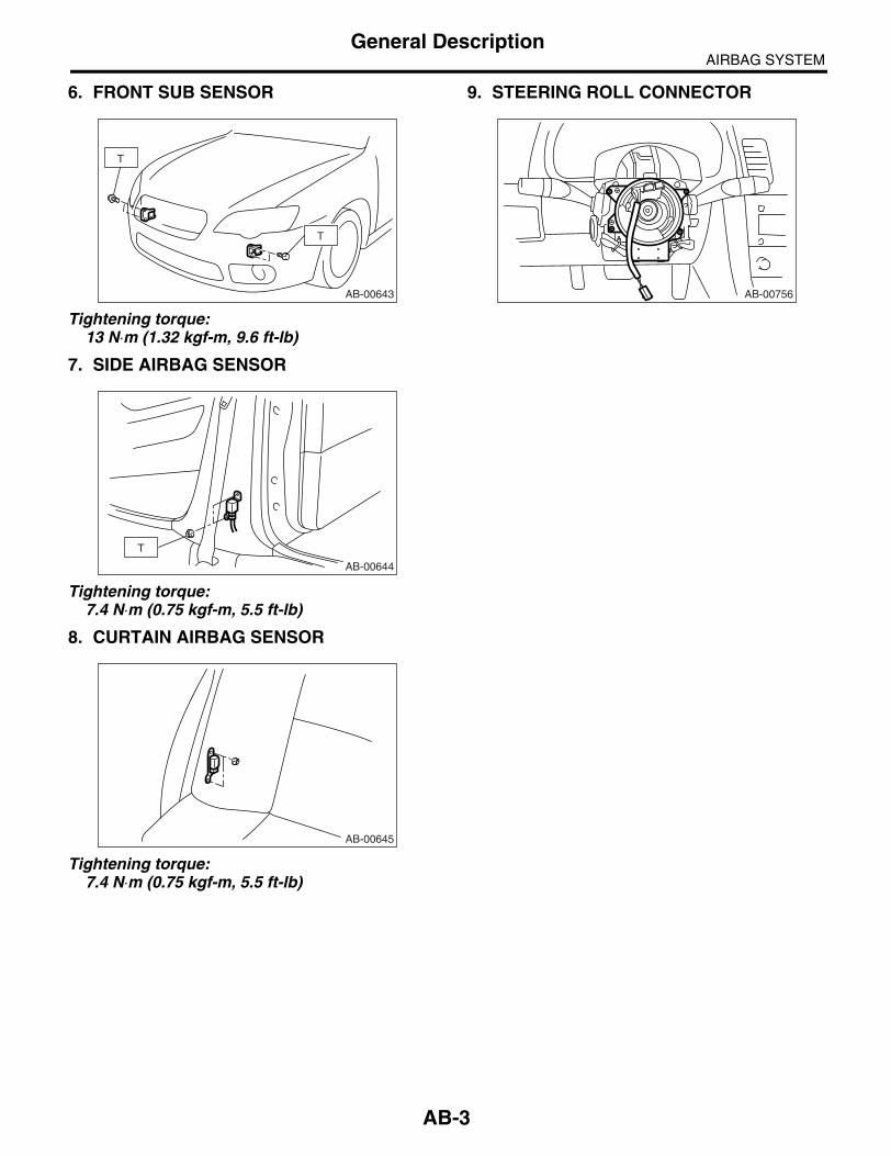
AIRBAG SYSTEMGeneral Description
6. FRONT SUB SENSOR
Tightening torque:13 N⋅m (1.32 kgf-m, 9.6 ft-lb)
7. SIDE AIRBAG SENSOR
Tightening torque:7.4 N⋅m (0.75 kgf-m, 5.5 ft-lb)
8. CURTAIN AIRBAG SENSOR
Tightening torque:7.4 N⋅m (0.75 kgf-m, 5.5 ft-lb)
9. STEERING ROLL CONNECTOR
AB-00643
T
T
AB-00644
T
AB-00645
AB-00756
AB-3
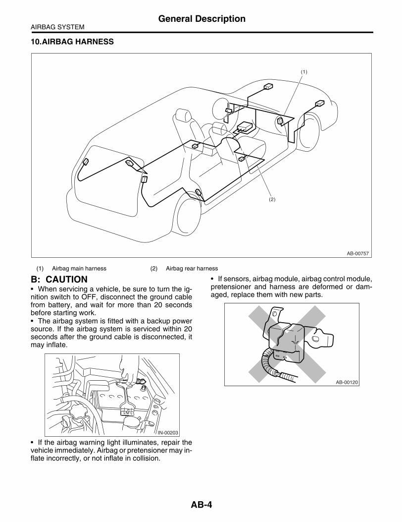
AIRBAG SYSTEMGeneral Description
10.AIRBAG HARNESS
B: CAUTION• When servicing a vehicle, be sure to turn the ig-nition switch to OFF, disconnect the ground cablefrom battery, and wait for more than 20 secondsbefore starting work.• The airbag system is fitted with a backup powersource. If the airbag system is serviced within 20seconds after the ground cable is disconnected, itmay inflate.
• If the airbag warning light illuminates, repair thevehicle immediately. Airbag or pretensioner may in-flate incorrectly, or not inflate in collision.
• If sensors, airbag module, airbag control module,pretensioner and harness are deformed or dam-aged, replace them with new parts.
(1) Airbag main harness (2) Airbag rear harness
AB-00757
(1)
(2)
IN-00203
AB-00120
AB-4

AIRBAG SYSTEMGeneral Description
• When checking the airbag system, be sure touse a digital circuit tester. Use of an analog circuittester may cause the airbag to activate erroneous-ly.
• When checking, use a test harness (1). Sincedamage to the connector terminal may cause theairbag to activate erroneously, do not directly applythe tester probe to any connector terminal of theairbag.
• Do not check continuity of the airbag modules fordriver, passenger, side or curtain, or pretensioner.
• Do not drop the airbag modules, subject them tohigh temperature over 93°C (199°F), or let water,oil or grease get on them; the internal parts may bedamaged and reliability greatly lowered.
• If any damage, opening or rust is found on theairbag system wire harness, do not attempt to re-pair using soldering equipment. Be sure to replacethe faulty harness with a new genuine part.
• Install the wire harness securely with the speci-fied clips to avoid interference or tangled up withother parts.
AB-00121
AB-00122
(1)
AB-00006
AB-00123
AB-00124
AB-00125
AB-5

AIRBAG SYSTEMGeneral Description
• Do not allow water or oil to come in contact withthe connector terminals. Do not touch the connec-tor terminals.
• Either of the airbag modules for driver, passen-ger, side or curtain, or pretensioner must not bedisassembled.
• The removed front seat with airbag module mustbe kept at least 200 mm (8 in) away from walls andother objects.
• Do not use the airbag or pretensioner parts fromother vehicles. Always replace the defective partswith new parts.• Never reuse a deployed airbag and pretensioner.• When painting or performing sheet metal workon the front part of the vehicle, including the frontwheel apron front fender, and front side frame, re-move the front sub sensors and wire harness ofairbag system.
• When painting or performing sheet metal workon the side of the vehicle, including the side sill,center pillar, and front and rear doors, remove theside airbag sensors and wire harness of airbag sys-tem.
(1) 200 mm (8 in) or more
AB-00126
AB-00127
AB-00128
(1)
AB-00129
AB-6

AIRBAG SYSTEMGeneral Description
• When storing a removed airbag module, do not place any objects on it or pile airbag modules on top ofeach other. If the airbag inflates for some reason when it is placed with its pad side facing downward or underany object, a serious accident may result.
(1) Driver’s airbag module (2) Passenger’s airbag module
AB-00130
(2)
(1)
AB-7

AIRBAG SYSTEMGeneral Description
C: PREPARATION TOOL1. SPECIAL TOOL
ILLUSTRATION TOOL NUMBER DESCRIPTION REMARKS
98299FC030 DEPLOYMENTADAPTER A
• Used for deploying side airbag module.• Used for deploying curtain airbag module.• Used with DEPLOYMENT TOOL (98299PA030).
98299SA030 DEPLOYMENTADAPTER E
• Used for deploying driver’s airbag module.• Used for deploying passenger’s airbag mod-ule.• Used with DEPLOYMENT TOOL (98299PA030).
98299AG030 DEPLOYMENTADAPTER X
• Used for deploying driver’s airbag module.• Used with DEPLOYMENT TOOL (98299PA030).• Can not reuse.
98299PA030 DEPLOYMENT TOOL
• Used for deploying airbag module.• Used with each deployment adapter.
ST98299FC030
ST98299SA030
ST98299AG030
ST98299PA030
AB-8

AIRBAG SYSTEMAirbag Connector
2. Airbag ConnectorA: PROCEDURE1. POWER SUPPLY1) How to disconnect:
(1) Move the slide lock (A) in the direction of ar-row.(2) With the slide lock (A) moved, separate theconnector.
CAUTION:When pulling the slide lock or disconnecting the connector, be sure to hold onto the connec-tor and not the wire.2) How to connect:Holding the connector (A), and push it in carefullyuntil a connecting sound is heard.
CAUTION:Be sure to insert the connector in until it is locked. Then pull on it gently to make sure that it is locked.
2. DRIVER’S AIRBAG MODULE AND PRE-TENSIONER1) How to disconnect:
(1) Using a flat tip screwdriver, pry the pushlock upward to unlock.
(2) Pull the connector to disconnect from thedriver’s airbag module assembly or retractor as-sembly.
2) How to connect:Connect the connector in the reverse order of dis-connecting. At this time, be sure to insert the pushlock until a connecting sound is heard.
CAUTION:• Be sure to insert the connector in until it islocked. Then pull on it gently to make sure thatit is locked.• Be sure to push the push lock in securely.
NOTE:Connector can not be connected when the pushlock is in lock position. To connect the connector,set the push lock to unlock position.
AB-00721
(A)
AB-00016
AB-00478
AB-00479
AB-00480
AB-9

AIRBAG SYSTEMAirbag Connector
3. DRIVER’S AIRBAG (BETWEEN AIRBAG MAIN HARNESS AND ROLL CONNECTOR), PASSENGER’S AIRBAG1) How to disconnect:
(1) Push the slide lock (A) into the direction ofarrow.
(2) With the slide lock pushed, disconnect theconnector.
CAUTION:When pulling the side lock or disconnecting the connector, be sure to hold onto the connector and not the wire.2) How to connect:Holding the connector, and push it in carefully untila connecting sound is heard.
CAUTION:Be sure to insert the connector in until it is locked. Then pull on it gently to make sure that it is locked.
4. SIDE AIRBAG AND CURTAIN AIRBAG1) How to disconnect:
(1) Push the lock arm (A).(2) With the lock arm (A) pushed in, move theslide lock (B) in the direction of arrow.
(3) With the slide lock moved, release the lockarm (back to its original position), and discon-nect the connector.
CAUTION:When pulling the side lock or disconnecting the connector, be sure to hold onto the connector and not the wire.
5. FRONT SUB-SENSOR, SIDE AIRBAG SENSOR AND CURTAIN AIRBAG SENSOR1) How to disconnect:Holding the outer part (A), pull it in the direction ofarrow.
CAUTION:When pulling the side lock or disconnecting the connector, be sure to hold onto the connector and not the wire.
AB-00722
(A)
AB-00022
AB-00023
AB-00017
(A)
(B)
AB-00018
AB-00024
AB-10

AIRBAG SYSTEMAirbag Connector
2) How to connect:Holding the connector, and push it in carefully untila connecting sound is heard.
CAUTION:• The outer side (A) moves back, and so do notput your hand on the outer part.• Be sure to insert the connector in until it islocked. Then pull on it gently to make sure thatit is locked.
AB-00025
AB-11

AIRBAG SYSTEMInspection Locations After a Collision
3. Inspection Locations After a Collision
A: REPLACEMENTReplace the following parts when the airbag is de-ployed.
1. FRONT COLLISION1) Driver’s airbag module2) Passenger’s airbag module3) Driver’s seat belt (Pretensioner)4) Passenger’s seat belt (Pretensioner)5) Airbag control module6) Front sub sensor7) Roll connector8) Instrument panel (for integrating with passen-ger’s airbag module)
2. SIDE COLLISION1) Airbag control module2) Side airbag module (operating side seat back-rest)3) Side airbag sensor (operating side)4) Curtain airbag module (operating side)5) Curtain airbag sensor (operating side)
3. INSPECTION OF OTHER PARTSCheck for the following, and replace the damagedparts with new parts.1) Check the steering shaft for mounting conditionsand deflection of front and rear, upward and down-ward directions, and deflection of front and rear di-rection with tilt lever released. (After collision,absorbing part of steering shaft may work.)2) Check the direct type connector of driver’sairbag module, pretensioner, etc. for damage, andalso check each harness for pinch and connectordamage. Replace the harness as a unit if damageis found.3) Check the installing condition and play of theseat cushion, backrest, seat rail and headrest.
B: INSPECTIONIf the vehicle is involved in a collision on any side,even if it is a slight collision, be sure to check thefollowing systems.
1. DRIVER’S AIRBAG MODULE 1) Check for the following, and replace the dam-aged parts with new parts.• Airbag module is cracked or deformed.• Harness and/or connector is cracked, deformedor open. Harness wire is exposed.• The module surface is fouled with grease, oil,water or cleaning solvent.
2) When installing a new driver’s airbag module,check for the following, and replace the damagedparts with new parts.• The steering wheel is in the way, making it diffi-cult to install the airbag module.• The clearance between the driver’s airbag mod-ule and steering wheel is not constant.• When steering wheel deformation in axial, up-ward and downward directions exceed limits.
Standard value:Height deflection A
Less than 6 mm (0.24 in)O.D. deflection L
Less than 7 mm (0.28 in)
2. PASSENGER’S AIRBAG MODULE Check for the following, and replace the damagedparts with new parts.• Airbag module and instrument panel are crackedor deformed.• Harness and/or connector is cracked, deformedor open. Harness wire is exposed.• Mounting bracket is cracked or deformed.
3. SIDE AIRBAG MODULECheck for the following, and replace the damagedparts with new parts.• Front seat, airbag module and mounting bracketare damaged or deformed.• Harness and/or connector is cracked, deformedor open. Harness wire is exposed.
4. CURTAIN AIRBAG MODULECheck for the following, and replace the damagedparts with new parts.• Airbag cover is scratched or broken.• Harness and/or connector is cracked, deformedor open. Harness wire is exposed.• Mounting bracket and securing clip are crackedor deformed.
5. AIRBAG CONTROL MODULECheck for the following, and replace the damagedparts with new parts.• Control module is cracked or deformed.
AB-00028
L
A
AB-12

AIRBAG SYSTEMInspection Locations After a Collision
• Mounting bracket is cracked or deformed.• Connector is scratched, cracked or deformed.• Airbag is deployed.• Side airbag is deployed.• Curtain airbag is deployed.
6. FRONT SUB SENSORIf the section of vehicle as shown in the figure isdamaged, check for the following and replace thedamaged parts with new parts.
• Front sub sensor is cracked or deformed.• Mounting bracket is cracked or deformed.• Connector is scratched, cracked or deformed.• Airbag is deployed.
7. SIDE AIRBAG SENSOR AND CURTAIN AIRBAG SENSORIf the section of vehicle as shown in the figure isdamaged, check for the following and replace thedamaged parts with new parts.
• Side airbag sensor and curtain airbag sensor arecracked or deformed.• Mounting bracket is cracked or deformed.• Connector is scratched, cracked or deformed.• Side airbag sensor or curtain airbag is deployed.(operating side)
8. ROLL CONNECTORCheck for the following, and replace the damagedparts with new parts.• Combination switch or steering roll connector iscracked or deformed.
9. STEERING SHAFTCheck for the following, and replace the damagedparts with new parts.• Overall length of steering column should be with-in specifications.
Standard value:Overall length L
Except for OUTBACK model833.6 +1.3
−0.3 mm (32.8 +0.1−0.01 in)
OUTBACK model825.4 +1.3
−0.3 mm (32.5 +0.1−0.01 in)
AB-00029
AB-00030
AB-00728
L
AB-13

AIRBAG SYSTEMDriver’s Airbag Module
4. Driver’s Airbag Module A: REMOVALCAUTION:Refer to “CAUTION” of General Description be-fore handling the airbag module. <Ref. to AB-4, CAUTION, General Description.>1) Position the front wheels straight ahead. (Aftermoving a vehicle more than 5 m (16 ft) with frontwheels positioned straight ahead, make sure thevehicle moves straight ahead.)2) Turn the ignition switch to OFF.3) Disconnect the ground cable from battery andwait for at least 20 seconds before starting work.4) Using TORX® BIT T30 (1), remove the twoTORX® bolts on the side of steering wheel.
5) Disconnect the horn harness.6) Disconnect the airbag connector on the back ofairbag module, and then remove the airbag mod-ule. <Ref. to AB-9, PROCEDURE, Airbag Connec-tor.>
7) Refer to “CAUTION” for handling of a removedairbag module. <Ref. to AB-4, CAUTION, GeneralDescription.>
B: INSTALLATIONCAUTION:• Refer to “CAUTION” of General Descriptionbefore handling the airbag module. <Ref. to AB-4, CAUTION, General Description.>• Do not allow harness and connectors to inter-fere or get tangled up with other parts.• To prevent the misconnection, the connectoris colored. Connect the harness side connectorto the same color of module side connector.Install in the reverse order of removal.
Tightening torque:Refer to “COMPONENT” of “General Descrip-tion”. <Ref. to AB-2, DRIVER’S AIRBAG MOD-ULE, COMPONENT, General Description.>
C: INSPECTIONCAUTION:Refer to “CAUTION” of General Description be-fore handling the airbag module. <Ref. to AB-4, CAUTION, General Description.>Check for the following, and replace damagedparts with new parts.• Airbag module, harness, connector and mount-ing bracket are damaged. <Ref. to AB-12, DRIV-ER’S AIRBAG MODULE, INSPECTION,Inspection Locations After a Collision.>
CC-00018
(1)
AB-00622
AB-14

AIRBAG SYSTEMPassenger’s Airbag Module
5. Passenger’s Airbag Module A: REMOVALCAUTION:Refer to “CAUTION” of “General Description” before handling the airbag module. <Ref. to AB-4, CAUTION, General Description.>1) Turn the ignition switch to OFF.2) Disconnect the ground cable from battery andwait for at least 20 seconds before starting work.3) Remove the instrument panel. <Ref. to EI-56,INSTRUMENT PANEL (EXCLUDING STEERINGSUPPORT BEAM), REMOVAL, Instrument PanelAssembly.>4) Remove the pawl and remove the passenger’sairbag module.
5) Refer to “CAUTION” for handling of a removedairbag module. <Ref. to AB-4, CAUTION, GeneralDescription.>
B: INSTALLATIONCAUTION:Refer to “CAUTION” of General Description be-fore handling the airbag module. <Ref. to AB-4, CAUTION, General Description.>Install in the reverse order of removal.
CAUTION:Do not allow harness and connectors to inter-fere or get tangled up with other parts.
Tightening torque:Refer to “COMPONENT” of “General Descrip-tion”. <Ref. to AB-2, PASSENGER’S AIRBAG MODULE, COMPONENT, General Descrip-tion.>
C: INSPECTIONCAUTION:Refer to “CAUTION” of General Description be-fore handling the airbag module. <Ref. to AB-4, CAUTION, General Description.>Check for the following, and replace damagedparts with new parts.• Airbag module, harness, connector, and mount-ing bracket are damaged. <Ref. to AB-12, PAS-SENGER’S AIRBAG MODULE, INSPECTION,Inspection Locations After a Collision.>
EI-00615
AB-15

AIRBAG SYSTEMSide Airbag Module
6. Side Airbag ModuleA: REMOVALCAUTION:Refer to “CAUTION” of General Description be-fore handling the airbag module. <Ref. to AB-4, CAUTION, General Description.>
NOTE:Remove the passenger’s side by referring to driv-er’s side.1) Turn the ignition switch to OFF.2) Disconnect the ground cable from battery andwait for at least 20 seconds before starting work.3) Remove the front seats. <Ref. to SE-7, REMOV-AL, Front Seat.>4) Remove the clip from reverse side of seat cush-ion assembly and slide rail IN (A), and then removethe side airbag harness.
5) Remove the backrest cover. <Ref. to SE-7, DIS-ASSEMBLY, Front Seat.>6) Remove the side airbag harness from backrestframe assembly.
7) Remove the side airbag module (A) from back-rest frame assembly.
AB-00472
(A)
AB-00450
AB-00451
(A)
AB-16

AIRBAG SYSTEMSide Airbag Module
B: INSTALLATIONCAUTION:Refer to “CAUTION” of General Description be-fore handling the airbag module. <Ref. to AB-4, CAUTION, General Description.>1) Ensure that there are no foreign articles on sideairbag module.2) Install the side airbag module (A) to backrestframe assembly.
Tightening torque:6.0 N⋅m (0.61 kgf-m, 4.4 ft-lb)
3) Install the side airbag harness to backrest frameassembly.
NOTE:Secure the harness to its original position of seat.
4) Install the backrest cover. <Ref. to SE-12, AS-SEMBLY, Front Seat.>
5) Install the side airbag harness to slide rail IN (A),and then secure the connector to the bracket onback side of seat cushion assembly.
6) Recline the seat or slide it backward and for-ward, and check there is no contact between theseat backrest assembly, cushion cover assemblyand side airbag harness.
C: INSPECTIONCAUTION:Refer to “CAUTION” of General Description be-fore handling the airbag module. <Ref. to AB-4, CAUTION, General Description.>Perform the inspection of following items, and re-place the damaged parts with new ones. <Ref. toAB-12, SIDE AIRBAG MODULE, INSPECTION,Inspection Locations After a Collision.>1) With side collision (when side airbag is de-ployed)• Side airbag module assembly• Backrest pad assembly• Backrest frame assembly• Backrest cover assembly2) Other replacement parts, which found to bedamaged by visual check• Headrest assembly• Bushing• Slide rail OUT• Slide rail IN• Seat hinge cover• Seat lifter lever• Reclining lever• Side airbag harness and connector on body side.3) With side collision (when side airbag is not de-ployed)Check the seat and airbag module visually, andthen replace them with new ones if damaged orcracked.Specially inspect the damage of airbag modulebody, mounting bracket, and harness connector.4) Without side collision (dirt and damage of cover)Replace the corresponding part with a new one.
AB-00452
(A)
AB-00450
AB-00472
(A)
AB-17

AIRBAG SYSTEMCurtain Airbag Module
7. Curtain Airbag ModuleA: REMOVALCAUTION:Refer to “CAUTION” of General Description be-fore handling the airbag module. <Ref. to AB-4, CAUTION, General Description.>1) Turn the ignition switch to OFF.2) Disconnect the ground cable from battery andwait for at least 20 seconds before starting work.3) Remove the rear quarter trim. (Sedan model)<Ref. to EI-63, SEDAN MODEL (MODEL WITHCURTAIN AIRBAG), REMOVAL, Rear QuarterTrim.>4) Remove the quarter rear pillar trim. (Wagonmodel) <Ref. to EI-63, WAGON MODEL, REMOV-AL, Rear Quarter Trim.>5) Disconnect the curtain airbag module connector.• Sedan model
• Wagon model
6) Remove the roof trim. <Ref. to EI-67, REMOV-AL, Roof Trim.>7) Remove the bolts (A) and clips (B), and then re-move the curtain airbag module.
CAUTION:• Be careful not to damage the curtain airbagmodule during removal.• Never open the curtain airbag module beforedeploying it. Never reuse the opened curtainairbag module.
• Sedan model
• Wagon model
NOTE:Remove the rear center seat belt retractor on theRH side before servicing.8) Remove the airbag guide A from front pillar.
9) Remove the airbag guide B from center pillar.• Sedan model
AB-00623
AB-00624
(A)
(A) (A)
(A)
(A)
(A)
(A)(B)(B)
AB-00625
AB-00626
(A)(A)
(A)
(A)
(A)(B)
(B)(A)(A)
(A)(A)
AB-00628
AB-00629
AB-18

AIRBAG SYSTEMCurtain Airbag Module
• Wagon model
10) Remove the airbag guide C from quarter pillar.• Sedan model
• Wagon model
B: INSTALLATIONCAUTION:• Refer to “CAUTION” of General Descriptionbefore handling the airbag module. <Ref. to AB-4, CAUTION, General Description.>• When installing the curtain airbag module, in-stall a specified part at specified place.• Be careful not to damage the curtain airbagmodule during removal.• Never open the curtain airbag module beforedeploying it. Never reuse the deployed curtainairbag module.• Ensure that there are no foreign articles onairbag module.Install in the reverse order of removal.
Tightening torque:Refer to “COMPONENT” of “General Descrip-tion”. <Ref. to AB-2, CURTAIN AIRBAG MOD-ULE, COMPONENT, General Description.>
C: INSPECTIONCAUTION:Refer to “CAUTION” of General Description be-fore handling the airbag module. <Ref. to AB-4, CAUTION, General Description.>Perform the inspection of following items, and re-place the damaged parts with new ones. <Ref. toAB-12, CURTAIN AIRBAG MODULE, INSPEC-TION, Inspection Locations After a Collision.>1) With side collision (when curtain airbag is de-ployed)• Curtain airbag module assembly• Roof trim• Front pillar upper trim• Center pillar upper trim• Rear quarter pillar trim• Airbag guide A, B, C2) Other replacement parts, which found to bedamaged by visual check• Assist grip• Assist grip bracket• Curtain airbag harness and connector on bodyside.3) With side collision (when curtain airbag is not de-ployed)Check the roof trim, pillar trim and airbag modulevisually, and then replace them with new ones ifdamaged or cracked.Specially inspect the damage of airbag modulebody, mounting bracket, harness connector.4) Without side collision (dirt and damage of cover)Replace the corresponding part with a new one.
AB-00630
AB-00631
AB-00632
AB-19

AIRBAG SYSTEMAirbag Control Module
8. Airbag Control ModuleA: REMOVALCAUTION:• Do not disassemble the airbag control mod-ule.• If the airbag control module is deformed or ifwater damage is suspected, replace the airbagcontrol module with a new one.• Do not drop the airbag control module.• After removal, keep the airbag control mod-ule on a dry, clean surface away from moisture,heat and dust.1) Turn the ignition switch to OFF.2) Disconnect the ground cable from battery andwait for at least 20 seconds before starting work.3) Remove the console front panel and consoleside garnish. <Ref. to EI-54, REMOVAL, CenterConsole.>4) Remove the screws and pull out the audio unitassembly to disconnect the connector for removal.
5) Disconnect the connector from airbag controlmodule.6) Remove the bolts and remove airbag controlmodule.
B: INSTALLATIONCAUTION:Use new hexagon head bolts (for airbag control module only) during installation.Install in the reverse order of removal.
Tightening torque:Refer to “COMPONENT” of “General Descrip-tion”. <Ref. to AB-2, AIRBAG CONTROL MODULE, COMPONENT, General Descrip-tion.>
C: INSPECTIONCheck for the following, and replace the damagedparts with new parts.• Control module, connector, and mounting brack-et are damaged.• Airbag is deployed.• Side airbag is deployed.• Curtain airbag is deployed.
EI-00794
AB-00759
AB-20

AIRBAG SYSTEMSide Airbag Sensor
9. Side Airbag SensorA: REMOVAL1) Turn the ignition switch to OFF.2) Disconnect the ground cable from battery andwait for at least 20 seconds before starting work.3) Remove the center pillar lower trim. <Ref. to EI-60, REMOVAL, Lower Inner Trim.>4) Remove the center pillar inner protector lower.
5) Remove the front outer seat belt retractor. <Ref.to SB-12, OUTER SEAT BELT ASSEMBLY, RE-MOVAL, Front Seat Belt.>6) Remove the nut and disconnect the airbag con-nector to remove side airbag sensor.
B: INSTALLATIONCAUTION:Use new nuts (exclusive use for side airbag sensors) during installation.Install in the reverse order of removal.
Tightening torque:Refer to “COMPONENT” of “General Descrip-tion”. <Ref. to AB-3, SIDE AIRBAG SENSOR, COMPONENT, General Description.>
C: INSPECTIONCheck for the following, and replace the damagedparts with new parts.• Mounting bracket of airbag sensor or connectoris damaged.• Side airbag is deployed.
SB-00144
AB-00634
AB-21

AIRBAG SYSTEMCurtain Airbag Sensor
10.Curtain Airbag SensorA: REMOVAL1) Turn the ignition switch to OFF.2) Disconnect the ground cable from battery andwait for at least 20 seconds before starting work.3) Remove the rear seat. <Ref. to SE-14, REMOV-AL, Rear Seat.>4) Detach the nuts and disconnect the airbag con-nector to remove the curtain airbag sensor.
B: INSTALLATIONCAUTION:Use new nuts (exclusive use for curtain airbag sensors) during installation.Install in the reverse order of removal.
Tightening torque:Refer to “COMPONENT” of “General Descrip-tion”. <Ref. to AB-3, CURTAIN AIRBAG SEN-SOR, COMPONENT, General Description.>
C: INSPECTIONCheck for the following, and replace the damagedparts with new parts.• Mounting bracket of curtain airbag sensor or con-nector is damaged.• Curtain airbag is deployed.
AB-00727
AB-22

AIRBAG SYSTEMRoll Connector
11.Roll ConnectorA: REMOVAL1) Turn the ignition switch to OFF.2) Disconnect the ground cable from battery andwait for at least 20 seconds before starting work.3) Remove the driver’s airbag module. <Ref. to AB-14, REMOVAL, Driver’s Airbag Module.>4) Remove the steering wheel. <Ref. to PS-20, RE-MOVAL, Steering Wheel.>5) Remove the steering column cover.6) Remove the screws, and then remove the rollconnector.
B: INSTALLATION1) Install in the reverse order of removal.2) Before installing steering wheel, be sure to ad-just the direction of roll connector with steering.<Ref. to AB-23, ADJUSTMENT, Roll Connector.>
C: INSPECTIONCheck for the following, and replace the damagedparts with new parts.• Combination switch and roll connector arecracked or deformed.
D: ADJUSTMENT1) Check that front wheels are positioned in straightahead direction.2) Turn the roll connector pins (A) clockwise until itstops.3) Turn the roll connector pins (A) approx. 3.25turns until “” marks are aligned.
AB-00760
AB-00594
(A)
AB-23

AIRBAG SYSTEMFront Sub Sensor
12.Front Sub SensorA: REMOVAL1) Turn the ignition switch to OFF.2) Disconnect the ground cable from battery andwait for at least 20 seconds before starting work.3) Remove the front bumper face. <Ref. to EI-30,FRONT BUMPER FACE, REMOVAL, FrontBumper.>4) Remove the bolts, and then detach the front subsensor.
5) Disconnect the connector from front sub sensor.
B: INSTALLATIONInstall in the reverse order of removal.
Tightening torque:Refer to “COMPONENT” of “General Descrip-tion”. <Ref. to AB-3, FRONT SUB SENSOR, COMPONENT, General Description.>
C: INSPECTIONCheck for the following, and replace the damagedparts with new parts.• Front sub sensor, mounting bracket and connec-tor are damaged.• Airbag is deployed.
AB-00636
AB-24

AIRBAG SYSTEMDisposal of Airbag Module (Deployment Processing On Vehicle)
13.Disposal of Airbag Module (Deployment Processing On Vehicle)
A: PROCEDURECAUTION:• Do not discard an undeployed airbag mod-ules because it may cause a serious personalinjury when accidentally deployed.• As a rule, airbag modules should be de-ployed while still installed in the vehicle. Do notremove airbag modules unless necessary.• Deployment of airbag modules should bedone on a flat place free from any possible dan-ger. Avoid deploying outdoors during rainy orwindy weather.• Deploying an airbag module causes a highexplosive noise, be sure to warn people in thearea, and do not allow anyone within a 5 m (16ft) radius of the disposal site.• Some smoke will be emitted from deploymentof the airbag module. Therefore, it must be de-ployed in a well-ventilated place with no smokedetector nearby.• Wear protective gloves, safety goggles andearplugs during this operation. Wash yourhands afterwards.• After deployment, the airbag module will beespecially hot, leave it unattended for 40 min-utes, and then discard it.• Do not let water get on the deployed airbagmodule.• Wrap the deployed airbag module in an air-tight vinyl bag, and discard it.• If circumstances do not permit the airbagmodule deployment, contact the SUBARU deal-er.
1. DRIVER’S AIRBAG MODULE 1) Turn the ignition switch to OFF.2) Disconnect the ground cable from battery andwait for at least 20 seconds before starting work.3) Remove the instrument panel lower cover upper.<Ref. to EI-50, REMOVAL, Instrument Panel Low-er Cover.>
4) Disconnect the airbag connector.
5) Short the terminal to the alligator clip furnishedas deployment tool (A).6) Connect the deployment tool and deploymentadapter E (B).
CAUTION:The deployment tool should be kept shorted terminals until just before deployment of airbag module.
7) Connect the deployment adapter E (1) to airbagconnector (AB7).
(A) Deployment tool:(Tool number 98299PA030)
(B) Deployment adapter E:(Tool number 98299SA030)
(1) Deployment adapter E:(Tool number 98299SA030)
AB-00761
SB-00016
AB-00762
(AB7)
(1)
AB-25

AIRBAG SYSTEMDisposal of Airbag Module (Deployment Processing On Vehicle)
8) Extend the wiring of deployment tool to the limit,and make sure the vehicle is empty. Close all thewindows, sunroof and rear gate completely.
9) Move the battery at least 5 m (16 ft) from vehicle,and secure the nearby area. Connect the deploy-ment tool alligator clip to the battery negative (−)terminal.10) Connect the other cable of deployment tool tothe battery positive (+) terminal, and deploy theairbag module.
CAUTION:• After deployment, the airbag module will beespecially hot, leave it unattended for 40 min-utes, and then discard it.• Do not let water get on the deployed airbagmodule.11) Remove the airbag module. <Ref. to AB-14,Driver’s Airbag Module.>12) Wrap the deployed airbag module in airtight vi-nyl bag, and discard it.
2. PASSENGER’S AIRBAG MODULE 1) Turn the ignition switch to OFF.
2) Disconnect the ground cable from battery andwait for at least 20 seconds before starting work.3) Remove the instrument panel side cover of pas-senger’s side and disconnect the airbag connector.
4) Short the terminal to the alligator clip furnishedas deployment tool (A).5) Connect the deployment tool (A) and deploy-ment adapter E (B).
CAUTION:The deployment tool should be kept shorted terminals until just before deployment of airbag module.
6) Connect the deployment adapter E to airbagconnector (AB10).
SB-00017
SB-00018
AB-00591
(A) Deployment tool:(Tool number 98299PA030)
(B) Deployment adapter E:(Tool number 98299SA030)
AB-00763
SB-00016
AB-00764
(AB10)
AB-26

AIRBAG SYSTEMDisposal of Airbag Module (Deployment Processing On Vehicle)
7) Extend the wiring of deployment tool to the limit,and make sure the vehicle is empty. Close all thewindows, sunroof and rear gate completely.
8) Move the battery at least 5 m (16 ft) from vehicle,and secure the nearby area. Connect the deploy-ment tool alligator clip to the battery negative (−)terminal.9) Connect the other cable of deployment tool tothe battery positive (+) terminal, and deploy theairbag module.
CAUTION:• After deployment, the airbag module will beespecially hot, leave it unattended for 40 min-utes, and then discard it.• Do not let water get on the deployed airbagmodule.10) Remove the instrument panel upper. <Ref. toEI-56, REMOVAL, Instrument Panel Assembly.>11) Remove the passenger airbag module from in-strument panel upper.12) Wrap the airbag module, which were removedfrom instrument panel upper, in airtight vinyl bag,and discard it.
3. SIDE AIRBAG MODULE1) Turn the ignition switch to OFF.2) Disconnect the ground cable from battery andwait for at least 20 seconds before starting work.3) Disconnect the side airbag module connector(yellow) under the front seat cushion.
NOTE:For power seat type, seat need to be removed.When deploying in vehicle, reinstall the seat afterdisconnecting the airbag connector. When deploy-ing after removal from vehicle, refer to “Disposal ofAirbag Module (Deploying After Removal from Ve-hicle)”. <Ref. to AB-33, SIDE AIRBAG MODULE,PROCEDURE, Disposal of Airbag Module (De-ployment Processing After Removal from Vehi-cle).>4) Set the backrest at most standing position, andthen set the seat position at the center of slide rail.5) Short the terminal to the alligator clip furnishedas deployment tool (A).6) Connect the deployment tool and deploymentadapter A (B).
CAUTION:The deployment tool should be kept shorted terminals until just before deployment of airbag module.
7) Connect the deployment adapter A (1) to theside airbag module connector (yellow).
CAUTION:• Do not place any object on front seat.
SB-00017
SB-00018
AB-00592
(A) Deployment tool:(Tool number 98299PA030)
(B) Deployment adapter A:(Tool number 98299FC030)
SB-00016
AB-27
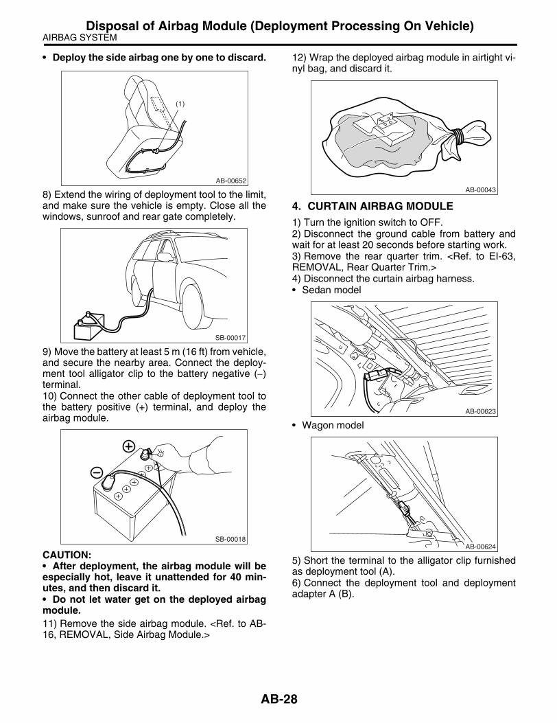
AIRBAG SYSTEMDisposal of Airbag Module (Deployment Processing On Vehicle)
• Deploy the side airbag one by one to discard.
8) Extend the wiring of deployment tool to the limit,and make sure the vehicle is empty. Close all thewindows, sunroof and rear gate completely.
9) Move the battery at least 5 m (16 ft) from vehicle,and secure the nearby area. Connect the deploy-ment tool alligator clip to the battery negative (−)terminal.10) Connect the other cable of deployment tool tothe battery positive (+) terminal, and deploy theairbag module.
CAUTION:• After deployment, the airbag module will beespecially hot, leave it unattended for 40 min-utes, and then discard it.• Do not let water get on the deployed airbagmodule.11) Remove the side airbag module. <Ref. to AB-16, REMOVAL, Side Airbag Module.>
12) Wrap the deployed airbag module in airtight vi-nyl bag, and discard it.
4. CURTAIN AIRBAG MODULE1) Turn the ignition switch to OFF.2) Disconnect the ground cable from battery andwait for at least 20 seconds before starting work.3) Remove the rear quarter trim. <Ref. to EI-63,REMOVAL, Rear Quarter Trim.>4) Disconnect the curtain airbag harness.• Sedan model
• Wagon model
5) Short the terminal to the alligator clip furnishedas deployment tool (A).6) Connect the deployment tool and deploymentadapter A (B).
(1)
AB-00652
SB-00017
SB-00018
AB-00043
AB-00623
AB-00624
AB-28

AIRBAG SYSTEMDisposal of Airbag Module (Deployment Processing On Vehicle)
CAUTION:The deployment tool should be kept shorted terminals until just before deployment of airbag module.
7) Connect the deployment adapter A (1) to thecurtain airbag module connector (yellow).• Sedan model
• Wagon model
8) Extend the wiring of deployment tool to the limit,and make sure the vehicle is empty. Close all thewindows, sunroof and rear gate completely.
9) Move the battery at least 5 m (16 ft) from vehicle,and secure the nearby area. Connect the deploy-ment tool alligator clip to the battery negative (−)terminal.10) Connect the other cable of deployment tool tothe battery positive (+) terminal, and deploy theairbag module.
CAUTION:• After deployment, the airbag module will beespecially hot, leave it unattended for 40 min-utes, and then discard it.• Do not let water get on the deployed airbagmodule.11) Remove the curtain airbag module. <Ref. toAB-18, REMOVAL, Curtain Airbag Module.>12) Wrap the deployed airbag module in airtight vi-nyl bag, and discard it.
NOTE:Fold the airbag cloth three or four times as requiredand fasten it with string and seal it with vinyl bag.
(A) Deployment tool:(Tool number 98299PA030)
(B) Deployment adapter A:(Tool number 98299FC030)
SB-00016
AB-00653
(1)
AB-00654
(1)
SB-00017
SB-00018
AB-00655
AB-29

AIRBAG SYSTEM
Disposal of Airbag Module (Deployment Processing After Removal from Vehi-cle)
14.Disposal of Airbag Module (Deployment Processing Af-ter Removal from Vehicle)
A: PROCEDURECAUTION:• Do not discard an undeployed airbag modulebecause it may cause serious personal injurywhen accidentally deployed.• As a rule, airbag modules should be de-ployed while still installed in the vehicle. Do notremove the airbag modules unless necessary.• Deployment of airbag modules should bedone on a flat place free from any possible dan-ger. Avoid deploying outdoors during rainy orwindy weather.• Do not damage the airbag module or drop it.• Deploying an airbag module causes a highexplosive noise, be sure to warn people in thearea, and do not allow anyone within a 5 m (16ft) radius of the disposal site.• Some smoke will be emitted from deploymentof the airbag module. Therefore, it must be de-ployed in a well ventilated place with no smokedetector nearby.• Wear protective gloves, safety goggles andearplugs during this operation. Wash yourhands afterwards.• After deployment, the airbag module will beespecially hot, leave it unattended for 40 min-utes, and then discard it.• Do not let water get on the deployed airbagmodule.• Wrap the deployed airbag module in an air-tight vinyl bag, and discard it.• If circumstances do not permit the airbagmodule deployment, contact the SUBARU deal-er.
1. DRIVER’S AIRBAG MODULE 1) Turn the ignition switch to OFF.2) Disconnect the ground cable from battery andwait for at least 20 seconds before starting work.3) Remove the driver’s airbag module. <Ref. to AB-14, Driver’s Airbag Module.>
4) Install the removed bolts to airbag module.
5) Bundle three automotive wire harnesses [eachwith a sectional area of 1.25 mm2 (0.00194 sq in) ormore], and bind them twofold around airbag mod-ule stay.
6) Short the terminal to the alligator clip furnishedas deployment tool (A).7) Connect the deployment tool and deploymentadapter X (B).
CAUTION:The deployment tool should be kept shorted terminals until just before deployment of airbag module.
8) Connect the deployment adapter X connector toairbag module.
(A) Deployment tool:(Tool number 98299PA030)
(B) Deployment adapter X:(Tool number 98299AG030)
AB-00047
AB-00048
AB-00715
(A)
(B)
AB-30

AIRBAG SYSTEM
Disposal of Airbag Module (Deployment Processing After Removal from Vehi-cle)
9) Install the airbag module with pad side facing up-ward on a wheel with tire.
10) Put three tires without wheels on the tire in-stalled with the airbag module. Put on an additionaltire with a wheel, and then fasten them tight with arope.
11) Move the battery at least 5 m (16 ft) from tires,and secure the nearby area. Connect the deploy-ment tool alligator clip to the battery negative (−)terminal.
12) Connect the other cable of deployment tool tothe battery positive (+) terminal, and deploy theairbag module.
CAUTION:• After deployment, the airbag module will beespecially hot, leave it unattended for 40 min-utes, and then discard it.• Do not let water get on the deployed airbagmodule.13) Wrap the deployed airbag module in airtight vi-nyl bag, and discard it.
2. PASSENGER’S AIRBAG MODULE 1) Turn the ignition switch to OFF.2) Disconnect the ground cable from battery andwait for at least 20 seconds before starting work.3) Remove the instrument panel assembly. <Ref.to EI-56, REMOVAL, Instrument Panel Assembly.>4) Remove the passenger airbag module. <Ref. toAB-15, Passenger’s Airbag Module.>
(1) 5 m (16 ft) or more
AB-00050
SB-00025
SB-00065
(1)
SB-00018
AB-00591
AB-31

AIRBAG SYSTEM
Disposal of Airbag Module (Deployment Processing After Removal from Vehi-cle)
5) Bundle three automotive wire harnesses [eachwith a sectional area of 1.25 mm2 (0.00194 sq in) ormore], route them through airbag module bracket(A). Then, twist them to add strength.
6) Short the terminal to the alligator clip furnishedas deployment tool (A).7) Connect the deployment tool and deploymentadapter E (B).
CAUTION:The deployment tool should be kept shorted terminals until just before deployment of airbag module.
8) Connect the deployment adapter E connector tothe airbag module.9) Install the airbag module with opening side fac-ing upward on a 14-inch or greater size wheel withtire.
10) Put three tires without wheels on the tire in-stalled with the airbag module. Put on an additionaltire with a wheel on top, and then fasten them tightwith a rope.
11) Move the battery at least 5 m (16 ft) from tires,and secure the nearby area. Connect the deploy-ment tool alligator clip to the battery negative (−)terminal.
12) Connect the other cable of deployment tool tothe battery positive (+) terminal, and deploy theairbag module.
CAUTION:• After deployment, the airbag module will beespecially hot, leave it unattended for 40 min-utes, and then discard it.• Do not let water get on the deployed airbagmodule.
(A) Deployment tool:(Tool number 98299PA030)
(B) Deployment adapter E:(Tool number 98299SA030)
AB-00723
(A)
SB-00016
AB-00052
(1) 5 m (16 ft) or more
SB-00025
SB-00065
(1)
SB-00018
AB-32

AIRBAG SYSTEM
Disposal of Airbag Module (Deployment Processing After Removal from Vehi-cle)
13) Wrap the deployed airbag module in airtight vi-nyl bag, and discard it.
3. SIDE AIRBAG MODULE1) Turn the ignition switch to OFF.2) Disconnect the ground cable from battery andwait for at least 20 seconds before starting work.3) Remove the front seats. <Ref. to SE-7, REMOV-AL, Front Seat.>4) Remove the side airbag module. <Ref. to AB-16,REMOVAL, Side Airbag Module.>5) Install the nuts (A) to airbag module, and thenbind them with bundled three automotive wire har-nesses [each with a sectional area of 1.25 mm2
(0.00194 sq in) or more].
6) Short the terminal to the alligator clip furnishedas deployment tool (A).7) Connect the deployment tool and deploymentadapter A (B).
CAUTION:The deployment tool should be kept shorted terminals until just before deployment of airbag module.
8) Connect the deployment adapter A connector toairbag module.9) Install the airbag module on a 14-inch or greatersize tire without wheel.
10) Put two tires without wheels (A) under the tireinstalled with the side airbag module (B). Put on anadditional tire without a wheel (C), and then put atire with a wheel (D) on top. Fasten them tight witha rope.
AB-00592
AB-00724
(A)
(A) Deployment tool:(Tool number 98299PA030)
(B) Deployment adapter A:(Tool number 98299FC030)
SB-00016
AB-00725
AB-00146
(A)
(B)
(C)
(D)
AB-33

AIRBAG SYSTEM
Disposal of Airbag Module (Deployment Processing After Removal from Vehi-cle)
11) Move the battery at least 5 m (16 ft) from tires,and secure the nearby area. Connect the deploy-ment tool alligator clip to the battery negative (−)terminal.
12) Connect the other cable of deployment tool tothe battery positive (+) terminal, and deploy theairbag module.
CAUTION:• After deployment, the airbag module will beespecially hot, leave it unattended for 40 min-utes, and discard it.• Do not let water get on the deployed airbagmodule.13) Wrap the deployed airbag module in airtight vi-nyl bag, and discard it.
4. CURTAIN AIRBAG MODULE1) Turn the ignition switch to OFF.2) Disconnect the ground cable from battery andwait for at least 20 seconds before starting work.
3) Remove the roof trim. <Ref. to EI-67, REMOV-AL, Roof Trim.>4) Remove the curtain airbag module. <Ref. to AB-18, REMOVAL, Curtain Airbag Module.>5) Extend the airbag cloth and cut off the airbag atthe position of 750 mm (29.5 in) (A) from inflatorend.
6) Bundle three automotive wire harnesses [eachwith a sectional area of 1.25 mm2 (0.00194 sq in) ormore], and then bind them through the holes inairbag module bracket.
7) Short the terminal to the alligator clip furnishedas deployment tool (A).8) Connect the deployment tool and deploymentadapter A (B).
(1) 5 m (16 ft) or more
SB-00065
(1)
SB-00018
AB-00043
AB-00656
A
AB-00657
AB-34

AIRBAG SYSTEM
Disposal of Airbag Module (Deployment Processing After Removal from Vehi-cle)
CAUTION:The deployment tool should be kept shorted terminals until just before deployment of airbag module.
9) Connect the deployment adapter A connector toairbag module.10) Install the airbag module on a 14-inch or great-er size tire without wheel.
11) Put a tire without a wheel (A) under the tire in-stalled with the curtain airbag module (B). Put ontwo additional tires without a wheels (C), and thenput a tire with a wheel (D) on top. Fasten them tightwith a rope.
12) Move the battery at least 5 m (16 ft) from tires,and secure the nearby area. Connect the deploy-ment tool alligator clip to the battery negative (−)terminal.
13) Connect the other cable of deployment tool tothe battery positive (+) terminal, and deploy theairbag module.
CAUTION:• After deployment, the airbag module will beespecially hot, leave it unattended for 40 min-utes, and discard it.• Do not let water get on the deployed airbagmodule.14) Wrap the deployed airbag module in airtight vi-nyl bag, and discard it.
(A) Deployment tool:(Tool number 98299PA030)
(B) Deployment adapter A:(Tool number 98299FC030)
SB-00016
AB-00658
AB-00659
(A)
(B)
(C)
(D)
(1) 5 m (16 ft) or more
SB-00065
(1)
SB-00018
AB-00655
AB-35

AIRBAG SYSTEM
Disposal of Airbag Module (Deployment Processing After Removal from Vehi-cle)
AB-36

AIRBAG SYSTEM (DIAGNOSTICS)
AB(diag)
Page1. Basic Diagnostic Procedure ........................................................................22. Check List for Interview...............................................................................33. General Description ....................................................................................44. Electrical Component Location .................................................................185. Airbag Control Module I/O Signal..............................................................226. Airbag Connector ......................................................................................267. Airbag Warning Light Illumination Pattern.................................................298. Read Diagnostic Trouble Code (DTC) ......................................................309. Inspection Mode........................................................................................31
10. Clear Memory Mode..................................................................................3211. Airbag Warning Light Failure.....................................................................3312. List of Diagnostic Trouble Code (DTC) .....................................................3713. Diagnostic Chart with Trouble Code .........................................................41

AIRBAG SYSTEM (DIAGNOSTICS)Basic Diagnostic Procedure
1. Basic Diagnostic ProcedureA: PROCEDURE
Step Check Yes No1 READ DTC.
<Ref. to AB(diag)-30, Read Diagnostic Trouble Code (DTC).>
Is the normal code detected? Finish the diagno-sis.
Go to step 2.
2 READ DTC.<Ref. to AB(diag)-30, Read Diagnostic Trouble Code (DTC).>
Is DTC displayed? Go to step 3. Go to “Airbag Warning Light Fail-ure”. <Ref. to AB(diag)-33, Air-bag Warning Light Failure.>
3 PERFORM DIAGNOSIS.1) Judge the possible cause from “List of Diagnostic Trouble Code” <Ref. to AB(diag)-37, List of Diagnostic Trouble Code (DTC).>.2) Inspect the DTC using “List of Diagnostic Trouble Code (DTC)”.3) Repair the trouble cause.4) Perform the clear memory mode. <Ref. to AB(diag)-32, Clear Memory Mode.>5) Perform the inspection mode. <Ref. to AB(diag)-31, Inspection Mode.>6) Read any DTC again.
Is DTC displayed? Perform the proce-dure 1) to 5) in step 3.
Finish the diagno-sis.
AB(diag)-2
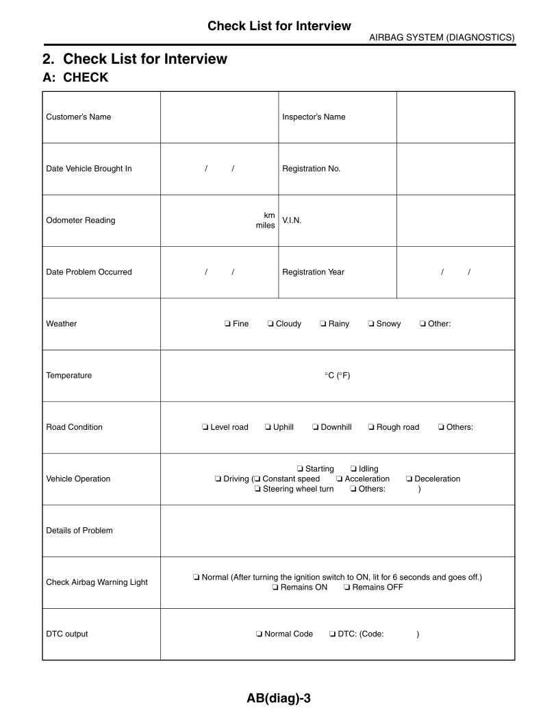
AIRBAG SYSTEM (DIAGNOSTICS)Check List for Interview
2. Check List for InterviewA: CHECK
Customer’s Name Inspector’s Name
Date Vehicle Brought In / / Registration No.
Odometer Readingkm
milesV.I.N.
Date Problem Occurred / / Registration Year / /
Weather Fine Cloudy Rainy Snowy Other:
Temperature °C (°F)
Road Condition Level road Uphill Downhill Rough road Others:
Vehicle Operation Starting Idling
Driving ( Constant speed Acceleration Deceleration Steering wheel turn Others: )
Details of Problem
Check Airbag Warning Light Normal (After turning the ignition switch to ON, lit for 6 seconds and goes off.)
Remains ON Remains OFF
DTC output Normal Code DTC: (Code: )
AB(diag)-3

AIRBAG SYSTEM (DIAGNOSTICS)General Description
3. General DescriptionA: CAUTION• When servicing a vehicle, be sure to turn the ig-nition switch to OFF, disconnect the ground cablefrom battery, and wait for more than 20 secondsbefore starting work.• The airbag system is equipped with a backuppower source. If the airbag system is serviced with-in 20 seconds from the ground cable is disconnect-ed, it may inflate.
• If sensors, airbag module, airbag control module,pretensioner and harness are deformed or dam-aged, replace them with new parts.
• Do not use the airbag system and pretensionerson other vehicles. When replacing parts, be sure toreplace them with new ones.• When checking the airbag system, be sure touse a digital circuit tester. Use of an analog circuittester may cause the airbag to activate erroneous-ly.
• When checking, use a test harness (1). Do notdirectly apply the tester probe to any connector ter-minal of the airbag.
• Do not drop the airbag module, subject them tohigh temperature over 93°C (199°F), or let water,oil or grease get on them; the internal parts may bedamaged and reliability is greatly lowered.
IN-00203
AB-00120
AB-00121
AB-00122
(1)
AB-00123
AB(diag)-4

AIRBAG SYSTEM (DIAGNOSTICS)General Description
• If any damage, opening or rust is found on theairbag system wire harness, do not attempt to re-pair using soldering equipment. Be sure to replacethe faulty harness with a new genuine part.
• Install the wire harness securely with the speci-fied clips to avoid interference or tangled up withother parts.
• Do not allow water or oil to come in contact withthe connector terminals. Do not touch the connec-tor terminals.
• Either of the airbag modules for driver, passen-ger, side or curtain, or pretensioner must not bedisassembled.
• The airbag module cannot be used again if oncedeployed.
• After removal, keep the airbag module with thepad facing upward on a dry, clean and flat surfaceaway from heat, light sources, moisture and dust.
• Do not check continuity of either of the airbagmodules for driver, passenger, side or curtain, orpretensioner.
AB-00124
AB-00125
AB-00126
AB-00127
AB-00056
AB-00006
AB(diag)-5

AIRBAG SYSTEM (DIAGNOSTICS)General Description
• The removed front seat with an airbag modulemust be kept at least 200 mm (8 in) away from wallsand other objects.
• When painting or performing sheet metal workon the front part of the vehicle, including the frontwheel apron, front fender and front side frame, re-move the front sub sensors and wire harness of theairbag system.• When painting or performing sheet metal workon the side of the vehicle, including the side sill,center pillar and front and rear doors, remove theside airbag sensors and wire harness of the airbagsystem.
• Do not discard undeployed airbag modules.They could easily cause a serious accident if acci-dentally deployed.
(1) 200 mm (8 in) or more
AB-00128
(1)
AB-00129
AB(diag)-6

AIRBAG SYSTEM (DIAGNOSTICS)General Description
• When storing a removed airbag module, do not place any objects on it or pile airbag modules on top ofeach other. If the airbag inflates for some reason when it is placed with its pad side facing downward or underany object, a serious accident may result.
(1) Driver’s airbag module (2) Passenger’s airbag module
AB-00130
(2)
(1)
AB(diag)-7

AIRBAG SYSTEM (DIAGNOSTICS)General Description
B: INSPECTIONMeasure the battery voltage and check electrolyte.
Standard voltage: 12 V
Specific gravity: Above 1.260
C: PREPARATION TOOLCAUTION:To check the voltage and resistance of airbag system component, be sure to use the specified test harness.
1. SPECIAL TOOL• TEST HARNESS F
ILLUSTRATION TOOL NUMBER DESCRIPTION REMARKS
98299FC010 TEST HARNESS F Used when measuring voltage and resistance of airbag module harnesses.
3F 2F
1F
ST98299FC010
AB-00719
3F
3F 2F 1F
2F
1F
3
4
6
5 1
1
2
2
13 4 5 6
2 1 2 2 1
AB(diag)-8

AIRBAG SYSTEM (DIAGNOSTICS)General Description
• TEST HARNESS H
ILLUSTRATION TOOL NUMBER DESCRIPTION REMARKS
98299FA030 TEST HARNESS H Used when measuring voltage and resistance of front sub-sensor.
3H
2H
1H
ST98299FA030
AB-00720
3H
3H 2H 1H
2H
1H
4
3
6
5
13 4 5 6
2
1
1
2
2
21 2 1
AB(diag)-9

AIRBAG SYSTEM (DIAGNOSTICS)General Description
• TEST HARNESS R
ILLUSTRATION TOOL NUMBER DESCRIPTION REMARKS
98299FE030 TEST HARNESS R Used when measuring voltage and resistance of airbag control module.
1R2R
3R 4R
5R
6R
ST98299FE030
AB-00606
52
1 2 3 4 5 6 7 8 9 10 11 12 13 14 15 16 17 18
1 2
1 2 3 4 5 6 7 8 9 10 11 12 13 14
123456789
1011121314151617181920
504947121097
851
4811163534363024434443
3727213832464245413314315162
1913
293940202815172325222618
1 2
1 2 3 4 5 67 8 9 10 11 12 13 14
2 3 4 5 6 7 8 911 12 13 14 17 18 19 20
110 15 16123456
789101112
13141516171819202122232425262728293031323334353637383940
414243444546474849505152
6R
2R
3R
4R
5R
1R
1 2 3 89 10
411 12 13 14 15 16
5 6 717 18
1 22 1
5R2R 6R1R
4R 3R
AB(diag)-10

AIRBAG SYSTEM (DIAGNOSTICS)General Description
• TEST HARNESS N
ILLUSTRATION TOOL NUMBER DESCRIPTION REMARKS
98299SA000 TEST HARNESS N Used when measuring voltage and resistance of driver’s airbag module and seat belt preten-sioner.
2N
1N
ST98299SA000
AB-00675
2N 1N
1
2
1
2
1 22 1
1N
2N
AB(diag)-11

AIRBAG SYSTEM (DIAGNOSTICS)General Description
• TEST HARNESS P
ILLUSTRATION TOOL NUMBER DESCRIPTION REMARKS
98299SA020 TEST HARNESS P Used when measuring voltage and resistance of driver’s airbag module harness and passenger airbag module harness.
ST98299SA020
1P
2P
3P
AB-00679
1P 2P
3P
4
1 2
4 3
3
2
1
4
1 2
3 4
3 12
AB(diag)-12

AIRBAG SYSTEM (DIAGNOSTICS)General Description
• TEST HARNESS Q
ILLUSTRATION TOOL NUMBER DESCRIPTION REMARKS
98299SA040 TEST HARNESS Q Used when measuring voltage and resistance of driver’s airbag module.
2Q
1Q
ST98299SA040
AB-00678
2Q 1Q
1
2
1
2
1 22 1
1Q
2Q
AB(diag)-13

AIRBAG SYSTEM (DIAGNOSTICS)General Description
• TEST HARNESS U
ILLUSTRATION TOOL NUMBER DESCRIPTION REMARKS
98299AG000 TEST HARNESS U Used when measuring voltage and resistance of airbag control module.
ST98299AG000
1U2U4U 3U
8U
9U
6U7U
5U
AB(diag)-14

AIRBAG SYSTEM (DIAGNOSTICS)General Description
AB-00676
1 2 3 4 5 67 8 9 10 11 12 13 14
2 3 4 5 6 7 8 911 12 13 14 17 18 19 20
110 15 16
1234567891011121314151617181920
21222324252627282930313233343536373839404142434445464748
1 2 3 89 10
411 12 13 14 15 16
5 6 717 18
6U
8U
7U
9U
2U
2U1U
4U 5U 6U 7U 8U 9U
3U
5U
1U
3U
4U
58 57 56 55 54 53596061626364
49505152
65666768
1 2 3 4 5 6 7 89 10 11 12 13 14 15 16
123456
26 5 4 3
1 1 213 4 5 6
2
1
2
3
4
5
6
7
8
9
10
11
12
13
14
15
16
17
18
19
20
1
686566641715161367145032443424438325245352946405854575341223911595560569201842127374748283623253133303426 51064963616219 78 12 1512
2
3
4
5
6
7
8
9
10
11
12
13
14
15
16
12345678910111213141516
17
18
1
2
3
4
5
6
1
2
3
4
5
6
1
2
1
2
3
4
5
6
1
2
3
4
5
6
7
8
9
10
11
12
13
14
AB(diag)-15

AIRBAG SYSTEM (DIAGNOSTICS)General Description
• TEST HARNESS V
ILLUSTRATION TOOL NUMBER DESCRIPTION REMARKS
98299AG010 TEST HARNESS V Used when measuring voltage and resistance of side airbag sensor and curtain airbag sensor.
ST98299AG010
1V3V
2V
AB-00677
3V
2V
1V
3V
8
5
1
4
2
3
7
6
3
4
1
2
2
1
4
3
1 2 34 5 6 7 8 4 3 2 1
2V
1 2 3 4
1V
AB(diag)-16

AIRBAG SYSTEM (DIAGNOSTICS)General Description
• AIRBAG RESISTOR
ILLUSTRATION TOOL NUMBER DESCRIPTION REMARKS
98299PA040 AIRBAG RESISTOR Used in replacement of airbag module for which resistance value is same as airbag module.
ST98299PA040
AB-00433
3
1
2
1212
13456
2
4
3
AB(diag)-17

AIRBAG SYSTEM (DIAGNOSTICS)Electrical Component Location
4. Electrical Component LocationA: LOCATION1. LHD MODEL
(1) Front sub-sensor (RH) (7) Driver’s airbag inflator (13) Curtain airbag sensor (RH)
(2) Front sub-sensor (LH) (8) Airbag rear harness (14) Curtain airbag sensor (LH)
(3) Airbag control module with built-in safing and electric sensor
(9) Side airbag sensor (RH) (15) Side airbag inflator (RH)
(10) Side airbag sensor (LH) (16) Side airbag inflator (LH)
(4) Airbag main harness (11) Seat belt pretensioner (RH) (17) Curtain airbag inflator (RH)
(5) Roll connector (12) Seat belt pretensioner (LH) (18) Curtain airbag inflator (LH)
(6) Passenger’s airbag inflator
AB-00777
(1)
(2)
(3)
(7)(10) (12)
(14)
(15)
(16)
(17)
(18)
(8)(9) (11) (13)
(5)
(6)
(4)
AB13
AB37
AB38AB18
AB17
AB10
AB23
AB25
AB20
AB19
AB23 AB21AB32
AB39
AB31
AB40
AB33
AB24
AB26 AB34
AB2
AB7
B31
AB1
AB9
AB6
AB16
AB(diag)-18

AIRBAG SYSTEM (DIAGNOSTICS)Electrical Component Location
Connector No.
(AB1) (AB2) (AB7) (AB9) (AB10) (AB13) (AB16) (AB17) (AB18) (AB19) (AB20) (AB21)
Pin 6 4 4 4 4 2 2 20 20 2 2 2
Color Yellow Yellow Yellow Yellow Yellow Yellow Yellow Yellow Yellow Yellow Yellow Black
Male/Female Female Female Male Female Male Female Female Male Male Female Male Female
Connector No.
(AB23) (AB24) (AB25) (AB26) (AB28) (AB31) (AB32) (AB33) (AB34) (AB37) (AB38) (AB39)
Pin 4 2 2 2 4 2 4 2 4 2 2 2
Color Yellow Yellow Yellow Black Yellow Yellow Yellow Yellow Yellow Orange Black Yellow
Male/Female Female Female Male Female Female Female Female Female Female Female Female Male
Connector No.
(AB40)
Pin 2
Color Yellow
Male/Female Male
AB(diag)-19

AIRBAG SYSTEM (DIAGNOSTICS)Electrical Component Location
2. RHD MODEL
(1) Front sub-sensor (LH) (7) Driver’s airbag inflator (13) Curtain airbag sensor (LH)
(2) Front sub-sensor (RH) (8) Airbag rear harness (14) Curtain airbag sensor (RH)
(3) Airbag control module with built-in safing and electric sensor
(9) Side airbag sensor (LH) (15) Side airbag inflator (LH)
(10) Side airbag sensor (RH) (16) Side airbag inflator (RH)
(4) Airbag main harness (11) Seat belt pretensioner (LH) (17) Curtain airbag inflator (LH)
(5) Roll connector (12) Seat belt pretensioner (RH) (18) Curtain airbag inflator (RH)
(6) Passenger’s airbag inflator
AB-00680
(1)
(2)
(3)
(7)(10) (12) (14)
(15)
(16)
(17)
(18)
(8)(9) (11) (13)
(5)
(6)
(4)
AB16 AB37
AB38AB18
AB17
AB10
AB23
AB20
AB25
AB24
AB28 AB26 AB34
AB40
AB33
AB39
AB31
AB19
AB21AB32
AB2
AB7
B31
AB1
AB9
AB6
AB13
AB(diag)-20

AIRBAG SYSTEM (DIAGNOSTICS)Electrical Component Location
Connector No.
(AB1) (AB2) (AB7) (AB9) (AB10) (AB13) (AB16) (AB17) (AB18) (AB19) (AB20) (AB21)
Pin 6 4 4 4 4 2 2 20 20 2 2 2
Color Yellow Yellow Yellow Yellow Yellow Yellow Yellow Yellow Yellow Yellow Yellow Black
Male/Female Female Female Male Female Male Female Female Male Male Female Male Female
Connector No.
(AB23) (AB24) (AB25) (AB26) (AB28) (AB31) (AB32) (AB33) (AB34) (AB37) (AB38) (AB39)
Pin 4 2 2 2 4 2 4 2 4 2 2 2
Color Yellow Yellow Yellow Black Yellow Yellow Yellow Yellow Yellow Orange Black Yellow
Male/Female Female Female Male Female Female Female Female Female Female Female Female Male
Connector No.
(AB40)
Pin 2
Color Yellow
Male/Female Male
AB(diag)-21

AIRBAG SYSTEM (DIAGNOSTICS)Airbag Control Module I/O Signal
5. Airbag Control Module I/O SignalA: WIRING DIAGRAM
AB-00769
E
FB-36
(IG)
FB-41
(IG)
FB-39
(IG)
B79i1 B36
B82
B81
AB1 AB6 i1
B31
AB1
AB6
R
6
3
14
A3 BrW
GY
FB-32
(IG)
GY
BrW
5 3 19 2
R
R
RB
GY 7
2
Lg
2
3R
RB
BY
BY
LgLgA13
6
A: i10
A: i10B79
1 23 4 5 6
RB
GY R Lg
TO POWER SUPPLY ROUTING
COMBINATIONMETER
CHECKCONNECTOR
DIAGNOSISCONNECTOR
GROUNDTERMINAL
AIRBAG CONTROL MODULE
(YELLOW) (GREEN)(GRAY)(YELLOW)
F/B FUSE NO.5 F/B FUSE NO.25 F/B FUSE NO.12 F/B FUSE NO.4
BrWA4AIRBAG
WARNING LIGHT
1 2 3 45 6 7 8 9 10
1611 1514131217 191823 2524
20 222126 2827
21 3 4 6 7 8 9 10222120191817161514131211
5
B82
1 2 34 5 6 7 8
1 2 3 4 5 67 8 9 10 11 12 13 14 15 16 17
18 19 20 21 22 23 24 25 26 27 28
2 310
18 9
4 512
6 71411 13
NOT CIRCUIT
1 3 456L
HD
LH
D
Lg RRBRGY
RHD
RHD
*
LHD: BY
RHD: B
*
AB(diag)-22

AIRBAG SYSTEM (DIAGNOSTICS)Airbag Control Module I/O Signal
AB-00770
AB9
AB6 AB38AB2 AB13
AB16
AB13
AB6
E
BW
BW
212
61
5
AB16
AB9
AB10
GAB-1
E
GAB-2
1 2
GWW
20 9
78 28 27
YG
YL
YW
L
21
1 2
AB38
1 2
(YELLOW)
AIRBAG CONTROL MODULE
INFLATOR (PASSENGER SIDE)
(YELLOW)
FRONT SUB SENSOR LH FRONT SUB SENSOR RH
G
L Br
L Br
BB
YL
YB
YYB
YW
4
YG
YB
YL
231
01
1
1Y
WY
GY
BY
L
AB37
1 2
YLLYYB
(YELLOW)
1 2 3 4 5 67 8 9 10 11 12 13 14 15 16 17
18 19 20 21 22 23 24 25 26 27 281 2 3 4
17
16
13
14
AB2
AB7
AB38
11
21 2
23 4
STEERINGROLLCONNECTOR
INFLATOR(DRIVER SIDE)
AB37
AB(diag)-23

AIRBAG SYSTEM (DIAGNOSTICS)Airbag Control Module I/O Signal
:
:
WC
OC
WITH CURTAIN AIRBAG
WITHOUT CURTAIN AIRBAG
11 12
5 6
AB26
PRETENSIONER RH
1 2 Y
R Y
R Y
L Y
L
WC
OC
AB18
AB34 AB33
AB40
13
16
17 8 7 5 6
RG
15 4 18
19
20
CURTAINAIRBAG
SENSOR RH
1 2 3 4
INFLATOR(CURTAIN RH)
1 2
AB28 AB24
AB25
SIDE AIRBAGSENSOR RH
1 2 3 4 1 2
RB
RW
RL
RG
RB
YG
YB
W L G B
RG
RB
RW
RL
RG
RB
YG
YB
W L G B
AB-00771
AIRBAG CONTROL MODULE
INFLATOR(SIDE RH)
WCOCAB28 AB18 AB18AB26
1 2 3 45 6 7 8 9 10 11 12
13 14 15 16 17 18 19 20
1 2 AB34
AB24
AB33
1 2 3 4 1 21 2 3 4 5 6
7 8 9 10 11 12
(YELLOW)(YELLOW)(YELLOW)
(YELLOW)
(YELLOW)
(YELLOW)
(YELLOW)
7 9 12
10 2 1
AB(diag)-24

AIRBAG SYSTEM (DIAGNOSTICS)Airbag Control Module I/O Signal
AB17
AB32 AB31
AB39
20
17
16 9 10 12
11
RG
18 1 15
14
13
WCOC
CURTAINAIRBAG
SENSOR LH
1 2 3 4
INFLATOR(CURTAIN LH)
1 2AB23 AB19
AB20
SIDE AIRBAGSENSOR LH
1 2 3 4 1 2
RB
RW
RL
RG
RB
YG
YB
W L G B
RG
RB
RW
RL
RG
RB
YG
YB
W L G B
AB23 AB17 AB17AB21
1 2 3 45 6 7 8 9 10 11 12
13 14 15 16 17 18 19 20
1 2 AB32
AB19
AB31
1 2 3 4 1 21 2 3 4 5 6
7 8 9 10 11 12
AB-00772
AIRBAG CONTROL MODULE
INFLATOR(SIDE LH)
(YELLOW)(YELLOW)(YELLOW)
(YELLOW)
(YELLOW)
(YELLOW)
(YELLOW)
:
:
WC
OC
WITH CURTAIN AIRBAG
WITHOUT CURTAIN AIRBAG
6 52 1
AB21
PRETENSIONER LH
1 2 Y
R Y
R Y
L Y
L
WC
OC 12
10 79 5 6
AB(diag)-25

AIRBAG SYSTEM (DIAGNOSTICS)Airbag Connector
6. Airbag ConnectorA: PROCEDURE1. POWER SUPPLY1) How to disconnect:
(1) Move the slide lock (A) in the direction of ar-row.(2) With the slide lock (A) moved, separate theconnector.
CAUTION:When pulling the slide lock or disconnecting the connector, be sure to hold onto the connec-tor and not the wire.2) How to connect:Holding the connector (A), and push it in carefullyuntil a connecting sound is heard.
CAUTION:Be sure to insert the connector in until it locks. Then pull on it gently to make sure that it is locked.
2. DRIVER’S AIRBAG MODULE AND PRE-TENSIONER1) How to disconnect:
(1) Using a flat tip screwdriver, pry the pushlock upward to unlock.
(2) Pull the connector to disconnect from driv-er’s side airbag module assembly or retractorassembly.
2) How to connect:Connect the connector in the reverse order of dis-connecting. At this time, be sure to insert the pushlock until a connecting sound is heard.
CAUTION:• Be sure to insert the connector in until itlocks. Then pull it gently to make sure that it islocked.• Be sure to push the push lock in securely.
NOTE:Connector can not be connected when the pushlock is in lock position. To connect the connector,set the push lock to unlock.
AB-00721
(A)
AB-00016
AB-00478
AB-00479
AB-00480
AB(diag)-26
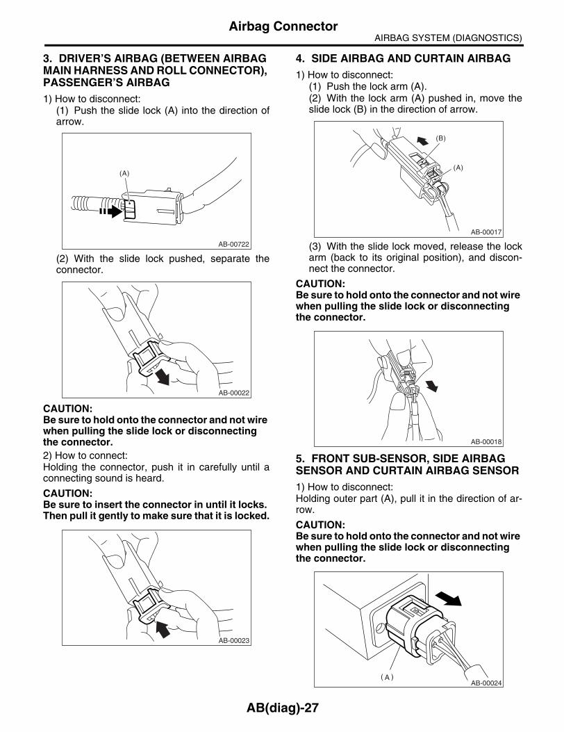
AIRBAG SYSTEM (DIAGNOSTICS)Airbag Connector
3. DRIVER’S AIRBAG (BETWEEN AIRBAG MAIN HARNESS AND ROLL CONNECTOR), PASSENGER’S AIRBAG1) How to disconnect:
(1) Push the slide lock (A) into the direction ofarrow.
(2) With the slide lock pushed, separate theconnector.
CAUTION:Be sure to hold onto the connector and not wire when pulling the slide lock or disconnecting the connector.2) How to connect:Holding the connector, push it in carefully until aconnecting sound is heard.
CAUTION:Be sure to insert the connector in until it locks. Then pull it gently to make sure that it is locked.
4. SIDE AIRBAG AND CURTAIN AIRBAG1) How to disconnect:
(1) Push the lock arm (A).(2) With the lock arm (A) pushed in, move theslide lock (B) in the direction of arrow.
(3) With the slide lock moved, release the lockarm (back to its original position), and discon-nect the connector.
CAUTION:Be sure to hold onto the connector and not wire when pulling the slide lock or disconnecting the connector.
5. FRONT SUB-SENSOR, SIDE AIRBAG SENSOR AND CURTAIN AIRBAG SENSOR1) How to disconnect:Holding outer part (A), pull it in the direction of ar-row.
CAUTION:Be sure to hold onto the connector and not wire when pulling the slide lock or disconnecting the connector.
AB-00722
(A)
AB-00022
AB-00023
AB-00017
(A)
(B)
AB-00018
AB-00024
AB(diag)-27

AIRBAG SYSTEM (DIAGNOSTICS)Airbag Connector
2) How to connect:Holding the connector, and push it in carefully untila connecting sound is heard.
CAUTION:• Outer side (A) move back, and so do not putyour hand on the outer part.• Be sure to insert the connector in until itlocks. Then pull it gently to make sure that it islocked.
AB-00025
AB(diag)-28

AIRBAG SYSTEM (DIAGNOSTICS)Airbag Warning Light Illumination Pattern
7. Airbag Warning Light Illumi-nation Pattern
A: INSPECTIONKeep the ignition switch ON, and confirm that theairbag warning light remains off approx. 6 secondsafter being turned on.
(1) Airbag warning light
(2) Approx. 6 sec.
(3) Ignition switch (ON)
AB-00135
(1)
(2)
(3)
OFF
ON
AB(diag)-29

AIRBAG SYSTEM (DIAGNOSTICS)Read Diagnostic Trouble Code (DTC)
8. Read Diagnostic Trouble Code (DTC)
A: OPERATION1) Remove the instrument panel lower cover upper.<Ref. to EI-50, REMOVAL, Instrument Panel Low-er Cover.>2) Turn the ignition switch to ON.3) Connect one of the ground terminals to the diag-nosis connector terminal No. 2 in the instrumentpanel lower cover area.
NOTE:The harness (yellow/black) of ground terminal iswrapped by tapes with the harness (red, red/black)of diagnosis connector.4) Read the DTC by identifying the way airbagwarning light blinks.The airbag warning light blinks a DTC correspond-ing to the faulty parts.The long segment (1.2 sec. on) indicates a “ten”,and the short segment (0.3 sec. on) indicates a“one”.
NOTE:• “List of Diagnostic Trouble Code (DTC)” <Ref. toAB(diag)-37, List of Diagnostic Trouble Code(DTC).>• “Airbag Warning Light Failure” <Ref. to AB(diag)-33, Airbag Warning Light Failure.>.
5) Turn the ignition switch to OFF, and disconnectthe ground terminal from diagnosis connector ter-minal No. 2.6) Wind the tape around the ground terminal andreturn it to its original position.
AB-00778876532
41
B82
(1) For example (3) Blinking code 21: (5) Sec.
(2) Blinking code 12: (4) Blinking normal code:
(2)
(1)
(3)
(4)
ON
OFF
ON
OFF
ON
OFF
(5)
(5)
(5)
10
1.2
10 10 10 10
1
1 1
1 10 11
1.2 1.2
0.60.6
0.30.3 0.3 1.2
0.3 0.3 1.20.30.3
AB-00137
AB(diag)-30

AIRBAG SYSTEM (DIAGNOSTICS)Inspection Mode
9. Inspection ModeA: PROCEDURERecreate the circumstance by referring to the con-ditions described in the checklist.
AB(diag)-31
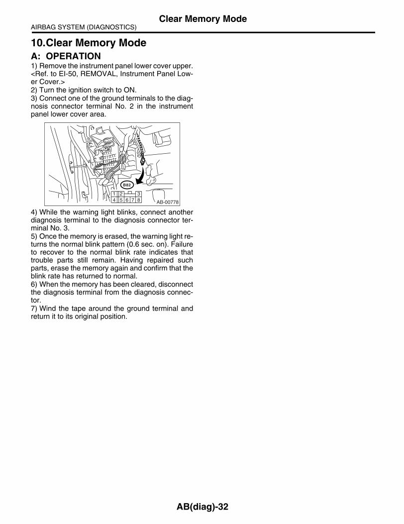
AIRBAG SYSTEM (DIAGNOSTICS)Clear Memory Mode
10.Clear Memory ModeA: OPERATION1) Remove the instrument panel lower cover upper.<Ref. to EI-50, REMOVAL, Instrument Panel Low-er Cover.>2) Turn the ignition switch to ON.3) Connect one of the ground terminals to the diag-nosis connector terminal No. 2 in the instrumentpanel lower cover area.
4) While the warning light blinks, connect anotherdiagnosis terminal to the diagnosis connector ter-minal No. 3.5) Once the memory is erased, the warning light re-turns the normal blink pattern (0.6 sec. on). Failureto recover to the normal blink rate indicates thattrouble parts still remain. Having repaired suchparts, erase the memory again and confirm that theblink rate has returned to normal.6) When the memory has been cleared, disconnectthe diagnosis terminal from the diagnosis connec-tor.7) Wind the tape around the ground terminal andreturn it to its original position.
AB-00778876532
41
B82
AB(diag)-32

AIRBAG SYSTEM (DIAGNOSTICS)Airbag Warning Light Failure
11.Airbag Warning Light FailureA: AIRBAG WARNING LIGHT REMAINS ONDETECTING CONDITION:• Airbag warning light failure• Airbag control module to airbag warning light circuit is shorted or open.• Grounding circuit is faulty.• Airbag control module is faulty.• (AB1) and (B31) are not connected properly.• (AB6) is not connected properly to airbag control module.
CAUTION:• Before diagnosing the airbag system, be sure to turn the ignition switch OFF, disconnect theground terminal from the battery, and wait more than 20 seconds before starting to work.• Before replacing the airbag module, seat belt pretensioner, roll connector, control module andsensor, reconnect each part and confirm that the warning light operates properly.• When inspecting the airbag main harness, disconnect the airbag module connector of the driver’sand passenger’s seats for safety reasons.WIRING DIAGRAM:
AB6
B31
AB1
No.5
3
A13
A3
A4
AB6
i10
3 41 2
5 6
AB1 i10
B36 i1
i1
1
14
AB-00661
IGNITIONSWITCH
AIRBAGINDICATOR
LIGHT
AIRBAGCIRCUIT
BA
TT
ER
Y
AIRBAG CONTROL MODULE
1 2 3 45 6 7 8 9 10
1611 1514131217 191823 2524
20 222126 2827
21 3 4 6 7 8 9 10222120191817161514131211
51 2 3 4 5 67 8 9 10 11 12 13 14 15 16 17
18 19 20 21 22 23 24 25 26 27 28
AB(diag)-33

AIRBAG SYSTEM (DIAGNOSTICS)Airbag Warning Light Failure
Step Check Yes No1 CHECK POOR CONTACT.
1) Turn the ignition switch OFF, disconnect the battery ground terminal, and wait more than 20 seconds.2) Confirm that the firm contact is secured between the airbag control module and con-nector (AB6). <Ref. to AB-20, Airbag Control Module.>
Is there poor contact in con-nector (AB6)?
Replace the airbag main harness with body harness or replace the airbag control module. <Ref. to AB-20, Airbag Control Module.>
Go to step 2.
2 CHECK AIRBAG MAIN HARNESS.1) Remove the instrument panel lower cover and disconnect the connector (AB7) and (AB2).2) Remove the instrument panel side cover of passenger side and disconnect the connector (AB10) and (AB9).3) Disconnect the connector (AB6) from air-bag control module, and connect the connector (1U) in the test harness U. <Ref. to AB-20, Air-bag Control Module.>4) Connect the battery ground terminal and turn the ignition switch ON.5) Connect the connectors (7U) and (8U) in the test harness U.
NOTE:After problem has been eliminated, disconnectthe connectors (7U) and (8U).
Does the airbag warning light go off?
Go to step 3. Go to step 4.
3 CHECK GROUND CIRCUIT.1) Turn the ignition switch OFF, disconnect the battery ground terminal, and wait more than 20 seconds.2) Disconnect the connector (AB6) from air-bag control module.3) Connect the connector (1U) in the test har-ness U to body harness connector (AB6).4) Measure the resistance between connector (2U) in the test harness U and chassis ground.
Connector & terminal(2U) No. 10 — Chassis ground:(2U) No. 11 — Chassis ground:
Is the resistance less than 10 Ω?
Replace the airbag control module. <Ref. to AB-20, Airbag Control Module.>
Repair the chas-sis ground circuit.
4 CHECK AIRBAG MAIN HARNESS AND BODY HARNESS.1) Disconnect the connector (7U) and (8U).2) Remove the combination meter.3) Measure the resistance between connector (i10) and connector (2U) in the test harness U.
Connector & terminal(2U) No. 7 — (i10) No. 13:
Is the resistance less than 10 Ω?
Replace the com-bination meter printed circuit. <Ref. to IDI-16, Combination Meter Assembly.>
Go to step 5.
5 CHECK POOR CONTACT IN CONNECTORS (AB1) AND (B31).1) Turn the ignition switch OFF, disconnect the battery ground terminal, and wait more than 20 seconds.2) Confirm that firm contact is secured between connectors (AB1) and (B31).
Is there poor contact in con-nectors (AB1) and (B31)?
Repair the body harness or replace the airbag main harness with body harness.
Go to step 6.
6 CHECK AIRBAG MAIN HARNESS.Check the airbag main harness for abnormali-ties.
Is anything unusual to airbag main harness?
Replace the airbag main harness with body harness.
Repair the body harness.
AB(diag)-34

AIRBAG SYSTEM (DIAGNOSTICS)Airbag Warning Light Failure
B: AIRBAG WARNING LIGHT REMAINS OFFDETECTING CONDITION:• Fuse No. 5 (in fuse box) is blown.• Body harness circuit is open.• Airbag warning light is faulty.• Airbag main harness is faulty.• Airbag control module is faulty.
CAUTION:• Before diagnosing the airbag system, be sure to turn the ignition switch OFF, disconnect theground terminal from battery, and wait more than 20 seconds before starting to work.• Before replacing the airbag module, seat belt pretensioner, roll connector, control module andsensor, reconnect each part and confirm that the warning light operates properly.• When inspecting the airbag main harness, disconnect the airbag module connector of the driver’sand passenger’s seats for safety reasons.WIRING DIAGRAM:
AB6
B31
AB1
No.5
3
A13
A3
A4
AB6
i10
3 41 2
5 6
AB1 i10
B36 i1
i1
1
14
AB-00661
IGNITIONSWITCH
AIRBAGINDICATOR
LIGHT
AIRBAGCIRCUIT
BA
TT
ER
Y
AIRBAG CONTROL MODULE
1 2 3 45 6 7 8 9 10
1611 1514131217 191823 2524
20 222126 2827
21 3 4 6 7 8 9 10222120191817161514131211
51 2 3 4 5 67 8 9 10 11 12 13 14 15 16 17
18 19 20 21 22 23 24 25 26 27 28
AB(diag)-35

AIRBAG SYSTEM (DIAGNOSTICS)Airbag Warning Light Failure
Step Check Yes No1 CHECK COMBINATION METER.
Turn the ignition switch to ON, and confirm that warning lights equipped in the combination meter are turned on.
Do warning lights other than the airbag turn on?
Go to step 2. Repair the combi-nation meter power supply. <Ref. to IDI-3, Combination Meter System.>
2 CHECK FUSE NO. 5 (IN MAIN FUSE BOX). Remove the fuse No. 5 and perform visual inspection.
Is the fuse No. 5 (in main fuse box) blown out?
Replace the fuse No. 5. If the fuse No. 5 is blown again, go to step 3.
Go to step 3.
3 CHECK AIRBAG WARNING LIGHT CIRCUIT (IN COMBINATION METER).1) Turn the ignition switch OFF, disconnect the battery ground terminal, and wait more than 20 seconds.2) Disconnect the connector (AB1) from (B31).3) Connect the battery ground terminal and turn the ignition switch ON.
Does the airbag warning light turn on?
Go to step 4. Replace the airbag warning light bulb or combination meter printed cir-cuit. <Ref. to IDI-16, Combination Meter Assembly.>
4 CHECK AIRBAG MAIN HARNESS.1) Turn the ignition switch OFF, disconnect the battery ground terminal, and wait more than 20 seconds.2) Connect the connector (AB1) to (B31).3) Disconnect the connector (AB6) from air-bag control module. <Ref. to AB-20, Airbag Control Module.>4) Connect the battery ground terminal and turn the ignition switch ON.
Does the airbag warning light turn on?
Replace the airbag control module. <Ref. to AB-20, Airbag Control Module.>
Replace the airbag main harness with body harness.
AB(diag)-36

AIRBAG SYSTEM (DIAGNOSTICS)List of Diagnostic Trouble Code (DTC)
12.List of Diagnostic Trouble Code (DTC)A: LIST
DTCMemory func-
tionContent of diagnosis Reference
11 Experienced
• Airbag main harness circuit is open, shorted or shorted to ground.• Airbag module harness (Driver’s side) circuit is open, shorted or shorted to ground.• Roll connector circuit is open, shorted or shorted to ground.• Airbag control module is faulty.• Driver’s airbag module is faulty.
<Ref. to AB(diag)-41, DTC 11, Diagnostic Chart with Trouble Code.>
12 Experienced
• Airbag main harness circuit is open, shorted or shorted to ground.• Airbag module harness (Passenger’s side) circuit is open, shorted or shorted to ground.• Airbag control module is faulty.• Passenger’s airbag module is faulty.
<Ref. to AB(diag)-44, DTC 12, Diagnostic Chart with Trouble Code.>
15 Experienced
• Airbag main harness circuit (Driver’s side) is shorted to power supply.• Airbag module harness circuit (Driver’s side) is shorted to power supply.• Roll connector is shorted to the power supply.• Airbag control module is faulty.• Driver’s airbag module is faulty.
<Ref. to AB(diag)-46, DTC 15, Diagnostic Chart with Trouble Code.>
16 Experienced
• Airbag main harness circuit (Passenger’s side) is shorted to power supply.• Airbag module harness circuit (Passenger’s side) is shorted to power supply.• Airbag control module is faulty.• Passenger’s airbag module is faulty.
<Ref. to AB(diag)-48, DTC 16, Diagnostic Chart with Trouble Code.>
21 Experienced
Airbag control module is faulty. <Ref. to AB(diag)-49, DTC 21, Diagnostic Chart with Trouble Code.>
22 Experienced
Front airbag module and seat belt pretensioner (LH/RH) are deployed.
<Ref. to AB(diag)-50, DTC 22, Diagnostic Chart with Trouble Code.>
23 None
(AB6), (AB17) and (AB18) are not connected prop-erly to airbag control module.
<Ref. to AB(diag)-51, DTC 23, Diagnostic Chart with Trouble Code.>
24 None
• Airbag control module is faulty.• Airbag main harness circuit is open.• Fuse No. 25 (in joint box) is blown.• Airbag rear harness circuit is open.
<Ref. to AB(diag)-52, DTC 24, Diagnostic Chart with Trouble Code.>
25 Experienced
• Airbag control module is faulty.• Airbag main harness circuit is open.• Fuse No. 12 (in joint box) is blown.• Airbag rear harness circuit is open.
<Ref. to AB(diag)-54, DTC 25, Diagnostic Chart with Trouble Code.>
31 Experienced
• Front sub-sensor harness (RH) circuit is shorted.• Front sub-sensor harness (RH) circuit is open.• Front sub-sensor (RH) is faulty.• Airbag control module is faulty.
<Ref. to AB(diag)-56, DTC 31, Diagnostic Chart with Trouble Code.>
AB(diag)-37

AIRBAG SYSTEM (DIAGNOSTICS)List of Diagnostic Trouble Code (DTC)
32 Experienced
• Front sub-sensor harness (LH) circuit is shorted.• Front sub-sensor harness (LH) circuit is open.• Front sub-sensor (LH) is faulty.• Airbag control module is faulty.
<Ref. to AB(diag)-58, DTC 32, Diagnostic Chart with Trouble Code.>
33 Experienced
Front sub-sensor (RH) is faulty. <Ref. to AB(diag)-59, DTC 33, Diagnostic Chart with Trouble Code.>
34 Experienced
Front sub-sensor (LH) is faulty. <Ref. to AB(diag)-59, DTC 34, Diagnostic Chart with Trouble Code.>
41 Experienced
• Side airbag harness (RH) is faulty.• Side airbag module (RH) is faulty.• Airbag control module is faulty.
<Ref. to AB(diag)-60, DTC 41, Diagnostic Chart with Trouble Code.>
42 Experienced
• Side airbag harness (LH) is faulty.• Side airbag module (LH) is faulty.• Airbag control module is faulty.
<Ref. to AB(diag)-65, DTC 42, Diagnostic Chart with Trouble Code.>
45 Experienced
• Side airbag harness (RH) is shorted to power sup-ply.• Airbag control module is faulty.
<Ref. to AB(diag)-70, DTC 45, Diagnostic Chart with Trouble Code.>
46 Experienced
• Side airbag harness (LH) is shorted to power sup-ply.• Airbag control module is faulty.
<Ref. to AB(diag)-73, DTC 46, Diagnostic Chart with Trouble Code.>
51 Experienced
• Side airbag sensor (RH) is faulty.• Side airbag harness (RH) is faulty.• Airbag control module is faulty.
<Ref. to AB(diag)-76, DTC 51, Diagnostic Chart with Trouble Code.>
52 Experienced
• Side airbag sensor (LH) is faulty.• Side airbag harness (LH) is faulty.• Airbag control module is faulty.
<Ref. to AB(diag)-79, DTC 52, Diagnostic Chart with Trouble Code.>
53 Experienced
Side airbag sensor (RH) is faulty. <Ref. to AB(diag)-82, DTC 53, Diagnostic Chart with Trouble Code.>
54 Experienced
Side airbag sensor (LH) is faulty. <Ref. to AB(diag)-82, DTC 54, Diagnostic Chart with Trouble Code.>
55 Experienced
• Side airbag module is deployed.• Curtain airbag module is deployed.
<Ref. to AB(diag)-82, DTC 55, Diagnostic Chart with Trouble Code.>
56 Experienced
• Curtain airbag sensor (RH) is faulty.• Curtain airbag harness (RH) is faulty.• Airbag control module is faulty.
<Ref. to AB(diag)-83, DTC 56, Diagnostic Chart with Trouble Code.>
57 Experienced
• Curtain airbag sensor (LH) is faulty.• Curtain airbag harness (LH) is faulty.• Airbag control module is faulty.
<Ref. to AB(diag)-85, DTC 57, Diagnostic Chart with Trouble Code.>
DTCMemory func-
tionContent of diagnosis Reference
AB(diag)-38

AIRBAG SYSTEM (DIAGNOSTICS)List of Diagnostic Trouble Code (DTC)
58 Experienced
Curtain airbag sensor (RH) is faulty. <Ref. to AB(diag)-86, DTC 58, Diagnostic Chart with Trouble Code.>
59 Experienced
Curtain airbag sensor (LH) is faulty. <Ref. to AB(diag)-86, DTC 59, Diagnostic Chart with Trouble Code.>
61 Experienced
• Seat belt pretensioner (RH) circuit is open, shorted or shorted to ground.• Airbag control module is faulty.• Pretensioner is faulty.• Pretensioner harness is faulty.
<Ref. to AB(diag)-87, DTC 61, Diagnostic Chart with Trouble Code.>
62 Experienced
• Seat belt pretensioner (LH) circuit is open, shorted or shorted to ground.• Airbag control module is faulty.• Pretensioner is faulty.• Pretensioner harness is faulty.
<Ref. to AB(diag)-90, DTC 62, Diagnostic Chart with Trouble Code.>
65 Experienced
• Seat belt pretensioner (RH) circuit is shorted to power supply.• Pretensioner is faulty.• Pretensioner harness is faulty.• Airbag control module is faulty.
<Ref. to AB(diag)-93, DTC 65, Diagnostic Chart with Trouble Code.>
66 Experienced
• Seat belt pretensioner (LH) circuit is shorted to power supply.• Pretensioner is faulty.• Pretensioner harness is faulty.• Airbag control module is faulty.
<Ref. to AB(diag)-96, DTC 66, Diagnostic Chart with Trouble Code.>
71 Experienced
• Airbag main harness circuit is open, shorted or shorted to ground.• Airbag module harness (Driver’s side) circuit is open, shorted or shorted to ground.• Roll connector circuit is open, shorted or shorted to ground.• Airbag control module is faulty.• Driver’s airbag module is faulty.
<Ref. to AB(diag)-99, DTC 71, Diagnostic Chart with Trouble Code.>
72 Experienced
• Airbag main harness circuit is open, shorted or shorted to ground.• Airbag module harness (Passenger’s side) circuit is open, shorted or shorted to ground.• Airbag control module is faulty.• Passenger’s airbag module is faulty.
<Ref. to AB(diag)-102, DTC 72, Diagnostic Chart with Trouble Code.>
75 Experienced
• Airbag main harness circuit (Driver’s side) is shorted to power supply.• Airbag module harness circuit (Driver’s side) is shorted to power supply.• Roll connector is shorted to power supply.• Airbag control module is faulty.• Driver’s airbag module is faulty.
<Ref. to AB(diag)-104, DTC 75, Diagnostic Chart with Trouble Code.>
76 Experienced
• Airbag main harness circuit (Passenger’s side) is shorted to power supply.• Airbag module harness circuit (Passenger’s side) is shorted to power supply.• Airbag control module is faulty.• Passenger’s airbag module is faulty.
<Ref. to AB(diag)-106, DTC 76, Diagnostic Chart with Trouble Code.>
DTCMemory func-
tionContent of diagnosis Reference
AB(diag)-39

AIRBAG SYSTEM (DIAGNOSTICS)List of Diagnostic Trouble Code (DTC)
91 Experienced
• Curtain airbag harness (RH) is faulty.• Curtain airbag module (RH) is faulty.• Airbag control module is faulty.
<Ref. to AB(diag)-108, DTC 91, Diagnostic Chart with Trouble Code.>
92 Experienced
• Curtain airbag harness (LH) is faulty.• Curtain airbag module (LH) is faulty.• Airbag control module is faulty.
<Ref. to AB(diag)-110, DTC 92, Diagnostic Chart with Trouble Code.>
95 Experienced
• Curtain airbag harness (RH) is shorted to power supply.• Airbag control module is faulty.
<Ref. to AB(diag)-112, DTC 95, Diagnostic Chart with Trouble Code.>
96 Experienced
• Curtain airbag harness (LH) is shorted to power supply.• Airbag control module is faulty.
<Ref. to AB(diag)-114, DTC 96, Diagnostic Chart with Trouble Code.>
DTCMemory func-
tionContent of diagnosis Reference
AB(diag)-40

AIRBAG SYSTEM (DIAGNOSTICS)Diagnostic Chart with Trouble Code
13.Diagnostic Chart with Trouble CodeA: DTC 11DTC DETECTING CONDITION:• Airbag main harness circuit is open, shorted or shorted to ground.• Airbag module harness (Driver’s side) circuit is open, shorted or shorted to ground.• Roll connector circuit is open, shorted or shorted to ground.• Driver’s airbag module is faulty.• Airbag control module is faulty.
CAUTION:• Before diagnosing the airbag system, be sure to turn the ignition switch OFF, disconnect theground terminal from battery, and wait more than 20 seconds before starting to work.• Before replacing the airbag module, seat belt pretensioner, roll connector, control module andsensor, reconnect each part and confirm that the warning light operates properly.• When inspecting the airbag main harness, disconnect the airbag module connector of the driver’sand passenger’s seats for safety reasons.WIRING DIAGRAM:
16
17
13
14
AB6
AB2
AB2
AB7
1 23 4
AB6
AB38
1 21 2
21
AB38
AIRBAG CONTROL MODULE
STEERINGROLL CONNECTOR
INFLATOR(DRIVER SIDE)
(YELLOW) (YELLOW)
AB37
1 2 3 4
(BLACK)
21
AB37 (ORANGE)
AB-00662
1 2 3 4 5 67 8 9 10 11 12 13 14 15 16 17
18 19 20 21 22 23 24 25 26 27 28
AB(diag)-41

AIRBAG SYSTEM (DIAGNOSTICS)Diagnostic Chart with Trouble Code
Step Check Yes No1 CHECK DRIVER’S AIRBAG MODULE.
1) Turn the ignition switch OFF, disconnect the battery ground terminal, and wait more than 20 seconds.2) Remove the driver’s airbag module. <Ref. to AB-14, Driver’s Airbag Module.>3) Connect the connector (1N) in the test har-ness N to connector (AB38).4) Connect the airbag resistor to connector (2N) in the test harness N.5) Connect the connectors (1Q) in the test harness Q to connector (AB37).6) Connect the airbag resistor to connector (2Q) in the test harness Q.7) Connect the battery ground terminal and turn the ignition switch ON.
Does the airbag warning light operate properly?
Replace the driver’s airbag module. <Ref. to AB-14, Driver’s Airbag Module.>
Go to step 2.
2 CHECK ROLL CONNECTOR.1) Turn the ignition switch OFF, disconnect the battery ground terminal, and wait more than 20 seconds.2) Disconnect the test harness N from con-nector (AB38).3) Disconnect the test harness Q from con-nector (AB37).4) Remove the instrument panel lower cover, disconnect the connector (AB7) from (AB2).5) Connect the connector (1P) in the test har-ness P to connector (AB2).6) Connect the airbag resistor to connector (2P) and (3P) in the test harness P.7) Connect the battery ground terminal and turn the ignition switch ON.
Does the airbag warning light operate properly?
Replace the roll connector. <Ref. to AB-23, Roll Con-nector.>
Go to step 3.
3 CHECK AIRBAG MAIN HARNESS (DRIV-ER’S AIRBAG HARNESS).1) Turn the ignition switch OFF, disconnect the battery ground terminal, and wait more than 20 seconds.2) Disconnect the airbag resistor from con-nector (2P) and (3P) in the test harness P.3) Remove the instrument panel side cover of passenger’s side and disconnect the connector (AB10) and (AB9). <Ref. to AB-15, Passen-ger’s Airbag Module.>4) Disconnect the connector (AB6) from air-bag control module, and connect the connector (1U) in the test harness U. <Ref. to AB-20, Air-bag Control Module.>5) Measure the resistance between connector (2U) in the test harness U and connector (2P) and (3P) in the test harness P.
Connector & terminal(2U) No. 2 — (2P) No. 1:(2U) No. 4 — (2P) No. 2:(2U) No. 8 — (3P) No. 3:(2U) No. 12 — (3P) No. 4:
Is the resistance less than 10 Ω?
Go to step 4. Replace the airbag main harness with body harness.
AB(diag)-42

AIRBAG SYSTEM (DIAGNOSTICS)Diagnostic Chart with Trouble Code
4 CHECK AIRBAG MAIN HARNESS (DRIV-ER’S AIRBAG HARNESS).Measure the resistance between connector (2U) terminals in the test harness U.
Connector & terminal(2U) No. 2 — (2U) No. 4:(2U) No. 4 — Chassis ground:(2U) No. 2 — Chassis ground:(2U) No. 8 — (2U) No. 12:(2U) No. 8 — Chassis ground:(2U) No. 12 — Chassis ground:
Is the resistance more than 1 MΩ?
Replace the airbag control module. <Ref. to AB-20, Airbag Control Module.>
Replace the airbag main harness with body harness.
Step Check Yes No
AB(diag)-43

AIRBAG SYSTEM (DIAGNOSTICS)Diagnostic Chart with Trouble Code
B: DTC 12DTC DETECTING CONDITION:• Airbag main harness circuit is open, shorted or shorted to ground.• Airbag module harness (Passenger’s side) circuit is open, shorted or shorted to ground.• Passenger’s airbag module is faulty.• Airbag control module is faulty.
CAUTION:• Before diagnosing the airbag system, be sure to turn the ignition switch OFF, disconnect theground terminal from battery, and wait more than 20 seconds before starting to work.• Before replacing the airbag module, seat belt pretensioner, roll connector, control module andsensor, reconnect each part and confirm that the warning light operates properly.• When inspecting the airbag main harness, disconnect the airbag module connector of the driver’sand passenger’s seats for safety reasons.WIRING DIAGRAM:
AB-00663
AB6
INFLATOR (PASSENGER SIDE)
AB9
AB9
AB10
11
10
3 4
7 81 2
AIRBAG CONTROL MODULEAB6
1 2 3 4 5 67 8 9 10 11 12 13 14 15 16 17
18 19 20 21 22 23 24 25 26 27 28
1 2 3 4
AB(diag)-44

AIRBAG SYSTEM (DIAGNOSTICS)Diagnostic Chart with Trouble Code
Step Check Yes No1 CHECK PASSENGER’S AIRBAG MODULE.
1) Turn the ignition switch OFF, disconnect the battery ground terminal, and wait more than 20 seconds.2) Remove the instrument panel side cover on the passenger’s side.3) Disconnect the connector (AB10) from (AB9).4) Connect the connector (1P) in the test har-ness P to connector (AB9).5) Connect the airbag resistor to connector (2P) and (3P) in the test harness P.6) Connect the battery ground terminal and turn the ignition switch ON.
Does the airbag warning light operate properly?
Replace the pas-senger’s airbag module. <Ref. to AB-15, Passen-ger’s Airbag Mod-ule.>
Go to step 2.
2 CHECK AIRBAG MAIN HARNESS (PASSEN-GER’S AIRBAG HARNESS).1) Turn the ignition switch OFF, disconnect the battery ground terminal, and wait more than 20 seconds.2) Disconnect the airbag resistor from con-nector (2P) and (3P) in the test harness P.3) Remove the instrument panel lower cover, disconnect the connector (AB7) from (AB2).4) Disconnect the connector (AB6) from air-bag control module, and connect the connector (1U) in the test harness U. <Ref. to AB-20, Air-bag Control Module.>5) Measure the resistance between connector (2U) in the test harness U and connector (2P) and (3P) in the test harness P.
Connector & terminal(2U) No. 3 — (2P) No. 1:(2U) No. 5 — (2P) No. 2:(2U) No. 9 — (3P) No. 3:(2U) No. 13 — (3P) No. 4:
Is the resistance less than 10 Ω?
Go to step 3. Replace the airbag main harness with body harness.
3 CHECK AIRBAG MAIN HARNESS (PASSEN-GER’S AIRBAG HARNESS).Measure the resistance between connector (2U) terminals in the test harness U and between the connector (2U) and chassis ground.
Connector & terminal(2U) No. 3 — (2U) No. 5:(2U) No. 3 — Chassis ground:(2U) No. 5 — Chassis ground:(2U) No. 9 — (2U) No. 13:(2U) No. 9 — Chassis ground:(2U) No. 13 — Chassis ground:
Is the resistance more than 1 MΩ?
Replace the airbag control module. <Ref. to AB-20, Airbag Control Module.>
Replace the airbag main harness with body harness.
AB(diag)-45

AIRBAG SYSTEM (DIAGNOSTICS)Diagnostic Chart with Trouble Code
C: DTC 15DTC DETECTING CONDITION:• Airbag main harness circuit (Driver’s side) is shorted to power supply.• Airbag module harness circuit (Driver’s side) is shorted to power supply.• Roll connector is shorted to the power supply.• Driver’s airbag module is faulty.• Airbag control module is faulty.
CAUTION:• Before diagnosing the airbag system, be sure to turn the ignition switch OFF, disconnect theground terminal from battery, and wait more than 20 seconds before starting to work.• Before replacing the airbag module, seat belt pretensioner, roll connector, control module andsensor, reconnect each part and confirm that the warning light operates properly.• When inspecting the airbag main harness, disconnect the airbag module connector of the driver’sand passenger’s seats for safety reasons.WIRING DIAGRAM:
16
17
13
14
AB6
AB2
AB2
AB7
1 23 4
AB6
AB38
1 21 2
21
AB38
AIRBAG CONTROL MODULE
STEERINGROLL CONNECTOR
INFLATOR(DRIVER SIDE)
(YELLOW) (YELLOW)
AB37
1 2 3 4
(BLACK)
21
AB37 (ORANGE)
AB-00662
1 2 3 4 5 67 8 9 10 11 12 13 14 15 16 17
18 19 20 21 22 23 24 25 26 27 28
AB(diag)-46

AIRBAG SYSTEM (DIAGNOSTICS)Diagnostic Chart with Trouble Code
Step Check Yes No1 CHECK DRIVER’S AIRBAG MODULE.
1) Turn the ignition switch OFF, disconnect the battery ground terminal, and wait more than 20 seconds.2) Remove the driver’s airbag module. <Ref. to AB-14, Driver’s Airbag Module.>3) Connect the connector (AB38) to connector (1N) in the test harness N.4) Connect the airbag resistor to connector (2N) in the test harness N.5) Connect the connectors (1Q) in the test harness Q to connector (AB37).6) Connect the airbag resistor to connector (2Q) in the test harness Q.7) Connect the battery ground terminal and turn the ignition switch ON.
Does the airbag warning light operate properly?
Replace the driver’s airbag module. <Ref. to AB-14, Driver’s Airbag Module.>
Go to step 2.
2 CHECK ROLL CONNECTOR.1) Turn the ignition switch OFF, disconnect the battery ground terminal, and wait more than 20 seconds.2) Disconnect the test harness N from con-nector (AB38).3) Disconnect the test harness Q from con-nector (AB37).4) Remove the instrument panel lower cover, disconnect the connector (AB7) from (AB2).5) Connect the connector (1P) in the test har-ness P to connector (AB2).6) Connect the airbag resistor to connector (2P) and (3P) in the test harness P.7) Connect the battery ground terminal and turn the ignition switch ON.
Does the airbag warning light operate properly?
Replace the roll connector. <Ref. to AB-23, Roll Con-nector.>
Go to step 3.
3 CHECK AIRBAG MAIN HARNESS (DRIV-ER’S AIRBAG HARNESS).1) Turn the ignition switch OFF, disconnect the battery ground terminal, and wait more than 20 seconds.2) Disconnect the airbag resistor from con-nector (2P) and (3P) in the test harness P.3) Remove the instrument panel side cover of passenger’s side and disconnect the connector (AB10) and (AB9).4) Disconnect the connector (AB6) from air-bag control module, and connect the connector (1U) in the test harness U. <Ref. to AB-20, Air-bag Control Module.>5) Connect the battery ground terminal and turn the ignition switch ON. (engine OFF)6) Measure the voltage between connector (2U) in the test harness U and chassis ground.
Connector & terminal(2U) No. 4 (+) — Chassis ground (−):(2U) No. 2 (+) — Chassis ground (−):(2U) No. 8 (+) — Chassis ground (−):(2U) No. 12 (+) — Chassis ground (−):
Is the voltage less than 1 V? Replace the airbag control module. <Ref. to AB-20, Airbag Control Module.>
Replace the airbag main harness with body harness.
AB(diag)-47

AIRBAG SYSTEM (DIAGNOSTICS)Diagnostic Chart with Trouble Code
D: DTC 16DTC DETECTING CONDITION:• Airbag main harness circuit (Passenger’s side) is shorted to power supply.• Airbag module harness circuit (Passenger’s side) is shorted to power supply.• Passenger’s airbag module is faulty.• Airbag control module is faulty.
CAUTION:• Before diagnosing the airbag system, be sure to turn the ignition switch OFF, disconnect theground terminal from battery, and wait more than 20 seconds before starting to work.• Before replacing the airbag module, seat belt pretensioner, roll connector, control module andsensor, reconnect each part and confirm that the warning light operates properly.• When inspecting the airbag main harness, disconnect the airbag module connector of the driver’sand passenger’s seats for safety reasons.WIRING DIAGRAM:
AB-00663
AB6
INFLATOR (PASSENGER SIDE)
AB9
AB9
AB10
11
10
3 4
7 81 2
AIRBAG CONTROL MODULEAB6
1 2 3 4 5 67 8 9 10 11 12 13 14 15 16 17
18 19 20 21 22 23 24 25 26 27 28
1 2 3 4
AB(diag)-48

AIRBAG SYSTEM (DIAGNOSTICS)Diagnostic Chart with Trouble Code
E: DTC 21DTC DETECTING CONDITION:Airbag control module is faulty.
CAUTION:• Before diagnosing the airbag system, be sure to turn the ignition switch OFF, disconnect theground terminal from battery, and wait more than 20 seconds before starting to work.• Before replacing the airbag module, seat belt pretensioner, roll connector, control module andsensor, reconnect each part and confirm that the warning light operates properly.
Step Check Yes No1 CHECK PASSENGER’S AIRBAG MODULE.
1) Turn the ignition switch OFF, disconnect the battery ground terminal, and wait more than 20 seconds.2) Remove the instrument panel side cover on the passenger’s side.3) Disconnect the connector (AB10) from (AB9).4) Connect the connector (1P) in the test har-ness P to connector (AB9).5) Connect the airbag resistor to connector (2P) and (3P) in the test harness P.6) Connect the battery ground terminal and turn the ignition switch ON.
Does the airbag warning light operate properly?
Replace the pas-senger’s airbag module. <Ref. to AB-15, Passen-ger’s Airbag Mod-ule.>
Go to step 2.
2 CHECK AIRBAG MAIN HARNESS (PASSEN-GER’S AIRBAG HARNESS).1) Turn the ignition switch OFF, disconnect the battery ground terminal, and wait more than 20 seconds.2) Disconnect the airbag resistor from con-nector (2P) and (3P) in the test harness P.3) Remove the instrument panel lower cover, disconnect the connector (AB7) from (AB2).4) Disconnect the connector (AB6) from air-bag control module, and connect the connector (1U) in the test harness U. <Ref. to AB-20, Air-bag Control Module.>5) Measure the voltage between connector (2U) in the test harness U and chassis ground.
Connector & terminal(2U) No. 3 (+) — Chassis ground (−):(2U) No. 5 (+) — Chassis ground (−):(2U) No. 9 (+) — Chassis ground (−):(2U) No. 13 (+) — Chassis ground (−):
Is the voltage less than 1 V? Replace the airbag control module. <Ref. to AB-20, Airbag Control Module.>
Replace the airbag main harness with body harness.
Step Check Yes No1 CHECK IF DTC 21 IS INDICATED.
Read the DTC. <Ref. to AB(diag)-30, Read Diagnostic Trouble Code (DTC).>
Is DTC 21 indicated for airbag warning light?
Replace the airbag control module. <Ref. to AB-20, Airbag Control Module.>
Perform the clear memory mode. <Ref. to AB(diag)-32, Clear Memory Mode.>
AB(diag)-49

AIRBAG SYSTEM (DIAGNOSTICS)Diagnostic Chart with Trouble Code
F: DTC 22WIRING DIAGRAM:
This DTC is indicated when the front airbag module and the pretensioner are deployed.Once this DTC is displayed, the memory cannot be cleared. Replace the following parts.• Airbag control module. <Ref. to AB-20, Airbag Control Module.>• Driver’s airbag module. <Ref. to AB-14, Driver’s Airbag Module.>• Passenger’s airbag module. <Ref. to AB-15, Passenger’s Airbag Module.>• Front sub-sensor of both sides. <Ref. to AB-24, Front Sub Sensor.>• Front seat belt outer with pretensioner of both sides. <Ref. to SB-12, Front Seat Belt.>
AB-00729
AB6 AB18AB17
AB26
1 2
AB9
AB10
AB21
1 41 2
17
16
13
14 11
10
AB2
AB7
AB38
11
21 2
23 4
AB9
AB2
AB38
1 2
AB17
AB6
STEERINGROLLCONNECTOR
INFLATOR(DRIVER SIDE)
INFLATOR(PASSENGER SIDE)PRETENSIONER LH
AIRBAG CONTROL MODULE
PRETENSIONER RH
AB3732
7 8
AB17 AB18 AB18
AB26
AB21 AB37
1 2
WITH CURTAIN AIRBAG
1
2
3
4
1 2 3 4
*1 : 6
*2 : 5
*3 : 11
*4 : 12
WITHOUT CURTAIN AIRBAG
*1 : 2
*2 : 1
*3 : 5
*4 : 6
* * * *
1 2 3 4 5 67 8 9 10 11 12 13 14 15 16 17
18 19 20 21 22 23 24 25 26 27 28
7 8 9 10 11 12
13 14 15 16 17 18 19
5 6
20
1 2 3 47 8 9 10 11 12
13 14 15 16 17 18 19
5 6
20
1 2 3 41 2 3 4 5 6
7 8 9 10 11 12
1 2 3 4 5 6
7 8 9 10 11 12
(WITHOUT CURTAIN AIRBAG) (WITHOUT CURTAIN AIRBAG)(WITH CURTAIN AIRBAG)(WITH CURTAIN AIRBAG)
AB(diag)-50

AIRBAG SYSTEM (DIAGNOSTICS)Diagnostic Chart with Trouble Code
G: DTC 23DTC DETECTING CONDITION:(AB6), (AB17) and (AB18) are not connected properly to airbag control module.
CAUTION:Before diagnosing the airbag system, be sure to turn the ignition switch OFF, disconnect the ground terminal from battery, and wait more than 20 seconds before starting to work.
Step Check Yes No1 CHECK POOR CONTACT IN CONNECTORS
(AB6), (AB17) AND (AB18).1) Turn the ignition switch OFF, disconnect the battery ground terminal, and wait more than 20 seconds.2) Disconnect the connectors (AB6), (AB17) and (AB18) from airbag control modules. <Ref. to AB-20, Airbag Control Module.>
Is there rust or damage on the harness connector and the control module connector?
Replace the airbag control module. <Ref. to AB-20, Airbag Control Module.> Replace the body harness with airbag main harness. Replace the body harness with side airbag harness.
Go to step 2.
2 CHECK POOR CONTACT IN CONNECTORS (AB6), (AB17) AND (AB18).1) Ensure that the connectors are firmly reconnected.2) Connect the battery ground terminal and turn the ignition switch ON.
Does the airbag warning light operate properly?
Finish the diagno-sis.
Replace the airbag control module. <Ref. to AB-20, Airbag Control Module.>
AB(diag)-51

AIRBAG SYSTEM (DIAGNOSTICS)Diagnostic Chart with Trouble Code
H: DTC 24DTC DETECTING CONDITION:• Airbag control module is faulty.• Airbag main harness circuit is open.• Fuse No. 25 (in joint box) is blown.• Body harness circuit is open.
CAUTION:• Before diagnosing the airbag system, be sure to turn the ignition switch OFF, disconnect theground terminal from battery, and wait more than 20 seconds before starting to work.• Before replacing the airbag module, seat belt pretensioner, roll connector, control module andsensor, reconnect each part and confirm that the warning light operates properly.• When inspecting the airbag main harness, disconnect the airbag module connector of the driver’sand passenger’s seats for safety reasons.WIRING DIAGRAM:
AB6
AB6
No.25
6
IGNITIONSWITCH
BA
TT
ER
Y
AIRBAG CONTROL MODULE
AB-00666
1 2 3 4 5 67 8 9 10 11 12 13 14 15 16 17
18 19 20 21 22 23 24 25 26 27 28
AB(diag)-52

AIRBAG SYSTEM (DIAGNOSTICS)Diagnostic Chart with Trouble Code
Step Check Yes No1 CHECK AIRBAG CONTROL MODULE.
1) Turn the ignition switch OFF, disconnect the battery ground terminal, and wait more than 20 seconds.2) Disconnect the connector (AB6) from air-bag control module. <Ref. to AB-20, Airbag Control Module.>3) Connect the connector (1U) in the test har-ness U to connector (AB6). 4) Connect the battery ground terminal and turn the ignition switch ON.5) Measure the voltage between connector (2U) in the test harness U and chassis ground.
Connector & terminal(2U) No. 1 (+) — Chassis ground (−):
Is the voltage more than 10 V? Replace the airbag control module. <Ref. to AB-20, Airbag Control Module.>
Go to step 2.
2 CHECK FUSE NO. 25 (IN JOINT BOX). 1) Confirm that the ignition switch is turned OFF.2) Remove the fuse No. 25 (in joint box) and perform visual inspection.
Is the fuse No. 25 blown out? Replace the fuse No. 25. If fuse No. 25 is blown out again, repair the body harness.
Repair the body harness.
AB(diag)-53

AIRBAG SYSTEM (DIAGNOSTICS)Diagnostic Chart with Trouble Code
I: DTC 25DTC DETECTING CONDITION:• Airbag control module is faulty.• Airbag main harness circuit is open.• Fuse No. 12 (in joint box) is blown.• Body harness circuit is open.
CAUTION:• Before diagnosing the airbag system, be sure to turn the ignition switch OFF, disconnect theground terminal from the battery, and wait more than 20 seconds before starting to work. • Before replacing the airbag module, seat belt pretensioner, roll connector, control module andsensor, reconnect each part and confirm that the warning light operates properly.• When inspecting the airbag main harness, disconnect the airbag module connector of the driver’sand passenger’s seats for safety reasons.WIRING DIAGRAM:
AB6
AB6
No.12
5
IGNITIONSWITCH
BA
TT
ER
Y
AIRBAG CONTROL MODULE
AB-00665
1 2 3 4 5 67 8 9 10 11 12 13 14 15 16 17
18 19 20 21 22 23 24 25 26 27 28
AB(diag)-54

AIRBAG SYSTEM (DIAGNOSTICS)Diagnostic Chart with Trouble Code
Step Check Yes No1 CHECK AIRBAG CONTROL MODULE.
1) Turn the ignition switch OFF, disconnect the battery ground terminal, and wait more than 20 seconds.2) Disconnect the connector (AB6) from air-bag control module. <Ref. to AB-20, Airbag Control Module.>3) Connect the connector (1U) in the test har-ness U to connector (AB6).4) Connect the battery ground terminal and turn the ignition switch ON.5) Measure the voltage between connector (2U) in the test harness U and chassis ground.
Connector & terminal(2U) No. 6 (+) — Chassis ground (−):
Is the voltage more than 10 V? Replace the airbag control module. <Ref. to AB-20, Airbag Control Module.>
Go to step 2.
2 CHECK FUSE NO. 12 (IN JOINT BOX). 1) Confirm that the ignition switch is turned OFF.2) Remove the fuse No. 12 (in joint box) and perform visual inspection.
Is the fuse No. 12 blown out? Replace the fuse No. 12. If fuse No. 12 is blown out again, repair the body harness.
Repair the body harness.
AB(diag)-55

AIRBAG SYSTEM (DIAGNOSTICS)Diagnostic Chart with Trouble Code
J: DTC 31DTC DETECTING CONDITION:• Front sub-sensor harness (RH) circuit is shorted.• Front sub-sensor harness (RH) circuit is open.• Front sub-sensor (RH) is faulty.• Airbag control module is faulty.
CAUTION:• Before diagnosing the airbag system, be sure to turn the ignition switch OFF, disconnect theground terminal from the battery, and wait more than 20 seconds before starting to work.• Before replacing the airbag module, seat belt pretensioner, roll connector, control module andsensor, reconnect each part and confirm that the warning light operates properly.• When inspecting the airbag main harness, disconnect the airbag module connector of the driver’sand passenger’s seats for safety reasons.WIRING DIAGRAM:
AB-00667
AB6
AB16
AB6
20 9
1
2
AB16
1 2
AIRBAG CONTROL MODULE
FRONT SUB SENSOR RH
1 2 3 4 5 67 8 9 10 11 12 13 14 15 16 17
18 19 20 21 22 23 24 25 26 27 28
AB(diag)-56

AIRBAG SYSTEM (DIAGNOSTICS)Diagnostic Chart with Trouble Code
Step Check Yes No1 CHECK AIRBAG MAIN HARNESS (FRONT
SUB-SENSOR HARNESS RH).1) Turn the ignition switch OFF, disconnect the battery ground terminal, and wait more than 20 seconds.2) Remove the instrument panel lower cover and disconnect the connector (AB7) and (AB2).3) Remove the instrument panel side cover on passenger’s side and disconnect the connector (AB10) and (AB9).4) Disconnect the connector (AB6) from air-bag control module. <Ref. to AB-20, Airbag Control Module.>5) Connect the connector (1U) in the test har-ness U to connector (AB6). 6) Disconnect the front sub-sensor (RH), and then connect the connector (1H) in the test harness H to connector (AB16).7) Measure the resistance between connector (3U) in the test harness U and connector (3H) in the test harness H.
Connector & terminal(3U) No. 7 — (3H) No. 5:(3U) No. 9 — (3H) No. 6:
Is the resistance less than 10 Ω?
Go to step 2. Replace the airbag main harness with body harness.
2 CHECK AIRBAG MAIN HARNESS (FRONT SUB-SENSOR HARNESS RH).Measure the resistance between connector (3U) in the test harness U and chassis ground.
Connector & terminal(3U) No. 7 — Chassis ground:(3U) No. 9 — Chassis ground:
Is the resistance more than 1 MΩ?
Replace the front sub-sensor (RH). <Ref. to AB-24, Front Sub Sen-sor.> When the sensor is not OK, though the sensor is replaced, replace the airbag control module. <Ref. to AB-20, Airbag Control Module.>
Replace the airbag main harness with body harness.
AB(diag)-57

AIRBAG SYSTEM (DIAGNOSTICS)Diagnostic Chart with Trouble Code
K: DTC 32DTC DETECTING CONDITION:• Front sub-sensor harness (LH) circuit is shorted.• Front sub-sensor harness (LH) circuit is open.• Front sub-sensor (LH) is faulty.• Airbag control module is faulty.
CAUTION:• Before diagnosing the airbag system, be sure to turn the ignition switch OFF, disconnect theground terminal from battery, and wait more than 20 seconds before starting to work.• Before replacing the airbag module, seat belt pretensioner, roll connector, control module andsensor, reconnect each part and confirm that the warning light operates properly.• When inspecting the airbag main harness, disconnect the airbag module connector of the driver’sand passenger’s seats for safety reasons.WIRING DIAGRAM:
AB-00668
AB6
AB13
AB6
15
26
2
1
AB13
1 2
AIRBAG CONTROL MODULE
FRONT SUB SENSOR LH
1 2 3 4 5 67 8 9 10 11 12 13 14 15 16 17
18 19 20 21 22 23 24 25 26 27 28
AB(diag)-58

AIRBAG SYSTEM (DIAGNOSTICS)Diagnostic Chart with Trouble Code
L: DTC 33DTC DETECTING CONDITION:Front sub-sensor (RH) is faulty.When DTC 33 is displayed, the circuit within the front sub-sensor (RH) is faulty. Replace the front sub-sensor(RH). <Ref. to AB-24, Front Sub Sensor.>
M: DTC 34DTC DETECTING CONDITION:Front sub-sensor (LH) is faulty.When DTC 34 is displayed, the circuit within the front sub-sensor (LH) is faulty. Replace the front sub-sensor(LH). <Ref. to AB-24, Front Sub Sensor.>
Step Check Yes No1 CHECK AIRBAG MAIN HARNESS (FRONT
SUB-SENSOR HARNESS LH).1) Turn the ignition switch OFF, disconnect the battery ground terminal, and wait more than 20 seconds.2) Remove the instrument panel lower cover and disconnect the connector (AB7) and (AB2).3) Remove the instrument panel side cover on passenger’s side and disconnect the connector (AB10) and (AB9).4) Disconnect the connector (AB6) from air-bag control module. <Ref. to AB-20, Airbag Control Module.>5) Connect the connector (1U) in the test har-ness U to connector (AB6).6) Disconnect the front sub-sensor (LH), and then connect the connector (1H) in the test harness H to connector (AB13).7) Measure the resistance between connector (3U) in the test harness U and connector (3H) in the test harness H.
Connector & terminal(3U) No. 6 — (3H) No. 5:(3U) No. 8 — (3H) No. 6:
Is the resistance less than 10 Ω?
Go to step 2. Replace the airbag main harness with body harness.
2 CHECK AIRBAG MAIN HARNESS (FRONT SUB-SENSOR HARNESS LH).Measure the resistance between connector (3U) in the test harness U and chassis ground.
Connector & terminal(3U) No. 6 — Chassis ground:(3U) No. 8 — Chassis ground:
Is the resistance more than 1 MΩ?
Replace the front sub-sensor (LH). <Ref. to AB-24, Front Sub Sen-sor.> When the sensor is not OK, though the sensor is replaced, replace the airbag control module. <Ref. to AB-20, Airbag Control Module.>
Replace the airbag main harness with body harness.
AB(diag)-59

AIRBAG SYSTEM (DIAGNOSTICS)Diagnostic Chart with Trouble Code
N: DTC 41DTC DETECTING CONDITION:• Side airbag harness (RH) is faulty.• Side airbag module (RH) is faulty.• Airbag control module is faulty.
CAUTION:• Before diagnosing the airbag system, be sure to turn the ignition switch OFF, disconnect theground terminal from battery, and wait more than 20 seconds before starting to work.• Before replacing the airbag module, seat belt pretensioner, roll connector, control module andsensor, reconnect each part and confirm that the warning light operates properly.• When inspecting the airbag main harness, disconnect the airbag module connector of the driver’sand passenger’s seats for safety reasons.• When inspecting the airbag rear harness, disconnect the side airbag module connector, curtainairbag module connector and seat belt pretensioner connector for safety reasons.WIRING DIAGRAM:
AB-00773
AB18
AB24
AB25
1 2
AB28
3 41 2
7815
17
13
16
AB18AB28AB24
1 2
AIRBAG CONTROL MODULE
INFLATOR(SIDE RH)
SIDE AIRBAGSENSOR RH
7 8 9 10 11 12
13 14 15 16 17 18 19
5 6
20
1 2 3 41 2 3 4
1210
127 9
:
:
WC
OC
WITH CURTAIN AIRBAG
WITHOUT CURTAIN AIRBAG
WC
OC
AB18
2 3 4 5 6
8 9 10 11 12
(WITHOUT CURTAIN AIRBAG)(WITH CURTAIN AIRBAG)
AB(diag)-60
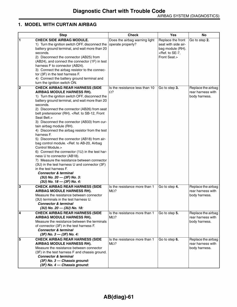
AIRBAG SYSTEM (DIAGNOSTICS)Diagnostic Chart with Trouble Code
1. MODEL WITH CURTAIN AIRBAG
Step Check Yes No1 CHECK SIDE AIRBAG MODULE.
1) Turn the ignition switch OFF, disconnect the battery ground terminal, and wait more than 20 seconds.2) Disconnect the connector (AB25) from (AB24), and connect the connector (1F) in test harness F to connector (AB24).3) Connect the airbag resistor to the connec-tor (3F) in the test harness F.4) Connect the battery ground terminal and turn the ignition switch ON.
Does the airbag warning light operate properly?
Replace the front seat with side air-bag module (RH). <Ref. to SE-7, Front Seat.>
Go to step 2.
2 CHECK AIRBAG REAR HARNESS (SIDE AIRBAG MODULE HARNESS RH).1) Turn the ignition switch OFF, disconnect the battery ground terminal, and wait more than 20 seconds.2) Disconnect the connector (AB26) from seat belt pretensioner (RH). <Ref. to SB-12, Front Seat Belt.>3) Disconnect the connector (AB33) from cur-tain airbag module (RH).4) Disconnect the airbag resistor from the test harness F.5) Disconnect the connector (AB18) from air-bag control module. <Ref. to AB-20, Airbag Control Module.>6) Connect the connector (1U) in the test har-ness U to connector (AB18).7) Measure the resistance between connector (3U) in the test harness U and connector (3F) in the test harness F.
Connector & terminal(3U) No. 20 — (3F) No. 3:(3U) No. 18 — (3F) No. 4:
Is the resistance less than 10 Ω?
Go to step 3. Replace the airbag rear harness with body harness.
3 CHECK AIRBAG REAR HARNESS (SIDE AIRBAG MODULE HARNESS RH).Measure the resistance between connector (3U) terminals in the test harness U.
Connector & terminal(3U) No. 20 — (3U) No. 18:
Is the resistance more than 1 MΩ?
Go to step 4. Replace the airbag rear harness with body harness.
4 CHECK AIRBAG REAR HARNESS (SIDE AIRBAG MODULE HARNESS RH).Measure the resistance between the terminals of connector (3F) in the test harness F.
Connector & terminal(3F) No. 3 — (3F) No. 4:
Is the resistance more than 1 MΩ?
Go to step 5. Replace the airbag rear harness with body harness.
5 CHECK AIRBAG REAR HARNESS (SIDE AIRBAG MODULE HARNESS RH).Measure the resistance between connector (3F) in the test harness F and chassis ground.
Connector & terminal(3F) No. 3 — Chassis ground:(3F) No. 4 — Chassis ground:
Is the resistance more than 1 MΩ?
Go to step 6. Replace the airbag rear harness with body harness.
AB(diag)-61

AIRBAG SYSTEM (DIAGNOSTICS)Diagnostic Chart with Trouble Code
6 CHECK AIRBAG REAR HARNESS (SIDE AIRBAG MODULE HARNESS RH).Measure the resistance between connector (3U) in the test harness U and chassis ground.
Connector & terminal(3U) No. 20 — Chassis ground:(3U) No. 18 — Chassis ground:
Is the resistance more than 1 MΩ?
Replace the airbag control module. <Ref. to AB-20, Airbag Control Module.>
Replace the airbag rear harness with body harness.
Step Check Yes No
AB(diag)-62

AIRBAG SYSTEM (DIAGNOSTICS)Diagnostic Chart with Trouble Code
2. MODEL WITHOUT CURTAIN AIRBAG
Step Check Yes No1 CHECK SIDE AIRBAG MODULE.
1) Turn the ignition switch OFF, disconnect the battery ground terminal, and wait more than 20 seconds.2) Disconnect the connector (AB25) from (AB24), and connect the connector (1F) in test harness F to connector (AB24).3) Connect the airbag resistor to the connec-tor (3F) in the test harness F.4) Connect the battery ground terminal and turn the ignition switch ON.
Does the airbag warning light operate properly?
Replace the front seat with side air-bag module (RH). <Ref. to SE-7, Front Seat.>
Go to step 2.
2 CHECK AIRBAG REAR HARNESS (SIDE AIRBAG MODULE HARNESS RH).1) Turn the ignition switch OFF, disconnect the battery ground terminal, and wait more than 20 seconds.2) Disconnect the connector (AB26) from seat belt pretensioner (RH). <Ref. to SB-12, Front Seat Belt.>3) Disconnect the connector (AB33) from cur-tain airbag module (RH).4) Disconnect the airbag resistor from the test harness F.5) Disconnect the connector (AB18) from air-bag control module. <Ref. to AB-20, Airbag Control Module.>6) Connect the connector (1R) in the test har-ness R to connector (AB18).7) Measure the resistance between connector (3R) in the test harness R and connector (3F) in the test harness F.
Connector & terminal(3R) No. 20 — (3F) No. 3:(3R) No. 18 — (3F) No. 4:
Is the resistance less than 10 Ω?
Go to step 3. Replace the airbag rear harness with body harness.
3 CHECK AIRBAG REAR HARNESS (SIDE AIRBAG MODULE HARNESS RH).Measure the resistance between connector (3R) terminals in the test harness R.
Connector & terminal(3R) No. 20 — (3R) No. 18:
Is the resistance more than 1 MΩ?
Go to step 4. Replace the airbag rear harness with body harness.
4 CHECK AIRBAG REAR HARNESS (SIDE AIRBAG MODULE HARNESS RH).Measure the resistance between the terminals of connector (3F) in the test harness F.
Connector & terminal(3F) No. 3 — (3F) No. 4:
Is the resistance more than 1 MΩ?
Go to step 5. Replace the airbag rear harness with body harness.
5 CHECK AIRBAG REAR HARNESS (SIDE AIRBAG MODULE HARNESS RH).Measure the resistance between connector (3F) in the test harness F and chassis ground.
Connector & terminal(3F) No. 3 — Chassis ground:(3F) No. 4 — Chassis ground:
Is the resistance more than 1 MΩ?
Go to step 6. Replace the airbag rear harness with body harness.
AB(diag)-63

AIRBAG SYSTEM (DIAGNOSTICS)Diagnostic Chart with Trouble Code
6 CHECK AIRBAG REAR HARNESS (SIDE AIRBAG MODULE HARNESS RH).Measure the resistance between connector (3R) in the test harness R and chassis ground.
Connector & terminal(3R) No. 20 — Chassis ground:(3R) No. 18 — Chassis ground:
Is the resistance more than 1 MΩ?
Replace the airbag control module. <Ref. to AB-20, Airbag Control Module.>
Replace the airbag rear harness with body harness.
Step Check Yes No
AB(diag)-64

AIRBAG SYSTEM (DIAGNOSTICS)Diagnostic Chart with Trouble Code
O: DTC 42DTC DETECTING CONDITION:• Side airbag harness (LH) is faulty.• Side airbag module (LH) is faulty.• Airbag control module is faulty.
CAUTION:• Before diagnosing the airbag system, be sure to turn the ignition switch OFF, disconnect theground terminal from battery, and wait more than 20 seconds before starting to work.• Before replacing the airbag module, seat belt pretensioner, roll connector, control module andsensor, reconnect each part and confirm that the warning light operates properly.• When inspecting the airbag main harness, disconnect the airbag module connector of the driver’sand passenger’s seats for safety reasons.• When inspecting the airbag rear harness, disconnect the side airbag module connector, curtainairbag module connector and seat belt pretensioner connector for safety reasons.WIRING DIAGRAM:
AB-00774
AB23
1 2
AB19
AB20
3 41 2
109 17
20
16
18
AB19
1 2
AB17
AB17 AIRBAG CONTROL MODULE
INFLATOR(SIDE LH)
SIDE AIRBAGSENSOR LH
7 8 9 10 11 12
13 14 15 16 17 18 19
5 6
20
1 2 3 4
AB23
1 2 3 4
:
:
WC
OC
WITH CURTAIN AIRBAG
WITHOUT CURTAIN AIRBAG
(WITH CURTAIN AIRBAG)
AB17
(WITHOUT CURTAIN AIRBAG)
1 2 3 4 5 6
7 8 9 10 11 12
65 10
12 79
WC
OC
AB(diag)-65

AIRBAG SYSTEM (DIAGNOSTICS)Diagnostic Chart with Trouble Code
1. MODEL WITH CURTAIN AIRBAG
Step Check Yes No1 CHECK SIDE AIRBAG MODULE.
1) Turn the ignition switch OFF, disconnect the battery ground terminal, and wait more than 20 seconds.2) Disconnect the connector (AB20) from (AB19), and connect the connector (1F) in test harness F to connector (AB19).3) Connect the airbag resistor to connector (3F) in the test harness F.4) Connect the battery ground terminal and turn the ignition switch ON.
Does the airbag warning light operate properly?
Replace the front seat with side air-bag module (LH). <Ref. to SE-7, Front Seat.>
Go to step 2.
2 CHECK AIRBAG REAR HARNESS (SIDE AIRBAG MODULE HARNESS LH).1) Turn the ignition switch OFF, disconnect the battery ground terminal, and wait more than 20 seconds.2) Disconnect the connector (AB21) from seat belt pretensioner (LH). <Ref. to SB-12, Front Seat Belt.>3) Disconnect the connector (AB31) from cur-tain airbag module (LH).4) Disconnect the airbag resistor from test harness.5) Disconnect the connector (AB17) from air-bag control module. <Ref. to AB-20, Airbag Control Module.>6) Connect the connector (1U) in the test har-ness U to connector (AB17).7) Measure the resistance between connector (3U) in the test harness U and connector (3F) in the test harness F.
Connector & terminal(3U) No. 12 — (3F) No. 3:(3U) No. 10 — (3F) No. 4:
Is the resistance less than 10 Ω?
Go to step 3. Replace the airbag rear harness with body harness.
3 CHECK AIRBAG REAR HARNESS (SIDE AIRBAG MODULE HARNESS LH).Measure the resistance between connector (3U) terminals in the test harness U.
Connector & terminal(3U) No. 12 — (3U) No. 10:
Is the resistance more than 1 MΩ?
Go to step 4. Replace the airbag rear harness with body harness.
4 CHECK AIRBAG REAR HARNESS (SIDE AIRBAG MODULE HARNESS LH).Measure the resistance between the terminals of connector (3F) in the test harness F.
Connector & terminal(3F) No. 3 — (3F) No. 4:
Is the resistance more than 1 MΩ?
Go to step 5. Replace the airbag rear harness with body harness.
5 CHECK AIRBAG REAR HARNESS (SIDE AIRBAG MODULE HARNESS LH).Measure the resistance between connector (3F) in the test harness F and chassis ground.
Connector & terminal(3F) No. 3 — Chassis ground:(3F) No. 4 — Chassis ground:
Is the resistance more than 1 MΩ?
Go to step 6. Replace the airbag rear harness with body harness.
AB(diag)-66

AIRBAG SYSTEM (DIAGNOSTICS)Diagnostic Chart with Trouble Code
6 CHECK AIRBAG REAR HARNESS (SIDE AIRBAG MODULE HARNESS LH).Measure the resistance between connector (3U) in the test harness U and chassis ground.
Connector & terminal(3U) No. 12 — Chassis ground:(3U) No. 10 — Chassis ground:
Is the resistance more than 1 MΩ?
Replace the airbag control module. <Ref. to AB-20, Airbag Control Module.>
Replace the airbag rear harness with body harness.
Step Check Yes No
AB(diag)-67

AIRBAG SYSTEM (DIAGNOSTICS)Diagnostic Chart with Trouble Code
2. MODEL WITHOUT CURTAIN AIRBAG
Step Check Yes No1 CHECK SIDE AIRBAG MODULE.
1) Turn the ignition switch OFF, disconnect the battery ground terminal, and wait more than 20 seconds.2) Disconnect the connector (AB20) from (AB19), and connect the connector (1F) in test harness F to connector (AB19).3) Connect the airbag resistor to connector (3F) in the test harness F.4) Connect the battery ground terminal and turn the ignition switch ON.
Does the airbag warning light operate properly?
Replace the front seat with side air-bag module (LH). <Ref. to SE-7, Front Seat.>
Go to step 2.
2 CHECK AIRBAG REAR HARNESS (SIDE AIRBAG MODULE HARNESS LH).1) Turn the ignition switch OFF, disconnect the battery ground terminal, and wait more than 20 seconds.2) Disconnect the connector (AB21) from seat belt pretensioner (LH). <Ref. to SB-12, Front Seat Belt.>3) Disconnect the connector (AB31) from cur-tain airbag module (LH).4) Disconnect the airbag resistor from test harness.5) Disconnect the connector (AB17) from air-bag control module. <Ref. to AB-20, Airbag Control Module.>6) Connect the connector (1R) in the test har-ness R to connector (AB17).7) Measure the resistance between connector (3R) in the test harness R and connector (3F) in the test harness F.
Connector & terminal(3R) No. 12 — (3F) No. 3:(3R) No. 10 — (3F) No. 4:
Is the resistance less than 10 Ω?
Go to step 3. Replace the airbag rear harness with body harness.
3 CHECK AIRBAG REAR HARNESS (SIDE AIRBAG MODULE HARNESS LH).Measure the resistance between connector (3R) terminals in the test harness R.
Connector & terminal(3R) No. 12 — (3R) No. 10:
Is the resistance more than 1 MΩ?
Go to step 4. Replace the airbag rear harness with body harness.
4 CHECK AIRBAG REAR HARNESS (SIDE AIRBAG MODULE HARNESS LH).Measure the resistance between the terminals of connector (3F) in the test harness F.
Connector & terminal(3F) No. 3 — (3F) No. 4:
Is the resistance more than 1 MΩ?
Go to step 5. Replace the airbag rear harness with body harness.
5 CHECK AIRBAG REAR HARNESS (SIDE AIRBAG MODULE HARNESS LH).Measure the resistance between connector (3F) in the test harness F and chassis ground.
Connector & terminal(3F) No. 3 — Chassis ground:(3F) No. 4 — Chassis ground:
Is the resistance more than 1 MΩ?
Go to step 6. Replace the airbag rear harness with body harness.
AB(diag)-68

AIRBAG SYSTEM (DIAGNOSTICS)Diagnostic Chart with Trouble Code
6 CHECK AIRBAG REAR HARNESS (SIDE AIRBAG MODULE HARNESS LH).Measure the resistance between connector (3R) in the test harness R and chassis ground.
Connector & terminal(3R) No. 12 — Chassis ground:(3R) No. 10 — Chassis ground:
Is the resistance more than 1 MΩ?
Replace the airbag control module. <Ref. to AB-20, Airbag Control Module.>
Replace the airbag rear harness with body harness.
Step Check Yes No
AB(diag)-69

AIRBAG SYSTEM (DIAGNOSTICS)Diagnostic Chart with Trouble Code
P: DTC 45DTC DETECTING CONDITION:• Side airbag harness (RH) is shorted to power supply.• Airbag control module is faulty.
CAUTION:• Before diagnosing the airbag system, be sure to turn the ignition switch OFF, disconnect theground terminal from battery, and wait more than 20 seconds before starting to work.• Before replacing the airbag module, seat belt pretensioner, roll connector, control module andsensor, reconnect each part and confirm that the warning light operates properly.• When inspecting the airbag main harness, disconnect the airbag module connector of the driver’sand passenger’s seats for safety reasons.• When inspecting the airbag rear harness, disconnect the side airbag module connector, curtainairbag module connector and seat belt pretensioner connector for safety reasons.WIRING DIAGRAM:
AB-00773
AB18
AB24
AB25
1 2
AB28
3 41 2
7815
17
13
16
AB18AB28AB24
1 2
AIRBAG CONTROL MODULE
INFLATOR(SIDE RH)
SIDE AIRBAGSENSOR RH
7 8 9 10 11 12
13 14 15 16 17 18 19
5 6
20
1 2 3 41 2 3 4
1210
127 9
:
:
WC
OC
WITH CURTAIN AIRBAG
WITHOUT CURTAIN AIRBAG
WC
OC
AB18
2 3 4 5 6
8 9 10 11 12
(WITHOUT CURTAIN AIRBAG)(WITH CURTAIN AIRBAG)
AB(diag)-70

AIRBAG SYSTEM (DIAGNOSTICS)Diagnostic Chart with Trouble Code
1. MODEL WITH CURTAIN AIRBAG
Step Check Yes No1 CHECK SIDE AIRBAG MODULE.
1) Turn the ignition switch OFF, disconnect the battery ground terminal, and wait more than 20 seconds.2) Disconnect the connector (AB25) from (AB24), and connect the connector (1F) in test harness F to connector (AB24). 3) Connect the airbag resistor to connector (3F) in the test harness F.4) Connect the battery ground terminal and turn the ignition switch ON.
Does the airbag warning light operate properly?
Replace the front seat with side air-bag module (RH). <Ref. to SE-7, Front Seat.>
Go to step 2.
2 CHECK AIRBAG REAR HARNESS (SIDE AIRBAG MODULE HARNESS RH).1) Turn the ignition switch OFF, disconnect the battery ground terminal, and wait more than 20 seconds.2) Disconnect the connector (AB26) from seat belt pretensioner (RH). <Ref. to SB-12, Front Seat Belt.>3) Disconnect the connector (AB33) from cur-tain airbag module (RH).4) Disconnect the airbag resistor from test harness.5) Disconnect the connector (AB18) from air-bag control module. <Ref. to AB-20, Airbag Control Module.>6) Connect the connector (1U) in the test har-ness U to connector (AB18).7) Connect the battery ground terminal and turn the ignition switch ON.8) Measure the voltage between connector (3U) in the test harness U and chassis ground.
Connector & terminal(3U) No. 20 (+) — Chassis ground (−):(3U) No. 18 (+) — Chassis ground (−):
Is the voltage less than 1 V? Replace the airbag control module. <Ref. to AB-20, Airbag Control Module.>
Replace the airbag rear harness with body harness.
AB(diag)-71

AIRBAG SYSTEM (DIAGNOSTICS)Diagnostic Chart with Trouble Code
2. MODEL WITHOUT CURTAIN AIRBAG
Step Check Yes No1 CHECK SIDE AIRBAG MODULE.
1) Turn the ignition switch OFF, disconnect the battery ground terminal, and wait more than 20 seconds.2) Disconnect the connector (AB25) from (AB24), and connect the connector (1F) in test harness F to connector (AB24). 3) Connect the airbag resistor to connector (3F) in the test harness F.4) Connect the battery ground terminal and turn the ignition switch ON.
Does the airbag warning light operate properly?
Replace the front seat with side air-bag module (RH). <Ref. to SE-7, Front Seat.>
Go to step 2.
2 CHECK AIRBAG REAR HARNESS (SIDE AIRBAG MODULE HARNESS RH).1) Turn the ignition switch OFF, disconnect the battery ground terminal, and wait more than 20 seconds.2) Disconnect the connector (AB26) from seat belt pretensioner (RH). <Ref. to SB-12, Front Seat Belt.>3) Disconnect the connector (AB33) from cur-tain airbag module (RH).4) Disconnect the airbag resistor from test harness.5) Disconnect the connector (AB18) from air-bag control module. <Ref. to AB-20, Airbag Control Module.>6) Connect the connector (1R) in the test har-ness R to connector (AB18).7) Connect the battery ground terminal and turn the ignition switch ON.8) Measure the voltage between connector (3R) in the test harness R and chassis ground.
Connector & terminal(3R) No. 20 (+) — Chassis ground (−):(3R) No. 18 (+) — Chassis ground (−):
Is the voltage less than 1 V? Replace the airbag control module. <Ref. to AB-20, Airbag Control Module.>
Replace the airbag rear harness with body harness.
AB(diag)-72

AIRBAG SYSTEM (DIAGNOSTICS)Diagnostic Chart with Trouble Code
Q: DTC 46DTC DETECTING CONDITION:• Side airbag harness (LH) is shorted to power supply.• Airbag control module is faulty.
CAUTION:• Before diagnosing the airbag system, be sure to turn the ignition switch OFF, disconnect theground terminal from battery, and wait more than 20 seconds before starting to work.• Before replacing the airbag module, seat belt pretensioner, roll connector, control module andsensor, reconnect each part and confirm that the warning light operates properly.• When inspecting the airbag main harness, disconnect the airbag module connector of the driver’sand passenger’s seats for safety reasons.• When inspecting the airbag rear harness, disconnect the side airbag module connector, curtainairbag module connector and seat belt pretensioner connector for safety reasons.WIRING DIAGRAM:
AB-00774
AB23
1 2
AB19
AB20
3 41 2
109 17
20
16
18
AB19
1 2
AB17
AB17 AIRBAG CONTROL MODULE
INFLATOR(SIDE LH)
SIDE AIRBAGSENSOR LH
7 8 9 10 11 12
13 14 15 16 17 18 19
5 6
20
1 2 3 4
AB23
1 2 3 4
:
:
WC
OC
WITH CURTAIN AIRBAG
WITHOUT CURTAIN AIRBAG
(WITH CURTAIN AIRBAG)
AB17
(WITHOUT CURTAIN AIRBAG)
1 2 3 4 5 6
7 8 9 10 11 12
65 10
12 79
WC
OC
AB(diag)-73

AIRBAG SYSTEM (DIAGNOSTICS)Diagnostic Chart with Trouble Code
1. MODEL WITH CURTAIN AIRBAG
Step Check Yes No1 CHECK SIDE AIRBAG MODULE.
1) Turn the ignition switch OFF, disconnect the battery ground terminal, and wait more than 20 seconds.2) Disconnect the connector (AB20) from (AB19), and connect the connector (1F) in test harness F to connector (AB19).3) Connect the airbag resistor to connector (3F) in the test harness F.4) Connect the battery ground terminal and turn the ignition switch ON.
Does the airbag warning light operate properly?
Replace the side airbag module (LH) with front seat. <Ref. to SE-7, Front Seat.>
Go to step 2.
2 CHECK AIRBAG REAR HARNESS (SIDE AIRBAG MODULE HARNESS LH).1) Turn the ignition switch OFF, disconnect the battery ground terminal, and wait more than 20 seconds.2) Disconnect the connector (AB21) from seat belt pretensioner (LH). <Ref. to SB-12, Front Seat Belt.>3) Disconnect the connector (AB31) from cur-tain airbag module (LH).4) Disconnect the airbag resistor from test harness.5) Disconnect the connector (AB17) from air-bag control module. <Ref. to AB-20, Airbag Control Module.>6) Connect the connector (1U) in the test har-ness U to connector (AB17).7) Connect the battery ground terminal and turn the ignition switch ON.8) Measure the voltage between connector (3U) in the test harness U and chassis ground.
Connector & terminal(3U) No. 12 (+) — Chassis ground (−):(3U) No. 10 (+) — Chassis ground (−):
Is the voltage less than 1 V? Replace the airbag control module. <Ref. to AB-20, Airbag Control Module.>
Replace the airbag rear harness with body harness.
AB(diag)-74

AIRBAG SYSTEM (DIAGNOSTICS)Diagnostic Chart with Trouble Code
2. MODEL WITHOUT CURTAIN AIRBAG
Step Check Yes No1 CHECK SIDE AIRBAG MODULE.
1) Turn the ignition switch OFF, disconnect the battery ground terminal, and wait more than 20 seconds.2) Disconnect the connector (AB20) from (AB19), and connect the connector (1F) in test harness F to connector (AB19).3) Connect the airbag resistor to connector (3F) in the test harness F.4) Connect the battery ground terminal and turn the ignition switch ON.
Does the airbag warning light operate properly?
Replace the side airbag module (LH) with front seat. <Ref. to SE-7, Front Seat.>
Go to step 2.
2 CHECK AIRBAG REAR HARNESS (SIDE AIRBAG MODULE HARNESS LH).1) Turn the ignition switch OFF, disconnect the battery ground terminal, and wait more than 20 seconds.2) Disconnect the connector (AB21) from seat belt pretensioner (LH). <Ref. to SB-12, Front Seat Belt.>3) Disconnect the connector (AB31) from cur-tain airbag module (LH).4) Disconnect the airbag resistor from test harness.5) Disconnect the connector (AB17) from air-bag control module. <Ref. to AB-20, Airbag Control Module.>6) Connect the connector (1R) in the test har-ness R to connector (AB17).7) Connect the battery ground terminal and turn the ignition switch ON.8) Measure the voltage between connector (3R) in the test harness R and chassis ground.
Connector & terminal(3R) No. 12 (+) — Chassis ground (−):(3R) No. 10 (+) — Chassis ground (−):
Is the voltage less than 1 V? Replace the airbag control module. <Ref. to AB-20, Airbag Control Module.>
Replace the airbag rear harness with body harness.
AB(diag)-75

AIRBAG SYSTEM (DIAGNOSTICS)Diagnostic Chart with Trouble Code
R: DTC 51DTC DETECTING CONDITION:• Side airbag sensor (RH) is faulty.• Side airbag harness (RH) is faulty.• Airbag control module is faulty.
CAUTION:• Before diagnosing the airbag system, be sure to turn the ignition switch OFF, disconnect theground terminal from battery, and wait more than 20 seconds before starting to work.• Before replacing the airbag module, seat belt pretensioner, roll connector, control module andsensor, reconnect each part and confirm that the warning light operates properly.• When inspecting the airbag main harness, disconnect the airbag module connector of the driver’sand passenger’s seats for safety reasons.• When inspecting the airbag rear harness, disconnect the side airbag module connector, curtainairbag module connector and seat belt pretensioner connector for safety reasons.WIRING DIAGRAM:
AB-00773
AB18
AB24
AB25
1 2
AB28
3 41 2
7815
17
13
16
AB18AB28AB24
1 2
AIRBAG CONTROL MODULE
INFLATOR(SIDE RH)
SIDE AIRBAGSENSOR RH
7 8 9 10 11 12
13 14 15 16 17 18 19
5 6
20
1 2 3 41 2 3 4
1210
127 9
:
:
WC
OC
WITH CURTAIN AIRBAG
WITHOUT CURTAIN AIRBAG
WC
OC
AB18
2 3 4 5 6
8 9 10 11 12
(WITHOUT CURTAIN AIRBAG)(WITH CURTAIN AIRBAG)
AB(diag)-76
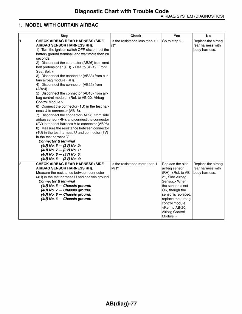
AIRBAG SYSTEM (DIAGNOSTICS)Diagnostic Chart with Trouble Code
1. MODEL WITH CURTAIN AIRBAG
Step Check Yes No1 CHECK AIRBAG REAR HARNESS (SIDE
AIRBAG SENSOR HARNESS RH).1) Turn the ignition switch OFF, disconnect the battery ground terminal, and wait more than 20 seconds.2) Disconnect the connector (AB26) from seat belt pretensioner (RH). <Ref. to SB-12, Front Seat Belt.>3) Disconnect the connector (AB33) from cur-tain airbag module (RH).4) Disconnect the connector (AB25) from (AB24).5) Disconnect the connector (AB18) from air-bag control module. <Ref. to AB-20, Airbag Control Module.>6) Connect the connector (1U) in the test har-ness U to connector (AB18). 7) Disconnect the connector (AB28) from side airbag sensor (RH), and connect the connector (2V) in the test harness V to connector (AB28).8) Measure the resistance between connector (4U) in the test harness U and connector (3V) in the test harness V.
Connector & terminal(4U) No. 5 — (3V) No. 2:(4U) No. 7 — (3V) No. 1:(4U) No. 8 — (3V) No. 5:(4U) No. 6 — (3V) No. 4:
Is the resistance less than 10 Ω?
Go to step 2. Replace the airbag rear harness with body harness.
2 CHECK AIRBAG REAR HARNESS (SIDE AIRBAG SENSOR HARNESS RH).Measure the resistance between connector (4U) in the test harness U and chassis ground.
Connector & terminal(4U) No. 5 — Chassis ground:(4U) No. 7 — Chassis ground:(4U) No. 8 — Chassis ground:(4U) No. 6 — Chassis ground:
Is the resistance more than 1 MΩ?
Replace the side airbag sensor (RH). <Ref. to AB-21, Side Airbag Sensor.> When the sensor is not OK, though the sensor is replaced, replace the airbag control module. <Ref. to AB-20, Airbag Control Module.>
Replace the airbag rear harness with body harness.
AB(diag)-77

AIRBAG SYSTEM (DIAGNOSTICS)Diagnostic Chart with Trouble Code
2. MODEL WITHOUT CURTAIN AIRBAG
Step Check Yes No1 CHECK AIRBAG REAR HARNESS (SIDE
AIRBAG SENSOR HARNESS RH).1) Turn the ignition switch OFF, disconnect the battery ground terminal, and wait more than 20 seconds.2) Disconnect the connector (AB26) from seat belt pretensioner (RH). <Ref. to SB-12, Front Seat Belt.>3) Disconnect the connector (AB33) from cur-tain airbag module (RH).4) Disconnect the connector (AB25) from (AB24).5) Disconnect the connector (AB18) from air-bag control module. <Ref. to AB-20, Airbag Control Module.>6) Connect the connector (1R) in the test har-ness R to connector (AB18). 7) Disconnect the connector (AB28) from side airbag sensor (RH), and connect the connector (2V) in the test harness V to connector (AB28).8) Measure the resistance between connector (4R) in the test harness R and connector (3V) in the test harness V.
Connector & terminal(4R) No. 5 — (3V) No. 2:(4R) No. 7 — (3V) No. 1:(4R) No. 8 — (3V) No. 5:(4R) No. 6 — (3V) No. 4:
Is the resistance less than 10 Ω?
Go to step 2. Replace the airbag rear harness with body harness.
2 CHECK AIRBAG REAR HARNESS (SIDE AIRBAG SENSOR HARNESS RH).Measure the resistance between connector (4R) in the test harness R and chassis ground.
Connector & terminal(4R) No. 5 — Chassis ground:(4R) No. 7 — Chassis ground:(4R) No. 8 — Chassis ground:(4R) No. 6 — Chassis ground:
Is the resistance more than 1 MΩ?
Replace the side airbag sensor (RH). <Ref. to AB-21, Side Airbag Sensor.> When the sensor is not OK, though the sensor is replaced, replace the airbag control module. <Ref. to AB-20, Airbag Control Module.>
Replace the airbag rear harness with body harness.
AB(diag)-78

AIRBAG SYSTEM (DIAGNOSTICS)Diagnostic Chart with Trouble Code
S: DTC 52DTC DETECTING CONDITION:• Side airbag sensor (LH) is faulty.• Side airbag harness (LH) is faulty.• Airbag control module is faulty.
CAUTION:• Before diagnosing the airbag system, be sure to turn the ignition switch OFF, disconnect theground terminal from battery, and wait more than 20 seconds before starting to work.• Before replacing the airbag module, seat belt pretensioner, roll connector, control module andsensor, reconnect each part and confirm that the warning light operates properly.• When inspecting the airbag main harness, disconnect the airbag module connector of the driver’sand passenger’s seats for safety reasons.• When inspecting the airbag rear harness, disconnect the side airbag module connector, curtainairbag module connector and seat belt pretensioner connector for safety reasons.WIRING DIAGRAM:
AB-00774
AB23
1 2
AB19
AB20
3 41 2
109 17
20
16
18
AB19
1 2
AB17
AB17 AIRBAG CONTROL MODULE
INFLATOR(SIDE LH)
SIDE AIRBAGSENSOR LH
7 8 9 10 11 12
13 14 15 16 17 18 19
5 6
20
1 2 3 4
AB23
1 2 3 4
:
:
WC
OC
WITH CURTAIN AIRBAG
WITHOUT CURTAIN AIRBAG
(WITH CURTAIN AIRBAG)
AB17
(WITHOUT CURTAIN AIRBAG)
1 2 3 4 5 6
7 8 9 10 11 12
65 10
12 79
WC
OC
AB(diag)-79

AIRBAG SYSTEM (DIAGNOSTICS)Diagnostic Chart with Trouble Code
1. MODEL WITH CURTAIN AIRBAG
Step Check Yes No1 CHECK AIRBAG REAR HARNESS (SIDE
AIRBAG SENSOR HARNESS LH).1) Turn the ignition switch OFF, disconnect the battery ground terminal, and wait more than 20 seconds.2) Disconnect the connector (AB21) from seat belt pretensioner (LH). <Ref. to SB-12, Front Seat Belt.>3) Disconnect the connector (AB31) from cur-tain airbag module (LH).4) Disconnect the connector (AB20) from (AB19).5) Disconnect the connector (AB17) from air-bag control module. <Ref. to AB-20, Airbag Control Module.>6) Connect the connector (1U) in the test har-ness U to connector (AB17).7) Disconnect the connector (AB23) from side airbag sensor (LH), and connect the connector (2V) in the test harness V to connector (AB23).8) Measure the resistance between connector (4U) in the test harness U and connector (3V) in the test harness V.
Connector & terminal(4U) No. 3 — (3V) No. 4:(4U) No. 1 — (3V) No. 5:(4U) No. 2 — (3V) No. 1:(4U) No. 4 — (3V) No. 2:
Is the resistance less than 10 Ω?
Go to step 2. Replace the airbag rear harness with body harness.
2 CHECK AIRBAG REAR HARNESS (SIDE AIRBAG SENSOR HARNESS LH).Measure the resistance between connector (4U) in the test harness U and chassis ground.
Connector & terminal(4U) No. 3 — Chassis ground:(4U) No. 1 — Chassis ground:(4U) No. 2 — Chassis ground:(4U) No. 4 — Chassis ground:
Is the resistance more than 1 MΩ?
Replace the side airbag sensor (LH). <Ref. to AB-21, Side Airbag Sensor.> When the sensor is not OK, though the sensor is replaced, replace the airbag control module. <Ref. to AB-20, Airbag Control Module.>
Replace the airbag rear harness with body harness.
AB(diag)-80

AIRBAG SYSTEM (DIAGNOSTICS)Diagnostic Chart with Trouble Code
2. MODEL WITHOUT CURTAIN AIRBAG
Step Check Yes No1 CHECK AIRBAG REAR HARNESS (SIDE
AIRBAG SENSOR HARNESS LH).1) Turn the ignition switch OFF, disconnect the battery ground terminal, and wait more than 20 seconds.2) Disconnect the connector (AB21) from seat belt pretensioner (LH). <Ref. to SB-12, Front Seat Belt.>3) Disconnect the connector (AB31) from cur-tain airbag module (LH).4) Disconnect the connector (AB20) from (AB19).5) Disconnect the connector (AB17) from air-bag control module. <Ref. to AB-20, Airbag Control Module.>6) Connect the connector (1R) in the test har-ness R to connector (AB17).7) Disconnect the connector (AB23) from side airbag sensor (LH), and connect the connector (2V) in the test harness V to connector (AB23).8) Measure the resistance between connector (4R) in the test harness R and connector (3V) in the test harness V.
Connector & terminal(4R) No. 3 — (3V) No. 4:(4R) No. 1 — (3V) No. 5:(4R) No. 2 — (3V) No. 1:(4R) No. 4 — (3V) No. 2:
Is the resistance less than 10 Ω?
Go to step 2. Replace the airbag rear harness with body harness.
2 CHECK AIRBAG REAR HARNESS (SIDE AIRBAG SENSOR HARNESS LH).Measure the resistance between connector (4R) in the test harness R and chassis ground.
Connector & terminal(4R) No. 3 — Chassis ground:(4R) No. 1 — Chassis ground:(4R) No. 2 — Chassis ground:(4R) No. 4 — Chassis ground:
Is the resistance more than 1 MΩ?
Replace the side airbag sensor (LH). <Ref. to AB-21, Side Airbag Sensor.> When the sensor is not OK, though the sensor is replaced, replace the airbag control module. <Ref. to AB-20, Airbag Control Module.>
Replace the airbag rear harness with body harness.
AB(diag)-81

AIRBAG SYSTEM (DIAGNOSTICS)Diagnostic Chart with Trouble Code
T: DTC 53DTC DETECTING CONDITION:Side airbag sensor (RH) is faulty.When DTC 53 is displayed, the circuit within the side airbag sensor (RH) is faulty. Replace the side airbagsensor (RH). <Ref. to AB-21, Side Airbag Sensor.>
U: DTC 54DTC DETECTING CONDITION:Side airbag sensor (LH) is faulty.When DTC 54 is displayed, the circuit within the side airbag sensor (LH) is faulty. Replace the side airbagsensor (LH). <Ref. to AB-21, Side Airbag Sensor.>
V: DTC 55This code is displayed when the side airbag module and curtain airbag module are deployed.Once this code is displayed, the memory cannot be erased. Replace the following parts. • Airbag control module. <Ref. to AB-20, Airbag Control Module.>• Front seat with side airbag module. (Operating side) <Ref. to SE-7, Front Seat.>• Side airbag sensor. (Operating side) <Ref. to AB-21, Side Airbag Sensor.>• Curtain airbag module. (Operating side) <Ref. to AB-18, Curtain Airbag Module.>• Curtain airbag sensor. (Operating side) <Ref. to AB-22, Curtain Airbag Sensor.>
AB(diag)-82

AIRBAG SYSTEM (DIAGNOSTICS)Diagnostic Chart with Trouble Code
W: DTC 56DTC DETECTING CONDITION:• Curtain airbag sensor (RH) is faulty.• Curtain airbag harness (RH) is faulty.• Airbag control module is faulty.
CAUTION:• Before diagnosing the airbag system, be sure to turn the ignition switch OFF, disconnect theground terminal from battery, and wait more than 20 seconds before starting to work.• Before replacing the airbag module, seat belt pretensioner, roll connector, control module andsensor, reconnect each part and confirm that the warning light operates properly.• When inspecting the airbag main harness, disconnect the airbag module connector of the driver’sand passenger’s seats for safety reasons.• When inspecting the airbag rear harness, disconnect the side airbag module connector, curtainairbag module connector and seat belt pretensioner connector for safety reasons.WIRING DIAGRAM:
AB-00671
AB18
AB33
AB40
1 265
AB34
20
194 18
3 41 2
AB18AB33
1 2
AIRBAG CONTROL MODULE
INFLATOR(CURTAIN RH)
CURTAIN AIRBAGSENSOR RH
7 8 9 10 11 12
13 14 15 16 17 18 19
5 6
20
1 2 3 4
AB34
1 2 3 4
AB(diag)-83

AIRBAG SYSTEM (DIAGNOSTICS)Diagnostic Chart with Trouble Code
Step Check Yes No1 CHECK AIRBAG REAR HARNESS (CUR-
TAIN AIRBAG SENSOR HARNESS RH).1) Turn the ignition switch OFF, disconnect the battery ground terminal, and wait more than 20 seconds.2) Disconnect the connector (AB26) from seat belt pretensioner (RH). <Ref. to SB-12, Front Seat Belt.>3) Disconnect the connector (AB24) from side airbag module (RH).4) Disconnect the connector (AB33) from (AB40).5) Disconnect the connector (AB18) from air-bag control module. <Ref. to AB-20, Airbag Control Module.>6) Connect the connector (1U) in the test har-ness U to connector (AB18). 7) Disconnect the connector (AB34) from cur-tain airbag sensor (RH), and connect the con-nector (2V) in the test harness V to connector (AB34).8) Measure the resistance between connector (5U) in the test harness U and connector (3V) in the test harness V.
Connector & terminal(5U) No. 14 — (3V) No. 4:(5U) No. 16 — (3V) No. 5:(5U) No. 15 — (3V) No. 1:(5U) No. 13 — (3V) No. 2:
Is the resistance less than 10 Ω?
Go to step 2. Replace the airbag rear harness with body harness.
2 CHECK AIRBAG REAR HARNESS (CUR-TAIN AIRBAG SENSOR HARNESS RH).Measure the resistance between connector (5U) in the test harness U and chassis ground.
Connector & terminal(5U) No. 14 — Chassis ground:(5U) No. 16 — Chassis ground:(5U) No. 15 — Chassis ground:(5U) No. 13 — Chassis ground:
Is the resistance more than 1 MΩ?
Replace the cur-tain airbag sensor (RH). <Ref. to AB-22, Curtain Airbag Sensor.> When the sensor is not OK, though the sensor is replaced, replace the airbag control module. <Ref. to AB-20, Airbag Control Module.>
Replace the airbag rear harness with body harness.
AB(diag)-84

AIRBAG SYSTEM (DIAGNOSTICS)Diagnostic Chart with Trouble Code
X: DTC 57DTC DETECTING CONDITION:• Curtain airbag sensor (LH) is faulty.• Curtain airbag harness (LH) is faulty.• Airbag control module is faulty.
CAUTION:• Before diagnosing the airbag system, be sure to turn the ignition switch OFF, disconnect theground terminal from battery, and wait more than 20 seconds before starting to work.• Before replacing the airbag module, seat belt pretensioner, roll connector, control module andsensor, reconnect each part and confirm that the warning light operates properly.• When inspecting the airbag main harness, disconnect the airbag module connector of the driver’sand passenger’s seats for safety reasons.• When inspecting the airbag rear harness, disconnect the side airbag module connector, curtainairbag module connector and seat belt pretensioner connector for safety reasons.WIRING DIAGRAM:
AB-00672
AB32
1 21
11
2
AB31
AB39
151 14
13
3 41 2
AB31
1 2
AB17
AB17 AIRBAG CONTROL MODULE
INFLATOR(CURTAIN LH)
CURTAIN AIRBAGSENSOR LH
7 8 9 10 11 12
13 14 15 16 17 18 19
5 6
20
1 2 3 4
AB32
1 2 3 4
AB(diag)-85

AIRBAG SYSTEM (DIAGNOSTICS)Diagnostic Chart with Trouble Code
Y: DTC 58DTC DETECTING CONDITION:Curtain airbag sensor (RH) is faulty.When DTC 58 is displayed, the circuit within the curtain airbag sensor (RH) is faulty. Replace the curtain air-bag sensor (RH). <Ref. to AB-22, Curtain Airbag Sensor.>
Z: DTC 59DTC DETECTING CONDITION:Curtain airbag sensor (LH) is faulty.When DTC 59 is displayed, the circuit within the curtain airbag sensor (LH) is faulty. Replace the curtain air-bag sensor (LH). <Ref. to AB-22, Curtain Airbag Sensor.>
Step Check Yes No1 CHECK AIRBAG REAR HARNESS (CUR-
TAIN AIRBAG SENSOR HARNESS LH).1) Turn the ignition switch OFF, disconnect the battery ground terminal, and wait more than 20 seconds.2) Disconnect the connector (AB21) from seat belt pretensioner (LH). <Ref. to SB-12, Front Seat Belt.>3) Disconnect the connector (AB19) from side airbag module (LH).4) Disconnect the connector (AB31) from (AB39).5) Disconnect the connector (AB17) from air-bag control module. <Ref. to AB-20, Airbag Control Module.>6) Connect the connector (1U) in the test har-ness U to connector (AB17).7) Disconnect the connector (AB32) from cur-tain airbag sensor (LH), and connect the con-nector (2V) in the test harness V to connector (AB32).8) Measure the resistance between connector (5U) in the test harness U and connector (3V) in the test harness V.
Connector & terminal(5U) No. 11 — (3V) No. 4:(5U) No. 9 — (3V) No. 5:(5U) No. 10 — (3V) No. 1:(5U) No. 12 — (3V) No. 2:
Is the resistance less than 10 Ω?
Go to step 2. Replace the airbag rear harness with body harness.
2 CHECK AIRBAG REAR HARNESS (CUR-TAIN AIRBAG SENSOR HARNESS LH).Measure the resistance between connector (5U) in the test harness U and chassis ground.
Connector & terminal(5U) No. 11 — Chassis ground:(5U) No. 9 — Chassis ground:(5U) No. 10 — Chassis ground:(5U) No. 12 — Chassis ground:
Is the resistance more than 1 MΩ?
Replace the cur-tain airbag sensor (LH). <Ref. to AB-22, Curtain Airbag Sensor.> When the sensor is not OK, though the sensor is replaced, replace the airbag control module. <Ref. to AB-20, Airbag Control Module.>
Replace the airbag rear harness with body harness.
AB(diag)-86

AIRBAG SYSTEM (DIAGNOSTICS)Diagnostic Chart with Trouble Code
AA:DTC 61DTC DETECTING CONDITION:• Seat belt pretensioner (RH) circuit is open, shorted or shorted to ground.• Airbag control module is faulty.• Pretensioner is faulty.• Pretensioner harness is faulty.
CAUTION:• Before diagnosing the airbag system, be sure to turn the ignition switch OFF, disconnect theground terminal from battery, and wait more than 20 seconds before starting to work.• Before replacing the airbag module, seat belt pretensioner, roll connector, control module andsensor, reconnect each part and confirm that the warning light operates properly.• When inspecting the airbag rear harness, disconnect the side airbag module connector, curtainairbag module connector and seat belt pretensioner connector for safety reasons.WIRING DIAGRAM:
AB-00775
1 2
AB18
AB26
AB26
1 2
AIRBAG CONTROL MODULE
PRETENSIONER RH
WITH CURTAIN AIRBAG
1
2
*1 : 11
*2 : 12
WITHOUT CURTAIN AIRBAG
*1 : 5
*2 : 6
* *
AB18 AB18
7 8 9 10 11 12
13 14 15 16 17 18 19
5 6
20
1 2 3 41 2 3 4 5 6
7 8 9 10 11 12
(WITHOUT CURTAIN AIRBAG)(WITH CURTAIN AIRBAG)
AB(diag)-87

AIRBAG SYSTEM (DIAGNOSTICS)Diagnostic Chart with Trouble Code
1. MODEL WITH CURTAIN AIRBAG
Step Check Yes No1 CHECK SEAT BELT PRETENSIONER.
1) Turn the ignition switch OFF, disconnect the battery ground terminal, and wait more than 20 seconds.2) Disconnect the connector (AB26) from seat belt pretensioner (RH). <Ref. to SB-12, Front Seat Belt.>3) Connect the connector (1N) in the test har-ness N to connector (AB26).4) Connect the airbag resistor to connector (2N) in the test harness N.5) Connect the battery ground terminal and turn the ignition switch ON.
Does the airbag warning light operate properly?
Replace the seat belt pretensioner (RH). <Ref. to SB-12, Front Seat Belt.>
Go to step 2.
2 CHECK AIRBAG REAR HARNESS (PRE-TENSIONER HARNESS RH).1) Turn the ignition switch OFF, disconnect the battery ground terminal, and wait more than 20 seconds.2) Disconnect the airbag resistor from test harness.3) Disconnect the connector (AB24) from side airbag module (RH).4) Disconnect the connector (AB33) from cur-tain airbag module (RH).5) Disconnect the connectors (AB17) and (AB18) from airbag control modules. <Ref. to AB-20, Airbag Control Module.>6) Connect the connector (1U) in the test har-ness U to connector (AB18).7) Measure the resistance between connector (3U) in the test harness U and connector (2N) in the test harness N.
Connector & terminal(3U) No. 17 — (2N) No. 1:(3U) No. 19 — (2N) No. 2:
Is the resistance less than 10 Ω?
Go to step 3. Replace the airbag rear harness with body harness.
3 CHECK AIRBAG REAR HARNESS (PRE-TENSIONER HARNESS RH).Measure the resistance between connector (3U) terminals in the test harness U.
Connector & terminal(3U) No. 19 — (3U) No. 17:
Is the resistance more than 1 MΩ?
Go to step 4. Replace the airbag rear harness with body harness.
4 CHECK AIRBAG REAR HARNESS (PRE-TENSIONER HARNESS RH).Measure the resistance between connector (3U) in the test harness U and chassis ground.
Connector & terminal(3U) No. 17 — Chassis ground:(3U) No. 19 — Chassis ground:
Is the resistance more than 1 MΩ?
Replace the airbag control module. <Ref. to AB-20, Airbag Control Module.>
Replace the airbag rear harness with body harness.
AB(diag)-88

AIRBAG SYSTEM (DIAGNOSTICS)Diagnostic Chart with Trouble Code
2. MODEL WITHOUT CURTAIN AIRBAG
Step Check Yes No1 CHECK SEAT BELT PRETENSIONER.
1) Turn the ignition switch OFF, disconnect the battery ground terminal, and wait more than 20 seconds.2) Disconnect the connector (AB26) from seat belt pretensioner (RH). <Ref. to SB-12, Front Seat Belt.>3) Connect the connector (1N) in the test har-ness N to connector (AB26).4) Connect the airbag resistor to connector (2N) in the test harness N.5) Connect the battery ground terminal and turn the ignition switch ON.
Does the airbag warning light operate properly?
Replace the seat belt pretensioner (RH). <Ref. to SB-12, Front Seat Belt.>
Go to step 2.
2 CHECK AIRBAG REAR HARNESS (PRE-TENSIONER HARNESS RH).1) Turn the ignition switch OFF, disconnect the battery ground terminal, and wait more than 20 seconds.2) Disconnect the airbag resistor from test harness.3) Disconnect the connectors (AB17) and (AB18) from airbag control modules. <Ref. to AB-20, Airbag Control Module.>4) Connect the connector (1R) in the test har-ness R to connector (AB18).5) Measure the resistance between connector (3R) in the test harness R and connector (2N) in the test harness N.
Connector & terminal(3R) No. 17 — (3N) No. 1:(3R) No. 19 — (3N) No. 2:
Is the resistance less than 10 Ω?
Go to step 3. Replace the airbag rear harness with body harness.
3 CHECK AIRBAG REAR HARNESS (PRE-TENSIONER HARNESS RH).Measure the resistance between connector (3R) terminals in the test harness R.
Connector & terminal(3R) No. 19 — (3R) No. 17:
Is the resistance more than 1 MΩ?
Go to step 4. Replace the airbag rear harness with body harness.
4 CHECK AIRBAG REAR HARNESS (PRE-TENSIONER HARNESS RH).Measure the resistance between connector (3R) in the test harness R and chassis ground.
Connector & terminal(3R) No. 17 — Chassis ground:(3R) No. 19 — Chassis ground:
Is the resistance more than 1 MΩ?
Replace the airbag control module. <Ref. to AB-20, Airbag Control Module.>
Replace the airbag rear harness with body harness.
AB(diag)-89

AIRBAG SYSTEM (DIAGNOSTICS)Diagnostic Chart with Trouble Code
AB:DTC 62DTC DETECTING CONDITION:• Seat belt pretensioner (LH) circuit is open, shorted or shorted to ground.• Airbag control module is faulty.• Pretensioner is faulty.• Pretensioner harness is faulty.
CAUTION:• Before diagnosing the airbag system, be sure to turn the ignition switch OFF, disconnect theground terminal from battery, and wait more than 20 seconds before starting to work.• Before replacing the airbag module, seat belt pretensioner, roll connector, control module andsensor, reconnect each part and confirm that the warning light operates properly.• When inspecting the airbag rear harness, disconnect the side airbag module connector, curtainairbag module connector and seat belt pretensioner connector for safety reasons.WIRING DIAGRAM:
AB-00776
1 2
AB17
AB21
AB21
1 2
AIRBAG CONTROL MODULE
PRETENSIONER LH
WITH CURTAIN AIRBAG
1
2
*1 : 6
*2 : 5
WITHOUT CURTAIN AIRBAG
*1 : 2
*2 : 1
* *
AB17 AB17
7 8 9 10 11 12
13 14 15 16 17 18 19
5 6
20
1 2 3 41 2 3 4 5 6
7 8 9 10 11 12
(WITHOUT CURTAIN AIRBAG)(WITH CURTAIN AIRBAG)
AB(diag)-90

AIRBAG SYSTEM (DIAGNOSTICS)Diagnostic Chart with Trouble Code
1. MODEL WITH CURTAIN AIRBAG
Step Check Yes No1 CHECK SEAT BELT PRETENSIONER.
1) Turn the ignition switch OFF, disconnect the battery ground terminal, and wait more than 20 seconds.2) Disconnect the connector (AB21) from seat belt pretensioner (LH). <Ref. to SB-12, Front Seat Belt.>3) Connect the connector (1N) in the test har-ness N to connector (AB21).4) Connect the airbag resistor to connector (2N) in the test harness N.5) Connect the battery ground terminal and turn the ignition switch ON.
Does the airbag warning light operate properly?
Replace the seat belt pretensioner (LH). <Ref. to SB-12, Front Seat Belt.>
Go to step 2.
2 CHECK AIRBAG REAR HARNESS (PRE-TENSIONER HARNESS LH).1) Turn the ignition switch OFF, disconnect the battery ground terminal, and wait more than 20 seconds.2) Disconnect the airbag resistor from test harness.3) Disconnect the connector (AB19) from side airbag module (LH).4) Disconnect the connector (AB31) from cur-tain airbag module (LH).5) Disconnect the connectors (AB17) and (AB18) from airbag control modules. <Ref. to AB-20, Airbag Control Module.>6) Connect the connector (1U) in the test har-ness U to connector (AB17).7) Measure the resistance between connector (3U) in the test harness U and connector (2N) in the test harness N.
Connector & terminal(3U) No. 13 — (2N) No. 2:(3U) No. 11 — (2N) No. 1:
Is the resistance less than 10 Ω?
Go to step 3. Replace the airbag rear harness with body harness.
3 CHECK AIRBAG REAR HARNESS (PRE-TENSIONER HARNESS LH).Measure the resistance between connector (3U) terminals in the test harness U.
Connector & terminal(3U) No. 11 — (3U) No. 13:
Is the resistance more than 1 MΩ?
Go to step 4. Replace the airbag rear harness with body harness.
4 CHECK AIRBAG REAR HARNESS (PRE-TENSIONER HARNESS LH).Measure the resistance between connector (3U) in the test harness U and chassis ground.
Connector & terminal(3U) No. 11 — Chassis ground:(3U) No. 13 — Chassis ground:
Is the resistance more than 1 MΩ?
Replace the airbag control module. <Ref. to AB-20, Airbag Control Module.>
Replace the airbag rear harness with body harness.
AB(diag)-91
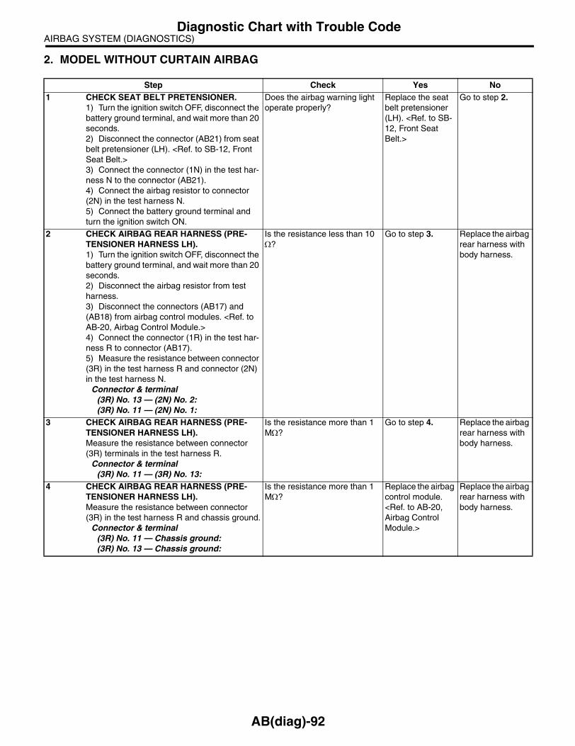
AIRBAG SYSTEM (DIAGNOSTICS)Diagnostic Chart with Trouble Code
2. MODEL WITHOUT CURTAIN AIRBAG
Step Check Yes No1 CHECK SEAT BELT PRETENSIONER.
1) Turn the ignition switch OFF, disconnect the battery ground terminal, and wait more than 20 seconds.2) Disconnect the connector (AB21) from seat belt pretensioner (LH). <Ref. to SB-12, Front Seat Belt.>3) Connect the connector (1N) in the test har-ness N to the connector (AB21).4) Connect the airbag resistor to connector (2N) in the test harness N.5) Connect the battery ground terminal and turn the ignition switch ON.
Does the airbag warning light operate properly?
Replace the seat belt pretensioner (LH). <Ref. to SB-12, Front Seat Belt.>
Go to step 2.
2 CHECK AIRBAG REAR HARNESS (PRE-TENSIONER HARNESS LH).1) Turn the ignition switch OFF, disconnect the battery ground terminal, and wait more than 20 seconds.2) Disconnect the airbag resistor from test harness.3) Disconnect the connectors (AB17) and (AB18) from airbag control modules. <Ref. to AB-20, Airbag Control Module.>4) Connect the connector (1R) in the test har-ness R to connector (AB17).5) Measure the resistance between connector (3R) in the test harness R and connector (2N) in the test harness N.
Connector & terminal(3R) No. 13 — (2N) No. 2:(3R) No. 11 — (2N) No. 1:
Is the resistance less than 10 Ω?
Go to step 3. Replace the airbag rear harness with body harness.
3 CHECK AIRBAG REAR HARNESS (PRE-TENSIONER HARNESS LH).Measure the resistance between connector (3R) terminals in the test harness R.
Connector & terminal(3R) No. 11 — (3R) No. 13:
Is the resistance more than 1 MΩ?
Go to step 4. Replace the airbag rear harness with body harness.
4 CHECK AIRBAG REAR HARNESS (PRE-TENSIONER HARNESS LH).Measure the resistance between connector (3R) in the test harness R and chassis ground.
Connector & terminal(3R) No. 11 — Chassis ground:(3R) No. 13 — Chassis ground:
Is the resistance more than 1 MΩ?
Replace the airbag control module. <Ref. to AB-20, Airbag Control Module.>
Replace the airbag rear harness with body harness.
AB(diag)-92

AIRBAG SYSTEM (DIAGNOSTICS)Diagnostic Chart with Trouble Code
AC:DTC 65DTC DETECTING CONDITION:• Seat belt pretensioner (RH) circuit is shorted to power supply.• Pretensioner is faulty.• Pretensioner harness is faulty.• Airbag control module is faulty.
CAUTION:• Before diagnosing the airbag system, be sure to turn the ignition switch OFF, disconnect theground terminal from battery, and wait more than 20 seconds before starting to work.• Before replacing the airbag module, seat belt pretensioner, roll connector, control module andsensor, reconnect each part and confirm that the warning light operates properly.• When inspecting the airbag rear harness, disconnect the side airbag module connector, curtainairbag module connector and seat belt pretensioner connector for safety reasons.WIRING DIAGRAM:
AB-00775
1 2
AB18
AB26
AB26
1 2
AIRBAG CONTROL MODULE
PRETENSIONER RH
WITH CURTAIN AIRBAG
1
2
*1 : 11
*2 : 12
WITHOUT CURTAIN AIRBAG
*1 : 5
*2 : 6
* *
AB18 AB18
7 8 9 10 11 12
13 14 15 16 17 18 19
5 6
20
1 2 3 41 2 3 4 5 6
7 8 9 10 11 12
(WITHOUT CURTAIN AIRBAG)(WITH CURTAIN AIRBAG)
AB(diag)-93

AIRBAG SYSTEM (DIAGNOSTICS)Diagnostic Chart with Trouble Code
1. MODEL WITH CURTAIN AIRBAG
Step Check Yes No1 CHECK SEAT BELT PRETENSIONER.
1) Turn the ignition switch OFF, disconnect the battery ground terminal, and wait more than 20 seconds.2) Disconnect the connector (AB26) from seat belt pretensioner (RH). <Ref. to SB-12, Front Seat Belt.>3) Connect the connector (1N) in the test har-ness N to connector (AB26).4) Connect the airbag resistor to connector (2N) in the test harness N.5) Connect the battery ground terminal and turn the ignition switch ON.
Does the airbag warning light operate properly?
Replace the seat belt pretensioner (RH). <Ref. to SB-12, Front Seat Belt.>
Go to step 2.
2 CHECK AIRBAG REAR HARNESS (PRE-TENSIONER HARNESS RH).1) Turn the ignition switch OFF, disconnect the battery ground terminal, and wait more than 20 seconds.2) Disconnect the airbag resistor from test harness.3) Disconnect the connector (AB24) from side airbag module (RH).4) Disconnect the connector (AB33) from cur-tain airbag module (RH).5) Disconnect the connectors (AB17) and (AB18) from airbag control modules. <Ref. to AB-20, Airbag Control Module.>6) Connect the connector (1U) in the test har-ness U to connector (AB18).7) Connect the battery ground terminal and turn the ignition switch ON.8) Measure the voltage between connector (3U) in the test harness U and chassis ground.
Connector & terminal(3U) No. 17 (+) — Chassis ground (−):(3U) No. 19 (+) — Chassis ground (−):
Is the voltage less than 1 V? Replace the airbag control module. <Ref. to AB-20, Airbag Control Module.>
Replace the airbag rear harness with body harness.
AB(diag)-94

AIRBAG SYSTEM (DIAGNOSTICS)Diagnostic Chart with Trouble Code
2. MODEL WITHOUT CURTAIN AIRBAG
Step Check Yes No1 CHECK SEAT BELT PRETENSIONER.
1) Turn the ignition switch OFF, disconnect the battery ground terminal, and wait more than 20 seconds.2) Disconnect the connector (AB26) from seat belt pretensioner (RH). <Ref. to SB-12, Front Seat Belt.>3) Connect the connector (1N) in the test har-ness N to connector (AB26).4) Connect the airbag resistor to connector (2N) in the test harness N.5) Connect the battery ground terminal and turn the ignition switch ON.
Does the airbag warning light operate properly?
Replace the seat belt pretensioner (RH). <Ref. to SB-12, Front Seat Belt.>
Go to step 2.
2 CHECK AIRBAG REAR HARNESS (PRE-TENSIONER HARNESS RH).1) Turn the ignition switch OFF, disconnect the battery ground terminal, and wait more than 20 seconds.2) Disconnect the airbag resistor from test harness.3) Disconnect the connectors (AB17) and (AB18) from the airbag control modules. <Ref. to AB-20, Airbag Control Module.>4) Connect the connector (1R) in the test har-ness R to connector (AB18).5) Connect the battery ground terminal and turn the ignition switch ON.6) Measure the voltage between connector (3R) in the test harness R and chassis ground.
Connector & terminal(3R) No. 19 (+) — Chassis ground (−):(3R) No. 17 (+) — Chassis ground (−):
Is the voltage less than 1 V? Replace the airbag control module. <Ref. to AB-20, Airbag Control Module.>
Replace the airbag rear harness with body harness.
AB(diag)-95

AIRBAG SYSTEM (DIAGNOSTICS)Diagnostic Chart with Trouble Code
AD:DTC 66DTC DETECTING CONDITION:• Seat belt pretensioner (LH) circuit is shorted to power supply.• Pretensioner is faulty.• Pretensioner harness is faulty.• Airbag control module is faulty.
CAUTION:• Before diagnosing the airbag system, be sure to turn the ignition switch OFF, disconnect theground terminal from battery, and wait more than 20 seconds before starting to work.• Before replacing the airbag module, seat belt pretensioner, roll connector, control module andsensor, reconnect each part and confirm that the warning light operates properly.• When inspecting the airbag rear harness, disconnect the side airbag module connector, curtainairbag module connector and seat belt pretensioner connector for safety reasons.WIRING DIAGRAM:
AB-00776
1 2
AB17
AB21
AB21
1 2
AIRBAG CONTROL MODULE
PRETENSIONER LH
WITH CURTAIN AIRBAG
1
2
*1 : 6
*2 : 5
WITHOUT CURTAIN AIRBAG
*1 : 2
*2 : 1
* *
AB17 AB17
7 8 9 10 11 12
13 14 15 16 17 18 19
5 6
20
1 2 3 41 2 3 4 5 6
7 8 9 10 11 12
(WITHOUT CURTAIN AIRBAG)(WITH CURTAIN AIRBAG)
AB(diag)-96

AIRBAG SYSTEM (DIAGNOSTICS)Diagnostic Chart with Trouble Code
1. MODEL WITH CURTAIN AIRBAG
Step Check Yes No1 CHECK SEAT BELT PRETENSIONER.
1) Turn the ignition switch OFF, disconnect the battery ground terminal, and wait more than 20 seconds.2) Disconnect the connector (AB21) from seat belt pretensioner (LH). <Ref. to SB-12, Front Seat Belt.>3) Connect the connector (1N) in the test har-ness N to the connector (AB21).4) Connect the airbag resistor to connector (2N) in the test harness N.5) Connect the battery ground terminal and turn the ignition switch ON.
Does the airbag warning light operate properly?
Replace the seat belt pretensioner (LH). <Ref. to SB-12, Front Seat Belt.>
Go to step 2.
2 CHECK AIRBAG REAR HARNESS (PRE-TENSIONER HARNESS LH).1) Turn the ignition switch OFF, disconnect the battery ground terminal, and wait more than 20 seconds.2) Disconnect the airbag resistor from test harness.3) Disconnect the connector (AB19) from side airbag module (LH).4) Disconnect the connector (AB31) from cur-tain airbag module (LH).5) Disconnect the connectors (AB17) and (AB18) from airbag control modules. <Ref. to AB-20, Airbag Control Module.>6) Connect the connector (1U) in the test har-ness U to connector (AB17).7) Connect the battery ground terminal and turn the ignition switch ON.8) Measure the voltage between connector (3U) in the test harness U and chassis ground.
Connector & terminal(3U) No. 11 (+) — Chassis ground (−):(3U) No. 13 (+) — Chassis ground (−):
Is the voltage less than 1 V? Replace the airbag control module. <Ref. to AB-20, Airbag Control Module.>
Replace the airbag rear harness with body harness.
AB(diag)-97

AIRBAG SYSTEM (DIAGNOSTICS)Diagnostic Chart with Trouble Code
2. MODEL WITHOUT CURTAIN AIRBAG
Step Check Yes No1 CHECK SEAT BELT PRETENSIONER.
1) Turn the ignition switch OFF, disconnect the battery ground terminal, and wait more than 20 seconds.2) Disconnect the connector (AB21) from seat belt pretensioner (LH). <Ref. to SB-12, Front Seat Belt.>3) Connect the connector (1N) in the test har-ness N to connector (AB21).4) Connect the airbag resistor to connector (2N) in the test harness N.5) Connect the battery ground terminal and turn the ignition switch ON.
Does the airbag warning light operate properly?
Replace the seat belt pretensioner (LH). <Ref. to SB-12, Front Seat Belt.>
Go to step 2.
2 CHECK AIRBAG REAR HARNESS (PRE-TENSIONER HARNESS LH).1) Turn the ignition switch OFF, disconnect the battery ground terminal, and wait more than 20 seconds.2) Disconnect the airbag resistor from test harness.3) Disconnect the connectors (AB17) and (AB18) from airbag control modules. <Ref. to AB-20, Airbag Control Module.>4) Connect the connector (1R) in the test har-ness R to connector (AB17).5) Connect the battery ground terminal and turn the ignition switch ON.6) Measure the voltage between connector (3R) in the test harness R and chassis ground.
Connector & terminal(3R) No. 13 (+) — Chassis ground (−):(3R) No. 11 (+) — Chassis ground (−):
Is the voltage less than 1 V? Replace the airbag control module. <Ref. to AB-20, Airbag Control Module.>
Replace the airbag rear harness with body harness.
AB(diag)-98

AIRBAG SYSTEM (DIAGNOSTICS)Diagnostic Chart with Trouble Code
AE:DTC 71DTC DETECTING CONDITION:• Airbag main harness circuit is open, shorted or shorted to ground.• Airbag module harness (Driver’s side) circuit is open, shorted or shorted to ground.• Roll connector circuit is open, shorted or shorted to ground.• Driver’s airbag module is faulty.• Airbag control module is faulty.
CAUTION:• Before diagnosing the airbag system, be sure to turn the ignition switch OFF, disconnect theground terminal from battery, and wait more than 20 seconds before starting to work.• Before replacing the airbag module, seat belt pretensioner, roll connector, control module andsensor, reconnect each part and confirm that the warning light operates properly.• When inspecting the airbag main harness, disconnect the airbag module connector of the driver’sand passenger’s seats for safety reasons.WIRING DIAGRAM:
16
17
13
14
AB6
AB2
AB2
AB7
1 23 4
AB6
AB38
1 21 2
21
AB38
AIRBAG CONTROL MODULE
STEERINGROLL CONNECTOR
INFLATOR(DRIVER SIDE)
(YELLOW) (YELLOW)
AB37
1 2 3 4
(BLACK)
21
AB37 (ORANGE)
AB-00662
1 2 3 4 5 67 8 9 10 11 12 13 14 15 16 17
18 19 20 21 22 23 24 25 26 27 28
AB(diag)-99

AIRBAG SYSTEM (DIAGNOSTICS)Diagnostic Chart with Trouble Code
Step Check Yes No1 CHECK DRIVER’S AIRBAG MODULE.
1) Turn the ignition switch OFF, disconnect the battery ground terminal, and wait more than 20 seconds.2) Remove the driver’s airbag module. <Ref. to AB-14, Driver’s Airbag Module.>3) Connect the connector (1N) in the test har-ness N to connector (AB38).4) Connect the airbag resistor to connector (2N) in the test harness N.5) Connect the connectors (1Q) in the test harness Q to connector (AB37).6) Connect the airbag resistor to connector (2Q) in the test harness Q.7) Connect the battery ground terminal and turn the ignition switch ON.
Does the airbag warning light operate properly?
Replace the driver’s airbag module. <Ref. to AB-14, Driver’s Airbag Module.>
Go to step 2.
2 CHECK ROLL CONNECTOR.1) Turn the ignition switch OFF, disconnect the battery ground terminal, and wait more than 20 seconds.2) Disconnect the test harness N from con-nector (AB38).3) Disconnect the test harness Q from con-nector (AB37).4) Remove the instrument panel lower cover, disconnect the connector (AB7) from (AB2).5) Connect the connector (1P) in the test har-ness P to connector (AB2).6) Connect the airbag resistor to connector (2P) and (3P) in the test harness P.7) Connect the battery ground terminal and turn the ignition switch ON.
Does the airbag warning light operate properly?
Replace the roll connector. <Ref. to AB-23, Roll Con-nector.>
Go to step 3.
3 CHECK AIRBAG MAIN HARNESS (DRIV-ER’S AIRBAG HARNESS).1) Turn the ignition switch OFF, disconnect the battery ground terminal, and wait more than 20 seconds.2) Disconnect the airbag resistor from con-nector (2P) and (3P) in the test harness P.3) Remove the instrument panel side cover of passenger’s side and disconnect the connector (AB10) and (AB9). <Ref. to AB-15, Passen-ger’s Airbag Module.>4) Disconnect the connector (AB6) from air-bag control module, and connect the connector (1U) in the test harness U. <Ref. to AB-20, Air-bag Control Module.>5) Measure the resistance between connector (2U) in the test harness U and connector (2P) and (3P) in the test harness P.
Connector & terminal(2U) No. 2 — (2P) No. 1:(2U) No. 4 — (2P) No. 2:(2U) No. 8 — (3P) No. 3:(2U) No. 12 — (3P) No. 4:
Is the resistance less than 10 Ω?
Go to step 4. Replace the airbag main harness with body harness.
AB(diag)-100

AIRBAG SYSTEM (DIAGNOSTICS)Diagnostic Chart with Trouble Code
4 CHECK AIRBAG MAIN HARNESS (DRIV-ER’S AIRBAG HARNESS).Measure the resistance between connector (2U) terminals in the test harness U and between the connector (2U) and chassis ground.
Connector & terminal(2U) No. 2 — (2U) No. 4:(2U) No. 4 — Chassis ground:(2U) No. 2 — Chassis ground:(2U) No. 8 — (2U) No. 12:(2U) No. 8 — Chassis ground:(2U) No. 12 — Chassis ground:
Is the resistance more than 1 MΩ?
Replace the airbag control module. <Ref. to AB-20, Airbag Control Module.>
Replace the airbag main harness with body harness.
Step Check Yes No
AB(diag)-101

AIRBAG SYSTEM (DIAGNOSTICS)Diagnostic Chart with Trouble Code
AF:DTC 72DTC DETECTING CONDITION:• Airbag main harness circuit is open, shorted or shorted to ground.• Airbag module harness (Passenger’s side) circuit is open, shorted or shorted to ground.• Passenger’s airbag module is faulty.• Airbag control module is faulty.
CAUTION:• Before diagnosing the airbag system, be sure to turn the ignition switch OFF, disconnect theground terminal from battery, and wait more than 20 seconds before starting to work.• Before replacing the airbag module, seat belt pretensioner, roll connector, control module andsensor, reconnect each part and confirm that the warning light operates properly.• When inspecting the airbag main harness, disconnect the airbag module connector of the driver’sand passenger’s seats for safety reasons.WIRING DIAGRAM:
AB-00663
AB6
INFLATOR (PASSENGER SIDE)
AB9
AB9
AB10
11
10
3 4
7 81 2
AIRBAG CONTROL MODULEAB6
1 2 3 4 5 67 8 9 10 11 12 13 14 15 16 17
18 19 20 21 22 23 24 25 26 27 28
1 2 3 4
AB(diag)-102

AIRBAG SYSTEM (DIAGNOSTICS)Diagnostic Chart with Trouble Code
Step Check Yes No1 CHECK PASSENGER’S AIRBAG MODULE.
1) Turn the ignition switch OFF, disconnect the battery ground terminal, and wait more than 20 seconds.2) Remove the instrument panel side cover on the passenger’s side.3) Disconnect the connector (AB10) from (AB9).4) Connect the connector (1P) in the test har-ness P to connector (AB9).5) Connect the airbag resistor to connector (2P) and (3P) in the test harness P.6) Connect the battery ground terminal and turn the ignition switch ON.
Does the airbag warning light operate properly?
Replace the pas-senger airbag module. <Ref. to AB-15, Passen-ger’s Airbag Mod-ule.>
Go to step 2.
2 CHECK AIRBAG MAIN HARNESS (PASSEN-GER’S AIRBAG HARNESS).1) Turn the ignition switch OFF, disconnect the battery ground terminal, and wait more than 20 seconds.2) Disconnect the airbag resistor from con-nector (2P) and (3P) in the test harness P.3) Remove the instrument panel lower cover, disconnect the connector (AB7) from (AB2).4) Disconnect the connector (AB6) from air-bag control module, and connect the connector (1U) in the test harness U. <Ref. to AB-20, Air-bag Control Module.>5) Measure the resistance between connector (2U) in the test harness U and connector (2P) and (3P) in the test harness P.
Connector & terminal(2U) No. 3 — (2P) No. 1:(2U) No. 5 — (2P) No. 2:(2U) No. 9 — (3P) No. 3:(2U) No. 13 — (3P) No. 4:
Is the resistance less than 10 Ω?
Go to step 3. Replace the airbag main harness with body harness.
3 CHECK AIRBAG MAIN HARNESS (PASSEN-GER’S AIRBAG HARNESS).Measure the resistance between connector (2U) terminals in the test harness U and between the connector (2U) and chassis ground.
Connector & terminal(2U) No. 3 — (2U) No. 5:(2U) No. 3 — Chassis ground:(2U) No. 5 — Chassis ground:(2U) No. 9 — (2U) No. 13:(2U) No. 9 — Chassis ground:(2U) No. 13 — Chassis ground:
Is the resistance more than 1 MΩ?
Replace the airbag control module. <Ref. to AB-20, Airbag Control Module.>
Replace the airbag main harness with body harness.
AB(diag)-103

AIRBAG SYSTEM (DIAGNOSTICS)Diagnostic Chart with Trouble Code
AG:DTC 75DTC DETECTING CONDITION:• Airbag main harness circuit (Driver’s side) is shorted to power supply.• Airbag module harness circuit (Driver’s side) is shorted to power supply.• Roll connector is shorted to the power supply.• Driver’s airbag module is faulty.• Airbag control module is faulty.
CAUTION:• Before diagnosing the airbag system, be sure to turn the ignition switch OFF, disconnect theground terminal from battery, and wait more than 20 seconds before starting to work.• Before replacing the airbag module, seat belt pretensioner, roll connector, control module andsensor, reconnect each part and confirm that the warning light operates properly.• When inspecting the airbag main harness, disconnect the airbag module connector of the driver’sand passenger’s seats for safety reasons.WIRING DIAGRAM:
16
17
13
14
AB6
AB2
AB2
AB7
1 23 4
AB6
AB38
1 21 2
21
AB38
AIRBAG CONTROL MODULE
STEERINGROLL CONNECTOR
INFLATOR(DRIVER SIDE)
(YELLOW) (YELLOW)
AB37
1 2 3 4
(BLACK)
21
AB37 (ORANGE)
AB-00662
1 2 3 4 5 67 8 9 10 11 12 13 14 15 16 17
18 19 20 21 22 23 24 25 26 27 28
AB(diag)-104

AIRBAG SYSTEM (DIAGNOSTICS)Diagnostic Chart with Trouble Code
Step Check Yes No1 CHECK DRIVER’S AIRBAG MODULE.
1) Turn the ignition switch OFF, disconnect the battery ground terminal, and wait more than 20 seconds.2) Remove the driver’s airbag module. <Ref. to AB-14, Driver’s Airbag Module.>3) Connect the connector (AB38) to connector (1N) in the test harness N.4) Connect the airbag resistor to connector (2N) in the test harness N.5) Connect the connectors (1Q) in the test harness Q to the connector (AB37).6) Connect the airbag resistor to connector (2Q) in the test harness Q.7) Connect the battery ground terminal and turn the ignition switch ON.
Does the airbag warning light operate properly?
Replace the driver’s airbag module. <Ref. to AB-14, Driver’s Airbag Module.>
Go to step 2.
2 CHECK ROLL CONNECTOR.1) Turn the ignition switch OFF, disconnect the battery ground terminal, and wait more than 20 seconds.2) Disconnect the test harness N from con-nector (AB38).3) Disconnect the test harness Q from con-nector (AB37).4) Remove the instrument panel lower cover, disconnect the connector (AB7) from (AB2).5) Connect the connector (1P) in the test har-ness P to connector (AB2).6) Connect the airbag resistor to connector (2P) and (3P) in the test harness P.7) Connect the battery ground terminal and turn the ignition switch ON.
Does the airbag warning light operate properly?
Replace the roll connector. <Ref. to AB-23, Roll Con-nector.>
Go to step 3.
3 CHECK AIRBAG MAIN HARNESS (DRIV-ER’S AIRBAG HARNESS).1) Turn the ignition switch OFF, disconnect the battery ground terminal, and wait more than 20 seconds.2) Disconnect the airbag resistor from con-nector (2P) and (3P) in the test harness P.3) Remove the instrument panel side cover of passenger’s side and disconnect the connector (AB10) and (AB9).4) Disconnect the connector (AB6) from air-bag control module, and connect the connector (1U) in the test harness U. <Ref. to AB-20, Air-bag Control Module.>5) Connect the battery ground terminal and turn the ignition switch ON. (engine OFF)6) Measure the voltage between connector (2U) in the test harness U and chassis ground.
Connector & terminal(2U) No. 4 (+) — Chassis ground (−):(2U) No. 2 (+) — Chassis ground (−):(2U) No. 8 (+) — Chassis ground (−):(2U) No. 12 (+) — Chassis ground (−):
Is the voltage less than 1 V? Replace the airbag control module. <Ref. to AB-20, Airbag Control Module.>
Replace the airbag main harness with body harness.
AB(diag)-105

AIRBAG SYSTEM (DIAGNOSTICS)Diagnostic Chart with Trouble Code
AH:DTC 76DTC DETECTING CONDITION:• Airbag main harness circuit (Passenger’s side) is shorted to power supply.• Airbag module harness circuit (Passenger’s side) is shorted to power supply.• Passenger’s airbag module is faulty.• Airbag control module is faulty.
CAUTION:• Before diagnosing the airbag system, be sure to turn the ignition switch OFF, disconnect theground terminal from battery, and wait more than 20 seconds before starting to work.• Before replacing the airbag module, seat belt pretensioner, roll connector, control module andsensor, reconnect each part and confirm that the warning light operates properly.• When inspecting the airbag main harness, disconnect the airbag module connector of the driver’sand passenger’s seats for safety reasons.WIRING DIAGRAM:
AB-00663
AB6
INFLATOR (PASSENGER SIDE)
AB9
AB9
AB10
11
10
3 4
7 81 2
AIRBAG CONTROL MODULEAB6
1 2 3 4 5 67 8 9 10 11 12 13 14 15 16 17
18 19 20 21 22 23 24 25 26 27 28
1 2 3 4
AB(diag)-106

AIRBAG SYSTEM (DIAGNOSTICS)Diagnostic Chart with Trouble Code
Step Check Yes No1 CHECK PASSENGER’S AIRBAG MODULE.
1) Turn the ignition switch OFF, disconnect the battery ground terminal, and wait more than 20 seconds.2) Remove the instrument panel side cover on the passenger’s side.3) Disconnect the connector (AB10) from (AB9).4) Connect the connector (1P) in the test har-ness P to connector (AB9).5) Connect the airbag resistor to connector (2P) and (3P) in the test harness P.6) Connect the battery ground terminal and turn the ignition switch ON.
Does the airbag warning light operate properly?
Replace the pas-senger airbag module. <Ref. to AB-15, Passen-ger’s Airbag Mod-ule.>
Go to step 2.
2 CHECK AIRBAG MAIN HARNESS (PASSEN-GER’S AIRBAG HARNESS).1) Turn the ignition switch OFF, disconnect the battery ground terminal, and wait more than 20 seconds.2) Disconnect the airbag resistor from con-nector (2P) and (3P) in the test harness P.3) Remove the instrument panel lower cover, disconnect the connector (AB7) from (AB2).4) Disconnect the connector (AB6) from air-bag control module, and connect the connector (1U) in the test harness U. <Ref. to AB-20, Air-bag Control Module.>5) Measure the voltage between connector (2U) in the test harness U and chassis ground.
Connector & terminal(2U) No. 3 (+) — Chassis ground (−):(2U) No. 5 (+) — Chassis ground (−):(2U) No. 9 (+) — Chassis ground (−):(2U) No. 13 (+) — Chassis ground (−):
Is the voltage less than 1 V? Replace the airbag control module. <Ref. to AB-20, Airbag Control Module.>
Replace the airbag main harness with body harness.
AB(diag)-107
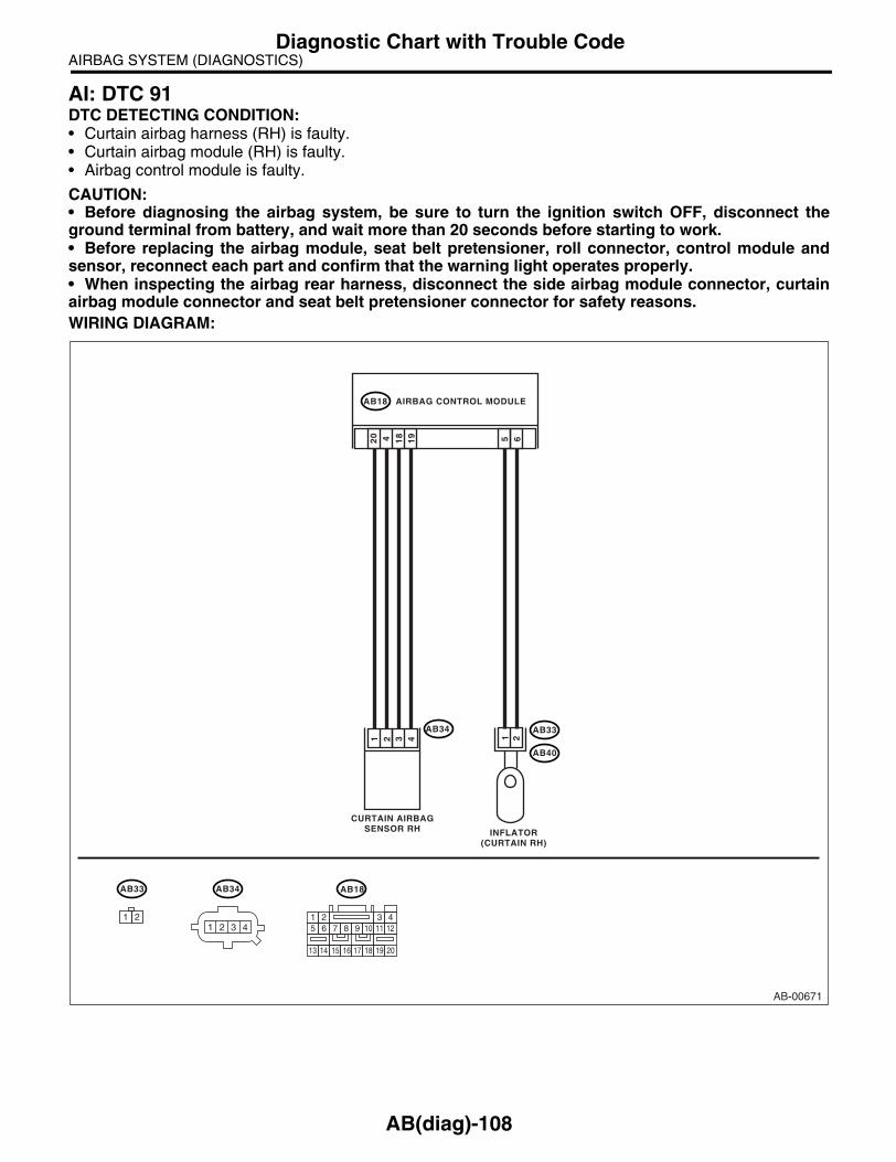
AIRBAG SYSTEM (DIAGNOSTICS)Diagnostic Chart with Trouble Code
AI: DTC 91DTC DETECTING CONDITION:• Curtain airbag harness (RH) is faulty.• Curtain airbag module (RH) is faulty.• Airbag control module is faulty.
CAUTION:• Before diagnosing the airbag system, be sure to turn the ignition switch OFF, disconnect theground terminal from battery, and wait more than 20 seconds before starting to work.• Before replacing the airbag module, seat belt pretensioner, roll connector, control module andsensor, reconnect each part and confirm that the warning light operates properly.• When inspecting the airbag rear harness, disconnect the side airbag module connector, curtainairbag module connector and seat belt pretensioner connector for safety reasons.WIRING DIAGRAM:
AB-00671
AB18
AB33
AB40
1 265
AB34
20
194 18
3 41 2
AB18AB33
1 2
AIRBAG CONTROL MODULE
INFLATOR(CURTAIN RH)
CURTAIN AIRBAGSENSOR RH
7 8 9 10 11 12
13 14 15 16 17 18 19
5 6
20
1 2 3 4
AB34
1 2 3 4
AB(diag)-108

AIRBAG SYSTEM (DIAGNOSTICS)Diagnostic Chart with Trouble Code
Step Check Yes No1 CHECK CURTAIN AIRBAG MODULE.
1) Turn the ignition switch OFF, disconnect the battery ground terminal, and wait more than 20 seconds.2) Disconnect the connector (AB33) from (AB40), and connect the connector (1F) in test harness F to connector (AB33).3) Connect the airbag resistor to connector (3F) in the test harness F.4) Connect the battery ground terminal and turn the ignition switch ON.
Does the airbag warning light operate properly?
Replace the cur-tain airbag mod-ule (RH). <Ref. to AB-18, Curtain Air-bag Module.>
Go to step 2.
2 CHECK AIRBAG REAR HARNESS (CUR-TAIN AIRBAG MODULE HARNESS RH).1) Turn the ignition switch OFF, disconnect the battery ground terminal, and wait more than 20 seconds.2) Disconnect the connector (AB26) from seat belt pretensioner (RH). <Ref. to SB-12, Front Seat Belt.>3) Disconnect the connector (AB24) from side airbag module (RH).4) Disconnect the airbag resistor from the test harness F.5) Disconnect the connector (AB18) from air-bag control module. <Ref. to AB-20, Airbag Control Module.>6) Connect the connector (1U) in the test har-ness U to connector (AB18).7) Measure the resistance between connector (5U) in the test harness U and connector (3F) in the test harness F.
Connector & terminal(5U) No. 6 — (3F) No. 3:(5U) No. 8 — (3F) No. 4:
Is the resistance less than 10 Ω?
Go to step 3. Replace the airbag rear harness with body harness.
3 CHECK AIRBAG REAR HARNESS (CUR-TAIN AIRBAG MODULE HARNESS RH).Measure the resistance between connector (5U) terminals in the test harness U.
Connector & terminal(5U) No. 6 — (5U) No. 8:
Is the resistance more than 1 MΩ?
Go to step 4. Replace the airbag rear harness with body harness.
4 CHECK AIRBAG REAR HARNESS (CUR-TAIN AIRBAG MODULE HARNESS RH).Measure the resistance between the terminals of connector (3F) in the test harness F.
Connector & terminal(3F) No. 3 — (3F) No. 4:
Is the resistance more than 1 MΩ?
Go to step 5. Replace the airbag rear harness with body harness.
5 CHECK AIRBAG REAR HARNESS (CUR-TAIN AIRBAG MODULE HARNESS RH).Measure the resistance between connector (3F) in the test harness F and chassis ground.
Connector & terminal(3F) No. 3 — Chassis ground:(3F) No. 4 — Chassis ground:
Is the resistance more than 1 MΩ?
Go to step 6. Replace the airbag rear harness with body harness.
6 CHECK AIRBAG REAR HARNESS (CUR-TAIN AIRBAG MODULE HARNESS RH).Measure the resistance between connector (5U) in the test harness U and chassis ground.
Connector & terminal(5U) No. 6 — Chassis ground:(5U) No. 8 — Chassis ground:
Is the resistance more than 1 MΩ?
Replace the airbag control module. <Ref. to AB-20, Airbag Control Module.>
Replace the airbag rear harness with body harness.
AB(diag)-109

AIRBAG SYSTEM (DIAGNOSTICS)Diagnostic Chart with Trouble Code
AJ:DTC 92DTC DETECTING CONDITION:• Curtain airbag harness (LH) is faulty.• Curtain airbag module (LH) is faulty.• Airbag control module is faulty.
CAUTION:• Before diagnosing the airbag system, be sure to turn the ignition switch OFF, disconnect theground terminal from battery, and wait more than 20 seconds before starting to work.• Before replacing the airbag module, seat belt pretensioner, roll connector, control module andsensor, reconnect each part and confirm that the warning light operates properly.• When inspecting the airbag main harness, disconnect the airbag module connector of the driver’sand passenger’s seats for safety reasons.• When inspecting the airbag rear harness, disconnect the side airbag module connector, curtainairbag module connector and seat belt pretensioner connector for safety reasons.WIRING DIAGRAM:
AB-00672
AB32
1 21
11
2
AB31
AB39
151 14
13
3 41 2
AB31
1 2
AB17
AB17 AIRBAG CONTROL MODULE
INFLATOR(CURTAIN LH)
CURTAIN AIRBAGSENSOR LH
7 8 9 10 11 12
13 14 15 16 17 18 19
5 6
20
1 2 3 4
AB32
1 2 3 4
AB(diag)-110

AIRBAG SYSTEM (DIAGNOSTICS)Diagnostic Chart with Trouble Code
Step Check Yes No1 CHECK CURTAIN AIRBAG MODULE.
1) Turn the ignition switch OFF, disconnect the battery ground terminal, and wait more than 20 seconds.2) Disconnect the connector (AB31) from (AB39), and connect the connector (1F) in test harness F to connector (AB31).3) Connect the airbag resistor to connector (3F) in the test harness F.4) Connect the battery ground terminal and turn the ignition switch ON.
Does the airbag warning light operate properly?
Replace the cur-tain airbag mod-ule (LH). <Ref. to AB-18, Curtain Air-bag Module.>
Go to step 2.
2 CHECK AIRBAG REAR HARNESS (CUR-TAIN AIRBAG MODULE HARNESS LH).1) Turn the ignition switch OFF, disconnect the battery ground terminal, and wait more than 20 seconds.2) Disconnect the connector (AB21) from seat belt pretensioner (LH). <Ref. to SB-12, Front Seat Belt.>3) Disconnect the connector (AB19) from side airbag module (LH).4) Disconnect the airbag resistor from the test harness F.5) Disconnect the connector (AB17) from air-bag control module. <Ref. to AB-20, Airbag Control Module.>6) Connect the connector (1U) in the test har-ness U to connector (AB17).7) Measure the resistance between connector (5U) in the test harness U and connector (3F) in the test harness F.
Connector & terminal(5U) No. 1 — (3F) No. 4:(5U) No. 3 — (3F) No. 3:
Is the resistance less than 10 Ω?
Go to step 3. Replace the airbag rear harness with body harness.
3 CHECK AIRBAG REAR HARNESS (CUR-TAIN AIRBAG MODULE HARNESS LH).Measure the resistance between connector (5U) terminals in the test harness U.
Connector & terminal(5U) No. 1 — (5U) No. 3:
Is the resistance more than 1 MΩ?
Go to step 4. Replace the airbag rear harness with body harness.
4 CHECK AIRBAG REAR HARNESS (CUR-TAIN AIRBAG MODULE HARNESS LH).Measure the resistance between the terminals of connector (3F) in the test harness F.
Connector & terminal(3F) No. 3 — (3F) No. 4:
Is the resistance more than 1 MΩ?
Go to step 5. Replace the airbag rear harness with body harness.
5 CHECK AIRBAG REAR HARNESS (CUR-TAIN AIRBAG MODULE HARNESS LH).Measure the resistance between connector (3F) in the test harness F and chassis ground.
Connector & terminal(3F) No. 3 — Chassis ground:(3F) No. 4 — Chassis ground:
Is the resistance more than 1 MΩ?
Go to step 6. Replace the airbag rear harness with body harness.
6 CHECK AIRBAG REAR HARNESS (CUR-TAIN AIRBAG MODULE HARNESS LH).Measure the resistance between connector (5U) in the test harness U and chassis ground.
Connector & terminal(5U) No. 1 — Chassis ground:(5U) No. 3 — Chassis ground:
Is the resistance more than 1 MΩ?
Replace the airbag control module. <Ref. to AB-20, Airbag Control Module.>
Replace the airbag rear harness with body harness.
AB(diag)-111

AIRBAG SYSTEM (DIAGNOSTICS)Diagnostic Chart with Trouble Code
AK:DTC 95DTC DETECTING CONDITION:• Curtain airbag harness (RH) is shorted to power supply.• Airbag control module is faulty.
CAUTION:• Before diagnosing the airbag system, be sure to turn the ignition switch OFF, disconnect theground terminal from battery, and wait more than 20 seconds before starting to work.• Before replacing the airbag module, seat belt pretensioner, roll connector, control module andsensor, reconnect each part and confirm that the warning light operates properly.• When inspecting the airbag main harness, disconnect the airbag module connector of the driver’sand passenger’s seats for safety reasons.• When inspecting the airbag rear harness, disconnect the side airbag module connector, curtainairbag module connector and seat belt pretensioner connector for safety reasons.WIRING DIAGRAM:
AB-00671
AB18
AB33
AB40
1 265
AB34
20
194 18
3 41 2
AB18AB33
1 2
AIRBAG CONTROL MODULE
INFLATOR(CURTAIN RH)
CURTAIN AIRBAGSENSOR RH
7 8 9 10 11 12
13 14 15 16 17 18 19
5 6
20
1 2 3 4
AB34
1 2 3 4
AB(diag)-112

AIRBAG SYSTEM (DIAGNOSTICS)Diagnostic Chart with Trouble Code
Step Check Yes No1 CHECK CURTAIN AIRBAG MODULE.
1) Turn the ignition switch OFF, disconnect the battery ground terminal, and wait more than 20 seconds.2) Disconnect the connector (AB33) from (AB40), and connect the connector (1F) in test harness F to connector (AB33). 3) Connect the airbag resistor to connector (3F) in the test harness F.4) Connect the battery ground terminal and turn the ignition switch ON.
Does the airbag warning light operate properly?
Replace the cur-tain airbag mod-ule (RH). <Ref. to AB-18, Curtain Air-bag Module.>
Go to step 2.
2 CHECK AIRBAG REAR HARNESS (CUR-TAIN AIRBAG MODULE HARNESS RH).1) Turn the ignition switch OFF, disconnect the battery ground terminal, and wait more than 20 seconds.2) Disconnect the connector (AB26) from seat belt pretensioner (RH). <Ref. to SB-12, Front Seat Belt.>3) Disconnect the connector (AB24) from side airbag module (RH).4) Disconnect the airbag resistor from the test harness F.5) Disconnect the connector (AB18) from air-bag control module. <Ref. to AB-20, Airbag Control Module.>6) Connect the connector (1U) in the test har-ness U to connector (AB18).7) Connect the battery ground terminal and turn the ignition switch ON.8) Measure the voltage between connector (5U) in the test harness U and chassis ground.
Connector & terminal(5U) No. 6 (+) — Chassis ground (−):(5U) No. 8 (+) — Chassis ground (−):
Is the voltage less than 1 V? Replace the airbag control module. <Ref. to AB-20, Airbag Control Module.>
Replace the airbag rear harness with body harness.
AB(diag)-113
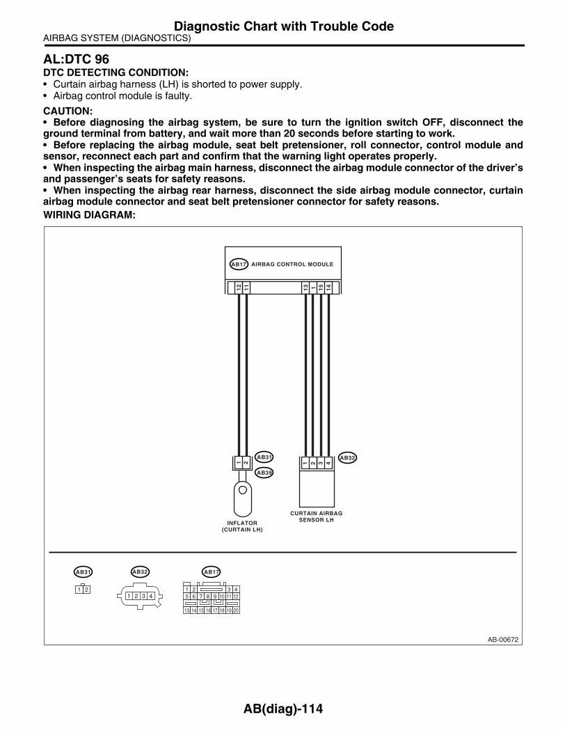
AIRBAG SYSTEM (DIAGNOSTICS)Diagnostic Chart with Trouble Code
AL:DTC 96DTC DETECTING CONDITION:• Curtain airbag harness (LH) is shorted to power supply.• Airbag control module is faulty.
CAUTION:• Before diagnosing the airbag system, be sure to turn the ignition switch OFF, disconnect theground terminal from battery, and wait more than 20 seconds before starting to work.• Before replacing the airbag module, seat belt pretensioner, roll connector, control module andsensor, reconnect each part and confirm that the warning light operates properly.• When inspecting the airbag main harness, disconnect the airbag module connector of the driver’sand passenger’s seats for safety reasons.• When inspecting the airbag rear harness, disconnect the side airbag module connector, curtainairbag module connector and seat belt pretensioner connector for safety reasons.WIRING DIAGRAM:
AB-00672
AB32
1 21
11
2
AB31
AB39
151 14
13
3 41 2
AB31
1 2
AB17
AB17 AIRBAG CONTROL MODULE
INFLATOR(CURTAIN LH)
CURTAIN AIRBAGSENSOR LH
7 8 9 10 11 12
13 14 15 16 17 18 19
5 6
20
1 2 3 4
AB32
1 2 3 4
AB(diag)-114

AIRBAG SYSTEM (DIAGNOSTICS)Diagnostic Chart with Trouble Code
Step Check Yes No1 CHECK SIDE AIRBAG MODULE.
1) Turn the ignition switch OFF, disconnect the battery ground terminal, and wait more than 20 seconds.2) Disconnect the connector (AB31) from (AB39), and connect the connector (1F) in test harness F to the connector (AB31).3) Connect the airbag resistor to connector (3F) in the test harness F.4) Connect the battery ground terminal and turn the ignition switch ON.
Does the airbag warning light operate properly?
Replace the cur-tain airbag mod-ule (LH). <Ref. to AB-18, Curtain Air-bag Module.>
Go to step 2.
2 CHECK AIRBAG REAR HARNESS (CUR-TAIN AIRBAG MODULE HARNESS LH).1) Turn the ignition switch OFF, disconnect the battery ground terminal, and wait more than 20 seconds.2) Disconnect the connector (AB21) from seat belt pretensioner (LH). <Ref. to SB-12, Front Seat Belt.>3) Disconnect the connector (AB19) from side airbag module (LH).4) Disconnect the airbag resistor from the test harness F.5) Disconnect the connector (AB17) from air-bag control module. <Ref. to AB-20, Airbag Control Module.>6) Connect the connector (1U) in the test har-ness U to connector (AB17).7) Connect the battery ground terminal and turn the ignition switch ON.8) Measure the voltage between connector (5U) in the test harness U and chassis ground.
Connector & terminal(5U) No. 1 (+) — Chassis ground (−):(5U) No. 3 (+) — Chassis ground (−):
Is the voltage less than 1 V? Replace the airbag control module. <Ref. to AB-20, Airbag Control Module.>
Replace the airbag rear harness with body harness.
AB(diag)-115

AIRBAG SYSTEM (DIAGNOSTICS)Diagnostic Chart with Trouble Code
AB(diag)-116

SEAT BELT SYSTEM
SB
Page1. General Description ....................................................................................22. Pretensioner Connector ..............................................................................63. Inspection Locations After a Collision .........................................................74. Seat Belt Warning System ..........................................................................85. Front Seat Belt ..........................................................................................126. Rear Seat Belt...........................................................................................147. Disposal of Pretensioner ...........................................................................17

SEAT BELT SYSTEMGeneral Description
1. General DescriptionA: COMPONENT1. FRONT SEAT BELT
(1) Adjustable anchor ASSY (4) Seat belt retractor Tightening torque: N⋅m (kgf-m, ft-lb)(2) Shoulder anchor (5) Center pillar upper trim T1: 30 (3.1, 22)(3) Outer seat belt ASSY (6) Inner seat belt ASSY T2: 38 (3.9, 28)
T3: 53 (5.4, 39)
SB-00178
(6)
T2
T1
T1
T3
(3)
(4)
(5)
(2)
(1)
T1
T3
SB-2
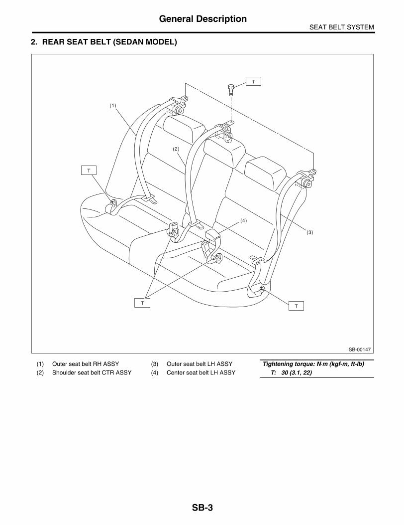
SEAT BELT SYSTEMGeneral Description
2. REAR SEAT BELT (SEDAN MODEL)
(1) Outer seat belt RH ASSY (3) Outer seat belt LH ASSY Tightening torque: N⋅m (kgf-m, ft-lb)(2) Shoulder seat belt CTR ASSY (4) Center seat belt LH ASSY T: 30 (3.1, 22)
SB-00147
T
(4)
(2)
(1)
(3)
TT
T
SB-3

SEAT BELT SYSTEMGeneral Description
3. REAR SEAT BELT (WAGON MODEL)
(1) Outer seat belt RH ASSY (5) Center seat belt LH ASSY Tightening torque: N⋅m (kgf-m, ft-lb)(2) Shoulder seat belt CTR ASSY (6) Outer belt guide RH T1: 30 (3.1, 22)(3) Outer seat belt LH ASSY (7) Outer belt guide LH T2: 53 (5.4, 39.1)(4) Center seat belt RH ASSY
SB-00148
(2)
(6)
(1)
(4)
(7)
T2
(5)
(3)
T1
T1 T1
T1
T1
SB-4

SEAT BELT SYSTEMGeneral Description
B: CAUTION• Before starting service, turn the ignition switch toOFF, disconnect the battery ground cable and waitfor 20 seconds or more.• The pretensioner system has a backup powersource. The pretensioner might deploy if you do notwait for 20 seconds or more before starting work.• Do not drop or apply any impact to the preten-sioner.• If oil, grease or water gets on the pretensioner,wipe it off immediately with a dry cloth.• Do not expose the pretensioner to high tempera-ture or flame.• Do not allow current to flow through or voltage toreach the pretensioner. Do not use a circuit testerto check resistance of the pretensioner.
• Do not disassemble or attempt to repair the pre-tensioner. If it is dented, cracked or deformed, re-place it with a new one.• Do not use the airbag or pretensioner parts fromother vehicles. Always replace the parts with newones.• When handling a seat belt with deployed preten-sioner, wear gloves and goggles. Wash your handsafterwards.• Do not reuse a seat belt with deployed preten-sioner.• If the material gets in your eyes or on your skinduring deployment, wash it away with clean water,and then consult a doctor.
C: PREPARATION TOOL1. SPECIAL TOOL
ILLUSTRATION TOOL NUMBER DESCRIPTION REMARKS
98299SA010 DEPLOYMENT ADAPTER D
• Used for deploying the pretensioner.• Used with DEPLOYMENT TOOL(98299PA030).
98299PA030 DEPLOYMENT TOOL
• Used for deploying the pretensioner.• Used with DEPLOYMENT ADAPTER D (98299SA010).
ST98299SA010
ST98299PA030
SB-5

SEAT BELT SYSTEMPretensioner Connector
2. Pretensioner Connector A: REMOVAL1) Using a flat tip screwdriver, pry the push lock up-ward to unlock.
2) Pull out the connector to disconnect it from re-tractor assembly.
B: INSTALLATIONConnect the connector in the reverse order of dis-connection. At this time, be sure to insert the pushlock until a connecting sound is heard.
CAUTION:• Be sure to insert the connector in until it islocked. Then pull on it gently to make sure thatit is locked.• Be sure to push the push lock in securely.
AB-00478
AB-00479
AB-00480
SB-6

SEAT BELT SYSTEMInspection Locations After a Collision
3. Inspection Locations After a Collision
A: INSPECTIONCheck for the following, and replace with new partsif necessary.• Center pillar lower garnish is discolored orcracked.• Wire harness and connector are damaged.
SB-7
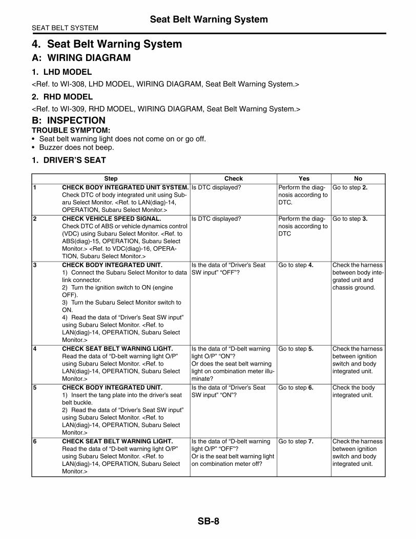
SEAT BELT SYSTEMSeat Belt Warning System
4. Seat Belt Warning SystemA: WIRING DIAGRAM1. LHD MODEL<Ref. to WI-308, LHD MODEL, WIRING DIAGRAM, Seat Belt Warning System.>
2. RHD MODEL<Ref. to WI-309, RHD MODEL, WIRING DIAGRAM, Seat Belt Warning System.>
B: INSPECTIONTROUBLE SYMPTOM:• Seat belt warning light does not come on or go off.• Buzzer does not beep.
1. DRIVER’S SEAT
Step Check Yes No1 CHECK BODY INTEGRATED UNIT SYSTEM.
Check DTC of body integrated unit using Sub-aru Select Monitor. <Ref. to LAN(diag)-14, OPERATION, Subaru Select Monitor.>
Is DTC displayed? Perform the diag-nosis according to DTC.
Go to step 2.
2 CHECK VEHICLE SPEED SIGNAL.Check DTC of ABS or vehicle dynamics control (VDC) using Subaru Select Monitor. <Ref. to ABS(diag)-15, OPERATION, Subaru Select Monitor.> <Ref. to VDC(diag)-16, OPERA-TION, Subaru Select Monitor.>
Is DTC displayed? Perform the diag-nosis according to DTC
Go to step 3.
3 CHECK BODY INTEGRATED UNIT.1) Connect the Subaru Select Monitor to data link connector.2) Turn the ignition switch to ON (engine OFF).3) Turn the Subaru Select Monitor switch to ON.4) Read the data of “Driver’s Seat SW input” using Subaru Select Monitor. <Ref. to LAN(diag)-14, OPERATION, Subaru Select Monitor.>
Is the data of “Driver’s Seat SW input” “OFF”?
Go to step 4. Check the harness between body inte-grated unit and chassis ground.
4 CHECK SEAT BELT WARNING LIGHT.Read the data of “D-belt warning light O/P” using Subaru Select Monitor. <Ref. to LAN(diag)-14, OPERATION, Subaru Select Monitor.>
Is the data of “D-belt warning light O/P” “ON”?Or does the seat belt warning light on combination meter illu-minate?
Go to step 5. Check the harness between ignition switch and body integrated unit.
5 CHECK BODY INTEGRATED UNIT.1) Insert the tang plate into the driver’s seat belt buckle.2) Read the data of “Driver’s Seat SW input” using Subaru Select Monitor. <Ref. to LAN(diag)-14, OPERATION, Subaru Select Monitor.>
Is the data of “Driver’s Seat SW input” “ON”?
Go to step 6. Check the body integrated unit.
6 CHECK SEAT BELT WARNING LIGHT.Read the data of “D-belt warning light O/P” using Subaru Select Monitor. <Ref. to LAN(diag)-14, OPERATION, Subaru Select Monitor.>
Is the data of “D-belt warning light O/P” “OFF”?Or is the seat belt warning light on combination meter off?
Go to step 7. Check the harness between ignition switch and body integrated unit.
SB-8

SEAT BELT SYSTEMSeat Belt Warning System
2. PASSENGER’S SEAT
7 CHECK VEHICLE MODEL. Is the vehicle EC, EK or KA model?
Go to step 8. The seat belt warning light sys-tem is normal at this time. A tempo-rary poor contact of harness con-nector may be the cause. Check the poor contact.
8 CHECK SEAT BELT WARNING SYSTEM.1) Hold the tang plate disconnected from seat belt buckle.2) Turn the ignition switch to ON.
Does the seat belt warning light illuminate?
Go to step 9. Replace the body integrated unit.
9 CHECK SEAT BELT WARNING SYSTEM.1) Lift-up the vehicle.
NOTE:Raise all wheels off floor.
2) Hold the tang plate disconnected from seat belt buckle.3) Start the engine, and set the vehicle speed to more than 24 km/h (15MPH).
NOTE:The speed difference between front and rearwheels may light the ABS or VDC warning light,but this indicates no malfunction. When diagno-sis is finished, perform the ABS or VDC memo-ry clearance procedure. <Ref. to ABS(diag)-15,OPERATION, Subaru Select Monitor.> <Ref. toVDC(diag)-16, OPERATION, Subaru SelectMonitor.>
Does the seat belt warning light blink and the buzzer beep?
Go to step 10. Replace the body integrated unit.
10 CHECK SEAT BELT WARNING SYSTEM.While the seat belt warning light is blinking and the buzzer is beeping, decelerate the vehicle speed to less than 21 km/h (13 MPH).
Does the buzzer stop beeping and the seat belt warning light change from blinking to illumi-nating?
Go to step 11. Replace the body integrated unit.
11 CHECK SEAT BELT WARNING SYSTEM.1) Start the engine, and set the vehicle speed to more than 24 km/h (15 MPH).2) Wait for approx. 108 seconds while the seat belt warning light is blinking and the buzzer is beeping.
NOTE:The speed difference between front and rearwheels may light the ABS or VDC warning light,but this indicates no malfunction. When diagno-sis is finished, perform the ABS or VDC memo-ry clearance procedure. <Ref. to ABS(diag)-15,OPERATION, Subaru Select Monitor.> <Ref. toVDC(diag)-16, OPERATION, Subaru SelectMonitor.>
Does the buzzer stop beeping and the seat belt warning light change from blinking to illumi-nating?
The seat belt warning system is normal. A tempo-rary poor contact of harness con-nector may be the cause. Check the poor contact.
Replace the body integrated unit.
Step Check Yes No1 CHECK BODY INTEGRATED UNIT SYSTEM.
Check DTC of body integrated unit using Sub-aru Select Monitor. <Ref. to LAN(diag)-14, OPERATION, Subaru Select Monitor.>
Is DTC displayed? Perform the diag-nosis according to DTC.
Go to step 2.
Step Check Yes No
SB-9

SEAT BELT SYSTEMSeat Belt Warning System
2 CHECK VEHICLE SPEED SIGNAL.Check DTC of ABS or VDC using Subaru Select Monitor. <Ref. to ABS(diag)-15, OPER-ATION, Subaru Select Monitor.> <Ref. to VDC(diag)-16, OPERATION, Subaru Select Monitor.>
Is DTC displayed? Perform the diag-nosis according to DTC.
Go to step 3.
3 CHECK BODY INTEGRATED UNIT.1) Connect the Subaru Select Monitor to data link connector.2) Turn the ignition switch to ON (engine OFF).3) Turn the Subaru Select Monitor switch to ON.4) Read the data of “P seatbelt SW input” using Subaru Select Monitor. <Ref. to LAN(diag)-14, OPERATION, Subaru Select Monitor.>
Is the data of “P seatbelt SW input” “OFF”?
Go to step 4. Check the harness between body inte-grated unit and chassis ground.
4 CHECK SEAT BELT WARNING LIGHT.Read the data of “P-belt warning light O/P” using Subaru Select Monitor. <Ref. to LAN(diag)-14, OPERATION, Subaru Select Monitor.>
Is the data of “P-belt warning light O/P” “ON”?Or does the passenger’s seat belt warning light illuminate?
Go to step 5. Check the harness between ignition switch and body integrated unit.
5 CHECK BODY INTEGRATED UNIT.1) Insert the tang plate into the passenger’s seat belt buckle.2) Read the data of “P seatbelt SW input” using Subaru Select Monitor. <Ref. to LAN(diag)-14, OPERATION, Subaru Select Monitor.>
Is the data of “P seatbelt SW input” “ON”?
Go to step 6. Check the body integrated unit.
6 CHECK SEAT BELT WARNING LIGHT.Read the data of “P-belt warning light O/P” using Subaru Select Monitor. <Ref. to LAN(diag)-14, OPERATION, Subaru Select Monitor.>
Is the data of “P-belt warning light O/P” “OFF”?Or is the passenger’s seat belt warning light off?
Go to step 7. Check the harness between ignition switch and body integrated unit.
7 CHECK VEHICLE MODEL. Is the vehicle EC, EK or KA model?
Go to step 8. The seat belt warning system is normal at this time. A temporary poor contact of har-ness connector may be the cause. Check the poor contact.
8 CHECK SEAT BELT WARNING SYSTEM.1) Hold the tang plate disconnected from seat belt buckle.2) Turn the ignition switch to ON.
Does the seat belt warning light illuminate?
Go to step 9. Replace the body integrated unit.
Step Check Yes No
SB-10

SEAT BELT SYSTEMSeat Belt Warning System
9 CHECK SEAT BELT WARNING SYSTEM.1) Lift-up the vehicle.
NOTE:Raise all wheels off floor.
2) Insert the tang plate of driver’s seat belt into seat belt buckle.3) Hold the tang plate of passenger’s seat belt disconnected from seat belt buckle.4) Start the engine, and set the vehicle speed to more than 24 km/h (15 MPH).
NOTE:The speed difference between front and rearwheels may light the ABS or VDC warning light,but this indicates no malfunction. When diagno-sis is finished, perform the ABS or VDC memo-ry clearance procedure. <Ref. to ABS(diag)-15,OPERATION, Subaru Select Monitor.> <Ref. toVDC(diag)-16, OPERATION, Subaru SelectMonitor.>
Does the seat belt warning light blink and the buzzer beep?
Go to step 10. Replace the body integrated unit.
10 CHECK SEAT BELT WARNING SYSTEM.While the seat belt warning light is blinking and the buzzer is beeping, decelerate the vehicle speed to less than 21 km/h (13 MPH).
Does the buzzer stop beeping and the seat belt warning light change from blinking to illumi-nating?
Go to step 11. Replace the body integrated unit.
11 CHECK SEAT BELT WARNING SYSTEM.1) Start the engine, and set the vehicle speed to more than 24 km/h (15 MPH).2) Wait for approx. 108 seconds while the seat belt warning light is blinking and the buzzer is beeping.
NOTE:The speed difference between front and rearwheels may light the ABS or VDC warning light,but this indicates no malfunction. When diagno-sis is finished, perform the ABS or VDC memo-ry clearance procedure. <Ref. to ABS(diag)-15,OPERATION, Subaru Select Monitor.> <Ref. toVDC(diag)-16, OPERATION, Subaru SelectMonitor.>
Does the buzzer stop beeping and the seat belt warning light change from blinking to illumi-nating?
The seat belt warning system is normal. A tempo-rary poor contact of harness con-nector may be the cause. Check the poor contact.
Replace the body integrated unit.
Step Check Yes No
SB-11

SEAT BELT SYSTEMFront Seat Belt
5. Front Seat BeltA: REMOVAL1. OUTER SEAT BELT ASSEMBLY1) Turn the ignition switch to OFF, disconnect thebattery ground cable from battery, and wait formore than 20 seconds before starting work.2) Fold the backrest all the way forward, and thenmove the front seat all the way forward.3) Remove the center pillar lower trim. <Ref. to EI-60, REMOVAL, Lower Inner Trim.>4) Remove the center pillar upper trim. <Ref. to EI-62, REMOVAL, Upper Inner Trim.>5) Remove the bolt, and remove the center pillar in-ner protector lower.
6) Remove the bolt, and then remove the shoulderanchor.
7) Remove the bolt, and then remove the adjust-able anchor assembly.
8) Disconnect the pretensioner connector (A), andremove the bolt, and then remove the seat belt re-tractor.
NOTE:Disconnect the tension reducer connector (B) forthe seat belt retractor with tension reducer function.
CAUTION:• Do not drop or apply any impact to the pre-tensioner.• Since the pretensioner and bracket are inte-grated as a unit, do not disassemble them.
2. INNER SEAT BELT ASSEMBLY1) Turn the ignition switch to OFF, disconnect thebattery ground cable from battery, and wait formore than 20 seconds before starting work.2) Remove the console box. <Ref. to EI-53, RE-MOVAL, Console Box.>3) Disconnect the seat belt warning light connectorunder the seat.4) Remove the harness clips from seat rail.5) Remove the TORX® bolt, and then remove theinner seat belt assembly.
SB-00144
SB-00152
SB-00153
SB-00154
(A)
(B)
SE-00332
SB-12

SEAT BELT SYSTEMFront Seat Belt
B: INSTALLATION1. OUTER SEAT BELT ASSEMBLYInstall in the reverse order of removal.
CAUTION:• The parts of driver and passenger sides arenot identical. Before installation, make surethat the correct part is used.• Be careful not to twist the seat belts duringinstallation.
Tightening torque:<Ref. to SB-2, FRONT SEAT BELT, COMPO-NENT, General Description.>
2. INNER SEAT BELT ASSEMBLYInstall in the reverse order of removal.
Tightening torque:<Ref. to SB-2, FRONT SEAT BELT, COMPO-NENT, General Description.>
C: INSPECTION1. OUTER SEAT BELT ASSEMBLYCheck for the following, and replace with new partsif necessary.• Pretensioner is cracked or deformed.• Seat belt is slackened, bent or worn. Seat belt isabnormally wound or extended.
2. INNER SEAT BELT ASSEMBLYCheck for the following, and replace with new partsif necessary.• Inner seat belt assembly is deformed or dam-aged.• Seat belt buckle cannot be engaged properly.
SB-13
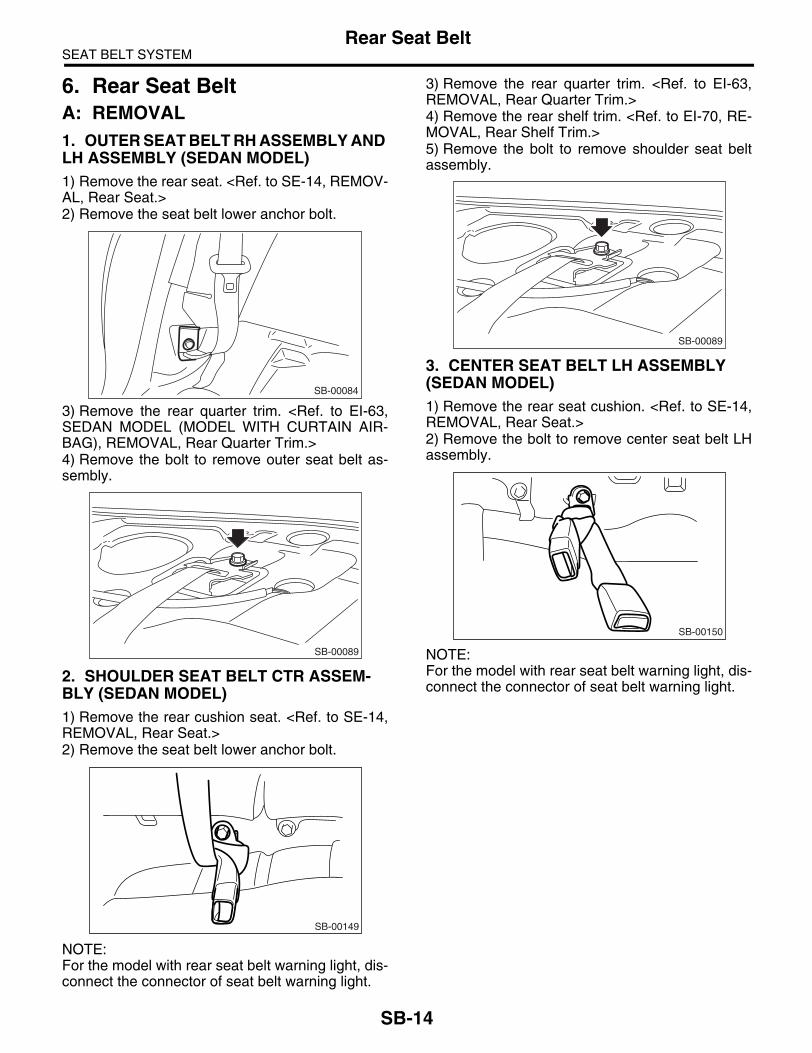
SEAT BELT SYSTEMRear Seat Belt
6. Rear Seat BeltA: REMOVAL1. OUTER SEAT BELT RH ASSEMBLY AND LH ASSEMBLY (SEDAN MODEL)1) Remove the rear seat. <Ref. to SE-14, REMOV-AL, Rear Seat.>2) Remove the seat belt lower anchor bolt.
3) Remove the rear quarter trim. <Ref. to EI-63,SEDAN MODEL (MODEL WITH CURTAIN AIR-BAG), REMOVAL, Rear Quarter Trim.>4) Remove the bolt to remove outer seat belt as-sembly.
2. SHOULDER SEAT BELT CTR ASSEM-BLY (SEDAN MODEL)1) Remove the rear cushion seat. <Ref. to SE-14,REMOVAL, Rear Seat.>2) Remove the seat belt lower anchor bolt.
NOTE:For the model with rear seat belt warning light, dis-connect the connector of seat belt warning light.
3) Remove the rear quarter trim. <Ref. to EI-63,REMOVAL, Rear Quarter Trim.>4) Remove the rear shelf trim. <Ref. to EI-70, RE-MOVAL, Rear Shelf Trim.>5) Remove the bolt to remove shoulder seat beltassembly.
3. CENTER SEAT BELT LH ASSEMBLY (SEDAN MODEL)1) Remove the rear seat cushion. <Ref. to SE-14,REMOVAL, Rear Seat.>2) Remove the bolt to remove center seat belt LHassembly.
NOTE:For the model with rear seat belt warning light, dis-connect the connector of seat belt warning light.
SB-00084
SB-00089
SB-00149
SB-00089
SB-00150
SB-14

SEAT BELT SYSTEMRear Seat Belt
4. OUTER SEAT BELT RH ASSEMBLY AND LH ASSEMBLY (WAGON MODEL)1) Remove the luggage floor box. <Ref. to EI-74,REMOVAL, Luggage Floor Box.>2) Remove the rear seat cushion and backrestshoulder. <Ref. to SE-14, SEDAN MODEL, RE-MOVAL, Rear Seat.> 3) Remove the rear quarter lower trim. <Ref. to EI-63, WAGON MODEL, REMOVAL, Rear QuarterTrim.>4) Remove the bolt to remove outer seat belt re-tractor.
5) Remove the bolts to remove outer seat beltguide.
5. SHOULDER SEAT BELT CTR ASSEM-BLY (WAGON MODEL)1) Remove the quarter rear pillar trim. <Ref. to EI-63, WAGON MODEL, REMOVAL, Rear QuarterTrim.>2) Remove the seat belt extract opening (A) fromroof trim, and then inset it to the inside of roof trim.
3) Remove the clips, and then lower the roof trimend.
CAUTION:When removing the roof trim clip, do not pull the roof trim end backward with excessive force, otherwise roof trim may be damaged.4) Remove the bolt to remove seat belt retractor.
6. CENTER SEAT BELT RH ASSEMBLY AND LH ASSEMBLY (WAGON MODEL)1) Remove the rear seat cushion. <Ref. to SE-14,SEDAN MODEL, REMOVAL, Rear Seat.>2) Remove the bolts, and then detach the centerseat belt assembly.
NOTE:For the model with rear seat belt warning light, dis-connect the connector of seat belt warning light.
SB-00151
SB-00158
(A)
SB-00159
SB-00155
SB-00160
SB-00156
SB-15

SEAT BELT SYSTEMRear Seat Belt
B: INSTALLATION1. OUTER SEAT BELT RH ASSEMBLY AND LH ASSEMBLY (SEDAN MODEL)Install in the reverse order of removal.
CAUTION:• During installation, make sure that the seatbelts are not twisted.• After installation, make sure that the seatbelts are smoothly extended and wound.
2. SHOULDER SEAT BELT CTR ASSEM-BLY (SEDAN MODEL)Install in the reverse order of removal.
CAUTION:• During installation, make sure that the seatbelts are not twisted.• After installation, make sure that the seatbelts are smoothly extended and wound.
3. CENTER SEAT BELT LH ASSEMBLY (SEDAN MODEL)Install in the reverse order of removal.
CAUTION:During installation, make sure that the seat belts are not twisted.
4. OUTER SEAT BELT RH ASSEMBLY AND LH ASSEMBLY (WAGON MODEL)Install in the reverse order of removal.
CAUTION:• During installation, make sure that the seatbelts are not twisted.• After installation, make sure that the seatbelts are smoothly extended and wound.
5. SHOULDER SEAT BELT CTR ASSEM-BLY (WAGON MODEL)Install in the reverse order of removal.
CAUTION:• After seat belt guide installation, make surethat the seat belts are wound.
• During installation, make sure that the seatbelts are not twisted. • After installation, make sure that the seatbelts are smoothly extended and wound.
6. CENTER SEAT BELT RH ASSEMBLY AND LH ASSEMBLY (WAGON MODEL)Install in the reverse order of removal.
CAUTION:During installation, make sure that the seat belts are not twisted.
C: INSPECTION1. OUTER SEAT BELT RH ASSEMBLY AND LH ASSEMBLY (SEDAN MODEL)Check for the following, and replace with new partsif necessary.• Seat belt is slackened, bent or wore. Seat belt isabnormally wound or extended.
2. SHOULDER SEAT BELT CTR ASSEM-BLY (SEDAN MODEL)Check for the following, and replace with new partsif necessary.• Seat belt is slackened, bent or wore. Seat belt isabnormally wound or extended.
3. CENTER SEAT BELT LH ASSEMBLY (SEDAN MODEL)Check for the following, and replace with new partsif necessary.• Inner belt is deformed or damaged.• Seat belt buckle cannot be engaged properly.
4. OUTER SEAT BELT RH ASSEMBLY AND LH ASSEMBLY (WAGON MODEL)Check for the following, and replace with new partsif necessary.• Seat belt is slackened, bent or wore. Seat belt isabnormally wound or extended.
5. SHOULDER SEAT BELT CTR ASSEM-BLY (WAGON MODEL)Check for the following, and replace with new partsif necessary. • Seat belt is slackened, bent or wore. Seat belt isabnormally wound or extended.
6. CENTER SEAT BELT RH ASSEMBLY AND LH ASSEMBLY (WAGON MODEL)Check for the following, and replace with new partsif necessary. • Inner belt is deformed or damaged. • Seat belt buckle cannot be engaged properly. SB-00157
SB-16

SEAT BELT SYSTEMDisposal of Pretensioner
7. Disposal of PretensionerA: CAUTION• Discard deployed pretensioners because it maycause serious personal injury when accidentallydeployed.• Deployment of the pretensioners should be doneon a flat place free from any possible danger. Avoiddeploying outdoors during rainy or windy weather.• Wear protective gloves, safety goggles and ear-plugs during this operation. Wash your hands after-wards.• Do not drop or damage the pretensioner.• Because deploying of pretensioners cause ahigh-explosive noise, be sure to warn people in thearea, and do not allow anyone within a 5 m (16 ft)radius of the disposal site.• Some smoke will be emitted after deployment ofthe pretensioner. Therefore, it must be deployed ina well-ventilated place with no fire alarms nearby.• After deployment, the pretensioner is especiallyhot, leave it unattended for 40 minutes or longer,and then discard it.• Do not let water get on the deployed pretension-er.• Wrap the deployed pretensioner in an airtight vi-nyl bag, and then discard it.• If circumstances do not permit the pretensionerdeployment, contact the SUBARU dealer.
B: PROCEDURE1. DEPLOYING OF PRETENSIONER WHILE INSTALLED IN VEHICLE1) Fold the backrest all the way forward, and thenmove the front seat all the way forward.2) Turn the ignition switch to OFF, disconnect thebattery ground terminal, and wait more than 20seconds.3) Remove the center pillar lower trim. <Ref. to EI-60, REMOVAL, Lower Inner Trim.>4) Disconnect the pretensioner connector (A).
5) Short the terminal to alligator clip of deploymenttool (A).6) Connect the deployment tool and deploymentadapter D (B).
CAUTION:The terminals of deployment tool should bekept shorted until just before deployment of thepretensioner.
7) Connect the deployment adapter D connectorand pretensioner connector.8) Extend the wiring of deployment tool to the limit,and make sure that the vehicle is empty. Close allwindows, sunroof and rear gate completely.
9) Move the battery at least 5 m (16 ft) from vehicle,and secure to the nearby area. Connect the deploy-ment tool alligator clip to the battery negative (−)terminal.10) Connect the other cable of deployment tool tothe battery positive (+) terminal, and deploy thepretensioner.
SB-00129
(A)
(A) Deployment tool:(Tool number 98299PA030)
(B) Deployment adapter D:(Tool number 98299SA010)
SB-00021
(A)
(B)
SB-00017
SB-00018
SB-17

SEAT BELT SYSTEMDisposal of Pretensioner
CAUTION:• After deployment, the pretensioner is espe-cially hot, leave it unattended for 40 minutes orlonger, and then discard it.• Do not let water get on the deployed preten-sioner.11) Remove the front outer belt. <Ref. to SB-12,REMOVAL, Front Seat Belt.>12) Cut off the seat belt as close to retractor as pos-sible.
13) Wrap the deployed pretensioner in airtight vinylbag, and discard it.
2. DEPLOYING OF PRETENSIONER AF-TER REMOVAL FROM VEHICLE1) Fold the backrest all the way forward, and thenmove the front seat all the way forward.2) Turn the ignition switch to OFF, disconnect thebattery ground terminal, and wait more than 20seconds.3) Remove the front outer belt. <Ref. to SB-12, RE-MOVAL, Front Seat Belt.>
4) Cut off the seat belt as close to retractor as pos-sible.
5) Short the terminal to alligator clip of deploymenttool.6) Connect the deployment tool (A) and deploy-ment adapter D (B).
CAUTION:The terminals of deployment tool should bekept shorted until just before deployment of thepretensioner.
7) Connect the deployment adapter D connectorand pretensioner connector.8) Install the pretensioner on a wheel with tire.Then, bundle three automotive wire harness [eachwith a sectional area of 1.25 mm2 (0.00194 sq in) ormore], and bind them twofold around the preten-sioner bracket and wheel.
SB-00130
SB-00131 (A) Deployment tool:(Tool number 98299PA030)
(B) Deployment adapter D:(Tool number 98299SA010)
SB-00130
SB-00021
(A)
(B)
SB-00024
SB-18

SEAT BELT SYSTEMDisposal of Pretensioner
9) Put three tires without wheels on the tire in-stalled with pretensioner. Put on an additional tirewith a wheel on top, and then fasten them tight witha rope.
10) Move the battery at least 5 m (16 ft) from tires,and secure the nearby area. Connect the deploy-ment tool alligator clip to the battery negative (−)terminal.
11) Connect the other cable of deployment tool tothe battery positive (+) terminal, and deploy thepretensioner.
CAUTION:• After deployment, the pretensioner is espe-cially hot, leave it unattended for 40 minutes orlonger, and then discard it.• Do not let water get on the deployed preten-sioner.
12) Wrap the deployed pretensioner in airtight vinylbag, and discard it.
(1) 5 m (16 ft) or more
SB-00025
SB-00065
(1)
SB-00018
SB-00131
SB-19

SEAT BELT SYSTEMDisposal of Pretensioner
SB-20

LIGHTING SYSTEM
LI
Page1. General Description ....................................................................................22. Headlight and Tail Light System .................................................................33. Front Fog Light System...............................................................................44. Rear Fog Light System ...............................................................................55. Turn Signal Light and Hazard Light System................................................66. Back-up Light System .................................................................................77. Stop Light System.......................................................................................88. Room Light System.....................................................................................99. Combination Switch (Light) .......................................................................10
10. Headlight Beam Leveler System...............................................................1211. Combination Base Switch Assembly.........................................................1312. Headlight Assembly ..................................................................................1413. Headlight Bulb...........................................................................................1814. Front Turn Signal Light Bulb .....................................................................1915. Clearance/Parking Light Bulb....................................................................2016. Front Fog Light Assembly .........................................................................2117. Front Fog Light Bulb..................................................................................2218. Rear Fog Light ..........................................................................................2319. Side Turn Signal Light Assembly ..............................................................2420. Rear Combination Light Assembly............................................................2521. Tail/Stop Light Bulb ...................................................................................2622. Rear Turn Signal Light Bulb ......................................................................2723. Back-up Light Assembly............................................................................2824. Back-up Light Bulb ....................................................................................2925. Rear Fog Light Bulb ..................................................................................3026. License Plate Light Assembly ...................................................................3127. License Plate Light....................................................................................3228. High-mounted Stop Light ..........................................................................3329. Spot Map Light ..........................................................................................3430. Room Light................................................................................................3531. Luggage Room Light.................................................................................3632. Trunk Room Light......................................................................................3733. Glove Box Light.........................................................................................3834. Door Step Light .........................................................................................3935. Ignition Switch Illumination........................................................................40
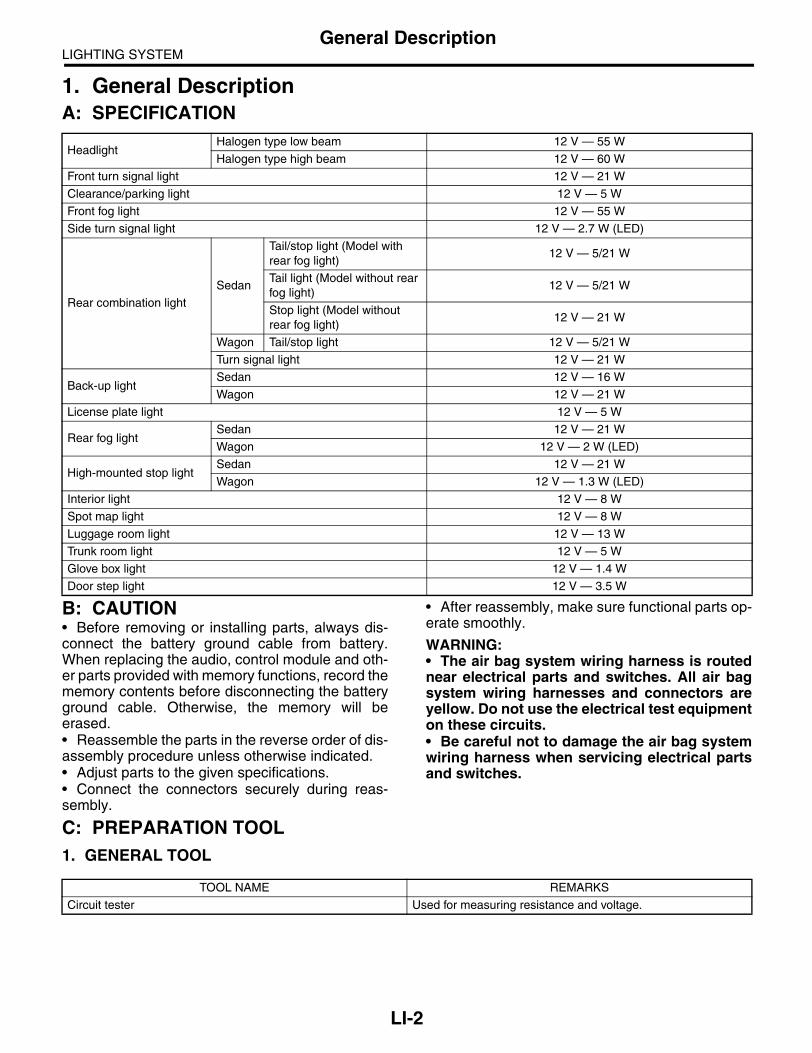
LIGHTING SYSTEMGeneral Description
1. General DescriptionA: SPECIFICATION
B: CAUTION• Before removing or installing parts, always dis-connect the battery ground cable from battery.When replacing the audio, control module and oth-er parts provided with memory functions, record thememory contents before disconnecting the batteryground cable. Otherwise, the memory will beerased.• Reassemble the parts in the reverse order of dis-assembly procedure unless otherwise indicated.• Adjust parts to the given specifications.• Connect the connectors securely during reas-sembly.
• After reassembly, make sure functional parts op-erate smoothly.
WARNING:• The air bag system wiring harness is routednear electrical parts and switches. All air bagsystem wiring harnesses and connectors areyellow. Do not use the electrical test equipmenton these circuits.• Be careful not to damage the air bag systemwiring harness when servicing electrical partsand switches.
C: PREPARATION TOOL1. GENERAL TOOL
HeadlightHalogen type low beam 12 V — 55 W
Halogen type high beam 12 V — 60 W
Front turn signal light 12 V — 21 W
Clearance/parking light 12 V — 5 W
Front fog light 12 V — 55 W
Side turn signal light 12 V — 2.7 W (LED)
Rear combination light
Sedan
Tail/stop light (Model with rear fog light)
12 V — 5/21 W
Tail light (Model without rear fog light)
12 V — 5/21 W
Stop light (Model without rear fog light)
12 V — 21 W
Wagon Tail/stop light 12 V — 5/21 W
Turn signal light 12 V — 21 W
Back-up lightSedan 12 V — 16 W
Wagon 12 V — 21 W
License plate light 12 V — 5 W
Rear fog lightSedan 12 V — 21 W
Wagon 12 V — 2 W (LED)
High-mounted stop lightSedan 12 V — 21 W
Wagon 12 V — 1.3 W (LED)
Interior light 12 V — 8 W
Spot map light 12 V — 8 W
Luggage room light 12 V — 13 W
Trunk room light 12 V — 5 W
Glove box light 12 V — 1.4 W
Door step light 12 V — 3.5 W
TOOL NAME REMARKS
Circuit tester Used for measuring resistance and voltage.
LI-2

LIGHTING SYSTEMHeadlight and Tail Light System
2. Headlight and Tail Light Sys-tem
A: WIRING DIAGRAM1. HALOGEN TYPE HEADLIGHT<Ref. to WI-269, WIRING DIAGRAM, HeadlightSystem.>
2. CLEARANCE LIGHT AND ILLUMINA-TION LIGHT<Ref. to WI-259, WIRING DIAGRAM, ClearanceLight and Illumination Light System.>
B: INSPECTION1. HEADLIGHT SWITCH<Ref. to LI-10, INSPECTION, Combination Switch(Light).>
2. HEADLIGHT RELAYMeasure the resistance between headlight relayterminals when connecting terminal No. 4 to batterypositive terminal and terminal No. 3 to batteryground terminal.
3. TAIL AND ILLUMINATION RELAYMeasure the resistance between tail and illumina-tion relay terminals when connecting terminal No. 4to battery positive terminal and terminal No. 3 tobattery ground terminal.
Current Terminal No. Standard
Flow1 and 2
Less than 1 ΩNo flow More than 1 MΩ
LI-00001
(1)(2)
(1)
(4)
(2)
(3)
(3) (4)
Current Terminal No. Standard
Flow1 and 2
Less than 1 ΩNo flow More than 1 MΩ
LI-00001
(1)(2)
(1)
(4)
(2)
(3)
(3) (4)
LI-3

LIGHTING SYSTEMFront Fog Light System
3. Front Fog Light SystemA: WIRING DIAGRAM1. FRONT FOG LIGHT<Ref. to WI-267, WIRING DIAGRAM, Front FogLight System.>
B: INSPECTION1. FRONT FOG LIGHT SWITCHMeasure the resistance between front fog lightswitch terminals.<Ref. to LI-10, INSPECTION, Combination Switch(Light).>
2. FRONT FOG LIGHT RELAYMeasure the resistance between front fog light re-lay terminals when connecting terminal No. 4 tobattery positive terminal and terminal No. 3 to bat-tery ground terminal.
Current Terminal No. Standard
Flow1 and 2
Less than 1 ΩNo flow More than 1 MΩ
LI-00001
(1)(2)
(1)
(4)
(2)
(3)
(3) (4)
LI-4

LIGHTING SYSTEMRear Fog Light System
4. Rear Fog Light SystemA: WIRING DIAGRAM1. REAR FOG LIGHT<Ref. to WI-279, WIRING DIAGRAM, Rear FogLight System.>
B: INSPECTION1. REAR FOG LIGHT SWITCHMeasure the rear fog light switch resistance be-tween terminals. <Ref. to LI-10, INSPECTION,Combination Switch (Light).>
2. REAR FOG LIGHT RELAYMeasure the resistance between rear fog light relayterminals while connecting terminal No. 4 to batterypositive terminal and No. 3 to battery ground termi-nal.
Current Terminal No. Standard
Flow1 and 2
Less than 1 ΩNo flow More than 1 MΩ
LI-00001
(1)(2)
(1)
(4)
(2)
(3)
(3) (4)
LI-5
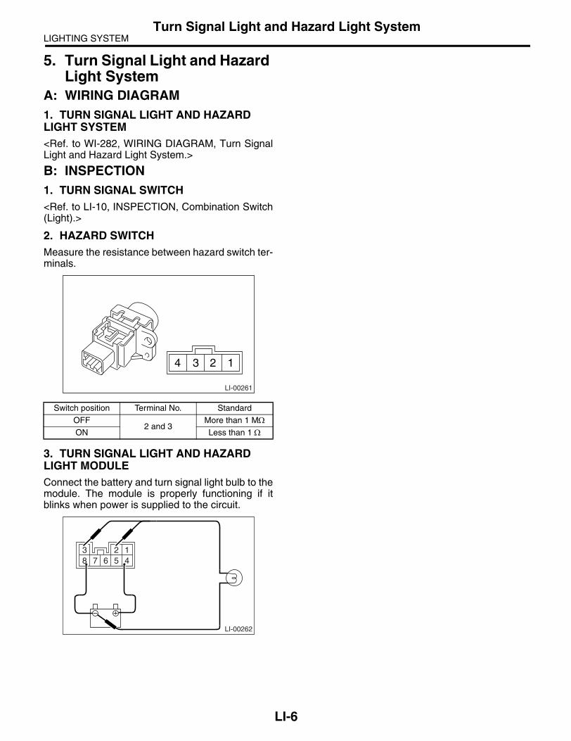
LIGHTING SYSTEMTurn Signal Light and Hazard Light System
5. Turn Signal Light and Hazard Light System
A: WIRING DIAGRAM1. TURN SIGNAL LIGHT AND HAZARD LIGHT SYSTEM<Ref. to WI-282, WIRING DIAGRAM, Turn SignalLight and Hazard Light System.>
B: INSPECTION1. TURN SIGNAL SWITCH<Ref. to LI-10, INSPECTION, Combination Switch(Light).>
2. HAZARD SWITCHMeasure the resistance between hazard switch ter-minals.
3. TURN SIGNAL LIGHT AND HAZARD LIGHT MODULEConnect the battery and turn signal light bulb to themodule. The module is properly functioning if itblinks when power is supplied to the circuit.
Switch position Terminal No. Standard
OFF2 and 3
More than 1 MΩON Less than 1 Ω
LI-00261
4 3 2 1
LI-00262
3 2 18 7 6 5 4
LI-6

LIGHTING SYSTEMBack-up Light System
6. Back-up Light SystemA: WIRING DIAGRAM1. BACK-UP LIGHT<Ref. to WI-257, WIRING DIAGRAM, Back-upLight System.>
B: INSPECTION1. BACK-UP LIGHT SWITCH (MT MODEL)Measure the resistance between back-up lightswitch terminals.
2. INHIBITOR SWITCH (4AT MODEL)Measure the resistance between inhibitor switchterminals.
3. BACK-UP LIGHT RELAY (5AT MODEL)Measure the resistance between back-up light re-lay terminals when connecting terminal No. 4 to
battery positive terminal and terminal No. 3 to bat-tery ground terminal.
NOTE:Check other than back-up light relay. <Ref. to 4AT-52, INSPECTION, Inhibitor Switch.>
Switch position Terminal No. Standard
When shift lever is set in reverse
position 1 and 2Less than 1 Ω
Other positions More than 1 MΩ
Switch position Terminal No. Standard
When the selec-tor lever is in “R”
range 1 and 2Less than 1 Ω
Other positions More than 1 MΩ
LI-00263
2 1
9
LI-00005
4 3 2 15678101112
Current Terminal No. Standard
Flow1 and 2
Less than 1 ΩNo flow More than 1 MΩ
LI-00001
(1)(2)
(1)
(4)
(2)
(3)
(3) (4)
LI-7

LIGHTING SYSTEMStop Light System
7. Stop Light SystemA: WIRING DIAGRAM1. STOP LIGHT<Ref. to WI-281, WIRING DIAGRAM, Stop LightSystem.>
B: INSPECTION1. STOP LIGHT SWITCHMeasure the resistance between stop light switchterminals.
(1) Model without cruise control
(2) Model with cruise control
Switch position Terminal No. Standard
When brake pedal is depressed
Model without cruise control: 1
and 2Less than 1 Ω
When brake pedal is released
Model with cruise control: 2 and 3
More than 1 MΩ
LI-00265
3412
12(1)
(2)
LI-8

LIGHTING SYSTEMRoom Light System
8. Room Light SystemA: WIRING DIAGRAM1. INTERIOR LIGHT<Ref. to WI-271, WIRING DIAGRAM, Interior LightSystem.>
B: INSPECTION1. DOOR SWITCHMeasure the resistance between door switch termi-nals.
2. REAR GATE LATCH SWITCHMeasure the resistance between rear gate latchswitch terminals.
3. TRUNK ROOM LIGHT SWITCHMeasure the resistance between trunk room lightswitch terminals.
Switch position Terminal No. Standard
When door is opened
1 and 3Less than 1 Ω
When door is closed
More than 1 MΩ
Switch position Terminal No. Standard
When rear gate is opened
1 and 2Less than 1 Ω
When rear gate is closed
More than 1 MΩ
123
LI-00007
LI-00276
1
2
Switch position Terminal No. Standard
When trunk lid is opened
1 and 3Less than 1 Ω
When trunk lid is closed
More than 1 MΩ
LI-00277
123
LI-9

LIGHTING SYSTEMCombination Switch (Light)
9. Combination Switch (Light)A: REMOVAL1) Disconnect the ground cable from battery.2) Remove the instrument panel lower cover. <Ref.to EI-56, REMOVAL, Instrument Panel Assembly.>3) Remove the screws and remove the steeringcolumn cover (upper and lower).
4) Disconnect the connector from combinationswitch.5) Remove three screws, and pull the combinationbase switch assembly toward you. (Only for KAmodel)
6) Remove the screws which secure switch, thenremove the combination switch.
B: INSTALLATIONInstall in the reverse order of removal.
C: INSPECTIONMeasure the resistance between combinationswitch terminals.
1. LIGHTING SWITCH• LHD model
SL-00258
LI -00332
(A) LHD and EK model
(B) KA model
Switch position Terminal No. Standard
OFF — More than 1 MΩTail 14 and 16 Less than 1 Ω
Head 13, 14 and 16 Less than 1 Ω
LI-00331
OFF OFF
LI-00184
1514131211 10 917 166 5 4 3 2 18 7
1514131211 10 917 166 5 4 3 2 18 7
(A)
(B)
LI-10

LIGHTING SYSTEMCombination Switch (Light)
• EK model
• KA model
2. DIMMER & PASSING SWITCH• LHD model
• EK model
• KA model
3. TURN SIGNAL SWITCH• LHD model/EK model
• KA model
4. FRONT FOG LIGHT• LHD model/EK model
• KA model
5. REAR FOG LIGHT• LHD model/EK model
• KA model
Switch position Terminal No. Standard
OFF — More than 1 MΩTail 14 and 16 Less than 1 Ω
Head 13, 14 and 10 Less than 1 Ω
Switch position Terminal No. Standard
OFF — More than 1 MΩTail 15 and 9 Less than 1 Ω
Head 14, 15 and 9 Less than 1 Ω
Switch position Terminal No. Standard
Passing 7, 8 and 16 Less than 1 ΩLow beam 17 and 16 Less than 1 ΩHigh beam 7 and 16 Less than 1 Ω
Switch position Terminal No. Standard
Passing 8, 7 and 10 Less than 1 ΩLow beam 17 and 10 Less than 1 ΩHigh beam 7 and 10 Less than 1 Ω
Switch position Terminal No. Standard
Passing 1, 2 and 9 Less than 1 ΩLow beam 10 and 9 Less than 1 ΩHigh beam 2 and 9 Less than 1 Ω
Switch position Terminal No. Standard
Left 1 and 2 Less than 1 ΩNeutral — More than 1 MΩRight 2 and 3 Less than 1 Ω
Switch position Terminal No. Standard
Left 6 and 7 Less than 1 ΩNeutral — More than 1 MΩRight 7 and 8 Less than 1 Ω
Switch position Terminal No. Standard
OFF — More than 1 MΩON 10 and 11 Less than 1 Ω
Switch position Terminal No. Standard
OFF12 and 16
More than 1 MΩON Less than 1 Ω
Switch position Terminal No. Standard
OFF — More than 1 MΩON 12 and 10 Less than 1 Ω
Switch position Terminal No. Standard
OFF16 and 13
More than 1 MΩON Less than 1 Ω
LI-11

LIGHTING SYSTEMHeadlight Beam Leveler System
10.Headlight Beam Leveler Sys-tem
A: WIRING DIAGRAM1. HEADLIGHT BEAM LEVELER SYSTEM<Ref. to WI-243, WIRING DIAGRAM, HeadlightBeam Leveler System.>
B: INSPECTION1. HEADLIGHT BEAM LEVELER ACTUA-TOR1) Turn on the headlights.2) Confirm the headlight beam level is lowered bychanging the switch position to 0 → 1 → 2 → 3 →4 → 5.
2. HEADLIGHT BEAM LEVELER SWITCHConnect the battery and headlight beam levelerswitch connector to the circuit tester. Measure thevoltage at each switch position.
Switch posi-tion
Terminal No. Standard
0
6, 7 (+) and battery (−)
Battery voltage
1 Battery voltage
2 Battery voltage
3 Battery voltage
4 Battery voltage
5 Battery voltage
LI-00270
v3 2 18 7 6 5 4
LI-12

LIGHTING SYSTEMCombination Base Switch Assembly
11.Combination Base Switch Assembly
A: REMOVAL1) Remove the driver’s airbag module. <Ref. to AB-14, REMOVAL, Driver’s Airbag Module.>2) Remove the steering wheel. <Ref. to PS-20, RE-MOVAL, Steering Wheel.>3) Remove the screws and remove the steeringcolumn lower cover.
4) Remove the combination switch. <Ref. to LI-10,REMOVAL, Combination Switch (Light).> <Ref. toWW-8, REMOVAL, Combination Switch (Wiper).>5) Remove the four screws and remove the rollconnector.6) Remove the three screws.
7) Disconnect the connector and remove the com-bination base switch assembly.
B: INSTALLATION1) Install in the reverse order of removal.2) Before installing steering wheel, be sure the di-rection of roll connector is adjusted with steering.<Ref. to AB-23, ADJUSTMENT, Roll Connector.>
C: INSPECTION1. COMBINATION BASE SWITCH ASSEM-BLYInspect the combination base switch assembly androll connector for crack or deformation. If any dam-age is found, replace with a new one.
2. PARKING SWITCHMeasure the resistance between parking switchterminals.
SL-00258
LI-00271
Switch position Terminal No. Standard
OFF 2 and 4 Less than 1 ΩON 1 and 4 Less than 1 Ω
LI-00183
1234
LI-13

LIGHTING SYSTEMHeadlight Assembly
12.Headlight AssemblyA: REMOVAL1) Disconnect the ground cable from battery.2) Remove the air intake duct. (When removing theheadlight RH)
3) Remove the front grille. <Ref. to EI-24, REMOV-AL, Front Grille.>4) Remove the front bumper. <Ref. to EI-30, RE-MOVAL, Front Bumper.>5) Disconnect each harness connector.6) Remove the 4 bolts and disengage clips, andthen detach the headlight assembly.
B: INSTALLATIONInstall in the reverse order of removal.
C: DISASSEMBLYCAUTION:• Do not touch the bulb glass portion.• Do not touch inside the lens (extension por-tion) or reflector portion.• Replace the packing with a new one.
1) Remove the headlight assembly. <Ref. to LI-14,REMOVAL, Headlight Assembly.>2) Remove the eight screws.
3) Remove headlight side bracket.
4) Heat the sealing portion between headlight as-sembly and lens using heating gun.
LI-00273
LI-00274
(A) Headlight side bracket
LI-00327
LI-00328
(A)
LI-14

LIGHTING SYSTEMHeadlight Assembly
CAUTION:Avoid heating one specific point of the seal por-tion and heating the headlight assembly to 100°C (212°F) or more.
5) Unhook the hook, and then take the lens off theheadlight assembly.
6) Remove the packing (A) from seal groove.
CAUTION:Completely remove the packing not to leave any chips behind.
D: ASSEMBLY1) Cut the tip of packing (A) at an angle of 45°.2) With the cut end facing upward, insert packing(A) into the groove around the seal.
CAUTION:• If the packing protrudes, slowly take it off thegroove.• Do not stretch the packing. If the packing isstretched, seal fails.
3) After making a round of the seal, cut its tip at anangle of 45°, with its length 10 mm (0.39 in) longerthan the circumference of seal so that the tip over-laps the other. Then, press it onto the seal, using ascrewdriver.
(A) Headlight ASSY upper
(B) Headlight ASSY lower
(C) Heated portion
(B)
(A)
(C)
(C)
LI-00329
LI-00330
(A) Packing
(A) Packing
LI-00060
(A)
LI-00061
(A)
LI-00062
10mm
LI-15

LIGHTING SYSTEMHeadlight Assembly
4) Match the positions of the lens and headlight as-sembly, and then insert the lens into the headlightassembly.
CAUTION:Remove the turn signal light bulb and clear-ance/parking light bulb before removing the lens.5) Secure the hook, and then install the clip andscrew.6) Put the seal portion of headlight assembly intothe water and check that water does not enter in-side the headlight.
CAUTION:Be sure that water does not enter inside the headlight through the bulb socket and ventila-tion hole.
E: ADJUSTMENT1. HEADLIGHT AIMING
CAUTION:Turn off the light before adjusting headlight beam level. If the light is necessary to check aiming, do not turn on for more than two min-utes.
NOTE:Before checking the headlight beam level, be sureof the following:• The area around the headlight has not sustainedany accident, damage or other type of deformation.• Vehicle is parked on a level surface.• The inflation pressure of tires is correct.• Vehicle’s fuel tank is fully filled.1) Bounce the vehicle several times to normalizethe suspension.2) Make certain that someone is seated in the driv-er’s seat.3) Turn the headlights on and then adjust the lowbeam pattern.
NOTE:• Position the headlight beam leveler switch to “0”.• Adjust the vertical aim (A) first, then horizontalaim (B).
LI-00275
(A)
(B)
LI-16

LIGHTING SYSTEMHeadlight Assembly
Illustration above shows the illumination pattern for LHD model. Illumination pattern for RHD model is sym-metrically opposite.
(A) Vehicle center (B) Bulb center marking (C) 3 m (10 ft)
W mm (in)
H mm (in)h mm (in)
at 3 m (10 ft)Sedan Wagon
640 (25.20)Except for OUTBACK OUTBACK
1,180 (46.46) 635 (25.00) 705 (27.76) 30 (1.18)
LI-00324
H
H
W1
W
W
W2
W2
W1
(A)
(A)
(C)
(B)
h
h
LI-17
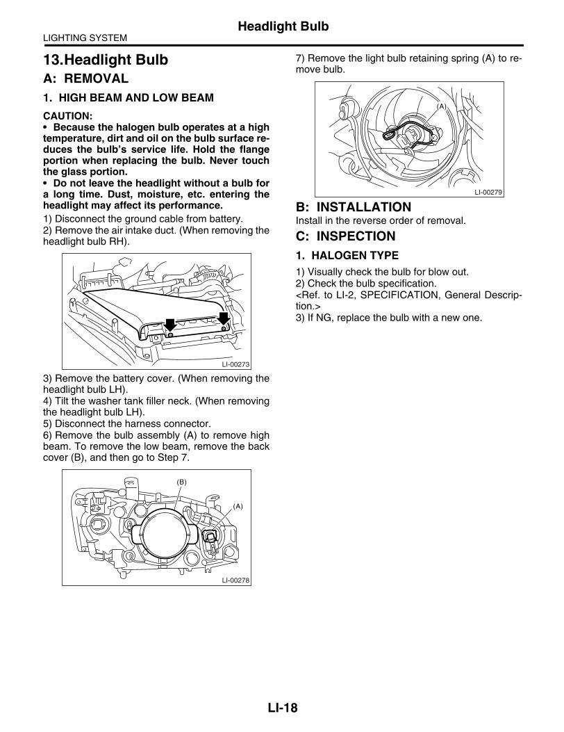
LIGHTING SYSTEMHeadlight Bulb
13.Headlight BulbA: REMOVAL1. HIGH BEAM AND LOW BEAM
CAUTION:• Because the halogen bulb operates at a hightemperature, dirt and oil on the bulb surface re-duces the bulb’s service life. Hold the flangeportion when replacing the bulb. Never touchthe glass portion.• Do not leave the headlight without a bulb fora long time. Dust, moisture, etc. entering theheadlight may affect its performance.1) Disconnect the ground cable from battery.2) Remove the air intake duct. (When removing theheadlight bulb RH).
3) Remove the battery cover. (When removing theheadlight bulb LH).4) Tilt the washer tank filler neck. (When removingthe headlight bulb LH).5) Disconnect the harness connector.6) Remove the bulb assembly (A) to remove highbeam. To remove the low beam, remove the backcover (B), and then go to Step 7.
7) Remove the light bulb retaining spring (A) to re-move bulb.
B: INSTALLATIONInstall in the reverse order of removal.
C: INSPECTION1. HALOGEN TYPE1) Visually check the bulb for blow out.2) Check the bulb specification.<Ref. to LI-2, SPECIFICATION, General Descrip-tion.>3) If NG, replace the bulb with a new one.
LI-00273
LI-00278
(A)
(B)
LI-00279
(A)
LI-18

LIGHTING SYSTEMFront Turn Signal Light Bulb
14.Front Turn Signal Light BulbA: REMOVAL1) When removing the turn signal light bulb, fullyturn the steering wheels to opposite direction fromdesired turn signal light bulb.
2) Turn the mud guard inward.3) Turn the socket (A) from wheel arch part, andthen remove the front turn signal light bulb.
CAUTION:For 5AT model, remove the turn signal light bulb LH from engine compartment with remov-ing battery, because it can not be removed from wheel arch part.
B: INSTALLATIONInstall in the reverse order of removal.
C: INSPECTION1) Visually check the bulb for blow out.2) Check the bulb specification.<Ref. to LI-2, SPECIFICATION, General Descrip-tion.>3) If NG, replace the bulb with a new one.
(1) Turn the steering wheel fully.
(2) Mud guard
(3) Front turn signal light
LI-00311
(3)
(2)
(1)
LI-00283
(A)
LI-19

LIGHTING SYSTEMClearance/Parking Light Bulb
15.Clearance/Parking Light BulbA: REMOVAL1) Remove the air intake duct. (When removing theclearance light/parking light bulb RH).
2) Remove the battery cover. (When removing theclearance light/parking light bulb LH)3) Tilt the washer tank filler neck. (When removingthe clearance/parking light bulb)4) Remove the headlight low beam back cover (B).5) Turn the socket (A) and remove the bulb.
B: INSTALLATIONInstall in the reverse order of removal.
C: INSPECTION1) Visually check the bulb for blow out.2) Check the bulb specification. <Ref. to LI-2,SPECIFICATION, General Description.>3) If NG, replace the bulb with a new one.
LI-00273
LI-00285
(A)
(B)
LI-20

LIGHTING SYSTEMFront Fog Light Assembly
16.Front Fog Light AssemblyA: REMOVAL1. EXCEPT FOR OUTBACK MODEL1) Disconnect the ground cable from battery.2) Remove the front fog light cover (A).
3) Disengage the two clips, and then turn over thelower mud guard.
4) Disconnect the harness connector.5) Remove the mounting bolts, and then detach thefog light assembly by pulling it.
2. OUTBACK MODEL1) Disconnect the ground cable from battery.2) Remove the two clips, and then turn over thelower mud guard.
3) Disconnect the harness connector.4) Remove the mounting bolts, and then detach thefog light assembly by pulling it.
B: INSTALLATIONInstall in the reverse order of removal.
CAUTION:When installing the fog light assembly, be sure to secure the upper hock.
LI-00287
(A)
LI-00288
LI-00289
LI-00288
LI-00325
LI-00326
LI-21

LIGHTING SYSTEMFront Fog Light Bulb
17.Front Fog Light BulbA: REMOVAL1) Disconnect the ground cable from battery.2) Disengage the two clips, and then turn over thelower mud guard.
3) Disconnect the harness connector.4) Remove the back cover.
5) Remove the spring retainer then detach the foglight bulb.
B: INSTALLATIONInstall in the reverse order of removal.
C: INSPECTION1) Visually check the bulb for blow out.2) Check the bulb specification. <Ref. to LI-2,SPECIFICATION, General Description.>3) If NG, replace the bulb with a new one.
LI-00288
LI-00291
LI-22

LIGHTING SYSTEMRear Fog Light
18.Rear Fog LightA: REMOVALNOTE:Rear fog light is installed to rear combination lightof driver’s side for sedan and rear gate garnish ofdriver’s side for wagon.
1. SEDAN MODELRemove the rear combination light. <Ref. to LI-25,REMOVAL, Rear Combination Light Assembly.>
2. WAGON MODEL1) Remove the rear gate trim. <Ref. to EI-69, RE-MOVAL, Rear Gate Trim.>2) Disconnect the harness connectors and removethe rear gate garnish. <Ref. to EI-76, REMOVAL,Rear Gate Garnish.>3) Remove the mounting nuts and detach the rearfog light assembly.
B: INSTALLATIONInstall in the reverse order of removal.
LI-00292
LI-23
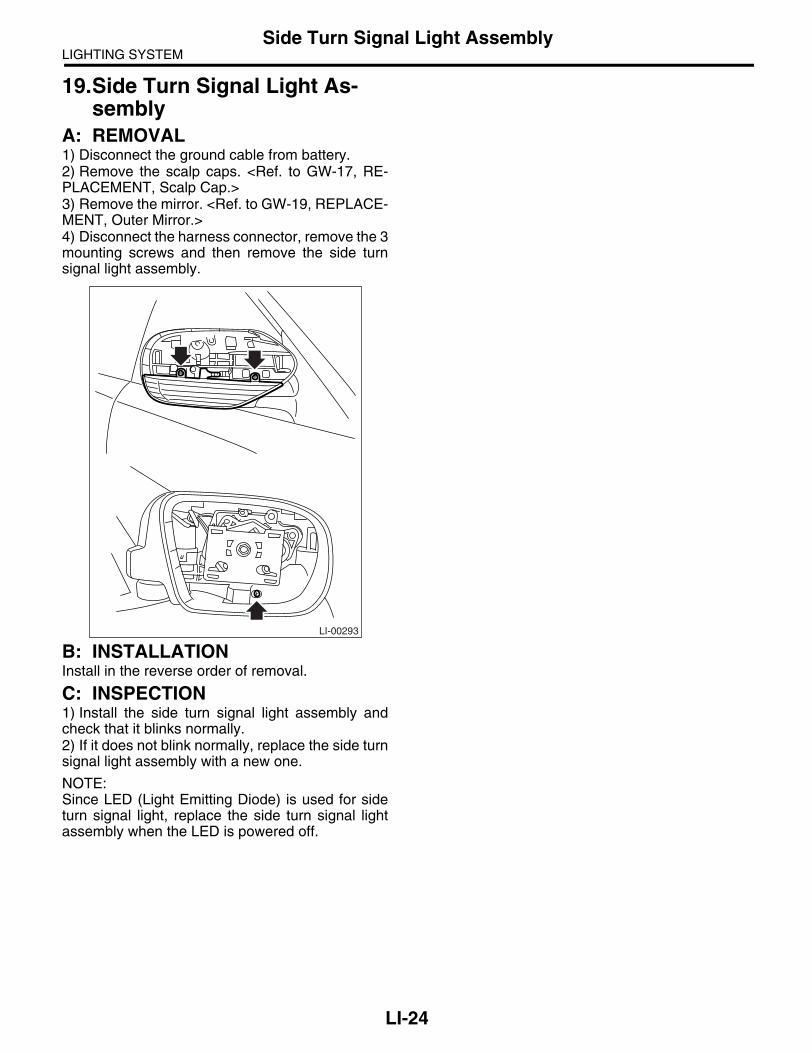
LIGHTING SYSTEMSide Turn Signal Light Assembly
19.Side Turn Signal Light As-sembly
A: REMOVAL1) Disconnect the ground cable from battery.2) Remove the scalp caps. <Ref. to GW-17, RE-PLACEMENT, Scalp Cap.>3) Remove the mirror. <Ref. to GW-19, REPLACE-MENT, Outer Mirror.>4) Disconnect the harness connector, remove the 3mounting screws and then remove the side turnsignal light assembly.
B: INSTALLATIONInstall in the reverse order of removal.
C: INSPECTION1) Install the side turn signal light assembly andcheck that it blinks normally.2) If it does not blink normally, replace the side turnsignal light assembly with a new one.
NOTE:Since LED (Light Emitting Diode) is used for sideturn signal light, replace the side turn signal lightassembly when the LED is powered off.
LI-00293
LI-24

LIGHTING SYSTEMRear Combination Light Assembly
20.Rear Combination Light As-sembly
A: REMOVAL1. SEDAN MODEL1) Disconnect the ground cable from battery.2) Remove the trunk room side trim. <Ref. to EI-71,REMOVAL, Trunk Room Trim.>3) Remove the four nuts, and then detach the rearcombination light after disconnecting the connec-tor.
2. WAGON MODEL1) Disconnect the ground cable from battery.2) Remove the clips.
3) While pressing the portion (A), insert your fingeror flat-tip screwdriver wrapped with tape into theclearance (B) to remove pawls in the order of (C),(D), (E), and remove the rear combination cover.
4) Remove the two bolts, and then detach the rearcombination light by pulling it to the rear side of ve-hicle.
5) Remove the rear combination light after turningthe socket of tail/stop light bulb and rear turn signallight bulb to remove the bulbs.
B: INSTALLATIONInstall in the reverse order of removal.
LI-00294
LI-00295
LI-00284
(E)
(C)
(D)
(B)
(A)
LI-00296
LI-25

LIGHTING SYSTEMTail/Stop Light Bulb
21.Tail/Stop Light BulbA: REMOVAL1. SEDAN MODEL1) Remove the trunk side trim cover.2) Turn the socket and remove the bulb.
2. WAGON MODEL1) Remove the rear combination light assembly.<Ref. to LI-25, WAGON MODEL, REMOVAL, RearCombination Light Assembly.>2) Turn the socket and remove the bulb.
B: INSTALLATIONInstall in the reverse order of removal.
C: INSPECTION1) Visually check the bulb for blow out.2) Check the bulb specification. <Ref. to LI-2,SPECIFICATION, General Description.>3) If NG, replace the bulb with a new one.
Model without rear fog light
(A) Tail light
(B) Stop light
Model with rear fog light
(A) Tail/stop light
(B) Rear fog light (Driver’s side only)
(A)
(B)
LI-00297
LI-00298
LI-26

LIGHTING SYSTEMRear Turn Signal Light Bulb
22.Rear Turn Signal Light BulbA: REMOVAL1. SEDAN MODEL1) Remove the trunk side trim cover.2) Turn the socket and remove the bulb.
2. WAGON MODEL1) Remove the rear combination light assembly.<Ref. to LI-25, WAGON MODEL, REMOVAL, RearCombination Light Assembly.>2) Turn the socket and remove the bulb.
B: INSTALLATIONInstall in the reverse order of removal.
C: INSPECTION1) Visually check the bulb for blow out.2) Check the bulb specification. <Ref. to LI-2,SPECIFICATION, General Description.>3) If NG, replace the bulb with a new one.
LI-00299
LI-00300
LI-27

LIGHTING SYSTEMBack-up Light Assembly
23.Back-up Light AssemblyA: REMOVALNOTE:In case of model with rear fog light, back-up light isinstalled to only passenger’s side.
1. SEDAN MODELRemove the rear combination light. <Ref. to LI-25,REMOVAL, Rear Combination Light Assembly.>
2. WAGON MODEL1) Remove the rear gate trim. <Ref. to EI-69, RE-MOVAL, Rear Gate Trim.>2) Disconnect the harness connectors and removethe rear gate garnish. <Ref. to EI-76, REMOVAL,Rear Gate Garnish.>3) Remove the mounting nuts and detach the back-up light assembly.
B: INSTALLATIONInstall in the reverse order of removal.
LI-00301
LI-28

LIGHTING SYSTEMBack-up Light Bulb
24.Back-up Light BulbA: REMOVAL1. SEDAN MODEL1) Remove the bulb inspection cover of trunk sidetrim.2) Turn the socket and remove the bulb.
2. WAGON MODEL1) Remove the bulb inspection cover of rear gatetrim.2) Turn the socket and remove the bulb.
B: INSTALLATIONInstall in the reverse order of removal.
C: INSPECTION1) Visually check the bulb for blow out.2) Check the bulb specification. <Ref. to LI-2,SPECIFICATION, General Description.>3) If NG, replace the bulb with a new one.
LI-00304
LI-00305
LI-29

LIGHTING SYSTEMRear Fog Light Bulb
25.Rear Fog Light BulbA: REMOVAL1. SEDAN MODEL1) Remove the bulb inspection cover of trunk sidetrim.2) Turn the socket and remove the bulb.
2. WAGON MODEL1) Remove the rear fog light assembly. <Ref. to LI-23, REMOVAL, Rear Fog Light.>2) Remove the mounting screws, and then removethe rear fog light assembly.
B: INSTALLATIONInstall in the reverse order of removal.
C: INSPECTION1. SEDAN MODEL1) Visually check the bulb for blow out.2) Check the bulb specification. <Ref. to LI-2,SPECIFICATION, General Description.>3) If NG, replace the bulb with a new one.
2. WAGON MODEL1) Install the rear fog light assembly to check that itilluminate normally.2) If it does not illuminate, replace the rear fog lightassembly with a new one.
NOTE:Since LED (Light Emitting Diode) is used for therear fog light, replace the rear fog light assemblywhen the LED is powered off.
LI-00302
LI-00292
LI-30

LIGHTING SYSTEMLicense Plate Light Assembly
26.License Plate Light AssemblyA: REMOVAL1. SEDAN MODEL1) Remove the trunk lid garnish. <Ref. to EI-75,REMOVAL, Trunk Lid Garnish.>2) Remove the trunk lid trim. <Ref. to EI-71,TRUNK LID TRIM, REMOVAL, Trunk Room Trim.>3) Turn and remove the bulb socket (A). Disengagethe clip (B) and remove the license plate light as-sembly.
B: INSTALLATIONInstall in the reverse order of removal.
LI-00306
(A)
(B) (B)
LI-31

LIGHTING SYSTEMLicense Plate Light
27.License Plate LightA: REMOVAL1. SEDAN MODEL1) Remove the trunk lid trim. <Ref. to EI-71,TRUNK LID TRIM, REMOVAL, Trunk Room Trim.>2) Turn and remove the bulb socket (A).
3) Remove the bulb.
2. WAGON MODEL1) Remove the license plate light mounting screw(A) and then remove the lens (B).
2) Remove the bulb.
B: INSTALLATIONInstall in the reverse order of removal.
C: INSPECTION1) Visually check the bulb for blow out.2) Check the bulb specification. <Ref. to LI-2,SPECIFICATION, General Description.>3) If NG, replace the bulb with a new one.
LI-00307
(A)
(A) (A)
(B) (B)
LI-00308
LI-32

LIGHTING SYSTEMHigh-mounted Stop Light
28.High-mounted Stop LightA: REMOVAL1. SEDAN MODEL1) Disconnect the ground cable from battery.2) Push the high-mounted stop light backward ofthe vehicle (1), raise the rear portion of it (2) and re-move the clips to remove it.
3) Remove the harness from clamp.
4) Disengage two claws (A), pull out the high-mounted stop light from the cover and remove theclaw (B).
5) Disengage three claws and remove the lens (A).
6) Remove the bulb.
2. WAGON MODEL1) Disconnect the ground cable from battery.2) Detach the roof spoiler. <Ref. to EI-40, REMOV-AL, Roof Spoiler.>3) Remove the nuts (A), then detach the high-mounted stop light.
B: INSTALLATIONInstall in the reverse order of removal.
C: INSPECTION1. SEDAN (STANDARD TYPE)1) Visually check the bulb for blow out.2) Check the bulb specification. <Ref. to LI-2,SPECIFICATION, General Description.>3) If NG, replace the bulb with a new one.
2. SEDAN (REAR SPOILER BUILT-IN TYPE) AND WAGON1) Install the high-mounted stop light to test if it illu-minates normally.2) If the high-mounted stop light does not illumi-nate, replace it with a new one.
NOTE:Since LED (Light Emitting Diode) is used for thehigh-mounted stop light of wagon model, replacethe high-mounted stop light assembly when theLED is powered off.
(1) Harness
(2) Clamp
(1)
(2)
LI-00333
(2)
(1)LI-00334
LI-00309
(A)
(B)
LI-00310(A)
LI-00312
(A)(A)
LI-33

LIGHTING SYSTEMSpot Map Light
29.Spot Map LightA: REMOVAL1) Disconnect the ground cable from battery.2) Remove the lens (A) and spot map light mount-ing screws (B).
• Model with sunroof
• Model without sunroof
3) Disconnect the harness connectors and removethe spot map light.
B: INSTALLATIONInstall in the reverse order of removal.
C: INSPECTION1. SPOT MAP LIGHT BULB1) Visually check the bulb for blow out.2) Check the bulb specification. <Ref. to LI-2,SPECIFICATION, General Description.>3) If NG, replace the bulb with a new one.
2. SPOT MAP LIGHT SWITCHMeasure the resistance between spot map lightswitch terminals.
LI-00313(A)
LI-00314(B)
LI-00320(B)
(B)
Switch position Terminal No. Standard
OFF — More than 1 MΩON 1 and 2 18±5.4 Ω
LI-34

LIGHTING SYSTEMRoom Light
30.Room LightA: REMOVAL1) Disconnect the ground cable from battery.2) Remove the lens (A) and mounting screws (B).
3) Disconnect the harness connector and removethe room light.
B: INSTALLATIONInstall in the reverse order of removal.
C: INSPECTION1. ROOM LIGHT BULB1) Visually check the bulb for blow out.2) Check the bulb specification. <Ref. to LI-2,SPECIFICATION, General Description.>3) If NG, replace the bulb with a new one.
2. ROOM LIGHT SWITCHMeasure the resistance between room light switchterminals.
LI-00315
(A)
LI-00316(B)
Switch position Terminal No. Standard
OFF — More than 1 MΩON 1 and 3 1.5±0.5 Ω
DOOR 2 and 3 1.5±0.5 Ω
LI-00257
3 2 1
LI-35
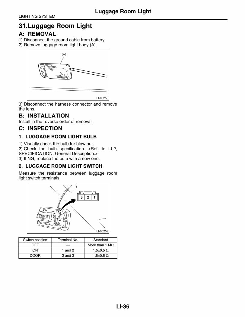
LIGHTING SYSTEMLuggage Room Light
31.Luggage Room LightA: REMOVAL1) Disconnect the ground cable from battery.2) Remove luggage room light body (A).
3) Disconnect the harness connector and removethe lens.
B: INSTALLATIONInstall in the reverse order of removal.
C: INSPECTION1. LUGGAGE ROOM LIGHT BULB1) Visually check the bulb for blow out.2) Check the bulb specification. <Ref. to LI-2,SPECIFICATION, General Description.>3) If NG, replace the bulb with a new one.
2. LUGGAGE ROOM LIGHT SWITCHMeasure the resistance between luggage roomlight switch terminals.
Switch position Terminal No. Standard
OFF — More than 1 MΩON 1 and 2 1.5±0.5 Ω
DOOR 2 and 3 1.5±0.5 Ω
LI-00258
(A)
LI-00259
3 2 1
LI-36

LIGHTING SYSTEMTrunk Room Light
32.Trunk Room LightA: REMOVAL1) Disconnect the ground cable from battery.2) Turn the trunk room light counterclockwise to60° to remove it and disconnect the harness con-nector.
3) Remove the bulb (A).
B: INSTALLATIONInstall in the reverse order of removal.
C: INSPECTION1. TRUNK ROOM LIGHT BULB1) Visually check the bulb for blow out.2) Check the bulb specification. <Ref. to LI-2,SPECIFICATION, General Description.>3) If NG, replace the bulb with a new one.
2. TRUNK LID SWITCH (TRUNK ROOM LIGHT SWITCH)Measure the resistance between trunk lid switchterminals.
LI-00321
LI-00286(A)
LI-00290
3 2 1
Trunk lid position Terminal No. Standard
Close1 and 3
More than 1 MΩOpen 1.5±0.5 Ω
LI-37

LIGHTING SYSTEMGlove Box Light
33.Glove Box LightA: REMOVAL1) Disconnect the ground cable from battery.2) Remove the glove box. <Ref. to EI-51, REMOV-AL, Glove Box.>3) Disconnect the harness connector.4) Remove the glove box light.
B: INSTALLATIONInstall in the reverse order of removal.
C: INSPECTION1) Visually check the bulb for blow out.2) Check the bulb specification. <Ref. to LI-2, SPECIFICATION, General Descrip-tion.>3) If NG, replace the bulb with a new one.
LI-00323
LI-38

LIGHTING SYSTEMDoor Step Light
34.Door Step LightA: REMOVAL1) Disconnect the ground cable from battery.2) Remove the lens (A), and then remove the doorstep light bulb.
3) Remove the front door trim. <Ref. to EI-48, RE-MOVAL, Door Trim.>4) Disconnect the harness connector.5) Remove the mounting screw from rear side oftrim and remove the door step light.
B: INSTALLATIONInstall in the reverse order of removal.
C: INSPECTION1) Visually check the bulb for blow out.2) Check the bulb specification. <Ref. to LI-2, SPECIFICATION, General Descrip-tion.>3) If NG, replace the bulb with a new one.
LI-00266
(A)
LI-00267
LI-39

LIGHTING SYSTEMIgnition Switch Illumination
35.Ignition Switch IlluminationA: REMOVAL1) Disconnect the ground cable from battery.2) Remove the screws and detach the upper col-umn cover and lower column cover.
3) Remove the instrument panel lower cover. <Ref.to EI-56, REMOVAL, Instrument Panel Assembly.>4) Disconnect the ignition switch illumination con-nector (A).
5) Turn the ignition switch illumination connector toleft and remove it.
B: INSTALLATIONInstall in the reverse order of removal.
C: INSPECTION
SL-00258
(A) Ignition switch illumination connector
(B) Ignition switch illumination
(C) Immobilizer antenna connector
LI-00343(C)
(B)
(A)
Step Check Yes No1 CHECK IGNITION SWITCH ILLUMINATION.
Make sure the ignition switch illumination illu-minates when driver’s side door is open.
Does the ignition switch illumi-nation illuminate?
Ignition switch illu-mination is normal.
Go to step 2.
2 CHECK IGNITION SWITCH ILLUMINATION.Make sure the ignition switch illumination blinks when ignition switch is turned to ON.
Does the ignition switch illumi-nation blink?
Check the func-tion setting of body integrated unit. <Ref. to LAN(diag)-2, Basic Diagnostic Proce-dure.>
Check the ignition switch illumination circuit. <Ref. to SL-27, CHECK IGNITION SWITCH ILLUMI-NATION, INSPEC-TION, Keyless Entry System.>
LI-40

WIPER AND WASHER SYSTEMS
WW
Page1. General Description ....................................................................................22. Wiper and Washer System .........................................................................73. Combination Switch (Wiper)........................................................................84. Wiper Blade...............................................................................................135. Washer Tank and Motor............................................................................166. Front Wiper Arm........................................................................................177. Front Wiper Motor and Link.......................................................................188. Front Washer Nozzle ................................................................................209. Rear Wiper Arm ........................................................................................21
10. Rear Wiper Motor......................................................................................2211. Rear Washer .............................................................................................24

WIPER AND WASHER SYSTEMSGeneral Description
1. General DescriptionA: SPECIFICATION
B: COMPONENT1. FRONT WIPER• LHD model
Front wiper motor Input 12 V — 72 W or less
Rear wiper motor Input 12 V — 42 W or less
Front washer motorPump type Centrifugal
Input 12 V — 36 W or less
Rear washer motorPump type Centrifugal
Input 12 V — 36 W or less
(1) Wiper rubber (4) Wiper link ASSY Tightening torque: N⋅m (kgf-m, ft-lb)(2) Wiper blade ASSY (5) Wiper motor ASSY T1: 6.0 (0.61, 4.4)(3) Wiper arm T2: 20 (2.0, 14.5)
WW-00215
T2
T2
(5)
(4)
(1)
(2)
(3)(1)
(2)
(3)
T1
T1
T1
T1
WW-2

WIPER AND WASHER SYSTEMSGeneral Description
• RHD model
(1) Wiper rubber (4) Wiper link ASSY Tightening torque: N⋅m (kgf-m, ft-lb)(2) Wiper blade ASSY (5) Wiper motor ASSY T1: 6.0 (0.61, 4.4)(3) Wiper arm T2: 20 (2.0, 14.5)
WW-00222
T2
T2
(5)
(4)
(1)
(2)
(3) (1)
(2)
(3)
T1
T1
T1
T1
WW-3
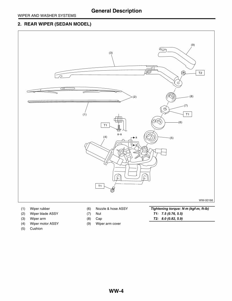
WIPER AND WASHER SYSTEMSGeneral Description
2. REAR WIPER (SEDAN MODEL)
(1) Wiper rubber (6) Nozzle & hose ASSY Tightening torque: N⋅m (kgf-m, ft-lb)(2) Wiper blade ASSY (7) Nut T1: 7.5 (0.76, 5.5)(3) Wiper arm (8) Cap T2: 8.0 (0.82, 5.9)(4) Wiper motor ASSY (9) Wiper arm cover
(5) Cushion
T1
T2
(4) (5)
(6)
(7)
(8)(2)
(1)
(3)
(9)
WW-00166
T1
T1
a
aa-a
WW-4

WIPER AND WASHER SYSTEMSGeneral Description
3. REAR WIPER (WAGON MODEL)
(1) Wiper rubber (4) Wiper arm cover Tightening torque: N⋅m (kgf-m, ft-lb)(2) Wiper blade ASSY (5) Cap T1: 7.5 (0.77, 6.0)(3) Wiper arm (6) Wiper motor ASSY T2: 8.0 (0.82, 5.9)
WW-00167
T1
(5)
(1)
T2
(2)
(3)
(4)
(6)
WW-5

WIPER AND WASHER SYSTEMSGeneral Description
4. WASHER TANK
C: CAUTION• Connect the connectors and hoses securely during reassembly.• After reassembly, make sure functional parts operate smoothly.• Be careful that wiring harnesses of airbag system pass near electrical parts and switches.• Wiring harnesses and connectors of all airbag system are yellow color. Do not use a tester equipment onthese circuits.• Care must be taken when connecting the piping hose so that no bending, jamming, etc. are caused.• If even a little oil or grease such as silicon oil gets in the tank and washer passages, an oil film is easilyformed on the glass, causing the wiper to chatter and judder, therefore, be careful not to let this happen.
(A) Sedan model (B) Wagon model Tightening torque: N⋅m (kgf-m, ft-lb)T: 6.0 (0.61, 4.4)
(1) Washer nozzle (5) Front washer motor
(2) Washer hose (6) Rear washer motor
(3) Washer tank (7) Grommet
(4) Washer tank cap (8) Washer motor cover
WW-00168
(1)
(2)
(2)
(7)
(6)
(5)
(2)
(4)
(3)
(7)(1)T
(1)
(8)
(A)
(B)
(1)
WW-6

WIPER AND WASHER SYSTEMSWiper and Washer System
2. Wiper and Washer SystemA: WIRING DIAGRAM1. WIPER AND WASHER (FRONT) LHD MODEL<Ref. to WI-324, LHD MODEL, WIRING DIAGRAM, Front Wiper and Washer System.>
2. WIPER AND WASHER (FRONT) RHD MODEL<Ref. to WI-325, RHD MODEL, WIRING DIAGRAM, Front Wiper and Washer System.>
3. WIPER AND WASHER (REAR) LHD MODEL<Ref. to WI-326, LHD MODEL, WIRING DIAGRAM, Rear Wiper and Washer System.>
4. WIPER AND WASHER (REAR) RHD MODEL<Ref. to WI-327, RHD MODEL, WIRING DIAGRAM, Rear Wiper and Washer System.>
B: INSPECTIONSymptom Repair order
Wiper and washers do not operate. (1) Wiper fuse (Front: F/B No. 30, Rear: F/B No. 23)(2) Combination switch(3) Wiper motor ASSY(4) Wiring harness(5) Body integrated unit (rear wiper only)
Wipers do not operate in LO or HI. (1) Combination switch(2) Wiper motor ASSY(3) Wiring harness
Wipers do not operate in INT. (1) Combination switch(2) Wiper motor ASSY(3) Wiring harness(4) Body integrated unit (rear wiper only)
Washer motor does not operate. (1) Washer switch(2) Washer motor(3) Wiring harness
Wipers do not operate when washer switch is ON. (1) Washer motor(2) Wiring harness
Washer fluid spray does not operate properly. (1) Washer motor(2) Washer hose and nozzle
WW-7
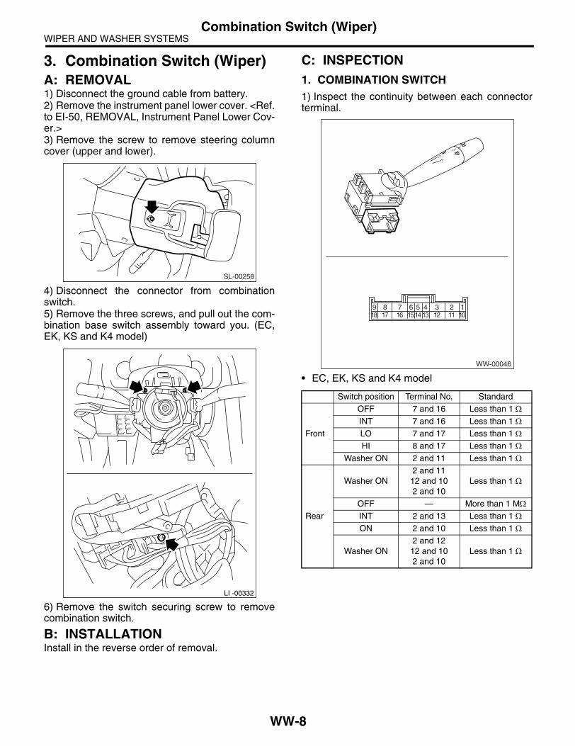
WIPER AND WASHER SYSTEMSCombination Switch (Wiper)
3. Combination Switch (Wiper)A: REMOVAL1) Disconnect the ground cable from battery.2) Remove the instrument panel lower cover. <Ref.to EI-50, REMOVAL, Instrument Panel Lower Cov-er.>3) Remove the screw to remove steering columncover (upper and lower).
4) Disconnect the connector from combinationswitch.5) Remove the three screws, and pull out the com-bination base switch assembly toward you. (EC,EK, KS and K4 model)
6) Remove the switch securing screw to removecombination switch.
B: INSTALLATIONInstall in the reverse order of removal.
C: INSPECTION1. COMBINATION SWITCH1) Inspect the continuity between each connectorterminal.
• EC, EK, KS and K4 model
SL-00258
LI -00332
Switch position Terminal No. Standard
Front
OFF 7 and 16 Less than 1 ΩINT 7 and 16 Less than 1 ΩLO 7 and 17 Less than 1 ΩHI 8 and 17 Less than 1 Ω
Washer ON 2 and 11 Less than 1 Ω
Rear
Washer ON2 and 1112 and 102 and 10
Less than 1 Ω
OFF — More than 1 MΩINT 2 and 13 Less than 1 ΩON 2 and 10 Less than 1 Ω
Washer ON2 and 1212 and 102 and 10
Less than 1 Ω
WW-00046
8 7 6 5 4 3 2 1917 16 1514 13 12 11 1018
WW-8

WIPER AND WASHER SYSTEMSCombination Switch (Wiper)
• KA model
2) If continuity is not as specified, replace theswitch.
Switch position Terminal No. Standard
Front
OFF 3 and 12 Less than 1 ΩINT 3 and 12 Less than 1 ΩLO 3 and 11 Less than 1 ΩHI 2 and 11 Less than 1 Ω
Washer ON 8 and 17 Less than 1 Ω
Rear
Washer ON8 and 16
16 and 188 and 18
Less than 1 Ω
OFF — More than 1 MΩINT 8 and 15 Less than 1 ΩON 8 and 18 Less than 1 Ω
Washer ON8 and 16
16 and 188 and 18
Less than 1 Ω
WW-9

WIPER AND WASHER SYSTEMSCombination Switch (Wiper)
2. FRONT WIPER1) Check with Subaru Select Monitor
2) Intermittent operation inspection(1) Turn the wiper switch to INT.(2) Adjust the intermittent control switch to MAX.(3) Apply the battery voltage to switch terminal No. 16 and 2 (EC, EK, KS and K4 model) or terminal No.12 and 8 (KA model).(4) Measure the voltage between combination switch terminals.
TerminalsNo. 7 — No. 2: EC, EK, KS and K4 modelNo. 3 — No. 8: KA model
3) If operation is not as specified, replace the switch.
Step Check Yes No1 CHECK INPUT SIGNAL TO BODY INTE-
GRATED UNIT.When the front wiper switch is operated, check the input signal using Subaru Select Monitor.1) Connect the Subaru Select Monitor to data link connector.2) Turn the ignition switch to ON.3) Select Body Integrated Unit from the main menu.4) Select Current Data Display & Save.5) When the front wiper switch is set to LO or HI, check the input signal.
Is the input signal normal? End. Replace the body integrated unit. <Ref. to SL-46, Body Integrated Unit.>
(A) Switch position (E) Non-intermittent type (H) Approx. 2 sec.
(B) Voltage (F) 12 V (I) 16±6 sec.
(C) MIN. (G) 0 V (J) 3±1 sec.
(D) MAX.
WW-00053
(A) (B)
(C)
(H)
(I)
(J)
(D)
(F)
(G)
(F)
(G)
(F)
(G)
(E)
WW-10

WIPER AND WASHER SYSTEMSCombination Switch (Wiper)
3. REAR WIPER1) Check with Subaru Select Monitor
2) Rear wiper motor circuit check
Step Check Yes No1 CHECK INPUT OF REAR WIPER.
Check the input from body integrated unit using Subaru Select Monitor.1) Connect the Subaru Select Monitor to data link connector.2) Turn the ignition switch to ON.3) Select Body Integrated Unit from the main menu.4) Select Current Data Display & Save.5) Check the input of rear wiper switch.
Is the input normal? Go to step 2. Check the rear wiper switch. <Ref. to WW-8, INSPECTION, Combination Switch (Wiper).>
2 CHECK OUTPUT OF BODY INTEGRATED UNIT.When the rear wiper switch is operated, check the output using Subaru Select Monitor.1) Turn the ignition switch to ON.2) Operate the rear wiper switch to set to each position of ON and INT.3) At this time, check the output of body inte-grated unit.
When it is set to ON, is ON out-put continuously? When it is set to INT, is ON/OFF output repeatedly? (INT OFF time (when vehicle parked): 3 sec-onds for Sedan, 12 seconds for Wagon)
Check the rear wiper motor. <Ref. to WW-23, INSPECTION, Rear Wiper Motor.>
Replace the body integrated unit. <Ref. to SL-46, Body Integrated Unit.>
Step Check Yes No1 CHECK POWER SUPPLY CIRCUIT OF REAR
WIPER MOTOR.1) Disconnect the harness connector of rear wiper motor.2) Turn the ignition switch to ACC.3) Measure the voltage between the rear wiper motor harness connector terminal and chassis ground.
Connector & terminalSedan model
(R132) No. 1 (+) — Chassis ground (−):Wagon model
(D43) No. 1 (+) — Chassis ground (−):
Is the voltage more than 10 V? Go to step 2. • Check the fuse (No. 23 in fuse & relay box).• Check the fus-ible link (No. 7 in main fuse box).
2 CHECK GROUND CIRCUIT OF REAR WIPER MOTOR.1) Turn the ignition switch to OFF.2) Measure the resistance between the rear wiper motor harness connector terminal and chassis ground.
Connector & terminalSedan model
(R132) No. 3 — Chassis ground:Wagon model
(D43) No. 3 — Chassis ground:
Is the resistance less than 10 Ω?
Go to step 3. Repair the open circuit of rear wiper motor ground cable.
WW-11

WIPER AND WASHER SYSTEMSCombination Switch (Wiper)
NOTE:Rear wiper intermittent time (AT model only)
3 CHECK HARNESS BETWEEN BODY INTE-GRATED UNIT AND REAR WIPER MOTOR.1) Turn the ignition switch to OFF.2) Disconnect the harness connector of body integrated unit.3) Disconnect the harness connector of rear wiper motor.4) Measure the resistance between the har-ness connector terminals of body integrated unit and rear wiper motor.
Connector & terminalSedan model
(B280) No. 1 — (R132) No. 2:(B280) No. 8 — (R132) No. 4:
Wagon model(B280) No. 1 — (D43) No. 2:(B280) No. 8 — (D43) No. 4:
Is the resistance less than 10 Ω?
Go to step 4. Repair the open circuit of harness between body inte-grated unit and rear wiper motor.
4 CHECK OPERATION OF REAR WIPER MO-TOR.1) Remove the rear wiper motor.2) Check the rear wiper motor. <Ref. to WW-23, INSPECTION, Rear Wiper Motor.>
Does the rear wiper motor rotate normally?
End. Replace the rear wiper motor.
Select lever position(AT model only)
Vehicle speed (km/h (MPH))Intermittent stopping time (sec.)
Sedan Wagon
Rev — Continuous operation
Except for reverse mode
80 — (50 — ) 12 3
50 — 80 (31 — 50) 9 6
20 — 50 (12 — 31) 6 9
0 — 20 (0 — 12) 3 12
Step Check Yes No
WW-12

WIPER AND WASHER SYSTEMSWiper Blade
4. Wiper BladeA: REMOVALCAUTION:When replacing wiper blades or etc., be sure to stand up the driver side wiper arm first, then passenger side wiper arm next. Also, when put-ting the wiper arms back, be sure to start with passenger side first, then driver side next. Do-ing this in the reverse order may result in dam-age of passenger side wiper arm by hitting with driver side wiper blade.
1. FRONT While pushing the locking clip (A) up, pull out theblade from arm to the arrow direction.
2. REAR Turn the blade in the direction of arrow (A) and re-move it from arm.
B: INSTALLATION1) Install in the reverse order of removal.2) Confirm that the clip is locked securely.
C: DISASSEMBLY1. METAL TYPEPull side (A) of the wiper rubber stopper and re-move the rubber from blade assembly.
2. RESIN TYPEPull the wiper rubber top slightly from the stopper(A) and pull out fully.
(A) Turn the wiper blade.
(1) Wiper arm
(2) Wiper blade
(3) Installing part of wiper blade
WW-00064
1
2
2
3
3
(A)
(1)
(2)
(3)(A)
WW-00207
WW-00009
WW-00143
(A)
WW-13

WIPER AND WASHER SYSTEMSWiper Blade
D: ASSEMBLY1. METAL TYPE1) Insert the wiper rubber onto blade so that thestopper is in the position shown in the figure.
2) Make sure the wiper rubber is securely fastenedto the pull stopper (A).
2. RESIN TYPE
1) Insert the wiper rubber through the claw (B). 2) Insert the wiper rubber until its top end protrudesapprox. 20 mm (0.79 in) from stopper (D).
WW-00230
WW-00037
WW-00193
A B C D
WW-00145
A
B
WW-00146
D
20 mm ( 0.79 in. )
WW-14

WIPER AND WASHER SYSTEMSWiper Blade
3) Insert the wiper rubber into the claw (A).
E: INSPECTION1) When the wiper does not perform well, inspectthe followings:• Make sure the movable part of the wiper bladeassembly moves smoothly.• Make sure the wiper rubber is not deformed ordamaged.2) If damaged, replace with new one.
A
WW-00147
WW-15

WIPER AND WASHER SYSTEMSWasher Tank and Motor
5. Washer Tank and MotorA: REMOVAL1) Open the hood.2) Disconnect the ground cable from battery.3) Remove the front bumper. <Ref. to EI-30, RE-MOVAL, Front Bumper.>4) Remove the clip holding washer water supplytap.
5) Remove the two bolts and one nut, hose, con-nector and washer motor cover, and then removethe washer tank.
B: INSTALLATIONInstall in the reverse order of removal.
Tightening torque:6.0 N⋅m (0.61 kgf-m, 4.4 ft-lb)
C: DISASSEMBLYPull out the washer motor from tank.
D: ASSEMBLY1) Assemble in the reverse order of disassembly.2) Confirm that water does not leak from installa-tion area of motor.
E: INSPECTIONApply battery voltage to the connector terminal ofthe washer motor and make sure the motor oper-ates.
WW-00170
WW-00171
WW-00172
WW-00173
12
WW-16

WIPER AND WASHER SYSTEMSFront Wiper Arm
6. Front Wiper ArmA: REMOVALCAUTION:When replacing wiper blades or etc., be sure to stand up the driver side wiper arm first, then passenger side wiper arm next. Also, when put-ting the wiper arms back, be sure to start with passenger side first, then driver side next. Do-ing this in the reverse order may result in dam-age of passenger side wiper arm by hitting with driver side wiper blade.1) Open the hood.2) Remove the cap.3) Remove the nut to remove wiper arm.
B: INSTALLATION1) Install in the reverse order of removal.2) Operate the wiper once.3) Align the wiper blade to ceramic print point mark(A) of front window panel.
Tightening torque:Refer to “COMPONENT” of “General Descrip-tion”.<Ref. to WW-2, FRONT WIPER, COMPO-NENT, General Description.>
C: ADJUSTMENTOperate the wiper once. Align the wiper blade toceramic print point mark (A) of front window panel.
WW-00232
WW-00048
(A)
WW-00048
(A)
WW-17

WIPER AND WASHER SYSTEMSFront Wiper Motor and Link
7. Front Wiper Motor and LinkA: REMOVAL1) Disconnect the ground cable from battery.2) Remove the cowl panel. <Ref. to EI-39, RE-MOVAL, Cowl Panel.>3) Disconnect the connector of wiper motor assem-bly.4) Remove the bolt to remove wiper assembly.
NOTE:Wiper motor and wiper link can not be disassem-bled, because those are assembly part.
B: INSTALLATIONInstall in the reverse order of removal.
Tightening torque:Refer to “COMPONENT” of “General Descrip-tion”.<Ref. to WW-2, FRONT WIPER, COMPO-NENT, General Description.>
C: INSPECTION1) When the battery is connected to the terminal ofconnectors, confirm that the wiper motor operatesat low speed.• LHD model
• RHD model
2) When the battery is connected to the terminal ofconnectors, confirm that the wiper motor operatesat high speed.• LHD model
• RHD model
3) Connect the battery to terminals of connector,and remove the terminal connection with wiper mo-tor rotated at low speed, and stop the wiper motorthrough operation.• LHD model
WW-00217
WW-00218
3 25 4
1
WW-00208
3 25 4
1
3 25 4
1
WW-00219
3 25 4
1
WW-00209
WW-00220
3 25 4
1
WW-18

WIPER AND WASHER SYSTEMSFront Wiper Motor and Link
• RHD model
4) Connect the battery and confirm that the wipermotor stops at automatic stop position after thewiper motor operates at low speed again.• LHD model
• RHD model
WW-00210
3 25 4
1
WW-00221
3 25 4
1
WW-00211
3 25 4
1
WW-19

WIPER AND WASHER SYSTEMSFront Washer Nozzle
8. Front Washer NozzleA: REMOVAL1) Remove the front hood insulator. <Ref. to EB-13, FRONT HOOD INSULATOR, REMOVAL,Front Hood.>2) Hold the pawl of washer nozzle (A) toward thearrow direction, and remove the washer nozzle.
3) Remove the washer hose from washer nozzle.
B: INSTALLATION1) Install in the reverse order of removal.2) Adjust the washer nozzle position. <Ref. to WW-20, ADJUSTMENT, Front Washer Nozzle.>
C: INSPECTION• Make sure the nozzle and hose are not clogged.• Make sure the hose is not bent.
D: ADJUSTMENT1) Turn the wiper switch to OFF position.2) While the vehicle is at standstill, adjust the wash-er injection position as shown in the figure.
Injection position:A: 250 mm (9.84 in)B: 435 mm (17.13 in)
Injection angle should be adjusted with 0.5 mm(0.020 in) thickness steel scale. Use maximumthickness of 0.5 mm steel scale, because the injec-tion slit width of washer nozzle is 0.6 mm (0.024 in).Adjusting with a flat tip driver may damage the in-jection slit and cause the faulty injection.
(1) Nozzle
(A)
WW-00177
WW-00161
A A
(1)
B
(1) Inside of washer nozzle injection
(2) 0.6 mm (0.024 in)
(3) Steel scale
(4) Max. 0.5 mm (0.020 in)
(4)
(3)(1)
(2)
WW-00212
WW-20

WIPER AND WASHER SYSTEMSRear Wiper Arm
9. Rear Wiper ArmA: REMOVAL1. SEDAN MODEL1) Detach the wiper arm cover (A).2) Remove the nut (B) to remove wiper arm.
2. WAGON MODEL1) Detach the wiper arm cover (A).2) Remove the nut (B) to remove wiper arm.
B: INSTALLATION1) Install in the reverse order of removal.2) Operate the rear wiper once.3) Align the blade with the marking (A) of glass.
Tightening torque:Refer to “COMPONENT” of “General Descrip-tion”.<Ref. to WW-4, REAR WIPER (SEDAN MOD-EL), COMPONENT, General Description.>
C: ADJUSTMENT1) Operate the rear wiper once.2) Align the blade with the marking (A) of glass.
(A)
(B)
WW-00178
WW-00179
(A)
(B)
(A)
WW-00229
(A)
WW-00229
WW-21
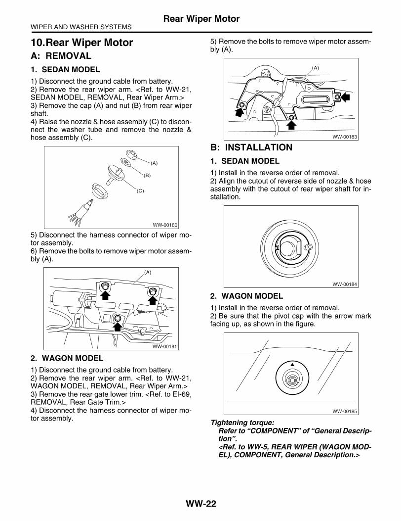
WIPER AND WASHER SYSTEMSRear Wiper Motor
10.Rear Wiper MotorA: REMOVAL1. SEDAN MODEL1) Disconnect the ground cable from battery.2) Remove the rear wiper arm. <Ref. to WW-21,SEDAN MODEL, REMOVAL, Rear Wiper Arm.>3) Remove the cap (A) and nut (B) from rear wipershaft.4) Raise the nozzle & hose assembly (C) to discon-nect the washer tube and remove the nozzle &hose assembly (C).
5) Disconnect the harness connector of wiper mo-tor assembly.6) Remove the bolts to remove wiper motor assem-bly (A).
2. WAGON MODEL1) Disconnect the ground cable from battery.2) Remove the rear wiper arm. <Ref. to WW-21,WAGON MODEL, REMOVAL, Rear Wiper Arm.>3) Remove the rear gate lower trim. <Ref. to EI-69,REMOVAL, Rear Gate Trim.>4) Disconnect the harness connector of wiper mo-tor assembly.
5) Remove the bolts to remove wiper motor assem-bly (A).
B: INSTALLATION1. SEDAN MODEL1) Install in the reverse order of removal.2) Align the cutout of reverse side of nozzle & hoseassembly with the cutout of rear wiper shaft for in-stallation.
2. WAGON MODEL1) Install in the reverse order of removal.2) Be sure that the pivot cap with the arrow markfacing up, as shown in the figure.
Tightening torque:Refer to “COMPONENT” of “General Descrip-tion”.<Ref. to WW-5, REAR WIPER (WAGON MOD-EL), COMPONENT, General Description.>
WW-00180
(A)
(B)
(C)
(A)
WW-00181
(A)
WW-00183
WW-00184
WW-00185
WW-22

WIPER AND WASHER SYSTEMSRear Wiper Motor
C: INSPECTION1) Connect the battery to wiper motor connectorand confirm that wiper motor operates.
2) Connect the battery to terminals of connector,and remove the terminal connection with wiper mo-tor rotated, and stop the wiper motor through oper-ation.
3) Connect the battery and confirm that the wipermotor stops at automatic stop position after thewiper motor operates at low speed again.
WW-00186
2 14 3
WW-00187
2 14 3
WW-00032
2 14 3
WW-23

WIPER AND WASHER SYSTEMSRear Washer
11.Rear WasherA: REMOVAL1. SEDAN MODEL1) Remove the rear wiper arm. <Ref. to WW-21,SEDAN MODEL, REMOVAL, Rear Wiper Arm.>2) Remove the cap (A) and nut (B) from rear wipershaft.3) Raise the nozzle & hose assembly (C) to discon-nect the washer hose, and remove the nozzle &hose assembly (C).
2. WAGON MODEL1) Detach the roof spoiler. <Ref. to EI-40, REMOV-AL, Roof Spoiler.>2) Remove the washer hose from washer nozzle.3) Push the pawl of nozzle from the reverse side ofroof spoiler with a flat tip screwdriver or equivalent,and remove the washer nozzle.
B: INSTALLATION1) Install in the reverse order of removal.2) Adjust the washer nozzle. <Ref. to WW-24, AD-JUSTMENT, Rear Washer.>
C: INSPECTION• Make sure the nozzle and hose are not clogged.• Make sure the hose is not bent.
D: ADJUSTMENT1) Turn the wiper switch to OFF position.2) While the vehicle is at standstill, adjust the wash-er injection position as shown in the figure.
NOTE:Injection position of rear washer nozzle is adjust-able only for sedan model.• Sedan model
• Wagon model
WW-00180
(A)
(B)
(C)
WW-00214
(1) Nozzle
(A) 310 mm (12.20 in)
(B) 5.5°
(1) Nozzle
(A) 70 mm (2.76 in)
(B) 70°
WW-00189
A
(1)
B B
WW-00054
A
(1)
B
WW-24

ENTERTAINMENT
ET
Page1. General Description ....................................................................................22. Audio System ..............................................................................................33. Front Accessory Power Supply Socket System ..........................................44. Audio ...........................................................................................................55. Front Speaker .............................................................................................66. Tweeter .......................................................................................................77. Squawker ....................................................................................................88. Rear Speaker ..............................................................................................99. Woofer.......................................................................................................10
10. Power Amplifier .........................................................................................1111. Antenna.....................................................................................................1212. Antenna Amplifier......................................................................................1313. Noise Suppressor......................................................................................1414. Navigation Display ....................................................................................1515. GPS Antenna ............................................................................................1616. Navigation Body ........................................................................................1717. Front Accessory Power Supply Socket .....................................................1818. Steering Satellite Switch ...........................................................................19

ENTERTAINMENTGeneral Description
1. General DescriptionA: CAUTION• Before disassembling or reassembling parts, al-ways disconnect the battery ground cable. Whenreplacing the audio, control unit, and other partsprovided with memory functions, record the memo-ry contents before disconnecting the batteryground cable. Otherwise, the memory will beerased.• Reassemble the parts in the reverse order of dis-assembly unless otherwise indicated.• Adjust parts to the given specifications.• Connect the connectors securely during reas-sembly.• After reassembly, make sure the functional partsoperate smoothly.
B: PREPARATION TOOL 1. GENERAL TOOL
TOOL NAME REMARKS
Circuit tester Used for measuring resis-tance and voltage.
Conductive silver composi-tion(DUPONT No. 4817 or equivalent)
Used for repairing antenna wire.
ET-2

ENTERTAINMENTAudio System
2. Audio SystemA: WIRING DIAGRAM<Ref. to WI-116, WIRING DIAGRAM, Audio System.>
B: INSPECTIONSymptom Repair order
No power coming in. (No display and no sound from speakers) (1) Check the fuse and power supply for audio.(2) Check the audio ground.(3) Remove the audio and repair it.
A specific speaker does not operate. (1) Check the speaker.(2) Check the output circuit between audio and speaker.
Audio generates noise with engine running. (1) Check the audio ground.(2) Check the generator.(3) Check the ignition coil.(4) Remove the audio and repair it.
AM (MW, LW: Europe only) and FM modes are weak or noisy. (1) Check the antenna.(2) Check the antenna amplifier.(3) Check the noise suppressor.(4) Check the audio ground.(5) Remove the audio and repair it.
ET-3

ENTERTAINMENTFront Accessory Power Supply Socket System
3. Front Accessory Power Sup-ply Socket System
A: WIRING DIAGRAM<Ref. to WI-242, WIRING DIAGRAM, Front Acces-sory Power Supply Socket System.>
ET-4

ENTERTAINMENTAudio
4. AudioA: REMOVAL1) Disconnect the ground cable from battery.2) Remove the console box. <Ref. to EI-53, RE-MOVAL, Console Box.>3) Remove the console front panel. <Ref. to EI-54,REMOVAL, Center Console.>4) Remove the console side garnish. <Ref. to EI-54, REMOVAL, Center Console.>
5) Remove the screws, and slightly pull the audioout from center console.
6) Disconnect the harness connector and antennafeeder cord, and then remove the audio.
B: INSTALLATIONInstall in the reverse order of removal.
(A) Console front panel
(B) Console side garnish
(B) (B)
ET-00113
(A)
ET-00114
ET-5

ENTERTAINMENTFront Speaker
5. Front SpeakerA: REMOVAL1) Disconnect the ground cable from battery.2) Remove the front door trim. <Ref. to EI-48, RE-MOVAL, Door Trim.>3) Remove the front speaker mounting screws.
4) Disconnect the harness connector and removefront speaker.
B: INSTALLATIONInstall in the reverse order of removal.
ET-00080
ET-6

ENTERTAINMENTTweeter
6. TweeterA: REMOVAL1. MODEL WITH TWEETER1) Disconnect the ground cable from battery.2) Remove the front door trim. <Ref. to EI-48, RE-MOVAL, Door Trim.>3) Remove the tweeter mounting screws.
4) Disconnect the harness connector and removetweeter.
2. MODEL WITH MCINTOSH AUDIO SYS-TEM1) Disconnect the ground cable from battery.2) Remove the front door trim. <Ref. to EI-48, RE-MOVAL, Door Trim.>3) Remove the gusset cover. <Ref. to GW-18, RE-MOVAL, Outer Mirror Assembly.>4) Disconnect the harness connector and removetweeter.
B: INSTALLATIONInstall in the reverse order of removal.
ET-00081
ET-00082
ET-7

ENTERTAINMENTSquawker
7. SquawkerA: REMOVALNOTE:Model with McIntosh audio system only.1) Disconnect the ground cable from battery.2) Remove the front door trim. <Ref. to EI-48, RE-MOVAL, Door Trim.>3) Remove the squawker mounting screws.
4) Disconnect the harness connectors and removesquawker.
B: INSTALLATIONInstall in the reverse order of removal.
ET-00083
ET-8

ENTERTAINMENTRear Speaker
8. Rear SpeakerA: REMOVAL1) Disconnect the ground cable from battery.2) Remove the rear door trim. <Ref. to EI-48, RE-MOVAL, Door Trim.>3) Remove the rear speaker mounting screws.
4) Disconnect the harness connector and removethe rear speaker.
B: INSTALLATIONInstall in the reverse order of removal.
ET-00084
ET-9

ENTERTAINMENTWoofer
9. WooferA: REMOVAL1. SEDAN MODEL
NOTE:Model with McIntosh audio system only.1) Disconnect the ground cable from battery.2) Remove the rear shelf trim. <Ref. to EI-70, RE-MOVAL, Rear Shelf Trim.>3) Remove the woofer mounting screws.
4) Disconnect the harness connector and detachwoofer.
2. WAGON MODEL
NOTE:Model with McIntosh audio system only.1) Disconnect the ground cable from battery.2) Remove the hooks (A) and detach woofer cover.<Ref. to EI-63, REMOVAL, Rear Quarter Trim.>
3) Remove the quarter lower trim. <Ref. to EI-63,REMOVAL, Rear Quarter Trim.>
4) Remove the woofer bracket mounting clips (A)and screws, and then remove the woofer bracket.
5) Disconnect the harness connector and detachwoofer.
B: INSTALLATIONInstall in the reverse order of removal.
ET-00085
(A) (A)
ET-00086
ET-00106
(A)
ET-10

ENTERTAINMENTPower Amplifier
10.Power AmplifierA: REMOVAL1) Disconnect the ground cable from battery.2) Remove the passenger’s seat. <Ref. to SE-7,REMOVAL, Front Seat.>3) Disconnect the harness connector.4) Remove the nuts to remove power amplifier.
B: INSTALLATIONInstall in the reverse order of removal.
ET-00029
ET-11

ENTERTAINMENTAntenna
11.AntennaA: INSPECTIONMeasure the resistance between antenna terminaland each antenna wire.If an antenna wire is OK, resistance will be lessthan 1 Ω. If an antenna wire is broken, resistancewill be more than 1 MΩ.
NOTE:When checking the continuity, wind a piece of alu-minum foil around the tip of tester probe and pressthe foil against wire with your finger.
To locate the broken point, move the probe alongantenna wire.
B: REPAIR1) Clean the antenna wire and surrounding areawith a cloth dampened by alcohol.2) Paste a thin masking film on the glass along bro-ken wire.
3) Apply conductive silver composition (DUPONTNo. 4817) on the broken portion with a drawingpen.
4) Dry out the deposited portion.5) After repair has been completed, measure theresistance in repaired wire.
(A) Tester probe
(B) Aluminum foil
(C) Antenna wire
ET-00007
(B)
(C)
(A)
ET-00008
(A) Broken portion
(B) Masking film
(C) Conductive silver composition
ET-00009
(B)
(C)
(A)
ET-12

ENTERTAINMENTAntenna Amplifier
12.Antenna AmplifierA: REMOVAL1. SEDAN MODEL1) Disconnect the ground cable from battery.2) Remove the rear quarter trim. <Ref. to EI-63,SEDAN MODEL (MODEL WITH CURTAIN AIR-BAG), REMOVAL, Rear Quarter Trim.>3) Disconnect the harness connectors and termi-nals.4) Remove the curtain airbag module. <Ref. to AB-18, REMOVAL, Curtain Airbag Module.>5) Remove the screw and detach antenna amplifi-er.
2. WAGON MODEL1) Disconnect the ground cable from battery.2) Remove the rear gate trim. <Ref. to EI-69, RE-MOVAL, Rear Gate Trim.>3) Disconnect the harness connectors and termi-nals.4) Remove the screw and detach antenna amplifi-er.
B: INSTALLATIONInstall in the reverse order of removal.
C: INSPECTIONMeasure the resistance of antenna amplifier.• Sedan model
• Wagon model
ET-00088
ET-00089
Terminal No. Standard
1-a and Amplifier body More than 10 kΩ1-b and Amplifier body More than 10 kΩ2-a and Amplifier body More than 10 kΩ3-a and Amplifier body More than 10 kΩ
ET-00090(3)
(2)
(2)-b(1)-a (1)-b (3)-a
(1)-a
(1)-b
ET-00091
(3)-a
(2)-b
(1)-a(1)-b(1)
(2),(3)
ET-13

ENTERTAINMENTNoise Suppressor
13.Noise SuppressorA: REMOVAL1. SEDAN MODEL1) Disconnect the ground cable from battery.2) Remove the rear quarter trim. <Ref. to EI-63,SEDAN MODEL (MODEL WITH CURTAIN AIR-BAG), REMOVAL, Rear Quarter Trim.>3) Remove the curtain airbag module. <Ref. to AB-18, REMOVAL, Curtain Airbag Module.>4) Disconnect the harness connector from noisesuppressor.5) Remove the harness clip.6) Remove the screw and detach noise suppres-sor.
2. WAGON MODEL1) Disconnect the ground cable from battery.2) Remove the rear gate trim. <Ref. to EI-69, RE-MOVAL, Rear Gate Trim.>3) Disconnect the harness connector from noisesuppressor.4) Remove the screws and detach noise suppres-sor.
B: INSTALLATIONInstall in the reverse order of removal.
ET-00092
ET-00093
ET-14
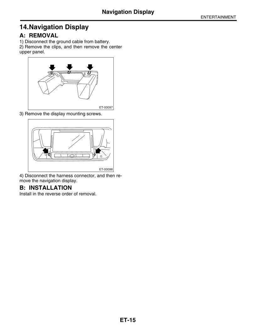
ENTERTAINMENTNavigation Display
14.Navigation DisplayA: REMOVAL1) Disconnect the ground cable from battery.2) Remove the clips, and then remove the centerupper panel.
3) Remove the display mounting screws.
4) Disconnect the harness connector, and then re-move the navigation display.
B: INSTALLATIONInstall in the reverse order of removal.
ET-00097
ET-00098
ET-15

ENTERTAINMENTGPS Antenna
15.GPS AntennaA: REMOVAL1) Disconnect the ground cable from battery.2) Remove the combination meter. <Ref. to IDI-16,REMOVAL, Combination Meter Assembly.>3) Remove the GPS antenna mounting screw, andthen remove the GPS antenna.
4) Remove the audio. <Ref. to ET-5, REMOVAL,Audio.>5) Remove the GPS antenna cord connector fromsteering support beam stay (on the driver’s side).
B: INSTALLATIONInstall in the reverse order of removal.
ET-00099
ET-00100
ET-16

ENTERTAINMENTNavigation Body
16.Navigation BodyA: REMOVAL1) Disconnect the ground cable from battery.2) Remove the glove box. <Ref. to EI-51, REMOV-AL, Glove Box.>3) Remove the navigation body mounting screws innumerical order and pull it out.
NOTE:To remove the screw (4) easier, move the naviga-tion body after removing the screw (3).
4) Remove the harness connector and antenna ca-ble, and then remove the navigation body.
B: INSTALLATIONInstall in the reverse order of removal.
ET-00107
(2)(3)
(4)(1)
ET-17

ENTERTAINMENTFront Accessory Power Supply Socket
17.Front Accessory Power Sup-ply Socket
A: REMOVAL1. FRONT 1) Disconnect the ground cable from battery.2) Remove the console front panel. <Ref. to EI-54,REMOVAL, Center Console.>3) Disconnect the harness connector, and removethe accessory power supply socket.
2. REAR 1) Disconnect the ground cable from battery.2) Remove the console box. <Ref. to EI-53, RE-MOVAL, Console Box.>3) Disconnect the harness connector, and removethe accessory power supply socket.
B: INSTALLATIONInstall in the reverse order of removal.
ET-00094
ET-00095
ET-18

ENTERTAINMENTSteering Satellite Switch
18.Steering Satellite SwitchA: REMOVAL1) Disconnect the ground cable from battery.2) Set the tire to the straight-ahead position.3) Remove the airbag module. <Ref. to AB-14, RE-MOVAL, Driver’s Airbag Module.>
WARNING:With the airbag module equipped, always referto “Airbag System” when performing the airbagmodule repair service. <Ref. to AB-14, INSPEC-TION, Driver’s Airbag Module.>4) Remove the steering wheel. <Ref. to PS-20, RE-MOVAL, Steering Wheel.>5) Remove the cover from steering wheel.6) Remove each one of satellite switch mountingscrew from the LH and RH side.
7) Remove the satellite switch.
B: INSTALLATIONInstall in the reverse order of removal.
CS-00331
ET-19

ENTERTAINMENTSteering Satellite Switch
C: INSPECTION
CS-00306
15
2 3 46 7 8
Step Check Yes No1 MUTE SWITCH CONTINUITY CHECK.
1) Press the mute switch.2) Measure the resistance between satellite switch connector terminals.
TerminalsNo. 7 — No. 6:
Is the resistance approx. 22 Ω? Go to step 2. Replace the satel-lite switch.
2 VOLUME SWITCH CONTINUITY CHECK.1) Press the volume switch.2) Measure the resistance between satellite switch connector terminals.
TerminalsNo. 7 — No. 6: Volume upNo. 7 — No. 6: Volume down
Is the resistance approx. 90 Ω? (Volume up)Is the resistance approx. 200 Ω? (Volume down)
Go to step 3. Replace the satel-lite switch.
3 MODE SWITCH CONTINUITY CHECK.1) Press the mode switch.2) Measure the resistance between satellite switch connector terminals.
TerminalsNo. 7 — No. 6:
Is the resistance approx. 360 Ω?
Go to step 4. Replace the satel-lite switch.
4 SEEK SWITCH CONTINUITY CHECK.1) Press the seek switch.2) Measure the resistance between satellite switch connector terminals.
TerminalsNo. 7 — No. 6: Seek upNo. 7 — No. 6: Seek down
Is the resistance approx. 690 Ω? (Seek up)Is the resistance approx. 1.5 kΩ? (Seek down)
Go to step 5. Replace the satel-lite switch.
5 CHECK SATELLITE SWITCH INSULATION.1) Not to operate the satellite switch.2) Measure the resistance between satellite switch connector terminals.
TerminalsNo. 7 — No. 6:
Is the resistance approx. 4.7 kΩ?
Satellite switch is normal.
Replace the satel-lite switch.
ET-20

COMMUNICATION SYSTEM
COM
Page1. General Description ....................................................................................22. Horn System ...............................................................................................33. Horn ............................................................................................................44. Horn Switch.................................................................................................5

COMMUNICATION SYSTEMGeneral Description
1. General DescriptionA: CAUTION• Before disassembling or reassembling parts, al-ways disconnect the battery ground cable from bat-tery. When replacing audio, control module, andother parts provided with memory functions, recordmemory contents before disconnecting the batteryground cable. Otherwise, the memory will beerased.• Reassemble in reverse order of disassembly, un-less otherwise indicated.• Adjust parts to the given specifications.• Connect the connectors securely during reas-sembly.• After reassembly, make sure functional parts op-erate smoothly.
B: PREPARATION TOOL1. GENERAL TOOLS
TOOL NAME
REMARKS
Circuit tester
Used for measuring resistance and voltage.
COM-2

COMMUNICATION SYSTEMHorn System
2. Horn SystemA: WIRING DIAGRAM1. HORN<Ref. to WI-245, WIRING DIAGRAM, Horn Sys-tem.>
B: INSPECTION1. HORN RELAYMeasure the horn relay resistance between termi-nals (indicated in table below) when connecting theterminal No. 4 to battery positive terminal and ter-minal No. 3 to battery ground cable.
Current Terminal No. Standard
Flow1 and 2
Less than 1 ΩNo Flow More than 1 MΩ
COM00001
(1)(2)
(1)
(4)
(2)
(3)
(3) (4)
COM-3

COMMUNICATION SYSTEMHorn
3. HornA: REMOVAL1) Disconnect the ground cable from battery.2) Remove the two clips and turn up the lower mudguard RH.
3) Remove the horn bracket mounting bolt (A).4) Disconnect the harness connector and removethe horn assembly (B).
B: INSTALLATIONInstall in the reverse order of removal.
C: INSPECTION With 12 V direct current supplied between horn ter-minals, check that the horn sounds properly.
LI-00288
COM00016(B)
(A)
COM00020
COM-4

COMMUNICATION SYSTEMHorn Switch
4. Horn SwitchA: REMOVALWARNING:Before servicing, be sure to read the notes inAB section for proper handling of driver’s air-bag module. <Ref. to AB-4, CAUTION, GeneralDescription.>
NOTE:Horn switch is a unit with the driver’s airbag mod-ule.1) Disconnect the ground cable from battery.2) Remove the driver’s airbag module. <Ref. to AB-14, REMOVAL, Driver’s Airbag Module.>
B: INSTALLATIONInstall in the reverse order of removal.
C: INSPECTIONMeasure the resistance between horn switch termi-nal and chassis ground.
Switch position Terminal No. Resistance
When horn switch is pushed. 3 and Chassis
ground
Less than 1 Ω
When horn switch is not pushed.
More than 1 MΩ
COM00018
3 27 6 5 4
1
COM-5

COMMUNICATION SYSTEMHorn Switch
COM-6

GLASS/WINDOWS/MIRRORS
GW
Page1. General Description ....................................................................................22. Power Window System ...............................................................................83. Power Window Control Switch ....................................................................94. Front Door Glass.......................................................................................105. Front Regulator and Motor Assembly .......................................................156. Remote Control Mirror System..................................................................167. Scalp Cap..................................................................................................178. Outer Mirror Assembly ..............................................................................189. Outer Mirror...............................................................................................19
10. Remote Control Mirror Switch ...................................................................2011. Rear Door Glass .......................................................................................2212. Rear Regulator and Motor Assembly ........................................................2413. Windshield Glass ......................................................................................2514. Rear Gate Glass .......................................................................................2815. Rear Window Glass ..................................................................................2916. Rear Window Defogger System................................................................3017. Rear Window Defogger.............................................................................3118. Rear Quarter Glass ...................................................................................3319. Sun Roof Glass .........................................................................................3420. Rearview Mirror.........................................................................................3521. Wiper Deicer System ................................................................................3622. Wiper Deicer Switch..................................................................................37

GLASS/WINDOWS/MIRRORSGeneral Description
1. General DescriptionA: COMPONENT1. FIXED GLASS (SEDAN MODEL)
(1) Windshield glass (4) Rearview mirror mount (7) Six light glass
(2) Dam rubber (5) Locating pin (8) Bracket
(3) Molding (6) Rear window glass (9) Clip
GW-00331
(2)
(6)
(2)
(7)(8)
(9)
(2)
(3)
(5)(3)
(8)
(1)
(2)
(3) (4)
(5)
(9)
(9)
GW-2

GLASS/WINDOWS/MIRRORSGeneral Description
2. FIXED GLASS (WAGON MODEL)
(1) Windshield glass (4) Rearview mirror mount (7) Rear quarter glass
(2) Dam rubber (5) Locating pin (8) Locating pin
(3) Molding (6) Fastener (9) Glass
GW-00314
(1)
(2)
(2)
(3)(4)
(5)
(6)
(6)
(7)
(8)
(8)(9)
GW-3
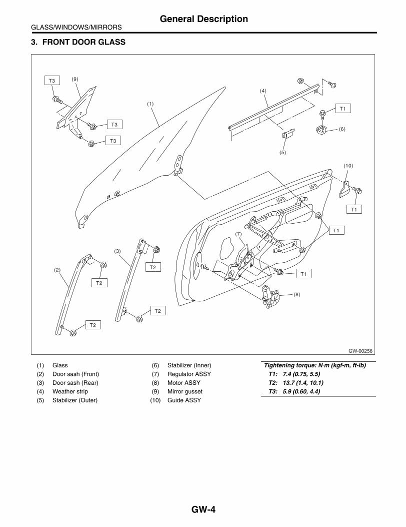
GLASS/WINDOWS/MIRRORSGeneral Description
3. FRONT DOOR GLASS
(1) Glass (6) Stabilizer (Inner) Tightening torque: N⋅m (kgf-m, ft-lb)(2) Door sash (Front) (7) Regulator ASSY T1: 7.4 (0.75, 5.5)(3) Door sash (Rear) (8) Motor ASSY T2: 13.7 (1.4, 10.1)(4) Weather strip (9) Mirror gusset T3: 5.9 (0.60, 4.4)(5) Stabilizer (Outer) (10) Guide ASSY
GW-00256
T2T1
T1
T3
T3
(8)
(7)
(3)
(2)
(1)
(9)
T2
T2
T2
T1
(6)
(5)
(4)
T3
T1
(10)
GW-4

GLASS/WINDOWS/MIRRORSGeneral Description
4. REAR DOOR GLASS
(1) Glass (5) Stabilizer (Outer) Tightening torque: N⋅m (kgf-m, ft-lb)(2) Door sash (Front) (6) Stabilizer (Inner) T1: 7.4 (0.75, 5.5)(3) Door sash (Rear) (7) Regulator ASSY T2: 13.7 (1.4, 10.1)(4) Weather strip (8) Motor ASSY
GW-00257
T1
T1
(8)
(7)
(1)
(2)
(3)
T2
T1
(6)
(5)
(4)
T2
GW-5

GLASS/WINDOWS/MIRRORSGeneral Description
5. MIRROR
B: CAUTION• When electrical connectors are disconnected, always conduct an operational check after connecting themagain.• Avoid impact and damage to the glass.
(1) Outer mirror (3) Scalp cap (5) Rearview mirror
(2) Mirror (4) Side turn signal light (6) Mount
GW-00258
(5)
(6)
(2)
(3)
(4)
(1)
GW-6

GLASS/WINDOWS/MIRRORSGeneral Description
C: PREPARATION TOOL1. SPECIAL TOOL
2. GENERAL TOOL
ILLUSTRATION TOOL NUMBER DESCRIPTION REMARKS
61299AE000 SPACER Used for adjusting the upper end position of front door glass. (Glass thickness: 5 mm (0.197 in))
61299AE010 SPACER Used for adjusting the upper end position of rear door glass. (Glass thickness: 4 mm (0.157 in))
TOOL NAME REMARKS
Circuit tester Used for checking voltage and continuity.
Piano wire Used for removing the window glass.
Windshield glass knife Used for removing the window glass.
ST61299AE000
ST61299AE010
GW-7

GLASS/WINDOWS/MIRRORSPower Window System
2. Power Window SystemA: WIRING DIAGRAM<Ref. to WI-294, Power Window System.>
B: INSPECTIONSymptom Repair order
All power windows do not operate.
(1) Fuse (SBF-5)(2) Power window circuit breaker(3) Power window relay(4) Wiring harness(5) Body integrated unit
One window does not operate.
(1) Power window main switch(2) Power window sub switch(3) Power window motor(4) Wiring harness
“Window Lock” does not operate. Power window main switch
GW-8

GLASS/WINDOWS/MIRRORSPower Window Control Switch
3. Power Window Control Switch
A: REMOVAL1. MAIN SWITCH1) Disconnect the ground cable from battery.2) Remove the front door trim. <Ref. to EI-48, RE-MOVAL, Door Trim.>3) Disconnect the harness connector.4) Remove the screws from the reverse side offront door trim to remove the power window mainswitch.
2. SUB SWITCH1) Disconnect the ground cable from battery.2) Remove the door trim. <Ref. to EI-48, REMOV-AL, Door Trim.>3) Disconnect the connector.4) Remove the screws from the reverse side ofdoor trim to remove the power window sub switch.
B: INSTALLATION1. MAIN SWITCHInstall in the reverse order of removal.
2. SUB SWITCHInstall in the reverse order of removal.
C: INSPECTION1. MAIN SWITCHMeasure switch resistance.• LHD model
• RHD model
Replace the main switch if faulty.
2. SUB SWITCHMeasure switch resistance.
Replace the sub switch if faulty.
GW-00259
GW-00260
Switch position Terminal No. Standard
Driver’s seat
AUTO UP 10 and 2, 7 and 1 Less than 1 ΩUP 10 and 2, 7 and 1 Less than 1 Ω
DOWN 10 and 1, 7 and 2 Less than 1 ΩAUTO DOWN 10 and 1, 7 and 2 Less than 1 Ω
Switch position Terminal No. Standard
Driver’s seat
AUTO UP 11 and 1, 14 and 2 Less than 1 ΩUP 11 and 1, 14 and 2 Less than 1 Ω
DOWN 11 and 2, 14 and 1 Less than 1 ΩAUTO DOWN 11 and 2, 14 and 1 Less than 1 Ω
Switch position Terminal No. Standard
Passenger’s seat and rear
UP 2 and 3, 4 and 5 Less than 1 ΩOFF 1 and 2, 4 and 5 Less than 1 Ω
DOWN 1 and 2, 3 and 4 Less than 1 Ω
GW-9

GLASS/WINDOWS/MIRRORSFront Door Glass
4. Front Door GlassA: REMOVAL1) Remove the front door trim. <Ref. to EI-48, RE-MOVAL, Door Trim.>2) Remove the sealing cover. <Ref. to EB-20, RE-MOVAL, Front Sealing Cover.>3) Remove the outer mirror assembly. <Ref. toGW-18, REMOVAL, Outer Mirror Assembly.>4) Remove the clip (A), and remove the front end ofweather strip.
5) Remove the gusset.
6) Remove the stabilizer.
7) Remove the clips (A), and remove the rear endof weather strip.
8) Remove the screw (A) from the rear end ofweather strip outer to remove weather strip outer.
9) Remove the screws to remove guide assembly.10) Operate the power window switch to moveglass to position shown in the figure, and then re-move the two nuts through service holes.
GW-00261
(A)
GW-00262
GW-00263
GW-00264
(A)
GW-00265
(A)
GW-00266
GW-10

GLASS/WINDOWS/MIRRORSFront Door Glass
11) Remove the door glass.
CAUTION:• Since the gear may be disengaged, do notturn regulator in the closing direction after re-moval of the glass.• Avoid impact and damage to the glass.
B: INSTALLATION1) Install in the reverse order of removal.
CAUTION:Make sure that glass stay is placed securely in sash. 2) Adjust the front door glass. <Ref. to GW-11, AD-JUSTMENT, Front Door Glass.>
Tightening torque:Refer to “COMPONENT” of “General Descrip-tion”. <Ref. to GW-4, FRONT DOOR GLASS, COMPONENT, General Description.>
C: ADJUSTMENTNOTE:Before adjustment, ensure that all adjusting bolts ofstabilizer, upper stopper and sash are loose anddoor glass is raised so that it is in contact withweather strip. 1) Temporarily tighten one adjusting bolt on oneside of rear sash at the midpoint of slotted hole inthe inner panel.2) Temporarily tighten the regulator B-channel in aposition at the top of slotted hole.3) Lower the door glass 10 — 15 mm (0.39 — 0.59in) from fully closed position. While applying out-ward pressure of 45.0± 5.0 N (4.5±0.5 kgf, 9.9±1.1lb) (F) to upper edge of glass above midpoint of twoouter stabilizers, press the inner stabilizer at pres-
sure of 25±5 N (2.5±0.5 kgf, 5.5±1.1 lb) to theglass, then secure it.
4) For adjustment of clearance between front glassand center pillar cover, loosen the nuts (A), andmove the glass sash back and forward until clear-ance becomes the value shown.
GW-00267
(1) Fully closed position
(2) Stabilizer
(3) 10 — 15 mm (0.39 — 0.59 in)
(1) Adjust a line parallel
(2) Sash
(3) Inner panel
(1) 11 mm (0.433 in)
(1) F
(2) A = A
A
(2)
(3)
GW-00063
A
GW-00319
(A)
(2) (1)
(3)
BO0388
AA
A-A
(1) (1)
GW-00064
GW-11

GLASS/WINDOWS/MIRRORSFront Door Glass
5) To adjust the upper end and lower end of centerpillar, loosen the stopper bolt (A) or nut (B) securingdoor sash, move the stopper position until theclearance between center pillar cover is equal.
CAUTION:Perform the measurement of clearance be-tween center pillar at less than 50 mm (1.969 in) from upper end of window glass.
6) Adjust so that the upper and lower ends of cen-ter pillar are the same size.
(1) Glass
(2) Center pillar cover
(3) Check point
(4) 50 mm (1.969 in)
(5) 11 mm (0.433 in)
(A)
GW-00320
GW-00321
(B)
(1)
(4)
(3)
(5)
(2)
GW-00322
(1) Narrow
(2) Wide
(3) Glass tilts too far rearward
(4) Glass tilts too far forward
(5) Stopper adjusting direction
GW-00323
(5)
(4)(1)
(2)
(1)
(2)
(3)
(5)
(5) (5)
GW-12

GLASS/WINDOWS/MIRRORSFront Door Glass
7) After adjusting the clearance between center pil-lar, up and down the glass several times to checkglass contact to stopper when glass is fully closed.Adjust it to contact the front and rear stopper simul-taneously.
8) For adjustment of the upper and lower ends ofcenter pillar, loosen the adjusting nut (A) of B-chan-nel (B).
9) For glass stroke adjustment, install the ST toglass, close the door, and raise the glass with reg-ulator until positional relationship between glassand weather strip becomes as shown. And securethe glass so that the upper stopper correctly touch-es the glass holder.ST 61299AE000 SPACER
(Glass thickness: 5 mm (0.197 in) for front door glass)
For preventing wind noise, adjust the glass at theposition where tip of gusset is raised up a little.
10) After stabilizer adjustment, carry out the glasscohesion adjustment. First, visually ensure the po-sitional relationship between retainer & moldingand glass of the roof side, and then begin with rearsash adjustment. Install the ST to glass and adjusttwo adjusting bolts alternately step by step to ob-tain dimensions shown below (cross-section A).
NOTE:If two nuts are loosened at the same time, the sashmoves back and forth. Therefore, when one nut isadjusted, secure the other.
(1) Narrow
(2) Wide
(3) When the stopper of door sash (rear) contacts first
(4) When the stopper of door sash (front) contacts first
(5) Raise B channel
(6) Lower B channel
GW-00324(6)
(5)
(4)(1)
(2)
(1)
(2)
(3)
(A)
GW-00269
(B)
(1) 3.2 — 4.8 mm (0.126 — 0.189 in)
(2) 7 mm (0.276 in)
(3) ST
(A) 0 — 1.5 mm (0 — 0.059 in)
GW-00336
A
A
(2)
(1)
(3)
(A)
GW-00325
GW-13

GLASS/WINDOWS/MIRRORSFront Door Glass
11) Make the same adjustment of two adjustingbolts of rear sash.ST 61299AE000 SPACER
(Glass thickness: 5 mm (0.197 in) for front door glass)
NOTE:Do not tilt the sash bracket to inner panel during ad-justment. Otherwise smooth regulator operationcannot be achieved.
12) Make adjustment of front sash in the samemanner as that of rear sash.
NOTE:Although front and rear sashes must, as a rule, beadjusted in the same manner, in some door instal-lation, the adjustment in a different manner may berequired. However, adjustment of one sash to themaximum amount and the other to the minimumamount is not permitted. Such adjustment may re-sult in application of excessive load to regulator. 13) After adjustments, tighten the nuts.14) After adjustment of the glass, close the door. Ifthere is a gap between outer lip of gusset and glasssurface, adjust the gap with adjusting bolt (A) in
lower fitting part of gusset to prevent generation ofwind noise.15) During adjustment, loosen the other threeclamping bolts.
16) After adjustment, tighten the bolts and nuts.
(1) 3.2 — 4.8 mm (0.126 — 0.189 in)
(2) 7 mm (0.276 in)
(3) ST
(1) Sash bracket
(2) Rear sash
(3) Adjust a line parallel
(4) Sash
(5) Inner panel
GW-00336
A
A
(2)
(1)
(3)
GW-00270
(1)
(2)
(4) (3)
(5)
GW-00271(A)
GW-14

GLASS/WINDOWS/MIRRORSFront Regulator and Motor Assembly
5. Front Regulator and Motor Assembly
A: REMOVAL1) Remove the door glass. <Ref. to GW-10, RE-MOVAL, Front Door Glass.>2) Disconnect the motor connector. 3) Remove the four bolts and two nuts to removeregulator assembly.
4) Remove the screws to remove motor assembly.
NOTE:When removing the motor assembly, secure thearm correctly, because the regulator arm moves inthe force of balancing spring.
B: INSTALLATION1) Install in the reverse order of removal.2) Adjust the front door glass. <Ref. to GW-11, AD-JUSTMENT, Front Door Glass.>
Tightening torque:Refer to “COMPONENT” of “General Descrip-tion”. <Ref. to GW-4, FRONT DOOR GLASS, COMPONENT, General Description.>
C: INSPECTION1) Make sure that the power window motor rotatesproperly when the battery voltage is applied to theterminals of motor connector.2) Change polarity of battery connection to termi-nals to ensure that the motor rotates in reverse di-rection.
GW-00273
GW-00274
GW-15

GLASS/WINDOWS/MIRRORSRemote Control Mirror System
6. Remote Control Mirror SystemA: WIRING DIAGRAM<Ref. to WI-306, Remote Control Mirror System.>
B: INSPECTIONSymptom Repair order
All function does not operate.(1) Fuse (F/B No. 6)(2) Mirror switch(3) Wiring harness
One side of the mirror motor does not operate.(1) Mirror switch(2) Mirror motor(3) Wiring harness
Mirror heater does not operate.(1) Mirror switch(2) Mirror heater(3) Wiring harness
GW-16

GLASS/WINDOWS/MIRRORSScalp Cap
7. Scalp CapA: REPLACEMENT1) Remove the outer mirror. <Ref. to GW-19, RE-PLACEMENT, Outer Mirror.>2) Press-in the upper side clips (A) from inside ofdoor mirror.
3) Pull the scalp cap frontward of door mirror, re-move the upper side clips (A) and lower side hooks(B), and then remove the scalp cap.
4) Insert the lower hooks (B) of scalp cap to doormirror and push the upper clips (A) in.
5) Install the scalp cap securely.
CAUTION:Do not remove the scalp cap forcibly. The lower hooks may be damaged.
GW-00312
(A)(A)
(A)
GW-00275(B)
(B)
(A)
GW-00276
GW-17

GLASS/WINDOWS/MIRRORSOuter Mirror Assembly
8. Outer Mirror AssemblyA: REMOVAL1) Remove the mirror gusset cover.
2) Remove the door trim. <Ref. to EI-48, REMOV-AL, Door Trim.>3) Disconnect the mirror connector.4) Remove the screws to remove mirror assembly.
B: INSTALLATIONInstall in the reverse order of removal.
C: INSPECTIONCheck that the rearview mirror moves properly when the battery voltage is applied to terminals.• Model without mirror heater
• Model with mirror heater
Replace the outer mirror assembly if defective.
(1) Hook
GW-00277
: (1)
GW-00278
Switch position Terminal No.
OFF —
UP 6 (+) and 3 (−) or 8 (−)
DOWN 3 (+) or 8 (+) and 6 (−)
LEFT 7 (+) and 3 (−) or 8 (−)
RIGHT 3 (+) or 8 (+) and 7 (−)
Switch position Terminal No.
OFF —
UP 7 (+) and 3 (−) or 9 (−)
DOWN 3 (+) or 9 (+) and 7 (−)
LEFT 8 (+) and 3 (−) or 9 (−)
RIGHT 3 (+) or 9 (+) and 8 (−)
GW-18

GLASS/WINDOWS/MIRRORSOuter Mirror
9. Outer MirrorA: REPLACEMENT1) Face the mirror upward. 2) Use a flat tip screwdriver to remove clip (A).3) Lift the lower mirror up to remove hooks (B).
4) Disconnect the mirror heater connector from theend of mirror. (Model with mirror heater)
5) Catch the hooks (A) and install clips (B).
CAUTION:• When removing the mirror, be careful not todamage the back side of mirror with a flat tipscrewdriver.• When installing the mirror, insert the hookand clip securely.
(A)
GW-00279
(B)
GW-00280
(A)
GW-00281(B)
GW-19

GLASS/WINDOWS/MIRRORSRemote Control Mirror Switch
10.Remote Control Mirror Switch
A: REMOVAL1) Remove the instrument panel lower cover. <Ref.to EI-50, REMOVAL, Instrument Panel Lower Cov-er.>2) Disconnect the connector.
3) Remove the remote control mirror switch frominstrument panel lower cover.
B: INSTALLATIONInstall in the reverse order of removal.
GW-00282
L R
01
GW-20

GLASS/WINDOWS/MIRRORSRemote Control Mirror Switch
C: INSPECTION1. REMOTE CONTROL MIRROR SWITCHMove the remote control mirror switch to each position and check continuity between terminals.
• Change over switch R
• Change over switch L
Replace the remote control mirror switch if defective.
GW-00283
914
7 6 5 4 3 2 1
813 12 11 1016 15
Switch position Terminal No. Standard
OFF — More than 1 MΩUP 10 and 12, 15 and 14 Less than 1 Ω
DOWN 10 and 15, 12 and 14 Less than 1 ΩLEFT 10 and 11, 15 and 14 Less than 1 Ω
RIGHT 10 and 15, 11 and 14 Less than 1 Ω
Switch position Terminal No. Standard
OFF — More than 1 MΩUP 10 and 8, 15 and 14 Less than 1 Ω
DOWN 10 and 15, 8 and 14 Less than 1 ΩLEFT 10 and 9, 15 and 14 Less than 1 Ω
RIGHT 10 and 15, 9 and 14 Less than 1 Ω
GW-21

GLASS/WINDOWS/MIRRORSRear Door Glass
11.Rear Door GlassA: REMOVAL1) Remove the rear door trim. <Ref. to EI-48, RE-MOVAL, Door Trim.>2) Remove the sealing cover. <Ref. to EB-24, RE-MOVAL, Rear Sealing Cover.>3) Remove the stabilizer.
4) Remove the clips (A), and remove the front endand rear end of weather strip.
5) Loosen the two screws to remove weather stripouter.
6) Operate the power window switch to move theglass to position shown in the figure, and then re-move the two nuts through service holes.
7) Remove the rear sash retaining nuts (A) andmove rear sash (B) backward.
8) Remove the door glass.
CAUTION:• Since the gear may be disengaged, do notturn regulator in the closing direction after re-moval of the glass.• Avoid impact and damage to the glass.
GW-00284
GW-00285
(A)
(A)
GW-00286
GW-00287
(B)
(A)
GW-00288
GW-22

GLASS/WINDOWS/MIRRORSRear Door Glass
B: INSTALLATION1) Install in the reverse order of removal.
CAUTION:Make sure that glass stay is placed securely in sash. 2) Adjust the rear door glass. <Ref. to GW-23, AD-JUSTMENT, Rear Door Glass.>
Tightening torque:Refer to “COMPONENT” of “General Descrip-tion”. <Ref. to GW-5, REAR DOOR GLASS, COMPONENT, General Description.>
C: ADJUSTMENTNOTE:The rear door glass, as a rule, should be adjustedin the same manner as front door glass, althoughthey are different in dimension. <Ref. to GW-11,ADJUSTMENT, Front Door Glass.> 1) Adjust the glass position using the following di-mensions as a guide line.
NOTE:• If dimensions are smaller than the given dimen-sions, glass may get caught in weather strip duringlifting/lowering operation and may not be fully open.• After adjustment, move the glass up and down tocheck whether it is caught.
2) Install the ST to glass and adjust the glass adhe-sion to the value shown.ST 61299AE010 SPACER
(Glass thickness: 4 mm (0.157 in) for rear door glass)
NOTE:• If rear glass adhesion is higher than necessary,glass may get caught in weather strip of center pil-lar corner, resulting in early wear of weather strip.Care should be taken for adjustment.• After adjustment, move the glass up and down tocheck whether it is caught.
(1) 11 mm (0.433 in)
AA
A-A
(1) (1)
GW-00067
(1) 3.2 — 4.8 mm (0.126 — 0.189 in)
(2) 7 mm (0.276 in)
(3) ST
A
A
A-A GW-00337
(2)
(1)
(3)
GW-23

GLASS/WINDOWS/MIRRORSRear Regulator and Motor Assembly
12.Rear Regulator and Motor As-sembly
A: REMOVAL1) Remove the rear door glass. <Ref. to GW-22,REMOVAL, Rear Door Glass.>2) Remove the nut (A) to remove front sash.
3) Disconnect the motor connector.4) Remove the four bolts and two nuts to removeregulator assembly.
5) Remove the screws to remove motor assembly.
B: INSTALLATION1) Install in the reverse order of removal.2) Adjust the rear door glass. <Ref. to GW-23, AD-JUSTMENT, Rear Door Glass.>
Tightening torque:Refer to “COMPONENT” of “General Descrip-tion”. <Ref. to GW-5, REAR DOOR GLASS, COMPONENT, General Description.>
C: INSPECTION1) Make sure that the power window motor rotatesproperly when the battery voltage is applied to theterminals of motor connector.2) Change polarity of battery connection to termi-nals to ensure that the motor rotates in reverse di-rection.
GW-00289
(A)
GW-00290
GW-00291
GW-24

GLASS/WINDOWS/MIRRORSWindshield Glass
13.Windshield GlassA: REMOVAL1. USING WINDSHIELD GLASS KNIFE1) Remove the cowl panel. <Ref. to EI-39, RE-MOVAL, Cowl Panel.>2) Remove the glass molding.3) Tape the body side of the circumference of wind-shield glass for protection.4) Apply sufficient amount of soapy water to the ad-hesive part.5) Insert the windshield glass knife into adhesivepart.6) While holding the knife edge and windshieldglass edge at a right angle, move the windshieldglass knife in parallel to the windshield glass edgealong face and edge of windshield glass to cut theadhesive part.
NOTE:• Do not twist windshield glass knife.• Cutting of adhesive part shall be started with wid-er gap between windshield glass and body.
• Because the locating pins are bonded to the cor-ners of glass, use piano wire to cut the pin.
2. USING PIANO WIRE1) Remove the cowl panel. <Ref. to EI-39, RE-MOVAL, Cowl Panel.>2) Remove the molding.3) Tape the body side of the circumference of wind-shield glass for protection.4) Make a hole in the adhesive part using drill orknife.5) Pass the piano wire through the hole, and attachsecurely both the wire ends to pieces of wood.
6) Pull the wire ends alternately to cut off the adhe-sive part.
CAUTION:• Do not tightly pull the piano wire against thewindshield glass edge.• Be careful not to damage interior and exteriorparts.• When removal is made with area close to in-strument panel, place a protection plate over it.Pay particular attention to the removal.• Do not cross piano wires. Otherwise theymay be cut.
(1) Putty knife
(2) Tape for protection
(3) Locating pin
(4) Windshield glass knife
GW-00069
(1)
(1)
(1)
(3)
(3)
(2)
(4)A
A-A
A
(1) Locating pin
(2) Body panel
(3) Windshield glass
(1)
(2)
(3)
A
A
GW-00070
A-A
GW-00039
GW-25

GLASS/WINDOWS/MIRRORSWindshield Glass
B: INSTALLATION1) Clean the external circumference of windshieldglass with alcohol or white gasoline.2) Remove the adhesive layer on the body usingcutter knife to obtain smooth face of 2 mm (0.08 in)thick.
CAUTION:Be careful not to damage the body and paint surface.
3) Clean the body with alcohol or white gasoline toeliminate cutting power, dust and dirt completelyfrom body.4) Align the locating pin of glass side with the holeof body side, and place the glass on the body.
5) Adjust the glass position to make uniform clear-ance between body and glass in four corners.
6) Remove the glass temporarily from body.7) Install the dam rubber.8) Fit molding mark (B) to notch (A) of glass sideand install the molding to entire perimeter of glass.
(1) Adhesive
(2) 2 mm (0.08 in)
(3) Dam rubber
(4) Glass
(4)(2)
(1)(3)
GW-00071
(1) Locating pin
(2) Dam rubber
(3) 9 mm (0.354 in)
(4) 11 mm (0.433 in)
(1)
(2)
(4)
(4)
(3)
GW-00315
GW-00316
(A)
(B)
GW-26

GLASS/WINDOWS/MIRRORSWindshield Glass
9) Apply two types of primers to the adhesive layerof glass using sponge.
Glass primer:Betawipe VP04604Betaprime 5001
10) Apply primer to the adhesive layer of body.
Painted surface primer:Betaprime 5402
NOTE:• Primer once attached to the painted surface ofthe body and internal trim is hard to wipe off. Maskthe circumference of such area.• Let primer dry for about ten minutes before in-stalling the glass.• Do not touch the surface coated with primer.
11) Cut off the cartridge nozzle tip as shown andset it in sealant gun.
12) Apply adhesive to the glass end surface asshown.
Adhesive:Gurit-ESSEXBetaseal 1502 or equivalent
13) Fit the locating pins using suction rubber cup toinstall windshield glass.
14) Lightly press the windshield glass for tight fit.15) Make flush the adhesive surface jutted out us-ing spatula.16) After completion of all work, allow the vehicle tostand for about 24 hours.
NOTE:• When door is opened/closed after glass is bond-ed, always lower the door glass and then open/close it carefully.• Move the vehicle slowly.• For minimum drying time and vehicle standingtime before driving after bonding, follow instruc-tions or instruction manual from the adhesive man-ufacturer. 17) After curing of adhesive, pour the water on ex-ternal surface of vehicle to check that there are nowater leaks.
NOTE:When a vehicle is returned to the user, tell him orher that the vehicle should not be subjected toheavy impact for at least three days. 18) Install the cowl panel. <Ref. to EI-39, INSTAL-LATION, Cowl Panel.>
(1) Application of primer
(2) Glass side
(3) Body side
(1) 10 mm (0.39 in)
(2) 15 mm (0.59 in)
(3)(2)
(1)
GW-00073
(1)
(2)
GW-00238
(1) 9 — 12 mm (0.35 — 0.47 in)
(1)
GW-00239
GW-00045
GW-27

GLASS/WINDOWS/MIRRORSRear Gate Glass
14.Rear Gate GlassA: REMOVAL1) Remove the rear wiper motor. <Ref. to WW-22,REMOVAL, Rear Wiper Motor.>2) Disconnect the electrical connectors from reardefogger terminal.3) Remove the glass in the same procedure as forwindshield glass. <Ref. to GW-25, REMOVAL,Windshield Glass.>
B: INSTALLATION1) Apply adhesive in the same procedure as forwindshield glass. <Ref. to GW-26, INSTALLA-TION, Windshield Glass.>2) Insert the glass clip pin into rear gate hole, andafter pushing on the area around the clip pin to se-cure it, push lightly all around the area to seal it.3) About one hour after installation, conduct a leaktest.
4) After completion of all work, allow the vehicle tostand for about 24 hours.
NOTE:• When door is opened/closed after glass is bond-ed, always lower the door glass and then open/close it carefully.• Move the vehicle slowly.• For minimum drying time and vehicle standingtime before driving after bonding, follow instruc-tions or instruction manual from the adhesive man-ufacturer. • When a vehicle is returned to the user, tell him orher that the vehicle should not be subjected toheavy impact for at least three days. 5) Connect the rear defogger terminals.6) Install the rear wiper. <Ref. to WW-22, INSTAL-LATION, Rear Wiper Motor.>
(1) Upside
(2) Molding
(3) Glass
(4) Adhesive
(5) Downside
(6) Glass
(7) Molding
(8) Adhesive
(1)
(5)
(4)
(8)
(2)
(3)
(7)
(6)
GW-00240
GW-28
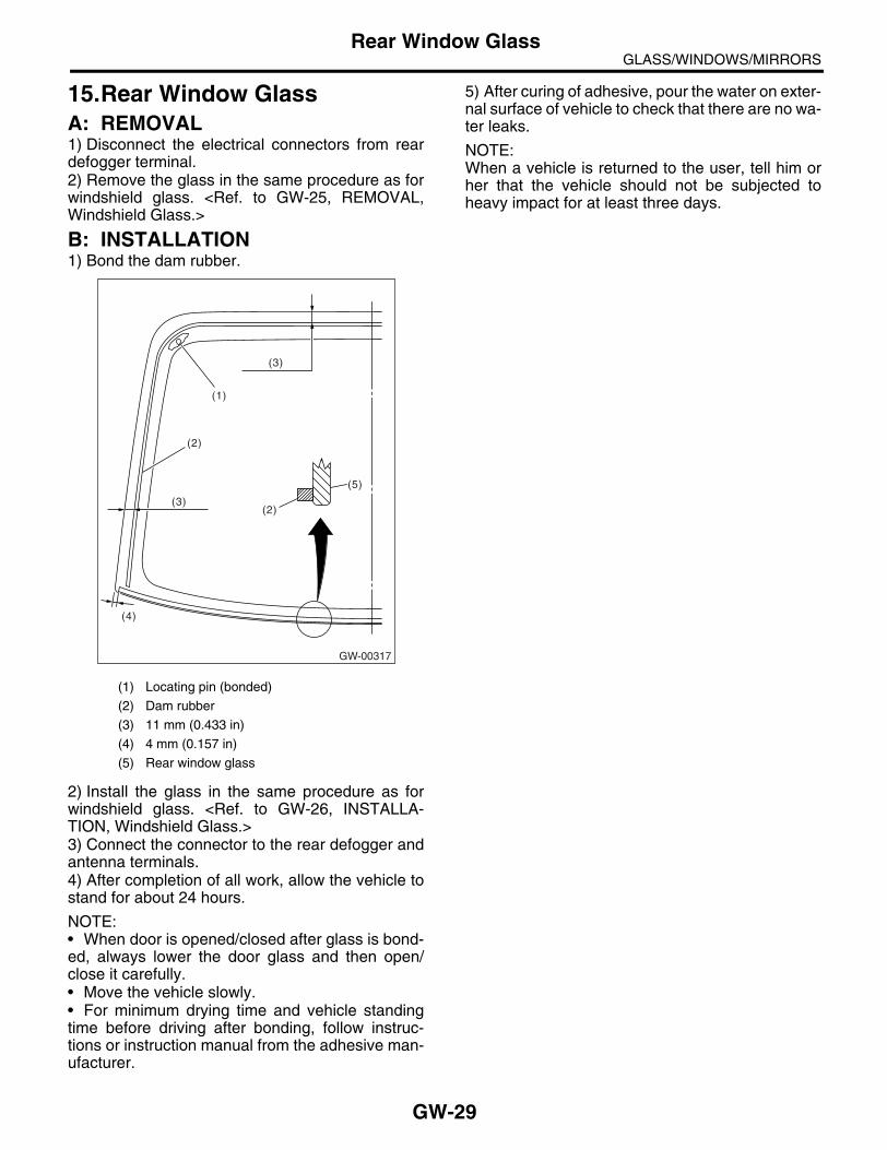
GLASS/WINDOWS/MIRRORSRear Window Glass
15.Rear Window GlassA: REMOVAL1) Disconnect the electrical connectors from reardefogger terminal.2) Remove the glass in the same procedure as forwindshield glass. <Ref. to GW-25, REMOVAL,Windshield Glass.>
B: INSTALLATION1) Bond the dam rubber.
2) Install the glass in the same procedure as forwindshield glass. <Ref. to GW-26, INSTALLA-TION, Windshield Glass.>3) Connect the connector to the rear defogger andantenna terminals.4) After completion of all work, allow the vehicle tostand for about 24 hours.
NOTE:• When door is opened/closed after glass is bond-ed, always lower the door glass and then open/close it carefully.• Move the vehicle slowly.• For minimum drying time and vehicle standingtime before driving after bonding, follow instruc-tions or instruction manual from the adhesive man-ufacturer.
5) After curing of adhesive, pour the water on exter-nal surface of vehicle to check that there are no wa-ter leaks.
NOTE:When a vehicle is returned to the user, tell him orher that the vehicle should not be subjected toheavy impact for at least three days.
(1) Locating pin (bonded)
(2) Dam rubber
(3) 11 mm (0.433 in)
(4) 4 mm (0.157 in)
(5) Rear window glass
(1)
(2)
(2)
(5)
(3)
(3)
GW-00317
(4)
GW-29

GLASS/WINDOWS/MIRRORSRear Window Defogger System
16.Rear Window Defogger SystemA: WIRING DIAGRAM<Ref. to WI-304, Rear Window Defogger System.>
B: INSPECTION
NOTE:Rear window defogger system can be customized on the touch panel in center display or Subaru Select Mon-itor.
Symptom Repair order
Rear window defogger does not operate.
(1) Fuse (M/B No. 10) (F/B No. 22)(2) Rear defogger relay(3) Defogger switch(4) Rear defogger condenser(5) Defogger wire(6) Wiring harness(7) Body integrated unit
System name Initial setting Customize setting
Rear window defogger timer OFF after 15 min. Repeat 15 min. operation and 2 min. stop.
GW-30

GLASS/WINDOWS/MIRRORSRear Window Defogger
17.Rear Window DefoggerA: INSPECTION1. WITH SUBARU SELECT MONITOR
CAUTION:Check that the rear window defogger timer is in initial setting or customize setting before inspection.
2. HEAT WIRE INSPECTION
CAUTION:When wiping stain on glass off with cloth, use a dry and soft cloth and move it along the heat wire to avoid damage to the heat wire.1) Turn the ignition switch to ON.2) Turn the defogger switch to ON.3) Wrap the tips of tester probe with aluminum foilto avoid damage to heat wire.
4) Measure the voltage at heat wire center with DCvoltmeter.
Standard voltage:Approx. 6 V
NOTE:• If the measured value is 12 volts, heat wire isopen between heat wire center and positive (+) ter-minal of tester probe.• If zero volt, heat wire is open between wire cen-ter and ground. 5) Connect the tester probe of positive lead of volt-meter to positive terminal of heat wire and movetester probe of negative lead along the heat wire upto the negative terminal end. If voltage changesfrom zero to several volts during movement oftester probe, heat wire is open at the voltagechange point.
Step Check Yes No1 CHECK INPUT SIGNAL TO BODY INTE-
GRATED UNIT.When the rear window defogger switch is oper-ated, check the input signal using Subaru Select Monitor.1) Connect the Subaru Select Monitor to data link connector.2) Turn the ignition switch to ON.3) Select Body Integrated Unit from «Main Menu».4) Select Current Data Display & Save.5) When the rear window defogger switch is set to ON, check the input signal.
After rear defogger switch is set to ON, does it turn to OFF in 15 minutes? Or does it repeat 15 minutes operation and 2 minutes stop?
END. Replace the body integrated unit. <Ref. to SL-46, REMOVAL, Body Integrated Unit.>
(1) Tester probe
(2) Aluminum foil
(3) Heat wire
(4) Push
GW-00076
(2)
(3)
(4)(1) (1) Center of heat wire
Voltage Criteria
Approx. 6 V Normal Operation
Approx. 12 V or 0 V Broken
GW-00077
(1)
GW-31

GLASS/WINDOWS/MIRRORSRear Window Defogger
B: REPAIR1) Clean the broken portion with alcohol or whitegasoline.2) Mask both side of wire with thin film.3) Apply the conductive silver composition (DU-PONT No. 4817) to the broken portion.
4) After repair, check the wire.
(1) Broken portion
(2) Thin film
(3) Broken wire
(4) Conductive silver composition (DUPONT No. 4817)
GW-00078
(2)
(3)
(4)
(1)
GW-32

GLASS/WINDOWS/MIRRORSRear Quarter Glass
18.Rear Quarter GlassA: REMOVALRemove the glass in the same procedure as forwindshield glass. <Ref. to GW-25, REMOVAL,Windshield Glass.>
B: INSTALLATION1) Install the dam rubber.
2) Cut out the nozzle head and apply adhesive tothe glass end surface as shown.
3) Install the glass in the same procedure as forwindshield glass. <Ref. to GW-26, INSTALLA-TION, Windshield Glass.>4) After completion of all work, allow the vehicle tostand for about 24 hours.
NOTE:• When door is opened/closed after glass is bond-ed, always lower the door glass and then open/close it carefully.• Move the vehicle slowly.• For minimum drying time and vehicle standingtime before driving after bonding, follow instruc-tions or instruction manual from the adhesive man-ufacturer. 5) After curing of adhesive, pour the water on exter-nal surface of vehicle to check that there are no wa-ter leaks.
NOTE:When a vehicle is returned to the user, tell him orher that the vehicle should not be subjected toheavy impact for at least three days.
(1) Locating pin
(2) Dam rubber
(1) Dam rubber
(2) Molding
(3) 10.5 mm (0.413 in) (constant)
(4) Ceramic terminal
GW-00332
(1)(1)
(2)
GW-00333
(2)(1)
(4)
(3)
(1) Locating pin
(2) Dam rubber
(3) Adhesive
(4) Molding
(5) 8 — 10 mm (0.31 — 0.39 in)
(6) 15 mm (0.59 in)
(7) 10 mm (0.39 in)
GW-00334
(2)
(3)
(4)
(1)(7)
(6)
(5)
(2)(3)
GW-33

GLASS/WINDOWS/MIRRORSSun Roof Glass
19.Sun Roof GlassA: REMOVAL<Ref. to SR-6, REMOVAL, Glass Lid.>
B: INSTALLATION<Ref. to SR-7, INSTALLATION, Glass Lid.>
C: ADJUSTMENT<Ref. to SR-7, ADJUSTMENT, Glass Lid.>
GW-34

GLASS/WINDOWS/MIRRORSRearview Mirror
20.Rearview MirrorA: REMOVALNOTE:Never reuse the spring. Prepare a new spring be-fore removal. 1) Turn the mirror base 90° clockwise or counter-clockwise to remove it.
2) Remove the spring from rearview mirror mount.
CAUTION:Be careful not to damage the mirror surface. 3) When the rearview mirror mount is damaged,use the piano wire or spatula to remove.
CAUTION:Be careful not to damage the windshield glass.
B: INSTALLATION1) When the rearview mirror mount is removed,clean the old adhesive, and mate with the wind-shield glass mark to install.
Adhesive:REPAIR KIT IN MR (Part No. 65029FC000) or equivalent
2) Ensure the rearview mirror mount is securely at-tached and then install the spring to it.3) Install in the reverse order of removal.
C: INSPECTIONCheck that the mirror is not damaged.Check that the spring is not damaged.
GW-00046
GW-35

GLASS/WINDOWS/MIRRORSWiper Deicer System
21.Wiper Deicer SystemA: WIRING DIAGRAM<Ref. to WI-328, Wiper Deicer System.>
B: INSPECTION
Refer to “Rear Window Defogger” for inspection.<Ref. to GW-31, INSPECTION, Rear Window Defogger.>
NOTE:Wiper deicer system can be customized on the touch panel in center display or Subaru Select Monitor.
*: When one of following items is occurred, finish the continuous operation and goes to OFF after 15 min.• Ambient temperature that is more than 10°C (41°F) continues for 10 sec.• Malfunction occurs on ambient temperature sensor• Vehicle speed that is below 15 km/h (9 MPH) continues 15 min.• Malfunction occurs on CAN communication
C: REPAIRRefer to “Rear Window Defogger” for repair.<Ref. to GW-32, REPAIR, Rear Window Defogger.>
Symptom Repair order
Wiper deicer does not operate.
(1) Fuse (F/B No. 4, 9)(2) Wiper deicer relay(3) Wiper deicer switch(4) Wiring harness(5) Body integrated unit
System name Initial setting Customize setting
Wiper deicer timer OFF after 15 min. Continuous operation*
GW-36

GLASS/WINDOWS/MIRRORSWiper Deicer Switch
22.Wiper Deicer SwitchA: REMOVAL1) Remove the instrument panel lower cover. <Ref. to EI-50, REMOVAL, Instrument Panel Lower Cover.>2) Disconnect the harness connector and remove the wiper deicer switch.
B: INSTALLATIONInstall in the reverse order of removal.
C: INSPECTION1. WITH SUBARU SELECT MONITOR
CAUTION:Check that the wiper deicer timer is in initial setting or customize setting before inspection.
2. CHECK SWITCHRemove the wiper deicer switch and measure theswitch resistance.
Replace the wiper deicer switch if faulty.
GW-00292
L R
012
Step Check Yes No1 CHECK INPUT SIGNAL TO BODY INTE-
GRATED UNIT.When the wiper deicer switch is operated, check the input signal using Subaru Select Monitor.1) Connect the Subaru Select Monitor to data link connector.2) Turn the ignition switch to ON.3) Select Body Integrated Unit from «Main Menu».4) Select Current Data Display & Save.5) When the wiper deicer switch is set to ON, check the input signal.
After the wiper deicer switch is set to ON, does it turn to OFF in 15 minutes? Or does it oper-ates continuously?
END. Replace the body integrated unit. <Ref. to SL-46, REMOVAL, Body Integrated Unit.>
GW-00330
914
7 6 5 4 3 2 1
813 11 1015 12
Switch position Terminal No. Standard
OFF1 and 2
More than 1 MΩON Less than 1 Ω
GW-37
GLASS/WINDOWS/MIRRORSWiper Deicer Switch
GW-38
BODY STRUCTURE
BS
Page1. General Description ....................................................................................2

BODY STRUCTUREGeneral Description
1. General DescriptionA: SPECIFICATIONRefer to “Body repair manual” for body structure,datum points and datum dimensions. <Ref. to PubNo. L0879GJ.>
BS-2

INSTRUMENTATION/DRIVER INFO
IDI
Page1. General Description ....................................................................................22. Combination Meter System.........................................................................33. Clock System ............................................................................................134. Combination Meter Assembly ...................................................................165. Speedometer.............................................................................................186. Tachometer ...............................................................................................197. Fuel Gauge ...............................................................................................208. Water Temperature Gauge .......................................................................219. Clock .........................................................................................................22

INSTRUMENTATION/DRIVER INFOGeneral Description
1. General DescriptionA: SPECIFICATION
B: CAUTION• Be careful not to damage the meters and instrument panel.• Be careful not to damage the meter glass.• Make sure the electrical connector is connected securely.• After installation, make sure that each meter operates normally.• Use gloves to avoid damage and getting fingerprints on the glass surface and meter surfaces.• Do not apply an excessive force on the printed circuit.• Do not drop or otherwise apply impact.• When the combination meter of model with immobilizer has been replaced, be sure to perform the regis-tration procedure of immobilizer.
C: PREPARATION TOOL1. GENERAL TOOL
Combination meter
Speedometer
Stepping motor typeTachometer
Water temperature gauge
Fuel gauge
Malfunction indicator light
LED
Oil pressure warning light
ABS warning light
Airbag warning light
Seat belt warning light
Door open warning light
Brake fluid and parking brake warning light
Low fuel warning light
Charge warning light
ATF temperature warning light
AWD warning light
Vehicle dynamics control (VDC) warning light
Vehicle dynamics control (VDC) indicator light
Turn signal indicator light
HI-beam indicator light
Immobilizer indicator light
Cruise indicator light
Cruise set indicator light
Front fog light indicator light
Rear fog light indicator light
AWD LO indicator light
SPORT indicator light
AT select lever position indicator light
Light illumination indicator light
Meter illumination light
LCD back light
Odo/Trip indicatorLCD
SPORT shift indicator
TOOL NAME REMARKS
Circuit tester Used for measuring resistance and voltage.
IDI-2

INSTRUMENTATION/DRIVER INFOCombination Meter System
2. Combination Meter SystemA: WIRING DIAGRAM1. COMBINATION METER<Ref. to WI-130, WIRING DIAGRAM, CombinationMeter.>
B: INSPECTION1. SELF-DIAGNOSISThe self-diagnosis (checking of each meter, warn-ing light, indicator, illumination, LCD, buzzersound) of combination meter can be performed inthe following procedure.1) Connect the diagnostic connector (A) near thefuse & relay box.
2) Turn the ignition switch to ON.3) While meter indicator needle deflecting, pressthe odo/trip meter knob twice.
NOTE:When odo/trip meter knob is pressed only once,display mode is shifted to DTC display mode. <Ref.to IDI-12, DTC DISPLAY MODE, INSPECTION,Combination Meter System.>When the self-diagnosis function is operated, thechecking of warning light, indicator, and LCD dis-play is performed, hereafter, every pressing theodo/trip meter knob, the operation check is per-formed in the order of meter, illumination and buzz-er. <Ref. to IDI-4, LIST OF SELF-DIAGNOSISMODE OPERATION, INSPECTION, CombinationMeter System.> To cancel the self-diagnosismode, set the ignition switch to OFF or disconnectthe diagnosis connector.
NOTE:When the engine starts during diagnosis, the self-diagnosis mode is not cancelled, however, oncethe vehicle starts driving, the self-diagnosis modeis cancelled automatically for safety.
(A)
IDI00133
IDI-3

INSTRUMENTATION/DRIVER INFOCombination Meter System
2. LIST OF SELF-DIAGNOSIS MODE OPERATION
Speedometer, tachometer, fuel gauge, water temperature gauge
Microcomputer running type warning light, indicator light
AT select lever position indica-tor light
Odo/Trip indica-tor
SPORT shift indicator
Illumination (indicator nee-dle, plate, ring, LCD)
Buzzer (SPORT shift buzzer, speed warning buzzer)
Step 0. Processing to self-diagnosis mode
Operating initial operation
Initial illuminat-ing
Normal Normal Initial illuminat-ing
Initial illuminat-ing
Not beep.
Step 1-1. Check each indication after initial operation
Repeat the sweep opera-tion (After hold-ing on lowest position for one second, reaches to highest posi-tion within 5 seconds, and after holding on highest position for one second, reaches to low-est position within 5 sec-onds).
Light ON With the high-est brightness, illuminate the position sequen-tially at a cycle of 1.5 seconds.
Perform the seg-ment check. For the illumination order, refer to the illumination order table.
Perform the seg-ment check. For the illumination order, refer to the illumination order table.
Light at the highest bright-ness.
Not beep.
Step 1-2. Press the trip knob (trip knob input is not accepted till the meter indicator needle reaches the highest position): sweep complete, AT select lever position indicator display is set
After complet-ing sweep in step 1-1, back to lowest position.
Light ON Keep the posi-tion indicated when the trip knob is pressed.
Underbar “ _ ” is displayed.
“1” is displayed. Light at the highest bright-ness.
Not beep.
Step 2-1. Press the trip knob, and hold it: Check each meter
All meters are moved simulta-neously in every 0.5 sec. from the lowest posi-tion to highest position.Speedometer/Tachometer: Approx. 5 degrees at every move-ment.Water tempera-ture gauge/Fuel gauge: Approx. 2 degrees at every move-ment.
Light OFF Keep the posi-tion indicated that set in step 1-2.
Display the cur-rent meter directing angle on odometer.Ex.) Display “135054” when Speedometer/Tachometer: 135 degree, Water tempera-ture gauge/Fuel gauge: 54 degree.
“2” is dis-played.
Light at the highest bright-ness.
Not beep.
Step 2-2. Release the trip knob: Specifying the meter directing position
Stop at direct-ing position when the trip knob is released.
Light OFF Keep the posi-tion indicated that specified at step 1-2.
Display the cur-rent meter directing angle on odometer.
“2” is displayed. Light at the highest bright-ness.
Not beep.
Step 3-1. Press the trip knob, and hold it: Check illumination
IDI-4

INSTRUMENTATION/DRIVER INFOCombination Meter System
Keep the posi-tion that speci-fied at step 2-2.
Light OFF Varying from the highest bright-ness (ILL6) to the lowest lumi-nescence (ILL1) every second. After reaching at ILL1, repeat it from ILL6.
Illumination brightness is displayed. (From ILL6 to ILL1)
“3” is dis-played.
Varying from the highest bright-ness (ILL6) to the lowest lumi-nescence (ILL1) every second. After reaching at ILL1, repeat it from ILL6.
Not beep.
Step 3-2. Release the trip knob: Specifying the illumination brightness
Keep the posi-tion that speci-fied at step 2-2.
Light OFF Keep the bright-ness at the time when the trip knob is released.
Display the brightness at the time when the trip knob is released.
“3” is displayed. Keep the bright-ness at the time when the trip knob is released.
Not beep.
Step 4-1. Press the trip knob: Check the beeping of SPORT shift buzzer (AT model)
All meter indica-tor needle returns to lowest position.
Light OFF Light at the highest bright-ness. Keep the position indi-cated that set in step 1-2.
Illumination brightness is displayed.
“8” is dis-played. Blinks with buzzer.
Light at the highest bright-ness.
SPORT shift buzzer beeps.
Step 4-2. Press the trip knob: Check the VDC indicator light (Model with VDC)
All meter indica-tor needle returns to lowest position.
VDC warning light and VDC operation indica-tor light blink.
Light at the highest bright-ness. Keep the position indi-cated that set in step 1-2.
Illumination brightness is displayed.
“4” is displayed. Light at the highest bright-ness.
Not beep.
Step 4-3. Press the trip knob: Check the speed warning buzzer (KS model)
Speedometer indicates the vehicle speed, which was detected when the speed warn-ing started.
Light OFF Light at the highest bright-ness. Keep the position indi-cated that set in step 1-2.
Illumination brightness is displayed.
“4” is displayed. Light at the highest bright-ness.
Speed warning buzzer beeps.
Step 5. Press the trip knob: Complete the self-diagnosis 1 cycle
All meter indicator needle returns to lowest position, and go back to step 1 after completion.
Speedometer, tachometer, fuel gauge, water temperature gauge
Microcomputer running type warning light, indicator light
AT select lever position indica-tor light
Odo/Trip indica-tor
SPORT shift indicator
Illumination (indicator nee-dle, plate, ring, LCD)
Buzzer (SPORT shift buzzer, speed warning buzzer)
IDI-5

INSTRUMENTATION/DRIVER INFOCombination Meter System
• Illuminating order table
Illuminating order
1 2 3 4 5 6 7 8 9 10 11
Go back to 1 and repeat
Trip meter A/B AB A B A B A B A B A B
Odo/trip meter8888.8888888
00000000000
1111.1111111
22222222222
3333.3333333
44444444444
5555.5555555
66666666666
7777.7777777
88888888888
9999.9999999
SPORT shift indicator
8 1 2 3 4 5 1 2 3 4 5
AT select lever position indica-tor
P P R R R N N N D D D
Display time (sec.)
1 0.5 0.5 0.5 0.5 0.5 0.5 0.5 0.5 0.5 0.5
IDI-6

INSTRUMENTATION/DRIVER INFOCombination Meter System
3. SYMPTOM CHART
CAUTION:When measuring the voltage and resistance of each control module or sensor, use a tapered pin with a diameter of less than 0.64 mm (0.025 in) in order to avoid poor contact. Do not insert the pin of more than 2 mm (0.08 in) in diameter.
Symptom Repair order Reference
Combination meter assembly does not operate. (1) Power supply(2) Ground circuit(3) Combination meter
<Ref. to IDI-8, CHECK POWER SUPPLY AND GROUND CIRCUIT, INSPECTION, Combi-nation Meter System.>
Speedometer does not operate. (1) ABSCM or VDCCM(2) Harness(3) Combination meter
<Ref. to IDI-8, CHECK ABSCM OR VDCCM, INSPECTION, Combi-nation Meter System.>
Tachometer does not operate. (1) ECM(2) Harness(3) Combination meter
<Ref. to IDI-9, CHECK ENGINE CONTROL MODULE, INSPEC-TION, Combination Meter System.>
Fuel gauge does not operate. (1) Communication circuit(2) Fuel level sensor(3) Harness(4) Combination meter
<Ref. to IDI-9, CHECK FUEL LEVEL SEN-SOR., INSPECTION, Combination Meter System.>
Water temperature gauge does not operate. (1) Communication circuit(2) Engine coolant temperature sensor(3) Harness(4) Combination meter
<Ref. to IDI-11, CHECK ENGINE COOLANT TEMPERATURE SEN-SOR., INSPECTION, Combination Meter System.>
Error display is shown on the odo/trip meter. Communication circuit <Ref. to IDI-11, COM-MUNICATION ERROR DISPLAY, INSPEC-TION, Combination Meter System.>
IDI-7

INSTRUMENTATION/DRIVER INFOCombination Meter System
4. CHECK POWER SUPPLY AND GROUND CIRCUIT
5. CHECK ABSCM OR VDCCM
Step Check Yes No1 CHECK POWER SUPPLY FOR COMBINA-
TION METER.1) Remove the combination meter. <Ref. to IDI-16, REMOVAL, Combination Meter Assembly.>2) Disconnect the combination meter harness connector.3) Turn the ignition switch to ON.4) Measure the voltage between combination meter connector and chassis ground.
Connector & terminal(i10) No. 3, No. 4 (+) — Chassis ground (−):
Is the voltage more than 10 V? Go to step 2. Check the harness for open or short between the igni-tion switch and combination meter.
2 CHECK POWER SUPPLY FOR COMBINA-TION METER.Measure the voltage between combination meter connector and chassis ground.
Connector & terminal(i10) No. 1, No. 2 (+) — Chassis ground (−):
Is the voltage more than 10 V? Go to step 3. Check the harness for open or short between the fuse and combination meter.
3 CHECK GROUND CIRCUIT OF COMBINA-TION METER.1) Turn the ignition switch to OFF.2) Measure the resistance of harness between combination meter connector and chassis ground.
Connector & terminal(i10) No. 11, No. 12 — Chassis ground:
Is the resistance less than 10 Ω?
Replace the meter case assembly.
Repair the wiring harness.
Step Check Yes No1 CHECK VEHICLE SPEED SIGNAL.
1) Lift up the vehicle and support it with rigid racks.2) Drive the vehicle faster than 10 km/h (6 MPH).
Warning:Be careful not to get caught in the runningwheels.3) Measure the voltage between combination meter connector and chassis ground.
Connector & terminal(i10) No. 19 (+) — Chassis ground (−):
Is the voltage less than 1 V ←→ 5 V or more?
Replace the meter case assembly.
Go to step 2.
2 CHECK HARNESS BETWEEN ABSCM OR VDCCM AND COMBINATION METER.1) Turn the ignition switch to OFF.2) Disconnect the connector from ABSCM or VDCCM and combination meter.3) Measure the resistance between ABSCM or VDCCM harness connector and combina-tion meter harness connector.
Connector & terminalModel without VDC
(B301) No. 23 — (i10) No. 19:Model with VDC
(B310) No. 36 — (i10) No. 19:
Is the resistance less than 10 Ω?
Model without VDC: Check the ABSCM. <Ref. to ABS(diag)-2, Basic Diagnostic Procedure.> Model with VDC: Check the VDCCM. <Ref. to VDC(diag)-2, Basic Diagnostic Procedure.>
Repair the wiring harness.
IDI-8

INSTRUMENTATION/DRIVER INFOCombination Meter System
6. CHECK ENGINE CONTROL MODULE
7. CHECK FUEL LEVEL SENSOR.
Step Check Yes No1 CHECK ECM SIGNAL.
1) Start the engine.2) Measure the voltage between ECM con-nector and engine ground.
Connector & terminal2.0 L non-turbo model and 2.5 L KS, KA model
(B135) No. 27 (+) — Chassis ground (−):2.0 L turbo model, 3.0 L model and 2.5 L EC, K4, EK model
(B134) No. 23 (+) — Chassis ground (−):
Is the voltage more than 0 ←→ 14 V?
Go to step 2. Check the ECM. <Ref. to EN(H4SO 2.0)(diag)-2, Basic Diagnostic Proce-dure.> <Ref. to EN(H4SO 2.5)(diag)-2, Basic Diagnostic Proce-dure.> <Ref. to EN(H4DOTC)(diag)-2, Basic Diag-nostic Proce-dure.> <Ref. to EN(H6DO)(diag)-2, Basic Diagnos-tic Procedure.>
2 CHECK HARNESS BETWEEN COMBINA-TION METER AND ECM.1) Turn the ignition switch to OFF.2) Disconnect the connector from ECM and combination meter.3) Measure the resistance between ECM har-ness connector and combination meter har-ness connector.
Connector & terminal2.0 L non-turbo model and 2.5 L KS, KA model
(B135) No. 27 — (i10) No. 20:2.0 L turbo model, 3.0 L model and 2.5 L EC, K4, EK model
(B134) No. 23 — (i10) No. 20:
Is the resistance less than 10 Ω?
Replace the meter case assembly.
Repair the wiring harness.
Step Check Yes No1 CHECK COMMUNICATION ERROR DIS-
PLAY.1) Set the ignition switch to ON.2) Check that the error code is displayed in odo/trip meter.
Is the error code “Er xx” dis-played in odo/trip meter?
Check the commu-nication circuit. <Ref. to IDI-11, COMMUNICA-TION ERROR DISPLAY, INSPECTION, Combination Meter System.>
Go to step 2.
2 CHECK FUEL LEVEL SENSOR.1) Remove the fuel level sensor. <Ref. to FU(H4SO 2.0)-49, REMOVAL, Fuel Level Sen-sor.> <Ref. to FU(H4SO 2.5)-51, REMOVAL, Fuel Level Sensor.> <Ref. to FU(H4DOTC)-51, REMOVAL, Fuel Level Sensor.> <Ref. to FU(H6DO)-50, REMOVAL, Fuel Level Sen-sor.>2) Measure the resistance between fuel level sensor terminals when the float is in FULL or EMPTY position.
TerminalsNo. 1 — No. 4:
Is the resistance 1.0 — 3.0 Ω (FULL) or 31 — 33 Ω (EMPTY)?
Go to step 3. Replace the fuel level sensor.
IDI-9

INSTRUMENTATION/DRIVER INFOCombination Meter System
3 CHECK FUEL SUB LEVEL SENSOR.1) Remove the fuel sub level sensor. <Ref. to FU(H4SO 2.0)-50, REMOVAL, Fuel Sub Level Sensor.> <Ref. to FU(H4SO 2.5)-52, REMOVAL, Fuel Sub Level Sensor.> <Ref. to FU(H4DOTC)-52, REMOVAL, Fuel Sub Level Sensor.> <Ref. to FU(H6DO)-51, REMOVAL, Fuel Sub Level Sensor.>2) Measure the resistance between fuel sub level sensor terminals when the float is in FULL or EMPTY position.
TerminalsNo. 1 — No. 2:
Is the resistance 1.0 — 3.0 Ω (FULL) or 61 — 63 Ω (EMPTY)?
Go to step 4. Replace the fuel sub level sensor.
4 CHECK HARNESS BETWEEN FUEL SUB-LEVEL SENSOR AND BODY INTEGRATED UNIT.1) Disconnect the connector from body inte-grated unit.2) Measure the resistance between fuel sub level sensor harness connector terminal and body integrated unit harness connector termi-nal.
Connector & terminal(R59) No. 1 — (B281) No. 19:
Is the resistance less than 10 Ω?
Go to step 5. Repair the wiring harness.
5 CHECK HARNESS BETWEEN FUEL LEVEL SENSOR AND FUEL SUB LEVEL SENSOR.Measure the resistance between fuel level sen-sor harness connector terminal and fuel sub level sensor harness connector terminal.
Connector & terminal(R58) No. 1 — (R59) No. 2:
Is the resistance less than 10 Ω?
Go to step 6. Repair the wiring harness.
6 CHECK FUEL LEVEL SENSOR GROUND CIRCUIT.Measure the resistance between fuel level sen-sor harness connector terminal and chassis ground.
Connector & terminal(R58) No. 4 — Chassis ground:
Is the resistance less than 10 Ω?
Replace the meter case assembly.
Repair the wiring harness.
Step Check Yes No
IDI-10

INSTRUMENTATION/DRIVER INFOCombination Meter System
8. CHECK ENGINE COOLANT TEMPERATURE SENSOR.
9. COMMUNICATION ERROR DISPLAYWhen the following error code is displayed in theodo/trip meter, inspect the communication circuitsince the communication malfunction is generatedbetween each control module. <Ref. to LAN(diag)-2, Basic Diagnostic Procedure.>
Step Check Yes No1 CHECK COMMUNICATION ERROR DIS-
PLAY.1) Set the ignition switch to ON.2) Check that the error code is displayed in odo/trip meter.
Is the error code “Er xx” dis-played in odo/trip meter?
Check the commu-nication circuit. <Ref. to IDI-11, COMMUNICA-TION ERROR DISPLAY, INSPECTION, Combination Meter System.>
Go to step 2.
2 CHECK ENGINE COOLANT TEMPERATURE SENSOR.Check the engine coolant temperature sensor. <Ref. to EN(H4SO 2.0)(diag)-2, Basic Diag-nostic Procedure.> <Ref. to EN(H4DOTC)(diag)-2, Basic Diagnostic Proce-dure.> <Ref. to EN(H6DO)(diag)-2, Basic Diagnostic Procedure.>
Is the engine coolant tempera-ture sensor OK?
Replace the meter case assembly.
Replace the engine coolant temperature sen-sor.
IDI00100
Error code Remarks
Er IU Malfunction in integrated unit
Er −−Simultaneous malfunction of high/low speed CAN com-munication
Er HCMalfunction of high-speed CAN communication
Er LCMalfunction of low-speed CAN communication
Er EGEGI Communication mal-function
Er TCTCM Communication mal-function
Er AbABSCM/VDCCM Communi-cation malfunction
Er SPABSCM/VDCCM DTC infor-mation, vehicle speed pulse malfunction
Er SSWheel speed data malfunc-tion
IDI-11

INSTRUMENTATION/DRIVER INFOCombination Meter System
10.DTC DISPLAY MODEWhen DTC display mode is operated, ECM, TCM, ABSCM/VDCCM is displayed repeatedly in this orderby pressing the odo/trip meter button. DTC is displayed in the following table according to type of controlmodule, receiving DTC, DTC detected, No DTC. If CAN communication is broken down, “-----” is displayed.
Control module Condition Display
ECM
Receiving DTC Trip “A” + “P (blinking)”
DTC detected Trip “A” + “Pxxxx”
No DTC Trip “A” + “P----”
TCM
Receiving DTC Trip “B” + “P (blinking)”
DTC detected Trip “B” + “Pxxxx”
No DTC Trip “B” + “P----”
ABSCM/VDCCM
Receiving DTC Trip “A” + “C (blinking)”
DTC detected Trip “A” + “Cxxxx”
No DTC Trip “A” + “C----”
When CAN communication is broken down.
— “-----”
IDI-12

INSTRUMENTATION/DRIVER INFOClock System
3. Clock SystemA: WIRING DIAGRAM1. CLOCK<Ref. to WI-129, WIRING DIAGRAM, Clock System.>
B: INSPECTION1. SYMPTOM CHART
Symptom Repair order Reference
No display is shown. (1) Power supply(2) Clock body
<Ref. to IDI-14, CHECK POWER SUPPLY AND GROUND CIRCUIT, INSPECTION, Clock System.>
Illumination does not illuminate. (1) Illumination power supply(2) Clock body
<Ref. to IDI-14, CHECK ILLUMINATION CIR-CUIT, INSPECTION, Clock System.>
Brightness does not change even when bright switch is pressed.
(1) Bright switch(2) Clock body
<Ref. to IDI-14, CHECK BRIGHT CIRCUIT, INSPECTION, Clock System.>
“Acc” or “ign” is displayed. ACC or ignition power supply <Ref. to IDI-15, CHECK ACC OR IGNITION POWER SUPPLY, INSPECTION, Clock System.>
“Err” is displayed in all items. (1) Communication circuit between combination meter and clock(2) Clock body
<Ref. to IDI-15, CHECK COMMUNICATION CIRCUIT, INSPEC-TION, Clock System.>
“Err” is displayed when a specified item is selected.
Communication circuit between combination meter and each control module
<Ref. to IDI-11, COM-MUNICATION ERROR DISPLAY, INSPEC-TION, Combination Meter System.>
IDI-13
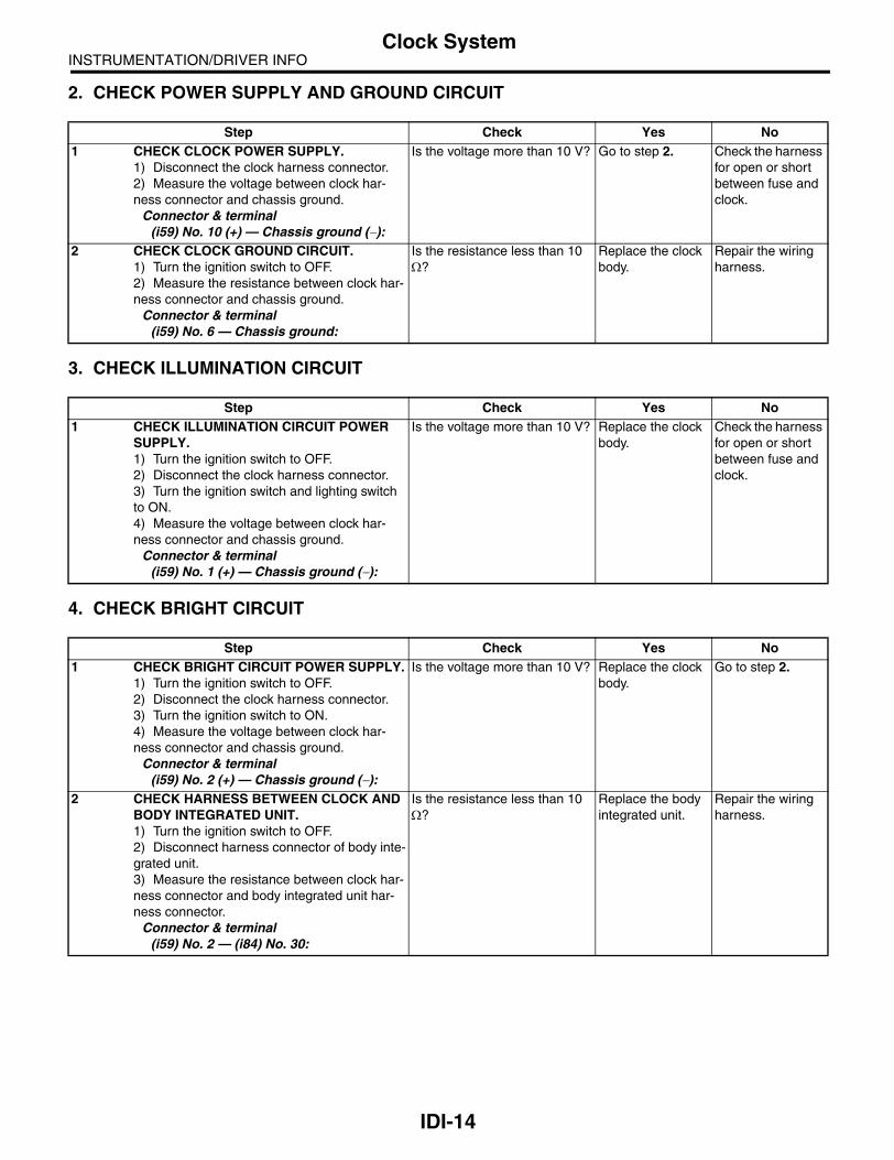
INSTRUMENTATION/DRIVER INFOClock System
2. CHECK POWER SUPPLY AND GROUND CIRCUIT
3. CHECK ILLUMINATION CIRCUIT
4. CHECK BRIGHT CIRCUIT
Step Check Yes No1 CHECK CLOCK POWER SUPPLY.
1) Disconnect the clock harness connector.2) Measure the voltage between clock har-ness connector and chassis ground.
Connector & terminal(i59) No. 10 (+) — Chassis ground (−):
Is the voltage more than 10 V? Go to step 2. Check the harness for open or short between fuse and clock.
2 CHECK CLOCK GROUND CIRCUIT.1) Turn the ignition switch to OFF.2) Measure the resistance between clock har-ness connector and chassis ground.
Connector & terminal(i59) No. 6 — Chassis ground:
Is the resistance less than 10 Ω?
Replace the clock body.
Repair the wiring harness.
Step Check Yes No1 CHECK ILLUMINATION CIRCUIT POWER
SUPPLY.1) Turn the ignition switch to OFF.2) Disconnect the clock harness connector.3) Turn the ignition switch and lighting switch to ON.4) Measure the voltage between clock har-ness connector and chassis ground.
Connector & terminal(i59) No. 1 (+) — Chassis ground (−):
Is the voltage more than 10 V? Replace the clock body.
Check the harness for open or short between fuse and clock.
Step Check Yes No1 CHECK BRIGHT CIRCUIT POWER SUPPLY.
1) Turn the ignition switch to OFF.2) Disconnect the clock harness connector.3) Turn the ignition switch to ON.4) Measure the voltage between clock har-ness connector and chassis ground.
Connector & terminal(i59) No. 2 (+) — Chassis ground (−):
Is the voltage more than 10 V? Replace the clock body.
Go to step 2.
2 CHECK HARNESS BETWEEN CLOCK AND BODY INTEGRATED UNIT.1) Turn the ignition switch to OFF.2) Disconnect harness connector of body inte-grated unit.3) Measure the resistance between clock har-ness connector and body integrated unit har-ness connector.
Connector & terminal(i59) No. 2 — (i84) No. 30:
Is the resistance less than 10 Ω?
Replace the body integrated unit.
Repair the wiring harness.
IDI-14

INSTRUMENTATION/DRIVER INFOClock System
5. CHECK ACC OR IGNITION POWER SUPPLY
6. CHECK COMMUNICATION CIRCUIT
Step Check Yes No1 CHECK ACC POWER SUPPLY.
1) Turn the ignition switch to OFF.2) Disconnect the clock harness connector.3) Turn the ignition switch to ACC.4) Measure the voltage between clock har-ness connector and chassis ground.
Connector & terminal(i59) No. 9 (+) — Chassis ground (−):
Is the voltage more than 10 V? Go to step 2. Check the open circuit in harness between fuse and clock.
2 CHECK THE IGNITION POWER SUPPLY.1) Turn the ignition switch to ON.2) Measure the voltage between clock har-ness connector and chassis ground.
Connector & terminal(i59) No. 8 (+) — Chassis ground (−):
Is the voltage more than 10 V? Replace the clock body.
Check the open circuit in harness between fuse and clock.
Step Check Yes No1 CHECK THE HARNESS BETWEEN CLOCK
AND COMBINATION METER.1) Turn the ignition switch to OFF.2) Disconnect the harness of clock and combi-nation meter.3) Measure the resistance between harness connectors of clock and combination meter.
Connector & terminal(i59) No. 5 — (i10) No. 18:
Is the resistance less than 10 Ω?
Go to step 2. Repair the wiring harness.
2 CHECK COMMUNICATION ERROR DIS-PLAY.1) Connect all the disconnected connectors.2) Turn the ignition switch to ON.3) Check that the error code is displayed in odo/trip meter.
Is the error code “Er xx” dis-played in odo/trip meter?
Check the commu-nication circuit. <Ref. to IDI-11, COMMUNICA-TION ERROR DISPLAY, INSPECTION, Combination Meter System.>
Replace the clock body.
IDI-15

INSTRUMENTATION/DRIVER INFOCombination Meter Assembly
4. Combination Meter Assem-bly
A: REMOVAL1) Disconnect the ground cable from battery.2) Set the tilt steering at the lowest position.3) Remove the instrument panel under cover andlower cover of driver’s seat side. <Ref. to EI-56,REMOVAL, Instrument Panel Assembly.>4) Remove the screws of combination meter (onefor upper side, two for lower side) and pull tilting themeter toward you.
5) Disconnect the connector in the rear side ofcombination meter to remove meter.
CAUTION:• Be careful not to damage the meter or instru-ment panel.• Pay particular attention to avoid damagingthe meter glass.
B: INSTALLATIONInstall in the reverse order of removal.
CAUTION:• Make sure the electrical connector is con-nected securely.• Make sure that each meter operates normally.• When the combination meter of model withimmobilizer has been replaced, be sure to per-form the registration procedure of immobilizer.
IDI00101
IDI-16

INSTRUMENTATION/DRIVER INFOCombination Meter Assembly
C: DISASSEMBLYCAUTION:• Use gloves to avoid damage and getting fingerprints on the glass surface and meter surfaces. • Be careful not to apply excessive force to the trip knob. • Be sure not to touch the meter indicator needle. Remove the pawl (A), and then detach the meter glass assembly (B) and meter panel assembly (C) frommeter case assembly (D).
1. BULB REPLACEMENTLEDs are used for all of warning lights and indicator lights of combination meters, replace the meter case as-sembly if faulty.
D: ASSEMBLYAssemble in the reverse order of disassembly.
(D)
IDI00102
(A)
(B)
(C)
IDI-17

INSTRUMENTATION/DRIVER INFOSpeedometer
5. SpeedometerA: SPECIFICATIONSince the meter case assembly cannot be disas-sembled, do not remove or inspect the speedome-ter alone. (Do not remove the cover on the backside.)
IDI-18

INSTRUMENTATION/DRIVER INFOTachometer
6. TachometerA: SPECIFICATIONSince the meter case assembly cannot be disas-sembled, do not remove or inspect the tachometeralone. (Do not remove the cover on the back side.)
IDI-19

INSTRUMENTATION/DRIVER INFOFuel Gauge
7. Fuel GaugeA: SPECIFICATIONSince the meter case assembly cannot be disas-sembled, do not remove or inspect the fuel gaugealone. (Do not remove the cover on the back side.)
IDI-20

INSTRUMENTATION/DRIVER INFOWater Temperature Gauge
8. Water Temperature GaugeA: SPECIFICATIONSince the meter case assembly cannot be disas-sembled, do not remove or inspect the water tem-perature gauge alone. (Do not remove the cover onthe back side.)
IDI-21

INSTRUMENTATION/DRIVER INFOClock
9. ClockA: REMOVAL1) Disconnect the ground cable from battery.2) Remove the center air vent grille. <Ref. to AC-44, REMOVAL, Air Vent Grille.>3) Loosen the screws, and then remove the clock(B) from center air vent grille (A).
B: INSTALLATIONInstall in the reverse order of removal.
IDI00103
(A)
(B)
IDI-22

SEATS
SE
Page1. General Description ....................................................................................22. Front Seat ...................................................................................................73. Rear Seat ..................................................................................................144. Seat Heater System ..................................................................................19

SEATSGeneral Description
1. General DescriptionA: COMPONENT1. FRONT SEAT (STANDARD SEAT)
(1) Backrest cover (12) Seat cushion cover (23) Inner belt
(2) Backrest pad (13) Seat cushion pad
(3) Backrest frame ASSY (14) Seat cushion frame ASSY Tightening torque: N⋅m (kgf-m, ft-lb)(4) Headrest ASSY (15) Bolt cover outer T1: 6 (0.61, 4.43)(5) Headrest lock bushing (16) Reclining lever T2: 10 (1.02, 7.38)(6) Side airbag module (17) Seat hinge outer cover T3: 22 (2.24, 16.2)(7) Cover frame (18) Lifter lever T4: 30 (3.06, 22.1)(8) Backrest back cover (19) Hinge inner cover LH T5: 52 (5.30, 38.4)(9) Seat hinge inner cover (20) Outer slide rail T6: 53 (5.40, 39.1)
(10) Hinge inner cover RH (21) Inner slide rail
(11) Bolt cover inner (22) Connecting wire
SE-00400
(1)
(2)
(3)
(8)
(4)
(5)
(6)(9)(10)
(11)
(12)
(13)
(14)
(15)
(16)
(17)
(19)
(20)
(21)
(22)
(23)
(18)
T4
T6
T6
T2
T5
T1
T2
T3
(7)
SE-2

SEATSGeneral Description
2. FRONT SEAT (POWER SEAT)
(1) Backrest cover (10) Hinge inner cover RH (19) Inner belt
(2) Backrest pad (11) Bolt cover inner (20) Seat rail ASSY
(3) Backrest frame ASSY (12) Seat cushion cover
(4) Headrest ASSY (13) Seat cushion pad Tightening torque: N⋅m (kgf-m, ft-lb)(5) Headrest lock bushing (14) Seat cushion frame ASSY T1: 6 (0.61, 4.43)(6) Side airbag module (15) Bolt cover outer T2: 22 (2.24, 16.2)(7) Cover frame (16) Seat switch T3: 52 (5.30, 38.4)(8) Backrest back cover (17) Seat hinge outer cover T4: 53 (5.40, 39.1)(9) Seat hinge inner cover (18) Hinge inner cover LH
SE-00401
(1)
(2)
(3)
(8)
(4)
(5)
(6)(9)
(10)
(11)
(12)
(13)
(14)
(15)
(16)
(17)
(20)
(19)
(18)
T4
T3
T2
T3
T1
T3
T3
(7)
T3
SE-3

SEATSGeneral Description
3. REAR SEAT (SEDAN MODEL)
(1) Backrest (7) Backrest pad ASSY Tightening torque: N⋅m (kgf-m, ft-lb)(2) Headrest (8) Backrest cover ASSY T1: 10 (1.02, 7.38)(3) Cushion (9) Rear pad & cushion frame ASSY T2: 24.5 (2.5, 18.1)(4) Armrest (10) Rear cushion cover
(5) Center through frame (11) Headrest bushing
(6) Hook
SE-00422
T1
T2
(3)
(4)
(6)
(2)
(1)
(8)
(7)
(11)
(5)
(10)(9)
(2)
SE-4

SEATSGeneral Description
4. REAR SEAT (WAGON MODEL)
(1) Headrest (10) Hinge ASSY LH (19) Backrest shoulder LH
(2) Headrest bushing (11) Backrest pad LH
(3) Backrest cover RH (12) Backrest cover LH Tightening torque: N⋅m (kgf-m, ft-lb)(4) Backrest pad RH (13) Backrest frame LH T1: 13.7 (1.40, 10.1)(5) Backrest frame RH (14) Seat back latch T2: 22 (2.24, 16.2)(6) Hinge ASSY RH (15) Seat back latch cover T3: 24.5 (2.5, 18.1)(7) Seat cushion pad (16) Holder & button T4: 33 (3.3, 24.6)(8) Seat cushion cover (17) Striker
(9) Hinge ASSY CTR (18) Backrest shoulder RH
SE-00402
(2)(16)
(14)
(17)
(15)
(11)
(10)
(12)
(13)
(8)
(7)
(2)(3)
(6)
(4)
(9)
(5)
(18)
(1)
T3
T4
T4
T4
T4
T2
T1
(19)
T1
SE-5

SEATSGeneral Description
B: CAUTIONWhen removing the front seat from a side airbag loaded vehicle, follow cautions given in the airbag section.<Ref. to AB-4, CAUTION, General Description.>
C: PREPARATION TOOL1. GENERAL TOOL
TOOL NAME REMARKS
Long nose pliers Used for removing the hog ring.
Hog ring pliers Used for installing the hog ring.
TORX® T50 Used for removing and installing the inner seat belt.
SE-6

SEATSFront Seat
2. Front SeatA: REMOVAL1) Disconnect the ground cable from battery, andwait for more than 20 seconds before starting work.
CAUTION:The airbag system is fitted with a backup power source. After disconnecting the battery ground cable, the airbag may deploy if you do not wait for 20 seconds before starting the repair of air-bag system.2) While pressing the headrest lock button, removethe headrest.
3) Tilt the backrest forward.4) Move the seat to full front end.5) Remove the bolt cover at the rear side of sliderail.
6) Remove the two bolts at the rear side of sliderail.
7) Move the seat to full rear end.
8) Remove the two bolts at the front side of sliderail.
9) Disconnect the connector under the seat.• Seat belt warning light connector• Side airbag connector (model with side airbag)• Seat heater connector (model with seat heater)
10) Remove the front seat from vehicle.
B: INSTALLATIONInstall in the reverse order of removal.
Tightening torque:Refer to “COMPONENT” of “General Descrip-tion”. <Ref. to SE-2, FRONT SEAT (STAN-DARD SEAT), COMPONENT, General Description.>
C: DISASSEMBLY1. STANDARD SEAT1) Remove the seat from vehicle. <Ref. to SE-7,REMOVAL, Front Seat.>2) Remove the seat lifter cover using a flat tipscrewdriver and loosen the inner bolt to removeseat lifter lever.
SE-00003
SE-00048
SE-00049
SE-00006
SE-00403
SE-00290
SE-7

SEATSFront Seat
3) Remove the hook (A) and detach reclining levercover.
4) Remove the screws (A) and clips (B), and thendetach the seat hinge outer cover.
5) Loosen the screws to detach seat hinge innercover.
6) Remove the TORX® bolt, and then remove theinner belt.
7) Remove the two bolts from reclining hinge oneach side.
8) Remove the clips and hooks, and then detachthe backrest back cover.
9) Remove the lock clip, and then remove the lum-ber support lever.
SE-00404
(A)
SE-00405(A)(A)
(B)
(B)
SE-00406
SE-00407
SE-00408
SE-00334
SE-00414
SE-8

SEATSFront Seat
10) Remove the hooks at the rear side of backrest.
11) Remove the cover frame (A).
12) Remove the headrest lock bushing.
NOTE:Push outside to remove it from the inside of seat.
13) Pull out the backrest frame assembly.14) Remove the hog rings (A) on the front side ofbackrest, and then remove the backrest cover frombackrest.
15) Remove the hooks (A), and then remove theseat cushion frame assembly.
16) Remove the hog rings (A), and then remove theseat cushion cover from seat cushion pad.
17) Remove the bolt of sliding adjustment bar andconnecting wire.
SE-00335
(A)
SE-00337
SE-00243
SE-00372: (A)
SE-00338
(A)
SE-00339: (A)
SE-00340
SE-9

SEATSFront Seat
18) Remove the bolts, and then remove the sliderail.
19) Remove the hooks and hog rings at the bottomof headrest, and then remove the headrest coverfrom headrest.
2. POWER SEAT1) Remove the seat from vehicle. <Ref. to SE-7,REMOVAL, Front Seat.>2) Remove the seat switch knob.
3) Disconnect the connector of reclining motor fromthe back of seat cushion.
4) Remove the screw (A) and clips (B), and thendisconnect the seat switch connector to removeseat hinge outer cover.
5) Remove the screw (A) and clip (B), and then re-move the seat hinge inner cover.
6) Remove the TORX® bolt, and then remove theinner belt.
SE-00409
SE-00342
SE-00410
SE-00383
SE-00411
(B)
(A)(B)
SE-00412
(A)(B)
SE-00407
SE-10

SEATSFront Seat
7) Remove the two bolts from the reclining hinge oneach left and right side.
8) Remove the clips and hooks, and then detachthe backrest back cover.
9) Remove the lock clip, and then remove the lum-ber support lever.
10) Remove the hooks at the rear side of backrest.
NOTE:For the seat with side airbag, the airbag module in-stallation side is secured with hog rings (A).
11) Remove the cover frame (A).
12) Remove the headrest lock bushing.
NOTE:Push outside to remove it from the inside of seat.
13) Pull out the backrest frame assembly.
SE-00413
SE-00334
SE-00414
SE-00335
SE-00415
(A)
(A)
SE-00337
SE-00243
SE-11
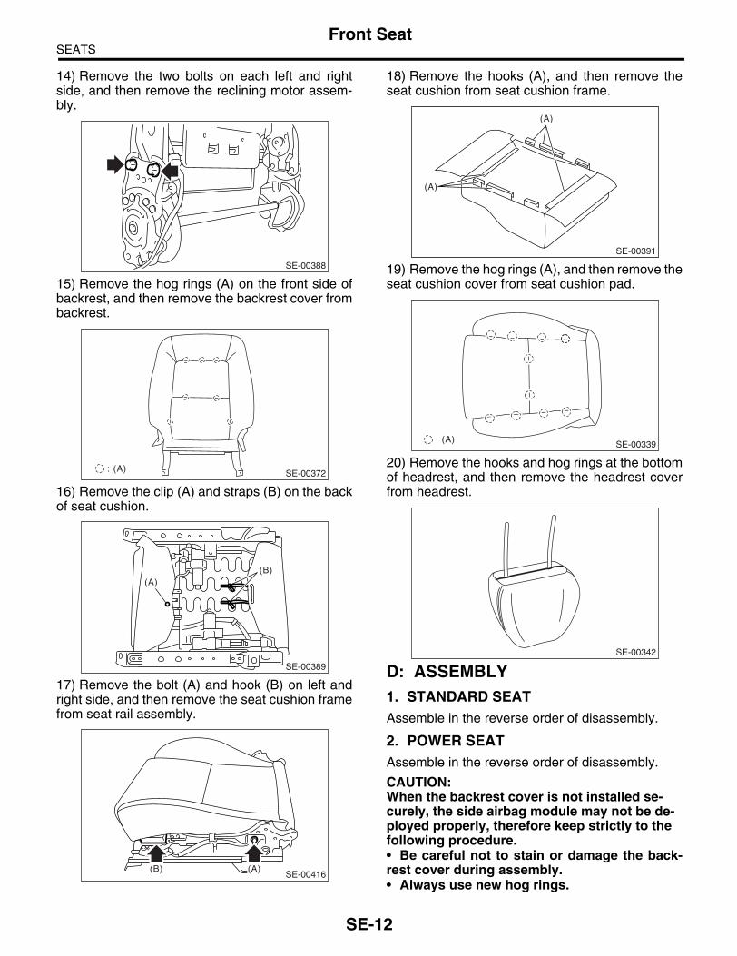
SEATSFront Seat
14) Remove the two bolts on each left and rightside, and then remove the reclining motor assem-bly.
15) Remove the hog rings (A) on the front side ofbackrest, and then remove the backrest cover frombackrest.
16) Remove the clip (A) and straps (B) on the backof seat cushion.
17) Remove the bolt (A) and hook (B) on left andright side, and then remove the seat cushion framefrom seat rail assembly.
18) Remove the hooks (A), and then remove theseat cushion from seat cushion frame.
19) Remove the hog rings (A), and then remove theseat cushion cover from seat cushion pad.
20) Remove the hooks and hog rings at the bottomof headrest, and then remove the headrest coverfrom headrest.
D: ASSEMBLY1. STANDARD SEATAssemble in the reverse order of disassembly.
2. POWER SEATAssemble in the reverse order of disassembly.
CAUTION:When the backrest cover is not installed se-curely, the side airbag module may not be de-ployed properly, therefore keep strictly to the following procedure.• Be careful not to stain or damage the back-rest cover during assembly.• Always use new hog rings.
SE-00388
SE-00372: (A)
SE-00389
(A)(B)
SE-00416(B) (A)
SE-00391
(A)
(A)
SE-00339: (A)
SE-00342
SE-12

SEATSFront Seat
• Secure the hog ring using hog ring pliers.• Install the hog rings to the specified pointssecurely and make sure that no wrinkle or twist-ing on the backrest cover.
Tightening torque:Refer to “COMPONENT” of “General Descrip-tion”. <Ref. to SE-2, FRONT SEAT (STAN-DARD SEAT), COMPONENT, General Description.>
E: INSPECTION1. SEAT COVERCheck that no tear or fray on the backrest coverand seat cushion cover.
NOTE:When the side airbag equipped model has tear orfray on the door side of backrest cover, the side air-bag may not be deployed properly. Replace it withnew one in such a case.
2. SEATING SENSORMake sure the passenger’s seat belt warning lightilluminates when applying load to the rear surfaceof passenger’s seat cushion. If not, replace the seatcushion pad with a new one.
SE-00418
SE-13

SEATSRear Seat
3. Rear SeatA: REMOVAL1. SEDAN MODEL1) Remove the two hooks while lifting up the rearseat cushion.
2) Remove the hook (A) by pushing it backwardwhile lifting up the front side of seat cushion to de-tach seat cushion.
3) Remove the lower anchor bolt of rear center seatbelt.
4) Remove the bolts which secure the bottom ofbackrest.
5) Remove the anchor part on backrest side fromthe hook on body side (A) while lifting up the back-rest to detach it from vehicle.
2. WAGON MODEL1) Disconnect the ground cable from battery.2) Remove the two hooks while lifting up the rearseat cushion.
SE-00343
SE-00345
(A)
EI-00675
SE-00344
SE-00346(A)
SE-00343
SE-14

SEATSRear Seat
3) Remove the hook (A) by pushing it backwardwhile lifting up the front side of seat cushion to de-tach seat cushion.
4) Remove the headrest, and then tilt the backrestforward.5) Remove the luggage floor box. <Ref. to EI-74,REMOVAL, Luggage Floor Box.>6) Remove the hinge assembly CTR bolts.
7) Remove the backrest from hinge assembly LH(hinge assembly RH).
NOTE:The backrest cannot be detached when the hingeassembly side does not mate with the backrest pinposition.8) Remove the lower anchor bolt (A) of outer seatbelt and backrest shoulder bolt (B).
9) Remove the backrest shoulder with lifting it up.
10) Remove the belt cover (A) from backrest shoul-der cover, and then pull out the seat belt.
B: INSTALLATION1. SEDAN MODELInstall in the reverse order of removal.
NOTE:• After installing the backrest, make sure that eachseat belt operates normally.• Make sure that they are secured on each hook ofvehicle side.
SE-00397
(A)
SE-00153
SE-00348
SE-00349
(B)(A)
SE-00350
SE-00351
(A)
SE-15

SEATSRear Seat
Tightening torque:Refer to “COMPONENT” of “General Descrip-tion”. <Ref. to SE-4, REAR SEAT (SEDAN MODEL), COMPONENT, General Descrip-tion.>
2. WAGON MODELInstall in the reverse order of removal.
NOTE:• After installing the backrest, make sure that eachseat belt operates normally.• Make sure that they are secured on each hook ofvehicle side.
Tightening torque:Refer to “COMPONENT” of “General Descrip-tion”. <Ref. to SE-5, REAR SEAT (WAGON MODEL), COMPONENT, General Descrip-tion.>
C: DISASSEMBLY1. SEDAN MODEL1) Remove the rear seat. <Ref. to SE-14, SEDANMODEL, REMOVAL, Rear Seat.>2) Remove the headrest.3) Remove the nuts, and then detach the trunkthrough assembly.
4) Remove the hog rings (A) on the rear side ofbackrest.
5) Remove the hog rings (A) on the front side ofbackrest.
6) Remove both sides of armrest hinge covers, andloosen the screws to remove armrest.
7) Remove the hook, and then detach the centerthrough cover.
8) Remove the hook, and then remove the armrestcover.
SE-00347
SE-00352: (A)
SE-00353: (A)
SE-00354
SE-00355
SE-00356
SE-16

SEATSRear Seat
9) Remove the hook and hog ring, and then re-move the headrest cover.
10) Remove the hog rings (A) on the rear side ofseat cushion.
11) Remove the hog rings (A), and then remove theseat cushion cover.
2. WAGON MODEL1) Remove the rear seat. <Ref. to SE-14, WAGONMODEL, REMOVAL, Rear Seat.>
2) Remove the hooks at the bottom of backrest as-sembly LH, and then turn over the backrest coverto remove the hog rings (A) and hooks (B).
3) Remove the hog rings (A) on the front side ofbackrest, and then remove the backrest cover.
4) Remove the bolts, and then remove the backrestlatch.
5) Loosen the screws to remove the armrest frombackrest assembly RH.
SE-00357
: (A)
SE-00399
: (A)
SE-00398
(A)(B)
SE-00359
SE-00360
(A)
(A)
SE-00361
SE-00358
SE-17

SEATSRear Seat
NOTE:Armrest cannot be removed when backrest assem-bly RH side does not mate with armrest side pin po-sition.6) After this operation, refer to the step 2) to disas-semble backrest assembly RH.7) Remove the hook, and then remove the armrestcover.
8) Remove the hook and hog ring, and then re-move the headrest cover.
9) Remove the hog rings (A) on the rear side ofseat cushion.
10) Remove the hog rings (A), and then remove theseat cushion cover.
D: ASSEMBLY1. SEDAN MODELAssemble in the reverse order of disassembly.
NOTE:• Do not contaminate or damage the cover.• While installing the hog rings, prevent the seatfrom getting wrinkled.
CAUTION:• Always use new hog rings.• Secure the hog ring using hog ring pliers.• Install the hog rings to the specified pointssecurely and be sure to prevent backrest coverfrom wrinkle or twisting.
2. WAGON MODELAssemble in the reverse order of disassembly.
NOTE:• Do not contaminate or damage the cover.• While installing the hog rings, prevent the seatfrom getting wrinkled.
CAUTION:• Always use new hog rings.• Secure the hog ring using hog ring pliers.• Install the hog rings to the specified pointssecurely and be sure to prevent backrest coverfrom wrinkle or twisting.
E: INSPECTIONCheck that no tear or fray on the seat cover.
SE-00356
SE-00357
: (A)
SE-00399
: (A)
SE-00398
SE-18

SEATSSeat Heater System
4. Seat Heater SystemA: REMOVAL1. SEAT HEATER UNIT1) Remove the front seats. <Ref. to SE-7, REMOV-AL, Front Seat.>2) Remove the backrest cover and seat cushioncover of front seat. <Ref. to SE-7, DISASSEMBLY,Front Seat.>3) Remove the hog ring, and then remove the seatheater unit.
2. SEAT HEATER SWITCH1) Remove the console box. <Ref. to EI-53, RE-MOVAL, Console Box.>2) Remove the seat heater switch from consolebox.
B: INSTALLATION1. SEAT HEATER UNITInstall in the reverse order of removal.
2. SEAT HEATER SWITCHInstall in the reverse order of removal.
SE-00082
SE-19

SEATSSeat Heater System
SE-20

SECURITY AND LOCKS
SL
Page1. General Description ....................................................................................22. Door Lock Control System ........................................................................103. Keyless Entry System ...............................................................................154. Front Inner Remote ...................................................................................285. Front Outer Handle ...................................................................................296. Front Door Latch and Door Lock Actuator Assembly................................307. Front Door Lock Actuator ..........................................................................318. Rear Inner Remote....................................................................................329. Rear Outer Handle ....................................................................................33
10. Rear Door Latch and Door Lock Actuator Assembly ................................3411. Rear Door Lock Actuator...........................................................................3512. Rear Gate Outer Handle ...........................................................................3613. Rear Gate Latch Assembly .......................................................................3714. Trunk Lid Lock Assembly ..........................................................................3915. Front Hood Lock Assembly .......................................................................4016. Remote Openers.......................................................................................4117. Ignition Key Lock.......................................................................................4318. Key Lock Cylinders ...................................................................................4419. Keyless Entry Control Unit ........................................................................4520. Body Integrated Unit .................................................................................4621. Keyless Transmitter ..................................................................................4722. Immobilizer Control Unit............................................................................4923. Immobilizer Antenna .................................................................................50

SECURITY AND LOCKSGeneral Description
1. General DescriptionA: COMPONENT1. DOOR LOCK ASSEMBLY• Model without double lock
(A) Front (B) Rear
(1) Inner remote ASSY (4) Key cylinder Tightening torque: N⋅m (kgf-m, ft-lb)(2) Front door latch & door lock actua-
tor ASSY(5) Striker T1: 6.5 (0.66, 4.8)(6) Rear door latch & door lock actua-
tor ASSYT2: 7.5 (0.76, 5.5)
(3) Door outer handle T3: 18 (1.8, 13.3)
SL-00271
T2
T3
T1
(5)
(2)
(3)
(4)
T2
(3)
(1)
(A)
(B)
(1)
T3
T1
(5)
(6)
SL-2

SECURITY AND LOCKSGeneral Description
• Model with double lock
(A) Front (B) Rear
(1) Inner remote ASSY (6) Rear door latch & door lock actua-tor ASSY
Tightening torque: N⋅m (kgf-m, ft-lb)(2) Front door latch & door lock actua-
tor ASSYT1: 6.5 (0.66, 4.8)
(7) Outer handle bracket T2: 7.5 (0.76, 5.5)(3) Door outer handle (8) Key cylinder cover A T3: 18 (1.8, 13.3)(4) Key cylinder (switch) (9) Key cylinder cover B
(5) Striker
(3)
(A)
(B)
(1)
T3
T1
(5)
(6)
(7)
T3
T1
(5)
(2)
(3)
(1)
(8)
(4)
(9)
T2
SL-00272
T2
T2
SL-3

SECURITY AND LOCKSGeneral Description
2. TRUNK LID AND REAR GATE LOCK• Model without double lock
(A) Trunk (B) Rear gate
(1) Cable (6) Rear gate latch Tightening torque: N⋅m (kgf-m, ft-lb)(2) Striker T1: 7.5 (0.76, 5.5)(3) Trunk lid lock ASSY T2: 25 (2.5, 18.4)(4) Rear gate outer handle T3: 7.35 (0.75, 5.39)(5) Rear gate actuator T4: 18 (1.8, 13.3)
SL-00309
(2)
T2
T4
T3
(1)
(A) (B)
(3)
(1)
(5)(4)
(6)
(2)
T3
T1
SL-4

SECURITY AND LOCKSGeneral Description
• Model with double lock
(A) Trunk (B) Rear gate
(1) Cable (6) Rear gate latch ASSY Tightening torque: N⋅m (kgf-m, ft-lb)(2) Striker T1: 7.5 (0.76, 5.5)(3) Trunk lid lock ASSY T2: 25 (2.5, 18.4)(4) Rear gate outer handle T3: 7.35 (0.75, 5.39)(5) Rear gate actuator T4: 18 (1.8, 13.3)
SL-00273
(2)
T2
T4
T3
(1)
(A) (B)
(3)
(1)
(5)
(4)
(6)
(2)
T3
T1
SL-5

SECURITY AND LOCKSGeneral Description
3. FRONT HOOD LOCK AND REMOTE OPENERS
(A) Sedan model (B) Wagon model (C) Hood
(1) Front hood lock ASSY (5) Cover Tightening torque: N⋅m (kgf-m, ft-lb)(2) Lever ASSY (6) Pull handle ASSY T: 33 (3.36, 24.2)(3) Lever ASSY bracket (7) Striker
(4) Cable
SL-00275
(2)
(5)
(6)
(B)
(C)
(A)
(4)
(4)
(1)
(3)
(5)
(6)
(4)
T
(7)
T
SL-6

SECURITY AND LOCKSGeneral Description
4. IMMOBILIZER SYSTEM
NOTE:Body integrated unit location for RHD model is symmetrically opposite.
(1) Antenna (2) Immobilizer indicator light (LED bulb)
(3) Body integrated unit
(4) Transponder
SL-00276
(3)
(2)
(4)
(1)
SL-7

SECURITY AND LOCKSGeneral Description
5. KEYLESS ENTRY SYSTEM
B: CAUTION• Before disassembling or reassembling parts, al-ways disconnect the battery ground cable. Whenrepairing the audio, control module, etc. which areprovided with memory functions, record the memo-ry contents before disconnecting the ground cablefrom battery. Otherwise, these contents are erasedupon disconnection.• Reassemble the parts in the reverse order of dis-assembly unless otherwise indicated.• Adjust the parts to the specifications described inthis manual if so designated.• Connect the connectors securely during reas-sembly.• After reassembly, ensure the functional parts op-erate smoothly.• The air bag system wiring harness is routed nearelectrical parts and switches.• All air bag system wiring harnesses and connec-tors are yellow. Do not use the electrical test equip-ment on these circuits.• Be careful not to damage the airbag system wir-ing harness when servicing the ignition key cylin-der.
(1) Keyless Entry Control Module (3) Door switch (5) Power window main switch
(2) Rear gate latch switch (Wagon) (4) Body integrated unit
SL-00277
(3)
(2)
(4)
(1)
(5)
SL-8

SECURITY AND LOCKSGeneral Description
C: PREPARATION TOOL1. SPECIAL TOOL
2. GENERAL TOOL
ILLUSTRATION TOOL NUMBER DESCRIPTION REMARKS
925580000 PULLER Used for removing trim clip.
TOOL NAME REMARKS
Circuit tester Used for measuring resistance and voltage.
Drill Used for replacing ignition key lock.
ST-925580000
SL-9
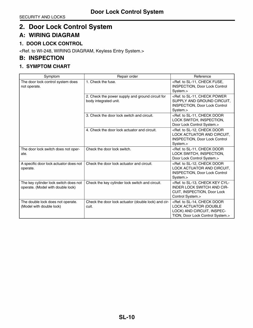
SECURITY AND LOCKSDoor Lock Control System
2. Door Lock Control SystemA: WIRING DIAGRAM1. DOOR LOCK CONTROL<Ref. to WI-248, WIRING DIAGRAM, Keyless Entry System.>
B: INSPECTION1. SYMPTOM CHART
Symptom Repair order Reference
The door lock control system does not operate.
1. Check the fuse. <Ref. to SL-11, CHECK FUSE, INSPECTION, Door Lock Control System.>
2. Check the power supply and ground circuit for body integrated unit.
<Ref. to SL-11, CHECK POWER SUPPLY AND GROUND CIRCUIT, INSPECTION, Door Lock Control System.>
3. Check the door lock switch and circuit. <Ref. to SL-11, CHECK DOOR LOCK SWITCH, INSPECTION, Door Lock Control System.>
4. Check the door lock actuator and circuit. <Ref. to SL-12, CHECK DOOR LOCK ACTUATOR AND CIRCUIT, INSPECTION, Door Lock Control System.>
The door lock switch does not oper-ate.
Check the door lock switch. <Ref. to SL-11, CHECK DOOR LOCK SWITCH, INSPECTION, Door Lock Control System.>
A specific door lock actuator does not operate.
Check the door lock actuator and circuit. <Ref. to SL-12, CHECK DOOR LOCK ACTUATOR AND CIRCUIT, INSPECTION, Door Lock Control System.>
The key cylinder lock switch does not operate. (Model with double lock)
Check the key cylinder lock switch and circuit. <Ref. to SL-13, CHECK KEY CYL-INDER LOCK SWITCH AND CIR-CUIT, INSPECTION, Door Lock Control System.>
The double lock does not operate. (Model with double lock)
Check the door lock actuator (double lock) and cir-cuit.
<Ref. to SL-14, CHECK DOOR LOCK ACTUATOR (DOUBLE LOCK) AND CIRCUIT, INSPEC-TION, Door Lock Control System.>
SL-10

SECURITY AND LOCKSDoor Lock Control System
2. CHECK FUSE
3. CHECK POWER SUPPLY AND GROUND CIRCUIT
4. CHECK DOOR LOCK SWITCH
Step Check Yes No1 CHECK FUSE.
Remove and visually check the fuse No. 3 (in the fuse and relay box) and No. 7 (in the fuse and relay box).
Is the fuse blown out? Replace the fuse with a new one.
Check the power supply and ground circuit. <Ref. to SL-11, CHECK POWER SUPPLY AND GROUND CIRCUIT, INSPECTION, Door Lock Control System.>
Step Check Yes No1 CHECK POWER SUPPLY.
1) Disconnect the harness connector of body integrated unit.2) Measure the voltage between harness con-nector terminal and chassis ground.
Connector & terminal(i84) No. 34 (+) — Chassis ground (−):(B281) No. 2 (+) — Chassis ground (−):
Is the voltage more than 10 V? Go to step 2. Check the harness for open or short circuit between body integrated unit and fuse.
2 CHECK GROUND CIRCUIT.Measure the resistance between harness con-nector terminal and chassis ground.
Connector & terminal(B280) No. 22 — Chassis ground:(B281) No. 8, 9, 22 — Chassis ground:
Is the resistance less than 10 Ω?
The power supply and ground circuit are OK.
Repair the har-ness.
Step Check Yes No1 CHECK DOOR LOCK SWITCH.
Check the input from door lock switch to body integrated unit using Subaru Select Monitor.1) Connect the Subaru Select Monitor to data link connector.2) Turn the ignition switch to ON.3) Select body integrated unit from main menu.4) Select Current Data Display & Save.5) Check the input to body integrated unit by operating the door lock switch.
Is the normal input signal dis-played when the door lock switch is moved to LOCK/UNLOCK?
The door lock switch is OK.
Go to step 2.
2 CHECK DOOR LOCK SWITCH CIRCUIT.1) Disconnect the body integrated unit har-ness connector.2) Measure the resistance between the har-ness connector terminal and chassis ground when moving the door lock switch to LOCK.
Connector & terminal(i84) No. 15 — Chassis ground:
Is the resistance less than 10 Ω?
Go to step 3. Go to step 4.
SL-11

SECURITY AND LOCKSDoor Lock Control System
5. CHECK DOOR LOCK ACTUATOR AND CIRCUIT
3 CHECK DOOR LOCK SWITCH CIRCUIT.Measure the resistance between the harness connector terminal and chassis ground when the door lock switch is moved to UNLOCK.
Connector & terminal(i84) No. 29 — Chassis ground:
Is the resistance less than 10 Ω?
The door lock switch is OK.
Go to step 4.
4 CHECK DOOR LOCK SWITCH.1) Disconnect the door lock switch harness connector.2) Measure the resistance between the door lock switch terminals when moving the door lock switch to LOCK.
Connector & terminalLHD model:
(D7) No. 4 — No. 7:RHD model:
(D7) No. 4 — No. 14:
Is the resistance less than 1 Ω?
Go to step 5. Replace the door lock switch.
5 CHECK DOOR LOCK SWITCH.Measure the resistance between the door lock switch terminals when moving the door lock switch to UNLOCK.
Connector & terminalLHD model:
(D7) No. 5 — No. 7:RHD model:
(D7) No. 5 — No. 14:
Is the resistance less than 1 Ω?
Check the harness for open circuits or shorts between the body inte-grated unit and the door lock switch.
Replace the door lock switch.
Step Check Yes No1 CHECK OUTPUT SIGNAL.
Measure the voltage between the harness con-nector terminal and chassis ground of body integrated unit when moving the door lock switch to LOCK.
Connector & terminal(i84) No. 7 (+) — Chassis ground (−):
Is the voltage more than 10 V? Go to step 2. Replace the body integrated unit. <Ref. to SL-46, Body Integrated Unit.>
2 CHECK OUTPUT SIGNAL.Measure the voltage between the harness con-nector terminal and chassis ground of body integrated unit when moving the door lock switch to UNLOCK.
Connector & terminal(i84) No. 8 (+) — Chassis ground (−):
Is the voltage more than 10 V? Go to step 3. Replace the body integrated unit. <Ref. to SL-46, Body Integrated Unit.>
3 CHECK POWER WINDOW MAIN SWITCH OUTPUT SIGNAL.Measure the voltage between the harness con-nector terminal of power window main switch and chassis ground when moving the door lock switch to LOCK.
Connector & terminal(D7) No. 4 (+) — Chassis ground (−):
Is the voltage more than 10 V? Go to step 4. Replace the power window main switch. <Ref. to GW-9, Power Win-dow Control Switch.>
Step Check Yes No
SL-12
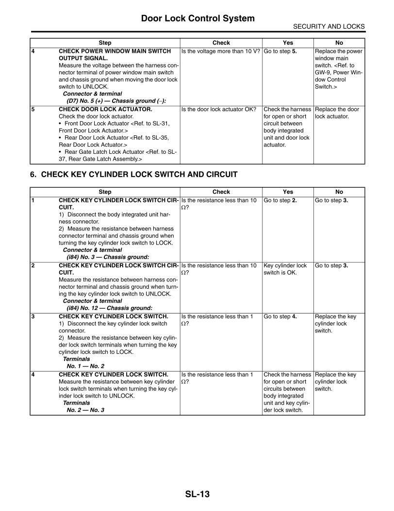
SECURITY AND LOCKSDoor Lock Control System
6. CHECK KEY CYLINDER LOCK SWITCH AND CIRCUIT
4 CHECK POWER WINDOW MAIN SWITCH OUTPUT SIGNAL.Measure the voltage between the harness con-nector terminal of power window main switch and chassis ground when moving the door lock switch to UNLOCK.
Connector & terminal(D7) No. 5 (+) — Chassis ground (−):
Is the voltage more than 10 V? Go to step 5. Replace the power window main switch. <Ref. to GW-9, Power Win-dow Control Switch.>
5 CHECK DOOR LOCK ACTUATOR.Check the door lock actuator.• Front Door Lock Actuator <Ref. to SL-31, Front Door Lock Actuator.>• Rear Door Lock Actuator <Ref. to SL-35, Rear Door Lock Actuator.>• Rear Gate Latch Lock Actuator <Ref. to SL-37, Rear Gate Latch Assembly.>
Is the door lock actuator OK? Check the harness for open or short circuit between body integrated unit and door lock actuator.
Replace the door lock actuator.
Step Check Yes No1 CHECK KEY CYLINDER LOCK SWITCH CIR-
CUIT.1) Disconnect the body integrated unit har-ness connector.2) Measure the resistance between harness connector terminal and chassis ground when turning the key cylinder lock switch to LOCK.
Connector & terminal(i84) No. 3 — Chassis ground:
Is the resistance less than 10 Ω?
Go to step 2. Go to step 3.
2 CHECK KEY CYLINDER LOCK SWITCH CIR-CUIT.Measure the resistance between harness con-nector terminal and chassis ground when turn-ing the key cylinder lock switch to UNLOCK.
Connector & terminal(i84) No. 12 — Chassis ground:
Is the resistance less than 10 Ω?
Key cylinder lock switch is OK.
Go to step 3.
3 CHECK KEY CYLINDER LOCK SWITCH.1) Disconnect the key cylinder lock switch connector.2) Measure the resistance between key cylin-der lock switch terminals when turning the key cylinder lock switch to LOCK.
TerminalsNo. 1 — No. 2
Is the resistance less than 1 Ω?
Go to step 4. Replace the key cylinder lock switch.
4 CHECK KEY CYLINDER LOCK SWITCH.Measure the resistance between key cylinder lock switch terminals when turning the key cyl-inder lock switch to UNLOCK.
TerminalsNo. 2 — No. 3
Is the resistance less than 1 Ω?
Check the harness for open or short circuits between body integrated unit and key cylin-der lock switch.
Replace the key cylinder lock switch.
Step Check Yes No
SL-13

SECURITY AND LOCKSDoor Lock Control System
7. CHECK DOOR LOCK ACTUATOR (DOUBLE LOCK) AND CIRCUIT
Step Check Yes No1 CHECK OUTPUT SIGNAL.
Measure the resistance between body inte-grated unit harness connector terminal and chassis ground when turning the key cylinder lock switch to LOCK.
Connector & terminal(i84) No. 35 (+) — Chassis ground (–):
Is the voltage more than 10 V? Go to step 2. Replace the body integrated unit.
2 CHECK OUTPUT SIGNAL.Measure the resistance between body inte-grated unit harness connector terminal and chassis ground when turning the key cylinder lock switch to UNLOCK.
Connector & terminal(i84) No. 35 (+) — Chassis ground (–):
Is the voltage more than 10 V? Go to step 3. Replace the body integrated unit.
3 CHECK DOOR LOCK ACTUATOR.Check the door lock actuator.Front door lock actuator: <Ref. to SL-31, Front Door Lock Actuator.>Rear door lock actuator: <Ref. to SL-35, Rear Door Lock Actuator.>
Is the door lock actuator nor-mal?
Check the harness for open or short circuits between body integrated unit and door lock actuator.
Replace the door lock actuator.
SL-14

SECURITY AND LOCKSKeyless Entry System
3. Keyless Entry SystemA: WIRING DIAGRAM1. KEYLESS ENTRY<Ref. to WI-248, WIRING DIAGRAM, Keyless Entry System.>
B: ELECTRICAL SPECIFICATION1. CUSTOMIZE SETTING OF SELECT UNLOCKSwitching from all door unlock to select unlock, or select unlock to all door unlock are performed with follow-ing procedure.1) Close the driver’s door, and then open it.2) Insert the key to ignition switch, and then turn the ignition switch from OFF to ON for more than 10 timeswithin 15 seconds. Complete the procedure in step 1) through 2) within 45 seconds. When the proceduresare completed correctly, the buzzer beeps once. If the buzzer does not beep, repeat the procedures fromstep 1).3) Close the driver’s door.4) While depressing the door lock switch to lock side, turn the ignition switch from OFF to ON.5) While depressing the door lock switch to unlock side, turn the ignition switch from ON to OFF, and then re-lease the door lock switch. Complete the procedure in step 3) through 5) within 30 seconds. When the pro-cedures are completed correctly, the buzzer beeps twice and door lock, unlock operates automatically. Whenthe buzzer does not beep, repeat the procedures from step 1).6) Remove the key from ignition switch, and then complete the procedure.7) Operate the key button to check that the setting is changed.
2. KEYLESS ENTRY CONTROL UNIT
SL-00228
4 3 2 18 7 6 5
i96To
Remarks Terminal No. Measuring conditions
Body integrated unit 3 (OUTPUT) Battery voltage cannot be measured because of digital signal.
Power supply (Backup) 4 Battery voltage is constantly present.
Ground 7 0 V is constantly present.
SL-15
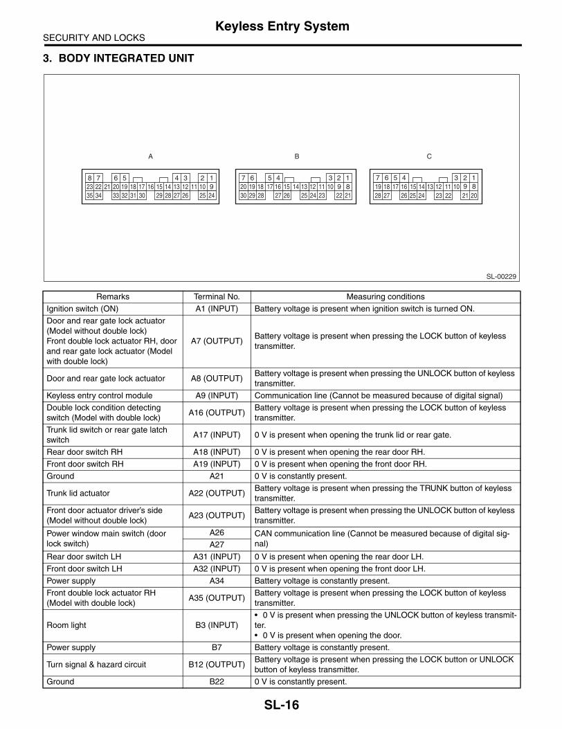
SECURITY AND LOCKSKeyless Entry System
3. BODY INTEGRATED UNIT
Remarks Terminal No. Measuring conditions
Ignition switch (ON) A1 (INPUT) Battery voltage is present when ignition switch is turned ON.
Door and rear gate lock actuator (Model without double lock)Front double lock actuator RH, door and rear gate lock actuator (Model with double lock)
A7 (OUTPUT)Battery voltage is present when pressing the LOCK button of keyless transmitter.
Door and rear gate lock actuator A8 (OUTPUT)Battery voltage is present when pressing the UNLOCK button of keyless transmitter.
Keyless entry control module A9 (INPUT) Communication line (Cannot be measured because of digital signal)
Double lock condition detecting switch (Model with double lock)
A16 (OUTPUT)Battery voltage is present when pressing the LOCK button of keyless transmitter.
Trunk lid switch or rear gate latch switch
A17 (INPUT) 0 V is present when opening the trunk lid or rear gate.
Rear door switch RH A18 (INPUT) 0 V is present when opening the rear door RH.
Front door switch RH A19 (INPUT) 0 V is present when opening the front door RH.
Ground A21 0 V is constantly present.
Trunk lid actuator A22 (OUTPUT)Battery voltage is present when pressing the TRUNK button of keyless transmitter.
Front door actuator driver’s side (Model without double lock)
A23 (OUTPUT)Battery voltage is present when pressing the UNLOCK button of keyless transmitter.
Power window main switch (door lock switch)
A26 CAN communication line (Cannot be measured because of digital sig-nal)A27
Rear door switch LH A31 (INPUT) 0 V is present when opening the rear door LH.
Front door switch LH A32 (INPUT) 0 V is present when opening the front door LH.
Power supply A34 Battery voltage is constantly present.
Front double lock actuator RH (Model with double lock)
A35 (OUTPUT)Battery voltage is present when pressing the LOCK button of keyless transmitter.
Room light B3 (INPUT)• 0 V is present when pressing the UNLOCK button of keyless transmit-ter.• 0 V is present when opening the door.
Power supply B7 Battery voltage is constantly present.
Turn signal & hazard circuit B12 (OUTPUT)Battery voltage is present when pressing the LOCK button or UNLOCK button of keyless transmitter.
Ground B22 0 V is constantly present.
SL-00229
A
1234567891011121314151617181920212223242526272829303132333435
C
5678
2 19
4 310
24 2223251112131415
26272816171819
2021
B
5 4678
2 19
310
22231112131415
24252627161718
28291920
2130
SL-16
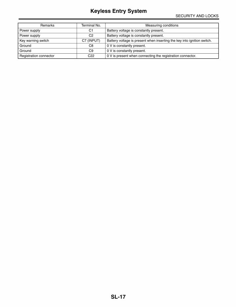
SECURITY AND LOCKSKeyless Entry System
Power supply C1 Battery voltage is constantly present.
Power supply C2 Battery voltage is constantly present.
Key warning switch C7 (INPUT) Battery voltage is present when inserting the key into ignition switch.
Ground C8 0 V is constantly present.
Ground C9 0 V is constantly present.
Registration connector C22 0 V is present when connecting the registration connector.
Remarks Terminal No. Measuring conditions
SL-17

SECURITY AND LOCKSKeyless Entry System
C: INSPECTION1. SYMPTOM CHART
Symptom Repair order Reference
None of the functions of keyless entry system operate.
1. Check the keyless transmitter battery. <Ref. to SL-20, CHECK KEYLESS TRANSMITTER BATTERY AND FUNCTION, INSPECTION, Keyless Entry System.>
2. Check the fuse. <Ref. to SL-21, CHECK FUSE, INSPECTION, Keyless Entry Sys-tem.>
3. Check the keyless entry control module. <Ref. to SL-21, CHECK KEYLESS ENTRY CONTROL MODULE, INSPECTION, Keyless Entry Sys-tem.>
4. Check the power supply and ground circuit for the body integrated unit.
<Ref. to SL-22, CHECK BODY INTE-GRATED UNIT POWER SUPPLY AND GROUND CIRCUIT, INSPEC-TION, Keyless Entry System.>
5. Check the key warning switch. <Ref. to SL-24, CHECK KEY WARN-ING SWITCH, INSPECTION, Keyless Entry System.>
6. Check the door switch. <Ref. to SL-23, CHECK DOOR SWITCH, INSPECTION, Keyless Entry System.>
7. Check the body integrated unit. <Ref. to LAN(diag)-2, Basic Diagnos-tic Procedure.>
The keyless transmitter cannot be registered.
1. Check the keyless transmitter battery. <Ref. to SL-20, CHECK KEYLESS TRANSMITTER BATTERY AND FUNCTION, INSPECTION, Keyless Entry System.>
2. Check registration connector circuit. <Ref. to SL-22, CHECK REGISTRA-TION CONNECTOR., INSPECTION, Keyless Entry System.>
3. Check the key warning switch. <Ref. to SL-24, CHECK KEY WARN-ING SWITCH, INSPECTION, Keyless Entry System.>
4. Check the door lock switch signal. <Ref. to SL-26, CHECK DOOR LOCK SWITCH, INSPECTION, Keyless Entry System.>
5. Check the body integrated unit. <Ref. to LAN(diag)-2, Basic Diagnos-tic Procedure.>
Door lock or unlock does not operate.NOTE:If the door lock control system doesnot operate when using the door lockswitch, check the door lock controlsystem. <Ref. to SL-10, INSPEC-TION, Door Lock Control System.>
1. Check the keyless transmitter battery. <Ref. to SL-20, CHECK KEYLESS TRANSMITTER BATTERY AND FUNCTION, INSPECTION, Keyless Entry System.>
2. Check the keyless entry control module. <Ref. to SL-21, CHECK KEYLESS ENTRY CONTROL MODULE, INSPECTION, Keyless Entry Sys-tem.>
3. Check the key warning switch. <Ref. to SL-24, CHECK KEY WARN-ING SWITCH, INSPECTION, Keyless Entry System.>
4. Check the door switch. <Ref. to SL-23, CHECK DOOR SWITCH, INSPECTION, Keyless Entry System.>
5. Check the body integrated unit. <Ref. to LAN(diag)-2, Basic Diagnos-tic Procedure.>
SL-18

SECURITY AND LOCKSKeyless Entry System
Trunk lid unlock does not operate. (Sedan model)
1. Check the keyless transmitter battery. <Ref. to SL-20, CHECK KEYLESS TRANSMITTER BATTERY AND FUNCTION, INSPECTION, Keyless Entry System.>
2. Check the keyless entry control module. <Ref. to SL-21, CHECK KEYLESS ENTRY CONTROL MODULE, INSPECTION, Keyless Entry Sys-tem.>
3. Check the key warning switch. <Ref. to SL-24, CHECK KEY WARN-ING SWITCH, INSPECTION, Keyless Entry System.>
4. Check the trunk lid lock actuator. <Ref. to SL-25, CHECK TRUNK LID LOCK ACTUATOR, INSPECTION, Keyless Entry System.>
5. Check the body integrated unit. <Ref. to LAN(diag)-2, Basic Diagnos-tic Procedure.>
Hazard light does not operate. 1. Check the hazard light operation. <Ref. to SL-25, CHECK HAZARD LIGHT OPERATION, INSPECTION, Keyless Entry System.>
2. Check the body integrated unit. <Ref. to LAN(diag)-2, Basic Diagnos-tic Procedure.>
Room light does not operate. 1. Check the room light operation. <Ref. to SL-24, CHECK ROOM LIGHT OPERATION, INSPECTION, Keyless Entry System.>
2. Check the body integrated unit. <Ref. to LAN(diag)-2, Basic Diagnos-tic Procedure.>
Ignition switch illumination does not operate.
1. Check the ignition switch illumination. <Ref. to SL-27, CHECK IGNITION SWITCH ILLUMINATION, INSPEC-TION, Keyless Entry System.>
2. Check the body integrated unit. <Ref. to LAN(diag)-2, Basic Diagnos-tic Procedure.>
Symptom Repair order Reference
SL-19

SECURITY AND LOCKSKeyless Entry System
2. CHECK KEYLESS TRANSMITTER BATTERY AND FUNCTION
CAUTION:Be sure to reset the keyless transmitter, which is registered from other vehicle to inspection target vehicle, and the vehicle, to which is registered keyless transmitter, to the condition of before inspec-tion. (Register the keyless transmitter to original condition.)
Step Check Yes No1 CHECK KEYLESS TRANSMITTER BAT-
TERY.1) Remove the battery from keyless transmit-ter. <Ref. to SL-47, REMOVAL, Keyless Trans-mitter.>2) Check the battery voltage. <Ref. to SL-47, INSPECTION, Keyless Transmitter.>
Is the voltage more than 2 V? Go to step 2. Replace the key-less transmitter battery. <Ref. to SL-47, Keyless Transmitter.>
2 CHECK KEYLESS TRANSMITTER.Register the keyless transmitter which oper-ates normally on other vehicles to inspection target vehicle. <Ref. to SL-47, REGISTRA-TION OF KEYLESS TRANSMITTER, REPLACEMENT, Keyless Transmitter.>1) Close all the doors and rear gate of inspec-tion target vehicle.2) Using keyless transmitter, lock and unlock the doors and rear gate of inspection target vehicle.
Is the inspection target vehicle operates lock and unlock nor-mally?
Go to step 3. Due to vehicle malfunction, con-tinue the keyless entry system diag-nosis.
3 CHECK KEYLESS TRANSMITTER.Register the keyless transmitter of inspection target vehicle to another vehicle which oper-ates keyless system normally. <Ref. to SL-47, REGISTRATION OF KEYLESS TRANSMIT-TER, REPLACEMENT, Keyless Transmitter.>
Is the keyless transmitter regis-tered correctly?
Go to step 4. Replace the key-less transmitter. <Ref. to SL-47, REGISTRATION OF KEYLESS TRANSMITTER, REPLACEMENT, Keyless Transmit-ter.>
4 CHECK KEYLESS TRANSMITTER.Check the registered keyless transmitter.1) Close all the doors and rear gate of the vehicle which operates keyless system nor-mally.2) Using keyless transmitter, lock and unlock the doors and rear gate of vehicle.
Is the vehicle operates lock and unlock normally?
Keyless transmit-ter is normal.
Replace the key-less transmitter. <Ref. to SL-47, REGISTRATION OF KEYLESS TRANSMITTER, REPLACEMENT, Keyless Transmit-ter.>
SL-20

SECURITY AND LOCKSKeyless Entry System
3. CHECK FUSE
4. CHECK KEYLESS ENTRY CONTROL MODULE
Step Check Yes No1 CHECK FUSE.
Remove and visually check the fuse No. 3 (in the fuse and relay box) and No. 7 (in the fuse and relay box).
Is the fuse blown out? Replace the fuse with a new one.
Check the power supply and ground circuit. <Ref. to SL-22, CHECK BODY INTE-GRATED UNIT POWER SUPPLY AND GROUND CIRCUIT, INSPECTION, Keyless Entry Sys-tem.>
Step Check Yes No1 CHECK DIAGNOSTIC TROUBLE CODE
(DTC)1) Connect the Subaru Select Monitor to data link connector.2) Turn the ignition switch to ON.3) Select Body integrated unit from main menu.4) Select the Diagnostic Trouble Code.5) Check that the DTC is displayed.
Is DTC B0500 “Keyless UART com. Malfunction” displayed?
Go to step 2. Keyless entry con-trol module is nor-mal.
2 CHECK POWER SUPPLY.1) Disconnect the keyless entry control mod-ule harness connector.2) Measure the voltage between the harness connector terminal and chassis ground.
Connector & terminal(i96) No. 4 (+) — Chassis ground (−):
Is the voltage more than 10 V? Go to step 3. Check the harness for open circuits and shorts between the key-less entry control module and fuse.
3 CHECK GROUND CIRCUIT.Measure the resistance between the harness connector terminal and chassis ground.
Connector & terminal(i96) No. 7 — Chassis ground:
Is the resistance less than 10 Ω?
Go to step 4. Repair the har-ness.
4 CHECK KEYLESS ENTRY CONTROL MOD-ULE CIRCUIT.1) Disconnect harness connector of body inte-grated unit.2) Measure the resistance between harness connector terminals.
Connector & terminal(i84) No. 9 — (i96) No. 3:
Is the resistance less than 10 Ω?
Replace the key-less entry control module. <Ref. to SL-45, Keyless Entry Control Unit.>
Repair the har-ness.
SL-21
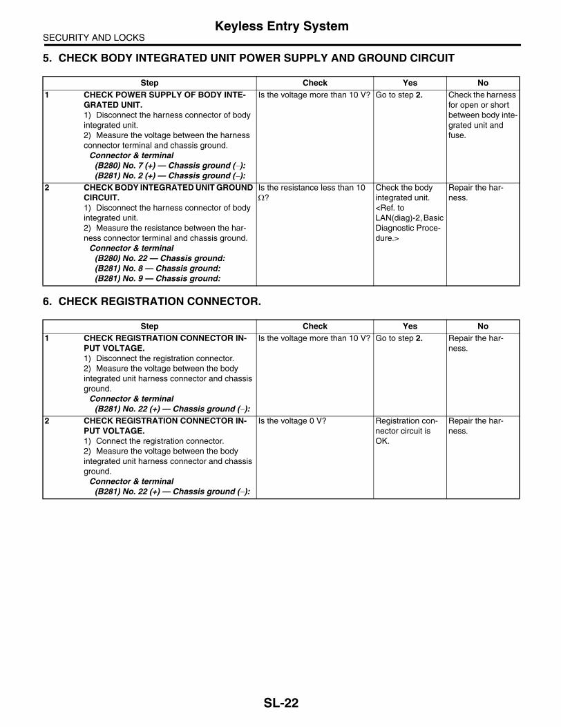
SECURITY AND LOCKSKeyless Entry System
5. CHECK BODY INTEGRATED UNIT POWER SUPPLY AND GROUND CIRCUIT
6. CHECK REGISTRATION CONNECTOR.
Step Check Yes No1 CHECK POWER SUPPLY OF BODY INTE-
GRATED UNIT.1) Disconnect the harness connector of body integrated unit.2) Measure the voltage between the harness connector terminal and chassis ground.
Connector & terminal(B280) No. 7 (+) — Chassis ground (−):(B281) No. 2 (+) — Chassis ground (−):
Is the voltage more than 10 V? Go to step 2. Check the harness for open or short between body inte-grated unit and fuse.
2 CHECK BODY INTEGRATED UNIT GROUND CIRCUIT.1) Disconnect the harness connector of body integrated unit.2) Measure the resistance between the har-ness connector terminal and chassis ground.
Connector & terminal(B280) No. 22 — Chassis ground:(B281) No. 8 — Chassis ground:(B281) No. 9 — Chassis ground:
Is the resistance less than 10 Ω?
Check the body integrated unit. <Ref. to LAN(diag)-2, Basic Diagnostic Proce-dure.>
Repair the har-ness.
Step Check Yes No1 CHECK REGISTRATION CONNECTOR IN-
PUT VOLTAGE.1) Disconnect the registration connector.2) Measure the voltage between the body integrated unit harness connector and chassis ground.
Connector & terminal(B281) No. 22 (+) — Chassis ground (−):
Is the voltage more than 10 V? Go to step 2. Repair the har-ness.
2 CHECK REGISTRATION CONNECTOR IN-PUT VOLTAGE.1) Connect the registration connector.2) Measure the voltage between the body integrated unit harness connector and chassis ground.
Connector & terminal(B281) No. 22 (+) — Chassis ground (−):
Is the voltage 0 V? Registration con-nector circuit is OK.
Repair the har-ness.
SL-22

SECURITY AND LOCKSKeyless Entry System
7. CHECK DOOR SWITCH
Step Check Yes No1 CHECK DOOR SWITCH CIRCUIT.
Measure the voltage between the body inte-grated unit harness connector terminal and chassis ground.
Connector & terminalFront door RH:
(i84) No. 19 (+) — Chassis ground (−):Front door LH:
(i84) No. 32 (+) — Chassis ground (−):Rear door RH:
(i84) No. 18 (+) — Chassis ground (−):Rear door LH:
(i84) No. 31 (+) — Chassis ground (−):Rear gate:
(i84) No. 17 (+) — Chassis ground (−):
Is the voltage 0 V when each door or rear gate is opened?
Go to step 2. Go to step 3.
2 CHECK DOOR SWITCH CIRCUIT.Measure the voltage between the body inte-grated unit harness connector terminal and chassis ground.
Connector & terminalFront door RH:
(i84) No. 19 (+) — Chassis ground (−):Front door LH:
(i84) No. 32 (+) — Chassis ground (−):Rear door RH:
(i84) No. 18 (+) — Chassis ground (−):Rear door LH:
(i84) No. 31 (+) — Chassis ground (−):Rear gate:
(i84) No. 17 (+) — Chassis ground (−):
Is the voltage more than 10 V when each door or rear gate is closed?
The door switch is OK.
Go to step 3.
3 CHECK DOOR SWITCH.1) Disconnect the door switch harness con-nector.2) Measure the resistance between door switch terminals.
Connector & terminal(R12) Front RH door switch:(R9) Front LH door switch:(R16) Rear RH door switch:(R22) Rear LH door switch:No. 1 — No. 3:Rear gate latch switch (Wagon model): (D46) No. 1 — No. 2:
Is the resistance more than 1 MΩ when door switch is pushed?
Go to step 4. Replace the door switch.
4 CHECK DOOR SWITCH.Measure the resistance between door switch terminals.
Connector & terminal(R12) Front RH door switch:(R9) Front LH door switch:(R16) Rear RH door switch:(R22) Rear LH door switch:No. 1 — No. 3:Rear gate latch switch (Wagon model): (D46) No. 1 — No. 2:
Is the resistance less than 1 Ω when door switch is released?
Check the harness for open or short between body inte-grated unit and door switch.
Replace the door switch.
SL-23

SECURITY AND LOCKSKeyless Entry System
8. CHECK KEY WARNING SWITCH
9. CHECK ROOM LIGHT OPERATION
Step Check Yes No1 CHECK FUSE.
Remove and visually check the fuse No. 14 (in the main fuse box).
Is the fuse blown out? Replace the fuse with a new one.
Go to step 2.
2 CHECK KEY WARNING SWITCH CIRCUIT.1) Disconnect the harness connector of body integrated unit.2) Insert the key into ignition switch. (LOCK position)3) Measure the voltage between the harness connector terminal and chassis ground.
Connector & terminal(B281) No. 7 (+) — Chassis ground (−):
Is the voltage more than 10 V? Go to step 3. Go to step 4.
3 CHECK KEY WARNING SWITCH CIRCUIT.1) Remove the key from ignition switch.2) Measure the voltage between the harness connector terminal and chassis ground.
Connector & terminal(B281) No. 7 (+) — Chassis ground (−):
Is the voltage 0 V? The key warning switch is OK.
Go to step 4.
4 CHECK KEY WARNING SWITCH.1) Disconnect the key warning switch harness connector.2) Insert the key into ignition switch. (LOCK position)3) Measure the resistance between key warn-ing switch terminals.
Connector & terminal(B350) No. 3 — No. 4:
Is the resistance less than 1 Ω?
Go to step 5. Replace the key warning switch.
5 CHECK KEY WARNING SWITCH.1) Remove the key from ignition switch.2) Measure the resistance between key warn-ing switch terminals.
Connector & terminal(B350) No. 3 — No. 4:
Is the resistance more than 1 MΩ?
Check the follow-ing:• Harness for open circuits and shorts between the key warning switch and fuse• Harness for open or short between the body integrated unit and key warning switch
Replace the key warning switch.
Step Check Yes No1 CHECK ROOM LIGHT OPERATION.
Make sure the room light illuminates when the room light switch is turned to ON.
Does the room light illuminate? Go to step 2. Check the room light circuit.
2 CHECK HARNESS BETWEEN ROOM LIGHT AND BODY INTEGRATED UNIT.1) Disconnect the body integrated unit har-ness connector and room light harness con-nector.2) Measure the resistance between the body integrated unit harness connector terminal and room light harness connector terminal.
Connector & terminal(B280) No. 3 — (R52) No. 2:
Is the resistance less than 10 Ω?
The room light operation circuit is OK.
Check the harness for open or short between body inte-grated unit and room light.
SL-24

SECURITY AND LOCKSKeyless Entry System
10.CHECK HAZARD LIGHT OPERATION
11.CHECK TRUNK LID LOCK ACTUATOR
Step Check Yes No1 CHECK HAZARD LIGHT OPERATION.
Make sure the hazard light blinks when hazard switch is turned to ON.
Does the hazard light blink? Go to step 2. Check the hazard light circuit.
2 CHECK OUTPUT TO HAZARD LIGHT.1) Turn the ignition switch to OFF.2) Disconnect the key warning switch harness connector.3) Connect the Subaru Select Monitor to data link connector.4) Turn the ignition switch to ON.5) Select Body integrated unit from main menu.6) Select ECM customizing.7) Check Hazard answer-back setup, and then switch to ON setting if necessary.8) Select Current Data Display & Save.9) When operating the LOCK/UNLOCK button of keyless transmitter, check the hazard output signal of body integrated unit.
Is output signal present when operating the keyless transmit-ter LOCK/UNLOCK button?
Go to step 3. Check the body integrated unit. <Ref. to LAN(diag)-2, Basic Diagnostic Proce-dure.>
3 CHECK CIRCUIT OF HAZARD LIGHT.1) Disconnect the harness connector of body integrated unit.2) Disconnect the turn signal & hazard unit harness connector. 3) Measure the resistance between harness connector terminals.
Connector & terminal(B280) No. 12 — (B32) No. 8:
Is the resistance less than 10 Ω?
Check the body integrated unit. <Ref. to LAN(diag)-2, Basic Diagnostic Proce-dure.>
Repair the har-ness.
Step Check Yes No1 CHECK TRUNK LID LOCK ACTUATOR.
1) Turn the ignition switch to OFF.2) Disconnect the key warning switch harness connector.3) Connect the Subaru Select Monitor to data link connector.4) Turn the ignition switch to ON.5) Select Body integrated unit from main menu.6) Select Current Data Display & Save.7) When operating the TRUNK button of key-less transmitter, check the trunk unlock output signal of body integrated unit.
Is output signal present when operating the keyless transmit-ter TRUNK button?
Go to step 2. Check the body integrated unit. <Ref. to LAN(diag)-2, Basic Diagnostic Proce-dure.>
2 CHECK THE CIRCUIT OF TRUNK LID ACTU-ATOR.1) Disconnect harness connector of body inte-grated unit.2) Disconnect the trunk lid actuator harness connector.3) Measure the resistance between harness connectors.
Connector & terminal(i84) No. 22 — (R186) No. 2:
Is the resistance less than 10 Ω?
Go to step 3. Repair the har-ness.
SL-25

SECURITY AND LOCKSKeyless Entry System
12.CHECK DOOR LOCK SWITCH
3 CHECK THE GROUND CIRCUIT OF TRUNK LID ACTUATOR.1) Disconnect the trunk lid actuator harness connector.2) Measure the resistance between the har-ness connector terminal and chassis ground.
Connector & terminal(R186) No. 1 — Chassis ground:
Is the resistance less than 10 Ω?
Check the trunk lid lock actuator. <Ref. to SL-39, Trunk Lid Lock Assembly.>
Repair the har-ness.
Step Check Yes No1 CHECK DOOR LOCK SWITCH.
Check the input signal from door lock switch to body integrated module using Subaru Select Monitor.1) Connect the Subaru Select Monitor to data link connector.2) Turn the ignition switch to ON.3) Select Body integrated unit from main menu.4) Select Current Data Display & Save.5) Check the input signal to body integrated unit by operating the door lock switch.
Is the normal input signal dis-played when the door lock switch is moved to LOCK/UNLOCK?
The door lock switch is OK.
Go to step 2.
2 CHECK DOOR LOCK SWITCH CIRCUIT.1) Disconnect the body integrated unit har-ness connector.2) Measure the resistance between the har-ness connector terminal and chassis ground when moving the door lock switch to LOCK.
Connector & terminal(i84) No. 15 — Chassis ground:
Is the resistance less than 10 Ω?
Go to step 3. Go to step 4.
3 CHECK DOOR LOCK SWITCH CIRCUIT.Measure the resistance between the harness connector terminal and chassis ground when the door lock switch is moved to UNLOCK.
Connector & terminal(i84) No. 29 — Chassis ground:
Is the resistance less than 10 Ω?
The door lock switch is OK.
Go to step 4.
4 CHECK DOOR LOCK SWITCH.1) Disconnect the door lock switch harness connector.2) Measure the resistance between the door lock switch terminals when moving the door lock switch to LOCK.
Connector & terminalLHD model:
(D7) No. 4 — No. 7:RHD model:
(D7) No. 4 — No. 14:
Is the resistance less than 1 Ω?
Go to step 5. Replace the door lock switch.
5 CHECK DOOR LOCK SWITCH.Measure the resistance between the door lock switch terminals when moving the door lock switch to UNLOCK.
Connector & terminalLHD model:
(D7) No. 5 — No. 7:RHD model:
(D7) No. 5 — No. 14:
Is the resistance less than 1 Ω?
Check the harness for open circuits or shorts between the body inte-grated unit and the door lock switch.
Replace the door lock switch.
Step Check Yes No
SL-26

SECURITY AND LOCKSKeyless Entry System
13.CHECK IGNITION SWITCH ILLUMINATION
Step Check Yes No1 CHECK FUSE.
Remove and visually check the fuse No. 14 (in the main fuse box).
Is the fuse blown out? Replace the fuse with a new one.
Go to step 2.
2 CHECK POWER SUPPLY.1) Disconnect the ignition switch illumination harness connector.2) Measure the voltage between the harness connector terminal and chassis ground.
Connector & terminal(B224) No. 2 (+) — Chassis ground (−):
Is the voltage more than 10 V? Go to step 3. Check the harness for open circuits and shorts between the igni-tion switch illumi-nation and fuse.
3 CHECK IGNITION SWITCH ILLUMINATION CIRCUIT.1) Disconnect the harness connector of body integrated unit and ignition switch illumination harness connector.2) Measure the resistance between body inte-grated unit harness connector terminal and ignition switch illumination harness connector terminal.
Connector & terminal(B280) No. 4 — (B224) No. 1:
Is the resistance less than 10 Ω?
Replace the igni-tion switch illumi-nation bulb with a new one. <Ref. to LI-40, REMOVAL, Ignition Switch Illu-mination.>
Check the harness for open circuits and shorts between the body integrated unit and ignition switch illu-mination.
SL-27

SECURITY AND LOCKSFront Inner Remote
4. Front Inner RemoteA: REMOVAL1) Remove the door trim. <Ref. to EI-48, REMOV-AL, Door Trim.>2) Remove the back cover (1) of inner remote. 3) Remove the outer cable (2). 4) Remove the wire end ball (3).5) Remove the screws (4), and detach the inner re-mote handle.
B: INSTALLATIONInstall in the reverse order of removal.
NOTE:Make sure the inner remote works correctly after in-stallation.
C: INSPECTION1) Check the outer wire and inner wire for deforma-tion. When it is deformed, straighten it because fail-ure operations may occur. When it is unrepairable,replace the front door latch & door lock actuator as-sembly.2) Check the lever, rod and wire for smooth opera-tion.
SL-00279
(2)
(4)
(1)
(3)
(4)
SL-28

SECURITY AND LOCKSFront Outer Handle
5. Front Outer HandleA: REMOVAL1. MODEL WITHOUT DOUBLE LOCK1) Raise the front door glass to the top position.2) Remove the door trim. <Ref. to EI-48, REMOV-AL, Door Trim.> 3) Remove the wire from front inner remote. <Ref.to SL-28, REMOVAL, Front Inner Remote.>4) Remove the sealing cover. <Ref. to EB-20, RE-MOVAL, Front Sealing Cover.>5) Remove the rod clamps (1).6) Remove the bolts (2), and then detach the frontouter handle.
2. MODEL WITH DOUBLE LOCK1) Raise the front door glass to the top position.2) Remove the door trim. <Ref. to EI-48, REMOV-AL, Door Trim.> 3) Remove the wire from front inner remote. <Ref.to SL-28, REMOVAL, Front Inner Remote.>4) Remove the sealing cover. <Ref. to EB-20, RE-MOVAL, Front Sealing Cover.>5) Remove the bolt (3), and then remove the keycylinder cover B (4).6) Remove the rod clamps (1).7) Remove the bolt (2), and then remove the keycylinder.8) Remove the key cylinder cover A, and then de-tach the front outer handle.
CAUTION:Do not apply excessive force to remove the handle from door panel. Otherwise door panel may be deformed.
B: INSTALLATIONInstall in the reverse order of removal.
NOTE:Make sure the outer handle works correctly after in-stallation.
C: INSPECTION1) Check the rod for deformation.2) Check the lever and rod for smooth operation.
SL-00280
(2)
(1)
SL-00313
(2)
(4)(3)
(1)
SL-29

SECURITY AND LOCKSFront Door Latch and Door Lock Actuator Assembly
6. Front Door Latch and Door Lock Actuator Assembly
A: REMOVAL1) Disconnect the ground cable from battery.2) Remove the front door trim. <Ref. to EI-48, RE-MOVAL, Door Trim.>3) Remove the wires from front inner remote. <Ref.to SL-28, REMOVAL, Front Inner Remote.>4) Remove the sealing cover. <Ref. to EB-20, RE-MOVAL, Front Sealing Cover.>5) Remove the front door glass. <Ref. to GW-10,REMOVAL, Front Door Glass.>6) Remove the rear sash. <Ref. to GW-15, RE-MOVAL, Front Regulator and Motor Assembly.>7) Remove the key cylinder cover B, and removethe key rod from key cylinder. (Model with doublelock)8) Open the handle rod cover of latch assembly.9) Remove the three screws.
10) Remove the front door latch & door lock actua-tor assembly, and disconnect the connector.
B: INSTALLATIONInstall in the reverse order of removal.
NOTE:Make sure the lock works correctly after installa-tion.
C: INSPECTION1) Check the rod, outer wire and inner wire for de-formation. When it is deformed, straighten it be-cause failure operations may occur. When it isunrepairable, replace the front door latch & doorlock actuator assembly.2) Check the lever, rod and wire for smooth opera-tion.
SL-00281
SL-30

SECURITY AND LOCKSFront Door Lock Actuator
7. Front Door Lock Actuator A: REMOVAL1) Remove the front door latch & door lock actuatorassembly. <Ref. to SL-30, REMOVAL, Front DoorLatch and Door Lock Actuator Assembly.>2) Remove the pawl of front door latch security cov-er, and then remove the cover. (Model without dou-ble lock)3) Remove the screw from the front door latch anddoor lock actuator, and then remove the door lockactuator. (Model without double lock)
B: INSTALLATIONInstall in the reverse order of removal.
NOTE:Make sure the lock works correctly after installa-tion.
C: INSPECTION1) Disconnect the door lock actuator harness con-nector.2) Connect the battery to door lock actuator termi-nals.If defective, replace the door lock actuator. 1. Model without double lock
2. Model with double lock
DOOR ACTUATOR RH:
DOOR ACTUATOR LH:
(1) Front door lock actuator
Terminal No. Actuator operation
No. 2 (+) and No. 1 (−) Unlocked → Locked
No. 1 (+) and No. 2 (−) Locked → Unlocked
SL-00282
(1)
SL-00235
2 1
Terminal No. Actuator operation
No. 5 (+) and No. 1 (−) Unlocked → Locked
No. 1 (+) and No. 5 (−) Locked → Unlocked
No. 6 (+) and No. 1 (−)Double lock released →
Double lock set
No. 1 (+) and No. 6 (−)Double lock set → Double
lock released
Terminal No. Actuator operation
No. 2 (+) and No. 6 (−) Unlocked → Locked
No. 6 (+) and No. 2 (−) Locked → Unlocked
No. 1 (+) and No. 6 (−)Double lock released →
Double lock set
No. 6 (+) and No. 1 (−)Double lock set → Double
lock released
SL-00283
6 5 4 3 2 1
SL-31
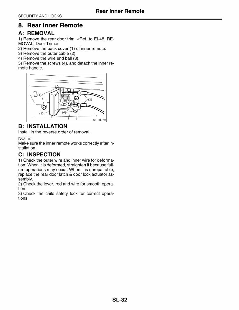
SECURITY AND LOCKSRear Inner Remote
8. Rear Inner RemoteA: REMOVAL1) Remove the rear door trim. <Ref. to EI-48, RE-MOVAL, Door Trim.>2) Remove the back cover (1) of inner remote. 3) Remove the outer cable (2). 4) Remove the wire end ball (3).5) Remove the screws (4), and detach the inner re-mote handle.
B: INSTALLATIONInstall in the reverse order of removal.
NOTE:Make sure the inner remote works correctly after in-stallation.
C: INSPECTION1) Check the outer wire and inner wire for deforma-tion. When it is deformed, straighten it because fail-ure operations may occur. When it is unrepairable,replace the rear door latch & door lock actuator as-sembly.2) Check the lever, rod and wire for smooth opera-tion.3) Check the child safety lock for correct opera-tions.
SL-00279
(2)
(4)
(1)
(3)
(4)
SL-32

SECURITY AND LOCKSRear Outer Handle
9. Rear Outer HandleA: REMOVAL1) Raise the rear door glass to the top position.2) Remove the rear door trim. <Ref. to EI-48, RE-MOVAL, Door Trim.>3) Remove the sealing cover. <Ref. to EB-24, RE-MOVAL, Rear Sealing Cover.>4) Remove the rear door latch assembly. <Ref. toSL-34, REMOVAL, Rear Door Latch and Door LockActuator Assembly.>5) Remove the wire from wire clamp (1) of outerhandle.6) Remove the two bolts.
7) Detach the outer handle bracket. (Model withdouble lock)8) Detach the rear outer handle.
CAUTION:Do not apply excessive force to remove the handle from door panel. Otherwise door panel may be deformed.
B: INSTALLATIONInstall in the reverse order of removal.
NOTE:Make sure the outer handle works correctly after in-stallation.
C: INSPECTION1) Check the wires for deformation. When it is de-formed, straighten it because failure operationsmay occur. When it is unrepairable, replace therear door latch & door lock actuator assembly.2) Check the lever and wire for smooth operation.
SL-00284
(1)
SL-33

SECURITY AND LOCKSRear Door Latch and Door Lock Actuator Assembly
10.Rear Door Latch and Door Lock Actuator Assembly
A: REMOVAL1) Disconnect the ground cable from battery.2) Remove the rear door trim. <Ref. to EI-48, RE-MOVAL, Door Trim.>3) Remove the wires from rear inner remote. <Ref.to SL-32, REMOVAL, Rear Inner Remote.>4) Remove the sealing cover. <Ref. to EB-24, RE-MOVAL, Rear Sealing Cover.>5) Remove the rear door glass. <Ref. to GW-22,REMOVAL, Rear Door Glass.>6) Remove the rear sash. <Ref. to GW-24, RE-MOVAL, Rear Regulator and Motor Assembly.>7) Take out the wire from wire clamp of outer han-dle.8) Detach the outer handle bracket. (Model withdouble lock)9) Remove the three screws.
10) Disconnect the connectors, and then removethe rear door latch & door lock actuator assembly.
B: INSTALLATIONInstall in the reverse order of removal.
NOTE:Make sure the lock works correctly after installa-tion.
C: INSPECTION1) Check the wires for deformation. When it is de-formed, straighten it because failure operationsmay occur. When it is unrepairable, replace therear door latch & door lock actuator assembly.2) Check the lever and wire for smooth operation.
SL-00285
SL-34

SECURITY AND LOCKSRear Door Lock Actuator
11.Rear Door Lock Actuator A: REMOVAL1) Remove the rear door latch & door lock actuatorassembly. <Ref. to SL-34, REMOVAL, Rear DoorLatch and Door Lock Actuator Assembly.>2) Remove the pawl of rear door latch security cov-er, and then remove the cover. (Except for EK mod-el)3) Remove the screw from the rear door latch anddoor lock actuator, and then remove the door lockactuator. (Except for EK model)
B: INSTALLATIONInstall in the reverse order of removal.
NOTE:Make sure the lock works correctly after installa-tion.
C: INSPECTION1) Disconnect the door lock actuator harness con-nector.2) Connect the battery to door lock actuator termi-nals.If defective, replace the door lock actuator. 1. Model without double lock
2. Model with double lock
DOOR ACTUATOR RH:
DOOR ACTUATOR LH:
(1) Rear door lock actuator
Terminal No. Actuator operation
No. 2 (+) and No. 1 (−) Unlocked → Locked
No. 1 (+) and No. 2 (−) Locked → Unlocked
SL-00282
(1)
SL-00235
2 1
Terminal No. Actuator operation
No. 5 (+) and No. 1 (−) Unlocked → Locked
No. 1 (+) and No. 5 (−) Locked → Unlocked
No. 6 (+) and No. 1 (−)Double lock released →
Double lock set
No. 1 (+) and No. 6 (−)Double lock set → Double
lock released
Terminal No. Actuator operation
No. 2 (+) and No. 6 (−) Unlocked → Locked
No. 6 (+) and No. 2 (−) Locked → Unlocked
No. 1 (+) and No. 6 (−)Double lock released →
Double lock set
No. 6 (+) and No. 1 (−)Double lock set → Double
lock released
SL-00283
6 5 4 3 2 1
SL-35

SECURITY AND LOCKSRear Gate Outer Handle
12.Rear Gate Outer HandleA: REMOVAL1) Remove the rear gate trim. <Ref. to EI-69, RE-MOVAL, Rear Gate Trim.>2) Remove the rear gate garnish. <Ref. to EI-76,REMOVAL, Rear Gate Garnish.>3) Remove the two nuts to take out the rear gateouter handle. 4) Remove the rear gate outer handle cable.
B: INSTALLATIONInstall in the reverse order of removal.
NOTE:Make sure the outer handle works correctly after in-stallation.
C: INSPECTION1) Check the rear gate handle cable for deforma-tion.2) Check the rear gate outer handle and rear gatehandle cable for smooth operation.
(1) Rear gate handle cable
SL-00239
(1)
SL-36

SECURITY AND LOCKSRear Gate Latch Assembly
13.Rear Gate Latch AssemblyA: REMOVAL1) Disconnect the ground cable from battery.2) Remove the rear gate trim. <Ref. to EI-69, RE-MOVAL, Rear Gate Trim.>3) Remove the two screws.
4) Remove the rear gate latch cover. (Model withdouble lock)
5) Disconnect the each connector and rear gatehandle cable.
6) Remove the rear gate latch assembly.
B: INSTALLATIONInstall in the reverse order of removal.
NOTE:Make sure the lock works correctly after installa-tion.
C: INSPECTION1) Disconnect the rear gate lock actuator harnessconnector.2) Connect the battery to rear gate lock actuatorterminals.
(1) Clip
(2) Claw
(3) Hook
SL-00240
SL-00286
(2)
(1)
(3)
(1) Rear gate handle cable
(2) Rear gate lock actuator connector
(3) Rear gate latch switch connector
Terminal No. Actuator operation
No. 2 (+) and No. 1 (−) Unlocked → Locked
No. 1 (+) and No. 2 (−) Locked → Unlocked
SL-00301
(2)
(1)
(3)
(2)
SL-00235
2 1
SL-37

SECURITY AND LOCKSRear Gate Latch Assembly
Replace the rear gate latch assembly if faulty. 3) Check the rear gate handle cable for deforma-tion.4) Check the lever and rear gate handle cable forsmooth operation.
SL-38

SECURITY AND LOCKSTrunk Lid Lock Assembly
14.Trunk Lid Lock AssemblyA: REMOVAL1. MODEL WITHOUT DOUBLE LOCK1) Disconnect the connectors and detach the trunkopener cable.2) Remove the two bolts to remove trunk lid lockassembly.
2. MODEL WITH DOUBLE LOCK1) Disconnect the connectors and detach the trunkopener cable.2) Remove the two bolts and clip to remove trunklid lock assembly.
B: INSTALLATIONInstall in the reverse order of removal.
NOTE:• Apply grease to the movable part.• Make sure the lock works correctly after installa-tion.
C: INSPECTION1) Disconnect the trunk lid actuator harness con-nector.
2) Connect the battery to trunk lid actuator termi-nals.
If defective, replace the trunk lid actuator. 3) Check the striker for deformation or abnormalwear.4) Check the safety lever for improper movement.5) Check other levers and the spring for rust forma-tion and unsmooth movement. 6) Check the trunk opener cable for smooth opera-tion.
SL-00243
SL-00308
Terminal No. Actuator operation
No. 2 (+) and No. 1 (−) Locked → Unlocked
SL-00255
3 2 1
SL-39

SECURITY AND LOCKSFront Hood Lock Assembly
15.Front Hood Lock AssemblyA: REMOVAL1) Open the front hood.2) Remove the bolts, and then detach the fronthood lock assembly.3) Remove the release cable from lock assembly.
B: INSTALLATIONInstall in the reverse order of removal.
NOTE:• Apply grease to the movable part.• Make sure the release cable works correctly afterinstallation.
C: ADJUSTMENTLoosen the bolt, and adjust the lock assembly whilemoving it up and down.
D: INSPECTION1) Check the striker for deformation or abnormalwear.2) Check the safety lever for improper movement.3) Check other levers and the spring for rust forma-tion and unsmooth movement.
SL-00287
SL-00290
SL-40

SECURITY AND LOCKSRemote Openers
16.Remote OpenersA: REMOVAL1. FRONT HOOD OPENER1) Remove the release cable from hood lock.2) Remove the bolt, and then detach the opener le-ver.
2. TRUNK LID OPENER1) Remove the rear seat. <Ref. to SE-14, REMOV-AL, Rear Seat.>2) Remove the center pillar lower trim, side sill cov-er, rear pillar lower trim and floor mat on the driver’sside. Remove the clip holding cable. 3) Remove the bolt, and then detach the openerpull handle.
4) Remove the cable from opener pull handle.5) Remove the trunk lid lock assembly from trunklid.
6) Remove the cable from trunk lid lock assembly.
3. FUEL FLAP OPENER1) Remove the rear seat. <Ref. to SE-14, REMOV-AL, Rear Seat.>2) Remove the center pillar lower trim, side sill cov-er, rear pillar lower trim and floor mat on the driver’sside. Remove the clip holding cable. 3) Remove the bolt, and then detach the openerpull handle.
4) Remove the cable from opener pull handle.5) Remove the rear quarter trim RH. <Ref. to EI-63,REMOVAL, Rear Quarter Trim.>
(1) Cover
(2) Pull handle ASSY
(3) Cable
SL-00291
SL-00302
(2) (1)
(3)
(1) Trunk lid lock ASSY
(2) Cable
(A) Sedan model
(B) Wagon model
(1) Cover
(2) Pull handle ASSY
(3) Cable
SL-00248
(1)
(2)
SL-00312
(2) (1)
(1)
(A)
(3)
(B)
SL-41

SECURITY AND LOCKSRemote Openers
6) Rotate the fuel lock inside of the quarter panel to90° and remove. (Either right or left turn)
B: INSTALLATION1. FRONT HOOD OPENERInstall in the reverse order of removal.
2. TRUNK LID OPENERInstall in the reverse order of removal.
3. FUEL FLAP OPENERInstall in the reverse order of removal.
C: INSPECTIONMake sure the front hood, trunk lid and fuel flapopen and close smoothly.
SL-00265
SL-42

SECURITY AND LOCKSIgnition Key Lock
17.Ignition Key LockA: REPLACEMENT1) Disconnect the ground cable from battery.2) Remove the steering column. <Ref. to PS-23,REMOVAL, Tilt Steering Column.>3) Secure the steering column in a vise. Removethe bolt with a drill.
4) Remove the ignition key lock.5) Using a new bolt, tighten the bolts all the way.
B: INSPECTION1) Remove the instrument panel lower panel.2) Remove the lower column cover.3) Unfasten the fixing clip which secures harness,and then disconnect the connector of the ignitionswitch from body harness.4) Turn the ignition key plate to each position andcheck the continuity between terminals of ignitionconnector.
If NG, replace the ignition switch.
SL-00024
SL-00025
SL-00266
13456
2
Switch position Terminal No. Standard
LOCK — —
ACC No. 3 and No. 4 Less than 1 Ω
ONNo. 3 and No. 1
and No. 4No. 3 and No. 6
Less than 1 Ω
STNo. 3 and No. 1No. 3 and No. 2
and No. 6Less than 1 Ω
SL-43
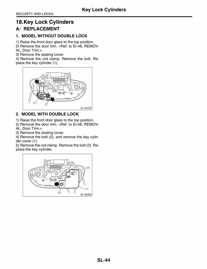
SECURITY AND LOCKSKey Lock Cylinders
18.Key Lock CylindersA: REPLACEMENT1. MODEL WITHOUT DOUBLE LOCK1) Raise the front door glass to the top position.2) Remove the door trim. <Ref. to EI-48, REMOV-AL, Door Trim.>3) Remove the sealing cover.4) Remove the rod clamp. Remove the bolt. Re-place the key cylinder (1).
2. MODEL WITH DOUBLE LOCK1) Raise the front door glass to the top position.2) Remove the door trim. <Ref. to EI-48, REMOV-AL, Door Trim.>3) Remove the sealing cover.4) Remove the bolt (2), and remove the key cylin-der cover (1).5) Remove the rod clamp. Remove the bolt (3). Re-place the key cylinder.
SL-00292
(1)
SL-00303
(1)
(3)
(2)
SL-44

SECURITY AND LOCKSKeyless Entry Control Unit
19.Keyless Entry Control UnitA: REMOVAL1) Disconnect the ground cable from battery.2) Remove the glove box. <Ref. to EI-51, REMOV-AL, Glove Box.>3) Remove the screw, then remove the keyless en-try control unit while disconnecting the connector.
B: INSTALLATIONInstall in the reverse order of removal.
SL-00293
SL-45

SECURITY AND LOCKSBody Integrated Unit
20.Body Integrated UnitA: REMOVALNOTE:• Prepare the security ID plate.• Prepare all registered immobilizer keys for themodel with immobilizer.• Make a registration of immobilizer for the modelwith immobilizer. For detailed operation procedure,refer to “IMMOBILIZER REGISTRATION MANU-AL”.• If replacing the body integrated unit, check thecurrent setting and note it. <Ref. to LAN(diag)-17,CONFIRMATION OF CURRENT SETTING, OP-ERATION, Subaru Select Monitor.>• When replacing the body integrated unit, recon-figure the select unlock as necessary. <Ref. to SL-15, CUSTOMIZE SETTING OF SELECT UN-LOCK, ELECTRICAL SPECIFICATION, KeylessEntry System.>1) Disconnect the ground cable from battery.2) Remove the instrument panel lower panel ondriver’s side. <Ref. to EI-56, REMOVAL, Instru-ment Panel Assembly.>3) Disconnect the connector of body integratedunit.
CAUTION:Be careful to keep water and other foreign ma-terials away from body integrated unit.4) Remove the body integrated unit from the bodyintegrated unit mounting bracket using flat tipscrewdriver.
CAUTION:Be careful not to damage the unit when remov-ing it forcibly from the bracket.5) Remove the clutch pedal stopper arm. (MT mod-el) <Ref. to CL-26, REMOVAL, Clutch Pedal.>6) Remove two body integrated unit bracket mount-ing bolts, and remove the bracket.
B: INSTALLATIONInstall in the reverse order of removal.
NOTE:Make sure it comforms to the current setting condi-tion after installation. <Ref. to LAN(diag)-17, CON-FIRMATION OF CURRENT SETTING,OPERATION, Subaru Select Monitor.>
SL-00295
SL-46
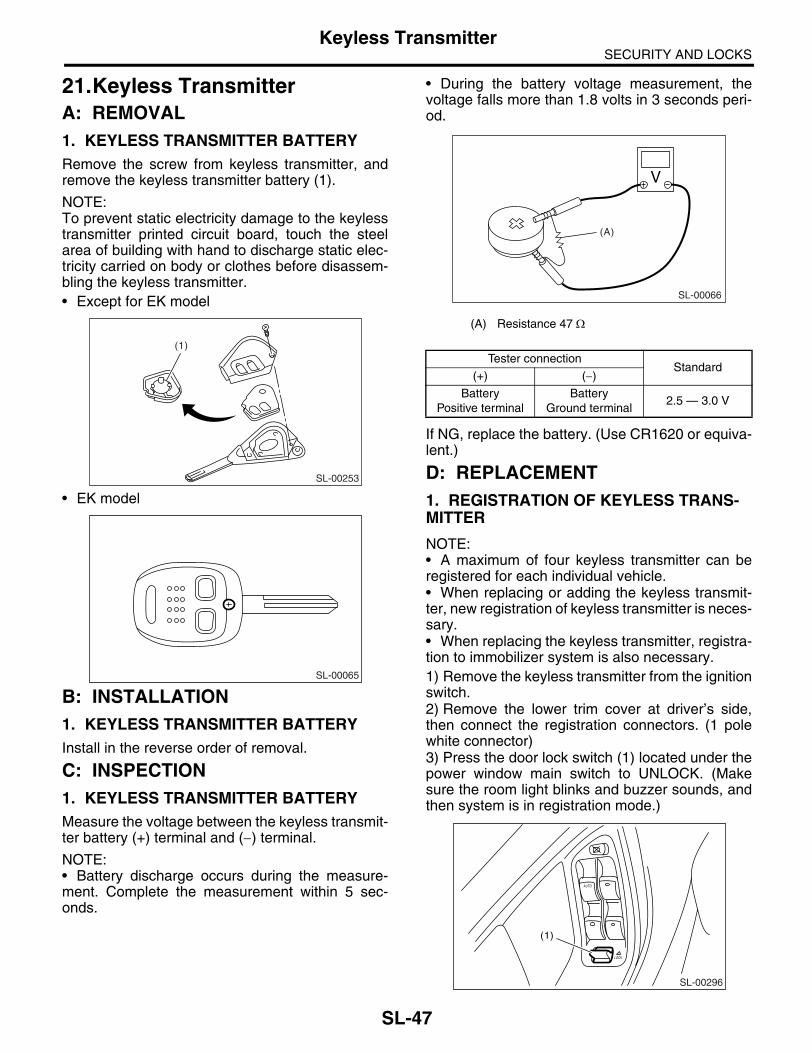
SECURITY AND LOCKSKeyless Transmitter
21.Keyless TransmitterA: REMOVAL1. KEYLESS TRANSMITTER BATTERYRemove the screw from keyless transmitter, andremove the keyless transmitter battery (1).
NOTE:To prevent static electricity damage to the keylesstransmitter printed circuit board, touch the steelarea of building with hand to discharge static elec-tricity carried on body or clothes before disassem-bling the keyless transmitter.• Except for EK model
• EK model
B: INSTALLATION1. KEYLESS TRANSMITTER BATTERYInstall in the reverse order of removal.
C: INSPECTION1. KEYLESS TRANSMITTER BATTERYMeasure the voltage between the keyless transmit-ter battery (+) terminal and (−) terminal.
NOTE:• Battery discharge occurs during the measure-ment. Complete the measurement within 5 sec-onds.
• During the battery voltage measurement, thevoltage falls more than 1.8 volts in 3 seconds peri-od.
If NG, replace the battery. (Use CR1620 or equiva-lent.)
D: REPLACEMENT1. REGISTRATION OF KEYLESS TRANS-MITTER
NOTE:• A maximum of four keyless transmitter can beregistered for each individual vehicle.• When replacing or adding the keyless transmit-ter, new registration of keyless transmitter is neces-sary.• When replacing the keyless transmitter, registra-tion to immobilizer system is also necessary.1) Remove the keyless transmitter from the ignitionswitch.2) Remove the lower trim cover at driver’s side,then connect the registration connectors. (1 polewhite connector)3) Press the door lock switch (1) located under thepower window main switch to UNLOCK. (Makesure the room light blinks and buzzer sounds, andthen system is in registration mode.)
SL-00253
(1)
SL-00065
(A) Resistance 47 Ω
Tester connectionStandard
(+) (−)
BatteryPositive terminal
BatteryGround terminal
2.5 — 3.0 V
SL-00066
(A)
SL-00296
(1)
LOCK
AUTO
SL-47

SECURITY AND LOCKSKeyless Transmitter
4) While pressing the button of keyless transmitterto be registered twice with door lock switch pressedto UNLOCK. (Button for LOCK, UNLOCK andTRUNK are acceptable)5) When the registration is completed normally, thedoor lock actuator will lock → unlock. If the lock →unlock operation is not carried out, repeat the pro-cedure 4).
NOTE:• When pressing the keyless transmitter button,slowly press for first and second (press longer forsecond) to check operation of door lock actuator.• Do not press the button of keyless transmittermore than twice.• Do not batter the button of keyless transmitter.6) Repeat the steps 4) if there is an additional key-less transmitter to be registered.7) Pull out the registration connector, and install thelower trim cover at driver’s side.
NOTE:• The transmitter can be registered only when thedoor lock switch is remain pushed to UNLOCK.• Continuing to press the door lock switch to UN-LOCK again allows to be registered although thedoor lock switch is released for once.• When adding the keyless transmitter, re-registra-tion of keyless transmitter which was already regis-tered is necessary.
2. CLEAR OF KEYLESS TRANSMITTER1) Remove the keyless transmitter from ignitionswitch.2) Remove the lower trim cover at driver’s side,then connect the registration connectors. (1 polewhite connector)3) Press the door lock switch located under thepower window main switch to LOCK. (Make surethe room light blinks and buzzer sounds, and sys-tem becomes in clear mode.)4) While pressing door lock switch to LOCK, insertand remove the key on ignition switch 10 timeswithin 10 seconds.5) When the clearing is completed normally, thedoor lock actuator will lock → unlock. If the lock →unlock operation is not carried out, repeat the pro-cedure 4).6) Pull out the registration connector, and install thelower trim cover at driver’s side.
NOTE:• The transmitter can be cleared only when thedoor lock switch is remain pushed to LOCK.• Continuing to press the door lock switch to LOCKagain allows to be cleared although the door lockswitch is released for once.
• If changing from registration mode to clear mode,you cannot go to clear mode unless completing theregistration mode. The reverse case is same asthis.
SL-48

SECURITY AND LOCKSImmobilizer Control Unit
22.Immobilizer Control UnitA: NOTEThe control of immobilizer system is carried out inbody integrated unit.
B: REMOVAL<Ref. to SL-46, REMOVAL, Body Integrated Unit.>
C: INSTALLATIONInstall in the reverse order of removal.
SL-49

SECURITY AND LOCKSImmobilizer Antenna
23.Immobilizer AntennaA: REMOVAL1) Disconnect the ground cable from battery.2) Remove the screws, and detach the upper col-umn cover and lower column cover.
3) Remove the instrument panel lower cover. <Ref.to EI-50, REMOVAL, Instrument Panel Lower Cov-er.>4) Disconnect the immobilizer antenna connector(A) and ignition switch lighting connector (B).5) Loosen the screw and release the lock (D) at op-posite side using flat-tip screwdriver (1), and thendetach the immobilizer antenna (C).
CAUTION:Do not apply excessive force to remove the im-mobilizer antenna and lock. Otherwise they may be broken because those parts are the products made of a plastic.
B: INSTALLATIONInstall in the reverse order of removal.
SL-00258
(D)
(1)
SL-00315
(A)
(C)
(B)
SL-50

SUNROOF/T-TOP/CONVERTIBLE TOP(SUNROOF)
SR
Page1. General Description ....................................................................................22. Sunroof Control System ..............................................................................53. Glass Lid .....................................................................................................64. Sunroof Assembly .......................................................................................95. Sunroof Motor ...........................................................................................126. Sunroof Switch ..........................................................................................15

SUNROOF/T-TOP/CONVERTIBLE TOP (SUNROOF)General Description
1. General DescriptionA: COMPONENT1. SEDAN MODEL
(1) Glass lid (7) Assist rail bracket (Front) Tightening torque: N⋅m (kgf-m, ft-lb)(2) Weatherstrip (8) Sunroof bracket (Rear) T1: 4.5 (0.46, 3.3)(3) Guide rail cover (9) Motor ASSY T2: 6.0 (0.61, 4.4)(4) Sunshade (10) Frame ASSY T3: 7.5 (0.76, 5.3)(5) Drain tube (11) Deflector
(6) Assist rail bracket (Rear)
SR-00074
(1)
(2)
(3)
(4)
(5)
(7)
(8)
(5)
(6)
(9)
(10)
T1(11)
T2
T3
T3
T3
T2
SR-2

SUNROOF/T-TOP/CONVERTIBLE TOP (SUNROOF)General Description
2. WAGON MODEL
(1) Glass lid (Front) (5) Drain tube Tightening torque: N⋅m (kgf-m, ft-lb)(2) Glass lid (Rear) (6) Cover (Front and rear) T1: 7.5 (0.76, 5.3)(3) Sunshade (7) Frame bracket T2: 4.5 (0.46, 3.0)(4) Frame ASSY (8) Motor ASSY
SR-00102
T1
T1
(3)
(5)
(8)
(7)
(5)
(1)
(6)
(4)
(7)T2
T1
T1
T1
T1
(2)
SR-3
SUNROOF/T-TOP/CONVERTIBLE TOP (SUNROOF)General Description
B: CAUTION• Before disassembling or reassembling parts, al-ways disconnect the battery ground cable. Whenreplacing the audio, control unit, and other partsprovided with memory functions, record the memo-ry contents before disconnecting the batteryground cable in order to prevent memory deletion. • Reassemble the parts in the reverse order of dis-assembly unless otherwise indicated.• Adjust parts to the given specifications.• Connect the connectors securely for reassem-bly.• After reassembly, make sure functional parts op-erate smoothly.
C: PREPARATION TOOL1. GENERAL TOOL
TOOL NAME REMARKS
Circuit tester Used for measuring resistance and voltage.
SR-4

SUNROOF/T-TOP/CONVERTIBLE TOP (SUNROOF)Sunroof Control System
2. Sunroof Control SystemA: WIRING DIAGRAM1. SUNROOF<Ref. to WI-316, WIRING DIAGRAM, Sunroof System.>
B: INSPECTION
• Failure turn of glass lid while driving rough road.Glass lid has auto-reverse function. When applied above specified force to the glass lid, the lid turns backand stops. When operating the glass lid (open or close) while driving the rough road, the lid judges vibrationas a force and may causes failure turns. When the failure turn is occurred, the initialize operation is requiredwith following procedure.
1. INITIALIZE OPERATION (SEDAN MODEL)1) Tilt up the glass lid. 2) Release the switch once, and press the tilt up switch again for 15 seconds.3) When the glass lid is raised a little and returned to tilt up position, release the switch for the moment. (Ini-tialization of position detecting function)4) Keep pressing the tilt up switch within 5 seconds from releasing the switch, glass lid tilts down → slidesopen → slides close operation automatically. (Time gap of more than 5 seconds will result in cancellation ofposition detecting function.)5) Initialize operation is completed.
2. INITIALIZE OPERATION (WAGON MODEL)1) Apply the force to glass lid in the direction of glass lid open while glass lid (rear) is closing, and then re-verse the lid five times in a row.However, in the following situation, the initialize operation is canceled.• When the lid is fully closed once during auto-reverse operation five times in a row.• When the interval of auto-reverse operation is more than 30 seconds once.2) When the operation of glass lid shift to brink operation*, fully close the lid on switch operation.3) Initialize operation is completed.
*Brink operation: Although keep pressing the switch, glass lid operates only at a moment when the switch is pressed.
Symptom Inspection order
Water leakage (1) Check roof panel and glass lid for improper or poor sealing.(2) Check drain tube for clogging.(3) Check sunroof frame seal and body for improper fit.
Booming noise, wind noise and other noise (1) Check glass lid and roof panel for improper clearance.(2) Check sunshade and roof trim for improper clearance.
Motor noise (1) Check installing part of motor for looseness.(2) Check gears and bearings for wear.(3) Check cable for wear.(4) Check cable pipe for deformities.
Failure of sunroof(Motor operates properly.)
(1) Check guide rail for foreign particles.(2) Check guide rail for improper installation.(3) Check parts for mutual interference.(4) Check cable slider for improper clinching.(5) Check cable for improper installation.
Motor does not rotate or rotate improperly. (1) Check fuse for blown out.(2) Check switch for improper function.(3) Check motor for incorrect terminal voltage.(4) Check the relay for improper operation.(5) Check poor grounding system.(6) Check harness for open or short and terminals for poor connections.
Failure turn of glass lid Check guide rail for foreign particles.
SR-5

SUNROOF/T-TOP/CONVERTIBLE TOP (SUNROOF)Glass Lid
3. Glass LidA: REMOVAL1. SEDAN MODEL1) Completely close the glass lid, and then openthe sunshade.2) Remove the cover (A), and then remove theTORX® bolts (B).
CAUTION:TORX® bolts are applied with thread locker. If they are removed, replace with new ones.
3) Remove the glass lid carefully.
2. WAGON MODEL (FRONT)1) Open the sunshade.
2) Pull out the cover (A) toward arrow mark, andthen remove the nut (B).
3) Remove the glass lid (front) carefully.
3. WAGON MODEL (REAR)1) Tilt up the glass lid (front), and then open thesunshade.2) Remove the cover (A), and then remove the nut(B).
3) Remove the glass lid carefully.
(A)
(B)
SR-00091
SR-00104
(B)
(A)
SR-00103
(A)
(B)
SR-6

SUNROOF/T-TOP/CONVERTIBLE TOP (SUNROOF)Glass Lid
B: INSTALLATIONInstall in the reverse order of removal.
C: ADJUSTMENT1. SEDAN MODELLoosen the glass lid mounting TORX® bolts (A),and then adjust the height with moving 9.5 mm(0.374 in) nut (B) on lid side.
Difference in height between glass lid and roof panel L:
2.0±1.0 mm (0.079±0.039 in)
2. WAGON MODELLoosen the glass lid installation nuts, and then ad-just the height by adding (max: four pieces) or ex-tracting (min: zero piece) shims (B) (standard: twopieces) which installed between glass lid (A) andbody.
Difference in height between glass lid and roof panel L:
2.0±1.0 mm (0.079±0.039 in)
D: FORCED DRIVEIf glass lid dose not operate or is not supplied withpower, move the glass lid using the emergencyhandle (wrench)*.*: Emergency handle (L shape general purposehexagon wrench)
Sedan model: bolt width 4 mm (0.16 in)Wagon model: bolt width 5 mm (0.20 in)
1. SEDAN MODEL1) Remove the spot map light. <Ref. to LI-34, RE-MOVAL, Spot Map Light.>2) Insert the wrench securely until it touches themotor shaft edge.3) Turn the wrench, and move the glass lid.• Turning right, the glass lid open.• Turning left, the glass lid close.
(B)
(A)
SR-00092
L
SR-00077
L (A)(B)
(B)
SR-00099
SR-7

SUNROOF/T-TOP/CONVERTIBLE TOP (SUNROOF)Glass Lid
2. WAGON MODEL1) Raise the left and right side hook (A) of sun-shade.
2) Slide the sunshade forward.3) Remove the plug in the rear side of roof trim.
4) Insert the wrench securely until it touches themotor shaft edge.5) Turn the wrench to right, and close the glass lid(front and rear).
CAUTION:After forced drive, the initialize operation is re-quired. <Ref. to SR-5, INSPECTION, Sunroof Control System.>
SR-00085
(A)
SR-00100
SR-00101
SR-8

SUNROOF/T-TOP/CONVERTIBLE TOP (SUNROOF)Sunroof Assembly
4. Sunroof AssemblyA: REMOVAL1. SEDAN MODEL1) Disconnect the ground cable from battery.2) Remove the roof trim. <Ref. to EI-67, SEDANMODEL, REMOVAL, Roof Trim.>3) Disconnect the harness connector of sunroofmotor.4) Remove the glass lid. <Ref. to SR-6, SEDANMODEL, REMOVAL, Glass Lid.>5) Remove the drain tube from frame assembly.6) Remove the assist rail bracket (front) (A) andsunroof bracket (rear) (B).
7) Remove the nuts, and then remove the frameassembly.
2. WAGON MODEL1) Disconnect the ground cable from battery.2) Remove the roof trim. <Ref. to EI-67, WAGONMODEL, REMOVAL, Roof Trim.>
3) Disconnect the harness connector of motor as-sembly.
4) Remove the front and rear glass lid. <Ref. to SR-6, WAGON MODEL (FRONT), REMOVAL, GlassLid.> <Ref. to SR-6, WAGON MODEL (REAR),REMOVAL, Glass Lid.>5) Remove the installation bolts (A) on rear sideframe bracket of frame assembly.
6) Remove the drain tube from frame assembly.7) Remove the frame bracket (A).
SR-00078
(A)(B)
SR-00079
SR-00080
(A)
SR-00081
SR-9

SUNROOF/T-TOP/CONVERTIBLE TOP (SUNROOF)Sunroof Assembly
8) Remove the bolts (B) and nuts (C), and then remove the frame assembly.
B: INSTALLATIONInstall in the reverse order of removal.
CAUTION:Be careful not to snag the harness.
NOTE:• Be sure to connect the harness connector.• When installing the drain tube, insert it securelyinto drain pipe.
Length A:15 mm (0.59 in) or more
C: DISASSEMBLY1. SEDAN MODEL1) Remove the glass lid.2) Slide the sunshade to full front end.
3) Remove the screw from the slider bracket (A) ofroof side.
4) Pull out the sunshade from roof opening.
NOTE:For sedan model, sunshade can be removed/in-stalled with frame assembly installed to the vehicle.
2. WAGON MODEL (FRONT)1) Remove the frame assembly. <Ref. to SR-9,REMOVAL, Sunroof Assembly.>2) Slide the sunshade to fully open position, andthen remove the screw from slider bracket (A).
3) Pull out the sunshade to backward.
SR-00082
(A) (A)(C)
(B) (B)
SR-00005
A
SR-00084
(A)
SR-00084
(A)
SR-10

SUNROOF/T-TOP/CONVERTIBLE TOP (SUNROOF)Sunroof Assembly
3. WAGON MODEL (REAR)1) Remove the frame assembly.2) Remove the shade stopper (A) of sunshade.
3) Pull out the sunshade (A) from sunroof frame.
D: ASSEMBLYAssemble in the reverse order of disassembly.
E: INSPECTION1. CHECK FOR MOVING LOAD OF SUN-SHADE1) Attach a spring balance to sunshade edge usinga cloth.
2) Pull the spring balance to measure moving loadof the sunshade.
Moving load of sunshade:Standard value
18.0±5.0 N (1.8±0.5 kgf, 13±3.7 lb)NOTE:Moving load is larger at the beginning of pulling aspring balance, so take a spring balance readingwhile sunshade sliding smoothly.3) If moving load exceeds specifications, check theglass lid, sunshade and frame assembly for im-proper installation.
SR-00093
(A)
SR-00086(A)
SR-00087
SR-11

SUNROOF/T-TOP/CONVERTIBLE TOP (SUNROOF)Sunroof Motor
5. Sunroof MotorA: REMOVALCAUTION:• When removing the clip, use great care not todamage the roof trim.• Never rotate the sunroof motor after remov-ing it.
1. SEDAN MODEL1) Completely close the glass lid.2) Disconnect the ground cable from battery.3) Remove the roof trim. <Ref. to EI-67, SEDANMODEL, REMOVAL, Roof Trim.>4) Disconnect the harness connector, and then re-move the motor assembly mounting screw.
CAUTION:When removing the motor assembly, secure the cable wires to prevent moves.
2. WAGON MODEL1) Fully close the glass lid (front) and glass lid(rear).2) Disconnect the ground cable from battery.3) Remove the luggage room light. <Ref. to LI-36,REMOVAL, Luggage Room Light.>4) Remove the roof trim. <Ref. to EI-67, WAGONMODEL, REMOVAL, Roof Trim.>5) Pass the seat belt tongue (A) located on centerof rear seat through the hole, and then pull it out tothe opposite side of trim.
6) Remove the clips, and then drop the rear end ofroof trim.
7) Disconnect the harness connector (A), and thenremove the motor assembly mounting bolt (B) andnuts (C).
B: INSTALLATIONCAUTION:When installing the motor assembly, be careful not to move the sunroof cable.
SR-00088
SR-00036
(A)
(B)
(C)
SR-00089
(A)
(B)
(C)
SR-12

SUNROOF/T-TOP/CONVERTIBLE TOP (SUNROOF)Sunroof Motor
1. SEDAN MODEL1) Align the coulisse assembly and link assembly in the same position.
2) Install the motor assembly.3) Connect the harness connector of motor assembly, and then connect the battery ground cable to battery.4) Perform the initialize operation of motor.
(1) Tilt up the glass lid. (2) Release the switch once, and press the tilt up switch again for 15 seconds.(3) When the glass lid is raised a little and on tilt up position, release the switch for the moment.(4) Keep pressing the tilt up switch within 5 seconds from releasing the switch, glass lid tilts down →slides open → slides close operation automatically, and then initialize operation is completed.
5) Check the operation of sunroof with following table.
6) Install the trim in the reverse order of removal.
(1) Front
(2) Coulisse ASSY
(3) Link ASSY
(4) 4.7 mm (0.185 in)
SR-00094
(1)
(3)
(2) (4)
Operation Switch position
(1) Glass lid closes completely. Close
(2) Glass lid tilt up to the top position. Tilt up
(3) Glass lid lowers completely. Tilt down
(4) Glass lid opens completely. Open
(5) Glass lid closes 150 mm (5.91 in) away from completely closed position. Close
(6) Glass lid closes completely. Close
SR-13

SUNROOF/T-TOP/CONVERTIBLE TOP (SUNROOF)Sunroof Motor
2. WAGON MODELCheck that the wedge of glass lid (front) bracket part is contacting in the direction of vehicle front.At this time, the lid is at fully open position.
1) Install the motor assembly.2) After the installation of motor assembly, check again that the wedge of glass lid (front) bracket part is con-tacting in the direction of vehicle front.3) Connect the harness connector of motor assembly, and then connect the battery ground cable to battery.4) Perform the initialize operation of motor.• When replacing the motor with a new one, fully close the glass once and perform the initialization of posi-tion, because the movement of glass lid shifts to brink operation.• When reusing the motor, operate the auto-reverse function five times in a row to shifts brink operation, andthen perform the initialization of position.5) Check the operation of sunroof with following table.
6) Install the trim in the reverse order of removal.
(1) Front
(2) Wedge
(3) Glass lid (Front)
(4) Glass lid (Rear)
SR-00095
(3)
(2)
(1)
(4)
Operation Switch position
(1) Glass lid (front) and glass lid (rear) closes completely. Close
(2) Glass lid (front) tilt up to the ventilating position. Open
(3) Glass lid (front) tilts up to top position, and glass lid (rear) opens near the completely open position.
Open
(4) Glass lid (rear) opens completely. Open
(5) Glass lid (rear) closes on 150 mm (5.91 in) from rear end of tilted up glass lid (front). Close
(6) Glass lid (rear) closes completely. Close
(7) Glass lid (front) lowers, and then glass lid (front) and glass lid (rear) closes completely. Close
SR-14

SUNROOF/T-TOP/CONVERTIBLE TOP (SUNROOF)Sunroof Switch
6. Sunroof SwitchA: REMOVAL1) Disconnect the ground cable from battery.2) Remove the spot map light lens (A) and sunroofswitch mounting screws (B).
3) Disconnect the harness connector, and then re-move the sunroof switch.
B: INSTALLATIONInstall in the reverse order of removal.
C: INSPECTION1. SEDAN MODELMeasure the sunroof switch resistance.
2. WAGON MODELMeasure the sunroof switch resistance.
LI-00313(A)
LI-00314(B)
Switch position Terminal No. StandardConnector
No.
Open 1 and 3Less than
1 ΩR128
Close 3 and 4Less than
1 Ω
Tilt up 4 and 3Less than
1 ΩR187
Tilt down 3 and 4Less than
1 Ω
Switch position Terminal No. Standard
Open 1 and 3 Less than 1 ΩClose 3 and 4 Less than 1 Ω
R128
345 12
SR-00098
R187
345 12
SR-00041
R128
345 12
SR-15

SUNROOF/T-TOP/CONVERTIBLE TOP (SUNROOF)Sunroof Switch
NOTE:If glass lid does not operate or is not supplied withpower, move the glass lid using the emergencyhandle. <Ref. to SR-7, FORCED DRIVE, GlassLid.>
SR-16

EXTERIOR/INTERIOR TRIM
EI
Page1. General Description ....................................................................................22. Front Grille ................................................................................................243. Front Hood Grille.......................................................................................254. Front Under Cover ....................................................................................265. Floor Under Protector................................................................................276. Fuel Tank Protector...................................................................................287. Mud Guard ................................................................................................298. Front Bumper ............................................................................................309. Rear Bumper.............................................................................................37
10. Cowl Panel ................................................................................................3911. Roof Spoiler ..............................................................................................4012. Side Sill Spoiler .........................................................................................4113. Side Protector ...........................................................................................4214. Side Garnish .............................................................................................4415. Rear Quarter Protector..............................................................................4516. Roof Molding .............................................................................................4617. Roof Rail ...................................................................................................4718. Door Trim ..................................................................................................4819. Instrument Panel Lower Cover..................................................................5020. Glove Box..................................................................................................5121. Console Box..............................................................................................5322. Center Console .........................................................................................5423. Instrument Panel Assembly ......................................................................5624. Lower Inner Trim .......................................................................................6025. Upper Inner Trim .......................................................................................6226. Rear Quarter Trim .....................................................................................6327. Sun Visor...................................................................................................6528. Assist Grip.................................................................................................6629. Roof Trim ..................................................................................................6730. Rear Gate Trim .........................................................................................6931. Rear Shelf Trim .........................................................................................7032. Trunk Room Trim ......................................................................................7133. Floor Mat ...................................................................................................7334. Luggage Floor Box....................................................................................7435. Trunk Lid Garnish......................................................................................7536. Rear Gate Garnish ....................................................................................7637. Heat Shield Cover .....................................................................................7738. Ornament ..................................................................................................78

EXTERIOR/INTERIOR TRIMGeneral Description
1. General DescriptionA: COMPONENT1. FRONT GRILLE
2. UNDER COVER
(1) Front grille (2) Front grille emblem (3) Front grille clip
Tightening torque: N⋅m (kgf-m, ft-lb)T: 14 (1.42, 10.3)
(3)
(1)
(2)
EI-00627
EI-00681
T
EI-2

EXTERIOR/INTERIOR TRIMGeneral Description
3. UNDER PROTECTOR
(1) Floor under protector (3) Fuel tank protector LH (4) Plastic nut
(2) Fuel tank protector RH
EI-00799
(1)
(2)
(3)
(4)
(4)
EI-3

EXTERIOR/INTERIOR TRIMGeneral Description
4. FRONT HOOD GRILLE
(1) Front hood grille (2) Grille duct upper (3) Grille duct lower
EI-00707
(2)
(3)
(1)
EI-4

EXTERIOR/INTERIOR TRIMGeneral Description
5. FRONT BUMPER
(1) Bumper face (7) Energy absorber foam upper (13) Lower center bracket
(2) Towing hook cover (8) Energy absorber foam lower (14) Radiator guide
(3) Fog light cover (9) Main beam reinforcement
(4) Lower side bracket (10) Main beam bracket Tightening torque: N⋅m (kgf-m, ft-lb)(5) Upper bracket (11) Bracket support T1: 7.5 (0.77, 5.5)(6) Side bracket (12) Energy absorber side T2: 33 (3.4, 24)
EI-00795
(1)
(2)
(3)(4)
(6)
(5)
(8)
(7)
(12)
(13)
(11)
(10)
(9)
(14)
T1
T2
T2
T2
T2 T2
EI-5

EXTERIOR/INTERIOR TRIMGeneral Description
6. REAR BUMPER (SEDAN MODEL)
(1) Bumper face (5) Lower bracket (9) Bumper beam bracket
(2) Exhaust end cover (6) Bumper side support upper
(3) Beam upper rear (7) Bumper side support lower Tightening torque: N⋅m (kgf-m, ft-lb)(4) Bracket corner (8) Beam main reinforcement T: 33 (3.4, 24)
EI-00796
(1)
(2)
(5)
(7)
(6)
(3)
(4)
(8)
(9)
T
T
EI-6

EXTERIOR/INTERIOR TRIMGeneral Description
7. REAR BUMPER (WAGON MODEL)
(1) Bumper face (5) Lower bracket (9) Bumper beam bracket
(2) Exhaust end cover (6) Bumper side support upper
(3) Beam upper rear (7) Bumper side support lower Tightening torque: N⋅m (kgf-m, ft-lb)(4) Bracket corner (8) Beam main reinforcement T: 33 (3.4, 24)
EI-00797
(1)
(2)
(5)
(4)
(7)
(6)
(3)
(8)
(9)
T
T
EI-7

EXTERIOR/INTERIOR TRIMGeneral Description
8. MUD GUARD
9. COWL PANEL
(1) Front mud guard (2) Rear mud guard
(1) Cowl panel (3) Cover cowl panel (4) Cowl side panel
(2) Weather strip
EI-00835
(2)
(1)
EI-00832
(1)
(4)
(3)
(3)
(4)
(2)
EI-8

EXTERIOR/INTERIOR TRIMGeneral Description
10.ROOF SPOILER
11.SIDE SILL SPOILER
(1) Roof spoiler (3) Washer nozzle Tightening torque: N⋅m (kgf-m, ft-lb)(2) High-mounted stop light T: 4.5 (0.46, 3.32)
(1) Side sill spoiler (2) Double-sided tape (3) Air flap side sill end
EI-00833
(1)
(2)
(3)
T
T
T
EI-00733
(1)
(2)
(3)
EI-9

EXTERIOR/INTERIOR TRIMGeneral Description
12.ROOF MOLDING
13.SIDE PROTECTOR
(1) Roof molding (3) Clip Tightening torque: N⋅m (kgf-m, ft-lb)(2) Roof carrier attachment (4) Roof carrier attachment bracket T: 4.5 (0.46, 3.32)
(1) Front door protector (2) Rear door protector
EI-00752
T
T
T
(2)
(3)
(4)
(1)
T
(2)
(3)
(4)
T
T
EI-00829
(1)
(2)
EI-10

EXTERIOR/INTERIOR TRIMGeneral Description
14.SIDE GARNISH
15.TRUNK LID GARNISH
(1) Front fender garnish (3) Rear door garnish (4) Rear quarter garnish
(2) Front door garnish
EI-00800
(4)
(3)
(2)
(1)
EI-00806
EI-11

EXTERIOR/INTERIOR TRIMGeneral Description
16.REAR GATE GARNISH
(1) Rear gate garnish (3) License plate light (5) Back-up light or rear fog light
(2) Ornament (4) Rear fog light or back-up light (6) License plate light bracket
EI-00807
(6)
(2)
(1)
(4)
(3)
(5)
EI-12

EXTERIOR/INTERIOR TRIMGeneral Description
17.DOOR TRIM
(1) Front door trim (5) Door grip (9) Power window switch
(2) Gusset cover (6) Door grip bracket upper (10) Step light cover
(3) Upper weather strip (7) Door grip frame (11) Speaker cover
(4) Inner remote cover (8) Door grip bracket lower (12) Rear door trim
EI-00714
(1)
(2)
(3)
(6)
(4)(5)
(7)
(8)
(6) (5)
(9)
(7)
(8)
(9)
(10)
(11)
(4)
(3)
(12)
EI-13

EXTERIOR/INTERIOR TRIMGeneral Description
18.CONSOLE BOX
(1) Upper lid (6) Rear lid (11) Console pocket
(2) Console cover (7) Rear cup holder (12) Front accessory power supply socket(3) Seat heater switch (8) Ash tray
(4) Front cup holder (9) Lid hinge (13) Console box harness
(5) Console box outer (10) Parking brake lever boot
EI-00812
(10)
(3)
(2)
(4)(5)
(1)(9)
(6)
(8)
(7)
(11)
(12)
(13)
A
A
EI-14
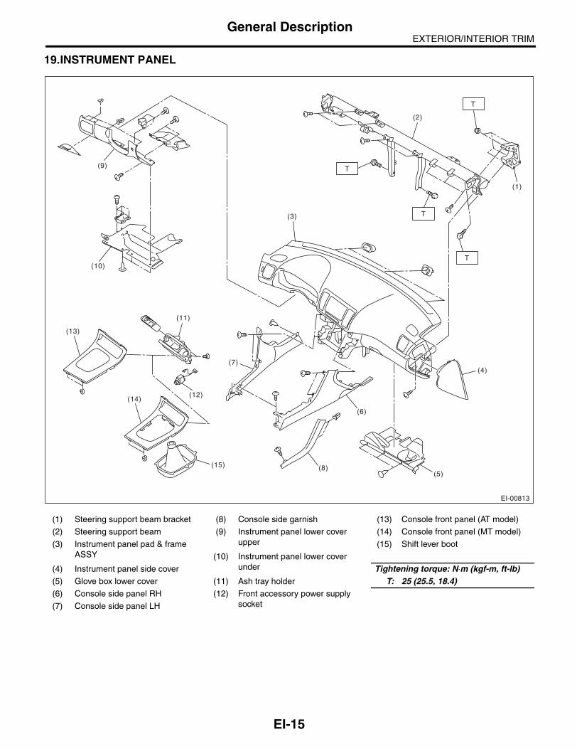
EXTERIOR/INTERIOR TRIMGeneral Description
19.INSTRUMENT PANEL
(1) Steering support beam bracket (8) Console side garnish (13) Console front panel (AT model)
(2) Steering support beam (9) Instrument panel lower cover upper
(14) Console front panel (MT model)
(3) Instrument panel pad & frame ASSY
(15) Shift lever boot
(10) Instrument panel lower cover under(4) Instrument panel side cover Tightening torque: N⋅m (kgf-m, ft-lb)
(5) Glove box lower cover (11) Ash tray holder T: 25 (25.5, 18.4)(6) Console side panel RH (12) Front accessory power supply
socket(7) Console side panel LH
EI-00813
T
T
T
T
(13)
(14)
(15) (8)
(7)
(6)
(5)
(4)
(3)
(2)
(1)
(12)
(11)
(10)
(9)
EI-15

EXTERIOR/INTERIOR TRIMGeneral Description
(1) Air vent side duct (6) Navigation unit bracket (Model with navigation system)
(10) Audio bracket (LH)
(2) Air vent center duct (11) Audio bracket (RH)
(3) Instrument panel pad & frame (7) Glove box panel (12) Center panel
(4) Air vent defroster grille (8) Center console frame (13) Glove box
(5) Air vent side grille (9) Air vent center grille (14) Glove box lid
EI-00814
(1)
(2)
(3)(4)
(5)
(7)
(6)
(8)(9)(10)
(11)
(12)
(14)
(13)
EI-16
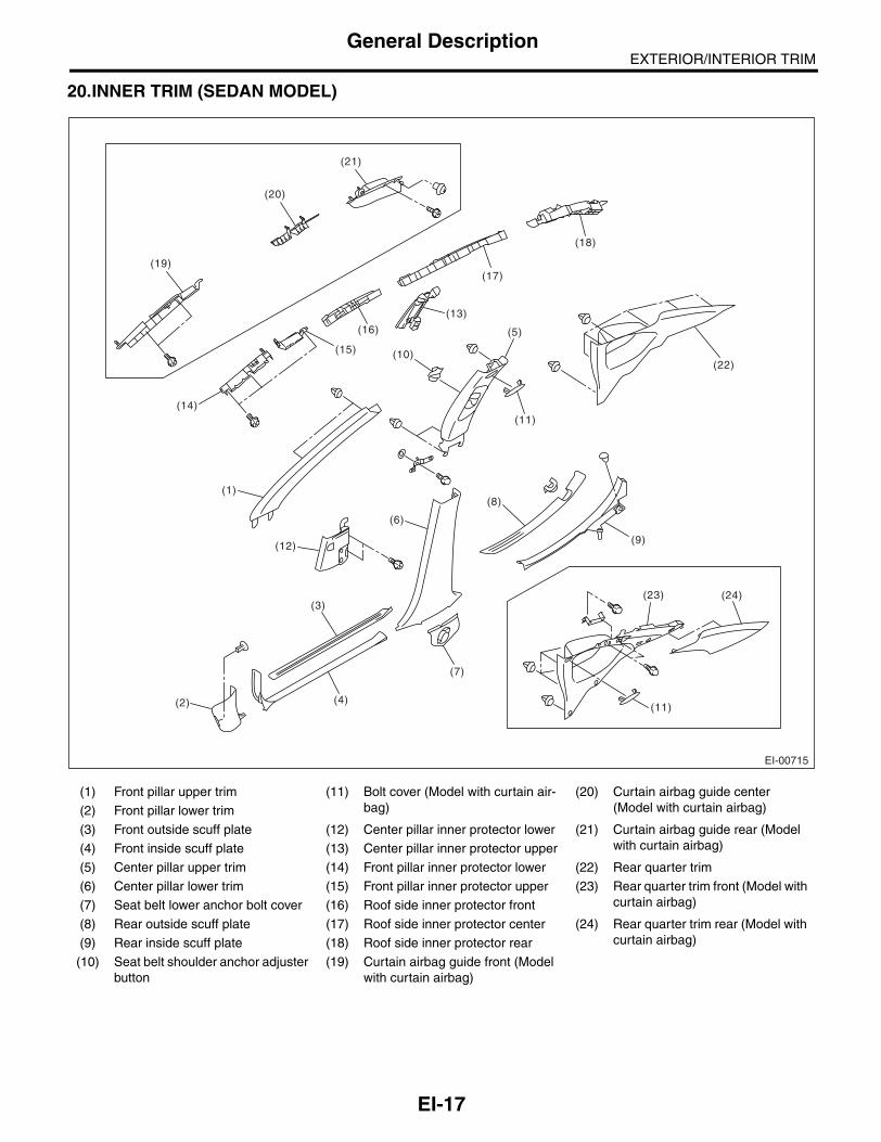
EXTERIOR/INTERIOR TRIMGeneral Description
20.INNER TRIM (SEDAN MODEL)
(1) Front pillar upper trim (11) Bolt cover (Model with curtain air-bag)
(20) Curtain airbag guide center (Model with curtain airbag)(2) Front pillar lower trim
(3) Front outside scuff plate (12) Center pillar inner protector lower (21) Curtain airbag guide rear (Model with curtain airbag)(4) Front inside scuff plate (13) Center pillar inner protector upper
(5) Center pillar upper trim (14) Front pillar inner protector lower (22) Rear quarter trim
(6) Center pillar lower trim (15) Front pillar inner protector upper (23) Rear quarter trim front (Model with curtain airbag)(7) Seat belt lower anchor bolt cover (16) Roof side inner protector front
(8) Rear outside scuff plate (17) Roof side inner protector center (24) Rear quarter trim rear (Model with curtain airbag)(9) Rear inside scuff plate (18) Roof side inner protector rear
(10) Seat belt shoulder anchor adjuster button
(19) Curtain airbag guide front (Model with curtain airbag)
EI-00715
(12)
(14)
(16)
(20)
(21)
(19)
(13)
(11)
(22)
(23) (24)
(11)
(17)
(18)
(10)(15)
(1)
(2)
(3)
(4)
(7)
(6)
(8)
(5)
(9)
EI-17

EXTERIOR/INTERIOR TRIMGeneral Description
21.INNER TRIM (WAGON MODEL)
(1) Front pillar upper trim (11) Bolt cover (Model with curtain air-bag)
(19) Curtain airbag guide front (Model with curtain airbag)(2) Front pillar lower trim
(3) Front outside scuff plate (12) Center pillar inner protector lower (20) Curtain airbag guide center (Model with curtain airbag)(4) Front inside scuff plate (13) Center pillar inner protector upper
(5) Center pillar upper trim (14) Front pillar inner protector lower (21) Curtain airbag guide rear (Model with curtain airbag)(6) Center pillar lower trim (15) Front pillar inner protector upper
(7) Seat belt lower anchor bolt cover (16) Roof side inner protector front (22) Rear quarter front pillar trim
(8) Rear outside scuff plate (17) Roof side inner protector center (23) Rear quarter rear pillar trim
(9) Rear inside scuff plate (18) Roof side inner protector rear (24) Rear quarter lower trim
(10) Seat belt shoulder anchor adjuster button
EI-00716
(12)
(14)
(16)
(20)
(22)
(21)
(19)
(13)
(11)
(11)
(23)
(24)
(17)
(18)
(10)
(15)
(1)
(2)
(3)
(4)
(7)
(6)
(8)
(5)
(9)
EI-18

EXTERIOR/INTERIOR TRIMGeneral Description
22.REAR GATE TRIM
23.ROOF TRIM (SEDAN MODEL)
(1) Rear gate panel upper trim (2) Rear gate panel pillar trim (3) Rear gate panel lower trim
EI-00808
(3)
(2)
(1)
EI-00755
EI-19

EXTERIOR/INTERIOR TRIMGeneral Description
24.ROOF TRIM (WAGON MODEL)
25.TRUNK ROOM TRIM
(1) Trunk lid trim (3) Trunk room mat (5) Combination light cover
(2) Trunk lid arm cover (4) Trunk side trim (6) Trunk room end cover
EI-00756
EI-00722
(1)
(3)
(2)
(4)
(5)
(6)
EI-20

EXTERIOR/INTERIOR TRIMGeneral Description
26.LUGGAGE FLOOR MAT
(1) Front floor mat (4) Center floor mat (7) Luggage floor end cover
(2) Floor box (RH) (5) Side floor mat (RH)
(3) Floor box (LH) (6) Side floor mat (LH)
EI-00757
(1)
(2)
(7)
(3)
(6)
(4)
(5)
EI-21

EXTERIOR/INTERIOR TRIMGeneral Description
27.ROOM INNER PARTS
28.HEAT SHIELD COVER
(1) Room mirror (3) Assist grip Tightening torque: N⋅m (kgf-m, ft-lb)(2) Sun visor (4) Coat hook (Wagon model) T: 7.4 (0.75, 5.46)
(1) Front heat shield cover (5AT model)
(3) Center heat shield cover (Turbo model)
(5) Rear heat shield cover RH
(6) Rear heat shield cover LH
(2) Front heat shield cover (4AT model and MT model)
(4) Center heat shield cover (Non-turbo model)
EI-00789
T
TT
T
T
TT
TE
E
E
(1)
(2)
(3)
(3)
(4)
EI-00798
(5)
(4)(3)
(2)
(1)
(6)
EI-22

EXTERIOR/INTERIOR TRIMGeneral Description
B: PREPARATION TOOLTOOL NAME REMARKS
Clip remover Used for removal of trim.
Clip clamp pliers Used for removal of various clips and clamps.
EI-23

EXTERIOR/INTERIOR TRIMFront Grille
2. Front GrilleA: REMOVAL1) Open the hood.2) Remove the push clips (A) and front grille clips(B) from each side of front grille.
3) Remove the clips on the back side of front grille. 4) Pull lower side of the front grille forward, removehooks (A), and then remove the front grille from ve-hicle body.
B: INSTALLATIONInstall in the reverse order of removal.
(B)(B)
(A) (A)
EI-00551
(A)EI-00552
EI-24

EXTERIOR/INTERIOR TRIMFront Hood Grille
3. Front Hood GrilleA: REMOVAL1) Open the front hood.2) Remove the front hood insulator. <Ref. to EB-13, FRONT HOOD INSULATOR, REMOVAL,Front Hood.>3) Remove the screws (A) and clip (B), and removethe front hood duct.
4) Loosen the nuts (A), remove the clip (B), andthen remove the front hood grille.
B: INSTALLATION1) Fit the clip (B) of front hood grille, and install thefront hood grille using nuts (A).
Tightening torque:4.5 N⋅m (0.46 kgf-m, 3.32 ft-lb)
2) Insert the hooks (B) of the front hood duct intoholes (A) of the front hood.
3) Install the front hood duct with the screws (A)and clip (B).
EI-00632
(B)
(A)
(A)
(A)(B)(A)
EI-00633
(A)(B)(A)
EI-00633
(B)
(A)
EI-00634
EI-00632
(B)
(A)
(A)
EI-25

EXTERIOR/INTERIOR TRIMFront Under Cover
4. Front Under CoverA: REMOVAL1) Lift-up the vehicle.2) Remove the clips (A), (C) and bolts (B) in frontfender, and then remove the front under cover.• Large type (Turbo model)
• Large type (DOHC non-turbo model)
• Small type (SOHC non-turbo model)
B: INSTALLATIONInstall in the reverse order of removal.
Tightening torque:14 N⋅m (1.42 kgf-m, 10.3 ft-lb)
(B)
(C)(A)
EI-00735
(A)
(A)
(B)
(A)
EI-00635
EI-00636
(A)
(B)
(A)
(A)
(A)
EI-26

EXTERIOR/INTERIOR TRIMFloor Under Protector
5. Floor Under ProtectorA: REMOVAL1) Lift-up the vehicle.
NOTE:Plate type lift can not be used.2) Remove the push turn clips (A) and bolts (B),and remove the floor under protector.
B: INSTALLATIONInstall in the reverse order of removal.
EI-00637
(A)(A)
(B)(A)(B)(A)(A)
(B)
(A) (A) (A) (A)(A)
EI-27

EXTERIOR/INTERIOR TRIMFuel Tank Protector
6. Fuel Tank ProtectorA: REMOVAL1) Lift-up the vehicle.2) Remove the bolts (A) and plastic nuts (B), andthen remove the fuel tank protector.
B: INSTALLATIONInstall in the reverse order of removal.
Tightening torque:Bolt
17.5 N⋅m (1.78 kgf-m, 12.9 ft-lb)
EI-00638
(B)(B)
(A)
(A)
(B)(B)
(A) (A)
(A) (A)
EI-28

EXTERIOR/INTERIOR TRIMMud Guard
7. Mud GuardA: REMOVAL1. FRONT MUD GUARD1) Jack-up the vehicle.2) Remove the front wheels.3) Loosen the screws and clips to remove mudguard.
2. REAR MUD GUARD1) Jack-up the vehicle.2) Remove the rear wheels.3) Loosen the screws and clips to remove mudguard.
B: INSTALLATION1. FRONT MUD GUARDInstall in the reverse order of removal.
2. REAR MUD GUARDInstall in the reverse order of removal.
EI-00639
EI-00640
EI-29

EXTERIOR/INTERIOR TRIMFront Bumper
8. Front BumperA: REMOVAL1. FRONT BUMPER FACE1) Disconnect the ground cable from battery.2) Remove the front grille. <Ref. to EI-24, REMOV-AL, Front Grille.>3) Turn over the front mud guard, and remove theclips connecting the fender and bumper.
4) Remove the clips at the lower side of bumper.
5) Disconnect the fog light connector. (Model withfog light)6) Remove the bumper from vehicle body.7) Remove the fog light from bumper face. <Ref. toLI-21, REMOVAL, Front Fog Light Assembly.>
2. FRONT BUMPER BEAM ASSEMBLY1) Disconnect the ground cable from battery.2) Remove the front grille. <Ref. to EI-24, REMOV-AL, Front Grille.>3) Remove the front bumper face. <Ref. to EI-30,FRONT BUMPER FACE, REMOVAL, FrontBumper.>4) Remove the energy absorber foam from bumperbeam.
5) Remove the bolts, and remove the bumperbeam assembly from vehicle body.
NOTE:After all bolts are removed, raise the whole bumperbeam a little to remove it from vehicle body.6) Remove the bolts and nuts, and disassemble thebumper beam.
EI-00572
EI-00573
EI-00575
EI-00576
EI-00577
EI-30

EXTERIOR/INTERIOR TRIMFront Bumper
7) Remove the clips, and remove the radiatorguide.
8) Remove the bolts and clips, and remove thebumper lower center bracket.
B: INSTALLATION1. FRONT BUMPER FACE1) Install in the reverse order of removal.2) Fit the slider (A) to the guide plate (B) securely.
2. FRONT BUMPER BEAM ASSEMBLYInstall in the reverse order of removal.
Tightening torque:Refer to “COMPONENT” of “General Descrip-tion”. <Ref. to EI-5, FRONT BUMPER, COM-PONENT, General Description.>
EI-00801
EI-00578
EI-00571
(B)
(A)
EI-31

EXTERIOR/INTERIOR TRIMFront Bumper
C: REPAIR1. COATING METHOD FOR PP BUMPER
Process No.
Process name Job contents
1 Bumper installationPlace the bumper on a paint worktable as required. Use the paint worktable conforming to inner shape of bumper when possible.
(1) Bumper(2) Set bumper section
2 MaskingMask specified part (black base) with masking tape. Use masking tape for PP (example, Nichiban No. 533, etc.).
3Degreasing, clean-ing
Clean all parts to be painted with white gasoline, normal alcohol, etc. to remove dirt, oil, fat, etc.
4 Primer paint Apply primer to all parts to be painted, using spray gun. Use primer (clear).
5 DryingDry at normal temperature [10 — 15 min. at 20°C (68°F)].In half-dried condition, PP primer paint is dissolved by solvent, e.g. thinner, etc.Therefore, if dust or dirt must be removed, use ordinary alcohol, etc.
6 Top coat paint (I)
Non-colored Metallic paint
Use section (block) paint for top coat.• Paint to be used (for each color):Solid paintHardener PBThinner T-301• Mixing ratio:Main agent vs. hardener = 4:1• Viscosity: 10 — 13 sec./20°C (68°F)• Film thickness: 35 — 45 µ• Spraying pressure: 245 — 343 kPa
(2.5 — 3.5 kg/cm2, 36 — 50 psi)
Use section (block) paint for top coat.• Paint to be used (for each color):Metallic paintHardener PBThinner T-306• Mixing ratio:Main agent vs. hardener = 10:1• Viscosity: 10 — 13 sec./20°C (68°F)• Film thickness: 15 — 20 µ• Spraying pressure: 245 — 343 kPa
(2.5 — 3.5 kg/cm2, 36 — 50 psi)
7 Drying Not required.Dry at normal temperature [more than 10 min. at 20°C (68°F)].In half-dried condition, avoid dust, dirt.
8 Top coat paint (II) Not required.
Apply a clear coat to parts with top coat paint (I), three times, at 5 — 7 minutes intervals.• Paint to be used:Metallic paintHardener PBThinner T-301• Mixing ratio:Clear coat vs. hardener = 6:1• Viscosity: 14 — 16 sec./20°C (68°F)• Film thickness: 25 — 30 µ• Spraying pressure: 245 — 343 kPa
(2.5 — 3.5 kg/cm2, 36 — 50 psi)
9 Drying60°C (140°F), 60 min. or 80°C (176°F), 30 min.If higher than 80°C (176°F), PP may be deformed. Keep maximum temperature at 80°C (176°F).
10 Inspection Paint check.
11 Masking removal Remove masking tape applied in process No. 2.
EI-00234(2)
(1)
EI-32

EXTERIOR/INTERIOR TRIMFront Bumper
2. REPAIR INSTRUCTIONS FOR COLORED PP BUMPER
NOTE:All PP bumpers are provided with a grained surface, and if the surface is damaged, it cannot normally be re-stored to its former condition. Damages limited to the shallow scratches that cause only a change in the lusterof the base material or coating, can be almost fully restored. Before repairing a damaged area, explain thispoint to the customer and obtain an understanding about the matter. Repair methods are outlined below,based on a classification of the extent of damage.1) Minor damage causing only a change in the lustre of the bumper due to a light touchAlmost restorable.
2) Deep damage caused by scratching with fences, etc.A dent cannot be repaired but a whitened or swelled part can be removed.
Process No.
Process name Job contents
1 Cleaning Clean the area to be repaired using water.
2 Sanding Grind the repairing area with #500 sand paper in a “feathering” motion.
3 Finish
Resin section Coated section
Repeatedly apply wax to the affected area using a soft cloth (such as flannel). Recom-mended wax: NITTO KASEI Soft 99 TIRE WAX BLACK, or equivalent.
Perform either the same process as for the resin section or process No. 18 and subse-quent in the “3)” section, depending on the degree and nature of damage.Polish the waxed area with a clean cloth after 5
to 10 minutes.
Process No.
Process name Job contents
1 Cleaning Clean damaged area with water.
2Removal of dam-aged area
Cut off protruding area, if any, due to collision, using a putty knife.
3 Sanding Grind the affected area with #100 to #500 sand paper.
4 FinishResin section Coated section
Same as Process No. 3 in the “1)” section.Perform Process No. 12 and subsequent oper-ations in the “3)” section.
EI-33
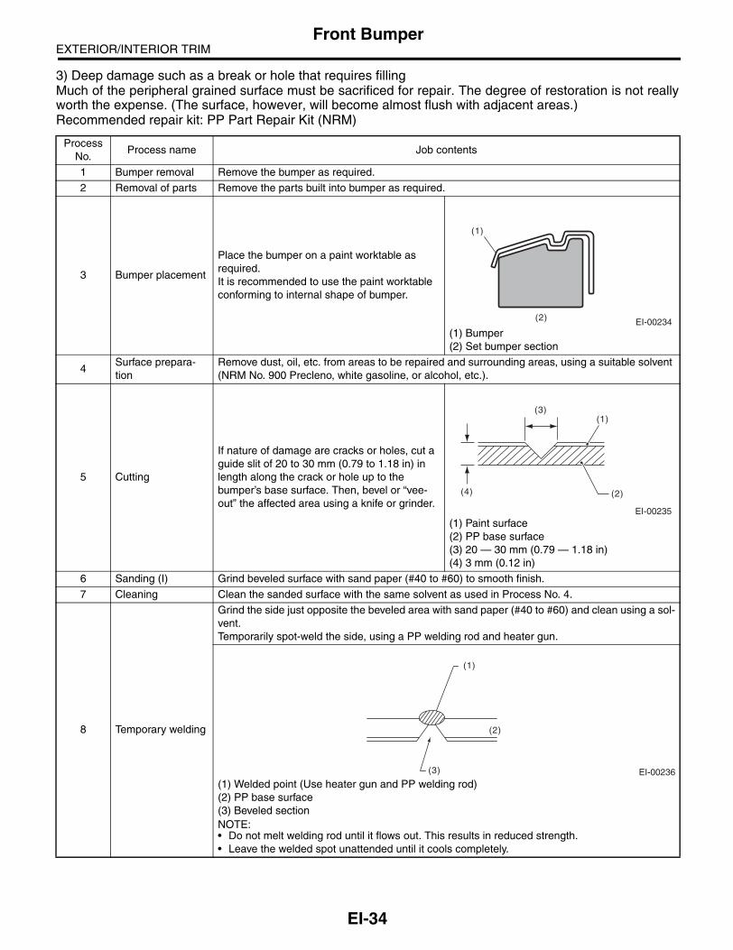
EXTERIOR/INTERIOR TRIMFront Bumper
3) Deep damage such as a break or hole that requires fillingMuch of the peripheral grained surface must be sacrificed for repair. The degree of restoration is not reallyworth the expense. (The surface, however, will become almost flush with adjacent areas.)Recommended repair kit: PP Part Repair Kit (NRM)
Process No.
Process name Job contents
1 Bumper removal Remove the bumper as required.
2 Removal of parts Remove the parts built into bumper as required.
3 Bumper placement
Place the bumper on a paint worktable as required.It is recommended to use the paint worktable conforming to internal shape of bumper.
(1) Bumper(2) Set bumper section
4Surface prepara-tion
Remove dust, oil, etc. from areas to be repaired and surrounding areas, using a suitable solvent (NRM No. 900 Precleno, white gasoline, or alcohol, etc.).
5 Cutting
If nature of damage are cracks or holes, cut a guide slit of 20 to 30 mm (0.79 to 1.18 in) in length along the crack or hole up to the bumper’s base surface. Then, bevel or “vee- out” the affected area using a knife or grinder.
(1) Paint surface(2) PP base surface(3) 20 — 30 mm (0.79 — 1.18 in)(4) 3 mm (0.12 in)
6 Sanding (I) Grind beveled surface with sand paper (#40 to #60) to smooth finish.
7 Cleaning Clean the sanded surface with the same solvent as used in Process No. 4.
8 Temporary welding
Grind the side just opposite the beveled area with sand paper (#40 to #60) and clean using a sol-vent.Temporarily spot-weld the side, using a PP welding rod and heater gun.
(1) Welded point (Use heater gun and PP welding rod)(2) PP base surface(3) Beveled sectionNOTE:• Do not melt welding rod until it flows out. This results in reduced strength.• Leave the welded spot unattended until it cools completely.
EI-00234(2)
(1)
EI-00235
(4) (2)
(1)(3)
EI-00236
(1)
(2)
(3)
EI-34

EXTERIOR/INTERIOR TRIMFront Bumper
9 Welding
Using a heater gun and PP welding rod, weld the beveled spot while melting the rod and dam-aged area.
(1) Welding rod(2) Melt hatched area(3) SectionNOTE:• Melt the sections indicated by hatched area.• Do not melt the welding rod until it flows out, in order to provide strength.• Always keep the heater gun 1 to 2 cm (0.4 to 0.8 in) away from the welding spot.• Leave the welded spot unattended until it cools completely.
10 Sanding (II)
Remove excess part of weld with a putty knife. If a drill or disc wheel is used instead of the knife, operate it at a rate lower than 1,500 rpm and grind the excess part little by little. A higher rpm will cause the PP substrate to melt from the heat.
Sand the welded spot smooth with #240 sand paper.
11 MaskingMask the black substrate section using masking tape.Recommended masking tape: Nichiban No. 533 or equivalent
12Cleaning/ degreas-ing
Completely clean the entire coated area, using solvent similar to that used in Process No. 4.
13 Primer coating
Apply a coat of primer to the repaired surface and its surrounding areas. Mask these areas, if necessary.Recommended primer: Mp/ 364 PP PrimerNOTE:Be sure to apply coat of primer at a spraying pressure of 245 — 343 kPa (2.5 — 3.5 kg/cm2, 36— 50 psi) with a spray gun.
14 Leave unattended
Leave the repaired area unattended at 20°C (68°F) for 10 to 15 minutes until primer is half-dry.NOTE:If dirt or dust comes in contact with the coated area, wipe it off with a cloth with alcohol. (Do notuse thinner since the coated area tends to melt.)
15Primer surfacer coating
Apply a coat of primer surfacer to the repaired area two or three times at an interval of 3 to 5 min-utes.Recommended surfacer:• UPS 300 Flex Primer• No. 303 UPS 300 Exclusive hardener• NPS 725 Exclusive Reducer (thinner)• Mixing ratio:2 : 1 (UPS 300 : No. 303)• Viscosity: 12 — 14 sec./20°C (68°F)• Coating film thickness: 40 — 50 µ
Process No.
Process name Job contents
(1)
(2)
(2)
(3)
EI-00237
EI-00042
EI-35

EXTERIOR/INTERIOR TRIMFront Bumper
16 Drying Allow the coated surface to dry for 20 minutes at 20°C (68°F) [or 30 minutes at 60°C (140°F)].
17 Sanding (III) Sand the coated surface and its surrounding areas using #400 sand paper and water.
18Cleaning/ degreas-ing
Same as Process No. 12.
19 Top coat (I)
Non-colored Metallic paint
Use a “block” coating method.• Recommended paint:Suncryl (SC)No. 307 Flex HardenerSC Reducer (thinner)• Mixing ratio:Suncryl (SC) vs. No. 307 Flex Hardener = 3 : 1• Viscosity: 11 — 13 sec./20°C (68°F)• Coating film thickness: 40 — 50 µ• Spraying pressure: 245 — 343 kPa
(2.5 — 3.5 kg/cm2, 36 — 50 psi)
Use a “block” coating method.• Recommended paint:Suncryl (SC)No. 307 Flex HardenerSC Reducer (thinner)• Mixing ratio:Suncryl (SC) vs. No. 307 Flex Hardener = 3 : 1• Viscosity: 11 — 13 sec./20°C (68°F)• Coating film thickness: 20 — 30 µ• Spraying pressure: 245 — 343 kPa
(2.5 — 3.5 kg/cm2, 36 — 50 psi)
20 Leave unattended Not required.
Leave unattended at 20°C (68°F) for at least 10 minutes until the topcoated area is half-dry.NOTE:Be careful to keep dust or dirt from coming incontact with the affected area.
21 Top coat (II) Not required.
Apply a clear coat three times at an interval of 3 to 5 minutes.• Recommended paint:SC710 Overlay ClearNo. 307 Flex HardenerSC Reducer (thinner)• Mixing ratio:Suncryl (SC) vs. No. 307 Flex Hardener = 3 : 1• Viscosity: 10 — 13 sec./20°C (68°F)• Coating film thickness: 20 — 30 µ• Spraying pressure: 245 — 343 kPa
(2.5 — 3.5 kg/cm2, 36 — 50 psi)
22 DryingAllow the coated surface to dry for 2 hours at 20°C (68°F) or 30 minutes at 60°C (140°F).NOTE:Do not allow the temperature to exceed 80°C (176°F) since this will deform the PP substrate.
23 Inspection Carefully check the condition of the repaired area.
24 Masking removal Remove the masking tape applied in Process No. 11 and 13.
25 Parts installation Install parts on the bumper in reverse order of removal.
26 Bumper installation Install the bumper.
Process No.
Process name Job contents
EI-36

EXTERIOR/INTERIOR TRIMRear Bumper
9. Rear BumperA: REMOVAL1. REAR BUMPER FACE1) Disconnect the ground cable from battery.2) Remove the rear combination light assembly.<Ref. to LI-25, REMOVAL, Rear Combination LightAssembly.>3) Remove the two clips.
4) Turn over the mud guard, and remove the bolt(A) inside wheel house, and the clips (B) on thelower side of bumper.
5) Remove the clips on the lower side of rearbumper.
6) Remove the service hole cover, and remove thebolt.
• Sedan model: trunk side trim
• Wagon model: rear quarter lower trim
NOTE:For model with McIntosh Audio, remove the woofercover.
7) Remove the rear bumper from vehicle body.
NOTE:• Do not pull with a excessive force. Otherwise thebracket installation area may be damaged.• Remove from the end in order.
EI-00579
EI-00580
(A)
(B)
EI-00581
EI-00583
EI-00584
EI-00585
EI-00802
EI-37

EXTERIOR/INTERIOR TRIMRear Bumper
2. REAR BUMPER BRACKET1) Remove the rear bumper face from vehiclebody.2) Remove the rear bumper bracket corner fromvehicle body. (both sides)
3) Remove the lower brackets from vehicle body.• Sedan model: 2 places
• Wagon model: 4 places
3. REAR BUMPER BEAM ASSEMBLY1) Disconnect the ground cable from battery.2) Remove the rear bumper face. <Ref. to EI-37,REAR BUMPER FACE, REMOVAL, RearBumper.>
3) Remove the nuts, and remove the beam mainreinforcement from vehicle body.
4) Remove the nuts, and remove the bumper beambracket and beam upper rear from vehicle body.
B: INSTALLATION1. REAR BUMPER FACE1) Install the beam upper rear to vehicle body.2) Install the bumper face to vehicle body.
NOTE:If the bumper face is easily come off the beam up-per rear, adjust the hook area of the bracket side.3) Install in the reverse order of removal.
Tightening torque:Refer to “COMPONENT” of “General Descrip-tion”.<Ref. to EI-6, REAR BUMPER (SEDAN MOD-EL), COMPONENT, General Description.>
2. REAR BUMPER BRACKETInstall in the reverse order of removal.
3. REAR BUMPER BEAM ASSEMBLYInstall in the reverse order of removal.
C: REPAIRRefer to the description for front bumper repair.<Ref. to EI-30, REMOVAL, Front Bumper.>
EI-00587
EI-00641
EI-00588
EI-00803
EI-00804
EI-38

EXTERIOR/INTERIOR TRIMCowl Panel
10.Cowl PanelA: REMOVAL1) Open the hood.2) Remove the wiper arm. <Ref. to WW-17, RE-MOVAL, Front Wiper Arm.>3) Remove the weather strip clip, and remove theweather strip.
NOTE:If the weather strip clip is removed with excessiveforce, the weather strip may be damaged. Be sureto use a clip remover to remove.
4) Remove the clip, and remove the cover cowlpanel.
5) Remove the cowl panel side and clip (A).
6) Remove the clips (A), and remove the cowl pan-el.
B: INSTALLATIONInstall in the reverse order of removal.
EI-00642
EB-00141
EI-00643
EI-00790
(A)
:(A) EI-00644
EI-39

EXTERIOR/INTERIOR TRIMRoof Spoiler
11.Roof SpoilerA: REMOVAL1) Disconnect the ground cable from battery.2) Remove the rear gate trim. <Ref. to EI-69, RE-MOVAL, Rear Gate Trim.>3) Disconnect the connector of the high mountedstop light and the washer hose of rear washer.4) Remove the cap nut and plastic caps.
5) Remove the clips, and remove the roof spoiler.
B: INSTALLATIONInstall in the reverse order of removal.
Tightening torque:4.5 N⋅m (0.46 kgf-m, 3.32 ft-lb)
EI-00828
EI-00646
EI-40

EXTERIOR/INTERIOR TRIMSide Sill Spoiler
12.Side Sill SpoilerA: REMOVALRemove the clips (two for front fender arch area, six for side sill spoiler lower area), and remove the sidespoiler.
B: INSTALLATIONInstall in the reverse order of removal.
NOTE:For the rearmost clip securing side sill spoiler, in-stall through the end cover.
(1) Side sill spoiler (2) Double-sided tape (3) End cover
EI-00733
(1)
(2)
(3)
(1) Vehicle body
(2) End cover
(3) Side sill spoiler
(1)
EI-00791
(2)
(3)
EI-41

EXTERIOR/INTERIOR TRIMSide Protector
13.Side ProtectorA: REMOVAL
1) Slide in a thin thread (A) of 0.8 mm (0.031 in) di-ameter or less (fishing line etc.) between body andprotector, cut the double-sided tape, and pull theprotector toward you, and remove the clip using clipremover.
NOTE:• To optimize the effect of solvent, slide the threadalong body without removing the double-sided tapeon the surface of body and spoiler.• If it is difficult to detach the double-sided tape,warm up to approx. 40°C (104°F).
• If the double-sided tape remains thick on the sur-face due to interfacial peeling, apply the solvent af-ter slicing off the double-sided tape using a cutter.
2) Apply masking tape around the double-sidedtape remaining on the surface of body or spoiler.3) Apply solvent uniformly on double-sided tape us-ing a brush.
CAUTION:• Do not use the solvent to the body which isrepaired with lacquer paint.• Wipe off immediately when the solvent istouched on surface of the body or spoiler.
Solvent:3M 8907 or equivalent
(1) Front door protector (2) Rear door protector
EI-00829
(1)
(2)
EI-00153
(A)
(A) Panel
(B) Side protector
(C) Double-sided tape
EI-00478(A) (B) (C)
EI-42

EXTERIOR/INTERIOR TRIMSide Protector
4) Cover the area where solvent is applied usingplastic wrap (A), and then heat the double-sidedtape for 5 to 10 minutes in 40 — 60°C (104 —140°F) using a heat lamp (B).
CAUTION:Do not heat the double-sided tape until the sur-face becomes white and excessively dried.5) Remove the double-sided tape using a plasticspatula.6) After completely removing the double-sidedtape, detach the masking tape and clean the sur-face using a cotton cloth damped with white gaso-line.
B: INSTALLATION1) Apply primer to the protector surface where thedouble-sided tape to be adhered, and then adherethe double-sided tape as shown in the figure.
Primer:3M K-500 or equivalent
Double-sided tape:3M 5531-5 or equivalent
2) Heat the adhering part using a heat lamp.Body side: 40 — 60°C (104 — 140°F)Protector side: 20 — 30°C (68 — 86°F)3) Detach the double-sided tape backing sheet,align the clip position, and then adhere to the bodyusing care to avoid air entering.
CAUTION:To keep the adhesion, do not wash the vehicle within 24 hours from installation.
(1) Double-sided tape: thickness 1.2 mm (0.047 in), width 5mm (0.197 in)
EI-00155
(A)
(B)
EI-00156
(A)
(B)
EI-00536
(1) (1)
EI-43

EXTERIOR/INTERIOR TRIMSide Garnish
14.Side GarnishA: REMOVAL
For removal of side garnish, refer to the removal procedure of “Side Protector”. <Ref. to EI-42, REMOVAL,Side Protector.>
EI-00805
EI-44

EXTERIOR/INTERIOR TRIMRear Quarter Protector
15.Rear Quarter ProtectorA: REMOVAL1) Remove the side sill spoilers. <Ref. to EI-41, RE-MOVAL, Side Sill Spoiler.>2) Remove the clips (A) with rotating it rearward us-ing the fender arch as a fulcrum, and then removethe rear quarter protector.
B: INSTALLATIONInstall in the reverse order of removal.
EI-00734 : (A)
EI-45

EXTERIOR/INTERIOR TRIMRoof Molding
16.Roof MoldingA: REMOVAL1) Disconnect the ground cable from battery.2) Remove the roof carrier attachment cover, andremove the bolts. (2 places for each side)
3) Pull the roof molding upward, and remove it fromvehicle body.
4) Remove the roof trim. <Ref. to EI-67, REMOV-AL, Roof Trim.>
5) Remove the nuts, and remove the roof carrier at-tachment.
B: INSTALLATIONInstall in the reverse order of removal.
CAUTION:Replace the clip with new one when the broken pin grommet is found during the removal of roof molding. When the body side cap or clip is damaged, or the roof molding is lifted or peeled from body, be sure to repair them correctly, be-cause those troubles may cause the water leak-age.
Tightening torque:7.5 N⋅m (0.76 kgf-m, 5.5 ft-lb)
(1) Locating pin
(2) Roof molding
(3) Cap
(4) Clip
(5) Grommet
EI-00658
EI-00660
(1)
(2)
(4)(3)
(5)
EI-00659
EI-46

EXTERIOR/INTERIOR TRIMRoof Rail
17.Roof RailA: REMOVAL1) Remove the roof trim. <Ref. to EI-67, REMOVAL, Roof Trim.>2) Remove the six nuts.
B: INSTALLATIONInstall in the reverse order of removal.
CAUTION:When removing or installing the roof rail, be careful not to scratch the body panel with the stud bolt of roof rail.
Tightening torque:7.5 N⋅m (0.76 kgf-m, 5.53 ft-lb)
EI-00834
(A) (B)
(C) (D) (E) (F)
AB
CD
E F
EI-47

EXTERIOR/INTERIOR TRIMDoor Trim
18.Door TrimA: REMOVAL1) Disconnect the ground cable from battery.2) Remove the cover (A) at inner remote area.
3) Pull the hand grip cover toward you, and removeit.
4) Loosen the screws.
5) Remove the clips, and disconnect each connec-tor and wire to remove door trim.• Front door trim
• Rear door trim
B: INSTALLATIONInstall in the reverse order of removal.
NOTE:Be careful not to install the hand grip cover andplate clip of hand grip in the wrong direction.• Hand grip cover (front and rear door)Convex upward
• Bottom clip of the front door faces the oppositedirection
EI-00649
(A)
EI-00650
EI-00651
EI-00652
EI-00656
EI-00653
EI-00654
EI-48

EXTERIOR/INTERIOR TRIMDoor Trim
• Lower side of the hand grip cover for front doorhas pawl part.• The lowest clip of rear door faces the opposite di-rection
EI-00655
EI-49

EXTERIOR/INTERIOR TRIMInstrument Panel Lower Cover
19.Instrument Panel Lower Cov-er
A: REMOVAL1) Disconnect the ground cable from battery.2) Remove the front door inside scuff plate (A) andfront pillar lower trim (B). <Ref. to EI-60, REMOV-AL, Lower Inner Trim.>
3) Remove the clips, and remove the instrumentpanel lower cover under.
4) Loosen the screw (A), disconnect the connec-tors, and remove the instrument panel lower coverupper.
B: INSTALLATIONInstall in the reverse order of removal.
(B) Clip
EI-00758
(B)
(A)
EI-00759
EI-00760(A):(B)
EI-50
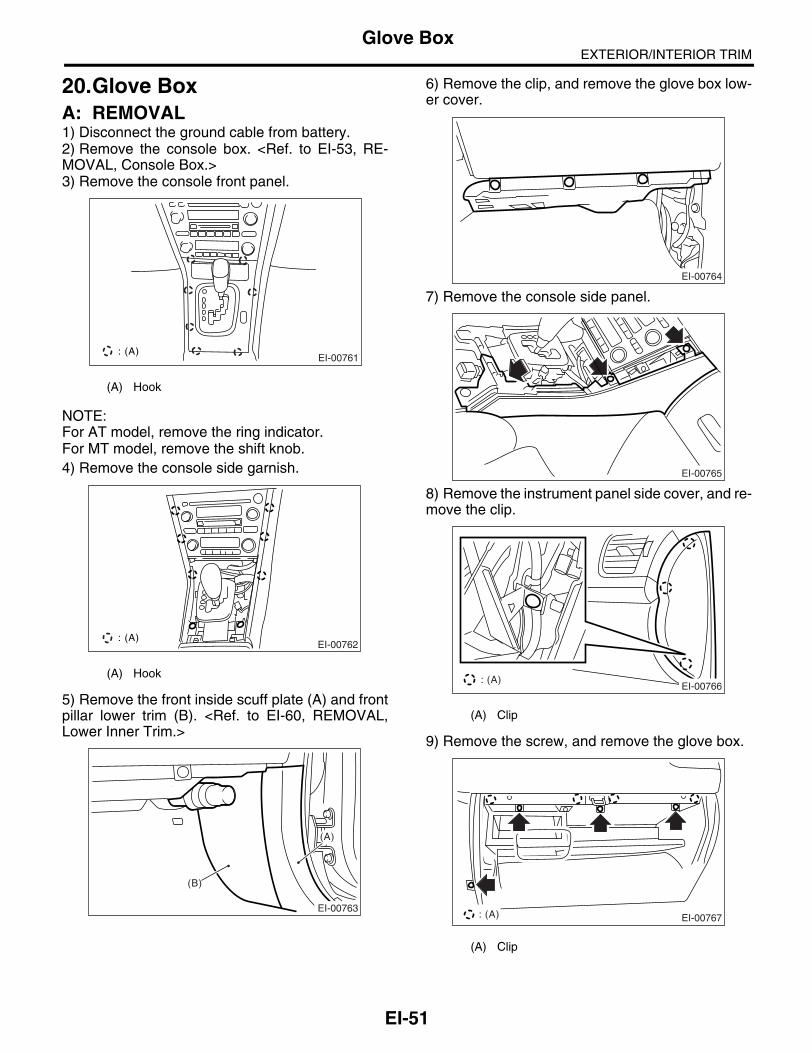
EXTERIOR/INTERIOR TRIMGlove Box
20.Glove BoxA: REMOVAL1) Disconnect the ground cable from battery.2) Remove the console box. <Ref. to EI-53, RE-MOVAL, Console Box.>3) Remove the console front panel.
NOTE:For AT model, remove the ring indicator.For MT model, remove the shift knob.4) Remove the console side garnish.
5) Remove the front inside scuff plate (A) and frontpillar lower trim (B). <Ref. to EI-60, REMOVAL,Lower Inner Trim.>
6) Remove the clip, and remove the glove box low-er cover.
7) Remove the console side panel.
8) Remove the instrument panel side cover, and re-move the clip.
9) Remove the screw, and remove the glove box.
(A) Hook
(A) Hook
EI-00761: (A)
EI-00762: (A)
EI-00763
(B)
(A)
(A) Clip
(A) Clip
EI-00764
EI-00765
: (A)EI-00766
EI-00767 : (A)
EI-51

EXTERIOR/INTERIOR TRIMGlove Box
B: INSTALLATIONInstall in the reverse order of removal.
EI-52

EXTERIOR/INTERIOR TRIMConsole Box
21.Console BoxA: REMOVAL1) Disconnect the ground cable from battery.2) Remove the parking brake lever cover.
3) Remove the bolts and clips.
4) Disconnect the connector, and remove the con-sole box.
B: INSTALLATIONInstall in the reverse order of removal.
EI-00810
EI-00811
EI-53

EXTERIOR/INTERIOR TRIMCenter Console
22.Center ConsoleA: REMOVAL1) Disconnect the ground cable from battery.2) Remove the console box. <Ref. to EI-53, RE-MOVAL, Console Box.>3) Remove the console front panel.
NOTE:For AT model, remove the ring indicator.For MT model, remove the shift knob.4) Loosen the screw, remove the hook, and re-move the console side garnish.
5) Remove the instrument panel lower cover. <Ref.to EI-50, REMOVAL, Instrument Panel Lower Cov-er.>
6) Remove the clip at the console side panel tip.
7) Remove the passenger side front inside scuffplate (A) and front pillar lower trim (B). <Ref. to EI-60, REMOVAL, Lower Inner Trim.>
8) Remove the clip, and remove the glove box low-er cover.
(A) Hook
(A) Hook
EI-00761: (A)
EI-00762: (A)
EI-00768
EI-00769
EI-00763
(B)
(A)
EI-00764
EI-54

EXTERIOR/INTERIOR TRIMCenter Console
9) Remove the screws, and remove the consoleside panel.
10) Loosen the screws to pull out the audio unit as-sembly, and disconnect the connector to removeaudio unit.
NOTE:Audio unit assembly can be removed without re-moving the console side panel.
B: INSTALLATIONInstall in the reverse order of removal.
EI-00770
EI-00794
EI-55

EXTERIOR/INTERIOR TRIMInstrument Panel Assembly
23.Instrument Panel AssemblyA: REMOVAL1. INSTRUMENT PANEL (EXCLUDING STEERING SUPPORT BEAM)
CAUTION:Be careful to the harness of airbag system when servicing the instrument panel. Damage may cause the system malfunction.1) Disconnect the ground cable from battery.2) Remove the front pillar upper trim. <Ref. to EI-62, REMOVAL, Upper Inner Trim.>3) Remove the console box. <Ref. to EI-53, RE-MOVAL, Console Box.>4) Remove the center console. <Ref. to EI-54, RE-MOVAL, Center Console.>5) Remove the instrument panel lower cover. <Ref.to EI-50, REMOVAL, Instrument Panel Lower Cov-er.>6) Remove the glove box. <Ref. to EI-51, REMOV-AL, Glove Box.>7) Remove the combination meter assembly. <Ref.to IDI-16, REMOVAL, Combination Meter Assem-bly.>8) Remove the screws.
9) Remove the driver side instrument panel sidecover, and remove the screws.
10) Remove the screw at the side of center con-sole.
11) Remove the center air vent grille of instrumentpanel. <Ref. to AC-44, CENTER GRILLE, REMOV-AL, Air Vent Grille.>12) Remove the screws.
13) Remove the screws at side of passenger sideinstrument panel.
14) Remove the bolts securing passenger side air-bag module to the steering support beam.
15) Disconnect the connectors, and remove the in-strument panel from vehicle body.
EI-00605
EI-00609
EI-00771
EI-00772
EI-00773
EI-00610
EI-56
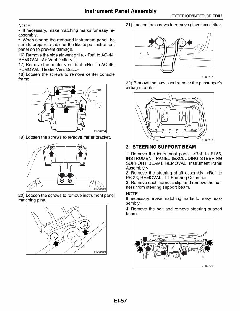
EXTERIOR/INTERIOR TRIMInstrument Panel Assembly
NOTE:• If necessary, make matching marks for easy re-assembly.• When storing the removed instrument panel, besure to prepare a table or the like to put instrumentpanel on to prevent damage.16) Remove the side air vent grille. <Ref. to AC-44,REMOVAL, Air Vent Grille.>17) Remove the heater vent duct. <Ref. to AC-46,REMOVAL, Heater Vent Duct.>18) Loosen the screws to remove center consoleframe.
19) Loosen the screws to remove meter bracket.
20) Loosen the screws to remove instrument panelmatching pins.
21) Loosen the screws to remove glove box striker.
22) Remove the pawl, and remove the passenger’sairbag module.
2. STEERING SUPPORT BEAM1) Remove the instrument panel. <Ref. to EI-56,INSTRUMENT PANEL (EXCLUDING STEERINGSUPPORT BEAM), REMOVAL, Instrument PanelAssembly.>2) Remove the steering shaft assembly. <Ref. toPS-23, REMOVAL, Tilt Steering Column.>3) Remove each harness clip, and remove the har-ness from steering support beam.
NOTE:If necessary, make matching marks for easy reas-sembly.4) Remove the bolt and remove steering supportbeam.
EI-00774
EI-00612
EI-00613
EI-00614
EI-00615
EI-00775
EI-57

EXTERIOR/INTERIOR TRIMInstrument Panel Assembly
5) Remove the steering support beam bracket.
3. INSTRUMENT PANEL ASSEMBLY (IN-CLUDING STEERING SUPPORT BEAM)
CAUTION:Be careful to the harness of airbag system when servicing the instrument panel. Damage may cause the system malfunction.1) Remove the front pillar upper trim. <Ref. to EI-62, REMOVAL, Upper Inner Trim.>2) Remove the center console. <Ref. to EI-54, RE-MOVAL, Center Console.>3) Remove the instrument panel lower cover. <Ref.to EI-50, REMOVAL, Instrument Panel Lower Cov-er.>4) Remove the glove box. <Ref. to EI-51, REMOV-AL, Glove Box.>5) Remove the steering shaft assembly. <Ref. toPS-23, REMOVAL, Tilt Steering Column.>6) Remove the driver side instrument panel sidecover, and remove the bolts.
7) Remove the bolts at the side of passenger sideinstrument panel.
8) Loosen the bolts on the center console side.
9) Disconnect each connector, and remove the in-strument assembly.
NOTE:If necessary, make matching marks for easy reas-sembly.
B: INSTALLATION1. INSTRUMENT PANEL (EXCLUDING STEERING SUPPORT BEAM)1) Insert the matching pins (3 places) on the instru-ment panel tip into the grommet (A) and (B) on thebody panel side.
2) Check the inserted state of matching pins, andpull the harness around.3) Tighten the instrument panel with screw, and re-check the installation of instrument panel and thestate of pulled harness.4) Install in the reverse order of removal.
2. STEERING SUPPORT BEAM1) Temporarily tighten the steering support beamwith bolt, and pull the harness around.2) Make sure that there is no mutual interference ineach pedal, and tighten the each bolt.
Tightening torque:25 N⋅m (25.5 kgf-m, 18.4 ft-lb)
3) Install in the reverse order of removal.
EI-00617
EI-00776
EI-00777
EI-00620
EI-00621
(B)(B) (A)
EI-58

EXTERIOR/INTERIOR TRIMInstrument Panel Assembly
3. INSTRUMENT PANEL ASSEMBLY (IN-CLUDING STEERING SUPPORT BEAM)1) Insert the matching pins (3 places) on the instru-ment panel tip into the grommet (A) and (B) on thebody panel side.
2) Check the inserted state of matching pins, andpull the harness around.3) Temporarily tighten the steering support beamwith bolt, and pull the harness around.4) Make sure that there is no mutual interference ineach pedal, and tighten the each bolt.
Tightening torque:25 N⋅m (25.5 kgf-m, 18.4 ft-lb)
5) Install in the reverse order of removal.
EI-00621
(B)(B) (A)
EI-59

EXTERIOR/INTERIOR TRIMLower Inner Trim
24.Lower Inner TrimA: REMOVAL1) Remove the hook, and remove the inside scuffplate.
2) Remove the door molding (A), and remove theoutside scuff plate.
3) Remove the clip (A), and remove the front pillarlower trim.
4) Remove the rear seat cushion. <Ref. to SE-14,REMOVAL, Rear Seat.>
5) Remove the clip (A), and remove the inside scuffplate.
6) Remove the door molding (A) and door catchercover (B), and then remove the outside scuff plate.
7) Remove the clips of the center pillar lower trim.
(A) Hook
(B) Clip
EI-00778: (A)
(A)
EI-00779: (B)
(A)
EI-00780
(B) Hook
(C) Hook with plate clip
(D) Clip
(A)
EI-00781: (B)
EI-00782
(A)
:(C) :(D)(B)
EI-00783
EI-60

EXTERIOR/INTERIOR TRIMLower Inner Trim
8) Remove the center pillar lower trim while push-ing the pawl part on the upper and lower side ofdropout prevention clip.
B: INSTALLATIONInstall in the reverse order of removal.
EI-00784
EI-61

EXTERIOR/INTERIOR TRIMUpper Inner Trim
25.Upper Inner TrimA: REMOVAL1) From the top side of trim, remove the metal clipusing flat tip driver.
CAUTION:When metal clip is removed from upper inner trim, replace the both of upper inner trim and metal clip with new ones.2) Remove the front pillar upper trim.
3) Remove the front inside scuff plate, rear insidescuff plate and center pillar lower trim. <Ref. to EI-60, REMOVAL, Lower Inner Trim.>4) Remove the cap on the upper side of pillar trim,and remove the bolt inside. (Model with curtain air-bag)
5) Remove the center pillar upper trim.
6) Remove the seat belt lower anchor bolt cover.
7) Remove the seat belt lower anchor bolt, and pullout the seat belt from center pillar upper trim.
B: INSTALLATIONInstall in the reverse order of removal.
EI-00785
EI-00786
EI-00562
(A) Clip
EI-00787
EI-00788: (A)
SB-00145
EI-62

EXTERIOR/INTERIOR TRIMRear Quarter Trim
26.Rear Quarter TrimA: REMOVAL1. SEDAN MODEL (MODEL WITHOUT CURTAIN AIRBAG)1) Remove the rear seat. <Ref. to SE-14, SEDANMODEL, REMOVAL, Rear Seat.>2) Remove the rear quarter trim.
2. SEDAN MODEL (MODEL WITH CURTAIN AIRBAG)1) Remove the rear seat. <Ref. to SE-14, WAGONMODEL, REMOVAL, Rear Seat.>2) Turn over the trim, and remove the quarter trimrear by pressing the claw (A) of metal clip using flattip screwdriver or the like.
3) Remove the cap on the upper side of trim, andremove the bolt inside.
4) Remove the bolts (A), and remove the quartertrim (front).
3. WAGON MODEL1) Remove the rear seat cushion and backrestshoulder. <Ref. to SE-14, SEDAN MODEL, RE-MOVAL, Rear Seat.>2) Remove the cap on the upper side of pillar trim,and remove the bolt inside. (Model with curtain air-bag)
(B) Hook
EI-00838
EI-00682
(A)
:(B)
EI-00562
EI-00839
(A)
(A)
EI-00562
EI-63

EXTERIOR/INTERIOR TRIMRear Quarter Trim
3) Remove the clip, and remove the quarter frontpillar trim.
4) Remove the quarter rear pillar trim.
5) Remove the luggage floor box. <Ref. to EI-74,REMOVAL, Luggage Floor Box.>6) Remove the luggage floor end cover.
7) Remove the woofer cover. (Model with McIntoshAudio)
8) Remove the screws (A) and bolts (B), and re-move the quarter lower trim.
NOTE:• Remove the screw cover on the tonneau coverinstalling part.• Pull out the shopping bag hook, remove thescrew on back.
B: INSTALLATION1. SEDAN MODELInstall in the reverse order of removal.
2. WAGON MODELInstall in the reverse order of removal.
EI-00840
EI-00564
EI-00570
EI-00622
EI-00567
(B)
(A)
(B)
(A)
EI-64

EXTERIOR/INTERIOR TRIMSun Visor
27.Sun VisorA: REMOVAL1) Remove the cover, loosen the mounting screws,and remove the sun visor.
2) Disconnect the connector. (Model with vanitymirror light)3) Press the (A) on both side using flat tip driver,pull the sun visor hook and remove it.
B: INSTALLATIONInstall in the reverse order of removal.
EI-00661
EI-00662
(A)
(A)
EI-65

EXTERIOR/INTERIOR TRIMAssist Grip
28.Assist GripA: REMOVAL1) Remove the screw cover, and remove the screwinside.2) Pull the left side of assist grip toward you, and ro-tate the right side of it counterclockwise to remove.
3) Remove the roof trim. <Ref. to EI-67, REMOV-AL, Roof Trim.>4) Remove the bolts, and remove the assist gripbracket.
B: INSTALLATIONInstall in the reverse order of removal.
CAUTION:Be sure to install the grommet to assist grip bracket.When install the assist grip without grommet, itmay cause the faulty returning.
EI-00809
EI-00664
EI-66

EXTERIOR/INTERIOR TRIMRoof Trim
29.Roof TrimA: REMOVAL1. SEDAN MODEL1) Disconnect the ground cable from battery.2) Remove the front seats. <Ref. to SE-7, REMOV-AL, Front Seat.>3) Remove the rear seat. <Ref. to SE-14, REMOV-AL, Rear Seat.>4) Remove the console box. <Ref. to EI-53, RE-MOVAL, Console Box.>5) Remove the center console. <Ref. to EI-54, RE-MOVAL, Center Console.>6) Remove the select lever. (AT model)<Ref. to CS-7, REMOVAL, Select Lever.>7) Remove the spot map light. <Ref. to LI-34, RE-MOVAL, Spot Map Light.>8) Remove the room light. <Ref. to LI-35, REMOV-AL, Room Light.>9) Remove the sun visor. <Ref. to EI-65, REMOV-AL, Sun Visor.>10) Remove the assist grip. <Ref. to EI-66, RE-MOVAL, Assist Grip.>11) Remove the upper inner trim. <Ref. to EI-62,REMOVAL, Upper Inner Trim.>12) Remove the rear quarter trim. <Ref. to EI-63,SEDAN MODEL (MODEL WITH CURTAIN AIR-BAG), REMOVAL, Rear Quarter Trim.>13) Remove the sunroof opening trim. (Model withsunroof)
14) Remove the clips and each harness, and re-move the roof trim.15) Pull out the roof trim from vehicle.
2. WAGON MODEL1) Disconnect the ground cable from battery.2) Remove the spot map light. <Ref. to LI-34, RE-MOVAL, Spot Map Light.>3) Remove the room light. <Ref. to LI-35, REMOV-AL, Room Light.>4) Remove the luggage room light. <Ref. to LI-36,REMOVAL, Luggage Room Light.>5) Remove the sun visor. <Ref. to EI-65, REMOV-AL, Sun Visor.>6) Remove the assist grip. <Ref. to EI-66, REMOV-AL, Assist Grip.>7) Remove the upper inner trim. <Ref. to EI-62, RE-MOVAL, Upper Inner Trim.>8) Remove the rear quarter trim. <Ref. to EI-63,WAGON MODEL, REMOVAL, Rear QuarterTrim.>
CAUTION:Do not remove the roof end trim with excessive force. Otherwise roof trim may be damaged. Roof trim and roof end trim are fastened by riv-ets.9) Remove the sunroof opening trim. (Model withsunroof)
10) Remove the coat hook.
11) Remove the clips and each harness, pull outthe rear center seat belt, and remove the roof trim.
EI-00501
EI-00667
EI-00501
EI-00668
EI-67

EXTERIOR/INTERIOR TRIMRoof Trim
CAUTION:Do not remove the roof end trim with excessive force. Otherwise roof trim may be damaged.
B: INSTALLATION1. SEDAN MODELInstall in the reverse order of removal.
2. WAGON MODELInstall in the reverse order of removal.
EI-00669
EI-68

EXTERIOR/INTERIOR TRIMRear Gate Trim
30.Rear Gate TrimA: REMOVAL1) Remove the clips (A), and remove the rear gatepillar trim.
2) Remove the clips, and detach the rear gate up-per trim.
3) Remove the cover in the inner handle, loosenthe inside screw.4) Turn over the weather strip, and remove theclips.
5) Remove the clips (A) and (B), remove the reargate lower trim.
6) Remove the rear gate weather strip.
NOTE:If the weather strip clip is removed with excessiveforce, the weather strip may be damaged. Be sureto use a clip remover to remove.
B: INSTALLATIONInstall in the reverse order of removal.
EI-00670:(A)
EI-00671
EI-00674
EI-00672
(A)(A)
(B) (B)
EI-00673
EB-00141
EI-69

EXTERIOR/INTERIOR TRIMRear Shelf Trim
31.Rear Shelf TrimA: REMOVAL1) Disconnect the ground cable from battery.2) Remove the rear quarter trim. <Ref. to EI-63,SEDAN MODEL (MODEL WITH CURTAIN AIR-BAG), REMOVAL, Rear Quarter Trim.>3) Remove the high-mounted stop light. <Ref. to LI-33, REMOVAL, High-mounted Stop Light.>4) Remove the rear seat cushion. <Ref. to SE-14,WAGON MODEL, REMOVAL, Rear Seat.>5) Remove the lower anchor bolt of rear center seatbelt.
6) After disconnecting the high-mounted stop lightharness connector (A) and removing the five clips,remove the rear shelf trim with pulling it frontward.
B: INSTALLATIONInstall in the reverse order of removal.
NOTE:Securely insert the vehicle body panel into the hookof rear shelf trim center, and then install the rearshelf trim.
EI-00675
(A) EI-00676
(1) Hook
(2) Rear shelf trim
(3) Vehicle body panel
(3)(1)
EI-00739
(2)
EI-70

EXTERIOR/INTERIOR TRIMTrunk Room Trim
32.Trunk Room TrimA: REMOVAL1. TRUNK LID TRIM1) Remove the trim clips and stopper rubbers, andremove the trunk lid trim.
2) Remove the clip (A) of trunk side trim, and thenremove the trunk lid arm cover.
2. TRUNK ROOM TRIM1) Remove the trunk room mat.
2) Remove the trim clips (A), and remove the trunkroom end cover.
3) Remove the rear seat backrest, and then re-move the trim clips at the front side of trunk sidetrim. <Ref. to SE-14, WAGON MODEL, REMOV-AL, Rear Seat.>
4) Insert the flat tip driver from the lower side oftrunk hook, and then remove the trunk hook with ro-tating it 90°.
EI-00628
EI-00629(A)
EI-00623
(B) Clip
EI-00624
(A)
:(B)
EI-00625
EI-00841
EI-71

EXTERIOR/INTERIOR TRIMTrunk Room Trim
5) Remove the trim clips, and remove the trunkside trim.
B: INSTALLATION1. TRUNK LID TRIMInstall in the reverse order of removal.
2. TRUNK ROOM TRIMInstall in the reverse order of removal.
EI-00626
EI-72

EXTERIOR/INTERIOR TRIMFloor Mat
33.Floor MatA: REMOVAL1) Remove the front seats. <Ref. to SE-7, REMOV-AL, Front Seat.>2) Remove the rear seat cushion. <Ref. to SE-14,REMOVAL, Rear Seat.>3) Remove the console box. <Ref. to EI-53, Con-sole Box.>4) Remove the console side panel. <Ref. to EI-54,REMOVAL, Center Console.>5) Remove the lower inner trim. <Ref. to EI-60, RE-MOVAL, Lower Inner Trim.>6) Remove the footrest. (MT model)7) Remove the clips from floor mat.8) Remove the mat hook on both side.9) Remove the mat from toe board area.10) Remove the mat from rear heater duct.11) Roll the mat, and then take it out of opened reardoor.
B: INSTALLATIONInstall in the reverse order of removal.
NOTE:• Secure the mat firmly with hook and clip.• Insert the mat edge firmly into the groove of sidesill cover.
EI-00677
EI-73
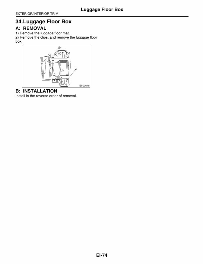
EXTERIOR/INTERIOR TRIMLuggage Floor Box
34.Luggage Floor BoxA: REMOVAL1) Remove the luggage floor mat.2) Remove the clips, and remove the luggage floorbox.
B: INSTALLATIONInstall in the reverse order of removal.
EI-00678
EI-74

EXTERIOR/INTERIOR TRIMTrunk Lid Garnish
35.Trunk Lid GarnishA: REMOVALRemove the license plate, loosen the bolts (A), andremove the trunk lid garnish.
B: INSTALLATIONInstall in the reverse order of removal.
Tightening torque:7.5 N⋅m (0.76 kgf-m, 5.5 ft-lb)
EI-00568
(A)
EI-75

EXTERIOR/INTERIOR TRIMRear Gate Garnish
36.Rear Gate GarnishA: REMOVAL1) Remove the rear gate trim. <Ref. to EI-69, RE-MOVAL, Rear Gate Trim.>2) Remove the clip (A), and remove the rear gatepanel side cover.
3) Remove the hexagon cap nut.
4) Remove the nuts, disconnect each connector,and remove the rear gate garnish.
B: INSTALLATIONInstall in the reverse order of removal.
(A)
EI-00569
EI-00630
EI-00631
EI-76

EXTERIOR/INTERIOR TRIMHeat Shield Cover
37.Heat Shield CoverA: REMOVAL1. FRONT HEAT SHIELD COVERRemove the four bolts to remove front heat shieldcover.
2. CENTER HEAT SHIELD COVERRemove the nut and bolt to remove center heatshield cover.
3. REAR HEAT SHIELD COVER1) Remove the muffler. <Ref. to EX(H4SO 2.0)-13,REMOVAL, Muffler.> <Ref. to EX(H4DOTC)-12,REMOVAL, Muffler.>2) Remove the four bolts to remove rear heat shieldcover.
B: INSTALLATIONInstall in the reverse order of removal.
(A) Transmission mount
DI-00211
(A)
EI-00679
EI-00680
EI-77

EXTERIOR/INTERIOR TRIMOrnament
38.OrnamentA: INSTALLATION1. LETTER MARKAdhere the letter mark with following dimension.• Sedan model
(a) Apply the apply tape with aligning the cut out to the end of trunk lid garnish.
(b) Apply the apply tape with aligning R stop on the top end of trunk lid garnish.
(c) Align the slit of apply tape to panel end.
(1) Letter mark (2) Apply tape (3) Rear combination light
EI-00815
(2)
(b)
(a)
(a)
A
B
A
A-A B-B
(1)
(2)
(C)
(3)
EI-78

EXTERIOR/INTERIOR TRIMOrnament
• Wagon model
2. AWD STICKERApply the AWD sticker from inside of glass with following dimension.• Sedan model
(a) Apply the apply tape with aligning the cut out to the end of rear gate panel.
(b) Apply the apply tape with aligning outer bottom end of rear gate gar-nish.
(c) Align the slit of apply tape to panel end.
(1) Letter mark (3) Rear gate garnish (4) Rear combination light
(2) Apply tape
(a) Apply the apply tape with aligning the cut out to the end of rear glass center.
(1) 1 mm (0.04 in) (3) Gradation end of ceramic print (without rear wiper)
(4) End of rear glass
(2) Gradation end of ceramic print (with rear wiper)
A-A
EI-00816
(2)
(b)
(3)
(a)
(a)A
A
B
B-B
(1)(2)
(C)
(4)
(a)(2)
(3)
(4)
(1)
EI-00741
EI-79

EXTERIOR/INTERIOR TRIMOrnament
• Wagon model (RH side)
• Wagon model (LH side)
(a) Apply the apply tape with aligning the cut out to the ceramic print.
(b) Gradation end of ceramic print
(1) 1 mm (0.04 in) (3) Molding (4) Front side of vehicle
(2) Glass antenna wire
EI-00742
(4)
(2)
(3)
(1)(1)
(a)
(b)
(4)
(2)
(3)
(1) (1)
(a)
(b)
EI-00743
EI-80
EXTERIOR BODY PANELS
EB
Page1. General Description ....................................................................................22. Front Hood ................................................................................................133. Front Fender Panel ...................................................................................164. Front Door .................................................................................................175. Front Sealing Cover ..................................................................................206. Rear Door..................................................................................................217. Rear Sealing Cover...................................................................................248. Trunk Lid ...................................................................................................259. Rear Gate..................................................................................................27

EXTERIOR BODY PANELSGeneral Description
1. General Description A: SPECIFICATION1. SIDE
(1) Front hood panel (4) Rear door panel (7) Side sill
(2) Front fender panel (5) Rear quarter panel (8) Rear quarter lower protector
(3) Front door panel (6) Door panel
Section Part Standard value
(A) Front hood panel to Front fender panel 3.5±1.0 mm (0.14±0.04 in)
(B) Front fender panel to Front door panel 4.65±1.0 mm (0.18±0.04 in)
(C) Front door panel to Rear door panel 5.1±1.0 mm (0.20±0.04 in)
(D) Rear door panel to Rear quarter panel 4.6±1.0 mm (0.18±0.04 in)
(E), (F) Door panel to Side sill 6.0±1.0 mm (0.24±0.04 in)
(G) Rear door panel to Rear quarter lower protector 5.0±1.0 mm (0.20±0.04 in)
EB-00176
(A)
(B) (C)(D)
(E) (F) (G)
(1)
(2)
(A)
(2) (3)
(B)
(3) (4)
(C)
(4)
(5)
(D)
(7)
(6)
(E),(F)
(4)
(G)
(8)
EB-2

EXTERIOR BODY PANELSGeneral Description
2. FRONT
(1) Front bumper (3) Front hood panel (5) Front fender panel
(2) Front grille (4) Headlight
Section Part Standard value
(A) Front bumper to Front grille (Longitudinal direction) 1.0±0.7 mm (0.04±0.03 in)
(B) Front hood panel to Front bumper 4.0 — 6.0 mm (0.16 — 0.24 in)
(C) Front hood panel to HeadlightC1: 6.0±1.0 mm (0.24±0.04 in)C2: 5.0±1.0 mm (0.20±0.04 in)
(D) Front fender panel to Headlight 2.0±1.0 mm (0.08±0.04 in)
(E) Front fender panel to Front bumper 1.0±0.7 mm (0.04±0.03 in)
EB-00177
(3)
(1)
(B)
(4)
(3)
C2
C1
(C)
(1)
(2)
(A)
(5)
(4)
(D)
(5)
(1)
(E)
(A) (B)
(C)
(D)
(E)
EB-3

EXTERIOR BODY PANELSGeneral Description
3. REAR (SEDAN MODEL)
(1) Trunk lid panel (3) Rear bumper (5) Fuel filler flap lid
(2) Rear combination light (4) Rear fender panel (6) Trunk lid garnish
Section Part Standard value
(A) Trunk lid garnish to Rear bumper 7.0±1.5 mm (0.28±0.06 in)
(B) Trunk lid garnish to Rear combination light 4.0±1.0 mm (0.16±0.04 in)
(C) Trunk lid panel to Rear combination light 3.5±1.0 mm (0.14±0.04 in)
(D) Trunk lid panel to Rear fender panel 3.5±1.0 mm (0.14±0.04 in)
(E) Rear fender panel to Rear bumper 1.0±0.7 mm (0.04±0.03 in)
(F)Rear fender panel to Fuel filler flap lid (Longitudinal direction)
F1: 3.7±0.5 mm (0.15±0.02 in) F2: 3.4±0.5 mm (0.13±0.02 in)
(G)Rear fender panel to Fuel filler flap lid (Lateral direc-tion)
G1, G2: 3.5±0.5 mm (0.14±0.02 in)
EB-00178
(6)(2)
(B)
(D)
(1)
(4)
(E)
(4)
(3)
(C)
(1) (2)
(A)
(6)
(3)
G1 G2
(G)
(5) (4)(4)
(F)(4)
(5)
F2
F1
(4)
(A)
(E)
(F)(D)
(C)
(B)
(G)
EB-4

EXTERIOR BODY PANELSGeneral Description
4. REAR (WAGON MODEL)
(1) Rear gate panel (4) Roof panel (7) Rear fender panel
(2) Rear bumper (5) Rear gate glass (8) Fuel filler flap lid
(3) Rear combination light (6) Door quarter glass (9) Roof spoiler
Section Part Standard value
(A) Rear gate panel to Rear bumper 8.0±1.5 mm (0.31±0.06 in)
(B) Rear gate panel to Rear combination light 5.1±1.0 mm (0.20±0.04 in)
(C) Rear gate glass to Rear combination light 5.5±1.0 mm (0.22±0.04 in)
(D) Rear gate glass to Rear quarter glass 4.0±1.5 mm (0.16±0.06 in)
(E) Roof panel to Roof spoiler 5.5±1.0 mm (0.22±0.04 in)
(F) Rear fender panel to Rear bumper 1.0±0.7 mm (0.04±0.03 in)
(G)Rear fender panel to Fuel filler flap lid (Longitudinal direction)
G1: 3.7±0.5 mm (0.15±0.02 in) G2: 3.4±0.5 mm (0.13±0.02 in)
(H)Rear fender panel to Fuel filler flap lid (Lateral direc-tion)
H1, H2: 3.5±0.5 mm (0.14±0.02 in)
EB-00179
H1 H2
(H)
(8) (7)(7)
(G)(7)
(8)
G2
G1
(7)
(A)
(1)
(2)(C)
(3)
(5)
(D)
(5)
(6)
(B)
(1)
(3)
(F)
(7)
(2)
(E)
(4)
(9)
(E)
(D)
(A)
(C)
(B)
(F)
(G)
(H)
EB-5

EXTERIOR BODY PANELSGeneral Description
B: COMPONENT1. FRONT HOOD
(1) Front hood panel (4) Intake duct weather strip Tightening torque: N⋅m (kgf-m, ft-lb)(2) Front hood insulator (5) Front hood weather strip T1: 33 (3.4, 24.5)(3) Front hood hinge (6) Front hood striker T2: 24.5 (2.5, 18.1)
EB-00148
T1
T2
T2
(6)
(5)
(4) (2)
(3)
(1)
EB-6

EXTERIOR BODY PANELSGeneral Description
2. FRONT FENDER PANEL
Tightening torque: N⋅m (kgf-m, ft-lb)T: 7.4 (0.75, 5.5)
EB-00145
T
T
T
EB-7

EXTERIOR BODY PANELSGeneral Description
3. FRONT DOOR PANEL
(1) Front door panel (6) Lower hinge Tightening torque: N⋅m (kgf-m, ft-lb)(2) Sealing cover (7) Door trim bracket upper T1: 7.4 (0.75, 5.5)(3) Front door weather strip (8) Door trim bracket lower T2: 24.5 (2.5, 18.1)(4) Checker T3: 29.4 (3.0, 21.7)(5) Upper hinge T4: 32.3 (3.3, 23.8)
EB-00149
T4
T1
T3
T2
T3
T2
(6)
(3)
(5)
(1) (7)
(8)(2)
(4)
EB-8

EXTERIOR BODY PANELSGeneral Description
4. REAR DOOR PANEL
(1) Rear door panel (6) Lower hinge Tightening torque: N⋅m (kgf-m, ft-lb)(2) Sealing cover (7) Door trim bracket upper T1: 7.4 (0.75, 5.5)(3) Rear door weather strip (8) Door trim bracket lower T2: 24.5 (2.5, 18.1)(4) Checker T3: 29.4 (3.0, 21.7)(5) Upper hinge T4: 32.3 (3.3, 23.8)
EB-00150
T1
T3
T2
(5)
(1)
T3
T2 (6)
T4
(4)
(7)
(8)
(2)
(3)
EB-9

EXTERIOR BODY PANELSGeneral Description
5. TRUNK LID PANEL
(1) Trunk lid panel (5) Trunk lid trim Tightening torque: N⋅m (kgf-m, ft-lb)(2) License plate light cover (6) Trunk lid arm cover T1: 17.6 (1.8, 12.9)(3) Trunk lid garnish (7) Trunk lid arm ASSY T2: 14 (1.43, 10.3)(4) Trunk lid lock ASSY (8) Torsion bar
EB-00161
(8)
(7)
(1)
(2)
(6)
(4)
(5)
T1
T2
(3)
EB-10

EXTERIOR BODY PANELSGeneral Description
6. REAR GATE PANEL
C: CAUTION• Exterior body panels are heavy. Do not drop anddamage the panels. During removal and installa-tion, do not damage the panel painting surface.• While removing mounting bolts, using assistancedevices such as a support jack will help to supportthe panel.• Be careful not to lose small parts.
(1) Rear gate damper stay (3) Rear gate panel Tightening torque: N⋅m (kgf-m, ft-lb)(2) Hinge (4) Rear gate side panel cover T1: 7.5 (0.76, 5.5)
T2: 14.0 (1.43, 10.3)T3: 25.0 (2.6, 18.4)
EB-00182
(3)
T3
T3
T1
T2
(2)
(1)
(4)
EB-11

EXTERIOR BODY PANELSGeneral Description
D: PREPARATION TOOL1. SPECIAL TOOL
2. GENERAL TOOL
ILLUSTRATION TOOL NUMBER DESCRIPTION REMARKS
925610000 WRENCH Used for removing and installing door hinge.
927780000 REMOVER Used for removing and installing trunk torsion bar.
TOOL NAME REMARKS
Support jack Used for supporting door panel.
Clip remover Used for removing various types of clips.
ST-925610000
ST-927780000
EB-12

EXTERIOR BODY PANELSFront Hood
2. Front HoodA: REMOVAL1. FRONT HOOD INSULATOR1) Open the hood.2) Release the clips to remove the front hood insu-lator.
2. FRONT HOOD WEATHER STRIP1) Open the hood.2) Remove the clips, and remove the front hoodweather strip (A) and intake duct weather strip (B).
NOTE:If the weather strip clip is removed with excessiveforce, the weather strip may be damaged. Be sureto use clip remover to remove.
3. FRONT HOOD HINGE1) Remove the bolts, and remove the front hoodpanel. <Ref. to EB-14, FRONT HOOD PANEL, RE-MOVAL, Front Hood.>
2) Remove the clips, and remove the cowl sidepanel front.
3) Remove the clamp (A) of the window washerhose, and remove bolt of the hinge.
(C) Clip
(D) Weather strip clip
EB-00139
EB-00140
(D)
(C) (A)
(B)
EB-00141
EB-00138
EB-00142
EB-00143
(A)
EB-13

EXTERIOR BODY PANELSFront Hood
4. FRONT HOOD STRIKER1) Open the hood.2) Remove the bolt, and remove the front hoodstriker.
5. FRONT HOOD PANEL1) Open the front hood to remove the windowwasher hose.
2) Remove the front hood insulator.<Ref. to EB-13, FRONT HOOD INSULATOR, RE-MOVAL, Front Hood.>3) Remove the front hood weather strip.<Ref. to EB-13, FRONT HOOD WEATHER STRIP,REMOVAL, Front Hood.>4) Remove the front hood striker.<Ref. to EB-14, FRONT HOOD STRIKER, RE-MOVAL, Front Hood.>5) Remove the front hood duct. (Turbo model)<Ref. to EI-25, REMOVAL, Front Hood Grille.>6) Remove the window washer hose and nozzle.<Ref. to WW-20, REMOVAL, Front Washer Noz-zle.>
7) Remove the bolts, and remove the front hoodpanel from front hood hinge.
B: INSTALLATION1. FRONT HOOD INSULATORInstall in the reverse order of removal.
NOTE:Be careful not to catch the window washer hose in.
2. FRONT HOOD WEATHER STRIPInstall in the reverse order of removal.
3. FRONT HOOD HINGEInstall in the reverse order of removal.
Tightening torque:24.5 N⋅m (2.5 kgf-m, 18.1 ft-lb)
4. FRONT HOOD STRIKERInstall in the reverse order of removal.
Tightening torque:33.0 N⋅m (3.4 kgf-m, 24.5 ft-lb)
5. FRONT HOOD PANELInstall in the reverse order of removal.
Tightening torque:24.5 N⋅m (2.5 kgf-m, 18.1 ft-lb)
C: ADJUSTMENT 1) Adjust the clearance between front hood paneland front fender panel. Clearance must be equal atboth sides. For the dimension of clearance, refer to“SPECIFICATIONS” in “General Description”.<Ref. to EB-2, SPECIFICATION, General Descrip-tion.>
EB-00144
EB-00137
EB-00138
EB-14

EXTERIOR BODY PANELSFront Hood
2) Use a hinge mounting bolts to align the fronthood longitudinally and laterally.
3) Adjust the height at the front end of hood. <Ref.to SL-40, ADJUSTMENT, Front Hood Lock Assem-bly.>4) Rotate the hood buffer to adjust lateral height.
EB-00138
EB-00164
EB-15

EXTERIOR BODY PANELSFront Fender Panel
3. Front Fender PanelA: REMOVAL1) Disconnect the ground cable from battery.2) Remove the side sill spoilers. <Ref. to EI-41, RE-MOVAL, Side Sill Spoiler.>3) Remove the front grille. <Ref. to EI-24, REMOV-AL, Front Grille.>4) Remove the front bumper face. <Ref. to EI-30,REMOVAL, Front Bumper.>5) Remove the headlight assembly. <Ref. to LI-14,REMOVAL, Headlight Assembly.>6) Remove the mud guard. <Ref. to EI-29, RE-MOVAL, Mud Guard.>7) Remove the cowl panel side.
8) Remove the bolt, and remove the front fenderpanel.
B: INSTALLATION1) Install in the reverse order of removal.2) Install with attention to make uniform clearancebetween front fender panel and front hood panel.For the dimension of clearance, refer to “SPECIFI-CATIONS” in “General Description”. <Ref. to EB-2,SPECIFICATION, General Description.>
Tightening torque:7.4 N⋅m (0.75 kgf-m, 5.5 ft-lb)
EB-00147
EB-00146
EB-16

EXTERIOR BODY PANELSFront Door
4. Front DoorA: REMOVAL1. FRONT DOOR PANEL1) Disconnect the ground cable from battery.2) Remove the front door trim. <Ref. to EI-48, RE-MOVAL, Door Trim.>3) Remove the outer mirror assembly. <Ref. toGW-18, REMOVAL, Outer Mirror Assembly.>4) Remove the front door speaker. <Ref. to ET-6,REMOVAL, Front Speaker.>5) Pull back the sealing cover. <Ref. to EB-20, RE-MOVAL, Front Sealing Cover.>6) Remove the gusset and front door glass. <Ref.to GW-10, REMOVAL, Front Door Glass.>7) Remove the door sash and front door regulatorand motor. <Ref. to GW-15, REMOVAL, FrontRegulator and Motor Assembly.>8) Remove the front door latch assembly. <Ref. toSL-30, REMOVAL, Front Door Latch and DoorLock Actuator Assembly.>9) Remove the front outer handle. <Ref. to SL-29,REMOVAL, Front Outer Handle.>10) Remove the screw to remove the door trimbracket.
11) Remove the front door weather strip.
NOTE:If the weather strip clip is removed with excessiveforce, the weather strip may be damaged. Be sureto use clip remover to remove.
12) Remove the bolts and nuts to remove the doorchecker.
13) Remove the front door. <Ref. to EB-17,FRONT DOOR ASSEMBLY, REMOVAL, FrontDoor.>
2. FRONT DOOR ASSEMBLY1) Disconnect the ground cable from battery.2) Remove the front pillar lower trim. <Ref. to EI-60,REMOVAL, Lower Inner Trim.>3) Remove the instrument panel lower cover orglove box lower cover. <Ref. to EI-50, REMOVAL,Instrument Panel Lower Cover.> or <Ref. to EI-51,REMOVAL, Glove Box.>
EB-00152
(A) Pin clip
(B) Weather strip clip
EB-00155
(A)
(B)
(A)
EB-00141
EB-00154
EB-17

EXTERIOR BODY PANELSFront Door
4) Disconnect the connector of door harness frombody harness.
5) Put a wooden block on jack and place jack underthe front door. Support the door with a jack to pro-tect it from damage.
6) Remove the bolt from the door checker.
7) Remove the door-side bolts for upper and lowerhinges to remove front door panel.
8) Remove the door hinge from vehicle.
B: INSTALLATION1. FRONT DOOR PANELInstall in the reverse order of removal.
Tightening torque:Refer to “COMPONENT” of “General Descrip-tion”.<Ref. to EB-8, FRONT DOOR PANEL, COM-PONENT, General Description.>
2. FRONT DOOR ASSEMBLY1) Put a wooden block on jack and place the frontdoor on that.
2) Apply grease to the sliding area of door hinges,and install the door hinge to vehicle.3) Install the front door to upper hinge and lowerhinge adjusting by jack.4) Tighten the bolt of door checker.5) Connect the door harness connector, and installthe instrument panel lower cover.6) Install the front pillar lower trim.
Tightening torque:Refer to “COMPONENT” of “General Descrip-tion”.<Ref. to EB-8, FRONT DOOR PANEL, COM-PONENT, General Description.>
C: ADJUSTMENT1) Using the ST, loosen the body-side bolts of up-per and lower hinges to align the position of frontdoor panel longitudinally and laterally.ST 925610000 DOOR HINGE WRENCH
EB-00151
EB-00013
EB-00014
EB-00015
EB-00013
EB-00016
ST
EB-18

EXTERIOR BODY PANELSFront Door
2) Loosen the screws (A), and tap the striker (B)using plastic hammer to adjust the gap betweenrear end surface of front door panel and front endsurface of rear door.
CAUTION:Do not use an impact wrench. Welding area on the striker nut plate is easily broken.
EB-00017
(B)(A)
EB-19

EXTERIOR BODY PANELSFront Sealing Cover
5. Front Sealing CoverA: REMOVAL1) Disconnect the ground cable from battery.2) Remove the front door trim. <Ref. to EI-48, RE-MOVAL, Door Trim.>3) Remove the front speaker. <Ref. to ET-6, RE-MOVAL, Front Speaker.>4) Pull back the sealing cover.
NOTE:• Carefully remove the butyl tape. Excessive forcewill easily break the cover.• If cover gets broken, replace it with a new one.
B: INSTALLATION 1) Install in the reverse order of removal.2) When replacing the sealing cover, use the butyltape.3) Press the butyl tape-applied area firmly to pre-vent any floating on surface.
Butyl tape:3M8626 or equivalent
NOTE:• Apply a uniform bead of butyl tape.• Attach the sealing cover, keeping it from becom-ing wrinkled.• Breaks in the bead will allow water leakage andcontamination.
C: INSPECTIONIf the sealing cover gets damaged, replace it with anew one.
EB-00018
EB-20

EXTERIOR BODY PANELSRear Door
6. Rear DoorA: REMOVAL1. REAR DOOR PANEL1) Disconnect the ground cable from battery.2) Remove the rear door trim. <Ref. to EI-48, RE-MOVAL, Door Trim.>3) Remove the rear speaker. <Ref. to ET-9, RE-MOVAL, Rear Speaker.>4) Pull back the sealing cover. <Ref. to EB-24, RE-MOVAL, Rear Sealing Cover.>5) Remove the rear door glass. <Ref. to GW-22,REMOVAL, Rear Door Glass.>6) Remove the door sash and rear door regulatorand motor assembly. <Ref. to GW-24, REMOVAL,Rear Regulator and Motor Assembly.>7) Remove the rear door latch. <Ref. to SL-34, RE-MOVAL, Rear Door Latch and Door Lock ActuatorAssembly.>8) Remove the rear outer handle. <Ref. to SL-33,REMOVAL, Rear Outer Handle.>9) Remove the screw to remove the door trimbracket.
10) Remove the rear door inner weather strip.
NOTE:If the weather strip clip is removed with excessiveforce, the weather strip may be damaged. Be sureto use clip remover to remove.
11) Remove the bolts and nuts to remove the doorchecker.
12) Remove the rear door. <Ref. to EB-21, REARDOOR ASSEMBLY, REMOVAL, Rear Door.>
2. REAR DOOR ASSEMBLY1) Disconnect the ground cable from battery.2) Remove the center pillar lower trim. <Ref. to EI-60, REMOVAL, Lower Inner Trim.>
EB-00152
(A) Pin clip
(B) Weather strip clip
EB-00156
(A)
(B)
(A)
EB-00141
EB-00154
EB-21

EXTERIOR BODY PANELSRear Door
3) Remove the center pillar inner protector lower.
4) Remove the harness holder (A), and disconnectthe door harness connector inside pillar.
5) Put a wooden block on jack and place jack underthe rear door. Support the rear door with the jack toprotect it from damage.
6) Remove the bolt from the door checker.
7) Remove the door-side bolts for upper and lowerhinges to remove the rear door panel.
8) Remove the door hinge from vehicle.
B: INSTALLATION1. REAR DOOR PANELInstall in the reverse order of removal.
Tightening torque:Refer to “COMPONENT” of “General Descrip-tion”.<Ref. to EB-9, REAR DOOR PANEL, COMPO-NENT, General Description.>
2. REAR DOOR ASSEMBLY1) Put a wooden block on jack and place the reardoor on that.
2) Apply grease to sliding area of the door hinges.3) Install the rear door to upper hinge and lowerhinge adjusting by jack.4) Tighten the bolt of door checker.5) Connect the door harness connector, and installthe center pillar inner protector.6) Install the center pillar lower trim.
Tightening torque:Refer to “COMPONENT” of “General Descrip-tion”.<Ref. to EB-9, REAR DOOR PANEL, COMPO-NENT, General Description.>
SB-00144
EB-00153
(A)
EB-00013
EB-00014
EB-00015
EB-00013
EB-22
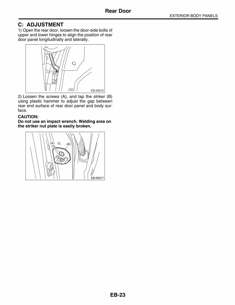
EXTERIOR BODY PANELSRear Door
C: ADJUSTMENT1) Open the rear door, loosen the door-side bolts ofupper and lower hinges to align the position of reardoor panel longitudinally and laterally.
2) Loosen the screws (A), and tap the striker (B)using plastic hammer to adjust the gap betweenrear end surface of rear door panel and body sur-face.
CAUTION:Do not use an impact wrench. Welding area on the striker nut plate is easily broken.
EB-00015
EB-00017
(B)(A)
EB-23

EXTERIOR BODY PANELSRear Sealing Cover
7. Rear Sealing CoverA: REMOVAL1) Disconnect the ground cable from battery.2) Remove the rear door trim. <Ref. to EI-48, RE-MOVAL, Door Trim.>3) Pull back the sealing cover.
NOTE:• Carefully remove the butyl tape. Excessive forcewill easily break the cover.• If cover gets broken, replace it with a new one.
B: INSTALLATION 1) Install in the reverse order of removal.2) When replacing the sealing cover, use the butyltape.3) Press the butyl tape-applied area firmly to pre-vent any floating on surface.
Butyl tape:3M8626 or equivalent
NOTE:• Apply a uniform bead of butyl tape.• Attach the sealing cover, keeping it from becom-ing wrinkled.• Breaks in the bead will allow water leakage andcontamination.
C: INSPECTIONIf the sealing cover gets damaged, replace it with anew one.
EB-00018
EB-24

EXTERIOR BODY PANELSTrunk Lid
8. Trunk LidA: REMOVAL1. TORSION BAR1) Open the trunk lid.2) Using the ST, remove the torsion bar from thehinge link.ST 927780000 REMOVER
CAUTION:During removal and installation, carefully han-dle the torsion bar, because it will generate re-active force.
3) Remove the right/left torsion bars.
2. TRUNK LID ARM1) Disconnect the ground cable from battery.2) Open the trunk lid to remove the trunk lid trim,trunk lid arm cover and trunk room trim. <Ref. to EI-71, TRUNK ROOM TRIM, REMOVAL, Trunk RoomTrim.>3) Disconnect the trunk lid release cable. <Ref. toSL-39, REMOVAL, Trunk Lid Lock Assembly.>4) Disconnect each connector, and remove theharness clip.5) Remove the trunk lid mounting bolts to removethe trunk lid panel from trunk lid arm.
6) Remove the torsion bar from the trunk lid hingelink. <Ref. to EB-25, TORSION BAR, REMOVAL,Trunk Lid.>7) Remove the rear shelf trim. <Ref. to EI-70, RE-MOVAL, Rear Shelf Trim.>
8) Remove the bolts to remove the trunk lid arm.
3. TRUNK LID PANEL1) Disconnect the ground cable from battery.2) Open the trunk lid to remove the trunk lid trimand trunk lid arm cover. <Ref. to EI-71, TRUNKROOM TRIM, REMOVAL, Trunk Room Trim.>3) Disconnect the connector to remove the trunk lidharness.4) Remove the trunk lid lock assembly. <Ref. to SL-39, REMOVAL, Trunk Lid Lock Assembly.>5) Remove the trunk lid garnish. <Ref. to EI-75,REMOVAL, Trunk Lid Garnish.>6) Remove the license plate light cover.
7) Remove the bolts to remove the trunk lid panelfrom the trunk lid arm.
B: INSTALLATION1. TORSION BAR1) Install in the reverse order of removal.2) Apply grease to the rotating area of hinges andof torsion bar.
EB-00067
ST
EB-00066
EB-00157
EB-00159
EB-00066
EB-25

EXTERIOR BODY PANELSTrunk Lid
2. TRUNK LID ARMInstall in the reverse order of removal.
Tightening torque:Refer to “COMPONENT” of “General Descrip-tion”.<Ref. to EB-10, TRUNK LID PANEL, COMPO-NENT, General Description.>
3. TRUNK LID PANEL1) Install in the reverse order of removal.2) Install with attention to make uniform clearancearound the trunk lid panel. For the dimension ofclearance, refer to “SPECIFICATIONS” in “GeneralDescription”. <Ref. to EB-2, SPECIFICATION,General Description.>
Tightening torque:14 N⋅m (1.43 kgf-m, 10.3 ft-lb)
EB-26

EXTERIOR BODY PANELSRear Gate
9. Rear GateA: REMOVAL1. REAR GATE PANEL1) Disconnect the ground cable from battery.2) Open the rear gate.3) Remove the rear gate trim. <Ref. to EI-69, RE-MOVAL, Rear Gate Trim.>4) Remove the rear gate garnish. <Ref. to EI-76,REMOVAL, Rear Gate Garnish.>5) Remove the rear wiper arm. <Ref. to WW-21,REMOVAL, Rear Wiper Arm.>6) Remove the rear wiper motor. <Ref. to WW-22,WAGON MODEL, REMOVAL, Rear Wiper Motor.>7) Remove the rear gate outer handle. <Ref. to SL-36, REMOVAL, Rear Gate Outer Handle.>8) Remove the rear gate latch assembly. <Ref. toSL-37, REMOVAL, Rear Gate Latch Assembly.>9) Detach the roof spoiler. <Ref. to EI-40, REMOV-AL, Roof Spoiler.>10) Remove harness clip of each connector fromthe rear gate panel.11) Remove the weather strip clips (A), and re-move the rear gate panel weather strip.
NOTE:If the weather strip clip is removed with excessiveforce, the weather strip may be damaged. Be sureto use clip remover to remove.
12) Remove the rubber duct (A) connection, andpull out the harness and washer hose from the reargate.
13) Before removing the rear gate damper stay,prevent the rear gate from closing using prop or thelike.
CAUTION:If the prop comes off, operators may get injured and vehicle may get damaged. Make sure to support the rear gate with secure material to prevent injury or damage.
14) Remove the mounting bolts of rear gate damp-er stay.EB-00162
:(A)
EB-00141
(A)
EB-00020
EB-00069
EB-00022
EB-27

EXTERIOR BODY PANELSRear Gate
15) Remove the rear gate hinge bolts, and removethe rear gate panel.
16) Remove the rear gate hinge from vehicle.
2. REAR GATE DAMPER STAY
CAUTION:• Do not damage piston rods and oil seals.• Never disassemble cylinders: They containgas.1) Open the rear gate.2) Before removing the rear gate damper stay, pre-vent the rear gate from closing using prop or thelike.
CAUTION:If the prop comes off, operators may get injured and vehicle may get damaged. Make sure to support the rear gate with secure material to prevent injury or damage.
3) Remove the mounting bolts of rear gate damperstay.
4) Remove the clips and then detach the rear com-bination light covers.
5) Remove the mounting bolt (A), and remove thedamper stay.
B: INSTALLATION1. REAR GATE PANEL1) Install in the reverse order of removal.2) Install with attention to make uniform clearancebetween rear gate panel and body. For the dimen-sion of clearance, refer to “SPECIFICATIONS” in“General Description”. <Ref. to EB-2, SPECIFICA-TION, General Description.>
Tightening torque:Refer to “COMPONENT” of “General Descrip-tion”.<Ref. to EB-11, REAR GATE PANEL, COMPO-NENT, General Description.>
EB-00023
EB-00069
EB-00022
LI-00295
EB-00158
(A)
EB-28

EXTERIOR BODY PANELSRear Gate
2. REAR GATE DAMPER STAY1) Prevent the rear gate from closing using prop orthe like.
CAUTION:If the prop comes off, operators may get injured and vehicle may get damaged. Make sure to support the rear gate with secure material to prevent injury or damage.
2) Install in the reverse order of removal.
Tightening torque:19.6 N⋅m (2.0 kgf-m, 14.5 ft-lb)
C: DISPOSAL1. REAR GATE DAMPER STAY
CAUTION:Gas is colorless, odorless and harmless. How-ever, gas pressure may spray cutting powder or oil. Be sure to wear dust-resistant goggles.1) Cover with a vinyl sack as shown in the figure.
NOTE:Prevent the vinyl sack from being caught by drillcutting edge.2) Lift the body side slightly with piston rods fullyextended, and secure the body side with vise.
Drill a hole in 2 to 3 mm (0.08 to 0.12 in) diameter ata point 10 to 200 mm (0.39 to 7.87 in) from doorside, and bleed rear gate damper stay gas com-pletely.
(1) Rear gate damper stay
(2) Vinyl sack
EB-00069
(1)
(2)
EB-00031
(1) Body side
(2) Door side
(3) 190 mm (7.48 in)
(4) 10 mm (0.39 in)
(5) Piston rod
(6) Cylinder
(7) Portion to be drilled
(3) (4)
(1)
(5) (6)
(7)
(2)
EB-00032
EB-29

EXTERIOR BODY PANELSRear Gate
EB-30

CRUISE CONTROL SYSTEM
CC
Page1. General Description ....................................................................................22. Cruise Control Unit......................................................................................43. Cruise Control Command Switch ................................................................54. Stop Light and Brake Switch .......................................................................65. Clutch Switch ..............................................................................................76. Inhibitor Switch............................................................................................87. Neutral Position Switch ...............................................................................9
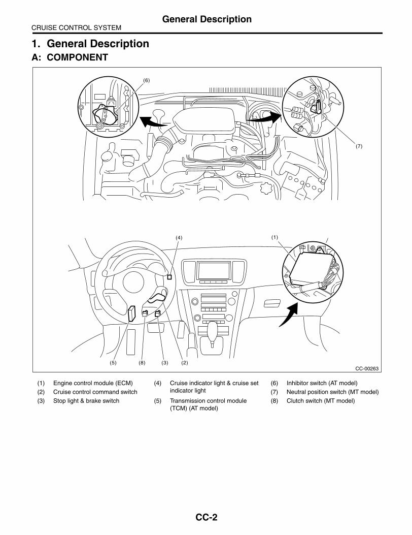
CRUISE CONTROL SYSTEMGeneral Description
1. General DescriptionA: COMPONENT
(1) Engine control module (ECM) (4) Cruise indicator light & cruise set indicator light
(6) Inhibitor switch (AT model)
(2) Cruise control command switch (7) Neutral position switch (MT model)
(3) Stop light & brake switch (5) Transmission control module (TCM) (AT model)
(8) Clutch switch (MT model)
CC-00263
(7)
(6)
(1)(4)
(2)(3)(8)(5)
CC-2

CRUISE CONTROL SYSTEMGeneral Description
B: CAUTION• Before disassembling or reassembling parts, al-ways disconnect the battery ground cable from bat-tery. When repairing the audio, control module, etc.which are provided with memory functions, recordthe memory contents before disconnecting theground cable from battery. Otherwise, the memorywill be erased.• Reassemble the parts in the reverse order of dis-assembly unless otherwise indicated.• Adjust the parts to specifications specified in thismanual.• Connect the connectors securely during reas-sembly.• After reassembly, ensure functional parts oper-ate properly.
C: PREPARATION TOOLTOOL NAME REMARKS
Circuit tester Used for measuring resis-tance and voltage.
CC-3

CRUISE CONTROL SYSTEMCruise Control Unit
2. Cruise Control UnitA: NOTEThe control of cruise control system is carried out inEngine control module (ECM).
B: REMOVAL<Ref. to FU(H4SO 2.0)-34, REMOVAL, EngineControl Module (ECM).> <Ref. to FU(H4SO 2.5)-36, REMOVAL, Engine Control Module (ECM).><Ref. to FU(H4DOTC)-35, REMOVAL, EngineControl Module (ECM).> <Ref. to FU(H6DO)-34,REMOVAL, Engine Control Module (ECM).>
C: INSTALLATION<Ref. to FU(H4SO 2.0)-34, INSTALLATION, En-gine Control Module (ECM).> <Ref. to FU(H4SO2.5)-36, INSTALLATION, Engine Control Module(ECM).> <Ref. to FU(H4DOTC)-35, INSTALLA-TION, Engine Control Module (ECM).> <Ref. toFU(H6DO)-34, INSTALLATION, Engine ControlModule (ECM).>
CC-4

CRUISE CONTROL SYSTEMCruise Control Command Switch
3. Cruise Control Command Switch
A: REMOVALWARNING:Before servicing, be sure to read the notes inthe “AB” section for proper handling of thedriver’s airbag module. <Ref. to AB-4, CAU-TION, General Description.>1) Set the front wheels in straight ahead position.2) Turn the ignition switch to OFF.3) Disconnect the ground cable from battery andwait for at least 20 seconds before starting work.4) Using TORX® BIT T30 (Tamper resistant type),loosen the two TORX® bolts which secure driver’sairbag module.
5) Disconnect the airbag module connector onback of the airbag module.6) Remove the steering wheel. <Ref. to PS-20, RE-MOVAL, Steering Wheel.>7) Remove the four screws to remove the lowercover from steering wheel.
8) Remove one screw to remove the cruise controlcommand switch from lower cover.
B: INSTALLATIONInstall in the reverse order of removal.
C: INSPECTIONMeasure the cruise control command switch resis-tance.
If NG, replace the cruise control command switch.
(1) TORX® BIT T30
CC-00018
(1)
CC-00181
Switch Area Terminal No. Standard
CANCELSET/COASTRESUME/
ACCEL
ALL OFF
2 and 3 Approx. 4 kΩ
CANCEL ON 2 and 3 Less than 1 ΩSET/COAST ON 2 and 3 Approx. 250 ΩRESUME/
ACCELON 2 and 3 Approx. 1500 Ω
MAINOFF 1 and 2 More than 1 MΩON 1 and 2 Less than 1 Ω
CC-00182
CC-00252
2 31
CC-5

CRUISE CONTROL SYSTEMStop Light and Brake Switch
4. Stop Light and Brake SwitchA: REMOVAL1) Disconnect the ground cable from battery.2) Disconnect the connector from stop light & brakeswitch, and then remove the switch. <Ref. to BR-45, REMOVAL, Stop Light Switch.>
B: INSTALLATIONInstall in the reverse order of removal.
C: INSPECTIONMeasure the resistance of brake switch (A) andstop light switch (B).
If NG, replace the stop light & brake switch.
Switch Pedal Terminal No. Standard
BrakeReleased 1 and 4 Less than 1 Ω
Depressed 1 and 4 More than 1 MΩ
Stop Light
Released 2 and 3 More than 1 MΩDepressed 2 and 3 Less than 1 Ω
CC-00022
1234
(A)
(B)
321 4
CC-6

CRUISE CONTROL SYSTEMClutch Switch
5. Clutch SwitchA: REMOVAL1) Disconnect the ground cable from battery.2) Disconnect the connector from clutch switch,and then remove the switch. <Ref. to CL-27, DIS-ASSEMBLY, Clutch Pedal.>
B: INSTALLATIONInstall in the reverse order of removal.
C: INSPECTIONMeasure the clutch switch resistance.
If NG, replace the clutch switch.
Switch Pedal Terminal No. Standard
ClutchReleased 1 and 2 Less than 1 Ω
Depressed 1 and 2 More than 1 MΩ
CC-00023
CC-7

CRUISE CONTROL SYSTEMInhibitor Switch
6. Inhibitor SwitchA: REMOVAL1) Disconnect the ground cable from battery.2) Disconnect the connector from inhibitor switch,and then remove the switch. <Ref. to 4AT-52, RE-MOVAL, Inhibitor Switch.>
B: INSTALLATIONInstall in the reverse order of removal.
C: INSPECTIONMeasure the inhibitor switch resistance.
If NG, replace the inhibitor switch.
Selector lever position
Terminal No. Standard
P
7 and 12
Less than 1 ΩN Less than 1 Ω
Except P and N More than 1 MΩ
CC-00024
123456789101112
CC-8

CRUISE CONTROL SYSTEMNeutral Position Switch
7. Neutral Position SwitchA: REMOVAL1) Disconnect the ground cable from battery.2) Disconnect the connector from neutral positionswitch, and then remove the switch. <Ref. to 5MT-41, BACK-UP LIGHT SWITCH AND NEUTRALPOSITION SWITCH, REMOVAL, Switches andHarness.>
B: INSTALLATIONInstall in the reverse order of removal.
C: INSPECTIONMeasure the neutral position switch resistance.
If NG, replace the neutral position switch.
Gear shift position Terminal No. Standard
Neutral position1 and 2
Less than 1 ΩOther positions More than 1 MΩ
MT-00110
12
CC-9

CRUISE CONTROL SYSTEMNeutral Position Switch
CC-10

CRUISE CONTROL SYSTEM(DIAGNOSTICS)
CC(diag)
Page1. Basic Diagnostic Procedure ........................................................................22. General Description ....................................................................................43. Electrical Component Location ...................................................................54. Engine Control Module (ECM) I/O Signal ...................................................65. Subaru Select Monitor.................................................................................86. Diagnostics with Phenomenon..................................................................107. List of Diagnostic Trouble Code (DTC) .....................................................128. Diagnostic Procedure with Diagnostic Trouble Code (DTC) .....................15

CRUISE CONTROL SYSTEM (DIAGNOSTICS)Basic Diagnostic Procedure
1. Basic Diagnostic ProcedureA: PROCEDURE
Step Check Yes No1 CHECK MALFUNCTION INDICATOR LIGHT.
Ensure the malfunction indicator light illumi-nates.
Does the malfunction indicator light illuminate?
Go to step 5. Go to step 2.
2 CHECK CRUISE INDICATOR LIGHT.Ensure the cruise indicator light blinks.
Does the cruise indicator light blink?
Go to step 5. Go to step 3.
3 CHECK CRUISE CONTROL MAIN SWITCH OPERATION.Check the cruise control main switch opera-tion. (Ensure the cruise indicator light illumi-nates.)
Is the cruise control main switch turned on? (Does the cruise indicator light illumi-nate?)
Go to step 4. Go to phenome-non 1. <Ref. to CC(diag)-10, DIAGNOSTIC PROCEDURE WITH PHENOME-NON, Diagnostics with Phenome-non.>
4 CHECK CRUISE CONTROL SET OPERA-TION.Check the cruise control set operation.
Can the cruise control be set while driving at more than 40 km/h (25 MPH)?
Go to step 6. Go to step 5.
5 PERFORM CRUISE CANCEL CONDITIONS DIAGNOSIS.Perform the cruise cancel conditions diagno-sis.
Is DTC displayed? Go to “List of Diag-nostic Trouble Code (DTC)”. <Ref. to CC(diag)-12, List of Diag-nostic Trouble Code (DTC).>
Go to phenome-non 2. <Ref. to CC(diag)-10, DIAGNOSTIC PROCEDURE WITH PHENOME-NON, Diagnostics with Phenome-non.>
6 CHECK CRUISE SET INDICATOR LIGHT.Ensure the cruise set indicator light illuminates.
Does the cruise set indicator light illuminate?
Go to step 7. Go to phenome-non 3. <Ref. to CC(diag)-10, DIAGNOSTIC PROCEDURE WITH PHENOME-NON, Diagnostics with Phenome-non.>
7 CHECK VEHICLE SPEED IS HELD WITHIN SET SPEED.Make sure the vehicle speed is held within set speed.
Is vehicle speed held within set speed ±3 km/h (±2 MPH)? (Make an inspection on a level road.)
Go to step 8. Go to phenome-non 4. <Ref. to CC(diag)-10, DIAGNOSTIC PROCEDURE WITH PHENOME-NON, Diagnostics with Phenome-non.>
8 CHECK RESUME/ACCEL OPERATION.Check the RESUME/ACCEL switch operation.
Does the vehicle speed increase or return to set speed after RESUME/ACCEL switch has been pressed?
Go to step 9. Go to phenome-non 5. <Ref. to CC(diag)-10, DIAGNOSTIC PROCEDURE WITH PHENOME-NON, Diagnostics with Phenome-non.>
CC(diag)-2

CRUISE CONTROL SYSTEM (DIAGNOSTICS)Basic Diagnostic Procedure
9 CHECK SET/COAST OPERATION.Check the SET/COAST switch operation.
Does the vehicle speed decrease after SET/COAST switch has been pressed?
Go to step 10. Go to phenome-non 6. <Ref. to CC(diag)-10, DIAGNOSTIC PROCEDURE WITH PHENOME-NON, Diagnostics with Phenome-non.>
10 CHECK CANCEL OPERATION.Check the CANCEL switch operation.
Is the cruise control released after CANCEL switch has been pressed?
Go to step 11. Go to phenome-non 7. <Ref. to CC(diag)-10, DIAGNOSTIC PROCEDURE WITH PHENOME-NON, Diagnostics with Phenome-non.>
11 CHECK CRUISE CONTROL RELEASE OP-ERATION.Check the cruise control release operation.
Is the cruise control released after brake pedal has been depressed?
Go to step 12. Go to phenome-non 8. <Ref. to CC(diag)-10, DIAGNOSTIC PROCEDURE WITH PHENOME-NON, Diagnostics with Phenome-non.>
12 CHECK CRUISE CONTROL RELEASE OP-ERATION.Check the cruise control release operation.
Is the cruise control released after shifting to the neutral position?
Go to step 13. Go to phenome-non 9. <Ref. to CC(diag)-10, DIAGNOSTIC PROCEDURE WITH PHENOME-NON, Diagnostics with Phenome-non.>
13 CHECK CRUISE CONTROL RELEASE OP-ERATION.Check the cruise control release operation.
Is the cruise control released after depressing the clutch pedal?
Finish the diagno-sis.
Go to phenome-non 10. <Ref. to CC(diag)-10, DIAGNOSTIC PROCEDURE WITH PHENOME-NON, Diagnostics with Phenome-non.>
Step Check Yes No
CC(diag)-3

CRUISE CONTROL SYSTEM (DIAGNOSTICS)General Description
2. General DescriptionA: CAUTIONAirbag system wiring harness is routed near the cruise control command switch.
CAUTION:• All airbag system wiring harnesses and connectors are yellow. Do not use the electrical test equip-ment on these circuits.• Be careful not to damage the airbag system wiring harness when servicing the cruise control com-mand switch.
B: PREPARATION TOOL1. SPECIAL TOOL
2. GENERAL TOOL
C: INSPECTIONMeasure the battery voltage and specific gravity of electrolyte.
Standard voltage:12 V or more
Specific gravity:More than 1.260
ILLUSTRATION TOOL NUMBER DESCRIPTION REMARKS
24082AA230 CARTRIDGE Troubleshooting for electrical system
22771AA030 SUBARU SELECT MONITOR KIT
Troubleshooting for electrical system• English: 22771AA030 (Without printer)• German: 22771AA070 (Without printer)• French: 22771AA080 (Without printer)• Spanish: 22771AA090 (Without printer)
TOOL NAME REMARKS
Circuit tester Used for measuring resistance, voltage and ampere.
ST24082AA230
ST22771AA030
CC(diag)-4
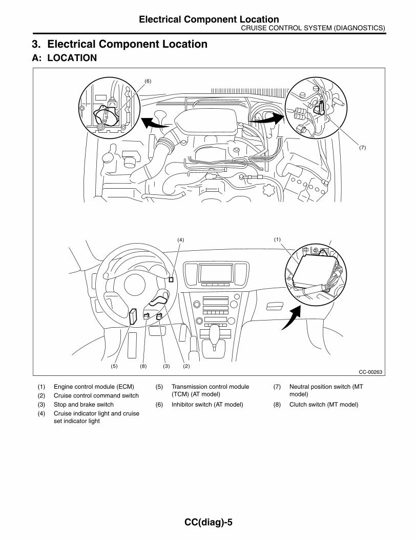
CRUISE CONTROL SYSTEM (DIAGNOSTICS)Electrical Component Location
3. Electrical Component LocationA: LOCATION
(1) Engine control module (ECM) (5) Transmission control module (TCM) (AT model)
(7) Neutral position switch (MT model)(2) Cruise control command switch
(3) Stop and brake switch (6) Inhibitor switch (AT model) (8) Clutch switch (MT model)
(4) Cruise indicator light and cruise set indicator light
CC-00263
(7)
(6)
(1)(4)
(2)(3)(8)(5)
CC(diag)-5
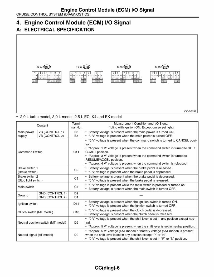
CRUISE CONTROL SYSTEM (DIAGNOSTICS)Engine Control Module (ECM) I/O Signal
4. Engine Control Module (ECM) I/O SignalA: ELECTRICAL SPECIFICATION
• 2.0 L turbo model, 3.0 L model, 2.5 L EC, K4 and EK model
ContentTermi-nal No.
Measurement Condition and I/O Signal(Idling with ignition ON: Except cruise set light)
Main power supply
VB (CONTROL 1)VB (CONTROL 2)
B6B5
• Battery voltage is present when the main power is turned ON.• “0 V” voltage is present when the main power is turned OFF.
Command Switch C11
• “0 V” voltage is present when the command switch is turned to CANCEL posi-tion.• “Approx. 1 V” voltage is present when the command switch is turned to SET/COAST position.• “Approx. 3 V” voltage is present when the command switch is turned to RESUME/ACCEL position.• “Approx. 4 V” voltage is present when the command switch is released.
Brake switch 1(Brake switch)
C9• Battery voltage is present when the brake pedal is released.• “0 V” voltage is present when the brake pedal is depressed.
Brake switch 2(Stop light switch)
C8• Battery voltage is present when the brake pedal is depressed.• “0 V” voltage is present when the brake pedal is released.
Main switch C7• “0 V” voltage is present while the main switch is pressed or turned on.• Battery voltage is present when the main switch is turned OFF.
GroundGND (CONTROL 1)GND (CONTROL 2)
D2D1
—
Ignition switch D14• Battery voltage is present when the ignition switch is turned ON.• “0 V” voltage is present when the ignition switch is turned OFF.
Clutch switch (MT model) C10• “0 V” voltage is present when the clutch pedal is depressed.• Battery voltage is present when the clutch pedal is released.
Neutral position switch (MT model) D9• “0 V” voltage is present when the shift lever is set in any position except neu-tral.• “Approx. 5 V” voltage is present when the shift lever is set in neutral position.
Neutral signal (AT model) D9• “Approx. 5 V” voltage (4AT model) or battery voltage (5AT model) is present when the shift lever is set in any position except “P” or “N”.• “0 V” voltage is present when the shift lever is set in “P” or “N” position.
CC-00197
B134
9
30 29 2832 3120 19 1822 211012 1114
2434 3327 2617 16
12345671323
1525
8
B135
9
30 29 2832 312022 21
1012 111424
35 3327 26
17 161234567
1323
1525
8
B136
9
30 29 2832 3120 19 1822 21
1012 111424
34 3327 2616
12345613
2315
258
B137
9
29 2820 19 1822 211012 1114
2417 16
12345671323
1525
81819
34
717
35 3031 27 26
To D:To C:To B:To A:
CC(diag)-6

CRUISE CONTROL SYSTEM (DIAGNOSTICS)Engine Control Module (ECM) I/O Signal
• 2.0 L non-turbo model, 2.5 L KS, KA model
B: WIRING DIAGRAM<Ref. to WI-134, WIRING DIAGRAM, Cruise Control System.>
ContentTermi-nal No.
Measurement Condition and I/O Signal(Idling with ignition ON: Except cruise set light)
Main power supply
VB (CONTROL 1)VB (CONTROL 2)
C3C4
• Battery voltage is present when the main power is turned ON.• “0 V” voltage is present when the main power is turned OFF.
Command Switch C21
• “0 V” voltage is present when the command switch is turned to CANCEL posi-tion.• “Approx. 1 V” voltage is present when the command switch is turned to SET/COAST position.• “Approx. 3 V” voltage is present when the command switch is turned to RESUME/ACCEL position.• “Approx. 4 V” voltage is present when the command switch is released.
Brake switch 1(Brake switch)
D12• Battery voltage is present when the brake pedal is released.• “0 V” voltage is present when the brake pedal is depressed.
Brake switch 2(Stop light switch)
D13• Battery voltage is present when the brake pedal is depressed.• “0 V” voltage is present when the brake pedal is released.
Main switch D14• “0 V” voltage is present while the main switch is pressed or turned on.• Battery voltage is present when the main switch is turned OFF.
GroundGND (CONTROL 1)GND (CONTROL 2)
C5C6
—
Ignition switch B13• Battery voltage is present when the ignition switch is turned ON.• “0 V” voltage is present when the ignition switch is turned OFF.
Clutch switch (MT model) D22• “0 V” voltage is present when the clutch pedal is depressed.• Battery voltage is present when the clutch pedal is released.
Neutral position switch (MT model) B12• “0 V” voltage is present when the shift lever is set in any position except neu-tral.• “Approx. 5 V” voltage is present when the shift lever is set in neutral position.
Neutral signal (AT model) B12• “Approx. 5 V” voltage is present when the shift lever is set in any position except “P” or “N”.• “0 V” voltage is present when the shift lever is set in “P” or “N” position.
CC(diag)-7

CRUISE CONTROL SYSTEM (DIAGNOSTICS)Subaru Select Monitor
5. Subaru Select MonitorA: OPERATION1. GENERAL DESCRIPTIONFor the on-board diagnosis function of the cruisecontrol system, use Subaru Select Monitor.The on-board diagnosis function operates undertwo categories, which are used depending on thetype of problems;1) Cruise Control Cancel Conditions Diagnosis:
(1) This category of diagnosis requires actualvehicle driving in order to determine the cause,as when cruise speed is cancelled during drivingalthough cruise cancel condition is not entered.(2) Cruise control memory in ECM stores thecancel condition (Code No.) which occurred dur-ing driving. When there are plural cancel condi-tions (Code No.), they are shown on the SubaruSelect Monitor.
CAUTION:• The cruise control memory stores not onlythe cruise “cancel” which occurred (although“cancel” operation is not entered by the driver),but also the “cancel” condition input by thedriver.• The content of memory is cleared when igni-tion switch or cruise control main switch isturned OFF.2) Real-time Diagnosis:Real-time diagnosis function is used to determinewhether or not the input signal system is in good or-der, according to the signal emitted from switches,sensors, etc.
(1) Vehicle cannot be driven at cruise speedwhen problem occurs in the cruise control sys-tem or its associated circuits.(2) Monitor the signal conditions from switchesand sensors.
2. CRUISE CANCEL CONDITIONS DIAG-NOSIS1) Prepare the Subaru Select Monitor kit.
2) Connect the diagnosis cable to Subaru SelectMonitor.
3) Insert the cartridge to Subaru Select Monitor.<Ref. to CC(diag)-4, SPECIAL TOOL, PREPARA-TION TOOL, General Description.>
4) Connect the Subaru Select Monitor to data linkconnector.
(1) Data link connector is located in the lowerportion of instrument panel (on the driver’s side).
(2) Connect the diagnosis cable to data linkconnector.
5) Start the engine and turn the cruise control mainswitch to ON.6) Turn the Subaru Select Monitor switch to ON.
7) On the «Main Menu» display screen, select theEach System Check and press the [YES] key.On the system selection display screen, select theEngine and press the [YES] key. Press the [YES]key after the information of engine type is dis-played.8) Drive vehicle at least 40 km/h (25 MPH) withcruise speed set.
CC-00028
(1) Power switch
CC-00029
IM-00084
CC-00045
(1)
CC(diag)-8

CRUISE CONTROL SYSTEM (DIAGNOSTICS)Subaru Select Monitor
9) If the cruise speed is canceled by itself (withoutdoing any cancel operations), DTC will display onthe screen when selecting the Check CancelCode and pressing the [YES] key on the enginemalfunction diagnosis display screen.
CAUTION:• When performing diagnostics, observe thelegal speed of the road.• DTC will also displayed when cruise controlcancel is effected by driver. Do not confuse.• Put a co-worker in the vehicle to assist the di-agnosis during driving.
NOTE:DTC will be cleared by turning ignition switch orcruise control main switch to OFF.
3. REAL-TIME DIAGNOSIS1) Connect the Subaru Select Monitor.2) Turn the ignition switch and cruise control mainswitch to ON.3) Turn the Subaru Select Monitor switch to ON.4) On the «Main Menu» display screen, select theEach System Check and press the [YES] key.5) On the «System Selection Menu» displayscreen, select the Engine and press the [YES]key.6) Press the [YES] key after the information of en-gine type is displayed.7) On the «Cruise Control Diagnosis» displayscreen, select the Current Data Display/Save,and then press the [YES] key.8) Make sure that normal indication is displayedwhen operated as follows:• Depress/release the brake pedal. (Stop lightswitch and brake switch turn ON.)• Turn the main switch to ON.• Turn the “CANCEL” switch to ON.• Turn ON the “SET/COAST” switch.• Turn ON the “RESUME/ACCEL” switch.• Depress or release the clutch pedal.• Place the shift lever in any position except neu-tral.
NOTE:• For details concerning operation procedure, re-fer to “SUBARU SELECT MONITOR OPERATIONMANUAL”.• For DTC, refer to “List of Diagnostic TroubleCode (DTC)”. <Ref. to CC(diag)-12, List of Diag-nostic Trouble Code (DTC).>
CC(diag)-9

CRUISE CONTROL SYSTEM (DIAGNOSTICS)Diagnostics with Phenomenon
6. Diagnostics with PhenomenonA: DIAGNOSTIC PROCEDURE WITH PHENOMENON
Phenomenon Checking item Reference
1
Cruise control main switch is not turned to ON. (Cruise indicator light does not illumi-nate.)
(1) Check the cruise indicator light.
<Ref. to CC(diag)-11, CHECK CRUISE INDICATOR LIGHT & CRUISE SET INDICATOR LIGHT., Diagnostics with Phenomenon.>
(2) Check the cruise control command switch.
<Ref. to CC(diag)-15, DTC 11, 15, 21 AND 24 CRUISE CONTROL COMMAND SWITCH, Diagnostic Procedure with Diagnostic Trouble Code (DTC).>
2
Cruise control cannot be set. (1) Check the cruise control command switch.
<Ref. to CC(diag)-15, DTC 11, 15, 21 AND 24 CRUISE CONTROL COMMAND SWITCH, Diagnostic Procedure with Diagnostic Trouble Code (DTC).>
(2) Check the stop light switch and brake switch.
<Ref. to CC(diag)-18, DTC 12 AND 25 STOP LIGHT SWITCH AND BRAKE SWITCH, Diagnostic Procedure with Diagnostic Trouble Code (DTC).>
(3) Check the clutch switch. <Ref. to CC(diag)-21, DTC 13 CLUTCH SWITCH, Diag-nostic Procedure with Diagnostic Trouble Code (DTC).>
(4) Check the neutral posi-tion switch.
<Ref. to CC(diag)-24, DTC 14 NEUTRAL POSITION SWITCH, Diagnostic Procedure with Diagnostic Trouble Code (DTC).>
(5) Check the vehicle speed sensor.
<Ref. to CC(diag)-32, DTC 22 AND 32 VEHICLE SPEED SENSOR, Diagnostic Procedure with Diagnostic Trouble Code (DTC).>
3Cruise set indicator light does not illuminate.
Check the cruise set indicator light.
<Ref. to CC(diag)-11, CHECK CRUISE INDICATOR LIGHT & CRUISE SET INDICATOR LIGHT., Diagnostics with Phenomenon.>
4Vehicle speed is not held within set speed ±3 km/h (±2 MPH).
Inspect the vehicle speed sensor.
<Ref. to CC(diag)-32, DTC 22 AND 32 VEHICLE SPEED SENSOR, Diagnostic Procedure with Diagnostic Trouble Code (DTC).>
5
Vehicle speed does not increase or does not return to set speed after RESUME/ACCEL switch has been pressed.
Check the RESUME/ACCEL switch.
<Ref. to CC(diag)-15, DTC 11, 15, 21 AND 24 CRUISE CONTROL COMMAND SWITCH, Diagnostic Procedure with Diagnostic Trouble Code (DTC).>
6Vehicle speed does not decrease after SET/COAST switch has been pressed.
Check the SET/COAST switch.
<Ref. to CC(diag)-15, DTC 11, 15, 21 AND 24 CRUISE CONTROL COMMAND SWITCH, Diagnostic Procedure with Diagnostic Trouble Code (DTC).>
7Cruise control is not released after CANCEL switch has been pressed.
Check the CANCEL switch. <Ref. to CC(diag)-15, DTC 11, 15, 21 AND 24 CRUISE CONTROL COMMAND SWITCH, Diagnostic Procedure with Diagnostic Trouble Code (DTC).>
8Cruise control is not released after brake pedal has been depressed.
Check the stop light switch and brake switch.
<Ref. to CC(diag)-18, DTC 12 AND 25 STOP LIGHT SWITCH AND BRAKE SWITCH, Diagnostic Procedure with Diagnostic Trouble Code (DTC).>
9Cruise control is not released after shifting to the neutral position.
Check the neutral position switch.
<Ref. to CC(diag)-24, DTC 14 NEUTRAL POSITION SWITCH, Diagnostic Procedure with Diagnostic Trouble Code (DTC).>
10Cruise control is not released after clutch pedal has been depressed.
Check the clutch switch. <Ref. to CC(diag)-21, DTC 13 CLUTCH SWITCH, Diag-nostic Procedure with Diagnostic Trouble Code (DTC).>
CC(diag)-10

CRUISE CONTROL SYSTEM (DIAGNOSTICS)Diagnostics with Phenomenon
B: CHECK CRUISE INDICATOR LIGHT & CRUISE SET INDICATOR LIGHT.TROUBLE SYMPTOM:Cruise control can be set, but the cruise indicator light & cruise set indicator light do not illuminate.
Step Check Yes No1 CHECK CRUISE INDICATOR LIGHT &
CRUISE SET INDICATOR LIGHT.1) Perform the self-diagnosis for combination meter. <Ref. to IDI-3, SELF-DIAGNOSIS, INSPECTION, Combination Meter System.>2) Check the cruise indicator light & cruise set indicator light illuminate.
Does the cruise indicator light & cruise set indicator light illu-minate?
Go to step 2. Replace the meter case assembly. <Ref. to IDI-16, Combination Meter Assembly.>
2 CHECK LAN COMMUNICATION CIRCUIT ERROR DISPLAY.1) Turn the ignition switch to ON again after completing self-diagnosis.2) Check that communication error is dis-played on the odo/trip meter in combination meter.
Is the error code “Er xx” dis-played on odo/trip meter?
Check the LAN communication cir-cuit. <Ref. to LAN(diag)-2, Basic Diagnostic Proce-dure.>
Replace the ECM. <Ref. to FU(H4SO 2.0)-34, Engine Control Module (ECM).> <Ref. to FU(H4SO 2.5)-36, Engine Control Module (ECM).> <Ref. to FU(H4DOTC)-35, Engine Control Module (ECM).> <Ref. to FU(H6DO)-34, Engine Control Module (ECM).>
CC(diag)-11

CRUISE CONTROL SYSTEM (DIAGNOSTICS)List of Diagnostic Trouble Code (DTC)
7. List of Diagnostic Trouble Code (DTC)A: LIST
DTC Item Contents of diagnosis Reference
11 Main switch Main switch of cruise control command switch is turned to OFF, and then the cruise control is released.
This DTC is indicated without operating the main switch. <Ref. to CC(diag)-15, DTC 11, 15, 21 AND 24 CRUISE CONTROL COMMAND SWITCH, Diagnostic Procedure with Diagnostic Trouble Code (DTC).>
12 Stop and brake switch Stop light switch or brake switch is turned to ON, and then the cruise control is released.
This DTC is indicated without depressing the brake pedal. <Ref. to CC(diag)-18, DTC 12 AND 25 STOP LIGHT SWITCH AND BRAKE SWITCH, Diagnostic Pro-cedure with Diagnostic Trouble Code (DTC).>
13 Clutch switch Clutch switch is turned to ON, and then the cruise control is released.
This DTC is indicated without depressing the brake pedal. <Ref. to CC(diag)-21, DTC 13 CLUTCH SWITCH, Diag-nostic Procedure with Diagnostic Trouble Code (DTC).>
14 Neutral switch Neutral position switch is turned to ON, and then the cruise control is released.
This DTC is indicated without shifting to neutral position. <Ref. to CC(diag)-24, DTC 14 NEUTRAL POSITION SWITCH, Diagnostic Pro-cedure with Diagnostic Trouble Code (DTC).>
15 Cancel switch Cancel switch is turned to ON, and then the cruise con-trol is released.
This DTC is indicated without operating the can-cel switch. <Ref. to CC(diag)-15, DTC 11, 15, 21 AND 24 CRUISE CON-TROL COMMAND SWITCH, Diagnostic Pro-cedure with Diagnostic Trouble Code (DTC).>
16 Ignition switch Ignition switch is turned to OFF, and then the cruise con-trol is released.
This DTC is indicated without operating the igni-tion switch. <Ref. to CC(diag)-29, DTC 16 IGNITION SWITCH, Diag-nostic Procedure with Diagnostic Trouble Code (DTC).>
CC(diag)-12

CRUISE CONTROL SYSTEM (DIAGNOSTICS)List of Diagnostic Trouble Code (DTC)
21 Cruise Control Switch Mal-function When Ignition Switch Is Turned To ON
When the ignition switch is turned to ON, each switch of cruise control command switch is already turned to ON.
This DTC is indicated without operating the main switch. <Ref. to CC(diag)-15, DTC 11, 15, 21 AND 24 CRUISE CONTROL COMMAND SWITCH, Diagnostic Procedure with Diagnostic Trouble Code (DTC).>
22 Vehicle Speed Variation Malfunction
Malfunction of vehicle speed signal variation is detected. <Ref. to CC(diag)-32, DTC 22 AND 32 VEHICLE SPEED SENSOR, Diag-nostic Procedure with Diagnostic Trouble Code (DTC).>
23 Engine Related Sensor Malfunction
Malfunction related to engine is detected. <Ref. to EN(H4SO 2.0)(diag)-2, Basic Diag-nostic Procedure.> <Ref. to EN(H4SO 2.5)(diag)-2, Basic Diagnostic Proce-dure.> <Ref. to EN(H4DOTC)(diag)-2, Basic Diagnostic Proce-dure.> <Ref. to EN(H6DO)(diag)-2, Basic Diagnostic Procedure.>
24 Cruise Control Related Switch Malfunction
Command switch malfunction is detected. (When the switch is being pressed ON for an abnormal period of time (about two minutes), open circuit is detected.)
This DTC is indicated with normal operation. <Ref. to CC(diag)-15, DTC 11, 15, 21 AND 24 CRUISE CON-TROL COMMAND SWITCH, Diagnostic Pro-cedure with Diagnostic Trouble Code (DTC).>
25 Brake Switch Input Circuit Malfunction
Malfunction of brake switch input circuit in ECM is detected.
<Ref. to CC(diag)-18, DTC 12 AND 25 STOP LIGHT SWITCH AND BRAKE SWITCH, Diag-nostic Procedure with Diagnostic Trouble Code (DTC).>
26 Engine speed signal • Abnormal increase of engine speed is detected.• Gear is placed in Neutral, 1st or Reverse positions.
Cruise in more than 2nd shift position.
32 Out of Vehicle Speed of Cruise Control Operation
• Controlled vehicle speed decreased under the limit during cruising.• Set operation was performed out of vehicle speed available for setting.• Resume operation was performed without memorized vehicle speed.
This DTC is displayed though the vehicle speed is increased to the speed available for cruise set and set operation was per-formed again. <Ref. to CC(diag)-32, DTC 22 AND 32 VEHICLE SPEED SENSOR, Diagnostic Pro-cedure with Diagnostic Trouble Code (DTC).>
DTC Item Contents of diagnosis Reference
CC(diag)-13

CRUISE CONTROL SYSTEM (DIAGNOSTICS)List of Diagnostic Trouble Code (DTC)
33 WAIT is prohibited after operating accelerator pedal.
Controlled vehicle speed increased above the limit dur-ing cruising.
This DTC is displayed when driving at higher speed than appropriate cruise control speed. In this case, lower the vehi-cle speed to the speed available for cruise set, and perform cruise set operation again.
34 Prohibited when accelera-tor pedal position large is continued.
The vehicle has been driven at higher speed than set vehicle speed for an abnormal period of time (about 10 minutes) during cruise driving.
This DTC is displayed when driving for a long period of time at higher speed than appropriate cruise set vehicle speed by operating accelerator pedal. In this case, release the cruise set.
35 Prohibited when vehicle speed feedback unavail-able.
Set vehicle speed cannot keep because of some rea-sons (steep uphill, parking brake, abnormal decrease of engine output, etc.) during cruise driving.
This DTC is displayed when driving condition is not suitable for cruise con-trol. Perform cruise set operation again after elim-inating the estimated cause.
41 VDC/TCS operation Vehicle dynamics control (VDC) or TCS is operated dur-ing cruise driving or cruise setting.
This DTC is displayed when driving condition is not suitable for cruise con-trol. Perform cruise set operation again after elim-inating the estimated cause.
42 High speed CAN commu-nication malfunction
High speed CAN communication malfunction is detected during cruise driving or cruise setting.
<Ref. to LAN(diag)-2, Basic Diagnostic Proce-dure.>
43 ABS/VDC malfunction ABS or vehicle dynamics control (VDC) system malfunc-tion is detected during cruise driving or cruise setting.
<Ref. to ABS(diag)-2, Basic Diagnostic Proce-dure.> or <Ref. to VDC(diag)-2, Basic Diag-nostic Procedure.>
44 Body integrated module malfunction
Body integrated module system malfunction is detected during cruise driving or cruise setting.
<Ref. to LAN(diag)-2, Basic Diagnostic Proce-dure.>
45 Meter malfunction Combination meter malfunction is detected during cruise driving or cruise setting.
<Ref. to LAN(diag)-2, Basic Diagnostic Proce-dure.>
DTC Item Contents of diagnosis Reference
CC(diag)-14

CRUISE CONTROL SYSTEM (DIAGNOSTICS)Diagnostic Procedure with Diagnostic Trouble Code (DTC)
8. Diagnostic Procedure with Diagnostic Trouble Code (DTC)A: DTC 11, 15, 21 AND 24 CRUISE CONTROL COMMAND SWITCHTROUBLE SYMPTOM:• Cruise control cannot be set. (Cancelled immediately.)• Cruise control cannot be released.WIRING DIAGRAM:• 2.0 L turbo model, 3.0 L model, 2.5 L EC, K4 and EK model
CC-00265
B136
9
302928 3231201918 2221
10 1211 1424
3433272616
1 2 3 4 5 613
2315
2587
1735
ST3
CRUISE CONTROLCOMMAND SWITCH
SET/COASTSWITCH
RESUME/ACCEL
SWITCH
CANCELSWITCH
B136C: ECM
C1
1
2
B68
STEERINGROLL CONNECTOR
31
MAINSWITCH
541C
7
E
*
B21
E2
*3
6
1 2 3 1 2 34 5 6 7 8
1 2 3 45 6 7 8
B21
1 2 3 412 13 14 15
5 6 7 816 17 18 19
9 10 1120 21 22
23 24 25 26 27 28 29 30 31 32 33
3534 3736 3938 41404342 44 45 4746
4948 5150 5352 54
ST3 B68B138
C:
* TERMINAL No. RANDOM ARRANGEMENT:
LHD
RHD
:
:
LHD MODEL
RHD MODEL
LHD
RHD
:
:
B122
B138
B122
CC(diag)-15

CRUISE CONTROL SYSTEM (DIAGNOSTICS)Diagnostic Procedure with Diagnostic Trouble Code (DTC)
• 2.0 L non-turbo model, 2.5 L KS, KA model
CC-00266
B136
9
302928 3231201918 2221
10 1211 1424
3433272616
1 2 3 4 5 613
2315
2587
1735
ST3
B136C: ECM
C2
1
2
B68
31
541D
14
E
B21
E2
36
1 2 34 5 6 7 8
1 2 3 45 6 7 8
B21
1 2 3 412 13 14 15
5 6 7 816 17 18 19
9 10 1120 21 22
23 24 25 26 27 28 29 30 31 32 33
3534 3736 3938 41404342 44 45 4746
4948 5150 5352 54
ST3 B68
1 2 3
B122 C:
CANCELSWITCH
SET/COASTSWITCH
MAINSWITCH
B137D:
B83
**
: LHD MODEL
: RHD MODEL
LHD
RHD
: LHD B122
: RHD B83
* : TERMINAL No. RANDOM ARRANGEMENT
RESUME/ACCEL
SWITCHCRUISE CONTROLCOMMAND SWITCH
STEERINGROLL CONNECTOR
B137
5 6 78
219
4310
22 2311 12 13 14 15
24 2526
16 1718 19 20 21
27 28 29 30 31
D:
CC(diag)-16

CRUISE CONTROL SYSTEM (DIAGNOSTICS)Diagnostic Procedure with Diagnostic Trouble Code (DTC)
Step Check Yes No1 CHECK CRUISE CONTROL COMMAND
SWITCH.1) Remove the driver’s airbag module. <Ref. to AB-14, REMOVAL, Driver’s Airbag Module.>2) Disconnect the harness connector of cruise control command switch.3) Turn the ignition switch to ON.4) Measure the voltage between harness con-nector terminal and chassis ground.
Connector & terminal(ST3) No. 1 (+) — Chassis ground (−):(ST3) No. 3 (+) — Chassis ground (−):
Is the voltage more than 5 V? Go to step 2. Check the harness for open or short circuit between cruise control command switch and ECM.
2 INSPECTION FOR CANCEL SWITCH.1) Turn the ignition switch to OFF.2) Remove the cruise control command switch. <Ref. to CC-5, REMOVAL, Cruise Con-trol Command Switch.>3) Measure the resistance between switch ter-minals when CANCEL switch is pressed and not pressed.
TerminalsNo. 2 — No. 3:
Is the resistance less than 1 Ω when CANCEL switch is pressed?Is the resistance approx. 4 kΩ when CANCEL switch is not pressed?
Go to step 3. Replace the cruise control command switch. <Ref. to CC-5, Cruise Con-trol Command Switch.>
3 CHECK SET/COAST SWITCH.Measure the resistance between switch termi-nals when SET/COAST switch is pressed and not pressed.
TerminalsNo. 2 — No. 3:
Is the resistance approx. 250 Ω when SET/COAST switch is pressed?Is the resistance approx. 4 kΩ when SET/COAST switch is not pressed?
Go to step 4. Replace the cruise control command switch. <Ref. to CC-5, Cruise Con-trol Command Switch.>
4 CHECK RESUME/ACCEL SWITCH CIRCUIT.Measure the resistance between switch termi-nals when RESUME/ACCEL switch is pressed and not pressed.
TerminalsNo. 2 — No. 3:
Is the resistance approx. 1500 Ω when RESUME/ACCEL switch is pressed?Is the resistance approx. 4 kΩ when RESUME/ACCEL switch is not pressed?
Replace the ECM. <Ref. to FU(H4SO 2.0)-34, Engine Control Module (ECM).> <Ref. to FU(H4SO 2.5)-36, Engine Control Module (ECM).> <Ref. to FU(H4DOTC)-35, Engine Control Module (ECM).> <Ref. to FU(H6DO)-34, Engine Control Module (ECM).>
Replace the cruise control command switch. <Ref. to CC-5, Cruise Con-trol Command Switch.>
CC(diag)-17

CRUISE CONTROL SYSTEM (DIAGNOSTICS)Diagnostic Procedure with Diagnostic Trouble Code (DTC)
B: DTC 12 and 25 STOP LIGHT SWITCH AND BRAKE SWITCHTROUBLE SYMPTOM:• Cruise control cannot be set.• Cruise control cannot be released.WIRING DIAGRAM:• 2.0 L turbo model, 3.0 L model, 2.5 L EC, K4 and EK model
CC-00267
B65
SBF-1 SBF-3 F/B No.8
B65
4
3
1
2
C8
C1
0
C9
1 23 4
B136C:
B136
9
302928 3231201918 2221
10 1211 1424
3433272616
1 2 3 4 5 613
2315
2587
1735
C:
SBF-9 F/B No.4
F5
B159
F9
F:
94
7621
538
B159F:
ECM
BATTERY
STOP LIGHT SWITCHAND BRAKE SWITCH
BRAKESWITCH
STOP LIGHT SWITCH
IGNITIONRELAY
FUSE & RELAY BOX
CLUTCH SWITCH (MT)
2
1
B107
MT
MT
1 2
B107
CC(diag)-18

CRUISE CONTROL SYSTEM (DIAGNOSTICS)Diagnostic Procedure with Diagnostic Trouble Code (DTC)
• 2.0 L non-turbo model, 2.5 L for KS, KA model
CC-00268
B65
SBF-1 SBF-3 F/B No.8
B65
4
3
1
2D
13
D2
2
D1
2
1 23 4
B137D:
SBF-9 F/B No.4
F5
B159
F9
F:
94
7621
538
B159F:
ECM
BATTERY
STOP LIGHT SWITCHAND BRAKE SWITCH
BRAKESWITCH
STOP LIGHT SWITCH
IGNITIONRELAY
FUSE & RELAY BOX
CLUTCH SWITCH (MT)
2
1
B107
MT
MT
1 2
B107 B137
5 6 78
219
4310
22 2311 12 13 14 15
24 2526
16 1718 19 20 21
27 28 29 30 31
D:
CC(diag)-19

CRUISE CONTROL SYSTEM (DIAGNOSTICS)Diagnostic Procedure with Diagnostic Trouble Code (DTC)
Step Check Yes No1 CHECK STOP LIGHT SWITCH AND BRAKE
SWITCH CIRCUIT.1) Turn the ignition switch to OFF.2) Disconnect the stop light switch and brake switch harness connector.3) Turn the ignition switch to ON.4) Measure the voltage between harness con-nector terminal and chassis ground.
Connector & terminal(B65) No. 2 (+) — Chassis ground (−):
Is the voltage more than 10 V? Go to step 2. • Check fuse No. 8 (in fuse & relay box).• Check the har-ness for open or short between stop light/brake switch and fuse & relay box.
2 CHECK STOP LIGHT SWITCH AND BRAKE SWITCH CIRCUIT.Measure the voltage between harness connec-tor terminal and chassis ground.
Connector & terminal(B65) No. 4 (+) — Chassis ground (−):
Is the voltage more than 10 V? Go to step 3. • Check fuse No. 4 (in fuse & relay box).• Check the har-ness for open or short between stop light/brake switch and fuse & relay box.
3 CHECK STOP LIGHT SWITCH AND BRAKE SWITCH CIRCUIT.1) Turn the ignition switch to OFF.2) Disconnect the harness connector of ECM.3) Measure the resistance between ECM har-ness connector terminal and stop light switch and brake switch harness connector terminal.
Connector & terminal2.0 L turbo model, 3.0 L model, 2.5 L EC, K4 and EK model:
(B136) No. 8 — (B65) No. 3:(B136) No. 9 — (B65) No. 1:
2.0 L non-turbo model, 2.5 L KS, KA mod-el:
(B137) No. 13 — (B65) No. 3:(B137) No. 12 — (B65) No. 1:
Is the resistance less than 10 Ω?
Go to step 4. Repair the har-ness.
4 CHECK STOP LIGHT SWITCH AND BRAKE SWITCH.Remove and check the stop light switch and brake switch. <Ref. to CC-6, Stop Light and Brake Switch.>
Are the stop light switch and brake switch OK?
Replace the ECM. <Ref. to FU(H4SO 2.0)-34, Engine Control Module (ECM).> <Ref. to FU(H4SO 2.5)-36, Engine Control Module (ECM).> <Ref. to FU(H4DOTC)-35, Engine Control Module (ECM).> <Ref. to FU(H6DO)-34, Engine Control Module (ECM).>
Replace the stop light switch and brake switch.
CC(diag)-20

CRUISE CONTROL SYSTEM (DIAGNOSTICS)Diagnostic Procedure with Diagnostic Trouble Code (DTC)
C: DTC 13 CLUTCH SWITCHTROUBLE SYMPTOM:• Cruise control cannot be set.• Cruise control cannot be released.WIRING DIAGRAM:• 2.5 L EC, K4 and EK model
CC-00267
B65
SBF-1 SBF-3 F/B No.8
B65
4
3
1
2
C8
C1
0
C9
1 23 4
B136C:
B136
9
302928 3231201918 2221
10 1211 1424
3433272616
1 2 3 4 5 613
2315
2587
1735
C:
SBF-9 F/B No.4
F5
B159
F9
F:
94
7621
538
B159F:
ECM
BATTERY
STOP LIGHT SWITCHAND BRAKE SWITCH
BRAKESWITCH
STOP LIGHT SWITCH
IGNITIONRELAY
FUSE & RELAY BOX
CLUTCH SWITCH (MT)
2
1
B107
MT
MT
1 2
B107
CC(diag)-21

CRUISE CONTROL SYSTEM (DIAGNOSTICS)Diagnostic Procedure with Diagnostic Trouble Code (DTC)
• 2.0 L non-turbo model, 2.5 L KS, KA model
CC-00268
B65
SBF-1 SBF-3 F/B No.8
B65
4
3
1
2D
13
D2
2
D1
2
1 23 4
B137D:
SBF-9 F/B No.4
F5
B159
F9
F:
94
7621
538
B159F:
ECM
BATTERY
STOP LIGHT SWITCHAND BRAKE SWITCH
BRAKESWITCH
STOP LIGHT SWITCH
IGNITIONRELAY
FUSE & RELAY BOX
CLUTCH SWITCH (MT)
2
1
B107
MT
MT
1 2
B107 B137
5 6 78
219
4310
22 2311 12 13 14 15
24 2526
16 1718 19 20 21
27 28 29 30 31
D:
CC(diag)-22

CRUISE CONTROL SYSTEM (DIAGNOSTICS)Diagnostic Procedure with Diagnostic Trouble Code (DTC)
Step Check Yes No1 CHECK CLUTCH SWITCH CIRCUIT.
1) Turn the ignition switch to OFF.2) Disconnect the clutch switch harness con-nector.3) Turn the ignition switch to ON.4) Measure the voltage between harness con-nector terminal and chassis ground.
Connector & terminal(B107) No. 1 (+) — Chassis ground (−):
Is the voltage more than 10 V? Go to step 2. • Check fuse No. 4 (in fuse & relay box).• Check the har-ness for open or short between clutch switch and fuse & relay box.
2 CHECK CLUTCH SWITCH CIRCUIT.1) Turn the ignition switch to OFF.2) Disconnect the ECM harness connector.3) Measure the resistance between clutch switch harness connector terminal and ECM harness connector terminal.
Connector & terminal2.5 L EC, K4 and EK model:
(B107) No. 2 — (B136) No. 10:2.0 L non-turbo model, 2.5 L KS, KA mod-el:
(B107) No. 2 — (B137) No. 22:
Is the resistance less than 10 Ω?
Go to step 3. Repair the har-ness.
3 CHECK CLUTCH SWITCH.Remove and check the clutch switch. <Ref. to CC-7, Clutch Switch.>
Is the clutch switch OK? Replace the ECM. <Ref. to FU(H4SO 2.0)-34, Engine Control Module (ECM).> <Ref. to FU(H4SO 2.5)-36, Engine Control Module (ECM).>
Replace the clutch switch.
CC(diag)-23

CRUISE CONTROL SYSTEM (DIAGNOSTICS)Diagnostic Procedure with Diagnostic Trouble Code (DTC)
D: DTC 14 NEUTRAL POSITION SWITCHTROUBLE SYMPTOM:Cruise control cannot be set.WIRING DIAGRAM:• 2.0 L turbo model, 3.0 L model
CC-00219
B137
ECM
D9
D:
B137
9
302928 31201918 222110 1211 14
242726
17161 2 3 4 5 6 7
1323
1525
8
D:
B1
9
B55
TCM
B:
1 2 3 410 11 1219 20 21
135 614 15
7 8 916 17 1822 23 24
B55B:
CC(diag)-24

CRUISE CONTROL SYSTEM (DIAGNOSTICS)Diagnostic Procedure with Diagnostic Trouble Code (DTC)
• 2.5 L EC, K4 and EK model
B25 T7B12
EE
T7T3B12
12
P R N D 3 2 1
7
12
11
AT
MT
1 2 3 45 6 7 89 10 11 12
1 2 3 4 5 67 8 9 10 11 12
ECM
D9
INHIBITOR SWITCH
CC-00269
B25
T2
1
T2
B25
2
NEUTRALPOSITIONSWITCH
B137D:
1 2
B137
5 6 78
219
4310
22 2311 12 13 14 15
24 2526
16 1718 19 20 21
27 28 29 30 31
D:
: AT MODEL
: MT MODEL
AT
MT
CC(diag)-25

CRUISE CONTROL SYSTEM (DIAGNOSTICS)Diagnostic Procedure with Diagnostic Trouble Code (DTC)
• 2.0 L non-turbo model, 2.5 L KS, KA model
B25 T7
B12
E
T7T3B12
7
P R N D 3 2 1
12
11
12
AT
MT
1 2 3 45 6 7 89 10 11 12
1 2 3 4 5 67 8 9 10 11 12
ECM
B1
2INHIBITOR SWITCH
CC-00270
B25
T2
2
T2
B25
1
NEUTRALPOSITIONSWITCH
B135B:
1 2
: LHD MODEL
: RHD MODEL
LHD
RHD
* : TERMINAL No. RANDOM ARRANGEMENT
MB14
STARTER MOTOR
MT : MT MODEL
AT : AT MODEL
**
:
:
LHD
RHD B83
B122
E2
B21
36
B135
5 6 78
219
4310
2422 23 2511 12 13 14 15
26 2728
16 17 18 1920 21
29 30 31 32 33 34 35
B: B21
1 2 3 412 13 14 15
5 6 7 816 17 18 19
9 10 1120 21 22
23 24 25 26 27 28 29 30 31 32 33
3534 3736 3938 41404342 44 45 4746
4948 5150 5352 54
B83
B122
1 2 3 45 6 7 8
CC(diag)-26

CRUISE CONTROL SYSTEM (DIAGNOSTICS)Diagnostic Procedure with Diagnostic Trouble Code (DTC)
Step Check Yes No1 CHECK VEHICLE FOR SPECIFICATION.
Check the vehicle for destination and specifica-tion.
Is the vehicle turbo model or 3.0 L model?
Go to step 2. Go to step 5.
2 CHECK NEUTRAL POSITION SWITCH.1) Connect the Subaru Select Monitor to data link connector.2) Turn the ignition switch and Subaru Select Monitor switch to ON.3) Select Engine from the main menu.4) Then, select Current Data Display & Save.5) Check the neutral position switch signal by shifting the select lever to “P” or “N” range.
Is ON displayed in the Subaru Select Monitor when the select lever is in “P” or “N” range?Or is OFF displayed in the Subaru Select Monitor when the select lever is in other than “P” or “N” range?
Replace the ECM. <Ref. to FU(H4DOTC)-35, Engine Control Module (ECM).> <Ref. to FU(H6DO)-34, Engine Control Module (ECM).>
Go to step 3.
3 CHECK TCM OUTPUT VOLTAGE.1) Turn the ignition switch to ON.2) Measure the voltage between TCM har-ness connector terminal and chassis ground.
Connector & terminal(B55) No. 19 (+) — Chassis ground (−):
Is the voltage more than 10 V when the select lever is in other than “P” or “N” range?Or is the voltage less than 1 V when the select lever is in “P” or “N” range?
Go to step 4. Inspect the TCM. <Ref. to 5AT(diag)-2, Basic Diagnos-tics Procedure.>
4 CHECK HARNESS BETWEEN TCM AND ECM.1) Turn the ignition switch to OFF.2) Disconnect the harness connector from TCM and ECM.3) Measure the resistance between TCM har-ness connector terminal and ECM harness connector terminal.
Connector & terminal(B137) No. 9 — (B55) No. 19:
Is the resistance less than 10 Ω?
Replace the ECM. <Ref. to FU(H4DOTC)-35, Engine Control Module (ECM).> <Ref. to FU(H6DO)-34, Engine Control Module (ECM).>
Repair the wiring harness.
5 CHECK TRANSMISSION TYPE. Is the transmission type AT? Go to step 6. Go to step 9.6 CHECK INHIBITOR SWITCH CIRCUIT.
1) Turn the ignition switch to OFF.2) Disconnect the inhibitor switch harness connector.3) Turn the ignition switch to ON.4) Measure the voltage between harness con-nector terminal and chassis ground.
Connector & terminal2.5 L EC, K4 and EK model:
(T7) No. 12 (+) — Chassis ground (−):2.0 L non-turbo model, 2.5 L KS, KA mod-el:
(T7) No. 7 (+) — Chassis ground (−):
Is the voltage approx. 5 V? Go to step 7. Check the harness for open or short between inhibitor switch and ECM.
7 CHECK INHIBITOR SWITCH CIRCUIT.1) Turn the ignition switch to OFF.2) Disconnect the starter motor harness con-nector.3) Measure the resistance between inhibitor switch harness connector terminal and chassis ground.
Connector & terminal2.5 L EC, K4 and EK model:
(T7) No. 7 — Chassis ground:2.0 L non-turbo model, 2.5 L KS, KA mod-el:
(T7) No. 12 — Chassis ground:
Is the resistance less than 10 Ω?
Go to step 8. Repair the har-ness.
CC(diag)-27
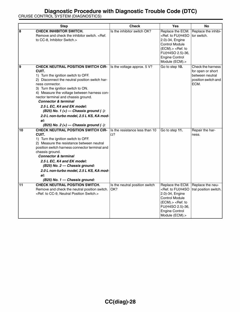
CRUISE CONTROL SYSTEM (DIAGNOSTICS)Diagnostic Procedure with Diagnostic Trouble Code (DTC)
8 CHECK INHIBITOR SWITCH.Remove and check the inhibitor switch. <Ref. to CC-8, Inhibitor Switch.>
Is the inhibitor switch OK? Replace the ECM. <Ref. to FU(H4SO 2.0)-34, Engine Control Module (ECM).> <Ref. to FU(H4SO 2.5)-36, Engine Control Module (ECM).>
Replace the inhibi-tor switch.
9 CHECK NEUTRAL POSITION SWITCH CIR-CUIT.1) Turn the ignition switch to OFF.2) Disconnect the neutral position switch har-ness connector.3) Turn the ignition switch to ON.4) Measure the voltage between harness con-nector terminal and chassis ground.
Connector & terminal2.5 L EC, K4 and EK model:
(B25) No. 1 (+) — Chassis ground (−):2.0 L non-turbo model, 2.5 L KS, KA mod-el:
(B25) No. 2 (+) — Chassis ground (−):
Is the voltage approx. 5 V? Go to step 10. Check the harness for open or short between neutral position switch and ECM.
10 CHECK NEUTRAL POSITION SWITCH CIR-CUIT.1) Turn the ignition switch to OFF.2) Measure the resistance between neutral position switch harness connector terminal and chassis ground.
Connector & terminal2.5 L EC, K4 and EK model:
(B25) No. 2 — Chassis ground:2.0 L non-turbo model, 2.5 L KS, KA mod-el:
(B25) No. 1 — Chassis ground:
Is the resistance less than 10 Ω?
Go to step 11. Repair the har-ness.
11 CHECK NEUTRAL POSITION SWITCH.Remove and check the neutral position switch. <Ref. to CC-9, Neutral Position Switch.>
Is the neutral position switch OK?
Replace the ECM. <Ref. to FU(H4SO 2.0)-34, Engine Control Module (ECM).> <Ref. to FU(H4SO 2.5)-36, Engine Control Module (ECM).>
Replace the neu-tral position switch.
Step Check Yes No
CC(diag)-28

CRUISE CONTROL SYSTEM (DIAGNOSTICS)Diagnostic Procedure with Diagnostic Trouble Code (DTC)
E: DTC 16 IGNITION SWITCHTROUBLE SYMPTOM:Cruise control cannot be set.WIRING DIAGRAM:• 2.0 L turbo model, 3.0 L model, 2.5 L EC, K4 and EK model
CC-00220
B137
ECM
D1
4
D:
B137
9
302928 31201918 222110 1211 14
242726
17161 2 3 4 5 6 7
1323
1525
8
D:
SBF-1 F/B No.12SBF-7
IGNITION SWITCHBATTERY
CC(diag)-29

CRUISE CONTROL SYSTEM (DIAGNOSTICS)Diagnostic Procedure with Diagnostic Trouble Code (DTC)
• 2.0 L non-turbo model, 2.5 L KS, KA model
CC-00271
B135
ECM
B1
3B:
SBF-1 F/B No.12SBF-7
IGNITION SWITCHBATTERY
B135
5 6 78
219
4310
2422 23 2511 12 13 14 15
26 2728
16 17 18 1920 21
29 30 31 32 33 34 35
B:
CC(diag)-30

CRUISE CONTROL SYSTEM (DIAGNOSTICS)Diagnostic Procedure with Diagnostic Trouble Code (DTC)
Step Check Yes No1 CHECK IGNITION SWITCH CIRCUIT.
1) Turn the ignition switch to OFF.2) Disconnect the ECM harness connector.3) Turn the ignition switch to ON.4) Measure the voltage between harness con-nector terminal and chassis ground.
Connector & terminal2.0 L turbo model, 3.0 L model, 2.5 L EC, K4 and EK model:
(B137) No. 14 (+) — Chassis ground (−):2.0 L non-turbo model, 2.5 L KS, KA mod-el:
(B135) No. 13 (+) — Chassis ground (−):
Is the voltage more than 10 V? Check poor con-tact in ECM con-nector.
• Check fuse No. 12 (in fuse & relay box).• Check the har-ness for open or short circuit between ignition switch and ECM.
CC(diag)-31

CRUISE CONTROL SYSTEM (DIAGNOSTICS)Diagnostic Procedure with Diagnostic Trouble Code (DTC)
F: DTC 22 AND 32 VEHICLE SPEED SENSORDIAGNOSIS:Disconnection or short circuit of vehicle speed sensor system.TROUBLE SYMPTOM:Cruise control cannot be set. (Cancelled immediately.)
Step Check Yes No1 CHECK ABS WARNING LIGHT.
1) Turn the ignition switch to ON.2) After the combination meter initial operation is completed, confirm that the ABS warning light continues to illuminate.
Does the ABS warning light continue to illuminate?
Check ABSCM or VDCCM <Ref. to ABS(diag)-2, Basic Diagnostic Procedure.> or <Ref. to VDC(diag)-2, Basic Diagnostic Procedure.>
Go to step 2.
2 CHECK LAN COMMUNICATION CIRCUIT ERROR DISPLAY.Check that the communication error is dis-played on the odo/trip meter in combination meter.
Is the error code “Er xx” dis-played on odo/trip meter?
Check the LAN communication cir-cuit. <Ref. to LAN(diag)-2, Basic Diagnostic Proce-dure.>
Replace the ECM. <Ref. to FU(H4SO 2.0)-34, Engine Control Module (ECM).> <Ref. to FU(H4SO 2.5)-36, Engine Control Module (ECM).> <Ref. to FU(H4DOTC)-35, Engine Control Module (ECM).> <Ref. to FU(H6DO)-34, Engine Control Module (ECM).>
CC(diag)-32

IMMOBILIZER (DIAGNOSTICS)
IM(diag)
Page1. Basic Diagnostic Procedure ........................................................................22. General Description ....................................................................................43. Electrical Component Location ...................................................................64. Immobilizer Control Module I/O Signal........................................................75. Subaru Select Monitor.................................................................................86. Read Diagnostic Trouble Code (DTC) ........................................................97. Clear Memory Mode..................................................................................108. Diagnostics Chart for Immobilizer Indicator Light......................................119. List of Diagnostic Trouble Code (DTC) .....................................................15
10. Diagnostic Procedure with Diagnostic Trouble Code (DTC) .....................17

IMMOBILIZER (DIAGNOSTICS)Basic Diagnostic Procedure
1. Basic Diagnostic ProcedureA: PROCEDURE
Step Check Yes No1 CHECK IMMOBILIZER WARNING LIGHT.
1) Turn the ignition switch to “OFF” or “ACC”.2) Wait for more than 60 seconds.
Does the immobilizer warning light blink?
Go to step 2. Check the immobi-lizer warning light circuit. <Ref. to IM(diag)-11, CHECK IMMOBI-LIZER INDICA-TOR CIRCUIT, INSPECTION, Diagnostics Chart for Immobilizer Indicator Light.>
2 CHECK KEY SWITCH.Remove the key from ignition switch.
Does the immobilizer warning light blink within 1 second after removing ignition key?
Go to step 3. Check the key switch circuit. <Ref. to IM(diag)-13, CHECK KEY SWITCH CIR-CUIT, INSPEC-TION, Diagnostics Chart for Immobi-lizer Indicator Light.>
3 CHECK IMMOBILIZER WARNING LIGHT.Turn the ignition switch to ON.
Does the immobilizer warning light off?
Go to step 5. Go to step 4.
4 CHECK ENGINE START.Turn the ignition switch to START.
Does the starter operate? Check the LAN communication cir-cuit. <Ref. to LAN(diag)-2, Basic Diagnostic Proce-dure.>
Check the DTC display (body inte-grated unit). Go to step 7.
5 CHECK ENGINE START.Turn the ignition switch to START.
Does the starter operate? Go to step 6. Check the LAN communication cir-cuit. <Ref. to LAN(diag)-2, Basic Diagnostic Proce-dure.>
6 CHECK ENGINE START.Turn the ignition switch to START.
Does the engine start? Immobilizer sys-tem is OK.
Check the DTC display (ECM). Go to step 7.
7 CHECK INDICATION OF DTC ON DISPLAY.1) Turn the ignition switch to OFF.2) Connect the Subaru Select Monitor to data link connector. <Ref. to IM(diag)-8, Subaru Select Monitor.>3) Turn the ignition switch and Subaru Select Monitor switch to ON.4) Read DTC on display.
Is the DTC displayed on screen?
Go to step 8. Repair the related parts.
IM(diag)-2

IMMOBILIZER (DIAGNOSTICS)Basic Diagnostic Procedure
8 PERFORM THE DIAGNOSIS.1) Inspect using the “Diagnostic Procedure with Diagnostic Trouble Code (DTC)”.<Ref. to IM(diag)-17, Diagnostic Procedure with Diagnostic Trouble Code (DTC).>2) Repair the trouble cause.3) Perform clear memory mode.4) Read DTC again.
Is the DTC displayed on screen?
Inspect using the “Diagnostic Proce-dure with Diagnos-tic Trouble Code (DTC)”. <Ref. to IM(diag)-17, Diag-nostic Procedure with Diagnostic Trouble Code (DTC).>
Finish the diagno-sis.
Step Check Yes No
IM(diag)-3

IMMOBILIZER (DIAGNOSTICS)General Description
2. General DescriptionA: CAUTIONCAUTION:• All airbag system wiring harnesses and con-nectors are yellow. Do not use the electricaltest equipment on these circuits.• Be careful not to damage the airbag systemwiring harness.• While diagnostic items are being checked, donot operate radios, portable telephones, etc.which emit electromagnetic waves near or in-side the vehicle.
• When turning the ignition switch to ON orOFF while diagnostic items are being checked,do not allow keys with different ID codes closeto the ignition switch. If the ignition key is in akey holder, remove it from the holder beforecarrying out diagnosis.
• When repeatedly turning the ignition switchto ON or OFF while diagnostic items are beingchecked, it should be switched in cycles of“ON” for at least 5 seconds → “OFF” for at least8 seconds.
• If the engine fails to start with a registered ig-nition key, detach the ignition key from ignitionswitch and wait for approx. 1 second until im-mobilizer indicator light begins to flash. Andthen start the engine again.• Before checking the diagnostic items, obtainall keys for the vehicle to be checked pos-sessed by owner.
IM-00001
IM-00002
(1) Ignition switch position
(2) Sec.
IM-00003
ON
OFF
5 8 (2)
(1)
IM(diag)-4

IMMOBILIZER (DIAGNOSTICS)General Description
B: PREPARATION TOOL1. SPECIAL TOOL
2. GENERAL TOOL
ILLUSTRATION TOOL NUMBER DESCRIPTION REMARKS
24082AA230 CARTRIDGE Troubleshooting for electrical system.
22771AA030 SUBARU SELECT MONITOR KIT
Troubleshooting for electrical system.• English: 22771AA030 (Without printer)• German: 22771AA070 (Without printer)• French: 22771AA080 (Without printer)• Spanish: 22771AA090 (Without printer)
TOOL NAME REMARKS
Circuit tester Used for measuring resistance, voltage and ampere.
ST24082AA230
ST22771AA030
IM(diag)-5

IMMOBILIZER (DIAGNOSTICS)Electrical Component Location
3. Electrical Component LocationA: LOCATION
NOTE:Body integrated unit location for RHD model is symmetrically opposite.
(1) Antenna (3) Body integrated unit (4) Transponder
(2) Immobilizer indicator light (LED bulb)
IM-00083
(2)
(4)
(1)
(3)
IM(diag)-6

IMMOBILIZER (DIAGNOSTICS)Immobilizer Control Module I/O Signal
4. Immobilizer Control Module I/O Signal
A: WIRING DIAGRAM1. IMMOBILIZER<Ref. to WI-246, WIRING DIAGRAM, ImmobilizerSystem.>
IM(diag)-7

IMMOBILIZER (DIAGNOSTICS)Subaru Select Monitor
5. Subaru Select MonitorA: OPERATION1. HOW TO USE SUBARU SELECT MONI-TOR1) Prepare the Subaru Select Monitor kit.
2) Connect the diagnosis cable to Subaru SelectMonitor.3) Insert the cartridge to Subaru Select Monitor.
4) Connect the Subaru Select Monitor to data linkconnector.
(1) Data link connector is located in the lowerportion of the instrument panel (on the driver’sside).
(2) Connect the diagnosis cable to data linkconnector.
CAUTION:Do not connect the scan tools except for Suba-ru Select Monitor.
5) Turn the ignition switch to ON (engine OFF), andthe Subaru Select Monitor switch to ON.
6) Using the Subaru Select Monitor, call up DTCsand various data, then record them.
2. READ DIAGNOSTIC TROUBLE CODE (DTC) FOR ENGINE AND BODY INTEGRAT-ED UNITRefer to Read Diagnostic Trouble Code for infor-mation about how to indicate DTC. <Ref. to IM(di-ag)-9, Read Diagnostic Trouble Code (DTC).>
3. COMMUNICATION LINE CHECK
NOTE:The communication line between ECM and bodyintegrated module can be checked in “System Op-eration Check Mode”. This is referred to as “Com-munication line check”.1) Connect the Subaru Select Monitor.2) On the «System operation check mode» display,select the security system.3) Start the communication line check.4) Is «Communication Line not Shorted» displayedon screen?If displayed, go to step 5).If “NO”, go to step 6). 5) After diagnostic results, it is determined that thecircuit is not shorted. Finish the communication linecheck.6) If a problem is detected, repair the troublecause. <Ref. to IM(diag)-22, DTC P1572 IMM CIR-CUIT FAILURE (EXCEPT ANTENNA CIRCUIT),Diagnostic Procedure with Diagnostic TroubleCode (DTC).>
CC-00028
CC-00029
IM-00084
(1) Power switch
CC-00045
(1)
IM(diag)-8

IMMOBILIZER (DIAGNOSTICS)Read Diagnostic Trouble Code (DTC)
6. Read Diagnostic Trouble Code (DTC)
A: OPERATION1. ECM1) On the «Main Menu» display screen, select theEach System Check and press the [YES] key.2) On the «System Selection Menu» displayscreen, select the Engine Control System andpress the [YES] key.3) Press the [YES] key after the information of en-gine type is displayed.4) On the «Engine Diagnosis» display screen, se-lect the Diagnostic Code(s) Display, and thenpress the [YES] key.5) On the «Diagnostic Code(s) Display» displayscreen, select the Current Diagnostic Code(s) orHistory Diagnostic Code(s), and then press the[YES] key.
NOTE:• For detailed operation procedure, refer to theSUBARU SELECT MONITOR OPERATION MAN-UAL.• For detailed concerning DTC, refer to the List ofDTC. <Ref. to IM(diag)-15, LIST, List of DiagnosticTrouble Code (DTC).>
2. BODY INTEGRATED UNIT1) On the «Main Menu» display screen, select theEach System Check and press the [YES] key.2) On the «System Selection Menu» displayscreen, select the Integ. unit mode and press the[YES] key.3) Press the [YES] key after the Integ. unit modeis displayed.4) On the «Integ. unit mode failure diag» displayscreen, select the Diagnostic Code(s) Displayand press the [YES] key.
NOTE:• For detailed operation procedure, refer to theSUBARU SELECT MONITOR OPERATION MAN-UAL.• For detailed concerning DTC, refer to the List ofDTC. <Ref. to IM(diag)-15, LIST, List of DiagnosticTrouble Code (DTC).>
IM(diag)-9

IMMOBILIZER (DIAGNOSTICS)Clear Memory Mode
7. Clear Memory ModeA: OPERATION1. ECM1) On the «Main Menu» display screen, select theEach System Check and press the [YES] key.2) On the «System Selection Menu» displayscreen, select the Engine Control System andpress the [YES] key.3) Press the [YES] key after the information of en-gine type is displayed.4) On the «Engine Diagnosis» display screen, se-lect the Clear Memory and press the [YES] key.5) When the ‘Done’ are shown on the displayscreen, turn the Subaru Select Monitor and ignitionswitch to OFF.
NOTE:• After the memory has been cleared, the idle aircontrol solenoid valve must be initialized. To exe-cute this procedure, turn the ignition switch to ON.Wait 3 seconds before starting the engine.• For detailed operation procedure, refer to theSUBARU SELECT MONITOR OPERATION MAN-UAL.
2. BODY INTEGRATED UNIT1) On the «Main Menu» display screen, select theEach System Check and press the [YES] key.2) On the «System Selection Menu» displayscreen, select the Integ. unit mode and press the[YES] key.3) Press the [YES] key after the Integ. unit modeis displayed.4) On the «Integ. unit mode failure diag» displayscreen, select the Clear Memory and press the[YES] key.5) When the ‘Done’ are shown on the displayscreen, turn the Subaru Select Monitor and ignitionswitch to OFF.
NOTE:For detailed operation procedure, refer to the SUB-ARU SELECT MONITOR OPERATION MANUAL.
IM(diag)-10
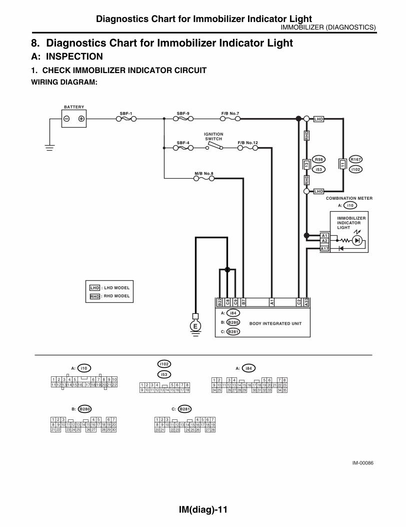
IMMOBILIZER (DIAGNOSTICS)Diagnostics Chart for Immobilizer Indicator Light
8. Diagnostics Chart for Immobilizer Indicator LightA: INSPECTION1. CHECK IMMOBILIZER INDICATOR CIRCUITWIRING DIAGRAM:
IM-00086
SBF-1
SBF-4
BATTERY
COMBINATION METER
BODY INTEGRATED UNIT
i10
R98
i53
F/B No.7
F/B No.12
IGNITIONSWITCH
A3
3
C2
B7
C9
C8
A17
A2
E
A:
A1
13
A1
M/B No.8
SBF-9
B2
2
i84A:
B280B:
B281C:
5 6 78
219
4310
2422 23 2511 12 13 14 15
26 27 2816 17 18 19
20 21
B281
i84
1 2 3 4 5 6 7 89 10 11 12 13 14 15 16 17 18 19 20 21 22 2324 25 26 27 28 29 30 31 32 33 34 35
54 6 78
219
310
22 2311 12 13 14 15
24 25 26 2716 17 18
28 2919 20
21 30
B280
i10
21 3 4 6 7 8 9 10222120191817161514131211
51 2 3 89 10
411 12 13 14 15 16
5 6 717 18
i53
A:
C:B:
A:
RH
D
LHD
11
R167
i102
: LHD MODEL
: RHD MODEL
LHD
RHD
i102
LHD
RH
D
IMMOBILIZERINDICATORLIGHT
IM(diag)-11
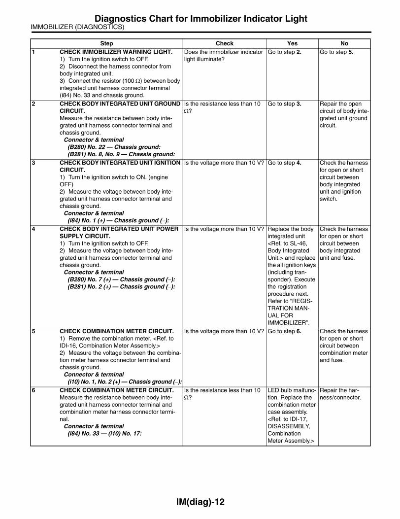
IMMOBILIZER (DIAGNOSTICS)Diagnostics Chart for Immobilizer Indicator Light
Step Check Yes No1 CHECK IMMOBILIZER WARNING LIGHT.
1) Turn the ignition switch to OFF.2) Disconnect the harness connector from body integrated unit.3) Connect the resistor (100 Ω) between body integrated unit harness connector terminal (i84) No. 33 and chassis ground.
Does the immobilizer indicator light illuminate?
Go to step 2. Go to step 5.
2 CHECK BODY INTEGRATED UNIT GROUND CIRCUIT.Measure the resistance between body inte-grated unit harness connector terminal and chassis ground.
Connector & terminal(B280) No. 22 — Chassis ground:(B281) No. 8, No. 9 — Chassis ground:
Is the resistance less than 10 Ω?
Go to step 3. Repair the open circuit of body inte-grated unit ground circuit.
3 CHECK BODY INTEGRATED UNIT IGNITION CIRCUIT.1) Turn the ignition switch to ON. (engine OFF)2) Measure the voltage between body inte-grated unit harness connector terminal and chassis ground.
Connector & terminal(i84) No. 1 (+) — Chassis ground (−):
Is the voltage more than 10 V? Go to step 4. Check the harness for open or short circuit between body integrated unit and ignition switch.
4 CHECK BODY INTEGRATED UNIT POWER SUPPLY CIRCUIT.1) Turn the ignition switch to OFF.2) Measure the voltage between body inte-grated unit harness connector terminal and chassis ground.
Connector & terminal(B280) No. 7 (+) — Chassis ground (−):(B281) No. 2 (+) — Chassis ground (−):
Is the voltage more than 10 V? Replace the body integrated unit <Ref. to SL-46, Body Integrated Unit.> and replace the all ignition keys (including tran-sponder). Execute the registration procedure next. Refer to “REGIS-TRATION MAN-UAL FOR IMMOBILIZER”.
Check the harness for open or short circuit between body integrated unit and fuse.
5 CHECK COMBINATION METER CIRCUIT.1) Remove the combination meter. <Ref. to IDI-16, Combination Meter Assembly.>2) Measure the voltage between the combina-tion meter harness connector terminal and chassis ground.
Connector & terminal(i10) No. 1, No. 2 (+) — Chassis ground (−):
Is the voltage more than 10 V? Go to step 6. Check the harness for open or short circuit between combination meter and fuse.
6 CHECK COMBINATION METER CIRCUIT.Measure the resistance between body inte-grated unit harness connector terminal and combination meter harness connector termi-nal.
Connector & terminal(i84) No. 33 — (i10) No. 17:
Is the resistance less than 10 Ω?
LED bulb malfunc-tion. Replace the combination meter case assembly. <Ref. to IDI-17, DISASSEMBLY, Combination Meter Assembly.>
Repair the har-ness/connector.
IM(diag)-12

IMMOBILIZER (DIAGNOSTICS)Diagnostics Chart for Immobilizer Indicator Light
2. CHECK KEY SWITCH CIRCUITWIRING DIAGRAM:
IM-00078
B350
KEY WARNINGSWITCH
B281
BODY INTEGRATED UNIT
BATTERY
M/B No.14
C7
34
C:
5 6 78
219
4310
2422 23 2511 12 13 14 15
26 27 2816 17 18 19
20 21
B281C:B350
1 2 3 4
IM(diag)-13

IMMOBILIZER (DIAGNOSTICS)Diagnostics Chart for Immobilizer Indicator Light
Step Check Yes No1 CHECK POWER SUPPLY CIRCUIT.
1) Disconnect the harness connector from key warning switch.2) Turn the ignition switch to “ACC” or “LOCK” (with key inserted).3) Measure the voltage between key warning switch harness connector terminal and chassis ground.
Connector & terminal(B350) No. 3 (+) — Chassis ground (−):
Is the voltage more than 10 V? Go to step 2. Check the harness for open or short circuit between key warning switch and fuse.
2 CHECK KEY WARNING SWITCH.1) Insert the ignition key to ignition switch. (OFF or ACC)2) Measure the resistance between key warn-ing switch terminals.
Connector & terminalNo. 3 — No. 4:
Is the resistance less than 1 Ω?
Go to step 3. Replace the key warning switch.
3 CHECK KEY WARNING SWITCH.1) Remove the ignition key from ignition switch.2) Measure the resistance between key warn-ing switch terminals.
Connector & terminalNo. 3 — No. 4:
Is the resistance more than 1 MΩ?
Go to step 4. Replace the key warning switch.
4 CHECK HARNESS BETWEEN KEY WARN-ING SWITCH AND BODY INTEGRATED UNIT.1) Disconnect the harness connector from key warning switch.2) Disconnect the harness connector from body integrated unit.3) Measure the resistance between key warn-ing switch harness connector terminal and body integrated unit harness connector termi-nal.
Connector & terminal(B350) No. 4 — (B281) No. 7:
Is the resistance less than 10 Ω?
Replace the body integrated unit <Ref. to SL-46, Body Integrated Unit.> and replace the all ignition keys (including tran-sponder). Execute the registration procedure next. Refer to “REGIS-TRATION MAN-UAL FOR IMMOBILIZER”.
Repair the har-ness between key warning switch and body inte-grated unit.
IM(diag)-14
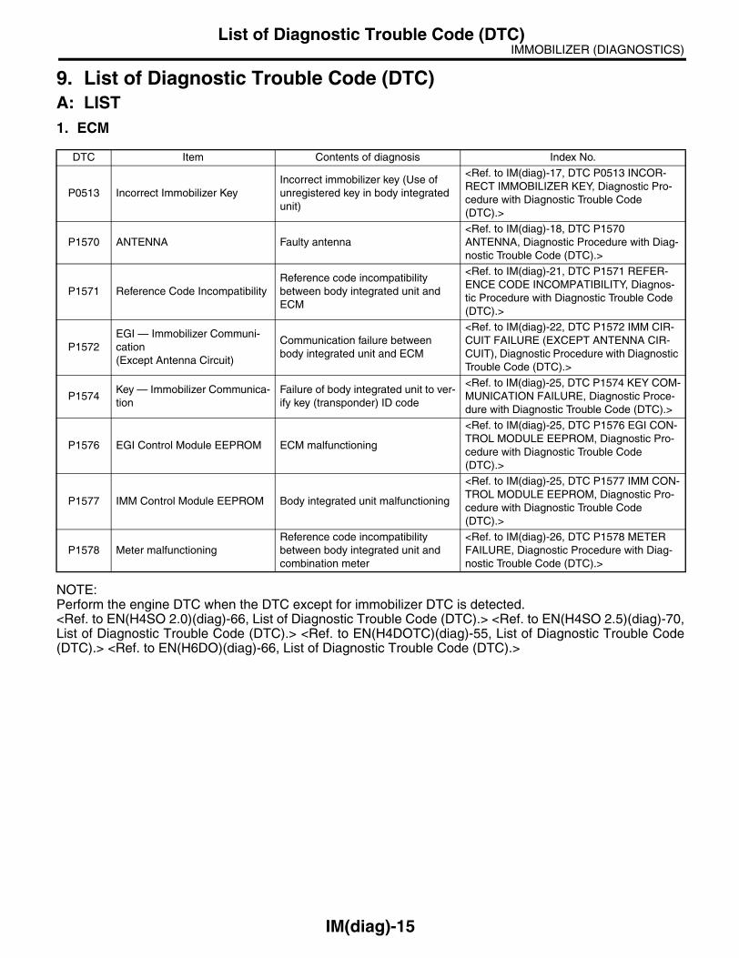
IMMOBILIZER (DIAGNOSTICS)List of Diagnostic Trouble Code (DTC)
9. List of Diagnostic Trouble Code (DTC)A: LIST1. ECM
NOTE:Perform the engine DTC when the DTC except for immobilizer DTC is detected. <Ref. to EN(H4SO 2.0)(diag)-66, List of Diagnostic Trouble Code (DTC).> <Ref. to EN(H4SO 2.5)(diag)-70,List of Diagnostic Trouble Code (DTC).> <Ref. to EN(H4DOTC)(diag)-55, List of Diagnostic Trouble Code(DTC).> <Ref. to EN(H6DO)(diag)-66, List of Diagnostic Trouble Code (DTC).>
DTC Item Contents of diagnosis Index No.
P0513 Incorrect Immobilizer KeyIncorrect immobilizer key (Use of unregistered key in body integrated unit)
<Ref. to IM(diag)-17, DTC P0513 INCOR-RECT IMMOBILIZER KEY, Diagnostic Pro-cedure with Diagnostic Trouble Code (DTC).>
P1570 ANTENNA Faulty antenna<Ref. to IM(diag)-18, DTC P1570 ANTENNA, Diagnostic Procedure with Diag-nostic Trouble Code (DTC).>
P1571 Reference Code IncompatibilityReference code incompatibility between body integrated unit and ECM
<Ref. to IM(diag)-21, DTC P1571 REFER-ENCE CODE INCOMPATIBILITY, Diagnos-tic Procedure with Diagnostic Trouble Code (DTC).>
P1572EGI — Immobilizer Communi-cation(Except Antenna Circuit)
Communication failure between body integrated unit and ECM
<Ref. to IM(diag)-22, DTC P1572 IMM CIR-CUIT FAILURE (EXCEPT ANTENNA CIR-CUIT), Diagnostic Procedure with Diagnostic Trouble Code (DTC).>
P1574Key — Immobilizer Communica-tion
Failure of body integrated unit to ver-ify key (transponder) ID code
<Ref. to IM(diag)-25, DTC P1574 KEY COM-MUNICATION FAILURE, Diagnostic Proce-dure with Diagnostic Trouble Code (DTC).>
P1576 EGI Control Module EEPROM ECM malfunctioning
<Ref. to IM(diag)-25, DTC P1576 EGI CON-TROL MODULE EEPROM, Diagnostic Pro-cedure with Diagnostic Trouble Code (DTC).>
P1577 IMM Control Module EEPROM Body integrated unit malfunctioning
<Ref. to IM(diag)-25, DTC P1577 IMM CON-TROL MODULE EEPROM, Diagnostic Pro-cedure with Diagnostic Trouble Code (DTC).>
P1578 Meter malfunctioningReference code incompatibility between body integrated unit and combination meter
<Ref. to IM(diag)-26, DTC P1578 METER FAILURE, Diagnostic Procedure with Diag-nostic Trouble Code (DTC).>
IM(diag)-15

IMMOBILIZER (DIAGNOSTICS)List of Diagnostic Trouble Code (DTC)
2. BODY INTEGRATED UNIT
NOTE:• Immobilizer system of 2.5 L EC, EK model and 3.0 L model perform the starter relay control. When thebody integrated unit detect the inconformity of reference code, immediately out put the starter relay cut signalto ECM, and then ECM stop the starter relay operation. In this case, engine does not start, and DTC is notrecorded in ECM. Check that the engine does not start on the DTC of body integrated unit.• DTC B0402 is recorded as freeze frame data when the ignition switch is turned to OFF. When trying to startthe engine with unregistered immobilizer key, DTC is not displayed on Subaru Select Monitor immediately.Turn the ignition switch to OFF once and turn to ON again before checking DTC. At this time (when turningthe ignition switch to ON again), be careful that the DTC is displayed as freeze frame data even with the reg-istered immobilizer key.
DTC Item Contents of diagnosis Index No.Relation between ECM and
DTC
B0401 M collation NGReference code incompatibil-ity between body integrated unit and combination meter
<Ref. to IM(diag)-26, DTC P1578 METER FAILURE, Diag-nostic Procedure with Diagnos-tic Trouble Code (DTC).>
P1578
B0402Immobilizer Key colla-tion NG
• Incorrect immobilizer key (Use of unregistered key in body integrated unit)• Faulty antenna
<Ref. to IM(diag)-17, DTC P0513 INCORRECT IMMOBI-LIZER KEY, Diagnostic Proce-dure with Diagnostic Trouble Code (DTC).> <Ref. to IM(diag)-18, DTC P1570 ANTENNA, Diagnostic Procedure with Diag-nostic Trouble Code (DTC).> or <Ref. to IM(diag)-25, DTC P1574 KEY COMMUNICA-TION FAILURE, Diagnostic Pro-cedure with Diagnostic Trouble Code (DTC).>
• P0513• P1570• P1574
B0403 E/G request NGCommunication failure between body integrated unit and ECM
<Ref. to IM(diag)-22, DTC P1572 IMM CIRCUIT FAILURE (EXCEPT ANTENNA CIR-CUIT), Diagnostic Procedure with Diagnostic Trouble Code (DTC).>
P1572
IM(diag)-16

IMMOBILIZER (DIAGNOSTICS)Diagnostic Procedure with Diagnostic Trouble Code (DTC)
10.Diagnostic Procedure with Diagnostic Trouble Code (DTC)A: DTC P0513 INCORRECT IMMOBILIZER KEYDTC DETECTING CONDITION:Incorrect immobilizer key (Use of unregistered key in body integrated unit)
Step Check Yes No1 PERFORM TEACHING OPERATION ON IG-
NITION KEY.Perform teaching operation on all keys of the vehicle. Refer to “REGISTRATION MANUAL FOR IMMOBILIZER”.
Is the teaching operation for all keys completed?
END. Replace the igni-tion keys (includ-ing transponder) which cannot be registered. Go to step 2.
2 PERFORM TEACHING OPERATION ON IG-NITION KEY.Perform teaching operation on all keys of the vehicle. Refer to “REGISTRATION MANUAL FOR IMMOBILIZER”.
Is the teaching operation for all keys completed?
END. Replace the body integrated unit <Ref. to SL-46, Body Integrated Unit.> and replace all the ignition keys (including tran-sponder). Execute the registration procedure next. Refer to “REGIS-TRATION MAN-UAL FOR IMMOBILIZER”.
IM(diag)-17

IMMOBILIZER (DIAGNOSTICS)Diagnostic Procedure with Diagnostic Trouble Code (DTC)
B: DTC P1570 ANTENNADTC DETECTING CONDITION:Faulty antennaWIRING DIAGRAM:
IM-00079
C2
0C
21
ANTENNA
B351
1 2
21
B281
BODY INTEGRATED UNIT
C:
B351
5 6 78
219
4310
2422 23 2511 12 13 14 15
26 27 2816 17 18 19
20 21
B281C:
IM(diag)-18

IMMOBILIZER (DIAGNOSTICS)Diagnostic Procedure with Diagnostic Trouble Code (DTC)
Step Check Yes No1 CHECK ANTENNA CIRCUIT.
1) Turn the ignition switch to OFF.2) Disconnect the harness connector from antenna. <Ref. to SL-50, Immobilizer Antenna.>3) Measure the resistance of antenna circuit.
Connector & terminal(B351) No. 1 — No. 2:
Is the resistance less than 10 Ω?
Go to step 2. Replace the antenna. <Ref. to SL-50, Immobi-lizer Antenna.>
2 CHECK ANTENNA CIRCUIT.1) Disconnect the harness connector from body integrated unit.2) Measure the resistance between harness connector and chassis ground.
Connector & terminal(B281) No. 21 — Chassis ground:
Is the resistance less than 10 Ω?
Repair the har-ness.
Go to step 3.
3 CHECK ANTENNA CIRCUIT.Measure the resistance between harness con-nector and chassis ground.
Connector & terminal(B281) No. 20 — Chassis ground:
Is the resistance less than 10 Ω?
Repair the har-ness.
Go to step 4.
4 CHECK ANTENNA CIRCUIT.1) Turn the ignition switch to ON. (engine OFF)2) Measure the voltage between harness con-nector and chassis ground.
Connector & terminal(B281) No. 21 (+) — Chassis ground (−):
Is the voltage 0 V? Go to step 5. Repair the har-ness.
5 CHECK ANTENNA CIRCUIT.Measure the voltage between harness connec-tor and chassis ground.
Connector & terminal(B281) No. 20 (+) — Chassis ground (−):
Is the voltage 0 V? Go to step 6. Repair the har-ness between body integrated unit and antenna, because there is short circuit with battery voltage line or ignition switch “ON” line.
6 CHECK BODY INTEGRATED UNIT FUNC-TION.1) Turn the ignition switch to OFF.2) Connect the harness connector to body integrated unit.3) Insert the key to ignition switch, and mea-sure the changes in voltage between antenna harness connectors.
Connector & terminal(B281) No. 20 (+) — No. 21 (−):
Is the voltage −30 to 30 V? (Approx. 0.1 second after inserting the key) Is the voltage 0 V? (Approx. 1 second after inserting the key)
Go to step 7. Replace the body integrated unit <Ref. to SL-46, Body Integrated Unit.> and replace all the ignition keys (including tran-sponder). Execute the registration procedure next. Refer to “REGIS-TRATION MAN-UAL FOR IMMOBILIZER”.
IM(diag)-19

IMMOBILIZER (DIAGNOSTICS)Diagnostic Procedure with Diagnostic Trouble Code (DTC)
7 CHECK IGNITION KEY (TRANSPONDER).1) Remove the key from ignition switch.2) Start the engine using other keys that have undergone the teaching operation, furnished with vehicle.
Does the engine start? Replace all the ignition keys (including tran-sponder). Execute the registration procedure next. Refer to “REGIS-TRATION MAN-UAL FOR IMMOBILIZER”.
Replace the body integrated unit <Ref. to SL-46, Body Integrated Unit.> and replace the all ignition keys (including tran-sponder). Execute the registration procedure next. Refer to “REGIS-TRATION MAN-UAL FOR IMMOBILIZER”.
Step Check Yes No
IM(diag)-20

IMMOBILIZER (DIAGNOSTICS)Diagnostic Procedure with Diagnostic Trouble Code (DTC)
C: DTC P1571 REFERENCE CODE INCOMPATIBILITYDTC DETECTING CONDITION:Reference code incompatibility between body integrated unit and ECM
Step Check Yes No1 PERFORM TEACHING OPERATION ON IG-
NITION KEY.Perform teaching operation on all keys of the vehicle. Refer to “REGISTRATION MANUAL FOR IMMOBILIZER”.
Is the teaching operation for all keys completed?
END. Replace the ECM. <Ref. to FU(H4SO 2.0)-34, Engine Control Module (ECM).> <Ref. to FU(H4SO 2.5)-36, Engine Control Module (ECM).> <Ref. to FU(H4DOTC)-35, Engine Control Module (ECM).> <Ref. to FU(H6DO)-34, Engine Control Module (ECM).> Replace the body integrated unit <Ref. to SL-46, Body Integrated Unit.> and replace all the ignition keys (including tran-sponder). Execute the registration procedure next. Refer to “REGIS-TRATION MAN-UAL FOR IMMOBILIZER”.
IM(diag)-21

IMMOBILIZER (DIAGNOSTICS)Diagnostic Procedure with Diagnostic Trouble Code (DTC)
D: DTC P1572 IMM CIRCUIT FAILURE (EXCEPT ANTENNA CIRCUIT)DTC DETECTING CONDITION:Communication failure between body integrated unit and ECMWIRING DIAGRAM:
IM-00087
SBF-1
SBF-9
SBF-4
BATTERY
F/B No.12
IGNITIONSWITCH
A1
B2
8
B1
8
C9
C2
B7
C8
E
F/B No.7
M/B No.8
BODY INTEGRATED UNIT
i84A:
B280B:
B281C:
B2
2
5 6 78
219
4310
2422 23 2511 12 13 14 15
26 27 2816 17 18 19
20 21
B281i84
1 2 3 4 5 6 7 89 10 11 12 13 14 15 16 17 18 19 20 21 22 2324 25 26 27 28 29 30 31 32 33 34 35
54 6 78
219
310
22 2311 12 13 14 15
24 25 26 2716 17 18
28 2919 20
21 30
B280A: C:B: B137
5 6 78
219
4310
22 2311 12 13 14 15
24 2526
16 1718 19 20 21
27 28 29 30 31
D:
D1
9
D2
7B
33
B2
51 *2 *
1*2*
: 2.0 L NA MODEL AND 2.5 L KS, KA MODEL
: 2.0 L TURBO MODEL, 3.0 L MODEL AND 2.5 L EC, K4, EK MODEL
B135
5 6 78
219
4310
2422 23 2511 12 13 14 15
26 2728
16 17 18 1920 21
29 30 31 32 33 34 35
B:
B137D:ECM
B135B:
IM(diag)-22

IMMOBILIZER (DIAGNOSTICS)Diagnostic Procedure with Diagnostic Trouble Code (DTC)
Step Check Yes No1 CHECK BODY INTEGRATED UNIT POWER
SUPPLY CIRCUIT.1) Turn the ignition switch to OFF.2) Disconnect the harness connector from body integrated unit.3) Measure the voltage between body inte-grated unit harness connector terminal and chassis ground.
Connector & terminal(B280) No. 7 (+) — Chassis ground (−):(B281) No. 2 (+) — Chassis ground (−):
Is the voltage more than 10 V? Go to step 2. Check the harness for open or short circuit between body integrated unit and fuse.
2 CHECK BODY INTEGRATED UNIT POWER SUPPLY CIRCUIT.1) Turn the ignition switch to ON. (engine OFF)2) Measure the voltage between body inte-grated unit harness connector terminal and chassis ground.
Connector & terminal(i84) No. 1 (+) — Chassis ground (−):
Is the voltage more than 10 V? Go to step 3. Check the harness for open or short circuit between body integrated unit and ignition switch.
3 CHECK BODY INTEGRATED UNIT GROUND CIRCUIT.1) Turn the ignition switch to OFF.2) Measure the resistance between body inte-grated unit harness connector terminal and chassis ground.
Connector & terminal(B280) No. 22 — Chassis ground:(B281) No. 8, No. 9 — Chassis ground:
Is the resistance less than 10 Ω?
Go to step 4. Repair the open circuit of body inte-grated unit ground circuit.
4 CHECK HARNESS BETWEEN BODY INTE-GRATED UNIT AND ECM.1) Disconnect the harness connector from body integrated unit and ECM.2) Measure the resistance between body inte-grated unit harness connector terminal and ECM connector terminal.
Connector & terminal2.0 L non-turbo model, 2.5 L KS, KA model
(B280) No. 18 — (B135) No. 25:2.0 L turbo model, 3.0 L model, 2.5 L EC, K4, EK model
(B280) No. 18 — (B137) No. 19:
Is the resistance less than 10 Ω?
Go to step 5. Repair the open circuit of harness between body inte-grated unit and ECM.
5 CHECK HARNESS BETWEEN BODY INTE-GRATED UNIT AND ECM.Measure the resistance between body inte-grated unit harness connector terminal and ECM connector terminal.
Connector & terminal2.0 L non-turbo model, 2.5 L KS, KA model
(B280) No. 28 — (B135) No. 33:2.0 L turbo model, 3.0 L model, 2.5 L EC, K4, EK model
(B280) No. 28 — (B137) No. 27:
Is the resistance less than 10 Ω?
Go to step 6. Repair the open circuit of harness between body inte-grated unit and ECM.
IM(diag)-23

IMMOBILIZER (DIAGNOSTICS)Diagnostic Procedure with Diagnostic Trouble Code (DTC)
6 CHECK HARNESS OF COMMUNICATION LINE.1) Turn the ignition switch to ON. (engine OFF)2) Measure the voltage between body inte-grated unit harness connector terminal and chassis ground.
Connector & terminal(B280) No. 18, No. 28 (+) — Chassis ground (−):
Is the voltage 0 V? Go to step 7. Repair the har-ness between body integrated unit and ECM, because there is short circuit with battery voltage line or ignition switch “ON” line.
7 CHECK HARNESS OF COMMUNICATION LINE.Measure the voltage between harness connec-tor terminal and engine ground.
Connector & terminal2.0 L non-turbo model, 2.5 L KS, KA model
(B135) No. 25, 33 (+) — Engine ground (−):
2.0 L turbo model, 3.0 L model, 2.5 L EC, K4, EK model
(B137) No. 19, 27 (+) — Engine ground (−):
Is the voltage 0 V? Go to step 8. Repair the har-ness between body integrated unit and ECM, because there is short circuit with battery voltage line or ignition switch “ON” line.
8 CHECK ECM BY COMMUNICATION LINE CHECK.1) Connect the harness connector to ECM.2) Disconnect the harness connector from body integrated unit.3) Start the communication line check. <Ref. to IM(diag)-8, COMMUNICATION LINE CHECK, OPERATION, Subaru Select Moni-tor.>
Does “Communication Line not Shorted” appear on the screen?
Replace the body integrated unit <Ref. to SL-46, Body Integrated Unit.> and replace the all ignition keys (including tran-sponder). Execute the registration procedure next. Refer to “REGIS-TRATION MAN-UAL FOR IMMOBILIZER”.
Replace the ECM. <Ref. to FU(H4SO 2.0)-34, Engine Control Module (ECM).> <Ref. to FU(H4SO 2.5)-36, Engine Control Module (ECM).> <Ref. to FU(H4DOTC)-35, Engine Control Module (ECM).> <Ref. to FU(H6DO)-34, Engine Control Module (ECM).> Perform the regis-tration procedure next. Refer to “REGISTRATION MANUAL FOR IMMOBILIZER”.
Step Check Yes No
IM(diag)-24

IMMOBILIZER (DIAGNOSTICS)Diagnostic Procedure with Diagnostic Trouble Code (DTC)
E: DTC P1574 KEY COMMUNICATION FAILUREDTC DETECTING CONDITION:Failure of body integrated unit to verify key (transponder) ID code
F: DTC P1576 EGI CONTROL MODULE EEPROMDTC DETECTING CONDITION:ECM malfunctioning
1. REPLACE ECMReplace the ECM. <Ref. to FU(H4SO 2.0)-34, Engine Control Module (ECM).> <Ref. to FU(H4SO 2.5)-36,Engine Control Module (ECM).> <Ref. to FU(H4DOTC)-35, Engine Control Module (ECM).> <Ref. toFU(H6DO)-34, Engine Control Module (ECM).>Perform the registration procedure next. Refer to “REGISTRATION MANUAL FOR IMMOBILIZER”.
G: DTC P1577 IMM CONTROL MODULE EEPROMDTC DETECTING CONDITION:Body integrated unit malfunctioning
1. REPLACE BODY INTEGRATED UNITReplace the body integrated unit <Ref. to SL-46, Body Integrated Unit.> and replace the all ignition keys (in-cluding transponder). Execute the registration procedure next. Refer to “REGISTRATION MANUAL FOR IM-MOBILIZER”.
Step Check Yes No1 CHECK BODY INTEGRATED UNIT FUNC-
TION.Insert the key to ignition switch (LOCK posi-tion), and measure the changes in voltage between antenna connectors.
Connector & terminal(B142) No. 1 — No. 2:
Is the voltage −30 to 30 V? (Approx. 0.1 second after inserting the key) Is the voltage 0 V? (Approx. 1 second after inserting the key)
Go to step 2. Replace the body integrated unit <Ref. to SL-46, Body Integrated Unit.> and replace the all ignition keys (including tran-sponder). Execute the registration procedure next. Refer to “REGIS-TRATION MAN-UAL FOR IMMOBILIZER”.
2 CHECK IGNITION KEY (TRANSPONDER).1) Remove the key from ignition switch.2) Start the engine using other keys that have undergone the teaching operation, furnished with vehicle.
Does the engine start? Replace all the ignition keys (including tran-sponder). Execute the registration procedure next. Refer to “REGIS-TRATION MAN-UAL FOR IMMOBILIZER”.
Replace the body integrated unit <Ref. to SL-46, Body Integrated Unit.> and replace the all ignition keys (including tran-sponder). Execute the registration procedure next. Refer to “REGIS-TRATION MAN-UAL FOR IMMOBILIZER”.
IM(diag)-25
IMMOBILIZER (DIAGNOSTICS)Diagnostic Procedure with Diagnostic Trouble Code (DTC)
H: DTC P1578 METER FAILUREDTC DETECTING CONDITION:Reference code incompatibility between body integrated unit and combination meter
1. CHECK LAN COMMUNICATION SYSTEMInspect LAN communication system in the following situation. <Ref. to LAN(diag)-2, Basic Diagnostic Proce-dure.>• DTC of body integrated unit B0300, B0301, B0302, B0111 or B0321 is displayed.• “Er IU” or “Er LC” is displayed in odo/trip meter on combination meter.
2. REPLACE COMBINATION METERReplace the combination meter. <Ref. to IDI-16, REMOVAL, Combination Meter Assembly.> Execute theregistration procedure of all immobilizer part (combination meter and etc.) next. Refer to “REGISTRATIONMANUAL FOR IMMOBILIZER”.
NOTE:• When the combination meter has been replaced, be sure to perform the registration procedure of immo-bilizer.• Engine may not start when the combination meter which removed from the model with immobilizer to themodel without immobilizer. When installed wrong one, correct with the following procedure.
(1) Turn the ignition switch to OFF.(2) Reinstall the combination meter. (Install the combination meter for the model without immobilizer.)(3) Disconnect the ground cable from battery, and reconnect one minute later.(4) Turn the ignition switch to START, and check that the engine starts.
• When the combination meter and body integrated unit are replaced at the same time, the registration pro-cedure cannot be performed. In this case, it is necessary to write an ID newly to body integrated unit.
IM(diag)-26

LAN SYSTEM (DIAGNOSTICS)
LAN(diag)
Page1. Basic Diagnostic Procedure ........................................................................22. Check List for Interview...............................................................................33. General Description ....................................................................................54. Electrical Component Location ...................................................................75. Control Module I/O Signal ...........................................................................96. Subaru Select Monitor...............................................................................147. Read Diagnostic Trouble Code (DTC) ......................................................248. Clear Memory Mode..................................................................................259. Read Current Data ....................................................................................26
10. Function Setting (Customize)....................................................................2711. List of Diagnostic Trouble Code (DTC) .....................................................2812. Diagnostic Procedure with Diagnostic Trouble Code (DTC) .....................3013. General Diagnostic Table..........................................................................79

LAN SYSTEM (DIAGNOSTICS)Basic Diagnostic Procedure
1. Basic Diagnostic ProcedureA: PROCEDURE1. WITH SUBARU SELECT MONITOR
CAUTION:• Subaru Select Monitor is required for reading DTC, performing diagnosis and reading current data.• Remove foreign matter (dust, water and oil etc.) from the body integrated unit connector during re-moval and installation.• For the model with immobilizer, registration of immobilizer may be needed after the replacement ofcontroller and etc. For detail procedure, refer to “REGISTRATION MANUAL FOR IMMOBILIZER”.
NOTE:• To check harness for broken wires or short circuits, shake it while holding it or the connector.• Check List for Interview <Ref. to LAN(diag)-3, Check List for Interview.>
Step Check Yes No1 CHECK PRE-INSPECTION.
1) Ask the customer when and how the trou-ble occurred using interview check list. <Ref. to LAN(diag)-3, Check List for Interview.>2) Check the display of freeze frame data. (Combination meter, odo/trip meter)
Is freeze frame data dis-played?
Go to step 3. Go to step 2.
2 BASIC INSPECTION.Check the components which might affect body control. <Ref. to LAN(diag)-5, INSPEC-TION, General Description.>
Is the component that might influence the body control problem normal?
Go to step 3. Repair or replace each unit.
3 CHECK INDICATION OF DTC.1) Read the DTC. <Ref. to LAN(diag)-14, READ DIAGNOSTIC TROUBLE CODE (DTC), OPERATION, Subaru Select Monitor.>
NOTE:If the communication function of the Subaru Se-lect Monitor cannot be executed normally,check the communication circuit. <Ref. toLAN(diag)-30, COMMUNICATION FOR INI-TIALIZING IMPOSSIBLE, Diagnostic Proce-dure with Diagnostic Trouble Code (DTC).>2) Record all DTCs and freeze frame data.
Is DTC displayed? Go to step 5. Go to step 4.
4 PERFORM THE GENERAL DIAGNOSTICS.Inspect using “General Diagnostics Table”. <Ref. to LAN(diag)-79, General Diagnostic Table.>
Is result of inspection OK? LAN system is nor-mal.
Go to step 5.
5 PERFORM THE DIAGNOSIS.1) Fix the wrong part.2) Perform the clear memory mode. <Ref. to LAN(diag)-20, CLEAR MEMORY MODE, OPERATION, Subaru Select Monitor.>3) Read DTC. <Ref. to LAN(diag)-14, READ DIAGNOSTIC TROUBLE CODE (DTC), OPERATION, Subaru Select Monitor.>
Is DTC displayed? Repeat step 5 until DTC is not shown.
Finish the diagno-sis.
LAN(diag)-2

LAN SYSTEM (DIAGNOSTICS)Check List for Interview
2. Check List for InterviewA: CHECKInspect the following items about the vehicle’s state.
1. DISPLAY OF FREEZE FRAME DATA
2. DISPLAY IN COMBINATION METER
3. SYMPTOMS
Freeze frame data is dis-played in odo/trip meter.
When and how often are they displayed? Always Sometimes Only once
Which freeze frame data is displayed? (Record them all) Er IU (Fail in the body integrated unit) Er HC (Fail of high-speed CAN) Er LC (Fail of low-speed CAN) Er −− (Fails of both high-speed and low-speed CAN) Er EG (Fail of EGI communication counter) Er TC (Fail of TCM communication counter) Er Ab (Fail of vehicle dynamics control (VDC)/ABS communication counter)
Ignition key position OFF ACC ON (before starting engine) START ON (after Engine starting, engine is running) ON (after Engine starting, engine is at a standstill)
Timing Immediately after turning the ignition to ON Immediately after turning the ignition to START
Display in combination meter
a) Display of temperature gauge OK / NG
b) Display of fuel gauge OK / NG
Center display c) Display of ambient temperature OK / NG
Display of other indicators d) Malfunction indicator light ON / OFF
e) SPORT indicator light (AT warning light) ON / OFF
f) ABS warning light/Vehicle dynamics control (VDC) warning light
ON / OFF
g) Immobilizer indicator light ON / Blink / OFF
h) Seat belt warning light (Driver’s seat) ON / OFF
i) Seat belt warning light (Passenger’s seat) ON / OFF
Behavior of vehicle a) Illumination volume control is not available. Yes / No
b) Rear wiper does not operate. Yes / No
c) Wiper deicer does not operate. Yes / No
d) Rear defogger does not operate. Yes / No
e) Door lock does not operate. Yes / No
f) Trunk/rear gate lock does not operate Yes / No
g) Driver’s door lock does not operate. Yes / No
h) Shift lock does not operate. Yes / No
i) Rear fog light does not come on. Yes / No
j) Double lock does not operate. (EK model) Yes / No
k) Heater cock valve does not operate. Yes / No
l) Key illumination blinks. Yes / No
LAN(diag)-3
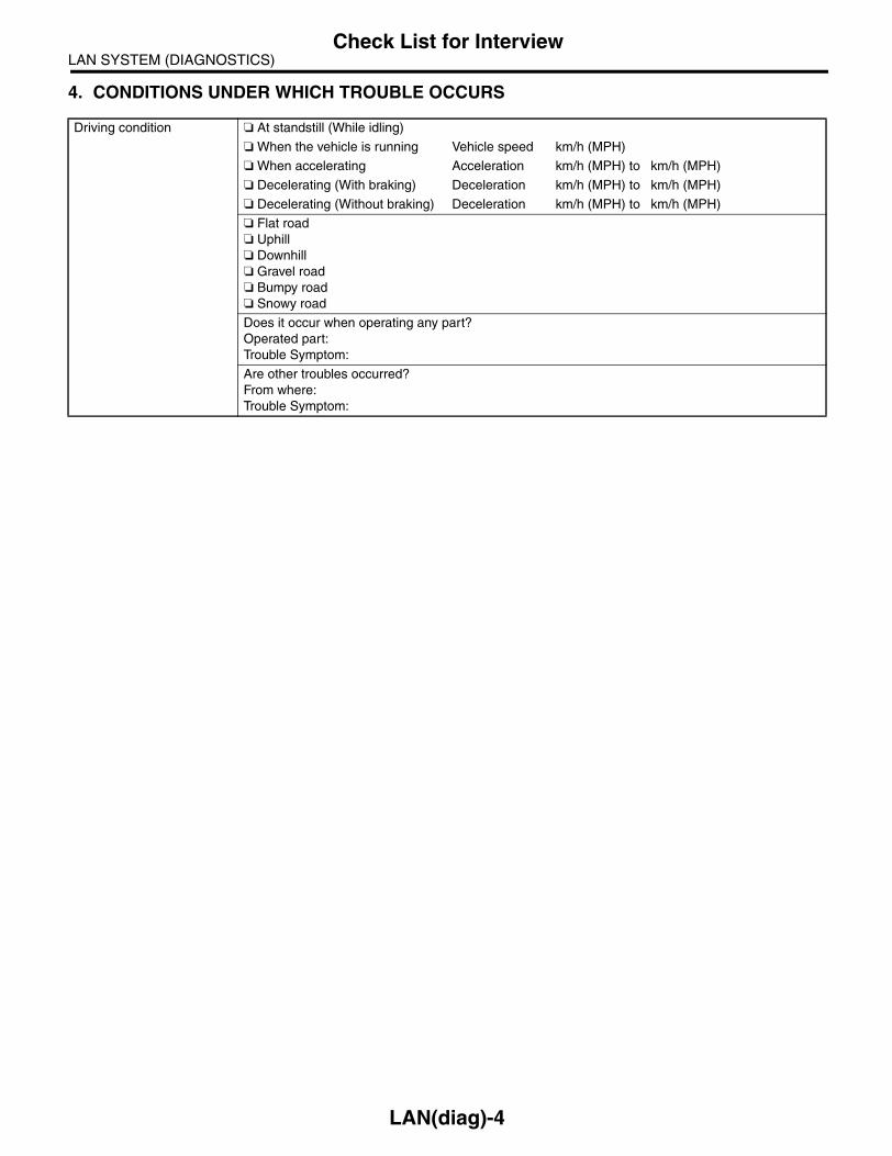
LAN SYSTEM (DIAGNOSTICS)Check List for Interview
4. CONDITIONS UNDER WHICH TROUBLE OCCURS
Driving condition At standstill (While idling)
When the vehicle is running Vehicle speed km/h (MPH)
When accelerating Acceleration km/h (MPH) to km/h (MPH)
Decelerating (With braking) Deceleration km/h (MPH) to km/h (MPH)
Decelerating (Without braking) Deceleration km/h (MPH) to km/h (MPH)
Flat road Uphill Downhill Gravel road Bumpy road Snowy road
Does it occur when operating any part?Operated part:Trouble Symptom:
Are other troubles occurred?From where:Trouble Symptom:
LAN(diag)-4

LAN SYSTEM (DIAGNOSTICS)General Description
3. General DescriptionA: CAUTION1. SRS AIRBAG SYSTEMAirbag system wiring harness is routed near thebody integrated unit and twisted pair line.
CAUTION:• All airbag system wiring harness and con-nectors are colored yellow. Do not use the elec-trical test equipment on these circuits.• Be careful not to damage the Airbag systemwiring harness when servicing the body inte-grated unit and LAN system.
2. LAN SYSTEM• Bus line of LAN system is twisted pair line. Becareful not to bypass or partly unbind the twistedpair line.• Do not make clearance between bus lines (CANHigh, CAN Low).• Difference of bus line length should be within 10cm (3.94 in).• Fray near the connector should be within 8 cm(3.94 in).
• If the characteristics of the twisted pair line ischanged, it may cause extremely weakness to thenoise.
• When repairing the harness, connect the wiresusing soldering and protect it with insulating tape,etc.
B: INSPECTIONBefore performing diagnostics, check the followingitems which might affect body integrated unit mal-functions.1) Measure the battery voltage and check electro-lyte.
Standard voltage: 12 V, or more
Specific gravity: Above 1.2602) Check the fuse condition.Make sure that ampere of the fuse is setting value,and it is not blown out.3) Check the connecting condition of harness andharness connector.4) Confirm settings of body integrated unit are cor-responded to vehicle equipment. <Ref. to LAN(di-ag)-18, REGISTRATION BODY INTEGRATEDUNIT (EQUIPMENT SETTING), OPERATION,Subaru Select Monitor.>5) Confirm setting are corresponded to vehicleequipment by function setting (ECM customizing)of body integrated unit. <Ref. to LAN(diag)-20,FREEZE FRAME DATA, OPERATION, SubaruSelect Monitor.>6) Confirm “Factory initial setting” of body integrat-ed unit registrations is “Market”.7) Confirm key illumination does not blink with igni-tion switch turned to ON.
(A) Bypass wire connection
LAN00081
(A)
(A) Soldering and protection with insulating tape
LAN00080
(A)
LAN(diag)-5
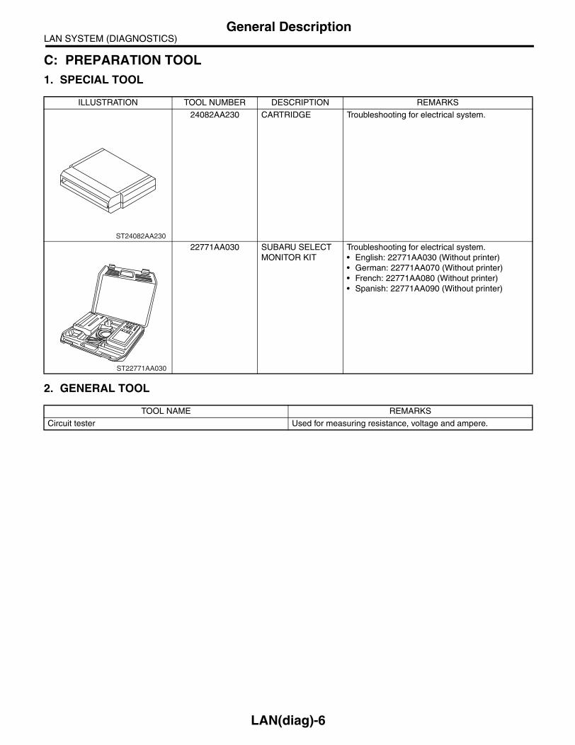
LAN SYSTEM (DIAGNOSTICS)General Description
C: PREPARATION TOOL1. SPECIAL TOOL
2. GENERAL TOOL
ILLUSTRATION TOOL NUMBER DESCRIPTION REMARKS
24082AA230 CARTRIDGE Troubleshooting for electrical system.
22771AA030 SUBARU SELECT MONITOR KIT
Troubleshooting for electrical system.• English: 22771AA030 (Without printer)• German: 22771AA070 (Without printer)• French: 22771AA080 (Without printer)• Spanish: 22771AA090 (Without printer)
TOOL NAME REMARKS
Circuit tester Used for measuring resistance, voltage and ampere.
ST24082AA230
ST22771AA030
LAN(diag)-6

LAN SYSTEM (DIAGNOSTICS)Electrical Component Location
4. Electrical Component LocationA: LOCATION
(1) Body integrated unit (6) A/C control panel (10) Steering angle sensor
(2) Engine control module (ECM) (7) Center display (11) ABSCM&H/U or VDCCM&H/U (In engine compartment)(3) Auto A/C control unit (8) Transmission control module
(TCM)(4) Navigation module (12) Odo/trip meter
(5) Keyless entry control unit (Antenna)
(9) Combination meter
LAN00101
(1)
(2)
(3)
(4)
(5)(6)(7)(8)
(9)
(10)
(11)
(12)
LAN00102
(1)
LAN00103
(2)
(3)
LAN(diag)-7

LAN SYSTEM (DIAGNOSTICS)Electrical Component Location
LAN00104
(4)
(5)
LAN00105
(6)
LAN00007
(7)
LAN00106
(8)
LAN00107
(9)
(10)
LAN00008
(11)
0
LAN00111
km/h
160
180
14040
608
20
P F
E
RND
SPORT
CRUISE
SET(12)
LAN(diag)-8

LAN SYSTEM (DIAGNOSTICS)Control Module I/O Signal
5. Control Module I/O SignalA: ELECTRICAL SPECIFICATION
DescriptionConnector
No.Terminal No.
Signal (V or Ω)NOTEIgnition switch ON
(engine OFF)
System control power supply
B281 C2 10 — 13 V Always
Backup power supply B280 B7 10 — 13 V Always
Ignition power supply i84 A1 10 — 13 V Ignition ON
ACC power supply i84 A24 10 — 13 V ACC ON
Ground
i84 A21
Less than 1 Ω AlwaysB281 C9
B281 C8
B280 B22
Key warning switch B281 C7 10 — 13 V When ignition key inserted
Stop light switch B281 C23 10 — 13 V When brake pedal depressed
Illumination volume (Vi1)
i84 A10 4.5 — 5.5 V Small light ON
Illumination volume (Vi 2)
i84 A2 0.5 — 4.5 V —
Illumination volume (Vi 3)
i84 A25 Less than 1 Ω Ground circuit
Illumination output i84 A5 10 — 13 V Small light ON
Front fog light input B281 C17 10 — 13 V Front fog light ON
Rear fog light input B281 C4 10 — 13 VSmall light ON
Front fog light ONRear fog light ON
Rear fog light output B280 B13 10 — 13 V Rear fog light ON
Headlight input B281 C16 10 — 13 V Headlight ON (Both of Hi, Lo)
Door switch inputDriver’s seat
i84 A19 Less than 1 V (10 — 13 V at OFF) Driver’s door open (ON)
Door switch inputPassenger’s seat
i84 A32 Less than 1 V (10 — 13 V at OFF) Passenger’s door open (ON)
Door switch inputRear RH seat
i84 A18 Less than 1 V (10 — 13 V at OFF) Rear RH door open (ON)
LAN00012
5 6 78
219
4310
2422 23 2511 12 13 14 15
26 27 2816 17 18 19
20 21
B281
54 6 78
219
310
22 2311 12 13 14 15
24 25 26 2716 17 18
28 2919 20
21 30
B280i84
1 2 3 4 5 6 7 89 10 11 12 13 14 15 16 17 18 19 20 21 22 2324 25 26 27 28 29 30 31 32 33 34 35
A: B: C:
LAN(diag)-9

LAN SYSTEM (DIAGNOSTICS)Control Module I/O Signal
Door switch input Rear LH seat
i84 A31 Less than 1 V (10 — 13 V at OFF) Rear LH door open (ON)
Door switchTrunk/Rear gate
i84 A17 Less than 1 V (10 — 13 V at OFF) Trunk/Rear gate open (ON)
Illumination control switch
i84 A30 10 — 13 V (at dimmer ON)Extinct the clock and audio illumi-
nation
Manual switch (LOCK) i84 A15 Less than 1 Ω Door lock switch ON
Manual switch (UNLOCK)
i84 A29 Less than 1 Ω Door lock switch ON
Door lock power supply i84 A34 10 — 13 V
All door LOCK output i84 A7 10 — 13 V Manual, door key switch ON
All door UNLOCK out-put
i84 A8 10 — 13 V Manual, door key switch ON
Trunk/Rear gate UNLOCK output
i84 A22 10 — 13 VWhen the trunk open signal received with keyless entry
(Sedan model)
Key/shift lock power supply
B281 C1 10 — 13 V
Shift lock output B280 B6 10 — 13 VIgnition switch ON, at “P” range,
foot brake ON
Wiper deicer switch i84 A14 Less than 1 Ω Wiper deicer switch ON
Wiper deicer relay out-put
B280 B14 Less than 1 Ω Wiper deicer relay ON
Rear defogger switch i84 A28 Less than 1 Ω Rear defogger switch ON
Rear defogger relay output
B281 B16 Less than 1 Ω Rear defogger relay ON
Shift switch (ON) B281 C26 Less than 1 Ω At Manual mode
Shift switch (UP) B281 C15 Less than 1 Ω At Manual mode UP
Shift switch (DOWN) B281 C25 Less than 1 Ω At Manual mode DOWN
“P” range switch B281 C13 Less than 1 Ω
Impact sensor B281 C5 Less than 1 Ω Impact sensor ON (Model with immobilizer)
Fuel level sensor B281 C19 0 — 102.3 Ω
Ambient sensorB281 C3 0.5 — 4.5 V SIG
B281 C10 Less than 1 Ω GND
Seat belt switch (driver’s seat)
i84 A4 Less than 1 Ω Driver’s seat belt worn
Seat belt switch (passenger’s seat)
i84 A13 Less than 1 Ω Passenger’s seat belt worn
Seat belt warning light (driver’s seat)
i84 A20 Less than 1 Ω Driver’s seat belt worn
Seat belt warning light (passenger’s seat)
B281 C24 Less than 1 Ω Passenger’s seat belt worn
Sedan/Wagon identifi-cation switch
B281 C11Sedan 10 — 13 VWagon 0 — 5 V
Rear wiper switch (ON) B281 C6 Less than 1 Ω Rear wiper switch ON
Rear wiper switch (INT) B281 C18 Less than 1 Ω Rear wiper switch ON
Rear washer switch B281 C27 Less than 1 Ω Rear washer switch ON
Rear wiper power sup-ply
B280 B21 10 — 13 V
Rear wiper ON output B280 B1 10 — 13 V Rear wiper switch ON
Rear wiper return B280 B8Less than 1 Ω
B1 — B8 1 Ω or lessAt wiper reversing
DescriptionConnector
No.Terminal No.
Signal (V or Ω)NOTEIgnition switch ON
(engine OFF)
LAN(diag)-10

LAN SYSTEM (DIAGNOSTICS)Control Module I/O Signal
Room light output B280 B3 Less than 1 ΩWhen LOCK, UNLOCK with key-
less entry
Key ring illumination output
B280 B4 Less than 1 Ω Ignition key removed, driver door open
Turn hazard output B280 B12 Less than 1 Ω When operating keyless entry answer back
Keyless buzzer output i84 A6 Less than 1 ΩWhen operating keyless entry
answer back
Immobilizer pilot light i84 A33 Less than 1 Ω At ignition key removed, immobi-lizer operating
Kick down switch B280 B12 Less than 1 Ω Kick down switch ON
Keyless communication i84 A9 2 — 10 V At keyless entry signal received
High-speed CAN circuit (Hi)
B280 B20Between B20 — B30Serial communication
At communicating (sending and receiving)High-speed CAN circuit
(Lo)B280 B30
Low-speed CAN circuit 1 (Hi)
i84 A26Between A25 — A26Serial communication
At communicating (sending and receiving)Low-speed CAN circuit
1 (Lo)i84 A25
Low-speed CAN circuit 2 (Hi)
B280 B26Between B25 — B27Serial communication
At communicating (sending and receiving)(Model with auto A/C)Low-speed CAN circuit
2 (Lo)B280 B27
Immobilizer antenna B281 C20 — C21 Serial communication
Immobilizer communi-cation(Main)
B280B18
(Back-up B28)
Serial communication
Subaru Select Monitor communication
B280 B19 Serial communication
DescriptionConnector
No.Terminal No.
Signal (V or Ω)NOTEIgnition switch ON
(engine OFF)
LAN(diag)-11

LAN SYSTEM (DIAGNOSTICS)Control Module I/O Signal
B: WIRING DIAGRAM
BODYINTEGRATED
UNIT
SYSTEM CONTROL POWER SUPPLY
IGNITION POWER SUPPLY
BACKUP POWER SUPPLY
GROUND
ACC POWER SUPPLY
GROUND
GROUND
GROUND
B7
A24
B22
A1
A25
A10
C23
A2
C7
C9
C2
A21
C8
KEY WARNING SWITCH
STOP LIGHT SWITCH(AT MODEL)
ILLUMINATIONVOLUME
FRONT FOG LIGHT INPUTREAR FOG LIGHT INPUT
HEADLIGHT INPUT
DRIVER'S SEATPASSENGER'S SEAT
REAR SEAT (RIGHT SIDE)REAR SEAT (LEFT SIDE)
TRUNK / REAR GATE
ILLUMINATION CONTROL SWITCH (CLOCK)
MANUAL SWITCH (LOCK)MANUAL SWITCH (UNLOCK) REAR WIPER SWITCH (ON)
REAR WIPER SWITCH (INT)
REAR WASHER SWITCH
WIPER DEICER SWITCH
SHIFT SWITCH (ON)
SHIFT SWITCH (UP)
SHIFT SWITCH (DOWN)
FUEL LEVEL SENSOR
AMBIENT SENSOR (SIG)
AMBIENT SENSOR (GND)
SEDAN / WAGON IDENTIFICATION SWITCH
REGISTRATION MODE SWITCH (EXCEPT FOR EK MODEL)KEYLESS COMMUNICATION
HIGH-SPEED CAN CIRCUIT (HI)HIGH-SPEED CAN CIRCUIT (LO)
LOW-SPEED CAN CIRCUIT 1 (HI)
LOW-SPEED CAN CIRCUIT 2 (HI)
LOW-SPEED CAN CIRCUIT 1 (LO)
LOW-SPEED CAN CIRCUIT 2 (LO)
IMMOBILIZER ANTENNA
IMMOBILIZER COMMUNICATION (MAIN)IMMOBILIZER COMMUNICATION (BACKUP)
SUBARU SELECT MONITOR COMMUNICATION
REAR DEFOGGER RELAY OUTPUT
DOOR LOCK POWER SUPPLYALL DOORS LOCK OUTPUT
TRUNK / REAR GATE UNLOCK OUTPUT
ALL DOORS UNLOCK OUTPUT
SHIFT LOCK POWER SUPPLY
SHIFT LOCK OUTPUT
REAR WIPER POWER SUPPLY
REAR WIPER ON OUTPUT
REAR WIPER RETURN
REAR DEFOGGER SWITCH(MODEL WITH MANUAL A/C)
WIPER DEICER RELAY OUTPUT
ILLUMINATION OUTPUT
ROOM LIGHT OUTPUT
KEY RING ILLUMINATION OUTPUT
A5
C4
C17
A17
A31A18
A32A19
C16
B13REAR FOG LIGHT OUTPUT
TURN HAZARD OUTPUT
B4
B3
B11
C22
B19
C28
A33
C18
C6
B28
B25
C21
C20
B18
B8
B21
B1
B12
IMMOBILIZER PILOT LIGHT
ALARM CONTROL ECM (EK MODEL)
5 6 78
219
4310
2422 23 2511 12 13 14 15
26 27 2816 17 18 19
20 21
B281
54 6 78
219
310
22 2311 12 13 14 15
24 25 26 2716 17 18
28 2919 20
21 30
B280i84
1 2 3 4 5 6 7 89 10 11 12 13 14 15 16 17 18 19 20 21 22 2324 25 26 27 28 29 30 31 32 33 34 35
A: B: C:
B281
B280
i84A:
B:
C:
LAN00108
(BLUE)
HEATER COCK VALVE OUTPUT
DRIVER'S SEAT DOOR LOCK (EXCEPT FOR EK MODEL)
DOUBLE LOCK OUTPUT (EK MODEL)
B14
A34
A7
B6C1
A15
A30
A22
A29
A28
A14
B16
A8
A16
B15
A23
A35
"P" RANGE SWITCH
SEAT BELT SWITCH (DRIVER'S SEAT)
SEAT BELT SWITCH (PASSENGER'S SEAT)
SEAT BELT WARNING LIGHT(DRIVER'S SEAT)SEAT BELT WARNING LIGHT (PASSENGER'S SEAT)
C25
C26
C15
C19
C3
C10
C13
A4
A13
C22
B20
A27
C11
B30
A9
A26
B26
A20
B27
ENGINE HOOD SWITCH
DOORSWITCH
INPUT
SECURITY HORN OUTPUT(EXCEPT FOR EK MODEL)
B11
LAN(diag)-12

LAN SYSTEM (DIAGNOSTICS)Control Module I/O Signal
C: LAN SYSTEM
(1) Body integrated unit (8) Audio⋅A/C control panel (15) Subaru Select Monitor communi-cation line(2) ECM (9) Navigation system
(3) TCM (10) Center display (16) Subaru Select Monitor
(4) VDC/ABSCM (11) Combination meter (17) Low speed CAN (Body integrated unit)(5) Steering angle sensor (12) Clock
(6) Keyless entry receiver (13) Exclusive communication line (18) High speed CAN (Driving control)
(7) A/C control unit (14) IE-Bus (AV)
LAN00109
(1)
(6)
(7)
(8)
(14)
(17)
(11)(12)
(13)
(18)
(13)
(13)
(9)
(13)
(10)
(13)
(2)
(3)
(15)
(4)
(5)
(16)
LAN(diag)-13

LAN SYSTEM (DIAGNOSTICS)Subaru Select Monitor
6. Subaru Select MonitorA: OPERATION1. READ DIAGNOSTIC TROUBLE CODE (DTC)
NOTE:• DTC is displayed in the sequence of inputting.(When inputting more than two simultaneously,DTC is displayed in the sequence of priority.)• When more than two DTCs are displayed, per-form the diagnosis of top of them.1) Prepare the Subaru Select Monitor kit.
2) Connect the diagnosis cable to Subaru SelectMonitor.3) Insert the cartridge to Subaru Select Monitor.<Ref. to LAN(diag)-6, SPECIAL TOOL, PREPARA-TION TOOL, General Description.>
4) Connect the Subaru Select Monitor to data linkconnector.Data link connector is located in the lower portion ofthe instrument panel (on the driver’s side).
CAUTION:Do not connect scan tools except for Subaru Select Monitor.5) Turn the ignition switch to ON (engine OFF) andturn the Subaru Select Monitor switch to ON.
6) On the «Main Menu» display screen, select theEach System Check and press the [YES] key.7) On the «System Selection Menu» displayscreen, select the Integ. Unit mode and press the[YES] key.8) On the «Integ. Unit mode failuer diag» displayscreen, select the Diagnostic Code(s) Displayand press the [YES] key.
NOTE:• For details concerning operation procedure, re-fer to “SUBARU SELECT MONITOR OPERATIONMANUAL”.• For details concerning DTCs, refer to the List ofDiagnostic Trouble Code (DTC). <Ref. to LAN(di-ag)-28, List of Diagnostic Trouble Code (DTC).>
LAN00014
LAN00015
ST
LAN00110
(A) Power switch
LAN00017
(A)
LAN(diag)-14

LAN SYSTEM (DIAGNOSTICS)Subaru Select Monitor
2. READ CURRENT DATA1) On the «Main Menu» display screen, select the Each System Check and press the [YES] key.2) On the «System Selection Menu» display screen, select the Integ. Unit mode and press the [YES] key.3) On the «Integ. Unit mode failuer diag» display screen, select the Current Data Display & Save and pressthe [YES] key.4) On the «Current Data Display & Save» display screen, select the 12 Data Display and press the [YES]key.5) Using the scroll key, scroll the display screen up or down until the desired data is shown.• A support list contains both of analog and digital data, and they are shown in the following table.
3. DISPLAY OF ANALOG DATA
Items to be displayed Unit of measure NOTE
BATT Voltage (Control) 10 — 15 V —
BATT Voltage (BACK UP) 10 — 15 V —
IG power supply voltage 10 — 15 V —
ACC voltage 10 — 15 V —
Illumination VR voltage 0 — 5 V —
Illumi. output d-ratio 0 — 100% —
ambient temp sensor V 0 — 5 V —
Ambient temperature −40 — 87.5°C —
Fuel level voltage 0 — 8 V —
Fuel level resistance 0 — 102.3 Ω Body integrated unit input value
key-lock solenoid V 6 — 12 V —
number of regist. 0 — 4 —
Front Wheel Speed km/h —
VDC/ABS latest f-code DTC display (Temporarily)This is normal when the DTC is not input
though the this code is displayed
Blower fan steps 0 — 2 level 0: OFF, 1: Low, 2: More than 2 level
Fuel level resistance2 0 — 102.3 Ω Body integrated unit output
Fuel consumption cc/s —
Coolant Temp. −40 — 130°C —
Vehicle lateral G m/s2 —
SPORT Shift Stages 0 — 7 levels(0: light OFF, 6: fail, 7: ATF temperature
High/Low)
Shift Position 0 — 7 levels (8 is no input)
Off delay time OFF, Short, Normal, Long —
Auto lock time 20, 30, 40, 50, 60 seconds —
LAN(diag)-15

LAN SYSTEM (DIAGNOSTICS)Subaru Select Monitor
4. DISPLAY OF ON/OFF DATA
Items to be displayed Unit of measure
key-lock warning SW ON/OFF
Stop Light Switch ON/OFF
Front fog lamp SW input ON/OFF
Rear fog lamp SW input ON/OFF
lighting SW input ON/OFF
Door key-lock SW input ON/OFF
Door unlock SW input ON/OFF
Driver’s door SW input ON/OFF
P-door SW input ON/OFF
Rear right door SW input ON/OFF
Rear left door SW input ON/OFF
R Gate SW input ON/OFF
Manual lock SW input ON/OFF
Manual unlock SW input ON/OFF
Lock SW (front hood) ON/OFF
Bright SW input ON/OFF
Tiptronic Mode Switch ON/OFF
TIP UPSW input ON/OFF
TIP DOWN SW input ON/OFF
P SW ON/OFF
R wiper ON SW input ON/OFF
R wiper INT SW input ON/OFF
R washer SW input ON/OFF
wiper deicer SW input ON/OFF
Rear Defogger SW ON/OFF
Driver’s Seat SW input ON/OFF
P seatbelt SW input ON/OFF
Fr wiper input ON/OFF
Registration SW input ON/OFF
Identification SW input ON/OFF
Rr defogger output ON/OFF
lock actuat. LOCK output ON/OFF
All seat UNLOCK output ON/OFF
D-seat UNLOCK output ON/OFF
R gate/trunk UNLK output ON/OFF
Double lock output ON/OFF
R wiper output ON/OFF
Shift Lock Solenoid ON/OFF
Key locking output ON/OFF
wiper deicer SW input ON/OFF
Starter cutting output ON/OFF
Hazard Output ON/OFF
Keyless Buzzer Output ON/OFF
Horn Output ON/OFF
Siren Output ON/OFF
D-belt warning light O/P ON/OFF
P-belt warning light O/P ON/OFF
Illumination lamp O/P ON/OFF
Room lamp output ON/OFF
key illumi. lamp o/p ON/OFF
R fog lamp output ON/OFF
R fog lamp monitor ON/OFF
Immobilizer lamp output ON/OFF
Keyless operation 1 Registration/Normal
Keyless operation 2 Clear/Normal
CC Main Lamp On/Off
CC Set Lamp On/Off
SPORT Lamp On/Off
SPORT Blink Blink/Off
ATF Temperature Lamp On/Off
ATF Blink Blink/Off
Tire diameter abnormal 1 On/Off
Tire diameter abnormal 2 Blink/Off
SPORT Shift (UP) UP/OFF
SPORT Shift (DOWN) DOWN/OFF
SPORT Shift (buzzer 1) ON/OFF
SPORT Shift (buzzer 2) ON/OFF
ABS/VDC Judging ABS/VDC
ADA Existence Judging Yes/No
Small lamp SW ON/OFF
Headlamp ON/OFF
Headlight HI ON/OFF
Turn signal LH ON/OFF
Turn signal RH ON/OFF
Rr Defogger SW ON/OFF
Australia Judging Flag Australia/Others
Tire 18inch flag 18 in/others
Number of cylinders 4 cylinders/6 cylinders
Cam shaft specification SOHC/DOHC
Turbo Turbo/Non-turbo
E/G displacement (2.5L) 2.5 L/ OFF
E/G displacement (3.0L) 3.0 L/ OFF
AT/MT identification terminal AT model/MT model
E/G cooling fan ON/OFF
Heater cock valve ON/OFF
Power window (Up) ON/OFF
Power window (Down) ON/OFF
Keyless buzzer ON/OFF
Bright Request ON/OFF
P/W ECM Failure NG/OK
Keyless Hook SW ON/OFF
Door lock SW (Open) ON/OFF
Door lock SW (Close) ON/OFF
Door Key SW (Open) ON/OFF
Door Key SW (Close) ON/OFF
Under hook registration ON/OFF
Hook registration end ON/OFF
Unlock request ON/OFF
Center display failure OK/NG
NAVI Failure OK/NG
IE Bus failure Can not use
Items to be displayed Unit of measure
LAN(diag)-16

LAN SYSTEM (DIAGNOSTICS)Subaru Select Monitor
NOTE:For details concerning operation procedure, referto “SUBARU SELECT MONITOR OPERATIONMANUAL”.
5. CONFIRMATION OF CURRENT SETTING1) On the «Main Menu» display screen, select the Each System Check and press the [YES] key.2) On the «System Selection Menu» display screen, select the Integ. Unit mode and press the [YES] key.3) On the «Integ. Unit mode failuer diag» display screen, select the Current Data Display & Save and pressthe [YES] key.4) On the «Current Data Display & Save» display screen, select the 12 Data Display and press the [YES]key.5) Using the scroll key, scroll the display screen up or down until the desired data is shown.6) Display the following items and record the settings.Required items for new registration (Except for system not equipped)
Auto A/C failure OK/NG
EBD Warning Light OK/OFF
ABS Warning Light OK/OFF
VDC OFF flag ON/OFF
VDC/ABS OK B OK/NG
VDC/ABS condition 0 — 4
Destinat. 0 — 16
Touch SW 0 — 64
Items to be displayed Unit of measure
Item Item to confirm Remarks
Key No. to register 1 2 3 4 Registered ID type
Off delay OFF Long Normal Short Setting for lighting off time
Auto-lock 60, 50, 40, 30, 20 OFF (Unit sec.)
Rr defogger op. mode Normal Continuous
Wiper deicer op. mode Normal Continuous Optional setting
Security Alarm Setup ON OFF
Impact Sensor Setup ON OFF Optional setting
Alarm monitor delay setting ON OFF
Lockout prevention ON OFF
Impact Sensor Yes No Optional setting
Siren setting Yes No Optional setting
Answer-back buzzer setup ON OFF Not equipped
Hazard answer-back setup ON OFF
Automatic locking setup ON OFF
Ans.-back Buzzer Yes No Not equipped
Auto locking Yes No
Door open warning (prevention of battery run-out)
Yes No
A/C ECM setting Yes No Model with auto A/C
P/W ECM setting Yes No Not equipped
Center display failure Yes No Model with center display
Wiper deicer Yes No Optional setting
Rear fog light setting Yes No Optional setting
Factory initial setting Manufacture Market Not change to Manufacture mode
Security setting (Specified security set-ting)
Yes NoOperate the selected security set.
(EK model)
LAN(diag)-17

LAN SYSTEM (DIAGNOSTICS)Subaru Select Monitor
6. REGISTRATION BODY INTEGRATED UNIT (EQUIPMENT SETTING)
CAUTION:Body integrated unit is core of LAN system, and also can select the function of all vehicle sys-tem control. It is possible to control the original functions of vehicle when registrations of body integrated unit and function setting are corre-sponded to vehicle equipment.If registrations and function setting are differ-ent from vehicle equipment, vehicle systemdoes not operate normally and diagnosis can-not be performed correctly. Pay attention toitems below.• Be sure to correspond registrations andfunction settings to vehicle equipment.• Do not change the settings of vehicle improp-erly.• Confirm key illumination does not blink or“Factory initial setting” of body integrated unitregistrations is “Market”. If “Factory initial set-ting” is set to “Factory”, key illumination blinkswith ignition key turned to ON to give warningof unconfirmed settings.• Key illumination does not blink with ignitionswitch turned to ON and go off with doorclosed.• Be sure to register immobilizer if body inte-grated unit is replaced with a new one. (Modelwith immobilizer)• Make a registration of immobilizer when theparts replaced related to immobilizer. Refer to“REGISTRATION MANUAL FOR IMMOBILIZ-ER”.1) Turn the ignition switch to OFF.2) Connect the Subaru Select Monitor to data linkconnector.
3) Turn the ignition switch to ON and Subaru SelectMonitor to ON.
4) On the «Main Menu» display screen, select theEach System Check and press the [YES] key.5) On the «Each System Check» display screen,select the Integ. Unit mode and then select the“ECM customizing”.
LAN00110
(A) Power switch
LAN00017
(A)
LAN(diag)-18

LAN SYSTEM (DIAGNOSTICS)Subaru Select Monitor
6) Change the setting with UP/DOWN key and press the [YES] key.• List of body integrated unit registration item
NOTE:Setting is different depending on grade of vehicle.
CAUTION:• It is possible to control the original functions of vehicle when registrations of body integrated unitand function setting are corresponded to vehicle equipment.• When body integrated unit is new one or “Factory” mode, key illumination blinks to show equip-ment settings does not completed.• Be sure not to change Factory initial setting except installation of new body integrated unit.
NOTE:• “Factory” mode:
• Body integrated unit has been not set yet. It can be recognized by key illumination blinking with ignitionswitch turned to ON.• All body integrated units as part for repair are set to “Factory” mode. When replacing a body integratedunit, be sure to perform the registration operation.
• “Market” mode:Each settings have been set. It can be recognized by key illumination coming on in concocting with roomlight and going off with ignition switch turned to ON.
Data Initial setting Registration Remarks
21 A/C ECM setting OFF
ONIllumination control does not operate if A/C ECM setting is set to “OFF” in case of model with auto A/C.
OFFIf A/C ECM setting is set to “ON” in case of model without auto A/C, illumination change to night illu-mination and it is difficult to be recognized.
22 P/W ECM setting OFFON Be sure to set P/W ECM setting to “OFF”.
Auto-reverse functionOFF
23 Center display failure (OP) OFFON Information may not be displayed on center display
if Center display failure is set to “OFF” in case of model with center display.OFF
24 Wiperdeicer (OP) OFFON ON signal does not output with operation of wiper
deicer switch if Wiperdeicer is set to “OFF” in model with wiper deicer.OFF
25 Rear fog light setting (OP) OFF
ONVehicle is controlled in rear fog light equipped mode.
OFFVehicle is controlled in rear fog light no-equipped mode. (Be sure to set to “OFF” in model without rear fog light.
26Factory initial setting (Reset of body integrated unit)
FactoryFactory (Reset) If Factory initial setting is set to “Factory”, registra-
tions of items above is changed to “OFF”. Be sure to set to “Market”.Market (Settlement)
LAN(diag)-19

LAN SYSTEM (DIAGNOSTICS)Subaru Select Monitor
7) Perform the Factory setting. On the «ECM cus-tomizing» display screen of Subaru Select Monitor,select the Factory initial setting and press the[YES] key.8) Change the mode from Factory into Market.9) Replace the immobilizer cartridge, and registerthe immobilizer key. (Model with immobilizer)10) Perform the registration according to the proce-dures of “IMMOBILIZER REGISTRATION MANU-AL”.11) When key registration is completed, “Do youwant to register remote engine start?” is displayed.Perform the registration only if equipped.12) Perform the function setting (ECM customiz-ing).<Ref. to LAN(diag)-21, FUNCTION SETTING(ECM CUSTOMIZING), OPERATION, Subaru Se-lect Monitor.>
NOTE:For details concerning operation procedure, referto “SUBARU SELECT MONITOR OPERATIONMANUAL”.
7. CLEAR MEMORY MODE1) On the «Main Menu» display screen, select the2. Each System Check and press the [YES] key.2) On the «System Selection Menu» displayscreen, select the Integ. Unit mode and press the[YES] key.3) Press [YES] key after displayed the informationof body integrated unit type.4) On the «Integ. Unit mode failuer diag» displayscreen, select the Clear Memory and press the[YES] key.
5) When the “Done” are shown on the displayscreen, turn the ignition switch to OFF.
NOTE:For detailed operation procedure, refer to “SUBA-RU SELECT MONITOR OPERATION MANUAL”.
8. FREEZE FRAME DATA
NOTE:• Data stored at the time of trouble occurrence isshown on display.• Freeze frame data will be memorized maximumto 20.• If freeze frame data is not stored in memory cor-rectly (caused by low power supply of body inte-grated unit), DTC will be displayed with “?” on thehead of it in the Subaru Select Monitor display. Thisshows it may be an unreliable reading.
Display Contents to be monitored
Clear memory?Clear function of DTC and freeze frame data
LAN(diag)-20

LAN SYSTEM (DIAGNOSTICS)Subaru Select Monitor
9. FUNCTION SETTING (ECM CUSTOMIZING)1) On the «Main Menu» display screen, select the Each System Check and press the [YES] key.2) On the «System Selection Menu» display screen, select the Integ. Unit mode and press the [YES] key.3) On the «Integ. Unit mode failuer diag» display screen, select the ECM customizing and press the [YES]key.4) Change the setting with UP/DOWN key and press the [YES] key.• List of function setting item (ECM customizing)
No. DataInitial
setting value
Customize setting Remarks
1 Off delay time Normal
Delay time below can be selected by setting.
Setting After door closed After key unlock
OFF 0 sec. 0 sec.
Short 3 sec. 10 sec.
Normal 5 sec. 20 sec.
Long 8 sec. 30 sec.
2 Auto-lock time 30 sec. 0 — 60 seconds
Workable when Auto locking is set to “ON” and Automatic locking setup is “ON”Time can be changed by 10 seconds: 0 (OFF) — 60 (maxi-mum).
3 Rr defogger op. mode 15 min.15 min.
Rear defogger stops in 15 minutes automatically after switch is turned to ON.
ContinuationRear defogger repeats active condition for 15 minutes and inactive condition for 2 minutes until switch is turned to OFF.
4 Wiper deicer op. mode 15 min.15 min.
Wiper deicer stops in 15 minutes automatically after switch is turned to ON.
ContinuationWiper deicer repeats active condition for 15 minutes and inactive condition for 2 minutes until switch is turned to OFF.
5 Security Alarm Setup OFFON Security alarm (horn or siren) in active condition
OFF Security alarm in inactive condition
6 Impact Sensor Setup OFF
ONWorkable when Impact Sensor Setup is set to “ON”Impact sensor in active condition
OFFImpact sensor in inactive condition(Set Impact Sensor Setup of model without impact sensor to “OFF”.)
7 Alarm monitor delay setting ON
After doors are locked by keyless entry system operated, Alarm monitor starts in following time.
ON Delay time is 30 seconds.
OFF Delay time is 0 second.
8 Lockout prevention ONON
Lockout prevention in active condition(Lockout prevention does not operate if safety knob is locked by hand.)
OFF Lockout prevention in inactive condition
9 Impact sensor (OP) OFFON
Vehicle is controlled in impact sensor equipped mode. (Set Impact sensor to “OFF” in model without impact sensor. If Impact sensor is set to “ON”, hazard, horn or siren operate after doors are locked by keyless entry system operated (Alarm monitor starting).
OFF Vehicle is controlled in impact sensor no-equipped mode.
10 Siren setting OFFON
Siren sounds when alarm operates.(Set Siren setting to “OFF” in model without siren. Horn does not sound if Siren setting is set to “ON”.)
OFF Horn sounds when alarm operates.
LAN(diag)-21

LAN SYSTEM (DIAGNOSTICS)Subaru Select Monitor
5) After setting, make sure that vehicle equipment is same as the setting changed in the Current Data Dis-play & Save.
CAUTION:• It is possible to control the original functions of vehicle when settings above are corresponded tovehicle equipment.• Do not change the settings except for setting above during operation of equipment setting.• Be sure not to change “Factory” initial setting except in installation of new body integrated unit.
NOTE:For details concerning operation procedure, refer to “SUBARU SELECT MONITOR OPERATION MANUAL”.
11 Answer-back buzzer setup ONON
Workable when Answer-back buzzer setup is set to “ON”When lock/unlock is selected by keyless entry system oper-ated, answer-back buzzer sounds.
OFFWhen lock/unlock is selected by keyless entry system oper-ated, answer-back buzzer does not sound.
12 Hazard answer-back setup ONON
Workable when Hazard answer-back setup is set to “ON”When lock/unlock is selected by keyless entry system oper-ated, hazard answer-back operates.
OFFWhen lock/unlock is selected by keyless entry system oper-ated, hazard answer-back does not operate.
13 Automatic locking setup ONON
Workable when Automatic locking setup is set to “ON”When lock/unlock is selected by keyless entry system oper-ated, automatic locking operates.
OFFWhen lock/unlock is selected by keyless entry system oper-ated, automatic locking does not operate.
14 Ans.-back Buzzer ON
ON Vehicle is controlled in answer-back buzzer equipped mode.
OFFVehicle is controlled in answer-back buzzer non-equipped mode. (Set Ans.-back Buzzer to “OFF” in model without answer back buzzer.)
15 Auto locking ON
ON Vehicle is controlled in auto locking equipped mode.
OFFVehicle is controlled in auto locking non-equipped mode. (Set Auto locking to “OFF” in model without answer-back buzzer.)
16 Initial Keyless Setting — — —
ExecutionSettings of keyless entry system are initialized. (No. 2: 30 sec., No.11: ON, No.12: ON, No.13: ON, No.14: ON)
17 Initial button setting — — —
ExecutionSettings of each function are initialized. (No. 1: Normal, No. 3: 15 min., No. 4: 15 min., No. 8: ON)
18 Initial Security setting — — —
ExecutionSettings of security system are initialized. (No. 5: OFF, No. 6: OFF, No. 7: ON, No.10: OFF)
19 Passive Alarm (Not used) OFFON Applicable to North America model (If Passive Alarm is set
to “ON”, nothing operates and there is no negative effect.)OFF
20Door open warning (prevention of battery run-out)
OFFON
If detecting door open for 30 minutes, room light, key illumi-nation and door warning light are turned off to prevent bat-tery run-out.
OFFRoom light, key illumination and door warning light is not turned off.
21(Specification) Security setup
OFFON Selected security settings in active condition (EK model)
OFF Normally in active condition
No. DataInitial
setting value
Customize setting Remarks
LAN(diag)-22

LAN SYSTEM (DIAGNOSTICS)Subaru Select Monitor
10.FUNCTION CHECK In order to check the body integrated unit function,inspect the body integrated unit and actuator usingSubaru Select Monitor without operating switches.1) On the «Main Menu» display screen, select theEach System Check and press the [YES] key.2) On the «System Selection Menu» displayscreen, select the Integ. Unit mode and press the[YES] key.3) On the «Integ. Unit mode failuer diag» displayscreen, select the System Operation Check Modeand press the [YES] key.4) Select item to operate on the «System OperationCheck Mode» display screen with “UP/Down key”,and press the [YES] key.
5) Pressing [YES] starts, [NO] cancels the opera-tion and [YES] returns to the System OperationCheck Mode display screen.
NOTE:If not equipped (based on area or condition), pro-cess will not go on.
LAN00018
Function checkHeater cock valve outputlock actuat, LOCK outputAll seat UNLOCK, outputDouble lock SolenoidShift Lock Solenoidkey locking outputHorn output
LAN(diag)-23
LAN SYSTEM (DIAGNOSTICS)Read Diagnostic Trouble Code (DTC)
7. Read Diagnostic Trouble Code (DTC)
A: OPERATION1. WITHOUT SUBARU SELECT MONITOR
NOTE:Use the Subaru Select Monitor, because DTCs cannot be read out.
2. WITH SUBARU SELECT MONITORFor details concerning DTC reading procedure, re-fer to “Subaru Select Monitor”. <Ref. to LAN(diag)-14, READ DIAGNOSTIC TROUBLE CODE (DTC),OPERATION, Subaru Select Monitor.>
LAN(diag)-24

LAN SYSTEM (DIAGNOSTICS)Clear Memory Mode
8. Clear Memory ModeA: OPERATION1. WITHOUT SUBARU SELECT MONITOR
NOTE:Use the Subaru Select Monitor for Clear MemoryMode.
2. WITH SUBARU SELECT MONITORFor detailed procedures of clearing DTC, refer to“SUBARU SELECT MONITOR”. <Ref. to LAN(di-ag)-20, CLEAR MEMORY MODE, OPERATION,Subaru Select Monitor.>
LAN(diag)-25

LAN SYSTEM (DIAGNOSTICS)Read Current Data
9. Read Current DataA: OPERATION1) On the «Main Menu» display screen, select theEach System Check and press the [YES] key.2) On the «System Selection Menu» displayscreen, select the Integ. Unit mode and press the[YES] key.3) On the «Integ. Unit mode failuer diag» displayscreen, select the Current Data Display & Saveand press the [YES] key.4) On the «Data Display Menu» screen, select the12 Data Display and press the [YES] key.5) Using the scroll key, scroll the display screen upor down until the desired data is shown.<Ref. to LAN(diag)-15, DISPLAY OF ANALOG DA-TA, OPERATION, Subaru Select Monitor.> <Ref.to LAN(diag)-16, DISPLAY OF ON/OFF DATA,OPERATION, Subaru Select Monitor.> <Ref. toLAN(diag)-17, CONFIRMATION OF CURRENTSETTING, OPERATION, Subaru Select Monitor.>
LAN(diag)-26

LAN SYSTEM (DIAGNOSTICS)Function Setting (Customize)
10.Function Setting (Customize)A: OPERATION1. WITHOUT SUBARU SELECT MONITOR
NOTE:Applied to the Model with center display.1) Display the information screen with pressing the“INFO” switch of center display.2) Select “SET” on the touch panel at the right topof center display screen.3) Select the item from “A: Keyless entry” or “B:Various setup” on the touch panel.
4) Change the setting on the touch panel whichcontains item to be changed.5) Return to the information display screen andcomplete it.Function setting item list
2. WITH SUBARU SELECT MONITORFor detailed procedures of function setting (ECMcustomizing), refer to “SUBARU SELECT MONI-TOR”. <Ref. to LAN(diag)-21, FUNCTION SET-TING (ECM CUSTOMIZING), OPERATION,Subaru Select Monitor.>
Item Setting
Keyless
Auto lock
Auto lock time setting
Answerback hazard
Each function
Room light delay time
Anti-lock out
Rear defogger
Wiper deicer
(B)(A)
LAN00112
LAN(diag)-27

LAN SYSTEM (DIAGNOSTICS)List of Diagnostic Trouble Code (DTC)
11.List of Diagnostic Trouble Code (DTC)A: LIST
DTC Item Content of diagnosis NOTE
None Communication for initializing impossible
Open or short in Subaru Select Monitor communi-cation line.
<Ref. to LAN(diag)-30, COMMUNICATION FOR INITIALIZING IMPOSSIBLE, Diagnostic Procedure with Diagnostic Trouble Code (DTC).>
None DTC is not stored. Internal error of combina-tion meter.
<Ref. to LAN(diag)-33, DIAGNOSTIC TROU-BLE CODE (DTC) IS NOT STORED, Diagnostic Procedure with Diagnostic Trouble Code (DTC).>
B0100 Integ. unit system error Body integrated unit inter-nal error
<Ref. to LAN(diag)-33, DTC B0100 INTEG. UNIT SYSTEM ERROR, Diagnostic Procedure with Diagnostic Trouble Code (DTC).>
B0101 BATT power supply (Control) error Open or short in battery power supply control cir-cuit
<Ref. to LAN(diag)-34, DTC B0101 BATT P/SUPPLY MALFUNCTION CONT., Diagnostic Procedure with Diagnostic Trouble Code (DTC).>
B0102 BATT p/supply malfunction cont. Open or short in BATT power backup circuit
<Ref. to LAN(diag)-36, DTC B0102 BATT P/SUPPLY MALFUNCTION CONT., Diagnostic Procedure with Diagnostic Trouble Code (DTC).>
B0103 IGN power failure Open or short in IGN power supply circuit
<Ref. to LAN(diag)-38, DTC B0103 IGNITION POWER FAILURE, Diagnostic Procedure with Diagnostic Trouble Code (DTC).>
B0104 ACC power failure Open or short in ACC power supply circuit
<Ref. to LAN(diag)-40, DTC B0104 ACC POWER FAILURE, Diagnostic Procedure with Diagnostic Trouble Code (DTC).>
B0106 shift lock circuit Failure Ground short of shift lock circuit
<Ref. to LAN(diag)-42, DTC B0106 SHIFT LOCK CIRCUIT FAILURE, Diagnostic Proce-dure with Diagnostic Trouble Code (DTC).>
B0107 R Fog lamp circuit Failure Ground short of rear fog circuit
<Ref. to LAN(diag)-44, DTC B0107 R FOG LAMP CIRCUIT FAILURE, Diagnostic Proce-dure with Diagnostic Trouble Code (DTC).>
B0201 High speed CAN fail ⋅ error counter abnormal
Malfunction of high-speed CAN communication
<Ref. to LAN(diag)-46, DTC B0201 CAN-HS COUNTER ABNORMAL, Diagnostic Procedure with Diagnostic Trouble Code (DTC).>
B0202 CAN-HS bus off Any unit is cut communi-cation.
<Ref. to LAN(diag)-47, DTC B0202 CAN-HS BUS OFF, Diagnostic Procedure with Diagnos-tic Trouble Code (DTC).>
B0211 CAN-HS (EGI) data abnormal Received error data from ECM.
<Ref. to LAN(diag)-51, DTC B0211 CAN-HS ECM DATA ABNORMAL, Diagnostic Procedure with Diagnostic Trouble Code (DTC).>
B0212 CAN-HS (TCM) data abnormal Received error data from TCM.
<Ref. to LAN(diag)-53, DTC B0212 CAN-HS TCM DATA ABNORMAL, Diagnostic Procedure with Diagnostic Trouble Code (DTC).>
B0213 CAN-HS VDC/ABS data abnormal Received error data from VDC/ABS unit.
<Ref. to LAN(diag)-54, DTC B0213 CAN-HS VDC/ABS DATA ABNORMAL, Diagnostic Pro-cedure with Diagnostic Trouble Code (DTC).>
B0221 CAN-HS ECM no-receive data Not received error data from ECM.
<Ref. to LAN(diag)-56, DTC B0221 CAN-HS ECM NO-RECEIVE DATA, Diagnostic Proce-dure with Diagnostic Trouble Code (DTC).>
B0222 CAN-HS TCM no-receive data Not received error data from TCM
<Ref. to LAN(diag)-60, DTC B0222 CAN-HS TCM NO-RECEIVE DATA, Diagnostic Proce-dure with Diagnostic Trouble Code (DTC).>
LAN(diag)-28

LAN SYSTEM (DIAGNOSTICS)List of Diagnostic Trouble Code (DTC)
B0223 CAN-HS VDC/ABS no-receive data
Not received error data from VDC/ABS unit.
<Ref. to LAN(diag)-62, DTC B0223 CAN-HS VDC/ABS NO-RECEIVE DATA, Diagnostic Pro-cedure with Diagnostic Trouble Code (DTC).>
B0300 CAN-LS malfunction Open or short in low-speed CAN circuit, on each side or both sides.
<Ref. to LAN(diag)-65, DTC B0300 CAN-LS MALFUNCTION, Diagnostic Procedure with Diagnostic Trouble Code (DTC).>
B0301 CAN-LS fail / error counter abnor-mal
Malfunction of low-speed CAN communication
<Ref. to LAN(diag)-68, DTC B0301 CAN-LS COUNTER ABNORMAL, Diagnostic Procedure with Diagnostic Trouble Code (DTC).>
B0302 CAN-LS bus off Any unit is cut communi-cation.
<Ref. to LAN(diag)-70, DTC B0302 CAN-LS BUS OFF, Diagnostic Procedure with Diagnos-tic Trouble Code (DTC).>
B0311 CAN-LS meter unit data abnormal Received error data from meter.
<Ref. to LAN(diag)-73, DTC B0311 CAN-LS METER UNIT DATA ABNORMAL, Diagnostic Procedure with Diagnostic Trouble Code (DTC).>
B0313 CAN-LS monitor data abnormal Received error data from monitor unit.
<Ref. to LAN(diag)-74, DTC B0313 CAN-LS MONITOR DATA ABNORMAL, Diagnostic Pro-cedure with Diagnostic Trouble Code (DTC).>
B0321 CAN-LS meter no-receive data Not received error data from meter
<Ref. to LAN(diag)-75, DTC B0321 CAN-LS METER NO-RECEIVE DATA, Diagnostic Pro-cedure with Diagnostic Trouble Code (DTC).>
B0401 M collation NG Malfunction related immo-bilizer
<Ref. to IM(diag)-15, List of Diagnostic Trouble Code (DTC).>
B0402 Immobilizer Key collation NG Malfunction related immo-bilizer
<Ref. to IM(diag)-15, List of Diagnostic Trouble Code (DTC).>
B0403 E/G request NG Malfunction related immo-bilizer
<Ref. to IM(diag)-15, List of Diagnostic Trouble Code (DTC).>
B0500 Keyless UART com. Malfunction Open or short circuit in keyless UART circuit
<Ref. to LAN(diag)-77, DTC B0500 KEYLESS UART COM. MALFUNCTION, Diagnostic Pro-cedure with Diagnostic Trouble Code (DTC).>
DTC Item Content of diagnosis NOTE
LAN(diag)-29

LAN SYSTEM (DIAGNOSTICS)Diagnostic Procedure with Diagnostic Trouble Code (DTC)
12.Diagnostic Procedure with Diagnostic Trouble Code (DTC)A: COMMUNICATION FOR INITIALIZING IMPOSSIBLENOTE:• DTC is displayed in the sequence of the amount of counter numbers.• When more than two DTCs are displayed, perform the diagnosis of top of them.DIAGNOSIS:Subaru Select Monitor communication line is open or shorted.TROUBLE SYMPTOM:Not communicable with Subaru Select Monitor.WIRING DIAGRAM:
10
A1
B1
9
1 2 3 4 5 6 7 8
9 10 11 12 13 14 15 16
B40
i84A:
B280B:
B40i84A: B280B:
LAN00021
5 6 78
219
4310
2422 23 2511 12 13 14 15
26 27 2816 17 18 19
20 21
1 2 3 4 5 6 7 89 10 11 12 13 14 15 16 17 18 19 20 21 22 2324 25 26 27 28 29 30 31 32 33 34 35
BODY INTEGRATED UNIT
IGNITION RELAY
DATA LINK CONNECTOR
(BLACK)
LAN(diag)-30

LAN SYSTEM (DIAGNOSTICS)Diagnostic Procedure with Diagnostic Trouble Code (DTC)
Step Check Yes No1 CHECK IGNITION SWITCH. Is the ignition switch ON? Go to step 2. Turn the ignition
switch to ON, and select Integ. Unit mode using Sub-aru Select Monitor.
2 CHECK BATTERY.1) Turn the ignition switch to OFF.2) Measure the battery voltage.
Is the voltage more than 11 V? Go to step 3. Charge or replace the battery.
3 CHECK BATTERY TERMINAL. Is there poor contact at battery terminal?
Repair or tighten the battery termi-nal.
Go to step 4.
4 CHECK COMMUNICATION OF SUBARU SE-LECT MONITOR.1) Turn the ignition switch to ON.2) Using the Subaru Select Monitor, check whether communication to other systems can be executed normally.
Are system and model year displayed?
Go to step 7. Go to step 5.
5 CHECK COMMUNICATION OF SUBARU SE-LECT MONITOR.1) Turn the ignition switch to OFF.2) Disconnect the body integrated unit con-nector.3) Turn the ignition switch to ON.4) Check whether communication to other systems can be executed normally.
Are system and model year displayed?
Go to step 7. Go to step 6.
6 CHECK HARNESS CONNECTOR BETWEEN EACH CONTROL UNIT AND SUBARU SE-LECT MONITOR.1) Turn the ignition switch to ON.2) Disconnect the body integrated unit con-nector.3) Measure the resistance between data link connector and chassis ground.
Connector & terminal(B40) No. 10 — Chassis ground:
Is the resistance more than 1 MΩ?
Go to step 7. Repair the har-ness and connec-tor between each control unit and Subaru Select Monitor.
7 CHECK OUTPUT SIGNAL TO BODY INTE-GRATED UNIT.1) Turn the ignition switch to ON.2) Measure the voltage between body inte-grated unit and chassis ground.
Connector & terminal(B40) No. 10 (+) — Chassis ground (−):
Is the voltage less than 1 V? Go to step 8. Repair the har-ness and connec-tor between each control unit and Subaru Select Monitor.
8 CHECK HARNESS CONNECTOR BETWEEN BODY INTEGRATED UNIT AND DATA LINK CONNECTOR.Measure the resistance between body inte-grated unit and data link connector.
Connector & terminal(B40) No. 10 — (B280) No. 19:
Is the resistance less than 1 Ω?
Go to step 9. Repair the har-ness and connec-tor between body integrated unit and Subaru Select Monitor.
9 CHECK INSTALLATION OF BODY INTE-GRATED UNIT CONNECTOR.Turn the ignition switch to OFF.
Is the body integrated unit con-nector inserted into body inte-grated unit until the clamp locks onto it?
Go to step 10. Insert the body integrated unit connector into body integrated unit.
LAN(diag)-31

LAN SYSTEM (DIAGNOSTICS)Diagnostic Procedure with Diagnostic Trouble Code (DTC)
CAUTION:When replacing body integrated unit on the model with immobilizer system, refer to “REGISTRATION MANUAL FOR IMMOBILIZER”.
10 CHECK POWER SUPPLY CIRCUIT.1) Turn the ignition switch to ON (engine OFF).2) Measure the ignition voltage between body integrated unit connector and chassis ground.
Connector & terminal(i84) No. 1 (+) — Chassis ground (−):
Is the voltage more than 10 V? Go to step 11. Repair the open circuit of harness between the body integrated unit and battery.
11 CHECK HARNESS CONNECTOR BETWEEN BODY INTEGRATED UNIT AND CHASSIS GROUND.1) Turn the ignition switch to OFF.2) Disconnect the connector from body inte-grated unit.3) Measure the harness resistance between the body integrated unit and chassis ground.
Connector & terminal(B280) No. 19 — Chassis ground:
Is the resistance more than 1 MΩ?
Go to step 12. Repair the poor contact of har-ness between the body integrated unit and ground.
12 CHECK POOR CONTACT IN CONNECTORS. Is there poor contact at control unit ground and Subaru Select Monitor?
Replace the body integrated unit. <Ref. to SL-46, Body Integrated Unit.>
Repair the poor contact connector.
Step Check Yes No
LAN(diag)-32

LAN SYSTEM (DIAGNOSTICS)Diagnostic Procedure with Diagnostic Trouble Code (DTC)
B: DIAGNOSTIC TROUBLE CODE (DTC) IS NOT STOREDDTC DETECTING CONDITION:Defective combination meterDIAGNOSIS:• Freeze frame data in odo/trip meter is not cleared.• “No trouble code” is displayed on Subaru Select Monitor.
NOTE:If DTC is not displayed on Subaru Select Monitor, LAN communication System should be OK.
C: DTC B0100 INTEG. UNIT SYSTEM ERRORDTC DETECTING CONDITION:System error in body integrated unitTROUBLE SYMPTOM:• Check light comes on in the combination meter, and displays freeze frame data “Er IU”.• LAN communication immobilizer function may not be executed normally.
Step Check Yes No1 CHECK FREEZE FRAME DATA WITH COM-
BINATION METER.Turn the ignition switch to ON.
Is the freeze frame data dis-played?
Perform the diag-nosis according to freeze frame data.
Go to step 2.
2 CHECK COMBINATION METER.Perform the self-diagnosis of combination meter.
Is combination meter OK? Go to step 3. Replace the com-bination meter. <Ref. to IDI-16, Combination Meter Assembly.>
3 CHECK BODY INTEGRATED UNIT.1) Display the current data of ECM using Sub-aru Select Monitor.2) Check data of “body integrated unit data received”.
Is the “Yes” displayed? Go to step 4. Replace the body integrated unit. <Ref. to SL-46, Body Integrated Unit.>
4 CHECK BODY INTEGRATED UNIT.1) Display the current data of ECM using Sub-aru Select Monitor.2) Check data of “body integrated unit counter update”.
Is the “Yes” displayed? Repair the poor contact connector.
Replace the body integrated unit. <Ref. to SL-46, Body Integrated Unit.>
Step Check Yes No1 CHECK ALL DTCS. Is DTC concerning ECM dis-
played?Go to step 2. Replace the body
integrated unit. <Ref. to SL-46, Body Integrated Unit.>
2 CHECK DTC CONCERNING ECM. Is output DTC on ECM con-cerning CAN communication error?
Replace the body integrated unit. <Ref. to SL-46, Body Integrated Unit.>
Perform the diag-nosis according to DTC concerning ECM.
LAN(diag)-33

LAN SYSTEM (DIAGNOSTICS)Diagnostic Procedure with Diagnostic Trouble Code (DTC)
D: DTC B0101 BATT P/SUPPLY MALFUNCTION CONT.DTC DETECTING CONDITION:BATT power supply control circuit is open or shorted.TROUBLE SYMPTOM:No malfunction occurs with back-up power supply function.
NOTE:When some B0102 BATT p/supply malfunction backup are output at the same time, all function of body in-tegrated unit may not function.WIRING DIAGRAM:
LAN00022
WL
B7
LR
C2
BY
A2
1B
Y
C9
BY
BY
B2
2
C8
REF.TO GND-02
LR
C2
4W
L
B1
3
i84
B52
B280
R168C: B:
B:
A:
1 2 3 4 5 6 7 8 910 11 12 19 2013 14 15 16 17 18
R168C:
B52B:
3 41 2 8 9 10 1112 13 14 15 16 17 18 19 20 21 22 23 24
5 6 7
E
MAIN SBF-11
FB
-18
No
.7
B281C:
E
REF.TO GND-03
E
B280B:
B281C:
5 6 78
219
4310
2422 23 2511 12 13 14 15
26 27 2816 17 18 19
20 21
54 6 78
219
310
22 2311 12 13 14 15
24 25 26 2716 17 18
28 2919 20
21 30
i84A:
1 2 3 4 5 6 7 89 10 11 12 13 14 15 16 17 18 19 20 21 22 2324 25 26 27 28 29 30 31 32 33 34 35
BATTERY
BODY INTEGRATED UNITMICRO COMPUTER
BA
CK
-UP
PO
WE
R S
UP
PLY
SY
ST
EM
CO
NT
RO
LP
OW
ER
SU
PP
LY
MB
-29
No
.8
LAN(diag)-34
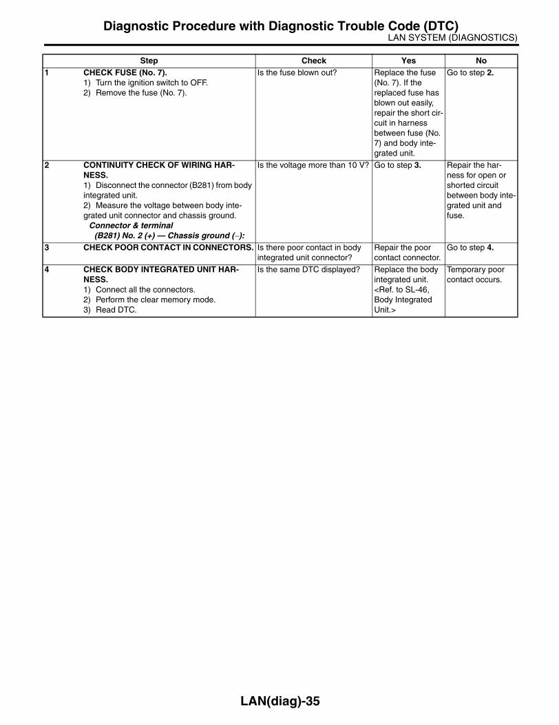
LAN SYSTEM (DIAGNOSTICS)Diagnostic Procedure with Diagnostic Trouble Code (DTC)
Step Check Yes No1 CHECK FUSE (No. 7).
1) Turn the ignition switch to OFF.2) Remove the fuse (No. 7).
Is the fuse blown out? Replace the fuse (No. 7). If the replaced fuse has blown out easily, repair the short cir-cuit in harness between fuse (No. 7) and body inte-grated unit.
Go to step 2.
2 CONTINUITY CHECK OF WIRING HAR-NESS.1) Disconnect the connector (B281) from body integrated unit.2) Measure the voltage between body inte-grated unit connector and chassis ground.
Connector & terminal(B281) No. 2 (+) — Chassis ground (−):
Is the voltage more than 10 V? Go to step 3. Repair the har-ness for open or shorted circuit between body inte-grated unit and fuse.
3 CHECK POOR CONTACT IN CONNECTORS. Is there poor contact in body integrated unit connector?
Repair the poor contact connector.
Go to step 4.
4 CHECK BODY INTEGRATED UNIT HAR-NESS.1) Connect all the connectors.2) Perform the clear memory mode.3) Read DTC.
Is the same DTC displayed? Replace the body integrated unit. <Ref. to SL-46, Body Integrated Unit.>
Temporary poor contact occurs.
LAN(diag)-35

LAN SYSTEM (DIAGNOSTICS)Diagnostic Procedure with Diagnostic Trouble Code (DTC)
E: DTC B0102 BATT P/SUPPLY MALFUNCTION CONT.DTC DETECTING CONDITION:BATT power backup circuit is open or shorted.TROUBLE SYMPTOM:• Engine malfunction indicator light may be illuminates.• Keyless entry, room light, key illumination does not operate.• “En IU” may display in combination meter.
NOTE:When some B0101 BATT p/supply malfunction cont. are output at the same time, all function of body inte-grated unit may not function.WIRING DIAGRAM:
LAN00022
WL
B7
LR
C2
BY
A2
1B
Y
C9
BY
BY
B2
2
C8
REF.TO GND-02
LR
C2
4W
L
B1
3
i84
B52
B280
R168C: B:
B:
A:
1 2 3 4 5 6 7 8 910 11 12 19 2013 14 15 16 17 18
R168C:
B52B:
3 41 2 8 9 10 1112 13 14 15 16 17 18 19 20 21 22 23 24
5 6 7
E
MAIN SBF-11
FB
-18
No
.7
B281C:
E
REF.TO GND-03
E
B280B:
B281C:
5 6 78
219
4310
2422 23 2511 12 13 14 15
26 27 2816 17 18 19
20 21
54 6 78
219
310
22 2311 12 13 14 15
24 25 26 2716 17 18
28 2919 20
21 30
i84A:
1 2 3 4 5 6 7 89 10 11 12 13 14 15 16 17 18 19 20 21 22 2324 25 26 27 28 29 30 31 32 33 34 35
BATTERY
BODY INTEGRATED UNITMICRO COMPUTER
BA
CK
-UP
PO
WE
R S
UP
PLY
SY
ST
EM
CO
NT
RO
LP
OW
ER
SU
PP
LY
MB
-29
No
.8
LAN(diag)-36

LAN SYSTEM (DIAGNOSTICS)Diagnostic Procedure with Diagnostic Trouble Code (DTC)
Step Check Yes No1 CHECK FUSE (No. 8).
1) Turn the ignition switch to OFF.2) Remove the fuse (No. 8).
Is the fuse blown out? Replace the fuse (No. 8). If the replaced fuse has blown out easily, repair the short cir-cuit in harness between fuse (No. 8) and body inte-grated unit.
Go to step 2.
2 CONTINUITY CHECK OF WIRING HAR-NESS.1) Disconnect the connector (B280) from body integrated unit.2) Measure the voltage between body inte-grated unit connector and chassis ground.
Connector & terminal(B280) No. 7 (+) — Chassis ground (−):
Is the voltage more than 10 V? Go to step 3. Repair the har-ness for open or shorted circuit between body inte-grated unit and fuse.
3 CHECK POOR CONTACT IN CONNECTORS. Is there poor contact in body integrated unit connector?
Repair the poor contact connector.
Go to step 4.
4 CHECK BODY INTEGRATED UNIT HAR-NESS.1) Connect all the connectors.2) Perform the clear memory mode.3) Read DTC.
Is the same DTC displayed? Replace the body integrated unit. <Ref. to SL-46, Body Integrated Unit.>
Temporary poor contact occurs.
LAN(diag)-37

LAN SYSTEM (DIAGNOSTICS)Diagnostic Procedure with Diagnostic Trouble Code (DTC)
F: DTC B0103 IGNITION POWER FAILURE DTC DETECTING CONDITION:IGN power supply circuit is open or shorted.TROUBLE SYMPTOM:Symptom that illuminating engine malfunction indicator light, “Er HC” high speed CAN error display may beoccurred.WIRING DIAGRAM:
LAN00023
YG
A1
GR
A2
4
GR
B1
YG
A8
B72
W 1 B
2
4
ACC
ACCOFF
IG
ON
G
Y
B52B:
3 41 2 8 9 10 1112 13 14 15 16 17 18 19 20 21 22 23 24
5 6 7
B280B:
B281C:
5 6 78
219
4310
2422 23 2511 12 13 14 15
26 27 2816 17 18 19
20 21
54 6 78
219
310
22 2311 12 13 14 15
24 25 26 2716 17 18
28 2919 20
21 30
i84A:
1 2 3 4 5 6 7 89 10 11 12 13 14 15 16 17 18 19 20 21 22 2324 25 26 27 28 29 30 31 32 33 34 35
1 2 3 4 5 6 7 8 910 11 12 19 2013 14 15 16 17 18
i5A:
B52 i5A:B:
E
MAIN SBF-11
FB
-28
No
.31
i84
B280B:
A:
B281C:
BATTERY
BODY INTEGRATED UNITMICRO COMPUTER
AC
C P
OW
ER
SU
PP
LY
IG P
OW
ER
SU
PP
LY
IGNITION SWITCH
BY
A2
1B
Y
C9
BY
BY
B2
2
C8
REF.TO GND-02
E
REF.TO GND-03
E
FB
-37
No
.12
1 34 5 6
2
B72
LAN(diag)-38

LAN SYSTEM (DIAGNOSTICS)Diagnostic Procedure with Diagnostic Trouble Code (DTC)
Step Check Yes No1 CHECK FUSE (No. 12).
1) Turn the ignition switch to OFF.2) Remove the fuse (No. 12).
Is the fuse blown out? Replace the fuse (No. 12). If the replaced fuse has blown out easily, repair the short cir-cuit in harness between fuse (No. 12) and body inte-grated unit.
Go to step 2.
2 CONTINUITY CHECK OF WIRING HAR-NESS.1) Disconnect the connector (i84) from body integrated unit.2) Turn the ignition switch to ON.3) Measure the voltage between body inte-grated unit connector and chassis ground.
Connector & terminal(i84) No. 1 (+) — Chassis ground (−):
Is the voltage more than 10 V? Go to step 3. Repair the har-ness for open or shorted circuit between body inte-grated unit and fuse.
3 CHECK POOR CONTACT IN CONNECTOR. Is there poor contact in body integrated unit connector?
Repair the poor contact connector.
Go to step 4.
4 CHECK BODY INTEGRATED UNIT HAR-NESS.1) Connect all the connectors.2) Perform the clear memory mode.3) Read DTC.
Is the same DTC displayed? Replace the body integrated unit. <Ref. to SL-46, Body Integrated Unit.>
Temporary poor contact occurs.
LAN(diag)-39

LAN SYSTEM (DIAGNOSTICS)Diagnostic Procedure with Diagnostic Trouble Code (DTC)
G: DTC B0104 ACC POWER FAILUREDTC DETECTING CONDITION:ACC power supply circuit is open or shorted.TROUBLE SYMPTOM:Rear wiper may not operate on ACC.WIRING DIAGRAM:
LAN00023
YG
A1
GR
A2
4
GR
B1
YG
A8
B72
W 1 B
2
4
ACC
ACCOFF
IG
ON
G
Y
B52B:
3 41 2 8 9 10 1112 13 14 15 16 17 18 19 20 21 22 23 24
5 6 7
B280B:
B281C:
5 6 78
219
4310
2422 23 2511 12 13 14 15
26 27 2816 17 18 19
20 21
54 6 78
219
310
22 2311 12 13 14 15
24 25 26 2716 17 18
28 2919 20
21 30
i84A:
1 2 3 4 5 6 7 89 10 11 12 13 14 15 16 17 18 19 20 21 22 2324 25 26 27 28 29 30 31 32 33 34 35
1 2 3 4 5 6 7 8 910 11 12 19 2013 14 15 16 17 18
i5A:
B52 i5A:B:
E
MAIN SBF-11
FB
-28
No
.31
i84
B280B:
A:
B281C:
BATTERY
BODY INTEGRATED UNITMICRO COMPUTER
AC
C P
OW
ER
SU
PP
LY
IG P
OW
ER
SU
PP
LY
IGNITION SWITCH
BY
A2
1B
Y
C9
BY
BY
B2
2
C8
REF.TO GND-02
E
REF.TO GND-03
E
FB
-37
No
.12
1 34 5 6
2
B72
LAN(diag)-40

LAN SYSTEM (DIAGNOSTICS)Diagnostic Procedure with Diagnostic Trouble Code (DTC)
Step Check Yes No1 CHECK FUSE (No. 31).
1) Turn the ignition switch to OFF.2) Remove the fuse (No. 31).
Is the fuse blown out? Replace the fuse (No. 31). If the replaced fuse has blown out easily, repair the short cir-cuit in harness between fuse (No. 31) and body inte-grated unit.
Go to step 2.
2 CONTINUITY CHECK OF WIRING HAR-NESS.1) Disconnect the connector (i84) from body integrated unit.2) Turn the ignition switch to ON.3) Measure the voltage between body inte-grated unit connector and chassis ground.
Connector & terminal(i84) No. 24 (+) — Chassis ground (−):
Is the voltage more than 10 V? Go to step 3. Repair the har-ness for open or shorted circuit between body inte-grated unit and fuse.
3 CHECK POOR CONTACT IN CONNECTOR. Is there poor contact in body integrated unit connector?
Repair the poor contact connector.
Go to step 4.
4 CHECK BODY INTEGRATED UNIT HAR-NESS.1) Connect all the connectors.2) Perform the clear memory mode.3) Read DTC.
Is DTC displayed? Replace the body integrated unit. <Ref. to SL-46, Body Integrated Unit.>
Temporary poor contact occurs.
LAN(diag)-41

LAN SYSTEM (DIAGNOSTICS)Diagnostic Procedure with Diagnostic Trouble Code (DTC)
H: DTC B0106 SHIFT LOCK CIRCUIT FAILUREDTC DETECTING CONDITION:Shift lock circuit is ground shorted.TROUBLE SYMPTOM:Key interlock does not unlock or lock.WIRING DIAGRAM:
B6
R R
B
FB-28F/B FUSE No.31
(ACC)
FB-37F/B FUSE No.12
(IG)
MB-28M/B FUSE No.34
(B)
YR
GR
YR
GR
WB
WB
WL
FB-3F/B FUSE No.8
(B)
BrR
BrW
BrR
B
E
F9
F5
34
A2
4
C2
3
C1
A1
i84A: B280B: B281C:
B1591 2 3 45 6 7 8 9 10
B116
F:
1 2 3 495 6 7 8
B159F:
5 6 78
219
4310
2422 23 2511 12 13 14 15
26 27 2816 17 18 19
20 21
B281C:
54 6 78
219
310
22 2311 12 13 14 15
24 25 26 2716 17 18
28 2919 20
21 30
B280B:
B116
WCOC2
3
WCOC1
2
B65WC
3 41 2
B64OC
1 2 3 4 5 6 7 89 10 11 12 13 14 15 16 17 18 19 20 21 22 2324 25 26 27 28 29 30 31 32 33 34 35
A: i84
LAN00025
1 2
:
:
B65WC
B64OC :
:
REF.TO POWER SUPPLY ROUTING
STOP LIGHTSWITCH
JOINT FUSE BOX
BODY INTEGRATED UNIT
SHIFT LOCKSOLENOID
REF.TO GND-02
: WITH CRUISE CONTROL
: WITHOUT CRUISE CONTROL
WC
OC
LAN(diag)-42

LAN SYSTEM (DIAGNOSTICS)Diagnostic Procedure with Diagnostic Trouble Code (DTC)
Step Check Yes No1 CHECK HARNESS.
1) Disconnect the body integrated unit con-nector (B280).2) Measure the resistance between body inte-grated unit connector and chassis ground.
Connector & terminal(B280) No. 6 — Chassis ground:
Is the resistance 10 — 30 Ω? Go to step 5. Go to step 2.
2 CHECK HARNESS.1) Disconnect the body integrated unit con-nector (B280).2) Disconnect the shift lock solenoid connec-tor.3) Measure the resistance between body inte-grated unit connector and shift lock solenoid connector.
Connector & terminal(B280) No. 6 — (B116) No. 3:
Is the resistance less than 10 Ω?
Go to step 3. Repair or replace the open or short circuit of harness.
3 CHECK SHIFT LOCK SOLENOID.1) Disconnect the shift lock solenoid connec-tor.2) Measure the internal resistance of shift lock solenoid.
Connector & terminal(B116) No. 3 — No. 4:
Is the resistance 10 — 30 Ω? Go to step 4. Replace the shift lock solenoid.
4 CHECK GROUND CIRCUIT.1) Disconnect the shift lock solenoid connec-tor.2) Measure the resistance between shift lock solenoid connector and chassis ground.
Connector & terminal(B116) No. 4 — Chassis ground:
Is the resistance less than 10 Ω?
Temporary poor contact occurs. Check the connec-tion of each termi-nals, and then repair them if nec-essary.
Replace the body integrated unit. <Ref. to SL-46, Body Integrated Unit.>
5 CHECK HARNESS.1) Disconnect the body integrated unit con-nector (B280).2) Measure the resistance between body inte-grated unit connector (B280) and chassis ground.
Connector & terminal(B280) No. 6 — Chassis ground:
Is the resistance more than 1 MΩ?
Replace the body integrated unit. <Ref. to SL-46, Body Integrated Unit.>
Repair or replace the short circuit of harness.
LAN(diag)-43

LAN SYSTEM (DIAGNOSTICS)Diagnostic Procedure with Diagnostic Trouble Code (DTC)
I: DTC B0107 R FOG LAMP CIRCUIT FAILUREDTC DETECTING CONDITION:Rear fog input/output circuits are ground shorted.TROUBLE SYMPTOM:• Rear fog light does not come on or go off.• Indicator in the combination meter may not be goes off.WIRING DIAGRAM:
LAN00026
FB-2F/B FUSE No.1
(B)
V
REF.TO POWER SUPPLY ROUTING
FB-14F/B FUSE No.16
(B)
26 28
25
27
B1
3C
4
ON
OFF
E
B
REF. TO GROUND DISTRIBUTION[GND-02]
13
16
LG
B225
REAR FOGLIGHT RELAY
REAR FOG LIGHT
B71
REAR FOGLIGHT SWITCH
910
1 2
3 4
5 6
7 8
11 1214
15 16
1318
19 20
1722
23 24
21
3839 40
3734
35 36
3330
31 32
2926
27 28
25
B225
2 3 4 5 6 71 89 10 11 12 13 14 15 16 17
B71
B280
B281
BODY INTEGRATED UNIT
B:
C:
5 6 78
219
4310
2422 23 2511 12 13 14 15
26 27 2816 17 18 19
20 21
B281
54 6 78
219
310
22 2311 12 13 14 15
24 25 26 2716 17 18
28 2919 20
21 30
B280B:
C:
LAN(diag)-44

LAN SYSTEM (DIAGNOSTICS)Diagnostic Procedure with Diagnostic Trouble Code (DTC)
Step Check Yes No1 CHECK HARNESS.
1) Disconnect the body integrated unit con-nector (B280).2) Measure the voltage between body inte-grated unit connector and chassis ground.
Connector & terminal(B280) No. 13 (+) — Chassis ground (−):
Is the voltage 10 — 13 V? Temporary poor contact.
Go to step 2.
2 CHECK HARNESS.1) Disconnect the body integrated unit con-nector (B280).2) Disconnect the rear fog light relay.3) Measure the resistance between body inte-grated unit connector and rear fog light relay connector.
Connector & terminal(B280) No. 13 — (B225) No. 27:
Is the resistance less than 1 Ω?
Go to step 3. Repair the open or short circuit of har-ness.
3 CHECK HARNESS.1) Disconnect the body integrated unit con-nector (B280).2) Disconnect the rear fog light relay.3) Measure the resistance between body inte-grated unit connector and chassis ground.
Connector & terminal(B280) No. 13 — Chassis ground:
Is the resistance more than 1 MΩ?
Replace the body integrated unit. <Ref. to SL-46, Body Integrated Unit.>
Repair or replace the short circuit of harness.
LAN(diag)-45

LAN SYSTEM (DIAGNOSTICS)Diagnostic Procedure with Diagnostic Trouble Code (DTC)
J: DTC B0201 CAN-HS COUNTER ABNORMAL DTC DETECTING CONDITION:High speed CAN communication of body integrated unit which monitoring the error data and non-receiveddata are faulty.TROUBLE SYMPTOM:• “Er HC” is displayed in odo/trip meter.• Engine malfunction indicator light illuminates.
Step Check Yes No1 CHECK HARNESS.
1) Disconnect the body integrated unit con-nector (B280).2) Measure the resistance between harness connector terminals.
Connector & terminal(B280) No. 20 — No. 30:
Is the resistance 55 — 65 Ω? Temporary poor contact occurs.
Go to step 2.
2 CHECK HARNESS.1) Disconnect the body integrated unit con-nector (B280).2) Measure the resistance between harness connector terminals.
Connector & terminal(B280) No. 20 — No. 30:
Is the resistance more than 30 MΩ?
Repair or replace the open circuit of harness.
Go to step 3.
3 CHECK HARNESS.1) Disconnect the body integrated unit con-nector (B280).2) Measure the input voltage between har-ness connector and chassis ground while turn-ing the ignition switch to ON.
Connector & terminal(B280) No. 20 (+) — Chassis ground (−):(B280) No. 30 (+) — Chassis ground (−):
Is the voltage more than 6 V? Repair or replace the short circuit of harness.
Go to step 4.
4 CHECK HARNESS.1) Disconnect the body integrated unit con-nector (B280).2) Measure the resistance between harness connector and chassis ground.
Connector & terminal(B280) No. 20 — Chassis ground:(B280) No. 30 — Chassis ground:
Is the resistance less than 10 Ω?
Repair or replace the short circuit of harness.
Go to step 5.
5 CHECK BODY INTEGRATED UNIT.Read the data of “body integrated unit data received” on ECM data display using Subaru Select Monitor.
Is the “Yes” displayed? Go to step 6. Replace the body integrated unit. <Ref. to SL-46, Body Integrated Unit.>
6 CHECK BODY INTEGRATED UNIT.Read the data of “body integrated unit counter update” on ECM data display using Subaru Select Monitor.
Is the “Yes” displayed? Temporary poor contact occurs. Check the con-nected condition of connector, read the DTC again to make sure that the DTC is not output.
Replace the body integrated unit. <Ref. to SL-46, Body Integrated Unit.>
LAN(diag)-46

LAN SYSTEM (DIAGNOSTICS)Diagnostic Procedure with Diagnostic Trouble Code (DTC)
K: DTC B0202 CAN-HS BUS OFFDTC DETECTING CONDITION:• Locate the unit or CAN line which trouble occurs, and repair and replace it.• Not received data and error data may be detected at the same time.TROUBLE SYMPTOM:“Er HC” is displayed in odo/trip meter.WIRING DIAGRAM:
LAN00113
VDCCM & H/U
B310
B301
4 5 6 7 8 916 17 18 19 20
2 3121 22 23 24 25 26
10 1113 1412 15
B2
0
B3
0
TW
IST
ED
WIR
E
BODY INTEGRATEDUNIT
B280B:
A1
2
A3
TCM
B54A:
11
26
B301
ABSCM & H/U
13
29
B231
2
1
3
STEERING ANGLESENSOR
AB
S
AB
S
VDC
VDC
B231
1 2 3 4
B54A:
1 2 7 8 95 63 410 11 1219 20 21
13 14 15 16 17 1822 23 24
B137D:
85 6
10 11 12 13 14 15721 3 4
16
3019 20 22
28 29
9 1718 2521 23 24
3126 27
B310
1 2 3 411 12 14 15 16 17 18 19 20 21 22 23 24 25
1026
27 28 29 30 31 32 33 34 35 36 37 38 39 40 41 4213
7 865 9
REF. TO GROUND DISTRIBUTION[GND-02]
B280B:
54 6 78
219
310
22 2311 12 13 14 15
24 25 26 2716 17 18
28 2919 20
21 30
ECMB137D:
C1
4
C1
3
A3
A4
D2
6
D1
8
5AT
4ATE
BY
5AT B54
1 2 78 9
5 63 410 11 1219 20 21
13 14 15 1617 18 22 23 24
4AT A:
B136C:
* 1
* 2
B136
5 67 8
219
4310
2422 23 2511 12 13 14 15
26 2728
1617 18 19 20 21
33 3429 3230 31 35
C:
1* : 2.0 L SOHC RHD MODEL; 2.5 L (KA) RHD MODEL; 2.0 L LHD MODEL; 2.5 L (KS) LHD MODEL
2* : EXCEPT FOR 2.0 L SOHC RHD AND 2.5 L (KA) RHD MODEL; 2.5 L (EC, K4) LHD MODEL; 3.0 L LHD MODEL
LAN(diag)-47

LAN SYSTEM (DIAGNOSTICS)Diagnostic Procedure with Diagnostic Trouble Code (DTC)
Step Check Yes No1 CHECK TCM.
1) Disconnect the TCM connector (B54).2) Perform the clear memory of body inte-grated unit. <Ref. to LAN(diag)-20, CLEAR MEMORY MODE, OPERATION, Subaru Select Monitor.>3) Read DTC of body integrated unit.
Is DTC (B0202) displayed? Go to step 2. Replace the TCM. <Ref. to 4AT-140, Transmission Con-trol Device.> <Ref. to 5AT-61, Trans-mission Control Module (TCM).>
2 CHECK STEERING ANGLE SENSOR.1) Disconnect the steering angle sensor con-nector (B231).2) Perform the clear memory mode of body integrated unit. <Ref. to LAN(diag)-20, CLEAR MEMORY MODE, OPERATION, Subaru Select Monitor.>3) Read DTC of body integrated unit.
Is DTC (B0202) displayed? Go to step 3. Replace the steer-ing angle sensor. <Ref. to VDC-16, REPLACEMENT, Steering Angle Sensor.>
3 CHECK BODY INTEGRATED UNIT.1) Disconnect the body integrated unit con-nector (B280).2) Read the data between VDC/ABSCM and ECM.Check item:• Engine speed• Average front wheel speed (value on con-stant driving)
Engine speed, front wheel speed is correctly communi-cated. (Appears same value)
Replace the body integrated unit. <Ref. to SL-46, Body Integrated Unit.>
Go to step 4.
4 CHECK HARNESS.1) Disconnect the body integrated unit con-nector (B280).2) Measure the resistance between harness connector terminals.
Connector & terminal(B280) No. 20 — No. 30:
Is the resistance 55 — 65 Ω? Go to step 10. Go to step 5.
5 CHECK HARNESS.1) Disconnect the body integrated unit con-nector (B280).2) Measure the resistance between harness connector terminals.
Connector & terminal(B280) No. 20 — No. 30:
Is the resistance 115 — 125 Ω?
Go to step 7. Go to step 6.
6 CHECK HARNESS.1) Disconnect the harness connector of body integrated unit.2) Measure the resistance between harness connector terminals.
Connector & terminal(B280) No. 20 — No. 30:
Is the resistance more than 30 MΩ?
Open harness on related line of body integrated unit. Repair or replace the open circuit of harness.
Go to step 7.
7 CHECK HARNESS.1) Disconnect the VDC/ABSCM connector (ABS:B301, VDC:310).2) Measure the resistance between harness connector terminals.
Connector & terminalABS
(B301) No. 11 — No. 26:VDC
(B310) No. 13 — No. 29:
Is the resistance 115 — 125 Ω?
Go to step 8. Go to step 9.
LAN(diag)-48

LAN SYSTEM (DIAGNOSTICS)Diagnostic Procedure with Diagnostic Trouble Code (DTC)
8 CHECK VDC/ABSCM.1) Disconnect the VDC/ABSCM connector (ABS:B301, VDC:310).2) Measure the resistance between VDC/ABSCM terminals.
Connector & terminalABS
(B301) No. 11 — No. 26:VDC
(B310) No. 13 — No. 29:
Is the resistance 115 — 125 Ω?
Go to step 9. Open harness in end resistance of VDC/ABSCM. Replace the VDC/ABSCM. <Ref. to ABS-6, ABS Con-trol Module and Hydraulic Control Unit (ABSCM&H/U).> <Ref. to VDC-7, VDC Control Module & Hydrau-lic Control Unit (VDCCM&H/U).>
9 CHECK ECM.1) Disconnect the ECM connector (*1: B136, *2: B137).2) Measure the resistance between ECM con-nector terminals.
Connector & terminal*1: 2.0 L SOHC RHD model, 2.5 L (KA) RHD model, 2.0 L LHD model, 2.5 L (KS) LHD model
(B136) No. 13 — No. 14:*2: Except for 2.0 L SOHC RHD and 2.5 L (KA) RHD model, 2.5 L (EC, K4) LHD model, 3.0 L LHD model
(B137) No. 18 — No. 26:
Is the resistance 115 — 125 Ω?
Repair or replace the open circuit of harness connec-tor.
Open harness in end resistance of ECM. Replace the ECM. <Ref. to FU(H4SO 2.0)-34, Engine Control Module (ECM).> <Ref. to FU(H4SO 2.5)-36, Engine Control Module (ECM).> <Ref. to FU(H4DOTC)-35, Engine Control Module (ECM).> <Ref. to FU(H6DO)-34, Engine Control Module (ECM).>
10 CHECK HARNESS.1) Disconnect the body integrated unit con-nector (B280).2) Measure the resistance between body inte-grated unit connector and chassis ground.
Connector & terminal(B280) No. 20 — Chassis ground:(B280) No. 30 — Chassis ground:
Is the resistance less than 10 Ω? (Ground)
Repair or replace the ground short circuit of the har-ness.
Go to step 11.
11 CHECK HARNESS.1) Disconnect the body integrated unit con-nector (B280).2) Measure the voltage between body inte-grated unit connector and chassis ground.
Connector & terminal(B280) No. 20 (+) — Chassis ground (−):(B280) No. 30 (+) — Chassis ground (−):
Is the voltage more than 6 V?(Power)
Repair or replace the short circuit of harness.
Go to step 12.
12 CHECK DTC.Read the DTC of ECM using Subaru Select Monitor. <Ref. to EN(H4SO 2.0)(diag)-25, READ DIAGNOSTIC TROUBLE CODE (DTC) FOR ENGINE (NORMAL MODE), OPERA-TION, Subaru Select Monitor.> <Ref. to EN(H4DOTC)(diag)-21, READ DIAGNOSTIC TROUBLE CODE (DTC) FOR ENGINE (NOR-MAL MODE), OPERATION, Subaru Select Monitor.>
Is DTC other than “CAN com-munication” displayed?
Perform the diag-nosis according to DTC.
Go to step 13.
Step Check Yes No
LAN(diag)-49

LAN SYSTEM (DIAGNOSTICS)Diagnostic Procedure with Diagnostic Trouble Code (DTC)
13 CHECK DTC.Read the DTC of VDC/ABSCM using Subaru Select Monitor. <Ref. to ABS(diag)-15, READ DIAGNOSTIC TROUBLE CODE (DTC), OPERATION, Subaru Select Monitor.> <Ref. to VDC(diag)-16, READ DIAGNOSTIC TROU-BLE CODE (DTC), OPERATION, Subaru Select Monitor.>
Is DTC other than “CAN com-munication” displayed?
Perform the diag-nosis according to DTC.
Go to step 14.
14 CHECK DTC.Read the DTC of TCM using Subaru Select Monitor. <Ref. to 4AT(diag)-17, READ DIAG-NOSTIC TROUBLE CODE (DTC), OPERA-TION, Subaru Select Monitor.> <Ref. to 5AT(diag)-16, READ DIAGNOSTIC TROU-BLE CODE (DTC), OPERATION, Subaru Select Monitor.>
Is DTC other than “CAN com-munication” displayed?
Perform the diag-nosis according to DTC.
Replace the body integrated unit. <Ref. to SL-46, Body Integrated Unit.>
Step Check Yes No
LAN(diag)-50

LAN SYSTEM (DIAGNOSTICS)Diagnostic Procedure with Diagnostic Trouble Code (DTC)
L: DTC B0211 CAN-HS ECM DATA ABNORMALDTC DETECTING CONDITION:Defective data from ECM.TROUBLE SYMPTOM:“Er HC” or “Er EG” is displayed in odo/trip meter.WIRING DIAGRAM:
LAN00114
B2
0
B3
0
TW
IST
ED
WIR
E
BODY INTEGRATEDUNIT
B280B:ECM
B137D:
C1
4
C1
3
D2
6
D1
8
B136C:
ABSCM & H/UVDCCM & H/U
TCM
B280B:
54 6 78
219
310
22 2311 12 13 14 15
24 25 26 2716 17 18
28 2919 20
21 30
B137
5 6 78
219
4310
22 2311 12 13 14 15
24 2526
16 1718 19 20 21
27 28 29 30 31
D:
* 1
* 2
B136
5 67 8
219
4310
2422 23 2511 12 13 14 15
26 2728
1617 18 19 20 21
33 3429 3230 31 35
C:
1* : 2.0 L SOHC RHD MODEL; 2.5 L (KA) RHD MODEL; 2.0 L LHD MODEL; 2.5 L (KS) LHD MODEL
2* : EXCEPT FOR 2.0 L SOHC RHD AND 2.5 L (KA) RHD MODEL; 2.5 L (EC, K4) LHD MODEL; 3.0 L LHD MODEL
LAN(diag)-51

LAN SYSTEM (DIAGNOSTICS)Diagnostic Procedure with Diagnostic Trouble Code (DTC)
Step Check Yes No1 CHECK ECM.
Read the DTC of ECM using Subaru Select Monitor.
Is DTC other than “CAN com-munication” displayed?
Perform the diag-nosis according to DTC.
Replace the ECM. <Ref. to FU(H4SO 2.0)-34, Engine Control Module (ECM).> <Ref. to FU(H4SO 2.5)-36, Engine Control Module (ECM).> <Ref. to FU(H4DOTC)-35, Engine Control Module (ECM).> <Ref. to FU(H6DO)-34, Engine Control Module (ECM).>
LAN(diag)-52

LAN SYSTEM (DIAGNOSTICS)Diagnostic Procedure with Diagnostic Trouble Code (DTC)
M: DTC B0212 CAN-HS TCM DATA ABNORMALDTC DETECTING CONDITION:TCM error, or harness between the main harness splice and TCM is open or short, the connector is not con-nected securely and the terminal has poor caulking.TROUBLE SYMPTOM:• SPORT indicator light blinks.• “Er HC” or “Er tC” is displayed in odo/trip meter.WIRING DIAGRAM:
Step Check Yes No1 CHECK TCM.
Read the DTC of TCM using Subaru Select Monitor. <Ref. to 4AT(diag)-17, READ DIAG-NOSTIC TROUBLE CODE (DTC), OPERA-TION, Subaru Select Monitor.> <Ref. to 5AT(diag)-16, READ DIAGNOSTIC TROU-BLE CODE (DTC), OPERATION, Subaru Select Monitor.>
Is DTC other than “CAN com-munication” displayed?
Perform the diag-nosis according to DTC.
Replace the TCM. <Ref. to 4AT-65, Transmission Con-trol Module (TCM).> <Ref. to 5AT-61, Transmis-sion Control Mod-ule (TCM).>
LAN00029
B280B:
54 6 78
219
310
22 2311 12 13 14 15
24 25 26 2716 17 18
28 2919 20
21 30
ABSCM & H/UVDCCM & H/U
B2
0
B3
0
BODY INTEGRATEDUNIT
B280B:
A1
2
A3
TCM
B54A:
A3
A45AT
4AT
ECM
B54A:
1 2 7 8 95 63 410 11 1219 20 21
13 14 15 16 17 1822 23 24
5AT B54
1 2 78 9
5 63 410 11 1219 20 21
13 14 15 1617 18 22 23 24
4AT A:
LAN(diag)-53

LAN SYSTEM (DIAGNOSTICS)Diagnostic Procedure with Diagnostic Trouble Code (DTC)
N: DTC B0213 CAN-HS VDC/ABS DATA ABNORMALDTC DETECTING CONDITION:VDC/ABSCM body error, or harness between the main harness splice and TCM is open or short, the con-nector is not connected securely and the terminal has poor caulking.TROUBLE SYMPTOM:• ABS warning light and VDC warning light come on.• “Er HC” or “Er Ab” is displayed in odo/trip meter.WIRING DIAGRAM:
LAN00030
B280B:
54 6 78
219
310
22 2311 12 13 14 15
24 25 26 2716 17 18
28 2919 20
21 30
VDCCM & H/U
B310
B2
0
B3
0
BODY INTEGRATEDUNIT
B280B:
11
26
B301
ABSCM & H/U
13
29
B231
2
1
3
STEERING ANGLESENSOR
AB
S
AB
S
VDC
VDC
REF. TO GROUND DISTRIBUTION[GND-02]
E
BY
B301
4 5 6 7 8 916 17 18 19 20
2 3121 22 23 24 25 26
10 1113 1412 15
B310
1 2 3 411 12 14 15 16 17 18 19 20 21 22 23 24 25
1026
27 28 29 30 31 32 33 34 35 36 37 38 39 40 41 4213
7 865 91 2 3 4
B231
ECM
LAN(diag)-54

LAN SYSTEM (DIAGNOSTICS)Diagnostic Procedure with Diagnostic Trouble Code (DTC)
Step Check Yes No1 CHECK VDC/ABSCM.
Read the DTC of VDC/ABSCM using Subaru Select Monitor.
Is DTC other than “CAN com-munication” displayed?
Perform the diag-nosis according to DTC.
Replace the VDC/ABSCM. <Ref. to ABS-6, ABS Con-trol Module and Hydraulic Control Unit (ABSCM&H/U).> <Ref. to VDC-7, VDC Control Module & Hydrau-lic Control Unit (VDCCM&H/U).>
LAN(diag)-55

LAN SYSTEM (DIAGNOSTICS)Diagnostic Procedure with Diagnostic Trouble Code (DTC)
O: DTC B0221 CAN-HS ECM NO-RECEIVE DATADTC DETECTING CONDITION:Defective ECM. (If error is in the main harness, Diagnostic Trouble Code (DTC) P0600 High-speed CAN cir-cuit is input simultaneously.)TROUBLE SYMPTOM:• Engine malfunction indicator light illuminates.• “Er HC” is displayed in odo/trip meter.WIRING DIAGRAM:
LAN00114
B2
0
B3
0
TW
IST
ED
WIR
E
BODY INTEGRATEDUNIT
B280B:ECM
B137D:
C1
4
C1
3
D2
6
D1
8
B136C:
ABSCM & H/UVDCCM & H/U
TCM
B280B:
54 6 78
219
310
22 2311 12 13 14 15
24 25 26 2716 17 18
28 2919 20
21 30
B137
5 6 78
219
4310
22 2311 12 13 14 15
24 2526
16 1718 19 20 21
27 28 29 30 31
D:
* 1
* 2
B136
5 67 8
219
4310
2422 23 2511 12 13 14 15
26 2728
1617 18 19 20 21
33 3429 3230 31 35
C:
1* : 2.0 L SOHC RHD MODEL; 2.5 L (KA) RHD MODEL; 2.0 L LHD MODEL; 2.5 L (KS) LHD MODEL
2* : EXCEPT FOR 2.0 L SOHC RHD AND 2.5 L (KA) RHD MODEL; 2.5 L (EC, K4) LHD MODEL; 3.0 L LHD MODEL
LAN(diag)-56

LAN SYSTEM (DIAGNOSTICS)Diagnostic Procedure with Diagnostic Trouble Code (DTC)
Step Check Yes No1 CHECK HARNESS.
1) Disconnect the body integrated unit con-nector (B280).2) Measure the resistance between harness connectors.
Connector & terminal(B280) No. 20 — No. 30:
Is the resistance 55 — 65 Ω? (Standard 60 Ω)
Read the DTC of ECM. Perform the diagnosis accord-ing to DTC. <Ref. to EN(H4SO 2.0)(diag)-25, READ DIAGNOS-TIC TROUBLE CODE (DTC) FOR ENGINE (NOR-MAL MODE), OPERATION, Subaru Select Monitor.> <Ref. to EN(H4SO 2.5)(diag)-26, READ DIAGNOS-TIC TROUBLE CODE (DTC) FOR ENGINE (NOR-MAL MODE), OPERATION, Subaru Select Monitor.> <Ref. to EN(H4DOTC)(diag)-21, READ DIAG-NOSTIC TROU-BLE CODE (DTC) FOR ENGINE (NORMAL MODE), OPERA-TION, Subaru Select Monitor.> <Ref. to EN(H6DO)(diag)-25, READ DIAG-NOSTIC TROU-BLE CODE (DTC) FOR ENGINE (NORMAL MODE), OPERA-TION, Subaru Select Monitor.>
Go to step 2.
2 CHECK HARNESS.1) Disconnect the body integrated unit con-nector (B280).2) Measure the resistance between harness connectors.
Connector & terminal(B280) No. 20 — No. 30:
Is the resistance 115 — 125 Ω? (End resistance or main line is open)
Go to step 3. Related line of body integrated unit is open when ∞ Ω. Repair or replace the open circuit of harness.
LAN(diag)-57

LAN SYSTEM (DIAGNOSTICS)Diagnostic Procedure with Diagnostic Trouble Code (DTC)
3 CHECK HARNESS.1) Disconnect the ECM connector (*1: B136, *2: B137).2) Measure the resistance between harness connector terminals.
Connector & terminal*1: 2.0 L SOHC RHD model, 2.5 L (KA) RHD model, 2.0 L LHD model, 2.5 L (KS) LHD model
(B136) No. 13 — No. 14:*2: Except for 2.0 L SOHC RHD and 2.5 L (KA) RHD model, 2.5 L (EC, K4) LHD model, 3.0 L LHD model
(B137) No. 18 — No. 26:
Is the resistance 115 — 125 Ω? (End resistance standard 120 Ω)
Go to step 4. Go to step 5.
4 CHECK ECM.1) Disconnect the ECM connector (*1: B136, *2: B137).2) Measure the resistance between ECM con-nector terminals.
Connector & terminal*1: 2.0 L SOHC RHD model, 2.5 L (KA) RHD model, 2.0 L LHD model, 2.5 L (KS) LHD model
(B136) No. 13 — No. 14:*2: Except for 2.0 L SOHC RHD and 2.5 L (KA) RHD model, 2.5 L (EC, K4) LHD model, 3.0 L LHD model
(B137) No. 18 — No. 26:
Is the resistance 115 — 125 Ω?
Read the DTC of ECM. Perform the diagnosis accord-ing to DTC. <Ref. to EN(H4SO 2.0)(diag)-25, READ DIAGNOS-TIC TROUBLE CODE (DTC) FOR ENGINE (NOR-MAL MODE), OPERATION, Subaru Select Monitor.> <Ref. to EN(H4SO 2.5)(diag)-26, READ DIAGNOS-TIC TROUBLE CODE (DTC) FOR ENGINE (NOR-MAL MODE), OPERATION, Subaru Select Monitor.> <Ref. to EN(H4DOTC)(diag)-21, READ DIAG-NOSTIC TROU-BLE CODE (DTC) FOR ENGINE (NORMAL MODE), OPERA-TION, Subaru Select Monitor.> <Ref. to EN(H6DO)(diag)-25, READ DIAG-NOSTIC TROU-BLE CODE (DTC) FOR ENGINE (NORMAL MODE), OPERA-TION, Subaru Select Monitor.>
End resistance is open. Replace the ECM. <Ref. to FU(H4SO 2.0)-34, Engine Control Module (ECM).> <Ref. to FU(H4SO 2.5)-36, Engine Control Module (ECM).> <Ref. to FU(H4DOTC)-35, Engine Control Module (ECM).> <Ref. to FU(H6DO)-34, Engine Control Module (ECM).>
Step Check Yes No
LAN(diag)-58

LAN SYSTEM (DIAGNOSTICS)Diagnostic Procedure with Diagnostic Trouble Code (DTC)
5 CHECK HARNESS.1) Disconnect the ECM connector (*1: B136, *2: B137).2) Measure the resistance between harness connector and chassis ground.
Connector & terminal*1: 2.0 L SOHC RHD model, 2.5 L (KA) RHD model, 2.0 L LHD model, 2.5 L (KS) LHD model
(B136) No. 13 — Chassis ground:(B136) No. 14 — Chassis ground:
*2: Except for 2.0 L SOHC RHD and 2.5 L (KA) RHD model, 2.5 L (EC, K4) LHD model, 3.0 L LHD model
(B137) No. 18 — Chassis ground:(B137) No. 26 — Chassis ground:
Is the resistance less than 10 Ω?
Repair or replace the short circuit of harness.
Go to step 6.
6 CHECK HARNESS.1) Disconnect the body integrated unit con-nector (B280), ECM connector (*1: B136, *2: B137), TCM connector (B54), ABS (B301)/VDC (B310) CM connector.2) Measure the input voltage between har-ness connector and chassis ground while turn-ing the ignition switch to ON.
Connector & terminal(B280) No. 20 (+) — Chassis ground (−):(B280) No. 30 (+) — Chassis ground (−):
Is the voltage more than 6 V? Repair or replace the short circuit of harness.
Read the DTC of ECM. Perform the diagnosis accord-ing to DTC. <Ref. to EN(H4SO 2.0)(diag)-25, READ DIAGNOS-TIC TROUBLE CODE (DTC) FOR ENGINE (NOR-MAL MODE), OPERATION, Subaru Select Monitor.> <Ref. to EN(H4SO 2.5)(diag)-26, READ DIAGNOS-TIC TROUBLE CODE (DTC) FOR ENGINE (NOR-MAL MODE), OPERATION, Subaru Select Monitor.> <Ref. to EN(H4DOTC)(diag)-21, READ DIAG-NOSTIC TROU-BLE CODE (DTC) FOR ENGINE (NORMAL MODE), OPERA-TION, Subaru Select Monitor.> <Ref. to EN(H6DO)(diag)-25, READ DIAG-NOSTIC TROU-BLE CODE (DTC) FOR ENGINE (NORMAL MODE), OPERA-TION, Subaru Select Monitor.>
Step Check Yes No
LAN(diag)-59

LAN SYSTEM (DIAGNOSTICS)Diagnostic Procedure with Diagnostic Trouble Code (DTC)
P: DTC B0222 CAN-HS TCM NO-RECEIVE DATADTC DETECTING CONDITION:TCM error, or harness between the main harness splice and TCM is open or short, the connector is not con-nected securely and the terminal has poor caulking.TROUBLE SYMPTOM:• Engine malfunction indicator light illuminates.• “Er HC” is displayed in odo/trip meter.WIRING DIAGRAM:
LAN00029
B280B:
54 6 78
219
310
22 2311 12 13 14 15
24 25 26 2716 17 18
28 2919 20
21 30
ABSCM & H/UVDCCM & H/U
B2
0
B3
0
BODY INTEGRATEDUNIT
B280B:
A1
2
A3
TCM
B54A:
A3
A45AT
4AT
ECM
B54A:
1 2 7 8 95 63 410 11 1219 20 21
13 14 15 16 17 1822 23 24
5AT B54
1 2 78 9
5 63 410 11 1219 20 21
13 14 15 1617 18 22 23 24
4AT A:
LAN(diag)-60

LAN SYSTEM (DIAGNOSTICS)Diagnostic Procedure with Diagnostic Trouble Code (DTC)
Step Check Yes No1 CHECK HARNESS.
1) Disconnect the TCM connector (B54)2) Measure the resistance between harness connector terminals.
Connector & terminal4AT MODEL
(B54) No. 3 — No. 12:5AT MODEL
(B54) No. 3 — No. 4:
Is the resistance ∞ Ω? Open harness in related lines of TCM. Repair or replace the open circuit of harness.
Go to step 2.
2 CHECK TCM.Read the DTC of TCM using Subaru Select Monitor. <Ref. to 4AT(diag)-17, READ DIAG-NOSTIC TROUBLE CODE (DTC), OPERA-TION, Subaru Select Monitor.> <Ref. to 5AT(diag)-16, READ DIAGNOSTIC TROU-BLE CODE (DTC), OPERATION, Subaru Select Monitor.>
Is DTC other than “CAN com-munication” displayed?
Perform the diag-nosis according to DTC.
Replace the TCM. <Ref. to 4AT-65, Transmission Con-trol Module (TCM).> <Ref. to 5AT-61, Transmis-sion Control Mod-ule (TCM).>
LAN(diag)-61

LAN SYSTEM (DIAGNOSTICS)Diagnostic Procedure with Diagnostic Trouble Code (DTC)
Q: DTC B0223 CAN-HS VDC/ABS NO-RECEIVE DATADTC DETECTING CONDITION:Defective VDC/ABSCM. (If error is in the main harness, DTC P0600 High-speed CAN circuit is input at thesame time.)TROUBLE SYMPTOM:• ABS warning light and VDC warning light come on.• “Er HC” is displayed in odo/trip meter.WIRING DIAGRAM:
LAN00030
B280B:
54 6 78
219
310
22 2311 12 13 14 15
24 25 26 2716 17 18
28 2919 20
21 30
VDCCM & H/U
B310
B2
0
B3
0
BODY INTEGRATEDUNIT
B280B:
11
26
B301
ABSCM & H/U
13
29
B231
2
1
3
STEERING ANGLESENSOR
AB
S
AB
S
VDC
VDC
REF. TO GROUND DISTRIBUTION[GND-02]
E
BY
B301
4 5 6 7 8 916 17 18 19 20
2 3121 22 23 24 25 26
10 1113 1412 15
B310
1 2 3 411 12 14 15 16 17 18 19 20 21 22 23 24 25
1026
27 28 29 30 31 32 33 34 35 36 37 38 39 40 41 4213
7 865 91 2 3 4
B231
ECM
LAN(diag)-62

LAN SYSTEM (DIAGNOSTICS)Diagnostic Procedure with Diagnostic Trouble Code (DTC)
Step Check Yes No1 CHECK HARNESS.
1) Disconnect the harness connector of body integrated unit.2) Measure the resistance between harness connector terminals.
Connector & terminal(B280) No. 20 — No. 30:
Is the resistance 55 — 65 Ω? Read the DTC of VDC/ABSCM, and perform the diag-nosis according to DTC.
Go to step 2.
2 CHECK HARNESS.1) Disconnect the harness connector of body integrated unit.2) Measure the resistance between harness connector terminals.
Connector & terminal(B280) No. 20 — No. 30:
Is the resistance 115 — 125 Ω?
Go to step 5. Go to step 3.
3 CHECK HARNESS.1) Disconnect the harness connector of body integrated unit.2) Measure the resistance between the har-ness connector terminal and chassis ground.
Connector & terminal(B280) No. 20 — Chassis ground:(B280) No. 30 — Chassis ground:
Is the resistance ∞ Ω? Open harness on related line of body integrated unit. Repair or replace the open circuit of harness.
Go to step 4.
4 CHECK HARNESS.1) Disconnect the harness connector of body integrated unit.2) Measure the voltage between the harness connector terminal and chassis ground. (Igni-tion switch ON)
Connector & terminal(B280) No. 20 (+) — Chassis ground (−):(B280) No. 30 (+) — Chassis ground (−):
Is the voltage more than 6 V? Repair or replace the short circuit of harness.
Go to step 5.
5 CHECK END RESISTANCE.1) Disconnect the VDC/ABSCM harness con-nector.2) Measure the resistance between VDC/ABSCM connector terminals.
Connector & terminalABS(B301) No. 11 — No. 26:VDC(B310) No. 13 — No. 29:
Is the resistance between 115 — 125 Ω?
Go to step 6. End resistance is opened. Replace the VDC/ABSCM. <Ref. to ABS-6, ABS Control Mod-ule and Hydraulic Control Unit (ABSCM&H/U).> <Ref. to VDC-7, VDC Control Mod-ule & Hydraulic Control Unit (VDCCM&H/U).>
6 CHECK HARNESS.1) Disconnect the body integrated unit con-nector (B280) and VDC/ABSCM connector (ABS:B301, VDC:310).2) Measure the resistance between harness connector terminals.
Connector & terminalABS(B301) No. 11 — (B280) No. 30:(B301) No. 26 — (B280) No. 20:VDC(B310) No. 13 — (B280) No. 20:(B310) No. 29 — (B280) No. 30:
Is the resistance less than 10 Ω?
Go to step 7. Main wiring har-ness opened. Repair or replace the open circuit of harness.
LAN(diag)-63

LAN SYSTEM (DIAGNOSTICS)Diagnostic Procedure with Diagnostic Trouble Code (DTC)
7 CHECK VDC/ABSCM.1) Connect all the connectors.2) Read the DTC of VDC/ABSCM using Sub-aru Select Monitor.
Is DTC other than “CAN com-munication” displayed?
Perform the diag-nosis according to DTC concerning VDC/ABSCM.
Temporary poor contact occurs. Check the con-necting condition of connector and terminals.
Step Check Yes No
LAN(diag)-64

LAN SYSTEM (DIAGNOSTICS)Diagnostic Procedure with Diagnostic Trouble Code (DTC)
R: DTC B0300 CAN-LS MALFUNCTIONDTC DETECTING CONDITION:Each side of low-speed CAN communication line is open or shorted, connector is not connected securely, theterminal has poor caulking.TROUBLE SYMPTOM:“Er LC” is displayed in odo/trip meter, but no interfere on communication.WIRING DIAGRAM:
LAN00115
: WITH AUTO A/C
54 6 78
219
310
22 2311 12 13 14 15
24 25 26 2716 17 18
28 2919 20
21 30
B: B280
A: i84
1 2 3 4 5 6 7 89 10 11 12 13 14 15 16 17 18 19 20 21 22 2324 25 26 27 28 29 30 31 32 33 34 35
A: i90 (BLACK)
2 3 4 5 6 7 8 912 13 14 15 16 17 18 19 20 21 22
10111
5 6 78
21 431110 12 13 14 15
816
B: B283
919 20
105 6 721 43131211 14 15 16 17
818
AE
A: i10 (BLACK)
i77
1 2 3 4 5 6 7 8 9 10 11 12
i103
1 23 4
i77 2 8 5
71
11
P V
CAN JOINTCONNECTOR
A: i10
B: B283
A2
1
A2
2
A14A6
VP
A: i90
A27A26
PV
B26
B25
P
V
A: i84
B: B280
B1B11
PV
TW
IST
ED
WIR
E
MODEL WITH NAVIGATION SYSTEM
AE
AE
P V
VPVP
COMBINATION METER
BODY INTEGRATEDUNIT
CENTERDISPLAY
AUTO A/CCONTROLMODULE
42
VP
i103
CENTERDISPLAY
MODEL WITHOUT NAVIGATION SYSTEM
LAN(diag)-65

LAN SYSTEM (DIAGNOSTICS)Diagnostic Procedure with Diagnostic Trouble Code (DTC)
Step Check Yes No1 CHECK HARNESS.
1) Disconnect the CAN junction connector (i77) and body integrated unit connector (i84).2) Measure the resistance between connector terminals.
Connector & terminal(i84) No. 26 — (i77) No. 8:(i84) No. 27 — (i77) No. 2:
Is the resistance less than 10 Ω?
Go to step 2. Repair or replace the short circuit of harness.
2 CHECK HARNESS.1) Disconnect the combination meter connec-tor.2) Measure the resistance between junction connector and combination meter connector.
Connector & terminal(i10) No. 21 — (i77) No. 1:(i10) No. 22 — (i77) No. 7:
Is the resistance less than 10 Ω?
Go to step 3. Repair or replace the open circuit of harness.
3 CHECK HARNESS.1) Disconnect the center display connector (i90).2) Measure the resistance between junction connector and center display connector.
Connector & terminalModel with navigation
(i90) No. 6 — (i77) No. 5:(i90) No. 14 — (i77) No. 11:
Model without navigation(i103) No. 2 — (i77) No. 5:(i103) No. 4 — (i77) No. 11:
Is the resistance less than 10 Ω?
Go to step 4. Repair or replace the open circuit of harness.
4 CHECK HARNESS.1) Disconnect the body integrated unit con-nector (B280) and auto A/C control unit con-nector (B238).2) Measure the resistance between body inte-grated unit connector and auto A/C control unit connector.
Connector & terminal(B238) No. 1 — (B280) No. 26:(B238) No. 11 — (B280) No. 25:
Is the resistance less than 10 Ω?
Go to step 5. Repair or replace the open circuit of harness.
5 CHECK HARNESS.1) Connect the junction connector.2) Measure the resistance between body inte-grated unit connector and chassis ground.
Connector & terminal(B280) No. 25 — Chassis ground:(B280) No. 26 — Chassis ground:(i84) No. 26 — Chassis ground:(i84) No. 27 — Chassis ground:
Is the resistance less than 10 Ω?
Repair or replace the short circuit of harness.
Go to step 6.
6 CHECK HARNESS.1) Turn the ignition switch to ON.2) Measure the voltage between body inte-grated unit connector and chassis ground.
Connector & terminal(B280) No. 25 (+) — Chassis ground (−):(B280) No. 26 (+) — Chassis ground (−):(i84) No. 26 (+) — Chassis ground (−):(i84) No. 27 (+) — Chassis ground (−):
Is the voltage more than 6 V? Repair or replace the short circuit of harness.
Go to step 7.
7 CHECK CENTER DISPLAY FAIL.Read the current data of body integrated unit.
Is center display fail OK? Go to step 8. Replace the center display.
LAN(diag)-66

LAN SYSTEM (DIAGNOSTICS)Diagnostic Procedure with Diagnostic Trouble Code (DTC)
8 CHECK AUTO A/C.Perform the auto A/C self-diagnosis. <Ref. to AC(diag)-13, A/C CONTROL SYSTEM SELF-DIAGNOSIS, OPERATION, Diagnostic Chart for Self-Diagnosis.>
Is the self-diagnosis OK? Go to step 9. Replace the auto A/C control unit. <Ref. to AC-32, Control Unit (Auto A/C Model).>
9 CHECK COMBINATION METER.1) Connect all the connectors.2) Turn the ignition switch to ON.3) Check the display of combination meter, odo/trip.
Is “Er SS” and “Er SP” dis-played?
Replace the body integrated unit. <Ref. to SL-46, Body Integrated Unit.>
Replace the com-bination meter. <Ref. to IDI-16, Combination Meter Assembly.>
Step Check Yes No
LAN(diag)-67

LAN SYSTEM (DIAGNOSTICS)Diagnostic Procedure with Diagnostic Trouble Code (DTC)
S: DTC B0301 CAN-LS COUNTER ABNORMALDTC DETECTING CONDITION:Locate the unit which trouble occurs, open or short in CAN line, and repair and replace it.(Free running counter error may be detected at the same time from the unit which the malfunction occurs.)TROUBLE SYMPTOM:“Er LC” is displayed in odo/trip meter.
Step Check Yes No1 CHECK CENTER DISPLAY.
1) Display the accelerator opening angle in the meter on “Information” of center display menu.2) Read the display when the accelerator opening angle is fully opened from fully closed.
Does the value changed from 0 to 100?
Go to step 2. Go to step 7.
2 CHECK AUTO A/C CONTROL UNIT.1) Display the current data of body integrated unit using Subaru Select Monitor. 2) Display the number of blower fan level in the analog data.3) Read the data display when the blower fan level is changed on air conditioner control part.
Does the data display change? Go to step 3. Go to step 5.
3 CHECK COMBINATION METER.1) Display the current data of body integrated unit using Subaru Select Monitor. 2) Display the door switch in analog data.3) Read the display of data and combination meter when each door is opened/closed.
Does the indicator of data and combination meter on body integrated unit change accord-ing to operation?
Go to step 4. Go to step 6.
4 CHECK CENTER DISPLAY HARNESS.1) Disconnect the center display harness con-nector and CAN joint connector.2) Measure the resistance between harness connectors.
Connector & terminal(i90) No. 14 — (i77) No. 1:(i90) No. 6 — (i77) No. 5:
Is the resistance less than 10 Ω?
Go to step 7. Repair or replace the open circuit of harness.
5 CHECK AUTO A/C CONTROL UNIT HAR-NESS.1) Disconnect the auto A/C control module connector.2) Disconnect the body integrated unit con-nector.3) Measure the resistance of harness between body integrated unit and auto A/C control unit.
Connector & terminal(B280) No. 26 — (B283) No. 1:(B280) No. 25 — (B283) No. 11:
Is the resistance less than 10 Ω?
Go to step 8. Repair or replace the open circuit of harness.
6 CHECK COMBINATION METER HARNESS.1) Disconnect the combination meter connec-tor.2) Disconnect the body integrated unit con-nector.3) Measure the resistance between body inte-grated unit and combination meter connector.
Connector & terminal(i84) No. 26 — (i10) No. 22:(i84) No. 27 — (i10) No. 21:
Is the resistance less than 10 Ω?
Go to step 9. Repair or replace the open circuit of harness.
LAN(diag)-68

LAN SYSTEM (DIAGNOSTICS)Diagnostic Procedure with Diagnostic Trouble Code (DTC)
7 CHECK CENTER DISPLAY.1) Display the current data of body integrated unit using Subaru Select Monitor.2) Read the fail display of center display.
Is center display fail OK? Go to step 8. Replace the center display.
8 CHECK AUTO A/C CONTROL UNIT.Perform the auto A/C control unit self-diagno-sis. <Ref. to AC(diag)-13, A/C CONTROL SYSTEM SELF-DIAGNOSIS, OPERATION, Diagnostic Chart for Self-Diagnosis.>
Is the self-diagnosis OK? Go to step 9. Replace the auto A/C control unit. <Ref. to AC-32, Control Unit (Auto A/C Model).>
9 CHECK COMBINATION METER.Perform the self-diagnosis for combination meter system. <Ref. to IDI-3, SELF-DIAGNO-SIS, INSPECTION, Combination Meter Sys-tem.>
Is the self-diagnosis OK? Go to step 10. Replace the com-bination meter. <Ref. to IDI-16, Combination Meter Assembly.>
10 CHECK BODY INTEGRATED UNIT.Read the data of “body integrated unit data received” on ECM data display using Subaru Select Monitor.
Is the “Yes” displayed? Go to step 11. Replace the body integrated unit. <Ref. to SL-46, Body Integrated Unit.>
11 CHECK BODY INTEGRATED UNIT.Read the data of “body integrated unit counter update” on ECM data display using Subaru Select Monitor.
Is the “Yes” displayed? Temporary poor contact occurs. Check the connec-tion of connector.
Replace the body integrated unit. <Ref. to SL-46, Body Integrated Unit.>
Step Check Yes No
LAN(diag)-69

LAN SYSTEM (DIAGNOSTICS)Diagnostic Procedure with Diagnostic Trouble Code (DTC)
T: DTC B0302 CAN-LS BUS OFFDTC DETECTING CONDITION:Because of occurring a lot of error data, some units are disconnected not to affect other units.Communication error from the unit which error is occurred is input at the same time.TROUBLE SYMPTOM:“Er LC” is displayed in odo/trip meter.WIRING DIAGRAM:
LAN00115
: WITH AUTO A/C
54 6 78
219
310
22 2311 12 13 14 15
24 25 26 2716 17 18
28 2919 20
21 30
B: B280
A: i84
1 2 3 4 5 6 7 89 10 11 12 13 14 15 16 17 18 19 20 21 22 2324 25 26 27 28 29 30 31 32 33 34 35
A: i90 (BLACK)
2 3 4 5 6 7 8 912 13 14 15 16 17 18 19 20 21 22
10111
5 6 78
21 431110 12 13 14 15
816
B: B283
919 20
105 6 721 43131211 14 15 16 17
818
AE
A: i10 (BLACK)
i77
1 2 3 4 5 6 7 8 9 10 11 12
i103
1 23 4
i77 2 8 5
71
11
P V
CAN JOINTCONNECTOR
A: i10
B: B283
A2
1
A2
2
A14A6
VP
A: i90
A27A26
PV
B26
B25
P
V
A: i84
B: B280
B1B11
PV
TW
IST
ED
WIR
E
MODEL WITH NAVIGATION SYSTEM
AE
AE
P V
VPVP
COMBINATION METER
BODY INTEGRATEDUNIT
CENTERDISPLAY
AUTO A/CCONTROLMODULE
42
VP
i103
CENTERDISPLAY
MODEL WITHOUT NAVIGATION SYSTEM
LAN(diag)-70

LAN SYSTEM (DIAGNOSTICS)Diagnostic Procedure with Diagnostic Trouble Code (DTC)
Step Check Yes No1 CHECK CENTER DISPLAY.
1) Display the accelerator opening angle in the meter on “Information” of center display menu.2) Read the display when the accelerator opening angle is fully opened from fully closed.
Is the value changes from 0 to 100?
Go to step 2. Go to step 7.
2 CHECK AUTO A/C CONTROL UNIT. (FOR MANUAL A/C, Go to step 3.)1) Display the current data of body integrated unit using Subaru Select Monitor. 2) Display the number of blower fan level in the analog data.3) Read the data display when the number of blower fan level is changed on air conditioner control part.
Does the data display change? Go to step 3. Go to step 5.
3 CHECK COMBINATION METER.1) Display the current data of body integrated unit using Subaru Select Monitor. 2) Display the door switch in analog data.3) Read the display of data and combination meter when each door is opened/closed.
Does the indicator of data and combination meter on body integrated unit change accord-ing to operation?
Go to step 4. Go to step 6.
4 CHECK CENTER DISPLAY HARNESS.1) Disconnect the center display harness con-nector and CAN joint connector.2) Measure the resistance between harness connectors.
Connector & terminal(i90) No. 14 — (i77) No. 11:(i90) No. 6 — (i77) No. 5:
Is the resistance less than 10 Ω?
Go to step 7. Repair or replace the open circuit of harness.
5 CHECK AUTO A/C CONTROL UNIT HAR-NESS.1) Disconnect the auto A/C control module connector.2) Disconnect the body integrated unit con-nector.3) Measure the resistance of harness between body integrated unit and auto A/C control unit.
Connector & terminal(B280) No. 26 — (D283) No. 1:(B280) No. 25 — (D283) No. 11:
Is the resistance less than 10 Ω?
Go to step 8. Repair or replace the open circuit of harness.
6 CHECK COMBINATION METER HARNESS.1) Disconnect the combination meter connec-tor.2) Disconnect the body integrated unit con-nector.3) Measure the resistance between body inte-grated unit and combination meter connector.
Connector & terminal(i84) No. 26 — (i10) No. 22:(i84) No. 27 — (i10) No. 21:
Is the resistance less than 10 Ω?
Go to step 9. Repair or replace the open circuit of harness.
7 CHECK CENTER DISPLAY.1) Display the current data of body integrated unit using Subaru Select Monitor.2) Read the fail display of center display.
Is center display fail OK? Go to step 8. Replace the center display.
8 CHECK AUTO A/C CONTROL UNIT.Perform the auto A/C control unit self-diagno-sis. <Ref. to AC(diag)-13, A/C CONTROL SYSTEM SELF-DIAGNOSIS, OPERATION, Diagnostic Chart for Self-Diagnosis.>
Is the self-diagnosis OK? Go to step 9. Replace the auto A/C control unit. <Ref. to AC-32, Control Unit (Auto A/C Model).>
LAN(diag)-71

LAN SYSTEM (DIAGNOSTICS)Diagnostic Procedure with Diagnostic Trouble Code (DTC)
9 CHECK COMBINATION METER.Perform the self-diagnosis for combination meter system. <Ref. to IDI-3, SELF-DIAGNO-SIS, INSPECTION, Combination Meter Sys-tem.>
Is the self-diagnosis OK? Go to step 10. Replace the com-bination meter. <Ref. to IDI-16, Combination Meter Assembly.>
10 CHECK BODY INTEGRATED UNIT.Read the data of “body integrated unit data received” on ECM data display using Subaru Select Monitor.
Is the “Yes” displayed? Go to step 11. Replace the body integrated unit. <Ref. to SL-46, Body Integrated Unit.>
11 CHECK BODY INTEGRATED UNIT.Read the data of “body integrated unit counter update” on ECM data display using Subaru Select Monitor.
Is the “Yes” displayed? Connect all the connector, and make sure same DTC is not dis-played.
Replace the body integrated unit. <Ref. to SL-46, Body Integrated Unit.>
Step Check Yes No
LAN(diag)-72

LAN SYSTEM (DIAGNOSTICS)Diagnostic Procedure with Diagnostic Trouble Code (DTC)
U: DTC B0311 CAN-LS METER UNIT DATA ABNORMALDTC DETECTING CONDITION:Combination meter error, or harness between the main harness splice and combination meter is open orshort, the connector is not connected securely and the terminal has poor caulking.TROUBLE SYMPTOM:“Er Lc” is displayed in odo/trip meter.WIRING DIAGRAM:
Step Check Yes No1 CHECK COMBINATION METER.
Perform the self-diagnosis for combination meter. <Ref. to IDI-3, SELF-DIAGNOSIS, INSPECTION, Combination Meter System.>
Is the self-diagnosis OK? Read the DTC again, and then perform the diag-nosis according to DTC displayed on the top.
Replace the com-bination meter. <Ref. to IDI-16, Combination Meter Assembly.>
i77 2 871
P
P
VV
A: i10A2
1
A2
2
A: i84
A2
7
A2
6
LAN00032
1 2 3 4 5 6 7 89 10 11 12 13 14 15 16 17 18 19 20 21 22 2324 25 26 27 28 29 30 31 32 33 34 35
2 3 4 5 6 7 8 912 13 14 15 16 17 18 19 20 21 22
10111
P V
P V
A: i84
CAN JOINTCONNECTOR
TW
IST
ED
WIR
E
A: i10 (BLACK)
COMBINATION METER
INTEGRATED UNIT
i77
1 2 3 4 5 6 7 8 9 10 11 12
LAN(diag)-73

LAN SYSTEM (DIAGNOSTICS)Diagnostic Procedure with Diagnostic Trouble Code (DTC)
V: DTC B0313 CAN-LS MONITOR DATA ABNORMALDTC DETECTING CONDITION:Center display unit error, or harness between the center display unit and combination meter is open or short,the connector is not connected securely and the terminal has poor caulking.TROUBLE SYMPTOM:“Er LC” is displayed in odo/trip meter.WIRING DIAGRAM:
Step Check Yes No1 CHECK CENTER DISPLAY.
1) Display the current data of body integrated unit using Subaru Select Monitor.2) Read the fail display of center display.
Is center display fail OK? Go to step 2. Replace the center display.
2 CHECK NAVIGATION.1) Display the current data of body integrated unit using Subaru Select Monitor.2) Read the display of NAVI fail.
Is NAVI fail OK? Replace the center display.
Send the naviga-tion unit to repair center.
i77 2 58 11
VP VP
A14
A6
V
P
A: i90
A27
A26
P
V
A: i84
LAN00116
A: i84
1 2 3 4 5 6 7 89 10 11 12 13 14 15 16 17 18 19 20 21 22 2324 25 26 27 28 29 30 31 32 33 34 35
A: i90 (BLACK)
5 6 78
21 431110 12 13 14 15
816
CAN JOINT CONNECTOR
MODEL WITHOUTNAVIGATION SYSTEM
BODY INTEGRATED
UNIT
CENTERDISPLAY
TWISTED WIRE
i77
1 2 3 4 5 6 7 8 9 10 11 12
4
2
A: i103
CENTERDISPLAY
V
P
MODEL WITHNAVIGATION SYSTEM
i103
1 23 4
LAN(diag)-74

LAN SYSTEM (DIAGNOSTICS)Diagnostic Procedure with Diagnostic Trouble Code (DTC)
W: DTC B0321 CAN-LS METER NO-RECEIVE DATADTC DETECTING CONDITION:Combination meter unit error, or harness between the main harness splice and combination meter unit isopen or short, the connector is not connected securely and the terminal has poor caulking.TROUBLE SYMPTOM:Fail mode occurs because the data is not received from combination meter unit.WIRING DIAGRAM:
i77 2 871
P
P
VV
A: i10A2
1
A2
2
A: i84
A2
7
A2
6
LAN00032
1 2 3 4 5 6 7 89 10 11 12 13 14 15 16 17 18 19 20 21 22 2324 25 26 27 28 29 30 31 32 33 34 35
2 3 4 5 6 7 8 912 13 14 15 16 17 18 19 20 21 22
10111
P V
P V
A: i84
CAN JOINTCONNECTOR
TW
IST
ED
WIR
E
A: i10 (BLACK)
COMBINATION METER
INTEGRATED UNIT
i77
1 2 3 4 5 6 7 8 9 10 11 12
LAN(diag)-75

LAN SYSTEM (DIAGNOSTICS)Diagnostic Procedure with Diagnostic Trouble Code (DTC)
Step Check Yes No1 CHECK COMMUNICATION LINE.
1) Warm up the engine.2) Compare the data of body integrated unit and combination meter using Subaru Select Monitor.Check item:• Engine speed• Each door switch• P switch
Is the data displayed same? Go to step 2. Perform the self-diagnosis for com-bination meter. <Ref. to IDI-3, SELF-DIAGNO-SIS, INSPEC-TION, Combination Meter System.>
2 CHECK HARNESS.1) Disconnect the body integrated unit, combi-nation meter connector.2) Measure the resistance between harness connectors.
Connector & terminal(i10) No. 21 — (i84) No. 27:(i10) No. 26 — (i84) No. 26:
Is the resistance less than 10 Ω?
Go to step 4. Go to step 3.
3 CHECK HARNESS.1) Disconnect the CAN joint connector (i77) with connector of unit is disconnected.2) Measure the resistance between harness connector.
Connector & terminal(i10) No. 21 — (i77) No. 1:(i10) No. 26 — (i77) No. 7:(i84) No. 27 — (i77) No. 2:(i84) No. 26 — (i77) No. 8:
Is the resistance less than 10 Ω?
Go to step 4. Repair or replace the open circuit of harness.
4 CHECK HARNESS.Measure the resistance between harness con-nector (i77) and chassis ground.
Connector & terminal(i77) No. 1 — Chassis ground:(i77) No. 7 — Chassis ground:(i77) No. 2 — Chassis ground:(i77) No. 8 — Chassis ground:
Is the resistance less than 10 Ω?
Repair or replace the short circuit of harness.
Go to step 5.
5 CHECK HARNESS.1) Turn the ignition switch to ON.2) Measure the voltage between harness con-nector (i77) and chassis ground.
Connector & terminal(i77) No. 1 (+) — Chassis ground (−):(i77) No. 7 (+) — Chassis ground (−):(i77) No. 2 (+) — Chassis ground (−):(i77) No. 8 (+) — Chassis ground (−):
Is the voltage more than 6 V? Repair or replace the short circuit of harness.
Go to step 6.
6 CHECK COMBINATION METER.Perform the self-diagnosis for combination meter. <Ref. to IDI-3, SELF-DIAGNOSIS, INSPECTION, Combination Meter System.>
Is the self-diagnosis OK? Temporary poor contact occurs.
Check the connec-tion of connector.Replace the com-bination meter. <Ref. to IDI-16, Combination Meter Assembly.>
LAN(diag)-76

LAN SYSTEM (DIAGNOSTICS)Diagnostic Procedure with Diagnostic Trouble Code (DTC)
X: DTC B0500 KEYLESS UART COM. MALFUNCTIONDTC DETECTING CONDITION:UART between keyless control unit and body integrated unit is open or shorted, connector is not connectedsecurely, the terminal has poor caulking.TROUBLE SYMPTOM:Door lock does not operate with keyless.WIRING DIAGRAM:
LAN00039
FB-10M/B FUSE No.28
(P)
LR
LR
LR
LR
YGYG
BY
1 B
YB
Y5
4
3
7
A9
A4
15
i84A:
i83
i82
i97
GB-3
i96
B
Y
E
A: i84i96
i97
i82
i83 1 2 3 4 5 6 7 89 10 11 12 13 14 15 16 17 18 19 20 21 22 2324 25 26 27 28 29 30 31 32 33 34 35
10 11 123 49
5 617
28
1 2 3 45 6 7 8
GROUND JOINTCONNECTOR
INTEGRATEDUNIT
REF.TO POWER SUPPLY ROUTING
KEYLESS ENTRYCONTROL MODULE
ILLMINATION & BACK-UPJOINT CONNECTOR
LAN(diag)-77

LAN SYSTEM (DIAGNOSTICS)Diagnostic Procedure with Diagnostic Trouble Code (DTC)
Step Check Yes No1 CHECK HARNESS.
1) Disconnect the body integrated unit con-nector (i84) and keyless entry control unit con-nector (i96).2) Measure the resistance between harness.
Connector & terminal(i84) No. 9 — (i96) No. 3:
Is the resistance less than 10 Ω?
Go to step 2. Repair or replace the open circuit of harness.
2 CHECK HARNESS.Measure the resistance between harness con-nector and chassis ground.
Connector & terminal(i84) No. 9 — Chassis ground:
Is the resistance less than 1 MΩ?
Repair or replace the short circuit of harness.
Go to step 3.
3 CHECK HARNESS.1) Turn the ignition switch to ON.2) Measure the voltage between harness con-nector and chassis ground.
Connector & terminal(i84) No. 9 (+) — Chassis ground (−):
Is the voltage more than 6 V? Repair or replace the short circuit of harness.
Go to step 4.
4 OPERATION CHECK.Check the door lock operation when the doors LOCK/UNLOCK using manual LOCK switch.
Does it operate on switch oper-ation?
Go to step 5. Replace the body integrated unit. <Ref. to SL-46, Body Integrated Unit.>
5 OPERATION CHECK.1) Disconnect the key warning switch connec-tor (B350).2) Close all the door, and then perform the LOCK/UNLOCK operation on keyless entry operation.
Does it operate? Check key warning switch.
Replace the key-less entry control module. <Ref. to SL-45, Keyless Entry Control Unit.>
LAN(diag)-78

LAN SYSTEM (DIAGNOSTICS)General Diagnostic Table
13.General Diagnostic TableA: INSPECTIONRead the DTC or inspect and diagnose the following data in the current data display using Subaru SelectMonitor.
1. LAN SYSTEM
2. BODY INTEGRATED UNIT
Item OperationSpecifications
NOTEYES NO
Diagnostic codeDTC is not displayed when inspect-ing all DTCs.
DTC is not dis-played.
Perform the diag-nosis according to DTC.
—
Engine coolant temperature
Check the current data display of ECM, TCM and body integrated unit, and make sure all data have same values.
Same valuesInspect LAN sys-tem.
If engine coolant tempera-ture sensor is not OK, inspect the sensor circuit.
R defogger SWIt turns to ON when pressing switch. (Low-speed CAN is OK)
Turns to ON.Inspect rear defog-ger switch.
Rear defogger switch is connected with Low-speed CAN.
R defogger output When switch input, it is output. OutputReplace the body integrated unit.
If not operate with output, check the rear defogger relay.
Door lock SWWhen locked with door lock switch, it turns to ON.
Turns to ON.Inspect door lock switch.
Door lock switch is con-nected with Low-speed CAN.
Door lock actuatorWhen locked with door lock switch, it is output.
OutputReplace the body integrated unit.
—
Item OperationSpecifications
NOTEYES NO
Illumination VR power supply
Operate the illumination volume, illumination light is controlled with changing of data display voltage.
Illumination light is controlled with
changing of data.
Inspect the illumi-nation volume.
—
Fuel level resis-tance
Check the fuel level resistance and fuel level resistance 2. Both resis-tances are same.
Same valuesInspect body inte-grated unit.
Compare the input and output values of body inte-grated unit.
R fog light inputWhen turned rear fog light switch to ON, data display turns to ON.
Turns to ON.Inspect rear fog light switch.
—
R fog light outputWhen turned rear fog light switch to ON, output turns to ON.
Turns to ON.Inspect body inte-grated unit.
If not operate with output turned to ON, check the rear fog light relay.
R wiper SW inputWhen rear wiper SW to ON, data display turns to ON.
Turns to ON.Inspect rear wiper switch.
—
R wiper outputWhen rear wiper switch to ON, out-put signal turns to ON.
Turns to ON.Replace the body integrated unit.
If not operate with output turned to ON, check the rear wiper motor.
Keyless EntryKeyless entry LOCK/UNLOCK the doors.
OperateInspect the key-less antenna.
If the antenna is OK, replace the body inte-grated unit.
Brake SWWhen brake pedal is depressed, it turns to ON.
Turns to ON.Inspect brake switch.
—
Shift lock solenoidThe shift lock releases when depressing the brake pedal.
ReleasedInspect the shift lock.
—
LAN(diag)-79

LAN SYSTEM (DIAGNOSTICS)General Diagnostic Table
Body integrated unit registration function setting
Does Vehicle equipment corre-spond to setting values?
CorrespondenceReconfigure the values according to vehicle equipment.
—
CustomizeWhen changing customize setting, the registration completes correctly.
RegisteredInspect body inte-grated unit.
—
Manual modeSwitch the shift (UP/DOWN) on Manual mode. Indicator is changed in 1 — 2.
ChangeInspect the shift lever.
—
Function checkEach checking item operate cor-rectly. (Except for not equipped)
OperateInspect for non-functional actuator.
—
Security
After looking with keyless entry sys-tem and open the door, security system is armed and the horn sounds.
Horn sounds. (Security system
operates.)
Inspect the secu-rity system.
—
Item OperationSpecifications
NOTEYES NO
LAN(diag)-80