200 Amp Digital Micro-Ohm Meter Model: Micro-Centurion II
18
Oberebenestrasse 11 5620 Bremgarten Switzerland Tel. +41 56 648 60 10 Fax. +41 56 648 60 11 200 Amp Digital Micro-Ohm Meter Model: Micro-Centurion II Instruction manual 90080-2.02
-
Upload
khangminh22 -
Category
Documents
-
view
1 -
download
0
Transcript of 200 Amp Digital Micro-Ohm Meter Model: Micro-Centurion II

Oberebenestrasse 115620 Bremgarten
SwitzerlandTel. +41 56 648 60 10Fax. +41 56 648 60 11
200 Amp Digital Micro-Ohm MeterModel: Micro-Centurion II
Instruction manual 90080-2.02

0.1Table of Contents
Section Page
Table of Contents 0.1 2Safety Precautions 1.0 3Uncrating Procedure 2.0 4Technical Specifications 3.0 5Introduction 4.0 6 Advantages & Features 6System Details 5.0 7 Limitations of Testing 7Front Panel Description 6.0 8Typical Display screens 7.0 10 Main Selection, Archive, Test 10 Store, Print, Auto Test, Clock, Contrast 11Getting Started 8.0 12 Operation 12 Single and Continuous Test Modes 12 Automatic Test Modes 13Archive 9.0 13Printer 10.0 14 Option MCO 102 14Temperature measurements 11.0 15 Option TP 01 15Basic Instructions – Quick Test 12.0 16Trouble Shooting 13.0 17 System firmware upgrades 17Warranty 14.0 18

SAFETY PRECAUTIONS! 1- 0
The following safety precautions must be observed during all phases of operation, service, and repair of this instrument. By purchasing this equipment the purchaser assumes all liability for the operation and use of this equipment. The intended use of the instrument, its design and manufacture, is to be conducted within the precautions or other specific warnings located within this manual. Failure to comply with these precautions and other specific warnings violates safety standards of design, manufacture, and intended use. Raytech Switzerland assumes no liability for the operation and use of this equipment.
SAFE OPERATIONOnly qualified knowledgeable persons should be permitted or attempt to operate this test equipment. All test personnel should fully familiarize themselves with the correct application and operation of this and all test equipment prior to operation. Persons directly and indirectly engaged in the operation of this test equipment should keep clear of all high voltage apparatus while conducting tests and measurements.
BEFORE APPLYING POWERRead this manual carefully before operating the system.The Centurion II is line operated. The system operates from an auto-sense input power from the main power input from 100 to 250 vac 50/60Hz.
DO NOT OPERATE IN AN EXPLOSIVE ATMOSPHEREDo not operate the instrument in the presence of flammable gases or fumes.
KEEP AWAY FROM LIVE CIRCUITSOperating personnel must not remove instrument covers. Component replacement and internal repairs must be made by qualified service personnel. Do not replace components with power cable connected. To avoid injuries, always disconnect power, discharge circuits, and remove external voltage sources before touching components.
DO NOT SUBSTITUTE PARTS OR MODIFY INSTRUMENTBecause of the danger of introducing additional hazards, do not install substitute parts or perform any unauthorized modification to the instrument. Return the instrument to a Raytech Switzerland service department for service to ensure proper operation and that safety features are maintained.
Instruments, which appear damaged or defective, should be made inoperative and secured against unintended operation until they can be repaired by qualified service personnel.
TEST WARNINGS! 1. Do not use on live circuits.2. The system is not intended for the testing of Inductive loads (transformers).

UNCRATING: 2 - 0
Unpack your new CENTURION II and check to see that you have the following standard items:
CENTURION II Instruction Potential Current Manual Leads Leads
If any of the above items are missing or damaged contact your local representative or Raytech Switzerland immediately. The test leads may be ordered other than shown.
* Note:
The Centurion II Field case is a waterproof design that incorporates an automatic pressure relief valve that will adjust to various atmospheric changes; i.e... Airplane Travel, High altitudes, etc... The valve is designed to be water resistant.

SPECIFICATIONS 3 – 0
MODEL: Micro-Centurion IISIZE: L: 521 mm (20.5”) W: 432 mm (17”) H: 216 mm (8.5”).WEIGHT: 14.4 kg (31.5 lbs.).INPUT POWER: 100 to 250 Vac (1kW max.), 50/60 Hz, Automatic ranging.TEST CURRENT: User Selectable: 200, 100, 50, 20, 10 Ampere.PANEL DISPLAY: LCD Graphic with back lighting.FRONT PANEL: Sealed anodized with a multi-actuation rotary knob.INTERFACE: 9 Pin RS232 Serial / 25 Pin Centronics Parallel.MEMORY STORAGE: Stores up to 2000 complete test results.
RESISTANCE RANGE : 0.01 to 5 MEASURING DUTY CYCYLE : 200A 10 min. on 5 min off. 100A & under continuous
MEASUREMENT PARAMETERS:
Current Range Measuring Range Accuracy Highest Resolution200 Amp : 0.00 ... 20m 0.1% Rdg 0.01 5 Digits or 0.01 100 Amp : 0.00 ... 40m 0.1% Rdg 0.02 5 Digits or 0.02 50 Amp : 0.00 ... 100m 0.1% Rdg 0.04 5 Digits or 0.05 20 Amp : 0.0 ... 1.0 0.1% Rdg 0.1 5 Digits or 0.1 10 Amp : 0.0 ... 5.0 0.1% Rdg 0.2 5 Digits or 0.2
TEMPERATURE : Operating: -10 C to 60 C Storage: -20 C to 70 C
CABLE SET / ACCESSORIESCurrent and potential lead set 5 meters, Power supply cord, Instruction Manual, Safety ground lead.
FEATURES: Standard ItemsAutomatic measurements of Low Resistance from 0.01 ...5.Pure filtered DC Power source for the highest accuracy readings.Microprocessor based system with internal storage for test results.Single or continuous measurements with automatic data storage.Automatic shut off for over-temperature conditionComplete automatic calibration system and system diagnostics.Centronics (Parallel) Interface & RS232 (serial) Interface.2 Year standard warranty
OPTIONS:Part No - MCO 101 – 200 A Kelvin clip setPart No - MCO 102 – Internal panel mount printerPart No - TP 01 – External Temperature probe assembly
* Specifications are subject to change at anytime.

INTRODUCTION 4 - 0
Raytech Digital Micro ohm meter, Micro-Centurion II, was designed for high degree of accuracy for the measurement of very low resistance. This technology was then packed into a portable test system for use by apparatus manufacturers, rebuild shops, and electrical maintenance crews.
Ease of use: This intelligent system has an easy to use operation screen, which allows quick selection of the current level and resistance level to be measured. The system has the ability to detect the resistance level and suggest the correct range to select which provides for extremely accurate results.
Impressive Accuracy: The Centurion II is a high precision, fully automatic, microprocessor based system. This system is designed for highly accurate readings on-site with laboratory precision.
Unique Measuring Technique: This newly designed technique of measurement incorporates a high precision measurement circuit and modular power source. Extensive filtering and high precision standards are used within the test system. The system is capable of precision measurements to 200 A.
Operation: The Centurion II applies a preset current level, selected by the user. The results of the test are displayed within a few seconds automatically. The results are reported on the easy to read liquid crystal display and can be stored or printed out.
Compact Design: The Centurion II is one of the most lightweight systems available that comes complete with its own rugged waterproof Fieldcase.
Simple Maintenance: There is No maintenance required. There is No calibration procedure (No potentiometers to turn). This is due to the utilization of high precision components in the design.
Advanced Protection: Upon powering on the system initializes itself with a self-calibrating, circuit checking sequence. If any problems are detected during this initialization period, or during operation, the operator is immediately notified. The system constantly monitors the condition when turned on. The Centurion II has extensive protection built in to the circuitry. This is one of the many reasons we can extend our warranty to 2 years.
Advantages & Features:
Highest accuracy and Precision of any high current test system.Automatic measurements of Low Resistance from 0.01 ...5.Microprocessor based system with internal storage for over 2000 test results.Single or continuous measurements with automatic data storage.User can preset a number of tests, at various timed intervals, for automatic data storage.Printing and Storage of test results while the test system is measuring. Complete automatic calibration system and system diagnostics.Standard Centronics (Parallel) Interface & RS232 (serial) Interface.Pure filtered DC Power source for the highest accuracy readings.Automatic, high efficiency cooling system to dissipate internal temperatures.Automatic shut off for over-temperature conditionPanel mounted Emergency Stop SwitchWide input power source rangeLightweight and Portable, less than 14,5 kg (33 Lbs.)2 Year standard warranty

SYSTEM DETAILS: 5 - 0
System Check:
The instrument is Line operated. The system is designed to be used with voltage power sources (mains power) between 100-250 vac 50/60Hz. The system performs a self check each time that it is powered on. The user should always visually inspect all connectors, cables and devices to be measured to avoid any safety issues.
Limitations of Resistance Testing:
The Test system is capable of sourcing 200 amperes DC. The current test leads should have a total resistance not exceeding 40 milliohms. Beyond the 40 milliohms the test set decreases the available output current at lower current settings. A warning message may appear:”Use 10 Amp range”. The system is just letting the user know that the selected current output that the user wishes to use may not be 100%. However, the system will continue to measure and display a less accurate result. If the message”Rx Too High” or “+++.+”is viewed in the display, then mandatory range switching must be complied with to continue to test.
Transformer windings:
Use of the Centurion II for high inductive winding resistance is not recommended. The inductive characteristics of transformer winding testing require a long period to saturate the winding to get a stable reading. In addition, care must be taken when removing test leads such that a voltage charge does not remain on the winding. Lethal currents might remain and may cause personal injury and possibly damage the instrument. Specialized test sets with heavy duty discharge circuits and higher potential compliance voltages and current should be considered for winding resistance measurements.Do not use test probes (MJO 201 or other) when testing Inductive loads (Motors, transformers) or at current levels above 10 amperes. Consult the factory for additional information.
Low Resistance Testing:
The Centurion II is an extremely useful device for checking Switch Contacts, SF6 Switchgear, Bus bars, Splices, Joints, Fuses, Breaker contacts, Rail bonds, and Low inductive windings.
The Centurion II utilizes a 4 wire measuring technique. The Two (2) connections on the front plate marked +I & -I are the current leads. The Two (2) connections on the front plate make +P & -P are the Potential or Voltage leads. By connecting a test specimen to the Current leads (See figure 1) and applying the Potential leads across the resistance to be measured. The points where the potential leads are connected determine the resistance reading.
Figure 1
The test set employs a very simple principle of Ohm’s law: R=V/IR = Resistance, V = Voltage, I = Current

FRONT PANEL: 6 - 0
FRONT PANEL DESCRIPTION:
Power, Emergency stop Button:
Power cord Connection and On/Off switch Emergency OFFAccepts 100...250 Vac Press to stop - Turn Clockwise to release
Printer and Computer Connections:
Serial Port: RS232 Bi- directional, Female 9 pin connector (See Section 10)Parallel Port: Standard Centronics, Female 25 pin connector (See Section 10)
FRONT PANEL DESCRIPTION: 6 –0
Test Connections:+I = Positive Current connection Earth Ground Terminal+P= Positive Potential (voltage) connection -I = Negative Current connection -P= Negative Potential (voltage) connection
Temperature Probe connection: 2 pin Connection for optional (external) temperature probe.
Buttons:
This is a multi-actuation, rotary knob which is the main user input and controlThis rotary knob allows the user:
To select the current level and resistance range.To setup the test system parameters.To start a test sequence.To store or print a test.To put the test set into various measuring modes.To view archive data (previous test reports saved into memory).
TYPICAL DISPLAY SCREENS: 7 – 0
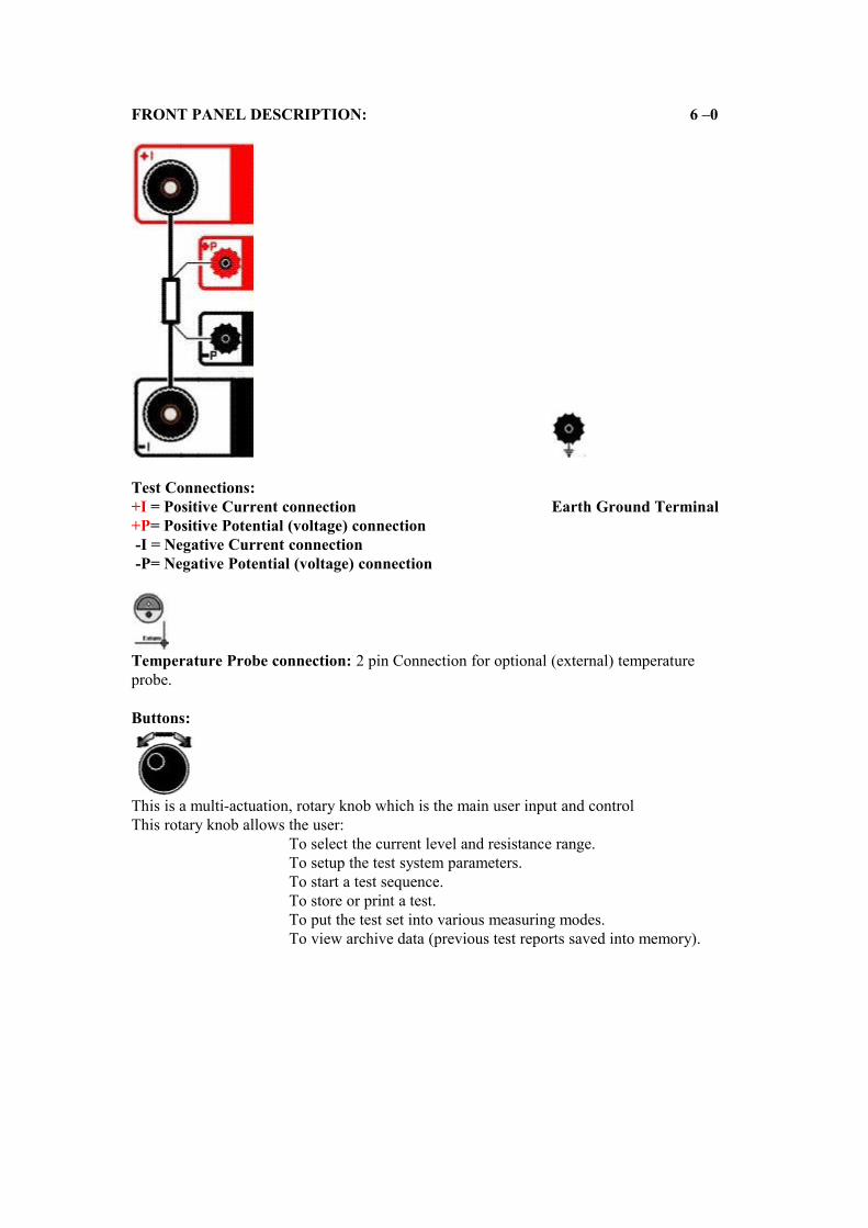
MAIN SELECTION SETUP ARCHIVE
MAIN SELECTION Screen:Allows access to the Archive (Memory), Setup and Resistance & Current test levels. Selection is made by turning the rotary knob to the desired position then pressing down on the rotary knob to confirm selection.
SETUP Screen:All selections for Printer options, LCD Contrast, Auto Test mode and Clock adjustments. Selections are made by turning the rotary knob to highlight the desired position then pressing the rotary knob for the selection.
ARCHIVE Screen:This is where the memory locations are kept.SHOW: This selection will allow viewing of all of the memory locations.PRINT: This selection will print all of the memory locations.ERASE: This selection will erase all of the memory locations.SETUP: This selection will return to the MAIN SELECTION screen.
START TEST TEST IN PROGRESS END OF TEST
START TEST Screen:Selection of “Single” starts a test sequence for a single test with the duration of about 8 seconds.Selection of “CONT” starts a continuous test sequence. In the continuous test mode the system will measure until the user presses stop. Also, while testing in continuous mode the user may Print or Store at test result at anytime.Selection of “AUTO” puts the system into the “Automatic measure and save mode”. The system will measure and save data at “user selectable” time intervals into the system’s memory location (Archive).
TEST IN PROGRESS Screen:This screen shows that the test is in progress and that there is current flowing.
END OF TEST Screen:At the completion of a test the user can select the following:GO: Run the same test again.STORE: Store the results of a test in a memory locationPRINT: Print the results to a printer (Serial or Parallel port output).MODE: Select a different test mode: AUTO, SINGLE, or CONTinuous.SETUP: Return to the Main Selection Screen.
TYPICAL DISPLAY SCREENS: Cont’d 7 – 0
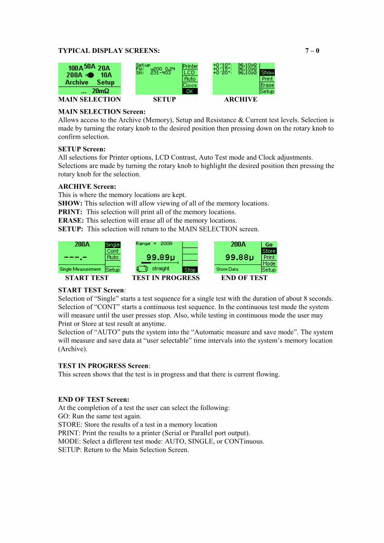
STORE PRINT PRINT MENU
STORE Screen:By pressing the rotary knob, with STORE highlighted, the system will store the test result in the next available memory location.
PRINT & PRINT MENU Screen:By pressing the rotary knob, with STORE highlighted, the system will open the sub-menu PRINT MENU, and allow the following to be selected:Selection of “HEADER” allows the user to Print a Header.Selection of “DATA” allows the user to Print the data.Selection of “FF” allows the user to print a Report form or advance the paper on the internal printer.Selection of “STOP” returns to the Test screen.
AUTO TEST CLOCK CONTRAST
AUTO TEST Screen:The Auto Test screen is accessed through the Set-up screen. This feature allows setting the number of tests required at certain time intervals set by the user.
CLOCK and CONTRAST Screens:The Clock and Contrast screens are accessed through the Set-up screen. The time can be set by turning the rotary knob and pressing the desired selection. Selections are made in this order: Year, Month, Day, Minute, and Hour.The Contrast (LCD) can be changed by pressing and then turning the rotary knob for the desired view.

GETTING STARTED: 8 - 0
WARNINGS!BEFORE OPERATING THIS OR ANY OTHER TEST EQUIPMENT READ ALL SAFETY WARNINGS AND UNDERSTAND THEM FULLY.
OPERATION:
This section describes a typical, step by step, operation of the Centurion IIOpen the top protection lid of the case and attach the test leads to the test set.The Two (2) connections on the front plate make +I & -I are the current leads.The Two (2) connections on the front plate make +P & -P are the Potential or Voltage leads.By connecting a test specimen to the Current leads (See figure 2) and applying the potential leads across the specimen the resistance readings will be determined.
Figure 2Turn the Power switch, located at the power input connector to the “ON” position.The Initial screen, MAIN SELECTION, will appear. The Instrument will also make the initial calibration.
Select the resistance range expected to be measured with the multi-turn Knob.Press the multi-turn Knob when the indicator is pointing (Highlighted) at the resistance and current level to be measured (If unsure of current level, then start at the 10A range and increase the current ranges until a valid reading appears).
After the current range is selected press the multi-turn Knob again.The following measuring modes can then be made:SINGLE (Single test -8 seconds), CONT (Continuous Test), AUTO (Automatic Test)
SINGLE: The SINGLE mode allows a single test to be made. Turn the multi-turn Knob until SINGLE is highlighted. Press the multi-turn Knob to select. The test set will start a measuring sequence immediately. The system will sense the current output and, if it is a valid reading, record the results on the display. The results can then be STORED or PRINTED.
CONT (Continuous): The CONT (Continuous) mode allows a single test to be made continuously. The instrument will continuously measure until the operator presses STOP.Turn the multi-turn Knob until CONT is highlighted. Press the multi-turn Knob to select. The test set will start measuring immediately. The system will sense the current output and, if it is a valid reading, display the results on the display. If the STOP button is selected the last valid reading displayed will remain on the display.
CONTINUOUS TESTNOTE: The results displayed can be stored or printed at anytime during the measurement process.

OPERATION: 8 - 0
AUTO (Automatic)
The AUTO (Automatic) mode will measure and store, automatically, numerous single sequential tests at timed intervals that are preset by the operator. To preset the number of tests at timed intervals please go to the Set-UP screen (See below) and select AUTO.In this AUTO mode the instrument will continuously measure multiple tests until the operator selects and presses STOP or until the number of tests that were preselected have been achieved.The instrument will automatically save test results in a numbered memory location that will increment by a timed interval.
AUTO Setup screen:Ti = Test IntervalN = Number of Tests desired.
A maximum of 10 minutes at 5 second intervals can be preset.
Measurement Notes:Note 1: The instrument will halt the measuring process if excessive interference is detected.
Note 2: If a warning message,”Rx Too High” is displayed, Or if ”+++.+” is displayed, Then return to the “SET UP” screen and select the next higher current range.The ”+++.+” is displayed when no input is measured on the +P & - P terminals.
ARCHIVE: 9 - 0
The Archive or Memory allows over 2000 complete test results to be saved. The method used for the memory location is:
Each memory location is designated a number, a date and time on which it was recorded, the results measured, and the current it was tested at.
If multiple tests are taken in one test sequence the memory location will appear like this:
The test results can be printed from the Archive via the RS232 port or Parallel printer port.

PRINTER: 10 - 0
Selecting Printing options:
From the SETUP Menu Select “Printer”:
The user now has the option to select:Internal – The optional panel mount printer. The system can be purchased with an optional printer.Parallel – An external printer connected to the 25 Pin connectorSerial – An external printer connected to the 9 Pin connector.
Internal Printer:The internal thermal printer report has the following options:
Header – Prints the header lines onto the report.Data – Prints the Data onto the report.FF – Form Feed
The user may at the completion of each test print the results or may recall previous tests from a memory location and print these results as well.
The test report is printed in the general following manner:
Test Report Measured by Raytech Type MC II
S/N : 231-002 Fw : u200 1.06
Operator : . . . . . . . . . . . . . . . . . Date : . . . . . . . . . . . . . . . . . Object : . . . . . . . . . . . . . . . . . Site : . . . . . . . . . . . . . . . . .
#1 at 200 A 10. Jan 02 12:00:00
+ 0’05” 10.000 mΩ+ 0’10” 10.001 mΩ+ 0’15” 10.003 mΩ+ 0’20” 10.004 mΩ+ 0’25” 10.006 mΩ

TEMPERATURE PROBE 11 - 0
Part Number: TP 01, can be purchased for the Centurion II for the purpose of recording temperatures. Recording the temperature of the device under test is highly recommended due to the characteristics of the increase of resistance of a metallic object as its temperature increases. There are temperature compensation tables for Copper and Aluminum available to calculate the conversion factor. The Centurion II is a very accurate and precise test system. To take full advantage of this high accuracy, the temperature of the device under test should be recorded.
The TP 01 temperature probe is mounted to a flexible extension cable that plugs into the front panel of the Centurion II. This option enables the user to record the ambient temperature or the actual temperature of the device under test.
The Centurion II will automatically sense when the optional temperature probe, TP 01, is connected to it. The temperature will be displayed on the instrument screen during a test and will appear when a print report is requested. The temperature, as well as the test results, can be saved into memory. The temperature can only be viewed during a test and on a printed report.
The actual temperature measured is displayed and can be saved into memory. TheCenturion II does not perform temperature corrections to the readings.

BASIC INSTRUCTION – QUICK TEST: 12 - 0
WARNINGS!BEFORE OPERATING THIS OR ANY OTHER TEST EQUIPMENT READ ALL SAFETYWARNINGS AND UNDERSTAND THEM FULLY.
WARNINGS!BEFORE USING THE BASIC OPERATING INSTRUCTIONS THE OPERATOR SHOULD BE COMPLETELY FAMILIAR WITH THE TEST SYSTEM AND THIS TYPE OF TESTING.
OPERATION: 12 - 1
This section outlines the basic measurement instruction, step by step, for the Centurion II.These are basic instructions, simplified, for the trained and qualified operator.
1. Connect the test leads (2 Current / 2 Potential) to an un-energized device to be measured.2. Connect the Safety Ground on the front panel to known good Earth Ground.3. Turn on the system.4. Turn the Rotary knob to select the Resistance Range / Current Range.5. Press the rotary knob once.6. Turn the Rotary knob to (highlight) select the required test: Single, Continuous, Automatic.7. Press the rotary knob once and the system will perform the test.8. Save or print the data.

TroubleshootingGeneral 13 - 0At powering on, the Centurion II internal calibration and check sequence is performed. Upon completion of the check sequence the test set will proceed to the “MAIN SELECTION“ Screen. Should there be any problem with the test set an error message will appear.
SYSTEM DOES NOT DISPLAY ANYTHING:1. Check the display for any Initialization.2. Check the fuse. The fuse is located in the Power switch / plug connector.
SYSTEM POWERS ON BUT THE DISPLAY FADES OUT OR BLINKS:1. Check the input power line for faults.2. If an extension cord is being used, check the size and condition of. An extension cord
should not exceed 25 feet long and should be at least #2 wire minimum.
TEST CURRENT CANNOT BE TURNED ON.1. Does the unit have an external safety switch incorporated? Is it properly operating?2. Is the Emergency stop switch pushed in? Turn to release it.3. Is the system connected in an excessive interference area?
“WARNING Rx TOO HIGH” or “+++.+” IS DISPLAYED.1. A warning message, ”Rx Too High” or “+++.+” will be displayed if the resistance being
measured is too high for the range selected.The ”+++.+” is displayed when no input is measured on the +P & - P terminals.
2. The current leads total resistance has exceeded the current capability of the instrument. Reduce the current lead length or increase the wire gauge of the current lead used.
THE DISPLAY CANNOT BE SEEN OR APPEARS TO BE NOT ON1. The contrast has been set to low.
ERRATIC OR ERRONEOUS READINGSPossible causes1. Test lead damaged or not connected.2. Poor test lead connection.3. Poor supply power. Check extension cords, plugs cables carefully.4. Test set attached to a “Live” load or high interference load.
The Centurion II is designed to be trouble free.If problems or questions do arise please contact your nearest Dealer or our service support group in the Switzerland.Office Tel. +41 56 640 06 70, Office Fax. +41 56 640 06 74
SYSTEM UPGRADES
System firmware upgrades are available at no charge from the web site www.raytech.chThis firmware is downloaded to a Windows based computer and then can be used to upgrade the Flash Eprom in the Micro-Centurion II via the RS232 link. For further details please contact our support group.

WARRANTY 14 - 0
1. RAYTECH Switzerland shall at their option and expense, repair, replace or newly provide any parts or services that prove to be defective within the warranty limitation period- irrespective of the operating time of the test equipment provided that the cause of the defect occurred prior to the time at which the risk was passed.
2. Warranty claims are subject to a warranty limitation period of 24 months from the date of shipment.
3. The purchaser is obligated to immediately notify RAYTECH Switzerland in writing form of any defects of the supplied test equipment.
4. RAYTECH Switzerland must always be given the opportunity to rectify a defect within a reasonable time. The purchaser shall grant an adequate time within the test equipment shall be repaired.
5. RAYTECH Switzerland covers the costs associated with the repair of the defect. Especially the costs for the material and work. Cost for sending the faulty test equipment shall be borne by the purchaser. RAYTECH Switzerland shall not be liable for material damage, or financial loss due to the loss of production, loss of data, loss of information, data or interest, regardless of their legal basis.
6. Warranty claim rights on replacement parts as well as repair of defective parts shall expire after 12 months.
7. Warranty limitation period shall be extendable according to the price list. The purchaser has the right to extend the warranty period by purchasing additional warranty years.
Limitation of Warranty
The foregoing warranty shall not apply to defects resulting from improper and unauthorized modifications or misuse and abuse of the product, negligence, alteration, modification, faulty installation by the customer, customer’s agents or employees. Attempted or actual dismantling, disassembling, service or repair by any person, firm, or corporation not specifically authorized in writing by RAYTECH Switzerland.Defects caused by or due to handling by carrier, or incurred during shipment, trans-shipment, or other move. Inadequate maintenance by the customer, second source supplied software or interfacing, operation outside the environmental limits, or improper site preparation.Exclusive remedies provided herein are the customer’s sole and exclusive remedies.RAYTECH Switzerland shall not be liable for any damages resulting from the use of this equipment whether direct, indirect, special, incidental, or consequential damages, or whether based on contract, tort, or any other legal theory.
NO OTHER WARRANTY IS EXPRESSED OR IMPLIED.
Arbitration
1. All disputes arising out of or in connection with the contract between the purchaser and RAYTECH Switzerland and including those regarding the legal validity of this contract and this arbitration clause shall be settled out of court and shall be referred to arbitration for final decision.
2. Any disputes between the purchaser and RAYTECH Switzerland shall be settled according to the rules of settlement and arbitration of the chamber of commerce in Zurich by one or more arbitrators appointed also according to the rules of arbitration of the chamber of commerce in Zurich Switzerland.


![Centurion: Defender Of Rome - User Manual [EN, FR]](https://static.fdokumen.com/doc/165x107/63388088c5ddac3e970cf85d/centurion-defender-of-rome-user-manual-en-fr.jpg)