1123.D.01.0002_8 Centor Installation manual - Centurion ...
40
Latest Revision: 15.03.2007 Document Ref.: 1123.D.01.0002_8 Product Code: CP72CENTOR CENTOR TRAFFIC BARRIER INSTALLATION MANUAL
-
Upload
khangminh22 -
Category
Documents
-
view
1 -
download
0
Transcript of 1123.D.01.0002_8 Centor Installation manual - Centurion ...

Latest Revision: 15.03.2007Document Ref.: 1123.D.01.0002_8
Product Code: CP72CENTOR
CENTORTRAFFICBARRIER
INSTALLATIONMANUAL

Introduction . . . . . . . . . . . . . . . . . . . . . . . . . . . . . . . . . . . . . . . . . . . . . . . . . . . . . . . . . . . . . . . . . . . 2
Basic Kit . . . . . . . . . . . . . . . . . . . . . . . . . . . . . . . . . . . . . . . . . . . . . . . . . . . . . . . . . . . . . . . . . . . 2
Recommended Tools . . . . . . . . . . . . . . . . . . . . . . . . . . . . . . . . . . . . . . . . . . . . . . . . . . . . . . . . . . . . 3
Types of Booms - Simplex / Complex . . . . . . . . . . . . . . . . . . . . . . . . . . . . . . . . . . . . . . . . . . . . . . . 4Determination of Operational Mode. . . . . . . . . . . . . . . . . . . . . . . . . . . . . . . . . . . . . . . . . . . . . . 5
Orientation . . . . . . . . . . . . . . . . . . . . . . . . . . . . . . . . . . . . . . . . . . . . . . . . . . . . . . . . . . . . . . . . . . . 6
Cable Requirements - Simplex / Complex . . . . . . . . . . . . . . . . . . . . . . . . . . . . . . . . . . . . . . . . . . . . 7
Counter Balance Spring Selection . . . . . . . . . . . . . . . . . . . . . . . . . . . . . . . . . . . . . . . . . . . . . . . . . . 9
Installation . . . . . . . . . . . . . . . . . . . . . . . . . . . . . . . . . . . . . . . . . . . . . . . . . . . . . . . . . . . . . . . . . . 10Positioning . . . . . . . . . . . . . . . . . . . . . . . . . . . . . . . . . . . . . . . . . . . . . . . . . . . . . . . . . . . . . . . . 10Bolting Down Arrangement . . . . . . . . . . . . . . . . . . . . . . . . . . . . . . . . . . . . . . . . . . . . . . . . . . . 10Converting Orientations. . . . . . . . . . . . . . . . . . . . . . . . . . . . . . . . . . . . . . . . . . . . . . . . . . . . . . 12Correct Boom Coupler Crank Arm Alignment in Boom Lowered Position . . . . . . . . . . . . . . . . 14Boom Pole Assembly. . . . . . . . . . . . . . . . . . . . . . . . . . . . . . . . . . . . . . . . . . . . . . . . . . . . . . . . 15Counter Balance Spring Selection. . . . . . . . . . . . . . . . . . . . . . . . . . . . . . . . . . . . . . . . . . . . . . 18
Electrical Connections . . . . . . . . . . . . . . . . . . . . . . . . . . . . . . . . . . . . . . . . . . . . . . . . . . . . . . . . . . 19Simplex . . . . . . . . . . . . . . . . . . . . . . . . . . . . . . . . . . . . . . . . . . . . . . . . . . . . . . . . . . . . . . . . . . 20
Mains Supply. . . . . . . . . . . . . . . . . . . . . . . . . . . . . . . . . . . . . . . . . . . . . . . . . . . . . . . . . . . 20Trigger Input . . . . . . . . . . . . . . . . . . . . . . . . . . . . . . . . . . . . . . . . . . . . . . . . . . . . . . . . . . . 21Safety Beam . . . . . . . . . . . . . . . . . . . . . . . . . . . . . . . . . . . . . . . . . . . . . . . . . . . . . . . . . . . 21Courtesy Light . . . . . . . . . . . . . . . . . . . . . . . . . . . . . . . . . . . . . . . . . . . . . . . . . . . . . . . . . . 22
Complex . . . . . . . . . . . . . . . . . . . . . . . . . . . . . . . . . . . . . . . . . . . . . . . . . . . . . . . . . . . . . . . . . 22Mains Supply. . . . . . . . . . . . . . . . . . . . . . . . . . . . . . . . . . . . . . . . . . . . . . . . . . . . . . . . . . . 22Memory Input (MI) . . . . . . . . . . . . . . . . . . . . . . . . . . . . . . . . . . . . . . . . . . . . . . . . . . . . . . . 22Closing Beam or Loop Input . . . . . . . . . . . . . . . . . . . . . . . . . . . . . . . . . . . . . . . . . . . . . . . 23
Unidirectional Traffic with Free Exit Loop . . . . . . . . . . . . . . . . . . . . . . . . . . . . . . . . . . 24Bi-Directional Traffic with Free Exit Loop . . . . . . . . . . . . . . . . . . . . . . . . . . . . . . . . . . 24
Non - Memory Input (NMI). . . . . . . . . . . . . . . . . . . . . . . . . . . . . . . . . . . . . . . . . . . . . . . . . 27Ticket Vend Interlock (T.V.I). . . . . . . . . . . . . . . . . . . . . . . . . . . . . . . . . . . . . . . . . . . . . . . . 27
Commissioning . . . . . . . . . . . . . . . . . . . . . . . . . . . . . . . . . . . . . . . . . . . . . . . . . . . . . . . . . . . . . . . 28
Diagnostic LEDs . . . . . . . . . . . . . . . . . . . . . . . . . . . . . . . . . . . . . . . . . . . . . . . . . . . . . . . . . . . . . . 31
Manual Release . . . . . . . . . . . . . . . . . . . . . . . . . . . . . . . . . . . . . . . . . . . . . . . . . . . . . . . . . . . . . . . 31
Maintenance . . . . . . . . . . . . . . . . . . . . . . . . . . . . . . . . . . . . . . . . . . . . . . . . . . . . . . . . . . . . . . . . . 32Fuses . . . . . . . . . . . . . . . . . . . . . . . . . . . . . . . . . . . . . . . . . . . . . . . . . . . . . . . . . . . . . . . . . . 32
Boom Head Assembly . . . . . . . . . . . . . . . . . . . . . . . . . . . . . . . . . . . . . . . . . . . . . . . . . . . . . . . . . . 33Enclosure Assembly. . . . . . . . . . . . . . . . . . . . . . . . . . . . . . . . . . . . . . . . . . . . . . . . . . . . . . . . . . . . 35
Wiring Diagram . . . . . . . . . . . . . . . . . . . . . . . . . . . . . . . . . . . . . . . . . . . . . . . . . . . . . . . . . . . . . . . 36
Specifications. . . . . . . . . . . . . . . . . . . . . . . . . . . . . . . . . . . . . . . . . . . . . . . . . . . . . . . . . . . . . . . . . 37
Glossary . . . . . . . . . . . . . . . . . . . . . . . . . . . . . . . . . . . . . . . . . . . . . . . . . . . . . . . . . . . . . . . . . . 38
Table of ContentsTable of Contents
Page 1

The boom kit comprises of one or more components shown in the identification list below.
NB. Mounting rawl bolts are not included (use 4 x M16x150)
PLEASE READ THE INSTRUCTIONS CAREFULLY
CP91 CONTROLLER
JACK-KNIFE KNUCKLE
JACK-KNIFESUPPORT PILLAR LOWER PIVOT POINT
UPPER PIVOT POINT
3m BOOM ARM
4.5m BOOM ARM
6m BOOM ARM
A CENTURION ACCESS AUTOMATION system is a quality product designed to give many years of trouble free service.
HOLDING DOWNBAR
LOOPDETECTOR
UNIT(optional)
ENCLOSURE AVAILABLE IN MILD OR STAINLESS STEEL
ENCLOSURE & GEARBOX COMPONENTS
Mounting Hardware (Part of Gearbox and Enclosure)
Jack-Knife Assembly (Optional) Electronics
F1
F2
BM
CV
5.x
BM
DV
5.x
TRG
OLSCLS
PEDIRB
IntroductionIntroduction
Basic KitBasic Kit
Page 2

SPANNER1 x 10mm/1 x 13mm1 x 17mm/1 x 19mm
SCREW DRIVER3,5mm FLAT
No 1. PHILLIPS
CRIMPING TOOLAND PIN LUGS
PLIERS/SIDECUTTER
MASONRY BITS16mm
HAMMER
TAPE MEASURE
ALLEN KEYS3mm ACROSS FLATS8mm ACROSS FLATS
10mm ACROSS FLATS
HACKSAW
PICK
SPADE
ELECTRICDRILLINGMACHINE
Recommended ToolsRecommended Tools
Page 3

Types of BoomTypes of Boom
Page 4
3.0m
4.5m
6.0m
ARM LENGTH
There are three standard arm lengths available:
OPERATIONAL MODES
• SIMPLEX (sometimes called Domestic) - Use BMDV5.X firmware
• COMPLEX (sometimes called Commercial) - Use BMCV5.X firmware
The mode is determined by the microprocessor fitted to the CP91 control card as
well as selecting which loop detectors are required, (See next section).
Two standard operational modes are available:

DETERMINATION OF OPERATIONAL MODE
MAJOR FEATURES OF OPERATIONAL MODES
B M C V 5 . X
Product Codee.g. BOOM
Version offirmwareTYPE:
D=Simplex (Domestic)C=Complex (Commercial)
NOTE: The type and version of firmware used will determine what operational modes are available, and what wiring is required.
Raising and lowering of the boom is done via a remote control or pushbutton.
Selectable, adjustable autoclose (±8 - 35 Seconds)
There is one safety input for use with I/R beams or inductive loop sensors. This input can be used to provide vehicle presence detection and auto close inhibit.
Potential free contact for external security light etc.
Memory input (MI) for cardreader input etc.
Non-memory input (NMI) for ticket vendor or cash register input.
Ticket vend interlock (TVI) via potential free contact to inhibit ticket issue if barrier is opening or open.
Barrier close /safety input, either loop detector (recommended) or infrared beam.
The mode is determined by the microprocessor fitted. Locate the label on the microprocessor to find out what operational mode will be effective.
SIMPLEX MODE (B M D V 5.X)
COMPLEX MODE (B M C V 5.X)
See Glossary, Section 14.0 for definition of non standard terms.
F1
F2
BMCV5.xBMDV5.x
TRG
OLS
CLS
PE
DIR
B
CP91CONTROL
CARD
BMDV5.x - SimplexBMCV5.x - Complex
Page 5

DEFAULT
Refer to Page 10
ORIENTATION 1
ORIENTATION 2
Refer to Page 10
DEFAULT
ORIENTATION 2
ORIENTATION 1
ORIENTATION 1 and 2
The following orientations are possible:-
The factory default is Orientation 1 for single barriers. See section 7.3 for details of converting to other orientations.
If barriers are to be paired, (e.g. in a wide entrance of say 6 metres, which requires 2 x 3 metre booms, then the pairs must be selected with one unit as orientation 1 and the other as orientation 2).
VEHICLE DIRECTION
PLAN VIEW
PLAN VIEW
WALL WALL
WALL
VEHICLE DIRECTION
WALL
WALL WALL WALL
FRONTVIEW
FRONTVIEW
OrientationOrientation
Page 6

COMPLEX (Commercial) (Basic Application)
T O
DIREC
NOF
I
TAV
REL
INFRARED BEAM(OR LOOP)
RESTRICTINGKERB
3,5M
1M
100
LOOPWIREFEED
2M
No Ticket Spitter
CLOSING LOOP
1M
POWER 220V
20mmCONDUIT
CARD READER/ KEYPAD
CABLING TOPUSHBUTTON
GUARDHUT
220V ACINPUT
SIMPLEX (Domestic) (Typical Application)
IMPORTANT :
1.Guard controls operation of barrier using pushbutton inside guard hut.
2. Infra red safety beam can be replaced with inductive loop detector, fitted to the "safety loop" relay base.
3. Fit BMDV5.X microprocessor to CP91 control card.
1. Loop detector is fitted to "safety loop" relay base. 2. Card reader is connected to MI input. 3. Fit BMCV5.X microprocessor to CP91 control card.
Before doing any cabling, check which operational mode is required for the barrier. (See Section 4.1)
Cabling RequirementsCabling Requirements
Page 7

COMPLEX (Commercial) Access to parking area with ticket spitter
RESTRICTING KERB
4Mmin
3,5M
1M
100
LOOPWIREFEED
2M
TICKETSPITTER
CLOSING LOOP
1M
PRESENCE LOOP
1M
1M
POWER 220V
20mmCONDUIT
CARD READER/ KEYPAD
COMPLEX (Application with Free Exit Loop - Bi-Directional Traffic)
RESTRICTING KERB
NOTE: For unidirectional traffic see 8.2.3.1 .
1. This distance must be less than a car length, if bi-directional traffic is required.2. Use BMCV5.X Microprocessor.3. Fit both safety and free exit loop detectors.
1. "CLOSING" loop detector is fitted to "Safety loop" relay base; 2. "Presence" loop is part of ticket spitter;3. Fit BMCV5.X microprocessor to CP91 control card.
SAFETY/CLOSING
LOOP
EXITDIRECTION
FREEEXIT
LOOP
1m1m
2m
1m
1m
Page 8

Counterbalance Spring SelectionCounterbalance Spring Selection
Page 9
76.2 x 1.27 Aluminium Tube = 0.81kg/m
76.2 x 1.27 Aluminium Tube = 0.81kg/m
76.2 x 1.27 Aluminium Tube = 0.81kg/m
76.2 x 1.8 Aluminium Tube = 1kg/m
76.2 x 1.8 Aluminium Tube = 1kg/m
76.2 x 1.8 Aluminium Tube = 1kg/m
80 x 1.5 Aluminium Tube = 1kg/m
80 x 1.5 Aluminium Tube = 1kg/m
80 x 1.5 Aluminium Tube = 1kg/m
NB: For counterbalance spring installation see page 18.
Boom Pole ProfilePole
LengthNumber of
SpringsRequired
Spring PartNumber
3m
4.5m
6m
3m
4.5m
6m
3m
4.5m
6m
1
2
3
1
2
4
1
2
4
SPRINGTM90
SPRINGTM90
SPRINGTM90
SPRINGTM90
SPRINGTM90
SPRINGTM90
SPRINGTM90
SPRINGTM90
SPRINGTM90

POSITIONING>Determine correct position for barrier
>Check orientation of door - see Section 5.0
>Prepare hole for concrete foundation 500 x 500 x 300mm.
BOLTING DOWN ARRANGEMENTAlternative 1
>Throw concrete slab approximately 500 x 500 x 300 mm deep;
>Install cable conduits, make sure conduits exit in cable entry area.
>Leave approximately 50 mm of conduit protruding above concrete base;
>Concrete in anchor bolts or fit rawl bolts later.
Cableentryarea
Holdingdownbar
Accessdoor
280
175
280
InstallationInstallation
Page 10
30
0m
m
CABLE ENTRYAREA (See section 7.2)
500mm
0m
50m
Either Anchor Bolt
Cable Entry Area
Concrete Slab
M16 x 150Rawl Bolts
Cable Conduit
Holding DownBar
M16 x 150Rawl Bolts
Either
NOTE: Enclosure base is clamped between concrete and holding down bar

>Before pouring the concrete ensure that the mounting plate is positioned correctly.
>Tighten top and bottom nut to aid inpositioning the plate when theconcrete is poured.
>Place the plate above surface of concrete.
>Leave the concrete to dry.
BASEPLATE
HOLDING DOWNBAR
CABLECONDUIT
CABLEENTRYAREA
CONCRETESLAB
Alternative 2
LE
AV
E A
T L
EA
ST
70
mm
Page 11
>Unscrew the nuts and washers, andremove them.
>Arrange enclosure in position and clamp it between the mounting plate and the holding down bar supplied using the nuts and washers that were removed.

BOOM COUPLERCRANK ARM
PILLOWBLOCK
BEARING
BASEPLATE
SPRINGCRANK ARM
CONVERTING ORIENTATIONS(To convert a factory default orientation 1 to orientation 2)
The following modifications are done only if it is necessary to change the orientation of the arm e.g. the unit has been incorrectly ordered, or site conditions have changed.
NB. 1. Make sure that all power to the unit is switched off. 2. Make sure that the counterbalance springs are retracted.
Step 1: Remove M12 Cap Screw
Step 2: Loosen the boom coupler from the shaft by inserting and tightening the M16 Bolt
Page 12
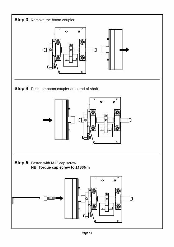
Step 3: Remove the boom coupler
Step 4: Push the boom coupler onto end of shaft
Step 5: Fasten with M12 cap screw. NB. Torque cap screw to ±180Nm
Page 13

CORRECT BOOM COUPLER CRANK ARM ALIGNMENT IN"BOOM LOWERED” POSITION
NB. The alignment of the boom coupler crank arm is a factory setting but may need adjustment over time to ensure that:
1. The boom arm is horizontal. 2. In a power failure situation the arm will raise automatically, or the boom is self-lock.
• adjust the length of the connecting rod to ensure that the boom Arm is horizontal.
• adjust the height of the rubber stoppers to ensure that the boom Arm will raise in the event of a power failure and be self locking.
• with power on the motor and the stoppers slightly compressed the Drive arm and connecting arm must be in a straight line.
B
A
BOOM ARMHORIZON
FRONTVIEW
BOOMCOUPLER
CONNECTINGROD
BASE PLATE
P = 82mm
RUBBER STOP(ADJUSTABLE FOR ARM IN LOWERED POSITION)
B
A
ADJUST L
ENGTH
Page 14

Tighten the cap screw using a 12mm allen key. To prevent the boom and clamping piece from slipping on the shaft, ensure that the cap screw is fastened very tightly (approx. 180Nm)
3
Fasten the external clamping piece onto the end of the shaft using the M12 x 55 cap screw
Using the external clamping piece as a template, mark and drill the 10.5mm holes in the boom pole.
2
BOOM POLE ASSEMBLY
1
Fitting the Boom Pole
Page 15

Removing the Boom Pole
Fit the boom pole into the external clamping piece. Fit the M10 bolts through the internal clamping piece and slide the assembly through the end of the boom pole. Locate the bolts in the holes in the boom pole.
4
Fasten the M10 nuts ontothe bolts and tighten.
5
Remove the M12 cap screw.Remove the M10 nuts.
21
Page 16

Insert and tighten the M16 bolt.
3
As the bolt is tightened against the end of the shaft, this action will pull the external clamping piece away from the shaft.
4
Page 17

COUNTERBALANCE SPRING INSTALLATION
Page 18
The Centor Barrier requires a specific number of springs to counterbalance the weight and length of the pole fitted (See Table on page 9.)
1. Determine the number of springs required (See Table on page 9.)
2. Ensure the pole adaptor (A) is in the vertical position.
3. Slip the threaded rod end of the spring (B) into the spring arm shaft (C) through the holes provided. Observe the order shown in the diagram.
4. Hook the bent tail of the spring into the hole provided in the base of the cabinet. See inset on the right hand side.
5. Wind the lock nut & washer provided (D) onto the threaded rod (B)
6. Carefully tension the springs by winding the nut down the threaded portion until they come into contact with the spring arm shaft. Take care to wind the nut down equally for all the springs present.
7. The spring tension should be set to balance the pole at 45º to the ground with no power present.
8. When satisfied that the barrier is balanced, put on power & cycle it. Watch for springs unhooking or the motor straining against the spring tension.
NB: When installing the springs the boom pole must be in the vertical position. ANY work on the springs must be done in this state. Should there be a need to cycle the operator KEEP YOUR HANDS CLEAR of the barrier entirely.
3rd
4th2nd
1st
3rd
D
C
B
Spring tensionAdjusting nuts
MainBaseplate
Springs(qty. To suitArm length)
A
(See Table on page 9)
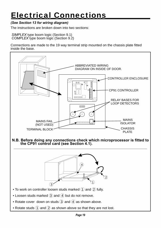
ABBREVIATED WIRINGDIAGRAM ON INSIDE OF DOOR.
CONTROLLER ENCLOSURE
CP91 CONTROLLER
RELAY BASES FORLOOP DETECTORS
TERMINAL BLOCK
MAINS FAIL(NOT USED)
CHASSISPLATE
MAINSISOLATOR
• To work on controller loosen studs marked 1 and 2 fully.
• Loosen studs marked 3 and 4 but do not remove.
• Rotate cover down on studs 3 and 4 as shown above.
• Rotate studs 1 and 2 as shown above so that they are not lost.
The instructions are broken down into two sections:
SIMPLEX type boom logic (Section 9.1) COMPLEX type boom logic (Section 9.2)
Connections are made to the 19 way terminal strip mounted on the chassis plate fittedinside the base.
(See Section 13 for wiring diagram)
N.B. Before doing any connections check which microprocessor is fitted to the CP91 control card (see Section 4.1).
3
4
2
1
Page 19
Electrical ConnectionsElectrical Connections

SIMPLEX TYPE BARRIER LOGIC
AC MAINS SUPPLY
Connect 220V AC, 50 HZ supply to terminals L, N, E
Only Switch "ON" isolator after all connections have been made
TYPICAL INPUTS FOR SEMI AUTOMATIC APPLICATION BMDV5.X CHIP
Notes:
1) trigger input functions as " start - stop - reverse"
2) safety beam prevents barrier from closing onto a vehicle
3) 12v aux supply can be used to power safety beams and radio receiver.
12V AUXSUPPLY
220V ACSUPPLY
SAFETYBEAM
TRIGGERINPUT
NOTUSED
BARRIERRAISE
COURTESYLIGHT
NOTUSED
NOTUSED
3 7 9 11 1351NL
CO
M
CO
M
CO
M
CO
M
MI
FRX
TVI
+12
V
IRB
4 8 10 12 14 1662E 15
Page 20
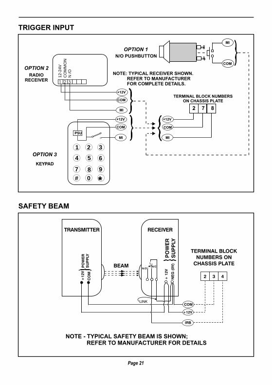
N/O PUSHBUTTON
TRIGGER INPUT
SAFETY BEAM
OPTION 2
OPTION 1
OPTION 3
KEYPAD
1
4
7
#
8
0
9
5 6
2 3
MI
COM
RADIORECEIVER
NOTE: TYPICAL RECEIVER SHOWN. REFER TO MANUFACTURER FOR COMPLETE DETAILS.
TERMINAL BLOCK NUMBERSON CHASSIS PLATE
*
MI MI
COM COM
PSU
+12V +12V
MI
COM
+12V
2 7 8
1
12
-24
V
CO
MM
ON
N /O
2 3
BEAM
IRB
+12V
LINK
NOTE - TYPICAL SAFETY BEAM IS SHOWN; REFER TO MANUFACTURER FOR DETAILS
+12
V
+ 1
2VP
OW
ER
SU
PP
LY
PO
WE
RS
UP
PLY
CO
M
NE
G (
0V)
N/CN/O
COM
TRANSMITTER RECEIVER
TERMINAL BLOCKNUMBERS ON
CHASSIS PLATE
2 3 4
Page 21

AC SUPPLY 220V AC, 50 HZ
MAINS ISOLATOR
ON CHASSISPLATE
INSIDE OF BOOM
ENCLOSURE
EXISTING WIRING
NOTE: Light stays on for 2 minutes
after boom has closed.
NOTE: The CP88 logic card counts and stores each trigger impulse on memory input terminals (M.I.). Barrier will stay raised until same number of closing signals are applied to closing input (See Section 8.2.3.)
TERMINAL BLOCK ON CHASSIS PLATE
TERMINAL BLOCK ON CHASSIS PLATE
COURTESY LIGHT
COMPLEX TYPE BARRIER LOGIC
ON
NEUTRAL
LIVE
OFF
141312
NE
L
AC MAINS SUPPLY See Section 8.1.1
MEMORY INPUT
E.g.MAGNETIC
CARDREADER
872
N/O
N/C
MI
COM
+12V
MA
G-C
AR
D
TYPICAL INPUTS FOR COMMERCIAL APPLICATION BMCV5.X CHIP
Notes: 1) Closing beam can be used if loop detector is not fitted 2) Memory input "counts" triggers 3) Non memory input activates when contact is closed and then released. 4) Barrier raise will keep the barrier raised while the contact is closed. 5) Ticket vend interlock is "closed" when the barrier is closing or closed.
220V ACSUPPLY
NL E
12V AUXSUPPLY
1
CO
M
+12
V
21
CO
M
+12
V
2
FREE EXITLOOP
15 1615 16
TICKET VENDINTERLOCK
13
TVI
1413
TVI
14
220V ACSUPPLY
NL E
CLOSINGBEAM
3
CO
M
ILP
43
CO
M
ILP
4
CLOSINGLOOP
5 65 6
MEMORYINPUT
7
CO
M
MI
87
CO
M
MI
8
NON-MEMORYINPUT
9
CO
M
NM
I
109
CO
M
NM
I
10
BARRIERRAISE
11C
OM
IRB
1211C
OM
IRB
12
Page 22

CLOSING BEAM OR LOOP INPUTTo lower the arm requires a closing signal. This is supplied by either a closing beam or Inductive loop detector.
N.B. THE CLOSING BEAM, OR LOOP, ALSO ACTS AS A SAFETY. THEREFORE MOUNT BEAM OR LOOP DIRECTLY UNDER BARRIER ARM.
INDUCTIVELOOP
TWISTEDWIRE
LOOP UNDERROADWAY
Page 23
It is recommended that 2 sets of ir beams are installed, spaced as shown, wired in series.This prevents a person walking through the entrance, while the Barrier is raised, to inadvertently cause the barrier to lower.
TERMINALBLOCK ONCHASSIS
PLATE
EXISTING WIRINGINSIDE BOOM
Inductive loop detector fittedTo chassis plate inside boom
Enclosure plugged into "safetyLoop" relay base.
1 2 3 4 5 6
N/CN/O
COM
+12V
COM
IRB
TRANSMITTER
500mm
+
+12V
+-
NEG
-COM
COM
N/O
N/O
N/C
N/C
1 2 3 4 5 6 7 8 9 10+ -
RECEIVER
Tx
Tx
Rx
Rx
IR BEAM
TRANSMITTER RECEIVER

DETAIL A
UNIDIRECTIONAL TRAFFIC WITH FREE EXIT LOOP
ONLY "SAFETY" LOOPDETECTOR IS FITTED
TO RELAY BASE
16 WAY TERMINALSTRIP ON CHASSIS
DETAIL B
DETAIL A
See also Section 6.3
EXITDIRECTION
EXITDIRECTION
BIDIRECTIONALTRAFFIC
SAFETY LOOP
SAFETY LOOP
FREE EXITLOOP
FREE EXITLOOP
0.5m
0.5m
0.5m
0.5m
0.5m
0.5m
0.5m
0.5m
0.5 m
1.5m
0.5 m
0.5 m
1m1m
1m1m
Note: 220V loop detectors are normally used In centor barriers, 220V AC type LD100
BI-DIRECTIONAL TRAFFIC WITH FREE EXIT LOOP
See also Section 6.3
Note: 220V loop detectors are normally used In centor barriers, type LD100.
5
5
1
4
23
6
FREEEXIT
NOTE 1
NOTE 2
11
7
10
8
96
Note: 1. Ensure free exit and safety Loops are wired in series. 2. Fit link to free exit relay Base as shown above.
Page 24
BOTH "SAFETY" AND "FREE EXIT"LOOP DETECTORS FITTED
TO RELAY BASES
16 WAY TERMINAL STRIP ON CHASSIS
DETAILB
5 156 16
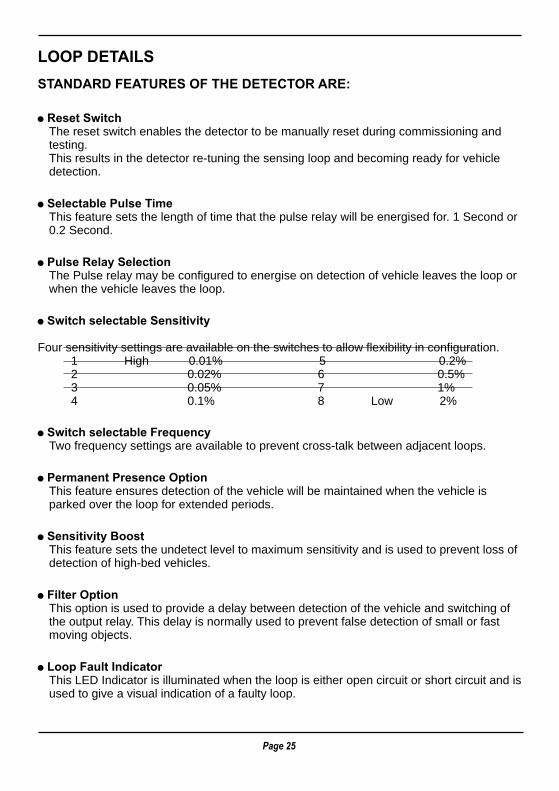
LOOP DETAILS
STANDARD FEATURES OF THE DETECTOR ARE:
! Reset SwitchThe reset switch enables the detector to be manually reset during commissioning and testing.This results in the detector re-tuning the sensing loop and becoming ready for vehicle detection.
! Selectable Pulse TimeThis feature sets the length of time that the pulse relay will be energised for. 1 Second or 0.2 Second.
! Pulse Relay SelectionThe Pulse relay may be configured to energise on detection of vehicle leaves the loop or when the vehicle leaves the loop.
! Switch selectable Sensitivity
Four sensitivity settings are available on the switches to allow flexibility in configuration. 1 High 0.01% 5 0.2% 2 0.02% 6 0.5% 3 0.05% 7 1% 4 0.1% 8 Low 2%
! Switch selectable FrequencyTwo frequency settings are available to prevent cross-talk between adjacent loops.
! Permanent Presence OptionThis feature ensures detection of the vehicle will be maintained when the vehicle is parked over the loop for extended periods.
! Sensitivity BoostThis feature sets the undetect level to maximum sensitivity and is used to prevent loss of detection of high-bed vehicles.
! Filter OptionThis option is used to provide a delay between detection of the vehicle and switching of the output relay. This delay is normally used to prevent false detection of small or fast moving objects.
! Loop Fault IndicatorThis LED Indicator is illuminated when the loop is either open circuit or short circuit and is used to give a visual indication of a faulty loop.
Page 25

Page 26
LOOPCIRCUMFERENCE
IN METRES
> 10
6 - 10
< 6
No. OFTURNS
2
3
4
Min
.100m
m
PLASTICCONDUIT
3 TURNS MULTISTRANDED
BrickPaving
30-5
0m
mD
EE
P
4mm
3 TURNS OFCABLE MULTISTRANDED
(SILICON COATED)(TYPICAL)
FILL WITH EPOXYCOMPOUND OR
BITUMEN MASTIC ROADSURFACE
ROAD
TWIST FEEDERAT LEAST 20
TURNS PER METRE
Width of cut 4mm
45
300mm
300mm
1m
Maxi
en
mu
mre
co
mm
ded
l00m
feed
er
en
gth
1
Loopdetector
DE
PT
H IN
TO
RO
AD
MIN
. 30-5
0m
m
2 m
DETAIL A DETAIL B
(Recommended settings)
Note: If two detectors are used, set different frequencies (S6)
• Wire: 1.5mm squared multi stranded cable (use silicon coated if placed directly into the ground)
• Spacing between two adjacent loops > 2 metres. Alternate adjacent loops using different numbers of turns.
• Loop and feeder should comprise one length of unjoined wire. If joints are made, then solder joint. ’Use screened feeder cable in electrically noisy environments or where feeder runs parallel to Power cables.

NON MEMORY INPUT (NMI)
TICKET VEND INTERLOCK (TVI)
An example of "NMI" is the signal given by a ticket vending machine.
NOTE: NMI responds only when contact goes from CLOSED to OPEN.
The " T.V.I " Signal from the CP91 CARD will prevent the ticket spitterfrom issuing another ticket until the arm is closing or closed.
CP91CARD
T.V.I.
T.V.I.
NMI
COM
12
1211
13 149 10 11
N.C.
N.O.
1211
CP91CARD
T.V.I.
T.V.I.
NMI
COM
12 13 149 10 11
N.C.
N.O.
Page 27

Before any commissioning is done it is important to make sure that the counterbalancesprings are providing sufficient force to balance the weight of the arm.
Depending on the length of the boom pole used different numbers of counterbalancesprings are used. See Table on page 9.
ADJUSTING SPRING TENSION
NB. Spring tension is correct when the arm rises slowly when power is removed from the motor.
a: Increase tension if boom pole does not rise orb: Release tension if boom pole rises too quickly
: Make sure the Boom pole is lowered
: Switch off power to the system (isolator)
: Check that the boom pole rises slowly
Step 1
Step 2
Step 3
Step 4
SPRING TENSIONADJUSTING NUTS
MAINBASEPLATE
SPRINGS(QTY. TO SUITARM LENGTH)
Page 28
CommissioningCommissioning

Switch on AC power and ensure the green “MAINS” on LED on the CP91 control card illuminates:
Trigger boom and check that TRG (i.e. MI signal) or PED (i.e. NMI signal) LED illuminates with trigger input.
MI SIGNALNMI SIGNAL
STATUS LED
AUTOCLOSE LINK
LOGICTERMINALS
POWERTERMINALS
TRANSFORMER
}}
MAINS ON(GREEN LED)CP91 CARD
CP91 CARD
CP91 CARD
BM
CV
5.x
BM
DV
5.x
BM
CV
5.x
BM
DV
5.x
BM
CV
5.x
BM
DV
5.x
TRG
TRG
TRG
OLS
OLS
OLS
CLS
CLS
CLS
PED
PED
PED
IRB
IRB
IRB
AUTO-CLOSE (SIMPLEX MODE ONLY)
Ensure that the auto-close link is fitted onto the pins provided.
NOTE: In the COMPLEX Mode the auto-close link has no effect on the operation of the unit.
NO AUTO-CLOSE
AUTO-CLOSEACTIVE
Page 29
N.B. See Section 10 for a summary of the Diagnostic LEDS available on the controller.
SECTION THROUGH INNER & OUTER RODS
ADJUST TO EXTEND ORRETRACT INNER ROD
INNER ROD OUTER ROD
GRUB SCREW
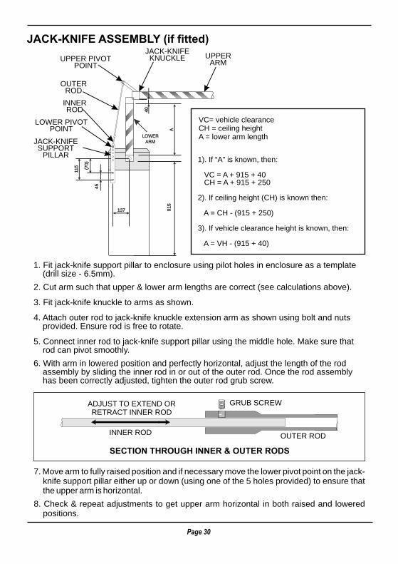
JACK-KNIFE ASSEMBLY (if fitted)
1. Fit jack-knife support pillar to enclosure using pilot holes in enclosure as a template (drill size - 6.5mm).
2. Cut arm such that upper & lower arm lengths are correct (see calculations above).
3. Fit jack-knife knuckle to arms as shown.
4. Attach outer rod to jack-knife knuckle extension arm as shown using bolt and nuts provided. Ensure rod is free to rotate.
5. Connect inner rod to jack-knife support pillar using the middle hole. Make sure that rod can pivot smoothly.
6. With arm in lowered position and perfectly horizontal, adjust the length of the rod assembly by sliding the inner rod in or out of the outer rod. Once the rod assembly has been correctly adjusted, tighten the outer rod grub screw.
7. knife support pillar either up or down (using one of the 5 holes provided) to ensure that the upper arm is horizontal.
8. Check & repeat adjustments to get upper arm horizontal in both raised and lowered positions.
Move arm to fully raised position and if necessary move the lower pivot point on the jack-
JACK-KNIFEKNUCKLE
OUTERROD
UPPER PIVOTPOINT
LOWER PIVOTPOINT
INNERROD
LOWERARM
UPPERARM
JACK-KNIFESUPPORT
PILLAR
VC= vehicle clearanceCH = ceiling heightA = lower arm length
1). If “A” is known, then:
VC = A + 915 + 40 CH = A + 915 + 250
2). If ceiling height (CH) is known then:
A = CH - (915 + 250)
3). If vehicle clearance height is known, then:
A = VH - (915 + 40)
91
5
A
115
(70
)
45
137
40
Page 30

TRG - ON when MI input is present.
PED - ON when NMI input is present.
IRB - ON when safety beam/loop broken.
MAINS ON - ON when mains power present.
OLS - not used.
CLS - not used.
LOGICTERMINALS
POWERTERMINALS
}
MAINS ON(GREEN LED)
CP91 CARD
F1
F2
}B
MC
V5.
xB
MD
V5.
x
TRG
OLSCLS
PEDIRB
MI SIGNALNMI SIGNAL
MANUAL RELEASE
In the event of a total malfunction of the boom SWITCH OFF MAINS POWER and arm willraise.
Page 31
Diagnostic LED'sDiagnostic LED's

FUSES
The Centurion boom requires a minimum amount of maintenance.The following checks should be done periodically: - Ensure all terminals are tight and that no nuts or bolts are loose. - Check the rubber end stops, and adjust if necessary. (See section 7.4 or 7.5)
The exploded view of the boom assembly lists all item codes if spares are required. ( See 12.2 & 12.3 )
F1 - AUXILIARY, 1A Fast Blow, 5 x 20.
F2 - MOTOR, 5A Fast Blow 5 x 20.
}
CP91 CARD
F1
F2
}
BM
CV
5.x
BM
DV
5.x
TRG
OLSCLS
PEDIRB
Page 32
MaintenanceMaintenance

DESCRIPTION STOCK CODE
GEARBOX ASSEMBLY
MAIN COMPONENTS
1 MOTOR, Torque, 10-rpm - 3/4m Units MTROM01000
2 MOTOR, Torque, 7.5-rpm - 6m Units MTROB00750
3 BASEPLATE, Centor Motor 1123009000
4 CRANK ARM, Spring (including PB Bush) 1123009008
5 CROSS SHAFT, 4 Spring Connector, Centor 1123009005
6 SPACER, Connecting Arm, Centor 1123009007
BOOM COUPLER - Version 1
7 BOOM COUPLER, Dia 71.5mm c/w Shaft (UK) 112300903E
8 BOOM COUPLER, Dia 73mm c/w Shaft 1123009003
33
41 10
14
25 & 3227
28
6
33, 38
15,20 1140
40
42
42
13
3
5
43
50
44
44
312645
19,24
18,23
29, 30
6
16,1721,22
16,1721,22
34, 3536, 37
47, 48
39
1,2
7,8,9
4
12
46
Page 33
Boom Head AssemblyBoom Head Assembly

9 BOOM COUPLER, Dia 75.5mm c/w Shaft (France) 112300903F
BOOM COUPLER - Version 2 (After 2/4/2001)
10 SHAFT, Output, Centor, Version 2 1123009010
11 CONNECTOR, Output Shaft, Version 2 1123020200
12 CLAMPING PLATE, Inside, BC, Version 2 1148010000
13 CLAMPING PLATE, Outside 1148020000
BEARINGS
14 BEARING, Pillow Block BBUCP20600
CONNECTING ROD - Version 1 (Pre March 2001, all
6m units remain as per Version 1)
15 CONNECTING ROD, (M16LH/RH) 1123009004
16 ROD END, LH Thread, 16mm BBPOS16LH0
17 ROD END, RH Thread, 16mm BBPOS16LH1
18 CRANK ARM, Boom Coupler, 16mm 1123009002
19 CRANK ARM, Motor, 16mm 1123009006
CONNECTING ROD - Version 2 (3/4.5m units only,
6m units as per Version 1)(After March 2001)
20 CONNECTING ROD, (M12LH/RH) 112300904B
21 ROD END, LH Thread, 12mm BBPOS12LH0
22 ROD END, RH Thread, 12mm BBPOS12LH1
23 CRANK ARM, Boom Coupler, 12mm 112300902B
24 CRANK ARM, Motor, 12mm 112300906B
MISCELLANEOUS FASTENERS
25 SCREW, Cap, Galv, M8x35mm B184108035
26 SCREW, Cap, Galv, M10x35mm B124110035
27 SCREW, Grub, Galv, Dog Point, M12x12mm B126112d12
28 SCREW, Grub, Galv, M12x25mm B126112025
29 SCREW, Set, HT, Galv, M12x50mm (3/4.5m Units) B121312050
30 SCREW, Set, HT, Galv, M16x50mm (6m Units) B121316050
31 NUT, Full, Galv, M8 N120108000
32 NUT, Nylok, Galv, M8 N320208000
33 NUT, Nylok, Galv, M12 N320112000
34 NUT, Full, Galv, M12 N120112000
35 NUT, Full, Galv, M12, LH Thread N1201120LH
36 NUT, Full, Galv, M16 N120116000
37 NUT, Full, Galv, M16, LH Thread N1201160LH
38 NUT, Nylok, Galv. M16 N320116000
39 WASHER, Flat, LD, Galv, M8 W120208000
40 WASHER, Flat, LD, Galv, M10 W120101000
41 WASHER, Flat, HD, Galv, M12x30x3 W220112004
42 NUT, Half, M10 N220110000
43 WASHER, Spring cross Shaft 1123009009
44 CIRCLIP, Cross Shaft, Galv, Dia 20 F-CIRCL920
45 BUFFER, Rubber RUBENST02
46 SCREW, Cap, Csk Hd, SS, M4x12
COUNTERBALANCE SPRINGS
47 SPRING. Standard SPRINGM90
48 SPRING, Heavy Duty SPRINGR02
DESCRIPTION STOCK CODE
Page 34

1 BODY, Centor, Mild Steel 1123001000
2 BODY, Centor, Stainless Steel 1123005000
3 DOOR, Centor, Mild Steel 1123002000
4 DOOR, Centor, 430 Stainless Steel 1123006000
5 COVER, Centor, Mild Steel 1123003000
6 COVER, Centor, 430 Stainless Steel 1123007000
7 BOLT, Hex, Centor Cover Tie Down 1123004000
8 NUT, Cage, M8 N-M8CAGE01
9 CHASSIS PLATE ASSEMBLY, Centor CENTOR-CP1
10 CAMLOCK, Centor M-B44BCPAT
DESCRIPTION STOCK CODE
1, 2
78
9
10
5, 6
3, 4
Page 35
Enclosure AssemblyEnclosure Assembly

7 7
10
PR
ES
EN
CE
PR
ES
EN
CE
PU
LSE
N/C
1 133L L
N N
13
10
LN
E14
1112
YE
LLO
W
YE
LLO
W
FRE
E E
XIT
LO
OP
DE
TEC
TOR
BLU
E
220V
MA
INS
INP
UT
220V
AC
SU
PP
LY
220V
AC
SU
PP
LY
12V
CO
M
WH
ITE
GR
EE
N
GR
EY
IRB
(IL
P)
PE
D (
NM
)I
TRG
(M
)I
FRX
(B
AR
RIE
R R
AIS
E)
OLS
CLS
CO
MB
8 8
6 6
LD 1
00
BR
OW
N
BR
OW
N
BLU
E
BLU
E
BLU
E
BR
OW
N
CLO
SIN
G o
rS
AFE
TYLO
OP
DE
TEC
TOR
2 244
RED
BLACK
BROWN
BLUE
N/C
CP
91C
ON
TRO
LLE
R
BM
C/D
V5.
0
4 3 1 9 A
5
2 3 5 15
PR
ES
EN
CE
7 9 11 13112
V D
CS
UP
PLY
CLO
SIN
GB
EA
M
220V
AC
INP
UT
SU
PP
LY
CH
AS
SIS
PLA
TE
ISO
LATO
R
L N
M.I
.
N.M
.I.
T.V.
I.
BA
RR
IER
RA
ISE
E
YE
LLO
W
YE
LLO
W
BLU
EGR
EE
N
BR
OW
NM
OTO
R
MO
TOR
CA
PC
ITO
R
MO
TOR
MO
TOR
BLA
CK
4 6 16
WH
ITE
GR
EE
N
BLU
E
RE
D
Ear
th p
oin
t
BLA
CK 0V
8 10 12 14
SAFETYLOOP
FREE EXITLOOP
TER
MIN
AL
STR
IP O
NC
HA
SS
IS P
LATE
2 13
M
Page 36
Wiring DiagramWiring Diagram

SpecificationsSpecifications
Page 37
MOTOR
Torque Motor Type (MC63-170) 3m; 4.5m
Motor Voltage 220V AC
POWER SUPPLY 230V AC, single phase 50Hz
GENERAL
Standard boom lengths 3,4,5,6m
Boom Cycle time 3 and 4.5m 3 seconds
6m 4 seconds
Duty Continuous
ENCLOSURE
Material 1.6mm mild steel or Grade 430 stainless steel
Surface Finish White epoxy power coat, red cover
Access Door Lockable, hinged. Surface coating as per main enclosure
CONTROLLER
Type Centurion CP91
Trigger Inputs Memory Input for pushbutton, keyswitch, radio control, card reader, keypad and any device with potential free N/O output.
Non-memory input for ticket vendor or cash register.
Inductive Loop Input or
IR Beam Input Simplex: Provides safety input
Complex: Boom lowers automatically when loop is cleared.
Auto-Close Simplex: Adjustable between 8 - 35 seconds
Complex: Fixed 90 seconds, not selectable
Interlocks Tickets vend interlock via potential free contact to inhibit ticket issue when boom is raising or up.
Terminals Screw in terminals for auxiliaries and power connection.

Glossary of TermsGlossary of Terms
Page 38
Anti PassbackProtection on card readers to prevent the same card from being passed back from one vehicle to the one following. The card reader has a memory which will only allow the card to be used for re-entry once the card has first been used to exit the same site.
Auto-CloseIf selected the electronic controller will cause the boom arm to reclose after a present time.
Closing LoopAn inductive loop which sends a signal to the electronic controller signalling that the vehicle is clear of the area and that the arm can close.
FirmwareThe instruction set (or code) contained in the microprocessor which controls the actions and responses of the electronic controller.
Free Exit LoopAn inductive loop provided for the purpose of automatically opening a barrier to allow a vehicle to exit.
Inductive Loop DetectorAn electronic device which is able to detect a change in inductance of a wire loop due to the presence of a metallic object being placed in the vicinity of the loop.
IR BeamAn infra red beam of light across a driveway. An object breaking the beam causes a relay
contact to open (or close) indicating an obstruction.
LoopA wire loop in the ground connected to an electronic, inductive loop detector to sense the presence of a metallic object (eg. a vehicle)
Memory Input Electronic controller input which memorises the number of pulses received (eg. from a crad reader). The arm will only close after the same number of "exit" pulses have been received (eg. from a closing loop)
Non Memory InputElectronic controller input which will store only one single pulse in memory irrespective of the number of the pulses received. The boom arm must be closing or closed before the next pulse will take effect.
Presence LoopAn inductive loop used to provide an identification to, for example, a ticket spitter that a vehicle is present and that a ticket can be issued. Also often used to "arm" a card reader, such that the card reader will only accept a valid card when a vehicle is present. (To prevent a pedestrian opening a barrier with a card without a vehicle present.)
Ticket SpitterA machine capable of issuing a ticket when signalled to do so.
Ticket Vending Interlock
A relay contact connected to a ticket vending machine to prevent tickets being issued while the boom arm is opening or open.

Sharecall 0860-CENTURION(Sharecall number applicable when dialed from within South Africa only)
(Omit (0) when dialing from outside South Africa)
or visit www.centsys.co.zafor details of your nearest agent
For technical support, contact:
South African Branches and Regional Distributors:
Other Countries:
Product Code: CP72CENTOR
Johannesburg Central/West Rand. . . . . . . . . . . . . . . . . . . . . . . . . . . . . . . . . . . . . . . . . 011-699-2400Johannesburg East-Rand . . . . . . . . . . . . . . . . . . . . . . . . . . . . . . . . . . . . . . . . . . . . . . . 011-397-6401Durban . . . . . . . . . . . . . . . . . . . . . . . . . . . . . . . . . . . . . . . . . . . . . . . . . . . . . . . . . . . . . . 031-701-9583Nelspruit . . . . . . . . . . . . . . . . . . . . . . . . . . . . . . . . . . . . . . . . . . . . . . . . . . . . . . . . . . . 013-752-8074/5Pretoria . . . . . . . . . . . . . . . . . . . . . . . . . . . . . . . . . . . . . . . . . . . . . . . . . . . . . . . . . . . . . . 012-349-1745Cape Town . . . . . . . . . . . . . . . . . . . . . . . . . . . . . . . . . . . . . . . . . . . . . . . . . . . . . . . . . . . 021-552-9425Port Elizabeth . . . . . . . . . . . . . . . . . . . . . . . . . . . . . . . . . . . . . . . . . . . . . . . . . . . . . . . 041-581-6994/5East London . . . . . . . . . . . . . . . . . . . . . . . . . . . . . . . . . . . . . . . . . . . . . . . . . . . . . . . . . . 043-743-4923Bloemfontein . . . . . . . . . . . . . . . . . . . . . . . . . . . . . . . . . . . . . . . . . . . . . . . . . . . . . . . . . 051-448-1714Kimberly . . . . . . . . . . . . . . . . . . . . . . . . . . . . . . . . . . . . . . . . . . . . . . . . . . . . . . . . . . . . . 053-832-3231Vereeniging . . . . . . . . . . . . . . . . . . . . . . . . . . . . . . . . . . . . . . . . . . . . . . . . . . . . . . . . . . 016-422-5667
Please refer to our website: www.centsys.co.za
Centurion Systems (Pty) Ltd Head Office:Tel: +27 (0)11-699-2400, Fax: +27 (0)11-704-3412 or (0)11-462-6669
148 Epsom Avenue, North RidingP.O. Box 506, Cramerview, 2060
South Africa
Latest Revision: 15.03.2007 Document Ref.: 1123.D.01.0002_8
Master address page: 0000.D.01.0004_5
© 2007 Centurion Systems (Pty) Ltd.


![Centurion: Defender Of Rome - User Manual [EN, FR]](https://static.fdokumen.com/doc/165x107/63388088c5ddac3e970cf85d/centurion-defender-of-rome-user-manual-en-fr.jpg)