Dynamic Single Chain Polymeric Nanoparticles: From Structure to Function
Upload
khangminh22Category
view
0download
0
2 Structure and Function of Wood
Alex C. Wiedenhoeft and Regis B. MillerUSDA, Forest Service, Forest Products Laboratory, Madison, WI
CONTENTS
2.1 The Tree2.2 Softwoods and Hardwoods2.3 Sapwood and Heartwood2.4 Axial and Radial Systems2.5 Planes of Section2.6 Vascular Cambium2.7 Growth Rings2.8 Cells in Wood2.9 Cell Walls2.10 Pits2.11 The Microscopic Structure of Softwoods and Hardwoods
2.11.1 Softwoods2.11.1.1 Tracheids2.11.1.2 Axial Parenchyma and Resin Canal Complexes2.11.1.3 Rays
2.11.2 Hardwoods2.11.2.1 Vessels2.11.2.2 Fibers2.11.2.3 Axial Parenchyma2.11.2.4 Rays
2.12 Wood Technology2.13 Juvenile Wood and Reaction Wood2.14 Wood IdentificationReferences
Despite the many human uses to which various woods are suited, at a fundamental level wood isa complex biological structure, itself a composite of many chemistries and cell types acting togetherto serve the needs of the plant. Although humans have striven to understand wood in the contextof wood technology, we have often overlooked the key and basic fact that wood evolved over thecourse of millions of years to serve three main functions in plants: the conduction of water fromthe roots to the leaves, the mechanical support of the plant body, and the storage of biochemicals.The need for these three functions has driven the evolution of approximately 20,000 different extantspecies of woody plants, each with unique properties, uses, and capabilities, in both plant andhuman contexts. Understanding the basic requirements dictated by these three functions and iden-tifying the structures in wood that perform them allows insights into the realm of human wood use
1588_C02.fm Page 9 Thursday, December 2, 2004 3:39 PM
© 2005 by CRC Press
(Hoadley 2000). A scientist with a robust understanding of the interrelationships between form andfunction can predict the usefulness of a specific wood in a new context.
To begin, it is necessary to define and delimit the component parts of wood at a variety ofscales. There is a significant difference in the quality and quantity of wood anatomical expertisenecessary for a researcher who is using a solid wood beam compared to the knowledge necessaryfor an engineer designing a glued-laminated beam, and these are in turn different compared to theknowledge required for making a wood-resin composite with wood flour. In the first case, a large-scale anatomical understanding may help to explain and quantify the mechanical properties of thebeam. In the second case, an understanding of anatomical effects on mechanical properties mustbe coupled with chemical knowledge about the efficacy of various adhesives. In the third case, anunderstanding of particle size distribution and wood cell wall chemistry will be key pieces ofknowledge. The differences in the kinds of knowledge in these three cases are related to the scaleat which one intends to interact with wood, and in all three cases the technologically differentproperties are derived from the biological needs of the living tree. For this reason, the structure ofwood will be explained in this chapter at decreasing scales, and in ways that demonstrate thebiological rationale for a plant to produce wood with such features. Such background will permitthe reader to access primary literature related to wood structure with greater ease.
Although shrubs and many vines form wood, the remainder of this chapter will focus on thewood from trees. As trees are the predominant source of wood for commercial applications andprovide examples of virtually all features that merit discussion, this restriction of scope is warranted.
2.1 THE TREE
The general body plan of a tree must be briefly outlined so that all subsequent information can beunderstood in its proper context within the living organism. A living, growing tree has two maindomains, the shoot and the roots. The roots are the subterranean structures responsible for wateruptake, mechanical support of the shoot, and storage of biochemicals. The shoot comprises the
FIGURE 2.1 Macroscopic view of a transverse section of a Quercus alba trunk. Beginning at the outside ofthe tree, there is the outer bark (ob), the inner bark (ib), and then the vascular cambium (vc), which is toonarrow to see at this magnification. Interior to the vascular cambium is the sapwood, which is easily differ-entiated from the heartwood that lies to the interior. At the center of the trunk is the pith (p), which is barelydiscernible in the center of the heartwood.
1588_C02.fm Page 10 Thursday, December 2, 2004 3:39 PM
© 2005 by CRC Press
trunk or bole of the tree, the branches, and the leaves (Raven et al. 1999). It is with the trunk ofthe tree that the remainder of the chapter will be concerned.
If one cuts down a tree and looks at the stump, there are several gross observations that canbe easily made. The trunk is composed of various materials present in concentric bands. From theoutside of the tree to the inside there are six layers: outer bark, inner bark, vascular cambium,sapwood, heartwood, and the pith (Figure 2.1). Outer bark provides mechanical protection to thesofter inner bark, and also helps to limit evaporative water loss. Inner bark (phloem) is the tissuethrough which sugars produced by photosynthesis (photosynthate or “food”) are translocated fromthe leaves to the roots or growing portions of the tree. The vascular cambium is the layer betweenthe bark and the wood that is responsible for producing both these tissues. The sapwood is theactive, “living” wood that is responsible for conducting the water (or sap) from the roots to theleaves. It has not yet accumulated the often-colored chemicals that set apart the nonconductiveheartwood found as a core of darker-colored wood in the middle of most trees. The pith at the verycenter of the trunk is the remnants of the early growth of the trunk, before wood was formed.
2.2 SOFTWOODS AND HARDWOODS
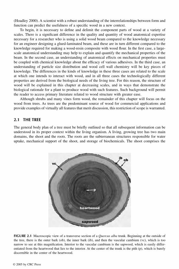
To define them botanically, softwoods are those woods that come from gymnosperms (mostlyconifers), and hardwoods are woods that come from angiosperms (flowering plants). In the tem-perate portion of the Northern Hemisphere, softwoods are generally needle-leaved evergreen treessuch as pine (Pinus) and spruce (Picea), whereas hardwoods are typically broadleaf, deciduoustrees such as maple (Acer) and birch (Betula). Not only do softwoods and hardwoods differ interms of the types of trees from which they are derived, but they also differ in terms of theircomponent cells. The single most important distinction between the two general kinds of wood isthat hardwoods have a characteristic type of cell called a vessel element (or pore), whereas softwoodslack these (Figure 2.2). An important cellular similarity between softwoods and hardwoods is that
FIGURE 2.2 Softwood and hardwood. (A) The general form of a generic softwood tree. (B) The general formof a generic hardwood tree. (C) Transverse section of Pseudotsuga mensiezii, a typical softwood. The three roundwhite spaces are resin canals. (D) Transverse section of Betula allegheniensis, a typical hardwood. The manylarge, round white structures are vessels or pores, the characteristic feature of a hardwood. Scale bars = 300 µm.
1588_C02.fm Page 11 Thursday, December 2, 2004 3:39 PM
© 2005 by CRC Press

in both kinds of wood, most of the cells are dead at maturity even in the sapwood. The cells thatare alive at maturity are known as parenchyma cells, and can be found in both softwoods andhardwoods. Additionally, despite what one might conclude based on the names, not all softwoodshave soft, lightweight wood, nor do all hardwoods have hard, heavy wood.
2.3 SAPWOOD AND HEARTWOOD
In both softwoods and hardwoods, the wood in the trunk of the tree is typically divided into twozones, each of which serves an important function distinct from the other. The actively conductingportion of the stem, in which the parenchyma cells are still alive and metabolically active, is referredto as the sapwood. A looser definition that is more broadly applied is that the sapwood is the bandof lighter-colored wood adjacent to the bark. The heartwood is the darker-colored wood found tothe interior of the sapwood (Figure 2.1).
In the living tree, the sapwood is responsible not only for the conduction of sap, but also for thestorage and synthesis of biochemicals. This function is often underappreciated in wood technologicaldiscourse. An important storage function is the long-term storage of photosynthate. The carbon thatmust be expended to form a new flush of leaves or needles must be stored somewhere in the tree,and it is often in the parenchyma cells of the sapwood that this material is stored. The primarystorage forms of photosynthate are starch and lipids. Starch grains are stored in the parenchymacells, and can be easily seen using a microscope. The starch content of sapwood can have importantramifications in the wood industry. For example, in the tropical tree ceiba (Ceiba pentandra), anabundance of starch can lead to the growth of anaerobic bacteria that produce ill-smelling compoundsthat can make the wood unusable (Chudnoff 1984). In the southern yellow pines of the United States,a high starch content encourages the growth of sap-stain fungi that, though they do not effect thestrength of the wood, can nonetheless cause a significant decrease in lumber value for aestheticreasons (Simpson 1991).
The living cells of the sapwood are also the agents of heartwood formation. In order for thetree to accumulate biochemicals, they must be actively synthesized and translocated by living cells.For this reason, living cells at the border between the heartwood and sapwood are responsible forthe formation and deposition of heartwood chemicals, one of the important steps leading toheartwood formation (Hillis 1996).
Heartwood functions in the long-term storage of biochemicals of many varieties depending onthe species in question. These chemicals are known collectively as extractives. In the past it wasthought that the heartwood was a disposal site for harmful by-products of cellular metabolism, theso-called secondary metabolites. This led to the concept of the heartwood as a dumping groundfor chemicals that, to a greater or lesser degree, would harm the living cells if not sequestered ina safe place. A more modern understanding of extractives indicates that they are a normal andintentional part of the plant’s efforts to protect its wood. Extractives are formed by parenchymacells at the heartwood-sapwood boundary and are then exuded through pits into adjacent cells(Hillis 1996). In this way it is possible for dead cells to become occluded or infiltrated withextractives despite the fact that these cells lack the ability to synthesize or accumulate thesecompounds on their own.
Extractives are responsible for imparting several larger-scale characteristics to wood. For exam-ple, extractives provide natural durability to timbers that have a resistance to decay fungi. In thecase of a wood such as teak (Tectona grandis), famed for its stability and water resistance, theseproperties are conferred by the waxes and oils formed and deposited in the heartwood. Many woodsvalued for their colors, such as mahogany (Swietenia mahagoni), African blackwood (Diospyrosmelanoxylon), Brazilian rosewood (Dalbergia nigra), and others, owe their value to the type andquantity of extractives in the heartwood. For these species, the sapwood has little or no value,because the desirable properties are imparted by heartwood extractives. Gharu wood, or eagle wood(Aquilaria malaccensis) has been driven to endangered status due to human harvest of the wood to
1588_C02.fm Page 12 Thursday, December 2, 2004 3:39 PM
© 2005 by CRC Press

3 Cell Wall Chemistry
Roger M. Rowell1,3, Roger Pettersen1, James S. Han1,Jeffrey S. Rowell2, and Mandla A. Tshabalala1USDA, Forest Service, Forest Products Laboratory, Madison, WI2Department of Forest Ecology and Management, Universityof Wisconsin, Madison, WI3Department of Biological Systems Engineering, Universityof Wisconsin, Madison, WI
CONTENTS
3.1 Carbohydrate Polymers3.1.1 Holocellulose3.1.2 Cellulose3.1.3 Hemicelluloses
3.1.3.1 Hardwood Hemicelluloses3.1.3.2 Softwood Hemicelluloses
3.1.4 Other Minor Polysaccharides3.2 Lignin3.3 Extractives3.4 Bark
3.4.1 Extractives3.4.1.1 Chemical Composition of Extractives
3.4.2 Hemicelluloses3.4.3 Cellulose3.4.4 Lignin3.4.5 Inorganics and pH
3.5 Inorganics3.6 Distribution of Chemical Components in the Cell Wall3.7 Juvenile Wood and Reaction Wood3.8 Analytical Procedures
3.8.1 Sampling Procedure3.8.2 Extraction
3.8.2.1 Scope and Summary3.8.2.2 Sample Preparation3.8.2.3 Apparatus3.8.2.4 Reagents and Materials3.8.2.5 Procedures
3.8.3 Ash Content (ASTM D-1102-84)3.8.3.1 Scope3.8.3.2 Sample Preparation3.8.3.3 Apparatus3.8.3.4 Procedure
1588_C03.fm Page 35 Thursday, December 2, 2004 3:43 PM
© 2005 by CRC Press
3.8.3.5 Report3.8.3.6 Precision
3.8.4 Preparation of Holocellulose (Chlorite Holocellulose)3.8.4.1 Scope3.8.4.2 Sample Preparation3.8.4.3 Apparatus3.8.4.4 Reagents3.8.4.5 Procedure
3.8.5 Preparation of Alpha-Cellulose (Determination of Hemicelluloses)3.8.5.1 Scope3.8.5.2 Principle of Method3.8.5.3 Apparatus3.8.5.4 Reagents3.8.5.5 Procedure3.8.5.6 Calculation and Report
3.8.6 Preparation of Klason Lignin3.8.6.1 Scope3.8.6.2 Apparatus3.8.6.3 Reagent3.8.6.4 Procedure3.8.6.5 Additional Information
3.8.7 Determination of Methoxyl Groups3.8.7.1 Scope3.8.7.2 Principle of Method3.8.7.3 Sample Preparation3.8.7.4 Apparatus3.8.7.5 Reagents3.8.7.6 Procedure3.8.7.7 Calculation and Report
3.8.8 Determination of Acetyl by Gas Liquid Chromatography3.8.8.1 Scope3.8.8.2 Reagents3.8.8.3 Sample Preparation3.8.8.4 Gas Chromatography3.8.8.5 Reporting
References
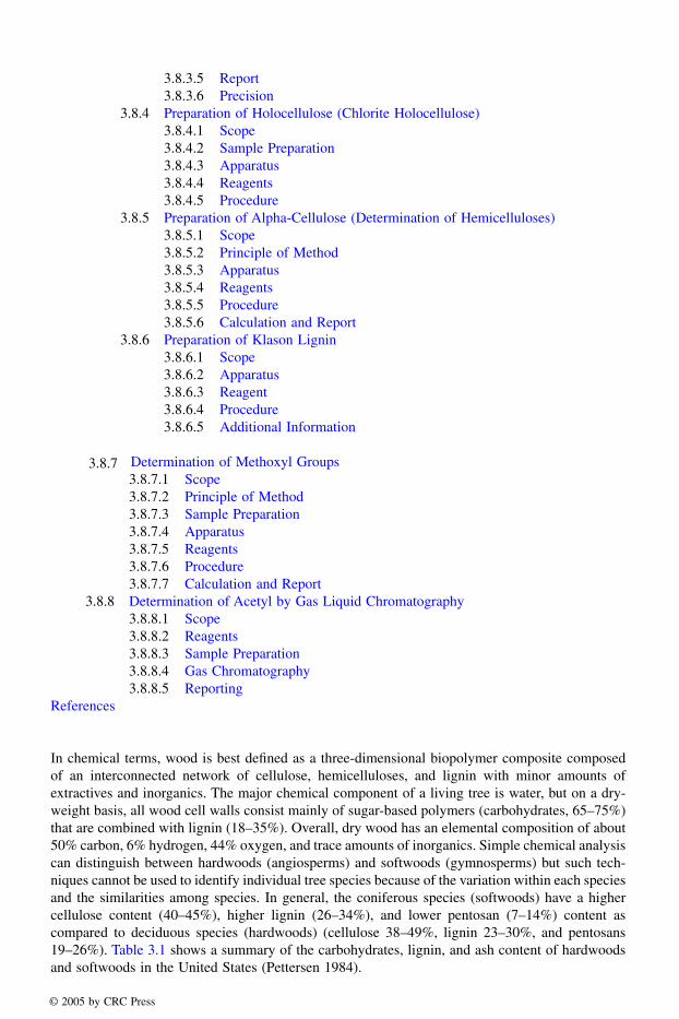
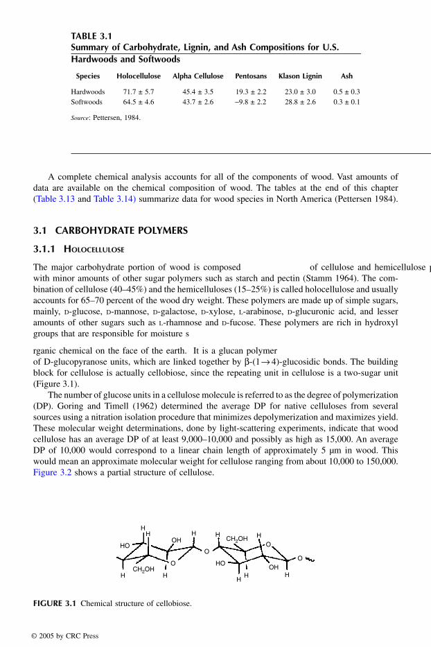
In chemical terms, wood is best defined as a three-dimensional biopolymer composite composedof an interconnected network of cellulose, hemicelluloses, and lignin with minor amounts ofextractives and inorganics. The major chemical component of a living tree is water, but on a dry-weight basis, all wood cell walls consist mainly of sugar-based polymers (carbohydrates, 65–75%)that are combined with lignin (18–35%). Overall, dry wood has an elemental composition of about50% carbon, 6% hydrogen, 44% oxygen, and trace amounts of inorganics. Simple chemical analysiscan distinguish between hardwoods (angiosperms) and softwoods (gymnosperms) but such tech-niques cannot be used to identify individual tree species because of the variation within each speciesand the similarities among species. In general, the coniferous species (softwoods) have a highercellulose content (40–45%), higher lignin (26–34%), and lower pentosan (7–14%) content ascompared to deciduous species (hardwoods) (cellulose 38–49%, lignin 23–30%, and pentosans19–26%). Table 3.1 shows a summary of the carbohydrates, lignin, and ash content of hardwoodsand softwoods in the United States (Pettersen 1984).
1588_C03.fm Page 36 Thursday, December 2, 2004 3:43 PM
© 2005 by CRC Press
Cell Wall Chemistry 37
A complete chemical analysis accounts for all of the components of wood. Vast amounts ofdata are available on the chemical composition of wood. The tables at the end of this chapter(Table 3.13 and Table 3.14) summarize data for wood species in North America (Pettersen 1984).
3.1 CARBOHYDRATE POLYMERS
3.1.1 HOLOCELLULOSE
The major carbohydrate portion of wood is composed of cellulose and hemicellulose polymerswith minor amounts of other sugar polymers such as starch and pectin (Stamm 1964). The com-bination of cellulose (40–45%) and the hemicelluloses (15–25%) is called holocellulose and usuallyaccounts for 65–70 percent of the wood dry weight. These polymers are made up of simple sugars,mainly, D-glucose, D-mannose, D-galactose, D-xylose, L-arabinose, D-glucuronic acid, and lesseramounts of other sugars such as L-rhamnose and D-fucose. These polymers are rich in hydroxylgroups that are responsible for moisture s
rganic chemical on the face of the earth. It is a glucan polymerof D-glucopyranose units, which are linked together by β-(1→ 4)-glucosidic bonds. The buildingblock for cellulose is actually cellobiose, since the repeating unit in cellulose is a two-sugar unit(Figure 3.1).
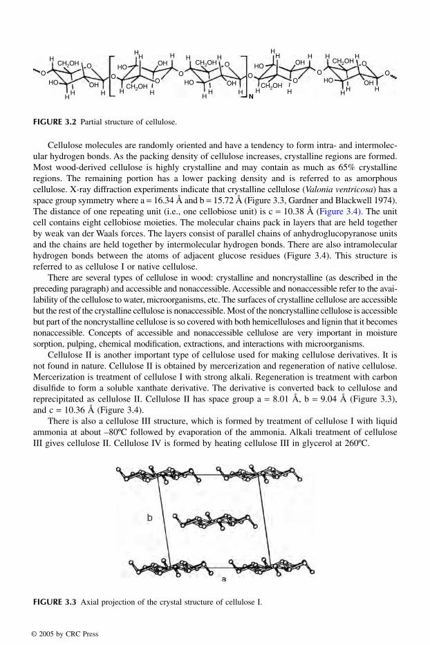
The number of glucose units in a cellulose molecule is referred to as the degree of polymerization(DP). Goring and Timell (1962) determined the average DP for native celluloses from severalsources using a nitration isolation procedure that minimizes depolymerization and maximizes yield.These molecular weight determinations, done by light-scattering experiments, indicate that woodcellulose has an average DP of at least 9,000–10,000 and possibly as high as 15,000. An averageDP of 10,000 would correspond to a linear chain length of approximately 5 µm in wood. Thiswould mean an approximate molecular weight for cellulose ranging from about 10,000 to 150,000.Figure 3.2 shows a partial structure of cellulose.
TABLE 3.1Summary of Carbohydrate, Lignin, and Ash Compositions for U.S. Hardwoods and Softwoods
Species Holocellulose Alpha Cellulose Pentosans Klason Lignin Ash
Hardwoods 71.7 ± 5.7 45.4 ± 3.5 19.3 ± 2.2 23.0 ± 3.0 0.5 ± 0.3Softwoods 64.5 ± 4.6 43.7 ± 2.6 −9.8 ± 2.2 28.8 ± 2.6 0.3 ± 0.1
Source: Pettersen, 1984.
FIGURE 3.1 Chemical structure of cellobiose.
HO
HO
OH
OH
HH H
H HH
H H
HH
OO
O
OCH2OH
CH2OH
1588_C03.fm Page 37 Thursday, December 2, 2004 3:43 PM
© 2005 by CRC Press
38 Handbook of Wood Chemistry and Wood Composites
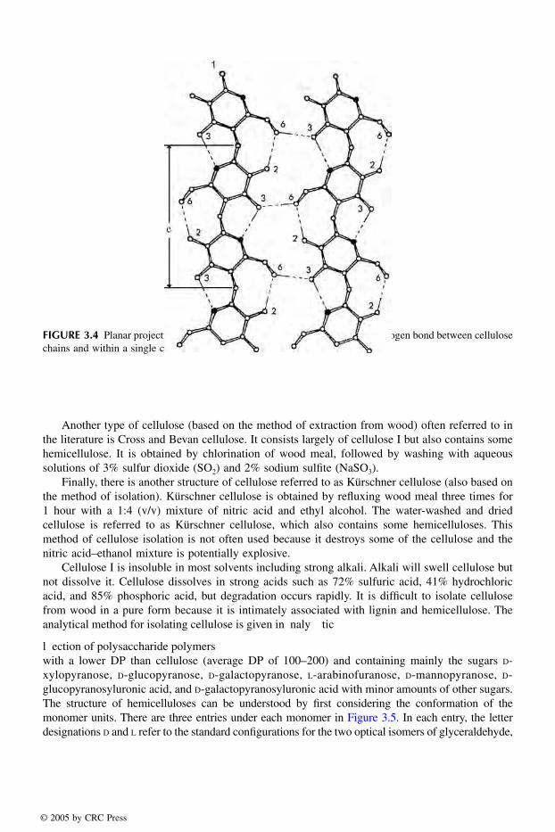
Cellulose molecules are randomly oriented and have a tendency to form intra- and intermolec-ular hydrogen bonds. As the packing density of cellulose increases, crystalline regions are formed.Most wood-derived cellulose is highly crystalline and may contain as much as 65% crystallineregions. The remaining portion has a lower packing density and is referred to as amorphouscellulose. X-ray diffraction experiments indicate that crystalline cellulose (Valonia ventricosa) has aspace group symmetry where a = 16.34 Å and b = 15.72 Å (Figure 3.3, Gardner and Blackwell 1974).The distance of one repeating unit (i.e., one cellobiose unit) is c = 10.38 Å (Figure 3.4). The unitcell contains eight cellobiose moieties. The molecular chains pack in layers that are held togetherby weak van der Waals forces. The layers consist of parallel chains of anhydroglucopyranose unitsand the chains are held together by intermolecular hydrogen bonds. There are also intramolecularhydrogen bonds between the atoms of adjacent glucose residues (Figure 3.4). This structure isreferred to as cellulose I or native cellulose.
There are several types of cellulose in wood: crystalline and noncrystalline (as described in thepreceding paragraph) and accessible and nonaccessible. Accessible and nonaccessible refer to the avai-lability of the cellulose to water, microorganisms, etc. The surfaces of crystalline cellulose are accessiblebut the rest of the crystalline cellulose is nonaccessible. Most of the noncrystalline cellulose is accessiblebut part of the noncrystalline cellulose is so covered with both hemicelluloses and lignin that it becomesnonaccessible. Concepts of accessible and nonaccessible cellulose are very important in moisturesorption, pulping, chemical modification, extractions, and interactions with microorganisms.
Cellulose II is another important type of cellulose used for making cellulose derivatives. It isnot found in nature. Cellulose II is obtained by mercerization and regeneration of native cellulose.Mercerization is treatment of cellulose I with strong alkali. Regeneration is treatment with carbondisulfide to form a soluble xanthate derivative. The derivative is converted back to cellulose andreprecipitated as cellulose II. Cellulose II has space group a = 8.01 Å, b = 9.04 Å (Figure 3.3),and c = 10.36 Å (Figure 3.4).
There is also a cellulose III structure, which is formed by treatment of cellulose I with liquidammonia at about –80ºC followed by evaporation of the ammonia. Alkali treatment of celluloseIII gives cellulose II. Cellulose IV is formed by heating cellulose III in glycerol at 260ºC.
FIGURE 3.2 Partial structure of cellulose.
FIGURE 3.3 Axial projection of the crystal structure of cellulose I.
HO
HO HO
HOHOOH
OH
OH
OH
OH
H
HH H
HH
HHH H
HH H
H H H
HHHH H
H
HH
OO
OO
O
O
OO
O
OOCH2OH
CH2OH
CH2OH
CH2OH
CH2OH
N
1588_C03.fm Page 38 Thursday, December 2, 2004 3:43 PM
© 2005 by CRC Press
Cell Wall Chemistry 39
Another type of cellulose (based on the method of extraction from wood) often referred to inthe literature is Cross and Bevan cellulose. It consists largely of cellulose I but also contains somehemicellulose. It is obtained by chlorination of wood meal, followed by washing with aqueoussolutions of 3% sulfur dioxide (SO2) and 2% sodium sulfite (NaSO3).
Finally, there is another structure of cellulose referred to as Kürschner cellulose (also based onthe method of isolation). Kürschner cellulose is obtained by refluxing wood meal three times for1 hour with a 1:4 (v/v) mixture of nitric acid and ethyl alcohol. The water-washed and driedcellulose is referred to as Kürschner cellulose, which also contains some hemicelluloses. Thismethod of cellulose isolation is not often used because it destroys some of the cellulose and thenitric acid–ethanol mixture is potentially explosive.
Cellulose I is insoluble in most solvents including strong alkali. Alkali will swell cellulose butnot dissolve it. Cellulose dissolves in strong acids such as 72% sulfuric acid, 41% hydrochloricacid, and 85% phosphoric acid, but degradation occurs rapidly. It is difficult to isolate cellulosefrom wood in a pure form because it is intimately associated with lignin and hemicellulose. Theanalytical method for isolating cellulose is given in naly tic
l ection of polysaccharide polymerswith a lower DP than cellulose (average DP of 100–200) and containing mainly the sugars D-xylopyranose, D-glucopyranose, D-galactopyranose, L-arabinofuranose, D-mannopyranose, D-glucopyranosyluronic acid, and D-galactopyranosyluronic acid with minor amounts of other sugars.The structure of hemicelluloses can be understood by first considering the conformation of themonomer units. There are three entries under each monomer in Figure 3.5. In each entry, the letterdesignations D and L refer to the standard configurations for the two optical isomers of glyceraldehyde,
FIGURE 3.4 Planar projection of two cellulose chains showing some of the hydrogen bond between cellulosechains and within a single cellulose chain.
1588_C03.fm Page 39 Thursday, December 2, 2004 3:43 PM
© 2005 by CRC Press
4 Moisture Properties
Roger M. RowellUSDA, Forest Service, Forest Products Laboratory,and Biological Systems Engineering Department, Universityof Wisconsin, Madison, WI
CONTENTS
4.1 Moisture Content of Green Wood4.2 Fiber Saturation Point4.3 Equilibrium Moisture Content4.4 Sorption Isotherms
4.4.1 Effect of Temperature on Sorption and Desorption of Water4.5 Swelling of Dry Wood in Water4.6 Distribution of Moisture4.7 Measuring Swelling4.8 Rate of Water Sorption and Activation Energy4.9 Cell Wall Elastic Limit4.10 Swelling Pressure4.11 Effects of Moisture Cycles4.12 Effects on Vibrational Properties4.13 Effects on Biological Properties4.14 Effects on Insulation and Electrical Properties4.15 Effects on Strength Properties4.16 Water Repellency and Dimensional Stability4.17 Swelling in Wood Composites4.18 Swelling in Liquids Other than WaterReferences
Wood was designed by Nature over millions of years to perform in a wet environment. The woodstructure is formed in a water-saturated environment in the living tree, and the water in the livingtree keeps the wood elastic and able to withstand environmental strain such as high wind loads.We cut down a tree, dry the wood, and mainly use it in its dry state. But wood in use remains ahygroscopic resource. Wood’s dimensions and mechanical, elastic, and thermal properties dependon the moisture content. Wood is also anisotropic, which means that its properties vary accordingto its growing direction (longitudinal [vertical or length direction], tangential [parallel to annualgrowth rings], and radial [perpendicular to the annual growth rings]). The mechanical propertiesdepend very much on both moisture content and growing direction.
4.1 MOISTURE CONTENT OF GREEN WOOD
Moisture exists in wood as both liquid moisture in the cell voids or lumens (free water) and asmoisture in the cell wall (bound water). The moisture content of green wood is defined as the total
1588_C04.fm Page 77 Thursday, December 2, 2004 3:46 PM
© 2005 by CRC Press

amount of free and bound water in the living tree. This is the maximum moisture content that canexist in a living tree. The moisture content of green wood varies from species to species and dependson the specific gravity. Lumen volume decreases as the specific gravity increases so the greenmoisture content decreases with increasing specific gravity. The maximum moisture content Mmax
can be calculated by the following:
where Gbsg is the basic specific gravity based on oven-dry weight and green volume and 1.54 isthe specific gravity of the wood cell wall.
Using this equation, the maximum possible moisture content of green wood would be 267%with a basic specific gravity of 0.3 and the minimum possible moisture content would be 44% witha basic specific gravity of 0.9. The density of most woods falls between 320 and 720 kg/m3, althoughbalsa is 160 kg/m3 and some imported hardwoods are 1040 kg/m3.
Table 4.1 shows some average moisture contents of green heartwood and sapwood of somecommon United States wood species. In some cases, the green moisture content is highest inheartwood and in others the sapwood is highest in moisture content.
TABLE 4.1Average Moisture Content of Green Wood
Moisture Content
Species Heartwood Sapwood
Aspen 95 113Basswood 81 133Beech 55 72Birch, Paper 89 72Cedar, Incense 40 213Cottonwood, Eastern 162 146Douglas-fir, Coastal 37 115Elm, American 95 92Fir, Balsam 88 173Hemlock, Western 85 170Maple, Sugar 65 72Oak, Red 83 75Pine, Longleaf 31 106Pine, Ponderosa 40 148Pine, Sugar 98 219Poplar, Yellow 83 106Redwood, Old growth 86 210Spruce, Sitka 41 142Sweetgum 79 137Sycamore, American 114 130Walnut, Black 90 73
Source: USDA, 1999.
M G
Gbsg
bsg
max ( . )
.
= −100 1 54
1 54
1588_C04.fm Page 78 Thursday, December 2, 2004 3:46 PM
© 2005 by CRC Press

4.2 FIBER SATURATION POINT
As water is lost in green wood, there is no change in the volume of the wood until it reaches thefiber saturation point (FSP). The FSP is defined as the moisture content of the cell wall when thereis no free water in the voids and the cell walls are saturated with water. This point ranges from 20to 50 percent weight gain depending on the wood species (Feist and Tarkow 1967). As moistureis removed below the FSP, the wood volume starts to shrink. As stated before, wood is anisotropic,so the shrinkage in wood is different in all three growing directions. Figure 4.1 shows the changein wood shape as a cross section of a log is dried below the FSP. It can be seen that, dependingon where the piece of wood is located in the log, the wood will not only get smaller due to theloss of water but also will become distorted due to the anisotropic properties of wood. As will bediscussed later, tangential shrinkage is about twice that of radial shrinkage, and longitudinalshrinkage, in most woods, is almost zero.
The shrinkage of wood upon drying depends on several variables, including specific gravity,rate of drying, and the size of the piece. As can be seen in Figure 4.1, the piece of wood cut fromthe center, left, and right middle is distorted the least (quarter sawing). Although quarter sawing issomewhat wasteful, it does result in minimum distortion in the cut lumber.
Table 4.2 shows the average shrinkage values for some common United States woods. It canbe seen that most radial shrinkage values are less than about 6 percent, most tangential shrinkagevalues less than 10%, and most volumetric shrinkage values less than 15 percent.
To determine the approximate volumetric shrinkage that would occur at a moisture contentgreater than oven-dry but less than the FSP, the approximate volumetric value at a given moisturecan be calculated using the following formula and using the data in Table 4.2:
whereSm is the volumetric shrinkage at a given moisture contentSo is the total volumetric shrinkageM is the moisture content
Table 4.2 does not include any longitudinal shrinkage (shrinkage parallel to the grain) becauseit is usually less than 0.2% for almost all United States species. If a piece of wood is cut near thecenter of a tree that contains a large amount of juvenile wood or a piece containing reaction wood,the longitudinal shrinkage from green to oven-dry can be as high as 2%.
FIGURE 4.1 Shrinkage and distortion of wood upon drying.
S S Mm o= × −30
30
1588_C04.fm Page 79 Thursday, December 2, 2004 3:46 PM
© 2005 by CRC Press

The size of the cell cavities remains almost the same size during the loss of water in the cellwall (Tiemann 1944). The thickness of the cell wall decreases in proportion to the moisture lostbelow the FSP, but the size of the cell lumen remains approximately constant. If this relationshipis constant, the volumetric shrinkage Vs of a wood with water soak specific gravity SPw can becalculated as follows (Stamm and Loughborough 1942):
Vs = (M) (SPw) or M = Vs /SPw
This ratio should be the approximate FSP for most woods. The value of M for 107 hardwoodspecies was 27 and for 52 softwood species the value was 26 (Stamm and Loughborough 1942).
4.3 EQUILIBRIUM MOISTURE CONTENT
As the green wood loses moisture, it does not change dimensions until the FSP is reached and afterthat the dimensions change respective to the relative humidity (RH) of the wood surroundings.When the wood is in equilibrium with the surrounding RH, the wood is defined as being at itsequilibrium moisture content (EMC). The moisture content of wood is a dynamic property in thatthe moisture content of wood is constantly changing as the surrounding moisture content changes.When the wood stays at one RH for long periods of time, the wood will reach an equilibriummoisture content. Test results show that, for small pieces of wood at a constant RH, the EMC isreached in about 14 days. A larger wood member may take several weeks to reach its EMC. Waxand extractive content of wood can have a large effect on the length of time it takes for wood toreach its EMC.
TABLE 4.2Average Radial, Tangential, and Volumetric Shrinkage
Shrinkage from Green to Over-Dry Moisture Content
Species Radial Tangential Volumetric
Aspen 3.5 6.7 11.5Basswood 6.6 9.3 15.8Beech 5.5 11.9 17.2Birch, Paper 6.3 8.6 16.2Cedar, Incense 3.3 5.2 7.7Cottonwood, Eastern 3.9 9.2 13.9Douglas-fir, Costal 4.8 7.6 12.4Elm, American 4.2 9.5 14.6Fir, Balsam 2.9 6.9 11.2Hemlock, Western 4.2 7.8 12.4Maple, Sugar 4.8 9.9 14.7Oak, Red 4.7 11.3 16.1Pine, Longleaf 5.1 7.5 12.2Pine, Ponderosa 3.9 6.2 9.7Pine, Sugar 2.9 5.6 7.9Redwood, Old growth 2.6 4.4 6.8Spruce, Sitka 4.3 7.5 11.5Sweetgum 5.3 10.2 15.8Sycamore, American 5.0 8.4 14.1Walnut, Black 5.5 7.8 12.8
Source: USDA, 1999.
1588_C04.fm Page 80 Thursday, December 2, 2004 3:46 PM
© 2005 by CRC Press

5 Biological Properties
Rebecca E. IbachUSDA, Forest Service, Forest Products Laboratory, Madison, WI
CONTENTS
5.1 Biological Degradations5.1.1 Bacteria5.1.2 Mold and Stain5.1.3 Decay Fungi
5.1.3.1 Brown-Rot Fungi5.1.3.2 White-Rot Fungi5.1.3.3 Soft-Rot Fungi
5.1.4 Insects5.1.4.1 Termites
5.1.4.1.1 Subterranean Termites5.1.4.1.2 Formosan Subterranean Termites5.1.4.1.3 Nonsubterranean (Drywood) Termites5.1.4.1.4 Dampwood Termites
5.1.4.2 Carpenter Ants5.1.4.3 Carpenter Bees5.1.4.4 Beetles
5.1.4.4.1 Lyctid Powder-Post Beetles5.1.4.4.2 Anobiid Powder-Post Beetles5.1.4.4.3 Flatheaded Borers5.1.4.4.4 Cerambycids
5.1.4.4.4.1 Long-Horned Beetles5.1.4.4.4.2 Old-House Borers
5.1.5 Marine Borers5.1.5.1 Shipworms5.1.5.2 Pholads5.1.5.3 Crustaceans
5.1.5.3.1 Gribbles5.1.5.3.2 Pillbugs
5.2 Prevention or Protection of Wood5.2.1 Wood Preservatives5.2.2 Timber Preparation and Conditioning5.2.3 Treatment Processes
5.2.3.1 Pressure Processes5.2.3.2 Nonpressure Processes
5.2.4 Purchasing and Handling of Treated WoodReferences
1588_C05.fm Page 99 Thursday, December 2, 2004 3:47 PM
© 2005 by CRC Press
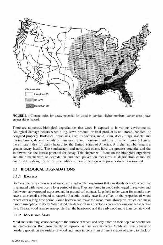
There are numerous biological degradations that wood is exposed to in various environments.Biological damage occurs when a log, sawn product, or final product is not stored, handled, ordesigned properly. Biological organisms, such as bacteria, mold, stain, decay fungi, insects, andmarine borers, depend heavily on temperature and moisture conditions to grow. Figure 5.1 givesthe climate index for decay hazard for the United States of America. A higher number means agreater decay hazard. The southeastern and northwest coasts have the greatest potential and thesouthwest has the lowest potential for decay. This chapter will focus on the biological organismsand their mechanism of degradation and then prevention measures. If degradation cannot becontrolled by design or exposure conditions, then protection with preservatives is warranted.
5.1 BIOLOGICAL DEGRADATIONS
5.1.1 BACTERIA
Bacteria, the early colonizers of wood, are single-celled organisms that can slowly degrade wood thatis saturated with water over a long period of time. They are found in wood submerged in seawater andfreshwater, aboveground exposure, and in-ground soil contact. Logs held under water for months mayhave a sour smell attributed to bacteria. Bacteria usually have little effect on the properties of woodexcept over a long time period. Some bacteria can make the wood more absorptive, which can makeit more susceptible to decay. When dried, the degraded area develops a cross checking on the tangentialface. The sapwood is more susceptible than the heartwood and the earlywood more than the latewood.
5.1.2 MOLD AND STAIN
Mold and stain fungi cause damage to the surface of wood, and only differ on their depth of penetrationand discoloration. Both grow mainly on sapwood and are various colors. Molds are usually fuzzy orpowdery growth on the surface of wood and range in color from different shades of green, to black or
FIGURE 5.1 Climate index for decay potential for wood in service. Higher numbers (darker areas) havegreater decay hazard.
1588_C05.fm Page 100 Thursday, December 2, 2004 3:47 PM
© 2005 by CRC Press

light colors. On softwoods, the fungal hyphae penetrate into the wood, but it can usually be brushed orplaned off. On the other hand, on large pored hardwoods, staining can penetrate too deeply to be removed.
The main types of fungus stains are called sapstain or bluestain. They penetrate deeply intothe wood and cannot be removed by planing. They usually cause blue, black, or brown darkeningof the wood, but some can also produce red, purple, or yellow colors. Figure 5.2 shows thediscoloration on a cross section of wood that appears as pie-shaped wedges that are oriented radially.
The strength of wood is usually not altered by molds and stains (except for toughness or shockresistance), but the absorptivity can be increased, which makes the wood more susceptible tomoisture and then decay fungi. Given moist and warm conditions, mold and stain fungi can establishon sapwood logs shortly after they are cut. To control mold and stain, the wood should be driedto less than 20 percent moisture content or treated with a fungicide. Wood logs can also be sprayedwith water to increase the moisture content to protect wood against fungal stain, as well as decay.
5.1.3 DECAY FUNGI
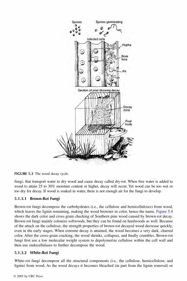
Decay fungi are single-celled or multicellular filamentous organisms that use wood as food.Figure 5.3 shows the decay cycle of wood. The fungal spores spread by wind, insects, or animals.They germinate on moist, susceptible wood, and the hyphae spread throughout the wood. Thesehyphae secrete enzymes that attack the cells and cause wood to deteriorate. After serious decay,a new fruiting body may form. Brown-, white-, and soft-rot fungi all appear to have enzymaticsystems that demethoxylate lignin, produce endocellulases, and with some fungi from each group,use single electron oxidation systems to modify lignin (Eaton and Hale 1993).
In the early or incipient stage of wood decay, serious strength losses can occur before it is evendetected (see Chapter 10). Toughness, or impact bending, is most sensitive to decay. With incipientdecay the wood may become discolored on unseasoned wood, but it is harder to detect on drywood. The advanced stages of wood decay are easier to detect. Decayed wet wood will break acrossthe grain, whereas sound wood will splinter.
Decay fungi need food (hemicellulose, cellulose, and lignin), oxygen (air), the right temperature(10 to 35°C; optimum 24 to 32°C), and moisture (above the fiber saturation point; about 30%moisture content) to grow. Free water must be present (from rain, condensation, or wet groundcontact) for the fiber saturation point to be reached and decay to occur. Air-dried wood will usually haveno more than 20% moisture content, so decay will not occur. But there are a few fungi, water-conducting
FIGURE 5.2 Radial penetration of sapstain fungi in a cross section of pine.
1588_C05.fm Page 101 Thursday, December 2, 2004 3:47 PM
© 2005 by CRC Press
fungi, that transport water to dry wood and cause decay called dry-rot. When free water is added towood to attain 25 to 30% moisture content or higher, decay will occur. Yet wood can be too wet ortoo dry for decay. If wood is soaked in water, there is not enough air for the fungi to develop.
5.1.3.1 Brown-Rot Fungi
Brown-rot fungi decompose the carbohydrates (i.e., the cellulose and hemicelluloses) from wood,which leaves the lignin remaining, making the wood browner in color, hence the name. Figure 5.4shows the dark color and cross-grain checking of Southern pine wood caused by brown-rot decay.Brown-rot fungi mainly colonize softwoods, but they can be found on hardwoods as well. Becauseof the attack on the cellulose, the strength properties of brown-rot decayed wood decrease quickly,even in the early stages. When extreme decay is attained, the wood becomes a very dark, charredcolor. After the cross-grain cracking, the wood shrinks, collapses, and finally crumbles. Brown-rotfungi first use a low molecular weight system to depolymerize cellulose within the cell wall andthen use endocellulases to further decompose the wood.
5.1.3.2 White-Rot Fungi
White-rot fungi decompose all the structural components (i.e., the cellulose, hemicellulose, andlignin) from wood. As the wood decays it becomes bleached (in part from the lignin removal) or
FIGURE 5.3 The wood decay cycle.
1588_C05.fm Page 102 Thursday, December 2, 2004 3:47 PM
© 2005 by CRC Press

white with black zone lines. White-rot fungi occur mainly on hardwoods but can be found onsoftwoods as well. The degraded wood does not crack across the grain until it is severely degraded.It keeps its outward dimensions but feels spongy. The strength properties decrease gradually asdecay progresses, except toughness. White-rot fungi have a complete cellulase complex and alsothe ability to degrade lignin.
5.1.3.3 Soft-Rot Fungi
Soft-rot fungi are related to molds and occur usually in wood that is constantly wet, but they canalso appear on surfaces that encounter wet-dry cycling. The decayed wood typically is shallow ingrowth and soft when wet, but the undecayed wood underneath is still firm. Upon drying, thedecayed surface is fissured. Figure 5.5 shows surface checking of soft-rotted wood when dry. Thewood becomes darker (dull-brown to blue-gray) when decayed by soft-rot fungi. Soft-rot fungihave a system to free the lignin in the wood to then allow the cellulases access to the substrate.
5.1.4 INSECTS
Insects are another biological cause of wood deterioration. Both the immature insect and the adultform may cause wood damage, and they are often not present when the wood is inspected. Therefore,identification is based on the description of wood damage as described in Table 5.1. Figure 5.6shows pictures of four types of insect damage caused by termites, powder-post beetles, carpenterants, and beetles.
FIGURE 5.4 Brown-rot decay of Southern pine wood.
FIGURE 5.5 Soft-rot decay of a treated pine pole.
1588_C05.fm Page 103 Thursday, December 2, 2004 3:47 PM
© 2005 by CRC Press
5.1.5.3.2 PillbugsPillbugs or Spaeroma are longer (13 mm long) and wider (6 mm wide) than Limnoria and looklike a pill bug that lives in damp places. They use the wood for shelter and prefer softer woods.Spaeroma are found along the south Atlantic and Gulf Coasts and from San Francisco southwardon the West Coast. It is common to find them in Florida estuaries. Dual treatment with CCA andthen creosote is the best protection because they are tolerant to CCA and with time tolerant tocreosote.
5.2 PREVENTION OR PROTECTION OF WOOD
To protect wood from biological degradation, chemical preservatives are applied to the wood eitherby nonpressure or pressure treatment (Eaton and Hale 1993). Penetration and retention of a chemicalwill depend on wood species and the amount of heartwood (more difficult to treat) or sapwood(easier to treat). The objective of adding wood preservatives is to obtain long-term effectivenessfor the wood product, thus sequestering carbon.
Starting January 2004, the U.S. Environmental Protection Agency (EPA) no longer allows themost widely used wood preservative, chromated copper arsenate (CCA), for products for anyresidential use (i.e., play structures, decks, picnic tables, landscaping timbers, residential fencing,patios, walkways, and boardwalks). However, it has not concluded that arsenic-containing CCA-treated wood poses unreasonable risks to the public from the wood being used around or near theirhomes (EPA 2002). Alternative preservatives such as ammoniacal copper quat (ACQ) and copperazole (CBA) have replaced CCA for residential use (EPA 2002; PMRA 2002). Looking beyondthese replacements for CCA may be wood protection systems not based on toxicity, but rathernontoxic chemical modifications to prevent biological degradation. Chemical modification altersthe chemical structure of the wood components thereby reducing the biodegradability of wood, aswell as increasing its dimensional stability when in contact with moisture (Rowell 1991) (seeChapter 14).
5.2.1 WOOD PRESERVATIVES
Wood preservatives work by being toxic to the biological organisms that attack wood. The activeingredients in wood preservative formulations are many and varied and each has its own mode ofaction, some of which are still unknown or unreported. In general, mechanisms of toxicity involvedenaturation of proteins, inactivation of enzymes, cell membrane disruption causing an increase incell permeability, and inhibition of protein synthesis.
The degree of protection of a particular preservative and treatment process depends on 4 basicrequirements: toxicity, permanence, retention, and depth of penetration into the wood. Toxicityrefers to how effective the chemical is against biological organisms, such as decay fungi, insects,and marine borers. Permanence refers to the resistance of the preservative to leaching, volatilization,and breakdown. Retention specifies the amount of preservative that must be impregnated into aspecific volume of wood to meet standards and ensure that the product will be effective againstnumerous biological agents.
Wood preservatives can be divided into two general classes: Oil-type, such as creosote andpetroleum solutions of pentachlorophenol, and waterborne salts that are applied as water solu-tions, such as CCA, ACQ, and CBA. The effectiveness of each preservative can vary greatlydepending on its chemical composition, retention, depth of penetration, and ultimately theexposure conditions of the final product. Three exposure categories are ground contact (i.e., highdecay hazard; usually pressure treated), aboveground contact (i.e., low decay hazard; not usuallyused for pressure treatment), and marine exposure (i.e., high decay hazard; often needs a dualtreatment). The degree of protection needed will depend on geographic location and potentialexposures of the wood, expected service life, structural and nonstructural applications, and
1588_C05.fm Page 111 Thursday, December 2, 2004 3:47 PM
© 2005 by CRC Press

replacement costs. Wood preservatives should always be used when exposed to ground (soil)contact and marine (salt-water) exposure.
Oilborne preservatives such as creosote and solutions with heavy, less volatile petroleum oilsoften help to protect wood from weathering but may adversely influence its cleanliness, odor, color,paintability, and fire performance. Waterborne preservatives are often used when cleanliness andpaintability of the treated wood are required. In seawater exposure, a dual treatment (waterbornecopper-containing salt preservatives followed by creosote) is most effective against all types ofmarine borers.
Exposure conditions and length of product lifetime need to be considered when choosing aparticular preservative treatment, process, and wood species (Cassens, Johnson et al. 1995). Theconsensus technical committees consider all these factors in setting reference levels required in theAmerican Wood Preservers’ Association (AWPA), the American Society for Testing and MaterialsInternational (ASTM), and the Federal Specification Standards. For various wood products, pre-servatives, and their required retention levels see Federal Specification TT-W-571 and 572, theAWPA Book of Standards, or the UDSA Forest Service Forest Products Laboratory (FPL) WoodHandbook, Chapter 14 (USFSS 1968, 1969; FPL 1999; ASTM 2000; AWPA 2003). Table 5.2 givesthe retention levels of creosote and some waterborne preservatives for lumber, timbers, and plywoodexposed to various conditions. The retention specifies the amount of preservative that must beimpregnated into a specific volume of wood to meet standards and to ensure that the product willbe effective against numerous biological agents.
Evaluation for efficacy of preservative-treated wood is first performed on small specimens inthe laboratory and then larger specimens with field exposure (ASTM 2000). The USDA ForestService FPL has had in-ground stake test studies on southern pine sapwood ongoing since 1938in Saucier, Mississippi, and Madison, Wisconsin (Gutzmer and Crawford 1995). Table 5.3 shows
TABLE 5.2 Retention Levels of Creosote and Some Waterborne Preservativesfor Lumber, Timbers, and Plywood Exposed to Various Conditionsa
Preservative Retention (kg/m3 (lb/ft3))
Salt Waterb
Ground Contact and Fresh Water Above Ground
Creosote 400 (25) 160 (10) 128 (8)CCA (Types I, II, or III) 40 (2.50) 6.4 (0.40) 4.0 (0.25)ACQ (Types B or D) NR 6.4 (0.40) 4.0 (0.25)CDDC as Cu NR 3.2 (0.20) 1.6 (0.10)CC 40 (2.50) 6.4 (0.40) 4.0 (0.25)CBA (Type A) NR NR 3.27 (0.20)
CCA, chromated copper arsenate; ACQ, ammoniacal copper quat; CDDC, copper bis(dimethyldithio-carbamate); CC, ammoniacal copper citrate, CBA, copper azole.
aRetention levels are those included in Federal Specification TT-W-571 and Commodity Standards ofthe American Wood Preservers’ Association. Refer to the current issues of these specifications for up-to-date recommendations and other details. In many cases, the retention is different depending onspecies and assay zone. Retentions for lumber, timbers, and plywood are determined by assay of boringsof a number and location as specified in Federal Specification TT-W-571 or in the Standards of theAmerican Wood Preservers’ Association. Unless noted, all waterborne preservative retention levels arespecified on an oxide basis. NR is not recommended.bDual treatments are recommended when marine borer activity is known to be high.
1588_C05.fm Page 112 Thursday, December 2, 2004 3:47 PM
© 2005 by CRC Press

results of the Forest Products Laboratory studies on 5- by 10- by 46-cm (2- by 4- by 18-in) SouthernPine sapwood stakes, pressure-treated with commonly used wood preservatives, installed at HarrisonExperimental Forest, Mississippi. A comparison of preservative treated small wood panels exposedto a marine environment in Key West, Florida has been evaluated (Johnson and Gutzmer 1990).Outdoor evaluations such as these compare various preservatives and retention levels under eachexposure condition at each individual site. These preservatives and treatments include creosotes,waterborne preservatives, dual treatments, chemical modification of wood, and various chemicallymodified polymers.
5.2.2 TIMBER PREPARATION AND CONDITIONING
Preparing the timber for treatment involves carefully peeling the round or slabbed products toenable the wood to dry quickly enough to avoid decay and insect damage and to allow thepreservative to penetrate satisfactorily. Drying the wood before treatment is necessary to preventdecay and stain and to obtain preservative penetration, but when treating with waterborne preser-vatives by certain diffusion methods, high moisture content levels may be permitted. Drying thewood before treatment opens up the checks before the preservative is applied, thus increasingpenetration and reducing the risk of checks opening up after treatment and exposing unpenetratedwood.
Treating plants that use pressure processes can condition green material by means other thanair and kiln drying, thus avoiding a long delay and possible deterioration. When green wood is tobe treated under pressure, one of several methods for conditioning may be selected. The steamingand vacuum process is used mainly for southern pines, and the Boulton (or boiling-under-vacuum)process is used for Douglas fir and sometimes hardwoods.
Heartwood of some softwood and hardwood species can be difficult to treat (see Table 5.4)(Mac Lean 1952). Wood that is resistant to penetration by preservatives, such as Douglas fir, westernhemlock, western larch, and heartwood, may be incised before treatment to permit deeper and moreuniform penetration. Incision involves passing the lumber or timbers through rollers that areequipped with teeth that sink into the wood to a predetermined depth, usually 13 to 19 mm (1/2to 3/4 in.). The incisions open cell lumens along the grain that improve penetration but can resultin significant strength reduction. As much cutting and hole boring of the wood product as is possibleshould be done before the preservative treatment, otherwise untreated interiors will allow readyaccess of decay fungi or insects.
TABLE 5.3 Results of the Forest Products Laboratory Studies on 5- by 10- by 46-cm (2- by 4- by 18-in) Southern Pine Sapwood Stakes, Pressure-Treated with Commonly Used Wood Preservatives, Installed at Harrison Experimental Forest, Mississippia
PreservativeAverage Retention
kg/m3 (lb/ft3)Average Life or Condition
at Last Inspection
CCA-Type III 6.41 (0.40) No failures after 20 yearsCoal-tar Creosote 160.2 (10.0) 90% failed after 51 yearsCopper naphthenate (0.86% copper in No. 2 fuel oil) 1.31 (0.082) 29.6 yearsOxine copper (copper-8-quinolinolate) (in heavy petroleum)
1.99 (0.124) No failures after 28 years
No preservative treatment 1.8 to 3.6 years
aSource: Gutzmer and Crawford, 1995.
1588_C05.fm Page 113 Thursday, December 2, 2004 3:47 PM
© 2005 by CRC Press

5.2.3 TREATMENT PROCESSES
There are two general types of wood-preserving methods: pressure processes and nonpressureprocesses. During pressure processes wood is impregnated in a closed vessel under pressure aboveatmospheric. In commercial practice wood is put on cars or trams and run into a long steel cylinder,which is then closed and filled with preservative. Pressure forces are then applied until the desiredamount of preservative has been absorbed into the wood.
5.2.3.1 Pressure Processes
Three pressure processes are commonly used: full-cell, modified full-cell, and empty-cell. The full-cell process is used when the retention of a maximum quantity of preservative is desired. The stepsinclude the following: (1) The wood is sealed in a treating cylinder and a vacuum is applied for ahalf-hour or more to remove air from the cylinder and wood, (2) the preservative (at ambient orelevated temperature) is admitted to the cylinder without breaking the vacuum, (3) pressure isapplied until the required retention, (4) the preservative is withdrawn from the cylinder, and (5) ashort final vacuum may be applied to free the wood from dripping preservative. The modified full-cell process is basically the same as the full-cell process except for the amount of initial vacuumand the occasional use of an extended final vacuum.
The goal of the empty-cell process is to obtain deep penetration with relatively low net retentionof preservative. Two empty-cell processes (the Rueping and the Lowry) use the expansive force ofcompressed air to drive out part of the preservative absorbed during the pressure period. TheRueping empty-cell process is often called the empty-cell process with initial air. Air pressure isforced into the treating cylinder, which contains the wood, and then the preservative is forced intothe cylinder. The air escapes into an equalizing or Rueping tank. The treating pressure is increasedand maintained until desired retention is attained. The preservative is drained and a final vacuumis applied to remove surplus preservative. The Lowry process is the same as the Rueping exceptthat there is no initial air pressure or vacuum applied. Hence, it is often called the empty-cellprocess without initial air pressure.
5.2.3.2 Nonpressure Processes
There are numerous nonpressure processes and they differ widely in their penetration and retentionof a preservative. Nonpressure methods consist of (1) surface applications of preservative bybrushing or brief dipping, (2) cold soaking in preservative oils or steeping in solutions of waterbornepreservative, (3) diffusion processes with waterborne preservatives, (4) vacuum treatment, and (5)various other miscellaneous processes.
5.2.4 PURCHASING AND HANDLING OF TREATED WOOD
The EPA regulates pesticides, and wood preservatives are one type of pesticide. Preservatives thatare not restricted by EPA are available to the general consumer for nonpressure treatments, whereasthe sale of others is restricted only to certified pesticide applicators. These preservatives can be usedonly in certain applications and are referred to as restricted-use. Restricted-use refers to the chemicalpreservative and not to the treated wood product. The general consumer may buy and use woodproducts treated with restricted-use pesticides; EPA does not consider treated wood a toxic substancenor is it regulated as a pesticide.
Consumer Safety Information Sheets (EPA-approved) are available from retailers of treatedwood products. The sheets provide users with information about the preservative and the use anddisposal of treated-wood products. There are consumer information sheets for three major groupsof wood preservatives (see Table 5.5): (1) creosote pressure-treated wood, (2) pentachlorophenolpressure-treated wood, and (3) inorganic arsenical pressure-treated wood.
1588_C05.fm Page 115 Thursday, December 2, 2004 3:47 PM
© 2005 by CRC Press

Wood Composites
Lars Berglund1 and Roger M. Rowell21Lightweight Structures Division, Royal Institute of Technology,Stockholm, Sweden 2USDA, Forest Service, Forest Products Laboratory, and Biological Systems Department, University of Wisconsin, Madison, WI
CONTENTS
10.1 Types of Composites and Applications10.1.1 Laminated Timbers10.1.2 Plywood10.1.3 Structural Composite Lumber10.1.4 Composite Beams10.1.5 Wafer- and Flakeboard10.1.6 Particleboard10.1.7 Fiberboard
10.1.7.1 Isolation of Fibers10.1.7.2 Low-Density Fiberboard (LDF)10.1.7.3 Medium-Density Fiberboard (MDF)10.1.7.4 High-Density Fiberboard (HDF)
10.1.8 Other Types of Composites10.1.9 Nanocomposites
10.2 Adhesives10.3 Production, Properties, Performance, and Applications
10.3.1 Glued Laminated Timber10.3.2 Structural Composite Lumber (LVL, PSL, LSL)10.3.3 Plywood10.3.4 Particleboard10.3.5 Flakeboard10.3.6 Fiberboard
10.3.6.1 Low-Density Fiberboard (Insulation Board)10.3.6.2 Medium-Density Fiberboard (MDF)10.3.6.3 High-Density Fiberboard (HDF, Hardboard)
10.3.7 Nanocomposites10.4 ConclusionsReferences
A composite can be defined as two or more elements held together by a matrix. By this definition,what we call “solid wood” is a composite. Solid wood is a three-dimensional composite composedof cellulose, hemicelluloses and lignin (with smaller amounts of inorganics and extractives), heldtogether by a lignin matrix. (See Chapter 3.)
10
© 2005 by CRC Press
The advantages of developing wood composites are (1) to use smaller trees, (2) to use wastewood from other processing, (3) to remove defects, (4) to create more uniform components, (5) todevelop composites that are stronger than the original solid wood, and (6) to be able to makecomposites of different shapes.
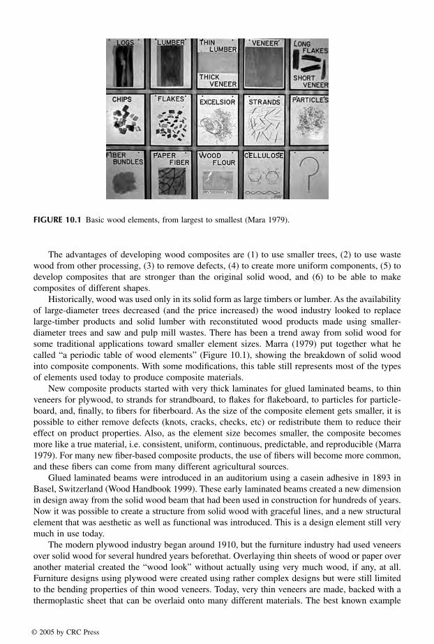
Historically, wood was used only in its solid form as large timbers or lumber. As the availabilityof large-diameter trees decreased (and the price increased) the wood industry looked to replacelarge-timber products and solid lumber with reconstituted wood products made using smaller-diameter trees and saw and pulp mill wastes. There has been a trend away from solid wood forsome traditional applications toward smaller element sizes. Marra (1979) put together what hecalled “a periodic table of wood elements” (Figure 10.1), showing the breakdown of solid woodinto composite components. With some modifications, this table still represents most of the typesof elements used today to produce composite materials.
New composite products started with very thick laminates for glued laminated beams, to thinveneers for plywood, to strands for strandboard, to flakes for flakeboard, to particles for particle-board, and, finally, to fibers for fiberboard. As the size of the composite element gets smaller, it ispossible to either remove defects (knots, cracks, checks, etc) or redistribute them to reduce theireffect on product properties. Also, as the element size becomes smaller, the composite becomesmore like a true material, i.e. consistent, uniform, continuous, predictable, and reproducible (Marra1979). For many new fiber-based composite products, the use of fibers will become more common,and these fibers can come from many different agricultural sources.
Glued laminated beams were introduced in an auditorium using a casein adhesive in 1893 inBasel, Switzerland (Wood Handbook 1999). These early laminated beams created a new dimensionin design away from the solid wood beam that had been used in construction for hundreds of years.Now it was possible to create a structure from solid wood with graceful lines, and a new structuralelement that was aesthetic as well as functional was introduced. This is a design element still verymuch in use today.
The modern plywood industry began around 1910, but the furniture industry had used veneersover solid wood for several hundred years beforethat. Overlaying thin sheets of wood or paper overanother material created the “wood look” without actually using very much wood, if any, at all.Furniture designs using plywood were created using rather complex designs but were still limitedto the bending properties of thin wood veneers. Today, very thin veneers are made, backed with athermoplastic sheet that can be overlaid onto many different materials. The best known example
FIGURE 10.1 Basic wood elements, from largest to smallest (Mara 1979).
© 2005 by CRC Press

of this technology is in the manufacture of business cards using these thin wood/thermoplasticlaminated sheets.
The particleboard industry started in the 1940’s, the hardboard industry around 1950, and theflakeboard and medium density fiberboard (MDF) industries in the early 1960s (Maloney 1996).In general, all of these products are produced in flat sheets and used in two-dimensional designs.It is possible, however, to produce all of these composites in three-dimensional products. Flakesand particles have been formed into pallets and packing materials using an adhesive and a rathersimple mold.
10.1 TYPES OF COMPOSITES AND APPLICATIONS
The earliest composite structures were made of solid beams. Figure 10.2 shows an example of solidbeam construction that was done about 200 years ago. Solid beam structures are still being builttoday but it is far more common to see smaller wood elements that are glued together in compositestructures.
10.1.1 LAMINATED TIMBERS
Structural glued-laminated beams (glulam) can be made using thick, wide wood members and areused as structural elements in large, open buildings. Glulam is a structural product that consists oftwo or more layers of lumber glued together with the grain all going parallel to the length. Figure 10.3shows a laminated beam being fitted into a steel plate that joins the beam to the ground. It can beformed straight or curved, depending on the desired application. Typically the laminates are 25 to50 mm in thickness. Douglas fir, southern pine, hem-fir and spruce are common wood species usedto make glulam in the United States (Wood Handbook 1999). Solid wood and glulam have a specificgravity of 0.4 to 0.8.
The biggest advantage of using glulam is that large beams can be made using small trees. Inaddition, lower quality wood can be used, thinner lumber can be dried much faster than large, thickbeams, and a variety of curved shapes can be produced.
FIGURE 10.2 Old cabin built using solid wooden beams.
© 2005 by CRC Press

10.1.2 PLYWOOD
Thin veneers can be glued together for plywood, a material that is used as a structural underlaymentin floors and roofs and in furniture manufacturing. There are two basic types of plywood: construc-tion and decorative. Construction-grade plywood has traditionally been produced using softwoodssuch as Douglas-fir, southern pines, white fir, larch, and western hemlock, and comes in severalgrades based on the quality of each layer and the adhesive used. Decorative plywood is usuallyproduced using softwoods for the back and inner layers, with a hardwood layer on the outer surface.Figure 10.4 shows a three-ply composite in which each layer is perpendicular to the layer aboveand below. The veneers can be produced either by peeling or slicing, and the grade of plywooddepends on the defects on the two faces. Different thicknesses of plywood can be produced usingmulti-layers of veneers. Usually an odd number of layers is used, and the products have a specificdensity from about 0.4 to 0.8.
10.1.3 STRUCTURAL COMPOSITE LUMBER
Structural composite lumber (SCL) is manufactured by laminating strips of veneers or strands ofwood glued parallel to the length. Figure 10.5 shows three types of SCL products: oriented strand
FIGURE 10.3 Large composite beam made from laminated lumber.
FIGURE 10.4 Thin veneers used to make plywood.
© 2005 by CRC Press
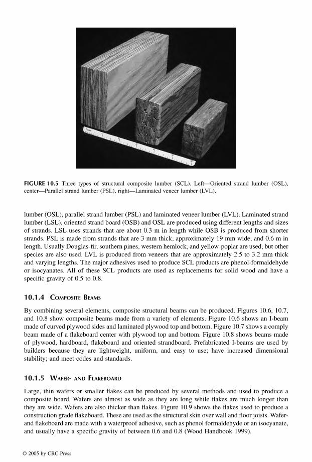
lumber (OSL), parallel strand lumber (PSL) and laminated veneer lumber (LVL). Laminated strandlumber (LSL), oriented strand board (OSB) and OSL are produced using different lengths and sizesof strands. LSL uses strands that are about 0.3 m in length while OSB is produced from shorterstrands. PSL is made from strands that are 3 mm thick, approximately 19 mm wide, and 0.6 m inlength. Usually Douglas-fir, southern pines, western hemlock, and yellow-poplar are used, but otherspecies are also used. LVL is produced from veneers that are approximately 2.5 to 3.2 mm thickand varying lengths. The major adhesives used to produce SCL products are phenol-formaldehydeor isocyanates. All of these SCL products are used as replacements for solid wood and have aspecific gravity of 0.5 to 0.8.
10.1.4 COMPOSITE BEAMS
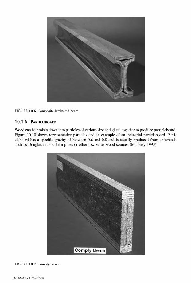
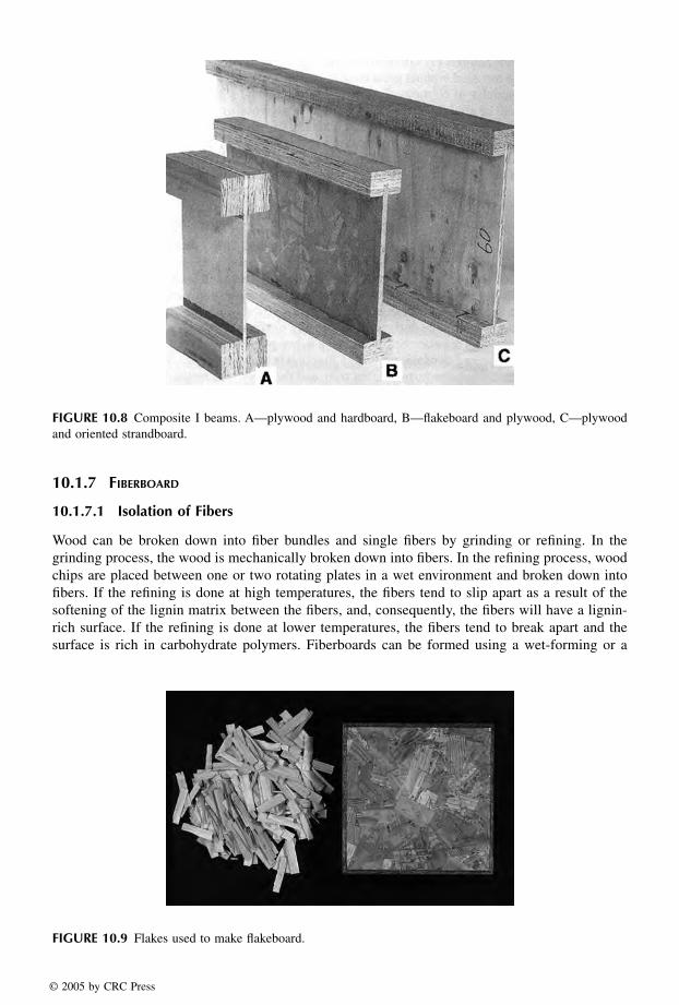
By combining several elements, composite structural beams can be produced. Figures 10.6, 10.7,and 10.8 show composite beams made from a variety of elements. Figure 10.6 shows an I-beammade of curved plywood sides and laminated plywood top and bottom. Figure 10.7 shows a complybeam made of a flakeboard center with plywood top and bottom. Figure 10.8 shows beams madeof plywood, hardboard, flakeboard and oriented strandboard. Prefabricated I-beams are used bybuilders because they are lightweight, uniform, and easy to use; have increased dimensionalstability; and meet codes and standards.
10.1.5 WAFER- AND FLAKEBOARD
Large, thin wafers or smaller flakes can be produced by several methods and used to produce acomposite board. Wafers are almost as wide as they are long while flakes are much longer thanthey are wide. Wafers are also thicker than flakes. Figure 10.9 shows the flakes used to produce aconstruction grade flakeboard. These are used as the structural skin over wall and floor joists. Wafer-and flakeboard are made with a waterproof adhesive, such as phenol formaldehyde or an isocyanate,and usually have a specific gravity of between 0.6 and 0.8 (Wood Handbook 1999).
FIGURE 10.5 Three types of structural composite lumber (SCL). Left—Oriented strand lumber (OSL),center—Parallel strand lumber (PSL), right—Laminated veneer lumber (LVL).
© 2005 by CRC Press
10.1.6 PARTICLEBOARD
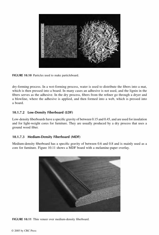
Wood can be broken down into particles of various size and glued together to produce particleboard.Figure 10.10 shows representative particles and an example of an industrial particleboard. Parti-cleboard has a specific gravity of between 0.6 and 0.8 and is usually produced from softwoodssuch as Douglas-fir, southern pines or other low-value wood sources (Maloney 1993).
FIGURE 10.6 Composite laminated beam.
FIGURE 10.7 Comply beam.
© 2005 by CRC Press
10.1.7 FIBERBOARD
10.1.7.1 Isolation of Fibers
Wood can be broken down into fiber bundles and single fibers by grinding or refining. In thegrinding process, the wood is mechanically broken down into fibers. In the refining process, woodchips are placed between one or two rotating plates in a wet environment and broken down intofibers. If the refining is done at high temperatures, the fibers tend to slip apart as a result of thesoftening of the lignin matrix between the fibers, and, consequently, the fibers will have a lignin-rich surface. If the refining is done at lower temperatures, the fibers tend to break apart and thesurface is rich in carbohydrate polymers. Fiberboards can be formed using a wet-forming or a
FIGURE 10.8 Composite I beams. A—plywood and hardboard, B—flakeboard and plywood, C—plywoodand oriented strandboard.
FIGURE 10.9 Flakes used to make flakeboard.
© 2005 by CRC Press
dry-forming process. In a wet-forming process, water is used to distribute the fibers into a mat,which is then pressed into a board. In many cases an adhesive is not used, and the lignin in thefibers serves as the adhesive. In the dry process, fibers from the refiner go through a dryer anda blowline, where the adhesive is applied, and then formed into a web, which is pressed intoa board.
10.1.7.2 Low-Density Fiberboard (LDF)
Low-density fiberboards have a specific gravity of between 0.15 and 0.45, and are used for insulationand for light-weight cores for furniture. They are usually produced by a dry process that uses aground wood fiber.
10.1.7.3 Medium-Density Fiberboard (MDF)
Medium-density fiberboard has a specific gravity of between 0.6 and 0.8 and is mainly used as acore for furniture. Figure 10.11 shows a MDF board with a melamine-paper overlay.
FIGURE 10.10 Particles used to make particleboard.
FIGURE 10.11 Thin veneer over medium-density fiberboard.
© 2005 by CRC Press
© 2005 by CRC Press LLC
11 Chemistry of Wood Strength
Jerrold E. Winandy1,2 and Roger M. Rowell1,3
1USDA, Forest Service, Forest Products Laboratory, Madison, WI2Department of Bio-Based Products, University of Minnesota, St. Paul, MN3Department of Biological Systems Engineering, University of Wisconsin, Madison, WI
CONTENTS
11.1 Mechanical Properties11.2 Factors Affecting Strength
11.2.1 Material Factors11.2.1.1 Specific Gravity11.2.1.2 Growth Characteristics
11.2.2 Environmental Factors11.2.2.1 Moisture11.2.2.2 Temperature
11.2.3 Load Factors11.2.3.1 Duration of Load11.2.3.2 Fatigue11.2.3.3 Mechanical Properties
11.2.4 Flexural Loading Properties11.2.4.1 Modulus of Rupture11.2.4.2 Fiber Stress at Proportional Limit11.2.4.3 Modulus of Elasticity11.2.4.4 Work to Proportional Limit11.2.4.5 Work to Maximum Load
11.2.5 Axial Loading Properties11.2.5.1 Compression Parallel to the Grain11.2.5.2 Compression Perpendicular to the Grain11.2.5.3 Tension Parallel to the Grain11.2.5.4 Tension Perpendicular to Grain
11.2.6 Other Mechanical Properties11.2.6.1 Shear11.2.6.2 Hardness11.2.6.3 Shock Resistance
11.3 Chemical Components of Strength11.3.1 Relationship of Structure to Chemical Composition .
11.3.1.1 Macroscopic Level11.3.1.2 Microscopic Level11.3.1.3 Composition11.3.1.4 Microfibril Orientation11.3.1.5 Molecular Level
11.4 Relationship of Chemical Composition to Strength
1588_C11.fm Page 303 Thursday, December 2, 2004 4:44 PM

11.4.1 Below Proportional Limit (Elastic Strength)11.4.2 Beyond Proportional Limit (Plastic Strength)
11.5 Relationship of Structure to Strength11.5.1 Molecular Level11.5.2 Microscopic Level11.5.3 Macroscopic Level
11.6 Environmental Effects11.6.1 Acids and Bases11.6.2 Adsorption of Elements11.6.3 Swelling Solvents11.6.4 Ultra Violet Degradation11.6.5 Thermal Degradation11.6.6 Microbial Degradation11.6.7 Naturally Occurring Chemicals
11.7 Treatment Effects11.8 SummaryReferences
The source of strength in solid wood is the wood fiber. Wood is basically a series of tubular fibersor cells cemented together. Each fiber wall is composed of various quantities of three polymers:cellulose, hemicelluloses, and lignin. Cellulose is the strongest polymer in wood and, thus, ishighly responsible for strength in the wood fiber because of its high degree of polymerizationand linear orientation. The hemicelluloses act as a matrix for the cellulose and increase thepacking density of the cell wall; hemicelluloses and lignin are also closely associated. The actualrole of hemicelluloses in wood strength has recently been shown to be far more critical towardthe overall engineering performance of wood than had previously been assumed. We suspect theprimary role of hemicelluloses is to act as a highly specific coupling agent capable of associatingboth with the more random areas (i.e., noncrystalline) of hydrophilic cellulose and the moreamorphous hydrophobic lignin. Lignin not only holds wood fibers themselves together but alsohelps bind carbohydrate molecules together within the cell wall of the wood fiber. The chemicalcomponents of wood that are responsible for mechanical properties can be viewed from threelevels: macroscopic (cellular), microscopic (cell wall), and molecular (polymeric) (Winandy andRowell 1984). Mechanical properties change with changes in the thermal, chemical, and/orbiochemical environment. Changes in temperature, pressure, humidity, pH, chemical adsorptionfrom the environment, UV radiation, fire, or biological degradation can have significant effectson the strength of wood.
Cellulose has long been thought to be primarily responsible for strength in the wood fiberbecause of its high degree of polymerization and linear orientation. Hemicellulose may act as alink between the fibrous cellulose and the amorphous lignin. Hemicellulose definitely acts as amatrix for the cellulose and to increase the packing density of the cell wall. Lignin, a phenoliccompound, not only holds the fibers together but also acts as a stiffening agent for the cellulosemolecules within the fiber cell wall. All three cell wall components contribute in different degreesto the strength of wood. Together the tubular structure and the polymeric construction are respon-sible for most of the physical and chemical properties exhibited by wood.
The strength of wood can be altered by environmental agents. The changes in pH, moisture,and temperature; the influence of decay, fire, and UV radiation; and the adsorption of chemicalsfrom the environment can have a significant effect on strength properties. Environmentally inducedchanges must be considered in any discussion on the strength of treated or untreated wood. Thissusceptibility of wood to strength loss, and the magnitude of that degrade, is directly related to theseverity of its thermal/chemical/biochemical exposure.
1588_C11.fm Page 304 Thursday, December 2, 2004 4:44 PM
© 2005 by CRC Press LLC

The strength of wood can also be altered by preservative and fire-retardant compounds usedto prevent environmental degradation. In some cases, the loss in mechanical properties caused bythese treatments may be large enough that the treated material can no longer be considered thesame as the untreated material. The treated wood may now resist environmental degradation butmay be structurally inferior to the untreated material. A long-term study of this problem has helpedengineers account for these potential alterations from untreated wood in the structural designprocess. The approach is based on a cumulative-damage approach relating thermal and chemicaldegradation of the polymers responsible for wood strength to kinetic- or mechanical-based models(Lebow and Winandy 1999a, Winandy and Lebow 2001). With preservative-treated wood, a largeamount of work was undertaken in the late 1980s and early 1990s to address treatment-relatedconcerns in the structural design process. This work developed an understanding of the thermochem-ical issues that primarily control preservative-related strength loss (Winandy 1996a) and was thenused to limit treatment-processing levels in standards, especially post-treatment kiln-drying temper-atures (Winandy 1996b). With fire-retardant treated (FRT) wood, a large amount of work has recentlyaddressed past problems with in-service thermal degradation of FRT wood exposed to elevated in-service temperatures and that work has been summarized (Winandy 2001).
This chapter presents a theoretical model to explain the relationship between the mechanicalproperties and the chemical components of wood. This model is then used to describe the effectsof altered composition on those mechanical properties. Many of the theories presented are onlypartially proven and just beginning to be understood. These theories should be considered as astarting point for dialogue between chemists and engineers that will eventually lead to a betterunderstanding of the chemistry of wood strength.
11.1 MECHANICAL PROPERTIES
Even wood that has no discernible defects has extremely variable properties as a result of itsheterogeneous composition and natural growth patterns. Wood is an anisotropic material in thatthe mechanical properties vary with respect to the three mutually perpendicular axes of the material(radial, tangential, and longitudinal). These natural characteristics are compounded further by theenvironmental influences encountered during the growth of the living tree. Yet wood is a viableconstruction material because workable estimates of the mechanical properties have been developed.
Mechanical properties relate a material’s resistance to imposed loads (i.e., forces). Mechanicalproperties include the following: (1) measures of resistance to deformations and distortions (elasticproperties), (2) measures of failure-related (strength) properties, and (3) measures of other perfor-mance-related issues. To preface any discussion concerning mechanical properties, two conceptsneed to be explained: stress (σ) and strain (ε).
Stress is a measure of the internal forces exerted in a material as a result of an application ofan external force (i.e., load). Three types of primary stress exist: tensile stress, which pulls orelongates an object (Figure 11.1a); compressive stress, which pushes or compresses an object(Figure 11.1b); and shear stress, which causes two contiguous segments (i.e., internal planes) of abody to rotate (i.e., slide) within the object (Figure 11.1c). Bending stress (Figure 11.1d) is acombination of all three of the primary stresses and causes rotational distortion or flexure in an object.
Strain is the measure of a material’s ability to deform—that is, elongate, compress, orrotate—while under stress. Over the elastic range of a material, stress and strain are related to eachother in a linear manner. In elastic materials, a unit of stress (σ) will cause a corresponding unitof strain (ε). This elastic theory yields one of the most critical engineering properties of a material,the elastic modulus (E). The theory is commonly known as Hooke’s law (Larson and Cox 1938):
E = σ/ε (11.1)
It applies to all elastic materials at points below their elastic or proportional limits.
1588_C11.fm Page 305 Thursday, December 2, 2004 4:44 PM
© 2005 by CRC Press LLC

Elastic theory relates a material’s ability to be deformed by a stress to its ability to regain itsoriginal dimensions when the stress is removed. The criterion for elasticity is not the amount ofdeformation but the ability of a material to completely regain its original dimensions when thestress is removed. The opposite quality is viscosity, which can also be thought of as plasticity. Aperfectly plastic body is one that makes no recovery of its original dimensions upon the removalof a stress. Wood is not ideally elastic; it will not completely recover deformation immediately onunloading, but in time, residual deformations tend to be recoverable. Wood is considered a vis-coelastic material. This viscoelasticity explains the creep phenomenon in which a given load willinduce an immediate deformation, and if that load is allowed to remain on that piece, additionalsecondary deformation (i.e., creep) will continue to occur over long time periods. However, forsimplicity’s sake and because the engineering community often also assumes such, wood will beconsidered as an elastic material in this chapter.
The two main elastic moduli are modulus of elasticity, which describes the relationship of load(stress) to axial deformation (strain), and modulus of rigidity or shear modulus, which describesthe internal distribution of shearing stress to shear strain or, more precisely, angular (i.e., rotational)displacement within a material.
Strength values are numerical estimates of the material’s ultimate ability to resist applied forces.The major strength properties are limit values for the stress–strain relationship within a material.Strength, in these terms, is the quality that determines the greatest unit stress a material can withstandwithout fracture or excessive distortion. In many cases the unqualified term strength is somewhatvague. It is sometimes more useful to think of specific strengths, such as compressive, tensile,shear, or ultimate bending strengths.
The American Society for Testing and Materials (ASTM) is the ISO-accredited organizationin North America that standardizes testing procedures to provide reliable and universally comparableestimates of wood strength. Several ASTM Standards for wood (see ASTM) outline procedures fordetermining basic mechanical properties and deriving allowable design stresses. In performing atest, a load is applied to a specimen in a particular manner and the resulting deformation ismonitored. The load information allows the internal forces within the specimen (stress) to becalculated. The deformation information allows the internal distortion (strain) to be calculated whenaccepting specific assumptions. When stress and strain are plotted against each other on a graph,a stress–strain diagram is developed (Figure 11.2).
FIGURE 11.1 Examples of the three axil and one flexural types of stress.
1588_C11.fm Page 306 Thursday, December 2, 2004 4:44 PM
© 2005 by CRC Press LLC

The unit stress corresponding to the upper limit of the linear segment of the stress–straindiagram is known as the proportional limit (Figure 11.2, Point A). This proportional or elastic limitmeasures the boundary of a material’s completely recoverable strength. At stress levels below theproportional limit, a perfectly elastic material will regain its original dimensions and form. At stresslevels in excess of the proportional limit, an elastic material will not regain its original shape; itwill be permanently distorted.
The unit stress represented by the maximum ordinate is the ultimate (maximum) strength(Figure 11.2, Point B). This point estimates the maximum stress at the time of failure. Many of themechanical properties of interest to the engineer, such as maximum crushing strength or ultimatebending strength, describe this point of maximum stress.
11.2 FACTORS AFFECTING STRENGTH
11.2.1 MATERIAL FACTORS
11.2.1.1 Specific Gravity
Specific gravity is the ratio of the weight of a given volume of wood to that of an equal volumeof water. As specific gravity increases, strength properties increase (USDA 1999) because internalstresses are distributed among more molecular material. Mathematical approximations of therelationship between specific gravity and various mechanical properties are shown in Table 11.1.
11.2.1.2 Growth Characteristics
As a fibrous product from living trees, wood is subjected to many environmental influences as itis formed and during its lifetime. These environmental influences can increase the variability ofthe wood material and, thus, increase the variability of the mechanical properties. To reduce theeffect of this inherent variability, standardized testing procedures using small, clear specimens ofwood are often used. Small, clear specimens do not have knots, checks, splits, or reaction wood.However, the wood products used and of economic importance in the real world have these defects.Strength estimates derived from small clear specimens are reported because most chemical treatmentdata have been generated from small clear specimens. Further, comparative analyses of chemicaltreatment-related effects has clearly shown that clear wood material is affected more than materialcontaining knots and voids (Winandy 1996a), such that it is now commonly assumed within thewood-engineering community that treatment effects are greater the more defect-free the woodmaterial and the straighter its grain.
Because strength is affected by material factors, such as specific gravity and growth char-acteristics, it is important to always consider property variability. The coefficient of variationis the statistical parameter used to approximate the variability associated with each strengthproperty. The estimated coefficient of variation of various strength properties can be found inTable 11.2.
FIGURE 11.2 A typical stress–strain diagram for wood.
1588_C11.fm Page 307 Thursday, December 2, 2004 4:44 PM
© 2005 by CRC Press LLC
Air Drying of Lumber
USDA Forest Service Forest Products Laboratory
Madison, Wisconsin

3
Chapter 1
Why Dry Lumber?
Most water in the cut tree must be removed before useful products can be made from the wood. The rough, green lumber sawn from the log must be dried before it is proc-essed into most end products. Drying the lumber at this stage has a number of distinct and important advantages:
• Drying reduces weight, thereby reducing shipping and handling costs.
• The shrinkage that accompanies drying takes place before the wood is used as a product.
• As wood dries, most strength properties increase.
• The strength of joints made with nails and screws is greater in dry wood than in green wood.
• Wood must be relatively dry before it can be glued or treated with preservatives and fire-retardant chemicals.
• Drying reduces the likelihood of mold, stain, or decay.
• Drying increases thermal insulating properties and im-proves finishing characteristics.
Drying Methods Several methods can be used to dry lumber, ranging from air and kiln drying to special seasoning processes. Basically, all methods involve moving moisture from the inside of the wood to the surface, where it is evaporated into the air. Heat and air movement speed up the drying process. Although this publication deals with air drying only, a brief description of other major methods is included to clarify how they differ from air drying.
Air Drying To air dry, the lumber is arranged in layers, or courses, with separating stickers, and built up into unit packages and piles outdoors so that atmospheric air can circulate through the piles and carry away moisture (Fig. 1). One modification of air drying is shed drying, where the lumber to be dried is placed in a shed having open sides (Fig. 2). The roofed structure protects the lumber from rain and direct solar radia-tion but allows outdoor air to circulate through the stickered lumber to dry it.
Fan Shed Air Drying To accelerate air drying, stickered unit packages of lumber are placed in an unheated shed or building that has fans on one side and is open on the other. The fans create air move-ment through the spaces between the courses of wood(Fig. 3).
Forced Air Drying and Predrying In more complex drying processes, stickered packages of lumber are placed in closed buildings that have fans to recir-culate heated air through the lumber piles. Both forced air dryers and predryers are commonly considered low tempera-ture, forced-air circulation, ventilated dry kilns (Fig. 4).
Kiln Drying To kiln dry, lumber is dried in a closed chamber by control-ling the temperature, relative humidity, and air circulation until the wood reaches a predetermined moisture content (Fig. 5).
Special Drying Processes To reduce drying time and degrade, several processes for drying lumber have been investigated. Solar energy has gained popularity with small drying operations. Vacuum drying, especially when combined with radio frequency or microwave delivery of energy to evaporate water, has also gained attention in recent years. The main advantage of vacuum drying is reduced drying time without increased drying defects. Other special drying processes in limited use are press drying between heated platens, solvent seasoning, and boiling in oil.
Choice of Methods Factors that determine the lumber drying process used at a plant are generally related in one way or another to econom-ics. A sawmill that produces a considerable volume of a rather slow-drying wood (such as oak) often selects air dry-ing followed by kiln drying. However, softwoods are often kiln dried green from the saw.

4
Figure 2—Shed for drying lumber protects the lumber from the weather.
Objectives The main purpose for air drying lumber is to evaporate as much water as possible while minimizing capital expendi-tures for dry-kiln capacity and without incurring a cost for the energy required. In air drying, lumber is usually left on stickers in the yard until it reaches a moisture content be-tween 20% and 25%. The lumber may then be ready for further processing, depending upon its end use. If it must be dried to lower moisture content levels, such as for use in furniture factories, the lumber will be kiln dried.
When lumber use does not require a low moisture content, air drying is usually sufficient. Lumber used for outdoor furniture and other outdoor exposures, or for building struc-tures such as barns, pole sheds, and garages that are not heated, can usually be air dried to a low enough moisture content. Rough sawn hardwoods are often air dried at the producing sawmills to reduce weight so that shipping costs are reduced. In addition, air drying reduces subsequent kiln-drying time.
The main benefit of the air-drying process, particularly for hardwoods, is that it offers a way to add value while the inventory of lumber is being held. To meet production of shipping schedules during periods of the year when the saw-mill cannot be operated to capacity, the yard inventory is built up when sawing conditions are favorable and the lum-ber is air dried while being held. Air drying is sometimes used to reduce the moisture content in wood, such as railroad ties, to a level suitable for preservative treatment.
Air drying further reduces the chance that mold and decay may develop in transit, storage, or subsequent use. Blue stain and wood-destroying fungi cannot grow in wood with a moisture content of 20% or less. However, green lumber may have to be treated with a fungicide to protect it from these fungi in the early stages of the air-drying process. Drying is also a protective measure against damage from most insects that bore holes in wood.
Figure 1—An air-drying yard arranged for good circulation of air around the piles of packaged lumber.

5
Figure 3—Fan shed air dryer draws air through the stickered packages of lumber.
Figure 4—Predryers are large structures that provide some means of controlling the drying conditions. The forklift in the background provides size comparison.
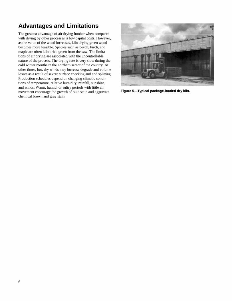
6
Advantages and Limitations The greatest advantage of air drying lumber when compared with drying by other processes is low capital costs. However, as the value of the wood increases, kiln drying green wood becomes more feasible. Species such as beech, birch, and maple are often kiln dried green from the saw. The limita-tions of air drying are associated with the uncontrollable nature of the process. The drying rate is very slow during the cold winter months in the northern sector of the country. At other times, hot, dry winds may increase degrade and volume losses as a result of severe surface checking and end splitting. Production schedules depend on changing climatic condi-tions of temperature, relative humidity, rainfall, sunshine, and winds. Warm, humid, or sultry periods with little air movement encourage the growth of blue stain and aggravate chemical brown and gray stain.
Figure 5—Typical package-loaded dry kiln.

43
Chapter 6
Air-Drying Defects—Causes and Remedies
Losses in value and volume resulting from defects that de-velop in lumber during air drying increase the cost of air drying. If known, such losses should be assessed directly against the air-drying process. Air-drying defects may be caused by chemical reaction, fungal infection, insect infesta-tion, or shrinkage. Chemical reactions cause chemical brown and gray stain, and sticker marking is one form of this dis-coloration. Fungal infection causes blue stain in the sapwoodas well as decay and mold. Insect infestation results in pith flecks, pinholes, and grub holes. Shrinkage causes end checks and end splitting, surface checks, honeycomb, and warp. Exposure of lumber directly to weathering conditions aggravates these shrinkage defects, and extended yarding after the lumber is air dried accelerates the rate of grade deterioration or volume losses. Drying defects that do not degrade rough lumber may cause volume losses during ma-chining. Warp may cause skips or splits in the dressing op-eration. Knots that are loosened in softwoods during drying may be knocked out during planing, and knots that are checked may be broken.
Chemical Reaction Certain stains or discolorations can develop in lumber during air drying in addition to those caused by fungi or by general weathering. These stains result from chemical changes that occur in the wood. Called chemical stains, they darken the wood to colors ranging from gray to buff to dark brown. Species that are subject to objectionable chemical stains are ponderosa pine, the true white pines, western hemlock, noble fir, redwood, and several hardwoods including ash, maple, birch, hickory, and magnolia.
In pine, chemical brown stain develops in either sapwood or heartwood. It is more prevalent in lumber sawn from old logs that have been cut for some time than in lumber from newly cut logs. It is also more prevalent in boards that have been solid piled for 2 or more days immediately after sawing than in boards stacked for drying immediately after sawing. The stain develops during hot, humid months and usually is ob-served on the surfaces of the boards, but it can penetrate deeply into the wood. In some cases, it occurs inside a board and does not show on the surface. The stain results from a concentration of extractives that are transported by the water and deposited at the point where the water is vaporized or
absorbed as bound water. These extractives are believed to be sugars and amino acids, which are present within the free water or are formed through enzymatic action immediately after felling or during solid piling of the lumber. The enzy-matic action can be slowed down by dipping the green lum-ber in enzyme-inhibiting chemicals.
Deep grayish-brown chemical stains may occur in the sap-wood of lumber in air-drying yards and predryers. These stains can be a problem in oak, hickory, ash, maple, tupelo gum, magnolia, persimmon, birch, basswood, and Douglas-fir. Stains develop during very slow drying. In this situation, enzymes are produced by slowly dying parenchyma cells, which darken when oxidized. To minimize these stains, green lumber should be stickered immediately after sawing, with good air circulation provided, and preferably at temperatures greater than 21oC (70oF).
Sticker marking, a form of chemical stain, develops in woods such as maple, white ash, and magnolia during the warm, humid summer months. The discoloration, which often does not surface out of the rough, dry boards, can be significantly reduced by using dry stickers and subjecting the lumber to good drying conditions immediately after stacking. Fan shed drying and forced air drying, or low temperature kiln drying, are very effective in preventing sticker marking in these woods during the warm months of the year.
Chemical stains can be reduced by conditions that encourage rapid drying. Rapid air drying can be promoted by keeping the yard surface well drained, free from vegetation and de-bris, using high and open-pile foundations, increasing the spacing between piles in the rows, and opening the unit packages by increasing board spacing and constructing more chimneys in hand-built piles.
Fungal Infection StainStains in wood can be caused by fungi that grow in the woodand use parts of it for food. These stains are confined largely to sapwood of both softwoods and hardwoods and are of various colors. The so-called “blue” stains, which vary in color from gray to bluish to bluish black, are most common. The blue color is caused by the thread-like hyphae of the
44
fungus that invade the wood. Except for toughness, blue stain has little effect on the strength properties of wood, althoughit does cause degrade where color is important.
Blue stain is likely to develop where air drying is retarded. It is most likely to occur during the warm, damp seasons of the year. It occurs in flat piles of self-stickered lumber, where green boards are used for stickers, and in end racking and crib piling, where the boards themselves come in contact. The likelihood of blue staining can be reduced by using narrow, dry stickers and by opening up the yard and the piles to encourage rapid air drying.
Fungal growth can be prevented in lumber by quickly drying it to a moisture content of 20% or less and keeping it dry. Air-drying conditions may not always be favorable to prevent the growth of staining fungi; therefore, chemical treatment of the freshly cut lumber may be necessary. The chemical treatment is usually accomplished by dipping the lumber or spraying it with a suitable fungicide. However, if the lumber has already become infected, the fungus may have penetrated so far below the surface that the organism is not completely killed by dipping. When such lumber is air dried slowly, the interior portions may blue stain, although the surfaces may remain bright. The effectiveness of the antistain chemicals may also be reduced by leaching if the lumber is exposed to wetting while in the yard.
Successful stain control with chemicals not only depends upon immediate and adequate treatment but also upon proper handling of the lumber in the air-drying yard. The yard and lumber storage areas must be kept as well drained and sani-tary as possible to reduce the chance of infection. The fungus is propagated by spores when the fungus has reached a cer-tain stage. These spores are airborne, are practically always present, and infect freshly sawn lumber by coming to rest on the surfaces. If the conditions of air, moisture, and tempera-ture are favorable, spores develop quickly into the fungus. Sap stain fungi can grow at temperatures from 1.7°C to 38°C(35°F to 100°F ). Spores, although generally carried by the wind, are also carried by insects, and when the insect burrows into the sapwood, the spores are carried into the burrows.
Mold Mold is also propagated by airborne spores. During warm, moist weather, mold grows on wood surfaces and penetrates the wood. In contrast to blue stain, the hyphae of molds are colorless and do not stain the wood. The discolorations of wood surfaces are caused by the fruiting bodies. Under ex-ceptional conditions, mold may develop to a point where it restricts air circulation in certain portions of a pile, thereby retarding drying. The measures used to reduce or control blue stain apply also to mold.
Decay Decay or rot is caused by fungi that not only discolor woodbut actually destroy it. Decay, blue stain, and mold organisms all thrive under similar conditions of moisture content, air, and temperature, but decay requires somewhat longer time to develop. Freshly sawn lumber may be infected by airborne spores or contact with decayed foundation timbers or stick-ers. The best way to combat decay is to dry the lumber to a moisture content of 20% or less as quickly as possible. In some cases, it may be necessary to treat decay with a suitable fungicide. Decay is frequently present in the living tree, and lumber sawn from the logs will contain the organisms. Some decay fungi may continue to develop in the lumber as it dries.
Insect Infestation In all stages of drying—from the green condition to com-pletely dry—wood can be subject to attack by insects. Piles of lumber in an air-drying yard are sometimes infested. De-bris, in the form of broken timbers or stickers, provides breeding places for insects that may spread to the lumber.
Powder post beetles attack hardwoods and softwoods, freshly cut and air-dried lumber. The sapwood of hickory, ash, and oak are particularly susceptible to attack. Damage is indi-cated by holes left in the surface of the lumber by the winged adults as they emerge and the fine powder that may fall from the wood. This is evidence that the insect has departed and that subsequent treatments to sterilize may serve no purpose. Sterilization of green lumber in saturated steam at 54°C(130°F) or at a lower relative humidity at 82°C (180°F) for 2°h is effective for 25-mm (1-in.) lumber. Thicker lumber requires a longer time to sterilize. Heat sterilized wood will not prevent subsequent infestation; therefore, good yard sanitation is essential to check infestation by these insects.
ShrinkageWhen a log is sawn into lumber, the drying process starts and soon after stacking in the air-drying yard, shrinkage of the board begins. The stresses set up in the surface zones of the lumber by shrinkage may cause deformation or failure. Be-cause the amount of shrinkage varies with the species of wood and the grain patterns of the lumber, a change in shape usually results. If the drying stresses exceed the strength of the wood, failures can develop, such as various types of splits and cracks.
ChecksChecks are failures of the wood that develop along the grain because of drying stresses. Checks are of three types: end, surface, and honeycomb. Some woods are inclined to check more readily than others (Table 10).

45
End checks originate on end-grain surfaces and appear as radiating lines pointing toward the pith or heart center of the tree (Fig. 47). They occur at the junction of the wood rays and the remainder of the wood cells, or within the wood rays. When started, end checks become wider and, by extending radially and longitudinally, develop into splits. Surface checks are similar separations of the wood under stress, but they occur on tangential or flatgrain faces (Fig. 48). End checks become longer by extending in the longitudinal direc-tion of the grain of the wood and deeper by extending in the radial direction. As drying progresses, the surface checks may close up on the surface but widen and deepen internally. These are called bottleneck checks (Fig. 49).
Exposure to the sun and breeze during sawing and hot, dry weather immediately after piling is likely to cause checking. End and surface checks will probably be more severe in those parts of the pile that are fully exposed, that is, the ends, sides, and top parts of the pile. Checks will be particularly severe in the upper surfaces of the boards in the top course if the pile is not roofed.
Table 10—Checking tendency of various woods
Low Intermediate High
Hardwoods
Alder Ash Beech
Aspen Birch, yellow Oaks
Basswood Butternut Sycamore
Birch, paper, sweet Elm, rock Tanoak
Cherry Hackberry
Cottonwood Hickory
Elm, American Maple, sugar, bigleaf
Magnolia, southern Pecan
Maple, red, silver Sweetgum
Tupelo Walnut
Yellow-poplar Willow
Softwoods
Baldcypress Firs, true Douglas-fir
Cedar Hemlocks Larch, western
Pine, sugar Pine, jack
Pine, loblolly Pine, lodgepole
Pine, shortleaf Pine, longleaf
Redwood Pine, ponderosa
Spruce Pine, red
Pine, slash
Pine, white
Figure 47—End checks in lumber can extend todevelop splits.
Figure 48—These oak boards surface checked in theearly stages of air drying. These surface checks can penetrate deep into the wood, and when they close at the surface, the internal failure appears to be honeycomb.
Figure 49—Bottleneck checks, which develop from closed surface checks, can look like honeycomb.

46
Volume losses as a result of end checking and end splitting can be serious. End coating the freshly sawn lumber immedi-ately after trimming to length retards the end drying that causes these failures. Several proprietary end coatings are available. The emulsified waxes that can be applied by either brushing or spraying are effective for use on lumber being air dried.
End checking frequently begins in the log yard. It may pay to end coat both ends with emulsified wax to minimize end checking. An alternative method would be to sprinkle the dry log deck with water.
Honeycomb Although not so common in air drying as end and surface checks, honeycomb or internal checking can occur (Fig. 50). This results from tensile failures entirely within the interior of the piece and usually occurs during kiln drying caused by too high a temperature too early in the schedule. Sometimes, surface depressions and grooves are indicated by the pres-ence of honeycomb, but sometimes it cannot be detected until a piece is planed or sawn.
Honeycomb and bottleneck checks look similar but result from different causes; therefore, it is beneficial to distinguish between the two. In doing so, elimination of the problem may be possible. Honeycomb begins internally and usually does not extend to the surface, thus is rarely exposed to the air. In contrast, bottleneck checks begin on the surface, and at one time were exposed to the air. With the surface open, some-times dirt collects in the check. If the defect in question extends to the surface or contains dirt, it is considered a bottleneck check.
After determining which type of defect is present, measures can be taken to avoid the defect in the future. Honeycomb is generally a kiln-drying problem caused by too high a tem-perature too early in the drying schedule. By waiting to increase the dry-bulb temperature or using a different drying schedule, this risk is reduced. Bottleneck checks can be an air- or a kiln-drying problem. If the check contains dirt, it most likely was initiated before entering the kiln and uncon-trolled air drying was probably the cause. By reducing the air flow and/or providing more protection, the risk of checking is reduced. This is accomplished by using a protective cloth (Fig. 30), closer stacking of piles, or converting to shed drying. If there is no debris in the check, severe conditions early in the kiln schedule could have caused the checks. In which case, either reducing the initial wet-bulb depression or not advancing to the second kiln schedule step as quickly can help avoid the defect.
ShakesFailures that do not conform with the usual definition of checks sometimes occur under shrinkage stresses. These failures are caused by abnormally weak wood and are called
shakes. They are check-like openings located within or at the junction of the growth rings. Shakes may originate on end-grain surfaces and look like end checks, except that they follow the growth rings rather than the wood rays. These ring failures are not considered a drying defect and cannot be avoided by altering the drying method (Fig. 51).
SplitsSplits are longitudinal and radial separations of the wood. Usually they occur radially. Splits are generally located at a board end, but occasionally occur along the length of a board. A split along the length of the board may or may not extend completely through the thickness of the piece. End splits often result from extension of end checks further into a board. Splits are sometimes associated with longitudinal stresses that were in the log and the board when it was freshly sawn. When a split originates, the longitudinal stresses cause it to open wide and extend along the length of the piece.
CracksCracks have the appearance of surface checks or splits but are formed differently. Cracks occur in pieces containing the pith or heart center of the tree. They generally develop from surface checks or end checks, but their characteristically large width is caused by the difference between tangential
Figure 50—Honeycomb is failure initiated internally along the rays.
Figure 51—Shake is failure that follows the growth rings.
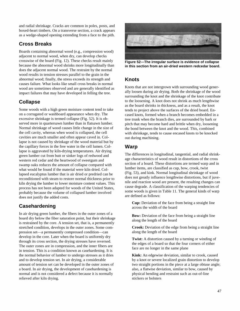
47
and radial shrinkage. Cracks are common in poles, posts, and boxed-heart timbers. On a transverse section, a crack appears as a wedge-shaped opening extending from a face to the pith.
Cross Breaks Boards containing abnormal wood (e.g., compression wood) adjacent to normal wood, when dry, can develop checks crosswise of the board (Fig. 12). These checks result mainly because the abnormal wood shrinks more longitudinally than does the adjacent normal wood. The restraint by the normal wood results in tension stresses parallel to the grain in the abnormal wood; finally, the stress exceeds its strength and causes failure. What looks like small cross breaks in normal wood are sometimes observed and are generally identified as impact failures that may have developed in felling the tree.
CollapseSome woods with a high green moisture content tend to take on a corrugated or washboard appearance when dry. The excessive shrinkage is termed collapse (Fig. 52). It is ob-served more in quartersawn lumber than in flatsawn lumber. Normal shrinkage of wood causes little change in the size of the cell cavity, whereas when wood is collapsed, the cell cavities are much smaller and often appear caved in. Col-lapse is not caused by shrinkage of the wood material but by the capillary forces in the free water in the cell lumen. Col-lapse is aggravated by kiln-drying temperatures. Air drying green lumber cut from butt or sinker logs of redwood and western red cedar and the heartwood of sweetgum and swamp oaks reduces the amount of collapse compared with what would be found if the material were kiln dried. Col-lapsed eucalyptus lumber that is air dried or predried can be reconditioned with steam to restore normal thickness prior to kiln drying the lumber to lower moisture content values. This process has not been adapted for woods of the United States, probably because the volume of collapsed lumber involved does not justify the added costs.
CasehardeningIn air drying green lumber, the fibers in the outer zones of a board dry below the fiber saturation point, but their shrinkage is restrained by the core. A tension set, that is, a permanently stretched condition, develops in the outer zones. Some com-pression set—a permanently compressed condition—can develop in the core. Later when the board is uniformly dry through its cross section, the drying stresses have reversed. The outer zones are in compression, and the inner fibers are in tension. This is a condition known as casehardening. It is the normal behavior of lumber to undergo stresses as it dries and to develop tension set. In air drying, a considerable amount of tension set can be developed in the outer zones of a board. In air drying, the development of casehardening is normal and is not considered a defect because it is normally relieved after kiln drying.
KnotsKnots that are not intergrown with surrounding wood gener-ally loosen during air drying. Both the shrinkage of the wood surrounding the knot and the shrinkage of the knot contribute to the loosening. A knot does not shrink as much lengthwise as the board shrinks in thickness, and as a result, the knot tends to project above the surfaces of the dried board. En-cased knots, formed when a branch becomes embedded in a tree trunk when the branch dies, are surrounded by bark or pitch that may become hard and brittle when dry, loosening the bond between the knot and the wood. This, combined with shrinkage, tends to cause encased knots to be knocked out during machining.
WarpThe differences in longitudinal, tangential, and radial shrink-age characteristics of wood result in distortions of the cross section of a board. These distortions are termed warp and in lumber items, are classified as cup, bow, crook, twist (Fig. 53), and kink. Normal longitudinal shrinkage of wood does not greatly influence lengthwise distortions, but if juve-nile and reaction wood are present, the resulting changes can cause degrade. A classification of the warping tendencies of some woods is given in Table 11. The general kinds of warp are defined as follows:
Cup: Deviation of the face from being a straight line across the width of the board
Bow: Deviation of the face from being a straight line along the length of the board
Crook: Deviation of the edge from being a straight line along the length of the board
Twist: A distortion caused by a turning or winding of the edges of a board so that the four corners of either face are no longer in the same plane
Kink: An edgewise deviation, similar to crook, caused by a knot or severe localized grain distortion to develop two straight portions in the piece at a large obtuse angle; also, a flatwise deviation, similar to bow, caused by physical bending and restraint such as out-of-line stickers or bolsters
Figure 52—The irregular surface is evidence of collapse in this section from an air-dried western redcedar board.

48
Cup is common in flatsawn boards, and all such boards tend to cup if permitted to dry and shrink without restraint. In a flatsawn board, because of the position of the growth rings, the face toward the bark of the tree has a greater shrinkage potential than does the face toward the pith. Consequently, when the board shrinks, the face toward the bark tends to become concave and the face towards the pith tends to be-come convex.
For a given species, the tendency to cup varies inversely with the distance the annual rings in the board are from the pith of the tree. The other forms of warp, bow, crook, and twist may be caused by spiral or diagonal grain, or localized distortions of grain, as around knots, for example. Spiral grain is present in the log, and diagonal grain is developed by sawing crooked logs or sawing parallel to the pith rather than to the bark.
The amount and character of warp depends on the slope of the grain and the location and size of the areas of cross grain. Bow, crook, or twist may also be caused by the presence of bands of compression, tension, or juvenile wood that has abnormal longitudinal shrinkage. Wood near the pith, which may contain juvenile or compression wood, often has abnormal longitudinal shrinkage. This is a good reason for boxing the heart in sawing so that the pith does not fall on one edge or face. Juvenile wood in the inner portions of mature trees is lighter in weight than the more mature wood nearer the bark and shrinks more along the grain. Conse-quently, boards containing both types of wood tend to warp during drying.
Kink is observed in softwood dimension lumber where a knot or the grain distortion that surrounds a knot is located on one edge near the middle of the piece. The two portions of the piece are essentially flat and straight. Sometimes the sharp bend in the faces of a board caused by an offset sticker and considerable superimposed loading is also called a kink.
Warp Reduction Warping is caused by the differences in shrinkage in the three grain directions and because of irregular and distorted grain. Warping can be minimized by following good stacking and piling practices. The tiers of stickers and other supporting members, such as foundation cross beams and bolsters, should be in good vertical alignment. Protecting the boards in the top course of a pile with a roof reduces expo-sure to the weather with its alternate wetting and drying cycles. Good sawing practices produce boards of uniform thickness, which is a desirable quality for stacking and drying uniformity.
Figure 53—Various types of warp in lumber.
Table 11—Warping tendency of various woods
Low Intermediate High
Hardwoods
Alder Ash Beech
Aspen Basswood Cottonwood
Birch, paper, sweet Birch, yellow Elm, American
Butternut Elm, rock Sweetgum
Cherry Hackberry Sycamore
Walnut Hickory Tanoak
Yellow-poplar Locust Tupelo
Magnolia, southern
Maples
Oaks
Pecan
Willow
Softwoods
Cedars Baldcypress
Pine, ponderosa Douglas-fir
Pine, Sugar Firs, true
Pine, white Hemlocks
Redwood Larch, western
Spruce Pine, jack
Pine, lodgepole
Pine, red
Pine, Southern

49
The more refractory (that is, difficult to dry) woods like oak and beech are very difficult to air dry during periods of good drying weather without surface checking. These failures result when the tension forces across the grain tend to local-ize at the small fractures created by the sawing process. Surfacing the green wood removes the sawing fractures, and the likelihood of surface checking in air drying is reduced. By presurfacing lumber to a uniform thickness, not only is the usable volume of a unit package increased, but the amount of warp present is reduced.
Stacking, Package Piling,and Pile Protection The volume and grade reduction as a result of poor stacking, improper piling practices, and inadequate pile protection can be appreciable. Warp is aggravated, and volume losses as a result of end checks, end splits, and surface checking are increased.
Stacking Effects Lumber of uniform thickness and trimmed for length can be stacked in such a way that warp is restrained. As a result of poor sorting, stacking, and piling practices, however, good grade and volume recovery might not be attained. In stack-ing, even dry stickers may vary in thickness. When associ-ated with poor sticker tier alignment, the introduced warp may be significantly increased. Perhaps length sorting cannot be justified, requiring that the packages be box piled. Insuffi-cient sticker tiers and carelessly locating them may further fail to provide adequate board end support. Along with care-less board placement, this further invites warp (Fig. 54). When long boards for the edges of the box piled courses are not readily available, shorter boards are often laid down, causing sticker overhang. If the space is not blocked, sag can be created in the courses of lumber above. This is a problem of greater concern in stacking the narrower unit packages.
When stickered packages of lumber, particularly 25-mm (1-in.) softwoods of the less dense species, are transported by forklift trucks, two extra tiers of stickers are often included. Such tiers, located so they will be above the pickup points of the fork, are often installed six to eight layers from the bot-tom. The package is usually stiffened enough so that the end stickers will not fall out during transport. Carrier bunks should be spotted at these extra sticker tiers to minimize the sag in the bottom lumber layers of the package when the package is transported or temporarily stored (Fig. 55).
Package Piling Effects Packages are usually piled one above the other two, three or four packages high, depending on the height of the packages.
Thus, the lower packages are weighted by the upper ones. Any failure of the pile foundation, or the bolsters between the packages, to adequately support the load will warp the lum-ber. Green lumber can be bent and, if it dried while bent, the bends become fixed and are permanent. Where the number of cross beams in the foundation does not adequately support the pile at the sticker tiers, the lower courses are likely to sag. This introduced bow can result in appreciable grade reduction.
Weathering Effects When piles are not covered, the upper layers are exposed and defects can develop that cause value losses as a result of grade reduction and volume losses in ripping and trimming to maintain grade. The economic effect is particularly notable in the upper grades of hardwoods and finish grades of soft-woods. A rain tight roof with overhang on sides and ends will prevent excessive moisture regain and reduce the overall drying time in the yard. Where the output of air-dried lumber per square meter of yard area must be fairly high and produc-tion fairly constant, prevention of moisture regain during rainy seasons of the year is a necessity. In this case, good prefabricated pile covers are economical. The prevention of alternate wetting and drying also reduces grade losses caused by general weathering, mainly surface checking and warp. The cost of the pile roof construction, placement, tiedown, storage when not in use, and maintenance may justify design-ing and installing drying sheds, particularly for high value lumber.
Figure 54—Example of poor sticker alignment.
Copyright © 2022 FDOKUMEN