198-013 UNO Fibroptic Thermometer User Guide
36
Fibroptic Thermometer User Guide Issue 7 30 April 2018 Publication Nº 198.013 Language: English © Land Instruments International, 2018
-
Upload
khangminh22 -
Category
Documents
-
view
0 -
download
0
Transcript of 198-013 UNO Fibroptic Thermometer User Guide

Fibroptic Thermometer
User Guide
Issue 730 April 2018
Publication Nº 198.013Language: English
© Land Instruments International, 2018

Health and Safety InformationRead all of the instructions in this booklet - including all the WARNINGS and CAUTIONS - before using this product. If there is any instruction which you do not understand, DO NOT USE THE PRODUCT.
Safety SignsWARNINGIndicates a potentially hazardous situation which, if not avoided, could result in death or personal injury.
CAUTIONIndicates a potentially hazardous situation which, if not avoided, could result in minor or moderate injury to the user or users, or result in damage to the product or to property.
NOTEIndicates a potentially hazardous situation which, if not avoided, could result in damage or the loss of data.
Signs and Symbols used on equipment and Documentation
Caution, risk of electric shock.
Caution, attention to possibility of risk of damage to the product, process or surroundings. Refer to instruction manual.
Caution, hot surface.
Protective Conductor Terminal.
Observe precautions for handling electrostatic discharge sensitive devices.
Equipment OperationUse of this instrument in a manner not specified by Land Instruments International may be hazardous. Read and understand the user documentation supplied before installing and operating the equipment.The safety of any system incorporating this equipment is the responsibility of the assembler.
Protective Clothing, Face and Eye ProtectionIt is possible that this equipment is to be installed on, or near to, machinery or equipment operating at high temperatures and high pressures. Suitable protective clothing, along with face and eye protection must be worn. Refer to the health and safety guidelines for the machinery/equipment before installing this product. If in doubt, contact Land Instruments International.
Electrical Power SupplyBefore working on the electrical connections, all of the electrical power lines to the equipment must be isolated. All the electrical cables and signal cables must be connected exactly as indicated in these operating instructions. If in doubt, contact Land Instruments International.
StorageThe instrument should be stored in its packaging, in a dry sheltered area.
UnpackingCheck all packages for external signs of damage. Check the contents against the packing note.
Lifting InstructionsWhere items are too heavy to be lifted manually, use suitably rated lifting equipment. Refer to the Technical Specification for weights. All lifting should be done as stated in local regulations.
IMPORTANT INFORMATION - PLEASE READ

Health and Safety InformationRead all of the instructions in this booklet - including all the WARNINGS and CAUTIONS - before using this product. If there is any instruction which you do not understand, DO NOT USE THE PRODUCT.
Safety SignsWARNINGIndicates a potentially hazardous situation which, if not avoided, could result in death or personal injury.
CAUTIONIndicates a potentially hazardous situation which, if not avoided, could result in minor or moderate injury to the user or users, or result in damage to the product or to property.
NOTEIndicates a potentially hazardous situation which, if not avoided, could result in damage or the loss of data.
Signs and Symbols used on equipment and Documentation
Caution, risk of electric shock.
Caution, attention to possibility of risk of damage to the product, process or surroundings. Refer to instruction manual.
Caution, hot surface.
Protective Conductor Terminal.
Observe precautions for handling electrostatic discharge sensitive devices.
Equipment OperationUse of this instrument in a manner not specified by Land Instruments International may be hazardous. Read and understand the user documentation supplied before installing and operating the equipment.The safety of any system incorporating this equipment is the responsibility of the assembler.
Protective Clothing, Face and Eye ProtectionIt is possible that this equipment is to be installed on, or near to, machinery or equipment operating at high temperatures and high pressures. Suitable protective clothing, along with face and eye protection must be worn. Refer to the health and safety guidelines for the machinery/equipment before installing this product. If in doubt, contact Land Instruments International.
Electrical Power SupplyBefore working on the electrical connections, all of the electrical power lines to the equipment must be isolated. All the electrical cables and signal cables must be connected exactly as indicated in these operating instructions. If in doubt, contact Land Instruments International.
StorageThe instrument should be stored in its packaging, in a dry sheltered area.
UnpackingCheck all packages for external signs of damage. Check the contents against the packing note.
Lifting InstructionsWhere items are too heavy to be lifted manually, use suitably rated lifting equipment. Refer to the Technical Specification for weights. All lifting should be done as stated in local regulations.
IMPORTANT INFORMATION - PLEASE READ Contact UsUK - DronfieldLand Instruments InternationalTel: +44 (0) 1246 417691
USA - PittsburghAMETEK Land, Inc.Tel: +1 412 826 4444
ChinaAMETEK Land China Service Tel: +86 21 5868 5111 ext 122
IndiaAMETEK Land India ServiceTel: +91 - 80 67823240
Email: [email protected]
Web: www.ametek-land.com
For further details on all AMETEK Land offices, distributors and representatives, please visit our website.
Return of Damaged GoodsIMPORTANT If any item has been damaged in transit, this should be reported to the carrier and to the supplier immediately. Damage caused in transit is the responsibility of the carrier not the supplier.DO NOT RETURN a damaged instrument to the sender as the carrier will not then consider a claim. Save the packing with the damaged article for inspection by the carrier.
Return of Goods for RepairIf you need to return goods for repair please contact our Customer Service Department. They will be able to advise you on the correct returns procedure.Any item returned to Land Instruments International should be adequately packaged to prevent damage during transit.You must include a written report of the problem together with your own name and contact information, address, telephone number, email address etc.
Design and Manufacturing StandardsThe Quality Management System of Land Instruments International is approved to BS EN ISO 9001 for the design, manufacture and on-site servicing of combustion, environmental monitoring and non-contact temperature measuring instrumentation.
Registered ISO 9001 Management System approvals apply in the USA
UK Calibration Laboratory: UKAS 0034
USA Calibration Laboratory: ANAB Accredited ISO/IEC 17025
National Accreditation Board for Testing and Calibration Laboratories approvals apply in India.
Operation of radio transmitters, telephones or other electrical/electronic devices in close proximity to the equipment while the enclosure doors of the instrument or its peripherals are open, may cause interference and possible failure where the radiated emissions exceed the EMC directive. The protection provided by this product may be invalidated if alterations or additions are made to the structural, electrical, mechanical or pneumatic parts of this system. Such changes may also invalidate the standard terms of warranty.
CopyrightThis manual is provided as an aid to owners of Land Instruments International’s products and contains information proprietary to Land Instruments International. This manual may not, in whole or part, be copied, or reproduced without the expressed written consent of Land Instruments International Ltd.
Copyright © 2018 Land Instruments International.
MARCOM0311, Issue 9, 12 April 2018

Fibroptic Thermometer User Guide
Blank

User Guide Fibroptic Thermometer
Contents
1 Introduction 1
1.1 About this guide 11.2 About the UNO Fibroptic thermometer 11.3 Unpacking the thermometer 11.4 Nomenclature 2
2 Specifications 3
2.1 U1 Series Thermometers 32.2 U2 Series Thermometers 42.3 V1 Series Thermometers 5
3 Installing the UNO Fibroptic Thermometer 6
3.1 Positioning the Optic Head 73.2 Installing the lightguide 83.3 Positioning the Thermometer 8
4 Using the Thermometer 9
4.1 Removing the chassis from the thermometer cover 94.2 Location of controls 104.3 Setting the Emissivity/Non Greyness value 114.4 Setting the Time Functions 124.5 Note your settings 144.6 Replacing the chassis into the thermometer cover 144.7 Electrical Connections 15
5 Laser Alignment Unit 19
5.1 About the Laser Alignment Unit 195.2 LaserAlignmentUnitSpecification 195.3 Using the Laser Alignment Unit 215.4 Laser Alignment Unit maintenance 21
6 Target Size Tables 22
6.1 Optic Head A10, Field of View 25:1 (Red spacer) 226.2 Optic Head A10, Field of View 75:1 (Red spacer) 226.3 Optic Head A25, Field of View 25:1 (Blue spacer) 236.4 Optic Head A25, Field of View 75:1 (Blue spacer) 236.5 Optic Head A50, Field of View 25:1 (No spacer) 246.6 Optic Head A50, Field of View 75:1 (No spacer) 24
7 Emissivity tables 25
7.1 Refractories 257.2 Alloys 257.3 Metals 267.4 Miscellaneous 27
8 Maintenance 28
8.1 Optic head 288.2 Air supply 28
Contents

Fibroptic Thermometer User Guide
Fig. 1 Land Fibroptic UNO thermometer

Page 1
User Guide Fibroptic Thermometer
1 Introduction
1.1 About this guideThis guide gives the information necessary for you to operate a LAND UNO Fibroptic Thermometer. Basic information regarding installation is contained within the Installation Guide.
1.2 About the UNO Fibroptic thermometerThe LAND UNO thermometer is an accurate, non contact thermometer designed for independent or STAND ALONE use.
The thermometer features include:
• Stand Alone operation.• Built in Averager or Peak Picker for signal conditioning.• Built in Emissivity or Non Greyness controls.• Achoiceoffibreopticslightguides,enablingthethermometer's
electronics to be located away from the often hostile measurement location.
• A choice of optic head focus distance.• Electrical connections for a 4 to 20mA output, linear over the
temperature span of the thermometer, and an emissivity input for high accuracy temperature measurement.
The LAND UNO range of thermometers and rugged mounting accessories is designed to provide precise, non contact temperature measurement solutions.
Internal controls for emissivity or non greyness together with selectable timefunctionsallowthethermometertobeconfiguredtosuitawiderangeof industrial applications. A comprehensive range of mountings is common to other LAND products, maximising commonality and simplifying system upgrades.
1.3 Unpacking the thermometerThe package containing the thermometer will contain the following items:
• CD containing this UNO User Documentation.• UNOFibropticthermometer,optichead(fittedwithprotectioncap)and
lightguide.• 2.5mm Hex screwdriver.• 2.5mmflatbladedscrewdriver.

Page 2
Fibroptic Thermometer User Guide
Fig. 2 UNO Thermometer Nomenclature UN970313
1.4 NomenclatureThe thermometer detail label is on the rear face of the thermometer above the eyepiece. The thermometer instrument type nomenclature is explained in Fig. 3.
Make a note of your thermometer’s instrument type and serial number in the space provided below.
Instrument type:
Serial Number:
The optic head variant (A10, A25 or A50) is determined by the type of spacer fitted. A10 = Red spacer (15mm long) = 10cm focus distance A25 = Blue spacer (3mm long) = 25cm focus distance A50=Nospacerfitted = 50cmfocusdistance
Silicon cell (1µm)Germanium cell (1.6µm)Lead Sulphide cell (2.4µm)
124
Wavelength
Minimum temperature
Single wavelengthRatio
UV
Thermometer Series
U 1 6 0 0 1 6 0 0 C Y L
Maximum temperature
Degrees CelsiusDegrees Fahrenheit
CF
Units
Variable Focus (Standard)Short Variable FocusFibroptic
VSL
Optics
10 = 1m lightguide20 = 2m lightguide35 = 3.5m lightguide
A10 = 10cm focusA20 = 20cm focusA50 = 50cm focus
Fibroptic nomenclature
0 A 1 01
L 01
A 1 0
Laser targeting systemLaser

Page 3
User Guide Fibroptic Thermometer
2 Specifications
2.1 U1 Series Thermometers
Thermometer Model U1 600/1600C-L U1 1100/2900F-L U1 800/2600C-L U1 1500/4700F-L
Temperature Range: 600 to 1600°C 1100 to 2900°F 800 to 2600°C 1500 to 4700°F
Wavelength: 1µm
Averager Response: Adjustable 5ms to 5s (0 to 95%)
Peak Picker: Adjustable 1.5 to 30%/s decay
Emissivity: Adjustable 0.10 to 1.00
Field of View (Nominal): 25:1 75:1
Target Diameter:
A10 Optic Head: 4mm at 100mm / 0.15in at 3.9in 1.3mm at 100mm / 0.05in at 3.9in
A25 Optic Head:
A50 Optic Head:
10mm at 250mm / 0.39in at 9.8in
23mm at 500mm / 0.90in at 19.6in
3.3mm at 250mm / 0.12in at 9.8in
6.7mm at 500mm / 0.26in at 19.6in
Accuracy
Repeatability: <1°C / 2°F <2°C / 4°F
Absolute: <0.75%K <0.75%K
Stability (Temperature): 0.2°/° ambient 0.3°/° ambient
Stability (Time): 2°C / 4°F per year
Vibration: 3G any axis 10 to 300 Hz
Humidity: 0 to 99% non condensing
Sealing: To IP65
Ambient Temperature:
Optic Head: 200°C / 392°F
Lightguide: 200°C / 392°F
Detector:
Specified: 0 to 70°C / 32 to 158°F
Operating: -10 to 80°C / 14 to 176°F
CE EN 50-082-2 (immunity) EN 50-081-1 (emission) IEC 1010 (safety)

Page 4
Fibroptic Thermometer User Guide
2.2 U2 Series Thermometers
Thermometer Model U2 300/1100C-L U2 600/2000F-L
Temperature Range: 300 to 1100°C 600 to 2000°F
Wavelength: 1.6µm
Averager Response: Adjustable 5ms to 5s (0 to 95%)
Peak Picker: Adjustable 1.5 to 30%/s decay
Emissivity: Adjustable 0.10 to 1.00
Field of View (Nominal): 25:1
Target Diameter:
A10 Optic Head: 4mm at 100mm / 0.15in at 3.9in
A25 Optic Head:
A50 Optic Head:
10mm at 250mm / 0.39in at 9.8in
23mm at 500mm / 0.90in at 19.6in
Accuracy
Repeatability: <1°C / 2°F
Absolute: <1.0%K
Stability (Temperature): 0.2°/° ambient
Stability (Time): 2°C / 4°F per year
Vibration: 3G any axis 10 to 300 Hz
Humidity: 0 to 99% non condensing
Sealing: To IP65
Ambient Temperature:
Optic Head: 200°C / 392°F
Lightguide: 200°C / 392°F
Detector:
Specified: 0 to 50°C / 32 to 122°F
Operating: -10 to 60°C / 14 to 140°F
CE EN 50-082-2 (immunity) EN 50-081-1 (emission) IEC 1010 (safety)

Page 5
User Guide Fibroptic Thermometer
2.3 V1 Series Thermometers
Thermometer Model V1 600/1600C-L V1 1100/2900F-L V1 1000/2600C-L V1 1800/4700F-L
Temperature Range: 600 to 1600°C 1100 to 2900°F 1000 to 2600°C 1800 to 4700°F
Wavelength: 0.85 to 1.1µm
Averager Response: Adjustable 5ms to 5s (0 to 95%)
Peak Picker: Adjustable 1.5 to 30%/s decay
Non Greyness: Adjustable 0.80 to 1.199
Field of View (Nominal): 25:1 75:1
Target Diameter:
A10 Optic Head: 4mm at 100mm / 0.15in at 3.9in 1.3mm at 100mm / 0.05in at 3.9in
A25 Optic Head:
A50 Optic Head:
10mm at 250mm / 0.39in at 9.8in
23mm at 500mm / 0.90in at 19.6in
3.3mm at 250mm / 0.12in at 9.8in
6.7mm at 500mm / 0.26in at 19.6in
Accuracy
Repeatability: <1°C / 2°F <2°C / 4°F
Absolute: <1.0%K <1.25%K
Stability (Temperature): 0.05°/° ambient
Stability (Time): 2°C / 4°F per year
Vibration: 3G any axis 10 to 300 Hz
Humidity: 0 to 99% non condensing
Sealing: To IP65
Ambient Temperature:
Optic Head: 200°C / 392°F
Lightguide: 200°C / 392°F
Detector:
Specified: 0 to 50°C / 32 to 122°F
Operating: -10 to 60°C / 14 to 140°F
CE EN 50-082-2 (immunity) EN 50-081-1 (emission) IEC 1010 (safety)

Page 6
Fibroptic Thermometer User Guide
3 Installing the UNO Fibroptic Thermometer
Fig. 3 UNO Fibroptic thermometer installation dimensions UN970324
M22 x 1.5P thread'Quick Release Fitting'M22 x 1.5P thread
To LANDFibropticthermometermountings
M22 x 1.5P threadClamp nuts eitherside of plate
25/1
.055
/2.2
156/
6.1
115/4.534
.5/1
.4
80/3
.1
Minimum bendradius 50/2.0
Approx. 160/6.3required for optic head removal
Light guide lengthL10 = 1000/39.4L20 = 2000/78.7L35 = 3500/137.8
18/0
.7
M22
x 1
.5th
read
Spa
cer
Mounting pad - 2 holes ¼" BSW7/0.3 deep on 25/1.0 centres
Recommended orientation ofthermometer to prevent ingressof water, and build up of dirt etc.on electrical and lightguideconnectors
All dimensions in millimetres/inches
TYPE
: U1 1100/2900F L 10 A10
SER
IAL N
o. 0000000/00/00
Fig. 4(b) Mounting the optic head into Land Fibroptic Thermometer mountings UN970328
Fig. 4(a) Mounting the optic head into a plate

Page 7
User Guide Fibroptic Thermometer
3.1 Positioning the Optic HeadIfyourUNOFibropticthermometerisfittedwithaLaserAlignmentUnit(e.g. U1 600/1600 C Y L), the laser be used to aid the installation of the thermometeropticheadbydefiningthetargetareaonwhichtheopticheadis aligned. This is particularly useful in applications where the target size is small and/or where correct alignment is critical. For more information on the Laser Alignment Unit, refer to Section 5.
In many cases, there are few options on location of the optic head, as this is generally dictated by the particular measurement application. Observe the following precautions:
1) Ifyourthermometerisan'U'seriesthermometer(e.g.U1600/1600CL), it must be positioned such that, at the chosen target distance, the targetislargeenoughtocompletelyfilltheoptichead'sfieldofview.Refertothetargetsizetables,Section5.Thethermometer'sviewofthetarget area must not be obstructed.
2) Ensurethattheanglebetweentheoptichead'slineofsightandthetarget area is as near to 90° as possible. However, if this is not possible, a viewing angle of up to 45° is acceptable.
3) If the optic head is located in an atmosphere containing a high proportion of dust/smoke etc, an air purge must be used in conjunction with the optic head. This prevents the lens from becoming dirty. Refer to the Installation Guide supplied with the mounting/purge assembly.
3.1.1 Installing the optic headThe optic head can either be mounted directly into a threaded hole in a user-supplied mounting plate, or connected to one of the range of Land Fibroptic thermometermountingsbymeansofthe'QuickReleaseFitting',LandPartNº029.591.
To mount the optic head in a plate:
1) Refer to Fig. 4(a). Unscrew the clamp nut nearest the lens on the optic head.
2) Screw the optic head into an M22 x 1.5P threaded hole in the plate.3) Re-attach the clamp nut onto the optic head. Tighten the nut so that the
mounting plate is held securely between the two clamp nuts on the optic head.
To mount the optic head into Land Fibroptic thermometer mountings:
1) Refer to Fig. 4(b). Screw the two clamp nuts up as far as they will go on the thread on the optic head.
2) Screwtheopticheadintothe‘QuickReleaseFitting’.3) Attachthefitting,plustheoptichead,totheLandFibropticthermometer
mountingbymeansofthetwistlockontheQuickReleaseFitting.

Page 8
Fibroptic Thermometer User Guide
3.2 Installing the lightguideWheninstallingthefibreopticlightguide,observethefollowingprecautions;
1) Ensure that the lightguide is not be subjected to any tension or other undue force. It is not necessary to clamp or lash the lightguide to surrounding structures unless, by leaving it hanging, it will vibrate violently, be a nuisance or a hazard.
2) Treat the lightguide as if it were a lightweight electrical cable and protect it if necessary. The minimum bend radius is 50mm.
3.3 Positioning the ThermometerWhen choosing a location for the thermometer, observe the following precautions:
1) If the thermometer is to be installed in a location where the ambient temperatureisoutsidetherangespecifiedforthethermometer,itmustbe mounted in a special cooling/heating jacket available from Land Instruments International.
2) If the thermometer is to be used in conjunction with a protection jacket, refer to the installation guide provided with the jacket.
3) If the thermometer is to be installed in a location where the ambient temperatureiswithintherangespecifiedforthethermometer,itcanbemounted using the two tapped holes on the mounting pad. Either hole can be used for direct tripod mounting.
4) Choose a location for the thermometer which is free from excess vibration, dirt and moisture.
5) It is important that, in order to prevent any possibility of water ingress into the electronics/detector module, the thermometer is mounted in the orientation shown in Fig. 3.
6) It is recommended that, in order to minimise the build-up of dirt etc. on the electrical and lightguide connectors, the thermometer is mounted such that these connectors are on the underside (as shown in Fig. 3).

Page 9
User Guide Fibroptic Thermometer
4 Using the ThermometerBeforefinalinstallationofthethermometer,theinternalcontrols(i.e.Emissivity, Averager response speed or Peak picker decay rate) must be set to match the particular measurement location. This involves removing the internal chassis from the thermometer cover.
4.1 Removing the chassis from the thermometer cover
Caution
Ensure that the thermometer is disconnected from the power supply before removing the chassis from the cover.
Ensure that the thermometer is dismantled in a clean laboratory orofficeenvironment.
1) Refer to Fig. 5. Use the 2.5mm Hex screw driver to loosen the four captive screws (A).
2) Slide the chassis out of the thermometer cover.
Fig. 5 Location of thermometer cover securing screws UN970329
A
A
A
A
TYPE: U1 1100/2900F L 10 A10
SERIAL No. 0000000/00/00
MADE IN ENGLAND

Page 10
Fibroptic Thermometer User Guide
4.2 Location of controlsThe Emissivity/Non greyness and Peak Picker/Averager control switches are located on the left hand circuit board (When viewing the thermometer from the rear). See Fig. 6.
Note
The4-wayswitch,SW1,isfittedinVseries(i.e.ratio)thermometersonly.
Protection sleeve Control switches'O' ring Gasket
Fig. 5 Location of internal control switches UN970329

Page 11
User Guide Fibroptic Thermometer
4.3 Setting the Emissivity/Non Greyness value
4.3.1 U series thermometersIn U series (i.e. single wavelength) thermometers, the emissivity value is set using switches SW2 and SW3. Refer to Fig. 7.
The emissivity can be set in the range 0.10 to 1.09 in steps of 0.01.
WhenswitchSW2issetfrom1to9,thisdenotesthefirstfigureafterthedecimalpointoftheemissivityvalue.e.g.foranemissivityvalueof'0.83',setSW2to'8'andSW3to'3'.
WhenswitchSW2issetto0,thisdenotesa'1'before,anda'0'after,thedecimal point of the emissivity value.
e.g.foranemissivityvalueof'1.00',setSW2to'0'andSW3to'0'.
Switches Emissivity SW2 SW3SW2SW1 SW3
SW4 SW5
0.10 1 00.80 8 00.83 8 30.95 9 51.00 0 01.09 0 9
Fig. 7 Emissivity setting for ‘U’ series thermometers
Note
An emissivity value of above 1.00 is not common in the majority of measurement applications.

Page 12
Fibroptic Thermometer User Guide
4.3.2 V series thermometersIn V series (i.e. ratio) thermometers, the non greyness value is set using switches SW1, SW2 and SW3. Refer to Fig. 8.
The non greyness can be set in the range 0.800 to1.199 in steps of 0.001.
ThesettingofswitchSW1denotesthefirstfigureafterthedecimalpointof the non greyness value. However, if SW1 is set to either ‘0’ or ‘1’, this denotes a ‘1’ before, and either a ‘0’ or ‘1’ (respectively) after the decimal point of the non greyness value.
e.g. For a non greyness value of ‘0.995’, set SW1 to ‘9’, SW2 to ‘9’ and SW3 to’5’. For a non greyness value of ‘1.199’, set SW1 to ‘1’, SW2 to ‘9’ and SW3 to ‘9’.
Switches Non greyness SW2 SW2 SW3
0.800 8 0 00.995 9 9 51.008 0 0 81.100 1 0 01.199 1 9 9
Fig. 8 Non greyness setting for ‘V’ series thermometers
4.4 Setting the Time FunctionsTheUNOthermometerisfittedwithAveragerandPeakpickertimefunctions.These functions are set using the switches SW4 and SW5. Refer to Fig. 9.
Switches SW4 Averager Peak PickerSW2 SW3
SW4 SW5
SW1
SW4 SW5 SW5
Setting Response time to 95% (ms)
Decay rate (%/s)
0 5 301 10 292 20 273 50 244 100 205 200 156 500 107 1000 58 2000 39 5000 1.5
Fig. 9 Averager and Peak picker time function selection
SW2 SW3
SW4 SW5
SW1

Page 13
User Guide Fibroptic Thermometer
4.4.1 AveragerThe Averager time function is selected by setting switch, SW5, to position 1 (i.e. up). The Averager response time can be set, via switch SW4, to any one of the ten values shown in Fig. 9. A graphical explanation of the Averager time function is given in Fig. 10.
NOTE
Setting the Averager response speed to a value faster than that quoted inthespecificationforyourthermometerwillnotproduceanincreaseinresponsespeedbeyondthespecifiedvalue.e.g.Fastestpossiblere-sponse speed for a V1 UNO is 15ms.
Raw signal Fast averager Slow averager
Fig. 10 Typical output of Averager time function UN970316
4.4.2 Peak pickerThe Peak picker time function is selected by setting switch, SW5, to position 2 (i.e. down). The Peak picker decay rate can be set, via switch SW4, to any one of the ten values shown in Fig. 9.
The CMD (Command) input, available between pins 3 and 7 of the thermometer electrical connector, enables remote resetting of the Peak picker time function. (Refer to Section 4.8.1). When the CMD input is open circuit, the Peak picker operates under the control of switches SW4 and SW5. When the CMD input is short circuit, the Peak picker function is RESET and the output signal reverts to tracking the input, regardless of the setting switches SW4 and SW5.
A graphical explanation of the Peak picker time function is given in Fig. 11.
Fig. 11 Typical output of Peak picker time function UN970317
Raw signal Fast decaySlow decay Reset

Page 14
Fibroptic Thermometer User Guide
4.5 Note your settingsThis section is provided as a quick reference guide which enables you to look up the internal settings of your thermometer without having to remove it from the measurement location.
Each time you adjust the settings, make a note of them in the spaces provided in Fig. 12.
Serial Number Date SettingsSW2 SW3
SW4 SW5
SW1
SW2 SW3
SW4 SW5
SW1
SW2 SW3
SW4 SW5
SW1
SW2 SW3
SW4 SW5
SW1
SW2 SW3
SW4 SW5
SW1
Fig. 12 Note your settings
4.6 Replacing the chassis into the thermometer coverWhen all internal controls have been set to suit your requirements, replace the thermometer chassis into the cover.
1) Ensurethatthegasketisfittedcorrectlyontheinnerfaceofthethermometer rear panel and slide the chassis into the thermometer cover.
2) Refer to Fig. 5. Tighten the four captive screws (A) using the 2.5mm Hex screwdriver.

Page 15
User Guide Fibroptic Thermometer
4.7 Electrical Connections
NOTE
Do not connect UNO thermometers to Land System 4 Signal Processors.
The electrical connections for the thermometer power supply, Peak picker reset and temperature output are made via the 6-way socket on the rear of the thermometer. See Fig. 13.
Electrical connection socketon rear of thermometer
TYPE: U1 1100/2900F L 10 A10
SERIAL No. 0000000/00/00
MADE IN ENGLAND
Fig. 13 Location of 6-way electrical connection socket UN970330
Electrical connection to the thermometer must be made by either the pre-wiredplug(LANDPartNº029.673)orviatheplughousedintheBackCap(LANDPartNº091.562).
To connect the cable:
1) Refer to Fig. 14. Align the red marker near the lugs of the pre-wired plug with the red marker above the keyway in the socket on the thermometer.
2) Push the plug into the socket.To disconnect the cable:
1) Grip the locking sleeve section of the plug.2) Pull the plug outwards to release the locking mechanism and disconnect
the cable.KeywayLugs
Marker
Marker
Fig. 13 Connection of the pre-wired cable to the thermometer S4970229

Page 16
Fibroptic Thermometer User Guide
4.7.1 Cable connection scheduleUNO thermometers can be connected, via the 6-way socket, to any compatible power supply and display equipment. A description of the required connections is given in the cable connection schedule, Fig. 15.
Cable Colour FunctionYellow 4 to 20mA linear temperature signal driveBlue 4 to 20mA linear temperature signal returnWhite CMD (Command) inputScreen ScreenRed 23 to 48V, <200mA, dc power (positive)Black 23 to 48V, <200mA, dc power (negative)Green CMD (Command) inputRecommended output load resistance: 100WMaximum output load resistance: 400W
Voltage-free switch closureSwitch open = PEAK PICKSwitch closed = TRACK (or RESET)
Fig. 15 UNO thermometer cable connection schedule UN970320
NOTE
The screen is connected to the thermometer case. The case must be grounded at the installation using your preferred method.
Warning
Do not connect either the thermometer output or the command input to the power supply rails (V+, V-) as this is likely to damage the thermometer.
If the wiring scheme illustrated in Fig. 16 is not followed, the thermometer is likely to be damaged. If in doubt, please contact Land Instruments International for advice.

Page 17
User Guide Fibroptic Thermometer
4.7.2 Recommended wiring schemeIt is recommended that the UNO thermometer is used in conjunction with the Land DIN Power supply Unit (DPU). In addition to providing the correct power supply voltage for the thermometer, the DPU has simple connections for mains supply, temperature output signal and Peak picker reset command signal.
To connect the thermometer to the DPU, connect the 6-way cable from the thermometer across pins 1 to 7 of the DPU as shown in Fig. 16. A description of each signal connection is given in the interconnection schedule, Fig. 17.
Green
YellowBlue
WhiteScreen
RedBlack
Reset control
1 2 3 4 5 6 7 8
L N 11 12 13 14 15 16
To th
erm
omet
er
Brown*Blue*
White* Green*
Blue*Yellow*Screen To
indi
cato
r
AC m
ains
(* Suggested colour)
Fig. 16 DPU interconnections UN970321
Page 18
Fibroptic Thermometer User Guide
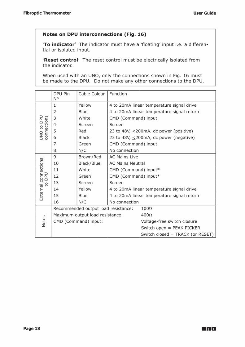
Notes on DPU interconnections (Fig. 16)
‘To indicator’Theindicatormusthavea‘floating’inputi.e.adifferen-tial or isolated input.
‘Reset control’ The reset control must be electrically isolated from the indicator.
When used with an UNO, only the connections shown in Fig. 16 must be made to the DPU. Do not make any other connections to the DPU.
DPU Pin Nº
Cable Colour Function
UN
O t
o D
PU
conn
ectio
ns
1 Yellow 4 to 20mA linear temperature signal drive2 Blue 4 to 20mA linear temperature signal return3 White CMD (Command) input4 Screen Screen5 Red 23 to 48V, <200mA, dc power (positive)6 Black 23 to 48V, <200mA, dc power (negative)7 Green CMD (Command) input8 N/C No connection
Exte
rnal
con
nect
ions
to
DPU
9 Brown/Red AC Mains Live10 Black/Blue AC Mains Neutral11 White CMD (Command) input*12 Green CMD (Command) input*13 Screen Screen14 Yellow 4 to 20mA linear temperature signal drive15 Blue 4 to 20mA linear temperature signal return16 N/C No connection
Not
es
Recommended output load resistance: 100WMaximum output load resistance: 400WCMD (Command) input: Voltage-free switch closure
Switch open = PEAK PICKERSwitch closed = TRACK (or RESET)

Page 19
User Guide Fibroptic Thermometer
5 Laser Alignment Unit
5.1 About the Laser Alignment UnitThe Laser Alignment Unit for Land UNO Fibroptic Thermometers is designed to aidtheinstallationofthethermometeropticheadbydefiningthetargetareaon which the optic head is aligned. This is particularly useful in applications where the target size is small and/or where correct alignment is critical.
TheLaserAlignmentUnitmayalsobeusedforfindingthecorrectdistancefrom the target at which to mount the optic head, as the laser image is sharpest at this point. This distance may not necessarily be the nominal focal distance.
IfyouhaveathermometerfittedwithanA10optichead,thelaserimageprojected by the alignment unit will be an almost full bright spot. For A25 and A50 optic heads, the laser image will consist of many individual bright lightspots,spacedrandomlywithinthefieldofview.
5.2 Laser Alignment Unit SpecificationEmbeddedlaserproductclassification Class1
Laser ‘on’ duration 115 seconds
Laser pulse frequency 2.5Hz, 54% duty cycle
Emission wavelength 635nm
Thermometer performance degradation Noise, Response time and Ambient drift increased by a factor of 2 (for bottom 5% of span only)
Thermometerambienttemperaturelimits 0to40°Cspecifiedandoperating (operation outside these limits will greatly reduce the life expectancy of the laser)
AllotherFibropticThermometerspecificationsareunaffectedbytheLaserAlignment Unit.
Note
If you have a V1 Fibroptic Thermometer, do not rely upon the accuracy of measurements in the bottom 10% of the span of the thermometer when the Laser Alignment Unit is operating.

Page 20
Fibroptic Thermometer User Guide
Fig.18LocationofwarninglabelonthermometerfittedwithLaserAlignmentUnit UN970331
Fig. 19 Location of the Laser Alignment Unit activating switch and LED UN970332
CLASS 1 LASER PRODUCT
MADE IN ENGLAND
TYPE: U1 1100/2900F L 10 A10
SERIAL No. 0000000/00/00
Laser Alignment Unitactivating switch
LED

Page 21
User Guide Fibroptic Thermometer
5.3 Using the Laser Alignment Unit
Warning
Class 1 Laser Product. This laser product does not permit human access to laser radiation in excess of the accessible emission limits of Class 1 for applicable wavelengths and emission durations. Refer to BS EN 60825-1, 1994.Embedded laser (diode) is Class 1M, <5mW. Do not view directlywithopticalmagnifiers.
Caution
Use of controls or adjustments, or performance of procedures otherthanthosespecifiedhereinmayresultinhazardousradiation exposure.
1) Choose a measurement location for the Optic Head (Refer to the Installation Guide and Section 2.1 of this User Guide).
2) Connect the Thermometer to a suitable power supply. WhentheThermometerisfirstswitchedon,theLaserAlignmentUnit
is activated and the target spot is illuminated by red laser light. When the laser is activated, a red LED in the push button on the front of the thermometerflashesforthedurationofthelaser(115seconds).
3) If the Laser Alignment Unit switches off before the optic head is aligned, press the button on the front of the Thermometer. Refer to Fig. 19.
4) Adjust the mounting of the optic head so that the required target is in thefieldofview(i.e.illuminatedbythelaser).Notethatfor'U'seriesUNOFibropticThermometers,thetargetmustfillthefieldofviewcompletely.
5) When the alignment of the optic head is correct, secure the mountings and tighten the optic head lock nuts.
5.4 Laser Alignment Unit maintenanceThe Laser Alignment Unit will operate reliably for years, provided it is operatedwithintheambienttemperaturesgiveninthespecification(RefertoSection 5.2).
If the Laser Alignment Unit develops a fault, return the Thermometer to Land Infrared.

Page 22
Fibroptic Thermometer User Guide
6 Target Size TablesTofindoutwhichtableappliestoyourthermometer:
1) Refer to the detail label, above the lightguide connector on the thermometer,tofindthetypeofoptichead(i.e.A10,A25orA50)fittedto your thermometer.
2) Refertothespecificationtableforyourthermometer,Section1.5,tofindthefieldofview(i.e.25:1or75:1)fortheoptichead.
6.1 Optic Head A10, Field of View 25:1 (Red spacer)
15.0mm0.59in
12.3mm0.48in
9.5mm0.37in
6.8mm0.27in
4.0mm0.16in
8.8mm0.35in
0mm0in
25mm0.98in
50mm1.97in
75mm2.95in
100mm3.94in
125mm4.92in
Target diameter
Target distance
6.2 Optic Head A10, Field of View 75:1 (Red spacer)
14.3mm0.56in
11.1mm0.44in
7.8mm0.31in
4.6mm0.18in
1.3mm0.05in
5.2mm0.20in
0mm0in
25mm0.98in
50mm1.97in
75mm2.95in
100mm3.94in
125mm4.92in
Target diameter
Target distance

Page 23
User Guide Fibroptic Thermometer
6.3 Optic Head A25, Field of View 25:1 (Blue spacer)
0mm0in
50mm1.97in
100mm3.94in
200mm7.87in
250mm9.84in
300mm11.81in
Target diameter
Target distance
150mm5.91in
11.2mm0.44in
11.0mm0.43in
10.7mm0.42in
10.2mm0.40in
10.0mm0.39in
14.2mm0.56in
10.5mm0.41in
6.4 Optic Head A25, Field of View 75:1 (Blue spacer)
0mm0in
50mm1.97in
100mm3.94in
200mm7.87in
250mm9.84in
300mm11.81in
Target diameter
Target distance
150mm5.91in
11.0mm0.43in
9.5mm0.37in
7.9mm0.31in
4.8mm0.19in
3.3mm0.13in
6.2mm0.24in
6.4mm0.25in

Page 24
Fibroptic Thermometer User Guide
6.5 Optic Head A50, Field of View 25:1 (No spacer)
6.6 Optic Head A50, Field of View 75:1 (No spacer)
Target diameter10.3mm0.41in
12.8mm0.50in
15.4mm0.61in
20.5mm0.81in
23.0mm0.91in
26.1mm1.03in
17.9mm0.70in
0mm0in
100mm3.94in
200mm7.87in
400mm15.75in
500mm19.69in
600mm23.62in
Target distance
300mm11.81in
Target diameter10.1mm0.38in
9.4mm0.37in
8.7mm0.34in
7.4mm0.29in
6.7mm0.26in
10.1mm0.38in
8.1mm0.32in
0mm0in
100mm3.94in
200mm7.87in
400mm15.75in
500mm19.69in
600mm23.62in
Target distance
300mm11.81in

Page 25
User Guide Fibroptic Thermometer
7 Emissivity tablesIn order to obtain accurate temperature measurements, the emissivity value of the target surface must be known. This section of the Thermometer User Guide contains emissivity values of the most commonly measured materials for each UNO thermometer. Where no emissivity value is quoted, this means that either the thermometer is not suitable for the measurement application or the temperature of the target is outside the thermometer’s measurement span. If you have a query regarding the emissivity of the target in your measurement application, contact Land Instruments International.
7.1 Refractories
RefractoriesMaterial Thermometer Series
U1 U2 U4Alumina 0.30 0.30 0.30
Brick
red 0.80 0.80 0.80white refractory 0.30 0.35 -silica 0.55 0.60 -sillimanite 0.60 0.60 -
Ceramics 0.40 0.50 -Magnesite - - 0.60
7.2 Alloys
AlloysMaterial Thermometer Series
U1 U2 U4Brass 0.20 0.18 -
oxidised 0.70 0.70 0.70Chromel & Alumel 0.30 0.30 0.30
oxidised 0.80 0.80 0.80Constantin & Manganin 0.25 0.22 0.20
oxidised 0.65 0.60 0.60Inconel 0.30 0.30 0.30
oxidised 0.85 0.85 0.85Monel 0.25 0.22 0.20
oxidised 0.70 0.70 0.70Nichrome 0.30 0.28 -
oxidised 0.85 0.85 0.85

Page 26
Fibroptic Thermometer User Guide
7.3 Metals
MetalsMaterial Thermometer Series
U1 U2 U4Aluminium 0.13 0.09 0.08
oxidised 0.40 0.40 0.40Chromium 0.43 0.34 -
oxidised 0.75 0.80 -Cobalt 0.32 0.28 -
oxidised 0.70 0.65 -Copper 0.06 0.05 0.04
oxidised 0.85 0.85 0.85Gold 0.05 0.02 0.02Iron & Steel 0.35 0.30 -
oxidised 0.85 0.85 0.85Lead 0.35 0.28 -
oxidised 0.65 0.65 0.65Magnesium 0.27 0.24 0.20
oxidised 0.75 0.75 0.75Molybdenum 0.33 0.25 -
oxidised 0.80 0.80 0.80Nickel 0.35 0.25 -
oxidised 0.85 0.85 0.85Palladium 0.28 0.23 -Platinum 0.27 0.22 -Rhodium 0.25 0.18 -Silver 0.05 0.04 0.04
oxidised 0.10 0.10 0.10Tin 0.40 0.28 -
oxidised 0.60 0.60 0.60Titanium 0.55 0.50 -
oxidised 0.80 0.80 -Tungsten 0.39 0.30 -Zinc 0.50 0.32 -
oxidised 0.60 0.55 -

Page 27
User Guide Fibroptic Thermometer
7.4 Miscellaneous
Miscellaneous MaterialsMaterial Thermometer Series
U1 U2 U4Asbestos (board/paper/cloth) 0.90 0.90 -Asphalt 0.85 0.85 -
Carbongraphite 0.85 0.85 -soot 0.95 0.95 -
Cement & Concrete 0.65 0.70 -Cloth - all types, close weave (Open weave reduces emissivity)
0.75 0.80 0.85
Glass
3mm thick - - -6mm thick - - -12mm thick - - -20mm thick 0.80 - -
Page 28
Fibroptic Thermometer User Guide
8 Maintenance
8.1 Optic headAfter initial installation, make regular inspections of the lens in order to establish a cleaning cycle.
If the lens requires cleaning, it is preferable to do so without disconnecting the lightguide from the optic head.
Clean the lens with a soft cloth and a little alcohol if necessary. Take care not to scratch the lens.
8.2 Air supplyIfanairpurgeisusedwiththeFibropticthermometer,theairfiltermustbechecked and cleaned at regular intervals, determined by the cleanliness of the air supply.
Checkthefilterdailyforthefirstweekortwoandthen,dependingonexperience, move to a weekly or monthly routine.

PRODUCT WARRANTYThank you for purchasing your new product from Land Instruments International. This Land manufacturer’s ‘back-to-base’ warranty covers product malfunctions arising from defects in design or manufacture. The warranty period commences on the instrument despatch date from the Land Instruments International Ltd. factory in Dronfield, UK.
36 MONTHS WARRANTYBuilding upon the reputation for reliability and longevity that System 4 and UNO thermometers have earned, Land are delighted to be able to provide our customers with an industry-leading 36 month warranty for the following products:-• SPOT thermometers, accessories* and mountings* and special instruments based on SPOT.
*Note: SPOT Actuators are provided with an 18 months Warranty.
• System 4 thermometers, processors, accessories and mountings and special instruments based on System 4.
• UNO thermometers, accessories and mountings and special instruments based on UNO.• Application-dedicated processors based on LANDMARK® Graphic.• ABTS/S and ABTS/U• FTS• VDT/S and VDT/U• DTT• FLT5/A
This 36 month warranty is provided as standard for all orders for the products listed above received from 1st May 2002.We believe that our customers expect us to set the standard in terms of performance, quality, reliability and value for money. This 36 months warranty, as a part of an on-going program of continuous improvement, is just one way in which Land strive to maintain our position as the temperature measurement partner of choice.
24 MONTHS WARRANTYThe following Land Instruments International products are provided with a 24 months warranty:
• ARC• FTI-E
• NIR
18 MONTHS WARRANTYThe following Land Instruments International products are provided with an 18 months warranty:
• SPOT Actuator
12 MONTHS WARRANTYAll Land Instruments International products not provided with either a 36, 24 or 18 month warranty (see lists above), are provided with a 12 months warranty.

PRODUCT WARRANTYEXCLUSIONS FROM WARRANTY
It should be noted that costs associated with calibration checks which may be requested during the warranty period are not covered within the warranty.Land reserve the right to charge for service/calibration checks undertaken during the warranty period if the cause is deemed to fall outside the terms of the warranty.This Land manufacturer’s warranty does not cover product malfunction arising from:-• incorrect electrical wiring.• connection to electrical power sources outside the rating of the product.• physical shock (being dropped, etc.) and impact damage.• inappropriate routing, support, physical shock & strain protection, etc. of the lightguide (Fibroptic
thermometers only).• environmental conditions exceeding the IP / NEMA rating of the product.• environmental conditions outside the Ambient Temperature, Humidity and Vibration rating of the product.• environmental contamination (solvent vapours, deposition of airborne contamination, cooling liquids of
non-neutral pH, etc.).• overheating as a result of interruption of water/air flow through cooling jackets or of incorrect installation.• inappropriate modification of product (drilling holes in thermometer bodies, etc.).• inappropriate recalibration which results in product calibration being taken outside specification.• improper resealing of thermometer following parameter adjustment (UNO, FLT5/A, etc.).• attempted repair by a non-Land-authorised repair centre.Land Instruments International Ltd • Dronfield S18 1DJ • England • Tel: +44 (0) 1246 417691 • Fax: +44 (0) 1246 410585 Email: [email protected] • www.landinst.comAMETEK Land, Inc . • 150 Freepor t Rd. • P i t t sburgh, PA 15238 • U.S.A. • Te l : +1 (412) 826 4444 Email: [email protected] • www.ametek-land.com
For a complete list of our international offices, please visit www.landinst.com Issue 5: 14 February 2018
MARCOM0290