Behaviour on bus voltage failure/reset - Futurasmus KNX Group
Upload
khangminh22Category
view
0download
0
18
KNX Catalogue
KN
X C
ATA
LOG
UE
20
18

248SMART VISU SERVER Visualisation solution for the smart home
06KNX The worldwide uniform standard
22PUSH-BUTTON SENSORS Product families F 50 and F 40
188MULTISTATION Compact device for the distribution

ACTUATORS / COMBINATION DEVICES
Actuators for rail mounting 162
Multistation 188
Flush mounting actuators 192
BINARY INPUTS
Binary inputs 202
ENERGY SENSOR
Energy sensor 206
MULTIROOM/AUDIO
Multiroom amplifier 210
Sonos Gateway 216
WEATHER STATIONS
Weather stations 220
SIGNALLING SYSTEM
Signalling System 230
VISUALISATION/OPERATION
Signal panel 236
Smart Panel 238
Smart Controls 242
Smart Visu Server 248
JUNG Visu Pro 256
JUNG Visu Pro Server 260
DOOR COMMUNICATION
Door communication and KNX 264
COMPANY
Progress as tradition 02
INTRODUCTION
When is a building smart? 04
KNX as worldwide standard 06
Functions and applications 08
Reference projects 10
TOPOLOGY
The JUNG KNX system 16
PUSH-BUTTON SENSORS/ ROOM CONTROLLER
Operate KNX in the JUNG design 18
Graphic Tool 20
F 50 family 22
F 40 family 50
Room controller 70
KNX RF 80
ROTARY SENSORS/PUSH-BUTTON BCU
Rotary sensors 88
Push-button BCU 94
ROOM AUTOMATION
Presence Detector Mini 116
Presence detector/ceiling observer 122
Automatic switch 126
Room thermostat 132
SYSTEM DEVICES
System design 146
COMMUNICATION/GATEWAYS
DALI-Gateway 158
Table of contents
Index 266
Sales terms and delivery conditions 271
Further information 272
CONTENTS 1

2 COMPANY
Company founder Albrecht Jung
Ernst Paris

COMPANY 3
Medium sized third generation
family company
WE ARE JUNG:
1912 “Made in Germany”
for more than 100 years.
17 subsidiaries and over
70 agencies worldwideAround 1,200 employees
When Albrecht Jung founded his company in 1912, three things
were already important to him: progress, quality and design.
These principles have characterised JUNG to date and are
noticeable and can be experienced in all parts of the company.
“Progress as tradition” is an attitude, the commitment to con-
stant new thinking. A commitment to the development of ideas
that create something new, for easier use, better functionality,
more attractive appearance and more customer-friendly service.
This motivates and unites us at JUNG. Every day.
Progress as tradition. Every day.

When is a building smart?
When all its functions of modern building system technology
are practically interlinked and communicate with each other.
This means extra comfort, cost-effectiveness, safety and energy
efficiency. Our solutions are based on the global KNX standard
and are therefore absolutely future-proof. From the easy to
use control element to the complex system, the JUNG KNX
components provide comprehensive, future-proof solutions
for control, visualisation and organisation of the building
system technology. Areas such as lighting, shade, heating /
air conditioning, surveillance / security, multimedia and smart
metering are completely covered here.
From the basic configuration to the high-end comfort solution,
everything is possible. The professional JUNG KNX technology
can be adapted to new requirements at any time.
4 INTRODUCTION
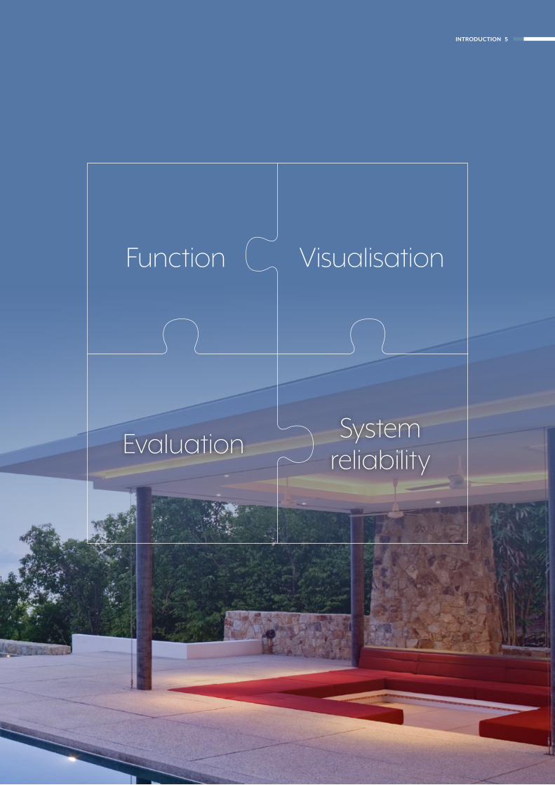
INTRODUCTION 5
Evaluation
Function Visualisation
System reliability

Date: May 2018
28 years of experience
FACTS AND FIGURES
199076.392 partners in
164 countries
444 training centres in
68 countries
442 manufacturers in
44 countries
KNX is the only globally recognised standard for building system
technology. The European standard EN 50090 has become
established as global standard according to ISO / IEC 14543-3.
The „KNX“ label makes clear the system compatibility of the
products of all manufacturers.
KNX – the worldwide systematic standard
6 INTRODUCTION

FUTURE-PROOF
KNX as building system technology is consistently further
developed. As international standard, KNX is future-
oriented and guarantees constant upgradeability when
new components appear, also manufacturer-independent.
INVESTMENT SECURITY
High quality, certified KNX products and the global standardi-
sation guarantee a sustainable investment in a long-lasting
system. The KNX system has existed for more than 25 years
and first generation devices are still compatible with the latest
KNX products.
SYSTEM RELIABILITY
Products with the KNX logo „speak and understand“ the KNX
language. They are programmed and put into operation
using the manufacturer-independent Engineering Tool (ETS™).
Strict KNX interworking rules ensure that the certified products
of different manufacturers can communicate with each other
in various applications. KNX has standardised complete
sets of data types for a large number of functions for this.
DECENTRALISED SYSTEM DESIGN
KNX functions as a modular system. Network and building
technology can thus be expanded and rebuilt in any way
at any time. Customised and economic solutions can always
be found for small or large projects, modernisation or new
construction.
INTRODUCTION 7

Life in the smart home: Functions and applications
KNX is the future-proof solution for the professional smart home:
the lighting scene in the living room matches the well-being
temperature perfectly. It stays pleasantly cool in the bedroom
because the shutters automatically descend during sunlight.
The favourite music can be heard in every room thanks to multi-
rooming. With intelligent technology from JUNG.
8 INTRODUCTION

LIGHTING
Individual control of the indoor and
outdoor lighting. Automatically, as
needed and thus energy saving.
BLINDS AND SHUTTERS
The automatic control of blinds and
shutters including louvre adjustment
is regulated by sunlight. The control is
performed centrally or decentralised.
MONITORING/ALARMING
Sensors for monitoring windows
and doors, central on/off controls
and notification and alarm systems
give a secure feeling.
HEATING, VENTILATION,
AIR CONDITIONING
Demand-based control of heating,
ventilation and air conditioning
ensure not only the individual well-
being temperature but also a healthy
room climate.
MULTIMEDIA
Multi-rooming in the entire house, TV
and entertainment systems and multi-
media components are integrated in
KNX.
VISUALISATION AND
REMOTE CONTROL
Display and operate all states in your
own home using touch displays. Also
when on the move from smart phones
and tablets.
INTRODUCTION 9

House at Achalm, Reutlingen
Architect: ALEXANDER BRENNER ARCHITEKTEN
Fitted with JUNG KNX technology
in the LS 990 design.
© Z
OO
EY
BR
AU
N
10 INTRODUCTION

Smart building technology in prestigious architecture – combined
in one high requirement: always only the best. Owners in the
whole world have confidence in the intelligent KNX technology
for their homes. Realised in the versatile JUNG design, pure
aesthetics become cultivated objectivity.
Cultivated objectivity
INTRODUCTION 11

Smart and economical
PHOTOS: © HENRIK SCHIPPER (TOP LEFT) © BENEDIKT KRAFT (BOTTOM LEFT/ BOTTOM RIGHT)
Investment security is the main argument for the decision for
building automation in office and administrative building
construction. It should be economic, energy-efficient and
functional. Also important: Flexibility in adaptation to changing
renting situations. The good thing here is that owners and plan-
ners worldwide can rely here on the smart KNX solutions of JUNG.
12 INTRODUCTION

Dreischeibenhaus, Düsseldorf
Architect: HPP Hentrich –
Petschnigg & Partner
Fitted with JUNG KNX technology
in the LS 990 design.
INTRODUCTION 13
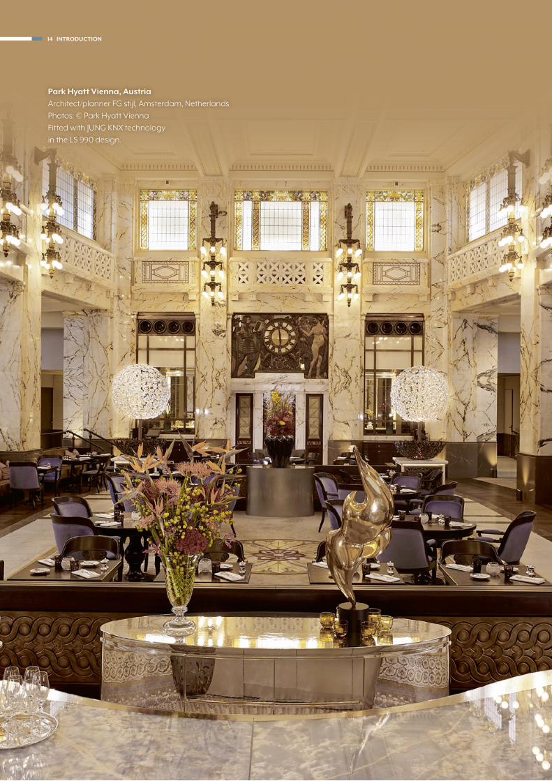
Park Hyatt Vienna, Austria
Architect/planner FG stijl, Amsterdam, Netherlands
Photos: © Park Hyatt Vienna
Fitted with JUNG KNX technology
in the LS 990 design.
14 INTRODUCTION
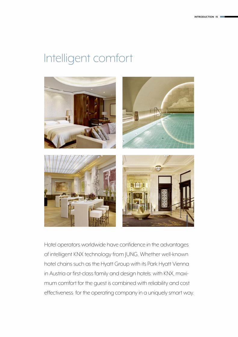
Hotel operators worldwide have confidence in the advantages
of intelligent KNX technology from JUNG. Whether well-known
hotel chains such as the Hyatt Group with its Park Hyatt Vienna
in Austria or first-class family and design hotels: with KNX, maxi-
mum comfort for the guest is combined with reliability and cost
effectiveness for the operating company in a uniquely smart way.
Intelligent comfort
INTRODUCTION 15

KNX line
Weather station
Signal panel
Rotary sensor
Push-button sensor
Push-button BCU
Room thermostat
External system
Room controller
CO2 sensor
CO2
Presence detector
Automatic switch with alarm indicator
Wind sensor
Control with touch display
Multiroom amplifier
Power supply
Media converter
Line coupler
IP interface
Sonos Gateway
Blinds actuator
Dimming actuator
Switch actuator
Heating actuator
DALI Gateway
Visu Pro Server /Visu Pro Software
Smart Visu Server
Aut
omat
ic s
enso
rs
Central control Ma
nual senso
rs
Gateways
Act
uato
rs
System
devices
Systematically linked: the JUNG KNX system
16 TOPOLOGY

116 AUTOMATIC SENSORS
Presence detectors, weather stations or room thermostats, among other things, convert physically measured factors into electrical values, process these and send a telegram on the KNX bus for implementation of the relevant commands.
22 MANUAL SENSORS
The execution of the commands and implementation of the physical states for the manual sensors are performed manually by pressing buttons or rotary movements. The information is forwarded via the KNX bus to the implementing devices.
236 CENTRAL CONTROL
The various KNX central control units form the node for networking and common control of all KNX functions, both room-related as well as for the entire building.
162 ACTUATORS
Actuators receive information from the sensors, execute com-mands and feed back current states to the display elements of the sensors. Appropriate actuators in different designs are available in the JUNG KNX system for every application.
158 GATEWAYS
The KNX gateways form an interface between KNX and an exter-nal network. Thereby, they translate the incoming and outgoing messages and transfer the data of the two different networks.
146 SYSTEM DEVICES
The different KNX system devices are needed for the establish-ment of the bus structure (line and area couplers), as interfaces for the programming and operation of the KNX installation.
TOPOLOGY 17

THE F 50 COMPACT ROOM CONTROLLER
LS 990 in black/chrome
Operate KNX in the JUNG design
18 PUSH-BUTTON SENSORS / ROOM CONTROLLERS

PUSH-BUTTON SENSOR F 50 PUSH-BUTTON SENSOR F 40
PUSH-BUTTON BCU ROTARY SENSOR
As for a conventional rotary dimmer: turn, press, initiate function.
Simply press: large buttons for control of the building technology.
Looks like a usual switch; however controls smart KNX functions.
Operating buttons on the left and right, large cover in the middle.
When the design makes the operation self-explanatory: the
KNX sensors in the JUNG design. High-quality materials and
clear forms complement the concept with style.
PUSH-BUTTON SENSORS / ROOM CONTROLLERS 19
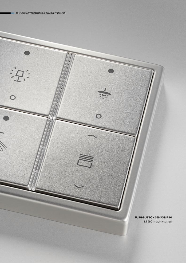
PUSH-BUTTON SENSOR F 40
LS 990 in stainless steel
20 PUSH-BUTTON SENSORS / ROOM CONTROLLERS

Clear labelling
JUNG components are labelled according to individual re-
quirements using the Graphic Tool. Using laser engraving or
colour printing process depending on material and colour.
Whether manufactured for the entire building or for one
piece. Inscription fields can also be printed independently
above the labelling.
LASER ENGRAVING
Precise erosion of the surface for a particularly valued appearance: the finest contours of symbols and texts must also be realised using laser engraving. A striking form of product refinement, particularly for the metal variants.
Labelling in the catalogue part:
COLOUR PRINTING
Easily integrate the design of the electrical installation in the own corporate design – using abrasion-resistant colour printing. Symbols, individual texts and patterns also give the elements an unmistakeable look.
Labelling in the catalogue part:
LABELLING
Many Jung products have an integrated labelling field. These can be printed with text or symbols using the labelling. The functions of KNX sensors and more are clearly identified.
Graphic-Tool on-line: jung.de/gt
L
P
PUSH-BUTTON SENSORS / ROOM CONTROLLERS 21

The F 50 sensors provide plenty of space on the concise
information area for individual marking with the graphic tool.
Operation is then via the buttons arranged at the side.
PUSH-BUTTON SENSOR F 50
LS 990 in aluminium/chrome
22 PUSH-BUTTON SENSORS/ROOM CONTROLLER

The F 50 family
PUSH-BUTTON SENSORS
For the control of functions and scenes. The scope of delivery includes the transparent design with a large labelling area as standard; this can optionally be replaced with a coloured version.
COMPACT ROOM CONTROLLER
Impressive thanks to an intuitive operating
concept and two integrated temperature
controllers. The backlit LC display clearly legibly
shows the most important values and functions.
PUSH-BUTTON SENSORS RF
KNX RF is the manufacturer-independent KNX
wireless standard. These push-button sensors
have the same operating concept and design
as the well-known push-button sensors with
twisted pair connection.
ROOM TEMPERATURE CONTROLLER
Device for individual room temperature control. The preference can be changed to the push- button sensor functions of switching, dimming, blinds, transducers, or scenes.
PUSH-BUTTON SENSORS/ROOM CONTROLLER 23

PUSH-BUTTON SENSOR F 50
LS ZERO in aluminium
24 PUSH-BUTTON SENSORS/ROOM CONTROLLER

Individual button assignment
TWO BUTTONS OPERATION TWO BUTTONS OPERATION
ONE BUTTON OPERATION ONE BUTTON OPERATION
Possible in one or two button operation
Two functions (operation up/down)
Four functions (toggle)
Two functions (operation left/right)
For the Standard and Universal F 50 push-button sensors two
operating modes can always be set: one button operation and
two buttons operation. In the case of the two buttons variant,
the operation can be optionally programmed for up/down or
left/right. Horizontal mounting with appropriate button assign-
ment can also be realised.
1 3
2 4
1 2
3 4
PUSH-BUTTON SENSORS/ROOM CONTROLLER 25

Illuminating: the RGB LEDs
Universal F 50 push-button sensors have one operation LED
and a status LED per button. These can be freely set in red,
green and blue. The LEDs and the illuminated labelling area
can each be adjusted for brightness so that, for example, one
LED can be used as pilot light.
THE F 50 COMPACT ROOM CONTROLLER
A creation in black with glass frame
26 PUSH-BUTTON SENSORS/ROOM CONTROLLER
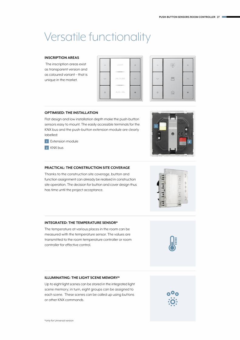
Versatile functionality
INSCRIPTION AREAS
The inscription areas exist
as transparent version and
as coloured variant – that is
unique in the market.
PRACTICAL: THE CONSTRUCTION SITE COVERAGE
Thanks to the construction site coverage, button and
function assignment can already be realised in construction
site operation. The decision for button and cover design thus
has time until the project acceptance.
INTEGRATED: THE TEMPERATURE SENSOR*
The temperature at various places in the room can be
measured with the temperature sensor. The values are
transmitted to the room temperature controller or room
controller for effective control.
ILLUMINATING: THE LIGHT SCENE MEMORY*
Up to eight light scenes can be stored in the integrated light
scene memory; in turn, eight groups can be assigned to
each scene. These scenes can be called up using buttons
or other KNX commands.
*only for Universal version
OPTIMISED: THE INSTALLATION
Flat design and low installation depth make the push-button
sensors easy to mount. The easily accessible terminals for the
KNX bus and the push-button extension module are clearly
labelled:
1 Extension module
2 KNX bus
1
2
LICHT
JALOUSIE
AUS / AN
PUSH-BUTTON SENSORS/ROOM CONTROLLER 27

Efficient and flexible: push-button extension module F 50
- 40 %
COST SAVING
In comparison with exclusive
use of push-button sensors in
the KNX installation shown, the
saving is 40%.
PUSH-BUTTON EXTENSION MODULE
The functions can be extended by connecting the 1- to 4-gang push-button extension module,
while at the same minimising the load on the bus. Particularly the option for installation of the
extension module at a distance of up to 30 m provides more flexibility.
Compact room controller
ROOM 1 ROOM 2 ROOM 3
Compact room controller
Extension module Extension module
max. 30 m max. 30 m
KNX line
28 PUSH-BUTTON SENSORS/ROOM CONTROLLER

Basic module
Extension module
KNX line
PUSH-BUTTON SENSORS/ROOM CONTROLLER 29

High quality materials, distinctive forms and a wide variety of
colours determine the JUNG design. The AS, A, CD and LS ranges
give the KNX sensors their attractive appearance. They can be
selected to match the ambiance for each room.
Variety of designs
LS 990 A CREATION
CD 500 AS 500
30 PUSH-BUTTON SENSORS/ROOM CONTROLLER

The 1, 2, 3 and 4-gang F 50 modules are available in the
JUNG design; also the corresponding 1 to 4-gang Cover kits.
The transparent or coloured labelling field is optionally added
to this. The design frames of the various ranges round off the
concept.
Modular system
USING THE LS RANGE AS EXAMPLE
1 Supporting ring
2 Plastering adapter
3 Frame
4 Push-button module
5 Cover kit
6 Labelling field
1
3
2
4
5
1-gang
2-gang
3-gang
transparent
coloured
4-gang
6
LS 990
LS-design
LS plus
LS ZERO
PUSH-BUTTON SENSORS/ROOM CONTROLLER 31

32
KNX
Standard push-button moduleincluding transparent cover ref.-no.: A 50 NA Intended use • Operation of loads, e.g. light on/off, dimming, blinds up/down, calling up and saving light scenes, etc. • Installation in flush-box according to DIN 49073
Product characteristics • Push-button functions for switching, dimming, blinds control, valuators, light scenes, etc. • To be completed with cover kit • Inscription field • One red status LED for a pair of buttons • One operation LED as orientation light and programming status – red, green or blue, adjustable • Energy saving mode • Integrated bus coupling unit • Transparent cover kit (included) for temporary site use without design covers
Ref.-no.
Push-button modules F 50
Standard push-button module, 1-gangfor cover kit 1-gang, complete, ref.-no.: A 501 TSA ..ETS product family: Push-buttonProduct type: 1-gang push-button
A 5071 TSM
Standard push-button module, 2-gangfor cover kit 2-gang, complete, ref.-no.: A 502 TSA ..ETS product family: Push-buttonProduct type: 2-gang push-button
A 5072 TSM
Standard push-button module, 3-gangfor cover kit 3-gang, complete, ref.-no.: A 503 TSA ..ETS product family: Push-buttonProduct type: 3-gang push-button
A 5073 TSM
Standard push-button module, 4-gangfor cover kit 4-gang, complete, ref.-no.: A 504 TSA ..ETS product family: Push-buttonProduct type: 4-gang push-button
A 5074 TSM

Universal push-button moduleincluding transparent cover ref.-no.: A 50 NAIntended use • Operation of loads, e.g. light on/off, dimming, blinds up/down, brightness values, temperatures, calling up and saving light scenes, etc. • Installation in flush-box according to DIN 49073
Product characteristics • Push-button functions for switching, dimming, blinds control, valuators, light scenes, etc. • One or two functions per button • To be completed with cover kit • Inscription field can be illuminated • One status LED per button, red, green or blue, adjustable • One operation LED as orientation light and programming status – red, green or blue, adjustable • Brightness of status LED, operation LED and inscription field adjustable, can be changed during operation, e.g. during night times • Measurement of room temperature • Extension unit for room temperature controller • Disabling function: Disabling or change function mode of single or all button functions • Alarm function, optional acknowledge by pressing any button • Energy saving mode • Integrated bus coupling unit • Connection for a push-button extension module, 1-4 gang • Transparent cover kit (included) for temporary site use without design covers
33
Ref.-no.
KNXPush-button modules F 50
Universal push-button module, 1-gangfor cover kit 1-gang, complete, ref.-no.: A 501 TSA ..can be extended by means of a push-button extension module, ref.-no.: A 509.. TSEMETS product family: Push-buttonProduct type: 1-gang push-button
A 5091 TSM
Universal push-button module, 2-gangfor cover kit 2-gang, complete, ref.-no.: A 502 TSA ..can be extended by means of a push-button extension module, ref.-no.: A 509.. TSEMETS product family: Push-buttonProduct type: 2-gang push-button
A 5092 TSM
Universal push-button module, 3-gangfor cover kit 3-gang, complete, ref.-no.: A 503 TSA ..can be extended by means of a push-button extension module, ref.-no.: A 509.. TSEMETS product family: Push-buttonProduct type: 3-gang push-button
A 5093 TSM
Universal push-button module, 4-gangfor cover kit 4-gang, complete, ref.-no.: A 504 TSA ..can be extended by means of a push-button extension module, ref.-no.: A 509.. TSEMETS product family: Push-buttonProduct type: 4-gang push-button
A 5094 TSM

34
KNX
Ref.-no.
Push-button modules F 50
Room temperature controller module 2-gangincluding transparent cover and inlay with symbolsfor cover kit 2-gang, complete, ref.-no.: A 502 TSA ..
Intended use • Single-room temperature control in KNX installations • Operation of loads, e.g. light on/off, dimming, blinds up/down, recalling and saving light scenes, etc. • Installation in wall box according to DIN 49073
Product characteristicsAll buttons can be assigned with push-button sensor functions or functions for controller operation. • Measurement of the room temperature • Room temperature control with setpoint value specification • Extension for room temperature controller • Push-button functions switching, dimming, blind control, value transmitter, scene recall, etc. • One or two functions per button • Completion with cover kit 2-gang • Illuminable inscription field • Two red status LEDs per button – red, green or blue adjustable • One operation LED as an orientation light and to indicate the programming status – red, green or blue adjustable • Brightness of status LED, operation LED and labelling field adjustable; switchable while in operation, e.g. during the night • Disabling function: Disable or function switch-over of all or of individual push-button functions • Alarm function, optionally with confirmation by pressing any button • Energy saving mode (for operation without controller function) • Integrated bus coupling unit • Connection for a push-button extension module, for extension with up to eight additional buttons
A 5178 TSM
Push-button extension moduleincluding transparent cover ref.-no.: A 50 NAfor the extension of the Universal push-button module (ref.-no.: A 509.. TSM) and room temperature controller module (ref.-no.: A 5178 TSM) with up to 4 additional push-buttons
Product characteristics • One or two functions per button • To be completed with cover kit • Inscription field can be illuminated • One status LED per button, red, green or blue, adjustable • One operation LED as orientation light and programming status – red, green or blue, adjustable • Brightness of status LED, operation LED and inscription field adjustable, can be changed during operation, e.g. during night times • Measurement of room temperature • Extension unit for room temperature controller • Disabling function: Disabling or change function mode of single or all button functions • Alarm function, optional acknowledge by pressing any button • Energy saving mode • Transparent cover kit (included) for temporary site use without design covers • Cable lenghts: max. 30 m, cable type: J-Y(St)Y 2 x 2 x 0.8 mm2
1-gang A 5091 TSEM2-gang A 5092 TSEM3-gang A 5093 TSEM4-gang A 5094 TSEM

35
Ref.-no.
KNXPush-button modules F 50
Room controller display compact module 2-gangfor cover kit 2-gang, complete, ref.-no.: A 502 TSA ..can be extended by means of a room controllerextension module, ref.-no.: A 5178 TSEMcan be extended by means of a push-button extension module, ref.-no.: A 509.. TSEM
recommended mounting height: 1.5 m
A 5192 KRM TS D
Room controller display compact module 4-gangfor cover kit 4-gang, complete, ref.-no.: A 504 TSA ..can be extended by means of a room controllerextension module, ref.-no.: A 5178 TSEMcan be extended by means of a push-button extension module, ref.-no.: A 509.. TSEM
recommended mounting height: 1.5 mIntended use • Measurement and feedback control of the room temperature • Operation of loads, e.g. light on/off, dimming, blinds up/down, brightness values, temperatures, calling up and saving light scenes, etc. • Installation in wall box according to DIN 49073
Product characteristicsEach button can be used for push-button sensor of contoller functions. • Backlit LC display • One or two functons per button • To be completed with cover kit • Eight status LED – red, green or blue • Brightness of status LED and LCD adjustable • Integrated bus coupling unit • Connection of extension modules • Integrated room temperature sensor • External sensor (ref.-no.: FF 7.8) can be connected • Room temperature control with setpoint value specification • Two internal independent controllers for two independent areas – in connection with extension modules • Display of room or set temperature (°C or °F) • Display of outdoor temperature – with external sensor, e.g. weather station • Display of time, in conjunction with KNX time encoder • Push-button function or rocker function • Inhibit function: blocking or change of function of the entire or single button functions • Alarm function, optional with acknowledge by pressing any button
A 5194 KRM TS D
Room controller extension module 2-gangfor cover kit 2-gang, complete, ref.-no.: A 502 TSA ..for the extension of a room controller module (ref.-no.: A 5192 KRM TS D, A 5194 KRM TS D) with a second room temperature control unit
Intended use • Operation of loads, e.g. light on/off, dimming, blinds up/down, brightness values, temperatures, calling up and saving light scenes, etc. • Measurement of room temperature • Extension for room controller modules (.. 5192 KRM TS D, .. 5194 KRM TS D) • Installation in wall box according to DIN 49073 • Cable lenghts: max. 30 m, cable type: J-Y(St)Y 2 x 2 x 0.8 mm2
A 5178 TSEM
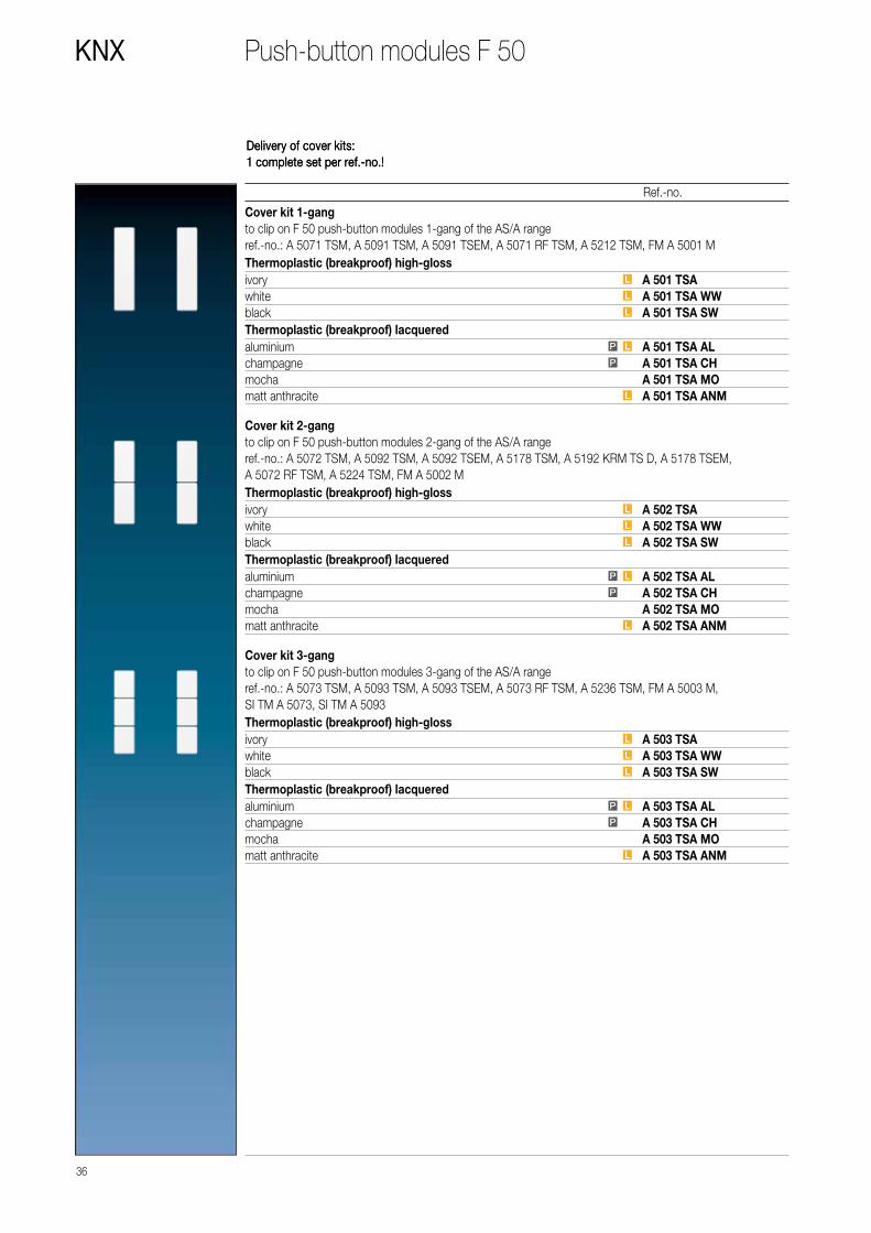
Delivery of cover kits:1 complete set per ref.-no.!
36
KNX
Ref.-no.
Push-button modules F 50
Cover kit 1-gangto clip on F 50 push-button modules 1-gang of the AS/A rangeref.-no.: A 5071 TSM, A 5091 TSM, A 5091 TSEM, A 5071 RF TSM, A 5212 TSM, FM A 5001 MThermoplastic (breakproof) high-glossivory L A 501 TSAwhite L A 501 TSA WWblack L A 501 TSA SWThermoplastic (breakproof) lacqueredaluminium P L A 501 TSA ALchampagne P A 501 TSA CHmocha A 501 TSA MOmatt anthracite L A 501 TSA ANM
Cover kit 2-gangto clip on F 50 push-button modules 2-gang of the AS/A rangeref.-no.: A 5072 TSM, A 5092 TSM, A 5092 TSEM, A 5178 TSM, A 5192 KRM TS D, A 5178 TSEM, A 5072 RF TSM, A 5224 TSM, FM A 5002 MThermoplastic (breakproof) high-glossivory L A 502 TSAwhite L A 502 TSA WWblack L A 502 TSA SWThermoplastic (breakproof) lacqueredaluminium P L A 502 TSA ALchampagne P A 502 TSA CHmocha A 502 TSA MOmatt anthracite L A 502 TSA ANM
Cover kit 3-gangto clip on F 50 push-button modules 3-gang of the AS/A rangeref.-no.: A 5073 TSM, A 5093 TSM, A 5093 TSEM, A 5073 RF TSM, A 5236 TSM, FM A 5003 M, SI TM A 5073, SI TM A 5093Thermoplastic (breakproof) high-glossivory L A 503 TSAwhite L A 503 TSA WWblack L A 503 TSA SWThermoplastic (breakproof) lacqueredaluminium P L A 503 TSA ALchampagne P A 503 TSA CHmocha A 503 TSA MOmatt anthracite L A 503 TSA ANM
Delivery of cover kits:1 complete set per ref.-no.!

Cover kit 4-gangto clip on F 50 push-button modules 4-gang of the AS/A rangeref.-no.: A 5074 TSM, A 5094 TSM, A 5094 TSEM, A 5194 KRM TS D, A 5074 RF TSM, A 5248 TSM, FM A 5004 M, ZLL A 5004 MThermoplastic (breakproof) high-glossivory L A 504 TSAwhite L A 504 TSA WWblack L A 504 TSA SWThermoplastic (breakproof) lacqueredaluminium P L A 504 TSA ALchampagne P A 504 TSA CHmocha A 504 TSA MOmatt anthracite L A 504 TSA ANM
Professional inscription see www.jung.de/gt
37
Ref.-no.
KNXPush-button modules F 50
Transparent cover with paper inlay(Spare part)to clip on F 50 push-button modules of the AS/A rangeref.-no.: A 507.. TSM, A 509.. TSM, A 509.. TSEM, A 5178 TSM, A 51.. KRM TS D, A 5178 TSEM, A 507.. RF TSM, A 52.. TSM, FM A 50.. M, ZLL A 5004 MAlso included in delivery of modules.inscription field 25 x 52.5 mmpaper inlay pearly A 50 NA
Neutral coverto clip on F 50 push-button modules of the AS/A rangeref.-no.: A 507.. TSM, A 509.. TSM, A 509.. TSEM, A 5178 TSM, A 51.. KRM TS D, A 5178 TSEM, A 507.. RF TSM, A 52.. TSM, FM A 50.. M, ZLL A 5004 Mdimensions: 25 x 55 mmThermoplastic (breakproof) high-glossivory L A 50 NA Wwhite L A 50 NA WWblack L A 50 NA SWThermoplastic (breakproof) lacqueredaluminium P L A 50 NA ALchampagne P A 50 NA CHmocha A 50 NA MOmatt anthracite L A 50 NA ANM
PP
LL
Colour printing possibleLaser labelling possible
38
KNX
Ref.-no.
Push-button modules F 50
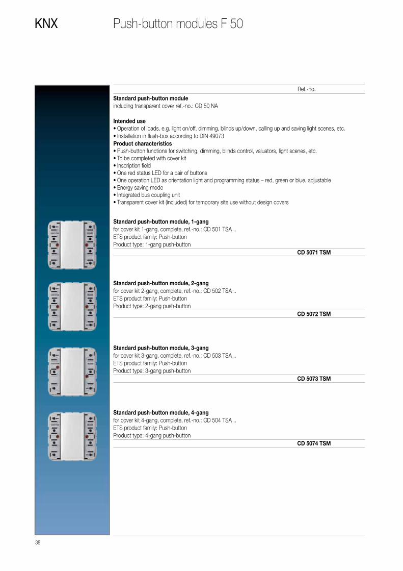
Standard push-button moduleincluding transparent cover ref.-no.: CD 50 NA Intended use • Operation of loads, e.g. light on/off, dimming, blinds up/down, calling up and saving light scenes, etc. • Installation in flush-box according to DIN 49073
Product characteristics • Push-button functions for switching, dimming, blinds control, valuators, light scenes, etc. • To be completed with cover kit • Inscription field • One red status LED for a pair of buttons • One operation LED as orientation light and programming status – red, green or blue, adjustable • Energy saving mode • Integrated bus coupling unit • Transparent cover kit (included) for temporary site use without design covers
Standard push-button module, 1-gangfor cover kit 1-gang, complete, ref.-no.: CD 501 TSA ..ETS product family: Push-buttonProduct type: 1-gang push-button
CD 5071 TSM
Standard push-button module, 2-gangfor cover kit 2-gang, complete, ref.-no.: CD 502 TSA ..ETS product family: Push-buttonProduct type: 2-gang push-button
CD 5072 TSM
Standard push-button module, 3-gangfor cover kit 3-gang, complete, ref.-no.: CD 503 TSA ..ETS product family: Push-buttonProduct type: 3-gang push-button
CD 5073 TSM
Standard push-button module, 4-gangfor cover kit 4-gang, complete, ref.-no.: CD 504 TSA ..ETS product family: Push-buttonProduct type: 4-gang push-button
CD 5074 TSM

39
Ref.-no.
KNXPush-button modules F 50
Universal push-button moduleincluding transparent cover ref.-no.: CD 50 NAIntended use • Operation of loads, e.g. light on/off, dimming, blinds up/down, brightness values, temperatures, calling up and saving light scenes, etc. • Installation in flush-box according to DIN 49073
Product characteristics • Push-button functions for switching, dimming, blinds control, valuators, light scenes, etc. • One or two functions per button • To be completed with cover kit • Inscription field can be illuminated • One status LED per button, red, green or blue, adjustable • One operation LED as orientation light and programming status – red, green or blue, adjustable • Brightness of status LED, operation LED and inscription field adjustable, can be changed during operation, e.g. during night times • Measurement of room temperature • Extension unit for room temperature controller • Disabling function: Disabling or change function mode of single or all button functions • Alarm function, optional acknowledge by pressing any button • Energy saving mode • Integrated bus coupling unit • Connection for a push-button extension module, 1-4 gang • Transparent cover kit (included) for temporary site use without design covers
Universal push-button module, 1-gangfor cover kit 1-gang, complete, ref.-no.: CD 501 TSA ..can be extended by means of a push-button extension module, ref.-no.: CD 509.. TSEMETS product family: Push-buttonProduct type: 1-gang push-button
CD 5091 TSM
Universal push-button module, 2-gangfor cover kit 2-gang, complete, ref.-no.: CD 502 TSA ..can be extended by means of a push-button extension module, ref.-no.: CD 509.. TSEMETS product family: Push-buttonProduct type: 2-gang push-button
CD 5092 TSM
Universal push-button module, 3-gangfor cover kit 3-gang, complete, ref.-no.: CD 503 TSA ..can be extended by means of a push-button extension module, ref.-no.: CD 509.. TSEMETS product family: Push-buttonProduct type: 3-gang push-button
CD 5093 TSM
Universal push-button module, 4-gangfor cover kit 4-gang, complete, ref.-no.: CD 504 TSA ..can be extended by means of a push-button extension module, ref.-no.: CD 509.. TSEMETS product family: Push-buttonProduct type: 4-gang push-button
CD 5094 TSM

40
KNX
Ref.-no.
Push-button modules F 50
Room temperature controller module 2-gangincluding transparent cover and inlay with symbolsfor cover kit 2-gang, complete, ref.-no.: CD 502 TSA ..
Intended use • Single-room temperature control in KNX installations • Operation of loads, e.g. light on/off, dimming, blinds up/down, recalling and saving light scenes, etc. • Installation in wall box according to DIN 49073
Product characteristicsAll buttons can be assigned with push-button sensor functions or functions for controller operation. • Measurement of the room temperature • Room temperature control with setpoint value specification • Extension for room temperature controller • Push-button functions switching, dimming, blind control, value transmitter, scene recall, etc. • One or two functions per button • Completion with cover kit 2-gang • Illuminable inscription field • Two red status LEDs per button – red, green or blue adjustable • One operation LED as an orientation light and to indicate the programming status – red, green or blue adjustable • Brightness of status LED, operation LED and labelling field adjustable; switchable while in operation, e.g. during the night • Disabling function: Disable or function switch-over of all or of individual push-button functions • Alarm function, optionally with confirmation by pressing any button • Energy saving mode (for operation without controller function) • Integrated bus coupling unit • Connection for a push-button extension module, for extension with up to eight additional buttons
CD 5178 TSM
Push-button extension moduleincluding transparent cover ref.-no.: CD 50 NAfor the extension of the Universal push-button module (ref.-no.: CD 509.. TSM) and room temperature controller module (ref.-no.: CD 5178 TSM) with up to 4 additional push-buttons
Product characteristics • One or two functions per button • To be completed with cover kit • Inscription field can be illuminated • One status LED per button, red, green or blue, adjustable • One operation LED as orientation light and programming status – red, green or blue, adjustable • Brightness of status LED, operation LED and inscription field adjustable, can be changed during operation, e.g. during night times • Measurement of room temperature • Extension unit for room temperature controller • Disabling function: Disabling or change function mode of single or all button functions • Alarm function, optional acknowledge by pressing any button • Energy saving mode • Transparent cover kit (included) for temporary site use without design covers • Cable lenghts: max. 30 m, cable type: J-Y(St)Y 2 x 2 x 0.8 mm2
1-gang CD 5091 TSEM2-gang CD 5092 TSEM3-gang CD 5093 TSEM4-gang CD 5094 TSEM

41
Ref.-no.
KNXPush-button modules F 50
Room controller display compact module 2-gangfor cover kit 2-gang, complete, ref.-no.: CD 502 TSA ..can be extended by means of a room controllerextension module, ref.-no.: CD 5178 TSEMcan be extended by means of a push-button extension module, ref.-no.: CD 509.. TSEM
recommended mounting height: 1.5 m
CD 5192 KRM TS D
Room controller display compact module 4-gangfor cover kit 4-gang, complete, ref.-no.: CD 504 TSA ..can be extended by means of a room controllerextension module, ref.-no.: CD 5178 TSEMcan be extended by means of a push-button extension module, ref.-no.: CD 509.. TSEM
recommended mounting height: 1.5 mIntended use • Measurement and feedback control of the room temperature • Operation of loads, e.g. light on/off, dimming, blinds up/down, brightness values, temperatures, calling up and saving light scenes, etc. • Installation in wall box according to DIN 49073
Product characteristicsEach button can be used for push-button sensor of contoller functions. • Backlit LC display • One or two functons per button • To be completed with cover kit • Eight status LED – red, green or blue • Brightness of status LED and LCD adjustable • Integrated bus coupling unit • Connection of extension modules • Integrated room temperature sensor • External sensor (ref.-no.: FF 7.8) can be connected • Room temperature control with setpoint value specification • Two internal independent controllers for two independent areas – in connection with extension modules • Display of room or set temperature (°C or °F) • Display of outdoor temperature – with external sensor, e.g. weather station • Display of time, in conjunction with KNX time encoder • Push-button function or rocker function • Inhibit function: blocking or change of function of the entire or single button functions • Alarm function, optional with acknowledge by pressing any button • Function symbols can be shown
CD 5194 KRM TS D
Room controller extension module 2-gangfor cover kit 2-gang, complete, ref.-no.: CD 502 TSA ..for the extension of a room controller module (ref.-no.: CD 5192 KRM TS D, CD 5194 KRM TS D) with a second room temperature control unit
Intended use • Operation of loads, e.g. light on/off, dimming, blinds up/down, brightness values, temperatures, calling up and saving light scenes, etc. • Measurement of room temperature • Extension for room controller modules (.. 5192 KRM TS D, .. 5194 KRM TS D) • Installation in wall box according to DIN 49073 • Cable lenghts: max. 30 m, cable type: J-Y(St)Y 2 x 2 x 0.8 mm2
CD 5178 TSEM

42
KNX
Ref.-no.
Push-button modules F 50
Cover kit 1-gangto clip on F 50 push-button modules 1-gang of the CD rangeref.-no.: CD 5071 TSM, CD 5091 TSM, CD 5091 TSEM, CD 5071 RF TSM, CD 5212 TSM, FM CD 5001 MThermoplastic (breakproof) high-glossivory L CD 501 TSAwhite L CD 501 TSA WWgrey L CD 501 TSA GRlight grey L CD 501 TSA LGblack L CD 501 TSA SW
PP
LL
Colour printing possibleLaser labelling possible
Cover kit 2-gangto clip on F 50 push-button modules 2-gang of the CD rangeref.-no.: CD 5072 TSM, CD 5092 TSM, CD 5092 TSEM, CD 5178 TSM, CD 5192 KRM TS D, CD 5178 TSEM, CD 5072 RF TSM, CD 5224 TSM, FM CD 5002 MThermoplastic (breakproof) high-glossivory L CD 502 TSAwhite L CD 502 TSA WWgrey L CD 502 TSA GRlight grey L CD 502 TSA LGblack L CD 502 TSA SW
Cover kit 3-gangto clip on F 50 push-button modules 3-gang of the CD rangeref.-no.: CD 5073 TSM, CD 5093 TSM, CD 5093 TSEM, CD 5073 RF TSM, CD 5236 TSM, FM CD 5003 M, SI TM CD 5073, SI TM CD 5093Thermoplastic (breakproof) high-glossivory L CD 503 TSAwhite L CD 503 TSA WWgrey L CD 503 TSA GRlight grey L CD 503 TSA LGblack L CD 503 TSA SW
Cover kit 4-gangto clip on F 50 push-button modules 4-gang of the CD rangeref.-no.: CD 5074 TSM, CD 5094 TSM, CD 5094 TSEM, CD 5194 KRM TS D, CD 5074 RF TSM, CD 5248 TSM, FM CD 5004 M, ZLL CD 5004 MThermoplastic (breakproof) high-glossivory L CD 504 TSAwhite L CD 504 TSA WWgrey L CD 504 TSA GRlight grey L CD 504 TSA LGblack L CD 504 TSA SW

43
Ref.-no.
KNXPush-button modules F 50
Professional inscription see www.jung.de/gt
Transparent cover with paper inlay(Spare part)to clip on F 50 push-button modules of the CD rangeref.-no.: CD 507.. TSM, CD 509.. TSM, CD 509.. TSEM, CD 5178 TSM, CD 51.. KRM TS D, CD 5178 TSEM, CD 507.. RF TSM, CD 52.. TSM, FM CD 50.. M, ZLL CD 5004 MAlso included in delivery of modules.inscription field 33 x 64 mmpaper inlay pearly CD 50 NA
Neutral coverto clip on F 50 push-button modules of the CD rangeref.-no.: CD 507.. TSM, CD 509.. TSM, CD 509.. TSEM, CD 5178 TSM, CD 51.. KRM TS D, CD 5178 TSEM, CD 507.. RF TSM, CD 52.. TSM, FM CD 50.. M, ZLL CD 5004 Mdimensions: 33 x 68 mmThermoplastic (breakproof) high-glossivory L CD 50 NA Wwhite L CD 50 NA WWgrey L CD 50 NA GRlight grey L CD 50 NA LGblack L CD 50 NA SW

44
KNX
Ref.-no.
Push-button modules F 50
Standard push-button moduleincluding transparent cover ref.-no.: LS 50 NA Intended use • Operation of loads, e.g. light on/off, dimming, blinds up/down, calling up and saving light scenes, etc. • Installation in flush-box according to DIN 49073
Product characteristics • Push-button functions for switching, dimming, blinds control, valuators, light scenes, etc. • To be completed with cover kit • Inscription field • One red status LED for a pair of buttons • One operation LED as orientation light and programming status – red, green or blue, adjustable • Energy saving mode • Integrated bus coupling unit • Transparent cover kit (included) for temporary site use without design covers
Standard push-button module, 1-gangfor cover kit 1-gang, complete, ref.-no.: ..501 TSA .. in the LS rangeETS product family: Push-buttonProduct type: 1-gang push-button
LS 5071 TSM
Standard push-button module, 2-gangfor cover kit 2-gang, complete, ref.-no.: ..502 TSA .. in the LS rangeETS product family: Push-buttonProduct type: 2-gang push-button
LS 5072 TSM
Standard push-button module, 3-gangfor cover kit 3-gang, complete, ref.-no.: ..503 TSA .. in the LS rangeETS product family: Push-buttonProduct type: 3-gang push-button
LS 5073 TSM
Standard push-button module, 4-gangfor cover kit 4-gang, complete, ref.-no.: ..504 TSA .. in the LS rangeETS product family: Push-buttonProduct type: 4-gang push-button
LS 5074 TSM

45
Ref.-no.
KNXPush-button modules F 50
Universal push-button moduleincluding transparent cover ref.-no.: LS 50 NAIntended use • Operation of loads, e.g. light on/off, dimming, blinds up/down, brightness values, temperatures, calling up and saving light scenes, etc. • Installation in flush-box according to DIN 49073
Product characteristics • Push-button functions for switching, dimming, blinds control, valuators, light scenes, etc. • One or two functions per button • To be completed with cover kit • Inscription field can be illuminated • One status LED per button, red, green or blue, adjustable • One operation LED as orientation light and programming status – red, green or blue, adjustable • Brightness of status LED, operation LED and inscription field adjustable, can be changed during operation, e.g. during night times • Measurement of room temperature • Extension unit for room temperature controller • Disabling function: Disabling or change function mode of single or all button functions • Alarm function, optional acknowledge by pressing any button • Energy saving mode • Integrated bus coupling unit • Connection for a push-button extension module, 1-4 gang • Transparent cover kit (included) for temporary site use without design covers
Universal push-button module, 1-gangfor cover kit 1-gang, complete, ref.-no.: ..501 TSA .. in the LS rangecan be extended by means of a push-button extension module, ref.-no.: LS 509.. TSEMETS product family: Push-buttonProduct type: 1-gang push-button
LS 5091 TSM
Universal push-button module, 2-gangfor cover kit 2-gang, complete, ref.-no.: ..502 TSA .. in the LS rangecan be extended by means of a push-button extension module, ref.-no.: LS 509.. TSEMETS product family: Push-buttonProduct type: 2-gang push-button
LS 5092 TSM
Universal push-button module, 3-gangfor cover kit 3-gang, complete, ref.-no.: ..503 TSA .. in the LS rangecan be extended by means of a push-button extension module, ref.-no.: LS 509.. TSEMETS product family: Push-buttonProduct type: 3-gang push-button
LS 5093 TSM
Universal push-button module, 4-gangfor cover kit 4-gang, complete, ref.-no.: ..504 TSA .. in the LS rangecan be extended by means of a push-button extension module, ref.-no.: LS 509.. TSEMETS product family: Push-buttonProduct type: 4-gang push-button
LS 5094 TSM

46
KNX
Ref.-no.
Push-button modules F 50
Room temperature controller module 2-gangincluding transparent cover and inlay with symbolsfor cover kit 2-gang, complete, ref.-no.: ..502 TSA .. in the LS range
Intended use • Single-room temperature control in KNX installations • Operation of loads, e.g. light on/off, dimming, blinds up/down, recalling and saving light scenes, etc. • Installation in wall box according to DIN 49073
Product characteristicsAll buttons can be assigned with push-button sensor functions or functions for controller operation. • Measurement of the room temperature • Room temperature control with setpoint value specification • Extension for room temperature controller • Push-button functions switching, dimming, blind control, value transmitter, scene recall, etc. • One or two functions per button • Completion with cover kit 2-gang • Illuminable inscription field • Two red status LEDs per button – red, green or blue adjustable • One operation LED as an orientation light and to indicate the programming status – red, green or blue adjustable • Brightness of status LED, operation LED and labelling field adjustable; switchable while in operation, e.g. during the night • Disabling function: Disable or function switch-over of all or of individual push-button functions • Alarm function, optionally with confirmation by pressing any button • Energy saving mode (for operation without controller function) • Integrated bus coupling unit • Connection for a push-button extension module, for extension with up to eight additional buttons
LS 5178 TSM
Push-button extension moduleincluding transparent cover ref.-no.: LS 50 NAfor the extension of the Universal push-button module (ref.-no.: LS 509.. TSM) and room temperature controller module (ref.-no.: LS 5178 TSM) with up to 4 additional push-buttons
Product characteristics • One or two functions per button • To be completed with cover kit • Inscription field can be illuminated • One status LED per button, red, green or blue, adjustable • One operation LED as orientation light and programming status – red, green or blue, adjustable • Brightness of status LED, operation LED and inscription field adjustable, can be changed during operation, e.g. during night times • Measurement of room temperature • Extension unit for room temperature controller • Disabling function: Disabling or change function mode of single or all button functions • Alarm function, optional acknowledge by pressing any button • Energy saving mode • Transparent cover kit (included) for temporary site use without design covers • Cable lenghts: max. 30 m, cable type: J-Y(St)Y 2 x 2 x 0.8 mm2
1-gang LS 5091 TSEM2-gang LS 5092 TSEM3-gang LS 5093 TSEM4-gang LS 5094 TSEM

47
Ref.-no.
KNXPush-button modules F 50
Room controller display compact module 2-gangfor cover kit 2-gang, complete, ref.-no.: ..502 TSA .. in the LS rangecan be extended by means of a room controllerextension module, ref.-no: LS 5178 TSEMcan be extended by means of a push-button extension module, ref.-no.: LS 509.. TSEM
recommended mounting height: 1.5 m
LS 5192 KRM TS D
Room controller display compact module 4-gangfor cover kit 4-gang, complete, ref.-no.: ..504 TSA .. in the LS rangecan be extended by means of a room controllerextension module, ref.-no: LS 5178 TSEMcan be extended by means of a push-button extension module, ref.-no.: LS 509.. TSEM
recommended mounting height: 1.5 mIntended use • Measurement and feedback control of the room temperature • Operation of loads, e.g. light on/off, dimming, blinds up/down, brightness values, temperatures, calling up and saving light scenes, etc. • Installation in wall box according to DIN 49073
Product characteristicsEach button can be used for push-button sensor of contoller functions. • Backlit LC display • One or two functons per button • To be completed with cover kit • Eight status LED – red, green or blue • Brightness of status LED and LCD adjustable • Integrated bus coupling unit • Connection of extension modules • Integrated room temperature sensor • External sensor (ref.-no.: FF 7.8) can be connected • Room temperature control with setpoint value specification • Two internal independent controllers for two independent areas – in connection with extension modules • Display of room or set temperature (°C or °F) • Display of outdoor temperature – with external sensor, e.g. weather station • Display of time, in conjunction with KNX time encoder • Push-button function or rocker function • Inhibit function: blocking or change of function of the entire or single button functions • Alarm function, optional with acknowledge by pressing any button • Function symbols can be shown
LS 5194 KRM TS D
Room controller extension module 2-gangfor cover kit 2-gang, complete, ref.-no.: ..502 TSA .. in the LS rangefor the extension of a room controller module (ref.-no.: LS 5192 KRM TS D, LS 5194 KRM TS D) with a second room temperature control unit
Intended use • Operation of loads, e.g. light on/off, dimming, blinds up/down, brightness values, temperatures, calling up and saving light scenes, etc. • Measurement of room temperature • Extension for room controller modules (.. 5192 KRM TS D, .. 5194 KRM TS D) • Installation in wall box according to DIN 49073 • Cable lenghts: max. 30 m, cable type: J-Y(St)Y 2 x 2 x 0.8 mm2
LS 5178 TSEM

48
KNX
Ref.-no.
Push-button modules F 50
Delivery of cover kits:1 complete set per ref.-no.!
Cover kit 1-gangto clip on F50 push-button modules 1-gang of the LS rangeref.-no.: LS 5071 TSM, LS 5091 TSM, LS 5091 TSEM, LS 5071 RF TSM, LS 5212 TSM, FM LS 5001 MThermoplastic (breakproof) high-glossivory L LS 501 TSAwhite L LS 501 TSA WWlight grey L LS 501 TSA LGblack L LS 501 TSA SWmetal versionsaluminium P L AL 2501 TSAstainless steel L ES 2501 TSAanthracite (aluminium lacquered) L AL 2501 TSA ANdark (aluminium lacquered) L AL 2501 TSA Dchrome GCR 2501 TSAgold-coloured GO 2501 TSAgold-plated LS 501 TSA GGOclassic brass P ME 2501 TSA Cantique brass ME 2501 TSA AT
Cover kit 2-gangto clip on F50 push-button modules 2-gang of the LS rangeref.-no.: LS 5072 TSM, LS 5092 TSM, LS 5092 TSEM, LS 5178 TSM, LS 5192 KRM TS D, LS 5178 TSEM, LS 5072 RF TSM, LS 5224 TSM, FM LS 5002 MThermoplastic (breakproof) high-glossivory L LS 502 TSAwhite L LS 502 TSA WWlight grey L LS 502 TSA LGblack L LS 502 TSA SWmetal versionsaluminium P L AL 2502 TSAstainless steel L ES 2502 TSAanthracite (aluminium lacquered) L AL 2502 TSA ANdark (aluminium lacquered) L AL 2502 TSA Dchrome GCR 2502 TSAgold-coloured GO 2502 TSAgold-plated LS 502 TSA GGOclassic brass P ME 2502 TSA Cantique brass ME 2502 TSA AT
Cover kit 3-gangto clip on F50 push-button modules 3-gang of the LS rangeref.-no.: LS 5073 TSM, LS 5093 TSM, LS 5093 TSEM, LS 5073 RF TSM, LS 5236 TSM, FM LS 5003 M, SI TM LS 5073, SI TM LS 5093Thermoplastic (breakproof) high-glossivory L LS 503 TSAwhite L LS 503 TSA WWlight grey L LS 503 TSA LGblack L LS 503 TSA SWmetal versionsaluminium P L AL 2503 TSAstainless steel L ES 2503 TSAanthracite (aluminium lacquered) L AL 2503 TSA ANdark (aluminium lacquered) L AL 2503 TSA Dchrome GCR 2503 TSAgold-coloured GO 2503 TSAgold-plated LS 503 TSA GGOclassic brass P ME 2503 TSA Cantique brass ME 2503 TSA AT

49
Ref.-no.
KNXPush-button modules F 50
PP
LL
Colour printing possibleLaser labelling possible
Cover kit 4-gangto clip on F50 push-button modules 4-gang of the LS rangeref.-no.: LS 5074 TSM, LS 5094 TSM, LS 5094 TSEM, LS 5194 KRM TS D, LS 5074 RF TSM, LS 5248 TSM, FM LS 5004 M, ZLL LS 5004 MThermoplastic (breakproof) high-glossivory L LS 504 TSAwhite L LS 504 TSA WWlight grey L LS 504 TSA LGblack L LS 504 TSA SWmetal versionsaluminium P L AL 2504 TSAstainless steel L ES 2504 TSAanthracite (aluminium lacquered) L AL 2504 TSA ANdark (aluminium lacquered) L AL 2504 TSA Dchrome GCR 2504 TSAgold-coloured GO 2504 TSAgold-plated LS 504 TSA GGOclassic brass P ME 2504 TSA Cantique brass ME 2504 TSA AT
Transparent cover with paper inlay(Spare part)to clip on F50 push-button modules of the LS rangeref.-no.: LS 507.. TSM, LS 509.. TSM, LS 509.. TSEM, LS 5178 TSM, LS 51.. KRM TS D, LS 5178 TSEM, LS 507.. RF TSM, LS 52.. TSM, FM LS 50.. M, ZLL LS 5004 MAlso included in delivery of modules.inscription field 33 x 67.5 mmpaper inlay pearly LS 50 NA
Professional inscription see www.jung.de/gt
Neutral coverto clip on F50 push-button modules of the LS rangeref.-no.: LS 507.. TSM, LS 509.. TSM, LS 509.. TSEM, LS 5178 TSM, LS 51.. KRM TS D, LS 5178 TSEM, LS 507.. RF TSM, LS 52.. TSM, FM LS 50.. M, ZLL LS 5004 Mdimensions: 33 x 70.5 mmThermoplastic (breakproof) high-glossivory L LS 50 NA Wwhite L LS 50 NA WWlight grey L LS 50 NA LGblack L LS 50 NA SWmetal versionsaluminium (lacquered) P AL 50 NA-Lstainless steel (lacquered) P ES 50 NA-Lanthracite (lacquered) AL 50 NA AN-Ldark (lacquered) AL 50 NA D-Lclassic brass (lacquered) P ME 50 NA C-Lantique brass (lacquered) ME 50 NA AT-L

Easy operating concept meets straight line design: The KNX
sensors of the F 40 family focussed on large, square control
buttons for comfortable handling.
PUSH-BUTTON SENSOR F 40
LS 990 in stainless steel
50 PUSH-BUTTON SENSORS/ROOM CONTROLLER
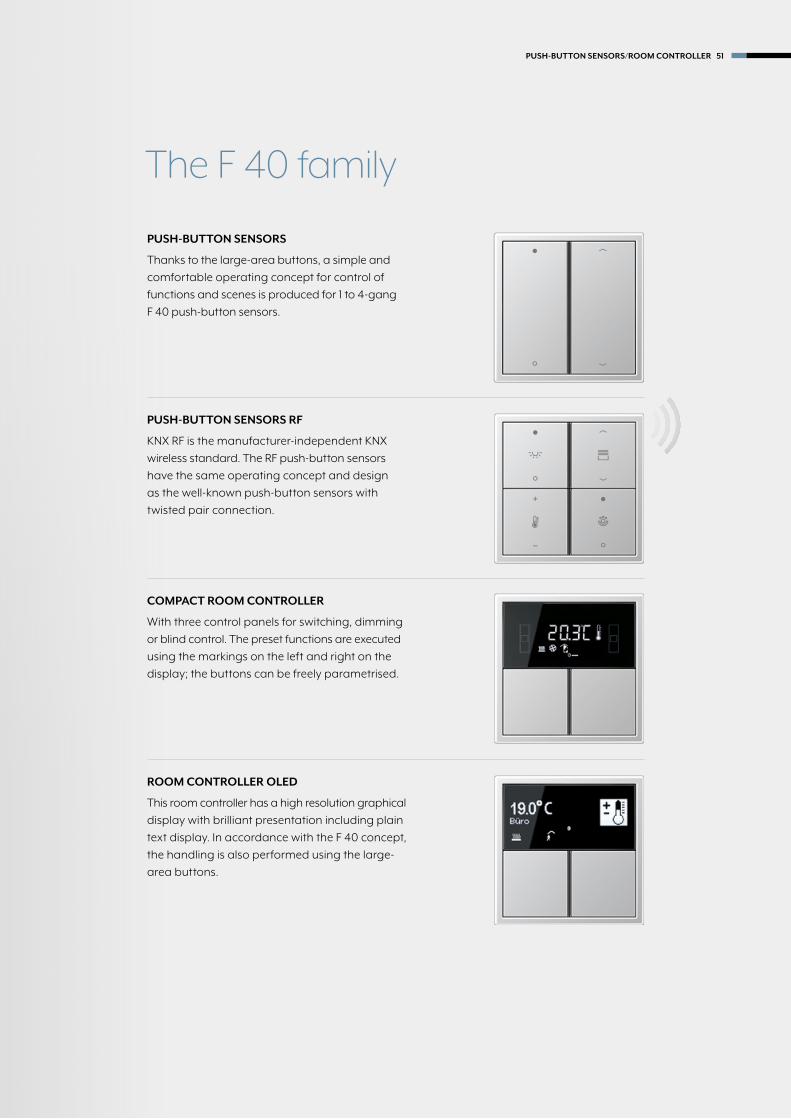
PUSH-BUTTON SENSORS
Thanks to the large-area buttons, a simple and
comfortable operating concept for control of
functions and scenes is produced for 1 to 4-gang
F 40 push-button sensors.
COMPACT ROOM CONTROLLER
With three control panels for switching, dimming
or blind control. The preset functions are executed
using the markings on the left and right on the
display; the buttons can be freely parametrised.
PUSH-BUTTON SENSORS RF
KNX RF is the manufacturer-independent KNX
wireless standard. The RF push-button sensors
have the same operating concept and design
as the well-known push-button sensors with
twisted pair connection.
ROOM CONTROLLER OLED
This room controller has a high resolution graphical
display with brilliant presentation including plain
text display. In accordance with the F 40 concept,
the handling is also performed using the large-
area buttons.
The F 40 family
PUSH-BUTTON SENSORS/ROOM CONTROLLER 51

PUSH-BUTTON SENSOR F 40
LS 990 surface-mounted design in aluminium
52 PUSH-BUTTON SENSORS/ROOM CONTROLLER

Individual button assignment
TWO BUTTON OPERATION TWO BUTTON OPERATION
ONE BUTTON OPERATION 90° MOUNTING
One button or two button operation can be set as operating
modes for the F 40 push-button sensors. One operating button
can be configured in each case as rocker or button. For the
rocker function, an operating button is divided into two opera-
ting pressure points with the same basic function. In contrast
for the button function, an operating button is evaluated in
two operating points with two individually parameterisable
functions. Horizontal mounting can also be realised.
In button function (toggle)
Possible in one or two button operation
In rocker function
In button function (toggle)
PUSH-BUTTON SENSORS/ROOM CONTROLLER 53

With regard to design and operating concept, the F 40 push button
sensors come close to a conventional switch. This also makes the
handling easy for users not used to KNX. The large areas can be
labelled easily and clearly recognisable that further optimises the
operation using the Graphic Tool.
PUSH-BUTTON SENSOR F 40
LS 990 in Dark
54 PUSH-BUTTON SENSORS/ROOM CONTROLLER

Versatile functionality
ILLUMINATING: THE LIGHTING SCENE MEMORY*
Up to eight light scenes can be stored in the integrated light
scene memory; in turn, eight groups can be assigned to
each scene. They can be recalled using the buttons or other
KNX commands.
INTEGRATED: THE TEMPERATURE SENSOR*
The temperature at a different place in the room can be
measured with the temperature sensor. The values are
transmitted to the room temperature controller or room
controller for effective control.
EXTENSION MODULE CONNECTION*
The flat push-button extension module can be directly
connected to the main module for flexible extension of the
functions. It is mounted in a 2-gang frame using a special
supporting ring. Advantage also for the retrofitting. No
separate flush-mounted box is needed.
PUSH-BUTTON SENSORS/ROOM CONTROLLER 55
PUSH-BUTTON QUICK MOUNTING
The operating buttons are provided as complete Cover kit
on a mounting aid for quick mounting. Each button can also
be individually replaced, e.g. for a laser-cut or printed version.
THE CONSTRUCTION SITE COVERAGE
Thanks to the construction site coverage, button and
function assignment can already be realised in construction
site operation. The decision for button and cover design
thus has time until the project acceptance.
* only for Universal version

PUSH-BUTTON SENSOR F 40
LS ZERO in aluminium
56 PUSH-BUTTON SENSORS/ROOM CONTROLLER

The AS, A, CD and LS ranges give the KNX sensors of the F 40
family their attractive appearance. Genuine materials, distinctive
forms and a wide variety of colours determine the JUNG design.
They can be matched to any ambiance.
Variety of designs
LS 990 A CREATION
CD 500 AS 500
PUSH-BUTTON SENSORS/ROOM CONTROLLER 57

F 40 – numerous combination possibilities
1 Supporting ring
2 Frame
3 1-gang adapter frame
4 Push-button module
5 Cover kit
1-gang
4
5
A
CD
LS
2-gang
1
2
A plus
A creation
A 500
AS AND A RANGES
2
LS-design
LS RANGE
LS plus
LS ZERO
LS 990
LS-1-gang adapter frame
3
58 PUSH-BUTTON SENSORS/ROOM CONTROLLER
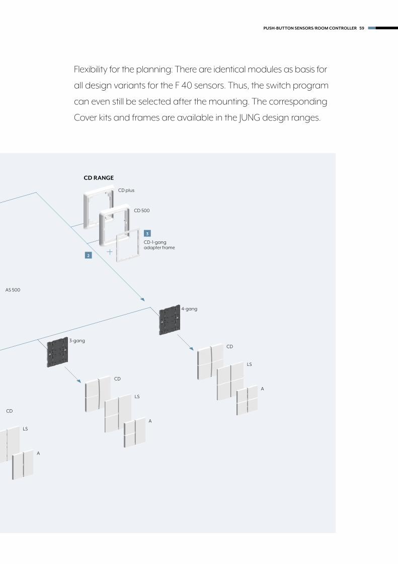
Flexibility for the planning: There are identical modules as basis for
all design variants for the F 40 sensors. Thus, the switch program
can even still be selected after the mounting. The corresponding
Cover kits and frames are available in the JUNG design ranges.
3-gang
A
CD
LS
A
CD
LS
4-gang
A
CD
LS
2
CD 500
CD plus
CD-1-gang adapter frame
3
CD RANGE
A 500
AS 500
PUSH-BUTTON SENSORS/ROOM CONTROLLER 59

60
KNX
Standard push-button module Intended use • Operation of loads, e.g. light on/off, dimming, blinds up/down, calling up and saving light scenes, etc. • Installation in flush-box according to DIN 49073
Product characteristics • Push-button functions for switching, dimming, blinds control, valuators, light scenes, etc. • To be completed with cover kit • One red status LED per button • One blue operation LED as an orientation light and to indicate the programming status • Integrated bus coupling unit • Transparent cover kit (included) for temporary site use without design covers
Ref.-no.
Push-button module F 40
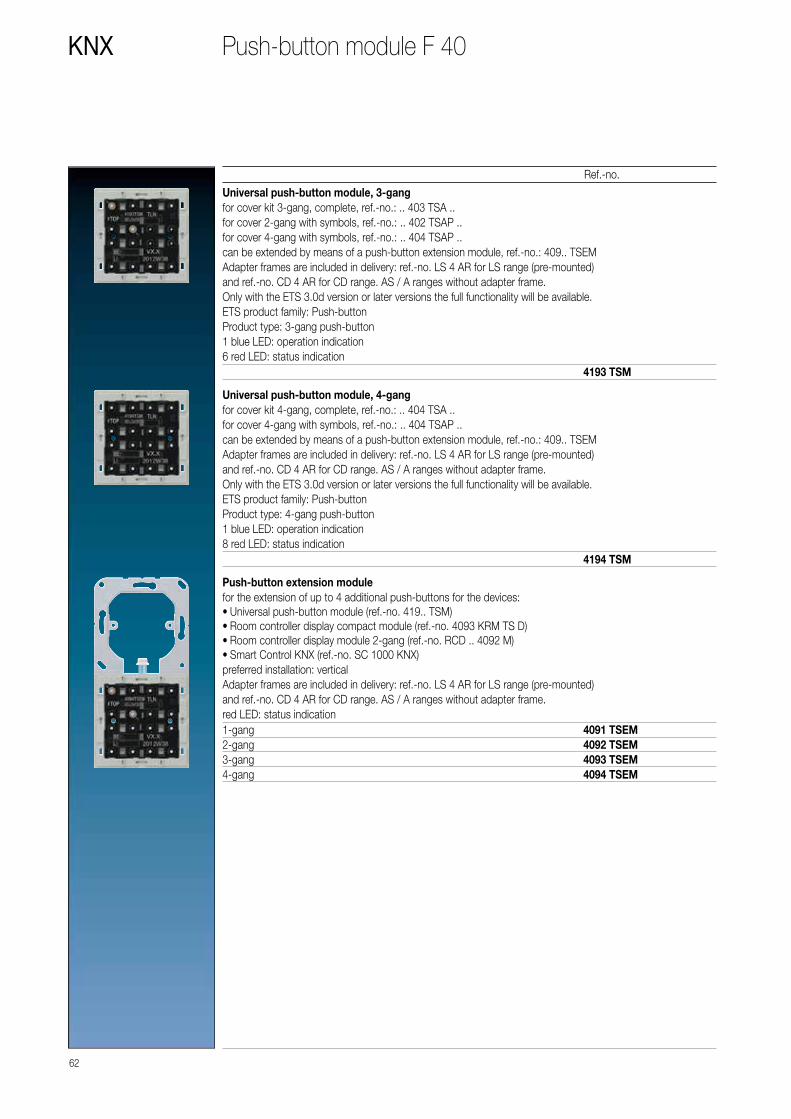
Standard push-button module, 1-gangfor cover kit 1-gang, complete, ref.-no.: .. 401 TSA ..for cover 1-gang with symbols, ref.-no.: .. 401 TSAP ..Adapter frames are included in delivery: ref.-no. LS 4 AR for LS range (pre-mounted) and ref.-no. CD 4 AR for CD range. AS / A ranges without adapter frame.Only with the ETS 3.0d version or later versions the full functionality will be available.ETS product family: Push-buttonProduct type: 1-gang push-button1 blue LED: operation indication1 red LED: status indication
4071 TSM
Standard push-button module, 2-gangfor cover kit 2-gang, complete, ref.-no.: .. 402 TSA ..for cover 2-gang with symbols, ref.-no.: .. 402 TSAP ..Adapter frames are included in delivery: ref.-no. LS 4 AR for LS range (pre-mounted) and ref.-no. CD 4 AR for CD range. AS / A ranges without adapter frame.Only with the ETS 3.0d version or later versions the full functionality will be available.ETS product family: Push-buttonProduct type: 2-gang push-button1 blue LED: operation indication2 red LED: status indication
4072 TSM
Standard push-button module, 3-gangfor cover kit 3-gang, complete, ref.-no.: .. 403 TSA ..for cover 2-gang with symbols, ref.-no.: .. 402 TSAP ..for cover 4-gang with symbols, ref.-no.: .. 404 TSAP ..Adapter frames are included in delivery: ref.-no. LS 4 AR for LS range (pre-mounted) and ref.-no. CD 4 AR for CD range. AS / A ranges without adapter frame.Only with the ETS 3.0d version or later versions the full functionality will be available.ETS product family: Push-buttonProduct type: 3-gang push-button1 blue LED: operation indication3 red LED: status indication
4073 TSM

Universal push-button module Intended use • Operation of loads, e.g. light on/off, dimming, blinds up/down, brightness values, temperatures, calling up and saving light scenes, etc. • Installation in flush-box according to DIN 49073
Product characteristics • Push-button functions for switching, dimming, blinds control, valuators, light scenes, etc. • Measurement of room temperature • To be completed with cover kit • Two red status LED per button • One blue operation LED as an orientation light and to indicate the programming status • Integrated bus coupling unit • One, two or three functions per button • Push-button function or rocker function, vertical or horizontal • Connection for a push-button extension module, 1-4 gang • Transparent cover kit (included) for temporary site use without design covers
61
Ref.-no.
KNXPush-button module F 40
Standard push-button module, 4-gangfor cover kit 4-gang, complete, ref.-no.: .. 404 TSA ..for cover 4-gang with symbols, ref.-no.: .. 404 TSAP ..Adapter frames are included in delivery: ref.-no. LS 4 AR for LS range (pre-mounted) and ref.-no. CD 4 AR for CD range. AS / A ranges without adapter frame.Only with the ETS 3.0d version or later versions the full functionality will be available.ETS product family: Push-buttonProduct type: 4-gang push-button1 blue LED: operation indication4 red LED: status indication
4074 TSM
Universal push-button module, 1-gangfor cover kit 1-gang, complete, ref.-no.: .. 401 TSA ..for cover 1-gang with symbols, ref.-no.: .. 401 TSAP ..can be extended by means of a push-button extension module, ref.-no.: 409.. TSEMAdapter frames are included in delivery: ref.-no. LS 4 AR for LS range (pre-mounted) and ref.-no. CD 4 AR for CD range. AS / A ranges without adapter frame.Only with the ETS 3.0d version or later versions the full functionality will be available.ETS product family: Push-buttonProduct type: 1-gang push-button1 blue LED: operation indication2 red LED: status indication
4191 TSM
Universal push-button module, 2-gangfor cover kit 2-gang, complete, ref.-no.: .. 402 TSA ..for cover 2-gang with symbols, ref.-no.: .. 402 TSAP ..can be extended by means of a push-button extension module, ref.-no.: 409.. TSEMAdapter frames are included in delivery: ref.-no. LS 4 AR for LS range (pre-mounted) and ref.-no. CD 4 AR for CD range. AS / A ranges without adapter frame.Only with the ETS 3.0d version or later versions the full functionality will be available.ETS product family: Push-buttonProduct type: 2-gang push-button1 blue LED: operation indication4 red LED: status indication
4192 TSM
62
KNX
Ref.-no.
Push-button module F 40
Universal push-button module, 3-gangfor cover kit 3-gang, complete, ref.-no.: .. 403 TSA ..for cover 2-gang with symbols, ref.-no.: .. 402 TSAP ..for cover 4-gang with symbols, ref.-no.: .. 404 TSAP ..can be extended by means of a push-button extension module, ref.-no.: 409.. TSEMAdapter frames are included in delivery: ref.-no. LS 4 AR for LS range (pre-mounted) and ref.-no. CD 4 AR for CD range. AS / A ranges without adapter frame.Only with the ETS 3.0d version or later versions the full functionality will be available.ETS product family: Push-buttonProduct type: 3-gang push-button1 blue LED: operation indication6 red LED: status indication
4193 TSM
Universal push-button module, 4-gangfor cover kit 4-gang, complete, ref.-no.: .. 404 TSA ..for cover 4-gang with symbols, ref.-no.: .. 404 TSAP ..can be extended by means of a push-button extension module, ref.-no.: 409.. TSEMAdapter frames are included in delivery: ref.-no. LS 4 AR for LS range (pre-mounted) and ref.-no. CD 4 AR for CD range. AS / A ranges without adapter frame.Only with the ETS 3.0d version or later versions the full functionality will be available.ETS product family: Push-buttonProduct type: 4-gang push-button1 blue LED: operation indication8 red LED: status indication
4194 TSM
Push-button extension modulefor the extension of up to 4 additional push-buttons for the devices: • Universal push-button module (ref.-no. 419.. TSM) • Room controller display compact module (ref.-no. 4093 KRM TS D) • Room controller display module 2-gang (ref.-no. RCD .. 4092 M) • Smart Control KNX (ref.-no. SC 1000 KNX)
preferred installation: verticalAdapter frames are included in delivery: ref.-no. LS 4 AR for LS range (pre-mounted) and ref.-no. CD 4 AR for CD range. AS / A ranges without adapter frame.red LED: status indication1-gang 4091 TSEM2-gang 4092 TSEM3-gang 4093 TSEM4-gang 4094 TSEM

Delivery of cover kits:1 complete set per ref.-no.!
Cover kits for AS and A ranges
Professional laser inscription and colour printing!For further information see www.jung.de/gt
63
Ref.-no.
KNXPush-button module F 40
Cover kit 1-gangto clip on F 40 push-button modules 1-gangref.-no.: 4071 TSM, 4191 TSM, 4091 TSEM, 4071 RF TSM, 4212 TSM, 4008 TSM, FM 4001 MThermoplastic (breakproof) high-glossivory L A 401 TSAwhite L A 401 TSA WWblack L A 401 TSA SWThermoplastic (breakproof) lacqueredaluminium P L A 401 TSA ALchampagne P A 401 TSA CHmocha A 401 TSA MOmatt anthracite L A 401 TSA ANM
Cover kit 2-gangto clip on F 40 push-button modules 2-gangref.-no.: 4072 TSM, 4192 TSM, 4092 TSEM, 4072 RF TSM, 4224 TSM, 4008 TSM, FM 4002 MThermoplastic (breakproof) high-glossivory L A 402 TSAwhite L A 402 TSA WWblack L A 402 TSA SWThermoplastic (breakproof) lacqueredaluminium P L A 402 TSA ALchampagne P A 402 TSA CHmocha A 402 TSA MOmatt anthracite L A 402 TSA ANM
Cover kit 3-gangto clip on F 40 push-button modules 3-gangref.-no.: 4073 TSM, 4193 TSM, 4093 TSEM, 4073 RF TSM, 4236 TSM, 4008 TSM, FM 4003 MThermoplastic (breakproof) high-glossivory L A 403 TSAwhite L A 403 TSA WWblack L A 403 TSA SWThermoplastic (breakproof) lacqueredaluminium P L A 403 TSA ALchampagne P A 403 TSA CHmocha A 403 TSA MOmatt anthracite L A 403 TSA ANM
Cover kit 4-gangto clip on F 40 push-button modules 4-gangref.-no.: 4074 TSM, 4194 TSM, 4094 TSEM, 4074 RF TSM, 4248 TSM, 4008 TSM, FM 4004 MThermoplastic (breakproof) high-glossivory L A 404 TSAwhite L A 404 TSA WWblack L A 404 TSA SWThermoplastic (breakproof) lacqueredaluminium P L A 404 TSA ALchampagne P A 404 TSA CHmocha A 404 TSA MOmatt anthracite L A 404 TSA ANM
PP
LL
Colour printing possibleLaser labelling possible

Delivery of cover kits:1 complete set per ref.-no.!
64
KNX
Covers with symbols for AS and A ranges
Ref.-no.
Push-button module F 40
Cover 1-gangwith symbols ▲▼
to clip on F 40 push-button modules 1-gangref.-no.: 4071 TSM, 4191 TSM, 4091 TSEM, 4071 RF TSM, 4212 TSM, 4008 TSM, FM 4001 MThermoplastic (breakproof) high-glossivory A 401 TSAPwhite A 401 TSAP WWblack A 401 TSAP SWThermoplastic (breakproof) lacqueredaluminium A 401 TSAP ALchampagne A 401 TSAP CHmocha A 401 TSAP MOmatt anthracite A 401 TSAP ANM
Cover 2-gangwith symbols ▲▼
to exchange the covers of the cover kit 2-gang ref.-no.: A 402 TSA..and the right cover of the cover kit 3-gang ref.-no.: A 403 TSA..Thermoplastic (breakproof) high-glossivory A 402 TSAPwhite A 402 TSAP WWblack A 402 TSAP SWThermoplastic (breakproof) lacqueredaluminium A 402 TSAP ALchampagne A 402 TSAP CHmocha A 402 TSAP MOmatt anthracite A 402 TSAP ANM
Cover 4-gangwith symbols ▲▼
to exchange the top left cover of the cover kit 3-gang ref.-no.: A 403 TSA..and top left and bottom right cover of the cover kit 4-gang ref.-no.: A 404 TSA..Thermoplastic (breakproof) high-glossivory A 404 TSAP 14white A 404 TSAP WW 14black A 404 TSAP SW 14Thermoplastic (breakproof) lacqueredaluminium A 404 TSAP AL 14champagne A 404 TSAP CH 14mocha A 404 TSAP MO 14matt anthracite A 404 TSAP ANM 14
Cover 4-gangwith symbols ▲▼
to exchange the bottom left cover of the cover kit 3-gang ref.-no.: A 403 TSA..and top right and bottom left cover of the cover kit 4-gang ref.-no.: A 404 TSA..Thermoplastic (breakproof) high-glossivory A 404 TSAP 23white A 404 TSAP WW 23black A 404 TSAP SW 23Thermoplastic (breakproof) lacqueredaluminium A 404 TSAP AL 23champagne A 404 TSAP CH 23mocha A 404 TSAP MO 23matt anthracite A 404 TSAP ANM 23

Cover kits for CD range
Professional laser inscription and colour printing!For further information see www.jung.de/gt
65
Ref.-no.
KNXPush-button module F 40
Cover kit 1-gangto clip on F 40 push-button modules 1-gangref.-no.: 4071 TSM, 4191 TSM, 4091 TSEM, 4071 RF TSM, 4212 TSM, 4008 TSM, FM 4001 MThermoplastic (breakproof) high-glossivory L CD 401 TSAwhite L CD 401 TSA WWgrey L CD 401 TSA GRlight grey L CD 401 TSA LGblack L CD 401 TSA SW
Cover kit 2-gangto clip on F 40 push-button modules 2-gangref.-no.: 4072 TSM, 4192 TSM, 4092 TSEM, 4072 RF TSM, 4224 TSM, 4008 TSM, FM 4002 MThermoplastic (breakproof) high-glossivory L CD 402 TSAwhite L CD 402 TSA WWgrey L CD 402 TSA GRlight grey L CD 402 TSA LGblack L CD 402 TSA SW
Cover kit 3-gangto clip on F 40 push-button modules 3-gangref.-no.: 4073 TSM, 4193 TSM, 4093 TSEM, 4073 RF TSM, 4236 TSM, 4008 TSM, FM 4003 MThermoplastic (breakproof) high-glossivory L CD 403 TSAwhite L CD 403 TSA WWgrey L CD 403 TSA GRlight grey L CD 403 TSA LGblack L CD 403 TSA SW
Cover kit 4-gangto clip on F 40 push-button modules 4-gangref.-no.: 4074 TSM, 4194 TSM, 4094 TSEM, 4074 RF TSM, 4248 TSM, 4008 TSM, FM 4004 MThermoplastic (breakproof) high-glossivory L CD 404 TSAwhite L CD 404 TSA WWgrey L CD 404 TSA GRlight grey L CD 404 TSA LGblack L CD 404 TSA SW
PP
LL
Colour printing possibleLaser labelling possible

66
KNX
Covers with symbols for CD range
Ref.-no.
Push-button module F 40
Cover 1-gangwith symbols ▲▼
to clip on F 40 push-button modules 1-gangref.-no.: 4071 TSM, 4191 TSM, 4091 TSEM, 4071 RF TSM, 4212 TSM, 4008 TSM, FM 4001 MThermoplastic (breakproof) high-glossivory CD 401 TSAPwhite CD 401 TSAP WWgrey CD 401 TSAP GRlight grey CD 401 TSAP LGblack CD 401 TSAP SW
Cover 2-gangwith symbols ▲▼
to exchange the covers of the cover kit 2-gang ref.-no.: CD 402 TSA..and the right cover of the cover kit 3-gang ref.-no.: CD 403 TSA..Thermoplastic (breakproof) high-glossivory CD 402 TSAPwhite CD 402 TSAP WWgrey CD 402 TSAP GRlight grey CD 402 TSAP LGblack CD 402 TSAP SW
Cover 4-gangwith symbols ▲▼
to exchange the top left cover of the cover kit 3-gang ref.-no.: CD 403 TSA..and top left and bottom right cover of the cover kit 4-gang ref.-no.: CD 404 TSA..Thermoplastic (breakproof) high-glossivory CD 404 TSAP 14white CD 404 TSAP WW 14grey CD 404 TSAP GR 14light grey CD 404 TSAP LG 14black CD 404 TSAP SW 14
Cover 4-gangwith symbols ▲▼
to exchange the bottom left cover of the cover kit 3-gang ref.-no.: CD 403 TSA..and top right and bottom left cover of the cover kit 4-gang ref.-no.: CD 404 TSA..Thermoplastic (breakproof) high-glossivory CD 404 TSAP 23white CD 404 TSAP WW 23grey CD 404 TSAP GR 23light grey CD 404 TSAP LG 23black CD 404 TSAP SW 23
Adapter frame(Spare part)to combine push-button modules with CD rangeAlso included in delivery of modules.
CD 4 AR
Delivery of cover kits:1 complete set per ref.-no.!

Cover kits for LS range
67
Ref.-no.
KNXPush-button module F 40
Cover kit 1-gangto clip on F 40 push-button modules 1-gangref.-no.: 4071 TSM, 4191 TSM, 4091 TSEM, 4071 RF TSM, 4212 TSM, 4008 TSM, FM 4001 MThermoplastic (breakproof) high-glossivory L LS 401 TSAwhite L LS 401 TSA WWlight grey L LS 401 TSA LGblack L LS 401 TSA SWmetal versionsaluminium P L AL 2401 TSAstainless steel L ES 2401 TSAanthracite (aluminium lacquered) L AL 2401 TSA ANdark (aluminium lacquered) L AL 2401 TSA Dclassic brass P ME 2401 TSA Cantique brass ME 2401 TSA AT
Cover kit 2-gangto clip on F 40 push-button modules 2-gangref.-no.: 4072 TSM, 4192 TSM, 4092 TSEM, 4072 RF TSM, 4224 TSM, 4008 TSM, FM 4002 MThermoplastic (breakproof) high-glossivory L LS 402 TSAwhite L LS 402 TSA WWlight grey L LS 402 TSA LGblack L LS 402 TSA SWmetal versionsaluminium P L AL 2402 TSAstainless steel L ES 2402 TSAanthracite (aluminium lacquered) L AL 2402 TSA ANdark (aluminium lacquered) L AL 2402 TSA Dclassic brass P ME 2402 TSA Cantique brass ME 2402 TSA AT
Cover kit 3-gangto clip on F 40 push-button modules 3-gangref.-no.: 4073 TSM, 4193 TSM, 4093 TSEM, 4073 RF TSM, 4236 TSM, 4008 TSM, FM 4003 MThermoplastic (breakproof) high-glossivory L LS 403 TSAwhite L LS 403 TSA WWlight grey L LS 403 TSA LGblack L LS 403 TSA SWmetal versionsaluminium P L AL 2403 TSAstainless steel L ES 2403 TSAanthracite (aluminium lacquered) L AL 2403 TSA ANdark (aluminium lacquered) L AL 2403 TSA Dclassic brass P ME 2403 TSA Cantique brass ME 2403 TSA AT
PP
LL
Colour printing possibleLaser labelling possible

68
KNX
Professional laser inscription and colour printing!For further information see www.jung.de/gt
Covers with symbols for LS range
Ref.-no.
Push-button module F 40
Cover kit 4-gangto clip on F 40 push-button modules 4-gangref.-no.: 4074 TSM, 4194 TSM, 4094 TSEM, 4074 RF TSM, 4248 TSM, 4008 TSM, FM 4004 MThermoplastic (breakproof) high-glossivory L LS 404 TSAwhite L LS 404 TSA WWlight grey L LS 404 TSA LGblack L LS 404 TSA SWmetal versionsaluminium P L AL 2404 TSAstainless steel L ES 2404 TSAanthracite (aluminium lacquered) L AL 2404 TSA ANdark (aluminium lacquered) L AL 2404 TSA Dclassic brass P ME 2404 TSA Cantique brass ME 2404 TSA AT
Cover 1-gangwith symbols ▲▼
to clip on F 40 push-button modules 1-gangref.-no.: 4071 TSM, 4191 TSM, 4091 TSEM, 4071 RF TSM, 4212 TSM, 4008 TSM, FM 4001 MThermoplastic (breakproof) high-glossivory LS 401 TSAPwhite LS 401 TSAP WWlight grey LS 401 TSAP LGblack LS 401 TSAP SWmetal versionsaluminium AL 2401 TSAPstainless steel ES 2401 TSAPanthracite (aluminium lacquered) AL 2401 TSAP ANdark (aluminium lacquered) AL 2401 TSAP D
Cover 2-gangwith symbols ▲▼
to exchange the covers of the cover kit 2-gang ref.-no.: ..402 TSA..and the right cover of the cover kit 3-gang ref.-no.: ..403 TSA.. in the LS rangeThermoplastic (breakproof) high-glossivory LS 402 TSAPwhite LS 402 TSAP WWlight grey LS 402 TSAP LGblack LS 402 TSAP SWmetal versionsaluminium AL 2402 TSAPstainless steel ES 2402 TSAPanthracite (aluminium lacquered) AL 2402 TSAP ANdark (aluminium lacquered) AL 2402 TSAP Dclassic brass ME 2402 TSAP Cantique brass ME 2402 TSAP AT
PP
LL
Colour printing possibleLaser labelling possible
Cover kits for LS range

69
Ref.-no.
KNXPush-button module F 40
Cover 4-gangwith symbols ▲▼
to exchange the top left cover of the cover kit 3-gang ref.-no.: ..403 TSA..and top left and bottom right cover of the cover kit 4-gang ref.-no.: ..404 TSA.. in the LS rangeThermoplastic (breakproof) high-glossivory LS 404 TSAP 14white LS 404 TSAP WW 14light grey LS 404 TSAP LG 14black LS 404 TSAP SW 14metal versionsaluminium AL 2404 TSAP 14stainless steel ES 2404 TSAP 14anthracite (aluminium lacquered) AL 2404 TSAP AN 14dark (aluminium lacquered) AL 2404 TSAP D 14classic brass ME 2404 TSAP C 14antique brass ME 2404 TSAP AT 14
Cover 4-gangwith symbols ▲▼
to exchange the bottom left cover of the cover kit 3-gang ref.-no.: ..403 TSA..and top right and bottom left cover of the cover kit 4-gang ref.-no.: ..404 TSA.. in the LS rangeThermoplastic (breakproof) high-glossivory LS 404 TSAP 23white LS 404 TSAP WW 23light grey LS 404 TSAP LG 23black LS 404 TSAP SW 23metal versionsaluminium AL 2404 TSAP 23stainless steel ES 2404 TSAP 23anthracite (aluminium lacquered) AL 2404 TSAP AN 23dark (aluminium lacquered) AL 2404 TSAP D 23classic brass ME 2404 TSAP C 23antique brass ME 2404 TSAP AT 23
Adapter frame(Spare part)to combine push-button modules with LS rangeAlso included in delivery of modules.
LS 4 AR
Covers with symbols for LS range
Delivery of cover kits:1 complete set per ref.-no.!

Room controller F 40
KNX OLED ROOM CONTROLLER
70 PUSH-BUTTON SENSORS/ROOM CONTROLLER

The room functions and scenes are controlled with the room
controllers of the F 40 family using the large operating buttons.
Status and function selection are shown on the graphical
display. Centrally arranged, coloured LEDs for operation and
status display round off the easy handling.
KNX ROOM CONTROLLER DISPLAY COMPACT MODULE
KNX OLED ROOM CONTROLLER
With three control panels for switching,
dimming or blind control the preset
functions are executed using the markings
on the left and right on the display; the
buttons can be freely parametrised.
This room controller has a high resolu-
tion OLED graphical display with brilliant
presentation including plain text display.
The large buttons are used for the
operation.
PUSH-BUTTON SENSORS/ROOM CONTROLLER 71

72
KNX
Ref.-no.
Room controller F 40
Room controller display compact modulecan be extended by means of a push-button extension module, ref.-no.: 409.. TSEMAdapter frames are included in delivery: ref.-no. LS 4 AR for LS range (pre-mounted) and ref.-no. CD 4 AR for CD range. AS / A ranges without adapter frame.
recommended mounting height: 1.5 mIntended use • Measurement and feedback control of the room temperature • Operation of loads, e.g. light on/off, dimming, blinds up/down, brightness values, temperatures, calling up and saving light scenes, etc. • Installation in wall box according to DIN 49073
Product characteristicsAll buttons can be assigned with functions for controller operation. • Four red status LEDs • A blue operation LED as an orientation light and to indicate the programming status • Integrated bus coupling unit • Connection of push-button extension module • Integrated room temperature sensor • Room temperature control with setpoint value specification • Display of room or set temperature • Display of outdoor temperature – with external sensor, e.g. weather station • Display of time, in conjunction with KNX time encoder • Push-button functions for switching, dimming, blinds control, valuators, light scenes, etc. • Push-button function or rockers function, vertical or horizontal • Fan coil application with up to 8 fan speeds and auto function • Transparent cover kit (included) for temporary site use without design covers
4093 KRM TS D
Push-button extension modulefor the extension of up to 4 additional push-buttons for the devices: • Universal push-button module (ref.-no. 419.. TSM) • Room controller display compact module (ref.-no. 4093 KRM TS D) • Room controller display module 2-gang (ref.-no. RCD .. 4092 M) • Smart Control KNX (ref.-no. SC 1000 KNX)
preferred installation: verticalAdapter frames are included in delivery: ref.-no. LS 4 AR for LS range (pre-mounted) and ref.-no. CD 4 AR for CD range. AS / A ranges without adapter frame.red LED: status indication1-gang 4091 TSEM2-gang 4092 TSEM3-gang 4093 TSEM4-gang 4094 TSEM

Delivery of cover kits:1 complete set per ref.-no.!
Cover kits for AS and A ranges
Professional laser inscription and colour printing!For further information see www.jung.de/gt
73
Ref.-no.
KNXRoom controller F 40
Cover kitto clip on room controller display compact module ref.-no.: 4093 KRM TS DThermoplastic (breakproof) high-glossivory L A 4093 TSAwhite L A 4093 TSA WWblack L A 4093 TSA SWThermoplastic (breakproof) lacqueredaluminium P L A 4093 TSA ALchampagne P A 4093 TSA CHmocha A 4093 TSA MOmatt anthracite L A 4093 TSA ANM
Cover with temperature symbolto exchange the display cover of the cover kit ref.-no.: A 4093 TSA..Thermoplastic (breakproof) high-gloss
A 409 T
Cover 4-gangwith symbols ▲▼
to exchange the bottom right cover of the cover kit ref.-no.: A 4093 TSA..Thermoplastic (breakproof) high-glossivory A 404 TSAP 14white A 404 TSAP WW 14black A 404 TSAP SW 14Thermoplastic (breakproof) lacqueredaluminium A 404 TSAP AL 14champagne A 404 TSAP CH 14mocha A 404 TSAP MO 14matt anthracite A 404 TSAP ANM 14
Cover 4-gangwith symbols ▲▼
to exchange the bottom left cover of the cover kit ref.-no.: A 4093 TSA..Thermoplastic (breakproof) high-glossivory A 404 TSAP 23white A 404 TSAP WW 23black A 404 TSAP SW 23Thermoplastic (breakproof) lacqueredaluminium A 404 TSAP AL 23champagne A 404 TSAP CH 23mocha A 404 TSAP MO 23matt anthracite A 404 TSAP ANM 23
PP
LL
Colour printing possibleLaser labelling possible

Delivery of cover kits:1 complete set per ref.-no.!
74
KNX
Cover kits for CD range
Professional laser inscription and colour printing!For further information see www.jung.de/gt
Ref.-no.
Room controller F 40
Cover kitto clip on room controller display compact module ref.-no.: 4093 KRM TS DThermoplastic (breakproof) high-glossivory L CD 4093 TSAwhite L CD 4093 TSA WWgrey L CD 4093 TSA GRlight grey L CD 4093 TSA LGblack L CD 4093 TSA SW
Cover with temperature symbolto exchange the display cover of the cover kit ref.-no.: CD 4093 TSA..Thermoplastic (breakproof) high-gloss
CD 409 T
Cover 4-gangwith symbols ▲▼
to exchange the bottom right cover of the cover kit ref.-no.: CD 4093 TSA..Thermoplastic (breakproof) high-glossivory CD 404 TSAP 14white CD 404 TSAP WW 14grey CD 404 TSAP GR 14light grey CD 404 TSAP LG 14black CD 404 TSAP SW 14
Cover 4-gangwith symbols ▲▼
to exchange the bottom left cover of the cover kit ref.-no.: CD 4093 TSA..Thermoplastic (breakproof) high-glossivory CD 404 TSAP 23white CD 404 TSAP WW 23grey CD 404 TSAP GR 23light grey CD 404 TSAP LG 23black CD 404 TSAP SW 23
Adapter frame(Spare part)to combine push-button modules with CD rangeAlso included in delivery of modules.
CD 4 AR

Cover kits for LS range
Professional laser inscription and colour printing!For further information see www.jung.de/gt
75
Ref.-no.
KNXRoom controller F 40
Cover kitto clip on room controller display compact module ref.-no.: 4093 KRM TS DThermoplastic (breakproof) high-glossivory L LS 4093 TSAwhite L LS 4093 TSA WWlight grey L LS 4093 TSA LGblack L LS 4093 TSA SWmetal versionsaluminium P L AL 4093 TSAstainless steel L ES 4093 TSAanthracite (aluminium lacquered) L AL 4093 TSA ANdark (aluminium lacquered) L AL 4093 TSA Dclassic brass P ME 4093 TSA Cantique brass ME 4093 TSA AT
Cover with temperature symbolto exchange the display cover of the cover kit ref.-no.: .. 4093 TSA .. in the LS rangeThermoplastic (breakproof) high-gloss
LS 409 T
Cover 4-gangwith symbols ▲▼
to exchange the bottom right cover of the cover kit ref.-no.: .. 4093 TSA .. in the LS rangeThermoplastic (breakproof) high-glossivory LS 404 TSAP 14white LS 404 TSAP WW 14light grey LS 404 TSAP LG 14black LS 404 TSAP SW 14metal versionsaluminium AL 2404 TSAP 14stainless steel ES 2404 TSAP 14anthracite (aluminium lacquered) AL 2404 TSAP AN 14dark (aluminium lacquered) AL 2404 TSAP D 14classic brass ME 2404 TSAP C 14antique brass ME 2404 TSAP AT 14
PP
LL
Colour printing possibleLaser labelling possible

76
Ref.-no.
Adapter frame(Spare part)to combine push-button modules with LS rangeAlso included in delivery of modules.
LS 4 AR
KNX Room controller F 40
Cover 4-gangwith symbols ▲▼
to exchange the bottom left cover of the cover kit ref.-no.: .. 4093 TSA .. in the LS range
Thermoplastic (breakproof) high-glossivory LS 404 TSAP 23white LS 404 TSAP WW 23light grey LS 404 TSAP LG 23black LS 404 TSAP SW 23metal versionsaluminium AL 2404 TSAP 23stainless steel ES 2404 TSAP 23anthracite (aluminium lacquered) AL 2404 TSAP AN 23dark (aluminium lacquered) AL 2404 TSAP D 23classic brass ME 2404 TSAP C 23antique brass ME 2404 TSAP AT 23
Cover kits for LS range

77
Ref.-no.
KNXRoom controller F 40
Room controller display module 2-gangcan be extended by means of a push-button extension module, ref.-no.: 409.. TSEM
recommended mounting height: 1.5 m Intended use • Operation of consumers, e.g. lights on/off, dimming, blinds/shutters up/down, brightness values, temperatures, storing and recalling of light scenes etc. • Room temperature control • Installation in mounting box according to DIN 49073
Product characteristics • Push-button functions for switching, dimming, blinds control, valuators, light scenes, etc. • Vertical and horizontal key/rocker functions • Two red LEDs per control key as status or operation indicators • Display of values and texts • Running text display for one or two messages with max. 14 characters • Integrated room temperature sensor • Room temperature control with setpoint value preset • Display of room temperature and setpoint temperature • Indication of outside temperature (only with external sensor) • Integrated bus coupling unit • In combination with Facitility Pilot "Multi-Room Control": music play control, display of music titles, artists, etc. • Display unit for the KNX central alarm unit • Fan coil application with up to 8 fan speeds and auto function • OLED graphic display with high resolution • High contrast • Viewing angle 170° from each direction • Transparent cover kit (included) for temporary site use without design covers • Connection for a push-button extension module, 1-4 gang
for CD rangeRCD CD 4092 M
for LS rangeRCD LS 4092 M
Push-button extension modulefor the extension of up to 4 additional push-buttons for the devices: • Universal push-button module (ref.-no. 419.. TSM) • Room controller display compact module (ref.-no. 4093 KRM TS D) • Room controller display module 2-gang (ref.-no. RCD .. 4092 M) • Smart Control KNX (ref.-no. SC 1000 KNX)
preferred installation: verticalAdapter frames are included in delivery: ref.-no. LS 4 AR for LS range (pre-mounted) and ref.-no. CD 4 AR for CD range. AS / A ranges without adapter frame.red LED: status indication1-gang 4091 TSEM2-gang 4092 TSEM3-gang 4093 TSEM4-gang 4094 TSEM

78
KNX
Cover kits for CD range
Professional inscription see www.jung.de/gt
Ref.-no.
Room controller F 40
Cover kitto clip on room controller display module 2-gang ref.-no.: RCD CD 4092 MThermoplastic (breakproof) high-glossivory L RCD CD 4092 TSAwhite L RCD CD 4092 TSA WWgrey L RCD CD 4092 TSA GRlight grey L RCD CD 4092 TSA LGblack L RCD CD 4092 TSA SW
Cover 4-gangwith symbols ▲▼
to exchange the bottom right cover of the cover kit ref.-no.: RCD CD 4092 TSA ..Thermoplastic (breakproof) high-glossivory CD 404 TSAP 14white CD 404 TSAP WW 14grey CD 404 TSAP GR 14light grey CD 404 TSAP LG 14black CD 404 TSAP SW 14
Cover 4-gangwith symbols ▲▼
to exchange the bottom left cover of the cover kit ref.-no.: RCD CD 4092 TSA ..Thermoplastic (breakproof) high-glossivory CD 404 TSAP 23white CD 404 TSAP WW 23grey CD 404 TSAP GR 23light grey CD 404 TSAP LG 23black CD 404 TSAP SW 23
PP
LL
Colour printing possibleLaser labelling possible

Delivery of cover kits:1 complete set per ref.-no.!
79
Ref.-no.
KNXRoom controller F 40
Cover kitto clip on room controller display module 2-gang ref.-no.: RCD LS 4092 MThermoplastic (breakproof) high-glossivory L RCD LS 4092 TSAwhite L RCD LS 4092 TSA WWlight grey L RCD LS 4092 TSA LGblack L RCD LS 4092 TSA SWmetal versionsaluminium P L RCD AL 4092 TSAstainless steel L RCD ES 4092 TSAanthracite (aluminium lacquered) L RCD AL 4092 TSA ANdark (aluminium lacquered) L RCD AL 4092 TSA Dclassic brass P RCD ME 4092 TSA Cantique brass RCD ME 4092 TSA AT
Cover 4-gangwith symbols ▲▼
to exchange the bottom right cover of the cover kit ref.-no.: RCD .. 4092 TSA .. in the LS rangeThermoplastic (breakproof) high-glossivory LS 404 TSAP 14white LS 404 TSAP WW 14light grey LS 404 TSAP LG 14black LS 404 TSAP SW 14metal versionsaluminium AL 2404 TSAP 14stainless steel ES 2404 TSAP 14anthracite (aluminium lacquered) AL 2404 TSAP AN 14dark (aluminium lacquered) AL 2404 TSAP D 14classic brass ME 2404 TSAP C 14antique brass ME 2404 TSAP AT 14
Cover 4-gangwith symbols ▲▼
to exchange the bottom left cover of the cover kit ref.-no.: RCD .. 4092 TSA .. in the LS rangeThermoplastic (breakproof) high-glossivory LS 404 TSAP 23white LS 404 TSAP WW 23light grey LS 404 TSAP LG 23black LS 404 TSAP SW 23metal versionsaluminium AL 2404 TSAP 23stainless steel ES 2404 TSAP 23anthracite (aluminium lacquered) AL 2404 TSAP AN 23dark (aluminium lacquered) AL 2404 TSAP D 23classic brass ME 2404 TSAP C 23antique brass ME 2404 TSAP AT 23
Cover kits for CD range

KNX RF
KNX RF RADIO CONVERTER KNX RF RADIO HAND-HELD TRANSMITTER
KNX RF RADIO WALL TRANSMITTER KNX RF RADIO WALL TRANSMITTER
Operating philosophy F 50
2-gang and 4-gang version
Operating philosophy F 40
Interface between KNX RF and KNX TP
The KNX radio standard in the JUNG design:
the radio wall transmitter in the F 50 and F 40
families is ideal for retrofitting and upgrading
existing KNX systems. The KNX radio wall
transmitter is perfefctly suited for structural
conditions where bus lines cannot or should
not be installed. This allows the particularly
flat devices to be flexibly placed in the room,
as they are simply glued on - be it plaster,
wood or glass. The room functions can be
conveniently controlled by a simple touch of
a button. KNX hand-held transmitters are
available as an alternative to the wall trans-
mitters. Addressing, parameterization and
diagnostics are carried out via the KNX radio
USB stick or alternatively via the KNX data
interface. The bidirectional connection of KNX
RF and wired KNX TP takes place via JUNG
radio converter.
80 PUSH-BUTTON SENSORS/ROOM CONTROLLER

KNX RF RADIO WALL TRANSMITTER F 40
PUSH-BUTTON SENSORS/ROOM CONTROLLER 81

82
KNX RF
KNX RF radio transmitter modules F 50
for AS and A ranges
Ref.-no.
Radio transmitter modules F 50
Intended use • Radio operation of loads, e.g. light on/off, dimming, Venetian blinds up/down, brightness values, calling up and saving light scenes • Operation in cabled KNX systems via radio converter (ref.-no.: MK 100 RF) • Mounting on appliance box according to DIN 49073, screw fixing on walls or adhesive fixing on smooth, even surfaces (glass)
Product characteristics • Push-button functions for switching, dimming, blinds control, valuators, light scenes, etc. • Button pairs for push-button function or rocker function • Status indication with LED • Integrated temperature sensor • Battery-powered device (battery compartment accessible from front)
Technical dataRated voltage: DC 3 VBattery type: 1 x lithium CR 2450 (included)Ambient temperature: −5 ... +45 °CRadio frequency: 868.0 ... 868.6 MHzTransmitting power: max. 20 mWTransmission range in free field: typical 100 m
KNX RF radio transmitter module 1-gangincluding transparent cover ref.-no.: A 50 NAfor cover kit 1-gang, complete, ref.-no.: A 501 TSA ..Project design and commissioning with ETS5 or a more recent version.ETS product family: Push-buttonProduct type: 1-gang push-button1 green LED: actuator status1 red LED: transmission status
A 5071 RF TSM
KNX RF radio transmitter module 2-gangincluding transparent cover ref.-no.: A 50 NAfor cover kit 2-gang, complete, ref.-no.: A 502 TSA ..Project design and commissioning with ETS5 or a more recent version.ETS product family: Push-buttonProduct type: 2-gang push-button2 green LED: actuator status1 red LED: transmission status
A 5072 RF TSM
KNX RF radio transmitter module 3-gangincluding transparent cover ref.-no.: A 50 NAfor cover kit 3-gang, complete, ref.-no.: A 503 TSA ..Project design and commissioning with ETS5 or a more recent version.ETS product family: Push-buttonProduct type: 3-gang push-button3 green LED: actuator status1 red LED: transmission status
A 5073 RF TSM

KNX RF radio transmitter modules F 50for CD range
83
Ref.-no.
KNX RFRadio transmitter modules F 50
KNX RF radio transmitter module 4-gangincluding transparent cover ref.-no.: A 50 NAfor cover kit 4-gang, complete, ref.-no.: A 504 TSA ..Project design and commissioning with ETS5 or a more recent version.ETS product family: Push-buttonProduct type: 4-gang push-button4 green LED: actuator status1 red LED: transmission status
A 5074 RF TSM
KNX RF radio transmitter module 1-gangincluding transparent cover ref.-no.: CD 50 NAfor cover kit 1-gang, complete, ref.-no.: CD 501 TSA ..Project design and commissioning with ETS5 or a more recent version.ETS product family: Push-buttonProduct type: 1-gang push-button1 green LED: actuator status1 red LED: transmission status
CD 5071 RF TSM
KNX RF radio transmitter module 2-gangincluding transparent cover ref.-no.: CD 50 NAfor cover kit 2-gang, complete, ref.-no.: CD 502 TSA ..Project design and commissioning with ETS5 or a more recent version.ETS product family: Push-buttonProduct type: 2-gang push-button2 green LED: actuator status1 red LED: transmission status
CD 5072 RF TSM
KNX RF radio transmitter module 3-gangincluding transparent cover ref.-no.: CD 50 NAfor cover kit 3-gang, complete, ref.-no.: CD 503 TSA ..Project design and commissioning with ETS5 or a more recent version.ETS product family: Push-buttonProduct type: 3-gang push-button3 green LED: actuator status1 red LED: transmission status
CD 5073 RF TSM
KNX RF radio transmitter module 4-gangincluding transparent cover ref.-no.: CD 50 NAfor cover kit 4-gang, complete, ref.-no.: CD 504 TSA ..Project design and commissioning with ETS5 or a more recent version.ETS product family: Push-buttonProduct type: 4-gang push-button4 green LED: actuator status1 red LED: transmission status
CD 5074 RF TSM
Cover kits for the A range see page 36 and 37
Cover kits for the CD range see page 42

84
KNX RF
KNX RF radio transmitter modules F 50 for LS range
Ref.-no.
Radio transmitter modules F 50
KNX RF radio transmitter module 1-gangincluding transparent cover ref.-no.: LS 50 NAfor cover kit 1-gang, complete, ref.-no.: ..501 TSA .. in the LS rangeCan not be combined with frames in Flat Design.Project design and commissioning with ETS5 or a more recent version.ETS product family: Push-buttonProduct type: 1-gang push-button1 green LED: actuator status1 red LED: transmission status
LS 5071 RF TSM
KNX RF radio transmitter module 2-gangincluding transparent cover ref.-no.: LS 50 NAfor cover kit 2-gang, complete, ref.-no.: ..502 TSA .. in the LS rangeCan not be combined with frames in Flat Design.Project design and commissioning with ETS5 or a more recent version.ETS product family: Push-buttonProduct type: 2-gang push-button2 green LED: actuator status1 red LED: transmission status
LS 5072 RF TSM
KNX RF radio transmitter module 3-gangincluding transparent cover ref.-no.: LS 50 NAfor cover kit 3-gang, complete, ref.-no.: ..503 TSA .. in the LS rangeCan not be combined with frames in Flat Design.Project design and commissioning with ETS5 or a more recent version.ETS product family: Push-buttonProduct type: 3-gang push-button3 green LED: actuator status1 red LED: transmission status
LS 5073 RF TSM
KNX RF radio transmitter module 4-gangincluding transparent cover ref.-no.: LS 50 NAfor cover kit 4-gang, complete, ref.-no.: ..504 TSA .. in the LS rangeCan not be combined with frames in Flat Design.Project design and commissioning with ETS5 or a more recent version.ETS product family: Push-buttonProduct type: 4-gang push-button4 green LED: actuator status1 red LED: transmission status
LS 5074 RF TSM
Cover kits for the LS range see page 48 and 49

85
Ref.-no.
KNX RFRadio transmitter modules F 40
KNX RF radio transmitter modules F 40Adapter frames are included in delivery: ref.-no. LS 4 AR for LS range (pre-mounted) and ref.-no. CD 4 AR for CD range. AS / A ranges without adapter frame.Project design and commissioning with ETS5 or a more recent version. Intended use • Radio operation of loads, e.g. light on/off, dimming, Venetian blinds up/down, brightness values, calling up and saving light scenes • Operation in cabled KNX systems via radio converter (ref.-no.: MK 100 RF) • Mounting on appliance box according to DIN 49073, screw fixing on walls or adhesive fixing on smooth, even surfaces (glass)
Product characteristics • Push-button functions for switching, dimming, blinds control, valuators, light scenes, etc. • Button pairs for push-button function or rocker function • Status indication with LED • Battery-powered device
Technical dataRated voltage: DC 3 VBattery type: 1 x lithium CR 2450N (included)Ambient temperature: −5 ... +45 °CRadio frequency: 868.0 ... 868.6 MHzTransmitting power: max. 20 mWTransmission range in free field: typical 100 m
KNX RF radio transmitter module 1-gangfor cover kit 1-gang, complete, ref.-no.: .. 401 TSA ..for cover 1-gang with symbols, ref.-no.: .. 401 TSAP ..Can not be combined with frames in Flat Design.ETS product family: Push-buttonProduct type: 1-gang push-button1 red LED: actuator status1 blue LED: transmission status
4071 RF TSM
KNX RF radio transmitter module 2-gangfor cover kit 2-gang, complete, ref.-no.: .. 402 TSA ..for cover 2-gang with symbols, ref.-no.: .. 402 TSAP ..Can not be combined with frames in Flat Design.ETS product family: Push-buttonProduct type: 2-gang push-button2 red LEDs: actuator status1 blue LED: transmission status
4072 RF TSM
KNX RF radio transmitter module 3-gangfor cover kit 3-gang, complete, ref.-no.: .. 403 TSA ..for cover 2-gang with symbols, ref.-no.: .. 402 TSAP ..for cover 4-gang with symbols, ref.-no.: .. 404 TSAP ..Can not be combined with frames in Flat Design.ETS product family: Push-buttonProduct type: 3-gang push-button3 red LEDs: actuator status1 blue LED: transmission status
4073 RF TSM

86
KNX RF
Ref.-no.
Radio transmitter modules F 40Radio hand-held transmitter
KNX RF radio transmitter module 4-gangfor cover kit 4-gang, complete, ref.-no.: .. 404 TSA ..for cover 4-gang with symbols, ref.-no.: .. 404 TSAP ..Can not be combined with frames in Flat Design.ETS product family: Push-buttonProduct type: 4-gang push-button4 red LEDs: actuator status1 blue LED: transmission status
4074 RF TSM
KNX RF radio hand-held transmitterProject design and commissioning with ETS5 or a more recent version.Intended use • Radio operation of loads, e.g. light on/off, dimming, Venetian blinds up/down, brightness values, calling up and saving light scenes • Operation in cabled KNX systems via radio converter (ref.-no.: MK 100 RF)
Product characteristics • Push-button functions for switching, dimming, blinds control, valuators, light scenes, etc. • Button pairs for push-button function or rocker function • Two-colour LED to display actuation, sending status and actuator feedback • Battery-powered device
Technical dataRated voltage: DC 3 VBattery type: 1 x lithium CR 2450N (included)Ambient temperature: −5 ... +45 °CRelative humidity: max. 80 % (no condensation)Radio frequency: 868.0 ... 868.6 MHzTransmitting power: max. 20 mWTransmission range in free field: typical 100 m
KNX RF radio hand-held transmitter2-ganganthracite HS 2 RF
KNX RF radio hand-held transmitter4-ganganthracite HS 4 RF
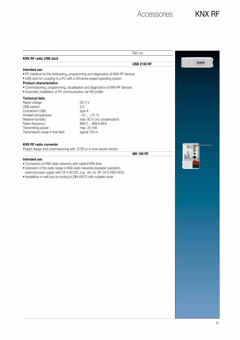
87
Ref.-no.
KNX RFAccessories
KNX RF radio USB stick
Intended use • PC interface for the addressing, programming and diagnostics of KNX-RF devices • USB stick for coupling to a PC with a Windows-based operating system
Product characteristics • Commissioning, programming, visualisation and diagnostics of KNX-RF devices • Automatic installation of PC communication via HID profile
USB 2130 RF
Technical dataRated voltage: DC 5 VUSB version: 2.0Connection USB: type AAmbient temperature: −10 ... +70 °CRelative humidity: max. 80 % (no condensation)Radio frequency: 868.0 ... 868.6 MHzTransmitting power: max. 20 mWTransmission range in free field: typical 100 m
KNX RF radio converterProject design and commissioning with ETS5 or a more recent version.
Intended use • Connection of KNX radio networks with cabled KNX lines • Extension of the radio range in KNX radio networks (repeater operation, external power supply with 24 V AC/DC, e.g. ref.-no. NT 2415 REG VDC) • Installation in wall box according to DIN 49073 with suitable cover
MK 100 RF

KNX ROTARY SENSOR
LS 990 in chrome
88 ROTARY SENSORS / BCU PUSH-BUTTONS

While the operation is also performed like a classic rotary dimmer,
the functionality for the KNX rotary sensor is much more extensive.
The room functions and scenes are controlled here according to
the proven „turn and press“ principle. It also harmonises perfectly
with the rest of the components in the JUNG design.
Rotary sensor
AS 500
CD 500
A CREATION
LS 990
ROTARY SENSORS / BCU PUSH-BUTTONS 89

Intuitive operating concept
FUNCTIONALITY
The KNX rotary sensor is used
for controlling dimming,
switching, and blind actuators
as well as for the setpoint shift
of a temperature controller.
It has two red status LEDs for
orientation.
Lighting control Blind control
Temperature / climate controlMusic control
OPERATION
The rotary sensor is innovative
because it implements an
operating concept that has
never before existed in this
form in the KNX system. The
well-known function of a
rotary dimmer was used as
template. The rotary sensor
operates according to the
same principle and also has
three extension inputs to
connect conventional,
floating contacts of switches,
buttons and magnetic con-
tacts. These combination
possibilities extend the range
of functions many times over.
Labelling using the Graphic
Tool further optimises the
handling.Turn
Press
90 ROTARY SENSORS / BCU PUSH-BUTTONS
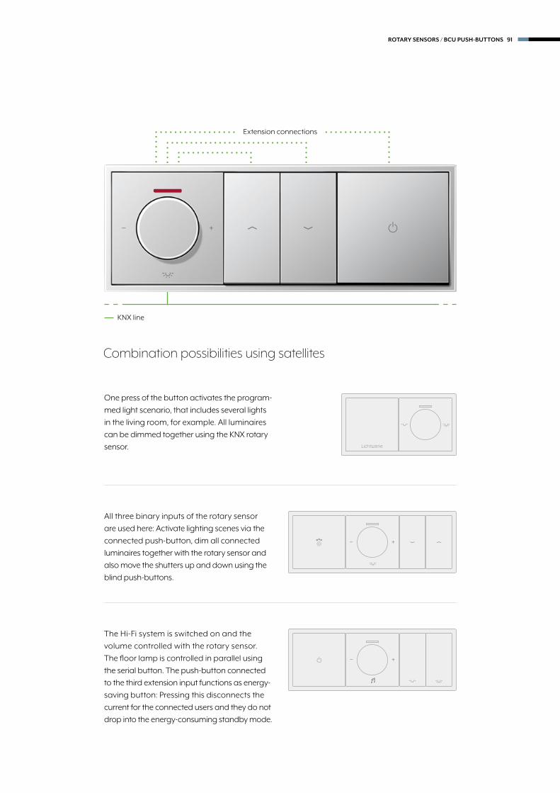
Combination possibilities using satellites
One press of the button activates the program-
med light scenario, that includes several lights
in the living room, for example. All luminaires
can be dimmed together using the KNX rotary
sensor.
All three binary inputs of the rotary sensor
are used here: Activate lighting scenes via the
connected push-button, dim all connected
luminaires together with the rotary sensor and
also move the shutters up and down using the
blind push-buttons.
The Hi-Fi system is switched on and the
volume controlled with the rotary sensor.
The floor lamp is controlled in parallel using
the serial button. The push-button connected
to the third extension input functions as energy-
saving button: Pressing this disconnects the
current for the connected users and they do not
drop into the energy-consuming standby mode.
Lichtszene
KNX line
Extension connections
ROTARY SENSORS / BCU PUSH-BUTTONS 91
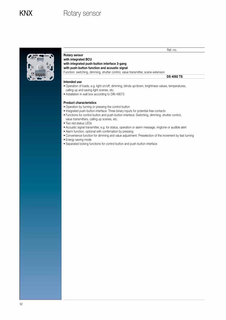
92
KNX
Ref.-no.
Rotary sensor
Rotary sensorwith integrated BCUwith integrated push-button interface 3-gangwith push-button function and acoustic signalFunction: switching, dimming, shutter control, value transmitter, scene extension
Intended use • Operation of loads, e.g. light on/off, dimming, blinds up/down, brightness values, temperatures, calling up and saving light scenes, etc. • Installation in wall box according to DIN 49073
Product characteristics • Operation by turning or pressing the control button • Integrated push-button interface: Three binary inputs for potential-free contacts • Functions for control button and push-button interface: Switching, dimming, shutter control, value transmitters, calling up scenes, etc. • Two red status LEDs • Acoustic signal transmitter, e.g. for status, operation or alarm message, ringtone or audible alert • Alarm function, optional with confirmation by pressing • Convenience function for dimming and value adjustment: Preselection of the increment by fast turning • Energy saving mode • Separated locking functions for control button and push-button interface
DS 4092 TS

Centre plate with knob and lensfor rotary sensor ref.-no.: DS 4092 TS
93
Ref.-no.
KNX
for AS and A rangesDuroplastic (scratch-proof) glossyivory P A 1540 KO5white P A 1540 KO5 WWblack A 1540 KO5 SWDuroplastic lacqueredaluminium P L A 1540 KO5 ALchampagne P A 1540 KO5 CHmocha A 1540 KO5 MOThermoplastic (breakproof) high-glosswhite L A 1540 BF KO5 WWblack L A 1540 BF KO5 SWThermoplastic (breakproof) lacqueredmatt anthracite L A 1540 BF KO5 ANM
for CD rangeDuroplastic (scratch-proof) glossyivory P CD 1540 KO5white P CD 1540 KO5 WWgrey CD 1540 KO5 GRlight grey P CD 1540 KO5 LGblack CD 1540 KO5 SW
for LS rangeDuroplastic (scratch-proof) glossyivory P LS 1940 KO5white P LS 1940 KO5 WWlight grey P LS 1940 KO5 LGblack LS 1940 KO5 SWmetal versionsaluminium P L AL 1940 KO5stainless steel L ES 1940 KO5anthracite (aluminium lacquered) L AL 1940 KO5 ANchrome GCR 1940 KO5gold-coloured GO 1940 KO5classic brass P ME 1940 KO5 Cantique brass ME 1940 KO5 AT
PP
LL
Colour printing possibleLaser labelling possible
Rotary sensor

Push-button BCU
Operating KNX in conventional design: The push-buttons with
integrated BCU (integrated bus coupling unit) are the same in
design and handling as conventional buttons; however, they
have the variety of functions of a smart KNX sensor.
94 ROTARY SENSORS / BCU PUSH-BUTTONS

PUSH-BUTTON BCU
LS 990 in aluminium
ROTARY SENSORS / BCU PUSH-BUTTONS 95

Attractive appearance for the BCU push-buttons with the AS,
A, CD and LS ranges. Form, material and variety of colours
determine the JUNG design. They harmoniously blend in to
the remaining electrical installation.
Variety of designs
AS 500
CD 500
A CREATION
LS 990
96 ROTARY SENSORS / BCU PUSH-BUTTONS

Designs and operation
1-GANG SWITCH POSITION 2-GANG NEUTRAL POSITION
2-GANG SWITCH POSITION 2-GANG NEUTRAL POSITION
The push-button BCUs are available in four versions depending
on the application. The desired parameters can be programmed
using the ETS software. The devices with neutral position have
a multiple function capability by operating the rocker „up“ and
„down“. Two single-colour LEDs are used for floor pilot lighting or
for status display and can also be set using parameters.
ROTARY SENSORS / BCU PUSH-BUTTONS 97

98
KNX
Depending on the version of the push-button BCU – 1-gang rocker or 2-gang rocker – centre plates are used with and without indication lights.The “upper” or “lower” rockers can be controlled with the push-button with “neutral position”, while only the “lower” rocker can be pressed with the push-button with “switch position”. The push-button BCU can only function with an application program i.e. the push-button BCU consists of the device (hardware) and the application program (software).
Ref.-no.
Push-button BCU
Push-button BCU, neutral positionFunction: switching, dimming, shutter controlLED: always ON, always OFF, status indication
Status indication is possible with LED
1-gang 4071.02 LED
Push-button BCU, switch positionFunction: switching, dimmingLED: always ON, always OFFCan be converted into pull cord push-button by means of pull cord insert ref.-no. 34 KO5 and rocker with lens.
Status indication is possible with LED
1-gang 4071.01 LED
Rockers for AS rangeAntibacterial version on request.When wallpapering, avoid wallpaper on the supporting frame of the insert.
1-gang rocker, full platefor 1-gang push-button BCUneutral position ref.-no.: 4071.02 LEDswitch position ref.-no.: 4071.01 LEDDuroplastic (scratch-proof) glossyivory full plate P AS 590
centre plate P AS 591white full plate P AS 590 WW
centre plate P AS 591 WW
1-gang rocker with symbols, full platefor 1-gang push-button BCUneutral position ref.-no.: 4071.02 LEDDuroplastic (scratch-proof) glossyivory full plate AS 590 P
centre plate AS 591 Pwhite full plate AS 590 P WW
centre plate AS 591 P WW
1-gang rocker with lens, full platefor 1-gang push-button BCUneutral position ref.-no.: 4071.02 LEDswitch position ref.-no.: 4071.01 LEDDuroplastic (scratch-proof) glossyivory full plate P AS 590 KO5
centre plate P AS 591 KO5white full plate P AS 590 KO5 WW
centre plate P AS 591 KO5 WW
PP
LL
Colour printing possibleLaser labelling possible

99
Ref.-no.
KNXPush-button BCU
1-gang rocker with lens and symbols, full platefor 1-gang push-button BCUneutral position ref.-no.: 4071.02 LEDDuroplastic (scratch-proof) glossyivory full plate AS 590 KO5P
centre plate AS 591 KO5Pwhite full plate AS 590 KO5P WW
centre plate AS 591 KO5P WW
Rockers for A rangeWhen wallpapering, avoid wallpaper on the supporting frame of the insert.
1-gang rockerfor 1-gang push-button BCUneutral position ref.-no.: 4071.02 LEDswitch position ref.-no.: 4071.01 LEDDuroplastic (scratch-proof) glossywhite P A 590 WWblack A 590 SWDuroplastic lacqueredaluminium P L A 590 ALchampagne P A 590 CHmocha A 590 MOThermoplastic (breakproof) high-glosswhite L A 590 BF WWblack L A 590 BF SWThermoplastic (breakproof) lacqueredmatt anthracite L A 590 BF ANM
1-gang rocker with symbolsfor 1-gang push-button BCUneutral position ref.-no.: 4071.02 LEDDuroplastic (scratch-proof) glossywhite A 590 P WWblack A 590 P SWDuroplastic lacqueredaluminium A 590 P ALchampagne A 590 P CHmocha A 590 P MOThermoplastic (breakproof) high-glosswhite A 590 BF P WWblack A 590 BF P SWThermoplastic (breakproof) lacqueredmatt anthracite A 590 BF P ANM

100
KNX
Ref.-no.
Push-button BCU
1-gang rocker with lensfor 1-gang push-button BCUneutral position ref.-no.: 4071.02 LEDswitch position ref.-no.: 4071.01 LEDDuroplastic (scratch-proof) glossywhite P A 590 KO5 WWblack A 590 KO5 SWDuroplastic lacqueredaluminium P L A 590 KO5 ALchampagne P A 590 KO5 CHmocha A 590 KO5 MOThermoplastic (breakproof) high-glosswhite L A 590 BF KO5 WWblack L A 590 BF KO5 SWThermoplastic (breakproof) lacqueredmatt anthracite L A 590 BF KO5 ANM
PP
LL
Colour printing possibleLaser labelling possible
Rockers for CD range
1-gang rocker with lens and symbolsfor 1-gang push-button BCUneutral position ref.-no.: 4071.02 LEDDuroplastic (scratch-proof) glossywhite A 590 KO5P WWblack A 590 KO5P SWDuroplastic lacqueredaluminium A 590 KO5P ALchampagne A 590 KO5P CHmocha A 590 KO5P MOThermoplastic (breakproof) high-glosswhite A 590 BF KO5P WWblack A 590 BF KO5P SWThermoplastic (breakproof) lacqueredmatt anthracite A 590 BF KO5P ANM
1-gang rockerfor 1-gang push-button BCUneutral position ref.-no.: 4071.02 LEDswitch position ref.-no.: 4071.01 LEDDuroplastic (scratch-proof) glossyivory P CD 590white P CD 590 WWbrown CD 590 BRgrey CD 590 GRlight grey P CD 590 LGblack CD 590 SWmetal versions (anodized aluminium)gold-bronze L CD 590 GBplatinum L CD 590 PT

Rockers for CD range
101
Ref.-no.
KNXPush-button BCU
1-gang rocker with symbolsfor 1-gang push-button BCUneutral position ref.-no.: 4071.02 LEDDuroplastic (scratch-proof) glossyivory CD 590 Pwhite CD 590 P WWbrown CD 590 P BRgrey CD 590 P GRlight grey CD 590 P LGblack CD 590 P SWmetal versions (anodized aluminium)gold-bronze CD 590 P GBplatinum CD 590 P PT
1-gang rocker with inscription field 9 x 58 mmfor 1-gang push-button BCUneutral position ref.-no.: 4071.02 LEDswitch position ref.-no.: 4071.01 LEDDuroplastic (scratch-proof) glossyivory P CD 590 NAwhite P CD 590 NA WWbrown CD 590 NA BRgrey CD 590 NA GRlight grey P CD 590 NA LGblack CD 590 NA SW
Transparent cover with paper inlayfor inscription field 9 x 58 mm(Spare part)paper inlay white CD 90 NA
1-gang rocker with lensfor 1-gang push-button BCUneutral position ref.-no.: 4071.02 LEDswitch position ref.-no.: 4071.01 LEDDuroplastic (scratch-proof) glossyivory P CD 590 KO5white P CD 590 KO5 WWbrown CD 590 KO5 BRgrey CD 590 KO5 GRlight grey P CD 590 KO5 LGblack CD 590 KO5 SWmetal versions (anodized aluminium)gold-bronze L CD 590 KO5 GBplatinum L CD 590 KO5 PT
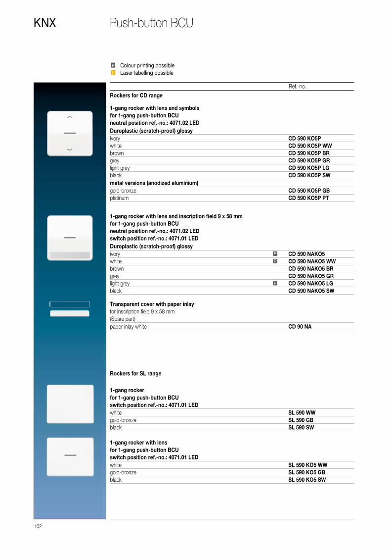
102
KNX
Rockers for CD range
Ref.-no.
Push-button BCU
1-gang rocker with lens and symbolsfor 1-gang push-button BCUneutral position ref.-no.: 4071.02 LEDDuroplastic (scratch-proof) glossyivory CD 590 KO5Pwhite CD 590 KO5P WWbrown CD 590 KO5P BRgrey CD 590 KO5P GRlight grey CD 590 KO5P LGblack CD 590 KO5P SWmetal versions (anodized aluminium)gold-bronze CD 590 KO5P GBplatinum CD 590 KO5P PT
Rockers for SL range
1-gang rocker with lens and inscription field 9 x 58 mmfor 1-gang push-button BCUneutral position ref.-no.: 4071.02 LEDswitch position ref.-no.: 4071.01 LEDDuroplastic (scratch-proof) glossyivory P CD 590 NAKO5white P CD 590 NAKO5 WWbrown CD 590 NAKO5 BRgrey CD 590 NAKO5 GRlight grey P CD 590 NAKO5 LGblack CD 590 NAKO5 SW
Transparent cover with paper inlayfor inscription field 9 x 58 mm(Spare part)paper inlay white CD 90 NA
1-gang rockerfor 1-gang push-button BCUswitch position ref.-no.: 4071.01 LEDwhite SL 590 WWgold-bronze SL 590 GBblack SL 590 SW
1-gang rocker with lensfor 1-gang push-button BCUswitch position ref.-no.: 4071.01 LEDwhite SL 590 KO5 WWgold-bronze SL 590 KO5 GBblack SL 590 KO5 SW
PP
LL
Colour printing possibleLaser labelling possible
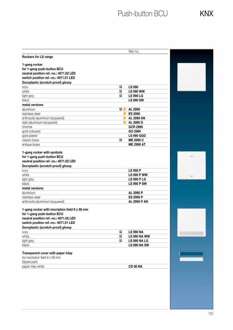
103
Ref.-no.
Rockers for LS range 1-gang rockerfor 1-gang push-button BCUneutral position ref.-no.: 4071.02 LEDswitch position ref.-no.: 4071.01 LEDDuroplastic (scratch-proof) glossyivory P LS 990white P LS 990 WWlight grey P LS 990 LGblack LS 990 SWmetal versionsaluminium P L AL 2990stainless steel L ES 2990anthracite (aluminium lacquered) L AL 2990 ANdark (aluminium lacquered) L AL 2990 Dchrome GCR 2990gold-coloured GO 2990gold-plated LS 990 GGOclassic brass P ME 2990 Cantique brass ME 2990 AT
1-gang rocker with symbolsfor 1-gang push-button BCUneutral position ref.-no.: 4071.02 LEDDuroplastic (scratch-proof) glossyivory LS 990 Pwhite LS 990 P WWlight grey LS 990 P LGblack LS 990 P SWmetal versionsaluminium AL 2990 Pstainless steel ES 2990 Panthracite (aluminium lacquered) AL 2990 P AN
1-gang rocker with inscription field 9 x 58 mmfor 1-gang push-button BCUneutral position ref.-no.: 4071.02 LEDswitch position ref.-no.: 4071.01 LEDDuroplastic (scratch-proof) glossyivory P LS 990 NAwhite P LS 990 NA WWlight grey P LS 990 NA LGblack LS 990 NA SW
Transparent cover with paper inlayfor inscription field 9 x 58 mm(Spare part)paper inlay white CD 90 NA
KNXPush-button BCU

104
KNX
Ref.-no.
Push-button BCU
Rockers for LS range 1-gang rocker with inscription field 12 x 55 mmfor 1-gang push-button BCUneutral position ref.-no.: 4071.02 LEDswitch position ref.-no.: 4071.01 LEDmetal versionsaluminium P L AL 2990 NAstainless steel L ES 2990 NAanthracite (aluminium lacquered) L AL 2990 NA ANdark (aluminium lacquered) L AL 2990 NA Dclassic brass P ME 2990 NA Cantique brass ME 2990 NA AT
Transparent coverfor inscription field 12 x 55 mm(Spare part)
M 20 NA
1-gang rocker with lensfor 1-gang push-button BCUneutral position ref.-no.: 4071.02 LEDswitch position ref.-no.: 4071.01 LEDDuroplastic (scratch-proof) glossyivory P LS 990 KO5white P LS 990 KO5 WWlight grey P LS 990 KO5 LGblack LS 990 KO5 SWmetal versionsaluminium P L AL 2990 KO5stainless steel L ES 2990 KO5anthracite (aluminium lacquered) L AL 2990 KO5 ANdark (aluminium lacquered) L AL 2990 KO5 Dchrome GCR 2990 KO5gold-coloured GO 2990 KO5gold-plated LS 990 KO5 GGOclassic brass P ME 2990 KO5 Cantique brass ME 2990 KO5 AT
1-gang rocker with lens and symbolsfor 1-gang push-button BCUneutral position ref.-no.: 4071.02 LEDDuroplastic (scratch-proof) glossyivory LS 990 KO5Pwhite LS 990 KO5P WWlight grey LS 990 KO5P LGblack LS 990 KO5P SWmetal versionsaluminium AL 2990 KO5Pstainless steel ES 2990 KO5Panthracite (aluminium lacquered) AL 2990 KO5P AN
PP
LL
Colour printing possibleLaser labelling possible

105
Ref.-no.
KNXPush-button BCU
Depending on the version of the push-button BCU – 1-gang rocker or 2-gang rocker – centre plates are used with and without indication lights.The “upper” or “lower” rockers can be controlled with the push-button with “neutral position”, while only the “lower” rocker can be pressed with the push-button with “switch position”. The push-button BCU can only function with an application program i.e. the push-button BCU consists of the device (hardware) and the application program (software).
Rockers for AS rangeAntibacterial version on request.When wallpapering, avoid wallpaper on the supporting frame of the insert.
Push-button BCU, neutral positionFunction: switching, dimming, shutter controlLED: always ON, always OFF, status indication
Status indication is possible with LED
2-gang 4072.02 LED
Push-button BCU, switch positionFunction: switching, dimming, shutter controlLED: always ON, always OFF
Status indication is possible with LED
2-gang 4072.01 LED
2-gang rocker, full platefor 2-gang push-button BCUneutral position ref.-no.: 4072.02 LEDswitch position ref.-no.: 4072.01 LEDDuroplastic (scratch-proof) glossyivory full plate P AS 590-5
centre plate P AS 591-5white full plate P AS 590-5 WW
centre plate P AS 591-5 WW
2-gang rocker with symbols, full platefor 2-gang push-button BCUneutral position ref.-no.: 4072.02 LEDDuroplastic (scratch-proof) glossyivory full plate AS 590-5 MP
centre plate AS 591-5 MPwhite full plate AS 590-5 MP WW
centre plate AS 591-5 MP WW
2-gang rocker with symbols, full platefor 2-gang push-button BCUswitch position ref.-no.: 4072.01 LEDDuroplastic (scratch-proof) glossyivory full plate AS 590-5 P
centre plate AS 591-5 Pwhite full plate AS 590-5 P WW
centre plate AS 591-5 P WW
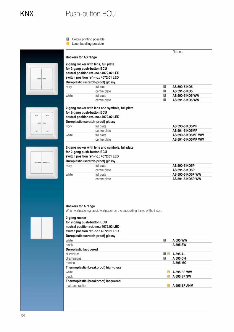
106
KNX
Ref.-no.
Push-button BCU
Rockers for AS range
2-gang rocker with lens, full platefor 2-gang push-button BCUneutral position ref.-no.: 4072.02 LEDswitch position ref.-no.: 4072.01 LEDDuroplastic (scratch-proof) glossyivory full plate P AS 590-5 KO5
centre plate P AS 591-5 KO5white full plate P AS 590-5 KO5 WW
centre plate P AS 591-5 KO5 WW
2-gang rocker with lens and symbols, full platefor 2-gang push-button BCUneutral position ref.-no.: 4072.02 LEDDuroplastic (scratch-proof) glossyivory full plate AS 590-5 KO5MP
centre plate AS 591-5 KO5MPwhite full plate AS 590-5 KO5MP WW
centre plate AS 591-5 KO5MP WW
2-gang rocker with lens and symbols, full platefor 2-gang push-button BCUswitch position ref.-no.: 4072.01 LEDDuroplastic (scratch-proof) glossyivory full plate AS 590-5 KO5P
centre plate AS 591-5 KO5Pwhite full plate AS 590-5 KO5P WW
centre plate AS 591-5 KO5P WW
PP
LL
Colour printing possibleLaser labelling possible
Rockers for A rangeWhen wallpapering, avoid wallpaper on the supporting frame of the insert.
2-gang rockerfor 2-gang push-button BCUneutral position ref.-no.: 4072.02 LEDswitch position ref.-no.: 4072.01 LEDDuroplastic (scratch-proof) glossywhite P A 595 WWblack A 595 SWDuroplastic lacqueredaluminium P L A 595 ALchampagne P A 595 CHmocha A 595 MOThermoplastic (breakproof) high-glosswhite L A 595 BF WWblack L A 595 BF SWThermoplastic (breakproof) lacqueredmatt anthracite L A 595 BF ANM

107
Ref.-no.
KNXPush-button BCU
2-gang rocker with symbolsfor 2-gang push-button BCUneutral position ref.-no.: 4072.02 LEDDuroplastic (scratch-proof) glossywhite A 595 MP WWblack A 595 MP SWDuroplastic lacqueredaluminium A 595 MP ALchampagne A 595 MP CHmocha A 595 MP MOThermoplastic (breakproof) high-glosswhite A 595 BF MP WWblack A 595 BF MP SWThermoplastic (breakproof) lacqueredmatt anthracite A 595 BF MP ANM
2-gang rocker with symbolsfor 2-gang push-button BCUswitch position ref.-no.: 4072.01 LEDDuroplastic (scratch-proof) glossywhite A 595 P WWblack A 595 P SWDuroplastic lacqueredaluminium A 595 P ALchampagne A 595 P CHmocha A 595 P MOThermoplastic (breakproof) high-glosswhite A 595 BF P WWblack A 595 BF P SWThermoplastic (breakproof) lacqueredmatt anthracite A 595 BF P ANM
Rockers for A rangeWhen wallpapering, avoid wallpaper on the supporting frame of the insert.
2-gang rocker with lensfor 2-gang push-button BCUneutral position ref.-no.: 4072.02 LEDswitch position ref.-no.: 4072.01 LEDDuroplastic (scratch-proof) glossywhite P A 595 KO5 WWblack A 595 KO5 SWDuroplastic lacqueredaluminium P L A 595 KO5 ALchampagne P A 595 KO5 CHmocha A 595 KO5 MOThermoplastic (breakproof) high-glosswhite L A 595 BF KO5 WWblack L A 595 BF KO5 SWThermoplastic (breakproof) lacqueredmatt anthracite L A 595 BF KO5 ANM

108
KNX
Ref.-no.
Push-button BCU
Rockers for A rangeWhen wallpapering, avoid wallpaper on the supporting frame of the insert.
2-gang rocker with lens and symbolsfor 2-gang push-button BCUneutral position ref.-no.: 4072.02 LEDDuroplastic (scratch-proof) glossywhite A 595 KO5MP WWblack A 595 KO5MP SWDuroplastic lacqueredaluminium A 595 KO5MP ALchampagne A 595 KO5MP CHmocha A 595 KO5MP MOThermoplastic (breakproof) high-glosswhite A 595 BF KO5MP WWblack A 595 BF KO5MP SWThermoplastic (breakproof) lacqueredmatt anthracite A 595 BF KO5MP ANM
2-gang rocker with lens and symbolsfor 2-gang push-button BCUswitch position ref.-no.: 4072.01 LEDDuroplastic (scratch-proof) glossywhite A 595 KO5P WWblack A 595 KO5P SWDuroplastic lacqueredaluminium A 595 KO5P ALchampagne A 595 KO5P CHmocha A 595 KO5P MOThermoplastic (breakproof) high-glosswhite A 595 BF KO5P WWblack A 595 BF KO5P SWThermoplastic (breakproof) lacqueredmatt anthracite A 595 BF KO5P ANM
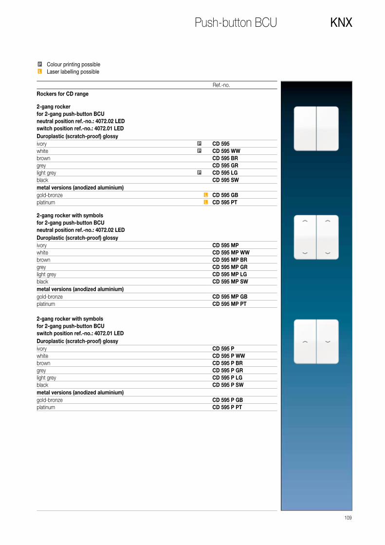
109
Ref.-no.
KNXPush-button BCU
PP
LL
Colour printing possibleLaser labelling possible
Rockers for CD range 2-gang rockerfor 2-gang push-button BCUneutral position ref.-no.: 4072.02 LEDswitch position ref.-no.: 4072.01 LEDDuroplastic (scratch-proof) glossyivory P CD 595white P CD 595 WWbrown CD 595 BRgrey CD 595 GRlight grey P CD 595 LGblack CD 595 SWmetal versions (anodized aluminium)gold-bronze L CD 595 GBplatinum L CD 595 PT
2-gang rocker with symbolsfor 2-gang push-button BCUneutral position ref.-no.: 4072.02 LEDDuroplastic (scratch-proof) glossyivory CD 595 MPwhite CD 595 MP WWbrown CD 595 MP BRgrey CD 595 MP GRlight grey CD 595 MP LGblack CD 595 MP SWmetal versions (anodized aluminium)gold-bronze CD 595 MP GBplatinum CD 595 MP PT
2-gang rocker with symbolsfor 2-gang push-button BCUswitch position ref.-no.: 4072.01 LEDDuroplastic (scratch-proof) glossyivory CD 595 Pwhite CD 595 P WWbrown CD 595 P BRgrey CD 595 P GRlight grey CD 595 P LGblack CD 595 P SWmetal versions (anodized aluminium)gold-bronze CD 595 P GBplatinum CD 595 P PT

110
KNX
Ref.-no.
Push-button BCU
Rockers for CD range 2-gang rocker with lensfor 2-gang push-button BCUneutral position ref.-no.: 4072.02 LEDswitch position ref.-no.: 4072.01 LEDDuroplastic (scratch-proof) glossyivory P CD 595 KO5white P CD 595 KO5 WWbrown CD 595 KO5 BRgrey CD 595 KO5 GRlight grey P CD 595 KO5 LGblack CD 595 KO5 SWmetal versions (anodized aluminium)gold-bronze L CD 595 KO5 GBplatinum L CD 595 KO5 PT
2-gang rocker with lens and symbolsfor 2-gang push-button BCUneutral position ref.-no.: 4072.02 LEDDuroplastic (scratch-proof) glossyivory CD 595 KO5MPwhite CD 595 KO5MP WWbrown CD 595 KO5MP BRgrey CD 595 KO5MP GRlight grey CD 595 KO5MP LGblack CD 595 KO5MP SWmetal versions (anodized aluminium)gold-bronze CD 595 KO5MP GBplatinum CD 595 KO5MP PT
PP
LL
Colour printing possibleLaser labelling possible
2-gang rocker with lens and symbolsfor 2-gang push-button BCUswitch position ref.-no.: 4072.01 LEDDuroplastic (scratch-proof) glossyivory CD 595 KO5Pwhite CD 595 KO5P WWbrown CD 595 KO5P BRgrey CD 595 KO5P GRlight grey CD 595 KO5P LGblack CD 595 KO5P SWmetal versions (anodized aluminium)gold-bronze CD 595 KO5P GBplatinum CD 595 KO5P PT

Rockers for SL range
111
Ref.-no.
KNXPush-button BCU
2-gang rockerfor 2-gang push-button BCUswitch position ref.-no.: 4072.01 LEDwhite SL 595 WWgold-bronze SL 595 GBblack SL 595 SW
2-gang rocker with symbolsfor 2-gang push-button BCUswitch position ref.-no.: 4072.01 LEDwhite SL 595 P WWgold-bronze SL 595 P GBblack SL 595 P SW
2-gang rocker with lensfor 2-gang push-button BCUswitch position ref.-no.: 4072.01 LEDwhite SL 595 KO5 WWgold-bronze SL 595 KO5 GBblack SL 595 KO5 SW
2-gang rocker with lens and symbolsfor 2-gang push-button BCUswitch position ref.-no.: 4072.01 LEDwhite SL 595 KO5P WWgold-bronze SL 595 KO5P GBblack SL 595 KO5P SW

112
KNX
Rockers for LS range
Ref.-no.
Push-button BCU
2-gang rockerfor 2-gang push-button BCUneutral position ref.-no.: 4072.02 LEDswitch position ref.-no.: 4072.01 LEDDuroplastic (scratch-proof) glossyivory P LS 995white P LS 995 WWlight grey P LS 995 LGblack LS 995 SWmetal versionsaluminium P L AL 2995stainless steel L ES 2995anthracite (aluminium lacquered) L AL 2995 ANdark (aluminium lacquered) L AL 2995 Dchrome GCR 2995gold-coloured GO 2995gold-plated LS 995 GGOclassic brass P ME 2995 Cantique brass ME 2995 AT
2-gang rocker with symbolsfor 2-gang push-button BCUneutral position ref.-no.: 4072.02 LEDDuroplastic (scratch-proof) glossyivory LS 995 MPwhite LS 995 MP WWlight grey LS 995 MP LGblack LS 995 MP SWmetal versionsaluminium AL 2995 MPstainless steel ES 2995 MPanthracite (aluminium lacquered) AL 2995 MP AN
2-gang rocker with symbolsfor 2-gang push-button BCUswitch position ref.-no.: 4072.01 LEDDuroplastic (scratch-proof) glossyivory LS 995 Pwhite LS 995 P WWlight grey LS 995 P LGblack LS 995 P SWmetal versionsaluminium AL 2995 Pstainless steel ES 2995 Panthracite (aluminium lacquered) AL 2995 P ANdark (aluminium lacquered) AL 2995 P Dchrome GCR 2995 Pgold-coloured GO 2995 Pclassic brass ME 2995 P Cantique brass ME 2995 P AT
PP
LL
Colour printing possibleLaser labelling possible

Rockers for LS range
113
Ref.-no.
KNXPush-button BCU
2-gang rocker with lensfor 2-gang push-button BCUneutral position ref.-no.: 4072.02 LEDswitch position ref.-no.: 4072.01 LEDDuroplastic (scratch-proof) glossyivory P LS 995 KO5white P LS 995 KO5 WWlight grey P LS 995 KO5 LGblack LS 995 KO5 SWmetal versionsaluminium P L AL 2995 KO5stainless steel L ES 2995 KO5anthracite (aluminium lacquered) L AL 2995 KO5 ANdark (aluminium lacquered) L AL 2995 KO5 Dchrome GCR 2995 KO5gold-coloured GO 2995 KO5classic brass P ME 2995 KO5 Cantique brass ME 2995 KO5 AT
2-gang rocker with lens and symbolsfor 2-gang push-button BCUneutral position ref.-no.: 4072.02 LEDDuroplastic (scratch-proof) glossyivory LS 995 KO5MPwhite LS 995 KO5MP WWlight grey LS 995 KO5MP LGblack LS 995 KO5MP SWmetal versionsaluminium AL 2995 KO5MPstainless steel ES 2995 KO5MPanthracite (aluminium lacquered) AL 2995 KO5MP AN
2-gang rocker with lens and symbolsfor 2-gang push-button BCUswitch position ref.-no.: 4072.01 LEDDuroplastic (scratch-proof) glossyivory LS 995 KO5Pwhite LS 995 KO5P WWlight grey LS 995 KO5P LGblack LS 995 KO5P SWmetal versionsaluminium AL 2995 KO5Pstainless steel ES 2995 KO5Panthracite (aluminium lacquered) AL 2995 KO5P AN

114
KNX
Depending on the version of the push-button BCU – 1-gang rocker or 2-gang rocker – centre plates are used with and without indication lights.The “upper” or “lower” rockers can be controlled with the push-button with “neutral position”, while only the “lower” rocker can be pressed with the push-button with “switch position”. The push-button BCU can only function with an application program i.e. the push-button BCU consists of the device (hardware) and the application program (software).
Ref.-no.
Push-button BCU
Push-button BCU, neutral positionFunction: switching, dimming, shutter controlLED: always ON, always OFF, status indication
Status indication is possible with LED
1-gang 8471.02 LED W
Push-button BCU, switch positionFunction: switching, dimmingLED: always ON, always OFF
Status indication is possible with LED
1-gang 8471.01 LED W
1-gang rocker with lensfor 1-gang push-button BCUneutral position ref.-no.: 8471.02 LED Wswitch position ref.-no.: 8471.01 LED W
800 NT
1-gang rocker with lens and symbolsfor 1-gang push-button BCUneutral position ref.-no.: 8471.02 LED W
800 P
Rocker with inscription fieldfor 1-gang push-button BCUneutral position ref.-no.: 8471.02 LED Wswitch position ref.-no.: 8471.01 LED Wwith inscription field 22 x 48 mm 800 NA
1-gang rocker with great lensfor 1-gang push-button BCUneutral position ref.-no.: 8471.02 LED Wswitch position ref.-no.: 8471.01 LED Wwith red symbol 800 KO
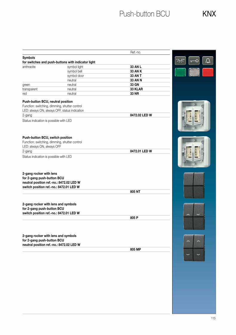
115
Ref.-no.
KNXPush-button BCU
Symbolsfor switches and push-buttons with indicator lightanthracite symbol light 33 AN L
symbol bell 33 AN Ksymbol door 33 AN Tneutral 33 AN N
green neutral 33 GNtransparent neutral 33 KLARred neutral 33 NR
Push-button BCU, neutral positionFunction: switching, dimming, shutter controlLED: always ON, always OFF, status indication
Status indication is possible with LED
2-gang 8472.02 LED W
Push-button BCU, switch positionFunction: switching, dimming, shutter controlLED: always ON, always OFF
Status indication is possible with LED
2-gang 8472.01 LED W
2-gang rocker with lensfor 2-gang push-button BCUneutral position ref.-no.: 8472.02 LED Wswitch position ref.-no.: 8472.01 LED W
805 NT
2-gang rocker with lens and symbolsfor 2-gang push-button BCUswitch position ref.-no.: 8472.01 LED W
805 P
2-gang rocker with lens and symbolsfor 2-gang push-button BCUneutral position ref.-no.: 8472.02 LED W
805 MP

Presence Detector Mini
Unobtrusive, compact, precise: the KNX Presence Detector Mini
is all of these. It is designed to control lighting systems, room
thermostats, and other electrical loads as needed. The striking
feature is its compact design with three ceiling mounting options:
Depending on the particular room situation, the unit may be
installed in a false ceiling, on the surface, or in a commercial
flush wall box.
KNX PRESENCE DETECTOR MINI
Available in the Standard and Universal versions
116 ROOM AUTOMATION

Three mounting types
FALSE CEILING
The most discreet installation type is clip-on mounting in a false ceiling. The spring clips ensure reliable fixing of the unit, and only the lens and the narrow design ring can be seen from below.
SURFACE MOUNTING
The third type of ceiling installation is the surface-mounted option. JUNG also provides a separate set for this that also includes a bezel as well as a surface cap for harmonious appearance.
FLUSH MOUNTING
Flush-mounted installation of the presence detector mini or the brightness sensor is carried out by means of a separate flush mounting set in an off-the-shelf DIN 49073 flush wall box.
BRIGHTNESS SENSOR
The KNX brightness controller with integrated brightness sensor is structurally identical to the
Presence Detector Mini. This performs the interior lighting control depending on the amount of
daylight present. This has the same installation options as for the Presence Detector Mini. The
brightness sensor with its harmonious proportions and the „invisible“ adjustment elements has
an unobtrusive design.
ROOM AUTOMATION 117

118
KNX
Ref.-no.
Presence detector mini
Presence detector miniwith integrated BCUETS product family: Physical sensorsProduct type: Movement
Intended use • Requirement-oriented control of lighting, room thermostats and other electrical consumers in interior rooms • Clamp mounting in suspended ceilings • Ceiling mounting on fixed ceilings in flush-mounted box according to DIN 49073 (with flush mounting set, ref.-no.: PMM-UP-SET-WW) or in surface-mounted housing (surface mounting set, ref.-no.: PMM-AP-SET-WW)
Product characteristics • Integrated bus coupling unit • 3 PIR sensors • Detection field 360° • Integrated brightness sensor • Deployed as presence detector, motion detector, or for alert operation • Output functions: Switching, staircase function, switching with forced position, value transmitter, light scene extension, operating mode setting for room temperature controller • Detection area extendible by parallel switching of several devices as main unit or extension unit • Manual sensitivity adjustment • Status LED: Flashes during motion detection; depending on programming in normal operation or only during the walking test mode
Additional characteristics of "Universal" version: • Manual operation with IR remote control possible (ref.-no.: KNX PM FB IR) • 5 function blocks for motion or presence detection each with 2 outputs • Function blocks switchable, e.g. for day/night operation • PIR sensors can be evaluated separately • Brightness sensor function with 3 limiting values • Light control with max. 3 channels, setpoint shift in operation, separate configuration of dimming-up, control and dimming-down phase • Light control can be combined with presence detector function
Presence detector function: • Detection of the smallest motions e.g. at a workplace for detecting the presence of persons • Switch on: Motion detection and brightness threshold not reached • Switch off: No motion in the detection field and shut-off delay elapsed or brightness threshold exceeded
Motion detector function: • Motion detection for passageways in buildings • Switch on: Motion detection and brightness threshold not reached • Switch off: No motion in the detection field and shut-off delay elapsed
After reacting and switching on, the motion detection works independently of the brightness.Signalling mode: • Brightness-independent detection of motions in the detection field • Switch on: After detection of an adjustable number of motions within the set monitoring period • Switch off: No persons in the detection field and shut-off delay elapsed
Standardwhite IP 3361 M WWUniversalwhite IP 3361-1 M WW
Protection level IP 44 ensuredIP

119
KNX
Technical data ref.-no. 3361 M WW and 3361-1 M WWRated voltage KNX: DC 21 ... 32 V SELVCurrent consumption KNX: max. 10 mAConnection bus: terminalProtection class: IIIAmbient temperature: −25 ... +55 °CStorage/transport temperature: −25 ... +70 °CRelative humidity: 10 ... 100 %
(no condensation)Protection level: IP 44Ceiling cut-out (Ø x D): 44 x 35 mmDimensions (Ø x H): 53.5 x 38 mm
(with design ring)Max. thickness of the suspended ceiling: approx. 25 mmInstallation depth: min. 35 mmDistance between concrete ceiling and suspended ceiling: min. 20 mmDesign ring Ø inside: 35.6 mmDesign ring Ø outside: 53.5 mmProfile height design ring: 1.8 mmProfile height lens: 5.5 mmMotion detection Detection angle: 360° Range: Ø approx. 12 m
(mounting height 3 m)Brightness sensor Measuring range: 10 ... 2000 lx Accuracy (≤ 80 lx): ± 10 lx Accuracy (> 80 lx): ± 5 %

IR remote controlfor KNX presence detector mini universal ref.-no.: 3361-1 M ..
Battery operation with one included lithium button cell (CR 2025)
KNX PM FB IR
Brightness controller miniwith integrated BCUETS-Produktfamilie: Phys. SensorenProdukttyp: Helligkeit
Intended use • Measurement and control of lighting in interior areas • Installation in false ceilings • Ceiling installation in appliance box according to DIN 49073 with flush mounting set (ref.-no.: PMM-UP-SET-WW) • Surface-mounted ceiling installation with surface mounting set (ref.-no.: PMM-AP-SET-WW)
Product characteristics • Integrated bus coupling unit • Integrated brightness sensor • Brightness sensor function with 3 limiting values • Light control with max. 3 channels, setpoint shift in operation, separate configuration of dimming-up, control and dimming-down phase • On-off control possible for switch actuators • Power supply via bus voltage
IP 2096 LUX
Technical dataRated voltage KNX: DC 21 ... 32 V SELVCurrent consumption KNX: max. 10 mAConnection bus: terminalProtection class: IIIAmbient temperature: −25 ... +55 °CStorage/transport temperature: −25 ... +70 °CRelative humidity: 10 ... 100 % (no condensation)Protection level: IP 44Ceiling cut-out (Ø x D): 44 x 35 mmDimensions (Ø x H): 53.5 x 38 mm (with design ring)Max. thickness of the suspended ceiling: approx. 25 mmInstallation depth: min. 35 mmDistance between concrete ceiling and suspended ceiling:
min. 20 mm
Design ring Ø inside: 35.6 mmDesign ring Ø outside: 53.5 mmProfile height design ring: 1.8 mmProfile height lens: 5.5 mmBrightness measurement Measuring range: 10 ... 2000 lx Accuracy (> 80 lx): ± 5 % Accuracy (≤ 80 lx): ± 10 lx
120
KNX
Ref.-no.
Protection level IP 44 ensuredIP

121
Ref.-no.
KNX
Flush mounting setfor ceiling installation of KNX presence detector mini (ref.-no.: 3361 M WW, 3361-1 M WW) and KNX brightness controller mini (ref.-no.: 2096 LUX)to be installed into 68 mm flush boxDesign ring Ø inside: 35.6 mm, Ø outside: 80 mmProfile height design ring: 3 mmProfile height lens: 6.6 mm
PMM-UP-SET-WW
Surface mounting setfor ceiling installation of KNX presence detector mini (ref.-no.: 3361 M WW, 3361-1 M WW) and KNX brightness controller mini (ref.-no.: 2096 LUX)Dimensions (Ø x H): 80 / 83 x 49 mm (incl. design ring)Design ring Ø inside: 35.6 mm, Ø outside: 80 mm
PMM-AP-SET-WW

Presence detector / ceiling observer
This presence detector / ceiling observer is reliable. even when
great height is a problem. When installed in heights of up to 5 m,
the unit registers everything that is moving within a diameter of
approx. 20 m. The detection angle of 360° may be divided
into three sensor segments of 120° each that may be enabled
individually.
KNX PRESENCE DETECTOR / CEILING OBSERVER
Available in the Standard and Universal versions
122 ROOM AUTOMATION

DETECTION FIELD
The presence detector / ceiling observer
has an especially homogeneous detection
area of around 20 m (when installed at a
height of 5 m). This allows precise motion
detection in large rooms as well.
RANGE
The 360° detection angle can be divided
into three separate 120° portions that can
be enabled individually by the relevant
one of the three PIR sensors.
These sensors can also be evaluated indi-
vidually by software so that the “viewing
direction” of the sensors can be modified
using parameters (Universal version).
A
B
C
There are Standard and Universal versions
of the presence detector / ceiling observer. In
addition to presence-dependent constant light
regulation, the Universal model also has five
function blocks that operate independently of
each other and to which the three PIR sensors
can be assigned. Each functional block may be
configured as desired for the presence detector,
ceiling observer, or signalling applications.
For example, using KNX commands, the blocks
can be switched to the respective required
application, depending on the time of day
and use. The unit may be optionally set up
and operated using an IR remote control.
Tip for installation in gymnasiums: The pre-
sence detector may optionally fitted with a
protective basket made of solid steel. Thus,
it will be effectively protected against damage
by thrown balls.
3 m
Ø 20 m
ROOM AUTOMATION 123

124
KNX
Ref.-no.
Motion and presence detector
Presence detectorwith integrated BCUETS product family: Physical sensorsProduct type: Movement
Intended use• Requirement-oriented control of lighting, room thermostats and other electrical loads in interior rooms • Ceiling mounting on fixed ceilings in appliance box according to DIN 49073 or surface-mounted housing ref.-no.: PM-KAPPE-1 or PM-KAPPE AL-1 Product characteristics• Integrated bus coupling unit • 3 PIR sensors • Detection field 360° (3 x 120°) • Integrated brightness sensor• Deployed as presence detector, motion detector, or for alert operation • Output functions: Switching, staircase function, switching with forced position, value transmitter, light scene extension, operating mode setting for room temperature controller • Detection area extendible by parallel switching of several devices as main unit or extension unit • Manual sensitivity adjustment • Status LED: Flashes during motion detection; depending on programming in normal operation or only during the walking test mode Additional characteristics of "Universal" version:• Manual operation with IR remote control possible (ref.-no.: KNX PM FB IR) • 5 function blocks for motion or presence detection each with 2 outputs • Function blocks switchable, e.g. for day/night operation • PIR sensors can be evaluated separately • Brightness sensor function with 3 limiting values • Light control with max. 3 channels, setpoint shift in operation, separate configuration of dimming-up, control and dimming-down phase • Light control can be combined with presence detector function Presence detector function:• Detection of the smallest motions e.g. at a workplace for detecting the presence of persons • Switch on: Motion detection and brightness threshold not reached • Switch off: No motion in the detection field and shut-off delay elapsed or brightness threshold exceeded Motion detector function:• Motion detection for passageways in buildings • Switch on: Motion detection and brightness threshold not reached • Switch off: No motion in the detection field and shut-off delay elapsed – After reacting and switching on, the motion detection works independently of the brightness. Signalling mode:• Brightness-independent detection of motions in the detection field • Switch on: After detection of an adjustable number of motions within the set monitoring period • Switch off: No persons in the detection field and shut-off delay elapsed
Standardwhite 3361 WWaluminium (lacquered) 3361 ALUniversalwhite 3361-1 WWaluminium (lacquered) 3361-1 AL
Technical dataRated voltage KNX: DC 21 ... 32 V SELVCurrent consumption KNX: max. 12.5 mAConnection bus: terminalAmbient temperature: −5 ... +45 °CStorage/transport temperature: −25 ... +70 °CRelative humidity: 5 ... 93 % (no condensation)Protection class: IIIDetection angle: 360°Range: Ø approx. 20 m (mounting height 3 m)Brightness sensor Measuring range: 0 ... 2000 lx Detection range: Ø 2 m

125
Ref.-no.
KNX
Surface-mounted housingfor ceiling installation (surface-mounted) of KNX presence detectors ref. no.: 3361 WW, 3361 AL, 3361-1 WW, 3361-1 AL
Dimensions: diameter 103 mm, height: 19 mm
white PM-KAPPE-1aluminium (lacquered) PM-KAPPE AL-1
IR remote controlfor KNX presence detector universal ref.-no.: 3361-1 ..
Battery operation with one included lithium button cell (CR 2025)
KNX PM FB IR
Protection cagefor KNX presence detector ref.-no.: 3361..
varnished steel with plastic coatingdimensions (Ø x H): approx. 180 x 90 mm
white SK 180-90 WW

KNX AUTOMATIC SWITCH
in the 1.10 m and 2.20 m versions
126 ROOM AUTOMATION
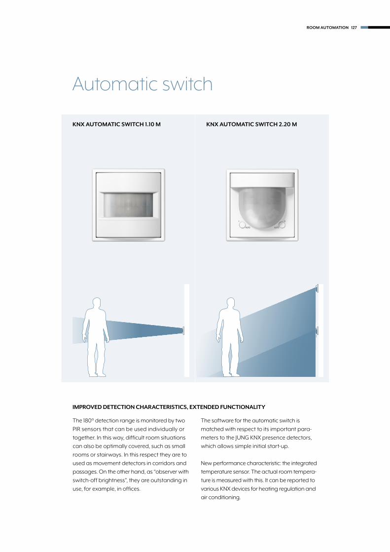
IMPROVED DETECTION CHARACTERISTICS, EXTENDED FUNCTIONALITY
The 180° detection range is monitored by two
PIR sensors that can be used individually or
together. In this way, difficult room situations
can also be optimally covered, such as small
rooms or stairways. In this respect they are to
used as movement detectors in corridors and
passages. On the other hand, as “observer with
switch-off brightness”, they are outstanding in
use, for example, in offices.
The software for the automatic switch is
matched with respect to its important para-
meters to the JUNG KNX presence detectors,
which allows simple initial start-up.
New performance characteristic: the integrated
temperature sensor. The actual room tempera-
ture is measured with this. It can be reported to
various KNX devices for heating regulation and
air conditioning.
KNX AUTOMATIC SWITCH 1.10 M KNX AUTOMATIC SWITCH 2.20 M
Automatic switch
ROOM AUTOMATION 127

Serie ASSerie ASerie CDSerie LS
128
KNX
Automatic switch 1.1 mfor bus coupling unit 3 ref.-no.: 2073 UETS product family: Physical sensorsProduct type: MovementIntended use • Requirement-oriented control of lighting and other electrical loads in interior rooms • Mounting on bus coupling unit 3 (ref.-no.: 2073 U)
Product characteristics • Automatic switching of lighting depending on the thermal movement and ambient brightness • 2 PIR sensors • Detection range 180° • Integrated brightness sensor • Switch-off brightness can be set • Output functions: switching, value transmitter, light scene extension, staircase function, switching with forced position, operating mode setting for room temperature controller • Extension of the detection area by way of operating several devices as main unit or extension unit • Sensitivity can be set manually • Status LEDs • Manual switching on the device • Up to half of the detection area can be screened off (cover or parameter setting)
Additional characteristics of "Universal" version: • Manual operation with IR remote control possible (ref.-no.: KNX PM FB IR) • 5 function blocks for motion detection each with 2 outputs • Function blocks switchable, e.g. for day/night operation • Brightness sensor function with 3 limiting values • Alarm message in case the device is removed from the bus coupling unit • Temperature measurement
Ref.-no.
Bus coupling unit 3screw fixing only, without claws
Intended use • Coupling of automatic switches (ref.-no.: ..3181.., ..3281..) to KNX systems • Installation in flush-box according to DIN 49073
2073 U
Technical dataKNX medium: TP 256Rated voltage KNX: DC 21 ... 32 V SELVAmbient temperature: −25 ... +55 °CStorage/transport temperature: −25 ... +70 °CProtection class: III
for AS and A ranges StandardThermoplastic (breakproof) high-glossivory A 3181white A 3181 WWblack A 3181 SWThermoplastic (breakproof) lacqueredaluminium A 3181 ALchampagne A 3181 CHmocha A 3181 MOmatt anthracite A 3181 ANM
Automatic switch

Serie ASSerie A
Serie CD
129
Ref.-no.
KNX
UniversalThermoplastic (breakproof) high-glossivory A 3181-1white A 3181-1 WWblack A 3181-1 SWThermoplastic (breakproof) lacqueredaluminium A 3181-1 ALchampagne A 3181-1 CHmocha A 3181-1 MOmatt anthracite A 3181-1 ANM
for CD range StandardThermoplastic (breakproof) high-glossivory CD 3181white CD 3181 WWgrey CD 3181 GRlight grey CD 3181 LGblack CD 3181 SW
UniversalThermoplastic (breakproof) high-glossivory CD 3181-1white CD 3181-1 WWgrey CD 3181-1 GRlight grey CD 3181-1 LGblack CD 3181-1 SW
for LS range StandardThermoplastic (breakproof) high-glossivory LS 3181white LS 3181 WWlight grey LS 3181 LGblack LS 3181 SWmetal versionsaluminium (lacquered) AL 3181stainless steel (lacquered) ES 3181anthracite (lacquered) AL 3181 ANdark (lacquered) AL 3181 Dclassic brass (lacquered) ME 3181 Cantique brass (lacquered) ME 3181 AT
UniversalThermoplastic (breakproof) high-glossivory LS 3181-1white LS 3181-1 WWlight grey LS 3181-1 LGblack LS 3181-1 SWmetal versionsaluminium (lacquered) AL 3181-1stainless steel (lacquered) ES 3181-1anthracite (lacquered) AL 3181-1 ANdark (lacquered) AL 3181-1 Dclassic brass (lacquered) ME 3181-1 Cantique brass (lacquered) ME 3181-1 AT
Automatic switch
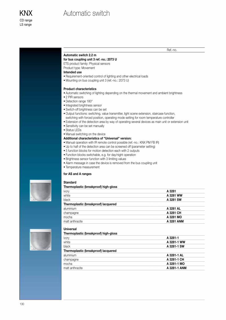
CD rangeLS range
130
KNX
Automatic switch 2.2 mfor bus coupling unit 3 ref.-no.: 2073 UETS product family: Physical sensorsProduct type: MovementIntended use • Requirement-oriented control of lighting and other electrical loads • Mounting on bus coupling unit 3 (ref.-no.: 2073 U)
Product characteristics • Automatic switching of lighting depending on the thermal movement and ambient brightness • 2 PIR sensors • Detection range 180° • Integrated brightness sensor • Switch-off brightness can be set • Output functions: switching, value transmitter, light scene extension, staircase function, switching with forced position, operating mode setting for room temperature controller • Extension of the detection area by way of operating several devices as main unit or extension unit • Sensitivity can be set manually • Status LEDs • Manual switching on the device
Additional characteristics of "Universal" version: • Manual operation with IR remote control possible (ref.-no.: KNX PM FB IR) • Up to half of the detection area can be screened off (parameter setting) • 5 function blocks for motion detection each with 2 outputs • Function blocks switchable, e.g. for day/night operation • Brightness sensor function with 3 limiting values • Alarm message in case the device is removed from the bus coupling unit • Temperature measurement
Ref.-no.
Automatic switch
for AS and A ranges StandardThermoplastic (breakproof) high-glossivory A 3281white A 3281 WWblack A 3281 SWThermoplastic (breakproof) lacqueredaluminium A 3281 ALchampagne A 3281 CHmocha A 3281 MOmatt anthracite A 3281 ANM
UniversalThermoplastic (breakproof) high-glossivory A 3281-1white A 3281-1 WWblack A 3281-1 SWThermoplastic (breakproof) lacqueredaluminium A 3281-1 ALchampagne A 3281-1 CHmocha A 3281-1 MOmatt anthracite A 3281-1 ANM

CD rangeLS range
131
Ref.-no.
KNX
for CD range StandardThermoplastic (breakproof) high-glossivory CD 3281white CD 3281 WWgrey CD 3281 GRlight grey CD 3281 LGblack CD 3281 SW
UniversalThermoplastic (breakproof) high-glossivory CD 3281-1white CD 3281-1 WWgrey CD 3281-1 GRlight grey CD 3281-1 LGblack CD 3281-1 SW
for LS range StandardThermoplastic (breakproof) high-glossivory LS 3281white LS 3281 WWlight grey LS 3281 LGblack LS 3281 SWmetal versionsaluminium (lacquered) AL 3281stainless steel (lacquered) ES 3281anthracite (lacquered) AL 3281 ANdark (lacquered) AL 3281 Dclassic brass (lacquered) ME 3281 Cantique brass (lacquered) ME 3281 AT
UniversalThermoplastic (breakproof) high-glossivory LS 3281-1white LS 3281-1 WWlight grey LS 3281-1 LGblack LS 3281-1 SWmetal versionsaluminium (lacquered) AL 3281-1stainless steel (lacquered) ES 3281-1anthracite (lacquered) AL 3281-1 ANdark (lacquered) AL 3281-1 Dclassic brass (lacquered) ME 3281-1 Cantique brass (lacquered) ME 3281-1 AT
Automatic switch

KNX ROOM THERMOSTAT FAN COIL
Consistent JUNG design also in the KNX
temperature and ventilation control:
The different room thermostats provide
a healthy room climate in private and
commercial buildings. Well thought out
operating concepts support the intuitive
handling in each case.
132 ROOM AUTOMATION

Room thermostat
ROOM TEMPERATURE CONTROLLER
Standalone solution for heating and cooling for
the residential and commercial areas. It is also
possible to interrogate conventional push-buttons
and/or window and door contacts as well as dew/
condensation and leak sensors.
ROOM AUTOSTAT
Has no setting wheel and thus cannot be manipu-
lated and therefore ideal for use in public buildings;
the KNX room autostat with integrated push-button
interface, 4-gang for convenient temperature control.
CLIMATE SENSOR
For automated ventilation applications and/or for
temperature control. Also possible: Interrogation of
conventional push-buttons and/or window and
door contacts as well as dew/condensation and
leak sensors.
ROOM TEMPERATURE CONTROLLER F 50
Controller for heating/cooling with integrated fan
coil actuation. With variable display and operation
options; self-explanatory symbols and coloured
status and operation LEDs optimise the operation.
ROOM THERMOSTAT FAN COIL
Controller for temperature and ventilation, mainly
for the hotel business. Intuitive operating concept
using capacitive sensor push-buttons. Clear display
and unambiguous symbols make the selection from
four operating modes easy.
ROOM AUTOMATION 133

PUSH-BUTTON EXTENSION MODULE FOR ROOM TEMPERATURE CONTROLLER F 50
The functions can be extended by connecting the 1- to 4-gang push-button extension module,
while at the same minimising the load on the bus. Particularly the option for installation of the
extension module at a distance of up to 30 m provides more flexibility.
BÜRO FLUR
KNX line
1 Room temperature controller F 50
2 Push-button extension module
Room temper- ature controller
ROOM 1 ROOM 2 ROOM 3
Room temper- ature controller
Extension module Extension module
max. 30 m max. 30 m
KNX line
1
2
1 2
max. 30 m
Room Temperature Controller F 50 options
BÜRO FLUR
OFFICE APPLICATION EXAMPLES
OFFICE CORRIDOROFFICE CORRIDOROFFICE CORRIDOR
134 ROOM AUTOMATION

PRESENCE BUTTON
The user can decide between presence and absence
with the Presence button. The appropriate symbols
and coloured LEDs display the current status.
Display and adjustment of the operating mode The tempera-
ture mode is selected as required using the "Comfort", "Stand-
by", "Night Operation" and "Frost Protection" operating modes.
MOVE BLINDS/SHUTTERS
Push-button sensor functions can be individually
parametrised. Here, the operating mode changeover
is changed to the "move blinds/shutters" push-button
function.
SWITCH/DIM
The "switch/dim" push-button functions on one side
have been combined with temperature setpoint
shift on the other side for this parametrisation.
STANDBY/NIGHT OPERATION
At times of absence a choice between the ‘frost
protection’ and ‘night reduction’ operation modes
can be made. Coloured LEDs next to the symbols
indicate the relevant mode.
ROOM AUTOMATION 135

136
KNX
Ref.-no.
Temperature controller fan coilIntended use • Sensor module for operating electrical fan coil units in KNX installations • Measurement and feedback control of the room temperature • Installation in flush-box according to DIN 49073 (recommendation: deep box)
Product characteristics • Real glass front panel • 8 capacitive sensor buttons • Internal temperature sensor • External temperature sensor can be evaluated • Control of fan coil units • Heating and/or cooling mode • Suitable for 2-pipe or 4-pipe systems • Up to 3 fan speeds can be controlled • Room temperature controller function • Preselection of the current energy level either through the option of 4 operating modes in accordance with KNX standard or of 5 temperature profiles for use in hotels or similar sites • Display for indication of temperature (°C or °F), fan speed, operating mode/profile • 1 operating level and 2 menu levels • Menu levels blockable • 1 status LED (red/green/blue) • Brightness and contrast adjustable • Duration of the display illumination up to 120 seconds • Operation as extension unit for temperature controller possible • Integrated bus coupling unit
Technical dataKNX medium: TP 256Rated voltage KNX: DC 21 ... 32 V SELVCurrent consumption KNX: 8 ... 17.5 mAProtection class: IIIAmbient temperature: −5 ... +45 °CStorage/transport temperature: −20 ... +70 °C
for AS and A rangeswhite TRD A 5248 WWblack TRD A 5248 SW
for LS rangewhite TRD LS 9248 WWblack TRD LS 9248 SW
Fan coil controller

Serie ASSerie A
Serie CDSerie LS
137
Ref.-no.
KNX
Room temperature controller module 2-gangincluding transparent cover and inlay with symbolsIntended use • Single-room temperature control in KNX installations • Operation of loads, e.g. light on/off, dimming, blinds up/down, recalling and saving light scenes, etc. • Installation in wall box according to DIN 49073
Product characteristicsAll buttons can be assigned with push-button sensor functions or functions for controller operation. • Measurement of the room temperature • Room temperature control with setpoint value specification • Extension for room temperature controller • Push-button functions switching, dimming, blind control, value transmitter, scene recall, etc. • One or two functions per button • Completion with cover kit 2-gang • Illuminable inscription field • Two red status LEDs per button – red, green or blue adjustable • One operation LED as an orientation light and to indicate the programming status – red, green or blue adjustable • Brightness of status LED, operation LED and labelling field adjustable; switchable while in operation, e.g. during the night • Disabling function: Disable or function switch-over of all or of individual push-button functions • Alarm function, optionally with confirmation by pressing any button • Energy saving mode (for operation without controller function) • Integrated bus coupling unit • Connection for a push-button extension module, for extension with up to eight additional buttons
for AS and A rangesfor cover kit 2-gang, complete, ref.-no.: A 502 TSA ..
A 5178 TSM
for CD rangefor cover kit 2-gang, complete, ref.-no.: CD 502 TSA ..
CD 5178 TSM
Room temperature controller
for LS rangefor cover kit 2-gang, complete, ref.-no.: ..502 TSA .. for the LS range
LS 5178 TSM

Serie ASSerie ASerie CDSerie LS
138
KNX
Room temperature controllerwith integrated BCUwith rotary knob for set point adjustment
Only with the ETS 3.0d version or later versions the full functionality will be available.
Intended use • Single-room temperature control in KNX installations • Installation in appliance box according to DIN 49073
Product characteristics • Measurement of room temperature and comparison with setpoint temperature • Setpoint specification by selection of the operating mode • Operating modes: Comfort, Standby, Night operation, Frost/heat protection • Heating and cooling mode • Heating and cooling with basic and additional step • Setpoint adjustment • Presence push-button • Status LEDs
Room temperature controller

for AS and A rangesThermoplastic (breakproof) high-glossivory A 2178white A 2178 WWblack A 2178 SWThermoplastic (breakproof) lacqueredaluminium A 2178 ALchampagne A 2178 CHmocha A 2178 MOmatt anthracite A 2178 ANM
for CD rangeThermoplastic (breakproof) high-glossivory 2178white CD 2178 WWgrey CD 2178 GRlight grey CD 2178 LGblack CD 2178 SW
for LS rangeThermoplastic (breakproof) high-glossivory LS 2178white LS 2178 WWlight grey LS 2178 LGblack LS 2178 SWmetal versionsaluminium AL 2178stainless steel ES 2178anthracite (aluminium lacquered) AL 2178 ANchrome GCR 2178classic brass ME 2178 Cantique brass ME 2178 AT
Serie ASSerie A
Serie CDSerie LS
139
Ref.-no.
KNXRoom temperature controller

Room temperature controllerwith integrated BCUwith integrated push-button interface 4-gangwith rotary knob for set point adjustment
Only with the ETS 3.0d version or later versions the full functionality will be available.
• Intended use • Single-room temperature control in KNX installations • Type of loads for binary output: LED or electronic relais • Installation in appliance box according to DIN 49073
Product characteristics • Measurement of room temperature and comparison with setpoint temperature • Setpoint specification by selection of the operating mode • Operating modes: Comfort, Standby, Night operation, Frost/heat protection • Heating and cooling mode • Heating and cooling with basic and additional step • Setpoint adjustment • Presence push-button • Status LEDs • Push-button interface with four inputs or two outputs (0.8 mA) and two inputs, e.g. for window contacts, push-buttons, LEDs, etc. • Function of the inputs: switching, dimming, shutter control, light scene extension, brightness or temperature value transmitter • Option: External temperature sensor (accessory ref.-no.: FF 7.8) connectable to input 4
Technical dataRated voltage KNX: DC 21 ... 32 V SELVCurrent consumption KNX: max. 10 mAConnection, KNX: terminalAmbient temperature: −5 ... +45 °CStorage/transport temperature: −25 ... +70 °COutput current: 0.8 mAInputs and outputs Cable type: J-Y(St)Y 2 x 2 x 0.8 mm2
Cable length: max. 5 m Temperature sensor cable length: max. 50 m
Use deep wall box for cables with 1.5 mm2
Serie ASSerie ASerie CDSerie LS
140
KNX Room temperature controller

Serie ASSerie A
Serie CDSerie LS
141
Ref.-no.
KNX
for AS and A rangesThermoplastic (breakproof) high-glossivory A 2178 TSwhite A 2178 TS WWblack A 2178 TS SWThermoplastic (breakproof) lacqueredaluminium A 2178 TS ALchampagne A 2178 TS CHmocha A 2178 TS MOmatt anthracite A 2178 TS ANM
for CD rangeThermoplastic (breakproof) high-glossivory 2178 TSwhite CD 2178 TS WWgrey CD 2178 TS GRlight grey CD 2178 TS LGblack CD 2178 TS SW
Room temperature controller
for LS rangeThermoplastic (breakproof) high-glossivory LS 2178 TSwhite LS 2178 TS WWlight grey LS 2178 TS LGblack LS 2178 TS SWmetal versionsaluminium AL 2178 TSstainless steel ES 2178 TSanthracite (aluminium lacquered) AL 2178 TS ANdark (aluminium lacquered) AL 2178 TS Dchrome GCR 2178 TSclassic brass ME 2178 TS Cantique brass ME 2178 TS AT
Serie ASSerie ASerie CDSerie LS
142
KNX
Room autostatwith integrated BCUwith integrated push-button interface 4-gangwithout rotary knob for set point adjustmentwithout any operational elements
Only with the ETS 3.0d version or later versions the full functionality will be available.
Intended use • Single-room temperature control in KNX installations • Integrated 4-gang binary input for universal use • Installation in appliance box according to DIN 49073 • Recommended for installations in public buildings
Product characteristics • Measurement of room temperature and comparison with setpoint temperature • Setpoint specification by selection of the operating mode • Operating modes: Comfort, Standby, Night operation, Frost/heat protection • Heating and cooling mode • Heating and cooling with basic and additional step • Operation solely via the bus • Push-button interface with four inputs or two outputs (0.8 mA) and two inputs, e.g. for window contacts, push-buttons, LEDs, etc. • Function of the inputs: switching, dimming, shutter control, light scene extension, brightness or temperature value transmitter • Option: External temperature sensor (accessory ref.-no.: FF 7.8) connectable to input 4
Technical dataRated voltage KNX: DC 21 ... 32 V SELVCurrent consumption KNX: max. 7.5 mAConnection, KNX: terminalAmbient temperature: −5 ... +45 °CStorage/transport temperature: −25 ... +70 °COutput current: 0.8 mAInputs and outputs Cable type: J-Y(St)Y 2 x 2 x 0.8 mm2
Cable length: max. 5 m Temperature sensor cable length: max. 50 m
Use deep wall box for cables with 1.5 mm2
Room autostat

Serie ASSerie A
Serie CDSerie LS
143
Ref.-no.
KNX
for AS and A rangesDuroplastic (scratch-proof) glossyivory A 2178 ORTSwhite A 2178 ORTS WWblack A 2178 ORTS SWDuroplastic lacqueredaluminium A 2178 ORTS ALchampagne A 2178 ORTS CHmocha A 2178 ORTS MOThermoplastic (breakproof) high-glosswhite A 2178 BF ORTS WWblack A 2178 BF ORTS SWThermoplastic (breakproof) lacqueredmatt anthracite A 2178 BF ORTS ANM
for CD rangeDuroplastic (scratch-proof) glossyivory 2178 ORTSwhite CD 2178 ORTS WWgrey CD 2178 ORTS GRlight grey CD 2178 ORTS LGblack CD 2178 ORTS SW
for LS rangeDuroplastic (scratch-proof) glossyivory LS 2178 ORTSwhite LS 2178 ORTS WWlight grey LS 2178 ORTS LGblack LS 2178 ORTS SWmetal versionsaluminium AL 2178 ORTSstainless steel ES 2178 ORTSanthracite (aluminium lacquered) AL 2178 ORTS ANchrome GCR 2178 ORTSclassic brass ME 2178 ORTS Cantique brass ME 2178 ORTS AT
Room autostat

Serie ASSerie ASerie CDSerie LS
144
KNX
CO2 multi-sensorwith integrated BCUwith humidity sensor and room temperature controllerwith integrated push-button interface 2-gang
Intended use • Measurement of CO2 concentration, relative air humidity and air temperature • Output of the measured values as telegram to the bus, e.g. for controlling fans or window drives via KNX telegrams • Single-room temperature control in KNX installations • Installation in appliance box according to DIN 49073
Product characteristics • Limit value monitoring for CO2 concentration (max. 4 threshold values) and air humidity (max. 2 threshold values) • Dew point alarm e.g. for cooling blankets and conservatories, to avoid mould formation • Two binary inputs for connection of floating contacts e.g. buttons, switches, window contacts • Logic gates for simple gating functions
Technical dataRated voltage KNX: DC 21 ... 32 V SELVCurrent consumption KNX: typical 12.5 mA
max. 25 mA (4 s/15 s as a cycle)Connection, KNX: terminalProtection class: IIIAmbient temperature: −5 ... +45 °CBinary inputs Cable length: max. 5 m Cable type: J-Y(St)Y 2 x 2 x 0.8 mm2
CO2 sensor Measuring range: 0 ... 2000 ppmHumidity sensor Measuring range: 10 ... 95 % relative humidity (r. h.)Temperature sensor Measuring range: −5 ... +45 °C
CO2 multi-sensor

for AS and A rangesDuroplastic (scratch-proof) glossyivory CO2 A 2178white CO2 A 2178 WWblack CO2 A 2178 SWDuroplastic lacqueredaluminium CO2 A 2178 ALchampagne CO2 A 2178 CHmocha CO2 A 2178 MOThermoplastic (breakproof) high-glosswhite CO2 A 2178 BF WWblack CO2 A 2178 BF SWThermoplastic (breakproof) lacqueredmatt anthracite CO2 A 2178 BF ANM
for CD rangeDuroplastic (scratch-proof) glossyivory CO2 CD 2178white CO2 CD 2178 WWgrey CO2 CD 2178 GRlight grey CO2 CD 2178 LGblack CO2 CD 2178 SW
145
Ref.-no.
KNX
for LS rangeDuroplastic (scratch-proof) glossyivory CO2 LS 2178white CO2 LS 2178 WWlight grey CO2 LS 2178 LGblack CO2 LS 2178 SWmetal versionsaluminium CO2 AL 2178stainless steel CO2 ES 2178anthracite (aluminium lacquered) CO2 AL 2178 ANdark (aluminium lacquered) CO2 AL 2178 Dchrome CO2 GCR 2178classic brass CO2 ME 2178 Cantique brass CO2 ME 2178 AT
CO2 multi-sensor
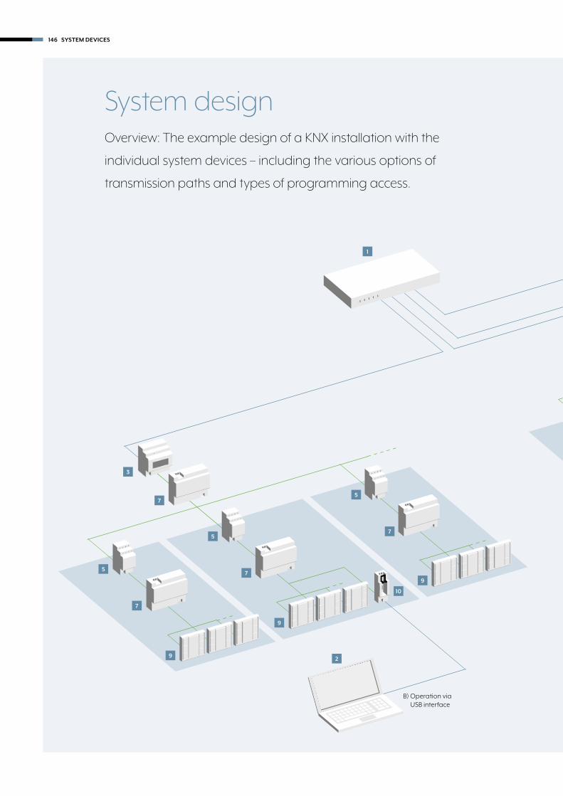
System designOverview: The example design of a KNX installation with the
individual system devices – including the various options of
transmission paths and types of programming access.
1
2
B) Operation via USB interface
5
7
9
5
7
9
10
5
7
9
3
7
146 SYSTEM DEVICES

1 LAN Router
2 Computer with installed ETS
3 IPR 200 for rail mounting as area coupler
4 IPR 200 for rail mounting as line coupler
5 Line coupler
6 Media converter
7 Power supply
8 IPS 200 for rail mounting
9 Node
10 USB interface
11 KNX RF
KNX line
LAN
2
A) Operation via IP using KNX IP Router or IP interface
2C) Operation using
KNX RF wireless USB stick
5
7
9
5
9
7
4
7
3
7
6
11
98
SYSTEM DEVICES 147

148
KNX
Power supplies Intended use • Supplying KNX devices with bus voltage • Supplying devices with direct current • Mounting on DIN rail according to EN 60715 in distribution boxes
Product characteristics • Output with integrated choke for supplying KNX bus lines • Output DC 30 V for supplying additional devices • Nominal current can be subdivided to outputs as desired • Reset button • Short-circuit proof • Overvoltage proof • No-load protection • Suitable for operation in systems with emergency power supply • Potential-free signal contact for operating and diagnostic message • With identical power supply parallel switchable (until the maximum short-circuit current is reached)
Ref.-no.
Power supply, 160 mARail mounting device, 4 rail unitsETS product family: System componentsProduct type: Power supply
20160 REG
Technical dataRated voltage AC: AC 180 ... 264 V ~Mains frequency: 50 / 60 Hz
max. 1.5 WEfficiency: approx. 76 %Rated voltage DC: DC 240 ... 250 VKNX KNX medium: TP 256 Bus output voltage: DC 28 ... 31 V SELV Output current: 160 mA (all outputs) Short-circuit current: max. 1 A Parallel operation with additional power supply: yesSignal output Switching voltage AC: AC 12 ... 230 V ~ Switching voltage DC: DC 2 ... 30 V Switching current: 5 mA ... 2 AAmbient temperature: −5 ... +45 °CStorage/transport temperature: −25 ... +75 °CRelative humidity: max. 93 % (no condensation)Mounting width: 72 mm (4 rail units)
Power supply

149
Ref.-no.
KNX
Power supply, 320 mARail mounting device, 4 rail unitsETS product family: System componentsProduct type: Power supply
20320 REG
Technical dataRated voltage AC: AC 180 ... 264 V ~Mains frequency: 50 / 60 Hz
max. 1.8 WEfficiency: approx. 84 %Rated voltage DC: DC 240 ... 250 VKNX KNX medium: TP 256 Bus output voltage: DC 28 ... 31 V SELV Output current: 320 mA (all outputs) Short-circuit current: max. 1 A Parallel operation with additional power supply: yesSignal output Switching voltage AC: AC 12 ... 230 V ~ Switching voltage DC: DC 2 ... 30 V Switching current: 5 mA ... 2 AAmbient temperature: −5 ... +45 °CStorage/transport temperature: −25 ... +75 °CRelative humidity: max. 93 % (no condensation)Mounting width: 72 mm (4 rail units)
Power supply, 640 mARail mounting device, 4 rail unitsETS product family: System componentsProduct type: Power supply
20640 REG
Technical dataRated voltage AC: AC 180 ... 264 V ~Mains frequency: 50 / 60 Hz
max. 2.9 WEfficiency: approx. 87 %Rated voltage DC: DC 240 ... 250 VKNX KNX medium: TP 256 Bus output voltage: DC 28 ... 31 V SELV Output current: 640 mA (all outputs) Short-circuit current: max. 1.5 A Parallel operation with additional power supply: yesSignal output Switching voltage AC: AC 12 ... 230 V ~ Switching voltage DC: DC 2 ... 30 V Switching current: 5 mA ... 2 AAmbient temperature: −5 ... +45 °CStorage/transport temperature: −25 ... +75 °CRelative humidity: max. 93 % (no condensation)Mounting width: 72 mm (4 rail units)
Power supply

150
KNX
Ref.-no.
Power supply, 1280 mARail mounting device, 6 rail unitsETS product family: System componentsProduct type: Power supply
21280 REG
Technical dataRated voltage AC: AC 180 ... 264 V ~Mains frequency: 50 / 60 Hz
max. 6.4 WEfficiency: approx. 86 %Rated voltage DC: DC 240 ... 250 VKNX KNX medium: TP 256 Bus output voltage: DC 28 ... 31 V SELV Output current: 1280 mA (all outputs) Short-circuit current: max. 3 A Parallel operation with additional power supply: noSignal output Switching voltage AC: AC 12 ... 230 V ~ Switching voltage DC: DC 2 ... 30 V Switching current: 5 mA ... 2 AAmbient temperature: −5 ... +45 °CStorage/transport temperature: −25 ... +75 °CRelative humidity: max. 93 % (no condensation)Mounting width: 108 mm (6 rail units)
Power supply

151
Ref.-no.
KNX
Uninterruptible KNX power supply 640 mA with integrated chokeRail mounting device, 8 rail unitsETS product family: System componentsProduct type: Power supply
Product characteristics • Generation and monitoring of the KNX bus voltage • With lead gel battery (ref.-no. BGA 12 AH) and cable set (ref.-no. KSB 4, KSE 2): buffering of the KNX bus voltage in the event of mains failure • Up to 2 batteries can be connected • Short-circuit proof • Overvoltage proof • Integrated choke • Alarm contact for fault message
USV 640 MA
Technical dataPower supply Rated voltage: AC 195 ... 255 V ~ Rated frequency: 45 ... 65 Hz Power consumption: max. 50 VA Power loss: max. 10 WAmbient temperature: −5 ... +45 °CStorage/transport temperature: −25 ... +70 °C
(Storage above +45 °C reduces the lifetime)KNX Bus output voltage: DC 28 ... 31 V SELV Output current: 640 mA (short-circuit proof) Short-circuit current: max. 1.4 A Connection: terminalConnection of fault indicator Switching voltage AC: AC 12 ... 230 V ~ Switching voltage DC: DC 12 ... 24 V Switching current AC: max. 6 A Switching current DC: max. 4 ABattery connection Cable length: approx. 2 m Fine-wire fuse: T 6.3 A H 250 V Rated voltage: DC 12 V Rated charging current: 650 mA, at battery capacity > 5 Ah
150 mA, at battery capacity < 5 AhMains failure bridging time (battery like new) 1 battery 12 V / 12 Ah: approx. 5.5 h 2 batteries 12 V / 12 Ah: approx. 11 hMounting width: 144 mm (8 rail units)Terminals: screw terminals single wire: 0.5 ... 4 mm2
stranded with ferrule: 0.2 ... 2.5 mm2
Power supply

152
KNX
Ref.-no.
Lead gel battery (rechargeable)
12 V DC, 12 AhIn combination with the uninterruptible KNX power supply, the lead gel battery serves for the buffering of the system voltage. Max. two lead gel batteries can be connected in parallel to the power supply. In that case two equal lead gel batteries must be used. For the connection of a single battery the 4-wire cable set must be used, for the connection of two batteries the 4-wire cable set must be used for the first one, the second one must be connected with the 2-wire cable set.The durability of lead gel batteries is up to 5 years.
BGA 12 AH
Technical dataPower supply Rated voltage: 12 V DC Battery capacity: 12 AhDimensions (W x H x D): 151 x 94 x 98 mmWeight: 4.2 kgAmbient temperature Operation: −20 ... +50 °C
Cable set
For the connection of the uninterruptible KNX power supply and the lead gel battery the 4-wire cable set (for one battery) must be used. For two batteries the 4-wire and the 2-wire set must be used.The 4-wire cable set has an integrated fuse and a temperature sensor, the 2-wire cable set has only an integrated fuse.
Basis KSB 4Extension KSE 2
Technical data KSB 4Cable Wires: 4-wire cable Cross-section: 0.75 mm2
Length: 2 mColour battery connection: red: positive (12 V battery)
black: negative (GND battery)Colour temperature sensor: white: positive (12 V temp. sensor)
yellow: negative (GND temp. sensor)Terminals Battery connection: for the connection to the uninterruptible
power supply: ferrulesfor the connection to the battery: cable lug (6.3 x 0.8 mm)
Temperature sensor: ferrulesFuse, model: exchangeable fuse with in-line
fuse holder (screw cap)Fuse, type: 5 x 20 mm, T6.3 H 250 V
Technical data KSE 2Cable Wires: 2-wire cable Cross-section: 0.75 mm2
Length: 2 mColour battery connection: red: positive (12 V battery)
black: negative (GND battery)Terminals Battery connection: for the connection to the
uninterruptible power supply: ferrulesfor the connection to the battery: cable lug (6.3 x 0.8 mm)
Fuse, model: exchangeable fuse with in-line fuse holder (screw cap)
Fuse, type: 5 x 20 mm, T6.3 H 250 V

153
Ref.-no.
KNX
USB data interfaceRail mounting device, 2 rail units
The USB data interface enables the coupling of a PC for the addressing, programming and diagnoses of KNX components. The power is fully supplied by the connected PC via the USB interface. This means that the USB data interface is no longer connected for the KNX if the USB cable is not plugged in. The device is only programmed locally with a physical address via the connected PC and therefore does not have a programming button or programming LED. The firmware of the USB data interface can be updated via a PC and is therefore safeguarded for future standards.Note: The USB data interface is supported by ETS 3 software from version “a” upwards and by the PC operating systems Windows XP and Windows 7.Connection: The connection to the KNX is carried out with the aid of the bus connecting terminal. The USB connection is carried out with a certified USB cable (1 x B plug required) with a max. length of 5 m.
2130 USB REG
Technical dataPower supply: via USB port of the PCConnection KNX: KNX bus connection block USB port: USB socket, type BTransfer rate: 9600 BaudTransmission protocol: compatible with USB 1.1/2.0Length of USB cable: max. 5 mAmbient temperature: −5 ... +45 °CStoring temperature: −25 ... +70 °CProtection class: IIMounting width: 36 mm (2 rail units)
USB data interface
2130 USB
Technical data KSE 2Cable Wires: 2-wire cable Cross-section: 0.75 mm2
Length: 2 mColour battery connection: red: positive (12 V battery)
black: negative (GND battery)Terminals Battery connection: for the connection to the
uninterruptible power supply: ferrulesfor the connection to the battery: cable lug (6.3 x 0.8 mm)
Fuse, model: exchangeable fuse with in-line fuse holder (screw cap)
Fuse, type: 5 x 20 mm, T6.3 H 250 V
Data interface

154
Ref.-no.
Centre platefor USB data interface ref.-no.: 2130 USB for AS and A rangesDuroplastic (scratch-proof) glossyivory P A 569 PLTwhite P A 569 PLT WWblack A 569 PLT SWDuroplastic lacqueredaluminium P L A 569 PLT ALchampagne P A 569 PLT CHmocha A 569 PLT MOThermoplastic (breakproof) high-glossivory L A 569 BFPLTwhite L A 569 BFPLT WWblack L A 569 BFPLT SWThermoplastic (breakproof) lacqueredmatt anthracite L A 569 BFPLT ANM
for CD rangeThermoplastic (breakproof) high-glossivory L 569 Twhite L CD 569 T WWgrey L CD 569 T GRlight grey L CD 569 T LGblack L CD 569 T SW
Centre plate with inscription field 6 x 37 mm
Thermoplastic (breakproof) high-glossivory L 569 TNAwhite L CD 569 TNA WW
Centre platefor USB data interface ref.-no.: 2130 USBfor LS rangeThermoplastic (breakproof) high-glossivory L LS 969 Twhite L LS 969 T WWlight grey L LS 969 T LGblack L LS 969 T SWmetal versionsaluminium P L AL 2969 Tstainless steel L ES 2969 Tanthracite (aluminium lacquered) L AL 2969 T ANdark (aluminium lacquered) L AL 2969 T Dchrome GCR 2969 Tclassic brass P ME 2969 T Cantique brass ME 2969 T AT
KNX Data interface
PP
LL
Colour printing possibleLaser labelling possible

155
Ref.-no.
KNX RF radio USB stick
Intended use • PC interface for the addressing, programming and diagnostics of KNX-RF devices • USB stick for coupling to a PC with a Windows-based operating system
Product characteristics • Commissioning, programming, visualisation and diagnostics of KNX-RF devices • Automatic installation of PC communication via HID profile
USB 2130 RF
Technical dataRated voltage: DC 5 VUSB version: 2.0Connection USB: type AAmbient temperature: −10 ... +70 °CRelative humidity: max. 80 % (no condensation)Radio frequency: 868.0 ... 868.6 MHzTransmitting power: max. 20 mWTransmission range in free field: typical 100 m
KNX RF radio converterProject design and commissioning with ETS5 or a more recent version.
Intended use • Connection of KNX radio networks with cabled KNX lines • Extension of the radio range in KNX radio networks (repeater operation, external power supply with 24 V AC/DC, e.g. ref.-no. NT 2415 REG VDC) • Installation in wall box according to DIN 49073 with suitable cover
MK 100 RF
KNXKNX RF

156
KNX
Ref.-no.
IP routerRail mounting device, 3 rail unitsETS product family: System componentsProduct type: IP router
Intended use • Connection between KNX devices and PC or other data processing devices via IP • Operation as line/area coupler or data interface • Mounting on DIN rail in distribution boxes
Product characteristics • KNXnet/IP routing for communication between KNX lines, areas and systems via IP network • Telegramm forwarding and filtering according to physical address or group address • LED display for KNX communication, Ethernet communication and programming mode • Configuration via ETS and Telnet • SNTP server, with battery backup • Commissioning with display support • Max. 5 connections to IP terminal devices, e.g. for simultaneous visualisation and configuration • Outage message of the KNX system to the IP system • Supply from network line (Power-over-Ethernet acc. to IEEE 802.3af) through separate voltage supply ref.-no. NT 2415 REG VDC or the auxiliary voltage output of the KNX voltage supply • Electrical isolation between KNX and IP network • Power consumption max. 1 W
IPR 200 REG
Power supply for rail mountingfor Smart Control ref.-no.: SC 7 AL, SC 7 SW, SC 10, SC 15, SC 19for IP interface ref.-no.: IPS 200 REG and IP router ref.-no.: IPR 200 REGRail mounting device, 4 rail units
NT 2415 REG VDC
Technical dataInput voltage: AC 100 ... 240 V ~, 50/60 HzInput current: 730 mAOutput voltage: 24 V DCOutput current: 1.5 AMounting width: 72 mm (4 rail units)Connection: screw terminals
IP interfaceRail mounting device, 3 rail units
Intended use • Connection between KNX devices and PC or other data processing devices via IP • Operation as data interface • Mounting on DIN rail in distribution boxes
Product characteristics • LED display for KNX communication, Ethernet communication and programming mode • Configuration via ETS, Telnet or software tool • Max. 5 connections to IP terminal devices, e.g. for simultaneous visualisation and configuration • Supply from network line (Power-over-Ethernet acc. to IEEE 802.3af) through separate voltage supply ref.-no. NT 2415 REG VDC or the auxiliary voltage output of the KNX voltage supply • Electrical isolation between KNX and IP network • Power consumption max. 1 W
IPS 200 REG
PIP router / interface

157
Ref.-no.
KNX
Area / line couplerRail mounting device, 2 rail unitsETS product family: System componentsProduct type: Line coupler
Function: The coupler connects two KNX data lines and ensures the electrical separation of these lines from one another. The definite functions of the device are defined by addressing and parameterization.Line coupler: Connection of a line with a main line. Alternatively with or without filter function. The coupler belongs logically to the subordinate line (here: line).Area coupler: Connection of a main line and an area line. Alternatively with or without filter function. The coupler belongs logically to the subordinate line (here: main line).Amplifier: Preparation and repetition of telegrams on a line, no filter function. Division of a line into max. 4 independent line segments (max. 3 line amplifiers connected in parallel per line). Each line segment requires a separate power supply including a choke.
When using the device as an area/line coupler with the application coupler/amplifier 901011, the telegram confirmation can be parameterised additionally on “always reject” (NACK) on a line.With this parameter setting a physical access (programming/commissioning) from this line to the coupler and the other lines is no longer possible (protective function).
2142 REG
Technical dataPower supply: 21 ... 32 V DC from superordinate lineCurrent consumption superordinate line: approx. 6 mA subordinate line: approx. 8 mAConnection: KNX bus connection block for superordinate
and subordinate lineMounting: on DIN railAmbient temperature: −5 ... +45 °CStoring temperature: −25 ... +70 °CProtection class: III acc. EN 61 140Mounting width: 36 mm (2 rail units)
Application unit logicRail mounting device, 2 rail unitsETS product family: ControllerProduct type: Controller
Product characteristics • Can be parameterised via ETS3 The latest .NET Framework is required. • 50 logical functions (AND, OR, One hot) • 50 unidirectional and bidirectional gates • 30 timers (with ON/OFF delay, pulse duration, staircase lighting function) • 10 comparators
ABL/S2.1

KNX DALI-Gateway TWIlluminate rooms in a targeted manner and use matching colour
temperatures to promote performance of people. The KNX DALI
gateway TW forms the interface to the control of DALI luminaires
in a KNX installation (for max. 64 DALI nodes in max. 32 groups).
As well as the regular brightness control, the control of the colour
temperature of white light is also performed. The lighting can thus
be adjusted as required at any time.
KNX DALI GATEWAY TW
Control Tunable White conveniently
158 COMMUNICATION/GATEWAYS

COMMUNICATION/GATEWAYS 159

The basic idea of Tunable White is to control
the colour temperature dynamically and
seamlessly from warm white (1,000 Kelvin)
to cold white (10,000 Kelvin). By adapting the
colour temperature to the room, the perceived
quality improves. Thanks to its very good
colour rendering, Tunable White stands for
a high level of lighting comfort – but also mainly
for its ability to adapt artificial light dynamically
to human biorhythms. This can provably im-
prove human performance and have a positive
effect on their health. The JUNG KNX DALI gate-
way TW is the first KNX device that offers this
capability with such scope.
COLOUR TEMPERATURE AND BRIGHTNESS
Using the KNX DALI Gateway TW, colour tem-
perature and brightness can be set indepen-
dently of each other or combined as desired.
In this way, the behaviour of an incandescent
lamp can be adjusted by changing the colour
temperature to the warmer range when dim-
ming and changing to the colder range when
making brighter.
5.000 KELVIN 3.000 KELVIN
160 COMMUNICATION/GATEWAYS

161
Ref.-no.
KNX
DALI gateway TWRail mounting device, 4 rail unitswith manual electronic operation and LED status indicationETS product family: IlluminationProduct type: Dimmer
Intended use • Controlling of luminaires and other applications with DALI operating device in KNX installations e.g. electronic ballast • Mounting on DIN rail according to EN 60715 in distribution boxes
Product characteristics • Control of up to 64 DALI devices in up to 32 groups • Setting of colour temperature for luminaires with DALI Device Type 8 for tunable white acc. to IEC 62386-209 • Suitable for operation in emergency lighting systems • Individual, group or central addressing • 16 light scenes • Effect control for dynamic lighting effects or colour games • Read out DALI device state via KNX, e.g. brightness or luminaire error • Manual operation of the DALI groups • Restraint function • Feedback of switching state and brightness value in bus and manual mode • Collective feedback • Central switching function • Disabling function for each DALI group • Separate ON and OFF delay • Staircase lighting timer with pre-warning function • Corridor function: when combined with motion detectors, reduced continuous lighting, if no motion is detected • Online or offline project design of the DALI devices with ETS plug-in • Short-circuit protection • Surge voltage protection • Overload protection • Operating hours counter • Signal of the global switching status of the DALI devices, e.g. to switch off the mains voltage of the DALI devices to avoid standby losses • An individual DALI device can be exchanged during operation without software • Linear or logarithmic dimming characteristic can be selected
2099 REGHE
Technical dataRated voltage: AC 110 ... 240 V ~, 50/60 HzRated voltage DC: DC 110 ... 240 VPower loss: max. 3 WAmbient temperature: −5 ... +45 °CStorage/transport temperature: −25 ... +70 °CRated voltage DALI: DC 16 VNumber of DALI devices: max. 64DALI transmission rate: 1.2 kbit/sDALI protocol: EN 62386Cable type: Sheathed cable 230 V, e,g. NYMCable length DALI with 1.5 mm2: max. 300 m with 1.0 mm2: max. 238 m with 0.75 mm2: max. 174 m with 0.5 mm2: max. 116 mMounting width: 72 mm (4 rail units)Connection, power supply and DALI: screw terminals single wire: 0.5 ... 4 mm2
stranded without ferrule: 0.5 ... 4 mm2
stranded with ferrule: 0.5 ... 2.5 mm2
KNX medium: TP 256Rated voltage KNX: DC 21 ... 32 V SELVPower consumption KNX: typical 150 mWConnection, KNX: terminal
DALI gateway TW

162 ACTUATORS / COMBINATION DEVICES

The various KNX actuators for rail mounting
are impressive due to high functionality in
compact design, whereby the space in the
distribution can be used optimally. Manual
operability for „local operation“ and for
maintenance purposes is common to all
of them; also status feedbacks in manual
mode. Scene operation is integrated in all
switching, dimming and blind actuators.
The switching actuators are optionally
available in the version with operating hours
counter and current detection (measurement
of the load current for each output). The JUNG
KNX actuators for rail mounting also meet
the applicable standards and established
engineering practice of the VDE test and
certification institute.
Actuators for rail mounting
COMBINATION OF KNX ACTUATORS FOR RAIL MOUNTING
This combination of two 8-gang and 16-gang switch/blind actuators has the advantage of optimal use of space with 12 TE/24 channels and the resulting function depth.
ACTUATORS / COMBINATION DEVICES 163

164
KNX
Ref.-no.
Switch actuator, 2-gangRail mounting device, 4 rail units2 make contacts with manual mechanical operation and status indicatorETS product family: OutputProduct type: Binary output
2302.16 REGHM
Technical dataRated voltage KNX: DC 21 ... 32 V SELVConnection, KNX: KNX bus connection blockPower consumption KNX: typical 150 mWPower loss: max. 2 WAmbient temperature: −5 ... +45 °CStorage/transport temperature: −25 ... +70 °CMounting width: 72 mm (4 rail units)Connection, outputs: screw terminals single wire: 0.5 ... 4 mm2
stranded without ferrule: 0.5 ... 4 mm2
stranded with ferrule: 0.5 ... 2.5 mm2
Switching outputsContact type: floating relay contacts (μ contact)Switching voltage AC: AC 250 / 400 VSwitching current 230 V AC1: 16 ASwitching current 230 V AC3: 10 ASwitching current 400 V AC1: 10 ASwitching current 400 V AC3: 6 AFluorescent lamps: 10 AXOhmic load: 3680 WCapacitive load: 10 A / 140 µFSwitching voltage DC: DC 12 ... 24 VSwitching current DC: 16 AMin. switching current: 100 mASwitch-on current 150 µs: 400 ASwitch-on current 600 µs: 200 ALamp loadsIncandescent lamps: 2500 WHV halogen lamps: 2500 WInductive transformers with LV halogen lamps: 1200 VAElectronic transformers with LV halogen lamps: 1500 WFluorescent lamps T5/T8 non-compensated: 2500 W parallel compensated: 1300 W / 140 μF lead-lag circuit: 2300 W / 140 µFCompact fluorescent lamps non-compensated: 2500 W parallel compensated: 1300 W / 140 μFMercury vapour lamps non-compensated: 2000 W parallel compensated: 2000 W / 140 µFApprovals: VDE
Actuators
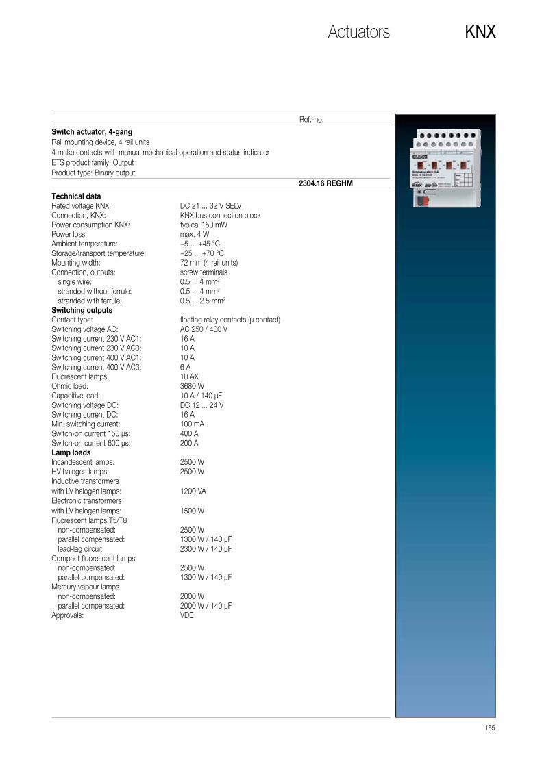
165
Ref.-no.
KNX
Switch actuator, 4-gangRail mounting device, 4 rail units4 make contacts with manual mechanical operation and status indicatorETS product family: OutputProduct type: Binary output
2304.16 REGHM
Technical dataRated voltage KNX: DC 21 ... 32 V SELVConnection, KNX: KNX bus connection blockPower consumption KNX: typical 150 mWPower loss: max. 4 WAmbient temperature: −5 ... +45 °CStorage/transport temperature: −25 ... +70 °CMounting width: 72 mm (4 rail units)Connection, outputs: screw terminals single wire: 0.5 ... 4 mm2
stranded without ferrule: 0.5 ... 4 mm2
stranded with ferrule: 0.5 ... 2.5 mm2
Switching outputsContact type: floating relay contacts (μ contact)Switching voltage AC: AC 250 / 400 VSwitching current 230 V AC1: 16 ASwitching current 230 V AC3: 10 ASwitching current 400 V AC1: 10 ASwitching current 400 V AC3: 6 AFluorescent lamps: 10 AXOhmic load: 3680 WCapacitive load: 10 A / 140 µFSwitching voltage DC: DC 12 ... 24 VSwitching current DC: 16 AMin. switching current: 100 mASwitch-on current 150 µs: 400 ASwitch-on current 600 µs: 200 ALamp loadsIncandescent lamps: 2500 WHV halogen lamps: 2500 WInductive transformers with LV halogen lamps: 1200 VAElectronic transformers with LV halogen lamps: 1500 WFluorescent lamps T5/T8 non-compensated: 2500 W parallel compensated: 1300 W / 140 μF lead-lag circuit: 2300 W / 140 µFCompact fluorescent lamps non-compensated: 2500 W parallel compensated: 1300 W / 140 μFMercury vapour lamps non-compensated: 2000 W parallel compensated: 2000 W / 140 µFApprovals: VDE
Actuators

166
KNX
Ref.-no.
Switch actuator, 8-gangRail mounting device, 8 rail units8 make contacts with manual mechanical operation and status indicatorOnly with the ETS 3.0d version or later versions the full functionality will be available.ETS product family: OutputProduct type: Binary output
2308.16 REGHM
Technical dataRated voltage KNX: DC 21 ... 32 V SELVConnection, KNX: KNX bus connection blockPower consumption KNX: typical 150 mWPower loss: max. 8 WAmbient temperature: −5 ... +45 °CStorage/transport temperature: −25 ... +70 °CMounting width: 144 mm (8 rail units)Connection, outputs: screw terminals single wire: 0.5 ... 4 mm2
stranded without ferrule: 0.5 ... 4 mm2
stranded with ferrule: 0.5 ... 2.5 mm2
Switching outputsContact type: floating relay contacts (μ contact)Switching voltage AC: AC 250 / 400 VSwitching current 230 V AC1: 16 ASwitching current 230 V AC3: 10 ASwitching current 400 V AC1: 10 ASwitching current 400 V AC3: 6 AFluorescent lamps: 10 AXOhmic load: 3680 WCapacitive load: 10 A / 140 µFSwitching voltage DC: DC 12 ... 24 VSwitching current DC: 16 AMin. switching current: 100 mASwitch-on current 150 µs: 400 ASwitch-on current 600 µs: 200 ALamp loadsIncandescent lamps: 2500 WHV halogen lamps: 2500 WInductive transformers with LV halogen lamps: 1200 VAElectronic transformers with LV halogen lamps: 1500 WFluorescent lamps T5/T8 non-compensated: 2500 W parallel compensated: 1300 W / 140 μF lead-lag circuit: 2300 W / 140 µFCompact fluorescent lamps non-compensated: 2500 W parallel compensated: 1300 W / 140 μFMercury vapour lamps non-compensated: 2000 W parallel compensated: 2000 W / 140 µFApprovals: VDE
Actuators

167
Ref.-no.
KNX
Switch actuator with C-load, 4-gangwith current detectionRail mounting device, 4 rail units4 make contacts with manual mechanical operation and status indicatorOnly with the ETS 3.0d version or later versions the full functionality will be available.ETS product family: OutputProduct type: Binary output
2304.16 REGCHM
Technical dataRated voltage KNX: DC 21 ... 32 V SELVConnection, KNX: KNX bus connection blockPower consumption KNX: typical 240 mWPower loss: max. 4 WAmbient temperature: −5 ... +45 °CStorage/transport temperature: −25 ... +70 °CMounting width: 72 mm (4 rail units)Connection, outputs: screw terminals single wire: 0.5 ... 4 mm2
stranded without ferrule: 0.5 ... 4 mm2
stranded with ferrule: 0.5 ... 2.5 mm2
Current detection (sine)Mains frequency: 50 / 60 HzMeasuring range: 0.25 ... 16 AAccuracy (≤ 1 A): ±100 mAAccuracy (> 1 A): ±8 % of curr. val.Switching outputsContact type: floating relay contacts (μ contact)Switching voltage AC: AC 250 / 400 VSwitching current 230 V AC1: 16 ASwitching current 230 V AC3: 10 ASwitching current 400 V AC1: 10 ASwitching current 400 V AC3: 6 AFluorescent lamps: 16 AXOhmic load: 3680 WCapacitive load: 16 A / 200 µFSwitching voltage DC: DC 12 ... 24 VSwitching current DC: 16 AMin. switching current: 100 mASwitch-on current 150 µs: 600 ASwitch-on current 600 µs: 300 ALamp loadsIncandescent lamps: 3680 WHV halogen lamps: 3680 WInductive transformers with LV halogen lamps: 2000 VAElectronic transformers with LV halogen lamps: 2500 WFluorescent lamps T5/T8 non-compensated: 3680 W parallel compensated: 2500 W / 200 µF lead-lag circuit: 3680 W / 200 µFCompact fluorescent lamps non-compensated: 3680 W parallel compensated: 2500 W / 200 µFMercury vapour lamps non-compensated: 3680 W parallel compensated: 3680 W / 200 µFApprovals: VDE
Actuators

168
KNX
Ref.-no.
Switch actuator with C-load, 8-gangwith current detectionRail mounting device, 8 rail units8 make contacts with manual mechanical operation and status indicatorOnly with the ETS 3.0d version or later versions the full functionality will be available.ETS product family: OutputProduct type: Binary output
2308.16 REGCHM
Technical dataRated voltage KNX: DC 21 ... 32 V SELVConnection, KNX: KNX bus connection blockPower consumption KNX: typical 240 mWPower loss: max. 8 WAmbient temperature: −5 ... +45 °CStorage/transport temperature: −25 ... +70 °CMounting width: 144 mm (8 rail units)Connection, outputs: screw terminals single wire: 0.5 ... 4 mm2
stranded without ferrule: 0.5 ... 4 mm2
stranded with ferrule: 0.5 ... 2.5 mm2
Current detection (sine)Mains frequency: 50 / 60 HzMeasuring range: 0.25 ... 16 AAccuracy (≤ 1 A): ±100 mAAccuracy (> 1 A): ±8 % of curr. val.Switching outputsContact type: floating relay contacts (μ contact)Switching voltage AC: AC 250 / 400 VSwitching current 230 V AC1: 16 ASwitching current 230 V AC3: 10 ASwitching current 400 V AC1: 10 ASwitching current 400 V AC3: 6 AFluorescent lamps: 16 AXOhmic load: 3680 WCapacitive load: 16 A / 200 µFSwitching voltage DC: DC 12 ... 24 VSwitching current DC: 16 AMin. switching current: 100 mASwitch-on current 150 µs: 600 ASwitch-on current 600 µs: 300 ALamp loadsIncandescent lamps: 3680 WHV halogen lamps: 3680 WInductive transformers with LV halogen lamps: 2000 VAElectronic transformers with LV halogen lamps: 2500 WFluorescent lamps T5/T8 non-compensated: 3680 W parallel compensated: 2500 W / 200 µF lead-lag circuit: 3680 W / 200 µFCompact fluorescent lamps non-compensated: 3680 W parallel compensated: 2500 W / 200 µFMercury vapour lamps non-compensated: 3680 W parallel compensated: 3680 W / 200 µFApprovals: VDE
Actuators

A1 A2 A3An ...
...
169
Ref.-no.
KNX
Switch / blinds actuator, 4/2-gangRail mounting device, 4 rail unitsSwitch actuator: max. 4-gangBlind actuator: max. 2-gangMax. 2-gang switch actuator/1-gang blind actuator in combinationwith manual electronic operation and LED status indicationOnly with the ETS 3.0d version or later versions the full functionality will be available.ETS product family: OutputProduct type: Binary output
The total current of two adjacent outputs must not exceed 20 A.
2304.16 REGHE
Technical dataPower supplyRated voltage: AC 110 V (−10 %) ... 240 V (+10 %)Mains frequency: 50 / 60 HzPower loss: max. 2 WAmbient temperature: −15 ... +45 °CStorage/transport temperature: −25 ... +70 °COutputsContact type: floating relay contacts (μ contact)Switch type: make contactSwitching voltage: AC 250 V ~Switching current AC1 (cos ϕ > 0.8): 16 AFluorescent lamps: 16 AXCurrent carrying capacity Neighbouring outputs: Σ 20 A Device: Σ 40 ALoads per output Ohmic load: 3000 W Capacitive load: 16 A / 140 µF Motors: 1380 VA Switch-on current 200 µs: max. 800 A Switch-on current 20 ms: max. 165 ALamp loadsIncandescent lamps: 3000 WHV halogen lamps: 2500 WElectronic transformers with LV halogen lamps: 1500 WInductive transformers with LV halogen lamps: 1200 VAFluorescent lamps T5/T8 non-compensated: 1000 W parallel compensated: 1160 W / 140 µF lead-lag circuit: 2300 W / 140 µFCompact fluorescent lamps non-compensated: 1000 W parallel compensated: 1160 W / 140 µFMercury vapour lamps non-compensated: 1000 W parallel compensated: 1160 W / 140 µFConnection, power supply and loadConnection mode: screw terminals single wire: 0.5 ... 4 mm2
stranded without ferrule: 0.5 ... 4 mm2
stranded with ferrule: 0.5 ... 2.5 mm2
KNXRated voltage KNX: DC 21 ... 32 V SELVPower consumption KNX: typical 150 mWConnection, KNX: terminalApprovals: VDE
Actuators

170
KNX
Ref.-no.
Switch / blinds actuator, 8/4-gangRail mounting device, 4 rail unitsSwitch actuator: max. 8-gangBlind actuator: max. 4-gangMax. 4-gang switch actuator/2-gang blind actuator in combinationwith manual electronic operation and LED status indicationOnly with the ETS 3.0d version or later versions the full functionality will be available.ETS product family: OutputProduct type: Binary output
The total current of two adjacent outputs must not exceed 20 A.
2308.16 REGHE
Technical dataPower supplyRated voltage: AC 110 V (−10 %) ... 240 V (+10 %)Mains frequency: 50 / 60 HzPower loss: max. 3 WAmbient temperature: −15 ... +45 °CStorage/transport temperature: −25 ... +70 °COutputsContact type: floating relay contacts (μ contact)Switch type: make contactSwitching voltage: AC 250 V ~Switching current AC1 (cos ϕ > 0.8): 16 AFluorescent lamps: 16 AXCurrent carrying capacity Neighbouring outputs: Σ 20 A Device: Σ 80 ALoads per output Ohmic load: 3000 W Capacitive load: 16 A / 140 µF Motors: 1380 VA Switch-on current 200 µs: max. 800 A Switch-on current 20 ms: max. 165 ALamp loadsIncandescent lamps: 3000 WHV halogen lamps: 2500 WElectronic transformers with LV halogen lamps: 1500 WInductive transformers with LV halogen lamps: 1200 VAFluorescent lamps T5/T8 non-compensated: 1000 W parallel compensated: 1160 W / 140 µF lead-lag circuit: 2300 W / 140 µFCompact fluorescent lamps non-compensated: 1000 W parallel compensated: 1160 W / 140 µFMercury vapour lamps non-compensated: 1000 W parallel compensated: 1160 W / 140 µFConnection, power supply and loadConnection mode: screw terminals single wire: 0.5 ... 4 mm2
stranded without ferrule: 0.5 ... 4 mm2
stranded with ferrule: 0.5 ... 2.5 mm2
KNXRated voltage KNX: DC 21 ... 32 V SELVPower consumption KNX: typical 150 mWConnection, KNX: terminalApprovals: VDE
Actuators
A1 A2 A3An ...
...

171
Ref.-no.
KNX
Switch / blinds actuator, 16/8-gangRail mounting device, 8 rail unitsSwitch actuator: max. 16-gangBlind actuator: max. 8-gangMax. 6-gang switch actuator/5-gang blind actuator in combinationwith manual electronic operation and LED status indicationOnly with the ETS 3.0d version or later versions the full functionality will be available.ETS product family: OutputProduct type: Binary output
The total current of two adjacent outputs must not exceed 20 A.
2316.16 REGHE
Technical dataPower supplyRated voltage: AC 110 V (−10 %) ... 240 V (+10 %)Mains frequency: 50 / 60 HzPower loss: max. 4.5 WAmbient temperature: −15 ... +45 °CStorage/transport temperature: −25 ... +70 °COutputsContact type: floating relay contacts (μ contact)Switch type: make contactSwitching voltage: AC 250 V ~Switching current AC1 (cos ϕ > 0.8): 16 AFluorescent lamps: 16 AXCurrent carrying capacity Neighbouring outputs: Σ 20 A Device: Σ 160 ALoads per output Ohmic load: 3000 W Capacitive load: 16 A / 140 µF Motors: 1380 VA Switch-on current 200 µs: max. 800 A Switch-on current 20 ms: max. 165 ALamp loadsIncandescent lamps: 3000 WHV halogen lamps: 2500 WElectronic transformers with LV halogen lamps: 1500 WInductive transformers with LV halogen lamps: 1200 VAFluorescent lamps T5/T8 non-compensated: 1000 W parallel compensated: 1160 W / 140 µF lead-lag circuit: 2300 W / 140 µFCompact fluorescent lamps non-compensated: 1000 W parallel compensated: 1160 W / 140 µFMercury vapour lamps non-compensated: 1000 W parallel compensated: 1160 W / 140 µFConnection, power supply and loadConnection mode: screw terminals single wire: 0.5 ... 4 mm2
stranded without ferrule: 0.5 ... 4 mm2
stranded with ferrule: 0.5 ... 2.5 mm2
KNXRated voltage KNX: DC 21 ... 32 V SELVPower consumption KNX: typical 150 mWConnection, KNX: terminalApprovals: VDE
Actuators
A1 A2 A3An ...
...

172
KNX
Ref.-no.
Blinds actuator, 4-gang DC 12 – 48 VRail mounting device, 4 rail unitswith manual electronic operation and LED status indicationOnly with the ETS 3.0d version or later versions the full functionality will be available.ETS product family: ShutterProduct type: Shutter
2424 REGHE
Technical dataOutputs: 4 independent channels for one blind/shutter motor eachContact type: floating make contactSwitching voltage DC: DC 12 ... 48 VBreaking capacity DC 12 V: 6 ABreaking capacity DC 24 V: 6 ABreaking capacity DC 48 V: 3 AMin. switching current DC: 100 mAConnection: screw terminals single wire: 0.5 ... 4 mm2
stranded without ferrule: 0.5 ... 4 mm2
stranded with ferrule: 0.5 ... 2.5 mm2
Blinds actuator, 2-gang AC 110 – 230 V, 1-gang DC 12 – 48 VRail mounting device, 4 rail unitswith manual electronic operation and LED status indicationOnly with the ETS 3.0d version or later versions the full functionality will be available.ETS product family: ShutterProduct type: Shutter
2502 REGHE
Technical dataOutputs: 2 channels AC 110 ... 230 V,
1 channel DC 12 ... 48 V Power supply mains: AC 110 V (−10 %) ... 240 V (+10 %)Mains frequency: 50 / 60 HzConnection: screw terminals single wire: 0.5 ... 4 mm2
stranded without ferrule: 0.5 ... 4 mm2
stranded with ferrule: 0.5 ... 2.5 mm2
Breaking capacity AC1: 6 A (230 V)Switching current DC 12/24 V: 6 ASwitching current DC 48 V: 3 AMax. blind/shutter running time: 20 minPower loss: max. 4.5 WAmbient temperature: −5 ... +45 °CStoring temperature: −25 ... +70 °CApprovals: VDE
Actuators

173
Ref.-no.
KNX
Blinds actuator, 4-gang AC 110 – 230 V, 2-gang DC 12 – 48 VRail mounting device, 4 rail unitswith manual electronic operation and LED status indicationOnly with the ETS 3.0d version or later versions the full functionality will be available.ETS product family: ShutterProduct type: Shutter
2504 REGHE
Technical dataOutputs: 4 channels AC 110 ... 230 V,
2 channels DC 12 ... 48 V Power supply mains: AC 110 V (−10 %) ... 240 V (+10 %)Mains frequency: 50 / 60 HzConnection: screw terminals single wire: 0.5 ... 4 mm2
stranded without ferrule: 0.5 ... 4 mm2
stranded with ferrule: 0.5 ... 2.5 mm2
Breaking capacity AC1: 6 A (230 V)Switching current DC 12/24 V: 6 ASwitching current DC 48 V: 3 AMax. blind/shutter running time: 20 minPower loss: max. 4.5 WAmbient temperature: −5 ... +45 °CStoring temperature: −25 ... +70 °CApprovals: VDE
Blinds actuator, 4-gang AC 110 – 230 V, 2-gang DC 12 – 48 VRail mounting device, 4 rail unitswith manual electronic operation and LED status indicationBlind/shutter correction for lower end position (e.g. for ventilation position for roller blinds)Only with the ETS 3.0d version or later versions the full functionality will be available.ETS product family: ShutterProduct type: Shutter
2514 REGHE
Technical dataOutputs: 4 channels AC 110 ... 230 V,
2 channels DC 12 ... 48 V Power supply mains: AC 110 V (−10 %) ... 240 V (+10 %)Mains frequency: 50 / 60 HzConnection: screw terminals single wire: 0.5 ... 4 mm2
stranded without ferrule: 0.5 ... 4 mm2
stranded with ferrule: 0.5 ... 2.5 mm2
Breaking capacity AC1: 6 A (230 V)Switching current DC 12/24 V: 6 ASwitching current DC 48 V: 3 AMax. blind/shutter running time: 20 minPower loss: max. 4.5 WAmbient temperature: −5 ... +45 °CStoring temperature: −25 ... +70 °CApprovals: VDE
Actuators

174
KNX
Ref.-no.
Blinds actuator, 8-gang AC 110 – 230 V, 4-gang DC 12 – 48 VRail mounting device, 8 rail unitswith manual electronic operation and LED status indicationOnly with the ETS 3.0d version or later versions the full functionality will be available.ETS product family: ShutterProduct type: Shutter
2508 REGHE
Technical dataOutputs: 8 channels AC 110 ... 230 V,
4 channels DC 12 ... 48 VPower supply mains: AC 110 V (−10 %) ... 240 V (+10 %)Mains frequency: 50 / 60 HzConnection: screw terminals single wire: 0.5 ... 4 mm2
stranded without ferrule: 0.5 ... 4 mm2
stranded with ferrule: 0.5 ... 2.5 mm2
Breaking capacity AC1: 6 A (230 V)Switching current DC 12/24 V: 6 ASwitching current DC 48 V: 3 AMax. blind/shutter running time: 20 minPower loss: max. 6 WAmbient temperature: −5 ... +45 °CStoring temperature: −25 ... +70 °CApprovals: VDE
Actuators

175
Ref.-no.
KNX
Shutter actuator 4-gang AC 110 – 230 VRail mounting device, 4 rail unitswith manual electronic operation and LED status indicationETS product family: ShutterProduct type: Shutter
Product characteristics • Outputs can be operated manually, construction site mode • Blind/shutter position directly controllable • Acknowledgement of the blind/shutter position in bus and manual mode • Safety functions: 3 independent wind alarms, rain alarm, frost alarm • Integration into the temperature management of the building • Disabling of individual outputs manually or via bus
• No central function • No end position detection • No feedback for drive movement • No sun protection • No scene function • No forced position • No fabric-stretching
2504 REGHER
Technical dataRated voltage: AC 110 V (−10 %) ... 240 V (+10 %)Mains frequency: 50 / 60 HzSwitching voltage: AC 250 V ~Switching current AC 250 V: 6 ASwitching current DC 12/24 V: 6 ASwitching current DC 48 V: 3 AConnection, power supply and load: screw terminals single wire: 0.5 ... 4 mm2
stranded without ferrule: 0.5 ... 4 mm2
stranded with ferrule: 0.5 ... 2.5 mm2
Max. blind/shutter running time: 20 minMounting width: 72 mm (4 rail units)Ambient temperature: −5 ... +45 °CStorage/transport temperature: −25 ... +70 °CPower loss: max. 4.5 WRated voltage KNX: DC 21 ... 32 V SELVPower consumption KNX: typical 150 mWConnection, KNX: terminalApprovals: VDE
Actuators
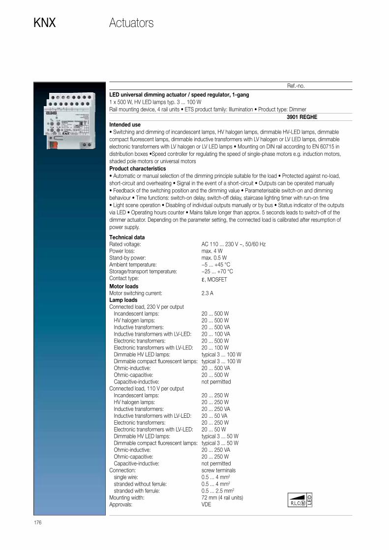
Technical dataRated voltage: AC 110 ... 230 V ~, 50/60 HzPower loss: max. 4 WStand-by power: max. 0.5 WAmbient temperature: −5 ... +45 °CStorage/transport temperature: −25 ... +70 °CContact type: ε, MOSFETMotor loadsMotor switching current: 2.3 ALamp loadsConnected load, 230 V per output Incandescent lamps: 20 ... 500 W HV halogen lamps: 20 ... 500 W Inductive transformers: 20 ... 500 VA Inductive transformers with LV-LED: 20 ... 100 VA Electronic transformers: 20 ... 500 W Electronic transformers with LV-LED: 20 ... 100 W Dimmable HV LED lamps: typical 3 ... 100 W Dimmable compact fluorescent lamps: typical 3 ... 100 W Ohmic-inductive: 20 ... 500 VA Ohmic-capacitive: 20 ... 500 W Capacitive-inductive: not permittedConnected load, 110 V per output Incandescent lamps: 20 ... 250 W HV halogen lamps: 20 ... 250 W Inductive transformers: 20 ... 250 VA Inductive transformers with LV-LED: 20 ... 50 VA Electronic transformers: 20 ... 250 W Electronic transformers with LV-LED: 20 ... 50 W Dimmable HV LED lamps: typical 3 ... 50 W Dimmable compact fluorescent lamps: typical 3 ... 50 W Ohmic-inductive: 20 ... 250 VA Ohmic-capacitive: 20 ... 250 W Capacitive-inductive: not permittedConnection: screw terminals single wire: 0.5 ... 4 mm2
stranded without ferrule: 0.5 ... 4 mm2
stranded with ferrule: 0.5 ... 2.5 mm2
Mounting width: 72 mm (4 rail units)Approvals: VDE
176
KNX
Ref.-no.
LED universal dimming actuator / speed regulator, 1-gang1 x 500 W, HV LED lamps typ. 3 ... 100 WRail mounting device, 4 rail units • ETS product family: Illumination • Product type: Dimmer
Intended use• Switching and dimming of incandescent lamps, HV halogen lamps, dimmable HV-LED lamps, dimmable compact fluorescent lamps, dimmable inductive transformers with LV halogen or LV LED lamps, dimmable electronic transformers with LV halogen or LV LED lamps • Mounting on DIN rail according to EN 60715 in distribution boxes •Speed controller for regulating the speed of single-phase motors e.g. induction motors, shaded pole motors or universal motors Product characteristics• Automatic or manual selection of the dimming principle suitable for the load • Protected against no-load, short-circuit and overheating • Signal in the event of a short-circuit • Outputs can be operated manually• Feedback of the switching position and the dimming value • Parameterisable switch-on and dimming behaviour • Time functions: switch-on delay, switch-off delay, staircase lighting timer with run-on time• Light scene operation • Disabling of individual outputs manually or by bus • Status indicator of the outputs via LED • Operating hours counter • Mains failure longer than approx. 5 seconds leads to switch-off of the dimmer actuator. Depending on the parameter setting, the connected load is calibrated after resumption of power supply.
LED
R,L,C, M
3901 REGHE
Actuators

177
Ref.-no.
KNX
Technical dataRated voltage: AC 110 ... 230 V ~, 50/60 HzPower loss: max. 4 WStand-by power: max. 0.8 WAmbient temperature: −5 ... +45 °CStorage/transport temperature: −25 ... +70 °CContact type: ε, MOSFETLamp loadsConnected load, 230 V per output Incandescent lamps: 20 ... 300 W HV halogen lamps: 20 ... 300 W Inductive transformers: 20 ... 300 VA Inductive transformers with LV-LED: 20 ... 100 VA Electronic transformers: 20 ... 300 W Electronic transformers with LV-LED: 20 ... 100 W Dimmable HV LED lamps: typical 3 ... 60 W Dimmable compact fluorescent lamps: typical 3 ... 60 W Ohmic-inductive: 20 ... 300 VA Ohmic-capacitive: 20 ... 300 W Capacitive-inductive: not permittedConnected load, 110 V per output Incandescent lamps: 20 ... 150 W HV halogen lamps: 20 ... 150 W Inductive transformers: 20 ... 150 VA Inductive transformers with LV-LED: 20 ... 50 VA Electronic transformers: 20 ... 150 W Electronic transformers with LV-LED: 20 ... 50 W Dimmable HV LED lamps: typical 3 ... 30 W Dimmable compact fluorescent lamps: typical 3 ... 30 W Ohmic-inductive: 20 ... 150 VA Ohmic-capacitive: 20 ... 150 W Capacitive-inductive: not permittedConnection: screw terminals single wire: 0.5 ... 4 mm2
stranded without ferrule: 0.5 ... 4 mm2
stranded with ferrule: 0.5 ... 2.5 mm2
Mounting width: 72 mm (4 rail units)Approvals: VDE
LED universal dimming actuator, 2-gang2 x 300 W, HV LED lamps typ. 2 x 3 ... 60 WRail mounting device, 4 rail unitsETS product family: Illumination • Product type: Dimmer
Intended use• Switching and dimming of incandescent lamps, HV halogen lamps, dimmable HV-LED lamps, dimmable compact fluorescent lamps, dimmable inductive transformers with LV halogen or LV LED lamps, dimmable electronic transformers with LV halogen or LV LED lamps • Mounting on DIN rail according to EN 60715 in distribution boxes Product characteristics• Automatic or manual selection of the dimming principle suitable for the load • Protected against no-load, short-circuit and overheating • Signal in the event of a short-circuit • Outputs can be operated manually• Feedback of the switching position and the dimming value • Parameterisable switch-on and dimming behaviour • Time functions: switch-on delay, switch-off delay, staircase lighting timer with run-on time • Light scene operation • Disabling of individual outputs manually or by bus • Status indicator of the outputs via LED • Operating hours counter • Mains failure longer than approx. 5 seconds leads to switch-off of the dimmer actuator. • Depending on the parameter setting, the connected load is calibrated after resumption of power supply.
LED
3902 REGHE
Actuators
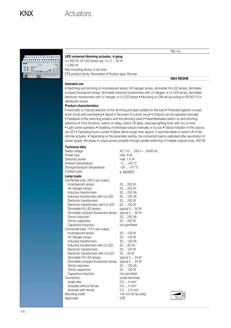
178
KNX
Ref.-no.
Technical dataRated voltage: AC 110 ... 230 V ~, 50/60 HzPower loss: max. 8 WStand-by power: max. 1.4 WAmbient temperature: −5 ... +45 °CStorage/transport temperature: −25 ... +70 °CContact type: ε, MOSFETLamp loadsConnected load, 230 V per output Incandescent lamps: 20 ... 250 W HV halogen lamps: 20 ... 250 W Inductive transformers: 20 ... 250 VA Inductive transformers with LV-LED: 20 ... 100 VA Electronic transformers: 20 ... 250 W Electronic transformers with LV-LED: 20 ... 100 W Dimmable HV LED lamps: typical 3 ... 50 W Dimmable compact fluorescent lamps: typical 3 ... 50 W Ohmic-inductive: 20 ... 250 VA Ohmic-capacitive: 20 ... 250 W Capacitive-inductive: not permittedConnected load, 110 V per output Incandescent lamps: 20 ... 120 W HV halogen lamps: 20 ... 120 W Inductive transformers: 20 ... 120 VA Inductive transformers with LV-LED: 20 ... 50 VA Electronic transformers: 20 ... 120 W Electronic transformers with LV-LED: 20 ... 50 W Dimmable HV LED lamps: typical 3 ... 24 W Dimmable compact fluorescent lamps: typical 3 ... 24 W Ohmic-inductive: 20 ... 120 VA Ohmic-capacitive: 20 ... 120 W Capacitive-inductive: not permittedConnection: screw terminals single wire: 0.5 ... 4 mm2
stranded without ferrule: 0.5 ... 4 mm2
stranded with ferrule: 0.5 ... 2.5 mm2
Mounting width: 144 mm (8 rail units)Approvals: VDE
LED universal dimming actuator, 4-gang4 x 250 W, HV LED lamps typ. 4 x 3 ... 50 W1 x 950 WRail mounting device, 8 rail unitsETS product family: Illumination • Product type: Dimmer
Intended use• Switching and dimming of incandescent lamps, HV halogen lamps, dimmable HV-LED lamps, dimmable compact fluorescent lamps, dimmable inductive transformers with LV halogen or LV LED lamps, dimmable electronic transformers with LV halogen or LV LED lamps • Mounting on DIN rail according to EN 60715 in distribution boxes Product characteristics• Automatic or manual selection of the dimming principle suitable for the load • Protected against no-load, short-circuit and overheating • Signal in the event of a short-circuit • Outputs can be operated manually• Feedback of the switching position and the dimming value • Parameterisable switch-on and dimming behaviour • Time functions: switch-on delay, switch-off delay, staircase lighting timer with run-on time• Light scene operation • Disabling of individual outputs manually or by bus • Status indicator of the outputs via LED • Operating hours counter • Mains failure longer than approx. 5 seconds leads to switch-off of the dimmer actuator. • Depending on the parameter setting, the connected load is calibrated after resumption of power supply. •Increase in output power possible through parallel switching of multiple outputs (max. 950 W)
LED
3904 REGHE
Actuators

179
Ref.-no.
KNX
LED dimming actuator 4-gang Rail mounting device, 4 rail units
Intended use • LED dimmer for controlling LEDs and LED modules 12 – 24 V (pulse width-modulated PWM) • Mounting on DIN rail according to EN 60715 in distribution boxes
Product characteristics • 4 individually configurable LED dimming channels • Maximum output current of 5 A per channel • At 24 V DC up to 480 W LED output • Possible channel combinations: – 4 x independent channels – 2 x Tunable White channels – 2 x independent channels, 1 x Tunable White channel – 1 x RGB channel, 1 x independent channel – 1 x RGBW channel • Activation of the colour channels via "HSV" or "RGB" • Integrated 230 V C-load relay to switch the LED power supply • Integrated protection with on-site display against: – Overcurrent – Overvoltage – Overtemperature – Reverse polarity
3904 REG LED
Technical dataRated voltage: AC 230 V ~Mains frequency: 50 HzRated current: 16 A (C load)Power loss: max. 6 WConnection: screw terminals single wire: 2.5 ... 4 mm2
stranded without ferrule: 4 mm2
stranded with ferrule: 2.5 mm2
Rated voltage KNX: DC 21 ... 32 V SELVCurrent consumption KNX: max. 18.9 mAConnection, KNX: terminalLED Connection: DC 12 ... 24 V SELV < 20 A
from device acc. to EN 61347-2-13 for LED modules with constant output voltage
Current consumption: 20 mAOutputs Number: 4 Max. current per output: 5 AFor LED modules with constant input voltage to EN 62031.LED modules with shared anode.PWM frequency: 488 / 600 HzCable length: depending on the cable resistance (voltage drop)Connection: screw terminals single wire: 4 mm2
stranded without ferrule: 4 mm2
Mounting width: 72 mm (4 rail units)Ambient temperature: −5 ... +45 °CStorage/transport temperature: −25 ... +70 °C
Actuators

Technical dataRated voltage: AC 230 V ~Mains frequency: 50 HzRated current: 16 A (C load)Power loss: max. 6 WConnection: screw terminals single wire: 2.5 ... 4 mm2
stranded without ferrule: 4 mm2
stranded with ferrule: 2.5 mm2
Rated voltage KNX: DC 21 ... 32 V SELVCurrent consumption KNX: max. 18.9 mAConnection, KNX: terminalLED Connection: DC 12 ... 24 V SELV < 20 A
from device acc. to EN 61347-2-13 for LED modules with constant output voltage
Current consumption: 20 mAOutputs Number: 4 Max. current per output: 5 AFor LED modules with constant input voltage to EN 62031.LED modules with shared anode.PWM frequency: 488 / 600 HzCable length: depending on the cable resistance (voltage drop)Connection: screw terminals single wire: 4 mm2
stranded without ferrule: 4 mm2
Dimensions (L x W x H): 196 x 40 x 32 mmProtection level: IP 20Protection class: IIAmbient temperature: −5 ... +45 °CStorage/transport temperature: −25 ... +70 °C
180
KNX
Ref.-no.
LED dimming actuator 4-gang
Intended use • LED dimmer for controlling LEDs and LED modules 12 – 24 V (pulse width-modulated PWM) • Mounting in false ceilings, surface mounting or in/ under furniture
Product characteristics • 4 individually configurable LED dimming channels • Maximum output current of 5 A per channel • At 24 V DC up to 480 W LED output • Possible channel combinations: – 4 x independent channels – 2 x Tunable White channels – 2 x independent channels, 1 x Tunable White channel – 1 x RGB channel, 1 x independent channel – 1 x RGBW channel • Activation of the colour channels via "HSV" or "RGB" • Integrated 230 V C-load relay to switch the LED power supply • Integrated protection with on-site display against: – Overcurrent – Overvoltage – Overtemperature – Reverse polarity
3904 EB LED
Actuators

181
Ref.-no.
KNX
Control unit 1 – 10 V, 4-gangRail mounting device, 4 rail unitsETS product family: IlluminationProduct type: Dimmer
Intended use• Switching and brightness setting for lamps with operating devices with 1 – 10 V interface • Switching of electrical loads • Mounting on DIN rail according to EN 60715 in distribution boxesProduct characteristics• Manual switching of the relays is independent of the bus • Switching of capacitive loads and the resulting high switch-on currents • Flexible assignment of control inputs to switching outputs, e.g. to control RGBW lamps• Operation of the switching outputs as a switching actuator • Connection of different phase conductors possible • No additional power supply necessary • Feedback of switching state and brightness value • Switch position display • Burn-in function for fluorescent lamps • Switch-on and dimming behaviour can be set • Time functions: switch-on delay, switch-off delay, staircase lighting timer with pre-warning function • Integration into light scenes • Operating hours counter
2194 REGHM
Technical dataRated voltage KNX: DC 21 ... 32 V SELVCurrent consumption KNX: max. 6 mAPower loss: max. 4 WAmbient temperature: −5 ... +45 °CStorage/transport temperature: −25 ... +70 °CControl outputsControl voltage: 1 ... 10 VControl current per output: max. 100 mACable length: max. 500 m (0.5 mm2)Switching outputsContact type: floating relay contacts (μ contact)Switching voltage AC: AC 250 / 400 VSwitching current 230 V AC1: 16 ASwitching current 230 V AC3: 10 ASwitching current 400 V AC1: 10 ASwitching current 400 V AC3: 6 AFluorescent lamps: 16 AXSwitching voltage DC: DC 12 ... 24 VSwitching current DC: 16 AMin. switching current: 100 mASwitch-on current 150 µs: 600 ASwitch-on current 600 µs: 300 AOhmic load: 3680 WCapacitive load: 16 A / 200 µFLamp loadsIncandescent lamps: 3680 WHV halogen lamps: 3680 WInductive transformers with LV halogen lamps: 2000 VAElectronic transformers with LV halogen lamps: 2500 WFluorescent lamps T5/T8 non-compensated: 3680 W parallel compensated: 2500 W / 200 µF lead-lag circuit: 3680 W / 200 µFConnection, outputs: screw terminals single wire: 0.5 ... 4 mm2
stranded without ferrule: 0.34 ... 4 mm2
stranded with ferrule: 0.14 ... 2.5 mm2
Mounting width: 72 mm (4 rail units)
Actuators
Compact fluorescent lamps non-compensated: 3680 W parallel compensated: 2500 W / 200 µFMercury vapour lamps non-compensated: 3680 W parallel compensated: 3680 W / 200 µF

Fan coil actuator 2-gangRail mounting device, 4 rail unitswith manual electronic operation and LED status indicationOnly with the ETS 3.0d version or later versions the full functionality will be available.ETS product family: Heating, A/C, VentilationProduct type: Fan-coil
Product characteristics • Connection of a fan coil unit with up to 6 fan stages or connection of fan coil units with up to 3 fan stages respectively • Manual output control, provisional operation • Control options for heating, cooling or combined heating/cooling operation • 2-pipe or 4-pipe operation • Individual or hierarchical switching of fan stages • Feedback • Output state indication • Disabling function for each channel
Modes of operation • Bus operation: operation via touch sensors or room controller • Temporary manual control: manual operation locally with keypad, automatic return to bus operation • Permanent manual control mode: only manual operation locally on device
FCA 2 REGHE
Technical dataKNX supply: DC 21 ... 32 V SELVPower consumption KNX: typical 150 mWRated voltage: AC 230/240 V ~, 50/60 HzPower loss: max. 3 WAmbient temperature: −5 ... +45 °CStoring temperature: −25 ... +70 °CConnection, KNX: bus connection blockConnection, mains and outputs: screw terminals single wire: 0.5 ... 4 mm2
stranded without ferrule: 0.5 ... 4 mm2
stranded with ferrule: 0.5 ... 2.5 mm2
Switch type: make contactContact type: floating relay contacts (μ contact)Switching voltage: AC 230/240 V ~Breaking capacity AC1: 10 ABreaking capacity AC3: 10 ASwitching capacities per outputOhmic load: 2300 WCapacitive load: 10 A / max. 140 µFMotors: 1380 VALamp loads: Incandescent lamps: 2300 W HV halogen lamps: 2300 W Inductive transformers with LV halogen lamps: 1200 VA Electronic transformers with LV halogen lamps: 1500 W Fluorescent lamps: – non-compensated: 1000 W – parallel compensated: 1160 W / 140 µF – lead-lag circuit: 2300 W / 140 µFApprovals: VDE
Actuators
182
KNX
Ref.-no.

183
Ref.-no.
KNX
Technical dataKNX supply: DC 21 ... 32 V SELVPower consumption KNX: max. 150 mWPower supply mains: AC 110 ... 230 V ~,
50/60 HzPower loss: max. 6 WAmbient temperature: −5 ... +45 °CStoring temperature: −25 ... +70 °CMounting width: 72 mm (4 rail units)Connection, KNX: bus connection blockConnection, mains and outputs: screw terminals single wire: 0.5 ... 4 mm2
stranded without ferrule: 0.5 ... 4 mm2
stranded with ferrule: 0.5 ... 2.5 mm2
Heating outputsNumber: 2Contact type: semiconductor, εSwitching voltage: AC 230/240 V ~Switching current: 5 ... 50 mASwitch-on current: max. 1.5 A (2 s)Number of drives per output: max. 4Approvals: VDE
Actuators
Intended use • Switching of electrical consumers AC 110 – 230 V with floating contacts • Switching of electrically operated blinds, shutters, awnings and similar curtains • Heating outputs: electronic outputs for switching electro-thermal valve drives
Product characteristics • Manual output control, provisional operation • Feedback in manual control mode and in bus operation • Scene function • Disabling of individual outputs by hand or via the bus
Switching function • Make-contact and break-contact operation • Logic operation and forcing function • Feedback function • Central switching function with group feedback • Time functions: ON-delay, OFF-delay, staircase lighting timer with early-warning function
Blind/shutter function • Suitable for AC motors 110 – 230 V • Direct control of blind/shutter position • Direct control of slat position • Checkback of running state, blind/shutter position and slat position • Forced-control position from primary control • Safety function: 3 independent wind alarms, rain alarm, frost alarm • Sun protection function
Control of valve drives 230 V • Switching or PWM operation • Control of valve drives with working characteristics “normally open” or “normally closed“ • Overload and short-circuit protection • Emergency operation in the event of bus failure for summer and winter • Protection against jamming valves • Forced-control position
Relay outputsNumber: 4 (2 channels
for operating blinds)Contact type: floating make contact
(µ contact)Switching voltage: AC 230/240 V ~Breaking capacity AC1: 16 ABreaking capacity AC3: 6 ABreaking capacity fluorescent lamps: 16 AXSwitching capacities per outputOhmic load: 3000 WCapacitive load: 16 A / max. 140 µFMotors: 1380 VALamp loads: Incandescent lamps: 3000 W HV halogen lamps: 2500 W Electronic transformers with LV halogen lamps: 1500 W Inductive transformers with LV halogen lamps: 1200 VA Fluorescent lamps: – non-compensated: 1000 W – parallel compensated: 1160 W / max. 140 µF – lead-lag circuit: 2300 W / max. 140 µF
Room actuator 110 – 230 VRail mounting device, 4 rail unitswith manual electronic operation and LED status indicationOnly with the ETS 3.0d version or later versions the full functionality will be available.ETS product family: OutputProduct type: Binary output
RA 23024 REGHE
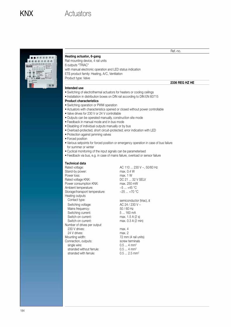
184
KNX
Ref.-no.
Actuators
Heating actuator, 6-gangRail mounting device, 4 rail units6 outputs "TRIAC"with manual electronic operation and LED status indicationETS product family: Heating, A/C, VentilationProduct type: Valve
Intended use • Switching of electrothermal actuators for heaters or cooling ceilings • Installation in distribution boxes on DIN rail according to DIN EN 60715
Product characteristics • Switching operation or PWM operation • Actuators with characteristics opened or closed without power controllable • Valve drives for 230 V or 24 V controllable • Outputs can be operated manually, construction site mode • Feedback in manual mode and in bus mode • Disabling of individual outputs manually or by bus • Overload-protected, short circuit-protected; error indication with LED • Protection against jamming valves • Forced position • Various setpoints for forced position or emergency operation in case of bus failure for summer or winter • Cyclical monitoring of the input signals can be parameterised • Feedback via bus, e.g. in case of mains failure, overload or sensor failure
2336 REG HZ HE
Technical dataRated voltage: AC 110 ... 230 V ~, 50/60 HzStand-by power: max. 0.4 WPower loss: max. 1 WRated voltage KNX: DC 21 ... 32 V SELVPower consumption KNX: max. 250 mWAmbient temperature: −5 ... +45 °CStorage/transport temperature: −25 ... +70 °CHeating outputs Contact type: semiconductor (triac), ε Switching voltage: AC 24 / 230 V ~ Mains frequency: 50 / 60 Hz Switching current: 5 ... 160 mA Switch-on current: max. 1.5 A (2 s) Switch-on current: max. 0.3 A (2 min)Number of drives per output 230 V drives: max. 4 24 V drives: max. 2Mounting width: 72 mm (4 rail units)Connection, outputs: screw terminals single wire: 0.5 ... 4 mm2
stranded without ferrule: 0.5 ... 4 mm2
stranded with ferrule: 0.5 ... 2.5 mm2

185
Ref.-no.
KNXActuators
Heating actuator, 6-gangwith controllerRail mounting device, 4 rail units6 outputs "TRIAC"with manual electronic operation and LED status indicationETS product family: Heating, A/C, VentilationProduct type: Valve
Intended use • Switching of electrothermal actuators for heaters or cooling ceilings • Installation in distribution boxes on DIN rail according to DIN EN 60715
Product characteristics • Integrated room temperature control with setpoint value specification • Six independent controllers to control up to six independent rooms • Controller function for heating and cooling • Switching operation or PWM operation • Actuators with characteristics opened or closed without power controllable • Valve drives for 230 V or 24 V controllable • Outputs can be operated manually, construction site mode • Feedback in manual mode and in bus mode • Disabling of individual outputs manually or by bus • Overload-protected, short circuit-protected; error indication with LED • Protection against jamming valves • Forced position • Various setpoints for forced position or emergency operation in case of bus failure for summer or winter • Cyclical monitoring of the input signals can be parameterised • Feedback via bus, e.g. in case of mains failure, overload or sensor failure
2336 REG HZR HE
Technical dataRated voltage: AC 110 ... 230 V ~, 50/60 HzStand-by power: max. 0.4 WPower loss: max. 1 WRated voltage KNX: DC 21 ... 32 V SELVPower consumption KNX: max. 250 mWAmbient temperature: −5 ... +45 °CStorage/transport temperature: −25 ... +70 °CHeating outputs Contact type: semiconductor (triac), ε Switching voltage: AC 24 / 230 V ~ Mains frequency: 50 / 60 Hz Switching current: 5 ... 160 mA Switch-on current: max. 1.5 A (2 s) Switch-on current: max. 0.3 A (2 min)Number of drives per output 230 V drives: max. 4 24 V drives: max. 2Mounting width: 72 mm (4 rail units)Connection, outputs: screw terminals single wire: 0.5 ... 4 mm2
stranded without ferrule: 0.5 ... 4 mm2
stranded with ferrule: 0.5 ... 2.5 mm2

186
KNX
Ref.-no.
Actuators
Analogue actuator, 4-gangRail mounting device, 4 rail unitsETS product family: OutputProduct type: Analogue output 4-gang
The analogue output needs 24 V AC for operation. The necessary power can be supplied by the power supply unit ref.-no.: WSSV 10. • The analogue output converts measuring data received via KNX telegrams (DPT-ID 9.0xx and 5.010) into analogue output signals. • The analogue output signals enable heating, ventilation and air conditioning units to adapt their output values to information received from the bus and thus to take part in control processes. Voltage signals: 0 ... 1 V DC 0 ... 10 V DC Current signals: 0 ... 20 mA DC 4 ... 20 mA DC • The analogue output offers four analog outputs which can be software-parameterised for one of the ranges mentioned above. Outputs not used can be deactivated. • The output variables can be force-controlled from a coordinating control system. • With an analogue output extension module, the number of analog outputs can be increased from 4 to 8. • In conjunction with the “dimming” function of a sensor, both, the analogue output and also the analogue output extension module can be used as an active control unit for dimming applications.
Remarks on the hardware: • The GND terminals must not be connected to the corresponding terminals of another device. • The outputs of the analogue output and of the analogue output extension module must not be connected to the 1 ... 10 V interface of electronic ballasts or electronic transformers. • All connected components must ensure safe separation from other voltages
2204.01 REGA
Technical dataPower supply Supply voltage: AC 24 V ~ ± 10 % Current consumption: max. 308 mARated voltage KNX: DC 21 ... 32 V SELVPower consumption KNX: typical 150 mWAmbient temperature: −5 ... +45 °CStorage/transport temperature: −25 ... +70 °CHumidity Ambient/storage/transport: max. 93 % r. h., no condensationMounting width: 72 mm (4 rail units)Weight: approx. 180 gTerminalsOutputs, power supply: screw terminals single wire: 0.5 ... 4 mm2
stranded without ferrule: 0.5 ... 4 mm2
stranded with ferrule: 0.5 ... 2.5 mm2
KNX: bus connection blockAnalogue outputs Number: 4 Ranges: 0 ... 1 V, 0 ... 10 V, DC
0 ... 20 mA, 4 ... 20 mA, DC Voltage signal load: ≥ 1 kW Current signal load: ≤ 500 WPower supplyAnalogue actuator module: DC 24 V via system bus
max. 80 mA

187
Ref.-no.
KNXActuators
Analogue actuator module, 4-gangRail mounting device, 4 rail units
Extension module for analogue actuator 4-gang ref.-no.: 2204.01 REGAFunction • The analogue actuator module extends a KNX analogue actuator 4-gang by four additional sensor outputs. • The analogue output extension module offers four analogue outputs which can be software parameterised for one of the following ranges. • Outputs not used can be deactivated. Voltage signals: 0 ... 1 V DC 0 ... 10 V DC Current signals: 0 ... 20 mA DC 4 ... 20 mA DC
2204.01 REGAM
Technical dataPower supply Supply voltage: AC 24 V ~ ± 10 % Current consumption: max. 120 mA Current consumption at system connector:
6 mA
Ambient temperature: −5 ... +45 °CStorage/transport temperature: −25 ... +70 °CHumidity Ambient/storage/transport: max. 93 % r. h., no condensationMounting width: 72 mm (4 rail units)Weight: approx. 155 gTerminalsOutputs, power supply: screw terminals single wire: 0.5 ... 4 mm2
stranded without ferrule: 72 mm (4 rail units) stranded with ferrule: 0.5 ... 2.5 mm2
Connection KNX device: KNX bus connection block Analogue outputs Number: 4 Ranges: 0 ... 1 V DC, 0 ... 10 V DC,
0 ... 20 mA DC, 4 ... 20 mA, DC Voltage signal load: ≥ 1 kW Current signal load: ≤ 500 W

The KNX Multistation combines input and output channels
in one compact device. Using logic functions, inter-device
connections to the building control system are possible.
Functions are combined in one unit that otherwise can only
be provided using multiple individual devices – such as lighting,
blind and temperature control.
KNX MULTISTATION
Compact device for the distribution
Multistation
188 ACTUATORS / COMBINATION DEVICES

This multitalent for building automation
proves itself as genuine problem solver:
Due to the functional depth, the Multistation
is ideally suitable for quick and cost-efficient
for equipping, for example, offices, hotels or
also hospitals. Only one device per room is
needed; the configuration can optionally be
made without ETS group addresses and then
easily duplicated for all other rooms. Without
additional work. With only 4 TE, the Multi-
station only requires a little space in the switch
cabinet and is thus also ideally suitable for
retrofitting. And due to the low requirement
for power supplies, the costs are of course
also lower than for the use of individual
switching, dimming and blinds actuators.
KNX HEATING VALVEDEW/CONDENSATIONSENSOR
SERIAL BUTTONBLINDS BUTTON
LIGHTSWITCHEDSOCKET
OFFICE
KNX lineBinary inputsOutputs
COOLINGVALVE
COOLINGCEILING
ACTUATORS / COMBINATION DEVICES 189
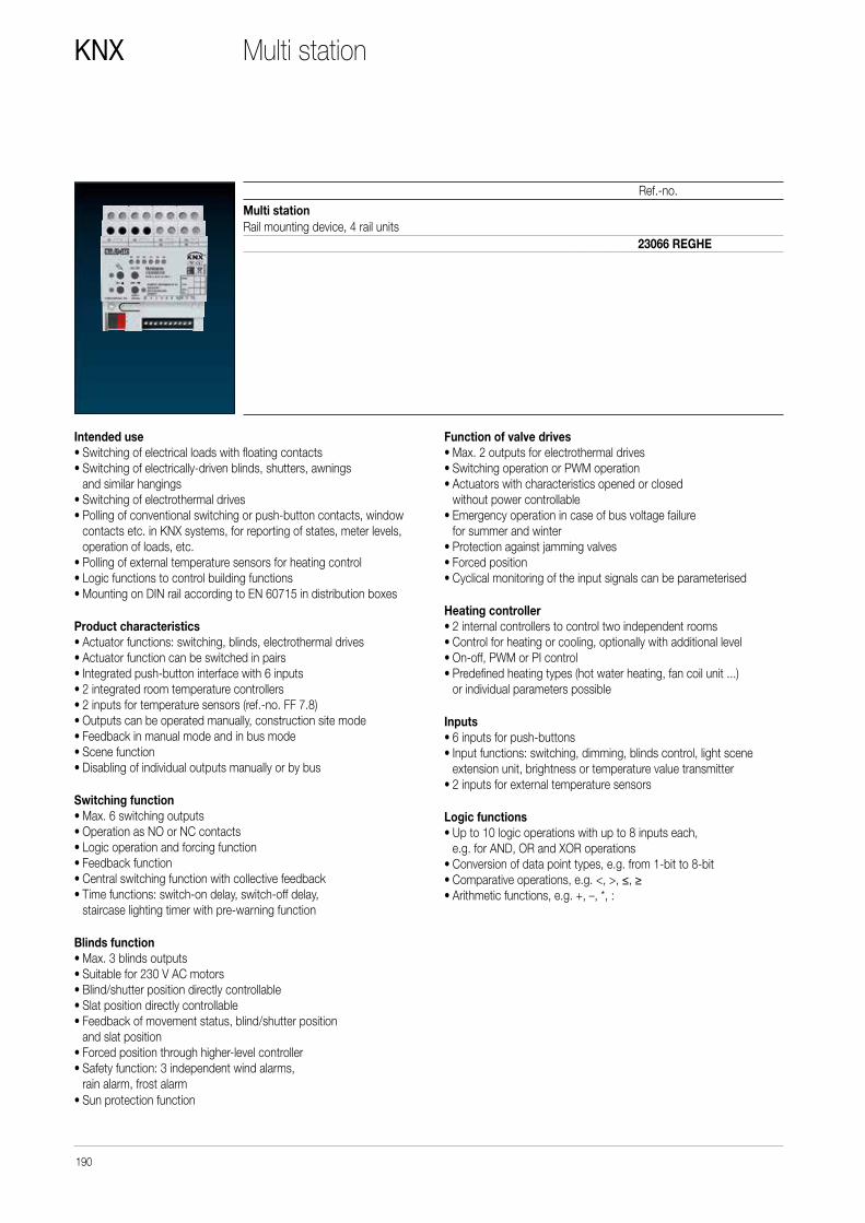
190
KNX
Ref.-no.
Multi stationRail mounting device, 4 rail units
23066 REGHE
Multi station
Intended use • Switching of electrical loads with floating contacts • Switching of electrically-driven blinds, shutters, awnings and similar hangings • Switching of electrothermal drives • Polling of conventional switching or push-button contacts, window contacts etc. in KNX systems, for reporting of states, meter levels, operation of loads, etc. • Polling of external temperature sensors for heating control • Logic functions to control building functions • Mounting on DIN rail according to EN 60715 in distribution boxes
Product characteristics • Actuator functions: switching, blinds, electrothermal drives • Actuator function can be switched in pairs • Integrated push-button interface with 6 inputs • 2 integrated room temperature controllers • 2 inputs for temperature sensors (ref.-no. FF 7.8) • Outputs can be operated manually, construction site mode • Feedback in manual mode and in bus mode • Scene function • Disabling of individual outputs manually or by bus
Switching function • Max. 6 switching outputs • Operation as NO or NC contacts • Logic operation and forcing function • Feedback function • Central switching function with collective feedback • Time functions: switch-on delay, switch-off delay, staircase lighting timer with pre-warning function
Blinds function • Max. 3 blinds outputs • Suitable for 230 V AC motors • Blind/shutter position directly controllable • Slat position directly controllable • Feedback of movement status, blind/shutter position and slat position • Forced position through higher-level controller • Safety function: 3 independent wind alarms, rain alarm, frost alarm • Sun protection function
Function of valve drives • Max. 2 outputs for electrothermal drives • Switching operation or PWM operation • Actuators with characteristics opened or closed without power controllable • Emergency operation in case of bus voltage failure for summer and winter • Protection against jamming valves • Forced position • Cyclical monitoring of the input signals can be parameterised
Heating controller • 2 internal controllers to control two independent rooms • Control for heating or cooling, optionally with additional level • On-off, PWM or PI control • Predefined heating types (hot water heating, fan coil unit ...) or individual parameters possible
Inputs • 6 inputs for push-buttons • Input functions: switching, dimming, blinds control, light scene extension unit, brightness or temperature value transmitter • 2 inputs for external temperature sensors
Logic functions • Up to 10 logic operations with up to 8 inputs each, e.g. for AND, OR and XOR operations • Conversion of data point types, e.g. from 1-bit to 8-bit • Comparative operations, e.g. <, >, ≤, ≥ • Arithmetic functions, e.g. +, –, *, :

191
KNXMulti station
Technical data ref.-no. 23066 REGHEKNX medium: TP 256Rated voltage KNX: DC 21 ... 32 V SELVCurrent consumption KNX: max. 20 mACurrent consumption KNX: min. 4 mAConnection, KNX: terminalPower loss: max. 6 WAmbient temperature: −5 ... +45 °CStorage/transport temperature: −25 ... +70 °CRelay outputs Contact type: floating relay contacts (μ contact) Switch type: make contact Switching voltage: AC 250 V ~ Min. switching current AC: 100 mA Switching current AC1 (cos ϕ > 0.8): 16 A Switching current AC3 (cos ϕ < 0.8): 6 A Fluorescent lamps: 16 AX Switch-on current 200 µs: max. 800 A Switch-on current 20 ms: max. 165 A Switching voltage DC: DC 12 ... 24 V Switching current DC 24 V: 6 AConnected load, 230 V Ohmic load: 3000 W blind / fan motors: 1380 VALamp loads 230 V Incandescent lamps: 3000 W HV halogen lamps: 2500 W HV LED lamps: max. 400 W Electronic transformers: 1500 W Inductive transformers: 1200 VAFluorescent lamps T5/T8 non-compensated: 1000 W parallel compensated: 1160 W / 140 µF lead-lag circuit: 2300 W / 140 µFCompact fluorescent lamps non-compensated: 1000 W parallel compensated: 1160 W / 140 µFMercury vapour lamps non-compensated: 1000 W parallel compensated: 1160 W / 140 µFElectrothermal valve drives Cycle time: min. 15 minConnection, load: screw terminals single wire: 0.5 ... 4 mm2
stranded without ferrule: 0.5 ... 4 mm2
stranded with ferrule: 0.5 ... 2.5 mm2
Inputs Rated voltage: DC 3.3 V SELV Signal duration: min. 100 ms Make contacts: max. 50 Break contacts: max. 50 Cable length: max. 30 mConnection, inputs: screw terminals single wire: 0.08 ... 1.5 mm2
stranded without ferrule: 0.08 mm2 ... 1.0 mm2
stranded with ferrule: 0.14 mm2 ... 0.5 mm2
Mounting width: 72 mm (4 rail units)

Flush mounting actuators
Small and compact: These features distinguish the KNX flush
mounting actuators. Thanks to the flush mounting or installation
in trunking etc., they are extremely space-saving with extensive
functional depth. They all have multiple, integrated binary inputs.
KNX SWITCH ACTUATOR
1-GANG FLUSH MOUNTING
192 ACTUATORS / COMBINATION DEVICES

USE CASE: ROOM CLIMATE INTERFACE
OFFICE 1 OFFICE 2
/3
/2
/3
/2
/4
Binary inputs
230 V supply
KNX line
1 Window interface
2 Shutter motor
3 Window contact
4 Actuator
5 Trunking
6 Blinds button
2
1
56
4
3
The Room Climate Interface offers one blind/shutter output,
one heating output and three binary inputs. On the one hand,
the binary inputs of the flush mounting actuators can be used for
„local operation“. On the other hand, they are used as extension
inputs for the connection of floating contacts e.g. window
contacts, whereby the respective range of functions can be
expanded at low cost.
ACTUATORS / COMBINATION DEVICES 193
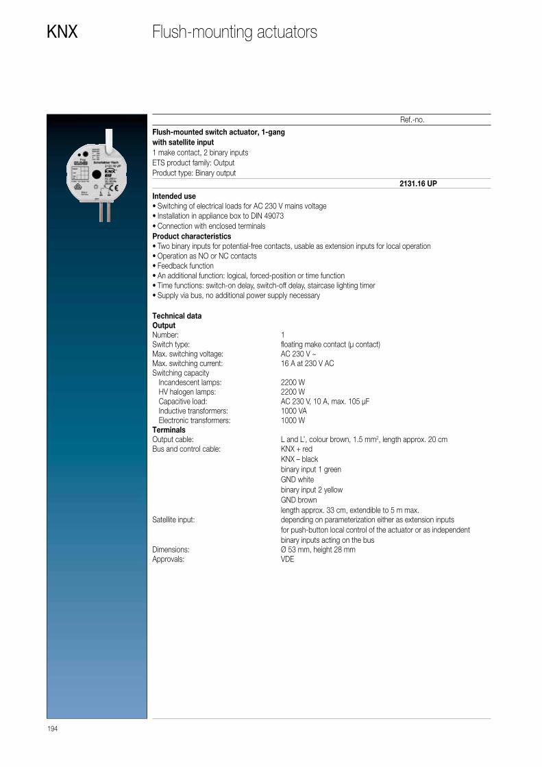
194
KNX
Ref.-no.
Flush-mounted switch actuator, 1-gang with satellite input1 make contact, 2 binary inputsETS product family: OutputProduct type: Binary output
Intended use • Switching of electrical loads for AC 230 V mains voltage • Installation in appliance box to DIN 49073 • Connection with enclosed terminals
Product characteristics • Two binary inputs for potential-free contacts, usable as extension inputs for local operation • Operation as NO or NC contacts • Feedback function • An additional function: logical, forced-position or time function • Time functions: switch-on delay, switch-off delay, staircase lighting timer • Supply via bus, no additional power supply necessary
2131.16 UP
Technical dataOutputNumber: 1Switch type: floating make contact (μ contact)Max. switching voltage: AC 230 V ~Max. switching current: 16 A at 230 V ACSwitching capacity Incandescent lamps: 2200 W HV halogen lamps: 2200 W Capacitive load: AC 230 V, 10 A, max. 105 µF Inductive transformers: 1000 VA Electronic transformers: 1000 WTerminalsOutput cable: L and L’, colour brown, 1.5 mm2, length approx. 20 cmBus and control cable: KNX + red
KNX – blackbinary input 1 greenGND whitebinary input 2 yellowGND brownlength approx. 33 cm, extendible to 5 m max.
Satellite input: depending on parameterization either as extension inputs for push-button local control of the actuator or as independent binary inputs acting on the bus
Dimensions: Ø 53 mm, height 28 mmApprovals: VDE
Flush-mounting actuators

195
Ref.-no.
KNX
Flush-mounted switch actuator, 2-gang with satellite input2 make contacts, 2 binary inputsETS product family: OutputProduct type: Binary output
Intended use • Switching of electrical loads for AC 230 V mains voltage • Installation in appliance box to DIN 49073 • Connection with enclosed terminals
Product characteristics • Two binary inputs for potential-free contacts, usable as extension inputs for local operation • Operation as NO or NC contacts • Feedback function for each output • An additional function for each output: logical, forced-position or time function • Time functions: switch-on delay, switch-off delay, staircase lighting timer • Supply via bus, no additional power supply necessary
2132.6 UP
Technical dataOutputNumber: 2Contact type: floating relay contacts (μ contact)Switch type: make contactMax. switching voltage: AC 230 V ~Max. switching current: 2 x 6 A at 230 V ACSwitching capacity Incandescent lamps: 1200 W HV halogen lamps: 1200 W Capacitive load: AC 230 V, 6 A, max. 14 µF Inductive transformers: 500 VA Electronic transformers: 500 WTerminalsOutput cable: L, L'1, L'2, black, pink, grey, 1.5 mm2,
length approx. 20 cmBus and control cable: KNX + red
KNX – blackbinary input 1 greenGND whitebinary input 2 yellowGND brownlength approx. 33 cm, extendible to 5 m max.
Satellite input: depending on parameterization either as extension inputs for push-button local control of the actuator or as independent binary inputs acting on the bus
Dimensions: Ø 53 mm, height 28 mmApprovals: VDE
Flush-mounting actuators

196
KNX
Ref.-no.
Flush-mounted room climate interface with satellite input3 binary inputs1 blinds output, 1 output "TRIAC" (heating)
Intended use • Switching of electrically-driven blinds, awnings and similar blinds for AC 230 V mains voltage • Switching of electrothermal actuators • Installation in appliance box to DIN 49073 • Connection with enclosed terminals
Product characteristics • Control of Venetian blinds, awnings and similar blinds • Control of electrothermal actuators • Three binary inputs for potential-free contacts, usable as extension inputs for local operation • Supply via bus, no additional power supply necessary
Blinds function • Blind position directly controllable • Slat position directly controllable • Feedback of movement status, blind position and slat position • Forced position through higher-level controller • Safety function: 3 independent wind alarms, rain alarm, frost alarm • Sun protection function
Function of valve drives • Switching operation or PWM operation • Valve drives with characteristics opened or closed without power • Overload-protected, short circuit-protected • Protection against jamming valves • Forced position • Cyclical monitoring of the input signals configurable
PWM operation: electrothermal actuators only have the positions Open and Closed. In PWM operation, switch-on and switch-off during the drive’s cycle time achieves an almost constant behaviour.
2531 UP
Technical dataRated voltage: AC 230/240 V ~, 50/60 HzSwitching voltage: AC 250 V ~Ambient temperature: −5 ... +45 °CStorage/transport temperature: −25 ... +70 °CBlinds output Contact type: µ Switching current AC1 (cos ϕ > 0.8): 3 A Min. switching current AC: 100 mA Motors (230 V): 600 VAHeating output Contact type: semiconductor (triac), ε Switching current: 5 ... 25 mA Switch-on current: max. 600 mA (2 s) Number of drives per output: max. 2Control cable: YY6x0.6 Input type: floating contact Total cable length: max. 5 m Voltage satellite inputs: approx. 5 VDimensions (Ø x H): 53 x 28 mmConnection: screwles terminals single wire: 1 ... 2.5 mm2
KNX supply: DC 21 ... 32 V SELVPower consumption KNX: max. 240 mWConnection, KNX: terminal connected to control cableApprovals: VDE
Flush-mounting actuators

197
Ref.-no.
KNX
Flush-mounted blinds actuator, 1-gangwith satellite input3 binary inputsETS product family: ShutterProduct type: Shutter
Intended use • Switching of electrically-driven blinds, awnings and similar blinds for AC 110 ... 230 V mains voltage • Installation in appliance box to DIN 49073 • Connection with enclosed terminals
Product characteristics • Control of blinds, awnings and similar blinds • Three binary inputs for potential-free contacts, usable as extension inputs for local operation • Supply via bus, no additional power supply necessary • Blind position directly controllable • Slat position directly controllable • Feedback of movement status, blind position and slat position • Forced position through higher-level controller • Safety function: 3 independent wind alarms, rain alarm, frost alarm • Sun protection function
2501 UP
Technical dataRated voltage: AC 110 ... 240 V ~, 50/60 HzSwitching voltage: AC 250 V ~Ambient temperature: −5 ... +45 °CStorage/transport temperature: −25 ... +70 °CBlinds output Contact type: µ Switching current AC1 (cos ϕ > 0.8): 3 A Min. switching current AC: 100 mA Motors (230 V): 600 VA Motors (110 V): 300 VAControl cable: YY6x0.6 Input type: floating contact Total cable length: max. 5 m Voltage satellite inputs: approx. 5 VDimensions (Ø x H): 53 x 28 mmConnection: screwles terminals single wire: 1 ... 2.5 mm2
KNX supply: DC 21 ... 32 V SELVPower consumption KNX: max. 240 mWConnection, KNX: terminal connected to control cableApprovals: VDE
Flush-mounting actuators

198
KNX
Ref.-no.
Flush-mounted dimming actuator, 1-gang, 50 – 210 W/VA with satellite input2 binary inputsETS product family: IlluminationProduct type: Dimmer
Intended use • Switching and dimming of incandescent lamps, 230 V halogen lamps and LV halogen lamps with inductive transformers or Tronic transformers • Installation in appliance box to DIN 49073
Product characteristics • Automatic selection of the dimming principle suitable for the load • Protected against no-load, short-circuit and overheating • Feedback of the switching position and the dimming value • Parameterisable switch-on and dimming behaviour • Timed dimmer: switch-on delay, switch-off delay, staircase lighting timer • Light scene operation • Two binary inputs for potential-free contacts, usable as extension inputs for local operation • Supply via bus, no additional power supply necessary • Mains failure longer than approx.0.7 seconds leads to switch-off of the dimmer actuator
3210 UP
Technical dataOutput: 1 Power MOS-FETDimming method: trailing edge or leading edge phase controlTerminals Output cable: L = black, dimming output = brown, 0.75 mm2
length approx. 20 cm Bus and control cable: KNX + red
KNX – blackbinary input 1 greenGND whitebinary input 2 yellowGND brownlength approx. 33 cm, extendible to 5 m max.
Satellite input: depending on parameterization either as extension inputs for push-button local control of the actuator or as independent binary inputs acting on the bus
Dimensions: Ø 63 mm, height 25 mmRated voltage: AC 230 V ~, 50/60 HzRated current: 0.9 AMinimum load: 50 WPower loss: 2 WTotal connected load: 210 W/VA Ohmic load: 50 ... 210 W Incandescent lamps: 50 ... 210 W HV halogen lamps: 50 ... 210 W Inductive transformers with LV halogen lamps: 50 ... 210 VA Electronic transformers with LV halogen lamps: 50 ... 210 VAMix of the specified load types (do not mix capacitive loads with inductive loads).When using mixed loads with inductive transformers, the ohmic load must not exceed 50 %.Approvals: VDE
Flush-mounting actuators
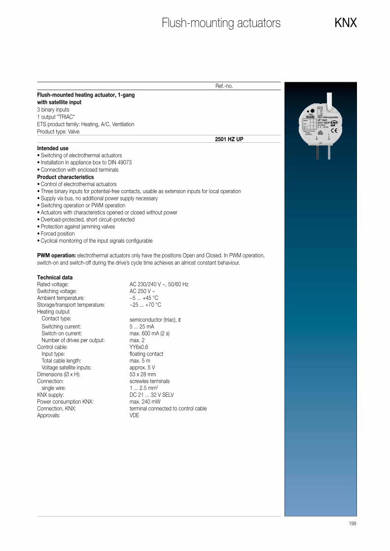
199
Ref.-no.
KNX
Flush-mounted heating actuator, 1-gang with satellite input3 binary inputs1 output "TRIAC"ETS product family: Heating, A/C, VentilationProduct type: Valve
Intended use • Switching of electrothermal actuators • Installation in appliance box to DIN 49073 • Connection with enclosed terminals
Product characteristics • Control of electrothermal actuators • Three binary inputs for potential-free contacts, usable as extension inputs for local operation • Supply via bus, no additional power supply necessary • Switching operation or PWM operation • Actuators with characteristics opened or closed without power • Overload-protected, short circuit-protected • Protection against jamming valves • Forced position • Cyclical monitoring of the input signals configurable
PWM operation: electrothermal actuators only have the positions Open and Closed. In PWM operation, switch-on and switch-off during the drive’s cycle time achieves an almost constant behaviour.
2501 HZ UP
Technical dataRated voltage: AC 230/240 V ~, 50/60 HzSwitching voltage: AC 250 V ~Ambient temperature: −5 ... +45 °CStorage/transport temperature: −25 ... +70 °CHeating output Contact type: semiconductor (triac), ε Switching current: 5 ... 25 mA Switch-on current: max. 600 mA (2 s) Number of drives per output: max. 2Control cable: YY6x0.6 Input type: floating contact Total cable length: max. 5 m Voltage satellite inputs: approx. 5 VDimensions (Ø x H): 53 x 28 mmConnection: screwles terminals single wire: 1 ... 2.5 mm2
KNX supply: DC 21 ... 32 V SELVPower consumption KNX: max. 240 mWConnection, KNX: terminal connected to control cableApprovals: VDE
Flush-mounting actuators

200
KNX
Ref.-no.
Valve drive (motor-operated)with controllerelectromechanical servo driveETS product family: Heating, A/C, VentilationProduct type: Valve
Intended use • Motor-operated valve drive for heating or cooling valves • To be screwed on valve head
Product characteristics • Integrated temperature sensor • Room temperature control • Mechanical indication of valve lift • Automatic detection of valve lift • One input, can be used as binary input or for an external temperature sensor (ref.-no.: FF 7.8) • Use in heating circles possible • Integrated bus coupling unit • Valve protection function
2177 SV R
Technical dataRated voltage KNX: DC 21 ... 32 V SELVCurrent consumption KNX: max. 20 mAProtection class: IIIValve connection: M 30 x 1.5Valve lift: 1.0 ... 4.2 mmActuating power: 80 ... 120 NDimensions (L x W x H): 76 x 47 x 85 mmConnection cable Cable type: J-YY 1 × 2 × 0.6 mm Cable length: 1 m Total length per line: max. 30 m Number of drives per line: max. 30Connection cable, binary input/external sensor Cable length: max. 10 m single wire: 0.08 ... 1.5 mm2
stranded without ferrule: 0.08 mm2 ... 1.0 mm2
stranded with ferrule: 0.14 mm2 ... 0.5 mm2
Protection level: IP 40Ambient temperature: 0 ... +50 °CStorage/transport temperature: −20 ... +70 °CRelative humidity: 5 ... 95 % (no condensation)
Valve drive
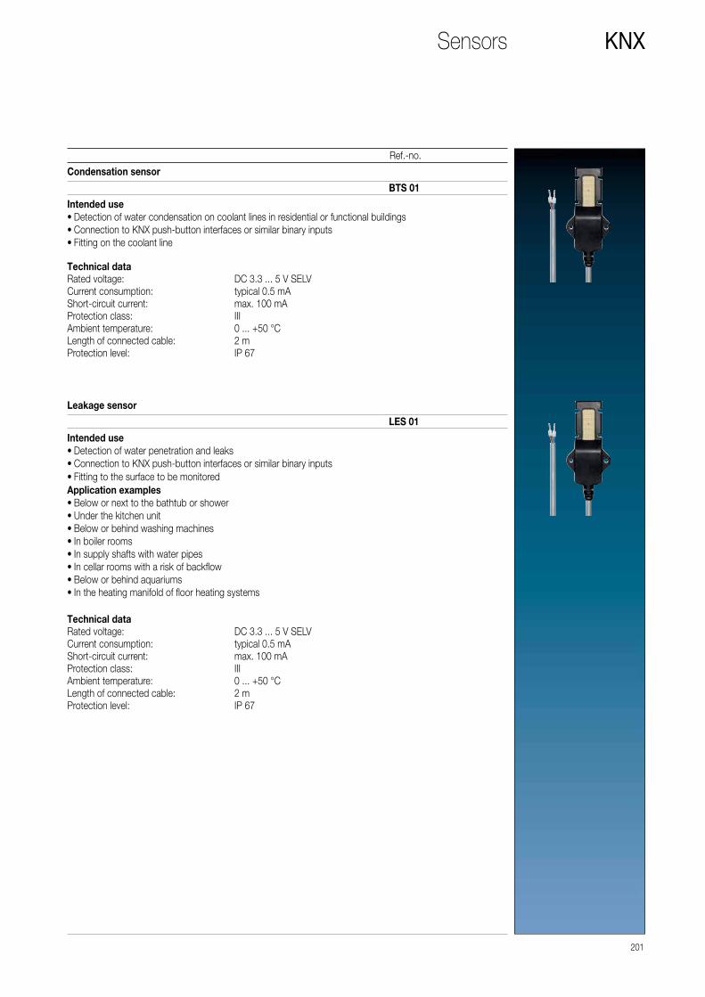
Condensation sensor
Intended use • Detection of water condensation on coolant lines in residential or functional buildings • Connection to KNX push-button interfaces or similar binary inputs • Fitting on the coolant line
BTS 01
Technical dataRated voltage: DC 3.3 ... 5 V SELVCurrent consumption: typical 0.5 mAShort-circuit current: max. 100 mAProtection class: IIIAmbient temperature: 0 ... +50 °CLength of connected cable: 2 mProtection level: IP 67
201
Ref.-no.
KNX
Leakage sensor
Intended use • Detection of water penetration and leaks • Connection to KNX push-button interfaces or similar binary inputs • Fitting to the surface to be monitored
Application examples • Below or next to the bathtub or shower • Under the kitchen unit • Below or behind washing machines • In boiler rooms • In supply shafts with water pipes • In cellar rooms with a risk of backflow • Below or behind aquariums • In the heating manifold of floor heating systems
LES 01
Technical dataRated voltage: DC 3.3 ... 5 V SELVCurrent consumption: typical 0.5 mAShort-circuit current: max. 100 mAProtection class: IIIAmbient temperature: 0 ... +50 °CLength of connected cable: 2 mProtection level: IP 67
Sensors

202
KNX
Ref.-no.
Binary input, 6-gangRail mounting device, 2 rail units6 inputs AC/DC 10 ... 230 V ~(different L conductors possible, e.g.: E1-3 = L1 and E4-E6 = L2)with status indicatorETS product family: InputProduct type: Binary input
Intended use • Polling of conventional switching or push-button contacts, window contacts etc. in KNX systems, for reporting of states, operation of loads, etc. • Mounting on DIN rail according to EN 60715 in distribution boxes
Product characteristics • Status LED for each input • Evaluation of voltage levels and changes at the input • Transmitting of input status to the bus • Transmitting behaviour adjustable • Functions: switching, dimming, blinds up/down, brightness values, temperatures, calling up and saving light scenes, etc. • Impuls and switch counter function • Inputs can be blocked separately • Connection of external AC or DC voltages
2116 REG
Technical dataRated voltage KNX: DC 21 ... 32 V SELVCurrent consumption KNX: max. 7.5 mAConnection, KNX: terminalAmbient temperature: −5 ... +45 °CStorage/transport temperature: −25 ... +75 °CRelative humidity: max. 93 % r. h., no condensationInputs Rated voltage: AC/DC 10 ... 230 V Signal level "0" signal: AC/DC 0 ... 2 V Signal level "1" signal: AC/DC 7 ... 265 VInput current at rated voltage: approx. 0.7 mA Rated frequency AC signal: 30 ... 60 Hz Signal duration pulse counter: min. 100 msCable length: max. 100 mNumber of contacts per input Make contacts: max. 50 Break contacts: max. 50Mounting width: 36 mm (2 rail units)Power loss: max. 1 WConnection: screw terminals single wire: 0.5 ... 4 mm2
stranded without ferrule: 0.5 ... 4 mm2
stranded with ferrule: 0.5 ... 2.5 mm2
Binary input
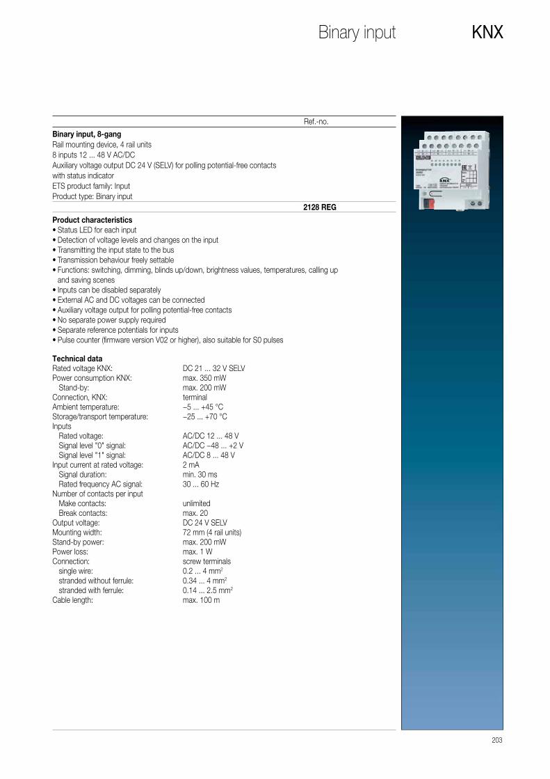
203
Ref.-no.
KNX
Binary input, 8-gangRail mounting device, 4 rail units8 inputs 12 ... 48 V AC/DCAuxiliary voltage output DC 24 V (SELV) for polling potential-free contactswith status indicatorETS product family: InputProduct type: Binary input
Product characteristics • Status LED for each input • Detection of voltage levels and changes on the input • Transmitting the input state to the bus • Transmission behaviour freely settable • Functions: switching, dimming, blinds up/down, brightness values, temperatures, calling up and saving scenes • Inputs can be disabled separately • External AC and DC voltages can be connected • Auxiliary voltage output for polling potential-free contacts • No separate power supply required • Separate reference potentials for inputs • Pulse counter (firmware version V02 or higher), also suitable for S0 pulses
2128 REG
Technical dataRated voltage KNX: DC 21 ... 32 V SELVPower consumption KNX: max. 350 mW Stand-by: max. 200 mWConnection, KNX: terminalAmbient temperature: −5 ... +45 °CStorage/transport temperature: −25 ... +70 °CInputs Rated voltage: AC/DC 12 ... 48 V Signal level "0" signal: AC/DC −48 ... +2 V Signal level "1" signal: AC/DC 8 ... 48 VInput current at rated voltage: 2 mA Signal duration: min. 30 ms Rated frequency AC signal: 30 ... 60 HzNumber of contacts per input Make contacts: unlimited Break contacts: max. 20Output voltage: DC 24 V SELVMounting width: 72 mm (4 rail units)Stand-by power: max. 200 mWPower loss: max. 1 WConnection: screw terminals single wire: 0.2 ... 4 mm2
stranded without ferrule: 0.34 ... 4 mm2
stranded with ferrule: 0.14 ... 2.5 mm2
Cable length: max. 100 m
Binary input

204
KNX
Ref.-no.
Push-button interface, 2-gangETS product family: InputProduct type: Binary input
• Can be used as binary input • Can be used as switching output, e.g. for LEDs, max. 0.8 mA
2076-2 T
Technical dataInputs Number: 2 Signal voltage: 5 V Signal current: > 1 mA Connection: branching terminal, 5 pins Length of input cable: 25 cm prefabricated, extendable to 5 m maxOutputs Output voltage: 5 V with outputs open circuit (ballast resistor 3.9 kΩ) Output current: 2 mA for red low-current LED (at approx. 1.4 V)Dimensions (W x H x D): 28 x 43 x 16 mm
Push-button interface

Push-button interface, 4-gangETS product family: InputProduct type: Binary input
• Can be used as binary input • Can be used as switching output, e.g. for LEDs, max. 0.8 mA
2076-4 T
Technical dataInputs Number: 4 Signal voltage: 5 V Signal current: > 1 mA Connection: branching terminal, 5 pins Length of input cable: 25 cm prefabricated, extendable to 5 m maxOutputs Output voltage: 5 V with outputs open circuit (ballast resistor 3.9 kΩ) Output current: 2 mA for red low-current LED (at approx. 1.4 V)Dimensions (W x H x D): 28 x 43 x 16 mm
205
Ref.-no.
KNXPush-button interface

The KNX energy sensor can also be retrofitted into already
existing KNX systems and has three channels for connecting
consumers. For each channel, the voltage, current, effective
power and reactive power can be measured: these data
are then sent cyclically to the KNX bus for evaluation and
visualisation and when any changes occur.
Energy sensor
KNX ENERGY SENSOR
Measurement and monitoring of energy consumption
206 ENERGY SENSOR
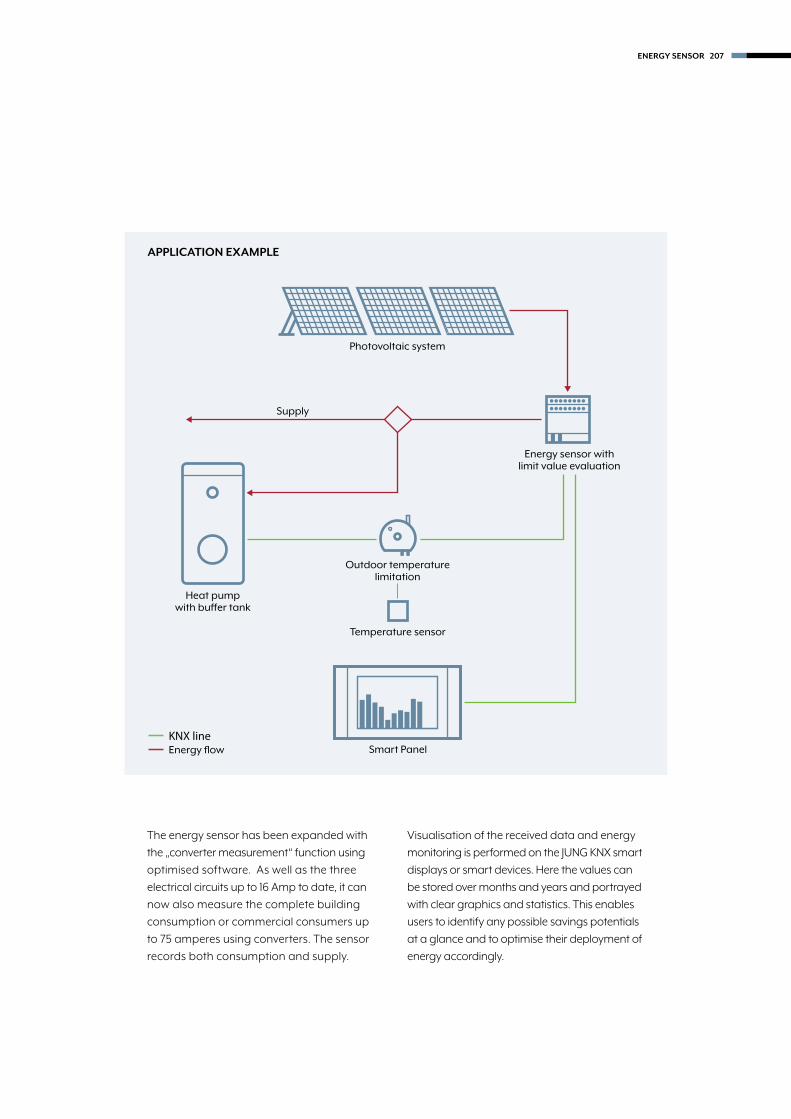
Outdoor temperature limitation
Temperature sensor
Supply
Photovoltaic system
Energy sensor with limit value evaluation
Heat pump with buffer tank
Smart PanelKNX lineEnergy flow
The energy sensor has been expanded with
the „converter measurement“ function using
optimised software. As well as the three
electrical circuits up to 16 Amp to date, it can
now also measure the complete building
consumption or commercial consumers up
to 75 amperes using converters. The sensor
records both consumption and supply.
Visualisation of the received data and energy
monitoring is performed on the JUNG KNX smart
displays or smart devices. Here the values can
be stored over months and years and portrayed
with clear graphics and statistics. This enables
users to identify any possible savings potentials
at a glance and to optimise their deployment of
energy accordingly.
APPLICATION EXAMPLE
ENERGY SENSOR 207

208
KNX
Ref.-no.
Energy detector, 3-gang, for rail mountingRail mounting device, 4 rail unitsETS product family: Physical sensorsProduct type: Energy detector
Product characteristicsThe energy detector has three channels for connecting loads to up to three separate phases with a common neutral conductor. Each channel can measure: • Voltage (eff.) • Current (eff.) • Active power • Reactive power
Additionally, the active power and reactive power of all channels will be summed up and displayed as three-phase power values along with the mains frequency.According to the parameterisation the measured values will be transmitted on the KNX bus, either cyclically and / or when the value changes. An additional telegram will be transmitted if certain values exceed or fall below a specified limit. The following meters exist for each channel and for the three-phase values: • 1 x energy meter total • 1 x energy meter ¼ h value • 3 x energy meter n • 3 x energy intermediate meter n
New in version 01: • Direct measurement (without transformer) • Transformer measurement (with external 75 A transformer, ratio 75:5, e.g. Phoenix Contact order key 2277611)
2103 REG ES
Energy detector

Technical data ref.-no. 2103 REG ESPower supply via E1/N Rated voltage: AC 110 ... 240 V ~ Mains frequency: 50 / 60 Hz Power consumption: max. 2 WInputs E1 ... E3 Rated voltage range: AC 85 ... 265 V ~ Rated current range: 4 mA ... 16 A Rated frequency: 50 / 60 Hz Measurands: voltage (rms value)
current (rms value) frequency active power (signed +/-) reactive power (signed +/-) active energy (signed +/-)
External transformer Transformation ratio: 75:5 Secondary current: 0 ... 5 AAccuracy: Direct measurement (without transformer): 1 % of 200 mA ... 16 A Transformer measurement (75 A transformer, class 1): 2 % of 7.5 A ... 75 APulses LED: Direct measurement (without transformer): 6400 / kWh Transformer measurement (75 A transformer): 427 / kWh Pulse duration: 4.9 msPower loss Voltage measurement: ≤ 0.03 W / phase Current measurement: ≤ 0.8 W / phase Power consumption from mains: < 1 WConnection: screw terminals single wire: 0.5 ... 2.5 mm2
stranded without ferrule: 0.5 ... 2.5 mm2
stranded with ferrule: 0.5 ... 2.5 mm2
Ambient temperature: −5 ... +45 °CStorage/transport temperature: −25 ... +70 °CMounting width: 72 mm (4 rail units)KNX medium: TP 256Rated voltage KNX: DC 21 ... 32 V SELVCurrent consumption KNX: max. 5 mAConnection, KNX: terminal
209
KNXEnergy detector

210 MULTIROOM/AUDIO

Multiroom amplifier
KNX MULTIROOM AMPLIFIER
integrated web radio and MP3 player
Sixteen radio stations can be selected using the integrated web radio. The MP3 player plays music data from the SD card that can be inserted into the integrated SD card reader. New music data can be transferred via FTP to the card at any time. Low-frequency (cinch) inputs for possible playback devices such as Hi-Fi system, DVD player and computer, etc. are available for the connection of other sources. Practical: Only the loudspeaker wiring is required in an existing KNX system.
Status LEDs
Mains power connection
Audio inputs/outputs
Loudspeaker connection terminals
Network connection/ SD card (WR version)
KNX connection
LEDs of the inputs/ outputs
Input/output push-buttons
Routing Audio configuration
Central unit for audio distribution: The KNX Multiroom amplifier
in its 19“ rack housing routes the stereo sound from four sources to
up to eight stereo loudspeaker outputs.
MULTIROOM/AUDIO 211

The multiroom amplifier including web radio
and MP3 player is operated via the KNX
system, together with room functions such
as lighting and temperature. The volume is
controlled using a rotary sensor; the source
selection is made using push-button sensor.
through the OLED graphic display of the
connected room controller, the title, artist
and album or radio station are displayed on
a scrolling text. The multiroom control can also
be optionally performed using a web interface.
As well as title selection and volume control
etc., the desired zone can also be selected
using this. Displaying the cover artwork of the
selected album is an additional feature.
EASY OPERATION USING KNX SENSORS
Dining area SleepingBathroom
LAN
TV
MP3 via SD card
Web radio via LAN
A 1
Q1
A 2
Q2
A 3
Q3
A 4
Q4
Lounge
KNX line
SYSTEM DESIGN
212 MULTIROOM/AUDIO

MULTIROOM/AUDIO 213

214
KNX
Ref.-no.
KNX Multiroom amplifierwith web radio and integrated MP3 playerwith integrated BCU4 outputs stereohousing made for the installation into 19'' racksETS product family: MultimediaProduct type: Multiroom
Intended use• Sound exposure of various building zones • Fixed installation in interior areas • For mounting in 19’’ rack systems IEC 60297 Product characteristics• Operation via KNX or via buttons on the front of the device • Audio matrix with integrated amplifiers• Independent sound exposure of 4 zones • 4 stereo inputs (AF signal) • 4 loudspeaker outputs stereo• 2 stereo outputs (AF signal) • Expandable due to modular structure • Integrated bus coupling unit • Status indicator • LAN connection RJ45 (10/100 Mbit/s) • Web radio • 16 radio stations can be accessed directly (KNX object) • Configuration of radio stations via web frontend • Integrated card reader for SD cards (max. 8 GB / FAT32) • SD card can be exchanged • Integrated MP3 player for music files on the SD card• New music files can be transferred to the SD card via FTP • Up to 16 folders with max. 250 tracks each• Functions such as Switch radio station, Choose title, Stop, Pause etc. are already included • Feedback of media information (artist, title etc.) directly into the KNX system (14 byte) • Web radio and integrated MP3 player can be fully operated via KNX (only web radio and MP3 player can be streamed)
MR WR-AMP 4.4
Technical dataRated voltage: AC 110 ... 230 V ~, 50/60 HzFuse: rear side of the device: T1.0A top side of the device: T10AConnection: power outlet acc. to IEC 60320-C13Power consumption: 110 V: approx. 181 W 230 V: approx. 177 W Stand-by 110 V: approx. 5 W Stand-by 230 V: approx. 6 WAmbient temperature: 0 ... +45 °CNumber of audio inputs (AF): 4Number of audio outputs (AF): 2Connection mode (AF): cinch (RCA) socketsNumber of loudspeaker outputs (pairs): 4Frequency range: 30 Hz ... 21 kHzTotal harmonic distortion: 0.2 %Nominal power output per zone: 30 W (2 x 15 W)Loudspeaker: Permissible load: min. 30 W Impedance: 8 Ohm Connection mode: screw terminals stranded without ferrule: 0.75 ... 2.5 mm2
KNX: Rated voltage: DC 21 ... 32 V SELV Connection bus: Hartmann/PTR BU 9502 Current consumption: max. 9 mADimensions (W x H x D): 483 x 44.5 x 230 mm
Multiroom amplifier

215
Ref.-no.
KNX
KNX Multiroom amplifierwith web radio and integrated MP3 playerwith integrated BCU8 outputs stereohousing made for the installation into 19'' racksETS product family: MultimediaProduct type: Multiroom
Intended use• Sound exposure of various building zones • Fixed installation in interior areas • For mounting in 19’’ rack systems IEC 60297 Product characteristics• Operation via KNX or via buttons on the front of the device • Audio matrix with integrated amplifiers• Independent sound exposure of 8 zones • 4 stereo inputs (AF signal) • 8 loudspeaker outputs stereo• 2 stereo outputs (AF signal) • Expandable due to modular structure • Integrated bus coupling unit • Status indicator • LAN connection RJ45 (10/100 Mbit/s) • Web radio • 16 radio stations can be accessed directly (KNX object) • Configuration of radio stations via web frontend • Integrated card reader for SD cards (max. 8 GB / FAT32) • SD card can be exchanged • Integrated MP3 player for music files on the SD card• New music files can be transferred to the SD card via FTP • Up to 16 folders with max. 250 tracks each• Functions such as Switch radio station, Choose title, Stop, Pause etc. are already included • Feedback of media information (artist, title etc.) directly into the KNX system (14 byte) • Web radio and integrated MP3 player can be fully operated via KNX (only web radio and MP3 player can be streamed)
MR WR-AMP 4.8
Technical dataRated voltage: AC 110 ... 230 V ~, 50/60 HzFuse: rear side of the device: T2.0A top side of the device: T10AConnection: power outlet acc. to IEC 60320-C13Power consumption: 110 V: approx. 397 W 230 V: approx. 391 W Stand-by 110 V: approx. 5.5 W Stand-by 230 V: approx. 6 WAmbient temperature: 0 ... +45 °CNumber of audio inputs (AF): 4Number of audio outputs (AF): 2Connection mode (AF): cinch (RCA) socketsNumber of loudspeaker outputs (pairs): 8Frequency range: 30 Hz ... 21 kHzTotal harmonic distortion: 0.2 %Nominal power output per zone: 30 W (2 x 15 W)Loudspeaker: Permissible load: min. 30 W Impedance: 8 Ohm Connection mode: screw terminals stranded without ferrule: 0.75 ... 2.5 mm2
KNX: Rated voltage: DC 21 ... 32 V SELV Connection bus: Hartmann/PTR BU 9502 Current consumption: max. 9 mADimensions (W x H x D): 483 x 44.5 x 230 mm
Multiroom amplifier

KNX ROOM CONTROLLER OLED
216 MULTIROOM/AUDIO

KNX SONOS GATEWAY
Integrating the Sonos sound system in KNX
KNX Sonos Gateway
This gateway connects the intelligent KNX technology to the Sonos
multiroom sound. Using various controls or smart devices, up to
30 Sonos devices can be controlled – together with room functions
such as lighting, shading and temperature. The operation of the
rooms is then optionally performed individually or in parallel using
the party mode.
MULTIROOM/AUDIO 217

Multiroom sound in the whole house, operated through JUNG control elements. by setting up
dynamic groups, up to five zones can each be equipped with a master. These zones can then
in turn be networked with up to five slave devices.
Volume control, title selection, start/stop etc.: Intuitively controlled
using KNX sensors or smart phone / tablet in connection with
Smart Visu Server. Title, interpret and album are also shown on
the displays of room controllers or smart devices. For even greater
music enjoyment, playing back music on a micro SD card is also
possible in the KNX Sonos Gateway (not included in the scope
of delivery).
Zone 1 Bathroom Zone 2 Kitchen
Zone 1 Bathroom
Zone 2Kitchen
KNX lineLAN
218 MULTIROOM/AUDIO

219
Ref.-no.
KNX
Sonos gatewayRail mounting device, 2 rail unitsETS product family: MultimediaProduct type: Multiroom
Intended use • Controlling of Sonos audio devices via KNX • Mounting on DIN rail according to EN 60715 in distribution boxes
Product characteristics • Control of up to 30 Sonos devices via KNX devices, independent of the Sonos App • Dynamic group creation of up to five zones with one master and five slave devices each via KNX objects • Party mode: same music for all rooms • Volume control for master, slaves and the whole group • Control of play lists • Playing music from microSD card (not included) in the Sonos gateway • Title, artist and album on KNX text objects • Integrated data network switch with two RJ45 terminals • Requires ETS version 4.2 or 5.0.2 or higher
MR-SONOS-REG
Technical dataExternal supply Rated voltage: DC 24 ... 30 V ± 10 % Connection: connecting terminal yellow/whitePower consumption: typical 2 W (at DC 24 V, two Ethernet cables connected)IP communication: Ethernet 10/100 BaseT (10/100 Mbit/s)IP connection: 2 x RJ45Protocols: ARP, ICMP, IGMP, UDP/IP, DHCP, AutoIP,
KNXnet/IP (Core, Device Management)Memory card: max. 32 GB microSDHCAmbient temperature: 0 ... +45 °CStorage/transport temperature: −25 ... +70 °CMounting width: 36 mm (2 rail units)Rated voltage KNX: DC 21 ... 32 V SELVConnection, KNX: bus connection block (red/black)
Sonos gateway

All important sensors for recording and evaluation of meteo-
rological data combined in compact design: the JUNG KNX
weather station for weather-dependent automatic shading
control for façade protection.
Universal weather station
KNX UNIVERSAL WEATHER STATION
Compact design, precise measurement
220 WEATHER STATIONS

Wind speed, wind direction, brightness in
four directions, twilight, global radiation,
precipitation, relative air humidity and air
pressure are measured using the integrated
sensors. The calculation of further data such
as absolute humidity and perceived tempe-
rature is also carried out. Operating inter-
dependently with each other, values are also
determined in terms of the mugginess curve
and comfort characteristic that can then be
used to optimise the ventilation control.
These features are enhanced with a GPS/
GLONASS receiver for the date and time and
an astro function for determining the position
of the sun. This makes it no-longer necessary
to set the time manually. The installation of
the weather station is carried out with its own
fastening arm on the installation mast. This
ensures the best capture and measurement
of the weather data. The weather station can
also be mounted onto the façade by means
of the fastening arm.
GPS/GLONASS receiver for date/
time and astro function
Precipitation sensor
Brightness sensor for four directions;
measurement of twilight and global
radiation
KNX bus coupling
(supply 24 V AC/DC)
Temperature and
dew point sensor
Humidity measurement
Sensor for wind direction
and wind speed
WEATHER STATIONS 221

222
KNX
Ref.-no.
KNX universal weather stationcompact housingincluding fastening armETS product family: InputProduct type: Analogue input 4-gang
Intended use • Measurement and evaluation of weather data: wind speed, wind direction, precipitation, brightness, global radiation, twilight, temperature, relative air humidity and air pressure • Installation on the outside of buildings, preferable in the roof and facade area • Operation with additional power supply (ref.-no.: WSSV 10)
Product characteristics • Integrated GPS/GLONASS receiver for automated positioning • Calculation of additional weather data: absolute air humidity, chill temperature, comfort • Function for shading control • Integrated KNX bus coupling unit • Measuring and limit value monitoring • Software logic modules for linking events • Integrated heating
The weather station needs an operating voltage supply of 24 V AC, for example power supply module ref.-no. WSSV 10.
2225 WS U
Technical dataPower supply Rated voltage: AC 24 V SELV (± 10 %)
DC 21 ... 32 V SELV Current consumption: 100 ... 400 mA (dependent on the weather)Protection class: IIICable type: LiYCY 4xAWG26Cable length: 5 mTotal length per line: 15 mNumber of weather stations: max. 3 (per line)Rated voltage KNX: DC 21 ... 32 V SELVCurrent consumption KNX: max. 5 mAAmbient temperature: −30 ... +60 °CStorage/transport temperature: −25 ... +70 °CProtection level: IP 44 (in position for use)Dimensions (Ø x H): 130 x 68 mmWind direction sensor Measuring range: 1 ... 360° Resolution: 1° Accuracy: ± 10 % (laminar wind stream)Wind speed sensor Measuring range: approx. 0 ... 40 m/s Resolution: 0.1 m/s Accuracy (≤ 10 m/s): ± 1 m/s Accuracy (> 10 m/s): ± 5 %Temperature sensor Measuring range: −30 ... +60 °C Resolution: 0.1 K Accuracy: ± 1 K (wind > 2 m/s, for −5 ... +25 °C)Precipitation sensor Measuring range: yes / no Accuracy: fine drizzle
Universal weather station

223
Ref.-no.
KNX
Fastening arm(Spare part)for installation of the universal weather station, ref.-no.: 2225 WSU
2225 BFA
Universal weather station
Continue Technical data ref.-no. 2225 WS UBrightness sensors Number: 4 Measuring range: approx. 0 ... 150 klx Resolution: 1 klx Accuracy: ± 3 % Spectral range: 475 ... 650 nmDawn sensor Measuring range: approx. 0 ... 900 lx Resolution: 1 lx Accuracy: ± 10 lxAir pressure sensor Measuring range: 300 ... 1100 hPa Resolution: 0.01 hPa Accuracy: ± 0.5 hPa (20 °C)Humidity sensor Measuring range: 0 ... 100 % relative humidity (r. h.) Resolution: 0.1 % relative humidity (r. h.) Accuracy: ± 10 % rel. humidity (20 °C) Absolute humidity: 0 ... 400 g/m3
Resolution: 0.01 g/m3
Global radiation Measuring range: 0 ... 1300 W/m2
Resolution: 1 W/m2
Accuracy: ± 10 % Spectral range: 350 ... 1100 nmAll accuracy specifications relate to the respective measuring range end value.

224
KNX
Ref.-no.
KNX weather station "home"
The KNX weather station detects the meteorological data "Wind speed", "Precipitation", "Twilight", "Temperature" and the brightness in three directions. Its main area of application is the automatic, weather-dependent control of shading. It is specially designed for use in homes. To increase functional reliability, the weather station monitors itself in some important functions, and reports any corresponding errors to the bus automatically via indicator objects. It is intended for outdoor installation on a mast or on a wall. The bus coupling to the KNX/EIB is integrated (monoblock).Evaluation of the data themselves, in particular the limiting value processing, is performed already in the weather station. A built-in heater protects against degradation of function from frost and moisture condensation down to –20 °C. The heating system further ensures that the sensor surface of the precipitation sensor will dry off quickly after rain, and also melts snow and ice. Power is supplied to the unit via the bus, except for the heating system and the power supply for the precipitation sensor. The weather station requires an external 24 V AC/DC power supply for the heating system, without which precipitation detection is not possible. Logic gates are available for cascading a number of weather stations and for linking the limiting values and the monitoring functions. Blocking elements make it possible to block individual functions at the installation location.Intended use • Measurement and evaluation of weather data: wind speed, precipitation, twilight, temperature and brightness • Vertical mounting on the outside of buildings, preferably on roofs and at façades
Product characteristics • Integrated KNX bus coupler • Compact housing • Low-maintenance device • Measured-value acquisition and limit value monitoring
The power supply ref.-no.: WSSV 10 is necessary for precipitation detection.
2224 WH
Weather station “home”
Techniscal dataRated voltage KNX: DC 21 ... 32 V SELVPower consumption KNX: typical 450 mWConnection, KNX: KNX bus connection blockExternal power supply Rated voltage: AC/DC 24 V SELV Power consumption: typical 7.5 W Connection: connecting terminal yellow/whiteAmbient temperature: −20 ... +55 °C (free of ice and dirt)Storing temperature: −40 ... +70 °CProtection level: IP 44 (in position for use)Protection class: IIIDimensions (W x H x D): approx. 88 ×170 ×204 mm
(with assembly arm)Weight: approx. 240 g
Sensor signalsTemperature sensor Measuring range: −20 ... +55 °C Accuracy: ± 1 K (for wind speeds > 0.5 m/s)Wind sensor Measuring range: approx. 0 ... 40 m/s Accuracy: ± 2 m/sPrecipitation sensor Measuring range: precipitation yes / no Sensitivity: fine drizzle Switch-off delay: adjustableBrightness sensor Direction: east, south, west Measuring range: approx. 1 ... 110 klx Spectral range: approx. 700 ... 1050 nm Accuracy: 10 %
(upper end of measuring range)Dawn sensor Direction: south Measuring range: approx. 0 ... 674 lx Spectral range: approx. 700 ... 1050 nm Accuracy: 10 %
(upper end of measuring range)

225
Ref.-no.
KNX
Connection setfor weather station home ref.-no.: 2224 WHfor pole mounting 50 – 120 mm Ø MM 100for edge mounting white MW 270 WW
aluminium (lacquered) MW 270 AL
Analogue input, 4-gangRail mounting device, 4 rail unitsETS product family: InputProduct type: Analogue input 4-gang
The analogue input processes measured-value data supplied by analogue sensors. Four analogue transducers in any combination can be connected to the input. The analogue input evaluates voltage and current signals.Voltage signals: 0 ... 1 V DC 0 ... 10 V DCCurrent signals: 0 ... 20 mA DC 4 ... 20 mA DCThe 4 ... 20 mA current inputs can be monitored for open-circuit conditions.
The analogue input needs a separate power supply, for example the power supply module ref.-no. WSSV 10.
2214 REG A
Technical dataSupply voltage: AC 24 V ~ ± 10 %Analogue inputs: 4 Format: EIS 5 (2 Byte) or EIS 6 (1 Byte) Ranges: voltage 0 ... 1 V, 0 ... 10 V;
current 0 ... 20 mA, 4 ... 20 mA;depending on parameterization
Limit values: 2 per channelSupply output for sensor: 2 terminal pairs Voltage: DC 24 V ± 25 % Total current: max. 100 mA
Analogue input
Sensor signalsTemperature sensor Measuring range: −20 ... +55 °C Accuracy: ± 1 K (for wind speeds > 0.5 m/s)Wind sensor Measuring range: approx. 0 ... 40 m/s Accuracy: ± 2 m/sPrecipitation sensor Measuring range: precipitation yes / no Sensitivity: fine drizzle Switch-off delay: adjustableBrightness sensor Direction: east, south, west Measuring range: approx. 1 ... 110 klx Spectral range: approx. 700 ... 1050 nm Accuracy: 10 %
(upper end of measuring range)Dawn sensor Direction: south Measuring range: approx. 0 ... 674 lx Spectral range: approx. 700 ... 1050 nm Accuracy: 10 %
(upper end of measuring range)

226
KNX
Ref.-no.
Power supply AC 24 V ~for universal weather station ref.-no.: 2225 WS Ufor weather station home ref.-no.: 2224 WHfor analogue input ref.-no.: 2214 REG Afor analogue actuator ref.-no.: 2204.01 REGARail mounting device, 4 rail units
Product characteristics • Two internally connected 24 V outputs • Overload and short-circuit protection via thermo switch
WSSV 10
Technical dataRated voltage: AC 230 V ~, 50/60 HzOutput current: max. 1 AOutput voltage: AC 24 V ~Storage/transport temperature: −25 ... +70 °CAmbient temperature: −5 ... +40 °CRelative humidity: max. 93 % r. h., no condensationMounting width: 72 mm (4 rail units)Connection: screw terminals single wire: 0.5 ... 4 mm2
stranded with ferrule: 0.14 ... 2.5 mm2
stranded without ferrule: 0.34 ... 4 mm2
Analogue input
Analogue input extension module, 4-gangRail mounting device, 4 rail unitsextension module for analogue input
The analogue input extension module provides a KNX analogue input 2214 REG A with four additional sensor inputs. The evaluation of the measured data and the limiting values will be handled by the connected KNX device.The analogue input extension module evaluates voltage and current signals.Voltage signals: 0 ... 1 V DC 0 ... 10 V DCCurrent signals: 0 ... 20 mA DC 4 ... 20 mA DC
2214 REGAM
Technical dataExternal supply Voltage: AC 24 V ~ ± 15 % Current consumption: max. 170 mA (incl. sensors)Analogue inputs: 4Measuring ranges per channel Voltage: 0 ... 1 V, 0 ... 5 V, 0 ... 10 V (DC)
Impedance approx. 18 kΩ Current: 0 ... 20 mA, 4 ... 20 mA
Impedance approx. 100 kΩA/D converter: 14 bitPower supply for sensors: DC 24 V max. 100 mA
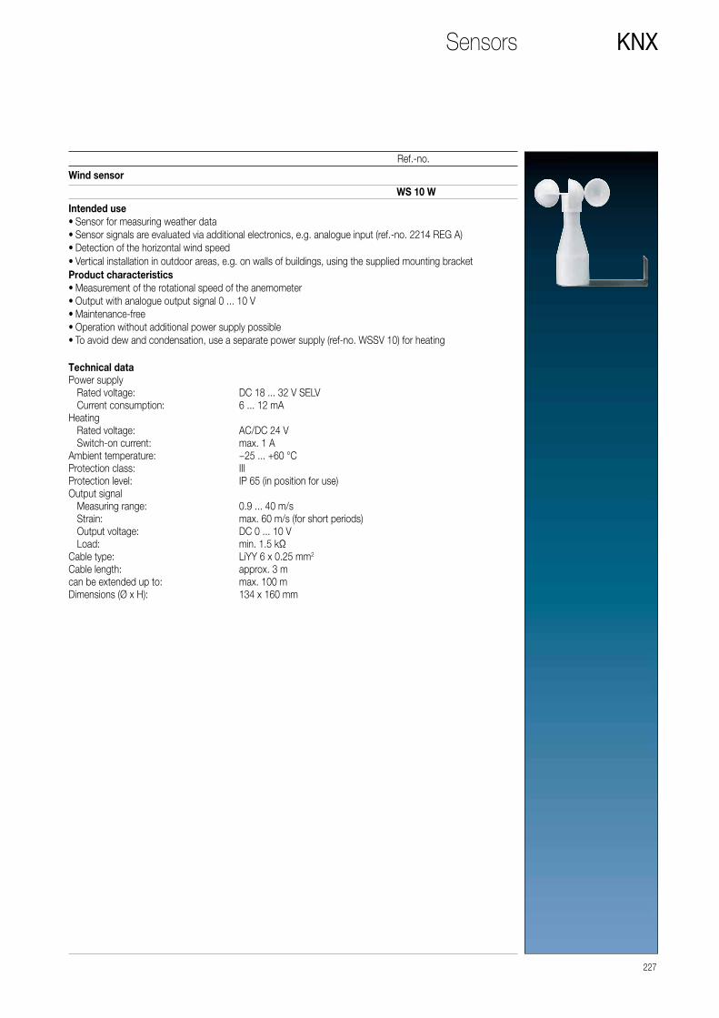
Wind sensor
Intended use • Sensor for measuring weather data • Sensor signals are evaluated via additional electronics, e.g. analogue input (ref.-no. 2214 REG A) • Detection of the horizontal wind speed • Vertical installation in outdoor areas, e.g. on walls of buildings, using the supplied mounting bracket
Product characteristics • Measurement of the rotational speed of the anemometer • Output with analogue output signal 0 ... 10 V • Maintenance-free • Operation without additional power supply possible • To avoid dew and condensation, use a separate power supply (ref-no. WSSV 10) for heating
WS 10 W
Technical dataPower supply Rated voltage: DC 18 ... 32 V SELV Current consumption: 6 ... 12 mAHeating Rated voltage: AC/DC 24 V Switch-on current: max. 1 AAmbient temperature: −25 ... +60 °CProtection class: IIIProtection level: IP 65 (in position for use)Output signal Measuring range: 0.9 ... 40 m/s Strain: max. 60 m/s (for short periods) Output voltage: DC 0 ... 10 V Load: min. 1.5 kΩCable type: LiYY 6 x 0.25 mm2
Cable length: approx. 3 mcan be extended up to: max. 100 mDimensions (Ø x H): 134 x 160 mm
227
Ref.-no.
KNXSensors

228
KNX
Ref.-no.
Rain sensor
Intended use • Sensor for measuring weather data • Sensor signals are evaluated via additional electronics, e.g. analogue input (ref.-no. 2214 REG A) • Detection of precipitation • Installation in outdoor areas, e.g. on walls of buildings, using the supplied 110° mounting bracket
Product characteristics • Measurement of the electrical conductivity on the sensor surface • Output by means of analogue output signal: 0 = dry, 10 V = rain • Heating of the sensor surface with separate 24 V AC/DC power supply, ref.-no.: WSSV 10
WS 10 R
Technical dataPower supply Rated voltage: DC 15 ... 30 V Current consumption: approx. 10 mAHeating Rated voltage: AC/DC 24 V Power consumption: max. 4.5 WAmbient temperature: −30 ... +70 °CProtection class: IIIProtection level: IP 65Output signal Output voltage: DC 0 / 10 V Load: min. 1 kΩ Reaction time: max. 4 minCable type: LiYY 5 x 0.25 mm2
Cable length: approx. 3 mcan be extended up to: max. 100 mDimensions (Ø x H): 58 x 83 x 17 mm
Sensors

Temperature sensorRated voltage 24 V DCrange -30 °C ... +70 °C, linear
The brightness sensor is used for the measuring and evaluation of the brightness.The dawn sensor is used for the measuring and evaluation of the brightness (dawn/dusk).The temperature sensor is used for the measuring and evaluation of the temperature.The value measured by the sensor is transmitted to an analogue output signal of 0 ... 10 V by the electronics.Connections:Plastic housing with PG7 thread + screw and pressure / moisture compensation (recommended cable 3 x 0.25 mm2)+UB: operating voltage 24 V DCGND: corresponding groundOUT: output 0 ... 10 V
58 x 35 x 64 mm WS 10 T
Technical dataSupply voltage: 24 V DC (15 ... 30 V DC)Connection: screw terminalsTerminals for: 2.5 mm2
Connecting cable: through screwed conduit entry PG 7Recommended cable: 3 x 0,25 mm2
Cable length: max. 100 mOutput: 0 ... 10 V DC (into a load of at least 1 kΩ, short-circuit protected)Ambient temperature: −30 ... +70 °CProtection level: IP 65Mounting position: optional
229
Ref.-no.
KNXSensors
Brightness sensorRated voltage 24 V DCrange 0 ... 60 000 lux, linear58 x 35 x 64 mm WS 10 H
Dawn sensorRated voltage 24 V DCrange 0 ... 255 lux, linear58 x 35 x 64 mm WS 10 D

The KNX signalling system uses a well thought out design for
optimal functionality. The core is the central centre where
the display is controlled and all processes are regulated.
KNX SMART PANEL 5.1
Signalling System
THE SYSTEM ALSO CONSISTS OF THE FOLLOWING MODULES AND FUNCTIONS:
Alert
Various devices for the loud and
silent alarms.
Certainty
There is a locking unit for use on
the entrance door.
Activation
Activation is done using a key switch.
Detectors
Sensors, contacts and movement detectors
perform the monitoring tasks in rooms, on
windows and doors.
230 SIGNALLING SYSTEM

ALARM SIGNALLING
POWER SUPPLY
ACTIVATION
DETECTORS
CERTAINTY
12 V 230 V KNX line Binary input
Outdoor / indoor siren Indoor siren Switch actuator, 4-gang Push-button interface, 4-gang Binary input, 6-gang
Switch actuator, 4-gang
Key switches
Push-button interface, 4-gang
Binary input, 6-gang
Binary input, 6-gang Locking unit
Switch actuator, 4-gang Push-button interface, 4-gang
Presence detector/ceiling observer
F 50 push-button sensor, 4-gang
Frame joint switch contact
Push-button interface, 4-gang
Glass-break sensor
Binary input, 6-gang
Magnet contact
Automatic switch 180°, universal
Uninterruptible Power Supply
CONTROL CENTRE
Smart Panel 5.1
SIGNALLING SYSTEM 231

232
KNX
Ref.-no.
Signalling System
Smart Panelwith integrated BCUaspect ratio 4:3for installation in walls, touch screenfanless, without rotating parts
Intended use • Operation and visualisation of system statuses and information on building automation • Flush-mounted fitting indoors
Integrated signalling systemA signalling system offers a safety-oriented system for the observation of windows and doors. The signalling system can display the status of window contacts, motion detectors or glass break sensors and monitors changes in the statuses of these detectors. The detectors integrated in the signalling system can be combined into up to two security areas (internal/external). Arming these areas allows monitoring of the secured area for break-ins when people are present or absent. In addition, sections of the area can be monitored for sabotage. If there is a break-in alarm, visual and acoustic alarms (flash light, siren) can be activated via KNX components (e.g. switching actuators).Max. 40 detectors (KNX)Two security areas Product characteristics • Illuminated graphic colour screen TFT, 640 x 480 pixels, 262 000 colours • Touchscreen • KNX Interface • Interfaces – accessible from front: 1 x USB 2.0 • Interfaces – accessible from behind: Ethernet • Graphical user interface for visualisation and operation of KNX devices • Predefined graphical user interface • Free graphical user interface • KNX special functions, e.g. scenes, forced position, timer, presence simulation • Fast access to pages and functions • Remote access (remote function) • Acoustic signal encoder, configurable • Combination of predefined and free graphical user interface • Master pages: max. 10 • Free pages: max. 50 • Elements: max. 400 • Copy & Paste functions • 50 rooms • 10 function units • 240 functions, e.g.: – Scene recalls: max. 40 – Signalling system: max. 40 detectors (internal and external skin together) – Datalogger: max. 20 datalogger channels – Logic gates: max. 80 gates with up to 8 inputs and one output each – Timers: max. 40 – Limiting value modules: max. 40 – Demultiplexer "1 to 2" and "1 to 4": max. of 7 each – Timer: max. 64 switching channels with a total of 128 switching times – Scenes: max. of 24 scenes, max. of 32 scene functions – Presence simulation: max. 8 simulations, max. 32 functions (15 functions per simulation) – Fault messages: max. 50 – Event e-mails: max. 50 – Video messages: max. 8 – System time: max. 40
Frames and accessories see page 241
SP 5.1 KNX

233
Ref.-no.
KNXSignalling System
Indoor siren
To be integrated into the signalling system of the Smart Panels by the KNX system via switching actuators (flash light and siren).Supply voltage 12 V DC, separate power supply
DAS 4120
Key switch/push-buttonfor activating and deactivating of alarm systems
Housing, front plate: diecast aluminiumDimensions of housing (W x H x D): 79 x 113 x 54 mmColour: white RAL 9010
Surface-mounted DAS 4300 A
Key switch/push-buttonfor activating and deactivating of alarm systems
Housing, front plate: aluminium (precision casting)Dimensions of front plate (W x H x D): 101 x 135 x 3 mmDimensions of flush housing (W x H x D): 79 x 113 x 54 mmprofile cylinder lock is not included• wired • sealed housing for indoor and outdoor use • either permanent or pulse contact • two LED for individual wiring • buzzer for acknowledgement or refusal • tear-off and lift-off contact against sabotage • protection against drillingTo be integrated into the signalling system of the Smart Panels by the KNX system via binary inputs / push-button interfaces (evaluation armed/unarmed) and switching actuator (ACK buzzer / LED). Cable: min. 6 wiresSupply voltage 12 V DC, separate power supply
Flush-mounted DAS 4300 U
Technical dataOperating voltage: 9 ... 15 V DCRated voltage: 12 V DCCurrent consumption per LED: approx. 10 mACurrent consumption buzzer: approx. 25 mABuzzer: buzzer 12 V 85 dBA / 10 cmPermissible load of all contacts: max. 60 V / 0.5 AProtection level: IP 54
Locking cylinder for key switcheswith 3 keysdifferent locks 28equal locks 28 G1
Key for locking cylinder 28 G1(Spare part)1 piece 28 G1 SL

234
KNX
Ref.-no.
Signalling System
Locking unit
The motorized locking unit serves for the mechanical door lock. It prevents an unintended entering of armed security areas.Can be cascaded for several doors.Features: • Robust housing of plastics a nd stainless steel • Electrical and mechanical emergency operation • Low noise • Low stand-by current • Integrated magnetic contact • Acknowledge of the bolt position • To be controlled with static or dynamic signals • Simple adaption to the door frame
One magnet and two counterparts are included in the delivery. To be integrated into the signalling system of the Smart Panels by the KNX system via switching actuators (inputs and emergency opening) or via binary inputs / push-button interfaces (evaluation of the locking unit outputs and the integrated magnetic contacts) respectively.Supply voltage 12 V DC, separate power supply
DAS 4370
Movement detectorPIR detection
Detected area: 90° (volumetric), 34 double zones in 3 levels, maximum detected area approx. 15 x 15 mThe detector is a compact passive infra-red movement detector with micro processor. Is is designed to be highly reliable and versatile. The detector has a memory which can be called by a signal at the control input. If the alarm system is active, a movement detection will trigger a relay and acivate the memory logic. The test LED is automatically disabled in the active state – there is no optical indication. If the alarm system is deactivated (no signal at set input) a stored alarm will be indicated by a permanently lit LED. The stored alarm will automatically be deleted when the alarm system is activated again. Since the control signal for the set input may vary, depending on the central unit, the polarity of the signal can be changed at the PIR detector.The pyroelectric element of the PIR detector is separately encased to prevent insects or atmospheric turbulence to trigger false alarms.The detector can be mounted at a wall or in a room corner.To be integrated into the signalling system of the Smart Panels by the KNX system via binary inputs / push-button interfaces (evaluation of movement or sabotage).Supply voltage 12 V DC, separate power supply
DAS 4210

Frame joint switch contact
Electromechanical switching contact for monitoring the locking ofdoors.To be mounted into the locking plate of the door frame and is activated by closing the door.Micro switch, dust and water proof with solder connectionZn diecast housingno limitation of the bolt pathConstruction kit with extension pieceTo be integrated into the signalling system of the Smart Panels by the KNX system via binary inputs / push-button interfaces.
DAS 4360
235
Ref.-no.
KNXSignalling System
Glass-break sensor, passive
break contactfor monitoring of plane glass surfaces (no laminated, structured or wired glass) A glass break or damage causes typical ultrasonic signals. The frequency and amplituede is evaluated. The generated energy activates the alarm by piezo ceramic vibrations.opening of the signalling line for approx. 0.5 to 5 seconds, depending on the glass type.To be integrated into the signalling system of the Smart Panels by the KNX system via binary inputs / push-button interfaces.
white similar RAL 9010 FUS 4415 WW
Magnet contact
A sealed tubular glass envelope protects the magnet contact (reed contact) against dust and water.The reed contact is actuated by means of a permanent magnet.For installation in steel profiles (magnetic material) only block reed contacts can be used.Included in delivery:2 surface-mounted housings, 2 caps,3 spacers 2 mm1 spacer 6 mmTo be integrated into the signalling system of the Smart Panels by the KNX system via binary inputs / push-button interfaces.
white similar RAL 9010 FUS 4410 WWbrown FUS 4410 BR

The KNX signal panel is ideal for use in supermarkets, shops
and offices: There are 24 capacitive sensor buttons on its high
quality glass front that are used to control the lighting, blinds and
scene functions for the entire premises. 24 coloured RGB LEDs
and individual labelling strips make labelling simple and clear.
Signal panel
KNX SIGNAL PANEL
Surface mounting variant with robust plastic enclosure
236 VISUALISATION/OPERATION

237
Ref.-no.
KNXSignal panel
Signal panelETS product family: DisplayProduct type: Signal panel
The glass panel with aluminium housing is equipped with 24 capacitive sensor buttons and 24 status LEDs.The panel enables the control of switching, dimming and push-button functions as well as light scene and value transmitter functions. The LEDs can be separately parameterised to be illuminated in green, red or blue to signalise different situations of the KNX installation. Single sensor buttons, full columns or the entire panel can be blocked with blocking functions. Acoustic signals when pushing the sensor buttons can be parameterised. The surface can be labelled with exchangeable labelling foils, which can be labelled with the JUNG label tool. The MBT 2424 will be installed into a 2-gang wall box or a surface-mounted housing. Programming takes place via ETS. A drilling template and a bit for assembling will be delivered with the device.Product characteristics • Switching, dimming, push-button and blinds control, value transmitter and light scenes • High quality glass surface with 24 sensor buttons • Operation via touching the sensor buttons • Labelling with exchangeable labelling foil • Status feedback with 24 LEDs; the colours red, green and blue can be configured • Acoustical feedback for touching sensor • Fault message on dismantling • Logic and time functions • Integrated BCU • Supply via separate power supply (ref.-no. NT 2405 VDC) or the auxiliary voltage output of the KNX power supply
glass green MBT 2424glass white MBT 2424 WWglass black MBT 2424 SW
Surface-mounted housingfor signal panel ref.-no.: MBT 2424 ..
EBG 2424
Flush-mounted power supplyfor signal panel ref.-no.: MBT 2424 ..
NT 2405 VDC

Smart Panel
KNX SMART PANEL 5.1
238 VISUALISATION/OPERATION

JUNG GRAPHICAL USER INTERFACE
Visualisation and operation are performed
using the uniform JUNG user interface that
allows logical and intuitive operation of the
various functions. This is generated quickly
using the Smart Panel Designer.
FREELY CONFIGURABLE USER INTERFACE
As an alternative or additionally, a freely
configurable user interface can be created.
This enables the realisation of an individual
display for the user.
Operating comfort on 14.5 cm screen diagonal: Thanks to
integrated control software, the functions are displayed and
controlled using the colour TFT touchscreen with the KNX
Smart Panel 5.1.
Additional security is provided by the integrated signalling system
in the Smart Panel for up to 40 detectors for interior and exterior
perimeter protection. Additional functions are the 64-channel
week timer with random and astro functions, the pre-configured
lighting scene management, data logger for consumption data,
limit value modules, and logic and time gates. These optimise
the features and are quickly integrated.
VISUALISATION/OPERATION 239

240
KNX
Ref.-no.
Smart Panel
Smart Panelwith integrated BCUaspect ratio 4:3for installation in walls, touch screenfanless, without rotating parts
Intended use • Operation and visualisation of system statuses and information on building automation • Flush-mounted fitting indoors
Product characteristics • Illuminated graphic colour screen TFT, 640 x 480 pixels, 262 000 colours • Touchscreen • KNX Interface • Interfaces – accessible from front: 1 x USB 2.0 • Interfaces – accessible from behind: Ethernet • Graphical user interface for visualisation and operation of KNX devices • Predefined graphical user interface • Free graphical user interface • KNX special functions, e.g. scenes, forced position, timer, presence simulation • Fast access to pages and functions • Remote access (remote function) • Acoustic signal encoder, configurable • Combination of predefined and free graphical user interface • Master pages: max. 10 • Free pages: max. 50 • Elements: max. 400 • Copy & Paste functions • 50 rooms • 10 function units • 240 functions, e.g.: – Scene recalls: max. 40 – Signalling system: max. 40 detectors (internal and external skin together) – Datalogger: max. 20 datalogger channels – Logic gates: max. 80 gates with up to 8 inputs and one output each – Timers: max. 40 – Limiting value modules: max. 40 – Demultiplexer "1 to 2" and "1 to 4": max. of 7 each – Timer: max. 64 switching channels with a total of 128 switching times – Scenes: max. of 24 scenes, max. of 32 scene functions – Presence simulation: max. 8 simulations, max. 32 functions (15 functions per simulation) – Fault messages: max. 50 – Event e-mails: max. 50 – Video messages: max. 8 – System time: max. 40
SP 5.1 KNX
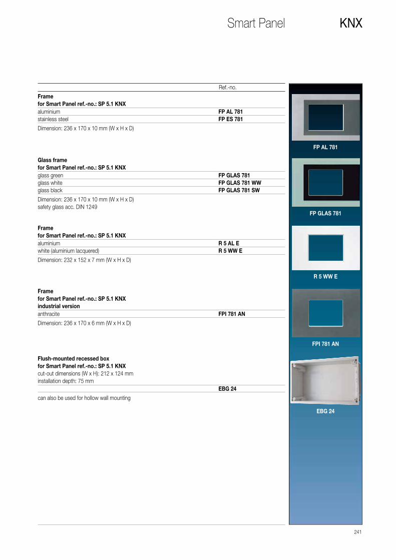
Framefor Smart Panel ref.-no.: SP 5.1 KNX
Dimension: 236 x 170 x 10 mm (W x H x D)
FP AL 781
aluminium FP AL 781stainless steel FP ES 781
241
Ref.-no.
KNXSmart Panel
Glass framefor Smart Panel ref.-no.: SP 5.1 KNX
Dimension: 236 x 170 x 10 mm (W x H x D)safety glass acc. DIN 1249
FP GLAS 781
glass green FP GLAS 781glass white FP GLAS 781 WWglass black FP GLAS 781 SW
Framefor Smart Panel ref.-no.: SP 5.1 KNX
Dimension: 232 x 152 x 7 mm (W x H x D)
R 5 WW E
aluminium R 5 AL Ewhite (aluminium lacquered) R 5 WW E
Framefor Smart Panel ref.-no.: SP 5.1 KNXindustrial version
Dimension: 236 x 170 x 6 mm (W x H x D)
FPI 781 AN
anthracite FPI 781 AN
Flush-mounted recessed boxfor Smart Panel ref.-no.: SP 5.1 KNXcut-out dimensions (W x H): 212 x 124 mminstallation depth: 75 mm
can also be used for hollow wall mounting
EBG 24
EBG 24

Smart Controls
SMART CONTROL 15
242 VISUALISATION/OPERATION

Multifunctional control panel for smart buildings: The smart
controls take over the control of various systems for building
automation using apps. Thanks to the JUNG Launcher, all
available applications are clearly displayed and can be called
up directly by tapping on the respective icon. Due to the open
operating system, the smart controls can be extended by other
apps at any time. They are available in four different versions,
depending on the application. In the most compact variant
with a screen diagonal of seven inches, the Smart Control can
also be mounted vertically.
The Smart Controls for wall mounting are available in four sizes as required.
15"19"
VARIANTS
10"7"
VISUALISATION/OPERATION 243
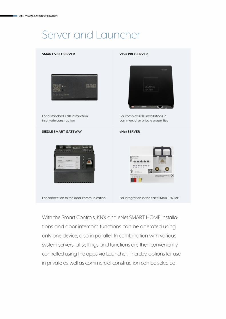
SMART VISU SERVER
SIEDLE SMART GATEWAY
VISU PRO SERVER
eNet SERVER
With the Smart Controls, KNX and eNet SMART HOME installa-
tions and door intercom functions can be operated using
only one device, also in parallel. In combination with various
system servers, all settings and functions are then conveniently
controlled using the apps via Launcher. Thereby, options for use
in private as well as commercial construction can be selected.
Server and Launcher
For integration in the eNet SMART HOME
For complex KNX installations in commercial or private properties
For connection to the door communication
For a standard KNX installation in private construction
244 VISUALISATION/OPERATION

WASTE SCHEDULER
Waste disposal dates can be re-
gistered individually; the reminder
is performed automatically.
KNX
KNX functions and scenes dis-
played on the JUNG Launcher
and individually matched to
the requirements.
DOOR COMMUNICATION
The Smart Controls become
video intercom stations using
the link with the Siedle Smart
Gateway.
WEATHER SCREEN
Good outlooks: The preinstalled
screen shows local weather and
travelling weather for the next
few days.
eNet SMART HOME
Visualise the wirelessly networked
smart home and control via the user
interface of the Smart Controls.
VISUALISATION/OPERATION 245

246
KNX
Ref.-no.
Smart Control
Smart Control 7’’aspect ratio 16:9for installation in walls, capacitive touch screenfanless, without rotating parts
• Door call function only in combination with Siedle Smart Gateway SG 650-.. • Smart Gateway with integrated image storage • For vertical or horizontal installation
Further functions: • KNX visualisation in combination with Visu Pro Server (ref.-no.: JVP-SERVER-H) • KNX visualization in combination with Smart Visu Server (ref.-no.: SV-SERVER-INT) • Pre-installed iHaus-Server-App; iHaus-KNX connection exclusively via IP router (ref.-no.: IPR 200 REG) or IP interface (ref.-no.: IPS 200 REG) • eNet visualisation in combination with eNet server for rail mounting (ref.-no.: ENET-SERVER) up to software version 1.4 • eNet visualisation in combination with eNet radio IP gateway IP (ref.-no.: FM-GATE-IP) • Pre-installed weather page
Update firmware prior to commissioning.Please check Release Notes.
aluminium SC 7 ALblack SC 7 SW
Flush-mounted recessed boxfor Smart Control ref.-no.: SC 7 AL, SC 7 SWcut-out dimensions (W x H): 202 x 141 mminstallation depth: 67 mm
SC 7 EBG
Power supply for rail mountingfor Smart Control ref.-no.: SC 7 AL, SC 7 SW, SC 10, SC 15, SC 19Rail mounting device, 4 rail units
NT 2415 REG VDC

247
Ref.-no.
KNXSmart Control
Smart Controls
aspect ratio 16:9for installation in walls, capacitive touch screenfanless, without rotating parts
• Door call function only in combination with Siedle Smart Gateway SG 650-.. • KNX visualisation in combination with Visu Pro Server (ref.-no.: JVP-SERVER-H) • KNX visualization in combination with Smart Visu Server (ref.-no.: SV-SERVER-INT) • Pre-installed iHaus-Server-App; iHaus-KNX connection exclusively via IP router (ref.-no.: IPR 200 REG) or IP interface (ref.-no.: IPS 200 REG) • eNet visualisation in combination with eNet server for rail mounting (ref.-no.: ENET-SERVER) up to software version 1.4 • eNet visualisation in combination with eNet radio IP gateway IP (ref.-no.: FM-GATE-IP) • Pre-installed weather page
Update firmware prior to commissioning.Please check Release Notes.
39.6 cm – 15.6’’ SC 15
Flush-mounted recessed boxfor Smart Control ref.-no.: SC 15cut-out dimensions (W x H): 492 x 288 mminstallation depth: 80 mm
SC 15 EBG
Smart Control 18.5’’aspect ratio 16:9for installation in walls, capacitive touch screenfanless, without rotating parts47 cm – 18.5’’ SC 19
Flush-mounted recessed boxfor Smart Control ref.-no.: SC 19cut-out dimensions (W x H): 582 x 327 mminstallation depth: 80 mm
SC 19 EBG
Smart Control 15.6’’
Smart Control 10.1’’aspect ratio 16:9for installation in walls, capacitive touch screenfanless, without rotating parts25.6 cm – 10.1’’ SC 10
Flush-mounted recessed boxfor Smart Control ref.-no.: SC 10cut-out dimensions (W x H): 315 x 182 mminstallation depth: 80 mm
SC 10 EBG

Smart Visu Server
248 VISUALISATION/OPERATION

Lighting mood, comfortable temperature, sun protection, music:
intelligently networked, brilliantly displayed. One fingertip and the
comfort scene is set. Everything controlled with a smartphone.
That is how easily a home becomes a Smart Home with the
Smart Visu Server.
SMART VISU SERVER
For wall or DIN rail mounting
VISUALISATION/OPERATION 249
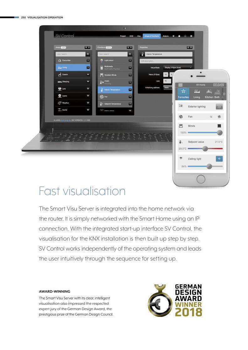
The Smart Visu Server is integrated into the home network via
the router. It is simply networked with the Smart Home using an IP
connection. With the integrated start-up interface SV Control, the
visualisation for the KNX installation is then built up step by step.
SV Control works independently of the operating system and leads
the user intuitively through the sequence for setting up.
Fast visualisation
AWARD-WINNING
The Smart Visu Server with its clear, intelligent
visualisation also impressed the respected
expert jury of the German Design Award, the
prestigious prize of the German Design Council.
250 VISUALISATION/OPERATION

ETS IMPORT
An existing KNX installation is imported directly
from the ETS using an OPC file. The group
addresses are presented in a sortable list for
an optimum overview and simple allocation.
ALWAYS UP-TO-DATE
All automatic updates and upgrades for the
Smart Visu Server are listed chronologically in
the “Change Log” document. This is available
to download as a PDF at www.jung.de/svs.
AREAS AND FUNCTIONS
Afterwards, areas are created first, such as rooms
or trades. Functions are allocated to these areas.
Both are named individually and provided with
symbols. In this way, 240 functions with up to 1,200
data points can be created.
BLOCK FUNCTIONS
The new Heating, Ventilation, Climate function
groups as well as Multimedia Playlist and Multi-
media Mode as „block functions“ are both easier
to integrate as well as to use.
PASSWORD PROTECTION
The areas that the end customer may edit himself
are defined during the project handover. All others
are password-protected. The password must be
advised if the end customer would like to edit
additional areas. This can also represent a clear
handover point of the responsibility and warranty
obligation.
VISUALISATION/OPERATION 251

Structure creates the overview and convenience: with their own,
individual groups, individual actions can be combined suitably so
that the user can then call them and activate them as required.
ADD FUNCTIONS
Up to 16 functions can be allocated to an action
and displayed in a selection list. The appropriate
value is set for every function, such as “Colour light
on” or “Dining table lamp on 50 %”. In addition,
time controls for actions can be specified.
USE GROUPS
Using the appropriate button on the Smart
Visu Home user interface, the user can call
individual groups. If the user wants to activate/
deactivate or edit a group, this takes place in SV
Control. The installer defines the rights via the
password protection.
CREATE GROUPS
Groups can then be assembled and named from
the actions. For example, “Holiday” includes all
actions for presence simulation, such as “Open
all shutters”, Living room lamps 100 %” and
“Path lighting on”. Each action can be allocated
to multiple groups.
CREATE ACTIONS
To create an action, first of all it is named. Allocating
meaningful names under which functions will
be collected is helpful. If required, the action can
then be allocated to an area, such as a particular
room or trade.
252 VISUALISATION/OPERATION

Feel-good lighting with the Smart Visu Server: With the connection
to the Philips Hue lighting system, users can create their own
personal light scene with a tap of a finger on their smartphone.
NAME/ALLOCATE LUMINAIRES
After the taught-in luminaires have been detected,
individually appropriate names can be assigned.
The lights named can then be appropriately
allocated to individual areas and a room, favourite
or trade.
AUTOMATIC SCAN
As soon as a Hue Bridge with learnt devices/lights
is recognised in the network, it can be accessed on
the Smart Visu Server interface.
CONVENIENT CONTROL
Control of the integrated lights is then via the
Smart Visu Home user interface, as desired
with a slider.
VISUALISATION/OPERATION 253

The Smart Visu Home user interface is realised in Responsive
Design. This guarantees optimal presentation and operation
on almost every smart device. Landing pages, background
colour, font size and other content can also be individually
adapted for each device and thus for each user. Responsive
Design also takes account of the use of the smart devices in
portrait or landscape orientation.
Smart Visu Home
254 VISUALISATION/OPERATION

255
Ref.-no.
KNXSmart Visu Server
Smart Visu Serverwith mounting plate for wall or rail mounting installationincluding plug-in power supply
Intended use • Visualisation and operation of KNX systems via devices with HTML5 browser, e.g. Smart Control (ref.-no.: SC 7 .., SC 10, SC 15, SC 19), smartphone, tablet, laptop, PC, etc. • Visualisation and operation of Philips Hue systems • Operation in local IP networks, which support DHCP (Dynamic Host Configuration Protocol) or with a fixed IP address (IPv4) • Operation indoors
Product characteristics • Web visualisation of KNX system for status indication and operation (SV-Home) • Integrated web-based commissioning tool (SV-Control) • Easy to create a pre-configured user interface, optimised for domestic applications and small commercial facilities • Graphical control elements: symbols can be selected from supplied libraries • Import of group addresses (three-stage) via OPC import (ETS3, ETS4, ETS5) • Manual input of group addresses possible • 24 areas • 240 dynamic functions (max. 1200 data points) • 250 configurable actions (max. 16 functions per action) – customised – switching times – status logic – depending on events • Connection to KNX bus via KNX IP router (ref.-no. IPR 200 REG) or KNX IP interface (ref.-no. IPS 200 REG) • Integration of Philips Hue systems in the KNX installation • Connection to Philips Hue via Philips Hue Bridge • Update and upgrade compatible
with Europlug SV-SERVER

VISUALISATION
The visualisation can be
individually customised.
GENERATOR
Imports projects created
with the Smart Assistant.
This software, as successor of Facility Pilot, is the professional way to
visualise and control building automation. Multiple, independent KNX
systems can be included and managed conveniently at the same time.
JUNG Visu Pro
256 VISUALISATION/OPERATION
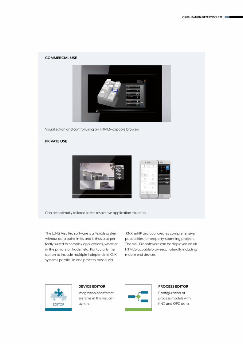
DEVICE EDITOR
Integration of different
systems in the visuali-
sation.
PROCESS EDITOR
Configuration of
process models with
KNX and OPC data.
The JUNG Visu Pro software is a flexible system
without data point limits and is thus also per-
fectly suited to complex applications, whether
in the private or trade field. Particularly the
option to include multiple independent KNX
systems parallel in one process model via
KNXnet/IP protocol creates comprehensive
possibilities for property-spanning projects.
The Visu Pro software can be displayed on all
HTML5-capable browsers, naturally including
mobile end devices.
COMMERCIAL USE
PRIVATE USE
Visualisation and control using an HTML5-capable browser
Can be optimally tailored to the respective application situation
VISUALISATION/OPERATION 257

The Visu Pro software consists of various function modules, each of
which clearly deals with a task. The modules/editors familiar from the
Facility-Pilot for creating the visualisation have been optimised and
simplified with respect to their use and graphical representation.
PROCESS MODEL
The process model is the logical core of the
system. Process connections are integrated here,
logics, time functions and scenes defined and
charts produced.
VISUALISATION
HTML5 visualisations are created consistently,
thus guaranteeing the representation on different
types of device. For this purpose, the control library
has been significantly extended with HTML5
elements. The HTML5 controls can be freely placed
on the spreadsheets and the look of the operating
elements can be completely individualised.
CONTROL LIBRARY
The JUNG symbol set is supplied as a library in black
and white. Alongside form factor, transparency and
background image can be set, as well as separate
views. In addition, individual symbols can also be
imported and used appropriately.
DEVICE EDITOR
Special functions can be implemented here
with process interfaces. System integrators with
knowledge of LUA can independently program
functions, including the communication with
third party systems via TCP or UDP protocol
(e.g. devices from consumer electronics).
258 VISUALISATION/OPERATION

Smart Assistant – intuitive planning assistance: To create
JUNG interfaces, the system integrator can fall back on
the Smart Assistant for automatic generation and thus
minimise the creation effort. Visualisations can thus be prepared based
on templates supplied.
CONFIGURATION
First of all, functions, timer switches and scenes
are selected from a tabular list and added to the
individual project. These can be linked with each
other as appropriate if required.
EXAMPLE: SMART METERING
With the production of a consumption data chart,
the settings for recording various consumptions
are made, such as for electricity, water and gas.
The visualisation of the consumption data check
is then automatically generated from this.
CREATE BUILDING STRUCTURE
Afterwards, the building structure can be
produced based on the floors and rooms,
in each case with individual names. The
previously configured functions and scenes
can be allocated as appropriate and thus
transferred to the visualisation.
VISUALISATION/OPERATION 259

Visu Pro ServerThe JUNG Visu Pro Server is a device for controlling building
automation in conjunction with the pre-installed Visu Pro software.
With its compact dimensions of 12 x 12 x 2.4 cm, the server is
designed for installation on a wall rail or DIN rail. The maximum
project scope is based on the templates as created using the
JUNG Smart Assistant and is thus ideally suitable for applications
in demanding private constructions.
NUMEROUS INTERFACES TO OTHER SYSTEMS
Gigabit-LAN 3.5 mm audio jackUSB 3.0 HDMI™ connection
2 x USB 2.0SD card slot
260 VISUALISATION/OPERATION

261
KNXVisu Pro Server
Ref.-no.
Visu Pro Serverfanless, without rotating parts
Intended use • Visualization and operation of system statuses and information on building automation in combination with JUNG Visu Pro software (pre-installed) • Desktop device, mounting on DIN rail according to EN 60715 possible • Max. size of the visualization project as template in JUNG Smart Assistant • Connection to KNX bus via KNX IP router (ref.-no. IPR 200 REG) or KNX IP interface (ref.-no. IPS 200 REG)
Product characteristics • Fanless mini PC • JUNG Visu Pro software pre-installed and activated • KNX interface (e.g. IPS 200 REG) needs to be ordered separately • Windows 10 Home (64-bit) pre-installed • Quadcore Intel Atom processor • 2 GB RAM • 32 GB internal memory, partly used by operating system • 1 x HDMI 1.4 • 2 x USB 2.0 • 1 x USB 3.0 • 1 x LAN RJ45 • Dual-band WLAN • Stand-by power max. 2 W, full load max. 7 W • Plug-in power supply 100 ... 240 V AC / 5 V DC / 2 A (included in delivery) • The visualization can be realized with devices with a browser suitable for HTML5 (e.g. latest version of Chrome, Firefox or Safari) • Access from max. 10 different clients possible
English version JVP-SERVER-H-GB
3933b_EN_KNX_230-265.indd 261 05.07.18 10:29

262
KNX Software
Ref.-no.
JUNG Visu Pro software
Note: The software can only be downloaded from the JUNG website www.jung.de. When downloading, you can choose between the English and the German version. Each installation will run in demo mode for 20 days or 400 starts. For an unrestricted use the software must be activated via a MyJUNG account. Intended use • Visualization and operation of system statuses and information on building automation • The visualization can be realized with devices with a browser suitable for HTML5 (e.g. latest version of Chrome, Firefox or Safari) • Access from max. 25 different clients possible
Requirements Hardwareas Visu Pro Server (ref.-no.: JVP-SERVER-H-GB) or betterPlease note: The performance of the hardware is one of the limiting factors for the project size. Operating systemsWindows 7 Home, Professional and Ultimate (32- and 64-bit) or higher, not Windows 2008 or 2012 Server Process connectionThe Falcon driver of the KNX Association is used for the KNX bus. The KNX connection requires a suitable version of the Falcon driver and the respective interfaces.An optional OPC client for the visualization allows the use of an OPC server instead of / in addition to KNX. Data import from ETSETS5: use of project export of ETS ETS2 version 1.1, 1.2 and 1.3: files generatedETS4: use of project export of ETS by “print export” can be readETS3: use of OPC export of ETS Previous ETS versions: not possible SoftwareFalcon driver 2.2 Internet ExplorerDirectX, version 9.0c .NET framework 3.5 SP1
Full version JVP-VPlanner version JVP-P
JUNG App Visu ProApp for remote control of all JUNG KNX devices with integrated Visu Pro software: You can control all functions with your iPad in a convenient and flexible way. The clearly structured visualization ensures an intuitive operation. In addition to controling your own KNX installation the app also includes a demo version.The free App "Visu Pro" can only be downloaded from the iTunes Store.
Smart Assistant
Note: The software can only be downloaded from the JUNG website www.jung.de. For an unrestricted use the software must be activated via a MyJUNG account. Smart Assistant is a planning tool for the simple creation of visualization projects for the JUNG Visu Pro software or other automation applications such as iHaus. The use of conventions and schemes (trade, floor, room, function) does not require knowledge of KNX group addresses.Export formats are available for JUNG Visu Pro software, iHaus and ETS group addresses. RequirementsServer/client-based software, but can be used with one PCOperating systems for server: Windows 7 Home, Professional and Ultimate (32- and 64-bit) or higher, not Windows 2008 or 2012 ServerClients: Browser suitable for HTML5 (e.g. latest version of Chrome, Firefox or Safari)
SMART-ASSIST
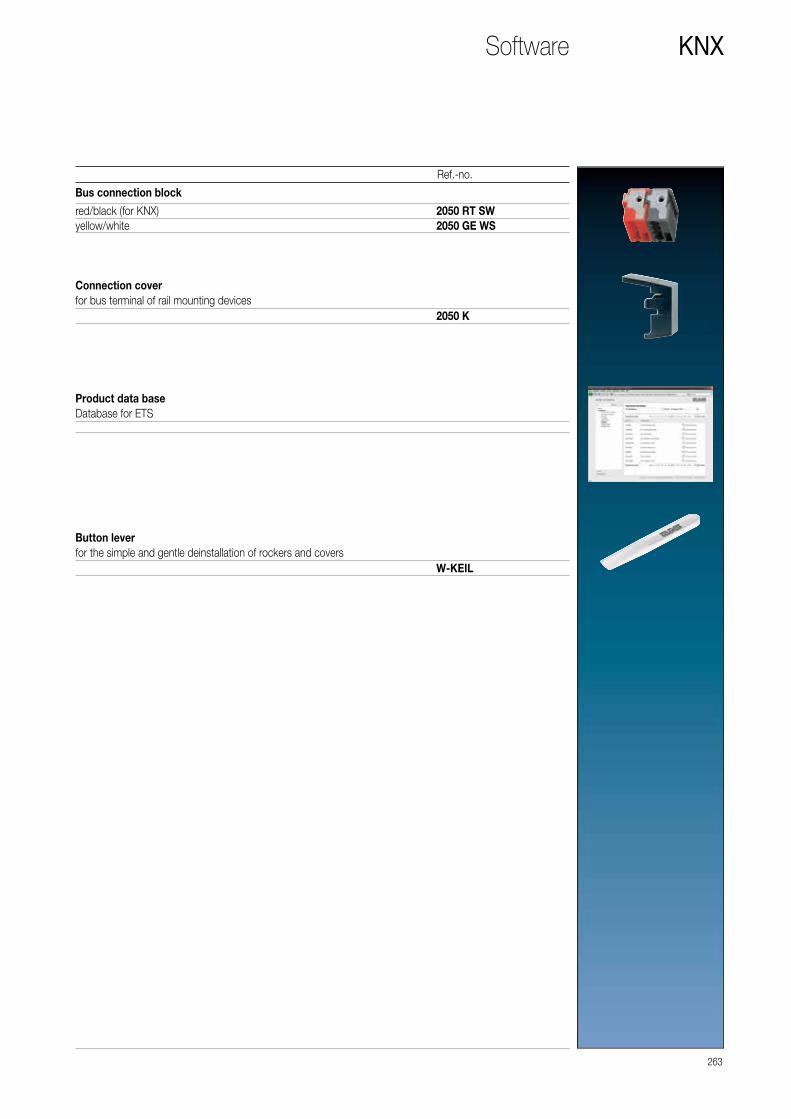
263
KNXSoftware
Ref.-no.
Bus connection block
red/black (for KNX) 2050 RT SWyellow/white 2050 GE WS
Connection coverfor bus terminal of rail mounting devices
2050 K
Product data baseDatabase for ETS
Button leverfor the simple and gentle deinstallation of rockers and covers
W-KEIL

SMART CONTROL 7
as video intercom station
264 DOOR COMMUNICATION

RouterSensors
Actuators
SmartGateway
Smart Control
KNXIP Gateway
JUNG Visu Pro/Smart Visu Server
KNX lineIn-Home busLAN
SYSTEM DESIGN
Door communication and KNX
Combined operation of building system technology and
building communication – for greater security and convenience:
The Siedle Smart Gateway functions as interface to the door
communication in a KNX installation. The JUNG KNX Smart
Controls 7, 10, 15 and 19 and smart devices become intuitively
usable video intercom stations using this.
DOOR COMMUNICATION 265

266
Index
Ref.-no. Page
20160 REG 14820320 REG 1492050 GE WS 2632050 K 2632050 RT SW 26320640 REG 1492073 U 1282076-2 T 2042076-4 T 2052096 LUX 1202099 REGHE 1612103 REG ES 2082116 REG 2022128 REG 20321280 REG 1502130 USB 1532130 USB REG 1532131.16 UP 1942132.6 UP 1952142 REG 1572177 SV R 2002178 1392178 ORTS 1432178 TS 1412194 REGHM 1812204.01 REGA 1862204.01 REGAM 1872214 REG A 2252214 REGAM 2262224 WH 2242225 BFA 2232225 WS U 2222302.16 REGHM 1642304.16 REGCHM 1672304.16 REGHE 1692304.16 REGHM 16523066 REGHE 190e2308.16 REGCHM 1682308.16 REGHE 1702308.16 REGHM 1662316.16 REGHE 1712336 REG HZ HE 1842336 REG HZR HE 1852424 REGHE 1722501 HZ UP 1992501 UP 1972502 REGHE 1722504 REGHE 1732504 REGHER 1752508 REGHE 1742514 REGHE 1732531 UP 19628 23328 G1 23328 G1 SL 2333210 UP 19833 AN K 11533 AN L 11533 AN N 11533 AN T 11533 GN 11533 KLAR 11533 NR 1153361 AL 1243361 M WW 1183361 WW 1243361-1 AL 1243361-1 M WW 1183361-1 WW 1243901 REGHE 1763902 REGHE 1773904 EB LED 1803904 REG LED 1793904 REGHE 178
Ref.-no. Page
4071 RF TSM 854071 TSM 604071.01 LED 984071.02 LED 984072 RF TSM 854072 TSM 604072.01 LED 1054072.02 LED 1054073 RF TSM 854073 TSM 604074 RF TSM 864074 TSM 614091 TSEM 624092 TSEM 624093 KRM TS D 724093 TSEM 624094 TSEM 624191 TSM 614192 TSM 614193 TSM 624194 TSM 62569 T 154569 TNA 154800 KO 114800 NA 114800 NT 114800 P 114805 MP 115805 NT 115805 P 1158471.01 LED W 1148471.02 LED W 1148472.01 LED W 1158472.02 LED W 115A 1540 BF KO5 ANM 93A 1540 BF KO5 SW 93A 1540 BF KO5 WW 93A 1540 KO5 93A 1540 KO5 AL 93A 1540 KO5 CH 93A 1540 KO5 MO 93A 1540 KO5 SW 93A 1540 KO5 WW 93A 2178 139A 2178 AL 139A 2178 ANM 139A 2178 BF ORTS ANM 143A 2178 BF ORTS SW 143A 2178 BF ORTS WW 143A 2178 CH 139A 2178 MO 139A 2178 ORTS 143A 2178 ORTS AL 143A 2178 ORTS CH 143A 2178 ORTS MO 143A 2178 ORTS SW 143A 2178 ORTS WW 143A 2178 SW 139A 2178 TS 141A 2178 TS AL 141A 2178 TS ANM 141A 2178 TS CH 141A 2178 TS MO 141A 2178 TS SW 141A 2178 TS WW 141A 2178 WW 139A 3181 128A 3181 AL 128A 3181 ANM 128A 3181 CH 128A 3181 MO 128A 3181 SW 128A 3181 WW 128A 3181-1 129
Ref.-no. Page
A 3181-1 AL 129A 3181-1 ANM 129A 3181-1 CH 129A 3181-1 MO 129A 3181-1 SW 129A 3181-1 WW 129A 3281 130A 3281 AL 130A 3281 ANM 130A 3281 CH 130A 3281 MO 130A 3281 SW 130A 3281 WW 130A 3281-1 130A 3281-1 AL 130A 3281-1 ANM 130A 3281-1 CH 130A 3281-1 MO 130A 3281-1 SW 130A 3281-1 WW 130A 401 TSA 63A 401 TSA AL 63A 401 TSA ANM 63A 401 TSA CH 63A 401 TSA MO 63A 401 TSA SW 63A 401 TSA WW 63A 401 TSAP 64A 401 TSAP AL 64A 401 TSAP ANM 64A 401 TSAP CH 64A 401 TSAP MO 64A 401 TSAP SW 64A 401 TSAP WW 64A 402 TSA 63A 402 TSA AL 63A 402 TSA ANM 63A 402 TSA CH 63A 402 TSA MO 63A 402 TSA SW 63A 402 TSA WW 63A 402 TSAP 64A 402 TSAP AL 64A 402 TSAP ANM 64A 402 TSAP CH 64A 402 TSAP MO 64A 402 TSAP SW 64A 402 TSAP WW 64A 403 TSA 63A 403 TSA AL 63A 403 TSA ANM 63A 403 TSA CH 63A 403 TSA MO 63A 403 TSA SW 63A 403 TSA WW 63A 404 TSA 63A 404 TSA AL 63A 404 TSA ANM 63A 404 TSA CH 63A 404 TSA MO 63A 404 TSA SW 63A 404 TSA WW 63A 404 TSAP 14 64A 404 TSAP 23 64A 404 TSAP AL 14 64A 404 TSAP AL 23 64A 404 TSAP ANM 14 64A 404 TSAP ANM 23 64A 404 TSAP CH 14 64A 404 TSAP CH 23 64A 404 TSAP MO 14 64A 404 TSAP MO 23 64A 404 TSAP SW 14 64A 404 TSAP SW 23 64
Ref.-no. Page
A 404 TSAP WW 14 64A 404 TSAP WW 23 64A 409 T 73A 4093 TSA 73A 4093 TSA AL 73A 4093 TSA ANM 73A 4093 TSA CH 73A 4093 TSA MO 73A 4093 TSA SW 73A 4093 TSA WW 73A 50 NA 37A 50 NA AL 37A 50 NA ANM 37A 50 NA CH 37A 50 NA MO 37A 50 NA SW 37A 50 NA W 37A 50 NA WW 37A 501 TSA 36A 501 TSA AL 36A 501 TSA ANM 36A 501 TSA CH 36A 501 TSA MO 36A 501 TSA SW 36A 501 TSA WW 36A 502 TSA 36A 502 TSA AL 36A 502 TSA ANM 36A 502 TSA CH 36A 502 TSA MO 36A 502 TSA SW 36A 502 TSA WW 36A 503 TSA 36A 503 TSA AL 36A 503 TSA ANM 36A 503 TSA CH 36A 503 TSA MO 36A 503 TSA SW 36A 503 TSA WW 36A 504 TSA 37A 504 TSA AL 37A 504 TSA ANM 37A 504 TSA CH 37A 504 TSA MO 37A 504 TSA SW 37A 504 TSA WW 37A 5071 RF TSM 82A 5071 TSM 32A 5072 RF TSM 82A 5072 TSM 32A 5073 RF TSM 82A 5073 TSM 32A 5074 RF TSM 83A 5074 TSM 32A 5091 TSEM 34A 5091 TSM 33A 5092 TSEM 34A 5092 TSM 33A 5093 TSEM 34A 5093 TSM 33A 5094 TSEM 34A 5094 TSM 33A 5178 TSEM 35A 5178 TSM 34A 5192 KRM TS D 35A 5194 KRM TS D 35A 569 BFPLT 154A 569 BFPLT ANM 154A 569 BFPLT SW 154A 569 BFPLT WW 154A 569 PLT 154A 569 PLT AL 154A 569 PLT CH 154A 569 PLT MO 154

267
Ref.-no. Page
A 569 PLT SW 154A 569 PLT WW 154A 590 AL 99A 590 BF ANM 99A 590 BF KO5 ANM 100A 404 TSAP WW 14 64A 404 TSAP WW 23 64A 409 T 73A 4093 TSA 73A 4093 TSA AL 73A 4093 TSA ANM 73A 4093 TSA CH 73A 4093 TSA MO 73A 4093 TSA SW 73A 4093 TSA WW 73A 50 NA 37A 50 NA AL 37A 50 NA ANM 37A 50 NA CH 37A 50 NA MO 37A 50 NA SW 37A 50 NA W 37A 50 NA WW 37A 501 TSA 36A 501 TSA AL 36A 501 TSA ANM 36A 501 TSA CH 36A 501 TSA MO 36A 501 TSA SW 36A 501 TSA WW 36A 502 TSA 36A 502 TSA AL 36A 502 TSA ANM 36A 502 TSA CH 36A 502 TSA MO 36A 502 TSA SW 36A 502 TSA WW 36A 503 TSA 36A 503 TSA AL 36A 503 TSA ANM 36A 503 TSA CH 36A 503 TSA MO 36A 503 TSA SW 36A 503 TSA WW 36A 504 TSA 37A 504 TSA AL 37A 504 TSA ANM 37A 504 TSA CH 37A 504 TSA MO 37A 504 TSA SW 37A 504 TSA WW 37A 5071 RF TSM 82A 5071 TSM 32A 5072 RF TSM 82A 5072 TSM 32A 5073 RF TSM 82A 5073 TSM 32A 5074 RF TSM 83A 5074 TSM 32A 5091 TSEM 34A 5091 TSM 33A 5092 TSEM 34A 5092 TSM 33A 5093 TSEM 34A 5093 TSM 33A 5094 TSEM 34A 5094 TSM 33A 5178 TSEM 35A 5178 TSM 34A 5192 KRM TS D 35A 5194 KRM TS D 35A 569 BFPLT 154A 569 BFPLT ANM 154A 569 BFPLT SW 154A 569 BFPLT WW 154A 569 PLT 154A 569 PLT AL 154A 569 PLT CH 154A 569 PLT MO 154
Ref.-no. Page
A 569 PLT SW 154A 569 PLT WW 154A 590 AL 99A 590 BF ANM 99A 590 BF KO5 ANM 100A 590 BF KO5 SW 100A 590 BF KO5 WW 100A 590 BF KO5P ANM 100A 590 BF KO5P SW 100A 590 BF KO5P WW 100A 590 BF P ANM 99A 590 BF P SW 99A 590 BF P WW 99A 590 BF SW 99A 590 BF WW 99A 590 CH 99A 590 KO5 AL 100A 590 KO5 CH 100A 590 KO5 MO 100A 590 KO5 SW 100A 590 KO5 WW 100A 590 KO5P AL 100A 590 KO5P CH 100A 590 KO5P MO 100A 590 KO5P SW 100A 590 KO5P WW 100A 590 MO 99A 590 P AL 99A 590 P CH 99A 590 P MO 99A 590 P SW 99A 590 P WW 99A 590 SW 99A 590 WW 99A 595 AL 106A 595 BF ANM 106A 595 BF KO5 ANM 107A 595 BF KO5 SW 107A 595 BF KO5 WW 107A 595 BF KO5MP ANM 108A 595 BF KO5MP SW 108A 595 BF KO5MP WW 108A 595 BF KO5P ANM 108A 595 BF KO5P SW 108A 595 BF KO5P WW 108A 595 BF MP ANM 107A 595 BF MP SW 107A 595 BF MP WW 107A 595 BF P ANM 107A 595 BF P SW 107A 595 BF P WW 107A 595 BF SW 106A 595 BF WW 106A 595 CH 106A 595 KO5 AL 107A 595 KO5 CH 107A 595 KO5 MO 107A 595 KO5 SW 107A 595 KO5 WW 107A 595 KO5MP AL 108A 595 KO5MP CH 108A 595 KO5MP MO 108A 595 KO5MP SW 108A 595 KO5MP WW 108A 595 KO5P AL 108A 595 KO5P CH 108A 595 KO5P MO 108A 595 KO5P SW 108A 595 KO5P WW 108A 595 MO 106A 595 MP AL 107A 595 MP CH 107A 595 MP MO 107A 595 MP SW 107A 595 MP WW 107A 595 P AL 107A 595 P CH 107A 595 P MO 107A 595 P SW 107
Ref.-no. Page
A 595 P WW 107A 595 SW 106A 595 WW 106ABL/S2.1 157AL 1940 KO5 93AL 1940 KO5 AN 93AL 2178 139AL 2178 AN 139AL 2178 ORTS 143AL 2178 ORTS AN 143AL 2178 TS 141AL 2178 TS AN 141AL 2178 TS D 141AL 2401 TSA 67AL 2401 TSA AN 67AL 2401 TSA D 67AL 2401 TSAP 68AL 2401 TSAP AN 68AL 2401 TSAP D 68AL 2402 TSA 67AL 2402 TSA AN 67AL 2402 TSA D 67AL 2402 TSAP 68AL 2402 TSAP AN 68AL 2402 TSAP D 68AL 2403 TSA 67AL 2403 TSA AN 67AL 2403 TSA D 67AL 2404 TSA 68AL 2404 TSA AN 68AL 2404 TSA D 68AL 2404 TSAP 14 69AL 2404 TSAP 23 69AL 2404 TSAP AN 14 69AL 2404 TSAP AN 23 69AL 2404 TSAP D 14 69AL 2404 TSAP D 23 69AL 2501 TSA 48AL 2501 TSA AN 48AL 2501 TSA D 48AL 2502 TSA 48AL 2502 TSA AN 48AL 2502 TSA D 48AL 2503 TSA 48AL 2503 TSA AN 48AL 2503 TSA D 48AL 2504 TSA 49AL 2504 TSA AN 49AL 2504 TSA D 49AL 2969 T 154AL 2969 T AN 154AL 2969 T D 154AL 2990 103AL 2990 AN 103AL 2990 D 103AL 2990 KO5 104AL 2990 KO5 AN 104AL 2990 KO5 D 104AL 2990 KO5P 104AL 2990 KO5P AN 104AL 2990 NA 104AL 2990 NA AN 104AL 2990 NA D 104AL 2990 P 103AL 2990 P AN 103AL 2995 112AL 2995 AN 112AL 2995 D 112AL 2995 KO5 113AL 2995 KO5 AN 113AL 2995 KO5 D 113AL 2995 KO5MP 113AL 2995 KO5MP AN 113AL 2995 KO5P 113AL 2995 KO5P AN 113AL 2995 MP 112AL 2995 MP AN 112AL 2995 P 112AL 2995 P AN 112
Ref.-no. Page
AL 2995 P D 112AL 3181 129AL 3181 AN 129AL 3181 D 129AL 3181-1 129AL 3181-1 AN 129AL 3181-1 D 129AL 3281 131AL 3281 AN 131AL 3281 D 131AL 3281-1 131AL 3281-1 AN 131AL 3281-1 D 131AL 4093 TSA 75AL 4093 TSA AN 75AL 4093 TSA D 75AL 50 NA AN-L 49AL 50 NA D-L 49AL 50 NA-L 49AS 590 98AS 590 KO5 98AS 590 KO5 WW 98AS 590 KO5P 99AS 590 KO5P WW 99AS 590 P 98AS 590 P WW 98AS 590 WW 98AS 590-5 105AS 590-5 KO5 106AS 590-5 KO5 WW 106AS 590-5 KO5MP 106AS 590-5 KO5MP WW 106AS 590-5 KO5P 106AS 590-5 KO5P WW 106AS 590-5 MP 105AS 590-5 MP WW 105AS 590-5 P 105AS 590-5 P WW 105AS 590-5 WW 105AS 591 98AS 591 KO5 98AS 591 KO5 WW 98AS 591 KO5P 99AS 591 KO5P WW 99AS 591 P 98AS 591 P WW 98AS 591 WW 98AS 591-5 105AS 591-5 KO5 106AS 591-5 KO5 WW 106AS 591-5 KO5MP 106AS 591-5 KO5MP WW 106AS 591-5 KO5P 106AS 591-5 KO5P WW 106AS 591-5 MP 105AS 591-5 MP WW 105AS 591-5 P 105AS 591-5 P WW 105AS 591-5 WW 105BGA 12 AH 152BTS 01 199CD 1540 KO5 93CD 1540 KO5 GR 93CD 1540 KO5 LG 93CD 1540 KO5 SW 93CD 1540 KO5 WW 93CD 2178 GR 139CD 2178 LG 139CD 2178 ORTS GR 143CD 2178 ORTS LG 143CD 2178 ORTS SW 143CD 2178 ORTS WW 143CD 2178 SW 139CD 2178 TS GR 141CD 2178 TS LG 141CD 2178 TS SW 141CD 2178 TS WW 141CD 2178 WW 139CD 3181 129

268
Ref.-no. Page
CD 3181 GR 129CD 3181 LG 129CD 3181 SW 129CD 3181 WW 129CD 3181-1 129CD 3181-1 GR 129CD 3181-1 LG 129CD 3181-1 SW 129CD 3181-1 WW 129CD 3281 131CD 3281 GR 131CD 3281 LG 131CD 3281 SW 131CD 3281 WW 131CD 3281-1 131CD 3281-1 GR 131CD 3281-1 LG 131CD 3281-1 SW 131CD 3281-1 WW 131CD 4 AR 66CD 401 TSA 65CD 401 TSA GR 65CD 401 TSA LG 65CD 401 TSA SW 65CD 401 TSA WW 65CD 401 TSAP 66CD 401 TSAP GR 66CD 401 TSAP LG 66CD 401 TSAP SW 66CD 401 TSAP WW 66CD 402 TSA 65CD 402 TSA GR 65CD 402 TSA LG 65CD 402 TSA SW 65CD 402 TSA WW 65CD 402 TSAP 66CD 402 TSAP GR 66CD 402 TSAP LG 66CD 402 TSAP SW 66CD 402 TSAP WW 66CD 403 TSA 65CD 403 TSA GR 65CD 403 TSA LG 65CD 403 TSA SW 65CD 403 TSA WW 65CD 404 TSA 65CD 404 TSA GR 65CD 404 TSA LG 65CD 404 TSA SW 65CD 404 TSA WW 65CD 404 TSAP 14 66CD 404 TSAP 23 66CD 404 TSAP GR 14 66CD 404 TSAP GR 23 66CD 404 TSAP LG 14 66CD 404 TSAP LG 23 66CD 404 TSAP SW 14 66CD 404 TSAP SW 23 66CD 404 TSAP WW 14 66CD 404 TSAP WW 23 66CD 409 T 74CD 4093 TSA 74CD 4093 TSA GR 74CD 4093 TSA LG 74CD 4093 TSA SW 74CD 4093 TSA WW 74CD 50 NA 43CD 50 NA GR 43CD 50 NA LG 43CD 50 NA SW 43CD 50 NA W 43CD 50 NA WW 43CD 501 TSA 42CD 501 TSA GR 42CD 501 TSA LG 42CD 501 TSA SW 42CD 501 TSA WW 42CD 502 TSA 42CD 502 TSA GR 42
Ref.-no. Page
CD 502 TSA LG 42CD 502 TSA SW 42CD 502 TSA WW 42CD 503 TSA 42CD 503 TSA GR 42CD 503 TSA LG 42CD 503 TSA SW 42CD 503 TSA WW 42CD 504 TSA 42CD 504 TSA GR 42CD 504 TSA LG 42CD 504 TSA SW 42CD 504 TSA WW 42CD 5071 RF TSM 83CD 5071 TSM 38CD 5072 RF TSM 83CD 5072 TSM 38CD 5073 RF TSM 83CD 5073 TSM 38CD 5074 RF TSM 83CD 5074 TSM 38CD 5091 TSEM 40CD 5091 TSM 39CD 5092 TSEM 40CD 5092 TSM 39CD 5093 TSEM 40CD 5093 TSM 39CD 5094 TSEM 40CD 5094 TSM 39CD 5178 TSEM 41CD 5178 TSM 40CD 5192 KRM TS D 41CD 5194 KRM TS D 41CD 569 T GR 154CD 569 T LG 154CD 569 T SW 154CD 569 T WW 154CD 569 TNA WW 154CD 590 100CD 590 BR 100CD 590 GB 100CD 590 GR 100CD 590 KO5 101CD 590 KO5 BR 101CD 590 KO5 GB 101CD 590 KO5 GR 101CD 590 KO5 LG 101CD 590 KO5 PT 101CD 590 KO5 SW 101CD 590 KO5 WW 101CD 590 KO5P 102CD 590 KO5P BR 102CD 590 KO5P GB 102CD 590 KO5P GR 102CD 590 KO5P LG 102CD 590 KO5P PT 102CD 590 KO5P SW 102CD 590 KO5P WW 102CD 590 LG 100CD 590 NA 101CD 590 NA BR 101CD 590 NA GR 101CD 590 NA LG 101CD 590 NA SW 101CD 590 NA WW 101CD 590 NAKO5 102CD 590 NAKO5 BR 102CD 590 NAKO5 GR 102CD 590 NAKO5 LG 102CD 590 NAKO5 SW 102CD 590 NAKO5 WW 102CD 590 P 101CD 590 P BR 101CD 590 P GB 101CD 590 P GR 101CD 590 P LG 101CD 590 P PT 101CD 590 P SW 101CD 590 P WW 101
Ref.-no. Page
CD 590 PT 100CD 590 SW 100CD 590 WW 100CD 595 109CD 595 BR 109CD 595 GB 109CD 595 GR 109CD 595 KO5 110CD 595 KO5 BR 110CD 595 KO5 GB 110CD 595 KO5 GR 110CD 595 KO5 LG 110CD 595 KO5 PT 110CD 595 KO5 SW 110CD 595 KO5 WW 110CD 595 KO5MP 110CD 595 KO5MP BR 110CD 595 KO5MP GB 110CD 595 KO5MP GR 110CD 595 KO5MP LG 110CD 595 KO5MP PT 110CD 595 KO5MP SW 110CD 595 KO5MP WW 110CD 595 KO5P 110CD 595 KO5P BR 110CD 595 KO5P GB 110CD 595 KO5P GR 110CD 595 KO5P LG 110CD 595 KO5P PT 110CD 595 KO5P SW 110CD 595 KO5P WW 110CD 595 LG 109CD 595 MP 109CD 595 MP BR 109CD 595 MP GB 109CD 595 MP GR 109CD 595 MP LG 109CD 595 MP PT 109CD 595 MP SW 109CD 595 MP WW 109CD 595 P 109CD 595 P BR 109CD 595 P GB 109CD 595 P GR 109CD 595 P LG 109CD 595 P PT 109CD 595 P SW 109CD 595 P WW 109CD 595 PT 109CD 595 SW 109CD 595 WW 109CD 90 NA 101CO2 A 2178 145CO2 A 2178 AL 145CO2 A 2178 BF ANM 145CO2 A 2178 BF SW 145CO2 A 2178 BF WW 145CO2 A 2178 CH 145CO2 A 2178 MO 145CO2 A 2178 SW 145CO2 A 2178 WW 145CO2 AL 2178 145CO2 AL 2178 AN 145CO2 AL 2178 D 145CO2 CD 2178 145CO2 CD 2178 GR 145CO2 CD 2178 LG 145CO2 CD 2178 SW 145CO2 CD 2178 WW 145CO2 ES 2178 145CO2 GCR 2178 145CO2 LS 2178 145CO2 LS 2178 LG 145CO2 LS 2178 SW 145CO2 LS 2178 WW 145CO2 ME 2178 AT 145CO2 ME 2178 C 145DAS 4120 231DAS 4210 232
Ref.-no. Page
DAS 4300 A 233DAS 4300 U 233DAS 4360 235DAS 4370 234DS 4092 TS 92EBG 24 241EBG 2424 237ES 1940 KO5 93ES 2178 139ES 2178 ORTS 143ES 2178 TS 141ES 2401 TSA 67ES 2401 TSAP 68ES 2402 TSA 67ES 2402 TSAP 68ES 2403 TSA 67ES 2404 TSA 68ES 2404 TSAP 14 69ES 2404 TSAP 23 69ES 2501 TSA 48ES 2502 TSA 48ES 2503 TSA 48ES 2504 TSA 49ES 2969 T 154ES 2990 103ES 2990 KO5 104ES 2990 KO5P 104ES 2990 NA 104ES 2990 P 103ES 2995 112ES 2995 KO5 113ES 2995 KO5MP 113ES 2995 KO5P 113ES 2995 MP 112ES 2995 P 112ES 3181 129ES 3181-1 129ES 3281 131ES 3281-1 131ES 4093 TSA 75ES 50 NA-L 49FCA 2 REGHE 182FP AL 781 241FP ES 781 241FP GLAS 781 241FP GLAS 781 SW 241FP GLAS 781 WW 241FPI 781 AN 241FUS 4410 BR 235FUS 4410 WW 235FUS 4415 WW 235GCR 1940 KO5 93GCR 2178 139GCR 2178 ORTS 143GCR 2178 TS 141GCR 2501 TSA 48GCR 2502 TSA 48GCR 2503 TSA 48GCR 2504 TSA 49GCR 2969 T 154GCR 2990 103GCR 2990 KO5 104GCR 2995 112GCR 2995 KO5 113GCR 2995 P 112GO 1940 KO5 93GO 2501 TSA 48GO 2502 TSA 48GO 2503 TSA 48GO 2504 TSA 49GO 2990 103GO 2990 KO5 104GO 2995 112GO 2995 KO5 113GO 2995 P 112HS 2 RF 86HS 4 RF 86IPR 200 REG 156IPS 200 REG 156
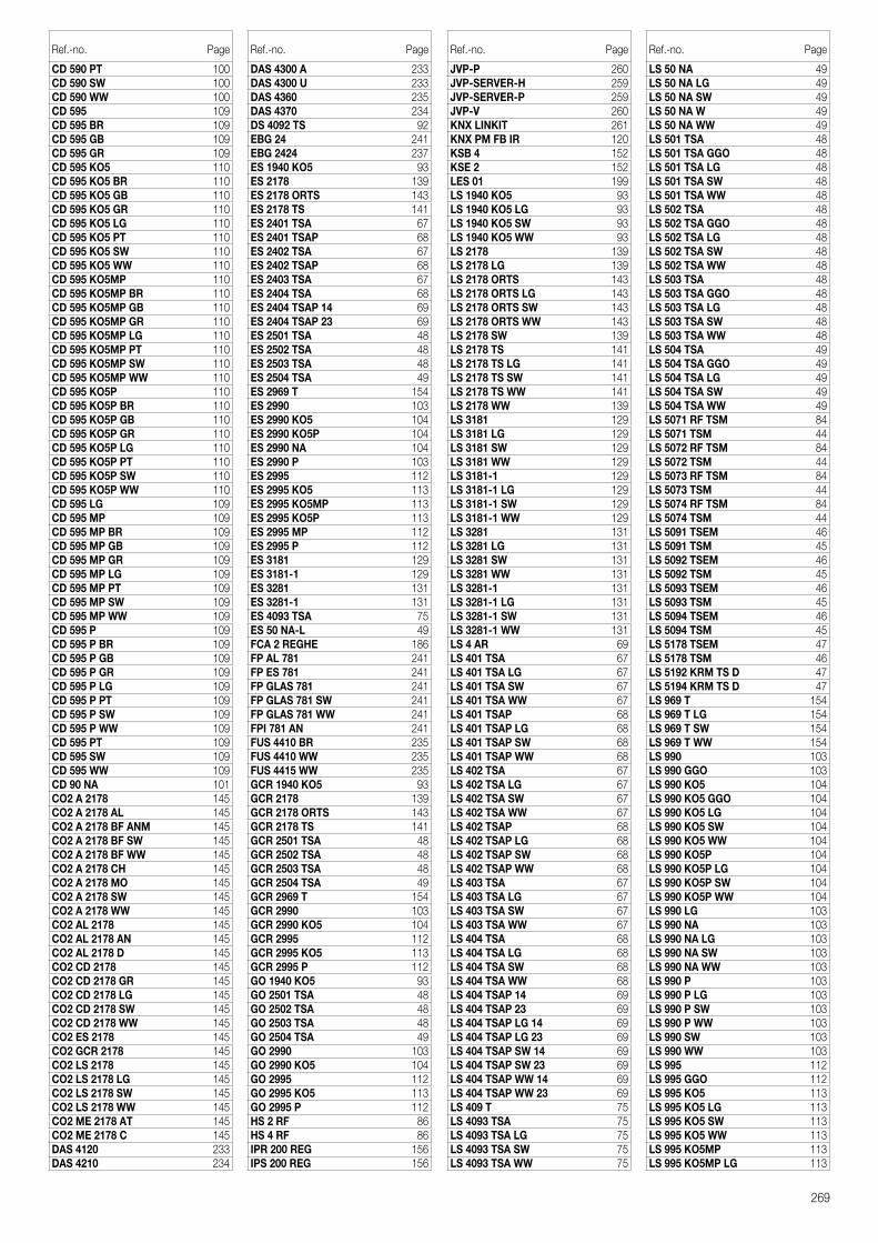
269
Ref.-no. Page
CD 590 PT 100CD 590 SW 100CD 590 WW 100CD 595 109CD 595 BR 109CD 595 GB 109CD 595 GR 109CD 595 KO5 110CD 595 KO5 BR 110CD 595 KO5 GB 110CD 595 KO5 GR 110CD 595 KO5 LG 110CD 595 KO5 PT 110CD 595 KO5 SW 110CD 595 KO5 WW 110CD 595 KO5MP 110CD 595 KO5MP BR 110CD 595 KO5MP GB 110CD 595 KO5MP GR 110CD 595 KO5MP LG 110CD 595 KO5MP PT 110CD 595 KO5MP SW 110CD 595 KO5MP WW 110CD 595 KO5P 110CD 595 KO5P BR 110CD 595 KO5P GB 110CD 595 KO5P GR 110CD 595 KO5P LG 110CD 595 KO5P PT 110CD 595 KO5P SW 110CD 595 KO5P WW 110CD 595 LG 109CD 595 MP 109CD 595 MP BR 109CD 595 MP GB 109CD 595 MP GR 109CD 595 MP LG 109CD 595 MP PT 109CD 595 MP SW 109CD 595 MP WW 109CD 595 P 109CD 595 P BR 109CD 595 P GB 109CD 595 P GR 109CD 595 P LG 109CD 595 P PT 109CD 595 P SW 109CD 595 P WW 109CD 595 PT 109CD 595 SW 109CD 595 WW 109CD 90 NA 101CO2 A 2178 145CO2 A 2178 AL 145CO2 A 2178 BF ANM 145CO2 A 2178 BF SW 145CO2 A 2178 BF WW 145CO2 A 2178 CH 145CO2 A 2178 MO 145CO2 A 2178 SW 145CO2 A 2178 WW 145CO2 AL 2178 145CO2 AL 2178 AN 145CO2 AL 2178 D 145CO2 CD 2178 145CO2 CD 2178 GR 145CO2 CD 2178 LG 145CO2 CD 2178 SW 145CO2 CD 2178 WW 145CO2 ES 2178 145CO2 GCR 2178 145CO2 LS 2178 145CO2 LS 2178 LG 145CO2 LS 2178 SW 145CO2 LS 2178 WW 145CO2 ME 2178 AT 145CO2 ME 2178 C 145DAS 4120 233DAS 4210 234
Ref.-no. Page
DAS 4300 A 233DAS 4300 U 233DAS 4360 235DAS 4370 234DS 4092 TS 92EBG 24 241EBG 2424 237ES 1940 KO5 93ES 2178 139ES 2178 ORTS 143ES 2178 TS 141ES 2401 TSA 67ES 2401 TSAP 68ES 2402 TSA 67ES 2402 TSAP 68ES 2403 TSA 67ES 2404 TSA 68ES 2404 TSAP 14 69ES 2404 TSAP 23 69ES 2501 TSA 48ES 2502 TSA 48ES 2503 TSA 48ES 2504 TSA 49ES 2969 T 154ES 2990 103ES 2990 KO5 104ES 2990 KO5P 104ES 2990 NA 104ES 2990 P 103ES 2995 112ES 2995 KO5 113ES 2995 KO5MP 113ES 2995 KO5P 113ES 2995 MP 112ES 2995 P 112ES 3181 129ES 3181-1 129ES 3281 131ES 3281-1 131ES 4093 TSA 75ES 50 NA-L 49FCA 2 REGHE 186FP AL 781 241FP ES 781 241FP GLAS 781 241FP GLAS 781 SW 241FP GLAS 781 WW 241FPI 781 AN 241FUS 4410 BR 235FUS 4410 WW 235FUS 4415 WW 235GCR 1940 KO5 93GCR 2178 139GCR 2178 ORTS 143GCR 2178 TS 141GCR 2501 TSA 48GCR 2502 TSA 48GCR 2503 TSA 48GCR 2504 TSA 49GCR 2969 T 154GCR 2990 103GCR 2990 KO5 104GCR 2995 112GCR 2995 KO5 113GCR 2995 P 112GO 1940 KO5 93GO 2501 TSA 48GO 2502 TSA 48GO 2503 TSA 48GO 2504 TSA 49GO 2990 103GO 2990 KO5 104GO 2995 112GO 2995 KO5 113GO 2995 P 112HS 2 RF 86HS 4 RF 86IPR 200 REG 156IPS 200 REG 156
Ref.-no. Page
JVP-P 260JVP-SERVER-H 259JVP-SERVER-P 259JVP-V 260KNX LINKIT 261KNX PM FB IR 120KSB 4 152KSE 2 152LES 01 199LS 1940 KO5 93LS 1940 KO5 LG 93LS 1940 KO5 SW 93LS 1940 KO5 WW 93LS 2178 139LS 2178 LG 139LS 2178 ORTS 143LS 2178 ORTS LG 143LS 2178 ORTS SW 143LS 2178 ORTS WW 143LS 2178 SW 139LS 2178 TS 141LS 2178 TS LG 141LS 2178 TS SW 141LS 2178 TS WW 141LS 2178 WW 139LS 3181 129LS 3181 LG 129LS 3181 SW 129LS 3181 WW 129LS 3181-1 129LS 3181-1 LG 129LS 3181-1 SW 129LS 3181-1 WW 129LS 3281 131LS 3281 LG 131LS 3281 SW 131LS 3281 WW 131LS 3281-1 131LS 3281-1 LG 131LS 3281-1 SW 131LS 3281-1 WW 131LS 4 AR 69LS 401 TSA 67LS 401 TSA LG 67LS 401 TSA SW 67LS 401 TSA WW 67LS 401 TSAP 68LS 401 TSAP LG 68LS 401 TSAP SW 68LS 401 TSAP WW 68LS 402 TSA 67LS 402 TSA LG 67LS 402 TSA SW 67LS 402 TSA WW 67LS 402 TSAP 68LS 402 TSAP LG 68LS 402 TSAP SW 68LS 402 TSAP WW 68LS 403 TSA 67LS 403 TSA LG 67LS 403 TSA SW 67LS 403 TSA WW 67LS 404 TSA 68LS 404 TSA LG 68LS 404 TSA SW 68LS 404 TSA WW 68LS 404 TSAP 14 69LS 404 TSAP 23 69LS 404 TSAP LG 14 69LS 404 TSAP LG 23 69LS 404 TSAP SW 14 69LS 404 TSAP SW 23 69LS 404 TSAP WW 14 69LS 404 TSAP WW 23 69LS 409 T 75LS 4093 TSA 75LS 4093 TSA LG 75LS 4093 TSA SW 75LS 4093 TSA WW 75
Ref.-no. Page
LS 50 NA 49LS 50 NA LG 49LS 50 NA SW 49LS 50 NA W 49LS 50 NA WW 49LS 501 TSA 48LS 501 TSA GGO 48LS 501 TSA LG 48LS 501 TSA SW 48LS 501 TSA WW 48LS 502 TSA 48LS 502 TSA GGO 48LS 502 TSA LG 48LS 502 TSA SW 48LS 502 TSA WW 48LS 503 TSA 48LS 503 TSA GGO 48LS 503 TSA LG 48LS 503 TSA SW 48LS 503 TSA WW 48LS 504 TSA 49LS 504 TSA GGO 49LS 504 TSA LG 49LS 504 TSA SW 49LS 504 TSA WW 49LS 5071 RF TSM 84LS 5071 TSM 44LS 5072 RF TSM 84LS 5072 TSM 44LS 5073 RF TSM 84LS 5073 TSM 44LS 5074 RF TSM 84LS 5074 TSM 44LS 5091 TSEM 46LS 5091 TSM 45LS 5092 TSEM 46LS 5092 TSM 45LS 5093 TSEM 46LS 5093 TSM 45LS 5094 TSEM 46LS 5094 TSM 45LS 5178 TSEM 47LS 5178 TSM 46LS 5192 KRM TS D 47LS 5194 KRM TS D 47LS 969 T 154LS 969 T LG 154LS 969 T SW 154LS 969 T WW 154LS 990 103LS 990 GGO 103LS 990 KO5 104LS 990 KO5 GGO 104LS 990 KO5 LG 104LS 990 KO5 SW 104LS 990 KO5 WW 104LS 990 KO5P 104LS 990 KO5P LG 104LS 990 KO5P SW 104LS 990 KO5P WW 104LS 990 LG 103LS 990 NA 103LS 990 NA LG 103LS 990 NA SW 103LS 990 NA WW 103LS 990 P 103LS 990 P LG 103LS 990 P SW 103LS 990 P WW 103LS 990 SW 103LS 990 WW 103LS 995 112LS 995 GGO 112LS 995 KO5 113LS 995 KO5 LG 113LS 995 KO5 SW 113LS 995 KO5 WW 113LS 995 KO5MP 113LS 995 KO5MP LG 113
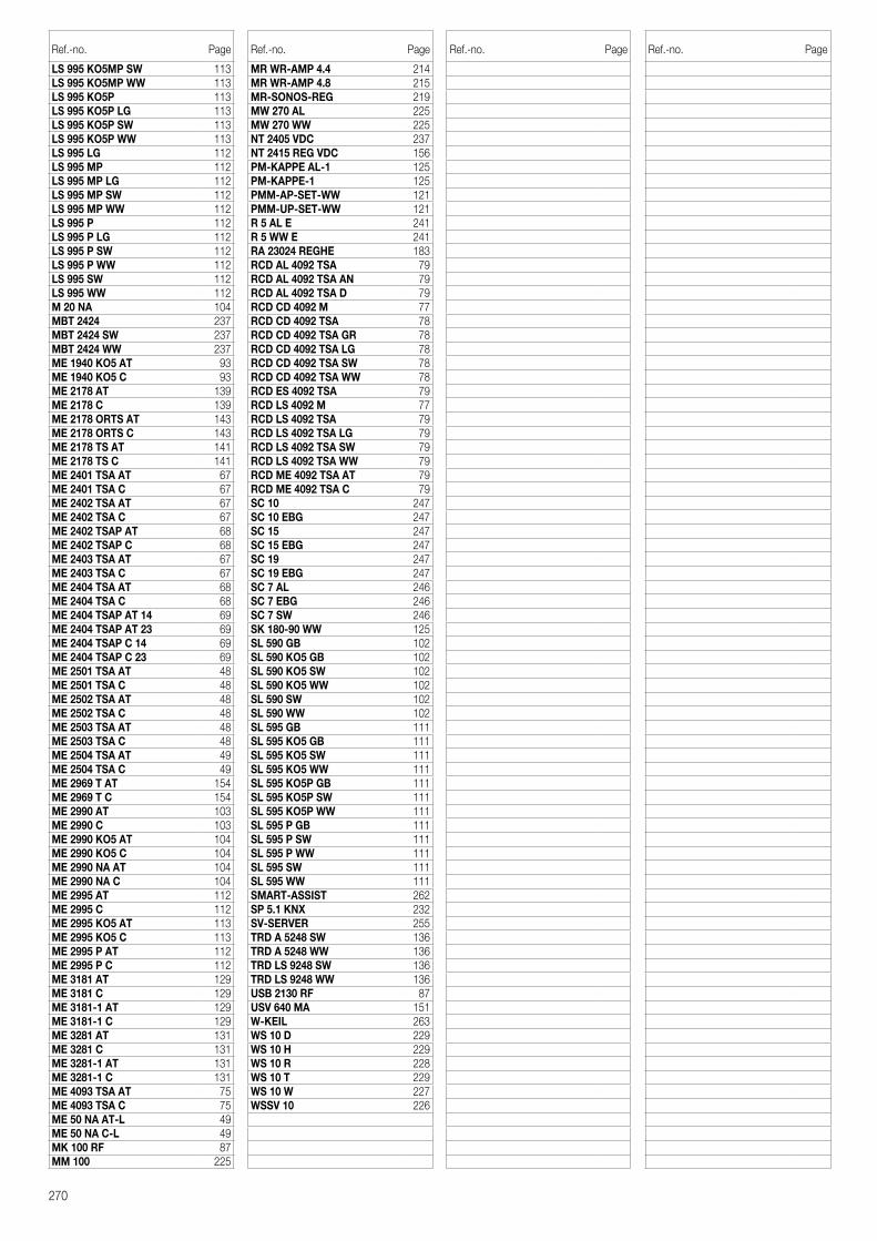
270
Ref.-no. Page
LS 995 KO5MP SW 113LS 995 KO5MP WW 113LS 995 KO5P 113LS 995 KO5P LG 113LS 995 KO5P SW 113LS 995 KO5P WW 113LS 995 LG 112LS 995 MP 112LS 995 MP LG 112LS 995 MP SW 112LS 995 MP WW 112LS 995 P 112LS 995 P LG 112LS 995 P SW 112LS 995 P WW 112LS 995 SW 112LS 995 WW 112M 20 NA 104MBT 2424 237MBT 2424 SW 237MBT 2424 WW 237ME 1940 KO5 AT 93ME 1940 KO5 C 93ME 2178 AT 139ME 2178 C 139ME 2178 ORTS AT 143ME 2178 ORTS C 143ME 2178 TS AT 141ME 2178 TS C 141ME 2401 TSA AT 67ME 2401 TSA C 67ME 2402 TSA AT 67ME 2402 TSA C 67ME 2402 TSAP AT 68ME 2402 TSAP C 68ME 2403 TSA AT 67ME 2403 TSA C 67ME 2404 TSA AT 68ME 2404 TSA C 68ME 2404 TSAP AT 14 69ME 2404 TSAP AT 23 69ME 2404 TSAP C 14 69ME 2404 TSAP C 23 69ME 2501 TSA AT 48ME 2501 TSA C 48ME 2502 TSA AT 48ME 2502 TSA C 48ME 2503 TSA AT 48ME 2503 TSA C 48ME 2504 TSA AT 49ME 2504 TSA C 49ME 2969 T AT 154ME 2969 T C 154ME 2990 AT 103ME 2990 C 103ME 2990 KO5 AT 104ME 2990 KO5 C 104ME 2990 NA AT 104ME 2990 NA C 104ME 2995 AT 112ME 2995 C 112ME 2995 KO5 AT 113ME 2995 KO5 C 113ME 2995 P AT 112ME 2995 P C 112ME 3181 AT 129ME 3181 C 129ME 3181-1 AT 129ME 3181-1 C 129ME 3281 AT 131ME 3281 C 131ME 3281-1 AT 131ME 3281-1 C 131ME 4093 TSA AT 75ME 4093 TSA C 75ME 50 NA AT-L 49ME 50 NA C-L 49MK 100 RF 87MM 100 225
Ref.-no. Page
MR WR-AMP 4.4 214MR WR-AMP 4.8 215MR-SONOS-REG 219MW 270 AL 225MW 270 WW 225NT 2405 VDC 237NT 2415 REG VDC 156PM-KAPPE AL-1 125PM-KAPPE-1 125PMM-AP-SET-WW 121PMM-UP-SET-WW 121R 5 AL E 241R 5 WW E 241RA 23024 REGHE 183RCD AL 4092 TSA 79RCD AL 4092 TSA AN 79RCD AL 4092 TSA D 79RCD CD 4092 M 77RCD CD 4092 TSA 78RCD CD 4092 TSA GR 78RCD CD 4092 TSA LG 78RCD CD 4092 TSA SW 78RCD CD 4092 TSA WW 78RCD ES 4092 TSA 79RCD LS 4092 M 77RCD LS 4092 TSA 79RCD LS 4092 TSA LG 79RCD LS 4092 TSA SW 79RCD LS 4092 TSA WW 79RCD ME 4092 TSA AT 79RCD ME 4092 TSA C 79SC 10 247SC 10 EBG 247SC 15 247SC 15 EBG 247SC 19 247SC 19 EBG 247SC 7 AL 246SC 7 EBG 246SC 7 SW 246SK 180-90 WW 125SL 590 GB 102SL 590 KO5 GB 102SL 590 KO5 SW 102SL 590 KO5 WW 102SL 590 SW 102SL 590 WW 102SL 595 GB 111SL 595 KO5 GB 111SL 595 KO5 SW 111SL 595 KO5 WW 111SL 595 KO5P GB 111SL 595 KO5P SW 111SL 595 KO5P WW 111SL 595 P GB 111SL 595 P SW 111SL 595 P WW 111SL 595 SW 111SL 595 WW 111SMART-ASSIST 262SP 5.1 KNX 232SV-SERVER 255TRD A 5248 SW 136TRD A 5248 WW 136TRD LS 9248 SW 136TRD LS 9248 WW 136USB 2130 RF 87USV 640 MA 151W-KEIL 263WS 10 D 229WS 10 H 229WS 10 R 228WS 10 T 229WS 10 W 227WSSV 10 226
Ref.-no. Page Ref.-no. Page

Terms and Conditions of Sale and Supply
I. General provisions
1) The mutual written declarations shall determine the scope of the supplies and services (hereinafter:supplies). However, General Terms and Conditions of Business on the part of the customer shall onlyapply insofar as we have expressly approved the same in writing.2) We shall unrestrictedly reserve our exploitation rights under proprietary right and copyright law to cost estimates, drawings and other documents (hereinafter: documents). Such documents may only berendered accessible to third parties with our prior consent and, upon request, shall, in the event that weshould not be awarded the commission, be returned to us without delay. Sentences 1 and 2 shall applymutatis mutandis to the customer’s submissions, though such submissions may be rendered accessibleto third parties to whom we have admissibly assigned responsibility for supplies.3) Partial supplies shall be admissible insofar as the customer may be reasonably expected to acceptthe same.
II. Prices and Terms and Conditions of Payment
1) Prices shall be understood to be ex-works excluding packaging and plus the statutory sales tax obtaining at any given time.2) Packaging shall be invoiced at the lowest possible prices and shall not be taken back.3) Insofar as nothing is agreed to the contrary, payment shall, irrespective of the receipt of the goodsinvolved, be made to us net within thirty days of the invoice date or within eight days with a 2 % discount.In the event that the payment deadline should be exceeded interest shall, without a reminder being required, be calculated pursuant to § 288 German Civil Code. 4) We shall be entitled to request advance payments in respect of the invoice amounts at any time priorto the dispatch of goods insofar as we deem such a step to be necessary. Should the customer defaulton the fulfilment of payment obligations or should the information pertaining to a customer no longer besatisfactory, we shall be entitled to request security for delivered goods or, once a payment deadline hasbeen set, withdraw from the purchase contract.5) The customer may only offset receivables which are undisputed or have been established on a legallybinding basis.
III. Reservation of title
Goods shall be supplied subject to reservation of title involving the following extensions:1) All supplied goods shall remain our property until such time as our claims vis-à-vis the customer, inclu-ding any such claims which may arise from the business link in the future, are settled in full and for suchtime as the account, including the bill and cheque commitments, has not been settled. This shall alsoapply in the event that the purchase price for certain deliveries of goods specified by the customer is tobe paid. In the case of a current account, the reserved title shall constitute security for our balance claim.2) The customer shall be revocable and, as long as they fulfil their obligations vis-à-vis ourselves andaffording consideration to the following provisions, entitled to sell and process during the normal course of business goods which are encumbered with reservation of title. However, the customer shall be forbidden from pledging or assigning as security goods subject to reservation of title which are supplied or processed. The customer shall, insofar as this is compatible with commercial practices, likewise under-take only to resell reserved goods which we have supplied in conjunction with reservation of title. Uponjustified request and in the case of default, the customer shall be obliged to apprise us of the name of thethird party customer.3) Insofar as goods encumbered with reservation of title are processed, such processing shall, thoughwithout any guarantee on our part, be effected for us. In the event of processing by the customer in conjunction with goods which are not our property, we shall be entitled to co-ownership of the new objectat the ratio of the value of the reserved goods to the other processed goods on the processing date.4) In the event that goods which we have supplied should be combined with other goods, we shallacquire co-ownership of the amount of the ratio of the value of the reserved goods in the combinationdate.5) Should the customer sell reserved goods which we have supplied or should such goods be suppliedto a third party – irrespective of what value or in which condition – or should such goods be installed within the framework of a work, work performance or a construction contract, the customer shall, untilsuch time as the claims stipulated in subsection 1) are settled in full, hereby assign to us, to the amount ofthe invoice value of our deliveries, the claim, together with all ancillary rights, including the compensationclaims accruing to them from the legal transaction involving the resale or installation, accruing to them vis-à-vis their customer or buyer from such sale, delivery or instalment. In the event of an assignment banobtaining in such work, work performance or contruction contract and in the event of payment default,the customer shall undertake to apprise their third party customers of the advance assignment.6) In the event that reserved goods which we have to supplied should be sold to third parties in con-junction with other goods, we shall be assigned that proportion of the total asking price corresponding to the invoice value of our deliveries.7) The reservation of title with the extensions pursuant to the above provision shall also remain in force in the event of individual claims against their customer on the part of the customer being included in thecurrent account. In this case, the customer shall, at this early juncture, assign to us the balance obtainingto their credit. The customer shall, upon request and particularly in the event of payment default on thepart of the purchaser, be obliged to facilitate the direct assertion of the claims involved and apprise thethird party debtor of the assignment.8) We shall be apprised without delay of any attachment and every kind of restriction which obtain in respect of our property. In the event that the value of the overall collateral stemming from the business linkwith which we have been furnished should exceed our delivery claims by more than 20 %, we shall, at therequest of the purchaser, be obliged to reassign the assigned claims to such extent.9) In the event of any incidence of damage or other impairment to the equipment supplied on the basisof our terms and conditions, the purchaser shall, at this early juncture, assign to us in advance the com-pensation claim accruing to them vis-à-vis the insurer from their insurance to the amount of the incidenceof damage in question to our reserved property.
IV. Deadline for deliveries; default
1) The deadline for deliveries or services shall commence on the day on which written agreement pertaining to the order in question obtains between the customer and ourselves. The observance of suchdeadline shall presuppose the prompt receipt of all the documents, requisite licences and releases to befurnished by the customer, the prompt clarification and approval of the plans and the observance of theagreed Terms of Conditions of Payment and other obligations. Should these prerequisites not be fulfilledon time, the delivery deadline shall be extended by an adequate period of time; this shall not apply in theevent that we should be responsible for a delay.2) Should the non-observance of deadlines be attributable to force majeure, such as mobilization, war civil commotion or similar occurrences, e.g. strike or lockout, delivery deadlines shall be extended by adequate periods of time.3) In the event that dispatch or delivery should, at the behest of the customer, be delayed by more thanone month following notification of dispatch readiness, the customer may, for every started month, beinvoiced storage costs to the amount of 0.5 % of the price of the delivery objects, though no more than a total of 5 %. The contracting parties shall be at liberty to prove that lower or higher storage costs have accrued.
V. Transfer of risk
The risk shall also pass to the customer in the event that carriagepaid delivery should have been agreed. In the absence of a written arrangement to the contrary, dispatch shall always be effected according toour best judgement. We shall not assume any responsibility for transportation at market prices. We shallonly arrange transport insurance policies the costs of which are borne by the purchaser upon express,written agreement.
VI. Acceptance
The customer may not refuse to accept deliveries on the grounds of the existence of minor defects.
VII. Material defects
1) The prerequisite for the assertion of material defects liability shall be the submission to us or our authorized representative of proof of acquisition (delivery note, invoice, etc.). The warranty entitlement may not be transferred to third parties without our consent. 2) All those components or services shall, as we see fit, be repaired, resupplied or refurnished which feature a material defect within the limitation period – irrespective of operating life – insofar as the origin of the same obtained at the point in time of transfer of risk.3) Material defects claims shall lapse after twelve month. This shall not apply insofar as the law pursuantto §§ 438, paragraph 1, no. 2 (constructions and objects for constructions), 479, paragraph 1 (claimunder a right of recourse) and 634a, paragraph 1, no. 2 (construction defects) German Civil Code makesprovision for longer periods of time, in instances of injury to life, body or health, in the event of a wilful orgrossly negligent breach of duty on our part and in the event of the malicious nondisclosure of a defect.The statutory provisions pertaining to the suspension of the running of a period, suspension and re-commencement of periods shall remain unaffected.4) The customer shall submit complaints pertaining to material defects to us in writing without delay.5) In the event of notifications of defects, payment on the part of the customer may be withheld on ascale which is in a reasonable ratio to the material defects which have occurred. The customer may onlywithhold payments should a complaint be asserted the justification of which is beyond doubt. Should acomplaint have been submitted without justification, we shall be entitled to request the that customerreimburse the costs which we incurred.6) In the first instance, we shall be granted the opportunity to effect subsequent fulfilment within a reasonable period of time.7) Should such subsequent fulfilment be unsuccessful, the customer – any compensation claims pursuant to subsection IX notwithstanding – may withdraw from the contract or reduce the amount of payment.8) Claims arising from defects shall not obtain in respect of a minor deviation from an agreed quality, aminor impairment to usefulness, natural wear and tear or incidences of prejudice which arise subsequentto the risk transfer in consequence of faulty or negligent handling, exessive strain, unsuitable operatingfacilities, faulty construction operations, unsuitable subsoil and, in particular, any external influences whichare not presupposed by the contract, as well as in respect of non-reproducible software defects.In theevent that modifications or maintenance operations should be improperly performed by the customer orany third parties, it shall likewise be the case that no claims arising from defects shall obtain for suchmodifications and maintenance operations or any resulting consequences.9) Any claims on the part of the customer for expenditure which it is necessary to incur for subsequentfulfilment purposes, particularly transport, travelling, labour and material costs, shall be excluded insofar assuch expenditure increases due to the fact that a delivery object has been subsequently transported to alocation other than the customer’s business premises unless such transportation is in line with the normalutilization of such object.10) Claims under rights of recourse vis-à-vis ourselves on the part of the customer pursuant to § 478German Civil Code (contractor’s recourse) shall only obtain insofar as the customer has not agreed anyarrangements with their customer exceeding the scope of the statutory claims arising from defects. No. 9 shall additionally apply mutatis mutandis to the scope of the customer’s claim under a right ofrecourse vis-à-vis ourselves pursuant to § 478, paragraph 1 German Civil Code. 11) It should be noted that subsection IX (other compensation claims) shall apply to compensationclaims. Any more farreaching claims for a material defect against us and our vicarious agents on the partof the customer and any claims for a material defect against us and our vicarious agents on the part ofthe customer other than those stipulated in subsection VII shall be excluded.
VIII. Impossibility, contractual revision
1) Insofar as a delivery is impossible the customer shall be entitled to claim compensation unless we arenot responsible for such impossibility. However, the customer’s entitlement to compensation shall berestrictes to 10 % of the value of that component of the delivery which cannot be put into appropriateoperation in consequence of such impossibility. This entitlement shall not apply insofar as, in cases of wilful intent, gross negligence or injury to life, body or heath, compulsory liability obtains; this shall not entail a change in the burden of proof to the detriment of the customer. The right of the customer to withdraw from the contract shall remain uneffected.2) Insofar as any unforeseeable occurrences within the purport of subsection IV, no. 2 considerably alter the economic importance or the object of a delivery or exercise a major influence on our operations,the contract shall be suitably revised in compliance with the principle of good faith. Insofar as this is noteconomically justifiable, we shall be entitled to withdraw from the contract. In the event that we shouldwish to exercise this right of withdrawal, we shall apprise the customer accordingly without delay uponbecoming cognizant of the implications of the occurrence in question, including in the event that an extension of the delivery period should initially have been agreed with the customer.
IX. Other compensation claims
1) Claims for compensation and claims for the compensation of expenses (hereinafter: compensationclaims), irrespective of on which legal grounds, particularly for a breach of the duties arising from the contractual obligation and for tortious acts, shall be excluded.2) This shall not apply insofar as compulsory liability obtains, e.g. pursuant to the Product Liability Act, in cases of wilful intent, gross negligence, injury to life, body or health and a breach of major contractualobligations. However, a claim to compensation for a breach of major contractual obligations shall berestricted to the contractually typical, foreseeable prejudice insofar as wilful intent or gross negligence donot obtain or liability obtains due to injury to life, body or health. The above stipulations shall not entail achange in the burden of proof to the detriment of the customer.3) Insofar as the customer is entitled to compensation claims pursuant to subsection IX, such claimsshall lapse upon the expiry of the limitation period pursuant to subsection VII, no. 3 applying to claims formaterial defects. In the case of compensation claims pursuant to the Product Liability Act, the prevailingstatutory limitation provisions shall apply.
X. Diagrams, measurements and weights
Diagrams, measurements and weights shall always be regarded as approximate.
XI. Place of performance, place of jurisdiction and applicable law
1) Insofar as nothing to the contrary is agreed, the place of performance shall be Schalksmühle.2) In the event of the customer being a businessman, the sole place of jurisdiction for all disputes arisingdirectly or indirectly from the contractual relationship shall be Hagen. However, we shall also be entitled toinstitute legal proceedings at the place of domicile of the customer.3) German substantive law shall, to the exclusion of the UN Convention on Contracts pertaining to theInternational Sale of Goods (CISG), apply to the legal relations obtaining in connection with this contract.
XII. The remaining provision of the contract shall continue to have binding force even in the event of the legal invalidity of any of the individual provisions contained in the same. This shall not apply inthe event of adherence to the contract constituting unreasonable hardship for one of the contractingparties.

Good to know: Brochures, films, websites and web portals –
further information, tools and practical supplements for
the smart JUNG technology can be found here.
Further information
eNet SMART HOME
Smart wireless technology, intelligently retro-
fitted. Systematics, modules, advantages and
strong partners. With practical application
examples.
KNX SMART HOME
The intelligent home – professionally realised
using solutions from JUNG. With advantages
and application examples; ideal for the
customer discussion.
KNX – THE SECURE AND SAFE STANDARD
Worldwide standard: the KNX system with
benefits, application examples and references
from commercial building and private home
construction. Including checklist for the
„Security“ subject.
JUNG BROCHURES
272

JUNG WEBSITE
All information about the KNX solutions can
be found thematically prepared and illustra-
ted on the JUNG website. Naturally also with
further links and download material.
jung-group.com
JUNG ONLINE CATALOGUE
Technical information for viewing and for
download is attached to the individual JUNG
articles in the online catalogue.
jung-group.com/online-catalogue
KNX FILMS
Descriptive films for possibilities and handling
of various KNX solutions can be found in the
JUNG media database.
jung-group.com/movies
FEELSMART.
The web platform for Smart Home solutions:
Electrical installers, planners and owners
come together here to plan projects jointly
via On-line Configurator.
feelsmart.com
WEBSITES AND ONLINE PORTALS
273

B-G
B-K
NX
KN
X C
ATA
LOG
UE
20
18
JUNG-GROUP.COM
ALBRECHT JUNG GMBH & CO. KG
P.O. Box 1320
58569 Schalksmühle
Germany
Phone +49 2355 806-553
Fax +49 2355 806-254
For sales cantacts in your country see:
jung-group.com/contact
Copyright © 2022 FDOKUMEN


![Carl Gustav Jung - Amintiri, vise, reflectii [ibuc info]](https://static.fdokumen.com/doc/165x107/63252e3d545c645c7f0990ba/carl-gustav-jung-amintiri-vise-reflectii-ibuc-info.jpg)