1677 SONET Link Installation Practices - Nokia Documentation
196
1677 SONET Link Installation Practices PN 3EM13849AD 01 R05.00, Issue 01, May 2006
-
Upload
khangminh22 -
Category
Documents
-
view
3 -
download
0
Transcript of 1677 SONET Link Installation Practices - Nokia Documentation

1677 SONET LinkInstallation Practices
PN 3EM13849AD 01R05.00, Issue 01, May 2006

Alcatel 2002-2006 - All Rights ReservedPrinted in U.S.A.
THIS PRODUCT COMPLIES WITH D.H.H.S. RADIATION PERFORMANCE STANDARDS 21CFR, 1040.10, FOR A CLASS 1 LASER PRODUCT.
DANGER
Invisible laser radiation is present when the optic connector is open. AVOID DIRECTEXPOSURE TO BEAM.
WARNING
This equipment has been tested and found to comply with the limits for a Class A digital device, pursuantto Part 15 of the FCC Rules. These limits are designed to provide reasonable protection against harmfulinterference when the equipment is operated in a commercial environment. This equipment generates,uses, and can radiate radio frequency energy and, if not installed and used in accordance with theinstruction manual, may cause harmful interference to radio communications. Operation of this equipmentin a residential area is likely to cause harmful interference in which case users will be required to correct theinterference at their own expense.
NOTICE
This manual applies to 1677 SONET Link R05.00 software. Release notes describing revisions to thissoftware may impact operations described in this manual.
This transfer of commodities, technology, or software, if from the United States, is an export in accordancewith the U.S. Export Administration Regulations. Diversion contrary to U.S. law is prohibited. The export orre-export (further transfer) of such commodities, technology, software or products made from suchtechnology is prohibited without proper authorization(s) from the U.S. Department of Commerce or otherappropriate U.S. government agency(s).
All rights reserved. No part of this manual may be reproduced, translated, stored in a retrieval system, ortransmitted or distributed by any means, electronic or mechanical, by photocopying, recording, or otherwise,without the written permission of Alcatel. Preparing derivative works or providing instruction based on thematerial is prohibited unless agreed to in writing by Alcatel.
The product specification and/or performance levels contained in this document are for informationpurposes only and are subject to change without notice. They do not represent any obligation on the part ofAlcatel. Such obligations will only be committed to in a written sales agreement signed by Alcatel.
DOCUMENTATION
Product documentation is available on Alcatel’s Online Support Documentation and Software web site athttp://www.alcatel.com/osds.
To offer comments on this documentation, visit Alcatel’s Online Support Documentation and Software website at http://www.alcatel.com/osds and select Online Services Helpdesk or write to the following address.
AlcatelAttention: Doc Comment, MS OLXDV
3400 W. Plano Pkwy.Plano, Texas 75075 USA

3EM13849ADIssue 01, May 2006
ALCATEL PRACTICEStandard
1677 SONET Link Installation PracticesTable of Contents
1677 SONET Link Installation Overview
1. INTRODUCTION . . . . . . . . . . . . . . . . . . . . . . . . . . . . . . . . . . . . . . . . . . . . . . . . . . . 1-1About This Manual . . . . . . . . . . . . . . . . . . . . . . . . . . . . . . . . . . . . . . . . . . . . 1-1Admonishments . . . . . . . . . . . . . . . . . . . . . . . . . . . . . . . . . . . . . . . . . . . . . . 1-1Installing Equipment . . . . . . . . . . . . . . . . . . . . . . . . . . . . . . . . . . . . . . . . . . . 1-2Method of Procedure (Optional, But Recommended) . . . . . . . . . . . . . . . . . 1-2Installation Tools. . . . . . . . . . . . . . . . . . . . . . . . . . . . . . . . . . . . . . . . . . . . . . 1-3Recommended Tools List. . . . . . . . . . . . . . . . . . . . . . . . . . . . . . . . . . . . . . . 1-4Related Documentation . . . . . . . . . . . . . . . . . . . . . . . . . . . . . . . . . . . . . . . . 1-6
2. SAFETY AWARENESS . . . . . . . . . . . . . . . . . . . . . . . . . . . . . . . . . . . . . . . . . . . . . . 1-7Fan, Equipment Rack, and Equipment Cabinet Precautions . . . . . . . . . . . . 1-7Electrical Precautions . . . . . . . . . . . . . . . . . . . . . . . . . . . . . . . . . . . . . . . . . . 1-7Laser Precautions. . . . . . . . . . . . . . . . . . . . . . . . . . . . . . . . . . . . . . . . . . . . . 1-8
3. ELECTROSTATIC-SENSITIVE DEVICES. . . . . . . . . . . . . . . . . . . . . . . . . . . . . . . 1-13Electrostatic-Sensitivity. . . . . . . . . . . . . . . . . . . . . . . . . . . . . . . . . . . . . . . . 1-13Handling Modules. . . . . . . . . . . . . . . . . . . . . . . . . . . . . . . . . . . . . . . . . . . . 1-14Repairing Modules . . . . . . . . . . . . . . . . . . . . . . . . . . . . . . . . . . . . . . . . . . . 1-15
4. PRODUCT SUPPORT INFORMATION. . . . . . . . . . . . . . . . . . . . . . . . . . . . . . . . . 1-17Telephone Support . . . . . . . . . . . . . . . . . . . . . . . . . . . . . . . . . . . . . . . . . . . 1-17Product Documentation and Training . . . . . . . . . . . . . . . . . . . . . . . . . . . . . 1-17Technical Assistance Center . . . . . . . . . . . . . . . . . . . . . . . . . . . . . . . . . . . 1-19Repair and Return Services . . . . . . . . . . . . . . . . . . . . . . . . . . . . . . . . . . . . 1-20Spare Parts and Replacement Modules. . . . . . . . . . . . . . . . . . . . . . . . . . . 1-20Service Center . . . . . . . . . . . . . . . . . . . . . . . . . . . . . . . . . . . . . . . . . . . . . . 1-21Installation and Maintenance Services . . . . . . . . . . . . . . . . . . . . . . . . . . . . 1-23
Chart-1 Unpack and Inspect Equipment . . . . . . . . . . . . . . . . . . . . . . . . . . . . . . . . . . . . . . . . . . . 2-1
Chart-2 Prepare Floor . . . . . . . . . . . . . . . . . . . . . . . . . . . . . . . . . . . . . . . . . . . . . . . . . . . . . . . . . 2-5
Chart-3 Install Racks. . . . . . . . . . . . . . . . . . . . . . . . . . . . . . . . . . . . . . . . . . . . . . . . . . . . . . . . . 2-13
Chart-4 Install Overhead Rack Support . . . . . . . . . . . . . . . . . . . . . . . . . . . . . . . . . . . . . . . . . . 2-19
Chart-5 Route and Connect Frame-Ground Cable . . . . . . . . . . . . . . . . . . . . . . . . . . . . . . . . . . 2-21
Chart-6 Mount Filler Panels and Brackets to Rack . . . . . . . . . . . . . . . . . . . . . . . . . . . . . . . . . . 2-23
© Alcatel 2002-2006 - All Rights Reserved i

3EM13849ADIssue 01, May 2006
Chart-7 Mount 1677 SONET Link Chassis and PDU-Quad in Rack. . . . . . . . . . . . . . . . . . . . . 2-27
Chart-8 Unseat Modules . . . . . . . . . . . . . . . . . . . . . . . . . . . . . . . . . . . . . . . . . . . . . . . . . . . . . . 2-31
Chart-9 Connect Power Cables Between PDU-Quad and 1677 SONET Link . . . . . . . . . . . . . 2-35
Chart-10 Route and Terminate Office Battery Power Cables . . . . . . . . . . . . . . . . . . . . . . . . . . . 2-37
Chart-11 Verify PDU-Quad Ground . . . . . . . . . . . . . . . . . . . . . . . . . . . . . . . . . . . . . . . . . . . . . . 2-41
Chart-12 Verify PDU-Quad Power . . . . . . . . . . . . . . . . . . . . . . . . . . . . . . . . . . . . . . . . . . . . . . . 2-49
Chart-13 Verify Frame Ground . . . . . . . . . . . . . . . . . . . . . . . . . . . . . . . . . . . . . . . . . . . . . . . . . . 2-57
Chart-14 Verify Secondary Power. . . . . . . . . . . . . . . . . . . . . . . . . . . . . . . . . . . . . . . . . . . . . . . . 2-59
Chart-15 Install DS1 Splitter and Route Internal Clock Cables. . . . . . . . . . . . . . . . . . . . . . . . . . 2-67
Chart-16 Route and Terminate External Clock Cables to DS1 Splitter . . . . . . . . . . . . . . . . . . . . 2-71
Chart-17 Route External Clock Cables to TC Slots . . . . . . . . . . . . . . . . . . . . . . . . . . . . . . . . . . 2-73
Chart-18 Install Fiber Management. . . . . . . . . . . . . . . . . . . . . . . . . . . . . . . . . . . . . . . . . . . . . . . 2-79
Chart-19 Route Central Office OC-n Signal Cables . . . . . . . . . . . . . . . . . . . . . . . . . . . . . . . . . . 2-83
Chart-20 Route Central Office GigE Signal Cables . . . . . . . . . . . . . . . . . . . . . . . . . . . . . . . . . . 2-89
Chart-21 Mount 48-Port or 96-Port DS3/EC1 Connector Panel . . . . . . . . . . . . . . . . . . . . . . . . . 2-93
Chart-22 Route and Terminate Central Office DS3 and EC1 Signal Cables . . . . . . . . . . . . . . 2-105
Chart-23 Connect Office Alarm Wiring to 1677 SONET Link . . . . . . . . . . . . . . . . . . . . . . . . . . 2-111
Chart-24 Connect Data Terminal or Modem to 1677 SONET Link . . . . . . . . . . . . . . . . . . . . . . 2-113
Chart-25 Connect Local Area Network (LAN) Wiring . . . . . . . . . . . . . . . . . . . . . . . . . . . . . . . . 2-117
Chart-26 Test 1677 SONET Link Wiring Continuity . . . . . . . . . . . . . . . . . . . . . . . . . . . . . . . . . 2-121
Chart-27 Install Rear Kick Plate . . . . . . . . . . . . . . . . . . . . . . . . . . . . . . . . . . . . . . . . . . . . . . . . 2-123
Chart-28 Install AC Outlets . . . . . . . . . . . . . . . . . . . . . . . . . . . . . . . . . . . . . . . . . . . . . . . . . . . . 2-125
Chart-29 Install Front Base Plate . . . . . . . . . . . . . . . . . . . . . . . . . . . . . . . . . . . . . . . . . . . . . . . 2-129
Chart-30 Install Electrical Switch. . . . . . . . . . . . . . . . . . . . . . . . . . . . . . . . . . . . . . . . . . . . . . . . 2-131
Table of Contentsii

3EM13849ADIssue 01, May 2006
Chart-31 Install Trim (Config Option 1) . . . . . . . . . . . . . . . . . . . . . . . . . . . . . . . . . . . . . . . . . . . 2-133
Chart-32 Install PDU-Quad Labels . . . . . . . . . . . . . . . . . . . . . . . . . . . . . . . . . . . . . . . . . . . . . . 2-135
Chart-33 Verify Final Installation . . . . . . . . . . . . . . . . . . . . . . . . . . . . . . . . . . . . . . . . . . . . . . . . 2-137
Installing MOS Modules
1. REQUIREMENTS . . . . . . . . . . . . . . . . . . . . . . . . . . . . . . . . . . . . . . . . . . . . . . . . . . 3-1Installation Requirements . . . . . . . . . . . . . . . . . . . . . . . . . . . . . . . . . . . . . . . 3-1Service-clearance Requirements . . . . . . . . . . . . . . . . . . . . . . . . . . . . . . . . . 3-1Environmental Requirements . . . . . . . . . . . . . . . . . . . . . . . . . . . . . . . . . . . . 3-1Electrical Power Requirements . . . . . . . . . . . . . . . . . . . . . . . . . . . . . . . . . . 3-2Equipment-rack Requirements . . . . . . . . . . . . . . . . . . . . . . . . . . . . . . . . . . . 3-2
2. INSPECTION . . . . . . . . . . . . . . . . . . . . . . . . . . . . . . . . . . . . . . . . . . . . . . . . . . . . . . 3-3Unpacking and Inspecting . . . . . . . . . . . . . . . . . . . . . . . . . . . . . . . . . . . . . . 3-3Fiber-optic Jumper Cable Requirements . . . . . . . . . . . . . . . . . . . . . . . . . . . 3-3Preventing ESD Damage . . . . . . . . . . . . . . . . . . . . . . . . . . . . . . . . . . . . . . . 3-4
3. INSTALLATION . . . . . . . . . . . . . . . . . . . . . . . . . . . . . . . . . . . . . . . . . . . . . . . . . . . . 3-519-Inch Mounting . . . . . . . . . . . . . . . . . . . . . . . . . . . . . . . . . . . . . . . . . . . . . 3-523-Inch Mounting . . . . . . . . . . . . . . . . . . . . . . . . . . . . . . . . . . . . . . . . . . . . . 3-5Fiber-optic Jumper Cable Requirements . . . . . . . . . . . . . . . . . . . . . . . . . . . 3-6Installing a Module . . . . . . . . . . . . . . . . . . . . . . . . . . . . . . . . . . . . . . . . . . . . 3-6Planning the Installation . . . . . . . . . . . . . . . . . . . . . . . . . . . . . . . . . . . . . . . . 3-7Mounting the Module . . . . . . . . . . . . . . . . . . . . . . . . . . . . . . . . . . . . . . . . . . 3-8Front-mounting the Modules. . . . . . . . . . . . . . . . . . . . . . . . . . . . . . . . . . . . . 3-9Mid-mounting a Module . . . . . . . . . . . . . . . . . . . . . . . . . . . . . . . . . . . . . . . 3-12
4. INSTALLING AND ROUTING FIBER-OPTIC CABLES . . . . . . . . . . . . . . . . . . . . . 3-17Cabling the MOS . . . . . . . . . . . . . . . . . . . . . . . . . . . . . . . . . . . . . . . . . . . . 3-18Selecting and Installing Fiber-optic Attenuators . . . . . . . . . . . . . . . . . . . . . 3-21
Table of Contents iii

3EM13849ADIssue 01, May 2006
Table of Contentsiv

3EM13849ADIssue 01, May 2006
1677 SONET Link Installation PracticesList of FiguresFigure 2-1. Manufacture Date Label (Equipment Shelf) . . . . . . . . . . . . . . . . . . . . . . . . . . . . . . . . . 1-10
Figure 2-2. Danger and Manufacture Date Labels (Modules) . . . . . . . . . . . . . . . . . . . . . . . . . . . . 1-11
Figure 3-3. Electrostatic-Sensitive Sign . . . . . . . . . . . . . . . . . . . . . . . . . . . . . . . . . . . . . . . . . . . . . 1-13
Figure 1-1. Unpack 1677 SONET Link . . . . . . . . . . . . . . . . . . . . . . . . . . . . . . . . . . . . . . . . . . . . . . . 2-3
Figure 2-1. Rack Footprint . . . . . . . . . . . . . . . . . . . . . . . . . . . . . . . . . . . . . . . . . . . . . . . . . . . . . . . . 2-7
Figure 2-2. Rack (PN 1AD014120032). . . . . . . . . . . . . . . . . . . . . . . . . . . . . . . . . . . . . . . . . . . . . . . 2-8
Figure 2-3. Self-Drilling Anchor . . . . . . . . . . . . . . . . . . . . . . . . . . . . . . . . . . . . . . . . . . . . . . . . . . . 2-10
Figure 2-4. Anchor Setting . . . . . . . . . . . . . . . . . . . . . . . . . . . . . . . . . . . . . . . . . . . . . . . . . . . . . . . 2-11
Figure 3-1. Config Option 1 (Front) . . . . . . . . . . . . . . . . . . . . . . . . . . . . . . . . . . . . . . . . . . . . . . . . 2-14
Figure 3-2. Config Option 2 (Front) . . . . . . . . . . . . . . . . . . . . . . . . . . . . . . . . . . . . . . . . . . . . . . . . 2-15
Figure 3-3. Typical Overhead Uni-Strut Support . . . . . . . . . . . . . . . . . . . . . . . . . . . . . . . . . . . . . . 2-17
Figure 4-1. Typical Overhead Rack Support . . . . . . . . . . . . . . . . . . . . . . . . . . . . . . . . . . . . . . . . . 2-20
Figure 7-1. Remove Shipping Brackets . . . . . . . . . . . . . . . . . . . . . . . . . . . . . . . . . . . . . . . . . . . . . 2-28
Figure 7-2. ANSI Equipment Rack Screw-Hole Pattern . . . . . . . . . . . . . . . . . . . . . . . . . . . . . . . . . 2-29
Figure 7-3. Align Chassis Bracket Mounting Holes with Equipment Rack Mounting Holes . . . . . . 2-30
Figure 8-1. System Module Interlock (Detail) . . . . . . . . . . . . . . . . . . . . . . . . . . . . . . . . . . . . . . . . . 2-33
Figure 8-2. Captive Thumbscrews (Detail) . . . . . . . . . . . . . . . . . . . . . . . . . . . . . . . . . . . . . . . . . . . 2-33
Figure 8-3. System Module Ejector Handles (detail) . . . . . . . . . . . . . . . . . . . . . . . . . . . . . . . . . . . 2-34
Figure 9-1. PDU-Quad (Front View) . . . . . . . . . . . . . . . . . . . . . . . . . . . . . . . . . . . . . . . . . . . . . . . . 2-35
Figure 9-2. 18RU Shelf Power Panel (Rear of Shelf) . . . . . . . . . . . . . . . . . . . . . . . . . . . . . . . . . . . 2-36
Figure 10-1. PDU-Quad (Front View) . . . . . . . . . . . . . . . . . . . . . . . . . . . . . . . . . . . . . . . . . . . . . . . . 2-38
Figure 11-1. PDU-Quad (Front View) . . . . . . . . . . . . . . . . . . . . . . . . . . . . . . . . . . . . . . . . . . . . . . . . 2-42
List of Figures v

3EM13849ADIssue 01, May 2006
Figure 11-2. Frame Ground . . . . . . . . . . . . . . . . . . . . . . . . . . . . . . . . . . . . . . . . . . . . . . . . . . . . . . . 2-43
Figure 11-3. PDU-Quad (Rear View) . . . . . . . . . . . . . . . . . . . . . . . . . . . . . . . . . . . . . . . . . . . . . . . . 2-44
Figure 12-1. PDU-Quad (Front View) . . . . . . . . . . . . . . . . . . . . . . . . . . . . . . . . . . . . . . . . . . . . . . . . 2-50
Figure 12-2. PDU-Quad (Rear view) . . . . . . . . . . . . . . . . . . . . . . . . . . . . . . . . . . . . . . . . . . . . . . . . 2-51
Figure 13-1. 18RU Shelf Power Panel (Rear of Shelf) . . . . . . . . . . . . . . . . . . . . . . . . . . . . . . . . . . . 2-57
Figure 14-1. 18RU Shelf Power Panel (Rear of Shelf) . . . . . . . . . . . . . . . . . . . . . . . . . . . . . . . . . . . 2-59
Figure 14-2. PDU-Quad (Front View) . . . . . . . . . . . . . . . . . . . . . . . . . . . . . . . . . . . . . . . . . . . . . . . . 2-60
Figure 14-3. BDFB to PDU QUAD Power Routing (Simplified Diagram) . . . . . . . . . . . . . . . . . . . . . 2-60
Figure 17-1. BITS Wire-Wrap Connection Locations . . . . . . . . . . . . . . . . . . . . . . . . . . . . . . . . . . . . 2-74
Figure 17-2. 1677 SONET Link TC Locations . . . . . . . . . . . . . . . . . . . . . . . . . . . . . . . . . . . . . . . . . 2-75
Figure 18-1. Flex-Tube Holder Locations . . . . . . . . . . . . . . . . . . . . . . . . . . . . . . . . . . . . . . . . . . . . . 2-81
Figure 21-1. Chassis-Mounted 48-Port DS3/EC1 Connector Panel Kit . . . . . . . . . . . . . . . . . . . . . . 2-94
Figure 21-2. Cable-Tie Brackets Attached to Chassis-Mounted 48-Port DS3/EC1 Connector Panel . . . . . . . . . . . . . . . . . . . . . . . . . . . . . . . . . . . . . . . 2-95
Figure 21-3. 1677 SONET Link Rear Connectors . . . . . . . . . . . . . . . . . . . . . . . . . . . . . . . . . . . . . . 2-95
Figure 21-4. Rear Connector Access Cover. . . . . . . . . . . . . . . . . . . . . . . . . . . . . . . . . . . . . . . . . . . 2-96
Figure 21-5. Port-Identifier Label . . . . . . . . . . . . . . . . . . . . . . . . . . . . . . . . . . . . . . . . . . . . . . . . . . . 2-97
Figure 21-6. Rack-Mounted 96-Port DS3/EC1 Connector Panel Kit . . . . . . . . . . . . . . . . . . . . . . . 2-100
Figure 21-7. Cable-Tie Brackets Attached to Rack-Mounted 96-Port DS3/EC1 Connector Panel . . . . . . . . . . . . . . . . . . . . . . . . . . . . . . . . . . . . . . 2-101
Figure 21-8. Adapter Plate Brackets (23-Inch) . . . . . . . . . . . . . . . . . . . . . . . . . . . . . . . . . . . . . . . . 2-102
Figure 21-9. Connector Panel/Adapter Plate Attached to Equipment Rack (19-inch shown) . . . . . . . . . . . . . . . . . . . . . . . . . . . . . . . . . . . . . . . 2-103
Figure 21-10. Rear Chassis Connector Cables Attached to Connector Panel . . . . . . . . . . . . . . . . . 2-103
Figure 22-1. Typical DS3/EC1 Signal Connectors . . . . . . . . . . . . . . . . . . . . . . . . . . . . . . . . . . . . . 2-109
Figure 24-1. Console Cable . . . . . . . . . . . . . . . . . . . . . . . . . . . . . . . . . . . . . . . . . . . . . . . . . . . . . . 2-114
List of Figuresvi

3EM13849ADIssue 01, May 2006
Figure 24-2. Connect Data Terminal to TC Console Port. . . . . . . . . . . . . . . . . . . . . . . . . . . . . . . . 2-114
Figure 24-3. Connect Modem to TC Console Port . . . . . . . . . . . . . . . . . . . . . . . . . . . . . . . . . . . . . 2-115
Figure 25-1. Locate TCs. . . . . . . . . . . . . . . . . . . . . . . . . . . . . . . . . . . . . . . . . . . . . . . . . . . . . . . . . 2-118
Figure 25-2. Locate 10/100Base-T Ethernet Connector on TC . . . . . . . . . . . . . . . . . . . . . . . . . . . 2-119
Figure 28-1. AC Duplex Outlet Installation, Front Mount . . . . . . . . . . . . . . . . . . . . . . . . . . . . . . . . 2-126
Figure 28-2. AC Duplex Outlet Installation, Rear Mount . . . . . . . . . . . . . . . . . . . . . . . . . . . . . . . . 2-127
Figure 2-1. Unpacking Diagram . . . . . . . . . . . . . . . . . . . . . . . . . . . . . . . . . . . . . . . . . . . . . . . . . . . . 3-4
Figure 3-1. ANSI/EIA-310-D or IEC Mounting Hole Patterns . . . . . . . . . . . . . . . . . . . . . . . . . . . . . . 3-5
Figure 3-2. Typical Module Placement . . . . . . . . . . . . . . . . . . . . . . . . . . . . . . . . . . . . . . . . . . . . . . . 3-8
Figure 3-3. Mounting Brackets . . . . . . . . . . . . . . . . . . . . . . . . . . . . . . . . . . . . . . . . . . . . . . . . . . . . . 3-9
Figure 3-4. Locate Front-Mounting Brackets on Rack . . . . . . . . . . . . . . . . . . . . . . . . . . . . . . . . . . 3-11
Figure 3-5. Locating Multiple Front-Mounting Brackets . . . . . . . . . . . . . . . . . . . . . . . . . . . . . . . . . 3-11
Figure 3-6. Install Cable Exit Clips . . . . . . . . . . . . . . . . . . . . . . . . . . . . . . . . . . . . . . . . . . . . . . . . . 3-12
Figure 3-7. Install Mid Mounting Brackets . . . . . . . . . . . . . . . . . . . . . . . . . . . . . . . . . . . . . . . . . . . 3-13
Figure 3-8. Proper Mid Mount Bracket Location. . . . . . . . . . . . . . . . . . . . . . . . . . . . . . . . . . . . . . . 3-14
Figure 4-1. Installing Fiber-optic Cable. . . . . . . . . . . . . . . . . . . . . . . . . . . . . . . . . . . . . . . . . . . . . . 3-18
Figure 4-2. Installing Express Path Cables . . . . . . . . . . . . . . . . . . . . . . . . . . . . . . . . . . . . . . . . . . 3-19
Figure 4-3. Connecting OMB Cables . . . . . . . . . . . . . . . . . . . . . . . . . . . . . . . . . . . . . . . . . . . . . . . 3-20
List of Figures vii

3EM13849ADIssue 01, May 2006
List of Figuresviii

3EM13849ADIssue 01, May 2006
1677 SONET Link Installation PracticesList of TablesTable 15-A. Clock Cable Routing . . . . . . . . . . . . . . . . . . . . . . . . . . . . . . . . . . . . . . . . . . . . . . . . . . 2-69
Table 16-A. BITS Clock Cable Connections . . . . . . . . . . . . . . . . . . . . . . . . . . . . . . . . . . . . . . . . . . 2-72
Table 17-A. Clock Cable Routing . . . . . . . . . . . . . . . . . . . . . . . . . . . . . . . . . . . . . . . . . . . . . . . . . . 2-76
Table 17-B. Clock Cable Routing . . . . . . . . . . . . . . . . . . . . . . . . . . . . . . . . . . . . . . . . . . . . . . . . . . 2-76
Table 26-A. Continuity Test List From 1677 SONET Link Location To Office Location . . . . . . . . 2-122
Table 28-A. AC Duplex Outlet Kits . . . . . . . . . . . . . . . . . . . . . . . . . . . . . . . . . . . . . . . . . . . . . . . . 2-125
Table 1-A. Environmental Requirements. . . . . . . . . . . . . . . . . . . . . . . . . . . . . . . . . . . . . . . . . . . . . 3-2
List of Tables ix

3EM13849ADIssue 01, May 2006
List of Tablesx

3EM13849ADIssue 01, May 2006
1677 SONET Link Installation Overview
1. INTRODUCTION
1.1 The 1677 SONET Link is a member of Alcatel's family of Synchronous Optical Network (SONET) products. This manual provides installation procedures for the 1677 SONET Link and its ancillary equipment. Here, installation means to physically mount and secure the frame, chassis, and ancillary items, as well as make all necessary power, ground, and office wiring connections.
About This Manual
1.2 The 1677 SONET Link can be installed in a variety of configurations, and installation may require various Alcatel-sourced ancillary equipment to address site-specific requirements. For these reasons, this manual provides information on installing individual pieces of equipment and installing frame assemblies. Each step-by-step chart in this manual describes a different installation procedure and, depending on customer selections, more than one chart may be needed to complete the installation.
1.3 This manual provides step-by-step charts to help users perform tasks. Each chart describes practices such as unpacking and inspection, facility preparation, installing frame bus cabling, and actual equipment wiring. The charts contain important introductory information that is essential to understanding and completing the task properly. Procedures must be started at step 1, and steps must be performed in the order given. Failure to do so may cause unforeseen hazardous conditions.
Admonishments
1.4 To avoid hazardous conditions, observe the following admonishments:
DANGER Possibility of personal injury.
WARNING Possibility of equipment damage.
1677 SONET Link Installation Overview 1-1

3EM13849ADIssue 01, May 2006
Installing Equipment
1.5 If the installation project matches a specific document, follow its directions (including all cross-references).
Method of Procedure (Optional, But Recommended)
1.6 The person responsible for the installation, in cooperation with the telco engineer and Central Office (CO) supervisor, should collect all essential information to prepare the Method of Procedure (MOP). After the MOP is prepared, it is submitted to CO management for approval. Work performed on common equipment may require that activities be accomplished during nonstandard working hours. This should be a joint decision between the CO management, telco engineer, and installation personnel.
1.7 As a minimum, the following items should be addressed, mutually understood, and agreed upon in establishing a MOP. This should be done before the start of installation:
• Identify potential service-affecting hazards and risks imposed.
• Define installation methods, tools, and test sets to be used.
• Assign experienced personnel to the job.
• Identify protection/safety requirements of the equipment and tools.
• Determine the time during which the various steps of the work will be performed and the equipment affected.
• Identify steps of the work that require prior notification of the CO personnel or the telco engineer.
• Define procedures to follow and tests to make before additional or modified equipment is connected to any working equipment.
• Develop steps the installer must take to disconnect any alarms associated with the work.
• Define procedures to follow to ensure that the fuse designation and fuse records are checked with the proper drawing before any fuse is removed.
• Identify the time of day or night the removed equipment is to be restored.
1677 SONET Link Installation Overview1-2

3EM13849ADIssue 01, May 2006
• Identify what measures can be taken to ensure that the equipment is restored to service on time in case of unforeseen delays.
• Define steps of the work that require the presence of CO personnel.
• Identify tests applicable to wiring operations.
• Specify the space requirements (for example, storage and administrative).
• When applicable, the MOP should include a restoration plan. This restoration plan is a joint effort among CO personnel, installation personnel, and the telco engineer.
1.8 The recommended sequence of events consists of the following steps:
• Install the frame, if applicable.
• Install the Power Distribution Unit, Quad Input (PDU-Quad), if applicable.
• Install the 1677 SONET Link chassis.
1.9 In addition to suggested MOP content, the following items should be mutually understood and agreed upon relative to using the MOP. This should be done before the start of installation:
• All work is done during the hours specified in the MOP.
• The MOP is approved by the telco engineer and the CO personnel before the installation start.
• After the MOP is adopted and approved, any deviation from the procedure must be approved by the telco engineer and the CO personnel.
• An approved copy of the MOP is available and posted for review at the job site at all times.
Installation Tools
1.10 To properly install Alcatel SONET equipment, the following tools should be available. Unique tools specific to a given task are listed in the installation section covering that task. Other tools may be required to perform special procedures as specified in instructions.
1677 SONET Link Installation Overview 1-3

3EM13849ADIssue 01, May 2006
Recommended Tools List
1.11 Refer to the following list for recommended tools:
• 1677 SONET Link reference manuals
• Safety glasses and ear protection
• Static protection accessories
– Strap, wrist ground, PN 055-9357-000
– Strap, heel, PN 055-9357-030
– ESD field service grounding kit, PN 126-3422-010
– Static booklet, PN 126-37442-010
• Rotary impact drill and associated drill bits
• Anchor setting tool (Redhead RT58 or equivalent)
• Level, 3 ft. length
• Pliers, needle-nose, 4 in.
• Diagonal cutters, 5 in.
• Screwdriver, standard 4 in.
• Screwdriver, standard 6 in.
• Screwdriver, Phillips, 6 in.
• Multi-stripper
• Scissors
• Wire-wrap gun, electric
• Wire-wrap bits/sleeves, 22 Ga., 24 Ga., 26 Ga.
• Hand unwrap tool
• Steel tape, 25 ft.
• Cable butting tool
• Cable stripper
1677 SONET Link Installation Overview1-4
3EM13849ADIssue 01, May 2006
• Cable cutters
• TY-wrap tool
• Wrenches, 3/8 in. to 15/16 in., open and box end combinations
• Extension cord, 50 ft.
• Hammer, claw
• Trouble lamp, insulated (for example, Duralamp brand)
• Stencil kit
• Socket set, 3/8 in. drive
• Tin snips
• Pinch bar
• Vacuum cleaner, High Efficiency Particulate Arrester (HEPA)
• Volt-ohm meter—Western Electric KS-14510, Triplet 630, or equivalent
• Audible continuity checker—Ideal 61-030, Hunter Tools 2647, or equivalent
• Optical power meter
1677 SONET Link Installation Overview 1-5

3EM13849ADIssue 01, May 2006
Related Documentation
1.12 For additional system information, refer to the following related documents:
• Unit Data Sheets (UDSs) in this manual
• 1677 SONET Link Product Information manual (PN 3EM13848AD)
• 1677 SONET Link Operation and Administration manual (PN 3EM13851AD)
• 1677 SONET Link Turn-Up manual (PN 3EM13850AB)
• 1677 SONET Link Maintenance and Trouble Clearing manual (PN 3EM13853AD)
• 1677 SONET Link Commands and Messages manual (PN 3EM13852AD)
• 1677 SONET Link Engineering Support Documentation manual (PN 3EM17362AB)
• 1677 SONET Link Address and Location Guide (PN 3EM13854AB)
1677 SONET Link Installation Overview1-6

3EM13849ADIssue 01, May 2006
2. SAFETY AWARENESS
Fan, Equipment Rack, and Equipment Cabinet Precautions
2.1 When installing the equipment observe the following:
DANGER Possibility of personal injury. Keep fingers away from the rotating fan blades. Pull the fan-tray by the thumbscrews only and wait for the fan blades to stop spinning before attempting to remove the fan-tray completely from the chassis.
DANGER Possibility of personal injury. The Alcatel 1677 SONET Link requires at least three people to support, align, and attach it to an equipment rack. To prevent equipment damage or personal injury, make sure help is available.
DANGER Possibility of personal injury. To prevent personal injury and equipment damage due to unbalanced loading of the equipment rack or cabinet, make sure the equipment rack or cabinet is properly secured to the floor, ceiling, or other rigid structure before mounting the Alcatel 1677 SONET Link in it. For approved methods of securing the equipment rack, read the equipment-rack installation instructions or contact the equipment-rack manufacturer.
Electrical Precautions
2.2 Take appropriate safety precautions when performing procedures on electrical equipment. Hazardous electrical potentials are present when system power is on.
2.3 Some procedures in this manual require working with small conductive objects, such as screwdrivers, fuses, washers, screws, and nuts. When working on a chassis at the top of an equipment rack, a dropped object that falls into a lower chassis can cause physical damage and electrical short circuits. To prevent this, place a piece of paper or other cover over the lower chassis to catch fallen objects. Remove the paper or other cover when work is complete.
DANGER Possibility of personal injury. Install the Alcatel 1677 SONET Link in a restricted-access area only. Entrance to a restricted-access area is intended for qualified or trained personnel and access to it is controlled by a locked barrier.
DANGER Possibility of personal injury. The chassis does not contain main overcurrent protection devices. The user must provide circuit breakers or fuses and
1677 SONET Link Installation Overview 1-7

3EM13849ADIssue 01, May 2006
disconnects between the power source and the Alcatel 1677 SONET Link. Each power feed from a source (-48 V dc and Return) requires a 25-amp dc-rated fast-trip circuit breaker or fuse and disconnect. Circuit breakers or fuses must meet applicable local and national electrical safety codes and be approved for the intended application.
DANGER Possibility of personal injury. Make sure to connect the node to a -48 V dc source that is electrically isolated from the ac source and is reliably connected to earth ground.
DANGER Possibility of personal injury. For personal safety, make sure to connect and secure the installation site’s frame-ground (earth ground) wire to the frame-ground terminal on the 1677 SONET Link before connecting any other wires to the node.
DANGER Possibility of personal injury. A dc-power source provides high energy, which can cause serious injury or equipment damage. Only Alcatel qualified personnel should connect the dc power to the Alcatel 1677 SONET Link. To prevent serious injury or equipment damage, make sure the power source cables are de-energized before handling or connecting them to the node.
Laser Precautions
2.4 Verify that laser labels on equipment state that the system conforms to all applicable standards of 21 CFR 1040.10. See figure 2-1 and 2-2. If there are no danger labels, call the Alcatel Technical Assistance Center (TAC).
2.5 The invisible infrared radiation emitted by the fiber-optic transmitter can cause eye damage. Observe local office procedures and the following dangers:
DANGER Possibility of personal injury. The use of controls and/or adjustments, or the performance of procedures other than those specified herein may result in hazardous infrared radiation exposure.
DANGER Possibility of personal injury. Laser infrared radiation is not in the visible spectrum; therefore, it is not visible to the naked eye or with laser safety glasses. Although it cannot be seen, laser radiation may be present.
DANGER Possibility of personal injury. Never look directly into an unterminated fiber-optic connector unless it is absolutely known that no optical power is being emitted by the connector.
1677 SONET Link Installation Overview1-8

3EM13849ADIssue 01, May 2006
DANGER Possibility of personal injury. Never look into a broken optical fiber cable unless it is absolutely known that no laser radiation is present.
DANGER Possibility of personal injury. Never look at an optical fiber splice, cable, or connector unless it is absolutely known that no laser radiation is present in the fiber. Laser radiation can come from a fiber-optic transmitter, an Optical Time Domain Reflectometer (OTDR), or other optical test equipment.
DANGER Possibility of personal injury. Never look directly into an unterminated optical connector or cable with a magnifier/microscope unless it is absolutely known that no laser radiation is being emitted from the connector or cable. A magnifier or microscope greatly increases the laser radiation hazard to the eyes.
DANGER Possibility of personal injury. This system normally operates as a Class I Laser Product (no hazard). However, during servicing operations, when optical connectors are being connected, disconnected, or handled without dust covers, it is possible to be exposed to Class IIIb laser radiation, which can cause eye damage.
DANGER Possibility of personal injury. Everyone within a 10 ft. radius of an unterminated optical fiber or connector that is connected to a powered transmitter must wear laser safety goggles or eye shields.
2.6 Laser safety goggles or eye shields are not required if the following work rules are strictly followed:
1. Always remove electrical power from fiber-optic transmitters before disconnecting fiber-optic connectors in the path between the transmitter and the receiver.
2. Never connect an unterminated optical cable to a fiber-optic transmitter. Always connect fiber-optic cables to fiber-optic receivers, test sets, or some other termination first.
1677 SONET Link Installation Overview 1-9

3EM13849ADIssue 01, May 2006
.
Figure 2-1. Manufacture Date Label (Equipment Shelf)
REAR VIEWOF 1677
677-0246-1031805
POWER B
POWER A
-48 VDC
-48 VDCRTN
ON
OFF
ON
OFF
-48 VDC
-48 VDC
RTN
RTN
RTN
GENERIC CLEI LABEL
GENERIC SHELFASSEMBLY LABEL
1677 SONET Link Installation Overview1-10

3EM13849ADIssue 01, May 2006
Figure 2-2. Danger and Manufacture Date Labels (Modules)
REACH/FIBER-TYPE
LABEL
LASERWARNING
LABELLASER
STATUS
OC48
677-0317-1031805
PARTNUMBER
LABEL
MN LABEL
SERIALNUMBER
LABEL
1677 SONET Link Installation Overview 1-11

3EM13849ADIssue 01, May 2006
1677 SONET Link Installation Overview1-12

3EM13849ADIssue 01, May 2006
3. ELECTROSTATIC-SENSITIVE DEVICES
Electrostatic-Sensitivity
3.1 An electrostatic-sensitive (ESS) device can withstand voltage spikes of only 10 to 100 volts and can be damaged or effectively destroyed by a discharge that might go unnoticed by a technician. Some devices have built-in protection. However, because this protection is effective only against the lower levels of electrostatic charges, a false sense of security often prevails.
WARNING Possibility of equipment damage. Common plastic, white foam, cellophane, and masking adhesive tapes must not come in contact with ESS devices or their packaging.
3.2 Common plastics (synthetic insulating materials), clothing, and paper or cardboard are the most common sources of static charges.
3.3 Observe special precautions when the ESS sign is displayed. See figure 3-3.
3.4 The following items are examples of ESS devices:
• MOS (Metal Oxide Semiconductor) capacitors, transistors, Integrated Circuits (ICs)
• CMOS (Complementary Metal Oxide Semiconductor) transistors, ICs
• JFET (Junction Field Effect Transistors)
• IGFET (Insulated Gate Field Effect Transistors)
Figure 3-3. Electrostatic-Sensitive Sign
677-0356-1071105
1677 SONET Link Installation Overview 1-13

3EM13849ADIssue 01, May 2006
Handling Modules
3.5 Although the risk of damage to an ESS device is reduced considerably after it is assembled into a circuit designed to protect sensitive components, take the following precautions to reduce static charges to harmless levels:
• Handle all modules as ESS devices unless they are known not to contain electrostatic-sensitive parts.
WARNING Possibility of equipment damage. Heel straps are effective only while standing on conductive or electrostatic-dissipative surfaces.
• Wear ground straps, wrist (PN 055-9357-010) or heel (PN 055-9357-020), before and while touching or handling modules containing ESS devices.
• Cover surfaces with resistance to ground in excess of 100 megohms, such as ordinary tile, with properly grounded static dissipative runners, or wax surfaces with a static dissipative wax (PN 057-4000-006).
• Store (even temporarily), pack, and ship modules in antistatic bags or containers.
• Do not handle printed circuit board or components unnecessarily. Use plastic handle.
• Do not use synthetic bristled brushes or acid brushes to clean modules.
• Handle failed modules with same precautions as good modules.
1677 SONET Link Installation Overview1-14

3EM13849ADIssue 01, May 2006
Repairing Modules
3.6 To protect ESS devices during repair, take the following precautions:
• The workbench must be earth-grounded, and the work surface must be covered with an antistatic or static dissipative material bonded to the bench (bolt). A field service kit (PN 126-3442-010) or equivalent can be used if an adequate workbench is not available.
• Repair technicians must wear a wrist strap of 250 kilohms to 2 megohms that contacts the repair technician's skin and the bolt bonding the covering to the bench or safety ground. The wrist strap must be connected before parts are removed from packaging.
• All electrical equipment must be grounded using a 3-wire power cord.
• Clothing must not touch the device under repair.
• ESS devices are delivered with protective packing (containers or conductive foam). The devices should remain in their original containers until needed.
• Containers with ESS devices must contact the antistatic work surface, and the wrist strap must be connected before parts are removed from packaging. Devices must be handled by their bodies. Leads must be contacted only when necessary.
• Test setups must have correct voltage polarity.
• Volt Ohm Milliamp (VOM)-type meters must not be used to measure resistance; they can damage devices.
• Only antistatic (metallized) desoldering tools should be used.
3.7 ESS devices are protected when properly packaged in conductive or antistatic packaging. Acceptable packaging is marked as either conductive or antistatic.
1677 SONET Link Installation Overview 1-15

3EM13849ADIssue 01, May 2006
1677 SONET Link Installation Overview1-16

3EM13849ADIssue 01, May 2006
4. PRODUCT SUPPORT INFORMATION
Telephone Support
Customer Service Telephone Support
4.1 For telephone support for the customer services mentioned in this Product Support Information, call 888-ALCATEC (888-252-2832) or 613-784-6100, 8:00 a.m. to 5:00 p.m., Central Time, Monday through Friday. Ask the operator for the appropriate service to be connected to a qualified representative or engineer.
4.2 After-hours emergency telephone support is also available by calling 888-ALCATEC (888-252-2832) or 613-784-6100. An emergency is defined as an out-of-service, traffic-affecting problem or a nonoperating alarm system on traffic-bearing systems.
Quality Hotline
4.3 A toll-free Quality Hotline (800-553-4056) is available to all customers to report quality issues related to products or services.
4.4 The Quality Hotline is answered 24 hours a day, 365 days a year, and is available throughout all 50 states and Canada.
4.5 To report quality issues, call 800-553-4056. An operator will take the information and have an Alcatel Quality Assurance Representative respond during normal business hours (8:00 a.m. to 5:00 p.m. Central Time, Monday through Friday). The regular customer service numbers should be used for normal customer service functions.
Product Documentation and Training
Product Documentation
4.6 Product documentation is available on both paper and CD-ROM. The documentation can also be accessed through Alcatel's Online Support Documentation and Software web site at http://www.alcatel.com/osds. Product documentation updates appear on Alcatel's Online Support Documentation and Software web site before they are available in any other format.
1677 SONET Link Installation Overview 1-17

3EM13849ADIssue 01, May 2006
4.7 At Alcatel's Online Support Documentation and Software web site, follow the on-screen instructions to register for access and obtain a login ID. In addition to accessing product documentation, the Alcatel Online Support Documentation and Software web site allows the user to view the following:
• Application notes
• Configuration notes
• Data collections
• Frequently Asked Questions (FAQs)
• General information books
• General Release Documents (GRDs)
• Installation documents
• Methods of Procedure (MOPs)
• Product Change Notifications (PCNs)
• Product Information Bulletins (PIBs)
• Product manual updates
• Software patch and software load documents
• Software Update Documents (SUDs)
• Technical bulletins
• Training documents
• Urgent Product Warnings (UPWs)
Training
4.8 Equipment training is available to all customers. Crafts and maintenance personnel who are trained by Alcatel's Training department can expect more effective assistance if they need to call the Technical Assistance Center. Regularly scheduled courses are available at the training facilities in Plano, Texas. If a customer cannot attend a standard course, the Training department can arrange a course for a specific requirement and conduct it at the customer's facility. For further information, call customer service telephone support and ask for a training coordinator or write to one of the following addresses:
1677 SONET Link Installation Overview1-18

3EM13849ADIssue 01, May 2006
4.9 The annual Product Training Catalog can be ordered by calling the training coordinator, or it can be viewed on-line at http://www7.alcatel.com/service/catalog.
Technical Assistance Center
4.10 The Technical Assistance Center staff is always ready to provide high-quality technical assistance. Customers can expect effective telephone assistance when their crafts and maintenance personnel have been trained by Alcatel's Training department and are equipped with adequate test equipment, spares, and documentation at the site.
4.11 For technical assistance, call customer service telephone support.
After-hours Emergency Telephone Support
4.12 Emergency support is available after-hours through dispatch operators. Call customer service telephone support and ask for the Lightwave, Microwave, Operations Support System (OSS), Digital Loop Carrier (LMS), or Digital Cross-Connect emergency duty engineer.
4.13 An emergency is defined as an out-of-service, traffic-affecting problem or a nonoperating alarm system on traffic-bearing systems.
4.14 Nonemergency is defined as installation turn-ups, application questions, traffic cutover, routine maintenance, or other non-service-affecting maintenance. All non-service-affecting, after-hours telephone services are billable to the customer.
4.15 Please provide the operator with the following information:
• Company name
• Caller name
• A telephone number where caller can be reached
• A brief description of the problem, including the product involved
IN USA: IN CANADA:Alcatel USA3400 W. Plano Pkwy.Plano, Texas 75075ATTN: Training M/S 1206-553
Alcatel CanadaNetwork Services DivisionP.O. Box 13600Ottawa, Ontario K2K 2E6
1677 SONET Link Installation Overview 1-19

3EM13849ADIssue 01, May 2006
After-hours Nonemergency Telephone Support
4.16 After-hours telephone support to address new installations, system expansions, system operations, system application, or other non-service-affecting issues is available by contacting Alcatel Customer Service at 1-888-252-2832 (1-888-ALCATEC) or 1-613-784-6100.
On-site Technical Support
4.17 On-site technical support is available when as issue cannot be resolved remotely. This determination is usually made by Alcatel TAC during the problem investigation process. These services may or may not be billable to a customer. This depends on several factors such as what type of Service Level Agreement a customer has with Alcatel, the age of the product, etc.
Repair and Return Services
4.18 As part of a comprehensive technical support program, Alcatel provides factory repair services for equipment. This service is available both during and after the warranty period through Alcatel's Return and Repair department.
Spare Parts and Replacement Modules
4.19 For spare parts, spare modules, module exchange, and in-warranty replacement on a routine or emergency basis, call customer service telephone support.
4.20 Provide the following information:
• Company name
• Caller name
• A telephone number where caller can be reached
• A brief description of the problem, including product line, part number, and quantity of parts needed
4.21 For emergency assistance after normal business hours, call customer service telephone support, ask the operator for Emergency Parts Assistance, and provide the operator with the required information. The operator will contact an appropriate individual to respond.
1677 SONET Link Installation Overview1-20

3EM13849ADIssue 01, May 2006
Return for Credit or Warranty Exchange Procedure
4.22 Returned equipment must have a Return Authorization (RA) number. Obtain an RA number either by calling customer service telephone support or by fax (972-519-4611).
4.23 No equipment should be returned without an RA number. The following information is required:
• Description and quantity of equipment to be returned
• Reason for return
• Order number the equipment was purchased against and approximate date of purchase
Service Center
4.24 The Service Center tests, repairs, and modifies all modules (both in and out of warranty). Modules received for repair or modification are returned promptly.
1677 SONET Link Installation Overview 1-21

3EM13849ADIssue 01, May 2006
Return for Repair Procedure
4.25 Refer to paragraph 4.22 for information on obtaining an RA number. Notification to the Service Center and issuance of an RA number by Alcatel personnel must be made prior to shipment of parts. The following information must be furnished with the request for return authorization:
• Purchase order number or requisition number
• Description and quantity of equipment to be returned
• Reason for return:
– Modification required
– Defective equipment to be repaired
• Warranty status (in or out of warranty) and warranty date stamped on unit
• Specific nature of problem
• Name and telephone number of person who identified problem
• Special instruction/information
1677 SONET Link Installation Overview1-22

3EM13849ADIssue 01, May 2006
Shipping Instructions for Repair, Credit, or Warranty Exchange
4.26 Return equipment or parts prepaid to the address provided when the RA number was issued. The RA number must be prominently marked on the shipping label, the packing list, and any correspondence regarding the order.
• Include company name, address, and name of person to contact in case of a question.
• Include specific reason for return. (This aids prompt processing.)
• Include the same requisition number or purchase order number that was furnished with request for return authorization.
• Include type number and part number of unit.
• State whether equipment is in or out of warranty.
• Furnish shipping address for return of unit, if applicable, or other pertinent details.
• Mail purchase order, if applicable, to address shown under Return for Repair Procedure, Attention: Service Center.
Installation and Maintenance Services
Engineering and Installation Service
4.27 Whether installation for specific equipment or a full turnkey network facility is needed, Installation Service can help. Alcatel has experience in central office, outside plant, and customer premises applications, and specializes in flexible scheduling and high-quality service. Qualified staff are in place nationwide, so an installation can be started and completed promptly.
Contract Maintenance Service
4.28 Field service from Alcatel offices nationwide is available if a maintenance contract is selected. Alcatel field service is well-suited for private networks of any size. For a fixed annual fee, Alcatel provides prompt response to service calls and provides scheduled preventive maintenance, including FCC-required measurements and record keeping.
1677 SONET Link Installation Overview 1-23

3EM13849ADIssue 01, May 2006
4.29 Factory-trained service technicians are qualified on similar systems before they are allowed to maintain customer equipment. They have direct access to additional technical support around the clock and to all necessary tools and test equipment.
1677 SONET Link Installation Overview1-24

Chart-13EM13849ADIssue 01, May 2006
Chart-1Unpack and Inspect EquipmentPURPOSE
Follow this procedure to unpack and inspect the 1677 SONET Link and to report any shipping damage or missing parts.
GENERAL
This procedure covers both the 18RU and 15RU shelf types.
RECOMMENDED TOOLS
Tin snips
STEP PROCEDURE
1 WARNING: Possibility of equipment damage. If product must be transported or reshipped, repack equipment with approved shipping materials (see figure 1-1). Repacking equipment improperly or using unapproved shipping materials may result in equipment damage, which is sender’s responsibility. If any shipping materials are lost, contact Alcatel before transporting or reshipping product.
2 Remove external packing slip from shipping container.
3 Before unpacking container, ensure there is no visible damage to outside of container.
If damage is visible, report damage to freight carrier before opening container. Freight carrier will advise as to next step to take. If a camera is available, take several pictures of damage.
4 Use tin snips to cut container strapping. See figure 1-1, detail A.
5 Open top flaps and remove optional air-plenum tray kit container and accessory carton(15 RU shelf) or bagged accessory items (18 RU shelf).See figure 1-1, detail B or C.
6 Remove packing inserts from top of container. See figure 1-1, detail D.
7 Open accessory bag or carton and inspect contents for damage or missing parts.
8 Open air-plenum tray kit carton and inspect contents for damage or missing parts.
9 Remove cardboard sleeve. See figure 1-1, detail D.
Unpack and Inspect Equipment 2-1

Chart-1 3EM13849ADIssue 01, May 2006
10 Inspect 1677 SONET Link chassis and its card cage area for visible damage. If damage is visible, contact Alcatel to report damage and to find out what to do next.
11 Remove four screws at the base of the shelf to release it from the shipping base. Discard the screws.
12 Install two 10-32 x .375l pph screws (included in bag) where two of the shipping brackets mounted to the shelf mounting bracket.
13 To report damage or missing parts, contact Alcatel CTAC at 1-888-252-2832.
14 STOP. This procedure is complete.
Unpack and Inspect Equipment2-2

Chart-13EM13849ADIssue 01, May 2006
Figure 1-1. Unpack 1677 SONET Link
677-0387
042706
AIR-PLENUMTRAY KIT
(C)
ACCESSORY CARTON
CONTAINS:
ESD WRIST STRAP,
CONSOLE CABLE
MOUNTING SCREW KIT,
23-INCH BRACKETS,
19-INCH BRACKETS,
MANUAL
CARDBOARD
SLEEVE
1677
SONET
LINK
SHOCK ABSORBING
SHIPPING BASE
(D)
CARDBOARD
SLEEVE
(B)
BAGGED ITEMS
INCLUDED WITH SHELF:
CABLE ASSEMBLIES (2),
COIL CORD, SCREWS,
WRIST STRAP
CARDBOARD
SLEEVE
(A)
18 RU SHELF
SHIPPING
CONTAINER
15 RU SHELF
SHIPPING
CONTAINER
REMOVE TWO SCREWS
ON BOTH SIDES OF SHELF
TO RELEASE IT FROM
SHIPPING BASE
Unpack and Inspect Equipment 2-3

Chart-1 3EM13849ADIssue 01, May 2006
Unpack and Inspect Equipment2-4

Chart-23EM13849ADIssue 01, May 2006
Chart-2Prepare FloorPURPOSE
This chart provides instructions to prepare floors.
GENERAL
Equipment racks are designed for fixed-location installation. Standard and earthquake rack assemblies are available. The 26 in. wide equipment racks are installed on 36 in. centers.
Alcatel provides expert Installation Services for installations that have different requirements from config option 1 and config option 2 as outlined in this manual. Contact Alcatel at 1-888-252-2832 for details.
RECOMMENDED TOOLS
Safety glasses
Chalk line and chalk (blue)
Heavy duty extension cord (50 ft.)
Felt-tipped marking pen
Insulated trouble lamp (droplight—Duralamp, or equivalent)
Rotary impact drill and associated drill bits
Steel measuring tape (50 ft.)
System template, single rack layout (PN 3EM19359AAAAHCZZA)
Vacuum cleaner, High Efficiency Particulate Arrester (HEPA)
Prepare Floor 2-5

Chart-2 3EM13849ADIssue 01, May 2006
STEP PROCEDURE
1 Observe the following guidelines:
a. Verify that layouts of floor, ceiling, and walls are as indicated in applicable drawings and specifications.
b. Verify that area dimensions and location of reference points correspond to floor plan.
c. Mark all reference and layout lines.
d. To avoid possibility of cumulative errors when short dimensions are laid out in a straight line, mark total length, divide into shorter lengths, and leave steel measuring tape in place.
e. Where layout lines intersect, extend lines at least 6 in. beyond point of intersection to check equipment alignment.
2 WARNING: Possibility of equipment damage. Use a level to check entire mounting floor space. Do not try to mount rack on uneven floor.
3 Follow job floor plan, and mark equipment locations on floor with chalk line. See figure 2-1 for rack footprint. See figure 2-2 for rack dimensions.
4 Verify required space for rack (see figure 2-1).
5 Follow chalk line to mark front baseline and end of rack.
6 Lay out system template (PN 3EM19359AAAAHCZZA, single rack layout).
7 Use felt-tipped marking pen to mark anchor points for rack.
Prepare Floor2-6

Chart-23EM13849ADIssue 01, May 2006
Figure 2-1. Rack Footprint
RACK FOOTPRINTALL DIMENSIONSIN INCHES
15.5
36
FRONT
677-0287-1032405
Prepare Floor 2-7

Chart-2 3EM13849ADIssue 01, May 2006
Figure 2-2. Rack (PN 1AD014120032)
25.94
15.63
4.75
10.09
17.25
25.94
5.25
RACK FOOTPRINT
5.91
REMOVABLE COVER
1.75
0.50
7.00
677-0318-1
USE TEMPLATE TO
5.00
031805
MARK FLOOR.
ALL DIMENSIONSIN INCHES
84.00
22.31
21.50
o45
Prepare Floor2-8

Chart-23EM13849ADIssue 01, May 2006
PREPARE FOR RACK INSTALLATION
8 Rack design is 5.00 in. extruded steel channel with 43 vertical EIA mounting increments with 12-24 tapped holes. Tapped hole pattern provides for mounting shelf assemblies and ancillary equipment on front of channels and rack rear covers. Racks are typically installed on concrete floors; however, rack can also be bolted to wood or steel floor. Earthquake rack installation is effective only on concrete flooring that is at least 6 in. thick, has minimum strength of 300 psi, and is reinforced with 0.5 percent steel rebar.
9 Is installation on concrete floor, raised computer-equipment floor, uni-strut floor anchor system, or wood or steel floor?
If concrete floor, go to step 10.If raised computer-equipment floor, go to step 26.If uni-strut floor anchor system, go to step 36.If wood or steel floor, go to step 46.
Concrete Floor
10 Install floor anchors and mount rack. Use base-mounting kit for standard rack on concrete floors.
11 Position and lock chuck/shank assembly in rotary impact drill.
12 Insert and seat anchor in chuck.
13 Let the tool do the work. Apply only enough pressure to control tool. Vertical force in excess of weight of tool reduces impact force, thus inhibiting drilling process for self-drill anchors.
To position anchor, operate drill in impact mode. Use impact action until teeth are embedded just below concrete surface.
14 DANGER: Possibility of personal injury. Never use air hose to clean dust from a hole, as dust may be blown into eyes and equipment. For the same reason, do not flick out dust. Use HEPA vacuum cleaner to remove dust from hole.
15 Care must be taken to ensure that concrete dust from drilling is contained in immediate vicinity of drill hole. The following two methods ensure that dust does not spread:
a. Use a HEPA vacuum cleaner to completely remove concrete cuttings from hole while drilling. Hole must be completely clear for proper seating of anchor.
b. Fill disposable cup with shaving cream and place it over drill hole. Drill through bottom of cup. Shaving cream will contain and trap dust particles.
Prepare Floor 2-9

Chart-2 3EM13849ADIssue 01, May 2006
16 Engage rotation mode, then drill until chuck is within 1/16 in. above concrete surface. See figure 2-3.
17 Stop tool and lift approximately 1 in. to disengage impact action, then start tool and withdraw anchor.
18 Disengage rotation action. While anchor is still attached, start tool to expel concrete cuttings from anchor.
19 Completely remove concrete cuttings from hole with vacuum, and inspect hole for any concrete chips. Hole must be completely clear for proper seating of anchor.
20 Insert and lightly seat expansion plug in anchor.
21 Verify that tool is in impact position. Insert anchor in hole and seat with impact action of tool until chuck is 1/16 in. above concrete. See figure 2-4.
Figure 2-3. Self-Drilling Anchor
CHUCK
CHUCKING CONE
ANCHOR(SELF-DRILLING)
CONCRETE
677-0319-1031805
1/16 IN.
CUTTINGBIT
Prepare Floor2-10

Chart-23EM13849ADIssue 01, May 2006
22 Break off chucking cone with hard push of tool.
23 Remove chucking cone from chuck.
24 If rack is not to be installed immediately, cover anchors with tape.
25 Go to step 50.
Raised Computer-Equipment Floor
26 Installation of equipment on raised computer-equipment floor is site specific. Installation should be in accordance with GR-1275-CORE, Central Office Environment Installation/Removal Generic Requirements for raised-floor environments. Method of installation will be determined when preparing Method of Procedure (MOP).
To install rack assembly on raised computer-equipment floor, ensure that floor can support rack load.
27 Follow job floor plan, and mark equipment locations on floor with chalk line.
28 Follow chalk line to mark front baseline and end of rack.
29 Lay out 1677 SONET Link system template (PN 3EM19359AAAAHCZZA, single rack layout).
30 Use felt-tipped marking pen and template to mark location of mounting holes.
31 Drill 5/8 in. hole for 5/8 in. threaded rod.
Figure 2-4. Anchor Setting
CHUCKING CONE
EXPANSION PLUG
677-0320-1
CHUCK
SHANK
031805
1/16 IN.
Prepare Floor 2-11

Chart-2 3EM13849ADIssue 01, May 2006
32 Drop plumb bob through drilled holes.
33 Use felt-tipped marking pen to mark position on concrete floor.
34 Remove floor tiles to gain access to concrete floor.
35 To install floor anchors on concrete floor, go to step 10.
Uni-Strut Floor Anchor System
36 Use felt-tipped marking pen and template to mark location of mounting holes.
37 Drill 5/8 in. hole for 5/8 in. threaded rod.
38 Drop plumb bob through drilled holes.
39 Use felt-tipped marking pen to mark position on concrete floor.
40 Remove floor tiles to gain access to concrete floor.
41 Use chalk line to mark line on front and rear of concrete floor; refer to MOP.
42 Position uni-strut on chalk lines.
43 Use felt-tipped marking pen to mark floor for anchor holes.
44 Remove uni-strut then drill holes for anchors.
45 To install floor anchors on concrete floor, go to step 10.
Wood or Steel Floor
46 Mark position for rack with four pilot holes for lag bolts, or four clearance holes for machine screws.
47 To mount standard rack on wood or steel floor, use 3/8 in. lag bolts on wood floor, or 1/2 in. screws or studs on steel floor.
48 Drill 3/16 in. pilot hole for lag bolts, or 9/16 in. clearance hole for machine screws.
49 If rack is not to be installed immediately, cover holes with tape.
50 STOP. This procedure is complete.
Prepare Floor2-12

Chart-33EM13849ADIssue 01, May 2006
Chart-3Install RacksPURPOSE
This chart provides instructions to install standard racks.
GENERAL
For more detailed information, refer to the 1677 SONET Link Engineering Support Documentation manual (PN 3EM17362AB) and see drawing 3EM171590004RJZZA.
The standard equipment rack design uses 5.00 in. extruded steel channel with 43 vertical EIA mounting increments that use 12-24 tapped holes. The tapped-hole pattern provides for mounting shelf assemblies and ancillary equipment on the front and rear of the channels. Standard racks are typically installed on concrete floors; however, standard racks can also be bolted to wood or steel floor, and to raised tile floor.
The racks shown in this chart are typical 23 in. ANSI racks.
Two configuration options are available:
1. Configuration option 1 (or config option 1) should be used if integrated rack-level fiber management and trim are to be used. This configuration option does not support horizontal mounting of the DS3/EC1 connector panel.
2. Configuration option 2 (or config option 2) should be used if horizontal DS3/EC1 connector panels are to be used. This configuration option does not support integrated rack-level fiber management and trim.
See figure 3-1 for config option 1, and see figure 3-2 for config option 2. These figures illustrate dual-shelf configurations, which consist of a PDU-Quad and two 1677 SONET Link shelves. Although two 1677 SONET Link shelves can be equipped in one rack, each shelf is an independent 1677 SONET Link system.
Alcatel provides expert Installation Services for installations that have different requirements from config option 1 and config option 2 as outlined in this manual. Contact Alcatel at 1-888-252-2832 for details.
Install Racks 2-13

Chart-3 3EM13849ADIssue 01, May 2006
Figure 3-1. Config Option 1 (Front)
SHELF 2
SHELF 1
677-0378-1020106
Install Racks2-14

Chart-33EM13849ADIssue 01, May 2006
Figure 3-2. Config Option 2 (Front)
SHELF 2
SHELF 1
677-0379-1020106
Install Racks 2-15

Chart-3 3EM13849ADIssue 01, May 2006
RECOMMENDED TOOLS
Carpenter’s level, heavy duty
Heavy-duty extension cord (50 ft.)
Foot-pound torque wrench
Insulated trouble lamp (droplight—Duralamp, or equivalent)
Pinch bar
Shims (0.06 in., 0.09 in., 0.012 in.)
Socket set, 3/8 in. drive with ratchet handle and extensions
Steel measuring tape (50 ft.)
Wrenches (3/8 to 11/16 in.), open- and box-end combination
STEP PROCEDURE
1 Verify that equipment rack is unpacked properly and that all other site-specific equipment is on site. Ensure that floor is properly prepared. Refer to Chart-2.
2 Cover surrounding floor area with protective covering as required by local practice.
Position Equipment
3 WARNING: Possibility of equipment damage. Brace top of rack during movement to prevent tipping and to avoid strains that might twist or otherwise damage backplane.
4 If positioning dolly is not available, place piece of canvas under rack footing to prevent damage to floor.
Use positioning dolly to move equipment to its permanent location in equipment room or vault.
5 Move frame to floor location for installation.
6 Verify proper rack type for each location, using site-specific engineering specification package.
7 WARNING: Possibility of equipment damage. If installed in rack, do not use PDU-Quad as a handhold when lifting rack.
8 Raise rack to vertical position.
Install Racks2-16

Chart-33EM13849ADIssue 01, May 2006
9 Carefully position frame over mounting holes on floor.
10 Use hardware supplied in rack mechanical kits to secure rack to floor.
11 Secure top of rack to overhead superstructure. See figure 3-3 for typical overhead uni-strut support assembly.
12 Install but do not tighten anchor bolts.
13 STOP. This procedure is complete.
Figure 3-3. Typical Overhead Uni-Strut Support
5/8-11 STOCK
NUT
WASHER
NUT
OVERHEAD UNI-STRUT SUPPORT BAR
FRONTOFBAY
EQUIPMENTSPACE
677-0323-1031805
Install Racks 2-17

Chart-3 3EM13849ADIssue 01, May 2006
Install Racks2-18

Chart-43EM13849ADIssue 01, May 2006
Chart-4Install Overhead Rack SupportPURPOSE
This chart provides instructions to install overhead rack supports.
GENERAL
Alcatel provides expert Installation Services for installations that have different requirements from config option 1 and config option 2 as outlined in this manual. Contact Alcatel at 1-888-252-2832 for details.
RECOMMENDED TOOLS
Insulated trouble lamp
Socket set, 3/8 in. drive with ratchet handle and extensions
Wrenches, (3/8 to 11/16 in.) open- and box-end combination
V-bolts, corner and wall brackets, channels, and other hardware
STEP PROCEDURE
1 Brace rack per recommended office practice. See figure 4-1 for typical method of bracing standard rack.
2 Lay out appropriate length of unistrut support bar sections on top of adjacent racks equipped with 1677 SONET Link systems.
3 Use supplied kit hardware to join unistrut support bar sections until unistrut support bar runs length of all adjacent racks.
4 Use hardware supplied in rack mechanical kits to secure rack to overhead uni-strut support bar.
5 Attach uni-strut bar under rack to secure rack to floor. Ensure that bar goes under both parallel support stringers below equipment.
6 Use supplied hardware to secure uni-strut bar to rack by running precut threaded rod through uni-strut, tile, and mounting hole in equipment.
7 Use supplied washers and nuts to secure rod.
8 Line up and plumb rack.
Install Overhead Rack Support 2-19

Chart-4 3EM13849ADIssue 01, May 2006
9 Check level and alignment of frame at base, top, and both sides. When necessary, insert shims under base to correct leveling.
10 Tighten and torque floor anchor bolts to 80 ft-lbs.
11 Tighten top support hardware and recheck floor anchor bolts.
12 Repeat steps 1 through 11 for each adjacent rack until all racks are installed.
13 STOP. This procedure is complete.
Figure 4-1. Typical Overhead Rack Support
5/8-11 STOCK
NUT
WASHER
NUT
OVERHEAD UNI-STRUT SUPPORT BAR
FRONTOFBAY
EQUIPMENTSPACE
677-0323-1031805
Install Overhead Rack Support2-20
Chart-53EM13849ADIssue 01, May 2006
Chart-5Route and Connect Frame-Ground CablePURPOSE
This chart provides instructions to route and connect frame-ground cable to equipment rack.
GENERAL
For more detailed information, refer to the 1677 SONET Link Engineering Support Documentation manual (PN 3EM17362AB) and see drawing 3EM171590004RJZZA, page 03.
RECOMMENDED TOOLS
Antioxidation compound such as NO-OX-ID 1 or equivalent
Wire crimp tool and die
Station-ground cable, #6 AWG (or larger) wire rack frame-ground
Wire compression lug requirements:
• Two-hole compression lugs are long barrel type. These lugs feature a peephole for visual inspection and verification of proper cable wire insertion.
• 1/4 in. hole diameter with 3/4 in. spacing between centers; color code/key=blue
STEP PROCEDURE
1 DANGER: Possibility of personal injury. Hazardous electrical potentials are present. Severe arcing is possible and can cause burns or eye injury. Remove rings, watches, and other metal jewelry when working with primary circuits. Exercise caution to avoid shorting power input terminals.
2 DANGER: Possibility of personal injury. Exercise care during the following test; exposed voltage of up to -56 V dc might be present on terminal.
3 Verify main CO breakers for A1, A2, B1, and B2 power are off. If not, set them to OFF.
4 Refer to job site documentation for cable specifications.
5 Complete an identification tag for each cable, then attach tag to cable.
1. NO-OX-OD is a trademark of Sanchem, Inc.
Route and Connect Frame-Ground Cable 2-21

Chart-5 3EM13849ADIssue 01, May 2006
6 Refer to 1677 SONET Link Engineering Support Documentation manual (PN 3EM17362AB) and see drawing 3EM171590004RJZZA, page 03, to connect frame-ground cable.
7 STOP. This procedure is complete.
Route and Connect Frame-Ground Cable2-22
Chart-63EM13849ADIssue 01, May 2006
Chart-6Mount Filler Panels and Brackets to RackPURPOSE
Follow this procedure to mount the filler panels and brackets to an equipment rack.
GENERAL
For more detailed information, refer to the 1677 SONET Link Engineering Support Documentation manual (PN 3EM17362AB) and see drawing 3EM171590004RJZZA.
Alcatel provides expert Installation Services for installations that have different requirements from config option 1 and config option 2 as outlined in this manual. Contact Alcatel at 1-888-252-2832 for details.
RECOMMENDED TOOLS
Phillips screwdriver, #2 × 4 in.
Adjustable wrench, 6 in.
STEP PROCEDURE
1 Select config option.
If config option 1, go to step 2.If config option 2, go to step 6.
2 Mount standoffs (PN 3EM11892AD) and washers (PN 1AD000870176) to rack. Refer to 1677 SONET Link Engineering Support Documentation manual (PN 3EM17362AB) and see drawing 3EM171590004RJZZA, page 04.
3 Are clock splitters being installed in rack?
If yes, go to step 4.If no, go to step 12.
4 Mount bottom filler panel (PN 3EM12177AC) to rear of rack such that press nuts face towards rear of rack (when DS1 splitters are installed in a later procedure, they will be installed on the front-facing side of the filler panel). Refer to 1677 SONET Link Engineering Support Documentation manual (PN 3EM17362AB) and see drawing 3EM171590004RJZZA, page 04.
5 Go to step 12.
Mount Filler Panels and Brackets to Rack 2-23

Chart-6 3EM13849ADIssue 01, May 2006
6 Are horizontal DS3/EC1 connector panels being installed on both front and rear of rack?
If yes, go to step 12.If no, go to step 7.
7 Are clock splitters being installed in rack?
If yes, go to step 8.If no, go to step 12.
8 If a horizontal DS3/EC1 connector panel is being installed on rack, the middle filler panel must be installed on the opposite side of rack. For example, if a horizontal DS3/EC1 connector panel is being installed on front of rack, then the middle filler panel must be installed on rear of rack. If no horizontal DS3/EC1 connector panels are being installed, then the middle filler panel can be installed on either the front or the rear of the rack.
Select action.
To install middle filler panel on front of rack, go to step 9.To install middle filler panel on rear of rack, go to step 11.
9 Mount middle filler panel (PN 3EM12177AC) to front of rack such that press nuts face towards rear of rack (when DS1 splitters are installed in a later procedure, they will be installed on the front-facing side of the filler panel). Refer to 1677 SONET Link Engineering Support Documentation manual (PN 3EM17362AB) and see drawing 3EM171590004RJZZA, page 04.
10 Go to step 12.
11 Mount middle filler panel (PN 3EM12177AC) to rear of rack such that press nuts face towards front of rack (when DS1 splitters are installed in a later procedure, they will be installed on the rear-facing side of the filler panel). Refer to 1677 SONET Link Engineering Support Documentation manual (PN 3EM17362AB) and see drawing 3EM171590004RJZZA, page 04.
12 Mount brackets (PN 3EM16494AB) to plates (PN 3EM131405AB) on bottom-rear of rack frame, placing plates on inside of rack frame and brackets on outside of rack frame. Refer to 1677 SONET Link Engineering Support Documentation manual (PN 3EM17362AB) and see drawing 3EM171590004RJZZA, page 04, detail 401-A.
13 Select config option.
If config option 1, go to step 14.If config option 2, go to step 17.
Mount Filler Panels and Brackets to Rack2-24

Chart-63EM13849ADIssue 01, May 2006
14 Mount tie brackets (PN 3EM11696AB) to rack at rack increments 1, 13, 24, 31, and 43 on both sides of rack. Refer to 1677 SONET Link Engineering Support Documentation manual (PN 3EM17362AB) and see drawing 3EM171590004RJZZA, page 05, detail 501-A for proper bracket orientation.
15 Mount tie brackets (PN 3EM11696AB) to rack at rack increments 2, 5, 9, 15, 23, 28, 34, and 41 on both sides of rack. Refer to 1677 SONET Link Engineering Support Documentation manual (PN 3EM17362AB) and see drawing 3EM171590004RJZZA, page 05, detail 501-B for proper bracket orientation.
16 Go to step 19.
17 Mount tie brackets (PN 3EM11696AB) to rack at rack increments 1, 13, 26, 32, and 43 on both sides of rack. Refer to 1677 SONET Link Engineering Support Documentation manual (PN 3EM17362AB) and see drawing 3EM171590004RJZZA, page 05, detail 501-A for proper bracket orientation.
18 Mount tie brackets (PN 3EM11696AB) to rack at rack increments 2, 5, 9, 15, 20, 28, 34, and 42 on both sides of rack. Refer to 1677 SONET Link Engineering Support Documentation manual (PN 3EM17362AB) and see drawing 3EM171590004RJZZA, page 05, detail 501-B for proper bracket orientation.
19 STOP. This procedure is complete.
Mount Filler Panels and Brackets to Rack 2-25

Chart-6 3EM13849ADIssue 01, May 2006
Mount Filler Panels and Brackets to Rack2-26

Chart-73EM13849ADIssue 01, May 2006
Chart-7Mount 1677 SONET Link Chassis and PDU-Quad in RackPURPOSE
Follow this procedure to mount the 1677 SONET Link chassis in an equipment rack.
GENERAL
Alcatel provides expert Installation Services for installations that have different requirements from config option 1 and config option 2 as outlined in this manual. Contact Alcatel at 1-888-252-2832 for details.
RECOMMENDED TOOLS
Phillips screwdriver, #2 × 4 in.
Adjustable wrench, 6 in.
STEP PROCEDURE
1 DANGER: Possibility of personal injury. The 1677 SONET Link requires a minimum of two people to lift, support, align, and attach it to an equipment rack. To prevent equipment damage or personal injury, make sure enough help or suitable lifting equipment is available
2 DANGER: Possibility of personal injury. Install Alcatel 1677 SONET Link in a restricted-access area only. Entrance to a restricted access area is intended for qualified or trained personnel and access to it is controlled by a locked barrier.
3 DANGER: Possibility of personal injury. To prevent personal injury and equipment damage due to unbalanced loading of equipment rack or cabinet, make sure equipment rack or cabinet is properly secured to floor, ceiling, or other rigid structure before mounting 1677 SONET Link in it.
Install 1677 SONET Link Chassis
4 Using an adjustable wrench, loosen six 1/4-20 hex-head bolts that secure left and right shipping brackets to shipping base (see figure 7-1).
5 Using a #2 Phillips screwdriver, remove four 10-32 screws that attach shipping brackets to base of chassis (see figure 7-1).
Mount 1677 SONET Link Chassis and PDU-Quad in Rack 2-27

Chart-7 3EM13849ADIssue 01, May 2006
6 Select config option being used.
If config option 1, go to step 7.If config option 2, go to step 12.
7 Is 1677 SONET Link chassis being installed shelf 1 (bottom of rack) or shelf 2 (top of rack)?
If shelf 1, go to step 8.If shelf 2, go to step 10.
8 Position 1677 SONET Link chassis in rack increments 22-39. Refer to 1677 SONET Link Engineering Support Documentation manual (PN 3EM17362AB) and see drawing 3EM171590004RJZZA, page 06.
9 Go to step 16.
10 Position 1677 SONET Link chassis in rack increments 3-20. Refer to 1677 SONET Link Engineering Support Documentation manual (PN 3EM17362AB) and see drawing 3EM171590004RJZZA, page 06.
11 Go to step 16.
12 Is 1677 SONET Link chassis being installed shelf 1 (bottom of rack) or shelf 2 (top of rack)?
If shelf 1, go to step 13.If shelf 2, go to step 15.
13 Position 1677 SONET Link chassis in rack increments 26-42. Refer to 1677 SONET Link Engineering Support Documentation manual (PN 3EM17362AB) and see drawing 3EM171590004RJZZA, page 06.
Figure 7-1. Remove Shipping Brackets
677-0077-1032405
STATUS
DS1EC1
OC12
STATUS
1
Rx
Tx
2
Rx
Tx
3
Rx
Tx
4
Rx
Tx
OC12
STATUS
1
Rx
Tx
2
Rx
Tx
3
Rx
Tx
4
Rx
Tx
LASER
STATUS
MGNT
Rx
MGNT
Rx
OC48
LASER
STATUS
MGNT
Rx
MGNT
Rx
OC48
STSSWITCH
DCC
DIAG
DIAG
STSSWITCH
DCC
DIAG
DIAG
COMMONCONTROL
PCMCIAA / B
COMMONCONTROL
PCMCIAA / B STATUS
LASER
EDFA
OC192
STATUS
OC192
STATUS
STATUS
TIMING
EXT.
IN-USE
BITS
TIP
TIP
TIP
TIP
RING
RING
RING
RING
GND
GND
GND
GND
A
B
TIMING
ETHERNET
CONSOLE
I
N
O
U
T
I
N
O
U
T
(3) 1/4-20 X 1/2HEX-HEAD
BOLTS
(2) 10-32 X 5/16PHILLIPS SCREWS
Mount 1677 SONET Link Chassis and PDU-Quad in Rack2-28

Chart-73EM13849ADIssue 01, May 2006
14 Go to step 16.
15 Position 1677 SONET Link chassis in rack increments 2-19. Refer to 1677 SONET Link Engineering Support Documentation manual (PN 3EM17362AB) and see drawing 3EM171590004RJZZA, page 06.
16 Ensure that bottom edge of each mounting bracket is aligned between two mounting-hole patterns (between 1/2 in. center-to-center hole dimension) (see figures 7-2 and 7-3).
17 Install #12-24 × 1/2 in. screws (PN 1AD000770242) provided in bottom right-front and left-front mounting brackets. Do not tighten screws completely.
18 Install remaining screws in mounting flanges or mounting brackets and tighten all screws using a #2 Phillips screwdriver.
19 Is there another 1677 SONET Link to install in same equipment rack?
If yes, go to step 4.If no, go to step 20.
Figure 7-2. ANSI Equipment Rack Screw-Hole Pattern
677-0380-1020106
2-HOLEWIDE SPACING
1.25
VERTICALRAIL
0.5
1.25
0.5
ALL DIMENSIONSIN INCHES
Mount 1677 SONET Link Chassis and PDU-Quad in Rack 2-29
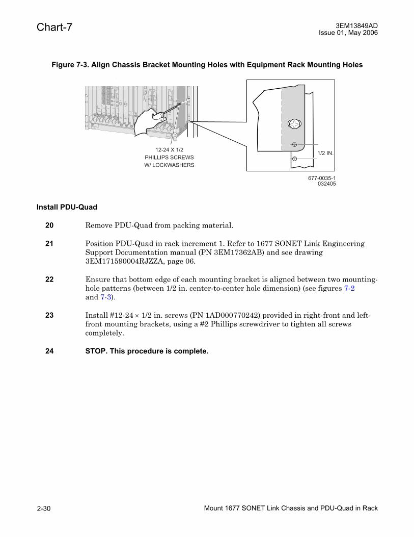
Chart-7 3EM13849ADIssue 01, May 2006
Install PDU-Quad
20 Remove PDU-Quad from packing material.
21 Position PDU-Quad in rack increment 1. Refer to 1677 SONET Link Engineering Support Documentation manual (PN 3EM17362AB) and see drawing 3EM171590004RJZZA, page 06.
22 Ensure that bottom edge of each mounting bracket is aligned between two mounting-hole patterns (between 1/2 in. center-to-center hole dimension) (see figures 7-2 and 7-3).
23 Install #12-24 × 1/2 in. screws (PN 1AD000770242) provided in right-front and left-front mounting brackets, using a #2 Phillips screwdriver to tighten all screws completely.
24 STOP. This procedure is complete.
Figure 7-3. Align Chassis Bracket Mounting Holes with Equipment Rack Mounting Holes
677-0035-1032405
STATUS
DS1EC1
OC12
STATUS
1
Rx
Tx
2
Rx
Tx
3
Rx
Tx
4
Rx
Tx
OC12
STATUS
1
Rx
Tx
2
Rx
Tx
3
Rx
Tx
4
Rx
Tx
LASER
STATUS
MGNTRx
MGNTRx
OC48
LASER
STATUS
MGNTRx
MGNTRx
OC48
STSSWITCH
DCC
DIAG
DIAG
STSSWITCH
DCC
DIAG
DIAG
COMMONCONTROL
PCMCIAA / B
COMMONCONTROL
PCMCIAA / B STATUS
LASER
EDFA
OC192
STATUS
OC192
STATUS
STATUS
TIMING
EXT.
IN-USE
BITS
TIP
TIP
TIP
TIP
RING
RING
RING
RING
GND
GND
GND
GND
A
B
TIMING
E
T
H
E
R
N
E
TC
O
N
S
O
L
E
IN
OUT
IN
OUT
12-24 X 1/2PHILLIPS SCREWSW/ LOCKWASHERS
1/2 IN.
Mount 1677 SONET Link Chassis and PDU-Quad in Rack2-30

Chart-83EM13849ADIssue 01, May 2006
Chart-8Unseat ModulesPURPOSE
This procedure is used to unseat modules in a 1677 SONET Link.
GENERAL
Refer to the 1677 SONET Link Address and Location Guide (PN 3EM13854AB) for module locations.
Modules are not shipped installed; they are shipped in individual electrostatic-sensitive containers. Fan trays are shipped installed in all shelves. With the exception of the fan trays, no other modules should be installed at the start of this procedure. However, instructions are provided for unplugging all modules for reference purposes.
RECOMMENDED TOOLS
Phillips screwdriver, #2 × 6-inch
STEP PROCEDURE
1 DANGER: Possibility of personal injury. Plug-in modules can be installed or removed with rack power on. Hazardous electrical potentials are present; use extreme care when installing or removing modules.
2 WARNING: Possibility of equipment damage. Plug-in modules contain electrostatic-sensitive devices. These devices can be damaged by electrostatic discharge. For special handling instructions, refer to Introduction, Section 3.
3 WARNING: Possibility of equipment damage. To prevent thumbscrew damage, do not use a power screwdriver to loosen thumbscrews.
4 CAUTION: Possibility of service interruption. Use this procedure only for initial installation of a system. Never use this procedure on a traffic-carrying system. To unseat or remove plug-in modules from a system that is turned on or carrying traffic, refer to the 1677 SONET Link Maintenance and Trouble Clearing manual (PN 3EM13853AD).
5 Select action.
To unseat SSC, CCC, or TC, go to step 6.To unseat ECC, EDFA, GIGE, OC-n, TMUX, or VSC, go to step 8.
6 Lift module interlock lever up (see figure 8-1).
Unseat Modules 2-31

Chart-8 3EM13849ADIssue 01, May 2006
7 While pulling ejector handle down, push interlock switch (see figure 8-1) to right.
8 Using a Phillips screwdriver, loosen two captive thumbscrews on module (see figure 8-2).
9 WARNING: Possibility of equipment damage. To prevent thumbscrew damage, do not use a power screwdriver to loosen thumbscrews.
10 Simultaneously, pull upper and lower ejector handles (see figure 8-3).
Ejector handles force module from backplane connectors.
11 Continue pulling on ejector handles until about 2 inches of module extend from slot (see figure 8-3).
12 Have all modules been unseated in shelf?
If yes, go to step 13.If no, go to step 5.
13 In shelf, loosen four captive screws on front of fan tray.
14 Carefully slide out fan tray until about 2 inches of fan tray extends from slot.
15 STOP. This procedure is complete.
Unseat Modules2-32

Chart-83EM13849ADIssue 01, May 2006
Figure 8-1. System Module Interlock (Detail)
Figure 8-2. Captive Thumbscrews (Detail)
677-0272-1050505
A
LEVER FULLY LATCHED LIFT INTERLOCKLEVER UP (1).
WHILE PULLING EJECTORHANDLE DOWN (2a), PUSHINTERLOCK SWITCHOUT (2b).
AFTER UNSCREWINGTHUMBSCREWS, PUSHEJECTOR HANDLEUP (3).
B C D
3
1
2a
2b
Thumbscrew
Phillipsscrewdriver
677-0073-1032003
Unseat Modules 2-33

Chart-8 3EM13849ADIssue 01, May 2006
Figure 8-3. System Module Ejector Handles (detail)
ON 7000
OI
OI
WARNING!THIS PRODUCT CONTAINS
LASER DEVICES. REFER TO
USER MANUAL PRIOR TO REMOVING.
OF
F
ON
OF
F
ON
WARNINGPOWER B
THIS PRODUCT IS EQQUIPEDWITHTWOPOWER FEEDS.
DISCONECT BOTH FEEDS
PRIOR TO SERVICE.
12
1
OC48OC48 STS
RUN
RUN
PRI.
PRI.
HEALTH
HEALTH
IN-USE
IN-USE
SWC
DCC
DIAG
DIAG
SWC
EXT.
TIP
TIP
TIP
TIP
RING
RING
RING
RING
GND
GND
GND
GND
A
B
TIMING
IN
OUT
IN
OUT
TIP
TIP
TIP
TIP
RING
RING
RING
RING
GND
GND
GND
GND
A
B
TIMING
IN
OUT
IN
OC192
STATUS
DS1EC1
STATUS
DS1EC1
RUN
PRI.RUN
89
1011
12 1314
1516
17
STSSWITCH
RUN
RUN
PRI.
PRI.
HEALTH
HEALTH
IN-USE
IN-USE
SWC
DCC
DIAG
DIAG
SWC
DCC
ON 7000
OI
OI
WARNING!THIS PRODUCT CONTAINS
LASER DEVICES. REFER TO
USER MANUAL PRIOR TO REMOVING.
OF
F
ON
OF
F
ON
WARNINGPOWER B
THIS PRODUCT IS EQQUIPEDWITHTWOPOWER FEEDS.
DISCONECT BOTH FEEDS
PRIOR TO SERVICE.
12
1
OC48OC48 STS
RUN
RUN
PRI.
PRI.
HEALTH
HEALTH
IN-USE
IN-USE
SWC
DCC
DIAG
DIAG
SWC
EXT.
TIP
TIP
TIP
TIP
RING
RING
RING
RING
GND
GND
GND
GND
A
B
TIMING
IN
OUT
IN
OUT
TIP
TIP
TIP
TIP
RING
RING
RING
RING
GND
GND
GND
GND
A
B
TIMING
IN
OUT
IN
OC192
STATUS
DS1EC1
STATUS
DS1EC1
RUN
PRI.RUN
89
1011
12 1314
1516
17
STS
SWC
DIAG
RUN
PRI.
HEALTH
IN-USE
SWC
Ejector 2 inches
RUN
PRI.
HEALTH
IN-USE
SWCRUN
PRI.
HEALTH
IN-USE
SWC
DCC
(a) (b)
677-0074-1051705
Unseat Modules2-34

Chart-93EM13849ADIssue 01, May 2006
Chart-9Connect Power Cables Between PDU-Quad and 1677 SONET LinkPURPOSE
Follow this procedure to terminate shelf power cables between the PDU-Quad and 1677 SONET Link shelves installed in the rack.
GENERAL
Alcatel provides expert Installation Services for installations that have different requirements from config option 1 and config option 2 as outlined in this manual. Contact Alcatel at 1-888-252-2832 for details.
RECOMMENDED TOOLS
3/8 in. hex-nut driver, box wrench, or open end wrench
Phillips screwdriver, #2 × 6 in.
STEP PROCEDURE
1 Verify that all PDU-Quad fuses are not installed. See figure 9-1.
2 Remove clear panel from rear of PDU-Quad.
3 At power panel of each 1677 SONET Link installed in rack, set Power A and Power B switches to OFF. See figure 9-2.
Figure 9-1. PDU-Quad (Front View)
677-0254-1102204
FRONT VIEW
A1-
1,T
PA
FU
SE
A2-
2,T
PA
FU
SE
A1-
3,G
MT
FU
SE
A2-
4,G
MT
FU
SE
A2-
3,G
MT
FU
SE
A1-
4,G
MT
FU
SE
A1-
2,T
PA
FU
SE
A2-
1,T
PA
FU
SE
BLOWN TPA FUSE INDICATOR LEDS
B2-
2,T
PA
FU
SE
B1-
1,T
PA
FU
SE
B2-
1,T
PA
FU
SE
B1-
2,T
PA
FU
SE
BLOWN TPA FUSE INDICATOR LEDS
B2-
4,G
MT
FU
SE
B1-
3,G
MT
FU
SE
B1-
4,G
MT
FU
SE
B2-
3,G
MT
FU
SE
A2
PO
WE
RLE
D
B2
PO
WE
RLE
D
FU
SE
ALA
RM
LED
A1
PO
WE
RLE
D
B1
PO
WE
RLE
D
Connect Power Cables Between PDU-Quad and 1677 SONET Link 2-35

Chart-9 3EM13849ADIssue 01, May 2006
4 Using a #2 Phillips screwdriver, remove transparent protective cover from Power A and Power B power connections (see figure 9-2) from each 1677 SONET Link installed in rack.
5 Run and tie down power cables from PDU-Quad to each 1677 SONET Link installed in rack. Refer to 1677 SONET Link Engineering Support Documentation manual (PN 3EM17362AB) and see drawing 3EM171590004RJZZA, page 07.
6 Torque all PDU-Quad lug nuts to 17 inch-pounds.
7 Torque all 1677 SONET Link shelf lug nuts to 20 inch-pounds.
8 Install labels (kit PN 3EM13721DR) onto ends of power cables connected between PDU-Quad and shelf 1 (lower shelf). Install labels 3 inches ± 1 inch from the ends of the cables. Refer to 1677 SONET Link Engineering Support Documentation manual (PN 3EM17362AB) and see drawing 3EM171590004RJZZA, page 07.
9 Is shelf 2 (upper shelf) equipped in rack?
If yes, go to step 10.If no, go to step 11.
10 Install labels (kit PN 3EM13721DS) onto ends of power cables connected between PDU-Quad and shelf 2. Install labels 3 inches ± 1 inch from the ends of the cables. Refer to 1677 SONET Link Engineering Support Documentation manual (PN 3EM17362AB) and see drawing 3EM171590004RJZZA, page 07.
11 Reinstall plastic covers over A and B power connections (see figure 9-2). Tighten screws using #2 Phillips screwdriver.
12 STOP. This procedure is complete.
Figure 9-2. 18RU Shelf Power Panel (Rear of Shelf)
A POWER SWITCH B POWER SWITCH
677-0381-1050106
RTN RTNPOWER A
RTN RTNPOWER B
-48 VDC -48 VDC-48 VDC -48 VDC
PROTECTIVE
PLASTIC COVER(8) 6-32
SCREWS
Connect Power Cables Between PDU-Quad and 1677 SONET Link2-36

Chart-103EM13849ADIssue 01, May 2006
Chart-10Route and Terminate Office Battery Power CablesPURPOSE
Follow this procedure to route and terminate office battery power cables from the office battery source to the PDU-Quad.
Office battery power is not applied in this procedure. Power is applied during initial turn-up. Refer to the 1677 SONET Link Turn-Up manual (PN 3EM13850AB).
GENERAL
For more detailed information, refer to the 1677 SONET Link Engineering Support Documentation manual (PN 3EM17362AB) and see drawing 3EM171590004RJZZA.
Alcatel provides expert Installation Services for installations that have different requirements from config option 1 and config option 2 as outlined in this manual. Contact Alcatel at 1-888-252-2832 for details.
RECOMMENDED TOOLS
Crimp tool and die
Wire compression lug requirements:
• Two-hole, #6, long barrel compression lugs are used to terminate #6 AWG wire used as power cables at the PDU-Quads in the racks. These lugs feature a peephole for visual inspection and verification of proper cable wire insertion.
• 1/4 in. hole diameter with 5/8 in. spacing between centers
These recommended lug sizes are for access to the 1677 SONET Link PDU-Quad. Power cable size requirements from the Power Distribution Bay to the equipment PDU-Quad will be determined on a site-by-site basis per proper power calculations.
#6 gauge cable is required for overhead and raised floor applications. H-taps must be applied to transition from #6 gauge cable to a larger gauge cable to properly access the equipment PDU-Quad and/or the Power Distribution Bay.
STEP PROCEDURE
1 DANGER: Possibility of personal injury. Hazardous electrical potentials are present. Severe arcing is possible and can cause burns or eye injury. Remove rings, watches, and other metal jewelry when working with primary circuits. Exercise caution to avoid shorting power input terminals.
Route and Terminate Office Battery Power Cables 2-37

Chart-10 3EM13849ADIssue 01, May 2006
2 DANGER: Possibility of personal injury. Exercise care during the following test; exposed voltage of up to -56 V dc might be present on terminal.
3 Verify that all PDU-Quad fuses are not installed. See figure 10-1.
4 Verify main CO breakers for A1, A2, B1, and B2 power are off. If not, set them to OFF.
5 Refer to job documentation for rack layout and cable specifications.
Each rack operates on -48 V dc (-42 to -56 V dc) with isolated positive (+) return. Office battery power and return cables are connected to PDU-Quads. These units provide transition from large cables that run between office Battery Distribution Fuse Bay (BDFB) to smaller cables that provide power to rack.
6 WARNING: Possibility of equipment damage. Do not violate minimum bend radius for cable size.
7 Complete an identification tag for each power cable, then attach tag to power cable.
8 #6 gauge cable is required for overhead and raised floor applications. Apply H-taps to transition from larger gauge cable to #6 gauge cable to properly access and connect to the PDU-Quad.
9 Is cable being routed overhead or under floor?
If overhead, go to step 10.If under floor, go to step 12.
Figure 10-1. PDU-Quad (Front View)
677-0254-1102204
FRONT VIEW
A1-
1,T
PA
FU
SE
A2-
2,T
PA
FU
SE
A1-
3,G
MT
FU
SE
A2-
4,G
MT
FU
SE
A2-
3,G
MT
FU
SE
A1-
4,G
MT
FU
SE
A1-
2,T
PA
FU
SE
A2-
1,T
PA
FU
SE
BLOWN TPA FUSE INDICATOR LEDS
B2-
2,T
PA
FU
SE
B1-
1,T
PA
FU
SE
B2-
1,T
PA
FU
SE
B1-
2,T
PA
FU
SE
BLOWN TPA FUSE INDICATOR LEDS
B2-
4,G
MT
FU
SE
B1-
3,G
MT
FU
SE
B1-
4,G
MT
FU
SE
B2-
3,G
MT
FU
SE
A2
PO
WE
RLE
D
B2
PO
WE
RLE
D
FU
SE
ALA
RM
LED
A1
PO
WE
RLE
D
B1
PO
WE
RLE
D
Route and Terminate Office Battery Power Cables2-38

Chart-103EM13849ADIssue 01, May 2006
Power and Frame Ground Routing Overhead
10 Route power cables down from cable ducts to PDU-Quad. Refer to 1677 SONET Link Engineering Support Documentation manual (PN 3EM17362AB) and see drawing 3EM171590004RJZZA, page 08, figure 803.
11 Go to step 16.
Power and Frame Ground Routing Under Floor
12 In a raised floor environment, route power cables through floor access holes. Refer to 1677 SONET Link Engineering Support Documentation manual (PN 3EM17362AB) and see drawing 3EM171590004RJZZA, page 08, figure 801.
13 Route cables up rack and tie power cables to the outside facing surface of cable tie brackets. Eight cable tie brackets are on each side of rack. Refer to 1677 SONET Link Engineering Support Documentation manual (PN 3EM17362AB) and see drawing 3EM171590004RJZZA, page 08, detail 802-A.
14 Extend power cables above top of rack to maintain proper bend radius. Refer to 1677 SONET Link Engineering Support Documentation manual (PN 3EM17362AB) and see drawing 3EM171590004RJZZA, page 08, detail 802-B.
15 Remove and discard top rear fiber duct brackets for raised floor applications to help maintain proper bend radius. These brackets must remain in place for overhead cabling installations.
16 Verify that all A1, A2, B1, and B2 power CO main breakers at BDFB are off; if not, set them to OFF.
17 DANGER: Possibility of personal injury. Short circuiting, low-voltage, low-impedance DC circuits can cause severe arcing that can cause burns or injure eyes. Remove rings, watches, and other metal jewelry while working with primary circuits. Exercise caution to avoid shorting power input terminals.
18 WARNING: Possibility of equipment damage. Do not apply battery power until it is determined that -48 V dc A and B battery cables with isolated returns and power cables are wired correctly.
19 Connect lug of office A1-battery return cable to A1-battery return terminal block on PDU-Quad. Refer to 1677 SONET Link Engineering Support Documentation manual (PN 3EM17362AB) and see drawing 3EM171590004RJZZA, page 08, figure 803.
20 Connect lug of office A2-battery return cable to A2-battery return terminal block on PDU-Quad.
21 Connect lug of office B1-battery return cable to B1-battery return terminal block on PDU-Quad.
Route and Terminate Office Battery Power Cables 2-39

Chart-10 3EM13849ADIssue 01, May 2006
22 Connect lug of office B2-battery return cable to B2-battery return terminal block on PDU-Quad.
23 Connect lug of office A1-battery power cable to A1-battery power terminal block on PDU-Quad.
24 Connect lug of office A2-battery power cable to A2-battery power terminal block on PDU-Quad.
25 Connect lug of office B1-battery power cable to B1-battery power terminal block on PDU-Quad.
26 Connect lug of office B2-battery power cable to B2-battery power terminal block on PDU-Quad.
27 Tie down power cable according to local office practice.
28 Attach loose end of PDU-Quad frame ground cable to rack. Refer to 1677 SONET Link Engineering Support Documentation manual (PN 3EM17362AB) and see drawing 3EM171590004RJZZA, page 08, figure 803.
29 STOP. This procedure is complete.
Route and Terminate Office Battery Power Cables2-40

Chart-113EM13849ADIssue 01, May 2006
Chart-11 Verify PDU-Quad GroundPURPOSE
This procedure is used to verify the isolation of frame, signal, return, and grounding of duplex outlets.
PREREQUISITES
Equipment rack must be disconnected from any power source. Main CO breakers at the BDFB panel are used to disconnect power from the rack.
GENERAL
Alcatel provides expert Installation Services for installations that have different requirements from config option 1 and config option 2 as outlined in this manual. Contact Alcatel at 1-888-252-2832 for details.
REQUIRED TOOL
Digital multimeter (dmm)
STEP PROCEDURE
1 DANGER: Possibility of personal injury. This equipment might contain aluminum electrolytic capacitors that present a potential safety hazard when overstressed. Wear safety glasses and observe all normal safety precautions.
2 DANGER: Possibility of personal injury. Hazardous electrical potentials are present. Severe arcing is possible and can cause burns or eye injury. Remove rings, watches, and other metal jewelry when working with primary circuits. Exercise caution to avoid shorting power input terminals.
3 DANGER: Possibility of personal injury. Exercise care during the following test; exposed voltage of up to -56 V dc might be present on Power Distribution Unit (PDU) circuit panel.
4 WARNING: Possibility of equipment damage. The chassis does not contain main overcurrent protection devices. The user must provide beakers or fuses and disconnects between the power source and the Alcatel 1677 SONET Link.
Verify PDU-Quad Ground 2-41

Chart-11 3EM13849ADIssue 01, May 2006
5 WARNING: Possibility of equipment damage. Each power feed from a source (-48 V dc and Return) requires a 48-amp dc-rated fast-trip circuit breaker or fuse and disconnects. Circuit breakers or fuses must meet applicable local and national electrical safety codes and be approved for the intended application.
6 Verify that all PDU-Quad fuses are not installed. See figure 11-1.
7 Is A1, A2, B1, and B2 power turned on to rack?
If yes, go to step 8.If no, go to step 9.
8 Verify that all A1, A2, B1, and B2 power CO main breakers at BDFB are off; if not, set them to OFF.
9 Remove clear panel from rear of PDU-Quad.
10 Verify that CO ground is connected to rack. See figure 11-2.
11 Set digital multimeter (dmm) to measure ohms.
Figure 11-1. PDU-Quad (Front View)
677-0254-1102204
FRONT VIEW
A1-
1,T
PA
FU
SE
A2-
2,T
PA
FU
SE
A1-
3,G
MT
FU
SE
A2-
4,G
MT
FU
SE
A2-
3,G
MT
FU
SE
A1-
4,G
MT
FU
SE
A1-
2,T
PA
FU
SE
A2-
1,T
PA
FU
SE
BLOWN TPA FUSE INDICATOR LEDS
B2-
2,T
PA
FU
SE
B1-
1,T
PA
FU
SE
B2-
1,T
PA
FU
SE
B1-
2,T
PA
FU
SE
BLOWN TPA FUSE INDICATOR LEDSB
2-4,
GM
TF
US
E
B1-
3,G
MT
FU
SE
B1-
4,G
MT
FU
SE
B2-
3,G
MT
FU
SE
A2
PO
WE
RLE
D
B2
PO
WE
RLE
D
FU
SE
ALA
RM
LED
A1
PO
WE
RLE
D
B1
PO
WE
RLE
D
Verify PDU-Quad Ground2-42

Chart-113EM13849ADIssue 01, May 2006
12 Make sure that contact with foreign objects (i.e. clothing or skin) is not made across measured circuits, as this contact affects the resistance measurement.
Use dmm to measure from frame ground on rear of PDU-Quad to PDU-Quad A1 return. See figure 11-3. Return distribution should be greater than 500 kilohms.
13 Is measured of resistance greater than 500 kilohms?
If yes, go to step 15.If no, go to step 14.
14 Refer to 1677 SONET Link Engineering Support Documentation manual (PN 3EM17362AB) power and ground distribution drawings for battery return paths, and verify there are no shorts to frame ground. Go to step 12.
15 Use dmm to measure from frame ground on rear of PDU-Quad to PDU-Quad A2 return. See figure 11-3. Return distribution should be greater than 500 kilohms.
Figure 11-2. Frame Ground
677-0330-1
REAR VIEW OF RACK
SCREW / WASHER ASSEMBLY(PN 330-2882-000)
TOP MOUNT
LOCKWASHERS
020306
ZINC ELECTRO DEPOSITEDGROUNDING STRIP
Verify PDU-Quad Ground 2-43

Chart-11 3EM13849ADIssue 01, May 2006
16 Is measured of resistance greater than 500 kilohms?
If yes, go to step 18.If no, go to step 17.
17 Refer to 1677 SONET Link Engineering Support Documentation manual (PN 3EM17362AB) power and ground distribution drawings for battery return paths, and verify there are no shorts to frame ground. Go to step 15.
18 Use dmm to measure from frame ground on rear of PDU-Quad to PDU-Quad B1 return. See figure 11-3. Return distribution should be greater than 500 kilohms.
19 Is measured of resistance greater than 500 kilohms?
If yes, go to step 21.If no, go to step 20.
20 Refer to 1677 SONET Link Engineering Support Documentation manual (PN 3EM17362AB) power and ground distribution drawings for battery return paths, and verify there are no shorts to frame ground. Go to step 18.
21 Use dmm to measure from frame ground on rear of PDU-Quad to PDU-Quad B2 return. See figure 11-3. Return distribution should be greater than 500 kilohms.
22 Is measured of resistance greater than 500 kilohms?
If yes, go to step 24.If no, go to step 23.
Figure 11-3. PDU-Quad (Rear View)
677-0255102204
REAR VIEW
A2-
4P
OW
ER
A1-
1P
OW
ER
A2
INP
UT
,-48
V
A2-
3P
OW
ER
A1-
4P
OW
ER
A1-
3P
OW
ER
A2-
2P
OW
ER
A2-
1P
OW
ER
A1-
2P
OW
ER
B1-
1P
OW
ER
B2-
4P
OW
ER
FR
AM
EG
RO
UN
D
B1-
2P
OW
ER
B2-
1P
OW
ER
B2-
2P
OW
ER
B1-
3P
OW
ER
B1-
4P
OW
ER
B2-
3P
OW
ER
A2-
4R
ET
UR
N
A1-
1R
ET
UR
N
A2-
3R
ET
UR
NA
1-4
RE
TU
RN
A1-
3R
ET
UR
NA
2-2
RE
TU
RN
A2-
1R
ET
UR
NA
1-2
RE
TU
RN
B1-
1R
ET
UR
N
B2-
4R
ET
UR
N
B1-
2R
ET
UR
NB
2-1
RE
TU
RN
B2-
2R
ET
UR
NB
1-3
RE
TU
RN
B1-
4R
ET
UR
NB
2-3
RE
TU
RN
A2
INP
UT
,RE
TU
RN
A1
INP
UT
,-48
V
A1
INP
UT
,RE
TU
RN
B1
INP
UT
,-48
V
B1
INP
UT
,RE
TU
RN
B2
INP
UT
,-48
V
B2
INP
UT
,RE
TU
RN
Verify PDU-Quad Ground2-44

Chart-113EM13849ADIssue 01, May 2006
23 Refer to 1677 SONET Link Engineering Support Documentation manual (PN 3EM17362AB) power and ground distribution drawings for battery return paths, and verify there are no shorts to frame ground. Go to step 21.
24 Use dmm to measure continuity from PDU-Quad A1 power to B1 power.
25 Is measured value from PDU-Quad A1 power to B1 power the equivalent of open circuit (infinite resistance) between points?
If yes, go to step 27.If no, go to step 26.
26 Refer to 1677 SONET Link Engineering Support Documentation manual (PN 3EM17362AB) power and ground distribution drawings. Include analysis of fan assembly as a point of failure during troubleshooting. Go to step 24.
27 Use dmm to measure continuity from PDU-Quad A1 power to B2 power.
28 Is measured value from PDU-Quad A1 power to B2 power the equivalent of open circuit (infinite resistance) between points?
If yes, go to step 30.If no, go to step 29.
29 Refer to 1677 SONET Link Engineering Support Documentation manual (PN 3EM17362AB) power and ground distribution drawings. Include analysis of fan assembly as a point of failure during troubleshooting. Go to step 27.
30 Use dmm to measure continuity from PDU-Quad A2 power to B1 power.
31 Is measured value from PDU-Quad A2 power to B1 power the equivalent of open circuit (infinite resistance) between points?
If yes, go to step 33.If no, go to step 32.
32 Refer to 1677 SONET Link Engineering Support Documentation manual (PN 3EM17362AB) power and ground distribution drawings. Include analysis of fan assembly as a point of failure during troubleshooting. Go to step 30.
33 Use dmm to measure continuity from PDU-Quad A2 power to B2 power.
34 Is measured value from PDU-Quad A2 power to B2 power the equivalent of open circuit (infinite resistance) between points?
If yes, go to step 36.If no, go to step 35.
Verify PDU-Quad Ground 2-45

Chart-11 3EM13849ADIssue 01, May 2006
35 Refer to 1677 SONET Link Engineering Support Documentation manual (PN 3EM17362AB) power and ground distribution drawings. Include analysis of fan assembly as a point of failure during troubleshooting. Go to step 33.
36 Is rack equipped with AC outlet?
If yes, go to step 37.If no, go to step 40.
37 Use dmm to measure from frame ground to AC ground.
38 Is measured value from frame ground to AC ground a maximum of 0.5 ohms between points?
If yes, go to step 40.If no, go to step 39.
39 Verify AC wiring and correct if necessary. Go to step 37.
40 Use dmm to measure A1 return cable to B1 return cable in PDU-Quad (see figure 11-3).
41 Is measured value from A1 return cable to B1 return cable greater than 500 kilohms?
If yes, go to step 43.If no, go to step 42.
42 Refer to 1677 SONET Link Engineering Support Documentation manual (PN 3EM17362AB) power and ground distribution drawings for battery return paths, and verify there are no shorts between A1 and B1 returns. Go to step 40.
43 Use dmm to measure A1 return cable to B2 return cable in PDU-Quad (see figure 11-3).
44 Is measured value from A1 return cable to B2 return cable greater than 500 kilohms?
If yes, go to step 46.If no, go to step 45.
45 Refer to 1677 SONET Link Engineering Support Documentation manual (PN 3EM17362AB) power and ground distribution drawings for battery return paths, and verify there are no shorts between A1 and B2 returns. Go to step 43.
46 Use dmm to measure A2 return cable to B1 return cable in PDU-Quad (see figure 11-3).
Verify PDU-Quad Ground2-46

Chart-113EM13849ADIssue 01, May 2006
47 Is measured value from A2 return cable to B1 return cable greater than 500 kilohms?
If yes, go to step 49.If no, go to step 48.
48 Refer to 1677 SONET Link Engineering Support Documentation manual (PN 3EM17362AB) power and ground distribution drawings for battery return paths, and verify there are no shorts between A2 and B1 returns. Go to step 46.
49 Use dmm to measure A2 return cable to B2 return cable in PDU-Quad (see figure 11-3).
50 Is measured value from A2 return cable to B2 return cable greater than 500 kilohms?
If yes, go to step 52.If no, go to step 51.
51 Refer to 1677 SONET Link Engineering Support Documentation manual (PN 3EM17362AB) power and ground distribution drawings for battery return paths, and verify there are no shorts between A2 and B2 returns. Go to step 49.
52 Use dmm to measure from A1 return feeder cable and CO ground feeder cable in PDU-Quad.
53 Is measured value from A1 return feeder cable to CO ground feeder cable greater than 500 kilohms?
If yes, go to step 55.If no, go to step 54.
54 Refer to 1677 SONET Link Engineering Support Documentation manual (PN 3EM17362AB) power and ground distribution drawings for battery return paths, and verify there are no shorts between A1 return feeder and CO ground. Go to step 52.
55 Use dmm to measure from A2 return feeder cable and CO ground feeder cable in PDU-Quad.
56 Is measured value from A2 return feeder cable to CO ground feeder cable greater than 500 kilohms between points?
If yes, go to step 58.If no, go to step 57.
57 Refer to 1677 SONET Link Engineering Support Documentation manual (PN 3EM17362AB) power and ground distribution drawings for battery return paths, and verify there are no shorts between A2 return feeder and CO ground. Go to step 55.
Verify PDU-Quad Ground 2-47

Chart-11 3EM13849ADIssue 01, May 2006
58 Use dmm to measure from B1 return feeder cable and CO ground feeder cable in PDU-Quad.
59 Is measured value from B1 return feeder cable to CO ground feeder cable greater than 500 kilohms between points?
If yes, go to step 61.If no, go to step 60.
60 Refer to 1677 SONET Link Engineering Support Documentation manual (PN 3EM17362AB) power and ground distribution drawings for battery return paths, and verify there are no shorts between B1 return feeder and CO ground. Go to step 58.
61 Use dmm to measure from B2 return feeder cable and CO ground feeder cable in PDU-Quad.
62 Is measured value from B2 return feeder cable to CO ground feeder cable greater than 500 kilohms between points?
If yes, go to step 64.If no, go to step 63.
63 Refer to 1677 SONET Link Engineering Support Documentation manual (PN 3EM17362AB) power and ground distribution drawings for battery return paths, and verify there are no shorts between B2 return feeder and CO ground. Go to step 61.
64 Verify mechanical connections and repair any gaps in metal-to-metal connections.
65 STOP. This procedure is complete.
Verify PDU-Quad Ground2-48

Chart-123EM13849ADIssue 01, May 2006
Chart-12Verify PDU-Quad PowerPURPOSE
This procedure is used to verify source voltage at the PDU-Quad in each rack containing a 1677 SONET Link. The PDU-Quad is capable of supporting two shelves per rack. This procedure verifies both shelves.
GENERAL
Racks served by PDU-Quads do not contain main overcurrent protection devices. The user must provide circuit breakers or fuses and disconnects between the power source and the Alcatel 1677 SONET Link.
Each power feed from a source (-48 V dc and Return) requires a 48-amp DC-rated fast-trip circuit breaker or fuse and disconnects. Circuit breakers or fuses must meet applicable local and national electrical safety codes and be approved for the intended application.
The acceptable voltage range is between -40 V dc and -57.5 V dc.
Alcatel provides expert Installation Services for installations that have different requirements from config option 1 and config option 2 as outlined in this manual. Contact Alcatel at 1-888-252-2832 for details.
REQUIRED TOOL
Digital multimeter (dmm)
STEP PROCEDURE
1 DANGER: Possibility of personal injury. Hazardous electrical potentials are present. Severe arcing is possible and can cause burns or eye injury. Remove rings, watches, and other metal jewelry when working with primary circuits. Exercise caution to avoid shorting power input terminals.
2 Verify that all PDU-Quad fuses are not installed. See figure 12-1.
Verify PDU-Quad Power 2-49

Chart-12 3EM13849ADIssue 01, May 2006
BDFB Power A1 and PDU-Quad
3 At CO BDFB panel, switch A1 BDFB breaker to ON. Ensure A2, B1 and B2 BDFB breakers are OFF.
4 Use digital multimeter (dmm) to measure voltage between A1 INPUT, -48V and A1 INPUT, RETURN power-ground distribution blocks. See figure 12-2.
5 Is voltage present?
If yes, go to step 6.If no, go to step 12.
6 Use dmm to measure voltage between A2 INPUT, -48V and A2 INPUT, RETURN power-ground distribution blocks. See figure 12-2.
7 Is voltage present?
If yes, go to step 12.If no, go to step 8.
8 Use dmm to measure voltage between B1 INPUT, 48V and B1 INPUT, RETURN power-ground distribution blocks. See figure 12-2.
Figure 12-1. PDU-Quad (Front View)
677-0254-1102204
FRONT VIEW
A1-
1,T
PA
FU
SE
A2-
2,T
PA
FU
SE
A1-
3,G
MT
FU
SE
A2-
4,G
MT
FU
SE
A2-
3,G
MT
FU
SE
A1-
4,G
MT
FU
SE
A1-
2,T
PA
FU
SE
A2-
1,T
PA
FU
SE
BLOWN TPA FUSE INDICATOR LEDS
B2-
2,T
PA
FU
SE
B1-
1,T
PA
FU
SE
B2-
1,T
PA
FU
SE
B1-
2,T
PA
FU
SE
BLOWN TPA FUSE INDICATOR LEDS
B2-
4,G
MT
FU
SE
B1-
3,G
MT
FU
SE
B1-
4,G
MT
FU
SE
B2-
3,G
MT
FU
SE
A2
PO
WE
RLE
D
B2
PO
WE
RLE
D
FU
SE
ALA
RM
LED
A1
PO
WE
RLE
D
B1
PO
WE
RLE
D
Verify PDU-Quad Power2-50

Chart-123EM13849ADIssue 01, May 2006
9 Is voltage present?
If yes, go to step 12.If no, go to step 10.
10 Use dmm to measure voltage between B2 INPUT, 48V and B2 INPUT, RETURN power-ground distribution blocks. See figure 12-2.
11 Is voltage present?
If yes, go to step 12.If no, go to step 13.
12 Cable routing problem exists between BDFB and PDU-Quad. Correct problem before proceeding.
BDFB Power A2 and PDU-Quad
13 At CO BDFB panel, switch A2 BDFB breaker to ON. Ensure A1, B1 and B2 BDFB breakers are OFF.
14 Use dmm to measure voltage between A2 INPUT, -48V and A2 INPUT, RETURN power-ground distribution blocks. See figure 12-2.
15 Is voltage present?
If yes, go to step 16.If no, go to step 22.
Figure 12-2. PDU-Quad (Rear view)
677-0255102204
REAR VIEW
A2-
4P
OW
ER
A1-
1P
OW
ER
A2
INP
UT
,-48
V
A2-
3P
OW
ER
A1-
4P
OW
ER
A1-
3P
OW
ER
A2-
2P
OW
ER
A2-
1P
OW
ER
A1-
2P
OW
ER
B1-
1P
OW
ER
B2-
4P
OW
ER
FR
AM
EG
RO
UN
D
B1-
2P
OW
ER
B2-
1P
OW
ER
B2-
2P
OW
ER
B1-
3P
OW
ER
B1-
4P
OW
ER
B2-
3P
OW
ER
A2-
4R
ET
UR
N
A1-
1R
ET
UR
N
A2-
3R
ET
UR
NA
1-4
RE
TU
RN
A1-
3R
ET
UR
NA
2-2
RE
TU
RN
A2-
1R
ET
UR
NA
1-2
RE
TU
RN
B1-
1R
ET
UR
N
B2-
4R
ET
UR
N
B1-
2R
ET
UR
NB
2-1
RE
TU
RN
B2-
2R
ET
UR
NB
1-3
RE
TU
RN
B1-
4R
ET
UR
NB
2-3
RE
TU
RN
A2
INP
UT
,RE
TU
RN
A1
INP
UT
,-48
V
A1
INP
UT
,RE
TU
RN
B1
INP
UT
,-48
V
B1
INP
UT
,RE
TU
RN
B2
INP
UT
,-48
V
B2
INP
UT
,RE
TU
RN
Verify PDU-Quad Power 2-51

Chart-12 3EM13849ADIssue 01, May 2006
16 Use dmm to measure voltage between A1 INPUT, -48V and A1 INPUT, RETURN power-ground distribution blocks. See figure 12-2.
17 Is voltage present?
If yes, go to step 22.If no, go to step 18.
18 Use dmm to measure voltage between B1 INPUT, -48V and B1 INPUT, RETURN power-ground distribution blocks. See figure 12-2.
19 Is voltage present?
If yes, go to step 22.If no, go to step 20.
20 Use dmm to measure voltage between B2 INPUT, -48V and B2 INPUT, RETURN power-ground distribution blocks. See figure 12-2.
21 Is voltage present?
If yes, go to step 22.If no, go to step 23.
22 Cable routing problem exists between BDFB and PDU-Quad. Correct problem before proceeding.
BDFB Power B1 and PDU-Quad
23 At CO BDFB panel, switch B1 BDFB breaker to ON. Ensure A1, A2 and B2 BDFB breakers are OFF.
24 Use dmm to measure voltage between B1 INPUT, -48V and B1 INPUT, RETURN power-ground distribution blocks. See figure 12-2.
25 Is voltage present?
If yes, go to step 26/If no, go to step 32.
26 Use dmm to measure voltage between B2 INPUT, -48V and B2 INPUT, RETURN power-ground distribution blocks. See figure 12-2.
27 Is voltage present?
If yes, go to step 32.If no, go to step 28.
Verify PDU-Quad Power2-52

Chart-123EM13849ADIssue 01, May 2006
28 Use dmm to measure voltage between A1 INPUT, -48V and A1 INPUT, RETURN power-ground distribution blocks. See figure 12-2.
29 Is voltage present?
If yes, go to step 32.If no, go to step 30.
30 Use dmm to measure voltage between A2 INPUT, -48V and A2 INPUT, RETURN power-ground distribution blocks. See figure 12-2.
31 Is voltage present?
If yes, go to step 32.If no, go to step 33.
32 Cable routing problem exists between BDFB and PDU-Quad. Correct problem before proceeding.
BDFB Power B2 and PDU-Quad
33 At CO BDFB panel, switch B2 BDFB breaker to ON. Ensure A1, A2 and B1 BDFB breakers are OFF.
34 Use dmm to measure voltage between B2 INPUT, -48V and B2 INPUT, RETURN power-ground distribution blocks. See figure 12-2.
35 Is voltage present?
If yes, go to step 36/If no, go to step 42.
36 Use dmm to measure voltage between B1 INPUT, -48V and B1 INPUT, RETURN power-ground distribution blocks. See figure 12-2.
37 Is voltage present?
If yes, go to step 42.If no, go to step 38.
38 Use dmm to measure voltage between A1 INPUT, -48V and A1 INPUT, RETURN power-ground distribution blocks. See figure 12-2.
39 Is voltage present?
If yes, go to step 42.If no, go to step 40.
Verify PDU-Quad Power 2-53

Chart-12 3EM13849ADIssue 01, May 2006
40 Use dmm to measure voltage between A2 INPUT, -48V and A2 INPUT, RETURN power-ground distribution blocks. See figure 12-2.
41 Is voltage present?
If yes, go to step 42.If no, go to step 43.
42 Cable routing problem exists between BDFB and PDU-Quad. Correct problem before proceeding.
PDU-Quad LEDs
43 At CO BDFB panel, switch A1 and A2 BDFB breaker to ON.
44 At CO BDFB panel, switch B1 and B2 BDFB breaker to OFF.
45 Are A1 POWER and A2 POWER LEDs on PDU-Quad ON?
If on, go to step 46.If off, troubleshoot CO BDFB panel breakers, then go to step 43.
46 Are B1 POWER and B2 POWER LEDs on PDU-Quad OFF?
If off, go to step 47.If on, troubleshoot CO BDFB panel breakers, then go to step 43.
47 At CO BDFB panel, switch A1 and A2 BDFB breaker to OFF.
48 At CO BDFB panel, switch B1 and B2 BDFB breaker to ON.
49 Are B1 POWER and B2 POWER LEDs on PDU-Quad ON?
If on, go to step 50If off, troubleshoot CO BDFB panel breakers, then go to step 47.
50 Are A1 POWER and A2 POWER LEDs on PDU-Quad OFF?
If off, go to step 51.If on, troubleshoot CO BDFB panel breakers, then go to step 47.
51 At CO BDFB panel, switch A1 and A2 BDFB breaker to ON. (Both A1 and A2 BDFB breaker and B1 and B2 BDFB breaker are now ON.)
52 Are A1 POWER, A2 POWER, B1 POWER, and B2 POWER LEDs on PDU-Quad ON?
If on, go to step 53If off, troubleshoot CO BDFB panel breakers, then go to step 51.
Verify PDU-Quad Power2-54

Chart-123EM13849ADIssue 01, May 2006
53 Replace clear panel on back of PDU-Quad.
54 STOP. This procedure is complete.
Verify PDU-Quad Power 2-55

Chart-12 3EM13849ADIssue 01, May 2006
Verify PDU-Quad Power2-56

Chart-133EM13849ADIssue 01, May 2006
Chart-13Verify Frame GroundPURPOSE
This procedure is used to verify frame grounding of equipment rack and 1677 SONET Link chassis.
STEP PROCEDURE
1 DANGER: Possibility of personal injury. This equipment might contain aluminum electrolytic capacitors that present a potential safety hazard when overstressed. Wear safety glasses and observe all normal safety precautions.
2 DANGER: Possibility of personal injury. Hazardous electrical potentials are present. Severe arcing is possible and can cause burns or eye injury. Remove rings, watches, and other metal jewelry when working with primary circuits. Exercise caution to avoid shorting power input terminals.
3 DANGER: Possibility of personal injury. Exercise care during the following test; exposed voltage of up to -56 V dc might be present on terminal.
4 At power panel, set 1677 SONET Link Power A and Power B switches to OFF. See figure 13-1.
5 Use digital multimeter (dmm) verify voltage does not exist between Power A and RTN and Power B and RTN. See figure 13-1.
6 Set dmm to measure resistance.
7 Use dmm to measure resistance between A battery return and frame ground. Measured resistance includes all wiring from battery return to frame ground.
Figure 13-1. 18RU Shelf Power Panel (Rear of Shelf)
A POWER SWITCH B POWER SWITCH
677-0335-1
032205
RTN RTNPOWER A
RTN RTNPOWER B
-48 VDC -48 VDC-48 VDC -48 VDC
Verify Frame Ground 2-57

Chart-13 3EM13849ADIssue 01, May 2006
8 Is measured value of resistance above 50 ohms?
If yes, troubleshoot and go to step 5.If no, go to step 9.
9 Use dmm to measure resistance between B battery return and frame ground. Measured resistance includes all wiring from battery return to frame ground.
10 Is measured value of resistance above 50 ohms?
If yes, troubleshoot and go to step 9.If no, go to step 12.
11 On BDFB or equivalent, use dmm to measure between frame ground and BDFB return point for A and B return distribution. Make note of measurement.
12 STOP. This procedure is complete.
Verify Frame Ground2-58

Chart-143EM13849ADIssue 01, May 2006
Chart-14Verify Secondary PowerPURPOSE
This procedure is used to verify power source A1, A2, B1, and B2 power is distributed correctly from the PDU-Quad to 1677 SONET Link, and fans operate from the designated power supplies.
GENERAL
Use this procedure only for initial installation of a system. Never use this procedure on a traffic-carrying system. When working with a traffic-carrying system and a module or fan assembly must be replaced or installed, refer to the 1677 SONET Link Maintenance and Trouble Clearing manual (PN 3EM13853AD).
STEP PROCEDURE
1 DANGER: Possibility of personal injury. Hazardous electrical potentials are present. Severe arcing is possible and can cause burns or eye injury. Remove rings, watches, and other metal jewelry when working with primary circuits. Exercise caution to avoid shorting power input terminals.
2 At power panel of each 1677 SONET Link shelf in rack, set Power A and Power B switches to OFF. See figure 14-1.
3 Is shelf to be tested installed in shelf 1 or shelf 2 position?
If shelf 1, go to step 4.If shelf 2, go to step 21.
Shelf 1, A1 Power
4 At CO BDFB panel, ensure all 1677 SONET Link circuit breakers are OFF.
Figure 14-1. 18RU Shelf Power Panel (Rear of Shelf)
A POWER SWITCH B POWER SWITCH
677-0335-1
032205
RTN RTNPOWER A
RTN RTNPOWER B
-48 VDC -48 VDC-48 VDC -48 VDC
Verify Secondary Power 2-59

Chart-14 3EM13849ADIssue 01, May 2006
5 At front of rack, remove all PDU-Quad TPA fuses except for A1-1 (40 amp fuse). See figure 14-2.
6 At CO BDFB panel, set A1 circuit breaker to ON. Circuit breakers A2, B1, and B2 remain OFF. See figure 14-3 for a simplified power routing diagram.
Figure 14-2. PDU-Quad (Front View)
Figure 14-3. BDFB to PDU QUAD Power Routing (Simplified Diagram)
677-0254-1102204
FRONT VIEW
A1-
1,T
PA
FU
SE
A2-
2,T
PA
FU
SE
A1-
3,G
MT
FU
SE
A2-
4,G
MT
FU
SE
A2-
3,G
MT
FU
SE
A1-
4,G
MT
FU
SE
A1-
2,T
PA
FU
SE
A2-
1,T
PA
FU
SE
BLOWN TPA FUSE INDICATOR LEDS
B2-
2,T
PA
FU
SE
B1-
1,T
PA
FU
SE
B2-
1,T
PA
FU
SE
B1-
2,T
PA
FU
SE
BLOWN TPA FUSE INDICATOR LEDS
B2-
4,G
MT
FU
SE
B1-
3,G
MT
FU
SE
B1-
4,G
MT
FU
SE
B2-
3,G
MT
FU
SE
A2
PO
WE
RLE
D
B2
PO
WE
RLE
D
FU
SE
ALA
RM
LED
A1
PO
WE
RLE
D
B1
PO
WE
RLE
D
677-0337-1032205
BDFB
PDU QUAD
SHELF 2
SHELF 1
A1 A2 B1 B2
A1 A2 B1 B2A1
B1
A2
B2
A1 A2 B1 B2
Verify Secondary Power2-60

Chart-143EM13849ADIssue 01, May 2006
7 Verify A1 power LED on PDU-Quad is lighted.
If ON, go to step 8.If OFF, troubleshoot fault, then go to step 4.
8 At shelf 1 power panel, set breaker A to ON and breaker B to OFF. See figure 14-1.
9 Verify fan tray in shelf 2 (if equipped) is not operating.
If ON, troubleshoot fault, then go to step 4.If OFF go to step 10.
10 Is fan tray in shelf 1 operating?
If yes, go to step 11.If no, troubleshoot fault, then go to step 4.
11 DANGER: Possibility of personal injury. Keep fingers away from rotating fan blades. Pull fan tray by thumbscrews only. Wait for fan blades to stop spinning before attempting to remove fan tray completely from the chassis.
12 WARNING: Possibility of equipment damage. Operating a shelf for more than three minutes with the fan tray removed will cause the shelf to overheat.
13 Loosen four captive screws on front of fan tray.
14 Carefully slide out fan tray.
15 Use dmm with needle probes to measure voltages at A Power -48 V dc input connector on shelf 1 fan tray.
16 Verify voltage is between -48 V dc and -57.5 V dc. If necessary, correct power distribution as required locally.
17 Slide fan tray back into place.
18 Tighten four captive screws on front of fan tray.
19 At shelf 1 power panel, set breaker A to OFF. See figure 14-1.
20 At CO BDFB panel, set A1 circuit breaker to OFF.
Shelf 1, B1 Power
21 At front of rack, remove PDU-Quad TPA A1-1 fuse and insert B1-1 (40 amp fuse). See figure 14-2.
Verify Secondary Power 2-61

Chart-14 3EM13849ADIssue 01, May 2006
22 At CO BDFB panel, set B1 circuit breaker to ON. Circuit breakers A1, A2, and B2 remain OFF. See figure 14-3 for a simplified power routing diagram.
23 Verify B1 power LED on PDU-Quad is lighted green.
If ON, go to step 24.If OFF, troubleshoot fault, then go to step 21.
24 At shelf 1 power panel, set breaker A to ON and breaker B to OFF. See figure 14-1.
25 Verify fan tray in shelf 2 (if equipped) is not operating.
If ON, troubleshoot fault, then go to step 21.If OFF, go to step 26.
26 Is fan tray in shelf 1 operating?
If yes, go to step 27.If no, trouble shoot fault, then go to step 21.
27 DANGER: Possibility of personal injury. Keep fingers away from rotating fan blades. Pull fan tray by thumbscrews only. Wait for fan blades to stop spinning before attempting to remove fan tray completely from the chassis.
28 WARNING: Possibility of equipment damage. Operating a shelf for more than three minutes with the fan tray removed will cause the shelf to overheat.
29 Loosen four captive screws on front of fan tray.
30 Carefully slide out fan tray.
31 Use dmm with needle probes to measure voltages at B1 Power -48 V dc input connector on shelf 1 fan tray.
32 Verify voltage is between -48 V dc and -57.5 V dc. If necessary, correct power distribution as required locally.
33 Slide fan tray back into place.
34 Tighten four captive screws on front of fan tray.
35 At shelf 1 power panel, set breaker B to OFF. See figure 14-1.
36 At CO BDFB panel, set B1 circuit breaker to OFF.
37 Go to step 70.
Verify Secondary Power2-62

Chart-143EM13849ADIssue 01, May 2006
Shelf 2, A2 Power
38 At front of rack, remove all PDU-Quad TPA fuses except for A2-1 (40 amp fuse). See figure 14-2. See figure 14-3 for a simplified power routing diagram.
39 At CO BDFB panel, set A2 circuit breaker to ON. Circuit breakers A1, B1, and B2 remain OFF. See figure 14-3 for a simplified power routing diagram.
40 Verify A2 power LED on PDU is lighted green.
If ON, go to step 41.If OFF, troubleshoot fault, then go to step 38.
41 At shelf 2 power panel, set breaker A to ON and breaker B to OFF. See figure 14-1.
42 Verify fan tray in shelf 1 (if equipped) is not operating.
If ON, troubleshoot fault, then go to step 38.If OFF, go to step 43.
43 Is fan tray in shelf 2 operating?
If yes, go to step 44.If no, troubleshoot fault, then go to step 38.
44 DANGER: Possibility of personal injury. Keep fingers away from rotating fan blades. Pull fan tray by thumbscrews only. Wait for fan blades to stop spinning before attempting to remove fan tray completely from the chassis.
45 WARNING: Possibility of equipment damage. Operating a shelf for more than three minutes with the fan tray removed will cause the shelf to overheat.
46 Loosen four captive screws on front of fan tray.
47 Carefully slide out fan tray.
48 Use dmm with needle probes to measure voltages at A Power -48 V dc input connector on shelf 2 fan tray.
49 Verify voltage is between -48 V dc and -57.5 V dc. If necessary, correct power distribution as required locally.
50 Slide fan tray back into place.
51 Tighten four captive screws on front of fan tray.
52 At shelf 2 power panel, set breaker A to OFF. See figure 14-1.
Verify Secondary Power 2-63

Chart-14 3EM13849ADIssue 01, May 2006
53 At CO BDFB panel, set A2 circuit breaker to OFF.
Shelf 2, B2 Power
54 At front of rack, remove PDU-Quad TPA A2-1 fuse and insert B2-1 (40 amp fuse). See figure 14-2.
55 At CO BDFB panel, set B2 circuit breaker to ON. Circuit breakers A1, A2, and B1 remain OFF. See figure 14-3 for a simplified power routing diagram.
56 Verify B2 power LED on PDU-Quad is lighted green.
If ON, go to step 57.If OFF, troubleshoot fault, then go to step 54.
57 At shelf 2 power panel, set breaker A to ON and breaker B to OFF. See figure 14-1.
58 Verify fan tray in shelf 1 (if equipped) is not operating.
If ON, troubleshoot fault, then go to step 54.If OFF, go to step 59.
59 Is fan tray in shelf 2 operating?
If yes, go to step 60.If no, trouble shoot fault, then go to step 54.
60 DANGER: Possibility of personal injury. Keep fingers away from rotating fan blades. Pull fan tray by thumbscrews only. Wait for fan blades to stop spinning before attempting to remove fan tray completely from the chassis.
61 WARNING: Possibility of equipment damage. Operating a shelf for more than three minutes with the fan tray removed will cause the shelf to overheat.
62 Loosen four captive screws on front of fan tray.
63 Carefully slide out fan tray.
64 Use dmm with needle probes to measure voltages at B1 Power -48 V dc input connector on shelf 2 fan tray.
65 Verify voltage is between -48 V dc and -57.5 V dc. If necessary, correct power distribution as required locally.
66 Slide fan tray back into place.
67 Tighten four captive screws on front of fan tray.
Verify Secondary Power2-64

Chart-143EM13849ADIssue 01, May 2006
68 At shelf 2 power panel, set breaker A to OFF. See figure 14-1.
69 At CO BDFB panel, set A2 circuit breaker to OFF.
70 Has secondary power for all 1677 SONET Link shelves in rack been tested?
If yes, go to step 71.If no, go to step 3.
71 At PDU-Quad, remove all fuses.
72 STOP. This procedure is complete.
Verify Secondary Power 2-65

Chart-14 3EM13849ADIssue 01, May 2006
Verify Secondary Power2-66

Chart-153EM13849ADIssue 01, May 2006
Chart-15Install DS1 Splitter and Route Internal Clock CablesThis chart provides instructions to install the DS1 splitters in the rack and route the clock cables from the DS1 splitters to the TC slots of shelves in the rack.
GENERAL
Perform this procedure only for shelves that will use a DS1 splitter. For shelves not using a DS1 splitter, skip this procedure, and perform Chart-17 instead.
Refer to the 1677 SONET Link Engineering Support Documentation manual (PN 3EM17362AB) and see drawing 3EM171590004RJZZA.
Alcatel provides expert Installation Services for installations that have different requirements from config option 1 and config option 2 as outlined in this manual. Contact Alcatel at 1-888-252-2832 for details.
RECOMMENDED TOOLS
Phillips screwdriver
Flat screwdriver
STEP PROCEDURE
1 Select action.
To install DS1 splitter for shelf 1 (lower shelf) in config option 1 rack, go to step 2.To install DS1 splitter for shelf 2 (upper shelf) in config option 1 rack, go to step 5.To install DS1 splitter for shelf 1 (lower shelf) in config option 2 rack, go to step 8.To install DS1 splitter for shelf 2 (upper shelf) in config option 2 rack, go to step 15.
2 Mount DS1 splitter (PN 3EM14189AD) on filler panel at bottom of rack using captive screws. Mount on right side of filler panel (when facing front of rack). Refer to 1677 SONET Link Engineering Support Documentation manual (PN 3EM17362AB) and see drawing 3EM171590004RJZZA, page 09.
3 Route clock cable from splitter box at bottom-right of rack (when facing front of rack) to TC slots in shelf 1. Refer to 1677 SONET Link Engineering Support Documentation manual (PN 3EM17362AB) and see drawing 3EM171590004RJZZA, page 10.
4 Go to step 21.
Install DS1 Splitter and Route Internal Clock Cables 2-67

Chart-15 3EM13849ADIssue 01, May 2006
5 Mount DS1 splitter (PN 3EM14189AE) on filler panel at bottom of rack using captive screws. Mount on left side of filler panel (when facing front of rack). Refer to 1677 SONET Link Engineering Support Documentation manual (PN 3EM17362AB) and see drawing 3EM171590004RJZZA, page 09.
6 Route clock cable from splitter box at bottom-left of rack (when facing front of rack) to TC slots in shelf 2. Refer to 1677 SONET Link Engineering Support Documentation manual (PN 3EM17362AB) and see drawing 3EM171590004RJZZA, page 10.
7 Go to step 21.
8 Is filler panel installed at front or rear of rack?
If front of rack, go to step 9.If rear of rack, go to step 12.
9 Mount DS1 splitter (PN 3EM14189AD) on filler panel at middle of rack using captive screws. Mount on right side of filler panel (when facing front of rack). Refer to 1677 SONET Link Engineering Support Documentation manual (PN 3EM17362AB) and see drawing 3EM171590004RJZZA, page 09.
10 Route clock cable from splitter box at middle-right of rack (when facing front of rack) to TC slots in shelf 1. Refer to 1677 SONET Link Engineering Support Documentation manual (PN 3EM17362AB) and see drawing 3EM171590004RJZZA, page 10.
11 Go to step 21.
12 Mount DS1 splitter (PN 3EM14189AD) on filler panel at middle of rack using captive screws. Mount on left side of filler panel (when facing rear of rack). Refer to 1677 SONET Link Engineering Support Documentation manual (PN 3EM17362AB) and see drawing 3EM171590004RJZZA, page 09.
13 Route clock cable from splitter box at middle-left of rack (when facing rear of rack) to TC slots in shelf 1. Refer to 1677 SONET Link Engineering Support Documentation manual (PN 3EM17362AB) and see drawing 3EM171590004RJZZA, page 10.
14 Go to step 21.
15 Is filler panel installed at front or rear of rack?
If front of rack, go to step 16.If rear of rack, go to step 19.
16 Mount DS1 splitter (PN 3EM14189AE) on filler panel at middle of rack using captive screws. Mount on left side of filler panel (when facing front of rack). Refer to 1677 SONET Link Engineering Support Documentation manual (PN 3EM17362AB) and see drawing 3EM171590004RJZZA, page 09.
Install DS1 Splitter and Route Internal Clock Cables2-68

Chart-153EM13849ADIssue 01, May 2006
17 Route clock cable from splitter box at middle-left of rack (when facing front of rack) to TC slots in shelf 2. Refer to 1677 SONET Link Engineering Support Documentation manual (PN 3EM17362AB) and see drawing 3EM171590004RJZZA, page 10.
18 Go to step 21.
19 Mount DS1 splitter (PN 3EM14189AE) on filler panel at middle of rack using captive screws. Mount on right side of filler panel (when facing rear of rack). Refer to 1677 SONET Link Engineering Support Documentation manual (PN 3EM17362AB) and see drawing 3EM171590004RJZZA, page 09.
20 Route clock cable from splitter box at middle-right of rack (when facing rear of rack) to TC slots in shelf 2. Refer to 1677 SONET Link Engineering Support Documentation manual (PN 3EM17362AB) and see drawing 3EM171590004RJZZA, page 10.
21 Leave BITS clock cable connectors hanging in front of designated TC slots (refer to table 15-A).
22 STOP. This procedure is complete.
Table 15-A. Clock Cable RoutingBITS CLOCK SLOT TC INPUT (FRONT OF TC)Primary 11A A
11B ASecondary 11A B
11B B
Install DS1 Splitter and Route Internal Clock Cables 2-69

Chart-15 3EM13849ADIssue 01, May 2006
Install DS1 Splitter and Route Internal Clock Cables2-70

Chart-163EM13849ADIssue 01, May 2006
Chart-16Route and Terminate External Clock Cables to DS1 SplitterThis chart provides instructions to route the external (local) primary and secondary Building Integrated Timing Supply (BITS) clock cables to the rack, and to install the clock cables from the DS1 splitter to the TC slots of shelves in the rack.
GENERAL
Perform this procedure only for shelves that will use a DS1 splitter. For shelves not using a DS1 splitter, skip this procedure, and perform Chart-17 instead.
Refer to the 1677 SONET Link Engineering Support Documentation manual (PN 3EM17362AB) and see drawing 3EM171590004RJZZA.
Alcatel provides expert Installation Services for installations that have different requirements from config option 1 and config option 2 as outlined in this manual. Contact Alcatel at 1-888-252-2832 for details.
RECOMMENDED TOOLS
Phillips screwdriver
Flat screwdriver
STEP PROCEDURE
1 WARNING: Possibility of equipment damage. Do not exceed minimum bend radius of 1 in. for clock cables.
2 Terminate two sets of primary and secondary CO BITS clock cables with 9-pin D-sub connectors (supplied in field installation kit, PN 3EM171580000AAAA). Refer to 1677 SONET Link Engineering Support Documentation manual (PN 3EM17362AB) and see drawing 3EM171590004RJZZA, page 14.
3 Route connectorized CO BITS clock cables into rack. Refer to 1677 SONET Link Engineering Support Documentation manual (PN 3EM17362AB) and see drawing 3EM171590004RJZZA, page 13.
4 Remove protective fiber cap from CO BITS clock cables.
5 Apply appropriate label (from Field Installation Kit [PN 3EM17158AAAA]) to each CO BITS clock cable before connection to splitter box. The J501 labels are for the primary CO BITS clock cables, and the J502 labels are for the secondary CO BITS clock cables.
6 Connect CO BITS clock cables to splitter box (refer to table 16-A).
Route and Terminate External Clock Cables to DS1 Splitter 2-71

Chart-16 3EM13849ADIssue 01, May 2006
7 STOP. This procedure is complete.
Table 16-A. BITS Clock Cable Connections
CLOCK TYPE DS1 SPLITTER CONNECTORCABLE ROUTE ON RACK(FRONT OF RACK)
Primary J501 Left sideSecondary J502 Right side
Route and Terminate External Clock Cables to DS1 Splitter2-72

Chart-173EM13849ADIssue 01, May 2006
Chart-17Route External Clock Cables to TC SlotsPURPOSE
Follow this procedure to route the primary and secondary Building Integrated Timing Supply (BITS) to the TC slots in the 1677 SONET Link chassis not using a DS1 splitter. The BITS A IN and BITS B IN connections provide redundant paths for the office BITS source. The BITS A OUT and BITS B OUT connections provide two separate DS1 clock references at remote sites that do not have a BITS office reference. The BITS OUT sources are referenced from a line-timed OC-n in the 1677 SONET Link.
GENERAL
Perform this procedure only for shelves that will not use a DS1 splitter. For shelves using a DS1 splitter, skip this procedure, and perform Chart-15 and Chart-16 instead.
Alcatel provides expert Installation Services for installations that have different requirements from config option 1 and config option 2 as outlined in this manual. Contact Alcatel at 1-888-252-2832 for details.
STEP PROCEDURE
1 WARNING: Possibility of equipment damage. This equipment contains static-sensitive devices. Refer to 1677 SONET Link Installation Overview for special handling instructions.
2 Locate BITS office reference sources.
Recommended connection is four separate BITS sources: a primary and a secondary for each TC. If two reference sources are connected (a primary for one TC and a secondary for the other TC), configuration always generates two active alarms. To prevent standing alarms, install jumper to TCs (see figure 17-1) when they are installed during turn-up, as outlined in the 1677 SONET Link Turn-Up manual (PN 3EM13850AB).
3 Select action.
To route four separate sources to node, go to step 4.To route two separate sources to node, go to step 7.
Route External Clock Cables to TC Slots 2-73

Chart-17 3EM13849ADIssue 01, May 2006
Figure 17-1. BITS Wire-Wrap Connection Locations
677-0049-1032405
TC11A
G
TR
TC11B
G
TR
REFER TO NOTE 1
REFER TO NOTE 2DRAIN CABLE WIRE
DRAIN CABLE WIRE
DRAIN DRAINNC*
1-PR T1 CABLE (STP)(REFER TO NOTE 1)
BB
ITS
CL
OC
K
T
R
NC*DRAINDRAIN
R
T AB
ITS
CL
OC
K
1-PR T1 CABLE (STP)(REFER TO NOTE 1)
NOTES:
1. T1, 22 AWG CABLE, AVAYA PN 108672890 (GRAY) OR 108672874 (RED)OR EQUIVALENT
2. DRAIN CABLE WIRE WILL BE GROUNDED AT ONE END ONLY,TYPICALLY AT BITS CLOCK (SOURCE). CUSTOMER MAY REQUIREIT BE GROUNDED AT TC (GND TERMINAL) RATHER THAN THE BITS CLOCK.
* NC = NOT CONNECTED (REFER TO NOTE 2).
TERMINATION OF BITS CLOCK CABLESON 1677 TIMING CARDS
Route External Clock Cables to TC Slots2-74

Chart-173EM13849ADIssue 01, May 2006
Route Four BITS Sources to Node
4 Run four pairs of twisted, shielded 22-AWG ABAM cable from BITS source to TCs in 1677 SONET Link chassis (see figure 17-2). Refer to 1677 SONET Link Engineering Support Documentation manual (PN 3EM17362AB) and see drawing 3EM171590004RJZZA, page 13. Drawing on page 13 shows cables being routed to DS1 splitters; for this procedure, route cable to TCs in shelf instead. Refer to 1677 SONET Link Engineering Support Documentation manual (PN 3EM17362AB) and see drawing 3EM171590004RJZZA, page 10, figure 1002, for cable routing inside shelf to TCs.
5 Leave BITS clock cables hanging in front of designated TC slots (refer to table 17-A).
Figure 17-2. 1677 SONET Link TC Locations
LOCATION OFTIMING CARDS
677-0242-1032405
Route External Clock Cables to TC Slots 2-75

Chart-17 3EM13849ADIssue 01, May 2006
6 Go to step 9.
Connect Two BITS Sources to Node
7 Run two pairs of twisted, shielded 22-AWG ABAM cable from BITS source TCs. Refer to 1677 SONET Link Engineering Support Documentation manual (PN 3EM17362AB) and see drawing 3EM171590004RJZZA, page 13. Drawing on page 13 shows cables being routed to DS1 splitters; for this procedure, route cable to TCs in shelf instead. Refer to 1677 SONET Link Engineering Support Documentation manual (PN 3EM17362AB) and see drawing 3EM171590004RJZZA, page 10, figure 1002, for cable routing inside shelf to TCs.
Primary source (A) is installed at position 11A (A IN) on 1677 SONET Link chassis, and secondary source (B) is installed at position 11B (B IN) (see figure 17-2).
If two reference sources are connected (primary source for a first TC and a secondary source for a second TC), configuration generates two active alarms. Standing alarms are prevented by installing jumper to TC cards, as shown in figure 17-1.
8 Leave BITS clock cables hanging in front of designated TC slots (refer to table 17-B).
9 Does installation require a 1.544 Mb/s signal to BITS office source from 1677 SONET Link?
If yes, go to step 10.If no, go to step 12.
10 Route two more pair of BITS cables between TCs and BITS source. Route cables along same path used in step 4 or step 7. One pair will be connected to BITS A OUT contacts, and the other pair will be connected to BITS B OUT contacts when the TCs are installed in the 1677 SONET Link Turn-Up manual (PN 3EM13850AB).
Table 17-A. Clock Cable RoutingBITS CLOCK SLOT TC INPUT (FRONT OF TC)Primary 11A A
11B ASecondary 11A B
11B B
Table 17-B. Clock Cable RoutingBITS CLOCK SLOT TC INPUT (FRONT OF TC)Primary 11A ASecondary 11B B
Route External Clock Cables to TC Slots2-76

Chart-173EM13849ADIssue 01, May 2006
11 Leave BITS clock cables hanging in front of TC slots 11A and 11B.
12 Update office records.
13 STOP. This procedure is complete.
Route External Clock Cables to TC Slots 2-77

Chart-17 3EM13849ADIssue 01, May 2006
Route External Clock Cables to TC Slots2-78

Chart-183EM13849ADIssue 01, May 2006
Chart-18Install Fiber ManagementPURPOSE
This chart provides instructions to install shelf-level and rack-level fiber management.
GENERAL
Shelf-level fiber management is optionally installed in shelves for config option 1 and config option 2. Rack-level fiber management is installed only for config option 1.
For more detailed information, refer to the 1677 SONET Link Engineering Support Documentation manual (PN 3EM17362AB) and see drawing 3EM171590004RJZZA.
Alcatel provides expert Installation Services for installations that have different requirements from config option 1 and config option 2 as outlined in this manual. Contact Alcatel at 1-888-252-2832 for details.
RECOMMENDED TOOLS
Phillips screw driver
STEP PROCEDURE
1 Use site plan to determine configuration of system.
2 Is shelf-level fiber management being installed?
If yes, go to step 3.If no, go to step 4.
3 Attach all shelf-level fiber management hardware to shelf. Refer to the 1677 SONET Link Engineering Support Documentation manual (PN 3EM17362AB) and see drawing 3EM171590004RJZZA, page 11.
4 Select configuration.
If config option 1, go to step 5.If config option 2, go to step 13.
5 Select action.
For raised-floor application, go to step 6.for overhead application, go to step 7.
Install Fiber Management 2-79

Chart-18 3EM13849ADIssue 01, May 2006
6 Move all flex-tube holders (PN 4-29000-1150) from top-left and top-right assemblies to bottom-left and bottom-right assemblies, respectively. See figure 18-1 for flex-tube holder locations. Refer to the 1677 SONET Link Engineering Support Documentation manual (PN 3EM17362AB) and see drawing 3EM171590004RJZZA, page 12, detail 1201-A.
7 Install top-left, top-right, bottom-left, and bottom-right assemblies to front of rack. Refer to the 1677 SONET Link Engineering Support Documentation manual (PN 3EM17362AB) and see drawing 3EM171590004RJZZA, page 12.
8 Join top-left assembly to bottom-left assembly. Refer to the 1677 SONET Link Engineering Support Documentation manual (PN 3EM17362AB) and see drawing 3EM171590004RJZZA, page 12, detail 1201-B.
9 Join top-right assembly to bottom-right assembly. Refer to the 1677 SONET Link Engineering Support Documentation manual (PN 3EM17362AB) and see drawing 3EM171590004RJZZA, page 12, detail 1201-B.
10 Install second layer of radius-limiting spools onto existing spools on assemblies. Refer to the 1677 SONET Link Engineering Support Documentation manual (PN 3EM17362AB) and see drawing 3EM171590004RJZZA, page 12, detail 1201-C and detail 1201-D.
11 Install rear middle kick plate. Refer to the 1677 SONET Link Engineering Support Documentation manual (PN 3EM17362AB) and see drawing 3EM171590004RJZZA, page 11.
12 Install front middle kick plate. Refer to the 1677 SONET Link Engineering Support Documentation manual (PN 3EM17362AB) and see drawing 3EM171590004RJZZA, page 12.
13 STOP. This procedure is complete.
Install Fiber Management2-80

Chart-183EM13849ADIssue 01, May 2006
Figure 18-1. Flex-Tube Holder Locations
677-0382-1020606
NEW LOCATIONS FOR FLEX-TUBE HOLDERSFOR RAISED-FLOOR APPLICATION
RIGHT SIDELEFT SIDE
FACTORY-INSTALLED FLEX-TUBE HOLDERS
Install Fiber Management 2-81

Chart-18 3EM13849ADIssue 01, May 2006
Install Fiber Management2-82

Chart-193EM13849ADIssue 01, May 2006
Chart-19Route Central Office OC-n Signal CablesPURPOSE
This chart provides instructions to route Central Office (CO) OC-n fiber-optic signal cables to 1677 SONET Link IOC modules. Optical cables are routed to staging positions in front of shelf slots, to be terminated when modules are installed.
GENERAL
Customer fiber-optic cables carry traffic signals from CO Network Elements (NEs) to and from 1677 SONET Link IOC modules. For detailed information, refer to the 1677 SONET Link Engineering Support Documentation manual (PN 3EM17362AB) and see drawing 3EM171590004RJZZA.
Alcatel provides expert Installation Services for installations that have different requirements from config option 1 and config option 2 as outlined in this manual. Contact Alcatel at 1-888-252-2832 for details.
STEP PROCEDURE
1 WARNING: Possibility of equipment damage. Dress fiber-optic optical cables with a bend radii greater than 1 in.
2 Refer to job documentation for port configuration and cable specification.
3 Complete an identification tag for each cable (if not supplied) and attach tag to cable. Use the following label format:
AID-Rack-Shelf-Slot: RX/TX.
4 Run working and protect optical fibers through overhead or raised-floor fiber channel panduit ducts to rack. Run working fibers to left side of rack (as viewed from front of rack), and run protect fibers to right side of rack (as viewed from front of rack). Follow diversity rules if applicable.
5 Are optical cables being run to a rack with config option 1 or config option 2?
If config option 1, go to step 6.If config option 2, go to step 29.
6 Are optical cables installed in raised-floor or cable-ladder environment?
If raised-floor environment, go to step 7.If cable-ladder environment, go to step 12.
Route Central Office OC-n Signal Cables 2-83

Chart-19 3EM13849ADIssue 01, May 2006
7 Position flex-hose tubing under rack and attach to flex-tube holders mounted at bottom of fiber management. Flex-hose tubing that supports working fibers enters fiber access hole on left side of rack base (as viewed from front of rack). Flex-hose tubing that supports protect fibers enters fiber access hole on right side of rack base (as viewed from front of rack). Refer to the 1677 SONET Link Engineering Support Documentation manual (PN 3EM17362AB) and see drawing 3EM171590004RJZZA, page 15.
8 Route working optical cables out of office panduit and up and into flex hose tubing under rack on front-left side (as viewed from front of rack). If rack supports two shelves, start with lower shelf, and cable up to upper shelf. Refer to the 1677 SONET Link Engineering Support Documentation manual (PN 3EM17362AB) and see drawing 3EM171590004RJZZA, page 15.
9 Route working optical cables up and into bottom of front-left rack panduit. Refer to the 1677 SONET Link Engineering Support Documentation manual (PN 3EM17362AB) and see drawing 3EM171590004RJZZA, page 15, figure 1501.
10 Route working optical cables up, using captive black retainer clips, and exit cables out of panduit at appropriate (upper or lower) exit bracket to enter fiber storage area. Refer to the 1677 SONET Link Engineering Support Documentation manual (PN 3EM17362AB) and see drawing 3EM171590004RJZZA, page 15, figures 1502 and 1503.
11 Go to step 16.
12 Position flex-hose tubing above rack and attach to flex-tube holders mounted at top of fiber management. Flex-hose tubing that supports working fibers enters fiber access hole on upper-left side of rack (as viewed from front of rack). Flex-hose tubing that supports protect fibers enters fiber access hole on upper-right side of rack (as viewed from front of rack). Refer to the 1677 SONET Link Engineering Support Documentation manual (PN 3EM17362AB) and see drawing 3EM171590004RJZZA, page 15, detail 1502-A.
13 Route working optical cables down from office panduit, into flex hose fiber duct on front left of rack (when viewed from front of rack). If rack supports two shelves, start with upper shelf, and cable down to lower shelf.
14 Route working optical cables down into top of front-left rack panduit.
15 Route working optical cables down, using captive black retainer clips, and exit cables out of panduit at appropriate (upper or lower) exit bracket to enter fiber storage area. Refer to the 1677 SONET Link Engineering Support Documentation manual (PN 3EM17362AB) and see drawing 3EM171590004RJZZA, page 15, figures 1502 and 1503.
Route Central Office OC-n Signal Cables2-84

Chart-193EM13849ADIssue 01, May 2006
16 Route working optical cables across guides on front of shelf to designated IOC module. Refer to the 1677 SONET Link Engineering Support Documentation manual (PN 3EM17362AB) and see drawing 3EM171590004RJZZA, page 15, detail 1502-B.
Use guides on top of shelf to access top modules containing straight optical connectors; use guides at bottom of shelf to access all bottom modules and top modules containing downward facing connectors.
17 Leave working optical cable connectors in front of designated IOC module slots.
18 Are protect optical cables installed in raised floor or cable ladder environment?
If raised floor, go to step 19.If cable ladder, go to step 23.
19 Route protect optical cables out of office panduit and up and into flex hose tubing under rack on front-right side (as viewed from front of rack). If rack supports two shelves, start with lower shelf, and cable up to upper shelf. Refer to the 1677 SONET Link Engineering Support Documentation manual (PN 3EM17362AB) and see drawing 3EM171590004RJZZA, page 15.
20 Route protect optical cables up and into bottom of front-right rack panduit. Refer to the 1677 SONET Link Engineering Support Documentation manual (PN 3EM17362AB) and see drawing 3EM171590004RJZZA, page 15, figure 1501.
21 Route protect optical cables up, using captive black retainer clips, and exit cables out of panduit at appropriate (upper or lower) exit bracket to enter fiber storage area. Refer to the 1677 SONET Link Engineering Support Documentation manual (PN 3EM17362AB) and see drawing 3EM171590004RJZZA, page 15, figures 1502 and 1503.
22 Go to step 26.
23 Route protect optical cables down from office panduit, into flex hose fiber duct on front-right of rack (when viewed from front of rack). If rack supports two shelves, start with upper shelf, and cable down to lower shelf.
24 Route protect optical cables down into top of front-right rack panduit.
25 Route protect optical cables down, using captive black retainer clips, and exit cables out of panduit at appropriate (upper or lower) exit bracket to enter fiber storage area. Refer to the 1677 SONET Link Engineering Support Documentation manual (PN 3EM17362AB) and see drawing 3EM171590004RJZZA, page 15, figures 1502 and 1503.
Route Central Office OC-n Signal Cables 2-85

Chart-19 3EM13849ADIssue 01, May 2006
26 Route protect optical cables across guides on front of shelf to designated IOC modules. Refer to the 1677 SONET Link Engineering Support Documentation manual (PN 3EM17362AB) and see drawing 3EM171590004RJZZA, page 15, detail 1502-B.
Use guides on top of shelf to access top modules containing straight optical connectors; use guides at bottom of shelf to access all bottom modules and top modules containing downward facing connectors.
27 Leave protect optical cable connectors in front of designated IOC module slots.
28 Go to step 51.
29 Are optical cables installed in raised-floor or cable-ladder environment?
If raised-floor environment, go to step 7.If cable-ladder environment, go to step 12.
30 Position flex-hose tubing under rack. Flex-hose tubing that supports working fibers enters fiber access hole on left side of rack base (as viewed from front of rack). Flex-hose tubing that supports protect fibers enters fiber access hole on right side of rack base (as viewed from front of rack). Refer to the 1677 SONET Link Engineering Support Documentation manual (PN 3EM17362AB) and see drawing 3EM171590004RJZZA, page 16.
31 Route working optical cables out of office panduit and up and into flex hose tubing under rack on front-left side (as viewed from front of rack). If rack supports two shelves, start with lower shelf, and cable up to upper shelf. Refer to the 1677 SONET Link Engineering Support Documentation manual (PN 3EM17362AB) and see drawing 3EM171590004RJZZA, page 16.
32 Route working optical cables up and into bottom of front-left rack panduit. Refer to the 1677 SONET Link Engineering Support Documentation manual (PN 3EM17362AB) and see drawing 3EM171590004RJZZA, page 16, figure 1601.
33 Route working optical cables up, and exit cables out of panduit at appropriate height to enter shelf. Refer to the 1677 SONET Link Engineering Support Documentation manual (PN 3EM17362AB) and see drawing 3EM171590004RJZZA, page 16, figure 1602.
34 Go to step 39.
35 Position flex-hose tubing above rack. Flex-hose tubing that supports working fibers enters fiber access hole on upper-left side of rack (as viewed from front of rack). Flex-hose tubing that supports protect fibers enters fiber access hole on upper-right side of rack (as viewed from front of rack). Refer to the 1677 SONET Link Engineering Support Documentation manual (PN 3EM17362AB) and see drawing 3EM171590004RJZZA, page 16.
Route Central Office OC-n Signal Cables2-86

Chart-193EM13849ADIssue 01, May 2006
36 Route working optical cables down from office panduit, into flex hose fiber duct on front left of rack (when viewed from front of rack). If rack supports two shelves, start with upper shelf, and cable down to lower shelf.
37 Route working optical cables down into top of front-left rack panduit.
38 Route working optical cables down, and exit cables out of panduit at appropriate height to enter shelf. Refer to the 1677 SONET Link Engineering Support Documentation manual (PN 3EM17362AB) and see drawing 3EM171590004RJZZA, page 16, figure 1602.
39 Route working optical cables across guides on front of shelf to designated IOC module. Refer to the 1677 SONET Link Engineering Support Documentation manual (PN 3EM17362AB) and see drawing 3EM171590004RJZZA, page 16, details 1602-A and 1602-B.
Use guides on top of shelf to access top modules containing straight optical connectors; use guides at bottom of shelf to access all bottom modules and top modules containing downward facing connectors.
40 Leave working optical cable connectors in front of designated IOC module slots.
41 Are protect optical cables installed in raised floor or cable ladder environment?
If raised floor, go to step 42.If cable ladder, go to step 46.
42 Route protect optical cables out of office panduit and up and into flex hose tubing under rack on front-right side (as viewed from front of rack). If rack supports two shelves, start with lower shelf, and cable up to upper shelf. Refer to the 1677 SONET Link Engineering Support Documentation manual (PN 3EM17362AB) and see drawing 3EM171590004RJZZA, page 16.
43 Route protect optical cables up and into bottom of front-right rack panduit. Refer to the 1677 SONET Link Engineering Support Documentation manual (PN 3EM17362AB) and see drawing 3EM171590004RJZZA, page 16, figure 1601.
44 Route protect optical cables up, and exit cables out of panduit at appropriate height to enter shelf. Refer to the 1677 SONET Link Engineering Support Documentation manual (PN 3EM17362AB) and see drawing 3EM171590004RJZZA, page 16, figure 1602.
45 Go to step 49.
46 Route protect optical cables down from office panduit, into flex hose fiber duct on front-right of rack (when viewed from front of rack). If rack supports two shelves, start with upper shelf, and cable down to lower shelf.
Route Central Office OC-n Signal Cables 2-87

Chart-19 3EM13849ADIssue 01, May 2006
47 Route protect optical cables down into top of front-right rack panduit.
48 Route protect optical cables down, and exit cables out of panduit at appropriate height to enter shelf. Refer to the 1677 SONET Link Engineering Support Documentation manual (PN 3EM17362AB) and see drawing 3EM171590004RJZZA, page 16, figure 1602.
49 Route protect optical cables across guides on front of shelf to designated IOC modules. Refer to the 1677 SONET Link Engineering Support Documentation manual (PN 3EM17362AB) and see drawing 3EM171590004RJZZA, page 16, details 1602-A and 1602-B.
Use guides on top of shelf to access top modules containing straight optical connectors; use guides at bottom of shelf to access all bottom modules and top modules containing downward facing connectors.
50 Leave protect optical cable connectors in front of designated IOC module slots.
51 Cut optical connector dust cap captive leads from optical cables.
52 Leave dust caps on optical connectors and discard severed leads.
Dust caps are removed and stored/discarded later when connected to IOC module ports.
53 Dress optical cables according to local practice.
54 STOP. This procedure is complete.
Route Central Office OC-n Signal Cables2-88

Chart-203EM13849ADIssue 01, May 2006
Chart-20Route Central Office GigE Signal CablesPURPOSE
This chart provides instructions to route Central Office (CO) GigE signal cables to 1677 SONET Link GIGE modules. GigE cables are routed to staging positions in front of shelf slots, to be terminated when modules are installed.
GENERAL
Customer GigE cables carry traffic signals from CO Network Elements (NEs) to and from 1677 SONET Link GIGE modules. For detailed information, refer to the 1677 SONET Link Engineering Support Documentation manual (PN 3EM17362AB) and see drawing 3EM171590004RJZZA.
Alcatel provides expert Installation Services for installations that have different requirements from config option 1 and config option 2 as outlined in this manual. Contact Alcatel at 1-888-252-2832 for details.
STEP PROCEDURE
1 Refer to job documentation for port configuration and cable specification.
2 Complete an identification tag for each cable (if not supplied) and attach tag to cable. Use the following label format:
AID-Rack-Shelf-Slot: RX/TX.
3 Run GigE cables through overhead or raised-floor fiber channel panduit ducts to rack. Run GigE cables that support modules in left side of shelf to left side of rack (as viewed from front of rack), and run GigE cables that support modules in right side of shelf to right side of rack (as viewed from front of rack). Follow diversity rules if applicable.
4 Are GigE cables being run to a rack with config option 1 or config option 2?
If config option 1, go to step 5.If config option 2, go to step 18.
5 Are GigE cables installed in raised-floor or cable-ladder environment?
If raised-floor environment, go to step 6.If cable-ladder environment, go to step 11.
Route Central Office GigE Signal Cables 2-89

Chart-20 3EM13849ADIssue 01, May 2006
6 Position flex-hose tubing under rack and attach to flex-tube holders mounted at bottom of fiber management on left and right sides. Refer to the 1677 SONET Link Engineering Support Documentation manual (PN 3EM17362AB) and see drawing 3EM171590004RJZZA, page 15.
7 Route GigE cables out of office panduit and up and into flex hose tubing under rack on front-left or front-right side (as viewed from front of rack) as appropriate for GIGE module location in shelf. If rack supports two shelves, start with lower shelf, and cable up to upper shelf. Refer to the 1677 SONET Link Engineering Support Documentation manual (PN 3EM17362AB) and see drawing 3EM171590004RJZZA, page 15.
8 Route GigE cables up and into bottom of front-left or front-right rack panduit. Refer to the 1677 SONET Link Engineering Support Documentation manual (PN 3EM17362AB) and see drawing 3EM171590004RJZZA, page 15, figure 1501.
9 Route GigE cables up, using captive black retainer clips, and exit cables out of panduit at appropriate (upper or lower) exit bracket to enter fiber storage area. Refer to the 1677 SONET Link Engineering Support Documentation manual (PN 3EM17362AB) and see drawing 3EM171590004RJZZA, page 15, figures 1502 and 1503.
10 Go to step 15.
11 Position flex-hose tubing above rack and attach to flex-tube holders mounted at top of fiber management on left and right sides. Refer to the 1677 SONET Link Engineering Support Documentation manual (PN 3EM17362AB) and see drawing 3EM171590004RJZZA, page 15, detail 1502-A.
12 Route GigE cables down from office panduit, into flex hose fiber duct on front-left or front-right of rack (when viewed from front of rack), as appropriate for module location in shelf. If rack supports two shelves, start with upper shelf, and cable down to lower shelf.
13 Route GigE cables down into top of front-left or front-right rack panduit.
14 Route GigE cables down, using captive black retainer clips, and exit cables out of panduit at appropriate (upper or lower) exit bracket to enter fiber storage area. Refer to the 1677 SONET Link Engineering Support Documentation manual (PN 3EM17362AB) and see drawing 3EM171590004RJZZA, page 15, figures 1502 and 1503.
Route Central Office GigE Signal Cables2-90

Chart-203EM13849ADIssue 01, May 2006
15 Route GigE cables across guides on front of shelf to designated GIGE module. Refer to the 1677 SONET Link Engineering Support Documentation manual (PN 3EM17362AB) and see drawing 3EM171590004RJZZA, page 15, detail 1502-B.
Use guides on top of shelf to access top modules containing straight optical connectors; use guides at bottom of shelf to access all bottom modules and top modules containing downward facing connectors.
16 Leave working GigE cable connectors in front of designated GIGE module slots.
17 Go to step 30.
18 Are GigE cables installed in raised-floor or cable-ladder environment?
If raised-floor environment, go to step 6.If cable-ladder environment, go to step 11.
19 Position flex-hose tubing under rack on right and left sides. Refer to the 1677 SONET Link Engineering Support Documentation manual (PN 3EM17362AB) and see drawing 3EM171590004RJZZA, page 16.
20 Route GigE cables out of office panduit and up and into flex hose tubing under rack on front-left or front-right side (as viewed from front of rack), as appropriate for module location in shelf. If rack supports two shelves, start with lower shelf, and cable up to upper shelf. Refer to the 1677 SONET Link Engineering Support Documentation manual (PN 3EM17362AB) and see drawing 3EM171590004RJZZA, page 16.
21 Route GigE cables up and into bottom of front-left or front-right rack panduit. Refer to the 1677 SONET Link Engineering Support Documentation manual (PN 3EM17362AB) and see drawing 3EM171590004RJZZA, page 16, figure 1601.
22 Route GigE cables up, and exit cables out of panduit at appropriate height to enter shelf. Refer to the 1677 SONET Link Engineering Support Documentation manual (PN 3EM17362AB) and see drawing 3EM171590004RJZZA, page 16, figure 1602.
23 Go to step 28.
24 Position flex-hose tubing above rack on right and left sides. Refer to the 1677 SONET Link Engineering Support Documentation manual (PN 3EM17362AB) and see drawing 3EM171590004RJZZA, page 16.
25 Route GigE cables down from office panduit, into flex hose fiber duct on front-left or front-right of rack (when viewed from front of rack), as appropriate for module location in shelf. If rack supports two shelves, start with upper shelf, and cable down to lower shelf.
26 Route GigE cables down into top of front-left or front-right rack panduit.
Route Central Office GigE Signal Cables 2-91

Chart-20 3EM13849ADIssue 01, May 2006
27 Route GigE cables down, and exit cables out of panduit at appropriate height to enter shelf. Refer to the 1677 SONET Link Engineering Support Documentation manual (PN 3EM17362AB) and see drawing 3EM171590004RJZZA, page 16, figure 1602.
28 Route GigE cables across guides on front of shelf to designated GIGE module. Refer to the 1677 SONET Link Engineering Support Documentation manual (PN 3EM17362AB) and see drawing 3EM171590004RJZZA, page 16, details 1602-A and 1602-B.
Use guides on top of shelf to access top modules containing straight GigE connectors; use guides at bottom of shelf to access all bottom modules and top modules containing downward facing connectors.
29 Leave GigE cable connectors in front of designated GIGE module slots.
30 Cut GigE connector dust cap captive leads from GigE cables.
31 Leave dust caps on GigE connectors and discard severed leads.
Dust caps are removed and stored/discarded later when connected to GIGE module ports.
32 Dress GigE cables according to local practice.
33 STOP. This procedure is complete.
Route Central Office GigE Signal Cables2-92
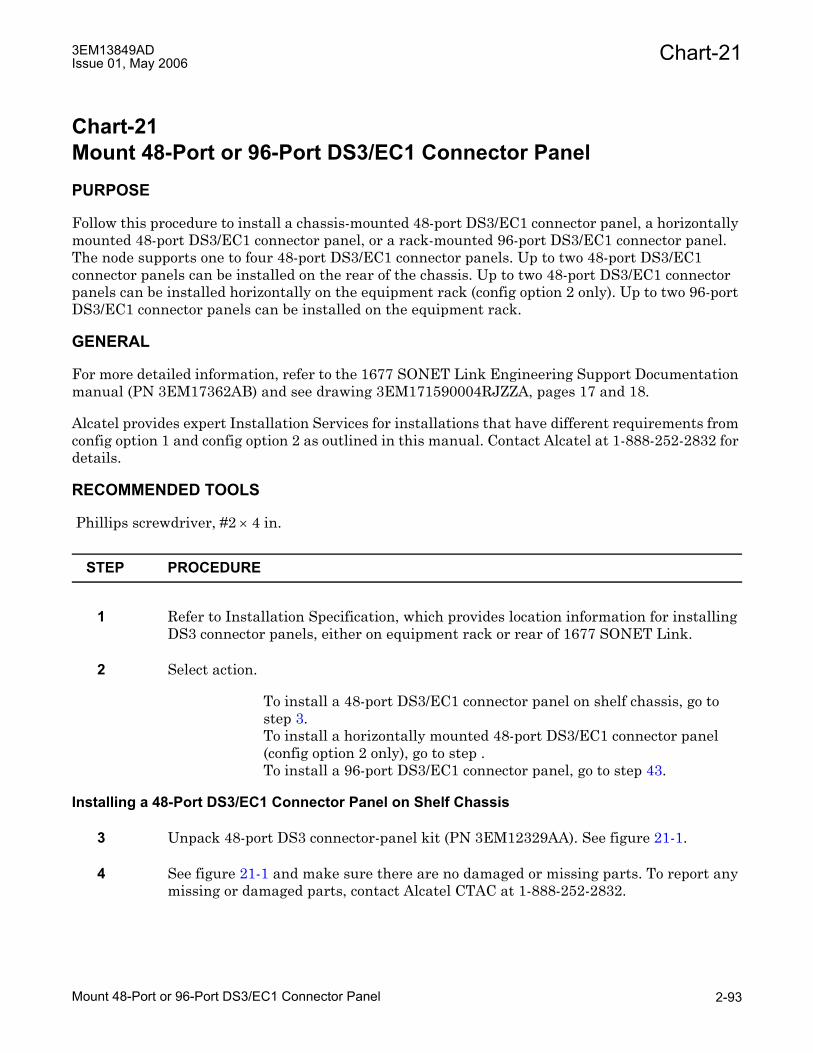
Chart-213EM13849ADIssue 01, May 2006
Chart-21 Mount 48-Port or 96-Port DS3/EC1 Connector PanelPURPOSE
Follow this procedure to install a chassis-mounted 48-port DS3/EC1 connector panel, a horizontally mounted 48-port DS3/EC1 connector panel, or a rack-mounted 96-port DS3/EC1 connector panel. The node supports one to four 48-port DS3/EC1 connector panels. Up to two 48-port DS3/EC1 connector panels can be installed on the rear of the chassis. Up to two 48-port DS3/EC1 connector panels can be installed horizontally on the equipment rack (config option 2 only). Up to two 96-port DS3/EC1 connector panels can be installed on the equipment rack.
GENERAL
For more detailed information, refer to the 1677 SONET Link Engineering Support Documentation manual (PN 3EM17362AB) and see drawing 3EM171590004RJZZA, pages 17 and 18.
Alcatel provides expert Installation Services for installations that have different requirements from config option 1 and config option 2 as outlined in this manual. Contact Alcatel at 1-888-252-2832 for details.
RECOMMENDED TOOLS
Phillips screwdriver, #2 × 4 in.
STEP PROCEDURE
1 Refer to Installation Specification, which provides location information for installing DS3 connector panels, either on equipment rack or rear of 1677 SONET Link.
2 Select action.
To install a 48-port DS3/EC1 connector panel on shelf chassis, go to step 3.To install a horizontally mounted 48-port DS3/EC1 connector panel (config option 2 only), go to step .To install a 96-port DS3/EC1 connector panel, go to step 43.
Installing a 48-Port DS3/EC1 Connector Panel on Shelf Chassis
3 Unpack 48-port DS3 connector-panel kit (PN 3EM12329AA). See figure 21-1.
4 See figure 21-1 and make sure there are no damaged or missing parts. To report any missing or damaged parts, contact Alcatel CTAC at 1-888-252-2832.
Mount 48-Port or 96-Port DS3/EC1 Connector Panel 2-93

Chart-21 3EM13849ADIssue 01, May 2006
5 Attach four cable-tie brackets to connector panel (see figure 21-2) as follows:
a. Insert alignment pin on bracket in top hole and secure each side of bracket with a 6-32 × 3/8 in. Phillips flathead screw in bottom threaded hole.
b. Tighten screws with a #2 Phillips screwdriver.
6 Locate connector 13B-16B or 2B-5B on rear of 1677 SONET Link onto which 48-port DS3/EC1 connector panel is to be installed (see figure 21-3).
7 Using a #2 Phillips screwdriver, remove appropriate connector access cover (see figure 21-4) at rear of chassis, and save it and attaching screws for possible future use.
8 Remove warning label that covers connector on 48-port DS3/EC1 connector panel.
9 Align two guide pins on 48-port DS3/EC1 connector panel with two guide holes in chassis.
10 WARNING: Possibility of equipment damage. To prevent damage to connector pins, do not force panel into connector. Make sure panel connector aligns with chassis connector before seating it.
11 Gently press 48-port DS3/EC1 connector panel into connector on rear of 1677 SONET Link until it seats. Do not force it.
Figure 21-1. Chassis-Mounted 48-Port DS3/EC1 Connector Panel Kit
677-0038-1042805
(8) 6-32 X 3/8PHILLIPS
FLATHEAD SCREWS
(4) CABLE-TIEBRACKETS
(1) 48-PORT DS3/EC1CONNECTOR PANEL
Mount 48-Port or 96-Port DS3/EC1 Connector Panel2-94

Chart-213EM13849ADIssue 01, May 2006
Figure 21-2. Cable-Tie Brackets Attached to Chassis-Mounted 48-Port DS3/EC1 Connector Panel
Figure 21-3. 1677 SONET Link Rear Connectors
677-0039-1032405
(8) 6-32 X 3/8PHILLIPS
FLATHEAD SCREWS
ALIGNMENTPIN
677-0040-1032405
SLOT
2B13B
SLOT
3B14B
SLOT
4B15B
SLOT
5B16B
13B-16BCONNECTOR
13A-16ACONNECTOR
2B-5BCONNECTOR
2A-5ACONNECTOR
REAR VIEW
Mount 48-Port or 96-Port DS3/EC1 Connector Panel 2-95

Chart-21 3EM13849ADIssue 01, May 2006
12 Align four captive screws of panel with threaded holes and tighten each one using a #2 Phillips screwdriver.
13 Is a second 48-port DS3/EC1 connector panel to be installed on back of chassis?
If yes, go to step 3.If no, go to step 14.
14 Locate 48-port DS3/EC1 connector panel label sheet.
15 Peel port-identifier label A from sheet and carefully position it in middle of chassis (see figure 21-5) so that top of label aligns with top of 48-port DS3/EC1 connector panel.
Label adhesive may allow positioning only once. Ensure alignment is correct first time.
16 Go to step 64.
Figure 21-4. Rear Connector Access Cover
677-0041-1032405
(4) 6-32 X 1/4PHILLIPS SCREW
W/LOCKWASHERS
Mount 48-Port or 96-Port DS3/EC1 Connector Panel2-96

Chart-213EM13849ADIssue 01, May 2006
Installing a Horizontal 48-Port DS3/EC1 Connector Panel
17 Unpack horizontal 48-port DS3/EC1 connector-panel kit (PN 3EM17158AYAA). Refer to 1677 SONET Link Engineering Support Documentation manual (PN 3EM17362AB) and see drawing 3EM171580000UDZZA for kit content information.
18 Make sure there are no damaged or missing parts in kit. See figure 21-1 for information on parts included with 48-port DS3/EC1 connector-panel (PN 3EM12329AA). To report any missing or damaged parts, contact Alcatel CTAC at 1-888-252-2832.
19 Attach 48-port DS3/EC1 connector-panel (PN 3EM12329AA) to horizontal mounting bracket (PN 3EM18816AA). Refer to 1677 SONET Link Engineering Support Documentation manual (PN 3EM17362AB) and see drawing 3EM171590004RJZZA, figure 1801 for orientation details.
20 Use screws (PN 1AD009010036) to attach standoffs (PN 1AD082550001) to horizontal mounting bracket. Refer to 1677 SONET Link Engineering Support Documentation manual (PN 3EM17362AB) and see drawing 3EM171590004RJZZA, figure 1802 for orientation details.
21 Use screws (PN 1AD009010036) to attach two cable-tie bars (PN 3EM18872AA) to standoffs. Refer to 1677 SONET Link Engineering Support Documentation manual (PN 3EM17362AB) and see drawing 3EM171590004RJZZA, figure 1803.
22 Remove warning label that covers connector on 48-port DS3/EC1 connector panel.
Figure 21-5. Port-Identifier Label
677-0042-1032405
RX1TX
RX2TX
RX3TX
RX4TX
RX5TX
RX6TX
RX7TX
RX8TX
RX9TX
RX10TX
RX11TX
RX12TX
RX1TX
RX2TX
RX3TX
RX4TX
RX5TX
RX6TX
RX7TX
RX8TX
RX9TX
RX10TX
RX11TX
RX12TX
RX1TX
RX2TX
RX3TX
RX4TX
RX5TX
RX6TX
RX7TX
RX8TX
RX9TX
RX10TX
RX11TX
RX12TX
RX1TX
RX2TX
RX3TX
RX4TX
RX5TX
RX6TX
RX7TX
RX8TX
RX9TX
RX10TX
RX11TX
RX12TX
SLOT
2B13B
SLOT
3B14B
EXAMPLE: 8 (PORT 8) FOR THE DS3 CARD IN SLOT 13B
12 PORTS(Tx/Rx)
Mount 48-Port or 96-Port DS3/EC1 Connector Panel 2-97

Chart-21 3EM13849ADIssue 01, May 2006
23 Is shelf being connected to horizontal 48-port DS3/EC1 connector panel an upper shelf or a lower shelf?
If upper shelf (shelf 2), go to step 24.If lower shelf (shelf 1), go to step 26.
24 Plug 36-inch connector panel cable (PN 3EM18954AA) into connector on rear of 48-port DS3/EC1 connector panel.
25 Go to step 27.
26 Plug 72-inch connector panel cable (PN 3EM18954AB) into connector on rear of 48-port DS3/EC1 connector panel.
27 WARNING: Possibility of equipment damage. To prevent thumbscrew damage, never tighten a thumbscrew with a power screwdriver or more than .09 m-kg (8 in.-lbs).
28 Using a #2 Phillips screwdriver, tighten four thumbscrews on cable to secure to rear of 48-port DS3/EC1 connector panel.
29 Attach cable retention clip (PN 1AD082520001) to horizontal mounting bracket. Attach to side of horizontal mounting bracket that faces 48-port DS3/EC1 connector panel. Install clip in the direction that cable exits its connector housing. Refer to 1677 SONET Link Engineering Support Documentation manual (PN 3EM17362AB) and see drawing 3EM171590004RJZZA, figure 1804.
30 Attach cable retention clip (PN 1AD082520001) to inside of rack channel. Install clip on same side of rack as shelf connector to which cable is connected. Refer to 1677 SONET Link Engineering Support Documentation manual (PN 3EM17362AB) and see drawing 3EM171590004RJZZA, figure 1805.
31 Is horizontal 48-port DS3/EC1 connector panel to be connected to connector 2A-5A or 13A-16A?
If connector 2A-5A, go to step 32.If connector 13A-16A, go to step 34.
32 Peel 2A-5A port-identifier label from sheet (PN 3EM18873AA) and carefully position it on panel assembly so that top of label aligns with top of panel assembly. Refer to 1677 SONET Link Engineering Support Documentation manual (PN 3EM17362AB) and see drawing 3EM171590004RJZZA, figure 1804.
Label adhesive may allow positioning only once. Ensure alignment is correct first time.
33 Go to step 35.
Mount 48-Port or 96-Port DS3/EC1 Connector Panel2-98

Chart-213EM13849ADIssue 01, May 2006
34 Peel 13A-16A port-identifier label from sheet (PN 3EM18873AB) and carefully position it on panel assembly so that top of label aligns with top of panel assembly. Refer to 1677 SONET Link Engineering Support Documentation manual (PN 3EM17362AB) and see drawing 3EM171590004RJZZA, figure 1804.
Label adhesive may allow positioning only once. Ensure alignment is correct first time.
35 Fill in shelf ID information on label to identify shelf to which 48-port DS3/EC1 connector panel is connected.
36 Use eight rack screws to mount horizontal 48-port DS3/EC1 connector panel assembly to rack increments 20 through 25. DS3/EC1 connectors must face outward from the rack (rearward for rear-mounted assembly or frontward for front-mounted assembly).
37 Locate connector 13A-16A or 2A-5A on rear of 1677 SONET Link to which 48-port DS3/EC1 connector panel is to be connected (see figure 21-3).
38 Using a #2 Phillips screwdriver, remove connector access cover (see figure 21-4) at rear of chassis, and save it and attaching screws for possible future use.
39 Plug connector panel cable into connector 2A-5A or 13A-16A on rear of chassis.
40 WARNING: Possibility of equipment damage. To prevent thumbscrew damage, never tighten a thumbscrew with a power screwdriver or more than .09 m-kg (8 in.-lbs).
41 Use a #2 Phillip screwdriver to tighten four thumbscrews on each connector panel cable on rear of chassis.
42 Is a second horizontal 48-port DS3/EC1 connector panel to be installed?
If yes, go to step 17.If no, go to step 64.
Installing a 96-Port DS3/EC1 Connector Panel on Equipment Rack
43 Unpack rack-mounted 96-port DS3/EC1 connector panel kit (see figure 21-6).
44 See figure 21-6 and make sure there are no damaged or missing parts. To report any missing or damaged parts, contact Alcatel CTAC at 1-888-252-2832.
Mount 48-Port or 96-Port DS3/EC1 Connector Panel 2-99

Chart-21 3EM13849ADIssue 01, May 2006
45 Attach four cable-tie brackets to 96-port DS3/EC1 connector panel (see figure 21-7) as follows:
a. Insert alignment pin on bracket in top hole and secure each side of bracket with a 6-32 × 3/8 in. flat-head Phillips screw in bottom threaded hole.
b. Tighten screws with a #2 Phillips screwdriver.
Figure 21-6. Rack-Mounted 96-Port DS3/EC1 Connector Panel Kit
677-0043-1032405
ANTISTATIC BAG
CONNECTOR-PANELLABEL SHEET
CONNECTOR PANELCABLES (2)
CONNECTORPANEL
ASSEMBLY
LIFTINGHANDLES
23-INCH MOUNTING BRACKETS (2)CABLE-TIE BRACKETS (4)
INSTALLATION HARDWARE
27.94 CM(11 IN.)
58.42 CM( 23 IN.)
58.42 CM( 23 IN.)
1
2
3
3
12
48 PORT DS3 CONNECTOR PANEL
48 PORTCONNECTOR PANEL
Mount 48-Port or 96-Port DS3/EC1 Connector Panel2-100

Chart-213EM13849ADIssue 01, May 2006
46 Select action.
If mounting 96-port DS3/EC1 connector panel on a 23 in. equipment rack, go to step 47.If mounting 96-port DS3/EC1 connector panel on a 19 in. equipment rack, go to step 48.
47 Using a #2 Phillips screwdriver, attach two 23 in. brackets to connector panel adapter plate with six 10-32 × 1/4 in. Phillips head screws (see figure 21-8).
48 Determine location to attach 96-port DS3/EC1 connector panel (on front or rear of equipment rack).
49 Position 96-port DS3/EC1 connector panel with adapter plate on equipment rack, and attach it with six 12-24 × 1/2 in. Phillips screws (see figure 21-9).
50 Using a #2 Phillips screwdriver, tighten six screws.
51 Locate two connector panel cables that are included in connector panel kit.
Figure 21-7. Cable-Tie Brackets Attached to Rack-Mounted 96-Port DS3/EC1 Connector Panel
677-0044-1032405
ALIGNMENTPIN
(8) 6-32 X 3/8PHILLIPS
FLATHEAD SCREWS
Mount 48-Port or 96-Port DS3/EC1 Connector Panel 2-101

Chart-21 3EM13849ADIssue 01, May 2006
52 Remove warning labels that cover connectors on rear of 96-port DS3/EC1 connector panel.
53 Plug one cable into each connector rear of 96-port DS3/EC1 connector panel.
54 Using a #2 Phillips screwdriver, tighten four thumbscrews on each rear chassis cable (see figure 21-10).
55 At rear of 1677 SONET Link, locate connectors in which two connector panel cables are to be plugged (see figure 21-3).
56 Using a #2 Phillips screwdriver, remove connector access covers (see figure 21-4) at rear of chassis, and save it and attaching screws for possible future use.
57 Plug connector panel cables into appropriate connectors on rear of 1677 SONET Link.
58 WARNING: Possibility of equipment damage. To prevent thumbscrew damage, never tighten a thumbscrew with a power screwdriver or more than .09 m-kg (8 in.-lbs).
59 Use a #2 Phillip screwdriver to tighten four thumbscrews on each connector panel cable on rear of chassis. See figure 21-10.
Figure 21-8. Adapter Plate Brackets (23-Inch)
677-0045-1032405
RX1TX
RX2TX
RX3TX
RX4TX
RX5TX
RX6TX
RX7TX
RX8TX
RX9TX
RX10TX
RX11TX
RX12TX
RX1TX
RX2TX
RX3TX
RX4TX
RX5TX
RX6TX
RX7TX
RX8TX
RX9TX
RX10TX
RX11TX
RX12TX
RX1TX
RX2TX
RX3TX
RX4TX
RX5TX
RX6TX
RX7TX
RX8TX
RX9TX
RX10TX
RX11TX
RX12TX
FRONT MOUNTINGFLANGES
(6) 12-24 X 1/2PHILLIPS SCREWSW/ LOCKWASHERS
(6) 10-32 X 3/8PHILLIPS SCREWSW/ LOCKWASHERS
RX1TX
RX2TX
RX3TX
RX4TX
RX5TX
RX6TX
RX1TX
RX2TX
RX3TX
RX4TX
RX5TX
RX6TX
Mount 48-Port or 96-Port DS3/EC1 Connector Panel2-102

Chart-213EM13849ADIssue 01, May 2006
Figure 21-9. Connector Panel/Adapter Plate Attached to Equipment Rack (19-inch shown)
Figure 21-10. Rear Chassis Connector Cables Attached to Connector Panel
677-0046-1032405
STATUS
EXT.
IN-USE
BITS
TIP
TIP
TIP
TIP
RING
RING
RING
RING
GND
GND
GND
GND
A
B
TIMING
E
T
H
E
R
N
E
TC
O
N
S
O
L
E
IN
OUT
IN
OUT
OC192
STATUS
1
Rx
Tx
2
Rx
Tx
3
Rx
Tx
4
Rx
Tx
1
Rx
Tx
2
Rx
Tx
3
Rx
Tx
4
Rx
Tx
LASER
MGNTRx
MGNTRx
OC48
LASER
STATUS
MGNTRx
MGNTRx
OC48
STS
DIAG
STS
SWC
DIAG
48 PORT DS3 CONNECTOR PANEL
48 PORT DS3 CONNECTOR PANEL
(8) 12-24 X 1/2PHILLIPS SCREWSW/ LOCKWASHERS
677-0047-1032405
Mount 48-Port or 96-Port DS3/EC1 Connector Panel 2-103

Chart-21 3EM13849ADIssue 01, May 2006
60 Is there a second 96-port DS3/EC1 connector panel kit to install on equipment rack?
If yes, go to step 43.If no, go to step 61.
61 Locate 96-port DS3/EC1 connector panel label sheet(s) that came in kit(s).
62 Label sheet has four labels, Labels A-D that correspond to different connections that can be made to the connectors on the rear of the chassis (see figure 21-3). Select appropriate label as follows:
– If left side of 96-port DS3/EC1 connector panel is cabled to 13B-16B connector on chassis and right side is cabled to 2B-5B connector, select Label A.
– If left side of 96-port DS3/EC1 connector panel is cabled to 13A-16A connector on chassis and right side is cabled to 2A-5A connector, select Label B.
– If left side of 96-port DS3/EC1 connector panel is cabled to 2B-5B connector on chassis and right side is cabled to 13B-16B connector, select Label C.
– If left side of 96-port DS3/EC1 connector panel is cabled to 2A-5A connector on chassis and right side is cabled to 13A-16A connector, select Label D.
63 Peel port-identifier label from sheet and carefully position it in middle of 96-port DS3/EC1 connector panel so that top of label aligns with top of 96-port DS3/EC1 connector panel (see figure 21-5).
Label adhesive may allow positioning only once. Ensure alignment is correct first time.
64 STOP. This procedure is complete.
Mount 48-Port or 96-Port DS3/EC1 Connector Panel2-104

Chart-223EM13849ADIssue 01, May 2006
Chart-22Route and Terminate Central Office DS3 and EC1 Signal CablesPURPOSE
This chart provides instructions to route and terminate Central Office (CO) DS3 and EC1 75 ohm coax cables to the 48-port or 96-port DS3/EC1 connector panels.
GENERAL
Customer coax cables carry traffic signals from CO patch panels to and from the 1677 SONET Link. For detailed information, refer to the 1677 SONET Link Engineering Support Documentation manual (PN 3EM17362AB) and see drawing 3EM171590004RJZZA.
Typically, if more than one 1677 SONET Link is equipped in a rack, coax cables are run to the first (lower position) 1677 SONET Link in a rack, then to the other (upper position) 1677 SONET Link as specified in job documentation.
Alcatel provides expert Installation Services for installations that have different requirements from config option 1 and config option 2 as outlined in this manual. Contact Alcatel at 1-888-252-2832 for details.
STEP PROCEDURE
1 Refer to job site documentation for port configurations and cable specifications.
2 Locate spool of seventy-five ohm coax cable at end of run, and pull required length.
3 Complete an identification tag for each cable (if not supplied) and attach tag to cable.
AID-Rack-Shelf-Slot: RX/TX
4 Use correct lock/crimp tool to make correct number of crimps (one or two) on each connector.
Prepare cable and secure BNC male connector to cable.
5 Route coax cable from customer patch panel to rack according to job specification.
6 Attach and tighten coax cable onto designated connector on customer patch panel.
7 Repeat steps 5 and 6 for each cable.
Route and Terminate Central Office DS3 and EC1 Signal Cables 2-105

Chart-22 3EM13849ADIssue 01, May 2006
8 Is working optical cable installed in raised floor or cable ladder environment?
If raised floor, go to step 9.If cable ladder, go to step 18.
9 Is DS3/EC1 connector panel to which coaxial cable is being routed horizontally mounted at the front of the rack?
If yes, go to step 10.If no, go to step 15.
10 Select action.
To route coaxial cable up side channel, go to step 11.To route coaxial cable up DS3 cable access channel at rear of rack, go to step 15.
11 Route coaxial cable up and into left or right side channel. Refer to the 1677 SONET Link Engineering Support Documentation manual (PN 3EM17362AB) and see drawing 3EM171590004RJZZA, page 21 (config option 2).
Use right side channel (as viewed from front of rack) for coaxial cables attaching to DS3/EC1 connectors on right side (as viewed from front of rack) of rack, and use left side channel (as viewed from front of rack) for coaxial cables attaching to DS3/EC1 connectors on left side (as viewed from front of rack) of rack.
12 Route coaxial cable up sides of rack, using bars inside side channel to support cables. Refer to the 1677 SONET Link Engineering Support Documentation manual (PN 3EM17362AB) and see drawing 3EM171590004RJZZA, page 21 (config option 2).
13 Route cable to front of rack.
14 Go to step 28.
15 Route coaxial cable up and into left or right DS3 cable access at bottom rear of rack. Refer to the 1677 SONET Link Engineering Support Documentation manual (PN 3EM17362AB) and see drawing 3EM171590004RJZZA, page 20 (config option 1) or page 21 (config option 2).
Use right DS3 cable access hole (as viewed from rear of rack) for coaxial cables attaching to DS3/EC1 connectors on right side (as viewed from rear of rack) of rack, and use left DS3 cable access hole (as viewed from rear of rack) for coaxial cables attaching to DS3/EC1 connectors on left side (as viewed from rear of rack) of rack.
Route and Terminate Central Office DS3 and EC1 Signal Cables2-106

Chart-223EM13849ADIssue 01, May 2006
16 Route coaxial cable up sides of rack, using cable-tie brackets to support cables. Use cable-tie brackets facing rearward and outward from rack. Refer to the 1677 SONET Link Engineering Support Documentation manual (PN 3EM17362AB) and see drawing 3EM171590004RJZZA, page 20 (config option 1) or page 21 (config option 2).
17 Go to step 26.
18 Is DS3/EC1 connector panel to which coaxial cable is being routed horizontally mounted at the front of the rack?
If yes, go to step 19.If no, go to step 24.
19 Select action.
To route coaxial cable down side channel, go to step 20.To route coaxial cable down DS3 cable access channel at rear of rack, go to step 24.
20 Route coaxial cable down and into left or right side channel. Refer to the 1677 SONET Link Engineering Support Documentation manual (PN 3EM17362AB) and see drawing 3EM171590004RJZZA, page 21 (config option 2).
Use right side channel (as viewed from front of rack) for coaxial cables attaching to DS3/EC1 connectors on right side (as viewed from front of rack) of rack, and use left side channel (as viewed from front of rack) for coaxial cables attaching to DS3/EC1 connectors on left side (as viewed from front of rack) of rack.
21 Route coaxial cable down sides of rack, using bars inside side channel to support cables. Refer to the 1677 SONET Link Engineering Support Documentation manual (PN 3EM17362AB) and see drawing 3EM171590004RJZZA, page 21 (config option 2).
22 Route cable to front of rack.
23 Go to step 28.
24 Route coaxial cable down and into left or right DS3 cable access at top rear of rack. Refer to the 1677 SONET Link Engineering Support Documentation manual (PN 3EM17362AB) and see drawing 3EM171590004RJZZA, page 20 (config option 1) or page 21 (config option 2).
Use right DS3 cable access hole (as viewed from rear of rack) for coaxial cables attaching to DS3/EC1 connectors on right side (as viewed from rear of rack) of rack, and use left DS3 cable access hole (as viewed from rear of rack) for coaxial cables attaching to DS3/EC1 connectors on left side (as viewed from rear of rack) of rack.
Route and Terminate Central Office DS3 and EC1 Signal Cables 2-107

Chart-22 3EM13849ADIssue 01, May 2006
25 Route coaxial cable down sides of rack, using cable-tie brackets to support cables. Use cable-tie brackets facing rearward and outward from rack. Refer to the 1677 SONET Link Engineering Support Documentation manual (PN 3EM17362AB) and see drawing 3EM171590004RJZZA, page 20 (config option 1) or page 21 (config option 2).
26 Is DS3/EC1 connector panel to which coaxial cable is being routed horizontally mounted at the front of the rack?
If yes, go to step 27.If no, go to step 28.
27 Route cable to front of rack.
28 Dress coaxial cables at appropriate height to 48/96-port DS3/EC1 connector panel. See figure 22-1 for typical DS3/EC1 connector locations. If 48-port DS3/EC1 connector panel is mounted horizontally, secure cables horizontal tie bars.
29 Attach and tighten coax cable to designated Tx or Rx port on 48-port DS3/EC1 connector panel.
30 Repeat steps 8 through 29 for each cable.
31 Carefully group and wire-tie coax cables to cable-tie brackets.
32 STOP. This procedure is complete.
Route and Terminate Central Office DS3 and EC1 Signal Cables2-108

Chart-223EM13849ADIssue 01, May 2006
Figure 22-1. Typical DS3/EC1 Signal Connectors
677-0383-1020806
R E AR V IE W
SLOT
2B13B
SLOT
3B14B
SLOT
4B15B
SLOT
1516B
R X1T X
R X2T X
R X3T X
R X4T X
R X5T X
R X6T X
R X7T X
R X8T X
R X9T X
R X10T X
R X11T X
R X12T X
R X1T X
R X2T X
R X3T X
R X4T X
R X5T X
R X6T X
R X7T X
R X8T X
R X9T X
R X10T X
R X11T X
R X12T X
R X1T X
R X2T X
R X3T X
R X4T X
R X5T X
R X6T X
R X7T X
R X8T X
R X9T X
R X10T X
R X11T X
R X12T X
R X1T X
R X2T X
R X3T X
R X4T X
R X5T X
R X6T X
R X7T X
R X8T X
R X9T X
R X10T X
R X11T X
R X12T X
48-P OR T DS 3/E C 1 C ONNE C T OR P ANE L
R X1T X
R X2T X
R X3T X
R X4T X
R X5T X
R X6T X
R X7T X
R X8T X
R X9T X
R X10T X
R X11T X
R X12T X
R X1T X
R X2T X
R X3T X
R X4T X
R X5T X
R X6T X
R X7T X
R X8T X
R X9T X
R X10T X
R X11T X
R X12T X
R X1T X
R X2T X
R X3T X
R X4T X
R X5T X
R X6T X
R X7T X
R X8T X
R X9T X
R X10T X
R X11T X
R X12T X
R X1T X
R X2T X
R X3T X
R X4T X
R X5T X
R X6T X
R X7T X
R X8T X
R X9T X
R X10T X
R X11T X
R X12T X
48-P OR T DS 3/E C 1 C ONNE C T OR P ANE L
Route and Terminate Central Office DS3 and EC1 Signal Cables 2-109

Chart-22 3EM13849ADIssue 01, May 2006
Route and Terminate Central Office DS3 and EC1 Signal Cables2-110

Chart-233EM13849ADIssue 01, May 2006
Chart-23Connect Office Alarm Wiring to 1677 SONET LinkPURPOSE
This cart provides the instructions to connect office alarm wiring to the 1677 SONET Link.
GENERAL
Office alarm reporting is optional per site requirements. The alarm contact termination points are on the alarm block of each CCC. Separate contacts are provided for both visual and audible indications for minor, major, and critical alarms. The alarm contacts on each CCC are redundant and can be wired to either one or two alarm connection points.
The 1677 SONET Link does not provide separate fan alarms, nor does it have external Alarm Cutoff (ACO) or processor reset wiring.
STEP PROCEDURE
1 A pair of wires is required for each visual and each audible alarm function (minor, major, and critical). Therefore, a nonredundant or semi redundant configuration requires six pairs and a fully redundant configuration requires 12 pairs.
Per job documentation, run appropriate number of 22-AWG solid-wire pairs to each CCC.
2 Connect wire pairs to appropriate termination points of alarm block of each CCC.
3 What type of configuration is this?
If a fully redundant configuration, go to step 4.If a nonredundant configuration, go to step 6.
4 Connect jumpers between termination points of first CCC alarm block to corresponding termination points of redundant CCC alarm block.
5 Connect redundant wire pairs to termination points on redundant CCC alarm block.
6 Update office records.
7 STOP. This procedure is complete.
Connect Office Alarm Wiring to 1677 SONET Link 2-111

Chart-23 3EM13849ADIssue 01, May 2006
Connect Office Alarm Wiring to 1677 SONET Link2-112

Chart-243EM13849ADIssue 01, May 2006
Chart-24Connect Data Terminal or Modem to 1677 SONET LinkPURPOSE
Follow this procedure to connect a data terminal or modem to a 1677 SONET Link.
STEP PROCEDURE
1 WARNING: Possibility of equipment damage. This equipment contains static-sensitive devices. Refer to 1677 SONET Link Installation Overview for special handling instructions.
2 Select action.
To connect a data terminal, go to step 3.To connect a modem, go to step 5.
Wiring to a Data Terminal
3 Connect RJ-11 connector of console cable 101094-A or 101093-A (see figure 24-1) to Timing Card (TC) console port (see figure 24-2).
4 Connect DB-9 connector on console connector to data terminal, then go to step 9.
Wiring to a Modem
5 Connect RJ-11 connector of console cable 101094-A or 101093-A (see figure 24-1) to TC console port (see figure 24-3).
6 Connect DB-25 (or DB-9) connector end of a null-modem cable into modem connector.
7 Connect other end of null modem cable to console cable.
8 Connect modem to transmission line.
9 Update office records.
10 STOP. This procedure is complete.
Connect Data Terminal or Modem to 1677 SONET Link 2-113
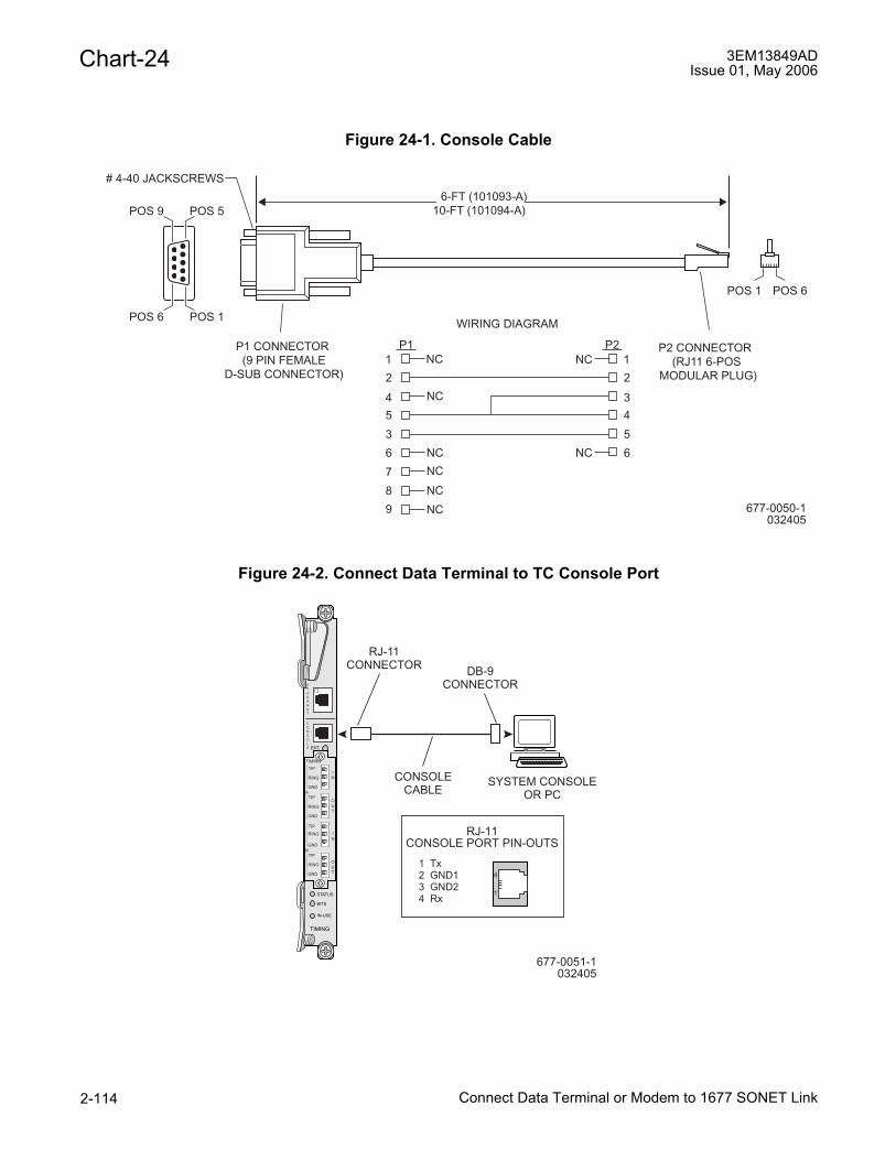
Chart-24 3EM13849ADIssue 01, May 2006
Figure 24-1. Console Cable
Figure 24-2. Connect Data Terminal to TC Console Port
677-0050-1032405
# 4-40 JACKSCREWS
WIRING DIAGRAM
P1 CONNECTOR(9 PIN FEMALE
D-SUB CONNECTOR)
POS 1 POS 6
POS 6 POS 1
POS 9 POS 5
P2 CONNECTOR(RJ11 6-POS
MODULAR PLUG)NC
NC
NC NC
NC
NC
NC
NC
1
2
4
5
3
6
1
2
3
4
5
6
7
8
9
P1 P2
6-FT (101093-A)10-FT (101094-A)
677-0051-1032405
STATUS
TIMING
EXT.
IN-USE
BITS
TIP
TIP
TIP
TIP
RING
RING
RING
RING
GND
GND
GND
GND
A
B
TIMING
IN
OUT
IN
OUT
SYSTEM CONSOLEOR PC
DB-9CONNECTOR
CONSOLECABLE
RJ-11CONNECTOR
1
4
1 Tx2 GND13 GND24 Rx
RJ-11CONSOLE PORT PIN-OUTS
ETHERNET
CONSOLE
Connect Data Terminal or Modem to 1677 SONET Link2-114

Chart-243EM13849ADIssue 01, May 2006
Figure 24-3. Connect Modem to TC Console Port
677-0052-1032405
STATUS
TIMING
EXT.
IN-USE
BITS
TIP
TIP
TIP
TIP
RING
RING
RING
RING
GND
GND
GND
GND
A
B
TIMING
IN
OUT
IN
OUT
DB-9CONNECTOR
MODEM
CONSOLECABLE
RJ-11CONNECTOR
NULL MODEMCABLE
TRANSMISSIONLINE
1
41 Tx2 GND13 GND24 Rx
RJ-11CONSOLE PORT PIN-OUTS
ETHERNET
CONSOLE
Connect Data Terminal or Modem to 1677 SONET Link 2-115

Chart-24 3EM13849ADIssue 01, May 2006
Connect Data Terminal or Modem to 1677 SONET Link2-116

Chart-253EM13849ADIssue 01, May 2006
Chart-25Connect Local Area Network (LAN) WiringPURPOSE
This chart provides instructions to terminate LAN connections at the 1677 SONET Link chassis. The chassis supports two 10/100Base-T interfaces, which operate at either 10 Mbps or 100 Mbps.
GENERAL
In a 10/100Base-T installation, the NE can be connected to only one other device. This can be another 1677 SONET Link or LAN hub or switch equipment. The 10/100Base-T interface requires CAT-5, twisted-pair 22- to 26-AWG using an RJ-45 male 8-pin connector. There is a maximum of 328 ft. from NE-to-NE or from the NE to the LAN hub or switch, unless a repeater is used.
Connections can be made to both 10/100 Base-T interfaces; however, it is possible to operate only one interface at a time.
STEP PROCEDURE
1 WARNING: Possibility of equipment damage. This equipment contains static-sensitive devices. Refer to 1677 SONET Link Installation Overview for special handling instructions.
2 Locate TC in front of 1677 SONET Link (see figure 25-1).
3 Per job documentation, run two CAT-5 twisted-pair AWG cables between 1677 SONET Link and terminating equipment (for example, another 1677 SONET Link NE, LAN hub, or switch). All 10/100Base-T interfaces require CAT-5, twisted-pair 22- to 26-AWG cable.
Connections between two NEs require a cross-over configuration; transmit pair of one NE should connect to receive pair of other NE.
4 CAUTION: Possibility of service interruption. Maximum distance from NE-to-NE or NE-to-hub cannot exceed 328 ft. Do not exceed this cable length unless deploying repeaters.
5 Are cables terminated with RJ-45 modular plugs being used?
If yes, go to step 7.If no, go to step 6.
Connect Local Area Network (LAN) Wiring 2-117

Chart-25 3EM13849ADIssue 01, May 2006
6 Using Ethernet port pin outs (see figure 25-2), terminate twisted-pair cable with an RJ-45 modular plug.
Connections between two NEs require a cross-over configuration; transmit pair of one NE should connect to receive pair of other NE.
7 Connect RJ-45 cable to Ethernet connector on 1677 SONET Link TC (see figure 25-2).
8 Make appropriate terminating connection on terminating equipment.
9 Update office records.
10 STOP. This procedure is complete.
Figure 25-1. Locate TCs
LOCATION OFTIMING CARDS
677-0242-1032405
Connect Local Area Network (LAN) Wiring2-118

Chart-253EM13849ADIssue 01, May 2006
Figure 25-2. Locate 10/100Base-T Ethernet Connector on TC
677-0053-1032405
TIMING
EXT.
IN-USE
BITS
GND
RING
TIP
GND
RING
TIP
GND
RING
TIP
GND
RING
TIP
A
B
TIMING
IN
OUT
IN
OUT
ETHERNET
CONSOLE
RJ-45
ETHERNET PORT PIN-OUTS
1 +Tx
2 -Tx
3 +Rx
4 N.C
5 N.C.
6 -Rx
7 N.C.
8 N.C
1
8
Connect Local Area Network (LAN) Wiring 2-119

Chart-25 3EM13849ADIssue 01, May 2006
Connect Local Area Network (LAN) Wiring2-120

Chart-263EM13849ADIssue 01, May 2006
Chart-26Test 1677 SONET Link Wiring ContinuityPURPOSE
Follow this procedure to verify the end-to-end wiring continuity of the 1677 SONET Link.
RECOMMENDED TOOLS
Triplett Volt-Ohm Meter (VOM), Model 630 or equivalent
STEP PROCEDURE
1 Set VOM to RX1 scale.
2 Verify end-to-end continuity of 1677 SONET Link wiring (refer to table 26-A as a guide).
Not all wiring listed in table 26-A is applicable to installation. Refer to job documentation to make sure.
3 Update office records to reflect changes to office equipment and wiring as result of performing this procedure.
4 STOP. This procedure is complete.
Test 1677 SONET Link Wiring Continuity 2-121

Chart-26 3EM13849ADIssue 01, May 2006
Table 26-A. Continuity Test List From 1677 SONET Link Location To Office Location1677 SONET Link TERMINATION POINT OFFICE TERMINATION LOCATIONCCC 9 minor alarm visual contact pair Office alarm interfaceCCC 9 major alarm visual contact pair Office alarm interfaceCCC 9 critical alarm visual contact pair Office alarm interfaceCCC 9 minor alarm audible contact pair Office alarm interfaceCCC 9 major alarm audible contact pair Office alarm interfaceCCC 9 critical alarm audible contact pair Office alarm interfaceCCC 10 minor alarm visual contact pair Office alarm interfaceCCC 10 major alarm visual contact pair Office alarm interfaceCCC 10 critical alarm visual contact pair Office alarm interfaceCCC 10 minor alarm audible contact pair Office alarm interfaceCCC 10 major alarm audible contact pair Office alarm interfaceCCC 10 critical alarm audible contact pair Office alarm interfaceTC A console interface Office serial interface or consoleTC B console interface Office serial interface or consoleTC A Ethernet (10/100Base-T) interface Office LANTC B Ethernet (10/100Base-T) interface Office LANTC A BITS-A In Office BITS sourceTC A BITS-B In Office BITS sourceTC B BITS-A In Office BITS sourceTC B BITS-B In Office BITS sourceTC A BITS-A Out Office BITS distributionTC A BITS-B Out Office BITS distributionTC B BITS-A Out Office BITS distributionTC B BITS-B Out Office BITS distributionDS3/EC1 connector panel interfaces DSX-3 patch panel
Test 1677 SONET Link Wiring Continuity2-122

Chart-273EM13849ADIssue 01, May 2006
Chart-27Install Rear Kick PlatePURPOSE
This chart provides instructions to install a rear kick plate to the rear of a rack containing a 1677 SONET Link system.
GENERAL
Brackets and fastening hardware, when required, are supplied in the kits.
For more detailed information, refer to the 1677 SONET Link Engineering Support Documentation manual (PN 3EM17362AB) and see drawing 3EM171590004RJZZA, page 22.
RECOMMENDED TOOLS
Phillips screw driver
STEP PROCEDURE
1 Mount rear kick plate (PN 3EM13407AC) to brackets (PN 3EM16494AB) using screws (PN 1AD009010033).
2 Attach captive cable on rear kick plate to rack rail using one rack screw.
3 STOP. This procedure is complete.
Install Rear Kick Plate 2-123

Chart-27 3EM13849ADIssue 01, May 2006
Install Rear Kick Plate2-124

Chart-283EM13849ADIssue 01, May 2006
Chart-28Install AC OutletsPURPOSE
This chart provides instructions to install AC outlets.
GENERAL
For AC outlet kit information, refer to the 1677 SONET Link Engineering Support Documentation manual (PN 3EM17362AB) and see drawing 3EM137210002UDZZA.
Alcatel provides expert Installation Services for installations that have different requirements from config option 1 and config option 2 as outlined in this manual. Contact Alcatel at 1-888-252-2832 for details.
RECOMMENDED TOOLS
Insulated trouble lamp
Phillips screw driver
STEP PROCEDURE
1 Use site plan to determine configuration of system and installation location of AC outlet.
Install AC Outlets
2 Refer to table 28-A to verify AC outlet installation kits.
3 Route power cable inside approved AC conduit.
4 Route power cable through AC conduit using 2 in. round cutouts at bottom of rack channel. Use cutouts located within rack channel, not those in front of channel.
5 Terminate AC cabling at desired outlets according to local practice.
Table 28-A. AC Duplex Outlet KitsOUTLET KIT PART NUMBERFront 3EM13721DMRear 3EM13721FP
Install AC Outlets 2-125

Chart-28 3EM13849ADIssue 01, May 2006
6 Is AC outlet being installed on front or rear of rack?
If front of rack, go to step 7.If rear of rack, go to step 9.
7 Install mounting bracket, duplex box, and AC outlet on rack (see figure 28-1).
8 Go to step 11.
9 Using Phillips screwdriver, remove AC junction box cover from rack rear kick plate.
10 Install duplex box, AC outlet, and outlet cover on rack rear kick plate (see figure 28-2).
11 Wire outlets according to local code.
12 STOP. This procedure is complete.
Figure 28-1. AC Duplex Outlet Installation, Front Mount
677-0376-1
RACK BASE(FRONT VIEW)DUPLEX
BOX
AC OUTLET
MOUNTINGBRACKET
100505
Install AC Outlets2-126

Chart-283EM13849ADIssue 01, May 2006
Figure 28-2. AC Duplex Outlet Installation, Rear Mount
677-0377-1100505
OUTLETCOVER
AC OUTLET
DUPLEXBOX
RACK BASE(REAR VIEW)
Install AC Outlets 2-127

Chart-28 3EM13849ADIssue 01, May 2006
Install AC Outlets2-128

Chart-293EM13849ADIssue 01, May 2006
Chart-29Install Front Base PlatePURPOSE
This chart provides instructions to install a front base plate on a rack.
GENERAL
A front base plate kit (PN 3EM13721DN) is installed on a 1677 SONET Link rack.
For more detailed information, refer to the 1677 SONET Link Engineering Support Documentation manual (PN 3EM17362AB) and see drawing 3EM171590004RJZZA, page 23.
RECOMMENDED TOOLS
Phillips screw driver
Hammer
Flat screw driver
STEP PROCEDURE
1 Is AC outlet installed in front of rack base?
If yes, go to step 2.If no, go to step 3.
2 Using hammer and flat screwdriver, remove outlet knockouts from front base plate for all racks on which front-mounted AC outlet is installed.
3 Install front base plate on each rack in system. Refer to the 1677 SONET Link Engineering Support Documentation manual (PN 3EM17362AB) and see drawing 3EM171590004RJZZA, page 23.
4 STOP. This procedure is complete.
Install Front Base Plate 2-129

Chart-29 3EM13849ADIssue 01, May 2006
Install Front Base Plate2-130

Chart-303EM13849ADIssue 01, May 2006
Chart-30Install Electrical SwitchPURPOSE
This chart provides the instructions to install an optional electrical switch for config option 1 or 2.
GENERAL
Installation of an electrical switch is optional. If not installing an electrical switch, skip this Chart.
For additional details, refer to the 1677 SONET Link Engineering Support Documentation manual (PN 3EM17362AB), and see drawing PN 3EM171590004RJZZA, page 25.
RECOMMENDED TOOLS
The following tool must be available for this procedure:
Screwdriver, Phillips
STEP PROCEDURE
1 Use site plan to determine configuration of system and installation location of electrical switch.
2 Mount electrical switch box (PN 1AD001250003) to switch box mounting bracket (PN 3EM18639AB). Refer to 1677 SONET Link Engineering Support Documentation manual (PN 3EM17362AB) and see drawing PN 3EM171590004RJZZA, page 25, figure 2501.
3 Mount switch box and switch box mounting bracket to rear rack channel. Refer to 1677 SONET Link Engineering Support Documentation manual (PN 3EM17362AB) and see drawing PN 3EM171590004RJZZA, page 25, figure 2502 and detail 2502-A.
4 Route power cable inside approved conduit.
5 Terminate AC cabling at electrical switch box according to local practice.
6 Wire electrical switch (PN 1AB198810002) according to local code and install using four screws (PN 1AD009010012).
7 STOP. This procedure is complete.
Install Electrical Switch 2-131

Chart-30 3EM13849ADIssue 01, May 2006
Install Electrical Switch2-132

Chart-313EM13849ADIssue 01, May 2006
Chart-31Install Trim (Config Option 1)PURPOSE
This chart provides the instructions to install rack rear, front, and middle trim for config option 1.
GENERAL
If performing an installation using config option 2, skip this Chart.
For additional details, refer to the 1677 SONET Link Engineering Support Documentation manual (PN 3EM17362AB), and see drawing PN 3EM171590004RJZZA, page 25.
RECOMMENDED TOOLS
The following tool must be available for this procedure:
Screwdriver, Phillips
STEP PROCEDURE
1 Install trim latch plates (PN 3EM13421AB) to the rear of the rack. Refer to 1677 SONET Link Engineering Support Documentation manual (PN 3EM17362AB) and see drawing PN 3EM171590004RJZZA, page 24.
2 Install rear trim panels (PN 3EM16590AM and PN 3EM16590AN), loosely tightening mounting screws. Refer to 1677 SONET Link Engineering Support Documentation manual (PN 3EM17362AB) and see drawing PN 3EM171590004RJZZA, page 26, figures 2601 and 2602.
3 Is electrical switch mounted on rack?
If yes, go to step 4.If no, go to step 6.
4 Install electrical switch plate (PN 695-9147-002) onto electrical switch box opening on side of each rear trim panel. Refer to 1677 SONET Link Engineering Support Documentation manual (PN 3EM17362AB) and see drawing PN 3EM171590004RJZZA, page 26, figure 2603.
5 Go to step 7.
6 Install blank wall plate (PN 695-9147-001) onto electrical switch box opening on side of each rear trim panel. Refer to 1677 SONET Link Engineering Support Documentation manual (PN 3EM17362AB) and see drawing PN 3EM171590004RJZZA, page 26, figure 2603.
Install Trim (Config Option 1) 2-133

Chart-31 3EM13849ADIssue 01, May 2006
7 Install front trim panels (PN 3EM16590AM and PN 3EM16590AN) to rack. Refer to 1677 SONET Link Engineering Support Documentation manual (PN 3EM17362AB) and see drawing PN 3EM171590004RJZZA, page 27.
8 Tighten mounting screws used to install rear trim panels in step 2.
9 Is rack installed adjacent to another rack containing 1677 SONET Link shelves?
If yes, go to step 10.If no, go to step 11.
10 Install front and rear middle trim (PN 3EM16590AP). Refer to 1677 SONET Link Engineering Support Documentation manual (PN 3EM17362AB) and see drawing PN 3EM171590004RJZZA, page 28.
11 STOP. This procedure is complete.
Install Trim (Config Option 1)2-134

Chart-323EM13849ADIssue 01, May 2006
Chart-32Install PDU-Quad LabelsPURPOSE
This chart provides the instructions to install PDU-Quad labels.
GENERAL
For additional details, refer to the 1677 SONET Link Engineering Support Documentation manual (PN 3EM17362AB), and see drawing PN 3EM171590004RJZZA, page 29.
STEP PROCEDURE
1 Install PDU-Quad fuse labels (PN 3EM16596AA and PN 3EM16596AB). Refer to 1677 SONET Link Engineering Support Documentation manual (PN 3EM17362AB) and see drawing PN 3EM171590004RJZZA, page 29. (Do not install PDU-Quad fuses at this time; they will be installed during initial turn-up.)
2 STOP. This procedure is complete.
Install PDU-Quad Labels 2-135

Chart-32 3EM13849ADIssue 01, May 2006
Install PDU-Quad Labels2-136

Chart-333EM13849ADIssue 01, May 2006
Chart-33Verify Final InstallationPURPOSE
This chart provides instructions to verify final installation. Final inspection ensures that basic installation is complete and that all electrical connections are made. When this procedure is complete, the system is ready for initial turn-up.
STEP PROCEDURE
1 Check that -48 V dc office power to 1677 SONET Link is turned off.
2 Ensure mounting assemblies (shelves, fuse panels, and so forth) were properly secured to equipment rack.
3 Check that equipment rack was located per approved floor plan.
4 Ensure equipment rack was properly secured to floor and/or top.
5 Ensure framework was properly aligned and plumbed within allowable tolerances.
6 Check that all shelves and ancillary equipment were installed per job description.
7 Check that all AC outlets were properly installed (proper locations, continuous ground, and polarity verification).
8 Ensure all conduit pieces were properly placed and secured.
9 Check that all cable lengths and cable segregation requirements are satisfied.
10 Check that all cables are protected against physical damage, especially where they contact metal edges or rough surfaces.
11 Check that all cables were routed in accordance with detailed office engineering specifications and that cable runways are free of cable pile-ups and blocked cable runs.
12 Check that all cables are supported properly.
13 Ensure all cable ties are free of sharp edges.
14 Ensure power source and ground leads were properly secured.
15 Check that appropriate shelf continuity tests were performed and cables were properly terminated per local practice.
Verify Final Installation 2-137

Chart-33 3EM13849ADIssue 01, May 2006
16 Verify all relay rack and BDFB labels are properly installed.
17 This completes basic installation. To turn up system, refer to 1677 SONET Link Turn-Up manual (PN 3EM13850AB).
18 STOP. This procedure is complete.
Verify Final Installation2-138

3EM13849ADIssue 01, May 2006
Installing MOS Modules
1. REQUIREMENTS
1.1 Follow the procedures in this chapter to perform the following:
• Unpack, inspect, and inventory an order
• Mount the optical modules in the equipment rack
• Route and connect cables to the Modular Optical System (MOS)
1.2 To install the MOS, installers will need the following tools and supplies:
• #2 Phillips screwdriver
• Cleaning materials listed in the cable-cleaning section
Installation Requirements
1.3 The following sections provide the installation-site requirements and equipment-rack requirements for the MOS. For optimal equipment performance and maximum equipment life, ensure the humidity and temperature of the installation site are maintained within the ranges listed here (refer to table 1-A).
Service-clearance Requirements
1.4 The MOS requires a minimum clearance of 76 mm (30 in.) in front, zero clearance in the rear, and zero clearance on the sides to install, operate, and service it. Always check the service-clearance requirements of other equipment installed in the equipment rack before positioning and securing the equipment rack. Other equipment installed in the same equipment rack may require more room to service and operate.
Environmental Requirements
1.5 Refer to table 1-A for temperature and humidity ranges for the installation site.
Installing MOS Modules 3-1

3EM13849ADIssue 01, May 2006
Electrical Power Requirements
1.6 The MOS uses passive optical components. It does not require electrical power.
Equipment-rack Requirements
DANGER Possibility of personal injury. To prevent personal injury and equipment damage due to unbalanced loading of the equipment rack or cabinet, ensure the equipment rack or cabinet is properly secured to the floor, ceiling, or other rigid structure before mounting the MOS in it. For approved methods of securing the equipment rack, read the equipment-rack installation instructions or contact the equipment-rack manufacturer
1.7 Each MOS requires one rack unit (1 RU) of vertical space for an ANSI/EIA-310-D or IEC equipment rack, or 2 in. of vertical space for an equipment rack with 1 in. on-center mounting holes. The customer must also provide a vertical cable-guide system that attaches to the outside rails of the equipment rack. The cable-guide system maintains the minimum fiber-optic cable bend radius, provides a way of dressing cables neatly to simplify servicing and installation, and provides a way of storing extra-long cables.
1.8 The following sections describe the 19 in. and 23 in. equipment-rack mounting options for the MOS. The modules come with both 19 in. and 23 in. mounting brackets.
Table 1-A. Environmental RequirementsTEMPERATURE (IMMEDIATELY SURROUNDING THE MODULES)Operating 5°C to 40°C (41°F to 104°F)Non-Operating -40°C to +70°C (-40°F to +158°F)TEMPERATURE CHANGE/HOUR (IMMEDIATELY SURROUNDING THE MODULES)Operation / Non-Operation less than 30°C (54°F) per hourHUMIDITYOperation / Non-Operation 5% to 85%ALTITUDEOperation / Non-Operation 0-3,048 m (0-10,000 ft.)
Installing MOS Modules3-2

3EM13849ADIssue 01, May 2006
2. INSPECTION
Unpacking and Inspecting
2.1 Follow the procedures in this section to unpack and inspect the MOS and to report any shipping damage or missing parts. For each optical module, locate the packing slip, which is attached to the outside of the carton.
1. Before opening, ensure there is no visible damage to outside of carton.
2. If there is visible damage, report damage to freight carrier before opening carton. Freight carrier will advise installers of next step to take. (If a camera is available, take several pictures of damage.)
3. Open carton and carefully remove and inspect contents for damage. If there is damage, contact Alcatel CTAC at 1-888-252-2832 to report damage and to find out what to do next.
4. Check label on module to ensure model number is the one that was ordered. Also ensure that loose parts (see figure 2-1) and any optional cables ordered are not missing or damaged.
5. Save shipping carton and packing materials in case needed to transport or reship module
WARNING Possibility of equipment damage. If equipment must be returned, repack it as shown in figure 2-1. Repacking the equipment improperly or using unapproved shipping materials may result in equipment damage, which is the sender’s responsibility.
6. Repeat steps 1. through 5. for each optical module.
7. If moving optical module from a colder location to a warmer location, a difference of 14°C (25°F) or more, make sure to allow module to adjust to warmer temperature before operating it. As a rule, acclimation time should equal time spent in colder temperature, but not more than 12 hours.
Fiber-optic Jumper Cable Requirements
2.2 Before beginning the installation, make sure installers have the correct number of cables of the proper lengths and with the correct style of connectors.
Installing MOS Modules 3-3

3EM13849ADIssue 01, May 2006
WARNING Possibility of equipment damage. If APC-type cable is inserted into SC-type connector on 1677 SONET Link, ferrule of connector may be damaged.
CAUTION Possibility of service interruption. High insertion loss and back reflections may occur if APC-type cable is inserted into SC-type connector on 1677 SONET Link.
2.3 The 1677 SONET Link uses an SC/UPC pigtailed laser and an SC/UPC pigtailed receiver. UPC is a type of domed polish that reduces back reflections to -55 db. Use SC/UPC cables with all SC-type connectors. The angle polish connectors are at 8 degrees and are typically used in broadband applications. The 1677 SONET Link SC-type connectors do not accept angle-polished connectors.
Preventing ESD Damage
2.4 The optical modules contain passive optical components, which are not subject to Electrostatic Discharge (ESD) damage. However, the electronic equipment that connects to the optical modules is susceptible to ESD. Therefore, once installers mount the optical modules in the equipment rack, installers should follow the same ESD prevention procedures when working on the modules as when working on the equipment that connects to the rack. To find out what the ESD prevention procedures entail, refer to the manuals for the equipment that connects to the MOS.
Figure 2-1. Unpacking Diagram
677-0169-1032405
OPTICAL
MODULE
(2) 19-INCH
MOUNTING
BRACKETS(2) 23-INCH
MOUNTING BRACKETS
(8) #6-32
SCREWS
(4) #12-24
SCREWS
(2) SIDE
EXIT CLIPS
Installing MOS Modules3-4

3EM13849ADIssue 01, May 2006
3. INSTALLATION
3.1 Follow the procedures in this section to plan and install mid-mounted and front-mounted modules in 19 in. and 23 in. equipment racks.
19-Inch Mounting
3.2 Installers can mid-mount or front-mount the MOS in a 19 in. equipment rack or cabinet using the two 19 in. mounting brackets that come with each module. The rack or cabinet must have either an ANSI/EIA-310-D or IEC standard mounting hole pattern, or a 1 in. on-center mounting hole pattern. The ANSI/EIA-310-D and IEC mounting-hole pattern may be either the 3-hole universal-spacing or the 2-hole wide-spacing shown in figure 3-1.
23-Inch Mounting
3.3 Installers can mid-mount or front-mount the MOS in a 23 in. equipment rack or cabinet using the two 23 in. mounting brackets that come with each module. The brackets allow the chassis to be mounted in a 23 in. equipment rack or cabinet that meets the ANSI/EIA-310-D or IEC standard or that has mounting holes that are on 1 in. centers. The ANSI/EIA-310-D and IEC mounting-hole pattern may be either the 3-hole universal-spacing or the 2-hole wide-spacing shown in figure 3-1.
Figure 3-1. ANSI/EIA-310-D or IEC Mounting Hole Patterns
677-0168-1032405
3-HOLEUNIVERSAL SPACING
2-HOLEWIDE SPACING
5/8
5/8
5/8
5/8
1.25
1.25
VERTICALRAIL
VERTICALRAIL
0.5
0.5 0.5
0.5
MENSIONSHES
ALL DIIN INCC
Installing MOS Modules 3-5

3EM13849ADIssue 01, May 2006
Fiber-optic Jumper Cable Requirements
3.4 Before beginning the installation, make sure installers have the correct number of cables of the proper lengths and with the correct style of connectors.
WARNING Possibility of equipment damage. If APC-type cable is inserted into SC-type connector on 1677 SONET Link, ferrule of connector may be damaged.
CAUTION Possibility of service interruption. High insertion loss and back reflections may occur if APC-type cable is inserted into SC-type connector on 1677 SONET Link.
3.5 The 1677 SONET Link uses an SC/UPC pigtailed laser and an SC/UPC pigtailed receiver. UPC is a type of domed polish that reduces back reflections to -55 db. Use SC/UPC cables with all SC-type connectors. The angle polish connectors are at 8 degrees and are typically used in broadband applications. The 1677 SONET Link SC-type connectors do not accept angle-polished connectors.
Installing a Module
3.6 Installers should have help when installing the first module. It is recommended that two people support, align, and attach the first module. Thereafter, one person can install the remaining modules. The following paragraphs describe the steps for front-mounting or mid-mounting a module.
Installing MOS Modules3-6

3EM13849ADIssue 01, May 2006
Planning the Installation
3.7 To simplify installation and to optimize cable routing and servicing, follow these recommendations:
1. Ensure there is enough space in equipment rack.
2. Each module requires one unit (1U) of vertical space for an ANSI/EIA-310-D or IEC equipment rack, or 2 in. of vertical space for an equipment rack with 1 in. on-center mounting holes. Multiply this vertical space requirement by total number of modules being installed. (Include any future modules that will be needed to upgrade system.) Draw a sketch showing module placement in equipment rack.
3. Mount all east modules above west modules (see figure 3-2). Working from center of installation, locate ADM modules in middle, then DWDM modules, and finally the DCMs. Leave any extra space at either end or both ends of stack of modules.
4. So that remaining space is usable, ensure it is not less than vertical space requirements of one optical module: 1U for an ANSI/EIA-310-D equipment rack and 2 in. for an equipment rack that has 1 in. on-center mounting holes.
5. Take time to accurately mount first module at bottom of stack. All other optical modules are positioned using bottom module as a guide.
3.8 Follow the procedures in the next section to install the optical modules.
Installing MOS Modules 3-7

3EM13849ADIssue 01, May 2006
Mounting the Module
DANGER Possibility of personal injury. To prevent personal injury and equipment damage, ensure the equipment rack is secured to the floor, ceiling, or other rigid structure before mounting the MOS in it. For approved methods of securing the equipment rack, read the equipment-rack installation instructions or contact the equipment-rack manufacturer.
3.9 A module can be either front-mounted or mid-mounted in an equipment rack. To front-mount a module, follow the procedures in the next section. To mid-mount a module, follow the procedures in the “Mid-mounting a Module” section
DANGER Possibility of personal injury. Each optical module weighs approximately 4.1 kg (9 lbs). It is recommended that two people support, align, and attach the first module. Thereafter, one person can install the remaining modules. To prevent equipment damage or personal injury, ensure enough help is available.
Figure 3-2. Typical Module Placement
677-0170-1032405
OTHER DWDM WEST MODULES
OTHER DWDM EAST MODULES
ADM EAST
DCM EAST
DWDM EAST
DWDM EAST
ADM EAST
ADM WEST
DWDM WEST
DWDM WEST
DCM WEST
WEST
MODULES
EAST
MODULES
Installing MOS Modules3-8

3EM13849ADIssue 01, May 2006
Front-mounting the Modules
3.10 Locate the module that will be installed in the lowest position. This module will be mounted first.
3.11 Determine which mounting brackets to use.
1. If mounting module in a 19 in. equipment rack, attach two 19 in. mounting brackets to front of left and right sides of module (see figure 3-3) using #2 Phillips screwdriver and eight #6-32 x 3/8 in. flat-head screws. Then go to paragraph 3.14.
2. If mounting module in a 23 in. equipment rack, attach two 23 in. mounting brackets to front of left and right sides of module (see figure 3-3) using #2 Phillips screwdriver and eight #6-32 x 3/8 in. flat-head screws.
3.12 Determine the mounting-hole spacing on the equipment rack, and mount and position the module according to the following.
Figure 3-3. Mounting Brackets
677-0171-1032405
6-32 X 3/8FLATHEADSCREWS
23-INCHMOUNTINGBRACKET
19-INCHMOUNTINGBRACKET
19-INCHMOUNTINGBRACKET
23-INCHMOUNTINGBRACKET
Installing MOS Modules 3-9

3EM13849ADIssue 01, May 2006
3.13 If mounting-hole spacing of equipment rack meets ANSI 310-D or IEC standard (see figure 3-1), do the following:
1. Position and support module in equipment rack so bottom edge of each front-mounting bracket is located roughly between two mounting-hole patterns (the 1/2 in. hole distance) as shown in figure 3-4, detail a.
2. Install four #12-24 x 1/2 in. screws provided in right front and left front-mounting brackets and lightly tighten each screw using a #2 Phillips screwdriver.
3. Adjust module so it is centered between two vertical rails of equipment rack and so bottom edge of each mounting bracket is between two mounting-hole patterns (1/2 in. hole distance).
4. Finish tightening all four screws using a #2 Phillips screwdriver, and go to step 1.
3.14 If the equipment rack has 1 in. on-center mounting holes, do the following:
1. Position module in equipment rack, making sure slotted holes in front-mounting brackets line up with four holes in equipment rack.
2. Install four #12-24 x 1/2 in. screws provided in right front and left front-mounting brackets and lightly tighten each screw with a #2 Phillips screwdriver.
3. Adjust module so bottom edge of each bracket is 5/8 in. above center of hole below it (see figure 3-4, detail b) and module is centered between two vertical rails of equipment rack.
4. Finish tightening all four screws using a #2 Phillips screwdriver, and go to step 1.
3.15 Use provided mounting screws for standard equipment racks with #12-24 threaded mounting holes. Do not force screws if they turn hard during installation. Instead, make sure the equipment rack uses #12-24 screws before continuing. If the equipment rack does not use #12-24 screws, obtain the correct mounting hardware.
Installing MOS Modules3-10

3EM13849ADIssue 01, May 2006
1. Locate next module to install, and attach either 19 in. or 23 in. mounting brackets to front of right and left side of module.
2. Slide module in rack above module just installed. Center the module in the equipment rack and attach it with four #12-24 x 1/2 in. screws.
3. If the equipment rack has 1 in. on-center mounting holes, leave approximately 1/4 in. spacing between brackets (see figure 3-5).
4. Tighten screws with a #2 Phillips screwdriver.
5. Repeat steps 1. through 4. until all optical modules are installed.
6. Install cable-exit clips in holes on right end and left end of modules (see figure 3-6).
Figure 3-4. Locate Front-Mounting Brackets on Rack
Figure 3-5. Locating Multiple Front-Mounting Brackets
677-0172-1032405
LOCATE BRACKETEDGE BETWEEN
1/2-INCHHOLE DISTANCE
(b) 1-INCH ON-CENTEREQUIPMENT RACK
(a) ANSI 310D OR IECEQUIPMENT RACK
LOCATE BRACKET EDGE5/8-INCH BELOW NEXT HOLE23-INCH OR
19-INCH MOUNTINGBRACKET
23-INCH OR19-INCH MOUNTING
BRACKET
677-0173-1032405
1-INCH ON-CENTEREQUIPMENT RACK
LEAVE 1/4-INCH SPACEBETWEEN BRACKETS
23-INCH OR 19-INCHMOUNTING BRACKETS
Installing MOS Modules 3-11

3EM13849ADIssue 01, May 2006
3.16 To install fiber-optic cables and OMB cables, follow the procedures in section 4. of this discussion of MOS modules.
Mid-mounting a Module
3.17 Locate the module that will be installed in the lowest position in the rack and mount this module first.
3.18 Determine which mounting brackets to use.
1. If mounting module in a 19 in. equipment rack, attach two 19 in. mounting brackets to front of left and right sides of module (see figure 3-7) using #2 Phillips screwdriver and eight #6-32 x 3/8 in. flat-head screws. Then go to paragraph 3.14.
2. If mounting module in a 23 in. equipment rack, attach two 23 in. mounting brackets to front of left and right sides of module (see figure 3-7) using #2 Phillips screwdriver and eight #6-32 x 3/8 in. flat-head screws.
Figure 3-6. Install Cable Exit Clips
677-0174-1032405
Installing MOS Modules3-12

3EM13849ADIssue 01, May 2006
3.19 Determine the mounting-hole spacing on the equipment rack, and mount and position the module according to the following.
3.20 If the equipment rack has mounting-hole spacing that meets the ANSI 310-D or IEC standard:
1. Position and support module in equipment rack so bottom edge of each mid-mounting bracket is located roughly between two mounting-hole patterns (the 1/2 in. hole distance) as shown in figure 3-8.
2. Install four #12-24 x 1/2 in. screws provided in right front and left mid-mounting brackets and lightly tighten each screw using a #2 Phillips screwdriver.
3. Adjust module so it is centered between two vertical rails of equipment rack and so bottom edge of each mounting bracket is between two mounting-hole patterns (1/2 in. hole distance).
4. Finish tightening all four screws using a #2 Phillips screwdriver, and go to step 3.23.
Figure 3-7. Install Mid Mounting Brackets
677-0171-1032405
6-32 X 3/8FLATHEADSCREWS
23-INCHMOUNTINGBRACKET
19-INCHMOUNTINGBRACKET
19-INCHMOUNTINGBRACKET
23-INCHMOUNTINGBRACKET
Installing MOS Modules 3-13

3EM13849ADIssue 01, May 2006
3.21 If the equipment rack has 1 in. on-center mounting holes:
1. Position module in equipment rack, making sure screw holes in front-mounting brackets line up with four holes in equipment rack.
2. Install four #12-24 x 1/2 in. screws provided in right and left mid-mounting brackets and lightly tighten each screw with a #2 Phillips screwdriver.
3. Adjust module so top edge of each bracket is 5/8 in. below center of hole above it (see figure 3-8) and module is centered between two vertical rails of equipment rack.
4. Finish tightening all four screws using a #2 Phillips screwdriver, and go to step 1.
3.22 Use provided mounting screws for standard equipment racks with #12-24 threaded mounting holes. Do not force screws if they turn hard during installation. Instead, make sure the equipment rack uses #12-24 screws before continuing. If the equipment rack does not use #12-24 screws, obtain the correct mounting hardware.
3.23 Locate the next module to install and attach either the 19 in. or 23 in. mounting brackets to the middle of the right and left side of the module.
3.24 Position the module in the rack above the module just installed. Center the module in the equipment rack and attach it with the four #12-24 x 1/2 in. screws. Tighten the screws with a #2 Phillips screwdriver. Repeat the procedures in paragraphs 3.23 and 3.24 until all optical modules are installed.
Figure 3-8. Proper Mid Mount Bracket Location
677-0175-1032405
LOCATE BRACKET EDGEBETWEEN 1/2-INCH
HOLE DISTANCE
(b) 1-INCH ON-CENTEREQUIPMENT RACK
(a) ANSI 310D OR IECEQUIPMENT RACK
LOCATE BRACKET EDGE5/8-INCH BELOW
NEXT HOLE23-INCH OR 19-INCH
MOUNTING BRACKET
23-INCH OR 19-INCHMOUNTING BRACKET
Installing MOS Modules3-14

3EM13849ADIssue 01, May 2006
3.25 Install the cable-exit clips in the holes on the right end and left end of the modules (see figure 3-6).
3.26 Follow the procedures in the next section to install and route the fiber-optic cables.
Installing MOS Modules 3-15

3EM13849ADIssue 01, May 2006
Installing MOS Modules3-16

3EM13849ADIssue 01, May 2006
4. INSTALLING AND ROUTING FIBER-OPTIC CABLES
4.1 The fiber-optic adapters on the modules are angled 45 degrees to reduce bending stress on the fiber-optic cables. The adapters are angled to the right on east modules and to the left on west modules. Therefore, it is important to route fiber-optic cables connected to east modules through the right cable-exit clip and fiber-optic cables connected to west modules through the left cable-exit clip
WARNING Possibility of equipment damage. Routing fiber-optic cables in the wrong direction bends the cable excessively, causing signal loss or permanent fiber-optic cable damage.
4.2 Vertical optical cable-guide systems are recommended for every MOS installation. The cable-guide system maintains the minimum fiber-optic cable bend radius, provides a way of dressing cables neatly to simplify servicing and installation, and provides a way of storing extra-long cables. The user must provide a vertical cable-guide system for the MOS. It is part of the equipment-rack requirements.
4.3 First, install the express-path cables, then install the tributary cables. This order of installation makes it easier to service and maintain the MOS. Whenever installing fiber-optic cables in the module adapter, perform the following steps:
1. Inspect and, when necessary, clean fiber-optic cable connector and module adapter before connecting them.
2. Refer to the 1677 SONET Link Turn-Up manual (PN 3EM13850AB) for inspection and cleaning procedure.
3. Open shutter on fiber-optic adapter of module (see figure 4-1).
4. Align key of cable connector with guide in fiber-optic adapter and push it in until a light click is heard.
WARNING Possibility of equipment damage. Do not force the connector into the adapter. Make sure the key on the connector lines up with the guide in the adapter
4.4 To install and connect the optical modules, a cable wiring diagram is required. This diagram will indicate the modules and where to connect the fiber-optic cables. The obtained cable wiring diagram will be the result of a network plan that was derived from a list of requirements. Using this diagram, follow the procedures in the next sections to connect and route the fiber-optic cables.
Installing MOS Modules 3-17

3EM13849ADIssue 01, May 2006
Cabling the MOS
DANGER Possibility of personal injury. Class B Invisible Laser Radiation present. To prevent serious eye damage, avoid direct eye exposure to the invisible laser beam. Never stare into the laser beam or view the beam directly with an optical instrument that is not eye safe. Never look directly into the fiber end of fiber-optic cables, fiber-optic connectors, or fiber-optic adapters.
4.5 Determine the number, the lengths, and the types of jumper cables that are needed.
4.6 Connect fiber-optic cables between the optical modules and an Alcatel 1677 SONET Link, then connect metallic cables between the OMB jacks of the module.
4.7 Install the west-to-east express path fiber-optic cable from the ADM East module to the ADM West module as follows (see figure 4-2):
1. Connect one end of cable into EXPRESS OUT adapter (port 2) of ADM East module.
2. Route cable as shown by solid line in figure 4-2 out right cable-exit clip, around vertical cable-guide system to left cable-exit clip of ADM West module, and into EXPRESS IN adapter (port 2) of ADM West module.
Figure 4-1. Installing Fiber-optic Cable
677-0176-1032405
GUIDE
SHUTTER
KEY
Installing MOS Modules3-18

3EM13849ADIssue 01, May 2006
4.8 Install the east-to-west express path fiber-optic cable from the ADM West module to the ADM East module as follows (see figure 4-2):
1. Install one end of cable into EXPRESS OUT adapter (port 11) of ADM West module.
2. Route cable as shown by dashed line in figure 4-2 out left cable-exit clip, around vertical cable-guide system to right cable-exit clip of ADM West module, and into EXPRESS IN adapter (port 11) of ADM West module.
4.9 Following the wiring diagram, install the tributary cables into the connectors of the east and west DWDM modules.
1. Route the fiber-optic cables connected to east modules through right cable-exit clip and around cable-guide system.
2. Route fiber-optic cables connected to west modules through left cable-exit clip and around cable-guide system.
Figure 4-2. Installing Express Path Cables
677-0177-1032405
ADM EAST
ADM WEST
PORT 1NETWORK
OUT
PORT 2EXPRESS IN(FROM EAST)
PORT 12NETWORK IN
PORT 11EXPRESS OUT
(TO EAST)
PORT 1NETWORK
IN
PORT 2EXPRESS OUT
(TO WEST)
PORT 12NETWORK
OUT
PORT 11EXPRESS IN
(FROM WEST)
Installing MOS Modules 3-19

3EM13849ADIssue 01, May 2006
4.10 Install the east-to-west network cables as follows:
1. Locate east side of east-to-west network cable. (Network cable should be clearly marked.)
2. Connect this side of east-to-west network fiber to NETWORK IN adapter (port 1) on ADM east module.
3. Locate west side of east-to-west network cable. (Network cable should be clearly marked.)
4. Connect this side of east-to-west network fiber to NETWORK OUT adapter (port 1) on ADM west module.
Figure 4-3. Connecting OMB Cables
677-0178-1032405
COMMON CONTROL CARDS (CCCs)IN ALCATEL 1677 SONET LINK
OPTICALMANAGEMENT BUS
CABLETO MOS
JACKTO MOS
JACK
OPTICALMODULES
DUPLICATE OPTICAL MANAGEMENT BUS PATHS(IDENTICAL EPROM DATA)
Installing MOS Modules3-20

3EM13849ADIssue 01, May 2006
4.11 Install the west-to-east network cables as follows:
1. Locate west side of west-to-east network cable. (Network cable should be clearly marked.)
2. Connect this side of east-to-west network fiber to NETWORK IN adapter (port 12) on ADM west module.
3. Locate east side of west-to-east network cable. (Network cable should be clearly marked.)
4. Connect this side of west-to-east network fiber to NETWORK OUT adapter (port 12) on ADM east module.
4.12 Connect the optical management bus (OMB) cables between the modules and the common control cards (CCCs) in the Alcatel 1677 SONET Link (see figure 4-3).
1. Route an OMB cable from left-side OUT jack of one module, through left cable-exit clip, and around cable guide to left-side IN jack of next module. Repeat for each module, then go to step 2.
2. Route an OMB cable from right-side OUT jack of one module, through right-side cable-exit clip, around cable guide to right-side IN jack of next module. Repeat for each module, then go to step 4.
3. Connect left-side OMB daisy-chain wiring to the TO MOS jack on front panel of left CCC.
4. Connect right-side OMB daisy-chain wiring to the TO MOS jack on front panel of right CCC.
Selecting and Installing Fiber-optic Attenuators
4.13 To reduce the optical signal power level, a fiber-optic attenuator is installed in a fiber-optic light path at the optical receiver of the node. This is often needed to prevent bit errors or, in extreme cases, to prevent damage to the optical receiver. To select and install an attenuator, contact Alcatel for more information
4.14 Do not install attenuators at the fiber-optic adapters of the optical modules. For more information, contact Alcatel as described in section 4. of 1677 SONET Link Installation Overview.
Installing MOS Modules 3-21

3EM13849ADIssue 01, May 2006
Installing MOS Modules3-22