1639726126417-Model question for ... - South Eastern Railway
475
471725/2021/O/o Sr.DSTE/RNC/SER 2
-
Upload
khangminh22 -
Category
Documents
-
view
1 -
download
0
Transcript of 1639726126417-Model question for ... - South Eastern Railway
471725/2021/O/o Sr.DSTE/RNC/SER2

471725/2021/O/o Sr.DSTE/RNC/SER3

471725/2021/O/o Sr.DSTE/RNC/SER4
471725/2021/O/o Sr.DSTE/RNC/SER5

S-1 Offline, Group A
1) Minimum Visibility of Home signal in LQ signalling is _______________
a) 1200 mts (0%)b) 400 mts (100%)c) 200 mts (0%)d) 800 mts (0%)
2) Minimum Visibility of outer signal with Warner separated is _______________
a) 400 mts (100%)b) 1200 mts (0%)c) 200 mts (0%)d) 800 mts (0%)
3) Minimum Visibility of outer signal, Where the sectional speed is less than 100 kmph is _______________
a) 200 mts (0%)b) 1200 mts (0%)c) 400 mts (0%)d) 800 mts (100%)
4) Minimum Visibility of outer signal, Where the sectional speed is 100 kmph or above is _______________
a) 800 mts (0%)b) 1200 mts (100%)c) 200 mts (0%)d) 400 mts (0%)
5) Visibility of calling-ON signal in MACLS is _______________
a) 800 mts (0%)b) 1200 mts (0%)c) Visibility is not a criteria (100%)d) 400 mts (0%)
6) Minimum Visibility of Loop line starter signal in MACLS is _______________
a) 400 mts (0%)b) 800 mts (0%)c) 200 mts (100%)d) 1200 mts (0%)
7) Minimum Visibility of loop line starter signal in LQ signalling is _______________
a) 1200 mts (0%)b) 200 mts (100%)c) 400 mts (0%)d) 800 mts (0%)
Page 1/51
471725/2021/O/o Sr.DSTE/RNC/SER6

S-1 Offline, Group A
8) Minimum Visibility of main line starter signal in LQ signalling is _______________
a) 1200 mts (0%)b) 800 mts (0%)c) 400 mts (100%)d) 200 mts (0%)
9) As the 'ON' aspect of outer signal is pre-warned, then _______________ of outer signal is not important
a) Sighting distance (100%)b) certain distance (0%)c) Reaction distance (0%)d) Breaking distance (0%)
10) If it is not possible to ensure _______________ continuous visibility of any stop signal while approaching it,a suitable speed restriction shall be imposed as per Para 7.7.7 of SEM Part 1, 1988
a) 1200 mts (0%)b) visibility is not a criteria (0%)c) 400 mts (0%)d) 200 mts (100%)
11) _______________ is the distance over which the most restrictive aspect of a signal is visible from thedriving compartment of an approaching train under normal conditions of visibility
a) a and d (0%)b) Sighting Distance (100%)c) Reaction distance (0%)d) Breaking distance (0%)
12) _______________ is the distance travelled at permissible speed during time taken by Loco Pilot to react tothe aspect of a signal
a) Reaction Distance (100%)b) a and d (0%)c) Sighting Distance (0%)d) Breaking distance (0%)
13) Minimum Visibility of Warner signal fixed on a separate post is _______________
a) 400 mts (100%)b) 200 mts (0%)c) 1200 mts (0%)d) 800 mts (0%)
14) Minimum Visibility of main line starter signal in MACLS is _______________
a) 1200 mts (0%)b) 200 mts (100%)c) 400 mts (0%)d) 800 mts (0%)
Page 2/51
471725/2021/O/o Sr.DSTE/RNC/SER7

S-1 Offline, Group A
15) Minimum Visibility of inner Distant signal in MACLS is _______________
a) 800 mts (0%)b) 1200 mts (0%)c) 200 mts (100%)d) 400 mts (0%)
16) Minimum Visibility of Distant signal in MACLS is _______________
a) 800 mts (0%)b) 1200 mts (0%)c) 400 mts (100%)d) 200 mts (0%)
17) The provision of sand humps, trap points etc in the yard for ____________ purpose
a) Connection (0%)b) Derailing (0%)c) Isolation (100%)d) Fouling mark (0%)
18) The isolation of goods reception lines from ____________ is considered desirable
a) Fouling mark (0%)b) over run lines (0%)c) Sand humps (0%)d) Sidings (100%)
19) Maximum recommended gradient on Indian Railways for all gauges is ____________
a) 1 : 400 (0%)b) 1 : 260 (0%)c) None of these (0%)d) 1 : 1200 (100%)
20) Slip siding will protects ____________
a) Station section (0%)b) Block section (100%)c) Station (0%)d) Station limit (0%)
21) Catch siding will protects ____________
a) Station section (100%)b) Station limit (0%)c) Block section (0%)d) Station (0%)
Page 3/51
471725/2021/O/o Sr.DSTE/RNC/SER8

S-1 Offline, Group A
22) If speed is less than ____________, then isolation of a passenger line from other connecting passengerline is not required
a) 75 kmph (0%)b) 100 kmph (0%)c) 50 kmph (100%)d) 15 kmph (0%)
23) A catch siding shall be provided if the gradient steeper than 1:80 in near vicinity of station and falling___________
a) Towards FM (0%)b) Towards station (100%)c) Towards lock bar (0%)d) Away from station (0%)
24) If speed is more than ____________ then one goods line shall not be isolated from other goods line
a) 75 kmph (0%)b) 50 kmph (100%)c) 100 kmph (0%)d) 15 kmph (0%)
25) A slip siding shall be provided if the gradient steeper than 1:100 in near vicinity of station and falling__________
a) Towards FM (0%)b) Lock bar (0%)c) Away from station (100%)d) Towards station (0%)
26) A line on which train movements at speeds higher than 50 kmph are permitted should be ____________from all connected lines
a) Pad locked (0%)b) Isolated (100%)c) Chain locked (0%)d) special locked (0%)
27) ____________ are provided for isolation purpose only
a) Trap point (0%)b) Slip sidings (0%)c) Catch sidings (0%)d) all b , c and d (100%)
Page 4/51
471725/2021/O/o Sr.DSTE/RNC/SER9
S-1 Offline, Group A
28) The isolation between goods lines is required if speed is more than ______________
a) 20 KMPH (0%)b) 50 KMPH (100%)c) 10 KMPH (0%)d) ZERO KMPH (0%)
29) Taking OFF two reception signals at a time for different trains is called ______________ of trains
a) simultaneous dispatch (0%)b) a and d (0%)c) simultaneous stop (0%)d) simultaneous reception (100%)
30) To provide simultaneous reception and dispatching facility on different lines , separate ___________ and___________ is required between them
a) Fouling mark (0%)b) Isolation (0%)c) b and c (100%)d) Overlap (0%)
31) Complete arrival of the train is checked by ___________
a) Continuous track circuit/Axle counter (0%)b) All a, c and d (100%)c) Physical verification with Tail lamp (0%)d) Physical verification with LV board (0%)
32) Absolute block system is based on _______________
a) Space interval method (100%)b) Geographical method (0%)c) Time interval method (0%)d) Group- cum -geographical method (0%)
33) The normally used block working in Indian Railways is / are
a) Absolute block system (0%)b) Automatic block system (0%)c) Pilot Guard System (0%)d) Both a and d (100%)
34) Automatic signals interlocked with Point and Level crossing gates are distinguished by the provision of___________ and illuminated 'A' marker
a) R-Marker (0%)b) P-marker (0%)c) Illuminated AG (100%)d) C-Marker (0%)
Page 5/51
471725/2021/O/o Sr.DSTE/RNC/SER10
S-1 Offline, Group A
35) Adequate distance in Automatic Block System on Double line is ___________
a) 120 mts (100%)b) 300 mts (0%)c) 400 mts (0%)d) 180 mts (0%)
36) When an automatic stop signal with 'A' marker is at 'ON', the Loco Pilot shall bring his train to stop in rear ofthe signal, after the train has been stopped he shall wait there for ___________ by day and ___________by night to pass the signal at ON
a) Two minute, One minute (0%)b) One minute, Four minutes (0%)c) One minute, two minutes (100%)d) One minute, Three minutes (0%)
37) The automatic stop signal can exhibit double yellow when the line is clear for two automatic block sectionsplus overlap in the case of ______________
a) 3-aspect signalling (0%)b) 2 Aspect signalling (0%)c) 4 aspect signalling (100%)d) 1 aspect signal (0%)
38) Automatic Signals interlocked with Level crossing gates are distinguished by the provision of 'G' marker(yellow enameled disc with a letter 'G' in black) in addition to ___________
a) C-Marker (0%)b) Illuminated 'A' marker (100%)c) R-Marker (0%)d) P-marker (0%)
39) In Indian Railways ___________ no of systems for train working are adopted
a) Six (100%)b) Two (0%)c) Four (0%)d) Seven (0%)
40) Where trains are worked on the Absolute Block System no train shall be allowed to leave a Block stationunless Line clear has been received from the Block station ___________
a) Station limit (0%)b) Head quarter (0%)c) In rear (0%)d) In advance (100%)
Page 6/51
471725/2021/O/o Sr.DSTE/RNC/SER11
S-1 Offline, Group A
41) As per essentials of automatic block system the line shall be provided with Continuous ___________
a) Points (0%)b) Slots (0%)c) Lock bar (0%)d) Track Circuits or Axle Counters (100%)
42) In auto signaling line between two stations may where required be divided into a series of section and eachsection known as ___________
a) Fouling section (0%)b) Station section (0%)c) Automatic Block Signaling Section (100%)d) Block section (0%)
43) In auto section track Circuits or Axle Counters should controls the aspects of the Signal such that to displayDG aspect (4 aspect MACLS) ___________ block sections plus overlap must be clear
a) Two (0%)b) One (0%)c) Three (100%)d) Four (0%)
44) In auto section track Circuits or Axle Counters should controls the aspects of the Signal such that to displayHHG aspect (4 aspect MACLS) ___________ block sections plus overlap must be clear
a) One (0%)b) Two (100%)c) Four (0%)d) Three (0%)
45) In auto section track Circuits or Axle Counters should controls the aspects of the Signal such that to displayHG aspect (4 aspect MACLS) ___________ block sections plus overlap must be clear
a) Three (0%)b) Four (0%)c) Two (0%)d) One (100%)
46) Normal aspect of automatic stop signal is ___________ aspect
a) Attention (0%)b) White light (0%)c) Proceed (100%)d) Caution (0%)
Page 7/51
471725/2021/O/o Sr.DSTE/RNC/SER12

S-1 Offline, Group A
47) The minimum equipment of fixed signals to be provided in automatic block territory on single line___________
a) a home signal (0%)b) a starter signal (0%)c) an automatic stop signal in rear of the home signal of station (0%)d) all b and c, d (100%)
48) The automatic stop signal can exhibit green aspect when the line is clear for two automatic block sectionsplus overlap in the case of ______________
a) 2 Aspect signalling (0%)b) 4 aspect signalling (0%)c) 1 aspect signal (0%)d) 3-aspect signalling (100%)
49) Shunting in the face of approaching train is not possible in ___________ station
a) class P (0%)b) class A (100%)c) class Q (0%)d) class B (0%)
50) In class-A station, Where Line Clear may not be given for a train unless the line on which it is intended toreceive the train is clear for at least ___________ beyond the Home signal or up to the Starter
a) 600 mts (0%)b) 200 mts (0%)c) 400 mts (100%)d) 1000 mts (0%)
51) ___________ means that portion of the running line between two Block stations on to which no runningtrain may enter until Line Clear has been received from the Block station at the other end of the Blocksection
a) Station limit (0%)b) Station section (0%)c) Block section (100%)d) Station (0%)
52) In Class 'C' stations, where Line Clear may not be given for a train unless the whole of the last precedingtrain has passed complete at least ___________ beyond the Home Signal and is continuing journey Thiswill also include an Intermediate Block Post
a) 600 mts (0%)b) 200 mts (0%)c) 400 meters (100%)d) 1000 mts (0%)
Page 8/51
471725/2021/O/o Sr.DSTE/RNC/SER13
S-1 Offline, Group A
53) ___________ stations are stopping places which are situated between two consecutive block stations anddo not form the boundary of any block section
a) Class-B (0%)b) Class- A (0%)c) Non-block stations or Class 'D' (100%)d) Class-C (0%)
54) ___________ is that portion of Station limits which can be used for shunting even after granting Line clearto station in rear
a) Station limit (0%)b) Station section (100%)c) Block section (0%)d) Station (0%)
55) Shunting in face of approaching train can be performed at ___________ station
a) Class B (100%)b) Class C (0%)c) Class D (0%)d) Class A (0%)
56) Station section exists only for ___________ Station
a) Class C (0%)b) Class B (100%)c) Class D (0%)d) Class A (0%)
57) Minimum signalling equipment required for Multiple aspect Class C station ___________
a) distant (0%)b) distant, Home, Starter (0%)c) Warner, Home (0%)d) distant, Home (100%)
58) _____________Station Obstruction is protected by two stop signals, so more safe
a) class C (0%)b) class A (100%)c) class B (0%)d) class D (0%)
59) There is no station section in ______________station
a) class A (0%)b) a and b (100%)c) class B (0%)d) class C (0%)
Page 9/51
471725/2021/O/o Sr.DSTE/RNC/SER14

S-1 Offline, Group A
60) Purpose of Class-C stations are ___________
a) To increase section capacity (100%)b) To decrease no of stations (0%)c) for shunting (0%)d) FM (0%)
61) Class A stations normally provided in ___________ signaling territory
a) any where (0%)b) MAUQ (0%)c) MACLS (0%)d) LQ (100%)
62) All running lines should be track circuited in _________ standard of interlocking
a) STD IV (100%)b) STD - 0 (0%)c) STD I (0%)d) Speed upto 50 kmph (0%)
63) The Maximum speed allowed in STD III revised interlocking is _________
a) 140 kmph (100%)b) 110 kmph (0%)c) 50 kmph (0%)d) 160 kmph (0%)
64) Prevention of SPAD cases desirable in _________ of interlocking
a) STD- 0 (0%)b) STD IIR (0%)c) STD IV R (100%)d) STD IR (0%)
65) The Multi aspect signals are compulsory in _________ interlocking installations
a) Standard III and standard IV (100%)b) STD O (0%)c) STD IIR (0%)d) STD IR (0%)
66) The Maximum speed allowed in STD II revised interlocking is _________
a) 140 kmph (0%)b) 160 kmph (0%)c) 50 KMPH (0%)d) 110 kmph (100%)
Page 10/51
471725/2021/O/o Sr.DSTE/RNC/SER15
S-1 Offline, Group A
67) _________of interlocking installations isolation is required
a) Speed up to 40 Kmph (0%)b) Speed up to 10 Kmph (0%)c) STD IVR (100%)d) STD 0 (0%)
68) Double distant signals are mandatory in _________ interlocking
a) Speed up to 50 KMPH (0%)b) STD 0 (0%)c) STD IV R (100%)d) STD IR (0%)
69) In STD IV revised interlocking, _________ mode of point operation is required
a) Mechanically (0%)b) Electrical (100%)c) Rod operation (0%)d) GF Lever (0%)
70) Starter signals are compulsory in _________ as they are required for high-speed operation
a) STD IIR (0%)b) STD 0 (0%)c) Speed up to 50 KMPH (0%)d) STD IIIR (100%)
71) Point Switch detection not provided for _________ interlocking stations
a) STD II (0%)b) STD III (0%)c) STD I (0%)d) STD 0 (100%)
72) Write the name of first stop signal in a MACLS Std-III (R ) interlocked station is _________ signal
a) Outer (0%)b) Starter (0%)c) Warner (0%)d) Home (100%)
73) The maximum speed permitted over the points for straight line fitted with Standard III revised interlocking is_________
a) 15 kmph (0%)b) 50 kmph (0%)c) 5 kmph (0%)d) 140 kmph (100%)
Page 11/51
471725/2021/O/o Sr.DSTE/RNC/SER16
S-1 Offline, Group A
74) Where sectional speed is _________ above, two distant signals shall be provided In such cases, thesesignals are called 'DISTANT' and 'INNER DISTANT' signal respectively
a) 75 kmph (0%)b) 100 kmph (0%)c) 50 kmph (0%)d) 120 kmph (100%)
75) The Maximum speed allowed in STD IV revised interlocking is _________
a) 160 kmph (100%)b) 140 kmph (0%)c) 110 kmph (0%)d) 50 kmph (0%)
76) Isolation and point lock detection is not required in _________ std of interlocking
a) STD IIIR (0%)b) STD IV R (0%)c) STD IR (100%)d) STD IIR (0%)
77) The distance at which points may be worked by rodding is stipulated in and must not exceed_____________ where the stroke at the lever tail is 200 mm
a) 460 mts (100%)b) 280 mts (0%)c) 320 mts (0%)d) 400 mts (0%)
78) The distance at which points may be worked by rodding is stipulated in and must not exceed_____________ where the stroke at the lever tail is 150 mm
a) 320 mts (100%)b) 460 mts (0%)c) 400 mts (0%)d) 280 mts (0%)
79) The maximum speed permitted over facing points set for the straight road as per revised version ofStandards III of Interlocking is as _____________
a) 140 kmph (100%)b) 160 kmph (0%)c) 50 kmph (0%)d) 110 kmph (0%)
Page 12/51
471725/2021/O/o Sr.DSTE/RNC/SER17

S-1 Offline, Group A
80) The maximum speed permitted over facing points set for the straight road as per revised version ofStandards I of Interlocking is as _____________
a) 110 kmph (0%)b) 160 kmph (0%)c) 50 kmph (100%)d) 140 kmph (0%)
81) The maximum speed permitted over facing points set for the straight road as per revised version ofStandards II of Interlocking is as _____________
a) 140 kmph (0%)b) 160 kmph (0%)c) 50 kmph (0%)d) 110 kmph (100%)
82) The maximum speed permitted over facing points set for the straight road as per revised version ofStandards IV of Interlocking is as _____________
a) 110 kmph (0%)b) 160 kmph (100%)c) 50 kmph (0%)d) 140 kmph (0%)
83) In case of an emergency __________-signals can be replaced to ON by any one of the agencies
a) Fouling mark (0%)b) Flare (0%)c) slotted (100%)d) Detonating signal (0%)
84) The __________ types of Controls/Slots are in general use in mechanical installations
a) The electric lever lock (0%)b) All b , c and d (100%)c) The mechanical lever lock worked by key transmitted electrically (0%)d) The electric signal reverser post type (0%)
85) Inter cabin control is also known as __________
a) Point (0%)b) Slotting (100%)c) b and c (0%)d) LC Gate (0%)
86) The Intermediate Block Signal (IB)-cum distant signal will display ___________ aspect whenever theBlock section ahead is not clear
a) Red (100%)b) White (0%)c) Green (0%)d) yellow (0%)
Page 13/51
471725/2021/O/o Sr.DSTE/RNC/SER18

S-1 Offline, Group A
87) The Last Stop Signal-cum distant signal of LC gate will display ___________ aspect When the Line clearhas been obtained and the LC gate is closed to road traffic
a) yellow (0%)b) Red (0%)c) Green (100%)d) White (0%)
88) The Last Stop Signal-cum distant signal of LC gate will display ___________ aspect when the Line clearhas not been obtained from the station in advance
a) White (0%)b) Green (0%)c) Red (100%)d) yellow (0%)
89) The Last Stop Signal-cum distant signal of LC gate will display ___________ aspect when the Line clearhas been obtained and the LC gate is open to road traffic
a) yellow (100%)b) Red (0%)c) White (0%)d) Green (0%)
90) Special class LC Gate to be provided when TVU more than ___________
a) 20,000 (0%)b) 25,000 (0%)c) 50, 000 (100%)d) 30,000 (0%)
91) The classification of Level crossings is made after conducting the Level crossing census once in___________ by a team consisting of supervisors of Engineering and Traffic department shall do thecensus of TVU for seven days generally and average per day is taken up
a) 01 year (0%)b) 04 years (0%)c) 5 years (0%)d) 03 years (100%)
92) In case of multiple aspect signalling territory, a stop signal with'G' marker shall be provided at 180 mtsfrom the LC Gate and a distant signal with P marker shall be provided at ___________ mts in rear ofthe Gate stop signal
a) 200 mts (0%)b) 180 mts (0%)c) 1000 mts (100%)d) 400 mts (0%)
Page 14/51
471725/2021/O/o Sr.DSTE/RNC/SER19
S-1 Offline, Group A
93) The intermediate Block (IB)-cum distant signal will display ___________ aspect when the train is requiredto stop at the Home signal of station ahead
a) White (0%)b) yellow (100%)c) Green (0%)d) Red (0%)
94) The intermediate Block (IB)-cum distant signal will display ___________ aspect when the train is requiredto stop at the Main line or Loop line Starter.
a) Double yellow (100%)b) yellow (0%)c) Red (0%)d) Green (0%)
95) The intermediate Block (IB)-cum distant signal will display ___________ aspect when block sectionahead is clear and train is to pass run through the station via Main line
a) Green (100%)b) yellow (0%)c) Double yellow (0%)d) Red (0%)
96) ___________ section all Level crossing gates shall be interlocked irrespective of the Classification
a) Fouling mark (0%)b) Sidings (0%)c) Auto signalling (100%)d) Block section (0%)
97) ___________ Section all Level crossings shall be provided with warning Bells operated by theapproaching trains
a) Sidings (0%)b) Block section (0%)c) Fouling mark (0%)d) Auto signalling (100%)
98) A gate cum distant signal will have ___________ number of aspects in MACLS territory
a) Four (100%)b) Three (0%)c) One (0%)d) Two (0%)
Page 15/51
471725/2021/O/o Sr.DSTE/RNC/SER20

S-1 Offline, Group A
99) A gate stop signal will have ___________ number of aspects in MACLS territory
a) Two (100%)b) One (0%)c) Four (0%)d) Three (0%)
100) If LC Gate is interlocked with advanced starter then ___________ maker shall be provided below Advancestarter
a) NO marker (100%)b) A & AG marker (0%)c) G marker (0%)d) AG marker (0%)
101) In UQ signalling a gate signal shall be located at minimum ___________ mts from the gate
a) 120 (0%)b) 180 (100%)c) 400 (0%)d) 580 (0%)
102) All Level crossing gates provide ( irrespective of classification ) on Automatic sections in Single/Doublelines shall be ___________ and provided with warning bells operated by approaching train
a) section capacity (0%)b) Isolated (0%)c) Interlocked (100%)d) Non-interlocked (0%)
103) In LQ Signalling territory Gate home signal is provided at __________ distance from LC Gate
a) 1000 mts (0%)b) 400 mts (100%)c) 200 mts (0%)d) 600 mts (0%)
104) In MAUQ territory Gate home signal is provided at __________ distance from LC Gate
a) 200 mts (0%)b) 120 mts (0%)c) 400 mts (0%)d) 180 mts (100%)
105) When road traffic crosses the rail traffic at the same level they are known as ___________
a) Bridges (0%)b) Slots (0%)c) Level crossings (100%)d) Cabins (0%)
Page 16/51
471725/2021/O/o Sr.DSTE/RNC/SER21
S-1 Offline, Group A
106) Where lifting barriers are operated mechanically from the nearest cabin, the range of operation from thecabin ( Winch ) to the Gate is limited to ___________
a) 100 mts (0%)b) 220 mts (0%)c) 400 mts (0%)d) 150 mts (100%)
107) The TVU ( train vehicle unit) = ___________________________
a) No of trains x No of road vehicles (100%)b) No of trains x No of trains (0%)c) No of Aeroplanes (0%)d) No of Road vehicle x No of road vehicles (0%)
108) 'A' class LC Gate to be provided when TVU between _______ to ___________ and number of roadvehicles greater than 1000
a) 30,000 – 50,000 (100%)b) 25,000 -20,000 (0%)c) 20,000 (0%)d) 50, 000 (0%)
109) 'B' class LC Gate to be provided when TVU is ______ to ___________ and number of road vehiclesgreater than 750
a) 10,000 (0%)b) 30,000 – 50,000 (0%)c) 20,000 - 30,000 (100%)d) 50, 000 (0%)
110) The Level crossings gates should not be located on ___________ lines
a) Stabling (0%)b) all a, b and d (100%)c) Within the signal overlap portion (0%)d) Fouling reception (0%)
111) A Special class LC gate provided at outside station limits should be interlocked with ___________
a) Route signal (0%)b) Shunt signal (0%)c) Gate signals (100%)d) Starter repeater (0%)
112) A Special class LC gate provided at inside station limit should be interlocked with ___________
a) Station signals (100%)b) Detonating signal (0%)c) IB signal (0%)d) Starter repeater (0%)
Page 17/51
471725/2021/O/o Sr.DSTE/RNC/SER22

S-1 Offline, Group A
113) The C class (Manned) LC gate provided at outside station limit should be interlocked with ___________in Automatic Block signalling sections
a) Distant signal (0%)b) Starter repeater indicator (0%)c) Station signals (0%)d) Gate signal (100%)
114) All manned Level crossing gates both within and outside station limits falling on suburban section andAutomatic Block signalling section shall be ___________ irrespective of the classification/Train VehicleUnits of the gates
a) Permanent open (0%)b) Permanent close (0%)c) Non-interlocked (0%)d) Interlocked (100%)
115) ___________ Locking should be provided for Special class LC Gate signal in suburban section
a) Track (0%)b) Route (0%)c) No (0%)d) Approach (100%)
116) ___________ Locking should be provided for C class LC Gate signal in suburban Section
a) Fouling mark (0%)b) No (0%)c) Premature (0%)d) Approach (100%)
117) The maximum number of trains that can be dealt on a given section of Railway during the period of twentyfour hours is called ______________
a) Train capacity (0%)b) signal capacity (0%)c) Station capacity (0%)d) Section capacity (100%)
118) To despatch a message from a block station intimating to the block station immediately in rear on a doubleline, that the block section is obstructed or is to be obstructed is called ___________
a) Block section (0%)b) Block limit (0%)c) Block forward (0%)d) Block back (100%)
Page 18/51
471725/2021/O/o Sr.DSTE/RNC/SER23
S-1 Offline, Group A
119) ___________ is the distance required to stop the train running at the maximum permissible speed of theline, at such a rate of deceleration that the passengers do not suffer discomfort
a) BD (0%)b) SBD (0%)c) EBD (0%)d) NBD (100%)
120) The most restrictive aspect of the fixed signal is ___________
a) Dual aspect (0%)b) ON Aspect (100%)c) OFF Aspect (0%)d) A, B and C (0%)
121) ___________ means the territory over which an approaching train has to pass before reaching the signallocation .
a) In advance of signal (0%)b) In rear of signal (100%)c) Shunting (0%)d) Block back (0%)
122) ___________ means the mark at which the infringement of fixed Standard Dimensions occurs, where twolines cross or join one another
a) Fouling Bar (0%)b) Stock rail joint (0%)c) Fouling Mark (100%)d) Lock Bar (0%)
123) The maximum number of trains that can be run on any given section during a calendar day of 24 hours iscalled ___________
a) Section limit (0%)b) Section capacity (100%)c) Block limit (0%)d) Station limit (0%)
124) _________ means the territory beyond a signal as seen from the approaching train
a) In rear of signal (0%)b) Shunting (0%)c) In advance of signal (100%)d) Block back (0%)
Page 19/51
471725/2021/O/o Sr.DSTE/RNC/SER24

S-1 Offline, Group A
125) A fixed signal which is displaying same aspect during day/ night time is _________
a) Detonator (0%)b) Colour light signal (100%)c) Semaphore signal (0%)d) Flare signal (0%)
126) ___________ means an electrical circuit provided to detect the presence of a vehicle on a portion of track,the rails of the track forming part of the circuit
a) Internal circuits (0%)b) Track circuit (100%)c) Indication circuit (0%)d) Selection circuit (0%)
127) ___________ is the distance travelled by train before coming to a stop by sudden application of brake atone stretch
a) Breaking distance (0%)b) Service breaking distance (0%)c) Normal breaking distance (0%)d) Emergency breaking distance (100%)
128) ___________ means a special instruction, which is subservient to the General Rule to which it relates andshall not be at variance with any General Rule
a) Special instructions (0%)b) Working time table (0%)c) General rule (0%)d) Subsidiary rule (100%)
129) The portion of a railway, which is under the control of a Station Master and is situated between theoutermost signals of the station or as may be specified by special instructions is called ___________
a) Block section (0%)b) Station section (0%)c) Station limit (100%)d) Station Boundary (0%)
130) The movement of a vehicle or vehicles with or without an engine or of any engine or any other self-propelledvehicle for the purpose of attaching, detaching or transfer or for any other purpose is called ___________
a) Shunting (100%)b) Gradient (0%)c) Dead end (0%)d) Sand hump (0%)
Page 20/51
471725/2021/O/o Sr.DSTE/RNC/SER25

S-1 Offline, Group A
131) ___________ means instructions issued from time to time by the authorized officer in respect to particularcases or special circumstances
a) Under approved special instructions (0%)b) Special instructions (100%)c) A, B and C (0%)d) Temporary order (0%)
132) ___________ means a Signalling arrangement in which signals display at any one time any one of thethree or more aspects and in which the aspect of every signal is pre-warned by the aspect of the previoussignal or signals
a) LQ Signal (0%)b) Co-acting signal (0%)c) MACLS (100%)d) Shunt Signal (0%)
133) ___________ means the permission given from a Block station to a Block station in rear for a train to leavethe latter and approach the former
a) Block limit (0%)b) Block Back (0%)c) Line clear (100%)d) Block forward (0%)
134) ___________ are not signals, but are appliances fitted to and working with points to indicate by day or bynight the position in which the points are set
a) Facing point lock (0%)b) Hand plunger lock (0%)c) Point and trap indicator (100%)d) Pad lock (0%)
135) ___________ means an arrangement, secured by the setting of points or other approved means, to protectthe line so isolated from the danger of obstruction from other connected line or lines
a) Interlocking (0%)b) Intermediate block post (0%)c) Intermediate block signalling (0%)d) Isolation (100%)
136) ___________ means a class 'C' station on a double line, remotely controlled from the Block station in rear
a) Intermediate block signalling (0%)b) Intermediate block post (100%)c) Interlocking (0%)d) Isolation (0%)
Page 21/51
471725/2021/O/o Sr.DSTE/RNC/SER26

S-1 Offline, Group A
137) Points are said to be _______________ when by their operation a train approaching them can be directlydiverted from the line upon which it is running
a) Facing Point (100%)b) Trap point (0%)c) Trailing point (0%)d) Fixed point (0%)
138) ___________ means an arrangement of signals, points and other appliances, operated from a panel orlever frame, so interconnected by mechanical locking or electrical locking or both that their operation musttake place in proper sequence to ensure safety
a) Pre-NI (0%)b) Non-interlocking (0%)c) Interlocking (100%)d) Improper connection (0%)
139) An arrangement, secured by the setting of points or other approved means, to protect the line so isolatedfrom the danger of obstruction from other connected line or lines is called ___________
a) Last stop signal (0%)b) Shunting (0%)c) Line clear (0%)d) Isolation (100%)
140) ___________ means special instructions approved of or prescribed by the Commissioner of RailwaySafety
a) Instructions (0%)b) Approved special instructions (100%)c) Special notice (0%)d) Notice (0%)
141) ___________ means an arrangement of Signalling on double line in which a long block section is split intotwo portions each constituting a separate block section by providing an Intermediate Block Post
a) Siding point (0%)b) Intermediate block signalling (100%)c) Intermediate siding (0%)d) Block section (0%)
142) A fixed Stop Signal of a station controlling the entry of trains into the next block section is called___________
a) Last stop signal (100%)b) Home signal (0%)c) Shunt signal (0%)d) Gate stop signal (0%)
Page 22/51
471725/2021/O/o Sr.DSTE/RNC/SER27

S-1 Offline, Group A
143) The portion of the running line between two Block stations on to which no running train may enter until Lineclear has been received from the Block station at the other end of the block section is ___________
a) Block limit (0%)b) Station section (0%)c) Block forward (0%)d) Block section (100%)
144) To dispatch a message from a Block station on a double line intimating to the Block station immediately inadvance the fact that the block section in advance is obstructed or is to be obstructed is called___________
a) Block limit (0%)b) Block back (0%)c) Block section (0%)d) Block forward (100%)
145) To despatch a message from a block station intimating to the block station immediately on either side on asingle line, that the block section is obstructed or is to be obstructed is ___________
a) Block back (100%)b) Block forward (0%)c) Block limit (0%)d) Block section (0%)
146) The distance sufficient to ensure safety is called ___________
a) Adequate distance (100%)b) Marginal distance (0%)c) Safety distance (0%)d) Clear distance (0%)
147) The authority given to the Driver of a train, under the system of working, to enter the block section with histrain is called ___________
a) Authority to proceed (100%)b) Temporary rule (0%)c) Caution order (0%)d) Speed restriction (0%)
148) The person who is duly empowered by general or special order of the Railway Administration, either byname or by virtue of his office, to issue instructions is called ___________
a) Authorised officer (100%)b) Driver (0%)c) Guard (0%)d) Special officer (0%)
Page 23/51
471725/2021/O/o Sr.DSTE/RNC/SER28

S-1 Offline, Group A
149) Reliability, simplicity and expansive capabilities shall be important considerations in the design of______________ and signaling systems
a) Block diagram (0%)b) Fouling mark (0%)c) Block (0%)d) Circuits (100%)
150) Each and every apparatus and circuit employed in a signaling system shall be so designed that a failure isoccurring in any of all the component parts of the system results in the signal or signals controlled by thesystem displaying their ______________
a) Most restrictive aspect (100%)b) White indication (0%)c) OFF aspect (0%)d) indication (0%)
151) The number of fixed signals provided shall be the ______________ for each route
a) Minimum (100%)b) More (0%)c) Optimum (0%)d) Maximum (0%)
152) The time interval method of train working is not practicable due to ____________________
a) Hauling capacity, Load of train and Brake power is not same for all trains (0%)b) a, b, and d (100%)c) Terrain is not same throughout the country (0%)d) Speed of the trains vary (0%)
153) A ______________ means to convey a particular pre-determined meaning in non-verbal form toapproaching loco Driver
a) Detonator (0%)b) Railway signal (100%)c) Voice (0%)d) Whistle (0%)
154) It is not possible to control the movement of trains under the "Time interval method", a better method tocontrol the movement of train is called _____________
a) Time interval method (0%)b) Space Interval Method (100%)c) Shunting (0%)d) Pilot method (0%)
Page 24/51
471725/2021/O/o Sr.DSTE/RNC/SER29
S-1 Offline, Group A
155) Semaphore signal, horizontal position of the arm during day time is considered as the ____________aspect of signal
a) a, b and c (0%)b) OFF (0%)c) Marker light (0%)d) ON (100%)
156) The semaphore arm of the ____________ is square ended, painted Red with White bar parallel to thesquare end in front and painted white with black bar in rear of signal
a) Flare signal (0%)b) Detonating signal (0%)c) Permissive signal (0%)d) stop signal (100%)
157) "A signal of fixed location indicating a condition affecting the movement of a train and includes asemaphore arm or disc or fixed light for use by day and a fixed light for use by night" is ___________
a) Fixed signal (100%)b) Detonating signal (0%)c) Flare signal (0%)d) Hand signal (0%)
158) Name of the permissive signal in LQ signalling is ____________
a) Home signal (0%)b) Warner signal (100%)c) outer signal (0%)d) starter signal (0%)
159) Semaphore signal inclined position of the arm during day time is considered as the ____________ aspectof the signal
a) OFF (100%)b) Marker light (0%)c) a, b and c (0%)d) ON (0%)
160) The LQ signal which gives warning about the condition of the stop signal ahead is called ____________
a) Warner signal (100%)b) outer signal (0%)c) starter signal (0%)d) Home signal (0%)
Page 25/51
471725/2021/O/o Sr.DSTE/RNC/SER30
S-1 Offline, Group A
161) Warner signal displaying OFF aspect indicates run through condition on ____________
a) Branch line (0%)b) loop line (0%)c) main line (100%)d) siding line (0%)
162) OFF aspect of warner signal provided on separate post during night time is ____________
a) Red light (0%)b) Attention aspect (0%)c) Caution aspect (0%)d) Fixed green light above proceed aspect (100%)
163) ________ marker should be provided on Warner signal in two aspect CLS
a) IB (0%)b) P (100%)c) C (0%)d) R (0%)
164) The combination of green Light above a Red Light distinguishes as Warner Signal ( on separate post ) at____________
a) OFF position (0%)b) a, b and c (0%)c) center position (0%)d) ON Position (100%)
165) The fixed stop signals are generally located on ____________ of the track
a) a and c (100%)b) Right hand side (0%)c) centre (0%)d) Left hand side (0%)
166) Semaphore signals used on the Railways are in the form of a ____________ arm fixed to a vertical post
a) Rectangular or fish tailed (100%)b) a and b (0%)c) Triangle shape (0%)d) Square type (0%)
167) Different types of signals used for train operation are ____________
a) a, b and d (100%)b) Fixed signals (0%)c) Repeater signal (0%)d) Hand signals (0%)
Page 26/51
471725/2021/O/o Sr.DSTE/RNC/SER31

S-1 Offline, Group A
168) A ____________ maker board shall be provided below Distant signal in MACLS
a) IB (0%)b) P (100%)c) R (0%)d) C (0%)
169) The semaphore stop signal arm in the horizontal position during daytime will considered as the 'ON'aspect. The indication conveyed ____________ to the loco pilot
a) proceed (0%)b) stop dead (100%)c) Proceed & be prepared to stop at next Stop Signal (0%)d) proceed with care (0%)
170) ____________ Signal day and night aspects are the same, therefore no confusion to the Loco Pilot
a) Semaphore signal (0%)b) Semaphore home signal (0%)c) MACLS (100%)d) b and c (0%)
171) A combination of 4 aspects can be possible in ____________
a) MACLS (100%)b) Semaphore signal (0%)c) b and c (0%)d) Semaphore home signal (0%)
172) Where "Distant" and "Inner Distant" signals are provided the Distant shall display only ____________aspect (Ref 3071 SR -SCR & BD's L68/W3/SG/5/4 of 5/2/70)
a) caution (0%)b) a and c (0%)c) attention or proceed (100%)d) only proceed (0%)
173) The ____________ Aspect of MACLS is placed at Loco Pilot's eye level
a) RG (100%)b) HG (0%)c) HHG (0%)d) DG (0%)
174) In MACLS territory , when a Stop signal display Attention aspect, it indicates ____________ to the locopilot
a) proceed (0%)b) Proceed & be prepared to pass next Stop Signal at restricted speed (100%)c) Stop dead (0%)d) Proceed & be prepared to stop at next Stop Signal (0%)
Page 27/51
471725/2021/O/o Sr.DSTE/RNC/SER32

S-1 Offline, Group A
175) Normal aspect of inner Distant signal is ____________
a) Caution (100%)b) proceed (0%)c) Attention (0%)d) no light (0%)
176) Normal aspect of Distant signal is in double distant territory is ____________
a) Attention (100%)b) Caution (0%)c) proceed (0%)d) no light (0%)
177) In MACLS territory , when a Stop signal display caution aspect, it indicates ____________ to the locopilot
a) Stop dead (0%)b) Proceed & be prepared to stop at next Stop Signal (100%)c) Proceed & be prepared to pass next Stop Signal at restricted speed (0%)d) proceed (0%)
178) Advantages of Colour light signalling are ____________
a) Long range of operation (0%)b) 4 aspects possible (0%)c) More visibility (0%)d) a, b and c (100%)
179) When Distant signal display Attention aspect, it indicates ____________ to the loco pilot
a) Proceed & be prepared to pass next Stop Signal at such a speed as prescribed by specialinstruction (100%)b) Proceed (0%)c) Stop dead (0%)d) Proceed and be prepared to stop at next stop Signal (0%)
180) When Distant signal ( single distant territory ) displaying Caution aspect, it indicates ____________ to theloco pilot
a) Proceed & be prepared to pass next Stop Signal at such a speed as prescribed by special instruction(0%)b) Stop dead (0%)c) Proceed and be prepared to stop at next stop Signal (100%)d) Proceed (0%)
Page 28/51
471725/2021/O/o Sr.DSTE/RNC/SER33
S-1 Offline, Group A
181) When Distant signal ( single distant territory ) displaying Proceed aspect , it indicates ____________ to theloco pilot
a) Stop and start (0%)b) Run through on Main line (100%)c) Stop at starter (0%)d) Run through on loop line (0%)
182) Normal aspect of Distant signal ( single distant territory ) in MACLS is ____________
a) Ctop dead (0%)b) Caution (100%)c) Proceed (0%)d) Attention (0%)
183) Name of the permisive signals in MACLS are ____________
a) Warner (0%)b) Inner Distant (0%)c) a and b (100%)d) Distant (0%)
184) Under certain circumstances a ____________signal is required to be placed on the post of first stopsignal of a station or last stop signal of previous station .
a) Outer (0%)b) Shunt (0%)c) Warner (100%)d) Flare (0%)
185) ____________ must not be capable of being taken 'OFF' for any line other than that over which thehighest speed is permitted (ie main line) and not until all the relevant signals ahead are taken 'OFF'
a) Warner signal (100%)b) Shunt signal (0%)c) Outer signal (0%)d) Flare signal (0%)
186) In MACLS territory , when Stop signal display proceed aspect, it indicates ____________ to the loco pilot
a) Proceed & be prepared to stop next Stop Signal (0%)b) Proceed & be prepared to pass next Stop Signal (0%)c) Stop dead (0%)d) proceed (100%)
187) The ____________ signal arm is fishtailed similar to lower quadrant Warner signal , the front side facingthe train is coloured yellow with a black bar and the back side is coloured white with a black bar, both barsare parallel to the end of the arm
a) Distant (100%)b) Flare signal (0%)c) Home signal (0%)d) Outer signal (0%)
Page 29/51
471725/2021/O/o Sr.DSTE/RNC/SER34
S-1 Offline, Group A
188) A ____________ signal in case of Two aspect signalling can be placed below the first stop signal or belowthe Last Stop Signal or can be on a post by itself with fixed green light above
a) Shunt (0%)b) Flare sig (0%)c) Warner (100%)d) Starter (0%)
189) Where departure of trains is controlled by more than one Stop Signal, the Outer most starter signal shall bethe Last ____________ of the station and is called "Advanced Starter"
a) Permissive signal (0%)b) Shunt signal (0%)c) First stop signal (0%)d) Last stop signal (100%)
190) Name of the main signals for reception of train used in LQ Signalling are ______________
a) Distant / Home signal (0%)b) Distant/ inner Dist / Home signal (0%)c) Warner/ outer/ home signal (100%)d) a, b and c (0%)
191) Name of the FSS in MACL Signalling is ____________
a) Outer sig (0%)b) Starter signal (0%)c) Last stop signal (0%)d) Home signal (100%)
192) LSS shall be placed at not less than ____________ in the case of MACL Signalling, from the outermostpoint on single line .
a) 180 mts (0%)b) 1000 mts (0%)c) 120 mts (100%)d) 400 mts (0%)
193) LSS shall be placed at not less than ____________ in the case of two aspect Signalling , from theoutermost point on single line and outside connections
a) 1000 mts (0%)b) 120 mts (0%)c) 180 mts (100%)d) 400 mts (0%)
Page 30/51
471725/2021/O/o Sr.DSTE/RNC/SER35

S-1 Offline, Group A
194) In Two aspect Signalling territory, to stop a train at starter signal ______________ aspects conveyed tothe Loco Pilot of an approaching train by Warner, outer and Home signals
a) RG, RG, RG (0%)b) RG, DG, DG (100%)c) RG, DG, RG (0%)d) DG, DG, DG (0%)
195) Name of the main signals used for reception of train in MACL Signalling are ______________
a) a, b and c (0%)b) Distant / Home signal (0%)c) Warner/ outer/ home signal (0%)d) Distant/ inner Dist / Home signal (100%)
196) Name of the FSS in LQ Signalling is ____________
a) Starter signal (0%)b) LSS (0%)c) Home signal (0%)d) Outer signal (100%)
197) ____________ is provided between starter & advanced starter where necessary, and is placed in rear ofthe point, which it protects
a) Route signal (0%)b) Flare signal (0%)c) Intermediate starter (100%)d) Home signal (0%)
198) For placing of LSS, the minimum distance 120 mts in MACLS shall be reckoned from the ____________signal on double line
a) Starter (100%)b) Shunt signal (0%)c) Facing point (0%)d) Home signal (0%)
199) For placing of LSS on single line, the minimum distance 120 mts in MACLS shall be reckoned from the____________
a) Shunt signal (0%)b) Home signal (0%)c) Starter signal (0%)d) Trailing point/Fouling mark (100%)
Page 31/51
471725/2021/O/o Sr.DSTE/RNC/SER36
S-1 Offline, Group A
200) Where the departure of trains is controlled by only one stop signal, it is called ____________ and is theLast Stop Signal of the station
a) Shunt signal (0%)b) Intermediate starter sig (0%)c) Flare signal (0%)d) Starter signal (100%)
201) Where the distance between the Home signal and the Reception lines of the station is far away, one morestop signal may be provided, as One Home signal will not be sufficient to facilitate the reception So a stopsignal provided between Home and the Reception lines shall be called a ____________
a) Routing Home signal (100%)b) Starter signal (0%)c) Distant signal (0%)d) Flare signal (0%)
202) If the sectional speed is 120 kmph or above, two distant signals shall be provided, these signals are called____________ and ____________ respectively
a) Distant & inner Distant (100%)b) Home & Calling On (0%)c) Starter & shunt (0%)d) Calling ON & Shunt (0%)
203) In Multiple Aspect Signalling a ____________ signal is provided to indicate the Loco Pilot about thecondition of the stop signal ahead
a) Distant (100%)b) Shunt (0%)c) Warner (0%)d) Flare signal (0%)
204) The starter signal referring to any line is placed so as to protect the facing point or fouling mark and shallnot be less than ____________ mts in advance of the Home signal
a) 200 mts (0%)b) 1000 mts (0%)c) 400 mts (100%)d) 600 mts (0%)
205) Minimum one permissive and one stop signal are sufficient for trains approaching a station, When stopsignal is taken 'OFF' it permits the train to enter the station, this is called ____________ signal of thestation
a) Warner (0%)b) Shunt (0%)c) Distant (0%)d) Home (100%)
Page 32/51
471725/2021/O/o Sr.DSTE/RNC/SER37
S-1 Offline, Group A
206) When distant signal (single) display green aspect then it conveyed ______________ to the approachingtrain loco pilot
a) Run through on main line (100%)b) Run through on loop line (0%)c) b and c (0%)d) Run through on siding line (0%)
207) The Purpose of warner signal is to warn the Loco Pilot that he is approaching a stop signal or to warn himabout the condition of ____________ ahead
a) Station (0%)b) Panel (0%)c) Fouling mark (0%)d) Block section (100%)
208) The Signals, which are governing the approach and entry of trains into a station section are ____________
a) Signal for Dispatching (0%)b) Miscellaneous signals (0%)c) Detonating signal (0%)d) Signal for Reception (100%)
209) At a station where two stop signals are provided in the approach, the first one shall be called ___________and the next shall be ____________
a) Distant, Inner Distant (0%)b) Shunt, Calling ON (0%)c) Outer, Home signal (100%)d) Repeater, Route signal (0%)
210) In LQ signalling run through on main line is conveyed by ______________
a) Warner (100%)b) Home signal (0%)c) Advanced starter (0%)d) Distant signal (0%)
211) Advanced Starter is ______________ signal of a station
a) Permissive signal (0%)b) First stop signal (0%)c) Last stop signal (100%)d) b and c (0%)
212) Distant is a permissive signal ( single distant territory ) most restrictive aspect of a distant signal is______________
a) Proceed (0%)b) No light (0%)c) Attention (0%)d) Caution (100%)
Page 33/51
471725/2021/O/o Sr.DSTE/RNC/SER38
S-1 Offline, Group A
213) Distant is a permissive signal most restrictive aspect of a distant signal in double distant signaling territoryis ______________
a) Proceed (0%)b) Attention (100%)c) No light (0%)d) Caution (0%)
214) In MACL Signalling distant signal placed at the distance of ___________ from FSS of a station
a) 1000 mts (0%)b) Min 2 km (100%)c) 400 mts (0%)d) 300 mts (0%)
215) In MACL Signalling distant signal placed at the distance of ___________ from inner distant signal
a) Min 2 km (0%)b) 300 mts (0%)c) Min 1000 mts (100%)d) 400 mts (0%)
216) A Warner is a permissive signal may be placed either ___________
a) On the post, 15 to 2 mts below the Last Stop Signal of a station (0%)b) b, c and d (100%)c) On the post, 15 to 2 mts below the arm of the Outer signal (0%)d) On a post by itself with a fixed green light by night 15 to 2 mts above it (0%)
217) In MACL Signalling inner distant signal placed at the distance of ___________ from FSS of a station
a) 300 mts (0%)b) 400 mts (0%)c) 1000 mts (100%)d) 180 mts (0%)
218) In MAUQ signalling the advanced starter shall be placed outside all connections on the line to which itapplies, and shall not be less than ___________ from the outermost point on single line
a) 400 mts (0%)b) 120 mts (100%)c) 300 mts (0%)d) 180 mts (0%)
219) ___________ Signals are usually placed in rear of the facing point or fouling mark of the converging linessuch that they should protect the adjacent running line or lines
a) Shunt signal (0%)b) Co-acting signal (0%)c) Starter (100%)d) Repeating signal (0%)
Page 34/51
471725/2021/O/o Sr.DSTE/RNC/SER39
S-1 Offline, Group A
220) In MAUQ signalling, to obtain maximum operational facility on single line, the Home signal shall be placedat not less than ___________ block overlap + signal overlap (180 mts + 120 mts) in rear of the first facingpoint if the facility of shunting in the face of an approaching train is desired, so that BO is available betweenthe Home and the opposite Advanced starter/Shunting Limit Board
a) 100 mts (0%)b) 180 mts (0%)c) 400 mts (0%)d) 300 mts (100%)
221) In MAUQ signalling on double line the Home Signal may be located at a distance of ___________ in rearof the facing point or Block section Limit Board (if first point in the approach is trailing or no point)
a) 400 mts (0%)b) 300 mts (0%)c) 100 mts (0%)d) 180 mts (100%)
222) In MAUQ Signalling the Home signal is the first stop signal of the station usually placed at Normal brakingdistance in rear of next stop signal and ___________ in rear of the point up to which the line may beobstructed, after the line clear has been given to the station in rear
a) 1000 mts (0%)b) 400 mts (0%)c) 180 mts (100%)d) 100 mts (0%)
223) In MAUQ on single line or double line, the distant signal shall be placed at an adequate distance ie Normalbraking distance in rear of the first stop signal of the station or gate stop signal, which shall not be less___________
a) 180 mts (0%)b) 100 mts (0%)c) 400 mts (0%)d) 1000 mts (100%)
224) In LQ an advanced starter shall be placed at outside all connections on the line to which it applies; it shallbe placed at not less than ___________ from the outermost point on single line
a) 400 mts (0%)b) 600 mts (0%)c) 180 mts (100%)d) 1200 mts (0%)
225) Home signal (LQ) shall be located in rear of all connections, and close to the first set of facing points clearof lock bar, or the fouling mark to protect ___________
a) Trap point (0%)b) Adjacent line (100%)c) b and c (0%)d) Stop Board (0%)
Page 35/51
471725/2021/O/o Sr.DSTE/RNC/SER40

S-1 Offline, Group A
226) In two aspect signalling where Outer signal is provided on single line it shall be placed at not less than___________ in rear of the point up to which the line may be obstructed after the line clear has been givento the station in rear
a) 180 mts (0%)b) 400 mts (0%)c) 580 mts (100%)d) 1200 mts (0%)
227) An ___________ shall be placed in rear of the point or fouling mark to which it protects
a) Flare signal (0%)b) Intermediate starter signal (100%)c) Shunt signal (0%)d) Detonating signal (0%)
228) In two aspect signalling where Outer signal is provided, it shall be placed not less than ___________ inrear of the point up to which the line may be obstructed after the line clear has been given to the station inrear on Double line
a) 400 mts (100%)b) 600 mts (0%)c) 1200 mts (0%)d) 180 mts (0%)
229) In Two aspect signalling where Outer signal is provided, it will be the ___________ of the station
a) Flare signal (0%)b) Last stop signal (0%)c) Permissive signal (0%)d) First stop signal (100%)
230) In MAUQ signalling, Home signal is the ___________ signal of the station
a) First stop signal (100%)b) LSS (0%)c) Permissive signal (0%)d) Flare signal (0%)
231) A Warner signal may be shall be located on separate post at the distance of not less than ___________ inrear of the first stop signal or Gate Stop Signal, unless otherwise it is permitted by approved specialinstructions
a) 400 mts (0%)b) 180 mts (0%)c) 600 mts (0%)d) 1200 mts (100%)
Page 36/51
471725/2021/O/o Sr.DSTE/RNC/SER41

S-1 Offline, Group A
232) In LQ Signalling the starter signal shall be placed at not less than ___________ in advance of the HomeSignal
a) 600 mts (0%)b) 400 mts (100%)c) 1200 mts (0%)d) 180 mts (0%)
233) If Warner signal is provided on separate post in LQ signalling territory ___________ board not toprovide
a) FM (0%)b) Passenger warning (100%)c) Stop (0%)d) Goods warning (0%)
234) ___________ types of Route Indicators to be provided on fixed signal
a) Stencil type (0%)b) Multi-lamp type (0%)c) All b ,c and d (100%)d) Junction (directional type) (0%)
235) All the Point indicators shall show no target by day and a green light by night in both directions when thepoints are set for the ___________
a) Turnout (Diversion) (100%)b) Mid-position (0%)c) Straight line (0%)d) Center (0%)
236) All the Point indicators shall show a white target by day or a white light by night in both directions when thepoints are set for the ___________
a) Diversion line (0%)b) Mid-position (0%)c) Straight line (100%)d) Center line (0%)
237) Gate stop signal in automatic block territory is interlocked with points also, provided with ________ marker
a) White illuminated letters 'A' and 'AC' against black back ground (0%)b) White illuminated letters 'IB ' and 'AG' against black back ground (0%)c) White illuminated letters 'C' and 'AG' against black back ground (0%)d) White illuminated letters 'A' and 'AG' against black back ground (100%)
Page 37/51
471725/2021/O/o Sr.DSTE/RNC/SER42

S-1 Offline, Group A
238) Gate signals in Automatic Block territory are provided with a 'G' marker and a ___________ against blackbackground also provided
a) White illuminated letter A (100%)b) P-Marker (0%)c) C-Marker (0%)d) R-Marker (0%)
239) Repeating signals ( in colour light Two aspect signalling territory ) are provided with ___________ Marker
a) 'A' lit marker (0%)b) P-Marker (0%)c) White illuminated letter R against black background (100%)d) C-Marker (0%)
240) Repeating signals of semaphore type are provided with ___________ board
a) P-Marker (0%)b) C-Marker (0%)c) letter R in black on white circular disc (100%)d) 'A' lit marker (0%)
241) Calling ON signals ( in CLS territory ) are provided with ___________ Marker board
a) P-Marker (0%)b) R-Marker (0%)c) 'A' lit marker (0%)d) letter C in black on white circular disc (100%)
242) The shunting limit board shall be placed at such a shunting distance from the outer most facing point as thelocal conditions may require, and shall not be less than ___________ mts from the opposing first stopsignal in Multiple Aspect Signalling
a) 400 (0%)b) 120 mts (0%)c) 180 mts (100%)d) 200 (0%)
243) ___________ shall be provided at a station on Double line, where there are no facing points or the outermost point at the approaching end is trailing
a) Shunting limit board (0%)b) Station limit board (0%)c) Block section limit board (100%)d) Station section limit board (0%)
Page 38/51
471725/2021/O/o Sr.DSTE/RNC/SER43

S-1 Offline, Group A
244) An intermediate siding taking off in the facing direction of running line outside station limits is provided witha ___________ to indicate to the Loco Pilot that a siding is being taken off from the main line
a) 'S' marker (100%)b) Passenger warning board (0%)c) Goods warning board (0%)d) W/L marker (0%)
245) The signals, which control the movement of trains within the station section are ___________ and___________ signals
a) a and b (100%)b) Flare signal (0%)c) Calling–On signal (0%)d) Shunt signal (0%)
246) The signals, which control the movement of trains within the station section, are to be differentiated andshould convey different indication to the Loco Pilot These signals are (a)Shunt signals and (b) Calling onSignals and are called as ___________
a) Co-acting signal (0%)b) signal for dispatching (0%)c) subsidiary signals (100%)d) b and c (0%)
247) Shunt signals authorise movement only at such slow speeds as to be able to stop short of any obstructionand control ___________ movements
a) Block Forward (0%)b) b and c (0%)c) Block Back (0%)d) Shunting (100%)
248) A Shunting Permitted Indicator is of ___________ types
a) Light type - Yellow cross light (0%)b) a and b (100%)c) Disc type - a black disc with yellow cross painted on it (0%)d) Control Disc (0%)
249) At certain stations where uninterrupted shunting operation is required in both the directions (to-and-frotowards the shunting neck or other connected lines) ___________ may be provided for shunting
a) Flare signal (0%)b) b and c (0%)c) Route indicator (0%)d) a Shunting Permitted Indicator (SPI) (100%)
Page 39/51
471725/2021/O/o Sr.DSTE/RNC/SER44

S-1 Offline, Group A
250) ___________ is not a stop signal, but an indicator, which is operated by a ground frame lever and works inconjunction with the stop signal such that either the SPI or the associated Shunt signal can be taken off at atime
a) Flare signal (0%)b) a Shunting Permitted Indicator (SPI) (100%)c) b and c (0%)d) Route indicator (0%)
251) A calling on signal is a subsidiary signal and has no ___________
a) C marker (0%)b) OFF aspect (0%)c) Independent existence (100%)d) b and c (0%)
252) A Calling on signals of the colour light type are provided with a ___________ board
a) R-Marker (0%)b) A-Marker (0%)c) C marker (100%)d) P marker (0%)
253) Calling 'ON' signal can be a ___________ type or ___________ type in Two aspect or Multiple aspectterritory
a) Fish tailed type (0%)b) Miniature semaphore arm (0%)c) Colour light (0%)d) c and d (100%)
254) In Two aspect Signalling territory, Miniature Semaphore arm type Calling ON Signal ON Aspect is___________ during night
a) Yellow (0%)b) No light (100%)c) a and b (0%)d) Green (0%)
255) A calling on signal is a_____________ signal and has no independent existence, It is provided below anystop signal other than LSS
a) subsidiary (100%)b) Permissive signal (0%)c) Detonating signal (0%)d) FSS (0%)
Page 40/51
471725/2021/O/o Sr.DSTE/RNC/SER45
S-1 Offline, Group A
256) When a dependent Shunt Signal is placed below a Stop Signal, it shall show ___________in the "ON"position
a) Green light (0%)b) White light (0%)c) No light (100%)d) Yellow light (0%)
257) Shunt signal shall be either ___________ types
a) Disc type shunt signal (0%)b) Position Light Shunt Signal (0%)c) a, b and d (100%)d) Under special instructions, a shunt signal may be a miniature arm also (0%)
258) More than one shunt signal may be placed on the same post in which case the top most signal shall applyto ___________ and the second shunt signal from the top shall apply to the next line from the extreme leftand so on
a) Extreme left hand line (100%)b) Extreme right hand line (0%)c) Middle line (0%)d) center line (0%)
259) Shunt signal can be placed on a separate post by itself close to the ground or can be placed below a stopsignal other than the ___________ signal of a station
a) permissive signal (0%)b) Last stop signal (0%)c) Flare signal (0%)d) first stop signal (100%)
260) In Two aspect Signalling territory, Miniature Semaphore type Calling ON Signal OFF Aspect is___________ during night
a) Yellow (100%)b) No light (0%)c) Green (0%)d) a and b (0%)
261) In MAUQ Signalling territory, Miniature Semaphore type Calling ON Signal OFF Aspect is ___________during night
a) a and b (0%)b) Yellow (100%)c) Green (0%)d) No light (0%)
Page 41/51
471725/2021/O/o Sr.DSTE/RNC/SER46
S-1 Offline, Group A
262) When it is not possible to get the minimum continuous visibility of fixed signal due to a foot-over bridge orroad-over bridge, or tunnel or any other partial obstruction, then ___________ signals are required to beprovided
a) Calling-On (0%)b) Co acting (100%)c) Shunt signal (0%)d) Permissive (0%)
263) Co-acting signals are ___________ signals fixed one below the other running signals on the same post
a) Main (0%)b) Duplicate (100%)c) Hand (0%)d) Detonating (0%)
264) The main signal and ___________ signal are rigidly connected and they work together
a) Main (0%)b) Co acting (100%)c) Detonating (0%)d) Hand (0%)
265) The OFF aspect of the colour light type repeating signal is ___________
a) Green (100%)b) No light (0%)c) Yellow (0%)d) Double yellow (0%)
266) The purpose of____________ is to inform the Loco Pilot of the approaching train about the aspectsdisplayed by the fixed signal in advance .
a) a and d (0%)b) fixed signal in rear (0%)c) the fixed signal in centre (0%)d) Repeating signal (100%)
267) The ON aspect of the colour light type repeating signal is ___________
a) Green (0%)b) No light (0%)c) Double yellow (0%)d) Yellow (100%)
268) The Gate stop signals are provided with ___________ board in absolute block working
a) 'A' lit marker (0%)b) letter G in black on yellow circular disc (100%)c) P-Marker (0%)d) R-Marker (0%)
Page 42/51
471725/2021/O/o Sr.DSTE/RNC/SER47
S-1 Offline, Group A
269) Permissive signals on a post by itself ( in MACLS territory ) are provided with ___________
a) C-Marker (0%)b) letter P in black on white circular disc (100%)c) 'A' lit marker (0%)d) R-Marker (0%)
270) Semi automatic stop signals are provided with ___________ to distinguish the signal, when working as anautomatic signal and Letter 'A' extinguishes when the signal is working as a manual signal
a) C-Marker (0%)b) White illuminated letter 'A' against black background (100%)c) P-Marker (0%)d) R-Marker (0%)
271) Automatic stop signals are provided with ___________ to distinguish the signal as a full automatic signal
a) P-Marker (0%)b) C-Marker (0%)c) White illuminated letter 'A' against black background (100%)d) R-Marker (0%)
272) Colour light Signal not in use or not commissioned are provided with ___________
a) Cross mark on signal unit both sides and such signals shall not be lit (0%)b) Cross mark on signal unit rear and such signals shall not be lit (0%)c) Z shape marker on signal unit and such signals shall not be lit (0%)d) Crossbars on signal unit and such signals shall not be lit (100%)
273) Approach stop signals for goods running lines are provided with one ___________ board on semaphorearm in LQ signalling
a) one black ring 'D' (0%)b) one black ring 'C' (0%)c) black ring 'R' (0%)d) one black ring 'O' (100%)
274) Approach stop signals leading to ___________ are provided with letter 'D' in black on semaphore arm inLQ signalling
a) Dock platforms (100%)b) Goods platforms (0%)c) Siding platforms (0%)d) Main platforms (0%)
275) Repeating signals are normally provided in ___________ signalling territory
a) Auto section (0%)b) MAUQ (0%)c) MACL (0%)d) TALQ (100%)
Page 43/51
471725/2021/O/o Sr.DSTE/RNC/SER48

S-1 Offline, Group A
276) A repeating signal shall be provided with a marker 'R' and shall be ___________ type
a) a square ended semaphore arm (0%)b) a banner (0%)c) a colour light signal (0%)d) all a, b and d (100%)
277) A fixed signal shall be visible to the approaching Loco Pilot however, due to the terrain of the land, a tunnelor bridge coming in between or any other obstruction, then it may not be always possible to get a clear viewof the signal from the specified distance to overcome this ___________ are provided in two aspectsignalling territory
a) Route indicator (0%)b) Shunt signal (0%)c) Calling-ON Signal (0%)d) Repeating signals (100%)
278) ______________ signals are duplicate signals fixed below running signals on the same post .
a) Shunt signal (0%)b) Co-ON signal (0%)c) Route indicator (0%)d) CO-Acting signal (100%)
279) In multiple aspect colour light signalling for speeds not exceeding 15 kmph ___________ type routeindicator to be used
a) all a, b and c (100%)b) Any route Indicator of approved design (0%)c) Junction (0%)d) Multi-lamp (0%)
280) The ___________ stop signal is provided with IB marker board
a) Distant signal (0%)b) Gate stop signal (0%)c) Starter signal (0%)d) Intermediate block stop signal (100%)
281) Certain appliances are provided on the un-interlocked points to indicate to the Loco Pilot and Points man,whether the points are set for the straight line or for the diverging line are called ___________
a) Trap indicators (0%)b) Point Indicators (100%)c) Name plates (0%)d) Markers (0%)
Page 44/51
471725/2021/O/o Sr.DSTE/RNC/SER49
S-1 Offline, Group A
282) Indicators are provided on the trap points to indicate whether they are open or closed These are called___________
a) Trap indicators (100%)b) Point Indicators (0%)c) Name plate (0%)d) Markers (0%)
283) In multiple aspect colour light signalling for speed in excess of 15 kmph ___________ type route Indicatorshould be used
a) Stencial type (0%)b) Direction (Junction) (100%)c) Multi laamp (0%)d) b and c (0%)
284) Junction-lamp type route indicator can display maximum ___________ no of routes
a) 04 (0%)b) 10 (0%)c) 99 (0%)d) 06 (100%)
285) Multi-lamp type route indicator can display maximum ___________ no of routes
a) 10 (0%)b) 99 (100%)c) 04 (0%)d) 06 (0%)
286) Stencil-lamp type route indicator can display maximum ___________ no of routes
a) 06 (0%)b) 10 (0%)c) 04 (100%)d) 99 (0%)
287) Shunting limit Board is provided on a single line ___________ station where shunting in the face of anapproaching train is permitted
a) Class-C (0%)b) Class-D (0%)c) Class 'B' (100%)d) Class 'A' (0%)
288) The shunting limit board shall be placed at such a shunting distance from the outer most facing point as thelocal conditions may require, and shall not be less than ___________ mts from the opposing first stopsignal in Two aspect
a) 200 (0%)b) 180 mts (0%)c) 120 mts (0%)d) 400 (100%)
Page 45/51
471725/2021/O/o Sr.DSTE/RNC/SER50
S-1 Offline, Group A
289) At certain stations where colour light signalling is provided a Starter Indicator may be provided to repeat theaspect of the starter signal as an aid to the Guard to enable him to know the aspect of the starter signal, Itshould show no light when starter signal is at 'ON' and show a ___________ when it is at 'OFF'
a) Red light (0%)b) Yellow light (100%)c) White light (0%)d) Green light (0%)
290) The Calling on signal at ON position displays ___________
a) Green (0%)b) no light (100%)c) White light (0%)d) Red light (0%)
291) The Shunting limit board is provided only in ___________
a) Class 'B' station on single line (100%)b) Class 'A' station on single line (0%)c) Block stations (0%)d) Class 'B' station on double line (0%)
292) To draw the attention of the Loco Pilot during the night time self reflecting sheets/ plastic reflectors ofapproved design are fixed on ___________
a) Passenger warning board (0%)b) S-Marker (0%)c) All b, c and d (100%)d) Goods warning board (0%)
293) In Double Distant signalling territory ___________ warning board is not required
a) Passenger (0%)b) Goods (100%)c) Siding (0%)d) P marker (0%)
294) Goods warning Board shall be located at not less than ___________ km in rear of the first stop signal inMACLS
a) 24 KM (0%)b) 10 KM (0%)c) 05 KM (0%)d) 1.4 KM (100%)
Page 46/51
471725/2021/O/o Sr.DSTE/RNC/SER51
S-1 Offline, Group A
295) In MACLS when distant signals are provided hence ___________ warning board is not required
a) Goods (0%)b) P marker (0%)c) Passenger (100%)d) Siding (0%)
296) The Passenger warning boards shall be located at not less than 1 km in rear of ___________ signal in LQsignalling
a) First stop (100%)b) Last stop signal (0%)c) Shunting permitting indicator (0%)d) Shunt signal (0%)
297) The Warning boards are provided in rear of the first stop signal of the station for the purpose of giving theLoco Pilot adequate warning that he is approaching a ___________
a) Stop signal (100%)b) Calling ON signal (0%)c) Shunt signal (0%)d) Calling on signal (0%)
298) BSLB shall be placed at a distance not less than ___________ mts from the Home Signal on double linein MACLS territory and protects the fouling mark of the trailing point
a) 180 mts (100%)b) 120 mts (0%)c) 200 (0%)d) 400 (0%)
299) Block section limit boards are provided on Double line in multiple aspect signalling territory to distinguishthe limit of the ___________
a) Station (0%)b) Railway boundary (0%)c) Block section (100%)d) Station limit (0%)
300) Shunting Limit Board demarcates the ___________ section
a) Point and fouling mark (0%)b) Station section and station limit (0%)c) Station section and Block (100%)d) Station section and FM (0%)
Page 47/51
471725/2021/O/o Sr.DSTE/RNC/SER52

S-1 Offline, Group A
301) The Semi automatic stop signals are provided with 'A' lit marker to distinguish the signal working as anautomatic signal and Letter 'A' extinguishes when the signal is working as ___________ signal
a) Repeater (0%)b) Automatic (0%)c) P-Marker (0%)d) Manual stop (100%)
302) The Intermediate block stop signals are provided with ___________ Marker board
a) C-Marker (0%)b) 'A' lit marker (0%)c) P-Marker (0%)d) letter IB in black on white circular disc (100%)
303) A repeating signal in semaphore signalling territory shall be provided with a ___________
a) P marker (0%)b) letter 'R' in black on white circular disc (100%)c) 'C' marker (0%)d) A-Marker (0%)
304) Under approved special instructions, a "calling on" signal may be provided below any stop signal except___________
a) Flare signal (0%)b) Last Stop Signal (100%)c) Permissive signal (0%)d) First stop signal (0%)
305) Indication boards are provided to give warning to the Loco Pilot about change in type of signalling or ofblock working, these board will have suitable legend like ___________
a) Entering token territory (0%)b) a, b and c (100%)c) Entering Automatic Block territory (0%)d) Entering Absolute Block territory (0%)
306) The target type Trap indicator must display ___________ light when trap point is open
a) Red (100%)b) White (0%)c) No light (0%)d) Yellow (0%)
307) A target type trap indicator displays ___________ light when trap point is closed
a) No light (0%)b) White (0%)c) Green (100%)d) Yellow (0%)
Page 48/51
471725/2021/O/o Sr.DSTE/RNC/SER53
S-1 Offline, Group A
308) Length of Block overlap in Automatic signalling on Single line is _____________
a) 120 mts (0%)b) Nil (100%)c) 400 mts (0%)d) 180 mts (0%)
309) To take 'OFF' a stop signal, the portion of the track to be kept clear not only up to the next stop signal butalso for an adequate distance beyond it This adequate distance is known as _____________
a) b and d (0%)b) Signal overlap (100%)c) Block overlap (0%)d) Alternative overlap (0%)
310) The length of track in advance of a stop signal, which should be kept clear before the signal next in rearcan be taken 'OFF' is known as the _____________
a) Signal overlap (100%)b) b and d (0%)c) Block overlap (0%)d) Alternative overlap (0%)
311) The overlap provided for last stop signals in Absolute Block territories is greater than for other stop signalsand this is referred as _____________
a) Block overlap (100%)b) Signal overlap (0%)c) Alternative overlap (0%)d) b and c (0%)
312) In Two aspect signalling the signalling overlaps is _____________
a) 80 mts (0%)b) 120 mts (0%)c) 180 mts (100%)d) 400 mts (0%)
313) Block overlap in a 3-aspect Signalling section is _____________ mts
a) 200 (0%)b) 120 (0%)c) 580 (0%)d) 180 (100%)
314) In Auto signalling the length of Block overlaps on double line is _____________
a) Nil (100%)b) 400 mts (0%)c) 120 mts (0%)d) 180 mts (0%)
Page 49/51
471725/2021/O/o Sr.DSTE/RNC/SER54

S-1 Offline, Group A
315) In Auto signalling the length of signal overlaps is _____________
a) 120 mts (100%)b) 400 mts (0%)c) 180 mts (0%)d) Nil (0%)
316) In Two aspect signalling the length of Block overlaps is _____________
a) 120 mts (0%)b) 180 mts (0%)c) 400 mts (100%)d) 80 mts (0%)
317) In multiple - aspect signalling the length of signal overlaps on Double line is __________
a) 80 mts (0%)b) 180 mts (0%)c) 400 mts (0%)d) 120 mts (100%)
318) In multiple aspect signalling the length of Block overlaps is _____________
a) 400 mts (0%)b) 80 mts (0%)c) 180 mts (100%)d) 120 mts (0%)
319) _____________ is the distance travelled by train before coming to a stop by sudden application of brake atone stretch
a) Service braking distance (0%)b) a, b and c (0%)c) Normal breaking distance (0%)d) Emergency breaking distance (100%)
320) _____________ is the distance required to stop the train running at the maximum permissible speed of theline, at such a rate of deceleration that the passengers do not suffer discomfort or alarm
a) Normal breaking distance (0%)b) Service braking distance (100%)c) a, b and c (0%)d) Emergency breaking distance (0%)
321) Train breaking distance is function of _____________ factors
a) a, c and d (100%)b) Speed of the train when the brakes are applied (0%)c) Track gradient when brakes are applied and mass distribution of the track (0%)d) The available friction between wheel and rail which influences the retardation rate available withcomplete brake application (0%)
Page 50/51
471725/2021/O/o Sr.DSTE/RNC/SER55

S-1 Offline, Group A
322) The factors affecting the braking distance are
a) Brake power and Rollability of wheels (0%)b) All a, b, d (100%)c) Speed and Gradient (0%)d) State of rails and curvellence (0%)
Powered by TCPDF (www.tcpdf.org)
Page 51/51
471725/2021/O/o Sr.DSTE/RNC/SER56

S7 Signalling in 25 KV AC Electrified Section
1
Objective
Chaprer-1 : Introduction to OHE System
1. Electric Traction began in India in 1925 with (d)
(a) 1000 Volt D.C.
(b) 7500 Volt D.C.
(c) 2000 Volt D.C.
(d) 1500 Volt D.C. 2. In the year of 1958 _________ Volt DC Electric Traction was introduced in India (c)
(a) 2000 Volt D.C.
(b) 2500 Volt D.C.
(c) 3000 Volt D.C.
(d) 3500 Volt D.C. 3. In the year 1951, _________ country first introduced 25 KV AC single phase 50 cycle traction
system in the world (a)
(a) FRANCE
(b) JAPAN
(c) CHINA.
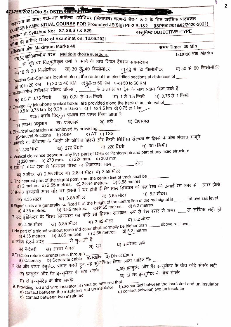
(d) INDIA 4. Traction Sub-Stations located along the route of the electrified sections at distances of
_________ (c)
(a) 10 to 20 KM
(b) 30 to 40 KM
(c) 40 to 50 KM
(d) 50 to 60 KM 5. At each traction sub-station, normally _________ no of single phase transformers of
21.6/30.2 MVA capacity are installed (b)
(a) One
(b) Two
(c) three
(d) four 6. The permissible variation of bus bar RE voltage is within _________ (b)
(a) +10% to –10%
(b) +10% to –5%
(c) +5% to –10%
(d) +5% to –5%
471725/2021/O/o Sr.DSTE/RNC/SER57
S7 Signalling in 25 KV AC Electrified Section
2
7. Emergency telephone socket boxes are provided along the track at an interval of (d)
(a) 0.5 to 0.75 km
(b) 0.25 to 0.5km
(c) 1 to 1.5 km
(d) 0.75 to 1 km 8. By plugging the portable telephone into an emergency socket it is possible to communicate
with the (a)
(a) TPC.
(b) Station SM
(c) Test Room
(d) Controler 9. Power for traction is tapped from different phases at adjacent substations in cyclic order(a)
(a) To minimize imbalance
(b) To improve the voltage
(c) To improve PF
(d) To minimise power loss 10. Electrical separation is achieved by providing _________ (a)
(a) Neutral Sections
(b) SSP
(c) AT
(d) TSS 11. These are situated approximately midway between two TSS (b)
(a) SSP
(b) SP
(c) AT
(d) STAGGERING 12. Neutral section is provided to avoid _________ of two different phases (c)
(a) staggering
(b) switching
(c) bridging
(d) anchoring 13. SSP facilitates maintenance and rapid isolation of OHE faults. (a)
(a) maintenance and rapid isolation
(b) switching
(c) bridging
(d) staggering
471725/2021/O/o Sr.DSTE/RNC/SER58

S7 Signalling in 25 KV AC Electrified Section
3
14. A stranded Cadmium Copper wire of about ____ sq.mm cross-section used for catenary (c)
(a) 100 sq.mm
(b) 150 sq.mm
(c) 65 sq.mm
(d) 50 sq.mm 15. A stranded Aluminium alloy wire of about ____ sq.mm cross-section used for catenary (a)
(a) 115 sq.mm
(b) 150 sq.mm
(c) 65 sq.mm
(d) 50 sq.mm 16. A grooved hard drawn Copper contact wire of 150 sq. mm wire is used to cater for higher
catenary current in new works (b)
(a) 115 sq.mm
(b) 150 sq.mm
(c) 65 sq.mm
(d) 50 sq.mm 17. The contact wire is supported from the catenary by means of droppers _________ (a)
(a) droppers
(b) insulators
(c) clips
(d) ties 18. OHE with automatic tensioning is called _________ OHE. (a)
(a) Regulated
(b) Un Regulated
(c) automatic tensioning
(d) Normal 19. The normal height of contact wire for regulated OHE is 5.55 m above rail level (a)
(a) 5,5 Mtrs
(b) 7.5 Mtrs
(c) 6.5 Mtrs
(d) 6 Mtrs 20. On straight tracks, the catenary system is normally supported at maximum intervals of
_________ m for BG (d)
(a) 50 Mtrs
(b) 65 Mtrs
(c) 55 Mtrs
(d) 72 Mtrs
471725/2021/O/o Sr.DSTE/RNC/SER59

S7 Signalling in 25 KV AC Electrified Section
4
21. On curvatured tracks, the catenary system is normally supported at minimum intervals of _________ m for BG (d)
(a) 20 Mtrs
(b) 35 Mtrs
(c) 55 Mtrs
(d) 27 Mtrs 22. The contact wire is "Staggered" so that it ensures a _________ (b)
(a) uniform wear & tear of the contact wire.
(b) uniform wear & tear of the pantographs.
(c) uniform wear & tear of the catenary wire.
(d) proper contact of pantograph with contact wire . 23. Providing of catenary wire along with contact wire to ensure (d)
(a) traction return current though it.
(b) Strengthening of conductivity.
(c) Less voltage drop.
(d) Constant hight of contact wire w.r.to rail . 24. The OHE conductors are terminated at intervals of about 1.5 KM to 2.0 KM with _________
anchored (a)
(a) anchored.
(b) isolated.
(c) Staggered
(d) neutralised. 25. ________________ are provided at all the signalling and operationally essential lighting
installations (a)
(a) Auxiliary transformers
(b) Sub sectioning posts
(c) Sectioning posts
(d) TSS. 26. Auxiliary transformers are to supply ac at _________ (d)
(a) 240 V, 60 Hz.
(b) 1100 V, 50 Hz.
(c) 2200 V, 50 Hz
(d) 240 V, 50 Hz. 27. Auxiliary transformers (AT) is made available to ensure reliable supply for Level crossings
located at a distance of more than 2 km from Railway Station (b)
(a) less than 2 km from Railway Station
(b) more than 2 km from Railway Station
(c) at 2 km from Railway Station
(d) more than 1 km from Railway Station
471725/2021/O/o Sr.DSTE/RNC/SER60
S7 Signalling in 25 KV AC Electrified Section
5
28. For collecting power from 25 KV AC contact wire pantographs are provided with _________ In order to improve the life of the contact wire (a)
(a) carbon strips
(b) silver strips
(c) brass strips
(d) copper strips 29. To indicate to the driver that he is approaching a neutral section two warning boards at a
distance of (b)
(a) 500 m and 250 m in rear
(b) 500 m and 250 m in advance
(c) 500 m and 1000 m in rear
(d) 500 m and 1000 m in advance
471725/2021/O/o Sr.DSTE/RNC/SER61
S7 Signalling in 25 KV AC Electrified Section
6
Chapter-2 : Signal Clearance And Visibility 1. In the vicinity of high voltage conductors, a minimum electrical clearance is required to be provided to safeguard against (c)
(a) flashing
(b) arcing
(c) flashing/arcing
(d) Conducting
2. Vertical clearance between any live part of OHE or Pantograph and part of any fixed structure (a)
(a) 320 mm.
(b) 270 mm.
(c) 220 mm.
(d) 300 mm.
3. Vertical clearance between any live part of OHE or Pantograph and part of moving load (b)
(a) 320 mm.
(b) 270 mm.
(c) 220 mm.
(d) 300 mm.
4. Lateral clearance between any live part of OHE or Pantograph and part of any fixed structure (a)
(a) 320 mm.
(b) 270 mm.
(c) 220 mm.
(d) 300 mm.
5. Lateral clearance between any live part of OHE or Pantograph and part of moving load (c)
(a) 320 mm.
(b) 270 mm.
(c) 220 mm.
(d) 300 mm.
6. Under no circumstances, a signal post or any of its fittings must be allowed to infringe _________ (b)
(a) Outside un-shaded portion
(b) in the un-shaded portion
(c) arcing zone
(d) plashing zone 7. When the signals have to be so located that they infringe, in to the shaded area (c)
(a) Warning board to be provided (b) Wire mesh without earth
(c) Wire mesh with earth (d) Earhing of Signal post
471725/2021/O/o Sr.DSTE/RNC/SER62

S7 Signalling in 25 KV AC Electrified Section
7
8. In case of signals located above the contact wire and provided with the iron screen it is necessary to connect them to the earth with earth resistance not exceeding _________ Ohms (b)
(a) 100 Ohms
(b) 10 Ohms
(c) 5 Ohms
(d) 2 Ohms 9. The screen shall be provided on the side adjacent to the catenary and for a signal post
between two wired tracks _________ (a)
(a) a screen on either side of the post will be required
(b) a screen any one side of the post will be required
(c) a screen on neither side of the post required
(d) its a option 10. The distance between the signal and the mast in front of it must be _________ (b)
(a) Less than 30 metres.
(b) more than 30 metres.
(c) Less than 10 metres.
(d) more than 10 metres. 11. It is not desirable to locate a signal closer than _________ from the mast behind it. (d)
(a) 50 metres.
(b) 40 metres.
(c) 20 metres.
(d) 10 metres. 12. The distance from centre line of track to the nearest part of the masts is normally
_________. This is called normal implantation or normal setting distance. (b)
(a) 2 metres.
(b) 2.5 metres.
(c) 3 metres.
(d) 3.5 metres. 13. The nearest part of the signal post from the centre line of track shall be _________ (c)
(a) 2 metres.
(b) 2.55 metres.
(c) 2.844 metres.
(d) 3.58 metres.
14. RDSO have recommended the setting distances/extra implantation of the masts in front of the signal MACLS without Route Indicator for a visibility of ____ on a tangent track. (b)
(a) 500 metres.
(b) 600 metres.
(c) 650 metres.
(d) 1000 metres.
471725/2021/O/o Sr.DSTE/RNC/SER63

S7 Signalling in 25 KV AC Electrified Section
8
15. RDSO have recommended the setting distances/extra implantation of the masts in front of the signal MACLS without Route Indicator for a visibility of ____ on a tangent track. (d)
(a) 500 metres.
(b) 600 metres.
(c) 650 metres.
(d) 1000 metres. 16. RDSO have recommended the setting distances/extra implantation of the masts in front of
the signal MACLS with route indicator with horizontal arm for a visibility of ______. (b)
(a) 500 metres.
(b) 600 metres.
(c) 650 metres.
(d) 1000 metres. 17. RDSO have recommended the setting distances/extra implantation of the masts in front of
the signal MACLS with route indicator without horizontal arm for a visibility of _____ (b)
(a) 500 metres.
(b) 600 metres.
(c) 650 metres.
(d) 1000 metres. 18. Signal units are generally so fixed that the height of the centre line of the red signal is
_________ above rail level (c)
(a) 4.35 metres.
(b) 3.85 metres.
(c) 3.65 metres.
(d) 5.2 metres. 19. No part of a signal without route indicator shall normally be higher than _________ above
rail level. (d)
(a) 4.35 metres.
(b) 3.85 metres.
(c) 3.65 metres.
(d) 5.2 metres. 20. For implantation no masts shall be provided for at least _________ spans in front of the
signal. (b)
(a) 4
(b) 3
(c) 2
(d) 1
471725/2021/O/o Sr.DSTE/RNC/SER64
S7 Signalling in 25 KV AC Electrified Section
9
Chapter 3 – Protection of Operating and S&T Staff 1. Traction return currents pass through _________ (c)
(a) Catenary
(b) Separate cable
(c) Rails
(d) Direct Earth
2. The rods and wires in AC Electrified areas do carry a certain amount of _________ (c)
(a) induced Current
(b) induced voltage
(c) induced voltage and current
(d) No induced voltage and current
3. To protect the Operating and S&T staff from the effects of the voltages the rod runs and wires are (a)
(a) provided with insulations.
(b) provided with metal paint.
(c) provided with warning
(d) provided with normal arrangement
4. Each rod shall be provided with an insulator in the lead-out as close to the cabin as possible. (a)
(a) as close to the cabin
(b) as away from the cabin
(c) as middle to the cabin
(d) as any where to the cabin 5. Providing rod and wire insulator, it must be ensured that (b)
(a) contact between the insulated and un insulator
(b) no contact between the insulated and un insulator
(c) contact between two insulated
(d) contact between two un insulator 6. An additional insulator shall be provided between the last adjustable crank and the point/lock
bar (b)
(a) The purpose to provide the adjustment to the run of rods
(b) The purpose to prevent the rail voltage being passed on to the run of rods
(c) The purpose to prevent the corrosion of rods
(d) The purpose to provide strength to the run of rods 7. If the rod transmission is more than 300 metres, _________ shall be provided on each rod
at every 300 metres (c)
(a) additional warning board
(b) additional adjustable crank
(c) additional insulators
(d) additional compensator
471725/2021/O/o Sr.DSTE/RNC/SER65

S7 Signalling in 25 KV AC Electrified Section
10
8. If the rod transmission is more than _________ metres, additional insulators shall be provided on each rod at every 300 metres (c)
(a) 200
(b) 400
(c) 300
(d) 250 9. The distance between the insulators and the adjacent rod roller guide shall be _________ to
permit the normal movement of the rod (d)
(a) Very close
(b) 1 Mtr
(c) 2 Mtrs
(d) adequate
10. Since the normal stroke is 200 mm, the insulation shall be at least _________ mm from the rod roller guide (a)
(a) 305
(b) 310
(c) 300
(d) 200
11. In case there is a large number of rodding in the same alignment, the insulated joints shall be provided on each rod run between the. (a)
(a) same sets of rod roller guides
(b) different sets of rod roller guides
(c) two no. of staggering of roller guides
(d) three no. of staggering of roller guides 12. The insulations shall be staggered so that the distance between the insulated joints of the
two neighbouring rods shall not be less than _________ mm (a)
(a) 305
(b) 310
(c) 300
(d) 200 13. For rod running under the track, the top of the rod shall not be less than _________ mm
below the bottom of the rail (b)
(a) 20
(b) 40
(c) 30
(d) 34
471725/2021/O/o Sr.DSTE/RNC/SER66

S7 Signalling in 25 KV AC Electrified Section
11
14. The distance between any OHE mast & the point rod shall not be less than ____ mm (b)
(a) 20
(b) 40
(c) 30
(d) 34
15. The wire insulator shall be provided on each wire as close to the cabin as possible. It is advisable to provide the insulator inside the cabin. (b)
(a) To avoid theft.
(b) is not exposed to sun and rain directly.
(c) For easy of maintenance.
(d) For better conduction.
16. An insulator shall be provided in each wire _________ the gear of operation (a)
(a) Near.
(b) At Starting to.
(c) Middle to.
(d) Any place to
17. All insulators shall be provided between _________ supporting brackets. (b)
(a) between three consecutive stakes or pulleys
(b) between two consecutive stakes or pulleys
(c) between four consecutive stakes or pulleys
(d) between six consecutive stakes or pulleys
18. The horizontal distance between two wires shall not be less than _________ mm. (b)
(a) 20
(b) 50
(c) 30
(d) 34
19. The vertical distance between two wires shall not be less than _________ mm. (d)
(a) 305
(b) 310
(c) 300
(d) 200 20. A minimum distance of _________ mm shall be maintained between the wire and the
nearest edge of the rail or mast (b)
(a) 20
(b) 40
(c) 30
(d) 34
471725/2021/O/o Sr.DSTE/RNC/SER67

S7 Signalling in 25 KV AC Electrified Section
12
Chapter 4 : Earthing arrangements in RE Area
1. To afford safety to the operating and maintenance personnel against electric shock. (c)
(a) Provide safety precaution
(b) Provide insulated gears
(c) Provide proper earthing to metal gears and safety precaution
(d) Avoid staff operating the gears 2. Dangerous (voltage) potential appearing on the exposed parts with respect to earth due to (c)
(a) electromagnetic induction
(b) electrostatic induction
(c) electromagnetic or electrostatic induction
(d) Proper earthing 3. To ensure reliable and safe operation of the equipment by limiting or eliminating the
___________ signal and Block circuits. (a)
(a) induced voltages in
(b) earthing of
(c) increasing length of parallelism
(d) introducing more metallic gears in 4. Block filter earthing and earthing of metallic cable sheath and armour are examples of this
type of earthing (d)
(a) increasing length of parallelism
(b) introducing more metallic gears in
(c) separation from earthing
(d) limiting or eliminating the induced voltages
5. Equipment against build up of unduly high, voltages this can cause dielectric (___________) breakdown (a)
(a) dielectric (Insulation) breakdown
(b) dielectric (conductor) breakdown
(c) dielectric (Earthing) breakdown
(d) dielectric (metallic body) breakdown
6. Dielectric (Insulation) breakdown can occur mostly due to the _______ and lightning (b)
(a) earthing
(b) physical contact of 25 KV with Track
(c) increasing length of parallelism
(d) introducing more metallic gears in
471725/2021/O/o Sr.DSTE/RNC/SER68
S7 Signalling in 25 KV AC Electrified Section
13
7. The lever frame and other metallic frames of the cabin ___________ (b)
(a) No earthing is required
(b) shall be connected together to a separate earthing
(c) shall be connected separate to a separate earthing
(d) shall be connected together to a block earthing
8. Metallic sheath and armouring of all underground cables (a)
(a) to be earthing both ends
(b) not to be earthed
(c) Earthing is option
(d) to be earthing any one ends 9. In case of signals falling within 2 meters from the live parts of the OHE, the protection screen
shall be connected (d)
(a) to the +ve Rails
(b) to the -ve Rails
(c) to the Both Rails
(d) to earth
10. The resistance of an earth shall not exceed ___________ ohms. Where a number of cables are run together (c)
(a) 2
(b) 4
(c) 10
(d) 5
471725/2021/O/o Sr.DSTE/RNC/SER69

S7 Signalling in 25 KV AC Electrified Section
14
Chapter 5 : Laying of Signalling Cables 1. In the vicinity of 25KV AC OHE, ___________ permitted to be used as they are subjected to
induction (b)
(a) aerial lines are (b) No aerial lines are
(c) No underground cable are (d) No MW comm. allowed 2. The main cables on AC electrified sections shall ordinarily be ___________ cable (d)
(a) PVC insulated
(b) Armoured
(c) aerial lines
(d) PVC insulated and armoured 3. Paper insulated lead sheathed and armoured cables were earlier used but have since been
discontinued in view of (c)
(a) special jointing are requirements
(b) special terminating requirements
(c) special jointing and terminating requirements
(d) Not to RE standards
4. Paper insulated Lead Sheathed (PILC) cables Failures on account of ___________ resulting in low insulation (a)
(a) ingress of moisture
(b) Improper Earthing
(c) Electro Magnetic induction
(d) Electro Static induction
5. Insulation resistance of each core shall not be _______ at 500C as per IRS: S 63-89. (d)
(a) more than 5.0 mega ohms/km
(b) less than 5.0 K. ohms/km
(c) more than 5.0 K. ohms/km
(d) less than 5.0 mega ohms/km
6. The use of screened cables was discontinued owing to practical reasons involving ________ (c)
(a) realisable earthing effect
(b) realisable cost effect
(c) realisable screening effect
(d) realisable induction effect 7. As per extant instructions, ___________ shall be used for carrying signalling circuits. (a)
(a) only PVC insulated, sheathed, armoured unscreened cable
(b) only PVC insulated, sheathed, armoured screened cable
(c) only PVC sheathed, armoured unscreened cable
(d) only PVC insulated, armoured unscreened cable
471725/2021/O/o Sr.DSTE/RNC/SER70

S7 Signalling in 25 KV AC Electrified Section
15
8. Screened signalling cable may be used in cases of signalling installations where _________ its further use (a)
(a) screened cable is already in use
(b) screened cable is already in use site conditions demand
(c) site conditions demand
(d) lightening is more
9. The cables laid parallel to the track shall normally be buried at a depth of ________ (c)
(a) 0.50 m
(b) 0.60 m
(c) 0.80 m
(d) 1.00 m
10. The cables laid across the track must be at a depth of ___________ Below the bottom of the rail. (d)
(a) 0.50 m
(b) 0.60 m
(c) 0.80 m
(d) 1.00 m
11. in case of rocky soil, the depth of main cable may be reduced to ___________ (a)
(a) 0.50 m
(b) 0.20 m
(c) 0.30 m
(d) 0.10 m
12. The depth of tail cables, which serve the track apparatus, shall not be less than ____ (a)
(a) 0.50 m
(b) 0.20 m
(c) 0.30 m
(d) 0.10 m
13. The cable shall be so laid that it is not less than ___________ from the nearest edge of the mast supporting the catenary or any other live conductor. (d)
(a) 3.00 m
(b) 2.00 m
(c) 2.00 m
(d) 1.00 m
14. When the cable is laid at a depth greater than 0.5 m, a min distance of ___________ between the cable and the nearest edge of the OHE structure shall be maintained (a)
(a) 3.00 m
(b) 2.00 m
(c) 2.00 m
(d) 1.00 m
471725/2021/O/o Sr.DSTE/RNC/SER71
S7 Signalling in 25 KV AC Electrified Section
16
15. The depth of the cable does not exceed ___________ if the distance between the cable and OHE structure is Less than 3 mtr (a)
(a) 0.50 m
(b) 0.60 m
(c) 0.80 m
(d) 1.00 m
16. If it is difficult to maintain distances between the cable and OHE structure the cable shall be laid in concrete/heavy duty HDPE/Ducts or any other approved means for a distance of ___________ on either side of the mast (a)
(a) 3.00 m
(b) 2.00 m
(c) 2.00 m
(d) 1.00 m
17. the cable laid in concrete/heavy duty HDPE/Ducts or any other approved means for a distance of 3 m on either side of the mast the distance between the cable and the mast may be reduced to ___________ (c)
(a) 0.80 m
(b) 0.60 m
(c) 0.50 m
(d) 1.00 m
18. In the vicinity of TSS, the cables shall be laid at least ___________ away from any metallic body of the substation (d)
(a) 0.80 m
(b) 0.60 m
(c) 0.50 m
(d) 1.00 m
19. In the vicinity of TSS, the cables shall be laid _____ away from the substation earth (d)
(a) 0.80 m
(b) 0.60 m
(c) 0.50 m
(d) 1.00 m
20. In the vicinity of TSS The cables shall therefore be laid in concrete pipes or enclosed brick channels for a length of ___________ on either side of the sub-station (c)
(a) 100 m
(b) 200 m
(c) 300 m
(d) 400 m
471725/2021/O/o Sr.DSTE/RNC/SER72

S7 Signalling in 25 KV AC Electrified Section
17
21. In the vicinity of TSS As far as possible, the cables shall be laid ___________ to the sub-station side. (b)
(a) on the side of the track same
(b) on the side of the track opposite
(c) in between the track
(d) Close to the TSS
22. In the vicinity of the switching stations the cables shall be laid at least ___________ metre away from any metallic body of the station which is fixed in the ground. (d)
(a) 0.80 m
(b) 0.60 m
(c) 0.50 m
(d) 1.00 m
23. In the vicinity of the switching stations the cables shall be laid at least ___________ away from the switching station earthing. (d)
(a) 3.00 m
(b) 2.00 m
(c) 4.00 m
(d) 5.00 m
24. by laying the cables through a concrete pipes In the vicinity of the switching station earting the distance can be reduced to ___________ (a)
(a) 1.00 m
(b) 2.00 m
(c) 4.00 m
(d) 5.00 m
25. When more than one cable is laid and the sheath and armouring of each cable is ___________, the screening improves, thereby reducing induced voltages (a)
(a) separately earthed
(b) earthed together
(c) isolated from earth
(d) connected to +ve Rail 26. When ___________ cables are laid in the same trench, a distance of 100mm is to be
maintained between them (b)
(a) signalling main and tail cables
(b) signalling and telecom cables
(c) signalling and LT or HT power cables
(d) telecom and tail cables
471725/2021/O/o Sr.DSTE/RNC/SER73

S7 Signalling in 25 KV AC Electrified Section
18
27. When ___________ cables are laid in the same trench, they must be separated by a row of bricks between them. (c)
(a) signalling main and tail cables
(b) signalling and telecom cables
(c) signalling and LT or HT power cables
(d) telecom and tail cables
28. For recognising different cables in same trench the cables shall be laid in an order from top (b) (a) Telecom, HT, bricks, signal, LT. cable
(b) Telecom, signal, bricks, LT,HT. cable
(c) Telecom, bricks ,signal,, LT,HT. cable
(d) signal, bricks, LT, Telecom, HT. cable
29. When _________ are laid in separate trench and are running parallel, a minimum horizontal distance of 0.50 m (a)
(a) HT or LT power and signalling cables
(b) signalling and Telecom cables
(c) Telecom and signalling cables
(d) HT and LT power cables
30. When HT or LT power cables and signalling cables are laid in separate trench _________ a minimum distance of 0.20 metres shall be maintained. (b)
(a) On fat forms
(b) On track crossings
(c) On bridges
(d) On culverts
31. During track crossings The cables should cross the track ___________ (b)
(a) Parallel to the track
(b) at right angles
(c) at angle of 45º
(d) ZIG Zag to the track
32. The cables should cross the track under ___________ (c)
(a) points and crossings
(b) bridges
(c) plain track where no points and crossings
(d) any place 33. The cables are to be laid in ___________ while crossing the track (a)
(a) concrete pipes
(b) GI pipe
(c) HDFC Pipes
(d) PVC Pipe
471725/2021/O/o Sr.DSTE/RNC/SER74

S7 Signalling in 25 KV AC Electrified Section
19
34. The ___________ of the cable trench shall be normally 0.46 metre (c)
(a) Depth
(b) Length
(c) width
(d) Size
35. The bottom of the cable trench In case, the ground is rocky, the cable shall be laid on a layer of _________ of 50mm thickness deposited at the bottom of the trench (c)
(a) River Sand
(b) Sea Sand
(c) Coal
(d) Metal stone
36. When cables have to cross a metallic bridge, they shall be placed inside a _________ withstand 6000 V AC (a)
(a) GI trough filled with sealing compound suitable to
(b) RCC Pipes
(c) GI PIPES
(d) HDFC
37. _________ the cables shall be laid at a distance of 8 to 10 metres from the centre of the nearest track (c)
(a) Within the station limits
(b) Outside Block section
(c) Outside station limits
(d) Station and Block section limits
38. _________ where there are no OHE masts along the route of the cable, the trenches shall preferably be dug at a distance of 3 metres from the centre of track. (a)
(a) Within the station limits
(b) Outside Block section
(c) Outside station limits
(d) Station and Block section limits
39. _________ when there are OHE masts along the route of the cable, the trenches shall be dug at a distance of not less than 5.5 metres from the centre of the track. (a)
(a) Within the station limits
(b) Outside Block section
(c) Outside station limits
(d) Station and Block section limits
40. Trenches shall be dug, cables laid and refilling done _________ (c)
(a) Within one week
(b) Within 10 days
(c) on the same day
(d) as per site condition
471725/2021/O/o Sr.DSTE/RNC/SER75

S7 Signalling in 25 KV AC Electrified Section
20
41. During excavation, the soil of the trenches shall be thrown _________ (b)
(a) on the ballast
(b) away from the ballast
(c) In side of track
(d) In between up and Down Track
42. In the case of track crossings, the work shall be done in the presence _________ (d)
(a) ASTE
(b) Sr.DSTE
(c) RPF
(d) JE/SSE P way
43. The cabling work shall be supervised at site personally by an official of S&T department not below the rank of (d)
(a) ASTE
(b) Sr.DSTE
(c) SSE/Sig
(d) JE/Sig
471725/2021/O/o Sr.DSTE/RNC/SER76
S7 Signalling in 25 KV AC Electrified Section
21
Chapter 6 : Block Instruments & Circuits 1. The block circuits shall he transferred to __________ in RE area (a)
(a) underground cables
(b) areal lines
(c) MW
(d) Wan Network
2. Since block circuits are safety circuits, __________ shall be provided for block circuits in RE area (a)
a. special P.V.C. insulated quads
b. underground cables
c. aerial lines
d. underground Un Screened cables
3. A __________ is provided for each pair of block quad (c)
a. Circuit Breaker
b. Earthing
c. transformer
d. Condenser
4. The pairs are used through the transformers for __________ circuits (d)
a. block telephones
b. block bell
c. block Instrument
d. block telephones and block bell
5. For block circuits, which work on DC, __________ used and so direct connection through the cables (b)
a. transformers can be
b. transformers cannot be
c. SPD can be
d. Condensers in series
6. To ______ cable conductors, the phantoms of each pair is used for the block circuit (c)
a. Improve insulation of
b. Reliable service of
c. economise on
d. avoid noise in 7. Protective devices shall be provided __________ for protection of the instruments as well as
the staff operating them (d)
a. as per site condition
b. at one end of the block circuit
c. as an option
d. at either end of the block circuit
471725/2021/O/o Sr.DSTE/RNC/SER77
S7 Signalling in 25 KV AC Electrified Section
22
8. The principal protective device used is called __________ For block working (c)
a. phantoms circuit
b. Isolation T/F
c. Block Filter
d. Condenser
9. The filter unit consists of __________ connected across the junction (b)
a. four chokes with Four condensers
b. four chokes with two condensers
c. Two chokes with two condensers
d. Two chokes with Four condensers
10. When OFC, Radio or other communication means are used for block working _________ of approved design shall be used (d)
a. Block panel
b. SSDAC
c. BPAC
d. UFSBI
11. UFSBI equipment always __________ block instruments (c)
a. in centre of Block section
b. Away from the
c. be close to the
d. Keep At LSS or Home for
12. In case the distance between UFSBI and block instrument is more than 500 metres ______ shall be inserted (c)
a. SPD
b. Isolation T/F
c. block filter
d. RE Cutting
13. When a block section originates at a station in electrified area and terminates at a station in non-electrified area, filters __________ of such block section (a)
a. shall be provided at both ends
b. shall be provided at one ends
c. are not required
d. are option
471725/2021/O/o Sr.DSTE/RNC/SER78

S7 Signalling in 25 KV AC Electrified Section
23
Chapter 7 : Stray Currents 1. Natural currents are found to be flowing in the soil in most parts of the world especially in
_______ (b)
a. Black Soils
b. rocky Soils
c. Hills area
d. sea shores 2. It is necessary that stray current tests be carried out to ensure that _______ do not operate
with stray currents (a)
a. DC track relays
b. Point operating relays
c. Block operating relays
d. Point operating relays 3. For measuring the stray current test are to be carried out only on _______ (d)
a. Station sections
b. Block sections
c. Electrified Areas
d. Non-electrified Areas
4. For measurement of stray voltage the resistance 'R' shall be equal to the resistance of the (b)
a. Earth pit
b. Track Relays
c. Rails
d. Ballast 5. For measurement of stray voltage, _______ as measured across the Resistance 'R' shall not
exceed 100 mill volts. (c)
a. Earth pit drop voltage
b. Track Relays voltage
c. Rail earth voltage
d. Cable Voltage Drop
6. The total stray current as measured, shall not exceed 10 milliamps if the length of the track circuit is (a)
a. less than 100 metres
b. More than 100 metres
c. less than 100 Khmers
d. More than 100 K.metres 7. The total stray current as measured, shall not exceed 100 milliamps, if the length of the track
circuit is. (b)
a. less than 100 metres b. More than 100 metres
c. less than 100 Khmers d. More than 100 K.metres
471725/2021/O/o Sr.DSTE/RNC/SER79
S7 Signalling in 25 KV AC Electrified Section
24
Chapter 8 : Alterations to Track Circuits 1. In a _______ only one rail is used for traction return current and the other rail is insulated for
track circuiting (a)
a. DC track circuit
b. Audio Frequency track circuit
c. Universal AXC
d. Digital AXC
2.The rail, which is reserved for traction return current, is called the un insulated rail Any connection from the OHE mast or any other structure shall be made to the _____ only (a)
a. un insulated rail
b. insulated rail
c. un insulated and insulated rail
d. Near by S&T Location
3. When the track is shunted by a pair of wheels at the far end large alternating current can flow through –ve rail and producing a voltage drop of 10 volts per 90 metres across _______ at 250 Amps. (d)
a. battery
b. Charger
c. +ve Rail
d. Track Relay
4. There are two contemporary methods of A.C. immunisation, one employing a series _______ and the other inherently immunising the relay itself (c)
a. battery
b. Charger
c. Choke
d. Track repeater Relay
5. _______ has high A.C. impedance, and D.C. resistance of only few ohms which can easily be connected in series with the relay (c)
a. battery
b. Charger
c. Choke
d. Track Relay
6. _______ safe and reliable operation, could be maintained with max: 50 V A.C. across the relay and on this basis, a maximum length of 450 meters (c)
a. Using A.C. immunised Track Repeater relays
b. Choke
c. Using A.C. immunised Track Relay
d. Regulating Resistance of 0-30Ω
471725/2021/O/o Sr.DSTE/RNC/SER80

S7 Signalling in 25 KV AC Electrified Section
25
7. If the feed end and relay ends happen to be interchanged, then the _______ is required to be protected from the A.C. voltages. (a)
a. battery
b. Charger
c. Choke
d. Track Relay
8. At Feed end, transformer rectifier set alone should _______ (a)
a. not be used
b. be used
c. Option
d. be used with SPD and filters
9. The maximum length of track circuit is 450 m, if _______ are provided with a train shunt resistance (TSR) value of 0.5 ohm. (b)
a. concrete sleepers
b. wooden sleepers
c. Iron sleeper
d. concrete and wooden sleepers
10. D.C. single rail track circuit length shall not exceed 350 metres when _______ are used (RDSO's letter No. STS/EANS/SLP dated 18.10.1978) (a)
a. concrete sleepers
b. wooden sleepers
c. Iron sleeper
d. concrete and wooden sleepers
11. Transverse Bonding is provided by Electrical Department but the identification of the non-insulated rail is to be done _______ Department (c)
a. Engineering
b. OHE
c. S and T
d. Operating
12. In the event of a break in the _______ very heavy current will have flow through the track relay as well as the equipment to avoid this, the un-insulated rails of adjacent tracks shall be cross bonded at intervals of 100 metres. (a)
a. un-insulated rail
b. insulated rail
c. un-insulated and insulated rail
d. catenary
13. _______ shall be provided on the un-insulated rail at either end of the track circuit in case the track circuit is less than 100 metres (b)
a. Transverse Bonding
b. Cross Bonding
c. Structural Bonding
d. Longitudinal Bonding
471725/2021/O/o Sr.DSTE/RNC/SER81
S7 Signalling in 25 KV AC Electrified Section
26
14. Cross Bonding shall be provided on the _______ at either end of the track circuit in case the track circuit is less than 100 metres (a)
a. un-insulated rail
b. insulated rail
c. S & T Signal Post
d. Un insulated and insulated rail
15. On single line sections, beyond top Points For _______ an extra rail (scrap rail) will be laid by Engineering Department (b)
a. Transverse Bonding
b. Cross Bonding
c. Structural Bonding
d. Longitudinal Bonding
16. Structural Bonds provided to connect any metallic structure of _______ which is near by the side of track to un-insulated rail (b)
a. Engineering
b. OHE
c. S and T
d. Operating
17. Structural Bonds provided to connect any metallic structure of OHE which is near by the side of track to _______ rail (a)
a. un-insulated rail
b. insulated rail
c. S and T Sigg Post
d. un-insulated and insulated rail
18. Longitudinal bonding on the insulated rails of single track circuits shall be provided by _______ with Standard No.8 SWG, G.I. wire (c)
a. Engineering Department
b. Electrical Department
c. S and T Department
d. Operating Department
19. Longitudinal bonding on the Un-insulated rails of single track circuits shall be provided by ___________ (c)
a. Engineering Department
b. Electrical Department
c. S and T Department
d. Operating Department 20. The Cross Bonding, longitudinal bonding, transverse bonding, structural bonding and shunt
bonding are done by _______. (b)
a. Engineering Department
b. Electrical Department
c. S and T Department
d. Operating Department
471725/2021/O/o Sr.DSTE/RNC/SER82
S7 Signalling in 25 KV AC Electrified Section
27
21. _______ has good immunity to 50Hz AC induced voltage or harmonics generated by thyristor controlled locos (a)
a. AFTC track circuit
b. AFTC and DC track circuit
c. DC track circuit
d. AC track circuit
471725/2021/O/o Sr.DSTE/RNC/SER83

S7 Signalling in 25 KV AC Electrified Section
28
Chapter 9 : Induction & It’s Effects on Signalling 1. When a conductor carries current, there is a _______ around the conductor (d)
a. EMF
b. Static field
c. magnetic field
d. Static field, magnetic field and EMF
2. Any conductor linking with magnetic lines of force, has a _______ in it according to the well known "Faraday's Law of Electromagnetic Induction (a)
a. voltage induced
b. Static field
c. magnetic field
d. Static and magnetic field
3. The _______ emanates from the positive charge and ends at the negative charge unlike magnetic lines of force (b)
a. electro-Magnetic static field
b. electro-static field
c. magnetic field
d. Electro Static and magnetic field
4. The electro-static field emanates and any conductor that exists within the field will ____ (d)
a. electro-Magnetic static field
b. electro-static field
c. magnetic field
d. Get charged 5. The power conductor and the S&T conductor in the vicinity can be deemed to have small
capacitance ____________ (b)
a. to Centenary
b. to earth and between themselves
c. to earth only
d. between themselves only
6. The magnitude of the capacitances depends on the _______ in RE area (b)
a. physical separation conditions only
b. physical separation and atmospheric conditions
c. atmospheric conditions only
d. cant say 7. The voltage induced electrostatic ally in an _______ situated at a distance of 10 metres from
the track was calculated to be about 3000V If the parallelism of this line is 1 KM (a)
a. an overhead
b. Return Rail
c. UG Signalling Cable
d. UG Telecom Cable
471725/2021/O/o Sr.DSTE/RNC/SER84

S7 Signalling in 25 KV AC Electrified Section
29
8. The voltage induced electrostatic ally in an overhead if someone touch this line, a current of about _______ will flow through the body of the person (b)
a. 4 amps
b. 4 milliamps
c. 10 milliamps
d. 10 amps
9. If the value of the current is _______ or above, it would prove to be fatal to a person. (c)
a. 4 amps
b. 4 milliamps
c. 15 milliamps
d. 15 amps 10. Electro-static voltage can be eliminated by providing _______ between the catenary and the
signal and telecommunication lines (b)
a. an earthed metallic armour
b. an earthed metallic screen
c. an earthed cable cores
d. an earthed power supply of trough cable
11. The best method to eliminate the electrostatic induction there shall be _______ in the vicinity of A.C. Electrified track. (c)
a. aerial lines with earthed aerial post
b. aerial lines only
c. no aerial lines
d. MW and Aerial lines
12.When the entire outward and return current is restricted to two conductors located physically close to each other, the induced voltage on a third conductor due to each one of these will ____________ (b)
a. high
b. very nearly zero
c. low
d. We cant say low are high
13. If there is no parallel path through the earth, the whole of the traction return current would flow in the rails throughout their length, the screening factor of the rails would have a _______ value (b)
a. high
b. low
c. medium
d. normal
471725/2021/O/o Sr.DSTE/RNC/SER85

S7 Signalling in 25 KV AC Electrified Section
30
14. The screening factor is ___________ near the vehicle and near the sub-station than elsewhere (b)
a. higher
b. lower
c. medium
d. Normal
15. The return current through the rails helps in reducing the induced voltage to some extent. This property of the rail current is defined as __________ (a)
a. rail reduction factor
b. screening factor
c. Power factor
d. safety factor
16. _______ is 0.56 in. the case of single track and 0.4 in the case of double track. (d)
a. screening factor
b. mutual screening factor
c. safety factor
d. rail reduction factor
17. The induced voltage in the core reduces considerably by using screened cables. The extent by which the induced voltage is reduced is called as ____________ (a)
a. screening factor
b. mutual screening factor
c. safety factor
d. rail reduction factor 18. _______ due to the presence of other cables and metallic objects is taken as 0.75 (b)
a. screening factor
b. mutual screening factor
c. safety factor
d. rail reduction factor 19. For calculating the induced voltages, the _______ current has been taken as 600 Amps. on
Double line and 300 Amps on Single Line. (d)
a. Cable load
b. Rail return
c. Loco
d. catenary 20. The value of 35 _______ was finally used for S&T system design. A common design was
adopted for single and double/multiple track electrified sections for screened cable (c)
a. V/M DC
b. V/KM DC
c. V/KM AC
d. V/M AC
471725/2021/O/o Sr.DSTE/RNC/SER86
S7 Signalling in 25 KV AC Electrified Section
31
21. The value of 87.5 _______ was finally used for S&T system design. A common design was adopted for single and double/multiple track electrified sections for un screened cable (c)
a. V/M DC
b. V/KM DC
c. V/KM AC
d. V/M AC
22. The maximum length of _______ that can run parallel to the track shall be 3.5 Km. for safe handling by staff (a)
a. screened cable
b. Un screened cable
c. screened and unscreened cable
d. Aerial lines
23. The maximum length of _______ that can run parallel to the track shall be 1.2 Km. for safe handling by staff (b)
a. screened cable
b. Un screened cable
c. screened and unscreened cable
d. Aerial lines 24. The lowest voltage at which glowing of the lamp occurs is called the _______ (c)
a. Static Voltage
b. saturated Voltage
c. Glow Voltage
d. AC Voltage 25. The __________ is found to be 2.3 volts for a signal lamp working on 12 volts. (b)
a. Static Voltage
b. Glow Voltage
c. saturated Voltage
d. AC Voltage
26. All equipment should, therefore, be capable of withstanding higher induced voltage. This safety margin is called ___________ (c)
a. screening factor
b. mutual screening factor
c. factor of safety
d. rail reduction factor
27. The _______ for signalling equipment used for line side circuit is prescribed as 2.5 times (c)
a. screening factor
b. mutual screening factor
c. factor of safety
d. rail reduction factor
471725/2021/O/o Sr.DSTE/RNC/SER87

S7 Signalling in 25 KV AC Electrified Section
32
28. The maximum length of direct feeding of signals shall not exceed _______ when screened cables are used. (a)
a. 600 meters
b. 240 Km
c. 600 km
d. 240 meters
29. The maximum length of direct feeding of signals shall not exceed _______ when un screened cables are used. (d)
a. 600 meters
b. 240 Km
c. 600 km
d. 240 meters
471725/2021/O/o Sr.DSTE/RNC/SER88

S7 Signalling in 25 KV AC Electrified Section
33
Chapter 10 : Personnel safety in 25KV RE Area 1.The size of the Caution Board shall be 225 mm x 200 mm indicating in Hindi, English and
regional language in white letters with a red back ground provided at a height of 3 metres above ___________ (a)
a. Rail Level.
b. Ground level.
c. Ground and Rail level.
d. Ground or Rail level 2. The flow of return current in the rails will give rise to a __________ (c)
a. Rail Resistance.
b. Rail impedance.
c. Potential difference.
d. Ballast Resistance 3. Induction in Metallic Bodies situated close to _______ Equipment (a)
a. Overhead Electric.
b. Track Rail
c. Underground cables.
d. Aerial Lines 4. No work shall be done within a distance of two meters from the _______ of the O.H.E
without a ‘permit-to-work. (c)
a. mast
b. Earth pit.
c. Live parts
d. Anchor support 5. For work adjacent to overhead equipment the _______ shall apply to the proper authority
sufficiently in advance for sanctioning the traffic and power block required (c)
a. SSE/JE Engg
b. Dy.SS.
c. SSE/JE Sigg
d. SSE/JE OHE
6. The Traction Power Controller through Traction Foreman will arrange to _________ the section concerned on the date and at the time specified in consultation with the Traffic Controller (d)
a. isolate
b. earth.
c. isolate or earth
d. isolate and earth
471725/2021/O/o Sr.DSTE/RNC/SER89
S7 Signalling in 25 KV AC Electrified Section
34
7. Use rubber gloves as far as possible or alternatively use _______. (d)
a. Earth support
b. isolate
c. isolate and earth
d. insulated rubber mats
8. Where a plastic sleeve cannot be provided as in the cases of tommy bars etc., the tools may be painted with insulating paint _________________ (c)
a. at regular intervals of 2 to 3 days.
b. at regular intervals of 2 to 3 weeks
c. at regular intervals of 2 to 3 months.
d. at regular intervals of 2 to 3 Years.
471725/2021/O/o Sr.DSTE/RNC/SER90

S7 Signalling in 25 KV AC Electrified Section
35
Chapter 11 : Evaluation & Upgradation of Existing System Design – Various parameters 1. Realisable screening factor of 0.4 can be achieved for a cable with Intrinsic Screening factor -
_______ with earthing resistance of (b)
a. 2 Ohms
b. 0.2 Ohms
c. 10 Ohms
d. 1 Ohms 2. Due to anticipated increase in Traffic upgraded traction current on single line normal case. (a)
a. 800Amps
b. 6000Amps
c. 1000Amps
d. 8000Amps
3. Due to anticipated increase in Traffic upgraded traction current on single line Short circuit case. (b)
a. 800Amps
b. 6000Amps
c. 1000Amps
d. 8000Amps 4. Due to anticipated increase in Traffic upgraded traction current on Double line normal case.
(c) a. 800Amps
b. 6000Amps
c. 1000Amps
d. 8000Amps 5. Due to anticipated increase in Traffic upgraded traction current on Double line Short circuit
case. (d)
a. 800Amps
b. 6000Amps
c. 1000Amps
d. 8000Amps
471725/2021/O/o Sr.DSTE/RNC/SER91

S7 Signalling in 25 KV AC Electrified Section
36
Chapter 12 : Induced Voltages due to Higher Catenary Currents 1. Resistance of __________ determines the realisable screening factor (a)
a. Earthing
b. Soil
c. Rals
d. Cables
2. Low __________ resistance is not always feasible the Signal Standards Committee came to the conclusion that use of Screened cable may be discarded and to adopt Unscreened Cable for revised design. (a)
a. Earthing
b. Soil
c. Rals
d. Cables 3. In __________ The Induced Voltage with revised standard, has been calculated as 95
V/KM for Double Line 116V/KM for Single Line (b)
a. screened with armouring earthed
b. Unscreened with armouring earthed
c. screened without armouring earthed
d. un screened without armouring earthed
4. Track Cable Separation when both the rails are available for traction return current single line (b) a. 9m
b. 8m
c. 6m
d. 4m
5. Track Cable Separation when both the rails are available for traction return current Double line (a)
a. 9m
b. 8m
c. 6m
d. 4m
6. Rail Reduction Factor when both the rails are available for traction return current Double line (a)
a. 0.2666
b. 0.3926
c. 0.4
d. 0.5
471725/2021/O/o Sr.DSTE/RNC/SER92

S7 Signalling in 25 KV AC Electrified Section
37
7. Rail Reduction Factor when both the rails are available for traction return current Single line (b)
a. 0.2666
b. 0.3926
c. 0.4
d. 0.5
8. Rail Impedance when both the rails are available for traction return current Double line (b)
a. 0.701
b. 0.561
c. 0.2
d. 0.3
9. Rail Impedance when both the rails are available for traction return current Single line (a)
a. 0.701
b. 0.561
c. 0.2
d. 0.3
471725/2021/O/o Sr.DSTE/RNC/SER93

S7 Signalling in 25 KV AC Electrified Section
38
Chapter 13 : Revised Design of Signalling System to Suit High Catenary Currents 1. __________ cables would be used and that the induced voltages have been calculated as
95V/KM for double line and 116V/KM for single line. as per the revised standards (a)
a. unscreened
b. unscreened and screened
c. screened
d. Normal 2. Unscreened cables would be used and that the induced voltages have been calculated as
__________ for double line. as per the revised standards (a)
a. 95 V/KM
b. 35 V/KM
c. 87.5 V/KM
d. 116 V/KM 3. Unscreened cables would be used and that the induced voltages have been calculated as
__________ for single line. as per the revised standards (d)
a. 95V/KM
b. 35V/KM
c. 87.5V/KM
d. 116V/KM 4. The maximum induced voltage which can safely be handled by maintenance staff as per the
revised standards (d)
a. 120 V
b. 235 V
c. 440 V
d. 400 V 5. Block filters are provided to protect the equipment up to __________ A.C. (b)
a. 120 V
b. 600 V
c. 440 V
d. 400 V 6. If the induced voltage exceeds __________ the lightning arrestors to be provided on the line
side of the block filter (c)
a. 120 V
b. 300 V
c. 150 V
d. 400 V
471725/2021/O/o Sr.DSTE/RNC/SER94
S7 Signalling in 25 KV AC Electrified Section
39
7. The Polarised Relays for block working currently in use, as per IRS-S.31-80 have an inherent A.C. immunity of __________ only (d)
a. 120 V
b. 300 V
c. 50 V
d. 10 V 8. As per the revised standards the max. length of parallelism of a power cable is _____ (c)
a. 2.0 KM
b. 2.4 KM
c. 3.0 KM
d. 2.6 KM 9. Block circuits are taken in Telecom Cables having an Intrinsic Screening factor of ____ (d)
a. 2
b. 1
c. 3
d. 0.1 10. Electrical Point Machine non-trailable type with this the maximum permissible distance
between the machine and the contactor would be __________ (b)
a. 2 KM
b. 1.1 KM
c. 1.3 KM
d. 0.6 KM 11. Point Contactor type PPWR 1 of WSF make, which is planned for manufacture in India, has
an immunity value of __________ (b)
a. 2000 V
b. 1000 V
c. 500 V
d. 750 V 12 QBAT relays can be used up to a maximum length of track circuit of __________ using one
‘B’ type choke at the relay end (c)
a. 350 mtrs
b. 450 mtrs
c. 750 mtrs
d. 1000 mtrs 13. With 120 ohm. Impedance choke (3 ohm D.C. resistances) in series with the track relay, the
length can be increased in single line with revised standards (b)
a. 350 mtrs
b. 450 mtrs
c. 750 mtrs
d. 1000 mtrs
471725/2021/O/o Sr.DSTE/RNC/SER95

S7 Signalling in 25 KV AC Electrified Section
40
14. With 120 ohm. Impedance choke (3 ohm D.C. resistances) in series with the track relay, the length can be increased in Double line with revised standards (b)
a. 350 mtrs
b. 450 mtrs
c. 750 mtrs
d. 1000 mtrs 15. With 120 ohm. Impedance choke 3 ohm D.C. resistances in series with the track relay, the
length can be increased in single line with out revised standards (d)
a. 350 mtrs
b. 450 mtrs
c. 300 mtrs
d. 200 mtrs 16. With 120 ohm. Impedance choke 3 ohm D.C. resistances in series with the track relay, the
length can be increased in Double line without revised standards (c)
a. 350 mtrs
b. 450 mtrs
c. 300 mtrs
d. 1000 mtrs 17. As per RDSO specification No.S24/90 - for Electrical Point Machine non-trailable type,
specifies the A.C. immunity level of Electrical Point Machine shall (b)
a. less than 160V RMS at 50 Hz
b. more than 160V RMS at 50 Hz
c. less than 110V RMS at 50 Hz
d. more than 110V RMS at 50 Hz 18. AC. Immunity level of SIEMENS IC type Point machine is (c)
a. 200V
b. 300V
c. 400V
d. 500V 19. AC. Immunity level of SIEMENS IB type Point machine is (b)
a. 200V
b. 300V
c. 400V
d. 500V 20. AC. Immunity level of SIEMENS IA type Point machine is (a)
a. 160V
b. 300V
c. 400V
d. 500V
471725/2021/O/o Sr.DSTE/RNC/SER96

S7 Signalling in 25 KV AC Electrified Section
41
21 A.C. immunity level of Electrical Point Machine with 160V RMS at 50 Hz, the maximum permissible distance between the machine and the contactor would be (b)
a. 1000 mtrs
b. 1100 mtrs
c. 1200 mtrs
d. 1300 mtrs 22. M/s. CEERI - PILANI have developed solid state conversion units which are extensively
used for A.C. locos. (b)
a. 3 phase to Single Phase
b. Single Phase to 3 phase
c. 3 phase to 3 phase
d. Single Phase to Single phase 23. __________ are provided to protect the Block equipments up to 600 V A.C. (a)
a. Block filters
b. Isolation T/F
c. SPDs
d. LDs 24. RDSO designed __________ has been subjected to 1000 Amps. catenary current on single
line section (a)
a. Axle Counter
b. AFTC
c. EI
d. UFSBI 25. The maximum length of parallelism of a __________ is 2. 4 KM in order to restrict the effect
of Induced voltage on the signal lamps (a)
a. power cable
b. Signalling cable
c. Quad cable
d. Tail cables 26. If the feed voltage of __________ increased to 300 V, the maximum permissible length for
direct feed is also up to 2 KM (b)
a. power cable
b. Signal
c. Points
d. Tracks 27. Maximum permissible length of parallelism with factor of safety of 1.5 single line and Double
line for Shelf Type AC Immunised (a)
a. 2.1KM/2.8 KM
b. 1KM/1.2 KM
c. 0.75KM/0.9 KM
d. 1.5KM/2.0 KM
471725/2021/O/o Sr.DSTE/RNC/SER97
S7 Signalling in 25 KV AC Electrified Section
42
28. Maximum permissible length of parallelism with factor of safety of 1.5 single line and Double line for QNA1 (a)
a. 2.1KM/2.8 KM
b. 1KM/1.2 KM
c. 0.75KM/0.9 KM
d. 1.5KM/2.0 KM
29. Maximum permissible length of parallelism with factor of safety of 1.5 single line and Double line for K-50 (B-1) (b)
a. 2.1KM/2.8 KM
b. 1KM/1.2 KM
c. 0.75KM/0.9 KM
d. 1.5KM/2.0 KM
30. Maximum permissible length of parallelism with factor of safety of 1.5 single line and Double line for K-50 (c)
a. 2.1KM/2.8 KM
b. 1KM/1.2 KM
c. 0.75KM/0.9 KM
d. 1.5KM/2.0 KM
471725/2021/O/o Sr.DSTE/RNC/SER98

S8 Offline, Group A
1) Every railway servant shall see that every exertion is made for ensuring the safety of the
a) Colleagues (0%)b) Bus passengers (0%)c) Railway employee (0%)d) Train passenger (100%)
2) Each railway servant shall be conversant with the rules related to
a) His duties (100%)b) Income tax rule (0%)c) Company rules (0%)d) Pass rule (0%)
3) Each railway servant shall promptly observe and obey the rules, special instruction given by
a) Traffic Inspector of the section (0%)b) Station Master off duty (0%)c) Superiors (100%)d) Subordinate staff (0%)
4) Any railway servant who observes any unusual circumstances likely to interfere with the safe running of thetrains shall be informed
a) After the completion of the duty (0%)b) After reaching home (0%)c) Immediately (100%)d) After taking permission from supervisor (0%)
5) If any railway servant on duty desires to absent himself from duty, he shall immediately report to
a) His subordinate (0%)b) His parents (0%)c) His superior (100%)d) His colleague (0%)
6) Every railway servant should attend for duty
a) Be in time (100%)b) 30 minutes before (0%)c) One hr before (0%)d) Two hrs before (0%)
7) Railway servant directly connected with the working of train shall not take alcohol
a) Within 4 hrs before commencement of duty (0%)b) Within 8 hrs before commencement of duty (100%)c) Within 6 hrs before commencement of duty (0%)d) Within 2 hrs before commencement of duty (0%)
Page 1/40
471725/2021/O/o Sr.DSTE/RNC/SER99

S8 Offline, Group A
8) Railway servant shall promptly obey the lawful orders given by
a) His superiors (100%)b) OC/RPF (0%)c) His parents (0%)d) Dy SS (0%)
9) Railway servant shall endeavor (attemp~ to prevent fire in
a) Railway premises (100%)b) Market premises (0%)c) Bus stand premises (0%)d) Cricket stadium premises (0%)
10) Every railway person is responsible for the security and protection of
a) Railway property (100%)b) His own property (0%)c) Fellow employee property (0%)d) Passenger's property (0%)
11) Every railway men satisfy himself that the staff working under him are conversant with the rules related
a) Right to information (0%)b) To his duties (100%)c) Right to expression (0%)d) Right to speak (0%)
12) Every railway servant shall render assistance in carrying out various rules and report promptly to the
a) Enquiry office (0%)b) Immediate superior (100%)c) Officer in charge, RPF (0%)d) Dy SS, station (0%)
13) Every railway servant shall be conversant with the rules relating to his duties and if necessary he mustexplain to them
a) Friends (0%)b) Public (0%)c) Relatives (0%)d) Staff working under him (100%)
14) Approach locking, indication locking, track locking and back locking should be tested
a) Once in six month (100%)b) Once in half year (0%)c) Once in a quarter (0%)d) Once in a year (0%)
Page 2/40
471725/2021/O/o Sr.DSTE/RNC/SER100
S8 Offline, Group A
15) In any interlocking lever frame having levers more than 30 levers testing of lever frame is the personalresponsibility of
a) SSE in charge only (0%)b) SSE/SE/JE sectional (0%)c) ASTE/DSTE/Sr DSTE (100%)d) SSE head quarter (0%)
16) Traffic notice issued by DOM/DSO should contain the following information's
a) Loco foreman to advice drivers to observe the temporary speed restriction? (0%)b) When the overhauling work would be taken up? (0%)c) All. (100%)d) What should be the speed during NI period? (0%)
17) On the actual date of 'non interlocking' for OH, if permitted action to be taken
a) No run through is permitted during NI (0%)b) Nominate and provided one 'Free Home Signal' (0%)c) All. (100%)d) Issue disconnection memo with actual time (0%)
18) The aspects shall be checked during the physical inspection
a) The signals, location boxes and other outdoor equipment are as per approved plans (0%)b) No equipment including relays is due for overhauling (0%)c) The lightning arrestors are properly connected and earthed as per plan (0%)d) All. (100%)
19) The interlocking frames shall be tested by JE/SE once in a
a) Two years (0%)b) Six months (0%)c) Three years (0%)d) Year (100%)
20) What should be the method for testing of interlocking?
a) All together. (100%)b) Testing against the interlocking (0%)c) Testing against the interlocking and yard diagram (0%)d) Visual inspection of interlocking (0%)
21) When lock bar is in unlocked position plunger of facing point lock should be clear from split stretcher bladesby
a) 12 mm (100%)b) 15 mm (0%)c) 13 mm (0%)d) 14 mm (0%)
Page 3/40
471725/2021/O/o Sr.DSTE/RNC/SER101

S8 Offline, Group A
22) The lock bar is used in mechanical point
a) To support the stock rail (0%)b) Holding the route (0%)c) To operate the point (0%)d) To avoid under wheel operation (100%)
23) In the mechanical points rod run stroke loss is due to
a) All the cases. (100%)b) Oblong holes of studs etc (0%)c) Slackness in the foundation of tressles (0%)d) Slackness in the guide roller assembly (0%)
24) The testing of the interlocking is to be maintained in the register
a) All registers. (100%)b) Register maintained by JE/SE/SSE (S) (0%)c) Signal failure and inspection book at the station (0%)d) Cards in divisional and headquarters office (0%)
25) The interlocking lever frame shall be overhauled at the intervals not exceeding
a) Four years (0%)b) Three years (100%)c) Five years (0%)d) Two years (0%)
26) To check the wheel marks on lock bar lock bar should be below the rail by
a) 38 mm (100%)b) 42 mm (0%)c) 35 mm (0%)d) 28 mm (0%)
27) The total no of lock bars clips in each lock bar is?
a) 12 (100%)b) 18 (0%)c) 15 (0%)d) 10 (0%)
28) When the lamps fixed on post are to be overhauled
a) Once in two year (0%)b) Once in three month (0%)c) Once in a year (100%)d) Once in six months (0%)
Page 4/40
471725/2021/O/o Sr.DSTE/RNC/SER102
S8 Offline, Group A
29) Mechanical rod run or in wire transmission the type of oil used for lubrication purpose
a) Mustard oil (0%)b) Black mineral oil (100%)c) SAE30 oil (0%)d) Kerosene oil (0%)
30) The double wire interlocking frames dynamometer test should be carried out
a) Once in three month (0%)b) Once in nine months (0%)c) Once in a year (0%)d) Once in six month (100%)
31) In double wire interlocking frames force required to operate a lever should not exceed
a) 35kg (100%)b) 25kg (0%)c) 40kg (0%)d) 30kg (0%)
32) Program of overhauling should be drawn out at the divisional level on monthly basis by
a) DOM (0%)b) DSTE (100%)c) ASTE/HQ (0%)d) DTI/HQ (0%)
33) When a lever frame or interlocked key box or any other interlocking frame is overhauled, the station mustbe worked in accordance with the special instructions issued by
a) Station superintendent (0%)b) DSO (0%)c) DSTE (0%)d) Each railway (100%)
34) During non interlocking work of any station movement of the trains is the responsibility of
a) Signal department (0%)b) Engineering department (0%)c) Commercial department (0%)d) Operating department (100%)
35) Periodical overhauling of single line token block instrument
a) 15 years (0%)b) 5 years (0%)c) 2 years (0%)d) 10 years (100%)
Page 5/40
471725/2021/O/o Sr.DSTE/RNC/SER103
S8 Offline, Group A
36) Periodical overhauling of double line block instrument
a) 5 years (0%)b) 7 years (100%)c) 2 years (0%)d) 10 years (0%)
37) Periodical overhauling of handle type single line token less block instrument
a) 8 years (0%)b) 10 years (0%)c) 5 years (0%)d) 7 years (100%)
38) The testing of all electrical signaling circuit of relay interlocking up to 20 routes shall be done by
a) DSTE (0%)b) Sr Technician (0%)c) JE/SE/SSE (100%)d) ASTE (0%)
39) No trolley shall be placed on the line except by a
a) Honest and laborious person appointed in this behalf (0%)b) senior person appointed in this behalf (0%)c) Qualified person appointed in this behalf (100%)d) Any one can be appointed on this behalf (0%)
40) The push trolley shall not exceed the speed by
a) 15 kmph (100%)b) 10 kmph (0%)c) 12 kmph (0%)d) 30 kmph (0%)
41) The attachment of push trolley or motor trolley to a train
a) Cannot be permitted (0%)b) Can be permitted (0%)c) Depends upon the authority (0%)d) Prohibited (100%)
42) The maximum number of persons including trolley men in trolley/motor trolley must not exceed
a) 10 (100%)b) 30 (0%)c) 05 (0%)d) 20 (0%)
Page 6/40
471725/2021/O/o Sr.DSTE/RNC/SER104

S8 Offline, Group A
43) The conveyance of trolley/motor trolley should be loaded in a train with the consent of
a) Sectional controller (0%)b) The official in-charge of trolley (0%)c) Guard of the train (100%)d) Driver of the train (0%)
44) The speed of the motor trolley shall not be more than 8 kmph while moving over
a) In curvature (0%)b) Loop line (0%)c) Points & crossing (100%)d) Main line (0%)
45) When the lorry is stopped in mid section for unloading protection to be taken by
a) Engineering department (100%)b) Signal department (0%)c) Operating department (0%)d) Commercial department (0%)
46) When a trolley in the mid section is stopped for unloading protection to be taken
a) Banner flag at 400 mtrs and at 800 mtrs three detonators (0%)b) Banner flag at 300 mtrs and at 1200 mtrs three detonators (0%)c) Banner flag at 600 mtrs and at 1200 mtrs three detonators (100%)d) Banner flag at 300 mtrs and at 600 mtrs three detonators (0%)
47) In long bridges cuttings and high banks some place is kept free at intervals for trolley is known as
a) Trolley stand (0%)b) Trolley station (0%)c) Trolley refuges (100%)d) Trolley garage (0%)
48) In a block section provided with IBH if a motor trolley is permitted to follow a train station master shall treatthe entire section as
a) Automatic block section (0%)b) One block section (100%)c) Two block section (0%)d) IBH section (0%)
49) The speed of the motor trolley should not exceed 15 kmph while passing over the
a) Points and crossings (100%)b) River bridges (0%)c) Main line (0%)d) Loop line (0%)
Page 7/40
471725/2021/O/o Sr.DSTE/RNC/SER105

S8 Offline, Group A
50) No trolley/motor trolley shall be placed on line unless it is fitted with
a) Efficient brake (100%)b) Search light (0%)c) Red back light (0%)d) Red flag on the top (0%)
51) When two or more trollies travelling together, to ensure the safety distance between the two trollies must be
a) 100 mtrs (100%)b) 400 mtrs (0%)c) 200 mtrs (0%)d) 300 mtrs (0%)
52) A motor trolley may be allowed to follow a motor trolley during
a) Unfavorable weather (0%)b) Stormy weather (0%)c) Clear weather (100%)d) Foggy weather (0%)
53) Which trollies are not currently prevalent in many railways
a) Motor trolley (0%)b) Moped trolley (100%)c) Push trolley (0%)d) Material trolley (0%)
54) When a motor trolley is loaded in the passenger train it should be ensured that
a) The flow of petrol in the carborator has been cutoff (0%)b) The tank is closed with well fitting cap (0%)c) Any pressure has been released from the tanks (0%)d) All. (100%)
55) In case of emergency trolley shall be used for the conveyance of persons other than railways like
a) Military (0%)b) Magistrate (0%)c) Medical &forest department (0%)d) All. (100%)
56) The minimum requirement of equipments for trolley and motor trolley
a) A chain and padlock (0%)b) Two red and two green hand signal flag (0%)c) All. (100%)d) 12 no of detonators (0%)
Page 8/40
471725/2021/O/o Sr.DSTE/RNC/SER106

S8 Offline, Group A
57) Whenever a trolley shall be placed on the platform or besides any running lines shall be
a) Perpendicular to track (0%)b) For away from the track (0%)c) Parallel to track (100%)d) Nearer to the track (0%)
58) The validity of the competency certificate issued for trolley, motor trolley, lorry is
a) Two year (0%)b) Four year (0%)c) One year (100%)d) Three year (0%)
59) The competency certificate issued in the favour of a staff should have
a) The Knowledge of other local language (0%)b) The Knowledge of Hindi (0%)c) Passed the prescribed medical test (0%)d) All. (100%)
60) The qualified person shall hold a ______________________ issued by an authorized officer-
a) Certificate of excellence (0%)b) Certificate of merit (0%)c) Certificate of benefited (0%)d) Certificate of competency (100%)
61) Any trolley which is propelled, by means of a motor shall be deemed to be a
a) Motor trolley (100%)b) Cycle trolley (0%)c) Material trolley (0%)d) Push trolley (0%)
62) Motor trolley shall be manned by
a) 7 able-bodied trolley man (0%)b) 4 able-bodied trolley man (100%)c) 5 able-bodied trolley man (0%)d) 6 able-bodied trolley man (0%)
63) The motor trolley shall not exceed the speed by____________ during the night
a) 15 kmph (0%)b) 10 kmph (0%)c) 30 kmph (100%)d) 12 kmph (0%)
Page 9/40
471725/2021/O/o Sr.DSTE/RNC/SER107

S8 Offline, Group A
64) All entries relating to the trains in TSL working shall be made in TSR by?
a) Red ink (100%)b) Green ink (0%)c) Black ink (0%)d) Blue ink (0%)
65) The engine or self propelled vehicle or other vehicles proceeding on ''Authority to proceed without line clearwhen view is clear at a speed not exceeding
a) 12 kmph (0%)b) 10 kmph (0%)c) 30 kmph (0%)d) 15 kmph (100%)
66) When non signaling movement is to be done in case of any unusual situation it's the duty of
a) SI to pass the train safely (0%)b) Section controller to pass the train safely (0%)c) Chief controller to pass the train safely (0%)d) SM to pass the train safely (100%)
67) When a signal fails authority to pass the signal is issued on a prescribed form
a) T/462 (0%)b) T/369(3B) (100%)c) T/369(1) (0%)d) S&T T/351 (0%)
68) The caution order or speed restriction is to be issued to the driver on a prescribed form
a) T/369(1) (0%)b) T/409 (100%)c) T/509 (0%)d) T/465 (0%)
69) When a material train is going into the section which will come back to the originating station
a) T/509 (0%)b) T/462 (100%)c) T/465 (0%)d) T/462 (0%)
70) The T/509 is the authority to be issued to the driver of a train
a) To enter into block section (0%)b) To enter into a private siding (0%)c) To enter into obstructed line (100%)d) To enter into wrong line (0%)
Page 10/40
471725/2021/O/o Sr.DSTE/RNC/SER108

S8 Offline, Group A
71) The T/465 is the authority to be issued to the driver of a
a) Track machine (100%)b) Goods train (0%)c) Material train (0%)d) Passenger train (0%)
72) All the records in connection with temporary single line working shall be retained at the station for thescrutiny by
a) P way inspector (0%)b) Signal inspector (0%)c) Traffic inspector (100%)d) Loco inspector (0%)
73) After scrutinizing the single line working record of a station by traffic inspector shall be submitted to
a) DOM (0%)b) DRM (100%)c) DSO (0%)d) ADRM (0%)
74) The speed of the first train passing over the temporary single line working is restricted to
a) 25kmph (100%)b) 20kmph (0%)c) 30kmph (0%)d) 15kmph (0%)
75) A record of all trains passed over the block station on 'authority to proceed without line clear' during thecourse of total interruption of communication shall be scrutinized by traffic inspector and submitted to DRMwithin
a) 5 days (0%)b) 3 days (0%)c) 7 days (100%)d) 9 days (0%)
76) The SM who has a train to dispatch into the effected block section with no communication shall establishcontact with the SM of the block station on the other end by sending
a) All. (100%)b) Light engine (0%)c) Motor trolley (0%)d) Train engine after detaching the train (0%)
Page 11/40
471725/2021/O/o Sr.DSTE/RNC/SER109

S8 Offline, Group A
77) Single line working on double line section due to rail fracture, Normal working of a train movement is to beintroduced by station master only after
a) Receiving the written certificate from responsible engineering officials (100%)b) Receiving the written certificate from responsible signal officials (0%)c) Receiving the written certificate from responsible operating officials (0%)d) Receiving the written certificate from responsible C&W officials (0%)
78) During the single line working, drivers of train, including light engine shall be issued a caution order inwhich the following information's are to be provided?
a) The line no on which train has to run (0%)b) Restriction of speed if any (0%)c) All. (100%)d) The kilometer no where the obstruction exists (0%)
79) The engine or self propelled vehicle or other vehicles proceeding on 'Authority to proceed without line clear'(when view is not clear & obstructed) at a speed not exceeding
a) 15 kmph (0%)b) 8 kmph (100%)c) 30 kmph (0%)d) 10 kmph (0%)
80) The minimum time interval between two successive trains shall not be less than--------in case of totalinterruption of communication.
a) 35 minutes (0%)b) 40 minutes (0%)c) 30 minutes (100%)d) 25 minutes (0%)
81) While train is moving back what is the protection to be taken and where?
a) One detonator at 100 mtrs and two detonators at 500 mtrs (0%)b) One detonator at 200 mtrs and two detonators at 500 mtrs (0%)c) One detonator at 250 mtrs and two detonators at 500 mtrs (100%)d) One detonator at 100 mtrs and two detonators at 400 mtrs (0%)
82) In case of total interruption of communication trains can be passed LSS signal only
a) With normal speed without permission (0%)b) With proper authority and restricted speed (100%)c) After getting the verbal instruction from SM on duty (0%)d) With proper authority to proceed (0%)
Page 12/40
471725/2021/O/o Sr.DSTE/RNC/SER110
S8 Offline, Group A
83) Exceptional case can the train be backed if so how far it can travel?
a) Depending upon the signal from guard can move up to any distance (0%)b) Can move backside up to certain distance with some protection (100%)c) Can move backside up to certain distance without any protection (0%)d) In any case train cannot be moved back side (0%)
84) Each SSE/JE shall submit an inspection and testing certificate in prescribed format to DSTE
a) Once in three months (0%)b) Once in six months (0%)c) Once in two months (0%)d) Every month (100%)
85) The competency certificate issued under GR1506 does not authorize signal technician to attend
a) Track circuit failure (0%)b) Burr on the point (0%)c) Interlocking failure (100%)d) Point failure (0%)
86) After completion of new work JE/SE/SSE'S shall submit a completion certificate to
a) Sr.DSTE (100%)b) SSTE (0%)c) Dy SS (0%)d) ASTE (0%)
87) The codal life of PTJ make push button block block instrument is
a) 20 yrs (0%)b) 10 yrs (0%)c) 15 yrs (0%)d) 25 yrs (100%)
88) The in charge SSE/JE should have the knowledge of establishment matters like
a) Workmen's compensation act (0%)b) Pass rules (0%)c) Payment of wages act (0%)d) Payment of wages act, Pass rules and Workmen's compensation act (100%)
89) Section JE shall carry out FOOTPLATE inspection of all the signals by day and night once in a
a) Month (100%)b) Quarterly (0%)c) Year (0%)d) Week (0%)
Page 13/40
471725/2021/O/o Sr.DSTE/RNC/SER111

S8 Offline, Group A
90) Competency certificate issued by zonal training school to signal technician for
a) One year (0%)b) Four years (100%)c) Three years (0%)d) Two years (0%)
91) Duties of signal technician
a) Efficient maintenance of signal gears (0%)b) Attend failure promptly and rectify the same (0%)c) Obey the orders of superiors (0%)d) All (100%)
92) All SSE/SE/JE'S shall posses the important books like
a) SOD (0%)b) SEM (0%)c) All (100%)d) GR & SR (0%)
93) Foot plate inspection report should be submitted to the
a) CSTE (0%)b) DSTE (100%)c) CSE (0%)d) SSTE (0%)
94) Testing of signaling gears are to be done periodically by
a) All. (100%)b) Technician II (0%)c) Technician I (0%)d) Technician III (0%)
95) Signal sighting committee consisting of
a) SIG inspector, TRAFFIC inspector and LOCO inspector (100%)b) P/WAY inspector, LOCO inspector and TRAFFIC inspector (0%)c) Signal inspector, P/WAY inspector and LOCO inspector (0%)d) P/WAY inspector, SIG inspector and TRAFFIC inspector (0%)
96) As per Indian railway financial code para 219 codal life of motor vehicle road or rail Motor trolley is
a) 11 yrs (0%)b) 10 yrs (100%)c) 7 yrs (0%)d) 5 yrs (0%)
Page 14/40
471725/2021/O/o Sr.DSTE/RNC/SER112
S8 Offline, Group A
97) As per Indian railway financial code para 219 codal life of signaling cable is
a) 50 yrs (0%)b) 40 yrs (0%)c) 30 yrs (100%)d) 20 yrs (0%)
98) Office records, stores, ledgers and accounts are maintained correctly by
a) SSE/ incharge (100%)b) SSE/section (0%)c) JE/section (0%)d) SSE/headquarter (0%)
99) All receipts and issues of store material shall be entered in the register known as
a) Store material register (0%)b) Store ledgers (0%)c) Daily material transaction registers (100%)d) Failure registers (0%)
100) Joint foot plate shall be carry out quarterly by
a) SI, LI, SI (0%)b) PWI, TI, SI (0%)c) SI, TI, LI (100%)d) PWI, LI, TI (0%)
101) Night FOOT PLATE should be done between
a) 20hrs - 22hrs (0%)b) 22hrs - 00hrs (0%)c) 2hrs - 4hrs (0%)d) 00hrs - 2hrs (100%)
102) Day FOOT PLATE inspection should be done during broad day light preferably between
a) 14hrs - 16hrs (0%)b) 8hrs - 10hrs (0%)c) 10hrs - 12hrs (0%)d) 12hrs - 14hrs (100%)
103) In charge SSE/JE'S shall certify that all the signals in his section have been inspected both by day andnight once in a
a) Week (0%)b) Fortnight (0%)c) Year (0%)d) Quarterly (100%)
Page 15/40
471725/2021/O/o Sr.DSTE/RNC/SER113
S8 Offline, Group A
104) Signal technician must possess a copy of the following books
a) AC traction manual (0%)b) Signal engineering manual (100%)c) IRPWM manual (0%)d) Gate working manual (0%)
105) Zonal training school issues the competency certificate to the
a) Technicians (100%)b) JE's/SE's (0%)c) khalasi (0%)d) khalasi helper (0%)
106) Duties of signal technician in case of locking failure
a) Left the spot immediately (0%)b) Just wait till the JE/SSE arrives (0%)c) Open the locking tray and attend the failure (0%)d) Try to attend the failure without opening the locking cover (100%)
107) In case of any emergency that may be beyond his competency and control shall bring to the notice of
a) Media (0%)b) Train passenger (0%)c) Immediate superior (100%)d) Railway employees (0%)
108) Signal technician shall carryout new works or alterations under the instruction of the
a) JE/SSE/SIG (100%)b) JE/SSE/P Way (0%)c) JE/SSE/C & Way (0%)d) JE/SSE/Elec (0%)
109) When a signal is defective duties of station master is
a) All. (100%)b) Report the same to the concerned staff (0%)c) Immediately arrange the signal replaced to 'ON' (0%)d) Take the necessary action to receive or despatch the train (0%)
110) Replacement of lamps, fuses etc. can be carried out.
a) With the consent of SM on duty (0%)b) Only after disconnecting the gear (0%)c) Without the consent of SM on duty (100%)d) Without disconnecting the gear (0%)
Page 16/40
471725/2021/O/o Sr.DSTE/RNC/SER114
S8 Offline, Group A
111) The relay room or cabin basement where relays and interlocking gears are kept shall be locked
a) two independent locks with two keys. (100%)b) Two independent lock with same key. (0%)c) Single lock with multiple keys. (0%)d) Single lock works on single key (0%)
112) Disconnection of pins of rodding runs crank compensator, interlocking frames which will lead to unsafecondition
a) Consent of SM is also not required (0%)b) Disconnection is not required (0%)c) Disconnection is required (100%)d) Consent of SM is sufficient (0%)
113) Cleaning of colour light signal inner lens and focusing of signal etc
a) permission of DSTE is required. (0%)b) Disconnection is required (0%)c) Disconnection is not required (0%)d) Consent of SM is also not required. (100%)
114) When a driver finds a gate stop signal is at 'ON'
a) Driver will proceed if he feels everything is Ok (0%)b) Driver will not stops his train at the foot of the signal (0%)c) Driver will proceed with train after waiting for a prescribed time (100%)d) Driver will proceed when he will get the signal (0%)
115) In case of sig failure technician shall proceed by
a) First available means (100%)b) Scooter or motorcycle only (0%)c) Passenger train only (0%)d) Goods train only (0%)
116) After getting the failure information technician will attend the failure
a) After receiving the failure memo and issuing disconnection memo only (100%)b) Without taking the failure memo from SM (0%)c) Without issuing the disconnection memo for the sig gear (0%)d) Taking the relay room key without entering in the register (0%)
117) If failure is beyond the competency of technician shall bring to the notice of
a) Sr DSTE (0%)b) SSE (100%)c) DSTE (0%)d) DRM (0%)
Page 17/40
471725/2021/O/o Sr.DSTE/RNC/SER115
S8 Offline, Group A
118) After rectification of the failure other details are to be entered in the following register
a) Complaint registers (0%)b) Relay room key register (0%)c) Joint inspection register (0%)d) Failure registers (100%)
119) Supervisors after receiving the summary of failures at the end of month shall send to
a) AEN/SrDEN (0%)b) ADRM/DRM (0%)c) DOM/Sr DOM (0%)d) DSTE/Sr DSTE (100%)
120) In case of mid section gate barrier is get damaged SM on duty shall issue the caution order to
a) Driver of an approaching train (100%)b) Sectional JE/SIG (0%)c) Guard of a train (0%)d) Sectional PWI (0%)
121) Gate signal in MACLS territory is to be located at a distance of
a) 400 mtrs (0%)b) 200 mtra (0%)c) 120 mtrs (0%)d) 180 mtrs (100%)
122) Every gate signal is to be provided with the marker in absolute block system
a) 'A' marker (0%)b) 'C' marker (0%)c) 'G' marker (100%)d) 'P' marker (0%)
123) A driver shall pass IBS signal at 'ON'
a) He can pass the signal after talking to the guard (0%)b) If he feels everything is ok (0%)c) He can start his train after talking to the station master of ahead station (0%)d) He can start his train after talking to the station master of rear station (100%)
124) While passing the IBS signal at 'ON' in night time
a) Driver shall not exceed the speed of the train by 208 kmph (0%)b) Driver shall not exceed the speed of the train by 8 kmph (100%)c) Driver shall not exceed the speed of the train by 10 kmph (0%)d) Driver shall not exceed the speed of the train by 15 kmph (0%)
Page 18/40
471725/2021/O/o Sr.DSTE/RNC/SER116

S8 Offline, Group A
125) When IB signal fails SM of the rear station treat the entire section up to the block station ahead of IB signalas
a) Pilot and guard system (0%)b) One train only system (0%)c) Automatic block system (0%)d) Absolute block system (100%)
126) All artisan staff particularly signal technicians should be given refresher training once in
a) A year (0%)b) Three years (0%)c) Four years (100%)d) Two years (0%)
127) In the interval between disconnection and reconnection, if necessary trains can be passed
a) If supervisor assumes nothing is wrong (0%)b) By taking of a signal (0%)c) If SM assumes everything is ok (0%)d) After physically checking and locking the route by SM (100%)
128) Testing of points, signals and interlocking of lever frame can be carried out
a) Without issuing the disconnection to the SM on duty (0%)b) Without the consent of SM on duty (0%)c) With the consent of SM on duty (100%)d) After issuing the disconnection to SM on duty (0%)
129) The relay room is provided with double key one key is with signal staff and other one is with
a) Commercial staff (0%)b) Operating staff (100%)c) Electrical staff (0%)d) Engineering staff (0%)
130) The maximum super elevation permitted in the BG track is
a) 250 mtrs (0%)b) 120 mtrs (0%)c) 200 mtrs (0%)d) 165 mtrs (100%)
131) The minimum clearance of check rail in a curve
a) 40 mm (0%)b) 24 mm (0%)c) 30 mm (0%)d) 44 mm (100%)
Page 19/40
471725/2021/O/o Sr.DSTE/RNC/SER117
S8 Offline, Group A
132) The maximum clearance of check rail at level crossing gate
a) 57 mm (100%)b) 44 mm (0%)c) 51 mm (0%)d) 41 mm (0%)
133) The minimum clearance of check rail at level crossing gate
a) 44 mm (0%)b) 54 mm (0%)c) 51 mm (100%)d) 41 mm (0%)
134) Schedule of dimensions formulated in the year
a) 1915 (0%)b) 1913 (100%)c) 1917 (0%)d) 1905 (0%)
135) Schedule of dimensions revised in the following year
a) 2000 (0%)b) 2002 (0%)c) 1998 (0%)d) 2004 (100%)
136) The maximum height of the high level platform from rail level is
a) 900 mm (0%)b) 840 mm (100%)c) 550 mm (0%)d) 700 mm (0%)
137) The minimum projection of flange of new tyre measured from tread at 63.5 mm is
a) 28 mm (0%)b) 27 mm (0%)c) 27.5 mm (0%)d) 28.5 mm (100%)
138) The distance between any live conductor and any earthed structure should not be less than----------- whenthe structure is not at rest.
a) 270 mm (100%)b) 150 mm (0%)c) 300 mm (0%)d) 200 mm (0%)
Page 20/40
471725/2021/O/o Sr.DSTE/RNC/SER118
S8 Offline, Group A
139) The distance between any live conductor and any earthed structure should not be less than------------ whenstructure is at rest.
a) 320 mm (100%)b) 190 mm (0%)c) 200 mm (0%)d) 120 mm (0%)
140) Outside the guage face of a rail no gear or track fitting must project above rail level for a distance of
a) 210 mm (0%)b) 200 mm (0%)c) 229 mm (100%)d) 219 mm (0%)
141) While a vehicle passing the track it oscillates up and dn on track is known as
a) Bouncing motion (100%)b) Lurching motion (0%)c) Spring motion (0%)d) Shuttling motion (0%)
142) While a vehicle passing the track it oscillates side by side on track is known as
a) Loose motion (0%)b) Side by side motion (0%)c) Fixed motion (0%)d) Lurching motion (100%)
143) The distance between the two adjacent lines
a) 1676 mm (100%)b) 5300 mm (0%)c) 1376 mm (0%)d) 1478 mm (0%)
144) The minimum distance between two adjacent track is
a) 4.7 mtrs (0%)b) 5.3 mtrs (100%)c) 5.5 mtrs (0%)d) 5 mtrs (0%)
145) The maximum height of the low level platform from rail level is
a) 375 mm (0%)b) 455 mm (100%)c) 400 mm (0%)d) 300 mm (0%)
Page 21/40
471725/2021/O/o Sr.DSTE/RNC/SER119

S8 Offline, Group A
146) The maximum and minimum thickness of tyre flange should be measured at
a) 13 mm (100%)b) 22 mm (0%)c) 21 mm (0%)d) 19 mm (0%)
147) The maximum horizontal clearance from centre of track to passenger platform wall
a) 1705 mm (0%)b) 1805 mm (0%)c) 1905 mm (100%)d) 1950 mm (0%)
148) The maximum horizontal clearance from centre of track to passenger platform coping
a) 1680mm (100%)b) 1720 mm (0%)c) 1630 mm (0%)d) 1700 mm (0%)
149) The minimum horizontal distance from centre of track to passenger platform coping
a) 1600 mm (0%)b) 1650 mm (0%)c) 1670 mm (100%)d) 1700 mm (0%)
150) The minimum length of the tongue rail is
a) 4000 mm (0%)b) 3660 mm (100%)c) 3880 mm (0%)d) 3000 mm (0%)
151) The minimum clearance between toe of the open switch and stock rail for new works
a) 110 mm (0%)b) 115 mm (100%)c) 105 mm (0%)d) 120 mm (0%)
152) No station yard should be constructed on a steeper grade than
a) 1 in 300 (0%)b) 1 in 260 (100%)c) 1 in 1200 (0%)d) 1 in 400 (0%)
Page 22/40
471725/2021/O/o Sr.DSTE/RNC/SER120
S8 Offline, Group A
153) Inside the guage face of a rail no gear or track fitting must project above rail level for a distance of
a) 170 mm (0%)b) 140 mm (100%)c) 160 mm (0%)d) 150 mm (0%)
154) The minimum horizontal distance from centre of track to any structure except a platform in new works
a) 2360 mm (100%)b) 2366 mm (0%)c) 2130 mm (0%)d) 2630 mm (0%)
155) Any new work which would infringe the schedule of dimensions cannot be carried out unless Prior sanctionhas been obtained from
a) DRM (0%)b) COM (0%)c) CRS (100%)d) CSTE (0%)
156) The schedule of dimensions based on requirement of 25 KV AC traction is prescribed in the version of
a) 1913 (0%)b) 1973 (100%)c) 1939 (0%)d) 1975 (0%)
157) The minimum clearance of rod transmission from nearest track centre
a) 1850 mm (0%)b) 1955 mm (0%)c) 1950 mm (0%)d) 1905 mm (100%)
158) The recommended gradient in the station yard for new works
a) 1 in 200 (0%)b) 1 in 1200 (100%)c) 1 in 400 (0%)d) 1 in 800 (0%)
159) The minimum radius of any curve in the railway track
a) 170 mtrs (0%)b) 175 mtrs (100%)c) 185 mtrs (0%)d) 180 mtrs (0%)
Page 23/40
471725/2021/O/o Sr.DSTE/RNC/SER121

S8 Offline, Group A
160) Drawing issued by RDSO to different zonal railways for their comments, the drawings together with thecomments are put up for discussion before SSC, the SSC stands for
a) Signal shooting committee (0%)b) Signal sighting committee (0%)c) Super specialty committee (0%)d) Signal standard committee (100%)
161) The size of the 'A'-3 size drawing sheet is
a) 200mm x 300mm (0%)b) 210mm x 297mm (0%)c) 210mm x 420mm (0%)d) 297mm x 420mm (100%)
162) The size of the 'A'-4 size drawing sheet is
a) 297mm x 420mm (0%)b) 210mm x 420mm (0%)c) 210mm x 297mm (100%)d) 420mm x 594mm (0%)
163) Tentative signal plan sent to division for comments should bear the legend
a) Tentative for comment only (100%)b) Tentative for execution only (0%)c) Tentative for checking only (0%)d) Tentative for approval only (0%)
164) All tentative plans shall be signed by at least
a) SAG (0%)b) Senior scale (100%)c) Junior scale (0%)d) HAG (0%)
165) All plans shall be prepared in accordance with the instructions issued by the
a) ADSTE (0%)b) SSTE (0%)c) DSTE (0%)d) CSTE (100%)
166) Name which point should be shown in every signaling plan
a) East point (0%)b) South point (0%)c) North point (100%)d) West point (0%)
Page 24/40
471725/2021/O/o Sr.DSTE/RNC/SER122

S8 Offline, Group A
167) The size of the 'U' size drawing sheet is
a) 200mm x any length (0%)b) 297mm x any length (100%)c) 165mm x any length (0%)d) 120mm x any length (0%)
168) The size of the 'A'-2 size drawing sheet is
a) 420mm x 594mm (100%)b) 210mm x 420mm (0%)c) 210mm x 297mm (0%)d) 297mm x 420mm (0%)
169) How much margin is to be left on left hand side in a drawing sheet for binding
a) 15 mm (0%)b) 40 mm (0%)c) 20 mm (0%)d) 30 mm (100%)
170) In a bunch of 40 drawing sheet 1st sheet is numbered as
a) Sh no-1 of 40 (0%)b) Sh no-1+40 (0%)c) Sh no-1/40 (100%)d) Sh no -1(40) (0%)
171) All drawing sheets shall be signed with
a) Gel pen (0%)b) Marker pen (0%)c) Indelible ink pen (100%)d) Normal ink pen (0%)
172) Signaling plan and locking tables shall be approved by
a) CRB (0%)b) DSTE (0%)c) JAG &above (100%)d) ADSTE (0%)
173) Locking diagram for lever frame having more than 50 levers shall be checked in full by
a) DSTE (0%)b) Sr TECHNICIAN (0%)c) ADSTE (100%)d) Sr sec engineer (0%)
Page 25/40
471725/2021/O/o Sr.DSTE/RNC/SER123

S8 Offline, Group A
174) All circuit diagram shall be approved & signed by
a) ASTE & above (0%)b) JAG& above (100%)c) SAG& above (0%)d) DSTE& above (0%)
175) Completion diagram shall be submitted by ASTE/DSTE of construction to the
a) CSTE construction (100%)b) CSTE open line (0%)c) CSTE planning (0%)d) CSE (0%)
176) In any relay interlocking installation relay contacts used shall be shown in
a) Relay rack particular sheet (0%)b) Contact analysis chart (100%)c) Cable corage plan (0%)d) Cable route plan (0%)
177) In any installation underground cable laying in the yard shall be shown in separate sheet as
a) Cable joint particulars (0%)b) Cable route plan (100%)c) Cable termination particulars (0%)d) Cable corage plan (0%)
178) In any signaling installation arrangement of power supply shall be shown in
a) Engineering plan (0%)b) SIP (0%)c) Relay rack particulars (0%)d) Power distribution sheet (100%)
179) If it is necessary to send tracing from one office to other it shall be rolled & inserted in
a) Aluminum pipe (0%)b) RCC pipe (0%)c) Cardboard cylinder (100%)d) Plastic pipe (0%)
180) Indian railway standard drawing has been issued by
a) DG/S&T (0%)b) CCRS (0%)c) DG/RDSO (100%)d) DG/POLICE (0%)
Page 26/40
471725/2021/O/o Sr.DSTE/RNC/SER124

S8 Offline, Group A
181) IRS stands for
a) Indian railway service (0%)b) Indian railway signaling (0%)c) Internal route section (0%)d) Indian railway standard drawing (100%)
182) Each drawing number is either prefixed with letters 'SA' or letter 'S' here SA stands for
a) Signal aspect (0%)b) Signal assembly (100%)c) South Asia (0%)d) South Africa (0%)
183) Director General RDSO issues the notification in connection with details of the new IRS specifications &drawings in every
a) Quarter (100%)b) Month (0%)c) Half year (0%)d) Yearly (0%)
184) All types of drawing may be available in
a) Ferro print (0%)b) Drawing paper (0%)c) All. (100%)d) Tracing paper (0%)
185) The maximum super elevation permitted in BG is
a) 165 mm (100%)b) 50 mm (0%)c) 185 mm (0%)d) 135 mm (0%)
186) Station working rule (SWR) must be revised once in
a) Two year (0%)b) Three year (0%)c) Four year (0%)d) Five year (100%)
187) SWR should contain the following information
a) Reception & dispatch of trains (0%)b) Station working rule diagram (0%)c) System of working & means of communication (0%)d) All. (100%)
Page 27/40
471725/2021/O/o Sr.DSTE/RNC/SER125
S8 Offline, Group A
188) Signal plan contains the following information
a) Details of railway boundary (0%)b) Reference no of engineering plan (100%)c) Description of work (0%)d) Details of platforms (0%)
189) Signaling plan is prepared on the basis of.
a) Engineering plan (100%)b) Route control chart (0%)c) Station building plan (0%)d) Cable corage plan (0%)
190) The main function of the sleeper is
a) To support the rails (0%)b) Keep two rails in correct guage (0%)c) All. (100%)d) Distribute the load from rails to ballast (0%)
191) The following guages are in used over Indian railways
a) Meter guage (0%)b) Broad guage (0%)c) All. (100%)d) Narrow guage (0%)
192) Who will ensure that class IV staff of the station read and understood the SWR?
a) Station superintendent (100%)b) Loco inspector (0%)c) Safety officer (0%)d) Signal inspector (0%)
193) In SWR working of signals, points interlocking siding points etc is covered in
a) Appendix 'D' (0%)b) Appendix 'B' (100%)c) Appendix 'C' (0%)d) Appendix 'A' (0%)
194) SWR must read in conjunction with
a) Accident manual (0%)b) AC traction manual (0%)c) GR & SR (100%)d) Telecom manual (0%)
Page 28/40
471725/2021/O/o Sr.DSTE/RNC/SER126

S8 Offline, Group A
195) Every station in RE area should have the SWR duly signed jointly by
a) DOM, DEN, DSO (0%)b) DSTE, DOM, DEN (0%)c) DEE, DSO, DEN (0%)d) DSTE, DOM, DEE (100%)
196) Engineering plan should contain the following information
a) Clear available length of all lines (100%)b) Standard of interlocking (0%)c) Class of the station (0%)d) Aspect control chart (0%)
197) Engineering plan is an important plan issued by
a) Chief engineer of zonal railway (100%)b) Sr divisional engineering (0%)c) SSE/P way head quarters (0%)d) SSE/P way sectional (0%)
198) The trains can run with higher speed in the crossing provided with
a) 1 in85 (0%)b) 1 in 12 curve switch (0%)c) 1 in 12 straight switches (0%)d) 1 in 16 (100%)
199) The maximum super elevation permitted in NG is
a) 70 mm (0%)b) 65 mm (100%)c) 95 mm (0%)d) 50 mm (0%)
200) The maximum super elevation permitted in MG is
a) 90 mm (100%)b) 50 mm (0%)c) 60 mm (0%)d) 70 mm (0%)
201) The creep indication at every 1KM is to be kept above the rail level by
a) 25 mm (100%)b) 18 mm (0%)c) 20 mm (0%)d) 15 mm (0%)
Page 29/40
471725/2021/O/o Sr.DSTE/RNC/SER127

S8 Offline, Group A
202) Creep indicator to measure the amount of creep is to be provided at an interval of
a) 2 KM (0%)b) 1 KM (100%)c) 15 KM (0%)d) 25 KM (0%)
203) The movement of rails due to moving loads or increased braking load is known as
a) Contraction (0%)b) Crawling (0%)c) Creep (100%)d) Expansion (0%)
204) The most commonly used rail in Indian railways is
a) Double headed rail (0%)b) Bull headed rail (0%)c) Single head rail (0%)d) Flat footed rail (100%)
205) The rail used in the route where traffic density is more than 20 GMT is
a) 52KG rail (0%)b) 60KG rail (100%)c) 90R rail (0%)d) 75KG rail (0%)
206) The classification of routes is not applicable to
a) Suburbans (0%)b) Narrow guage (100%)c) Broad guage (0%)d) Meter guage (0%)
207) In BG section maximum speed up to 160kmph is permissible in
a) 'D' route (0%)b) 'A' route (100%)c) 'C' route (0%)d) 'B' route (0%)
208) In a PSC sleeper, PSC stands for
a) Prestressed concrete (100%)b) Poststressed concrete (0%)c) Power sector cement (0%)d) Piyush sighania cement (0%)
Page 30/40
471725/2021/O/o Sr.DSTE/RNC/SER128

S8 Offline, Group A
209) The sleeper density with maximum permissible speed and with high traffic density is
a) 1560 (0%)b) 1310 (0%)c) 1400 (0%)d) 1660 (100%)
210) The works coming under pink book costing above
a) 4.5 Crore (0%)b) 2.5 Crore (100%)c) 3.5 Crore (0%)d) 1.5 Crore (0%)
211) The green notice or traffic notice contain the following items
a) System of working of signals, interlocking and block during the period (0%)b) Speed restriction and caution order to be followed (0%)c) All. (100%)d) Nature and probable duration of work (0%)
212) Joint inspection by divisional open line and construction organization both at supervisor & officer level shallbe undertaken
a) After one month of commissioning (0%)b) After the station is commissioned (0%)c) Before taking the non-interlocking (100%)d) Before work is started (0%)
213) Who will issue the greenen notice or traffic notice
a) Sr DOM (100%)b) Sr DEN (0%)c) Sr DSTE (0%)d) Sr DSO (0%)
214) Under the administrative control of CCRS all zonal railways &metro works are taken care by
a) 7no of CRS (0%)b) 9no of CRS (100%)c) 10no of CRS (0%)d) 11no of CRS (0%)
215) The concerned department will have to apply for green notice before commencement of work
a) At least 1 day before (0%)b) At least 3 days before (0%)c) At least 7 days before (100%)d) At least 5 days before (0%)
Page 31/40
471725/2021/O/o Sr.DSTE/RNC/SER129
S8 Offline, Group A
216) The currency of the traffic notice is
a) 100 days (0%)b) 90 days (100%)c) 70 days (0%)d) 50 days (0%)
217) The validity of CRS sanction is
a) 1 year (100%)b) 4 year (0%)c) 3 year (0%)d) 2 year (0%)
218) CCRS stands for
a) Chief of Commercial railway supervisor (0%)b) Chief Commissioner of railway safety (100%)c) Chief Commissioner for railway security (0%)d) Chief Commissioner of railway system (0%)
219) The commissioner of railway safety works under the administrative control of
a) Civil aviation ministry (100%)b) Home ministry (0%)c) Railway ministry (0%)d) Surface &transport ministry (0%)
220) The head quarter of chief commissioner of railway safety
a) AGRA (0%)b) KANPUR (0%)c) PATNA (0%)d) LUCKNOW (100%)
221) All new and modified signals must be inspected and passed by a
a) Signal sighting commission (0%)b) Signal sighting committee (100%)c) Signal standard committee (0%)d) Signal supervising committee (0%)
222) The safety certificate for engineering works should be signed by
a) P/way sectional (0%)b) Asst engineer (100%)c) P/way in charge (0%)d) Divisional engineer (0%)
Page 32/40
471725/2021/O/o Sr.DSTE/RNC/SER130

S8 Offline, Group A
223) Application to the commissioner of railway safety, for sanction for carrying out works in the division shouldbe made by
a) JAG officer (100%)b) HAG officer (0%)c) Sr HAG officer (0%)d) SAG officer (0%)
224) The signaling work which do not require CRS sanction
a) New station temporary or permanent (0%)b) Provision of lifting barriers in place of already interlocked leaf gate (100%)c) Addition, alteration or extension to existing block (0%)d) Change in block signaling and interlocking scheme (0%)
225) The signaling works which require CRS sanction
a) Provision of lifting barriers in place of already interlocked leaf gate (0%)b) New station temporary or permanent (100%)c) All types of track circuits within the yard (0%)d) Provision of telephone at already manned LC gate (0%)
226) Preliminary works proposal consisting of works costing below rupees
a) 4 Crore (0%)b) 2 Crore (0%)c) 1 Crore (0%)d) 5 Crore (100%)
227) The central circle CRS head quarter is at
a) Goa (0%)b) Mumbai (100%)c) Baroda (0%)d) Surat (0%)
228) The south central circle CRS head quarter is at
a) Hyderabad (0%)b) Chennai (0%)c) Secunderabad (100%)d) Hubli (0%)
229) The northeast frontier circle CRS head quarter is at
a) Bhubaneswar (0%)b) Visakhapatnam (0%)c) Patna (0%)d) Kolkata (100%)
Page 33/40
471725/2021/O/o Sr.DSTE/RNC/SER131
S8 Offline, Group A
230) The northeastern circle CRS head quarter is at
a) Kanpur (0%)b) Lucknow (100%)c) Gorakhpur (0%)d) Allahabad (0%)
231) The Western circle CRS head quarter is at
a) Jaipur (0%)b) Mumbai (100%)c) Ahmadabad (0%)d) Goa (0%)
232) The Eastern circle CRS head quarter is at
a) Maldah (0%)b) Kolkata (100%)c) Siliguri (0%)d) Gauhati (0%)
233) The Southern circle CRS head quarter is at
a) Bangalore (100%)b) Chennai (0%)c) Pondicherry (0%)d) Secunderabad (0%)
234) The Northern circle CRS head quarter is at
a) Kanpur (0%)b) New Delhi (100%)c) Gorakhpur (0%)d) Lucknow (0%)
235) How many Dy CRS's are posted in head quarter to assist the CCRS?
a) 7 no of Dy CRS (0%)b) 8 no of Dy CRS (0%)c) 5 no of Dy CRS (100%)d) 6 no of Dy CRS (0%)
236) Who is the principal technical advisor to central government of India?
a) General Managers (0%)b) CRB (0%)c) Member railway board (0%)d) CCRS (100%)
Page 34/40
471725/2021/O/o Sr.DSTE/RNC/SER132

S8 Offline, Group A
237) The most important duties of CRS are
a) All. (100%)b) Inspection of guage conversion work (0%)c) Inspection of doubling of lines (0%)d) Inspection of new lines before opening for the public (0%)
238) The southeastern circle CRS head quarter is at
a) Kharagpur (0%)b) Khurda road (0%)c) Jamshedpur (0%)d) Kolkata (100%)
239) All new works costing above Rs 2.5 crore are sanctioned by railway board in the----------book.
a) Orange book (0%)b) Blue book (0%)c) Green book (0%)d) Pink book (100%)
240) The currency of any sanction to estimate will ordinarily remain for __________________ years
a) Five (100%)b) Eight (0%)c) Three (0%)d) Seven (0%)
241) The schedule of rates (SOR) may be revised in
a) Every three years (0%)b) Every seven years (0%)c) Every eight years (0%)d) Every five years (100%)
242) The price list of stores issued by stores department shall be maintained by
a) Divisional office (100%)b) ASTE's office (0%)c) In charge SSE's office (0%)d) Zonal office (0%)
243) The new minor works costing
a) Rs 7000 and less (100%)b) Rs 6000 and less (0%)c) Rs 2000 and less (0%)d) Rs 5000 and less (0%)
Page 35/40
471725/2021/O/o Sr.DSTE/RNC/SER133
S8 Offline, Group A
244) Reconditioning work costing Rs 50000 and less, ______________ estimate is not required
a) Detail estimate (100%)b) Completion estimate (0%)c) Abstract estimate (0%)d) Revise estimate (0%)
245) The sanction of the competent authority to the detail estimate of a work is known as
a) Official sanction (0%)b) Departmental sanction (0%)c) Technical sanction (100%)d) Work sanction (0%)
246) The abstract estimate of construction project should be submitted for the approval of the railway board onform
a) E551 (0%)b) E550 (0%)c) E555 (0%)d) E554 (100%)
247) Who is eligible to give sanction on expenditure on new works out of turn in respect to user's amenities notexceeding 1 lakh in each case?
a) DYCSTE (0%)b) CSTE (0%)c) RAILWAY BOARD (0%)d) GENERAL MANAGER (100%)
248) No work may be commenced and no liability in expenditure incurred on a work until __________________for it has been sanctioned
a) Revised estimate (0%)b) Abstract estimate (0%)c) Detail estimate (100%)d) Sanctioned estimate (0%)
249) The following items are shown in completion estimate
a) Commitments on the date (0%)b) Amount of sanctioned estimate (0%)c) Anticipated further outlay (0%)d) All. (100%)
250) which department will take the initiative in preparing estimate for the line capacity?
a) Operating department (100%)b) Signal and telecom department (0%)c) Engineering department (0%)d) Commercial department (0%)
Page 36/40
471725/2021/O/o Sr.DSTE/RNC/SER134

S8 Offline, Group A
251) Clean the greasing nipples and grease all points with
a) Plastic gun (0%)b) Grease gun (100%)c) Glue gun (0%)d) Water gun (0%)
252) Signal technician will report to the supervisor if he observes
a) Any defect observed in the design of any equipment (0%)b) Excess wear and tear of the equipment (0%)c) If the foundations are shaking (0%)d) In all the cases (100%)
253) Roding roller guide assembly etc Which only need a protective covering shall be painted.
a) Once in six years (0%)b) Once in four years (0%)c) Once in two years (0%)d) Once in three years (100%)
254) The paints shall be stored in
a) Away from flame (0%)b) Dry place (0%)c) Anywhere. (0%)d) Cool place (100%)
255) The junction boxes battery boxes and apparatus cases shall be painted with
a) Red oxide (0%)b) Silver paint (0%)c) Aluminum paint (100%)d) White paint (0%)
256) The size of the SLB and BSLB board shall be
a) 600 mm x 900 mm (100%)b) 600 mm x 800 mm (0%)c) 300 mm x 600 mm (0%)d) 400 mm x 600 mm (0%)
257) The king lever is to be painted with the colour
a) White & blue bands 150 mm wide (0%)b) Blue & white bands 150 mm wide (0%)c) Red & yellow bands 150 mm wide (0%)d) Red & white bands 150 mm wide (100%)
Page 37/40
471725/2021/O/o Sr.DSTE/RNC/SER135

S8 Offline, Group A
258) The level crossing gate control lever is to be painted with the color
a) Chocolate (100%)b) Green (0%)c) Brown (0%)d) Red (0%)
259) The double distant territory distant signal post shall be painted with alternative black and Yellow strips
a) 400 mm (0%)b) 200 mm (0%)c) 500 mm (0%)d) 300 mm (100%)
260) The JE/SE sectional shall check the insulation test of the point machine is to be measured
a) Quarterly (0%)b) Yearly (0%)c) Half yearly (100%)d) Monthly (0%)
261) Signal technician shall check the polarity of the coil of reverser to be changed once in a
a) Weekly (0%)b) Quarterly (0%)c) Monthly (100%)d) Yearly (0%)
262) The JE/SE sectional shall check the signal lamps are working at 90% of rated voltage
a) Weekly (0%)b) Monthly (0%)c) Fortnight (100%)d) Quarterly (0%)
263) The JE/SE sectional shall check the cleanliness of lenses inside and outside once in a
a) Day (0%)b) Half yearly (0%)c) Quarter (100%)d) Week (0%)
264) The JE/SE sectional shall check the switches are housed properly against stock rail and check spring onthe switches equal in the normal and reverse position once in a
a) Monthly (100%)b) Fortnight (0%)c) Weekly (0%)d) Daily (0%)
Page 38/40
471725/2021/O/o Sr.DSTE/RNC/SER136
S8 Offline, Group A
265) The JE/SE sectional shall check the cleaning and lubrication of moving parts of point and check pointchairs
a) Everyday (0%)b) Monthly (100%)c) Fortnight (0%)d) Weekly (0%)
266) The JE/SE sectional shall check the rodding run, under the track is clear of rails and obstruction
a) Quarterly (100%)b) Fortnight (0%)c) Yearly (0%)d) Half yearly (0%)
267) The JE/SE sectional shall check the rodding run, alignment, spacing of rollers free from vegetation growth
a) Once in two months (0%)b) Once in a month (100%)c) Once in a year (0%)d) Once in six months (0%)
268) The testing of locking as per locking table is to be done
a) Once in a year (100%)b) Once in four years (0%)c) Once in two year (0%)d) Once in three year (0%)
269) The double line block instrument metal casing is to be painted with
a) Green enamel (100%)b) Blue enamel (0%)c) Black enamel (0%)d) Grey enamel (0%)
270) The single line token less block instruments body is to be painted with
a) Grey enamel (100%)b) Blue enamel (0%)c) Black enamel (0%)d) Green enamel (0%)
271) The single line token & tablet instruments body is to be painted with
a) Blue enamel (0%)b) Black enamel (0%)c) Grey enamel (100%)d) Green enamel (0%)
Page 39/40
471725/2021/O/o Sr.DSTE/RNC/SER137

S8 Offline, Group A
272) The no of lever shall also be painted on the front and back side of the girder supporting the frame oppositeeach lever in
a) 40 mm (0%)b) 20 mm (0%)c) 25 mm (0%)d) 30 mm (100%)
273) The lever number of points and facing lock bars should be painted on the web close to the toe of the switchrail in
a) 50 mm letters (100%)b) 40 mm letters (0%)c) 60 mm letters (0%)d) 30 mm letters (0%)
274) Every JE/SE/SSE shall submit requisition for the painting material sufficiently in advance to?
a) Sr DSO (0%)b) Sr DSTE (100%)c) Sr DMO (0%)d) Sr DCS (0%)
275) Each JE/SE/SSE shall maintain painting program and shall record in the register?
a) Signal failure register (0%)b) Signal incidence book (100%)c) Complaint registers (0%)d) Inspection registers (0%)
276) Signal posts and cabin levers which are to be distinguished by colors shall be painted
a) Once in four years (0%)b) Once in two years (0%)c) Once in three years (100%)d) Once in six years (0%)
277) Signal arm, indicators etc which are to be painted conventional colors shall be painted
a) Once in three years (100%)b) Once in six months (0%)c) Once in two years (0%)d) Once in a year (0%)
Powered by TCPDF (www.tcpdf.org)
Page 40/40
471725/2021/O/o Sr.DSTE/RNC/SER138
S10 Offline, Group A
1) The voltage shall not be more than _________ of rated voltage at signal lamp terminals
a) 80% (0%)b) 100% (0%)c) 90% (100%)d) 95% (0%)
2) To ensure good visibility it is essential that the signal lighting unit is focused to align the beam of lighttowards the __________
a) Driver / Loco pilot (100%)b) Public (0%)c) Guard (0%)d) Pasengers (0%)
3) _________ signal lamp is used for OFF aspect when aspect control circuit has cascading
a) SL33 (0%)b) SL35 (0%)c) SL21 (0%)d) SL 18 (100%)
4) The light units are specifically designed to avoid ______ & ___ effects in sunlight
a) phantom & double indication (100%)b) double indication (0%)c) phantom (0%)d) over lighting (0%)
5) Colour light signal are made with ___________ material
a) Aluminum and iron (0%)b) Cast iron and sheet metals (100%)c) Aluminum and Cast iron (0%)d) Aluminum and Gold (0%)
6) _____________ beam of light is produced by colour light signal
a) Great penetrating power (0%)b) Low intensity (0%)c) High intensity with Great penetrating power (100%)d) High intensity (0%)
7) Colour light signals fails due to moving parts in signal unit
a) 100 % correct (0%)b) Partially correct (0%)c) Correct (0%)d) Wrong (100%)
Page 1/23
471725/2021/O/o Sr.DSTE/RNC/SER139

S10 Offline, Group A
8) Back grounds such as trees and buildings are __________ back grounds for colour light signals
a) shaded (0%)b) No idea (0%)c) Good (100%)d) Bad (0%)
9) Red Aspect can be displayed at driver's __________
a) below eye level (0%)b) engine horn level (0%)c) eye level (100%)d) above eye level (0%)
10) In colour light signals cable termination box is provided at ______________ of the signal unit.
a) Above mounting socket (100%)b) besides the signal unit (0%)c) Below mounting socket (0%)d) Not available in the unit (0%)
11) Breathing holes are also provided on the back side cover, one for each compartment to ensure _______
a) sun light (0%)b) back side focusing (0%)c) lighting (0%)d) ventilation (100%)
12) The signal lamp to be used in directional route indicator is ______
a) SL35 (0%)b) SL33 (100%)c) SL25 (0%)d) SL13 (0%)
13) The tapping on secondary side of signal transformer is/are
a) 0, 0.5 & 13 V (0%)b) 1, 14.5 & 16 V (0%)c) 0, 0.5 ,13 ,1, 14.5 & 16 V (100%)d) 11, 12 & 15 V (0%)
14) Diameter of inner coloured lens in colour light signals is ________
a) 200 mm (0%)b) 100 mm (0%)c) 140 mm (100%)d) 213 mm (0%)
Page 2/23
471725/2021/O/o Sr.DSTE/RNC/SER140

S10 Offline, Group A
15) % Regulation measured on secondary side shall not be more than ___________
a) 15% (100%)b) 25% (0%)c) 30% (0%)d) 20% (0%)
16) Diameter of Outer lens in colour light signals is __________
a) 140 mm (0%)b) 100 mm (0%)c) 200 mm (0%)d) 213 mm (100%)
17) Diameter of signal base in colour light signals is ________
a) 160 mm (100%)b) 170 mm (0%)c) 140 mm (0%)d) 150 mm (0%)
18) Diameter of tubular post in colour light signals is ________
a) 140 mm (100%)b) 150 mm (0%)c) 170 mm (0%)d) 160 mm (0%)
19) The power ratting of a signal transformer is ________
a) 4000 VA (0%)b) 4 VA (0%)c) 40 VA (100%)d) 400 VA (0%)
20) The No load current of a signal transformer shall not be more than ______
a) 5 mA (0%)b) 10 mA (0%)c) 15 mA (100%)d) 20 mA (0%)
21) Number of Lens used in colour light signal
a) 3 (0%)b) 5 (0%)c) 2 (100%)d) 4 (0%)
Page 3/23
471725/2021/O/o Sr.DSTE/RNC/SER141

S10 Offline, Group A
22) Sighting Apertures are provided on the __________ of the signal units on terminal box (two numbers)
a) No side (0%)b) Right side (100%)c) Left side (0%)d) All sides (0%)
23) Inside the signal unit each compartment should be painted with __________ colour
a) Black (0%)b) Yellow (0%)c) White (100%)d) Green (0%)
24) _________ number of moving parts are in colour light signals
a) 5 (0%)b) Only door (100%)c) 7 (0%)d) 6 (0%)
25) Night aspect and day aspect are _________ in colour light signal
a) Different (0%)b) Same (100%)c) Changes with climate (0%)d) Difficult to predict (0%)
26) The number of lens used in colour light signal are
a) 3 (0%)b) 4 (0%)c) 2 (100%)d) 5 (0%)
27) Three-Aspect Distant Signal Control Circuit (PERMISSIVE SIGNAL) __________ indication will appearwhen DR↓
a) HHG (100%)b) HG (0%)c) DG (0%)d) RG (0%)
28) HR↑ + HHR↓ + DR↑ gives Green indication. This method is used in ________ Block working
a) Absolute (100%)b) Not in Indian railways (0%)c) Pilot (0%)d) One train only (0%)
Page 4/23
471725/2021/O/o Sr.DSTE/RNC/SER142

S10 Offline, Group A
29) For 4-aspect signal, _____ no. of controllng relays are required
a) 5 (0%)b) 7 (0%)c) 3 (100%)d) 1 (0%)
30) For 3-aspect signal, _____ no. of controllng relays are required
a) 8 (0%)b) 6 (0%)c) 4 (0%)d) 2 (100%)
31) For 2-aspect signal, _____ no. of controlling relays are required
a) 7 (0%)b) 1 (100%)c) 5 (0%)d) 3 (0%)
32) For 3-aspect signal control relays used are _________ & __________
a) HHR & CRR (0%)b) HR & RR (0%)c) HR & DR (100%)d) RR & DR (0%)
33) Front contact of _____ relay is used for green aspect lamp circuit
a) HR (0%)b) DR (100%)c) RR (0%)d) HHR (0%)
34) Front contact of _____ relay is used for Yellow aspect lamp circuit
a) HHR (0%)b) HR (100%)c) DR (0%)d) RR (0%)
35) HR↑ + HHR↑ + DR↑ gives Green indication. This method is used in ________ Block working
a) Pilot (0%)b) One train only (0%)c) Automatic (100%)d) not in Indian railways (0%)
Page 5/23
471725/2021/O/o Sr.DSTE/RNC/SER143

S10 Offline, Group A
36) HR↓ gives ______ indication
a) Red (100%)b) Pink (0%)c) Green (0%)d) YELLOW (0%)
37) HR↑ + DR↓ gives ______indication
a) YELLOW (100%)b) Pink (0%)c) Green (0%)d) Red (0%)
38) HR↑ + HHR↑ + DR↓ gives _______ indication in 4-aspect signal control circuit
a) DG (0%)b) RG (0%)c) HHG (100%)d) HG (0%)
39) Energisation of HR relay connects "OFF" Aspect ________ indication
a) Pink (0%)b) Green (0%)c) YELLOW (100%)d) Red (0%)
40) ______ no: methods are adopted for repeating signal aspect on the panel / SM room
a) 3 (100%)b) 4 (0%)c) 1 (0%)d) 2 (0%)
41) DECR is connected _______ side of signal transformer
a) Secondary (0%)b) Primary (100%)c) Top (0%)d) Bottom (0%)
42) HECR is connected _______ side of signal transformer
a) Primary (100%)b) Bottom (0%)c) Top (0%)d) Secondary (0%)
Page 6/23
471725/2021/O/o Sr.DSTE/RNC/SER144
S10 Offline, Group A
43) RECR is connected _______ side of signal transformer
a) Secondary (0%)b) Bottom (0%)c) Primary (100%)d) Top (0%)
44) H – type transformer is used in _______ side of signal transformer
a) Primary (0%)b) Bottom (0%)c) Secondary (100%)d) Top (0%)
45) The transformer mentioned below is not used in IR
a) L–type (0%)b) J–type (100%)c) I–type (0%)d) H-type (0%)
46) _____ types of current transformers are in use over Indian railways
a) 2 (0%)b) 1 (0%)c) 4 (0%)d) 3 (100%)
47) ECR MEANS
a) Lamp checking relay (100%)b) Lamp cooled relay (0%)c) ELECTRONIC relay (0%)d) Current relay (0%)
48) I – type transformer is used in _______ side of signal transformer
a) Secondary (0%)b) Bottom (0%)c) Top (0%)d) Primary (100%)
49) In potential drop method, the indications connected across the resistor in __________
a) Series (0%)b) Hexagonal (0%)c) Parallel (100%)d) Perpendicular (0%)
Page 7/23
471725/2021/O/o Sr.DSTE/RNC/SER145

S10 Offline, Group A
50) ______ Relay pick up proves MECR pick up condition
a) HECR (0%)b) RECR (0%)c) DECR (0%)d) GXPR (100%)
51) Glowing of signalling lamps are the main tools for giving proper communication to driver through theindication in ________ form/fashion
a) Audible (0%)b) Non-verbal (100%)c) Verbal (0%)d) Non-Visual (0%)
52) In colour light Signalling, where there is no cutting-in arrangement, lamps________, 12 V / 33 W (12 V / 24W &16 V / 12 W ) double filament 3-pin are used for OFF aspect.
a) SL-21 (100%)b) SL-20 (0%)c) SL-40 (0%)d) SL-31 (0%)
53) _______ will appear in the cabin/Panel when main filament is fused so that lamp can be replaced beforethe failure of auxiliary filament
a) Indication only (0%)b) No Alarm / Indication (0%)c) Both Alarm & Indication (100%)d) Alarm only (0%)
54) In Triple pole lamps The auxiliary filament lighted as soon as the main filament is ______
a) lighting (0%)b) Decrease brightness (0%)c) fused (100%)d) Glowing (0%)
55) MECR picks up when ___________ filament lits
a) Auxiliary (0%)b) Either Auxiliary or Supporting (0%)c) Main (100%)d) Supporting (0%)
56) The lamp given below is a three pin & triple pole & double filament
a) SL-21 (0%)b) SL-35BL (100%)c) SL-18 (0%)d) SL-5 (0%)
Page 8/23
471725/2021/O/o Sr.DSTE/RNC/SER146
S10 Offline, Group A
57) The lamp given below is a three pin & triple pole & double filament
a) SL-18 (0%)b) SL-35B (100%)c) SL-21 (0%)d) SL-17 (0%)
58) The lamp given below is a three pin & triple pole & double filament
a) SL-18 (0%)b) SL-5 (0%)c) SL-21 (0%)d) SL-35AL (100%)
59) The lamp given below is a three pin & triple pole & double filament
a) SL-21 (0%)b) SL-18 (0%)c) SL-35A (100%)d) SL-17 (0%)
60) The lamp given below is a three pin & double pole & double filament
a) SL-18 (0%)b) SL-35A (0%)c) SL-21 (100%)d) SL-35B (0%)
61) The lamp given below is a three pin & double pole & double filament
a) SL-35A (0%)b) SL-17 (100%)c) SL-35B (0%)d) SL-18 (0%)
62) SL 35BL (Longer life) 12 V / 24 W, 24 W ______ hours
a) 3000 (0%)b) 6000 (0%)c) 4000 (0%)d) 5000 (100%)
63) SL 35AL (Longer life) 12 V / 24 W, 24 W ______ hours
a) 3000 (0%)b) 6000 (0%)c) 5000 (100%)d) 4000 (0%)
Page 9/23
471725/2021/O/o Sr.DSTE/RNC/SER147
S10 Offline, Group A
64) SL 35A 12 V / 24 W, 24 W 1000 hours Normally used for ________Aspect in CLS
a) Red (0%)b) Orange (0%)c) Blue (0%)d) OFF (100%)
65) MECR is normally up and made _______ to avoid wrong indication at the time of aspect changing
a) Quick to release (0%)b) slow to release (100%)c) slow to pickup (0%)d) quick to pickup (0%)
66) Auxiliary filament gets supply through_______________ in series with the MECR drop contact
a) IC (0%)b) Condenser (0%)c) Diode (0%)d) Resistance (100%)
67) MECR means
a) Multi electronic computing relay (0%)b) Multi purpose current relay (0%)c) Miniature cascading relay (0%)d) Main lamp checking relay (100%)
68) In Triple pole lamps, there are two filaments of _________ wattage
a) Very High and very low (0%)b) Same or equal (100%)c) Different (0%)d) High and low (0%)
69) With Triple pole lamps the chances of signal becoming no light due to lamp fusing are ________
a) slightly Increased (0%)b) drastically Increased (0%)c) Increased (0%)d) drastically reduced. (100%)
70) Triple pole lamps and Double pole lamps can be interchanged with changing holders
a) Only in FSS (0%)b) only in LSS (0%)c) not possible in any signal (100%)d) possible in Distant signal (0%)
Page 10/23
471725/2021/O/o Sr.DSTE/RNC/SER148

S10 Offline, Group A
71) The schedule of replacement of signal lamp is ______________ for OFF aspects
a) 100 days (0%)b) 60 days (0%)c) 50 days (0%)d) 90 days (100%)
72) The schedule of replacement of signal lamp is ______________ for ON aspects
a) 25 days or 2000 hours (0%)b) 35 days or 2000 hours (0%)c) 45 days or 1000 hours (100%)d) 50 days or 2000 hours (0%)
73) In colour light Signalling, where there is cutting-in arrangement, lamps ________ 12 V / 24 W singlefilament 2-pole 3-pin lamps are used for OFF aspect
a) SL-31 (0%)b) SL-40 (0%)c) SL-20 (0%)d) SL 18 (100%)
74) Railway signalling failures cause hamper the punctuality of the _______ running
a) Aeroplane (0%)b) Train (100%)c) Auto (0%)d) Taxi (0%)
75) In double distant territory the ______ Warning boards shall be dispensed after providing double distantsignal
a) Goods &Passenger (100%)b) SLB (0%)c) Express (0%)d) Passenger (0%)
76) Normal Aspect of FSS in Double Distant Territory
a) Proceed (0%)b) Caution (0%)c) Attention (0%)d) Stop (100%)
77) Interlocked _____ gates which are also provided with second distant signals
a) ROB (0%)b) Sub way (0%)c) RUB (0%)d) Level crossing (100%)
Page 11/23
471725/2021/O/o Sr.DSTE/RNC/SER149
S10 Offline, Group A
78) In double distant territory the inner signal for an approaching train is called __________________
a) LSS (0%)b) Distant signal (0%)c) Inner distant signal (100%)d) FSS (0%)
79) In double distant territory the outer most signal for an approaching train is called __________________
a) inner distant signal (0%)b) FSS (0%)c) Distant signal (100%)d) LSS (0%)
80) Normal Aspect of inner distant in Double Distant Territory
a) Stop (0%)b) Proceed (0%)c) Attention (0%)d) Caution (100%)
81) Normal Aspect of distant in Double Distant Territory
a) Proceed (0%)b) Stop (0%)c) Attention (100%)d) Caution (0%)
82) In Double Distant Territory green on inner distant and green on FSS indicates
a) May stop at home (0%)b) stop at distant (0%)c) run through (100%)d) May stop at main line starter (0%)
83) In Double Distant Territory green on distant and Yellow on inner distant indicates
a) stop at distant (0%)b) May stop at home (0%)c) May stop at main line starter (100%)d) run through (0%)
84) In Double Distant Territory green on distant and green on FSS indicates
a) May stop at home (0%)b) run through (100%)c) stop at distant (0%)d) May stop at main line starter (0%)
Page 12/23
471725/2021/O/o Sr.DSTE/RNC/SER150

S10 Offline, Group A
85) In Double Distant Territory green on distant and Yellow on FSS indicates
a) run through (0%)b) stop at distant (0%)c) May stop at home (0%)d) May stop at main line starter (100%)
86) In Double Distant Territory double yellow on distant and red on FSS indicates
a) May stop at home (100%)b) stop at distant (0%)c) May stop at main line starter (0%)d) run through (0%)
87) In Single Distant Territory Green on distant indicates
a) May stop at home (0%)b) May stop at main line starter (0%)c) Run through (100%)d) stop at distant (0%)
88) In Single Distant Territory double yellow on distant indicates with FSS yellow
a) May stop at main line starter (100%)b) May stop at home (0%)c) run through (0%)d) stop at distant (0%)
89) In Single Distant Territory yellow on distant indicates
a) run through (0%)b) May stop at home (100%)c) May stop at main line starter (0%)d) stop at distant (0%)
90) The _____ signals are also provided with second distant signals
a) LSS (0%)b) CALLING ON (0%)c) SHUNT (0%)d) IBS (100%)
91) Distant signal shall be placed at _____from the inner distant signal.
a) 2 KM (0%)b) 3 Km (0%)c) 4 KM (0%)d) 1 KM (100%)
Page 13/23
471725/2021/O/o Sr.DSTE/RNC/SER151
S10 Offline, Group A
92) In MACLS the distant signal can be placed at an _____ distance in the rear of home signal
a) More (0%)b) Less (0%)c) Short (0%)d) Adequate (100%)
93) In double distant territory the outer most signal is called ________ & the inner signal is called _______
a) Distant & FSS signal (0%)b) FSS & LSS signal (0%)c) LSS & inner distant signal (0%)d) Distant & inner distant signal (100%)
94) A general rule (GR) 3.07(6) stipulates that "Wherever necessary more than one ______ signal may beprovided
a) FSS (0%)b) LSS (0%)c) Advance starters (0%)d) Distant (100%)
95) Distant signal Pre-warns the_________
a) Route (0%)b) Calling On (0%)c) stop signal (100%)d) Shunt (0%)
96) The distance between distant signal and FSS in MACLS tertiary is _________
a) 3 KM (0%)b) 1 KM (100%)c) 4 KM (0%)d) 2 KM (0%)
97) Permissive signal is provided for _______ signal in advance
a) Stop (100%)b) Passenger Warning board (0%)c) Goods Warning board (0%)d) Express Warning board (0%)
98) Distant signal is located at an adequate distance in _______ of the stop signal
a) Advance (0%)b) Bottom (0%)c) Rear (100%)d) Top (0%)
Page 14/23
471725/2021/O/o Sr.DSTE/RNC/SER152

S10 Offline, Group A
99) In MACLS system, the driver of a train is warned of approaching a stop signal by _______signal
a) Route (0%)b) Permissive (100%)c) Shunt (0%)d) Calling On (0%)
100) LED lamps are ________ with existing signal unit
a) Not compatible (0%)b) Requires alteration (0%)c) Compatible (100%)d) does not match (0%)
101) In LED lamps, light sources are solid state p-n junction _________devices
a) Insulator (0%)b) Semiconductor (100%)c) Resistor (0%)d) Conductor (0%)
102) The minimum illumination of LED signal units measured at a distance of 1.5 metres in axial direction is_______ lux for GREEN aspect ( Not O/P Lux )
a) 110 (0%)b) 130 (0%)c) 120 (0%)d) 100 (100%)
103) The minimum illumination of LED signal units measured at a distance of 1.5 metres in axial direction is_______ lux for YELLOW aspect ( Not O/P Lux )
a) 90 (0%)b) 100 (100%)c) 110 (0%)d) 80 (0%)
104) The minimum illumination of LED signal units measured at a distance of 1.5 metres in axial direction is_______ lux for RED aspect ( Not O/P Lux )
a) 40 (0%)b) 60 (0%)c) 50 (100%)d) 70 (0%)
105) _______ ECR can be used for LED AC signal latest version
a) LED AC ECR (100%)b) ON aspect ECR (0%)c) LED DC ECR (0%)d) Conventional ECR (0%)
Page 15/23
471725/2021/O/o Sr.DSTE/RNC/SER153
S10 Offline, Group A
106) LED signal lighting units displayed area for Route and Shunt signals are ______ mm diameter
a) 95 (0%)b) 75 (0%)c) 85 (100%)d) 65 (0%)
107) LED signal lighting units displayed area for Main and Calling-On signals are ____ mm diameter
a) 200 (0%)b) 100 (0%)c) 125 (100%)d) 150 (0%)
108) Fuse to be used in LED signal unit installation is / are _______
a) 1.5 A (0%)b) 2 A (0%)c) 230 mA (0%)d) 630 mA (100%)
109) Normal working voltage of LED signal unit is / are _______
a) 230V AC (0%)b) 230V DC (0%)c) 110 V AC (100%)d) 110V DC (0%)
110) Visibility of Route indicator is ______ with LED signals
a) 500 m (0%)b) 600 m (0%)c) 800 m (0%)d) 400 m (100%)
111) The visibility of GREEN aspect of LED signal unit _____ in clear day light
a) 600 m (100%)b) 800 m (0%)c) 400 m (0%)d) 500 m (0%)
112) The visibility of YELLOW aspect of LED signal unit _____ in clear day light
a) 600 m (100%)b) 400 m (0%)c) 500 m (0%)d) 800 m (0%)
Page 16/23
471725/2021/O/o Sr.DSTE/RNC/SER154
S10 Offline, Group A
113) The visibility of RED aspect of LED signal unit ____ in clear day light
a) 800 m (0%)b) 600 m (100%)c) 500 m (0%)d) 400 m (0%)
114) The visibility of each main aspect of LED signal unit ___ in clear day light
a) 600 m (100%)b) 400 m (0%)c) 800 m (0%)d) 500 m (0%)
115) The number of LED's used should not be less than _____ for Shunt signal
a) 14 (0%)b) 13 (100%)c) 12 (0%)d) 11 (0%)
116) The number of LED's used should not be less than _____ for GREEN aspect
a) 50 (0%)b) 60 (0%)c) 30 (100%)d) 40 (0%)
117) The number of LED's used should not be less than _____ for RED & YELLOW aspects
a) 80 (0%)b) 40 (0%)c) 60 (100%)d) 50 (0%)
118) All aspects (except route and shunt) use ____ arrays for higher noise immunity and also provide theredundancy
a) 4 (0%)b) 3 (0%)c) 2 (100%)d) 1 (0%)
119) LED Signal aspect unit comprises of a cluster of _____ in series and parallel combinations
a) Condenser (0%)b) Resistance (0%)c) LEDs (100%)d) BY 126 diode (0%)
Page 17/23
471725/2021/O/o Sr.DSTE/RNC/SER155
S10 Offline, Group A
120) Maintenance costs ________ as they don't need frequent replacement
a) Reduced (100%)b) Un-bearable (0%)c) Enhanced (0%)d) Increased (0%)
121) The current required to pick up LED ECR is
a) 108 mA (100%)b) 80 mA (0%)c) 20 mA (0%)d) 60 mA (0%)
122) LED signals use _____ energy
a) Less (100%)b) High (0%)c) More (0%)d) Very high (0%)
123) Traffic hazards while bulbs are being changed by maintenance staff are _____ with LED
a) Over Increased (0%)b) No change (0%)c) Increased (0%)d) Eliminated (100%)
124) LED lamp is ________ and do not need external lenses or periodic focussing
a) Out of focused (0%)b) Pre-focussed (100%)c) Over focused (0%)d) Un focused (0%)
125) The colour of emitted light depend upon __________ & ________used in LED
a) resistance & condenser (0%)b) ohms & hertz (0%)c) frequency & company (0%)d) wavelength & materials (100%)
126) In LED convert excess energy into ________
a) Smell (0%)b) Light (100%)c) Taste (0%)d) Sound (0%)
Page 18/23
471725/2021/O/o Sr.DSTE/RNC/SER156

S10 Offline, Group A
127) Life of LED signals is __________ hours
a) 5 lakh (0%)b) 2 lakh (0%)c) 1 lakh (100%)d) 4 lakh (0%)
128) Signals are provided to guide the _______driver for safe journey
a) bus (0%)b) car (0%)c) rail engine (100%)d) lorry (0%)
129) The line is track circuited throughout its length, each section of which is governed by an _________in Automatic block working
a) Starter (0%)b) FSS (0%)c) Automatic Stop Signal (100%)d) LSS (0%)
130) Signals are operated __________ by the passage of trains into and out of the automatic signalling sections
a) BY operating staff (0%)b) Automatically (100%)c) Manually (0%)d) BY S & T staff (0%)
131) The movement of trains into Automatic Block Working is controlled by _________ signals
a) Calling-On (0%)b) Stop (100%)c) permissive (0%)d) Shunt (0%)
132) No Automatic Signal assumes 'OFF' unless the line is clear not only upto the stop signal ahead, but also an________ distance beyond it
a) Either Over lap or Adequate distance (100%)b) Isolation (0%)c) Over lap (0%)d) Adequate (0%)
133) The Automatic Signalling arrangement facilitates to Increase the ______________
a) Section capacity (0%)b) Division capacity (0%)c) Line capacity (0%)d) All (100%)
Page 19/23
471725/2021/O/o Sr.DSTE/RNC/SER157
S10 Offline, Group A
134) Track circuits used in Automatic Block Working are of _______________ type
a) AC single rail or double rail (0%)b) DC single rail or double rail (0%)c) Electronic track circuit (0%)d) Any one type (100%)
135) Number of signaling sections are required to be clear to get attention aspect in Automatic Block Workingwith 4 aspect signaling
a) 3 + over lap (0%)b) 1 + over lap (0%)c) 4 + over lap (0%)d) 2 + over lap (100%)
136) Number of signaling sections are required to be clear to get caution aspect in Automatic Block Workingwith 4 aspect signaling
a) 3 + over lap (0%)b) 2 + over lap (0%)c) 1 + over lap (100%)d) 4 + over lap (0%)
137) Number of signaling sections are required to be clear to get proceed aspect in Automatic Block Workingwith 3 aspect signaling
a) 4 + over lap (0%)b) 3 + over lap (0%)c) 2 + over lap (100%)d) 1 + over lap (0%)
138) GECR pick up proves that signal a head/ in advance is _______ condition
a) Fused (0%)b) Not Blank (100%)c) Blank (0%)d) Not glowing (0%)
139) DECR _________ contact is used across DR back contact in cascading circuit
a) Back (100%)b) All contacts (0%)c) Arm (0%)d) Front (0%)
140) HECR ___________ contact is used across HR back contact in cascading circuit
a) Back (100%)b) Arm (0%)c) all contacts (0%)d) Front (0%)
Page 20/23
471725/2021/O/o Sr.DSTE/RNC/SER158

S10 Offline, Group A
141) The purpose of Red lamp protection is _______________________
a) Protect blank signal ahead (100%)b) Prevent blanking of signal (0%)c) Replacement of signal to ON (0%)d) signal failed indication (0%)
142) If HG fuses ______ aspect will glow in 4-aspect cascading circuit
a) Green (0%)b) Double Yellow (0%)c) Red (100%)d) Yellow (0%)
143) If HHG fuses ______ aspect will glow in 4-aspect cascading circuit
a) Green (0%)b) Double Yellow (0%)c) Red (0%)d) Yellow (100%)
144) If DG fuses ______ aspect will glow in 4-aspect cascading circuit
a) Yellow (0%)b) Green (0%)c) Red (0%)d) Double Yellow (100%)
145) If HG fuses ______ aspect will glow in 3-aspect cascading circuit
a) Red (100%)b) Yellow (0%)c) Route (0%)d) Green (0%)
146) If DG fuses ______ aspect will glow in 3-aspect cascading circuit
a) Yellow (100%)b) Route (0%)c) Green (0%)d) Red (0%)
147) DECR & HECR back contact are used across DR & HR back contact to glow ______ aspect in cascadingcircuit
a) Yellow (0%)b) Route (0%)c) Red (100%)d) Green (0%)
Page 21/23
471725/2021/O/o Sr.DSTE/RNC/SER159

S10 Offline, Group A
148) Displaying next restrictive aspect when any aspect fused in a signal unit is called _______
a) Cascading circuit (100%)b) Red Lamp Protection (0%)c) Green Lamp Protection (0%)d) Yellow Lamp Protection (0%)
149) Proving of GECR up-contact in HR/HYR of signal in rear is called _______ circuit
a) Green Lamp Protection (0%)b) Yellow Lamp Protection (0%)c) Route Lamp Protection (0%)d) Red Lamp Protection (100%)
150) To pick HYR1/HR of S1 in Automatic Block Working the GECR of ____________ up-contact is used
a) Advance signal (100%)b) Front signal (0%)c) Rear signal (0%)d) No signal (0%)
151) Number of signaling sections are required to be clear to get caution aspect in Automatic Block Workingwith 3 aspect signaling
a) 4 + over lap (0%)b) 3 + over lap (0%)c) 2 + over lap (0%)d) 1 + over lap (100%)
152) Number of signaling sections signaling sections are required to be clear to get proceed aspect in AutomaticBlock Working with 4 aspect signaling
a) 3 + over lap (100%)b) 1 + over lap (0%)c) 4 + over lap (0%)d) 2 + over lap (0%)
153) The numbering in _______ Block Working are as ODD numbers in one direction& even numbers in theother direction
a) Pilot guard (0%)b) Absolute (0%)c) Automatic (100%)d) One train only (0%)
154) Type of Signals provided in Automatic Block Working are _________
a) TACLS (0%)b) Semaphore lower quadrant (0%)c) MACLS (100%)d) Semaphore upper quadrant (0%)
Page 22/23
471725/2021/O/o Sr.DSTE/RNC/SER160
S10 Offline, Group A
155) The second portion between two automatic stop signals is termed as _________
a) Isolation (0%)b) over lap (0%)c) Minor portion (0%)d) Berth Track (100%)
156) The first portion between two automatic stop signals is termed as _________
a) Isolation (0%)b) Berth Track (0%)c) Minor portion (0%)d) over lap (100%)
157) The section between two automatic stop signals is divided into minimum ______ portions
a) 3 (0%)b) 1 (0%)c) 2 (100%)d) 4 (0%)
158) The track divided into sections in Automatic Block Working are called the _______________
a) Absolute Signalling Sections (0%)b) One train only Signalling Sections (0%)c) Automatic Signalling Sections (100%)d) Pilot guard Signalling Sections (0%)
159) The adequate distance /overlap in Automatic Block Working, shall not be less than ___________ metres
a) 120 (100%)b) 200 (0%)c) 180 (0%)d) 300 (0%)
160) The Automatic Signalling arrangement facilitates to _________ the Line capacity
a) Reduce (0%)b) Increase (100%)c) Hamper (0%)d) Decrease (0%)
161) In ___________ Block Working is a system of train working in which movement of the trains is controlledby the automatic stop signals
a) Pilot guard (0%)b) Absolute (0%)c) One train only (0%)d) Automatic (100%)
Powered by TCPDF (www.tcpdf.org)
Page 23/23
471725/2021/O/o Sr.DSTE/RNC/SER161

S11 Offline, Group A
1) The voltage shall not be more than _________ of rated voltage at signal lamp terminals
a) 100% (0%)b) 90% (100%)c) 80% (0%)d) 95% (0%)
2) To ensure good visibility it is essential that the signal lighting unit is focused to align the beam of lighttowards the __________
a) Public (0%)b) Driver / Loco pilot (100%)c) Pasengers (0%)d) Guard (0%)
3) _________ signal lamp is used for OFF aspect when aspect control circuit has cascading
a) SL 18 (100%)b) SL35 (0%)c) SL33 (0%)d) SL21 (0%)
4) The light units are specifically designed to avoid ______ & ___ effects in sunlight
a) phantom (0%)b) over lighting (0%)c) double indication (0%)d) phantom & double indication (100%)
5) Colour light signal are made with ___________ material
a) Aluminum and Cast iron (0%)b) Aluminum and Gold (0%)c) Cast iron and sheet metals (100%)d) Aluminum and iron (0%)
6) _____________ beam of light is produced by colour light signal
a) High intensity (0%)b) High intensity with Great penetrating power (100%)c) Low intensity (0%)d) Great penetrating power (0%)
7) Colour light signals fails due to moving parts in signal unit
a) 100 % correct (0%)b) Wrong (100%)c) Partially correct (0%)d) Correct (0%)
Page 1/23
471725/2021/O/o Sr.DSTE/RNC/SER162
S11 Offline, Group A
8) Back grounds such as trees and buildings are __________ back grounds for colour light signals
a) No idea (0%)b) shaded (0%)c) Bad (0%)d) Good (100%)
9) Red Aspect can be displayed at driver's __________
a) engine horn level (0%)b) eye level (100%)c) below eye level (0%)d) above eye level (0%)
10) In colour light signals cable termination box is provided at ______________ of the signal unit.
a) besides the signal unit (0%)b) Below mounting socket (0%)c) Above mounting socket (100%)d) Not available in the unit (0%)
11) Breathing holes are also provided on the back side cover, one for each compartment to ensure _______
a) ventilation (100%)b) back side focusing (0%)c) lighting (0%)d) sun light (0%)
12) The signal lamp to be used in directional route indicator is ______
a) SL33 (100%)b) SL25 (0%)c) SL35 (0%)d) SL13 (0%)
13) The tapping on secondary side of signal transformer is/are
a) 1, 14.5 & 16 V (0%)b) 0, 0.5 & 13 V (0%)c) 11, 12 & 15 V (0%)d) 0, 0.5 ,13 ,1, 14.5 & 16 V (100%)
14) Diameter of inner coloured lens in colour light signals is ________
a) 200 mm (0%)b) 213 mm (0%)c) 100 mm (0%)d) 140 mm (100%)
Page 2/23
471725/2021/O/o Sr.DSTE/RNC/SER163
S11 Offline, Group A
15) % Regulation measured on secondary side shall not be more than ___________
a) 15% (100%)b) 20% (0%)c) 30% (0%)d) 25% (0%)
16) Diameter of Outer lens in colour light signals is __________
a) 200 mm (0%)b) 100 mm (0%)c) 213 mm (100%)d) 140 mm (0%)
17) Diameter of signal base in colour light signals is ________
a) 160 mm (100%)b) 140 mm (0%)c) 150 mm (0%)d) 170 mm (0%)
18) Diameter of tubular post in colour light signals is ________
a) 150 mm (0%)b) 140 mm (100%)c) 170 mm (0%)d) 160 mm (0%)
19) The power ratting of a signal transformer is ________
a) 4 VA (0%)b) 4000 VA (0%)c) 40 VA (100%)d) 400 VA (0%)
20) The No load current of a signal transformer shall not be more than ______
a) 15 mA (100%)b) 20 mA (0%)c) 5 mA (0%)d) 10 mA (0%)
21) Number of Lens used in colour light signal
a) 3 (0%)b) 5 (0%)c) 2 (100%)d) 4 (0%)
Page 3/23
471725/2021/O/o Sr.DSTE/RNC/SER164
S11 Offline, Group A
22) Sighting Apertures are provided on the __________ of the signal units on terminal box (two numbers)
a) No side (0%)b) Right side (100%)c) Left side (0%)d) All sides (0%)
23) Inside the signal unit each compartment should be painted with __________ colour
a) Yellow (0%)b) Black (0%)c) White (100%)d) Green (0%)
24) _________ number of moving parts are in colour light signals
a) 5 (0%)b) Only door (100%)c) 7 (0%)d) 6 (0%)
25) Night aspect and day aspect are _________ in colour light signal
a) Changes with climate (0%)b) Same (100%)c) Difficult to predict (0%)d) Different (0%)
26) The number of lens used in colour light signal are
a) 5 (0%)b) 4 (0%)c) 2 (100%)d) 3 (0%)
27) Three-Aspect Distant Signal Control Circuit (PERMISSIVE SIGNAL) __________ indication will appearwhen DR↓
a) RG (0%)b) HG (0%)c) HHG (100%)d) DG (0%)
28) HR↑ + HHR↓ + DR↑ gives Green indication. This method is used in ________ Block working
a) One train only (0%)b) Not in Indian railways (0%)c) Pilot (0%)d) Absolute (100%)
Page 4/23
471725/2021/O/o Sr.DSTE/RNC/SER165

S11 Offline, Group A
29) For 4-aspect signal, _____ no. of controllng relays are required
a) 7 (0%)b) 1 (0%)c) 3 (100%)d) 5 (0%)
30) For 3-aspect signal, _____ no. of controllng relays are required
a) 8 (0%)b) 4 (0%)c) 2 (100%)d) 6 (0%)
31) For 2-aspect signal, _____ no. of controlling relays are required
a) 3 (0%)b) 7 (0%)c) 5 (0%)d) 1 (100%)
32) For 3-aspect signal control relays used are _________ & __________
a) HR & DR (100%)b) HHR & CRR (0%)c) HR & RR (0%)d) RR & DR (0%)
33) Front contact of _____ relay is used for green aspect lamp circuit
a) HR (0%)b) RR (0%)c) DR (100%)d) HHR (0%)
34) Front contact of _____ relay is used for Yellow aspect lamp circuit
a) DR (0%)b) HHR (0%)c) RR (0%)d) HR (100%)
35) HR↑ + HHR↑ + DR↑ gives Green indication. This method is used in ________ Block working
a) Pilot (0%)b) One train only (0%)c) not in Indian railways (0%)d) Automatic (100%)
Page 5/23
471725/2021/O/o Sr.DSTE/RNC/SER166

S11 Offline, Group A
36) HR↓ gives ______ indication
a) Pink (0%)b) Green (0%)c) Red (100%)d) YELLOW (0%)
37) HR↑ + DR↓ gives ______indication
a) Green (0%)b) YELLOW (100%)c) Red (0%)d) Pink (0%)
38) HR↑ + HHR↑ + DR↓ gives _______ indication in 4-aspect signal control circuit
a) HG (0%)b) HHG (100%)c) DG (0%)d) RG (0%)
39) Energisation of HR relay connects "OFF" Aspect ________ indication
a) YELLOW (100%)b) Red (0%)c) Green (0%)d) Pink (0%)
40) ______ no: methods are adopted for repeating signal aspect on the panel / SM room
a) 2 (0%)b) 3 (100%)c) 1 (0%)d) 4 (0%)
41) DECR is connected _______ side of signal transformer
a) Secondary (0%)b) Top (0%)c) Primary (100%)d) Bottom (0%)
42) HECR is connected _______ side of signal transformer
a) Top (0%)b) Secondary (0%)c) Bottom (0%)d) Primary (100%)
Page 6/23
471725/2021/O/o Sr.DSTE/RNC/SER167

S11 Offline, Group A
43) RECR is connected _______ side of signal transformer
a) Top (0%)b) Bottom (0%)c) Primary (100%)d) Secondary (0%)
44) H – type transformer is used in _______ side of signal transformer
a) Bottom (0%)b) Top (0%)c) Primary (0%)d) Secondary (100%)
45) The transformer mentioned below is not used in IR
a) J–type (100%)b) I–type (0%)c) L–type (0%)d) H-type (0%)
46) _____ types of current transformers are in use over Indian railways
a) 2 (0%)b) 3 (100%)c) 4 (0%)d) 1 (0%)
47) ECR MEANS
a) Lamp cooled relay (0%)b) Lamp checking relay (100%)c) ELECTRONIC relay (0%)d) Current relay (0%)
48) I – type transformer is used in _______ side of signal transformer
a) Secondary (0%)b) Bottom (0%)c) Top (0%)d) Primary (100%)
49) In potential drop method, the indications connected across the resistor in __________
a) Hexagonal (0%)b) Series (0%)c) Parallel (100%)d) Perpendicular (0%)
Page 7/23
471725/2021/O/o Sr.DSTE/RNC/SER168
S11 Offline, Group A
50) ______ Relay pick up proves MECR pick up condition
a) DECR (0%)b) HECR (0%)c) GXPR (100%)d) RECR (0%)
51) Glowing of signalling lamps are the main tools for giving proper communication to driver through theindication in ________ form/fashion
a) Non-verbal (100%)b) Audible (0%)c) Verbal (0%)d) Non-Visual (0%)
52) In colour light Signalling, where there is no cutting-in arrangement, lamps________, 12 V / 33 W (12 V / 24W &16 V / 12 W ) double filament 3-pin are used for OFF aspect.
a) SL-20 (0%)b) SL-40 (0%)c) SL-31 (0%)d) SL-21 (100%)
53) _______ will appear in the cabin/Panel when main filament is fused so that lamp can be replaced beforethe failure of auxiliary filament
a) Alarm only (0%)b) Both Alarm & Indication (100%)c) Indication only (0%)d) No Alarm / Indication (0%)
54) In Triple pole lamps The auxiliary filament lighted as soon as the main filament is ______
a) Decrease brightness (0%)b) Glowing (0%)c) lighting (0%)d) fused (100%)
55) MECR picks up when ___________ filament lits
a) Supporting (0%)b) Either Auxiliary or Supporting (0%)c) Main (100%)d) Auxiliary (0%)
56) The lamp given below is a three pin & triple pole & double filament
a) SL-5 (0%)b) SL-18 (0%)c) SL-21 (0%)d) SL-35BL (100%)
Page 8/23
471725/2021/O/o Sr.DSTE/RNC/SER169
S11 Offline, Group A
57) The lamp given below is a three pin & triple pole & double filament
a) SL-21 (0%)b) SL-18 (0%)c) SL-17 (0%)d) SL-35B (100%)
58) The lamp given below is a three pin & triple pole & double filament
a) SL-21 (0%)b) SL-35AL (100%)c) SL-5 (0%)d) SL-18 (0%)
59) The lamp given below is a three pin & triple pole & double filament
a) SL-17 (0%)b) SL-18 (0%)c) SL-35A (100%)d) SL-21 (0%)
60) The lamp given below is a three pin & double pole & double filament
a) SL-35A (0%)b) SL-18 (0%)c) SL-21 (100%)d) SL-35B (0%)
61) The lamp given below is a three pin & double pole & double filament
a) SL-17 (100%)b) SL-18 (0%)c) SL-35B (0%)d) SL-35A (0%)
62) SL 35BL (Longer life) 12 V / 24 W, 24 W ______ hours
a) 5000 (100%)b) 6000 (0%)c) 3000 (0%)d) 4000 (0%)
63) SL 35AL (Longer life) 12 V / 24 W, 24 W ______ hours
a) 5000 (100%)b) 4000 (0%)c) 3000 (0%)d) 6000 (0%)
Page 9/23
471725/2021/O/o Sr.DSTE/RNC/SER170
S11 Offline, Group A
64) SL 35A 12 V / 24 W, 24 W 1000 hours Normally used for ________Aspect in CLS
a) OFF (100%)b) Orange (0%)c) Red (0%)d) Blue (0%)
65) MECR is normally up and made _______ to avoid wrong indication at the time of aspect changing
a) slow to release (100%)b) Quick to release (0%)c) quick to pickup (0%)d) slow to pickup (0%)
66) Auxiliary filament gets supply through_______________ in series with the MECR drop contact
a) Diode (0%)b) IC (0%)c) Condenser (0%)d) Resistance (100%)
67) MECR means
a) Main lamp checking relay (100%)b) Multi purpose current relay (0%)c) Multi electronic computing relay (0%)d) Miniature cascading relay (0%)
68) In Triple pole lamps, there are two filaments of _________ wattage
a) Same or equal (100%)b) Very High and very low (0%)c) High and low (0%)d) Different (0%)
69) With Triple pole lamps the chances of signal becoming no light due to lamp fusing are ________
a) Increased (0%)b) slightly Increased (0%)c) drastically reduced. (100%)d) drastically Increased (0%)
70) Triple pole lamps and Double pole lamps can be interchanged with changing holders
a) Only in FSS (0%)b) not possible in any signal (100%)c) possible in Distant signal (0%)d) only in LSS (0%)
Page 10/23
471725/2021/O/o Sr.DSTE/RNC/SER171

S11 Offline, Group A
71) The schedule of replacement of signal lamp is ______________ for OFF aspects
a) 100 days (0%)b) 60 days (0%)c) 90 days (100%)d) 50 days (0%)
72) The schedule of replacement of signal lamp is ______________ for ON aspects
a) 25 days or 2000 hours (0%)b) 50 days or 2000 hours (0%)c) 45 days or 1000 hours (100%)d) 35 days or 2000 hours (0%)
73) In colour light Signalling, where there is cutting-in arrangement, lamps ________ 12 V / 24 W singlefilament 2-pole 3-pin lamps are used for OFF aspect
a) SL 18 (100%)b) SL-31 (0%)c) SL-40 (0%)d) SL-20 (0%)
74) Railway signalling failures cause hamper the punctuality of the _______ running
a) Taxi (0%)b) Aeroplane (0%)c) Auto (0%)d) Train (100%)
75) In double distant territory the ______ Warning boards shall be dispensed after providing double distantsignal
a) Express (0%)b) Passenger (0%)c) Goods &Passenger (100%)d) SLB (0%)
76) Normal Aspect of FSS in Double Distant Territory
a) Attention (0%)b) Stop (100%)c) Caution (0%)d) Proceed (0%)
77) Interlocked _____ gates which are also provided with second distant signals
a) Sub way (0%)b) RUB (0%)c) Level crossing (100%)d) ROB (0%)
Page 11/23
471725/2021/O/o Sr.DSTE/RNC/SER172

S11 Offline, Group A
78) In double distant territory the inner signal for an approaching train is called __________________
a) FSS (0%)b) Distant signal (0%)c) Inner distant signal (100%)d) LSS (0%)
79) In double distant territory the outer most signal for an approaching train is called __________________
a) FSS (0%)b) inner distant signal (0%)c) LSS (0%)d) Distant signal (100%)
80) Normal Aspect of inner distant in Double Distant Territory
a) Caution (100%)b) Attention (0%)c) Proceed (0%)d) Stop (0%)
81) Normal Aspect of distant in Double Distant Territory
a) Caution (0%)b) Attention (100%)c) Stop (0%)d) Proceed (0%)
82) In Double Distant Territory green on inner distant and green on FSS indicates
a) May stop at main line starter (0%)b) May stop at home (0%)c) stop at distant (0%)d) run through (100%)
83) In Double Distant Territory green on distant and Yellow on inner distant indicates
a) May stop at main line starter (100%)b) stop at distant (0%)c) May stop at home (0%)d) run through (0%)
84) In Double Distant Territory green on distant and green on FSS indicates
a) stop at distant (0%)b) May stop at main line starter (0%)c) run through (100%)d) May stop at home (0%)
Page 12/23
471725/2021/O/o Sr.DSTE/RNC/SER173
S11 Offline, Group A
85) In Double Distant Territory green on distant and Yellow on FSS indicates
a) May stop at main line starter (100%)b) run through (0%)c) May stop at home (0%)d) stop at distant (0%)
86) In Double Distant Territory double yellow on distant and red on FSS indicates
a) stop at distant (0%)b) May stop at home (100%)c) May stop at main line starter (0%)d) run through (0%)
87) In Single Distant Territory Green on distant indicates
a) stop at distant (0%)b) May stop at home (0%)c) Run through (100%)d) May stop at main line starter (0%)
88) In Single Distant Territory double yellow on distant indicates with FSS yellow
a) run through (0%)b) stop at distant (0%)c) May stop at main line starter (100%)d) May stop at home (0%)
89) In Single Distant Territory yellow on distant indicates
a) May stop at home (100%)b) run through (0%)c) May stop at main line starter (0%)d) stop at distant (0%)
90) The _____ signals are also provided with second distant signals
a) LSS (0%)b) CALLING ON (0%)c) SHUNT (0%)d) IBS (100%)
91) Distant signal shall be placed at _____from the inner distant signal.
a) 2 KM (0%)b) 1 KM (100%)c) 3 Km (0%)d) 4 KM (0%)
Page 13/23
471725/2021/O/o Sr.DSTE/RNC/SER174

S11 Offline, Group A
92) In MACLS the distant signal can be placed at an _____ distance in the rear of home signal
a) Less (0%)b) More (0%)c) Adequate (100%)d) Short (0%)
93) In double distant territory the outer most signal is called ________ & the inner signal is called _______
a) Distant & FSS signal (0%)b) Distant & inner distant signal (100%)c) FSS & LSS signal (0%)d) LSS & inner distant signal (0%)
94) A general rule (GR) 3.07(6) stipulates that "Wherever necessary more than one ______ signal may beprovided
a) FSS (0%)b) Advance starters (0%)c) LSS (0%)d) Distant (100%)
95) Distant signal Pre-warns the_________
a) Calling On (0%)b) Shunt (0%)c) Route (0%)d) stop signal (100%)
96) The distance between distant signal and FSS in MACLS tertiary is _________
a) 3 KM (0%)b) 2 KM (0%)c) 1 KM (100%)d) 4 KM (0%)
97) Permissive signal is provided for _______ signal in advance
a) Stop (100%)b) Express Warning board (0%)c) Goods Warning board (0%)d) Passenger Warning board (0%)
98) Distant signal is located at an adequate distance in _______ of the stop signal
a) Bottom (0%)b) Advance (0%)c) Rear (100%)d) Top (0%)
Page 14/23
471725/2021/O/o Sr.DSTE/RNC/SER175
S11 Offline, Group A
99) In MACLS system, the driver of a train is warned of approaching a stop signal by _______signal
a) Permissive (100%)b) Calling On (0%)c) Shunt (0%)d) Route (0%)
100) LED lamps are ________ with existing signal unit
a) Not compatible (0%)b) does not match (0%)c) Compatible (100%)d) Requires alteration (0%)
101) In LED lamps, light sources are solid state p-n junction _________devices
a) Insulator (0%)b) Semiconductor (100%)c) Resistor (0%)d) Conductor (0%)
102) The minimum illumination of LED signal units measured at a distance of 1.5 metres in axial direction is_______ lux for GREEN aspect ( Not O/P Lux )
a) 130 (0%)b) 110 (0%)c) 100 (100%)d) 120 (0%)
103) The minimum illumination of LED signal units measured at a distance of 1.5 metres in axial direction is_______ lux for YELLOW aspect ( Not O/P Lux )
a) 110 (0%)b) 80 (0%)c) 100 (100%)d) 90 (0%)
104) The minimum illumination of LED signal units measured at a distance of 1.5 metres in axial direction is_______ lux for RED aspect ( Not O/P Lux )
a) 60 (0%)b) 50 (100%)c) 40 (0%)d) 70 (0%)
105) _______ ECR can be used for LED AC signal latest version
a) LED DC ECR (0%)b) Conventional ECR (0%)c) ON aspect ECR (0%)d) LED AC ECR (100%)
Page 15/23
471725/2021/O/o Sr.DSTE/RNC/SER176

S11 Offline, Group A
106) LED signal lighting units displayed area for Route and Shunt signals are ______ mm diameter
a) 75 (0%)b) 85 (100%)c) 65 (0%)d) 95 (0%)
107) LED signal lighting units displayed area for Main and Calling-On signals are ____ mm diameter
a) 125 (100%)b) 200 (0%)c) 150 (0%)d) 100 (0%)
108) Fuse to be used in LED signal unit installation is / are _______
a) 230 mA (0%)b) 1.5 A (0%)c) 630 mA (100%)d) 2 A (0%)
109) Normal working voltage of LED signal unit is / are _______
a) 230V AC (0%)b) 110 V AC (100%)c) 230V DC (0%)d) 110V DC (0%)
110) Visibility of Route indicator is ______ with LED signals
a) 400 m (100%)b) 500 m (0%)c) 800 m (0%)d) 600 m (0%)
111) The visibility of GREEN aspect of LED signal unit _____ in clear day light
a) 500 m (0%)b) 400 m (0%)c) 600 m (100%)d) 800 m (0%)
112) The visibility of YELLOW aspect of LED signal unit _____ in clear day light
a) 400 m (0%)b) 500 m (0%)c) 600 m (100%)d) 800 m (0%)
Page 16/23
471725/2021/O/o Sr.DSTE/RNC/SER177

S11 Offline, Group A
113) The visibility of RED aspect of LED signal unit ____ in clear day light
a) 500 m (0%)b) 800 m (0%)c) 400 m (0%)d) 600 m (100%)
114) The visibility of each main aspect of LED signal unit ___ in clear day light
a) 400 m (0%)b) 800 m (0%)c) 600 m (100%)d) 500 m (0%)
115) The number of LED's used should not be less than _____ for Shunt signal
a) 14 (0%)b) 13 (100%)c) 11 (0%)d) 12 (0%)
116) The number of LED's used should not be less than _____ for GREEN aspect
a) 40 (0%)b) 50 (0%)c) 60 (0%)d) 30 (100%)
117) The number of LED's used should not be less than _____ for RED & YELLOW aspects
a) 40 (0%)b) 60 (100%)c) 50 (0%)d) 80 (0%)
118) All aspects (except route and shunt) use ____ arrays for higher noise immunity and also provide theredundancy
a) 1 (0%)b) 3 (0%)c) 4 (0%)d) 2 (100%)
119) LED Signal aspect unit comprises of a cluster of _____ in series and parallel combinations
a) LEDs (100%)b) Resistance (0%)c) BY 126 diode (0%)d) Condenser (0%)
Page 17/23
471725/2021/O/o Sr.DSTE/RNC/SER178

S11 Offline, Group A
120) Maintenance costs ________ as they don't need frequent replacement
a) Un-bearable (0%)b) Increased (0%)c) Enhanced (0%)d) Reduced (100%)
121) The current required to pick up LED ECR is
a) 20 mA (0%)b) 80 mA (0%)c) 60 mA (0%)d) 108 mA (100%)
122) LED signals use _____ energy
a) Less (100%)b) Very high (0%)c) High (0%)d) More (0%)
123) Traffic hazards while bulbs are being changed by maintenance staff are _____ with LED
a) Eliminated (100%)b) Over Increased (0%)c) Increased (0%)d) No change (0%)
124) LED lamp is ________ and do not need external lenses or periodic focussing
a) Un focused (0%)b) Over focused (0%)c) Pre-focussed (100%)d) Out of focused (0%)
125) The colour of emitted light depend upon __________ & ________used in LED
a) resistance & condenser (0%)b) ohms & hertz (0%)c) wavelength & materials (100%)d) frequency & company (0%)
126) In LED convert excess energy into ________
a) Sound (0%)b) Smell (0%)c) Light (100%)d) Taste (0%)
Page 18/23
471725/2021/O/o Sr.DSTE/RNC/SER179
S11 Offline, Group A
127) Life of LED signals is __________ hours
a) 5 lakh (0%)b) 2 lakh (0%)c) 1 lakh (100%)d) 4 lakh (0%)
128) Signals are provided to guide the _______driver for safe journey
a) car (0%)b) bus (0%)c) rail engine (100%)d) lorry (0%)
129) The line is track circuited throughout its length, each section of which is governed by an _________in Automatic block working
a) Automatic Stop Signal (100%)b) FSS (0%)c) Starter (0%)d) LSS (0%)
130) Signals are operated __________ by the passage of trains into and out of the automatic signalling sections
a) Manually (0%)b) BY S & T staff (0%)c) BY operating staff (0%)d) Automatically (100%)
131) The movement of trains into Automatic Block Working is controlled by _________ signals
a) Stop (100%)b) permissive (0%)c) Calling-On (0%)d) Shunt (0%)
132) No Automatic Signal assumes 'OFF' unless the line is clear not only upto the stop signal ahead, but also an________ distance beyond it
a) Either Over lap or Adequate distance (100%)b) Isolation (0%)c) Over lap (0%)d) Adequate (0%)
133) The Automatic Signalling arrangement facilitates to Increase the ______________
a) Section capacity (0%)b) Division capacity (0%)c) All (100%)d) Line capacity (0%)
Page 19/23
471725/2021/O/o Sr.DSTE/RNC/SER180
S11 Offline, Group A
134) Track circuits used in Automatic Block Working are of _______________ type
a) AC single rail or double rail (0%)b) Electronic track circuit (0%)c) Any one type (100%)d) DC single rail or double rail (0%)
135) Number of signaling sections are required to be clear to get attention aspect in Automatic Block Workingwith 4 aspect signaling
a) 1 + over lap (0%)b) 3 + over lap (0%)c) 4 + over lap (0%)d) 2 + over lap (100%)
136) Number of signaling sections are required to be clear to get caution aspect in Automatic Block Workingwith 4 aspect signaling
a) 1 + over lap (100%)b) 4 + over lap (0%)c) 2 + over lap (0%)d) 3 + over lap (0%)
137) Number of signaling sections are required to be clear to get proceed aspect in Automatic Block Workingwith 3 aspect signaling
a) 4 + over lap (0%)b) 1 + over lap (0%)c) 2 + over lap (100%)d) 3 + over lap (0%)
138) GECR pick up proves that signal a head/ in advance is _______ condition
a) Not glowing (0%)b) Fused (0%)c) Blank (0%)d) Not Blank (100%)
139) DECR _________ contact is used across DR back contact in cascading circuit
a) Front (0%)b) All contacts (0%)c) Back (100%)d) Arm (0%)
140) HECR ___________ contact is used across HR back contact in cascading circuit
a) Front (0%)b) Arm (0%)c) all contacts (0%)d) Back (100%)
Page 20/23
471725/2021/O/o Sr.DSTE/RNC/SER181

S11 Offline, Group A
141) The purpose of Red lamp protection is _______________________
a) Prevent blanking of signal (0%)b) Protect blank signal ahead (100%)c) signal failed indication (0%)d) Replacement of signal to ON (0%)
142) If HG fuses ______ aspect will glow in 4-aspect cascading circuit
a) Yellow (0%)b) Red (100%)c) Green (0%)d) Double Yellow (0%)
143) If HHG fuses ______ aspect will glow in 4-aspect cascading circuit
a) Yellow (100%)b) Green (0%)c) Double Yellow (0%)d) Red (0%)
144) If DG fuses ______ aspect will glow in 4-aspect cascading circuit
a) Red (0%)b) Double Yellow (100%)c) Green (0%)d) Yellow (0%)
145) If HG fuses ______ aspect will glow in 3-aspect cascading circuit
a) Yellow (0%)b) Green (0%)c) Route (0%)d) Red (100%)
146) If DG fuses ______ aspect will glow in 3-aspect cascading circuit
a) Yellow (100%)b) Red (0%)c) Route (0%)d) Green (0%)
147) DECR & HECR back contact are used across DR & HR back contact to glow ______ aspect in cascadingcircuit
a) Route (0%)b) Yellow (0%)c) Green (0%)d) Red (100%)
Page 21/23
471725/2021/O/o Sr.DSTE/RNC/SER182

S11 Offline, Group A
148) Displaying next restrictive aspect when any aspect fused in a signal unit is called _______
a) Green Lamp Protection (0%)b) Cascading circuit (100%)c) Yellow Lamp Protection (0%)d) Red Lamp Protection (0%)
149) Proving of GECR up-contact in HR/HYR of signal in rear is called _______ circuit
a) Green Lamp Protection (0%)b) Yellow Lamp Protection (0%)c) Route Lamp Protection (0%)d) Red Lamp Protection (100%)
150) To pick HYR1/HR of S1 in Automatic Block Working the GECR of ____________ up-contact is used
a) No signal (0%)b) Front signal (0%)c) Advance signal (100%)d) Rear signal (0%)
151) Number of signaling sections are required to be clear to get caution aspect in Automatic Block Workingwith 3 aspect signaling
a) 2 + over lap (0%)b) 3 + over lap (0%)c) 4 + over lap (0%)d) 1 + over lap (100%)
152) Number of signaling sections signaling sections are required to be clear to get proceed aspect in AutomaticBlock Working with 4 aspect signaling
a) 1 + over lap (0%)b) 4 + over lap (0%)c) 3 + over lap (100%)d) 2 + over lap (0%)
153) The numbering in _______ Block Working are as ODD numbers in one direction& even numbers in theother direction
a) Absolute (0%)b) Automatic (100%)c) Pilot guard (0%)d) One train only (0%)
154) Type of Signals provided in Automatic Block Working are _________
a) MACLS (100%)b) Semaphore lower quadrant (0%)c) Semaphore upper quadrant (0%)d) TACLS (0%)
Page 22/23
471725/2021/O/o Sr.DSTE/RNC/SER183

S11 Offline, Group A
155) The second portion between two automatic stop signals is termed as _________
a) Berth Track (100%)b) Minor portion (0%)c) over lap (0%)d) Isolation (0%)
156) The first portion between two automatic stop signals is termed as _________
a) Minor portion (0%)b) Isolation (0%)c) over lap (100%)d) Berth Track (0%)
157) The section between two automatic stop signals is divided into minimum ______ portions
a) 2 (100%)b) 4 (0%)c) 1 (0%)d) 3 (0%)
158) The track divided into sections in Automatic Block Working are called the _______________
a) Pilot guard Signalling Sections (0%)b) One train only Signalling Sections (0%)c) Automatic Signalling Sections (100%)d) Absolute Signalling Sections (0%)
159) The adequate distance /overlap in Automatic Block Working, shall not be less than ___________ metres
a) 180 (0%)b) 120 (100%)c) 300 (0%)d) 200 (0%)
160) The Automatic Signalling arrangement facilitates to _________ the Line capacity
a) Increase (100%)b) Hamper (0%)c) Decrease (0%)d) Reduce (0%)
161) In ___________ Block Working is a system of train working in which movement of the trains is controlledby the automatic stop signals
a) Absolute (0%)b) One train only (0%)c) Pilot guard (0%)d) Automatic (100%)
Powered by TCPDF (www.tcpdf.org)
Page 23/23
471725/2021/O/o Sr.DSTE/RNC/SER184

S-15 Offline, Group A
1) In Table of Control; Route Sections eliminated indicates __________
a) Route Sections conflicting to the required set route section are Set (0%)b) Route Sections to be set for the required movement (0%)c) Overlaps conflicting to be set are written (0%)d) Route Sections conflicting to the required set route section are Not Set (100%)
2) In Table of Control; Route Sections Set, indicates _________
a) Overlaps conflicting to be set are written (0%)b) Route Sections conflicting to the required set route section are Set (0%)c) Route Sections to be set for the required movement (100%)d) Route Sections conflicting to the required set route section are Not Set (0%)
3) In the format of Table of Controls Signal Routes are defined as
a) Each Signal Route is defined separately with respect to Exit/destination and with differentOverlaps (100%)b) Each Signal route is defined separately (0%)c) Each Signal Route is defined separately with respect to Overlap (0%)d) Each Signal Route is defined separately with respect to Exit/destination (0%)
4) Panel Testing is carried out with the help of
a) Table of Controls (100%)b) Signaling Plan Only (0%)c) Route Section Plans (0%)d) Signaling Plan (0%)
5) Inputs for the design of circuits are taken from
a) Route Section Plans (0%)b) Signaling Plan Only (0%)c) Table of Controls (100%)d) Signaling Plan (0%)
6) Control Table is a tabular representation of a______
a) Crank Handle Groups (0%)b) Signaling Yards (100%)c) Timer Groups (0%)d) It represents only Timer Groups (0%)
7) Inputs for the preparation of Table of Controls are taken from_______
a) Engineering Plan (0%)b) Signaling Plan (0%)c) Route Section Plans (100%)d) Signaling Plan Only (0%)
Page 1/22
471725/2021/O/o Sr.DSTE/RNC/SER185

S-15 Offline, Group A
8) In Table of Control; Route Sections Set, indicates _________
a) Overlaps conflicting to be set are written (0%)b) Route Sections conflicting to the required set route section are Set (0%)c) Route Sections to be set for the required movement (0%)d) refers to overlap sections required to be set for the given. Signal route (100%)
9) Locked by Crank Handle group caters to the information about
a) Shunt Signal to be locked (0%)b) C-On signal to be locked (0%)c) Main Signal to be locked (0%)d) Crank Handle groups to be locked for the points (100%)
10) Approach Locking Track circuit for Loop Line Starter Signal __________
a) Not required for loop line starter (0%)b) Berthing Track (100%)c) Dead Approach locking (0%)d) From the berthing track to first control track circuit of the Home signal (0%)
11) Approach Locking Track circuit for Main Line Starter Signal___________
a) Not required for main line starter (0%)b) Dead Approach locking (0%)c) From the berthing track to first control track circuit of the Home signal (0%)d) From the berthing track to first control track circuit of the Home signal, if Points are set toMain Line (100%)
12) In Table of Control; Signal to Danger Track Circuits indicates _________
a) Approach Track Circuit (0%)b) to the first track circuit in advance of a signal and occupation of which will replace theconcerned signal to ON aspect (100%)c) to the first track circuit in advance of a signal (0%)d) Back lock Track Circuits (0%)
13) Aspect of Signal ahead to be proved generally this input is taken from __________
a) Aspect Control Chart from Signaling plan (100%)b) From selection table (0%)c) Route Section Plan (0%)d) Not required (0%)
14) When any UN Button is press UNR picks up _________
a) Inside the Route Group (0%)b) Provided Separately in K-50 Mini Group (100%)c) Inside the Signal group (0%)d) Inside the Point group (0%)
Page 2/22
471725/2021/O/o Sr.DSTE/RNC/SER186
S-15 Offline, Group A
15) GNR relay is provided in the respective
a) Signal Group (100%)b) Only in Universal Route Group (0%)c) Universal Route Group (0%)d) Point group. (0%)
16) GNCR Relay is Normally Pick up when..
a) When all GNRs and GNPRs are dropped (0%)b) Only GNPRs are dropped (100%)c) When All GNRs are dropped (0%)d) Whenever any Button on the Panel is pressed condition (0%)
17) GNR and EGNR relays in the Signal group pick up even though SM key of the panel is taken out
a) To put back an OFF Signal to ON in an Emergency (100%)b) Route can be altered in Emergency (0%)c) For full route cancellation (0%)d) To Initiate C-ON,when track Circuit is failed (0%)
18) In GNR Circuit, EGNR back contact is proved to ensure that
a) EGNR is Normally Pickup relay (0%)b) GNR is normally down (0%)c) Because both are inside the same group (0%)d) One operation (clearance or cancellation) is possible at a time (100%)
19) A common relay GNCR is picked up proving all
a) Signal buttons are Normal(GNR) (100%)b) GNRs are Normal ,but GNPRs are pickup (0%)c) All EGNRs are Normal (0%)d) GN is pressed and its repeater GNPR has energised (0%)
20) In NNCR Circuit, back contact of ZDUCR indicates
a) For next operation it is not required (0%)b) ZDUCR is drop, for next operation (100%)c) Used to bypass Initiation Circuit (0%)d) Not required (0%)
21) In NNCR Circuit
a) Only GNCR and UNCR pickup is proved (0%)b) All GNCR,UNCR and WNCR pickup is proved (100%)c) GNCR,UNCR and WNCR drop are proved (0%)d) GNCR and UNCR is not required (0%)
Page 3/22
471725/2021/O/o Sr.DSTE/RNC/SER187

S-15 Offline, Group A
22) Is a Slow to release Relay _______________
a) NNCR (100%)b) WNCR (0%)c) GNCR (0%)d) UNCR (0%)
23) NNCR is
a) All Signal Button Checking relay (0%)b) All Panel Control(Button) Normal Checking relay (100%)c) All Route Button Checking relay (0%)d) All Point Button Checking relay (0%)
24) WNCR remains in the energised condition through the back contacts of all the
a) WLR (0%)b) UNR (0%)c) WNR (100%)d) GNR (0%)
25) ZDUCR
a) Relay checking the condition of Key Lock at site and its Slot in the cabin (0%)b) Main Signal Initiating Relay (0%)c) Route Permissibility checking relay Common for all Signal routes in a yard (100%)d) Shunt Signal Initiating relay. (0%)
26) Normalisation of G(N)LR ensures ___________
a) Train is on berthing track (0%)b) Both "b" & "c" (100%)c) Overlap is Normal i.e. OVZU(N)R (0%)d) Last Route Section is released (0%)
27) Emergency overlap release with the help of OYN button. Only when
a) Only after two minutes on train occupying berthing track partially (0%)b) Releases immediately without any time delay, with the release of last Route Section (100%)c) Releases immediately without any time delay (0%)d) Only after two minutes on train occupying berthing track (0%)
28) In the regular process, a Main Signal Overlap gets release
a) Only after two minutes on train occupying berthing track Partially (0%)b) Time delay is must as train has not occupied berthing track (0%)c) Releases immediately without any time delay (0%)d) Only after two minutes on train occupying berthing track (100%)
Page 4/22
471725/2021/O/o Sr.DSTE/RNC/SER188
S-15 Offline, Group A
29) COULR1 ensures that ____________
a) Only Main Signal is not taken OFF (0%)b) Only C-ON controlling track is down (0%)c) Main Signal is not taken OFF & C-ON controlling track is down (100%)d) Main Signal is taken OFF (0%)
30) SH-GLSR is normally kept energised proving that
a) The concerned Route sections are set (0%)b) Main signal has initiated (0%)c) The concerned Overlaps are set (0%)d) The concerned Route sections are normalized after previous operation (100%)
31) SH-GZR
a) Main Signal Initiating Relay (Common for all signals in a yard) (0%)b) Shunt Signal Initiating relay (Common for all signals in a yard) (100%)c) Initiates the Main Signal to be cleared (0%)d) Ensures availability of all required conditions for setting a Main Signal route (0%)
32) MN-GZR
a) Main Signal Initiating Relay (Common for all signals in a yard) (100%)b) Shunt Signal Initiating relay (Common for all signals in a yard) (0%)c) Ensures availability of all required conditions for setting a Sh-Signal route (0%)d) Initiates the Shunt Signal to be cleared (0%)
33) OVZ2U(R)R
a) Signal Locking Relay (0%)b) Sub Route Locking Relay (0%)c) Overlap Release relay (0%)d) Overlap Setting Relay (100%)
34) STN EUYR
a) Repeater of the EUYNR (0%)b) Emergency Route release relay (100%)c) Proved in CO-ON off aspect control circuit ___________ (0%)d) Repeater of the EUUYNCR (0%)
35) EUYNR
a) Repeats Button operation in circuit (0%)b) Common relay to repeat the operation of any Shunt Signal Button relay (0%)c) Emergency Route Section Release Button relay (100%)d) Common relay to repeat the operation of any Main Signal Button relay (0%)
Page 5/22
471725/2021/O/o Sr.DSTE/RNC/SER189
S-15 Offline, Group A
36) Z1UR
a) Sub Route initiating relay common for entire zone (0%)b) Signal Initiation Relay (0%)c) Diversion Selection Relay (0%)d) Sub Route initiating relay (common for all Route sections in a sub route (100%)
37) COULR2
a) Emergency Route Release relay (0%)b) Common Calling ON Signal Button relay (0%)c) Calling ON Signal Control relay-2 (100%)d) Used for the initiation of Sh-Signal (0%)
38) KL(R)R
a) Point Key Lock Release Relay (100%)b) Direction determining relay.( Right to Left) (0%)c) Relay checking the condition of Key Lock at site and its Slot in the cabin (0%)d) Point Key Lock Normal relay (0%)
39) G(R)LR
a) Common relay to repeat the operation of any Main Signal Button relay (0%)b) Provided to interlock the Signals in opposite direction (0%)c) Direction determining relay.( Right to Left) (0%)d) Signal Locking Relay (100%)
40) ZU(N)R
a) Used for the initiation of Sh-Signal only (0%)b) Used for the initiation of Sh-Signal only (0%)c) Direction determining relay.( Right to Left) (0%)d) Direction determining relay.(Left to Right) (100%)
41) ZU(R)R
a) Direction determining relay.(Left to Right) (0%)b) Used for the initiation of Sh-Signal only (0%)c) Direction determining relay.( Right to Left) (100%)d) Used for the initiation of C-ON (0%)
42) SH-G(R)R
a) Initiates Main /CO Signal and Route when Normal (0%)b) Direction determining relay (0%)c) Main & C.O. Signal selection relay (0%)d) Shunt Signal selection relay (100%)
Page 6/22
471725/2021/O/o Sr.DSTE/RNC/SER190

S-15 Offline, Group A
43) SH – GNPR
a) Used for the bifurcation Mn Signal and Sh Signal Initiation (100%)b) Common relay to repeat the operation of any Main Signal Button relay (0%)c) Common relay to repeat the operation of Starter Signal Button relay (0%)d) Used for the initiation of C-ON (0%)
44) MN – GNPR
a) Used for the initiation of Sh-Signal (0%)b) Used for the initiation of C-ON (0%)c) Provided to interlock the Signals in opposite direction on a road (0%)d) Used for the bifurcation Mn Signal and Sh signal initiation (100%)
45) MN – GNPR
a) Common relay to repeat the operation of any Main Signal Button relay (0%)b) Common relay to repeat the operation of Starter Signal Button relay (0%)c) Common relay to repeat the operation of any Main Signal Button relay (100%)d) Used for the initiation of C-ON (0%)
46) During Route and Signal initiation of main Signal it is checked ____________
a) Route to be set is free from all conflicting movements (100%)b) Only overlap portion is checked (0%)c) Route may be free but Overlap not required (0%)d) Only points in the overlap are checked (0%)
47) Relay ensures Route and Signal Initiation
a) DUCR (0%)b) Mn GZR (0%)c) ZDUCR (100%)d) UDKR (0%)
48) First Stage of Signal Clearance is
a) Route Setting, Checking and Locking (0%)b) Signal Clearance (0%)c) Point Operation (0%)d) Route and Signal Initiation (100%)
49) Signal clearance takes place in ___________
a) One Stage (0%)b) Directly (0%)c) Two Stages (0%)d) Three Stage (100%)
Page 7/22
471725/2021/O/o Sr.DSTE/RNC/SER191

S-15 Offline, Group A
50) SH G(N)R
a) Shunt Signal selection relay (0%)b) Initiates Shunt Signal and Route when Reversed (0%)c) Main & C.O. Signal selection relay (100%)d) Direction determining relay (0%)
51) SH-GLSR is normally _________
a) Normally drop but picks up when Route Sections are set (0%)b) Drop Relay (0%)c) Pickup Relay (100%)d) Normally drop but picks up when Overlaps are set (0%)
52) Feed to GR2 is extended only after
a) G(R)LR picks up and G(N)LR drops (100%)b) G(R)LR is dropped (0%)c) U(R)S (0%)d) Both G(R)LR & G(N)LR drops (0%)
53) Feed to GR2 is taken from __________
a) From GLSR Circuits (0%)b) From G(R)LR Circuit (0%)c) Same feed of GR1 Circuits (100%)d) From the Signal group its self (0%)
54) Purpose of making two Signal controlling relays GR1 and GR2 is
a) Because it is a final stage of Signal Clearance (0%)b) Back contact is proved because of Metal to Metal Contact (0%)c) To ensure double safety (0%)d) To check the working of GLSR, as One train One signal (100%)
55) In case of GR2 Circuit
a) GLSR front contact is proved (0%)b) G(R)LR front contact is proved (0%)c) GLSR back contact is proved (100%)d) G(R)LR back contact is proved (0%)
56) In case of GR1 Circuit
a) G(R)LR front contact is proved (0%)b) G(R)LR back contact is proved (0%)c) GLSR front contact is proved (100%)d) GLSR back contact is proved (0%)
Page 8/22
471725/2021/O/o Sr.DSTE/RNC/SER192

S-15 Offline, Group A
57) Stick path in GR1 is provided
a) Only option "a" (0%)b) Because GLSR is going to drop (0%)c) It prevents unintentional operation when GNR buttons is pressed (0%)d) Both the option "a" & "b" (100%)
58) GR1 is made slow to release ___________
a) It prevents un authorized operation (0%)b) It prevents signal going to danger when GLSR is drop (0%)c) It prevents signal going to danger,when G(R)LR picks up (0%)d) It prevents signal going to danger when track circuits flickered (100%)
59) Feed to GR1 is taken from _________
a) From the Signal group its self (0%)b) Signal in advance, for Red lamp protection (100%)c) From GLSR supply feed (0%)d) From Lamp circuit of controlling Signal (0%)
60) EGNR back contact is proved in GLSR circuit ___________
a) To cut the feed of GLSR, for full route cancellation (100%)b) Not required (0%)c) To cut the feed of GR1,before its picksup (0%)d) To cut the feed of G(R)LR (0%)
61) GLSR Slow to release features start, when ____________
a) GPR1 picks up & cut the holding feed (100%)b) When G(R)LR is pickup (0%)c) When GN & UN Buttons are released and cut the feed (0%)d) When GR2 picks up (0%)
62) When GN & UN buttons are released GLSR,Holds through _____________
a) G(R)LR front contact (0%)b) U(R)S front contact only (0%)c) GR1 front contact (0%)d) U(R)S front contact and Own front Contact (100%)
63) In GLSR pickup main path ___________
a) GN and UN Buttons are not required (0%)b) GN and UN Buttons are not required as Route Section is already set (0%)c) GN & UN Buttons are required to be kept pressed (100%)d) Can be released after ZDUCR is up (0%)
Page 9/22
471725/2021/O/o Sr.DSTE/RNC/SER193
S-15 Offline, Group A
64) GLSR is made Slow to release ___________
a) To pickup G(R) LR.(a) (100%)b) To pickup G(N)LR (0%)c) To pickup GR2 (0%)d) To pickup GR1 (0%)
65) To pickup DUCR following sequence is required ___________
a) Only NWKR/RWKR is pickup (0%)b) Point detection is not required (0%)c) U(R)S,TPR & NWKR/RWKR is pickup (100%)d) Only U(R)S& TPR is pickup (0%)
66) UDKR is an normally drop relay and picks up only when…
a) Concerned U(R)S and TPR is pickup (100%)b) When the TPR is pickup only (0%)c) Pickup with Route Section setting if TPR is dropped (0%)d) When the Route section is set only (0%)
67) UDKR is an __________
a) Pickup with Route Section setting if TPR is dropped (0%)b) Is an Interlocked Relay (0%)c) Normally pickup relay (0%)d) Normally drop relay (100%)
68) UDKR
a) Common Relays for Sub Route (100%)b) In Sub Route each route Section has its own UDKR (0%)c) It works for Right to Left movements (0%)d) It works for Left to Right movements (0%)
69) Pickup of OVZ2U(R) proves that
a) Conflicting Route Sections are set (0%)b) Conflicting overlaps are Normal and not set but Route Section may set (0%)c) Points in the overlap are not set and detected to the required position correctly (0%)d) Conflicting overlaps are Normal and not set (100%)
70) Pickup of OVZ2U(R) R ensures __________
a) Only Mn GZR is pickup (0%)b) Both Mn GZR and ZDUCR is pickup (100%)c) Mn GZR not required (0%)d) Route is initiated ZDUCR is pickup (0%)
Page 10/22
471725/2021/O/o Sr.DSTE/RNC/SER194

S-15 Offline, Group A
71) In case of C-ON Signal Initiation ZDUCR operates only after the
a) Without Mn GZR & Sh GZR (100%)b) Energisation of Mn GZR (0%)c) Energisation of GLSR (0%)d) Energisation of SH GZR (0%)
72) Whenever Main signals are to be cleared, ZDUCR relay operates only after the
a) Energisation of U(R)S (0%)b) Energisation of GLSR (0%)c) Energisation of OVZ2U(R)R (0%)d) Energisation of Mn GZR (100%)
73) Z1UR Picks up during….
a) Picks Up in both i.e. Route Initiation and Full Route Cancellation (0%)b) Not required in Full Route Cancellation (0%)c) During full Route Cancellation only (0%)d) Route Initiation. for Signal Clearance only (100%)
74) SH GLSR Ensures that
a) All the Route Sections and Overlap falling in the Shunt Signal Route is Normal (100%)b) Ensures availability of all required conditions for setting a Main Signal route (0%)c) Initiates the Main Signal to be cleared (0%)d) Main Signal Initiating Relay (0%)
75) In case of a train running through on a set Route ahead, the Overlap gets released
a) without time delay, as soon as the last Route section of signal route is released (100%)b) Without any time delay (0%)c) Time delay is ensured by OV AJTR (0%)d) Only after pickup of AJTR2 and AJTR3 (0%)
76) G(N)LR gets picks up Only,when
a) when the set Routes and Overlap are normalized (100%)b) Set Routes are normalized (0%)c) When ZDUCR drops (0%)d) Only Overlaps are normalized (0%)
77) In the route release processes UDKR drops only
a) When the Sub Route is Unlocked, U(N)S up and track circuit is also pickup (100%)b) Only U(N)S is up (0%)c) When the Sub Route Tracks picks up (0%)d) When the Sub Route is unlocked only (0%)
Page 11/22
471725/2021/O/o Sr.DSTE/RNC/SER195
S-15 Offline, Group A
78) OV-AJTR3 Overlap Release Time control relay No.3
a) Proves time lapse for releasing overlap (100%)b) G(N)LR Signal Unlocking Relay (0%)c) Normalised to release locking on a set Route Section (0%)d) Normalised to make Points and Slots in the Route Section free (0%)
79) OV AJTR Overlap Release Time Setting relay
a) Normalised to release locking on Signals conflicting, with the cleared Main Signal (0%)b) Normalised to make Points and Slots in the Route Section free (0%)c) Provides for time lapse before an Overlap is released (100%)d) Overlap Release Time Setting relay (0%)
80) OVAJTR-2 Overlap Release Time Control relay no.2
a) Provides for time lapse before an Overlap is released (0%)b) Proves necessary conditions for Overlap release before setting time (100%)c) Proves time lapse for releasing overlap (0%)d) Releases Overlap either after 2 min. on train stopping at the Signal in advance or soon after the trainrun through (0%)
81) G(N)LR Signal Unlocking Relay
a) Proves necessary conditions for Overlap release before setting time (0%)b) Normalised to release locking on Signals conflicting, with the cleared Main Signal (100%)c) Normalised to make Points and Slots in the Route Section free (0%)d) Normalised to release locking on a set Route Section (0%)
82) U(N)S Route Section normalizing relay
a) Normalised to release locking on Signals conflicting, with the cleared Main Signal (0%)b) Proves necessary conditions for Overlap release before setting time (0%)c) Normalised to make Points and Slots in the Route Section free (100%)d) Normalised to release locking on a set Route Section (0%)
83) U(N)LR Sub Route normalizing relay
a) Normalised to release locking on a set Route Section (100%)b) Proves necessary conditions for Overlap release before setting time (0%)c) Normalised to release locking on Signals conflicting, with the cleared Main Signal (0%)d) Normalised to make Points and Slots in the Route Section free (0%)
84) ZR Track Circuit Power Supply Checking relay
a) Use to ensure that TPRs drop only with train movement (100%)b) Picks up with train movements (0%)c) It is an Normally drop relay (0%)d) It is an Normally drop relay and Picks up with train movements (0%)
Page 12/22
471725/2021/O/o Sr.DSTE/RNC/SER196

S-15 Offline, Group A
85) UDKR _________
a) Route clear indicating relay normally pickup (0%)b) Route clear indicating relay common for a Sub Route (100%)c) Route clear indicating relay separate for each route section (0%)d) Route clear indicating relay normally pickup (0%)
86) For Emergency Sub Route release controls to be pressed ____________
a) WN and EUUYN are operated together and released (0%)b) GN and EGN are operated together and released (0%)c) WN and EUYN are operated together and released (0%)d) WN and EUYN are operated together and released (100%)
87) In full Route cancellation, pressing of GN and UN button cause ___________
a) Signal goes to danger (0%)b) Only Route Sections get initiated to operate EUUYNCR (100%)c) Route Initiation (0%)d) Route is initiated and ZDUCR picks up (0%)
88) In full route cancellation GN Button is
a) May be release before EUUYN Button (0%)b) EUUYN buttons is not required manual route release (0%)c) UN buttons is not required manual route release (0%)d) required to kept pressed till UN Buttons is pressed (100%)
89) For Manual Route Release operation…
a) First GN and EUUYN are pressed (0%)b) first GN and EGGN are pressed together and released (100%)c) EUUYN buttons is not required manual route release (0%)d) Directly pressed EUUYN Button (0%)
90) STN-EUUYR
a) Emergency Route Release Relay (common for station yard) (100%)b) Common relay to prove the operation of any MN-GNR (0%)c) Signal Button Relay (0%)d) Emergency Route Release relay (common for a station yard) (0%)
91) EUUYNR
a) Emergency Route Release Button Relay (common for the station yard) (100%)b) Common relay to prove the operation of any MN-GNR (0%)c) Signal Button Relay (0%)d) Relay proving Route Initiation during Emergency Route Release (0%)
Page 13/22
471725/2021/O/o Sr.DSTE/RNC/SER197

S-15 Offline, Group A
92) Emergency Sub Route release can also be performed,when
a) After the release of Overlap (0%)b) Only when, point zone track is up (0%)c) Only after delay of 2 minutes (0%)d) Even if, Point zone track is failed (100%)
93) EGGNR ___________
a) Common relay to prove the operation of any MN-GNR (0%)b) Signal Button Relay (0%)c) Emergency Signal Replacement Button relay (100%)d) Emergency Signal Replacement control relay (0%)
94) The Only Emergency cancellation which requires Signal Engineers authorization…
a) Emergency Overlap release (0%)b) Emergency full route cancellation (0%)c) Sub Route Cancellation (100%)d) Emergency point operation (0%)
95) In emergency Sub Route cancellation
a) EUYR directly operates to release the Route section and normalize (100%)b) EUUYNCR directly operates to release the Route section and normalize (0%)c) OYN directly operates to release the Route section and normalize (0%)d) EUUYR directly operates to release the Route section and normalize (0%)
96) Number of indication provided on Route Group
a) One (0%)b) Two (100%)c) Three (0%)d) Four (0%)
97) Indication on major point group, when point is set,locked and detected
a) No Indication (0%)b) RKE steady (100%)c) Blank (0%)d) RKE flashing (0%)
98) Indication on major point group, during point operation or point is failed
a) Blank (0%)b) RKE flashing (100%)c) No Indication (0%)d) RKE steady (0%)
Page 14/22
471725/2021/O/o Sr.DSTE/RNC/SER198
S-15 Offline, Group A
99) Normally failed conditions for Point is
a) Indicated with flashing (100%)b) Indicated with Steady Yellow Indication (0%)c) Indicated with Steady red Indication (0%)d) Indicated with Steady Indication (0%)
100) Number of indications provided on Point Minor Group
a) Two (0%)b) One (100%)c) Four (0%)d) Three (0%)
101) Indication on 3 Aspect Signal group, When Signal is showing Green aspect
a) DKE is flashing (0%)b) DKE is Steady (100%)c) RKE is flashing (0%)d) RKE Steady (0%)
102) Indication on 3 Aspect Signal group, When Signal is showing Yellow aspect
a) RKE Steady (0%)b) DKE is Steady (100%)c) RKE is flashing (0%)d) DKE is flashing (0%)
103) Indication on 3 Aspect Signal group, When Signal is supposed to show ON aspect and ON aspect is failed
a) DKE is Steady (0%)b) DKE is flashing (0%)c) RKE Steady (0%)d) RKE is flashing (100%)
104) Indication on 3 Aspect Signal group,When Signal is Showing Red Aspect _____________
a) DKE is Steady (0%)b) DKE is flashing (0%)c) RKE is Flashing (0%)d) RKE Steady (100%)
105) Number of Indications provided on three aspect signal groups are
a) Four (0%)b) One (0%)c) Three (0%)d) Two (100%)
Page 15/22
471725/2021/O/o Sr.DSTE/RNC/SER199
S-15 Offline, Group A
106) Indication on major point group when Point zone track circuit is failed
a) RKE steady Indication (100%)b) All three indications are flashing (0%)c) RKE flashing Indication (0%)d) 1st HKE Flashing Indication (0%)
107) Indication on major point group,during point operation or point is failed
a) 1st HKE Steady Indication (0%)b) RKE steady Indication (0%)c) All three indications are flashing (0%)d) 1st HKE Flashing Indication (100%)
108) Indication on major point group, When point is set,locked and detected ______________
a) 1st HKE Flashing Indication (0%)b) All three indications are flashing (0%)c) RKE steady Indication (0%)d) 1st HKE Steady Indication (100%)
109) Number of Indications provided over Major point groups are
a) Three (100%)b) Four (0%)c) Two (0%)d) One (0%)
110) Indication on Route Group when, it is set with any route section ____________
a) No Indication (0%)b) HKE is Steady (0%)c) RKE Steady (0%)d) Both RKE and HKE steady (100%)
111) Normal indication on Route Group when it is not engaged in any movement
a) HKE is Steady (0%)b) No Indication (100%)c) RKE is flashing (0%)d) RKE Steady (0%)
112) KLR at site is an ______________
a) It gets drop immediately as Slot is transmitted (0%)b) Normally Pick-up Relay (100%)c) It gets drop, when route is initiated (0%)d) Normally drop Relay (0%)
Page 16/22
471725/2021/O/o Sr.DSTE/RNC/SER200

S-15 Offline, Group A
113) LX(N)R
a) Level Crossing Key Lock Relay (0%)b) Level crossing control Normal relay (100%)c) Level Crossing Slot key in Proving relays (0%)d) Level Crossing control Release relay (0%)
114) LX(R)R
a) Level crossing control Normal relay (0%)b) Level Crossing control Release relay (100%)c) Level Crossing Key Lock Relay (0%)d) Level Crossing Slot key in Proving relays (0%)
115) LXPR
a) Level Crossing control Release relay (0%)b) Level Crossing Slot key in Proving relays (0%)c) Level crossing control Normal relay (0%)d) Level Crossing Key Lock Relay (100%)
116) LXCPRS
a) Common Slot Return ack. Button Relay (0%)b) Level Crossing Slot key in Proving relays (100%)c) Level Crossing control Button Relay (0%)d) Common Slot Control Button Relay (0%)
117) YRNR
a) Level Crossing Slot key in Proving relays (0%)b) Common Slot Control Button Relay (0%)c) Level Crossing control Button Relay (0%)d) Common Slot Return ack.Button Relay (100%)
118) YYNR
a) Common Slot Control Button Relay (100%)b) Level Crossing control Button Relay (0%)c) Level Crossing Slot key in Proving relays (0%)d) Common Slot Return ack.Button Relay (0%)
119) LXNR
a) Common Slot Return ack. Button Relay (0%)b) Level Crossing control Button Relay (100%)c) Common Slot Control Button Relay (0%)d) Level Crossing Slot key in Proving relays (0%)
Page 17/22
471725/2021/O/o Sr.DSTE/RNC/SER201
S-15 Offline, Group A
120) CH –Y(R)R
a) Crank handle Slot Normal Relay (0%)b) Crank Handle Key Lock Relays (0%)c) Crank Handle key locked ‘IN’ Proving relay (0%)d) Crank handle Slot Release relay (100%)
121) CH-KLR
a) Crank Handle Key Lock Relays (100%)b) Common Slot Return ack. Button Relay (0%)c) Common Slot Return ack. Button Relay (0%)d) Crank handle Slot Normal Relay (0%)
122) CH1KLCR
a) Crank Handle key locked ‘IN’ Proving relay (100%)b) Crank handle Slot Release relay (0%)c) Crank handle Slot Normal Relay (0%)d) Crank Handle Key Lock Relays (0%)
123) YRNR
a) Common Slot Return ack. Button Relay (0%)b) Crank Handle Release Button (0%)c) Common Slot Release Button Relay (100%)d) Crank Handle key locked ‘IN’ Proving relay (0%)
124) YYNR
a) Common Slot Return ack. Button Relay (0%)b) Crank Handle Release Button (0%)c) Common Slot Release Button Relay (100%)d) Crank Handle key locked ‘IN’ Proving relay (0%)
125) CH- YNR….
a) Crank Handle key locked ‘IN’ Proving relay (0%)b) Common Slot Return ack. Button Relay (0%)c) Common Slot Release Button Relay (0%)d) Crank Handle Release Button (100%)
126) Relay used for switching heavy starting current of Point motor through its front contacts
a) WJR (0%)b) WKR2 (0%)c) WKR3 (0%)d) WR (100%)
Page 18/22
471725/2021/O/o Sr.DSTE/RNC/SER202

S-15 Offline, Group A
127) Relay affords overload protection to Point motor by cutting off operation feed when point fails to operate intime
a) WJR (100%)b) WKR2 (0%)c) WKR3 (0%)d) WR (0%)
128) Point Operations buttons contacts are proved in the of _________relay
a) Both in Z1NWR & Z1RWR (100%)b) Only in Z1RWR (0%)c) WKR2 (0%)d) Only in Z1RWR (0%)
129) During Normal to Reverse operation, when point group changes its position from (N)WLR to (R)WLR relayspicks up for change in correspondence __________
a) WKR3 (0%)b) WKR1 (0%)c) RWKR (0%)d) WKR2 (100%)
130) Though the Coil of WKR2 is in series with WKR1,but WKR2 will not pickup as _____________
a) Because both are interlocked relays (0%)b) As current required to operate WKR2 is not sufficient in detection mode (100%)c) WKR2 May be picksup,but drops immediately (0%)d) Because WKR2 is normally drop relay (0%)
131) Relay prove out of correspondence, when Point at site is Normal and group inside the cabin is Reverse
a) WKR2 (100%)b) RWKR (0%)c) WKR3 (0%)d) WKR1 (0%)
132) Purpose of use of double coil relays in point operation circuit is
a) It is an slow to pickup relay (0%)b) To keep the condition live when the first condition is cut off (100%)c) It remains in the last operated position (0%)d) To keep the condition live at all time (0%)
133) Z1WR1 is an
a) Double Coil Relays (100%)b) Interlocked Relay (0%)c) Neutral Relay (0%)d) Checking Relay (0%)
Page 19/22
471725/2021/O/o Sr.DSTE/RNC/SER203
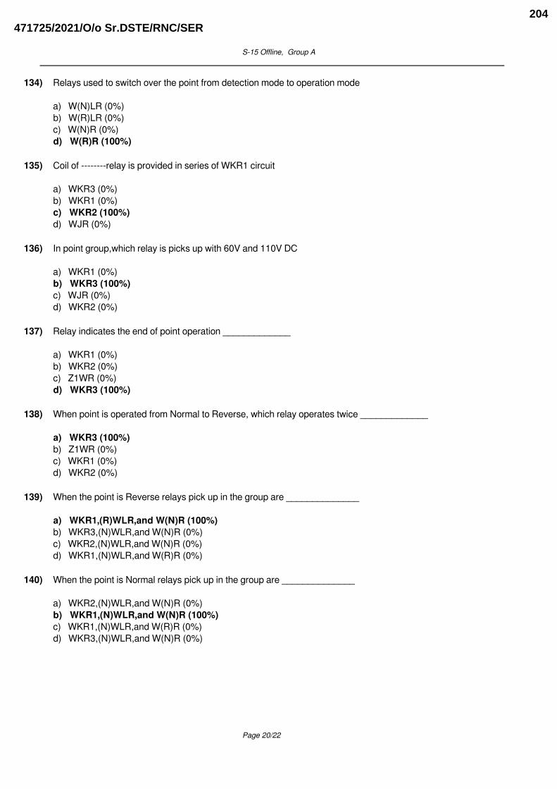
S-15 Offline, Group A
134) Relays used to switch over the point from detection mode to operation mode
a) W(N)LR (0%)b) W(R)LR (0%)c) W(N)R (0%)d) W(R)R (100%)
135) Coil of --------relay is provided in series of WKR1 circuit
a) WKR3 (0%)b) WKR1 (0%)c) WKR2 (100%)d) WJR (0%)
136) In point group,which relay is picks up with 60V and 110V DC
a) WKR1 (0%)b) WKR3 (100%)c) WJR (0%)d) WKR2 (0%)
137) Relay indicates the end of point operation _____________
a) WKR1 (0%)b) WKR2 (0%)c) Z1WR (0%)d) WKR3 (100%)
138) When point is operated from Normal to Reverse, which relay operates twice _____________
a) WKR3 (100%)b) Z1WR (0%)c) WKR1 (0%)d) WKR2 (0%)
139) When the point is Reverse relays pick up in the group are ______________
a) WKR1,(R)WLR,and W(N)R (100%)b) WKR3,(N)WLR,and W(N)R (0%)c) WKR2,(N)WLR,and W(N)R (0%)d) WKR1,(N)WLR,and W(R)R (0%)
140) When the point is Normal relays pick up in the group are ______________
a) WKR2,(N)WLR,and W(N)R (0%)b) WKR1,(N)WLR,and W(N)R (100%)c) WKR1,(N)WLR,and W(R)R (0%)d) WKR3,(N)WLR,and W(N)R (0%)
Page 20/22
471725/2021/O/o Sr.DSTE/RNC/SER204

S-15 Offline, Group A
141) Which relay operates to break the detection of point from Reverse to Normal operation
a) WJR (100%)b) WKR3 (0%)c) WR (0%)d) WKR1 (0%)
142) Which relay operates to break the detection of point from Normal to Reverse operation___________
a) WLR (0%)b) WKR1 (0%)c) WKR3 (100%)d) WKR2 (0%)
143) Which Relay operates first in the group, when point is operated from Reverse to Normal
a) Z1WR1(1) (100%)b) Z1WR1(2) (0%)c) WKR1 (0%)d) Z1RWR (0%)
144) Which Relay operates first in the group, when point is operated fro Normal to Reverse
a) Z1RWR (0%)b) WKR1 (0%)c) Z1WR1(1) (100%)d) Z1WR1(2) (0%)
145) When the point zone track circuit is in failed condition, the point operation can be initiated by the operationof
a) When concern point button WN and common point button YYN simultaneously (0%)b) When concern point button WN and Emergency point button EWN (100%)c) When concern point button WN and common point button EUUYN simultaneously (0%)d) When concern point button WN and common point button WWN simultaneously (0%)
146) This operation is called as normal point operation ___________
a) When concern point button WN and common point button EWN simultaneously (0%)b) When concern point button WN and common point button YYN simultaneously (0%)c) When concern point button WN and common point button EUUYN simultaneously (0%)d) When concern point button WN and common point button WWN simultaneously (100%)
147) In the first stage which is common for normal and reverse initiations
a) Z1NWR picks up (0%)b) Z2WR1 picks up (0%)c) Z1WR1 picks up (100%)d) Z1RWR picks up (0%)
Page 21/22
471725/2021/O/o Sr.DSTE/RNC/SER205
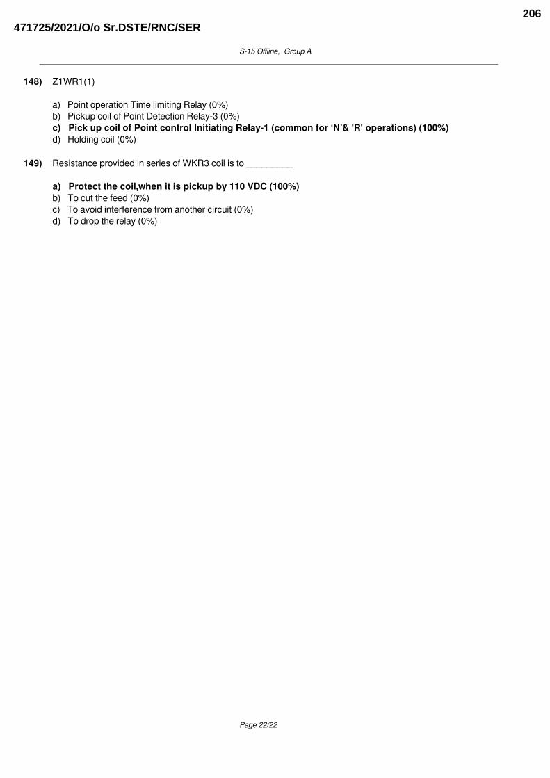
S-15 Offline, Group A
148) Z1WR1(1)
a) Point operation Time limiting Relay (0%)b) Pickup coil of Point Detection Relay-3 (0%)c) Pick up coil of Point control Initiating Relay-1 (common for ‘N’& 'R' operations) (100%)d) Holding coil (0%)
149) Resistance provided in series of WKR3 coil is to _________
a) Protect the coil,when it is pickup by 110 VDC (100%)b) To cut the feed (0%)c) To avoid interference from another circuit (0%)d) To drop the relay (0%)
Powered by TCPDF (www.tcpdf.org)
Page 22/22
471725/2021/O/o Sr.DSTE/RNC/SER206

S-16 Offline, Group A
1) NWKR/RWKR are normally de-energized, picks up only,when
a) Overlap is set (0%)b) When the Route sections are set then only (0%)c) If the point set in route then with U(R)S if in Overlap then with OVZ2U(R)R (100%)d) When route setting is done (0%)
2) In case of Route setting type Relay Interlocking
a) NWKR is only pickup (0%)b) NWKR & RWKR are normally dropped (100%)c) RWKR is only pickup (0%)d) NWKR & RWKR are normally pickup (0%)
3) Auto operation of Point in the Isolation takes place with the pickup of relays as _____________
a) OVZ2U(R)R (0%)b) UZ4(R)R (100%)c) WN and WWN (0%)d) U(R)S (0%)
4) Auto operation of Point in the Overlap takes place with the pickup of relays as _____________
a) WN and WWN (0%)b) U(R)S (0%)c) UZ4(R)R (0%)d) OVZ2U(R)R (100%)
5) Auto operation of Point in the Route takes place with the pickup of relays as _____________
a) OVZ2U(R)R (0%)b) UZ4(R)R (0%)c) WN and WWN (0%)d) U(R)S (100%)
6) In case of Route setting type Relay Interlocking for the clearance of signal _____________
a) Points are required to be operates individually (0%)b) Only points in the isolation are required to operate (0%)c) Points in the overlaps are required to operate only (0%)d) Points in the Route, Overlap and in isolation operate automatically, with the pressing of GNand UN Buttons (100%)
7) In case of Route setting type Relay Interlocking additional Group used for sequential point operation alongwith Point Major Group _____________
a) Point Chain Group (100%)b) Mini Group (0%)c) Minor Group (0%)d) Timer Group (0%)
Page 1/9
471725/2021/O/o Sr.DSTE/RNC/SER207

S-16 Offline, Group A
8) Point Group used in case of Route setting type Relay Interlocking
a) Major Group (100%)b) Mini Group (0%)c) Minor Group (0%)d) Point Chain Group (0%)
9) The only difference of Siemens Route Relay Interlocking with respect to Siemens Panel Interlocking is that
a) It has the additional facility to set the points on the route, overlap and in isolationautomatically (100%)b) It has the additional facility to set the points on the route (0%)c) It has the additional facility to set the points on the route and, overlap (0%)d) It has the additional facility to set the points in the isolation only (0%)
10) Route setting type Relay Interlocking (Route Relay Interlocking) system is adopted for
a) Major Yard (0%)b) Way Side Station (0%)c) As per new circular for any new installation Route Setting type (100%)d) Only for Major Yard (0%)
11) Auto operation of point can be initiated only when _____________
a) UZ4(R)R (0%)b) WKR2 is pickup (0%)c) WKR3 is pickup (0%)d) WKR1 is pickup (100%)
12) Auto operation of point can be initiated only when _____________
a) Only proved in case of points in overlap (0%)b) Point zone track circuit is not included (0%)c) Point zone track circuit is pickup (100%)d) Even though the point zone track circuit is failed (0%)
13) In case of auto operation of point, Normal Point operation is imitated due to
a) A U(R)S (100%)b) B U(R)S (0%)c) OV-2 Z2U(R)R (0%)d) OVZ2U(R)R (0%)
14) In case of auto operation of point, points in the Overlap are operated with the pickup of _____________
a) Z3WR (0%)b) OVZ2U(R)R (100%)c) UZ4(R)R (0%)d) U(R) S (0%)
Page 2/9
471725/2021/O/o Sr.DSTE/RNC/SER208
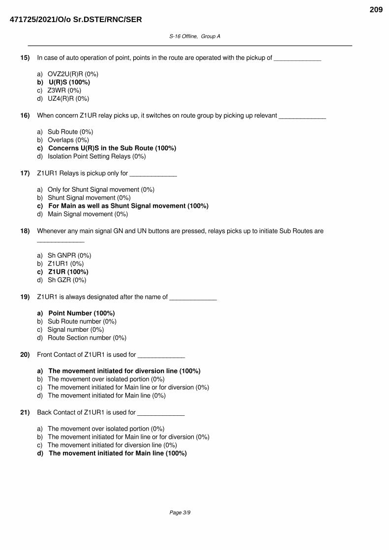
S-16 Offline, Group A
15) In case of auto operation of point, points in the route are operated with the pickup of _____________
a) OVZ2U(R)R (0%)b) U(R)S (100%)c) Z3WR (0%)d) UZ4(R)R (0%)
16) When concern Z1UR relay picks up, it switches on route group by picking up relevant _____________
a) Sub Route (0%)b) Overlaps (0%)c) Concerns U(R)S in the Sub Route (100%)d) Isolation Point Setting Relays (0%)
17) Z1UR1 Relays is pickup only for _____________
a) Only for Shunt Signal movement (0%)b) Shunt Signal movement (0%)c) For Main as well as Shunt Signal movement (100%)d) Main Signal movement (0%)
18) Whenever any main signal GN and UN buttons are pressed, relays picks up to initiate Sub Routes are_____________
a) Sh GNPR (0%)b) Z1UR1 (0%)c) Z1UR (100%)d) Sh GZR (0%)
19) Z1UR1 is always designated after the name of _____________
a) Point Number (100%)b) Sub Route number (0%)c) Signal number (0%)d) Route Section number (0%)
20) Front Contact of Z1UR1 is used for _____________
a) The movement initiated for diversion line (100%)b) The movement over isolated portion (0%)c) The movement initiated for Main line or for diversion (0%)d) The movement initiated for Main line (0%)
21) Back Contact of Z1UR1 is used for _____________
a) The movement over isolated portion (0%)b) The movement initiated for Main line or for diversion (0%)c) The movement initiated for diversion line (0%)d) The movement initiated for Main line (100%)
Page 3/9
471725/2021/O/o Sr.DSTE/RNC/SER209

S-16 Offline, Group A
22) Z1UR1 is normally _____________
a) Pickup Relay (0%)b) Slow to release Relay (0%)c) Drop Relay (100%)d) Slow to pickup Relay (0%)
23) Purpose of Z1UR1 in case of RRI is to check _____________
a) The movement over isolated portion (0%)b) The movement initiated for Main line (0%)c) The movement initiated for diversion line (0%)d) The movement initiated for Main line or for diversion (100%)
24) Z1UR1 is
a) Route Section Initiation Relay (0%)b) Isolation Point setting Relay (0%)c) Sub Route Initiating Relay (0%)d) Diversion Selection Relay (100%)
25) In case of Normal to Reverse Operation which relay pickup twice ___________
a) Z3WR (0%)b) WKR3 (100%)c) WKR1 (0%)d) WKR2 (0%)
26) When a point falls in the route/overlap/isolation, Relay operates to lock the point group electrically___________
a) U(R)LR picks up and locks the point group electrically (0%)b) WLR picks up and locks the point group electrically (0%)c) G(R)LR picks up and locks the point group electrically (0%)d) W(R)LR picks up and locks the point group electrically (100%)
27) R7 - 1000 ��, it is connected in series with the WKR3 relay because it
a) Serves to isolate the condenser from the 60 V supply after WJR has picked up (0%)b) Drops the 110 V supply for the WKR3 relay to pick up which has a 60 V coil (100%)c) It reduces the holding current of WR relay. WR requires a higher pick up current (0%)d) It reduces the holding current of WR relay. WR requires a higher pick up current (0%)
28) R6 - 270 ��, it is connected in series with the coil of WKR2 relay. WKR2 relay is connected in series withWKR1 relay but it does not pick up as it requires a higher pick up current.So
a) It reduces the holding current of WR relay. WR requires a higher pick up current (0%)b) It reduces the holding current of WR relay. WR requires a higher pick up current (0%)c) It reduces the initial charging surge of the condenser and improves the time delay for WJR to drop (0%)d) When the coil of WKR1 is not in its circuit the WKR2 relay picks up. Thus WKR2 picking upis prevented by WKR1 coil resistance and R6 in series (100%)
Page 4/9
471725/2021/O/o Sr.DSTE/RNC/SER210

S-16 Offline, Group A
29) R5 - 39 ��, it is connected in series with the WJR condenser as it ___________
a) It reduces the holding current of WR relay. WR requires a higher pick up current (0%)b) It prevents the 60 V positive from being shorted to 60 V negative when (R)WLR3 drops (0%)c) It reduces the initial charging surge of the condenser and improves the time delay for WJRto drop (100%)d) It reduces the initial charging surge of the condenser and improves the time delay for WJR to drop (0%)
30) R4 - 18000 ��, it is connected in series with the WJR condenser as it
a) Serves to isolate the condenser from the 60 V supply after WJR has picked up (100%)b) It reduces the holding current of WR relay. WR requires a higher pick up current (0%)c) It prevents the 60 V positive from being shorted to 60 V negative when (N)WLR3 drops (0%)d) It prevents the 60 V positive from being shorted to 60 V negative when (R)WLR3 drops (0%)
31) R3 - 600 ��, it is connected in parallel with WR back contact in the WR circuit.
a) It reduces the holding current of WR relay. WR requires a higher pick up current (100%)b) It prevents the 60 V positive from being shorted to 60 V negative when (R)WLR3 drops (0%)c) It prevents the 60 V positive from being shorted to 60 V negative when (N) WLR3 drops (0%)d) Serves to isolate the condenser from the 60 V supply after WJR has picked up (0%)
32) R2 - 220 ��, it is connected in series with the second coil of Z1NWR
a) lt prevents the 60 V positive from being shorted to 60 V negative when (R)WLR3 drops(100%)b) It prevents the 60 V positive from being shorted to 60 V negative when (N) WLR3 drops (0%)c) It reduces the initial charging surge of the condenser and improves the time delay for WJR to drop (0%)d) Serves to isolate the condenser from the 60 V supply after WJR has picked up (0%)
33) R1 -220 ��, it is connected in series with the second coil of Z1RWR
a) Serves to isolate the condenser from the 60 V supply after WJR has picked up (0%)b) It prevents the 60 V positive from being shorted to 60 V negative when (N) WLR3 drops(100%)c) It reduces the initial charging surge of the condenser and improves the time delay for WJR to drop (0%)d) lt prevents the 60 V positive from being shorted to 60 V negative when (R)WLR3 drops (0%)
34) Z3WR is named as ___________
a) Point to Point Reverse Relay (0%)b) End of Point Chain command Relay (0%)c) Point Chain Group Initiating Relay (100%)d) Isolation Point Setting Relay (0%)
35) WWR is named as
a) Point Chain Group Relays (100%)b) End of Point Chain command Relay (0%)c) Point to Point Reverse Relay (0%)d) Point Chain Group Initiating Relay (0%)
Page 5/9
471725/2021/O/o Sr.DSTE/RNC/SER211
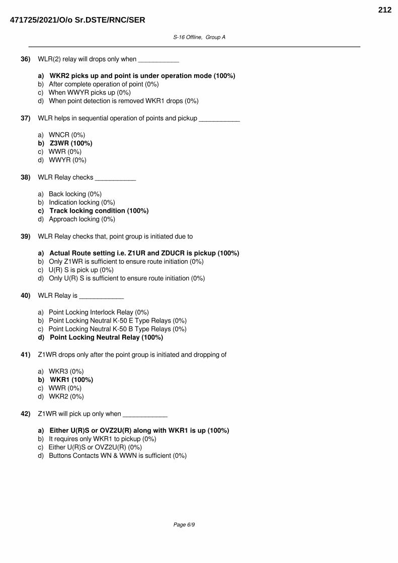
S-16 Offline, Group A
36) WLR(2) relay will drops only when ___________
a) WKR2 picks up and point is under operation mode (100%)b) After complete operation of point (0%)c) When WWYR picks up (0%)d) When point detection is removed WKR1 drops (0%)
37) WLR helps in sequential operation of points and pickup ___________
a) WNCR (0%)b) Z3WR (100%)c) WWR (0%)d) WWYR (0%)
38) WLR Relay checks ___________
a) Back locking (0%)b) Indication locking (0%)c) Track locking condition (100%)d) Approach locking (0%)
39) WLR Relay checks that, point group is initiated due to
a) Actual Route setting i.e. Z1UR and ZDUCR is pickup (100%)b) Only Z1WR is sufficient to ensure route initiation (0%)c) U(R) S is pick up (0%)d) Only U(R) S is sufficient to ensure route initiation (0%)
40) WLR Relay is ____________
a) Point Locking Interlock Relay (0%)b) Point Locking Neutral K-50 E Type Relays (0%)c) Point Locking Neutral K-50 B Type Relays (0%)d) Point Locking Neutral Relay (100%)
41) Z1WR drops only after the point group is initiated and dropping of
a) WKR3 (0%)b) WKR1 (100%)c) WWR (0%)d) WKR2 (0%)
42) Z1WR will pick up only when ____________
a) Either U(R)S or OVZ2U(R) along with WKR1 is up (100%)b) It requires only WKR1 to pickup (0%)c) Either U(R)S or OVZ2U(R) (0%)d) Buttons Contacts WN & WWN is sufficient (0%)
Page 6/9
471725/2021/O/o Sr.DSTE/RNC/SER212

S-16 Offline, Group A
43) If a point is flashing during initiation of a route
a) Point Operation will get initiate (0%)b) Point Operation will not get initiate (100%)c) Point Operation will initiate, but WKR1 will not pickup. (0%)d) It will not get affects, as point zone track circuit is pickup (0%)
44) First relay to operate in the Point group, under route initiation to operate a point in the route, overlap orisolation ___________
a) Z1WR (100%)b) Z1WR1 (0%)c) WWYR (0%)d) Z3WR (0%)
45) In point major group first relay to pickup during Individual operation
a) WWYR (0%)b) Z3WR (0%)c) Z1WR (0%)d) Z1WR1 (100%)
46) The number of Major Point Group in a Relay Rack is
a) 8 (100%)b) 5 (0%)c) 12 (0%)d) 16 (0%)
47) Chain Groups are always provided in accordance to the ________________
a) Number of points (0%)b) Depends upon the number of Minor Point Group in a Relay racks (0%)c) It is Common for the entire yard (0%)d) Depends upon the number of Major Point Group in a Relay racks (100%)
48) Z2WR1 is used for
a) Only indications of the point (0%)b) Both Normal and Reverse indications of the point (100%)c) Only Normal indications of the point (0%)d) Reverse indications of the point (0%)
49) If the point is in required position to the route initiated ________________
a) First point has to operate then it gets locks by W(R)LR (0%)b) Point will not operate and locks directly by W(R) LR (100%)c) Point will not operate and locks directly by UZ4(R)R (0%)d) First point has to operate then it gets locks by WLR (0%)
Page 7/9
471725/2021/O/o Sr.DSTE/RNC/SER213
S-16 Offline, Group A
50) Pickup of 8th WWR in Chain group drops ________________
a) WKR2 (0%)b) WLR (0%)c) WWYR (100%)d) WKR3 (0%)
51) In case of RRI, points in the isolation are operated by ________________
a) U(R)S (0%)b) OVZ2U(R)R (0%)c) ZDUCR (0%)d) UZ4(R)R (100%)
52) In a Chain Group commands for the operation of third points starts only ________________
a) WWYR is drop (0%)b) When the WLRs of first point is drops (0%)c) When the WLRs of second point is drops (0%)d) When the WLRs of first two point drops (100%)
53) Chain Groups always gives command for at least.
a) Three Points for operation (0%)b) Two Point for operation (100%)c) Four Points for operation (0%)d) One point for operation (0%)
54) Main function of WWYR Relay is
a) End of Chain Operation by dropping Z3WR (100%)b) Helps in sequential operation of points (0%)c) To prevent Z1WR and WLR to drop (0%)d) It provides smooth working to Chain group (0%)
55) WWYR is a normally ________________
a) Pickup relay (100%)b) Slow to pickup relay (0%)c) Slow to drop relay (0%)d) Drop relay (0%)
56) Z3WR is made Slow to release ________________
a) To prevent ZDUCR to drop (0%)b) To prevent WWYR to drop (0%)c) For smooth working of chain group (100%)d) To prevent Z1WR and WLR to drop (0%)
Page 8/9
471725/2021/O/o Sr.DSTE/RNC/SER214

S-16 Offline, Group A
57) Condition to pickup Z3WR is ________________
a) Z1WR and WLR are up (100%)b) Only Z1WR is up (0%)c) Z1WR and WLR is drop (0%)d) Only WLR is up (0%)
58) Z3WR is normally
a) Normally drop relay (100%)b) End of Chain Operation Relay (0%)c) Slow to pickup relay (0%)d) Pickup Relay (0%)
59) Z3WR is named as ________________
a) End of Point Chain command Relay (0%)b) Point to Point Reverse Relay (0%)c) Point Chain Group Initiating Relay (100%)d) Isolation Point Setting Relay (0%)
60) WWR is named as
a) Point to Point Reverse Relay (0%)b) Point Chain Group Initiating Relay (0%)c) Point Chain Group Relays (100%)d) End of Point Chain command Relay (0%)
Powered by TCPDF (www.tcpdf.org)
Page 9/9
471725/2021/O/o Sr.DSTE/RNC/SER215
S-18 Offline, Group A
1) In Microlok-II CPU card is provided with ______________ processor.
a) Triple (0%)b) Dual (0%)c) 68000 (0%)d) Single (100%)
2) An EI can be operated by -----------
a) CCIP only (0%)b) PP (0%)c) OC (0%)d) VDU as well as CCIP (100%)
3) ----------------------- contacts are used as Read back contacts
a) Vital output Relay (100%)b) Event logger (0%)c) Vital in put Relay (0%)d) Non Vital (0%)
4) The vital out card in an EI-----------------
a) 12 V DC (0%)b) Delivers output bit to drive a O/P relay (100%)c) Part of CPU (0%)d) Drives INPUT (0%)
5) NWKRs, RWKRs are treated as ___________ to the Electronic Interlocking system
a) Non Vital Inputs (0%)b) Non Vital outputs (0%)c) Vital inputs (100%)d) Vital outputs (0%)
6) In case of Distributed Interlocking system, ____ cable is used
a) No cable required (0%)b) Aluminum cable (0%)c) Optical Fiber Cable (100%)d) Brass cable (0%)
7) ________ works with communication cables
a) RRI (0%)b) TC (0%)c) PI (0%)d) EI (100%)
Page 1/41
471725/2021/O/o Sr.DSTE/RNC/SER216

S-18 Offline, Group A
8) EI has inbuilt--------------------
a) Axelcounter (0%)b) Block Instrument (0%)c) Event logger (100%)d) AFTC (0%)
9) ---------------- cable is required for the VDU connectivity with EI
a) Serial communication / Ethernt (100%)b) 1.5 Sq mm Signaling cable (0%)c) Power cable (0%)d) Copper cable (0%)
10) _________________ earthing arrangement is required for EI
a) 10 Megha ohms (0%)b) 2 Mega ohms (0%)c) 100 ohms (0%)d) Perimeter/ ring (100%)
11) Example for Hardware redundant EI system is--------------
a) MEI 633 (100%)b) MLK II (0%)c) RRI (0%)d) WESTRACE Mark- I (0%)
12) The Reverse Compiler converts -----------------------------------
a) The Source code (0%)b) Machine Language in to High level language (100%)c) Compiler (0%)d) High level language to Machine Language (0%)
13) SIL4 - safety integrity level is required for
a) MTC (0%)b) EI Hardware (100%)c) VDU software (0%)d) VDU Hardware (0%)
14) Indication bits such as NWKEs, RWKEs are treated as ___________ to the Electronic Interlocking system
a) Non Vital Inputs (0%)b) Non Vital outputs (100%)c) Vital in puts (0%)d) Vital output s (0%)
Page 2/41
471725/2021/O/o Sr.DSTE/RNC/SER217
S-18 Offline, Group A
15) All TPRs,ECRs are treated as __________ to the EI
a) Vital outputs (0%)b) Non Vital outputs (0%)c) Non Vital Inputs (0%)d) Vital inputs (100%)
16) Executive program is loaded in to -------------------
a) I/O connecters (0%)b) Data EPROMs (0%)c) Executive PROMS of CPU Card (100%)d) VDU Pc (0%)
17) ----------------is used as an operating interface to the EI
a) Data logger (0%)b) Object controller (0%)c) VDU/OPC (100%)d) Maintenance PC (0%)
18) Based on the station interlocking circuits_______program is prepared
a) Station Data (0%)b) Application (100%)c) Communication (0%)d) Executive (0%)
19) HRs, DRs are treated as _________ to the Electronic Interlocking system
a) Non Vital outputs (0%)b) Non Vital Inputs (0%)c) Vital in puts (0%)d) Vital outputs (100%)
20) _____________PROMS is loaded with Application software.
a) Data (100%)b) I/O (0%)c) Executive (0%)d) Communication (0%)
21) EN 50121 deals with --------------------------
a) RAMS (0%)b) EMC (100%)c) Communication (0%)d) Software (0%)
Page 3/41
471725/2021/O/o Sr.DSTE/RNC/SER218

S-18 Offline, Group A
22) EN 50126 deals with --------------------------
a) EMC (0%)b) Software (0%)c) RAMS (100%)d) Communication (0%)
23) MEI 633 is the Example for ------------------------
a) Hardware redundant EI system (100%)b) software redundant EI system (0%)c) TMR (0%)d) 1OO2 (0%)
24) MLK II EI is an Example for --------------
a) Hardware redundant EI system (0%)b) software redundant EI system (100%)c) 2OO2 (0%)d) TMR (0%)
25) The interface between CCIP and the EI is called _____
a) OCI (0%)b) VDUCT (0%)c) NV I/O card (0%)d) PP. (100%)
26) ------------is connected through Protocol converter
a) OFC (0%)b) OC (0%)c) The external Datalogger (100%)d) Flasher EPROM (0%)
27) Surge protection arrangement is must for
a) PI (0%)b) EI (100%)c) RRI (0%)d) Track circuit (0%)
28) The CPU card is loaded with
a) Application logic & Executive logic (100%)b) Non Vital data only (0%)c) Operating parameters alone (0%)d) Output relay status only (0%)
Page 4/41
471725/2021/O/o Sr.DSTE/RNC/SER219
S-18 Offline, Group A
29) ------------------------- verifies the INPUT relay status in an EI
a) INPUT card (100%)b) NV I/O card (0%)c) CPU (0%)d) The vital out card (0%)
30) In Warm standby arrangement -----------
a) Both systems OFF (0%)b) Both systems contineously ON (0%)c) Only one system is switched ON (100%)d) Redundent (0%)
31) The RS 232 serial communication cable is used as
a) VDU connectivity cable with EI (100%)b) Power cable (0%)c) Copper cable (0%)d) 1.5 Sq mm Signaling cable (0%)
32) In Hot Standby arrangement ------------------------------------------------ .
a) Power backup (0%)b) Only one system ON (0%)c) Cold standby (0%)d) Both systems power ON. (100%)
33) Self intigrity test is the inbuilt feature of--------------------
a) PI (0%)b) RRI (0%)c) Track circuit (0%)d) EI (100%)
34) EI needs -------------- space
a) No (0%)b) More (0%)c) Less (100%)d) Equal to RRI (0%)
35) Based on Non Vital I/O bit calculation, ---------------can be calculated.
a) Panel processor cards (100%)b) Wires count (0%)c) Communication details (0%)d) Power supply detailes (0%)
Page 5/41
471725/2021/O/o Sr.DSTE/RNC/SER220

S-18 Offline, Group A
36) ----------safety Integrity level to be maintained for Hardware of any EI
a) SIL 2 (0%)b) SIL 1 (0%)c) SIL 4 (100%)d) SIL 3 (0%)
37) Example for software redundant EI system is--------------
a) MLK II (100%)b) K5BMC (0%)c) MEI 633 (0%)d) VHLC (0%)
38) To start Application design of EI, the Inputs required are ________
a) CT rack termination details. (0%)b) Approved Signal Interlocking Plan & Front Plate Drawing and RCC (100%)c) Communication details only. (0%)d) Details of any additional interlocking equipment only. (0%)
39) The external Data logger can be connected to EI through-------------
a) Protocol converter (100%)b) OFC (0%)c) Flash EPROMs (0%)d) OC (0%)
40) The EI application logic is loaded in to -------------
a) Output card (0%)b) Non Vital I/O card (0%)c) CPU card (100%)d) CPU and Out put cards. (0%)
41) As per latest guide lines--------------- standby set up is to be used in EI.
a) Power backup (0%)b) Hot Standby. (100%)c) Cold standby (0%)d) Warm standby (0%)
42) The ------------------- converts High level language to Machine Language
a) Source code (0%)b) Reverse compiler (0%)c) Compiler (100%)d) Object code (0%)
Page 6/41
471725/2021/O/o Sr.DSTE/RNC/SER221

S-18 Offline, Group A
43) Based on --------------- calculation, number of I/O cards can be calculated.
a) Vital & Non Vital I/O bit (100%)b) Wires (0%)c) Connectors (0%)d) Card files (0%)
44) By using Object Controllers --------------------------
a) Main signaling cables can be eliminated due to OFC communication (100%)b) Cost factor can be minimized (0%)c) Failures can be minimized (0%)d) Communication cable can be reduced (0%)
45) All Electronic Interlocking Systems have
a) No diagnosis process (0%)b) Housing system (0%)c) Inbuilt object controllers (0%)d) Self-diagnostic feature (100%)
46) External Data logger provision to EI is ------------
a) Not mandatory (0%)b) It is a part of VDU (0%)c) Mandatory (100%)d) It is a part of EI Hardware (0%)
47) When any unsafe failures are recognised by an EI-----------
a) Supply voltage to non vital outputs cuts off (0%)b) No action takes place (0%)c) System is steady (0%)d) System shutdown and all outputs withdrawn. (100%)
48) In Electronic interlocking system, executive software is -----------------
a) Station specific. (0%)b) Common to all EI’s of same model of same OEM. (100%)c) Similar to Application software (0%)d) Separately not required. (0%)
49) In EI, application software is--------------------------.
a) Similar to Executive software (0%)b) Common to all stations (0%)c) Station specific (100%)d) Remotely loaded (0%)
Page 7/41
471725/2021/O/o Sr.DSTE/RNC/SER222

S-18 Offline, Group A
50) The calculation of EI card file /OC/Housing is mainly depends on -----------
a) Software (0%)b) Communication cables (0%)c) Vital & Non vital bit chart (100%)d) Communication ports (0%)
51) Prime inputs for the EI Interface design are -----------------
a) Software (0%)b) Card files (0%)c) Cables (0%)d) SIP, FPD and RCC (100%)
52) The -------------- card makes System Integrity checks and System health status
a) OUT 16 (0%)b) CPU card (100%)c) ECB card (0%)d) SYNC card (0%)
53) In Microlok-II------------- pin Connector assembly is used for Power supplycard
a) 16 (0%)b) 48 (100%)c) 96 (0%)d) 2 (0%)
54) In Microlok-II card file, CPU card occupies ---------------- slots.
a) 16 and17 slots (0%)b) 14 and 15 slots (0%)c) 1 and 2 slots (0%)d) 18 and 19 slots (100%)
55) In SYNC Board ___________ no of inputs is connected
a) 3 (0%)b) 2 (0%)c) 1 (0%)d) 4 (100%)
56) In Microlok II, each card file has ------------- slots.
a) 16 (0%)b) 14 (0%)c) 20 (100%)d) 10 (0%)
Page 8/41
471725/2021/O/o Sr.DSTE/RNC/SER223

S-18 Offline, Group A
57) Microlok-II is a -------------------- system.
a) 1 out of 1 architecture (100%)b) 2 out of 3 architecture (0%)c) 2 out of 2 architecture (0%)d) TMR. (0%)
58)
Executive based synchronization between two MICROLOK II units supports in ___________ versions
a) CC 1.0 (0%)b) CC 2.0 (0%)c) CC 3.0 and Above (100%)d) CC 1.5 (0%)
59)
Executive based synchronization between two MICROLOK II units supports in ___________ versions
a)
CC 1.0 (0%)b) CC 1.5 (0%)c) CC 2.0 (0%)d) CC 3.0 and above (100%)
60) The System power supply for MLK-II EI is-------------
a) 12 v DC (100%)b) 16 v DC (0%)c) 48 v DC (0%)d) 96 v DC (0%)
61) In the MLK-II EI CPU card, 1 to 8 LEDs are meant for ----------------
a) Point indication. (0%)b) VCOR indication (0%)c) signal (0%)d) User defined indications (100%)
Page 9/41
471725/2021/O/o Sr.DSTE/RNC/SER224

S-18 Offline, Group A
62) EEPROM PCB is provided in ----------------------connector
a) ECB card (0%)b) SYNC card (0%)c) CPU card (100%)d) 96 pin (0%)
63) In Microlok-II, Vital input cards are suitable for
a) 10V DC (0%)b) 6 V DC (0%)c) 24 V DC (100%)d) 50 v Dc (0%)
64) In Microlok-II, the 48 Pin Connector assembly is used for connecting__________
a) Vital Input, Output, CPU & PS boards (100%)b) Non-vital I/O boards (0%)c) Vital Input boards only (0%)d) Vital Output boards only (0%)
65) The external Data logger can be connected to MLK-II through-------------------
a) PP (0%)b) Protocol converter (100%)c) OC (0%)d) Flash EPROMs (0%)
66) In the Card File the OUT16 PCB is placed in
a) Slot No. 16 & 17 (0%)b) Slot No. 15 & 16 (0%)c) In any slot other than CPU, PS slots (100%)d) Slot No. 18 & 19 (0%)
67) VCOR Relay Nominal working voltage
a) 3 ma (0%)b) 12V Dc (100%)c) 30 A (0%)d) 24V DC (0%)
68) In MLK-II EI ___________________ card is required to provide for Hot standby arrangement
a) ECB (0%)b) CSI (0%)c) OUT16 (0%)d) SYNC (100%)
Page 10/41
471725/2021/O/o Sr.DSTE/RNC/SER225

S-18 Offline, Group A
69) In Microlok-II, MTC can be connected to Port No._____ of CPU card.
a) 3 (0%)b) 5 (100%)c) 1 (0%)d) 4 (0%)
70) In Microlok-II card file -------------- prevents plugging of wrong type of card.
a) Keying plugs (100%)b) Software prevents . (0%)c) Code pins (0%)d) Address select jumpers (0%)
71) In Microlok-II card file, Power supply card occupies ------------- slots.
a) 4 (0%)b) 1 (0%)c) 20 (0%)d) 2 (100%)
72) In Microlok-II --------------- is provided with FLASH ROMs / EEPROMs for storing the executive andapplication software.
a) OUT16 (0%)b) CPU Card (100%)c) IN16 card (0%)d) ECB card (0%)
73) In Microlok-II, each card file should be provided with __________
a) CPU card, Power supply card (100%)b) VCOR (0%)c) OC (0%)d) Panel processor (0%)
74) In the MLK-II EI,Non-vital Inputs are
a) Track Circuits TPRs. Point Detection (0%)b) Control Panel Push Buttons & Key contacts (100%)c) HRs, DRs (0%)d) VCOR indication (0%)
75) In the MLK-II EI,Each Vital input PCB occupies
a) 1 slot (100%)b) 4 slots (0%)c) 2 slots (0%)d) 3 slots (0%)
Page 11/41
471725/2021/O/o Sr.DSTE/RNC/SER226
S-18 Offline, Group A
76) In the MLK-II EI,Each NonVital l/O PCB occupies
a) 4 slots (0%)b) 2 slots (0%)c) 3 slots (0%)d) 1 slot (100%)
77) In Microlok-II, --------are used to address particular slot of the card file.
a) PROMs (0%)b) Dip switches (0%)c) EEPROM (0%)d) Address select jumpers (100%)
78) Slow to pick” is defined as
a) RELEASE DELAY” (100%)b) CLEAR DELAY” (100%)c) “SET DELAY (100%)d) “SET UP DELAY (0%)
79) Slow to Release” is defined as
a) SETUP DELAY (100%)b) “SET DELAY" (0%)c) 1 SEC” (100%)d) “CLEAR DELAY" (100%)
80) In Microlok-II system -------------- are used for Non-Vital data interface.
a) RS-232 serial ports (100%)b) Keying plugs (0%)c) RS-485 serial ports (0%)d) 48 Pin connector (0%)
81) In the MLK-II EI, ----------- of Flash EPROMs are used in the CPU card for program data
a) 4 nos (100%)b) 2 Nos (0%)c) 3 nos (0%)d) one (0%)
82) In MLK_II EI, CPS signal is -------------------HZ
a) 20 (0%)b) 256 (0%)c) 512 (0%)d) 250 (100%)
Page 12/41
471725/2021/O/o Sr.DSTE/RNC/SER227

S-18 Offline, Group A
83) In MICROLOK II EI, ---------- v dc supply is used to drive all the PCBs
a) +12 (0%)b) +5 (100%)c) -12 (0%)d) +24 (0%)
84) VCOR is required for---------------
a) Any MLK-II card file (0%)b) MLK-II card file with PS card (0%)c) MLK-II card file having Vital OUTPUT cards (100%)d) MLK-II card file having Vital INPUT cards (0%)
85) In MLK_II EI, CPS means -------------------
a) Conditional power supply (100%)b) Continuous power supply (0%)c) Contiguous power supply (0%)d) Communication power supply (0%)
86) Application program in the MLK-II EI is written in -----------------------
a) Boolean equations (100%)b) Assembly language (0%)c) ‘C’ language (0%)d) UNIX (0%)
87) In MLK-II, fast static RAMs are used for storing _________
a) Event logger data (100%)b) Application program (0%)c) Application program &Executive program (0%)d) Installation Address (0%)
88) In MLK-II, Error codes are displayed in---------------------
a) CPU card, Power supply card, I/O cards (0%)b) Power Supply Card (0%)c) CPU card (100%)d) VCOR (0%)
89) In Microlok-II card file, Max.--------------- nos. of Input / Output interface cards can be accommodated.
a) 4 (0%)b) 16 (100%)c) 20 (0%)d) 2 (0%)
Page 13/41
471725/2021/O/o Sr.DSTE/RNC/SER228

S-18 Offline, Group A
90) In Microlok-II system ------------------ are used for vital interface.
a) Keying plugs (0%)b) RS-485 serial ports (100%)c) RS-232 serial ports (0%)d) 96 Pin connector (0%)
91) Microprocessor used in Microlok-II is
a) Intel 8086 (0%)b) Motorola 68332 (100%)c) Intel 68332 (0%)d) Motorola 8086 (0%)
92) VCOR relay has
a) 6F. 6B contact (0%)b) 6F/6B independent contact (0%)c) 6F/B dependent contact (100%)d) 3F.3B (0%)
93) In Microlok-II, Vital I/O cards are suitable for ----------------
a) 24 V DC (100%)b) 50 v Dc (0%)c) 6 V DC (0%)d) 10 V DC (0%)
94) In MLK-II Card File, the PS Card is normally placed in the slot no. ____
a) 15&16 (0%)b) 16&17 (100%)c) 20 (0%)d) 18&19 (0%)
95) In Microlok-II system, each Non-vital input- output card can be connected with maximum _____ no. ofinputs and _____ no. of outputs respectively.
a) 16 Inputs & 16 Outputs (0%)b) 32 Inputs & 32 Outputs (100%)c) 8 Inputs & 8 Outputs (0%)d) 16 Inputs & 32 Outputs (0%)
96) In Microlok-II system, each vital output card drives _______no. of relays
a) 8 (0%)b) 4 (0%)c) 16 (100%)d) 32 (0%)
Page 14/41
471725/2021/O/o Sr.DSTE/RNC/SER229
S-18 Offline, Group A
97) In Microlok-II system, Input capacity of each Vital input card is_______
a) 64 input (0%)b) 32 input (0%)c) 16 input (100%)d) 8 input (0%)
98) In Microlok-II system, CPU card is provided with ______ no. of ports.
a) 4 parallel and 1 serial (0%)b) 5 serial (100%)c) 5 parallel. (0%)d) 4 serial and 1 parallel (0%)
99) VCOR Relay contact current rating is____ Amp
a) 3A (100%)b) 50mA (0%)c) 5A (0%)d) 1A (0%)
100) In Microlok-II, Application Program ‘+ ‘ symbol is used for _______
a) BACK CONTACT (0%)b) PARALLEL (100%)c) BIT SEPERATION (0%)d) SERIES (0%)
101) In Microlok-II, Application Program ‘ * ‘ symbol is used for _______
a) BACK CONTACT (0%)b) SERIES (100%)c) BIT SEPERATION (0%)d) PARALLEL (0%)
102) In Microlok-II, the 96 Pin connector assembly is used for ___________
a) Vital Input boards only (0%)b) Non-vital I/O boards (100%)c) Vital Output boards only (0%)d) Vital Input and Output boards (0%)
103) In MLK-II EI, _______supply is connected to the system for O/P relay driving
a) 12 v DC (0%)b) 50 v DC (0%)c) 24 v DC. (100%)d) 16 v DC (0%)
Page 15/41
471725/2021/O/o Sr.DSTE/RNC/SER230
S-18 Offline, Group A
104) In Medha EI, WFP means -----------
a) Wayside function processor (100%)b) Wayside frontend processor (0%)c) Warm frontend processor (0%)d) Warm function processor (0%)
105) Max No of CIUs that can be inter connected to MEI633 is---------------
a) as many OCs (0%)b) one only (0%)c) any Number (0%)d) 2 to 4 (100%)
106) In Medha EI, Max No of output cards that can be provided in each OC is--------------
a) 5 (0%)b) 6 (0%)c) 4 (0%)d) 3 (100%)
107) In Medha EI, Max No of Input cards that can be provided in each OC is---------------
a) 6 (0%)b) 5 (100%)c) 3 (0%)d) 4 (0%)
108) In Medha EI, Max No of outputs that can be connected to each Vital O/Pcard is----
a) 8 (100%)b) 4 (0%)c) 16 (0%)d) 32 (0%)
109) In Medha EI, ---------------- type of power supply card is provided for CVC/VIC card.
a) D TYPE (0%)b) A TYPE (0%)c) C TYPE (0%)d) B TYPE (100%)
110) In Medha EI, --------------- type of power supply card is provided for CCC card.
a) A TYPE (0%)b) C TYPE (0%)c) D TYPE (0%)d) B TYPE (100%)
Page 16/41
471725/2021/O/o Sr.DSTE/RNC/SER231

S-18 Offline, Group A
111) In Medha EI, ----------------type of power supply cards are provided for OCs.
a) B&C TYPE (100%)b) A&D TYPE (0%)c) A&B TYPE (0%)d) C&D TYPE (0%)
112) In Medha EI, -----------------type of power supply cards are provided for PP.
a) C&D TYPE (0%)b) B&C TYPE (0%)c) A&B TYPE (100%)d) A&D TYPE (0%)
113) In Medha EI, ----------------- No of Rs485 serial ports are available at CIU
a) 12 (100%)b) 8 (0%)c) 32 (0%)d) 3 (0%)
114) In Medha EI, ----------------- No of Rs232 serial ports are available at CIU
a) 3 (100%)b) 4 (0%)c) 8 (0%)d) 12 (0%)
115) In Medha EI, ERROR messages are displayed on---------------------- of CIU
a) FDP (0%)b) FMS (0%)c) VIF (0%)d) FPD (100%)
116) In Medha EI, RM means------------
a) Ring Modem (100%)b) Repetition Maximum (0%)c) Random Memory (0%)d) Relay Module (0%)
117) In Medha EI, Max No of RS 232 channels provided in each CIU is -------------------
a) 3 (100%)b) 6 (0%)c) 5 (0%)d) 4 (0%)
Page 17/41
471725/2021/O/o Sr.DSTE/RNC/SER232

S-18 Offline, Group A
118) In Medha EI, Max No of I/Ps connected to each nonVital Input card of a PP is-------
a) 16 (0%)b) 8 (0%)c) 64 (100%)d) 128 (0%)
119) In Medha EI, Max No of O/Ps can be connected to each nonVital O/P card of a PP is
a) 128 (0%)b) 16 (0%)c) 64 (100%)d) 8 (0%)
120) In Medha EI, ‘A’ - type of power supply card is provided for ------.
a) COUNTER BOX (0%)b) CIU (0%)c) PP (100%)d) OC (0%)
121) In Medha EI, ‘C’- type of power supply card is provided for ------------------.
a) COUNTER BOX (0%)b) CIU (0%)c) OC (100%)d) PP (0%)
122) In Medha EI, 'B'- type of power supply cards are provided for -------------------.
a) CIU, OC and PP (100%)b) Mini IPS (0%)c) MTC (0%)d) OC only (0%)
123) In Medha EI, Voltage & Current rating of ‘B’ type of power supply cards ----------.
a) 4.5V @ 8A (0%)b) 4.5V @ 3A (100%)c) 4.5V @ 2A (0%)d) 4.5V @ 6A (0%)
124) In Medha EI, Voltage & Current rating of ‘C’ type of power supply cards ----------.
a) 4.5V@ 2A (0%)b) 4.5V @ 8A (0%)c) 4.5V @ 3A (0%)d) 4.5V @ 6A, 5.8@ 2A (100%)
Page 18/41
471725/2021/O/o Sr.DSTE/RNC/SER233
S-18 Offline, Group A
125) In Medha EI, Voltage & Current rating of ‘A’ type of power supply cards ----------.
a) 4.5V @ 6A (0%)b) 4.5V @ 8A (100%)c) 4.5V @ 3A (0%)d) 4.5V @ 2A (0%)
126) In Medha EI, Counter digits are displayed on----------------------
a) CIU (0%)b) COUNTER BOX Module (100%)c) PP (0%)d) OC (0%)
127) In Medha EI, WFM means----------------
a) Point function module (0%)b) Point frequency module (0%)c) Wayside frequency module (0%)d) Wayside function module (100%)
128) In Medha EI, In each port of CIU------------- No of PPs / VDUs can be connected.
a) 1 (0%)b) 4 (100%)c) 2 (0%)d) 3 (0%)
129) In Medha EI, ORLD card is used in------------------
a) CIU (0%)b) COUNTER BOX (0%)c) PP (0%)d) OC (100%)
130) In Medha EI,EMI filters provided in 24V DC supply------------- type of SPD
a) C (0%)b) A (0%)c) D (100%)d) B (0%)
131) In Medha EI, The rated current of VCOR is --------------- amps
a) 2 (0%)b) 1 (0%)c) 3 (100%)d) 4 (0%)
Page 19/41
471725/2021/O/o Sr.DSTE/RNC/SER234

S-18 Offline, Group A
132) Max No of Routes that can be handled by an CIU of MEI633 ---------
a) 450 (100%)b) 250 (0%)c) 350 (0%)d) 550 (0%)
133) Max No of RS 485 channels provided in each CIU is--------------------
a) 10 (0%)b) 8 (0%)c) 12 (100%)d) 16 (0%)
134) ------------communication channel provide between MEI 633 and MTC
a) Rs-423 (0%)b) CLA (0%)c) Rs-232 (100%)d) Rs-485 (0%)
135) The output supply of PSB in MEI 633 is-------------
a) 5.8V DC (0%)b) 4.8V DC (0%)c) 5.5V DC (0%)d) 4.5V DV (100%)
136) Input supply for the PSB cards provided in Medha EI is---------------
a) 5V DC (0%)b) 4.8V DC (0%)c) 12V DC (0%)d) 24V DC (100%)
137) Intercommunication between MEI633 and the PP is-------------------
a) OFC (100%)b) Rs-423 (0%)c) Parellel (0%)d) Rs-232 (0%)
138) Max response time for MEI633 is ------------------
a) b) c) d)
Page 20/41
471725/2021/O/o Sr.DSTE/RNC/SER235
S-18 Offline, Group A
139) MEI 633 has --------------------------- stand by arrangement
a) Cold (0%)b) None (0%)c) Hot (100%)d) Warm (0%)
140) In MEI633 The rated voltage of VCOR---------------
a) 24V DC (100%)b) 12V DC (0%)c) 60V DC (0%)d) 5 V DC (0%)
141) CIF card is used in--------------------
a) MT (0%)b) CIU (100%)c) PP (0%)d) OC (0%)
142) In each port of CIU--------------------- No of Ocs can be connected.
a) 6 (0%)b) 4 (100%)c) 8 (0%)d) 32 (0%)
143) In Medha EI, RMs acts like----------- converter
a) SERIAL to PARELLEL (0%)b) SERIAL to OFC (100%)c) SERIAL-USB (0%)d) PARELLEL-OFC (0%)
144) Max No of Non vital I/Os that can be handled by an CIU of MEI633 -----
a) 1048 (0%)b) 2048 (0%)c) 4072 (0%)d) 3072 (100%)
145) Max No of vital I/Os that can be handled by an CIU of MEI633 -----
a) 1048 (0%)b) 3072 (0%)c) 2048 (100%)d) 4072 (0%)
Page 21/41
471725/2021/O/o Sr.DSTE/RNC/SER236
S-18 Offline, Group A
146) Max No of inputs that can be connected to each Vital I/P card is------
a) 12 (0%)b) 16 (0%)c) 32 (0%)d) 8 (100%)
147) Max No of Ocs that can be connected to MEI633 is------------
a) 32 (100%)b) 16 (0%)c) 128 (0%)d) 64 (0%)
148) Inter communication between MEI 633 and datalogger is-----------
a) RS-423 (0%)b) CLA (0%)c) RS- 232/OFC (100%)d) RS-485/OFC (0%)
149) The output supply of Dc-Dc converters in the Mini IPS of MEI 633 is------- ----------------
a) 12V DC (0%)b) 110V DC (0%)c) 60V DC (0%)d) 24V DC (100%)
150) Input supply for the Mini IPS provided in Medha EI room is-----------
a) 24V DC (0%)b) 110V DC (100%)c) 110V AC (0%)d) 230V AC (0%)
151) Intercommunication between MEI633 and the OCs is---------------
a) RS-232/OFC (0%)b) RS-423 (0%)c) CLA (0%)d) RS 485/OFC (100%)
152) Cycle time in MEI633 is --------------------
a) 222ms (0%)b) 333ms (100%)c) 444ms (0%)d) 111ms (0%)
Page 22/41
471725/2021/O/o Sr.DSTE/RNC/SER237
S-18 Offline, Group A
153) MEI 633 is of ----------------------------- architecture
a) 1 Out of 1 (0%)b) 2 Out of 4 (0%)c) 2 Out of 3 (0%)d) 2 Out of 2 (100%)
154) In WESTRACE EI, any un used slot can be filled with----------------
a) any VPIM card (0%)b) Blanker card only (100%)c) OPC card (0%)d) any VROM card (0%)
155) In WESTRACE EI, One PSU can be connected to Max---------- Housings.
a) 3 (0%)b) 1 (0%)c) 4 (0%)d) 2 (100%)
156) Non- Vital carks (MMIF cards) are provided in __________ rack
a) EM6 RACK (100%)b) OBJECT CONTROLLER (0%)c) LOGIC SUBRACK (0%)d) EP5 RACK (0%)
157) Maximum no of I/O cards connected to one optical link on FIO 7(P) Card
a) 25 (0%)b) 12 (0%)c) 15 (100%)d) 5 (0%)
158) vital input/out put card capacity of K5BMC ________
a) 32 input 54 output (0%)b) 32 input 64 output (0%)c) 32 input 44 output (0%)d) 32 input and 32 output (100%)
159) NCDM to be located in--------------- slot
a) 3&4 (0%)b) 1 (0%)c) 4 (100%)d) 2 (0%)
Page 23/41
471725/2021/O/o Sr.DSTE/RNC/SER238
S-18 Offline, Group A
160) WESTRONICS can be connected through------------------ port.
a) Serial / Ethernet port (0%)b) OFC port (0%)c) SERIAL port only (100%)d) ETHERNET port only (0%)
161) The interlocking circuits in the WESTRACE EI application logic is called as--------------
a) Rangs (0%)b) Rungs (100%)c) Rongs (0%)d) Rings (0%)
162) -------------- voltage relays used as Vital I/P relays in the WESTRACE EI
a) K-50 60v (0%)b) Q Series 12v (0%)c) Q Series 50v (0%)d) Q series 24v (100%)
163) System Input supply for the WESTRACE EI is--------
a) 24v & 50v DC (100%)b) 12v & 60v DC (0%)c) 12v & 50 v DC (0%)d) 24v & 60v DC (0%)
164) NCDM consists of--------------------- OFC ports
a) 3 sets (0%)b) 2 sets (100%)c) 1 set (0%)d) 4 sets (0%)
165) WESTRACE Mark-I system has ------Architecture
a) 2 out of 1 logic (0%)b) 1 out of 1 logic (100%)c) 1 out of 2 logic (0%)d) 2 out of 2 logic (0%)
166) In WESTRACE Mark-I system, VLM includes--------------
a) VLC & OPC (100%)b) VLC & PSU (0%)c) VLC& VLOM (0%)d) VLC & PFM (0%)
Page 24/41
471725/2021/O/o Sr.DSTE/RNC/SER239
S-18 Offline, Group A
167) NCDM includes---------------
a) NCDC& PSU (0%)b) NCDC & VLOM (0%)c) NCDC & PFM (100%)d) NCDC & OPC (0%)
168) One WESTRACE Mark-I system, consists of Max------------- Housings
a) 3 (0%)b) 1 (0%)c) 4 (100%)d) 2 (0%)
169) In WESTRACE Mark-I system, One Housing consists of ------------------- No of slots
a) 16 (100%)b) 18 (0%)c) 20 (0%)d) 14 (0%)
170) In WESTRACE Mark-I system, Max---------------I/O Modules can accomdate in the First Housing
a) 9 (0%)b) 3 (0%)c) 5 (100%)d) 7 (0%)
171) In WESTRACE Mark-I system, max-------------I/O Modules can be accommodated in 2nd Housing
a) 9 (0%)b) 7 (100%)c) 5 (0%)d) 3 (0%)
172) In theWESTRACE Mark-I system, VDU is to be connected to----------------- port
a) Ethernet port only (0%)b) Parallel port (0%)c) Serial/ ethernet port (100%)d) OFC port (0%)
173) In WESTRACE EI, External data logger can be connected to------------ port
a) Serial / Ethernet port (100%)b) OFC (0%)c) Ethernet port only (0%)d) Parallel (0%)
Page 25/41
471725/2021/O/o Sr.DSTE/RNC/SER240

S-18 Offline, Group A
174) In the1st Housing of WESTRACE EI Mark-I system,Slot no 1&15 are filled with---------------
a) VROM card (0%)b) VLOM card (0%)c) VPIM card (0%)d) Blanker card (100%)
175) In WESTRACE EI, VSEV is meant for-------------
a) Hot standby synchronization (100%)b) Warm standby (0%)c) OPCR energisation (0%)d) Stand alone working (0%)
176) In WESTRACE EI, the amount of voltage for VSEV is-------------
a) 5v DC (0%)b) 12v DC (0%)c) 50v DC (0%)d) 24v DC (100%)
177) In WESTRACE EI Mark-I system,the output voltage of VROM is--------------
a) 50v DC (100%)b) 12v DC (0%)c) 5v DC (0%)d) 24v DC (0%)
178) In WESTRACE EI, PFM is used as-------------
a) ELD (0%)b) MOV (0%)c) NPD (0%)d) Protection Filter (100%)
179) CAT 5 cable is used for-------- communication in WESTRACE EI..
a) Serial (0%)b) Ethernet (100%)c) OFC (0%)d) Parallel (0%)
180) ----------- logic is used for writing WESTRACE Application program
a) Ladder (100%)b) Gate (0%)c) Maxwell (0%)d) Boolean (0%)
Page 26/41
471725/2021/O/o Sr.DSTE/RNC/SER241
S-18 Offline, Group A
181) PCGE is used for-------------- generation
a) User data log files (0%)b) Maintenance tool files (0%)c) Station Layout files for VDU (100%)d) Application logic files (0%)
182) Input range of PSU in WESTRACE EI is-----------------------
a) 18-30V DC (100%)b) 10-18v DC (0%)c) 16.5-26.5V DC (0%)d) 15-25V DC (0%)
183) --------------- voltage relays used as Vital O/P relays in the WESTRACE EI
a) Q series 24v (0%)b) Q Series 12v (0%)c) Q Series 50v (100%)d) K-50 60v (0%)
184) Max------ No of I/O modules can be accommodated in an WESTRACE
a) 16 (0%)b) 14 (0%)c) 26 (100%)d) 12 (0%)
185) In WESTRACE EI, The ----------is provided as mini mother board for VL M&NCDM
a) UHVBC (100%)b) UHPSU (0%)c) UHNCDM (0%)d) UHVLM (0%)
186) In WESTRACE EI, VSEV means-----------
a) Virtual serial emergency voltage (0%)b) Vital serial emergency voltage (0%)c) Vital serial enable voltage (100%)d) Virtual serial enable voltage (0%)
187) In WESTRACE EI, Slot No--------- is dedicated for PSU
a) 16 (100%)b) 15 (0%)c) 2 (0%)d) 1 (0%)
Page 27/41
471725/2021/O/o Sr.DSTE/RNC/SER242
S-18 Offline, Group A
188) OPCR works on---------------voltage
a) 24v DC (0%)b) 60v DC (0%)c) 50v DC (100%)d) 12v DC (0%)
189) PFM means----------------
a) Protection filter module (100%)b) Power Factor Module (0%)c) Protection factor module (0%)d) Power fillter module (0%)
190) INCL is used for--------------
a) Intercoommunication between VLM to VLM (0%)b) Intercoommunication between NCDM to NCDM (100%)c) Interconnects between VLM & NCDM (0%)d) Interconnects between VLC & OPC (0%)
191) IHCL is used for--------------
a) Intercoommunication between VLM to VLM (100%)b) Interconnects between VLC & OPC (0%)c) Interconnects between VLM & NCDM (0%)d) Intercoommunication between NCDM to NCDM (0%)
192) NCDM consists of--------------------- Ethernet COM ports
a) 2 (0%)b) 1 (100%)c) 3 (0%)d) 4 (0%)
193) NCDM consists of--------------------- Serial COM ports
a) 3 (100%)b) 2 (0%)c) 1 (0%)d) 4 (0%)
194) How many WETRACE units can be interconnected?
a) 16 (100%)b) 8 (0%)c) 10 (0%)d) 12 (0%)
Page 28/41
471725/2021/O/o Sr.DSTE/RNC/SER243
S-18 Offline, Group A
195) In the WESTRACE EI, Max No of O/Ps that can be connected to a Vital O/P module is ---------------
a) 8 (100%)b) 16 (0%)c) 10 (0%)d) 12 (0%)
196) In the WESTRACE EI, Max No of I/Ps that can be connected to a Vital I/P module is ---------------
a) 10 (0%)b) 16 (0%)c) 12 (100%)d) 8 (0%)
197) In the WESTRACE EI, Vital I/P module is named as --------------
a) VIOM (0%)b) VPIM (100%)c) VLIM (0%)d) VRIM (0%)
198) In the WESTRACE EI, Vital O/P module is named as --------------
a) VIOM (0%)b) VROM (100%)c) VLOM (0%)d) VPOM (0%)
199) VLM to be located in--------------- slots
a) 3&4 (0%)b) 1&2 (0%)c) 2&3 (100%)d) 4&5 (0%)
200) MOVOLAW is used as-------------
a) CTC (0%)b) MT (100%)c) PP (0%)d) VDU (0%)
201) WESTCAD is used for--------------
a) MT (0%)b) VDU (100%)c) PP (0%)d) CTC (0%)
Page 29/41
471725/2021/O/o Sr.DSTE/RNC/SER244
S-18 Offline, Group A
202) NCDM means------------
a) Network centre diagnosis model (0%)b) Network communication debug module (0%)c) Network communication diagnostic module (100%)d) Network centre debug module (0%)
203) VLM means----------------
a) Vital logic module (100%)b) Vital link module (0%)c) Vital link model (0%)d) Vital logic model (0%)
204) ___________application is used to build the simulated file
a) TCS (0%)b) LDC (0%)c) Workbench (100%)d) offline (0%)
205) In the logic sub rack of K5BMC EI system ________ total No. of cards are provided for system A
a) 7 (100%)b) 4 (0%)c) 6 (0%)d) 5 (0%)
206) The input voltage to IPU6C card is ________
a) 24V DC (100%)b) 12V DC (0%)c) 60V DC (0%)d) 5V DC (0%)
207) The IC card is inserted into ________ card
a) DID (0%)b) 486-4I (100%)c) FIO7 (0%)d) IPU6C (0%)
208) FIO7-[P] is a ________ card for FSIO module
a) Electrical to Optical converter (0%)b) Optical converter (0%)c) Electrical to Optical and Optical to electrical (100%)d) Ethernet converter (0%)
Page 30/41
471725/2021/O/o Sr.DSTE/RNC/SER245

S-18 Offline, Group A
209) IPU6C is located in ________ sub rack
a) EM6 (0%)b) ET/EP5 (0%)c) LK7-C (100%)d) Journal module (0%)
210) IPU6C is the name of ________ module
a) Communication (0%)b) Power supply (100%)c) CPU (0%)d) Interface (0%)
211) K5BMC EI system, the cycle time is ________
a) 5000 ms (0%)b) 900 ms (0%)c) 300 ms (100%)d) 3333 ms (0%)
212) K5BMC EI system can handle up to ________ number of signal routes with one logic unit.
a) 600 (0%)b) 450 (0%)c) 200 (0%)d) 300 (100%)
213) K5BMC EI system has been designed to work as ________ system
a) Open (0%)b) Distributed (0%)c) Centralised (0%)d) Centralised as well as distributed (100%)
214) K5BMC EI system has been designed with ________ arrangement
a) Cold standby (0%)b) Both Hot standby and Warm standby (0%)c) Hot standby (100%)d) Warm standby (0%)
215) ________ is the Reserved Character in Kyosan logic circuit design
a) / (0%)b) * (0%)c) # (100%)d) ; (0%)
Page 31/41
471725/2021/O/o Sr.DSTE/RNC/SER246
S-18 Offline, Group A
216) ___________ bit used to initiate all signals cancellation during system start-up
a) PICKUP (100%)b) EI.NOR (0%)c) SYSSTART (0%)d) FCOR (0%)
217) ___________ contact used in all vital circuits
a) EI.NOR (0%)b) EI_FSR.NOR (100%)c) EILFL (0%)d) FSR.NOR (0%)
218) In K5BMC, channel No.1 card ID start from ________ and end with ________
a) 61, 6F (100%)b) 61, 69 (0%)c) 71, 7F (0%)d) 71, 79 (0%)
219) K5BMC System receives _____________ size of data from data Logger for synchronization of time
a) 512bytes (0%)b) 1024 bytes (0%)c) 9Bytes (100%)d) 9bits (0%)
220) The logic sub rack has ________ slots in the front side
a) 10 (0%)b) 7 (0%)c) 16 (0%)d) 20 (100%)
221) ____________ parameter is used to configure/send data to Data Logger in OFFLINE tool
a) ET-NET (0%)b) option line (100%)c) System setup (0%)d) Maintenance system (0%)
222) Maximum data size that can be sent to data Logger through Journal Module
a) 512 bits (0%)b) 1024 bits (0%)c) 4096 Bytes (0%)d) 512 Bytes (100%)
Page 32/41
471725/2021/O/o Sr.DSTE/RNC/SER247

S-18 Offline, Group A
223) _____________ file will be generated after compilation of application logic with LDC tool
a) K6.Dat (0%)b) sampleAPL.txt (0%)c) logic11.obj (100%)d) Dataversion.dat (0%)
224) In Relay Library, maximum _________________ bytes are reserved for channel 1outputs
a) 60 bytes (100%)b) 120 bytes (0%)c) 360 bytes (0%)d) 180 bytes (0%)
225) _______________ software tool is used to write application software in to IC Card
a) LDC Tool (0%)b) OFFLINE Tool (100%)c) TCS Design tool (0%)d) TSTS Support Tool (0%)
226) The file name to map the indication and control logic for VDU design ________
a) RELAYLIB (0%)b) LOGIC11 (0%)c) Sample.APL (100%)d) LOGIC0 (0%)
227) maximum no of Input/ouput cards that can be connected to one logic sub rack
a) 90 (0%)b) 45 (100%)c) 15 (0%)d) 60 (0%)
228) K5BMC EI system is developed with ________ architecture
a) 2oo3 (0%)b) 2oo2 (100%)c) 1oo1 (0%)d) 1oo1 & 2002 (0%)
229) _______ card is used to connect the VDU pc with logic sub rack
a) journal module (0%)b) EM6 module (0%)c) MMIF card (0%)d) INIO2 card (100%)
Page 33/41
471725/2021/O/o Sr.DSTE/RNC/SER248

S-18 Offline, Group A
230) In K5BMC System, the system status is as follows 1. System 1 is working and system 2 is standby in logicsubrack 2. Line 2b card of system 1 is working and line 2b card of system2 is working in EP5 subrack. 3.Line M2 card of system 1 is working and line M2 card of system2 is also working in EM6 subrack Nowcalling on signal is cleared and system 1 is switched off, then the calling on signal is __________
a) Calling on signal will extinguish (0%)b) Vital card in which starter HR is located will only be effected and rest of the system will available indegraded mode. (0%)c) No change (100%)d) All output status will be low and further processing of vital logic will be stopped (0%)
231) In Kyosan EI Boolean expressions are evaluated one by one sequentially in __________ order
a) bottom to top (0%)b) left to right (0%)c) right to left (0%)d) top to bottom (100%)
232) The maximum character length allowed to name a Boolean Bit ________
a) 12 (0%)b) 25 (0%)c) 15 (0%)d) 21 (100%)
233) In K5BMC System, the system status is as follows 1. System 1 is working and system 2 is standby in logicsubrack 2. Line 2b card of system 1 is working and line 2b card of system2 is working in EP5 subrack 3.Line M2 card of system 1 is working and line M2 card of system2 is also working in EM6 subrack Nowstarter signal HR is picked up by false feed, then the expected response of EI is ____________
a) Vital card in which starter HR is located will only be effected and rest of the system will available indegraded mode. (0%)b) All output status will be low and further processing of vital logic will be stopped (100%)c) System will restart (0%)d) System will shut down (0%)
234) In Kyosan EI for logic circuit design for Back Contact Boolean expressions is represented by ________
a) / (100%)b) * (0%)c) ! (0%)d) + (0%)
235) By default, the K5BMC delivers optical output suitable to _______
a) multimode (100%)b) RS 485 (0%)c) Both single mode and multimode (0%)d) Single mod (0%)
Page 34/41
471725/2021/O/o Sr.DSTE/RNC/SER249

S-18 Offline, Group A
236) In Kyosan logic circuit design, Pickup Time Delay Boolean expressions is represented by ________
a) * (0%)b) ! (0%)c) d) + (0%)
237) The capacity of non vital card is ______
a) 32 input and 64 output (100%)b) 64 input and 64 output (0%)c) 32 input and 32 output (0%)d) 64 input and 32 output (0%)
238) In Kyosan logic circuit design, Series Boolean expressions is represented by ________
a) / (0%)b) * (100%)c) ! (0%)d) + (0%)
239) Journal module is connected ________ module for time synchronization
a) MT (100%)b) EM6 (0%)c) ET/EP5 (0%)d) Data logger (0%)
240) The maximum No. of of ET-PIO2 cards that can be provided in one ET/EP5 sub rack (without redundancy)
a) 5 (100%)b) 10 (0%)c) 8 (0%)d) 6 (0%)
241) LINE 2B card has ________ number of optical ports
a) four (0%)b) two (100%)c) three (0%)d) five (0%)
242) ________ is a power supply module among the modules given below
a) SPHC- TT (0%)b) SPHC –PW (100%)c) ZNIO2 (0%)d) SPHC- PAM (0%)
Page 35/41
471725/2021/O/o Sr.DSTE/RNC/SER250

S-18 Offline, Group A
243) In K5BMC, ________ card is meant for hot standby synchronisation
a) FSIO –Ext (0%)b) DID card (100%)c) IC card (0%)d) F486-4I card (0%)
244) The mother board of logic sub rack of K5BMC system connected to other cards through ________ bus
a) CME (0%)b) VME (100%)c) VMA (0%)d) AME (0%)
245) Application logic is uploaded in ________ card
a) F486-4Icard (0%)b) IC card (100%)c) DID card (0%)d) FIO7 card (0%)
246) Total No. of cards are provided on the rear side of the logic sub rack of K5BMC
a) 10 (0%)b) 8 (0%)c) 12 (0%)d) 6 (100%)
247) Capacity of Relay Library____________________
a) 4096 Bytes (100%)b) 512 Bytes (0%)c) 4096 bits (0%)d) 512 bits (0%)
248) __________tool is used to generate Logic11.csv, RelayLib.csv and Relay0.csv.
a) TSTS Support Tool (100%)b) OFFLINE Tool (0%)c) LDC Tool (0%)d) TCS Design tool (0%)
249) ____________ bit extension for output is used While loading sampleAPL into TCS design
a) .CSV (0%)b) .AVO (100%)c) .DOC (0%)d) .AVI (0%)
Page 36/41
471725/2021/O/o Sr.DSTE/RNC/SER251
S-18 Offline, Group A
250) In K5BMC System, the system status is as follows 1. System 2 is working and system 1 is off in logicsubrack 2. Line 2b card of system 1 is not working and line 2b card of system2 is working in EP5 subrack.3. Line M2 card of system 1 is not working and line M2 card of system2 is also working in EM6 subrackNow shunt signal is cleared and system 1 is switched on , then the system 1 status will _____
a) Both system 1 and 2 will be on line. (0%)b) System 1 will be in standby mode and system2 in active mode (100%)c) System 1 will be active mode and system2 will go to standby mode (0%)d) All output status will be low and further processing of vital logic will be stopped (0%)
251) In K5BMC System, the system status is as follows 1. System 1 is working and system 2 is standby in logicsubrack 2. Line 2b card of system 1 is working and line 2b card of system2 is working in EP5 subrack. 3.Line M2 card of system 1 is working and line M2 card of system2 is also working in EM6 subrack Nowhome signal is cleared for proceed and signal also assumed the proceed aspect, Then Line 2b card ofsystem 1 is switched off , then the response will be
a) Cleared signal remain in proceed aspect (100%)b) No change (0%)c) System 1 will go to standby mode (0%)d) Cleared signal will go to danger (0%)
252) In VDU Design, the symbols started with 2xxxxx will come in the group of
a) POINT (100%)b) SIGNAL (0%)c) MISC (0%)d) TRACK (0%)
253) In K5BMC System, the system status is as follows 1. System 1 is working and system 2 is standby in logicsubrack 2. Line 2b card of system 1 is faulty and line 2b card of system2 is working in EP5 subrack. 3. LineM2 card of system 1 is working and line M2 card of system2 is also working in EM6 subrack Now homesignal is cleared for proceed and signal also assumed the proceed aspect, Then system 2 in logic subrackis switched off, then the response will be
a) System 1 will go to standby mode (0%)b) No change (0%)c) Cleared signal remain in proceed aspect (0%)d) Cleared signal will go to danger (100%)
254)
1. SMs key is taken as -----------------input.
a) Vital (100%)b) Non vital (50%)c) both vital and non-vital (25%)d) vital or non vital (40%)
Page 37/41
471725/2021/O/o Sr.DSTE/RNC/SER252

S-18 Offline, Group A
255) The VDU file used for simulation testing is -------------------
a) station.bet (100%)b) Station.ydc (0%)c) Station.yrd (0%)d) Station.vdu (0%)
256) The software used for designing of VDU is ------------------
a) YDC-FSP (0%)b) YDC- FET (100%)c) VSPE (0%)d) Application data generation tool (0%)
257) In Configuration diagram, the single line connection indicates --------------
a) not used (0%)b) physical wiring (0%)c) physical wiring connection and communication link (10%)d) communication link (100%)
258) The Genesys Master slave protocol is used for --------------- serial communication in Microlok-II
a) none (11%)b) Vital (5%)c) Non vital (100%)d) either vital or non- vital (10%)
259) In Non-vital serial communication link, the operator PC(VDU) is defined as -----------------
a) Genisys slave (10%)b) Microlok master (14%)c) Genisys master (100%)d) Microlok slave (14%)
260) In Local I/O definition section, the bits are separated by ---------------
a) bracket (13%)b) semicolon (10%)c) comma (100%)d) colon (11%)
261) In MEI633 System, the system status is as follows 1. System 1 is working and system 2 is standby in CIUrack. 2. All the OC are healthy Now main line home signal is cleared Accordingly HR picked up and site thesignal green aspect is burning. But the HR read back is failed then the home signals status is __________
a) All output status will be low and further processing of vital logic will be stopped (100%)b) The OC in which point indication is located will only be affected and rest of the system will available indegraded mode. (0%)c) Home signals will go back to danger (0%)d) None of the above (0%)
Page 38/41
471725/2021/O/o Sr.DSTE/RNC/SER253

S-18 Offline, Group A
262) In MEI633 System, the system status is as follows 1. System 1 is working and system 2 is standby in CIUrack. 2. All the OC are healthy Now run through signals are cleared for UP line and one unconnected pointindication is locally fed in the relay room (the point indication is read by different OC), then the run thourhgsignals status is _________
a) All output status will be low and further processing of vital logic will be stopped (100%)b) The OC in which point indication is located will only be affected and rest of the system will available indegraded mode (0%)c) None of the above (0%)d) All the signals will go back to danger (0%)
263) In MEI633 System, the system status is as follows 1. System 1 is working and system 2 is standby in CIUrack. 2. All the OC are healthy Now calling on signal is cleared and system 1 is switched off, then thecalling on signal is ___________
a) None of the above (100%)b) All output status will be low and further processing of vital logic will be stopped (0%)c) Calling on signal will extinguish (0%)d) The OC in which calling on HR is located will only be affected and rest of the system will available indegraded mode. (0%)
264) In MEI633 System, the system status is as follows 1. System 1 is working and system 2 is standby in CIUrack. 2. All the OC are healthy Now up home signal is cleared for Mainline and accordingly HR picked up(read back also available) and but the Signal at site also assumed YELLOW aspect. Then one of theunconnected OC’s VCOR (non of inputs required to clear above signal are part of this OC) relay dropped,Then the cleared signal status ___________
a) The OC in which HECR indications is located will only be affected and rest of the system will availablein degraded mode. (0%)b) Will drop as the HR bit will be withdrawn by the system 2. (0%)c) None of the above (0%)d) Remain in picked up condition as read back is also available. (100%)
265) In MEI633 System, the system status is as follows 1. System 1 : All cards are working except CVC card. 2.All the OC are healthy. 3. System 2 : all cards working except CCC card. The system status is
a) The OC in which point indications is located will only be affected and rest of the system will available indegraded mode. (0%)b) System 1 is in standby and system 2 is online mode. (100%)c) All outputs will be driven low. (0%)d) Both systems fail. (0%)
Page 39/41
471725/2021/O/o Sr.DSTE/RNC/SER254
S-18 Offline, Group A
266) In MEI633 System, the system status is as follows 1. System 1 is working and system 2 is standby in CIUrack. 2. All the OC are healthy. Now up home signal is cleared for Mainline and accordingly HR picked upand Signal assumed YELLOW aspect at site. The panel also was showing YELLO indication. Now thesystem 1 gone to standby mode and system 2 gone to online mode. Now SM got line clear and advancestarter cleared for run though movement including starter. Accordingly home signal DR relay picked up andsignal assumed GREEN at site. Now the system 2 gone to standby mode and system 1 gone to onlinemode (health ok). The home signal status is __________
a) Home signal will assume YELLOW aspect instead of GREEN. (0%)b) All output status will be low and further processing of vital logic will be stopped (0%)c) All the signals will go back to danger (100%)d) The OC in which point indication is located will only be affected and rest of the system will available indegraded mode. (0%)
267) In MEI633 System, the system status is as follows 1. System 1 is working and system 2 is standby in CIUrack. 2. All the OC are healthy Now up home signal is cleared for Mainline and accordingly HR picked upand Signal assumed YELLOW aspect at site. The panel also was showing YELLO indication. Now SM gotline clear and advance starter cleared for run though movement including starter. Accordingly home signalDR relay picked up and signal assumed GREEN at site. Meanwhile readback from DR failed then the homesignal status is _________
a) Home signal will assume YELLOW aspect instead of GREEN . (100%)b) The OC in which point indication is located will only be affected and rest of the system will available indegraded mode. (0%)c) All the signals will go back to danger. (0%)d) All output status will be low and further processing of vital logic will be stopped. (0%)
268) In MEI633 System, the system status is as follows 1. System 1: All cards are working except CVC card. 2.All the OC are healthy 3. System 2 : all cards working except CCC card. The system status is
a) Both systems fail. (0%)b) System 1 is in main and system 2 is standby mode. (0%)c) System 1 is in standby and system 2 is online mode. (100%)d) All outputs will be driven low. (0%)
269) In MEI633 System, the system status is as follows 1. System 1: All cards are working and it is online mode.2. All the OC are healthy 3. System 2 : all cards working and it is on standby mode. It is a double line stationand both direction main line run through is cleared. Now the up home signal DR picked and DECR isavailable but read back failed. Up home DECR is available even DR is down by the system the status ofDown home signal will be
a) Will assume danger (100%)b) No change (0%)c) All OC will be shut down (0%)d) Data insufficient to answer. (0%)
Page 40/41
471725/2021/O/o Sr.DSTE/RNC/SER255
S-18 Offline, Group A
270) In MEI633 System, the system status is as follows 1. System 1 is working and system 2 is standby in CIUrack. 2. All the OC are healthy Now up home signal is cleared for Mainline and accordingly HR picked up(read back also available) and but the Signal at site not assumed YELLOW aspect. Then the status of HRrelay of Home singal is __________
a) The OC in which HECR indications is located will only be affected and rest of the system will availablein degraded mode. (0%)b) Remain in picked up condition as read back is also available. (0%)c) Will drop as the HR bit will be withdrawn by the system 2. (0%)d) None of the above (100%)
271) The interlocking simulator software is used for carrying out ---------------
a) FAT & SAT both (0%)b) SAT (0%)c) FAT (100%)d) For designing of application software (0%)
272) The application program file to be loaded into CIU is -------------
a) FITTER.mdb (0%)b) station.yrd (0%)c) BETEquations.txt (0%)d) Fitter_BinaryFile.bin (100%)
273) Medha EI can be configured as ----------------
a) centralised EI only (0%)b) Distributed EI only (0%)c) centralised as well as distributed EI (100%)d) warm standby only (0%)
274)
The symbol “&” is for ----------------- operation while writing BETequations
a) series (100%)b) series and parallel (40%)c) Parallel (75%)d) not used in medha (20%)
Powered by TCPDF (www.tcpdf.org)
Page 41/41
471725/2021/O/o Sr.DSTE/RNC/SER256

S-19 Offline, Group A
1) Power Cables are used
a) To transmit Power Supply (100%)b) To regulate Electric Supply (0%)c) Carrying Shunt Signal supply (0%)d) To step down supply (0%)
2) Sequential Route Release is achieved by
a) TSR (0%)b) UYR-1andUYR-2 (100%)c) TLSR (0%)d) WLR (0%)
3) Route Locking is achieved by employing
a) ASR (100%)b) WLR (0%)c) TRSR (0%)d) TSR (0%)
4) Copper slug is meant for
a) Traction Area (0%)b) AC Immunisation (100%)c) Non-RE Area (0%)d) DC suppression (0%)
5) Signal aspect is sensed by
a) Lamp Proving Relays (100%)b) Artificial Intelligence (0%)c) Electronics (0%)d) Radio Waves (0%)
6) UCR means
a) Underground Cable (0%)b) Undo the prescription (0%)c) Route Checking Relay (100%)d) Route Crossing Relay (0%)
7) WLR means
a) Whistle Long (0%)b) Whistle Short (0%)c) Whistle Level Crossing (0%)d) Point Lock Relay (100%)
Page 1/41
471725/2021/O/o Sr.DSTE/RNC/SER257

S-19 Offline, Group A
8) TSR means
a) Track Stick Relay (100%)b) Track stop board (0%)c) Track Running Relay (0%)d) Track Slot Relay (0%)
9) WLR stands for
a) Point rotation relay (0%)b) Point left side relay (0%)c) Point lever relay (0%)d) Point lock relay (100%)
10) CHKLR means
a) Calling-on Signal (0%)b) Crank Handle Key Lock Relay (100%)c) Crossing Point (0%)d) Catch siding (0%)
11) CO-GGNR means
a) Common Button for Calling-on signals (100%)b) Common Button Relay (0%)c) Common Bus- bar (0%)d) Common Signal Relay (0%)
12) EWZ means
a) Point scanning Relay (0%)b) Point Special Relay (0%)c) Emergency Point operation counter (100%)d) Emergency Counter (0%)
13) WR means
a) Point Relay (0%)b) Point Latch Relay (0%)c) Point detection Relay (0%)d) Point Contactor Relay (100%)
14) XOKR stands for
a) Wrong Operational detection Relay (0%)b) Gate closed Relay (0%)c) Right Indication Relay (0%)d) Gate Opened Indicating Relay (100%)
Page 2/41
471725/2021/O/o Sr.DSTE/RNC/SER258

S-19 Offline, Group A
15) WWNR means
a) Common Point Relay (0%)b) Common Button Relay (0%)c) Common Signal Relay (0%)d) Common Point Button Relay (100%)
16) EUYR stands for
a) Electric Lamp Relay (0%)b) Emergency Route release Relay (100%)c) Emergency Route Relay (0%)d) Emergency Lock Relay (0%)
17) WNR stands for Point normal relay
a) Point Checking Relay (0%)b) Point Status Proving Relay (0%)c) Point Detection Relay (0%)d) Point Button Relay (100%)
18) XYNR stands for Gate control slot release Button relay
a) Gate control slot release Button relay (100%)b) Level Crossing Closing Relay (0%)c) Gate Operating Relay (0%)d) Level Crossing Locking Relay (0%)
19) GNCR stands for green aspect checking relay
a) Ground Lever Control Relay (0%)b) Signal Button Control Relay (100%)c) Signal Normal Control Relay (0%)d) Signal Reverse Control Relay (0%)
20) WJR relay stands for point flashing relay
a) Point Indication Relay (0%)b) Point Timer Relay (100%)c) Point Motor operational Relay (0%)d) Point Snubbing Relay (0%)
21) WRR stands for
a) Point right operation relay (0%)b) Point left operation relay (0%)c) Point normal operation relay (0%)d) Point reverse operation relay (100%)
Page 3/41
471725/2021/O/o Sr.DSTE/RNC/SER259
S-19 Offline, Group A
22) ASR stands for
a) Approach stick relay (100%)b) Advance search relay (0%)c) Approach search relay (0%)d) Advance starter control relay (0%)
23) UCR stands for
a) Route checking relay (100%)b) Route controlling relay (0%)c) Route register relay (0%)d) Route relay Interlocking (0%)
24) TRSR stands for
a) Train right stick relay (0%)b) Track right stick relay (0%)c) Train stick relay (0%)d) Train Sending Relay (100%)
25) In Metal to Carbon contact relays, the Metal contact element is made of
a) Gold (0%)b) Silver (100%)c) Steel (0%)d) Bronze (0%)
26) Contactor relays are used for feeding
a) High current Circuits (100%)b) No current Circuits (0%)c) Low current Circuits (0%)d) Medium current Circuits (0%)
27) Lamp proving relay picks up when the
a) Signal lamp glows (100%)b) Gate indication lamp glows (0%)c) Point machine lamp glows (0%)d) Panel Key lamp glows (0%)
28) Slow to pick up Relay is used in ________ circuit
a) JSLR (100%)b) TPR (0%)c) ASR (0%)d) HR (0%)
Page 4/41
471725/2021/O/o Sr.DSTE/RNC/SER260
S-19 Offline, Group A
29) What is the actual time lag of Siemens K50 Relay relay with 100 uF capacitor?
a) 100ms (0%)b) 1000ms (100%)c) 440ms (0%)d) 200ms (0%)
30) What is the role of resistor in time lag circuit of a slow acting relay?
a) Storing Energy (0%)b) Breaking circuit (0%)c) Limiting current (100%)d) Introducing time lag in ciruit (0%)
31) What is the role of capacitor in time lag circuit of a slow acting relay?
a) Limiting current (0%)b) Introducing time lag in ciruit (0%)c) Storing Energy (100%)d) Breaking circuit (0%)
32) What is the role of diode connected in reverse bias across R1/R2 in time lag circuit of a slow acting relay?
a) Limiting current (0%)b) Breaking circuit (0%)c) Slow to Pickup (100%)d) Slow to Release (0%)
33) Addition of a diode in parallel to the relay coil makes
a) stick path (0%)b) Slow to pick up (0%)c) it slow to release (100%)d) for timer circuit (0%)
34) The increase in capacitance of the parallel capacitor increases
a) The Drop Away Time Of The Relay (0%)b) The Resistance Of Path (0%)c) The Pickup Time Of The Relay (100%)d) The Steady Time (0%)
35) Slow to pick up Relay is used in ________ circuit
a) None of The above (0%)b) HR (0%)c) TSR (100%)d) TPR (0%)
Page 5/41
471725/2021/O/o Sr.DSTE/RNC/SER261

S-19 Offline, Group A
36) Slow to pick up Relay is used in ________ circuit
a) None of The above (0%)b) TPR (100%)c) JSLR (0%)d) HR (0%)
37) QSPA1 is slow to ________
a) Both (0%)b) Pickup (0%)c) Release (100%)d) None (0%)
38) What is the actual Time lag of DC Shelf type relay with 100 uF capacitor?
a) 180ms (0%)b) 300ms (100%)c) 100ms (0%)d) 120ms (0%)
39) What is the actual Time lag of Line relay with 250 uF capacitor?
a) 440ms (100%)b) 200ms (0%)c) 100ms (0%)d) 300ms (0%)
40) Addition of a capacitor in parallel and a resistance in series to the relay coil makes.
a) Slow to release (0%)b) For timer circuit (0%)c) Stick path (0%)d) it slow to pick up (100%)
41) Addition of a capacitor and a resistance in parallel to the relay coil makes
a) slow to release (0%)b) it slow to pick up (0%)c) Not in use (100%)d) stick path (0%)
42) The increase in capacitance of the parallel capacitor increases.
a) The Steady Time (0%)b) The Drop Away Time Of The Relay. (0%)c) The Resistance of Path (0%)d) The Pickup Time of The Relay (100%)
Page 6/41
471725/2021/O/o Sr.DSTE/RNC/SER262

S-19 Offline, Group A
43) The release time lag obtained in Slow to Relase Relayswith Diode is
a) 250 to 500 milliseconds (100%)b) 350 to 500 milliseconds (0%)c) 150 to 500 milliseconds (0%)d) 450 to 500 milliseconds (0%)
44) The Condenser value for1000ohms ITI make Relay
a) 100 micro-Farads (0%)b) 250 micro-Farads (0%)c) 200 micro-Farads (0%)d) 375 micro-Farads (100%)
45) The Condenser value for DC Shelf Type Relay release Time lag
a) 100 micro-Farads (100%)b) 70 micro-Farads (0%)c) 60 micro-Farads (0%)d) 80 micro-Farads (0%)
46) The Condenser value for Line Relay
a) 100 micro-Farads (0%)b) 250 micro-Farads (100%)c) 120 micro-Farads (0%)d) 10 micro-Farads (0%)
47) The Condenser value forSiemens K-50Relay
a) 300 micro-Farads (0%)b) 20 micro-Farads (0%)c) 40 micro-Farads (0%)d) 100 micro-Farads (100%)
48) The Actual Time lag for Slow release Line Relays
a) 600ms (0%)b) 440 ms (100%)c) 450ms (0%)d) 300ms (0%)
49) The Actual Time lag for Slow release DC Shelf Type Relays
a) 440 ms (0%)b) 300ms (100%)c) 200ms (0%)d) 450ms (0%)
Page 7/41
471725/2021/O/o Sr.DSTE/RNC/SER263
S-19 Offline, Group A
50) The Actual Time lag for Slow release Siemens K-50 Relays
a) 440 ms (0%)b) 600ms (0%)c) 300ms (0%)d) 1 Second (100%)
51) The Actual Time lag for Slow to release 1000 ohms ITI make Relays
a) 300ms (0%)b) 440 ms (0%)c) 450ms (0%)d) 560ms (100%)
52) What is the actual Time lag of Line relay with 250 uF capacitor?
a) 300ms (0%)b) 200ms (0%)c) 440ms (100%)d) 100ms (0%)
53) Addition of a capacitor in parallel and a resistance in series to the relay coil makes
a) For timer circuit (0%)b) it slow to pick up (100%)c) Stick path (0%)d) Slow to release (0%)
54) Addition of capacitor and resistance in parallel to the relay coil makes
a) slow to release (0%)b) Not in use (100%)c) it slow to pick up (0%)d) stick path (0%)
55) Addition of a diode in parallel to the relay coil makes
a) for timer circuit (0%)b) it slow to release (100%)c) stick path (0%)d) Slow to pick up (0%)
56) The increase in capacitance of the parallel capacitor increases
a) The Pickup Time of the Relay (100%)b) The Resistance of Path (0%)c) The Drop Away Time of the Relay (0%)d) The Study Time (0%)
Page 8/41
471725/2021/O/o Sr.DSTE/RNC/SER264

S-19 Offline, Group A
57) Slow to pick up Relay is used in ________ circuit
a) HR (0%)b) TPR (0%)c) TSR (100%)d) AZTR (0%)
58) Slow to pick up Relay is used in ________ circuit
a) HR (0%)b) TPR (100%)c) TR (0%)d) JSLR (0%)
59) Slow to pick up Relay is used in ________ circuit
a) AZTR (0%)b) HR (0%)c) JSLR (100%)d) TPR (0%)
60) QSPA1 is slow to ________.
a) Release (100%)b) Both (0%)c) Conduct (0%)d) Pickup (0%)
61) What is the actual Time lag of DC Shelf type relay with 100 uF capacitor?
a) 100ms (0%)b) 120ms (0%)c) 180ms (0%)d) 300ms (100%)
62) Permitted over energisation of DC POLAR relay
a) 30ma (0%)b) 25 ma (100%)c) 21ma (0%)d) 17 ma (0%)
63) Current carrying capacity of DC POLAR realy
a) 1A (100%)b) 3A (0%)c) 4A (0%)d) 2A (0%)
Page 9/41
471725/2021/O/o Sr.DSTE/RNC/SER265

S-19 Offline, Group A
64) Specification of DC Polar Realy Spec No.
a) S31-79 (0%)b) S31-80 (100%)c) S31-82 (0%)d) S31-81 (0%)
65) When the electromagnet coil is energized with normal polarity,say +ve on R1 and -ve on R2, the south poleat the free end of the strap is attracted towards
a) the north pole of electromagnet to move to the left (100%)b) the north pole of electromagnet to move to the centre (0%)c) the south pole of electromagnet to move to the left (0%)d) the north pole of electromagnet to move to the right (0%)
66) When -ve polarity supply is connected to the coil, +ve on R2 and -ve on R1,the south pole of the strap isattracted towards
a) the north pole of electromagnet on the centre (0%)b) the north pole of electromagnet on the right (100%)c) the north pole of electromagnet on the left (0%)d) the north pole of electromagnet on upward direction (0%)
67) Drop away value of Polarised Relay shall
a) Not be less than 80% of pick up value (0%)b) Not be less than 70% of pick up value (0%)c) Not be less than 50% of pick up value (100%)d) Not be less than 60% of pick up value (0%)
68) Drop away value of DC polar relay not less than -------of PU value.
a) 40% (0%)b) 70% (0%)c) 50% (100%)d) 60% (0%)
69) In a DC polar relay if –ve is applied to R1 and + ve is applied to R2 of the relay coil the arm spring deflectsto
a) To Middle (0%)b) No Response (0%)c) To Right (100%)d) to left (0%)
70) In the de-energised condition of the polar relay ,the air gap between the arm spring and both side contactpins shall not be less than.
a) .5mm (0%)b) 2.5mm (0%)c) 1.5 mm (100%)d) 1 mm (0%)
Page 10/41
471725/2021/O/o Sr.DSTE/RNC/SER266
S-19 Offline, Group A
71) The AC immunity value of DC polar relay is
a) 20 V AC (0%)b) 18 V AC (0%)c) 15 V AC (0%)d) 10V AC (100%)
72) The coil resistance of DC polar relay is.
a) 40 ohms (0%)b) 50 ohms (0%)c) 65 ohms (0%)d) 77 ohms (100%)
73) The contact resistance of DC polar relay with 10% excess of PU voltage shall be.
a) 0.52 ohms (0%)b) 0.65 ohms (0%)c) 0.70 ohms (0%)d) 0.25 ohms (100%)
74) The pick up value of DC POLAR relay
a) 14ma (0%)b) 17ma (100%)c) 15 ma (0%)d) 19 ma (0%)
75) The rated pick value of DC POLAR relay
a) 17ma (0%)b) 19 ma (0%)c) 21ma (100%)d) 15 ma (0%)
76) The AC immunity value of DC polar relay is
a) 20 V AC (0%)b) 25 V AC (0%)c) 10 V AC (100%)d) 15 V AC (0%)
77) The coil resistance of DC polar relay is ----ohms
a) 74 (0%)b) 70 (0%)c) 77 (100%)d) 80 (0%)
Page 11/41
471725/2021/O/o Sr.DSTE/RNC/SER267

S-19 Offline, Group A
78) The contact resistance of DC polar relay with 10% excess of PU voltage shall be
a) 0.25 ohms (100%)b) 0.15 ohms (0%)c) 0.35 ohm s (0%)d) 0.52 ohms (0%)
79) According to colour code, Indoor cable Brown coloured conductor can be numbered as
a) 8 (0%)b) 5 (100%)c) 7 (0%)d) 6 (0%)
80) According to colour code, Indoor cable Pink coloured conductor can be numbered as
a) 7 (0%)b) 5 (0%)c) 8 (0%)d) 9 (100%)
81) According to colour code, Indoor cable Yellow coloured conductor can be numbered as
a) 7 (100%)b) 5 (0%)c) 6 (0%)d) 2 (0%)
82) According to colour code, Indoor cable White coloured conductor can be numbered as
a) 8 (100%)b) 2 (0%)c) 10 (0%)d) 4 (0%)
83) According to colour code, Indoor cable Grey coloured conductor can be numbered as
a) 3 (100%)b) 2 (0%)c) 1 (0%)d) 4 (0%)
84) According to colour code, Indoor cable Black coloured conductor can be numbered as
a) 5 (0%)b) 6 (100%)c) 3 (0%)d) 4 (0%)
Page 12/41
471725/2021/O/o Sr.DSTE/RNC/SER268
S-19 Offline, Group A
85) According to colour code, Indoor cable Green coloured conductor can be numbered as
a) 8 (0%)b) 6 (0%)c) 2 (0%)d) 4 (100%)
86) According to colour code, Indoor cable Violet coloured conductor can be numbered as
a) 8 (0%)b) 4 (0%)c) 10 (100%)d) 6 (0%)
87) For Q-Series relay wiring, flexible loose wire used is of
a) 18 strand 0.2mm.dia (0%)b) 14 strand 0.2mm.dia (0%)c) 20 strand 0.2mm.dia (0%)d) 16 strand 0.2mm.dia (100%)
88) According to colour code, Indoor cable Blue coloured conductor can be numbered as
a) 2 (0%)b) 1 (100%)c) 3 (0%)d) 10 (0%)
89) Power cables are laid by Signal & Telecommunication Department for carrying power supply up to
a) 440 Volts (100%)b) 110 Volts (0%)c) 230 Volts (0%)d) 120 Volts (0%)
90) 0.6 mm dia copper single strand indoor cables are used for.
a) LC Gate Circuit (0%)b) Axle counter (0%)c) Relay wiring (100%)d) Point Operation Circuit (0%)
91) 1mm dia copper single strand indoor cables are used for.
a) Panel Operation (0%)b) Point Operation Circuit (100%)c) Indication Lamp Circuit (0%)d) Axle counter (0%)
Page 13/41
471725/2021/O/o Sr.DSTE/RNC/SER269
S-19 Offline, Group A
92) The dia. of Single strand copper wire used for Relay wiring in case of Indoor Cables is
a) 0.5 (0%)b) 0.2 (0%)c) 0.8 (0%)d) 0.6 (100%)
93) Outdoor signalling cables are available with maximum.
a) 40 cores (0%)b) 30 cores (100%)c) 50 cores (0%)d) 60 cores (0%)
94) The main cables shall ordinarily be PVC insulated screened and armoured cable to I.R.S. specification No.is
a) S.30/1970 (0%)b) S.40/1970 (0%)c) S.35/1970 (100%)d) S.46/1970 (0%)
95) The tail cables shall be P.V.C. cables to Specification No.
a) IRS S.35 (0%)b) IRS S.46 (0%)c) IRS S.50 (0%)d) IRS S.63 (100%)
96) Screened Cable screening factor is
a) 0.5 (0%)b) 0.2 (0%)c) 0.3 (0%)d) 0.4 (100%)
97) Unscreened cable IRS specification
a) S-56/07 (0%)b) S-67/07 (0%)c) S-45/07 (0%)d) S-63/07 (100%)
98) According to colour code, Indoor cable Red coloured conductor can be numbered as
a) 4 (0%)b) 2 (100%)c) 3 (0%)d) 1 (0%)
Page 14/41
471725/2021/O/o Sr.DSTE/RNC/SER270
S-19 Offline, Group A
99) Relays are
a) Sophisticated switch gears (100%)b) Solid state components (0%)c) Transmitters (0%)d) Linked electrical apparatus (0%)
100) The Relays operating the Buzzers are called as
a) Non-vital Relays (100%)b) Vital Relays (0%)c) Line Relays (0%)d) Track Relays (0%)
101) When the supply is disconnected to Relay, the Flux decay exists for a while due to
a) Low current (0%)b) No current (0%)c) Eddy currents (100%)d) High current (0%)
102) The difference between pick-up and drop away current of a Track Relay should be
a) As small as possible (100%)b) Variable (0%)c) Steady (0%)d) High (0%)
103) It is essential to maintain a small air gap between the armature and Pole faces so that
a) Low value of residual magnetism is achieved (100%)b) High value of residual magnetism is achieved (0%)c) High current is passed (0%)d) Low current is passed (0%)
104) In DC Neutral Relay, the magnetic Flux passes through
a) Only Stop Pin (0%)b) Yoke and Armature (100%)c) Only Yoke (0%)d) Conductor (0%)
105) In case of Proved Type Relays
a) Energisation of the Relay is to be proved (0%)b) Each operation is to be logged (0%)c) Malfunction of relay is to be proved (0%)d) Normalisation after each operation is to be proved incircuit (100%)
Page 15/41
471725/2021/O/o Sr.DSTE/RNC/SER271
S-19 Offline, Group A
106) Railway Signalling Relays operate on
a) High Resistance (0%)b) Low Voltage and Current (100%)c) Low Resistance (0%)d) High Voltage and Current (0%)
107) DC Relays with Electronic components are called as
a) Latched Relays (0%)b) Remote Relays (0%)c) Magnetic Relays (0%)d) Electronic Relays (100%)
108) Armature of a Relay is supported by
a) Bolts and Nuts (0%)b) Insulated materials (0%)c) Copper strips (0%)d) Brackets (100%)
109) The Relay Iron should have
a) Optimum Hysteresis loss (0%)b) Low Hysteresis loss (100%)c) High Hysteresis loss (0%)d) High retentivity (0%)
110) More number of contacts of a Relay
a) Increase the Load current of the Relay Coil (100%)b) Decrease the Load current (0%)c) No change in Load current (0%)d) Require less Load current (0%)
111) High hysteresis loss
a) improves the sensitivity of the relay (100%)b) malfunctions the Relay (0%)c) nullifies the flux (0%)d) causes heating effect (0%)
112) The air gap between core and armature of the relay has
a) no effect (0%)b) negative effect on release Time (0%)c) multiplies the Time (0%)d) a positive effect on the release time of the relay (100%)
Page 16/41
471725/2021/O/o Sr.DSTE/RNC/SER272
S-19 Offline, Group A
113) ABB relay contacts are of
a) Carbon to Carbon (0%)b) Metal to Metal (100%)c) Metal to Carbon (0%)d) Carbon to Silver (0%)
114) Electro-magnetic Iron may be in the form of
a) Silver bars (0%)b) Copper bars (0%)c) Swedish charcoal Iron (100%)d) Magnesium bars (0%)
115) AC Track circuits are used in
a) Non-RE Area (0%)b) AC Traction Area (0%)c) DC Traction Area (100%)d) LC Gate Area (0%)
116) In any Electro-magnetic system, the force attraction F is directly proportional to
a) B.B.a (100%)b) B.a.a (0%)c) B.a (0%)d) a.B (0%)
117) Timer Relay is used for
a) Time delay (100%)b) reading Data Logger clock (0%)c) Time slot (0%)d) Time registration (0%)
118) The bottom of each core is equipped with a
a) Brass (0%)b) Aluminium (0%)c) Silver block (0%)d) Iron block known as pole piece or face. (100%)
119) The relay core is made up of
a) specially selected Silver (0%)b) specially selected Tin (0%)c) specially selected Copper (0%)d) specially selected Iron (100%)
Page 17/41
471725/2021/O/o Sr.DSTE/RNC/SER273
S-19 Offline, Group A
120) Polar relay works on the principle of
a) Direction of Train (0%)b) Direction of Current (100%)c) Direction of Motor Trolley (0%)d) Direction of the Traffic (0%)
121) Metal to Metal contact relays are known as
a) AC immunised Relays (0%)b) Non-proved Type (0%)c) Polar Relays (0%)d) Proved Type (100%)
122) Vital Relay is used for detecting presence of
a) Simultaneous Reception (0%)b) LC Gate operation (0%)c) SM’s Key (0%)d) Train (100%)
123) All relays other than Track relays are known as
a) Neutral Relays (0%)b) Line relays (100%)c) Two Position Relay (0%)d) Polar Relays (0%)
124) The Track relay shall not get energized
a) with abrupt application of up to 450V 50Hz AC to its coil (0%)b) with abrupt application of up to 350V 50Hz AC to its coil (100%)c) with abrupt application of up to 650V 50Hz AC to its coil (0%)d) with abrupt application of up to 250V 50Hz AC to its coil (0%)
125) Minimum total pick up time, when the Track Relay is fed with 250% of the maximum specified pick upcurrent,
a) shall not be less than 250 milli seconds (100%)b) shall not be less than 450 milli seconds (0%)c) shall not be less than 650 milli seconds (0%)d) shall not be less than 850 milli seconds (0%)
126) In case of AC Immunised Track Relays,when the coil current is falling,
a) the slug current nullifies the flux through the core (0%)b) the slug current favours the decay of flux through the core (0%)c) the slug current opposes the decay of flux through the core (100%)d) the slug current increases (0%)
Page 18/41
471725/2021/O/o Sr.DSTE/RNC/SER274

S-19 Offline, Group A
127) Maximum drop away transfer time when the relay is fed with 250% of the max. Specified pick up current
a) shall not be more than 600 milli seconds (0%)b) shall not be more than 200 milli seconds (100%)c) shall not be more than 150 milli seconds (0%)d) shall not be more than 300 milli seconds (0%)
128) When 100V 50Hz AC voltage is applied continuously to AC Immunised Shelf Type Line relay coil(s) for 30minutes,
a) the heat generated in the coils shall not damage the coils (0%)b) the heat generated in the coils shall not damage the copper slug (0%)c) the heat generated in the coils shall not damage the Yoke (0%)d) the heat generated in the coils shall not damage the insulation of the coils (100%)
129) This Question is redundant. To be deleted
a) Two Coils of 200 Ohms each (0%)b) Two Coils of 400 Ohms each (0%)c) Two Coils of 600 Ohms each (0%)d) Two Coils of 500 Ohms each (100%)
130) Maximum number of arm contact springs,the armature of shelf type relay can carry
a) 5 (0%)b) 4 (0%)c) 8 (0%)d) 6 (100%)
131) The front contacts of shelf type relay are made of
a) SIG (100%)b) Carbon (0%)c) Nickel (0%)d) Copper (0%)
132) The maximum permitted resistance of front contacts of a shelf type relay is
a) 0.5 ohm (0%)b) 0.12 ohm (0%)c) 0.2 ohm (100%)d) 1.0 ohms (0%)
133) Each coil of a shelf type line relay has a resistance of ------- ohms
a) 400 (0%)b) 700 (0%)c) 500 (100%)d) 250 (0%)
Page 19/41
471725/2021/O/o Sr.DSTE/RNC/SER275
S-19 Offline, Group A
134) Maximum number of back contacts of a non immunised shelf type track relay are
a) 8 (0%)b) 6 (0%)c) 4 (0%)d) 2 (100%)
135) The front contacts of shelf type can carry ---- Amps current continuously
a) 3 (100%)b) 2 (0%)c) 9 (0%)d) 5 (0%)
136) The maximum pickup voltage of a 9 ohms shelf type track relay is
a) 5 (0%)b) None of the above (100%)c) 0.56 v (0%)d) 1.4v (0%)
137) The minimum percentage release of shelf type line relay is
a) 50% (100%)b) 70% (0%)c) 40% (0%)d) 65% (0%)
138) The minimum percentage release of shelf type track relay is
a) 68% (100%)b) 60% (0%)c) 56% (0%)d) 75% (0%)
139) The AC immunity of a ac immunised shelf type track relay is
a) 60V (0%)b) 40V (0%)c) 50V (100%)d) 10V (0%)
140) The period of overhauling for a shelf type line relay is
a) 25 Yaears (0%)b) 10 years (0%)c) 15years (100%)d) 20 years (0%)
Page 20/41
471725/2021/O/o Sr.DSTE/RNC/SER276
S-19 Offline, Group A
141) The Normal working voltage of shelf type line relay is
a) 12V (100%)b) 10V (0%)c) 24V (0%)d) 24V (0%)
142) Independent contact means, the condition in which
a) the movable arm contact connects a back contact (0%)b) the movable arm contact connects to only front contact (0%)c) the movable arm contact connects no contact (0%)d) the movable arm contact connects to either a front or a back contact but not to both (100%)
143) Back contact of a Relay means
a) That contact which is not movable (0%)b) That contact which is made with 'arm contact' when the relay is de-energized. (100%)c) That contact which is movable (0%)d) That contact which is made with 'arm contact' when the relay is energized. (0%)
144) To avoid damage to contacts of Track Relay during transportation,
a) the relay shall be provided with a transport screw. (100%)b) the relay shall be provided with copper slug (0%)c) the relay shall be handled carefully (0%)d) the relay shall be provided with bolt and nuts (0%)
145) Contact Current rating for continuous front contact of Line Relay
a) 6 A (0%)b) 4 A (0%)c) 3 A (100%)d) 5 A (0%)
146) Maximum operating time for front contacts of a non-ACI Line Relay
a) 700 ms (0%)b) 580 ms (0%)c) 450 ms (100%)d) 300 ms (0%)
147) Permissible max. rise in P.U current from initial value for line Relay
a) 30% (0%)b) 25% (0%)c) 20% (0%)d) 10% (100%)
Page 21/41
471725/2021/O/o Sr.DSTE/RNC/SER277

S-19 Offline, Group A
148) Track Relays carry less number of contacts
a) To have low power operation (100%)b) To have high power operation (0%)c) To have no power operation (0%)d) To have optimum power operation (0%)
149) The base of a Plug-in Type Relay is
a) Aluminium moulding (0%)b) Iron piece moulding (0%)c) moulding of non-hygroscope thermosetting material. (100%)d) Magnetic material (0%)
150) The fundamental relay of the Q-series is
a) the DC neutral line relay style QN3 (0%)b) the DC neutral line relay style QN1 (100%)c) the DC neutral line relay style QN2 (0%)d) the DC neutral line relay style QN4 (0%)
151) No electrical connection is possible between plug board and the relay base
a) Relay retention clip is provided (0%)b) Relay Jack bolts are provided (0%)c) Relay Rack is installed (0%)d) until code pins were correctly engaged (100%)
152) All the contacts of Q series relay are
a) 3position contacts (0%)b) Series contacts (0%)c) independent contacts (100%)d) Dependent contacts (0%)
153) Q series relays have
a) metal to carbon contacts (100%)b) silver to silver contacts (0%)c) metal to metal contacts (0%)d) carbon to carbon contacts (0%)
154) Q series relays have
a) common plug board (100%)b) no plug board (0%)c) different plug board (0%)d) only partial plug boards (0%)
Page 22/41
471725/2021/O/o Sr.DSTE/RNC/SER278
S-19 Offline, Group A
155) AC immunity (volts ) of QN1 relay is
a) 1000 (0%)b) None of the above (0%)c) 300 (100%)d) 200 (0%)
156) The Resistance of Reverse Coil of QL 1 Relay
a) 145 Ohms (100%)b) 300 Ohms (0%)c) 100 Ohms (0%)d) 200 Ohms (0%)
157) The working Voltage of QL 1 Relay is
a) 24V (100%)b) 20V (0%)c) 12 V (0%)d) 10V (0%)
158) AC Immunity of QSRA 1 Relay
a) 400V AC (0%)b) 800V AC (0%)c) 600V AC (0%)d) 300V AC (100%)
159) Coil resistance of QS3 relay is------- ohms
a) 1000 (100%)b) 600 (0%)c) 300 (0%)d) 400 (0%)
160) Minimum drop away voltage of QN1 relay is
a) 4.2 (0%)b) 3.6 v (100%)c) 10v (0%)d) 3.0 v (0%)
161) Maximum pickup voltage of QN1 relay is
a) 12V (0%)b) 19.8 v (0%)c) 19 v (0%)d) 19.2 (100%)
Page 23/41
471725/2021/O/o Sr.DSTE/RNC/SER279

S-19 Offline, Group A
162) The Coil Resistance of QSPA 1 is
a) 300 Ohms (0%)b) 400 Ohms (0%)c) 100 Ohms (0%)d) 208 Ohms (100%)
163) The front contacts of QBCA 1 can carry and switch up to (at 110 VDC).
a) 15A (0%)b) 20A (0%)c) 30A (100%)d) 10A (0%)
164) The rated Voltage and Current for QB 3 Relay
a) 10V and 25mA (0%)b) 12V and 60mA (100%)c) 8Vand 10mA (0%)d) 24V and 100mA (0%)
165) Minimum Pick Up Voltage for QS 3 Relayis
a) 12 V (0%)b) 10 V (0%)c) 15 V (0%)d) 7.5 V (100%)
166) The operating current of QS3: Q Series Sensitive Neutral Relay
a) 15mA (0%)b) 20mA (0%)c) 12mA (100%)d) 34mA (0%)
167) AC immunity level of QNA 1 Relay is
a) 2000V (R.M.S) 1-phase 50 Hz (0%)b) 1000V (R.M.S) 1-phase 50 Hz (100%)c) 3000V (R.M.S) 1-phase 50 Hz (0%)d) 4000V (R.M.S) 1-phase 50 Hz (0%)
168) The Coil Resistance of DC twin Neutral Line Relay (QNN 1) is
a) 500 Ohms (0%)b) 300 Ohms (0%)c) 470 Ohms (100%)d) 600 Ohms (0%)
Page 24/41
471725/2021/O/o Sr.DSTE/RNC/SER280
S-19 Offline, Group A
169) The operating Current of QN 1 Relay is
a) 60mA (100%)b) 70 Ma (0%)c) 40mA (0%)d) 80mA (0%)
170) On the plug board of a Q series relay,
a) Five coil connections can be terminated (0%)b) Three Coil connections can be terminated (0%)c) Four coil connections can be terminated (0%)d) Two coil connections can be terminated (100%)
171) Residual pin is not provided on the armature of aQ series
a) Electrical Latch Relays (0%)b) Neutral Relays (0%)c) Mechanical Latch Relays (0%)d) Magnetic latch relay (100%)
172) The rated life of Q series relays
a) 10,00,000 operations (100%)b) 2000 operations (0%)c) 1000 operations (0%)d) 5000 operatins (0%)
173) Periodical overhauling of Shelf Type Track Relays
a) 8 years (0%)b) 10 years (100%)c) 20 years (0%)d) 5 years (0%)
174) Armature of a Plug-in Type Relay is
a) Copper plate (0%)b) mounted on a Phosphor Bronze pivot plate riveted to the heel piece. (100%)c) Bronze plate (0%)d) mounted on on a Aluminium pivot plate riveted to the heel piece. (0%)
175) In DC Nuetral Plug-in type QN1 Relays, the contact springs are made of
a) Manganese (0%)b) Nickel (0%)c) Phosphor bronze (100%)d) Silver (0%)
Page 25/41
471725/2021/O/o Sr.DSTE/RNC/SER281

S-19 Offline, Group A
176) The coil resistance of lamp checking relay------
a) 65.0 ohms (0%)b) 66.1 ohms (0%)c) 64.1 ohms (100%)d) 70 ohms (0%)
177) The K-50 ECR relay has maximum ----- contacts only
a) 4 (0%)b) 2 (0%)c) 5 (0%)d) 6 (100%)
178) In a K 50 relay with 4F/4B configuration contact number ------ are front contacts
a) 05&15 (0%)b) 04& 14 (0%)c) 01 & 11 (0%)d) 02&12 (100%)
179) The K -50 interlocked relay has a
a) electromechanical latch (0%)b) mechanical latch (100%)c) electrical latch (0%)d) none of the above (0%)
180) The K -50 mini relay group has----- code pins
a) 3 (0%)b) 4 (0%)c) 2 (100%)d) 5 (0%)
181) The K -50 mini relay group has---- guide pins
a) 3 (0%)b) 4 (100%)c) 5 (0%)d) 2 (0%)
182) The contact resistance of a new proved type relays shall not exceed-------
a) 0.1 ohms (100%)b) 0.4 ohms (0%)c) 0.5 ohms (0%)d) 0.6 ohms (0%)
Page 26/41
471725/2021/O/o Sr.DSTE/RNC/SER282
S-19 Offline, Group A
183) The contacts of proved type relays are rated for a continuous current of -----
a) 3 Amps (100%)b) 6amps (0%)c) 8amps (0%)d) 4amps (0%)
184) The thickness of residual pin in K50- A type relay-----
a) .35mm (100%)b) .50mm (0%)c) .15mm (0%)d) .45mm (0%)
185) The coil resistance of an K- 50 Interlocked relay is-------
a) 750 ohms (0%)b) 815 ohms (0%)c) 800ohms (0%)d) 400 ohms (100%)
186) The coil resistance of an 5F/3B K-50 Neutral relay is -------
a) 1900 ohms (0%)b) 1260 ohms (100%)c) 1300ohms (0%)d) 1810phms (0%)
187) The coil resistance of an AC immunised K-50 immunised relay is -------
a) 1810omhs (0%)b) 1800 ohms (0%)c) 1840 ohms (100%)d) 1800 ohms (0%)
188) The UECR relays are classified as----- type
a) K50 –E (0%)b) K50 –B (100%)c) K50 –A (0%)d) K-20 (0%)
189) The Interlocked relays are classified as ------type
a) K50 –A (100%)b) K50 –B (0%)c) K-17 (0%)d) K50 –E (0%)
Page 27/41
471725/2021/O/o Sr.DSTE/RNC/SER283

S-19 Offline, Group A
190) The ON –ECR & OFF – ECR relays are classified as-------
a) K50 – B (0%)b) k50 –A (0%)c) K50 –E type (100%)d) none (0%)
191) The thickness of residual pin of a K50 –E type relay is -----
a) 0.40mm (0%)b) 0.45mm (100%)c) .30mm (0%)d) .15mm (0%)
192) The release time of a K 50 relay is ----------
a) 16-5ms (0%)b) 14-8ms (0%)c) 15 to 7 m sec (100%)d) 12-5ms (0%)
193) The operating voltage of K-50 Neutral relay is DC
a) 60v (100%)b) 50v (0%)c) 90v (0%)d) 80v (0%)
194) In a K 50 relay with 6F/2B configuration contact number ----- are back contacts
a) 05&15 (100%)b) 03&13 (0%)c) 04& 14 (0%)d) 02&12 (0%)
195) The K -50 mini relay group can have a maximum of ------ contacts
a) 8 (100%)b) 6 (0%)c) 5 (0%)d) 10 (0%)
196) The K -50 mini relay group can have a maximum of ----- relays
a) 5 (0%)b) 2 (100%)c) 4 (0%)d) 10 (0%)
Page 28/41
471725/2021/O/o Sr.DSTE/RNC/SER284
S-19 Offline, Group A
197) The thickness of residual pin in K50- B type relay-----
a) .35mm (0%)b) .15mm (100%)c) .90mm (0%)d) .45mm (0%)
198) The thickness of residual pin in K50- E type relay-----
a) .68mm (0%)b) .45mm (100%)c) .15mm (0%)d) .35mm (0%)
199) Coil resistance of interlocked relays-------
a) 600 ohms (0%)b) 615 ohms (100%)c) 625ohms (0%)d) 300 ohms (0%)
200) The secondary voltage of the `L’ Type current transformer is rectified and utilised to
a) de-energise AC immunised relay (0%)b) de-energise neutral Relay (0%)c) energise AC immunised relay (0%)d) energise neutral relay (100%)
201) The------ transformer is used to energise ECR relay
a) I type (0%)b) H type (100%)c) L type (0%)d) N type (0%)
202) The ------transformer is connected in series with the secondary of the signal transformer
a) H type (100%)b) I type (0%)c) Q type (0%)d) L type (0%)
203) The voltage ratio of current transformer in Siemens type RECR is
a) 1:5 (0%)b) 1:6 (0%)c) 1: 4 (0%)d) 1: 3 (100%)
Page 29/41
471725/2021/O/o Sr.DSTE/RNC/SER285

S-19 Offline, Group A
204) When the Signal lamp is not lit in a potential drop method, the signal transformer will work as a
a) resistor (0%)b) choke (100%)c) diode (0%)d) condenser (0%)
205) In triple pole lamp MECR circuit,
a) ‘H’ type current transformer is used (100%)b) MCB Iis used (0%)c) 'L’ type current Transformer is used (0%)d) No current Transformer is used (0%)
206) 'H' type:- Suitable for high current in the range of
a) 3.5 Amp on the primary side (0%)b) 1.5 Amp on the primary side (0%)c) 2.5 Amp on the primary side (100%)d) 4.5 Amp on the primary side (0%)
207) 'L' type Transformer is suitable for low current in the range of
a) 0.3 Amp on the primary (100%)b) 0.5 Amp on the primary (0%)c) 0.6 Amp on the primary (0%)d) 0.4 Amp on the primary (0%)
208) `I’ type of current transformer is provided where
a) SM’s Key Indication is given (0%)b) only Signal Aspect Indication is to be given (100%)c) only LC Gate Indication is given (0%)d) only Point Indication is given (0%)
209) In Current Transformer method, if the Signal Lamp fuses then no load cuerrent on primary side of Signal is
a) less than 10mA (0%)b) less than 15mA (100%)c) less than 12mA (0%)d) less than 8mA (0%)
210) ECR means
a) Electric Lamp Checking Relay (100%)b) Entry Checking Relay (0%)c) Encryption Coding Relay (0%)d) Emergency Coding Relay (0%)
Page 30/41
471725/2021/O/o Sr.DSTE/RNC/SER286
S-19 Offline, Group A
211) In ECR circuit, the voltage required for the energisation of relay can be adjusted by employing
a) Inductance coil (0%)b) Diode (0%)c) condenser (0%)d) variable resistor (100%)
212) When the Signal lamp fuses in Potential Drop method, the current through the resistance
a) decreases (100%)b) does not change (0%)c) becomes nil (0%)d) increases (0%)
213) Bridge rectifier is employed in ECR Circuits in order to convert
a) AC into DC (100%)b) DC into DC (0%)c) get Amplification (0%)d) DC into AC (0%)
214) The draw back of Potential drop method with respect to Signal Lamp Indication is
a) Greater drop in voltage (100%)b) Inrensity of Light (0%)c) Reacting Time of ECR (0%)d) Maximum Power Transfer (0%)
215) in case of 'I' type of current transformer, the secondary of a current transformer is connected to
a) 4V/4W indication lamp (0%)b) 12V/4W indication lamp (100%)c) 6V/4W indication lamp (0%)d) 8V/4W indication lamp (0%)
216) 'I' type of current transformer is connected in series with
a) the secondary of the step up transformer (0%)b) the primary of the step up transformer (0%)c) the primary of the Signal transformer (100%)d) the secondary of the Signal Transformer (0%)
217) the number of diodes used in ECR mehod for rectification
a) 3 (0%)b) 1 (0%)c) 2 (0%)d) 4 (100%)
Page 31/41
471725/2021/O/o Sr.DSTE/RNC/SER287
S-19 Offline, Group A
218) When the Signal lamp is lit a potential drop method, the Voltage obtained Resistor is about
a) 9V (0%)b) 8V (0%)c) 6V (0%)d) 10 V (100%)
219) In Potential Drop Method of RECR Circuit, the Resistance employed on primary side of Signal Transformeris
a) 600 ohms (0%)b) 1000 ohms (100%)c) 500 ohms (0%)d) 800 ohms (0%)
220) The coil resistance ofSiemens type UECR is ---
a) 1820ohms (0%)b) 64.1 ohms (100%)c) 645ohms (0%)d) 615 ohms (0%)
221) The voltage ratio of current transformer in Siemens type RECR is
a) 1:6 (0%)b) 1: 3 (100%)c) 1: 4 (0%)d) 1:5 (0%)
222) ------type current transformers are suitable for low current circuits
a) H type (0%)b) I type (0%)c) L type (0%)d) b and c (100%)
223) The ------transformer is connected in series with the primary of the signal transformer
a) L type (100%)b) h type (0%)c) I type (0%)d) B type (0%)
224) The -----transformer is connected in series with the secondary of the signal transformer
a) I type (0%)b) none (0%)c) L type (0%)d) h type (100%)
Page 32/41
471725/2021/O/o Sr.DSTE/RNC/SER288

S-19 Offline, Group A
225) The Siemens Motorised clockwork timer relay needs both -----to function
a) 110V AC & 110V DC (0%)b) 110 v AC & 24v DC (100%)c) 110 v AC & 12 V DC (0%)d) 230 V DC (0%)
226) In thermal timer relay the hot contact is not proved in the circuit of
a) AJPR (0%)b) JR (0%)c) JSR (100%)d) TPR (0%)
227) In thermal timer relay the closing of cold contact----- JR relay
a) ideal state (0%)b) evaporates (0%)c) de-energises (0%)d) energises (100%)
228) Specification of Thermal timer relay is---
a) BR Spec no 936 (0%)b) BR Spec no 937 (100%)c) BR Spec no 934 (0%)d) BR Spec no 935 (0%)
229) In Siemens motorised timer relay the no.of pinions and no.of gear wheels
a) 4 and 4 (100%)b) 3 and 4 (0%)c) 3 and 5 (0%)d) 4 and 5 (0%)
230) The Siemens Motorised clockwork timer relay has a time range of -------
a) 1 to 4 mins (0%)b) 5mins (0%)c) 1 to 2 minutes (0%)d) 1 to 5mins (100%)
231) 9 ohms QT2 relay is used for ----track circuits
a) very longer (0%)b) Shorter (100%)c) medium (0%)d) longer (0%)
Page 33/41
471725/2021/O/o Sr.DSTE/RNC/SER289
S-19 Offline, Group A
232) The AC immunity of QTA2 relay is
a) 40 V AC (0%)b) 30V AC (0%)c) 60V AC (0%)d) 50V AC (100%)
233) The contact configuration of QTA2 is
a) 4F/2B (0%)b) 2F/1B (100%)c) 4F/4B (0%)d) 2F/2B (0%)
234) ----- is used as the second repeater of QTA2 in RE area
a) QSPA1 (100%)b) QNA1 (0%)c) QTA2 (0%)d) QN1 (0%)
235) The maximum length of Track circuit permitted with QTA2 is
a) 250mt (0%)b) 200 mts (0%)c) 720 mts (0%)d) 450 mts (100%)
236) Pickup voltage of QTA2 relay with 9 ohms coil is
a) 1.3V (0%)b) 1.4V (100%)c) 1.2V (0%)d) 1.5V (0%)
237) The AC immunity of QBAT relay is
a) 150V AC (0%)b) 80V AC (100%)c) 30V AC (0%)d) 50V AC (0%)
238) The maximum length of Track circuit permitted with QBAT is
a) 250mts (0%)b) 200mts (0%)c) 450mts (0%)d) 720mt (100%)
Page 34/41
471725/2021/O/o Sr.DSTE/RNC/SER290

S-19 Offline, Group A
239) The maximum permitted excitation of QBAT relay is up to ----of P.U voltage
a) 300% (0%)b) 235% (100%)c) 200% (0%)d) 230% (0%)
240) Pick up current of QBAT
a) 140- 175 ma (100%)b) 130-160m (0%)c) 132- 174 ma (0%)d) 140-170ma (0%)
241) Pick up current of QTA2 of 20 ohms
a) 80-90 ma (100%)b) 90-100ma (0%)c) 100-110ma (0%)d) 110-120ma (0%)
242) Pick up current of QTA2 of 9ohms
a) 90-100ma (0%)b) 110-120ma (0%)c) 120-140ma (100%)d) 80-90 ma (0%)
243) Pick up voltage of QT2 relay of 4 ohms
a) 1- 2v (0%)b) .3-.5v (100%)c) .6 -.7v (0%)d) .5-.6 v (0%)
244) Pick up voltage of QT2 relay of 9 ohms
a) 4v (0%)b) 1.5v (100%)c) 3v (0%)d) 2v (0%)
245) Pick up current of QT2 relay of 9 ohms
a) 117- 112ma (0%)b) 100-110ma (0%)c) 103-117ma (100%)d) 110-120ma (0%)
Page 35/41
471725/2021/O/o Sr.DSTE/RNC/SER291

S-19 Offline, Group A
246) Maximum excitation of QT2 relay
a) 300% (100%)b) 350% (0%)c) 250% (0%)d) 200% (0%)
247) Minimum excitation of QT2 realy
a) 250% (0%)b) 350% (0%)c) 125% (100%)d) 200% (0%)
248) Pick up current of QTA2 relay of 20ohms
a) 80-100ma (0%)b) 80-90ma (100%)c) 110-124ma (0%)d) 90-110ma (0%)
249) Pick up current of QTA2 relay of 9ohms
a) 80-100ma (0%)b) 110-124ma (0%)c) 80-90ma (0%)d) 120-140ma (100%)
250) QBAT relay configuration
a) 4f/2b (0%)b) 2f/1b (0%)c) 2f/2b (100%)d) 4f/4b (0%)
251) Maximum excitation of QBAT realy
a) 200% (0%)b) 235% (100%)c) 300% (0%)d) 250% (0%)
252) The 4 ohms QT2 relay is used for
a) Loop Line TC (0%)b) LC Gate area TC (0%)c) Shorter Track Circuit (0%)d) Longer Track Circuit (100%)
Page 36/41
471725/2021/O/o Sr.DSTE/RNC/SER292

S-19 Offline, Group A
253) The purpose for the back contact in track relays
a) Cross protection (100%)b) No use (0%)c) False Feed (0%)d) For data Logger (0%)
254) Coil resistance of QT 2 relay---
a) 9 ohms and 5 ohms (0%)b) 4ohms and 9 ohms (100%)c) 4 and 5ohms (0%)d) 4 ohms and 8 ohms (0%)
255) Track relays are designed with less number of contacts to make them
a) More sensitive (100%)b) not affects its sensitivity (0%)c) increase inertia (0%)d) less sensitive (0%)
256) The 4ohms QT2 relay is used for -----track circuits
a) Short (0%)b) parallel (0%)c) medium (0%)d) long (100%)
257) The pickup voltage of QT2 relay with 9 ohms coil is
a) 1.7v (0%)b) 1.5V (100%)c) 1.3 v (0%)d) 1.4 v (0%)
258) Siemens Thermo Flasher unit uses --------- metal
a) Steel (0%)b) bronze (0%)c) mercury (100%)d) zinc (0%)
259) Siemens Thermo Flasher unit generates ------- number of flashing impulses per minute
a) 60 (100%)b) 40 (0%)c) 50 (0%)d) 30 (0%)
Page 37/41
471725/2021/O/o Sr.DSTE/RNC/SER293

S-19 Offline, Group A
260) The contacts of Siemens Thermo Flasher unit can carry ------Amps current @12V
a) 6 (100%)b) 2 (0%)c) 5 (0%)d) 7 (0%)
261) Siemens Thermo Flasher is used in ________ circuit
a) HR (0%)b) Point indication (100%)c) Axle Counter (0%)d) Route indication (0%)
262) Siemens Thermo Flasher is used in _________ circuit
a) Cancellation indication (100%)b) Route indication (0%)c) Axle counter (0%)d) HR (0%)
263) In Siemens Thermo Flasher _______ gas is used
a) LPG (0%)b) Helium (0%)c) Hydrogen (100%)d) Mercury (0%)
264) In Siemens Thermo Flasher _________ closes heating circuit
a) Iron (0%)b) Mercury (100%)c) Hydrogen (0%)d) Copper (0%)
265) Contact Load Capacity of Thermo Flasher Unit Current on contact:
a) 5A @ 12V, 2A @ 110V & 1A @ 220V (0%)b) 8A @ 12V, 2A @ 110V & 1A @ 220V (0%)c) 6A @ 12V, 2A @ 110V & 1A @ 220V (100%)d) 3A @ 12V, 2A @ 110V & 1A @ 220V (0%)
266) Siemens Thermo Flasher Unit has Sleeve terminal for a conductor cross section
a) of 5.5 sq mm (0%)b) of 2.5 sq mm (100%)c) of 1.5 sq mm (0%)d) of 3.5 sq mm (0%)
Page 38/41
471725/2021/O/o Sr.DSTE/RNC/SER294

S-19 Offline, Group A
267) Siemen's Thermo Flasher Unit are used in
a) British Panel (0%)b) Siemens RRI Installations (100%)c) Electromechanical Yards (0%)d) British RRI Installations (0%)
268) In Siemen's Thermo Flasher Unit the following is employed
a) co-effecient of leinear expansion (0%)b) Adiabatic expansion (0%)c) mercury column swinging mechanism (100%)d) Isothermic expansion (0%)
269) In Siemens Thermo Flasher filamet is used to _________ gas
a) Evacuate (0%)b) Explode (0%)c) Expand (100%)d) Contract (0%)
270) In Siemens Thermo Flasher once the what makes mercury come back to its original position?
a) Force of repulsion (0%)b) Force of Gravitation (100%)c) Force of assumption (0%)d) Force of condensation (0%)e) Force of (0%)
271) Siemens Thermo Flasher has input load of ______W @ 220Vduring impulse
a) 9 (0%)b) 20 (100%)c) 25 (0%)d) 2 (0%)
272) In Siemens Thermo Flasher Relay Mercury is used as
a) Non-metal to disconnect terminals (0%)b) Metal to Short terminals (100%)c) Liquid Coolant (0%)
273) Siemens Thermo Flasher is used in ______ RRI
a) Both (0%)b) British (0%)c) Siemens (100%)d) Electromechanical Yards (0%)
Page 39/41
471725/2021/O/o Sr.DSTE/RNC/SER295

S-19 Offline, Group A
274) Siemens Thermo Flasher has input load of ______W @ 110Vduring heating impulse
a) 20 (100%)b) 25 (0%)c) 9 (0%)d) 2 (0%)
275) Siemens Thermo Flasher has ______ times/ minute frequency
a) 30 (0%)b) 60 (100%)c) 120 (0%)d) 240 (0%)
276) Siemens Thermo Flasher has ______ shaped glass
a) V (0%)b) C (0%)c) O (0%)d) U (100%)
277) Siemens Thermo Flasher has ______ times/ second frequency
a) 1 (100%)b) 120 (0%)c) 30 (0%)d) 60 (0%)
278) Siemens Thermo Flasher coil has 12V/ ______ V/220V DC or AC supply
a) 24 (0%)b) 110 (100%)c) 60 (0%)d) 48 (0%)
279) The contacts of Siemens Thermo Flasher unit can carry ------Amps current @12V
a) 2 (0%)b) 7 (0%)c) 5 (0%)d) 6 (100%)
280) Siemens Thermo Flasher unit uses --------- metal
a) bronze (0%)b) zinc (0%)c) Steel (0%)d) mercury (100%)
Page 40/41
471725/2021/O/o Sr.DSTE/RNC/SER296

S-19 Offline, Group A
281) Siemens Thermo Flasher unit generates ------- number of flashing impulses per minute
a) 60 (100%)b) 50 (0%)c) 40 (0%)d) 30 (0%)
282) Siemens Thermo Flasher has input load of ______W @ 12V
a) 3 (0%)b) 9 (100%)c) 5 (0%)d) 20 (0%)
Powered by TCPDF (www.tcpdf.org)
Page 41/41
471725/2021/O/o Sr.DSTE/RNC/SER297

S-21 Offline, Group A
1) :Ch5-Siemen’s D.C. Electric Point Machine:: A clamp lock that clamps together the closed switch againstthe
a) Fish plate (0%)b) Stock rail (100%)c) SRJ (0%)d) Tongue rail (0%)
2) In case of Electrical Point Detector(EPD), Point set in Normal and un-locked then which contacts will bemade
a) Nsh &Rd (0%)b) Rsh & Nsh (100%)c) Nsh & Nd (0%)d) Rsh & Rd (0%)
3) 13) In case of Electrical Point Detector(EPD), Point set in Reverse and un-locked then which contacts willbe made
a) Rsh & Nsh (100%)b) Nsh & Nd (0%)c) Rsh & Rd (0%)d) Nsh &Rd (0%)
4) In case of Electrical Point Detector(EPD), Point set in Reverse and locked then which contacts will bemade
a) Rsh & Nd (0%)b) Nsh & Nd (0%)c) Nsh &Rd (100%)d) Rsh & Rd (0%)
5) In case of Electrical Point Detector(EPD), Point set in Normal and locked then which contacts will be made
a) Nsh &Rd (0%)b) Rsh & Nd (100%)c) Nsh & Nd (0%)d) Rsh & Rd (0%)
6) Electrical Point Detector(EPD) Detection relay works on power supply
a) 24 & 60 VDC (100%)b) 60 VDC (0%)c) 110 V AC (0%)d) 24 VDC (0%)
Page 1/13
471725/2021/O/o Sr.DSTE/RNC/SER298

S-21 Offline, Group A
7) Electrical Point Detector(EPD) is fixed beween sleeper number __& ___ from SRJ
a) 5&6 (0%)b) 3&4 (0%)c) 1&2 (0%)d) 2&3 (100%)
8) In Electrical Point Detector(EPD) , Total number of Shunts contacts
a) 06 (0%)b) 04 (0%)c) 08 (0%)d) 02 (100%)
9) 7) In Electrical Point Detector(EPD) , Types of Shunt contacts are
a) Nd & Rd (0%)b) Nsh (0%)c) Rsh (0%)d) Nsh & Rsh (100%)
10) Electrical Point Detector(EPD) : when 3.25mm Obstruction test is done
a) the bridge contact should make (0%)b) the points get locked (0%)c) the bridge contact should not make (100%)d) the shunt contact remains open (0%)
11) In Electrical Point Detector(EPD) , Total number of contacts (‘detection & ‘shunt’)
a) 10 nos (0%)b) 08 nos (100%)c) 12 nos (0%)d) 06 nos (0%)
12) In Electrical Point Detector(EPD) , Total number of contacts (‘detection & ‘shunt’)
a) 08 nos (100%)b) 10 nos (0%)c) 06 nos (0%)d) 12 nos (0%)
13) In Electrical Point Detector(EPD) , movement of Detector slides (‘C’ & ‘D’) in case of BG
a) 100 MM (0%)b) 220 MM (0%)c) 115 MM (100%)d) 143 MM (0%)
Page 2/13
471725/2021/O/o Sr.DSTE/RNC/SER299
S-21 Offline, Group A
14) In Electrical Point Detector(EPD) , movement of Lock slide (‘A’ & ‘B’)
a) 0 MM (0%)b) 42 MM (0%)c) 32 MM (100%)d) 10 MM (0%)
15) In Electrical Point Detector(EPD),use of Detector slide ‘C’ shall be connected to
a) Nearest switch rail (100%)b) FPL (0%)c) farthest switch rail (0%)d) Any one switch rail (0%)
16) When Electrical Point Detector(EPD) is fixed on double slip then Detector slides used are
a) Detector slid C,D & lock slid A (0%)b) a,b (100%)c) Detector slid C &D (0%)d) Detector slid A & B (0%)
17) Electrical Point Detector(EPD) : 3.25mm Obstruction test is done at what distance from the toe of theswitch
a) 120mm (0%)b) 150mm (100%)c) 170mm (0%)d) 160mm (0%)
18) Electrical Point Detector(EPD) what grade of oil is used to lubricate the slide the rolls and pins
a) IS 1328 (0%)b) IS 1628 (100%)c) IS 1378 (0%)d) IS 1358 (0%)
19) Time consumed for operation in case of Electric point machine
a) 0-2 sec (0%)b) 6-9 sec (0%)c) 3-5 sec (100%)d) 7-10 sec (0%)
20) Purpose of Frictiotn in case of Electric point machine
a) over load protection for Motor (100%)b) limits thorow (0%)c) slips end after detection makes (0%)d) ensures lock (0%)
Page 3/13
471725/2021/O/o Sr.DSTE/RNC/SER300
S-21 Offline, Group A
21) Method of point cross over(A end & B end) is operated by Electric point machine
a) Series and Parallel method (0%)b) a or c (100%)c) Parallel method (0%)d) Series method (0%)
22) Purpose of Crank handle cut out contacts in case of Electric point machine
a) Ensures smooth operation (0%)b) Over load protection for Motor (0%)c) Quick operation (0%)d) Ensures either manual or power operation (100%)
23) Advantage of power operation of point
a) throw, lock & dectection at the same operation (0%)b) a,b&c (100%)c) Longer distance (0%)d) Quick operation (0%)
24) Purpose of Gears reduction in case of Electric point machine
a) Quick operation (0%)b) Over load protection for Motor (0%)c) Reduces speed to increase torque (100%)d) Ensures smooth operation (0%)
25) Snubbing arrangement is provided in IRS point machine
a) No Snubbing (0%)b) Mechanical Snubbing (100%)c) A & B (0%)d) Electrical Snubbing (0%)
26) The IRS point machine is provided with which locking
a) ROTATORY Locking (100%)b) Reverse & Forward Locking (0%)c) OUT & IN Locking (0%)d) IN & OUT Locking (0%)
27) The point motor is fixed on which sleeper
a) 1th & 2th sleeper (0%)b) 5th & 6th sleeper (0%)c) 4th & 5th sleeper (0%)d) 3th & 4th sleeper (100%)
Page 4/13
471725/2021/O/o Sr.DSTE/RNC/SER301
S-21 Offline, Group A
28) Difference between normal working current and obstruction current shall not be less than
a) 10 Amps (0%)b) 2.5 Amps (0%)c) 5 Amps (0%)d) 0.5 Amps (100%)
29) During obstruction test of machine operated point with 5mm test piece
a) Point shall not lock (0%)b) Friction clutch shall slip (0%)c) Detection contacts shall not make (0%)d) all the choices (100%)
30) IRS point machine: spring loaded friction clutch consist
a) Compression spring assembly (0%)b) A & B (100%)c) Drive disc (0%)d) Slip ring (0%)
31) IRS point machine: number of teeth available to the motor pinion
a) 12 Nos (100%)b) 15 Nos (0%)c) 17 Nos (0%)d) 18 Nos (0%)
32) Obstruction current shall not be more than ________ of normal working current
a) 0.5 times (100%)b) 100 times (0%)c) 4 times (0%)d) 2 times (0%)
33) Crank handle contacts are provided to simultaneous _______ and ______ operation
a) Hydraulic (0%)b) Power (0%)c) A & B (100%)d) Manual (0%)
34) Power supply to point machine is control at _________ level
a) Battery (0%)b) Circuit (0%)c) Machine (0%)d) a & c both (100%)
Page 5/13
471725/2021/O/o Sr.DSTE/RNC/SER302
S-21 Offline, Group A
35) How many dectection and control are available in Siemens point machine
a) 2 Control & 2 Detection contacts (0%)b) 4 Control & 4 Detection contacts (100%)c) 4 Control & 6 Detection contacts (0%)d) 1 Control & 1 Detection contacts (0%)
36) Various detection contact available in IRS point machine
a) 3/3a,4/4a 7/7a,8/8a (100%)b) 1/1a,2/2a 5/5a,6/6a (0%)c) 1/1a,3/3a 5/5a,6/6a (0%)d) 1/1a,2/2a 3/3a,4/4a (0%)
37) IRS point machine: number of teeth available in the main gear rim
a) 52 Nos (0%)b) 82 Nos (0%)c) 72 Nos (0%)d) 92 Nos (100%)
38) The leading stretcher bar is to be fixed at ____mm from toe
a) 470 mm (100%)b) 250 mm (0%)c) 220 mm (0%)d) 290 mm (0%)
39) The total movement of the drive disc is.
a) 270degree (100%)b) 250degree (0%)c) 220degree (0%)d) 290degree (0%)
40) AC immunity of the point motor is
a) 180VAC (0%)b) 160VAC (100%)c) 130VAC (0%)d) 170VAC (0%)
41) Insulation resistance of point motor should be more than.
a) 30 mega ohms (0%)b) 10 mega ohms (100%)c) 20 mega ohms (0%)d) 15 mega ohms (0%)
Page 6/13
471725/2021/O/o Sr.DSTE/RNC/SER303
S-21 Offline, Group A
42) RPM of the point motor is.
a) 1400 (0%)b) 1600 (0%)c) 1500 (0%)d) 1700 (100%)
43) SAE30 gear oil is to be poured once in.
a) 9months (0%)b) 6months (100%)c) 7months (0%)d) 3months (0%)
44) Point is set and lock in reverse contacts make.
a) NC&RC (0%)b) RC&ND (0%)c) ND&RD (0%)d) RD&NC (100%)
45) Point is set and lock in normal contacts make.
a) RD&NC (0%)b) NC&RC (0%)c) RC&ND (100%)d) ND&RD (0%)
46) The stroke of a low stroke point machine is
a) 143mm (100%)b) 220mm (0%)c) 140mm (0%)d) 200mm (0%)
47) Siemens point machine Point: If the point is set in Reverse and un-locked then which contacts will be made
a) Nc (100%)b) RC & RD (0%)c) Nc & Rc (0%)d) RD & ND (0%)
48) Siemens point machine: the idle strike to be given
a) 65 mm (0%)b) 33 mm (0%)c) 25 mm (100%)d) 45 mm (0%)
Page 7/13
471725/2021/O/o Sr.DSTE/RNC/SER304
S-21 Offline, Group A
49) What metal strips are provided between the two point detection slides to avoid the slides getting movetogether in case of breakage
a) Copper (0%)b) Gold (0%)c) Brass (100%)d) Aluminium (0%)
50) What is minimum power operating voltage of Siemens point machine
a) 110V DC (0%)b) 60 V DC (100%)c) 24 V DC (0%)d) 12 AC (0%)
51) Siemens point machine: the spacing between sleeper no 3 & 4 shall be
a) 985mm (0%)b) 385mm (0%)c) 485mm (0%)d) 685mm (100%)
52) What is the rated current consumption of Siemens point machine
a) 3 Amps (0%)b) 9 Amps (0%)c) 4 Amps (0%)d) 2 Amps (100%)
53) What is the obstruction current of Siemens point machine
a) 2.6 times of working (0%)b) 2.3 times of working (0%)c) 1.6 times of working (100%)d) 2.2 times of working (0%)
54) What is the rated voltage of Siemens point machine operation
a) 12 VDC (0%)b) 110 V AC (0%)c) 110 VDC (100%)d) 24 VDC (0%)
55) Siemens point machine: the complete rotation of transmission assembly is just over
a) 290 degree (0%)b) 320 degree (0%)c) 270 degree (100%)d) 340 degree (0%)
Page 8/13
471725/2021/O/o Sr.DSTE/RNC/SER305
S-21 Offline, Group A
56) In case of Siemens point machine Point, Point set in Normal and un-locked then which contacts will bemade
a) Rc (100%)b) Rc & Rd (0%)c) Nc (0%)d) Nd &Rd (0%)
57) 21) Siemens point machine: clearance of the ground connection rods from the bottom of the rail
a) 45 mm (0%)b) 25 mm (100%)c) 15 mm (0%)d) 65 mm (0%)
58) Siemens point machine Point set in Reverse and locked then which contacts will be made
a) Rd & Nd (0%)b) RC & Rd (0%)c) Nc & Rd (100%)d) Nc & Rc (0%)
59) Siemens point machine: If Point set in Normal and locked then which contacts will be made
a) Nc & Nd (0%)b) Rd & Rc (0%)c) Rc & Nc (0%)d) Rc & Nd (100%)
60) How many dectection and control are available in Siemens point machine
a) 4 Control & 6 Detection contacts (0%)b) 2 Control & 2 Detection contacts (0%)c) 4 Control & 4 Detection contacts (100%)d) 1 Control & 1 Detection contacts (0%)
61) Snubbing arrangement is provided in Siemens point machine
a) Electrical Snubbing (0%)b) A & B (0%)c) Mechanical Snubbing (100%)d) No Snubbing (0%)
62) Various detection contact available in Siemens point machine
a) 1/1a,2/2a 3/3a,4/4a (0%)b) 1/1a,3/3a 5/5a,6/6a (0%)c) 1/1a,2/2a 5/5a,6/6a (0%)d) 3/3a,4/4a 7/7a,8/8a (100%)
Page 9/13
471725/2021/O/o Sr.DSTE/RNC/SER306
S-21 Offline, Group A
63) The stroke of Siemens point machine
a) 118 nos (100%)b) 143 nos (0%)c) 115 nos (0%)d) 114 nos (0%)
64) In Siemens point machine how many greesing nipples are available
a) 5 nos (0%)b) 4 nos (0%)c) 3 nos (0%)d) 8 nos (100%)
65) Which of the following bracket is Siemens point machine ground connections are fixed.
a) A backet (0%)b) D backet (100%)c) B backet (0%)d) C backet (0%)
66) The Siemens point machine is fixed with how many bolts
a) 2 nos (100%)b) 3 nos (0%)c) 4 nos (0%)d) 5 nos (0%)
67) The opening of the conventional Point machine is
a) 95-115mm (100%)b) 180-190mm (0%)c) 220-225mm (0%)d) 160-170mm (0%)
68) Siemens point machine: centre line of the point machine shall be what distance from the nearest gaugeface of the rail
a) 1050 mm (100%)b) 15665 mm (0%)c) 1125 mm (0%)d) 1145 mm (0%)
69) Spring Setting Device(SSD) is provided in between sleepers
a) 17 & 18 (0%)b) 11 & 12 (0%)c) 13 & 14 (100%)d) 15 & 16 (0%)
Page 10/13
471725/2021/O/o Sr.DSTE/RNC/SER307

S-21 Offline, Group A
70) What type of gear oil is used for lubrication
a) SAE 30 (100%)b) SAE 95 (0%)c) SAE 40 (0%)d) SGE 30 (0%)
71) What is the power of DC series motor of IRS clamp point machine
a) 240 Watts (0%)b) 200 Watts (0%)c) 440 Watts (100%)d) 330 Watts (0%)
72) What is the operating time of IRS Clamp type Point machine
a) 10 to 12 Second (0%)b) 4 to 5 Second (100%)c) 1 to 2 Second (0%)d) 4 to 10 Second (0%)
73) What is the rated current of IRS clamp type point machine
a) 4.0A to 8.0A (0%)b) 5.3A to 8.5A (100%)c) 2.3A to 8.0A (0%)d) 3.3A to 8.0A (0%)
74) What round per minute of the DC series motor used in IRS clamp type machine
a) 1600 (0%)b) 1700 (0%)c) 1500 (0%)d) 1110 (100%)
75) What is rated voltage of IRS clamp type point machine
a) 110V AC (0%)b) 60 V DC (0%)c) 24 V DC (0%)d) 110V DC (100%)
76) Which is not the part of IRS clamp type machine
a) Stopper (0%)b) Rubber pad (100%)c) Drive lug (0%)d) lnsulating plates (0%)
Page 11/13
471725/2021/O/o Sr.DSTE/RNC/SER308

S-21 Offline, Group A
77) The stroke of a high stroke point machine is
a) 220mm (0%)b) 180mm (100%)c) 160mm (0%)d) 200mm (0%)
78) Due to the 160 mm opening of thick web switch at toe the clearance at junction of rail head is
a) 80mm (0%)b) 60mm (100%)c) 50mm (0%)d) 70mm (0%)
79) The Thrust of a high thrust point machine is
a) 400kg (0%)b) 600kg (0%)c) 500kg (0%)d) 700kg (100%)
80) The Thrust of a low thrust point machine is
a) 400kg (0%)b) 500kg (0%)c) 550kg (0%)d) 450kg (100%)
81) SSD of the point for clamp type point machine is.
a) Shunt switch device (100%)b) Switch setting device (0%)c) Switch spring device (0%)d) Spring setting device (0%)
82) J.O.H clearance in clamp type point machine should be more than.
a) 100mm (0%)b) 80mm (0%)c) 57mm (100%)d) 60mm (0%)
83) Switch opening of the point for clamp type point machine is.
a) 130mm (0%)b) 220mm (0%)c) 160mm (100%)d) 180mm (0%)
Page 12/13
471725/2021/O/o Sr.DSTE/RNC/SER309

S-21 Offline, Group A
84) Locking of the point for clamp type point machine is.
a) 60mm (100%)b) 220mm (0%)c) 100mm (0%)d) 130mm (0%)
85) Throw of the point for clamp type point machine is.
a) 160 mm (0%)b) 220 mm (0%)c) 100 mm (100%)d) 130 mm (0%)
86) Unlock of the point for clamp type point machine is.
a) 60mm (100%)b) 160mm (0%)c) 100mm (0%)d) 130mm (0%)
87) How many grease gun stroke should be used in each nipple provided to lubricate the bearings
a) 3 (0%)b) 5 (100%)c) 9 (0%)d) 7 (0%)
Powered by TCPDF (www.tcpdf.org)
Page 13/13
471725/2021/O/o Sr.DSTE/RNC/SER310
S-22 Offline, Group A
Write features and RE modifications of Neale’s token ballinstrument?
voltage of lightning arrestor in filter unit
Write the advantages of double line instruments over single lineinstruments ?
Explain about Polarised Relay
1) The portion of the running line between two block stations on to which no running train may enter until LineClear has been received from the block station at the other end is called
a) Station section (0%)b) Station limit (0%)c) Station section and Block section (0%)d) Block section (100%)
2) It is the authority given to Loco Pilot of the train , under the system of working. To enter the block sectionwith his train
a) Authority to Stop (0%)b) Authority to proceed (100%)c) Authority to stop and wait (0%)d) Authority not to Proceed (0%)
3) An equipment used for safe running of trains between two adjacent block stations is
a) Point Machine (0%)b) EI (0%)c) Block Instrument (100%)d) RRI (0%)
4) Permission to enter the block section is
a) Line clear (100%)b) Line close (0%)c) Train on line (0%)d) Cancellation (0%)
Page 1/24
471725/2021/O/o Sr.DSTE/RNC/SER311
S-22 Offline, Group A
5) Train Signal Register shall be kept by the _______ under his custody
a) SSE (SIGNAL) (0%)b) PWI (0%)c) Signal maintainer (0%)d) SM (100%)
6) Absolute block working system allows
a) Multiple trains in block (0%)b) Only two trains in block (0%)c) Only one train in block (100%)d) No trains in block (0%)
7) The permission obtained by block station from a block station in advance for Train to leave the former andproceed towards later is
a) Block forward (0%)b) Line clear (100%)c) Line close (0%)d) Block back (0%)
8) Bell code for Line clear is
a) 2 Bell Beats (100%)b) 1 Bell Beats (0%)c) 4 Bell Beats (0%)d) 3 Bell Beats (0%)
9) Block Instrument competency certificate is valid for ______ years
a) 1 year (0%)b) 4 years (0%)c) 2 years (0%)d) 3 years (100%)
10) Bell code for train entering into block section is
a) 4 Bell Beats (0%)b) 2 Bell Beats (0%)c) 1 Bell Beat (0%)d) 3 Bell Beats (100%)
11) Only Block Back is facility of
a) Both Single line and Double line (0%)b) Neither Single line nor Double line (0%)c) Double line (0%)d) Single line (100%)
Page 2/24
471725/2021/O/o Sr.DSTE/RNC/SER312

S-22 Offline, Group A
12) Bell code for Attention
a) 1 Bell Beat (100%)b) 3 Bell Beats (0%)c) 2 Bell Beats (0%)d) 4 Bell Beats (0%)
13) Bell code for block section clear or Train out of Block section is
a) 2 Bell Beats (0%)b) 1 Bell Beats (0%)c) 4 Bell Beats (100%)d) 3 Bell Beats (0%)
14) Bell code for Cancellation of Line Clear is
a) 5 Bell Beats (100%)b) 2 Bell Beats (0%)c) 4 Bell Beats (0%)d) 1 Bell Beats (0%)
15) Bell code for TOL is
a) One Bell Beat (0%)b) Two Bell Beats (0%)c) Four Bell Beats (0%)d) Three Bell Beats (100%)
16) Block Back and Block Forward both are facilities of
a) Single line (0%)b) Double line (100%)c) Both Single Line and Double line (0%)d) New line (0%)
17) Private Number is Issued by
a) Both Sending and Receiving SM's (0%)b) Neither Sending SM nor Receiving SM (0%)c) Sending SM (0%)d) Receiving SM (100%)
18) The distance sufficient to ensure safety is
a) Bakcward distance (0%)b) Adequate distance (100%)c) Formal Distance (0%)d) Informal distance (0%)
Page 3/24
471725/2021/O/o Sr.DSTE/RNC/SER313

S-22 Offline, Group A
19) Block section's jurisdiction is
a) FSS to LSS and its overlap (0%)b) Only LSS to FSS (0%)c) Only LSS and its overlap (0%)d) LSS to FSS and its overlap (100%)
20) Block section is controlled by
a) only receiving sm (0%)b) Advance station SM (0%)c) Rear Station SM (0%)d) By both Sending and Receiving SM's (100%)
21) The distance sufficient to ensure safety is called
a) Forward distance and backward distance (0%)b) Backward distance (0%)c) Adequate distance (100%)d) Forward distance (0%)
22) Under Absolute Block working system, block stations are classified as
a) Only Class B and D Stations (0%)b) Only Class A Station (0%)c) Class A,B and C stations (100%)d) Only class A and B stations (0%)
23) Authority to proceed is given to __________ to enter the block section with his train
a) ESM (0%)b) Guard (0%)c) SM (0%)d) Driver (100%)
24) Bell code for Testing of Block Instrument is
a) 3 Bell Beats (0%)b) 4 Bell Beats (0%)c) 16 Bell Beats (100%)d) 12 Bell Beats (0%)
25) Normally ____ number of token's are used in a connected pair of Block instruments.
a) 34 (0%)b) 36 (0%)c) 38 (0%)d) 32 (100%)
Page 4/24
471725/2021/O/o Sr.DSTE/RNC/SER314
S-22 Offline, Group A
26) In Neale's Ball token RE block instrument replacement of rest contact is done by using
a) PR (0%)b) SR!, SR2 (0%)c) ZR1,ZR3 (0%)d) BNR and BNPR (100%)
27) In Neale's token ball RE block instrument Physical isolation of line conductors are to be ensured, byproviding
a) ZR1,ZR2 (0%)b) SR1,SR2 (0%)c) PR (0%)d) BNR and BNPR (100%)
28) In Neale's token ball instrument when commutator is normal and Bell plunger is pressed the contacts make
a) 1,2 and 3,4 contacts (100%)b) Only 1,2 contacts are made (0%)c) No contacts are made (0%)d) 1,3 and 3,4 contacts (0%)
29) In Neale's token ball instrument when commutator is reverse and plunger pressed which contacts aremade
a) Only 1,4 contacts are made (0%)b) Only 3,4 contacts are made (0%)c) 1,4 and 2,3 contacts (100%)d) 1,2 and 3,4 contacts (0%)
30) Number of Token races available in Neale's token ball instrument
a) 3 (0%)b) 5 (0%)c) 2 (0%)d) 4 (100%)
31) Number of token configurations available in Neale's Token Block instrument is
a) 2 (0%)b) 5 (100%)c) 3 (0%)d) 4 (0%)
32) Neale's Token Block Instrument can be used in
a) Only in RE (0%)b) Both RE and Non RE Areas (100%)c) Only in Non-RE (0%)d) Neither a nor b (0%)
Page 5/24
471725/2021/O/o Sr.DSTE/RNC/SER315
S-22 Offline, Group A
33) Which one of the following Token configurations are not available in Neale's Token Block Iinstrument
a) Square (100%)b) Rectangular (0%)c) Round (0%)d) Triangular (0%)
34) How Many number of Line conductors are required for Neale's Token Ball instrument in Non RE area.
a) None (0%)b) 1 line wire with eath return (100%)c) 2 line wires with earth return (0%)d) 4 conductors (0%)
35) Number of Line conductors required For Neale's Token Block Instrument in RE area
a) Two conductors (0%)b) Six conductors (0%)c) Four conductors (100%)d) Three conductors (0%)
36) Neale's Token Block Instrument has the capacity of maximum ____ tokens to meet the traffic
a) 36 (100%)b) 38 (0%)c) 34 (0%)d) 32 (0%)
37) Line current of Neale's Token Block Iinstrument is
a) 25 mA (100%)b) 45 mA (0%)c) 60 mA (0%)d) 15 mA (0%)
38) The spring contact normally connected to rest contact to connect PR to Line and get disconnected whenbell plunger is pressed
a) Spring 5 (100%)b) Spring 4 (0%)c) Spring 2 (0%)d) Spring 3 (0%)
39) BXR is the
a) TCF relay (0%)b) TGT relay (0%)c) Indication relay (0%)d) Bell relay (100%)
Page 6/24
471725/2021/O/o Sr.DSTE/RNC/SER316

S-22 Offline, Group A
40) The contact which is not provided in neale's token ball RE instrument
a) Contact no.1 (0%)b) Contact no.4 (0%)c) Contact no.3 (0%)d) Contact no.5 (100%)
41) Turnout ratio of Isolation transformer
a) 1:100 (0%)b) 1:2 (0%)c) 3:1 (0%)d) 1:1 (100%)
42) Testing voltage of Protective choke(S2) in filter unit
a) 40 v (0%)b) 77 v (0%)c) 60 v (0%)d) 50 v (100%)
43) Resistance of Protective choke (S2) in filter unit
a) 40 ohms (100%)b) 66 ohms (0%)c) 77 ohms (0%)d) 50 ohms (0%)
44) In filter unit, the Protective choke (S1) Testing voltage is
a) 200 v (0%)b) 500 v (0%)c) 100 v (0%)d) 600 v (100%)
45) Flash voltage of gaseous lightning arrestor in Filter unit
a) 75v (0%)b) 250v (0%)c) 150v (100%)d) 60v (0%)
46) Condenser used in Filter unit is
a) 4 Terminal (100%)b) 3 Terminal (0%)c) 6 Terminal (0%)d) 2 Terminal (0%)
Page 7/24
471725/2021/O/o Sr.DSTE/RNC/SER317

S-22 Offline, Group A
47) Filter unit using in RE area must be
a) Band pass filter (0%)b) Low pass filter (100%)c) Medium pass filter (0%)d) High pass filter (0%)
48) What is purpose of Modifications in RE area
a) To allow induction (0%)b) To reduce induction (0%)c) To increase induction (0%)d) To prevent induction (100%)
49) TGT lock coil to be energised to operate bottom handle from
a) Normal to TGT (100%)b) TCF to Normal (0%)c) TGT to Normal (0%)d) Normal to TCF (0%)
50) Which one of the following prevents declutching of commutator shaft from spring clutch shaft
a) Jerk{ing contact (0%)b) Safety catch (100%)c) Token selector (0%)d) Top handle (0%)
51) The polarity of the current depends on the position of the
a) Tappet rod (0%)b) Commutator (100%)c) Safety catch (0%)d) Token selector (0%)
52) Different contacts present in Polarised relay
a) i. Front and back contacts ii. pick up and drop contacts (0%)b) i. pickup ii. drop contact (0%)c) i. front contact ii. back contact (0%)d) i. Arm contact ii. normal contact iii. reverse contact (100%)
53) Polarised relay is
a) 3 positioned relay (100%)b) 4 positioned relay (0%)c) 2 positioned relay (0%)d) 1 positioned relay (0%)
Page 8/24
471725/2021/O/o Sr.DSTE/RNC/SER318

S-22 Offline, Group A
54) In polarised relay the position of the armature when the relay is energies with coil terminal R1 connected topositive and R2 connected to negative terminal of the battery it is called
a) Reverse position (0%)b) Backward position (0%)c) Forward position (0%)d) Normal position (100%)
55) Bottom handle of neales token ball instrument is turned towards TCF to NORMAL when _____ Coil isenergised
a) Line clear coil (0%)b) TGT (0%)c) TCF (100%)d) TOL (0%)
56) Only relay used inside the Neales token block instrument is
a) Polarised Relay (100%)b) ABB relay (0%)c) Seimens relay (0%)d) Q style Relay (0%)
57) No person shall operate the electric block instrument without
a) Certificate of competence (100%)b) IRISET certificate (0%)c) Certificate of proficiency (0%)d) Certificate of clearance (0%)
58) Jerking contact is also known as
a) Normal contact (0%)b) Spring contact (0%)c) Interstroke Interrupter (100%)d) Rest contact (0%)
59) Authorised operation is ensured by
a) Maintainer Key (0%)b) SM key (100%)c) Shunt key (0%)d) LCB key (0%)
60) Which one of the configurations are not there in NTBI
a) Triangular (0%)b) Rectangular (0%)c) Cylindrical (100%)d) Round (0%)
Page 9/24
471725/2021/O/o Sr.DSTE/RNC/SER319

S-22 Offline, Group A
61) Which one of the configurations are not there in NTBI
a) hexagonal (100%)b) triangular (0%)c) rectangular (0%)d) Round (0%)
62) Which one of the configurations are not there in NTBI
a) Round (0%)b) Two sided (100%)c) Rectangular (0%)d) Triangular (0%)
63) Token is extracted in ____ Condition
a) TGT (100%)b) TCF (0%)c) LC (0%)d) TOL (0%)
64) Neale's Token Block Instrument is
a) Both co-operative and non co-operative (0%)b) Co-operative (100%)c) Non Co-operative (0%)d) Handle less (0%)
65) Neale's Token Block Instrument is used for
a) Double line (0%)b) Both Single Line and Double Line (0%)c) Auto Territory (0%)d) Single line (100%)
66) Working current of galvo in neales token ball instrument is
a) 60mA (0%)b) 100mA (0%)c) 15-25mA (100%)d) 40mA (0%)
67) Current rating of polarised relay is
a) 45mA (0%)b) 77mA (0%)c) 66mA (0%)d) 25mA (100%)
Page 10/24
471725/2021/O/o Sr.DSTE/RNC/SER320

S-22 Offline, Group A
68) Impedance of protective choke (S2) in filter unit
a) Z at 50 HZ = 20000 ohms (100%)b) Z at 50 HZ = 60000 ohms (0%)c) Z at 40 HZ = 80000 ohms (0%)d) Z at 40 HZ = 35000 ohms (0%)
69) Resistance of Bell coil of Neales token ball instrument is
a) 77 ohms (0%)b) 40 ohms (0%)c) 25 ohms (100%)d) 100 ohms (0%)
70) Which one of the following Token configurations are not availabe in Neale's Token Block Instrument
a) Half round (100%)b) Round (0%)c) Rectangular (0%)d) Triangular (0%)
71) Voltage required for Operating Neale's Token Block Instrument is
a) 50v (0%)b) 16v (0%)c) 12v (100%)d) 14v (0%)
72) In Neale's Token Block Instrument Energisation of TCF lock is required turn handle from
a) Normal to TCF, TCF to Normal and TGT to Normal (100%)b) only normal TO TCF (0%)c) Only TCF TO Normal (0%)d) only TGT TO Normal (0%)
73) For one complete operation in Neale's Token Block Instrument how many Number of times does TCF andTGT coils will energise
a) 3,3 (0%)b) 3,1 (100%)c) 1,3 (0%)d) 2,2 (0%)
74) Period of Over Hauling for one of the following Block instruments is 10 years
a) FM block instrument (0%)b) Push Button block instrument (0%)c) double line SGE Block Instrument (0%)d) Neale's token Block Instrument (100%)
Page 11/24
471725/2021/O/o Sr.DSTE/RNC/SER321

S-22 Offline, Group A
75) In RE with Neale's Token Block Instrument , 2 resistances are used in circuit with rating
a) 4000 ? (0%)b) 250 ? (0%)c) 5000 ? (100%)d) 2500 ? (0%)
76) Resistence of polaried relay is
a) 100 ohms (0%)b) 90 ohms (0%)c) 77 ohms (100%)d) 25 ohms (0%)
77) Minimum operating current of Block bell of Neale's token ball instrument is
a) 20mA (0%)b) 80mA (100%)c) 100mA (0%)d) 150 mA (0%)
78) Minimum working voltage of TCF and TGT coils of neales token ball instrument is
a) 24 v (0%)b) 60 v (0%)c) 75 v (0%)d) 4.5 v (100%)
79) Operating current of TGT and TCF coils of neales token ball instrument is
a) 60mA (0%)b) 40mA (0%)c) 20mA (0%)d) 160mA (100%)
80) Bottom handle of neales token ball instrument is turned towards Normal to TGT when _____coil isenergised
a) TOL (0%)b) TCF (0%)c) TGT (100%)d) Line clear coil (0%)
81) Bottom handle of neales token ball instrument is turned towards Normal to TCF when _____Coil isenergised
a) TCF (100%)b) Line clear coil (0%)c) TGT (0%)d) TOL (0%)
Page 12/24
471725/2021/O/o Sr.DSTE/RNC/SER322
S-22 Offline, Group A
82) Sequence of token selection from the races of Neale's token ball instrument is
a) Races: 1,2,3,4,3 (0%)b) Races :3,4,2,1,2 (0%)c) Races : 3,4,1,2,1 (100%)d) Races : 2,3,4,1 (0%)
83) Period Of OverHauling for Neale's Token Block Instrument is
a) 5 years (0%)b) 12 years (0%)c) 10 years (100%)d) 7 years (0%)
84) In polarised relay the position of the armature when the relay is energies with coil terminal R2 connected topositive and R1 connected to negative terminal of the battery it is called
a) Backward position (0%)b) Normal position (0%)c) Reverse position (100%)d) Forward position (0%)
85) In Polarised relay the armature contact clearance between fixed contacts shall not be less than
a) 1.5mm (100%)b) 2.5 mm (0%)c) 10mm (0%)d) 3.5mm (0%)
86) A steel rod with an electroplated knob passing through the middle of the bottom handle is
a) Tappet rod/Bell plunger (100%)b) Inter stroke interrupter (0%)c) Token selector (0%)d) Spring clutch assembly (0%)
87) Which one of the following determines that from which races, token shall be selected to issue out ofinstrument
a) Safety catch (0%)b) Top handle (0%)c) Token selector (100%)d) Bottom handle (0%)
88) A normal polarity instrument can be converted to reverse polarity by reversing the connection of thefollowing
a) by changing Commutator (0%)b) Needle indicator, polarised relay and line battery (100%)c) Only polarised relay (0%)d) Only line battery (0%)
Page 13/24
471725/2021/O/o Sr.DSTE/RNC/SER323

S-22 Offline, Group A
89) TCF lock coil to be enegised to operate bottom handle from
a) Normal to TCF, TCF to Normal and TGT to Normal (100%)b) Only Normal to TCF (0%)c) Only TCF to Normal (0%)d) Only TGT to normal (0%)
90) Normal REST contact is provided in
a) NON- RE Neales token ball instrument (100%)b) Neither a nor b (0%)c) Both RE and Non RE Neale's token Block instrument (0%)d) RE Neales token ball instrument (0%)
91) Resistance of Protective Choke(S1) in filter unit
a) 10 ohms (0%)b) 50 ohms (100%)c) 20 ohms (0%)d) 100 ohms (0%)
92) Impedance of Protective choke (S1) in filter unit
a) Z at 50 HZ = 40,000 ohms (100%)b) Z at 60 HZ = 80,000 ohms (0%)c) Z at 40 HZ = 60,000 ohms (0%)d) Z at 100 HZ = 80,000 ohms (0%)
93) All operations of Double Line Block Instrument is performed by
a) Both Sending SM and Receiving SM (0%)b) Neither Receiving SM nor Sending SM (0%)c) Sending SM (0%)d) Receiving SM (100%)
94) Resistance of Double Line Block Instrument Block Bell Relay coil is
a) 60 Ohms (100%)b) 30 Ohms (0%)c) 20 Ohms (0%)d) 40 Ohms (0%)
95) Double line Block instrument is
a) Co-operative (0%)b) Both Co-operative and Non co-operative (0%)c) Non co-operative (100%)d) Neither Co-operative nor Non co-operative (0%)
Page 14/24
471725/2021/O/o Sr.DSTE/RNC/SER324

S-22 Offline, Group A
96) Double Line Block Instrument has three handle Positions
a) LINE CLOSE ,Train On Line ,LINE CLEAR (100%)b) LINE CLOSE, TGT, TCF (0%)c) LINE CLOSE,TGT,LINE CLEAR (0%)d) LINE CLOSE ,TCF,LINE CLEAR (0%)
97) Line Current of Double Line Block Instrument is
a) 35 mA (0%)b) 25 mA (100%)c) 45 mA (0%)d) 60 mA (0%)
98) Line supply Double Line Block Instrument is
a) 25V plus Line drop (0%)b) 12V plus Line drop (100%)c) 45V plus Line drop (0%)d) 75V plus Line drop (0%)
99) IN Double Line Block Instrument commutator handle gets locked when it is
a) Turns from TRAIN ON LINE TO LINE CLOSE (0%)b) Turns from LINE CLOSE to TRAIN ON LINE (0%)c) Turns from LINE CLEAR to TRAIN ON LINE (100%)d) Turns from LINE CLOSE to LINE CLEAR (0%)
100) The Resistance of door lock coil is ______ in SGE Double Line Bblock Instrument
a) 80 ohms (0%)b) 50 ohms (100%)c) 40 ohms (0%)d) 160 ohms (0%)
101) In Double Line Block Instrument , one signal for one train movement is achieved by ____ relay/Relays
a) ZR1,ZR2,ZR3 (0%)b) FVTR (0%)c) SR1,SR2 (100%)d) LCPR (0%)
102) Double Line Block Instrument is
a) TOKEN LESS (100%)b) PUSH BUTTON TYPE (0%)c) HANDLE LESS (0%)d) TOKEN INSTRUMENT (0%)
Page 15/24
471725/2021/O/o Sr.DSTE/RNC/SER325

S-22 Offline, Group A
103) Over hauling period of Double Line Block Instrument is
a) 3 y (0%)b) 10 y (0%)c) 7 y (100%)d) 5 y (0%)
104) Double Line Block Instrument can be used in
a) Non RE only (0%)b) Both RE and Non RE Areas (100%)c) RE Only (0%)d) Neither RE nor Non RE Areas (0%)
105) Block Releasing relays or sequential proving relays in Double Line Block Instrument is
a) ZR1,ZR2,ZR3 (100%)b) 1R,2R,3R (0%)c) LCPR, LSS DR (0%)d) SR1,SR2 (0%)
106) Number of conductors required for RE Double Line Block Instrument is
a) 6 conductors (0%)b) 4 conductors (100%)c) 1conductor (0%)d) 2 conductors (0%)
107) Number of conductors required for Bell circuit of Non RE Double Line Block Instrument is
a) 2 conductors and earthing (0%)b) 4 conductors and earthing (0%)c) 3 conductors and earthing (0%)d) 1 conductor and earthing (100%)
108) LCPR in LSS Clearence Circuit of Double Line Block Instrument is
a) Fast to release (0%)b) Slow to release (100%)c) Fast to pick up (0%)d) Slow to pick up (0%)
109) Armature is apart of ___ in SGE Double Line Block Iinstrument
a) Top indicator (0%)b) Bottom indicator (0%)c) Block Bell unit (0%)d) Door lock mechanism (100%)
Page 16/24
471725/2021/O/o Sr.DSTE/RNC/SER326

S-22 Offline, Group A
110) In Double Line Block Instrument Self station operation is shown in
a) Top indicator (0%)b) Bottom indicator (100%)c) Middle indicator (0%)d) Side indicator (0%)
111) In SGE Double Line Block Instrument number of commutator segments available are
a) 3 in number (0%)b) 5 in number (0%)c) 2 in number (0%)d) 4 in number (100%)
112) Output of Block bell equipment in RE Double Line Block Instrument is
a) 75v ac,150hz (0%)b) 30v ac,150hz (0%)c) 100v ac ,150hz (0%)d) 60v ac,150hz (100%)
113) Top indicator in Double line Block instrument refers to
a) Other end station operation (100%)b) Both self station operation and other end station operations (0%)c) Self station operation (0%)d) Neither self station operation nor other end station operation (0%)
114) In Double line SGE Block instrument Bell unit and polarised Relay is provided
a) Both inside and outside (0%)b) Outside the block instrument (100%)c) Inside the block instrument (0%)d) Neither out side nor inside (0%)
115) Which of the following is the Contact arrangement provided in Double LINE PTJ make
a) Push button type (0%)b) 6 way circuit controller type or pin type (100%)c) 9 way drum type with slotted segments (0%)d) Brass segments arrangement on ebonite butterfly shaped plate (0%)
116) Which of the following is the Contact arrangement provided in Double line Byculla make
a) Brass segments arrangement on ebonite butterfly shaped plate (100%)b) 9 way drum type with slotted segments (0%)c) 6 way circuit controller type or pin type (0%)d) Push button type (0%)
Page 17/24
471725/2021/O/o Sr.DSTE/RNC/SER327
S-22 Offline, Group A
117) Which of the following is the Contact arrangement provided in SGE make
a) Push button type (0%)b) 4 pairs of springs contacts, contacts are closed by Brass segments arrangement on ebonitebutterfly shaped plate (100%)c) 9 way drum type with slotted segments (0%)d) 6 way circuit controller type or pin type (0%)
118) Which of the following is Door lock mechanism used in Double line SGE Block instrument
a) Electrical stick (0%)b) Mechanical stick (100%)c) Both Electric stick and electronic stick (0%)d) Electronic stick (0%)
119) Which of the following is Door lock mechanism used in Double line HWH Block instrument
a) Both Electric and Electronic stic (0%)b) Electronic stick (0%)c) Electrical stick (0%)d) Mechanical stick (100%)
120) SM's lock is effective in locking BELL plunger in the following make
a) Byculla (0%)b) Howrah (0%)c) Both Byculla and Howrah (0%)d) PTJ (100%)
121) Auto TOL BUZZER/indication is provided in the following make
a) Both Byculla and Howrah (0%)b) Howrah (0%)c) Byculla (0%)d) PTJ (100%)
122) Working current of Door coil/TOL Lock coil of Double line PTJ make is
a) 350mA (0%)b) 300mA (0%)c) 250mA (100%)d) 200mA (0%)
123) Working current of Door coil/TOL Lock coil of Double line SGE make is
a) 350mA (0%)b) 200mA (100%)c) 250mA (0%)d) 300mA (0%)
Page 18/24
471725/2021/O/o Sr.DSTE/RNC/SER328
S-22 Offline, Group A
124) Working current of Door coil/TOL Lock coil of Double line HWH make is
a) 350mA (0%)b) 250mA (100%)c) 300mA (0%)d) 200mA (0%)
125) Working current of Bell Relay of Double line SGE make is
a) 25mA (0%)b) 20mA (100%)c) 77mA (0%)d) 30mA (0%)
126) Working current of Bell relay of Double line Howrah make is
a) 25mA (100%)b) 20mA (0%)c) 77mA (0%)d) 30mA (0%)
127) Resistance of Bell coil of Double line HWH make is
a) 77 Ohms (0%)b) 48 Ohms (0%)c) 30 Ohms (100%)d) 60 Ohms (0%)
128) Resistance of Bell coil of Double line PTJ make is
a) 60 Ohms (0%)b) 77 Ohms (0%)c) 25 Ohms (0%)d) 48 Ohms (100%)
129) In Double Line Block clearance circuit ZR1 picks up when
a) ATR PICK Up, BTR DROP, ZR2 DROP, ZR3 DROP (0%)b) ATR DROP, BTR PICKUP, ZR2 PICK UP, ZR3 PICK UP (0%)c) ATR PICK Up, BT PICK Up, ZR2 PICKUP, ZR3 Down (0%)d) ATR DROP, BTR PICK Up, ZR2 DROP, ZR3 DROP (100%)
130) In Double Line Block clearance circuit ZR2 picks up when
a) ATR PICK Up, BTR PICKUP, ZR1 DROP, ZR3 PICKUP (0%)b) ATR PICK Up, BTR DROP, ZR1PICKUP, ZR3 DROP (100%)c) ATR DROP, BTR DROP, ZR2 DROP, ZR3 DROP (0%)d) ATR DROP, BTR PICK Up, ZR1 PICKUP, ZR3 DROP (0%)
Page 19/24
471725/2021/O/o Sr.DSTE/RNC/SER329
S-22 Offline, Group A
131) In Double line NON-RE Block instruments , Bell circuit is common for
a) Bell and indication circuit (0%)b) Bell and Telephone (100%)c) Telephone and LSS clearance (0%)d) Telephone and indication circuit (0%)
132) Which of the following relays are used in Block releasing circuit of Double LIne Block Instrument
a) ZR1, ZR2 AND ZR3 (100%)b) SR1, SR2 AND SR3 (0%)c) RZ1, RZ2 AND RZ3 (0%)d) RS1, RS2 AND RS3 (0%)
133) Resistance of Protective Choke(S1) in filter unit is
a) 20 Ohms (0%)b) 100 Ohms (0%)c) 50 Ohms (100%)d) 10 Ohms (0%)
134) Resistance of Protective choke (S2) in filter unit is
a) 50 ohms (0%)b) 77 ohms (0%)c) 66 ohms (0%)d) 40 ohms (100%)
135) Impedance of protective choke (S2) in filter unit is
a) Z at 50 HZ equal to 60000 ohms (0%)b) Z at 40 HZ equal to 20000 ohms (0%)c) Z at 50 HZ equal to 20000 ohms (100%)d) Z at 40 HZ equal to 50000 ohms (0%)
136) Testing voltage of Protective choke(S2) in filter unit is
a) 60 v (0%)b) 50 v (100%)c) 77 v (0%)d) 40 v (0%)
137) Flash Voltage of Lightning arrestor (Gaseous Type) in filter unit is
a) 50v (0%)b) 300 v (0%)c) 75 v (0%)d) 150v (100%)
Page 20/24
471725/2021/O/o Sr.DSTE/RNC/SER330

S-22 Offline, Group A
138) Isolation Transformer turnout ratio
a) 1:2 (0%)b) 1:1 (100%)c) 1:100 (0%)d) 3:1 (0%)
139) In filter unit, the Protective choke (S1) Testing voltage is
a) 200 v (0%)b) 500 v (0%)c) 600 v (100%)d) 100 v (0%)
140) Impedance of Protective choke (S1) in filter unit
a) Z at 10 HZ equql to 10,000 ohms (0%)b) Z at 60HZ equql to 20,000 ohms (0%)c) Z at 50HZ equql to 40,000 ohms (100%)d) Z at 30 HZ equql to 30,000 ohms (0%)
141) Condenser used in Filter unit is
a) 6 Terminal (0%)b) 3 Terminal (0%)c) 2 Terminal (0%)d) 4 Terminal (100%)
142) Filter unit using in RE area must be
a) Medium pass filter (0%)b) High pass filter (0%)c) Low pass filter (100%)d) Band pass filter (0%)
143) What is purpose of Modifications in RE area
a) To reduce induction (0%)b) To increase induction (0%)c) To allow induction (0%)d) To prevent induction (100%)
144) Which of the following is Door lock mechanism used in Double line PTJ Block instrument
a) Electrical stick (100%)b) Mechanical stick (0%)c) Both Mechanical stick and Electronic stick (0%)d) Electronic stick (0%)
Page 21/24
471725/2021/O/o Sr.DSTE/RNC/SER331
S-22 Offline, Group A
145) Resistance of Bell coil of Double line SGE make
a) 77 Ohms (0%)b) 60 Ohms (100%)c) 25 Ohms (0%)d) 48 Ohms (0%)
146) In Double Line Block clearance circuit ZR3 picks up when
a) TOL contacts make +ZR2 Up (100%)b) TOL contacts make +ZR2 Down (0%)c) TOL contacts make +ZR1 Up (0%)d) TOL contacts make+ ZR1 Down (0%)
147) BXR is
a) Bell relay (100%)b) Stick relay (0%)c) line relay (0%)d) Indication relay (0%)
148) Super imposition of circuits is called
a) Newton ckt (0%)b) RE ckt (0%)c) lenz ckt (0%)d) Phantom ckt (100%)
149) Different types of Double Line Block Instruments are
a) Neales tablet token block, Push Button and FM Block (0%)b) Push Button, Neales token Instrument and FM block (0%)c) FM instrument, PTJ and Token Ball instrument (0%)d) SGE, MODIFIED SGE/PTJ and IRS/HWH (100%)
150) Resistance of Bell relay of Double Line HWH make is
a) 500 Ohms (0%)b) 400 Ohms (100%)c) 100 Ohms (0%)d) 300 Ohms (0%)
151) Resistance of Bell relay of Double Line PTJ make is
a) 400 Ohms (100%)b) 500 Ohms (0%)c) 100 Ohms (0%)d) 300 Ohms (0%)
Page 22/24
471725/2021/O/o Sr.DSTE/RNC/SER332

S-22 Offline, Group A
152) Resistance of Bell relay of Double Line Byculla make is
a) 500 Ohms (100%)b) 400 Ohms (0%)c) 100 Ohms (0%)d) 300 Ohms (0%)
153) In Double Line Block instrument Bottom indicator is also called as
a) TCF and TON indicators (0%)b) TGT indicator (0%)c) TCF Indicator (100%)d) TOL indicator (0%)
154) In Double Line Block instrument top indicator is also called as
a) TGT indicator (100%)b) TOL indicator (0%)c) TCF Indicator (0%)d) TCF and TON indicators (0%)
155) Line voltage of Non RE Double line block instrument is
a) 44v (0%)b) 25v (0%)c) 60v (0%)d) 12v (100%)
156) Train arrival buzzer is activated when ____ relay energised
a) ZR3 (0%)b) SR1 (0%)c) ZR2 (100%)d) ZR1 (0%)
157) In absolute Block working system signals are interlocked with
a) Point machine (0%)b) Lock bar (0%)c) Track circuit (0%)d) Block instrument (100%)
158) Number of conductors required for Non RE Double Line indication circuit is
a) 4 conductors with separate earthing (0%)b) 2 conductors with separate earthing (100%)c) 1 conductor with separate earthing (0%)d) 3 conductors with separate earthing (0%)
Page 23/24
471725/2021/O/o Sr.DSTE/RNC/SER333
S-22 Offline, Group A
159) Working current of Bell relay of Double line PTJ make
a) 77mA (0%)b) 25mA (100%)c) 20ma (0%)d) 30mA (0%)
160) Energisation of TGT lock is required when handle of Neale's Token Block Instrument turn from
a) TCF TO LC (0%)b) TGT TO LC (0%)c) LC TO TGT (100%)d) LC TO TCF (0%)
161) Bottom handle of Neale's token ball instrument is turned towards TGT to NORMAL when _____ Coil isenergised
a) TGT (0%)b) Line clear coil (0%)c) TCF (100%)d) TOL (0%)
Powered by TCPDF (www.tcpdf.org)
Page 24/24
471725/2021/O/o Sr.DSTE/RNC/SER334

S-24 Offline, Group A
1) The verification of rear section is done by ----------- in IB Signalling System.
a) ACPR (100%)b) NSR (0%)c) ACZR (0%)d) HSR (0%)
2) LSS NSR in IBS System is used to avoid --------- failure
a) IBS (100%)b) Starter (0%)c) Home (0%)d) Distant (0%)
3) Which relay does reinforce the train passed IBS at Green in ACZR circuit?
a) IBS HSR (100%)b) ACZR (0%)c) LSS NSR (0%)d) IBSTPR (0%)
4) In IBS, the button used for resetting axle counter with co-operation button PB3 at receiving is
a) PB1 (0%)b) PB3 at sending end (0%)c) PB2 at sending end (100%)d) Ack Button. (0%)
5) The following relay is used to avoid LSS failure in IBS system
a) ACZNR (0%)b) HSR (0%)c) ACZNPR (0%)d) LSS NSR (100%)
6) IBS System exists only in
a) Double line (100%)b) Twin single line (0%)c) Single line (0%)d) Automatic section (0%)
7) One of the following relay is used for IB SPAD resetting purpose
a) LSS DR (0%)b) IBS DR (0%)c) ACZNPR (100%)d) PBPR (0%)
Page 1/27
471725/2021/O/o Sr.DSTE/RNC/SER335

S-24 Offline, Group A
8) The purpose of ACZR relay is to detect whether a train has passed ---- at ON
a) IBS (100%)b) LSS (0%)c) Advance starter (100%)d) Starter (0%)
9) LSS NSR is used to sustain ACZR in case of -------- bobbing during no train operation in IBS system
a) LSS TPR (0%)b) LV TPR (0%)c) FV TPR (0%)d) IBS TPR (100%)
10) K1 appears when one of the following happens in IBS system
a) When IBS passed at green (0%)b) When IBS passed at red (100%)c) When LSS passed at green (0%)d) When LSS passed at red (0%)
11) Section capacity of IBS section is less than ------------- section
a) Single line (0%)b) Twin single line (0%)c) Double line (0%)d) Auto (100%)
12) ACZR contact is not proved in the following circuit of IBS system
a) K1 (0%)b) LSS YR (0%)c) LSS NSR (100%)d) IBS DR (0%)
13) ACZR back contact is proved in the following circuit of IBS system
a) LSS NSR (0%)b) LSS SR (0%)c) K1 (100%)d) IBS HSR (0%)
14) ACZR front contact is proved in the following circuit of IBS system
a) IBS HSR (0%)b) LSS NSR (0%)c) LSS YR (100%)d) LSS SR (0%)
Page 2/27
471725/2021/O/o Sr.DSTE/RNC/SER336
S-24 Offline, Group A
15) ACZR front contact is proved in the following circuit of IBS system
a) IBS HSR (0%)b) IBS DR (100%)c) LSS NSR (0%)d) LSS SR (0%)
16) In IBS System, the Double Line Block Instrument monitors
a) Rear section (0%)b) Overlap portion only (0%)c) Rear & adv. Section (0%)d) Advance section (100%)
17) The ------------ relay contact is used in the K1 buzzer circuit in IBS system
a) ACZNR (0%)b) PBPR (100%)c) XR (0%)d) CRR (0%)
18) The --------- relay contact is used in the K4 buzzer circuit in IBS system
a) CRR (0%)b) XR (100%)c) PBPR (0%)d) ACZNR (0%)
19) LSS NSR proves the ----------- relay pick up in IBS system
a) LSS YR (0%)b) ACZNPR (0%)c) LSS SR (100%)d) HSR (0%)
20) One of the following is false regarding ASR1 & ASR2 in IBS system
a) Having two stick paths (0%)b) Complies one train one line clear (0%)c) Pick up when the commutater is turned to TOL at the sending end (100%)d) Pick up when the commutater is turned to TOL at the receiving end (0%)
21) One of the following relay is used for axle counter resetting in IBS system
a) ACZNPR (0%)b) ACZNR (0%)c) ACZR (0%)d) CRR (100%)
Page 3/27
471725/2021/O/o Sr.DSTE/RNC/SER337
S-24 Offline, Group A
22) One of the following is not used for axle counter resetting in IBS system
a) CRR (0%)b) PB2 (0%)c) PB3 (0%)d) ACZNR (100%)
23) CRR corresponds to ------- button in IBS system
a) Acknowledgement button (0%)b) PB1 (0%)c) PB3 (100%)d) PB2 (0%)
24) ACZNR corresponds to ------- button in IBS system
a) PB2 (0%)b) Acknowledgement button (0%)c) PB1 (100%)d) PB3 (0%)
25) PB3 pressing at receiving end picks up ----- relay at sending end in IBS system
a) ACZR (0%)b) ACZNPR (0%)c) CRR (100%)d) ACZNR (0%)
26) PB1 pressing at sending end directly picks up ------- relay in IBS system
a) ACZR (0%)b) CRR (0%)c) ACZNR (100%)d) ACZNPR (0%)
27) IBS HSR stick path is having the drop contact of the following relay
a) LV TPR (0%)b) FV TPR (0%)c) LSS TPR (0%)d) IBS TPR (100%)
28) In IBS the LSS signal is controlled by
a) IB Signal (0%)b) Token instrument (0%)c) Block instrument (0%)d) Axle counter (100%)
Page 4/27
471725/2021/O/o Sr.DSTE/RNC/SER338

S-24 Offline, Group A
29) IB SPAD resetting can be done by using the following button on co-operation of PB3 button at receivingend
a) Ack button (0%)b) PB1 (100%)c) PB3 at sending end (0%)d) PB2 (0%)
30) In IBS clearance circuit ASR1 & ASR2 relays are having ----- stick paths
a) One (0%)b) Three (0%)c) Four (0%)d) Two (100%)
31) Block overlap, which is common for both rear and advance section is -------- m in IBS system
a) 200 (0%)b) 120 (0%)c) 400 (100%)d) 180 (0%)
32) In case of IBS TPR bobbing for any reason after completion of a train movement,ACZR will be held through----------- front contact in IBS system
a) ACZNPR (0%)b) IBS HSR (0%)c) ACZNR (0%)d) LSS NSR (100%)
33) In case IBS not clearing, if communication fails, driver is suppose to stop ----- Minute day/night
a) 10 (0%)b) 5 (100%)c) 1 (0%)d) 2 (0%)
34) One of the following relay is not used for IBS resetting purpose
a) ACZNPR (0%)b) CRR (0%)c) ACZNR (0%)d) PBPR (100%)
35) HSR is a ------------- relay in IBS system
a) Quick to pick up (0%)b) Slow to pick up (0%)c) Quick to release (0%)d) Slow to release (100%)
Page 5/27
471725/2021/O/o Sr.DSTE/RNC/SER339
S-24 Offline, Group A
36) ACZR is a ------------- relay in IBS system
a) Quick to pick up (0%)b) Slow to pick up (0%)c) Slow to release (100%)d) Quick to release (0%)
37) ACZR is having ------ number of parallel paths in its pick up circuit in IBS system
a) Five (0%)b) Four (0%)c) Two (0%)d) Three (100%)
38) The ---------------------- SM operates the IB signal in IBS system
a) Class D station (0%)b) Class C station (0%)c) Sending end (100%)d) Receiving end (0%)
39) One of the following is false related to IBS
a) Line clear through block instrument is not required to clear LSS (0%)b) Rear section is monitored by axle counter (0%)c) IB Signal post telephone connected to advance station (100%)d) IB Signal post telephone connected to rear station (0%)
40) One of the following block instruments are required for IBS system
a) Push button (0%)b) Token (0%)c) Daido (0%)d) Double line (100%)
41) In IBS, ------- trains can be dealt at a time on a lengthy double line section
a) five (0%)b) Two (100%)c) Three (0%)d) Four (0%)
42) IBS splits block section into ------- sections
a) Two (100%)b) Five (0%)c) Four (0%)d) Three (0%)
Page 6/27
471725/2021/O/o Sr.DSTE/RNC/SER340
S-24 Offline, Group A
43) IBS substitutes class C station in --------- section
a) Triple line (0%)b) Double line (100%)c) Quadruple line (0%)d) Single line (0%)
44) IBS substitutes ------- station on double line
a) Class D (0%)b) Class C (100%)c) Class A (0%)d) Class B (0%)
45) One of the following pair of buttons is used for rear section A/C resetting
a) PB2 & PB3 (100%)b) PB1 & Ack. Button (0%)c) PB1 & PB3 (0%)d) PB1 & PB2 (0%)
46) One of the following pair of buttons is used for IB SPAD resetting
a) PB2 & PB3 (0%)b) PB1 & PB2 (0%)c) PB1 & Ack. Button (0%)d) PB1 & PB3 (100%)
47) Train passed IBS signal but control not normalized is indicated by
a) K2 (0%)b) K1 (0%)c) K3 (100%)d) K4 (0%)
48) Train passed LSS signal but control not normalized in IBS system is indicated by
a) K4 (0%)b) K3 (0%)c) K1 (0%)d) K2 (100%)
49) If IB Signal fails, it should be treated as
a) Advance Section failure (0%)b) Signal failure (0%)c) Entire Section failure as a whole (100%)d) Rear Section failure (0%)
Page 7/27
471725/2021/O/o Sr.DSTE/RNC/SER341

S-24 Offline, Group A
50) The IBS Panel can be embedded with
a) SM's Panel (100%)b) Solar panel (0%)c) Block Panel (0%)d) LC Gate Panel (0%)
51) IBS System in RE Area requires
a) RE cutting (100%)b) Single cutting (0%)c) Operator at class C Stn (0%)d) Double cutting (0%)
52) The block overlap for rear section in IBS system is not less than
a) 600m (0%)b) 500m (0%)c) 400m (100%)d) 200m (0%)
53) In case of IBS failure, the Loco-Pilot should follow Rule No.
a) GR 3.75 (100%)b) GR 3.76 (0%)c) GR3.85 (0%)d) GR 4.75 (0%)
54) The IBS passed at danger is registered by
a) ACPR (0%)b) ACZR (100%)c) NSR (0%)d) HSR (0%)
55) In SGE DLBI, the commutater handle Co-ordination is checked by
a) ZR3 (0%)b) ASR1 (0%)c) PR relay (100%)d) LCPR (0%)
56) The frequency of train traffic can be improved if we adopt --------- system
a) Absolute block (0%)b) One train only (0%)c) Pilot guard (0%)d) Absolute block with IBS (100%)
Page 8/27
471725/2021/O/o Sr.DSTE/RNC/SER342

S-24 Offline, Group A
57) The rear section is monitored by the following relay in IBS system
a) IBSTPR (0%)b) ACPR (100%)c) FVTPR (0%)d) LSS TPR (0%)
58) ZR3 front contacts are used for extending cooperation in IBS to pick up
a) HSR (0%)b) ACZR (0%)c) NSR (0%)d) CRR (100%)
59) K2 is associated with ---------------- in IBS system
a) IBS Knob (0%)b) LSS Knob (100%)c) Home Knob (0%)d) Starter Knob (0%)
60) K3 is associated with --------------- in IBS system
a) Home Knob (0%)b) Starter Knob (0%)c) LSS Knob (0%)d) IBS Knob (100%)
61) IB Signal blank is indicated by the following Indication lamp in IBS
a) K1 (0%)b) K3 (0%)c) K4 (100%)d) K2 (0%)
62) In IBS system, IBS TPR front contact in ACZR circuit is masked by
a) ACZNPR (0%)b) ACZR (0%)c) SR (0%)d) HSR front contact. (100%)
63) HSR in IBS is used to
a) LSS blank (0%)b) To avoid signal blank (0%)c) To retain ACZR in pick up (100%)d) Register SPAD (0%)
Page 9/27
471725/2021/O/o Sr.DSTE/RNC/SER343

S-24 Offline, Group A
64) PB2 in IBS is used for
a) IB SPAD (0%)b) TOL Ack (0%)c) A/C resetting (100%)d) Signal Blank (0%)
65) PB3 in IBS is used for
a) Independent operation (0%)b) Cancellation (0%)c) Co-operation (100%)d) Acknowledge (0%)
66) PB1 is used along with Co-operation Indication in IBS for resetting
a) LSS failure (0%)b) Axle counter failure (0%)c) IB SPAD (100%)d) IBS TPR failure (0%)
67) IBS Passed at danger is indicated by
a) K2 (0%)b) K4 (0%)c) K1 (100%)d) K3 (0%)
68) The augmentation of axle counter on a block section verifies ---------
a) First Vehicle (0%)b) Arrival Train (0%)c) Partial Train (0%)d) Last Vehicle (100%)
69) Intermediate Block Signal Post Telephone is connected to
a) Receiving Station (0%)b) Rear station (100%)c) Advance station (0%)d) LC Gate (0%)
70) 4W/2W converter card is associated with -------- in ACBW system
a) Panel (0%)b) Multiplexer (0%)c) EJB (100%)d) Evaluator (0%)
Page 10/27
471725/2021/O/o Sr.DSTE/RNC/SER344
S-24 Offline, Group A
71) If BPAC s are introduced in Block Sections, we can
a) Dispense with End to End electromechanical operations (0%)b) All the three (100%)c) Introduce Block Panel with Relay cabinet (0%)d) Media diversity (0%)
72) During block shunt movement in BPAC with panel & UFSBI System ----------------- Indication is given
a) Line Closed (0%)b) Line occupied (100%)c) TOL (0%)d) No (0%)
73) In BPAC with block panel operation, the TOL Buzzer is given at
a) Only at sending (0%)b) Neither at sending nor at receiving (0%)c) Both at sending & receiving (100%)d) Only at receiving (0%)
74) In BPAC with block panel operation, the section clearance buzzer is given at
a) Only at receiving (0%)b) Only at sending (0%)c) Both at sending & receiving (100%)d) neither at sending nor at receiving (0%)
75) In BPAC with panel and UFSBI the top arrow illumination indicates
a) Line close (0%)b) TOL (0%)c) TCF (0%)d) TGT (100%)
76) In BPAC with panel and UFSBI the Bottom Arrow illumination indicates
a) TGT (0%)b) TOL (0%)c) TCF (100%)d) Line close (0%)
77) Line of ----------- is essential for efficient radio communication
a) Sight (100%)b) Intersection d Aperture (0%)c) Symmetry (0%)
Page 11/27
471725/2021/O/o Sr.DSTE/RNC/SER345
S-24 Offline, Group A
78) The introduction of UFSBI in Absolute Block Working enabled
a) Only OFC (0%)b) Only quad (0%)c) Media diversity (100%)d) Only Radio (0%)
79) In UFSBI address configuration jumpers are provided on
a) Mother Board (100%)b) Input card (0%)c) CC Card (0%)d) CPU card (0%)
80) The task assigned to output card in UFSBI is
a) to give buzzer (0%)b) to drive safety relays (100%)c) to disable block (0%)d) to perform CRC (0%)
81) Line clear blocking key is provided in
a) SGE double line block instrument (0%)b) Single line token instrument (0%)c) Double line BPAC panel (100%)d) Single line BPAC panel (0%)
82) While Resetting UFSBI, ------ is displayed on CPUs
a) 0b (100%)b) 0d (0%)c) 0c (0%)d) 0a (0%)
83) Each UFSBI in the section has a unique address, which is settable through -------------- Panel jumpersprovided on mother board of UFSBI
a) Neither front nor back (a) (0%)b) Both front & back (0%)c) Front (0%)d) Back (100%)
84) Data of SSBPAC (D) is given through ------------ port
a) Parallel (0%)b) Serial (100%)c) Neither serial nor parallel (0%)d) Both serial & parallel (0%)
Page 12/27
471725/2021/O/o Sr.DSTE/RNC/SER346

S-24 Offline, Group A
85) Line Clear Blocking Key is a facility given to --------- end SM to prevent the despatch of a train at sendingend
a) Both sending & receiving (0%)b) neither sending nor receiving (0%)c) Sending (0%)d) Receiving (100%)
86) The line clear can be obtained by the ------------------ in BPAC with panels
a) Receiving SM without co-operation from the sending SM (0%)b) Sending SM with co-operation from the receiving SM (0%)c) Sending SM without co-operation from the receiving SM (100%)d) Receiving SM with co-operation from the sending SM (0%)
87) During resetting of UFSBI, the modems start communicating with each other while the CPUs display -------and the link fail indication disappears
a) 0b (0%)b) 0c (0%)c) 0a (0%)d) 00 (100%)
88) Advance starter signal normal checking repeating relay in UFSBI is denoted by
a) HSBTPR (0%)b) HSATPR (0%)c) ASGNCPR (100%)d) HSGNCPR (0%)
89) Train going to button relay in UFSBI is denoted by
a) TGTXR (0%)b) TGTNR (100%)c) TCFXR (0%)d) TCFR (0%)
90) Train coming from relay in UFSBI is denoted by
a) TCFXR (0%)b) TGTR (0%)c) TGTXR (0%)d) TCFR (100%)
91) BIPR1 & BIPR2 is of normally --------- type relay in UFSBI
a) Toggle (100%)b) Slow to pick up (0%)c) Pick up (0%)d) Drop (0%)
Page 13/27
471725/2021/O/o Sr.DSTE/RNC/SER347
S-24 Offline, Group A
92) Health monitoring relays in UFSBI
a) TCFCR & TCFZR (0%)b) TGTR & TCFR (0%)c) HSATPR & HSBTPR (0%)d) BIPR1 & BIPR2 (100%)
93) Train going to relay in UFSBI is denoted by
a) TGTR (100%)b) TCFR (0%)c) TCFXR (0%)d) TGTXR (0%)
94) Advance starter signal control relay in UFSBI is denoted by
a) HSBTPR (0%)b) ASGNCPR (0%)c) ASCR (100%)d) HSATPR (0%)
95) Train going to normal proving relay in UFSBI is denoted by
a) TGTYR (0%)b) TGTZR (0%)c) TCFXR (0%)d) TGTPR (100%)
96) Train coming from normal proving relay in UFSBI is denoted by
a) TGTZR (0%)b) TCFZR (100%)c) TGTXR (0%)d) TGTYR (0%)
97) Train coming from cancellation relay in UFSBI is denoted by
a) TGTYR (0%)b) TGTXR (0%)c) TCFCR (100%)d) TGTZR (0%)
98) Train going to code receive relay in UFSBI is denoted by
a) TGTYR (100%)b) TGTXR (0%)c) TGTZR (0%)d) TCFXR (0%)
Page 14/27
471725/2021/O/o Sr.DSTE/RNC/SER348

S-24 Offline, Group A
99) Train coming from code receive relay in UFSBI is denoted by
a) TCFXR (100%)b) TGTXR (0%)c) TGTZR (0%)d) TGTYR (0%)
100) Train going to code relay in UFSBI is denoted by
a) TGTXR (100%)b) TCFXR (0%)c) TGTYR (0%)d) TGTZR (0%)
101) Home signal normal checking relay in UFSBI is denoted by
a) ASGNCR (0%)b) HSBTPR (0%)c) HSATPR (0%)d) HSGNCR (100%)
102) Advance starter signal normal checking relay in UFSBI is denoted by
a) ASGNCR (100%)b) HSBTPR (0%)c) HSATPR (0%)d) HSGNCR (0%)
103) The display indication ----- indicates link failure in UFSBI
a) 33 (100%)b) 0c (0%)c) 0b (0%)d) 00 (0%)
104) Address of the adjacent equipment shall be ------------ in UFSBI system
a) Soft wired (0%)b) Hard wired (100%)c) Hard wared (0%)d) Soft wared (0%)
105) There are ---- number of relays in the relay rack of UFSBI with single line panel
a) 100 (0%)b) 18 (0%)c) 32 (100%)d) 11 (0%)
Page 15/27
471725/2021/O/o Sr.DSTE/RNC/SER349
S-24 Offline, Group A
106) Previous ------- faults are stored in the Maintainer terminal for further viewing in SSBPAC (D)
a) 1000 (0%)b) 100000 (0%)c) 100 (100%)d) 10000 (0%)
107) In SSBPAC (D) system POST means
a) Power On Shelf Test (0%)b) Put On Self Test (0%)c) Power On Self Trouble (0%)d) Power On Self Test (100%)
108) One of the following regarding the BPAC IS is true
a) BPAC means block instrument only without axle counter (0%)b) BPAC is a combination of an axle counter, block panel only (0%)c) BPAC is a combination of an axle counter, block instrument or block panel (100%)d) BPAC is a combination of an axle counter, block instrument only (0%)
109) BPAC with panel supports -------- system of working
a) Absolute block (100%)b) Automatic block (0%)c) One train only (0%)d) Pilot guard (0%)
110) BPAC with UFSBI requires ------ number of voice channels for single line
a) 1 (0%)b) 3 (100%)c) 4 (0%)d) 2 (0%)
111) BPAC with UFSBI requires ------ number of voice channels for double line
a) 4 (100%)b) 3 (0%)c) 1 (0%)d) 2 (0%)
112) BPAC with UFSBI requires ------ number of quad cable for single line
a) 3 (0%)b) 1 (0%)c) 2 (100%)d) 4 (0%)
Page 16/27
471725/2021/O/o Sr.DSTE/RNC/SER350
S-24 Offline, Group A
113) ACBW with multiplexer requires
a) 2 quad cable (0%)b) 3 quad cable (0%)c) 1 quad cable (0%)d) 1.5 quad cable (100%)
114) SSBPAC (D) is developed as per ---------- of CENELEC standards
a) SIL 3 (0%)b) SIL 1 (a) (0%)c) SIL 4 (100%)d) SIL 2 (0%)
115) Remote system ID to be set manually by DIP switch provided on -------------in SSBPAC
a) Voter card (100%)b) Communication card (0%)c) Modem card (0%)d) Scrambler card (0%)
116) Self system ID to be set manually by DIP switch provided on ------ in SSBPAC
a) Voter card (100%)b) Communication card (0%)c) Scrambler card (0%)d) Modem card (0%)
117) Transmission loss permitted between two instruments in SSBPAC (D) is --------- at 1 KHz
a) 30 db (100%)b) 30 v (0%)c) 30 w (0%)d) 30 A (0%)
118) Each UFSBI in the section has a unique address, which is settable through Back panel jumpers providedon ------------- of UFSBI
a) Modem (a) (0%)b) CPU card (0%)c) CC Card (0%)d) Mother board (100%)
119) UFSBI is a ------------ digital multiplexer
a) 1 out of 3 (0%)b) 2 out of 3 (100%)c) 3 out of 3 (0%)d) 0 out of 3 (0%)
Page 17/27
471725/2021/O/o Sr.DSTE/RNC/SER351

S-24 Offline, Group A
120) UFSBI not used for Interfacing -------------- block instrument
a) Daido (0%)b) Neal’s (0%)c) Push button (100%)d) Double line (0%)
121) In UFSBI, software should be in conformity with ------------- standardization
a) CENELEC (100%)b) Bharath IV (0%)c) BIS (0%)d) ISI (0%)
122) Battery voltage should not exceed the range ---------------- In UFSBI
a) 22v to 24v (0%)b) 19v to 28v (0%)c) 19.5v to 28.8v (100%)d) 23vto 25v (0%)
123) Each UFSBI equipment in the section shall have at least --------unique addresses, which shall be stored inthe system
a) 1000 (0%)b) 10000 (0%)c) 10 (0%)d) 100 (100%)
124) A RS 232-C port should be provided for directly connecting to -----------channel on OFC/microwave radio inUFSBI System
a) Low speed communication (0%)b) Low speed data (100%)c) High speed communication (0%)d) High speed data (0%)
125) -------------- Card drives output relays in UFSBI
a) Output (100%)b) Input (0%)c) Control & communication (0%)d) CPU (0%)
126) -------------- card drives health checking relays BIPR1 & BIPR2 in UFSBI
a) Output (0%)b) Control & communication (100%)c) CPU (0%)d) Input (0%)
Page 18/27
471725/2021/O/o Sr.DSTE/RNC/SER352
S-24 Offline, Group A
127) CPU card validates the data by ----------- communication system of UFSBI
a) Inter modem (0%)b) Inter output card (0%)c) Inter processor (100%)d) Inter input card (0%)
128) The optical Isolation is done in ------ card of UFSBI
a) Output (0%)b) CPU (0%)c) Control & Communication (0%)d) Input (100%)
129) The Interlocking circuits and input/output through Q series relays provide---------- Isolation
a) Electrical (0%)b) Mechanical (0%)c) Optical (0%)d) Galvanic (100%)
130) Allowable channel loss between modem to modem is ------- in UFSBI
a) 25 A (0%)b) 25 db (100%)c) 25 w (0%)d) 25 v (0%)
131) The Maximum current it takes for working of UFSBI is
a) 1A (0%)b) 2A (0%)c) 5A (100%)d) 3A (0%)
132) The UFSBI system works on -------
a) 24V DC +20% --10% (100%)b) 12V DC +20% --10% (0%)c) 60V DC +20% --10% (0%)d) 110V DC +20% --10% (0%)
133) The UFSBI system acts as a Multiplexer for communicating the commands in
a) Simplex (0%)b) Half duplex (0%)c) Duplex (100%)d) Full duplex (0%)
Page 19/27
471725/2021/O/o Sr.DSTE/RNC/SER353
S-24 Offline, Group A
134) The frequencies used in ACBW multiplexer are ------- & ------ Hz
a) 150 (0%)b) 65/85 & 1800/2700 (0%)c) 1100/1300 & 1500/1700 (100%)d) 11/13K (0%)
135) The ------ shift keying signals are used in ACBW multiplexer
a) Amplitude (0%)b) Frequency (100%)c) Time (0%)d) Phase (0%)
136) Block bell oscillator transmits ------- Hz frequency on cable in ACBW system
a) 150 (100%)b) 1500 (0%)c) 2700 (0%)d) 1800 (0%)
137) 2W/4W converter card is associated with -------- in ACBW system
a) Evaluator (0%)b) Multiplexer (100%)c) EJB (0%)d) Panel (0%)
138) The CRC check is done in -------- card of UFSBI
a) Output (0%)b) CC (0%)c) CPU (100%)d) Input (0%)
139) The number of CPU Cards in UFSBI are
a) 5 (0%)b) 3 (100%)c) 4 (0%)d) 6 (0%)
140) The number of Output cards in UFSBI are
a) 2 (100%)b) 9 (0%)c) 6 (0%)d) 8 (0%)
Page 20/27
471725/2021/O/o Sr.DSTE/RNC/SER354
S-24 Offline, Group A
141) The number of input cards in UFSBI are
a) 6 (100%)b) 7 (0%)c) 9 (0%)d) 8 (0%)
142) The TCFR used in UFSBI rack is of
a) ACI relay (0%)b) Polarized relay (0%)c) Neutral relay (0%)d) Latch relay (100%)
143) The TGTR used in UFSBI rack is of
a) Neutral relay (0%)b) Latch relay (100%)c) ACI relay (0%)d) Polarized relay (0%)
144) SNK and SNOEK are possible only in
a) UFSBI with block instruments (0%)b) Conventional block operations (0%)c) UFSBI with block panels (100%)d) Auto Signalling (0%)
145) In BPAC with panel, shunt movement in block section is indicated by ------ display
a) Line Occupied (100%)b) TOL (0%)c) TGT (0%)d) TCF (0%)
146) SM's Alarm Panels are employed for the purpose of ------- in BPAC with UFSBI
a) Resetting (0%)b) Preventive Maintenance and system failure (100%)c) Self restoration (0%)d) Train Operations (0%)
147) If an interface is connected for OFC compatibility, then the Block operating signals can be sent through
a) PET quad cable (0%)b) Quad cable (0%)c) Radio (0%)d) OFC (100%)
Page 21/27
471725/2021/O/o Sr.DSTE/RNC/SER355

S-24 Offline, Group A
148) Radio Interface is required for Block operating Signals where
a) Cable laying possible (0%)b) OFC is available (0%)c) The Terrain is rocky (100%)d) The Line of Sight is not good (0%)
149) Shunt key is handed over to the loco pilot during block back shunting
a) On double line section (0%)b) On single line section (100%)c) Siding (0%)d) IBS (0%)
150) The introduction of Single Section Digital Axle Counters rendered
a) Evaluator (0%)b) Block Interface (0%)c) UFSBI (0%)d) Mini panel (100%)
151) In SSBPAC (D) block working, the SM's operational time is
a) Drastically Increased (0%)b) Retained as in conventional Instruments (0%)c) Increased (0%)d) reduced (100%)
152) In SSBPAC (D) block working,
a) 13 relays used (0%)b) 36 relays are used (0%)c) 20 relays are used (0%)d) Solid state components used in equipment (100%)
153) The total number of relays in Efftronics make SSBPAC (D) is
a) 24 (0%)b) 36 (0%)c) 14 (0%)d) 11 (100%)
154) UFSBI Equipment requires
a) Radio Interface for OFC connection (0%)b) OFC direct connection (0%)c) Opto coupler for OFC transmission (100%)d) Antenna for OFC transmission (0%)
Page 22/27
471725/2021/O/o Sr.DSTE/RNC/SER356

S-24 Offline, Group A
155) Radio Interface is required for
a) OFC transmission (0%)b) Radio wave transmission (100%)c) Signalling cable transmission (0%)d) Optical transmission (0%)
156) UFSBI, Modem is connected to
a) Other end modem (100%)b) Input card (0%)c) CC Card (0%)d) Output card (0%)
157) UFSBI is capable of driving
a) 3Input – 3 Output (0%)b) 18 Input-18 Output (0%)c) 6 Input- 6 Output (0%)d) 16 Input - 16 Output (100%)
158) UFSBI equipment can drive ----------- relays
a) Safety signalling (100%)b) Line (0%)c) Polarized (0%)d) Track (0%)
159) In UFSBI, the TTL to RS232 Protocol is done in -------- card
a) Input (0%)b) Output (0%)c) CPU (0%)d) CC (100%)
160) The battery bank used for UFSBI system is of
a) 40V (0%)b) 30V (0%)c) 24V (100%)d) 90V (0%)
161) UFSBI equipment can also be used in -------------- system
a) IPS (0%)b) Mechanical (0%)c) IBS (100%)d) Electrically operated LC Gate (0%)
Page 23/27
471725/2021/O/o Sr.DSTE/RNC/SER357
S-24 Offline, Group A
162) In UFSBI Panel the SM's Key is required for ------------- commands
a) Neither incoming nor out going (0%)b) both Incoming & Outgoing (0%)c) Only Incoming (0%)d) Only Outgoing (100%)
163) In UFSBI panel, the CC Card is connected to
a) Output cards (100%)b) Reset unit (0%)c) Button relays (0%)d) Input card (0%)
164) In UFSBI Panel, the 5V DC supply is used for -------- circuits
a) Digital logic (100%)b) Relay drive (0%)c) Buzzer (0%)d) Button (0%)
165) During shunt movement in the block section, the Indication displayed On BPAC block panel is
a) Line occupied (100%)b) TOL (0%)c) TGTK (0%)d) Line closed (0%)
166) In BPAC with panel, Line Clear Blocking Key is provided in
a) Power panel (0%)b) Double line block panel (100%)c) Single line block panel (0%)d) Station operating panel (0%)
167) Shunt Key release Key is employed in
a) Single line block panel (100%)b) Absolute section (0%)c) Auto section (0%)d) Double line block panel (0%)
168) Shunt key is used as a tangible authority in single line BPAC with panel system for
a) Push back (0%)b) Cancellation (0%)c) Block forward (0%)d) Block back (100%)
Page 24/27
471725/2021/O/o Sr.DSTE/RNC/SER358

S-24 Offline, Group A
169) The number of acknowledgement buttons on double line UFSBI block panel is
a) 2 (100%)b) 4 (0%)c) 1 (0%)d) 3 (0%)
170) AZTR in UFSBI System is used as
a) Axle Counter proving Relay (100%)b) Shunt Key Relay (0%)c) Bell relay (0%)d) Acknowledgement Relay (0%)
171) The connectivity in UFSBI is achieved through
a) Modem (0%)b) CC Card (0%)c) Reset Unit (0%)d) Mother Board (100%)
172) TTL logic is taking place in -------- card of UFSBI
a) CC (100%)b) Output (0%)c) Input (0%)d) CPU (0%)
173) The RS 232 Conversion is done in -------- card of UFSBI
a) Output (0%)b) CC (100%)c) CPU (0%)d) Input (0%)
174) Operation of block instrument in BPAC is
a) Totally different (0%)b) Depends upon the block instruments (0%)c) Same as earlier without BPAC (100%)d) With a little change (0%)
175) The advantage of Digital Axle Counter is
a) VPR picked up at receiving end only (0%)b) VPR picked up at sending end only (0%)c) VPR is picked up at both the Ends (100%)d) VPR picked up at neither end (0%)
Page 25/27
471725/2021/O/o Sr.DSTE/RNC/SER359
S-24 Offline, Group A
176) VPR front contacts are proved in
a) Block clearance circuit (0%)b) Line clear circuit (0%)c) all these three circuits (100%)d) Advance starter circuit (0%)
177) The augmentation of axle counter in conventional block working ensures
a) Only brake van. (0%)b) Partial train (0%)c) Complete train (100%)d) Only engine (0%)
178) VPR proves the status of the block section in case of
a) Digital Axle Counter (100%)b) MSDAC (0%)c) SSDAC (0%)d) Analog Axle Counter (0%)
179) ACPR proves the status of the block section in case of
a) MSDAC (0%)b) SSDAC (0%)c) Analog Axle Counter (100%)d) Digital Axle Counter (0%)
180) Axle counters are added to conventional Block Instruments for
a) Ensuring arrival of the train (0%)b) Ensuring LC Gate (0%)c) Ensuring complete arrival of the train (100%)d) Distant Signal (0%)
181) In push button block Instrument, if axle counter is added the VPR, Pick Up contact is to be inserted in---------- circuit
a) TRSR (0%)b) NR (0%)c) PBPR (0%)d) SNR (100%)
182) In double line block instrument, if axle counter is added, the VPR Pick Up contact is inserted in --------circuit
a) A/C occupied (0%)b) SNR (0%)c) Line Clear (100%)d) Bell (0%)
Page 26/27
471725/2021/O/o Sr.DSTE/RNC/SER360

S-24 Offline, Group A
183) In FM Block Instrument, if axle counter is added, VPR Pick Up contact is inserted in --------- circuit
a) BLR (0%)b) HSR (0%)c) PBPR (100%)d) NR (0%)
184) In IBS clearance circuit, second stick path of ASR1 & ASR2 bypasses
a) FV TPR (0%)b) IBS TPR (100%)c) LV TPR (0%)d) LSS TPR (0%)
Powered by TCPDF (www.tcpdf.org)
Page 27/27
471725/2021/O/o Sr.DSTE/RNC/SER361

S-25 Offline, Group A
1) The least resistance value at which the track relay picks up is called as
a) Train shunt resistance value (0%)b) Drop shunt value (0%)c) Regulating resistance value (0%)d) Pick up shunt value (100%)
2) The highest resistance which, when applied across the track, can open the track relay front contacts isknown as its
a) Rail resistance (0%)b) Regulating resistance (0%)c) Ballast Resistance (0%)d) Train shunt resistance (100%)
3) Train Shunt test shall be taken at
a) Feed end only (0%)b) Relay end only (0%)c) Relay end, turn outs/crossings (100%)d) Turn outs only (0%)
4) Increase in Relay voltage is due to one or more of the following factors
a) Increase in ballast resistance (100%)b) decrease in Feed end voltage (0%)c) Increase in Feed end resistance (0%)d) Increase in Rail resistance (0%)
5) Train shunt Resistance for AC track circuits is specified as
a) o.15 ohms (100%)b) 0.5 ohms (0%)c) 1 ohm (0%)d) 2 ohms (0%)
6) Train shunt Resistance for DC track circuits is specified as
a) 1 ohm (0%)b) o.15 ohms (0%)c) 2ohms (0%)d) 0.5 ohms (100%)
7) Maximum permissible rail resistance per kilometre for Track circuit length more than 700mts
a) 0.5 ohms (100%)b) 2 ohms (0%)c) 1.5 ohms (0%)d) 1 ohm (0%)
Page 1/22
471725/2021/O/o Sr.DSTE/RNC/SER362

S-25 Offline, Group A
8) Maximum permissible rail resistance per kilometre for Track circuit length up to 700mts
a) 0.5 ohms (0%)b) 2 ohms (0%)c) 1 ohm (0%)d) 1.5 ohms (100%)
9) With PSC sleepers, availability of insulated GFN) liners up to a level of------- shall be ensured
a) 50% (0%)b) 100% (0%)c) 97% (100%)d) 90% (0%)
10) Minimum Ballast resistance per km length of track circuit in Block section should be
a) 2ohms (0%)b) 6 ohms (0%)c) 4ohms (100%)d) 1ohm (0%)
11) Ballast resistance is----------------- proportional to the length of Track circuit
a) not proportional (0%)b) inversely (100%)c) equal (0%)d) directly (0%)
12) Minimum percentage release of track relays should be
a) 60% (0%)b) 68% (100%)c) 50% (0%)d) 78% (0%)
13) A series resistance of 0 -30 Ohms with --------------ohms tapping is used in RE area
a) 1,2,3,4 (0%)b) 2,4,8,16 (100%)c) 2,3,4,5 (0%)d) 3,4,5,6 (0%)
14) A series resistance of 0 -15 Ohms with ---------------ohms tapping is used in Non-RE
a) 2,3,4,5 (0%)b) 1,2,4,8 (100%)c) 1,2,3,4 (0%)d) 3,4,5,6 (0%)
Page 2/22
471725/2021/O/o Sr.DSTE/RNC/SER363

S-25 Offline, Group A
15) Regulating resistance does not serve the following purpose
a) It causes voltage drop (0%)b) It protects the feed end equipment (0%)c) It protects the relay (100%)d) It adjust the relay end voltage (0%)
16) In DC track circuit, a resistance called Regulating Resistance is connected in--------with feed end
a) Series (100%)b) parallel (0%)c) series-parallel (0%)d) not connected (0%)
17) Minimum Permissible Resistance of a Concrete Sleeper for DC Track circuits in Non - RE and AC RE areais
a) 500 ohms (100%)b) 800 ohms (0%)c) 1000 ohms (0%)d) 600 0hms (0%)
18) The drop shunt value must be higher than the minimum permissible
a) Regulating resistance (0%)b) Pick up shunt (0%)c) Train shunt resistance (TSR) (100%)d) Drop Shunt resistance (0%)
19) The highest value of shunting resistance that can cause the Track relay to drop is referred as
a) Pick up shunt resistance (0%)b) Rail resistance (0%)c) Drop Shunt value (100%)d) Train shunt Resistance (0%)
20) Among the following , which is not a components of D.C track circuit
a) Regulating Resistance (100%)b) Ballast Resistance (0%)c) TSR (0%)d) Rail Resistance (0%)
21) In multiple line sections traction return rails in track circuits are cross connected with --------------- Bonds atan interval of about 100metres in between them
a) Transverse bonds (0%)b) Structure Bonds (0%)c) Longitudinal bonds (0%)d) Cross bonds (100%)
Page 3/22
471725/2021/O/o Sr.DSTE/RNC/SER364
S-25 Offline, Group A
22) Negative rails of adjoining track circuits are provided with a cross connection-bonding strip in between,known as
a) Cross bonds (0%)b) 'Transverse Bond' (100%)c) Structure bonds (0%)d) Longitudinal bonds (0%)
23) In closed Track Circuit, feed end contains
a) Battery only (0%)b) Battery, regulating resistance and Battery charger (100%)c) Battery charger only (0%)d) Regulating resistance only (0%)
24) To detect presence of a vehicle of a set portion of track is known as ---------- Detection
a) Train (100%)b) Signal (0%)c) point (0%)d) Track (0%)
25) Minimum Ballast resistance per km length of track circuit in Station yards should be
a) 1ohm (0%)b) 2 ohms (100%)c) 6 ohms (0%)d) 4ohms (0%)
26) In A.C Track circuits __________ is used for bonding the rails of a Double Rail track circuit with adjacenttrack rails
a) Shunt bond (0%)b) Alpha bond (0%)c) Impedance bond (100%)d) S-bond (0%)
27) A reliable ------------------ supply is a pre-requisite for working AC track circuits in Siemens practice
a) 3-phase AC (100%)b) Single phase AC (0%)c) DC (0%)d) 2-phase AC (0%)
28) The local coil voltage is _______ @ 83 1/3 Hz
a) 165 V (100%)b) 230 V (0%)c) 130 V (0%)d) 110 V (0%)
Page 4/22
471725/2021/O/o Sr.DSTE/RNC/SER365

S-25 Offline, Group A
29) The local coil voltage is _______ @ 50 Hz
a) 230 V (0%)b) 165 V (0%)c) 130 V (100%)d) 110 V (0%)
30) A minimum TSR of _____ ohm is permitted to be maintained in AC track circuits
a) 0.5 (0%)b) 0.4 (0%)c) 0.15 (100%)d) 0.25 (0%)
31) In single rail A.C. Track Circuits -------------supply is used between the Nominated phases
a) 110 V 60 Hz AC (0%)b) 110 V 15Hz AC (0%)c) 110 V 83 1/3 Hz AC (100%)d) 230 V AC (0%)
32) Track relay used in D.C. Track circuit RE area is
a) QSPA1 (0%)b) QT2 (0%)c) QNA1 (0%)d) QTA2 (100%)
33) Resistance of QT2 Track relay for track length less than metres
a) 2.25 ohms (0%)b) 2 ohms (0%)c) 9 ohms (100%)d) 4 ohms (0%)
34) Resistance of QT2 Track relay for track length more than 100 metres
a) 2.25 ohms (0%)b) 2 ohms (0%)c) 4 ohms (100%)d) 9 ohms (0%)
35) A ‘B’ Type choke (R equal to 3 ohms and Z equal to 120 ohms at 50 Hz) shall be connected in -------------with track feed end
a) Series-Parallel (0%)b) Parallel (0%)c) Series (100%)d) not connected (0%)
Page 5/22
471725/2021/O/o Sr.DSTE/RNC/SER366

S-25 Offline, Group A
36) A 'B' Type choke-------------------------------- shall be connected in series with track feed to the un-insulatedrail (-ve Rail)
a) R equal to 15 ohms and Z equal to 30 ohms at 50 Hz (0%)b) R equal to 3 ohms and Z equal to 120 ohms at 50 Hz (100%)c) R equal to 120 ohms and Z equal to 3 ohms at 50 Hz (0%)d) R equal to 3 ohms and Z equal to 100 ohms at 50 Hz (0%)
37) when minimum permissible Train shunt resistance is connected across track, the voltage across the trackrelay shall not be more than -------- of its drop away value
a) 50% (0%)b) 90% (0%)c) 67% (0%)d) 85% (100%)
38) Measurement of stray voltage: Rail earth voltage as measured across the Resistance 'R' shall not exceed------------
a) 100 millivolts (100%)b) 10 milli volts (0%)c) 10 volts (0%)d) 50 mill volts (0%)
39) The total stray current as measured, shall not exceed ----------- if the length of the track circuit is more than100metres
a) 10 ma (0%)b) 1 ma (0%)c) 100ma (100%)d) 1 amp (0%)
40) The total stray current as measured, shall not exceed ----------- if the length of the track circuit is less than100metres
a) 100ma (0%)b) 1 ma (0%)c) 10 ma (100%)d) 1 amp (0%)
41) Cut section Track circuits is generally adopted when it is not possible to work at a long track circuit due topoor
a) Relay resistance (0%)b) Regulating resistance (0%)c) Ballast resistance (100%)d) Rail resistance (0%)
Page 6/22
471725/2021/O/o Sr.DSTE/RNC/SER367
S-25 Offline, Group A
42) Minimum excitation of the track relay shall be _______ % for QBAT track relay
a) 250 (0%)b) 122 (100%)c) 235 (0%)d) 125 (0%)
43) Minimum excitation of the track relay shall be _______ % for QTA2 track relay
a) 235 (0%)b) 122 (0%)c) 125 (100%)d) 250 (0%)
44) Maximum excitation at relay end shall not exceed -------------- % QBAT track relay
a) 250 (0%)b) 235 (100%)c) 300 (0%)d) 125 (0%)
45) Maximum excitation at relay end shall not exceed --------------% for shelf type track relay
a) 235 (0%)b) 300 (0%)c) 250 (100%)d) 125 (0%)
46) Maximum excitation at relay end shall not exceed -------------- % for QT2/QTA2 track relay
a) 125 (0%)b) 235 (0%)c) 250 (0%)d) 300 (100%)
47) Maximum length of Track Circuit in RE-area with QBAT Relay shall be ----------- metres
a) 750 (100%)b) 670 (0%)c) 350 (0%)d) 450 (0%)
48) Maximum length of Track Circuit in RE-area with QTA2 Relay shall be ---------- metres
a) 670 (0%)b) 750 (0%)c) 720 (0%)d) 450 (100%)
Page 7/22
471725/2021/O/o Sr.DSTE/RNC/SER368
S-25 Offline, Group A
49) Maximum length of DC Track Circuit in non RE-area with PSC sleepers in Block section shall be -----------metres
a) 450 (0%)b) 350 (0%)c) 670 (0%)d) 1000 (100%)
50) Maximum length of DC Track Circuit in non RE-area with PSC sleepers in yard shall be ----------- metres
a) 1000 (0%)b) 350 (0%)c) 670 (100%)d) 450 (0%)
51) AC Immunity of QBAT track relay is ----------- volts
a) 100 (0%)b) 50 (0%)c) 80 (100%)d) 30 (0%)
52) AC Immunity of QTA2 track relay is --------- volts
a) 80 (0%)b) 300 (0%)c) 100 (0%)d) 50 (100%)
53) The Induced voltage due to RE catenary on parallel conducting path (Rails) is ----------volts per 90 Mtrslength of track
a) 20 (0%)b) 15 (0%)c) 30 (0%)d) 10 (100%)
54) TPR (Track proving relay) for QTA2 or QBAT track relay shall be -------------relay
a) QNA1 (0%)b) QNA1K (0%)c) QN1 (0%)d) QSPA1 (100%)
55) Negative rails of adjoining track circuits are provided with a cross connection-bonding strip in between,known as
a) Structure bonds (0%)b) Longitudinal bonds (0%)c) Transverse bonds (100%)d) Cross bonds (0%)
Page 8/22
471725/2021/O/o Sr.DSTE/RNC/SER369

S-25 Offline, Group A
56) In multiple line sections traction return rails in track circuits are cross connected with bonding straps (crossbonds) at an interval of about
a) 200 mtrs (0%)b) 100 mtrs (100%)c) 50 mtrs (0%)d) 150 mtrs (0%)
57) The rail at whose block joint, traction return current flow is stopped is called
a) Uninsulated rail (0%)b) Insulated rail (100%)c) Traction rail (0%)d) negative rail (0%)
58) In RE areas, traction return current flow through the negative rail to
a) Sleepers (0%)b) OHE mast (0%)c) Catenary (0%)d) Sub-station (SP) Earth (100%)
59) Minimum length of DC track circuit is 3 rail length track for train speed up to ---------
a) 110 kmph (0%)b) 160 kmph (100%)c) 100 kmph (0%)d) 130 kmph (0%)
60) Minimum length of DC track circuit is 2 rail length track for train speed up to ------------
a) 110 kmph (0%)b) 130 kmph (100%)c) 100 kmph (0%)d) 160 kmph (0%)
61) Glued joints are fabricated in workshop in ------------- m Length
a) 4.2 m& 6.2 m (100%)b) 4.2 m only (0%)c) 4 & 6 m (0%)d) 6.2 m only (0%)
62) Channel pins shall be driven with a ----------------kg hammer
a) 1.5 kg (100%)b) 3 kg (0%)c) 1 Kg (0%)d) 2 kg (0%)
Page 9/22
471725/2021/O/o Sr.DSTE/RNC/SER370

S-25 Offline, Group A
63) To fix a pair of bonds at each rail joint ----------mm holes are drilled on the rails
a) 7.2 (100%)b) 7 (0%)c) 6 (0%)d) 7.5 (0%)
64) -------------- SWG Galvanised Iron wires are provided to make Rail Bonds
a) 10 (0%)b) 6 (0%)c) 12 (0%)d) 8 (100%)
65) Block joints shall be provided away from fouling mark at a distance of not less than ---------- metres towardsdivergence
a) 3 m (100%)b) 2 m (0%)c) 4 m (0%)d) 5 m (0%)
66) The Ballast clearance from the underside of rail must not be less than -------------
a) 40mm (0%)b) 30mm (0%)c) 50mm (100%)d) 20mm (0%)
67) Insulation Resistance of Glued Joint Shall not be less than -----------ohms in Wet weather condition
a) 3 kilo ohms (100%)b) 5 Mega ohms (0%)c) 10 Mega ohms (0%)d) 25 Mega ohms (0%)
68) Insulation Resistance of Glued Joint Shall not be less than -------------ohms in Dry weather condition
a) 10 Mega ohms (0%)b) 5 Mega ohms (0%)c) 25 Mega ohms (100%)d) 3 kilo ohms (0%)
69) Nylon Insulated Rail joints are available in -------sizes
a) 90R only) (0%)b) 60 kg only (0%)c) 90R, 52 kg & 60kg (100%)d) 52 kg only (0%)
Page 10/22
471725/2021/O/o Sr.DSTE/RNC/SER371

S-25 Offline, Group A
70) There are ------- types of Block Joints
a) 1type (0%)b) 4types (0%)c) 2 types (100%)d) 3 types (0%)
71) At least --------- sleepers on either side of the Glued Joint to be well packed
a) 10 (100%)b) 8 (0%)c) 3 (0%)d) 6 (0%)
72) William stretcher bars provided on points turnouts have to be ------------ in the middle
a) Insulated (100%)b) joined (0%)c) Disconnected (0%)d) Shorted (0%)
73) Glued joints are to be replaced once in --------- years
a) 3 years (0%)b) 5 years (100%)c) 6 years (0%)d) 10 years (0%)
74) Glued joints are to be replaced after _______ GMT (Gross Million Tonnes) of Movement of Traffic
a) 150 GMT (0%)b) 250 GMT (100%)c) 200 GMT (0%)d) 100 GMT (0%)
75) Track circuits require --------------for isolating adjacent track circuits
a) Transverse Bonds (0%)b) Bond wire (0%)c) Longitudinal Bonds (0%)d) Block Joints (100%)
76) Insulation Resistance of Glued Joint shall be measured with a -----------meggar
a) 100 VDC (100%)b) 500 V DC (0%)c) 500 VAC (0%)d) 100V AC (0%)
Page 11/22
471725/2021/O/o Sr.DSTE/RNC/SER372

S-25 Offline, Group A
77) For track circuiting turnouts---------------- type of arrangement is possible
a) Series-parallel (0%)b) parallel, series and series-parallel (100%)c) Parallel (0%)d) Series (0%)
78) Signal replacement track circuit Block joint shall be kept at a distance of _____ mts from the signal post
a) 5 (0%)b) 2 (0%)c) 3 (100%)d) 6 (0%)
79) Chargers used in Track circuits shall be rated not less than ________ ampere
a) 1 (0%)b) 5 (0%)c) 2 (0%)d) 3 (100%)
80) All track circuit tail cables should be meggared once in
a) a year (0%)b) 2 years (0%)c) 6months (100%)d) 3 months (0%)
81) ___________ joint inspection with JE/SSE (P-Way) helps in carrying out timely preventive of track circuits
a) Quarterly (100%)b) Half-yearly (0%)c) yearly (0%)d) monthly (0%)
82) Any change of their components or adjustments shall be immediately followed by a test of
a) Ballast resistance (0%)b) Glued joint (0%)c) Rail resistance (0%)d) TSR (100%)
83) In RE area in addition to four end position block joints on main line, ______ block joints are exclusivelyprovided on cross overs and _______ block joints in between, to separate the track circuits
a) 3 & 4 (0%)b) 4 & 4 (100%)c) 4 & 3 (0%)d) 4 & 2 (0%)
Page 12/22
471725/2021/O/o Sr.DSTE/RNC/SER373

S-25 Offline, Group A
84) In RE area ________ end position block joints on main line are provided in addition to block joints in crossovers
a) 2 (0%)b) 1 (0%)c) 4 (100%)d) 3 (0%)
85) Positive feed jumpers in RE area are provided by ___________ Dept.
a) Engg (0%)b) OHD (0%)c) S&T (100%)d) Elec. (0%)
86) The portion of the track circuit in which occupation by a vehicle is not detected is
a) Trap (0%)b) Dead section (100%)c) open Track circuit (0%)d) Isolation (0%)
87) A track circuit shall extend beyond -------------- on both straight road and diversion portions
a) Crossing (0%)b) SRJ (0%)c) Starter (0%)d) Fouling mark (100%)
88) ------------ connection (bonding) is preferred for DC track circuit in RE-area
a) Series-parallel (100%)b) Series (0%)c) Parallel (0%)d) Series-series (0%)
89) In parallel connection of a simple turn-out ----------- block joints are provided in the middle of the track circuit
a) 1 (0%)b) 2 (100%)c) 3 (0%)d) 0 (0%)
90) Block Joint protecting Fouling shall not be less than---------------- Mtrs from Fouling mark
a) 6mtrs (0%)b) 3mtrs (100%)c) 2mtrs (0%)d) 5mtrs (0%)
Page 13/22
471725/2021/O/o Sr.DSTE/RNC/SER374
S-25 Offline, Group A
91) All the track circuit tail cables shall be meggered once in
a) 6 months (100%)b) 2 years (0%)c) a year (0%)d) 3months (0%)
92) If the dead section is longer than ------------ metres, a 'Trap Circuit' shall be provided
a) 6 metres (0%)b) 10.8 metres (100%)c) 3.6 metres (0%)d) 11.7 metres (0%)
93) Dead section on point’s zone shall not be more than
a) 6 metres (0%)b) 3.6 metres (0%)c) 12 metres (0%)d) 1.8metres (100%)
94) The dead section shall
a) not accommodate a four wheeler (100%)b) not accommodate a eight wheeler (0%)c) accommodate a eight wheeler (0%)d) accommodate a four wheeler (0%)
95) For Balancing the Traction Return currents _________ are used
a) Transverse bonds (0%)b) Structure bonds (0%)c) Tuning unit (0%)d) Impedance bonds (100%)
96) AFTCs work in the frequency range of
a) 2k Hz to 20k Hz (0%)b) 20 Hz (0%)c) 20 Hz to 20K Hz (100%)d) 20000 Hz (0%)
97) The communication from Receiver to Tuning unit is through
a) OFC (0%)b) Quad cable (100%)c) Radio (0%)d) Signal cable (0%)
Page 14/22
471725/2021/O/o Sr.DSTE/RNC/SER375

S-25 Offline, Group A
98) The communication from Transmitter to Tuning unit is through
a) Radio (0%)b) Quad cable (100%)c) OFC (0%)d) Signal Cable (0%)
99) In AFTC, Minimum Insulation Resistance of Quad cable in each pair (Tx & Rx) should be more than
a) 10 m ohms (100%)b) 100 m ohms (0%)c) 20 m ohms (0%)d) 50 m ohms (0%)
100) AFTC can be used
a) AC electrified areas only (0%)b) DC electrified areas only (0%)c) non RE areas only (0%)d) universally in all areas (100%)
101) Remote feeding up to ________km is possible in AFTC
a) 2.5 km (0%)b) 1 km (0%)c) 2 km (0%)d) 3.5 km (100%)
102) For adjacent AFTC there should be at least __________ frequency separation
a) 1 (100%)b) 3 (0%)c) 2 (0%)d) 4 (0%)
103) Audio frequency track circuits can be classified into ----------- major groups
a) 2 (100%)b) 4 (0%)c) 3 (0%)d) 5 (0%)
104) Audio Frequency Track Circuit (AFTC) works with
a) Frequency modulation (100%)b) phase width modulation (0%)c) Amplitude modulation (0%)d) Phase modulation (0%)
Page 15/22
471725/2021/O/o Sr.DSTE/RNC/SER376

S-25 Offline, Group A
105) Audio frequency track circuit requires
a) Block Joints (0%)b) Tuning units (100%)c) Track relay (0%)d) Choke (0%)
106) Audio frequency track circuit requires
a) Block Joints (0%)b) impedance bonds (100%)c) Transverse bond (0%)d) Track relay (0%)
107) There are -------major manufacturers of AFTC
a) 5 (0%)b) 2 (0%)c) 4 (100%)d) 3 (0%)
108) The codal life of AFTC is
a) 12 years (0%)b) 20 years (0%)c) 15 years (100%)d) 10 years (0%)
109) The basic carrier frequency is generated by
a) Oscillator (100%)b) Power supply unit (0%)c) Transmitter (0%)d) Receiver (0%)
110) 0.9mm quad cable is best suited for __________ matching
a) Frequency (0%)b) impendence (100%)c) capacitance (0%)d) amplitude (0%)
111) In AFTC, the output of the modulated signal from the Transmitter is connected to the tuning unit whichforms a ____________ circuit
a) Resonant (100%)b) Resistive (0%)c) Inductive (0%)d) Capacitive (0%)
Page 16/22
471725/2021/O/o Sr.DSTE/RNC/SER377

S-25 Offline, Group A
112) A tuning unit is located at
a) Track side connection box (100%)b) Relay Room (0%)c) At the centre of Track (0%)d) Location box (0%)
113) Tuned Zone can be located
a) in a Level crossing (0%)b) on check rails (0%)c) on either side of a level crossing (100%)d) on a Bridge (0%)
114) Length of track circuit in ABB AFTC in normal mode is ---------------- metres
a) 30 (0%)b) 200 - 650 (100%)c) 50 - 250 (0%)d) 100-250 (0%)
115) Length of track circuit in ABB AFTC in Low power mode is ---------------- metres
a) 100-250 (0%)b) 50 - 250 (100%)c) 30 (0%)d) 200 - 650 (0%)
116) In ABB AFTC, -------------Relay is used
a) 60 V DC (0%)b) 24VDC (0%)c) 50 V DC (100%)d) 12V DC (0%)
117) In ABB AFTC, The electrical separation of adjacent track circuits is obtained by Tuning a short length oftrack about -------- metres
a) 20 (0%)b) 18.5 (0%)c) 19.5 (100%)d) 18 (0%)
118) ABB AFTC works with a modulated frequency of +/-
a) 11HZ (0%)b) 17HZ (100%)c) 4.8HZ (0%)d) 64 (0%)
Page 17/22
471725/2021/O/o Sr.DSTE/RNC/SER378
S-25 Offline, Group A
119) In ABB (AFTC) multi vibrator generates a square wave signal of --------- frequency
a) 17HZ (0%)b) 11HZ (0%)c) 4.8HZ (100%)d) 4HZ (0%)
120) In ABB (AFTC) there are ---------- number of nominal frequencies
a) 4 (0%)b) 8 (100%)c) 12 (0%)d) 6 (0%)
121) ABB (AFTC) Track circuits less than _______ meters should be connected in Low power mode
a) 100 (0%)b) 200 (100%)c) 50 (0%)d) 300 (0%)
122) ABB (AFTC) Track circuits more than _______ meters should be connected in Normal power mode
a) 300 (0%)b) 100 (0%)c) 400 (0%)d) 200 (100%)
123) Normal power (ABB) Track circuit feeds about ____ Watt power in the track
a) 40 W (100%)b) 5 W (0%)c) 10 W (0%)d) 20 W (0%)
124) Low power (ABB) Track circuit feeds about ____ Watt power in the track
a) 5 W (0%)b) 2 W (0%)c) 4 W (0%)d) 3 W (100%)
125) Maximum_____ Receivers of different frequencies can be connected to the same Power supply unit inABB AFTC
a) 4 (0%)b) 8 (100%)c) 2 (0%)d) 6 (0%)
Page 18/22
471725/2021/O/o Sr.DSTE/RNC/SER379
S-25 Offline, Group A
126) Maximum_____ transmitters of different frequencies can be connected to the same Power supply unit inABB AFTC
a) 3 (0%)b) 4 (0%)c) 1 (0%)d) 2 (100%)
127) Siemens FTGS-46 AFTC has a distance limitation of ------------- for remote fed with 0.9 mm quad cable
a) 1.5 km (0%)b) 1 km (0%)c) 2.9 km (100%)d) 2km (0%)
128) Siemens FTGS-917 AFTC has a distance limitation of ------------- for remote fed with 0.9 mm quad cable
a) 2km (0%)b) 1 km (100%)c) 500 metres (0%)d) 1.5 km (0%)
129) For FTGS 917 a frequency spacing equal to or greater than ______ kHz must be observed
a) 1.5 KHz (0%)b) 2 KHz (100%)c) 0.5 KHz (0%)d) 1 KHz (0%)
130) Siemens AFTC is ----------------AFTC
a) Non-coded (0%)b) Local fed (0%)c) coded (0%)d) Remote Fed- coded (100%)
131) There are ----------no. of frequencies in Siemens AFTC
a) 16 (0%)b) 4 (0%)c) 12 (100%)d) 8 (0%)
132) There are ----------no. of code bit patterns in Siemens AFTC
a) 12 (0%)b) 8 (0%)c) 20 (0%)d) 15 (100%)
Page 19/22
471725/2021/O/o Sr.DSTE/RNC/SER380
S-25 Offline, Group A
133) Siemens AFTC works with a modulated frequency of +/-
a) 17HZ (0%)b) 64Hz (100%)c) 11Hz (0%)d) 100Hz (0%)
134) Siemens FTGS 46 consists of ---- no. of frequencies
a) 12 (0%)b) 4 (100%)c) 8 (0%)d) 6 (0%)
135) Siemens FTGS 921 consists of ---- no. of frequencies’
a) 6 (0%)b) 8 (100%)c) 12 (0%)d) 4 (0%)
136) If SIEMENS AFTC is followed by SIEMENS AFTC then ______ bonds shall be used between the twoadjacent track circuits
a) S-Bond (100%)b) shunt bond (0%)c) Impendence bond (0%)d) alpha bond (0%)
137) If SIEMENS AFTC is followed by other AFTC or DC track circuit then ______ bonds shall be used betweenthe two adjacent track circuits
a) Impendence bond (0%)b) alpha bond (100%)c) S-Bond (0%)d) shunt bond (0%)
138) If no other track circuit is there after Siemens AFTC ____ bond is used
a) shunt bond (100%)b) S-Bond (0%)c) alpha bond (0%)d) Impendence bond (0%)
139) For FTGS 46 a frequency spacing equal to or greater than ______ kHz must be observed
a) 0.5 KHz (0%)b) 1 KHz (100%)c) 1.5 KHz (0%)d) 2 KHz (0%)
Page 20/22
471725/2021/O/o Sr.DSTE/RNC/SER381

S-25 Offline, Group A
140) ALSTOM AFTC DTC 24 consists of ---- no. of frequencies
a) 8 (0%)b) 12 (0%)c) 4 (0%)d) 6 (100%)
141) Alstom AFTC code bit length is
a) 100 bits (0%)b) 200 bits (100%)c) 8 bits (0%)d) 16 (0%)
142) There are ----------no. of code bit patterns in Alstom AFTC
a) 42 (100%)b) 16 (0%)c) 8 (0%)d) 15 (0%)
143) There are ----------no. of frequencies in Alstom AFTC
a) 4 (0%)b) 8 (0%)c) 14 (100%)d) 12 (0%)
144) ALSTOM AFTC DTC 921 consists of ---- no. of frequencies
a) 12 (0%)b) 14 (0%)c) 8 (100%)d) 4 (0%)
145) In UM71 a pair of frequencies assigned to one track circuit (TRACK I) are
a) 1700-2600 Hz (0%)b) 1700-2300 Hz (100%)c) 2000-2300 Hz (0%)d) 1700-2000 Hz (0%)
146) The UM71 operates at one of the -----------------basic frequencies
a) 3 (0%)b) 2 (0%)c) 6 (0%)d) 4 (100%)
Page 21/22
471725/2021/O/o Sr.DSTE/RNC/SER382

S-25 Offline, Group A
147) In UM 71 ESJ length varies from ------------------ Metres
a) 20-26 (0%)b) 20-24 (0%)c) 20-29 (100%)d) 20-22 (0%)
148) In UM71 pair of frequencies assigned to second track circuit (TRACK II) are
a) 2000-2600 Hz (100%)b) 1700-2000 Hz (0%)c) 2000-2300 Hz (0%)d) 1700-2600 Hz (0%)
Powered by TCPDF (www.tcpdf.org)
Page 22/22
471725/2021/O/o Sr.DSTE/RNC/SER383
S-26 Offline, Group A
1) Two models of axle counters known as single entry/exit and Multi entry/exit axle counter are developed by
a) Indian Railways RDSO (100%)b) Konkan Railways (0%)c) Northern Railways (0%)d) Srilankan Railway (0%)
2) Initially Single entry/exit RDSO Mark-I model was introduced in
a) Konkan Railways (0%)b) Srilankan Railway (0%)c) Northern Railways (0%)d) Indian Railways (100%)
3) Axle counters is a substitute for
a) track circuits (100%)b) CLS (0%)c) Block (0%)d) AFTC (0%)
4) In Digital Axle counter, minimum distance between two Transduces (DP) to be maintained is
a) 2 meters (0%)b) 3 meters (100%)c) 5 meter (0%)d) 9 meters (0%)
5) Axle counter performance affected by
a) Flooding (0%)b) Change of wheather (0%)c) cable parameters (100%)d) EMI/EMC (0%)
6) One detection point Single section in
a) Block section (0%)b) Point Zone (0%)c) IB (0%)d) terminal lines/siding (100%)
7) Resetting type of axle counter system in case of failure
a) B & C (100%)b) preparatory reset (0%)c) Hard Reset (0%)d) Conditional Hard Reset (0%)
Page 1/19
471725/2021/O/o Sr.DSTE/RNC/SER384

S-26 Offline, Group A
8) data processing is done at the centralised place then the connection between ‘Trackside Equipment’ and‘Central Evaluator’ is made using
a) OFC (0%)b) A & B (100%)c) Signaling Cable (0%)d) Quad (0%)
9) For ‘wheel detection’ track device uses accordingly their type
a) Both (100%)b) None (0%)c) Phase Reversal Modulation’ technique (0%)d) ‘Amplitude Modulation‘ (0%)
10) An universal axle counter system can cover a very long section up to
a) 5 Kms (0%)b) 10 Kms (0%)c) 15Kms (100%)d) 20 Kms (0%)
11) Universal AXC system detects up to __________ on Straight/Points Zone track portion
a) 1 ‘Entry / Exit’ (0%)b) 3 ‘Entry / Exit’ (0%)c) 2 ‘Entry / Exit’ (0%)d) 4 ‘Entry / Exit’ (100%)
12) New axle counter developed by RDSO is known as “UNIVERSAL AXLE COUNTER”
a) None (0%)b) Mark-I (0%)c) UAC (100%)d) Mark-II (0%)
13) Initially axle counters were imported from
a) UK (0%)b) JAPAN (0%)c) USA (0%)d) Germany (100%)
14) Axle counter system used to detect
a) ‘Loop lines’ (0%)b) All (0%)c) ‘Main lines’ (0%)d) Platform lines’ (0%)
Page 2/19
471725/2021/O/o Sr.DSTE/RNC/SER385
S-26 Offline, Group A
15) Axle counter system requires
a) ESJ (0%)b) IRJ (0%)c) Wooden/PSC (0%)d) None (100%)
16) For connecting the output of electronic junction box to evaluator, the following cables are to be useddepending upon the distance between the two and whether to be used in R.E. or non R.E. Area.
a) PET quad of main telecom cable as per specification No.TC-14/75 (0%)b) 4 quad axle counter cable as per specification No. TC-30 for RE & TC-31 for Non-RE (0%)c) All of these (100%)d) Polythene jelly filled telephone cable as per specification No.TC-41/90 (0%)
17) Relays used for EVR & SUPR are of ______________ neutral line relays
a) QN1 type & 12V DC (0%)b) QNA1 type & 12V DC (0%)c) QS3 type & 24V DC (0%)d) QS3 type & 12V DC (100%)
18) Minimum length of Track circuit required for trolley protection on either side of a detection point in singleLine section is __________________ mtrs
a) 3 Rail lengths (0%)b) 5 Rail lengths (100%)c) 8 Rail lengths (0%)d) 9 Rail lengths (0%)
19) Minimum spacing between sleepers for fixing Tx / Rx is _______
a) 550 mm (100%)b) 400 mm (0%)c) 800 mm (0%)d) 200 mm (0%)
20) In UAC, Dip voltage measured at the Receiver output coil shall be not more than ------ of its normal value.
a) 10% (100%)b) 90% (0%)c) 85% (0%)d) 15% (0%)
21) In UAC Receiver card out put voltage is _______________
a) 105 to 110mv AC (0%)b) 1.2 to 1.5 V AC (100%)c) 1.2 to 1.5 V DC (0%)d) 60 VAC (0%)
Page 3/19
471725/2021/O/o Sr.DSTE/RNC/SER386
S-26 Offline, Group A
22) In UAC Transmitter coil current is ____________
a) 420 milli Amps (100%)b) 100 milli Amps (0%)c) 420 micro Amps (0%)d) 3 to 5 micro Amps (0%)
23) In UAC Receiver coil output voltage is __________
a) 1.0 to 1.2 V DC (0%)b) 0.7 to 1.0 V AC (100%)c) 60 VAC (0%)d) 105 to 110mv AC (0%)
24) In UAC, Oscillator card output voltage & frequency is _________
a) 30 VAC & 5Hz (0%)b) 60 VAC & 5KHz (100%)c) 60 VAC & 5Hz (0%)d) 30 VAC & 5KHz (0%)
25) In Universal Axle counters, the minimum input channel voltage coming from EJB required at Evaluator CTBis _____ mv AC.
a) 175 (100%)b) 1500 (0%)c) 1000 (0%)d) 150 (0%)
26) In UAC, DC-DC converter output voltages are ____, _____ & _______
a) +5 V, -10V, +10V(ISO) (0%)b) +5 V, -12V, +12V(ISO) (0%)c) +5 V, +10V, +10V(ISO) (100%)d) +5 V, +12V, +12V(ISO) (0%)
27) Preparatory reset can be used in case of the __________sections provided with axle counters.
a) all (100%)b) Main line (0%)c) Section between Advance starter and IBS (0%)d) Block Instrument and BPAC (0%)
28) In UAC, Transmitter signal (coil) frequency is __________
a) 31 kHz (0%)b) 21 kHz (0%)c) 5KHz (100%)d) 23 kHz (0%)
Page 4/19
471725/2021/O/o Sr.DSTE/RNC/SER387
S-26 Offline, Group A
29) UAC can work for train speed upto
a) 300kmph (0%)b) 250kmph (0%)c) 200kmph (100%)d) 350kmph (0%)
30) In UAC, Card -1 Output of all channels should be
a) 105 +/- 5mv acx (100%)b) 105 +/- 5v acx (0%)c) 105- 5mv acx (0%)d) 105 + 5v acx (0%)
31) Rectified Voltage in CEL SSDAC
a) 8 V.Dc (0%)b) 9 V.Dc (0%)c) 12 V.Dc (0%)d) 2.2 V.DC (100%)
32) TX1 and TX2 coils are connected in ______________ Analog axle counter
a) none (0%)b) in Parallel (0%)c) in Parallel and series (0%)d) series (100%)
33) In UAC, input voltage to EJB and EV is
a) 24 V.DC (100%)b) 60 V.DC (0%)c) 48 V.DC (0%)d) 90V.DC (0%)
34) When a wheel passes between Tx and Rx coils, disturbs
a) both a & b (0%)b) none of the (0%)c) frequency (0%)d) magnetic flux (100%)
35) The separation between two track devices of different axle counter system should be minimum of
a) 3 meters (100%)b) 2 meters (0%)c) 5 meter (0%)d) 9 meters (0%)
Page 5/19
471725/2021/O/o Sr.DSTE/RNC/SER388

S-26 Offline, Group A
36) Transmitter coils are energised by
a) Common oscillator (0%)b) A&B (0%)c) A or B (100%)d) Separate oscillator (0%)
37) Trolley Suppression circuit is not required for which modulation techneque
a) none of these (0%)b) Phase Reversal Modulation (100%)c) both A & B (0%)d) Amplitude Modulation (0%)
38) For resetting the Axle counter system which reset shall not be provided
a) conditional (0%)b) piloting (0%)c) A and B (0%)d) Direct Hard reset (100%)
39) In Digital Axle Counters all the required logics are achieved through
a) A and B (0%)b) none of these (0%)c) hardware only (0%)d) software (100%)
40) In Analog Axle Counters all the required logics are achieved through
a) software (0%)b) hardware only (100%)c) none of these (0%)d) A and B (0%)
41) In case of Digital Axle Counters which Modulation technique is favored
a) A or B (0%)b) Phase Reversal Modulation (100%)c) both A & B (0%)d) Amplitude Modulation (0%)
42) Track device uses technique for wheel detection
a) both A & B (0%)b) A or B (100%)c) Amplitude Modulation (0%)d) Phase Reversal Modulation (0%)
Page 6/19
471725/2021/O/o Sr.DSTE/RNC/SER389
S-26 Offline, Group A
43) Transmitter coils are always fixed to
a) outer side of the rail (100%)b) any side of the rail (0%)c) A or B (0%)d) Inside of the rail (0%)
44) Axle detector consists of
a) 2Tx and 2 Rx coils (0%)b) 2Tx and 1 Rx coil (100%)c) 1Tx and 2Rx coils (0%)d) A and B both (0%)
45) Axle counter requires
a) No insulation joint (100%)b) Gluid joints (0%)c) Insulation joint (0%)d) Fish plate (0%)
46) An axle counter system can cover a very long section up to
a) 12 Kms (0%)b) 45 Kms (0%)c) 15 Kms (100%)d) 5 Kms (0%)
47) Axle counter requires, sleepers
a) none of these (0%)b) wooden only (0%)c) PSC only (0%)d) wooden or PSC (100%)
48) “UNIVERSAL AXLE COUNTER” is universal system up to four entry/exit points of one section of
a) Points zone portion (0%)b) None of these (0%)c) A or B (100%)d) straight road (0%)
49) “UNIVERSAL AXLE COUNTER” is universal system up to two entry/exit points of one section of
a) Both (0%)b) Points zone portion (0%)c) None of these (0%)d) straight road (100%)
Page 7/19
471725/2021/O/o Sr.DSTE/RNC/SER390

S-26 Offline, Group A
50) 15. Wheel of Dia more than _________ is detected By CEL SSDAC
a) 330 mm (0%)b) 600 mm (0%)c) 550 mm (0%)d) 400 mm (100%)
51) 14. In SSDAC of CEL make, card no 8 is _________
a) Event Logger Card (0%)b) Modem Card (0%)c) Relay Driver Card (0%)d) DC-DC conv (100%)
52) In SSDAC of CEL make, card no 7 is _________
a) Relay Driver Card (100%)b) Modem Card (0%)c) Micro controller Logic Board (0%)d) Event Logger Card (0%)
53) In SSDAC of CEL make, card no 6 is _________
a) Micro controller Logic Board (0%)b) Modem Card (100%)c) Event Logger Card (0%)d) Relay Driver Card (0%)
54) In SSDAC of CEL make, output voltages of the DC-DC converter Card is
a) 5V DC & 24V DC (0%)b) 5V DC & 12V DC (0%)c) None of these (0%)d) Both A & B (100%)
55) In SSDAC of CEL make, card no 4 is _________
a) Modem Card (0%)b) Micro controller Logic Board (0%)c) MLB 2 (100%)d) Event Logger Card (0%)
56) In SSDAC of CEL make, Input voltage of the DC-DC converter Card is
a) 24V DC (100%)b) 110V AC (0%)c) 110V DC (0%)d) 12V DC (0%)
Page 8/19
471725/2021/O/o Sr.DSTE/RNC/SER391
S-26 Offline, Group A
57) In SSDAC of CEL make, card no 3 is _________
a) Relay Driver Card (0%)b) Event Logger Card (0%)c) Micro controller Logic Board (0%)d) MLB 1 (100%)
58) In SSDAC of CEL make, the function of the Micro-controller Logic Board card is
a) Train direction is checking and Wheel counting. (0%)b) All of these (100%)c) Receives the remote wheel count and computes the status of the section for clear or occupied (0%)d) Wheel detection (0%)
59) In SSDAC of CEL make, card no 2 is _________
a) Relay Driver Card (0%)b) Modem Card (0%)c) SCC2 (100%)d) Micro controller Logic Board (0%)
60) Baud rate of modem card in SSDAC of CEL is _________
a) 56KBPS (0%)b) 300 BPS (100%)c) 9600BPS (0%)d) 3000BPS (0%)
61) In SSDAC of CEL make, card no1 is _________
a) Micro controller Logic Board (0%)b) Event Logger Card. (0%)c) scc1 (100%)d) Relay Driver Card. (0%)
62) In SSDAC of CEL make, _______ no. of conductors required for connecting two SSDAC units
a) 10 (0%)b) 4 (0%)c) 8 (0%)d) 2 (100%)
63) In SSDAC of CEL make, card no 5 is _________
a) Modem Card (0%)b) Micro controller Logic Board (0%)c) Relay Driver Card (0%)d) Event Logger Card (100%)
Page 9/19
471725/2021/O/o Sr.DSTE/RNC/SER392
S-26 Offline, Group A
64) SSDAC used with block working, type of reset used is ________
a) Direct Hard Reset (0%)b) Conditional Hard Reset (0%)c) Any one these can be used (0%)d) Preparatory Reset (100%)
65) ALCATEL SSDAC is not suitable in point’s zone track section having more than _______ detection points
a) 5 (0%)b) 4 (0%)c) 2 (0%)d) 3 (100%)
66) ELDYNE equipment detects the diameter of the wheel more than __________
a) 450 mm (0%)b) 250 mm (0%)c) 500 mm (0%)d) 330 mm (100%)
67) ELDYNE equipment Bit __________ defines the counting direction corresponding to RCD (ReferenceCounting Direction)
a) 13 (0%)b) 15 (100%)c) 16 (0%)d) 14 (0%)
68) ELDYNE equipment Bit __________ indicates whether the corresponding evaluator card is monitoring astraight section or a point zone
a) 14 (100%)b) 13 (0%)c) 12 (0%)d) 15 (0%)
69) ELDYNE equipment Drilling the three holes of __________ diameter with drill machine.
a) none (0%)b) 13 mm ± 0.2mm (100%)c) 12 mm ± 0.2mm (0%)d) 14 mm ± 0.2mm (0%)
70) Minimum distance 2m from neighbouring Rail Contact
a) 4 mtr (0%)b) 1 mtr (0%)c) 3 mtr (0%)d) 2 mtr (100%)
Page 10/19
471725/2021/O/o Sr.DSTE/RNC/SER393

S-26 Offline, Group A
71) Messab voltage ranges from
a) 80-1000m (100%)b) 0-500mv (0%)c) 100-1000mv (0%)d) 100-750mv (0%)
72) ELDYNE equipment Each Tx/Rx head is equipped with fixed cables of __________ mtr length forconnection to the electronic Junction box (EAK). Upon request,
a) 4 (0%)b) all (100%)c) 5.5 (0%)d) 8 (0%)
73) The SSDAC of ELDYNE equipment compartable to the rail profile
a) all (100%)b) 52kg, (0%)c) 60kg, (0%)d) 90paund (0%)
74) The SK30H is fitted by __________ no of bolts to the web of the rail
a) 2 (0%)b) 3 (100%)c) 4 (0%)d) 5 (0%)
75) The SSDAC of ELDYNE equipment is working
a) Phase modulation (100%)b) Both (0%)c) None (0%)d) Amplitude modulation (0%)
76) In AzLS, EAK consists of ____________
a) Analog board (0%)b) Back plane (0%)c) Evaluator board (0%)d) all of these (100%)
77) Baud rate in SSDAC of ELDYNE (AzLS) is __________
a) 300 BPS (100%)b) 56KBPS (0%)c) 3000BPS (0%)d) 9600BPS (0%)
Page 11/19
471725/2021/O/o Sr.DSTE/RNC/SER394

S-26 Offline, Group A
78) SSDAC-G36 Transmitter voltage
a) 40-60 Vrms (0%)b) 30-70 Vrms (0%)c) 30-60 Vrms (0%)d) 40-70 Vrms (100%)
79) SSDAC-G36 Communication between two SSDAC systems is through FSK communication with
a) V.22 Modem (0%)b) V.24 Modem (0%)c) V.23 Modem (100%)d) V.21Modem (0%)
80) SSDAC-G36 Communication between two SSDAC systems is through FSK communication at
a) 9600bps (0%)b) 14400bps (0%)c) 300bps (0%)d) 1200bps (100%)
81) SSDAC-G36 Under wheel condition Tx and Rx will be IN-PHASE Rx Voltage is
a) 82) SSDAC-G36 Rx Phase volage ranges
a) 8-12 V.DC (0%)b) 10-12 V.DC (100%)c) 2-4 V.DC (0%)d) 20-24 V.DC (0%)
83) SSDAC-G36 units can be configured for the following applications:
a) 3DP1S (0%)b) 3DP2S (0%)c) All of these (100%)d) 2DP1S (0%)
84) Provision for total _________ number of cards in GGtronics SSDAC
a) 6 (0%)b) 8 (0%)c) 10 (100%)d) 4 (0%)
85) Wheel of Dia more than _________ is detected By GGtronics SSDAC
a) 400 mm (0%)b) 300 mm (0%)c) 550 mm (100%)d) 330 mm (0%)
Page 12/19
471725/2021/O/o Sr.DSTE/RNC/SER395
S-26 Offline, Group A
86) The power to the EAK goes through _________ fuse provided in PDCU and if it is blown then there will beno power at detection point and a red LED within the PDCU will glow.
a) 355mA (0%)b) 155mA (0%)c) 355mA (100%)d) 455mA (0%)
87) The maximum transmission distance is with a good quality communication cable having maximumcapacitance of
a) 100nF/KM (0%)b) 45nF/KM (100%)c) 25nF/KM (0%)d) 60nF/KM (0%)
88) The maximum transmission distance with a good quality communication cable having maximum resistanceof
a) 100 Ω/KM (0%)b) 120 Ω/KM (0%)c) 56 Ω/KM (100%)d) 65 Ω/KM (0%)
89) The maximum transmission distance is _________ without PDCU(Local fed power supply)
a) 10.5 KM (0%)b) 7.5 KM (0%)c) 4.5 KM (0%)d) 12 KM (100%)
90) The maximum transmission distance is _________ with PDCU
a) 12 KM (0%)b) 7.5 KM (0%)c) 4.5 KM (0%)d) 10.5 KM (100%)
91) Recommended power supply for trackside electronic unit (EAK) for AzLM is _________
a) 54V DC to 72V DC (100%)b) 54V DC to 110V DC (0%)c) 54V DC to90V DC (0%)d) 54V DC to 60V DC (0%)
92) MSDAC Alcatel One PDCU Card can monitor maximum _________ DPs
a) four (0%)b) three (0%)c) one (100%)d) two (0%)
Page 13/19
471725/2021/O/o Sr.DSTE/RNC/SER396

S-26 Offline, Group A
93) MSDAC Alcatel One Parallel Card can monitor maximum _________ Section
a) two (0%)b) one (100%)c) four (0%)d) three (0%)
94) MSDAC Alcatel One Serial Card can monitor maximum _________ detection points.
a) one (0%)b) three (0%)c) four (0%)d) two (100%)
95) MSDAC Alcatel Serial Card receives information from detection points through
a) ISDN (100%)b) V.21Modem (0%)c) V.22 Modem (0%)d) V.23 Modem (0%)
96) MSDAC Alcatel Power Supply Card configuration
a) 2oo2 (0%)b) 2oo3 (0%)c) none (100%)d) both (0%)
97) MSDAC Alcatel CPU configuration
a) A & B (100%)b) 2oo2 (0%)c) 2oo3 (0%)d) 1oo2 (0%)
98) MSDAC Alcatel support upto a track Detections(DP)
a) 32 (100%)b) 23 (0%)c) 40 (0%)d) 43 (0%)
99) MSDAC Alcatel support upto a track sections
a) 22 (0%)b) 32 (0%)c) 42 (0%)d) 24 (100%)
Page 14/19
471725/2021/O/o Sr.DSTE/RNC/SER397

S-26 Offline, Group A
100) WDE to VESBA two frequencies are sends they are f1 and f2, f2 equal to
a) 3.50 kHz (0%)b) 7.37 kHz (0%)c) 6.37 kHz (100%)d) 8.37 kHz (0%)
101) WDE to VESBA two frequencies are send they are f1 and f2, f1 equal to
a) 7.37 kHz (0%)b) 3.50 kHz (100%)c) 8.37 kHz (0%)d) 6.37 kHz (0%)
102) The SIRIUS2 board provides _____ serial, bidirectional interfaces for data transmission
a) 1 (0%)b) 2 (100%)c) 4 (0%)d) 5 (0%)
103) Az S 350 U, the BLEA12 Configuring by means of _____ DIP switches
a) 25 (0%)b) 44 (0%)c) 66 (0%)d) 96 (100%)
104) The BLEA12 board is the input/output interface of the AZ S 350 U. It has 12 floating Opto coupler inputs
a) 12 (100%)b) 15 (0%)c) 16 (0%)d) 13 (0%)
105) The BLEA12 board is the input/output interface of the AZ S 350 U. It has _____ floating relay outputs
a) 14 (0%)b) 12 (100%)c) 15 (0%)d) 13 (0%)
106) Az S 350 U SIRIUS2 board. The maximum _____ ‘User-Defined Information’ can be transmitted
a) 12 (100%)b) 11 (0%)c) 13 (0%)d) 14 (0%)
Page 15/19
471725/2021/O/o Sr.DSTE/RNC/SER398

S-26 Offline, Group A
107) Az S 350 Uby using modem for data transmission in between two ‘Evaluation Units’ the length of datatransmission is
a) unlimited (100%)b) 25Kmtr (0%)c) 30Kmtr (0%)d) 50Kmtr (0%)
108) Az S 350 U Data transmission in between two ‘Evaluation Units’ is without modem limited up to_________.
a) none (0%)b) 30Kmtr (0%)c) 3mtr (0%)d) 30mtr (100%)
109) Az S 350 U An overall evaluation computers is able to process the signals of up to _______ track vacancydetection sections per overall system
a) 14 (0%)b) 13 (0%)c) 15 (0%)d) 12 (100%)
110) Az S 350 U an overall evaluation computers is able to process the signals of up to ____ wheel detectorsper evaluation
a) 11 (100%)b) 13 (0%)c) 12 (0%)d) 14 (0%)
111) Az S 350 U An overall system consisting of _________ evaluation computers
a) 4 (0%)b) 3 (100%)c) 5 (0%)d) 1 (0%)
112) Each ‘Evaluation Unit’ can be connected to two other ‘Evaluation Units’ via
a) V.22 Modem (0%)b) V.23 Modem (0%)c) V.21Modem (0%)d) V.23 Modem (100%)
Page 16/19
471725/2021/O/o Sr.DSTE/RNC/SER399
S-26 Offline, Group A
113) One ‘Evaluation Computer’ (EC) can be connected directly up to _________ detection points directly
a) 6 (0%)b) 5 (100%)c) 4 (0%)d) 2 (0%)
114) Az S 350 U One ‘Evaluation Computer’ (EC) can be monitor upto _________ track sections directly.
a) 5 (0%)b) 3 (0%)c) 4 (100%)d) 1 (0%)
115) WDE with 43 kHz frequency generation
a) 21 kHz (0%)b) 23 kHz (0%)c) 43 kHz (100%)d) 25 kHz (0%)
116) MSDAC 730CEL can connect point zones having 2, 3, 4 and above up to _____ Detection point tracksections
a) 4 (0%)b) 2 (0%)c) 1 (0%)d) 8 (100%)
117) MSDAC 730CEL can connect up to 40 track sections
a) 33 (0%)b) 43 (0%)c) 23 (0%)d) 40 (100%)
118) MSDAC 730CEL can connect up to _____ detections
a) 43 (0%)b) 40 (100%)c) 23 (0%)d) 33 (0%)
119) In CEL MSDAC, each Digital Axle counter field unit _____________
a) All (100%)b) Transmits count and health information to Central Evaluator (0%)c) Detects wheels and store counts based on 2 out of 2 logic (0%)d) Is configured as one Detection point. (0%)
Page 17/19
471725/2021/O/o Sr.DSTE/RNC/SER400

S-26 Offline, Group A
120) In MSDAC, Central Evaluator unit drives _______ Vital Relay in order to give Free and occupied indicationof an axle counter track section.
a) None of these (0%)b) 24VDC, 1000 ohms Plug-in type (100%)c) 12VDC, 1000 ohms Shelf type (0%)d) 110VAC, 1000 ohms Plug-in type (0%)
121) Multi-section Digital Axle Counter system consists of ______________
a) Central Evaluator Unit and Reset Unit (0%)b) All (100%)c) Relay Unit and Event logger and diagnostic terminal (0%)d) Detection Point (0%)
122) GGTronics MSDAC to MSDAC it can share up to _______ vital I/O
a) 32 vital logics (0%)b) 16 vital logics (100%)c) 20 vital logics (0%)d) 48vital logics (0%)
123) GGTronics MSDAC monitor up to _______ sections
a) 80 (0%)b) 75 (0%)c) 60 (0%)d) 40 (100%)
124) MSDAC-G39 Wheel Dimension : =>
a) 500 mm (0%)b) 600 mm (0%)c) 400 mm (100%)d) 200 mm (0%)
125) MSDAC-G39 Maximum Detection Points _______
a) 25 (0%)b) 50 (0%)c) 40 (100%)d) 35 (0%)
126) GG Tronics MSDAC on 1.4 Sq mm Quad Cable, 6 Km’s with Centralized Power Supply 110 VDC
a) 6 Km’s (100%)b) 3 Km’s (0%)c) 8 Km’s (0%)d) 5 Km’s (0%)
Page 18/19
471725/2021/O/o Sr.DSTE/RNC/SER401

S-26 Offline, Group A
127) GG Tronics MSDAC On 0.9 Sq mm Quad Cable, _______ with Centralized Power Supply 110 VDC
a) 8 Km’s (0%)b) 5 Km’s (0%)c) 7 Km’s (0%)d) 3 Km’s (100%)
128) GG Tronics MSDAC Interface to Electronic Interlocking (SSI) via high speed isolated
a) None (0%)b) RS232 (0%)c) both (100%)d) RS485 (0%)
129) GG Tronics MSDAC _______ Power supply arrangements available in CE
a) 1 out of 1 (0%)b) 2 out of 2 (0%)c) 1 out of 2 (100%)d) 2 out of 3 (0%)
130) GG Tronics MSDAC Wheel detection at speeds up to _______
a) 250 Kmph (100%)b) 350 Kmph (0%)c) 150 Kmph (0%)d) 450 Kmph (0%)
131) GG Tronics MSDAC baud rate settings available from _____ in Serial port Mode.
a) 2500 Bps to 19.2Kbps (0%)b) 1600Bps to 19.2Kbps (0%)c) 1200 Bps to 19.2Kbps (100%)d) 2000 Bps to 19.2Kbps (0%)
Powered by TCPDF (www.tcpdf.org)
Page 19/19
471725/2021/O/o Sr.DSTE/RNC/SER402

S-27 Offline, Group A
Write short notes on SPRINGS CONDITION
1) Railway Safety review Committee is also know as____________
a) Khanna Committee (100%)b) Sikri Committee (0%)c) Wanchoo Committee (0%)d) Kunzru Committee (0%)
2) Railway Accident Inquiry Committee is also know as___________
a) Sikri Committee (0%)b) Khanna Committee (0%)c) Kunzru Committee (0%)d) Wanchoo Committee (100%)
3) Railway Accident Committee is also know as___________
a) Sikri Committee (0%)b) Kunzru Committee (100%)c) Wanchoo Committee (0%)d) Khanna Committee (0%)
4) Automatic clearance of Block Section has been provided through use of _________
a) AXLE COUNTER (100%)b) TPWS (0%)c) DCTC (0%)d) AFTC (0%)
5) Railway Safety review Committee started in _______
a) 1998 (100%)b) 1990 (0%)c) 1975 (0%)d) 1989 (0%)
6) Railway Accident Inquiry Committee(wanchoo committie) started in __________
a) 1987 (0%)b) 1967 (0%)c) 1968 (100%)d) 1934 (0%)
Page 1/29
471725/2021/O/o Sr.DSTE/RNC/SER403
S-27 Offline, Group A
7) Railway Accident Inquiry Committee started in _______
a) 1956 (0%)b) 1975 (0%)c) 1977 (0%)d) 1978 (100%)
8) Railway Accident Committee started in ____
a) 1962 (100%)b) 1964 (0%)c) 1983 (0%)d) 1965 (0%)
9) Indian Railways formulated a ___________year Corporate Safety Plan
a) 30 (0%)b) 20 (0%)c) 10 (100%)d) 40 (0%)
10) ________cable laid by RailTel Corporation of Indian Limited
a) RJ45 (0%)b) Coaxial (0%)c) QUAD (0%)d) OFC (100%)
11) Indian Railways have been periodically getting its safety preparedness reviewed by expert committees
a) judges (0%)b) chief judges (0%)c) chief judges of supreme court (100%)d) chief judges of high court (0%)
12) _______________ is the slogan of Indian Railways
a) Safety culture (0%)b) Safety (0%)c) Safety operation (0%)d) Safety first (100%)
13) The Indian Railways network transports more than __________ million tons of bulk freight every day
a) 2 (100%)b) 4 (0%)c) 3 (0%)d) 1 (0%)
Page 2/29
471725/2021/O/o Sr.DSTE/RNC/SER404

S-27 Offline, Group A
14) The Indian Railways network transports about ____________million passengers
a) 15 (0%)b) 18 (100%)c) 17 (0%)d) 16 (0%)
15) On Board Train Protection Warning System (TPWS) has been commissioned on _______
a) Bangalore (0%)b) Chennai Central (100%)c) Mumbai (0%)d) kolkata (0%)
16) The Indian Railways comprises the world’s ___________largest rail network under a single management.
a) Second (0%)b) FIRST (0%)c) Third (0%)d) Fourth (100%)
17) Mobile Train Radio Communication system for communication has been commissioned at about_________Route Kms
a) 800 (0%)b) 900 (0%)c) 700 (100%)d) 500 (0%)
18) To improve reliability and visibility of signals, out dated filament type signals have been replaced with longlife, highly durable ____________signals
a) LED (100%)b) LCD (0%)c) GDT (0%)d) MOSFET (0%)
19) Rs.__________ billion Special Railway Safety Fund
a) 130 (0%)b) 120 (0%)c) 170 (100%)d) 160 (0%)
20) _____________Route Kms of OFC has so far been laid on Indian Railway system
a) 38,000 (0%)b) 40,000 (0%)c) 37,000 (100%)d) 39,000 (0%)
Page 3/29
471725/2021/O/o Sr.DSTE/RNC/SER405
S-27 Offline, Group A
21) All types of derailments comes under the Categeory of_____
a) Yard accidents (0%)b) Train accidents (100%)c) Indicative accidents (0%)d) Equipment failures (0%)
22) C&W, Loco failures comes under the Categeory of________
a) Train accidents (0%)b) Equipment Failures (100%)c) Yard accidents (0%)d) Indicative Accidients (0%)
23) Every railway servant who observes
a) anything wrong with a train (0%)b) any obstruction (0%)c) All the above (100%)d) any signal is defective (0%)
24) Point machine failure comes under the ________
a) CLASS M (100%)b) CLASSB (0%)c) CLASS A (0%)d) CLASS D (0%)
25) Block instrument failure comes under the _______
a) CLASSB (0%)b) CLASS M (100%)c) CLASS D (0%)d) CLASS A (0%)
26) Track circuit/axle counter failure comes under the ____________
a) CLASS M (100%)b) CLASSB (0%)c) CLASS D (0%)d) CLASS A (0%)
27) Total failure of interlocking comes under the ____________
a) CLASS M (100%)b) CLASS A (0%)c) CLASS D (0%)d) CLASSB (0%)
Page 4/29
471725/2021/O/o Sr.DSTE/RNC/SER406

S-27 Offline, Group A
28) Obstruction in rail traffic more than 24 hours comes under the Categeory of_______
a) Indicative accidents (0%)b) Consequential Train Accidents (100%)c) Yard accidents (0%)d) Equipment failures (0%)
29) Loss of railway property more than ` 2 crore.comes under the Categeory of_______
a) Equipment failures (0%)b) Consequential Train Accidents (100%)c) Indicative accidents (0%)d) Yard accidents (0%)
30) Serious injuries to passenger or railway workercomes under the Categeory of_____
a) Yard accidents (0%)b) Consequential Train Accidents (100%)c) Equipment failures (0%)d) Indicative accidents (0%)
31) Death of passenger or railway worker comes under the Categeory of____
a) Equipment failures (0%)b) Yard accidents (0%)c) Indicative accidents (0%)d) Consequential Train Accidents (100%)
32) S&T department failures comes under the Categeory of ____________
a) Indicative accidents (0%)b) Yard accidents (0%)c) Equipment failures (100%)d) Train accidents (0%)
33) Electric department failures comes under the Categeory of____________
a) Yard accidents (0%)b) Train accidents (0%)c) Equipment failures (100%)d) Indicative accidents (0%)
34) Engg. department failures comes under the Categeory of______
a) Train accidents (0%)b) Yard accidents (0%)c) Equipment failures (100%)d) Indicative accidents (0%)
Page 5/29
471725/2021/O/o Sr.DSTE/RNC/SER407

S-27 Offline, Group A
35) Signal passing at danger (SPAD cases) comes under the Categeory of_____
a) Indicative accidents (100%)b) Equipment failures (0%)c) Train accidents (0%)d) Yard accidents (0%)
36) Averted collisions cases comes under the Categeory of_______
a) Train accidents (0%)b) Indicative accidents (100%)c) Yard accidents (0%)d) Equipment failures (0%)
37) Collision on obstruction or passing over obstruction but safe__________
a) Yard accidents (0%)b) Train accidents (100%)c) Equipment failures (0%)d) Indicative accidents (0%)
38) LC gate accidents comes under the Categeory of______
a) Train accidents (100%)b) Equipment failures (0%)c) Yard accidents (0%)d) Indicative accidents (0%)
39) Cases of fire and blastscomes under the Categeory of______
a) Train accidents (100%)b) Indicative accidents (0%)c) Yard accidents (0%)d) Equipment failures (0%)
40) All types of collisions comes under the Categeory of___
a) Train accidents (100%)b) Equipment failures (0%)c) Indicative accidents (0%)d) Yard accidents (0%)
41) Failures of ‘Railway Equipment’ are also treated as technical and potential______
a) Accidents (100%)b) Asset failures (0%)c) Assets safely (0%)d) Failures (0%)
Page 6/29
471725/2021/O/o Sr.DSTE/RNC/SER408

S-27 Offline, Group A
42) DRM/ADRM &all safety officers are responsible for dissemination of__
a) DDPM-Divisional Disaster Management Plan (100%)b) First Responders (0%)c) Disaster Management (0%)d) Disaster Management Team (0%)
43) Earth quake, Flood, Cyclone, Volcanoes, Tsunami are Examples of______
a) Natural Disaster (100%)b) Man made disaster (0%)c) Railway Disaster (0%)d) National disaster (0%)
44) Disaster is an _________occurrence
a) Unusual (100%)b) ordinary (0%)c) exceptional (0%)d) usual (0%)
45) As per The ___________“Ministries of Government of India shall be responsible for National DisasterManagement
a) Disaster Management Act, 2009 (0%)b) Disaster Management Act, 2008 (0%)c) Disaster Management Act, 2010 (0%)d) Disaster Management Act, 2005 (100%)
46) Gas leakage,Nuclear leakage, Terrorist activity, Plane crash, Rail accidents are examples of___
a) Natural disaster (0%)b) Railway Disaster (0%)c) National Disaster (0%)d) Man made disaster (100%)
47) The _______________must include ‘who is responsible for what activities’ in detail
a) First Responders (0%)b) Disaster Management (0%)c) Disaster Management Plan (100%)d) Disaster Management Team (0%)
48) The Golden Hour must be consider at ___________priority level during preparation of disastermanagement plan
a) LOW (0%)b) No (0%)c) Medium (0%)d) High (100%)
Page 7/29
471725/2021/O/o Sr.DSTE/RNC/SER409

S-27 Offline, Group A
49) Non-railway resources available within or outside the division comes under the ____________
a) Resource Unit I (0%)b) Resource Unit III (0%)c) Resource Unit IV (100%)d) Resource Unit II (0%)
50) Railway resources available at ARME/ART depots and elsewhere on adjoining Zones and Divisions comesunder the __________
a) Resource Unit II (0%)b) Resource Unit I (0%)c) Resource Unit IV (0%)d) Resource Unit III (100%)
51) Railway resources available at ARME/ART depots and else where within the division comes under the________.
a) Resource Unit I (0%)b) Resource Unit II (100%)c) Resource Unit IV (0%)d) Resource Unit III (0%)
52) Railway and non-railway resources available on the train, and at nearby surroundings comes under the___________
a) Resource Unit I (100%)b) Resource Unit II (0%)c) Resource Unit III (0%)d) Resource Unit IV (0%)
53) Railway and non-railway resources available on the _____________
a) Platform (0%)b) Control room (0%)c) TRAIN (100%)d) Station (0%)
54) DMP must be reviewed and updated in month of ____________ of every year
a) JANUARY (100%)b) DECEMBER (0%)c) JUNE (0%)d) JULY (0%)
55) Aim of booklet is to inculcate safety habits in ___________ working
a) yearly (0%)b) week to week (0%)c) month to month (0%)d) day to day (100%)
Page 8/29
471725/2021/O/o Sr.DSTE/RNC/SER410

S-27 Offline, Group A
56) DPM booklet is kept at control room, all depots, railway hospital and ___________
a) SM Room (0%)b) Railway station (100%)c) Booking office (0%)d) Parcel office (0%)
57) If the accident is declared as a Disaster, all instructions as contained in_____
a) Disaster Management Team (0%)b) Divisional Disaster Management Plans (0%)c) Disaster Management (0%)d) Disaster Management Plan (100%)
58) One-hour period is generally known as___________
a) Silver Hour (0%)b) Diamond Hour (0%)c) Platinium Hour (0%)d) Golden Hour (100%)
59) DDMP Divisional Disaster Management Plan is available in the form of booklet duly signedby___________
a) AGM (0%)b) DRM (0%)c) DRM/ADRM (100%)d) GM (0%)
60) Accident as a Disaster. Such declaration will be issued to all concerned with the approval of____________
a) GM (100%)b) DRM (0%)c) AGM (0%)d) ADRM (0%)
61) ___________ is the authorised officer to declare an accident as a Disaster.
a) Sr.DOM (0%)b) Sr.DSTE (0%)c) COM (100%)d) DOM (0%)
62) It is necessary to preserve all clues for the ________/accident enquiry committee
a) CRS (100%)b) COS (0%)c) AOM (0%)d) COM (0%)
Page 9/29
471725/2021/O/o Sr.DSTE/RNC/SER411

S-27 Offline, Group A
63) The Sr.DOM and in his absence, ______________the shall take charge of the control office
a) DOM/AOM (100%)b) COM/AOM (0%)c) COM/DOM (0%)d) COM/COS (0%)
64) On receipt of the information of the occurrence of an accident, the __________shall proceed by thequickest available means to the scene of the accident
a) JE/SSE(S&T) (100%)b) JE/SSE(TELE) (0%)c) JE/SSE(PWAY) (0%)d) JE/SSE(SIGNAL) (0%)
65) When an accident is reported, it is the bound duty of every _________, to proceed to the accident site bythe quickest possible means.
a) JE/SSE(TELE) (0%)b) JE/SSE(PWAY) (0%)c) JE/SSE(S&T) (0%)d) JE/SSE(SIGNAL) (100%)
66) In case of an accident an _________ telegram is invariably is
a) Nominated officer (0%)b) Concerned officers (0%)c) All concerned (100%)d) No officer (0%)
67) At _____________ level, safety directorate shall issue the message and take follow up action
a) Headquarter (0%)b) Board’s (100%)c) Safety Officer (0%)d) Control Office (0%)
68) Central Control shall send a daily summary of the accidents/unusual to _______
a) COM (0%)b) DMO (0%)c) CSO (100%)d) DSO (0%)
69) FIRST INFORMATION FROM THE ACCIDENT SITE
a) Time and date of accident (0%)b) Train No (0%)c) All the Above (100%)d) Location (0%)
Page 10/29
471725/2021/O/o Sr.DSTE/RNC/SER412

S-27 Offline, Group A
70) 16.During Night TARGET TIME FOR TURNING OUT THE BREAK DOWN TRAINS/TOWER WAGON
a) 40 minutes (0%)b) 35 minutes (0%)c) 45 minutes (100%)d) 55 minutes (0%)
71) During Day TARGET TIME FOR TURNING OUT THE BREAK DOWN TRAINS/TOWER WAGON______
a) 40 Minutes (0%)b) 20 Minutes (0%)c) 30 Minutes (100%)d) 35 Minutes (0%)
72) Double exit siding TARGET TIME FOR TURNING OUT THE MEDICAL VAN__________
a) 10 Minutes (0%)b) 15 Minutes (100%)c) 5 Minutes (0%)d) 25 Minutes (0%)
73) Single exit siding TARGET TIME FOR TURNING OUT THE MEDICAL VAN________
a) 25 Minutes (0%)b) 20 Minutes (100%)c) 40Minutes (0%)d) 30 Minutes (0%)
74) Cancellation of ARMV / ART Hooter will sound for 90 seconds ___________ time only.
a) ONE (100%)b) FOUR (0%)c) THREE (0%)d) TWO (0%)
75) Accident occurred at out of home station Medical relief is required Hooter will sound for 45 seconds___________ times with a gap of 5 seconds
a) ONE (0%)b) FIVE (100%)c) FOUR (0%)d) TWO (0%)
76) Accident occurred at out of home stationMedical relief not required Hooter will sound for 45 seconds____________ times with a gap of 5 seconds
a) FOUR (0%)b) ONE (0%)c) TWO (0%)d) THREE (100%)
Page 11/29
471725/2021/O/o Sr.DSTE/RNC/SER413

S-27 Offline, Group A
77) Accident occurred at Home station / marshalling yard,Medical relief not required Hooter will sound for 45seconds ____________ times with a gap of 5 seconds
a) FOUR (0%)b) THREE (0%)c) ONE (0%)d) TWO (100%)
78) Rule books to be provided in relief trains are_________
a) General and Subsidiary Rules (0%)b) Accident Manual. (0%)c) All the Above (100%)d) Working Time Table (0%)
79) All Safety and other concerned Officers must inspect breakdown trains and ARME must make a thoroughinspection at least once in ___________months
a) SIX (0%)b) THREE (100%)c) FOUR (0%)d) TWO (0%)
80) ____________tool vans are also available for use in emergencies
a) S&T (0%)b) Mechanical (0%)c) Engineering (100%)d) Electrical (0%)
81) In __________booklet the locations (station/division/headquarter) of the ‘Break Down Trains’ are givenwith the telephone numbers of its ‘Incharges’.
a) State Executive Committee (0%)b) Administrative Training Institutes (0%)c) Disaster Management Plan (100%)d) Disaster Management Team (0%)
82) In case Siding _______ exit available , the medical van and the crane should be stabled nearest to thepoint of exit
a) Four (0%)b) One (100%)c) Three (0%)d) TWO (0%)
Page 12/29
471725/2021/O/o Sr.DSTE/RNC/SER414

S-27 Offline, Group A
83) Siding is with two exit ends one end ‘Medical Van’ will be the ________ and at other end ‘Crane’ will be the____________
a) Second,Frist (0%)b) First,second (0%)c) First,First (100%)d) Second,Second (0%)
84) The Breakdown trains are stabled with the __________coupled together on such type of sidings.
a) Crane (0%)b) Crane and Vehicles (100%)c) Tower Wagon (0%)d) Vehicles (0%)
85) Accident Relief Trains are ____________
a) ARME (0%)b) SPART - Self Propelled Accident Relief Train and Tower wagon (0%)c) All the Above (100%)d) Breakdown Trains (0%)
86) At head quarters _______shall disseminate such information to the press and electronic media
a) COS (0%)b) CRS (0%)c) PRO (0%)d) CPRO (100%)
87) The position of the signal levers, point levers and block instruments should be immediately checked andrecorded jointly with at least____________ dept.
a) Four (0%)b) Two (0%)c) Three (0%)d) One (100%)
88) FOLLOWING DETAILS SHOULD BE RECORDED in the BALLAST
a) ALL the above (100%)b) Shape of ballast particle (0%)c) Ballast material (0%)d) State of consolidation (0%)
89) FOLLOWING DETAILS SHOULD BE RECORDED in the TRACK GEOMETRY
a) Radius of curvature (0%)b) Creep (0%)c) ALL the above (100%)d) Gauge (0%)
Page 13/29
471725/2021/O/o Sr.DSTE/RNC/SER415
S-27 Offline, Group A
90) FOLLOWING DETAILS SHOULD BE RECORDED in the FAILURES OF RAIL
a) Vertical wear (0%)b) Abnormal bend (0%)c) Fractures (0%)d) ALL the above (100%)
91) FOLLOWING DETAILS SHOULD BE RECORDED in the FAILURES OF SLEEPER
a) Sleeper packing (0%)b) ALL the above (100%)c) Sleeper conditions (0%)d) Sleeper Connections (0%)
92) CHECK LIST FOR LOCOMOTIVE INVESTIGATION
a) Thickness of sole plates. (0%)b) Side play of bearings (0%)c) Thickness of bearings (0%)d) ALL the above (100%)
93) __________shall be responsible for maintaining Accident register and Accident charts and keeping theseup to date.
a) SM (100%)b) SSE (0%)c) ESM (0%)d) JE (0%)
94) The first __________ representative to arrive at site Examination of site and preparation of sketches
a) Engineering. (100%)b) Welfare (0%)c) Medical (0%)d) S &T (0%)
95) Variation in the __________of buffers indicating twisted under frames
a) Breadth (0%)b) Height (100%)c) Length (0%)d) Width (0%)
96) REMOVAL OF UNDAMAGED ROLLING STOCK should be taken and stabled at the nearest convenientstation further examination can be done under the supervision of the __________
a) ADME (0%)b) Sr. DME (0%)c) All the above (100%)d) DME (0%)
Page 14/29
471725/2021/O/o Sr.DSTE/RNC/SER416
S-27 Offline, Group A
97) Rolling stock which remains on track undamaged may be taken away after the written permission of theSenior__________ Official at the site.
a) Personnel (0%)b) Police (100%)c) Administrative official (0%)d) Welfare (0%)
98) The ________must confront the Driver and Guard with regard to the position of the signal arm and positionof the lever concerned
a) Cabin man (0%)b) SS (0%)c) All the above (100%)d) SM (0%)
99) Measurements of rolling stock should be taken as per __________ Manual.
a) Signal engineering (0%)b) Accident (0%)c) Engineering (0%)d) C & W (100%)
100) The distance between the two trains should be measured in ___________ in the case of averted collision
a) Metres (0%)b) Decimetres (100%)c) Millimetres (0%)d) Centimetres (0%)
101) The __________Register Books should be signed so as to indicate the last entry made and then seized
a) Relay (0%)b) Train (100%)c) Point (0%)d) Signal (0%)
102) ‘DETAILED REPORT’ SHALL INCLUDE_________
a) List of damaged gears (0%)b) List of requirements (0%)c) all the above (100%)d) List of replaced gears (0%)
103) Preliminary Report should be followed with a ‘DETAILED REPORT should be submitted within a_________
a) TWO Weeks (0%)b) Week (100%)c) Three Weeks (0%)d) Four weels (0%)
Page 15/29
471725/2021/O/o Sr.DSTE/RNC/SER417

S-27 Offline, Group A
104) Furnish a ‘PRELIMINARY REPORT’ to____________by the quickest possible means
a) ASTE (0%)b) Sr.DSO (0%)c) DSTE (0%)d) Sr.DSTE (100%)
105) The _____ most Railway Officer at the site of accident shall be responsible for the general appraisal of thesituation and to co-ordinate all work
a) Junior (0%)b) Most Junior (0%)c) Senior (100%)d) Junior grade (0%)
106) The senior most Official at site of the accident shall, submit a briefing note to the ____
a) ADRM (0%)b) GM (0%)c) AGM (0%)d) DRM (100%)
107) The responsibility of ensuring correct reporting of accidents shall be with the______at the Zonal level
a) CRS (0%)b) GM (100%)c) AGM (0%)d) ADRM (0%)
108) All ‘Serious Accidents’ shall be enquired by the __________
a) CRS (100%)b) AGM (0%)c) GM (0%)d) Railway board (0%)
109) In case CRS or CCRS is not in a position to enquire into ‘Serious Accident cases the enquiry should bedone at least by a committee of _________
a) Senior grade officers (0%)b) SAG Officers (0%)c) JA grade Officers (100%)d) HAGOfficers (0%)
110) All cases of ‘Collisions’ must be enquired into by a committee of SA Grade Officers unless the same isbeing enquired into by ____________
a) AGM (0%)b) GM (0%)c) CRS (100%)d) HAGOfficers (0%)
Page 16/29
471725/2021/O/o Sr.DSTE/RNC/SER418

S-27 Offline, Group A
111) All other ‘Consequential Train Accidents’ except unmanned level crossing accidents shall be enquired intoby a committee of
a) Senior grade officers (0%)b) HAG Officers (0%)c) SAG Officers (0%)d) JA Grade Officers (100%)
112) Consequential unmanned level crossing accidents shall be enquired into by a committee of ____________
a) Junior Scale Officers (100%)b) HAG Officers (0%)c) JA Grade Officers (0%)d) SAG Officers (0%)
113) All other ‘Train Accidents’ shall be enquired into by a committee of Senior or Junior scale Officers asdecided by respective ____________
a) DRMs (100%)b) CRS (0%)c) GM (0%)d) ADRM (0%)
114) All ‘Yard Accidents’ shall be enquired into by a committee of _______
a) Junior Supervisors (0%)b) Senior Supervisors (100%)c) Senior grade officers (0%)d) JA grade Officers (0%)
115) All cases of ‘Indicative Accidents’ shall be enquired into by a committee of________
a) Senior Supervisors (0%)b) Senior grade officers (0%)c) Junior Supervisors (0%)d) JA grade Officers (100%)
116) ____________ Officer shall be one of the members of all Departmental Enquiry Committee
a) Signal (0%)b) Medical (0%)c) Safety (100%)d) Welfare (0%)
117) In case Safety officer in same grade as of the Enquiry Committee is not available in the Division, SafetyOfficer of ___________ may be nominated for the inquiry committee.
a) Two grade below (0%)b) One grade below (100%)c) Two grade Above (0%)d) One grade Above (0%)
Page 17/29
471725/2021/O/o Sr.DSTE/RNC/SER419

S-27 Offline, Group A
118) All cases of ‘Equipment Failures’ shall be enquired into by____________of the respective department
a) Junior supervisors (0%)b) Senior grade officers (0%)c) Senior supervisors (100%)d) JA Grade Officers (0%)
119) ____________shall be the accepting authority for these inquiries subject to the review by CSO
a) GM (0%)b) AGM (0%)c) DRM (100%)d) ADRM (0%)
120) Date of Accident model Time is _
a) D (100%)b) D+1 (0%)c) D+7 (0%)d) D+3 (0%)
121) DRM/GM* shall order the inquiry, if no particular department accepts the responsibility model Time is
a) D+1 (100%)b) D+3 (0%)c) D (0%)d) D+7 (0%)
122) Committee shall convene the inquiry into the accident model Time is
a) D+5 (0%)b) D+9 (0%)c) D+2 (0%)d) D+3 (100%)
123) Committee shall submit the inquiry report to DRM/GM*. model Time is __________
a) D+4 (0%)b) D+10 (0%)c) D+7 (100%)d) D+6 (0%)
124) Acceptance of inquiry report by the DRM/GM*/Sr.DSO (only for yard accident) model Time is
a) D+10 (100%)b) D+5 (0%)c) D+9 (0%)d) D+7 (0%)
Page 18/29
471725/2021/O/o Sr.DSTE/RNC/SER420

S-27 Offline, Group A
125) Inquiry reports will be finalized by CSO/AGM.model Time is
a) D+15 (100%)b) D+11 (0%)c) D+6 (0%)d) D+10 (0%)
126) DAR action against responsible officials to be completed
a) D+12 (0%)b) D+7 (0%)c) d+90 (100%)d) D+16 (0%)
127) In the case of Driver passing Engineering stop Indicators or passing Fixed Signal at danger or running intoBanner flagsaccident may be due to __________
a) subsequent enquiry (0%)b) defective vision (100%)c) general evidence (0%)d) regarding suspension (0%)
128) An___________ conducting a Preliminary Enquiry is authorised to examine
a) Officer only (0%)b) Sr. Subordinate only (0%)c) Officerand Sr. Subordinate (0%)d) Officer or Sr. Subordinate (100%)
129) Normally the __________ shall order these detailed Enquiries for accidents
a) DRMs (100%)b) ADSO (0%)c) ADRM (0%)d) CSO (0%)
130) Enquiry committee will normally consist of __________officers from Safety, Electrical, Signalling,Operating, Mechanical and Engineering Department
a) THREE (100%)b) Two grade below (0%)c) FOUR (0%)d) One grade one grade (0%)
131) In case of___________accident the representative of RPF should also be associated
a) Derailment (0%)b) Train (0%)c) Fire (100%)d) Yard Train (0%)
Page 19/29
471725/2021/O/o Sr.DSTE/RNC/SER421

S-27 Offline, Group A
132) An enquiry must be held either at the place where the
a) Nearest station only (0%)b) Any other place (0%)c) Accident took place or at the nearest station (100%)d) Only accident took place (0%)
133) Every Accident to a train carrying passengers which is attended with loss of humanlife or grievous hurt asdefined in the Indian penal code to a passenger or passenger in the train or with serious damage to Rly.Property of the value exceeding ___________
a) 4 crores (0%)b) 3 crores (0%)c) 3 lakhs (0%)d) 2 crores (100%)
134) CRS shall submit a confidential report in writing to the Chief Commissioner of Railway Safety and shallforward copies of the report to _____________
a) Railway Administration (0%)b) ALL the above (100%)c) Railway Board; (0%)d) Other Commissioners of Railway Safety (0%)
135) MAJOR JOINT ENQUIRY NOT NECESSARY AS UNDER When an enquiry is held by __________
a) CSTE (0%)b) DRM (0%)c) CRS (100%)d) CMO (0%)
136) The Enquiry must be held at the station nearest to the site of the accident and within ___________daysafter the accident
a) 6 (0%)b) 3 (100%)c) 4 (0%)d) 5 (0%)
137) In the case of joint enquiries, it is to necessary for the members of the___________ to attend
a) Magistrate only (0%)b) Sub inspector (0%)c) Magistrate and the police (100%)d) Policeonly (0%)
Page 20/29
471725/2021/O/o Sr.DSTE/RNC/SER422

S-27 Offline, Group A
138) The responsibility of ensuring correct reporting of accidents shall be with the ___________at Divisionallevel
a) CRS (0%)b) DRM (100%)c) AGM (0%)d) ADRM (0%)
139) Collisions involving a train Involving loss or not loss of human life Minimum Penalty
a) Removal from Service (0%)b) Dismissal or Major penalties (100%)c) Major penalties (0%)d) compulsory retirement (0%)
140) Dismissal from Service Item number of major penalty
a) VI (0%)b) VII (0%)c) IX (100%)d) IX (0%)
141) Removal from Service Item number of major penalty
a) VIII (100%)b) VII (0%)c) IX (0%)d) VI (0%)
142) Compulsory retirementItem number of major penaltyis
a) VIII (0%)b) VII (100%)c) IX (0%)d) VI (0%)
143) Reduction to a lower timescale of Pay, Grade, Post or ServiceItem number of major penalty is
a) IX (0%)b) VI (100%)c) VII (0%)d) VIII (0%)
144) Reduction to lower stage in time scale of Pay for a period not exceeding 3 years, without cumulativeeffect.Item number of major penalty is
a) IX (0%)b) VII (0%)c) VI (0%)d) V (100%)
Page 21/29
471725/2021/O/o Sr.DSTE/RNC/SER423

S-27 Offline, Group A
145) Excessive/uneven loading or improper securing of loads Minimum Penalty is
a) WIT upto three years (100%)b) WIT upto one year (0%)c) WIT upto fouryears (0%)d) WIT upto two years (0%)
146) Wrong marshalling Minimum Penalty is
a) Reduction to a lower stage in a time scale of pay (100%)b) Reduction to a lower grade with loss of seniority (0%)c) Reductionof pay for 2 years with cumulative effect (0%)d) Reductionof pay for 2 years without cumulative effect (0%)
147) Wrong setting/manipulation of pointsMinimum Penalty is
a) Reductionof pay for 2 years with cumulative effect (0%)b) Reduction to a lower grade with loss of seniority (100%)c) Reduction to a lower grade with loss of seniority (0%)d) Reductionof pay for 2 years without cumulative effect (0%)
148) Derailment of goods train within station yard other than main lineMinimum Penalty is
a) Reductionof pay for 3 years without cumulative effect (100%)b) Reductionof pay for 3 years with cumulative effect (0%)c) Reductionof pay for 2 years with cumulative effect (0%)d) Reductionof pay for 2 years without cumulative effect (0%)
149) Derailment of goods train on the main line, in mid-section or within station limits Minimum Penalty isReduction to a lower timescale of Service
a) Grade (0%)b) All the above (100%)c) Pay (0%)d) Post or service (0%)
150) Station derailments while shunting: Due to Driver’s fault.Minimum Penalty is
a) WIT for 4 years (0%)b) WIT for 3 years (0%)c) WIT for 2 years (100%)d) WIT for 1 year (0%)
151) Failure of Driver in observing rulesbefore passing a gate signal in danger Minimum Penalty is
a) Reduction to a lower grade with out loss ofseniority (0%)b) compulsory retirement (0%)c) Removal (0%)d) Reduction to a lower grade with loss ofseniority (100%)
Page 22/29
471725/2021/O/o Sr.DSTE/RNC/SER424
S-27 Offline, Group A
152) Derailment of passenger trainInvolving loss of human life.Minimum Penalty is
a) Dismissal or Major penalties (100%)b) Major penalties (0%)c) compulsory retirement (0%)d) Minor penalties (0%)
153) Failure of Gateman to close the gate. Not Involving loss of human life.Minimum Penalty is
a) Dismissal (0%)b) Major penalties (0%)c) compulsory retiremen (0%)d) Removal (100%)
154) Failure of Gateman to close the gate.Involving loss of human life.Minimum Penalty is _________
a) Major penalties (0%)b) Removal from Service (0%)c) Dismissal (100%)d) compulsory retiremen (0%)
155) Train passing signal at danger.Minimum Penalty is ______
a) compulsory retirement (0%)b) Removal from Service orMajor penalty (0%)c) Major penalties (0%)d) Removal or compulsory retiremen (100%)
156) Averted collisions involving a train Minimum Penalty is
a) Major penalties (0%)b) compulsory retirement (0%)c) Removal from Service orMajor penalty (100%)d) Removal from Service (0%)
157) The penalty imposed will depend on the _________of their contribution to the accident
a) Degree (100%)b) authority (0%)c) discretion (0%)d) Disciplinary (0%)
158) Staff who are found to have secondary responsibility for the accident.
a) 'B' Staff: (0%)b) 'S' Staff: (100%)c) 'C' Staff: (0%)d) 'D' Staff (0%)
Page 23/29
471725/2021/O/o Sr.DSTE/RNC/SER425

S-27 Offline, Group A
159) Staff directly held responsible for the accident.
a) 'S' Staff: (0%)b) 'C' Staff: (0%)c) 'B' Staff: (0%)d) 'D' Staff (100%)
160) On 29.6.09 at Balugaon station of ECoR,three wagons of goods train derails at point 17B while startingfrom station due to two road of point due to interference by S&T staff.Action taken by railways
a) ESM has been permanently reverted to the post of Tech III (100%)b) ESM has been permanently reverted to the post of khalasi (0%)c) ESM has been Temporvarlyreverted to the post of Tech III (0%)d) ESM has been permanently reverted to the post of Tech II (0%)
161) On 6.08.09 at Leharia Sarai station of ECR, Engine & SLR of Ex.0589A Jasidis – Darbhanga Spl derailedwhile entering due to two Road of Point No. 17B due to interlockingfailureAction taken by railways
a) SF-5 issued to SE/Signal & MCM (0%)b) SF-5 issued to JE/Signal & MCM (0%)c) SF-5 issued to SE/Signal (100%)d) SF-5 issued to MCM (0%)
162) On 21-10-09 at Mathura NCR station express 2779 Goa dashed to express 2964 on rear side-malfunctioning to S&T gears.Action taken by Railways
a) SSE has been removed from service (0%)b) ESM has been removed from service (100%)c) MCM has been removed from service (0%)d) JE has been removed from service (0%)
163) 13On 9.02.11 at Jaipur station of NWR, SLR & GS 12462 Mandore Exp. Derailed while entering stationdue to operation of point under wheel due to premature clearance of track circuit.Action taken by Railways
a) ESM are taken up for poor maintenance (0%)b) JE are taken up for poor maintenance (0%)c) ESM and JE are not taken up for poor maintenance (0%)d) ESM and JE are taken up for poor maintenance (100%)
164) change over Relay wiring can be done with ______%testing without resorting to disconnections
a) 50 (0%)b) 25 (0%)c) 100 (100%)d) 10 (0%)
Page 24/29
471725/2021/O/o Sr.DSTE/RNC/SER426
S-27 Offline, Group A
165) Signal technician and JE/SSE are the backbone of ______
a) operating (0%)b) mechanical (0%)c) Commercial (0%)d) S&T (100%)
166) Signal staff shall be created as per ___________ to avoid overburden of work
a) track circuit modified (0%)b) Operating staff (0%)c) Installation defect (0%)d) yard stick (100%)
167) Comprehensive __________for modern signalling equipments
a) GMC (0%)b) CMC (0%)c) BMC (0%)d) PMC (100%)
168) Under block failure conditions, Trains were to be worked on paper line clear (PLC) by exchanging______number through VHF sets
a) PN (100%)b) AN (0%)c) DN (0%)d) CN (0%)
169) Cable route markers shall be provided at every __________Mts.
a) 100 (0%)b) 400 (0%)c) 200 (100%)d) 300 (0%)
170) Relay room must be opened only after entering in the _____________Relay room key register
a) SS (0%)b) SM (100%)c) SMR (0%)d) TI (0%)
171) A written advice is to be sent by the _________ to the ESM regarding signal failure
a) Station Manager (0%)b) signal inspector (0%)c) Station Master (100%)d) Traffic inspector (0%)
Page 25/29
471725/2021/O/o Sr.DSTE/RNC/SER427

S-27 Offline, Group A
172) __________ reports showed that the train no. 437 passed signal
a) SSDAC (0%)b) protocol converter (0%)c) Data logger (100%)d) MSDAC (0%)
173) Validation work of data logger done by
a) JE only (0%)b) JE/SSE (100%)c) SSE only (0%)d) ASTE (0%)
174) After any replacement or any change in AFTC track circuit, gain adjustment and checking of_______ isessential and compulsory
a) UCR (0%)b) ASR (0%)c) TSR (100%)d) TLSR (0%)
175) On 09.04.09 in Kharsaliya - Derol section of WR, Up BCN/E dashed Auto Rickshaw at interlocked LC gatedue to malfunctioning of gate signalAction taken by railways
a) ESM/SIGNAL has been removed from service (0%)b) JE/SSE/SIGNAL has been removed from service (0%)c) SSE/SIGNAL has been removed from service (100%)d) JE/SIGNAL has been removed from service (0%)
176) On 26.5.09 at Takari station of CR, 1029 Koyan express derailed at point 109 while leaving from stationdue to point operation under the wheel due to incorrect wiring by S&T staff.Action taken by railways
a) Reduction to lower stagefor the period of six months (100%)b) Reduction to lower stagefor the period of 8 months (0%)c) Reduction to lower stagefor the period of 7 months (0%)d) Reduction to lower stagefor the period of 5 months (0%)
177) In case of LC gate accidents In case of death __________
a) 2000/- (0%)b) 1000/- (0%)c) 4000/- (100%)d) 3000/- (0%)
178) In case of LC gate accidents In case of grievous injury _________
a) 1400 (0%)b) 1000 (0%)c) 1500 (100%)d) 1200 (0%)
Page 26/29
471725/2021/O/o Sr.DSTE/RNC/SER428
S-27 Offline, Group A
179) The Ex-gratia payment should be sanctioned /arranged preferably on the spot by an officer not less than asenior scale nominated by the _____________
a) GM (100%)b) CSO (0%)c) CRS (0%)d) AGM (0%)
180) For the purpose of this section 124 “passenger” includes a _________ servant on duty
a) injured (0%)b) administration (0%)c) railway (100%)d) compartment (0%)
181) EX- GRATIA is a ____________word
a) latin (100%)b) French (0%)c) Greek (0%)d) English (0%)
182) injuries for a period of ______ hours after the occurrence of the accident.
a) 48 (100%)b) 12 (0%)c) 24 (0%)d) 36 (0%)
183) hospitalisation up to 30 days
a) Emasculation. (0%)b) Permanent privation (0%)c) SIMPLE INJURIES (100%)d) GRIEVOUS INJURIES (0%)
184) Any hurt which endangers life, or which causes the sufferer to be, during the period of twenty days, insevere bodily pain or unable to follow his ordinary pursuits.
a) Permanent privation (0%)b) GRIEVOUS INJURIES (100%)c) SIMPLE INJURIES (0%)d) Emasculation. (0%)
185) injures as defined in Section _____________of Indian Penal Code
a) 420 (0%)b) 120 (0%)c) 220 (0%)d) 320 (100%)
Page 27/29
471725/2021/O/o Sr.DSTE/RNC/SER429

S-27 Offline, Group A
186) Injuries are classified as
a) Simple (0%)b) Grievous (0%)c) Emasculation (0%)d) Grievous and Simple (100%)
187) _________equipped telephone should be made available to passengers to communicate with theirrelatives
a) STD (100%)b) LOCAL (0%)c) ISD (0%)d) All the above (0%)
188) ____________ can hire a few cellular phones in case of passenger train accidents
a) DSO (0%)b) SM (100%)c) SS (0%)d) TI (0%)
189) _________ should prepare a map of the division showing the areas where cell phone is operative/available
a) ASTE (0%)b) CSTE (0%)c) Sr DSTE (100%)d) DSTE (0%)
190) _________should set up machinery to hire sufficient number of cell phones for emergencies
a) ASTE (0%)b) DSTE (0%)c) Sr DSTE (100%)d) CSTE (0%)
191) No compensation shall be payable under this section by the railway administration if the passenger dies orsuffers injury due to:
a) Any natural cause or disease (0%)b) All the above (100%)c) Suicide (0%)d) Self – inflicted injury (0%)
192) The accidental falling of any passenger from a train carrying passengers______
a) accidental falling (0%)b) commission of robbery (0%)c) inflicted injury (0%)d) “Untoward incident” (100%)
Page 28/29
471725/2021/O/o Sr.DSTE/RNC/SER430
S-27 Offline, Group A
193) No ex-gratia is admissible to the____________
a) road users at unmanned level crossing (0%)b) trespassers (0%)c) All the above (100%)d) person electrocuted (0%)
194) Ex-gratia is also payable to the__________
a) rail servants killed (0%)b) injured by the moving train while performing their duty (0%)c) All the above (100%)d) injured passenger during accident. (0%)
195) In case of death ____________
a) 12000/- (0%)b) 10000/- (0%)c) 25000/- (0%)d) 15000/- (100%)
196) In case of grievous injury hospitalisation up to 30 days_________
a) 4000/- (0%)b) 6000/- (0%)c) 3000/- (0%)d) 5000/- (100%)
197) In case of grievous injury hospitalisation up to 6 months_________
a) 1000/- (100%)b) 5000/- (0%)c) 6000/- (0%)d) 4000/- (0%)
198) In case of grievous injury hospitalisation up to further 6 months _________
a) 500/- (100%)b) 4001/- (0%)c) 2000/- (0%)d) 5001/- (0%)
199) In case of grievous injury hospitalisation up tomax period ________
a) 10 months (0%)b) 12months (0%)c) 11months (0%)d) 13months (100%)
Powered by TCPDF (www.tcpdf.org)
Page 29/29
471725/2021/O/o Sr.DSTE/RNC/SER431

S-28 Offline, Group A
1) Up to 1024 digital inputs of Data logger the rating of DC-DC converter can be
a) 10 A (0%)b) 5 A (100%)c) 8 A (0%)d) 15 A (0%)
2) The communication buffer of Data logger can hold ___________ packets in its memory
a) 120 (0%)b) 128 (100%)c) 180 (0%)d) 100 (0%)
3) In Data logger one analog event Packet is generated whenever the analog channel value changes beyond___________ % of nominal value
a) 15 (0%)b) 10 (0%)c) 5 (100%)d) 12 (0%)
4) One analog scanner unit consists of ___________ number of analog scanner cards in Data logger
a) 6 (0%)b) 4 (0%)c) 2 (100%)d) 5 (0%)
5) Each analog scanner card interfaces ___________ analog inputs in Data logger
a) 12 (0%)b) 10 (0%)c) 16 (0%)d) 8 (100%)
6) The seven segment LCD on CPU board of Data logger displays
a) current time of data logger (100%)b) modem link status (0%)c) analog input status (0%)d) digital input capacity of data logger (0%)
7) The LED matrix on CPU board of Data logger has ___________ number of LEDs
a) 564 (0%)b) 580 (0%)c) 412 (0%)d) 512 (100%)
Page 1/17
471725/2021/O/o Sr.DSTE/RNC/SER432
S-28 Offline, Group A
8) Maximum ___________ relay inputs can be connected to one digital input card in Data logger
a) 64 (100%)b) 45 (0%)c) 48 (0%)d) 128 (0%)
9) The button on the CPU board front panel of Data logger is used to ___________
a) shut down power (0%)b) refresh the display on CPU (100%)c) reset the modem (0%)d) reset the CPU (0%)
10) The type of Microprocessor used in FEP of Data logger net work is
a) M678500 (0%)b) M68000 (100%)c) M6800 (0%)d) m695300 (0%)
11) The dip switches on CPU board are used to configure ___________
a) data logger input voltage (0%)b) Analog input capacity (0%)c) Data logger ID and Digital input capacity (100%)d) Datalogger type (0%)
12) The data logger interfaces relay contacts through
a) communication card (0%)b) modem card (0%)c) analog input card (0%)d) digital input card (100%)
13) The data from networked data loggers first goes to ___________
a) Central Monitoring Unit (0%)b) Server (0%)c) Front End Processor (100%)d) LAN switch (0%)
14) The data transmission speed between data logger and another data logger is ___________
a) 56 kbps (0%)b) 57.6 kbps (100%)c) 64 kbps (0%)d) 115 kbps (0%)
Page 2/17
471725/2021/O/o Sr.DSTE/RNC/SER433

S-28 Offline, Group A
15) The working voltage of data logger is ___________ Volts DC
a) 24 (100%)b) 48 (0%)c) 110 (0%)d) 12 (0%)
16) The data logger event Packet has ___________ number of bytes
a) 12 (100%)b) 14 (0%)c) 13 (0%)d) 10 (0%)
17) The data logger analog input capacity can be expandable up to ___________ inputs
a) 48 (0%)b) 96 (100%)c) 75 (0%)d) 16 (0%)
18) The data logger digital input capacity can be expandable up to ___________ inputs
a) 4096 (100%)b) 4012 (0%)c) 4048 (0%)d) 4036 (0%)
19) The analog scanner card which supports ___________ channels has a micro controller in it
a) 8 to 16 (100%)b) 17 to 32 (0%)c) 33 to 40 (0%)d) 1 to 8 (0%)
20) Data logger is configured with a minimum of ___________ digital inputs
a) 512 (100%)b) 275 (0%)c) 1024 (0%)d) 556 (0%)
21) Data logger is configured with a minimum of ___________ analog inputs
a) 32 (100%)b) 12 (0%)c) 18 (0%)d) 10 (0%)
Page 3/17
471725/2021/O/o Sr.DSTE/RNC/SER434

S-28 Offline, Group A
22) Data logger modem is connected with ___________ number of wires
a) 6 wires (0%)b) 8 wires (0%)c) 2 wires (0%)d) 4 wires (100%)
23) Rating of DC-DC converter shall be 5A upto ___________ digital inputs odf data logger
a) 512 (0%)b) 2048 (0%)c) 1024 (100%)d) 256 (0%)
24) If power supply is disconnected
a) data logger will not receive data but sends data (0%)b) data logger continues to work (0%)c) only analog data is logged (0%)d) logged data is retained in memory (100%)
25) Protocol converter is needed to connect data logger with
a) RTU (0%)b) EI system (100%)c) RRI (0%)d) IPS (0%)
26) Digital input cards are connected to mother board through ___________ connectors
a) multi core indoor cable (0%)b) quad cable (0%)c) Flat ribbon Cable (100%)d) tail cable (0%)
27) The data logger ID can be configured using a ___________
a) 4 way dip switch (0%)b) 10 way dip switch (0%)c) 8 way dip switch (100%)d) 12 way dip switch (0%)
28) Efftronics make data logger ID number starts from ___________
a) 66 (0%)b) 63 (0%)c) 64 (0%)d) 65 (100%)
Page 4/17
471725/2021/O/o Sr.DSTE/RNC/SER435

S-28 Offline, Group A
29) The CPU board in Efftronics make data logger has ___________ number of dip switches
a) 1 (0%)b) 2 (100%)c) 4 (0%)d) 3 (0%)
30) The data logger time clock with internal battery backup will give a data retention up to
a) 14 years (0%)b) 13 years (0%)c) 12 years (0%)d) 10 years (100%)
31) Datalogger scans analog inputs in ___________
a) 5 seconds (0%)b) 2 seconds (0%)c) less than 1 sec (100%)d) less than 2 sec (0%)
32) Datalogger scans relay inputs once in every ___________ milli seconds
a) 15 (0%)b) 16 (100%)c) 18 (0%)d) 12 (0%)
33) Data logger can store up to ___________ lakh packets
a) 15 (0%)b) 10 (100%)c) 100 (0%)d) 20 (0%)
34) Data logger is having a microprocessor ___________
a) M6890 (0%)b) M6832 (0%)c) M68000 (100%)d) M6846 (0%)
35) In data logger 4 wirelesed modems shall be used if the serial communication
a) is more than 8 km (0%)b) more than 3 km (100%)c) 2 km (0%)d) less than 3 km (0%)
Page 5/17
471725/2021/O/o Sr.DSTE/RNC/SER436
S-28 Offline, Group A
36) Data loggers are used at stations/stations/yards, whereas in case of Auto section & IBH mini data loggerknown as ___________ used
a) FEP (0%)b) FAS (0%)c) CMU (0%)d) RTU (100%)
37) For data logger ___________ contact of a relay is used
a) any potential free (100%)b) front and back (0%)c) front (0%)d) back (0%)
38) In data logger data means
a) Relay inputs (0%)b) All the other three (100%)c) Analog voltages (0%)d) Serial inputs of EI (0%)
39) Data logger can be used to log the data of
a) PI/EI/RRI installations (100%)b) PI installation only (0%)c) RRI installation only (0%)d) EI only installation only (0%)
40) Data logger is a ___________ based system
a) Micro controller (0%)b) Analog (0%)c) Digital (0%)d) Microprocessor (100%)
41) Fixed balise in TPWS is connected to ___________
a) BTM (0%)b) Antenna (0%)c) none (100%)d) LEU (0%)
42) The Balise of TPWS is programmed using ___________
a) palm held (0%)b) Balise programmer verifier (100%)c) LEU (0%)d) Desk top PC (0%)
Page 6/17
471725/2021/O/o Sr.DSTE/RNC/SER437

S-28 Offline, Group A
43) The LEU module of TPWS works on ___________ volts DC
a) 110 (0%)b) 48 (100%)c) 24 (0%)d) 60 (0%)
44) The PFSK module inside LEU of TPWS is a
a) output module (100%)b) Power supply module (0%)c) Input module (0%)d) processor module (0%)
45) The PIND module inside LEU of TPWS is a
a) Input module (100%)b) Power supply module (0%)c) processor module (0%)d) output module (0%)
46) The DMI of TPWS is having a ___________ for various controls & data entry
a) touch screen (100%)b) set of switches (0%)c) set of buttons, switches & touch screen (0%)d) set of buttons (0%)
47) The on board computer of TPWS takes input from
a) all the other three (100%)b) Speed sensor (0%)c) BTM (0%)d) DMI (0%)
48) In TPWS , BTM generates ___________ signal for transmission to track side
a) 28 MHZ (0%)b) 25 MHZ (0%)c) 24 MHZ (0%)d) 27 MHZ (100%)
49) On board computer (OBC) is based on ___________ architecture in the TPWS of Indian Railways
a) single hardware software redundant (0%)b) no redundancy (0%)c) two out of two (100%)d) two out of three (0%)
Page 7/17
471725/2021/O/o Sr.DSTE/RNC/SER438

S-28 Offline, Group A
50) DMI stands for ___________ in TPWS
a) driver modernized interface (0%)b) Double machine interface (0%)c) Driver Machine interface (100%)d) Developed mechanical interface (0%)
51) The release speed is set by ___________ in TPWS
a) control centre (0%)b) guard (0%)c) loco pilot (0%)d) automatically by system when the train approaches a stop signal at danger (100%)
52) When a signal is passed at danger ___________ mode is set in TPWS
a) Shunt (0%)b) staff responsible (0%)c) Trip (100%)d) Onsite (0%)
53) In Auto section having TPWS , the loco pilot can pass a signal at danger in ___________ mode
a) Trip (0%)b) Staff responsible (100%)c) Onsite (0%)d) Standby (0%)
54) In the TPWS project of Southern Railway ___________ are applied, if switchable balise is missed
a) emergency brakes (100%)b) service brakes (0%)c) No brakes (0%)d) service and emergency brakes (0%)
55) In TPWS when the train approaches very near to stop signal at danger the driver should follow___________
a) 40 kmph (0%)b) any speed (0%)c) release speed (100%)d) 50 kmph (0%)
56) When ever speed of train is +5 kmph above permitted speed ___________ are applied in TPWS
a) service brakes (100%)b) no brakes (0%)c) Emergency brakes (0%)d) both service & emergency brakes (0%)
Page 8/17
471725/2021/O/o Sr.DSTE/RNC/SER439

S-28 Offline, Group A
57) When SPAD occurs ___________ are applied in TPWS .
a) both service & emergency brakes (0%)b) Emergency brakes (100%)c) no brakes (0%)d) service brakes (0%)
58) In TPWS the balise that is not connected with data cable to LEU is
a) Infill balise (0%)b) Switchable balise (0%)c) Fixed balise (100%)d) All types of balises (0%)
59) TPWS is similar to
a) TCAS (0%)b) TWAS (0%)c) AWS (100%)d) ACD (0%)
60) Track side system of TPWS consists
a) LEU & Balise (100%)b) LEU (0%)c) Radio block centre (0%)d) Balise (0%)
61) The TPWS has a total of ___________ type of packets for track to train transmission
a) 45 (0%)b) 40 (0%)c) 38 (100%)d) 30 (0%)
62) The BTM is mounted in the ___________ of the cab
a) relay room (0%)b) LT room (100%)c) switch room (0%)d) power room (0%)
63) The input data to be fed to OBC through DMI is
a) All the other three (100%)b) wheel diameter (0%)c) length of train (0%)d) deceleration factor (0%)
Page 9/17
471725/2021/O/o Sr.DSTE/RNC/SER440

S-28 Offline, Group A
64) On board antenna is provided
a) near the driver (0%)b) Under the cab (100%)c) On the top of the cab (0%)d) in the LT room of cab (0%)
65) On board system of TPWS consists
a) wheel sensors (0%)b) All the other three (100%)c) OBC (0%)d) BTM & SDMI (0%)
66) The MA is transmitted in TPWS by ___________
a) switachable balise (0%)b) Radio block (0%)c) fixed balise (0%)d) infil and switchable balise (100%)
67) If TPWS becomes faulty, the train can be worked as
a) by calling electrical department (0%)b) by calling S&T (0%)c) system can be isolated by loco pilot (100%)d) at speed less than 20 kmph (0%)
68) In ETCS level 1, the line side signals are ___________
a) removed (0%)b) required (100%)c) not mandatory (0%)d) in IR only removed (0%)
69) The infill balise is placed ___________ meters in front of the signal
a) 200 (0%)b) 400 (0%)c) 100 (0%)d) 500 (100%)
70) FS mode is achieved by TPWS when system switched on in level 0 and
a) system is isolated (0%)b) loco pilot switches on FS mode (0%)c) Loco pilot wants (0%)d) when loco passes the first group of balises (100%)
Page 10/17
471725/2021/O/o Sr.DSTE/RNC/SER441

S-28 Offline, Group A
71) In TPWS the MA is updated as ___________
a) Intermittently at balise location (100%)b) when loco pilot wants (0%)c) control centre wants to do (0%)d) Continuously (0%)
72) ___________ number of relay front contacts can be wired as inputs to LEU
a) 10 (100%)b) 5 (0%)c) 8 (0%)d) 4 (0%)
73) One LEU can feed up to ___________ number of balises
a) 4 (100%)b) 2 (0%)c) 1 (0%)d) 3 (0%)
74) TPWS equipment is of ETCS ___________ level equipment
a) level 3 (0%)b) level 1 (100%)c) level 2 (0%)d) O level (0%)
75) RFID tags of TCAS are fitted ___________
a) in track side location (0%)b) on the track (100%)c) In the cab (0%)d) under the cab (0%)
76) RFID tags of TCAS provide
a) Site specific dynamic information (0%)b) site specific static information (100%)c) Movement authority (0%)d) Both static and dynamic information (0%)
77) Stationary TCAS unit is provided at
a) at stations, IBS & LC gates (100%)b) Mid section LC gates (0%)c) IBS (0%)d) Stations (0%)
Page 11/17
471725/2021/O/o Sr.DSTE/RNC/SER442
S-28 Offline, Group A
78) The on board system of TCAS consists
a) BTM antenna (0%)b) Radio antenna & GPS antenna (100%)c) Radio antenna (0%)d) GPS antenna (0%)
79) TCAS is developed to meet the requirements of ___________ standard
a) SIL 4 (100%)b) SIL 2 (0%)c) SIL 3 (0%)d) SIL 1 (0%)
80) In TCAS line side signals are
a) required (100%)b) required only at stations (0%)c) optional (0%)d) not required (0%)
81) In TCAS on track side ___________ are provided
a) switchable balises (0%)b) both RFID tags and balises (0%)c) RFID tags (100%)d) fixed balises (0%)
82) The required communication range in TCAS is up to ___________
a) 3.0 km (0%)b) 3.5 km (100%)c) 4.5 km (0%)d) 2.5 km (0%)
83) Locomotive TCAS unit receives data normally on ___________ frequency
a) f1 (100%)b) f3 (0%)c) f1 & f2 (0%)d) f2 (0%)
84) Locomotive TCAS unit transmits data normally on ___________ frequency
a) f2 (100%)b) f3 (0%)c) f1 & f2 (0%)d) f1 (0%)
Page 12/17
471725/2021/O/o Sr.DSTE/RNC/SER443

S-28 Offline, Group A
85) Stationary TCAS unit receives data on ___________ frequency
a) f1 & f2 (0%)b) f2 (100%)c) f1 (0%)d) f3 (0%)
86) Stationary TCAS unit transmits data on ___________ frequency
a) f1 & f2 (0%)b) f2 (0%)c) f3 (0%)d) f1 (100%)
87) ___________ number of frequencies are used for radio transmission in TCAS
a) 3 (0%)b) 4 (0%)c) 2 (100%)d) 6 (0%)
88) TCAS uses ___________ radio communication between stationary and locomotive units
a) Half duplex VHF (0%)b) Full duplex UHF (100%)c) Full duplex VHF (0%)d) Half duplex UHF (0%)
89) TCAS includes the functions of
a) TPWS & ACD (100%)b) TPWS (0%)c) AWS (0%)d) ACD (0%)
90) In AWS the cable connecting the opto coupler unit with track magnet has _______ number of cores
a) 8 (0%)b) 6 (100%)c) 10 (0%)d) 12 (0%)
91) The auxiliary output cable of opto coupler in AWS consists
a) 5 cores (0%)b) 4 cores (0%)c) 6 cores (0%)d) 3 cores (100%)
Page 13/17
471725/2021/O/o Sr.DSTE/RNC/SER444

S-28 Offline, Group A
92) In AWS the track magnet generates two of the _______ audio frequencies for each signal aspect
a) 7 (100%)b) 8 (0%)c) 10 (0%)d) 12 (0%)
93) The frequency range used in AWS is __________
a) 2000 - 4000 hz (0%)b) 2800 - 7600 hz (100%)c) 4000 - 6000 hz (0%)d) 5000 - 7000 khz (0%)
94) In AWS the 50 KHZ & 100 KHZ frequencies are generated in
a) Engine magnet (0%)b) track magnet (0%)c) Opto coupler unit (0%)d) On board computer (100%)
95) In AWS the track magnet is located at __________ distance from the right hand side rail
a) 231 mm (100%)b) 251 mm (0%)c) 351 mm (0%)d) 431 mm (0%)
96) In AWS the track magnet is located at least __________ sleepers away from rail joint
a) 6 (0%)b) 3 (100%)c) 5 (0%)d) 4 (0%)
97) In AWS the permitted air gap between track magnet and engine magnet is __________
a) 175 mm - 225 mm (100%)b) 110 mm - 200 mm (0%)c) 200 mm - 300 mm (0%)d) 200 mm - 250 mm (0%)
98) In AWS the loco pilot has to acknowledge a buzzer alarm in __________ seconds
a) 4 seconds (100%)b) 6 seconds (0%)c) 10 seconds (0%)d) 2 seconds (0%)
Page 14/17
471725/2021/O/o Sr.DSTE/RNC/SER445

S-28 Offline, Group A
99) AWS is suitable to work in sections with speed up to __________ KMPH
a) 150 (0%)b) 175 (0%)c) 250 (100%)d) 200 (0%)
100) In AWS __________ frequency is used to transfer data from track magnet to on board
a) 100 khz (100%)b) 50 khz (0%)c) 200 khz (0%)d) 60 khz (0%)
101) In AWS __________ frequency is used to detect the presence of track magnet on track side
a) 50 khz (100%)b) 60 khz (0%)c) 100 khz (0%)d) 200 khz (0%)
102) The opto coupler unit establishes ________ loops in track magnet for each signal aspect
a) 6 (0%)b) 3 (0%)c) 2 (100%)d) 4 (0%)
103) In AWS the opto coupler unit needs __________ supply
a) 12 V DC (0%)b) 110 V DC (0%)c) 24 V DC (0%)d) no supply (100%)
104) The main purpose of ACD is _____________
a) To pre warn loco pilots (0%)b) To increase section speed (0%)c) To prevent derailments (0%)d) To prevent collisions (100%)
105) In ACD _____________ is used to track the location of train
a) GSM (0%)b) Station ACD (0%)c) GPS (100%)d) Radio transmitter (0%)
Page 15/17
471725/2021/O/o Sr.DSTE/RNC/SER446

S-28 Offline, Group A
106) In ACD _____________ is used for communication between locomotives
a) GPS (0%)b) GPS & GSM (0%)c) Radio frequency (100%)d) GSM (R) (0%)
107) In ECTS the STM of Onboard equipment stands for
a) single transmission module (0%)b) signal transmission module (0%)c) site transmission module (0%)d) specific transmission module (100%)
108) _____________ & _____________ have the same function
a) Euro loop & LEU (0%)b) LEU & RBC (0%)c) Euro loop & Infill Balise (0%)d) Euro loop & Radio infil unit (100%)
109) The LEU of ETCS Level I is provided _____________
a) on board (0%)b) on signal unit (0%)c) nearer to signal (100%)d) under the cab (0%)
110) ERTMS uses _____________ for communication
a) Internet (0%)b) GSM (R) (100%)c) GPS (0%)d) GSM (0%)
111) Moving block system is possible in ETCS _____________
a) Level III (0%)b) Level II (0%)c) Level III & Level II (0%)d) Level I & II (0%)
112) In ETCS Level 1 line signals _____________
a) Are not compulsory (0%)b) can be removed (0%)c) only main line signals are needed (0%)d) are compulsory (100%)
Page 16/17
471725/2021/O/o Sr.DSTE/RNC/SER447

S-28 Offline, Group A
113) In ETCS Level 0 _____________ is monitored
a) SPAD cases (0%)b) line signal aspects (0%)c) Only speed supervision (100%)d) both a & b (0%)
Powered by TCPDF (www.tcpdf.org)
Page 17/17
471725/2021/O/o Sr.DSTE/RNC/SER448
S-29 Offline, Group A
1) Power supply to each circuit should be protected through HRC fuse of capacity
a) 1.4 times (0%)b) 1.2 times (0%)c) 1.3 times (0%)d) 1.5 times (100%)
2) Specification for battery charger used for charging LMLA cells is
a) s86-2000 (100%)b) s84-2000 (0%)c) s76-2000 (0%)d) s74-2000 (0%)
3) For Universal Axle Counter for track circuiting in the yard, with a evaluator of ¾ device consumes a currentof
a) 1A (0%)b) 3A (0%)c) 2A (100%)d) 4A (0%)
4) For Universal Axle Counter for track circuiting in the yard, the junction box consumes a current of
a) b) c) d)
5) Power requirement for devices used for Analog Axle counter i.e. Evaluator, junction Box & resetting Box is
a) 21.6 - 28.8 V DC (100%)b) 19.2 - 24 V DC (0%)c) 28.8 - 30 V DC (0%)d) 24 - 26 V DC (0%)
6) Maximum permissible length of AFTC for Central fed AFTC track ckt. is
a) 360-450 mts (0%)b) 250-400 mts (0%)c) 150-250 mts (0%)d) 450-700 mts (100%)
7) Maximum permissible length of AFTC for end fed AFTC track ckt. is
a) 250 mts (0%)b) 450 mts (100%)c) 350 mts (0%)d) 750 mts (0%)
Page 1/28
471725/2021/O/o Sr.DSTE/RNC/SER449
S-29 Offline, Group A
8) The Voltage drop in 230 V AC feeding from Stn. to LC gate shall be
a) 9-12 V per Km (0%)b) 7-8 V per Km (0%)c) 13-14 V per Km (0%)d) 15-18 V per Km (100%)
9) The Satisfactory working voltage of IPS input supply is
a) 150-200 V (0%)b) 150-230 V (0%)c) 150-275 V (100%)d) 150-175 V (0%)
10) Lightning protection for AC inputs lines given is
a) C type (0%)b) D type (0%)c) A type (0%)d) B type (100%)
11) Specification for integrated power supply (IPS) is
a) RDSO/SPN/99/2012 (0%)b) RDSO/SPN/165/2012 (100%)c) RDSO/SPN/187/2012 (0%)d) RDSO/SPN/182/2012 (0%)
12) Battery to be isolated form the load of output voltage goes
a) 1.9 V/cell (0%)b) 2 V/cell (0%)c) 1.7 V/cell (0%)d) 1.8 V/cell (100%)
13) Specification for track feed battery charger is
a) S-89/93 (100%)b) S86/2000 (0%)c) S-76/93 (0%)d) S74/2000 (0%)
14) Recommended capacity of charger used for battery capacity 120 AH is
a) 20 A (0%)b) 50 A (0%)c) 10 A (0%)d) 30 A (100%)
Page 2/28
471725/2021/O/o Sr.DSTE/RNC/SER450

S-29 Offline, Group A
15) In RE area battery required for tack circuit length of up to 750 mts to plug in type 9 ohms relay is
a) 4 V (0%)b) 8 V (100%)c) 6 V (0%)d) 2 V (0%)
16) In RE area battery required for track circuit length of 450 mts for plug in type 9 ohms relay is
a) 4 V (0%)b) 8 V (0%)c) 2 V (0%)d) 6 V (100%)
17) In non re area battery required for track circuit length for more than 100 mts in plug in type 9 ohms relay is
a) 6 V (0%)b) 2 V (0%)c) 8 V (0%)d) 4 V (100%)
18) The demineralised water to be added in Lead Acid cells conforming to
a) IS:1049 (0%)b) IS:266 (0%)c) IS:1069 (100%)d) IS:268 (0%)
19) In Lead acid cell (LMLA type) the grade of dilute sulphuric acid used in
a) IS:268 (0%)b) IS:266 (100%)c) IS:264 (0%)d) IS:269 (0%)
20) Power distribution board shall be made of hylam sheet thickness
a) 15 mm (0%)b) 3 mm (0%)c) 12 mm (100%)d) 6 mm (0%)
21) In battery room acid proof tiles to be fixed on ground and to wall height up to
a) 1.4 M (0%)b) 1.7 M (0%)c) 1.6 M (0%)d) 1.5 M (100%)
Page 3/28
471725/2021/O/o Sr.DSTE/RNC/SER451
S-29 Offline, Group A
22) AC supply for signal transformer shall be derived from a voltage regulate conforming to the specification
a) IRS S-64/89 (0%)b) IRS S-74/90 (0%)c) IRS S-74/85 (0%)d) IRS S-74/89 (100%)
23) Capacity of the equipment under maximum load condition require at
a) 1.3 times (0%)b) 1.2 times (0%)c) 1.5 times (100%)d) 1.4 times (0%)
24) Size of power cable drawn from 10 KVA transformer to CLS panel
a) 2x300 sq mm conductor (0%)b) 2x25 sq mm at conductor (0%)c) 2x150 sq mm conductor (0%)d) 2x70 sq mm at conductor (100%)
25) The grade of Power cable shall be
a) 1100 V (100%)b) 440 V (0%)c) 230 V (0%)d) 1200 V (0%)
26) CLS Power panel provided in A.S.M's room is provided by
a) S&T (0%)b) DHR dept (0%)c) Operating dept (0%)d) Electrical dept (100%)
27) In Railway electrified area Primary supply for signalling installation shall be
a) Main AT (100%)b) local supply (0%)c) Generator (0%)d) Generator 1 (0%)
28) In Railway electrified area on single line section one of the following source are not used
a) Dn AT (100%)b) DG (0%)c) single AT (0%)d) local supply (0%)
Page 4/28
471725/2021/O/o Sr.DSTE/RNC/SER452

S-29 Offline, Group A
29) In Railway electrified are one of the following supplying shall act as a stand by source of power supply
a) Up AT (0%)b) Dn AT (0%)c) Generator (0%)d) Local power supply (100%)
30) In non railway electrified area power supply shall be drawn form
a) Up AT (0%)b) Stn. Feeder (100%)c) Dn AT (0%)d) Solar panel (0%)
31) Normal power supply for signalling installation shall be
a) 110 V DC (0%)b) 110 V AC (0%)c) 230 V AC (100%)d) 415 V (0%)
32) Power distribution with in relay room from rack to rack is done by using
a) 16/0.2 mm (0%)b) 3/20 wire (100%)c) 10Sq.mm (0%)d) 25 Sq.mm (0%)
33) In case panel room is far away from relay room following cable to be laid from relay room to panel room
a) Signalling cable (100%)b) 40 core (0%)c) 25 core (0%)d) 60 core (0%)
34) Clearance of ARA terminals from floor level on the relay rack shall be
a) 600 mm (0%)b) 500 mm (0%)c) 400 mm (0%)d) 300 mm (100%)
35) Clearance of last row of relays from floor level on the relay racks shall be at least
a) 300 mm (0%)b) 400 mm (0%)c) 500 mm (0%)d) 600 mm (100%)
Page 5/28
471725/2021/O/o Sr.DSTE/RNC/SER453

S-29 Offline, Group A
36) The clearance of relay rack from wall is
a) 90 cm (100%)b) 80 cm (0%)c) 70 cm (0%)d) 90 mm (0%)
37) The clearance between two rows of relays on a rack is
a) 55 mm (0%)b) 75 mm (100%)c) 65 mm (0%)d) 85 mm (0%)
38) Fabrication of relay rack shall be as
a) 65x65x5 mm (100%)b) 35x35x5 mm (0%)c) 45x45x5 mm (0%)d) 55x55x5 mm (0%)
39) Total capacity of a rack with Max.TMA type relays are
a) 80 relays (0%)b) 120 relays (0%)c) 90 relays (100%)d) 70 relays (0%)
40) Total capacity of a rack with Max. K-50 relays are
a) 48 relays (0%)b) 32 relays (0%)c) 50 relays (100%)d) 60 relays (0%)
41) Total capacity of a rack with Max. Q-Style relays are
a) 48 relays (100%)b) 58 relays (0%)c) 38 relays (0%)d) 64 relays (0%)
42) Specification for 16/0.2 mm single core, multi strand, flexible annealed tinned copper wire is
a) IS674 (0%)b) IS794 (0%)c) IS694 (100%)d) IS684 (0%)
Page 6/28
471725/2021/O/o Sr.DSTE/RNC/SER454
S-29 Offline, Group A
43) Power supply extended from power distribution board to relay room shall be
a) 3/20 wire (0%)b) 7/20 wire (0%)c) 25 mm (0%)d) 10 sq mm (100%)
44) Wiring of relay rack & various equipment shall be in accordance with the IRS specification
a) S-74 (0%)b) S-92 (0%)c) S-76 (0%)d) S-23 (100%)
45) Name of the relay should be written on
a) Frame (front side) (0%)b) Relay Plug board (Rear Side) (0%)c) all the three (100%)d) Relay (0%)
46) Where electronic timers are used they shall be of
a) double (100%)b) triple (0%)c) Quadruple (0%)d) single (0%)
47) For LED light signals the ECR shall only be used is
a) LED ECR (100%)b) ON ECR (0%)c) OFF ECR (0%)d) Route ECR (0%)
48) Relay racks shall have space to accommodate relays for future alteration
a) 15% (100%)b) 20% (0%)c) 10% (0%)d) 25% (0%)
49) Minimum depth of the foundation of signal location box below the ground level shall be
a) 50 mm (100%)b) 150 mm (0%)c) 200 mm (0%)d) 100 mm (0%)
Page 7/28
471725/2021/O/o Sr.DSTE/RNC/SER455
S-29 Offline, Group A
50) For foundation of full location box mixture of cement, sand and stone chips
a) 1:2:4 (0%)b) 1:2:2 (0%)c) 1:2:3 (0%)d) 1:3:6 (100%)
51) Foundation bolts used for erection of half/full location box
a) 16x300 mm (100%)b) 16x200 mm (0%)c) 12x300 mm (0%)d) 8x300 mm (0%)
52) Bitumen to be applied are the bottom of location box to avoid
a) Rodents (0%)b) Snakes (0%)c) Corrosion (100%)d) Ants (0%)
53) Location box available in S&T installation are
a) Full L.B (0%)b) All the three (100%)c) half L.B (0%)d) Quartor L.B (0%)
54) Cable route plan prepared by S&T shall be approved by
a) Engineering and electrical (100%)b) OHE (0%)c) Engineering (0%)d) Electrical (0%)
55) In RE area when the cable is laid at a depth greater than 0.5 m a minimum distance of cable from the OHEstructure is
a) 0.5 m (0%)b) 1 m (0%)c) 1.5 m (0%)d) 3 m (100%)
56) Where there are OHE structures along the cable route the cable trenches shall be
a) 5.5 mtrs from center of the track (100%)b) 3.5 mtrs (0%)c) 4.5 mtrs (0%)d) 2.5 mtrs (0%)
Page 8/28
471725/2021/O/o Sr.DSTE/RNC/SER456

S-29 Offline, Group A
57) The power cables must not be laid in the same trench along with signaling cables
a) OHE (0%)b) Electrical Dept (0%)c) All the three (100%)d) Telecom of BSNL (0%)
58) Thickness of sand covered in the cable trench is
a) 4" (0%)b) 8" (0%)c) 6" (100%)d) 2" (0%)
59) The width of the cable trench shall normally be
a) 550 mm (0%)b) 300 mm (0%)c) 450 mm (0%)d) 500 mm (100%)
60) Cables to be laid beyond home signal, automatic signal area, IBH & level crossing gates at a depth of
a) 1.5 m (0%)b) 0.8 m (0%)c) 1 m (0%)d) 1.2 m (100%)
61) IRS specification for screened cable shall be
a) IS-1554 (0%)b) IRS S-23 (0%)c) IRS S-74 (0%)d) IRS S-35 (100%)
62) Spare conductors to be kept spare if we use 3 conductor or less
a) not required (100%)b) 3 (0%)c) 1 (0%)d) 2 (0%)
63) Percentage of spare conductors provided in each main cable from the outermost to outermost signals
a) 10% (100%)b) 30% (0%)c) 20% (0%)d) 5% (0%)
Page 9/28
471725/2021/O/o Sr.DSTE/RNC/SER457

S-29 Offline, Group A
64) Percentage of spare conductors provided in each main cable upto the farthest point zone
a) 5% (0%)b) 10% (0%)c) 30% (0%)d) 20% (100%)
65) RDSO specification for outdoor signaling cable is
a) IRS S-83/89 (0%)b) IRS S-74/89 (0%)c) IRS S-53/89 (0%)d) IRS S-63/89 (100%)
66) In RE area the maximum permissible length of paralleliSM between point contactor and point motor indouble line is __________
a) 800 m (0%)b) 1000 m (0%)c) 910 m (0%)d) 1100 m (100%)
67) The no of spindle oil drops to be poured on the helical spring guide of contact assembly
a) 2 drops (0%)b) 3 drops (0%)c) 5 drops (100%)d) 4 drops (0%)
68) The gap between the anti raising bar and bottom of the rail shall be
a) 1 mm to 1.5 mm (0%)b) 1.5 mm to 2 mm (0%)c) 1.5 mm to 3 mm (100%)d) 1.5 mm to 4 mm (0%)
69) Intial opening of the switch rail at the toe shall be
a) 118 mm (0%)b) 120 mm (0%)c) 115 mm (100%)d) 100 mm (0%)
70) Distance between running face of rail and centre of the point machine is
a) 1010 mm (0%)b) 1030 mm (0%)c) 1020 mm (0%)d) 1050 mm (100%)
Page 10/28
471725/2021/O/o Sr.DSTE/RNC/SER458

S-29 Offline, Group A
71) Point machine to be fixed on between sleeper no.
a) 2 & 4 (0%)b) 3 & 4 (100%)c) 1 & 2 (0%)d) 2 & 3 (0%)
72) The stroke of the point machine used with clamp lock arrangement.
a) 220 mm (100%)b) 143 mm (0%)c) 132 mm (0%)d) 120 mm (0%)
73) The stroke of the universal point machine is.
a) 143 mm (100%)b) 120 mm (0%)c) 220 mm (0%)d) 132 mm (0%)
74) The distance between centre to centre of sleeper no 3 & 4for fixing thick web switch with 220 mm strokepoint machine.
a) 685 mm (0%)b) 710 mm (0%)c) 745 mm (100%)d) 750 mm (0%)
75) The distance between centre to centre of sleeper no 3 & 4 for fixing universal point machine is
a) 700 mm (0%)b) 685 mm (100%)c) 745 mm (0%)d) 710 mm (0%)
76) Opening of tongue rail at the toe with thick web switches is ___________
a) 143 mm (0%)b) 118 mm (0%)c) 115 mm (0%)d) 160 mm (100%)
77) For 220 mm throw IRS point machine with clamp type lock arrangement the clearance at junction of railhead (JOH) is
a) 30 mm (0%)b) 40 mm (0%)c) 50 mm (0%)d) 60 mm (100%)
Page 11/28
471725/2021/O/o Sr.DSTE/RNC/SER459

S-29 Offline, Group A
78) For conventional point layouts the clearance at junction of rail head (JOH)
a) 60 mm (0%)b) 25-40 mm (0%)c) 35-45 mm (100%)d) 40-45 mm (0%)
79) Specification for all temperature grease is ________________
a) IS207/208 (0%)b) IS507/508 (100%)c) IS307/308 (0%)d) IS407/408 (0%)
80) Commutator of the point machine shall be cleaned with
a) Chamois leather (100%)b) Hand kerchief (0%)c) White paper (0%)d) Cotton cloth (0%)
81) The periodicity of pouring lubricating oil SAE30 through into the reservoir for lubrication gear box of themotor is ____________
a) once in a year (0%)b) once in 6 month (0%)c) once in 3 month (100%)d) a month (0%)
82) Check insulation of point cables with 500 V megger once in
a) once in 6 month (100%)b) a month (0%)c) once in 3 month (0%)d) once in a year (0%)
83) The periodicity of track locking shall be ______________
a) 1 month (100%)b) 4 months (0%)c) 3 months (0%)d) 2 months (0%)
84) The value slipping current of friction clutch is ____________
a) 3-5 Amps (100%)b) 4-6 Amps (0%)c) 5-6 Amps (0%)d) 2-3 Amps (0%)
Page 12/28
471725/2021/O/o Sr.DSTE/RNC/SER460
S-29 Offline, Group A
85) In RE area the maximum permissible length of parallelism between point contactor and point motor insingle line is _________
a) 1000 m (0%)b) 800 m (0%)c) 910 m (100%)d) 1100 m (0%)
86) Friction clutch should be adjusted for slipping current _____________
a) 1 - 3 times (0%)b) 2 - 4 times (0%)c) 1.5 - 2 times (100%)d) 1.5 - 3 times (0%)
87) With 5 mm test piece between stock rail & switch rail at 150 mm from toe of the closed switch ensure that
a) Detection contact make (0%)b) Lock entered & Detection made (0%)c) Lock not entered & detection not make (100%)d) Lock entered (0%)
88) With 1.6 mm test piece between stock rail & switch rail at 150 mm from toe of the closed switch ensure
a) Lock entered & detection made (100%)b) Lock entered (0%)c) Detection contact make (0%)d) Detection contact broke (0%)
89) Reverse cross protection in point is made when the point is not in
a) Normal (0%)b) Reverse (100%)c) In the middle (0%)d) Normal & Reverse (0%)
90) Normal cross protection in point machine is made when the point is not in
a) In the middle (0%)b) Normal & Reverse (0%)c) Normal (100%)d) Reverse (0%)
91) From the toe of the closed switch 5 mm obstruction test piece is placed at a distance of
a) 143 mm (0%)b) 150 mm (100%)c) 220 mm (0%)d) 110 mm (0%)
Page 13/28
471725/2021/O/o Sr.DSTE/RNC/SER461

S-29 Offline, Group A
92) Point machine ground connection rods shall be clear of the bottom of the rail
a) 25 mm to 40 mm (100%)b) 10 mm to 25 mm (0%)c) 15 mm to 30 mm (0%)d) 20 mm to 30 mm (0%)
93) The actual distance behind the toe of the switch towards SRJ shall be within the limits of nominal trackgauge.
a) 25 mm (0%)b) 15 mm (100%)c) 10 mm (0%)d) 20 mm (0%)
94) Points shall be checked for proper housing of switch rail with stock rail for not less than _____________
a) 2 sleeper (0%)b) 4 sleeper (0%)c) 3 sleeper (0%)d) 5 sleeper (100%)
95) To fix point machine on sleepers the diameter of bolt is ___________
a) 21 mm (0%)b) 19 mm (0%)c) 20 mm (100%)d) 22 mm (0%)
96) To fix point machine on PSC sleepers diameter of the drill bit to be used for making holes is _________
a) 20.5 mm dia (0%)b) 19.5 mm dia (0%)c) 22.5 mm dia (0%)d) 21.5 mm dia (100%)
97) In AC line feeds primary protection begins at the
a) service entrance (100%)b) on AVR (0%)c) equipment (0%)d) on SMR (0%)
98) The rating of SPD for 10/350 M.sec wave form peak current of protection class 3 & 4 is
a) 150 (0%)b) 200 (0%)c) 100 (100%)d) 80 (0%)
Page 14/28
471725/2021/O/o Sr.DSTE/RNC/SER462

S-29 Offline, Group A
99) The rating of SPD for 10/350 M.sec wave form peak current of protection class 2 is
a) 80 (0%)b) 100 (0%)c) 200 (0%)d) 150 (100%)
100) The rating of SPD for 10/350 M.sec wave form peak current of protection class 1 is
a) 150 (0%)b) 100 (0%)c) 200 (100%)d) 80 (0%)
101) The magnitude and duration of the current in LPZ0B zone is
a) 5 KA:8/20 M.sec (100%)b) 10 KA:1.2/50 M.sec (0%)c) 50 KA:1.2/50 M.sec (0%)d) 100 KA:10/350 M.sec (0%)
102) The magnitude and duration of the current in LPZ0A zone is
a) 50 KA:8/20 M.sec (0%)b) 10 KA:1.2/50 M.sec (0%)c) 10 KA:1.2/50 M.sec (0%)d) 100 KA:10/350 M.sec (100%)
103) Copper tape size to be used for earth conductor from equipment room to the low voltage earth is
a) 3 x 25 mm (100%)b) 1 x 25 mm (0%)c) 2 x 25 mm (0%)d) 4 x 25 mm (0%)
104) The distance between adjacent earth rods shall not be exceeding the driven depth of _________
a) single rod length (0%)b) Twice (100%)c) quadruple (0%)d) Triple (0%)
105) A trench made between all rod holes is of size.(D x W)
a) 12" x 24" (0%)b) 24" x 12" (100%)c) 24" x 24" (0%)d) 12" x 12" (0%)
Page 15/28
471725/2021/O/o Sr.DSTE/RNC/SER463

S-29 Offline, Group A
106) The size of the bit used for auguring for providing earth rod is
a) 6" (0%)b) 10" (0%)c) 4" (0%)d) 8" (100%)
107) Length of the earth rod used for earthing is
a) 10 ft (100%)b) 3 ft (0%)c) 6 ft (0%)d) 8 ft (0%)
108) IEC stands for
a) electromagnetic interference (0%)b) International electro technical commission (100%)c) electromagnetic compatibility (0%)d) Institute of electrical and electronic engineers (0%)
109) For personnel protection equipment chassis & rack body is connected to
a) ground resistance >10 ohms (0%)b) ground (100%)c) not grounded (0%)d) each other (0%)
110) Proper grounding and surge protection of electronic installation for providing protection to
a) Personnel & equipment (100%)b) other equipment (0%)c) Personnel (0%)d) Equipment (0%)
111) On electrified section in case of track circuit the minimum distance of rail inductor and the nearest blockjoint is
a) 10 m (0%)b) 5 m (0%)c) 20 m (100%)d) 15 m (0%)
112) For axle counter section feeding with IPS module peak to peak noise voltage shall be
a) 50 mv (100%)b) 150 mv (0%)c) 100 mv (0%)d) 200 mv (0%)
Page 16/28
471725/2021/O/o Sr.DSTE/RNC/SER464
S-29 Offline, Group A
113) The capacity of maintenance free batteries shall be in non RE area.
a) 200 AH (100%)b) 300 AH (0%)c) 80 AH (0%)d) 120 AH (0%)
114) Rails on which track devices are fixed shall not be badly worn out beyond for 52 kg rails
a) 10 mm (0%)b) 4 mm (0%)c) 8 mm (100%)d) 6 mm (0%)
115) Rails on which track device are fixed shall not be badly worn out beyond for 60 kg rails
a) 13 mm (100%)b) 8 mm (0%)c) 4 mm (0%)d) 6 mm (0%)
116) A cable separation between transmitter and receiver is
a) 500 m (100%)b) 300 m (0%)c) 600 m (0%)d) 400 m (0%)
117) Rail deflection shall be provided on either Side of transmitter/receiver at
a) 60 cms (0%)b) 30 cms (100%)c) 50 cms (0%)d) 20 cms (0%)
118) The track device of different axle counter system should be separated by
a) 3M to 5M (100%)b) 2M to 3M (0%)c) 3M to 4M (0%)d) 1M to 2M (0%)
119) The sleeper spacing at the track devices location fixed on rail clamps should be minimum
a) 450 mm (0%)b) 550 mm (100%)c) 350 mm (0%)d) 650 mm (0%)
Page 17/28
471725/2021/O/o Sr.DSTE/RNC/SER465

S-29 Offline, Group A
120) The type of quad cable for axle counter shall be as re IRS
a) TC40 (0%)b) TC50 (0%)c) TC30 (100%)d) TC60 (0%)
121) For SSDAC the maximum length of section is limited to a transmission loss of
a) 40db (0%)b) 4db (0%)c) 15db (0%)d) 20db (100%)
122) The double line block system with universal axle counter and multiplexer requires quad cable for the blockoperation
a) one quad (0%)b) 3 quads (0%)c) one and half quad (100%)d) two quads (0%)
123) If the distance for EJB to evaluator is more than 2 kms additional conduction to be added to each channel
a) 4 (0%)b) 8 (0%)c) 2 (100%)d) 6 (0%)
124) Conductor required from EJB to axle counter evaluator for single section analogue axle counter
a) 2 (0%)b) 5 (0%)c) 3 (0%)d) 4 (100%)
125) The capacity maintenance for batteries shall be in RE area.
a) 80 AH (0%)b) 120 AH (100%)c) 300 AH (0%)d) 200 AH (0%)
126) The normal load of a 4D axle counter is
a) 2 A (100%)b) 1 A (0%)c) 2.5 A (0%)d) 3 A (0%)
Page 18/28
471725/2021/O/o Sr.DSTE/RNC/SER466
S-29 Offline, Group A
127) The normal load of 2D axle counter including EJB is
a) 2 A (0%)b) 1 A (0%)c) 2.5 A (0%)d) 1.5 A (100%)
128) The distance between track device and insulation joint/glued joint when the speed of the train is 160 kmph
a) 22.2 m (100%)b) 16.6 m (0%)c) 13.8 m (0%)d) 19.5 m (0%)
129) For trolly suppression track circuit the relay used are
a) shelf type line relay (0%)b) shelf type track relay (0%)c) plug in type track relay (0%)d) plug in type line relay or track relay (100%)
130) Trolly suppression track circuit shall be provided for analogue axle counter in the section
a) All the three (100%)b) Track circuit shall be close type (0%)c) where trolly are used (0%)d) prevent operation of axle counter by immolated wheels (0%)
131) In digital axle counter section the following to be indicated in the signalling plan
a) All the three (100%)b) Detection point (0%)c) Line verification box (0%)d) conditional hard rest (0%)
132) In digital axle counter a maximum of track section may be assigned to one detection point.
a) 4 (0%)b) 3 (0%)c) 2 (100%)d) 1 (0%)
133) In digital axle counter a max. of detection points cab be assigned to a track section
a) 3 (0%)b) 4 (100%)c) 2 (0%)d) 1 (0%)
Page 19/28
471725/2021/O/o Sr.DSTE/RNC/SER467

S-29 Offline, Group A
134) The track section controlled through a single entry or multi entry axle counter must be longer then
a) 150 mm (0%)b) 250 mm (0%)c) Maximum wheel base of the train (100%)d) 100 mm (0%)
135) In axle counter section track section to be controlled through
a) Single entry (0%)b) Single or multi entry (100%)c) Track circuit (0%)d) Multi entry (0%)
136) Axle counter are always be got installed through
a) Department (0%)b) Construction wing (0%)c) Manufacturer (100%)d) contractor (0%)
137) For unused erected signal post a cross made of wood of following dimensions to be provided
a) 50X1000 mm (100%)b) 50X100 mm (0%)c) 50X500 mm (0%)d) 50X150 mm (0%)
138) On double line Maximum permissible length of parallelism for external circuit with QNA1 relay
a) 2.1 Km (0%)b) 1 Km (0%)c) 1.2 Km (0%)d) 2.8 km (100%)
139) On single line maximum permissible length of parallelism in external circuit with QNA1 relays
a) 2.1 Km (100%)b) 2.8 km (0%)c) 1.2 Km (0%)d) 1 Km (0%)
140) In case of non availability of LED ECR conventional ECR of Siemens make use in its place
a) Off metal to metal (100%)b) shunt metal to metal (0%)c) route metal to metal (0%)d) on metal to metal (0%)
Page 20/28
471725/2021/O/o Sr.DSTE/RNC/SER468
S-29 Offline, Group A
141) In case of non availability of LED ECRs conventional ECR OF CG&M/S hytronics make use in its place
a) stick metal to carbon (0%)b) route metal to carbon (0%)c) off metal carbon (0%)d) on metal to carbon (100%)
142) In LED type route indicator lit signal route ECR shall pick up for no of aspects lit
a) 6 (0%)b) 3 (100%)c) 2 (0%)d) 1 (0%)
143) The size of anchor bolt required to be used for lifting barrier winch mechanism is of size
a) 20 x 450 mm (100%)b) 25 x 900 mm (0%)c) 20 x 300 mm (0%)d) 25 x 300 mm (0%)
144) Direct feeding of signal with screened cable on a single line track is
a) 600 mtrs (100%)b) 220 mtrs (0%)c) 180 mtrs (0%)d) 500 mtrs (0%)
145) Lifting barrier shall be capable of operating voltage satisfactorily between the limits
a) 25% - 50% (0%)b) 75% - 125% (100%)c) 50% - 75% (0%)d) 75% - 100% (0%)
146) The size of the alternate black and yellow colour bands painted on a boom is of width
a) 200 mm (0%)b) 15 mm (0%)c) 300 mm (100%)d) 250 mm (0%)
147) When the gate is closed to road traffic clearance between road surface and the boom shall be
a) 0.6 to 0.8 m (0%)b) 0.8 to 1 m (100%)c) 0.7 to 09 m (0%)d) 0.9 to 1 m (0%)
Page 21/28
471725/2021/O/o Sr.DSTE/RNC/SER469
S-29 Offline, Group A
148) winch for operation of lifting barrier shall be located at a distance not less than
a) 150 m (100%)b) 200 m (0%)c) 175 m (0%)d) 100 m (0%)
149) The size of anchor bolt used for fixing pedestal of a lifting barrier
a) 20 mm x 900 mm (0%)b) 25 mm x 900 mm (100%)c) 25 mm x 450 mm (0%)d) 20 mm x 450 mm (0%)
150) Anchor bolt required for fixing shunts signal posts
a) 20 mm x 50 mm (0%)b) 20 mm x 450 mm (100%)c) 25 mm x 450 mm (0%)d) 25 mm x 150 mm (0%)
151) Specification for LED signals is RDSO/SPN
a) 153/2012 (100%)b) 165/2002 (0%)c) 99/2012 (0%)d) 164/2002 (0%)
152) The life of a SL35BL (longer life) is
a) 3000 hrs (0%)b) 1000 hrs (0%)c) 5000 hrs (100%)d) 2000 hrs (0%)
153) On single line maximum permissible length of parallelism in external circuit with K-50 relay
a) 0.9 km (0%)b) 1.2 km (0%)c) 1 km (0%)d) 0.75 km (100%)
154) Length of parallelism permitted for 21 V on Single line per Kilo meter is
a) 220 m (0%)b) 200 m (0%)c) 230 m (0%)d) 180 m (100%)
Page 22/28
471725/2021/O/o Sr.DSTE/RNC/SER470
S-29 Offline, Group A
155) Length of parallelism permitted in 21 V on double line per Kilo meter is
a) 200 m (0%)b) 180 m (0%)c) 230 m (0%)d) 220 m (100%)
156) Glow Voltage of 2.3 V on secondary side of Signal transformer when voltage on primary side is equivalentto
a) 20 V (0%)b) 12 V (0%)c) 24 V (0%)d) 21 V (100%)
157) Rating Volts of signal lamp type SL 21 in CLS area for Main /Auxiliary filaments
a) 16V/12V (0%)b) 12V/16V (100%)c) 12V/4 V (0%)d) 12V/12V (0%)
158) The rating of the Signal lamp need in CLS type SL 35B
a) 12/4 W (0%)b) 33/33 W (100%)c) 12/12 W (0%)d) 24/24 W (0%)
159) A Signal lamp must be tested for
a) 40 hrs (0%)b) 35 hrs (0%)c) 45 hrs (100%)d) 30 hrs (0%)
160) The rating of the bulb for Calling-On Signal is
a) 110V/5 W (0%)b) 110V/25 W (100%)c) 110V/100 W (0%)d) 110V/75 W (0%)
161) Point and trap indicator target type having Red/Green/Lunar white is of dia.
a) 101 mm (100%)b) 213 mm (0%)c) 92 mm (0%)d) 127 mm (0%)
Page 23/28
471725/2021/O/o Sr.DSTE/RNC/SER471
S-29 Offline, Group A
162) The diameter of the inner lens of route indicator & direction type indicator is
a) 213 mm (0%)b) 127 mm (0%)c) 140 mm (0%)d) 92 mm (100%)
163) The diameter of the outer lens of route indicator & direction type indicator is
a) 127 mm (100%)b) 92 mm (0%)c) 213 mm (0%)d) 140 mm (0%)
164) The diameter of the lens of white lens for stop signal is
a) 213 mm (100%)b) 140 mm (0%)c) 127 mm (0%)d) 92 mm (0%)
165) The diameter of the lens of Red/Green/Yellow aspects is
a) 92 mm (0%)b) 140 mm (100%)c) 213 mm (0%)d) 127 mm (0%)
166) Type of route indicator in a station yard in a necessarily be of type
a) Multi lamp type (0%)b) May be combined (100%)c) Stencil type (0%)d) Junction type (0%)
167) The Size of the anchor bolts to be used for erection of a Signal post
a) 25x900 mm (100%)b) 25x800 mm (0%)c) 25x500 mm (0%)d) 25x600 mm (0%)
168) The size of the ballast to be used for erection of a Signal post
a) 25x25 mm (100%)b) 12x12 mm (0%)c) 10x25 mm (0%)d) 12x25 mm (0%)
Page 24/28
471725/2021/O/o Sr.DSTE/RNC/SER472
S-29 Offline, Group A
169) All Stop Signals shall have minimum visibility of
a) 400 m (0%)b) 300 m (0%)c) 100 m (0%)d) 200 m (100%)
170) Minimum visibility of a inner Distant Signal shall be
a) 200 m (100%)b) 300 m (0%)c) 400 m (0%)d) 100 m (0%)
171) Minimum visibility of a Distant Signal shall be
a) 100 m (0%)b) 300 m (0%)c) 200 m (0%)d) 400 m (100%)
172) No part of a signal post without route indicator shall normally be higher than rail level
a) 4 m (0%)b) 5.2 m (100%)c) 4.72 m (0%)d) 3.65 m (0%)
173) The distance between the traction mast and Signal post shall not be less than
a) 40 m (0%)b) 30 m (100%)c) 20 m (0%)d) 10 m (0%)
174) Iron screening to be provided in 25 KV if live conductor is within a distance any portion of a signal post orits fitting
a) 3 m (0%)b) 1 m (0%)c) 2 m (100%)d) 4 m (0%)
175) The normal height of the catenary at its highest point is
a) 4.58 m (0%)b) 7.05 m (100%)c) 4.02 m (0%)d) 5.6 m (0%)
Page 25/28
471725/2021/O/o Sr.DSTE/RNC/SER473
S-29 Offline, Group A
176) Normal height of the Contact wire in RE area
a) 4.02 m (0%)b) 7.05 m (0%)c) 5.6 m (100%)d) 4.58 m (0%)
177) On Platform Signal post clearance from centre of adjacent track is
a) 2.36 m (0%)b) 2.16 m (0%)c) 4.72 m (100%)d) 3 m (0%)
178) Location of Signal ensuring minimum clearance from immediate adjacent track centre is
a) 3 m (0%)b) 2.16 m (0%)c) 2.36 m (100%)d) 4.72 m (0%)
179) Distance between adjacent track centres in straight portion shall be minimum for new line
a) 4.72 m (0%)b) 5.3 m (100%)c) 2.36 m (0%)d) 3 m (0%)
180) The height of the normal aspect of a signal from rail level
a) 3 m (0%)b) 3.25 m (0%)c) 3.65 m (100%)d) 6.05 m (0%)
181) Signal sighting committee consists of officials
a) Signal, traffic & mechanical (100%)b) Optg & electrical (0%)c) S&T & electrical (0%)d) S&T & Optg (0%)
182) PSC sleepers used in track circuited area must be tested by measuring resistance between insert to insertand the value is
a) 500 Ohms (100%)b) 200 ohms (0%)c) 300 ohms (0%)d) 400 Ohms (0%)
Page 26/28
471725/2021/O/o Sr.DSTE/RNC/SER474

S-29 Offline, Group A
183) Percentage of insulated liners/pad to be ensured for availability in track circuited area is
a) 70% (0%)b) 60% (0%)c) 87% (0%)d) 97% (100%)
184) Type of pandrol clip used in glued joint to prevent shorting of rail foot to the fish plate
a) J type (100%)b) L type (0%)c) K type (0%)d) I type (0%)
185) In track circuited area insulated rail shall be kept clear of ballast by
a) 50 mm (100%)b) 25 mm (0%)c) 30 mm (0%)d) 40 mm (0%)
186) The size of the conductors used for supply to track circuit in DC track circuit area from the location box is ofsize
a) 2.5 Sqmm (100%)b) 0.6 Sqmm (0%)c) 1.5 Sqmm (0%)d) 25 Sqmm (0%)
187) Feed end and Relay End Track lead junction Boxes shall be provided from track centre at a distance of
a) 2 m (0%)b) 2.5 m (100%)c) 1.5 m (0%)d) 5 m (0%)
188) Approved battery charger 110 V Ac/5-12 V DC 5A capacity as per RDSO spec shall be used
a) S40/84 (0%)b) S30/84 (0%)c) S89/93 (100%)d) S65/83 (0%)
189) The Bond wire used in Track circuited portion of rail joints for through rails is
a) 8SWG (100%)b) 5SWG (0%)c) 4SWG (0%)d) 6SWG (0%)
Page 27/28
471725/2021/O/o Sr.DSTE/RNC/SER475

S-29 Offline, Group A
190) The B type choke used in DC track circuit is of specification
a) S65/83 (100%)b) S89/93 (0%)c) S40/84 (0%)d) S30/84 (0%)
Powered by TCPDF (www.tcpdf.org)
Page 28/28
471725/2021/O/o Sr.DSTE/RNC/SER476