1492-RCD Residual Current Devices
10
1492-RCD Residual Current Devices 85 Rockwell Automation Publication 1492-SG122G-EN-P — October 2014 Features Provides protection against current leakage to ground (earth) caused by an insulation loss between a live conductor and an exposed conductive part (such as an abraded wire, or a grounded person touching the live conductor) Suitable for protection against AC and pulsating DC (rectified AC) earth leakage current 30 mA sensitivity devices for personnel protection (consult local requirements) 100, 300 and 500 mA sensitivity devices for equipment protection Dual terminals allow a more secure connection of two wires, or both a wire and bus bar Reversible line and load connections The Bulletin 1492-RCD line includes Residual Current Devices, also known as Residual Current Circuit Breakers, for detecting and interrupting leakage current to ground. By detecting small leakage currents and disconnecting all ungrounded connectors quickly, RCDs can prevent injury to exposed personnel and damage to equipment. RCDs are used in series with miniature circuit breakers for additional circuit protection from not only overload and short circuit, but also ground fault. Many short circuits begin as undetected ground faults. Using an RCD in an application may detect problems before costly equipment damage and downtime occurs. These devices are Type A Residual Current Devices to IEC Standards. 1492-RCD Residual Current Devices Current Ratings 25, 40, 63, 80 A Rated Sensitivity IΔn 30, 100, 300, 500 mA Poles 2, 4 Standards Compliance UL 1053 ANSI/NFPA 70 EN 61008 CSA C22.2 No.144 GB 16916 Certifications cURus Recognized, File No. E53935 CE Marked CCC Certified VDE Certified RoHS Compliant Suitable for DIN Rail mounting Scratch- and solvent- resistant printing IP20 finger-safe design (all sides) Test push button to verify device functionality Approval marks are easily visible on dome Accepts right-mounted auxiliary and signal contacts Terminal design helps prevent wiring misses Dual terminals provide wiring/bus bar flexibility and clamp from both sides to improve connection reliability Indicator window reflects contact state red: closed; green: open
-
Upload
khangminh22 -
Category
Documents
-
view
2 -
download
0
Transcript of 1492-RCD Residual Current Devices

1492-RCD Residual Current Devices
85Rockwell Automation Publication 1492-SG122G-EN-P — October 2014
Features
� Provides protection against current leakage to ground (earth) caused by an insulation
loss between a live conductor and an exposed conductive part (such as an abraded
wire, or a grounded person touching the live conductor)
� Suitable for protection against AC and pulsating DC (rectified AC) earth leakage current
� 30 mA sensitivity devices for personnel protection (consult local requirements)
� 100, 300 and 500 mA sensitivity devices for equipment protection
� Dual terminals allow a more secure connection of two wires, or both a wire and bus bar
� Reversible line and load connections
The Bulletin 1492-RCD line includes Residual Current Devices, also known as Residual
Current Circuit Breakers, for detecting and interrupting leakage current to ground. By
detecting small leakage currents and disconnecting all ungrounded connectors quickly,
RCDs can prevent injury to exposed personnel and damage to equipment.
RCDs are used in series with miniature circuit breakers for additional circuit protection
from not only overload and short circuit, but also ground fault. Many short circuits begin
as undetected ground faults. Using an RCD in an application may detect problems
before costly equipment damage and downtime occurs.
These devices are Type A Residual Current Devices to IEC Standards.
1492-RCD Residual Current Devices
CurrentRatings
25, 40, 63, 80 A
RatedSensitivity I∆n
30, 100, 300, 500 mA
Poles 2, 4
StandardsCompliance
UL 1053
ANSI/NFPA 70
EN 61008
CSA C22.2 No.144
GB 16916
Certi7cations
cURus Recognized, File No. E53935
CE Marked
CCC Certified
VDE Certified
RoHS Compliant
Suitable for DIN
Rail mounting
Scratch- and solvent-
resistant printing
IP20 �nger-safe design
(all sides)
Test push button to
verify device functionality
Approval marks are
easily visible on dome
Accepts right-mounted
auxiliary and signal contacts
Terminal design helps
prevent wiring misses
Dual terminals provide
wiring/bus bar �exibility
and clamp from both sides to
improve connection reliability
Indicator window
re�ects contact state
red: closed; green: open

1492-RCD Residual Current Devices
Rockwell Automation Publication 1492-SG122G-EN-P — October 201486
1492 - RCDA 2 A 25
a b c d e
b
Poles
Code Description
2 2-Pole
4 4-Polee
Delay Option (available on select 4-pole devices)
Code Description
Can be left blank
S With Delay
d
Rated Current (In)
Code Current [A]
25 25
40 40
63 63
80 80
Catalog Number Explanation
a
Type
Code Description
RCDA Residual Current Device, Type A
c
Sensitivity I∆n
Code Rated Sensitivity [mA]
A 30
B 100
C 300
D 500
Note: Examples given in this section are for reference purposes. This basic explanation should not be used for product selection; some combinations may not produce a valid catalog number.
1492-RCD Residual Current Devices
Rockwell Automation Publication 1492-SG122G-EN-P — October 2014 87
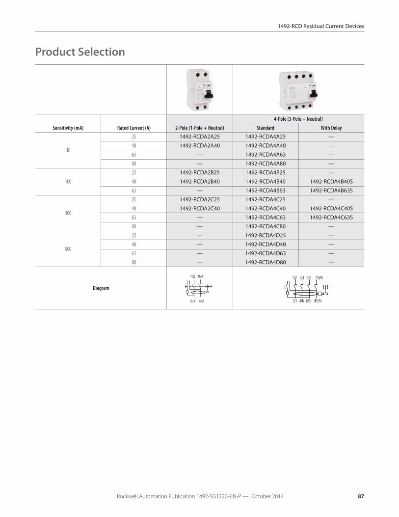
Product Selection
Sensitivity (mA) Rated Current (A) 2-Pole (1-Pole + Neutral)
4-Pole (3-Pole + Neutral)
Standard With Delay
30
25 1492-RCDA2A25 1492-RCDA4A25 —
40 1492-RCDA2A40 1492-RCDA4A40 —
63 — 1492-RCDA4A63 —
80 — 1492-RCDA4A80 —
100
25 1492-RCDA2B25 1492-RCDA4B25 —
40 1492-RCDA2B40 1492-RCDA4B40 1492-RCDA4B40S
63 — 1492-RCDA4B63 1492-RCDA4B63S
300
25 1492-RCDA2C25 1492-RCDA4C25 —
40 1492-RCDA2C40 1492-RCDA4C40 1492-RCDA4C40S
63 — 1492-RCDA4C63 1492-RCDA4C63S
80 — 1492-RCDA4C80 —
500
25 — 1492-RCDA4D25 —
40 — 1492-RCDA4D40 —
63 — 1492-RCDA4D63 —
80 — 1492-RCDA4D80 —
Diagram

1492-RCD Residual Current Devices
Rockwell Automation Publication 1492-SG122G-EN-P — October 201488
Power Loss Due to Current
Rated Current [A]
Power Loss [W]
2-pole 4-pole
25 1 1.3
40 2.4 3.2
63 3.2 4.4
80 8.8 33.3
Specifications
General Data
Poles 2,4
Rated currentIn 25, 40, 63, 80 A
Rated sensitivity I∆n2-pole 30, 100, 300 mA
4-pole 30, 100, 300, 500 mA
Electrical Ratings
Rated short-circuit strength10 kA with 63 A gG/gL back-up fuse,
10 kA with 80 A gG/gL back-up fuse for 80 A device
Rated operational voltage Ue perIEC/EN
230/400V AC
Rated voltage Ue per UL 480Y/277V AC
Max. operating voltage of circuit test 254V AC
Min. operating voltage of circuit test 110V
Rated frequency 50/60 Hz
Rated conditional short-circuit 10 kA (SCPD - fuse gG 100 A)
Rated residual breaking capacity 1 kA
Rated impulse withstand voltageUimp (1.2/50µs)
4 kV
Dielectric test voltage at ind. freq. for1 min.
2.5 kV
Electrical endurance 10,000 operations
Mechanical
Indicator window Red ON/green OFF
Protection degree Housing IP4X
Terminals IP2X
Environmental
Ambient temperature (with daily average +35 °C)
-25...+55 °C
Storage temperature -40...+70 °C
Mechanical endurance 20,000 operations
Installation
Terminal type Dual terminal
Cross-section of wire -solid, stranded, flexible
(front/back terminal slot)
25...63 A25/25 mm2
18...4 AWG
80 A35/35 mm2
18…2 AWG
Cross-section of bus bars(front/back terminal slot)
25...63 A 10/10 mm2
80 A 16/16 mm2
Tightening torque
25...63 A2.8 N·m
25 in·lb
80 A4.8 N·m
43 in·lb
Mounting DIN Rail EN 60715 (35 mm) with fast clip device
Supply Optional
Approximate Dimensions and Weight
Dimensions (H x D x W)2-pole 88 x 67 x 35 mm
4-pole 88 x 67 x 70 mm
Weight2-pole 200 g (7.1 oz.)
4-pole 350 g (12.3 oz.)
Combination with Auxiliary Elements
Auxiliary contact Yes
Signal contact Yes

1492-RCD Residual Current Devices
Rockwell Automation Publication 1492-SG122G-EN-P — October 2014 89
Note: Dimensions are shown in millimeters (inches). Dimensions are not intended for manufacturing purposes.
35 mm
(1.4”)
88 mm
(3.5”)
67 mm
(2.6”)75 mm
(3.0”)
70 mm
(2.8”)
2-Pole 4-Pole
Approximate Dimensions
2-, 4-Pole

1492-RCD Residual Current Devices
Rockwell Automation Publication 1492-SG122G-EN-P — October 201490
Right Mount
Photo
Product Description
‡�∆ Contacts Standards Certi7cations
UL/CSA Max.
Current/Voltage
IEC Ratings
Current/Voltage Cat. No.
Auxiliary/SignalContact
1 N.O./N.C.
(1 C.O.) UL 1077
CSA 22.2 No. 235
EN 60947-5-1
GB 14048.5
UL Recognized
CSA Certified
CE Marked
VDE Certified
CCC Certified
1 A @ 480V AC
2 A @ 277V AC
1.5 A @ 125V DC
2 A @ 60V DC
4 A @ 24V DC
2 A @ 230V (AC-14)
1 A @ 400V (AC-14)
1.5 A @ 110V (DC-12)
1 A @ 220V (DC-12)
4 A @ 24V (DC-13)
2 A @ 60V (DC-13)
189-ASCR39698
95
Auxiliary Contact
1 N.O./N.C.
(1 C.O.) UL 1077
CSA 22.2 No. 235
EN 60947-5-1
GB 14048.5
UL Recognized
CSA Certified
CE Marked
VDE Certified
CCC Certified
1 A @ 480V AC
2 A @ 277V AC
1.5 A @ 125V DC
2 A @ 60V DC
4 A @ 24V DC
2 A @ 230V (AC-14)
1 A @ 400V (AC-14)
1.5 A @ 110V (DC-12)
1 A @ 220V (DC-12)
4 A @ 24V (DC-13)
2 A @ 60V (DC-13)
189-AR3
1- 2- 3-
- 4
- 1
- 2
1 N.O. + 1 N.C.
UL 1077
CSA 22.2 No. 235
EN 60947-5-1
GB 14048.5
UL Recognized
CSA Certified
CE Marked
VDE Certified
CCC Certified
1 A @ 400V AC
2 A @ 230V AC
1 A @ 50V DC
2 A @ 30V DC
2 A @ 230V (AC-14)
1 A @ 400V (AC-14)
2 A @ 30V (DC-12)
1 A @ 50V (DC-12)
2 A @ 30V (DC-13)
1 A @ 50V (DC-13)
189-AR11-1
-2
-3
-4
1- 2 -
2 N.C.
UL 1077
CSA 22.2 No. 235
EN 60947-5-1
GB 14048.5
UL Recognized
CSA Certified
CE Marked
VDE Certified
CCC Certified
1 A @ 400V AC
2 A @ 230V AC
1 A @ 50V DC
2 A @ 30V DC
2 A @ 230V (AC-14)
1 A @ 400V (AC-14)
2 A @ 30V (DC-12)
1 A @ 50V (DC-12)
2 A @ 30V (DC-13)
1 A @ 50V (DC-13)
189-AR02
1- 2 -
-1
- 2
- 1
-2
2 N.O.
UL 1077
CSA 22.2 No. 235
EN 60947-5-1
GB 14048.5
UL Recognized
CSA Certified
CE Marked
VDE Certified
CCC Certified
1 A @ 400V AC
2 A @ 230V AC
1 A @ 50V DC
2 A @ 30V DC
2 A @ 230V (AC-14)
1 A @ 400V (AC-14)
2 A @ 30V (DC-12)
1 A @ 50V (DC-12)
2 A @ 30V (DC-13)
1 A @ 50V (DC-13)
189-AR20-3 -3
-4
1- 2 -
-4
‡ A maximum of one C.O. type signal contact, and one C.O. type auxiliary contact OR two C.O. type auxiliary contacts may be installed per 1492-RCD.
�A maximum of one 189-AR11, -AR02, or -AR20 auxiliary contact may be installed per 1492-RCD. They may not be combined with C.O. type contacts.
∆ A maximum of three accessories of any type may be installed per 1492-RCD. The signal contact must be mounted closest to the RCD, then the auxiliary contact(s). For allowed combinations, and installation instructions please contact your localRockwell Automation sales office or Allen-Bradley distributor.
Accessories

1492-RCD Residual Current Devices
Rockwell Automation Publication 1492-SG122G-EN-P — October 2014 91
Note: Dimensions are shown in millimeters (inches). Dimensions are not intended for manufacturing purposes.
Accessory Approximate Dimensions
85 mm
(3.35”)8.8 mm
(0.35”)
74 mm
(2.91”)
189-ASCR3
85 mm
(3.35”)
8.8 mm
(0.35”)
74 mm
(2.91”)
189-AR3
189-AR11, 189-AR02, 189-AR20
85 mm
(3.35”)
8.8 mm
(0.35”)
74 mm
(2.91”)

1492-RCD Residual Current Devices
Rockwell Automation Publication 1492-SG122G-EN-P — October 201492
Bus Bars
1492-RCD Cuttable Bus Bars
Description Pins Pkg. Qty.
Cat. No.
�2-Phase MCB to RCD 4 10 189-CL204
4-Phase MCB to RCD 8 10 189-CL408
� These devices are CE Marked, but not certified to any UL, CSA, or other standard.
1492-RCD Bus Bar Accessories
Description Pkg. Qty.
Cat. No.
�Terminal Power Feed, 6...25 mm2 10 189-CLT25
Terminal Power Feed, 6...50 mm² 10 189-CLT50
Dedicated Power Feed, 50 mm² 10 189-CLT50D
For 2-phase bus bar‡ 10 189-CL3EC
For 4-phase bus bar 10 189-CL4EC
Protective Shroud for unused pins 10 189-CLPS
� These devices are CE Marked, but not certified to any UL, CSA, or other standard.
‡ 189-CL3EC also used for 2- and 3-phase MCB bus bars.
1492-RCD
2.4 Nm
(21 lb in)
1492-RCD Residual Current Devices
Rockwell Automation Publication 1492-SG122G-EN-P — October 2014 93
Bus Bar Approximate Dimensions
Note: Dimensions are shown in millimeters (inches). Dimensions are not intended for manufacturing purposes.
2- and 4-Phase Bus Bars
4 mm
(0.16”)
11.5mm
(0.45”)
17.6 mm
(0.69”)
1 mm
(0.04”)
19.3 mm
(0.76”)
30.5 mm
(1.20”)19 mm
(0.75”)
7 x 17.6 = 123.2 mm
(7 x 0.69 = 4.85”)
148 mm+2
(5.82”) +2
4 mm
(0.16”)
9.8 mm
(0.39”)
17.6 mm
(0.69”)
3 x 17.6 = 52.6 mm
(3 x 0.69 = 2.21”)
72 mm+2
(2.83”) +2
1 mm
(0.04”)
14.8 mm
(0.58”)
19.2 mm
(0.76”)
29 mm
(1.14”)
189-CL204
189-CL408

1492-RCD Residual Current Devices
Rockwell Automation Publication 1492-SG122G-EN-P — October 201494
12 mm
(0.47”)
13.9 mm
(0.55”)
18 mm
(0.71”)3.6 mm
(0.14”)
mm
5”)
17 mm
(0.67”)
3.5 mm
(0.14”)
23.7 mm
(0.93”)
8 mm
(0.31”)
7 mm
(0.27”)
4.3 mm
(0.17”)
15 mm
(0.59”)
13 mm
(0.51”)
2 mm
(0.08”)
32.5mm
(1.28”)
16.5 mm
(0.65”)
4.3 mm
(0.16”)
15 mm
(0.59”)
13 mm
(0.65”)
2 mm
(0.08”)
35 mm
(1.38”)
25.6 mm
(1.01”)
11 mm
(0.43”)
28.8 mm
(1.13”)
17.75 mm
(0.70”)
12.3 mm
(0.48”)
10.5 mm
(0.41”)
35.3 mm
(1.39”)
29.8 mm
(1.17”)
13.5 mm
(0.53”)
4.3 mm
(0.17”)
84.7 mm
(3.33”)
17.8 mm
(0.70”)
18.5 mm
(0.73”)
4.2 mm
(0.17”)
11.6 mm
(0.46”)
3.5
(0.
4 x 17.8 = 71.2 mm
(4 x 0.70 = 2.80”)
189-CL3EC
189-CL4EC
189-CLT25 189-CLT50
189-CLT50D
189-CLPS
Bus Bar Accessory Approximate Dimensions
Note: Dimensions are shown in millimeters. Dimensions are not intended for manufacturing purposes.