146/1997 - Vaisala
48
We make the interface between people and their environment. 146/1997 146/1997
-
Upload
khangminh22 -
Category
Documents
-
view
1 -
download
0
Transcript of 146/1997 - Vaisala

We make the interfacebetween peopleand their environment. 146/1997146/1997
Vaisala News 146/97 Final 7.1.1998 09:57 Page 1

The goal of the Frontsand Atlantic StormTra cks Experiment(FASTE X) is toimprove weatherobservations andforecasting at sea. Then ew l y - d ev e l o p e dNC AR GPSDropsonde, theVaisala RD93, wasused for the FASTE Xs o u n d i n g s.
Neste’s ha r bo rs insouthern Finlanduse Va i s a l am o n i t o r i n gs ystems to helpimprove the safety
and economy of shipping. The system includes aMILOS 500 weather station and an FD 12visibility sensor, as well as water level andconductivity sensors.
The Da n i s hMe t e o r o l o g i c a lInstitute (DMI)c e l e b rated its 12 5 t ha n n i v e rsary in
19 97. Co o p e ration with Vaisala began in19 3 6. Since then, the DMI has prepared nearly200,000 weather forecasts using Va i s a l ae q u i p m e n t.
2 146/19972
Contents
3 President’s Column
4 W IND30 Multichannel Wind Display
Covers Wi d e -Ranging Applications
6 W IND20 Display for Applied
M e t eo r o l o g y
8 Wind System Upgrade at the Coast
Guard Station
9 W M S 3 01/302 Combined Wind Sensors
11 DMI Provides All-Round Wea t h e r
Observation and Fo r ecasting Service in
D e n m a rk
14 Radiosonde Production: Five Million and
Counting
15 AWS Network for the Moscow Circle
Road
16 Listening to Cloud Songs
19 RD93 Flies with FAST EX
21 R ea l -Time Water Vapor Mea s u r e m e n t s
24 A RM TS Up and Running in Ta i w a n
27 The Ic e b r eaker “Apu” Lives Up to its
N a m e
28 O n -Board AWS Provides More Reliable
Wind Data at Sea
30 H y d r o m e t eorological Observation System
S u p p o rts Harbor Operations
E d i t o r - i n -C h i e f :
M a rit Fi n n e
P u b l i s h e r :
Vaisala Oy, P.O. Box 26
FI- 0 0 4 21 Helsinki,
FINL A ND
Phone (int. ) :
(+358 9) 894 91
Te l e f a x :
(+358 9) 894 9227
Te l e x :
122832 vsala fi
In t e rn e t :
h t t p : / / w w w. v a i s a l a. c o m
Design and Art w o rk :
N o n -Stop Studiot Oy
E d i t o r s :
Axioma Oy
P ri n t ed in Finland by
S ä v y p a i n o, Fi n l a n d
ISSN 12 3 8 - 2 3 8 8
Vaisala in Brief
- We dev e l o p, manufacture and mark e t
products and services for environmental
and similar industrial mea s u r e m e n t s.
- The purpose of these measurements is to
provide the basis for better quality of life,
cost savings, protection of the environment,
and improved safety and perf o rm a n c e .
3 2 S t e p -B y -Step Automation of
Observing Systems in Slovakia
3 5 Windfinding Accuracy of Te r r e s t ri a l
N a v a i d s
39 Replacement Systems for Omega Wi n d
M easurement
40 Using Lo r a n -C for Upper Air Winds
40 Comprehensive Service for Upper Air
Weather Systems
4 2 Croatia Upgrading its Meteo r o l o g i c a l
S y s t e m s
4 2 The Customer Comes First at Zagrel
4 3 M HS: Ready for Future Challenges
44 Air Traffic Safety Authority Prepares for
In c r easing Air Tr a f f i c
4 5 AWS Plays a Key Role in Power and
Water Management
46 RT20 Radiotheodolite Stands Up to
Harsh Field Conditions
47 N ew Calibration Method for Reference
and Field Pyranometers
47 S ea Launch Meets the Growing Need
for Commercial Satellite Launch Services
- We focus on market segments where we
can be world lea d e r s, the preferred suppli-
e r. We pay high attention on customer sat-
i s f a c t i o n. Competitive advantage is en-
h a n c ed by economies of scale and scope.
Extensive R&D creates innovative solutions,
which lead the way in the industry.
Cover photo: Le h t i k u v a /S u p e r s t o c k
Vaisala News 146/97 Final 7.1.1998 09:57 Page 2

3146/1997/1997
s a radiosonde manu-facturer for morethan half a century,we have marke d
m a ny milestones. ProfessorVilho Väisälä made his firstsuccessful radiosounding 66years ago, and this September,Va i sala produced its five mil-lionth radiosonde. Measuredin today’s demand, five mil-lion radiosondes would beenough for at least six years ofglobal soundings. This is animpressive figure and a sourceof great pride for us. At them o m e n t, Va i sala’s history -m a king radiosonde, a GPSsonde, is on my desk. Soon itwill be on display in theVa i sala showroom.
During the same monththat we manufactured the fivemillionth radiosonde, theO m e ga n a v i gation networkwas phased out. By earlyO c t o b e r, hundreds of sound-ing stations throughout theworld had switched to GPS-based wind finding and GPSr a d i o s o n d e s. In regions wherecoverage is available, Loran-Cwindfinding was also adopted.
President’s Column
Despite some initial concern,the changeover has been verys m o o t h.
S u rface wind measurement isone of the most import a n tweather observ a t i o n s. Wi n dhas an effect on many aspectsof our daily lives, and windo b s e rvations are critical, ofcourse, for meteorological ap-p l i c a t i o n s. Va i sala was the firstto introduce wind display withcircular presentation for winddata with the mean value windmeasurement integrated intothe electronic display. Air traf-fic controllers, in part i c u l a r,have appreciated this easy-t o -read wind instrument. Now wehave developed a new-g e n e r a-tion series of wind displays.These products cover variousapplications and needs, includ-ing comprehensive wind sys-t e m s. Using the latest compo-nent tech n o l o g y, we have madethe display even easier to read.This equipment is also morecompact and convenient to use.
As the articles in this Va i sa l aNews demonstrate, the applica-tions of weather observ a t i o n scover the full range, from float-
Marking Milestones
Aing launch platforms to cloudgenerated music. These are twoextremes on the scale, withweather representing an obsta-cle for one and an opport u n i t yfor the other. In some cases,the conditions can pose a realt h r e a t. In others, weather ob-s e rvations are just ‘nice to kn o w ’.It might seem that such vary i n gdemands and conditions wouldrequire many different types ofmeasurement instruments. Th i sis not the case. Because today’sproducts are flexible, program-mable and designed for ex-treme conditions, they are alsov e r satile enough to handlethese wide-ranging applications.Whatever the need, Va i sa l aproducts offer a solution. No te v e n the sky’s the limit. Onlythe ima g i n a t i o n.
Pe kka KetonenPresident and CEO
Vaisala News 146/97 Final 7.1.1998 09:57 Page 3

4 146/1997
Va i sala’s WIND30 isa flexible display unit
that can be tailoredfor a wide range of
demanding applica-t i o n s. Easy installa-
tion and mainte-nance are two more
advantages of thisnew wind display.
Tapani Ti u sa n e n, Ph.D. (P hy s. )Product ManagerS u rface Weather DivisionVa i sala Oy, Finland
WIND 3 0 Multi c h ann e lWi n d D i s p l a y C oversWid e -R angingApplicat i o n s
Figure 1. Various wind
s e n s o rs and wind
t ra n s m i t t e rs can be
connected to the display.
An RS485 serial line is
typically used to
communicate with
intelligent dev i c e s,
including other displays,
data loggers and PCs.
Figure 2. The averaging multichannel wind
measurement system over a long distance shows an
installation where two wind sites are connected to
the display cha i n. WAT 12 analog wind
t ra n s m i t t e rs are used to sample the wind sensors
and send current loop signals to the display.
Figure 3. Mu l t i channel wind measurement with
other basic pa ra m e t e rs such as tempera t u r e ,
h u m i d i t y, pressure, etc. All the different variables
are connected to the QLC50 data logger, which is
configured to send data via an RS485 to the office.
The whole system is supplied with a local power
unit such as a WHP25 outdoor mains power
s u p p l y. The WIND30 display presents real-time
wind data from all four (4) sensor pa i rs, and the
PC is used to further process and print the results.
Vaisala News 146/97 Final 7.1.1998 09:58 Page 4

5146/1997
a i sala’s WIND 3 0M u l t i channel Wi n dDisplay is a more ad-vanced version of the
basic W IND20 model. The unitis designed for applicationsrequiring wind data for every-day operations. Examples in-clude forec a s t i n g, harbor opera-tions and industrial applica-t i o n s.
C l ear wind speedp r e s e n t a t i o n
The display produces a numeri-cal presentation of wind speed –plus maximum and minimumvalues – in a 3-digit 7-s e g m e n tL ED field. The wind directionand variance are presented withtwo separate concentric LEDc i r c l e s, with wind direction rep-resented by the inner circle andvariation by the outer. Primary
and secondary values are differ-entiated with two colors; highintensity red LEDs are used forwind speed and direction, whileyellow LEDs are used for speedextremes and direction vari-ance. Automatic brightness con-trol and a matt-finished frontpanel filter offer good contrastand readability in various lightc o n d i t i o n s.
Operators use a rotatings w i t ch and a 3-state push but-ton to select between differentwind measurement sites and op-erating modes: instantaneous, 2minute, 10 minute averaging.The unit also supports alarmp r o c e s s i n g, manual intensitycontrol and self testing.
Easy servicing
The WIND30 display has thesame housing design and face
The serial interface is basical-ly an RS485 serial line that sup-p o rts both half and full duplexc o m m u n i c a t i o n s. It also serv e sas an NMEA compatible opto-isolated serial interface or anRS232 port. The fixed opto-i s o-lated RS485 is typically used asa service line or to chain severald i s p l a y s. This makes it easy todisplay wind data at several dif-ferent locations simultaneously.
An optional communicationmodule such as the DM X 5 01modem allows data receptionfrom several remote measure-ment sites.
Tailoring the unit fors p ecific needs
The user interface, calculations,I/O devices and telecommuni-cation modes are configured viaa serial line using a PC terminalp r o g r a m. The software has asimple ASCII command inter-face for changing configura-tions either one command at atime or by downloading a com-plete configuration file to thed i s p l a y.
Selectable speed units includem / s, kt, km/h and miles/h.Wind speed is presented as aninteger or decimal value. If de-s i r e d, the automatic brightnesscontrol feature can be disa b l e d.
Some data processing occursbefore the wind data is present-ed on the display. This includesmagnetic deviation correction,speed alarm settings, time outfor correct data, etc. All of thesesettings can be independentlyspecified for each of the fourdisplay ch a n n e l s. Using sensorID s, the data can be displayedon any ch a n n e l.
When sensors such as theWAA 151, WAV 151 or WMS 3 01/302 are connected directly tothe display, the processor opti-mizes the sampling and datap r o c e s s i n g. If current loop sig-nals are used, current scales andthe corresponding data scalesare freely selectable. So almosta ny current or voltage transmit-ter can be used with the display.
The innovative serial inter-face, an RS485 that support sboth half and full duplex com-m u n i c a t i o n s, also functions asan NMEA compatible opto-i s o-lated serial interface or as anRS232 port. Standard commu-nication parameters such asbaud rate, data bits, stop bits
Figure 5. The
WIND30 Mu l t i-
channel Wind Display
produces a numerical
presentation of wind
speed – plus maximum
and minimum values –
in a 3-digit 7- s e g m e n t
L ED field.
size (144 x 144 mm) as theW IND20. The compact bodycan also be mounted to 115 x133 mm panel openings. Th eunit comes with a stand, whichcan be used to mount the dis-play on a wall or ceiling. Th eW IND30 has been designedfor easy servicing even after theunit has been mounted on ap a n e l. The entire display can bedissembled from behind, andthe electronics and connectors,as well as the communicationmodule and jumpers, are alsoaccessible from the rear.
Versatile eq u i p m e n tc o n f i g u r a t i o n s
The display can be used withseveral types of sensors, trans-mitters and data loggers (seeF i gure 1) .
Va i sala digital wind sensors –WAA 151 and WAV 151 – can beconnected directly to the digi-tal input of the display, and com-bined wind sensors (W MS s) canbe integrated with the analogi n p u t s. The WIND30 and its100 Ω internal shunt resistorscan even process current loopsignals – from a WAT 12 AnalogWind Tr a n s m i t t e r, for example.
VFigure 4. The WIND team from
the right: Kai In ha, Ta pa n i
Ti u s a n e n, Ari Hyväoja, Ma r t t i
Ka r j a n m a a, Anu Räisänen, Pe k k a
P u u ra, Mauri Vilpponen, Ma t t i
Ta m m i v i r t a, Seppo Vuohtoniemi,
Vesa Nu o t i o, Elina Ahde and
Ta pani Lammi. Marja Asikainen
is missing in the picture.
Vaisala News 146/97 Final 7.1.1998 11:54 Page 5

6 146/1997
DMX501 module communicatesover long distances
The DM X 5 01 communication module is a miniature modemfor long-distance fixed line communications. It is designed forinstruments with a Va i sala communication module slot. Th eDM X 5 01 contains a US A RT and a modem chip that is capableof V. 21/ V. 2 2 / V. 2 3 / V. 21bis (i.e. from 300 to 2400 bit/sec) com-munication modes.
This modem module is capable of operating in extreme env i-ronmental conditions while consuming very little power – acombination that is not available from any other manufacturer.
The DM X 5 01 communication module.
and parity can be specifiedindependently for each of thelogical communication port s.
For compatibility reasons,the 1.0 version of the programonly supports the basic mes-sages commonly used with Va i-sala wind systems.
A veraging wind systems
The WIND30 display is a basicinstrument that connects winds e n s o r s / t r a n s m i t t e r s, processesand displays data, and finallydistributes it via an RS485, mo-dem line. The multipurpose I/Ois supported by configurablesoftware for different types of in-stallations and data processingn e e d s.
Figure 2 shows an installationwhere two wind sites are con-nected to the display ch a i n.WAT 12 analog wind transmittersare used to sample the wind sen-sors and send current loop sig-
nals to the display. A local powersupply is required at the base ofthe mast if the distance betweenthe wind mast and display is akilometer or more, or if shaftheating is used for the sensors.
Longer distances of 10 km ormore require an advanced trans-mitter like the WAT 15 insteadof a WAT 12. In this case, theW IND30 must be equippedwith a DM X 5 01 modem com-munication module. Althoughthe display automatically recog-nizes the module, some basiccommunication parameters canbe defined to optimize theo p e r a t i o n. A local power supplys u ch as the WHP151 is neededfor WAT 15 wind transmitters.The office equipment consistsof two wind displays, with thefirst transmitting raw wind datavia the RS485 line to the sec-o n d. Both of the displays carryout independent data process-ing and presentation.
Behind the basicappearance of the
W IND20 lies ahighly advanced dis-play unit. The flexi-bility and versa t i l i t yof this display make
it an excellentchoice for applied
m e t e o r o l o g y.
a i sala’s single ch a n-nel WIND20 displayis an economic solu-tion for displaying in-
stant short averaged values ofwind speed and direction. Whenused with Va i sala sensors, it is areliable, easy-t o -use wind system.
Flexibility plus ve r s a t i l i t y
With its many advanced fea-t u r e s, the WIND20 display isflexible enough to meet mostwind measurement and displayn e e d s. Wind speed units (m/s,k m / h, kt, mph), for example, aswell as alarms, magnetic devia-tion correction and averagingtime can all be tailored using aterminal or PC connected tothe display’s service interf a c e .
An I/O with 20 terminals sup-p o rts both analog and digitals e n s o r s / t r a n s m i t t e r s, while a 3.5V DC reference output providesa stable reference for analogsensors such as potentiometer-based wind direction sensors.P u l s e / f r e q u e n cy input is t y p i-cally used with digital anemo-m e t e r s, and a wind speed alarmtriggers a 120 mA relay drive.
Tapani Ti u sa n e n, Ph. D . (P hy s. )Product ManagerS u rface Weather DivisionVa i sala Oy, Finland
Simple and effective:
W IND20 Display for
The WIND20 Display is an economic solution for
displaying instant short averaged values of wind
speed and direction.
V
Vaisala News 146/97 Final 7.1.1998 09:58 Page 6

The multipurpose serial inter-face, which supports bothRS485 or NME A -c o m p a t i b l eo p t o -isolated serial lines, can beused to link additional displaysat different locations. If the dis-play is located within a fewmeters of the PC, the data canbe sent directly to the PC via anRS232 interface for further pro-cessing or arch i v i n g.
When used with Va i sala sen-s o r s, the WIND20 typically con-sumes 5 W of 10 . 5 – 15.5 VDC ,so an economic wall adapter isoften enough to supply the dis-play and sensors/transmitters. Alocal supply is needed, however,if the site is located several ki l o-meters from the display or ifsensor heating is used. The unitcomplies with the EMC direc-tive (89/336/EEC) and is sup-plied with a CE label.
E a s y - t o - r ea d, ea s y - t o - u s e
Wind speed is presented digital-ly in a 3-digit 7-segment LEDf i e l d. The wind direction andvariation are displayed on a dis-tinct analog LED circle, and theselected speed unit is clearly
i n d i c a t e d. The information isshown in conspicuous red andyellow LED s.
A light sensor responds toambient light conditions, auto-matically controlling the bright-ness of the display. The frontpanel filter is matt-f i n i s h e d, soit has good optical qualities.These features offer good con-trast and make the display easyto read in various light condi-t i o n s.
The user interface has beendesigned for ease of operation.The unit has just one push but-ton for manual brightness con-t r o l, quick ch e ck and reset func-t i o n s. A separate alarm indica-tor is triggered when wind speedexceeds the specified limit.
Various mountingo p t i o n s
The face size of the WIND20 is144 x 144 mm (138 x 138 mmbody), which complies withDIN panel standards. Th a n ksto its special slim line body de-s i g n, the unit can even be mount-ed to 115 x 133 mm (height xw i d t h) panel frames and open-i n g s. The stand included in the
ay for Applied Meteoro l o g yd e l i v e ry can be used to attachthe display to the wall, ceilingor a table.
Examples of singlechannel wind systems
With the versatile I/O, varioustypes of sensors or transmitterscan be connected to the display.Figures 1, 2 and 3 illustrate sev-eral possible options.
In Figure 1, for example, aWAA 151 digital anemometer isconnected directly to the dis-p l a y. Only three wires (with as h i e l d) are needed. The frequen-cy output from the sensor isconnected to the SPEED inputof the WIND20 display. Th epower for the sensor can also besupplied via the display’s paral-lel supply terminals. The entiresystem can be operated usingthe same power supply; thepower consumption of the sen-sor is negligible, however, so asmall 12 VDC wall adapter isoften enough to supply the en-tire system.
Figure 2 shows an economicsolution for measuring bothwind speed and direction. Acombined wind sensor has been
connected directly to the dis-p l a y. This system consumesjust a few watts of power andcan be supplied with a low-c o s tpower unit.
The data can also be loggedor processed with a PC, by simp-ly connecting the display’s se-rial line to the PC’s RS232 port.The display also functions as adigital wind transmitter (analogto serial) between the sensorand the PC.
In Figure 3, WAA 151 andWAV 151 digital wind sensorsare connected to the WAT 12analog wind transmitter, whichis used to send two currentloop signals to the display. Th eWAT 12 supports a range ofcurrent scales. To achieve thebest accuracy, however, 0–20mA or 4–20 mA scales are rec-o m m e n d e d. The display itselfs u p p o rts any scale, so it is aflexible current/voltage meas-uring device. In this example, acommercial analog recorderhas been added to the systemto plot instant wind data onp a p e r. Another display isl i n ked to the system to showwind data at a different loca-t i o n. The data is transferredbetween the display via anRS485 serial line. A WHP151outdoor mains power supply atthe base of the mast is neededfor shaft heating of the sensorsand for transmissions coveringa distance of several ki l o m e t e r s.
Figure 1. Wind speed
measurement; a WAA 151
digital anemometer is connected
directly to the display.
Figure 2. An economic solution
for measuring both wind speed
and direction. A combined
wind sensor has been connected
directly to the display.
Figure 3. Wind measurement at
long distance: WAA 151 and
WAV 151 digital wind sensors
are connected to the WAT 12
analog wind tra n s m i t t e r, which
is used to send two current loop
signals to the display.
7146/1997
Vaisala News 146/97 Final 7.1.1998 09:58 Page 7

8 146/1997
The Glosholm CoastGuard Station is locat-ed on Pe l l i n ki Islandoff the southern coastof Finland. The operat-ing area of the stationcovers Finnish watersin the Gulf of Finland.To improve the sta-tion’s weather moni-toring capability, a n e wVa i sala wind meas-urement system wasinstalled early lasts u m m e r.
A new Vaisala wind measurement
s ystem was installed at the Glosholm
Coast Guard Station’s watchtower in
early summer 19 97.
Petteri Leskinen inside the Glosholm
w a t ch t o w e r.
Wind System U p g rade
at the Glosholm Coast Guard Sta t i o n
Wind System U p g rade
at the Glosholm Coast Guard Sta t i o n
Vaisala News 146/97 Final 7.1.1998 09:58 Page 8
9146/1997
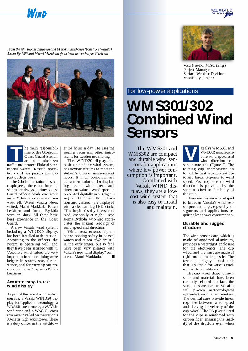
From the left: Ta pani Tiusanen and Markku Sinkkonen (both from Va i s a l a ) ,
Jorma Rytkölä and Mauri Markkula (both from the station) at Glosholm.
The WMS 3 01 andW MS302 are compactand durable wind sen-
sors for applicationswhere low power con-
sumption is import a n t.Combined with
Va i sala WIND dis-p l a y s, they are a low-cost wind system thatis also easy to install
and maintain.
a i sala’s WMS 3 01 andW MS302 sensors com-bine wind speed andwind direction sen-
sors in one unit (Figure 2). Th erotating cup anemometer ontop of the unit provides isotrop-ic and linear response to winds p e e d. Fast response to winddirection is provided by thevane attached to the body ofthe unit.
These sensors were developedto broaden Va i sala’s wind sen-sor product range, especially forsegments and applications re-quiring low power consumption.
Durable and ruggeds t r u c t u r e
The wind sensor core, which ismade of anodized aluminum,provides a watertight enclosurefor the electronics. The cupwheel and the vane are made ofrigid and durable plastic. Th eresult is a highly durable unitthat is suitable for various env i-ronmental conditions.
The cup wheel shape, dimen-sions and materials have beencarefully selected. In fact, thesame cups are used in Va i sa l a ’ swell proven meteorologicalo p t o -electronic anemometers.The conical cups provide linearresponse between wind speedand the angular velocity of thecup wheel. The PA plastic usedfor the cups is reinforced withcarbon fiber, ensuring the rigid-ity of the structure even when
Ve sa Nuotio, M. S c. (E n g. )Project ManagerS u rface Weather DivisionVa i sala Oy, Finland
For low-power applications:
W MS 3 01/ 3 0 2Combined Wi n dSe n s o r s
he main responsibil-ities of the GlosholmCoast Guard Stationare to monitor sea
traffic and protect Finland’s ter-ritorial waters. Rescue opera-tions and sea patrols are alsop a rt of their work.
The Glosholm station has tenemployees, three or four ofwhom are always on duty. CoastGuard officers work one weekon – 24 hours a day – and oneweek off. When Va i sala Ne w sv i s i t e d, Mauri Markku l a, Pe t t e r iLeskinen and Jorma Rytköläwere on duty. All three havelong experience in the CoastG u a r d.
A new Va i sala wind system,including a WIND20 display,has been installed at the station.According to the officers, thesystem is operating well, andthey have been satisfied with it.“Accurate wind values are veryi m p o rtant for determining waveheights in stormy seas, for in-stance, and for carrying out res-cue operations,” explains Pe t t e r iL e s ki n e n.
Accurate ea s y - t o - u s ewind display
As part of the recent wind systemupgrade, a Va i sala WIND20 dis-play for applied meteorology, aWAA 151 anemometer, a WAV 151wind vane and a WA C 151 crossarm were installed on the station’s3 0 -meter high watch t o w e r. Th e r eis a duty officer in the watch t o w-
er 24 hours a day. He uses theweather radar and other instru-ments for weather monitoring.
The WIND20 display, thebasic unit of the wind system,has flexible features to meet thestation’s diverse measurementn e e d s. It is an economic andc o nvenient solution for display-ing instant wind speed anddirection values. Wind speed ispresented digitally in a 3-digit 7-segment LED field. Wind direc-tion and variation are displayedwith a clear analog LED circle.“ The bright display is easier tor e a d, especially at night,” sa y sJorma Rytkölä, who also appre-ciates the instant readings ofwind speed and direction.
Wind measurements help en-hance boating safety in coastalwaters and at sea. “We are stillin the early stages, but so far Ihave been very pleased withVa i sala’s new wind display,” com-ments Mauri Markku l a.
T
V
Vaisala News 146/97 Final 7.1.1998 09:58 Page 9

10 146/1997
exposed to extremely high winds p e e d s.
The anemometer ball bearingassembly comprises a cup wheels h a f t, a pair of low-friction ballbearings and a shaft fixed mag-n e t. The reed relay and elec-tronics in the sensor body con-v e rt the cup wheel rotation top u l s e s. So the sensor electronicscan be connected to virt u a l l ya ny data logger, either by count-ing the number of closureswithin a fixed time period or bymeasuring the time betweensuccessive pulses. The sensingelements are located inside aw a t e rtight compart m e n t, pro-viding full protection for thesensor electronics against water,dust and pollutants.
The balanced wind vane isintegrated underneath the cupwheel in the unit housing. Th ecircular tail is located far enoughfrom the body and cup wheel toavoid the turbulence caused bythese structures. Made of PAplastic reinforced with fiber-g l a s s, the vane is a durable andlightweight structure offeringfast response and low inert i a.
The angle of the vane isdetected using an axial symmet-ric rotating potentiometer. Th i spotentiometer features low start-ing and running torque, a lineara r c -t o -resistance transfer ratio,and long operating life. With aconstant voltage applied to thep o t e n t i o m e t e r, the output volt-age is directly proportional tothe azimuth angle.
Choice of one or twos l i d e - t y p ep o t e n t i o m e t e r s
The type of potentiometer usedis the only difference betweenthe two wind sensor models.The WMS 3 01 is equipped witha one wiper-type potentiometerwith an open gap of less than 5d e g r e e s. This type of sensorshave been available for manyy e a r s, so adopting the WMS 3 01requires minimal work fromsystem suppliers. To overcomethe gap continuity problem, theW MS302, which is typicallyused with Va i sala systems, hastwo wiper-type potentiometers.For this reason, the transmitter,
data logger or other processingunit requires a more complexv o l t a g e -t o -direction conv e r s i o na l g o r i t h m.
Simple installation, easy maintenance
Simple installation was a highpriority in the design of theW MS 3 01 and WMS302. Th esensor is supplied with a 30 mmm a s t -top mounting adapter, asleeve with a screw joint at theb o d y, and an industry standard5 -pin connector at the bottomof the unit. After attaching theadapter at the top of the mastand guiding the cable and con-nector through the tube, theinstallation of the sensor isq u i ck and easy. In fact, it can bemounted and dismounted with-out any tools.
After several years of use,m e chanical sensors with ballbearings typically require ser-vice. Th a n ks to the intelligentdesign of these wind sensors,bearing service is easy and trou-blefree. The anemometer bear-ings assembly can be replacedusing a simple open-end wrench.Changing the vane bearingst a kes just a few more minutes.
W MS sensors combined withVa i sala WIND displays are ac o s t -effective solution for manya p p l i c a t i o n s, including serialoutput for sharing informationbetween additional displays orP C s. The basic single ch a n n e lwind system comprises a WINDd i s p l a y, WMS sensor, cable andpower supply, as illustrated inFigure 1.
Figure 2. Vaisala’s compact WMS 3 01 and WMS302 wind sensors
combine a wind speed and wind direction sensor in one unit.
Figure 1. A complete low-cost wind sys t e m.
Vaisala News 146/97 Final 7.1.1998 09:58 Page 10

11146/1997
Ev e rybody talks aboutw e a t h e r, but the pro-
fessionals at theDanish Meteorological
Institute (DMI) dosomething about it.
Drawing on theirextensive resources,
DMI analyzes weatherinformation and pre-
pares accurate fore-c a s t s, contributing tothe safety and econo-my of many activities
on land and sea. Since1936, the Institute has
prepared about200,000 weather fore-
casts using Va i sa l ae q u i p m e n t.
o d a y, the Danish Me-t eorological Institute(DMI) is the nerv ecenter of the kn o w-
how and databases of the Me-teorological Institute, the Aero-nautical Meteorological Serv i c efor civil aviation, and theDanish Defence Weather Serv i c e .DMI is organized into fourd e p a rtments: Forecasting Ser-v i c e s, Research and Devel-o p m e n t, Observ a t i o n, and DataP r o c e s s i n g. The central admin-istration is the responsibility ofthe Secretariat, which alongwith the office of the Director-G e n e r a l, Mr. Lars Prahm, Dr.S c., handles general administra-t i o n.
The Meteorological Institutewas founded in 1872 and cel-ebrated its 125th anniversa ry in19 97. The cooperation betweenDMI and Va i sala began in 19 3 6 ,the year that Va i sala was estab-l i s h e d.
O verview of DMI activities
With its staff of about 400,DMI operates under the Minis-t ry of Tr a n s p o rt. The Institute isresponsible for the meteorol o g i-c a l, climatological and ocean-ographic surveillance of Den-m a r k, Greenland, the Faroe Is-
l a n d s, and the surroundingwaters and air space. This repre-sents a large geographic area,m a ny regions of which are noteasily accessible.
Based at the Narsa r s u a qA i rf i e l d, DMI’s Ice Observ a-tion and Warning Service, forexample, makes a major contri-bution to the safety of shippingin Greenland’s waters. The Ser-vice provides ice observ a t i o nand piloting information fors h i p s. The Aviation We a t h e rS e rvice, which is also part ofDMI’s orga n i z a t i o n, helps im-prove air traffic safety and econo-my. At the Copenhagen Airportalone, 80,000 flight crews relyon their meteorological infor-mation every year.
Marit FinneE d i t o r -i n -C h i e fVa i sala Ne w sVa i sala Oy, Finland
DMI Provides Al l -R o u n dWeather Observa t i o n
and Fo recasting Se r v i c ein Denmark
TMr. Lars Pra h m,
DMI’s Director-
Ge n e ra l.
Vaisala News 146/97 Final 7.1.1998 09:59 Page 11

12 146/1997
to maximize the return on tax-payer money, in this case byoptimizing our weather ob-s e rv a t i o n s,” comments Mr.H e d e ga a r d.
E x t e n s i ve softwa r eexpertise
The Observation Depart m e n thas technical facilities for de-v e l o p i n g, testing and preparingo b s e rvation instruments. Onthe software side, the depart-ment has advanced expertise indata communication and digi-tal image processing. The latestcomputerized technology hasbeen adopted at DMI.
Carsten Paludan-M ü l l e r, M. S c.(E n g.), and Software EngineerKlavs Allerslev Je n s e n, bothfrom the Te chnical Division ofthe Observation Depart m e n t,are software experts at DMI.Va i sala’s MILOS500 weatherstations have been one of their
latest projects. Mr. Paludan-Müller has worked at DMI forabout one and a half years. Mr.Jensen joined the Institute staffin 1976, so he has many yearsof experience in the field andwith Va i sala products.
As Mr. Jensen notes, goodquality and first-rate documen-tation are very important formeteorological systems. Mr.P a l u d a n -Müller adds: “When Ineed technical support or ad-vice about Va i sala’s products, Ijust give them a call. ”
J a egersborg soundingstation opts for Va i s a l aeq u i p m e n t
The Observation Depart m e n tis responsible for operatingDMI’s observation stations.
M r. Torben Rye Nielsen,Chief of the Jaegersborg sound-ing station near Copenhagen,explains: “Our staff comprises
Upper air stations turn 50
DMI has a comparatively largenetwork of sounding stationsfor a country the size of Den-m a r k. There are five stations inG r e e n l a n d, one in the FaroeI s l a n d s, one in Denmark, andtwo on ASAP ships. The Insti-tute has always worked activelywith the ASAP (AutomatedShipboard Aerological Pro-gramme), reflecting their beliefthat this cost-efficient programgives the best value for moneyfor upper air profiles over data-sparse ocean areas. Denmark’ supper air stations are currentlycelebrating their 50th anniver-sa r i e s. The Faroes station, forinstance, turned 50 in No v e m-ber 19 9 6 .
M r. Klaus Hedega a r d, Ph. D . ,Deputy Director of DMI ’ sO b s e rvation Depart m e n t, hasalso been Acting Director sinceJ a n u a ry 1996. The Depart m e n thas about 70 employees.
According to Mr. Hedega a r d,his first contact with Va i sa l awas in 1989, when he took overresponsibility for the then A e r o-logical Depart m e n t. “DMI h a sp u r chased Va i sala radiosondessince 1936, with the only inter-ruption during the SecondWorld Wa r. Va i sala has also de-livered a total of 11 DigiCORAand MARW IN ground equip-ment units for DMI soundings t a t i o n s, including those in theFaroes and Greenland,” he ex-p l a i n s. The Aerological Depart-
ment was established in 19 3 6and since then has providedh i g h -quality upper air measure-ments from Danish upper airs t a t i o n s. In 1989, the Depart-ment was merged with the gen-eral Observation Depart m e n t.
An extensive upgrade of theInstitute’s equipment is cur-rently underw a y, including thea u t omation of their observ a-t i o n s. In recent years, DMI hasp u r chased a number of surf a c eweather observation units fromVa i sa l a, including several FD 12 Ppresent weather sensors, CT25Klaser ceilometers, MILOS 5 0 0weather stations, and othermeasurement instruments. Th euse of unmanned automaticweather stations for surf a c eweather observations is on theincrease in Denmark, as light-houses and other manned ob-s e rving stations are graduallyclosed down or automated.DMI’s new Cloud CoverageA l g o r i t h m, another recent de-l i v e ry from Va i sa l a, provides aneasy and cost-effective way toproduce more information fromceilometer data. By processingthis data, the cloud amountand the height of various cloudlayers can be calculated.
DMI constantly evaluatesthe value for money of its inv e s t-m e n t s. “Va i sala provides welld o cum e n t e d, high-quality pro-ducts which require only slightor no additional developmentat DMI before we take theminto operational use. This is ani m p o rtant factor in our effort
The Observation Department ove r s e e sthe following operations andeq u i p m e n t :
• 7 radiosounding stations• 2 ASAP ships with marine sounding stations• a wind profiler
• 50 primary synoptic stations• aeronautical observations at 11 airport s• 60 secondary synoptic stations• 45 voluntary observing ships
• 450 precipitation stations• 20 climatological stations• 16 hydrographical stations• 20 stations with tide ga u g e s
• 3 ground stations with satellite reception forimages and data
• 3 weather radars• 4 stations with lightning detection• 3 geophysical observatories in Greenland• Greenland Ice Patrol
The statue of the
Little Me r m a i d,
made famous by the
H. C. An d e rs e n
fairy tale, is a well-
known tourist
a t t raction in
Co p e n ha g e n.
The Ja e g e rs borg sounding station. From the left: Torben Rye Nielsen, Be n d t
N i e l s e n, Lars K. An d e rs e n, and Lutz O.R. Niegsch.
Vaisala News 146/97 Final 7.1.1998 09:59 Page 12

13146/1997
he cost of ASAPupper air sounding isabout 15 per cent ofthe figure for an up-
per air sounding from a weathers h i p, and equal to or less thanthe cost of a land-based sound-i n g. For this reason, the ASAPsystem is an economical sourceof baseline upper air data fromthe oceans and a vital part ofglobal ocean observing systems.
The containerized ASAP sys-tem offers important advan-tages in today’s flexible ship-ping env i r o n m e n t. If there is asudden change in shippingr o u t e s, the unit can simply be
The AutomatedShipboard AerologicalProgramme (ASAP) isa cost-effective source
of upper air weatherdata over data-s p a r s e
ocean areas. Denmarkhas always been active-
ly involved in theASAP program.
Va i sala’s radiosondesand ground equipment
are used in the coun-t ry’s ASAP ships.
Tinka Ar c t i c a, one of Denmark’s ASAP observation ships.
t r a n sferred to a ship that ismore suitable for ASAP opera-t i o n s. It has become apparent,h o w e v e r, that the number ofships capable of carrying such asystem is limited.
The countries with currentlydeployed ASAP systems areDenmark (2 units), France (4),G e r m a ny (5), Spain (1), Swe-d e n /Iceland (1), the UK (1) andthe USA (1).
The ASAP was instituted inits current form in the mid-19 8 0 s. It was organized by theASAP Coordinating Commit-tee (ACC) established by theW MO Executive Council in1985. From 19 9 4 – 19 97, Kl a u sH e d e gaard from the DanishMeteorological Institute was thechairman of ACC.
“ The quality of ASAP data isgenerally very high, comparablewith the quality of data fromocean weather ships, with aver-age sounding heights e x c e e d i n g20,000 gpm. Va i sala’s radioson-des and ground equipment havebeen used in Danish ASAP shipsfrom the beginn i n g,” commentsM r. Hedega a r d.
The total number of ASAPsoundings has risen to about5,000 annually. This corre-sponds to approximately sevenocean weather ships when basedon comparable observation p r o t o c o l s. From this standpoint,ASAP plays a vital role in theWorld Weather Wa t ch.
five permanent employees. Wel a u n ch one radiosonde twice aday from Jaegersborg. Onw e e k d a y s, when more than oneperson is working at the sta-t i o n, we fill the balloons withhy d r o g e n. For safety reasons,we use helium when we haveonly one person on duty, dur-ing the night shift and week-e n d s, for example.”
Lars Andersen and BendtNielsen were on duty the daythat Va i sala News visited, andLutz O.R. Niegsch was also atthe sounding station. Mr. An-dersen is a Software Engineerresponsible for the program-ming software for DMI’s upperair stations. As he explained,Va i sala’s products have provento be reliable, and he has beensatisfied with them. Good qual-ity makes all the difference wheninstruments must function wellin demanding conditions.
Lutz O.R. Niegsch, Com-mander and Po rt Meteoro-logical Officer (P MO), is incharge of ship observ a t i o n s. Hes e rved in the Danish Navybefore joining DMI four yearsa g o. According to Mr. Niegsch,two MILOS500 weather sta-tions will be installed on shipsin Copenhagen in the nearfuture.
To measure upper atmos-pheric conditions, Va i sala radio-sondes are launched twice aday from seven DMI soundings t a t i o n s. When needed, thesestations can measure the radio-active profile of the atmos-phere. Upper air measurementsare also made at two radiosondestations on board ASAP shipstravelling between Denmark andG r e e n l a n d.
In cooperation with researchinstitutes in Europe and theUnited States, DMI also moni-tors the ozone layer and meas-ures ultraviolet radiation inGreenland and Denmark.
The ASAP Coordinating Committee (ACC) in
R ey k j a v i k, Ic e l a n d, in June 19 9 6. From the left
( ba ck row): P. E. De x t e r, Switzerland; J. Mo r e n z,
USA; S. Burns, Germany; and P. J. Ko s t a m o
(invited speaker from Vaisala), Finland. Middle
row: H. Hjartars s o n, Iceland; M. Rocha s, Fra n c e ;
A. Ga r c i a -Me n d e z, UK; and F. Sigurdsson,
Ic e l a n d. Front row: S. M. No r w e l l, UK; W. H.
Ke e n a n, USA; K. Hedegaard (cha i r m a n ) ,
De n m a r k.
T
C os t-E f fe c t i ve ASAP
Vaisala News 146/97 Final 7.1.1998 09:59 Page 13

14 146/1997
Vilho Väisälä, thefounder of Va i sa l a,
made the first success-ful radiosounding in
19 31. On 24September 19 97 – 66
years later – Va i sa l aproduced its5 , 0 0 0 , 0 0 0 t h
radiosonde. To d a y,Va i sala is the marke t
leader in upper airm e a s u r e m e n t s, and its
radiosondes are usedin more than 10 0
countries worldwide.
ith the production ofits 5,000,000th radio-sonde, Va i sala reach e da major milestone in
S e p t e m b e r. This RS 8 0 - 15G radio-sonde, a GPS sonde, will be ex-hibited in the Va i sala showroom.Radiosonde number 5,000,001,also an RS 8 0 - 15 G, was launch e dfrom Va i sala on 24 September19 97 to commemorate the newp r oduction record.
During its 62-year history,Va i sala has been at the forefrontof upper air observation tech-n o l o g y. From the start, the c o m-p a ny has worked in close co-operation with customers to con-tinuously develop new meas-urement solutions.
Recent trends inr a d i o s o n d ed e ve l o p m e n t
In the 1980s and 19 9 0 s, develop-ment has focused on the needto maintain continuous dataavailability in a changing oper-ating env i r o n m e n t. Tighter budg-ets have had an impact onupper air observ a t i o n s, with thepressure to reduce operatingcosts leading to greater automa-tion of observ a t i o n s. To ensurereliable low-cost observ a t i o n sthroughout the world, new windfinding solutions have also beend e v e l o p e d.
In part i c u l a r, the recentO m e ga termination prompted amajor R&D effort and testingprogram to develop alternativewind finding methods. Beforethe phase-o u t, the Va i sala RS 8 0
Ritva Siika m ä ki, M. A.Ad v e rtising EditorUpper Air DivisionVa i sala Oy, Finland
Marit FinneE d i t o r -i n -C h i e fVa i sala Ne w sVa i sala Oy, Finland
Radiosonde production:
Five Millionand Counti n g
W
To commemorate the
production of the
5,000,000th ra d i o s o n d e ,
Professor Seppo Huovila,
former President of
CIMO (Commission on
Instruments and Me t h o d s
of Observations) released
radiosonde number
5 , 0 0 0 , 0 01 from the
Vaisala headquarters. Mr.
Jan Hörha m m e r, from
Vaisala Oy, in the right.
Vaisala News 146/97 Final 7.1.1998 11:55 Page 14

15146/1997
Mr. Keijo Mesiäinen ready to launch an RS 21 radiosonde in 1973 .
radiosonde family, which offershighly accurate results at a lowc o s t, was a popular choice forO m e ga wind finding. Between1972 and 19 97, Va i sala pro-duced some 2 million Omegar a d i o s o n d e s.
Building on this success, Va i-sala introduced the first radio-sondes for GPS wind finding in1995. This new global wind f i n d-ing solution has gained a strongfoothold since then, with furt h e rgrowth expected in the post-O m e ga era.
Radiosondes offer accurateand reliable measurements at areasonable cost. They are sureto maintain their strong posi-tion for a wide range of obser-vation methods. This is a well-established tech n o l o g y, onethat has been developed, testedand improved over a long peri-od of time.
P r oven quality and accuracy
Today’s RS80 radiosondes areused for synoptic observ a t i o n s
at weather stations throughoutthe world, and for defense and re-s e a r ch applications. The RS 8 0combines high accuracy andreliability in a cost-effective in-strument that has perf o r m e dwell in international compari-s o n s. The RS80 product familyincludes a range of wind f i n d-ing options (including GPS) , a swell as radioactivity andozonesondes and wind-o n l ym o d e l s. The transmission fre-quencies are in the 400.15 – 4 0 6MHz or 16 6 8 – 1700 MHz Me-teorological Aid Band. Bothc ry s t a l -controlled and tunablef r e e -oscillating transmitters area v a i l a b l e .
C o m p a c t, lightweight andeasy to use, the RS80 radio-sonde can be launched by justone operator, which minimizessounding costs. The RS80 is alsoAU TOSONDE-c o m p a t i b l e ,allowing full automation ofupper air stations.
AWS Netwo r kfor the MoscowC i rcle RoadVa i sala has signed a contract to supply automatic weather sta-tions (AWS) for the Moscow Circle Road that surrounds thecity of Moscow. The road covers a distance of more than 10 0k m.
Once the third part of the project is implemented by late19 97, the Moscow Circle Road system will include seven Va i sa l aroad weather measuring points. Information for ice warning istransmitted to a central station equipped with IceCast software,and the data is also displayed on several workstations in the sys-t e m. All measuring points have a present weather detector.
One measuring point was installed in June, during the firstphase of the project. The second phase started in Septemberand included the installation of three measuring points.
Konstantin Radetski (right) from the Moscow Hydrometeorological and
Environmental Monitoring Center and Leena Puhakka from Vaisala on
a visit to a road weather station site in Finland last April.
Vaisala News 146/97 Final 7.1.1998 09:59 Page 15

16 146/1997
As part of a uniqueproject in Quebec,
C a n a d a, the Va i sa l aC T 12K ceilometer has
made its musicald e b u t. The KeplerianH a r p, played for the
first time at the Th i r dSymposium for the
Visual Art s, conv e rt scloud height and den-sity information into
complex orch e s t r a-t i o n s. With its mix ofa rt, science and tech-n o l o g y, this celestial
music has a widea p p e a l. In the follow-
i n g, Nicolas Reevesr e p o rts on the devel-opment of this newmusical instrument.
he Third Symposiumfor the Visual Art sb e gan on 6 July 19 97in Amos, Quebec.
For the Nxi Gestatio DesignLab from the University ofQ u e b e c, this marked the culmi-nation of a unique project andthe introduction of our K e p-lerian Harp, a mammoth mus i c a linstrument that ‘plays’ the songsof clouds in real time.
The operating principle ofthe harp can be compared witha huge reverse CD player. Wi t hCD tech n o l o g y, a lens capturest i ny laser beam modulations,while a decoding system con-v e rts them into music or sound.With the harp, a laser beam isprojected skyw a r d s, and a tele-scope captures the laser modu-lations produced by the cloudc o v e r. A MIDI musical inter-face replaces the decoding sys-t e m.
The harp is meant to playnight and day, with the orch e s-tration varying according to thetime of day, the weather, andthe climatic conditions. Th eunit consists of four caissonsthat house and protect all thee q u i p m e n t. Its morphology isalso derived from the structureof a cloud.
Nicolas Reeves, Arch i t e c tD i r e c t o r, NXI GES TAT IODesign La bD e p a rtment of DesignUniversity of QuebecM o n t r e a l, Canada
Keplerian Harp:
L i s t e n i n g to
T
The Keplerian Harp from the ba ck during the completion phase. The laser
beam is transmitted through the upper pipe.
Vaisala News 146/97 Final 7.1.1998 09:59 Page 16

17146/1997
Last-minute search for a ceilometer
The hardest part of the projectwas to find an appropriate laser/telescope combination. To avoidthe need for fine-tuned adjust-ments and alignment, we decidedon an integrated system. A Cana-dian research center promised theloan of a powerful lidar, and theharp was designed accordingly.U n f o rt u n a t e l y, the lidar becameunavailable just a few weeks be-fore the Symposium.
At this point, we started mak-ing urgent telephone calls to lidarmanufacturers and research cen-ters – any place that could spare alidar or ceilometer for a feww e e ks. Although intrigued byour project, no one was able toprovide a lidar at such shortnotice. We spent a full week onthe phone and Internet. Finally,we found a solution to our prob-lem – in the form of an e-m a i lm e ssage from Mr. Selwyn Alpertat Va isala’s office in Wo b u r n,M a s sa chusetts (US A) .
S p e a king for everyone at thelab, I cannot overemphasize thekindness and helpful attitude ofM r. Alpert, who understoodour desperate situation and ob-tained a CT12K ceilometer forus within just a few days.
Pe r f ect solution for the harp
We knew the CT12K becauseour neighbour, McGill Univer-sity in Montreal, has one in-stalled on their roof. We were im-
pressed with the ruggedness ofthis instrument, which can op-erate year-round in Quebec’s ex-treme weather conditions.
U n l i ke other turnkey sys-t e m s, the CT12K is not blindedby certain atmospheric condi-tions such as heavy rain or hail.This was another key factor,since everyone was curious tohear the music generated by amassive thunderstorm or even ah e a vy blizzard.
Two other features of the sys-tem were also import a n t. Stand-ard connections allow easy con-f i g u r a t i o n, and the infraredbeam – a low power, pulsedlaser – is much safer to use thana regular beam. In addition, theoutput serial port providesA SCII messa g e s, so there is noneed for an expensive dataacquisition card, and we did nothave to write a new driver.
Once the lidar was installed,we plunged into the operationm a n u a l, made all the connec-tions – and the data began flow-ing into the computer.
C o n verting clouds to music
We knew then that the harpwould be ready on schedule, butthere was still a lot of work to bedone. The cloud-t o -music inter-facing software was the core of
n g to Cloud So n g sThe complete Keplerian Harp team ( from the left): Mario Tr u d e l, Catherine Lambert, Celine Bietlot,
Nicolas Reev e s, Chryso Ba s h o n g a, Bilal Jamous and Se bastien Duceppe.
Vaisala News 146/97 Final 7.1.1998 09:59 Page 17
18 146/1997
our instrument, and since theC T 12K was different from thesystem we originally planned touse, we had to re-write parts ofour software.
The main difference was thef r e q u e n cy of data transmission.The CT12K delivers a messa g ee v e ry thirty seconds, with eachm e s sage providing a maximumof five or six ‘m u s i c -u sa b l e ’n u m b e r s. To produce the sim-plest kind of music, we neededabout eight thousand numbersper minute. Ev e ry note requiresabout twenty parameters, andwe wanted to be able to play upto eight notes per second.
To solve the problem, we hadto reconstitute the cloud varia-tions between the messa g e s. Wedeveloped a simple fractal equa-tion that allowed us to producethe required amount of dataafter a few minutes of scanning.Later we learned that our art -inspired method has alreadybeen used by several scientists –and that more complex equa-tions had not proved better ormore physically realistic.
A selection of 228i n s t r u m e n t s
The final software was designedwith a user-friendly interf a c eallowing users to toggle be-tween two different displays.The cloud screen shows thelidar information, while themusic screen displays music-related data, with the sixteenwindows corresponding to onechannel each.
With this advanced software,the orchestrations can be freelysaved and loaded. Five catego-ries of cloud conditions havebeen assigned: clear sky, one ortwo cloud layers, partial cloudc o v e r, complete cloud cover.When the cloud cover ch a n g e s,the orchestration changes auto-m a t i c a l l y.
E a ch of the sixteen ch a n n e l scan play one of 228 instru-m e n t s. Many of these instru-ments are already polyphonic,so at times the harp sounds likea complete orch e s t r a. The atmos-phere can be divided in numer-ous altitude ranges, with eachone corresponding to an instru-mental section and mapped to ac e rtain frequency interv a l. Analtitude of 0 to 600 feet can ber e s e rved for the percussion, forexample; 400 to 1000 feet, forthe brass; 1000 to 1100 feet, forthe timpani; 1000 to 2000, forthe violins and cellos; and soo n, up to maximum altituderange of 12,500 feet. In this way,the atmosphere becomes a hugemusical score.
The MIDI interface dividesthe range of frequencies into128 notes, from 0 to 127, sepa-rated by half-tone interv a l s.Noting this, we decided to asso-ciate an altitude of 12,600 feetwith a totally obscured sky, andan altitude of 12 ,700 feet withclear conditions or with anycloud cover out of the lidarrange. On this basis, we wereable to define the fundamentalharp setting, with each 10 0 -f o o trange mapped to one half-t o n e .
Th u s, any person with a trainedear can ‘hear’ the height of thec l o u d.
Orchestrations forvarious cloudscapes
When we first started playingwith the system, we set almostall the music parameters – vol-ume, duration, tempo, lengthof the notes, etc. – to fixed val-u e s. Only the note to be playedwas defined by the cloud. Afterwe learned to recognize thesequences produced by differ-ent kinds of clouds, we let thecloud control more and moreof the parameters.
We spent hours experiment-ing with different orch e s t r a-t i o n s, trying to find arrange-ments particularly suited to dif-ferent ‘cloudscapes’. Ne e d l e s sto sa y, the experience was fasci-n a t i n g. At one point, we haddefined a very primal and mini-malist arrangement, simulatingthree wind flutes playing in theb a s s, baritone and tenor regis-t e r s. A heavy thunderstorm cameu p, with lightning striking allaround us, and almost continuoust h u n d e r. Surrounded by greatp i n e s, with low-tone rumblingf l u t e s, under cascades of waterand a natural light show, thiswas a unique and awe-i n s p i r i n ge x p e r i e n c e .
The debut performance forthe general public triggered amix of responses, from incre-dulity on the one hand to fasci-nation on the other. Some peo-ple just could not believe thats u ch an instrument was pos-sible: they looked for a hiddentape recorder in the unit. Th e
great majority of people, how-e v e r, appreciated this encounterbetween art, science and tech-n o l o g y, and the poetic back-ground underlying the project.
Wide-ranging plans for the future
We have many plans for thefuture. By installing a visiblelaser beam near the lidar, wewould like to show the audi-ence where the laser enters and‘plays’ the cloud. We also planto sample noises from the env i-r o n m e n t, allowing the harp toplay sequences that incorporatevoices from the audience. Ourfinal plan is to install a com-plete Keplerian Harp at a fixedl o c a t i o n. This harp will featureseven long-range vertical YA Glaser beams at 20–50 meteri n t e rv a l s. The impact of theseseven green beams is sure to bei m p r e s s i v e .
All of these plans will requirelidar equipment, the availabilityof which is uncert a i n. From theb e g i n n i n g, we knew that imple-menting the harp project wouldrequire partners with uncom-mon curiosity and an openm i n d.
Although we are not surew h i ch equipment we will use inthe future, we would like tocontinue with Va i sala instru-m e n t s. Their compact size, stur-d i n e s s, ease of use, flexibilityand overall features, as well asthe kindness of the Va i sala peo-ple in Wo b u r n, allowed us tocomplete our project on time –to the great satisfaction of ouraudience and our design team.
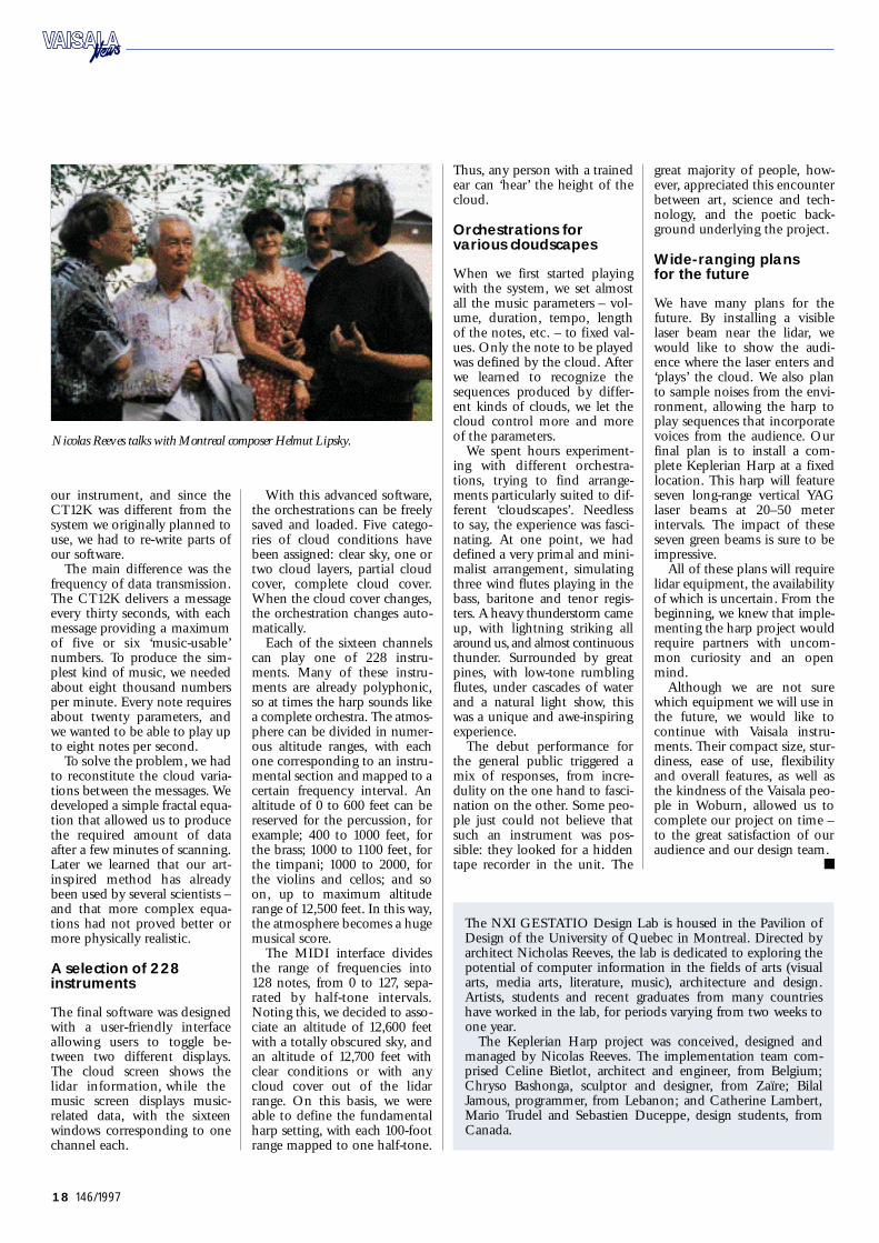
Nicolas Reeves talks with Montreal composer Helmut Lipsky.
The NXI GES TAT IO Design Lab is housed in the Pavilion ofDesign of the University of Quebec in Montreal. Directed bya r chitect Nicholas Reeves, the lab is dedicated to exploring thepotential of computer information in the fields of arts (visuala rt s, media art s, literature, music), architecture and design.A rt i s t s, students and recent graduates from many countrieshave worked in the lab, for periods varying from two weeks toone year.
The Keplerian Harp project was conceived, designed andmanaged by Nicolas Reeves. The implementation team com-prised Celine Bietlot, architect and engineer, from Belgium;C h ryso Bashonga, sculptor and designer, from Zaïre; BilalJ a m o u s, programmer, from Lebanon; and Catherine La m b e rt,Mario Trudel and Sebastien Duceppe, design students, fromC a n a d a.
Vaisala News 146/97 Final 7.1.1998 09:59 Page 18

19146/1997
Even today, weather observations atsea are far from the quality and regu-larity of land observ a t i o n s. Toimprove this situation and the reliabil-ity of short -term forecasting, theFronts and Atlantic Storm Tr a cksExperiment was established. As part ofthe experiment, dropsonde soundingswere made over ordinarily unobserv e dregions in the No rth Atlantic. Th en e w l y -developed NCAR GPSDropsonde, the Va i sala RD93, wasused for these soundings.
Te r ry Hock, El. Eng.Project ManagerG PS Dropsonde in the Surface andSounding FacilityAtmospheric Te chnology DivisionNational Center for AtmosphericR e s e a r ch (NCAR) B o u l d e r, Colorado, US A
Fronts and Atlantic
Storm Tracks Experiment
RD93 Fl i e swith FAST EX
orecasting the development of oceanicstorms continues to be a ch a l l e n g e ,largely because there are fewer weathero b s e rvations at sea than over land.
During the winter of 19 9 6 – 19 97, the Fronts andAtlantic Storm Tr a cks Experiment (FA S T EX), amajor international field program involving scien-tists from eleven countries, NCAR and NOAA(National Oceanic Atmospheric Ad m i n i s t r a t i o n) ,studied the fierce winter storms that move eastwardacross the Atlantic Ocean from Newfoundland toIreland and western Europe.
F
The new l y - d eveloped NC AR GPS
Dropsonde, the Vaisala RD93, was
used for the FASTEX soundings.
c o n t i n u e s. . .
Vaisala News 146/97 Final 7.1.1998 09:59 Page 19

20 146/1997
Dropsonde soundingsover the North Atlantic
The principal scientists inv o l v-ed in FA S T EX planned an‘adaptive observation’ strategyof dropsonde soundings overthe No rth Atlantic. During thep r o j e c t, more than 750 RD 9 3G PS Dropsondes were de-ployed from NOAA’s new Gulf-stream IV and an NCA R -l e a s e dLear 36 aircraft. In addition tothe dropsondes, several other in-struments were used. These in-cluded radiosondes and windprofilers on research ships anddoppler radar on other aircraft(NCAR Electra and NOAA P-3).
The FA S T EX project bega non 6 January 19 97 and ranthrough February 19 97. Duringthis time, the G-IV, based inS h a n n o n, Ireland, perf o r m e dten objective targeting missionsand seven other missions overthe No rth Atlantic, dropping atotal of 550 RD93 GPS Drop-s o n d e s. The Lear 36, based inS t. Jo h n, Ne w f o u n d l a n d, carriedout 13 missions in the No rt hA t l a n t i c, dropping 214 RD 9 3G PS Dropsondes. Both aircraftwere equipped with NCA R -developed four-channel aircraftdata systems.
Once the aircraft were in thetargeted area, the dropsondes
w e r e generally deployed at 10 -minute intervals at altitudesranging from 26,000 ft. to40,000 ft (7, 9 2 5 – 12 ,192 m). Th eLear 36 typically released 17d r o p s o n d e s, while the G-I Vreleased 30. In a few cases, up to50 dropsondes were deployedduring a single mission. Wi t hthe four-channel aircraft datas y s t e m, four dropsondes can bein the air simultaneously, andthis proved to be a valuableasset during FA S T EX.
First results ve r yp r o m i s i n g
The dropsondes were deployedunder varying atmospheric con-d i t i o n s. This provided an exten-sive data set for preliminaryevaluation of the overall perf o r-mance of the dropsondes. Th epressure performance was out-s t a n d i n g, as calculated using thehydrostatic equation and inte-grating the pressure data fromthe surface to the aircraft. Th i swas then compared with thegeopotential altitude of the air-c r a f t. The temperature accuracywas difficult to evaluate; how-e v e r, 34 soundings had obviousmelting levels, which offered anatural single point calibrationo p p o rt u n i t y. The majority of thedropsondes were within ±0.2 ° Cand the rest within ±0.5 ° C .
The humidity data from FA S-T EX is currently being evaluatedfor overall accuracy.
The GPS winds providedexceptional detail on the windf i e l d s. Since independent windmeasurements were made every0.5 seconds, the vertical resolu-tion was outstanding. The windsin the boundary layer to thes u rface were easily observ e dwith the GPS Dropsonde. Th eG PS navigation system has sig-nificantly improved the capabil-ity of dropsonde wind perf o r-mance. Even though dropson-des have been used as meteoro-
logical instruments for almost30 years, the new NCA R -d e v e l-oped GPS Dropsonde takes thismeasurement capability to anew – and unprecedented – level.
Using the RD93 GPS Drop-s o n d e s, the findings of FA S T EXwill lead to better forecasts forthe western coasts of bothEurope and No rth America, aswell as a better understanding ofhow oceanic winter storms affectworld climate.
Cutaway view of a GPS Dropsonde.
Raw unfiltered FASTEX PTU and wind data from the RD93. The data is
very clean, thanks to the digital RF telemetry link with CRC error ch e ck i n g.
FASTEX GPS Dropsonde data, Lear 36, Drop No. 5, 11 January 19 97.
Vaisala News 146/97 Final 7.1.1998 09:59 Page 20

21146/1997
Water vapor information is essential in aviationand atmospheric science, and the data providedby the current 12 -hourly radiosonde network is
inadequate. In response, the FAA initiated a p r o ject to specify a Water Vapor Sensing System(W V SS) that could be used to measure real-t i m ewater vapor content from commercial aircraft.
The system ensuing from this project usesVa i sala’s HMM30D module, and the first WVSSunit has been working on a Boeing 757 for five
months now without failure.
With the introduc-tion of the WVSS, anew tool has beenadded to the observ-
ing systems for weather predic-tion and other atmospheric sci-ence applications. This system,w h i ch is now operational on aBoeing 757 aircraft, comple-ments the author’s early work in1979 on obtaining winds andtemperatures in real-time in theU. S. as part of the GlobalWeather Experiment. The fol-
Rex J. Fleming, Ph. D .D i r e c t o rClimate Observ a t i o n s,NOAA /OG PB o u l d e r, Colorado, US A
R e a l -Time Water Va p o rM e a s u re m e n t s
lowing article briefly outlinesthe events leading to the cur-rent water vapor project, thestatus of the project and itsexpected future direction.
Federal project targetswater va p o ri n f o r m a t i o n
The U. S. Federal Aviation Ad-ministration (FAA) funded theCommercial Aviation SensingHumidity (CA SH) program in
19 91. The original purpose wasto establish the feasibility ofobtaining water vapor informa-tion from commercial aircraftand to develop formats for pro-viding such data in real-time tor e s e a r chers involved in theFAA’s Aviation Weather Pro-g r a m.
A history of the use of com-mercial aircraft as platforms fore nvironmental measurement isprovided by Fleming (19 9 6 ) .Po rtions of that paper also pro-vide more details about theCA SH program and real-t i m eaircraft communications.
A lack of knowledge aboutwater vapor has become a majorimpediment in the m a i n s t r e a mof socio-economic app l i c a t i o n sof atmospheric science. One o fthese areas involves mesoscaleweather and aviation.
Mesoscale weather systemsaffect aviation efficiency, ca-pacity and sa f e t y. Profiles ofw i n d s, temperature, and watervapor are needed far more fre-quently than the current 12 -hourly radiosonde network can
W
Commercial aircraft play a role in atmospheric science:Commercial aircraft play a role in atmospheric science:
Figure 1a.
A close-up of the Water Vapor Sensing System (W V SS) probe. The probe extends three
i n ches into the atmosphere and five inches beneath the surface of the fuselage.
Figure 1b.
The probe is located on
the left side of the
a i r c ra ft tailward of the
c o ckpit door (in the area
of the black stripe).
Photos courtesy of
L o ck h e e d -Ma r t i n, BF
Go o d r i ch Rosemount
A e r o s pace, and Un i t e d
Parcel Se r v i c e .
Vaisala News 146/97 Final 7.1.1998 09:59 Page 21

22 146/1997
provide. Th u s, the original in-tent of the CA SH program wasto help contribute to this watervapor measurement ch a l l e n g e .
Defining the sensings y s t e m
The accuracy of water vapormeasurements on commercialaircraft was an important factor,but only one of many to beconsidered in the test program.Since the purpose was to gener-ate specifications for the pro-curement of a Water Va p o rSensing System (W V SS), only afew of the thirteen or so identi-fied measurement concepts wereactually feasible for real-t i m ecommercial aircraft applica-t i o n s.
The sensor system had to bel i g h t w e i g h t, compact, rugged,sensitive and shielded fromc o n t a m i n a n t s. It also had toprovide reliable performance ata wide range of temperatures,p r e s s u r e s, Mach numbers andwater vapor conditions. The cri-teria for the WVSS includedeasy installation on existing air-craft and accurate perf o r m a n c eover at least a three-m o n t hunattended period. Any main-tenance required at that pointin time had to be completed inless than one hour.
In addition, the response timeof the WVSS had to be shortenough to accurately resolve thev e rtical structure of the watervapor in the lower troposphereat typical aircraft ascent/descentr a t e s. The vertical structure ofwater vapor in the lower atmos-phere is especially important toaviation – as well as to the fullspectrum of other atmosphericapplications: weather predic-t i o n, hy d r o l o g y, ch e m i s t ry, pol-lution and global climatech a n g e .
The test program was fairlycomplete and included tests ina laboratory ch a m b e r, in a wetwind tunnel, and on a well-instrumented research aircraft.The complete test results (H i l l sand Fleming 1994), includingthe potential problem areasrevealed during the tests, were
distributed to all potential bid-ders for the WVSS procure-ment phase. Based on scientificrequirements for the ascent/descent region, operational con-s t r a i n t s, and the FAA test re-s u l t s, specifications were pre-pared and a competitive gov-ernment procurement was con-d u c t e d. Three excellent propo-sals were received which ad-dressed the limitations identi-fied in the test results. The win-ning contractor was Lockh e e dM a rtin Corporation (L M C). Th emain characteristics of the WVSSare identified below.
The winning solution
Ev e ry commercial aircraft has atemperature probe for measur-ing the total air temperatureoutside the boundary layer nextto the aircraft ski n. The dynam-ic heating effect of the movingaircraft is taken into account tocalculate the ambient air tem-perature from the total air tem-perature measurement. Th eW V SS probe is more advancedthan conventional probes andhas better aerodynamic proper-t i e s. Both probes extend about3 inches (see Figure 1a) fromthe aircraft ski n. A ‘can’ be-neath the aircraft skin housesthe conditioning electronics.This can is about the same sizeas the container used for theangle of attack probe (3.2” indiameter and 5” deep) .
The air carriers wanted assur-ance that the new probe wouldhave no impact on their normalo p e r a t i o n s. The key features forthem are the WVSS mainte-nance interval of three to sixm o n t h s, sensor replacement intwelve minutes, and the com-plete system weight, includingc a b l e s, of about 10 pounds. Th eoriginal specification for sensorreplacement was sixty minutesor less and a weight of 15 pounds.The maintenance interval couldbe anything greater than threemonths as long as it coincidedwith normal scheduled mainte-nance ch e ck periods.
For users, the key features ofthe WVSS data are response timeand accuracy. The response t i m eof the sensor – a Va i sala thin-f i l mcapacitor – is 2–3 seconds in thelowest 20,000 ft. of the atmos-phere. Since ascent and descentwere the key areas of interest forthe FAA, the accuracy specifica-
tion was also over this lower20,000 ft. The expected accura-cy of the WVSS in this range is3–5 per cent.
Formats and the initial data
Of the over 40,000 wind andtemperature Aircraft Communi-cation Addressing and Report-ing System (ACA RS) reports re-ceived every day in the UnitedS t a t e s, 95 per cent are at flightl e v e l. Since virtually all aviationweather activity is related tomesoscale phenomena – evenflight level winds on the synop-tic scale are often disturbed bymesoscale outflow from conv e c-tion – obtaining mesoscale pro-files of winds, temperatures, andwater vapor was a highly desir-able part of the FAA’s A v i a t i o nWeather Program. Severe o p e r a-tional constraints had to be ad-dressed in the design of the newascent/descent formats. Th e s ed es i gn goals are listed below inpriority order:
(1) Maximum vertical meas-urement resolution
( 2 ) Minimum communica-tions cost
( 3 ) Minimum communica-tions traffic at busy air t e r m i n a l s
( 4 ) Greater horizontal meas-urement resolution atflight levels
( 5 ) F u rther optimization forother operational require-m e n t s.
The new ‘ascent’ format, whichis sent as a single message, rep-resents a compromise between(1), (2) and (3) above. A reportusing the standard or defaultvalue of every six seconds pro-vides data every 300 feet or 10 0meters for typical climb-o u tr a t e s. The permissible report in-t e rval is every 3–20 seconds.
To d a y, the typical carrier pro-vides the ACA RS winds and tem-perature information by send-ing a single report every 6–7m i n u t e s. The new ‘en route’ for-mat has a standard sa m p l i n grate of every three minutes (per-missible range 1–60 minutes) .Data is concatenated into sixconsecutive reports and sent asa single message as a compromisesolution to (2) and (4) above. At
typical aircraft speeds, the three-minute sampling interval repre-sents about 40 km horizontalr e s o l u t i o n.
The ‘descent’ format take sinto account factors (2), (3) and(5) above. The standard datasampling rate for ‘descent’ ise v e ry 60 seconds with 10 report sconcatenated and sent as a sin-gle message every 10 minutes.This sampling rate is allowed tov a ry by 20–300 seconds withinthe format. The rate itself canbe changed to match the termi-nal situation by an ACA RS mes-sa g e .
These new formats are nowaccepted by the Airline Electri-cal Engineering Committee( A EEC). They are included asp a rt of the ARINC 620 specifi-c a t i o n, and are now being usedroutinely by United ParcelS e rvice (UPS) .
First WVSS unit in use
LMC has obtained FAA cert i f i-cation for the WVSS on Boeing757 aircraft, and the first unithas been working for over fivemonths without a failure. Fig-ure 2 shows a sounding take nfrom a real display of the dataon the Internet.
The water vapor informationis obtained by a Va i sala modelHMM30D, the basic elementof which is a relative humiditys e n s o r. Even though humidityis measured, it has been shown(Fleming 1996) that greater ac-c u r a cy can be achieved by down-l i n king the atmospheric watervapor mixing ratio on a dynam-ically moving aircraft.
Although the data is stillunder evaluation, an excellentdynamic range of mixing ratioinformation has been ach i e v e d,the data comparison between as-cent and descent from the sa m eair terminal has been consistent,and comparisons against radio-s o n d e s, when possible, havebeen quite good with consistentv e rtical changes in degrees of wet-n e s s.
Six production units havebeen produced as part of thec o n t r a c t. These six WVSS units
Vaisala News 146/97 Final 7.1.1998 09:59 Page 22

23146/1997
are installed on United ParcelS e rvice Boeing 757 aircraft (seeFigure 1b). The aircraft operateout of Louisville, Kentucky, andfly to destinations throughoutthe United States.
Looking to the future
The National Oceanic and Atm o s-pheric Administration (NOAA)has contracted for an additional60 WVSS units, which will beinstalled beginning in February1998. A further option for 10 0more units will be exercised laterin 1998. These units will be addedto the UPS fleet and primarilyto other U. S. air carriers.
Once a sufficient number ofW V SS-equipped aircraft are fly-i n g, a data analysis of the fore-cast impacts and an official 2-year Demonstration Programfor the FAA can begin. This pro-gram will determine the impact
of ascent/descent profiles ofw i n d s, t e m p e r a t u r e s, and watervapor on aviation weather prod-ucts and industry operations.
The Integrated Terminal We a t h-er System (I T WS), to be deployedin the near future (cf. Evans andD u c o t, 1995), will be a key appli-cation of the data. The WVSSinformation will make a signifi-cant contribution to the radarsand automated surface systemsin the air terminal env i r o n m e n t– thus helping to reduce the fre-q u e n cy and severity of flightdelays and improve the safety ofair travel.
The NOAA Office of GlobalPrograms is also funding theW V SS p r o c u r e m e n t. Data fromthe WVSS fleet, which will sup-p o rt more accurate water vaporflux information, will be usedby scientists involved in theGlobal Energy and Water E x-periment (GE W EX) Continen-
t a l -scale International Project(G CIP). Data is being provideddirectly to this project, and thefull WVSS fleet will fly at leastuntil September 2000, coveringthe last three years of GCIP.Water and energy budget stud-ies (with and without theW V SS information) will bec o n d u c t e d. The data will be avail-able through the GCIP datamanagement system.
Re f e r e n c e s
Ev a n s, J. E., and E. R. Ducot,1994: The integrated terminalweather system (I T WS). LincolnLab. Journal 7, No. 2, 449–474[Available from MI T, 244 Wo o dS t., Lexington, MA, 02173 – 910 8 ]
F l e m i n g, R. J. 1996: The useof commercial aircraft as plat-forms for environmental measure-m e n t s. Bull. Amer. Meteor. Soc. ,77, 2229–2242
H i l l s, A. J. and R. J. Fleming,1994: Commercial aviation sens-ing humidity: Sensor evaluationphase. Final Rep. To FederalAviation Ad m i n i s t r a t i o n, 149 pp.[Available from 800Independence Ave SW,Wa s h i n g t o n, D.C., 20591]
Figure 2. Ascent sounding, 1 km from Louisville, Ke n t u ck y, starting on 22 May 19 97 at 8:31 UTC, lasting 14 minutes and covering 145 km.
F u rther information about the WVSS project may be obtained on the Internet. C o n t a c t : w w w. j o s s. u c a r. e d u /w v s s /
Vaisala News 146/97 Final 7.1.1998 10:00 Page 23

24 146/1997
The climatic conditions affecting Taiwan are veryc o m p l e x. Typhoons, monsoons and thunder-
storms leave their mark on the country: the aver-age yearly damage from severe weather is aroundUSD 330 million. To provide advance warningof storms and floods and to prevent weather-related damage, Taiwan has built an extensive
meteorological observation system covering theentire country.
he objective of Ta i-wan’s Automatic Ra i n-fall and Meteorolog-ical Te l e m e t ry Sys-
tem (ARM TS) is to study thecharacteristics of heavy rain andthunderstorms in small andm e s o s c a l e s. This information isused to improve prediction oflocal heavy rains and provideflood and other warnings.
The main island of Taiwan isabout 200 km wide and 400 kml o n g, with a central mountainup to 4,000 m in height run-ning north to south. Geophy s-i c a l l y, the country falls withinthe subtropical monsoon zone,and it is on the main typhoonpath in the western Pacific.
Taiwan’s complex terrain andclimate conditions cause dra-matic seasonal variations in thew e a t h e r. These are often accom-panied by severe weather condi-tions such as typhoons in thesummer and autumn, cold frontsin the winter, thunderstorms in
the spring, and monsoons inthe early summer. All of theseweather phenomena have thepotential to cause heavy dam-a g e .
Fighting the battleagainst wea t h e rd a m a g e
According to statistics from19 61 to 1985, the average yearlydamage from severe weatherwas about USD 330 million; ofthis amount, typhoons account-ed for 70 per cent and heavyrains for 26 per cent. In re-sponse, the government initiat-ed a large-scale 5-year hazardprevention project in 1982. Th eCentral Weather Bureau (C W B)was responsible for implemen-tation of ARM TS.
The ARM TS project start e dwith the western region of Ta i-wan in 1986, followed by theeastern region of the country in1994. The entire network was
Joel HsuP r e s i d e n tE nvironmental Science & Eng’n CorpTa i p e i, Ta i w a n
Vaisala helps prevent weather damage:
A RM TS Up and Running in Ta i wa n
TThe Automatic Rainfall and
Meteorological Te l e m e t r y
S ystem (ARM TS) netwo r k.
A MILOS500 weather station in Ta i w a n.
Vaisala News 146/97 Final 7.1.1998 10:00 Page 24
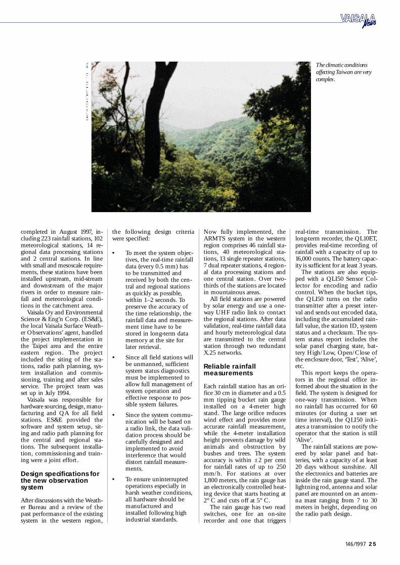
25146/1997
completed in August 19 97, in-cluding 223 rainfall stations, 10 2meteorological stations, 14 re-g i o nal data processing stationsand 2 central stations. In linewith small and mesoscale require-m e n t s, these stations have beeninstalled upstream, mid-s t r e a mand downstream of the majorrivers in order to measure rain-fall and meteorological condi-tions in the catchment area.
Va i sala Oy and Env i r o n m e n t a lScience & Eng’n Corp. (ES & E) ,the local Va i sala Surface We a t h-er Observations’ agent, handledthe project implementation inthe Taipei area and the entireeastern region. The projectincluded the siting of the sta-t i o n s, radio path planning, sys-tem installation and commis-s i o n i n g, training and after sa l e ss e rvice. The project team wasset up in July 19 9 4 .
Va i sala was responsible forhardware sourcing, design, manu-facturing and QA for all fields t a t i o n s. ES&E provided thesoftware and system setup, sit-ing and radio path planning forthe central and regional sta-t i o n s. The subsequent installa-t i o n, commissioning and train-ing were a joint effort.
Design specifications forthe new observa t i o ns y s t e m
After discussions with the We a t h-er Bureau and a review of thepast performance of the existingsystem in the western region,
the following design criteriawere specified:
• To meet the system objec-t i v e s, the real-time rainfalldata (every 0.5 mm) hasto be transmitted andreceived by both the cen-tral and regional stationsas quickly as possible,within 1–2 seconds. Top r e s e rve the accuracy ofthe time relationship, therainfall data and measure-ment time have to bestored in long-term datam e m o ry at the site forlater retrieval.
• Since all field stations willbe unmanned, sufficientsystem status diagnosticsmust be implemented toallow full management ofsystem operation andeffective response to pos-sible system failures.
• Since the system commu-nication will be based ona radio link, the data vali-dation process should becarefully designed andimplemented to avoidi n t e rference that wouldd i s t o rt rainfall measure-m e n t s.
• To ensure uninterruptedoperations especially inharsh weather conditions,all hardware should bemanufactured andinstalled following highindustrial standards.
Now fully implemented, theA RM TS system in the westernregion comprises 46 rainfall sta-t i o n s, 40 meteorological sta-t i o n s, 13 single repeater stations,7 dual repeater stations, 4 region-al data processing stations andone central station. Over two-thirds of the stations are locatedin mountainous areas.
All field stations are poweredby solar energy and use a one-way UHF radio link to contactthe regional stations. After datav a l i d a t i o n, real-time rainfall dataand hourly meteorological dataare transmitted to the centralstation through two redundantX.25 networks.
Reliable rainfallm ea s u r e m e n t s
E a ch rainfall station has an ori-fice 30 cm in diameter and a 0.5mm tipping bucket rain ga u g einstalled on a 4-meter highs t a n d. The large orifice reduceswind effect and provides moreaccurate rainfall measurement,while the 4-meter installationheight prevents damage by wildanimals and obstruction bybushes and trees. The systema c c u r a cy is within ±2 per centfor rainfall rates of up to 250m m / h. For stations at over1,800 meters, the rain gauge hasan electronically controlled heat-ing device that starts heating at2° C and cuts off at 5° C.
The rain gauge has two reads w i t ch e s, one for an on-s i t erecorder and one that triggers
r e a l -time transmission. Th el o n g -term recorder, the QL10 ET,provides real-time recording ofrainfall with a capacity of up to16,000 counts. The battery capac-ity is sufficient for at least 3 years.
The stations are also equip-ped with a QLI50 Sensor Col-lector for encoding and radioc o n t r o l. When the bucket tips,the QLI50 turns on the radiotransmitter after a preset inter-val and sends out encoded data,including the accumulated rain-fall value, the station ID, systemstatus and a ch e cks u m. The sys-tem status report includes thesolar panel charging state, bat-t e ry High/L o w, Open/Close ofthe enclosure door, ‘Test’, ‘A l i v e ’ ,e t c.
This report keeps the opera-tors in the regional office in-formed about the situation in thef i e l d. The system is designed foro n e -way transmission. Whenno rainfall has occurred for 60minutes (or during a user settime interv a l), the QLI50 initi-ates a transmission to notify theoperator that the station is still‘Alive’.
The rainfall stations are pow-ered by solar panel and bat-t e r i e s, with a capacity of at least2 0 days without sunshine. Allthe electronics and batteries areinside the rain gauge stand. Th elightning rod, antenna and solarpanel are mounted on an anten-na mast ranging from 7 to 30meters in height, depending onthe radio path design.
The climatic conditions
affecting Taiwan are very
c o m p l e x.
Vaisala News 146/97 Final 7.1.1998 10:00 Page 25

26 146/1997
Me t eorological stationsm easure rainfall, windand temperature
The meteorological stations sharethe same rain gauge design asthe rainfall stations. In addi-t i o n, they have a 6-meter highinstrument mast for meteoro-logical instruments such as winds p e e d, wind direction and tem-perature sensors, and the enclo-sure used with the MILOS 5 0 0Automatic Weather Station andD PA 21 pressure sensor.
Because of the complexity ofmeteorological measurement,the MILOS500 is used for datap r o c e s s i n g, logging and control.To provide hourly average anddaily extreme values, theMILOS500 runs in continuousmode. The meteorological sta-tions transmit rainfall data inthe same way as the rainfall sta-t i o n s, on an hourly and dailyb a s i s. All transmitted data alsoincludes the station ID, systemstatus and a ch e cks u m. Alongwith a QL10 ET for rainfall re-c o r d i n g, a 1 MB capacity PCM-CIA card is used for the storageof meteorological data.
Re p eater stations relay the data
The ARM TS contains singleand dual repeater stations. Asingle repeater is simply a radiotransceiver for data relay. Dualrepeater stations are used inmore critical radio paths. Th e ycontain two redundant trans-c e i v e r s. One is in the activemode and the other in the hotstandby mode. The data re-ceived by both units is trans-mitted to the MILOS500 fordata validation, including errorch e cking and limit ch e cking of
the station ID. The message isthen directed through the firstt r a n s m i t t e r.
At the same time, the trans-mitted data is picked up by thethird receiver and fed again tothe MILOS500 for ch e cki n g. Ifthe transmission fails, theMILOS500 re-initiates trans-mission through the secondt r a n s m i t t e r, inserting a failurem e s sage along with other sys-tem status messa g e s.
Regional and centralstations processm e t eorological data
E a ch regional data processingstation has three to four differ-ent frequency antennas andradio receivers, depending onthe area radio path design. Th ereceiving station is also equip-ped with a MILOS500 unit forremoving any corrupt ch a r a c-ters that may arise from the ran-dom nature of rainfall and themeteorological station transmis-s i o n s. The data transferred tothe data receiving and process-ing computers is therefore freefrom any corrupt ch a r a c t e r s. Allserial lines are buffered, so simul-taneous reception of data doesnot cause any data loss.
The data processing systemcontains a LAN with a DEC 3 3 0 0RISC-based serv e r, a DEC PCwork station and communica-tion devices such as a router andm o d e m s.
The software is based on aC l i e n t -S e rver structure with thefollowing functions :
The networking between theregional stations and the centralstation is provided by two X. 2 5l i n ks operating in load balanc-ing and load sharing modes.
The central station has thesame software and similar hard-ware (a DEC3800 server) as theregional stations. The data fromall regional stations is transmit-ted to the Central We a t h e rBureau’s forecasting center viaC W B’s intranet in real-t i m e ,and then stored for other users.
Me t eorological dataplays a valuable role indamage preve n t i o n
Among many other benefits,the ARM TS provides effectiver e a l -time rainfall and hourlymeteorological data for weatherw a t ches and the prediction ofh e a vy rains. When combinedwith radar and satellite informa-t i o n, it is also used for localizedweather system study and quan-titative analysis. Through thecomputer network, it providesvaluable data for flood warn-i n g s, reservoir operation, waterresources study, and even env i-ronmental impact studies forland development.
The ARM TS supplied byVa i sala and ES&E uses only twointelligent devices, a QLI50 andMILOS500, to implement thecomplete system. This simplic-ity underlies the success of theA RM TS. With a correlationwithin 2 per cent between ther e a l -time and on-site recordingd a t a, the ARM TS is a reliableand advanced system.
• Data Reception
• Data Calculation and Processing
• System Fault Identification and Alarm Logging
• Detailed Station Information
• Data Storage
• Data Transfer between Regional and/or Central Computers
• R e p o rt Generation and Graphics Display
Vaisala News 146/97 Final 7.1.1998 10:00 Page 26

27146/1997
Finland’s icebreakers arebusy from December toMay keeping the coun-t ry’s ports open on theGulf of Bothnia. Highwinds and extreme tem-peratures make this a par-ticularly demandingapplication for weatheri n s t r u m e n t a t i o n. Using aMILOS weather station,the icebreaker ‘Apu’ – or‘Help’ in English – col-lects important data, aswell as assisting vessels ats e a.
inland’s icebreake rfleet of 9 vessels oper-ates under the Finn-ish Maritime Ad m i n-
i s t r a t i o n. One of them, the ice-b r e a ker Apu, was built in 1970 .She operates mainly in the Gulfof Finland.
Harsh conditions at sea
M r. Pe r -Henrik Nyström, Com-mander of the icebreaker Apu,has served on various icebreak-ers for 23 years, including 10years on the Apu. During thewinter season, his crew numbersfrom 34 to 40. According toCommander Nyström, Va i sa l a ’ sweather instruments have func-tioned well on the Apu. Th eship’s MILOS weather stationand meteorological sensors fortemperature, humidity, pres-sure, wind speed and directionwere installed in 19 87.
As Commander Nyströme x p l a i n s, the icebreaker and hiscrew must contend with harshweather conditions: “Duringsevere storms, winds can reachover 30 m/s and even close to40 m/s. The ice moves withgreat force, making it very diffi-
cult to keep a channel open. Insome cases, cargo ships have tobe towed. Our weather instru-ments must withstand theseextremely harsh weather condi-tions and still work reliably.This was the reason behind ourchoice of Va i sala’s observ a t i o ni n s t r u m e n t s. ”
On-board wea t h e rs t a t i o n
The Apu’s MILOS weather sta-tion measures wind speed andd i r e c t i o n, relative humidity, tem-perature, pressure, and sea tem-perature, combining this infor-mation with ship speed (fromthe log and position), which itreceives from the naviga t o r. Th estation calculates mean valuesas well as true wind values.
This information is displayedon the bridge for naviga t i o n.The data is also sent to theFinnish Maritime Ad m i n i s t r a t-ion three times a day, for usewith daily ice forecasts. Mer-chant vessels operating in theGulf of Bothnia need informa-tion on ice formation, ice melt-ing and real-time ice condi-t i o n s.
Commander
Pe r -Henrik Nyström
of the icebreaker Apu.
Marit FinneE d i t o r -i n -C h i e fVa i sala Ne w sVa i sala Oy, Finland
The icebreaker Apu was built in 1970. She opera t e s
mainly in the Gulf of Finland.
F
The Icebre a k e r ‘A p u ’
Li ves Up to its Name
The Icebre a k e r ‘A p u ’
Li ves Up to its Name
Vaisala News 146/97 Final 7.1.1998 10:00 Page 27

28 146/1997
Truly representativeinformation aboutwind direction and
speed at sea cannot beobtained by observ i n g
the weather on thec o a s t. Australia’s
Bureau of Meteorologyhas outfitted the MVSpirit of Tasmania for
maritime weathero b s e rv a t i o n s. Ev e ry
time the ferry crossesBass Strait betweenMainland Australia
and Ta s m a n i a, an auto-matic weather stationmeasures wind, pres-
sure, temperature andh u m i d i t y.
ompetitors in therenowned Sydney toH o b a rt yacht raceare more than famil-
iar with the treacherous watersof Bass Strait. Situated betweenthe southern corner of main-land Australia and the island ofTa s m a n i a, the strait is rega r d e das one of the most dangerouss t r e t ches of water around Aus-t r a l i a.
Regular wea t h e ro b s e r vations from Bass Strait
The MV Spirit of Tasmaniam a kes regular crossings of BassS t r a i t, ferrying vehicles, freightand passengers between Mel-bourne and Devonport. Forsome years, the Bureau of Me-teorology weather forecasters,p a rticularly in Ta s m a n i a, haveb e e n eager to establish a moreregular weather reporting mech a-nism using the MV Spirit ofTa s m a n i a. The ship maintains astrict schedule in all but themost extreme weather events, so
it is an ideal platform for record-ing weather observations duringits traverse of Bass Strait.
Automatic Weather Stations( AWS) are the most practicaltool for obtaining weather re-p o rt s. They enable accurate, reli-able and regular measurementswithout imposing on the ship’sc r e w. Because the ship and theAWS are moving, a number offactors must be kept in mind toensure accurate measurementsand reliable data transmission tothe Bureau Head Office. Th i srequires a certain amount of flex-ibility from the AWS, which wasone of the reasons behind thechoice of the MILOS500. Th eBureau has purchased four Va i-sala MILOS500 ship AWS units,with the installation on the Spiritof Tasmania being the pilot proj-e c t.
AWS wo r k si n d e p e n d e n t l y
The MILOS500 measures wind,pressure, temperature and humid-ity from sensors located above
the bridge of the Spirit ofTa s m a n i a. An INM A RS AT-Csatellite transmitter with aninternal GPS receiver is used totransmit observations back tothe Bureau’s network. The GPSreceiver provides informationon the ship’s position andspeed and its course over thew a t e r.
A flux gate compass providesinformation on the Spirit ofTasmania’s heading, so theAWS is completely indepen-dent of the ship’s own naviga-tion and communication sys-t e m s. A laptop PC on the bridgedisplays real-time informationon the AWS measurements. Italso enables manual entry ofo b s e rvations such as visibilityand sea state.
The cost of data transmissionfrom the Spirit of Tasmania isan important consideration. Forthis reason, the standard Synopm e s sage is conv e rted to a shortb i n a ry report prior to transmis-sion and then decoded back tothe standard Ship Synop codeat the Bureau. This enables the
C
The MV Spirit of Tasmania makes regular daily crossings of Bass Stra i t, ferrying vehicles,
freight and pa s s e n g e rs between Me l bourne and Dev o n p o r t.
Outfitting the MV Spirit of Tasmania for weather observationsOutfitting the MV Spirit of Tasmania for weather observations
O n -B o a rd AWS Provides MoreReliable Wind Data at Se a
Vaisala News 146/97 Final 7.1.1998 10:00 Page 28

29146/1997
use of very short data transmis-s i o n s. The benefits are two-f o l d.O b s e rvations can be made asfrequently as once per hour,and costs are significantly lowercompared with other sa t e l l i t ec a r r i e r s.
I m p r oved wind data at sea
Once the system is fully opera-t i o n a l, observations retrievedfrom the Spirit will be of greatbenefit to forecasters in bothTasmania and Vi c t o r i a. At pre-s e n t, the Bureau’s coastal weath-er observations sites do notalways provide wind speed anddirection data that is truly rep-resentative of winds at sea.These sites tend to be located inareas that are either very shel-t e r e d, such as townships locatedin river valleys, or very exposed,s u ch as capes and promontorieswhere winds tend to acceleratearound a geographical feature.
Ship observations are there-fore the only source of reliableinformation for determiningtrue wind speeds over water. For
this reason, the AWS data fromthe Spirit of Tasmania will sig-nificantly contribute to improv-ed accuracy of forecasts. Th egreater frequency of observ a-tions will also enable a study ofwind patterns across Bass Strait,as part of an effort to enhancethe Bureau’s computer derivedforecasts and improve forecast-ing for Bass Strait.
Bass Strait forecasts will notbe the only beneficiaries ofo b s e rvations from the Spirit ofTa s m a n i a. The data will providemore accurate information aboutthe location of cold fronts inBass Strait, and this will helpforecasters predict the move-ment of these fronts throughTasmania and the southernm a i n l a n d. This information isextremely important for fore-casts during the summer, par-ticularly for fire fighting anda v i a t i o n.
Other ships of the AustralianVo l u n t a ry Observing Fleet( AVOF) will be fitted withVa i sala MILOS500 Ship AWSunits over the next serv e r a ly e a r s.
Simon HarrodSales ManagerVa i sala Pty LtdMelbourne, Australia
Graham Jo n e s, CP. EngS u p e rvising EngineerUpper Air & Marine Te l e m e t ryBureau of MeteorologyA u s t r a l i a
Marine and Estuarine Protected Areas Tasmania
SO U RC E S :
Australian Nature Conservation AgencyProjection: Albera Equal AreaStandard Parallel: 18 and 36 degrees SouthCentral Meridian: 132 degrees EastAustralian Spheroid
0 100km 200km
Marine and Estuarine Protected Area.
From the left: Robert Ireland (Vaisala) and Ross Hibbins
(Bo M) installing the MILOS500 weather station on board the
Spirit of Ta s m a n i a.
Vaisala News 146/97 Final 7.1.1998 10:00 Page 29

30 146/1997
The Finnish oil com-p a ny Neste has pur-
chased two harborweather stations fromVa i sa l a. The completehy d r o m e t e o r o l o g i c a lo b s e rvation systems
were installed in 19 97,one at the Po rvoo har-bor in the spring and
another in Naantali inthe early summer.
Located in southernF i n l a n d, Neste’s mod-ern harbors offer con-venient shipping con-nections to and fromthe Baltic countries.
easured in cargo vol-ume, Neste’s harborin Po rvoo is thelargest in Finland.
Va i sala has installed a completehydrometeorological monitor-ing system to help improve thesafety and economy of ship-ping from both Po rvoo andN a a n t a l i. Va i sala’s system com-prises a complete MILOS 5 0 0automatic weather station, aswell as an FD 12 visibility sen-sor and sensors for water leveland conductivity. For back-u pp u r p o s e s, water levels are meas-ured using two different princi-ples: hydrostatic pressure andu l t r a s o n i c.
The measurements are dis-played on a graphical terminaland on large outdoor numeri-cal displays that can be seenfrom the deck of approach i n gs h i p s. They are also integratedinto the real-time air qualitymonitoring system of the Env i-
ronmental La b o r a t o ry at Ne s t e ’ sr e f i n e ry, which is located closeto the harbor. The sa m e data isavailable throughout the PCn e t w o r k.
Versatile harborweather stations
M r. Risto Ra j a l a, DevelopmentM a n a g e r, is in charge of devel-oping the technical and work-ing methods at Po rvoo’s har-b o r. As he explains: “Ev e ryy e a r, 16 million tons of rawmaterials and products areshipped through the harbor,for a total of 1,200 ship visits.The harbor has seven wharv e s,with a maximum water depthof 15.3 meters. The shippingtraffic served by the harbor in-cludes sea-going freighters onthe Baltic. To ensure the sa f e t yof cargo shipments at sea, werely on advanced hy d r o m e t e o-rological observation systems. ”
As Te chnical Supervisor ofHarbor Serv i c e s, Mr. ErkkiH e i kkilä is responsible for sys-tem maintenance. “A c c u r a t e ,r e a l -time hy d r o m e t e o r o l o g i c a ldata is essential for shipping op-erations in the harbor. Ne s t e ’ smodern oil refinery and ch e mi-cals units are conveniently lo-cated on the southern coast ofF i n l a n d, allowing competitivecargo shipments to countries onthe Gulf of Finland. FromNe s t e ’ s h a r b o r s, there also is adirect sea route to the rest ofthe Baltic Ri m,” he notes.
I m p r oved operationale f f i c i e n c y
Neste uses Va i sala equipmentto measure and monitor thetemperature and salinity of thesea water, as well as the waterl e v e l, wind speed and direc-t i o n, air temperature, and vis-i b i l i t y. The salinity observ a-
H y d ro m e t e o rological Observa t i o nSystem Supports Harbor Opera t i o n s
Every year, 16 million tons of raw materials and products are shipped through Neste’s ha r bor in Porvoo, for a total of
1,200 ship visits. Vaisala wind sensors have been installed on the mast in the ba ck g r o u n d.
M
Vaisala News 146/97 Final 7.1.1998 10:00 Page 30

31146/1997
Marit FinneE d i t o r -i n -C h i e fVa i sala Ne w sVa i sala Oy, Finland
tions are used in the determi-nation of cargo weight limits.
The measurements are storedin a database that is also inte-grated into the air quality moni-toring system of the Env i r o n-mental La b o r a t o ry. If needed,the data can be used to tracee m i s s i o n s.
Neste has always taken pridein maintaining the high tech-nological level of its refineries.To meet market demand andimplement the latest refiningt e ch n o l o g y, production pro-cesses are systematically upgrad-e d during shut-d o w n s. Ne s t ehas invested in design innova-tions to reduce emissions at thePo rvoo refinery, which pro-duces ten million tons of petro-leum products every year. Th euse of low-sulfur crude oil andVOC (volatile organic com-p o u n d) recovery systems reducesthe environmental load of ther e f i n e ry. Neste regards env i r o n-
m e n t a l, health and safety issuesas an integral part of its opera-t i o n s. In this light, says Mr.H e i kkilä, “Va i sala’s productshave performed well. They havealso improved the effic i e n cy ofour harbor operations. ”
According to Mr. Ra j a l a,“ Weather conditions have adual significance for us. First ofa l l, information about windspeed and direction and waterlevels is essential in our dailyo p e r a t i o n s. We also use thedatabase for long-term analysesof general weather and waterconditions and for air qualitymonitoring by Neste’s Env i r o n-mental La b o r a t o ry. The abilityto access information on ouro w n w o r kstations is an impor-tant practical advantage for us.We chose Va i sala because of itsgood reputation and accuratep r o d u c t s. ”
Mr. Risto Rajala,
Development Ma n a g e r, is in
charge of developing the
t e chnical and wo r k i n g
methods at Neste’s ha r bor in
P o r v o o.
Mr. Erkki Heikkilä is the
Te chnical Supervisor of
Ha r bor Se r v i c e s.
Vaisala’s MILOS 5 0 0
weather station for
hydrological monitoring at
Neste’s ha r bor in Porvoo.
The control tower at the ha r bor in Porvoo.
Vaisala News 146/97 Final 7.1.1998 10:00 Page 31
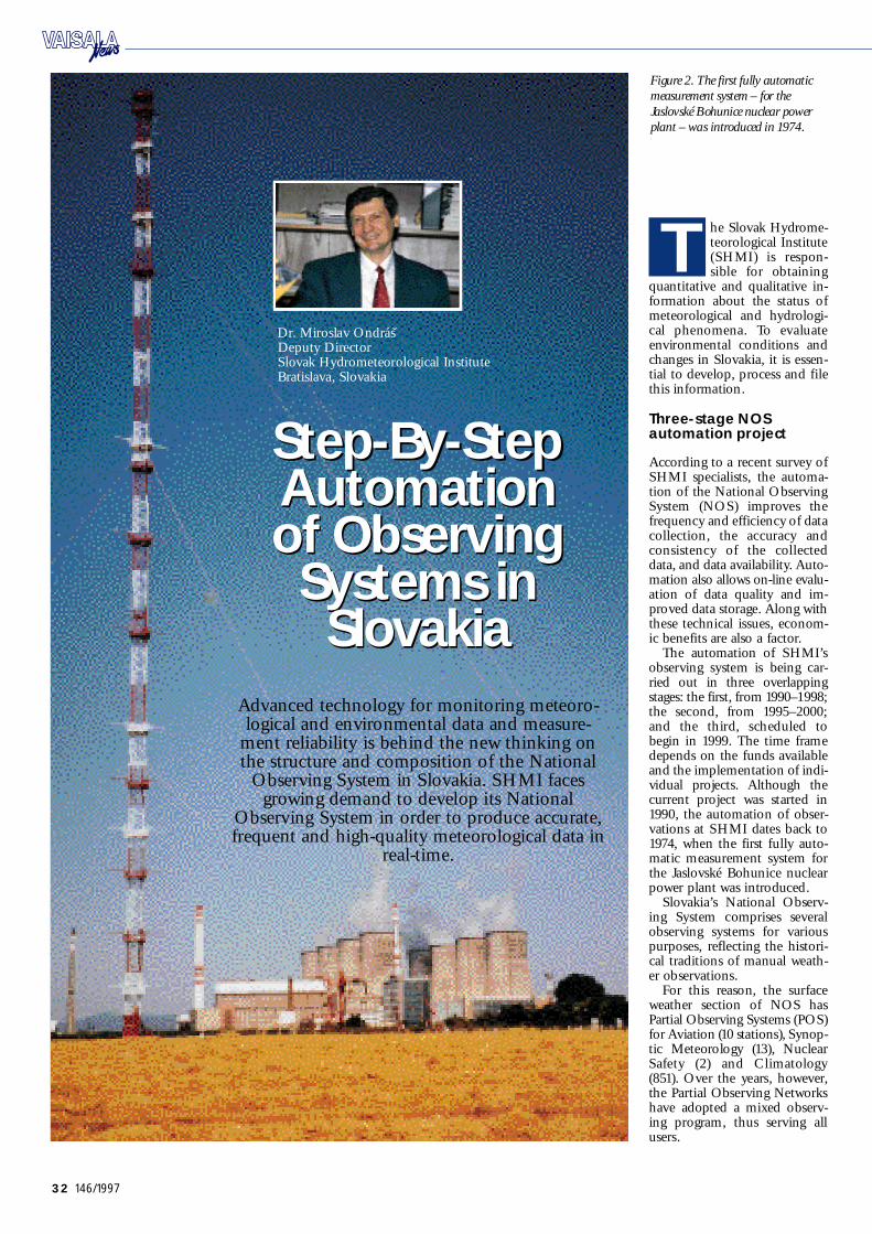
32 146/1997
he Slovak Hydrome-teorological Institute(SHMI) is respon-sible for obtaining
quantitative and qualitative in-formation about the status ofmeteorological and hy d r o l o g i-cal phenomena. To evaluatee nvironmental conditions andchanges in Slovaki a, it is essen-tial to develop, process and filethis information.
Three-stage NOSautomation projec t
According to a recent survey ofSHMI specialists, the automa-tion of the National Observ i n gSystem (NOS) improves thef r e q u e n cy and efficiency of datac o l l e c t i o n, the accuracy andc o n s i s t e n cy of the collectedd a t a, and data availability. Auto-mation also allows on-line evalu-ation of data quality and im-proved data storage. Along withthese technical issues, econom-ic benefits are also a factor.
The automation of SHMI ’ so b s e rving system is being car-ried out in three overlappings t a g e s : the first, from 19 9 0 – 19 9 8 ;the second, from 19 9 5 – 2 0 0 0 ;and the third, scheduled tobegin in 1999. The time framedepends on the funds availableand the implementation of i n d i-vidual projects. Although thecurrent project was started in1990, the automation of obser-vations at SHMI dates back to1974, when the first fully auto-matic measurement system forthe Jaslovské Bohunice nuclearpower plant was introduced.
S l o v a kia’s National Observ-ing System comprises severalo b s e rving systems for variousp u r p o s e s, reflecting the histori-cal traditions of manual weath-er observ a t i o n s.
For this reason, the surf a c eweather section of NOS hasP a rtial Observing Systems (POS)for Aviation (10 stations), Synop-tic Meteorology (13), NuclearSafety (2) and Climatology( 8 51). Over the years, however,the Partial Observing Ne t w o r kshave adopted a mixed observ-ing program, thus serving allu s e r s.
T
Figure 2. The first fully automatic
measurement system – for the
Jaslovské Bohunice nuclear power
plant – was introduced in 1974.
Advanced technology for monitoring meteoro-logical and environmental data and measure-
ment reliability is behind the new thinking onthe structure and composition of the National
O b s e rving System in Slovaki a. SHMI facesgrowing demand to develop its National
O b s e rving System in order to produce accurate,frequent and high-quality meteorological data in
r e a l -t i m e .
D r. Miroslav OndrásDeputy DirectorSlovak Hydrometeorological InstituteB r a t i s l a v a, Slovaki a
S t e p -B y -S t e pAutomation of ObservingSystems inS l ova k i a
S t e p -B y -S t e pAutomation of ObservingSystems inS l ova k i a
Vaisala News 146/97 Final 7.1.1998 10:00 Page 32

33146/1997
(MOR); background luminance;cloud base level; present weath-er; and gamma radiation doses.
Some sensor types are usedfor historical reasons. To d a y,the general trend is to use a spe-cific type of sensor or at leastsensors from one manufacturer.
SHMI has plans to monitorozone and certain air qualityparameters near the surface, aswell as lightning strikes andlightning activities. For this rea-s o n, the number of parametersand sensors will be extended.
In the semiautomatic mode,the MILOS500 and ESC 8800automatic stations are linked tothe IMS (Integrated Meteoro-logical System), which is a PC-based multi-purpose system.When needed, the system cani n t e rface with a human observ-er who can input his own obser-vations and supervise the sys-t e m. Data pre-p r o c e s s i n g, datach e cking and control, arch i v-i n g, the compilation of meteoro-logical messages and data trans-mission are done autom a t i c a l l yusing the IMS to transmit datato the Message Switching Sys-tem (MSS) of the NationalTelecommunication Centre.
In fully automatic mode, theMILOS500 automatic stationscan work with or without theIMS. This allows redundancy inthe performance of some jobs,p a rticularly data pre-p r o c e s s i n g,
data ch e cking and control, ar-ch i v i n g, the compilation of me-t eorological messages and datat r a n sm i s s i o n. When an auto-matic station is installed at atypical meteorological station,the IMS, which is situated atthe observer’s room, is linked tothe automatic station.
Both the IMS and AS sendcompiled messages to the Mes-sage Switching System indepen-dently in fully automatic mode,although data from the IMS hasp r i o r i t y. This provides a back-up in case of a breakdown ofthe IMS or a lack of personnel.In purely field installations, ofcourse, the AS works withoutthe IMS System. This providesthe flexibility for all possibleinstallations – fully and part i a l l ymanned and unmanned me-teorological stations.
The semiautomatic mode isused in fully manned meteoro-logical stations that operate 24hours per day. The automaticand semiautomatic modes runc o n t i n u o u s l y, so it is possible tos w i t ch automatically to theautomatic mode in case of afailure without losing any meas-u r e m e n t s. The automatic modeis used at partially manned me-teorological stations, which op-erate 18 hours a day, and also infield conditions. Reflecting thecontinuing decrease in the totalnumber of observers in the
f i e l d, the automatic mode isreplacing the semiautomaticmode. In this respect SHMI isw o r king to develop a fully auto-matic station, not only for syn-o p t i c, but also for aviation pur-p o s e s. Existing hardware isbeing used to achieve this goal.
E x t e n s i ve data chec kr o u t i n e s
Both the Automatic Stationand Integrated MeteorologicalSystem process raw data by pro-ducing 1-minute, 10 -minute and1 -hour data sets that are sent tothe MSS via the Private DataNe t w o r k. The 10 -minute data issent every 10 minutes; the 1-minute data, once a day or onrequest; and the 1-hour data,e v e ry hour.
In addition, compiled mes-sages like SYNOP, META R ,CL IM AT, IN T ER or local typesof messages and various pre-p r o-cessed data in tables (monthlys h e e t s) are also produced. Th eAutomated Weather Observ a-tion System at Bratislava Air-p o rt compiles messages on hori-zontal and vertical wind shear,
Current parameters andsensor systems
To d a y, SHMI operates twenty-one Va i sala MILOS500 auto-matic stations (AS), four ESC8800 AS units, five SHMI IS-32 AS units, three Va i sa l aMIDAS600 systems, and oneVa i sa l a -MPS-SHMI tower auto-matic system in either fully auto-matic or semi-automatic mode.The older ESC 8800 equipmentwill be replaced by Va i sa l a ’ sMILOS500 systems within thenext two years. Depending onthe observation program, auto-matic stations are used formonitoring the following data,m a ny parameters of which arecomputerized: wind speed anddirection on the surface and atdifferent atmospheric levels; airtemperature and humidity;ground surface temperature;soil temperature; barometricpressure; global, diffuse andUVB radiation; radiation bal-ance and Photo Active Ra d i a-tion (FAR); sunshine duration;precipitation; evaporation; hori-zontal visibility and Meteorolog-ical Observation Ra n g e
Figure 1. The network of the National Observing System in
Slovakia (including three subsystem A, B and C) .
Vaisala News 146/97 Final 7.1.1998 10:01 Page 33

34 146/1997
as well. The automatic datach e ck routines are run in the ASand IMS to ensure the internalvalidity and consistency of theraw data and compiled mes-sa g e s. Manually measured param-eters are compared with AS dataat three-hour interv a l s. It is theo b s e rver’s responsibility to takeaction if any discrepancieso c c u r.
In the future, an automaticch e ck of 10 -minute data will bei n t r o d u c e d. There is a temporal( a p p r o x. from 60 to 90 days)storage on site in both the ASand IMS. Diskettes are used forf u rther on-site storage. Fromthe MSS, all data is sent to localusers on line and to the KMIS(Climatological and Meteoro-logical Information System) .Data sets and compiled mes-sages are saved hourly in theK MIS, which runs comprehen-sive data ch e ck routines. The 1-and 10 -minute data sets, whichare only monitored at theCentral Forecasting Office, aresaved on an optical disc in theoriginal form. In the future, alldata will be stored in the KMIS.In case of missing data or mes-sa g e s, an automatic function isbeing developed to retrieve datafrom the original AS or IMS.F u rther post-processing is doneby the KMIS, where other datacontrol is applied and if neces-sa ry, data corrections are made.
Flexible communicationn e t work
The SHMI’s communicationnetwork is an integral part of aninformation system that hasbeen designed to meet the needfor data and information distri-bution on a national and inter-national level. It is a packe t -s w i t ching private network usingthe X.25 protocol.
The connection between themain nodes of the backbone net-work is made via leased lines.The aviation and synoptic me-teorological stations and region-al offices are connected to theb a ckbone mostly by leased lines,and occasionally by dial lines.
Operation andmaintenance procedures
Operation of all AutomaticStations is monitored continu-o u s l y, and action is taken incase of a breakdown. Regularmaintenance and repairs arecontracted to local companieson a monthly or quarterly basis.For this reason, a sufficientquantity of spare parts is kept ins t o ck, and operators receivemaintenance training. There isoccasionally some discrepancy,h o w e v e r, between theory andr e a l i t y. In some cases, SHMIallows local contractors to useour Communication Ne t w o r kfor remote control and mainte-nance of the software.
SHMI guarantees the accura-cy of measurements by calibrat-ing all sensors regularly in ourown calibration laboratories orelsewhere. SHMI’s Measure-ment Standards are comparedwith the National MeasurementStandards in the Slovak Met-rology Institute or with interna-tional standards. All calibrationequipment is now being replacedby advanced tech n o l o g y, and newmethodology and calibrationt e chniques are being developedfor integration with both the oldand new instrumentation.
Meeting the challengesof automation
Automation is an essential com-ponent of new observing meth-ods and procedures, many ofw h i ch differ significantly fromthe older ones. At manned sta-t i o n s, weather observations orsubjective parameters are esti-mated by an observer at a cer-
tain location based on spatiali n t e g r a t i o n. The observation ofcloud amount and present weath-er is one example. An automat-ic system, on the other hand,estimates the same parametersfrom measurements made at ac e rtain location based on tem-poral integration. This repre-sents the principal differencebetween the behavior of ano b s e rver and an automatic sys-tem when estimating these weath-er phenomena. The crucial pointin the development of newautomatic weather stations is tofind not only new sensors, butalso new algorithms that allowthe calculation of the spatialdistribution of a parameter frompoint measurements.
Automatic weather stationswill inevitably introduce incon-gruities into the old climaticrecords because of changes insensor design, the physical prin-ciple of measurements, observ a-tion tech n i q u e s, observ a t i o ntime and data processing algo-r i t h m s. For this reason, ane f f o rt should be made to studythe homogeneity of data overtime after the change in instru-m e n t a t i o n.
Hardware protection aga i n s tlightning strikes and over-v o l t-age surges poses a special ch a l-lenge for the automation of theo b s e rving network. SHMI isi nvesting a great deal in this areaafter a series of problems in19 9 5 .
Without automatic measure-ment of weather phenomena(cloud height and amount, vis-i b i l i t y, present weather), whichup to now were the observ e r ’ sd o m a i n, the automatic stationis not complete. With this in
m i n d, FD 12P present weathersensors were installed at threeMILOS500 stations for a test-ing and development period.CT25K ceilometers, moreover,were also included in the frame-work of the project, the goal ofw h i ch is to develop a fully auto-matic station. The problem, how-e v e r, has turned out to be morecomplex than expected, and re-quires extended study.
Measurements of soil tem-perature by the ESC 8800 wereaffected by an incorrect sensordesign and their short period ofo p e r a t i o n. This is not a problemwith the MILOS500 station.
Precipitation measurementsduring the winter are affectedby the heated elements of therain gauge, and this can result inan underestimation of rainfall.
A careful approach toa u t o m a t i o n
The aim of this article was notonly to describe the progress inthe automation of Slovaki a ’ sNOS (particularly the automa-tion of the surface aviation andsynoptic network), but also todiscuss several related issues.
The continuously increasingdemands for regular, timely ando n -line data from all of Slo-v a kia’s territory are the maindriving force behind the auto-mation and restructuring ofNOS operations. Even so, auto-mation should be implementedv e ry carefully with respect tocurrent limitations and oppos-ing trends.
One of these issues is thec o n s e rvative approach requiredon the part of climatology. Th i sis why the Partial Observ i n gSystem for climatology will bethe last to be automated. Ev e nt h e n, a substantial number ofstations will maintain their oldinstrumentation and observ i n gm e t h o d s. A long-term compari-son of data from automatic sta-tions and classical instrumenta-tion has been initiated for thisr e a s o n. Negotiations are beingheld with Va i sala to take part inthis project.
Figure 3. The Ko l i ba Observatory in Slovakia.
Vaisala News 146/97 Final 7.1.1998 10:01 Page 34

35146/1997
espite the termina-tion of the OmegaN a v i gation System o n30 September 19 97,
t h e r e is continuing interest inthe use of terrestrial naviga t i o naids (N a v a i d) for windfinding.This is partly due to the lowercost for radiosondes comparedwith GPS systems.
L o r a n -C and differential L o-r a n -C in particular provide ex-cellent accuracy, exceeding num-erical forecast requirements.The accuracy of the Va i sala Lo-r a n -C is comparable to GPSand precision radars (ref. 1, ref.8, ref. 9).
V L F-Navaid (Alpha+ComVLF) provides sustained wind-finding accuracy that meets nu-merical forecast requirements.
Windfinding accuracy and theeffect of sounding geometry onwindfinding are discussed in thefollowing article. The findingsare based on a series of triplesoundings and the analysis of thewindfinding accuracy of Loran-C, Omega and VLF-N a v a i d(O m e ga+ Alpha+Com VLF) .
Windfinding accuracy
The accuracy of windfinding sys-tems can be affected by manyf a c t o r s, including the atmos-phere, climate, time of the day,time of the year, signal propaga-tion direction, the ch a r a c t e r i s-tics of the propagation path,system electronics, system soft-ware and the geometry of thesystem transmission stationsand receivers.
Although most of these influ-ences cannot be controlled,their effect on the windfindingsolution can be estimated.
Detailed accuracye s t i m a t i o n s
The accuracy estimates present-ed in this article are based onthe master’s thesis of Erkka Pälä(ref. 9), which contains a de-tailed mathematical analysis ofdata from a series of triples o u n d i n g s.
Of all the windfinding accu-r a cy estimation systems report-ed to date, most have been basedon the use of a stationary refer-ence method such as precisionr a d a r s. The ultimate objective ofthe current study was to devel-op a spatially and temporally in-dependent measuring systemthat could be used anytime anda nywhere without the need fora stationary reference method.
Wind data can be expressedin the form of two vector com-ponents: north wind compo-nent and east wind component(N and E quantities, respective-
ly). As Figure 1 illustrates, windspeed (magnitude) and winddirection can be calculatedfrom these two components.The procedure presented hereproduces accuracy estimates forall four wind quantities, provid-ing a method independent oflocation for determining thea c c u r a cy of different windfind-ing methods.
The effect of soundingg eo m e t r y
The location of the naviga t i o ntransmitters relative to the radio-sonde can have a significant effecton windfinding. It is thereforev e ry useful to be able to esti-mate the feasibility of windfind-ing at a particular sounding sta-t i o n.
The common practice is touse Dilution of Precision(DOP) factors to describe theeffect of the geometric transmit-ter distribution on the accuracyobtained for the windfindings o l u t i o n.
[1] = DOP • 0
where 0 denotes the stand-ard deviation of the observ e dp s e u d o -r a n g e s, and is thestandard deviation of the hori-zontal or vertical precision, forexample. A discussion of DOPfactors can be found in Leick(ref. 7).
As the above equation clearlys h o w s, a small DOP factor is pref-erable. The higher the DOP, thegreater the noise in the wind-finding solution, and after a cer-tain point the windfinding solu-tion becomes unstable.
An estimate of good and badDOP can be made by analyzinga number of successful and un-successful Loran-C soundings.This leads to the following ruleof thumb:
Juhana Jaatinen, M. S c. (E n g)a n dE r kka Pälä Upper Air DivisionVa i sala OyH e l s i n ki, Finland
Report on the results of comparison tests:
Wi n dfinding Accuracy of Te r restrial Nava i d s
DOP Influence in windfinding
< 5 GOOD geometry, reliable winds
> 10 POOR geometry, missing winds
> 20 BAD geometry, probably no wind
D
Figure 1. Variability between the four different wind quantities. Wind error
v e c t o rs start from the origin.
Table 1. Dilution of Precision (DOP) rule of thumb.
Terrestrial naviga t i o naids (N a v a i d) are still
an attractive option forw i n d f i n d i n g. The mer-its of various Navaids,as determined on the
basis of comparisont e s t s, are discussed
b e l o w. Loran-C andV L F-Navaid windfind-
ing systems wereincluded in the study.
Vaisala News 146/97 Final 7.1.1998 10:01 Page 35

36 146/1997
From experience, it is alsoknown that the DOP is belowthree in a GPS-sounding withgood geometry.
Figures 2–7 give three exam-ples of different transmitter dis-t r i b u t i o n s. The horizontal dilu-tion of precision (HDOP) de-scribes the effect of the geomet-ric transmitter configuration onwindfinding accuracy. Two fig-ures illustrate each example.
Figure 2 shows the transmit-ter locations with respect to thesounding station. This is anideal case, with transmitters situ-ated all around the soundings t a t i o n.
Figure 5 shows the corre-sponding horizontal dilution ofprecision (HDOP). The sound-ing station is located in the cen-ter of the graph. The dilution ofprecision is calculated at severallocations around the soundings t a t i o n. This 200 km x 200 kmarea forms the grid on theg r a p h.
Figure 3. When all the avail-able transmitters are facing in oned i r e c t i o n, the sounding geome-t ry may become a problem. Th esmaller the angle, the worse thes i t u a t i o n.
Figure 6. As the radiosondemoves to the nort hw e s t, there isa steady decrease in the angleformed with the transmitters.This causes the horizontal dilu-tion of precision to increase.
Figure 4. The last example iseven more drastic. As the radio-sonde moves to the west, the6731 -M and 6731-X Lessay ch a i ntransmitters finally fall on thesame line when viewed from theradiosonde receiver.
Figure 7. When this happens,the horizontal dilution of preci-sion increases to infinity, andwindfinding becomes impos-sible. During easterly winds,severe windfinding problemscould be expected with this setof transmitters.
Optimum transmitter sets arenot always available. Serv i c eb r e a ks and bad radio propaga-tion conditions may result inmissing transmitters, and thishas an immediate effect on thesounding geometry.
Procedure for estimating accuracy
The procedure for estimating ac-c u r a cy is based on a compari-
son of the estimation methoddata with accurate referenced a t a. In the first phase of theprocedure, the accuracy of thereference method is verified.
In the second phase, twosimultaneous data sets are ac-q u i r e d, one from the referenceradiosonde and the other fromthe radiosonde being evaluated.This simultaneous data acquisi-tion is achieved with a doublesounding with the estimate andreference radiosonde.
F i n a l l y, during the third phase,the difference calculated fromthe double sounding results iscombined with the previouslydetermined reference methoda c c u r a cy to evaluate the wind-finding accuracy of the estima-tion method.
Choosing the bestreference method
The Global Positioning Systemmeets all the critical criteria fora reference method, offering ac-c u r a cy, continuous availability,worldwide coverage and unbi-ased estimates. This does notexclude the use of other refer-ence methods with this proce-dure if required. Loran-C is alsoa feasible alternative.
There are three ways to calcu-late the windfinding accuracy of
the reference system. The firstoption is to calculate the accu-r a cy using the residuals of theG PS windfinding solution. Th esecond option is to make a dou-ble sounding with two referencetype radiosondes, and the thirdis to make a zero wind measure-ment with the reference typer a d i o s o n d e .
G PS residuals should be usedif reliable reception from five ormore satellites is possible dur-ing most of the sounding time.
Options two or three shouldbe used with Loran-C and otherreference methods. The sa m eapplies to GPS residuals if onlyfour satellites can be received atthe time of the reference accu-r a cy measurement (simultaneousreception of transmissions fromfour GPS satellites is the mini-mum requirement for success-ful GPS windfinding) .
Ze ro wind soundings
Two series of zero wind meas-urements were completed forthe current study. The firstseries was made with a Loran-Cradiosonde (Va i sala RS 8 0 - 18 L )and the second with a GPSradiosonde (Va i sala RS 8 0 - 18 G) .
In zero wind soundings, theradiosonde is attached to a sta-t i o n a ry pole for the entire dura-
tion of the sounding. Hence,the name zero wind. Each ofthe current soundings lasted for120 minutes.
GPS residual measure m e n t s
The residual accuracy calcula-tion method is accurate andeasy to use.
G PS raw wind data, i.e. datathat has not been filtered in anyw a y, is acquired twice a second,and the GPS windfinding equa-tion group is solved every time.The pseudo-range residuals ofthis equation group describethe amount of error, or variabil-i t y, of the range of the radio-sonde from each of the sa t e l l i t e sin the windfinding result.
To obtain the actual wind-finding variability, the effect ofthe satellite geometry at thetime of every windfinding meas-urement (twice every second)must be taken into account.
Triple soundings withG PS, Lo r a n -C and VLF-N a vaid (O m eg a + A l p h a+ C o m V L F)
A series of nineteen triplesoundings was made to deter-mine the accuracy of GPSwindfinding using residual cal-c u l a t i o n, Loran-C windfinding
Component erro r G PS zero wind G PS re s i d u a l s L o r a n -C zero wind[m / s] [m / s] [m / s]
N mean 0 . 01 0 . 0 0 0 . 0
N standard deviation 0 . 0 4 0 .13 0 . 4
E mean 0 . 01 0 . 0 0 0 . 0
E standard deviation 0 . 0 4 0 .13 0 . 5
Table 2. Accuracy of the reference method.
Component erro r L o r a n -C O m e g a V L F -Navaid R a d i o t h e o d o l i t e[m / s] [m / s] [m / s] [m / s]
N mean 0 .1 0 . 6 0 . 5 0 . 4
N standard deviation 0 . 6 1. 8 1. 9 0 . 5
N wind error estimate 0 . 7 2 . 5 2 . 5 1.1
E mean 0 .1 0 . 2 0 . 0 - 0 . 2
E standard deviation 0 . 5 1. 8 2 . 4 0 . 5
E wind error estimate 0 . 6 2 . 2 2 . 4 0 . 8
Table 3. Windfinding accura c y.
Vaisala News 146/97 Final 7.1.1998 10:02 Page 36

37146/1997
Figure 2. Excellent sounding geometry.
Figure 3. Mediocre sounding geometry.
Figure 4. Poor sounding geometry.
Figure 5. Good dilution of precision.
Figure 6. Mediocre dilution of precision.
Figure 7. Poor dilution of precision.
Vaisala News 146/97 Final 7.1.1998 10:03 Page 37
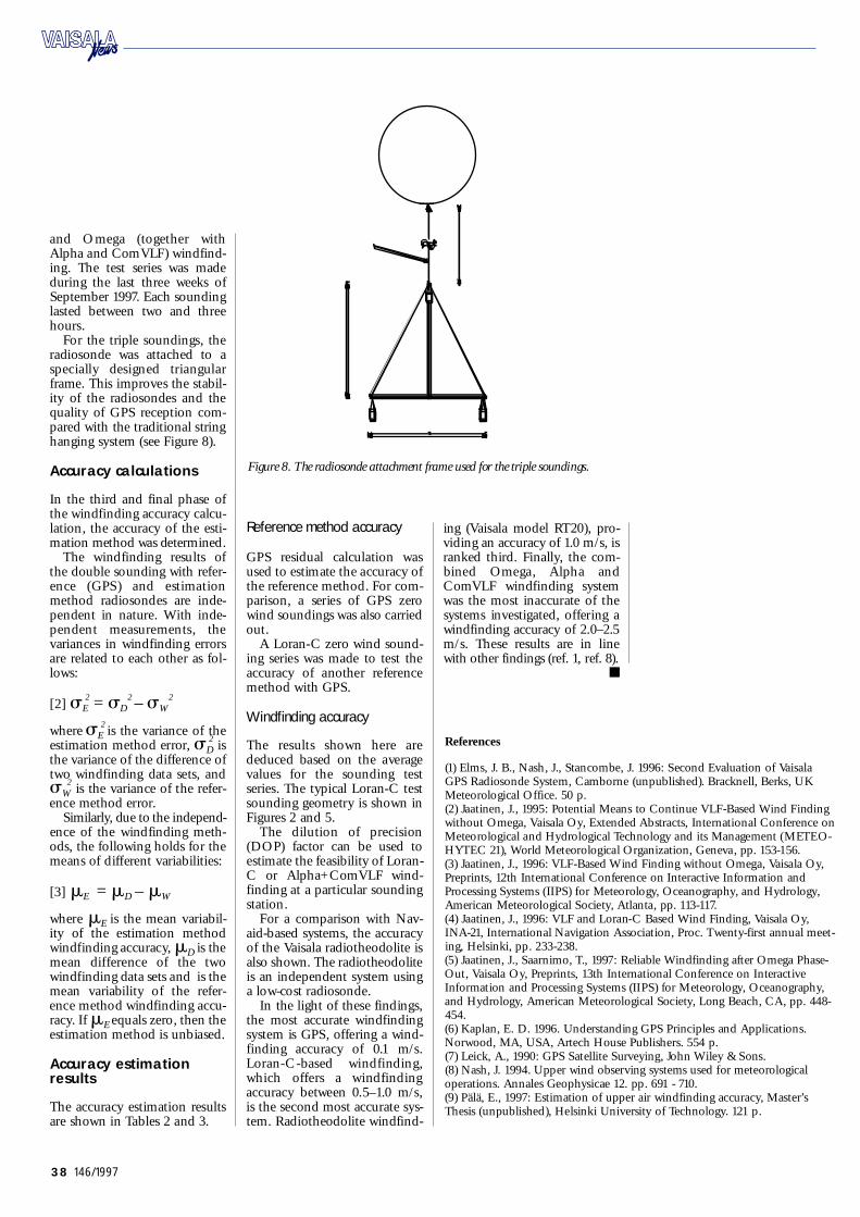
38 146/1997
R e f e r e n c e s
(1) Elms, J. B., Nash, J., Stancombe, J. 1996: Second Evaluation of Va i sa l aG PS Radiosonde System, Camborne (unpublished). Brackn e l l, Berks, UKMeteorological Office. 50 p.(2) Jaatinen, J., 1995: Potential Means to Continue VLF-Based Wind Findingwithout Omega, Va i sala Oy, Extended Abstracts, International Conference onMeteorological and Hydrological Te chnology and its Management (MET EO-H Y T EC 21), World Meteorological Orga n i z a t i o n, Geneva, pp. 15 3 - 15 6 .(3) Jaatinen, J., 1996: VLF-Based Wind Finding without Omega, Va i sala Oy,P r e p r i n t s, 12th International Conference on Interactive Information andProcessing Systems (I IPS) for Meteorology, Oceanography, and Hydrology,American Meteorological Society, Atlanta, pp. 113 - 117.(4) Jaatinen, J., 1996: VLF and Loran-C Based Wind Finding, Va i sala Oy,INA - 21, International Navigation Association, Proc. Twenty-first annual meet-i n g, Helsinki, pp. 233-238.(5) Jaatinen, J., Saarnimo, T., 19 97: Reliable Windfinding after Omega Phase-O u t, Va i sala Oy, Preprints, 13th International Conference on InteractiveInformation and Processing Systems (I IPS) for Meteorology, Oceanography,and Hydrology, American Meteorological Society, Long Beach, CA, pp. 448-4 5 4 .(6) Ka p l a n, E. D. 1996. Understanding GPS Principles and Applications.No rw o o d, MA, US A, Art e ch House Publishers. 554 p.(7) Leick, A., 1990: GPS Satellite Surv e y i n g, John Wiley & Sons.(8) Nash, J. 1994. Upper wind observing systems used for meteorologicalo p e r a t i o n s. Annales Geophysicae 12. pp. 691 - 710 .(9) Pälä, E., 19 97: Estimation of upper air windfinding accuracy, Master’sThesis (unpublished), Helsinki University of Te ch n o l o g y. 121 p.
and Omega (together withAlpha and ComVLF) windfind-i n g. The test series was madeduring the last three weeks ofSeptember 19 97. Each soundinglasted between two and threeh o u r s.
For the triple soundings, theradiosonde was attached to aspecially designed triangularframe. This improves the stabil-ity of the radiosondes and thequality of GPS reception com-pared with the traditional stringhanging system (see Figure 8).
Accuracy calculations
In the third and final phase ofthe windfinding accuracy calcu-l a t i o n, the accuracy of the esti-mation method was determined.
The windfinding results ofthe double sounding with refer-ence (G PS) and estimationmethod radiosondes are inde-pendent in nature. With inde-pendent measurements, thevariances in windfinding errorsare related to each other as fol-l o w s :
[2] E
2= D
2 – W
2
w h e r e E
2 is the variance of the
estimation method error, D
2i s
the variance of the difference oftwo windfinding data sets, and
W
2is the variance of the refer-
ence method error. S i m i l a r l y, due to the independ-
ence of the windfinding meth-o d s, the following holds for themeans of different variabilities:
[3] E = D – W
where E is the mean variabil-ity of the estimation methodwindfinding accuracy, D is themean difference of the twowindfinding data sets and is themean variability of the refer-ence method windfinding accu-r a cy. If E equals zero, then theestimation method is unbiased.
Accuracy estimationr e s u l t s
The accuracy estimation resultsare shown in Tables 2 and 3.
R e f e rence method accura c y
G PS residual calculation wasused to estimate the accuracy ofthe reference method. For com-p a r i s o n, a series of GPS zerowind soundings was also carriedo u t.
A Loran-C zero wind sound-ing series was made to test thea c c u r a cy of another referencemethod with GPS.
Windfinding accura c y
The results shown here arededuced based on the averagevalues for the sounding tests e r i e s. The typical Loran-C testsounding geometry is shown inFigures 2 and 5.
The dilution of precision(DOP) factor can be used toestimate the feasibility of Loran-C or Alpha+ComVLF wind-finding at a particular soundings t a t i o n.
For a comparison with Nav-a i d -based systems, the accuracyof the Va i sala radiotheodolite isalso shown. The radiotheodoliteis an independent system usinga low-cost radiosonde.
In the light of these findings,the most accurate windfindingsystem is GPS, offering a wind-finding accuracy of 0.1 m/s.L o r a n -C-based windfinding,w h i ch offers a windfindinga c c u r a cy between 0.5–1.0 m/s,is the second most accurate sys-t e m. Radiotheodolite windfind-
ing (Va i sala model RT20), pro-viding an accuracy of 1.0 m/s, isr a n ked third. Finally, the com-bined Omega, Alpha andComVLF windfinding systemwas the most inaccurate of thesystems inv e s t i ga t e d, offering awindfinding accuracy of 2.0–2.5m / s. These results are in linewith other findings (ref. 1, ref. 8).
Figure 8. The radiosonde attachment frame used for the triple soundings.
Vaisala News 146/97 Final 7.1.1998 10:03 Page 38
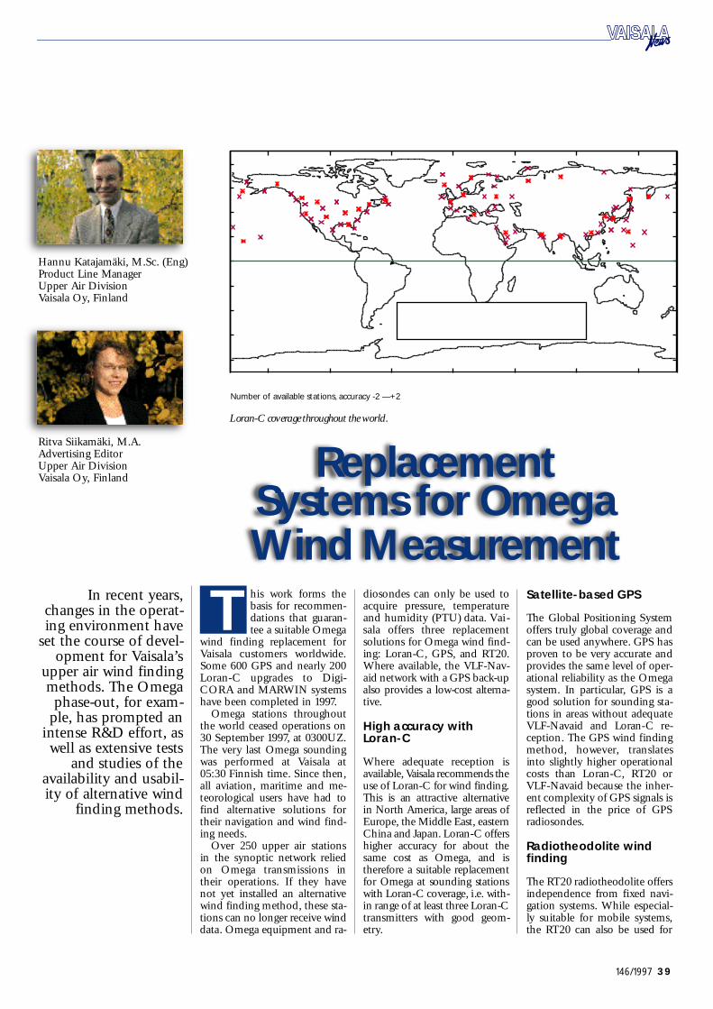
39146/1997
In recent years,changes in the operat-ing environment have
set the course of devel-opment for Va i sa l a ’ s
upper air wind findingm e t h o d s. The Omegap h a s e -o u t, for exam-
ple, has prompted anintense R&D effort, aswell as extensive tests
and studies of theavailability and usa b i l-ity of alternative wind
finding methods.
his work forms thebasis for recommen-dations that guaran-tee a suitable Omega
wind finding replacement forVa i sala customers worldwide.Some 600 GPS and nearly 200L o r a n -C upgrades to Digi-CORA and MARW IN systemshave been completed in 19 97.
O m e ga stations throughoutthe world ceased operations on30 September 19 97, at 0300UZ.The very last Omega soundingwas performed at Va i sala at05:30 Finnish time. Since then,all aviation, maritime and me-teorological users have had tofind alternative solutions fortheir navigation and wind find-ing needs.
Over 250 upper air stationsin the synoptic network reliedon Omega transmissions intheir operations. If they havenot yet installed an alternativewind finding method, these sta-tions can no longer receive windd a t a. Omega equipment and ra-
d i osondes can only be used toacquire pressure, temperatureand humidity (PTU) data. Vai-sala offers three replacementsolutions for Omega wind find-ing: Loran-C, GPS, and RT 2 0 .Where available, the VLF-N a v-aid network with a GPS back-u palso provides a low-cost alterna-t i v e.
High accuracy withLo r a n -C
Where adequate reception isa v a i lable, Va i sala recommends theuse of Loran-C for wind finding.This is an attractive alternative in No rth America, large areas ofEurope, the Middle East, easternChina and Japan. Loran-C offershigher accuracy for about thesame cost as Omega, and istherefore a suitable replacementfor Omega at sounding stationswith Loran-C coverage, i.e. with-in range of at least three Loran-Ctransmitters with good geom-e t ry.
Satellite-based GPS
The Global Positioning Systemoffers truly global coverage andcan be used anywhere. GPS hasproven to be very accurate andprovides the same level of oper-ational reliability as the Omegas y s t e m. In part i c u l a r, GPS is agood solution for sounding sta-tions in areas without adequateV L F-Navaid and Loran-C re-c e p t i o n. The GPS wind findingm e t h o d, however, translatesinto slightly higher operationalcosts than Loran-C, RT20 orV L F-Navaid because the inher-ent complexity of GPS signals isreflected in the price of GPSr a d i o s o n d e s.
Ra d i o t h eodolite windf i n d i n g
The RT20 radiotheodolite offersindependence from fixed navi-gation systems. While especial-ly suitable for mobile systems,the RT20 can also be used for
Hannu Ka t a j a m ä ki, M. S c. (E n g)Product Line ManagerUpper Air DivisionVa i sala Oy, Finland
Ritva Siika m ä ki, M. A.Ad v e rtising EditorUpper Air DivisionVa i sala Oy, Finland Replacement
Systems for OmegaWind Measure m e n t
L o ra n -C coverage throughout the wo r l d.
T
Number of available stations, accuracy -2 — +2
Vaisala News 146/97 Final 7.1.1998 10:04 Page 39

40 146/1997
he eight-member Te ch-nical Support team inthe Upper Air Divi-sion (UA D) inc l u d e s
Olavi A l a n ko, Aleksander Bon-d a r e n ko, Jarmo Franssila, MarkkuJ ä rv i n e n, Ismo Ku p i a i n e n, JarmoM o n o n e n and Mikko Niininen.Keijo Mesiäinen, a former teammember and familiar face tom a ny Va i sala customers over thepast forty years, retired on 1 No-vember 19 97.
Te chnical Support personnelare specialists in system engin e e r-ing fields, with expertise coveri n ga u t o s o n d e s, radiotheodolites, spe-cial sensors, etc. They also kn o wthe basics of all Va i sala’s upperair observation products. Eng-l i s h, Va i sala’s corporate lan-guage, is the main language usedfor communication with custom-e r s, although some team m e m-bers also speak French, G e rm a n,S p a n i s h, Russian, Swedish and o fcourse Finnish.
Using Lo ra n -C fo rUpper Air Wi n d sThe article ‘Countdown to Omega Te r m i n a t i o nContinues’ that appeared in the 14 2 /19 97 issue ofVa i sala News provided a list of alternatives forobtaining upper air winds following termination ofthe worldwide Omega navigation system. Omegatransmissions ceased on 30 September 19 97, afterproviding signals used by upper air windfinders formore than 25 years.
In the article, the use of Loran-C, a long-range butregional radionavigation system, was cited as one ofthe attractive options that could be used where cov-erage is available. Unfort u n a t e l y, during the editingp r o c e s s, the use of Loran-C was described as being a‘more uncertain’ option while the original text stat-ed that the Loran-C option was one ‘that has morec e rtainty’. We apologize for this error.
Winds determined using Loran-C are generallymore accurate than those obtained by Omega, butu n l i ke Omega, whose signals could be receivedworldwide, Loran-C coverage is regional. Th eNo rt hwest Europe Loran-C System (NEL S) isexpected to be fully operational in 1998, and plan-ning is in progress to extend this coverage to the eastand into the Mediterranean region using Chayka,the compatible Russian system. The EuropeanU n i o n, in a 1992 resolution, calls for Loran-C in thefuture mix of radionavigation systems, and this isreflected in the European Ra d i o n a v i gation Plan cur-rently in preparation. The Loran-C Far EastRa d i o N a v i gation System (FERNS) which China,K o r e a, Japan and Russia operate jointly continues tobe upgraded. Loran-C is also operating in otherp a rts of the world, including Canada and India.
The Loran-C picture in the United States is stillu n c e rtain and confusing. The 1996 Federal Ra d i o-n a v i gation Plan released in hard copy in September19 97 continues to state that Loran-C will be termi-nated in the United States in the year 2000, but theU. S. Congress has appropriated funds and stipulat-ed that the Department of Tr a n s p o rtation upgradethe transmitting stations and plan for operation afterthe year 2000. Congressionally mandated report sdefining this plan are in preparation for submissionto Congress within the next six months.
Where coverage is available, Loran-C provideswind finding capability at a cost comparable to thatof Omega. The alternatives are to use GPS at a high-er cost or the more traditional method using ther a d i o t h e o d o l i t e .
John M. Beuke r sB. S c. (E n g. )F l o r i d a, US A
The Te chnical Supportteam from Va i sa l a ’ s
Upper Air Division playsa key role in after sa l e s
p r o c e s s e s. The team helpscustomers with tech n i c a l
issues related to thei n s t a l l a t i o n, operation,
use and maintenance oftheir upper air systems.
Customer feedback iscritically important to the
entire team, which iscommitted to providing
comprehensive serv i c eand support to customers
w o r l d w i d e .
Ve sa Koivula, M. S c. (E n g)Te chnical Support ManagerUpper Air DivisionVa i sala Oy, Finland
synoptic observ a t i o n s. The priceof the ground equipment ish i g h e r, and the upgrading pro-cess is more complex than thec a r d -based MW upgrades forL o r a n -C and GPS wind find-i n g. The cost for radiosondes,h o w e v e r, is lower with an RT 2 0s y s t e m. For sounding stationsoutside Loran-C and VLF-Navaid reception, an upgradeto GPS or RT 20 is recom-m e n d e d.
V L F -N a vaid option
V L F-Navaid transmissions areavailable in some areas. Fromthe user’s standpoint, however,V L F-Navaid wind findingbased on the simultaneous useof the Russian Alpha and Com-m u n i c a t i o n s -VLF (C o m V L F) isnot sufficiently dependable.Continuous wind data avail-ability cannot be guaranteedbecause of maintenance breaksin the Alpha system and theintermittent transmissions ofthe ComVLF system. For theser e a s o n s, Va i sala discouragescomplete reliance on VLF-N a v-aid for wind finding and rec-ommends the use of Loran-C ,G PS or RT20 as either a prima-ry or backup system. VLF-Navaid may be used as the pri-m a ry system in Alaska, Canadaand northern Asia.
Flexible upgrades
A ny Va i sala DigiCORA orM A RW IN system can be up-graded for GPS, Loran-C orradiotheodolite wind finding.The upgrade includes either aG PS or Loran-C receiver &processor module that ismounted inside the DigiCORAand MARW IN frame. All nec-e s sa ry cables, connectors andtools are included in the up-grade set, along with easy-t o -f o l-low instructions. The upgrade i sextremely easy to carry out,even for less experienced opera-t o r s. Radiotheodolite upgradesare more complex, and we rec-ommend that Va i sala’s trainedpersonnel perform them. Forf u rther information, please con-tact Upper Air Division’s Te ch-nical Support, tel. +358 9 8949345, e-mail tech u a d @ v a i sa l a. c o m.
T
Vaisala News 146/97 Final 7.1.1998 10:04 Page 40
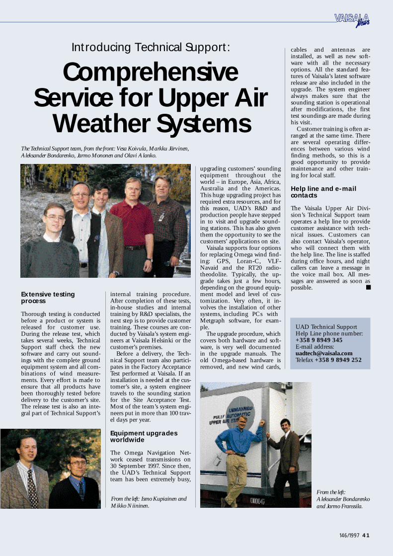
41146/1997
internal training procedure.After completion of these tests,i n -house studies and internaltraining by R&D specialists, thenext step is to provide customert r a i n i n g. These courses are con-ducted by Va i sala’s system engi-neers at Va i sala Helsinki or thecustomer’s premises.
Before a delivery, the Te ch-nical Support team also part i c i-pates in the Factory AcceptanceTest performed at Va i sa l a. If aninstallation is needed at the cus-tomer’s site, a system engineertravels to the sounding stationfor the Site Acceptance Te s t.Most of the team’s system engi-neers put in more than 100 trav-el days per year.
Equipment upgradeswo r l d w i d e
The Omega Navigation Ne t-work ceased transmissions on30 September 19 97. Since then,the UAD’s Te chnical Supportteam has been extremely busy,
upgrading customers’ soundingequipment throughout theworld – in Europe, Asia, Africa,Australia and the Americas.This huge upgrading project hasrequired extra resources, and forthis reason, UAD’s R&D andp r oduction people have steppedin to visit and upgrade sound-ing stations. This has also giventhem the opportunity to see thecustomers’ applications on site.
Va i sala supports four optionsfor replacing Omega wind find-ing: GPS, Loran-C, VLF-Navaid and the RT20 radio-theodolite. Typically, the up-grade takes just a few hours,depending on the ground equip-ment model and level of cus-t o m i z a t i o n. Ve ry often, it in-volves the installation of others y s t e m s, including PCs withMetgraph software, for exam-p l e .
The upgrade procedure, whichcovers both hardware and soft-ware, is very well documentedin the upgrade manuals. Th eold Omega -based hardware isr e m o v e d, and new wind cards,
cables and antennas arei n s t a l l e d, as well as new soft-ware with all the necessa ryo p t i o n s. All the standard fea-tures of Va i sala’s latest softwarerelease are also included in theupgrade. The system engineeralways makes sure that thesounding station is operationalafter modifications, the firsttest soundings are made duringhis visit.
Customer training is often ar-ranged at the same time. Th e r eare several operating differ-ences between various windfinding methods, so this is agood opportunity to providemaintenance and other train-ing for local staff.
Help line and e-mailc o n t a c t s
The Va i sala Upper Air Divi-sion’s Te chnical Support teamoperates a help line to providecustomer assistance with tech-nical issues. Customers canalso contact Va i sala’s operator,who will connect them withthe help line. The line is staffedduring office hours, and nightcallers can leave a message inthe voice mail box. All mes-sages are answered as soon asp o s s i b l e .
Introducing Technical Support:
C o m p re h e n s i veService for Upper Air
Weather Systems
E x t e n s i ve testingp r o c e s s
Thorough testing is conductedbefore a product or system isreleased for customer use.During the release test, whicht a kes several weeks, Te ch n i c a lS u p p o rt staff ch e ck the newsoftware and carry out sound-ings with the complete groundequipment system and all com-binations of wind measure-m e n t s. Ev e ry effort is made toensure that all products havebeen thoroughly tested befored e l i v e ry to the customer’s site.The release test is also an inte-gral part of Te chnical Support ’ s
From the left :
Aleksander Bo n d a r e n k o
and Jarmo Fra n s s i l a.
UAD Te chnical SupportHelp Line phone number:+358 9 8949 345E-mail address:u a d t e ch @ v a i s a l a. c o mTelefax +358 9 8949 252
From the left: Ismo Kupiainen and
Mikko Niininen.
The Te chnical Support team, from the front: Vesa Ko i v u l a, Markku Järvinen,
Aleksander Bo n d a r e n k o, Jarmo Mononen and Olavi Alanko.
Vaisala News 146/97 Final 7.1.1998 10:04 Page 41

42 146/1997
Electricity Company and Cro-atian Army, have mainly orderedmeteorological equipment. Salesof measurement instruments,h o w e v e r, are also growing.
Full service guaranteescustomer satisfaction
Program Manager Zeljko Bas icis one of the company’s thir-teen employees. “We try toform as close a connection be-tween the end user and Va i sa l a
as possible. We are also com-mitted to understanding ourcustomers’ needs and offeringthem the best possible tech n i c a ls o l u t i o n. After the equipmenthas been delivered and in-s t a l l e d, we provide assistancewith equipment service andmaintenance. In this respect,our cooperation with Va i sa l ahas been very successful,” sa y sM r. Bas ic .
“Zagrel is a technically strongc o m p a ny, so we can offer fulls e rvice. In our view, this is thebest way to satisfy our cus-t o m e r s. ”
M r. Domac is confidentabout Va i sala’s future in Croa-t i a. To d a y, the market growthreflects increasing demand foradvanced measurement systems.“ Va i sala’s research and develop-ment work is thorough and ex-tensive, and the company playsa leading role in the world mar-ke t. We can learn a lot fromVa i sa l a, but I hope this processis a two-way street, with bothp a rties learning from each otherand raising the level of cus-tomer satisfaction even higher. ”
agrel d. o. o. was foun-ded in 19 91 and hasbeen Va i sala’s repre-sentative in Croatia
ever since. The connection be-tween Zagrel and Va i sa l a, how-e v e r, dates back much fart h e r.Z e l j ko Bas ic, now Program Ma-nager at Zagrel, visited Va i sa l ain 1982 when he was still work-ing for the Croatian Hydrome-teorological Service. This wasthe start of the warm relation-ship between the two compa-n i e s.
“ M r. Jussi Paananen and Mr.Ismo Kupiainen are my oldestcontacts at Va i sala and also myf r i e n d s. Jussi even calls me ‘hisbest long-term inv e s t m e n t ’ , ”says Mr. Bas ic with a smile.
Zagrel focuses oncontrol and automation
Zagrel is a private companywith offices in the center ofZagreb. The company’s activ-ities cover a wide range, includ-ing the engineering, develop-m e n t, production, marke t i n gand servicing of electronic equipment and mach i n e ry.
Zagrel’s main focus is on re-mote control and telemetric s y s-
The upper old town of Zagreb .
The Customer Comes First at Zagre lStrong confidence in the growth of the Croatian
m a r ke t, Va i sala’s products and a successful future –these are the underlying beliefs at Zagrel, Va i sa l a ’ srepresentative in Croatia. Backed up by its tech n i-cal strengths, Zagrel can provide customers with
full service as well as high-quality products.
tems for hy d r o t e ch n i c a l, waters u p p l y, electric power andradio communication systems,as well as radio networks. In-dustrial automation and meas-urements also account for amajor part of their business.Va i sala is one of Zagrel’s mosti m p o rtant part n e r s.
To date, Zagrel’s largest Va i-sala customers, including theCroatian Air Traffic SafetyA u t h o r i t y, Meteorological andHydrological Service, National
C roatia Upgrading Its Met
“Our cooperation with Vaisala ha s
been very successful,” comments Mr.
Bas ic, Program Manager from
Z a g r e l.
Z
Tomislav Do m a c, Director of
Z a g r e l, believes in the continuing
success of Vaisala’s products in the
C r oatian market.
Marit FinneE d i t o r -i n -C h i e fVa i sala Ne w sVa i sala Oy, Finland
Vaisala News 146/97 Final 7.1.1998 10:04 Page 42

43146/1997
Va i sala and the Croatian Meteorological andHydrological Service (MHS) have worke d
together in the fields of upper air and surf a c eweather observations for more than a decade. In1994, the Finnish Meteorological Institute (F MI)donated ground equipment to the MHS. AfterVa i sala refurbished the system, it was presented
to the MHS in February 19 9 5 .
roatia has had ano r ganized meteoro-logical observ a t i o nsystem for over 15 0
y e a r s. The predecessor of theCroatian Meteorological andH y d r ological Service (MHS)was founded in 19 47, so 19 97m a r ked their 50-year jubilee.
The Meteorological and Hydrological Service is the mainmeteorological authority in Croa-t i a. It is involved in all aspectsof meteorology, from weatherforecasting and hydrology toa g r o m e t e o r o l o g y, marine me-t e o r o l o g y, research and hails u p p r e s s i o n.
M HS: Ready for Future Challenges
A balloon launch at the
Z a g r e b – Maksimir Observatory.
From the left: Mr. Milan Filipc ic
(head of the observatory) and Mr.
Ivica Dundovic .
ground equipment have beenkey Va i sala products for MHS.
Va i sala also gave presenta-tions about upper-air and sur-face meteorological instru-ments in the mid-19 8 0 s. In1995, a MILOS500 automaticweather station was sited at theZ a g r e b – M a ksimir Meteorologi-cal and Aerological Observ a-t o ry for six months, as part of ap r e s e n t a t i o n.
The observational network ofmeteorological stations in Croa-tia is defined in accordance withW MO guidelines and generatesall the measurements requiredfor meteorological data ex-change. The network has not yetbeen fully automated.
In the future, there are plansto build one radiosounding sta-tion in Zagreb, two stationsalong the Adriatic coast and onein Slavonski Brod.
Ground equipment from FMI
The Finnish Meteorological In-stitute (F MI) donated a M i c r o -CORA system to the MHS a tthe end of 1994. The groundequipment had been in use atthe Jo kioinen Observ a t o ry,F i n l a n d, and after refurbishingat Va i sa l a, it was presented tothe MHS in February 19 9 5 .
D r. Erkki Jatila from FMI andM r. Jussi Paananen from Va i sa l aplayed an active role in arrangingthe donation. Va i sala also pro-
Zvonimir Ka t us i nAssistant DirectorMeteorological andHydrological Serv i c eZagreb, Croatia
As soon as MHS became amember of the World Meteoro-logical Organization in 1992, itb e gan to establish close linkswith other WMO members, es-pecially in Europe, to exch a n g edata and experiences.
Cooperation for over ten years
Va i sala’s first contact with theMHS was in 1984, when Mr.Jussi Paananen gave a presenta-tion about Va i sala’s radiosound-ing equipment. MHS began touse Va i sala radiosondes in 19 9 5 ,and ever since, radiosondes and
Meteorological Systems
C
Vaisala News 146/97 Final 7.1.1998 10:04 Page 43

44 146/1997
The growth of tourismin Croatia is generat-
ing more air traffic. Tohelp ensure passenger
sa f e t y, the country ’ seight international air-p o rts need up-t o -d a t e
i n s t r u m e n t a t i o n. Since1994, the Croatian Air
Traffic Serv i c e sAuthority has relied
on Va i sala instruments.
roatia is a beautifulMediterranean coun-t ry and an increas-ingly popular tourist
d e s t i n a t i o n. To d a y, the countryhas eight international airport s,most of them on the Ad r i a t i cC o a s t, as well as some smallera i r p o rts for general aviation.With the growing number oftourists visiting the country, thea i r p o rts must be prepared tohandle the increase in air traffic.The number of airport s, more-o v e r, particularly small ones, isalso expected to grow.
The Croatian Air Traffic Ser-vices Authority (CATS A) is partof the Ministry of MaritimeA f f a i r s, Tr a n s p o rt and Com-m u n i c a t i o n s. Along with itsmanagement and area controls e rvice center in Zagreb,CATSA has airport control ser-vice centers at each airport. Allair traffic services in Croatia arehandled by CATS A, which is acomplex organization with re-sponsibility for managing theoperations in the units of theAir Traffic Service (ATS), Aero-nautical Meteorology and Te ch-nical Division. Mr. DrazenRa m l j a k, Director General,manages the organization withthe help of three DeputyD i r e c t o r s, Mr. Vlado Bracevic( ATS), Ms. Bozica Gelo (MET ) ,and Mr. Franjo Kiseli (Te ch n i c a lS u p p o rt).
Compliance with ICAO regu-lations for flight passenger sa f e t yis also in the hands of CATS A.M s. Aleksandra Kr asovec headsCATS A’s Navigation and Me-teorology Department within
the Technical Division. Thed e p a rtment is responsible forinstalling and maintaining then a v i gation and meteorologicalequipment at the Zagreb airport.They also help other airport ssolve any equipment problemsthat may arise. In cooperationwith his technical colleagues,M r. Miroslav Jalacic, Meteorolo-g i s t, coordinates all calibrationand maintenance of meteorolog-ical equipment.
Quality costs less in the long run
Va i sala made its first productpresentation to CATSA in Zagrebin 1992. The first purchases were
made soon after, and Va i sa l aWA D 21M wind systems wereinstalled at the Dubrovnik,Split and Zagreb airport s.
Product quality was the focusof special attention in the selec-tion of the Va i sala products. AsM s. Kr asovec explains: “Goodquality is less expensive in thelong run. While the price maybe higher to start with, you cancount on quality later on. ”CATSA also has a policy ofbuying observation systems
Air Traffic Safety Authority Pre p a resfor Increasing Air Tra f f i c
C ATSA representatives at the Vaisala training course. (from the left): Mr.
Nenad Rodic, Mr. Damir Ko v a c, Mr. Zeljko Knjaz, Mr. Harry Alm and
M s. Liisa Nummela (both from Vaisala), Ms. Aleksandra Kras o v e c, Mr.
Augustin Kastelan and Mr. Tomislav Ko s t a.
vided training in the use andmaintenance of the Micro-CORA system to Dr. Kr es oPandzic and Mr. Ivan Sm a l j c e l jfrom the Croatian Meteoro-logical Institute. Mr. Zeljko Basi cfrom Zagrel, Va i sala’s distributorin Croatia, also attended thetraining session.
The MicroCORA was start-ed up on 25 February 19 9 5after a short ceremony at theZ a g r e b – M a ksimir Meteorologi-cal and Aerological Observ a-t o ry. The ceremony was attend-ed by Dr. Mikko Alestalo,Head of the Te chnical Depart-ment at FMI. Mr. To m i s l a vV uce t ic, Director; Mr. MladenMatvijev, Vice Director; andM r. Zvonimir Ka t usi n, Assis-tant Director and Head of theC l i m a t o l o g i c a l, Meteorologicaland Upper Air M e a s u r e m e n tD e p a rt m e n t, represented theMHS. Mr. Eero P u h a kka wason hand from Va isa l a, as well asDomac Tomislav, Director, andM r. Zeljko Basic from Zagrel,Va i sala’s distributor in Croatia.The ceremony was also fol-lowed by everyone from MHS,the Croatian Army and Cro-atian Air Traffic Control who isi nvolved in upper air measure-m e n t.
Future needs
Now that the Omega systemhas been discontinued, MHS isusing Va i sala’s RT20 radio-theodolite and a 1680 MH zRS 8 0 - 67 radiosonde at theZ a g r e b – M a ksimir Observ a t o ry.L o o king to the future, thisradiosounding system might bereplaced by GPS or Loran-Cwind measurement, after inter-national tendering.
From the left: Ms. Aleksandra
K ras o v e c, Mr. Zeljko Bas ic, Mr.
Miroslav Jelacic and Ms. Bo z i c a
Gelo at the Zagreb airport.
C
Vaisala News 146/97 Final 7.1.1998 10:04 Page 44

45146/1997
H rv a t s ka Elekt r o P r i v r e d a, Croatia’snational electricity company, needsweather information for planning itsfuture power and water management sys-t e m s. The first Va i sala automatic weatherstation (AWS) for this application wasinstalled at the Pe r uca dam in 19 9 6 .
B r a n ko Grgic, M. S c.Development Department H rv a t s ka ElektroPrivreda d. d.Zagreb, Croatia
AWS Plays a Key Role in Power andWater Management
Mr. Branko Gr g ic stands beside Va i s a l a ’ s
automatic weather station, which is equipped
with a QLI50 sensor collector integrated with
L a b VIEW soft w a r e .
only from well-known and repu-table manufacturers.
This year, a loan from theEuropean Bank for Researchand Development made it pos-sible to order updated AWOSand RVR systems for the Zag-reb airport. Aga i n, CATS Aturned to Va i sa l a. ALMOS Sys-tems from Australia suppliedthe central unit and software,while Va i sala supplied the fields e n s o r s, including RVR, soft-ware, anemometers and pres-sure, temperature and humiditys e n s o r s.
“ We have found the qualityof the products to be very high,and we have been happy withthe service, too,” notes Ms.Kr aso v e c. “We also have a goodrelationship with Zagrel, Va i-sala’s local representative. Th e yhave been very helpful. ”
Technical training in Finland
In the summer of 19 97, a groupof CATS A’s technicians visitedVa i sala to learn more abouttheir new equipment. Six ex-p e rts received training in thei n s t a l l a t i o n, use and mainte-nance of WAA 15A and WAV 15 Awind systems, CT12K ceilom-et e r s, HMP35D humidity andt e mperature probes, DPA 12 Ap r e ssure transmitters, andMI T RAS RVR systems. Va i sa l a ’ sProject Manager Liisa Nummelawas the instructor of the train-ing course.
A l e ksandra Kr asovec wasone of the trainees: “In my 22years at CATS A, I have wornm a ny hats. In a small orga n i z a-tion like ours, it is import a n tfor everyone to pitch in whenn e e d e d. I like working in thef i e l d. It’s the best way to learnabout the equipment. ”
Zagrel did a good job orga n-izing the training session, incooperation with CATSA andVa i sa l a. According to the train-e e s, the course was very useful,thorough and even fun. Ms.Kr asovec sums up their feel-ings: “We were very happy tosee the factory where our prod-ucts were made. Even theweather was beautiful. ”
Designed to gather weather information, a Vaisala automatic weather station
was installed at the Pe r uca dam in 19 9 6.
rv a t s ka ElektroPrivreda d. d. is responsiblefor electricity generation, transmissionand distribution in Croatia. To plan andoptimize the construction and utilization
of future power and water management systems, thec o m p a ny is installing a series of automatic weatherstations (AWS) throughout the country. The climat-i c, meteorological and hydrological parameters thatthe stations collect will be used in system planning.
H rv a t s ka Elektroprivreda d. d. operates under thes u p e rvision of Croatian government authorities.
AWS helps determine rainfall and runoff
The first new weather station was installed in 1996 atthe Pe r uca dam, which had been severely damagedduring the recent civil war. The installation of the sta-tion coincided with the start of dam repairs. No wfully operational, the station gathers data used todetermine the relationship between rainfall andrunoff in the dam catchment area.
Va i sala’s automatic weather station is equippedwith a QLI50 sensor collector integrated withLa b V IEW software. This combination is a flexibleand accurate tool for comprehensive data acquisitionand analysis. Good references and the high quality ofVa i sala’s equipment were deciding factors inH rv a t s ka Elekt r oPrivreda’s choice. As they report, thesystem seems to be very solid and up-t o -date, basedon their experiences so far.
First of five installations
The Pe r uca dam is the first in aseries of five installations plan-ned in Croatia. Hrv a t s kaE l e ktroPrivreda intends toch a rt the meteorological andhydrological characteristics ofthe entire region, which coversthe Cetina, Kr ka and Zrmanjariver basin. To complete the sys-t e m, four more weather sta-tions will be needed in the nearf u t u r e .
H
Vaisala News 146/97 Final 7.1.1998 10:04 Page 45

46 146/1997
Jarmo Mononen from Vaisala provided operator training in the use of the
RT20 radiotheodolite at the Center of Strategic Studies. From the left (the firs t
row): Mr. Zeljko Bas ic (Zagrel), Ms. Dunja Placko (HQ Meteo), Mr. Ja r m o
Mononen (Vaisala); a group of opera t o rs and military personnel stand behind
t h e m.
The Croatian Army isdedicated to develop-
ing its personnel,equipment and pro-
cedures to a high op-erational level. Th e
procurement of reli-able meteorological
measurement equip-ment is one aspect of
this developmente f f o rt. Va i sala’s RT 2 0radiotheodolite met
the army’s need for ane a s y -t o -use, easy-t o -
t r a n s p o rt system thatw o r ks in any weather
c o n d i t i o n s, day orn i g h t.
ince then, the Cen-ter of Strategic Stud-i es (CSI) has beenc o ntributing to the
a r my ’s development. The cen-ter’s long-term aim is to becomea military research and develop-ment institution specializing inm i l i t a ry tech n o l o g y. Studiesthat are critical to defence andthe armed forces, and to nation-al and global security are amongCSI’s activities.
F i s t o n ic I g o r, M. S c., M. E n g.H e a d m a s t e r, Briga d i e rCenter for Strategic Studies,M i n i s t ry of DefenceC r o a t i a
RT20 Radiotheodolite Stands Up to Harsh Field Conditions
The Croatian Army gives high
marks to the all-weather reliability
of Vaisala’s RT20 ra d i o t h e o d o l i t e .
S
Demanding m easurements in the field
The Croatian Army neededequipment to measure meteo-rological parameters – includ-ing temperature, humidity,pressure, wind direction andwind speed – at altitudes of upto 20,000 meters. In 1994, localM i n i s t ry of Defence expert sand experts from the StateMeteorological Institute joinedforces to determine the bestmeasurement solution.
They decided on Va i sa l a ’ sRT20 radiotheodolite. Th i schoice was based on the RT 2 0 ’ smeasurement capability in allweather conditions and duringthe night, and its easy assemblyand transport a t i o n. The passivemeasuring method of the RT 2 0and the relatively low probabil-ity of jamming – by radar orradio stations – were also sig-nificant factors in their deci-s i o n. It takes just one or twopeople to operate the RT 2 0 ,and the learning time is short.
Multiple uses in thei n f a n t r y, navy and airf o r c e
The Croatian military hasfound many different uses forthe RT20 radiotheodolite – bythe infantry, navy and air forcea l i ke. Examples include themeasurement of atmosphericconditions for art i l l e ry andr o cket launch practices.
Strong winds create danger-ous turbulence, so wind infor-mation is particularly impor-tant for the air force. The RT 2 0can also be used to determinethe chance of freezing, which isanother benefit of meteorologi-cal measurements for flight ap-p l i c a t i o n s. Based on this infor-m a t i o n, airplanes can be pre-pared for flight accordingly.
The meteorological data isalso used in the developmentof long-term and short -t e r mf o r e c a s t s, and to determine theatmospheric conditions ford e c i s i o n -m a king in extremeweather conditions and ecologi-cal catastrophes.
Tested reliability
Va i sala’s RT20 radiotheodoliteenables highly sophisticated in-formation processing of wind,pressure, humidity and tem-p e r a t u re readings. The infor-mation can be displayed, andthe output can be produced inthe desired format and medium.
The RT20 has been tested inthe harshest field conditions.Poor visibility and severe weath-er conditions have not affectedthe operation of this advancedand reliable radiotheodolite.
Vaisala News 146/97 Final 7.1.1998 10:04 Page 46
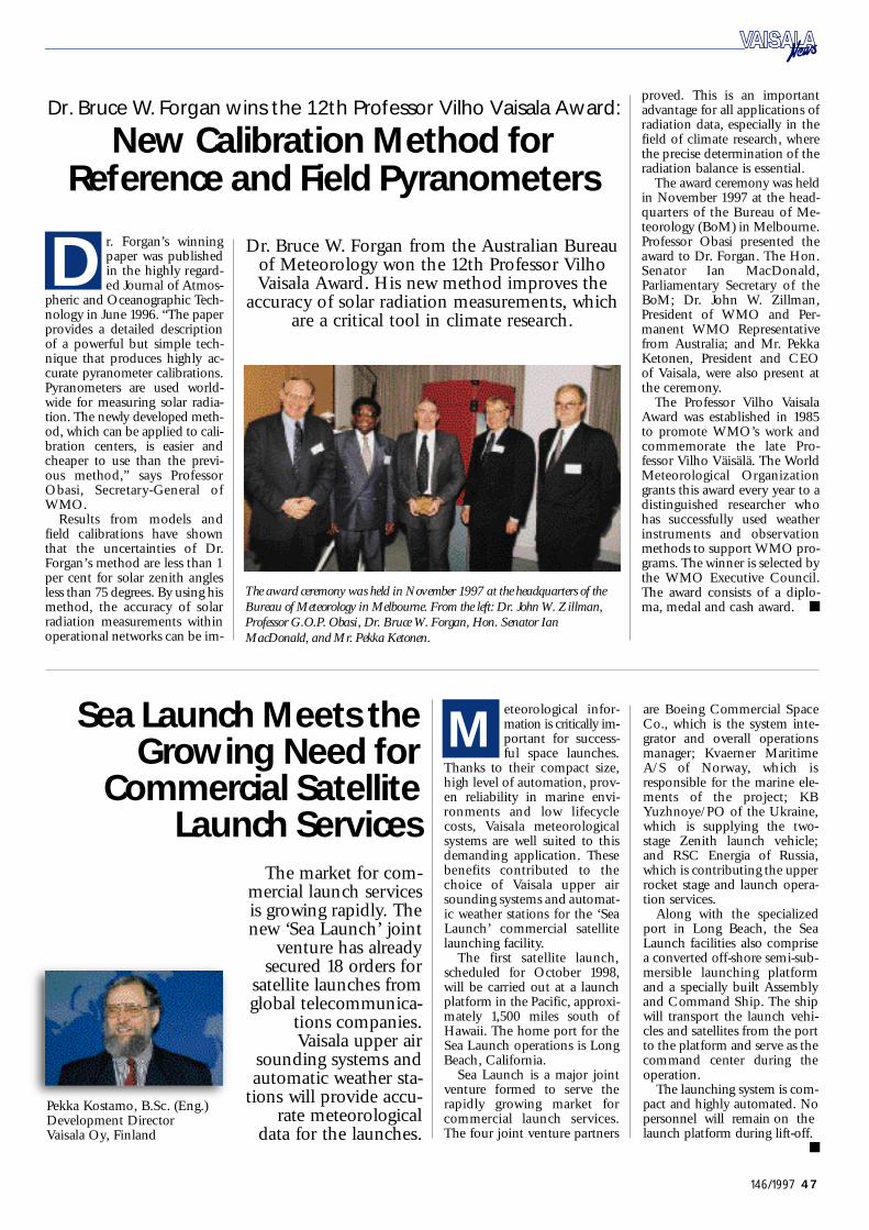
47146/1997
The award ceremony was held in November 19 97 at the headquarters of the
Bureau of Meteorology in Me l bourne. From the left: Dr. John W. Zillman,
Professor G. O . P. Oba s i, Dr. Bruce W. Fo r g a n, Ho n. Senator Ian
Ma c Do n a l d, and Mr. Pekka Ke t o n e n.
D r. Bruce W. Forgan from the Australian Bureauof Meteorology won the 12th Professor Vi l h oVa i sala Award. His new method improves the
a c c u r a cy of solar radiation measurements, whichare a critical tool in climate research.
r. Forgan’s winningpaper was publishedin the highly rega r d-ed Journal of Atmos-
pheric and Oceanographic Te ch-nology in June 1996. “The paperprovides a detailed descriptionof a powerful but simple tech-nique that produces highly ac-curate pyranometer calibrations.Pyranometers are used world-wide for measuring solar radia-t i o n. The newly developed meth-o d, which can be applied to cali-bration centers, is easier andcheaper to use than the previ-ous method,” says ProfessorO b a s i, Secretary -General ofW MO .
Results from models andfield calibrations have shownthat the uncertainties of Dr.F o r gan’s method are less than 1per cent for solar zenith anglesless than 75 degrees. By using hism e t h o d, the accuracy of solarradiation measurements withinoperational networks can be im-
p r o v e d. This is an import a n tadvantage for all applications ofradiation data, especially in thefield of climate research, wherethe precise determination of theradiation balance is essential.
The award ceremony was heldin November 19 97 at the head-q u a rters of the Bureau of Me-teorology (B o M) in Melbourne.Professor Obasi presented theaward to Dr. Forga n. The Hon.Senator Ian MacDonald,P a r l i a m e n t a ry Secretary of theBoM; Dr. John W. Zillman,President of WMO and Pe r-manent WMO Representativefrom Australia; and Mr. Pe kkaK e t o n e n, President and CEOof Va i sa l a, were also present atthe ceremony.
The Professor Vilho Va i sa l aAward was established in 19 8 5to promote WMO’s work andcommemorate the late Pro-fessor Vilho Väisälä. The Wo r l dMeteorological Orga n i z a t i o ngrants this award every year to adistinguished researcher whohas successfully used weatherinstruments and observ a t i o nmethods to support WMO pro-g r a m s. The winner is selected bythe WMO Executive Council.The award consists of a diplo-m a, medal and cash award.
Dr. Bruce W. Forgan wins the 12th Professor Vilho Vaisala Award:
New Calibration Method for R e fe rence and Field Pyra n o m e t e r s
The market for com-mercial launch serv i c e sis growing rapidly. Th enew ‘Sea La u n ch’ joint
venture has alreadysecured 18 orders for
satellite launches fromglobal telecommunica-
tions companies.Va i sala upper air
sounding systems andautomatic weather sta-
tions will provide accu-rate meteorological
data for the launch e s.
Pe kka Kostamo, B. S c. (E n g. )Development DirectorVa i sala Oy, Finland
Sea Launch Meets theG rowing Need fo r
C o m m e rcial Sa t e l l i t eLaunch Se r v i c e s
eteorological infor-mation is critically im-p o rtant for success-ful space launch e s.
Th a n ks to their compact size,high level of automation, prov-en reliability in marine env i-ronments and low lifecy c l ec o s t s, Va i sala meteorologicalsystems are well suited to thisdemanding application. Th e s ebenefits contributed to thechoice of Va i sala upper airsounding systems and automat-ic weather stations for the ‘SeaLa u n ch’ commercial sa t e l l i t el a u n ching facility.
The first satellite launch,s cheduled for October 19 9 8 ,will be carried out at a launchplatform in the Pacific, approxi-mately 1,500 miles south ofH a w a i i. The home port for theSea La u n ch operations is LongB e a ch, California.
Sea La u n ch is a major jointventure formed to serve therapidly growing market forcommercial launch serv i c e s.The four joint venture part n e r s
are Boeing Commercial SpaceC o., which is the system inte-grator and overall operationsmanager; Kvaerner MaritimeA /S of No rw a y, which isresponsible for the marine ele-ments of the project; KBY u z h n o y e /PO of the Ukr a i n e ,w h i ch is supplying the two-stage Zenith launch vehicle;and RSC Energia of Russia,w h i ch is contributing the upperr o cket stage and launch opera-tion serv i c e s.
Along with the specializedp o rt in Long Beach, the SeaLa u n ch facilities also comprisea conv e rted off-shore semi-s u b-mersible launching platformand a specially built Assemblyand Command Ship. The shipwill transport the launch vehi-cles and satellites from the portto the platform and serve as thecommand center during theo p e r a t i o n.
The launching system is com-pact and highly automated. Nopersonnel will remain on thel a u n ch platform during lift-o f f .
D
M
Vaisala News 146/97 Final 7.1.1998 10:04 Page 47

Measuring the E nv iro nm e n t
E u r o p e
VAISALA OyP.O. Box 26, FIN- 0 0 4 21 HelsinkiFINL A NDPhone int.: +358 9 894 91Telefax: +358 9 894 9227Telex: 122832 vsala fiInternet: http://w w w. v a i sa l a. c o m
VAISALA GmbHPo s t f a ch 540267D-22502 Hamburg DEU TSCHL A NDPhone int.: +49 40 858 027Telefax: +49 40 850 8444
VAISALA GmbHS t u t t ga rt BranchZw e i g n i e d e r l a s s u n gPestalozzi Str. 8D-70563 Stuttga rt DEU TSCHL A NDPhone int.: +49 711 734 057Telefax: +49 711 735 6340
VAISALA (UK) LtdSuffolk House Fordham RoadNe w m a r ket Suffolk CB8 7AAUNI T ED KINGDOMPhone int.: +44 1638 674 400Telefax: +44 1638 674 411
VAISALA TMI LtdVa i sala House349 Bristol RoadBirmingham B5 7SWUNI T ED KINGDOMPhone int.: +44 121 683 12 0 0Telefax: +44 121 683 12 9 9
VAISALA SA3, Parc ArianeS a i n t -Q u e n t i n -E n -Y v e l i n e sF-78284 Guyancourt CedexFRA NCEPhone int.: +33 1 3057 272 8Telefax: +33 1 3096 0858
North America
VAISALA Inc.100 Commerce Wa yWo b u r n, MA 018 01 - 10 6 8US APhone int.: +1 781 933 4500Telefax: +1 781 933 8029
VAISALA Inc.A rtais Division 7450 Industrial Parkw a yPlain City, Ohio 43064-9005US APhone int.: +1 614 873 6880Telefax: +1 614 873 6890
Asia and Pa c i f i c
VAISALA KK42 Ka g u r a z a ka 6-C h o m eS h i n j u ku -Ku, To kyo 16 2JA PA NPhone int.: +81 3 3266 9611Telefax: +81 3 3266 9610
VAISALA KK/Osaka Branch1 - 12 - 15, Higa s h i m i ku n iYo d o ga w a -Ku, Osa ka 532JA PA NPhone int.: +81 6 391 2441Telefax: +81 6 391 2442
VAISALA Pty Ltd3 Guest StreetH o w t h o r n, VIC 312 2AUS T RA L I APhone int.: +61 3 9818 4200Telefax: +61 3 9818 4522A. C . N. 006 500 616
VAISALA Beijing Representative OfficeWangfujing Grand HotelRoom 518 - 5 2 057, Wangfujing StreetBeijing 10 0 0 0 6PEOPLE’S REPUBL IC OF CHINAPhone int.: +86 10 6522 4050Telefax: +86 10 6522 4051
Vaisala News 146/97 Final 7.1.1998 09:57 Page 48